JP7144555B2 - Sheet support structure - Google Patents
Sheet support structure Download PDFInfo
- Publication number
- JP7144555B2 JP7144555B2 JP2021013188A JP2021013188A JP7144555B2 JP 7144555 B2 JP7144555 B2 JP 7144555B2 JP 2021013188 A JP2021013188 A JP 2021013188A JP 2021013188 A JP2021013188 A JP 2021013188A JP 7144555 B2 JP7144555 B2 JP 7144555B2
- Authority
- JP
- Japan
- Prior art keywords
- fastener
- sheet
- tape
- attached
- pair
- Prior art date
- Legal status (The legal status is an assumption and is not a legal conclusion. Google has not performed a legal analysis and makes no representation as to the accuracy of the status listed.)
- Active
Links
Images


Description
本発明は、シート状物の支持構造に関する。 TECHNICAL FIELD The present invention relates to a support structure for a sheet-like article.
従来のシート状物の支持構造として、四辺形枠部を有するパイプ構造物と、そのパイプ構造物の四辺形枠部内に張設される矩形状のシート状物と、そのシート状物の少なくとも1組の対向辺縁部のそれぞれを四辺形枠部の少なくとも1組の対向一対のパイプのそれぞれに取り付けるパイプホルダとからなり、シート状物の1組の対向辺縁部に沿ってガイド突条が設けられ、パイプホルダが周方向の一部に切り離し部を有する筒状部の外周に長さ方向に延びる対向一対の突条が設けられ、その一対の突条のそれぞれにガイド突条が挿通されるガイド溝が形成され、そのガイド溝の開口部にガイド突条を抜止めする状態でスライド案内する内向きフランジが設けられた径方向に弾性変形可能な合成樹脂の成形品とされるものが知られている(例えば、特許文献1参照)。 As a conventional support structure for a sheet-like object, a pipe structure having a quadrilateral frame, a rectangular sheet-like object stretched within the quadrilateral frame of the pipe structure, and at least one of the sheet-like objects a pipe holder for attaching each of the pair of opposed margins to each of at least one pair of opposed pipes of the quadrilateral, wherein guide ridges are provided along the pair of opposed margins of the sheet. A pair of opposing projections extending in the longitudinal direction are provided on the outer periphery of the cylindrical portion of the pipe holder having a cut-off portion in a part of the circumferential direction, and a guide projection is inserted through each of the pair of projections. A synthetic resin molding that is elastically deformable in the radial direction and is provided with an inward flange that slides and guides the guide protrusion at the opening of the guide groove in a state of preventing it from coming off. known (see, for example, Patent Document 1).
ところで、上記特許文献1に記載のシート状物の支持構造では、シート状物を交換する場合、パイプ構造物である構造部材からパイプホルダを取り外す必要があるため、シート状物の交換作業が非常に煩瑣であり、作業時間が長くなってしまっていた。
By the way, in the support structure for the sheet-shaped object described in
本発明は、前述した事情に鑑みてなされたものであり、その目的は、構造部材に対してシート状物を容易に脱着することができるシート状物の支持構造を提供することにある。 SUMMARY OF THE INVENTION It is an object of the present invention to provide a support structure for a sheet-like object that allows the sheet-like object to be easily attached to and detached from a structural member.
本発明の上記目的は、下記の構成により達成される。
(1)少なくとも1本の構造部材にシート状物を取り付けるシート状物の支持構造であって、構造部材に取り付けられる合成樹脂製の筒状のホルダと、ホルダに取り付けられるテープ状部材と、テープ状部材に取り付けられるシート状物と、を備え、テープ状部材の一方の側縁部に沿ってガイド部が設けられ、テープ状部材の他方の側縁部及びシート状物の側縁部に沿って、一対の互いに結合または分離可能な部材からなるファスナー部材の片側がそれぞれ取り付けられ、ホルダは、周方向の一部に切り離し部を有する筒状部と、筒状部の切り離し部の対向する縁部に沿ってそれぞれ形成される支持部と、支持部の長さ方向に沿って形成され、テープ状部材のガイド部を挿通させるガイド溝と、を有し、支持部のガイド溝にテープ状部材のガイド部を挿通することにより、テープ状部材がホルダに取り付けられ、ファスナー部材の結合または分離により、シート状物がホルダに対して脱着されることを特徴とするシート状物の支持構造。
(2)ガイド部は、ファスナーエレメントであることを特徴とする(1)に記載のシート状物の支持構造。
(3)ファスナー部材は、スライドファスナーであることを特徴とする(1)又は(2)に記載のシート状物の支持構造。
(4)スライドファスナーは、一対のファスナーテープと、一対のファスナーテープの対向するテープ側縁部に取り付けられる一対のファスナーエレメントと、一対のファスナーエレメントを結合・分離させるスライダーと、を備え、ファスナーテープに取り付けられ、一対のファスナーエレメントを覆うカバー部材を更に備えることを特徴とする(3)に記載のシート状物の支持構造。
The above objects of the present invention are achieved by the following configurations.
(1) A support structure for a sheet-like article for attaching a sheet-like article to at least one structural member, comprising a cylindrical holder made of synthetic resin attached to the structural member, a tape-like member attached to the holder, and a tape. a sheet-shaped article attached to the tape-shaped member, a guide section provided along one side edge of the tape-shaped member, and along the other side edge of the tape-shaped member and the side edge of the sheet-shaped article; One side of a fastener member composed of a pair of mutually connectable or separable members is attached to the holder, and the holder includes a cylindrical portion having a cut-off portion in a part of the circumferential direction and edges of the cut-off portion of the cylindrical portion facing each other. and a guide groove formed along the longitudinal direction of the support portion and through which the guide portion of the tape-shaped member is inserted. A support structure for a sheet-like object, wherein the tape-like member is attached to the holder by passing through the guide portion of the tape-like member, and the sheet-like object is attached to and detached from the holder by joining or separating the fastener member.
(2) The support structure for a sheet-like object according to (1), wherein the guide portion is a fastener element.
(3) The support structure for a sheet-like article according to (1) or (2), wherein the fastener member is a slide fastener.
(4) The slide fastener includes a pair of fastener tapes, a pair of fastener elements attached to the tape side edge portions facing each other of the pair of fastener tapes, and a slider for connecting and separating the pair of fastener elements. The support structure for a sheet-like object according to (3), further comprising a cover member attached to the fastener element to cover the pair of fastener elements.
本発明によれば、構造部材に取り付けられる合成樹脂製の筒状のホルダと、ホルダに取り付けられるテープ状部材と、テープ状部材に取り付けられるシート状物と、を備え、テープ状部材の一方の側縁部に沿ってガイド部が設けられ、テープ状部材の他方の側縁部及びシート状物の側縁部に沿って、一対の互いに結合または分離可能な部材からなるファスナー部材の片側がそれぞれ取り付けられ、ホルダは、周方向の一部に切り離し部を有する筒状部と、筒状部の切り離し部の対向する縁部に沿ってそれぞれ形成される支持部と、支持部の長さ方向に沿って形成され、テープ状部材のガイド部を挿通させるガイド溝と、を有し、支持部のガイド溝にテープ状部材のガイド部を挿通することにより、テープ状部材がホルダに取り付けられ、ファスナー部材の結合または分離により、シート状物がホルダに対して脱着されるため、構造部材に対してシート状物を容易に脱着することができる。 According to the present invention, a synthetic resin cylindrical holder attached to a structural member, a tape-like member attached to the holder, and a sheet-like object attached to the tape-like member are provided. A guide portion is provided along the side edge, and one side of a fastener member composed of a pair of mutually connectable or separable members is provided along the other side edge of the tape-like member and the side edge of the sheet-like material. The holder includes a tubular portion having a cutaway portion in a portion of the circumferential direction, support portions respectively formed along opposite edges of the cutaway portion of the tubular portion, and longitudinally extending the support portion. a guide groove formed along the tape-shaped member through which the guide portion of the tape-shaped member is inserted; by inserting the guide portion of the tape-shaped member into the guide groove of the support portion, the tape-shaped member is attached to the holder, By coupling or separating the members, the sheet-like material can be attached/detached to/from the holder, so that the sheet-like material can be easily attached/detached to/from the structural member.
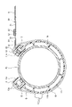
以下、本発明に係るシート状物の支持構造の一実施形態について、図面に基づいて詳細に説明する。なお、以後の説明において、上側とは図1の紙面に対して手前側、下側とは図1の紙面に対して奥側とする。 An embodiment of a support structure for a sheet-like object according to the present invention will be described in detail below with reference to the drawings. In the following description, the upper side is the front side with respect to the paper surface of FIG. 1, and the lower side is the rear side with respect to the paper surface of FIG.
本実施形態のシート状物の支持構造は、図1に示す構造物ST1に採用されており、この構造物ST1は、平面視四角形状に組み立てられた4本のパイプ部材(構造部材)P1~P4を備え、本実施形態では、対向する2本のパイプ部材P1,P2に平面視四角形状のシート状物Sが張った状態で取り付けられている。そして、2本のパイプ部材P1,P2にシート状物Sの縁部が本実施形態のシート状物の支持構造によりそれぞれ支持されている。なお、本実施形態のシート状物Sはメッシュシートである。 The support structure for the sheet-shaped object of the present embodiment is employed in the structure ST1 shown in FIG. 1. This structure ST1 includes four pipe members (structural members) P1 to P4 is provided, and in this embodiment, a sheet-like material S having a square shape in a plan view is attached to two pipe members P1 and P2 facing each other in a stretched state. The edges of the sheet S are supported by the two pipe members P1 and P2 by the support structure for the sheet of the present embodiment. Note that the sheet-like material S of this embodiment is a mesh sheet.
本実施形態のシート状物の支持構造は、図2及び図3に示すように、パイプ部材P1,P2に取り付けられる合成樹脂製の筒状のパイプホルダ(ホルダ)10と、パイプホルダ10に取り付けられるハーフストリンガー(テープ状部材)20と、ハーフストリンガー20に取り付けられるシート状物Sと、を備える。
As shown in FIGS. 2 and 3, the support structure for the sheet-like object of this embodiment includes a synthetic resin cylindrical pipe holder (holder) 10 attached to the pipe members P1 and P2, and a
パイプホルダ10は、合成樹脂製の円筒状部材であり、図2及び図3に示すように、周方向の一部に切り離し部11aを有する筒状部11と、筒状部11の切り離し部11aの対向する縁部に沿ってそれぞれ突条として形成される支持部12と、支持部12の長さ方向に沿って形成され、後述するハーフストリンガー20のファスナーエレメント22を挿通させるガイド溝13と、を有する。パイプホルダ10は、径方向に弾性変形可能な合成樹脂の押出し成形品であり、合成樹脂としては、例えば、塩化ビニル樹脂が使用される。
The
また、ガイド溝13の開口部には、ハーフストリンガー20のファスナーエレメント22を抜け止めする状態で、テープ長さ方向にスライド案内する一対の内向きフランジ13aが形成されている。
At the opening of the
また、筒状部11の内周面には、複数のリブ11bが周方向に所定の間隔を存して形成されている。なお、リブ11bはなくてもよい。
A plurality of
そして、パイプホルダ10は、その筒状部11の切り離し部11aを押し広げて、径方向外方に広げられた筒状部11をパイプ部材P1,P2に被せることにより、パイプ部材P1,P2に取り付けらえる。筒状部11の復元弾性力により筒状部11がパイプ部材P1,P2の外周面を締め付けることにより、筒状部11がパイプ部材P1,P2に保持される。
Then, the
また、本実施形態では、パイプホルダ10の取り付け後に、筒状部11の切り離し部11aが開かないようにするために、パイプホルダ10の端部外周面に合成樹脂製の結束バンド15が取り付けられている。また、結束バンド15をパイプホルダ10の端部より内側に配置したい場合は、ハーフストリンガー20のファスナーテープ21に貫通穴を形成して、その貫通穴に結束バンド15を挿通させるようにする。また、その場合、ファスナーテープ21が貫通穴から解れないように貫通穴にハトメを取り付けるとより好ましい。また、ハトメの形状は、円形状や長円形状が好ましい。なお、結束バンド15は、金属製のホースバンドであってもよい。
Further, in this embodiment, a
ハーフストリンガー(テープ状部材)20は、図3に示すように、スライドファスナーの一対のファスナーストリンガーの片側であり、ファスナーテープ21と、ファスナーテープ21の一方の側縁部に取り付けられるファスナーエレメント(ガイド部)22と、ファスナーテープ21の他方の側縁部に取り付けられる後述するスライドファスナー(ファスナー部材)30の一対のファスナーストリンガーの片側と、を備える。ファスナーエレメント22は、例えば、モノフィラメントがらせん状に巻かれたコイルエレメントである。
The half stringer (tape-shaped member) 20 is one side of a pair of fastener stringers of the slide fastener, as shown in FIG. 22 and one side of a pair of fastener stringers of a later-described slide fastener (fastener member) 30 attached to the other side edge of the
そして、パイプホルダ10の支持部12のガイド溝13にハーフストリンガー20のファスナーエレメント22を挿通することにより、ハーフストリンガー20がパイプホルダ10に取り付けられる。
The
また、支持部12のガイド溝13の長手方向の端部が開口していると、ガイド溝13からハーフストリンガー20のファスナーエレメント22が抜け出てしまうため、ガイド溝13の長手方向の端部に栓部材14が取り付けられている。なお、本実施形態では、栓部材14には、ねじが使用されている。
Further, if the longitudinal end of the
シート状物Sは、図2及び図3に示すように、その側縁部に沿って後述するスライドファスナー(ファスナー部材)30の一対のファスナーストリンガーの片側が取り付けられる。 2 and 3, one side of a pair of fastener stringers of a slide fastener (fastener member) 30, which will be described later, is attached along the side edges of the sheet S, as shown in FIGS.
スライドファスナー(ファスナー部材)30は、図2及び図3に示すように、一対のファスナーテープ31と、一対のファスナーテープ31の対向するテープ側縁部に取り付けられる一対のファスナーエレメント32と、一対のファスナーエレメント32を結合・分離させるスライダー33と、一対のファスナーテープ31のテープ側縁部の上端部にそれぞれ取り付けられる不図示の上止部と、一対のファスナーテープ31のテープ側縁部の下端部に取り付けられる開き具34と、を備える。なお、一対のファスナーテープ31と一対のファスナーエレメント32により一対のストリンガーが構成され、これらは互いに結合または分離可能である。
The slide fastener (fastener member) 30, as shown in FIGS. A
つまり、スライドファスナー30の一方側(図3の左側)のファスナーテープ31にハーフストリンガー20のファスナーテープ21が取り付けられ、スライドファスナー30の他方側(図3の右側)のファスナーテープ31にシート状物Sが取り付けられる。なお、ファスナーテープ同士の取り付け、及びファスナーテープとシート状物との取り付けには、縫着や溶着が用いられる。
That is, the
次に、本実施形態のシート状物の支持構造におけるシート状物Sの取り付け手順の一例について説明する。まず、パイプ部材P1,P2にパイプホルダ10を取り付ける。次いで、パイプホルダ10のガイド溝13にハーフストリンガー20を取り付ける。次いで、ハーフストリンガー20に取り付けられているスライドファスナー30の一方側のファスナーテープ31のファスナーエレメント32に、シート状物Sが取り付けられている他方側のファスナーテープ31のファスナーエレメント32をスライダー33の摺動により結合させる。以上の作業により、シート状物Sがパイプホルダ10に取り付けられる。
Next, an example of a procedure for attaching the sheet-like material S to the support structure for the sheet-like material of the present embodiment will be described. First, the
そして、シート状物Sを交換する際には、まず、スライダー33の摺動によりスライドファスナー30の一対のファスナーエレメント32を分離させ、スライドファスナー30を開くことにより、古いシート状物Sがパイプホルダ10から取り外される(図4参照)。次に、新しいシート状物Sを所定の位置に配置した後、スライダー33の摺動によりスライドファスナー30の一対のファスナーエレメント32を結合させ、スライドファスナー30を閉じることにより、新しいシート状物Sがパイプホルダ10に取り付けられる。従って、本実施形態のシート状物の支持構造は、スライドファスナー30の開閉により、シート状物Sがパイプホルダ10に対して脱着されるように構成されている。
When replacing the sheet S, first, the
以上説明したように、本実施形態のシート状物の支持構造によれば、パイプ部材P1,P2に取り付けられるパイプホルダ10と、パイプホルダ10に取り付けられるハーフストリンガー20と、ハーフストリンガー20に取り付けられるシート状物Sと、を備え、ハーフストリンガー20のファスナーテープ21の側縁部及びシート状物Sの側縁部に沿ってスライドファスナー30の一対のファスナーストリンガーの片側がそれぞれ取り付けられ、スライドファスナー30の開閉により、シート状物Sがパイプホルダ10に対して脱着されるため、パイプ部材P1,P2に対してシート状物Sを容易に脱着することができる。
As described above, according to the sheet-like object support structure of the present embodiment, the
なお、上記実施形態では、2本のパイプ部材P1,P2にシート状物Sを取り付ける場合を例示したが、これに限定されず、図5に示すように、4本のパイプ部材P1~P4にシート状物Sを取り付けるようにしてもよい。 In the above embodiment, the case where the sheet S is attached to the two pipe members P1 and P2 was illustrated, but the present invention is not limited to this, and as shown in FIG. A sheet-like object S may be attached.
また、本実施形態のシート状物の支持構造の第1変形例として、図6に示すように、スライドファスナー30の一方のファスナーテープ31の上面に、一対のファスナーエレメント32を覆うカバー部材35を取り付けてもよい。そして、本変形例によれば、一対のファスナーエレメント32がカバー部材35により覆われるため、一対のファスナーエレメント32の耐候性を向上することができる。
Further, as a first modification of the support structure for the sheet-like object of this embodiment, as shown in FIG. may be installed. According to this modification, the pair of
また、本実施形態のシート状物の支持構造の第2変形例として、図7に示すように、一対のファスナーエレメント32が下向きになるようにスライドファスナー30を配置すると共に、スライドファスナー30の一方のファスナーテープ31の上面に、一対のファスナーエレメント32を覆うカバー部材35を取り付けてもよい。この場合、一対のファスナーテープ31間の隙間を覆えばよいため、カバー部材35の材料を少なくすることができ、製品コストを低減することができる。
Further, as a second modification of the support structure for the sheet-like object of this embodiment, as shown in FIG. A
さらに、本発明のシート状物の支持構造が採用される構造物の他の例として、図8及び図9に示す導風装置ST2を挙げることができる。この導風装置ST2は、導風板60の高い方から低い方に風を通過させて、風の流速を上げる装置である。なお、図8中の矢印Wは通過させる風を表している。
Furthermore, as another example of a structure to which the support structure for a sheet-shaped object of the present invention is employed, there is a baffle device ST2 shown in FIGS. 8 and 9. FIG. This baffle device ST2 is a device that increases the flow velocity of the wind by allowing the wind to pass from the high side to the low side of the
導風装置ST2は、図8及び図9に示すように、複数の支柱51を有するベースフレーム50と、ベースフレーム50の複数の支柱51の上端部に取り付けられる導風板60と、を備える。
As shown in FIGS. 8 and 9, the air guide device ST2 includes a
導風板60は、平面視四角形状且つ側面視下方に湾曲する形状に形成されるフレーム61と、フレーム61に張った状態で取り付けられる平面視四角形状のシート状物Sと、を備える。
The
フレーム61は、6本の横パイプ部材61A~61Fと、4本の横パイプ部材61A~61Dの両端部をそれぞれ連結する6本の縦パイプ部材62A~62Fと、2本の横パイプ部材61E,61Fの両端部をそれぞれ連結する2本の縦パイプ部材62G,62Hと、を備える。
The
そして、横パイプ部材61A,61F及び8本の縦パイプ部材62A~62Hに、上記パイプホルダ10がそれぞれ取り付けられ、その各パイプホルダ10に、上記ハーフストリンガー20及びスライドファスナー30を介してシート状物Sが取り付けられている。また、上記ハーフストリンガー20及びスライドファスナー30は、シート状物Sの各辺にそれぞれ取り付けられている。また、シート状物Sは、横パイプ部材61B~61Eの下方を通過するように配置されている。
The
なお、本発明は上記実施形態に例示したものに限定されるものではなく、本発明の要旨を逸脱しない範囲において適宜変更可能である。
例えば、上記実施形態では、1本のパイプ部材に1つのパイプホルダを取り付けているが、これに限定されず、1本のパイプ部材に複数に分割されたパイプホルダを取り付けてもよい。
また、スライドファスナーは、一対のスライダーを配置した両開き可能なスライドファスナーであってもよい。この場合、スライドファスナーの両端からの取り外し、取り付けが可能となる。
また、スライダーの引手は、金属製に限定されず、紐やテープをループ状に結んだ引手であってもよい。この場合、引手に柔軟性があるため、作業性を向上することができる。
It should be noted that the present invention is not limited to the above-described embodiments, and can be modified as appropriate without departing from the gist of the present invention.
For example, in the above embodiment, one pipe holder is attached to one pipe member, but the present invention is not limited to this, and a plurality of divided pipe holders may be attached to one pipe member.
Also, the slide fastener may be a double-openable slide fastener having a pair of sliders. In this case, it is possible to remove and attach the slide fastener from both ends.
Further, the pull tab of the slider is not limited to being made of metal, and may be a pull tab formed by tying a string or tape in a loop. In this case, since the pull is flexible, workability can be improved.
また、上記実施形態では、ファスナー部材としてスライドファスナー30を使用しているが、これに限定されず、ファスナー部材として面ファスナー30B(図10参照)又はスナップボタン30C(図11参照)を使用してもよい。なお、面ファスナー30B及びスナップボタン30Cは、互いに結合または分離可能な一対の係合部材からなる。この場合も、ハーフストリンガー(テープ状部材)20のファスナーテープ21の側縁部及びシート状物Sの側縁部に沿って、面ファスナー(ファスナー部材)30B又はスナップボタン(ファスナー部材)30Cの片側がそれぞれ取り付けられている。
In addition, although the
また、上記実施形態では、テープ状部材としてハーフストリンガー20を使用しているが、これに限定されず、テープ状部材として図12に示す樹脂製の押し出し部材20Bを使用してもよい。
Further, in the above-described embodiment, the
押し出し部材20Bは、スライドファスナー30の一方側のファスナーテープ31が取り付けられる基部21Bと、基部21Bの側縁部に一体形成される頭部(ガイド部)22Bと、を備え、合成樹脂の押し出し成形により形成される。そして、押し出し部材20Bの頭部22Bは、パイプホルダ10の支持部12のガイド溝13に挿通される。
The extruding
また、押し出し部材20Bは、同じ樹脂により成形されてもよいが、2種類の樹脂により成形されていてもよい。例えば、基部21Bを軟質樹脂、頭部22Bを硬質樹脂で成形してもよい。この場合、基部21Bが軟質樹脂で成形されているため、押し出し部材20Bをファスナーテープ31に縫着可能となる。また、頭部22Bが硬質樹脂で成形されているため、ガイド溝13との係合力を向上することができる。さらに、基部21Bを硬質樹脂で成形してもよい。この場合、シート状物Sの張り具合を高めることができ、ファスナーテープ31に溶着により取り付けられる。
Also, the pushing
また、図13及び図14に示すように、スライドファスナー30の一方側のファスナーテープ31の外側縁部に、パイプホルダ10の支持部12のガイド溝13に挿通される樹脂製のガイドエレメント(ガイド部)22Cを形成して、スライドファスナー30の一対のファスナーストリンガーの片側をテープ状部材としてもよい。この場合、テープ状部材の一方の側縁部にガイドエレメント(ガイド部)22Cが形成され、他方の側縁部にファスナーエレメント(ファスナー部材)32が形成される。そして、ガイドエレメント22Cは、ファスナーテープ31の外側縁部に連続的に射出成形されている。この場合、ファスナーテープ31にガイドエレメント22Cを直接射出成形するため、ファスナーテープ31にハーフストリンガー20などを縫着する手間を省くことができる。また、ガイドエレメント22Cを連続的に射出成形するため、シート状物Sの張り具合を高めることができる。シート状物Sの側縁部にも、ファスナーエレメント(ファスナー部材)32が形成され、テープ状部材及びシート状物Sに設けられたファスナーエレメント32の結合または分離により、シート状物Sがパイプホルダ10に対して脱着される。なお、ファスナーエレメント32をシート状物に取り付ける際に、ファスナーテープ31を介するか否かは問わない。
Further, as shown in FIGS. 13 and 14 , a resin guide element (guide element) inserted into the
また、図15に示すように、図13に示すガイドエレメント22Cを、ファスナーテープ31の外側縁部に間欠的に射出成形してもよい。この場合、ガイドエレメント22Cを間欠的に射出成形するため、カーブした形状の構造部材にも対応することができる。
Alternatively, as shown in FIG. 15,
また、図16に示すように、スライドファスナー30の一方側のファスナーテープ31の外側縁部に、パイプホルダ10の支持部12のガイド溝13に挿通される膨出部(ガイド部)22Dを設けて、スライドファスナー30の一対のファスナーストリンガーの片側をテープ状部材としてもよい。この場合、テープ状部材の一方の側縁部に膨出部(ガイド部)22Dが形成され、他方の側縁部にファスナーエレメント(ファスナー部材)32が形成される。この膨出部22Dは、ファスナーテープ31の外側縁部に形成される袋状部25と、袋状部25内に挿通される芯材26と、を備える。シート状物Sの側縁部にも、ファスナーエレメント(ファスナー部材)32が形成され、テープ状部材及びシート状物Sに設けられたファスナーエレメント32の結合または分離により、シート状物Sがパイプホルダ10に対して脱着される。なお、ファスナーエレメント32をシート状物に取り付ける際に、ファスナーテープ31を介するか否かは問わない。
Further, as shown in FIG. 16, the outer edge of the
袋状部25は、ファスナーテープ31の外側縁部を折り返し、その折り返した部分をファスナーテープ31に縫着又は溶着することにより形成される。芯材26は、モノフィラメントワイヤー、金属ワイヤー、及び間欠ボールチェーンなどである。この場合、ファスナーテープ31に膨出部22Dを直接設けるため、ファスナーテープ31にハーフストリンガー20などを縫着する手間を省くことができる。また、芯材26がモノフィラメントワイヤーや金属ワイヤーの場合、シート状物Sの張り具合を高めることができ、芯材26が間欠ボールチェーンの場合、カーブした形状の構造部材にも対応することができる。なお、モノフィラメントワイヤーや金属ワイヤーの断面形状は、円形状、楕円形状、長円形状などを採用してよく、その形状に制限はない。
The bag-
10 パイプホルダ(ホルダ)
11 筒状部
11a 切り離し部
12 支持部
13 ガイド溝
20 ハーフストリンガー(テープ状部材)
21 ファスナーテープ
22 ファスナーエレメント(ガイド部)
30 スライドファスナー(ファスナー部材)
31 ファスナーテープ
32 ファスナーエレメント
33 スライダー
34 開き具
35 カバー部材
20B 押し出し部材(テープ状部材)
21B 基部
22B 頭部(ガイド部)
30B 面ファスナー(ファスナー部材)
30C スナップボタン(ファスナー部材)
P1~P4 パイプ部材(構造部材)
S シート状物
10 pipe holder (holder)
REFERENCE SIGNS
21
30 slide fastener (fastener member)
31
30B hook-and-loop fastener (fastener member)
30C snap button (fastener member)
P1 to P4 pipe members (structural members)
S sheet material
Claims (3)
前記構造部材(P1~P4)に取り付けられる合成樹脂製の筒状のホルダ(10)と、
前記ホルダ(10)に取り付けられる、前記シート状物(S)とは異なる部材のテープ状部材(20B)と、
前記シート状物(S)と、
を備え、
前記テープ状部材(20B)の一方の側縁部に沿ってガイド部(22B)が設けられ、
前記テープ状部材(20B)の他方の側縁部及び前記シート状物(S)の側縁部に沿って、一対の互いに結合または分離可能な部材からなるファスナー部材(30)の片側がそれぞれ取り付けられ、
前記ファスナー部材(30)は、一対のファスナーテープ(31)と、前記一対のファスナーテープ(31)の対向するテープ側縁部に取り付けられる一対のファスナーエレメント(32)と、を備えるスライドファスナー(30)であり、
前記テープ状部材(20B)は合成樹脂製の押し出し部材であり、
前記テープ状部材(20B)は、前記ファスナー部材(30)の片側が取り付けられる基部(21B)と、前記基部(21B)の側縁部に一体形成される前記ガイド部(22B)と、を備え、
前記テープ状部材(20B)は、2種類の樹脂により形成されており、
前記ホルダ(10)は、周方向の一部に切り離し部(11a)を有する筒状部(11)と、前記筒状部(11)の前記切り離し部(11a)の対向する縁部に沿ってそれぞれ形成される支持部(12)と、前記支持部(12)の長さ方向に沿って形成され、前記テープ状部材(20B)の前記ガイド部(22B)を挿通させるガイド溝(13)と、を有し、
前記支持部(12)の前記ガイド溝(13)に前記テープ状部材(20B)の前記ガイド部(22B)を挿通することにより、前記テープ状部材(20B)が前記ホルダ(10)に取り付けられ、
前記ファスナー部材(30)の結合または分離により、前記シート状物(S)が前記ホルダ(10)に対して脱着され、
前記基部(21B)は軟質樹脂で成形され、前記ガイド部(22B)は硬質樹脂で成形されることを特徴とするシート状物の支持構造。 A support structure for a sheet-like article for attaching a sheet-like article (S) to at least one structural member (P1 to P4),
a cylindrical synthetic resin holder (10) attached to the structural members (P1 to P4);
a tape-shaped member (20B) different from the sheet-shaped object (S) attached to the holder (10);
the sheet material (S);
with
A guide portion (22B) is provided along one side edge of the tape-shaped member (20B),
One side of a fastener member (30) composed of a pair of mutually connectable or separable members is attached along the other side edge of the tape-like member (20B) and the side edge of the sheet-like material (S). be
The fastener member (30) is a slide fastener (30) comprising a pair of fastener tapes (31) and a pair of fastener elements (32) attached to opposite tape side edges of the pair of fastener tapes (31). ) and
The tape-shaped member (20B) is an extruded member made of synthetic resin,
The tape-shaped member (20B) includes a base portion (21B) to which one side of the fastener member (30) is attached, and the guide portion (22B) integrally formed on the side edge portion of the base portion (21B). ,
The tape-shaped member (20B) is made of two types of resin,
The holder (10) includes a cylindrical portion (11) having a cut-off portion (11a) in a part of the circumferential direction, and along the edge portions of the cut-off portion (11a) of the cylindrical portion (11) facing each other. a support portion (12) formed respectively; and a guide groove (13) formed along the length direction of the support portion (12) for inserting the guide portion (22B) of the tape-shaped member (20B). , has
The tape-shaped member (20B) is attached to the holder (10) by inserting the guide portion (22B) of the tape-shaped member (20B) into the guide groove (13) of the support portion (12). ,
By coupling or separating the fastener member (30), the sheet (S) is detached from the holder (10),
A support structure for a sheet-like object, wherein the base portion (21B) is molded from a soft resin, and the guide portion (22B) is molded from a hard resin .
前記ファスナーテープ(31)に取り付けられ、前記一対のファスナーエレメント(32)を覆うカバー部材(35)を更に備えることを特徴とする請求項1に記載のシート状物の支持構造。 The slide fastener (30) has a slider (33) for joining and separating the pair of fastener elements (32),
2. The support structure for a sheet-like object according to claim 1, further comprising a cover member (35) attached to said fastener tape (31) and covering said pair of fastener elements (32).
Priority Applications (1)
| Application Number | Priority Date | Filing Date | Title |
|---|---|---|---|
| JP2021013188A JP7144555B2 (en) | 2021-01-29 | 2021-01-29 | Sheet support structure |
Applications Claiming Priority (1)
| Application Number | Priority Date | Filing Date | Title |
|---|---|---|---|
| JP2021013188A JP7144555B2 (en) | 2021-01-29 | 2021-01-29 | Sheet support structure |
Related Parent Applications (1)
| Application Number | Title | Priority Date | Filing Date |
|---|---|---|---|
| JP2016066808A Division JP2017179814A (en) | 2016-03-29 | 2016-03-29 | Support structure of sheet-like material |
Publications (2)
| Publication Number | Publication Date |
|---|---|
| JP2021073397A JP2021073397A (en) | 2021-05-13 |
| JP7144555B2 true JP7144555B2 (en) | 2022-09-29 |
Family
ID=75802423
Family Applications (1)
| Application Number | Title | Priority Date | Filing Date |
|---|---|---|---|
| JP2021013188A Active JP7144555B2 (en) | 2021-01-29 | 2021-01-29 | Sheet support structure |
Country Status (1)
| Country | Link |
|---|---|
| JP (1) | JP7144555B2 (en) |
Citations (3)
| Publication number | Priority date | Publication date | Assignee | Title |
|---|---|---|---|---|
| WO2006137293A1 (en) | 2005-06-21 | 2006-12-28 | Ykk Corporation | Device for article, used for changing string-end securing portion |
| WO2012176486A1 (en) | 2011-06-24 | 2012-12-27 | Ykk株式会社 | Slide fastener |
| JP2015197026A (en) | 2014-04-03 | 2015-11-09 | 林口工業株式会社 | Mounting apparatus of sheet-like material |
Family Cites Families (2)
| Publication number | Priority date | Publication date | Assignee | Title |
|---|---|---|---|---|
| JPS6094544U (en) * | 1983-12-05 | 1985-06-27 | 株式会社長谷川工務店 | Connection structure of curing sheet |
| JPH0635058Y2 (en) * | 1988-03-24 | 1994-09-14 | 精三 林口 | Protective film mounting device |
-
2021
- 2021-01-29 JP JP2021013188A patent/JP7144555B2/en active Active
Patent Citations (3)
| Publication number | Priority date | Publication date | Assignee | Title |
|---|---|---|---|---|
| WO2006137293A1 (en) | 2005-06-21 | 2006-12-28 | Ykk Corporation | Device for article, used for changing string-end securing portion |
| WO2012176486A1 (en) | 2011-06-24 | 2012-12-27 | Ykk株式会社 | Slide fastener |
| JP2015197026A (en) | 2014-04-03 | 2015-11-09 | 林口工業株式会社 | Mounting apparatus of sheet-like material |
Also Published As
| Publication number | Publication date |
|---|---|
| JP2021073397A (en) | 2021-05-13 |
Similar Documents
| Publication | Publication Date | Title |
|---|---|---|
| US4854015A (en) | Adjustable loop clamp | |
| US3696472A (en) | Closure assembly with slidable closure member | |
| USRE41348E1 (en) | Multi-branch junction overwrap | |
| US20120049403A1 (en) | Releasable fastening arrangement | |
| EP2777438A1 (en) | Cover-material fastening cord | |
| SE460988B (en) | SLANGKLAEMMA | |
| US8083040B2 (en) | Zipper for luggage and luggage using the same | |
| JP4610516B2 (en) | Articles with slide fasteners | |
| JP7144555B2 (en) | Sheet support structure | |
| JP2008220842A (en) | Concealed slide fastener | |
| CN110274106B (en) | Connector for flexible pipes, flexible pipe with interchangeable end and method thereof | |
| US10624464B2 (en) | Double mattress connecting system | |
| JP2017179814A (en) | Support structure of sheet-like material | |
| US5857511A (en) | Drapery with heart-shaped headers | |
| US4238871A (en) | Slide fastener installation | |
| US3905073A (en) | Top stops for slide fasteners | |
| JP4853980B2 (en) | Garbage bag holding device in dust box | |
| US3431605A (en) | Closure assembly | |
| EP2374366A1 (en) | Zipper for luggage and luggage using the same | |
| US11338951B1 (en) | Bag holder clamp and Method | |
| US20080285895A1 (en) | Bag with integrally formed closure | |
| JP2003501185A (en) | Closure device | |
| JP4624444B2 (en) | book cover | |
| CN209749992U (en) | Zipper head and zipper convenient to fix and store earphone cable | |
| JP2000350339A (en) | Protective cover |
Legal Events
| Date | Code | Title | Description |
|---|---|---|---|
| A621 | Written request for application examination |
Free format text: JAPANESE INTERMEDIATE CODE: A621 Effective date: 20210129 |
|
| A977 | Report on retrieval |
Free format text: JAPANESE INTERMEDIATE CODE: A971007 Effective date: 20211125 |
|
| A131 | Notification of reasons for refusal |
Free format text: JAPANESE INTERMEDIATE CODE: A131 Effective date: 20211207 |
|
| A521 | Request for written amendment filed |
Free format text: JAPANESE INTERMEDIATE CODE: A523 Effective date: 20220114 |
|
| A131 | Notification of reasons for refusal |
Free format text: JAPANESE INTERMEDIATE CODE: A131 Effective date: 20220426 |
|
| A521 | Request for written amendment filed |
Free format text: JAPANESE INTERMEDIATE CODE: A523 Effective date: 20220527 |
|
| TRDD | Decision of grant or rejection written | ||
| A01 | Written decision to grant a patent or to grant a registration (utility model) |
Free format text: JAPANESE INTERMEDIATE CODE: A01 Effective date: 20220816 |
|
| A61 | First payment of annual fees (during grant procedure) |
Free format text: JAPANESE INTERMEDIATE CODE: A61 Effective date: 20220915 |
|
| R150 | Certificate of patent or registration of utility model |
Ref document number: 7144555 Country of ref document: JP Free format text: JAPANESE INTERMEDIATE CODE: R150 |