JP7144460B2 - How to control the ozone generator - Google Patents
How to control the ozone generator Download PDFInfo
- Publication number
- JP7144460B2 JP7144460B2 JP2019570429A JP2019570429A JP7144460B2 JP 7144460 B2 JP7144460 B2 JP 7144460B2 JP 2019570429 A JP2019570429 A JP 2019570429A JP 2019570429 A JP2019570429 A JP 2019570429A JP 7144460 B2 JP7144460 B2 JP 7144460B2
- Authority
- JP
- Japan
- Prior art keywords
- ozone
- gas
- pressure
- adjusting
- ozg
- Prior art date
- Legal status (The legal status is an assumption and is not a legal conclusion. Google has not performed a legal analysis and makes no representation as to the accuracy of the status listed.)
- Active
Links
Images

Classifications
-
- C—CHEMISTRY; METALLURGY
- C01—INORGANIC CHEMISTRY
- C01B—NON-METALLIC ELEMENTS; COMPOUNDS THEREOF; METALLOIDS OR COMPOUNDS THEREOF NOT COVERED BY SUBCLASS C01C
- C01B13/00—Oxygen; Ozone; Oxides or hydroxides in general
- C01B13/10—Preparation of ozone
- C01B13/11—Preparation of ozone by electric discharge
- C01B13/115—Preparation of ozone by electric discharge characterised by the electrical circuits producing the electrical discharge
-
- H—ELECTRICITY
- H01—ELECTRIC ELEMENTS
- H01T—SPARK GAPS; OVERVOLTAGE ARRESTERS USING SPARK GAPS; SPARKING PLUGS; CORONA DEVICES; GENERATING IONS TO BE INTRODUCED INTO NON-ENCLOSED GASES
- H01T23/00—Apparatus for generating ions to be introduced into non-enclosed gases, e.g. into the atmosphere
-
- C—CHEMISTRY; METALLURGY
- C01—INORGANIC CHEMISTRY
- C01B—NON-METALLIC ELEMENTS; COMPOUNDS THEREOF; METALLOIDS OR COMPOUNDS THEREOF NOT COVERED BY SUBCLASS C01C
- C01B2201/00—Preparation of ozone by electrical discharge
- C01B2201/30—Dielectrics used in the electrical dischargers
- C01B2201/32—Constructional details of the dielectrics
-
- C—CHEMISTRY; METALLURGY
- C01—INORGANIC CHEMISTRY
- C01B—NON-METALLIC ELEMENTS; COMPOUNDS THEREOF; METALLOIDS OR COMPOUNDS THEREOF NOT COVERED BY SUBCLASS C01C
- C01B2201/00—Preparation of ozone by electrical discharge
- C01B2201/90—Control of the process
Landscapes
- Chemical & Material Sciences (AREA)
- Organic Chemistry (AREA)
- Inorganic Chemistry (AREA)
- Oxygen, Ozone, And Oxides In General (AREA)
Description
本発明は、オゾン発生機を制御する方法に関し、特に、オゾン化ギャップおよび誘電体層によって分離される少なくとも2つの電極を有するオゾン発生器を備え、二酸素を含み、オゾン化ギャップの中を流れるガス内で放電を生成するために、電力ユニットに連結されるオゾン発生機に関する。 The present invention relates to a method of controlling an ozonator, in particular comprising an ozonizer having at least two electrodes separated by an ozonization gap and a dielectric layer, containing dioxygen and flowing through the ozonization gap. It relates to an ozonator coupled to a power unit to create an electrical discharge within the gas.
米国特許第8728402号明細書は、少なくとも2つの電極を含むオゾン発生機の例を記載している。しかし、このような機械は、所定の量のオゾン(所定の濃度および所定の出力ガス流量)を生成する一方で、別の量のオゾンを供給するように設定されている可能性がある。そのような場合、電極に供給される電力および/または入口ガス流は、新しい生産目標に到達するように変更される。しかし、この文献に開示されている方法の効率は向上され得る。 US Pat. No. 8,728,402 describes an example of an ozonator comprising at least two electrodes. However, while such a machine produces a given amount of ozone (at a given concentration and a given output gas flow rate), it may be set to deliver another amount of ozone. In such cases, the power supplied to the electrodes and/or the inlet gas flow are changed to reach the new production goals. However, the efficiency of the method disclosed in this document can be improved.
本発明は、従来技術の上述の欠点に対処すること、かつ生産範囲が変更された場合でも、オゾン生成の効率を高めるように(電気費用または原材料費用の観点から)、少なくとも2つの電極を含むオゾン発生機を制御する方法を第1に提案することを目的とする。 The present invention addresses the above-mentioned drawbacks of the prior art and includes at least two electrodes to increase the efficiency of ozone generation (in terms of electricity or raw material costs) even if the production range is changed. The object is firstly to propose a method for controlling an ozonator.
この目的で、本発明の第1の態様は、オゾン化ギャップおよび誘電体層によって分離され、二酸素を含む供給ガスを受け取るための少なくともガス入口と、オゾンを含むガスを排出するためのガス出口とを備えるオゾン発生器内に配置された少なくとも2つの電極を備えるオゾン発生機内でオゾンを生成するための方法であって、
-所定の供給ガス流量および供給ガス圧力で、二酸素を含む供給ガスをオゾン発生器のガス入口に供給するステップと、
-オゾン発生器の前記少なくとも2つの電極に交流電流を供給して、オゾン化ギャップに放電を生成して、オゾン発生器のガス出口で所定量のオゾンを生成するステップと、
-オゾン発生器のガス出口で生成されたオゾンの量を調整するために、電流電力と、供給ガス流量、電流周波数、電流電圧、オゾン発生器の冷却温度を含む複数のプロセスパラメータの少なくとも1つとを調整するステップと
を含み、
オゾン生成中に、
-電力と、供給ガス流量、電流周波数、電流電圧、冷却温度を含む複数のプロセスパラメータの少なくとも1つのパラメータとを監視するステップと、
-電流電力と、前記少なくとも1つのプロセスパラメータとの調整に応じて供給ガス圧力を調整するステップと
を含むことを特徴とする方法である。上記の方法によれば、すべての生産中にプロセスパラメータが監視され、別のプロセスパラメータによる電力の調整に加えて、ガス供給圧力が調整される。このガス供給圧力の調整は、オゾン生成の全体的な効率を高めるために行われ、この効率は通常、電力消費と比較して生成されるオゾンの量である(オゾン生産量または特定エネルギー消費とも呼ばれる)。言い換えれば、この方法は、生産費用を削減するために、生産条件を最適化された構成にするためのガス供給圧力調整のステップを含む。
To this end, a first aspect of the invention provides at least a gas inlet for receiving a feed gas containing dioxygen and a gas outlet for discharging a gas containing ozone, separated by an ozonation gap and a dielectric layer. 1. A method for producing ozone in an ozonator comprising at least two electrodes arranged in the ozonator comprising:
- supplying a feed gas containing dioxygen to the gas inlet of the ozone generator at a predetermined feed gas flow rate and feed gas pressure;
- supplying an alternating current to said at least two electrodes of the ozonator to create an electrical discharge in the ozonation gap to create a predetermined amount of ozone at the gas outlet of the ozonator;
- current power and at least one of a plurality of process parameters including feed gas flow rate, current frequency, current voltage, ozonator cooling temperature to adjust the amount of ozone produced at the gas outlet of the ozonator; and
During ozone generation,
- monitoring power and at least one of a plurality of process parameters including feed gas flow rate, current frequency, current voltage, cooling temperature;
- adjusting the supply gas pressure in response to the adjustment of the current power and said at least one process parameter. According to the above method, process parameters are monitored during all production and the gas supply pressure is adjusted in addition to adjusting the power according to another process parameter. This adjustment of the gas supply pressure is done to increase the overall efficiency of ozone production, which is usually the amount of ozone produced compared to power consumption (also known as ozone production or specific energy consumption). be called). In other words, the method includes a step of gas supply pressure adjustment for optimized configuration of production conditions to reduce production costs.
特に、オゾン発生器の冷却温度は、オゾン発生器の冷却経路に入る冷却液の温度である。冷却経路は、通常、オゾン発生器、ポンプ、および熱交換器の冷却経路を含む冷却回路の一部である。冷却液は水である場合があり、任意選択で添加剤(腐食、凍結などに対し
て)を含む。
Specifically, the cooling temperature of the ozone generator is the temperature of the coolant entering the cooling path of the ozone generator. The cooling path is typically part of a cooling circuit that includes an ozone generator, a pump, and a heat exchanger cooling path. The coolant may be water, optionally with additives (against corrosion, freezing, etc.).
特に、電流電力の調整とは、電力密度(電極の1平方メートルあたりkW)の調整である。 In particular, adjusting the current power is adjusting the power density (kW per square meter of electrode).
有利には、供給ガス圧力を調整するステップは、
-電流電力の調整された値および前記少なくとも1つの調整されたプロセスパラメータによって運転されるオゾン発生器の最適化された効率につながる最適供給ガス圧力を決定するために、供給ガス圧力、電流電力および前記少なくとも1つの前記プロセスパラメータに基づいて、オゾン発生器の性能を予測するモデルの供給ガス圧力に関する導関数を計算するステップと、
-オゾン発生器内の最適なガス供給圧力に達するように供給ガス圧力を調整するステップと
を含む。この実施形態によれば、ガス供給圧力の調整は、予測モデルに従って行われ、予測モデルは、電力の調整値および前記少なくとも1つのパラメータに対して、結果として最も効率的なオゾンの生成に到るガス供給圧力の最適値を与える。このようなモデルは経験的モデルになり得るが、しかし学習段階中にディープニューラルネットワークによっても確立され、またはファジーロジックによって駆動されるモデルにもなる可能性がある。
Advantageously, the step of adjusting the supply gas pressure comprises:
- for determining an optimum feed gas pressure leading to an optimized efficiency of the ozone generator operated with the adjusted value of the current power and said at least one adjusted process parameter, the feed gas pressure, the current power and calculating a derivative with respect to feed gas pressure of a model that predicts the performance of an ozonator based on said at least one process parameter;
- adjusting the supply gas pressure to reach the optimum gas supply pressure in the ozone generator. According to this embodiment, the adjustment of the gas supply pressure is made according to a predictive model, which for the adjusted value of power and said at least one parameter results in the most efficient production of ozone. Gives the optimum value of the gas supply pressure. Such models can be empirical models, but also models established by deep neural networks during the learning phase, or driven by fuzzy logic.
有利には、この方法は、オゾン濃度を測定すること、および/またはオゾン発生器を通って流れるガスの流量を測定することにより、オゾン発生器のガス出口でオゾン発生量を監視するステップを含む。この測定ステップは、通常、オゾン濃度の正確な計算について基礎となる(流量および圧力測定によって)。通常、任意のオゾン発生機にはデフォルトでそのようなセンサが装備されているが、装備されていない場合は、オゾン濃度センサは設置場所に簡単に追加され得る。 Advantageously, the method comprises monitoring the amount of ozone produced at the gas outlet of the ozonator by measuring the ozone concentration and/or measuring the flow rate of the gas flowing through the ozonator. . This measurement step is usually the basis for an accurate calculation of the ozone concentration (via flow and pressure measurements). Any ozone generator is typically equipped with such a sensor by default, but if not, an ozone concentration sensor can be easily added to the installation site.
有利には、最適な供給ガス圧力を計算するステップおよび供給ガス圧力を調整するステップが、電流電力または複数のプロセスパラメータの前記少なくとも1つのパラメータの変化と同時に、または変化後の所定の運転時間内に実行される。言い換えれば、オゾンの発生量を調整するための変化があるとすぐに、生成中にガス供給圧力が絶えず調整される。 Advantageously, the steps of calculating the optimum feed gas pressure and adjusting the feed gas pressure are performed simultaneously with the change of said at least one of the current power or the plurality of process parameters or within a predetermined operating time after the change. is executed. In other words, the gas supply pressure is constantly adjusted during production as soon as there is a change to regulate the amount of ozone produced.
有利には、電流電力の調整は、電流周波数の調整である。実際に、電流電力は周波数の変化によって調整される可能性がある。そのような場合、調整される他のパラメータは、周波数とは別のプロセスパラメータであり、供給ガス流量、冷却温度などが考えられる。 Advantageously, the adjustment of the current power is an adjustment of the current frequency. In fact, the current power can be adjusted by changing the frequency. In such cases, the other parameters to be adjusted are process parameters other than frequency, such as feed gas flow rate, cooling temperature, and the like.
有利には、電流周波数および供給ガス流量のみが調整され、
-電流周波数の増加は、供給ガス圧力の増加につながり、
-電流周波数の低下は、供給ガス圧力の低下につながる。ガス供給圧力のこれらの変化は、効率の向上につながる。
Advantageously, only the current frequency and the supply gas flow are regulated,
- an increase in the current frequency leads to an increase in the supply gas pressure,
- A decrease in current frequency leads to a decrease in supply gas pressure. These changes in gas supply pressure lead to increased efficiency.
有利には、調整電力は、電流電圧の調整である。実際に、電流電力は、電流電圧の変化(電圧振幅またはピーク電圧とも呼ばれる)によって調整される可能性がある。そのような場合、調整される他のパラメータは、電圧とは別のプロセスパラメータであり、供給ガス流量、冷却温度などが考えられる。 Advantageously, the regulated power is a regulation of current voltage. In practice, current power may be adjusted by changes in current voltage (also called voltage amplitude or peak voltage). In such cases, the other parameters to be adjusted are process parameters other than voltage, such as feed gas flow rate, cooling temperature, and the like.
有利には、電流電圧および供給ガス流量のみが調整され、
-電流電圧の増加は、供給ガス圧力の増加につながり、
-電流電圧の低下は、供給ガス圧力の低下につながる。ガス供給圧力のこれらの変化は
、効率の向上につながる。
Advantageously, only the current voltage and the supply gas flow are regulated,
- an increase in current voltage leads to an increase in supply gas pressure,
- A drop in current voltage leads to a drop in supply gas pressure. These changes in gas supply pressure lead to increased efficiency.
有利には、オゾン発生器内の絶対ガス圧は、[0.5バール(a)~6バール(a)]の範囲で変化する。 Advantageously, the absolute gas pressure in the ozone generator varies in the range [0.5 bar(a) to 6 bar(a)].
有利には、オゾン発生機は、オゾン発生器に接続された圧力調整器を備え、オゾン発生器内の供給ガス圧力を調整するステップは、圧力調整器を制御するステップを含む。 Advantageously, the ozonator comprises a pressure regulator connected to the ozonator, and adjusting the feed gas pressure in the ozonator comprises controlling the pressure regulator.
有利には、オゾン発生機は、オゾン発生器の少なくとも2つの電極に接続された電力ユニットを備え、電極に供給される電力を調整するステップは、電力ユニットを制御するステップを含む。 Advantageously, the ozonator comprises a power unit connected to at least two electrodes of the ozonator, and adjusting the power supplied to the electrodes comprises controlling the power unit.
有利には、オゾン発生機は、オゾン発生器に接続された流量調整器を備え、供給ガス流量を調整するステップは、流量調整器を制御するステップを含む。 Advantageously, the ozone generator comprises a flow regulator connected to the ozone generator, and adjusting the feed gas flow rate comprises controlling the flow regulator.
有利には、オゾン発生器のガス入口で供給ガスを供給するステップは、少なくとも95%の二酸素ガスを含むガスを供給することから成るステップである。 Advantageously, the step of supplying a feed gas at the gas inlet of the ozonator comprises supplying a gas comprising at least 95% dioxygen gas.
有利には、オゾン発生器のガス入口で二酸素ガスを供給するステップは、わずか5%の窒素ガスまたはアルゴンガスを含むガスを供給することから成るステップである。 Advantageously, the step of supplying dioxygen gas at the gas inlet of the ozonator comprises supplying a gas containing no more than 5% nitrogen gas or argon gas.
有利には、オゾン発生器のガス入口で供給ガスを供給するステップは、空気を供給することから成るステップである。 Advantageously, the step of supplying feed gas at the gas inlet of the ozonator comprises supplying air.
有利には、この方法は、
-オゾンの発生量を監視するステップと、
-供給ガス圧力を監視するステップと、
-消費電力量を監視するステップと、
-オゾンの発生量および消費電力量に基づいて、オゾン生産量を計算および/または測定および監視するステップと、
-ガス供給圧力を調整するステップの前後でオゾン生産量を比較するステップと、
-オゾン生産量を最適化するために、ガス供給圧力を調整するステップの後に、オゾン生産量が低下した場合、供給ガス圧力を調整するステップを繰り返すステップと
を含む。
Advantageously, the method
- monitoring the amount of ozone generated;
- monitoring the supply gas pressure;
- monitoring power consumption;
- calculating and/or measuring and monitoring ozone production based on ozone generation and power consumption;
- comparing the ozone production before and after adjusting the gas supply pressure;
- repeating the step of adjusting the gas supply pressure to optimize the ozone production, followed by the step of adjusting the supply gas pressure if the ozone production drops.
上記の実施形態によれば、供給ガス圧力を調整する効果が監視され(計算により、またはオゾン濃度、ガス流量/ガス圧力の測定に基づいて)、効率の損失(オゾン生産量の損失)がある場合、さらなる調整が行われる。調整は、試行錯誤によって最適なガス供給圧力を見つけるために、運転範囲をスクリーニングするための「試行およびテスト」方策に従って設定され得る。また、ディープニューラルネットワークによって与えられた指示、あるいは予測モデルからの基本的な計算、あるいはファジーロジック計算に基づいている場合もある。 According to the above embodiments, the effect of adjusting the feed gas pressure is monitored (either by calculation or based on measurements of ozone concentration, gas flow/gas pressure) and there is a loss in efficiency (loss in ozone production). If so, further adjustments are made. Adjustments may be set according to a "try and test" strategy for screening operating ranges to find the optimum gas supply pressure by trial and error. It may also be based on instructions given by deep neural networks, or basic calculations from predictive models, or fuzzy logic calculations.
有利には、方法は、オゾン生産量がさらに増加するように、ガス供給圧力を調整するステップの後にオゾン生産量が増加するか、または同じである場合、供給ガス圧力をさらに調整するステップを含む。 Advantageously, the method comprises the step of further adjusting the supply gas pressure if the ozone production increases or remains the same after the step of adjusting the gas supply pressure such that the ozone production further increases. .
有利には、方法は、ガス供給圧力を調整するステップの後にオゾン生産量が増加するか、または同じである場合、供給ガス圧力を維持するステップを含む。最も効率的な条件でオゾンを生成するために、最適な条件は、一旦到達すると維持される。 Advantageously, the method includes maintaining the supply gas pressure if the ozone production increases or remains the same after the step of adjusting the gas supply pressure. Optimum conditions are maintained once reached in order to produce ozone at the most efficient conditions.
本発明の第2の態様は、
-二酸素を含む供給ガスを受け取るための入口と、オゾンを含むガスを排出するための出口とを含むオゾン発生器と、
-オゾン発生器内に配置され、オゾン化ギャップおよび誘電体層によって分離された少なくとも2つの電極と、
-オゾン発生器に接続された圧力調整器と、
-少なくとも2つの電極に接続された電力ユニットと、
-オゾン発生器に接続された流量調整器と、
-第1の態様による方法を実行するために、前記圧力調整器、電力ユニット、流量調整器を制御するように配置された制御ユニットと
を備えるオゾン発生機に関する。
A second aspect of the present invention is
- an ozone generator comprising an inlet for receiving a feed gas containing dioxygen and an outlet for discharging a gas containing ozone;
- at least two electrodes placed in the ozone generator and separated by an ozonation gap and a dielectric layer;
- a pressure regulator connected to an ozone generator;
- a power unit connected to at least two electrodes;
- a flow regulator connected to an ozone generator;
- an ozonator comprising: a control unit arranged to control said pressure regulator, a power unit and a flow regulator to carry out the method according to the first aspect;
一実施形態では、電極は金属であり、誘電体層は、電極の少なくとも1つに塗布されたセラミックコーティングを含む。 In one embodiment, the electrodes are metal and the dielectric layer comprises a ceramic coating applied to at least one of the electrodes.
本発明の他の特徴および利点は、添付の図面によって例示される本発明の特定の非限定的な例の以下の詳細な説明からより明らかになるであろう。 Other features and advantages of the invention will become more apparent from the following detailed description of certain non-limiting examples of the invention illustrated by the accompanying drawings.
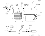
図1は、図3に示すように、複数の電極セットESがハウジングH内に配置されたオゾン発生器OzGを備える簡易化したオゾン発生機OGMを示す。各電極セットは、オゾン化ギャップOGおよび誘電体層(明確にするために図には示されていない)によって分離された2つの電極E1およびE2を含む。オゾン発生機OGMは、各電極セットに電流を供給するための電力ユニットEPUも備える。各オゾン化ギャップOGは、オゾン発生機の運転時に、二酸素を含むガスを受け取るために、上流でオゾン発生器OzGのガス入口O2INに接続され、オゾンを含むガスを排出するために、下流でガス出口O3OUTに接続される。 FIG. 1 shows a simplified ozone generator OGM comprising an ozone generator OzG with a plurality of electrode sets ES arranged in a housing H, as shown in FIG. Each electrode set includes two electrodes E1 and E2 separated by an ozonation gap OG and a dielectric layer (not shown in the figure for clarity). The ozone generator OGM also comprises a power unit EPU for supplying current to each electrode set. Each ozonation gap OG is connected upstream to the gas inlet O2IN of the ozonator OzG for receiving the gas containing dioxygen and downstream for discharging the gas containing ozone during operation of the ozonator. It is connected to the gas outlet O3OUT.
オゾン化ギャップOG内にガス流を生成するために、オゾン発生機は、オゾン発生器OzGに特定のガス供給流量および特定のガス供給圧力を設定するように設計された酸素循環ポンプOCPを備える。電極に電力が供給され、ガスの流れが確立されると、電極間のオゾン化ギャップOGで放電が発生し、コロナ効果を与え、ガス入口O2INで供給された酸素の一部がオゾンに変換され、それが所定量でガス出口O3OUTに排出される。 In order to generate a gas flow in the ozonation gap OG, the ozonator comprises an oxygen circulation pump OCP designed to set a specific gas supply flow rate and a specific gas supply pressure to the ozonator OzG. When the electrodes are energized and gas flow is established, a discharge occurs in the ozonation gap OG between the electrodes, giving rise to a corona effect and converting part of the oxygen supplied at the gas inlet OIN to ozone. , which is discharged in a predetermined amount to the gas outlet O3OUT.
オゾンの生成中に安定した状態を保証するために、冷却回路がオゾン発生器OzG内に冷却経路を備えており、その結果、冷却液がオゾン発生器OzGを通って流れて、各電極セットESを直接冷却することができる。図3は、冷却水WCがオゾン発生器OzG内に存在することを示す。オゾン発生器は、冷却水入口WCIN、および冷却水出口WCOUTを備える。 In order to ensure stable conditions during the production of ozone, a cooling circuit is provided with a cooling path within the ozone generator OzG, so that cooling liquid flows through the ozone generator OzG and each electrode set ES can be cooled directly. FIG. 3 shows that cooling water WC is present in the ozone generator OzG. The ozone generator has a cooling water inlet WCIN and a cooling water outlet WCOUT.
通常、オゾン発生機OGMは次の範囲で運転され得る。
電力密度の範囲:電極の1平方メートルあたり[0.1~10]kW
電流周波数の範囲:[10~30000]Hz
ピーク電圧の上限の範囲:[2~20]kV
ガス出口でのオゾン濃度:1~16重量%
供給ガスの絶対圧力の範囲、[0.5バール(a)~6バール(a)]
Normally, the ozone generator OGM can be operated in the following ranges.
Power density range: [0.1-10] kW per square meter of electrode
Current frequency range: [10 to 30000] Hz
Range of upper limit of peak voltage: [2 to 20] kV
Ozone concentration at gas outlet: 1 to 16% by weight
Range of absolute pressure of feed gas, [0.5 bar(a) to 6 bar(a)]
窒素(N2)および/またはアルゴン(Ar)が、少なくとも0.1~5重量%の濃度で供給ガスに存在し、残りが二酸素であることが望ましい場合がある。別法として、オゾン発生器に空気を供給することができる。 It may be desirable to have nitrogen (N 2 ) and/or argon (Ar) present in the feed gas in a concentration of at least 0.1-5% by weight, with the remainder being dioxygen. Alternatively, the ozone generator can be supplied with air.
オゾン発生機OGMは、オゾンの生成を監視および点検するための適切なセンサも装備しており、発生機は、図1に示すように、酸素濃度センサOCS、酸素圧力センサOPS、酸素流量センサOFS、オゾン濃度センサO3S、オゾン圧力センサO3PS、オゾン循環流量センサO3Q、冷却水入口温度センサIWCTSおよび冷却水出口温度センサOWCTS、冷却水入口流量センサIWCQSおよび冷却水出口流量センサOWCQS、例えば電極強度センサ、電極電圧センサ、および周波数センサ含む電極電力測定手段EPSを備えることができる。 The ozone generator OGM is also equipped with suitable sensors for monitoring and checking the production of ozone, the generator includes an oxygen concentration sensor OCS, an oxygen pressure sensor OPS, an oxygen flow sensor OFS, as shown in FIG. , ozone concentration sensor O3S, ozone pressure sensor O3PS, ozone circulation flow sensor O3Q, cooling water inlet temperature sensor IWCTS and cooling water outlet temperature sensor OWCTS, cooling water inlet flow sensor IWCQS and cooling water outlet flow sensor OWCQS, e.g. electrode strength sensor, An electrode voltage sensor and an electrode power measuring means EPS including a frequency sensor may be provided.
オゾンの生成は、ユーザの要件に応じて調整可能であり、通常、電力ユニットEPUは、電極E1、E2に供給される電力を調整するように配置される。電流電圧(電流振幅、またはピーク電圧とも呼ばれる)および/または電流周波数を調整することができる。ガス供給流量を調整することもでき、その結果、酸素循環ポンプOCSが循環流量を変更できる。代替的または追加的に、ガス経路に沿って流量調整器O3Rを実行して、ガス供給流量(および結果としてガス排気流量)を特定の値に設定することができる。調整の対象となるもう1つのパラメータはオゾン発生器の温度であり、このために、冷却水温度を調整することができる。 The production of ozone is adjustable according to the user's requirements, typically the power unit EPU is arranged to adjust the power supplied to the electrodes E1, E2. Current voltage (also called current amplitude or peak voltage) and/or current frequency can be adjusted. The gas supply flow rate can also be adjusted so that the oxygen circulation pump OCS can change the circulation flow rate. Alternatively or additionally, a flow regulator O3R can be implemented along the gas path to set the gas supply flow rate (and consequently the gas exhaust flow rate) to a particular value. Another parameter to be adjusted is the temperature of the ozonator, for which the cooling water temperature can be adjusted.
全体として、電極に供給される電力、および供給ガス流量、電流周波数、電流電圧、オゾン発生器の冷却温度を含む複数のプロセスパラメータの少なくとも1つを調整して、オゾン発生器のガス出口O3OUTで発生するオゾンの量を調整することができる。 In general, the power supplied to the electrodes and at least one of a plurality of process parameters, including supplied gas flow rate, current frequency, current voltage, and ozonator cooling temperature, are adjusted so that the ozonator gas outlet O OUT The amount of ozone generated can be adjusted.
オゾンの生成中に、電力およびその他のパラメータを調整して、オゾン発生器で生成されるオゾンの量を変更することができる。これらの調整に加えて、最適化された生成状態にオゾン発生器OzGを配置するために、ガス供給圧力を調整することもまた提案されている。 During ozone production, power and other parameters can be adjusted to change the amount of ozone produced by the ozone generator. In addition to these adjustments, it has also been proposed to adjust the gas supply pressure in order to place the ozone generator OzG in optimized production conditions.
これを可能にするために、この方法は、電力および他のプロセスパラメータの変化と同時に、または所定の運転時間内に、電力および他のプロセスパラメータの値を連続的に監視することにより、ガス供給圧力を調整することを提案する。 To enable this, the method continuously monitors the values of the power and other process parameters simultaneously with changes in the power and other process parameters or within a predetermined run time to monitor the gas supply. Suggest adjusting the pressure.
次に、ガス供給圧力の調整を管理する複数の可能性が存在する。 There are then multiple possibilities for managing the regulation of the gas supply pressure.
最初の選択肢は、電流電力の調整された値および前記少なくとも1つの調整されたプロセスパラメータによって運転されるオゾン発生器の最適化された効率につながる最適供給ガス圧力を決定するために、供給ガス圧力、電流電力および前記少なくとも1つのプロセスパラメータに基づいて、オゾン発生器の性能を予測するモデルの供給ガス圧力に関する導関数を計算することである。次に、ガス供給圧力を計算値に設定すると、オゾン生成の効率が向上し、原材料またはエネルギー費用の費用節約につながる。 A first option is to determine the optimum feed gas pressure leading to optimized efficiency of the ozone generator operated with the adjusted value of current power and said at least one adjusted process parameter. and calculating the derivative with respect to feed gas pressure of a model predicting the performance of the ozonator based on the current power and said at least one process parameter. Setting the gas supply pressure to the calculated value then increases the efficiency of ozone generation, leading to cost savings in raw material or energy costs.
モデルの例として、次の式を使用して、オゾン濃度、供給ガス圧力、電力密度、冷却水温度、および電流の周波数に関連した機械効率を計算することができる。
η(c,p,q,T,f) = 9.234E+00 + 2.124E-01 × c + 2.451E+00 × p + 3.072E-01 × q +
2.568E-01 ×T + 1.688E-03 × f + 0.000E+00 ×c × p - 1.774E-01 × c × q - 2.6
79E-02 × c × T + 0.000E+00 × c × f + 9.869E-01× p × q + 0.000E+00 × p × T - 1.502E-03 × p × f - 3.585E-02 × q × T + 3.888E-04 × q × f + 0.000E+00 × T × f - 4.680E-02 × c2 - 1.238E+00 × p2 - 2.777E-01 × q2 - 1.873E-03 × T2 + 1.000E-08 × f2
その場合、
c=オゾン濃度(重量%)
p=供給ガス圧力(バール-a)
q=電力密度(kW/m2)
T=冷却水温度(°C)
f=オゾン発生器に供給される電流の周波数(Hz)。
As an example model, the following equations can be used to calculate mechanical efficiency in relation to ozone concentration, feed gas pressure, power density, cooling water temperature, and current frequency.
η(c,p,q,T,f) = 9.234E+00 + 2.124E-01 × c + 2.451E+00 × p + 3.072E-01 × q +
2.568E-01 × T + 1.688E-03 × f + 0.000E+00 × c × p - 1.774E-01 × c × q - 2.6
79E-02 × c × T + 0.000E+00 × c × f + 9.869E-01 × p × q + 0.000E+00 × p × T - 1.502E-03 × p × f - 3.585E-02 × q × T + 3.888E-04 × q × f + 0.000E+00 × T × f - 4.680E-02 × c 2 - 1.238E+00 × p 2 - 2.777E-01 × q 2 - 1.873E-03 × T2 + 1.000E - 08 × f2
In that case,
c = ozone concentration (% by weight)
p = supply gas pressure (bar-a)
q = power density (kW/m 2 )
T = cooling water temperature (°C)
f=frequency of the current supplied to the ozone generator (Hz).
このようなモデルは通常、実験計画(DoE)の測定計画に従って、測定キャンペーンを実行することによって決定される。変化する変数を伴う技術の物理的挙動を説明するモデルの係数を決定するために、各新技術または既存技術の機械のプロトタイプは、好適には高い精度または正確さでプロセス制御および測定機器に接続される。その後、実験計画のルールに従って5つの変数を含む測定計画が生成され、5つの変数すべてが必要な範囲にわたって変化する[参照:Myers、Raymond H.Response Surface Methodology.Boston:Allyn and Bacon、Inc.、1971]。例として、この範囲は以下のようになる。
c∈[1;5]重量%
p∈[1;2]バール(a)
q∈[0.5;2.5]kW/m2
T∈[5;40]℃
f∈[500;1000]Hz。
Such models are typically determined by running a measurement campaign according to a design of experiments (DoE) measurement plan. Each new or existing technology machine prototype is preferably connected with high precision or accuracy to process control and measurement equipment in order to determine the coefficients of a model that describes the physical behavior of the technology with varying variables. be done. A measurement plan is then generated containing five variables according to the rules of the design of experiments, and all five variables are varied over the required range [see: Myers, Raymond H.; Response Surface Methodology. Boston: Allyn and Bacon, Inc.; , 1971]. By way of example, this range would be:
c∈[1;5] wt %
pε[1;2]bar(a)
q ∈ [0.5; 2.5] kW/ m2
Tε[5;40]°C
fε[500;1000] Hz.
その後、各変数に必要な値の範囲でシステムの物理的挙動をモデル化するのに適した数学関数、この場合は次の形式の完全な二次多項式
η(c,p,q,T,f) = a0 + a1× c + a2 × p + a3 × q + a4× T + a5 × f + a6 × c
× p + a7 × c × q + a8× c × T + a9 × c × f + a10 × p × q + a11 × p ×
Τ + a12 × p × f + a13 × q × T + a14 × q × f + a15× T × f + a16 × c2 + a17 × p2 + a18× q2 + a19 × T2 + a20 × f2、
が選択される。十分な数の変数の組み合わせを測定した後、すべての係数a(i=0...20)の正確な値を決定するために、記録されたデータセットの線形回帰分析が実行される。
Then a mathematical function suitable to model the physical behavior of the system over the range of values required for each variable, in this case a full second-order polynomial of the form η(c,p,q,T,f ) = a 0 + a 1 × c + a 2 × p + a 3 × q + a 4 × T + a 5 × f + a 6 × c
× p + a 7 × c × q + a 8 × c × T + a 9 × c × f + a 10 × p × q + a 11 × p ×
T + a 12 × p × f + a 13 × q × T + a 14 × q × f + a 15 × T × f + a 16 × c 2 + a 17 × p 2 + a 18 × q 2 + a 19 × T2 + a20 × f2 ,
is selected. After measuring a sufficient number of variable combinations, a linear regression analysis of the recorded data set is performed to determine the exact values of all coefficients a (i=0...20).
この第1の選択肢によれば、最適なガス供給圧力が正確に予測され、機械パラメータを新しい値に設定することにより、オゾンの生成が直接かつ迅速に最適化されることにつながる。いくつかの係数はゼロであることに留意すべきであり、これは特定の技術に依存しているためである。別の技術、例えば、ギャップ幅、他の電極材料、または発電機の形状が異なると、モデル係数が異なることになり、その結果、標準的なステップは、適切なモデルまたは係数を決定するために、そのような測定キャンペーンを実行または再実行することになる。異なる次数の多項式、対数関数または指数関数、べき関数、またはそれらの組み合わせを含むがこれらに限定されない他の数学関数を使用して効率を予測できることにも留意されたい。ただし、誘電体バリア放電を使用するオゾン発生器の各実施について、上記の手順に従って効率を予測する近似曲線を生成する適切な数学関数を見つけることが可能である。 According to this first option, the optimum gas supply pressure is accurately predicted and setting the machine parameters to new values leads directly and quickly to optimizing the production of ozone. Note that some coefficients are zero, as this is dependent on the specific technology. Different techniques, e.g., different gap widths, other electrode materials, or generator geometries will result in different model coefficients, and as a result, standard steps are taken to determine the appropriate model or coefficients. , would run or rerun such a measurement campaign. It should also be noted that other mathematical functions can be used to predict efficiency, including but not limited to polynomials of different orders, logarithmic or exponential functions, power functions, or combinations thereof. However, for each implementation of an ozonator using dielectric barrier discharge, it is possible to find a suitable mathematical function that produces an approximate curve predicting efficiency following the procedure above.
ただし、学習段階の後、電力および別のプロセスパラメータの設定を変更した後、ガス供給圧力の最適値を予測できるディープニューラルネットワークを使用することも可能である。この場合、ディープニューラルネットワークが生産パラメータ、変化、および生産
データの結果(生成されるオゾンの量)を保存する学習段階中に構築されるので、モデルは純粋に経験的である。別の代替案では、ファジーロジックを使用して経験的モデルを構築することにより、ガス供給圧力の変化を駆動することも可能である。
However, after the learning phase, it is also possible to use a deep neural network that can predict the optimum value of the gas supply pressure after changing the power and other process parameter settings. In this case, the model is purely empirical as a deep neural network is built during the learning phase that stores the production parameters, changes and results of the production data (amount of ozone produced). In another alternative, it is possible to drive changes in gas supply pressure by building an empirical model using fuzzy logic.
第2の選択肢では、試行錯誤の方法に従って、電力および少なくとも1つの他のプロセスパラメータの設定を変更した後、ガス供給圧力の範囲をスクリーニングすることができる。この場合、オゾン生産量が計算され(生成されたオゾンの量および消費電力に基づいて)、少なくともガス供給圧力の変化の前後に監視される。ガス供給圧力がオゾン生産量の低下につながる場合、そのときガス供給圧力は、以前のより良い生産条件を復元するために以前の値に、またはより良い条件が見つかる可能性があるかどうかを検査するために別の値に別時に変更される。目的は、ガス供給圧力をスクリーニングすることにより、機械の効率を最適化することである。 In a second option, a range of gas supply pressures can be screened after changing the power and at least one other process parameter setting according to a trial and error method. In this case, ozone production is calculated (based on the amount of ozone produced and power consumption) and monitored at least before and after changes in gas supply pressure. If the gas supply pressure leads to a decrease in ozone production, then the gas supply pressure is checked to the previous value to restore the previous better production conditions, or if better conditions can be found. is changed to another value at another time to The purpose is to optimize the efficiency of the machine by screening the gas supply pressure.
この第2の選択肢では、最小圧力から最大圧力までのスクリーニング、結果の比較などの複数の手順が続いて、供給ガス圧力を最大効率のポイントに設定することができる。電力および前記少なくとも他のプロセスパラメータの調整後に、供給ガス圧力の規則正しい減少および供給ガス圧力の増加を計画して、オゾン発生機の効率を最大化するために傾向に従うことを最初に決定することもまた可能である。もちろん、この方法は、オゾン生産量の増加を最小にするか、オゾン生産量をできるだけ高くするかのいずれかに決定されたレベルに供給ガス圧力を維持する。 In this second option, multiple procedures such as screening from minimum pressure to maximum pressure, comparison of results, etc. can be followed to set the feed gas pressure to the point of maximum efficiency. After adjustment of the power and said at least other process parameters, it may also be initially determined to follow trends to maximize the efficiency of the ozonator by scheduling systematic reductions in feed gas pressure and increases in feed gas pressure. It is also possible. Of course, this method maintains the feed gas pressure at a level determined to either minimize the increase in ozone production or maximize ozone production.
ガス供給圧力調整の繰り返しを最小限に抑えるために、第1の選択肢(最適なガス供給圧力を予測する計算)および第2の選択肢(追加の調整について決定するための供給ガス圧力の調整および効率の前後の比較)を混在させることも可能である。 To minimize iterations of gas supply pressure adjustments, the first option (calculations to predict optimal gas supply pressure) and the second option (supply gas pressure adjustment and efficiency to determine additional adjustments) comparison before and after ) can be mixed.
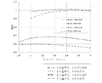
図2は、ガス供給圧力が本方法に従って調整される場合、図1のオゾン発生機OGMの効率曲線を示す。曲線は相対的な効率を示しており、基準線は、2.8バール-aでオゾン濃度が10重量%、100%負荷の生産ポイントである。 FIG. 2 shows the efficiency curve of the ozone generator OGM of FIG. 1 when the gas supply pressure is adjusted according to the method. The curves show the relative efficiencies, the baseline being the production point at 2.8 bar-a, 10 wt% ozone concentration and 100% load.
第1の場合は、第1のオゾン量が生成された場合(10重量%)、機械の全能力での生産中(100%負荷)、および機械の半分の能力での生産中(50%負荷)の効率への影響を示す。この場合は、2つの上方の曲線(小さな点線と二点鎖線)で表される。 In the first case, when the first amount of ozone is produced (10% by weight), during production at full capacity of the machine (100% load) and during production at half capacity of the machine (50% load) ) on efficiency. This case is represented by the two upper curves (small dotted line and dash-dotted line).
この場合(生成されるオゾンの10重量%)、頂部の曲線(小さな点線)は、機械がその能力の50%で運転されている場合、最適な供給ガス圧力が約2.6バール-a(絶対圧力)であることを示す。負荷が最大能力まで増加すると、第2の曲線(二点鎖線)は、最適な供給ガス圧力が約2.75バール-a(絶対圧力)であることを示す。オゾン発生器のガス出口で10重量%の同じオゾン濃度で生産量(生成されるオゾンの量)が増加する場合、数ポイントの効率を節約するために、供給ガス圧力を上昇させることが有利である。 In this case (10% by weight of ozone produced), the top curve (small dashed line) indicates that when the machine is running at 50% of its capacity, the optimum feed gas pressure is about 2.6 bar-a ( absolute pressure). As the load increases to maximum capacity, the second curve (dash-dot line) shows that the optimum feed gas pressure is approximately 2.75 bar-a (absolute pressure). If the output (amount of ozone produced) is increased with the same ozone concentration of 10 wt. be.
オゾン発生器OzGのガス出口O3OUTで、生成されたオゾンの濃度が13重量%である第2の場合も示されている。この場合は、下方の2つの曲線(大きな点線と一点鎖線)で表される。 A second case is also shown in which the concentration of ozone produced is 13% by weight at the gas outlet O3OUT of the ozone generator OzG. This case is represented by the lower two curves (large dotted line and dashed line).
この場合(生成されるオゾンの13重量%)、底部の曲線(一点鎖線)は、機械がその能力の50%で運転されている場合、最適な供給ガス圧力が約2.1バール-a(絶対圧力)であることを示す。負荷が最大能力まで増加すると、下からの第2の曲線(大きな点線)は、最適な供給ガス圧力が約2.35バール-a(絶対圧力)であることを示す。オゾン発生器のガス出口で13重量%の同じオゾン濃度で生産量(生成されるオゾンの量)
が増加する場合、数ポイントの効率を節約するために、供給ガス圧力を上昇させることが有利である。
In this case (13% by weight of ozone produced), the bottom curve (dashed-dotted line) indicates that when the machine is running at 50% of its capacity, the optimum feed gas pressure is about 2.1 bar-a ( absolute pressure). As the load increases to maximum capacity, the second curve from below (large dashed line) shows that the optimum feed gas pressure is approximately 2.35 bar-a (absolute pressure). At the same ozone concentration of 13% by weight at the gas outlet of the ozonator the output (amount of ozone produced)
increases, it is advantageous to increase the feed gas pressure in order to save a few points of efficiency.
当然のことながら、添付の特許請求の範囲によって定義される本発明の範囲内にありながら、当業者にとって明らかな改良および/または修正が実施され得ることを理解されたい。 It should, of course, be understood that improvements and/or modifications, obvious to those skilled in the art, may be implemented while remaining within the scope of the invention as defined by the appended claims.
Claims (12)
-所定の供給ガス流量および供給ガス圧力で、前記二酸素を含む供給ガスを前記オゾン発生器(OzG)の前記ガス入口(O2IN)に供給するステップと、
-前記オゾン発生器(OzG)の前記少なくとも2つの電極(E1、E2)に交流電流を供給して、前記オゾン化ギャップ(OG)に放電を生成して、前記オゾン発生器(OzG)の前記ガス出口(O3OUT)で所定量のオゾンを生成するステップと、
-前記オゾン発生器(OzG)の前記ガス出口(O3OUT)で生成された前記オゾンの量を調整するために、電流電力と、供給ガス流量、電流周波数、電流電圧、前記オゾン発生器(OzG)の冷却温度を含む複数のプロセスパラメータの少なくとも1つとを調整するステップと
を含み、
オゾン生成中に、
-電力と、供給ガス流量、電流周波数、電流電圧、冷却温度を含む前記複数のプロセスパラメータの前記少なくとも1つのパラメータとを監視するステップと、
-次いで、電流電力と、前記少なくとも1つのプロセスパラメータとの調整に応答して前記供給ガス圧力を調整するステップと
を含み、
前記供給ガス圧力を調整する前記ステップが、
-電流電力の前記調整された値および前記少なくとも1つの調整されたプロセスパラメータによって運転される前記オゾン発生器(OzG)の最適化された効率につながる最適供給ガス圧力を決定するために、供給ガス圧力、電流電力および前記少なくとも1つの前記プロセスパラメータに基づいて、前記オゾン発生器(OzG)の性能を予測するモデルの供給ガス圧力に関する導関数を計算するステップと、
-前記オゾン発生器(OzG)内部で前記最適なガス供給圧力に達するように前記供給ガス圧力を調整するステップと、
を含むことを特徴とする方法。 Ozone comprising at least a gas inlet (O2IN) for receiving a feed gas containing dioxygen and a gas outlet (O3OUT) for discharging an ozone containing gas, separated by an ozonation gap (OG) and a dielectric layer. A method for generating ozone in an ozone generator (OGM) comprising at least two electrodes (E1, E2) arranged in the generator (OzG), comprising:
- supplying said dioxygen-containing feed gas to said gas inlet (O2IN) of said ozone generator (OzG) at a predetermined feed gas flow rate and feed gas pressure;
- supplying an alternating current to said at least two electrodes (E1, E2) of said ozonator (OzG) to create an electrical discharge in said ozonation gap (OG), said generating a predetermined amount of ozone at a gas outlet (O3OUT);
current power and supplied gas flow rate, current frequency, current voltage, said ozone generator (OzG) to regulate the amount of said ozone produced at said gas outlet (O3OUT) of said ozone generator (OzG) and adjusting at least one of a plurality of process parameters including the cooling temperature of
During ozone generation,
- monitoring power and said at least one of said plurality of process parameters including feed gas flow rate, current frequency, current voltage, cooling temperature;
- then adjusting said feed gas pressure in response to the adjustment of current power and said at least one process parameter ;
said step of adjusting said supply gas pressure comprising:
- feed gas to determine an optimum feed gas pressure leading to optimized efficiency of said ozone generator (OzG) operated with said adjusted value of current power and said at least one adjusted process parameter; calculating the derivative with respect to feed gas pressure of a model predicting the performance of the ozone generator (OzG) based on pressure, current power and said at least one said process parameter;
- adjusting the supply gas pressure to reach the optimum gas supply pressure inside the ozone generator (OzG);
A method comprising :
-電流周波数の増加は、供給ガス圧力の増加につながり、
-電流周波数の低下は、供給ガス圧力の低下につながる、請求項4に記載の方法。 during said step of adjusting current power and at least one of a plurality of process parameters, only said current frequency and said feed gas flow are adjusted;
- an increase in the current frequency leads to an increase in the supply gas pressure,
- A method according to claim 4 , wherein a decrease in current frequency leads to a decrease in supply gas pressure.
-電流電圧の増加は、供給ガス圧力の増加につながり、
-電流電圧の低下は、供給ガス圧力の低下につながる、請求項6に記載の方法。 during said step of adjusting current power and at least one of a plurality of process parameters, only said current voltage and said feed gas flow are adjusted;
- an increase in current voltage leads to an increase in supply gas pressure,
- A method according to claim 6 , wherein a decrease in current voltage leads to a decrease in supply gas pressure.
-前記供給ガス圧力を監視するステップと、
-消費電力量を監視するステップと、
-オゾンの前記発生量および前記消費電力量に基づいてオゾン生産量を計算および監視するステップと、
-前記ガス供給圧力を調整する前記ステップの前後で前記オゾン生産量を比較するステップと、
-前記オゾン生産量を最適化するために、前記ガス供給圧力を調整する前記ステップの後に、オゾン生産量が低下した場合、前記供給ガス圧力を調整する前記ステップを繰り返すステップと
を含む、請求項1に記載の方法。 - monitoring said generation of ozone;
- monitoring the supply gas pressure;
- monitoring power consumption;
- calculating and monitoring ozone production based on said generation of ozone and said power consumption;
- comparing the ozone production before and after the step of adjusting the gas supply pressure;
- repeating said step of adjusting said supply gas pressure if, after said step of adjusting said gas supply pressure, said ozone production drops, in order to optimize said ozone production. 1. The method according to 1.
-前記オゾン発生器(OzG)内に配置され、オゾン化ギャップ(OzG)および誘電体層によって分離された少なくとも2つの電極(E1、E2)と、
-前記オゾン発生器(OzG)に接続された圧力調整器と、
-前記少なくとも2つの電極(E1、E2)に接続された電力ユニット(EPU)と、
-前記オゾン発生器(OG)に接続された流量調整器(O3R)と、
-請求項1から11のいずれか一項に記載の方法を実行するために、前記圧力調整器、電力ユニット、流量調整器を制御するように適合された制御ユニットと、
を備えるオゾン発生機(OGM)。 an ozone generator (OzG) comprising a gas inlet (O2IN) for receiving a feed gas containing dioxygen and a gas outlet (O3OUT) for discharging a gas containing ozone;
- at least two electrodes (E1, E2) arranged in said ozone generator (OzG) and separated by an ozonation gap (OzG) and a dielectric layer;
- a pressure regulator connected to said ozone generator (OzG);
- a power unit (EPU) connected to said at least two electrodes (E1, E2);
- a flow regulator (O3R) connected to said ozone generator (OG);
- a control unit adapted to control the pressure regulator, the power unit, the flow regulator to carry out the method according to any one of claims 1 to 11 ;
an ozone generator (OGM).
Applications Claiming Priority (3)
| Application Number | Priority Date | Filing Date | Title |
|---|---|---|---|
| EP17305834.8 | 2017-06-30 | ||
| EP17305834.8A EP3421417A1 (en) | 2017-06-30 | 2017-06-30 | Method for controlling an ozone generating machine |
| PCT/EP2018/067517 WO2019002527A1 (en) | 2017-06-30 | 2018-06-29 | Method for controlling an ozone generating machine |
Publications (2)
| Publication Number | Publication Date |
|---|---|
| JP2020525383A JP2020525383A (en) | 2020-08-27 |
| JP7144460B2 true JP7144460B2 (en) | 2022-09-29 |
Family
ID=59315541
Family Applications (1)
| Application Number | Title | Priority Date | Filing Date |
|---|---|---|---|
| JP2019570429A Active JP7144460B2 (en) | 2017-06-30 | 2018-06-29 | How to control the ozone generator |
Country Status (9)
| Country | Link |
|---|---|
| US (1) | US11453586B2 (en) |
| EP (2) | EP3421417A1 (en) |
| JP (1) | JP7144460B2 (en) |
| KR (1) | KR102573770B1 (en) |
| CN (1) | CN110914193B (en) |
| CA (1) | CA3067907A1 (en) |
| RU (1) | RU2757780C2 (en) |
| SG (1) | SG11201911862RA (en) |
| WO (1) | WO2019002527A1 (en) |
Families Citing this family (4)
| Publication number | Priority date | Publication date | Assignee | Title |
|---|---|---|---|---|
| CN111333035A (en) * | 2020-04-28 | 2020-06-26 | 河南迪诺环保科技股份有限公司 | Automatic switching and loading control system of ozone generator |
| WO2022152992A1 (en) | 2021-01-18 | 2022-07-21 | Gb Developpement | Fluid dispenser with priming means |
| CN113073339B (en) * | 2021-03-18 | 2021-12-28 | 无锡维邦工业设备成套技术有限公司 | Ozone generation system for biological pharmacy |
| CN112661118A (en) * | 2021-03-22 | 2021-04-16 | 佛山市玉凰生态环境科技有限公司 | Ozone generating equipment suitable for sewage treatment device |
Citations (6)
| Publication number | Priority date | Publication date | Assignee | Title |
|---|---|---|---|---|
| JP2009500855A (en) | 2005-07-07 | 2009-01-08 | エム ケー エス インストルメンツ インコーポレーテッド | Ozone system for multi-chamber tools |
| JP2009114003A (en) | 2007-11-02 | 2009-05-28 | Metawater Co Ltd | Ozone production device |
| JP2013193893A (en) | 2012-03-16 | 2013-09-30 | Toshiba Corp | Ozone generator |
| JP2014122157A (en) | 2009-11-26 | 2014-07-03 | Toshiba Mitsubishi-Electric Industrial System Corp | Ozone generation unit and ozone gas supply system |
| JP2016023112A (en) | 2014-07-23 | 2016-02-08 | 日野自動車株式会社 | Apparatus and method for controlling ozone generation amount |
| JP2018193265A (en) | 2017-05-16 | 2018-12-06 | 東芝三菱電機産業システム株式会社 | Ozone gas generation apparatus |
Family Cites Families (10)
| Publication number | Priority date | Publication date | Assignee | Title |
|---|---|---|---|---|
| US3899684A (en) * | 1974-06-03 | 1975-08-12 | Ozone Inc | Control system for corona discharge ozone generating unit |
| US5106589A (en) * | 1990-12-11 | 1992-04-21 | Conrad Richard H | Method of controlling ozone generator |
| US6372096B1 (en) * | 2000-05-25 | 2002-04-16 | Novazone | Pressure regulation process for ozone generating cell |
| ES2283175B1 (en) * | 2005-02-18 | 2008-08-16 | Oxigranja, S.L. | DEVICE FOR OZONE PRODUCTION. |
| WO2007014473A1 (en) | 2005-08-03 | 2007-02-08 | Ozonia Ag | Ozone generator |
| US9056300B2 (en) * | 2009-11-26 | 2015-06-16 | Toshiba Mitsubishi-Electric Industrial Systems Corporation | Ozone gas generation unit and ozone gas supply system |
| US9039985B2 (en) * | 2011-06-06 | 2015-05-26 | Mks Instruments, Inc. | Ozone generator |
| CA2869291C (en) * | 2012-04-05 | 2017-01-17 | Mitsubishi Electric Corporation | Ozone-generating system and ozone generation method |
| RU2524921C1 (en) * | 2013-01-29 | 2014-08-10 | Федеральное государственное бюджетное образовательное учреждение высшего профессионального образования "Кубанский государственный аграрный университет" | Method of monitoring ozoniser output and apparatus for realising said method |
| UA88308U (en) * | 2013-10-03 | 2014-03-11 | Михаил Сергеевич Зубакин | Ozonizer |
-
2017
- 2017-06-30 EP EP17305834.8A patent/EP3421417A1/en not_active Withdrawn
-
2018
- 2018-06-29 US US16/622,907 patent/US11453586B2/en active Active
- 2018-06-29 WO PCT/EP2018/067517 patent/WO2019002527A1/en unknown
- 2018-06-29 CN CN201880041854.0A patent/CN110914193B/en active Active
- 2018-06-29 EP EP18737845.0A patent/EP3645456A1/en active Pending
- 2018-06-29 CA CA3067907A patent/CA3067907A1/en active Pending
- 2018-06-29 JP JP2019570429A patent/JP7144460B2/en active Active
- 2018-06-29 RU RU2019143136A patent/RU2757780C2/en active
- 2018-06-29 SG SG11201911862RA patent/SG11201911862RA/en unknown
- 2018-06-29 KR KR1020197037615A patent/KR102573770B1/en active IP Right Grant
Patent Citations (6)
| Publication number | Priority date | Publication date | Assignee | Title |
|---|---|---|---|---|
| JP2009500855A (en) | 2005-07-07 | 2009-01-08 | エム ケー エス インストルメンツ インコーポレーテッド | Ozone system for multi-chamber tools |
| JP2009114003A (en) | 2007-11-02 | 2009-05-28 | Metawater Co Ltd | Ozone production device |
| JP2014122157A (en) | 2009-11-26 | 2014-07-03 | Toshiba Mitsubishi-Electric Industrial System Corp | Ozone generation unit and ozone gas supply system |
| JP2013193893A (en) | 2012-03-16 | 2013-09-30 | Toshiba Corp | Ozone generator |
| JP2016023112A (en) | 2014-07-23 | 2016-02-08 | 日野自動車株式会社 | Apparatus and method for controlling ozone generation amount |
| JP2018193265A (en) | 2017-05-16 | 2018-12-06 | 東芝三菱電機産業システム株式会社 | Ozone gas generation apparatus |
Also Published As
| Publication number | Publication date |
|---|---|
| RU2019143136A3 (en) | 2021-06-23 |
| RU2757780C2 (en) | 2021-10-21 |
| US20200115229A1 (en) | 2020-04-16 |
| JP2020525383A (en) | 2020-08-27 |
| RU2019143136A (en) | 2021-06-23 |
| SG11201911862RA (en) | 2020-01-30 |
| CN110914193A (en) | 2020-03-24 |
| EP3645456A1 (en) | 2020-05-06 |
| WO2019002527A1 (en) | 2019-01-03 |
| CN110914193B (en) | 2023-05-09 |
| KR20200026819A (en) | 2020-03-11 |
| EP3421417A1 (en) | 2019-01-02 |
| US11453586B2 (en) | 2022-09-27 |
| KR102573770B1 (en) | 2023-09-04 |
| CA3067907A1 (en) | 2019-01-03 |
Similar Documents
| Publication | Publication Date | Title |
|---|---|---|
| JP7144460B2 (en) | How to control the ozone generator | |
| RU2021129871A (en) | POWER CONTROL METHOD AND SYSTEM FOR AEROSOL GENERATING DEVICE POWERED BY BATTERY | |
| JP6462679B2 (en) | Method for controlling air flow in a fuel cell power system | |
| BR102013031722A2 (en) | LAMINATION CONTROL DEVICE, LAMINATION CONTROL METHOD AND LAMINATION CONTROL PROGRAM | |
| JP2010267472A (en) | Device and method for estimating internal state of fuel cell | |
| KR101315764B1 (en) | Method for detecting fail of hydrogen supply system for fuel cell | |
| CN112262260B (en) | Device for pumping and method for pumping | |
| JP2020128576A (en) | Control device and control method of hydrogen production plant | |
| JP5035302B2 (en) | Fuel cell internal state estimation device and internal state estimation method | |
| US11366440B2 (en) | Method for controlling an ozone generating machine | |
| JP6521773B2 (en) | Dissolved hydrogen concentration measuring device and measuring method | |
| WO2019142840A1 (en) | Air pressure system | |
| KR101738963B1 (en) | Control system and method of the ozone generator | |
| EP3868182A1 (en) | Method for the generation under dynamic conditions of an atmospheric plasma with a low ozone content and a surface discharge system with dielectric barrier for the realisation of the method | |
| JP7187124B2 (en) | Gas generation method | |
| JP3115082B2 (en) | Operation control device for heat source equipment | |
| US10695740B2 (en) | Method and device for controlling an ozone generator power supply | |
| Khmelev et al. | Adjusting and calibration electronic ultrasonic generators | |
| NL2032699B1 (en) | A method and device for disinfecting water and water supply system comprising said device | |
| KR20180025437A (en) | Fouling preventing system of heat exchanger and control method of the same | |
| CN113438752A (en) | Heating control method and device for heater | |
| TW201530074A (en) | Water temperature prediction system, feed-forward system and method thereof for a cooling tower | |
| KR20180026002A (en) | Active noise control applied fouling preventing system of heat exchanger |
Legal Events
| Date | Code | Title | Description |
|---|---|---|---|
| RD02 | Notification of acceptance of power of attorney |
Free format text: JAPANESE INTERMEDIATE CODE: A7422 Effective date: 20201027 |
|
| RD04 | Notification of resignation of power of attorney |
Free format text: JAPANESE INTERMEDIATE CODE: A7424 Effective date: 20201102 |
|
| A521 | Request for written amendment filed |
Free format text: JAPANESE INTERMEDIATE CODE: A821 Effective date: 20201027 |
|
| A621 | Written request for application examination |
Free format text: JAPANESE INTERMEDIATE CODE: A621 Effective date: 20210218 |
|
| RD13 | Notification of appointment of power of sub attorney |
Free format text: JAPANESE INTERMEDIATE CODE: A7433 Effective date: 20210422 |
|
| A521 | Request for written amendment filed |
Free format text: JAPANESE INTERMEDIATE CODE: A523 Effective date: 20210810 |
|
| A977 | Report on retrieval |
Free format text: JAPANESE INTERMEDIATE CODE: A971007 Effective date: 20220127 |
|
| A131 | Notification of reasons for refusal |
Free format text: JAPANESE INTERMEDIATE CODE: A131 Effective date: 20220215 |
|
| A601 | Written request for extension of time |
Free format text: JAPANESE INTERMEDIATE CODE: A601 Effective date: 20220513 |
|
| A521 | Request for written amendment filed |
Free format text: JAPANESE INTERMEDIATE CODE: A523 Effective date: 20220715 |
|
| TRDD | Decision of grant or rejection written | ||
| A01 | Written decision to grant a patent or to grant a registration (utility model) |
Free format text: JAPANESE INTERMEDIATE CODE: A01 Effective date: 20220830 |
|
| A61 | First payment of annual fees (during grant procedure) |
Free format text: JAPANESE INTERMEDIATE CODE: A61 Effective date: 20220915 |
|
| R150 | Certificate of patent or registration of utility model |
Ref document number: 7144460 Country of ref document: JP Free format text: JAPANESE INTERMEDIATE CODE: R150 |