JP7144074B2 - coffee bean grinder - Google Patents
coffee bean grinder Download PDFInfo
- Publication number
- JP7144074B2 JP7144074B2 JP2020201272A JP2020201272A JP7144074B2 JP 7144074 B2 JP7144074 B2 JP 7144074B2 JP 2020201272 A JP2020201272 A JP 2020201272A JP 2020201272 A JP2020201272 A JP 2020201272A JP 7144074 B2 JP7144074 B2 JP 7144074B2
- Authority
- JP
- Japan
- Prior art keywords
- grinder
- grinding
- ground
- beans
- coffee bean
- Prior art date
- Legal status (The legal status is an assumption and is not a legal conclusion. Google has not performed a legal analysis and makes no representation as to the accuracy of the status listed.)
- Active
Links
- 241000533293 Sesbania emerus Species 0.000 title claims description 183
- 238000000227 grinding Methods 0.000 claims description 145
- 239000002245 particle Substances 0.000 claims description 84
- 235000013353 coffee beverage Nutrition 0.000 claims description 16
- 235000019580 granularity Nutrition 0.000 claims description 12
- 238000000034 method Methods 0.000 description 58
- 238000000926 separation method Methods 0.000 description 56
- 235000003276 Apios tuberosa Nutrition 0.000 description 44
- 244000170226 Voandzeia subterranea Species 0.000 description 44
- 235000013030 Voandzeia subterranea Nutrition 0.000 description 44
- 235000007924 ground bean Nutrition 0.000 description 44
- 238000009826 distribution Methods 0.000 description 24
- 230000008569 process Effects 0.000 description 20
- 239000000126 substance Substances 0.000 description 17
- 230000001737 promoting effect Effects 0.000 description 13
- 238000003860 storage Methods 0.000 description 11
- 238000010586 diagram Methods 0.000 description 9
- 230000008859 change Effects 0.000 description 8
- 238000004891 communication Methods 0.000 description 8
- 230000007246 mechanism Effects 0.000 description 8
- 235000019640 taste Nutrition 0.000 description 8
- 244000046052 Phaseolus vulgaris Species 0.000 description 6
- 235000010627 Phaseolus vulgaris Nutrition 0.000 description 6
- 238000004519 manufacturing process Methods 0.000 description 6
- 239000000796 flavoring agent Substances 0.000 description 5
- 235000019634 flavors Nutrition 0.000 description 5
- 230000012447 hatching Effects 0.000 description 5
- 239000002699 waste material Substances 0.000 description 5
- 230000002093 peripheral effect Effects 0.000 description 4
- 230000007423 decrease Effects 0.000 description 3
- 239000000843 powder Substances 0.000 description 3
- 230000000452 restraining effect Effects 0.000 description 3
- 230000005540 biological transmission Effects 0.000 description 2
- 230000015572 biosynthetic process Effects 0.000 description 2
- 230000003247 decreasing effect Effects 0.000 description 2
- 238000001514 detection method Methods 0.000 description 2
- 230000006866 deterioration Effects 0.000 description 2
- 230000000694 effects Effects 0.000 description 2
- 230000020169 heat generation Effects 0.000 description 2
- 239000004570 mortar (masonry) Substances 0.000 description 2
- 239000011295 pitch Substances 0.000 description 2
- 238000010298 pulverizing process Methods 0.000 description 2
- 238000010079 rubber tapping Methods 0.000 description 2
- 241000885593 Geisha Species 0.000 description 1
- 230000008901 benefit Effects 0.000 description 1
- 235000013361 beverage Nutrition 0.000 description 1
- 230000000052 comparative effect Effects 0.000 description 1
- 238000001816 cooling Methods 0.000 description 1
- 239000006185 dispersion Substances 0.000 description 1
- 238000000605 extraction Methods 0.000 description 1
- 230000006872 improvement Effects 0.000 description 1
- 230000009191 jumping Effects 0.000 description 1
- 239000007788 liquid Substances 0.000 description 1
- 238000012986 modification Methods 0.000 description 1
- 230000004048 modification Effects 0.000 description 1
Images


Classifications
-
- A—HUMAN NECESSITIES
- A47—FURNITURE; DOMESTIC ARTICLES OR APPLIANCES; COFFEE MILLS; SPICE MILLS; SUCTION CLEANERS IN GENERAL
- A47J—KITCHEN EQUIPMENT; COFFEE MILLS; SPICE MILLS; APPARATUS FOR MAKING BEVERAGES
- A47J42/00—Coffee mills; Spice mills
- A47J42/38—Parts or details
-
- A—HUMAN NECESSITIES
- A47—FURNITURE; DOMESTIC ARTICLES OR APPLIANCES; COFFEE MILLS; SPICE MILLS; SUCTION CLEANERS IN GENERAL
- A47J—KITCHEN EQUIPMENT; COFFEE MILLS; SPICE MILLS; APPARATUS FOR MAKING BEVERAGES
- A47J42/00—Coffee mills; Spice mills
- A47J42/22—Coffee mills; Spice mills having pulverising beaters or rotary knives
- A47J42/26—Coffee mills; Spice mills having pulverising beaters or rotary knives mechanically driven
-
- A—HUMAN NECESSITIES
- A47—FURNITURE; DOMESTIC ARTICLES OR APPLIANCES; COFFEE MILLS; SPICE MILLS; SUCTION CLEANERS IN GENERAL
- A47J—KITCHEN EQUIPMENT; COFFEE MILLS; SPICE MILLS; APPARATUS FOR MAKING BEVERAGES
- A47J31/00—Apparatus for making beverages
- A47J31/42—Beverage-making apparatus with incorporated grinding or roasting means for coffee
-
- A—HUMAN NECESSITIES
- A47—FURNITURE; DOMESTIC ARTICLES OR APPLIANCES; COFFEE MILLS; SPICE MILLS; SUCTION CLEANERS IN GENERAL
- A47J—KITCHEN EQUIPMENT; COFFEE MILLS; SPICE MILLS; APPARATUS FOR MAKING BEVERAGES
- A47J42/00—Coffee mills; Spice mills
- A47J42/22—Coffee mills; Spice mills having pulverising beaters or rotary knives
-
- G—PHYSICS
- G07—CHECKING-DEVICES
- G07F—COIN-FREED OR LIKE APPARATUS
- G07F13/00—Coin-freed apparatus for controlling dispensing or fluids, semiliquids or granular material from reservoirs
- G07F13/04—Coin-freed apparatus for controlling dispensing or fluids, semiliquids or granular material from reservoirs by weight
-
- G—PHYSICS
- G07—CHECKING-DEVICES
- G07F—COIN-FREED OR LIKE APPARATUS
- G07F13/00—Coin-freed apparatus for controlling dispensing or fluids, semiliquids or granular material from reservoirs
- G07F13/06—Coin-freed apparatus for controlling dispensing or fluids, semiliquids or granular material from reservoirs with selective dispensing of different fluids or materials or mixtures thereof
- G07F13/065—Coin-freed apparatus for controlling dispensing or fluids, semiliquids or granular material from reservoirs with selective dispensing of different fluids or materials or mixtures thereof for drink preparation
-
- G—PHYSICS
- G07—CHECKING-DEVICES
- G07F—COIN-FREED OR LIKE APPARATUS
- G07F9/00—Details other than those peculiar to special kinds or types of apparatus
- G07F9/001—Interfacing with vending machines using mobile or wearable devices
-
- G—PHYSICS
- G07—CHECKING-DEVICES
- G07F—COIN-FREED OR LIKE APPARATUS
- G07F9/00—Details other than those peculiar to special kinds or types of apparatus
- G07F9/002—Vending machines being part of a centrally controlled network of vending machines
-
- G—PHYSICS
- G07—CHECKING-DEVICES
- G07F—COIN-FREED OR LIKE APPARATUS
- G07F9/00—Details other than those peculiar to special kinds or types of apparatus
- G07F9/006—Details of the software used for the vending machines
Description
本発明は、コーヒー豆挽き装置に関する。 The present invention relates to a coffee bean grinding device.
コーヒー飲料を製造するコーヒー飲料製造装置が提案されている(例えば特許文献1)。 A coffee beverage manufacturing apparatus for manufacturing coffee beverages has been proposed (for example, Patent Document 1).
しかし、従来のコーヒー飲料製造装置はコーヒー豆を挽く構成に改善の余地がある。 However, the conventional coffee beverage production apparatus has room for improvement in the configuration for grinding coffee beans.
本発明は、よりコーヒーの味を楽しむことができるコーヒー豆挽き装置を提供することを目的とする。 SUMMARY OF THE INVENTION An object of the present invention is to provide a coffee bean grinder that allows the user to enjoy the taste of coffee more.
上記目的を解決するためのコーヒー豆挽き装置は、
コーヒー豆を挽くグラインダと、
前記グラインダを制御する制御装置と、
を備えたコーヒー豆挽き装置であって、
前記グラインダは、コーヒー挽き豆を生成するにあたって設定可能な粒度を複数種類有するものであり、
前記制御装置は、設定された複数の粒度に従って前記グラインダの設定粒度を変更しつつコーヒー挽き豆を生成する制御を行うことが可能なものであり、
前記制御装置は、ユーザからのオーダー情報に基づいて前記複数の粒度を設定可能なものであり、
前記制御装置は、一の前記オーダー情報に対して設定可能な前記複数の粒度のパターンを複数種類有するものである、
ことを特徴とする。
The coffee bean grinder for solving the above object is
a grinder for grinding coffee beans,
a control device that controls the grinder;
A coffee grinder comprising:
The grinder has a plurality of types of particle sizes that can be set for generating ground coffee beans,
The control device is capable of controlling the generation of ground coffee beans while changing the set particle size of the grinder according to a plurality of set particle sizes,
The control device is capable of setting the plurality of granularities based on order information from a user,
The control device has a plurality of types of patterns of the plurality of granularities that can be set for one piece of the order information,
It is characterized by
このコーヒー豆挽き装置では、コーヒー挽き豆の新たな味わいを提供することができ、特に、顧客の嗜好に合わせた様々な味のコーヒー挽き豆を提供することができる。 With this coffee bean grinding apparatus, it is possible to provide new tastes of ground coffee beans , and in particular, to provide ground coffee beans with various tastes that suit the tastes of customers .
また、上記コーヒー豆挽き装置は、
前記オーダー情報をネットワーク経由で受信可能な受信装置を備えたものであってもよい。
In addition, the above coffee bean grinding device
A receiving device capable of receiving the order information via a network may be provided.
このコーヒー豆挽き装置では、オーダーの際の利便性を高めることができる。 This coffee bean grinder can enhance the convenience of ordering.
また、上記目的を解決するためのコーヒー豆挽き装置は、
コーヒー豆を挽くグラインダと、
前記グラインダを制御する制御装置と、
を備えたコーヒー豆挽き装置であって、
前記グラインダは、コーヒー挽き豆を生成するにあたって設定可能な粒度を複数種類有するものであり、
前記制御装置は、設定された複数の粒度に従って前記グラインダの設定粒度を変更しつつコーヒー挽き豆を生成する制御を行うことが可能なものであり、
前記制御装置は、第一の粒度および第二の粒度を含む前記複数の粒度が設定された場合に、前記グラインダによって前記第一の粒度及び前記第二の粒度のうちのどちらを先に挽くか設定可能なものである、
ことを特徴とする。
In addition, the coffee bean grinding device for solving the above object is
a grinder for grinding coffee beans,
a control device that controls the grinder;
A coffee grinder comprising:
The grinder has a plurality of types of particle sizes that can be set for generating ground coffee beans,
The control device is capable of controlling the generation of ground coffee beans while changing the set particle size of the grinder according to a plurality of set particle sizes,
When the plurality of grain sizes including the first grain size and the second grain size are set, the control device determines which of the first grain size and the second grain size is first ground by the grinder. is configurable ,
It is characterized by
このコーヒー豆挽き装置では、様々な味のコーヒー挽き豆を提供することができる。 With this coffee bean grinding machine, ground coffee beans with various flavors can be provided.
また、上記コーヒー豆挽き装置は、
前記制御装置は、設定された一の粒度に従って前記グラインダの粒度を設定してコーヒー挽き豆を生成する制御を行うことが可能なものであってもよい。
In addition, the above coffee bean grinding device
The control device may be capable of setting the grain size of the grinder according to one set grain size to control the production of ground coffee beans.
このコーヒー豆挽き装置では、様々な味のコーヒー挽き豆を提供することができる。 With this coffee bean grinding machine, ground coffee beans with various flavors can be provided.
また、前記コーヒー豆挽き装置と通信可能な外部装置を備えたコーヒー豆挽きシステムであってもよい。 Moreover, the coffee bean grinding system may be provided with an external device capable of communicating with the coffee bean grinding device.
本発明によれば、よりコーヒーの味を楽しむことができるコーヒー豆挽き装置を提供することができる。 According to the present invention, it is possible to provide a coffee bean grinder that allows the user to enjoy the taste of coffee more.
図面を参照して本発明の実施形態について説明する。 An embodiment of the present invention will be described with reference to the drawings.
<1.コーヒー豆挽き装置>
図1を参照してコーヒー豆挽き装置1について説明する。図1はコーヒー豆挽き装置1の斜視図である。コーヒー豆挽き装置1は、貯留装置4及び粉砕装置5と、これらを制御する制御装置11(図1では不図示)を含む。なお、図1に示すように貯留装置4のホッパ40には、情報表示装置12が設けられている。この情報表示装置12は、制御装置11と接続され、コーヒー豆挽き装置1の各種制御を行うためのタッチパネル式のディスプレイであり、各種の情報の表示の他、管理者や飲料の需要者の入力を受け付けたりすることが可能である。
<1. Coffee bean grinder>
A coffee
<1-1.貯留装置>
貯留装置4は、焙煎後のコーヒー豆が収容されるホッパ40を含む。なお、本実施形態では一つのホッパ40を設けたが、複数のホッパ40が設けられる構成であってもよい。また、複数のホッパ40を設けた場合には、種類や焙煎度を異ならせた焙煎コーヒー豆を分けて収容してもよい。ホッパ40には、焙煎コーヒー豆を下流側に送出する送出機構(不図示)が設けられており、この送出機構によって粉砕装置5へ焙煎コーヒー豆が供給される。
<1-1. Storage device>
The
<1-2.粉砕装置>
図1及び図2を参照して粉砕装置5を説明する。図2は粉砕装置5の縦断面図である。粉砕装置5は、グラインダ5A及び5B、及び、分離装置6を含む。グラインダ5A及び5Bは貯留装置4から供給される焙煎コーヒー豆を挽く機構である。グラインダ5Aは、コーヒー豆に付着している不要物を分離しやすくするために、ある程度(例えば1/4程度)の大きさに砕くためのグラインダである。またグラインダ5Bは、グラインダ5Aで砕かれた状態のコーヒー豆を所望の粒度のコーヒーの挽き豆にするためのグラインダである。このため、これらのグラインダ5A及び5Bは、豆を挽く粒度が異なっており、グラインダ5Aよりもグラインダ5Bの方がより細かい粒度のグラインダとなっている。なお、グラインダ5Bにおける挽き豆の粒度については、誤差(±5μm程度)が生じる場合があるものの、回転刃58bと固定刃57bとの間隔を調整することによって調整可能である。
<1-2. Crushing device>
The crushing
<1-2-1.グラインダ>
グラインダ5Aは、モータ52a及び本体部53aを含む。モータ52aはグラインダ5Aの駆動源である。本体部53aはカッターを収容するユニットであり、回転軸54aが内蔵されている。回転軸54aにはギア55aが設けられており、モータ52aの駆動力がギア55aを介して回転軸54aに伝達される。
<1-2-1. Grinder>
The
回転軸54aには、カッターである回転刃58aが設けられている。また、回転刃58aの周囲には、カッターである固定刃57aが設けられている。本体部53aの内部は投入口50a及び排出口51aと連通している。貯留装置4から供給される焙煎コーヒー豆は本体部53aの側部に形成されている投入口50aから本体部53aへ進入し、回転刃58aと固定刃57aとの間に挟まれるようにして粉砕される。回転軸54aの回転刃58aよりも上側には抑制板56aが設けられており、抑制板56aは焙煎コーヒー豆が上側に逃げることを抑制する。グラインダ5Aでは焙煎コーヒー豆が例えば1/4程度に粉砕される。粉砕された挽き豆は排出口51aから分離装置6へ排出される。
A
なお、投入口50aに供給された焙煎コーヒー豆は、回転刃58aの上方からではなく、側面に当たるような高さに供給されてもよい。その場合は、回転刃58aにより焙煎コーヒー豆が上側へ逃げることが抑制されるため、抑制板56aを設けなくてもよい。
The roasted coffee beans supplied to the
グラインダ5Aは、回転刃58aの回転数を変化させることで、粉砕された後に排出される焙煎コーヒー豆の大きさを変化させてもよい。また、回転刃58aと固定刃57aとの間の距離を手動で調整することで変化させてもよい。
The
分離装置6は挽き豆から不要物を分離する機構である。分離装置6はグラインダ5Aとグラインダ5Bとの間に配置されている。つまり、本実施形態の場合、貯留装置4から供給される焙煎コーヒー豆は、まず、グラインダ5Aで粗挽きされ、その粗挽き豆から分離装置6によって不要物が分離される。不要物が分離された粗挽き豆は、グラインダ5Bにより細挽きされる。分離装置6で分離する不要物は、代表的にはチャフや微粉である。これらはコーヒー飲料の味を低下させる場合がある。分離装置6は空気の吸引力により不要物を分離する機構であり、その詳細は後述する。
The
グラインダ5Bは、モータ52b及び本体部53bを含む。モータ52bはグラインダ5Bの駆動源である。本体部53bは、カッターを収容するユニットであり、回転軸54bが内蔵されている。回転軸54bにはプーリ55bが設けられており、モータ52bの駆動力がベルト59b及びプーリ55bを介して回転軸54bに伝達される。
The
回転軸54bには、また、回転刃58bが設けられており、回転刃58bの上側には固定刃57bが設けられている。本体部53bの内部は投入口50b及び排出口51bと連通している。分離装置6から落下してくる挽き豆は投入口50bから本体部53bへ進入し、回転刃58bと固定刃57bとの間に挟まれるようにして更に粉砕される。粉状に粉砕された挽き豆は排出口51bから排出される。なお、グラインダ5Bにおける挽き豆の粒度は、回転刃58bと固定刃57bとの間隔を調整することによって調整可能である。
The rotary shaft 54b is also provided with a rotary blade 58b, and a fixed
焙煎コーヒー豆の粉砕は、一つのグラインダ(一段階の粉砕)であってもよい。しかし、本実施形態のように、二つのグラインダ5A、5Bによる二段階の粉砕とすることで、挽き豆の粒度が揃い易くなり、コーヒー液の抽出度合を一定にすることができる。豆の粉砕の際にはカッターと豆との摩擦により、熱が発生する場合がある。二段階の粉砕とすることで、粉砕時の摩擦による発熱を抑制し、挽き豆の劣化(例えば風味が落ちる)を防止することもできる。
Grinding of roasted coffee beans may be in one grinder (single stage grinding). However, as in the present embodiment, two-stage grinding by the two
また、粗挽き→不要物の分離→細挽きという段階を経ることで、チャフなどの不要物を分離する際、不要物と挽き豆(必要部分)との質量差を大きくできる。これは不要物の分離効率を上げることができるとともに、挽き豆(必要部分)が不要物として分離されてしまうことを防止することができる。また、粗挽きと細挽きとの間に、空気の吸引を利用した不要物の分離処理が介在することで、空冷によって挽き豆の発熱を抑えることができる。これにより挽き豆の劣化(例えば風味が落ちる)を防止することもできる。 In addition, by going through the stages of coarse grinding → separation of unnecessary substances → fine grinding, when separating unnecessary substances such as chaff, it is possible to increase the mass difference between the unnecessary substances and the ground beans (required parts). This can improve the separation efficiency of unnecessary substances, and can prevent ground beans (required portions) from being separated as unnecessary substances. In addition, the heat generation of the ground beans can be suppressed by the air cooling by interposing the unnecessary matter separation processing using air suction between the coarse grinding and the fine grinding. This can also prevent deterioration of the ground beans (for example, loss of flavor).
<1-2-2.分離装置>
次に、図1~図3を参照して分離装置6を説明する。図3は分離装置6の一部破断斜視図である。分離装置6は、吸引ユニット6A及び形成ユニット6Bを含む。形成ユニット6Bは、グラインダ5Aから自由落下してくる挽き豆が通過する分離室SCを形成する中空体である。吸引ユニット6Aは、挽き豆の通過方向(本実施形態の場合、上下方向)と交差する方向(本実施形態の場合、左右方向)で分離室SCと連通し、分離室SC内の空気を吸引するユニットである。分離室SC内の空気を吸引することで、チャフや微粉といった軽量な物体が吸引される。これにより、挽き豆から不要物を分離できる。
<1-2-2. Separation device>
Next, the
吸引ユニット6Aは遠心分離方式の機構である。吸引ユニット6Aは、送風ユニット60A及び回収容器60Bを含む。送風ユニット60Aは本実施形態の場合、ファンモータであり、回収容器60B内の空気を上方へ排気する。
The
回収容器60Bは、分離可能に係合する上部61と下部62とを含む。下部62は上方が開放した有底の筒型をなしており、不要物を蓄積する空間を形成する。上部61は下部62の開口に装着される蓋部を構成する。上部61は、円筒形状の外周壁61aと、これと同軸上に形成された排気筒61bとを含む。送風ユニット60Aは排気筒61b内の空気を吸引するように排気筒61bの上方において上部61に固定されている。上部61は、また、径方向に延設された筒状の接続部61cを含む。接続部61cは形成ユニット6Bと接続され、分離室SCと回収容器60Bとを連通させる。接続部61cは排気筒61bの側方に開口している。
送風ユニット60Aの駆動により、図3において矢印d1~d3で示す気流が発生する。この気流により、分離室SCから不要物を含んだ空気が接続部61cを通って回収容器60B内に吸引される。接続部61cは排気筒61bの側方に開口しているため、不要物を含んだ空気は排気筒61bの周囲を旋回する。空気中の不要物Dは、その重量によって落下し、回収容器60Bの一部に集められる(下部62の底面上に堆積する)。空気は排気筒61bの内部を通って上方に排気される。
By driving the
排気筒61bの周面には複数のフィン61dが一体に形成されている。複数のフィン61dは排気筒61bの周方向に配列されている。個々のフィン61dは、排気筒61bの軸方向に対して斜めに傾斜している。このようなフィン61を設けたことで、不要物Dを含んだ空気の排気筒61bの周囲の旋回を促進する。また、フィン61により不要物Dの分離が促進される。この結果、吸引ユニット6Aの上下方向の長さを抑えることができ、装置の小型化に寄与する。
A plurality of
また、本実施形態では、グラインダ5A及び5Bによる挽き豆の落下経路に形成ユニット6Bを配置する一方、落下経路の側方に遠心分離方式の吸引ユニット6Aを配置している。遠心分離方式の機構は上下方向に長くなり易いが、吸引ユニット6Aを落下経路からずらして側方に配置することで、吸引ユニット6Aをグラインダ5A及びグラインダ5Bに対して横方向に並設することができる。これは装置の上下方向の長さを抑えることに寄与する。特に本実施形態のように、二つのグラインダ5A及び5Bにより二段階の粉砕を行う場合、装置の上下方向の長さが長くなる傾向になるため、吸引ユニット6Aのこのような配置が装置の小型化に有効である。
In this embodiment, the
図1~図6を参照して形成ユニット6Bを説明する。図4は形成ユニット6Bの縦断面図である。図5は形成ユニット6Bの斜視図及び部分拡大図である。図6は形成ユニット6Bの平面図であって、断面積の比較説明図である。
The forming
形成ユニット6Bは、本実施形態の場合、上下に半割された二部材を結合して形成されている。形成ユニット6Bは、管部63及び分離室形成部64を含み、平面視でスプーン形状を有している。管部63は、吸引ユニット6Aとの連通路63aを形成する筒体であり、横方向(後述する中心線CLと交差する方向)に延設されている。分離室形成部64は管部63に接続され、分離室SCを形成する、中央が上下方向に開口した円環形状の中空体である。
In the case of this embodiment, the forming
本実施形態では、挽き豆から不要物を分離するにあたり、グラインダ5Aから落下してくる挽き豆に横方向の風圧を作用させて不要物を吸引する方式を採用している。これは、遠心分離方式よりも鉛直方向の長さを短くできる点で有利である。
In the present embodiment, in order to separate the unwanted substances from the ground beans, a method is adopted in which lateral wind pressure is applied to the ground beans falling from the
分離室形成部64は、上下方向に延設された筒状部65を含む。筒状部65はその上下方向の中央部から下部にかけて分離室SC内に突出している。筒状部65は上側の一端に開口部65aを有し、開口部65aは分離室SCに連通した、挽き豆の投入口を形成している。開口部65aは分離室SC外に位置しており、グラインダ5Aの排出口51aに接続されている。これにより、排出口51aから落下する挽き豆が漏れなく分離室形成部64に導入される。筒状部65は下側の他端に開口部65bを有する。開口部65bは分離室SC内に位置している。開口部65bが分離室SCに臨んでいるため、排出口51aから落下する挽き豆が漏れなく分離室SCに導入される。
The separation
筒状部65は、本実施形態の場合、円筒形状を有しており、開口部65a及び開口部65bは中心線CL上に位置する同心の円形状を有している。これにより、排出口51aから落下する挽き豆が筒状部65を通過し易くなる。筒状部65は内部空間の断面積が開口部65a側から開口部65b側へ向かって徐々に小さくなるテーパ形状を有している。筒状部65の内壁がすり鉢形状となるため、落下してくる挽き豆が内壁に衝突し易くなる。グラインダ5Aから落下してくる挽き豆は、粒同士が密着して塊となって落下してくる場合がある。挽き豆が塊の状態であると、不要物の分離効率が低下する場合がある。本実施形態の場合、塊となった挽き豆が筒状部65の内壁に衝突することで、塊を崩し、不要物を分離し易くすることができる。
In this embodiment, the
なお、挽き豆の塊を崩す点では、筒状部65の内壁はすり鉢形状に限られない。筒状部65の途中部位に開口部65aよりも内部空間の断面積が小さい箇所があり、それにより、中心線CLに対して傾斜した(水平ではない)内壁があれば、塊との衝突を促進しつつ、挽き豆を円滑に落下させることができる。また、筒状部65は分離室SC内に突出している必要はなく、分離室形成部64の外面から上側に突出した部分のみを有するものであってもよい。但し、筒状部65を分離室SC内に突出させたことで、筒状部65の周囲の風速を向上できる。このため、管部63から相対的に遠い領域R1において、風圧による不要物の分離効果を高めることができる。
Note that the inner wall of the
分離室形成部64は、不要物を分離した後の挽き豆が排出される、分離室SCに連通した排出口66を有している。排出口66は、本実施形態の場合、開口部65bの下方に位置しており、筒状部65を通った挽き豆は、分離室SCを通過して排出口66から自由落下する。本実施形態の場合、排出口66は中心線CL上に位置する円形の開口であり、開口部65a及び開口部65bと同心円の開口である。このため、挽き豆が分離室形成部64を自由落下により通過し易くなり、分離室形成部64内に挽き豆が堆積することを防止することができる。
The separation
図6に示すように、本実施形態の場合、開口部65bの断面積SC1よりも排出口66の断面積SC2の方が大きい。本実施形態の場合、開口部65bと排出口66とが上下方向で見て、互いに重なっている。したがって、排出口66に対して、上下方向に開口部65bを投影すると、排出口66の内側に開口部65bが収まることになる。換言すると、開口部65bは、排出口66を上下方向に延長した領域内に収まる。開口部65bと排出口66とが同一中心線上にないが重なっている構成や、少なくとも一方が円形でないが重なっている構成も採用可能である。
As shown in FIG. 6, in this embodiment, the cross-sectional area SC2 of the
断面積SC2に対する断面積SC1の比率は、例えば、95%以下、あるいは、85%以下であり、また、例えば、60%以上、あるいは、70%以上である。開口部65b、排出口66は同心円であるため、中心線CL方向に見ると互いに重なっている。このため、開口部65bから自由落下する挽き豆が排出口66から排出され易くなる。また、落下する挽き豆が排出口66の縁に衝突して管部63側へ跳ねることを防止し、必要な挽き豆が吸引ユニット6Aに吸引されてしまうことも抑制できる。排出口(例えば66)の開口面積よりも一端開口部(例えば65a)の開口面積の方が小さいと例示してきたが、排出口(例えば66)の開口面積と一端開口部(例えば65a)の開口面積は同じであってもよいし、排出口(例えば66)の開口面積よりも一端開口部(例えば65a)の開口面積の方が大きくてもよい。排出口(例えば66)の開口面積よりも他端開口部(例えば65b)の開口面積の方が小さいと例示してきたが、排出口(例えば66)の開口面積と他端開口部(例えば65b)の開口面積は同じであってもよいし、排出口(例えば66)の開口面積よりも他端開口部(例えば65b)の開口面積の方が大きくてもよい。吸引ユニット(例えば6A)によって排出口66及び投入口(例えば65a,65a’)から空気が吸引されることを例示したが、投入口(例えば65a,65a’)から吸引される空気の量よりも排出口66から吸引される空気の量の方が多くなるようにしてもよい。これは、分離室内に他端開口部(例えば65b)が突出していることや、一端開口部(例えば65a)の開口面積の大きさよりも排出口66の断面積の大きさが大きいことで実現してもよいし、他端開口部(例えば65b)の開口面積の大きさよりも排出口66の断面積の大きさが大きいことで実現してもよいし、一端開口部(例えば65a)から分離室までの距離よりも排出口66から分離室までの距離が近いことで実現してもよいし、一端開口部(例えば65a)から排気筒61bまでの距離よりも排出口66から排気筒61bまでの距離が近いことで実現してもよいし、一端開口部(例えば65a)から送風ユニット60Aまでの距離よりも排出口66から送風ユニット60Aまでの距離が近いことで実現してもよい。形成ユニット6Bや分離室SCを構成する部材(63~65)の内壁部のいずれかや筒状部65や他端開口部(例えば65b)であるが、グラインダ(5A及び5Bのうちの少なくとも一方)と直接又は他の部材を介して間接的に接触して、当該グラインダの回転による振動が伝わって、振動するように構成されていてもよい。例えば、実施例におけるコーヒー豆挽き装置1の場合、それらは直接的又は間接的に接触していることから、グラインダの動作中は、形成ユニット6Bや分離室SCを構成する部材(63~65)の内壁部のいずれかや筒状部65や他端開口部(例えば65b)が振動し、振動により当該分離室SC内に生じる乱れた空気によって、他端開口部(例えば65b)から分離室SCに進入する軽い不要物にブレーキを与えて、当該不要物を吸引ユニット(例えば6A)によって吸引しやすくしている。特に、実施例におけるコーヒー豆挽き装置1のように形成ユニット6Bは、グラインダ5A及びグラインダ5Bのうちのグラインダ5Aと直接接触しているが、このように一のグラインダに直接接触させることで形成ユニット6Bに適度な振動を与えて、軽い不要物を吸引しやすくしてもよい。
The ratio of cross-sectional area SC1 to cross-sectional area SC2 is, for example, 95% or less, or 85% or less, or, for example, 60% or more, or 70% or more. Since the
本実施形態の場合、吸引ユニット6Aにより吸引される空気は、主に、排出口66から吸引される。このため、排出口66とグラインダ5Bの投入口50bとの間には隙間が設けられており、空気の吸引が促進される。矢印d4は吸引ユニット6Aにより吸引される空気の気流の向きを模式的に示している。排出口66から空気を吸引することで不要物が排出口66から排出されにくくなり、挽き豆と不要物との分離性能を向上できる。なお、吸引ユニット6Aにより吸引される空気は、開口部65aからも吸引される。
In the case of this embodiment, the air sucked by the
排出口66を画定する周囲壁には、乱流促進部67が形成されている。乱流促進部67は排出口66から分離室SCへ吸引される空気に乱流を生じさせる。乱流促進部67を形成したことにより、特に、開口部65bとの排出口66との間の領域R2において、乱流が生じやすくなる。また、本実施形態の場合、筒状部65の周囲で風速が向上するので、領域R2での乱流の発生を相乗的に促進させることができる。
A turbulent
投入口65aに投入された挽き豆は領域R2を通過する際に乱流の影響を受けて攪拌される。本実施形態の場合、特に、上記のとおり開口部65bの断面積SC1よりも排出口66の断面積SC2の方が大きいため、挽き豆は領域R2を必ず通過する。乱流によって、チャフや微粉といった不要物が、挽き豆から分離されやすくなる。よって、分離室SCが小さい空間であっても、不要物の分離効率を向上することができ、特に、分離室SCの上下方向の長さを小さくすることに寄与し、本実施形態のように二つのグラインダ5A、5Bで二段階の粉砕を行う場合の装置の小型化に有利である。
The ground beans introduced into the
本実施形態の場合、乱流促進部67は複数の乱流促進要素67aを含む。乱流促進要素67aは、上下方向で下向きに突出した突起である。乱流促進要素67aの突出方向は、どの方向であってもよいが、分離室SC内に乱流をより発生させ易くする点で、下方向から径方向内側方向の範囲内の方向が好適である。本実施形態のように、突出方向が下方向であれば、落下してきた挽き豆が引っ掛かることがなく、より好ましい。
In the case of this embodiment, the turbulence-promoting
乱流促進要素67aの断面形状は、台形形状の四角柱を断面の上底が中心線CL方向に向くように配置され、かつ先端部の内側に面取り67bを施された形状となっている。乱流促進要素67aの形状は、本実施形態の形状に限られないが、排出口66の形状を三次元的に複雑にする形状が好適である。
The cross-sectional shape of the
本実施形態の場合、乱流促進要素67aは、排出口66の周囲方向d5に繰り返し形成されている。これにより、領域Rへ多方向から空気が吹き込み、乱流の発生が促進される。隣接する乱流促進要素67aのピッチは、異ピッチでもよいが、本実施形態では等ピッチである。乱流促進要素67aは12個形成されているが、乱流促進要素67aの数は任意である。
In the case of this embodiment, the
<1-2-3.他の構成例>
図7を参照して分離室形成部64の他の構成例について説明する。乱流促進要素67aは、突起のほか、切欠きや穴であってもよい。図7のEX1の例は、乱流促進要素67aを排出口66の周囲壁に形成した貫通穴とした例を例示している。このような穴も領域R2における乱流発生を促進可能である。
<1-2-3. Other configuration examples>
Another configuration example of the separation
図7のEX2の例は、筒状部65を設けない例を示している。この場合においても、投入口65a’の断面積SC1’よりも、排出口66の断面積SC2を大きくした構成が好適である。
The example EX2 in FIG. 7 shows an example in which the
筒状部65の開口部65bは水平面上の開口ではなく、傾斜面上の開口であってもよい。図7のEX3の例は、筒状部65の管部63側の下端が、反対側の下端よりも下方向に突出していている。このようにすることで、領域R1側へ挽き豆が案内され易くなって分離室SCにおける挽き豆の滞留時間を長くとることができ、分離効果を高めることができる。
The
<2.制御装置>
図8を参照してコーヒー豆挽き装置1の制御装置11について説明する。図8は制御装置11のブロック図である。
<2. Control device>
The
制御装置11はコーヒー豆挽き装置1の全体を制御する。制御装置11は、処理部11a、記憶部11b及びI/F(インタフェース)部11cを含む。処理部11aは例えばCPU等のプロセッサである。記憶部11bは例えばRAMやROMである。I/F部11cは外部デバイスと処理部11aとの間の信号の入出力を行う入出力インタフェースを含む。I/F部11cは、また、インターネットなどの通信ネットワーク15を介してサーバ16、携帯端末17とデータ通信が可能な通信インタフェースを含む。サーバ16は、通信ネットワーク15を介してスマートフォン等の携帯端末17との通信が可能であり、例えば、需要者の携帯端末17からコーヒーの挽き豆製造の予約や、感想などの情報を受信可能である。コーヒー豆挽き装置1と、サーバ16と、携帯端末17とを含んで、コーヒー豆を挽くためのシステムを構成する。
The
処理部11aは記憶部11bに記憶されたプログラムを実行し、情報表示装置12からの指示或いはセンサ群13の検出結果若しくはサーバ16からの指示に基づいて、アクチュエータ群14を制御する。センサ群13はコーヒー豆挽き装置1に設けられた各種のセンサ(例えば、機構の動作位置検出センサ等)である。アクチュエータ群14はコーヒー豆挽き装置1に設けられた各種のアクチュエータ(例えばモータ等)である。
The
<3.動作制御例>
処理部11aが実行するコーヒー豆挽き装置1の制御処理例について図9を参照して説明する。図9はコーヒーの挽き豆製造の制御処理例を示している。なお、この処理は、コーヒー挽き豆装置1の外部(例えば、サーバ16や携帯端末17)からのオーダー情報に従ってグラインド処理を実行する場合の例である。
<3. Operation control example>
An example of control processing of the coffee
ステップS1では、コーヒーの挽き豆のオーダー情報を受け付けたか否かが判定される。オーダー情報を受け付けていない場合はこのステップS1が繰り返し実行される。そして、オーダー情報を受け付けた場合はステップS2に進む。なお、オーダー情報の具体的な内容については後述する。 In step S1, it is determined whether or not order information for ground coffee beans has been received. If order information has not been received, step S1 is repeatedly executed. Then, when the order information is received, the process proceeds to step S2. Note that the specific contents of the order information will be described later.
ステップS2では、受信したオーダー情報が情報表示装置12に表示され、ステップS3に進む。
In step S2, the received order information is displayed on the
ステップS3では、コーヒー豆のグラインド開始操作を受け付けたか否かが判定される。グラインド開始操作を受け付けていない場合はステップS4に進み、グラインド開始操作を受け付けた場合はステップS6に進む。 In step S3, it is determined whether or not an operation to start grinding coffee beans has been received. If the grind start operation has not been received, the process proceeds to step S4, and if the grind start operation has been received, the process proceeds to step S6.
ステップS4では、オーダー情報の変更操作を受け付けたか否かが判定される。オーダー情報の変更操作を受け付けた場合はステップS5に進み、オーダー情報の変更操作を受け付けていない場合はステップS3に戻る。 In step S4, it is determined whether or not an operation to change order information has been received. If the order information change operation has been accepted, the process proceeds to step S5, and if the order information change operation has not been accepted, the process returns to step S3.
ステップS5では、オーダー情報の変更操作に従って受け付けたオーダー情報が更新され、ステップS3に戻る。 In step S5, the received order information is updated according to the order information change operation, and the process returns to step S3.
オーダー情報を受け付けてからグラインド開始操作を受け付けるまでの間においては、ステップS4、ステップS5によって受け付けたオーダー情報を変更することができる。グラインド開始操作やオーダー情報の変更操作は、情報表示装置12の操作に限らず、携帯端末17からの操作を受け付けるようにしてもよく、また、この操作の情報はコーヒー豆挽き装置1に送信されるものであれば、その送信経路はどのような経路であってもよい。
During the period from the reception of the order information to the reception of the grind start operation, the received order information can be changed in steps S4 and S5. The grind start operation and the order information change operation are not limited to the operation of the
ステップS6では、コーヒー豆のグラインド処理が実行される。まず、オーダー情報で指定された分量の焙煎コーヒー豆が貯留装置4からグラインダ5Aに供給される。グラインダ5Aでは砕かれたコーヒー豆は、分離装置6によって不要物が分離された後、グラインダ5Bに供給される。このグラインダ5Bでは、オーダー情報に従って固定刃57bと回転刃58bとの間隔を所定間隔(例えば、50μm刻み)で変更しつつコーヒー豆が挽かれ、コーヒーの挽き豆が排出口51bから排出される。このグラインド処理が終了すると、コーヒーの挽き豆の製造処理が終了する。
In step S6, the coffee beans are ground. First, the amount of roasted coffee beans specified by the order information is supplied from the
上記の例では、コーヒー挽き豆装置1の外部からのオーダー情報に従ってグラインド処理を実行する場合について説明したが、情報表示装置12を用いて直接コーヒー挽き豆装置1にオーダー情報を入力する構成としてもよい。この構成の場合には、図9のステップS2、ステップS4、ステップS5を削除した構成としてもよい。
In the above example, the case where the grind processing is executed according to the order information from the outside of the ground
また、上記の例では、オーダー情報を受け付けてからグラインド開始操作を受け付けるまでの間において、オーダー情報を変更することができるが、こうした変更の機会を設けずに、オーダー情報を受け付けたらそのままグラインド処理が開始されるようにしてもよい。 Also, in the above example, the order information can be changed between the reception of the order information and the reception of the grind start operation. may be started.
<4.オーダーおよび動作例>
以下、図9を用いて説明した制御処理のフローを参照しつつ、オーダー情報に対する動作の例について、図10~図15を用いて説明する。図10~図12は、オーダー情報の入力時の様子を示す図である。図13はオーダー情報の変更時の様子を示す図である。図14は、オーダーに対するグラインダ5Bの制御パラメータの一例を示す図である。図15は、グラインド処理の実行中における表示の一例を示す図である。
<4. Order and operation example>
An example of the operation for order information will be described below with reference to FIGS. 10 to 15 while referring to the control processing flow described with reference to FIG. 10 to 12 are diagrams showing how order information is input. FIG. 13 is a diagram showing how order information is changed. FIG. 14 is a diagram showing an example of control parameters of the
この例では、携帯端末17にコーヒーの挽き豆についてのオーダー情報を送信するためのアプリケーションがインストールされているものとする。図10には、このアプリケーションを用いたオーダー情報の入力画面の一例が示されている。この入力画面では、オーダーのタイトル入力欄171、コーヒー豆を挽く際の粒度に対する割合を指定する入力テーブル172、細挽き状態から粗挽き状態となる挽き方を指示する細→粗挽きボタン173aと、粗挽き状態から細挽き状態となる挽き方を指示する粗→細挽きボタン173bと、入力テーブル172に入力された内容をグラフで表示するためのグラフエリア174と、オーダー情報を送信するための送信ボタン175が表示されている。
In this example, it is assumed that the
図11には、オーダー情報が入力された状態の入力画面の一例が示されている。この入力画面では、タイトル入力欄171に「ゲイシャ フレンチプレス向け」との文字が入力されている。また、入力テーブル172には、粒度200μmの割合を示す「40」と粒度800μmの割合を示す「60」が入力され、その合計割合が「100」%であることが示されている。また、粒度200μm、粒度800μm、合計のそれぞれに対応するメモが入力されていることが示されている。また、粗→細挽きボタン173bが選択されている。グラフエリア174には、入力テーブル172に入力された内容がグラフで表示されている。このグラフでは2つのピークが示されているが、このうち左側のピークは200μmの粒度が40%の割合であることを示し、右側のピークは800μmの粒度が60%の割合であることを示している。
FIG. 11 shows an example of an input screen in which order information has been input. In this input screen, characters such as “Geisha for French Press” are input in the
グラフエリア174では、グラフの一部をドラッグすることで、入力テーブル172に入力された内容を間接的に変更することができる。図12では、図11に示すグラフエリア174の2つのピークのうち、右側のピークを左に移動させている例が示されている。そしてこの操作により、入力テーブル172に入力されていた粒度800μmの割合を示す「60」が「0」になり、粒度600μmの割合を示す「0」が「60」に変更されていることが示されている。このようなグラフをドラッグすることによる入力方法は、粒度を変更させるものに限らず、割合を変更するものであってもよい。例えば、グラフの一部を上下にドラッグすることで、対応する粒度の割合を増減させたりすることができるようにしてもよい。
By dragging part of the graph in the
また、図12の例では入力テーブル172に値が入力された後に、グラフの一部をドラッグすることで入力テーブル172に入力された値を変更している。この構成に限らず、入力テーブル172に値を入力する前の状態(初期状態)からグラフエリア174に初期状態のグラフ(フラットな直線、図10では太線で示す)を表示するようにしておき、このグラフをドラッグすることで、入力テーブル172の値を設定することができるようにしてもよい。
Further, in the example of FIG. 12, after values are input to the input table 172, the values input to the input table 172 are changed by dragging part of the graph. Not limited to this configuration, the graph of the initial state (flat straight line, indicated by the thick line in FIG. 10) is displayed in the
上記のようなグラフを用いた入力方法によって、ユーザがより直感的に粒度の割合を設定することができる。 The input method using the graph as described above allows the user to more intuitively set the granularity ratio.
また、あるピークに対してその大きさを増加すると、他のピークの大きさが相対的に減少するといったように、一つのピークに対してその大きさを増減することで、他のピークの大きさが相対的に増減するようにしてもよい。グラフエリア174の大きさが限られているような場合には、グラフエリア174をより有効に利用することができる。
In addition, increasing or decreasing the magnitude of one peak will relatively decrease the magnitude of other peaks. You may make it increase/decrease relatively. When the size of the
タイトル、粒度の割合、挽き方、およびコーヒー豆の量(図10~図12では不図示)を設定した後、送信ボタン175をタップすることで、通信ネットワーク15を介してコーヒー豆挽き装置1の制御装置11にオーダー情報が送信される。なお、一旦サーバ16に送信した後、サーバ16および通信ネットワーク15を介して送信されるものであってもよい。
After setting the title, the grain size ratio, the grinding method, and the amount of coffee beans (not shown in FIGS. 10 to 12), by tapping the
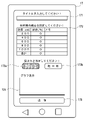
オーダー情報を受信すると、情報表示装置12には受信したオーダー情報の内容が表示される(図9のステップS1でYes、ステップS2)。図13(A)には、図12に示す内容で送信されたオーダー情報を制御装置11が受信し、情報表示装置12にその内容が表示された例が示されている。具体的には、図12のタイトル入力欄171に入力されたタイトルと、入力テーブル172のうち、割合が0で且つメモ欄が空欄の粒度の行(図12では粒度400μm、1000μmの行)を除いた部分の内容が受信テーブル121に表示されている。さらに、挽き方指示欄122には、図12において粗→細挽きボタン173bが選択されたことで、粗挽き状態から細挽き状態となる挽き方が指示されたことが示されている。また、豆量欄123には、受信した豆の量(この例では60g)が示されている。なお、豆の量については店側で別途設定できるようにしてもよい。
When the order information is received, the content of the received order information is displayed on the information display device 12 (Yes in step S1 of FIG. 9, step S2). FIG. 13A shows an example in which the
この状態でグラインド開始ボタン124をタップするとコーヒー豆のグラインド処理が実行される(詳細は後述)が、グラインド開始ボタン124をタップする前の状態では、オーダー情報を変更することができるようになっている(図9のステップS3でNo、ステップS4でYes、ステップS5)。オーダー情報を変更した場合には、この情報に従ってコーヒー豆のグラインド処理が実行される。グラインドの際の気温や湿度によっては、コーヒーの挽き豆の粒度が細目(あるいは粗目)になってしまう場合があるが、店側でオーダー情報を変更して調整することが可能となっている。
When the
例えば、図13(A)のオーダー情報を受信したものの、湿度が低いためにコーヒーの挽き豆の粒度が細目になってしまう状況であったとする。このとき例えば図13(B)に示すように、受信テーブル121において、粒度200μmの割合を示す「40」を「45」に変更し、さらに粒度600μmの割合を示す「60」を「55」に変更することで、コーヒーの挽き豆の粒度を粗目にして所望の粒度になるように調整することができる。なお、この図13(B)の例ではメモ欄に「低湿度→割合増」の記載が追加されているが、このようなメモがあることで、例えば修正理由のような情報を伝えることができる場合がある。 For example, it is assumed that although the order information of FIG. 13A is received, the grain size of ground coffee beans becomes finer due to low humidity. At this time, for example, as shown in FIG. 13B, in the reception table 121, "40" indicating the ratio of the particle size of 200 μm is changed to "45", and "60" indicating the ratio of the particle size of 600 μm is changed to "55". By changing, the grain size of ground coffee beans can be made coarser to adjust to the desired grain size. In the example of FIG. 13(B), the description of "low humidity→proportion increase" is added to the memo column. Sometimes we can.
次に、グラインド開始ボタン124をタップした以降の動作について、図13(B)に示す状態でグラインド開始ボタン124がタップされた場合を例に説明する。グラインド開始ボタン124をタップすると、オーダー情報に従ってコーヒー豆のグラインド処理が実行される(図9のステップS3でYes、ステップS6)。図14(A)には、図13(B)で指定された粒度およびその割合が示されている。
Next, the operation after tapping the
このグラインド処理では、製造されるコーヒー挽き豆の粒度分布が、オーダー情報で指定されたコーヒー挽き豆の粒度に対してある程度の範囲(本実施形態では、±100~150μmの範囲)まで広がるように、グラインダ5Bの刃の間隔(固定刃57bと回転刃58bとの間隔)を所定間隔(例えば、50μm刻み)で変更しつつコーヒー豆を挽く制御が実行される。例えば、図14(B)には、図14(A)で指定されている粒度200μmの指定に対し、グラインダ5Bの刃の間隔を50~350μmの範囲で変更しつつ動作させるための動作時間が設定されていることが示されている。また、図14(B)には、図14(A)で指定されている粒度600μmの指定に対してグラインダ5Bの刃の間隔を450~700μmの範囲で変更しつつ動作させるための動作時間が設定されていることが示されている。さらに図14(D)には、図14(B)に示すグラインダ5Bの刃の間隔ごとの動作時間の長さがグラフで示されている。なお、ここで設定されたグラインダ5Bの刃の間隔とその動作時間は、製造されるコーヒー挽き豆の粒度分布に対応するものであることから、粒度分布が設定されている、とも言える。
In this grinding process, the particle size distribution of the ground coffee beans to be produced is expanded to a certain range (in this embodiment, the range of ±100 to 150 μm) with respect to the particle size of the ground coffee beans specified in the order information. , control is executed to grind coffee beans while changing the interval between the blades of the
上記の例では、オーダー情報で指定された60gの分量のコーヒー挽き豆を製造するのに合計30秒かかるとした場合を想定している。そして、この動作時間のうち45%(13.5秒)を粒度200μmに対する動作に割り当てている。上記の例では、粒度200μmの指定に対してグラインダ5Bの刃の間隔を50~350μmの範囲で変更しつつ動作させることから、13.5秒の動作時間をこの範囲でのグラインダ動作に割り当てている。なお、図14(B)では、間隔50~350μmの範囲でのグラインダの動作時間の合計が13.5秒となっている。また、合計30秒の動作時間のうち55%(16.5秒)を粒度600μmに対する動作に割り当てている。上記の例では、粒度600μmの指定に対してグラインダ5Bの刃の間隔を450~700μmの範囲で変更しつつ動作させることから、16.5秒の動作時間をこの範囲でのグラインダ動作に割り当てている。なお、図14(B)では、間隔450~700μmの範囲でのグラインダの動作時間の合計が16.5秒となっている。上記説明したように図14(B)に示す動作時間は、コーヒー挽き豆の製造に要する時間から導出されたものである。なお、図14(B)では、二種類の粒度の指定に対するグラインダ5Bの刃の間隔の範囲が重複していない例について説明したが、これらの範囲が重複する場合には、その部分の動作時間が加算される。
In the above example, it is assumed that it takes a total of 30 seconds to produce 60 g of ground coffee beans specified in the order information. Then, 45% (13.5 seconds) of this operation time is allocated to the operation for the particle size of 200 μm. In the above example, since the
図14(B)の例で説明したように、グラインダ5Bの刃の間隔を変更しつつコーヒー挽き豆を製造することで、コーヒー挽き豆の粒度を分散させることができる。粒度を分散させたコーヒー挽き豆から抽出されたコーヒーは、粒度を分散させていないコーヒー挽き豆から抽出されたコーヒーと比較して、様々な味を含ませることができる。なお、こうした味が好みでない人向けに、例えば図14(C)に示すような動作時間が設定される場合を設けてもよい。この図14(C)では、グラインダ5Bの動作時間が、オーダー情報で指定された粒度と同じ値の刃の間隔での動作に対してのみ設定されており、粒度の分散を抑えた粒度分布に対応したものになっている。これらの構成は一例であり、粒度の指定の際に粒度分布の範囲を指定できるようにしてもよい。
As described in the example of FIG. 14B, the particle size of the ground coffee beans can be dispersed by producing the ground coffee beans while changing the interval between the blades of the
また図14(B)の例では、オーダー情報で指定された粒度と同じ値の刃の間隔での動作時間が最も長く、指定された粒度とグラインダ5Bの刃の間隔との差が大きくなるに従って動作時間が短くなっているが、例えば、指定された粒度に対して±50μmのグラインダ5Bの刃の間隔での動作について動作時間を同じ値に設定する、といったようにしてもよく、粒度分布のパターンを複数設けてそこから選択できるようにしてもよい。
In the example of FIG. 14(B), the operation time is the longest when the blade spacing is the same as the grain size specified in the order information, and as the difference between the specified grain size and the blade spacing of the
また、図14(B)のような動作時間の情報をオーダー情報作成の際に入力できるようにし、オーダー情報に動作時間の情報が含まれている場合に、この情報に従ってグラインド処理を実行できるようにしてもよい。 In addition, it is made possible to input operation time information as shown in FIG. 14(B) when creating order information, and if the order information includes operation time information, grind processing can be executed according to this information. can be
なお、図14(A)では二種類の粒度の値が設定されているが、値が指定される粒度の種類の数については複数でなく一種類であってもよい。例えば、一種類の粒度の値が設定されている場合には、この値に基づいて動作時間が設定される。 Although two types of granularity values are set in FIG. 14A, the number of types of granularity for which values are specified may be one instead of plural. For example, if one type of granularity value is set, the operating time is set based on this value.
なお、本実施形態でのグラインダ5Bにおける挽き方は、細挽き状態から粗挽き状態となる挽き方と、粗挽き状態から細挽き状態となる挽き方の二種類があり、図10~図12で説明した細→粗挽きボタン173aと粗→細挽きボタン173bを用いていずれかの挽き方が指定される。細挽き状態から粗挽き状態となる挽き方が指定されている場合には、グラインダ5Bの刃の間隔を50μmから1000μmまで広げつつ、各間隔に対して設定された動作時間だけグラインダ5Bを動作させる。一方、粗挽き状態から細挽き状態となる挽き方が指定されている場合には、グラインダ5Bの刃の間隔を1000μmから50μmまで狭めつつ、各間隔に対して設定された動作時間だけグラインダ5Bを動作させる。この挽き方によっては、製造されるコーヒー挽き豆の粒度分布に微妙な違いが生じる場合があり、味に違いが生じる可能性があることから、本実施形態ではこれらの挽き方を設定可能な構成を採用している。
It should be noted that there are two types of grinding methods in the
図13(B)では、粗挽き状態から細挽き状態となる挽き方が指定されているため、グラインダ5Bの刃の間隔を1000μmから50μmまで狭めつつ、各間隔に対して設定された動作時間だけグラインダ5Bを動作させる。このとき、情報表示装置12には、図14(D)に示すグラフが表示され、この動作の進行に合わせてグラフ内の領域の色が変化する。図15(A)には、グラインド開始から12.6秒が経過したときの様子が示されている。このとき、グラインダ5Bの刃の間隔は550μmに設定された状態となっており、図15(A)では、この550μmを境に右側の領域の色が変化したことがハッチングによって示されている。このハッチングは、該当する領域のグラインド処理が終了していることを示す一例である。また、図15(B)には、グラインド開始から30秒が経過してグラインド処理が終了したときの様子が示されている。この図15(B)においては、すべての領域がハッチングされているのは、すべてのグラインド処理が完了していることを示す一例である。図15(A)(B)の例のように、グラインド処理の進行具合が表示されることで、顧客の待ち時間を退屈しないようにしたり、店員がその間別の作業を行うといったような効率的な作業が可能となる場合がある。
In FIG. 13(B), since the way of grinding from the coarse grinding state to the fine grinding state is specified, the interval between the blades of the
なお、図15(A)(B)の例では粗挽き状態から細挽き状態となる挽き方が指定されている場合に、グラフの右側からハッチングが広がっていく表示例について説明したが、細挽き状態から粗挽き状態となる挽き方が指定されている場合には、図15(A)(B)の例とは異なり、グラフの左側からハッチングが広がっていく表示になる。 In addition, in the examples of FIGS. 15A and 15B, a display example in which hatching expands from the right side of the graph when the grinding state from the coarse grinding state to the fine grinding state is specified has been described. When the coarse grinding state is specified from the state, unlike the examples of FIGS. 15A and 15B, the hatching spreads from the left side of the graph.
また、上記の例では情報表示装置12にグラインド処理の進行具合が表示される構成について説明したが、オーダー情報を送信した携帯端末17においてグラインド処理の進行具合が表示される構成としてもよい。
In the above example, the progress of the grind process is displayed on the
<5.その他の構成>
以上説明したコーヒー豆挽き装置1では、粉砕装置5がグラインダ5Aとグラインダ5Bを用いて二段階に分けてコーヒー豆を挽く構成を採用している。しかし、図9~図15を用いて説明した動作を実行するにあたってはこのような構成に限らず、一つのグラインダを用いる構成であってもよく、また、グラインダの機構についても上記説明した機構に限定されるものではない。
<5. Other configurations>
In the coffee
また、図14を用いて説明したように、コーヒー挽き豆の粒度を分散させるにあたっては、例えば、粒度50μm以上500μm未満の範囲を担当するグランダと、粒度500μm以上1000μmまでの範囲を担当するグラインダの2つを設け、オーダー情報に応じてこれらを切り替えて使用したり、同時に使用したりする構成としてもよい。すなわち、複数のグラインダを切り替えて使用する構成としてもよく、複数のグラインダを同時に使用する構成としてもよい。また、複数のグラインダにつては、それぞれが担当するコーヒー挽き豆の粒度の範囲が異なる構成に限られるものではなく、これらの範囲が重複する構成であってもよいし、これらの範囲が同じであってもよい。 Further, as described with reference to FIG. 14, when dispersing the particle size of the ground coffee beans, for example, a grounder is in charge of the particle size range of 50 μm or more and less than 500 μm, and a grinder is in charge of the particle size range of 500 μm or more and 1000 μm. A configuration may be adopted in which two are provided, and these are used by switching according to the order information, or used simultaneously. That is, a configuration in which a plurality of grinders are used by switching may be adopted, or a configuration in which a plurality of grinders are used simultaneously may be adopted. In addition, the plurality of grinders are not limited to a configuration in which the range of the particle size of the ground coffee beans for which each grinder is responsible is different. There may be.
また、上記の例では、情報表示装置12を用いてコーヒー挽き豆のオーダー情報を表示したりグラインド開始操作を行う構成について説明したが、こうした役割については、例えば携帯端末17やサーバ16といった外部装置で実行可能な構成としてもよい。すなわち、コーヒー挽き豆装置1と、サーバ16あるいは携帯端末17とを含む、コーヒー挽き豆システムを構成してもよい。
In the above example, the
<実施形態のまとめ>
上記の実施形態では、
コーヒー豆を挽くグラインダ(例えば、グラインダ5B)と、
前記グラインダを制御する制御装置(例えば、制御装置11)と、
を備えたコーヒー豆挽き装置(例えば、コーヒー豆挽き装置1)であって、
前記制御装置は、設定された粒度分布に従って前記グラインダを制御可能なものである(例えば、図14(B))、
ことを特徴とするコーヒー豆挽き装置、について説明した。
<Summary of embodiment>
In the above embodiment,
a grinder for grinding coffee beans (for example,
a control device (for example, a control device 11) that controls the grinder;
A coffee bean grinding device (for example, a coffee bean grinding device 1) comprising
The control device is capable of controlling the grinder according to the set particle size distribution (for example, FIG. 14 (B)),
A coffee bean grinder characterized by:
また、上記記載のコーヒー豆挽き装置であって、
前記制御装置は、ユーザからのオーダー情報に基づいて前記粒度分布を設定可能なものである(例えば、図9、図14(A)、図14(B))、
ことを特徴とするコーヒー豆挽き装置、について説明した。
Also, the coffee bean grinding device described above,
The control device can set the particle size distribution based on order information from a user (for example, FIG. 9, FIG. 14 (A), FIG. 14 (B)),
A coffee bean grinder characterized by:
また、上記記載のコーヒー豆挽き装置であって、
前記オーダー情報をネットワーク経由で受信可能な受信装置(例えば、I/F部11c)を備えた、
ことを特徴とするコーヒー豆挽き装置、について説明した。
Also, the coffee bean grinding device described above,
A receiving device (for example, I /
A coffee bean grinder characterized by:
また、上記記載のコーヒー豆挽き装置であって、
前記制御装置は、一の前記オーダー情報に対して設定可能な前記粒度分布のパターンを複数種類有するものである、
ことを特徴とするコーヒー豆挽き装置、について説明した。
Also, the coffee bean grinding device described above,
The control device has a plurality of types of the particle size distribution pattern that can be set for one piece of the order information.
A coffee bean grinder characterized by:
また、上記記載のコーヒー豆挽き装置であって、
前記制御装置は、第一の粒度および第二の粒度を含む前記粒度分布が設定された場合に、前記グラインダによって前記第一の粒度及び前記第二の粒度のうちのどちらを先に挽くか設定可能なものである(例えば、図11の細→粗挽きボタン173a、粗→細挽きボタン173b)、
ことを特徴とするコーヒー豆挽き装置、について説明した。
Also, the coffee bean grinding device described above,
The control device sets which of the first particle size and the second particle size is first ground by the grinder when the particle size distribution including the first particle size and the second particle size is set. is possible (for example, fine→
A coffee bean grinder characterized by:
また、上記記載のコーヒー豆挽き装置であって、
前記グラインダは、コーヒー挽き豆を生成するにあたって設定可能な粒度を複数種類有するものであり、
前記制御装置は、前記グラインダの設定粒度を変更しつつコーヒー挽き豆を生成する制御を行うものである(例えば、図14(B))、
ことを特徴とするコーヒー豆挽き装置、について説明した。
Also, the coffee bean grinding device described above,
The grinder has a plurality of types of particle sizes that can be set for generating ground coffee beans,
The control device performs control to generate ground coffee beans while changing the set particle size of the grinder (for example, FIG. 14 (B)),
A coffee bean grinder characterized by:
また、上記コーヒー豆挽き装置と通信可能な外部装置(例えば、サーバ16、携帯端末17)を備えたコーヒー豆挽きシステムについて説明した。
Also, a coffee bean grinding system including an external device (eg,
また、
粒度分布を設定する粒度分布設定ステップと、
設定された粒度分布に従ってコーヒー豆を挽くコーヒー豆挽きステップと、を有する、
ことを特徴とするコーヒー豆挽き方法(例えば、図14(B))、について説明した。
again,
a particle size distribution setting step for setting the particle size distribution;
a coffee bean grinding step of grinding coffee beans according to a set particle size distribution;
A coffee bean grinding method (for example, FIG. 14(B)) characterized by the above has been described.
また、上記記載のコーヒー豆挽き方法であって、
前記粒度分布設定ステップは、ユーザからのオーダー情報に基づいて前記粒度分布を設定するステップである(例えば、図9、図14(A)、図14(B))、
ことを特徴とするコーヒー豆挽き方法、について説明した。
Also, the coffee bean grinding method described above,
The particle size distribution setting step is a step of setting the particle size distribution based on order information from a user (for example, FIGS. 9, 14 (A), and 14 (B)),
A coffee bean grinding method characterized by:
また、上記記載のコーヒー豆挽き方法であって、
前記オーダー情報をネットワーク経由で受信するオーダー受信ステップと、を有する、
ことを特徴とするコーヒー豆挽き方法、について説明した。
Also, the coffee bean grinding method described above,
an order receiving step of receiving the order information via a network;
A coffee bean grinding method characterized by:
また、上記記載のコーヒー豆挽き方法であって、
前記粒度分布設定ステップは、一の前記オーダー情報に対して設定可能な前記粒度分布のパターンを複数種類有する、
ことを特徴とするコーヒー豆挽き方法、について説明した。
Also, the coffee bean grinding method described above,
The particle size distribution setting step has a plurality of types of particle size distribution patterns that can be set for one piece of the order information.
A coffee bean grinding method characterized by:
また、上記記載のコーヒー豆挽き方法であって、
第一の粒度および第二の粒度を含む前記粒度分布が設定された場合に、前記第一の粒度及び前記第二の粒度のうちのどちらを先に挽くか設定する挽き方設定ステップ(例えば、図11の細→粗挽きボタン173a、粗→細挽きボタン173b)と、を有する、
ことを特徴とするコーヒー豆挽き方法、について説明した。
Also, the coffee bean grinding method described above,
When the particle size distribution including the first particle size and the second particle size is set, a grinding method setting step of setting which of the first particle size and the second particle size is ground first (for example, Fine →
A coffee bean grinding method characterized by:
また、上記記載のコーヒー豆挽き方法であって、
前記コーヒー豆挽きステップは、コーヒー挽き豆を生成するにあたって設定可能な粒度を複数種類有するグラインダの設定粒度を変更しつつコーヒー豆を挽くステップである(例えば、図14(B))、
ことを特徴とするコーヒー豆挽き方法、について説明した。
Also, the coffee bean grinding method described above,
The step of grinding coffee beans is a step of grinding coffee beans while changing the set particle size of a grinder having a plurality of types of particle sizes that can be set for generating ground coffee beans (for example, FIG. 14 (B)).
A coffee bean grinding method characterized by:
上記の実施形態では、
コーヒー豆を挽くグラインダ(例えば、グラインダ5B)と、
前記グラインダを制御する制御装置(例えば、制御装置11)と、
を備えたコーヒー豆挽き装置(例えば、コーヒー豆挽き装置1)であって、
前記グラインダは、コーヒー挽き豆を生成するにあたって設定可能な粒度を複数種類有するものであり、
前記制御装置は、設定された複数の粒度に従って前記グラインダの設定粒度を変更しつつコーヒー挽き豆を生成する制御を行うものである(例えば、図14(B))、
ことを特徴とするコーヒー豆挽き装置、について説明した。
In the above embodiment,
a grinder for grinding coffee beans (for example,
a control device (for example, a control device 11) that controls the grinder;
A coffee bean grinding device (for example, a coffee bean grinding device 1) comprising
The grinder has a plurality of types of particle sizes that can be set for generating ground coffee beans,
The control device performs control to generate ground coffee beans while changing the set particle size of the grinder according to the set multiple particle sizes (for example, FIG. 14 (B)).
A coffee bean grinder characterized by:
また、上記記載のコーヒー豆挽き装置であって、
前記制御装置は、ユーザからのオーダー情報に基づいて前記複数の粒度を設定可能なものである(例えば、図9、図14(A)、図14(B))、
ことを特徴とするコーヒー豆挽き装置、について説明した。
Also, the coffee bean grinding device described above,
The control device can set the plurality of granularities based on order information from a user (for example, FIGS. 9, 14 (A), and 14 (B)),
A coffee bean grinder characterized by:
また、上記記載のコーヒー豆挽き装置であって、
前記オーダー情報をネットワーク経由で受信可能な受信装置(例えば、I/F部11c)を備えた、
ことを特徴とするコーヒー豆挽き装置、について説明した。
Also, the coffee bean grinding device described above,
A receiving device (for example, I /
A coffee bean grinder characterized by:
また、上記記載のコーヒー豆挽き装置であって、
前記制御装置は、一の前記オーダー情報に対して設定可能な前記複数の粒度のパターンを複数種類有するものである、
ことを特徴とするコーヒー豆挽き装置、について説明した。
Also, the coffee bean grinding device described above,
The control device has a plurality of types of patterns of the plurality of granularities that can be set for one piece of the order information,
A coffee bean grinder characterized by:
また、上記記載のコーヒー豆挽き装置であって、
前記制御装置は、第一の粒度および第二の粒度を含む前記複数の粒度が設定された場合に、前記グラインダによって前記第一の粒度及び前記第二の粒度のうちのどちらを先に挽くか設定可能なものである(例えば、図11の細→粗挽きボタン173a、粗→細挽きボタン173b)、
ことを特徴とするコーヒー豆挽き装置、について説明した。
Also, the coffee bean grinding device described above,
When the plurality of grain sizes including the first grain size and the second grain size are set, the control device determines which of the first grain size and the second grain size is first ground by the grinder. It can be set (for example, fine →
A coffee bean grinder characterized by:
また、上記記載のコーヒー豆挽き装置であって、
前記制御装置は、設定された一の粒度に従って前記グラインダの粒度を設定してコーヒー挽き豆を生成する制御を行うものである、
ことを特徴とするコーヒー豆挽き装置、について説明した。
Also, the coffee bean grinding device described above,
The control device controls the generation of ground coffee beans by setting the particle size of the grinder according to the set particle size.
A coffee bean grinder characterized by:
また、上記コーヒー豆挽き装置と通信可能な外部装置(例えば、サーバ16、携帯端末17)を備えたコーヒー豆挽きシステムについて説明した。
Also, a coffee bean grinding system including an external device (eg,
また、
粒度分布を設定する粒度分布設定ステップと、
設定された粒度分布に従ってコーヒー豆を挽くコーヒー豆挽きステップと、を有するコーヒー豆挽き方法であって、
前記コーヒー豆挽きステップは、コーヒー挽き豆を生成するにあたって設定可能な粒度を複数種類有するグラインダの設定粒度を変更しつつコーヒー豆を挽くステップである(例えば、図14(B))、
ことを特徴とするコーヒー豆挽き方法、について説明した。
again,
a particle size distribution setting step for setting the particle size distribution;
A coffee bean grinding method comprising a coffee bean grinding step of grinding coffee beans according to a set particle size distribution,
The step of grinding coffee beans is a step of grinding coffee beans while changing the set particle size of a grinder having a plurality of types of particle sizes that can be set for generating ground coffee beans (for example, FIG. 14 (B)).
A coffee bean grinding method characterized by:
また、上記記載のコーヒー豆挽き方法であって、
前記粒度分布設定ステップは、ユーザからのオーダー情報に基づいて前記複数の粒度を設定するステップである(例えば、図9、図14(A)、図14(B))、
ことを特徴とするコーヒー豆挽き方法、について説明した。
Also, the coffee bean grinding method described above,
The particle size distribution setting step is a step of setting the plurality of particle sizes based on order information from a user (for example, FIG. 9, FIG. 14(A), FIG. 14(B)),
A coffee bean grinding method characterized by:
また、上記記載のコーヒー豆挽き方法であって、
前記オーダー情報をネットワーク経由で受信するオーダー受信ステップと、を有する、
ことを特徴とするコーヒー豆挽き方法、について説明した。
Also, the coffee bean grinding method described above,
an order receiving step of receiving the order information via a network;
A coffee bean grinding method characterized by:
また、上記記載のコーヒー豆挽き方法であって、
前記粒度分布設定ステップは、一の前記オーダー情報に対して設定可能な前記複数の粒度のパターンを複数種類有する、
ことを特徴とするコーヒー豆挽き方法、について説明した。
Also, the coffee bean grinding method described above,
The particle size distribution setting step has a plurality of types of the plurality of particle size patterns that can be set for one piece of the order information.
A coffee bean grinding method characterized by:
また、上記記載のコーヒー豆挽き方法であって、
第一の粒度および第二の粒度を含む前記複数の粒度が設定された場合に、前記第一の粒度及び前記第二の粒度のうちのどちらを先に挽くか設定する挽き方設定ステップ(例えば、図11の細→粗挽きボタン173a、粗→細挽きボタン173b)と、を有する、
ことを特徴とするコーヒー豆挽き方法、について説明した。
Also, the coffee bean grinding method described above,
When the plurality of grain sizes including the first grain size and the second grain size are set, a grinding method setting step of setting which of the first grain size and the second grain size is ground first (for example , fine →
A coffee bean grinding method characterized by:
また、上記記載のコーヒー豆挽き方法であって、
前記コーヒー豆挽きステップは、設定された一の粒度に従って前記グラインダの粒度を設定してコーヒー挽き豆を生成可能なステップである、
ことを特徴とするコーヒー豆挽き方法、について説明した。
Also, the coffee bean grinding method described above,
The step of grinding coffee beans is a step that can generate ground coffee beans by setting the grain size of the grinder according to a set grain size.
A coffee bean grinding method characterized by:
本発明は上記実施の形態に制限されるものではなく、本発明の精神及び範囲から離脱することなく、様々な変更及び変形が可能である。
The present invention is not limited to the embodiments described above, and various modifications and variations are possible without departing from the spirit and scope of the present invention.
Claims (4)
前記グラインダを制御する制御装置と、
を備えたコーヒー豆挽き装置であって、
前記グラインダは、コーヒー挽き豆を生成するにあたって設定可能な粒度を複数種類有するものであり、
前記制御装置は、設定された複数の粒度に従って前記グラインダの設定粒度を変更しつつコーヒー挽き豆を生成する制御を行うことが可能なものであり、
前記制御装置は、ユーザからのオーダー情報に基づいて前記複数の粒度を設定可能なものであり、
前記制御装置は、一の前記オーダー情報に対して設定可能な前記複数の粒度のパターンを複数種類有するものである、
ことを特徴とするコーヒー豆挽き装置。 a grinder for grinding coffee beans,
a control device that controls the grinder;
A coffee grinder comprising:
The grinder has a plurality of types of particle sizes that can be set for generating ground coffee beans,
The control device is capable of controlling the generation of ground coffee beans while changing the set particle size of the grinder according to a plurality of set particle sizes,
The control device is capable of setting the plurality of granularities based on order information from a user,
The control device has a plurality of types of patterns of the plurality of granularities that can be set for one piece of the order information,
A coffee bean grinder characterized by:
前記オーダー情報をネットワーク経由で受信可能な受信装置を備えた、
ことを特徴とするコーヒー豆挽き装置。 A coffee bean grinding device according to claim 1 ,
Equipped with a receiving device capable of receiving the order information via a network,
A coffee bean grinder characterized by:
前記グラインダを制御する制御装置と、
を備えたコーヒー豆挽き装置であって、
前記グラインダは、コーヒー挽き豆を生成するにあたって設定可能な粒度を複数種類有するものであり、
前記制御装置は、設定された複数の粒度に従って前記グラインダの設定粒度を変更しつつコーヒー挽き豆を生成する制御を行うことが可能なものであり、
前記制御装置は、第一の粒度および第二の粒度を含む前記複数の粒度が設定された場合に、前記グラインダによって前記第一の粒度及び前記第二の粒度のうちのどちらを先に挽くか設定可能なものである、
ことを特徴とするコーヒー豆挽き装置。 a grinder for grinding coffee beans,
a control device that controls the grinder;
A coffee grinder comprising:
The grinder has a plurality of types of particle sizes that can be set for generating ground coffee beans,
The control device is capable of controlling the generation of ground coffee beans while changing the set particle size of the grinder according to a plurality of set particle sizes,
When the plurality of grain sizes including the first grain size and the second grain size are set, the control device determines which of the first grain size and the second grain size is first ground by the grinder. is configurable,
A coffee bean grinder characterized by:
前記制御装置は、設定された一の粒度に従って前記グラインダの粒度を設定してコーヒー挽き豆を生成する制御を行うことも可能なものである、
ことを特徴とするコーヒー豆挽き装置。 A coffee bean grinding device according to any one of claims 1 to 3 ,
The control device is also capable of controlling the generation of ground coffee beans by setting the particle size of the grinder according to one set particle size.
A coffee bean grinder characterized by:
Priority Applications (8)
| Application Number | Priority Date | Filing Date | Title |
|---|---|---|---|
| JP2020201272A JP7144074B2 (en) | 2020-12-03 | 2020-12-03 | coffee bean grinder |
| PCT/JP2021/040974 WO2022118609A1 (en) | 2020-12-03 | 2021-11-08 | Coffee bean grinding apparatus |
| US18/038,724 US20240032732A1 (en) | 2020-12-03 | 2021-11-08 | Coffee bean grinding machine |
| CA3203284A CA3203284A1 (en) | 2020-12-03 | 2021-11-08 | Coffee bean grinding machine |
| KR1020237019879A KR20230101913A (en) | 2020-12-03 | 2021-11-08 | coffee bean grinder |
| EP21900364.7A EP4258231A4 (en) | 2020-12-03 | 2021-11-08 | Coffee bean grinding apparatus |
| CN202180081280.1A CN116745825A (en) | 2020-12-03 | 2021-11-08 | coffee bean grinding device |
| TW110143470A TW202228582A (en) | 2020-12-03 | 2021-11-23 | Coffee bean grinding apparatus |
Applications Claiming Priority (1)
| Application Number | Priority Date | Filing Date | Title |
|---|---|---|---|
| JP2020201272A JP7144074B2 (en) | 2020-12-03 | 2020-12-03 | coffee bean grinder |
Publications (2)
| Publication Number | Publication Date |
|---|---|
| JP2022089051A JP2022089051A (en) | 2022-06-15 |
| JP7144074B2 true JP7144074B2 (en) | 2022-09-29 |
Family
ID=81853661
Family Applications (1)
| Application Number | Title | Priority Date | Filing Date |
|---|---|---|---|
| JP2020201272A Active JP7144074B2 (en) | 2020-12-03 | 2020-12-03 | coffee bean grinder |
Country Status (8)
| Country | Link |
|---|---|
| US (1) | US20240032732A1 (en) |
| EP (1) | EP4258231A4 (en) |
| JP (1) | JP7144074B2 (en) |
| KR (1) | KR20230101913A (en) |
| CN (1) | CN116745825A (en) |
| CA (1) | CA3203284A1 (en) |
| TW (1) | TW202228582A (en) |
| WO (1) | WO2022118609A1 (en) |
Citations (2)
| Publication number | Priority date | Publication date | Assignee | Title |
|---|---|---|---|---|
| JP2004105627A (en) | 2002-09-20 | 2004-04-08 | Niwa Shoji Kk | Coffee supply device |
| WO2016132412A1 (en) | 2015-02-18 | 2016-08-25 | パナソニックIpマネジメント株式会社 | Beverage supply device |
Family Cites Families (8)
| Publication number | Priority date | Publication date | Assignee | Title |
|---|---|---|---|---|
| JPH04312419A (en) * | 1991-04-11 | 1992-11-04 | Matsushita Electric Ind Co Ltd | Coffee percolator |
| AU2014248876A1 (en) * | 2013-03-11 | 2015-10-01 | Neil M. DAY | Method and apparatus for replicating coffee flavor |
| US9154547B2 (en) * | 2013-03-14 | 2015-10-06 | Blossom Coffee, Inc. | Methods for brewing coffee |
| US9940004B2 (en) * | 2013-03-15 | 2018-04-10 | Gregory Mayworm | Methods and systems for predicting and evaluating coffee characteristics |
| JP7052983B6 (en) | 2017-08-07 | 2022-07-15 | 株式会社大都技研 | Crushing equipment and beverage manufacturing equipment |
| KR101981334B1 (en) | 2017-09-14 | 2019-05-22 | 에스케이텔레콤 주식회사 | Mobile communication system and method applying distributed data packet handling |
| IT201900000591A1 (en) * | 2019-01-15 | 2020-07-15 | La Marzocco Srl | Coffee grinder configured to supply a dose of stratified ground coffee and relative method |
| IT201900001629A1 (en) * | 2019-02-05 | 2020-08-05 | La Marzocco Srl | Coffee grinder machine configured to provide different particle size profiles and relative method |
-
2020
- 2020-12-03 JP JP2020201272A patent/JP7144074B2/en active Active
-
2021
- 2021-11-08 CA CA3203284A patent/CA3203284A1/en active Pending
- 2021-11-08 KR KR1020237019879A patent/KR20230101913A/en unknown
- 2021-11-08 EP EP21900364.7A patent/EP4258231A4/en active Pending
- 2021-11-08 CN CN202180081280.1A patent/CN116745825A/en active Pending
- 2021-11-08 US US18/038,724 patent/US20240032732A1/en active Pending
- 2021-11-08 WO PCT/JP2021/040974 patent/WO2022118609A1/en active Application Filing
- 2021-11-23 TW TW110143470A patent/TW202228582A/en unknown
Patent Citations (2)
| Publication number | Priority date | Publication date | Assignee | Title |
|---|---|---|---|---|
| JP2004105627A (en) | 2002-09-20 | 2004-04-08 | Niwa Shoji Kk | Coffee supply device |
| WO2016132412A1 (en) | 2015-02-18 | 2016-08-25 | パナソニックIpマネジメント株式会社 | Beverage supply device |
Also Published As
| Publication number | Publication date |
|---|---|
| CN116745825A (en) | 2023-09-12 |
| CA3203284A1 (en) | 2022-06-09 |
| TW202228582A (en) | 2022-08-01 |
| US20240032732A1 (en) | 2024-02-01 |
| EP4258231A4 (en) | 2024-01-31 |
| KR20230101913A (en) | 2023-07-06 |
| JP2022089051A (en) | 2022-06-15 |
| EP4258231A1 (en) | 2023-10-11 |
| WO2022118609A1 (en) | 2022-06-09 |
Similar Documents
| Publication | Publication Date | Title |
|---|---|---|
| CN102670096B (en) | A kind of mixer | |
| JP7144074B2 (en) | coffee bean grinder | |
| JP7144073B2 (en) | coffee bean grinder | |
| JP6481280B2 (en) | Horizontal axis type rice mill | |
| WO2022196247A1 (en) | Coffee machine | |
| WO2022196246A1 (en) | Coffee machine | |
| CN108324132A (en) | Cooking machine with agitating function | |
| JP7282422B2 (en) | coffee machine | |
| WO2022196248A1 (en) | Coffee machine | |
| JP2022106221A (en) | Coffee bean grinder | |
| JP2022144799A (en) | coffee bean grinder | |
| JP2022144798A (en) | Coffee grinder | |
| JP2022144792A (en) | coffee bean grinder | |
| JP2022144795A (en) | coffee bean grinder | |
| JP7080525B1 (en) | Coffee machine | |
| JP2022144794A (en) | coffee bean grinder | |
| JP2905196B1 (en) | Pulverizer | |
| JPH0818009B2 (en) | Wheat grain adjusting device | |
| RU2209119C2 (en) | Forage grain crusher | |
| JP2003159543A (en) | Wood flour manufacturing apparatus | |
| KR20240016687A (en) | Apparatus for grinding coffee beans | |
| JP2002320866A (en) | Air quantity adjusting device for husking separator | |
| JP2001113188A (en) | Grain refining device |
Legal Events
| Date | Code | Title | Description |
|---|---|---|---|
| A621 | Written request for application examination |
Free format text: JAPANESE INTERMEDIATE CODE: A621 Effective date: 20220117 |
|
| A871 | Explanation of circumstances concerning accelerated examination |
Free format text: JAPANESE INTERMEDIATE CODE: A871 Effective date: 20220204 |
|
| A711 | Notification of change in applicant |
Free format text: JAPANESE INTERMEDIATE CODE: A712 Effective date: 20220316 |
|
| A131 | Notification of reasons for refusal |
Free format text: JAPANESE INTERMEDIATE CODE: A131 Effective date: 20220419 |
|
| A521 | Request for written amendment filed |
Free format text: JAPANESE INTERMEDIATE CODE: A523 Effective date: 20220606 |
|
| TRDD | Decision of grant or rejection written | ||
| A01 | Written decision to grant a patent or to grant a registration (utility model) |
Free format text: JAPANESE INTERMEDIATE CODE: A01 Effective date: 20220823 |
|
| A61 | First payment of annual fees (during grant procedure) |
Free format text: JAPANESE INTERMEDIATE CODE: A61 Effective date: 20220908 |
|
| R150 | Certificate of patent or registration of utility model |
Ref document number: 7144074 Country of ref document: JP Free format text: JAPANESE INTERMEDIATE CODE: R150 |