JP7142110B2 - Knife and knife assembly for slicing device, and slicing device provided with the same - Google Patents
Knife and knife assembly for slicing device, and slicing device provided with the same Download PDFInfo
- Publication number
- JP7142110B2 JP7142110B2 JP2020566943A JP2020566943A JP7142110B2 JP 7142110 B2 JP7142110 B2 JP 7142110B2 JP 2020566943 A JP2020566943 A JP 2020566943A JP 2020566943 A JP2020566943 A JP 2020566943A JP 7142110 B2 JP7142110 B2 JP 7142110B2
- Authority
- JP
- Japan
- Prior art keywords
- knife
- edge
- cutting
- cutting edge
- clamp
- Prior art date
- Legal status (The legal status is an assumption and is not a legal conclusion. Google has not performed a legal analysis and makes no representation as to the accuracy of the status listed.)
- Active
Links
Images


Classifications
-
- B—PERFORMING OPERATIONS; TRANSPORTING
- B26—HAND CUTTING TOOLS; CUTTING; SEVERING
- B26D—CUTTING; DETAILS COMMON TO MACHINES FOR PERFORATING, PUNCHING, CUTTING-OUT, STAMPING-OUT OR SEVERING
- B26D7/00—Details of apparatus for cutting, cutting-out, stamping-out, punching, perforating, or severing by means other than cutting
- B26D7/26—Means for mounting or adjusting the cutting member; Means for adjusting the stroke of the cutting member
- B26D7/2614—Means for mounting the cutting member
-
- B—PERFORMING OPERATIONS; TRANSPORTING
- B26—HAND CUTTING TOOLS; CUTTING; SEVERING
- B26D—CUTTING; DETAILS COMMON TO MACHINES FOR PERFORATING, PUNCHING, CUTTING-OUT, STAMPING-OUT OR SEVERING
- B26D1/00—Cutting through work characterised by the nature or movement of the cutting member or particular materials not otherwise provided for; Apparatus or machines therefor; Cutting members therefor
- B26D1/0006—Cutting members therefor
-
- B—PERFORMING OPERATIONS; TRANSPORTING
- B26—HAND CUTTING TOOLS; CUTTING; SEVERING
- B26D—CUTTING; DETAILS COMMON TO MACHINES FOR PERFORATING, PUNCHING, CUTTING-OUT, STAMPING-OUT OR SEVERING
- B26D1/00—Cutting through work characterised by the nature or movement of the cutting member or particular materials not otherwise provided for; Apparatus or machines therefor; Cutting members therefor
- B26D1/01—Cutting through work characterised by the nature or movement of the cutting member or particular materials not otherwise provided for; Apparatus or machines therefor; Cutting members therefor involving a cutting member which does not travel with the work
- B26D1/02—Cutting through work characterised by the nature or movement of the cutting member or particular materials not otherwise provided for; Apparatus or machines therefor; Cutting members therefor involving a cutting member which does not travel with the work having a stationary cutting member
- B26D1/03—Cutting through work characterised by the nature or movement of the cutting member or particular materials not otherwise provided for; Apparatus or machines therefor; Cutting members therefor involving a cutting member which does not travel with the work having a stationary cutting member with a plurality of cutting members
-
- B—PERFORMING OPERATIONS; TRANSPORTING
- B26—HAND CUTTING TOOLS; CUTTING; SEVERING
- B26D—CUTTING; DETAILS COMMON TO MACHINES FOR PERFORATING, PUNCHING, CUTTING-OUT, STAMPING-OUT OR SEVERING
- B26D7/00—Details of apparatus for cutting, cutting-out, stamping-out, punching, perforating, or severing by means other than cutting
- B26D7/06—Arrangements for feeding or delivering work of other than sheet, web, or filamentary form
- B26D7/0691—Arrangements for feeding or delivering work of other than sheet, web, or filamentary form by centrifugal force
-
- B—PERFORMING OPERATIONS; TRANSPORTING
- B26—HAND CUTTING TOOLS; CUTTING; SEVERING
- B26D—CUTTING; DETAILS COMMON TO MACHINES FOR PERFORATING, PUNCHING, CUTTING-OUT, STAMPING-OUT OR SEVERING
- B26D1/00—Cutting through work characterised by the nature or movement of the cutting member or particular materials not otherwise provided for; Apparatus or machines therefor; Cutting members therefor
- B26D1/0006—Cutting members therefor
- B26D2001/006—Cutting members therefor the cutting blade having a special shape, e.g. a special outline, serrations
-
- B—PERFORMING OPERATIONS; TRANSPORTING
- B26—HAND CUTTING TOOLS; CUTTING; SEVERING
- B26D—CUTTING; DETAILS COMMON TO MACHINES FOR PERFORATING, PUNCHING, CUTTING-OUT, STAMPING-OUT OR SEVERING
- B26D2210/00—Machines or methods used for cutting special materials
- B26D2210/02—Machines or methods used for cutting special materials for cutting food products, e.g. food slicers
Description
本出願は、本明細書に参照として組み込まれる2018年6月8日に出願された米国特許仮出願第62/682,386号の優先権の利益を主張する。 This application claims the priority benefit of US Provisional Patent Application No. 62/682,386, filed Jun. 8, 2018, which is incorporated herein by reference.
本発明は、食品に適したスライス装置を含む、さまざまな製品の切断装置に関する。具体的には、遠心タイプのスライス装置に使用するナイフおよびナイフアセンブリに関する。 The present invention relates to cutting devices for various products, including slicing devices suitable for food products. More particularly, it relates to knives and knife assemblies for use in centrifugal-type slicing devices.
野菜、果実、乳製品、肉製品などの食品をスライスし、細断し、粉砕するためのさまざまな装置が知られている。このような目的に広く使用されている装置は、アーシェル・ラボラトリーズ,インク.から、「モデルCC(Model CC(登録商標))」および「(モデルCCL(Model CCL)」のブランド名で市販されている。モデルCCおよびモデルCCLは、遠心タイプのスライサを備え、さまざまな食品のスライスを高い生産能力で行うことができる。モデルCCシリーズの装置は、均一なスライス、皮むき、細断、および粉砕を行うのに適している。モデルCCシリーズの装置の構成および態様に関しては、米国特許第3,139,128号公報、米国特許第3,139,129号公報、米国特許第5,694,824号公報、および、米国特許第6,968,765号公報において明示されており、これらのすべての内容は、本明細書に参照として組み込まれる。 Various devices are known for slicing, chopping and grinding food products such as vegetables, fruits, dairy products and meat products. Apparatus widely used for such purposes is available from Urschel Laboratories, Inc.; , Inc., under the brand names "Model CC®" and "Model CCL." slicing can be performed with high production capacity.Model CC series equipment is suitable for uniform slicing, peeling, shredding and grinding.Regarding the configuration and aspects of model CC series equipment , U.S. Pat. No. 3,139,128, U.S. Pat. No. 3,139,129, U.S. Pat. No. 5,694,824, and U.S. Pat. No. 6,968,765. , the contents of all of which are incorporated herein by reference.
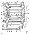
図1は、モデルCCシリーズの装置の代表的なスライス装置10を模式的に示している。スライス装置10は、内周に切断ナイフ(図示せず)を備える略環状のヘッド12を有する。インペラ14は、切断ヘッド12内に同軸に取り付けられており、切断ヘッド12の軸と一致する回転軸17を有する。インペラ14は、ハウジング18内に収納され、ギアボックス16に連結されたシャフトを介して、軸17を中心に回転駆動する。切断ヘッド12は、ギアボックス16の上方にあるサポートリング15に取り付けられ、インペラ14が回転する際には静止している。製品は、インペラ14の上方に位置する供給ホッパ11を介して、切断ヘッド12およびインペラ14に運ばれる。作動時に、ホッパ11が製品をインペラ14に運ぶと、遠心力により製品は外方に移動し、切断ヘッド12のナイフとの係合部へと運ばれる。インペラ14は、実質的に径方向を向いたパドル13を備え、それぞれのパドル13は、インペラ14の回転に従って、製品に係合し、かつ、切断ヘッド12のナイフに向けて径方向外方に製品を導く面を有する。モデルCCシリーズの装置の構造に関する他の構成および操作に関しては、その改良された実施形態を含み、米国特許第3,139,128号、第3,139,129号、第5,694,824号、第6,968,765号、第7,658,133号、第8,161,856号、第9,193,086号、第9,469,041号、および第9,517,572号、並びに、米国特許出願公開第2016/0158953号および第2016/0361831号において明示されており、その内容のすべては本明細書に参照として組み込まれる。
FIG. 1 schematically shows a
図2および図3は、図1に示したモデルCCシリーズのスライス装置10あるいは該装置に変更および改良を施した構造を含む、係属中の米国特許出願第16/394,048号(2019年4月25日出願)に開示されている、さまざまな切断装置に使用可能な切断ヘッド12の一実施形態を取り出して示す図である。切断ヘッド12については、図1に示したインペラ14を備えるスライス装置10を参照して説明する。切断ヘッド12およびインペラ14の同軸配置に基づいて、「軸方向」、「周方向」、「径方向」などの相対的な用語、および、これらに関連する表現が、図2に示された切断ヘッド12を説明するために使用される。
FIGS. 2 and 3 illustrate the structure of the model CC
図2において単独で示されている切断ヘッド12は、略環状であって、その周囲に切断ナイフ20が取り付けられている。それぞれのナイフ20は、切断ヘッド12内におけるインペラ14の回転方向とは実質的に逆方向であって径方向内側に向けて突出し、かつ、径方向の最も内側に刃先を備える。切断ヘッド12は、下部サポートリング22および上部サポートリング24をさらに備え、これらの間に周方向に間隔をあけて配置されたスライスユニット26が取り付けられ、それぞれのスライスユニット26は、切断ヘッド12の切断ステーションを形成する。切断ヘッド12のナイフ20は、クランプアセンブリ28によって、スライスユニット26にそれぞれ固定される。図3から明らかなように、それぞれのスライスユニット26のクランプアセンブリ28は、1対の取付ブロック34の間にファスナ32により取り付けられたナイフホルダ30を備える。取付ブロック34は、ファスナ36により、サポートリング22および24に強固に固定されている。それぞれのクランプアセンブリ28は、ナイフ20を固定するために、ナイフホルダ30の径方向外面側に配置されるクランプ31をさらに備える。図3に示すように、ナイフ20は、ナイフホルダ30の径方向外面により支持され、クランプ31は、ナイフホルダ30上にあるため、ナイフ20は、ナイフホルダ30と、ナイフホルダ30と向き合うクランプ31の径方向内面との間に位置する。ナイフ20、ナイフホルダ30、およびクランプ31の位置合わせは、ナイフホルダ30からナイフ20の相補スロットおよびクランプ31の孔に突出するピン48により達成される。ナイフホルダ30に向けてクランプ31に力を加えることにより、クランプ31は、ナイフ20のうちの刃先に隣接する部分にクランプ力を付与する。
The
図2および図3は、ファスナ42により取付ブロック34に固定された調整可能なゲート40を備えたスライスユニット26を示す。食品は、ゲート40を横切ってから、スライスユニット26に取り付けられたナイフ20に接する。ナイフ20の刃先および先行するゲート40の先行する後縁46により、ナイフ20によって生産されるスライスの厚さを決定するゲート開口部が形成される。スライスされる食品の厚さをよりきめ細かく微調整できるようにするために、取付ブロック34は、ゲート40と係合する調節ねじ44を備え、後続するナイフ20の刃先に対するゲート40の後縁46の径方向位置を変更することが可能となっている。
FIGS. 2 and 3
図3に示すように、偏心カムロッド50は、クランプ31にクランプ力を付与するためのクイック・クランプ機能を提供する。カムロッド50は、取付ブロック34の孔および相補孔を通過し、ファスナ36により構成されるクランプ31の枢動軸とともに、クランプ31を取付ブロック34に緩く組み付けている。図3に示すように、カムロッド50を時計回りに回転させることにより、カムロッド50が偏心的に移動して、クランプ31の表面と係合することにより、クランプ31がナイフ20と係合する。カムロッド50によりクランプ31に付与された力は、ロッド50を反時計回りに回転させることにより解除される。
As shown in FIG. 3, the
クランプ31は、取付ブロック34に枢動可能に取り付けられ、図示の実施形態では、取付ブロック34をサポートリング22および24に固定するファスナ36が、取付ブロック34を通過して伸長して、クランプ31用のピボットピンとしても機能する。取付ブロック34は、サポートリング22および24に備わる孔に係合するピン38を有する。サポートリング22および24に備わる孔を適切に位置させることで、取付ブロック34の向き、すなわち、取付ブロック34に取り付けられたナイフ20、ナイフホルダ30、およびクランプ31の向きを変えることにより、切断ヘッド12の軸に対するナイフ20の刃先の径方向位置を変更することが可能となる。これにより、スライスされた食品の相対的な粗調整が可能となる。
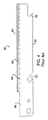
図4は、ナイフ20を単独で示しており、ナイフ20は、ナイフホルダ30から突出するピン48に係合するために、刃先54とは反対側の縁55に備わるスロット52を有する。さらに、図2および図3に示すように、ナイフ20は、上方長手方向端部に、上部サポートリング24に備わる開口部を通過して突出するハンドル56を有する。ハンドル56は、カムロッド50を回転させてクランプ31およびカムロッド50からナイフ20に付与されたクランプ力を解除した後において、ナイフ20を把持して、ナイフ20を切断ヘッド12から容易に取り外すことを可能にする。図5は、アーシェル・ラボラトリーズ,インク.が製造している遠心タイプのスライサに使用される、米国特許第5,694,824号に開示されるナイフ20の他の構成を示す。図4および図5に示したナイフハンドル56の横幅は異なっており、図4に示す幅広のハンドル56を有するナイフ20と比較すると、図5に示すナイフ20では、ナイフハンドル56についての寸法補助線62によって示される、ナイフハンドル56が存在する範囲を超えて横方向に伸長する部分60がより大きい。図4に示したナイフ20の幅広なナイフハンドル56では、より容易にナイフ20を把持して、切断ヘッド12から取り外すことができる。
FIG. 4 shows the
本発明は、スライス装置用ナイフおよびナイフアセンブリと、これらを備えた遠心タイプのスライス装置を提供する。 SUMMARY OF THE INVENTION The present invention provides a knife and knife assembly for a slicing machine and a centrifugal type slicing machine equipped therewith.
本発明の一態様によれば、ナイフは、刃先と、該刃先と反対側に位置するエッジ部とを含む。前記刃先および前記エッジ部は、該ナイフの長手方向に沿って伸長し、該ナイフは、その長手方向端部にハンドルを有する。移行部が前記刃先と前記ハンドルとの間に備えられ、該移行部は、該ナイフの前記刃先と前記エッジ部との間の横幅の約2分の1の最小横幅を有する。すなわち、該ナイフのうちの前記移行部の範囲を超えて幅方向に伸長する部分の横幅は、前記刃先と前記エッジ部との間の該ナイフの横幅の約半分以下である。 According to one aspect of the invention, a knife includes a cutting edge and an edge portion opposite the cutting edge. The cutting edge and the edge extend along the length of the knife and the knife has a handle at its longitudinal end. A transition is provided between the cutting edge and the handle, the transition having a minimum lateral width of about one-half the lateral width between the cutting edge and the edge of the knife. That is, the width of the portion of the knife that extends widthwise beyond the transition is less than or equal to about half the width of the knife between the cutting edge and the edge.
本発明の別の態様によれば、上述したナイフを備える、ナイフアセンブリが提供される。 According to another aspect of the invention there is provided a knife assembly comprising a knife as described above.
本発明のさらに別の態様によれば、切断ヘッドと、上述したナイフを備え、前記切断ヘッドに取り付けられたナイフアセンブリとを備える、スライス装置が提供される。 According to yet another aspect of the invention there is provided a slicing apparatus comprising a cutting head and a knife assembly comprising a knife as described above and attached to said cutting head.
本発明のその他の特徴および効果は、以下の詳細な説明により明らかにされる。 Other features and advantages of the present invention will become apparent from the detailed description below.
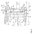
図6および図7はそれぞれ、図2および図3に示した切断ヘッド12に適用可能なナイフ120およびナイフホルダ130の非限定的な実施形態を示し、図8~図10は、ナイフ120およびナイフホルダ130が設置された切断ヘッド12を示す図である。切断ヘッド12については、図1に示したインペラ14を備える図1に示したスライス装置10を参照して説明する。したがって、以下の説明は、主に本発明の特定の特徴に焦点を当てているが、以下に詳述しないその他の特徴については、構造、機能、材料などを含めて、図1~図3を参照して説明したのと同様である。ただし、本発明は、その他のタイプの切断装置にも適用可能である。
6 and 7 show non-limiting embodiments of
以下に示す、図示された実施形態の説明を容易にするために、図1に示したスライス装置10に取り付けられたと仮定して、切断ヘッド12の方向に関して、「垂直」、「水平」、「側方」、「前」、「後」、「横」、「前方」、「後方」、「上」、「下」、「上方」、「下方」、「右」、「左」などを含むがこれらに限定されない相対的な用語が使用される。スライス装置10の切断ヘッド12およびインペラ14の同軸配置に基づき、相対的な用語には、「軸方向」、「周方向」、「径方向」などが含まれるが、これらに限定されることはない。これらと同様の語も、図示された非限定的な実施形態を説明する上で利用されうる。そのような相対的な用語はすべて、切断ヘッド12の部品および特徴の構造および相対的な方向を示すものであり、図示された実施形態を説明するために有用であるが、本発明の範囲を限定するものとして解釈されるべきではない。
To facilitate the following discussion of the illustrated embodiments, the terms "vertical", "horizontal", "vertical", "horizontal", and "vertical" are used to refer to the orientation of the cutting
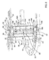
図2および図3に示すように、切断ヘッド12は略環状であり、図6および図7に示したナイフ120およびナイフホルダ130は、図8および図10の部分的な図示から明らかなように、切断ヘッド12の周囲に取り付けられる。図6および図8~図10では、ナイフ120は、食品が平らにスライスされるように直線状の刃先154を備えており、以下の説明ではフラットナイフと称する。ただし、食品をひだ状(波形)に形成したり、皮むき、細断、および粉砕したりするための他の形状の刃先を切断ヘッド12に適用することもできる。それぞれのナイフ120は、インペラ14の回転方向とは逆方向であって、径方向内方にかつインペラ14に向けて突出し、ナイフ120の径方向に関して最も内側には刃先154が設けられている。図8~図10から明らかなように、それぞれのナイフ120およびナイフホルダ130は、スライスユニット26の部材であり、切断ヘッド12の下部サポートリング22と上部サポートリング24との間にそれぞれ取り付けられ、切断ヘッド12の切断ステーションを形成する。図2および図3に示した切断ヘッド12と同様に、ナイフ120は、クランプアセンブリ28によって、スライスユニット26内にそれぞれ固定される。それぞれのナイフ120とクランプアセンブリ28が、図8に例示したようなナイフアセンブリを構成する。
As shown in FIGS. 2 and 3, the cutting
図2および図3に示した切断ヘッド12と同様に、ナイフホルダ130は、1対の取付ブロック34の間にファスナ32により取り付けられる。取付ブロック34は、ファスナ36により、サポートリング22および24に固定されている。切断ヘッド12内におけるサポートリング22および24の位置により、それぞれのスライスユニット26の取付ブロック34は、切断ヘッド12の軸方向に関して互いに離れて配置される。ファスナ36により、サポートリング22および24に取付ブロック34が強固に固定されることが好ましい。クランプアセンブリ28は、取付ブロック34の間に取り付けられたクランプ31をさらに備え、クランプ31は、ナイフ20を固定するために、ナイフホルダ130の径方向外面側に配置される(図9においては、ナイフ120が明瞭となるように、クランプアセンブリ28のクランプ31は省略されている)。クランプ31は、取付ブロック34に枢動可能に取り付けられることが好ましく、非限定的な実施形態においては、取付ブロック34をサポートリング22および24に固定するファスナ36は、クランプ31のピボットピンとしても機能するために、取付ブロック34を通過して伸長してもよい。取付ブロック34は、サポートリング22および24に備わる孔に係合するピン38を有する。サポートリング22および24に備わる孔を適切に位置させることで、取付ブロック34の向き、したがって、取付ブロック34に取り付けられたナイフ120、ナイフホルダ130、およびクランプ31の向きを変えることにより、切断ヘッド12の軸に対するナイフ120の刃先154の径方向位置を変更することができる。これにより、スライスされる食品の厚さの粗調整が可能となる。
Similar to the cutting
さらに、図8~図10は、ファスナ42により取付ブロック34に固定された調整可能なゲート40を備えたスライスユニット26を示す。食品は、ゲート40を横切ってから、スライスユニット26に取り付けられたナイフ120に接する。スライスされる食品の厚さの微調整を可能とするために、取付ブロック34は、ゲート40と係合する調節ねじ44を備え、調節ねじ44により、後続するナイフ120の刃先154に対するゲート40の後縁46の径方向位置を変更することが可能となっている。
8-10 further illustrate slicing
図8に示すように、ナイフ120は、ナイフホルダ130の径方向外面130Aに支持され、クランプ31は、ナイフホルダ130上にあるため、ナイフ120は、ナイフホルダ130の外面130Aと、ナイフホルダ130と向き合うクランプ31の径方向内面との間に位置する。ナイフ120、ナイフホルダ130、およびクランプ31の位置合わせは、ナイフホルダ130からナイフ120(図9)の相補スロット152およびクランプ31の孔に突出するピン48により達成される。クランプ31に対してナイフホルダ130の方向に向けて力を加えることにより、クランプ31は、ナイフ120のうちの刃先154に隣接する部分にクランプ力を付与し、ナイフホルダ130の外面130Aにナイフ120を挟持する。図2および図3に示した切断ヘッド12と同様に、偏心カムロッド50が備えられ、偏心カムロッド50は、クランプ31にクランプ力を付与するためのクイック・クランプ機能を有する。しかしながら、ナイフ120をナイフホルダ130に挟持または固定させる手段としては、ファスナなどの他の手段を用いることもできる。
As shown in FIG. 8, the
図2、図3、および図8~図10に示した実施形態のカムロッド50は、取付ブロック34の孔を通過し、クランプ31の反対側端部に位置する直立フランジ21B(図8)の相補孔を通過し、ファスナ36により構成されるクランプ31の枢動軸とともに、クランプ31を取付ブロック34に緩く組み付けている。カムロッド50は、ナイフ120を固定するクランプ位置と、ナイフ120を解除するリリース位置との間で回転される際にクランプ31の外面31Aと係合または係合解除するカム部50Aを備える。図8は、クランプ位置を示す。カム部50Aがクランプ31と係合する状態から、カムロッド50を図8の上方から見た場合の反時計回りに回転させることにより、カム部50Aが偏心的に移動して、クランプ31と係合から外れ、クランプ31からナイフ120に付与されたクランプ力は解除される。
2, 3, and 8-10 pass through holes in mounting
図示の実施形態においては、カムロッド50は、その両端部を取付ブロック34に形成された孔に挿入することにより、スライスユニット26の取付ブロック34に回転可能に取り付けられる。カムロッド50の両端部は、好ましくは同軸であり、両端部間にあるカム部50Aは、両端部と、両端部が挿入される孔とに対して偏心している。換言すると、カム部50Aの軸は、カムロッド50の両端部とは平行であるが、同軸ではない。カムロッド50は、前述したクランプ位置およびリリース位置の間において孔内で回転可能である。手動による回転を容易化するために、カムロッド50の一端にハンドル58が備えられている。図示の実施形態においては、ハンドル58は、図8~図10に示すように、上部サポートリング24の上方に位置するように、カムロッド50に取り付けられている。
In the illustrated embodiment,
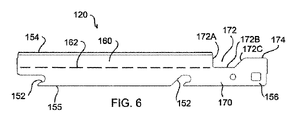
図6は、刃先154とは反対側に配置されたエッジ部155を有するナイフ120を示す。刃先154およびエッジ部155は、ナイフ120の長手方向に沿って伸長する。図6および図8~図10に示したナイフ120は、長手方向端部の一方にハンドル156を有し、ハンドル156は、上部サポートリング24の開口部57を通過して突出するサイズおよび形状を有する。ハンドル156は、ナイフ120のエッジ部155と、ハンドル156に形成され、刃先154およびエッジ部155に対して略平行である第3エッジ部174との間で測定される横幅を有する。ハンドル156によって、ナイフ120を把持することができ、カムロッド50を回転させることにより、クランプ31からナイフ120に付与されたクランプ力を解除した後において、切断ヘッド12からナイフ120を取り外すことが容易となる。ナイフ120を単独で示す図6から明らかなように、ナイフ120の構成は、図4および図5に示した従来のナイフの構成とは異なっている。ナイフ120の刃先154とエッジ部155との間におけるナイフ120の横幅に対する、ナイフハンドル156の横幅は、図4に示したナイフ20のハンドル56の横幅と同様である。したがって、ナイフハンドル156は、図5に示したナイフ20よりも容易にナイフ120を把持し、切断ヘッド12から取り外すことを可能とする十分な横幅を有する。しかしながら、ナイフ120は、ナイフハンドル156と、ナイフ120の残部、すなわち刃先154とエッジ部155との間にある部分との間に、幅の狭い移行部170をさらに有する。移行部170の最小横幅は、ナイフ120の刃先154とエッジ部155との間の横幅の約2分の1であるか、あるいは、これよりもわずかに大きい。このため、移行部170の寸法補助線162で視覚化されている、移行部170が存在する範囲を超えて横方向に伸長するナイフ120の部分160の横幅は、ナイフ120の刃先154とエッジ部155との間の横幅の約半分であるか、あるいは、これよりも僅かに小さい。ナイフ120の狭い移行部170により、クランプ31によって付与されたクランプ力は、主にハンドル156が存在する範囲を超えて伸長するナイフ120の部分160との接触を通して付与される。この際、ハンドル156によってナイフ120にもたらされる追加的な剛性は、ナイフホルダ130とクランプ31との間におけるナイフ120の屈曲性に影響を与えない。したがって、ナイフ120は、ナイフホルダ130の径方向外面130Aとより完全かつ均一に係合することができる。その結果、ナイフ120とナイフホルダ130の外面130Aとの間に存在し得る間隙を消滅させる、あるいは、大幅に低減させることができ、切断ヘッド12の衛生的な操作がより促進される。
FIG. 6 shows a
図6は、刃先154とは反対側に配置されたエッジ部155を有するナイフ120を示す。刃先154およびエッジ部155は、ナイフ120の長手方向に沿って伸長する。図6および図8~図10に示したナイフ120は、長手方向端部の一方にハンドル156を有し、ハンドル156は、上部サポートリング24の開口部57を通過して突出するサイズおよび形状を有する。ハンドル156は、ナイフ120のエッジ部155と、ハンドル156に形成され、刃先154およびエッジ部155に対して略平行である第3エッジ部174との間で測定される横幅を有する。ハンドル156によって、ナイフ120を把持することができ、カムロッド50を回転させることにより、クランプ31からナイフ120に付与されたクランプ力を解除した後において、切断ヘッド12からナイフ120を取り外すことが容易となる。ナイフ120を単独で示す図6から明らかなように、ナイフ120の構成は、図4および図5に示した従来のナイフの構成とは異なっている。ナイフ120の刃先154とエッジ部155との間におけるナイフ120の横幅に対する、ナイフハンドル156の横幅は、図4に示したナイフ20のハンドル56の横幅と同様である。したがって、ナイフハンドル156は、図5に示したナイフ20よりも容易にナイフ120を把持し、切断ヘッド12から取り外すことを可能とする十分な横幅を有する。しかしながら、ナイフ120は、ナイフハンドル156と、ナイフ120の残部、すなわち刃先154とエッジ部155との間にある部分との間に、幅の狭い移行部170をさらに有する。移行部170の最小横幅は、ナイフ120の刃先154とエッジ部155との間の横幅よりわずかに大きい場合を含み、刃先154とエッジ部155との間の横幅の約2分の1である。このため、移行部170の寸法補助線162で視覚化されている、移行部170が存在する範囲を超えて横方向に伸長するナイフ120の部分160の横幅は、ナイフ120の刃先154とエッジ部155との間の横幅よりわずかに小さい場合を含み、刃先154とエッジ部155との間の横幅の約半分である。ナイフ120の狭い移行部170により、クランプ31によって付与されたクランプ力は、主にハンドル156が存在する範囲を超えて伸長するナイフ120の部分160との接触を通して付与される。この際、ハンドル156によってナイフ120にもたらされる追加的な剛性は、ナイフホルダ130とクランプ31との間におけるナイフ120の屈曲性に影響を与えない。したがって、ナイフ120は、ナイフホルダ130の径方向外面130Aとより完全かつ均一に係合することができる。その結果、ナイフ120とナイフホルダ130の外面130Aとの間に存在し得る間隙を消滅させる、あるいは、大幅に低減させることができ、切断ヘッド12の衛生的な操作がより促進される。
FIG. 6 shows a
図6に示すように、移行部170は、刃先154とハンドル156の第3エッジ部174との間に凹部172を設けることにより形成されるため、刃先154に並置される。凹部172は、刃先154に隣接し、刃先154に対してほぼ垂直である横方向縁172Aと、該横方向縁172Aに隣接し、刃先154およびエッジ部155とほぼ平行である長手方向縁172Bと、移行部170の長手方向縁172Bと、ハンドル156の第3エッジ部174とに隣接する移行縁172Cとによって構成される。移行縁172Cは、刃先154、エッジ部155、および第3エッジ部174に対して平行でも垂直でもないため、移行部170の横幅は、長手方向縁172Bとエッジ部155との間の最小横幅からハンドル156の第3エッジ部174に向かうにつれて徐々に増加する。このため、刃先154とハンドル156との間に移行部170が存在することによって鋭いコーナー部が形成されることはない。図示の例においては、凹部172と、凹部172を形成する縁172A、172B、および172Cの形状を直線的に示したが、凹部172を形成する縁172A、172B、および172Cのいずれかまたはすべてが曲線状である形状を採用することもできる。
As shown in FIG. 6, the
以上のように、本発明について、特定の実施形態に関して説明を行ったが、本発明の代替態様についても、当業者によって適用可能であることは明らかである。たとえば、スライス装置10、切断ヘッド12、インペラ14、スライスユニット26、およびこれらの部品は、図示の態様および構造とは異なっていてもよく、特定の部品の機能は、異なる構造を有するが機能が類似する(必ずしも同等でなくてもよい)部品により達成されてもよく、スライス装置10、切断ヘッド12、インペラ14、スライスユニット26、およびこれらの部品を加工するためには、さまざまな材料を採用することができる。したがって、上述した詳細な説明は、図示された特定の実施形態、並びに、これに関するが必須ではない機能および特徴を記述することを意図しており、上記特定の実施形態、並びに、その機能および特徴の必須ではない代替構成は同じものと解釈される。非限定的な例として、本発明は、開示された実施形態の1つ以上の機能または特徴を有していない、追加的または代替的な実施形態を包含し、あるいは、異なる実施形態の特定の特徴を組み合わせることができる。したがって、本発明は、本明細書に記述された実施形態または図示された実施形態に限定されない。また、図示した実施形態を説明する目的で本明細書において使用した語法および用語は、本発明の範囲を限定するものではない。したがって、本発明の範囲は本願の特許請求の範囲のみによって限定される。
While the invention has been described with respect to specific embodiments, it should be apparent to those skilled in the art that alternative aspects of the invention are also applicable. For example, the slicing
10 スライス装置
12 切断ヘッド
14 インペラ
20、120 ナイフ
22 下部サポートリング
24 上部サポートリング
26 スライスユニット
28 クランプアセンブリ
30、130 ナイフホルダ
31 クランプ
34 取付ブロック
36 ファスナ
40 ゲート
42 ファスナ
44 調節ねじ
46 後縁
48 ピン
50 カムロッド
54、154 刃先
58 ハンドル
155 エッジ部
156 ハンドル
164 先端縁
168 凹部
170 移行部
172 凹部
174 第3エッジ部
10
Claims (16)
前記刃先とは反対側に配置され、前記長手方向に沿って伸長するエッジ部と、
前記長手方向の端部に備えられ、前記エッジ部と第3エッジ部とにより画定される横幅を有するハンドルと、および、
前記刃先と前記ハンドルとの間に備えられた移行部と、
を備えたナイフであって、
前記移行部は凹部を設けることで構成されており、該凹部は、前記エッジ部とは反対側で、前記刃先と前記第3エッジ部との間に配置され、かつ、前記刃先に隣接するように設けられており、
前記移行部の最小横幅は、該ナイフの前記刃先と前記エッジ部との間の横幅の約2分の1であり、該ナイフのうちの前記移行部の範囲を超えて横方向に伸長する部分の横幅は、該ナイフの前記刃先と前記エッジ部との間の横幅の約半分であり、
前記凹部は、前記刃先に隣接し、前記刃先に対して略垂直である横方向縁と、前記横方向縁に隣接し、前記刃先および前記エッジ部に対して略平行である直線状の長手方向縁と、前記長手方向縁と、前記ハンドルの前記第3エッジ部とに隣接する移行縁とによって構成されており、および、
前記移行縁は、前記刃先、前記エッジ部、または前記第3エッジ部に対して平行でも垂直でもなく、前記移行部の横幅が、前記長手方向縁と前記エッジ部との間の最小幅から前記ハンドルの前記第3エッジ部に向けて大きくなっている、
ナイフ。 a cutting edge extending along the longitudinal direction;
an edge portion disposed on the side opposite to the cutting edge and extending along the longitudinal direction;
a handle provided at the longitudinal end and having a lateral width defined by the edge and a third edge ; and
a transition provided between the cutting edge and the handle;
a knife comprising
The transition portion is configured by providing a recess, which is located on the side opposite the edge portion, between the cutting edge and the third edge portion and adjacent to the cutting edge. is provided in
The minimum lateral width of the transition is about one-half of the lateral width between the cutting edge and the edge of the knife, the portion of the knife extending laterally beyond the transition. is about half the width between the cutting edge and the edge of the knife ,
The recess has a lateral edge adjacent to the cutting edge and substantially perpendicular to the cutting edge, and a linear longitudinal edge adjacent to the lateral edge and substantially parallel to the cutting edge and the edge portion. an edge, said longitudinal edge and a transition edge adjacent said third edge portion of said handle; and
The transition edge is neither parallel nor perpendicular to the cutting edge, the edge portion, or the third edge portion, and the lateral width of the transition portion is from the minimum width between the longitudinal edge and the edge portion to the increasing toward the third edge of the handle;
knife.
該ナイフアセンブリは、クランプアセンブリを有し、
該クランプアセンブリは、
外面を有するナイフホルダと、
前記ナイフホルダの前記外面に前記ナイフを固定するために前記ナイフにクランプ力を付与するクランプと、
を備える、
ナイフアセンブリ。 A knife assembly comprising the knife of claim 1, comprising:
the knife assembly has a clamp assembly;
The clamp assembly includes
a knife holder having an outer surface;
a clamp for applying a clamping force to the knife to secure the knife to the outer surface of the knife holder;
comprising a
knife assembly.
前記ナイフアセンブリは、ナイフと、ナイフホルダと、クランプとを備え、
前記ナイフは、長手方向に沿って伸長する刃先と、
前記刃先とは反対側に配置され、前記長手方向に沿って伸長するエッジ部と
前記長手方向の端部に備えられ、前記エッジ部と第3エッジ部とにより画定される横幅を有するハンドルと、および、
前記刃先と前記ハンドルとの間に備えられた移行部と、を備え、
前記移行部は凹部を設けることで構成されており、該凹部は、前記エッジ部とは反対側で、前記刃先と前記第3エッジ部との間に配置され、かつ、前記刃先に隣接するように設けられており、
前記移行部の最小横幅は、該ナイフの前記刃先と前記エッジ部との間の横幅の約2分の1であり、該ナイフのうちの前記移行部の範囲を超えて横方向に伸長する部分の横幅は、該ナイフの前記刃先と前記エッジ部との間の横幅の約半分であり、
前記凹部は、前記刃先に隣接し、前記刃先に対して略垂直である横方向縁と、前記横方向縁に隣接し、前記刃先および前記エッジ部に対して略平行である直線状の長手方向縁と、前記長手方向縁と、前記ハンドルの前記第3エッジ部とに隣接する移行縁とによって構成されており、および、
前記移行縁は、前記刃先、前記エッジ部、または前記第3エッジ部に対して平行でも垂直でもなく、前記移行部の横幅が、前記長手方向縁と前記エッジ部との間の最小幅から前記ハンドルの前記第3エッジ部に向けて大きくなっており、
前記ナイフホルダは外面を有し、および、
前記クランプは、前記ナイフにクランプ力を付与して、該ナイフを前記ナイフホルダの前記外面に固定する、
スライス装置。 A slicing device comprising a cutting head and a knife assembly attached to the cutting head, comprising:
the knife assembly comprises a knife, a knife holder and a clamp;
The knife has a cutting edge extending along the longitudinal direction;
a handle located opposite the cutting edge and extending along the longitudinal direction; a handle provided at the longitudinal end and having a lateral width defined by the edge and a third edge ; and,
a transition provided between the cutting edge and the handle;
The transition portion is configured by providing a recess, which is located on the side opposite the edge portion, between the cutting edge and the third edge portion and adjacent to the cutting edge. is provided in
The minimum lateral width of the transition is about one-half of the lateral width between the cutting edge and the edge of the knife, the portion of the knife extending laterally beyond the transition. is about half the width between the cutting edge and the edge of the knife,
The recess has a lateral edge adjacent to the cutting edge and substantially perpendicular to the cutting edge, and a linear longitudinal edge adjacent to the lateral edge and substantially parallel to the cutting edge and the edge portion. an edge, said longitudinal edge and a transition edge adjacent said third edge portion of said handle; and
The transition edge is neither parallel nor perpendicular to the cutting edge, the edge portion, or the third edge portion, and the lateral width of the transition portion is from the minimum width between the longitudinal edge and the edge portion to the increasing toward the third edge of the handle,
the knife holder has an outer surface, and
the clamp applies a clamping force to the knife to secure the knife to the outer surface of the knife holder;
slicing device.
Applications Claiming Priority (3)
| Application Number | Priority Date | Filing Date | Title |
|---|---|---|---|
| US201862682386P | 2018-06-08 | 2018-06-08 | |
| US62/682,386 | 2018-06-08 | ||
| PCT/US2019/036330 WO2019237111A1 (en) | 2018-06-08 | 2019-06-10 | Knives and knife assemblies for slicing machines and slicing machines equipped therewith |
Publications (2)
| Publication Number | Publication Date |
|---|---|
| JP2021525658A JP2021525658A (en) | 2021-09-27 |
| JP7142110B2 true JP7142110B2 (en) | 2022-09-26 |
Family
ID=68765394
Family Applications (1)
| Application Number | Title | Priority Date | Filing Date |
|---|---|---|---|
| JP2020566943A Active JP7142110B2 (en) | 2018-06-08 | 2019-06-10 | Knife and knife assembly for slicing device, and slicing device provided with the same |
Country Status (6)
| Country | Link |
|---|---|
| US (1) | US10933552B2 (en) |
| EP (1) | EP3802028A4 (en) |
| JP (1) | JP7142110B2 (en) |
| CA (1) | CA3101655C (en) |
| MX (1) | MX2020013118A (en) |
| WO (1) | WO2019237111A1 (en) |
Families Citing this family (3)
| Publication number | Priority date | Publication date | Assignee | Title |
|---|---|---|---|---|
| EP4223467A3 (en) | 2017-10-02 | 2023-08-16 | Fam | Cutting head for a centrifugal cutting apparatus and centrifugal cutting apparatus equipped with same |
| US20220332004A1 (en) * | 2021-04-20 | 2022-10-20 | Urschel Laboratories, Inc. | Knife assemblies of slicing machines, methods of clamping and releasing knives therefrom, and slicing machines equipped therewith |
| AU2022292660A1 (en) * | 2021-06-16 | 2023-11-30 | Urschel Laboratories, Inc. | Clamping assemblies for securing knives to slicing machines, slicing machines equipped therewith, and tools for use therewith |
Citations (3)
| Publication number | Priority date | Publication date | Assignee | Title |
|---|---|---|---|---|
| JP2006076166A (en) | 2004-09-10 | 2006-03-23 | Toshiba Corp | Cutform issuing device |
| US20130125404A1 (en) | 2011-11-18 | 2013-05-23 | Alex NIKAS | Trimmer and double acting blade assemblies for trimmers |
| US20150174777A1 (en) | 2013-12-10 | 2015-06-25 | Urschel Laboratories, Inc. | Double-edged knife for food cutting apparatus |
Family Cites Families (22)
| Publication number | Priority date | Publication date | Assignee | Title |
|---|---|---|---|---|
| US1477488A (en) * | 1922-09-18 | 1923-12-11 | Holland Charles John | Knife sharpener |
| US3139129A (en) | 1959-06-29 | 1964-06-30 | Joe R Urschel | Method of slicing a food product |
| US3139128A (en) | 1963-02-14 | 1964-06-30 | Joe R Urschel | Machine for slicing a food product |
| JPS60127821U (en) * | 1984-02-06 | 1985-08-28 | ホリゾン・インタ−ナシヨナル株式会社 | Cutting blade attachment device |
| US5694824A (en) | 1994-04-18 | 1997-12-09 | Urschel Laboratories Incorporated | Cutting head for slicing a food product |
| WO1996001148A1 (en) * | 1994-07-06 | 1996-01-18 | Urschel Laboratories, Inc. | Knife for a food slicing apparatus |
| US5479711A (en) * | 1995-04-06 | 1996-01-02 | S-B Power Tool Company | Orbital and adjustable cant mechanism for reciprocating saws |
| WO2004106015A2 (en) | 2003-05-29 | 2004-12-09 | Urschel Laboratories, Inc. | Cutting head for cutting a food product |
| US7152327B2 (en) * | 2004-08-05 | 2006-12-26 | Rudisill Kent W | Side folding knife |
| TWM284510U (en) * | 2005-08-30 | 2006-01-01 | K & W Tools Co Ltd | Cutter with changeable blade |
| US20070169351A1 (en) * | 2006-01-25 | 2007-07-26 | Mentor Group Llc | Folding tool with lockback mechanism |
| US7658133B2 (en) | 2006-04-18 | 2010-02-09 | Urschel Laboratories, Inc. | Apparatus for cutting food product |
| US8161856B2 (en) | 2006-04-18 | 2012-04-24 | Urschel Laboratories, Inc. | Apparatus for cutting food product |
| US8850709B2 (en) * | 2011-11-18 | 2014-10-07 | Alex NIKAS | Trimmer and double acting blade assemblies for trimmers |
| US9517572B2 (en) | 2011-12-27 | 2016-12-13 | Urschel Laboratories, Inc. | Apparatuses for cutting food products |
| PT3243613T (en) | 2012-04-23 | 2021-12-28 | Urschel Laboratories Inc | Methods and equipment for cutting food products |
| US8714068B2 (en) | 2012-09-28 | 2014-05-06 | Frito-Lay North America, Inc. | Tailored slicing |
| US9193086B2 (en) | 2013-04-02 | 2015-11-24 | Urschel Laboratories, Inc. | Apparatus for cutting food products |
| US20150224664A1 (en) * | 2014-02-13 | 2015-08-13 | Glassline Corporation | Cutter assembly |
| US10456943B2 (en) | 2014-12-03 | 2019-10-29 | Urschel Laboratories, Inc. | Machines and methods for cutting products and impellers therefor |
| EP3307499B1 (en) | 2015-06-12 | 2022-10-05 | Urschel Laboratories, Inc. | Machines and methods for cutting products |
| KR101861518B1 (en) * | 2016-08-08 | 2018-05-28 | 임정빈 | Blade for cutting sandwich panel |
-
2019
- 2019-06-10 CA CA3101655A patent/CA3101655C/en active Active
- 2019-06-10 WO PCT/US2019/036330 patent/WO2019237111A1/en unknown
- 2019-06-10 US US16/436,068 patent/US10933552B2/en active Active
- 2019-06-10 JP JP2020566943A patent/JP7142110B2/en active Active
- 2019-06-10 EP EP19814872.8A patent/EP3802028A4/en active Pending
- 2019-06-10 MX MX2020013118A patent/MX2020013118A/en unknown
Patent Citations (3)
| Publication number | Priority date | Publication date | Assignee | Title |
|---|---|---|---|---|
| JP2006076166A (en) | 2004-09-10 | 2006-03-23 | Toshiba Corp | Cutform issuing device |
| US20130125404A1 (en) | 2011-11-18 | 2013-05-23 | Alex NIKAS | Trimmer and double acting blade assemblies for trimmers |
| US20150174777A1 (en) | 2013-12-10 | 2015-06-25 | Urschel Laboratories, Inc. | Double-edged knife for food cutting apparatus |
Also Published As
| Publication number | Publication date |
|---|---|
| CA3101655A1 (en) | 2019-12-12 |
| EP3802028A4 (en) | 2022-03-23 |
| WO2019237111A1 (en) | 2019-12-12 |
| US10933552B2 (en) | 2021-03-02 |
| EP3802028A1 (en) | 2021-04-14 |
| US20190375126A1 (en) | 2019-12-12 |
| JP2021525658A (en) | 2021-09-27 |
| MX2020013118A (en) | 2021-02-18 |
| CA3101655C (en) | 2023-04-18 |
Similar Documents
| Publication | Publication Date | Title |
|---|---|---|
| US10780602B2 (en) | Clamping assemblies and slicing machines equipped therewith | |
| JP6811332B2 (en) | Module unit, clamp assembly, and slicing device with these | |
| JP7142110B2 (en) | Knife and knife assembly for slicing device, and slicing device provided with the same | |
| US9193086B2 (en) | Apparatus for cutting food products | |
| US10786922B2 (en) | Modular units, clamping assemblies, and slicing machines equipped therewith | |
| EP3538331B1 (en) | Knife assembly for slicing machines and machines equipped therewith | |
| AU2014363915B2 (en) | Double-edged knife for food cutting apparatus | |
| JP2022521139A (en) | Blade replacement tool and how to use it |
Legal Events
| Date | Code | Title | Description |
|---|---|---|---|
| A621 | Written request for application examination |
Free format text: JAPANESE INTERMEDIATE CODE: A621 Effective date: 20210129 |
|
| A977 | Report on retrieval |
Free format text: JAPANESE INTERMEDIATE CODE: A971007 Effective date: 20220224 |
|
| A131 | Notification of reasons for refusal |
Free format text: JAPANESE INTERMEDIATE CODE: A131 Effective date: 20220308 |
|
| A521 | Request for written amendment filed |
Free format text: JAPANESE INTERMEDIATE CODE: A523 Effective date: 20220607 |
|
| TRDD | Decision of grant or rejection written | ||
| A01 | Written decision to grant a patent or to grant a registration (utility model) |
Free format text: JAPANESE INTERMEDIATE CODE: A01 Effective date: 20220906 |
|
| A61 | First payment of annual fees (during grant procedure) |
Free format text: JAPANESE INTERMEDIATE CODE: A61 Effective date: 20220912 |
|
| R150 | Certificate of patent or registration of utility model |
Ref document number: 7142110 Country of ref document: JP Free format text: JAPANESE INTERMEDIATE CODE: R150 |