JP7141069B2 - METAL ACCESSORY HAVING NON-CONTACT NEAR-RANGE WIRELESS COMMUNICATION FUNCTION AND MANUFACTURING METHOD THEREOF - Google Patents
METAL ACCESSORY HAVING NON-CONTACT NEAR-RANGE WIRELESS COMMUNICATION FUNCTION AND MANUFACTURING METHOD THEREOF Download PDFInfo
- Publication number
- JP7141069B2 JP7141069B2 JP2021503137A JP2021503137A JP7141069B2 JP 7141069 B2 JP7141069 B2 JP 7141069B2 JP 2021503137 A JP2021503137 A JP 2021503137A JP 2021503137 A JP2021503137 A JP 2021503137A JP 7141069 B2 JP7141069 B2 JP 7141069B2
- Authority
- JP
- Japan
- Prior art keywords
- slit
- integrated circuit
- loop antenna
- circuit element
- control integrated
- Prior art date
- Legal status (The legal status is an assumption and is not a legal conclusion. Google has not performed a legal analysis and makes no representation as to the accuracy of the status listed.)
- Active
Links
Images


Classifications
-
- H—ELECTRICITY
- H01—ELECTRIC ELEMENTS
- H01Q—ANTENNAS, i.e. RADIO AERIALS
- H01Q1/00—Details of, or arrangements associated with, antennas
- H01Q1/27—Adaptation for use in or on movable bodies
- H01Q1/273—Adaptation for carrying or wearing by persons or animals
-
- A—HUMAN NECESSITIES
- A44—HABERDASHERY; JEWELLERY
- A44C—PERSONAL ADORNMENTS, e.g. JEWELLERY; COINS
- A44C25/00—Miscellaneous fancy ware for personal wear, e.g. pendants, crosses, crucifixes, charms
-
- H—ELECTRICITY
- H01—ELECTRIC ELEMENTS
- H01Q—ANTENNAS, i.e. RADIO AERIALS
- H01Q7/00—Loop antennas with a substantially uniform current distribution around the loop and having a directional radiation pattern in a plane perpendicular to the plane of the loop
-
- H—ELECTRICITY
- H01—ELECTRIC ELEMENTS
- H01Q—ANTENNAS, i.e. RADIO AERIALS
- H01Q7/00—Loop antennas with a substantially uniform current distribution around the loop and having a directional radiation pattern in a plane perpendicular to the plane of the loop
- H01Q7/04—Screened antennas
-
- H—ELECTRICITY
- H04—ELECTRIC COMMUNICATION TECHNIQUE
- H04B—TRANSMISSION
- H04B5/00—Near-field transmission systems, e.g. inductive or capacitive transmission systems
- H04B5/20—Near-field transmission systems, e.g. inductive or capacitive transmission systems characterised by the transmission technique; characterised by the transmission medium
- H04B5/24—Inductive coupling
- H04B5/26—Inductive coupling using coils
-
- H—ELECTRICITY
- H04—ELECTRIC COMMUNICATION TECHNIQUE
- H04W—WIRELESS COMMUNICATION NETWORKS
- H04W4/00—Services specially adapted for wireless communication networks; Facilities therefor
- H04W4/80—Services using short range communication, e.g. near-field communication [NFC], radio-frequency identification [RFID] or low energy communication
-
- A—HUMAN NECESSITIES
- A44—HABERDASHERY; JEWELLERY
- A44C—PERSONAL ADORNMENTS, e.g. JEWELLERY; COINS
- A44C25/00—Miscellaneous fancy ware for personal wear, e.g. pendants, crosses, crucifixes, charms
- A44C25/001—Pendants
-
- A—HUMAN NECESSITIES
- A44—HABERDASHERY; JEWELLERY
- A44C—PERSONAL ADORNMENTS, e.g. JEWELLERY; COINS
- A44C27/00—Making jewellery or other personal adornments
- A44C27/001—Materials for manufacturing jewellery
- A44C27/002—Metallic materials
-
- A—HUMAN NECESSITIES
- A44—HABERDASHERY; JEWELLERY
- A44C—PERSONAL ADORNMENTS, e.g. JEWELLERY; COINS
- A44C9/00—Finger-rings
- A44C9/0053—Finger-rings having special functions
-
- H—ELECTRICITY
- H04—ELECTRIC COMMUNICATION TECHNIQUE
- H04B—TRANSMISSION
- H04B5/00—Near-field transmission systems, e.g. inductive or capacitive transmission systems
- H04B5/70—Near-field transmission systems, e.g. inductive or capacitive transmission systems specially adapted for specific purposes
Landscapes
- Engineering & Computer Science (AREA)
- Computer Networks & Wireless Communication (AREA)
- Signal Processing (AREA)
- Credit Cards Or The Like (AREA)
- Adornments (AREA)
- Details Of Aerials (AREA)
- Support Of Aerials (AREA)
Description
本発明は、非接触式近距離無線通信機能を有する金属飾り具及びその製造方法に係り、さらに詳しくは、環状を呈する金属または貴金属材質の指輪やペンダント(pendant)に制御用集積回路素子(IC chip)との非接触式近距離無線通信を可能にするループアンテナを搭載して、非接触式近距離無線通信機能を有するように構成された金属材質の飾り具及びこのような金属飾り具の製造方法に関する。 The present invention relates to a metal ornament having a non-contact short-range wireless communication function and a manufacturing method thereof. A metal ornament equipped with a loop antenna that enables non-contact short-range wireless communication with chip) and configured to have a non-contact short-range wireless communication function, and such a metal ornament It relates to a manufacturing method.
最近、クレジットカードの使用が増えつつあるだけではなく、交通カードやデビットカードなどは少額決済のためにも多用されている。このようなカードの使用形態に応じて、使い勝手がよいながらも、カードの紛失のリスクを極力抑えるための多種多様な方法が提案されている。 Recently, not only is the use of credit cards increasing, but transportation cards, debit cards, etc. are also frequently used for small amount payments. A wide variety of methods have been proposed for minimizing the risk of loss of the card while maintaining ease of use, depending on how the card is used.
このような方法の一例として、指輪状のカードが提案されている。 As an example of such a method, a ring-shaped card has been proposed.
大韓民国登録実用新案第20-0294180号は、「ICチップを組み込んだ指輪」に関するものであり、同公報には、指輪、時計などの飾り具にICチップを組み込んで、ICカードを用いたクレジットカード、交通カード、電子貨幣、駐車場カード、デパートカードなどといった多くの機能が行えるようにしたICチップを組み込んだ指輪が開示されている。前述した考案に係るICチップを組み込んだ指輪は、非接触式近距離無線通信機能を提供するICチップに接続されたループアンテナが指輪の胴体に巻回されるような構造となっている。ICチップに接続されたループアンテナは、外部の端末と非接触式近距離無線通信を行い、非接触式近距離無線通信により、ループアンテナは、誘導電流を生成してICチップに与えるだけではなく、外部の端末とのデータの送受信を行う。 Korean Registered Utility Model No. 20-0294180 relates to "a ring incorporating an IC chip", and the publication describes a credit card using an IC card by incorporating an IC chip into accessories such as rings and watches. , a transportation card, an electronic currency, a parking lot card, a department store card, etc., a ring incorporating an IC chip is disclosed that enables it to perform many functions. The finger ring incorporating the IC chip according to the invention described above has a structure in which a loop antenna connected to the IC chip that provides the non-contact short-range wireless communication function is wound around the body of the finger ring. A loop antenna connected to an IC chip performs contactless short-range wireless communication with an external terminal. , to send and receive data to and from external terminals.
しかしながら、ループアンテナが金属物質に巻回されている場合、金属物質は外部の端末から受信される信号の強さを減衰させ、その結果、ループアンテナは、誘導電流を生成できなくなるだけではなく、外部の端末とデータの送受信を行うことが困難になる。 However, if the loop antenna is wrapped around a metallic material, the metallic material will attenuate the strength of the signal received from the external terminal, so that the loop antenna not only cannot generate an induced current, It becomes difficult to transmit and receive data to and from an external terminal.
したがって、ICチップの非接触式近距離無線通信機能を円滑に行うために、前記指輪の胴体は、必ず電気が流れない電気絶縁性を有する物質からならなければならない。したがって、前述した考案に係る指輪は、電気が流れる金属材質や貴金属材質からは製作されることができず、プラスチックなどの合成樹脂、陶器などのように電気が流れない絶縁性物質から製作されなければならないという限界点を有している。 Therefore, in order to smoothly perform the non-contact near-field communication function of the IC chip, the body of the ring should be made of an electrically insulating material that does not allow electricity to flow. Therefore, the ring according to the above invention cannot be made of a metal material or precious metal material that conducts electricity, and must be made of an insulating material that does not conduct electricity, such as synthetic resin such as plastic or ceramics. There is a limit point that must be
一方、韓国登録実用新案第20-0445348号は、「交通カード」に関するものであり、同公報には、交通カードチップとループアンテナ及びキャパシターを備えるが、交通カードチップの2つの端子にループアンテナの2つの端子及びキャパシタの2つの端子が並列に接続されてなり、ループアンテナは、同心円の向きに3~5回巻回されるように形成されて環部の内部に組み込まれ、交通カードチップとキャパシターは胴体部の内部に組み込まれた交通カードが開示されている。しかしながら、前述した考案においても同様に、電磁気の遮へいにより交通カードとカード端末とが通信不能状態に陥ることを防ぐために、環部及び胴体部は合成樹脂などの絶縁性物質から成形されなければならないということが明示的に記載されている。したがって、前述した考案に係る交通カードもまた指輪の形状に製作されることはできるが、指輪の胴体が金属物質や貴金属物質からは製作できないという限界を有している。 On the other hand, Korean Registered Utility Model No. 20-0445348 relates to a "traffic card", and the publication describes a traffic card chip, a loop antenna and a capacitor. Two terminals and two terminals of a capacitor are connected in parallel, and a loop antenna is formed so as to be wound 3 to 5 times in a concentric direction and is incorporated inside the ring part, and the traffic card chip and A transportation card is disclosed in which the capacitor is embedded inside the torso. However, in the above-mentioned device as well, the ring part and the body part must be molded from an insulating material such as synthetic resin in order to prevent the traffic card and the card terminal from becoming unable to communicate due to electromagnetic shielding. is explicitly stated. Therefore, although the traffic card according to the above invention can also be made in the shape of a ring, it has a limitation that the body of the ring cannot be made of a metal material or a precious metal material.
前述した問題を解決するための本発明の目的は、非接触式近距離無線通信機能を有する金属材質または貴金属材質の金属飾り具を提供することである。 SUMMARY OF THE INVENTION It is an object of the present invention to solve the above-mentioned problems by providing a metal ornament made of metal or precious metal, which has a function of non-contact short-range wireless communication.
前述した技術的課題を達成するための本発明の第1の特徴による非接触式近距離無線通信機能を有する金属飾り具は、外部の端末と非接触式近距離無線通信が行える制御用集積回路素子(IC chip)と、両端がそれぞれ前記制御用集積回路素子の両端につながれた所定の長さのループアンテナと、金属または貴金属物質からなり、中央に貫通口が形成された環状を呈するが、環の一部の区間が切り欠かれて形成されたスリットを有する胴体部と、を備え、前記胴体部の内部に前記制御用集積回路素子及びループアンテナが搭載され、前記ループアンテナは、前記環状の胴体部に沿って数回巻回されたことを特徴とし、前記胴体部は、前記スリットにより環状の一部が完全に切り欠かれたことを特徴とする。 A metal ornament having a non-contact short-range wireless communication function according to the first aspect of the present invention for achieving the above-mentioned technical problems is a control integrated circuit capable of non-contact short-range wireless communication with an external terminal. An element (IC chip), a loop antenna of a predetermined length having both ends connected to both ends of the control integrated circuit element, and a ring made of metal or noble metal material and having a through hole formed in the center, a body having a slit formed by cutting a section of a ring, wherein the control integrated circuit element and the loop antenna are mounted inside the body, and the loop antenna is mounted on the ring is wound several times along the body of the body, and the body is characterized in that a part of the ring is completely cut out by the slit.
前述した第1の特徴による非接触式近距離無線通信機能を有する金属飾り具において、前記胴体部は、制御用集積回路素子及びループアンテナが搭載される溝が内周面または外周面に沿って形成された主ボディと、前記溝を覆う蓋体と、を備え、前記スリットは、前記主ボディ及び蓋体にそれぞれ形成されるが、主ボディのスリットと蓋体のスリットとは互いに連絡されるように構成してもよい。 In the metal ornament having a non-contact short-range wireless communication function according to the first feature described above, the body part has a groove in which a control integrated circuit element and a loop antenna are mounted along the inner or outer peripheral surface. a formed main body and a lid covering the groove, wherein the slits are respectively formed in the main body and the lid, but the slits in the main body and the slits in the lid communicate with each other It may be configured as
前述した第1の特徴による非接触式近距離無線通信機能を有する金属飾り具において、前記胴体部は、中央に貫通口が形成された環状を呈するが、環の一部の区間が切り欠かれて形成されたスリットを有する第1の胴体部と、第1の胴体部と同じ形状を呈するが、一方の面が第1の胴体部の一方の面に当接できるように構成された第2の胴体部と、を備え、前記第1の胴体部及び第2の胴体部の互いに当接する面に前記制御用集積回路素子及びループアンテナが搭載される溝が形成され、前記第1の胴体部のスリットと第2の胴体部のスリットは、互いに対応する位置に形成されるように構成してもよい。 In the metal ornament having the non-contact short-range wireless communication function according to the first feature, the body has a ring shape with a through hole formed in the center, but a part of the ring is notched. and a second body having the same shape as the first body but configured so that one surface can abut one surface of the first body. and a groove in which the control integrated circuit element and the loop antenna are mounted is formed on the surfaces of the first body and the second body that contact each other, and the first body and the slits of the second body portion may be configured to be formed at positions corresponding to each other.
前述した第1の特徴による非接触式近距離無線通信機能を有する金属飾り具において、前記制御用集積回路素子は、前記ループアンテナを介して外部の端末と非接触式近距離無線通信を行って電力を提供され、データを送受信することが好ましく、
前記制御用集積回路素子は、クレジットカード用ICチップ、決済用ICチップまたは扉施錠装置用ICチップであることがより好ましい。
In the metal ornament having a non-contact short-range wireless communication function according to the first feature, the control integrated circuit element performs non-contact short-range wireless communication with an external terminal via the loop antenna. preferably powered and transmitting and receiving data;
More preferably, the control integrated circuit element is a credit card IC chip, a payment IC chip, or a door locking device IC chip.
前述した第1の特徴による非接触式近距離無線通信機能を有する金属飾り具において、前記胴体部は、指輪の形状を呈するか、あるいは、ペンダント(pendant)状を呈することが好ましい。 In the metal ornament having the non-contact short-range wireless communication function according to the first feature, the body preferably has a ring shape or a pendant shape.
前述した第1の特徴による非接触式近距離無線通信機能を有する金属飾り具において、前記胴体部のスリットは、電気絶縁性を有する物質で充填されるか、または、電気絶縁性を有する物質から製作されるか、あるいは、表面が酸化処理されて電気絶縁性を有するように構成されたスリット充填モジュールで満たされたことが好ましい。 In the metal ornament having a non-contact short-range wireless communication function according to the first feature described above, the slit in the body is filled with an electrically insulating material, or is made of an electrically insulating material. It is preferably fabricated or filled with a slit fill module that is surface oxidized and configured to be electrically insulating.
本発明の第2の特徴による非接触式近距離無線通信機能を有する金属飾り具の製造方法は、(a)金属または貴金属物質を用いて主ボディと蓋体とから構成された胴体部を製作するが、前記胴体部は、全体的に中央に貫通口が形成された環状を呈することを特徴とするステップと、(b)前記胴体部の主ボディの内周面または外周面に沿ってループアンテナを嵌め込むための一定の深さの第1の溝を形成するステップと、(c)前記内周面または外周面に形成された第1の溝の所定の領域に制御用集積回路素子を搭載するための第2の溝を形成するステップと、(d)前記第2の溝に制御用集積回路素子を搭載し、前記第1の溝にループアンテナを数回巻いて搭載した後、制御用集積回路素子の両端とループアンテナの両端とを接着してつなぐステップと、を含む。 According to the second aspect of the present invention, there is provided a method for manufacturing a metal ornament having a non-contact short-range wireless communication function. (b) forming a loop along the inner or outer peripheral surface of the main body of the body; (c) placing a control integrated circuit element in a predetermined region of the first groove formed on the inner or outer peripheral surface; forming a second groove for mounting; (d) mounting a control integrated circuit element in the second groove; and gluing together the ends of the integrated circuit element for the antenna and the ends of the loop antenna.
前述した第2の特徴による非接触式近距離無線通信機能を有する金属飾り具の製造方法において、前記ステップ(a)は、(a1)金属物質または貴金属物質を用いて中央に貫通口が形成された環状の主ボディを製作するステップと、(a2)前記主ボディの外周面または内周面に形成されるべき第1の溝及び第2の溝を覆うべき蓋体を製作するステップと、(a3)前記主ボディの一部の区間を完全に切り欠いて第1のスリットを形成するステップと、を含む。 In the method of manufacturing a metal ornament having a non-contact short-range wireless communication function according to the second feature, the step (a) includes: (a2) manufacturing a lid body to cover a first groove and a second groove to be formed in the outer or inner peripheral surface of the main body; a3) completely notching a section of the main body to form a first slit;
前述した第2の特徴による非接触式近距離無線通信機能を有する金属飾り具の製造方法において、前記製造方法は、(a4)前記蓋体の一部の区間を完全に切り欠いて第2のスリットを形成するが、前記第2のスリットは、第1のスリットと連絡されるように形成するステップをさらに含むか、あるいは、(a5)前記蓋体を電気絶縁性を有する物質から製作したり、前記蓋体の表面を酸化処理して電気絶縁性を持たせたりするステップをさらに含むことが好ましい。 In the method of manufacturing a metal ornament having a non-contact short-range wireless communication function according to the second feature described above, the manufacturing method includes (a4) completely cutting out a portion of the lid to form a second forming a slit such that the second slit communicates with the first slit; or (a5) fabricating the lid from an electrically insulating material. Preferably, the method further includes the step of oxidizing the surface of the lid to make it electrically insulating.
前述した第2の特徴による非接触式近距離無線通信機能を有する金属飾り具の製造方法において、前記製造方法は、(a6)前記第1のスリットを電気絶縁性を有する物質で充填するステップをさらに含むか、あるいは、(a7)電気絶縁性を有する物質からスリット充填モジュールを製作したり、所定の物質からスリット充填モジュールを製作した後、電気絶縁性を有するように表面を酸化処理したりした後、前記スリット充填モジュールを第1のスリットに嵌め込むステップをさらに含むことが好ましい。 In the method of manufacturing a metal ornament having a non-contact short-range wireless communication function according to the second feature described above, the manufacturing method includes the step of (a6) filling the first slit with an electrically insulating material. Alternatively, (a7) manufacturing a slit-filled module from a material having electrical insulation, or manufacturing a slit-filled module from a predetermined material and then subjecting the surface to an oxidation treatment so as to have electrical insulation. After that, it is preferable to further include the step of fitting the slit filling module into the first slit.
本発明の第3の特徴による非接触式近距離無線通信機能を有する金属飾り具の製造方法は、(a)金属物質または貴金属物質を用いて中央に貫通口が形成された環状の第1の胴体部を製作するステップと、(b)金属または貴金属物質を用いて中央に貫通口が形成された第2の胴体部と同じ環状の第2の胴体部を製作するステップと、(c)前記第1の胴体部と第2の胴体部とが互いに当接する面にループアンテナを嵌め込むための一定の深さの第1の溝を形成するステップと、(d)前記第1の胴体部と第2の胴体部とが互いに当接する面のうちの一方の面に形成された第1の溝の所定の領域に制御用集積回路素子を搭載するための第2の溝を形成するステップと、(e)前記第2の溝と前記第1の溝にそれぞれ制御用集積回路素子及び前記制御用集積回路素子の両端につながれたループアンテナを搭載するステップと、(f)ループアンテナの搭載された面が露出されないように前記第1の胴体部と第2の胴体部の一方の面とを互いに当接するように接着するステップと、
を含み、前記第1の胴体部の一方の面と第2の胴体部の一方の面は、同じ大きさと形状を有して、互いに当接するように配置された後に接着される。
A method for manufacturing a metal ornament having a non-contact short-range wireless communication function according to a third feature of the present invention comprises: (a) a ring-shaped first ring having a through hole formed in the center using a metal substance or a precious metal substance; (b) fabricating a second body of the same annular shape as the second body with a central through hole using a metal or precious metal material; (c) (d) forming a first groove of a certain depth for fitting the loop antenna in a surface where the first body portion and the second body portion abut against each other; forming a second groove for mounting the control integrated circuit element in a predetermined region of the first groove formed in one of the surfaces with which the second body portion abuts against each other; (e) mounting a control integrated circuit element and a loop antenna connected to both ends of the control integrated circuit element in the second groove and the first groove, respectively; and (f) mounting the loop antenna. adhering one surface of the first body portion and the second body portion so as to abut against each other so that the surfaces are not exposed;
wherein one surface of the first body and one surface of the second body have the same size and shape and are adhered after being placed in contact with each other.
前述した第3の特徴による非接触式近距離無線通信機能を有する金属飾り具の製造方法において、前記ステップ(a)は、(a1)金属物質または貴金属物質を用いて中央に貫通口が形成された環状の第1の胴体部を製作するステップと、(a2)前記第1の胴体部の環の一部の区間を完全に切り欠いて第1のスリットを形成するステップと、を含み、
前記ステップ(b)は、(b1)金属物質または貴金属物質を用いて中央に貫通口が形成された環状の第2の胴体部を製作するステップと、(b2)前記第2の胴体部の環の一部の区間を完全に切り欠いて第2のスリットを形成するステップと、を含み、
前記第1のスリットと第2のスリットとは、互いに連絡されたことが好ましい。
In the method of manufacturing a metal ornament having a non-contact short-range wireless communication function according to the third feature described above, the step (a) includes (a1) forming a through hole in the center using a metal substance or a noble metal substance; (a2) completely notching a section of a ring of said first body to form a first slit;
The step (b) includes (b1) fabricating a ring-shaped second body having a through hole formed in the center using a metal material or a precious metal material; completely cutting out a portion of the section to form a second slit;
It is preferable that the first slit and the second slit are connected to each other.
前述した第3の特徴による非接触式近距離無線通信機能を有する金属飾り具の製造方法において、前記製造方法は、(a6)前記第1のスリット及び第2のスリットを電気絶縁性を有する物質で充填するステップをさらに含むか、あるいは、(a7)電気絶縁性を有する物質からスリット充填モジュールを製作したり、所定の物質からスリット充填モジュールを製作した後、電気絶縁性を有するように表面を酸化処理したりした後、前記充填モジュールを第1のスリット及び第2のスリットに嵌め込むステップをさらに含むことが好ましい。 In the method of manufacturing a metal ornament having a non-contact short-range wireless communication function according to the third feature described above, the method includes (a6) forming the first slit and the second slit with an electrically insulating material. or (a7) fabricating the slit-filled module from a material having electrical insulation properties, or fabricating the slit-filled module from a predetermined material, and then treating the surface to have electrical insulation properties. It is preferable to further include the step of fitting the filling module into the first slit and the second slit after oxidizing.
本発明に係る金属飾り具は、環状の指輪またはペンダントの形状に製作し、その内部に非接触無線通信を可能にする集積回路素子及びループアンテナを搭載することにより、非接触式のクレジットカード、交通カードなどの機能を提供することが可能になる。 The metal ornament according to the present invention is manufactured in the shape of an annular ring or pendant, and by mounting an integrated circuit element and a loop antenna that enable contactless wireless communication inside it, a contactless credit card, It becomes possible to provide functions such as a transportation card.
また、本発明に係る金属飾り具は、中央に貫通口が形成された環状の金属物質または貴金属物質から製作するが、環状の胴体に一部の領域を切り欠いたスリットを備えることにより、外形は従来の貴金属指輪などと同じでありながらも、非接触式クレジットカードまたは交通カードなどの機能を提供することが可能になる。 In addition, the metal ornament according to the present invention is made of an annular metal material or precious metal material having a through hole formed in the center. Although it is the same as a conventional precious metal ring, it is possible to provide functions such as a contactless credit card or transportation card.
本発明に係る非接触式近距離無線通信機能を有する金属飾り具は、金属または貴金属材質の環状の指輪またはペンダント(pendant)であって、胴体の内部に集積回路素子及びループアンテナが搭載されて外部の端末と非接触式近距離無線通信が行えることを特徴とする。 A metal ornament having a contactless short-range wireless communication function according to the present invention is an annular ring or pendant made of metal or precious metal, and has an integrated circuit element and a loop antenna mounted inside the body. It is characterized by being able to perform non-contact short-range wireless communication with an external terminal.
以下、添付図面に基づいて、本発明の好適な実施形態に係る非接触式近距離無線通信機能を有する金属飾り具の構造、動作及びその製造方法について詳しく説明する。 The structure, operation, and manufacturing method of the metal ornament having a non-contact short-range wireless communication function according to a preferred embodiment of the present invention will now be described in detail with reference to the accompanying drawings.
<第1の実施形態>
図1から図3に基づいて、本発明の第1の実施形態に係る非接触式近距離無線通信機能を有する金属飾り具の構造及び動作について詳しく説明する。
<First embodiment>
Based on FIGS. 1 to 3, the structure and operation of the metal ornament having a non-contact short-range wireless communication function according to the first embodiment of the present invention will be described in detail.
図1は、本発明の第1の実施形態に係る非接触式近距離無線通信機能を有する金属飾り具の一実施の形態を例示的に示す斜視図である。図2及び図3は、図1の金属飾り具の分解斜視図及び底面から見た分解斜視図である。 FIG. 1 is a perspective view exemplifying one embodiment of a metal ornament having a non-contact short-range wireless communication function according to a first embodiment of the present invention. 2 and 3 are an exploded perspective view and a bottom exploded perspective view of the metal ornament of FIG.
図1を参照すると、本実施形態に係る非接触式金属飾り具1は、指輪の形状を呈する金属飾り具であって、制御用集積回路素子100、ループアンテナ110、胴体部120及びスリット充填モジュール130を備える。
Referring to FIG. 1, the
前記制御用集積回路素子100は、外部の端末と非接触式近距離無線通信が行える集積回路素子(IC chip)であって、前記ループアンテナを介して外部の端末と非接触式近距離無線通信を行って電力を提供され、データを送受信し、送受信されたデータを用いて予め設定されたプログラムが起動され得る。前記制御用集積回路素子は、非接触方式により駆動されるクレジットカード用ICチップ、決済用ICチップまたは扉施錠装置用ICチップから構成されてもよい。前記制御用集積回路素子がカード用ICチップである場合、本発明に係る金属飾り具は、クレジットカードまたは交通カードなどの機能を行ったり、決済用カードの機能を行ったりすることができる。なお、前記制御用集積回路素子が扉施錠装置用ICチップである場合、本発明に係る金属飾り具は、扉施錠装置の携帯型鍵としての機能を行うことができる。
The control integrated
前記ループアンテナ110は、両端がそれぞれ前記制御用集積回路素子の両端に接着されてつながれた所定の長さのアンテナであって、前記制御用集積回路素子とともに前記胴体部の内部に搭載される。前記ループアンテナ110は、前記環状の胴体部に沿って数回巻回されて構成されることが好ましい。
The
外部の端末との円滑なデータの送受信に求められる信号の強さを得るために、前記ループアンテナは、全体的に約700mm以上の長さからなることが好ましい。 In order to obtain signal strength required for smooth data transmission/reception with an external terminal, it is preferable that the loop antenna has a length of about 700 mm or more as a whole.
前記胴体部120は、金属または貴金属物質からなる主ボディ121と蓋体122とから構成され、前記胴体部120は、全体的には、中央に貫通口'a'が形成された環状を呈する。
The
前記胴体部の主ボディは、内周面または外周面に沿って前記制御用集積回路素子及びループアンテナが搭載されるための第2の溝及び第1の溝を備える。前記ループアンテナ110は、数回巻回されて前記環状の胴体部の主ボディ121の第1の溝に搭載される。前記制御用集積回路素子は、前記主ボディ121の第2の溝に搭載され、前記ループアンテナの両端は、前記制御用集積回路素子に接着されてつなぎ合わせられる。
The main body of the torso section has a second groove and a first groove for mounting the control integrated circuit element and the loop antenna along an inner or outer peripheral surface. The
前記蓋体122は、前記主ボディ121の第1の溝及び第2の溝に嵌合されるように構成される。前記蓋体は、図1に示すように、複数の部品に分けられて製作されてもよく、単一の形状に製作されてもよい。
The
前記胴体部の主ボディ121は、金属または貴金属物質から構成されるが、銀、金、白金、銀、銅などの貴金属物質または電気伝導性を有する金属物質の一つからなってもよい。なお、前記胴体部の主ボディ121は、環の一部の領域が完全に切り欠かれて形成された第1のスリットS1を備えなければならない。
The
一方、前記主ボディの第1のスリットS1は、電気絶縁性を有する物質、例えば、合成樹脂などで充填されて、あるいは、第1のスリットに対応する形状の第1のスリット充填モジュール131が嵌め込まれて、前記第1のスリットが見かけ上には表示されないようにするとともに、胴体部に搭載されたループアンテナが外部に露出されないようにしてもよい。前記第1のスリット充填モジュール131は、電気絶縁性を有する物質から製作されてもよく、あるいは、金属などの物質から製作された後、表面を酸化処理して表面が電気絶縁性を有するように構成してもよい。
On the other hand, the first slit S1 of the main body is filled with an electrically insulating material such as synthetic resin, or is fitted with a first
前記蓋体122は、電気絶縁性を有する物質から製作されてもよく、あるいは、主ボディと同じ物質から製作されてもよい。前記蓋体が金属または貴金属のように主ボディと同じ物質から製作される場合、前記蓋体は、環状の一部の区間が完全に切り欠かれて形成された第2のスリットを備えなければならず、前記第2のスリットは、前記主ボディの第1のスリットと連絡されなければならない。
The
一方、前記蓋体の第2のスリットは、電気絶縁性を有する物質、例えば、合成樹脂などで充填されて、あるいは、第2のスリットに対応する形状の第2のスリット充填モジュール132が嵌め込まれて、前記第2のスリットが見かけ上には表示されないようにするとともに、胴体部に搭載されたループアンテナが外部に露出されないようにしてもよい。前記第2のスリット充填モジュール132は、電気絶縁性を有する物質から製作されてもよく、あるいは、金属などの物質から製作された後に表面を酸化処理して表面が電気絶縁性を有するように構成してもよい。
On the other hand, the second slit of the lid is filled with an electrically insulating material such as synthetic resin, or a second
スリット充填モジュール130は、前述したように、第1のスリット充填モジュール131と第2のスリット充填モジュール132とから構成され、スリット充填モジュールにより胴体部のスリットが電気絶縁性を有する物質で満たされる。
The
このように、金属物質または貴金属物質からなる胴体部の主ボディ及び蓋体に第1のスリット及び第2のスリットを形成することにより、ループアンテナが外部の端末による誘導電流を生じさせて制御用集積回路素子を駆動することができ、制御用集積回路素子がループアンテナを介して外部の端末とデータを送受信することが可能になる。 In this way, by forming the first slit and the second slit in the main body and lid made of metal or precious metal, the loop antenna generates an induced current from an external terminal and is used for control. The integrated circuit element can be driven, and the control integrated circuit element can transmit and receive data to and from an external terminal via the loop antenna.
前記第1のスリット及び第2のスリットは、単一の直線状に形成されてもよく、少なくとも一つ以上の折曲げ部を有するように構成してもよい。前記第1及び第2のスリットを折曲げ部を有するように構成することにより、胴体部の剛性を向上させることが可能になる。 The first slit and the second slit may be formed in a single straight line, or may be configured to have at least one or more bent portions. By configuring the first and second slits to have bent portions, it is possible to improve the rigidity of the body portion.
前記胴体部は、図1に示すように、指輪の形状を呈して、本発明に係る金属飾り具は、指輪型カードまたは指輪型扉施錠装置用鍵として使用可能になる。 As shown in FIG. 1, the body part has the shape of a ring, and the metal ornament according to the present invention can be used as a ring-shaped card or a ring-shaped door locking device key.
以下、添付図面に基づいて、前述した本発明の第1の実施形態に係る金属飾り具の製造方法について詳しく説明する。 Hereinafter, the method for manufacturing the metal ornament according to the first embodiment of the present invention will be described in detail with reference to the accompanying drawings.
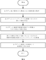
図4は、本発明の第1の実施形態に係る金属飾り具の製造方法を示すフローチャートである。 FIG. 4 is a flow chart showing the method for manufacturing the metal ornament according to the first embodiment of the present invention.
図4を参照すると、本発明の第1の実施形態に係る金属飾り具の製造方法は、(a)金属または貴金属物質を用いて主ボディと蓋体とから構成された胴体部を製作するが、前記胴体部は、全体的に中央に貫通口が形成された環状を呈することを特徴とするステップと、(b)前記胴体部の主ボディの内周面または外周面に沿ってループアンテナを嵌め込むための一定の深さの第1の溝を形成するステップと、(c)前記内周面または外周面に形成された第1の溝の所定の領域に制御用集積回路素子を搭載するための第2の溝を形成するステップと、(d)前記第2の溝に制御用集積回路素子を搭載し、前記第1の溝にループアンテナを数回巻回して搭載した後、制御用集積回路素子の両端とループアンテナの両端とを接着してつなぐステップと、を含む。 Referring to FIG. 4, the method for manufacturing a metal ornament according to the first embodiment of the present invention includes (a) manufacturing a body portion composed of a main body and a lid using a metal or precious metal material; (b) placing a loop antenna along the inner or outer peripheral surface of the main body of the main body; (c) mounting a control integrated circuit element in a predetermined region of the first groove formed on the inner peripheral surface or the outer peripheral surface; (d) mounting a control integrated circuit element in the second groove and mounting a loop antenna wound several times in the first groove; and gluing the ends of the integrated circuit element to the ends of the loop antenna.
前記ステップ(a)は、(a1)金属物質または貴金属物質を用いて中央に貫通口が形成された環状の主ボディを製作するステップと、(a2)前記主ボディの外周面または内周面に形成されるべき第1の溝及び第2の溝を覆うべき蓋体を製作するステップと、(a3)前記主ボディの一部の区間を完全に切り欠いて第1のスリットを形成するステップと、を含む。 The step (a) consists of (a1) fabricating a ring-shaped main body having a through hole formed in the center using a metallic material or a noble metal material; (a3) completely notching a section of the main body to form a first slit; ,including.
一方、前記製造方法においては、前記蓋体を主ボディと同一の金属または貴金属物質から製作してもよく、電気絶縁性を有する物質から製作してもよい。前記蓋体を主ボディと同一の金属または貴金属物質から製作する場合、前記蓋体の一部の区間を完全に切り欠いて第2のスリットを形成するが、前記第2のスリットは、第1のスリットと連絡されるように形成するステップをさらに含むか、あるいは、前記蓋体の表面を酸化処理して電気絶縁性を持たせるステップをさらに含むことが好ましい。一方、前記蓋体に第2のスリットを形成する場合、前記第2のスリットは、主ボディの第1のスリットと連絡されるように構成することが好ましい。 On the other hand, in the manufacturing method, the lid may be made of the same metal or precious metal material as the main body, or may be made of an electrically insulating material. When the lid is made of the same metal or precious metal material as the main body, a section of the lid is completely cut away to form a second slit. or the step of oxidizing the surface of the lid to make it electrically insulating. On the other hand, when forming the second slit in the lid, it is preferable that the second slit communicates with the first slit of the main body.
前記製造方法は、前記第1のスリット及び第2のスリットを電気絶縁性を有する物質で充填するステップをさらに含むか、あるいは、スリット充填モジュールを嵌め込むステップをさらに含むことが好ましい。前記スリット充填モジュールは、電気絶縁性を有する物質から充填モジュールを製作したり、所定の物質から充填モジュールを製作した後、表面を酸化処理することにより、電気絶縁性を持たせたりすることが好ましい。 Preferably, the manufacturing method further comprises filling the first slit and the second slit with an electrically insulating material, or inserting a slit filling module. It is preferable that the slit filling module is made of a material having electrical insulation, or made of a predetermined material and then oxidized to give it electrical insulation. .
<第2の実施形態>
以下、添付図面に基づいて、本発明の第2の実施形態に係る金属飾り具の構造及び動作について詳しく説明する。
<Second embodiment>
The structure and operation of the metal ornament according to the second embodiment of the present invention will be described in detail below with reference to the accompanying drawings.
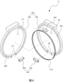
図5は、本発明の第2の実施形態に係る非接触式近距離無線通信機能を有する金属飾り具の一実施の形態を例示的に示す斜視図である。図6は、図5の金属飾り具の分解斜視図である。 FIG. 5 is a perspective view exemplifying one embodiment of a metal ornament having a non-contact short-range wireless communication function according to a second embodiment of the present invention. 6 is an exploded perspective view of the metal ornament of FIG. 5; FIG.
図5及び図6を参照すると、本実施形態に係る非接触式金属飾り具5は、指輪の形状を呈する金属飾り具であって、制御用集積回路素子500、ループアンテナ510、胴体部520及びスリット充填モジュール530を備える。
Referring to FIGS. 5 and 6, the non-contact metal ornament 5 according to the present embodiment is a ring-shaped metal ornament comprising a control integrated
前記制御用集積回路素子500及び前記ループアンテナ510は、第1の実施形態のそれらと同様であるため、重複する説明は省略する。
The control integrated
前記胴体部520は、金属または貴金属物質からなる第1の胴体部580及び第2の胴体部590から構成され、前記胴体部520は、全体的には、中央に貫通口'a'が形成された環状を呈する。前記第1の胴体部と第2の胴体部は、それぞれ第1の貫通口a1及び第2の貫通口a2を備え、全体的に同じ形状を呈するが、一方の面が互いに当接できるように構成されることが好ましい。
The
前記第1及び第2の胴体部の互いに当接する面のうちの一方の面または両方の面に前記制御用集積回路素子及びループアンテナが搭載されるための溝584、594を備える。前記ループアンテナ510は、数回巻回されて前記環状の第1及び第2の胴体部のどちらか一方に形成された第1の溝に搭載される。前記制御用集積回路素子は、第1及び第2の胴体部のどちらか一方に形成された第2の溝に搭載され、前記ループアンテナの両端は、前記制御用集積回路素子に接着されてつなぎ合わせられる。
一方、前記制御用集積回路素子及びループアンテナは、前記第1の溝及び第2の溝に搭載可能な形状に鋳造されて一体形に形成されたアンテナモジュールを構成してもよく、アンテナモジュールを前記第1の溝と第2の溝に搭載して完成してもよい。 On the other hand, the control integrated circuit element and the loop antenna may be cast into a shape that can be mounted in the first groove and the second groove to form an integral antenna module. It may be completed by being mounted in the first groove and the second groove.
前記胴体部の第1の胴体部580及び第2の胴体部590は、金属または貴金属物質から構成されるが、銀、金、白金、銀、銅などの貴金属物質または電気伝導性を有する金属物質のいずれか一種からなってもよい。また、前記胴体部の第1の胴体部580及び第2の胴体部590は、それぞれ環の一部の領域が完全に切り欠かれて形成された第1のスリットS1及び第2のスリットS2を備えなければならない。前記第1のスリットと第2のスリットとは、互いに連絡されるように構成されることが好ましい。
The
一方、前記第1のスリットS1及び第2のスリットS2は、電気絶縁性を有する物質、例えば、合成樹脂などから充填されて、あるいは、第1のスリット及び第2のスリットのそれぞれは、第1のスリット及び第2のスリットに対応する形状を呈する第1のスリット充填モジュール582及び第2のスリット充填モジュール592が嵌め込まれて、前記第1のスリット及び第2のスリットが見かけ上には表示されないようにするとともに、胴体部に搭載されたループアンテナが外部に露出されないようにしてもよい。前記第1のスリット充填モジュール及び第2のスリット充填モジュールは、電気絶縁性を有する物質から製作されてもよく、あるいは、金属などの物質から製作された後、表面を酸化処理して表面が電気絶縁性を有するように構成してもよい。
On the other hand, the first slit S1 and the second slit S2 are filled with an electrically insulating material such as a synthetic resin, or each of the first slit and the second slit is filled with the first A first
このように、金属物質または貴金属物質からなる胴体部の第1の胴体部及び第2の胴体部にそれぞれ第1のスリット及び第2のスリットを形成することにより、ループアンテナが外部の端末による誘導電流を生じさせて制御用集積回路素子を駆動することができ、制御用集積回路素子がループアンテナを介して外部の端末とデータを送受信することが可能になる。 Thus, by forming the first slit and the second slit in the first and second body portions, respectively, of the body portion made of metal or noble metal, the loop antenna can be guided by an external terminal. A current can be generated to drive the control integrated circuit element, allowing the control integrated circuit element to transmit and receive data to and from an external terminal via the loop antenna.
前記第1のスリット及び第2のスリットは、単一の直線の形状に形成されてもよく、あるいは、少なくとも一つ以上の折曲げ部を有するように構成してもよい。前記第1及び第2のスリットを折曲げ部を有するように構成することにより、胴体部の剛性を向上させることが可能になる。 The first slit and the second slit may be formed in the shape of a single straight line, or may be configured to have at least one or more bent portions. By configuring the first and second slits to have bent portions, it is possible to improve the rigidity of the body portion.
前記胴体部は、図5に示すように、指輪の形状を呈して、本発明に係る金属飾り具は、指輪型カードまたは指輪型扉施錠装置用鍵として使用可能になる。 As shown in FIG. 5, the body has a ring shape, and the metal ornament according to the present invention can be used as a ring-shaped card or a ring-shaped door locking device key.
以下、添付図面に基づいて、前述した本発明の第2の実施形態に係る金属飾り具の製造方法について詳しく説明する。 Hereinafter, based on the accompanying drawings, a detailed description will be given of the metal ornament manufacturing method according to the second embodiment of the present invention.
図9は、本発明の第2の実施形態に係る金属飾り具の製造方法を示すフローチャートである。 FIG. 9 is a flow chart showing a method for manufacturing a metal ornament according to the second embodiment of the present invention.
図9を参照すると、本発明の第2の実施形態に係る金属飾り具の製造方法は、(a)金属物質または貴金属物質を用いて中央に貫通口が形成された環状の第1の胴体部を製作するステップと、(b)金属または貴金属物質を用いて中央に貫通口が形成された第2の胴体部と同じ環状の第2の胴体部を製作するステップと、(c)前記第1の胴体部と第2の胴体部とが互いに当接する面にループアンテナを嵌め込むための一定の深さの第1の溝を形成するステップと、(d)前記第1の胴体部と第2の胴体部とが互いに当接する面のうちの一方の面に形成された第1の溝の所定の領域に制御用集積回路素子を搭載するための第2の溝を形成するステップと、(e)前記第2の溝と前記第1の溝にそれぞれ制御用集積回路素子及び前記制御用集積回路素子の両端につながれたループアンテナを搭載するステップと、(f)ループアンテナの搭載された面が露出されないように前記第1の胴体部と第2の胴体部の一方の面とを互いに当接するように接着するステップと、を含む。 Referring to FIG. 9, a method for manufacturing a metal ornament according to a second embodiment of the present invention includes (a) an annular first body portion having a through hole formed in the center using a metal or precious metal material; (b) using a metal or precious metal material to fabricate a second body having the same annular shape as the second body having a central through hole; (c) the first (d) forming a first groove of a certain depth for fitting the loop antenna in the surface where the body portion and the second body portion abut against each other; (d) the first body portion and the second body portion (e a) mounting a control integrated circuit element and a loop antenna connected to both ends of the control integrated circuit element in the second groove and the first groove, respectively; and gluing one side of the first body and the second body so as to abut against each other so as not to be exposed.
前記第1の胴体部の一方の面と第2の胴体部の一方の面は、同じ大きさと形状を有して、互いに当接するように配置した後、接着して一体形に構成することが好ましい。 One surface of the first body part and one surface of the second body part have the same size and shape, and are arranged to be in contact with each other and then bonded together to form an integral body. preferable.
前記ステップ(a)は、(a1)金属物質または貴金属物質を用いて中央に貫通口が形成された環状の第1の胴体部を製作するステップと、(a2)前記第1の胴体部の環の一部の区間を完全に切り欠いて第1のスリットを形成するステップと、を含む。前記ステップ(b)は、(b1)金属物質または貴金属物質を用いて中央に貫通口が形成された環状の第2の胴体部を製作するステップと、(b2)前記第2の胴体部の環の一部の区間を完全に切り欠いて第2のスリットを形成するステップと、を含み、前記第1のスリットと第2のスリットとは、互いに連絡されるように構成することが好ましい。 The step (a) consists of (a1) fabricating a ring-shaped first body portion with a through hole formed in the center using a metal material or a precious metal material; completely cutting out a section of the to form a first slit. The step (b) includes (b1) fabricating a ring-shaped second body having a through hole formed in the center using a metal material or a precious metal material; and forming a second slit by completely notching a part of the section of the first slit and the second slit, preferably configured to communicate with each other.
前記製造方法は、(a6)前記第1のスリットを電気絶縁性を有する物質で充填するステップをさらに含むか、あるいは、(a7)電気絶縁性を有する物質からスリット充填モジュールを製作したり、所定の物質からスリット充填モジュールを製作した後、電気絶縁性を有するように表面を酸化処理したりした後、前記スリット充填モジュールを第1のスリットに嵌合するステップをさらに含むことが好ましい。 The manufacturing method further includes (a6) filling the first slit with an electrically insulating material, or (a7) fabricating a slit filling module from an electrically insulating material, or After fabricating the slit filling module from the material of (1), oxidizing the surface so as to have electrical insulation, and fitting the slit filling module into the first slit.
<第3の実施形態>
以下、添付図面に基づいて、本発明の第3の実施形態に係る金属飾り具の構造及び動作について詳しく説明する。本発明の第3の実施形態に係る金属飾り具は、ペンダント(pendant)状を呈して、ネックレスまたは携帯電話ストラップなどにつながれて決済用カードまたは扉施錠装置用鍵として使用可能である。
<Third Embodiment>
The structure and operation of the metal ornament according to the third embodiment of the present invention will be described in detail below with reference to the accompanying drawings. The metal ornament according to the third embodiment of the present invention has a pendant shape and can be used as a payment card or a key for a door lock by being connected to a necklace or a mobile phone strap.
図7は、本発明の第3の実施形態に係る非接触式近距離無線通信機能を有する金属飾り具の一実施の形態を例示的に示す斜視図である。図8は、図7の金属飾り具の分解斜視図である。 FIG. 7 is a perspective view exemplifying one embodiment of a metal ornament having a non-contact short-range wireless communication function according to a third embodiment of the present invention. 8 is an exploded perspective view of the metal ornament of FIG. 7; FIG.
図7及び図8を参照すると、本実施形態に係る非接触式金属飾り具7は、ペンダントのような金属飾り具であって、制御用集積回路素子700、ループアンテナ710、胴体部720及びスリット充填モジュール730を備える。
7 and 8, the non-contact metal ornament 7 according to the present embodiment is a metal ornament such as a pendant, and includes a control integrated circuit element 700, a
前記制御用集積回路素子700及び前記ループアンテナ710は、第2の実施形態のそれらと同様であるため、重複する説明は省略する。
The control integrated circuit element 700 and the
前記胴体部720は、金属または貴金属物質からなる第1の胴体部780及び第2の胴体部790から構成され、前記胴体部720には、前記制御用集積回路素子700及び数回以上巻回された状態で前記制御用集積回路素子の両端につながれたループアンテナ710が搭載される。前記胴体部において、前記ループアンテナの内側の領域には所定の直径以上の孔'a'が形成され、前記胴体部には孔と連絡されるスリットS1、S2が形成されることが好ましい。各スリットS1、S2には、スリット充填モジュール782、792が嵌合される。
The
前記第1の胴体部と第2の胴体部は、それぞれ第1の孔a1及び第2の孔a2を備え、全体的に同じ形状を呈するが、一方の面が互いに当接できるように構成されることが好ましい。 The first body part and the second body part are provided with a first hole a1 and a second hole a2, respectively, and have the same shape as a whole, but are configured so that one surfaces can contact each other. preferably.
前記第1及び第2の胴体部の互いに当接する面のうちの一方の面または両方の面に前記制御用集積回路素子及びループアンテナが搭載されるための溝784、794を備える。前記ループアンテナ710は、数回巻回されて前記環状の第1及び第2の胴体部のどちらか一方に形成された第1の溝に搭載される。前記制御用集積回路素子は、第1及び第2の胴体部のどちらか一方に形成された第2の溝に搭載され、前記ループアンテナの両端は、前記制御用集積回路素子に接着されてつなぎ合わせられる。
前述した第1から第3の実施形態において、本発明に係る金属飾り具は、胴体部におけるループアンテナが搭載される領域の内部領域に貫通孔を形成したり孔を形成したりすることにより、磁場が通過できる空間を与える。また、本発明に係る金属飾り具は、胴体部におけるループアンテナが搭載される領域の一部の領域にスリットを形成することにより、共振効果を奏する。したがって、本発明に係る金属飾り具のループアンテナ及び制御用集積回路素子は、外部の端末や読み取り機(リーダー)と非接触式近距離無線通信を行うことが可能になる。 In the first to third embodiments described above, the metal ornament according to the present invention has a through hole or a hole formed in the inner region of the region where the loop antenna is mounted in the body, It gives a space through which the magnetic field can pass. In addition, the metal ornament according to the present invention exhibits a resonance effect by forming a slit in a part of the area of the body where the loop antenna is mounted. Therefore, the loop antenna and control integrated circuit element of the metal ornament according to the present invention can perform non-contact short-range wireless communication with an external terminal or reader.
以上、本発明についてその好適な実施形態を中心として説明したが、これは単なる例示にすぎず、本発明を限定するものではなく、本発明が属する分野における通常の知識を有する者であれば、本発明の本質的な特性を逸脱しない範囲において以上に例示されていない種々の変形と応用が可能であるということが理解できる筈である。そして、このような変形と応用に係わる相違点は、特許請求の範囲において定める本発明の範囲に含まれるものと解釈されるべきである。 Although the preferred embodiments of the present invention have been described above, they are merely examples and are not intended to limit the scope of the present invention. It should be understood that various modifications and applications not exemplified above are possible without departing from the essential characteristics of the invention. Such variations and differences in application should be construed as included within the scope of the invention as defined in the appended claims.
Claims (16)
両端がそれぞれ前記制御用集積回路素子の両端につながれた所定の長さのループアンテナと、
金属または貴金属物質からなり、中央に貫通口が形成された環状を呈するが、環の一部の区間が切り欠かれて形成されたスリットを有する胴体部と、
を備え、
前記胴体部の内部に前記制御用集積回路素子及びループアンテナが搭載され、前記ループアンテナは、前記環状の胴体部に沿って数回巻回されたことを特徴とし、
前記胴体部は、前記スリットにより環状の一部が完全に切り欠かれ、前記ループアンテナが外部の端末からの無線信号により誘導電流を生じさせて前記制御用集積回路素子を駆動するように構成されたことを特徴とする非接触式近距離無線通信機能を有する金属飾り具。 A control integrated circuit element (IC chip) capable of non-contact short-range wireless communication with an external terminal;
a loop antenna of a predetermined length having both ends connected to both ends of the control integrated circuit element;
a body portion made of a metal or precious metal material and having a ring shape with a through hole formed in the center, but having a slit formed by cutting out a section of the ring;
with
The control integrated circuit element and the loop antenna are mounted inside the body, and the loop antenna is wound several times along the annular body,
A part of the annular body is completely cut out by the slit, and the loop antenna is configured to generate an induced current by a radio signal from an external terminal to drive the control integrated circuit element. A metal ornament having a non-contact short-range wireless communication function, characterized by:
制御用集積回路素子及びループアンテナが搭載される溝が内周面または外周面に沿って形成された主ボディと、
前記溝を覆う蓋体と、
を備え、
前記スリットは、前記主ボディ及び蓋体にそれぞれ形成されるが、主ボディのスリットと蓋体のスリットとは互いに連絡されていることを特徴とする請求項1に記載の非接触式近距離無線通信機能を有する金属飾り具。 The body portion is
a main body having grooves along its inner or outer peripheral surface in which the control integrated circuit element and the loop antenna are mounted;
a lid covering the groove;
with
2. The non-contact short-range radio according to claim 1, wherein the slits are formed in the main body and the lid, respectively, and the slits in the main body and the slits in the lid communicate with each other. A metal ornament that has a communication function.
中央に貫通口が形成された環状を呈するが、環の一部の区間が切り欠かれて形成されたスリットを有する第1の胴体部と、
第1の胴体部と同じ形状を呈するが、一方の面が第1の胴体部の一方の面に当接できるように構成された第2の胴体部と、
を備え、
前記第1の胴体部及び第2の胴体部の互いに当接する面に前記制御用集積回路素子及びループアンテナが搭載される溝が形成されたことを特徴とし、
前記第1の胴体部のスリットと第2の胴体部のスリットは、互いに対応する位置に形成されたことを特徴とする請求項1に記載の非接触式近距離無線通信機能を有する金属飾り具。 The body portion is
a first body having a ring shape with a through hole formed in the center and having a slit formed by cutting out a part of the ring;
a second body having the same shape as the first body, but configured such that one face can abut one face of the first body;
with
A groove in which the control integrated circuit element and the loop antenna are mounted is formed on the surfaces of the first body and the second body that contact each other,
2. The metal ornament with non-contact short-range wireless communication function according to claim 1, wherein the slits of the first body part and the slits of the second body part are formed at positions corresponding to each other. .
ペンダント(pendant)状を呈することを特徴とする請求項1に記載の非接触式近距離無線通信機能を有する金属飾り具。 the body has the shape of a ring; or
2. The metal ornament having a non-contact short-range wireless communication function as claimed in claim 1, which has a pendant shape.
電気絶縁性を有する物質で充填されるか、または、
電気絶縁性を有する物質から製作されるか、あるいは、表面が酸化処理されて電気絶縁性を有するように構成されたスリット充填モジュールで満たされたことを特徴とする請求項1に記載の非接触式近距離無線通信機能を有する金属飾り具。 The slit in the body is
filled with an electrically insulating material, or
2. The non-contact according to claim 1, characterized in that it is made of an electrically insulating material or is filled with a slit-filled module whose surface is oxidized so as to be electrically insulating. A metal ornament with a short-range wireless communication function.
両端がそれぞれ前記制御用集積回路素子の両端につながれた所定の長さのループアンテナと、
金属または貴金属物質からなり、前記制御用集積回路素子及びその両端につながれたループアンテナが搭載された胴体部と、
を備え、
前記胴体部における前記ループアンテナが搭載された領域の内部領域に孔(hole)が形成され、前記胴体部には孔と連絡されるように構成されたスリットが形成されたことを特徴とし、
前記胴体部は、前記スリットにより一部が完全に切り欠かれ、前記ループアンテナが外部の端末からの無線信号により誘導電流を生じさせて前記制御用集積回路素子を駆動するように構成されたことを特徴とする非接触式近距離無線通信機能を有する金属飾り具。 A control integrated circuit element (IC chip) capable of non-contact short-range wireless communication with an external terminal;
a loop antenna of a predetermined length having both ends connected to both ends of the control integrated circuit element;
a body made of a metal or precious metal material and having the control integrated circuit element and loop antennas connected to both ends thereof;
with
A hole is formed in an inner region of the region where the loop antenna is mounted in the body, and a slit configured to communicate with the hole is formed in the body,
A portion of the body portion is completely cut out by the slit, and the loop antenna is configured to generate an induced current by a radio signal from an external terminal to drive the control integrated circuit element. A metal ornament having a non-contact short-range wireless communication function.
ループアンテナが搭載された領域の内部領域に孔が形成され、一部の区間が切り欠かれて形成されたスリットを有する第1の胴体部と、
第1の胴体部と同じ形状を呈するが、一方の面が第1の胴体部の一方の面に当接できるように構成された第2の胴体部と、
を備え、
前記第1の胴体部及び第2の胴体部の互いに当接する面に前記制御用集積回路素子及びループアンテナが搭載されることを特徴とし、
前記第1の胴体部のスリットと第2の胴体部のスリットは、互いに対応する位置に形成されたことを特徴とする請求項8に記載の非接触式近距離無線通信機能を有する金属飾り具。 The body portion is
a first body having a slit formed by cutting out a part of the section of the first body having a hole formed in the inner region of the region where the loop antenna is mounted;
a second body having the same shape as the first body, but configured such that one face can abut one face of the first body;
with
characterized in that the control integrated circuit element and the loop antenna are mounted on the surfaces of the first body portion and the second body portion that contact each other,
9. The metal ornament having contactless short-range wireless communication function as claimed in claim 8, wherein the slits of the first body part and the slits of the second body part are formed at positions corresponding to each other. .
(b)前記胴体部の主ボディの内周面または外周面に沿ってループアンテナを嵌め込むための一定の深さの第1の溝を形成するステップと、
(c)前記内周面または外周面に形成された第1の溝の所定の領域に制御用集積回路素子を搭載するための第2の溝を形成するステップと、
(d)前記第2の溝に制御用集積回路素子を搭載し、前記第1の溝にループアンテナを数回巻いて搭載した後、制御用集積回路素子の両端とループアンテナの両端とを接着してつなぐステップと、
を含み、
前記ステップ(a)は、前記胴体部の主ボディの一部の区間を完全に切り欠いて第1のスリットを形成することを特徴とする非接触式近距離無線通信機能を有する金属飾り具の製造方法。 (a) A body composed of a main body and a lid is manufactured using a metal or precious metal material, and the body has an annular shape with a through hole formed in the center. and
(b) forming a first groove of a certain depth for fitting a loop antenna along the inner or outer peripheral surface of the main body of the torso;
(c) forming a second groove for mounting a control integrated circuit element in a predetermined region of the first groove formed on the inner or outer peripheral surface;
(d) Mounting the control integrated circuit element in the second groove, winding the loop antenna several times and mounting it in the first groove, and then bonding both ends of the control integrated circuit element to both ends of the loop antenna. a step of connecting by
including
In the step (a), a part of the main body of the torso part is completely cut out to form a first slit . Production method.
(a1)金属物質または貴金属物質を用いて中央に貫通口が形成された環状の主ボディを製作するステップと、
(a2)前記主ボディの外周面または内周面に形成されるべき第1の溝及び第2の溝を覆うべき蓋体を製作するステップと、
(a3)前記主ボディの一部の区間を完全に切り欠いて第1のスリットを形成するステップと、
を含むことを特徴とする請求項10に記載の非接触式近距離無線通信機能を有する金属飾り具の製造方法。 Said step (a) comprises:
(a1) fabricating an annular main body with a central through hole using a metallic or precious metal material;
(a2) manufacturing a lid body to cover the first groove and the second groove to be formed on the outer or inner peripheral surface of the main body;
(a3) completely cutting out a section of the main body to form a first slit;
11. The method of manufacturing a metal ornament having a non-contact short-range wireless communication function according to claim 10, comprising:
(a4)前記蓋体の一部の区間を完全に切り欠いて第2のスリットを形成するが、前記第2のスリットは、第1のスリットと連絡されるように形成するステップをさらに含むか、あるいは、
(a5)前記蓋体を電気絶縁性を有する物質から製作したり、前記蓋体の表面を酸化処理して電気絶縁性を持たせたりするステップをさらに含むことを特徴とする請求項11に記載の非接触式近距離無線通信機能を有する金属飾り具の製造方法。 The manufacturing method is
(a4) forming a second slit by completely cutting out a portion of the cover, and forming the second slit to communicate with the first slit? ,or,
12. The method according to claim 11, further comprising: (a5) making the lid from an electrically insulating material, or oxidizing the surface of the lid to provide electrical insulation. A method for manufacturing a metal ornament having a non-contact short-range wireless communication function.
(a6)前記第1のスリットを電気絶縁性を有する物質で充填するステップをさらに含むか、あるいは、
(a7)電気絶縁性を有する物質からスリット充填モジュールを製作したり、所定の物質からスリット充填モジュールを製作した後、電気絶縁性を有するように表面を酸化処理したりした後、前記スリット充填モジュールを第1のスリットに嵌め込むステップをさらに含むことを特徴とする請求項11に記載の非接触式近距離無線通信機能を有する金属飾り具の製造方法。 The manufacturing method is
(a6) further comprising filling the first slit with an electrically insulating material, or
(a7) manufacturing a slit filling module from a material having electrical insulation, or manufacturing a slit filling module from a predetermined material and then subjecting the surface to an oxidation treatment so as to have electrical insulation; 12. The manufacturing method of the metal ornament with non-contact short-range wireless communication function according to claim 11, further comprising the step of fitting into the first slit.
(b)金属または貴金属物質を用いて中央に貫通口が形成された第2の胴体部と同じ環状の第2の胴体部を製作するステップと、
(c)前記第1の胴体部と第2の胴体部とが互いに当接する面にループアンテナを嵌め込むための一定の深さの第1の溝を形成するステップと、
(d)前記第1の胴体部と第2の胴体部とが互いに当接する面のうちの一方の面に形成された第1の溝の所定の領域に制御用集積回路素子を搭載するための第2の溝を形成するステップと、
(e)前記第2の溝と前記第1の溝にそれぞれ制御用集積回路素子及び前記制御用集積回路素子の両端につながれたループアンテナを搭載するステップと、
(f)ループアンテナの搭載された面が露出されないように前記第1の胴体部と第2の胴体部の一方の面とを互いに当接するように接着するステップと、
を含み、
前記第1の胴体部の一方の面と第2の胴体部の一方の面は、同じ大きさと形状を有して、互いに当接するように配置された後に接着されることを特徴とし、
前記ステップ(a)は、前記第1の胴体部の環の一部の区間を完全に切り欠いて第1のスリットを形成し、前記ステップ(b)は、前記第2の胴体部の環の一部の区間を完全に切り欠いて第2のスリットを形成することを特徴とする非接触式近距離無線通信機能を有する金属飾り具の製造方法。 (a) fabricating an annular first body with a central through-hole using a metallic or precious metal material;
(b) using a metal or precious metal material to fabricate a second body having an annular shape identical to the second body having a central through hole;
(c) forming a first groove of a certain depth for fitting the loop antenna in the surface where the first body portion and the second body portion abut against each other;
(d) for mounting a control integrated circuit element in a predetermined region of a first groove formed in one of the surfaces where the first body portion and the second body portion abut against each other; forming a second groove;
(e) mounting a control integrated circuit element and a loop antenna connected to both ends of the control integrated circuit element in the second groove and the first groove, respectively;
(f) adhering one surface of the first body portion and the second body portion so as to contact each other so that the surface on which the loop antenna is mounted is not exposed;
including
One surface of the first body part and one surface of the second body part have the same size and shape, and are bonded after being placed in contact with each other,
The step (a) completely cuts a partial section of the first body ring to form a first slit, and the step (b) cuts the second body ring. A method of manufacturing a metal ornament having a non-contact short-range wireless communication function, characterized by forming a second slit by completely notching a part of the section .
(a1)金属物質または貴金属物質を用いて中央に貫通口が形成された環状の第1の胴体部を製作するステップと、
(a2)前記第1の胴体部の環の一部の区間を完全に切り欠いて第1のスリットを形成するステップと、
を含み、
前記ステップ(b)は、
(b1)金属物質または貴金属物質を用いて中央に貫通口が形成された環状の第2の胴体部を製作するステップと、
(b2)前記第2の胴体部の環の一部の区間を完全に切り欠いて第2のスリットを形成するステップと、
を含み、
前記第1のスリットと第2のスリットとは、互いに連絡されたことを特徴とする請求項14に記載の非接触式近距離無線通信機能を有する金属飾り具の製造方法。 Said step (a) comprises:
(a1) fabricating a ring-shaped first body portion with a through hole formed in the center using a metallic material or a noble metal material;
(a2) completely notching a section of the ring of the first body to form a first slit;
including
The step (b) includes
(b1) fabricating a ring-shaped second body with a through-hole formed in the center using a metallic or precious metal material;
(b2) completely notching a section of the second body ring to form a second slit;
including
15. The method of claim 14, wherein the first slit and the second slit are connected to each other.
(g)前記第1のスリット及び第2のスリットを電気絶縁性を有する物質で充填するステップをさらに含むか、あるいは、
(a7)電気絶縁性を有する物質からスリット充填モジュールを製作したり、所定の物質からスリット充填モジュールを製作した後、電気絶縁性を有するように表面を酸化処理したりした後、前記充填モジュールを第1のスリット及び第2のスリットに嵌め込むステップをさらに含むことを特徴とする請求項15に記載の非接触式近距離無線通信機能を有する金属飾り具の製造方法。 The manufacturing method is
(g) further comprising filling the first slit and the second slit with an electrically insulating material; or
(a7) manufacturing a slit filling module from a material having electrical insulation, or manufacturing a slit filling module from a predetermined material, subjecting the surface to an oxidation treatment so as to have electrical insulation, and then manufacturing the filling module; 16. The method of claim 15, further comprising the step of fitting into the first slit and the second slit.
Applications Claiming Priority (3)
| Application Number | Priority Date | Filing Date | Title |
|---|---|---|---|
| KR1020180094493A KR102070245B1 (en) | 2018-08-13 | 2018-08-13 | Metal accessory having contactless-type wireless communication function and method of fabricating the metal accessory |
| KR10-2018-0094493 | 2018-08-13 | ||
| PCT/KR2019/009599 WO2020036349A1 (en) | 2018-08-13 | 2019-08-01 | Metal accessory having non-contact short-range wireless communication function, and manufacturing method therefor |
Publications (3)
| Publication Number | Publication Date |
|---|---|
| JP2021533445A JP2021533445A (en) | 2021-12-02 |
| JPWO2020036349A5 JPWO2020036349A5 (en) | 2022-05-19 |
| JP7141069B2 true JP7141069B2 (en) | 2022-09-22 |
Family
ID=69370427
Family Applications (1)
| Application Number | Title | Priority Date | Filing Date |
|---|---|---|---|
| JP2021503137A Active JP7141069B2 (en) | 2018-08-13 | 2019-08-01 | METAL ACCESSORY HAVING NON-CONTACT NEAR-RANGE WIRELESS COMMUNICATION FUNCTION AND MANUFACTURING METHOD THEREOF |
Country Status (6)
| Country | Link |
|---|---|
| US (1) | US11621475B2 (en) |
| EP (1) | EP3831238A4 (en) |
| JP (1) | JP7141069B2 (en) |
| KR (1) | KR102070245B1 (en) |
| CN (1) | CN112469303A (en) |
| WO (1) | WO2020036349A1 (en) |
Families Citing this family (7)
| Publication number | Priority date | Publication date | Assignee | Title |
|---|---|---|---|---|
| USD1003752S1 (en) | 2020-04-09 | 2023-11-07 | Jon E. Arendsen | Kit assembly for adapting a gemstone between ring and pendant |
| KR102337902B1 (en) * | 2020-06-29 | 2021-12-10 | (주)파트론 | Wearable electronic devices |
| FR3135196B1 (en) * | 2022-05-06 | 2025-03-07 | Valeur Declaree | Fine jewelry piece with payment method |
| KR102889509B1 (en) | 2022-08-08 | 2025-11-25 | 정지용 | Ring for a card having contactless-type wireless communication function and method of fabricating the ring |
| CN115377652A (en) * | 2022-08-31 | 2022-11-22 | 联想(北京)有限公司 | an electronic device |
| US20240122315A1 (en) * | 2022-10-14 | 2024-04-18 | Plume Design, Inc. | Attaching a decorative element to a smart ring |
| KR20250114642A (en) | 2024-01-22 | 2025-07-29 | 정연진 | Bracelet with wireless communication function |
Citations (6)
| Publication number | Priority date | Publication date | Assignee | Title |
|---|---|---|---|---|
| JP2003271910A (en) | 2002-03-15 | 2003-09-26 | Kobayashi Kirokushi Co Ltd | Ring type rfid data carrier |
| WO2006059454A1 (en) | 2004-11-30 | 2006-06-08 | Konica Minolta Holdings, Inc. | Information processing apparatus |
| JP2008146640A (en) | 2006-11-14 | 2008-06-26 | Semiconductor Energy Lab Co Ltd | Article management system |
| US20180261911A1 (en) | 2017-03-08 | 2018-09-13 | Google Inc. | Body-mountable device to provide radio-frequency wireless communication |
| JP2020184764A (en) | 2019-05-08 | 2020-11-12 | ギャラティー テクノロジー エルエルシーGalatea Technology LLC | Rings used for short-range wireless communication and their manufacturing methods |
| JP2021527290A (en) | 2018-06-06 | 2021-10-11 | ジョイント ストック カンパニー “ペイ リング”Joint Stock Company ‘Pay Ring’ | Contactless smart card |
Family Cites Families (26)
| Publication number | Priority date | Publication date | Assignee | Title |
|---|---|---|---|---|
| JPH0529413U (en) * | 1991-04-30 | 1993-04-20 | 株式会社英工芸 | Jewelry ring |
| JPH0767709A (en) * | 1993-08-31 | 1995-03-14 | Naokatsu Imaizumi | Accessory with two ornamental sections for clipping on fingers |
| JPH09232990A (en) * | 1996-02-20 | 1997-09-05 | S I I R D Center:Kk | Small sized radio equipment |
| JP4327982B2 (en) * | 1999-05-28 | 2009-09-09 | 株式会社日本自動車部品総合研究所 | Portable radio antenna |
| KR200294180Y1 (en) | 2002-06-11 | 2002-11-04 | 한상필 | Ring with IC chip |
| KR200445348Y1 (en) | 2006-12-18 | 2009-07-22 | 주식회사 이씨글로벌 | Traffic Card |
| US8325015B2 (en) * | 2008-01-18 | 2012-12-04 | Nxp B.V. | Conductive silicone wristband for wireless communications |
| KR101001719B1 (en) * | 2010-06-17 | 2010-12-15 | 김재열 | Couple accessories |
| EP2522458B1 (en) | 2011-05-13 | 2016-07-06 | ESSILOR INTERNATIONAL (Compagnie Générale d'Optique) | Process for determining position parameters of a manufactured surface relative to a reference surface |
| US9812782B2 (en) * | 2011-08-08 | 2017-11-07 | Féinics Amatech Teoranta | Coupling frames for RFID devices |
| US9697459B2 (en) * | 2014-08-10 | 2017-07-04 | Féinics Amatech Teoranta | Passive smart cards, metal cards, payment objects and smart jewelry |
| US9836684B2 (en) * | 2014-08-10 | 2017-12-05 | Féinics Amatech Teoranta | Smart cards, payment objects and methods |
| US10733494B2 (en) * | 2014-08-10 | 2020-08-04 | Féinics Amatech Teoranta | Contactless metal card constructions |
| KR101255928B1 (en) * | 2011-10-20 | 2013-04-23 | 김태성 | Ring comprsing the elctronic chip |
| JP5866231B2 (en) * | 2012-03-05 | 2016-02-17 | 日本アンテナ株式会社 | Ring antenna |
| KR20150042069A (en) * | 2013-10-10 | 2015-04-20 | 에스케이플래닛 주식회사 | Device function control method using RFID and Device therefor |
| KR102256580B1 (en) * | 2015-02-27 | 2021-05-26 | 삼성전자주식회사 | Wearable Electronic Device Including Communication Circuit |
| KR101524549B1 (en) | 2015-03-26 | 2015-06-01 | 박계수 | The pliable fork coupling with ring cover |
| FR3035993B1 (en) * | 2015-05-06 | 2017-06-09 | Centre Nat Rech Scient | MINIATURIZED WIRELESS ALARM DEVICE |
| US20200279465A1 (en) * | 2015-12-02 | 2020-09-03 | Kimberly A. GAVIN | System and method for wearable technology |
| CN105533949A (en) * | 2016-01-26 | 2016-05-04 | 段元文 | Intelligent jewelry with information transmission function |
| KR102592459B1 (en) * | 2016-02-11 | 2023-10-25 | 삼성전자 주식회사 | Electronic device having loop antenna |
| CN205568081U (en) * | 2016-03-24 | 2016-09-14 | 四川省力华珠宝有限公司 | Ornament pendant with electronic payment function |
| KR101824998B1 (en) * | 2016-07-13 | 2018-02-02 | 엘지전자 주식회사 | Mobile terminal |
| CN206848414U (en) * | 2017-06-26 | 2018-01-05 | 云南电网有限责任公司文山供电局 | Detect the external sensor of GIS device discharge signal |
| US11427385B1 (en) * | 2019-12-27 | 2022-08-30 | Lawrence D. Cutter | Returnable shipping container |
-
2018
- 2018-08-13 KR KR1020180094493A patent/KR102070245B1/en active Active
-
2019
- 2019-08-01 US US17/258,943 patent/US11621475B2/en active Active
- 2019-08-01 CN CN201980045644.3A patent/CN112469303A/en active Pending
- 2019-08-01 JP JP2021503137A patent/JP7141069B2/en active Active
- 2019-08-01 WO PCT/KR2019/009599 patent/WO2020036349A1/en not_active Ceased
- 2019-08-01 EP EP19849995.6A patent/EP3831238A4/en active Pending
Patent Citations (6)
| Publication number | Priority date | Publication date | Assignee | Title |
|---|---|---|---|---|
| JP2003271910A (en) | 2002-03-15 | 2003-09-26 | Kobayashi Kirokushi Co Ltd | Ring type rfid data carrier |
| WO2006059454A1 (en) | 2004-11-30 | 2006-06-08 | Konica Minolta Holdings, Inc. | Information processing apparatus |
| JP2008146640A (en) | 2006-11-14 | 2008-06-26 | Semiconductor Energy Lab Co Ltd | Article management system |
| US20180261911A1 (en) | 2017-03-08 | 2018-09-13 | Google Inc. | Body-mountable device to provide radio-frequency wireless communication |
| JP2021527290A (en) | 2018-06-06 | 2021-10-11 | ジョイント ストック カンパニー “ペイ リング”Joint Stock Company ‘Pay Ring’ | Contactless smart card |
| JP2020184764A (en) | 2019-05-08 | 2020-11-12 | ギャラティー テクノロジー エルエルシーGalatea Technology LLC | Rings used for short-range wireless communication and their manufacturing methods |
Also Published As
| Publication number | Publication date |
|---|---|
| KR102070245B1 (en) | 2020-01-28 |
| US20210344105A1 (en) | 2021-11-04 |
| EP3831238A4 (en) | 2022-08-17 |
| JP2021533445A (en) | 2021-12-02 |
| EP3831238A1 (en) | 2021-06-09 |
| WO2020036349A1 (en) | 2020-02-20 |
| CN112469303A (en) | 2021-03-09 |
| US11621475B2 (en) | 2023-04-04 |
Similar Documents
| Publication | Publication Date | Title |
|---|---|---|
| JP7141069B2 (en) | METAL ACCESSORY HAVING NON-CONTACT NEAR-RANGE WIRELESS COMMUNICATION FUNCTION AND MANUFACTURING METHOD THEREOF | |
| CN207320328U (en) | Antenna device and communication terminal device | |
| US11329383B2 (en) | Ultra-low-profile triaxial low frequency antenna for integration in a mobile phone and mobile phone therewith | |
| US20090305657A1 (en) | Antenna device and radio wave-using apparatus | |
| JP2002341059A (en) | Watch with tag | |
| CN112313670A (en) | Non-contact smart card | |
| WO2014104921A1 (en) | Contactless chip card | |
| KR20200023321A (en) | LED-illuminating accessory having wireless near field communication function and method of fabricating the LED-illuminating accessory | |
| KR102078104B1 (en) | LED-illuminating metal accessory having contactless-type wireless communication function and method of fabricating the metal accessory | |
| WO2020034657A1 (en) | Wireless communication antenna structure for both heat dissipation and radiation | |
| KR102889509B1 (en) | Ring for a card having contactless-type wireless communication function and method of fabricating the ring | |
| JP2018148452A (en) | Antenna device and communication terminal device | |
| JPWO2020036349A5 (en) | ||
| EP3301821B1 (en) | Antenna for an nfc device and nfc device | |
| CN117766267A (en) | Induction coil assemblies for electronic equipment and accessories | |
| KR102620604B1 (en) | Ultra-low-profile, low-frequency antenna | |
| WO2025149766A1 (en) | Radio frequency identification (rfid) ring with coil antenna | |
| KR100791973B1 (en) | Jewelry with RF communication module and manufacturing method of metal case | |
| US20240303460A1 (en) | Wearable Device for Data Storage and Exchange | |
| KR20250160107A (en) | Bracelet with wireless communication function | |
| CN209357100U (en) | A kind of noncontact IC chip shell and device | |
| CN201556227U (en) | Non-contact integrated circuit IC device | |
| WO2023244097A1 (en) | Finger ring-type article functioning as an nfc transponder (variants) | |
| KR200370648Y1 (en) | Ornament Having RF Transceiver |
Legal Events
| Date | Code | Title | Description |
|---|---|---|---|
| A521 | Request for written amendment filed |
Free format text: JAPANESE INTERMEDIATE CODE: A523 Effective date: 20220511 |
|
| A871 | Explanation of circumstances concerning accelerated examination |
Free format text: JAPANESE INTERMEDIATE CODE: A871 Effective date: 20220511 |
|
| TRDD | Decision of grant or rejection written | ||
| A01 | Written decision to grant a patent or to grant a registration (utility model) |
Free format text: JAPANESE INTERMEDIATE CODE: A01 Effective date: 20220802 |
|
| A61 | First payment of annual fees (during grant procedure) |
Free format text: JAPANESE INTERMEDIATE CODE: A61 Effective date: 20220830 |
|
| R150 | Certificate of patent or registration of utility model |
Ref document number: 7141069 Country of ref document: JP Free format text: JAPANESE INTERMEDIATE CODE: R150 |
|
| R250 | Receipt of annual fees |
Free format text: JAPANESE INTERMEDIATE CODE: R250 |