JP7141005B2 - Communication device, second communication device, communication system, and communication method - Google Patents
Communication device, second communication device, communication system, and communication method Download PDFInfo
- Publication number
- JP7141005B2 JP7141005B2 JP2021501246A JP2021501246A JP7141005B2 JP 7141005 B2 JP7141005 B2 JP 7141005B2 JP 2021501246 A JP2021501246 A JP 2021501246A JP 2021501246 A JP2021501246 A JP 2021501246A JP 7141005 B2 JP7141005 B2 JP 7141005B2
- Authority
- JP
- Japan
- Prior art keywords
- signal
- subheader
- random access
- communication
- access procedure
- Prior art date
- Legal status (The legal status is an assumption and is not a legal conclusion. Google has not performed a legal analysis and makes no representation as to the accuracy of the status listed.)
- Active
Links
Images


Classifications
-
- H—ELECTRICITY
- H04—ELECTRIC COMMUNICATION TECHNIQUE
- H04W—WIRELESS COMMUNICATION NETWORKS
- H04W74/00—Wireless channel access, e.g. scheduled or random access
- H04W74/08—Non-scheduled or contention based access, e.g. random access, ALOHA, CSMA [Carrier Sense Multiple Access]
- H04W74/0833—Non-scheduled or contention based access, e.g. random access, ALOHA, CSMA [Carrier Sense Multiple Access] using a random access procedure
- H04W74/0841—Non-scheduled or contention based access, e.g. random access, ALOHA, CSMA [Carrier Sense Multiple Access] using a random access procedure with collision treatment
-
- H—ELECTRICITY
- H04—ELECTRIC COMMUNICATION TECHNIQUE
- H04W—WIRELESS COMMUNICATION NETWORKS
- H04W28/00—Network traffic management; Network resource management
- H04W28/02—Traffic management, e.g. flow control or congestion control
- H04W28/06—Optimizing the usage of the radio link, e.g. header compression, information sizing, discarding information
-
- H—ELECTRICITY
- H04—ELECTRIC COMMUNICATION TECHNIQUE
- H04W—WIRELESS COMMUNICATION NETWORKS
- H04W72/00—Local resource management
- H04W72/12—Wireless traffic scheduling
- H04W72/1263—Mapping of traffic onto schedule, e.g. scheduled allocation or multiplexing of flows
- H04W72/1273—Mapping of traffic onto schedule, e.g. scheduled allocation or multiplexing of flows of downlink data flows
-
- H—ELECTRICITY
- H04—ELECTRIC COMMUNICATION TECHNIQUE
- H04W—WIRELESS COMMUNICATION NETWORKS
- H04W74/00—Wireless channel access, e.g. scheduled or random access
- H04W74/002—Transmission of channel access control information
-
- H—ELECTRICITY
- H04—ELECTRIC COMMUNICATION TECHNIQUE
- H04W—WIRELESS COMMUNICATION NETWORKS
- H04W74/00—Wireless channel access, e.g. scheduled or random access
- H04W74/002—Transmission of channel access control information
- H04W74/006—Transmission of channel access control information in the downlink, i.e. towards the terminal
-
- H—ELECTRICITY
- H04—ELECTRIC COMMUNICATION TECHNIQUE
- H04W—WIRELESS COMMUNICATION NETWORKS
- H04W74/00—Wireless channel access, e.g. scheduled or random access
- H04W74/08—Non-scheduled or contention based access, e.g. random access, ALOHA, CSMA [Carrier Sense Multiple Access]
- H04W74/0833—Non-scheduled or contention based access, e.g. random access, ALOHA, CSMA [Carrier Sense Multiple Access] using a random access procedure
-
- H—ELECTRICITY
- H04—ELECTRIC COMMUNICATION TECHNIQUE
- H04W—WIRELESS COMMUNICATION NETWORKS
- H04W80/00—Wireless network protocols or protocol adaptations to wireless operation
- H04W80/02—Data link layer protocols
Description
本発明は、通信装置、第2通信装置、通信システム、及び通信方法に関する。 The present invention relates to a communication device, a second communication device, a communication system, and a communication method.
現在の通信ネットワークは、モバイル端末(スマートフォンやフューチャーホン)のトラフィックが通信ネットワークのリソースの大半を占めている。また、モバイル端末が使用するトラフィックは、今後も拡大していく傾向にある。 In current communication networks, the traffic of mobile terminals (smartphones and feature phones) occupies most of the communication network resources. In addition, the traffic used by mobile terminals tends to expand in the future.
一方で、通信ネットワークは、IoT(Internet of Things)サービス(例えば、交通システム、スマートメータ、装置等の監視システム)の展開にあわせて、多様な要求条件を持つサービスに対応することが求められている。そのため、第5世代移動体通信(5Gまたは、NR(New Radio))の通信規格では、第4世代移動体通信(4G)の標準技術(例えば、非特許文献1~12)に加えて、さらなる高データ信号レート化、大容量化、低遅延化を実現する技術が求められている。なお、第5世代通信規格については、3GPPの作業部会(例えば、TSG-RAN WG1、TSG-RAN WG2等)で技術検討が進められており、2017年12月に、初版がリリースされている(非特許文献13~40)。
On the other hand, in line with the development of IoT (Internet of Things) services (e.g. transportation systems, smart meters, monitoring systems for equipment, etc.), communication networks are required to support services with diverse requirements. there is Therefore, in the communication standard of the 5th generation mobile communication (5G or NR (New Radio)), in addition to the standard technology of the 4th generation mobile communication (4G) (for example,
上述した多種多様なサービスに対応するため、5Gにおいては、eMBB(Enhanced Mobile BroadBand)、Massive MTC(Machine Type Communications)、およびURLLC(Ultra-Reliable and Low Latency Communication)に分類される多くのユースケースのサポートを想定している。 In order to support the wide variety of services mentioned above, 5G has many use cases classified into eMBB (Enhanced Mobile BroadBand), Massive MTC (Machine Type Communications), and URLLC (Ultra-Reliable and Low Latency Communication). Assuming support.
無線通信システムでは、基地局装置と通信装置(例えば、端末装置)が通信を開始するに当たって、通信装置が最初に送信するためのチャネルが用意されている。3GPPにおいては、これをランダムアクセスチャネル(RACH:Random Access Channel)と呼び、RACHによる通信開始手順をランダムアクセス手順(Random Access Procedure)と呼んでいる。RACHには、通信装置が送信した無線信号を基地局が識別する情報としてプリアンブルと呼ばれる情報が含まれている。この情報により、基地局装置が端末装置を識別できるようにしている。 In a radio communication system, a channel is prepared for initial transmission by a communication device when a base station device and a communication device (for example, a terminal device) start communication. In 3GPP, this is called a random access channel (RACH), and a procedure for starting communication by the RACH is called a random access procedure. The RACH contains information called a preamble as information for the base station to identify the radio signal transmitted by the communication device. This information enables the base station to identify the terminal.
なお、ランダムアクセス手順は、イニシャルアクセスを実施する場合、データ信号発生、及びハンドオーバ時の同期を確立する場合等で実行される。 The random access procedure is executed when performing initial access, when generating data signals, when establishing synchronization during handover, and the like.
無線通信システムでは、ランダムアクセス手順を実行して同期(上り同期)を確立させた後にデータ通信を行う。 In a wireless communication system, data communication is performed after executing a random access procedure to establish synchronization (uplink synchronization).
5Gに関する技術については、以下の先行技術文献に記載されている。 Technologies related to 5G are described in the following prior art documents.
無線通信システムにおいて、データ信号通信の遅延時間を低減することが要求されている。例えば、5Gで想定されているURLLCのサービスに対応できるような遅延時間が要求される場合がある。そのため、例えば、通信装置と基地局装置との同期が取れない状況においてデータ信号が発生した場合においても、データ信号送信までの遅延時間の低減が要求される。 In radio communication systems, it is required to reduce the delay time of data signal communication. For example, there are cases where a delay time is required to support the URLLC service envisioned for 5G. Therefore, even when a data signal is generated in a situation where the communication device and the base station device cannot be synchronized, for example, it is required to reduce the delay time until the data signal is transmitted.
開示の技術は、データ信号送信までの遅延時間を低減する通信装置、第2通信装置、通信システム、及び通信方法を提供することにある。 The disclosed technique is to provide a communication device, a second communication device, a communication system, and a communication method that reduce the delay time until data signal transmission.
ランダムアクセス手順を実施する通信装置であって、前記ランダムアクセス手順における第1の信号と,前記ランダムアクセス手順の信号ではない第2の信号と、を送信できる送信部と、前記第1の信号に対応する第1サブヘッダに含まれる第1の情報を、前記第2の信号に対応する第2サブヘッダに含ませて送信するよう制御することができる制御部と、を有する。 A communication device that implements a random access procedure, comprising: a transmitter capable of transmitting a first signal in the random access procedure and a second signal that is not the random access procedure signal; and a control unit capable of performing control so that the first information included in the corresponding first subheader is included in the second subheader corresponding to the second signal and transmitted.
一開示は、データ信号送信までの遅延量を低減することができる。 One disclosure can reduce the amount of delay to data signal transmission.
以下、本実施の形態について図面を参照して詳細に説明する。本明細書における課題及び実施例は一例であり、本願の権利範囲を限定するものではない。特に、記載の表現が異なっていたとしても、技術的に同等であれば、異なる表現であっても本願の技術を適用可能であり、権利範囲を限定するものではない。 Hereinafter, this embodiment will be described in detail with reference to the drawings. The problems and examples in this specification are examples, and do not limit the scope of rights of the present application. In particular, even if the expressions in the description are different, as long as they are technically equivalent, the technology of the present application can be applied even if the expressions are different, and the scope of rights is not limited.
[第1の実施の形態]
最初に第1の実施の形態について説明する。[First embodiment]
First, the first embodiment will be explained.
図1は、基地局装置20の構成例を示す図である。基地局装置20は、例えば、通信装置及び送信元通信装置である。基地局装置20は、送信先通信装置(図示しない)に、第1の信号、及び第2の信号を送信する。また、基地局装置20は、データを送信する通信装置である。
FIG. 1 is a diagram showing a configuration example of the
基地局装置20は、送信部21と制御部22を有する。送信部21及び制御部22は、例えば、基地局装置20が有するコンピュータやプロセッサが、プログラムをロードし、実行することで構築される。
The
基地局装置20は、送信先通信装置にデータを送信するとき、ランダムアクセス手順を実行する。ランダムアクセス手順は、基地局装置20と送信先通信装置との間で実行される無線通信における、無線接続を確立する手順であり、送信するデータ信号の発生時や、ハンドオーバ時の同期を確立する場合に実行される。
The
第1の信号は、基地局装置20がランダムアクセス手順で使用する信号である。第1の信号に対応するサブヘッダは、第1の信号で送信される情報に対応する第1の情報を含む。第1の情報は、ランダムアクセス手順において無線接続を確立するために使用する情報である。
A first signal is a signal that
第2の信号は、ランダムアクセス手順には使用しない信号であって、例えば、データを送信するための信号である。 The second signal is a signal that is not used for random access procedures, eg, a signal for transmitting data.
送信部21は、第1の信号及び第2の信号を送信する。送信部21は、第1の信号と第2の信号を、それぞれ異なるタイミングで送信してもよいし、同時に(連続して)送信してもよい。
The
制御部22は、第1の信号に対応するサブヘッダに含まれる第1の情報を、第2の信号に対応するサブヘッダでも送信するよう制御することができる。制御部22は、送信部21が第1の信号の送信と同時に第2の信号を送信するとき、第2の信号に対応するサブヘッダに第1の情報を含んで送信すること(または、第1の情報含むサブヘッダを繰り返し送信すること)で、同時に第2の信号(あるいは第2の信号に含まれる情報)が送信されることを、送信先通信装置に認識させる。
The
図2は、通信装置10の構成を示す図である。通信装置10は、通信部11と制御部12を備える。
FIG. 2 is a diagram showing the configuration of the
通信部11は、基地局装置20から送信された信号を受信する。例えば、第1の信号や第2の信号を受信する。
The
制御部12は、通信部11が受信した信号に対して信号処理を行うように制御する。例えば、第2の信号に対するサブヘッダに第1の情報が含まれている場合、第1の信号と第2の信号が同時に送信されたことを認識し、データの複合処理等のデータ受信処理を行うように制御することができる。
The
なおデータ受信処理は、例えば、第2サブヘッダに含まれる情報を用いての第2の信号のデータ複合、HARQ(Hybrid Automatic repeat request)プロセスの実施である。 Note that the data reception processing is, for example, data decoding of the second signal using information included in the second subheader, and implementation of the HARQ (Hybrid Automatic Repeat Request) process.
第1の実施の形態において、基地局装置20は、第1の信号に対応するサブヘッダに含まれる第1の情報を、第2の信号に対応するサブヘッダでも送信するよう制御することで、第2の信号(あるいは第2の信号に含まれる情報)が、第1の信号と同時に送信されることを通信装置10に認識させることができる。すなわち、基地局装置20は、第1の信号に対応するサブヘッダに含まれる第1の情報を、第2の信号に対応するサブヘッダでも送信するよう制御することで、第2の信号を第1の信号と同時に送信することができ、通信装置10とのメッセージ数を減少させることが可能となる。これにより、基地局装置20が通信装置10にデータを送信するまでの時間が短縮され、データの送信遅延を抑制することができる。
In the first embodiment, the
[第2の実施の形態]
次に、第2の実施の形態について説明する。第2の実施の形態は,第1の実施の形態を具象化した実施例として捉えてもよい。例えば,第1の実施例の基地局装置は本実施例の基地局装置200と等価として捉えてもよい。また、例えば、第1の実施例の通信装置は本実施例の端末装置100と等価として捉えてもよい。[Second embodiment]
Next, a second embodiment will be described. The second embodiment may be regarded as an example that embodies the first embodiment. For example, the base station apparatus of the first embodiment may be regarded as equivalent to the
<通信システムの構成例>
図3は、通信システム30の構成例を示す図である。通信システム30は、端末装置100及び基地局装置200を有する。通信システム30は、例えば、5Gに準拠した無線通信の通信システムである。この場合、基地局装置200は、例えば、5GにおけるgNodeBである。また、端末装置100は、基地局装置200と、あるいは基地局装置200を介して他の通信装置と通信を行う装置であって、例えば、スマートフォンやタブレット端末などの移動体通信端末である。なお、以下の説明において、基地局装置200をデータの送信元である送信元通信装置、端末装置100をデータの送信先である送信先通信装置と呼ぶ場合がある。<Configuration example of communication system>
FIG. 3 is a diagram showing a configuration example of the
通信システム30において、基地局装置200と端末装置100は、例えば、基地局装置200から端末装置100にデータを送信するとき、ランダムアクセス手順により無線接続を確立する場合がある。
In the
通信システム30では、ランダムアクセス手順のためのチャネルが用意されている。3GPPにおいては、これをランダムアクセスチャネル(RACH:Random Access Channel)と呼び、RACHによる通信開始手順をランダムアクセス手順(Random Access Procedure)と呼ぶ。RACHには、端末装置100が送信した無線信号を基地局装置が識別するための情報として、プリアンブルと呼ばれる情報が含まる。この情報により、基地局装置200は端末装置100を識別する。
In
ランダムアクセス手順は、例えば、競合型ランダムアクセス手順(Contention Based Random Access Procedure)と、非競合型ランダムアクセス手順(Non-contention Based Random Access Procedure)がある。基地局装置200は、上り非同期時に下りデータ(DL data)の送信機会が発生すると、通常は非競合型ランダムアクセス手順を実施する。しかし、例えば、端末に固有な個別プリアンブルが不足している等で個別プリアンブルの割当が困難な場合、競合型ランダムアクセス手順を実施するように制御してもよい。
Random access procedures include, for example, contention-based random access procedures and non-contention-based random access procedures.
図4は、競合型ランダムアクセス手順の例を示すシーケンスである。基地局装置200は、端末装置100に割り当てた共有プリアンブルを、Random Access Preamble assignment(メッセージ0:Msg0)で送信する(S11)。端末装置100は、メッセージ0を受信すると、Random access Preamble(メッセージ1:Msg1)をRACHで基地局装置200に送信する(S12)。基地局装置200は、メッセージ1を受信すると、上り通信のための同期信号や送信許可などと共にメッセージ1の応答信号であるRandom Access Response(メッセージ2:Msg2)を、端末装置100に送信する(S13)。
FIG. 4 is a sequence showing an example of a contention-based random access procedure. The
端末装置100は、メッセージ2を受信すると、有効な端末装置の識別子等を含むScheduled Transmission(メッセージ3:Msg3)を、基地局装置200に送信する(S14)。基地局装置200は、メッセージ3を受信すると、Contention Resolution(メッセージ4:Msg4)を、端末装置100に送信する(S15)。
Upon receiving the
基地局装置200は、ランダムアクセス手順で確立した無線リソースを使用し、データ(DL data)を端末装置100に送信する(S16)。端末装置100は、データの受信に成功すると、基地局装置200にACK(ACKnowledgement:肯定応答)信号を返信し(S17)、データの受信に失敗すると、基地局装置200にNACK(NonACKnowledgement:否定応答)信号を送信する(S17)。
The
また、アクセス手順には、上記シーケンスにおける各メッセージの一部又は全部を、同時に送信することで、メッセージの送受信回数を減少させることができる2-step ランダムアクセス手順(以降、TSRAと呼ぶ場合がある)がある。図5は、TSRAのシーケンスの例を示す図である。 In addition, the access procedure includes a 2-step random access procedure (hereinafter referred to as TSRA) that can reduce the number of message transmissions and receptions by transmitting all or part of each message in the above sequence at the same time. ). FIG. 5 is a diagram showing an example of a TSRA sequence.
基地局装置200は、端末装置100にメッセージ0を送信する(S21)。端末装置100は、メッセージ0を受信すると、メッセージ1とメッセージ3を含むメッセージA(MsgA)を、基地局装置200に送信する(S22)。基地局装置200は、メッセージAを受信すると、メッセージ1の応答メッセージであるメッセージ2と、メッセージ3の応答メッセージであるメッセージ4を含むメッセージB(MsgB)を、端末装置100に送信する(S23)。
The
基地局装置200は、TSRAで確立した無線リソースを使用し、データ(DL data)を端末装置100に送信する(S24)。端末装置100は、データの受信に成功すると、基地局装置200にACK信号を返信し(S25)、データの受信に失敗すると、基地局装置200にNACK信号を送信する(S25)。
The
図5に示すように、TSRAは、図4に示す競合型ランダムアクセス手順に比べ、少ない数のメッセージ送受信となるため、ランダムアクセス手順の時間を短くすることで、データの送信遅延を抑制することができる。 As shown in FIG. 5, TSRA requires fewer messages to be sent and received than the contention-type random access procedure shown in FIG. can be done.
また、さらに、メッセージの送受信を減少させるため、TSRAにおける下りデータを、メッセージBに含め送信するTSRAの変形シーケンスがある。図6は、TSRAの変形シーケンスの例を示す図である。図6のシーケンスにおける処理S21及びS22は、図5に示す処理S21及びS22と同様である。 Furthermore, there is a modified sequence of TSRA in which down data in TSRA is included in message B and transmitted in order to reduce message transmission/reception. FIG. 6 is a diagram showing an example of a modified sequence of TSRA. Processes S21 and S22 in the sequence of FIG. 6 are the same as processes S21 and S22 shown in FIG.
基地局装置200は、メッセージAを受信すると、メッセージ2及びメッセージ4に、さらにデータ(第2の信号)を、メッセージB(第1の信号)で、同時に(あるいは連続して)端末装置100に送信する(S31)。端末装置100は、データの受信に成功すると、基地局装置200にACK信号を返信し(S32)、データの受信に失敗すると、基地局装置200にNACK信号を送信する(S32)。
When the
TSRAの変形シーケンスは、図6に示すTSRAのシーケンスに比べ、1メッセージだけ省略できるため、さらにランダムアクセス手順の時間を短くし、データの送信遅延をさらに抑制することができる。 Compared to the TSRA sequence shown in FIG. 6, the modified sequence of TSRA can omit only one message, so that the time for the random access procedure can be further shortened and the data transmission delay can be further suppressed.
ランダムアクセス手順においては、免許不要帯域(非ライセンス帯域または暗ライセンスバンドと呼ぶ場合がある)を用いた競合型ランダムアクセス手順において、各メッセージの送信時にキャリアセンスが発生する場合がある。キャリアセンスが発生すると、データの送信完了までの遅延は、さらに大きな時間となる。 In random access procedures, carrier sense may occur at the time of transmission of each message in contention random access procedures using unlicensed bands (sometimes called unlicensed bands or dark licensed bands). When carrier sense occurs, the delay until data transmission is completed becomes even longer.
基地局装置200や端末装置100などの通信装置は、免許不要帯域を用いて信号(メッセージまたはデータ)を送信する場合、キャリアセンスを実行し、当該免許不要帯域に信号(またはデータ)がない(所定受信電力以下)であることを確認して送信する必要がある。そのため、メッセージ送受信の回数が増加すると、キャリアセンスの回数も増加するため、データの送信完了までの遅延が大きくなる。
When a communication device such as the
よって、TSRAの変形シーケンスは、免許不要帯域を使用する場合、他の方式(図4及び図5)に比べ、メッセージの送受信に加えキャリアセンスの回数も減少するため、よりデータの送信遅延を抑制することができる。 Therefore, when using an unlicensed band, the modified sequence of TSRA reduces the number of times of message transmission and reception as well as carrier sensing compared to other methods (Figs. 4 and 5), so data transmission delay is further suppressed. can do.
<基地局装置の構成例>
図7は、基地局装置200の構成例を示す図である。基地局装置200は、例えば、通信装置及び送信側通信装置、及び送信側装置である。基地局装置200は、CPU(Central Processing Unit)210、ストレージ220、DRAM(Dynamic Random Access Memory)などのメモリ230、NIC(Network Interface Card)240、及びRF(Radio Frequency)回路250を有する。基地局装置200は、例えば、データを端末装置100に送信する、送信装置である。<Configuration example of base station device>
FIG. 7 is a diagram showing a configuration example of the
ストレージ220は、プログラムやデータを記憶する、フラッシュメモリ、HDD(Hard Disk Drive)、又はSSD(Solid State Drive)などの補助記憶装置である。ストレージ220は、通信制御プログラム221、ランダムアクセス制御プログラム222を記憶する。
The
メモリ230は、ストレージ220に記憶されているプログラムをロードする領域である。また、メモリ230は、プログラムがデータを記憶する領域としても使用される。
NIC240は、インターネットやイントラネットなどのネットワーク(図示しない)と接続するネットワークインターフェースである。基地局装置200は、NIC240を介して、ネットワークに接続する通信装置と通信する。
The
RF回路250は、端末装置100と無線接続する装置である。RF回路250は、例えば、アンテナ251を有する。
The
CPU210は、ストレージ220に記憶されているプログラムを、メモリ230にロードし、ロードしたプログラムを実行し、各処理を実現するプロセッサ又はコンピュータである。
The
CPU210は、通信制御プログラム221を実行することで、送信部、制御部を構築し、通信制御処理を行う。通信制御処理は、端末装置100との間の無線通信を制御する処理である。
By executing the
CPU210は、ランダムアクセス制御プログラムを実行することで、送信部、制御部を構築し、ランダムアクセス制御処理を行う。ランダムアクセス制御処理は、端末装置100間におけるランダムアクセス手順を制御する処理である。基地局装置200は、ランダムアクセス制御処理において、例えば、実行するランダムアクセス手順の種別(非競合、競合、TSRA、TSRAの変形シーケンスなど)を選択する。また、基地局装置200は、ランダムアクセス制御処理において、例えば、選択したランダムアクセス手順を実行する。
By executing a random access control program, the
なお、基地局装置200は、ランダムアクセス制御処理において、例えば、TSRAの変形シーケンスを選択した場合、以下に説明する第1フォーマットから第5フォーマットのうち、いずれかのフォーマットを選択してもよいし、あらかじめ設定された(決定されている)フォーマットを使用してもよい。
Note that, in the random access control process, for example, when the modified sequence of TSRA is selected, the
<端末装置の構成例>
図8は、端末装置100の構成例を示す図である。端末装置100は、例えば、第2通信装置、受信側通信装置、及び送信相手装置である。端末装置100は、CPU110、ストレージ120、DRAMなどのメモリ130、及びRF回路150を有する。端末装置100は、例えば、データを基地局装置200から受信する、受信装置である。<Configuration example of terminal device>
FIG. 8 is a diagram showing a configuration example of the
ストレージ120は、プログラムやデータを記憶する、フラッシュメモリ、HDD、又はSSDなどの補助記憶装置である。ストレージ120は、通信プログラム121及びランダムアクセスプログラム122を記憶する。
The
メモリ130は、ストレージ120に記憶されているプログラムをロードする領域である。また、メモリ130は、プログラムがデータを記憶する領域としても使用される。
RF回路150は、基地局装置200と無線接続する装置である。RF回路150は、例えば、アンテナ151を有する。
The
CPU110は、ストレージ120に記憶されているプログラムを、メモリ130にロードし、ロードしたプログラムを実行し、各処理を実現するプロセッサ又はコンピュータである。
The
CPU110は、通信プログラム121を実行することで、受信部及び受信制御部を構築し、通信処理を行う。通信処理は、基地局装置200との間の無線通信を行う処理である。
By executing the
CPU110は、ランダムアクセスプログラム122を実行することで、受信部及び受信制御部を構築し、ランダムアクセス処理を行う。ランダムアクセス処理は、基地局装置200が選択したランダムアクセス手順を実行する処理である。
By executing the
<TSRAの変形シーケンスにおけるメッセージフォーマット>
TSRAの変形シーケンスにおいて、通信システム30は、 データ部を含む(あるいは付随する)RAR(Random Access Response:第1の信号で送信する情報)のサブヘッダのフォーマットを定義する。以下、TSRAの変形シーケンスにおけるメッセージフォーマットについて説明する。 <Message format in the modified sequence of TSRA>
In the TSRA variant sequence, the
<1.第1フォーマット>
図9は、第1フォーマットのサブヘッダの例を示す図である。図9(A)は、サブヘッダを含むMAC(Medium Access Control)レイヤのsubPDU(Protocol Data Unit)の例を示す図である。以降、MACレイヤのsubPDUをMAC subPDUと呼ぶ場合がある。<1. First format>
FIG. 9 is a diagram showing an example of a subheader of the first format. FIG. 9A is a diagram showing an example of a MAC (Medium Access Control) layer subPDU (Protocol Data Unit) including a subheader. Henceforth, subPDU of a MAC layer may be called MAC subPDU.
図9(A)において、下り信号は、複数(n個)のMAC subPDUとpaddingで構成される。例えば、1番目のMAC subPDUのサブヘッダSH1は、BI(Backoff Indicator)フィールドを含むことを示すE/T/R/R/BIサブヘッダである。図9(B)は、E/T/R/R/BIサブヘッダの例を示す図である。E/T/R/R/BIサブヘッダSH1は、E(Extension)フィールド、T(Type)フィールド、2ビットのR(Reseve)ビット、及びBIフィールドを有する。 In FIG. 9A, a downlink signal is composed of multiple (n) MAC subPDUs and padding. For example, the subheader SH1 of the first MAC subPDU is an E/T/R/R/BI subheader indicating inclusion of a BI (Backoff Indicator) field. FIG. 9B is a diagram showing an example of an E/T/R/R/BI subheader. The E/T/R/R/BI subheader SH1 has an E (Extension) field, a T (Type) field, 2-bit R (Reserve) bits, and a BI field.
Eフィールドは、拡張フィールドであり、例えば、“1”(ON)である場合、後続にE/T/RAPIDサブヘッダなどが付随することを示し、“0”(OFF)である場合、後続がパディングやRARであることを示す。 The E field is an extension field. For example, when it is "1" (ON), it indicates that the E/T/RAPID subheader etc. follow, and when it is "0" (OFF), it indicates that the following is padding. or RAR.
Tフィールドは、タイプフィールドであり、例えば、“0”である場合はサブヘッダにBIフィールドが含まれることを示し、“1”である場合はサブヘッダにRAPIDフィールドが含まれることを示す。図9(A)においては、Tフィールドは“0”である。 The T field is a type field. For example, if it is "0", it indicates that the subheader contains the BI field, and if it is "1", it indicates that the subheader contains the RAPID field. In FIG. 9A, the T field is "0".
BIフィールドは、例えば、ランダムアクセスにおいて返答を受信できない場合に、次のランダムアクセスを試みるまでのランダムな待機時間を示すインジケーターである。 The BI field is, for example, an indicator of a random waiting time before attempting the next random access if no reply is received in the random access.
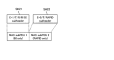
2番目のMAC subPDUのサブヘッダSH2は、RAPID(Random Access Preamble Identifier)フィールドを含むことを示すE/T/RAPIDサブヘッダである。図9(C)は、E/T/RAPIDサブヘッダの例を示す図である。E/T/RAPIDサブヘッダSH1は、Eフィールド、Tフィールド、及びRAPIDフィールドを有する。RAPID(第1の情報)は、ランダムアクセスプリアンブルの識別子であり、送信するRARに対応する。また、図9(C)において、Tフィールドは“1”である。 The subheader SH2 of the second MAC subPDU is an E/T/RAPID subheader indicating that it contains a RAPID (Random Access Preamble Identifier) field. FIG. 9C is a diagram showing an example of the E/T/RAPID subheader. The E/T/RAPID subheader SH1 has an E field, a T field and a RAPID field. RAPID (first information) is a random access preamble identifier and corresponds to the RAR to be transmitted. Also, in FIG. 9C, the T field is "1".
3番目のMAC subPDUのサブヘッダSH3は、下りデータ(DL data)が付随することを示すサブヘッダである。通信システム30においては、後続のペイロードに下りデータが含まれることを示すサブヘッダSH3が定義される。
The subheader SH3 of the third MAC subPDU is a subheader indicating that downlink data (DL data) is attached. In the
端末装置100は、サブヘッダSH3を受信することで、例えば、RARを含むペイロードP1の後に、下りデータを含むペイロードP2が付随することを認識し、下りデータを取得することができる。
By receiving the subheader SH3, the
<2.第2フォーマット>
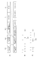
図10は、第2フォーマットの例を示す図である。第2フォーマットは、下りデータが付随することを、E/T/RAPIDサブヘッダを繰り返すことで示す。<2. Second format>
FIG. 10 is a diagram showing an example of the second format. The second format indicates that downlink data is attached by repeating the E/T/RAPID subheader.
サブヘッダSH11及びサブヘッダSH12は、図9におけるサブヘッダSH1及びサブヘッダSH2と同様である。なお、サブヘッダSH11及びサブヘッダSH12のEフィールドは、それぞれ“1”である。 Subheader SH11 and subheader SH12 are the same as subheader SH1 and subheader SH2 in FIG. The E fields of the subheaders SH11 and SH12 are both "1".
3番目のMAC subPDUのサブヘッダSH3は、Eフィールドが“1”である。端末装置100は、サブヘッダSH3のEフィールドが“1”であるため、後続にサブヘッダがあることを認識する。端末装置100は、RARを含むペイロードP11に続き、サブヘッダSH14を取得する。端末装置100は、サブヘッダSH14がサブヘッダSH13の繰り返しであることを認識すると、当該サブヘッダSH14の航続にデータを含むペイロードP12が続くことを認識することができる。これにより、端末装置100は、下りデータを取得することができる。
The E field of the subheader SH3 of the third MAC subPDU is "1". Since the E field of the subheader SH3 is "1", the
<3.第3フォーマット>
図11は、第3フォーマットの例を示す図である。第3フォーマットでは、第2フォーマットの変形例である。第3フォーマットでは、データを含むsubPDUの前の(従来のRARとの境目となる)サブヘッダにおけるEフィールドに、“0”を設定する。<3. Third format>
FIG. 11 is a diagram showing an example of the third format. The third format is a modification of the second format. In the third format, "0" is set in the E field in the subheader (which serves as a boundary with the conventional RAR) before the subPDU containing data.
サブヘッダSH21は、図10におけるサブヘッダSH11と同様である。サブヘッダSH22は、図10におけるサブヘッダSH12と異なり、Eフィールドが“0”である。以降、サブヘッダSH23、ペイロードP21、サブヘッダSH24、及びペイロードP22は、図10におけるサブヘッダSH13、ペイロードP11、サブヘッダSH14、及びペイロードP12と同様である。 The subheader SH21 is the same as the subheader SH11 in FIG. The subheader SH22 has an E field of "0" unlike the subheader SH12 in FIG. Subheader SH23, payload P21, subheader SH24, and payload P22 are the same as subheader SH13, payload P11, subheader SH14, and payload P12 in FIG.
端末装置100は、従来のRARとデータが付随するRARが多重化された場合に、第3フォーマットを使用することで、デコード処理の簡素化が可能となる。
When conventional RAR and RAR with data are multiplexed, the
図12は、第3フォーマットに対応している端末装置100、及び第3フォーマットに対応していない端末装置100が行うデコード処理の範囲の例を示す図である。図12(A)は、第3フォーマットに対応していない端末装置100の例を示し、図12(B)は、第3フォーマットに対応している端末装置100の例を示す。
FIG. 12 is a diagram showing an example of the range of decoding performed by the
第3フォーマットに対応していない端末装置100(従来端末装置)は、サブヘッダSH22を取得すると、Eフィールドが“0”であるため、以降のサブヘッダSH23、ペイロードP21、サブヘッダSH24、及びペイロードP22を、例えばパディングとして扱い、デコード処理の対象としない。すなわち、第3フォーマットに対応していない端末装置100は、先頭(サブヘッダSH21)からEフィールドが“0”であるサブヘッダ(サブヘッダSH22)まで(網掛け部)を、デコード処理の対象とする。
When the terminal device 100 (conventional terminal device) that does not support the third format acquires the subheader SH22, since the E field is "0", the following subheader SH23, payload P21, subheader SH24, and payload P22 are For example, it is treated as padding and not subject to decoding. That is, the
一方、第3フォーマットに対応している端末装置100(新規端末装置)は、サブヘッダSH22を取得すると、Eフィールドが“0”であるため、以降にデータが付随するRARが存在する可能性があることを認識する。そして、端末装置100は、データ付随するRARのサブヘッダ(サブヘッダSH23)を取得し、ペイロードP21、サブヘッダSH24、及びペイロードP22をデコード処理の対象(網掛け部)とする。これにより、端末装置100は、データを取得することができる。
On the other hand, when the terminal device 100 (new terminal device) compatible with the third format obtains the subheader SH22, the E field is "0", so there is a possibility that there is an RAR with data attached after that. Recognize that. Then, the
上述したように、第3フォーマットを使用することで、第3フォーマットに非対応の端末装置における余分なデコード処理を省略することができる。 As described above, by using the third format, it is possible to omit redundant decoding processing in a terminal device that is not compatible with the third format.
なお、第3フォーマットにおいて、Eフィールドが“0”であるサブヘッダSH22の後続のサブヘッダが、E/T/RAPIDサブヘッダではなく、R/R/LCID(Logical Channel Identifier)サブヘッダの場合がある。 In the third format, the subheader following the subheader SH22 whose E field is "0" may be an R/R/LCID (Logical Channel Identifier) subheader instead of an E/T/RAPID subheader.
図13は、後続のサブヘッダSH25がR/R/LCIDサブヘッダである例を示す図である。端末装置100は、第3フォーマットにおいて、Eフィールドが“0”であるサブヘッダSH22を受信すると、後続のサブヘッダがE/T/RAPIDサブヘッダかR/R/LCIDサブヘッダのいずれかであるかを判定する。端末装置100は、サブヘッダ種別判定処理S100を実行する。
FIG. 13 shows an example in which the subsequent subheader SH25 is the R/R/LCID subheader. In the third format, when the
図14は、サブヘッダ種別判定処理S100の処理フローチャートの例を示す図である。端末装置100は、Eフィールドが“0”であるサブヘッダの次に出現するサブヘッダを待ち受ける(S100-1のNo)。そして、端末装置100は、Eフィールドが“0”であるサブヘッダの次に出現するサブヘッダを取得すると(S100-1のYes)、取得したサブヘッダの2ビット目がON(1)であるか否かを確認する(S100-2)。
FIG. 14 is a diagram showing an example of a processing flowchart of the subheader type determination processing S100. The
端末装置100は、2ビット目がONである場合(S100-2のYes)、E/T/RAPIDサブヘッダであると判定する(S100-3)。
If the second bit is ON (Yes in S100-2), the
一方、端末装置100は、2ビット目がONでない場合(S100-2のNo)、R/R/LCIDサブヘッダであると判定する(S100-4)。
On the other hand, if the second bit is not ON (No in S100-2), the
図13に戻り、端末装置100は、サブヘッダSH25の2ビット目が“0”であり、ONではないため、当該サブヘッダSH25は、R/R/LCIDサブヘッダであると判定する。
Returning to FIG. 13, the
このように、第3フォーマットにおいて、端末装置100は、サブヘッダの2ビット目を確認することで、E/T/RAPIDサブヘッダかR/R/LCIDサブヘッダかを分類することができる。
Thus, in the third format, the
なお、E/T/R/R/BIサブヘッダは、Eフィールドが“0”であるサブヘッダの後続には設定されることはない。そこで、Tフィールドを再定義してもよい。図15は、再定義したサブヘッダのフォーマットの例を示す図である。図15(A)は、LCIDを含むサブヘッダの例を示し、図15(B)は、RAPIDを含むサブヘッダの例を示す。 Note that the E/T/R/R/BI subheader is not set after the subheader whose E field is "0". So you can redefine the T field. FIG. 15 is a diagram showing an example of the redefined subheader format. FIG. 15(A) shows an example of a subheader containing LCID, and FIG. 15(B) shows an example of a subheader containing RAPID.
図15(A)に示すように、Eフィールドが“0”であるサブヘッダの後続のサブヘッダにおいて、Tフィールドが“0”である場合、後ろ6ビットをLCIDと定義する。また、図15(B)に示すように、Eフィールドが“0”であるサブヘッダの後続のサブヘッダにおいて、Tフィールドが“1”である場合、後ろ6ビットをRAPIDと定義する。 As shown in FIG. 15A, in the subheader following the subheader whose E field is "0", if the T field is "0", the last 6 bits are defined as LCID. Also, as shown in FIG. 15B, when the T field is "1" in the subheader subsequent to the subheader whose E field is "0", the last 6 bits are defined as RAPID.
なお、図15に示すようTフィールドを再定義した場合でも、端末装置100は2ビット目を確認することで、E/T/LCIDサブヘッダとE/T/RAPIDサブヘッダを判定することができる。
Note that even when the T field is redefined as shown in FIG. 15, the
また、端末装置100は、後続にPaddingが必要ない場合、サブヘッダSH22に含まれるEフィールドの“0”を、最後尾と解釈する。図16は、Paddingが必要ない場合の例を示す図である。図16に示すように、サブヘッダSH22に続くデータがない場合、端末装置100は、サブヘッダSH22に含まれるEフィードの“0”を、以降に続くデータがない(すなわち最後尾である)と判定する。
Also, if the
<4.第4フォーマット>
図17は、第4フォーマットの例を示す図である。 図17におけるサブヘッダSH31、サブヘッダSH32、サブヘッダSH33、及びペイロードP32は、図10におけるサブヘッダSH11、サブヘッダSH12、サブヘッダSH13、及びペイロードP12と同様である。<4. Fourth Format>
FIG. 17 is a diagram showing an example of the fourth format. Subheader SH31, subheader SH32, subheader SH33, and payload P32 in FIG. 17 are the same as subheader SH11, subheader SH12, subheader SH13, and payload P12 in FIG.
第4フォーマットでは、RARを含むペイロードP31内のRビットの1つを、後続にデータを有するか否かを示すビットとして使用することを定義する。例えば、ペイロードP31内の定義されたRビットがON(1)である場合、当該RARの後続にデータがあることを示す。図17に示すように、端末装置100は、RARを含むペイロードP31の定義されたRビットが“1”であることを確認し、後続にデータを含むペイロードP32が存在することを認識する。
The fourth format defines using one of the R bits in the payload P31 containing the RAR as a bit indicating whether or not there is data following it. For example, if the defined R bit in payload P31 is ON (1), it indicates that there is data following the RAR. As shown in FIG. 17, the
<第5フォーマット>
図18は、第5フォーマットの例を示す図である。第5フォーマットは、中間に現れる(先頭以外に現れる)E/T/RAPIDサブヘッダのTフィールドに“0”を設定することを許容する。途中で現れるサブヘッダおけるTフィールドが“0”であった場合、データが付随することを示す。<Fifth format>
FIG. 18 is a diagram showing an example of the fifth format. The fifth format allows setting the T field of the E/T/RAPID subheader appearing in the middle (appearing other than at the beginning) to "0". If the T field in the subheader appearing in the middle is "0", it indicates that data is attached.
サブヘッダSH41及びサブヘッダSH42は、図9におけるサブヘッダSH1及びサブヘッダSH2と同様である。また、ペイロードP41及びペイロードP42は、図9におけるペイロードP1及びペイロードP2と同様である。 Subheader SH41 and subheader SH42 are the same as subheader SH1 and subheader SH2 in FIG. Also, payload P41 and payload P42 are the same as payload P1 and payload P2 in FIG.
E/T/RAPIDサブヘッダSH43は、Tフィールドが“0”である。端末装置100は、サブヘッダSH41で、すでにTフィールドが“0”を受信しているため、サブヘッダSH43におけるTフィールドの“0”は、2回目の受信であること(当該Tフィールドの“0”は、途中で現れていること)を認識し、後続にデータが付随することを認識する。言い換えると、端末装置100は、中間に位置するE/T/RAPIDサブヘッダについて、Tフィールドが“0”を許可することによって、従来とは違うフォーマットと認識する。端末装置100は、RARを含むペイロードP41に続くペイロードP42に含まれるデータを取得する。
The E/T/RAPID subheader SH43 has a T field of "0". Since the
なお、E/T/RAPIDサブヘッダのTフィールドに“0”を許容するためには、E/T/R/R/BIサブヘッダが先頭に現れることが条件となる。しかし、BIフィールドで指定される数値は、ランダムアクセスへの返答がないときに、次のランダムアクセスを試みるまでのランダムな待機時間(Backoff Parameter value)に対応するインデックスであるため、待機時間が0である場合、BIフィールドを含むサブヘッダは設定されない(送信されない)場合がある。そこで、インデックスの一つに、待機時間の0を定義する。 In order to allow "0" in the T field of the E/T/RAPID subheader, the E/T/R/R/BI subheader must appear at the top. However, the number specified in the BI field is an index corresponding to the random waiting time (Backoff Parameter value) until the next random access is attempted when there is no response to random access, so the waiting time is 0. , the subheader containing the BI field may not be set (sent). Therefore, one of the indices is defined as 0 for the waiting time.
図19は、Backoff Parameter valueのパラメータの例を示す図である。例えば、BIフィールドに設定されるインデックスとBackoff Parameter valueは、TS38.321 Subclause 7.2に規定されている。図19においては、Resevedと規定されているインデックス14に、Backoff Parameter value(待機時間)の“0”を新たに規定する。
FIG. 19 is a diagram showing an example of Backoff Parameter value parameters. For example, the index and Backoff Parameter value set in the BI field are specified in TS38.321 Subclause 7.2. In FIG. 19, the Backoff Parameter value (waiting time) of "0" is newly defined for the
[その他の実施の形態]
上述したデータは、例えば、ユーザデータでもよいし、MAC CE(Control Element)であってもよい。MAC CEのフォーマットについては、例えば、TS38.321 Fig.6.1.2-4に記載されている。基地局装置200は、例えば、CG(Cell Group) activation MAC CEを、メッセージBと同時に送信してもよい。これにより、MAC CEメッセージの送信完了までの時間が短縮し、データの送信遅延を抑制することができる。[Other embodiments]
The data described above may be, for example, user data or MAC CE (Control Element). The MAC CE format is described, for example, in TS38.321 Fig.6.1.2-4.
また、各実施の形態は、それぞれ組み合わせてもよい。通信システム30において、端末装置100及び基地局装置200は、第1フォーマットから第5フォーマットのいずれか1つに対応してもよいし、2つ以上の組み合わせに対して対応してもよい。また、通信システム30において、端末装置100及び基地局装置200は、例えば、電波状態(干渉度合い、受信電力など)に応じて、各メッセージフォーマットを使い分けてもよい。
Also, each embodiment may be combined. In the
10 :通信装置
11 :通信部
12 :制御部
20 :基地局装置
21 :送信部
22 :制御部
30 :通信システム
100 :端末装置
110 :CPU
120 :ストレージ
121 :通信プログラム
122 :ランダムアクセスプログラム
130 :メモリ
150 :RF回路
151 :アンテナ
200 :基地局装置
210 :CPU
220 :ストレージ
221 :通信制御プログラム
222 :ランダムアクセス制御プログラム
230 :メモリ
250 :RF回路
251 :アンテナ10: communication device 11: communication unit 12: control unit 20: base station device 21: transmission unit 22: control unit 30: communication system 100: terminal device 110: CPU
120: Storage 121: Communication Program 122: Random Access Program 130: Memory 150: RF Circuit 151: Antenna 200: Base Station Device 210: CPU
220: storage 221: communication control program 222: random access control program 230: memory 250: RF circuit 251: antenna
Claims (6)
前記第1の信号に対応する第1サブヘッダに含まれる第1の情報を、前記第2の信号に対応する第2サブヘッダに含ませて送信するよう制御することができる制御部と、
を有し、
前記制御部は、前記第1の信号と前記第2の信号を同時に送信する場合、前記第1サブヘッダの第2ビットの値を0に設定するように制御する
通信装置。 a communication device that implements a random access procedure, the transmitting unit capable of transmitting a first signal in the random access procedure and a second signal that is not the signal in the random access procedure;
a control unit capable of performing control so that first information included in a first subheader corresponding to the first signal is included in a second subheader corresponding to the second signal and transmitted;
havedeath,
The control unit controls to set a value of a second bit of the first subheader to 0 when the first signal and the second signal are simultaneously transmitted.
Communication device.
請求項1記載の通信装置。 The communication device according to claim 1, wherein the control unit performs control such that the first signal and the second signal are simultaneously transmitted according to information included in the subheader.
請求項1記載の通信装置。 The communication device according to claim 1, wherein an extension field included in the first subheader of the first information appearing before the second subheader and related to extension of a subsequent message is set to OFF.
前記ランダムアクセス手順における第1の信号と,前記ランダムアクセス手順の信号ではない第2の信号と、を受信できる受信部と、
前記第1の信号に対応する第1サブヘッダに含まれる第1の情報を含む、前記第2の信号に対応する第2サブヘッダを受信すると、前記第2の信号を受信したと認識する受信制御部と、を有し、
前記第1の信号と前記第2の信号が同時に送信される場合、前記第1サブヘッダの第2ビットの値が0に設定される
第2通信装置。 In a second communication device that implements a random access procedure,
a receiving unit capable of receiving a first signal in the random access procedure and a second signal that is not the signal in the random access procedure;
A reception control unit that recognizes that the second signal has been received upon receiving a second subheader corresponding to the second signal, which includes the first information contained in the first subheader corresponding to the first signal. and havedeath,
If the first signal and the second signal are transmitted at the same time, the value of the second bit of the first subheader is set to 0.
Second communication device.
前記送信元通信装置は、
前記ランダムアクセス手順における第1の信号と,前記ランダムアクセス手順の信号ではない第2の信号と、を送信できる送信部と、
前記第1の信号に対応する第1サブヘッダに含まれる第1の情報を、前記第2の信号に対応する第2サブヘッダに含ませて送信するよう制御することができる制御部と、を有し、
前記制御部は、前記第1の信号と前記第2の信号を同時に送信する場合、前記第1サブヘッダの第2ビットの値を0に設定するように制御し、
前記送信先通信装置は、
前記第1の信号と前記第2の信号と、を受信できる受信部と、
前記第2サブヘッダを受信すると、前記第2の信号を受信したと認識する受信制御部と、を有する
通信システム。 A communication system having a source communication device and a destination communication device implementing a random access procedure,
The source communication device,
a transmitter capable of transmitting a first signal in the random access procedure and a second signal that is not the signal in the random access procedure;
a control unit capable of controlling transmission of first information included in a first subheader corresponding to the first signal, including the first information in a second subheader corresponding to the second signal. ,
the control unit controls to set a value of a second bit of the first subheader to 0 when the first signal and the second signal are simultaneously transmitted;
The destination communication device,
a receiver capable of receiving the first signal and the second signal;
a reception control unit that recognizes that the second signal has been received when the second subheader is received.
Communications system.
前記ランダムアクセス手順における第1の信号と,前記ランダムアクセス手順の信号ではない第2の信号と、を送信する手順と、
前記第1の信号に対応する第1サブヘッダに含まれる第1の情報を、前記第2の信号に対応する第2サブヘッダに含ませて送信するよう制御する手順と、
前記第1の信号と前記第2の信号を同時に送信する場合、前記第1サブヘッダの第2ビットの値を0に設定するように制御する手順と、
を有する通信方法。 A communication method in a communication device that implements a random access procedure,
transmitting a first signal in the random access procedure and a second signal that is not a signal in the random access procedure;
a procedure for controlling transmission by including first information included in a first subheader corresponding to the first signal in a second subheader corresponding to the second signal;
a step of controlling to set the value of the second bit of the first subheader to 0 when the first signal and the second signal are simultaneously transmitted;
communication method.
Applications Claiming Priority (1)
| Application Number | Priority Date | Filing Date | Title |
|---|---|---|---|
| PCT/JP2019/006716 WO2020170412A1 (en) | 2019-02-22 | 2019-02-22 | Communication device, second communication device, communication system, and communication method |
Publications (2)
| Publication Number | Publication Date |
|---|---|
| JPWO2020170412A1 JPWO2020170412A1 (en) | 2021-11-25 |
| JP7141005B2 true JP7141005B2 (en) | 2022-09-22 |
Family
ID=72144821
Family Applications (1)
| Application Number | Title | Priority Date | Filing Date |
|---|---|---|---|
| JP2021501246A Active JP7141005B2 (en) | 2019-02-22 | 2019-02-22 | Communication device, second communication device, communication system, and communication method |
Country Status (6)
| Country | Link |
|---|---|
| US (1) | US11849490B2 (en) |
| EP (1) | EP3930413B1 (en) |
| JP (1) | JP7141005B2 (en) |
| KR (1) | KR20210122848A (en) |
| CN (1) | CN113424642B (en) |
| WO (1) | WO2020170412A1 (en) |
Citations (2)
| Publication number | Priority date | Publication date | Assignee | Title |
|---|---|---|---|---|
| WO2010077004A2 (en) | 2009-01-02 | 2010-07-08 | Lg Electronics Inc. | Random access scheme for user equipment |
| WO2019029300A1 (en) | 2017-08-11 | 2019-02-14 | 华为技术有限公司 | Method for transmitting random access response, access network device, and terminal device |
Family Cites Families (14)
| Publication number | Priority date | Publication date | Assignee | Title |
|---|---|---|---|---|
| JP4824953B2 (en) | 2005-06-23 | 2011-11-30 | 富士通株式会社 | Communication method, mobile station and base station in mobile communication system |
| JP2011223479A (en) | 2010-04-14 | 2011-11-04 | Sharp Corp | Mobile station apparatus, base station apparatus, wireless communication system, wireless communication method, and integrated circuit |
| JP6294088B2 (en) * | 2014-01-30 | 2018-03-14 | 株式会社Nttドコモ | User apparatus, base station, control information detection method, and control information transmission method |
| US10299244B2 (en) | 2015-06-19 | 2019-05-21 | Qualcomm Incorporated | Small data transmission in a wireless communications system |
| CN107046728B (en) * | 2016-02-06 | 2020-09-22 | 中兴通讯股份有限公司 | Information reporting method and device and discontinuous transmission method |
| CN108282901B (en) * | 2017-01-06 | 2019-08-09 | 电信科学技术研究院 | A kind of random access response method and apparatus |
| CN108282897B (en) * | 2017-01-06 | 2020-04-17 | 电信科学技术研究院 | Random access feedback and processing method, base station and terminal |
| CN108632987B (en) * | 2017-03-17 | 2021-06-08 | 华硕电脑股份有限公司 | Method and apparatus for a fallback mechanism for random access procedures in wireless communications |
| US11057935B2 (en) * | 2017-03-22 | 2021-07-06 | Comcast Cable Communications, Llc | Random access process in new radio |
| US10568007B2 (en) * | 2017-03-22 | 2020-02-18 | Comcast Cable Communications, Llc | Handover random access |
| EP3619950A1 (en) * | 2017-05-04 | 2020-03-11 | Ofinno, LLC | Beam-based measurement configuration |
| CN109392017B (en) * | 2017-08-11 | 2021-07-09 | 大唐移动通信设备有限公司 | Random access response method, device, base station and terminal |
| CA3066439A1 (en) * | 2019-01-03 | 2020-07-03 | Comcast Cable Communications, Llc | Access procedures in wireless communications |
| CA3067546A1 (en) * | 2019-01-10 | 2020-07-10 | Comcast Cable Communications, Llc | Access procedures in wireless communications |
-
2019
- 2019-02-22 CN CN201980091558.6A patent/CN113424642B/en active Active
- 2019-02-22 WO PCT/JP2019/006716 patent/WO2020170412A1/en unknown
- 2019-02-22 KR KR1020217028832A patent/KR20210122848A/en active Search and Examination
- 2019-02-22 EP EP19916122.5A patent/EP3930413B1/en active Active
- 2019-02-22 JP JP2021501246A patent/JP7141005B2/en active Active
-
2021
- 2021-08-13 US US17/401,490 patent/US11849490B2/en active Active
Patent Citations (3)
| Publication number | Priority date | Publication date | Assignee | Title |
|---|---|---|---|---|
| WO2010077004A2 (en) | 2009-01-02 | 2010-07-08 | Lg Electronics Inc. | Random access scheme for user equipment |
| WO2019029300A1 (en) | 2017-08-11 | 2019-02-14 | 华为技术有限公司 | Method for transmitting random access response, access network device, and terminal device |
| US20200178318A1 (en) | 2017-08-11 | 2020-06-04 | Huawei Technologies Co., Ltd. | Method for transmitting random access response, access network device, and terminal device |
Also Published As
| Publication number | Publication date |
|---|---|
| WO2020170412A1 (en) | 2020-08-27 |
| CN113424642B (en) | 2023-11-21 |
| KR20210122848A (en) | 2021-10-12 |
| EP3930413A1 (en) | 2021-12-29 |
| US20210378029A1 (en) | 2021-12-02 |
| JPWO2020170412A1 (en) | 2021-11-25 |
| EP3930413A4 (en) | 2022-03-09 |
| EP3930413B1 (en) | 2023-10-04 |
| US11849490B2 (en) | 2023-12-19 |
| CN113424642A (en) | 2021-09-21 |
Similar Documents
| Publication | Publication Date | Title |
|---|---|---|
| US11800557B2 (en) | Transport block size for contention free random access in random access procedure | |
| US20210219350A1 (en) | Random access method and communications apparatus | |
| US10701737B2 (en) | Terminal device, base station device, wireless communication system, and scheduling request method | |
| CN110461007B (en) | Random access method and communication device | |
| WO2016045487A1 (en) | Virtual busy-tone for full-duplex wireless networks | |
| TW202116043A (en) | Random access in communication system | |
| JP7141005B2 (en) | Communication device, second communication device, communication system, and communication method | |
| CN111886918B (en) | Random access method and device | |
| JP7348183B2 (en) | Random access preamble transmission method and terminal device | |
| US20210298071A1 (en) | Base station apparatus, terminal apparatus, and communication system | |
| US20210160920A1 (en) | Base station, terminal, and wireless communication system | |
| EP3298849B1 (en) | Classification of non-standard user equipment in wireless communication network | |
| JP2022549398A (en) | Two-step random access method, device, terminal and storage medium | |
| US20210337603A1 (en) | Communication device, second communication device, and communication system | |
| WO2023217271A1 (en) | Message transmission method and communication apparatus | |
| KR102656607B1 (en) | Method and apparatus for communication on unlicensed band using multi-channels in wireless communication system | |
| KR101766840B1 (en) | Method and apparatus for random access in mobile communication system for low latency support | |
| JP2020025368A (en) | Terminal device, base station device and scheduling request method | |
| CN116489807A (en) | Method and device for transmitting information | |
| KR20220002237A (en) | Wireless communication with collision avoidance |
Legal Events
| Date | Code | Title | Description |
|---|---|---|---|
| A521 | Request for written amendment filed |
Free format text: JAPANESE INTERMEDIATE CODE: A523 Effective date: 20210707 |
|
| A621 | Written request for application examination |
Free format text: JAPANESE INTERMEDIATE CODE: A621 Effective date: 20210707 |
|
| A131 | Notification of reasons for refusal |
Free format text: JAPANESE INTERMEDIATE CODE: A131 Effective date: 20220524 |
|
| A521 | Request for written amendment filed |
Free format text: JAPANESE INTERMEDIATE CODE: A523 Effective date: 20220722 |
|
| TRDD | Decision of grant or rejection written | ||
| A01 | Written decision to grant a patent or to grant a registration (utility model) |
Free format text: JAPANESE INTERMEDIATE CODE: A01 Effective date: 20220809 |
|
| A61 | First payment of annual fees (during grant procedure) |
Free format text: JAPANESE INTERMEDIATE CODE: A61 Effective date: 20220822 |
|
| R150 | Certificate of patent or registration of utility model |
Ref document number: 7141005 Country of ref document: JP Free format text: JAPANESE INTERMEDIATE CODE: R150 |