JP7140879B2 - Configurable I/O devices and how to operate them - Google Patents
Configurable I/O devices and how to operate them Download PDFInfo
- Publication number
- JP7140879B2 JP7140879B2 JP2021084501A JP2021084501A JP7140879B2 JP 7140879 B2 JP7140879 B2 JP 7140879B2 JP 2021084501 A JP2021084501 A JP 2021084501A JP 2021084501 A JP2021084501 A JP 2021084501A JP 7140879 B2 JP7140879 B2 JP 7140879B2
- Authority
- JP
- Japan
- Prior art keywords
- input
- output
- channel
- universal
- output channel
- Prior art date
- Legal status (The legal status is an assumption and is not a legal conclusion. Google has not performed a legal analysis and makes no representation as to the accuracy of the status listed.)
- Active
Links
Images


Classifications
-
- H—ELECTRICITY
- H04—ELECTRIC COMMUNICATION TECHNIQUE
- H04L—TRANSMISSION OF DIGITAL INFORMATION, e.g. TELEGRAPHIC COMMUNICATION
- H04L45/00—Routing or path finding of packets in data switching networks
- H04L45/24—Multipath
-
- G—PHYSICS
- G06—COMPUTING; CALCULATING OR COUNTING
- G06F—ELECTRIC DIGITAL DATA PROCESSING
- G06F13/00—Interconnection of, or transfer of information or other signals between, memories, input/output devices or central processing units
- G06F13/38—Information transfer, e.g. on bus
- G06F13/382—Information transfer, e.g. on bus using universal interface adapter
- G06F13/385—Information transfer, e.g. on bus using universal interface adapter for adaptation of a particular data processing system to different peripheral devices
-
- H—ELECTRICITY
- H03—ELECTRONIC CIRCUITRY
- H03K—PULSE TECHNIQUE
- H03K19/00—Logic circuits, i.e. having at least two inputs acting on one output; Inverting circuits
- H03K19/0175—Coupling arrangements; Interface arrangements
- H03K19/017581—Coupling arrangements; Interface arrangements programmable
-
- G—PHYSICS
- G06—COMPUTING; CALCULATING OR COUNTING
- G06F—ELECTRIC DIGITAL DATA PROCESSING
- G06F13/00—Interconnection of, or transfer of information or other signals between, memories, input/output devices or central processing units
- G06F13/14—Handling requests for interconnection or transfer
- G06F13/36—Handling requests for interconnection or transfer for access to common bus or bus system
- G06F13/362—Handling requests for interconnection or transfer for access to common bus or bus system with centralised access control
- G06F13/366—Handling requests for interconnection or transfer for access to common bus or bus system with centralised access control using a centralised polling arbiter
-
- G—PHYSICS
- G06—COMPUTING; CALCULATING OR COUNTING
- G06F—ELECTRIC DIGITAL DATA PROCESSING
- G06F13/00—Interconnection of, or transfer of information or other signals between, memories, input/output devices or central processing units
- G06F13/38—Information transfer, e.g. on bus
- G06F13/40—Bus structure
- G06F13/4063—Device-to-bus coupling
- G06F13/4068—Electrical coupling
-
- G—PHYSICS
- G06—COMPUTING; CALCULATING OR COUNTING
- G06F—ELECTRIC DIGITAL DATA PROCESSING
- G06F13/00—Interconnection of, or transfer of information or other signals between, memories, input/output devices or central processing units
- G06F13/38—Information transfer, e.g. on bus
- G06F13/40—Bus structure
- G06F13/4063—Device-to-bus coupling
- G06F13/409—Mechanical coupling
-
- H—ELECTRICITY
- H03—ELECTRONIC CIRCUITRY
- H03K—PULSE TECHNIQUE
- H03K19/00—Logic circuits, i.e. having at least two inputs acting on one output; Inverting circuits
- H03K19/0175—Coupling arrangements; Interface arrangements
- H03K19/01759—Coupling arrangements; Interface arrangements with a bidirectional operation
Landscapes
- Engineering & Computer Science (AREA)
- Theoretical Computer Science (AREA)
- General Engineering & Computer Science (AREA)
- Physics & Mathematics (AREA)
- Computer Hardware Design (AREA)
- General Physics & Mathematics (AREA)
- Computing Systems (AREA)
- Mathematical Physics (AREA)
- Signal Processing (AREA)
- Computer Networks & Wireless Communication (AREA)
- Programmable Controllers (AREA)
- Data Exchanges In Wide-Area Networks (AREA)
- Logic Circuits (AREA)
Description
本発明は、入出力装置に関するものであって、特に、設定可能な入出力装置、および、その操作方法に関するものである。 The present invention relates to input/output devices, and more particularly to configurable input/output devices and methods of operating same.
各種工業的応用において、高い信頼性の冗長設計が必要である。通常、信頼できるデータ収集のために、複数の入出力(I/O)チャネルが、同一タイプのフィールドデバイスに接続されて単一障害点を防止しており、これにより、冗長設計が必然的に高価になる。よって、上記の構造設計は改善が必要である。 A variety of industrial applications require highly reliable redundant designs. For reliable data collection, multiple input/output (I/O) channels are typically connected to the same type of field device to prevent single points of failure, which necessitates a redundant design. get expensive. Therefore, the above structural design needs improvement.
本発明は、設定可能な入出力装置、および、その操作方法を提供することを目的とする。 SUMMARY OF THE INVENTION It is an object of the present invention to provide a configurable input/output device and an operating method thereof.
(1) 本発明は、複数の入出力端子、ルーティングモジュール、および、第一ユニバーサル入出力チャネルを有する、設定可能な入出力装置を提供する。入出力端子は、複数のフィールドデバイスに接続される。入出力端子は、フィールドデバイスから複数の入力信号を受信する。入出力端子は、複数の出力信号をフィールドデバイスに出力する。少なくとも二個の入力信号は異なり、少なくとも二個の出力信号は異なり、少なくとも二個のフィールドデバイスは異なる。ルーティングモジュールは、入出力端子に接続される。第一ユニバーサル入出力チャネルは、ルーティングモジュールに接続される。ルーティングモジュールは、第一ユニバーサル入出力チャネルと入出力端子間の接続を制御する。ルーティングモジュールはさらに、入力信号および出力信号の送受信順序を制御することを特徴とする。 (1) The present invention provides a configurable input/output device having a plurality of input/output terminals, a routing module, and a first universal input/output channel. The input/output terminals are connected to a plurality of field devices. The input/output terminal receives a plurality of input signals from field devices. The input/output terminal outputs a plurality of output signals to the field device. At least two input signals are different, at least two output signals are different, and at least two field devices are different. A routing module is connected to the input/output terminals. A first universal input/output channel is connected to the routing module. A routing module controls connections between the first universal input/output channel and the input/output terminals. The routing module is further characterized by controlling the order of transmission and reception of input and output signals.
(2) 上記(1)に記載の設定可能な入出力装置であって、前記ルーティングモジュールは、前記第一ユニバーサル入出力チャネルおよび前記入出力端子に接続されるスイッチングモジュールと、前記スイッチングモジュールに接続される処理モジュールと、を有し、前記処理モジュールは設定信号を受信するとともに、前記設定信号にしたがって制御信号を生成し、前記スイッチングモジュール、および、前記入力信号および前記出力信号の前記送受信順序を制御し、これにより、前記スイッチングモジュールが、前記第一ユニバーサル入出力チャネルと前記入出力端子間の前記接続を切り換えることを特徴とする。
(3) 上記(2)に記載の設定可能な入出力装置であって、前記処理モジュールは、第一ユニバーサル入出力チャネルから前記スイッチングモジュールを切断し、前記処理モジュールは、前記第一ユニバーサル入出力チャネルから前記設定信号を受信し、前記処理モジュールは前記第一ユニバーサル入出力チャネルを切断し、前記処理モジュールは、前記設定信号にしたがって前記制御信号を生成して、前記スイッチングモジュールを制御し、これにより、前記スイッチングモジュールが、前記第一ユニバーサル入出力チャネルと前記入出力端子間の前記接続を切り換え、前記入力信号および前記出力信号が、連続して、前記第一ユニバーサル入出力チャネル、前記スイッチングモジュール、および、前記入出力端子を介して送受信されることを特徴とする。
(4) 上記(2)に記載の設定可能な入出力装置であって、前記ルーティングモジュールに接続される第二ユニバーサル入出力チャネルを有し、前記ルーティングモジュールは、前記第一ユニバーサル入出力チャネルと前記入出力端子間の前記接続、および、前記第二ユニバーサル入出力チャネルと前記入出力端子間の接続を同時に制御することを特徴とする。
(5) 上記(4)に記載の設定可能な入出力装置であって、前記第一ユニバーサル入出力チャネルおよび前記第二ユニバーサル入出力チャネルは、出力信号を同時に提供し、前記ルーティングモジュールはさらに、前記第一ユニバーサル入出力チャネルあるいは前記第二ユニバーサル入出力チャネルからの前記出力信号を選択するとともに、前記出力信号を前記フィールドデバイスの一つに送信するアービターを有することを特徴とする。
(6) 上記(5)に記載の設定可能な入出力装置であって、前記入出力端子はそれぞれ、前記ルーティングモジュールが、前記第一ユニバーサル入出力チャネルおよび前記第二ユニバーサル入出力チャネルから前記入出力端子を切断すると、前記フィールドデバイスに出力される前記出力信号の出力状態を維持するラッチユニットを有することを特徴とする。
(7) 上記(1)に記載の設定可能な入出力装置であって、さらに、前記ルーティングモジュールに接続されるとともに、前記複数の前記入出力端子に対応する複数の入出力チャネルを有し、前記ルーティングモジュールは、前記第一ユニバーサル入出力チャネルと、前記入出力チャネルと、前記入出力端子との間の前記接続を制御することを特徴とする。
(8) 上記(7)に記載の設定可能な入出力装置であって、前記第一ユニバーサル入出力チャネルおよび前記入出力チャネルの一つが入力チャネルであるとき、前記第一ユニバーサル入出力チャネルおよび前記入出力チャネルの一つは冗長であり、且つ、前記第一ユニバーサル入出力チャネルが入力チャネルであり、前記入出力チャネルの前記ひとつが出力チャネルであるとき、前記入出力チャネルの前記一つが前記第一ユニバーサル入出力チャネルにより診断されることを特徴とする。
(2) The configurable input/output device according to (1) above, wherein the routing module includes a switching module connected to the first universal input/output channel and the input/output terminal, and a switching module connected to the switching module. a processing module that receives a setting signal, generates a control signal according to the setting signal, and controls the switching module and the order of transmission and reception of the input signal and the output signal. control so that the switching module switches the connection between the first universal input/output channel and the input/output terminal.
(3) The configurable input/output device of (2) above, wherein the processing module disconnects the switching module from the first universal input/output channel, and the processing module disconnects the first universal input/output channel. receiving the setting signal from a channel, the processing module disconnecting the first universal input/output channel, the processing module generating the control signal according to the setting signal to control the switching module, and causes the switching module to switch the connection between the first universal input/output channel and the input/output terminal, wherein the input signal and the output signal are continuously connected to the first universal input/output channel, the switching module , and is transmitted and received via the input/output terminal.
(4) The configurable input/output device of (2) above, comprising a second universal input/output channel connected to the routing module, wherein the routing module is connected to the first universal input/output channel. The connection between the input/output terminals and the connection between the second universal input/output channel and the input/output terminal are simultaneously controlled.
(5) The configurable input/output device of (4) above, wherein the first universal input/output channel and the second universal input/output channel simultaneously provide output signals, the routing module further comprising: An arbiter selects the output signal from the first universal input/output channel or the second universal input/output channel and transmits the output signal to one of the field devices.
(6) The configurable input/output device of (5) above, wherein each of said input/output terminals is configured such that said routing module receives said inputs from said first universal input/output channel and said second universal input/output channel. A latch unit is provided for maintaining the output state of the output signal output to the field device when the output terminal is disconnected.
(7) The configurable input/output device according to (1), further comprising: a plurality of input/output channels connected to the routing module and corresponding to the plurality of input/output terminals; The routing module is characterized in that it controls the connection between the first universal input/output channel, the input/output channel and the input/output terminal.
(8) In the configurable input/output device of (7) above, when the first universal input/output channel and one of the input/output channels are input channels, the first universal input/output channel and the front input/output channel are input channels. One of the I/O channels is redundant, and when the first universal I/O channel is an input channel and the one of the I/O channels is an output channel, the one of the I/O channels is the first universal I/O channel. It is characterized by being diagnosed by one universal input/output channel.
(9) 本発明はさらに、以下のステップを含む、設定可能な入出力装置の操作方法を提供する。複数の入出力端子を設けて、複数のフィールドデバイスに接続し、フィールドデバイスから複数の入力信号を受信するとともに、複数の出力信号をフィールドデバイスに出力し、少なくとも二個の入力信号は異なり、少なくとも二個の出力信号は異なり、少なくとも二個のフィールドデバイスは異なる。ルーティングモジュールを設けて、入出力端子に接続する。第一ユニバーサル入出力チャネルを設けて、ルーティングモジュールに接続する。ルーティングモジュールを用いて、第一ユニバーサル入出力チャネルと入出力端子間の接続、および、入力信号および出力信号の送受信順序を制御することを特徴とする。 (9) The present invention further provides a method for operating a configurable input/output device, including the following steps. A plurality of input/output terminals are provided to connect to a plurality of field devices, receive a plurality of input signals from the field devices, and output a plurality of output signals to the field devices, wherein at least two input signals are different and at least The two output signals are different and the at least two field devices are different. A routing module is provided to connect to the input/output terminals. A first universal input/output channel is provided and connected to the routing module. A routing module is used to control the connection between the first universal input/output channel and the input/output terminals, and the transmission/reception order of the input and output signals.
(10) 上記(9)に記載の設定可能な入出力装置の操作方法であって、前記ルーティングモジュールは、スイッチングモジュールおよび処理モジュールを有し、前記ルーティングモジュールを用いて、前記第一ユニバーサル入出力チャネルと前記入出力端子間の接続、および、前記入力信号および前記出力信号の前記送受信順序を制御する前記工程は、前記処理モジュールを用いて、設定信号を受信するとともに、前記設定信号にしたがって制御信号を生成して、前記スイッチングモジュール、および、前記入力信号および前記出力信号の前記送受信順序を制御して、前記スイッチングモジュールが、前記第一ユニバーサル入出力チャネルと前記入出力端子間の前記接続を切り換える工程、を有することを特徴とする。
(11) 上記(10)に記載の設定可能な入出力装置の操作方法であって、前記処理モジュールは、前記第一ユニバーサル入出力チャネルから前記スイッチングモジュールを切断し、前記処理モジュールは、前記第一ユニバーサル入出力チャネルから前記設定信号を受信し、前記処理モジュールは、前記第一ユニバーサル入出力チャネルを切断し、前記処理モジュールは、前記設定信号にしたがって前記制御信号を生成して、前記スイッチングモジュールを制御し、よって、前記スイッチングモジュールが、前記第一ユニバーサル入出力チャネルと前記入出力端子間の前記接続を切り換え、前記入力信号および前記出力信号が、連続して、前記第一ユニバーサル入出力チャネル、前記スイッチングモジュール、および、前記入出力端子を介して送受信されることを特徴とする。
(12) 上記(10)に記載の設定可能な入出力装置の操作方法であって、さらに、第二ユニバーサル入出力チャネルを設けて、前記ルーティングモジュールに接続する工程、および、前記ルーティングモジュールを用いて、前記第一ユニバーサル入出力チャネルと前記入出力端子間の前記接続、および、前記第二ユニバーサル入出力チャネルと前記入出力端子間の接続を同時に制御する工程、を有することを特徴とする。
(13) 上記(12)に記載の設定可能な入出力装置の操作方法であって、前記ルーティングモジュールはさらにアービターを有し、前記操作方法はさらに、前記第一ユニバーサル入出力チャネルおよび前記第二ユニバーサル入出力チャネルが同時に出力信号を提供すると、前記アービターを用いて、前記第一ユニバーサル入出力チャネルあるいは前記第二ユニバーサル入出力チャネルからの前記出力信号を選択するとともに、前記出力信号を前記フィールドデバイスの一つに送信する工程を有することを特徴とする。
(14) 上記(13)に記載の設定可能な入出力装置の操作方法であって、前記入出力端子はそれぞれラッチユニットを有し、前記操作方法はさらに、前記ルーティングモジュールが、前記第一ユニバーサル入出力チャネルおよび前記第二ユニバーサル入出力チャネルから前記入出力端子を切断すると、前記ラッチユニットを用いて、前記フィールドデバイスに出力される前記出力信号の出力状態を維持する工程を有することを特徴とする。
(15) 上記(9)に記載の設定可能な入出力装置の操作方法であって、さらに、複数の入出力チャネルを設けて、前記ルーティングモジュールに接続するとともに、前記複数の入出力端子に対応させる工程、および、前記ルーティングモジュールを用いて、前記第一ユニバーサル入出力チャネルと、前記入出力チャネルと、前記入出力端子との間の前記接続を制御する工程、を有することを特徴とする。
(16) 上記(15)に記載の設定可能な入出力装置の操作方法であって、前記第一ユニバーサル入出力チャネルおよび前記入出力チャネルの一つが入力チャネルであるとき、前記第一ユニバーサル入出力チャネルおよび前記入出力チャネルの前記一つは冗長であり、且つ、前記第一ユニバーサル入出力チャネルが入力チャネルであり、前記入出力チャネルの前記一つが出力チャネルであるとき、前記入出力チャネルの前記一つが前記第一ユニバーサル入出力チャネルにより診断されることを特徴とする。
(10) The method of operating a configurable input/output device according to (9) above, wherein the routing module comprises a switching module and a processing module, and using the routing module, the first universal input/output The step of controlling the connections between the channels and the input/output terminals and the order of transmission and reception of the input signals and the output signals uses the processing module to receive a setting signal and control according to the setting signal. generating a signal to control the switching module and the order of transmission and reception of the input signal and the output signal to cause the switching module to establish the connection between the first universal input/output channel and the input/output terminal; and a step of switching.
(11) The method of operating a configurable input/output device according to (10) above, wherein the processing module disconnects the switching module from the first universal input/output channel, and the processing module disconnects the switching module from the first universal input/output channel. receiving the setting signal from one universal input/output channel, the processing module disconnecting the first universal input/output channel, the processing module generating the control signal according to the setting signal, and the switching module so that said switching module switches said connection between said first universal input/output channel and said input/output terminal, said input signal and said output signal continuously controlling said first universal input/output channel , the switching module, and the input/output terminal.
(12) The method of operating a configurable input/output device according to (10), further comprising providing a second universal input/output channel to connect to the routing module; and simultaneously controlling the connection between the first universal input/output channel and the input/output terminal and the connection between the second universal input/output channel and the input/output terminal.
(13) The method of operating a configurable input/output device of (12) above, wherein said routing module further comprises an arbiter, said operating method further comprising said first universal input/output channel and said second universal input/output channel. When the universal input/output channels simultaneously provide output signals, the arbiter is used to select the output signal from the first universal input/output channel or the second universal input/output channel and direct the output signal to the field device. and transmitting to one of the
(14) The method of operating a configurable input/output device according to (13) above, wherein the input/output terminals each have a latch unit, the operating method further comprising: and maintaining the output state of the output signal output to the field device using the latch unit when the input/output terminal is disconnected from the input/output channel and the second universal input/output channel. do.
(15) The method of operating a settable input/output device according to (9) above, further comprising: providing a plurality of input/output channels, connecting to the routing module, and corresponding to the plurality of input/output terminals; and controlling the connections between the first universal input/output channel, the input/output channels and the input/output terminals using the routing module.
(16) The method of operating a configurable input/output device according to (15) above, wherein said first universal input/output channel and one of said input/output channels is an input channel, said first universal input/output channels and said one of said I/O channels are redundant, and said one of said I/O channels is redundant when said first universal I/O channel is an input channel and said one of said I/O channels is an output channel. One is diagnosed by the first universal input/output channel.
本発明により、冗長設計が必然的に高価になる単一障害点を防止し、且つ、高い信頼性が達成される。 The present invention prevents single points of failure for which redundant designs are necessarily expensive and achieves high reliability.
以下の実施形態のそれぞれにおいて、同じ参照符号は、同一または類似の素子あるいはコンポーネントを示す。 In each of the following embodiments, the same reference numbers indicate the same or similar elements or components.
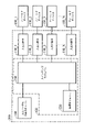
図1は、本発明の一実施形態による設定可能な入出力装置を示す図である。図1を参照する。設定可能な入出力(I/O)装置100は、複数の入出力端子110_1~110_N、ルーティングモジュール120、および、ユニバーサル入出力チャネル130を有し、Nは、1より大きい正の整数である。
FIG. 1 is a diagram illustrating a configurable input/output device according to one embodiment of the present invention. Please refer to FIG. Configurable input/output (I/O)
入出力端子110_1~110_Nは、複数のフィールドデバイス150_1~150_Nに接続される。たとえば、入出力端子110_1は、フィールドデバイス150_1に接続され、入出力端子110_2は、フィールドデバイス150_2に接続され、入出力端子110_Nは、フィールドデバイス150_Nに接続される。本実施形態において、入出力端子110_1~110_Nは、たとえば、アナログ入出力端子、および、デジタル入出力端子を有する。たとえば、入出力端子110_1はアナログ入出力端子、入出力端子110_2はデジタル入出力端子、入出力端子110_3はデジタル入出力端子であり、入出力端子110_Nはアナログ入出力端子であるが、本発明の実施形態は、それらに限定されない。 The input/output terminals 110_1-110_N are connected to a plurality of field devices 150_1-150_N. For example, input/output terminal 110_1 is connected to field device 150_1, input/output terminal 110_2 is connected to field device 150_2, and input/output terminal 110_N is connected to field device 150_N. In this embodiment, the input/output terminals 110_1 to 110_N have, for example, analog input/output terminals and digital input/output terminals. For example, the input/output terminal 110_1 is an analog input/output terminal, the input/output terminal 110_2 is a digital input/output terminal, the input/output terminal 110_3 is a digital input/output terminal, and the input/output terminal 110_N is an analog input/output terminal. Embodiments are not so limited.
入出力端子110_1~110_Nは、フィールドデバイス150_1~150_Nから複数の入力信号を受信するとともに、複数の出力信号をフィールドデバイス150_1~150_Nに出力する。本実施形態において、少なくとも二個の入力信号は異なる。つまり、フィールドデバイス150_1~150_Nにより生成される少なくとも二個の入力信号は異なる。このほか、入力信号には、アナログ入力信号およびデジタル入力信号が挙げられる。たとえば、フィールドデバイス150_1により生成される入力信号はアナログ入力信号、フィールドデバイス150_2により生成される入力信号はデジタル入力信号、フィールドデバイス150_3により生成される入力信号はデジタル入力信号、フィールドデバイス150_Nにより生成される入力信号はアナログ入力信号であるが、本発明の実施形態は、それらに限定されない。ユーザーは、要求に応じて、フィールドデバイス150_1~150_Nにより生成される入力信号のタイプを調整することができる。 The input/output terminals 110_1-110_N receive a plurality of input signals from the field devices 150_1-150_N and output a plurality of output signals to the field devices 150_1-150_N. In this embodiment, at least two input signals are different. That is, at least two input signals generated by field devices 150_1-150_N are different. In addition, input signals include analog input signals and digital input signals. For example, the input signal generated by field device 150_1 is an analog input signal, the input signal generated by field device 150_2 is a digital input signal, the input signal generated by field device 150_3 is a digital input signal, and the input signal generated by field device 150_N is a digital input signal. Although the input signal used is an analog input signal, embodiments of the present invention are not so limited. A user can adjust the type of input signal generated by the field devices 150_1-150_N as desired.
本実施形態において、少なくとも二個の出力信号は異なる。つまり、フィールドデバイス150_1~150_Nに出力される少なくとも二個の出力信号は異なる。このほか、出力信号には、アナログ出力信号およびデジタル出力信号が挙げられる。たとえば、フィールドデバイス150_1に出力される出力信号はアナログ出力信号、フィールドデバイス150_2に出力される出力信号はデジタル出力信号、フィールドデバイス150_3に出力される出力信号はデジタル出力信号、フィールドデバイス150_Nに出力される出力信号はアナログ出力信号であるが、本発明の実施形態は、それらに限定されない。ユーザーは、要求に応じて、フィールドデバイス150_1~150_Nにより生成される出力信号のタイプを調整することができる。 In this embodiment, at least two output signals are different. That is, at least two output signals output to the field devices 150_1-150_N are different. In addition, output signals include analog output signals and digital output signals. For example, the output signal output to the field device 150_1 is an analog output signal, the output signal output to the field device 150_2 is a digital output signal, the output signal output to the field device 150_3 is a digital output signal, and the output signal is output to the field device 150_N. Although the output signal is an analog output signal, embodiments of the present invention are not so limited. A user can adjust the type of output signal generated by the field devices 150_1-150_N as desired.
本実施形態において、フィールドデバイス150_1~150_Nのうち少なくとも二個は異なる。このほか、フィールドデバイス150_1~150_Nは、任意で、センサー、アクチュエーター、あるいは、信号調節器を有してもよいが、本発明の実施形態は、それらに限定されない。たとえば、フィールドデバイス150_1はセンサー、フィールドデバイス150_2はアクチュエータ、フィールドデバイス150_3は信号調節器、フィールドデバイス150_Nはセンサーであるが、本発明の実施形態は、それらに限定されない。ユーザーは、必要に応じて、フィールドデバイス150_1~150_Nのタイプを調整することができる。さらに、信号調節器が用いられて、信号の増幅、信号の減衰、信号のろ過、信号の隔離等を実行する。 In this embodiment, at least two of the field devices 150_1-150_N are different. Additionally, field devices 150_1-150_N may optionally include sensors, actuators, or signal conditioners, although embodiments of the present invention are not so limited. For example, field device 150_1 is a sensor, field device 150_2 is an actuator, field device 150_3 is a signal conditioner, and field device 150_N is a sensor, although embodiments of the present invention are not so limited. The user can adjust the type of field devices 150_1-150_N as needed. In addition, signal conditioners are used to perform signal amplification, signal attenuation, signal filtering, signal isolation, and the like.
ルーティングモジュール120は、入出力端子110_1~110_Nに接続される。ユニバーサル入出力チャネル130は、ルーティングモジュール120に接続される。このほか、ユニバーサル入出力チャネル130は、“デジタルーアナログ”変換、および、“アナログ―デジタル”変換の機能を備えてもよい。本実施形態において、ルーティングモジュール120は、ユニバーサル入出力チャネル130と入出力端子110_1~110_N間の接続、および、フィールドデバイス150_1~150_Nから入力信号を受信、および、出力信号をフィールドデバイス150_1~150_Nに出力する時間系列を制御する。本実施形態において、ルーティングモジュール120は、たとえば、時分割多重アクセス(TDMA)あるいは類似技術を、入力信号および出力信号に適用する。
The
設定可能な入出力装置100の操作において、ルーティングモジュール120は、ユニバーサル入出力チャネル130が入出力端子110_1に接続されるように制御し、これにより、フィールドデバイス150_1(たとえば、アナログセンサー)により生成される入力信号(たとえば、アナログ入力信号)は、入出力端子110_1、ルーティングモジュール120を介して、ユニバーサル入出力チャネル130に送信され得る、あるいは、フィールドデバイス150_1(たとえば、アナログアクチュエーター)に出力される出力信号(たとえば、アナログ出力信号)は、ユニバーサル入出力チャネル130、ルーティングモジュール120を介して、入出力端子110_1に送信され得る。
In operation of the configurable input/
その後、ルーティングモジュール120は、入出力端子110_1から、ユニバーサル入出力チャネル130を切断するとともに、ユニバーサル入出力チャネル130が入出力端子110_2に接続されるように制御し、これにより、フィールドデバイス150_2(たとえば、デジタルセンサー)により入力信号(たとえば、デジタル入力信号)は、入出力端子110_2、ルーティングモジュール120を介して、ユニバーサル入出力チャネル130に送信され得る、あるいは、フィールドデバイス150_2(たとえば、デジタルアクチュエーター)に出力される出力信号(たとえば、デジタル出力信号)は、ユニバーサル入出力チャネル130、ルーティングモジュール120を介して、入出力端子110_2に送信され得る。残りのユニバーサル入出力チャネル130と入出力端子110_3~110_N間の接続、および、入力信号および出力信号の送受信順序は、上記の実施形態に類似するので、この記述はここで繰り返さない。
After that,
よって、設定可能な入出力装置100は、入出力端子110_1~110_Nにより、同時に、各種タイプのフィールドデバイス150_1~150_Nに接続され、入出力端子110_1~110_N(フィールドデバイス150_1~150_N)は、同じユニバーサル入出力チャネル130を共有し、これにより、回路設計の複雑性を減少させ、且つ、使用の便宜性を向上させる。
Thus, the configurable input/
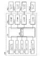
図2は、本発明の別の実施形態による設定可能な入出力装置を示す図である。図2を参照する。設定可能な入出力装置200は、図1の設定可能な入出力装置100に類似する。図2において、入出力端子110_1~110_N、ユニバーサル入出力チャネル130、および、フィールドデバイス150_1~150_Nは、入出力端子110_1~110_N、ユニバーサル入出力チャネル130、および、フィールドデバイス150_1~150_Nと等しい、あるいは、類似する。したがって、図2の入出力端子110_1~110_N、ユニバーサル入出力チャネル130、および、フィールドデバイス150_1~150_Nは、図1の実施形態を参照し、それらの記述はここで繰り返さない。
FIG. 2 is a diagram illustrating a configurable input/output device according to another embodiment of the invention. Please refer to FIG. Configurable input/
本実施形態において、ルーティングモジュール120は、スイッチングモジュール210、および、処理モジュール220を有する。スイッチングモジュール210は、ユニバーサル入出力チャネル130、および、入出力端子110_1~110_Nに接続される。本実施形態において、スイッチングモジュール210は、たとえば、マルチプレクサであるが、本発明の実施形態は、それらに限定されない。
In this embodiment,
処理モジュール220は、スイッチングモジュール210に接続される。本実施形態において、処理モジュール220は、マイクロプロセッサ、あるいは、マイクロコントローラーであるが、本発明の実施形態は、それらに限定されない。処理モジュール220は、設定信号を受信するとともに、設定信号にしたがって制御信号を生成し、スイッチングモジュール210、および、入力信号および出力信号の送受信順序を制御して、これにより、スイッチングモジュール210は、ユニバーサル入出力チャネル130と入出力端子110_1~110_N間の接続を切り換える。
本実施形態において、設定信号は、たとえば、スイッチングモジュール210に対応する切り換え順序、および、入力信号および出力信号の送受信順序を含み得るが、本発明の実施形態は、それらに限定されない。ある実施形態において、設定信号は、外部処理モジュール(図示しない)により提供され、たとえば、処理モジュール220は、外部処理モジュールから設定信号を受信して、制御信号を生成する。ある実施形態において、設定信号は、ユニバーサル入出力チャネル130、あるいは、その他の伝送線(図示しない)を介して提供され、たとえば、処理モジュール220は、ユニバーサル入出力チャネル130、あるいは、その他の伝送線を介して設定信号を受信して、制御信号を生成する。ある実施形態において、処理モジュール220は省略され、スイッチングモジュール210は、外部の処理モジュールにより制御される。
In this embodiment, the configuration signal may include, for example, the switching order corresponding to the
ルーティングモジュール120の操作において、処理モジュール220は、まず、ユニバーサル入出力チャネル130からスイッチングモジュール210を切断する。その後、処理モジュール220は、ユニバーサル入出力チャネル130から設定信号を受信するとともに、設定信号にしたがって制御信号を生成する。その後、処理モジュール220は、ユニバーサル入出力チャネル130から切断される。処理モジュール220は、制御信号をスイッチングモジュール210に送信して、スイッチングモジュール210を制御し、これにより、スイッチングモジュール210が、ユニバーサル入出力チャネル130と入出力端子110_1~110_N間の接続を切り換え、且つ、入力信号および出力信号は、連続して、ユニバーサル入出力チャネル130、スイッチングモジュール210、および、入出力端子110_1~110_Nにより送受信される。
In operation of
設定可能な入出力装置200の操作において、スイッチングモジュール210は、ユニバーサル入出力チャネル130と入出力端子110_1の接続を切り換え、これにより、フィールドデバイス150_1(たとえば、アナログセンサー)により生成される入力信号(たとえば、アナログ入力信号)は、入出力端子110_1、スイッチングモジュール210を介して、ユニバーサル入出力チャネル130に送信され得る、あるいは、フィールドデバイス150_1(たとえば、アナログアクチュエーター)に出力される出力信号(たとえば、アナログ出力信号)は、ユニバーサル入出力チャネル130、スイッチングモジュール210を介して、入出力端子110_1に送信され得る。
In operation of the configurable input/
その後、スイッチングモジュール210は、入出力端子110_1からのユニバーサル入出力チャネル130の切断を切り換えて、ユニバーサル入出力チャネル130と入出力端子110_2を接続し、これにより、フィールドデバイス150_2(たとえば、デジタルセンサー)により生成される入力信号(たとえば、デジタル入力信号)は、入出力端子110_2、スイッチングモジュール210を介して、ユニバーサル入出力チャネル130に送信され得、且つ、その後、フィールドデバイス150_2(たとえば、デジタルアクチュエーター)に出力される出力信号(たとえば、デジタル出力信号)は、ユニバーサル入出力チャネル130、スイッチングモジュール210を介して、入出力端子110_2に送信され得る。残りのユニバーサル入出力チャネル130と入出力端子110_3~110_N間の接続、および、入力信号および出力信号の送受信順序は、上記の実施形態に類似するので、この記述はここで繰り返さない。
The
よって、設定可能な入出力装置100は、入出力端子110_1~110_Nにより、同時に、各種タイプのフィールドデバイス150_1~150_Nに接続され、入出力端子110_1~110_N(フィールドデバイス150_1~150_N)は、同じユニバーサル入出力チャネル130を共有し、これにより、回路設計の複雑性を減少させ、且つ、使用の便宜性を向上させる。
Thus, the configurable input/
図3Aは、本発明の別の実施形態による設定可能な入出力装置を示す図である。設定可能な入出力装置300は、複数の入出力端子110_1~110_N、ルーティングモジュール120、ユニバーサル入出力チャネル130、および、ユニバーサルチャネル310を有する。本実施形態において、入出力端子110_1~110_N、ユニバーサル入出力チャネル130、および、フィールドデバイス150_1~150_Nは、図1の入出力端子110_1~110_N、ユニバーサル入出力チャネル130、および、フィールドデバイス150_1~150_Nと等しい、あるいは、類似する。したがって、図3Aの入出力端子110_1~110_N、ユニバーサル入出力チャネル130、および、フィールドデバイス150_1~150_Nは、図1の実施形態を参照し、それらの記述は、ここで繰り返さない。
FIG. 3A is a diagram illustrating a configurable input/output device according to another embodiment of the invention. The configurable input/
ユニバーサル入出力チャネル310は、ルーティングモジュール120に接続される。このほか、ユニバーサル入出力チャネル310は、データ抽出、“デジタルーアナログ”変換、および、“アナログーデジタル”変換の機能も有する。ルーティングモジュール120は、ユニバーサル入出力チャネル130と入出力端子110_1~110_N間の接続、ユニバーサル入出力チャネル310と入出力端子110_1~110_N間の接続を、同時に制御する。
Universal input/
図3Bに示されるように、デバイス150_1、150_3~150_N-1がアナログセンサー、フィールドデバイス150_2、150_4~150_Nがデジタルセンサーであると仮定する。この実施形態において、ルーティングモジュール120は、ユニバーサル入出力チャネル130およびユニバーサル入出力チャネル310が入出力端子110_1に接続されるように同時に制御して、フィールドデバイス150_1(たとえば、アナログセンサー)により生成される入力信号(たとえば、アナログ入力信号)は、同時に、ユニバーサル入出力チャネル130およびユニバーサル入出力チャネル310に送信される。
Assume that devices 150_1, 150_3 through 150_N-1 are analog sensors and field devices 150_2, 150_4 through 150_N are digital sensors, as shown in FIG. 3B. In this embodiment,
その後、ルーティングモジュール120は、入出力端子110_1から、ユニバーサル入出力チャネル130およびユニバーサル入出力チャネル310を切断するとともに、ユニバーサル入出力チャネル130およびユニバーサル入出力チャネル310が入出力端子110_2に接続されるように同時に制御し、よって、フィールドデバイス150_2(たとえば、デジタルセンサー)により生成される入力信号(たとえば、デジタル入力信号)は、同時に、ユニバーサル入出力チャネル130およびユニバーサル入出力チャネル310に送信される。残りのユニバーサル入出力チャネル130とユニバーサル入出力チャネル310と入出力端子110_3~110_N間の接続、および、入力信号の送信順序は、上記の実施形態に類似するので、この記述はここで繰り返さない。
After that,
よって、ユニバーサル入出力チャネル130、および、ユニバーサル入出力チャネル310は、同時に、同一タイプの入力信号を受信するので、設定可能な入出力装置300は重複機能を達成する。
Thus, since universal I/
図3Cに示されるように、デバイス150_1、150_3~150_N-1がアナログアクチュエーター、フィールドデバイス150_2、150_4~150_Nがデジタルアクチュエーターであると仮定する。本実施形態において、ルーティングモジュール120はさらにアービター330を有し、入出力端子110_1~110_Nはさらにラッチユニット340_1~340_Nを有する。この実施形態において、ルーティングモジュール120は、ユニバーサル入出力チャネル130およびユニバーサル入出力チャネル310が入出力端子110_1に接続されるように同時に制御し、ユニバーサル入出力チャネル130、および、ユニバーサル入出力チャネル310は、同時に、出力信号(たとえば、アナログ出力信号)をアービター330に出力する。その後、アービター330は、ユニバーサル入出力チャネル130あるいはユニバーサル入出力チャネル310からの出力信号を選択するとともに、出力信号をフィールドデバイス150_1(たとえば、アナログアクチュエーター)に送信して、フィールドデバイス150_1を駆動する。
Assume that devices 150_1, 150_3 to 150_N-1 are analog actuators and field devices 150_2, 150_4 to 150_N are digital actuators, as shown in FIG. 3C. In this embodiment, the
その後、ルーティングモジュール120は、入出力端子110_1から、ユニバーサル入出力チャネル130およびユニバーサル入出力チャネル310を切断するとともに、ユニバーサル入出力チャネル130およびユニバーサル入出力チャネル310が入出力端子110_2に接続されるように同時に制御して、ユニバーサル入出力チャネル130およびユニバーサル入出力チャネル310は、同時に、出力信号(たとえば、デジタル出力信号)をアービター330に出力する。その後、アービター330は、ユニバーサル入出力チャネル130、あるいは、ユニバーサル入出力チャネル310から出力信号を選択するとともに、出力信号をフィールドデバイス150_2(たとえば、デジタルアクチュエーター)に送信し、これにより、フィールドデバイス150_2を駆動する。この時、入出力端子110_1はラッチユニット340_1を有するので、ラッチユニット340_1は、フィールドデバイス150_1に出力される出力信号の出力状態を維持する。
After that,
残りのユニバーサル入出力チャネル130とユニバーサル入出力チャネル310と入出力端子110_3~110_N間の接続、および、出力信号の送信順序は、上記の実施形態に類似するので、この記述はここで繰り返さない。よって、ユニバーサル入出力チャネル130およびユニバーサル入出力チャネル310は、同時に同一タイプの出力信号を送信して、設定可能な入出力装置300が重複機能を達成することができる。
The connections between the remaining universal I/
図3Dに示されるように、デバイス150_1、150_3~150_N-1がアナログアクチュエーター、フィールドデバイス150_2、150_4~150_Nがデジタルアクチュエーターであると仮定する。この実施形態において、ルーティングモジュール120は、ユニバーサル入出力チャネル130およびユニバーサル入出力チャネル310が入出力端子110_1に接続されるように同時に制御する。この時、ユニバーサル入出力チャネル130はアナログ出力チャネルに変わり、ユニバーサル入出力チャネル310はアナログ入力チャネルに変わる。その後、ユニバーサル入出力チャネル130は、出力信号(たとえば、アナログ出力信号)をフィールドデバイス150_1(たとえば、アナログアクチュエーター)に出力して、フィールドデバイス150_1を駆動する。同時に、ユニバーサル入出力チャネル130はさらに、出力信号をユニバーサル入出力チャネル310に出力し、それによりユニバーサル入出力チャネル130の出力信号は、ユニバーサル入出力チャネル310により診断される。
Assume that devices 150_1, 150_3 to 150_N-1 are analog actuators and field devices 150_2, 150_4 to 150_N are digital actuators, as shown in FIG. 3D. In this embodiment,
その後、ルーティングモジュール120は、入出力端子110_1から、ユニバーサル入出力チャネル130およびユニバーサル入出力チャネル310を切断するとともに、ユニバーサル入出力チャネル130およびユニバーサル入出力チャネル310が入出力端子110_2に接続されるように同時に制御する。この時、ユニバーサル入出力チャネル130はデジタル出力チャネルに変わり、ユニバーサル入出力チャネル310はデジタル入力チャネルに変わる。その後、ユニバーサル入出力チャネル130は、出力信号(たとえば、デジタル出力信号)をフィールドデバイス150_2(たとえば、デジタルアクチュエーター)に出力して、これにより、フィールドデバイス150_2を駆動する。同時に、ユニバーサル入出力チャネル130はさらに出力信号をユニバーサル入出力チャネル310に出力し、それによって、ユニバーサル入出力チャネル130の出力信号が、ユニバーサル入出力チャネル310により診断される。
After that,
残りのユニバーサル入出力チャネル130とユニバーサル入出力チャネル310と入出力端子110_3~110_N間の接続、および、出力信号の送信順序は、上記の実施形態に類似するので、この記述はここで繰り返さない。設定可能な入出力装置300は診断機能を達成する。
The connections between the remaining universal I/
図3Eに示されるように、デバイス150_1、150_3~150_N-1がアナログセンサーあるいはデジタルセンサー、フィールドデバイス150_2、150_4~150_Nがアナログアクチュエーターあるいはデジタルアクチュエーターであると仮定する。この実施形態において、ルーティングモジュール120は、ユニバーサル入出力チャネル130およびユニバーサル入出力チャネル310が入出力端子110_1に接続されるように同時に制御する。この時、ユニバーサル入出力チャネル130およびユニバーサル入出力チャネル310は入力チャネル(たとえば、アナログ入力チャネル、あるいは、デジタル入力チャネル)に変わり、フィールドデバイス150_1(たとえば、アナログセンサー、あるいは、デジタルセンサー)により生成される入力信号(たとえば、アナログ入力信号、あるいは、デジタル入力信号)は、同時に、ユニバーサル入出力チャネル130およびユニバーサル入出力チャネル310に送信される。
Assume that devices 150_1, 150_3 to 150_N-1 are analog or digital sensors and field devices 150_2, 150_4 to 150_N are analog or digital actuators, as shown in FIG. 3E. In this embodiment,
その後、ルーティングモジュール120は、入出力端子110_1からユニバーサル入出力チャネル130とユニバーサル入出力チャネル310を切断するとともに、ユニバーサル入出力チャネル130およびユニバーサル入出力チャネル310が入出力端子110_2に接続されるように同時に制御する。この時、ユニバーサル入出力チャネル130は出力チャネル(たとえば、アナログ出力チャネル、あるいは、デジタル出力チャネル)に変わり、ユニバーサル入出力チャネル310は入力チャネル(たとえば、アナログ入力チャネル、あるいは、デジタル入力チャネル)に変わる。その後、ユニバーサル入出力チャネル130は、出力信号(たとえば、アナログ出力信号あるいは、デジタル信号)をフィールドデバイス150_2(たとえば、アナログアクチュエーター、あるいは、デジタルアクチュエーター)に出力して、フィールドデバイス150_2を駆動する。同時に、ユニバーサル入出力チャネル130はさらに出力信号をユニバーサル入出力チャネル310に出力し、それによりユニバーサル入出力チャネル130の出力信号がユニバーサル入出力チャネル310により診断される。
After that, the
残りのユニバーサル入出力チャネル130とユニバーサル入出力チャネル310と入出力端子110_3~110_N間の接続、および、入力信号および出力信号の送受信順序は、上記の実施形態に類似するので、この記述はここで繰り返さない。設定可能な入出力装置300は、診断および重複機能を達成する。
The connections between the remaining universal I/
図3Fに示されるように、ルーティングモジュール120は、ユニバーサル入出力チャネル130がユニバーサル入出力チャネル310に接続されるように制御する。この時、ユニバーサル入出力チャネル130は出力チャネル(たとえば、アナログ出力チャネル、あるいは、デジタル出力チャネル)に変わり、ユニバーサル入出力チャネル310は入力チャネル(たとえば、アナログ入力チャネル、あるいは、デジタル入力チャネル)に変わる。その後、ユニバーサル入出力チャネル130は、出力信号(たとえば、アナログ出力信号、あるいは、デジタル出力信号)をユニバーサル入出力チャネル310に出力して、ユニバーサル入出力チャネル130の出力信号は、ユニバーサル入出力チャネル310により診断される。
As shown in FIG. 3F,
その後、ユニバーサル入出力チャネル130は入力チャネル(たとえば、アナログ入力チャネル、あるいは、デジタル入力チャネル)に変わり、ユニバーサル入出力チャネル310は出力チャネル(たとえば、アナログ出力チャネル、あるいは、デジタル出力チャネル)に変わる。その後、ユニバーサル入出力チャネル310は、出力信号(たとえば、アナログ出力信号、あるいは、デジタル出力信号)をユニバーサル入出力チャネル130に出力して、ユニバーサル入出力チャネル310の出力信号は、ユニバーサル入出力チャネル310により診断される。
Thereafter, universal input/
よって、長時間、入力状態に変化がない場合、ユニバーサル入出力チャネル130およびユニバーサル入出力チャネル310は互いに診断されることにより、設定可能な入出力装置300が診断機能を発揮する。
Therefore, when there is no change in the input state for a long time, universal input/
上述の実施形態において、設定可能な入出力装置300は、二個のユニバーサル入出力チャネル(たとえば、ユニバーサル入出力チャネル130、および、ユニバーサル入出力チャネル310)を有するが、本発明の実施形態はそれらに限定されない。いくつかの実施形態において、設定可能な入出力装置300は、三個以上のユニバーサル入出力チャネルを有してもよく、三個以上のユニバーサル入出力チャネルは、ユニバーサル入出力チャネル130およびユニバーサル入出力チャネル310の上記の実施形態を参照し、それらの記述はここで繰り返さない。したがって、同じ効果が達成される。
In the above-described embodiment, configurable I/
図4Aは、本発明の別の実施形態による設定可能な入出力装置を示す図である。設定可能な入出力装置400は、複数の入出力端子110_1~110_N、ルーティングモジュール120、ユニバーサル入出力チャネル130、複数の入出力チャネル410_1~410_Nを有する。本実施形態において、入出力端子110_1~110_N、ユニバーサル入出力チャネル130、および、フィールドデバイス150_1~150_Nは、図1の入出力端子110_1~110_N、ユニバーサル入出力チャネル130、および、フィールドデバイス150_1~150_Nと同じであるか、あるいは、類似する。したがって、図4Aの入出力端子110_1~110_N、ユニバーサル入出力チャネル130、および、フィールドデバイス150_1~150_Nは、図1の実施形態を参照し、その記述はここで繰り返さない。
FIG. 4A is a diagram illustrating a configurable input/output device according to another embodiment of the invention. The configurable input/
入出力チャネル410_1~410_Nは、ルーティングモジュール120に接続されるとともに、入出力端子110_1~110_Nに対応する。たとえば、入出力チャネル410_1は入出力端子110_1に対応し、入出力チャネル410_2は入出力端子110_2に対応し、入出力チャネル410_3は入出力端子110_3に対応し、入出力チャネル410_Nは入出力端子110_Nに対応する。本実施形態において、入出力チャネル410_1~410_Nには、たとえば、アナログ入出力チャネルおよびデジタル入出力チャネルが挙げられる。たとえば、入出力チャネル410_1はアナログ入出力チャネル、入出力チャネル410_2はデジタル入出力チャネル、入出力チャネル410_3は、デジタル入出力チャネル、入出力チャネル410_Nはアナログ入出力チャネルであるが、本発明の実施形態はそれらに限定されない。
The input/output channels 410_1 to 410_N are connected to the
ルーティングモジュール120は、同時に、ユニバーサル入出力チャネル130と入出力チャネル410_1~410_N間の接続、および、入出力端子110_1~110_Nと入出力チャネル間の対応接続を制御する。
The
図4Bに示されるように、フィールドデバイス150_1、150_3~150_N-1がアナログセンサー、デバイス150_1、150_3~150_N-1がデジタルセンサーであると仮定する。入出力チャネル410_1~410_Nは、ルーティングモジュール120により、入出力端子110_1~110_Nに接続される。この実施形態において、ルーティングモジュール120は、ユニバーサル入出力チャネル130が入出力端子110_1に接続されるように制御する。この時、ユニバーサル入出力チャネル130はアナログ入力チャネルに変わる。その後、フィールドデバイス150_1(たとえば、アナログセンサー)により生成される入力信号(たとえば、アナログ入力信号)は、同時に、ユニバーサル入出力チャネル130および入出力チャネル410_1に送信される。
Assume that field devices 150_1, 150_3 to 150_N-1 are analog sensors and devices 150_1, 150_3 to 150_N-1 are digital sensors, as shown in FIG. 4B. Input/output channels 410_1-410_N are connected by routing
その後、ルーティングモジュール120は、入出力端子110_1からユニバーサル入出力チャネル130を切断するとともに、ユニバーサル入出力チャネル130が入出力端子110_2に接続されるように制御する。この時、ユニバーサル入出力チャネル130はデジタル入力チャネルに変わる。その後、フィールドデバイス150_2(たとえば、デジタルセンサー)により生成される入力信号(たとえば、デジタル入力信号)は、同時に、ユニバーサル入出力チャネル130および入出力チャネル410_2に送信される。
After that, the
残りのユニバーサル入出力チャネル130と入出力端子110_3~110_N間の接続、および、入力信号の送信順序は、上記の実施形態に類似するので、この記述はここで繰り返さない。よって、ユニバーサル入出力チャネル130、および、入出力チャネル410_1~410_Nの一つは、同時に同一タイプの入力信号を受信し、それにより、設定可能な入出力装置400がさらに重複機能を発揮し、使用の便宜性が向上する。
The connections between the remaining universal input/
図4Cに示されるように、デバイス150_1、150_3~150_N-1はアナログアクチュエーター、フィールドデバイス150_2、150_4~150_Nはデジタルアクチュエーターであると仮定する。本実施形態において、ルーティングモジュール120はさらにアービター430を有する。入出力チャネル410_1~410_Nは、それぞれ、ルーティングモジュール120により、入出力端子110_1~110_Nに接続される。この実施形態において、ルーティングモジュール120は、ユニバーサル入出力チャネル130が入出力端子110_1に接続されるように制御する。この時、ユニバーサル入出力チャネル130はアナログ出力端子になる。その後、ユニバーサル入出力チャネル130、および、入出力チャネル410_1は、同時に、出力信号(たとえば、アナログ出力信号)をアービター430に出力する。その後、アービター430は、ユニバーサル入出力チャネル130あるいは入出力チャネル410_1から出力信号を選択するとともに、出力信号をフィールドデバイス150_1(たとえば、アナログアクチュエーター、あるいは、アナログ信号調節器)に送信して、フィールドデバイス150_1を駆動する。
Assume that devices 150_1, 150_3 to 150_N-1 are analog actuators and field devices 150_2, 150_4 to 150_N are digital actuators, as shown in FIG. 4C. In this embodiment,
その後、ルーティングモジュール120は、入出力端子110_1からユニバーサル入出力チャネル130を切断するとともに、ユニバーサル入出力チャネル130が入出力端子110_2に接続されるように制御する。この時、ユニバーサル入出力チャネル130はデジタル出力端に変わる。その後、ユニバーサル入出力チャネル130および入出力チャネル410_2は、同時に、出力信号(たとえば、デジタル出力信号)をアービター430に出力する。その後、アービター430は、ユニバーサル入出力チャネル130あるいは入出力チャネル410_2から出力信号を選択するとともに、出力信号をフィールドデバイス150_2(たとえば、デジタルアクチュエーター)に送信して、フィールドデバイス150_2を駆動する。
After that, the
残りのユニバーサル入出力チャネル130と入出力端子110_3~110_N間の接続、および、出力信号の送信順序は、上述の実施形態に類似するので、この記述はここで繰り返さない。よって、ユニバーサル入出力チャネル130、および、入出力チャネル410_1~410_Nの一つは、同時に同一タイプの出力信号を送信し、それにより、設定可能な入出力装置400が重複機能を発揮する。
The connections between the remaining universal input/
図4Dで示されるように、デバイス150_1、150_3~150_N-1はアナログアクチュエーター、フィールドデバイス150_2、150_4~150_Nはデジタルアクチュエーターであると仮定する。入出力チャネル410_1~410_Nはそれぞれ、ルーティングモジュール120により、入出力端子110_1~110_Nに接続される。この実施形態において、ルーティングモジュール120は、ユニバーサル入出力チャネル130が入出力端子110_1に接続されるように制御する。この時、ユニバーサル入出力チャネル130はアナログ入力チャネルに変わる。その後、入出力チャネル410_1は、出力信号(たとえば、アナログ出力信号)をフィールドデバイス150_1(たとえば、アナログアクチュエーター)に出力して、フィールドデバイス150_1を駆動する。同時に、入出力チャネル410_1はさらに出力信号をユニバーサル入出力チャネル130に出力して、入出力チャネル410_1の出力信号がユニバーサル入出力チャネル130により診断される。
Assume that devices 150_1, 150_3 to 150_N-1 are analog actuators and field devices 150_2, 150_4 to 150_N are digital actuators, as shown in FIG. 4D. Input/output channels 410_1-410_N are connected by routing
その後、ルーティングモジュール120は、入出力端子110_1からユニバーサル入出力チャネル130を切断するとともに、ユニバーサル入出力チャネル130が入出力端子110_2に接続されるように制御する。この時、ユニバーサル入出力チャネル130はデジタル入力チャネルに変わる。その後、入出力チャネル410_2は、出力信号(たとえば、デジタル出力信号)をフィールドデバイス150_2(たとえば、デジタルアクチュエーター)に出力して、フィールドデバイス150_2を駆動する。同時に、入出力チャネル410_2はさらに出力信号をユニバーサル入出力チャネル130に出力して、入出力チャネル410_2の出力信号がユニバーサル入出力チャネル130により診断される。
After that, the
残りのユニバーサル入出力チャネル130と入出力端子110_3~110_N間の接続、および、出力信号の送信順序は、上記の実施形態に類似するので、この記述はここで繰り返さない。設定可能な入出力装置400は、診断、および、重複機能を達成する。
The connections between the remaining universal input/
図4Eに示されるように、デバイス150_1、150_3~150_N-1はアナログセンサー、あるいは、デジタルセンサー、フィールドデバイス150_2、150_4~150_Nはアナログアクチュエーター、あるいは、デジタルアクチュエーターであると仮定する。入出力チャネル410_1~410_Nは、ルーティングモジュール120により、それぞれ、入出力端子110_1~110_Nに接続される。この実施形態において、ルーティングモジュール120は、ユニバーサル入出力チャネル130が入出力端子110_1に接続されるように制御する。この時、ユニバーサル入出力チャネル130は入力チャネル(たとえば、アナログ入力チャネル、あるいは、デジタル入力チャネル)に変わる。その後、フィールドデバイス150_1(たとえば、アナログセンサー、あるいは、デジタルセンサー)により生成される入力信号(たとえば、アナログ入力信号、あるいは、デジタル入力信号)は、同時に、ユニバーサル入出力チャネル130および入出力チャネル410_1に送信される。
Assume that devices 150_1, 150_3 to 150_N-1 are analog or digital sensors, and field devices 150_2, 150_4 to 150_N are analog or digital actuators, as shown in FIG. 4E. Input/output channels 410_1 through 410_N are connected by routing
その後、ルーティングモジュール120は、入出力端子110_1からユニバーサル入出力チャネル130を切断するとともに、ユニバーサル入出力チャネル130が入出力端子110_2に接続されるように制御する。この時、ユニバーサル入出力チャネル130は、入力チャネル(たとえば、アナログ入力チャネル、あるいは、デジタル入力チャネル)にもなる。その後、入出力チャネル410_2は、出力信号(たとえば、アナログ出力信号、あるいは、デジタル信号)をフィールドデバイス150_2(たとえば、アナログアクチュエーター、あるいは、デジタルアクチュエーター)に出力して、フィールドデバイス150_2を駆動する。同時に、入出力チャネル410_2はさらに出力信号をユニバーサル入出力チャネル130に出力して、入出力チャネル410_2の出力信号がユニバーサル入出力チャネル130により診断される。
After that, the
残りのユニバーサル入出力チャネル130と入出力端子110_3~110_N間の接続、および、入力信号および出力信号の送受信順序は、上記の実施形態に類似するので、この記述はここで繰り返さない。設定可能な入出力装置400は、診断および重複機能を達成する。
The connections between the remaining universal input/
図4Fおよび図4Gを参照する。図4Fに示されるように、ルーティングモジュール120は、ユニバーサル入出力チャネル130が入出力チャネル410_1に接続されるように制御するとともに、入出力端子110_1から入出力チャネル410_1を切断する。この時、入出力チャネル410_1が入力チャネル(たとえば、アナログ入力チャネル、あるいは、デジタル入力チャネル)であると仮定すると、ユニバーサル入出力チャネル130は出力チャネル(たとえば、アナログ出力チャネル、あるいは、デジタル出力チャネル)に変わる。その後、入出力チャネル410_1は、ユニバーサル入出力チャネル130から入力信号(たとえば、アナログ入力信号、あるいは、デジタル入力信号)を入力して、入出力チャネル410_1の入力信号がユニバーサル入出力チャネル130により診断される。あるいは、入出力チャネル410_1が出力チャネル(たとえば、アナログ出力チャネル、あるいは、デジタル出力チャネル)であると仮定すると、ユニバーサル入出力チャネル130は入力チャネル(たとえば、アナログ入力チャネル、あるいは、デジタル入力チャネル)に変わる。その後、ユニバーサル入出力チャネル130は、入出力チャネル410_1から入力信号(たとえば、アナログ入力信号、あるいは、デジタル入力信号)を入力して、ユニバーサル入出力チャネル130の入力信号が入出力チャネル410_1により診断される。
See Figures 4F and 4G. As shown in FIG. 4F,
その後、図4Gに示されるように、ルーティングモジュール120は入出力端子110_1に接続され、ルーティングモジュール120は、ユニバーサル入出力チャネル130が入出力チャネル410_2に接続されるように制御して、入出力チャネル410_2と入出力端子110_2を切断する。この時、入出力チャネル410_2が入力チャネル(たとえば、アナログ入力チャネル、あるいは、デジタル入力チャネル)であると仮定すると、ユニバーサル入出力チャネル130は出力チャネル(たとえば、アナログ出力チャネル、あるいは、デジタル出力チャネル)に変わる。その後、入出力チャネル410_2は、ユニバーサル入出力チャネル130から入力信号(たとえば、アナログ入力信号、あるいは、デジタル入力信号)を入力して、入出力チャネル410_2の入力信号がユニバーサル入出力チャネル130により診断される。あるいは、入出力チャネル410_2が出力チャネル(たとえば、アナログ出力チャネル、あるいは、デジタル出力チャネル)であると仮定すると、ユニバーサル入出力チャネル130は入力チャネル(たとえば、アナログ入力チャネル、あるいは、デジタル入力チャネル)に変わる。その後、ユニバーサル入出力チャネル130は、入出力チャネル410_2から入力信号(たとえば、アナログ入力信号、あるいは、デジタル入力信号)を入力して、ユニバーサル入出力チャネル130の入力信号が入出力チャネル410_2により診断される。
Thereafter, as shown in FIG. 4G,
残りのユニバーサル入出力チャネル130と入出力チャネル410_3~410_N間の接続、および、出力信号の送信順序は、図4Fと図4Gの上記の実施形態は類似するので、この記述はここで繰り返さない。よって、長時間、入力状態に変化がない場合、入出力チャネル410_1~410_Nの一つは、ユニバーサル入出力チャネル130により診断され、それにより、設定可能な入出力装置400が診断機能を発揮する。
The connections between the remaining universal I/
図5は、本発明の一実施形態による設定可能な入出力装置の操作方法のフローチャートである。工程S502において、本方法は、複数の入出力端子を設けて、複数のフィールドデバイスに接続し、フィールドデバイスから複数の入力信号を受信するとともに、複数の出力信号をフィールドデバイスに出力する工程を有する。ここで、少なくとも二個の入力信号は異なり、少なくとも二個の出力信号は異なり、少なくとも二個のフィールドデバイスは異なる。工程S504において、本方法は、ルーティングモジュールを設けて、入出力端子に接続する工程を有する。工程S506において、本方法は、第一ユニバーサル入出力チャネルを設けて、ルーティングモジュールに接続する工程を有する。工程S508において、本方法は、ルーティングモジュールを用いて、第一ユニバーサル入出力チャネルと入出力端子間の接続、および、入力信号および出力信号の送受信順序を制御する。このほか、ルーティングモジュールは、スイッチングモジュールおよび処理モジュールを有し、工程S508は、処理モジュールを用いて、設定信号を受信するとともに、設定信号にしたがって制御信号を生成し、スイッチングモジュール、および、入力信号および出力信号の送受信順序を制御してもよく、それにより、スイッチングモジュールが、第一ユニバーサル入出力チャネルと入出力端子間の接続を切り換える。 FIG. 5 is a flowchart of a method for operating a configurable input/output device according to one embodiment of the present invention. In step S502, the method includes providing a plurality of input/output terminals to connect to a plurality of field devices to receive a plurality of input signals from the field devices and output a plurality of output signals to the field devices. . Here, at least two input signals are different, at least two output signals are different, and at least two field devices are different. In step S504, the method includes providing a routing module to connect to the input/output terminals. At step S506, the method includes providing a first universal input/output channel to connect to the routing module. In step S508, the method uses a routing module to control the connection between the first universal input/output channel and the input/output terminals and the order of transmission and reception of input and output signals. In addition, the routing module has a switching module and a processing module, and step S508 uses the processing module to receive the setting signal, generate the control signal according to the setting signal, switch the switching module, and the input signal. and the order of transmission and reception of the output signals, whereby the switching module switches the connection between the first universal input/output channel and the input/output terminals.
図6は、本発明の別の実施形態による設定可能な入出力装置の操作方法のフローチャートである。本実施形態において、図6中の工程S502~S506は図5と同じであり、これらの工程は、図5中の実施形態で記述されており、それらの記述はここで繰り返さない。 FIG. 6 is a flowchart of a method for operating a configurable input/output device according to another embodiment of the present invention. In this embodiment, steps S502-S506 in FIG. 6 are the same as in FIG. 5, and these steps have been described in the embodiment in FIG. 5 and their descriptions will not be repeated here.
工程S602において、本方法は、第二ユニバーサル入出力チャネルを設けて、ルーティングモジュールに接続する工程を有する。工程S604において、本方法は、ルーティングモジュールを用いて、同時に、第一ユニバーサル入出力チャネルと入出力端子間の接続、および、第二ユニバーサル入出力チャネルと入出力端子間の接続を制御する工程を有する。 At step S602, the method includes providing a second universal input/output channel to connect to the routing module. In step S604, the method simultaneously controls the connection between the first universal input/output channel and the input/output terminal and the connection between the second universal input/output channel and the input/output terminal using the routing module. have.
このほか、ルーティングモジュールはさらにアービターを有し、図6はさらに工程S606を有する。工程S606において、本方法は、第一ユニバーサル入出力チャネルおよび第二ユニバーサル入出力チャネルが、同時に、出力信号を提供すると、アービターを用いて、第一ユニバーサル入出力チャネルあるいは第二ユニバーサル入出力チャネルからの出力信号を選択するとともに、出力信号をフィールドデバイスの一つに送信する工程を有する。さらに、各入出力端子はさらにラッチユニットを有し、図6はさらに工程S608を有する。工程S608において、本方法は、ルーティングモジュールが、第一ユニバーサル入出力チャネルおよび第二ユニバーサル入出力チャネルから入出力端子を切断すると、ラッチユニットを用いて、フィールドデバイスに出力される出力信号の信号状態を維持する工程を有する。 In addition, the routing module further has an arbiter, and FIG. 6 further has step S606. In step S606, the method uses an arbiter to select from the first universal input/output channel or the second universal input/output channel when the first universal input/output channel and the second universal input/output channel simultaneously provide output signals. and transmitting the output signal to one of the field devices. In addition, each input/output terminal further has a latch unit, and FIG. 6 further has step S608. In step S608, the method uses the latch unit to determine the signal state of the output signal output to the field device when the routing module disconnects the input/output terminals from the first universal input/output channel and the second universal input/output channel. a step of maintaining
図7は、本発明の別の実施形態による設定可能な入出力装置の操作方法のフローチャートである。本実施形態において、図7中の工程S502~工程S506は図5と同じであり、これらの工程は図5で記述されており、それらの記述はここで繰り返さない。 FIG. 7 is a flowchart of a method for operating a configurable input/output device according to another embodiment of the present invention. In this embodiment, steps S502-S506 in FIG. 7 are the same as in FIG. 5, and these steps have been described in FIG. 5, and their descriptions will not be repeated here.
工程S702において、本方法は、複数の入出力チャネルを設けて、ルーティングモジュールに接続し、複数の入出力端子に対応させる工程を有する。工程S704において、本方法は、ルーティングモジュールを用いて、第一ユニバーサル入出力チャネルと、入出力チャネルと、入出力端子との間の接続を制御する工程を有する。 In step S702, the method includes providing a plurality of input/output channels to connect to the routing module and correspond to a plurality of input/output terminals. At step S704, the method includes using the routing module to control connections between the first universal input/output channel, the input/output channel, and the input/output terminals.
注意すべきことは、図5、図6、および、図7の工程の順序は、単なる説明目的のためであり、本発明の工程の順序を限定することを意図しない。ユーザーは、必要に応じて、工程の順序を変化させることができる。上記のフローチャートは、本発明の精神と範囲を逸脱しない状況下で、追加工程を足したり、少ない工程を用いたりすることができる。 It should be noted that the order of steps in FIGS. 5, 6 and 7 is for illustrative purposes only and is not intended to limit the order of steps of the present invention. The user can change the order of the steps as desired. Additional steps or fewer steps may be employed in the flow charts above without departing from the spirit and scope of the present invention.
要約すると、本発明により開示される設定可能な入出力装置、および、その操作方法によれば、入出力端子はフィールドデバイスに接続され、フィールドデバイスから入力信号を受信し、出力信号をフィールドデバイスに出力し、ルーティングモジュールは、第一ユニバーサル入出力チャネル間に接続され、ルーティングモジュールは、第一ユニバーサル入出力チャネルと入出力端子間の接続、および、入力信号および出力信号の送受信順序を制御する。よって、設定可能な入出力装置は、入出力端子により、同時に、各種タイプのフィールドデバイスに接続され、入出力端子(フィールドデバイス)は、同じユニバーサル入出力チャネルを共有して、入力信号あるいは出力信号を送信し、これにより、回路設計の複雑性を減少させるとともに、使用の便宜性を向上させる。 In summary, according to the configurable input/output device and its operating method disclosed by the present invention, input/output terminals are connected to field devices, receive input signals from the field devices, and output signals to the field devices. A routing module is connected between the first universal input/output channels, the routing module controlling the connections between the first universal input/output channels and the input/output terminals and the order of transmission and reception of input and output signals. Thus, the configurable input/output devices are simultaneously connected by input/output terminals to field devices of various types, and the input/output terminals (field devices) share the same universal input/output channel to provide input or output signals. , thereby reducing circuit design complexity and increasing convenience of use.
このほか、一実施形態において、設定可能な入出力装置はさらに第二ユニバーサル入出力チャネルを有し、第一ユニバーサル入出力チャネルおよび第二ユニバーサル入出力チャネルは、同時に、同一タイプの入力信号あるいは出力信号を送信して、設定可能な入出力装置が重複機能を発揮するとともに、重複性のコストが効果的に減少する。あるいは、別の実施形態において、設定可能な入出力装置はさらに入出力チャネルを有し、ルーティングモジュールは、第一ユニバーサル入出力チャネルと入出力端子間の接続を制御する、あるいは、ルーティングモジュールはさらに、第一ユニバーサル入出力チャネルと入出力端子間の接続、および、入出力端子と入出力チャネル間の接続を同時に制御して、設定可能な入出力装置がさらに、診断および/または重複機能を発揮し、重複性のコストが効率的に減少する。 In addition, in one embodiment, the configurable input/output device further has a second universal input/output channel, wherein the first universal input/output channel and the second universal input/output channel are simultaneously capable of inputting or outputting the same type of input signal or output. Signaling the configurable I/O devices to perform redundant functions, effectively reducing the cost of redundancy. Alternatively, in another embodiment, the configurable input/output device further comprises input/output channels, the routing module controls connections between the first universal input/output channel and the input/output terminals, or the routing module further comprises , the connection between the first universal input/output channel and the input/output terminal, and the connection between the input/output terminal and the input/output channel simultaneously, the configurable input/output device further provides diagnostic and/or redundant functions. and effectively reduce the cost of redundancy.
本発明では好ましい実施例を前述の通り開示したが、これらは決して本発明に限定するものではなく、当該技術を熟知する者なら誰でも、本発明の思想を脱しない範囲内で各種の変形を加えることができる。 Although preferred embodiments of the present invention have been disclosed as described above, they are by no means limited to the present invention, and any person skilled in the art can make various modifications without departing from the spirit of the present invention. can be added.
100、200、300、400…設定可能な入出力(I/O)装置
110_1~110_N…入出力端子
120…ルーティングモジュール
130、310…ユニバーサル入出力チャネル
150_1~150_N…フィールドデバイス
210…スイッチングモジュール
220…処理モジュール
330、430…アービター
410_1~410_N…入出力チャネル
100, 200, 300, 400 ... configurable input/output (I/O) devices 110_1 to 110_N ... input/
Claims (12)
複数のフィールドデバイスに接続され、前記フィールドデバイスから複数の入力信号を受信し、および/または、複数の出力信号を前記フィールドデバイスに出力し、前記複数の入力信号を受信する場合、少なくとも二個の入力信号は異なり、前記複数の出力信号を出力する場合、少なくとも二個の出力信号は異なり、少なくとも二個のフィールドデバイスは異なる複数の入出力端子と、
前記入出力端子に接続され、第一ユニバーサル入出力チャネルおよび前記入出力端子に接続されるスイッチングモジュールと、処理モジュールとを有するルーティングモジュールと、
前記ルーティングモジュールに接続される前記第一ユニバーサル入出力チャネルと、を有し、
前記ルーティングモジュールは、前記第一ユニバーサル入出力チャネルと前記入出力端子間の接続、および、前記入力信号および前記出力信号の送受信順序を制御し、
前記処理モジュールは、第一ユニバーサル入出力チャネルから前記スイッチングモジュールを切断し、前記処理モジュールは、前記第一ユニバーサル入出力チャネルから設定信号を受信し、前記処理モジュールは前記第一ユニバーサル入出力チャネルを切断し、前記処理モジュールは、前記設定信号にしたがって制御信号を生成して、前記スイッチングモジュールを制御し、これにより、前記スイッチングモジュールが、前記第一ユニバーサル入出力チャネルと前記入出力端子間の前記接続を切り換え、前記入力信号および前記出力信号が、連続して、前記第一ユニバーサル入出力チャネル、前記スイッチングモジュール、および、前記入出力端子を介して送受信される
ことを特徴とする設定可能な入出力装置。 A configurable input/output device,
When connected to multiple field devices, receiving multiple input signals from said field devices and/or outputting multiple output signals to said field devices and receiving said multiple input signals, at least two a plurality of input/output terminals having different input signals and outputting the plurality of output signals, wherein at least two output signals are different and at least two field devices are different;
a routing module connected to said input/output terminal and having a switching module connected to a first universal input/output channel and said input/output terminal; and a processing module ;
said first universal input/output channel connected to said routing module;
the routing module controls the connection between the first universal input/output channel and the input/output terminal, and the transmission/reception order of the input signal and the output signal ;
The processing module disconnects the switching module from the first universal input/output channel, the processing module receives a configuration signal from the first universal input/output channel, the processing module disconnects the first universal input/output channel. and the processing module generates a control signal according to the setting signal to control the switching module, so that the switching module causes the switching module between the first universal input/output channel and the input/output terminal. A configurable input switching connection, wherein said input signal and said output signal are sequentially transmitted and received via said first universal input/output channel, said switching module and said input/output terminal. output device.
前記ルーティングモジュールに接続される第二ユニバーサル入出力チャネルを有し、
前記ルーティングモジュールは、前記第一ユニバーサル入出力チャネルと前記入出力端子間の前記接続、および、前記第二ユニバーサル入出力チャネルと前記入出力端子間の接続を同時に制御する
ことを特徴とする請求項1に記載の設定可能な入出力装置。 moreover,
a second universal input/output channel connected to the routing module;
3. The routing module of claim 1 wherein said routing module simultaneously controls said connection between said first universal input/output channel and said input/output terminal and said connection between said second universal input/output channel and said input/output terminal. 2. The configurable input/output device of claim 1.
前記ルーティングモジュールはさらに、
前記第一ユニバーサル入出力チャネルあるいは前記第二ユニバーサル入出力チャネルからの前記出力信号を選択するとともに、前記出力信号を前記フィールドデバイスの一つに送信するアービターを有する
ことを特徴とする請求項2に記載の設定可能な入出力装置。 said first universal input/output channel and said second universal input/output channel simultaneously providing output signals;
The routing module further comprises:
3. An arbiter for selecting said output signal from said first universal input/output channel or said second universal input/output channel and for transmitting said output signal to one of said field devices. A configurable input/output device as described.
前記ルーティングモジュールが、前記第一ユニバーサル入出力チャネルおよび前記第二ユニバーサル入出力チャネルから前記入出力端子を切断すると、前記フィールドデバイスに出力される前記出力信号の出力状態を維持するラッチユニットを有する
ことを特徴とする請求項3に記載の設定可能な入出力装置。 Each of the input/output terminals is
The routing module has a latch unit that maintains the output state of the output signal output to the field device when the input/output terminal is disconnected from the first universal input/output channel and the second universal input/output channel. 4. The configurable input/output device of claim 3 , wherein:
前記ルーティングモジュールは、前記第一ユニバーサル入出力チャネルと、前記入出力チャネルと、前記入出力端子との間の前記接続を制御する
ことを特徴とする請求項1に記載の設定可能な入出力装置。 further comprising a plurality of input/output channels connected to the routing module and corresponding to the plurality of input/output terminals;
2. The configurable input/output device of claim 1, wherein said routing module controls said connections between said first universal input/output channel, said input/output channel and said input/output terminal. .
ことを特徴とする請求項5に記載の設定可能な入出力装置。 when said first universal input/output channel and one of said input/output channels are input channels, said first universal input/output channel and one of said input/output channels are redundant; and said first universal input/output channel is an input channel and said one of said I/O channels is an output channel, said one of said I/O channels is diagnosed by said first universal I/O channel. Configurable input/output devices.
複数の入出力端子を設けて、複数のフィールドデバイスに接続し、前記フィールドデバイスから複数の入力信号を受信し、および/または、複数の出力信号を前記フィールドデバイスに出力し、前記複数の入力信号を受信する場合、少なくとも二個の入力信号は異なり、前記複数の出力信号を出力する場合、少なくとも二個の出力信号は異なり、少なくとも二個のフィールドデバイスは異なる工程、
ルーティングモジュールを設けて、前記入出力端子に接続する工程、
第一ユニバーサル入出力チャネルを設けて、前記ルーティングモジュールに接続する工程、
前記ルーティングモジュールを用いて、前記第一ユニバーサル入出力チャネルと前記入出力端子間の接続、および、前記入力信号および前記出力信号の送受信順序を制御する工程、
を有し、
前記ルーティングモジュールは、前記第一ユニバーサル入出力チャネルと前記入出力端子を接続するスイッチングモジュール、および処理モジュールを有し、
前記処理モジュールは、前記第一ユニバーサル入出力チャネルから前記スイッチングモジュールを切断し、前記処理モジュールは、前記第一ユニバーサル入出力チャネルから設定信号を受信し、前記処理モジュールは、前記第一ユニバーサル入出力チャネルを切断し、前記処理モジュールは、前記設定信号にしたがって制御信号を生成して、前記スイッチングモジュールを制御し、よって、前記スイッチングモジュールが、前記第一ユニバーサル入出力チャネルと前記入出力端子間の前記接続を切り換え、前記入力信号および前記出力信号が、連続して、前記第一ユニバーサル入出力チャネル、前記スイッチングモジュール、および、前記入出力端子を介して送受信される
ことを特徴とする設定可能な入出力装置の操作方法。 A method of operating a configurable input/output device, comprising:
a plurality of input/output terminals for connecting to a plurality of field devices, receiving a plurality of input signals from the field devices , and/or outputting a plurality of output signals to the field devices; at least two input signals are different when receiving and at least two output signals are different when outputting said plurality of output signals and at least two field devices are different;
providing a routing module to connect to the input/output terminals;
providing a first universal input/output channel to connect to the routing module;
using the routing module to control the connection between the first universal input/output channel and the input/output terminals and the order of transmission and reception of the input signals and the output signals;
has
the routing module has a switching module connecting the first universal input/output channel and the input/output terminal, and a processing module;
The processing module disconnects the switching module from the first universal input/output channel, the processing module receives a configuration signal from the first universal input/output channel, the processing module receives the first universal input/output channel. disconnecting a channel, the processing module generates a control signal according to the setting signal to control the switching module, so that the switching module can connect between the first universal input/output channel and the input/output terminal; configurable switch, wherein the connection is switched so that the input signal and the output signal are sequentially transmitted and received via the first universal input/output channel, the switching module, and the input/output terminal; How to operate input/output devices.
第二ユニバーサル入出力チャネルを設けて、前記ルーティングモジュールに接続する工程、および、
前記ルーティングモジュールを用いて、前記第一ユニバーサル入出力チャネルと前記入出力端子間の前記接続、および、前記第二ユニバーサル入出力チャネルと前記入出力端子間の接続を同時に制御する工程、
を有する
ことを特徴とする請求項7に記載の設定可能な入出力装置の操作方法。 moreover,
providing a second universal input/output channel to connect to the routing module; and
simultaneously controlling the connection between the first universal input/output channel and the input/output terminal and the connection between the second universal input/output channel and the input/output terminal using the routing module;
8. The method of operating a configurable input/output device according to claim 7 , comprising:
前記操作方法はさらに、
前記第一ユニバーサル入出力チャネルおよび前記第二ユニバーサル入出力チャネルが同時に出力信号を提供すると、前記アービターを用いて、前記第一ユニバーサル入出力チャネルあるいは前記第二ユニバーサル入出力チャネルからの前記出力信号を選択するとともに、前記出力信号を前記フィールドデバイスの一つに送信する工程を有する
ことを特徴とする請求項8に記載の設定可能な入出力装置の操作方法。 the routing module further comprises an arbiter;
The method of operation further comprises:
When the first universal input/output channel and the second universal input/output channel simultaneously provide output signals, the arbiter is used to select the output signal from the first universal input/output channel or the second universal input/output channel. 9. A method of operating a configurable input/output device according to claim 8 , comprising the step of selecting and transmitting said output signal to one of said field devices.
前記操作方法はさらに、
前記ルーティングモジュールが、前記第一ユニバーサル入出力チャネルおよび前記第二ユニバーサル入出力チャネルから前記入出力端子を切断すると、前記ラッチユニットを用いて、前記フィールドデバイスに出力される前記出力信号の出力状態を維持する工程を有する
ことを特徴とする請求項9に記載の設定可能な入出力装置の操作方法。 each of the input and output terminals has a latch unit;
The method of operation further comprises:
When the routing module disconnects the input/output terminal from the first universal input/output channel and the second universal input/output channel, the output state of the output signal output to the field device is determined using the latch unit. 10. A method of operating a configurable input/output device as claimed in claim 9 , comprising the step of maintaining.
複数の入出力チャネルを設けて、前記ルーティングモジュールに接続するとともに、前記複数の入出力端子に対応させる工程、および、
前記ルーティングモジュールを用いて、前記第一ユニバーサル入出力チャネルと、前記入出力チャネルと、前記入出力端子との間の前記接続を制御する工程、
を有することを特徴とする請求項7に記載の設定可能な入出力装置の操作方法。 moreover,
providing a plurality of input/output channels to connect to the routing module and correspond to the plurality of input/output terminals;
using the routing module to control the connections between the first universal input/output channel, the input/output channels and the input/output terminals;
8. The method of operating a configurable input/output device according to claim 7 , comprising:
ことを特徴とする請求項11に記載の設定可能な入出力装置の操作方法。 when said first universal input/output channel and one of said input/output channels are input channels, said first universal input/output channel and said one of said input/output channels are redundant, and said first universal input/output channel 12. The method of claim 11 , wherein when a channel is an input channel and said one of said input/output channels is an output channel, said one of said input/output channels is diagnosed by said first universal input/output channel. Configurable I/O device operation method.
Applications Claiming Priority (2)
| Application Number | Priority Date | Filing Date | Title |
|---|---|---|---|
| US17/082,487 | 2020-10-28 | ||
| US17/082,487 US11474964B2 (en) | 2020-10-28 | 2020-10-28 | Configurable input/output device and operation method thereof |
Publications (2)
| Publication Number | Publication Date |
|---|---|
| JP2022071809A JP2022071809A (en) | 2022-05-16 |
| JP7140879B2 true JP7140879B2 (en) | 2022-09-21 |
Family
ID=73835352
Family Applications (1)
| Application Number | Title | Priority Date | Filing Date |
|---|---|---|---|
| JP2021084501A Active JP7140879B2 (en) | 2020-10-28 | 2021-05-19 | Configurable I/O devices and how to operate them |
Country Status (5)
| Country | Link |
|---|---|
| US (1) | US11474964B2 (en) |
| EP (1) | EP3993268A1 (en) |
| JP (1) | JP7140879B2 (en) |
| CN (1) | CN114500363B (en) |
| TW (1) | TWI746358B (en) |
Families Citing this family (1)
| Publication number | Priority date | Publication date | Assignee | Title |
|---|---|---|---|---|
| CN114928578B (en) * | 2022-07-19 | 2022-09-16 | 中科声龙科技发展(北京)有限公司 | Chip structure |
Citations (3)
| Publication number | Priority date | Publication date | Assignee | Title |
|---|---|---|---|---|
| JP2017228254A (en) | 2016-06-24 | 2017-12-28 | 横河電機株式会社 | Equipment maintenance device, equipment maintenance system, equipment maintenance method, equipment maintenance program, and recording medium |
| JP2019028550A (en) | 2017-07-26 | 2019-02-21 | 横河電機株式会社 | Production method of input/output device and input/output device |
| JP2020517198A (en) | 2017-05-31 | 2020-06-11 | オムロン株式会社 | Switch devices for automation networks |
Family Cites Families (15)
| Publication number | Priority date | Publication date | Assignee | Title |
|---|---|---|---|---|
| US4247882A (en) * | 1979-04-17 | 1981-01-27 | Gould Inc. | Universal input/output system construction for programmable controllers |
| US6225825B1 (en) * | 1998-09-30 | 2001-05-01 | Rockwell Technologies, Llc | Industrial control systems having input/output circuits with programmable input/output characteristics |
| CN101119115B (en) * | 2006-08-03 | 2011-06-01 | 深圳达实智能股份有限公司 | Multi-channel A/D conversion device and method |
| US8063665B1 (en) * | 2008-07-01 | 2011-11-22 | Cypress Semiconductor Corporation | Programmable buffer circuit |
| US8217700B1 (en) * | 2008-07-01 | 2012-07-10 | Cypress Semiconductor Corporation | Multifunction input/output circuit |
| CN101527521B (en) * | 2009-04-22 | 2012-05-30 | 广州金升阳科技有限公司 | Multipath-output switch power supply circuit |
| US8179161B1 (en) * | 2009-05-05 | 2012-05-15 | Cypress Semiconductor Corporation | Programmable input/output circuit |
| US8373586B2 (en) * | 2010-03-18 | 2013-02-12 | General Electric Company | Configurable analog input circuit |
| US9612981B2 (en) | 2012-02-17 | 2017-04-04 | Netronome Systems, Inc. | Configurable mesh data bus in an island-based network flow processor |
| CN202583739U (en) * | 2012-04-20 | 2012-12-05 | 上海龙创自控系统有限公司 | Multi-digital-input-point expansion apparatus |
| US9024670B2 (en) * | 2013-10-08 | 2015-05-05 | Texas Instruments Incorporated | System and method for controlling circuit input-output timing |
| GB2546232A (en) * | 2015-06-16 | 2017-07-19 | Nordic Semiconductor Asa | Integrated circuit inputs and outputs |
| US10432412B2 (en) * | 2016-11-17 | 2019-10-01 | General Electric Company | Process control device using power over ethernet with configurable analog and digital interface |
| KR102069521B1 (en) * | 2017-12-07 | 2020-01-23 | (주)로보티즈 | Universal input/output interface device and control method thereof |
| CN211557467U (en) * | 2019-12-31 | 2020-09-22 | 深圳易科声光科技股份有限公司 | Digital audio processing circuit with configurable port direction and equipment |
-
2020
- 2020-10-28 US US17/082,487 patent/US11474964B2/en active Active
- 2020-12-14 EP EP20213661.0A patent/EP3993268A1/en active Pending
-
2021
- 2021-01-28 TW TW110103240A patent/TWI746358B/en active
- 2021-03-22 CN CN202110302574.4A patent/CN114500363B/en active Active
- 2021-05-19 JP JP2021084501A patent/JP7140879B2/en active Active
Patent Citations (3)
| Publication number | Priority date | Publication date | Assignee | Title |
|---|---|---|---|---|
| JP2017228254A (en) | 2016-06-24 | 2017-12-28 | 横河電機株式会社 | Equipment maintenance device, equipment maintenance system, equipment maintenance method, equipment maintenance program, and recording medium |
| JP2020517198A (en) | 2017-05-31 | 2020-06-11 | オムロン株式会社 | Switch devices for automation networks |
| JP2019028550A (en) | 2017-07-26 | 2019-02-21 | 横河電機株式会社 | Production method of input/output device and input/output device |
Also Published As
| Publication number | Publication date |
|---|---|
| US20220129401A1 (en) | 2022-04-28 |
| EP3993268A1 (en) | 2022-05-04 |
| TW202218378A (en) | 2022-05-01 |
| TWI746358B (en) | 2021-11-11 |
| CN114500363B (en) | 2023-10-24 |
| US11474964B2 (en) | 2022-10-18 |
| JP2022071809A (en) | 2022-05-16 |
| CN114500363A (en) | 2022-05-13 |
Similar Documents
| Publication | Publication Date | Title |
|---|---|---|
| US8001306B2 (en) | Interface unit and communication system having a master/slave structure | |
| JP7140879B2 (en) | Configurable I/O devices and how to operate them | |
| JPH01245335A (en) | Multiplexing system for programmable controller | |
| US11868302B2 (en) | Status signal output | |
| AU2020224218B9 (en) | Ultrasound imaging apparatus | |
| JPH04286239A (en) | Communication equipment | |
| KR20100063522A (en) | Plc positioning system | |
| JP2577484B2 (en) | Signal path switching method in the device | |
| TWI729586B (en) | Data switch matrix system | |
| KR102663136B1 (en) | ultrasonic imaging device | |
| JP3183184U (en) | LAN interface switching device | |
| JP2586170B2 (en) | Redundant three-stage switch control method | |
| JPS6316101Y2 (en) | ||
| JPS61112204A (en) | Input/output for remote process | |
| KR20220042572A (en) | Input/output device capable of both LVDS mode and TTL mode | |
| JP2569765B2 (en) | Signal processing integrated circuit device | |
| JP3933135B2 (en) | Switching hub device and network failure avoidance circuit and method | |
| JP2663489B2 (en) | Power control device | |
| JPS6096939A (en) | Data transmission system | |
| JP2000261871A (en) | Communication unit | |
| JPH04321322A (en) | Switching display device for active and standby devices | |
| JP2000004181A (en) | Signal switching device | |
| JPH05167598A (en) | High speed lan light transmission line detour system | |
| JPS6198040A (en) | Wiring processing system between master station and slave station | |
| JPH02257351A (en) | Communication control system |
Legal Events
| Date | Code | Title | Description |
|---|---|---|---|
| A621 | Written request for application examination |
Free format text: JAPANESE INTERMEDIATE CODE: A621 Effective date: 20210519 |
|
| A131 | Notification of reasons for refusal |
Free format text: JAPANESE INTERMEDIATE CODE: A131 Effective date: 20220607 |
|
| A521 | Request for written amendment filed |
Free format text: JAPANESE INTERMEDIATE CODE: A523 Effective date: 20220811 |
|
| TRDD | Decision of grant or rejection written | ||
| A01 | Written decision to grant a patent or to grant a registration (utility model) |
Free format text: JAPANESE INTERMEDIATE CODE: A01 Effective date: 20220830 |
|
| A61 | First payment of annual fees (during grant procedure) |
Free format text: JAPANESE INTERMEDIATE CODE: A61 Effective date: 20220908 |
|
| R150 | Certificate of patent or registration of utility model |
Ref document number: 7140879 Country of ref document: JP Free format text: JAPANESE INTERMEDIATE CODE: R150 |