JP7140817B2 - Method and system using long-term correlation difference between left and right channels for time-domain downmixing of stereo audio signals into primary and secondary channels - Google Patents
Method and system using long-term correlation difference between left and right channels for time-domain downmixing of stereo audio signals into primary and secondary channels Download PDFInfo
- Publication number
- JP7140817B2 JP7140817B2 JP2020199441A JP2020199441A JP7140817B2 JP 7140817 B2 JP7140817 B2 JP 7140817B2 JP 2020199441 A JP2020199441 A JP 2020199441A JP 2020199441 A JP2020199441 A JP 2020199441A JP 7140817 B2 JP7140817 B2 JP 7140817B2
- Authority
- JP
- Japan
- Prior art keywords
- channel
- long
- stereo audio
- encoding
- term
- Prior art date
- Legal status (The legal status is an assumption and is not a legal conclusion. Google has not performed a legal analysis and makes no representation as to the accuracy of the status listed.)
- Active
Links
- 230000007774 longterm Effects 0.000 title claims description 109
- 238000000034 method Methods 0.000 title claims description 98
- 230000005236 sound signal Effects 0.000 title claims description 46
- 230000006978 adaptation Effects 0.000 claims description 20
- 238000012937 correction Methods 0.000 claims description 15
- 230000006870 function Effects 0.000 claims description 12
- 230000000694 effects Effects 0.000 claims description 11
- 238000013507 mapping Methods 0.000 claims description 3
- 230000004044 response Effects 0.000 claims 4
- 230000003247 decreasing effect Effects 0.000 claims 3
- 238000009499 grossing Methods 0.000 claims 3
- 108091006146 Channels Proteins 0.000 description 502
- 239000011295 pitch Substances 0.000 description 85
- 238000004458 analytical method Methods 0.000 description 34
- 238000010586 diagram Methods 0.000 description 29
- 238000004364 calculation method Methods 0.000 description 18
- 238000004891 communication Methods 0.000 description 17
- 230000000875 corresponding effect Effects 0.000 description 15
- 238000010606 normalization Methods 0.000 description 13
- 238000001514 detection method Methods 0.000 description 12
- 238000012545 processing Methods 0.000 description 12
- 238000013139 quantization Methods 0.000 description 12
- 230000003595 spectral effect Effects 0.000 description 10
- 238000001228 spectrum Methods 0.000 description 8
- 230000005540 biological transmission Effects 0.000 description 7
- 238000001914 filtration Methods 0.000 description 7
- 230000008901 benefit Effects 0.000 description 6
- 230000003044 adaptive effect Effects 0.000 description 5
- 230000002596 correlated effect Effects 0.000 description 5
- 238000010219 correlation analysis Methods 0.000 description 5
- 238000013461 design Methods 0.000 description 5
- 230000010363 phase shift Effects 0.000 description 5
- 238000005070 sampling Methods 0.000 description 5
- 230000002123 temporal effect Effects 0.000 description 5
- 238000007781 pre-processing Methods 0.000 description 4
- 206010019133 Hangover Diseases 0.000 description 3
- 230000009471 action Effects 0.000 description 3
- 238000013459 approach Methods 0.000 description 3
- 230000009977 dual effect Effects 0.000 description 3
- 238000004091 panning Methods 0.000 description 3
- 238000003860 storage Methods 0.000 description 3
- 239000013598 vector Substances 0.000 description 3
- 230000006399 behavior Effects 0.000 description 2
- 230000015572 biosynthetic process Effects 0.000 description 2
- 230000008859 change Effects 0.000 description 2
- 238000006243 chemical reaction Methods 0.000 description 2
- 210000005069 ears Anatomy 0.000 description 2
- 230000005284 excitation Effects 0.000 description 2
- 239000000284 extract Substances 0.000 description 2
- 230000010354 integration Effects 0.000 description 2
- 239000000203 mixture Substances 0.000 description 2
- 230000008569 process Effects 0.000 description 2
- 238000011524 similarity measure Methods 0.000 description 2
- 238000003786 synthesis reaction Methods 0.000 description 2
- 230000009466 transformation Effects 0.000 description 2
- 230000007704 transition Effects 0.000 description 2
- 230000002411 adverse Effects 0.000 description 1
- 238000003491 array Methods 0.000 description 1
- 230000009286 beneficial effect Effects 0.000 description 1
- 239000000872 buffer Substances 0.000 description 1
- 230000001413 cellular effect Effects 0.000 description 1
- 238000004590 computer program Methods 0.000 description 1
- 238000010276 construction Methods 0.000 description 1
- 230000007812 deficiency Effects 0.000 description 1
- 230000000593 degrading effect Effects 0.000 description 1
- 238000011161 development Methods 0.000 description 1
- 238000009826 distribution Methods 0.000 description 1
- 238000005516 engineering process Methods 0.000 description 1
- 238000011156 evaluation Methods 0.000 description 1
- 239000000835 fiber Substances 0.000 description 1
- 239000000796 flavoring agent Substances 0.000 description 1
- 235000019634 flavors Nutrition 0.000 description 1
- 230000002452 interceptive effect Effects 0.000 description 1
- 230000004807 localization Effects 0.000 description 1
- 238000002156 mixing Methods 0.000 description 1
- 238000005457 optimization Methods 0.000 description 1
- 238000000513 principal component analysis Methods 0.000 description 1
- 230000011664 signaling Effects 0.000 description 1
- 238000012360 testing method Methods 0.000 description 1
Images


Classifications
-
- G—PHYSICS
- G10—MUSICAL INSTRUMENTS; ACOUSTICS
- G10L—SPEECH ANALYSIS OR SYNTHESIS; SPEECH RECOGNITION; SPEECH OR VOICE PROCESSING; SPEECH OR AUDIO CODING OR DECODING
- G10L19/00—Speech or audio signals analysis-synthesis techniques for redundancy reduction, e.g. in vocoders; Coding or decoding of speech or audio signals, using source filter models or psychoacoustic analysis
- G10L19/008—Multichannel audio signal coding or decoding using interchannel correlation to reduce redundancy, e.g. joint-stereo, intensity-coding or matrixing
-
- G—PHYSICS
- G10—MUSICAL INSTRUMENTS; ACOUSTICS
- G10L—SPEECH ANALYSIS OR SYNTHESIS; SPEECH RECOGNITION; SPEECH OR VOICE PROCESSING; SPEECH OR AUDIO CODING OR DECODING
- G10L19/00—Speech or audio signals analysis-synthesis techniques for redundancy reduction, e.g. in vocoders; Coding or decoding of speech or audio signals, using source filter models or psychoacoustic analysis
- G10L19/002—Dynamic bit allocation
-
- G—PHYSICS
- G10—MUSICAL INSTRUMENTS; ACOUSTICS
- G10L—SPEECH ANALYSIS OR SYNTHESIS; SPEECH RECOGNITION; SPEECH OR VOICE PROCESSING; SPEECH OR AUDIO CODING OR DECODING
- G10L19/00—Speech or audio signals analysis-synthesis techniques for redundancy reduction, e.g. in vocoders; Coding or decoding of speech or audio signals, using source filter models or psychoacoustic analysis
- G10L19/02—Speech or audio signals analysis-synthesis techniques for redundancy reduction, e.g. in vocoders; Coding or decoding of speech or audio signals, using source filter models or psychoacoustic analysis using spectral analysis, e.g. transform vocoders or subband vocoders
- G10L19/032—Quantisation or dequantisation of spectral components
-
- G—PHYSICS
- G10—MUSICAL INSTRUMENTS; ACOUSTICS
- G10L—SPEECH ANALYSIS OR SYNTHESIS; SPEECH RECOGNITION; SPEECH OR VOICE PROCESSING; SPEECH OR AUDIO CODING OR DECODING
- G10L19/00—Speech or audio signals analysis-synthesis techniques for redundancy reduction, e.g. in vocoders; Coding or decoding of speech or audio signals, using source filter models or psychoacoustic analysis
- G10L19/04—Speech or audio signals analysis-synthesis techniques for redundancy reduction, e.g. in vocoders; Coding or decoding of speech or audio signals, using source filter models or psychoacoustic analysis using predictive techniques
- G10L19/06—Determination or coding of the spectral characteristics, e.g. of the short-term prediction coefficients
-
- G—PHYSICS
- G10—MUSICAL INSTRUMENTS; ACOUSTICS
- G10L—SPEECH ANALYSIS OR SYNTHESIS; SPEECH RECOGNITION; SPEECH OR VOICE PROCESSING; SPEECH OR AUDIO CODING OR DECODING
- G10L19/00—Speech or audio signals analysis-synthesis techniques for redundancy reduction, e.g. in vocoders; Coding or decoding of speech or audio signals, using source filter models or psychoacoustic analysis
- G10L19/04—Speech or audio signals analysis-synthesis techniques for redundancy reduction, e.g. in vocoders; Coding or decoding of speech or audio signals, using source filter models or psychoacoustic analysis using predictive techniques
- G10L19/08—Determination or coding of the excitation function; Determination or coding of the long-term prediction parameters
- G10L19/09—Long term prediction, i.e. removing periodical redundancies, e.g. by using adaptive codebook or pitch predictor
-
- G—PHYSICS
- G10—MUSICAL INSTRUMENTS; ACOUSTICS
- G10L—SPEECH ANALYSIS OR SYNTHESIS; SPEECH RECOGNITION; SPEECH OR VOICE PROCESSING; SPEECH OR AUDIO CODING OR DECODING
- G10L19/00—Speech or audio signals analysis-synthesis techniques for redundancy reduction, e.g. in vocoders; Coding or decoding of speech or audio signals, using source filter models or psychoacoustic analysis
- G10L19/04—Speech or audio signals analysis-synthesis techniques for redundancy reduction, e.g. in vocoders; Coding or decoding of speech or audio signals, using source filter models or psychoacoustic analysis using predictive techniques
- G10L19/08—Determination or coding of the excitation function; Determination or coding of the long-term prediction parameters
- G10L19/12—Determination or coding of the excitation function; Determination or coding of the long-term prediction parameters the excitation function being a code excitation, e.g. in code excited linear prediction [CELP] vocoders
-
- G—PHYSICS
- G10—MUSICAL INSTRUMENTS; ACOUSTICS
- G10L—SPEECH ANALYSIS OR SYNTHESIS; SPEECH RECOGNITION; SPEECH OR VOICE PROCESSING; SPEECH OR AUDIO CODING OR DECODING
- G10L19/00—Speech or audio signals analysis-synthesis techniques for redundancy reduction, e.g. in vocoders; Coding or decoding of speech or audio signals, using source filter models or psychoacoustic analysis
- G10L19/04—Speech or audio signals analysis-synthesis techniques for redundancy reduction, e.g. in vocoders; Coding or decoding of speech or audio signals, using source filter models or psychoacoustic analysis using predictive techniques
- G10L19/16—Vocoder architecture
- G10L19/18—Vocoders using multiple modes
- G10L19/24—Variable rate codecs, e.g. for generating different qualities using a scalable representation such as hierarchical encoding or layered encoding
-
- G—PHYSICS
- G10—MUSICAL INSTRUMENTS; ACOUSTICS
- G10L—SPEECH ANALYSIS OR SYNTHESIS; SPEECH RECOGNITION; SPEECH OR VOICE PROCESSING; SPEECH OR AUDIO CODING OR DECODING
- G10L19/00—Speech or audio signals analysis-synthesis techniques for redundancy reduction, e.g. in vocoders; Coding or decoding of speech or audio signals, using source filter models or psychoacoustic analysis
- G10L19/04—Speech or audio signals analysis-synthesis techniques for redundancy reduction, e.g. in vocoders; Coding or decoding of speech or audio signals, using source filter models or psychoacoustic analysis using predictive techniques
- G10L19/26—Pre-filtering or post-filtering
-
- G—PHYSICS
- G10—MUSICAL INSTRUMENTS; ACOUSTICS
- G10L—SPEECH ANALYSIS OR SYNTHESIS; SPEECH RECOGNITION; SPEECH OR VOICE PROCESSING; SPEECH OR AUDIO CODING OR DECODING
- G10L25/00—Speech or voice analysis techniques not restricted to a single one of groups G10L15/00 - G10L21/00
- G10L25/03—Speech or voice analysis techniques not restricted to a single one of groups G10L15/00 - G10L21/00 characterised by the type of extracted parameters
- G10L25/06—Speech or voice analysis techniques not restricted to a single one of groups G10L15/00 - G10L21/00 characterised by the type of extracted parameters the extracted parameters being correlation coefficients
-
- G—PHYSICS
- G10—MUSICAL INSTRUMENTS; ACOUSTICS
- G10L—SPEECH ANALYSIS OR SYNTHESIS; SPEECH RECOGNITION; SPEECH OR VOICE PROCESSING; SPEECH OR AUDIO CODING OR DECODING
- G10L25/00—Speech or voice analysis techniques not restricted to a single one of groups G10L15/00 - G10L21/00
- G10L25/03—Speech or voice analysis techniques not restricted to a single one of groups G10L15/00 - G10L21/00 characterised by the type of extracted parameters
- G10L25/21—Speech or voice analysis techniques not restricted to a single one of groups G10L15/00 - G10L21/00 characterised by the type of extracted parameters the extracted parameters being power information
-
- G—PHYSICS
- G10—MUSICAL INSTRUMENTS; ACOUSTICS
- G10L—SPEECH ANALYSIS OR SYNTHESIS; SPEECH RECOGNITION; SPEECH OR VOICE PROCESSING; SPEECH OR AUDIO CODING OR DECODING
- G10L25/00—Speech or voice analysis techniques not restricted to a single one of groups G10L15/00 - G10L21/00
- G10L25/48—Speech or voice analysis techniques not restricted to a single one of groups G10L15/00 - G10L21/00 specially adapted for particular use
- G10L25/51—Speech or voice analysis techniques not restricted to a single one of groups G10L15/00 - G10L21/00 specially adapted for particular use for comparison or discrimination
-
- H—ELECTRICITY
- H04—ELECTRIC COMMUNICATION TECHNIQUE
- H04S—STEREOPHONIC SYSTEMS
- H04S1/00—Two-channel systems
-
- H—ELECTRICITY
- H04—ELECTRIC COMMUNICATION TECHNIQUE
- H04S—STEREOPHONIC SYSTEMS
- H04S1/00—Two-channel systems
- H04S1/007—Two-channel systems in which the audio signals are in digital form
-
- H—ELECTRICITY
- H04—ELECTRIC COMMUNICATION TECHNIQUE
- H04S—STEREOPHONIC SYSTEMS
- H04S2400/00—Details of stereophonic systems covered by H04S but not provided for in its groups
- H04S2400/01—Multi-channel, i.e. more than two input channels, sound reproduction with two speakers wherein the multi-channel information is substantially preserved
-
- H—ELECTRICITY
- H04—ELECTRIC COMMUNICATION TECHNIQUE
- H04S—STEREOPHONIC SYSTEMS
- H04S2400/00—Details of stereophonic systems covered by H04S but not provided for in its groups
- H04S2400/03—Aspects of down-mixing multi-channel audio to configurations with lower numbers of playback channels, e.g. 7.1 -> 5.1
Description
本開示は、ステレオ音声の符号化に関し、これに限らないが特に、複雑なオーディオシーンにおいて良好なステレオ品質を低ビットレートおよび低遅延で生成することができるステレオスピーチおよび/またはオーディオ符号化に関する。 TECHNICAL FIELD This disclosure relates to coding of stereophonic audio, and more particularly, but not exclusively, to stereo speech and/or audio coding that can produce good stereo quality at low bitrate and low latency in complex audio scenes.
従来の会話用の電話技術は、ユーザの片耳にのみ音声を出力するために1つのトランスデューサのみを有するハンドセットによって実装されてきた。ここ10年間に、ユーザは、それらのユーザの可搬型のハンドセットを、主に音楽を聴き、ときどきスピーチも聞くためにユーザの両耳で音声を聞くヘッドフォンと併せて使用し始めた。それにもかかわらず、可搬型のハンドセットが会話のスピーチを送受信するために使用されるとき、内容は、未だにモノラルであるが、ヘッドフォンが使用されるときにはユーザの両耳に与えられる。 Traditional conversational telephony has been implemented by handsets having only one transducer to output sound to only one ear of the user. In the last decade, users have begun using their portable handsets in conjunction with headphones that allow the user to hear audio in both ears, primarily for listening to music and occasionally speech. Nevertheless, when the portable handset is used to send and receive conversational speech, the content is still mono, but is presented to both ears of the user when headphones are used.
すべての内容が参照により本明細書に組み込まれる参考文献[1]に記載の最新の3GPPスピーチコーディング規格により、可搬型のハンドセットを通じて送受信されるコーディングされた音声、たとえば、スピーチおよび/またはオーディオの品質が著しく改善されていた。次の自然なステップは、受信機が通信リンクの反対側で捕捉される実際のオーディオシーンに可能な限り近づくようにステレオ情報を送信することである。 Quality of coded voice, e.g. was significantly improved. The next natural step is to transmit the stereo information so that the receiver is as close as possible to the actual audio scene captured on the other side of the communication link.
たとえば、すべての内容が参照により本明細書に組み込まれる参考文献[2]に記載のオーディオコーデックにおいては、通常、ステレオ情報の送信が使用される。 For example, the audio codec described in reference [2], the entire contents of which are incorporated herein by reference, typically uses the transmission of stereo information.
会話のスピーチのコーデックに関しては、モノラル信号が規範である。ステレオ信号が送信されるときは、左チャンネルと右チャンネルとの両方がモノラルコーデックを使用してコーディングされるので、ビットレートを倍にする必要があることが多い。これはほとんどの筋書きでは上手く機能するが、ビットレートを倍にし、2つのチャンネル(左チャンネルおよび右チャンネル)の間のいかなる潜在的な冗長性も利用することができないという欠点を呈する。さらに、全体のビットレートを妥当なレベルに保つために、各チャンネルに関して非常に低いビットレートが使用され、したがって、全体的な音声品質に影響を与える。 For colloquial speech codecs, mono signals are the norm. When a stereo signal is transmitted, it is often necessary to double the bitrate because both the left and right channels are coded using mono codecs. This works well in most scenarios, but presents the drawback of doubling the bitrate and not being able to take advantage of any potential redundancy between the two channels (left and right channels). Furthermore, in order to keep the overall bitrate at a reasonable level, a very low bitrate is used for each channel, thus affecting the overall audio quality.
可能な代替的な手法は、すべての内容が参照により本明細書に組み込まれる参考文献[6]に記載のいわゆるパラメトリックステレオ(parametric stereo)を使用することである。パラメトリックステレオは、たとえば、両耳間時間差(ITD)または両耳間強度差(IID)などの情報を送信する。後者の情報は、周波数帯域毎に送信され、低ビットレートでは、ステレオ送信に関連するビットバジェット(bit budget)は、これらのパラメータが効率的に機能することを可能にするほど十分には大きくない。 A possible alternative approach is to use the so-called parametric stereo as described in reference [6], the entire contents of which are incorporated herein by reference. Parametric stereo transmits information such as interaural time difference (ITD) or interaural intensity difference (IID), for example. The latter information is transmitted per frequency band, and at low bitrates the bit budget associated with stereo transmission is not large enough to allow these parameters to work efficiently. .
パニング因子(panning factor)を送信することが、基本的なステレオ効果を低ビットレートで生成するのに役立つ可能性があるが、そのような技術は、雰囲気を保つためにまったく役立たず、固有の限界を呈する。パニング因子の速すぎる適応は、聞き手の邪魔になり、一方、パニング因子の遅すぎる適応は、発話者の実際の位置を反映せず、そのことは、邪魔をする話者がいる場合にまたは背景雑音の変動が重大であるときに良い品質を得ることを難しくする。現在、すべてのあり得るオーディオシーンに関して素晴らしい品質で会話のステレオスピーチを符号化することは、広帯域(WB)信号に関して約24kb/sの最小ビットレートを必要とし、そのビットレート未満では、スピーチの品質は、損なわれ始める。 Transmitting a panning factor could help produce a basic stereo effect at low bitrates, but such techniques do nothing to preserve ambiance and are inherently Exhibit limits. Adapting the panning factor too quickly will disturb the listener, while adapting the panning factor too slowly will not reflect the speaker's actual position, which means that the speaker may be disturbed or background. It makes it difficult to get good quality when the noise variation is significant. Currently, encoding speech stereo speech with excellent quality for all possible audio scenes requires a minimum bitrate of about 24kb/s for wideband (WB) signals, below which the speech quality begins to deteriorate.
労働力のグローバル化および作業チームの全世界への分散がますます進んでいることにより、通信の改善のニーズが存在する。たとえば、遠隔会議の参加者は、異なる遠く離れた場所にいる可能性がある。一部の参加者は、それらの参加者の自動車の中にいる可能性があり、その他の参加者は、大きな無響室の中にいる可能性があり、またはそれらの参加者のリビングルームの中にいる可能性さえある。実際、すべての参加者は、それらの参加者が対面で議論しているかのように感じたいと望む。可搬型のデバイスにステレオスピーチ、より広くステレオ音声を実装することは、これに向けた大きなステップである。 Due to the globalization of the workforce and the increasing distribution of work teams around the world, there is a need for improved communications. For example, teleconference participants may be in different remote locations. Some participants may be in their cars, others in a large anechoic chamber, or in their living room. You may even be inside. In fact, all participants want to feel as if they were discussing face-to-face. Implementing stereo speech, and more broadly stereo audio, on portable devices is a big step towards this.
第1の態様によれば、本開示は、入力ステレオ音声信号の右チャンネルおよび左チャンネルをプライマリチャンネルおよびセカンダリチャンネルに時間領域ダウンミックスするためのステレオ音声信号符号化システムにおいて実施される方法に関する。この方法によれば、左チャンネルおよび右チャンネルの正規化された相関が、音声のモノラル信号バージョンに関連して決定され、長期相関差が、左チャンネルの正規化された相関および右チャンネルの正規化された相関に基づいて決定され、長期相関差が、因子βに変換され、左チャンネルおよび右チャンネルが、因子βを使用してプライマリチャンネルおよびセカンダリチャンネルを生成するためにミックスされる。因子βは、プライマリチャンネルおよびセカンダリチャンネルの生成への左チャンネルおよび右チャンネルのそれぞれの寄与を決定する。 According to a first aspect, the present disclosure relates to a method implemented in a stereo audio signal coding system for time domain downmixing right and left channels of an input stereo audio signal into primary and secondary channels. According to this method, the left and right channel normalized correlations are determined relative to a monophonic signal version of the audio, and the long-term correlation difference is the left channel normalized correlation and the right channel normalized correlation. The long-term correlation difference is converted to a factor β and the left and right channels are mixed to produce primary and secondary channels using the factor β. The factor β determines the respective contributions of the left and right channels to the generation of the primary and secondary channels.
第2の態様によれば、入力ステレオ音声信号の右チャンネルおよび左チャンネルをプライマリチャンネルおよびセカンダリチャンネルに時間領域ダウンミックスするためのシステムが提供され、このシステムは、左チャンネルおよび右チャンネルの正規化された相関を音声のモノラル信号バージョンに関連して決定するための正規化相関アナライザと、左チャンネルの正規化された相関および右チャンネルの正規化された相関に基づく長期相関差の計算器と、因子βへの長期相関差のコンバータと、因子βを使用してプライマリチャンネルおよびセカンダリチャンネルを生成するための左チャンネルおよび右チャンネルのミキサであって、因子βが、プライマリチャンネルおよびセカンダリチャンネルの生成への左チャンネルおよび右チャンネルのそれぞれの寄与を決定する、ミキサとを含む。 According to a second aspect, there is provided a system for time-domain downmixing right and left channels of an input stereo audio signal into primary and secondary channels, the system comprising normalized left and right channels. a normalized correlation analyzer for determining a correlation relative to a mono signal version of the audio; a long-term correlation difference calculator based on the left channel normalized correlation and the right channel normalized correlation; A converter of the long-term correlation difference to β and a left and right channel mixer for generating the primary and secondary channels using a factor β, the factor β being a factor for generating the primary and secondary channels. and a mixer that determines the contribution of each of the left and right channels.
第3の態様によれば、入力ステレオ音声信号の右チャンネルおよび左チャンネルをプライマリチャンネルおよびセカンダリチャンネルに時間領域ダウンミックスするためのシステムが提供され、このシステムは、少なくとも1つのプロセッサと、プロセッサに接続された、非一時的命令を含むメモリとを含み、この命令は、実行されるときにプロセッサに、左チャンネルおよび右チャンネルの正規化された相関を音声のモノラル信号バージョンに関連して決定するための正規化相関アナライザと、左チャンネルの正規化された相関および右チャンネルの正規化された相関に基づく長期相関差の計算器と、因子βへの長期相関差のコンバータと、因子βを使用してプライマリチャンネルおよびセカンダリチャンネルを生成するための左チャンネルおよび右チャンネルのミキサであって、因子βが、プライマリチャンネルおよびセカンダリチャンネルの生成への左チャンネルおよび右チャンネルのそれぞれの寄与を決定する、ミキサとを実施させる。 According to a third aspect, there is provided a system for time-domain downmixing right and left channels of an input stereo audio signal into primary and secondary channels, the system comprising at least one processor and coupled to the processor. and a memory containing non-temporal instructions which, when executed, instruct the processor to determine the normalized correlation of the left and right channels in relation to the monophonic signal version of the audio. , a long-term correlation difference calculator based on the left channel normalized correlation and the right channel normalized correlation, a long-term correlation difference converter to a factor β, and a factor β left and right channel mixers for generating the primary and secondary channels with a factor β determining the respective contributions of the left and right channels to the generation of the primary and secondary channels; be implemented.
さらなる態様は、入力ステレオ音声信号の右チャンネルおよび左チャンネルをプライマリチャンネルおよびセカンダリチャンネルに時間領域ダウンミックスするためのシステムに関し、このシステムは、少なくとも1つのプロセッサと、プロセッサに接続された、非一時的命令を含むメモリとを含み、この命令は、実行されるときにプロセッサに、左チャンネルおよび右チャンネルの正規化された相関を音声のモノラル信号バージョンに関連して決定することと、左チャンネルの正規化された相関および右チャンネルの正規化された相関に基づく長期相関差を計算することと、長期相関差を因子βに変換することと、因子βを使用してプライマリチャンネルおよびセカンダリチャンネルを生成するために左チャンネルおよび右チャンネルをミックスすることであって、因子βが、プライマリチャンネルおよびセカンダリチャンネルの生成への左チャンネルおよび右チャンネルのそれぞれの寄与を決定する、ミックスすることとを行わせる。 A further aspect relates to a system for time-domain downmixing right and left channels of an input stereo audio signal into primary and secondary channels, the system comprising: at least one processor; and a memory containing instructions which, when executed, instruct the processor to determine the normalized correlation of the left and right channels with respect to a mono signal version of the audio and the normalized correlation of the left channel. calculating the long-term correlation difference based on the normalized correlation and the normalized correlation of the right channel; converting the long-term correlation difference to a factor β; and using the factor β to generate the primary and secondary channels. A factor β determines the respective contribution of the left and right channels to the generation of the primary and secondary channels.
本開示は、さらに、実行されるときにプロセッサに上述の方法の動作を実施させる非一時的命令を含むプロセッサ可読メモリに関する。 The present disclosure further relates to a processor readable memory containing non-transitory instructions that, when executed, cause a processor to perform the operations of the methods described above.
入力ステレオ音声信号の右チャンネルおよび左チャンネルをプライマリチャンネルおよびセカンダリチャンネルに時間領域ダウンミックスするための方法およびシステムの上述のおよびその他の目的、利点、および特徴は、添付の図面を参照して例としてのみ与えられるその方法およびシステムの例示的な実施形態の以下の非限定的な説明を読むとより明らかになるであろう。 The above and other objects, advantages and features of the method and system for time domain downmixing of right and left channels of an input stereo audio signal into primary and secondary channels are illustrated by way of example with reference to the accompanying drawings. It will become clearer after reading the following non-limiting description of exemplary embodiments of the method and system, only given.
本開示は、これに限らないが特に複雑なオーディオシーンからのステレオ音声の内容、たとえば、スピーチおよび/またはオーディオの内容の現実感のある表現の、低ビットレートおよび低遅延の生成および送信に関する。複雑なオーディオシーンは、(a)マイクロフォンによって記録される音声信号の間の相関が低く、(b)背景雑音の重大な変動があり、および/または(c)邪魔をする話者が存在する状況を含む。複雑なオーディオシーンの例は、A/Bマイクロフォン構成を備えた大きな無反響会議室、バイノーラル式のマイクロフォンを備えた小さな反響のある部屋、およびモノラル/サイドマイクロフォンセットアップ(mono/side microphones set-up)を備えた小さな反響のある部屋を含む。これらすべての部屋の構成は、変動する背景雑音および/または邪魔をする話者を含み得る。 The present disclosure relates to low bit-rate and low-latency generation and transmission of realistic representations of stereo audio content, e.g., speech and/or audio content, from particularly, but not exclusively, complex audio scenes. Complex audio scenes are situations in which (a) there is low correlation between the audio signals recorded by the microphones, (b) there is significant variation in background noise, and/or (c) there is an interfering speaker. including. Examples of complex audio scenes are a large anechoic conference room with an A/B microphone configuration, a small reverberant room with binaural microphones, and a mono/side microphones set-up. Including a small reverberant room with All these room configurations may contain fluctuating background noise and/or disturbing speakers.
すべての内容が参照により本明細書に組み込まれる参考文献[7]に記載の3GPP AMR-WB+などの知られているステレオ音声コーデックは、特に低ビットレートでモノラルモデルに近くない音声をコーディングするには不十分である。特定の場合は、既存のステレオ技術を使用して符号化するのが特に難しい。そのような場合は、以下を含む。 Known stereo audio codecs, such as the 3GPP AMR-WB+ described in reference [7], the entire contents of which are incorporated herein by reference, are particularly useful for coding audio that is not close to the mono model at low bitrates. is insufficient. Certain cases are particularly difficult to encode using existing stereo techniques. Such cases include:
- LAAB(A/Bマイクロフォンセットアップを備えた大きな無響室) - LAAB (large anechoic chamber with A/B microphone setup)
- SEBI(バイノーラル式のマイクロフォンセットアップを備えた小さな反響のある部屋)、および - SEBI (small reverberant room with binaural microphone setup), and
- SEMS(モノラル/サイドマイクロフォンセットアップを備えた小さな反響のある部屋) - SEMS (small reverberant room with mono/side microphone setup)
変動する背景雑音および/または邪魔をする話者を追加することは、これらの音声信号をパラメトリックステレオなどのステレオ専用技術を使用して低ビットレートで符号化することをさらに難しくする。そのような信号を符号化するための頼みの綱は、2つのモノラルチャンネルを使用し、したがって、使用されているビットレートおよびネットワーク帯域幅を倍にすることである。 Adding fluctuating background noise and/or disturbing speakers makes these speech signals more difficult to encode at low bitrates using stereo-only techniques such as parametric stereo. A recourse for encoding such signals is to use two monophonic channels, thus doubling the bit rate and network bandwidth used.
最新の3GPP EVSの会話のスピーチ規格は、広帯域(WB)の動作のための7.2kb/sから96kb/sまでおよび超広帯域(SWB)の動作のための9.6kb/sから96kb/sまでのビットレートの範囲を提供する。これは、EVSを使用する3つの最も低いデュアルモノラルビットレートは、WBの動作のために14.4、16.0、および19.2kb/sであり、SWBの動作のために19.2、26.3、および32.8kb/sである。すべての内容が参照により本明細書に組み込まれる参考文献[3]に記載の展開された3GPP AMR-WBのスピーチの品質はその以前のコーデックよりも高くなるが、雑音の多い環境内の7.2kb/sにおけるコーディングされたスピーチの品質は、明瞭とはほど遠く、したがって、14.4kb/sにおけるデュアルモノラルのスピーチの品質も制限されることが予測され得る。そのような低いビットレートにおいては、最良の可能なスピーチの品質が可能な限り多く得られるように、ビットレートの使用が最大化される。下の説明において開示されるステレオ音声符号化方法およびシステムによって、会話のステレオスピーチの内容のための最小限の総ビットレートは、複雑なオーディオシーンの場合でさえも、WBのために約13kb/sであり、SWBのために約15.0kb/sであるはずである。デュアルモノラルの手法で使用されるビットレート未満であるビットレートにおいて、ステレオスピーチの品質および明瞭度は、複雑なオーディオシーンに関して大きく改善される。 The latest 3GPP EVS conversational speech standards are 7.2kb/s to 96kb/s for wideband (WB) operation and 9.6kb/s to 96kb/s for ultra-wideband (SWB) operation. Provides a range of bitrates. This shows that the three lowest dual mono bitrates using EVS are 14.4, 16.0 and 19.2kb/s for WB operation and 19.2, 26.3 and 32.8kb/s for SWB operation. is. Deployed 3GPP AMR-WB as described in reference [3], the entire contents of which are incorporated herein by reference, is higher than its predecessor codec, but with 7.2kb in noisy environments. The quality of coded speech at /s is far from clear, so it can be expected that the quality of dual mono speech at 14.4 kb/s will also be limited. At such low bitrates, the bitrate usage is maximized so that the best possible speech quality is obtained as much as possible. With the stereo audio encoding method and system disclosed in the description below, the minimum total bitrate for conversational stereo speech content, even for complex audio scenes, is about 13 kb/s for WB. s and should be about 15.0 kb/s for SWB. At bit rates that are less than those used in the dual mono approach, stereo speech quality and intelligibility are greatly improved for complex audio scenes.
図1は、下の説明において開示されるステレオ音声符号化方法およびシステムの実装のあり得る文脈を示すステレオ音声処理および通信システム100の概略ブロック図である。
FIG. 1 is a schematic block diagram of a stereo audio processing and
図1のステレオ音声処理および通信システム100は、通信リンク101を介したステレオ音声信号の送信をサポートする。通信リンク101は、たとえば、有線または光ファイバリンクを含む可能性がある。代替的に、通信リンク101は、少なくとも部分的に無線周波数リンクを含む可能性がある。無線周波数リンクは、セルラー電話技術によって発見され得るような共有された帯域幅リソースを必要とする複数の同時通信をサポートすることが多い。示されていないが、通信リンク101は、後で再生するために符号化されたステレオ音声信号を記録し、記憶する処理および通信システム100の単一デバイス実装のストレージデバイスによって置き換えられ得る。
Stereo audio processing and
引き続き図1を参照すると、たとえば、マイクロフォン102および122の対が、たとえば、複雑なオーディオシーン内で検出された元のアナログステレオ音声信号の左103チャンネルおよび右123チャンネルを生成する。上述の説明に示されるように、音声信号は、これに限らないが特にスピーチおよび/またはオーディオを含み得る。マイクロフォン102および122は、A/B、バイノーラル、またはモノラル/サイドセットアップによって配置され得る。
Continuing to refer to FIG. 1, for example, a pair of
元のアナログ音声信号の左103チャンネルおよび右123チャンネルは、それらを元のデジタルステレオ信号の左105チャンネルおよび右125チャンネルに変換するためにアナログ-デジタル(A/D)コンバータ104に供給される。元のデジタルステレオ音声信号の左105チャンネルおよび右125チャンネルは、ストレージデバイス(図示せず)に記録され、そこから供給される可能性もある。
The left 103 and right 123 channels of the original analog audio signal are supplied to an analog-to-digital (A/D)
ステレオ音声エンコーダ106は、デジタルステレオ音声信号の左105チャンネルおよび右125チャンネルを符号化し、それによって、任意の誤り訂正エンコーダ108に配信されるビットストリーム107の形態の下で多重化される1組の符号化パラメータを生成する。任意の誤り訂正エンコーダ108は、存在するとき、結果として得られるビットストリーム111を通信リンク101上で送信する前にビットストリーム107内の符号化パラメータのバイナリ表現に冗長性を加える。
A
受信機側では、任意の誤り訂正デコーダ109は、受信されたデジタルビットストリーム111内の上述の冗長な情報を利用して、通信リンク101上での送信中に発生した可能性がある誤りを検出し、訂正し、受信された符号化パラメータを伴うビットストリーム112を生成する。ステレオ音声デコーダ110は、デジタルステレオ音声信号の合成された左113チャンネルおよび右133チャンネルを生成するためにビットストリーム112内の受信された符号化パラメータを変換する。ステレオ音声デコーダ110内で再構築されたデジタルステレオ音声信号の左113チャンネルおよび右133チャンネルは、デジタル-アナログ(D/A)コンバータ115においてアナログステレオ音声信号の合成された左114チャンネルおよび右134チャンネルに変換される。
On the receiver side, the optional
アナログステレオ音声信号の合成された左114チャンネルおよび右134チャンネルは、それぞれ、ラウドスピーカユニット116および136の対において再生される。代替的に、ステレオ音声デコーダ110からのデジタルステレオ音声信号の左113チャンネルおよび右133チャンネルはストレージデバイス(図示せず)に供給され、記録される可能性もある。
The synthesized left 114 and right 134 channels of analog stereo audio signals are reproduced on pairs of
図1の元のデジタルステレオ音声信号の左105チャンネルおよび右125チャンネルは、図2、図3、図4、図8、図9、図13、図14、図15、図17、および図18の左Lチャンネルおよび右Rチャンネルに対応する。また、図1のステレオ音声エンコーダ106は、図2、図3、図8、図15、図17、および図18のステレオ音声符号化システムに対応する。
The left 105 and right 125 channels of the original digital stereo audio signal in Figure 1 are the Corresponds to left L channel and right R channel. Also,
本開示によるステレオ音声符号化方法およびシステムは、2つの部分からなり、第1のモデルおよび第2のモデルが、提供される。 A stereo audio coding method and system according to the present disclosure consists of two parts, a first model and a second model are provided.
図2は、EVSコアに基づく統合されたステレオ設計として提示される第1のモデルによるステレオ音声符号化方法およびシステムを同時に示すブロック図である。 FIG. 2 is a block diagram that simultaneously illustrates the stereo audio coding method and system according to the first model presented as an integrated stereo design based on the EVS core.
図2を参照すると、第1のモデルによるステレオ音声符号化方法は、時間領域ダウンミックス動作201、プライマリチャンネル符号化動作202、セカンダリチャンネル符号化動作203、および多重化動作204を含む。
Referring to FIG. 2, the stereo audio coding method according to the first model includes a time
時間領域ダウンミックス動作201を実行するために、チャンネルミキサ251は、2つのステレオチャンネル(右チャンネルRおよび左チャンネルL)をミックスしてプライマリチャンネルYおよびセカンダリチャンネルXを生成する。
To perform the time
セカンダリチャンネル符号化動作203を実行するために、セカンダリチャンネルのエンコーダ253は、最小限の数のビット(最小ビットレート)を選択し、使用して、下の説明において定義される符号化モードのうちの1つを使用してセカンダリチャンネルXを符号化し、対応するセカンダリチャンネルが符号化されたビットストリーム206を生成する。関連するビットバジェットは、フレームの内容に応じてあらゆるフレームを変更する可能性がある。
To perform the secondary
プライマリチャンネル符号化動作202を実施するために、プライマリチャンネルのエンコーダ252が使用される。セカンダリチャンネルのエンコーダ253は、セカンダリチャンネルXを符号化するために現在のフレームにおいて使用されたビット208の数をプライマリチャンネルのエンコーダ252にシグナリングする。任意の好適な種類のエンコーダが、プライマリチャンネルのエンコーダ252として使用され得る。非限定的な例として、プライマリチャンネルのエンコーダ252は、CELP型エンコーダである可能性がある。この例示的な実施形態において、プライマリチャンネルのCELP型エンコーダは、レガシーのEVSエンコーダの修正されたバージョンであり、EVSエンコーダは、プライマリチャンネルとセカンダリチャンネルとの間の柔軟なビットレートの割り当てを可能にするためにより大きなビットレートのスケーラビリティを提供するように修正される。このようにして、修正されたEVSエンコーダは、対応するビットレートでプライマリチャンネルYを符号化するためにセカンダリチャンネルXを符号化するために使用されないすべてのビットを使用し、対応するプライマリチャンネルが符号化されたビットストリーム205を生成することができる。
A
マルチプレクサ254は、多重化動作204を完了するために、プライマリチャンネルビットストリーム205およびセカンダリチャンネルビットストリーム206を連結して多重化されたビットストリーム207を形成する。
第1のモデルにおいて、セカンダリチャンネルXを符号化するために使用される(ビットストリーム206内の)ビットの数および対応するビットレートは、プライマリチャンネルYを符号化するために使用される(ビットストリーム205内の)ビットの数および対応するビットレートよりも小さい。これは、2つのチャンネルXおよびYのビットレートの合計が一定の総ビットレートを表す2つの可変ビットレートチャンネルと見なされ得る。この手法は、プライマリチャンネルYを多かれ少なかれ強調した異なる特色を有する可能性がある。第1の例によれば、プライマリチャンネルYが最大限に強調されるとき、セカンダリチャンネルXのビットバジェットは、強引に最小にされる。第2の例によれば、プライマリチャンネルYの強調がより弱い場合、セカンダリチャンネルXのためのビットバジェットは、より一定にされる可能性があり、つまり、セカンダリチャンネルXの平均ビットレートが、第1の例と比べてわずかに高い。 In the first model, the number of bits (in bitstream 206) and the corresponding bit rate used to encode the secondary channel X are used to encode the primary channel Y (bitstream 205) and the corresponding bit rate. This can be viewed as two variable bitrate channels where the sum of the bitrates of the two channels X and Y represents a constant total bitrate. This approach may have different flavors that emphasize the primary channel Y to a greater or lesser extent. According to a first example, when the primary channel Y is maximally emphasized, the bit budget of the secondary channel X is brute-force minimized. According to a second example, if the emphasis on primary channel Y is weaker, the bit budget for secondary channel X may be made more constant, i.e. the average bitrate of secondary channel X is Slightly higher than example 1.
入力デジタルステレオ音声信号の右Rチャンネルおよび左LチャンネルはEVS処理において使用されるフレームの継続時間に対応する可能性がある所与の継続時間の連続的なフレームによって処理されることが、思い出される。各フレームは、フレームの所与の継続時間および使用されているサンプリングレートに応じて右Rチャンネルおよび左Lチャンネルのいくつかのサンプルを含む。 It is recalled that the right R and left L channels of the input digital stereo audio signal are processed by successive frames of given duration, which may correspond to the frame duration used in EVS processing. . Each frame contains several samples of the right R and left L channels depending on the given duration of the frame and the sampling rate used.
図3は、組み込み型のモデルとして提示される第2のモデルによるステレオ音声符号化方法およびシステムを同時に示すブロック図である。 FIG. 3 is a block diagram that simultaneously illustrates a stereo audio coding method and system according to a second model presented as an embedded model.
図3を参照すると、第2のモデルによるステレオ音声符号化方法は、時間領域ダウンミックス動作301、プライマリチャンネル符号化動作302、セカンダリチャンネル符号化動作303、および多重化動作304を含む。
Referring to FIG. 3, the stereo audio coding method according to the second model includes a time
時間領域ダウンミックス動作301を完了するために、チャンネルミキサ351は、2つの入力右Rチャンネルおよび左Lチャンネルをミックスして、プライマリチャンネルYおよびセカンダリチャンネルXを形成する。
To complete the time
プライマリチャンネル符号化動作302において、プライマリチャンネルのエンコーダ352は、プライマリチャンネルYを符号化してプライマリチャンネルが符号化されたビットストリーム305を生成する。やはり、任意の好適な種類のエンコーダが、プライマリチャンネルのエンコーダ352として使用され得る。非限定的な例として、プライマリチャンネルのエンコーダ352は、CELP型エンコーダである可能性がある。この例示的な実施形態において、プライマリチャンネルのエンコーダ352は、たとえば、レガシーのEVSモノラル符号化モードまたはAMR-WB-IO符号化モードなどのスピーチコーディング規格を使用し、つまり、ビットストリーム305のモノラル部分は、ビットレートがレガシーのEVS、AMR-WB-IO、またはレガシーのAMR-WBデコーダと互換性があるとき、そのようなデコーダと相互運用可能である。選択されている符号化モードに応じて、プライマリチャンネルYの何らかの調整が、プライマリチャンネルのエンコーダ352による処理のために必要とされる可能性がある。
In primary
セカンダリチャンネル符号化動作303において、セカンダリチャンネルのエンコーダ353は、下の説明において定義される符号化モードのうちの符号化モードのうちの1つを使用してより低いビットレートでセカンダリチャンネルXを符号化する。セカンダリチャンネルのエンコーダ353は、セカンダリチャンネルが符号化されたビットストリーム306を生成する。
In secondary
多重化動作304を実行するために、マルチプレクサ354は、プライマリチャンネルが符号化されたビットストリーム305をセカンダリチャンネルが符号化されたビットストリーム306と連結して、多重化されたビットストリーム307を形成する。これは、ステレオに関連するセカンダリチャンネルが符号化されたビットストリーム306が相互運用可能なビットストリーム305の上に追加されるので組み込み型のモデルと呼ばれる。セカンダリチャンネルビットストリーム306は、多重化されたステレオビットストリーム307(連結されたビットストリーム305およびビットストリーム306)から任意の瞬間に引き剥がされ、結果として、本明細書において上で説明されたレガシーのコーデックによって復号可能なビットストリームをもたらす可能性があり、一方、最も新しいバージョンのコーデックのユーザは、引き続き完全なステレオの復号を享受することができる。
To perform multiplexing
上述の第1のモデルおよび第2のモデルは、実際のところ互いに近い。2つのモデルの間の主な違いは、ビット割り当てが相互運用性の考慮事項のために第2のモデルにおいてはより制限される一方で、第1のモデルにおいては2つのチャンネルYおよびXの間で動的なビット割り当てを使用する可能性である。 The first and second models mentioned above are actually close to each other. The main difference between the two models is that the bit allocation is more restricted in the second model due to interoperability considerations, while in the first model the bit allocation between the two channels Y and X is the possibility to use dynamic bit allocation in
上述の第1のモデルおよび第2のモデルを実現するために使用される実装および手法の例が、下の説明において与えられる。 Examples of implementations and techniques used to implement the first and second models above are given in the discussion below.
1)時間領域ダウンミックス
上述の説明において示されたように、低ビットレートで動作する知られているステレオモデルは、モノラルモデルに近くないスピーチをコーディングするのに困難を抱えている。これまでの手法は、すべての内容が参照により本明細書に組み込まれる参考文献[4]および[5]に記載されているように、2つのベクトルを得るために、たとえば、カルフネン-ロエヴェ変換(klt)を使用する主成分分析(pca)に関連する周波数帯域毎の相関をたとえば使用して周波数帯域毎に周波数領域においてダウンミックスを実行する。これら2つのベクトルのうちの一方が、すべての非常に相関がある内容を組み込む一方、他方のベクトルは、あまり相関がないすべての内容を定義する。低ビットレートでスピーチを符号化するための最もよく知られている方法は、知られている周波数領域の解決策が直接適用され得ない、CELP(Code-Excited Linear Prediction:符号励振線形予測)などの時間領域のコーデックを使用する。そうした理由で、周波数帯域毎のpca/kltの背後にある考え方は興味深いが、内容がスピーチであるとき、プライマリチャンネルYは、時間領域に変換して戻される必要があり、そのような変換の後、その内容は、特にCELPなどのスピーチに固有のモデルを使用する上述の構成の場合、もはやこれまでのスピーチのように見えない。これは、スピーチのコーデックの性能を落とす影響がある。さらに、低ビットレートにおいては、スピーチのコーデックの入力は、コーデックの内部モデルの予測に可能な限り近いべきである。
1) Time-Domain Downmix As shown in the discussion above, known stereo models operating at low bitrates have difficulty coding speech that is not close to the mono model. Previous techniques have used, for example, the Karhunen-Loewe transform ( klt) to perform a downmix in the frequency domain per frequency band using, for example, correlation per frequency band associated with principal component analysis (pca) using pca. One of these two vectors incorporates all highly correlated content, while the other vector defines all less correlated content. The best-known methods for encoding speech at low bitrates are CELP (Code-Excited Linear Prediction), for which known frequency-domain solutions cannot be applied directly. use a time domain codec. For that reason, the idea behind pca/klt per frequency band is interesting, but when the content is speech, the primary channel Y needs to be transformed back to the time domain, and after such transformation , the content no longer looks like traditional speech, especially for the constructions described above that use speech-specific models such as CELP. This has the effect of degrading the performance of speech codecs. Furthermore, at low bitrates, the speech codec's input should be as close as possible to the predictions of the codec's internal model.
低ビットレートのスピーチのコーデックの入力が予測されるスピーチ信号に可能な限り近いべきであるという考え方から始まって、第1の技術が開発された。第1の技術は、これまでのpca/klt方式の進化に基づく。これまでの方式は周波数帯域毎にpca/kltを計算するが、第1の技術は、直接時間領域内でフレーム全体にわたってpca/kltを計算する。これは、背景雑音または邪魔をする話者が存在しないものとして、アクティブなスピーチセグメント中に十分に機能する。pca/klt方式は、どちらのチャンネル(左Lチャンネルまたは右Rチャンネル)が最も有用な情報を含むかを判定し、このチャンネルは、プライマリチャンネルのエンコーダに送信される。残念なことに、フレーム毎のpca/klt方式は、背景雑音が存在する場合または2人以上の人が互いに話しているとき、信頼できない。pca/klt方式の原理は、一方の入力チャンネル(RまたはL)または他方の入力チャンネルの選択を含み、多くの場合、符号化されるプライマリチャンネルの内容の急激な変化につながる。少なくとも上の理由で、第1の技術は、十分に信頼できず、したがって、第2の技術が、第1の技術の欠陥を克服するために本明細書において提示され、入力チャンネルの間のより滑らかな遷移を可能にする。この第2の技術は、図4~図9を参照して本明細書において説明される。 The first technique was developed starting with the idea that the input of a codec for low bitrate speech should be as close as possible to the expected speech signal. The first technology is based on the previous evolution of the pca/klt scheme. While previous schemes compute pca/klt for each frequency band, the first technique computes pca/klt over the entire frame directly in the time domain. This works well during active speech segments, assuming no background noise or disturbing speakers are present. The pca/klt scheme determines which channel (left L channel or right R channel) contains the most useful information, and this channel is sent to the primary channel encoder. Unfortunately, the frame-by-frame pca/klt scheme is unreliable in the presence of background noise or when two or more people are talking to each other. The pca/klt principle involves the selection of one input channel (R or L) or the other, often leading to abrupt changes in the content of the primary channel being encoded. For at least the above reasons, the first technique is not sufficiently reliable, and therefore a second technique is presented here to overcome the deficiencies of the first technique, providing more Allows for smooth transitions. This second technique is described herein with reference to FIGS. 4-9.
図4を参照すると、時間領域ダウンミックスの動作201/301(図2および図3)は、以下の下位動作、すなわち、エネルギー分析下位動作401、エネルギー動向分析下位動作402、LおよびRチャンネル正規化相関分析(L and R channel normalized correlation analysis)下位動作403、長期(LT)相関差計算下位動作404、長期相関差-因子β変換および量子化下位動作405、ならびに時間領域ダウンミックス下位動作406を含む。
Referring to FIG. 4, the time domain downmix
(スピーチおよび/またはオーディオなどの)低ビットレートの音声のコーデックの入力ができる限り同質であるべきであるという考え方に留意しながら、エネルギー分析下位動作401は、関係(1)を使用して各入力チャンネルRおよびLのrms(2乗平均平方根)エネルギーをフレームによって最初に決定するためにチャンネルミキサ252/351においてエネルギーアナライザ451によって実行される。
Keeping in mind the idea that the input of low-bitrate audio codecs (such as speech and/or audio) should be as homogeneous as possible, the

ここで、添字LおよびRは、それぞれ、左チャンネルおよび右チャンネルを意味し、L(i)は、チャンネルLのサンプルiを意味し、R(i)は、チャンネルRのサンプルiを意味し、Nは、フレーム毎のサンプル数に対応し、tは、現在のフレームを意味する。 where the subscripts L and R denote the left and right channels respectively, L(i) denotes sample i of channel L, R(i) denotes sample i of channel R, N corresponds to the number of samples per frame and t means the current frame.
そして、エネルギーアナライザ451は、関係(1)のrms値を使用して、関係(2)を使用して各チャンネルに関する長期rms値


ここで、tは、現在のフレームを表し、t-1は、前のフレームを表す。 where t represents the current frame and t -1 represents the previous frame.
エネルギー動向分析下位動作402を実行するために、チャンネルミキサ251/351のエネルギー動向アナライザ452は、長期rms値


長期rms値の動向は、マイクロフォンによって捕捉された時間的なイベントが次第に小さくなっているかどうか、またはそれらの時間的なイベントがチャンネルを変えているかどうかを示す情報として使用される。長期rms値およびそれらの動向は、本明細書において後で説明されるように、長期相関差の収束の速度αを決定するためにも使用される。 Long-term rms value trends are used as information that indicates whether the temporal events captured by the microphone are tapering off or whether they are changing channels. Long-term rms values and their trends are also used to determine the rate of convergence α of long-term correlation differences, as described later in this specification.
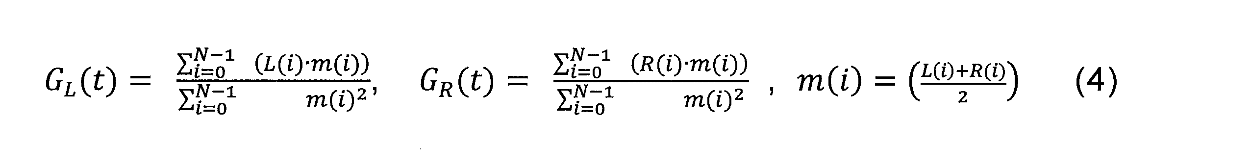
チャンネルLおよびR正規化相関分析下位動作403を実行するために、LおよびR正規化相関アナライザ453は、関係(4)を使用してフレームtにおいてスピーチおよび/またはオーディオなどの音声のモノラル信号バージョンm(i)に対して正規化された左Lチャンネルおよび右Rチャンネルの各々に関する相関GL|Rを計算する。
To perform the channel L and R normalized
ここで、Nは、上述のように、フレーム内のサンプルの数に対応し、tは、現在のフレームを表す。現在の実施形態においては、関係1から4によって決定されたすべての正規化された相関およびrms値が、フレーム全体に関して時間領域で計算される。別の可能な構成において、これらの値は、周波数領域において計算され得る。たとえば、スピーチの特徴を有する音声信号に適合される本明細書において説明される技術は、周波数領域の一般の(generic)ステレオオーディオコーディング方法と本開示において説明される方法との間を切り替えることができるより大きなフレームワークの一部である可能性がある。この場合、周波数領域において正規化された相関およびrms値を計算することは、複雑さまたはコードの再利用の点で何らかの利点をもたらし得る。
where N corresponds to the number of samples in the frame, as described above, and t represents the current frame. In the current embodiment, all normalized correlations and rms values determined by
下位動作404において長期(LT)相関差を計算するために、計算器454は、関係(5)を使用して、現在のフレームにおける各チャンネルLおよびRに関して、平滑化された正規化された相関を計算する。
To calculate the long-term (LT) correlation difference in

ここで、αは、収束の上述の速度である。最後に、計算器454は、関係(6)を使用して長期(LT)相関差


1つの例示的な実施形態において、収束の速度αは、関係(2)において計算された長期のエネルギーおよび関係(3)において計算された長期のエネルギーの動向に応じて値0.8または0.5を有する可能性がある。たとえば、収束の速度αは、左Lチャンネルおよび右Rチャンネルの長期のエネルギーが同じ方向に発展し、フレームtにおける長期相関差


変換および量子化下位動作405を実行するために、長期相関差

因子βは、1つのパラメータへと組み合わされるステレオ入力の2つの側面を表す。第1に、因子βは、プライマリチャンネルYを生成するために一緒に組み合わされる右Rチャンネルおよび左Lチャンネルのそれぞれの割合または寄与を表し、第2に、因子βは、音声のモノラル信号バージョンがそのように見えるものにエネルギー領域において近いプライマリチャンネルを得るためにプライマリチャンネルYに適用するエネルギースケーリング因子も表す可能性がある。したがって、組み込み型の構造の場合、それは、ステレオパラメータを運ぶセカンダリビットストリーム306を受信する必要なしにプライマリチャンネルYが単独で復号されることを可能にする。このエネルギーパラメータは、セカンダリチャンネルXの大域的なエネルギーがセカンダリチャンネルのエンコーダの最適なエネルギーの範囲により近いように、セカンダリチャンネルXの符号化の前にセカンダリチャンネルXのエネルギーを再スケーリングするために使用される可能性もある。図2に示されるように、因子β内に本来存在するエネルギー情報も、プライマリチャンネルとセカンダリチャンネルとの間のビット割り当てを改善するために使用され得る。
The factor β represents two aspects of the stereo input combined into one parameter. First, the factor β represents the proportion or contribution of each of the right R and left L channels that are combined together to produce the primary channel Y, and second, the factor β represents the monophonic signal version of the audio. It may also represent an energy scaling factor to apply to the primary channel Y to obtain a primary channel that is close in energy domain to what it looks like. Therefore, for the embedded structure, it allows the primary channel Y to be decoded alone without having to receive the
量子化された因子βは、インデックスを使用してデコーダに送信され得る。因子βは(a)プライマリチャンネルへの左チャンネルおよび右チャンネルのそれぞれの寄与と、(b)音声のモノラル信号バージョンを得るためにプライマリチャンネルに適用するためのエネルギースケーリング因子、またはプライマリチャンネルYとセカンダリチャンネルXとの間にビットをより効率的に割り当てるのに役立つ相関/エネルギー情報との両方を表し得るので、デコーダに送信されるインデックスは、同じ数のビットによって2つの互いに異なる情報要素を運ぶ。 The quantized factor β may be sent to the decoder using the index. The factor β is (a) the contribution of each of the left and right channels to the primary channel and (b) the energy scaling factor to apply to the primary channel to obtain a monophonic signal version of the audio, or the primary channel Y and the secondary The index sent to the decoder carries two different information elements with the same number of bits, since it can represent both correlation/energy information that helps to allocate bits between channels X more efficiently.
長期相関差


代替的な実装において、その値をたとえば0.4と0.6との間にさらに制限することによって、線形化された長期相関差

線形化の後、コンバータおよび量子化器455は、関係(8)を使用して「余弦」領域への線形化された長期相関差


時間領域ダウンミックス下位動作406を実行するために、時間領域ダウンミキサ456は、関係(9)および(10)を使用して、プライマリチャンネルYおよびセカンダリチャンネルXを右Rチャンネルおよび左Lチャンネルの混合として生成する。
Y(i) = R(i)・(1 - β(t)) + L(i)・β(t) (9)
X(i) = L(i)・(1 - β(t)) - R(i)・β(t) (10)
To perform the time
Y(i) = R(i)・(1 - β(t)) + L(i)・β(t) (9)
X(i) = L(i)・(1 - β(t)) - R(i)・β(t) (10)
ここで、i = 0,…,N-1は、フレーム内のサンプルのインデックスであり、tは、フレームのインデックスである。 where i = 0,...,N-1 is the index of the sample within the frame and t is the index of the frame.
図13は、事前適応因子を使用してステレオ音像の安定性を高める図2および図3のステレオ音声符号化方法の時間領域ダウンミックス動作201/301の下位動作ならびに図2および図3のステレオ音声符号化システムのチャンネルミキサ251/351のモジュールのその他の実施形態を同時に示すブロック図である。図13に示される代替的な実装において、時間領域ダウンミックス動作201/301は、以下の下位動作、すなわち、エネルギー分析下位動作1301、エネルギー動向分析下位動作1302、LおよびRチャンネル正規化相関分析下位動作1303、事前適応因子計算下位動作1304、正規化された相関に事前適応因子を適用する動作1305、長期(LT)相関差計算下位動作1306、利得-因子β変換および量子化下位動作1307、ならびに時間領域ダウンミックス下位動作1308を含む。
FIG. 13 shows the sub-operations of the time-
下位動作1301、1302、および1303は、図4の下位動作401、402、および403ならびにアナライザ451、452、および453に関連して上述の説明において説明されたのと実質的に同じ方法で、エネルギーアナライザ1351、エネルギー動向アナライザ1352、ならびにLおよびR正規化相関アナライザ1353によってそれぞれ実行される。
下位動作1305を実行するために、チャンネルミキサ251/351は、両方のチャンネルのエネルギーおよび特徴に応じて相関GL|R(GL(t)およびGR(t))の発展が平滑化されるように関係(4)からのそれらの相関GL|Rに相関事前適応因子arを直接適用するための計算器1355を含む。信号のエネルギーが低い場合、または信号が何らかの無声の(unvoiced)特徴を有する場合、相関利得の発展はより遅い可能性がある。
To perform
事前適応因子計算下位動作1304を実行するために、チャンネルミキサ251/351は、(a)エネルギーアナライザ1351からの関係(2)の長期左および右チャンネルエネルギー値、(b)前のフレームのフレーム分類、ならびに(c)前のフレームの音声活動(voice activity)情報を供給される事前適応因子計算器1354を含む。事前適応因子計算器1354は、関係(6a)を使用して、アナライザ1351からの左チャンネルおよび右チャンネルの最小の長期rms値


実施形態において、係数Maは、値0.0009を有する可能性があり、係数Baは、値0.16を有する可能性がある。変形形態において、事前適応因子arは、たとえば、2つのチャンネルRおよびLの前の分類が無声の特徴およびアクティブな信号を示す場合、強制的に0.15にされる可能性がある。音声区間検出(VAD:voice activity detection)ハングオーバー(hangover)フラグも、フレームの内容の前の部分がアクティブなセグメントであったと判定するために使用される可能性がある。 In an embodiment, the coefficient M a may have the value 0.0009 and the coefficient B a may have the value 0.16. In a variant, the pre-adaptation factor a r may be forced to 0.15, for example, if the previous classification of the two channels R and L shows unvoiced features and active signals. A voice activity detection (VAD) hangover flag may also be used to determine that the previous portion of the frame's content was an active segment.
左Lチャンネルおよび右Rチャンネルの正規化された相関GL|R(関係(4)からのGL(t)およびGR(t))に事前適応因子arを適用する動作1305は、図4の動作404とは異なる。αが収束の上述の定義された速度(関係(5))であるものとして、正規化された相関GL|R(GL(t)およびGR(t))に因子(1-α)を適用することによって長期の(LT)平滑化された正規化された相関を計算する代わりに、計算器1355は、関係(11b)を使用して左Lチャンネルおよび右Rチャンネルの正規化された相関GL|R(GL(t)およびGR(t))に事前適応因子arを直接適用する。
An

計算器1355は、長期(LT)相関差の計算器1356に提供される適合された相関利得τL|Rを出力する。時間領域ダウンミックス201/301の動作(図2および図3)は、図13の実装においては、それぞれ図4の下位動作404、405、および406と同様の長期(LT)相関差計算下位動作1306、長期相関差-因子β変換および量子化下位動作1307、ならびに時間領域ダウンミックス下位動作1308を含む。
時間領域ダウンミックス201/301の動作(図2および図3)は、図13の実装においては、それぞれ図4の下位動作404、405、および406と同様の長期(LT)相関差計算下位動作1306、長期相関差-因子β変換および量子化下位動作1307、ならびに時間領域ダウンミックス下位動作1308を含む。
The operations of the time domain downmix 201/301 (FIGS. 2 and 3) are, in the implementation of FIG. , the long-term correlation difference-factor β transform and
下位動作1306、1307、および1308は、下位動作404、405、および406と、計算器454、コンバータおよび量子化器455、ならびに時間領域ダウンミキサ456とに関連して上述の説明において説明されたのと実質的に同じ方法で計算器1356、コンバータおよび量子化器1357、ならびに時間領域ダウンミキサ1358によってそれぞれ実行される。
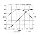
図5は、線形化された長期相関差


一方、線形化された長期相関差

実施形態において、因子βは、ビットレートの割り当てを決定するためにプライマリチャンネルのエンコーダ252/352とセカンダリチャンネルのエンコーダ253/353との両方に関するインジケータとして使用される可能性もある。たとえば、β因子が0.5に近く、つまり、2つの入力チャンネルのエネルギー/モノラルとの相関が互いに近い場合、より多くのビットがセカンダリチャンネルXに割り当てられ、より少ないビットがプライマリチャンネルYに割り当てられるが、ただし、両方のチャンネルの内容が非常に近い場合に、セカンダリチャンネルが非常に低エネルギーであり、非アクティブ(inactive)と考えられる可能性が高く、したがって、非常にわずかなビットがセカンダリチャンネルを符号化することを可能にすることを例外とする。一方、因子βが0または1により近い場合、ビットレートの割り当ては、プライマリチャンネルYに有利になる。
In an embodiment, the factor β may also be used as an indicator for both the
図6は、フレーム全体上に上述のpca/klt方式を使用すること(図6の上2つの曲線)と因子βを計算するために関係(8)において作り出された「余弦」関数を使用すること(図6の下の曲線)との間の差を示す。元来、pca/klt方式は、最小または最大を探す傾向がある。これは、図6の真ん中の曲線によって示されるアクティブなスピーチの場合は上手く機能するが、背景雑音のあるスピーチに関しては、図6の真ん中の曲線によって示されるように0から1へと連続的に切り替わる傾向があるのであまり上手く機能しない。限界である0および1へのあまりにも頻繁な切り替わりは、低ビットレートでコーディングするとき、多くのアーティファクトを生じる。潜在的な解決策は、pca/klt方式の判断を滑らかにならすことだったであろうが、これが、スピーチのバーストおよびそれらの正しい位置の検出に悪影響を与えたであろう一方で、関係(8)の「余弦」関数は、この点に関してより効率的である。 Figure 6 uses the pca/klt method described above over the entire frame (top two curves in Figure 6) and the "cosine" function developed in relation (8) to calculate the factor β. (bottom curve in Figure 6). By nature, the pca/klt method tends to look for a minimum or maximum. This works well for active speech as shown by the middle curve in FIG. 6, but for speech with background noise it continuously goes from 0 to 1 as shown by the middle curve in FIG. It doesn't work very well because it tends to switch. Too frequent switching to marginal 0s and 1s causes many artifacts when coding at low bitrates. A potential solution would have been to smooth the decisions of the pca/klt scheme, but while this would have adversely affected the detection of bursts of speech and their correct positions, the relationship ( The "cosine" function of 8) is more efficient in this regard.
図7は、背景にオフィスの雑音がある小さな反響のある部屋の中でバイノーラル式のマイクロフォンセットアップを使用して記録されたステレオサンプルに時間領域ダウンミックスを適用した結果として得られるプライマリチャンネルY、セカンダリチャンネルX、ならびにこれらのプライマリチャンネルYおよびセカンダリチャンネルXのスペクトルを示す。時間領域ダウンミックス動作の後、両方のチャンネルは引き続き同様のスペクトルの形状を有し、セカンダリチャンネルXは引き続きスピーチに似た時間的内容を有し、したがって、ユーザがスピーチに基づくモデルを使用してセカンダリチャンネルXを符号化することを可能にすることが分かる。 Figure 7 shows the resulting primary channel Y, secondary Channel X and their primary and secondary channel X spectra are shown. After the time-domain downmixing operation, both channels still have similar spectral shapes and the secondary channel X still has speech-like temporal content, thus allowing the user to use a speech-based model to It can be seen that it makes it possible to encode the secondary channel X.
上述の説明において提示された時間領域ダウンミックスは、位相が反転される右Rチャンネルおよび左Lチャンネルの特別な場合にいくつかの問題を示す可能性がある。右Rチャンネルおよび左Lチャンネルを合計してモノラル信号を得ることは、互いを打ち消す右Rチャンネルおよび左Lチャンネルをもたらす。このあり得る問題を解決するために、実施形態において、チャンネルミキサ251/351は、モノラル信号のエネルギーを右Rチャンネルと左Lチャンネルとの両方のエネルギーと比較する。モノラル信号のエネルギーは、少なくとも、右Rチャンネルおよび左Lチャンネルのうちの一方のエネルギーよりも大きいはずである。そうでない場合、この実施形態において、時間領域ダウンミックスモデルが、位相の反転された特別な場合に入る。この特別な場合が存在すると、因子βは、強制的に1にされ、セカンダリチャンネルXは、強制的に一般または無声モードを使用して符号化され、したがって、非アクティブコーディングモードを避け、セカンダリチャンネルXの適切な符号化を保証する。エネルギーの再スケーリングが適用されないこの特別な場合は、因子βの送信のために利用可能な最後のビットの組合せ(インデックス値)を使用することによってデコーダにシグナリングされる(基本的に、上述のように、βが5ビットを使用して量子化され、31個のエントリ(量子化レベル)が量子化のために使用されるので、32番目の可能なビットの組合せ(エントリまたはインデックス値)がこの特別な場合をシグナリングするために使用される)。
The time-domain downmix presented in the above discussion can present some problems in the special case of phase-reversed right R and left L channels. Summing the right R channel and left L channel to get a mono signal results in right R channel and left L channel canceling each other. To solve this possible problem, in an embodiment the
代替的な実装において、位相のずれたまたはほとんど位相のずれた信号の場合などでは、上述のダウンミックスおよびコーディング技術のために準最適である信号の検出がより強調される可能性がある。これらの信号が検出されると、基礎をなすコーディング技術が、必要に応じて適合される可能性がある。 In alternative implementations, more emphasis may be placed on detecting signals that are sub-optimal for the downmixing and coding techniques described above, such as in the case of out-of-phase or near-out-of-phase signals. When these signals are detected, the underlying coding technique can be adapted as needed.
概して、本明細書において説明される時間領域ダウンミックスに関して、入力ステレオ信号の左Lチャンネルおよび右Rチャンネルの位相がずれているとき、ダウンミックスプロセス中に何らかの打ち消しが起こる可能性があり、それが、準最適な品質につながる可能性がある。上の例において、これらの信号の検出は、簡単であり、コーディングの方針は、両方のチャンネルを別々に符号化することを含む。しかしときには、位相のずれた信号などの特別な信号によって、サイドチャンネルがより強調されるモノラル/サイドと同様のダウンミックス(β=0.5)を引き続き実行することがより効率的である可能性がある。これらの信号の何らかの特別な取り扱いが有益である可能性があることを考慮すると、そのような信号の検出は、慎重に実行される必要がある。さらに、上述の説明において説明された通常の時間領域ダウンミックスモデルおよびこれらの特別な信号を扱っている時間領域ダウンミックスモデルからの遷移が、2つのモデルの間の切り替わりが最小限の主観的影響(subjective effect)を有するように、非常に低いエネルギーの領域において、または両方のチャンネルのピッチが安定しない領域においてトリガされる可能性がある。 In general, with respect to the time domain downmix described herein, when the left L and right R channels of the input stereo signal are out of phase, some cancellation can occur during the downmix process, which is , which can lead to suboptimal quality. In the above example, detection of these signals is straightforward and the coding strategy involves encoding both channels separately. However, sometimes it may be more efficient to still perform a mono/side-like downmix (β=0.5) where the side channels are more emphasized by special signals such as out-of-phase signals. . Given that some special handling of these signals may be beneficial, detection of such signals needs to be performed with caution. Furthermore, the transitions from the normal time-domain downmix model described in the discussion above and the time-domain downmix model dealing with these special signals should have minimal subjective impact on switching between the two models. It may trigger in regions of very low energy, or in regions where the pitch of both channels is not stable, so as to have a subjective effect.
LチャンネルとRチャンネルとの間の時間遅延補正(TDC)(図17および図18の時間遅延補正器1750参照)、またはすべての内容が参照により本明細書に組み込まれる参考文献[8]に記載されているものと同様の技術が、ダウンミックスモジュール201/301、251/351に入る前に実行される可能性がある。そのような実施形態において、因子βは、結局、上で説明された意味とは異なる意味を持つことになる可能性がある。この種の実装に関しては、時間遅延補正が予測されたとおりに働くという条件で、因子βは、0.5に近くなる可能性があり、つまり、時間領域ダウンミックスの構成はモノラル/サイド構成に近い。時間遅延補正(TDC)の適切な動作によって、サイドは、より少ない量の重要な情報を含む信号を含む可能性がある。その場合、セカンダリチャンネルXのビットレートは、因子βが0.5に近いとき、最小である可能性がある。一方、因子βが0または1に近い場合、これは、時間遅延補正(TDC)が遅延のずれた状況を適切に克服し得ず、セカンダリチャンネルXの内容がより複雑である可能性が高く、したがって、より高いビットレートを必要とすることを意味する。両方の種類の実装に関して、因子βと、それに関連してエネルギー正規化(再スケーリング)因子εとは、プライマリチャンネルYとセカンダリチャンネルXとの間のビット割り当てを改善するために使用され得る。
Time Delay Compensation (TDC) between L and R Channels (see
図14は、ダウンミックス動作201/301およびチャンネルミキサ251/351の一部を形成する位相のずれた信号の検出の動作および位相ずれ信号検出器1450のモジュールを同時に示すブロック図である。位相のずれた信号の検出の動作は、時間領域ダウンミックス動作201/301と位相ずれに特有の時間領域ダウンミックス動作1404との間の選択を行うために、図14に示されるように、位相ずれ信号検出動作1401、切り替わり位置(switching position)検出動作1402、およびチャンネルミキサ選択動作1403を含む。これらの動作は、それぞれ、位相ずれ信号検出器1451、切り替わり位置検出器1452、チャンネルミキサセレクタ1453、上述の時間領域ダウンチャンネルミキサ251/351、および位相ずれに特有の時間領域ダウンチャンネルミキサ1454によって実行される。
FIG. 14 is a block diagram illustrating simultaneously the operation of the out-of-phase signal detection and modules of the out-of-
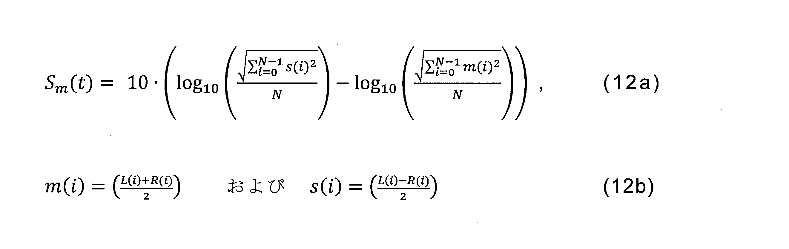
位相ずれ信号検出1401は、前のフレーム内のプライマリチャンネルとセカンダリチャンネルとの間の開ループ相関(open loop correlation)に基づく。この目的で、検出器1451は、関係(12a)および(12b)を使用して前のフレームにおいてサイド信号s(i)とモノラル信号m(i)との間のエネルギーの差Sm(t)を計算する。
Out-of-
そして、検出器1451は、関係(12c)を使用して長期のモノラルに対するサイドのエネルギーの差


ここで、tは、現在のフレームを示し、t-1は、前のフレームであり、非アクティブな内容は、音声区間検出器(VAD:Voice Activity Detector)ハングオーバーフラグからまたはVADハングオーバーカウンタから導出され得る。 where t denotes the current frame, t -1 is the previous frame, and the inactive content is either from the Voice Activity Detector (VAD) hangover flag or from the VAD hangover counter. can be derived.
長期のモノラルに対するサイドのエネルギーの差


長期のモノラルに対するサイドのエネルギーの差


そうでない場合、準最適性フラグFsubは0に設定され、左Lチャンネルと右Rチャンネルとの間に位相のずれ状態がないことを示す。 Otherwise, the suboptimality flag F sub is set to 0, indicating that there is no out-of-phase condition between the left L channel and the right R channel.
準最適性フラグの判断にいくらかの安定性を加えるために、切り替わり位置検出器1452は、各チャンネルYおよびXのピッチの曲線に関する基準を実装する。切り替わり位置検出器1452は、例示的な実施形態において、準最適性フラグFsubの少なくとも3つの連続したインスタンスが1に設定され、プライマリチャンネルまたはセカンダリチャンネルのうちの1つの最後のフレームのピッチの安定性ppc(t-1)またはpsc(t-1)が64を超えるとき、チャンネルミキサ1454が準最適な信号をコーディングするために使用されると決定する。ピッチの安定性は、関係(12d)を使用して切り替わり位置検出器1452によって計算される、参考文献[1]の5.1.10において定義された3つの開ループピッチ(open loop pitch)p0|1|2の絶対的な差の合計に存する。
ppc = |p1 - p0| + |p2 - p1|およびpsc = |p1 - p0| + |p2 - p1| (12d)
To add some stability to the determination of the sub-optimal flag, the
p pc = |p 1 - p 0 | + |p 2 - p 1 | and p sc = |p 1 - p 0 | + |p 2 - p 1 | (12d)
切り替わり位置検出器1452は、チャンネルミキサセレクタ1453に判断を伝え、そして今度は、チャンネルミキサセレクタ1453が、それに応じてチャンネルミキサ251/351またはチャンネルミキサ1454を選択する。チャンネルミキサセレクタ1453は、チャンネルミキサ1454が選択されるときに、以下の条件が満たされるまで、つまり、いくつかの連続するフレーム、たとえば、20個のフレームが最適であると考えられ、プライマリチャンネルまたはセカンダリチャンネルのうちの1つの最後のフレームのピッチの安定性ppc(t-1)またはpsc(t-1)が所定の数、たとえば、64を超えており、長期のモノラルに対するサイドのエネルギーの差

2)プライマリチャンネルとセカンダリチャンネルとの間の動的な符号化
図8は、スピーチまたはオーディオなどのステレオ音声信号のプライマリYチャンネルとセカンダリXチャンネルとの両方の符号化の最適化の可能な実装によるステレオ音声符号化方法およびシステムを同時に示すブロック図である。
2) Dynamic encoding between primary and secondary channels Figure 8 shows a possible implementation of the optimization of the encoding of both the primary Y channel and the secondary X channel of a stereophonic audio signal such as speech or audio. 1 is a block diagram that simultaneously illustrates a stereo audio encoding method and system; FIG.
図8を参照すると、ステレオ音声符号化方法は、低複雑性プリプロセッサ851によって実施される低複雑性前処理動作801、信号分類器852によって実施される信号分類動作802、判断モジュール853によって実施される判断動作803、4サブフレームモデルの一般のみの符号化(four (4) subframes model generic only encoding)モジュール854によって実施される4サブフレームモデルの一般のみの符号化動作804、2サブフレームモデル符号化モジュール855によって実施される2サブフレームモデル符号化動作805、およびLPフィルタコヒーレンスアナライザ856によって実施されるLPフィルタコヒーレンス分析動作806を含む。
Referring to FIG. 8, the stereo audio coding method is performed by a low-
時間領域ダウンミックス301がチャンネルミキサ351によって実行された後、組み込み型のモデルの場合、プライマリチャンネルYは、(a)レガシーのEVSエンコーダまたは任意のその他の好適なレガシーの音声エンコーダなどのレガシーのエンコーダをプライマリチャンネルのエンコーダ352として使用して符号化される(プライマリチャンネル符号化動作302)(上述の説明において述べられたように、任意の好適な種類のエンコーダがプライマリチャンネルのエンコーダ352として使用され得ることに留意されたい)。統合された構造の場合、専用のスピーチコーデックが、プライマリチャンネルのエンコーダ252として使用される。専用スピーチエンコーダ252は、可変ビットレート(VBR)に基づくエンコーダ、たとえば、フレーム毎のレベルで可変ビットレートの取り扱いを可能にするより高いビットレートのスケーラビリティを持つように修正されたレガシーのEVSエンコーダの修正されたバージョンである可能性がある(上述の説明において述べられたように、任意の好適な種類のエンコーダがプライマリチャンネルのエンコーダ252として使用され得ることにやはり留意されたい)。これは、セカンダリチャンネルXを符号化するために使用されるビットの最小の量が各フレームにおいて変わり、符号化される音声信号の特徴に適合されることを可能にする。最後に、セカンダリチャンネルXのシグネチャは、可能な限り同質になる。
After the
セカンダリチャンネルX、すなわち、より低いエネルギー/モノラル入力との相関の符号化は、これに限らないが特にスピーチに似た内容のために最小限のビットレートを使用するように最適化される。その目的のために、セカンダリチャンネルの符号化は、LPフィルタ係数(LPC)および/またはピッチのラグ807などのプライマリチャンネルYに既に符号化されたパラメータを利用することができる。特に、以降で説明されるように、プライマリチャンネルの符号化中に計算されたパラメータが、セカンダリチャンネルの符号化中に計算される対応するパラメータと、セカンダリチャンネルの符号化中に再利用されるのに十分なだけ近いかどうかが判断される。
The encoding of the secondary channel X, ie the correlation with the lower energy/mono input, is optimized to use the minimum bit rate especially for but not limited to speech-like content. To that end, the encoding of the secondary channel can utilize parameters already encoded in the primary channel Y such as the LP filter coefficients (LPC) and/or
第1に、低複雑性前処理動作801が、低複雑性プリプロセッサ851を使用してセカンダリチャンネルXに適用され、LPフィルタ、音声区間検出(VAD)、および開ループピッチが、セカンダリチャンネルXに応じて計算される。後者の計算は、たとえば、EVSのレガシーのエンコーダにおいて実行され、上で示されたようにすべての内容が参照により本明細書に組み込まれる参考文献[1]の5.1.9、5.1.12、および5.1.10節においてそれぞれ説明される計算によって実施され得る。上述の説明において述べられたように、任意の好適な種類のエンコーダがプライマリチャンネルのエンコーダ252/352として使用され得るので、上の計算は、そのようなプライマリチャンネルのエンコーダにおいて実行される計算によって実施され得る。
First, low-
そして、セカンダリチャンネルXの信号の特徴が、同じ参考文献[1]の5.1.13節に記載のEVS信号分類機能の技術と同様の技術を使用してセカンダリチャンネルXを無声、一般、または非アクティブとして分類するために信号分類器852によって分析される。これらの動作は、当業者に知られており、簡単にするために3GPP TS 26.445、v.12.0.0規格から引き出され得るが、代替的な実装も、使用され得る。
Then, the characteristics of the signal on secondary channel X determine whether secondary channel X is unvoiced, general, or inactive using techniques similar to those of the EVS signal classifier described in Section 5.1.13 of the same reference [1]. is analyzed by
a.プライマリチャンネルのLPフィルタ係数の再利用
ビットレートの消費の重要な部分は、LPフィルタ係数(LPC)の量子化にある。低ビットレートにおいて、LPフィルタ係数の完全な量子化は、ビットバジェットうち最大でほぼ25%を占める可能性がある。セカンダリチャンネルXが周波数の内容においてプライマリチャンネルYと近いことが多いが、ただしエネルギーレベルが最も低いことを考慮すると、プライマリチャンネルYのLPフィルタ係数を再利用することが可能かどうかは、検証する価値がある。そのようにするために、図8に示されるように、プライマリチャンネルYのLPフィルタ係数(LPC)807を再利用するか否かの可能性を確認するためにわずかなパラメータが計算され、比較される、LPフィルタコヒーレンスアナライザ856によって実施されるLPフィルタコヒーレンス分析動作806が開発された。
a. Reuse of Primary Channel LP Filter Coefficients An important part of the bitrate consumption is in the quantization of the LP filter coefficients (LPC). At low bitrates, full quantization of the LP filter coefficients can occupy up to almost 25% of the bit budget. Considering that secondary channel X is often close in frequency content to primary channel Y, but has the lowest energy level, it is worth investigating whether it is possible to reuse the LP filter coefficients of primary channel Y. There is To do so, a small number of parameters are calculated and compared to ascertain the possibility of reusing or not LP filter coefficients (LPC) 807 of primary channel Y, as shown in FIG. LP filter
図9は、図8のステレオ音声符号化方法およびシステムのLPフィルタコヒーレンス分析動作806および対応するLPフィルタコヒーレンスアナライザ856を示すブロック図である。
FIG. 9 is a block diagram illustrating the LP filter
図8のステレオ音声符号化方法およびシステムのLPフィルタコヒーレンス分析動作806および対応するLPフィルタコヒーレンスアナライザ856は、図9に示されるように、LP(線形予測)フィルタアナライザ953によって実施されるプライマリチャンネルLPフィルタ分析下位動作903、重み付けフィルタ954によって実施される重み付け下位動作904、LPフィルタアナライザ962によって実施されるセカンダリチャンネルLPフィルタ分析下位動作912、重み付けフィルタ951によって実施される重み付け下位動作901、ユークリッド距離アナライザ952によって実施されるユークリッド距離分析下位動作902、残差(residual)フィルタ963によって実施される残差フィルタリング下位動作913、残差のエネルギーの計算器964によって実施される残差エネルギー計算下位動作914、減算器965によって実施される減算下位動作915、エネルギーの計算器960によって実施される(スピーチおよび/またはオーディオなどの)音声エネルギー計算下位動作910、セカンダリチャンネル残差フィルタ956によって実施されるセカンダリチャンネル残差フィルタリング動作906、残差のエネルギーの計算器957によって実施される残差エネルギー計算下位動作907、減算器958によって実施される減算下位動作908、利得比計算器によって実施される利得比計算下位動作911、比較器966によって実施される比較下位動作916、比較器967によって実施される比較下位動作917、判断モジュール968によって実施されるセカンダリチャンネルLPフィルタ使用判断下位動作918、ならびに判断モジュール969によって実施されるプライマリチャンネルLPフィルタ再利用判断下位動作919を含む。
The LP filter
図9を参照すると、LPフィルタアナライザ953が、プライマリチャンネルYに対してLPフィルタ分析を実行し、一方、LPフィルタアナライザ962は、セカンダリチャンネルXに対してLPフィルタ分析を実行する。プライマリYチャンネルおよびセカンダリXチャンネルの各々に対して実行されるLPフィルタ分析は、参考文献[1]の5.1.9節に記載の分析と同様である。
Referring to FIG. 9,
そして、LPフィルタアナライザ953からのLPフィルタ係数Ayが、セカンダリチャンネルXの第1の残差フィルタリングrYのために残差フィルタ956に供給される。同じようにして、LPフィルタアナライザ962からの最適なLPフィルタ係数Axが、セカンダリチャンネルXの第2の残差フィルタリングrXのために残差フィルタ963に供給される。どちらかのフィルタ係数AYまたはAXによる残差フィルタリングは、関係(11)を使用して実行される。
LP filter coefficients A y from

ここで、この例において、sxは、セカンダリチャンネルを表し、LPフィルタの次数は、16であり、Nは、通常は12.8kHzのサンプリングレートで20msのフレームの継続時間に対応する256であるフレーム内のサンプルの数(フレームサイズ)である。 where, in this example, s x represents the secondary channel, the order of the LP filter is 16, and N is typically 256 frames, corresponding to a frame duration of 20ms at a sampling rate of 12.8kHz. is the number of samples in (frame size).
計算器910は、関係(14)を使用してセカンダリチャンネルX内の音声信号のエネルギーExを計算する。

計算器957は、関係(15)を使用して残差フィルタ956からの残差のエネルギーEryを計算する。

減算器958は、計算器960からの音声エネルギーから計算器957からの残差エネルギーを引いて予測利得GYを生成する。
A
同じようにして、計算器964は、関係(16)を使用して残差フィルタ963からの残差のエネルギーErxを計算する。
In a similar manner,

減算器965は、計算器960からの音声エネルギーからこの残差エネルギーを引いて予測利得GXを生成する。
A
計算器961は、利得比GY/GXを計算する。比較器966は、利得比GY/GXを、例示的な実施形態においては0.92である閾値τと比較する。比GY/GXが閾値τよりも小さい場合、比較の結果が、判断モジュール968に送信され、判断モジュール968は、セカンダリチャンネルXを符号化するためにセカンダリチャンネルのLPフィルタ係数を使用することを強制する。
ユークリッド距離アナライザ952は、プライマリチャンネルYに応じてLPフィルタアナライザ953によって計算された線スペクトル対lspYと、セカンダリチャンネルXに応じてLPフィルタアナライザ962によって計算された線スペクトル対lspXとの間のユークリッド距離などのLPフィルタの類似性の測定を実行する。当業者に知られているように、線スペクトル対lspYおよびlspXは、量子化領域におけるLPフィルタ係数を表す。アナライザ952は、関係(17)を使用してユークリッド距離distを決定する。
The

ここで、Mは、フィルタの次数を表し、lspYおよびlspXは、それぞれ、プライマリYチャンネルおよびセカンダリXチャンネルに関して計算された線スペクトル対を表す。 where M represents the order of the filter and lsp Y and lsp X represent the line spectrum pair calculated for the primary Y and secondary X channels, respectively.
アナライザ952においてユークリッド距離を計算する前に、スペクトルの特定の部分が多かれ少なかれ強調されるようにそれぞれの重み係数によって線スペクトル対lspYおよびlspXの両方の組を重み付けすることが可能である。その他のLPフィルタの表現も、LPフィルタの類似性の測定値を計算するために使用され得る。
Before calculating the Euclidean distance in the
ユークリッド距離distが知られると、そのユークリッド距離は、比較器967において閾値σと比較される。例示的な実施形態において、閾値σは、値0.08を有する。比GY/GXが閾値τ以上であると比較器966が判定し、ユークリッド距離distが閾値σ以上であると比較器967が判定するとき、比較の結果が、判断モジュール968に送信され、判断モジュール968は、セカンダリチャンネルXを符号化するためにセカンダリチャンネルのLPフィルタ係数を使用することを強制する。比GY/GXが閾値τ以上であると比較器966が判定し、ユークリッド距離distが閾値σ未満であると比較器967が判定するとき、これらの比較の結果が、判断モジュール969に送信され、判断モジュール969は、セカンダリチャンネルXを符号化するためにプライマリチャンネルのLPフィルタ係数を再利用することを強制する。後者の場合、プライマリチャンネルのLPフィルタ係数がセカンダリチャンネルの符号化の一部として再利用される。
Once the Euclidean distance dist is known, it is compared in
特定の場合、たとえば、LPフィルタ係数も符号化するために利用可能なビットレートがまだ存在するほど信号が符号化することが十分に容易である無声のコーディングモードの場合、セカンダリチャンネルXを符号化するためにプライマリチャンネルのLPフィルタ係数を再利用することを制限するためにいくつかの追加のテストが行われる可能性がある。非常に低い残差利得がセカンダリチャンネルのLPフィルタ係数によって既に得られているとき、またはセカンダリチャンネルXが非常に低いエネルギーレベルを有するとき、プライマリチャンネルのLPフィルタ係数を再利用することを強制することも可能である。最後に、LPフィルタ係数を再利用することが強制され得る変数τ、σ、残差利得のレベル、または非常に低いエネルギーレベルは、利用可能なビットバジェットに応じておよび/または内容の種類に応じて適合され得る。たとえば、セカンダリチャンネルの内容が非アクティブであると考えられる場合、たとえエネルギーが高いとしても、プライマリチャンネルのLPフィルタ係数を再利用すると判断される可能性がある。 In certain cases, e.g., unvoiced coding modes where the signal is easy enough to encode that there is still a bitrate available to encode the LP filter coefficients as well, encode the secondary channel X Some additional tests may be done to limit the reuse of the primary channel LP filter coefficients to Forcing reuse of the LP filter coefficients of the primary channel when too low residual gain is already obtained by the LP filter coefficients of the secondary channel or when the secondary channel X has a very low energy level. is also possible. Finally, the variables τ, σ, the level of residual gain, or very low energy levels that may force us to reuse the LP filter coefficients may vary depending on the available bit budget and/or depending on the type of content. can be adapted for For example, if the content of the secondary channel is considered inactive, it may be decided to reuse the LP filter coefficients of the primary channel, even though the energy is high.
b.セカンダリチャンネルの低ビットレートの符号化
プライマリYチャンネルおよびセカンダリXチャンネルが右R入力チャンネルと左L入力チャンネルとの両方のミックスである可能性があるので、これは、たとえセカンダリチャンネルXのエネルギーの内容がプライマリチャンネルYのエネルギーの内容と比べて低いとしても、チャンネルのアップミックスが実行されると、コーディングアーティファクトが知覚される可能性があることを示唆する。そのような起こり得るアーティファクトを制限するために、セカンダリチャンネルXのコーディングシグネチャ(coding signature)は、すべての意図されていないエネルギーの変動を制限するために可能な限り一定に保たれる。図7に示されるように、セカンダリチャンネルXの内容は、プライマリチャンネルYの内容と同様の特徴を有し、そのために、非常に低いビットレートのスピーチに似たコーディングモデルが、作られた。
b. Low Bitrate Encoding of Secondary Channels Since the primary Y channel and the secondary X channel can be a mix of both the right R and left L input channels, this reduces the energy of the secondary channel X even if suggest that coding artifacts may be perceived when channel upmixing is performed, even though the content of Y is low compared to the energy content of the primary channel Y. To limit such possible artifacts, the coding signature of the secondary channel X is kept as constant as possible to limit any unintended energy fluctuations. As shown in FIG. 7, the content of the secondary channel X has similar characteristics to the content of the primary channel Y, so a very low bit rate speech-like coding model was created.
再び図8を参照すると、LPフィルタコヒーレンスアナライザ856が、判断モジュール969からのプライマリチャンネルのLPフィルタ係数を再利用する判断、または判断モジュール968からのセカンダリチャンネルのLPフィルタ係数を使用する判断を、判断モジュール853に送信する。そして、判断モジュール803は、プライマリチャンネルのLPフィルタ係数が再利用されるとき、セカンダリチャンネルのLPフィルタ係数を量子化しないと判断し、判断がセカンダリチャンネルのLPフィルタ係数を使用するというものであるとき、セカンダリチャンネルのLPフィルタ係数を量子化すると判断する。後者の場合、量子化されたセカンダリチャンネルのLPフィルタ係数が、多重化されたビットストリーム207/307に含めるためにマルチプレクサ254/354に送信される。
Referring again to FIG. 8, LP
4サブフレームモデルの一般のみの符号化動作804および対応する4サブフレームモデルの一般のみの符号化モジュール854においては、ビットレートをできる限り低く保つために、プライマリチャンネルYからのLPフィルタ係数が再利用され得るとき、セカンダリチャンネルXが信号分類器852によって一般として分類されるとき、ならびに入力右Rチャンネルおよび左Lチャンネルのエネルギーが中心に近く、つまり、右Rチャンネルと左Lチャンネルとの両方のエネルギーが互い近いときにのみ、参考文献[1]の5.2.3.1節に記載のACELPの探索が使用される。そして、4サブフレームモデルの一般のみの符号化モジュール854におけるACELPの探索中に見つかったコーディングパラメータが、セカンダリチャンネルビットストリーム206/306を構築するために使用され、多重化されたビットストリーム207/307に含めるためにマルチプレクサ254/354に送信される。
In the 4-subframe model general-
そうではなく、2サブフレームモデル符号化動作805および対応する2サブフレームモデル符号化モジュール855においては、プライマリチャンネルYからのLPフィルタ係数が再利用され得ないとき、一般の内容のセカンダリチャンネルXを符号化するためにハーフバンド(half-band)モデルが使用される。非アクティブな無声の内容に関しては、スペクトルの形状のみがコーディングされる。
Instead, in the 2-subframe
符号化モジュール855において、非アクティブな内容の符号化は、参考文献[1]の(a) 5.2.3.5.7節および5.2.3.5.11節ならびに(b) 5.2.2.1節にそれぞれ記載されているように必要とされるとき、(a)雑音による穴埋め(noise filling)付きの周波数領域のスペクトル帯域の利得のコーディングおよび(b)セカンダリチャンネルのLPフィルタ係数のコーディングを含む。非アクティブな内容は、たった1.5kb/sの低いビットレートで符号化され得る。
In
符号化モジュール855において、セカンダリチャンネルXの無声の符号化は、無声の符号化が無声のセカンダリチャンネルに関して符号化されるセカンダリチャンネルのLPフィルタ係数の量子化のために追加のいくつかのビットを使用することを除いてセカンダリチャンネルXの非アクティブの符号化と同様である。
In
ハーフバンド一般コーディングモデルが、参考文献[1]の5.2.3.1節に記載のACELPと同様にして構築されるが、フレーム毎に2サブフレームのみで使用される。したがって、そのようにするために、参考文献[1]の5.2.3.1.1節に記載の残差、参考文献[1]の5.2.3.1.4節に記載の適応コードブックのメモリ、および入力セカンダリチャンネルが、最初に、2分の1にダウンサンプリングされる。LPフィルタ係数も、参考文献[1]の5.4.4.2節に記載の技術を使用して12.8kHzのサンプリング周波数の代わりにダウンサンプリングされた領域を表すように修正される。 A half-band general coding model is constructed similar to ACELP described in Section 5.2.3.1 of reference [1], but with only two subframes per frame. Therefore, to do so, we need residuals as described in section 5.2.3.1.1 of reference [1], the memory of the adaptive codebook as described in section 5.2.3.1.4 of reference [1], and the input The secondary channel is first downsampled by a factor of two. The LP filter coefficients are also modified to represent the downsampled region instead of the 12.8 kHz sampling frequency using the technique described in Section 5.4.4.2 of Ref. [1].
ACELPの探索の後、帯域幅の拡張が、励振の周波数領域において実行される。帯域幅の拡張は、まず、比較的低いスペクトル帯域のエネルギーを比較的高い帯域に複製する。スペクトル帯域のエネルギーを複製するために、初めの9つのスペクトル帯域のエネルギーGbd(i)が、参考文献[1]の5.2.3.5.7節に記載されたように発見され、終わりの帯域が、関係(18)に示されるように埋められる。
Gbd(i) = Gbd(16 - i - 1), for i = 8,…,15 (18)
After the ACELP search, bandwidth extension is performed in the frequency domain of the excitation. Bandwidth extension first duplicates the energy in the lower spectral bands into the higher bands. To duplicate the energy of the spectral bands, the energies of the first nine spectral bands G bd (i) are found as described in section 5.2.3.5.7 of ref. [1], and the last band is , is filled as shown in relation (18).
G bd (i) = G bd (16 - i - 1), for i = 8,…,15 (18)
そして、参考文献[1]の5.2.3.5.9節に記載の周波数領域において表された励起ベクトルの高周波数の内容fd(k)が、関係(19)を使用して比較的低い帯域の周波数の内容を用いて埋められる。
fd(k) = fd(k - Pb), for k = 128,…,255 (19)
Then, the high-frequency content f d (k) of the excitation vector expressed in the frequency domain as described in section 5.2.3.5.9 of ref. Filled with frequency content.
f d (k) = f d (k − P b ), for k = 128,…,255 (19)
ここで、ピッチのオフセットPbは、参考文献[1]の5.2.3.1.4.1節に記載の複数のピッチ情報に基づき、関係(20)に示されるように周波数ビンのオフセットに変換される。 Here, the pitch offset Pb is converted to a frequency bin offset as shown in relationship (20) based on multiple pitch information described in Section 5.2.3.1.4.1 of Reference [1].

ここで、

そして、2サブフレームモデル符号化モジュール855において実行される低レートの非アクティブの符号化、低レートの無声の符号化、またはハーフバンド一般符号化中に見つかったコーディングパラメータが、多重化されたビットストリーム207/307に含めるためにマルチプレクサ254/354に送信されるセカンダリチャンネルビットストリーム206/306を構築するために使用される。
Then, the coding parameters found during low-rate inactive encoding, low-rate unvoiced encoding, or half-band general encoding performed in the two-subframe
c.セカンダリチャンネルの低ビットレートの符号化の代替的な実装
セカンダリチャンネルXの符号化は、最良の可能な品質を実現し、一定のシグネチャを保ちながら最小限の数のビットを使用するという同じ目的を持って異なるようにして実現され得る。セカンダリチャンネルXの符号化は、LPフィルタ係数およびピッチ情報の潜在的な再利用とは独立して、利用可能なビットバジェットによって部分的に駆動される可能性がある。また、2サブフレームモデル符号化(動作805)は、ハーフバンドであるかまたはフルバンド(full band)であるかのどちらかである可能性がある。セカンダリチャンネルの低ビットレートの符号化のこの代替的な実装においては、プライマリチャンネルのLPフィルタ係数および/またはピッチ情報が、再利用される可能性があり、2サブフレームモデル符号化が、セカンダリチャンネルXを符号化するために利用可能なビットバジェットに基づいて選択される可能性がある。さらに、下に提示される2サブフレームモデル符号化は、その入力/出力パラメータをダウンサンプリング/アップサンプリングする代わりにサブフレーム長を倍にすることによって生成された。
c. Alternative implementation of low-bitrate encoding of the secondary channel The encoding of the secondary channel X achieves the best possible quality and uses the same minimum number of bits while maintaining a constant signature. It can be purposively implemented in different ways. The encoding of the secondary channel X may be partially driven by the available bit budget, independent of potential reuse of LP filter coefficients and pitch information. Also, the two-subframe model encoding (operation 805) can be either half-band or full-band. In this alternative implementation of low bitrate encoding of the secondary channel, the LP filter coefficients and/or pitch information of the primary channel may be reused, and two-subframe model encoding is applied to the secondary channel. It may be chosen based on the available bit budget for encoding X. Furthermore, the two-subframe model encoding presented below was generated by doubling the subframe length instead of downsampling/upsampling its input/output parameters.
図15は、代替的なステレオ音声符号化方法および代替的なステレオ音声符号化システムを同時に示すブロック図である。図15のステレオ音声符号化方法およびシステムは、同じ参照番号を使用して特定され、簡潔にするために説明が本明細書において繰り返されない図8の方法およびシステムの動作およびモジュールのうちのいくつかを含む。加えて、図15のステレオ音声符号化方法は、動作202/302におけるその方法の符号化の前にプライマリチャンネルYに適用される前処理動作1501、ピッチコヒーレンス分析動作1502、無声/非アクティブ判断動作1504、無声/非アクティブコーディング判断動作1505、および2/4サブフレームモデル判断動作1506を含む。
FIG. 15 is a block diagram that simultaneously illustrates an alternative stereophonic speech coding method and an alternative stereophonic speech coding system. The stereo audio encoding method and system of FIG. 15 are identified using the same reference numerals, and some of the operations and modules of the method and system of FIG. 8 are not repeated here for the sake of brevity. including Additionally, the stereo audio encoding method of FIG. 15 includes
下位動作1501、1502、1503、1504、1505、および1506は、低複雑性プリプロセッサ851と同様のプリプロセッサ1551、ピッチコヒーレンスアナライザ1552、ビット割り当て推定器1553、無声/非アクティブ判断モジュール1554、無声/非アクティブ符号化判断モジュール1555、および2/4サブフレームモデル判断モジュール1556によってそれぞれ実行される。
ピッチコヒーレンス分析動作1502を実行するために、ピッチコヒーレンスアナライザ1552は、プリプロセッサ851および1551によって、プライマリYチャンネルとセカンダリXチャンネルとの両方の開ループピッチ、それぞれ、OLpitchpriおよびOLpitchsecを供給される。図15のピッチコヒーレンスアナライザ1552は、ピッチコヒーレンス分析動作1502の下位動作およびピッチコヒーレンスアナライザ1552のモジュールを同時に示すブロック図である図16により詳細に示される。
To perform pitch
ピッチコヒーレンス分析動作1502は、プライマリチャンネルYとセカンダリチャンネルXとの間の開ループピッチの類似性の評価を実行して、どのような状況においてプライマリの開ループピッチがセカンダリチャンネルXを符号化する際に使用され得るのかを判断する。この目的で、ピッチコヒーレンス分析動作1502は、プライマリチャンネル開ループピッチ加算器1651によって実行されるプライマリチャンネル開ループピッチ総和下位動作1601と、セカンダリチャンネル開ループピッチ加算器1652によって実行されるセカンダリチャンネル開ループピッチ総和下位動作1602とを含む。加算器1652からの総和が、減算器1653を使用して加算器1651からの総和から引かれる(下位動作1603)。下位動作1603からの減算の結果は、ステレオのピッチのコヒーレンスを与える。非限定的な例として、下位動作1601および1602における総和は、各チャンネルYおよびXのために利用可能な3つの前の連続した開ループピッチに基づく。開ループは、たとえば、参考文献[1]の5.1.10節において定義されたように計算され得る。ステレオのピッチのコヒーレンスSpcは、関係を(21)を用いて下位動作1601、1602、および1603において計算される。
A pitch

ここで、pp|s(i)は、プライマリYチャンネルおよびセカンダリXチャンネルの開ループピッチを表し、iは、開ループピッチの位置を表す。 where p p|s(i) represents the open loop pitches of the primary Y channel and the secondary X channel, and i represents the position of the open loop pitch.
ステレオのピッチのコヒーレンスが所定の閾値Δ未満であるとき、プライマリチャンネルYからのピッチ情報の再利用が、セカンダリチャンネルXを符号化するために利用可能なビットバジェットに応じて許される可能性がある。また、利用可能なビットバジェットに応じて、プライマリYチャンネルとセカンダリXチャンネルとの両方に関して有声の特徴を有する信号に関するピッチ情報の再利用を制限することが可能である。 When the stereo pitch coherence is below a predetermined threshold Δ, reuse of pitch information from the primary channel Y may be allowed depending on the bit budget available for encoding the secondary channel X. . Also, depending on the available bit budget, it is possible to limit the reuse of pitch information for signals with voiced features for both the primary Y channel and the secondary X channel.
この目的で、ピッチコヒーレンス分析動作1502は、(たとえば、プライマリおよびセカンダリチャンネルのコーディングモードによって示される)利用可能なビットバジェットおよび音声信号の特徴を考慮する判断モジュール1654によって実行される判断下位動作1604を含む。利用可能なビットバジェットが十分であるかまたはプライマリYチャンネルとセカンダリXチャンネルとの両方に関する音声信号が有声の特徴を持たないことを判断モジュール1654が検出するとき、判断は、セカンダリチャンネルXに関連するピッチ情報を符号化する(1605)というものである。
To this end, the pitch
利用可能なビットバジェットがセカンダリチャンネルXのピッチ情報を符号化するという目的には少ないかまたはプライマリYチャンネルとセカンダリXチャンネルとの両方に関する音声信号が有声の特徴を持つことを判断モジュール1654が検出するとき、判断モジュールは、ステレオのピッチのコヒーレンスSpcを閾値Δと比較する。ビットバジェットが少ないとき、閾値Δは、ビットバジェットがより重大である(セカンダリチャンネルXのピッチ情報を符号化するのに十分である)場合と比較してより大きな値に設定される。ステレオのピッチのコヒーレンスSpcの絶対値が閾値Δ以下であるとき、モジュール1654は、セカンダリチャンネルXを符号化するためにプライマリチャンネルYからのピッチ情報を再利用する(1607)と判断する。ステレオのピッチのコヒーレンスSpcの値が閾値Δよりも大きいとき、モジュール1654は、セカンダリチャンネルXのピッチ情報を符号化する(1605)と判断する。
The
チャンネルが有声の特徴を有することを保証することは、滑らかなピッチの発展の見込みを高め、したがって、プライマリチャンネルのピッチを再利用することによってアーティファクトを付け加えるリスクを下げる。非限定的な例として、ステレオビットバジェットが14kb/s未満であり、ステレオのピッチのコヒーレンスSpcが6(Δ=6)以下であるとき、プライマリのピッチ情報が、セカンダリチャンネルXを符号化する際に再利用される可能性がある。別の非限定的な例によれば、ステレオビットバジェットが14kb/sを超えており、26kb/s未満である場合、プライマリYチャンネルとセカンダリXチャンネルとの両方が、有声であると考えられ、ステレオのピッチのコヒーレンスSpcが、より低い閾値Δ=3と比較され、それが、22kb/sのビットレートのプライマリチャンネルYのピッチ情報のより低い再利用のレートにつながる。 Ensuring that the channel has voiced characteristics increases the likelihood of smooth pitch evolution, thus reducing the risk of adding artifacts by reusing the pitch of the primary channel. As a non-limiting example, the primary pitch information encodes the secondary channel X when the stereo bit budget is less than 14 kb/s and the stereo pitch coherence S pc is less than or equal to 6 (Δ=6). may be reused. According to another non-limiting example, both the primary Y channel and the secondary X channel are considered voiced if the stereo bit budget is greater than 14 kb/s and less than 26 kb/s; The stereo pitch coherence S pc is compared with a lower threshold Δ=3, which leads to a lower reuse rate of the primary channel Y pitch information at a bit rate of 22 kb/s.
再び図15を再び参照すると、ビット割り当て推定器1553が、チャンネルミキサ251/351からの因子βを供給され、LPフィルタコヒーレンスアナライザ856からのプライマリチャンネルのLPフィルタ係数を再利用するかまたはセカンダリチャンネルのLPフィルタ係数を使用し、符号化するという判断を供給され、ピッチコヒーレンスアナライザ1552によって決定されたピッチ情報を供給される。プライマリおよびセカンダリチャンネルの符号化の要件に応じて、ビット割り当て推定器1553は、プライマリチャンネルYを符号化するためのビットバジェットをプライマリチャンネルのエンコーダ252/352に提供し、セカンダリチャンネルXを符号化するためのビットバジェットを判断モジュール1556に提供する。1つの可能な実装において、INACTIVEでないすべての内容に関して、総ビットレートのうちのわずかな部分が、セカンダリチャンネルに割り当てられる。そして、セカンダリチャンネルのビットレートが、
Bx = BM + (0.25・ε- 0.125)・(Bt - 2・BM) (21a)
のように上述のエネルギー正規化(再スケーリング)因子εに関連する量だけ増やされ、ここで、Bxは、セカンダリチャンネルXに割り当てられるビットレートを表し、Btは、利用可能な総ステレオビットレートを表し、BMは、セカンダリチャンネルに割り当てられる最小ビットレートを表し、通常、総ステレオビットレートの約20%である。最後に、εは、上述のエネルギー正規化因子を表す。したがって、プライマリチャンネルに割り当てられるビットレートは、総ステレオビットレートとセカンダリチャンネルのステレオビットレートとの間の差に対応する。代替的な実装において、セカンダリチャンネルのビットレートの割り当ては、以下のように記述され得る。
Again referring to FIG. 15, a
B x = B M + (0.25 ε- 0.125) (B t - 2 B M ) (21a)
where B x represents the bit rate allocated to the secondary channel X and B t is the total stereo bits available BM represents the minimum bitrate allocated to the secondary channel, typically around 20% of the total stereo bitrate. Finally, ε represents the energy normalization factor mentioned above. The bitrate allocated to the primary channel thus corresponds to the difference between the total stereo bitrate and the stereo bitrate of the secondary channel. In an alternative implementation, the secondary channel bit rate allocation can be written as follows.

ここでもやはり、Bxは、セカンダリチャンネルXに割り当てられるビットレートを表し、Btは、利用可能な総ステレオビットレートを表し、BMは、セカンダリチャンネルに割り当てられる最小ビットレートを表す。最後に、εidxは、エネルギー正規化因子の送信されるインデックスを表す。したがって、プライマリチャンネルに割り当てられるビットレートは、総ステレオビットレートとセカンダリチャンネルのビットレートとの間の差に対応する。すべての場合において、INACTIVEな内容に関して、セカンダリチャンネルのビットレートは、通常は2kb/sに近いビットレートを与えるセカンダリチャンネルのスペクトルの形状を符号化するために必要とされる最小ビットレートに設定される。 Again, Bx represents the bitrate allocated to the secondary channel X , Bt represents the total available stereo bitrate, and BM represents the minimum bitrate allocated to the secondary channel. Finally, ε idx represents the transmitted index of the energy normalization factor. The bitrate allocated to the primary channel thus corresponds to the difference between the total stereo bitrate and the bitrate of the secondary channel. In all cases, for INACTIVE content, the bitrate of the secondary channel is set to the minimum bitrate required to encode the spectral shape of the secondary channel, which usually gives a bitrate close to 2 kb/s. be.
一方、信号分類器852は、セカンダリチャンネルXの信号の分類を判断モジュール1554に提供する。音声信号が非アクティブまたは無声であると判断モジュール1554が判定する場合、無声/非アクティブ符号化モジュール1555は、セカンダリチャンネルXのスペクトルの形状をマルチプレクサ254/354に提供する。代替的に、判断モジュール1554は、音声信号が非アクティブでも無声でもないときに判断モジュール1556に知らせる。そのような音声信号に関して、セカンダリチャンネルXを符号化するためのビットバジェットを使用して、判断モジュール1556は、4サブフレームモデルの一般のみの符号化モジュール854を使用してセカンダリチャンネルXを符号化するために十分な数の利用可能なビットが存在するかどうかを判定し、そうでない場合、判断モジュール1556は、2サブフレームモデル符号化モジュール855を使用してセカンダリチャンネルXを符号化することを選択する。4サブフレームモデルの一般のみの符号化モジュールを選択するために、セカンダリチャンネルのために利用可能なビットバジェットは、LP係数およびピッチ情報および利得を含む他のあらゆるものが量子化されるかまたは再利用されると、代数的コードブック(algebraic codebook)に少なくとも40ビットを割り当てるのに十分なだけ大きくなければならない。
上述の説明から理解されるように、4サブフレームモデルの一般のみの符号化動作804および対応する4サブフレームモデルの一般のみの符号化モジュール854においては、ビットレートをできるだけ低く保つために、参考文献[1]の5.2.3.1節に記載のACELPの探索が使用される。4サブフレームモデルの一般のみの符号化においては、ピッチ情報が、プライマリチャンネルから再利用される可能性がありまたは再利用されない可能性がある。そして、4サブフレームモデルの一般のみの符号化モジュール854におけるACELPの探索中に見つかったコーディングパラメータが、セカンダリチャンネルビットストリーム206/306を構築するために使用され、多重化されたビットストリーム207/307に含めるためにマルチプレクサ254/354に送信される。
As can be appreciated from the above description, in the 4-subframe model general-
代替的な2サブフレームモデル符号化動作805および対応する代替的な2サブフレームモデル符号化モジュール855において、一般コーディングモデルが、参考文献[1]の5.2.3.1節に記載のACELPと同様にして構築されるが、フレーム毎に2サブフレームのみで使用される。したがって、そのようにするために、サブフレームの長さが、64サンプルから128サンプルまで増やされるが、内部サンプリングレートを12.8kHzに引き続き保つ。ピッチコヒーレンスアナライザ1552がセカンダリチャンネルXを符号化するためにプライマリチャンネルYからのピッチ情報を再利用すると決定した場合、プライマリチャンネルYの初めの2つのサブフレームのピッチの平均が計算され、セカンダリチャンネルXの前半のフレームに関するピッチの推定値として使用される。同様に、プライマリチャンネルYの最後の2つのサブフレームのピッチの平均が計算され、セカンダリチャンネルXの後半のフレームのために使用される。プライマリチャンネルYから再利用されるとき、LPフィルタ係数が補間され、参考文献[1]の5.2.2.1節に記載のLPフィルタ係数の補間が、第2のおよび第4の補間因子によって第1のおよび第3の補間因子を置き換えることによって2サブフレーム方式に適応するように修正される。
In alternative 2-subframe
図15の実施形態において、4サブフレーム符号化方式と2サブフレーム符号化方式とのどちらかに決定するプロセスは、セカンダリチャンネルXを符号化するために利用可能なビットバジェットによって駆動される。上述のように、セカンダリチャンネルXのビットバジェットは、利用可能な総ビットバジェット、因子βまたはエネルギー正規化因子ε、時間遅延補正(TDC)モジュールが存在するか否か、プライマリチャンネルYからのLPフィルタ係数および/またはピッチ情報の再利用が可能か否かなどの異なる要素から導出される。 In the embodiment of FIG. 15, the process of deciding between the 4-subframe coding scheme and the 2-subframe coding scheme is driven by the available bit budget for encoding the secondary channel X. In the embodiment of FIG. As mentioned above, the bit budget for secondary channel X is the total bit budget available, the factor β or energy normalization factor ε, whether a time delay correction (TDC) module is present, the LP filter from primary channel Y It is derived from different factors such as whether coefficients and/or pitch information can be reused.
LPフィルタ係数とピッチ情報との両方がプライマリチャンネルYから再利用されるときにセカンダリチャンネルXの2サブフレーム符号化モデルによって使用される絶対的な最小ビットレートは、一般信号に関して約2kb/sであり、一方、4サブフレーム符号化方式に関しては約3.6kb/sである。ACELPに似たコーダに関しては、2または4サブフレーム符号化モデルを使用すると、品質の大部分が、参考文献[1]の5.2.3.1.5節において定義された代数的コードブック(ACB)の探索に割り当てられ得るビットの数に由来する。 The absolute minimum bitrate used by the two-subframe coding model for secondary channel X when both the LP filter coefficients and pitch information are reused from primary channel Y is about 2 kb/s for common signals. Yes, while about 3.6 kb/s for the 4-subframe coding scheme. For ACELP-like coders, using the 2- or 4-subframe coding models, the quality is mostly that of the algebraic codebook (ACB) defined in section 5.2.3.1.5 of ref. [1]. It comes from the number of bits that can be allocated for searching.
そのとき、品質を最大化するために、4サブフレームの代数的コードブック(ACB)の探索と2サブフレームの代数的コードブック(ACB)の探索との両方のために利用可能なビットバジェットを比較し、その後にコーディングされるものがすべて考慮に入れられるという発想である。たとえば、特定のフレームに関して、セカンダリチャンネルXをコーディングするために4kb/s(20msのフレーム毎に80ビット)が存在する場合、ピッチ情報が送信される必要があるが、LPフィルタ係数が再利用され得る。そのとき、80ビットから取り除かれるのは、代数的コードブックを符号化するために利用可能なビットバジェットを得るための、セカンダリチャンネルのシグナリング、セカンダリチャンネルのピッチ情報、利得、ならびに2サブフレームと4サブフレームとの両方のための代数的コードブックを符号化するための最小限の量のビットである。たとえば、4サブフレームの代数的コードブックを符号化するために少なくとも40ビットが利用可能である場合、4サブフレーム符号化モデルが選択され、そうでない場合、2サブフレーム方式が使用される。 Then, to maximize quality, the available bit budget for both a 4-subframe algebraic codebook (ACB) search and a 2-subframe algebraic codebook (ACB) search is The idea is that everything that is compared and subsequently coded is taken into account. For example, for a particular frame, if there are 4 kb/s (80 bits per frame of 20 ms) to code the secondary channel X, the pitch information needs to be transmitted, but the LP filter coefficients are reused. obtain. Then removed from the 80 bits is secondary channel signaling, secondary channel pitch information, gain, and 2 subframes and 4 subframes to get the available bit budget for encoding the algebraic codebook. is the minimum amount of bits to encode the algebraic codebook for both subframes. For example, if at least 40 bits are available to encode a 4-subframe algebraic codebook, the 4-subframe coding model is selected, otherwise the 2-subframe scheme is used.
3)部分的なビットストリームからのモノラル信号の近似
上述の説明において説明されたように、時間領域ダウンミックスは、モノラルと相性が良く、つまり、プライマリチャンネルYがレガシーのコーデックによって符号化され(上述の説明において述べられたように、任意の好適な種類のエンコーダがプライマリチャンネルのエンコーダ252/352として使用され得ることに留意されたい)、ステレオのビットがプライマリチャンネルビットストリームに付加される組み込み型の構造の場合、ステレオのビットが引き剥がされる可能性があり、レガシーのデコーダが仮説的なモノラル合成に主観的に近い合成を生み出す可能性がある。そのようにするためには、プライマリチャンネルYを符号化する前に、エンコーダ側で単純なエネルギーの正規化が必要とされる。プライマリチャンネルYのエネルギーを音声のモノラル信号バージョンのエネルギーに十分に近い値に再スケーリングすることによって、レガシーのデコーダによるプライマリチャンネルYの復号は、音声のモノラル信号バージョンのレガシーのデコーダによる復号と同様になり得る。エネルギーの正規化の関数は、関係(7)を使用して計算された線形化された長期相関差


正規化のレベルが、図5に示される。実際には、関係(22)を使用する代わりに、正規化値εを因子βのそれぞれの可能な値(この例示的な実施形態においては31個の値)に関連付けるルックアップテーブルが使用される。たとえ統合化モデルでステレオ音声信号、たとえば、スピーチおよび/またはオーディオを符号化するときにこの追加のステップが必要とされないとしても、これは、ステレオのビットを復号することなくモノラル信号のみを復号するときに役立つ可能性がある。 Levels of normalization are shown in FIG. In practice, instead of using the relationship (22), a lookup table is used that associates the normalized value ε with each possible value of the factor β (31 values in this exemplary embodiment). . Even though this additional step is not required when encoding stereophonic audio signals, e.g. speech and/or audio, with the unified model, it only decodes mono signals without decoding stereo bits. can be helpful at times.
4)ステレオの復号およびアップミックス
図10は、ステレオ音声復号方法およびステレオ音声復号システムを同時に示すブロック図である。図11は、図10のステレオ音声復号方法およびステレオ音声復号システムのさらなる特徴を示すブロック図である。
4) Stereo Decoding and Upmix FIG. 10 is a block diagram showing simultaneously a stereo audio decoding method and a stereo audio decoding system. FIG. 11 is a block diagram illustrating further features of the stereo audio decoding method and system of FIG.
図10および図11のステレオ音声復号方法は、デマルチプレクサ1057によって実施される多重分離動作1007、プライマリチャンネルのデコーダ1054によって実施されるプライマリチャンネル復号動作1004、セカンダリチャンネルデコーダ1055によって実施されるセカンダリチャンネル復号動作1005、および時間領域チャンネルアップミキサ1056によって実施される時間領域アップミックス動作1006を含む。セカンダリチャンネル復号動作1005は、図11に示されるように、判断モジュール1151によって実施される判断動作1101、4サブフレーム一般デコーダ1152によって実施される4サブフレーム一般復号動作1102、および2サブフレーム一般/無声/非アクティブデコーダ1153によって実施される2サブフレーム一般/無声/非アクティブ復号動作1103を含む。
The stereo audio decoding method of FIGS. 10 and 11 includes
ステレオ音声復号システムにおいて、ビットストリーム1001が、エンコーダから受信される。デマルチプレクサ1057は、ビットストリーム1001を受信し、そのビットストリーム1001から、プライマリチャンネルY(ビットストリーム1002)の符号化パラメータ、セカンダリチャンネルX(ビットストリーム1003)の符号化パラメータ、およびプライマリチャンネルのデコーダ1054、セカンダリチャンネルデコーダ1055、およびチャンネルアップミキサ1056に供給される因子βを抽出する。上述のように、因子βは、プライマリチャンネルのエンコーダ252/352とセカンダリチャンネルのエンコーダ253/353との両方がビットレートの割り当てを決定するためのインジケータとして使用され、したがって、プライマリチャンネルのデコーダ1054およびセカンダリチャンネルデコーダ1055は、両方とも、ビットストリームを適切に復号するために因子βを再利用している。
In a stereo audio decoding system, a
プライマリチャンネルの符号化パラメータは、受信されたビットレートのACELPコーディングモデルに対応し、レガシーのまたは修正されたEVSコーダに関連する可能性がある(上述の説明において述べられたように、任意の好適な種類のエンコーダがプライマリチャンネルのエンコーダ252として使用され得ることにここで留意されたい)。プライマリチャンネルのデコーダ1054は、参考文献[1]と同様の方法を使用してプライマリチャンネル符号化パラメータ(図11に示されるようコーデックモード1、β、LPC1、Pitch1、固定のコードブックインデックス1、および利得1)を復号して復号されたプライマリチャンネルY'を生成するためにビットストリーム1002を供給される。
The coding parameters of the primary channel correspond to the ACELP coding model of the received bitrate and may be relevant for legacy or modified EVS coders (as mentioned in the discussion above, any preferred Note here that any kind of encoder can be used as the primary channel encoder 252). The
セカンダリチャンネルデコーダ1055によって使用されるセカンダリチャンネル符号化パラメータは、セカンダリチャンネルXを復号するために使用されるモデルに対応し、以下を含み得る。
The secondary channel coding parameters used by
(a)プライマリチャンネルYからのLPフィルタ係数(LPC1)および/またはその他の符号化パラメータ(たとえば、ピッチのラグPitch1など)を再利用する一般コーディングモデル。セカンダリチャンネルデコーダ1055の4サブフレーム一般デコーダ1152(図11)は、デコーダ1054からプライマリチャンネルYからのLPフィルタ係数(LPC1)および/もしくはその他の符号化パラメータ(たとえば、ピッチのラグPitch1など)、ならびに/またはビットストリーム1003(図11に示されるβ、Pitch2、固定のコードブックインデックス2、および利得2)を供給され、符号化モジュール854(図8)の方法の反対の方法を使用して復号されたセカンダリチャンネルX'を生成する。
(a) A generic coding model that reuses the LP filter coefficients (LPC 1 ) from the primary channel Y and/or other coding parameters (eg, pitch lag Pitch 1 , etc.). The 4-subframe general decoder 1152 (FIG. 11) of the
(b)その他のコーディングモデルは、プライマリチャンネルYからのLPフィルタ係数(LPC1)および/またはその他の符号化パラメータ(たとえば、ピッチのラグPitch1など)を再利用する可能性がありまたは再利用しない可能性があり、ハーフバンド一般コーディングモデル、低レート無声コーディングモデル、および低レート非アクティブコーディングモデルを含む。例として、非アクティブコーディングモデルは、プライマリチャンネルのLPフィルタ係数LPC1を再利用する可能性がある。セカンダリチャンネルデコーダ1055の2サブフレーム一般/無声/非アクティブデコーダ1153(図11)は、プライマリチャンネルYからのLPフィルタ係数(LPC1)および/もしくはその他の符号化パラメータ(たとえば、ピッチのラグPitch1など)、ならびに/またはビットストリーム1003(図11に示されるコーデックモード2、β、LPC2、Pitch2、固定のコードブックインデックス2、および利得2)を供給され、符号化モジュール855(図8)の方法の反対の方法を使用して復号されたセカンダリチャンネルX'を生成する。
(b) other coding models may or may not reuse the LP filter coefficients (LPC 1 ) from primary channel Y and/or other coding parameters (e.g. pitch lag Pitch 1 , etc.) may not, including the half-band general coding model, the low-rate silent coding model, and the low-rate inactive coding model. As an example, the inactive coding model may reuse the LP filter coefficients LPC 1 of the primary channel. The two-subframe general/silent/inactive decoder 1153 (FIG. 11) of the
セカンダリチャンネルX(ビットストリーム1003)に対応する受信された符号化パラメータは、使用されているコーディングモデルに関連する情報(コーデックモード2)を含む。判断モジュール1151は、この情報(コーデックモード2)を使用してどちらのコーディングモデルが使用されるべきであるかを決定し、4サブフレーム一般デコーダ1152および2サブフレーム一般/無声/非アクティブデコーダ1153に示す。
The received coding parameters corresponding to secondary channel X (bitstream 1003) contain information related to the coding model being used (codec mode 2 ). The
組み込み型の構造の場合、因子βが、デコーダ側のルックアップテーブル(図示せず)に記憶されるエネルギースケーリングインデックスを取り出すために使用され、時間領域アップミックス動作1006を実行する前にプライマリチャンネルY'を再スケーリングするために使用される。最後に、因子βは、チャンネルアップミキサ1056に供給され、復号されたプライマリY'チャンネルおよびセカンダリX'チャンネルをアップミックスするために使用される。時間領域アップミックス動作1006は、関係(23)および(24)を使用して復号された右R'チャンネルおよび左L'チャンネルを得るためにダウンミックスの関係(9)および(10)の逆として実行される。
For the embedded structure, the factor β is used to retrieve the energy scaling index, which is stored in a lookup table (not shown) on the decoder side, prior to performing the time

ここで、n = 0,…,N-1は、フレーム内のサンプルのインデックスであり、tは、フレームのインデックスである。 where n=0,...,N-1 is the index of the sample within the frame and t is the index of the frame.
5)時間領域の符号化および周波数領域の符号化の統合
周波数領域のコーディングモードが使用される現在の技術の応用のために、いくらか複雑性を取り除くかまたはデータフローを簡素化するために周波数領域において時間のダウンミックスを実行することも考えられる。そのような場合、時間領域ダウンミックスの利点を保つために、すべてのスペクトル係数に同じミックス因子(mixing factor)が適用される。これは、周波数領域ダウンミックスの応用のほとんどの場合と同様に周波数帯域毎にスペクトル係数を適用することからの逸脱であることが、観察され得る。ダウンミキサ456は、関係(25.1)および(25.2)を計算するように適合され得る。
FY(k) = FR(k)・(1 - β(t)) + FL(k)・β(t) (25.1)
FX(k) = FL(k)・(1 - β(t)) - FR(k)・β(t) (25.2)
5) Integration of time-domain coding and frequency-domain coding. It is also conceivable to perform a time downmix in . In such cases, the same mixing factor is applied to all spectral coefficients to preserve the benefits of the time domain downmix. It can be observed that this is a departure from applying spectral coefficients per frequency band as in most frequency domain downmix applications.
F Y (k) = F R (k)・(1 - β(t)) + F L (k)・β(t) (25.1)
F X (k) = FL (k)・(1 - β(t)) - F R (k)・β(t) (25.2)
ここで、FR(k)は、右チャンネルRの周波数係数kを表し、同様に、FL(k)は、左チャンネルLの周波数係数kを表す。そして、プライマリYチャンネルおよびセカンダリXチャンネルが、ダウンミックスされた信号の時間表現を得るために逆周波数変換を適用することによって計算される。 where F R (k) represents the right channel R frequency coefficient k, and similarly FL (k) represents the left channel L frequency coefficient k. The primary Y channel and secondary X channel are then calculated by applying an inverse frequency transform to obtain the time representation of the downmixed signal.
図17および図18は、プライマリYチャンネルおよびセカンダリXチャンネルの時間領域のコーディングと周波数領域のコーディングとの間を切り替えることができる周波数領域ダウンミックスを使用する時間領域ステレオ符号化方法およびシステムの可能な実装を示す。 Figures 17 and 18 illustrate possible time domain stereo encoding methods and systems using frequency domain downmixing that can switch between time domain and frequency domain coding of the primary Y and secondary X channels. Show the implementation.
そのような方法およびシステムの第1の変化形が、時間領域および周波数領域において動作可能である時間領域のダウンスイッチング(down-switching)を使用するステレオ符号化方法およびシステムを同時に示すブロック図である図17に示される。 1 is a block diagram showing simultaneously a stereo encoding method and system using down-switching in the time domain operable in the time and frequency domains; FIG. Shown in FIG.
図17において、ステレオ符号化方法およびシステムは、前の図を参照して説明され、同じ参照番号によって特定される多くの上述の動作およびモジュールを含む。判断モジュール1751(判断動作1701)は、時間遅延補正器1750からの左L'チャンネルおよび右R'チャンネルが時間領域において符号化されるべきであるかまたは周波数領域において符号化されるべきであるのかを判定する。時間領域のコーディングが選択される場合、図17のステレオ符号化方法およびシステムは、たとえば、前の図のステレオ符号化方法およびシステムと実質的に同じ方法で、図15の実施形態と同様に限定なしに動作する。
In FIG. 17, the stereo encoding method and system are described with reference to previous figures and include many of the above-described operations and modules identified by the same reference numerals. Decision module 1751 (decision operation 1701) determines whether the left L' and right R' channels from
判断モジュール1751が周波数コーディングを選択する場合、時間-周波数コンバータ1752(時間-周波数変換動作1702)が、左L'チャンネルおよび右R'チャンネルを周波数領域に変換する。周波数領域ダウンミキサ1753(周波数領域ダウンミックス動作1703)は、プライマリYおよびセカンダリX周波数領域チャンネルを出力する。周波数領域のプライマリチャンネルは、周波数-時間コンバータ1754(周波数-時間変換動作1704)によって時間領域に変換して戻され、結果として得られる時間領域のプライマリチャンネルYが、プライマリチャンネルのエンコーダ252/352に適用される。周波数領域ダウンミキサ1753からの周波数領域のセカンダリチャンネルXは、通常のパラメトリックおよび/または残差エンコーダ1755(パラメトリックおよび/または残差符号化動作1705)によって処理される。
If
図18は、時間領域および周波数領域において動作可能である周波数領域のダウンミックを使用するその他のステレオ符号化方法およびシステムを同時に示すブロック図である。図18において、ステレオ符号化方法およびシステムは、図17のステレオ符号化方法およびシステムと同様であり、新しい動作およびモジュールのみが、説明される。 FIG. 18 is a block diagram illustrating simultaneously another stereo encoding method and system using downmics in the frequency domain, which is operable in the time domain and the frequency domain. In FIG. 18, the stereo encoding method and system are similar to the stereo encoding method and system of FIG. 17, and only new operations and modules are described.
時間領域アナライザ1851(時間領域分析動作1801)が、上述の時間領域チャンネルミキサ251/351(時間領域ダウンミックス動作201/301)を置き換える。時間領域アナライザ1851は、図4のモジュールのうちのほとんどを含むが、時間領域ダウンミキサ456は除く。したがって、時間領域アナライザ1851の役割は、もっぱら因子βの計算を提供することである。この因子βは、プリプロセッサ851と、時間領域の符号化のために、周波数領域ダウンミキサ1753から受信された周波数領域のセカンダリXチャンネルおよびプライマリYチャンネルを時間領域にそれぞれ変換する周波数-時間領域コンバータ1852および1853(周波数-時間領域変換動作1802および1803)とに供給される。したがって、コンバータ1852の出力は、プリプロセッサ851に提供される時間領域のセカンダリチャンネルXであり、一方、コンバータ1853の出力は、プリプロセッサ1551とエンコーダ252/352との両方に提供される時間領域のプライマリチャンネルYである。
A time domain analyzer 1851 (time domain analysis operation 1801) replaces the time
6)例示的なハードウェア構成
図12は、上述のステレオ音声符号化システムおよびステレオ音声復号システムの各々を形成するハードウェア構成要素の例示的な構成の簡略化されたブロック図である。
6) Exemplary Hardware Configuration FIG. 12 is a simplified block diagram of an exemplary configuration of hardware components forming each of the stereo audio encoding system and stereo audio decoding system described above.
ステレオ音声符号化システムおよびステレオ音声復号システムの各々は、モバイル端末の一部として、ポータブルメディアプレイヤーの一部として、または任意の同様のデバイスに実装され得る。(図12の1200として特定される)ステレオ音声符号化システムおよびステレオ音声復号システムの各々は、入力1202、出力1204、プロセッサ1206、およびメモリ1208を含む。
Each of the stereo audio encoding system and stereo audio decoding system may be implemented as part of a mobile terminal, as part of a portable media player, or in any similar device. The stereo audio encoding system and stereo audio decoding system (identified as 1200 in FIG. 12) each include an
入力1202は、ステレオ音声符号化システムの場合にデジタルもしくはアナログ形式の入力ステレオ音声信号の左Lチャンネルおよび右Rチャンネルを受信するか、またはステレオ音声復号システムの場合にビットストリーム1001を受信するように構成される。出力1204は、ステレオ音声符号化システムの場合に多重化されたビットストリーム207/307を供給するか、またはステレオ音声復号システムの場合に復号された左チャンネルL'および右チャンネルR'を供給するように構成される。入力1202および出力1204は、共通のモジュール、たとえば、シリアル入力/出力デバイスに実装され得る。
プロセッサ1206は、入力1202、出力1204、およびメモリ1208に動作可能なように接続される。プロセッサ1206は、図2、図3、図4、図8、図9、図13、図14、図15、図16、図17、および図18に示されたステレオ音声符号化システムならびに図10および図11に示されたステレオ音声復号システムの各々の様々なモジュールの機能を支援するコード命令を実行するための1つまたは複数のプロセッサとして実現される。
メモリ1208は、プロセッサ1206によって実行可能なコード命令を記憶するための非一時的なメモリ、特に、実行されるときにプロセッサに本開示において説明されるようにステレオ音声符号化方法およびシステムならびにステレオ音声復号方法およびシステムの動作およびモジュールを実施させる非一時的命令を含むプロセッサ可読メモリを含み得る。メモリ1208は、プロセッサ1206によって実行される様々な機能からの中間処理データを記憶するためのランダムアクセスメモリまたはバッファを含む可能性もある。
当業者は、ステレオ音声符号化方法およびシステムならびにステレオ音声復号方法およびシステムの説明が例示的であるに過ぎず、限定的であるようにまったく意図されていないことを認識するであろう。その他の実施形態は、本開示の恩恵を受けるそのような当業者にそれらのその他の実施形態自体をすぐに示唆する。さらに、開示されるステレオ音声符号化方法およびシステムならびにステレオ音声復号方法およびシステムは、ステレオ音声を符号化および復号する既存のニーズおよび問題に対する価値ある解決策を提供するためにカスタマイズされ得る。 Those skilled in the art will recognize that the descriptions of stereo audio encoding methods and systems and stereo audio decoding methods and systems are exemplary only and in no way intended to be limiting. Other embodiments will readily suggest themselves to such persons of ordinary skill in the art having the benefit of this disclosure. Moreover, the disclosed stereo audio encoding method and system and stereo audio decoding method and system can be customized to provide valuable solutions to existing needs and problems of encoding and decoding stereo audio.
明瞭にするために、ステレオ音声符号化方法およびシステムならびにステレオ音声復号方法およびシステムの実装の決まり切った特徴のすべてが示され、説明されている訳ではない。もちろん、ステレオ音声符号化方法およびシステムならびにステレオ音声復号方法およびシステムのいずれのそのような実際の実装の開発においても、アプリケーション、システム、ネットワーク、およびビジネスに関連する制約に準拠することなどの開発者の特定の目的を実現するために数多くの実装に固有の判断がなされる必要がある可能性があり、これらの特定の目的が実装毎および開発者毎に変わることは、理解されるであろう。さらに、開発の努力は複雑で、時間がかかる可能性があるが、それでもなお、本開示の恩恵を受ける音声処理の分野の通常の技術を有する者にとっては工学技術の日常的な仕事であることが、理解されるであろう。 For the sake of clarity, not all the routine features of implementations of stereo audio encoding methods and systems and stereo audio decoding methods and systems have been shown and described. Of course, developers, such as complying with application, system, network, and business-related constraints, in developing any such actual implementations of stereo audio encoding methods and systems and stereo audio decoding methods and systems. It will be understood that many implementation-specific decisions may need to be made to achieve the specific goals of . Moreover, the development effort can be complex and time consuming, but is nevertheless a routine engineering task for those of ordinary skill in the field of speech processing who will benefit from this disclosure. but it will be understood.
本開示によれば、本明細書において説明されたモジュール、処理動作、および/またはデータ構造は、様々な種類のオペレーティングシステム、計算プラットフォーム、ネットワークデバイス、コンピュータプログラム、および/または汎用機械を使用して実装され得る。加えて、当業者は、配線されたデバイス、フィールドプログラマブルゲートアレイ(FPGA)、特定用途向け集積回路(ASIC)などのより汎用目的の性質の少ないデバイスも使用され得ることを認めるであろう。一連の動作および下位動作を含む方法がプロセッサ、コンピュータまたはマシンによって実装され、それらの動作および下位動作がプロセッサ、コンピュータ、またはマシンによって読み取り可能な一連の非一時的なコード命令として記憶され得る場合、それらの動作および下位動作は、有形のおよび/または非一時的な媒体に記憶される可能性がある。 In accordance with this disclosure, the modules, processing operations, and/or data structures described herein can be implemented using various types of operating systems, computing platforms, network devices, computer programs, and/or general purpose machines. can be implemented. Additionally, those skilled in the art will appreciate that devices of a less general purpose nature such as hard-wired devices, field programmable gate arrays (FPGAs), application specific integrated circuits (ASICs), etc., may also be used. If a method comprising a series of acts and sub-acts is implemented by a processor, computer or machine, and those acts and sub-acts can be stored as a series of non-transitory code instructions readable by the processor, computer or machine; These operations and sub-operations may be stored in tangible and/or non-transitory media.
本明細書において説明されたステレオ音声符号化方法およびシステムならびにステレオ音声復号方法およびシステムのモジュールは、本明細書において説明された目的に好適なソフトウェア、ファームウェア、ハードウェア、またはソフトウェア、ファームウェア、もしくはハードウェアの任意の組合せを含み得る。 The modules of the stereo audio encoding method and system and the stereo audio decoding method and system described herein may be software, firmware, hardware or software, firmware or hardware suitable for the purposes described herein. Any combination of garments may be included.
本明細書において説明されたステレオ音声符号化方法およびステレオ音声復号方法において、様々な動作および下位動作は、様々な順序で実行される可能性があり、動作および下位動作の一部は、任意である可能性がある。 Various operations and sub-operations in the stereo audio encoding and stereo audio decoding methods described herein may be performed in various orders, and some of the operations and sub-operations may optionally be There is a possibility.
本開示は本開示の非限定的な例示的実施形態として上で説明されたが、これらの実施形態は、本開示の精神および本質を逸脱することなく添付の請求項の範囲内で随意に修正され得る。 While the disclosure has been described above as non-limiting exemplary embodiments of the disclosure, these embodiments may be modified at will within the scope of the appended claims without departing from the spirit and essence of the disclosure. can be
参考文献
以下の参考文献は、本明細書において参照され、それらの参考文献のすべての内容は、参照により本明細書に組み込まれる。
[1] 3GPP TS 26.445, v.12.0.0,「Codec for Enhanced Voice Services (EVS); Detailed Algorithmic Description」,2014年9月
[2] M. Neuendorf, M. Multrus, N. Rettelbach, G. Fuchs, J. Robillard, J. Lecompte, S. Wilde, S. Bayer, S. Disch, C. Helmrich, R. Lefevbre, P. Gournayら,「The ISO/MPEG Unified Speech and Audio Coding Standard - Consistent High Quality for All Content Types and at All Bit Rates」,J. Audio Eng. Soc.,第61巻,第12号,956~977頁,2013年12月
[3] B. Bessette, R. Salami, R. Lefebvre, M. Jelinek, J. Rotola-Pukkila, J. Vainio, H. Mikkola, およびK. Jarvinen,「The Adaptive Multi-Rate Wideband Speech Codec (AMR-WB)」,Special Issue of IEEE Trans. Speech and Audio Proc.,第10巻,620~636頁,2002年11月
[4] R.G. van der WaalおよびR.N.J. Veldhuis,「Subband coding of stereophonic digital audio signals」,Proc. IEEE ICASSP,第5巻,3601~3604頁,1991年4月
[5] Dai Yang, Hongmei Ai, Chris Kyriakakis, およびC.-C. Jay Kuo,「High-Fidelity Multichannel Audio Coding With Karhunen-Loeve Transform」,IEEE Trans. Speech and Audio Proc.,第11巻,第4号,365~379頁,2003年7月
[6] J. Breebaart, S. van de Par, A. Kohlrausch, およびE. Schuijers,「Parametric Coding of Stereo Audio」,EURASIP Journal on Applied Signal Processing,第9号,1305~1322頁,2005年
[7] 3GPP TS 26.290 V9.0.0,「Extended Adaptive Multi-Rate - Wideband (AMR-WB+) codec; Transcoding functions (Release 9)」,2009年9月
[8] Jonathan A. Gibbs,「Apparatus and method for encoding a multi-channel audio signal」,米国特許第8577045(B2)号
REFERENCES The following references are referenced herein and the entire contents of those references are hereby incorporated by reference.
[1] 3GPP TS 26.445, v.12.0.0, "Codec for Enhanced Voice Services (EVS); Detailed Algorithmic Description", September 2014.
[2] M. Neuendorf, M. Multrus, N. Rettelbach, G. Fuchs, J. Robillard, J. Lecompte, S. Wilde, S. Bayer, S. Disch, C. Helmrich, R. Lefevbre, P. Gournay et al., "The ISO/MPEG Unified Speech and Audio Coding Standard - Consistent High Quality for All Content Types and at All Bit Rates", J. Audio Eng. Soc., Vol.61, No.12, pp.956-977, 2013 December
[3] B. Bessette, R. Salami, R. Lefebvre, M. Jelinek, J. Rotola-Pukkila, J. Vainio, H. Mikkola, and K. Jarvinen, “The Adaptive Multi-Rate Wideband Speech Codec (AMR- WB)", Special Issue of IEEE Trans. Speech and Audio Proc., Vol. 10, pp. 620-636, November 2002.
[4] RG van der Waal and RNJ Veldhuis, "Subband coding of stereophonic digital audio signals", Proc. IEEE ICASSP, Vol. 5, pp. 3601-3604, April 1991.
[5] Dai Yang, Hongmei Ai, Chris Kyriakakis, and C.-C. Jay Kuo, “High-Fidelity Multichannel Audio Coding With Karhunen-Loeve Transform,” IEEE Trans. Speech and Audio Proc., Vol. 11, Vol. 4 No., pp.365-379, July 2003
[6] J. Breebaart, S. van de Par, A. Kohlrausch, and E. Schuijers, "Parametric Coding of Stereo Audio", EURASIP Journal on Applied Signal Processing, No. 9, pp. 1305-1322, 2005.
[7] 3GPP TS 26.290 V9.0.0, "Extended Adaptive Multi-Rate - Wideband (AMR-WB+) codec; Transcoding functions (Release 9)", September 2009.
[8] Jonathan A. Gibbs, “Apparatus and method for encoding a multi-channel audio signal,” U.S. Patent No. 8577045(B2).
100 ステレオ音声処理および通信システム
101 通信リンク
102 マイクロフォン
103 左
104 アナログ-デジタル(A/D)コンバータ
105 左
106 ステレオ音声エンコーダ
107 ビットストリーム
108 誤り訂正エンコーダ
109 エラー訂正デコーダ
110 ステレオ音声デコーダ
111 ビットストリーム
112 ビットストリーム
113 左
114 左
115 デジタル-アナログ(D/A)コンバータ
116 ラウドスピーカユニット
122 マイクロフォン
123 右
125 右
133 右
134 右
136 ラウドスピーカユニット
201 時間領域ダウンミックス動作
202 プライマリチャンネル符号化動作
203 セカンダリチャンネル符号化動作
204 多重化動作
205 ビットストリーム
206 ビットストリーム
207 多重化されたビットストリーム
208 ビット
251 チャンネルミキサ
252 プライマリチャンネルのエンコーダ
253 セカンダリチャンネルのエンコーダ
254 マルチプレクサ
301 時間領域ダウンミックス動作
302 プライマリチャンネル符号化動作
303 セカンダリチャンネル符号化動作
304 多重化動作
305 ビットストリーム
306 ビットストリーム
307 多重化されたビットストリーム
351 チャンネルミキサ
352 プライマリチャンネルのエンコーダ
353 セカンダリチャンネルのエンコーダ
354 マルチプレクサ
401 エネルギー分析下位動作
402 エネルギー動向分析下位動作
403 LおよびRチャンネル正規化相関分析下位動作
404 長期(LT)相関差計算下位動作
405 長期相関差-因子β変換および量子化下位動作
406 時間領域ダウンミックス下位動作
451 エネルギーアナライザ
452 エネルギー動向アナライザ
453 LおよびR正規化相関アナライザ
454 計算器
455 コンバータおよび量子化器
456 時間領域ダウンミキサ
801 低複雑性前処理動作
802 信号分類動作
803 判断動作
804 4サブフレームモデルの一般のみの符号化動作
805 2サブフレームモデル符号化動作
806 LPフィルタコヒーレンス分析動作
807 LPフィルタ係数(LPC)および/またはピッチのラグ
851 低複雑性プリプロセッサ
852 信号分類器
853 判断モジュール
854 4サブフレームモデルの一般のみの符号化モジュール
855 2サブフレームモデル符号化モジュール
856 LPフィルタコヒーレンスアナライザ
901 重み付け下位動作
902 ユークリッド距離分析下位動作
903 プライマリチャンネルLPフィルタ分析下位動作
904 重み付け下位動作
906 セカンダリチャンネル残差フィルタリング動作
907 残差エネルギー計算下位動作
908 減算下位動作
910 音声エネルギー計算下位動作
911 利得比計算下位動作
912 セカンダリチャンネルLPフィルタ分析下位動作
913 残差フィルタリング下位動作
914 残差エネルギー計算下位動作
915 減算下位動作
916 比較下位動作
917 比較下位動作
918 セカンダリチャンネルLPフィルタ使用判断下位動作
919 プライマリチャンネルLPフィルタ再利用判断下位動作
951 重み付けフィルタ
952 ユークリッド距離アナライザ
953 LPフィルタアナライザ
954 重み付けフィルタ
956 セカンダリチャンネル残差フィルタ
957 残差のエネルギーの計算器
958 減算器
960 エネルギーの計算器
962 LPフィルタアナライザ
963 残差フィルタ
964 残差のエネルギーの計算器
965 減算器
966 比較器
967 比較器
968 判断モジュール
969 判断モジュール
1001 ビットストリーム
1002 ビットストリーム
1003 ビットストリーム
1004 プライマリチャンネル復号動作
1005 セカンダリチャンネル復号動作
1006 時間領域アップミックス動作
1007 多重分離動作
1054 プライマリチャンネルのデコーダ
1055 セカンダリチャンネルのデコーダ
1056 時間領域チャンネルアップミキサ
1057 デマルチプレクサ
1101 判断動作
1102 4サブフレーム一般復号動作
1103 2サブフレーム一般/無声/非アクティブ復号動作
1151 判断モジュール
1152 4サブフレーム一般デコーダ
1153 2サブフレーム一般/無声/非アクティブデコーダ
1200 ステレオ音声符号化システムおよびステレオ音声復号システム
1202 入力
1204 出力
1206 プロセッサ
1208 メモリ
1301 エネルギー分析下位動作
1302 エネルギー動向分析下位動作
1303 LおよびRチャンネル正規化相関分析下位動作
1304 事前適応因子計算下位動作
1305 正規化された相関に事前適応因子を適用する動作
1306 長期(LT)相関差計算下位動作
1307 利得-因子β変換および量子化下位動作
1308 時間領域ダウンミックス下位動作
1351 エネルギーアナライザ
1352 エネルギー動向アナライザ
1353 LおよびR正規化相関アナライザ
1354 事前適応因子計算器
1355 計算器
1356 長期(LT)相関差の計算器
1357 コンバータおよび量子化器
1358 時間領域ダウンミキサ
1401 位相ずれ信号検出動作
1402 切り替わり位置検出動作
1403 チャンネルミキサ選択動作
1404 位相ずれに特有の時間領域ダウンミックス動作
1450 位相ずれ信号検出器
1451 位相ずれ信号検出器
1452 切り替わり位置検出器
1453 チャンネルミキサセレクタ
1454 位相ずれに特有の時間領域ダウンチャンネルミキサ
1501 前処理動作
1502 ピッチコヒーレンス分析動作
1504 無声/非アクティブ判断動作
1505 無声/非アクティブコーディング判断動作
1506 2/4サブフレームモデル判断動作
1551 プリプロセッサ
100 Stereo Audio Processing and Communication Systems
101 communication link
102 Microphone
103 Left
104 Analog-to-Digital (A/D) Converters
105 Left
106 stereo audio encoder
107 bitstream
108 Error Correction Encoder
109 Error Correction Decoder
110 stereo audio decoder
111 bitstream
112 bitstream
113 Left
114 left
115 Digital-to-analog (D/A) converters
116 Loudspeaker Unit
122 microphone
123 right
125 Right
133 Right
134 Right
136 Loudspeaker Unit
201 Time Domain Downmix Operation
202 Primary Channel Coding Operation
203 Secondary Channel Coding Operation
204 multiplexing operation
205 bitstream
206 bitstream
207 multiplexed bitstream
208 bits
251 channel mixer
252 primary channel encoder
253 Secondary channel encoder
254 Multiplexer
301 Time Domain Downmix Operation
302 Primary Channel Coding Operation
303 Secondary Channel Coding Operation
304 multiplexing operation
305 bitstream
306 bitstream
307 multiplexed bitstream
351 channel mixer
352 primary channel encoder
353 Secondary channel encoder
354 Multiplexer
401 Energy Analysis Suboperation
402 Energy trend analysis sub-operation
403 L and R channel normalized correlation analysis sub-operations
404 Long Term (LT) Correlation Difference Calculation Suboperation
405 Long Term Correlation Difference-Factor Beta Transformation and Quantization Sub-Operations
406 Time Domain Downmix Sub-Operation
451 Energy Analyzer
452 Energy Trends Analyzer
453 L and R Normalized Correlation Analyzer
454 calculator
455 converter and quantizer
456 Time Domain Downmixer
801 Low Complexity Preprocessing Operations
802 Signal Classification Operation
803 Judgment Action
General-only coding behavior for 804 4-subframe model
805 2-subframe model encoding operation
806 LP Filter Coherence Analysis Operation
807 LP filter coefficients (LPC) and/or pitch lag
851 low-complexity preprocessor
852 Signal Classifier
853 Judgment Module
General-only encoding module for 854 4-subframe model
855 2-subframe model coding module
856 LP Filter Coherence Analyzer
901 weighted sub-operations
902 Euclidean Distance Analysis Suboperations
903 Primary channel LP filter analysis sub-operation
904 weighted sub-operations
906 Secondary Channel Residual Filtering Operation
907 Residual Energy Calculation Suboperation
908 Subtraction Lower Operation
910 Speech Energy Calculation Suboperation
911 Gain Ratio Calculation Suboperation
912 Secondary Channel LP Filter Analysis Sub-Operation
913 Residual filtering sub-operation
914 Residual Energy Calculation Suboperation
915 Subtraction Lower Operation
916 comparison lower operation
917 Compare lower operation
918 Secondary channel LP filter use judgment lower operation
919 Primary Channel LP Filter Reuse Decision Subordinate Operation
951 weighting filter
952 Euclidean Distance Analyzer
953 LP Filter Analyzer
954 weighting filter
956 Secondary Channel Residual Filter
957 Residual Energy Calculator
958 Subtractor
960 energy calculator
962 LP Filter Analyzer
963 residual filter
964 Residual Energy Calculator
965 Subtractor
966 Comparator
967 Comparator
968 Judgment Module
969 Judgment Module
1001 bitstream
1002 bitstream
1003 bitstream
1004 Primary Channel Decode Operation
1005 Secondary Channel Decode Operation
1006 Time Domain Upmix Operation
1007 Demultiplexing operation
1054 primary channel decoder
1055 secondary channel decoder
1056 Time Domain Channel Upmixer
1057 Demultiplexer
1101 Judgment action
1102 4-subframe general decoding operation
1103 2-subframe general/silent/inactive decoding operation
1151 Decision Module
1152 4-subframe general decoder
1153 2-subframe general/silent/inactive decoder
1200 Stereo Speech Coding System and Stereo Speech Decoding System
1202 input
1204 output
1206 processor
1208 memory
1301 Energy analysis sub-operation
1302 Energy trend analysis sub-operation
1303 L and R channel normalized correlation analysis sub-operation
1304 Pre-adaptation factor calculation sub-operation
1305 Operation of applying pre-adaptation factor to normalized correlation
1306 Long Term (LT) Correlation Difference Calculation Suboperation
1307 Gain-Factor Beta Transform and Quantization Sub-Operation
1308 Time Domain Downmix Sub-Operation
1351 Energy Analyzer
1352 Energy Trend Analyzer
1353 L and R Normalized Correlation Analyzer
1354 Pre-Adaptation Factor Calculator
1355 calculator
1356 Long Term (LT) Correlation Difference Calculator
1357 converters and quantizers
1358 Time Domain Downmixer
1401 Phase shift signal detection operation
1402 Switching position detection operation
1403 channel mixer selection operation
1404 Phase Shift Specific Time Domain Downmix Operation
1450 out-of-phase signal detector
1451 out-of-phase signal detector
1452 Switching Position Detector
1453 channel mixer selector
1454 Phase Shift Specific Time Domain Downchannel Mixer
1501 Pretreatment operation
1502 Pitch Coherence Analysis Operation
1504 Silent/Inactive Decision Behavior
1505 Silent/Inactive Coding Decision Operation
1506 2/4 subframe model judgment operation
1551 Preprocessor
Claims (32)
前記左チャンネルの正規化された相関および前記右チャンネルの正規化された相関を前記ステレオ音声のモノラル信号バージョンに関連して決定するステップと、
前記左チャンネルの前記正規化された相関および前記右チャンネルの前記正規化された相関に基づいて長期相関差を決定するステップと、
前記長期相関差を因子βに変換するステップであって、0≦β≦1である、ステップと、
前記入力ステレオ音声信号の前記左チャンネルおよび前記右チャンネルからプライマリチャンネルおよびセカンダリチャンネルを生成するステップと、
符号化されたプライマリチャンネルビットストリームを生成するために前記プライマリチャンネルを符号化し、符号化されたセカンダリチャンネルビットストリームを生成するために前記セカンダリチャンネルを符号化するステップであって、前記プライマリチャンネルを符号化することおよび前記セカンダリチャンネルを符号化することは、前記因子βを使用して前記プライマリチャンネルの符号化と前記セカンダリチャンネルの符号化とにビットバジェットを割り当てることを含む、ステップと
を含み、
前記符号化されたプライマリチャンネルビットストリームおよび前記符号化されたセカンダリチャンネルビットストリームが前記ステレオ音声の符号化バージョンを形成する、ステレオ音声符号化方法。 A stereo audio encoding method for encoding stereo audio in response to an input stereo audio signal comprising left and right channels, comprising:
determining the left channel normalized correlation and the right channel normalized correlation relative to a mono signal version of the stereo audio;
determining a long-term correlation difference based on the normalized correlation of the left channel and the normalized correlation of the right channel;
converting the long-term correlation difference into a factor β, where 0≦β≦1;
generating primary and secondary channels from the left and right channels of the input stereo audio signal;
encoding the primary channel to generate an encoded primary channel bitstream; and encoding the secondary channel to generate an encoded secondary channel bitstream, wherein the primary channel is encoded. encoding and encoding the secondary channel includes allocating a bit budget to encoding the primary channel and encoding the secondary channel using the factor β;
A stereo audio encoding method, wherein the encoded primary channel bit-stream and the encoded secondary channel bit-stream form an encoded version of the stereo audio.
前記左チャンネルの前記エネルギーを使用して前記左チャンネルの長期エネルギー値を決定し、前記右チャンネルの前記エネルギーを使用して前記右チャンネルの長期エネルギー値を決定するステップと、
前記左チャンネルの前記長期エネルギー値を使用して前記左チャンネルにおける前記エネルギーの増大または減少する動向を決定し、前記右チャンネルの前記長期エネルギー値を使用して前記右チャンネルにおける前記エネルギーの増大または減少する動向を決定するステップと
を含む、請求項1に記載のステレオ音声符号化方法。 determining the energy of each of the left channel and the right channel;
determining a long-term energy value for the left channel using the energy of the left channel and determining a long-term energy value for the right channel using the energy of the right channel;
The long-term energy value of the left channel is used to determine an increasing or decreasing trend of the energy in the left channel, and the long-term energy value of the right channel is used to increase or decrease the energy in the right channel. 2. The stereophonic speech encoding method of claim 1, comprising the steps of:
前記左チャンネルおよび前記右チャンネルにおける前記エネルギーの前記動向を使用して決定された前記長期相関差の収束の速度を使用して前記左チャンネルおよび前記右チャンネルの前記正規化された相関を平滑化するステップと、
平滑化された前記正規化された相関を使用して前記長期相関差を決定するステップと
を含む、請求項2に記載のステレオ音声符号化方法。 The step of determining the long-term correlation difference comprises:
smoothing the normalized correlation of the left and right channels using a rate of convergence of the long-term correlation difference determined using the trends in the energy in the left and right channels; a step;
and determining the long-term correlation difference using the smoothed normalized correlation.
前記長期相関差を線形化するステップと、
線形化された前記長期相関差を所与の関数にマッピングして、前記因子βを生成するステップと
を含む、請求項1に記載のステレオ音声符号化方法。 the step of converting the long-term correlation difference to a factor β,
linearizing the long-term correlation difference;
mapping the linearized long-term correlation difference to a given function to generate the factor β.
を含む、請求項1に記載のステレオ音声符号化方法。 when time domain correction (TDC) is not used, increase the bit rate for encoding the secondary channel when the factor β is close to 0.5, and increase the secondary channel when the factor β is close to 1.0 or 0.0 ; 2. The stereo audio encoding method according to claim 1, comprising the step of reducing bit rate for encoding.
を含む、請求項1に記載のステレオ音声符号化方法。 When time domain correction (TDC) is used , the bit rate for encoding the secondary channel is reduced when the factor β is close to 0.5, and the secondary channel is reduced when the factor β is close to 1.0 or 0.0. 2. The stereo audio encoding method according to claim 1, comprising increasing a bit rate for encoding the .
を含む、請求項1に記載のステレオ音声符号化方法。 2. The method of claim 1, comprising applying a pre-adaptation factor directly to the normalized correlations of the left and right channels prior to the step of determining long-term correlation differences.
を含む、請求項9に記載のステレオ音声符号化方法。 calculating the pre-adaptation factor as a function of (a) a long-term left channel energy value and a long-term right channel energy value, (b) a frame classification of a previous frame, and (c) voice activity information from the previous frame. 10. A stereo audio coding method according to claim 9, comprising the steps of:
少なくとも1つのプロセッサと、
前記プロセッサに接続された、非一時的命令を含むメモリと
を含み、前記命令は、実行されるときに前記プロセッサに、
前記左チャンネルの正規化された相関および前記右チャンネルの正規化された相関を前記ステレオ音声のモノラル信号バージョンに関連して決定するための正規化相関アナライザと、
前記左チャンネルの前記正規化された相関および前記右チャンネルの前記正規化された相関に基づく長期相関差の計算器と、
因子βへの前記長期相関差のコンバータであって、0≦β≦1である、コンバータと、
前記入力ステレオ音声信号の前記左チャンネルおよび前記右チャンネルからのプライマリチャンネルおよびセカンダリチャンネルの生成器と、
符号化されたプライマリチャンネルビットストリームを生成するための前記プライマリチャンネルのプライマリチャンネルエンコーダ、および符号化されたセカンダリチャンネルビットストリームを生成するための前記セカンダリチャンネルのセカンダリチャンネルエンコーダであって、前記プライマリチャンネルエンコーダおよび前記セカンダリチャンネルエンコーダは、前記因子βを使用する、前記プライマリチャンネルの符号化と前記セカンダリチャンネルの符号化とへのビットバジェットの割り当て器を含む、プライマリチャンネルエンコーダおよびセカンダリチャンネルエンコーダと
を実施させ、
前記符号化されたプライマリチャンネルビットストリームおよび前記符号化されたセカンダリチャンネルビットストリームが前記ステレオ音声の符号化バージョンを形成する、ステレオ音声符号化システム。 A stereo audio encoding system for encoding stereo audio in response to an input stereo audio signal comprising left and right channels, comprising:
at least one processor;
and a memory coupled to the processor containing non-transitory instructions, wherein the instructions, when executed, cause the processor to:
a normalized correlation analyzer for determining the left channel normalized correlation and the right channel normalized correlation relative to a mono signal version of the stereo audio;
a long-term correlation difference calculator based on the normalized correlation of the left channel and the normalized correlation of the right channel;
a converter of the long-term correlation difference to a factor β, where 0≦β≦1;
a primary and secondary channel generator from the left and right channels of the input stereo audio signal;
a primary channel encoder of the primary channel to generate an encoded primary channel bitstream and a secondary channel encoder of the secondary channel to generate an encoded secondary channel bitstream, wherein the primary channel encoder and said secondary channel encoder comprises a bit budget allocator to said primary channel encoding and said secondary channel encoding using said factor β;
A stereo audio encoding system, wherein the encoded primary channel bit-stream and the encoded secondary channel bit-stream form an encoded version of the stereo audio.
(a)前記左チャンネルおよび前記右チャンネルの各々のエネルギーを決定し、(b)前記左チャンネルの前記エネルギーを使用して前記左チャンネルの長期エネルギー値を決定し、前記右チャンネルの前記エネルギーを使用して前記右チャンネルの長期エネルギー値を決定するためのエネルギーアナライザと、
前記左チャンネルの前記長期エネルギー値を使用して前記左チャンネルにおける前記エネルギーの増大または減少する動向を決定し、前記右チャンネルの前記長期エネルギー値を使用して前記右チャンネルにおける前記エネルギーの増大または減少する動向を決定するためのエネルギー動向アナライザと
を実施させる、請求項12に記載のステレオ音声符号化システム。 The instructions, when executed, cause the processor to:
(a) determining the energy of each of the left channel and the right channel; and (b) using the energy of the left channel to determine a long-term energy value of the left channel and using the energy of the right channel. an energy analyzer for determining a long-term energy value of the right channel by
The long-term energy value of the left channel is used to determine an increasing or decreasing trend of the energy in the left channel, and the long-term energy value of the right channel is used to increase or decrease the energy in the right channel. 13. The stereophonic speech coding system of claim 12, comprising: an energy trend analyzer for determining trends in speech.
前記左チャンネルおよび前記右チャンネルにおける前記エネルギーの前記動向を使用して決定された前記長期相関差の収束の速度を使用して前記左チャンネルおよび前記右チャンネルの前記正規化された相関を平滑化し、
平滑化された正規化された相関を使用して前記長期相関差を決定する、請求項13に記載のステレオ音声符号化システム。 wherein the calculator of the long-term correlation difference comprises:
smoothing the normalized correlation of the left and right channels using a rate of convergence of the long-term correlation difference determined using the trends in the energy in the left and right channels;
14. The stereophonic speech coding system of claim 13, wherein a smoothed normalized correlation is used to determine the long-term correlation difference.
前記長期相関差を線形化し、
線形化された前記長期相関差を所与の関数にマッピングして、前記因子βを生成する、請求項12に記載のステレオ音声符号化システム。 the converter of the long-term correlation difference to a factor β comprising:
linearizing the long-term correlation difference;
13. The stereo speech coding system of claim 12, wherein the linearized long-term correlation difference is mapped to a given function to generate the factor β.
時間領域補正(TDC)が使用されないとき、前記因子βが0.5に近いときに前記セカンダリチャンネルを符号化するためのビットレートを大きくし、前記因子βが1.0または0.0に近いときに前記セカンダリチャンネルを符号化するためのビットレートを小さくするための手段
を実施させる、請求項12に記載のステレオ音声符号化システム。 The instructions, when executed, cause the processor to:
when time domain correction (TDC) is not used, increase the bit rate for encoding the secondary channel when the factor β is close to 0.5, and increase the secondary channel when the factor β is close to 1.0 or 0.0 ; 13. A stereo audio coding system according to claim 12, comprising means for reducing bit rate for coding.
時間領域補正(TDC)が使用されるとき、前記因子βが0.5に近いときに前記セカンダリチャンネルを符号化するためのビットレートを小さくし、前記因子βが1.0または0.0に近いときに前記セカンダリチャンネルを符号化するためのビットレートを大きくするための手段
を実施させる、請求項12に記載のステレオ音声符号化システム。 The instructions, when executed, cause the processor to:
When time domain correction (TDC) is used , the bit rate for encoding the secondary channel is reduced when the factor β is close to 0.5, and the secondary channel is reduced when the factor β is close to 1.0 or 0.0. 13. A stereo audio coding system according to claim 12, comprising: means for increasing the bit rate for coding the .
前記長期相関差を決定する前に、前記左チャンネルおよび前記右チャンネルの前記正規化された相関に事前適応因子を直接適用するための事前適応因子計算器
を実施させる、請求項12に記載のステレオ音声符号化システム。 The instructions, when executed, cause the processor to:
13. The stereo of claim 12, comprising: a pre-adaptation factor calculator for directly applying a pre-adaptation factor to the normalized correlations of the left and right channels prior to determining the long-term correlation difference. speech coding system.
前記左チャンネルの正規化された相関および前記右チャンネルの正規化された相関を前記ステレオ音声のモノラル信号バージョンに関連して決定するための正規化相関アナライザと、
前記左チャンネルの前記正規化された相関および前記右チャンネルの前記正規化された相関に基づく長期相関差の計算器と、
因子βへの前記長期相関差のコンバータであって、0≦β≦1である、コンバータと、
前記入力ステレオ音声信号の前記左チャンネルおよび前記右チャンネルからのプライマリチャンネルおよびセカンダリチャンネルの生成器と、
符号化されたプライマリチャンネルビットストリームを生成するための前記プライマリチャンネルのプライマリチャンネルエンコーダ、および符号化されたセカンダリチャンネルビットストリームを生成するための前記セカンダリチャンネルのセカンダリチャンネルエンコーダであって、前記プライマリチャンネルエンコーダおよび前記セカンダリチャンネルエンコーダは、前記因子βを使用する、前記プライマリチャンネルの符号化と前記セカンダリチャンネルの符号化とへのビットバジェットの割り当て器を含む、プライマリチャンネルエンコーダおよびセカンダリチャンネルエンコーダと
を含み、
前記符号化されたプライマリチャンネルビットストリームおよび前記符号化されたセカンダリチャンネルビットストリームが前記ステレオ音声の符号化バージョンを形成する、ステレオ音声符号化システム。 A stereo audio encoding system for encoding stereo audio in response to an input stereo audio signal comprising left and right channels, comprising:
a normalized correlation analyzer for determining the left channel normalized correlation and the right channel normalized correlation relative to a mono signal version of the stereo audio;
a long-term correlation difference calculator based on the normalized correlation of the left channel and the normalized correlation of the right channel;
a converter of the long-term correlation difference to a factor β, where 0≦β≦1;
a primary and secondary channel generator from the left and right channels of the input stereo audio signal;
a primary channel encoder of the primary channel to generate an encoded primary channel bitstream and a secondary channel encoder of the secondary channel to generate an encoded secondary channel bitstream, wherein the primary channel encoder and said secondary channel encoder comprises a primary channel encoder and a secondary channel encoder comprising a bit budget allocator to said primary channel encoding and said secondary channel encoding using said factor β;
A stereo audio encoding system, wherein the encoded primary channel bit-stream and the encoded secondary channel bit-stream form an encoded version of the stereo audio.
少なくとも1つのプロセッサと、
前記プロセッサに接続された、非一時的命令を含むメモリと
を含み、前記命令は、実行されるときに前記プロセッサに、
前記左チャンネルの正規化された相関および前記右チャンネルの正規化された相関を前記ステレオ音声のモノラル信号バージョンに関連して決定することと、
前記左チャンネルの前記正規化された相関および前記右チャンネルの前記正規化された相関に基づく長期相関差を計算することと、
前記長期相関差を因子βに変換することであって、0≦β≦1である、ことと、
前記入力ステレオ音声信号の前記左チャンネルおよび前記右チャンネルからプライマリチャンネルおよびセカンダリチャンネルを生成することと、
符号化されたプライマリチャンネルビットストリームを生成するために、プライマリチャンネルエンコーダを使用して前記プライマリチャンネルを符号化し、符号化されたセカンダリチャンネルビットストリームを生成するために、セカンダリチャンネルエンコーダを使用して前記セカンダリチャンネルを符号化することであって、前記プライマリチャンネルエンコーダおよび前記セカンダリチャンネルエンコーダは、前記因子βを使用して前記プライマリチャンネルの符号化と前記セカンダリチャンネルの符号化とにビットバジェットを割り当てる、ことと
を行わせ、
前記符号化されたプライマリチャンネルビットストリームおよび前記符号化されたセカンダリチャンネルビットストリームが前記ステレオ音声の符号化バージョンを形成する、ステレオ音声符号化システム。 A stereo audio encoding system for encoding stereo audio in response to an input stereo audio signal comprising left and right channels, comprising:
at least one processor;
and a memory coupled to the processor containing non-transitory instructions, wherein the instructions, when executed, cause the processor to:
determining the left channel normalized correlation and the right channel normalized correlation relative to a mono signal version of the stereo audio;
calculating a long-term correlation difference based on the normalized correlation of the left channel and the normalized correlation of the right channel;
converting the long-term correlation difference to a factor β, where 0≦β≦1;
generating primary and secondary channels from the left and right channels of the input stereo audio signal;
encoding the primary channel using a primary channel encoder to generate an encoded primary channel bitstream; and using a secondary channel encoder to generate an encoded secondary channel bitstream. encoding a secondary channel, wherein the primary channel encoder and the secondary channel encoder use the factor β to allocate a bit budget to the encoding of the primary channel and the encoding of the secondary channel; and
A stereo audio encoding system, wherein the encoded primary channel bit-stream and the encoded secondary channel bit-stream form an encoded version of the stereo audio.
(a)前記左チャンネルおよび前記右チャンネルの各々のエネルギーを決定し、(b)前記左チャンネルの前記エネルギーを使用して前記左チャンネルの長期エネルギー値を決定し、前記右チャンネルの前記エネルギーを使用して前記右チャンネルの長期エネルギー値を決定し、
前記左チャンネルの前記長期エネルギー値を使用して前記左チャンネルにおける前記エネルギーの増大または減少する動向を決定し、前記右チャンネルの前記長期エネルギー値を使用して前記右チャンネルにおける前記エネルギーの増大または減少する動向を決定する、請求項23に記載のステレオ音声符号化システム。 The processor
(a) determining the energy of each of the left channel and the right channel; and (b) using the energy of the left channel to determine a long-term energy value of the left channel and using the energy of the right channel. to determine the long-term energy value of the right channel;
The long-term energy value of the left channel is used to determine an increasing or decreasing trend of the energy in the left channel, and the long-term energy value of the right channel is used to increase or decrease the energy in the right channel. 24. The stereophonic audio coding system of claim 23, wherein the stereo audio coding system determines a trend to move.
前記左チャンネルおよび前記右チャンネルにおける前記エネルギーの前記動向を使用して決定された前記長期相関差の収束の速度を使用して前記左チャンネルおよび前記右チャンネルの前記正規化された相関を平滑化し、
平滑化された前記正規化された相関を使用して前記長期相関差を決定する、請求項24に記載のステレオ音声符号化システム。 To determine the long-term correlation difference, the processor comprises:
smoothing the normalized correlation of the left and right channels using a rate of convergence of the long-term correlation difference determined using the trends in the energy in the left and right channels;
25. The stereophonic speech coding system of Claim 24, wherein the smoothed normalized correlation is used to determine the long-term correlation difference.
前記長期相関差を線形化し、
線形化された前記長期相関差を所与の関数にマッピングして、前記因子βを生成する、請求項23に記載のステレオ音声符号化システム。 To convert the long-term correlation difference to the factor β, the processor:
linearizing the long-term correlation difference;
24. The stereophonic speech coding system of claim 23, wherein the linearized long-term correlation difference is mapped to a given function to produce the factor β.
Applications Claiming Priority (4)
| Application Number | Priority Date | Filing Date | Title |
|---|---|---|---|
| US201562232589P | 2015-09-25 | 2015-09-25 | |
| US62/232,589 | 2015-09-25 | ||
| US201662362360P | 2016-07-14 | 2016-07-14 | |
| US62/362,360 | 2016-07-14 |
Related Parent Applications (1)
| Application Number | Title | Priority Date | Filing Date |
|---|---|---|---|
| JP2018515504A Division JP6804528B2 (en) | 2015-09-25 | 2016-09-22 | Methods and systems that use the long-term correlation difference between the left and right channels to time domain downmix the stereo audio signal to the primary and secondary channels. |
Publications (2)
| Publication Number | Publication Date |
|---|---|
| JP2021047431A JP2021047431A (en) | 2021-03-25 |
| JP7140817B2 true JP7140817B2 (en) | 2022-09-21 |
Family
ID=58385516
Family Applications (6)
| Application Number | Title | Priority Date | Filing Date |
|---|---|---|---|
| JP2018515518A Active JP6976934B2 (en) | 2015-09-25 | 2016-09-22 | A method and system for encoding the left and right channels of a stereo audio signal that makes a choice between a 2-subframe model and a 4-subframe model depending on the bit budget. |
| JP2018515517A Active JP6887995B2 (en) | 2015-09-25 | 2016-09-22 | Methods and systems for encoding stereo audio signals that use the coding parameters of the primary channel to encode the secondary channel |
| JP2018515504A Active JP6804528B2 (en) | 2015-09-25 | 2016-09-22 | Methods and systems that use the long-term correlation difference between the left and right channels to time domain downmix the stereo audio signal to the primary and secondary channels. |
| JP2020199441A Active JP7140817B2 (en) | 2015-09-25 | 2020-12-01 | Method and system using long-term correlation difference between left and right channels for time-domain downmixing of stereo audio signals into primary and secondary channels |
| JP2021084635A Active JP7124170B2 (en) | 2015-09-25 | 2021-05-19 | Method and system for encoding a stereo audio signal using coding parameters of a primary channel to encode a secondary channel |
| JP2021182560A Active JP7244609B2 (en) | 2015-09-25 | 2021-11-09 | Method and system for encoding left and right channels of a stereo audio signal that selects between a two-subframe model and a four-subframe model depending on bit budget |
Family Applications Before (3)
| Application Number | Title | Priority Date | Filing Date |
|---|---|---|---|
| JP2018515518A Active JP6976934B2 (en) | 2015-09-25 | 2016-09-22 | A method and system for encoding the left and right channels of a stereo audio signal that makes a choice between a 2-subframe model and a 4-subframe model depending on the bit budget. |
| JP2018515517A Active JP6887995B2 (en) | 2015-09-25 | 2016-09-22 | Methods and systems for encoding stereo audio signals that use the coding parameters of the primary channel to encode the secondary channel |
| JP2018515504A Active JP6804528B2 (en) | 2015-09-25 | 2016-09-22 | Methods and systems that use the long-term correlation difference between the left and right channels to time domain downmix the stereo audio signal to the primary and secondary channels. |
Family Applications After (2)
| Application Number | Title | Priority Date | Filing Date |
|---|---|---|---|
| JP2021084635A Active JP7124170B2 (en) | 2015-09-25 | 2021-05-19 | Method and system for encoding a stereo audio signal using coding parameters of a primary channel to encode a secondary channel |
| JP2021182560A Active JP7244609B2 (en) | 2015-09-25 | 2021-11-09 | Method and system for encoding left and right channels of a stereo audio signal that selects between a two-subframe model and a four-subframe model depending on bit budget |
Country Status (17)
| Country | Link |
|---|---|
| US (8) | US10325606B2 (en) |
| EP (8) | EP4235659A3 (en) |
| JP (6) | JP6976934B2 (en) |
| KR (3) | KR102636424B1 (en) |
| CN (4) | CN108352163B (en) |
| AU (1) | AU2016325879B2 (en) |
| CA (5) | CA2997334A1 (en) |
| DK (1) | DK3353779T3 (en) |
| ES (4) | ES2955962T3 (en) |
| HK (4) | HK1253569A1 (en) |
| MX (4) | MX2018003242A (en) |
| MY (2) | MY188370A (en) |
| PL (1) | PL3353779T3 (en) |
| PT (1) | PT3353779T (en) |
| RU (6) | RU2764287C1 (en) |
| WO (5) | WO2017049397A1 (en) |
| ZA (2) | ZA201801675B (en) |
Families Citing this family (39)
| Publication number | Priority date | Publication date | Assignee | Title |
|---|---|---|---|---|
| CN108352163B (en) | 2015-09-25 | 2023-02-21 | 沃伊斯亚吉公司 | Method and system for decoding left and right channels of a stereo sound signal |
| CN107742521B (en) * | 2016-08-10 | 2021-08-13 | 华为技术有限公司 | Coding method and coder for multi-channel signal |
| CN117351965A (en) * | 2016-09-28 | 2024-01-05 | 华为技术有限公司 | Method, device and system for processing multichannel audio signals |
| CN110419079B (en) | 2016-11-08 | 2023-06-27 | 弗劳恩霍夫应用研究促进协会 | Down mixer and method for down mixing at least two channels, and multi-channel encoder and multi-channel decoder |
| CN108269577B (en) | 2016-12-30 | 2019-10-22 | 华为技术有限公司 | Stereo encoding method and stereophonic encoder |
| US11176954B2 (en) * | 2017-04-10 | 2021-11-16 | Nokia Technologies Oy | Encoding and decoding of multichannel or stereo audio signals |
| EP3396670B1 (en) * | 2017-04-28 | 2020-11-25 | Nxp B.V. | Speech signal processing |
| US10224045B2 (en) | 2017-05-11 | 2019-03-05 | Qualcomm Incorporated | Stereo parameters for stereo decoding |
| CN109300480B (en) * | 2017-07-25 | 2020-10-16 | 华为技术有限公司 | Coding and decoding method and coding and decoding device for stereo signal |
| CN109389984B (en) * | 2017-08-10 | 2021-09-14 | 华为技术有限公司 | Time domain stereo coding and decoding method and related products |
| CN117133297A (en) * | 2017-08-10 | 2023-11-28 | 华为技术有限公司 | Coding method of time domain stereo parameter and related product |
| CN114898761A (en) | 2017-08-10 | 2022-08-12 | 华为技术有限公司 | Stereo signal coding and decoding method and device |
| CN109389985B (en) | 2017-08-10 | 2021-09-14 | 华为技术有限公司 | Time domain stereo coding and decoding method and related products |
| CN109427337B (en) * | 2017-08-23 | 2021-03-30 | 华为技术有限公司 | Method and device for reconstructing a signal during coding of a stereo signal |
| CN109427338B (en) | 2017-08-23 | 2021-03-30 | 华为技术有限公司 | Coding method and coding device for stereo signal |
| US10891960B2 (en) * | 2017-09-11 | 2021-01-12 | Qualcomm Incorproated | Temporal offset estimation |
| KR20200054221A (en) * | 2017-09-20 | 2020-05-19 | 보이세지 코포레이션 | Method and device for allocating bit-budget between sub-frames in CL codec |
| CN109859766B (en) * | 2017-11-30 | 2021-08-20 | 华为技术有限公司 | Audio coding and decoding method and related product |
| CN110556119B (en) * | 2018-05-31 | 2022-02-18 | 华为技术有限公司 | Method and device for calculating downmix signal |
| CN110556117B (en) * | 2018-05-31 | 2022-04-22 | 华为技术有限公司 | Coding method and device for stereo signal |
| CN110556118B (en) * | 2018-05-31 | 2022-05-10 | 华为技术有限公司 | Coding method and device for stereo signal |
| CN110660400B (en) * | 2018-06-29 | 2022-07-12 | 华为技术有限公司 | Coding method, decoding method, coding device and decoding device for stereo signal |
| CN110728986B (en) * | 2018-06-29 | 2022-10-18 | 华为技术有限公司 | Coding method, decoding method, coding device and decoding device for stereo signal |
| CN113841197B (en) * | 2019-03-14 | 2022-12-27 | 博姆云360公司 | Spatial-aware multiband compression system with priority |
| EP3719799A1 (en) * | 2019-04-04 | 2020-10-07 | FRAUNHOFER-GESELLSCHAFT zur Förderung der angewandten Forschung e.V. | A multi-channel audio encoder, decoder, methods and computer program for switching between a parametric multi-channel operation and an individual channel operation |
| CN111988726A (en) * | 2019-05-06 | 2020-11-24 | 深圳市三诺数字科技有限公司 | Method and system for synthesizing single sound channel by stereo |
| CN112233682A (en) * | 2019-06-29 | 2021-01-15 | 华为技术有限公司 | Stereo coding method, stereo decoding method and device |
| CN112151045A (en) | 2019-06-29 | 2020-12-29 | 华为技术有限公司 | Stereo coding method, stereo decoding method and device |
| JP2022543083A (en) * | 2019-08-01 | 2022-10-07 | ドルビー ラボラトリーズ ライセンシング コーポレイション | Encoding and Decoding IVAS Bitstreams |
| CN110534120B (en) * | 2019-08-31 | 2021-10-01 | 深圳市友恺通信技术有限公司 | Method for repairing surround sound error code under mobile network environment |
| CN110809225B (en) * | 2019-09-30 | 2021-11-23 | 歌尔股份有限公司 | Method for automatically calibrating loudspeaker applied to stereo system |
| US10856082B1 (en) * | 2019-10-09 | 2020-12-01 | Echowell Electronic Co., Ltd. | Audio system with sound-field-type nature sound effect |
| EP4120251A4 (en) | 2020-03-09 | 2023-11-15 | Nippon Telegraph And Telephone Corporation | Sound signal encoding method, sound signal decoding method, sound signal encoding device, sound signal decoding device, program, and recording medium |
| US20230319498A1 (en) | 2020-03-09 | 2023-10-05 | Nippon Telegraph And Telephone Corporation | Sound signal downmixing method, sound signal coding method, sound signal downmixing apparatus, sound signal coding apparatus, program and recording medium |
| WO2021181746A1 (en) * | 2020-03-09 | 2021-09-16 | 日本電信電話株式会社 | Sound signal downmixing method, sound signal coding method, sound signal downmixing device, sound signal coding device, program, and recording medium |
| US20230109677A1 (en) * | 2020-03-09 | 2023-04-13 | Nippon Telegraph And Telephone Corporation | Sound signal encoding method, sound signal decoding method, sound signal encoding apparatus, sound signal decoding apparatus, program, and recording medium |
| CN113571073A (en) | 2020-04-28 | 2021-10-29 | 华为技术有限公司 | Coding method and coding device for linear predictive coding parameters |
| CN111599381A (en) * | 2020-05-29 | 2020-08-28 | 广州繁星互娱信息科技有限公司 | Audio data processing method, device, equipment and computer storage medium |
| EP4243015A4 (en) * | 2021-01-27 | 2024-04-17 | Samsung Electronics Co Ltd | Audio processing device and method |
Citations (2)
| Publication number | Priority date | Publication date | Assignee | Title |
|---|---|---|---|---|
| JP2005202248A (en) | 2004-01-16 | 2005-07-28 | Fujitsu Ltd | Audio encoding device and frame region allocating circuit of audio encoding device |
| JP2007183528A (en) | 2005-12-06 | 2007-07-19 | Fujitsu Ltd | Encoding apparatus, encoding method, and encoding program |
Family Cites Families (64)
| Publication number | Priority date | Publication date | Assignee | Title |
|---|---|---|---|---|
| JPH01231523A (en) * | 1988-03-11 | 1989-09-14 | Fujitsu Ltd | Stereo signal coding device |
| JPH02124597A (en) * | 1988-11-02 | 1990-05-11 | Yamaha Corp | Signal compressing method for channel |
| US6330533B2 (en) * | 1998-08-24 | 2001-12-11 | Conexant Systems, Inc. | Speech encoder adaptively applying pitch preprocessing with warping of target signal |
| SE519552C2 (en) * | 1998-09-30 | 2003-03-11 | Ericsson Telefon Ab L M | Multichannel signal coding and decoding |
| EP1054575A3 (en) * | 1999-05-17 | 2002-09-18 | Bose Corporation | Directional decoding |
| US6397175B1 (en) * | 1999-07-19 | 2002-05-28 | Qualcomm Incorporated | Method and apparatus for subsampling phase spectrum information |
| SE519976C2 (en) * | 2000-09-15 | 2003-05-06 | Ericsson Telefon Ab L M | Coding and decoding of signals from multiple channels |
| SE519981C2 (en) | 2000-09-15 | 2003-05-06 | Ericsson Telefon Ab L M | Coding and decoding of signals from multiple channels |
| JP4805540B2 (en) * | 2002-04-10 | 2011-11-02 | コーニンクレッカ フィリップス エレクトロニクス エヌ ヴィ | Stereo signal encoding |
| JP2004325633A (en) * | 2003-04-23 | 2004-11-18 | Matsushita Electric Ind Co Ltd | Method and program for encoding signal, and recording medium therefor |
| SE527670C2 (en) * | 2003-12-19 | 2006-05-09 | Ericsson Telefon Ab L M | Natural fidelity optimized coding with variable frame length |
| DE102004009954B4 (en) * | 2004-03-01 | 2005-12-15 | Fraunhofer-Gesellschaft zur Förderung der angewandten Forschung e.V. | Apparatus and method for processing a multi-channel signal |
| US7668712B2 (en) * | 2004-03-31 | 2010-02-23 | Microsoft Corporation | Audio encoding and decoding with intra frames and adaptive forward error correction |
| SE0400998D0 (en) | 2004-04-16 | 2004-04-16 | Cooding Technologies Sweden Ab | Method for representing multi-channel audio signals |
| US7283634B2 (en) | 2004-08-31 | 2007-10-16 | Dts, Inc. | Method of mixing audio channels using correlated outputs |
| US7630902B2 (en) * | 2004-09-17 | 2009-12-08 | Digital Rise Technology Co., Ltd. | Apparatus and methods for digital audio coding using codebook application ranges |
| BRPI0516201A (en) * | 2004-09-28 | 2008-08-26 | Matsushita Electric Ind Co Ltd | scalable coding apparatus and scalable coding method |
| JPWO2006059567A1 (en) * | 2004-11-30 | 2008-06-05 | 松下電器産業株式会社 | Stereo encoding apparatus, stereo decoding apparatus, and methods thereof |
| EP1691348A1 (en) * | 2005-02-14 | 2006-08-16 | Ecole Polytechnique Federale De Lausanne | Parametric joint-coding of audio sources |
| US7573912B2 (en) | 2005-02-22 | 2009-08-11 | Fraunhofer-Gesellschaft Zur Foerderung Der Angewandten Forschunng E.V. | Near-transparent or transparent multi-channel encoder/decoder scheme |
| US9626973B2 (en) * | 2005-02-23 | 2017-04-18 | Telefonaktiebolaget L M Ericsson (Publ) | Adaptive bit allocation for multi-channel audio encoding |
| ATE521143T1 (en) | 2005-02-23 | 2011-09-15 | Ericsson Telefon Ab L M | ADAPTIVE BIT ALLOCATION FOR MULTI-CHANNEL AUDIO ENCODING |
| US7751572B2 (en) | 2005-04-15 | 2010-07-06 | Dolby International Ab | Adaptive residual audio coding |
| US8227369B2 (en) | 2005-05-25 | 2012-07-24 | Celanese International Corp. | Layered composition and processes for preparing and using the composition |
| MX2007014570A (en) * | 2005-05-25 | 2008-02-11 | Koninkl Philips Electronics Nv | Predictive encoding of a multi channel signal. |
| CA2617050C (en) * | 2005-07-29 | 2012-10-09 | Lg Electronics Inc. | Method for signaling of splitting information |
| CN101253557B (en) * | 2005-08-31 | 2012-06-20 | 松下电器产业株式会社 | Stereo encoding device and stereo encoding method |
| US7974713B2 (en) * | 2005-10-12 | 2011-07-05 | Fraunhofer-Gesellschaft Zur Foerderung Der Angewandten Forschung E.V. | Temporal and spatial shaping of multi-channel audio signals |
| US20080262853A1 (en) * | 2005-10-20 | 2008-10-23 | Lg Electronics, Inc. | Method for Encoding and Decoding Multi-Channel Audio Signal and Apparatus Thereof |
| KR100888474B1 (en) | 2005-11-21 | 2009-03-12 | 삼성전자주식회사 | Apparatus and method for encoding/decoding multichannel audio signal |
| CN101390443B (en) * | 2006-02-21 | 2010-12-01 | 皇家飞利浦电子股份有限公司 | Audio encoding and decoding |
| ATE538604T1 (en) | 2006-03-28 | 2012-01-15 | Ericsson Telefon Ab L M | METHOD AND ARRANGEMENT FOR A DECODER FOR MULTI-CHANNEL SURROUND SOUND |
| DE602007013415D1 (en) * | 2006-10-16 | 2011-05-05 | Dolby Sweden Ab | ADVANCED CODING AND PARAMETER REPRESENTATION OF MULTILAYER DECREASE DECOMMODED |
| US20100121633A1 (en) * | 2007-04-20 | 2010-05-13 | Panasonic Corporation | Stereo audio encoding device and stereo audio encoding method |
| US8046214B2 (en) * | 2007-06-22 | 2011-10-25 | Microsoft Corporation | Low complexity decoder for complex transform coding of multi-channel sound |
| GB2453117B (en) * | 2007-09-25 | 2012-05-23 | Motorola Mobility Inc | Apparatus and method for encoding a multi channel audio signal |
| KR101244515B1 (en) * | 2007-10-17 | 2013-03-18 | 프라운호퍼 게젤샤프트 쭈르 푀르데룽 데어 안겐반텐 포르슝 에. 베. | Audio coding using upmix |
| KR101505831B1 (en) | 2007-10-30 | 2015-03-26 | 삼성전자주식회사 | Method and Apparatus of Encoding/Decoding Multi-Channel Signal |
| US8103005B2 (en) | 2008-02-04 | 2012-01-24 | Creative Technology Ltd | Primary-ambient decomposition of stereo audio signals using a complex similarity index |
| EP2264698A4 (en) | 2008-04-04 | 2012-06-13 | Panasonic Corp | Stereo signal converter, stereo signal reverse converter, and methods for both |
| KR20130069833A (en) | 2008-10-08 | 2013-06-26 | 프라운호퍼 게젤샤프트 쭈르 푀르데룽 데어 안겐반텐 포르슝 에. 베. | Multi-resolution switched audio encoding/decoding scheme |
| JP5269914B2 (en) * | 2009-01-22 | 2013-08-21 | パナソニック株式会社 | Stereo acoustic signal encoding apparatus, stereo acoustic signal decoding apparatus, and methods thereof |
| WO2010091555A1 (en) * | 2009-02-13 | 2010-08-19 | 华为技术有限公司 | Stereo encoding method and device |
| WO2010097748A1 (en) | 2009-02-27 | 2010-09-02 | Koninklijke Philips Electronics N.V. | Parametric stereo encoding and decoding |
| CN101826326B (en) * | 2009-03-04 | 2012-04-04 | 华为技术有限公司 | Stereo encoding method and device as well as encoder |
| ES2519415T3 (en) * | 2009-03-17 | 2014-11-06 | Dolby International Ab | Advanced stereo coding based on a combination of adaptively selectable left / right or center / side stereo coding and parametric stereo coding |
| US8666752B2 (en) | 2009-03-18 | 2014-03-04 | Samsung Electronics Co., Ltd. | Apparatus and method for encoding and decoding multi-channel signal |
| MY166169A (en) * | 2009-10-20 | 2018-06-07 | Fraunhofer Ges Forschung | Audio signal encoder,audio signal decoder,method for encoding or decoding an audio signal using an aliasing-cancellation |
| KR101710113B1 (en) * | 2009-10-23 | 2017-02-27 | 삼성전자주식회사 | Apparatus and method for encoding/decoding using phase information and residual signal |
| EP2323130A1 (en) | 2009-11-12 | 2011-05-18 | Koninklijke Philips Electronics N.V. | Parametric encoding and decoding |
| TR201901336T4 (en) * | 2010-04-09 | 2019-02-21 | Dolby Int Ab | Mdct-based complex predictive stereo coding. |
| US8463414B2 (en) * | 2010-08-09 | 2013-06-11 | Motorola Mobility Llc | Method and apparatus for estimating a parameter for low bit rate stereo transmission |
| FR2966634A1 (en) | 2010-10-22 | 2012-04-27 | France Telecom | ENHANCED STEREO PARAMETRIC ENCODING / DECODING FOR PHASE OPPOSITION CHANNELS |
| PT2633521T (en) * | 2010-10-25 | 2018-11-13 | Voiceage Corp | Coding generic audio signals at low bitrates and low delay |
| WO2012058805A1 (en) * | 2010-11-03 | 2012-05-10 | Huawei Technologies Co., Ltd. | Parametric encoder for encoding a multi-channel audio signal |
| CN103493127B (en) | 2012-04-05 | 2015-03-11 | 华为技术有限公司 | Method for parametric spatial audio coding and decoding, parametric spatial audio coder and parametric spatial audio decoder |
| EP2834814B1 (en) * | 2012-04-05 | 2016-03-02 | Huawei Technologies Co., Ltd. | Method for determining an encoding parameter for a multi-channel audio signal and multi-channel audio encoder |
| US9479886B2 (en) * | 2012-07-20 | 2016-10-25 | Qualcomm Incorporated | Scalable downmix design with feedback for object-based surround codec |
| RU2630370C9 (en) * | 2013-02-14 | 2017-09-26 | Долби Лабораторис Лайсэнзин Корпорейшн | Methods of management of the interchannel coherence of sound signals that are exposed to the increasing mixing |
| TWI634547B (en) * | 2013-09-12 | 2018-09-01 | 瑞典商杜比國際公司 | Decoding method, decoding device, encoding method, and encoding device in multichannel audio system comprising at least four audio channels, and computer program product comprising computer-readable medium |
| TWI557724B (en) * | 2013-09-27 | 2016-11-11 | 杜比實驗室特許公司 | A method for encoding an n-channel audio program, a method for recovery of m channels of an n-channel audio program, an audio encoder configured to encode an n-channel audio program and a decoder configured to implement recovery of an n-channel audio pro |
| CN106416302B (en) * | 2013-12-23 | 2018-07-24 | 韦勒斯标准与技术协会公司 | Generate the method and its parametrization device of the filter for audio signal |
| WO2015164572A1 (en) * | 2014-04-25 | 2015-10-29 | Dolby Laboratories Licensing Corporation | Audio segmentation based on spatial metadata |
| CN108352163B (en) | 2015-09-25 | 2023-02-21 | 沃伊斯亚吉公司 | Method and system for decoding left and right channels of a stereo sound signal |
-
2016
- 2016-09-22 CN CN201680062619.2A patent/CN108352163B/en active Active
- 2016-09-22 US US15/761,868 patent/US10325606B2/en active Active
- 2016-09-22 KR KR1020187008429A patent/KR102636424B1/en active IP Right Grant
- 2016-09-22 CA CA2997334A patent/CA2997334A1/en active Pending
- 2016-09-22 MX MX2018003242A patent/MX2018003242A/en unknown
- 2016-09-22 JP JP2018515518A patent/JP6976934B2/en active Active
- 2016-09-22 KR KR1020187008427A patent/KR102636396B1/en active IP Right Grant
- 2016-09-22 ES ES16847684T patent/ES2955962T3/en active Active
- 2016-09-22 EP EP23172915.3A patent/EP4235659A3/en active Pending
- 2016-09-22 CN CN201680062618.8A patent/CN108352164B/en active Active
- 2016-09-22 CA CA2997332A patent/CA2997332A1/en active Pending
- 2016-09-22 CA CA2997331A patent/CA2997331C/en active Active
- 2016-09-22 MX MX2021005090A patent/MX2021005090A/en unknown
- 2016-09-22 RU RU2020126655A patent/RU2764287C1/en active
- 2016-09-22 JP JP2018515517A patent/JP6887995B2/en active Active
- 2016-09-22 MY MYPI2018700870A patent/MY188370A/en unknown
- 2016-09-22 RU RU2018114898A patent/RU2728535C2/en active
- 2016-09-22 CA CA2997513A patent/CA2997513A1/en active Pending
- 2016-09-22 CN CN202310177584.9A patent/CN116343802A/en active Pending
- 2016-09-22 US US15/761,900 patent/US10339940B2/en active Active
- 2016-09-22 MX MX2021006677A patent/MX2021006677A/en unknown
- 2016-09-22 EP EP16847685.1A patent/EP3353779B1/en active Active
- 2016-09-22 US US15/761,895 patent/US10522157B2/en active Active
- 2016-09-22 US US15/761,858 patent/US10319385B2/en active Active
- 2016-09-22 PL PL16847685T patent/PL3353779T3/en unknown
- 2016-09-22 DK DK16847685.1T patent/DK3353779T3/en active
- 2016-09-22 RU RU2018114901A patent/RU2730548C2/en active
- 2016-09-22 RU RU2018114899A patent/RU2729603C2/en active
- 2016-09-22 WO PCT/CA2016/051106 patent/WO2017049397A1/en active Application Filing
- 2016-09-22 EP EP16847686.9A patent/EP3353780B1/en active Active
- 2016-09-22 WO PCT/CA2016/051108 patent/WO2017049399A1/en active Application Filing
- 2016-09-22 MY MYPI2018700869A patent/MY186661A/en unknown
- 2016-09-22 WO PCT/CA2016/051107 patent/WO2017049398A1/en active Application Filing
- 2016-09-22 KR KR1020187008428A patent/KR20180056662A/en active IP Right Grant
- 2016-09-22 EP EP16847684.4A patent/EP3353778B1/en active Active
- 2016-09-22 EP EP16847683.6A patent/EP3353777B8/en active Active
- 2016-09-22 ES ES16847683T patent/ES2949991T3/en active Active
- 2016-09-22 MX MX2018003703A patent/MX2018003703A/en unknown
- 2016-09-22 EP EP20170546.4A patent/EP3699909A1/en active Pending
- 2016-09-22 PT PT168476851T patent/PT3353779T/en unknown
- 2016-09-22 WO PCT/CA2016/051105 patent/WO2017049396A1/en active Application Filing
- 2016-09-22 EP EP16847687.7A patent/EP3353784A4/en active Pending
- 2016-09-22 RU RU2020124137A patent/RU2763374C2/en active
- 2016-09-22 RU RU2020125468A patent/RU2765565C2/en active
- 2016-09-22 US US15/761,883 patent/US10839813B2/en active Active
- 2016-09-22 WO PCT/CA2016/051109 patent/WO2017049400A1/en active Application Filing
- 2016-09-22 EP EP21201478.1A patent/EP3961623A1/en active Pending
- 2016-09-22 CN CN201680062546.7A patent/CN108352162B/en active Active
- 2016-09-22 AU AU2016325879A patent/AU2016325879B2/en not_active Expired - Fee Related
- 2016-09-22 ES ES16847686T patent/ES2904275T3/en active Active
- 2016-09-22 CA CA2997296A patent/CA2997296C/en active Active
- 2016-09-22 ES ES16847685T patent/ES2809677T3/en active Active
- 2016-09-22 JP JP2018515504A patent/JP6804528B2/en active Active
-
2018
- 2018-03-12 ZA ZA2018/01675A patent/ZA201801675B/en unknown
- 2018-10-08 HK HK18112774.7A patent/HK1253569A1/en unknown
- 2018-10-08 HK HK18112775.6A patent/HK1253570A1/en unknown
-
2019
- 2019-01-03 HK HK19100048.1A patent/HK1257684A1/en unknown
- 2019-02-01 HK HK19101883.7A patent/HK1259477A1/en unknown
- 2019-03-29 US US16/369,156 patent/US10573327B2/en active Active
- 2019-03-29 US US16/369,086 patent/US11056121B2/en active Active
- 2019-04-11 US US16/381,706 patent/US10984806B2/en active Active
-
2020
- 2020-06-11 ZA ZA2020/03500A patent/ZA202003500B/en unknown
- 2020-12-01 JP JP2020199441A patent/JP7140817B2/en active Active
-
2021
- 2021-05-19 JP JP2021084635A patent/JP7124170B2/en active Active
- 2021-11-09 JP JP2021182560A patent/JP7244609B2/en active Active
Patent Citations (2)
| Publication number | Priority date | Publication date | Assignee | Title |
|---|---|---|---|---|
| JP2005202248A (en) | 2004-01-16 | 2005-07-28 | Fujitsu Ltd | Audio encoding device and frame region allocating circuit of audio encoding device |
| JP2007183528A (en) | 2005-12-06 | 2007-07-19 | Fujitsu Ltd | Encoding apparatus, encoding method, and encoding program |
Also Published As
Similar Documents
| Publication | Publication Date | Title |
|---|---|---|
| JP7140817B2 (en) | Method and system using long-term correlation difference between left and right channels for time-domain downmixing of stereo audio signals into primary and secondary channels | |
| US20210027794A1 (en) | Method and system for decoding left and right channels of a stereo sound signal |
Legal Events
| Date | Code | Title | Description |
|---|---|---|---|
| A621 | Written request for application examination |
Free format text: JAPANESE INTERMEDIATE CODE: A621 Effective date: 20201221 |
|
| A977 | Report on retrieval |
Free format text: JAPANESE INTERMEDIATE CODE: A971007 Effective date: 20220125 |
|
| A131 | Notification of reasons for refusal |
Free format text: JAPANESE INTERMEDIATE CODE: A131 Effective date: 20220131 |
|
| A521 | Request for written amendment filed |
Free format text: JAPANESE INTERMEDIATE CODE: A523 Effective date: 20220502 |
|
| TRDD | Decision of grant or rejection written | ||
| A01 | Written decision to grant a patent or to grant a registration (utility model) |
Free format text: JAPANESE INTERMEDIATE CODE: A01 Effective date: 20220815 |
|
| A61 | First payment of annual fees (during grant procedure) |
Free format text: JAPANESE INTERMEDIATE CODE: A61 Effective date: 20220908 |
|
| R150 | Certificate of patent or registration of utility model |
Ref document number: 7140817 Country of ref document: JP Free format text: JAPANESE INTERMEDIATE CODE: R150 |