JP7127072B2 - Quick lacing system and shoes equipped with it - Google Patents
Quick lacing system and shoes equipped with it Download PDFInfo
- Publication number
- JP7127072B2 JP7127072B2 JP2019570436A JP2019570436A JP7127072B2 JP 7127072 B2 JP7127072 B2 JP 7127072B2 JP 2019570436 A JP2019570436 A JP 2019570436A JP 2019570436 A JP2019570436 A JP 2019570436A JP 7127072 B2 JP7127072 B2 JP 7127072B2
- Authority
- JP
- Japan
- Prior art keywords
- lacing system
- rocker
- jaws
- quick lacing
- lace
- Prior art date
- Legal status (The legal status is an assumption and is not a legal conclusion. Google has not performed a legal analysis and makes no representation as to the accuracy of the status listed.)
- Active
Links
Images


Classifications
-
- A—HUMAN NECESSITIES
- A43—FOOTWEAR
- A43C—FASTENINGS OR ATTACHMENTS OF FOOTWEAR; LACES IN GENERAL
- A43C7/00—Holding-devices for laces
- A43C7/08—Clamps drawn tight by laces
-
- A—HUMAN NECESSITIES
- A43—FOOTWEAR
- A43C—FASTENINGS OR ATTACHMENTS OF FOOTWEAR; LACES IN GENERAL
- A43C11/00—Other fastenings specially adapted for shoes
- A43C11/008—Combined fastenings, e.g. to accelerate undoing or fastening
-
- A—HUMAN NECESSITIES
- A43—FOOTWEAR
- A43B—CHARACTERISTIC FEATURES OF FOOTWEAR; PARTS OF FOOTWEAR
- A43B5/00—Footwear for sporting purposes
- A43B5/04—Ski or like boots
- A43B5/0401—Snowboard boots
-
- A—HUMAN NECESSITIES
- A43—FOOTWEAR
- A43C—FASTENINGS OR ATTACHMENTS OF FOOTWEAR; LACES IN GENERAL
- A43C1/00—Shoe lacing fastenings
- A43C1/003—Zone lacing, i.e. whereby different zones of the footwear have different lacing tightening degrees, using one or a plurality of laces
-
- A—HUMAN NECESSITIES
- A43—FOOTWEAR
- A43C—FASTENINGS OR ATTACHMENTS OF FOOTWEAR; LACES IN GENERAL
- A43C11/00—Other fastenings specially adapted for shoes
- A43C11/14—Clamp fastenings, e.g. strap fastenings; Clamp-buckle fastenings; Fastenings with toggle levers
- A43C11/1406—Fastenings with toggle levers; Equipment therefor
-
- A—HUMAN NECESSITIES
- A43—FOOTWEAR
- A43C—FASTENINGS OR ATTACHMENTS OF FOOTWEAR; LACES IN GENERAL
- A43C7/00—Holding-devices for laces
- A43C7/04—Hinged devices
-
- F—MECHANICAL ENGINEERING; LIGHTING; HEATING; WEAPONS; BLASTING
- F16—ENGINEERING ELEMENTS AND UNITS; GENERAL MEASURES FOR PRODUCING AND MAINTAINING EFFECTIVE FUNCTIONING OF MACHINES OR INSTALLATIONS; THERMAL INSULATION IN GENERAL
- F16G—BELTS, CABLES, OR ROPES, PREDOMINANTLY USED FOR DRIVING PURPOSES; CHAINS; FITTINGS PREDOMINANTLY USED THEREFOR
- F16G11/00—Means for fastening cables or ropes to one another or to other objects; Caps or sleeves for fixing on cables or ropes
- F16G11/10—Quick-acting fastenings; Clamps holding in one direction only
- F16G11/101—Quick-acting fastenings; Clamps holding in one direction only deforming the cable by moving a part of the fastener
-
- F—MECHANICAL ENGINEERING; LIGHTING; HEATING; WEAPONS; BLASTING
- F16—ENGINEERING ELEMENTS AND UNITS; GENERAL MEASURES FOR PRODUCING AND MAINTAINING EFFECTIVE FUNCTIONING OF MACHINES OR INSTALLATIONS; THERMAL INSULATION IN GENERAL
- F16G—BELTS, CABLES, OR ROPES, PREDOMINANTLY USED FOR DRIVING PURPOSES; CHAINS; FITTINGS PREDOMINANTLY USED THEREFOR
- F16G11/00—Means for fastening cables or ropes to one another or to other objects; Caps or sleeves for fixing on cables or ropes
- F16G11/10—Quick-acting fastenings; Clamps holding in one direction only
- F16G11/105—Clamps holding in one direction only
- F16G11/106—Clamps holding in one direction only using a toothed surface
Landscapes
- Engineering & Computer Science (AREA)
- General Engineering & Computer Science (AREA)
- Mechanical Engineering (AREA)
- Health & Medical Sciences (AREA)
- General Health & Medical Sciences (AREA)
- Physical Education & Sports Medicine (AREA)
- Footwear And Its Accessory, Manufacturing Method And Apparatuses (AREA)
Description
本発明は、請求項1の前提部によるクイックレーシングシステム、及び請求項6の前提部によるそのようなクイックレーシングシステムを装備された靴に関する。 The invention relates to a quick lacing system according to the preamble of claim 1 and to a shoe equipped with such a quick lacing system according to the preamble of claim 6.
靴紐がある靴は、いわゆるスリッパなどの靴紐のない靴と比較して、又は面ファスナー付きの靴と比較しても依然として広く普及している。通常、靴紐は靴を履いた後に自動的に緩むのを防ぐためにループを結んで固定される。これは面倒な活動であり、最初に習得されなければならず、自明ではない。 Shoes with laces are still more popular than shoes without laces, such as so-called slippers, or even with hook-and-loop fasteners. Shoelaces are usually secured by tying loops to prevent them from automatically loosening after the shoe is put on. This is a tedious activity, must first be mastered, and is non-trivial.
ループを結ぶ必要性を回避するために、例えば独国特許出願DE891065号に靴紐用の締め具が記載されており、それを用いて靴紐を任意の強さで引っ張って締め付けることができる。不適切なループ開口、及びそれに伴い靴を脱ぐ際に靴紐に結び目ができることは、上記の締め具によって防がれる。独国特許出願DE891065号に示されている締め具は、本質的に楔形に先が細くなっているハウジングと、これに対応する楔からなり、楔は締め具の閉位置でそれぞれの靴紐の端をハウジング壁に押し付け、それにより締め付けて拘束する。 To avoid the need for tying loops, German patent application DE 891 065, for example, describes a tightener for shoelaces, with which the shoelace can be pulled and tightened with arbitrary strength. Improper loop openings and the concomitant formation of knots in the laces when the shoe is removed are prevented by the above binding. The binding shown in German patent application DE 891 065 consists of an essentially wedge-shaped tapering housing and corresponding wedges which, in the closed position of the binding, engage the respective laces. The ends are pressed against the housing wall, thereby clamping and constraining.
締め具の開位置、即ち締め具内で靴紐が動ける位置に達するには、楔を手で開位置に入れる必要がある。靴紐が閉位置で再び締め付けられるのを避けるために、楔は引き続き手で開位置に保たなければならず、その結果として靴紐を動かそうとする限り、靴紐を開位置に保つために使用者の手が必要とされる。これは、使用者が靴紐を締めるなど、他のタスクのために片方の手しか使えないために非実用的である。 To reach the open position of the binding, where the lace can move within the binding, the wedge must be manually placed in the open position. To avoid the lace being re-tightened in the closed position, the wedge must still be manually held in the open position, and as a result, to keep the lace in the open position as long as one attempts to move the lace. user's hand is required. This is impractical because the user can use only one hand for other tasks, such as lacing shoes.
これに関する改善は、米国特許出願US6339867Bl号に記載されている。したがってこの文書から靴紐を開位置で拘束できる靴紐用の締め具が知られている。しかしながらこの締め具は構造が複雑であり、締め具をその開位置からその閉位置にもたらすには相当な力が必要である。 An improvement in this regard is described in US patent application US6339867B1. Thus, from this document a binding for shoelaces is known with which the shoelaces can be restrained in the open position. However, this fastener is complex in construction and requires considerable force to bring the fastener from its open position to its closed position.
従来知られているこれらすべての靴紐用の締め具に共通しているのは、高価な構造を必要とし、また複雑で扱いにくいことである。 Common to all of these shoelace closures known in the prior art is that they require expensive construction and are complex and cumbersome.
本発明の課題は、上述した難点を解決し、単純で直感的に操作可能なレーシングシステム、特にクイックレーシングシステム、及びこれを装備された靴を提供することである。 SUMMARY OF THE INVENTION It is an object of the present invention to overcome the above-mentioned drawbacks and to provide a simple and intuitive lacing system, in particular a quick lacing system, and a shoe equipped with it.
上記の課題は、請求項1に記載のクイックレーシングシステム、及び請求項6に記載の靴によって解決される。 The above problems are solved by a quick lacing system according to claim 1 and a shoe according to claim 6.
特に、この課題は、少なくとも1本の靴紐を通すための通路を備えたハウジングを有する、少なくとも1本の靴紐を取り外し可能に固定するためのクイックレーシングシステムによって解決され、この通路は、第1の側では、通路の方向に向けられて実質的に凹状内側を持つ可動に支持されたロッカーによって少なくとも一部の区域で形成され、第2の実質的にロッカーと向き合う側では、少なくともクイックレーシングシステムの閉位置でロッカーと協働する偏心ジョーによって少なくとも一部の区域で形成されており、ロッカーは閉止部と開放部を有し、閉止部は閉動作中に使用者によって加えられる張力の方向に配置され、開放部はクイックレーシングシステムの使用位置でロッカーの実質的に反対方向に配置されており、閉止部は閉動作の過程でぴんと張った靴紐によってジョーから離れて保持位置に押し入れられて、開放部はジョーに接近し、ロッカーは保持位置で、特にラッチ及び/又はスナップにより拘束可能である。 In particular, this problem is solved by a quick lacing system for releasably securing at least one shoelace, which has a housing with a passageway for the passage of at least one shoelace, the passageway being connected to the second shoelace. On one side it is formed in at least a section by a movably supported rocker oriented in the direction of the passage and having a substantially concave inner side, and on a second side substantially facing the rocker at least a quick lacing. formed at least in part by an eccentric jaw cooperating with the rocker in the closed position of the system, the rocker having a closed portion and an open portion, the closed portion being the direction of tension applied by the user during the closing movement; with the opening part being positioned substantially opposite the rocker in the position of use of the quick lacing system and the closing part being forced into the holding position away from the jaws by the taut shoelace in the course of the closing movement. The opening then approaches the jaws and the locker can be locked in the retaining position, particularly by latching and/or snapping.
本発明はさらに、少なくとも1本の靴紐を通すための通路を備えたハウジングを有する、少なくとも1本の靴紐を取り外し可能に固定するためのクイックレーシングシステムによって解決され、この通路は、第1の側では、通路の方向に向けられて実質的に凹状内側を持つ可動に支持されたロッカーによって少なくとも一部の区域で形成され、第2の実質的にロッカーと向き合う側では、少なくともクイックレーシングシステムの閉位置でロッカーと協働する偏心ジョーによって少なくとも一部の区域で形成されており、ロッカーは閉止部と開放部を有し、閉止部は閉動作中に使用者によって加えられる張力の方向に配置され、開放部はクイックレーシングシステムの使用位置でロッカーの実質的に反対方向に配置されており、閉止部は閉動作の過程でぴんと張った靴紐によってジョーから離れて保持位置に押し入れられて、開放部はジョーに接近し、ロッカーは保持位置で、特にラッチ及び/又はスナップ及び/又はブロックにより拘束可能及び/又は阻止可能である。 The invention is further solved by a quick lacing system for releasably securing at least one shoelace, comprising a housing with a passageway for passing at least one shoelace, the passageway being a first is formed in at least a section by a movably supported rocker with a substantially concave inner side oriented in the direction of the passage, and on a second substantially rocker-facing side, at least a quick lacing system is defined at least in part by an eccentric jaw cooperating with the rocker in its closed position, the rocker having a closed portion and an open portion, the closed portion extending in the direction of the tension applied by the user during the closing movement. with the opening portion being disposed substantially opposite the rocker in the position of use of the quick lacing system and the closing portion being pushed away from the jaws into the holding position by the taut lace during the closing motion. , the opening approaches the jaws and the locker is securable and/or blockable in the retaining position, in particular by means of latches and/or snaps and/or blocks.
本発明の本質的な点は、本発明によるクイックレーシングシステムはロッカーを可動に支持するハウジングを有しており、ロッカーは湾曲していて、ロッカーの凹状内側がハウジング内に形成された通路の方向に向けられていることにある。さらに、ロッカーと向かい合わせに偏心ジョーが配置されており、偏心ジョー自体も少なくとも一部の区域で通路の一部を形成する。本発明によるクイックレーシングシステムの使用状態では、少なくとも1本の靴紐が通路、及びロッカーの凹状内側と偏心ジョーの間を通って延びている。 The essential point of the present invention is that the quick lacing system according to the present invention has a housing that movably supports a rocker, the rocker being curved such that the concave inside of the rocker is aligned with the direction of the passageway formed in the housing. It is directed to Furthermore, an eccentric jaw is arranged opposite the rocker, the eccentric jaw itself also forming part of the passage at least in some areas. In use of the quick lacing system according to the invention, at least one lace extends through the passageway and between the concave inside of the rocker and the eccentric jaw.
ロッカーは、通路の一部を限定し、支点を中心にシーソーのように支持されている。ロッカーは、閉止部と開放部を有する。この場合、閉止部と開放部はロッカーの互いに反対の端部に配置されており、閉止部はクイックレーシングシステムを操作する使用者の手の方向に延びるロッカーの端部にあり、使用者は張力によって閉動作を引き起こす。これと反対側にロッカーの開放部が、靴から来る靴紐の方向に延びている。 The rocker defines a portion of the passage and is supported like a seesaw around a fulcrum. The locker has a closed portion and an open portion. In this case, the closure and the opening are arranged at opposite ends of the rocker, the closure being at the end of the rocker extending in the direction of the hand of the user operating the quick lacing system, the user being in tension. causes the closing action. Opposite this, the opening of the rocker extends in the direction of the lace coming from the shoe.
本発明の本質的な点は、ロッカーがシーソーのように設計されていて、凹状内側を有する点であり、閉止部はクイックレーシングシステムの開放状態で、通路のロッカーと向き合う側の方向に延びている。この開放状態では、ロッカーの開放部は通路のジョーと向き合う側でジョーから離間している。 The essential point of the invention is that the rocker is designed like a seesaw and has a concave inside, the closure extending in the open state of the quick lacing system in the direction of the side of the passage facing the rocker. there is In this open condition, the opening of the rocker is spaced from the jaws on the jaw-facing side of the passageway.
使用者が閉動作若しくは固定動作を引き起こす場合、使用者が靴紐の自由端を引っ張ると靴紐はぴんと張る。なぜなら靴紐は一方では靴若しくは靴のループを通されてそれによって保持され、他方では使用者によって力が加えられるからである。靴紐をぴんと張ることにより靴紐は緊張し、それによりロッカーの通路を狭くしているロッカーの閉止部に押し当てられ、閉止部を自動的にジョーから離れて保持位置に押し入れ、そこでロッカーは特にラッチ及び/又はスナップによって拘束される。ロッカーの閉止部が保持位置に向かって動くのと同時に、ロッカーの開放部がジョーに向かって動き、その際にロッカーの開放部が靴紐を移動させて、好ましくは歯の付いた表面を有するジョーが少なくとも一部の区域で靴紐と当接し、靴紐をロッカーの開放部の凹状内側に押し付けるようにし、それによって使用者が靴を閉じる若しくは締めるために靴紐に加える力を弛めるとすぐに靴紐がさらに滑って戻ることが防がれる。閉動作の過程で靴紐の張力を弛めることにより、靴紐は通路内で少し滑って戻り、その際に回転可能に支持された偏心ジョーの好ましくは歯付き表面で阻止されて、ジョーをロッカーの開放部に向かって動かすので、靴紐は偏心ジョー部とロッカーの開放部の凹状内側との間で締め付けられる。 When the user causes a closing or locking motion, the lace is pulled taut when the user pulls on the free end of the lace. This is because on the one hand the lace is threaded through and held by the shoe or shoe loop and on the other hand the force is applied by the user. Tightening the lace tensions the lace so that it presses against the closure of the locker narrowing the passageway of the locker and automatically forces the closure away from the jaws into a retained position where the locker is held. Especially constrained by latches and/or snaps. At the same time as the locker closure moves toward the holding position, the locker opening moves toward the jaws, whereupon the rocker opening displaces the shoelace and preferably has a toothed surface. The jaws abut at least a portion of the shoelace so as to force the shoelace against the concave interior of the locker opening, so that as soon as the user releases the force applied to the shoelace to close or tighten the shoe. further slipping back of the shoelace is prevented. By releasing the tension in the lace during the closing motion, the lace slips back in the passageway a short distance, in doing so being blocked by the preferably toothed surfaces of the rotatably supported eccentric jaws, causing the jaws to rock. As it moves toward the opening of the locker, the lace is tightened between the eccentric jaw and the concave inside of the locker opening.
上述のように、ロッカーはクイックレーシングシステムの閉位置で保持位置に拘束されている。これはラッチ機構又はスナップ機構によって実現されてよく、例えばロッカーに形成された凹部又はフックが、ロック解除キー若しくはロック解除レバーと当接又は係合する。 As mentioned above, the rocker is constrained in a holding position in the closed position of the quick lacing system. This may be achieved by a latching or snapping mechanism, for example recesses or hooks formed in the locker that abut or engage the unlocking key or lever.
このロック解除キー又はこのロック解除レバーは、ロッカー若しくはロッカーに取り付けたフック、ピン又はその他の作用点により少なくとも保持位置で、ロック解除キー若しくはロック解除レバーの操作部がハウジングから突出する位置に押し出されて、使用者はロック解除キー若しくはロック解除レバーの操作部を押し、そうすることでロッカーの拘束を解除できる。 This unlocking key or this unlocking lever is pushed out at least in the holding position by a hook, pin or other point of action attached to the locker or the locker to a position where the operating portion of the unlocking key or unlocking lever protrudes from the housing. Then, the user presses the unlocking key or the operating portion of the unlocking lever, thereby releasing the locker from the locker.
この場合、本発明により、ロッカーは靴紐によって保持位置に押し入れられると自動的に拘束され、その際にロック解除キー若しくはロック解除レバーの操作部はやはり自動的に、場合によりばね作用に抗して、ハウジングから押し出されて、ロック解除キー若しくはロック解除レバーの操作部の操作を可能にする。 In this case, according to the invention, the locker is automatically restrained when it is pushed into the holding position by the shoelace, while the actuating part of the unlocking key or unlocking lever is also automatically, possibly against a spring action. are pushed out of the housing to enable operation of the lock release key or lock release lever operating portion.
本発明の代替実施形態によれば、ロッカーの閉止部が閉動作中にジョーから離れ、若しくは開放部が閉動作中にジョーに押し付けられると、ロック解除キー若しくは操作部は解放されてばね力によってハウジングから押し出されて、ロック解除キー若しくは操作部は靴紐を緩める動作のために使用者にとって到達可能となる。この実施形態によれば、ロック解除キー若しくは操作部はクイックレーシングシステムの開位置で、特にばね力に抗してハウジング内に保持される。次に閉動作の過程で靴紐が緊張してロッカーの閉止部を押し付け、それによってロッカーをジョーから離れる方向に押すと、同様にロッカーの開放部がジョーに向かって動き、その際にロック解除キー若しくは操作部を解放するので、ロック解除キー若しくは操作部は、特にばねに支援されて、即ちばね力によってハウジングから押し出され、そうすることによって靴紐を緩める動作のために使用者にとって到達可能となる。 According to an alternative embodiment of the invention, when the closing part of the locker is released from the jaws during the closing movement or the opening part is pressed against the jaws during the closing movement, the unlocking key or operating part is released by spring force. Pushed out of the housing, the unlocking key or operator is accessible to the user for the action of loosening the shoelace. According to this embodiment, the unlocking key or operating part is held in the housing in the open position of the quick lacing system, in particular against the spring force. Then, in the course of the closing action, the lace is tensioned and presses against the closing portion of the rocker, thereby pushing the rocker away from the jaws, likewise causing the opening portion of the rocker to move toward the jaws, thereby unlocking. As the key or actuation is released, the unlocking key or actuation is particularly spring-assisted, i.e. pushed out of the housing by the spring force, thereby being accessible to the user for the action of loosening the shoelace. becomes.
この場合、閉動作の過程でロッカーの開放部はロック解除キーの下部との係合から外れ、これはロック解除キーの下部にも相互に該当し、続いて靴紐を緊張することによってロッカーの開放部はジョーに向かって押し付けられ、ロック解除キーの下部は開放部と横方向に当接して、この開放部が後ろに滑るのを防ぐ。靴紐を再び開くには、ロック解除キーを上方向に付勢しているばね力に抗してロック解除キーを再び下方に押す。その際に靴紐が弛緩した状態で開放部がロック解除キーの下部と再び係合し、そうしてロック解除キーが拘束されるまで押し下げると、クイックレーシングシステムが締められていない状態でロック解除キーはハウジングから外方に動くことができない。 In this case, in the course of the closing movement, the opening of the locker comes out of engagement with the lower part of the unlocking key, which reciprocally applies to the lower part of the unlocking key, and subsequently the locker is released by tightening the shoelace. The opening is pressed against the jaws and the lower portion of the unlocking key abuts the opening laterally to prevent it from sliding back. To reopen the laces, the unlock key is pushed downward again against the spring force biasing the unlock key upward. When the release is then re-engaged with the lower portion of the unlocking key with the laces relaxed and the unlocking key is then pressed down until it is restrained, the quick lacing system unlocks without being tightened. The key cannot move outwardly from the housing.
靴紐を緩めることは本発明によれば、ロッカーが保持位置での拘束から解除されて、ロック解除後にロッカーが自由に動けることによって極めて有利に行われる。このロッカーが自由に動けることによって、ロッカーは、開放部の凹状内側とジョーの間での靴紐の拘束と、靴若しくは靴の鳩目との間で延びてぴんと張られた靴紐によってジョーから離れてクイックレーシングシステムの開位置に押され、その結果ジョーが開放部の凹状内側に対して及ぼした締付け作用はなくなる。この状態で靴紐は通路内を自由に動くことができて靴を開くことができる。 The loosening of the shoelace is very advantageously achieved according to the invention by releasing the locker from its restraint in the holding position and allowing the locker to move freely after unlocking. The freedom of movement of this rocker causes it to move away from the jaws by means of the lace restraining it between the concave inside of the opening and the jaws and the lace extending taut between the shoe or the eyelet of the shoe. are pushed into the open position of the quick lacing system so that the clamping action exerted by the jaws against the concave inside of the opening is eliminated. In this state the lace is free to move in the passageway to open the shoe.
さらに本発明の本質的な点は、靴紐が両側に、即ち靴の方向に向かっても、頭部側、即ち使用者の手の方向に向かっても、クイックレーシングシステムのハウジングから自由に延びることができ、ハウジングによって妨げられない。このようにしてロッカーは靴紐の緊張のみによって保持位置に入れることも、保持位置から出して動かすこともできる。 A further essential aspect of the invention is that the laces are free to extend from the quicklacing system housing on both sides, i.e. towards the shoe and towards the head side, i.e. towards the user's hand. and not obstructed by the housing. In this way the rocker can be moved into and out of the holding position by the tension of the shoelace alone.
本発明の別の実施形態によれば、ジョーはダブルジョーとして設計され、特に好適な実施形態によればダブルジョーは互いに独立に動かすことができる2つの可動シングルジョーからなる。この実施形態は、1本又は2本の靴紐がジョーによってロッカーの開放部の凹状内側に対して拘束されるのではなく、それぞれの靴紐が別々に拘束されるという決定的な利点を包含している。さらにまた、本発明はジョーを互いに独立に可動な2つ以上のシングルジョーに分割する可能性を含む。後者の実施形態は、3本以上の靴紐を固定する場合に有用であり得る。それ以外にもジョーをダブルジョーとして形成すると、ダブルジョーのシングルジョー隔壁によって互いに分離されている場合に靴紐がねじれることが不可能であるという決定的な利点がある。 According to another embodiment of the invention the jaws are designed as double jaws and according to a particularly preferred embodiment the double jaws consist of two movable single jaws which can be moved independently of each other. This embodiment includes the crucial advantage that each lace is constrained separately, rather than one or two laces being constrained by jaws against the concave inside of the locker opening. is doing. Furthermore, the invention includes the possibility of dividing the jaws into two or more single jaws movable independently of each other. The latter embodiment may be useful when securing more than two laces. Besides that, forming the jaws as double jaws has the decisive advantage that it is impossible for the lace to twist when separated from each other by a single jaw partition of the double jaws.
さらに、本発明の課題は、上述した実施形態による少なくとも1つのクイックレーシングシステムを装備された請求項6に記載の靴によっても解決される。 Furthermore, the problem of the invention is also solved by a shoe according to claim 6, equipped with at least one quick lacing system according to the embodiments described above.
特に好適な実施形態によれば、クイックレーシングシステムは、シャフト部の上端部、特にインナーシューズ若しくはインナーシェルとアウターシューズ若しくはアウターシェルの間で、好ましくはクイックレーシングシステム用に設けられた凹部に配置されている。 According to a particularly preferred embodiment, the quick lacing system is arranged at the upper end of the shaft part, in particular between the inner shoe or inner shell and the outer shoe or outer shell, preferably in a recess provided for the quick lacing system. ing.
さらに、本発明による靴は、有利にはシャフト部の両側にクイックレーシングシステムを有する。 Furthermore, the shoe according to the invention advantageously has a quick lacing system on both sides of the shaft portion.
したがって要約すると、本発明の本質的な点は次のように記述することができる。 In summary, therefore, the essential points of the invention can be described as follows.
本発明の好適な実施形態によれば、スノーボード靴のクイックレーシングシステム用の締め具は5つの部分からなる。本発明によるクイックレーシングシステム用の保持具は、本発明によればシャフト部の上端部と同一平面で、従来のFLDから既知の位置にあるが、甲革材料と裏革材料との間に縫い付けられている。したがってクイックレーシングシステムはシャフト部に組み込まれた状態では、平面図でしか見ることができない。 According to a preferred embodiment of the invention, the binding for the quick lacing system of snowboard shoes consists of five parts. The retainer for the quick lacing system according to the invention is flush with the upper end of the shaft part according to the invention, in a position known from conventional FLDs, but sewn between the upper and lining materials. attached. Therefore, the quick lacing system can only be seen in plan view when assembled on the shaft.
靴の製造において、ハウジングは、他の部材、即ちロッカー、ジョー、ロック解除キー又はロック解除レバーを挿入して靴紐を通した後、上から保持具に押し入れられ、正しい位置に固定される。この目的のために保持具には位置グリッドが設けられている。次に上端部と同一平面で閉じる。クイックレーシングシステムの交換が所望される場合、クイックレーシングシステムは有利には保持具から取り出して交換することができる。 In the manufacture of the shoe, the housing is pressed from above into the retainer and fixed in position after inserting other elements, ie lockers, jaws, unlocking keys or unlocking levers and threading the laces. For this purpose the holder is provided with a position grid. It is then closed flush with the top edge. If replacement of the quick lacing system is desired, the quick lacing system can advantageously be removed from the holder and replaced.
ハウジングの内部には、ロックされた状態でのみ外からよく見えて到達可能なプッシュボタン、ロッカー、及び靴紐をより良好に把持するために歯を付けた偏心ジョーがある。 Inside the housing there is a push button visible and accessible only in the locked state, a rocker and eccentric jaws with teeth for better gripping of the shoelace.
靴紐はジョーとロッカーの間を通る。靴を閉じるために靴紐を引っ張ると、それによってロッカーの上部が押しボタンに向かって押され、そこでロッカーが機械的にロックされる。それによりロッカーの下部はジョーに接近して、両部材が靴紐に圧力を加えるようになる。ジョーの偏心形状により靴紐をさらに引っ張ることが可能であり、靴紐を放すとジョーは自動的に挟まれて動かなくなる。 The shoelace passes between the jaw and the locker. When the lace is pulled to close the shoe, it pushes the top of the rocker against the push button, where it is mechanically locked. The lower portion of the rocker thereby approaches the jaws and both members exert pressure on the lace. The eccentric shape of the jaws allows the lace to be pulled further, and when the lace is released the jaws are automatically pinched and immobilized.
締め具のロックを解除するには、プッシュボタンを押してハウジング内に戻し、ロッカーを解除する。靴紐は高い緊張下でロッカーの前にあるので、靴紐はロッカーの下部を横方向に押し、その結果靴紐は再び締め具の間を自由に通れるようになる。 To unlock the fastener, push the button back into the housing to unlock the locker. Since the lace is in front of the rocker under high tension, the lace pushes laterally against the bottom of the rocker so that the lace is free to pass again between the bindings.
この構造により、クイックレーシングシステムに標準的な1本又は2本の靴紐も、代替的に古典的な1本の靴紐も使用できる。 This construction allows the use of the standard one or two laces for quick lacing systems, or alternatively the classic single lace.
シングルジョーの代わりに、2本の靴紐を互いに独立に締め付けるダブルジョーも可能である。ダブルジョーは2つの個々の狭いジョーからなり、これらは統合された軸を介して結合されている。2つの狭いジョーの一方にのみ必要な隔壁は、靴紐が交差するのを防ぐ。ただし、この可能性はクイックレーシングシステムに標準的な2本の靴紐を使用する場合のみ提供される。 Instead of a single jaw, a double jaw is also possible with which the two shoelaces are tightened independently of each other. A double jaw consists of two individual narrow jaws which are connected via an integrated shaft. A partition, which is only required on one of the two narrow jaws, prevents the laces from crossing over. However, this possibility is only offered when using the standard two laces for quick lacing systems.
本発明の利点は、次のように要約することができる。 The advantages of the invention can be summarized as follows.
締め具との相互作用が最小限に抑えられている。靴紐を結ぶ際は、靴紐を引っ張るだけで自動的にロックが機能する。靴を開くにはボタンを押すだけで、靴紐が緩む。この原理により締め具はより単純で直感的に理解しやすくなり、非常に速く靴の紐を結ぶことができる。 Interaction with fasteners is minimized. When tying the shoelaces, simply pull the shoelaces to automatically lock them. Simply press a button to open the shoe and the laces will loosen. This principle makes the binding simpler and more intuitive, and makes lacing the shoe much faster.
偏心ジョーは、ジョーとロッカーの間に隙間がなくなるまで大きく回動できるが、これは極めて強い締付けを保証するのみではない。例えば摩耗して既に細くなった靴紐でも、新品と同様にしっかりと保持される。とりわけ異なる太さの靴紐を使用することが可能であり、それにより新種のレーシングが実現可能になる。例えば他の締め具を必要とすることなく古典的な靴紐を用いるクイックレーシングシステムが考えられよう。1本又は2本の細い靴紐を使用することも、あまり調整することなく可能である。これによりスノーボード靴の全コレクションに関して金型コストを削減できる一方、より多くの異なる靴のデザインが可能である。 The eccentric jaws can be rotated to a great extent until there is no gap between the jaws and the rocker, but this not only guarantees a very strong clamping. For example, even a shoelace that has already become thin due to wear can be held as firmly as new. Among other things, it is possible to use shoelaces of different thickness, which makes possible new types of lacing. For example, consider a quick lacing system that uses classic laces without the need for other bindings. It is also possible to use one or two narrow laces without too much adjustment. This reduces tooling costs for an entire collection of snowboard shoes while allowing for more different shoe designs.
本発明のその他の実施形態は、従属請求項に記載されている。 Further embodiments of the invention are described in the dependent claims.
以下に本発明を実施形態に基づいて記述し、図面に基づいて詳細に説明する。 The present invention will be described below on the basis of embodiments and explained in detail on the basis of the drawings.
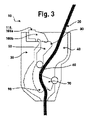
図1は、本発明によるクイックレーシングシステム10の概略図を示す。クイックレーシングシステム10は、ハウジング30を通って延びる通路40を有する。図1では通路40は、左側は部分的にロッカー50によって限定され、右側は部分的にジョー70により限定されている。ロッカー50は、図1でクイックレーシングシステム10の上端部の方向に延びる閉止部80を有しており、使用者が閉動作を行うと、この方向からクイックレーシングシステム10を閉じる若しくは締めるための引張りが行われる。ロッカー50の反対側の端部には開放部90があり、その凹状内側60はジョー70と協働して靴紐20を閉位置で締め付ける。
FIG. 1 shows a schematic diagram of a
図1から分かるように、ロッカー50の閉止部80は、通路40のロッカー側とは反対側の方向に延びている。靴紐を固定する動作を引き起こすために靴紐20を上方に引っ張ると、靴紐20がぴんと張ってロッカー50の閉止部80を押し、これを保持位置の方向に動かし、そこでロッカー50はロック解除レバー100bと係合する。閉止部80が保持位置に向かって動くのと同時に、開放部90はその凹状内側60と共に歯付きジョー70に向かって動いて、靴紐20がジョー70の歯と接触するようになる。ロッカー50は保持位置に拘束されているので、ロッカー50の開放部90は靴紐20及びジョー70による逆圧が発生しても逃げることができない。靴紐20が引張りから解放されて、偏心ジョー70と一緒にロッカー50の開放部90の凹状内側60に押されると、靴紐はジョー70とロッカー50の開放部90の凹状内側60との間で締め付けられる。
As can be seen in FIG. 1, the
クイックレーシングシステム10を開くために、ロック解除レバー100bの操作部110若しくはロック解除キー100aを押して操作すると、ロッカー50をその保持位置からその開位置に動かすことができる。この動きは靴紐20の緊張により自動的に機能し、その際に開放部90は靴紐20により若しくは靴紐20の緊張によりジョー70から離れる左方向に押される。
To open the
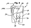
図4~図9に本発明の別の実施形態が概略図に示されているが、それらの締付け機構及び開放機構は図1~図3に示すものと同一である。 Another embodiment of the invention is shown schematically in FIGS. 4-9, wherein the tightening and opening mechanisms are identical to those shown in FIGS. 1-3.
ただし、図1~図3に示された実施形態と異なり、図4~図9に示す実施形態では操作部110若しくは解除ボタン100aは、本発明によるクイックレーシングシステム10が閉位置にある場合にのみ見える。この状態では、図4~図6に示すようにロック解除キー100aは、ロッカー50に形成されたフックによって押し上げられて、クイックレーシングシステム10のハウジング30から突出し、使用者がクイックレーシングシステム10を開くために押すことができる。図7~図8によれば、これはロック解除キーではなくロック解除レバー100bであり、その操作部110はクイックレーシングシステム10の閉位置でクイックレーシングシステム10のハウジング30から上方に突出して、同様にクイックレーシングシステム10を開くために操作できる。
However, unlike the embodiment shown in FIGS. 1-3, in the embodiment shown in FIGS. 4-9, the
図10及び図11には、本発明によるクイックレーシングシステム10に2つのシングルジョー70の代替として使用できる、互いに対して可動な2つのシングルジョー70を有するダブルジョーシステムが示されている。
Figures 10 and 11 show a double jaw system with two
図12には、本発明による靴120が示されており、そのシャフト部130の両側にそれぞれ1つの本発明によるクイックレーシングシステム10が凹部140に配置されている。
FIG. 12 shows a
図13は、クイックレーシングシステム10が開位置にある本発明による第2の実施形態の概略図を示しており、ここでは靴紐20が通路40を通って案内されており、通路40はハウジング30内に配置されて、図13によれば左側が閉止部80と開放部90を有するロッカー50によって限定され、右側がジョー70によって限定されている。図13によれば開放部90は係合部160と係合し、それによりロック解除キー100aをばね150の圧力に抗して、ロック解除キー100aが実質的にクイックレーシングシステム10のハウジング3内に引き戻された位置に拘束されている。
FIG. 13 shows a schematic view of a second embodiment according to the invention with the
本発明によるクイックレーシングシステム10を閉じるために、図14に概略的に示されているように、靴紐20に上方への張力を加えると、靴紐20はロッカー50の閉止部80と当接して、閉止部80をジョー70から離れる方向に押し若しくはこの閉止部80をロック解除キー100aに向かって動かす。ここで開放部90は係合部160との係合から出てジョー70に向かって移動し、ロック解除キー100aはばね150のばね力によりハウジング30から上方に押し出される。この上方への直線運動によりロック解除キー100aの阻止部170は開放部90の内側60とは反対側の外側に沿って滑動し、このようにして靴紐20がロッカー50の内側60とジョーの間で締め付けられる間、ロッカー50の開放部90が逸れるのを防ぐ。この状態では、クイックレーシングシステム10を靴紐20で閉じる過程でジョーはまだロッカーの内側60と圧縮当接していないので、本発明によるクイックレーシングシステム10は半閉位置にある。
To close the
図15は、図13に示された本発明の実施形態の閉位置における概略図を示しており、このときにはジョー20は靴紐20の上部の弛緩、及び靴紐20の下部に形成された張力により、ロッカー50の開放部90の内側60との圧縮当接に滑り込み、靴紐を確実に締付け、誤って開くことがないようにする一方、阻止部170はロッカー50の開放部90をその閉じた位置に確保する。この閉じた位置ではロック解除キー100aはハウジング30から押し出された状態にある。
FIG. 15 shows a schematic view of the embodiment of the invention shown in FIG. 13 in the closed position, when the
図16は、図13に示された本発明の実施形態の開いた位置における概略図を示しており、本発明によるクイックレーシングシステム10を開くためにロック解除キー100aに圧力が加えられると、阻止部170はロッカー50の開放部90の下に滑り込み、その際に開放部90を解放し、それによりクイックレーシングシステム10も同様に内側60とジョー部70との間の締付けから解放されて、通路40を通ってハウジング30から下方へ滑り出ることができる。次に本発明によるクイックレーシングシステムを再び閉じる過程で靴紐20は歯付きジョー70に当接していて、回転軸で支持されたジョー70をロッカー50の閉止部に向かって連行し、使用者がさらに張力を加えると靴紐は再び閉止部80と当接して、これを上述したように横方向に押しやり、その結果としてロッカー50の内側60が靴紐20と当接して、これを再びジョー70の歯の付いた表面に押し付ける。
FIG. 16 shows a schematic view of the embodiment of the invention shown in FIG. 13 in the open position, and when pressure is applied to the unlock key 100a to open the
この箇所で指摘しておくと、上記のすべての部分はそれ自体で見ても、あらゆる組み合わせにおいても、特に図面に示されている詳細も、本発明に不可欠であると要求される。これらの変更は当業者によく知られている。
本明細書に開示される発明は以下の態様を含む。
〔態様1〕
少なくとも1本の靴紐(20)を通すための通路(40)を備えたハウジング(30)を有する、少なくとも1本の靴紐(20)を取り外し可能に固定するためのクイックレーシングシステム(10)であって、
通路(40)は、第1の側では、通路(40)の方向に向けられて実質的に凹状内側(60)を持つ可動に支持されたロッカー(50)によって少なくとも一部の区域で形成され、第2の実質的に前記ロッカーと向き合う側では、クイックレーシングシステム(10)の少なくとも閉位置でロッカー(50)と協働する偏心ジョー(70)によって少なくとも一部の区域で形成されており、ロッカー(50)は閉止部(80)と開放部(90)を有し、閉止部(80)は閉動作中に使用者によって加えられる張力の方向に配置され、開放部(90)はクイックレーシングシステム(10)の使用位置でロッカー(50)の実質的に反対方向に配置されており、閉止部(80)は閉動作の過程でぴんと張った靴紐(20)によってジョー(70)から離れて保持位置に押し入れられて、開放部(90)はジョー(70)に接近し、ロッカー(50)は保持位置で、特にラッチ及び/又はスナップにより拘束可能であることを特徴とする、クイックレーシングシステム。
〔態様2〕
ロッカー(50)は、少なくとも保持位置でロック解除キー(100a)又はロック解除レバー(100b)と当接及び/又は係合していることを特徴とする、態様1に記載のクイックレーシングシステム。
〔態様3〕
ロック解除キー(100a)若しくはロック解除レバー(100b)の操作部(110)は、少なくとも保持位置でロッカー(50)によって、場合によりばね作用に抗してハウジング(30)から押し出され、ロック解除キー(100a)若しくはロック解除レバー(100b)の操作部(110)は靴紐を緩める動作のために使用者にとって到達可能となることを特徴とする、態様2に記載のクイックレーシングシステム。
〔態様4〕
ロッカー(50)の閉止部(80)が閉動作中にジョー(70)から離れ、若しくは開放部(90)が閉動作中にジョー(70)に押し付けられると、ロック解除キー(100a)若しくは操作部(110)は解放されてばね力によってハウジング(30)から押し出されて、ロック解除キー(100a)若しくは操作部(110)は靴紐を緩める動作のために使用者にとって到達可能となることを特徴とする、態様2に記載のクイックレーシングシステム。
〔態様5〕
ロッカー(50)の開放部(90)は、閉動作中にぴんと張った靴紐(20)によってジョー(70)から離れる方向に押されることを特徴とする、態様1から4のいずれか一態様に記載のクイックレーシングシステム。
〔態様6〕
ジョー(70)は、2つの、特に互いに独立した可動シングルジョーからなるダブルジョーとして構成されていることを特徴とする、態様1から5のいずれか一態様に記載のクイックレーシングシステム。
〔態様7〕
態様1から6のいずれか一態様に記載の少なくとも1つのクイックレーシングシステム(10)を装備された靴(120)、特にスノーボード靴。
〔態様8〕
クイックレーシングシステム(10)は、シャフト部(130)の上端部、特にインナーシューズ若しくはインナーシェルとアウターシューズ若しくはアウターシェルの間で、好ましくはクイックレーシングシステム(10)用に設けられた凹部(140)に配置されていることを特徴とする、態様7に記載の靴。
〔態様9〕
靴は、シャフト部(130)の両側にクイックレーシングシステム(10)を有することを特徴とする、態様8に記載の靴。
It should be pointed out at this point that all parts of the above, viewed by themselves and in any combination, and in particular the details shown in the drawings, are claimed to be essential to the invention. These modifications are well known to those skilled in the art.
The invention disclosed in this specification includes the following aspects.
[Aspect 1]
A quick lacing system (10) for removably securing at least one shoelace (20) having a housing (30) with a passageway (40) for passing at least one shoelace (20). and
The passageway (40) is at least partially defined on the first side by a movably supported rocker (50) with a substantially concave interior (60) directed toward the passageway (40). , on the side facing the second substantially said rocker, at least in part formed by an eccentric jaw (70) cooperating with the rocker (50) in at least the closed position of the quick lacing system (10), The rocker (50) has a closed part (80) and an open part (90), the closed part (80) being oriented in the direction of the tension applied by the user during the closing movement and the opening part (90) being quick lacing. Disposed substantially opposite the locker (50) in the use position of the system (10), the closure (80) is separated from the jaws (70) by the taut lace (20) during the closing process. quick lacing, characterized in that the opening (90) approaches the jaws (70) and the rocker (50) can be constrained in the holding position, in particular by means of latches and/or snaps, when pushed into the holding position with the system.
[Aspect 2]
A quick lacing system according to aspect 1, characterized in that the rocker (50) abuts and/or engages with the unlocking key (100a) or the unlocking lever (100b) at least in the holding position.
[Aspect 3]
The actuating part (110) of the unlocking key (100a) or of the unlocking lever (100b) is pushed out of the housing (30) by the rocker (50), possibly against a spring action, at least in the holding position and the unlocking key A quick lacing system according to aspect 2, characterized in that the operating portion (110) of the (100a) or unlocking lever (100b) is accessible to the user for the action of loosening the laces.
[Aspect 4]
When the closing part (80) of the locker (50) is separated from the jaws (70) during the closing movement or the opening part (90) is pressed against the jaws (70) during the closing movement, the unlock key (100a) or the operation The part (110) is released and pushed out of the housing (30) by the spring force so that the unlocking key (100a) or the operating part (110) becomes accessible to the user for the act of loosening the shoelace. A quick lacing system according to aspect 2, characterized in that:
[Aspect 5]
5. The aspect of any one of aspects 1 to 4, wherein the opening (90) of the rocker (50) is pushed away from the jaws (70) by the taut lace (20) during the closing action. The quick lacing system described in .
[Aspect 6]
6. Quick lacing system according to any one of aspects 1 to 5, characterized in that the jaw (70) is configured as a double jaw consisting of two, in particular independently movable single jaws.
[Aspect 7]
A shoe (120), in particular a snowboard shoe, equipped with at least one quick lacing system (10) according to any one of aspects 1 to 6.
[Aspect 8]
The quick lacing system (10) comprises a recess (140) preferably provided for the quick lacing system (10) at the upper end of the shaft portion (130), particularly between the inner shoe or inner shell and the outer shoe or outer shell. 8. The shoe of aspect 7, characterized in that it is positioned in the
[Aspect 9]
9. A shoe according to aspect 8, characterized in that the shoe has a quick lacing system (10) on both sides of the shaft portion (130).
10 クイックレーシングシステム
20 靴紐
30 ハウジング
40 通路
50 ロッカー
60 内側
70 ジョー
80 閉止部
90 開放部
100a ロック解除キー
100b ロック解除レバー
110 操作部
120 靴
130 シャフト部
140 凹部
150 ばね
160 係合部
170 阻止部
10
Claims (8)
通路(40)は、
第1の側では、通路(40)の方向に向けられて凹状内側(60)を持つ可動に支持されたロッカー(50)によって、少なくとも一部の区域で形成され、
第2の前記ロッカーと向き合う側では、クイックレーシングシステム(10)の閉位置でロッカー(50)と協働して靴紐を締め付ける偏心ジョー(70)によって、少なくとも一部の区域で形成されており、
ロッカー(50)は閉止部(80)と開放部(90)を有し、
閉止部(80)は閉動作中に使用者によって加えられる張力の方向に配置され、
開放部(90)は、少なくとも1本の靴紐が通路及びロッカーの凹状内側と偏心ジョーの間を通って延びているクイックレーシングシステム(10)の使用状態で、前記閉止部(80)と反対方向に配置されており、
ロッカー(50)は、少なくとも保持位置でロック解除キー(100a)又はロック解除レバー(100b)と当接及び/又は係合し、
閉止部(80)は閉動作の過程でぴんと張った靴紐(20)によってジョー(70)から離れて保持位置に押し入れられて、
開放部(90)はジョー(70)に接近し、ロッカー(50)は前記保持位置で、拘束可能である、
ことを特徴とする、クイックレーシングシステム。 A quick lacing system (10) for removably securing at least one shoelace (20) having a housing (30) with a passageway (40) for passing at least one shoelace (20). and
The aisle (40) is
formed at least in part on a first side by a movably supported rocker (50) oriented in the direction of the passageway (40) and having a concave inner side (60);
On the side facing the second said rocker , at least a portion of the area is secured by an eccentric jaw (70) which cooperates with the rocker (50) to tighten the lace in the closed position of the quick lacing system (10). is formed of
The locker (50) has a closed portion (80) and an open portion (90),
the closure (80) is positioned in the direction of the tension applied by the user during the closing action;
The open portion (90) is opposite said closed portion (80) in use of the quick lacing system (10) in which at least one lace extends between the concave inside of the passageway and locker and the eccentric jaws. are placed in the direction of
the rocker (50) abuts and/or engages the unlocking key (100a) or the unlocking lever (100b) at least in the holding position;
The closure (80) is forced into a retained position away from the jaws (70) by the taut lace (20) during the closing process,
the opening (90) is close to the jaws (70) and the rocker (50) is constrainable in said holding position ;
A quick lacing system characterized by
Applications Claiming Priority (3)
| Application Number | Priority Date | Filing Date | Title |
|---|---|---|---|
| DE102017113778.5A DE102017113778A1 (en) | 2017-06-21 | 2017-06-21 | Quick lacing system and shoe equipped with it |
| DE102017113778.5 | 2017-06-21 | ||
| PCT/EP2018/066172 WO2018234264A1 (en) | 2017-06-21 | 2018-06-19 | RAPID LACING SYSTEM AND SHOE EQUIPPED WITH SAID SYSTEM |
Publications (2)
| Publication Number | Publication Date |
|---|---|
| JP2020524559A JP2020524559A (en) | 2020-08-20 |
| JP7127072B2 true JP7127072B2 (en) | 2022-08-29 |
Family
ID=62684803
Family Applications (1)
| Application Number | Title | Priority Date | Filing Date |
|---|---|---|---|
| JP2019570436A Active JP7127072B2 (en) | 2017-06-21 | 2018-06-19 | Quick lacing system and shoes equipped with it |
Country Status (6)
| Country | Link |
|---|---|
| US (1) | US11617419B2 (en) |
| EP (1) | EP3641581B1 (en) |
| JP (1) | JP7127072B2 (en) |
| CN (1) | CN110785098B (en) |
| DE (1) | DE102017113778A1 (en) |
| WO (1) | WO2018234264A1 (en) |
Families Citing this family (3)
| Publication number | Priority date | Publication date | Assignee | Title |
|---|---|---|---|---|
| CN111685971A (en) * | 2020-06-16 | 2020-09-22 | 孙春凡 | Bandage fixed knot on medical rehabilitation training machine constructs |
| CN220442052U (en) | 2023-07-29 | 2024-02-06 | 江西思创通智能科技有限公司 | A new type of lacing system |
| IT202300021750A1 (en) * | 2023-10-18 | 2025-04-18 | Hawai Italia Srl | SAFETY FOOTWEAR WITH AT LEAST ONE SELF-LOCKING LACE EYE DEVICE |
Citations (2)
| Publication number | Priority date | Publication date | Assignee | Title |
|---|---|---|---|---|
| JP3106517U (en) | 2003-07-10 | 2005-01-06 | サロモン エス.エー. | String fixing device |
| JP2013529994A (en) | 2010-06-30 | 2013-07-25 | ディーラックス シュポルトアルティーケル ハンデルス ゲーエムベーハー | Boots, especially ski boots or snowboard boots |
Family Cites Families (24)
| Publication number | Priority date | Publication date | Assignee | Title |
|---|---|---|---|---|
| US583646A (en) * | 1897-06-01 | Washin | ||
| GB191504857A (en) | 1915-03-29 | 1915-11-18 | James Calib Doust | Improvements in Rope Grips. |
| DE891065C (en) | 1951-11-03 | 1953-09-24 | Erwin Neubauer | Closure for laces |
| US4071926A (en) * | 1974-05-09 | 1978-02-07 | D. B. Enterprises, Inc. | Safety device for ladder climbers |
| US4355441A (en) | 1978-11-24 | 1982-10-26 | Haell Gunnar B | Rope-lock |
| DK159628C (en) * | 1988-01-21 | 1991-04-29 | Berendsen Sophus Marine As | LATCH MECHANISM FOR A ROPE, A LINE OR A SIMILAR ELEVATIVE LIVING BODY |
| JPH0630002Y2 (en) | 1990-04-06 | 1994-08-17 | ダイワ精工株式会社 | Ski shoes |
| CN2183469Y (en) | 1994-03-02 | 1994-11-23 | 王雷 | Flexible cord clip |
| US5572770A (en) * | 1995-08-18 | 1996-11-12 | Boden; Robert O. | Self locking cord lock |
| US7226043B2 (en) * | 1997-12-03 | 2007-06-05 | Peter Stone | Stable fail-safe cleat with automatic in-line locking cam |
| FR2798176B1 (en) | 1999-09-08 | 2001-10-12 | Salomon Sa | LACET FASTENER |
| AUPQ742200A0 (en) * | 2000-05-11 | 2000-06-01 | Britax Child-Care Products Pty Ltd | Webbing length adjustor |
| FR2815874B1 (en) * | 2000-11-02 | 2002-12-27 | Protecta Internat Sa | PERSONAL SECURITY DEVICE FOR A VERTICAL CABLE |
| US6729000B1 (en) * | 2003-02-12 | 2004-05-04 | Kun-Chung Liu | Lace tightening assembly |
| US7281341B2 (en) * | 2003-12-10 | 2007-10-16 | The Burton Corporation | Lace system for footwear |
| FR2881809B1 (en) | 2005-02-04 | 2007-04-13 | Salomon Sa | QUICK LACET BLOCKER |
| US20070000105A1 (en) * | 2005-06-14 | 2007-01-04 | K-2 Corporation | Lace locking device |
| FR2898506B1 (en) | 2006-03-15 | 2008-05-30 | Zedel Soc Par Actions Simplifi | MULTI-FUNCTIONAL ROPE INSURANCE APPARATUS |
| US20080168685A1 (en) * | 2007-01-17 | 2008-07-17 | Dc Shoes, Inc. | Single lace boot with multiple compression zones |
| US8474157B2 (en) * | 2009-08-07 | 2013-07-02 | Pierre-Andre Senizergues | Footwear lacing system |
| US8371004B2 (en) * | 2009-09-18 | 2013-02-12 | Daniel A. Huber | Universal lace/cord lock system |
| GB2481849B (en) | 2010-07-09 | 2012-10-03 | Tim James Ussher | Cord clamping device |
| FR2985643B1 (en) | 2012-01-17 | 2015-04-03 | Salomon Sas | FOOTWEAR WITH AN IMPROVED TIGHTENING DEVICE |
| ES2690536T3 (en) * | 2012-12-14 | 2018-11-21 | Vans, Inc. | Shoe retention systems |
-
2017
- 2017-06-21 DE DE102017113778.5A patent/DE102017113778A1/en active Pending
-
2018
- 2018-06-19 WO PCT/EP2018/066172 patent/WO2018234264A1/en not_active Ceased
- 2018-06-19 EP EP18732740.8A patent/EP3641581B1/en active Active
- 2018-06-19 CN CN201880040926.XA patent/CN110785098B/en active Active
- 2018-06-19 JP JP2019570436A patent/JP7127072B2/en active Active
- 2018-06-19 US US16/624,713 patent/US11617419B2/en active Active
Patent Citations (2)
| Publication number | Priority date | Publication date | Assignee | Title |
|---|---|---|---|---|
| JP3106517U (en) | 2003-07-10 | 2005-01-06 | サロモン エス.エー. | String fixing device |
| JP2013529994A (en) | 2010-06-30 | 2013-07-25 | ディーラックス シュポルトアルティーケル ハンデルス ゲーエムベーハー | Boots, especially ski boots or snowboard boots |
Also Published As
| Publication number | Publication date |
|---|---|
| WO2018234264A1 (en) | 2018-12-27 |
| CN110785098B (en) | 2022-08-30 |
| JP2020524559A (en) | 2020-08-20 |
| CN110785098A (en) | 2020-02-11 |
| US20200214398A1 (en) | 2020-07-09 |
| EP3641581A1 (en) | 2020-04-29 |
| US11617419B2 (en) | 2023-04-04 |
| DE102017113778A1 (en) | 2018-12-27 |
| EP3641581B1 (en) | 2022-03-02 |
Similar Documents
| Publication | Publication Date | Title |
|---|---|---|
| JP7127072B2 (en) | Quick lacing system and shoes equipped with it | |
| DK202000005Y4 (en) | Integrated closure device components and methods | |
| CN100571559C (en) | Clamping device for shoelaces or similar fastening devices | |
| US4660302A (en) | Ski boot | |
| US7877845B2 (en) | Controlled-release fastening device | |
| US7946007B2 (en) | Device for blocking flexible strands | |
| JP2003093109A (en) | Device for activating lace-up traction device for shoe | |
| NO168403B (en) | DEVICE FOR FIXING SCHOOLS | |
| JPS62258603A (en) | Apparatus for closing boots | |
| JPH10155503A (en) | Device for tightening toothed strap | |
| KR20170042626A (en) | Closure system | |
| JP2011512178A (en) | Shoelace fasteners and shoes | |
| JP2007500835A (en) | Cord lock device | |
| US2893090A (en) | Shoelace tightener | |
| US7343650B2 (en) | Web adjuster and harness for child restraint seat | |
| US20100018018A1 (en) | Closure for shoelaces | |
| US10390590B2 (en) | Lace ratcheting device II | |
| US20090133234A1 (en) | Buckle mechanism | |
| US7370392B2 (en) | Locking device | |
| JPH0394702A (en) | Adjustable binding device for sports shoe, and sports shoe using its device | |
| CN101513291B (en) | Shoelace tightness-controlling device and shoes | |
| US11234489B2 (en) | Spring lace ratcheting device | |
| CN201171394Y (en) | Bootlace tightness control device and shoes | |
| WO1992003945A1 (en) | Lever fastening device for footwear in general | |
| KR101229165B1 (en) | Device for tightenning up a shoelace |
Legal Events
| Date | Code | Title | Description |
|---|---|---|---|
| A521 | Request for written amendment filed |
Free format text: JAPANESE INTERMEDIATE CODE: A523 Effective date: 20200220 |
|
| A621 | Written request for application examination |
Free format text: JAPANESE INTERMEDIATE CODE: A621 Effective date: 20210518 |
|
| A977 | Report on retrieval |
Free format text: JAPANESE INTERMEDIATE CODE: A971007 Effective date: 20211124 |
|
| A131 | Notification of reasons for refusal |
Free format text: JAPANESE INTERMEDIATE CODE: A131 Effective date: 20211207 |
|
| A521 | Request for written amendment filed |
Free format text: JAPANESE INTERMEDIATE CODE: A523 Effective date: 20220304 |
|
| TRDD | Decision of grant or rejection written | ||
| A01 | Written decision to grant a patent or to grant a registration (utility model) |
Free format text: JAPANESE INTERMEDIATE CODE: A01 Effective date: 20220719 |
|
| A61 | First payment of annual fees (during grant procedure) |
Free format text: JAPANESE INTERMEDIATE CODE: A61 Effective date: 20220817 |
|
| R150 | Certificate of patent or registration of utility model |
Ref document number: 7127072 Country of ref document: JP Free format text: JAPANESE INTERMEDIATE CODE: R150 |
|
| R250 | Receipt of annual fees |
Free format text: JAPANESE INTERMEDIATE CODE: R250 |