JP7127033B2 - Antimicrobial susceptibility testing using digital microscopy - Google Patents
Antimicrobial susceptibility testing using digital microscopy Download PDFInfo
- Publication number
- JP7127033B2 JP7127033B2 JP2019538232A JP2019538232A JP7127033B2 JP 7127033 B2 JP7127033 B2 JP 7127033B2 JP 2019538232 A JP2019538232 A JP 2019538232A JP 2019538232 A JP2019538232 A JP 2019538232A JP 7127033 B2 JP7127033 B2 JP 7127033B2
- Authority
- JP
- Japan
- Prior art keywords
- image
- pathogens
- pathogen
- depicted
- test
- Prior art date
- Legal status (The legal status is an assumption and is not a legal conclusion. Google has not performed a legal analysis and makes no representation as to the accuracy of the status listed.)
- Active
Links
Images


Classifications
-
- G—PHYSICS
- G01—MEASURING; TESTING
- G01N—INVESTIGATING OR ANALYSING MATERIALS BY DETERMINING THEIR CHEMICAL OR PHYSICAL PROPERTIES
- G01N15/00—Investigating characteristics of particles; Investigating permeability, pore-volume or surface-area of porous materials
- G01N15/06—Investigating concentration of particle suspensions
-
- C—CHEMISTRY; METALLURGY
- C12—BIOCHEMISTRY; BEER; SPIRITS; WINE; VINEGAR; MICROBIOLOGY; ENZYMOLOGY; MUTATION OR GENETIC ENGINEERING
- C12M—APPARATUS FOR ENZYMOLOGY OR MICROBIOLOGY; APPARATUS FOR CULTURING MICROORGANISMS FOR PRODUCING BIOMASS, FOR GROWING CELLS OR FOR OBTAINING FERMENTATION OR METABOLIC PRODUCTS, i.e. BIOREACTORS OR FERMENTERS
- C12M1/00—Apparatus for enzymology or microbiology
- C12M1/34—Measuring or testing with condition measuring or sensing means, e.g. colony counters
- C12M1/3492—Measuring or testing with condition measuring or sensing means, e.g. colony counters with use of lecture and interpretation devices, grids
-
- C—CHEMISTRY; METALLURGY
- C12—BIOCHEMISTRY; BEER; SPIRITS; WINE; VINEGAR; MICROBIOLOGY; ENZYMOLOGY; MUTATION OR GENETIC ENGINEERING
- C12M—APPARATUS FOR ENZYMOLOGY OR MICROBIOLOGY; APPARATUS FOR CULTURING MICROORGANISMS FOR PRODUCING BIOMASS, FOR GROWING CELLS OR FOR OBTAINING FERMENTATION OR METABOLIC PRODUCTS, i.e. BIOREACTORS OR FERMENTERS
- C12M41/00—Means for regulation, monitoring, measurement or control, e.g. flow regulation
- C12M41/12—Means for regulation, monitoring, measurement or control, e.g. flow regulation of temperature
- C12M41/14—Incubators; Climatic chambers
-
- C—CHEMISTRY; METALLURGY
- C12—BIOCHEMISTRY; BEER; SPIRITS; WINE; VINEGAR; MICROBIOLOGY; ENZYMOLOGY; MUTATION OR GENETIC ENGINEERING
- C12M—APPARATUS FOR ENZYMOLOGY OR MICROBIOLOGY; APPARATUS FOR CULTURING MICROORGANISMS FOR PRODUCING BIOMASS, FOR GROWING CELLS OR FOR OBTAINING FERMENTATION OR METABOLIC PRODUCTS, i.e. BIOREACTORS OR FERMENTERS
- C12M41/00—Means for regulation, monitoring, measurement or control, e.g. flow regulation
- C12M41/30—Means for regulation, monitoring, measurement or control, e.g. flow regulation of concentration
- C12M41/36—Means for regulation, monitoring, measurement or control, e.g. flow regulation of concentration of biomass, e.g. colony counters or by turbidity measurements
-
- C—CHEMISTRY; METALLURGY
- C12—BIOCHEMISTRY; BEER; SPIRITS; WINE; VINEGAR; MICROBIOLOGY; ENZYMOLOGY; MUTATION OR GENETIC ENGINEERING
- C12Q—MEASURING OR TESTING PROCESSES INVOLVING ENZYMES, NUCLEIC ACIDS OR MICROORGANISMS; COMPOSITIONS OR TEST PAPERS THEREFOR; PROCESSES OF PREPARING SUCH COMPOSITIONS; CONDITION-RESPONSIVE CONTROL IN MICROBIOLOGICAL OR ENZYMOLOGICAL PROCESSES
- C12Q1/00—Measuring or testing processes involving enzymes, nucleic acids or microorganisms; Compositions therefor; Processes of preparing such compositions
- C12Q1/02—Measuring or testing processes involving enzymes, nucleic acids or microorganisms; Compositions therefor; Processes of preparing such compositions involving viable microorganisms
- C12Q1/18—Testing for antimicrobial activity of a material
-
- G—PHYSICS
- G01—MEASURING; TESTING
- G01N—INVESTIGATING OR ANALYSING MATERIALS BY DETERMINING THEIR CHEMICAL OR PHYSICAL PROPERTIES
- G01N15/00—Investigating characteristics of particles; Investigating permeability, pore-volume or surface-area of porous materials
- G01N15/02—Investigating particle size or size distribution
- G01N15/0205—Investigating particle size or size distribution by optical means
- G01N15/0227—Investigating particle size or size distribution by optical means using imaging; using holography
-
- G—PHYSICS
- G01—MEASURING; TESTING
- G01N—INVESTIGATING OR ANALYSING MATERIALS BY DETERMINING THEIR CHEMICAL OR PHYSICAL PROPERTIES
- G01N15/00—Investigating characteristics of particles; Investigating permeability, pore-volume or surface-area of porous materials
- G01N15/10—Investigating individual particles
- G01N15/14—Optical investigation techniques, e.g. flow cytometry
- G01N15/1429—Signal processing
- G01N15/1433—Signal processing using image recognition
-
- G—PHYSICS
- G06—COMPUTING OR CALCULATING; COUNTING
- G06T—IMAGE DATA PROCESSING OR GENERATION, IN GENERAL
- G06T5/00—Image enhancement or restoration
- G06T5/70—Denoising; Smoothing
-
- G—PHYSICS
- G06—COMPUTING OR CALCULATING; COUNTING
- G06T—IMAGE DATA PROCESSING OR GENERATION, IN GENERAL
- G06T7/00—Image analysis
- G06T7/0002—Inspection of images, e.g. flaw detection
- G06T7/0012—Biomedical image inspection
-
- G—PHYSICS
- G06—COMPUTING OR CALCULATING; COUNTING
- G06T—IMAGE DATA PROCESSING OR GENERATION, IN GENERAL
- G06T7/00—Image analysis
- G06T7/10—Segmentation; Edge detection
- G06T7/136—Segmentation; Edge detection involving thresholding
-
- G—PHYSICS
- G06—COMPUTING OR CALCULATING; COUNTING
- G06T—IMAGE DATA PROCESSING OR GENERATION, IN GENERAL
- G06T7/00—Image analysis
- G06T7/60—Analysis of geometric attributes
- G06T7/62—Analysis of geometric attributes of area, perimeter, diameter or volume
-
- G—PHYSICS
- G01—MEASURING; TESTING
- G01N—INVESTIGATING OR ANALYSING MATERIALS BY DETERMINING THEIR CHEMICAL OR PHYSICAL PROPERTIES
- G01N15/00—Investigating characteristics of particles; Investigating permeability, pore-volume or surface-area of porous materials
- G01N15/06—Investigating concentration of particle suspensions
- G01N15/075—Investigating concentration of particle suspensions by optical means
-
- G—PHYSICS
- G01—MEASURING; TESTING
- G01N—INVESTIGATING OR ANALYSING MATERIALS BY DETERMINING THEIR CHEMICAL OR PHYSICAL PROPERTIES
- G01N15/00—Investigating characteristics of particles; Investigating permeability, pore-volume or surface-area of porous materials
- G01N15/10—Investigating individual particles
- G01N2015/1006—Investigating individual particles for cytology
-
- G—PHYSICS
- G01—MEASURING; TESTING
- G01N—INVESTIGATING OR ANALYSING MATERIALS BY DETERMINING THEIR CHEMICAL OR PHYSICAL PROPERTIES
- G01N15/00—Investigating characteristics of particles; Investigating permeability, pore-volume or surface-area of porous materials
- G01N15/10—Investigating individual particles
- G01N15/14—Optical investigation techniques, e.g. flow cytometry
- G01N2015/1486—Counting the particles
-
- G—PHYSICS
- G06—COMPUTING OR CALCULATING; COUNTING
- G06T—IMAGE DATA PROCESSING OR GENERATION, IN GENERAL
- G06T2207/00—Indexing scheme for image analysis or image enhancement
- G06T2207/10—Image acquisition modality
- G06T2207/10056—Microscopic image
-
- G—PHYSICS
- G06—COMPUTING OR CALCULATING; COUNTING
- G06T—IMAGE DATA PROCESSING OR GENERATION, IN GENERAL
- G06T2207/00—Indexing scheme for image analysis or image enhancement
- G06T2207/30—Subject of image; Context of image processing
- G06T2207/30004—Biomedical image processing
- G06T2207/30024—Cell structures in vitro; Tissue sections in vitro
-
- G—PHYSICS
- G06—COMPUTING OR CALCULATING; COUNTING
- G06T—IMAGE DATA PROCESSING OR GENERATION, IN GENERAL
- G06T2207/00—Indexing scheme for image analysis or image enhancement
- G06T2207/30—Subject of image; Context of image processing
- G06T2207/30242—Counting objects in image
Landscapes
- Chemical & Material Sciences (AREA)
- Engineering & Computer Science (AREA)
- Health & Medical Sciences (AREA)
- Life Sciences & Earth Sciences (AREA)
- Organic Chemistry (AREA)
- Zoology (AREA)
- Wood Science & Technology (AREA)
- Bioinformatics & Cheminformatics (AREA)
- Physics & Mathematics (AREA)
- General Health & Medical Sciences (AREA)
- Analytical Chemistry (AREA)
- Biochemistry (AREA)
- Biotechnology (AREA)
- General Physics & Mathematics (AREA)
- Microbiology (AREA)
- General Engineering & Computer Science (AREA)
- Genetics & Genomics (AREA)
- Immunology (AREA)
- Proteomics, Peptides & Aminoacids (AREA)
- Biomedical Technology (AREA)
- Sustainable Development (AREA)
- Theoretical Computer Science (AREA)
- Dispersion Chemistry (AREA)
- Pathology (AREA)
- Computer Vision & Pattern Recognition (AREA)
- Biophysics (AREA)
- Toxicology (AREA)
- Molecular Biology (AREA)
- Signal Processing (AREA)
- Medical Informatics (AREA)
- Radiology & Medical Imaging (AREA)
- Quality & Reliability (AREA)
- Nuclear Medicine, Radiotherapy & Molecular Imaging (AREA)
- Geometry (AREA)
- Thermal Sciences (AREA)
- Medicinal Chemistry (AREA)
- Apparatus Associated With Microorganisms And Enzymes (AREA)
- Measuring Or Testing Involving Enzymes Or Micro-Organisms (AREA)
- Investigating Or Analysing Biological Materials (AREA)
- Investigating Or Analysing Materials By Optical Means (AREA)
Description
(関連出願の相互参照)
本願は、米国仮出願第62/574,795号(2017年10月20日出願)および米国仮出願第62/449,373号(2017年1月23日出願)の利益を主張する。
(Cross reference to related applications)
This application claims the benefit of US Provisional Application No. 62/574,795 (filed October 20, 2017) and US Provisional Application No. 62/449,373 (filed January 23, 2017).
患者診断および治療に関連する種々のタイプの試験が、患者の微生物または「病原菌」の分析によって実施されることができる。病原菌は、単細胞または多細胞であり得る細菌、菌類、またはウイルス等の微視的生命有機体である。患者の微生物を含む生物学的サンプルが、患者の感染部、体液、または膿瘍から採取され得、患者の処置を補助するために、試験パネルまたはアレイ内に設置され、種々の試薬と組み合わせられ、培養され、分析され得る。自動化生化学分析装置が、手動動作を使用する分析と比較したとき、患者サンプルの分析を促進し、アッセイ結果の正確度および信頼性を改良するための医療施設および他の機関の必要性を満たすために、かつ、種々の抗菌剤の有効性を決定することにおいて補助するために開発された。抗菌剤は、細菌に対して使用される抗生物質および菌類に対して使用される抗真菌剤等の微生物を死滅させる、またはそれらの成長を阻害する作用剤である。しかしながら、絶えず変化する細菌属および新しく発見される抗菌剤によって、生物学的試験に対する要求は、複雑性および量の両方において増加している。 Various types of tests related to patient diagnosis and therapy can be performed by analyzing a patient's microorganisms or "pathogens." Pathogens are microscopic living organisms such as bacteria, fungi, or viruses that can be unicellular or multicellular. Biological samples containing the patient's microorganisms can be taken from the patient's infected areas, bodily fluids, or abscesses, placed into test panels or arrays, and combined with various reagents to aid in patient treatment; It can be cultured and analyzed. Automated biochemical analyzers meet the need of medical facilities and other institutions to expedite the analysis of patient samples and improve the accuracy and reliability of assay results when compared to analyzes using manual operations. It was developed for and to aid in determining the efficacy of various antimicrobial agents. Antimicrobial agents are agents that kill or inhibit the growth of microorganisms, such as antibiotics used against bacteria and antifungal agents used against fungi. However, with ever-changing bacterial genera and newly discovered antimicrobial agents, the demands on biological testing are increasing in both complexity and quantity.
ある重要な自動化微生物学的分析装置系は、感染している微生物の同定および微生物の成長を制御することにおいて効果的な抗菌剤の同定の両方を決定するための診断ツールとして機能する。病原菌成長は、細胞サイズではなく、細胞数の増加である。例えば、細菌における病原菌成長は、二分裂を通して提供され、細胞は、1つの細胞から2つの娘細胞に分裂する。二分裂が、温度または栄養素の欠如等のある環境要因を通して阻害されるとき、いかなる成長も、結果として生じない。 One important automated microbiological analyzer system serves as a diagnostic tool to determine both the identification of infecting microorganisms and the identification of antimicrobial agents effective in controlling microbial growth. Pathogen growth is an increase in cell number, not cell size. For example, pathogen growth in bacteria is provided through binary fission, in which cells divide from one cell into two daughter cells. When binary fission is inhibited through some environmental factor such as temperature or lack of nutrients, no growth results.
自動化微生物学的分析装置は、感染している微生物の同定および微生物の成長を制御することにおいて効果的な抗菌剤の同定の両方を決定するための診断ツールとして機能する。診断試験を実施することにおいて、生物学的サンプルから単離された微生物の同定および生体外抗菌剤感受性パターンが、確認される。そのような分析装置の従来のバージョンは、段階希釈において異なる酵素基質または抗菌剤を含むパネルもしくはアレイ内の複数の小サンプル試験ウェルの中に試験されるべき小サンプルを設置し得る。微生物の同定(ID)試験および微生物に対して効果的な抗菌剤の最小抑制濃度(MIC)を決定するための抗菌剤感受性試験(AST)は、アレイにおいて作成されたサンプル試験ウェル内の色変化、蛍光変化、混濁の程度(濁度)、または試験から導出される他の情報を利用し得る。ASTおよびID測定の両方ならびに後続分析は、再現性、処理時間の低減、転写エラーの回避、および実験室で実行される全ての試験に対する標準化における利点を提供するために、コンピュータ制御された微生物学的分析装置によって実施され得る。 Automated microbiological analyzers serve as diagnostic tools to determine both the identification of infecting microorganisms and the identification of antimicrobial agents effective in controlling microbial growth. In performing diagnostic tests, the identity and in vitro antimicrobial susceptibility patterns of microorganisms isolated from biological samples are confirmed. Conventional versions of such analyzers can place subsamples to be tested into multiple subsample test wells in panels or arrays containing different enzymatic substrates or antimicrobial agents in serial dilutions. Microbial identification (ID) testing and antimicrobial susceptibility testing (AST) to determine the minimum inhibitory concentration (MIC) of an antimicrobial agent effective against microbes are performed by color change in sample test wells created in the array. , changes in fluorescence, degree of turbidity (turbidity), or other information derived from the test. Both AST and ID measurements and subsequent analysis were performed using computer-controlled microbiology to provide advantages in reproducibility, reduced processing time, avoidance of transcription errors, and standardization for all tests performed in the laboratory. can be performed by a standard analyzer.
微生物のID試験では、接種材料として公知の患者の微生物サンプルの標準化された希釈物が、所定の既知の濃度を有する細菌または細胞懸濁液を提供するために、最初に調製される。この接種材料は、所定の試験培地を含むか、またはその後にそれを供給され得る複数の試験ウェル内に設置される。存在する微生物の種に応じて、この培地は、培養後の色、濁度、蛍光、または他の特性の変化を促進するであろう。これらの変化は、ID試験において微生物を同定するために使用される。 In a microbial ID test, a standardized dilution of a patient's microbial sample, known as an inoculum, is first prepared to provide a bacterial or cell suspension having a predetermined known concentration. This inoculum is placed in a plurality of test wells that contain or can be fed with a predetermined test medium. Depending on the species of microorganisms present, this medium will promote changes in color, turbidity, fluorescence, or other properties after cultivation. These changes are used to identify microorganisms in ID tests.
AST試験では、複数の試験ウェルが、接種材料および増加する濃度のいくつかの異なる抗菌剤、例えば、抗生物質を充填される。異なる抗菌剤は、成長培地または液体培地中で臨床的に着目されるそれらを含む濃度まで希釈され得る。培養後、濁度は、成長がそれらの試験ウェル内の抗菌剤によって阻害されていない試験ウェル内で増加させられるか、または変化させられないであろう。各抗菌剤のMICは、各濃度の抗菌剤に対する成長の欠如によって測定される。成長の欠如を示す抗菌剤の最低濃度が、MICということになる。 In the AST test, multiple test wells are filled with an inoculum and increasing concentrations of several different antimicrobial agents, eg, antibiotics. Different antimicrobial agents can be diluted in growth medium or liquid medium to concentrations containing them that are of clinical interest. After incubation, turbidity will either increase or remain unchanged in test wells where growth is not inhibited by the antimicrobial agent in those test wells. The MIC of each antimicrobial agent is determined by the lack of growth for each concentration of antimicrobial agent. The lowest concentration of antimicrobial agent that showed lack of growth would be the MIC.
本願明細書は、例えば、以下の項目も提供する。
(項目1)
方法であって、前記方法は、
(a)混合物の未加工画像を捕捉することであって、前記混合物は、複数の病原菌と、抗菌剤とを含む、ことと、
(b)前記未加工画像を向上画像に向上させることと、
(c)前記向上画像に関連付けられた病原菌総数を決定することと
を含み、
前記病原菌総数は、前記向上画像内に描写された前記複数の病原菌における病原菌の数に基づく、方法。
(項目2)
(a)前記未加工画像を向上させることに先立って、前記未加工画像内に描写された前記複数の病原菌における前記病原菌のサイズを決定することと、
(b)少なくとも部分的に前記サイズに基づいて、前記未加工画像を前記向上画像に向上させることと
をさらに含む、項目1に記載の方法。
(項目3)
(a)前記向上画像のための閾値を決定することと、
(b)少なくとも部分的に前記閾値に基づいて、前記向上画像をセグメント化することと
をさらに含む、項目2に記載の方法。
(項目4)
(a)前記サイズからピクセル半径を導出することと、
(b)少なくとも部分的に前記ピクセル半径に基づいて、前記未加工画像の勾配画像を生成することと、
(c)少なくとも部分的に前記勾配画像に基づいて、前記未加工画像を前記向上画像に向上させることと
をさらに含む、項目3に記載の方法。
(項目5)
方法であって、前記方法は、
(a)混合物の未加工画像を捕捉することであって、前記混合物は、複数の病原菌と、抗菌剤とを含む、ことと、
(b)前記未加工画像を向上画像に向上させることと、
(c)前記向上画像をセグメント化画像にセグメント化することと、
(d)前記セグメント化画像内に描写された病原菌の量をカウントすることと
を含む、方法。
(項目6)
前記向上画像の前記セグメント化に先立って、前記向上画像に雑音低減フィルタを適用することをさらに含む、項目5に記載の方法。
(項目7)
(a)前記向上画像のための閾値を決定することと、
(b)少なくとも部分的に前記閾値に基づいて、前記向上画像をセグメント化することと
をさらに含む、項目5に記載の方法。
(項目8)
(a)前記未加工画像を向上させることに先立って、前記未加工画像内に描写された前記複数の病原菌における前記病原菌のサイズを決定することと、
(b)少なくとも部分的に前記サイズに基づいて、前記未加工画像を前記向上画像に向上させることと
をさらに含む、項目5に記載の方法。
(項目9)
(a)前記サイズからピクセル半径を導出することと、
(b)少なくとも部分的に前記ピクセル半径に基づいて、前記未加工画像の勾配画像を生成することと、
(c)少なくとも部分的に前記勾配画像に基づいて、前記未加工画像を前記向上画像に向上させることと
をさらに含む、項目8に記載の方法。
(項目10)
(a)試験濃度において前記抗菌剤を前記複数の病原菌に添加することと、
(b)少なくとも部分的に前記カウントされた病原菌の量に基づいて、前記試験濃度が前記複数の病原菌に対する前記抗菌剤の最小抑制濃度であるかどうかを決定することと
をさらに含む、項目5に記載の方法。
(項目11)
方法であって、前記方法は、
(a)混合物を試験アレイにおける各試験ウェルの中に堆積させることであって、各試験ウェル内の前記混合物は、複数の病原菌と、異なる濃度の抗菌剤とを含む、ことと、
(b)各試験ウェル内の前記混合物の画像を捕捉することと、
(c)各画像内に描写された前記複数の病原菌の特性を収集することと、
(d)前記複数の病原菌に対する前記抗菌剤の最小抑制濃度を決定することと
を含み、
前記最小抑制濃度は、少なくとも部分的に前記特性に基づき、前記最小抑制濃度は、少なくとも部分的に各試験ウェルに関連付けられる前記抗菌剤の前記濃度に基づく、方法。
(項目12)
各画像内に描写された前記複数の病原菌の前記特性を収集することに先立って、前記画像を向上させることをさらに含む、項目11に記載の方法。
(項目13)
(a)前記画像を向上させることに先立って、前記画像内に描写された前記複数の病原菌における前記病原菌のサイズを決定することと、
(b)少なくとも部分的に前記病原菌の前記サイズに基づいて、前記画像を向上させることと
をさらに含む、項目12に記載の方法。
(項目14)
(a)前記病原菌の前記サイズからピクセル半径を導出することと、
(b)少なくとも部分的に前記ピクセル半径に基づいて、前記画像の勾配画像を生成することと、
(c)少なくとも部分的に前記勾配画像に基づいて、前記画像を向上画像に向上させることと
をさらに含む、項目13に記載の方法。
(項目15)
各画像内に描写された前記複数の病原菌の前記特性を収集することに先立って、前記向上画像をセグメント化することをさらに含む、項目14に記載の方法。
(項目16)
前記向上画像の前記セグメント化に先立って、前記向上画像に雑音低減フィルタを適用することをさらに含む、項目15に記載の方法。
(項目17)
(a)前記向上画像のための閾値を決定することと、
(b)少なくとも部分的に前記閾値に基づいて、前記向上画像をセグメント化することと
をさらに含む、項目16に記載の方法。
(項目18)
前記特性は、各画像内に描写された前記複数の病原菌における病原菌の量である、項目11に記載の方法。
(項目19)
前記特性は、各画像内に描写された前記複数の病原菌における前記病原菌のサイズである、項目11に記載の方法。
(項目20)
前記特性は、比率であり、前記比率は、少なくとも部分的に各画像内に描写された病原菌の量に基づき、前記比率は、少なくとも部分的に各画像内に描写された前記複数の病原菌における前記病原菌の前記サイズに基づく、項目11に記載の方法。
(項目21)
前記特性は、比率であり、前記比率は、少なくとも部分的に各画像内に描写された前記複数の病原菌における前記病原菌に関連付けられたピクセルの量に基づく、項目11に記載の方法。
(項目22)
方法であって、前記方法は、
混合物を試験アレイにおける各試験ウェルの中に堆積させることであって、各試験ウェル内の前記混合物は、複数の病原菌と、異なる濃度の抗菌剤とを含む、ことと、
(b)各試験ウェル内の前記混合物の未加工画像を捕捉することと、
(c)前記未加工画像を最終画像に操作することと、
(d)各最終画像内の病原菌の量をカウントすることと、
(e)各最終画像内でカウントされた前記病原菌の量をデータセット内に記憶することであって、各最終画像内でカウントされた前記病原菌の量は、前記データセット内の前記試験ウェル内の前記抗菌剤の前記濃度に関連付けられている、ことと、
(f)ある期間にわたって待つことと、
(g)前記期間後、(b)、(c)、(d)、および(e)を繰り返すことと、
(h)前記データセットに基づいて、前記複数の病原菌に対する前記抗菌剤の最小抑制濃度を決定することと
を含む、方法。
(項目23)
前記未加工画像を向上画像に向上させることをさらに含み、前記最終画像は、少なくとも部分的に前記向上画像に基づく、項目22に記載の方法。
(項目24)
(a)前記未加工画像内に描写された前記複数の病原菌における前記病原菌のサイズを決定することと、
(b)少なくとも部分的に前記病原菌の前記サイズに基づいて、前記未加工画像を前記向上画像に向上させることと
をさらに含む、項目23に記載の方法。
(項目25)
(a)前記病原菌の前記サイズからピクセル半径を導出することと、
(b)少なくとも部分的に前記ピクセル半径に基づいて、前記未加工画像の勾配画像を生成することと、
(c)少なくとも部分的に前記勾配画像に基づいて、前記未加工画像を前記向上画像に向上させることと
をさらに含む、項目23に記載の方法。
(項目26)
前記向上画像を前記最終画像にセグメント化することをさらに含む、項目23に記載の方法。
(項目27)
前記向上画像を前記最終画像にセグメント化することに先立って、前記向上画像に雑音低減フィルタを適用することをさらに含む、項目26に記載の方法。
(項目28)
(a)前記向上画像のための閾値を決定することと、
(b)少なくとも部分的に前記閾値に基づいて、前記向上画像を前記最終画像にセグメント化することと
をさらに含む、項目26に記載の方法。
(項目29)
生物学的試験システムであって、前記生物学的試験システムは、
(a)培養器システムであって、前記培養器システムは、ある期間にわたって試験ウェル内に配置された混合物を培養するように構成され、前記混合物は、複数の病原菌と、抗菌剤とを含む、培養器システムと、
(b)光学システムであって、前記光学システムは、
(i)ステージであって、前記ステージは、前記期間にわたって前記培養器システム内で培養した後、前記試験ウェルを選択的に受け取るように構成されている、ステージと、
(ii)カメラであって、前記カメラは、前記ステージ上の前記試験ウェル内に配置された前記混合物の未加工画像を捕捉するように構成されている、カメラと
を備えている、光学システムと、
(c)前記培養器システムと前記光学システムとの間で前記試験ウェルを移動させるように構成された移動システムと、
(d)データベースであって、前記未加工画像は、前記データベース内に記憶される、データベースと、
(e)プロセッサと
を備え、
前記プロセッサは、
(i)前記未加工画像を最終画像に操作することと、
(ii)前記最終画像から前記混合物の特性を収集することと、
(iii)前記特性に基づいて、前記複数の病原菌に対する前記抗菌剤の最小抑制濃度を決定することと
を行うように構成されている、生物学的試験システム。
(項目30)
前記ステージは、第1の方向および第2の方向に移動可能である、項目29に記載の生物学的試験システム。
(項目31)
前記ステージは、第3の方向に移動可能である、項目30に記載の生物学的試験システム。
(項目32)
前記特性は、前記最終画像内に描写された前記複数の病原菌における病原菌の量である、項目29に記載の生物学的試験システム。
(項目33)
前記特性は、前記最終画像内に描写された前記複数の病原菌における前記病原菌のサイズである、項目29に記載の生物学的試験システム
(項目34)
前記特性は、比率であり、前記比率は、少なくとも部分的に前記最終画像内に描写された病原菌の量に基づき、前記比率は、少なくとも部分的に前記最終画像内に描写された前記複数の病原菌における前記病原菌の前記サイズに基づく、項目29に記載の生物学的試験システム
(項目35)
前記特性は、比率であり、前記比率は、少なくとも部分的に前記最終画像内に描写された前記複数の病原菌における前記病原菌に関連付けられたピクセルの量に基づく、項目29に記載の生物学的試験システム。
本明細書は、本発明を特に指示し、明確に請求する請求項で終了するが、本発明は、同様の参照番号が同一の要素を識別する付随の図面と併せて検討されるある実施例の以下の説明からより深く理解されるであろうと考えられる。
This specification also provides the following items, for example.
(Item 1)
A method, the method comprising:
(a) capturing a raw image of a mixture, the mixture comprising a plurality of pathogens and an antimicrobial agent;
(b) enhancing the raw image to an enhanced image;
(c) determining a pathogen count associated with the enhanced image;
including
The method, wherein the pathogen count is based on the number of pathogens in the plurality of pathogens depicted in the enhanced image.
(Item 2)
(a) prior to enhancing the raw image, determining the size of the pathogen in the plurality of pathogens depicted in the raw image;
(b) enhancing the raw image to the enhanced image based at least in part on the size;
The method of
(Item 3)
(a) determining a threshold for the enhancement image;
(b) segmenting the enhanced image based at least in part on the threshold;
3. The method of
(Item 4)
(a) deriving a pixel radius from said size;
(b) generating a gradient image of said raw image based at least in part on said pixel radius;
(c) enhancing the raw image to the enhanced image based at least in part on the gradient image;
4. The method of
(Item 5)
A method, the method comprising:
(a) capturing a raw image of a mixture, the mixture comprising a plurality of pathogens and an antimicrobial agent;
(b) enhancing the raw image to an enhanced image;
(c) segmenting the enhanced image into segmented images;
(d) counting the amount of pathogens depicted in the segmented image;
A method, including
(Item 6)
6. The method of
(Item 7)
(a) determining a threshold for the enhancement image;
(b) segmenting the enhanced image based at least in part on the threshold;
6. The method of
(Item 8)
(a) prior to enhancing the raw image, determining the size of the pathogen in the plurality of pathogens depicted in the raw image;
(b) enhancing the raw image to the enhanced image based at least in part on the size;
6. The method of
(Item 9)
(a) deriving a pixel radius from said size;
(b) generating a gradient image of said raw image based at least in part on said pixel radius;
(c) enhancing the raw image to the enhanced image based at least in part on the gradient image;
9. The method of item 8, further comprising:
(Item 10)
(a) adding the antimicrobial agent to the plurality of pathogens at a test concentration;
(b) based at least in part on the quantity of the counted pathogens, determining whether the test concentration is a minimal inhibitory concentration of the antimicrobial agent against the plurality of pathogens;
6. The method of
(Item 11)
A method, the method comprising:
(a) depositing a mixture into each test well in a test array, wherein the mixture within each test well comprises a plurality of pathogens and different concentrations of an antimicrobial agent;
(b) capturing an image of said mixture in each test well;
(c) collecting characteristics of the plurality of pathogens depicted in each image;
(d) determining a minimum inhibitory concentration of said antimicrobial agent against said plurality of pathogens;
including
A method, wherein the minimum inhibitory concentration is based at least in part on the property, and wherein the minimum inhibitory concentration is based at least in part on the concentration of the antimicrobial agent associated with each test well.
(Item 12)
12. The method of
(Item 13)
(a) prior to enhancing the image, determining the size of the pathogen in the plurality of pathogens depicted in the image;
(b) enhancing said image based at least in part on said size of said pathogen;
13. The method of
(Item 14)
(a) deriving a pixel radius from the size of the pathogen;
(b) generating a gradient image of said image based at least in part on said pixel radius;
(c) enhancing said image into an enhanced image based at least in part on said gradient image;
14. The method of
(Item 15)
15. The method of
(Item 16)
16. The method of
(Item 17)
(a) determining a threshold for the enhancement image;
(b) segmenting the enhanced image based at least in part on the threshold;
17. The method of item 16, further comprising:
(Item 18)
12. The method of
(Item 19)
12. The method of
(Item 20)
The characteristic is a ratio, wherein the ratio is based at least in part on the amount of pathogens depicted in each image, and wherein the ratio is at least partially in the plurality of pathogens depicted in each image. 12. The method of
(Item 21)
12. The method of
(Item 22)
A method, the method comprising:
depositing a mixture into each test well in a test array, wherein the mixture within each test well comprises a plurality of pathogens and different concentrations of an antimicrobial agent;
(b) capturing a raw image of said mixture in each test well;
(c) manipulating the raw image into a final image;
(d) counting the amount of pathogens in each final image;
(e) storing in a dataset the amount of said pathogen counted in each final image, wherein said amount of said pathogen counted in each final image is stored in said test wells in said dataset; is associated with the concentration of the antimicrobial agent of
(f) waiting for a period of time;
(g) repeating (b), (c), (d), and (e) after said period of time;
(h) determining a minimum inhibitory concentration of said antimicrobial against said plurality of pathogens based on said data set;
A method, including
(Item 23)
23. The method of item 22, further comprising enhancing the raw image to an enhanced image, wherein the final image is based at least partially on the enhanced image.
(Item 24)
(a) determining the size of the pathogen in the plurality of pathogens depicted in the raw image;
(b) enhancing the raw image into the enhanced image based at least in part on the size of the pathogen;
24. The method of
(Item 25)
(a) deriving a pixel radius from the size of the pathogen;
(b) generating a gradient image of said raw image based at least in part on said pixel radius;
(c) enhancing the raw image to the enhanced image based at least in part on the gradient image;
24. The method of
(Item 26)
24. The method of
(Item 27)
27. The method of
(Item 28)
(a) determining a threshold for the enhancement image;
(b) segmenting the enhanced image into the final image based at least in part on the threshold;
27. The method of
(Item 29)
A biological test system, said biological test system comprising:
(a) an incubator system, said incubator system configured to incubate a mixture disposed within a test well for a period of time, said mixture comprising a plurality of pathogenic bacteria and an antimicrobial agent; an incubator system;
(b) an optical system, said optical system comprising:
(i) a stage configured to selectively receive said test wells after culturing in said incubator system for said period of time;
(ii) a camera, said camera configured to capture a raw image of said mixture disposed within said test well on said stage;
an optical system comprising
(c) a transfer system configured to transfer the test well between the incubator system and the optical system;
(d) a database, wherein said raw image is stored within said database;
(e) a processor;
with
The processor
(i) manipulating the raw image into a final image;
(ii) collecting properties of said mixture from said final image;
(iii) determining a minimum inhibitory concentration of said antimicrobial against said plurality of pathogens based on said properties;
A biological test system configured to perform
(Item 30)
30. The biological test system of
(Item 31)
31. The biological test system of item 30, wherein the stage is movable in a third direction.
(Item 32)
30. The biological test system of
(Item 33)
30. The biological test system of
(Item 34)
said characteristic is a ratio, said ratio being based at least in part on an amount of pathogens delineated in said final image, said ratio being at least in part delineated in said final image of said plurality of pathogens 30. The biological test system of
(Item 35)
30. The biological test of
While the specification concludes with claims particularly pointing and distinctly claiming the invention, the present invention is one embodiment to be considered in conjunction with the accompanying drawings in which like reference numerals identify the same elements. It is believed that it will be better understood from the following description of.
図面は、いかようにも限定であるように意図されず、本発明の種々の実施形態が、必ずしも図面に描写されるわけではないものを含む種々の他の方法で実行され得ることが考慮される。本明細書に組み込まれ、その一部を形成する付随の図面は、本発明のいくつかの側面を図示し、説明とともに、本発明の原理を解説する役割を果たすが、しかしながら、本発明は、示される精密な配列に限定されないことを理解されたい。 The drawings are not intended to be limiting in any way and it is contemplated that the various embodiments of the invention can be implemented in various other ways, including those not necessarily depicted in the drawings. be. The accompanying drawings, which are incorporated in and form a part of the specification, illustrate several aspects of the invention and, together with the description, serve to explain the principles of the invention; It should be understood that the precise sequences shown are not limiting.
本発明のある実施例の以下の説明は、本発明の範囲を限定するように使用されるべきではない。本発明の他の実施例、特徴、側面、実施形態、および利点が、例証として、本発明を実行するために考慮される最良の形態のうちの1つである以下の説明から当業者に明白となるであろう。認識されるであろうように、本発明は、全て本発明から逸脱することなく、他の異なる明白な側面が可能である。故に、図面および説明は、制限ではなく、本質的に例証として見なされるべきである。 The following description of certain embodiments of the invention should not be used to limit the scope of the invention. Other embodiments, features, aspects, embodiments, and advantages of the present invention will be apparent to those skilled in the art from the following description, which is, by way of illustration, one of the best modes contemplated for carrying out the invention. will be As will be realized, the invention is capable of other different and obvious aspects, all without departing from the invention. Accordingly, the drawings and description are to be regarded as illustrative in nature and not restrictive.
本明細書に説明される教示、表現、バージョン、実施例等のうちのいずれか1つ以上のものは、本明細書に説明される他の教示、表現、バージョン、実施例等のうちのいずれか1つ以上のものと組み合わせられ得ることを理解されたい。以下に説明される教示、表現、バージョン、実施例等は、したがって、互いに対して孤立して見なされるべきではない。本明細書の教示が組み合わせられ得る種々の好適な方法が、本明細書の教示に照らして当業者に容易に明白となるであろう。そのような修正および変形例は、請求項の範囲内に含まれることが意図される。 Any one or more of the teachings, expressions, versions, examples, etc. described herein may be superseded by any other teachings, expressions, versions, examples, etc. described herein. can be combined with one or more of The teachings, expressions, versions, examples, etc. described below should therefore not be viewed in isolation from each other. Various suitable ways in which the teachings herein can be combined will be readily apparent to those skilled in the art in light of the teachings herein. Such modifications and variations are intended to fall within the scope of the claims.
(I.生物学的試験システムハードウェア) (I. Biological test system hardware)
図1Aおよび1Bは、生物学的試験システム1において利用可能な種々のハードウェア構成要素の図式的実施例を描写する。生物学的試験システム1は、最適化抗菌剤感受性試験(AST)方法101(図19)を促進する。生物学的試験システム1は、大まかには、消耗品調製システム3と、接種システム5と、培養器システム7と、光学システム9とを含む。生物学的試験システム1内の種々のシステムは、互いに協調し、ユーザによって適正な物質を装填されると、自動的に機能する。
1A and 1B depict schematic examples of various hardware components available in a
生物学的試験システム1を動作させるために、ユーザは、最初に、適切な病原菌サンプルを取得する。図1Aに示されるように、病原菌サンプルは、寒天板11から取得され得るか、またはある状況下では、血液サンプルが、使用され得る。次に、ユーザは、好適な液体培地または培養液を含む管の中に病原菌を移送することによって接種材料懸濁液を調製する。1つのそのような管が、接種材料13として図1Aに示される。生物学的試験システム1のいくつかのバージョンでは、液体培地または培養液は、MIC決定または他の関連付けられる試験に有害に干渉することなく、溶液中に導入される病原菌の生存能力を維持することを補助するための少量のナトリウムおよび塩化カリウムを伴う約0.5mMのリン酸緩衝液であり得る。リン酸緩衝液は、2つのシステムにわたる異なる接種材料の必要性を最小化し、単一の培養液を有することの効率を活用するために、ID試験およびAST試験の両方において使用され得る。各接種材料13は、接種材料ラック15の中に設置され、接種材料ラック全体15が、接種システム5の中に設置される。接種システム5内に入ると、各接種材料13内の接種材料は、必要に応じて、接種材料17を生成するために0.5マクファーランドの標準濁度値まで調節される。生物学的試験システム1のいくつかのバージョンでは、1マイクロリットルプラスチックループまたは綿棒が、寒天板からコロニーを容易に採集し、接種材料を所望の濁度値にするために必要とされる調節の量を最小化するために、ユーザに提供され得る。所望の濁度値まで調節されると、接種材料は、完成される。完成された接種材料は、以降では、図1Bに描写されるように、接種材料17と称されるであろう。接種材料17は、1:250希釈物にさらに希釈され、接種材料18に変換され得る。下でより詳細に議論されるであろうように、各接種材料17内に含まれる接種材料は、同定(ID)アレイ保持器21に適用される一方、各接種材料18内に含まれる接種材料は、ASTアレイ保持器23に適用される。IDアレイ保持器21およびASTアレイ保持器23の両方は、消耗品調製システム3によって組み立てられ、接種材料17および接種材料18との使用のために接種システム5に提供される。
To operate the
消耗品調製システム3は、試験アレイ19のマガジンを装填され、試験アレイ19は、一連の試験ウェル20内に配置される生物学的試験システム1によって要求される種々の抗菌剤または他の作用剤を含み得る。例えば、試験アレイ19は、抗菌剤希釈物アレイまたは同定アレイを備え得る。消耗品調製システム3は、バルク希釈液(図示せず)、および/または、IDアレイ保持器21、ASTアレイ保持器23およびそれらの中の接種材料を調製し、完成させるための種々の他の要素を装填され得る。主として、消耗品調製システム3は、要求に応じて試験アレイ19を回収し、各回収された試験アレイ19をIDアレイ保持器21またはASTアレイ保持器23のいずれかに組み合わせるように動作する。試験アレイ19は、ロボットグリッパ(図示せず)または規定された試験によって指示されるような他の機械的特徴によって選択され、組み立てられ得る。例えば、医師が、抗生物質アモキシシリンを使用する生物学的試験を指図し得る。アモキシシリン試験に関連する試験アレイ19が、したがって、回収され、適切なIDアレイ保持器21およびASTアレイ保持器23に組み立てられる。試験アレイ19の全てまたはいくつかの部分は、各試験ウェル20をデジタルで検査するとき、蛍光相互干渉、降下物、および/または気泡を低減させることを補助するために、スチレン材料から形成され得る。スチレン材料から形成された試験アレイ19は、再水和のために適正であり、接種材料または希釈液が試験ウェル20から剥がれ落ちることを防止するためのコロナ処理を要求しないことが見出されている。
The
接種材料17、接種材料18、IDアレイ保持器21、およびASTアレイ保持器23が組み立てられると、接種システム5は、実質的に希釈されていない接種材料を接種材料17からIDアレイ保持器21の試験ウェル20の中に分注し、希釈された接種材料を接種材料18からASTアレイ保持器23の試験ウェル20の中に分注する。接種材料17をIDアレイ保持器21に適用すること、または接種材料18をASTアレイ保持器23に適用することと、その中に配置される病原菌の対数成長の開始との間の時間は、「遅延時間」として公知である。遅延時間は、酵母抽出物、ビタミン、および/またはミネラルを伴う培養液等の強化培養液を使用することによって減少させられ得る。遅延時間は、接種材料を増加させることによっても減少させられ得る。生物学的試験システム1のいくつかのバージョンでは、接種材料の量は、MIC決定の正確度に影響を及ぼすことなく、約30分だけ遅延時間を減少させるために、倍増され得る。分注は、必要に応じて、種々の回路、チャネル、および管類とともに、グリッパ(図示せず)およびピペッタ(図示せず)を伴うXYロボットまたはXYZロボット(図示せず)を有するエレベータアセンブリ26を介して遂行され得る。XYZロボットは、接種材料ラック15から接種材料を回収し、接種材料をIDアレイ保持器21およびASTアレイ保持器23の試験ウェル20の中に分注することを任務とする。IDアレイ保持器21およびASTアレイ保持器23が接種材料を十分に装填されると、各IDアレイ保持器21およびASTアレイ保持器23は、エレベータアセンブリ26を用いて培養器システム7の中に移動させられる。
Once
図2に示されるように、培養器システム7は、多数のIDアレイ保持器21およびASTアレイ保持器23を保持するためのスロット27を含む。各アレイ保持器は、XYZロボット29によってグリッパ31を使用して対応するスロット27の中に設置される。XYZロボット29は、XYZ平面の任意の部分において移動し、グリッパ31を所望のIDアレイ保持器21またはASTアレイ保持器23に近接して位置付けるように動作する。培養器システム7内にある間、各アレイ保持器は、具体的な所望の環境条件において培養される。例えば、培養器システム7は、摂氏35度においてアレイ保持器を培養するように設定され得る。培養中、ある時間間隔において、XYZロボット29は、特定のIDアレイ保持器21またはASTアレイ保持器23を回収し、選択されたアレイ保持器を光学システム9の中に移動させる。
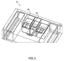
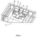
As shown in FIG. 2,
図2-4に示されるように、光学システム9は、IDアレイ保持器21またはASTアレイ保持器23の各試験ウェル20のための画像を観察、監視、精査、および/または捕捉するように構成される特徴を含む。具体的には、各IDアレイ保持器21は、ID蛍光光度計33によって監視される一方、各ASTアレイ保持器23は、ASTカメラ35によって監視される。監視を遂行するために、XYZロボット29は、グリッパ31を用いて特定のアレイ保持器を回収し、選択されたアレイ保持器をXYステージ37上に設置する。XYステージ37は、関連付けられる監視要素の下にアレイ保持器を位置付けるようにXY平面において移動し、すなわち、光学システム9における監視および観察のために、IDアレイ保持器21は、ID蛍光光度計33の下に配置され、ASTアレイ保持器23は、ASTカメラ35の下に配置される。XYステージ37は、関連付けられるアレイ保持器の各試験ウェル20が、ID蛍光光度計33またはASTカメラ35のいずれかの観察フレーム内に正確に位置付けられることを可能にするために、微調整されたモータ制御を含む。
As shown in FIGS. 2-4,
図5は、光学システム9のAST光学部分39のための例示的アーキテクチャを図示する。AST光学部分39は、照明源41と、対物レンズ43と、管レンズ45と、折り返しミラー47とを含む。照明源41は、ASTアレイ保持器23の各試験ウェル20の単色照明を提供するための集光LEDシステムを備え得る。対物レンズ43は、Nikon 20倍 0.45NA ELWD対物レンズまたは任意の他の好適な種類のレンズを備え得る。対物レンズ43は、各ピクセルが約0.33ミクロンに及ぶ20倍対物レンズを備え得る。20倍対物レンズは、細胞成長の開始時に相当な数の細胞(約100~200個の細胞)を検出する能力と、下で説明されるような伸びから正常な成長を分離するための細胞形態を検出する能力との両方を提供する。対物レンズ43は、その中の病原菌をカウントするために十分な分解能を維持しながら、各試験ウェル20のより広いダイナミックレンジおよび/またはより大きいサンプルのための10倍対物レンズおよび/または5MPカメラを備え得る。光学システム9のいくつかの例示的実施形態では、1回の通過あたりの試験ウェル20あたり1つのみの写真または画像が、対物レンズ43によって取得される。対物レンズ43は、試験ウェル20の底部からの背景雑音を排除するために、試験ウェル20の底部からわずかに外して焦点を合わせ得る。光学システム9のいくつかのバージョンでは、対物レンズ43は、試験ウェル20の底部から約5~10ミクロンに焦点を合わせるように構成される。光学システム9のいくつかのバージョンでは、対物レンズ43は、試験ウェル20の底部から8ミクロンに焦点を合わせるように構成される。対物レンズ43はまた、対物レンズ43がXYステージ37に対してZ軸に移動することを可能にするためのZステージ44を含み得る。したがって、ASTアレイ保持器23をXY平面において移動させるXYステージ37と、対物レンズ43をZ軸において移動させるZステージ44との間で、アレイ保持器23の各試験ウェル20は、試験ウェル20をASTカメラ35のフレームと精密に整列させるために、任意の3次元空間において移動させられ得る。管レンズ45は、色消管レンズにおいて具現化され得る。ASTカメラ35は、Sony IMX253カメラまたは任意の他の好適な種類のカメラを備え得る。光学システム9のいくつかのバージョンでは、XYステージ37およびZステージ44は、試験ウェル20の3次元移動の全ての3つの軸を提供するために、XYZステージと置換される。
FIG. 5 illustrates an exemplary architecture for the AST
ここで図6を参照すると、生物学的試験システム1の種々の構成要素は、例示的コンピュータシステム49等の1つ以上のコンピューティングデバイスまたはシステムを組み込み得る。例えば、消耗品調製システム3、接種システム5、培養器システム7、および/または光学システム9のうちのいずれか1つは、例示的コンピュータシステム49等の1つ以上のコンピューティングシステムを組み込み得る。代替として、生物学的試験システム1のこれらのサブシステムの各々は、例示的コンピュータシステム49等の1つの全体的コンピューティングシステムからのコマンドを介して機能し得る。
Referring now to FIG. 6, various components of
コンピュータシステム49は、プロセッサ51と、メモリ53と、大容量記憶メモリデバイス55と、入力/出力(I/O)インターフェース57と、ヒューマンマシンインターフェース(HMI)59とを含み得る。コンピュータシステム49は、ネットワーク63またはI/Oインターフェース57を介して1つ以上の外部リソース61にも動作可能に結合され得る。外部リソースは、限定ではないが、サーバ、データベース、大容量記憶デバイス、周辺デバイス、クラウドベースのネットワークサービス、またはコンピュータシステム49によって使用され得る任意の他の好適なコンピュータリソースを含み得る。
プロセッサ51は、マイクロプロセッサ、マイクロコントローラ、デジタル信号プロセッサ、マイクロコンピュータ、中央処理ユニット、フィールドプログラマブルゲートアレイ、プログラマブル論理デバイス、状態マシン、論理回路、アナログ回路、デジタル回路、またはメモリ53内に記憶される動作命令に基づいて信号(アナログもしくはデジタル)を操作する任意の他のデバイスから選択される1つ以上のデバイスを含み得る。メモリ53は、限定ではないが、読み取り専用メモリ(ROM)、ランダムアクセスメモリ(RAM)、揮発性メモリ、不揮発性メモリ、スタティックランダムアクセスメモリ(SRAM)、ダイナミックランダムアクセスメモリ(DRAM)、フラッシュメモリ、キャッシュメモリ、または情報を記憶することが可能な任意の他のデバイスを含む単一のメモリデバイスもしくは複数のメモリデバイスを含み得る。大容量記憶メモリデバイス55は、ハードドライブ、光学ドライブ、テープドライブ、不揮発性ソリッドステートデバイス、または情報を記憶することが可能な任意の他のデバイス等のデータ記憶デバイスを含み得る。
プロセッサ51は、メモリ53内に常駐するオペレーティングシステム65の制御下で動作し得る。オペレーティングシステム65は、コンピュータリソースを管理し得、それによって、メモリ53内に常駐するアプリケーション67等の1つ以上のコンピュータソフトウェアアプリケーションとして具現化されるコンピュータプログラムコードは、プロセッサ51によって実行される命令を有し得る。代替実施形態では、プロセッサ51は、アプリケーション67を直接実行し得、その場合、オペレーティングシステム65は、省略され得る。1つ以上のデータ構造69も、メモリ53内に常駐し得、データを記憶または操作するために、プロセッサ51、オペレーティングシステム65、またはアプリケーション67によって使用され得る。
I/Oインターフェース57は、プロセッサ51をネットワーク63または外部リソース61等の他のデバイスおよびシステムに動作可能に結合する機械インターフェースを提供し得る。アプリケーション67は、それによって、本発明の実施形態を構成する種々の特徴、機能、アプリケーション、プロセス、またはモジュールを提供するために、I/Oインターフェース57を介して通信することによってネットワーク63または外部リソース61と協働的に機能し得る。アプリケーション67は、1つ以上の外部リソース61によって実行されるプログラムコードも有するか、または別様に、コンピュータシステム49の外部の他のシステムもしくはネットワークコンポーネントによって提供される機能または信号に依拠し得る。実際に、ほぼ無限のハードウェアおよびソフトウェア構成が可能であることを所与として、当業者は、本発明の異なるバージョンが、コンピュータシステム49の外部に位置する複数のコンピュータまたは他の外部リソース61間に分散されるか、もしくはクラウドコンピューティングサービス等のネットワーク63を経由するサービスとして提供されるコンピューティングリソース(ハードウェアおよびソフトウェア)によって提供されるアプリケーションを含み得ることを理解するであろう。
I/
HMI 59は、ユーザがコンピュータシステム49と直接相互作用することを可能にするために、公知の様式でコンピュータシステム49のプロセッサ51に動作可能に結合され得る。HMI 59は、ビデオまたは英数字ディスプレイ、タッチスクリーン、スピーカ、およびデータをユーザに提供することが可能な任意の他の好適なオーディオならびに視覚インジケータを含み得る。HMI 59は、ユーザからコマンドまたは入力を受け取り、入力された入力をプロセッサ51に伝送することが可能な英数字キーボード、ポインティングデバイス、キーパッド、プッシュボタン、制御ノブ、マイクロホン等の入力デバイスおよび制御装置も含み得る。
データベース71は、大容量記憶メモリデバイス55上に常駐し得、本明細書に説明される種々のシステムおよびモジュールによって使用されるデータを収集ならびに編成するために使用され得る。データベース71は、データおよびデータを記憶ならびに編成する支援データ構造を含み得る。特に、データベース71は、限定ではないが、リレーショナルデータベース、階層化データベース、ネットワークデータベース、またはそれらの組み合わせを含む任意のデータベース編成もしくは構造で配列され得る。プロセッサ51上の命令として実行されるコンピュータソフトウェアアプリケーションの形態におけるデータベース管理システムが、クエリに応答して、データベース71の記録に記憶された情報またはデータにアクセスするために使用され得、クエリは、オペレーティングシステム65、他のアプリケーション67、または1つ以上のモジュールによって動的に決定および実行され得る。
(II.最適化ASTシステムおよび方法) (II. Optimized AST System and Method)
図7-23は、最適化AST方法101(図19)の種々の特徴およびステップを図示する。いくつかのバージョンでは、上で議論されるようなシステム1は、最適化AST方法101において提供される特徴のうちのいくつかまたは全てを促進するために使用され得る。最適化AST方法101は、MICが決定されるまで、画像分析サイクル102を繰り返し実行することを含む。
7-23 illustrate various features and steps of optimized AST method 101 (FIG. 19). In some versions,
いくつかの従来のプロセスでは、MICは、病原菌が成長することを可能にするための期間を待った後、試験ウェルの手動目視検査を通して決定される。しかしながら、図7に示されるように、試験ウェル内の病原菌サンプル成長は、接種材料が試験ウェル内に配置された後の4~10時間まで裸眼で観察可能ではない。MICを決定する伝統的方法は、試験ウェル内の病原菌の成長に対して人間が視覚的に知覚し得るものによって限定される。さらに、MIC濃度を下回る抗菌剤希釈濃度の存在は、成長速度を緩慢にし、知覚するためにさらに長くかかり得る。図7に示されるように、病原菌サンプルの最初の6~7回の倍加は、人の眼によって視覚的に観察されることができない。しかしながら、これらの初期倍加を通して提供される情報は、多くの場合、MICを示す。図7-23に示されるように、最適化AST方法101は、試験ウェルにおける接種時点から成長速度を監視するためにデジタル顕微鏡検査を利用し、したがって、MICのより迅速かつ正確な検出を可能にする。加えて、病原菌のサイズおよび形状等の試料形態情報が、MIC決定の正確度を向上させるために使用されることができる。例えば、目視観察は、ベータラクタム抗生物質によって引き起こされる伸び等の異常成長と正常成長との間を検出することができないので、伸び等の試料形態情報が、MIC決定の正確度を向上させるために使用され得る。
In some conventional processes, the MIC is determined through manual visual inspection of test wells after waiting a period of time to allow pathogens to grow. However, as shown in Figure 7, pathogen sample growth in the test wells is not observable to the naked eye until 4-10 hours after the inoculum is placed in the test wells. Traditional methods of determining the MIC are limited by the human visual perception of the growth of pathogens in test wells. Furthermore, the presence of dilute antimicrobial concentrations below the MIC concentration may slow growth rates and take longer to perceive. As shown in Figure 7, the first 6-7 doublings of the pathogen sample cannot be visually observed by the human eye. However, the information provided through these initial doublings is often indicative of the MIC. As shown in FIGS. 7-23, the optimized
図8は、最適化AST方法101において使用するためのいくつかの例示的デジタル顕微鏡検査パラメータを提供する。試験ウェル20は、透明な視認底部を有する「384」式試験ウェルによって具現化される。試験ウェル20内の接種材料の体積は、AST方法101によって要求されるバルク希釈液等の材料の量を低減させ、および/または光アーチファクトを最小化し、0.5マクファーランドの接種材料の1:250希釈物から一貫した数の病原菌のサンプリングを提供するために、20マイクロリットルに設定され得る。試験ウェル20内の接種材料の体積を減少させることは、概して、光アーチファクトを増加させる。いくつかの事例では、ASTカメラ35が0.33ミクロン/ピクセルに設定される20倍対物レンズにおいて単一の垂直面103を捕捉することは、接種材料をサンプリングし、各個々の病原菌が認識可能であることを確実にするために十分であり得る。しかしながら、これらのパラメータは、構成可能であり、ユーザまたはシステムの根本的な必要性によって、所望に応じて変化し得る。単一の垂直面103内で約5ミクロン間隔を置かれたた3つの焦点部位を捕捉することも、最適化AST方法101における使用のために、カウントするために十分な数のサンプル中の病原菌を提供し得る。これらの3つの焦点部位は、図8において部位105、部位107、および部位109と標識化される。最適化AST方法101の例示的バージョンでは、各焦点部位は、3つの異なる垂直面において3つの部位を捕捉するのではなく、単一の垂直面103内で約700×700ミクロンである。ASTカメラ35、光学システム9、およびコンピュータ49は、連続した期間において各焦点部位の画像を捕捉し、これらの画像の各々を操作し、その後、MIC決定を行うためにこれらの操作された画像から導出されるデータを使用するように構成される。
FIG. 8 provides some exemplary digital microscopy parameters for use in the
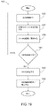
画像分析サイクル102は、概して、図9に描写され、画像捕捉ステップ111と、画像向上ステップ113と、画像セグメント化ステップ115と、物体カウントステップ117とを含む。最適化AST方法101は、MICが決定されるまで、画像分析サイクル102を繰り返し実施することを含む。画像分析サイクル102は、画像捕捉ステップ111、画像向上ステップ113、画像セグメント化ステップ115、および物体カウントステップ117、ならびにその中に提供される任意のサブステップを実施するために、コンピュータ49の1つ以上のインスタンスおよびその種々の要素を利用する。
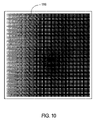
画像分析サイクル102は、画像捕捉ステップ111から開始され、光学システム9のASTカメラ35を介して接種材料の未加工画像119(図10)を捕捉し、未加工画像119をメモリ53内に記憶する。未加工画像119は、単一の画像として描写されるが、未加工画像119は、垂直面103内で取得されたいくつかの別個の画像の合成物、例えば、部位105、部位107、および部位109の合成物であり得る。未加工画像119は、接種材料サンプル内の異なる平面内で取得されたいくつかの画像の合成物でもあり得るか、または、単一の画像であり得る。図10に図示されるように、未加工画像119は、不均一な照明等の欠陥を含み得る。不均一な照明は、照明源41の経路に影響を及ぼし得る関連付けられる試験ウェル20の壁と組み合わせて接種材料によって生成されるメニスカスの結果であり得る。不均一な背景強度も、塑性変形等の環境問題によって、または種々の他の源から引き起こされ得る。未加工画像119が画像捕捉ステップ111において捕捉された後、画像捕捉ステップ111は、画像向上ステップ113に進む。
The
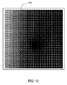
図9および11-14に示されるように、画像向上ステップ113は、向上画像121(図11)を作成するために未加工画像119を処理し、それによって、向上画像121は、細菌等の病原菌をカウントおよび認識するプロセスのためにより好適である。画像向上ステップ113中、未加工画像119の1つ以上の属性が、修正される。これらの属性は、基本的グレーレベル変換、雑音フィルタリング、およびメディアンフィルタリングを含み得る。例えば、不均一な照明の問題を解決するために、メディアンフィルタが、勾配画像123(図12)に到達するために未加工画像119に適用され得る。これは、未加工画像119の背景照明の勾配のみを含む結果として生じる画像を提供するために十分なピクセル半径を選択することによって遂行され得る。勾配画像123は、次いで、不均一な照明を補正し、不均一な照明のない向上画像121を生成するために、未加工画像119から減算される。
As shown in FIGS. 9 and 11-14, the
画像向上ステップ113は、静的に、動的に、または両方のいずれかで画像向上を適用し得る。例えば、メディアンフィルタのためのピクセル半径は、静的に設定された一定値であり得るか、または光学システム9を通して捕捉された各未加工画像119の特性から動的に適応的に導出され得る。図13に示されるように、画像向上ステップ113のいくつかのバージョンは、ステップ125を含み得、それによって、作業中の画像が向上を受けるべきかどうかに関する決定が、行われる。ステップ125が、作業中の画像が向上させられるべきであると決定する場合、ステップ125は、ステップ127に進む。ステップ127において、静的向上が適用されるべきかどうかに関する決定が、行われる。ステップ127が、静的向上が適用されるべきであると決定する場合、ステップ127は、ステップ129に進む。ステップ127が、静的向上が適用されるべきではないと決定する場合、ステップ127は、ステップ131に進む。ステップ127において、静的向上が、作業中の画像に適用され、ステップ127は、ステップ125に戻る。ステップ131において、動的向上が、作業中の画像に適用され、ステップ131は、ステップ125に戻る。ステップ125が、作業中の画像がさらに向上させられるべきであると決定する場合、ステップ125は、終了に進む。
図14は、動的画像向上の方法133の例を図示する。動的画像向上の方法133は、メディアンフィルタ向上において使用するための適切なピクセル半径を動的に決定することを対象とする。動的画像向上の方法133は、ステップ135から開始され、それによって、未加工画像119内に描写される病原菌のサイズが、決定される。病原菌は、グラム陽性細菌、グラム陰性細菌、酵母、または任意の他の生元素もしくは微生物の形態であり得る。未加工画像119内の病原菌のサイズは、接種材料および全体的光学システム9に関連付けられる種々の状況ならびにパラメータに応じて変化し得る。したがって、試験されている特定の病原菌の文字通りのサイズは、概して、本質的に一定であるが、未加工画像119内に描写される微生物の相対的サイズは、レンズオブジェクト化等のパラメータの差異により、動的かつ可変である。ステップ135が未加工画像119内の病原菌のサイズを決定すると、ステップ135は、ステップ137に進む。ステップ137において、ピクセル半径が、病原菌の決定されたサイズから導出される。一般的例として、ステップ135が、未加工画像119内の任意の所与の病原菌の最大長が5ピクセルであると決定する場合、ピクセル半径は、フィルタ処理された画像が背景に含まれる勾配のみを表すように、5を上回るべきことが決定され得る。ステップ135が動的に決定された病原菌のサイズに基づいてピクセル半径を導出した後、ステップ135は、ステップ139に進む。ステップ139において、勾配画像123が、導出されたピクセル半径を用いて未加工画像119を処理することに基づいて生成される。勾配画像123が生成された後、ステップ139は、ステップ141に進む。ステップ141において、勾配画像123は、向上画像121を生成するために未加工画像119から減算される。その後、動的画像向上の方法133は、終了に進む。
FIG. 14 illustrates an
図9、15、および16に示されるように、画像セグメント化ステップ115は、画像を、病原菌を前景または背景のいずれかとして表すピクセルを含む明確に異なる領域に区分化するために使用される。画像セグメント化ステップ115は、図15に示されるように、向上画像121をセグメント化画像143に変換する。画像セグメント化ステップ115は、向上画像121からバイナリ画像を生成し、全ピクセルは、0または1のいずれかの値に等しく、0は、背景を指し、1は、特定の病原菌の一部を指す。
As shown in FIGS. 9, 15 and 16, an
雑音等の画像アーチファクトが、セグメント化アルゴリズムを適用することに先立って、雑音低減フィルタを適用することによって除去され得る。セグメント化は、静的閾値を使用して、またはOtsuクラスタベースの二値化アルゴリズム等の適応画像二値化方法を使用して取得されることができる。このアルゴリズムでは、グレーレベルサンプルは、背景および前景(物体)として2つの部分にクラスタ化されるか、または代替として、2つのガウス分布の混合物としてモデル化される。使用される特定の画像二値化アルゴリズムに関する閾値は、画像セグメント化ステップ115に提供される全体的画像および画像の相対的グレースケールレベルに応じて、動的に決定され得る。例えば、接種システム5またはシステム1の別の要素は、ニグロシンが細菌等のある病原菌に付着しないので、画像を向上させるために各試験ウェル20にニグロシンを適用するように構成され得る。これは、ニグロシンを伴わない未加工画像119と比較して、未加工画像119内の相対的グレースケールレベルを改変し、セグメント化アルゴリズムのための異なる閾値を要求し得る。最適化AST方法101のいくつかのバージョンでは、閾値は、画像のいくつかのエリア内のエッジを捜すことによって動的に決定され得る。これらのエッジは、背景と病原菌との間の遷移点である。したがって、閾値は、次いで、見つけられたエッジの各側のピクセルに対する平均グレースケール値として計算されることができる。
Image artifacts such as noise can be removed by applying a noise reduction filter prior to applying the segmentation algorithm. Segmentation can be obtained using static thresholds or using adaptive image binarization methods such as the Otsu cluster-based binarization algorithm. In this algorithm, gray-level samples are clustered into two parts as background and foreground (object), or alternatively modeled as a mixture of two Gaussian distributions. The threshold for the particular image binarization algorithm used can be dynamically determined depending on the overall image and the relative grayscale level of the image provided to the
図16に示されるように、画像セグメント化ステップ115のいくつかのバージョンは、ステップ145から開始され得る。ステップ145において、雑音低減フィルタを向上画像121に適用すべきかどうかに関する決定が、行われる。ステップ145が、雑音低減フィルタが適用されるべきであると決定する場合、ステップ145は、ステップ147に進み、雑音低減フィルタが、適用される。ステップ147は、その後、ステップ149に進む。ステップ145が、雑音低減フィルタが適用されるべきではないと決定する場合、ステップ145は、直接、ステップ149に進む。ステップ149において、閾値を動的に決定すべきかどうかに関する決定が、行われる。ステップ149が、閾値が動的に決定されるべきであると決定する場合、ステップ149は、ステップ151に進み、閾値が、決定される。ステップ149は、その後、ステップ153に進む。ステップ149が、閾値を動的に決定しないと決定する場合、静的な所定の閾値が、使用され、ステップ149は、直接、ステップ153に進む。ステップ153において、向上画像121は、選択された閾値を使用してセグメント化され、ステップ153は、終了に進み、その後、画像セグメント化ステップ115は、終了に進む。
Some versions of the
画像セグメント化ステップ115がセグメント化画像143を生成すると、画像セグメント化ステップ115は、物体カウントステップ117に進む。物体カウントステップ117では、背景および前景ピクセルが、サンプル中の病原菌の数、サンプル中の病原菌によって占有される面積、および病原菌の数と病原菌によって占有される面積との間の比率に関する情報を導出するために考慮される。物体カウントステップ117のいくつかのバージョンでは、実際の病原菌総数が、平均病原菌総数と比較され、エラーが画像捕捉プロセス内で起こったかどうかを決定する。比較は、病原菌比較を一般化するために、平均病原菌総数とともに標準偏差を組み込み得る。
Once
物体カウントステップ117は、画像内の病原菌の数に関する情報を導出するように構成され得る。物体カウントステップ117のいくつかの実施形態では、セグメント化画像143内の前景ピクセルの数が、接種材料の撮像された部分内の病原菌の数を決定するために、所定の幅および/または長さに従ってカウントされ得る。潜在的な病原菌の外形が、セグメント化画像143内の対応する異なる前景ピクセル形状を提供するので、カウントアルゴリズムは、2つの別個のアルゴリズムに分割され得、1つは、桿形病原菌をカウントするためのものであり、1つは、球形病原菌をカウントするためのものである。例えば、カウントアルゴリズムは、球形病原菌のためのカウント目的のために2×2ピクセルの正方形を病原菌と見なすように構成され得るか、または桿形病原菌のためのカウント目的のために1×4ピクセルの長方形を病原菌と見なし得る。さらに、カウントアルゴリズムは、桿形病原菌の異なる3次元向きを捕捉するために、両方のアルゴリズムを処理するように構成され得る。例えば、細長い桿がASTカメラ35に向かって端方向に位置付けられる場合、それは、ASTカメラ35を通して2次元において視認されると、非常に異なる外形を有するであろう。したがって、両方のカウントアルゴリズムが、画像分析サイクル102のカウント段階の間に使用され得る。代替として、カウントアルゴリズムは、背景ピクセルによって包囲される任意の前景ピクセルを病原菌として見なし、カウントするように構成され得る。
物体カウントステップ117は、画像内の病原菌の全てによって占有される合計面積に関する情報を導出するように構成され得る。物体カウントステップ117のいくつかのバージョンでは、セグメント化画像143内の前景ピクセルの合計数が、カウントされ、セグメント化画像143内の背景ピクセルの合計数と比較され得る。物体カウントステップ117は、30%等のパーセントとして、または「450個の合計ピクセルのうち138個の前景ピクセル」もしくは「138個の前景ピクセルおよび312個の背景ピクセル」等のピクセルの文字通りの数としてのものを含む任意のフォーマットで面積カウント情報を表し得る。
物体カウントステップ117は、画像内の病原菌の全てによって占有される合計面積と病原菌の合計数との間の比率に関する情報を導出するように構成され得る。この情報は、病原菌が経時的に伸びを受けているかどうかを決定することによって有用であり得る。伸びは、死滅の前兆であり、抗菌剤希釈物の濃度が病原菌に悪影響を及ぼしていることを示す。より具体的には、伸びは、細菌等の病原菌が効果的な量の抗生物質に遭遇すると起こり得る。
例えば、図17および18は、大腸菌によって具現化される病原菌を描写する。図17は、抗生物質アンピシリンの希釈物にさらされた後の大腸菌を描写する一方、図18は、どんなアンピシリン暴露もない大腸菌を描写する。図17は、アンピシリン暴露の結果としての伸びの形態における異常成長を図示する。この伸びは、細菌の死滅の前兆であり、アンピシリンの濃度が細菌を中和するために十分であることを例証する。図18は、正常成長を図示する。細菌の全てによって占有される合計面積と細菌総数との間の比率は、各細菌の伸びを表すために経時的に増加するということになる。例えば、特定の画像サンプルが、100匹の細菌を含み、各細菌が、各々、約4ピクセルと測定される場合、画像内で100匹の細菌によって占有される面積は、400ピクセルである。この画像サンプルでは、細菌総数に対する細菌面積の比率は、4.0である。経時的に、サンプル中の各細菌が、各々、約12ピクセルまで伸びる場合、後の画像内の100匹の細菌によって占有される面積は、1,200ピクセルであり、この後の画像内の細菌総数に対する細菌面積の比率は、12.0である。比率におけるこの増加は、細菌が伸びており、それが、次に、差し迫った死滅を示すので、アンピシリンの濃度が大腸菌を中和させることにおいて効果的であることを示す。 For example, Figures 17 and 18 depict pathogens embodied by E. coli. Figure 17 depicts E. coli after exposure to dilutions of the antibiotic ampicillin, while Figure 18 depicts E. coli without any ampicillin exposure. Figure 17 illustrates abnormal growth in the form of elongation as a result of ampicillin exposure. This elongation is a precursor to bacterial death and illustrates that the concentration of ampicillin is sufficient to neutralize the bacteria. Figure 18 illustrates normal growth. It follows that the ratio between the total area occupied by all of the bacteria and the total number of bacteria increases over time to represent the growth of each bacteria. For example, if a particular image sample contains 100 bacteria, each measuring approximately 4 pixels, the area occupied by 100 bacteria in the image is 400 pixels. In this image sample, the ratio of bacterial area to total bacteria is 4.0. Over time, if each bacterium in the sample extends to about 12 pixels each, the area occupied by 100 bacteria in the later image is 1,200 pixels, and the area occupied by 100 bacteria in the later image is 1,200 pixels. The ratio of bacterial area to total number is 12.0. This increase in ratio indicates that the concentration of ampicillin is effective in neutralizing E. coli as the bacteria are growing, which in turn indicates imminent death.
物体カウントステップ117がセグメント化画像143から所望の情報を導出すると、画像分析サイクル102は、終了する。最適化AST方法101は、各試験ウェル20内の病原菌が、特定の抗菌剤希釈物ペアリングに対して変化し、反応している様子を決定するために、設定された時間間隔において画像分析サイクル102を反復的に実施する。さらに、最適化AST方法101は、病原菌が抗菌剤希釈物の各濃度に対して反応している様子を決定するために、病原菌に関連付けられる各試験ウェル20に画像分析サイクル102を反復的に実施する。例えば、試験される病原菌が大腸菌であり、3つの試験ウェル20が試験され、各試験ウェル20がその中に20マイクロリットルの溶液を有すると仮定する。第1の試験ウェル20は、1ミリリットルあたり1マイクログラム(mcg/ml)の抗菌剤希釈物を含み得、第2の試験ウェル20は、2mcg/mlの抗菌剤希釈物を含み得、第3の試験ウェル20は、4mcg/mlの抗菌剤希釈物を含み得る。最適化AST方法101は、(a)各抗菌剤希釈物が病原菌に影響を及ぼしている様子、および、(b)各抗菌剤希釈物が他の抗菌剤希釈物に対して機能している様子を決定するために、各設定された時間間隔において3つの試験ウェルの各々に画像分析サイクル102を実施する。データが、1mcg/mlの抗菌剤希釈物が病原菌の中和において2および4mcg/mlの抗菌剤希釈物と同程度に効果的であることを示す場合、1mcg/mlの抗菌剤希釈物が、MICである。
Once the
最適化AST方法101の例示的バージョンが、図19に図示され、ステップ155から開始される。ステップ155において、システムは、選択された試験ウェル20内の病原菌に、特定の抗菌剤希釈物に対する成長速度または反応に関する新しい情報を提供するために十分な時間を可能にするために、設定された期間閾値にわたって待つ。最適化AST方法101は、任意の所与の静的または動的期間閾値を利用するように構成され得る。例えば、いくつかの細菌または酵母もしくは他の病原菌は、非常に迅速に反応し、1時間以内にMIC決定を行うことに関する情報を提供し得る。このシナリオでは、最適化AST方法101は、試験ウェル20内の急速に変化する環境に関するデータを捕捉するために、5分毎に画像分析サイクル102を実施するように構成され得る。他の病原菌は、比較的に緩慢に抗菌剤希釈物に反応し得、したがって、1時間の期間閾値が、より適切であり得る。ステップ155が規定された期間閾値を待つと、ステップ155は、ステップ157に進む。
An exemplary version of optimized
ステップ157において、画像分析サイクル102の1回の反復が、選択された試験ウェル20を用いて特定の病原菌に実施される。上で議論されるように、画像分析サイクル102の反復は、選択された試験ウェル20内の病原菌の成長速度に関するデータを導出する。画像分析サイクル102の反復が実施された後、ステップ157は、ステップ159に進む。ステップ159において、ステップ157において収集されたデータが、メモリ内に記憶および/または更新され、メモリは、データベース、単層ファイル、または任意の他の類似するメモリもしくは記憶デバイスの形態であり得る。最適化AST方法101のいくつかの実施形態では、ステップ159は、ステップ157において収集されたデータをデータベース71(図6)内に記憶する。ステップ159が収集されたデータを記憶/更新すると、ステップ159は、ステップ161に進む。
At
ステップ161において、最適化AST方法101は、MICを決定するために十分なデータが収集されたかどうかを決定する。より多くのデータがMICを正確に決定するために必要とされる場合、ステップ161は、ステップ155に戻り、将来の時間間隔においてより多くのデータを収集するために別の画像分析サイクル102を実施するために待つ。ステップ161が、十分な量のデータが収集されたと決定する場合、ステップ161は、ステップ163に進む。他の試験ウェル20および抗菌剤希釈物に対する病原菌の相対的成長速度がMICを示すので、ステップ161は、病原菌および抗菌剤希釈物に関連付けられる特定の試験ウェル20に関して収集されたデータだけを考慮するのではなく、ステップ161は、試験ウェル20の全てに関して収集されたデータの全てを考慮する。
At
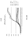
ステップ163において、MICが、決定される。決定は、病原菌サンプルのための抗菌剤希釈物の全てに関する画像分析サイクル102の各反復の間に収集されたデータに基づく。図20A、20B、および20Cに示されるように、決定は、各画像内の各細菌または他の病原菌の総数(図20A)、各画像内の病原菌によって占有される面積(図20B)、もしくは各画像内の病原菌の総数に対する占有面積に関する比率データ(図20C)に基づき得る。
At
図20Aは、「総数合計」情報を描写し、それによって、各濃度の抗生物質における細菌総数の合計が、経時的な相対的細菌総数を示すようにプロットされる。図20Aに示されるように、「Cax 0.12」希釈物は、細菌総数が、概して、成長培養液を含むが、抗生物質等のいずれの抗菌剤もない成長サンプルと同一の曲線に沿って増加するので、大腸菌サンプルにいかなる影響も及ぼさないと考えられる。大腸菌サンプルに影響を及ぼすための最小量の抗菌剤希釈物は、「Cax 0.25」希釈物であり、したがって、0.25希釈物において適用されたCax抗生物質が、MICであると決定されることができる。 FIG. 20A depicts the "Total Total" information whereby the sum of total bacterial counts at each concentration of antibiotic is plotted to show the relative total bacterial counts over time. As shown in FIG. 20A, the "Cax 0.12" dilution showed that the bacterial counts generally followed the same curve as the growth samples containing growth medium but without any antimicrobial agents such as antibiotics. increased, it is not expected to have any effect on E. coli samples. The minimum amount of antimicrobial dilution to affect an E. coli sample is the "Cax 0.25" dilution, therefore Cax antibiotic applied at the 0.25 dilution was determined to be the MIC. can
図20Bは、「面積合計」情報を描写し、それによって、各濃度の抗生物質における細菌の面積が、経時的な細菌集団の相対的集合体サイズを示すようにプロットされる。図20Bに提供される「面積合計」情報は、「Cax 0.25」が大腸菌によって占有された面積に所望の影響を及ぼすための最小量の抗生物質であるので、図20Aの決定を確認するために使用され得る。図20Bは、細菌が総数において増加していない(「成長」および「Cax 0.12」チャート線の間の比較によって示されるように)が、面積において増加していることを伝える。したがって、細菌は、抗菌剤希釈物中の抗生物質に起因する細菌の差し迫った死滅の結果として、伸び、異常成長を被っている。 FIG. 20B depicts 'Area Sum' information whereby the area of bacteria at each concentration of antibiotic is plotted to indicate the relative aggregate size of the bacterial population over time. The "total area" information provided in Figure 20B confirms the determination of Figure 20A, as "Cax 0.25" is the minimum amount of antibiotic to have the desired effect on the area occupied by E. coli. can be used for FIG. 20B reports that the bacteria have not increased in total number (as shown by the comparison between the “Growth” and “Cax 0.12” chart lines) but have increased in area. Thus, the bacteria are undergoing elongation and overgrowth as a result of their imminent death due to the antibiotics in the antimicrobial diluent.
図20Cは、「面積/総数比率」情報を描写し、それによって、「総数合計」データと「面積合計」データとの間の比率が、抗生物質の濃度毎の面積に対する細菌集団の相対的差異を示すようにプロットされる。伸びデータは、面積と総数との間の比率が描写される図20Cにおいてより顕著である。細菌が成長培養液を供給されない「成長なし」チャート線に見られるように、面積と総数との比率は、約4.0において平坦である。これは、各細菌がサイズにおいて約4ピクセルであり、細菌が総数において増加しておらず、伸びも被っていないことを示す。「成長」および「Cax 0.12」を反映するチャート線は、比率において増加するが、漸進的増加は、細菌の総数および面積の両方が増加していることを示す。8.0を上回る比率の急激なスパイクは、面積が増加するが、細菌の全体的総数が一定のままであるので、細菌の伸びを示す。この顕著な伸びスパイクを被る最少量の抗生物質は、「Cax 0.25」サンプルであり、したがって、図20Cの比率データも、図20Aおよび20Bにおけるデータによって提供される同一のMIC決定の確認においてMIC0.25を提供する。 FIG. 20C depicts the “area/total ratio” information whereby the ratio between “total total” and “total area” data indicates the relative difference of bacterial population to area for each concentration of antibiotic. is plotted as shown. The elongation data is more pronounced in FIG. 20C, where the ratio between area and total number is depicted. The ratio of area to total number plateaus at about 4.0, as seen in the "no growth" chart line where the bacteria are not supplied with growth medium. This indicates that each bacterium is approximately 4 pixels in size and that the bacterium has not increased in total number and has not undergone elongation. The chart lines reflecting "Growth" and "Cax 0.12" increase in rate, but the gradual increase indicates that both total number and area of bacteria are increasing. Sharp spikes at ratios above 8.0 indicate bacterial elongation as the area increases but the overall total number of bacteria remains constant. The lowest amount of antibiotic to suffer this significant elongation spike was the 'Cax 0.25' sample, so the ratio data in FIG. 20C are also in confirmation of the same MIC determination provided by the data in FIGS. It provides an MIC of 0.25.
MIC決定は、データ収集フォーマットおよび経時的なデータの一般的傾向の種々の組み合わせにも基づき得るか、または、データの1つの組が、MICを決定するために使用され得る一方、別の組が、決定されたMICを確認するために使用され得る。上で説明される「総数合計」、「面積合計」、および「面積/総数比率」機構の任意の組み合わせが、MICを決定または確認するために使用され得る。例えば、図21および22は、抗生物質セフェピムの種々の抗菌剤希釈物を用いて試験される大腸菌サンプルに関して15分毎に収集されたデータ点を図示する。200分マークの周囲において、図21に提供される細菌総数データは、「Cpe 0.06」希釈物がMICであることを示す。図22に提供される比率データは、「Cpe 0.03」を上回る抗菌剤希釈物の全てが120分マークの周囲において伸びスパイクを提供するので、「Cpe 0.06」が120分マークの周囲においてMICであることを示す。したがって、MICの予備決定が、120分における比率データ(図22)を使用して行われ得、決定されたMICの確認が、200分における総数データ(図21)を使用して行われ得る。最適化AST方法101の本実施形態は、したがって、120分において利用可能な予備MIC決定および200分において利用可能な確認MIC決定を用いて、データの二重試験を提供する。図9を参照すると、4時間または240分が、手動目視検査方法を使用してMIC決定を行うための最も早い可能な閾値であり、それは、より不正確であり、より人手がかかる。
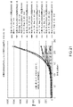
MIC determination can also be based on various combinations of data collection formats and general trends of data over time, or one set of data can be used to determine MIC while another set , can be used to confirm the determined MIC. Any combination of the "Total Sum", "Area Sum", and "Area/Total Ratio" mechanisms described above may be used to determine or ascertain the MIC. For example, Figures 21 and 22 illustrate data points collected every 15 minutes for E. coli samples tested with various antimicrobial dilutions of the antibiotic cefepime. Around the 200 minute mark, the bacterial count data provided in Figure 21 show that the "Cpe 0.06" dilution is the MIC. The ratio data provided in FIG. 22 indicate that 'Cpe 0.06' around the 120 minute mark as all antimicrobial dilutions above 'Cpe 0.03' provide an extension spike around the 120 minute mark. indicates that it is MIC. Thus, a preliminary determination of the MIC can be made using the ratio data at 120 minutes (Figure 22) and confirmation of the determined MIC can be made using the total number data at 200 minutes (Figure 21). This embodiment of the optimized
(III.最小抑制濃度(MIC)を決定するためのデジタル顕微鏡検査アルゴリズム) (III. Digital Microscopy Algorithm for Determining Minimum Inhibitory Concentration (MIC))
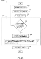
図23は、同様の要素が同様の特徴を有する方法101Aと以降で称される例示的最適化AST方法101の別のバージョンを描写する。方法101Aは、方法201として図23に描写されるMICを決定するための例示的デジタル顕微鏡検査アルゴリズムを組み込む。方法201は、方法101のステップ161および163の代わりに実行され得る。
FIG. 23 depicts another version of exemplary optimized
図23に示されるように、画像データが更新および記憶された後、ステップ159は、方法201に進む。方法201は、ステップ203から開始され、それによって、成長ウェル内の病原菌の総数に関する決定が、行われる。図20A、20B、および20Cに示されるように、各AST試験アレイ23は、抗生物質等のどんな抗菌剤もない接種材料18がその中に配置される試験ウェル20を含み得る。成長ウェルは、したがって、試験を受ける特定の病原菌の阻害されない成長を例証する。ステップ203は、成長ウェル内の病原菌の総数が、第1の総数閾値を超えているかどうかを決定する。方法201のいくつかのバージョンでは、第1の総数閾値は、設定された静的総数量であり得る。例えば、第1の総数閾値は、15,000匹の病原菌であり得る。方法201の他のバージョンでは、第1の閾値量は、新しい試験または試験のバッチが開始される度に生物学的試験システム1のユーザによって構成され得る。方法201のさらにいくつかの他のバージョンでは、第1の総数閾値は、生物学的試験システム1およびID蛍光光度計によって病原菌に実施されたID試験の結果に基づいて、各試験のために動的に設定され得る。
After the image data has been updated and stored, step 159 advances to
ステップ203が、成長ウェル内の病原菌の数が第1の総数閾値を超えていないと決定する場合、ステップ203は、期間待ちステップ(ステップ155)の別の反復を実施するためのステップ155、画像分析サイクルステップ(ステップ157)、およびデータ記憶/更新ステップ(ステップ159)に戻る。ステップ203が、成長ウェル内の病原菌の数が第1の総数閾値を超えていると決定する場合、ステップ203は、ステップ205に進む。
If
ステップ205において、ASTアレイ保持器23内の各試験ウェル20のための病原菌総数のパーセンテージ変化が、過去の直近の期間にわたって計算される。ステップ205のいくつかのバージョンでは、期間は、前の1時間またはステップ155においてもたらされた期間であり得る。例えば、試験ウェル20A(図示せず)内の病原菌総数が、前の1時間にわたって1,000匹の病原菌から1,200匹の病原菌に増加する場合、ステップ205において計算されるパーセンテージ変化は、20%である。このように、ASTアレイ保持器23内の各試験ウェル20は、計算され、その後、ステップ205は、ステップ207に進む。
At
ステップ207は、ステップ205において計算されたパーセンテージ変化と各試験ウェルのための現在の病原菌総数とを利用することによって、MICを決定する。具体的には、ステップ207は、あるパーセント閾値未満のパーセンテージ変化と第2の総数閾値未満の病原菌総数との両方を含む試験ウェル20を決定する。これらの2つの必要条件を満たす最も低い抗菌薬希釈物が、MICであると決定される。第1の総数閾値に関して上で特に言及されるように、パーセンテージ閾値および/または第2の総数閾値は、静的パラメータであるか、試験の開始時にユーザによって入力され得るか、または、特定の病原菌に対してID蛍光光度計33によって実施されたID試験の結果を反映するように動的に変更され得る。例えば、ステップ207のいくつかのバージョンでは、パーセント閾値は、15%であり得、第2の総数閾値は、5,000匹の病原菌であり得る。この例では、下記の表1に描写されるデータが、生物学的試験システム1によって収集される場合、MICは、試験ウェル20c内で見出される0.5希釈物であろう。なぜなら、これが、両方の基準を満たす最も低い抗菌薬希釈物であるからである。すわなち、試験ウェル20cの抗菌薬希釈物は、15%未満のパーセンテージ変化と5,000未満の病原菌総数との両方を含む最も低い試験希釈物である。試験ウェル20bは、5,000未満の病原菌総数を含むが、パーセンテージ変化は、17%である。同様に、試験ウェル20aのパーセンテージ変化は、12%であるが、病原菌総数は、6,500である。試験ウェル20dは、両方の基準を満たすが、抗菌剤希釈は、試験ウェル20cを上回る。

ステップ207が両方の基準を満たす最も低い抗菌剤希釈物を決定すると、ステップ207は、MICをステップ165に供給し、方法101Aは、それに応じて、MIC情報を記憶および報告するように進む。
When
図24は、同様の要素が同様の特徴を有する方法101bと以降で称される例示的最適化AST方法101の別のバージョンを描写する。方法101Aと同様に、方法101Bは、方法301として図24に描写されるMICを決定するための例示的デジタル顕微鏡検査アルゴリズムを組み込む。方法301は、方法101のステップ161および163の代わりに実行され得る。方法301は、特に、メタロベータラクタマーゼに起因するカルバペネム耐性を伴うもの等の病原菌における耐性機構の発現が緩慢である場合に有用であり得る。耐性の発現が緩慢であるいくつかの病原菌は、視覚的に、4時間またはそれを上回るまで成長を開始するように見えない。しかしながら、感受性ASTカメラ35は、存在する抗菌剤が導入された瞬間から成長におけるわずかな増加を評価することを可能にする。
FIG. 24 depicts another version of exemplary optimized
方法301は、ステップ303から開始され、それによって、成長ウェルの病原菌総数が第1の総数閾値を上回るかどうかに関する決定が、行われる。方法201の第1の総数閾値で説明されるように、第1の総数閾値は、静的パラメータ、ユーザ入力パラメータであり得るか、または、病原菌に関するID試験の結果に基づいて動的に変更され得る。例えば、第1の総数閾値は、20,000であり得る。この例では、ステップ303は、成長ウェル総数が20,000未満であるという決定に応じて、ステップ155に戻るであろう。成長ウェル総数が20,000を上回る場合、ステップ303は、ステップ305に進む。
ステップ305は、各試験ウェルの病原菌総数を成長ウェルの病原菌総数と比較することによって、MICを決定する。MICは、成長ウェルの病原菌総数の総数パーセンテージ未満である病原菌総数に関連付けられる最も低い抗菌薬希釈物であると決定される。方法201の第1の総数閾値で説明されるように、総数パーセンテージパラメータは、静的パラメータ、ユーザ入力パラメータであり得るか、または、病原菌に関するID試験の結果に基づいて動的に変更され得る。例えば、総数パーセンテージは、成長ウェル総数の4%であり得、方法101Bは、下記の表2に描写されるデータを含み得る。このシナリオでは、試験ウェル20cが、MICである。なぜなら、これが、成長ウェル総数の4%未満である病原菌総数に関連付けられる最も低い抗菌薬希釈物であるからである。試験ウェル20dも、基準を満たすが、試験ウェル20cよりも高い希釈を有する。

ステップ305が基準を満たす最も低い抗菌薬希釈物を決定すると、ステップ305は、MICをステップ165に供給し、方法101Bは、それに応じて、MIC情報を記憶および報告するように進む。
Once
方法201および/または方法301のいくつかのバージョンは、所与の抗菌剤に対するMICを決定することを補助するために、「面積合計」情報(図20B)および「面積/総数比率」情報(図20C)等の前述で議論された概念を組み込み得る。
Some versions of
(IV.結果のマッピング) (IV. Mapping of Results)
方法201および/または方法301のいくつかのバージョンは、所与の抗菌剤にのための具体的MICを提供することなく抗菌剤治療を推奨することを可能にするために、結果のマッピングを組み込み得る。方法201および/または方法301のいくつかのバージョンでは、抗菌剤の希釈範囲は、切り捨てられる。例えば、16または32のMICは、「>=8」または(8以上)の結果にマッピングされ得る。この情報は、抗菌剤治療が具体的MICを提供することなく進行することを可能にするであろう。
Some versions of
(V.病原菌耐性システムおよび方法の決定) (V. Determination of Pathogen Resistance Systems and Methods)
光学システム9から導出される成長パターン情報は、試験されている病原菌における耐性のいくつかの機構を検出するために、pHの変化を測定する蛍光試験とも組み合わせられ得る。例として、蛍光試験基材のうちの1つは、抗菌剤であり得る。抗菌剤の分解は、接種後2時間以内に培地のpHの変化につながり、pH変化は、pHの変化とともに蛍光を変化させる指示薬を用いて検出されることができる。抗菌剤が分解したという指示とともに、上で説明されるような成長パターン(細胞総数、面積、および面積/総数)に関する情報を組み合わせることは、病原菌に耐性があるかどうかを迅速に確認する方法を提供し、有機体のMICを決定することに役立つ。
Growth pattern information derived from the
例えば、抗生物質メロペネムは、クレブシエラ肺炎カルバペネマーゼ(KPC)耐性機構を持つグラム陰性細菌等の病原菌によって酵素的に分解される。メロペネムが分解される場合、培地は、pHにおいて低下する。蛍光pH指示薬であるMEU(メチルウンベリフェロン)は、その変化とともに蛍光において変化(減少)するであろう。この変化は、1~2時間以内に起こる。特定の病原菌がID試験を通して2時間以内に同定され、メロペネムを含む試験ウェルにのためのpHが1~2時間以内に変化し、成長パターンが上で説明される面積カウント方法を通して同定される場合、MICは、1mcg/mlを上回り、微生物は、いくつかの抗生物質に耐性があると予測することができる。 For example, the antibiotic meropenem is enzymatically degraded by pathogens such as Gram-negative bacteria with Klebsiella pneumoniae carbapenemase (KPC) resistance mechanisms. When meropenem is degraded, the medium drops in pH. MEU (methylumbelliferone), a fluorescent pH indicator, will change (decrease) in fluorescence with the change. This change occurs within 1-2 hours. If the specific pathogen is identified within 2 hours through the ID test, the pH for test wells containing meropenem changes within 1-2 hours, and the growth pattern is identified through the area counting method described above. , the MIC is above 1 mcg/ml and the organism can be expected to be resistant to several antibiotics.
(VI.例示的組み合わせ) (VI. Exemplary combinations)
以下の実施例は、本明細書の教示が組み合わせられる、または適用され得る種々の非包括的方法に関する。以下の実施例は、本願の任意の時点で、または本願の後続出願において提示され得る任意の請求項の範囲を制限するように意図されないことを理解されたい。いかなる放棄も、意図されない。以下の実施例は、単に、例証目的としてしか提供されていない。本明細書の種々の教示は、多数の他の方法で配列および適用され得ることが考慮される。いくつかの変形例が下記の実施例において言及されるある特徴を省略し得ることも考慮される。したがって、下で言及される側面または特徴のいずれも、別様に明示的にそのように示されない限り、後日、本発明者によって、または本発明者の権利相続人によって、不可欠と見なされるべきではない。下で言及されるものを超える追加の特徴を含む任意の請求項が、本願に、または本願に関連する後続出願に提示される場合、それらの追加の特徴は、特許性に関連するいずれかの理由から追加されたと見なされないものとする。 The following examples relate to various non-exhaustive ways in which the teachings herein can be combined or applied. It should be understood that the following examples are not intended to limit the scope of any claims that may be presented at any point in this application or in subsequent applications of this application. No waiver is intended. The following examples are provided for illustrative purposes only. It is contemplated that the various teachings herein can be arranged and applied in numerous other ways. It is also contemplated that some variations may omit certain features mentioned in the examples below. Accordingly, none of the aspects or features referred to below should be subsequently considered essential by the inventors, or by the inventors' successors in title, unless expressly indicated to the contrary. do not have. If any claim presented in this application, or in a subsequent application related to this application, that contains additional features beyond those mentioned below, then those additional features will be deemed to be shall not be considered added for any reason.
実施例1 Example 1
(a)混合物の未加工画像を捕捉することであって、混合物は、複数の病原菌と、抗菌剤とを含む、ことと、(b)未加工画像を向上画像に向上させることと、(c)向上画像に関連付けられた病原菌総数を決定することであって、病原菌総数は、向上画像内に描写された複数の病原菌における病原菌の数に基づく、こととを含む、方法。 (a) capturing a raw image of a mixture, the mixture comprising a plurality of pathogens and an antimicrobial agent; (b) enhancing the raw image to an enhanced image; ) determining a total pathogen count associated with the enhanced image, wherein the total pathogen count is based on the number of pathogens in the plurality of pathogens depicted in the enhanced image.
実施例2 Example 2
(a)未加工画像を向上させることに先立って、未加工画像内に描写された複数の病原菌における病原菌のサイズを決定することと、(b)少なくとも部分的にサイズに基づいて、未加工画像を向上画像に向上させることとをさらに含む、実施例1または後述の実施例のいずれかに記載の方法。 (a) determining the size of pathogens in a plurality of pathogens depicted in the raw image prior to enhancing the raw image; and (b) based at least in part on the size of the raw image. to an enhanced image. The method of Example 1 or any of the examples below.
実施例3 Example 3
(a)向上画像のための閾値を決定することと、(b)少なくとも部分的に閾値に基づいて、向上画像をセグメント化することとをさらに含む、前述または後述の実施例のいずれかに記載の方法。 Any of the preceding or following embodiments, further comprising: (a) determining a threshold for the enhanced image; and (b) segmenting the enhanced image based at least in part on the threshold. the method of.
実施例4 Example 4
(a)サイズからピクセル半径を導出することと、(b)少なくとも部分的にピクセル半径に基づいて、未加工画像の勾配画像を生成することと、(c)少なくとも部分的に勾配画像に基づいて、未加工画像を向上画像に向上させることとをさらに含む、前述または後述の実施例のいずれかに記載の方法。 (a) deriving a pixel radius from the size; (b) generating a gradient image of the raw image based at least in part on the pixel radius; and (c) based at least in part on the gradient image. and enhancing the raw image to the enhanced image.
実施例5 Example 5
(a)混合物の未加工画像を捕捉することであって、混合物は、複数の病原菌と、抗菌剤とを含む、ことと、(b)未加工画像を向上画像に向上させることと、(c)向上画像をセグメント化画像にセグメント化することと、(d)セグメント化画像内に描写された病原菌の量をカウントすることとを含む、方法。 (a) capturing a raw image of a mixture, the mixture comprising a plurality of pathogens and an antimicrobial agent; (b) enhancing the raw image to an enhanced image; a) segmenting the enhanced image into segmented images; and (d) counting the amount of pathogens depicted in the segmented images.
実施例6 Example 6
向上画像のセグメント化に先立って、向上画像に雑音低減フィルタを適用することをさらに含む、前述または後述の実施例のいずれかに記載の方法。 A method as in any preceding or following example, further comprising applying a noise reduction filter to the enhanced image prior to segmenting the enhanced image.
実施例7 Example 7
(a)向上画像のための閾値を決定することと、(b)少なくとも部分的に閾値に基づいて、向上画像をセグメント化することとをさらに含む、前述または後述の実施例のいずれかに記載の方法。 Any of the preceding or following embodiments, further comprising: (a) determining a threshold for the enhanced image; and (b) segmenting the enhanced image based at least in part on the threshold. the method of.
実施例8 Example 8
(a)未加工画像を向上させることに先立って、未加工画像内に描写された複数の病原菌における病原菌のサイズを決定することと、(b)少なくとも部分的にサイズに基づいて、未加工画像を向上画像に向上させることとをさらに含む、前述または後述の実施例のいずれかに記載の方法。 (a) determining the size of pathogens in a plurality of pathogens depicted in the raw image prior to enhancing the raw image; and (b) based at least in part on the size of the raw image. The method of any preceding or following example, further comprising: enhancing to an enhanced image.
実施例9 Example 9
(a)サイズからピクセル半径を導出することと、(b)少なくとも部分的にピクセル半径に基づいて、未加工画像の勾配画像を生成することと、(c)少なくとも部分的に勾配画像に基づいて、未加工画像を向上画像に向上させることとをさらに含む、前述または後述の実施例のいずれかに記載の方法。 (a) deriving a pixel radius from the size; (b) generating a gradient image of the raw image based at least in part on the pixel radius; and (c) based at least in part on the gradient image. . and enhancing the raw image to the enhanced image. The method of any preceding or following example.
実施例10 Example 10
(a)試験濃度において抗菌剤を複数の病原菌に添加することと、(b)少なくとも部分的にカウントされた病原菌の量に基づいて、試験濃度が複数の病原菌に対する抗菌剤の最小抑制濃度であるかどうかを決定することとをさらに含む、前述または後述の実施例のいずれかに記載の方法。 (a) adding an antimicrobial agent to a plurality of pathogens at a test concentration; and (b) based at least in part on the amount of pathogens counted, the test concentration is the minimum inhibitory concentration of the antimicrobial agent against the plurality of pathogens. The method of any preceding or following example, further comprising determining whether.
実施例11 Example 11
(a)混合物を試験アレイにおける各試験ウェルの中に堆積させることであって、各試験ウェル内の混合物は、複数の病原菌と、異なる濃度の抗菌剤とを含む、ことと、(b)各試験ウェル内の混合物の画像を捕捉することと、(c)各画像内に描写された複数の病原菌の特性を収集することと、(d)複数の病原菌に対する抗菌剤の最小抑制濃度を決定することであって、最小抑制濃度は、少なくとも部分的に特性に基づき、最小抑制濃度は、少なくとも部分的に各試験ウェルに関連付けられる抗菌剤の濃度に基づく、こととを含む、方法。 (a) depositing a mixture into each test well in a test array, wherein the mixture in each test well comprises a plurality of pathogens and different concentrations of an antimicrobial agent; capturing images of the mixture within the test wells; (c) collecting characteristics of the multiple pathogens depicted in each image; and (d) determining the minimal inhibitory concentration of the antimicrobial agent against the multiple pathogens. wherein the minimum inhibitory concentration is based, at least in part, on the characteristic, and wherein the minimum inhibitory concentration is based, at least in part, on the concentration of the antimicrobial agent associated with each test well.
実施例12 Example 12
各画像内に描写された複数の病原菌の特性を収集することに先立って、画像を向上させることをさらに含む、前述または後述の実施例のいずれかに記載の方法。 The method of any preceding or following example, further comprising enhancing the image prior to collecting characteristics of the plurality of pathogens depicted within each image.
実施例13 Example 13
(a)画像を向上させることに先立って、画像内に描写された複数の病原菌における病原菌のサイズを決定することと、(b)少なくとも部分的に病原菌のサイズに基づいて、画像を向上させることとをさらに含む、前述または後述の実施例のいずれかに記載の方法。 (a) determining the size of a pathogen in a plurality of pathogens depicted in the image prior to enhancing the image; and (b) enhancing the image based at least in part on the size of the pathogen. The method of any preceding or following example further comprising:
実施例14 Example 14
(a)病原菌のサイズからピクセル半径を導出することと、(b)少なくとも部分的にピクセル半径に基づいて、画像の勾配画像を生成することと、(c)少なくとも部分的に勾配画像に基づいて、画像を向上画像に向上させることとをさらに含む、前述または後述の実施例のいずれかに記載の方法。 (a) deriving a pixel radius from the size of the pathogen; (b) generating a gradient image of the image based at least in part on the pixel radius; and (c) based at least in part on the gradient image. . . . enhancing the image to the enhanced image.
実施例15 Example 15
各画像内に描写された複数の病原菌の特性を収集することに先立って、向上画像をセグメント化することをさらに含む、前述または後述の実施例のいずれかに記載の方法。 The method of any preceding or following example, further comprising segmenting the enhanced image prior to collecting characteristics of the plurality of pathogens depicted within each image.
実施例16 Example 16
向上画像のセグメント化に先立って、向上画像に雑音低減フィルタを適用することをさらに含む、前述または後述の実施例のいずれかに記載の方法。 A method as in any preceding or following example, further comprising applying a noise reduction filter to the enhanced image prior to segmenting the enhanced image.
実施例17 Example 17
(a)向上画像のための閾値を決定することと、(b)少なくとも部分的に閾値に基づいて、向上画像をセグメント化することとをさらに含む、前述または後述の実施例のいずれかに記載の方法。 Any of the preceding or following embodiments, further comprising: (a) determining a threshold for the enhanced image; and (b) segmenting the enhanced image based at least in part on the threshold. the method of.
実施例18 Example 18
特性は、各画像内に描写された複数の病原菌における病原菌の量である、前述または後述の実施例のいずれかに記載の方法。 The method of any preceding or following example, wherein the characteristic is the amount of the pathogen in the plurality of pathogens depicted within each image.
実施例19 Example 19
特性は、各画像内に描写された複数の病原菌における病原菌のサイズである、前述または後述の実施例のいずれかに記載の方法。 The method of any preceding or following example, wherein the characteristic is the size of the pathogen in the plurality of pathogens depicted within each image.
実施例20 Example 20
特性は、比率であり、比率は、少なくとも部分的に各画像内に描写された病原菌の量に基づき、比率は、少なくとも部分的に各画像内に描写された複数の病原菌における病原菌のサイズに基づく、前述または後述の実施例のいずれかに記載の方法。 The characteristic is a ratio, the ratio being based at least in part on the amount of pathogens depicted in each image, and the ratio being based at least in part on the size of pathogens in the plurality of pathogens depicted in each image. , a method as described in any of the preceding or following examples.
実施例21 Example 21
特性は、比率であり、比率は、少なくとも部分的に各画像内に描写された複数の病原菌における病原菌に関連付けられたピクセルの量に基づく、前述または後述の実施例のいずれかに記載の方法。 The method of any preceding or following example, wherein the characteristic is a ratio, and the ratio is based, at least in part, on the amount of pixels associated with the pathogen in the plurality of pathogens depicted within each image.
実施例22 Example 22
(a)混合物を試験アレイにおける各試験ウェルの中に堆積させることであって、各試験ウェル内の混合物は、複数の病原菌と、異なる濃度の抗菌剤とを含む、ことと、(b)各試験ウェル内の混合物の未加工画像を捕捉することと、(c)未加工画像を最終画像に操作することと、(d)各最終画像内の病原菌の量をカウントすることと、(e)各最終画像内でカウントされた病原菌の量をデータセット内に記憶することであって、各最終画像内でカウントされた病原菌の量は、データセット内の試験ウェル内の抗菌剤の濃度に関連付けられている、ことと、(f)ある期間にわたって待つことと、(g)その期間後、(b)、(c)、(d)、および(e)を繰り返すことと、(h)データセットに基づいて、複数の病原菌に対する抗菌剤の最小抑制濃度を決定することとを含む、方法。 (a) depositing a mixture into each test well in a test array, wherein the mixture in each test well comprises a plurality of pathogens and different concentrations of an antimicrobial agent; (c) manipulating the raw images into final images; (d) counting the amount of pathogens in each final image; (e) Storing the amount of pathogens counted in each final image in a data set, wherein the amount of pathogens counted in each final image is related to the concentration of the antimicrobial agent in the test wells in the data set. (f) waiting for a period of time; (g) repeating (b), (c), (d), and (e) after that period; (h) the data set and determining a minimum inhibitory concentration of an antimicrobial agent against a plurality of pathogens based on.
実施例23 Example 23
未加工画像を向上画像に向上させることをさらに含み、最終画像は、少なくとも部分的に向上画像に基づく、前述または後述の実施例のいずれかに記載の方法。 The method of any preceding or following example, further comprising enhancing the raw image to an enhanced image, wherein the final image is based at least in part on the enhanced image.
実施例24 Example 24
(a)未加工画像内に描写された複数の病原菌における病原菌のサイズを決定することと、(b)少なくとも部分的に病原菌のサイズに基づいて、未加工画像を向上画像に向上させることとをさらに含む、前述または後述の実施例のいずれかに記載の方法。 (a) determining the size of a pathogen in a plurality of pathogens depicted in the raw image; and (b) enhancing the raw image into an enhanced image based at least in part on the size of the pathogen. The method of any preceding or following example, further comprising:
実施例25 Example 25
(a)病原菌のサイズからピクセル半径を導出することと、(b)少なくとも部分的にピクセル半径に基づいて、未加工画像の勾配画像を生成することと、(c)少なくとも部分的に勾配画像に基づいて、未加工画像を向上画像に向上させることとをさらに含む、前述または後述の実施例のいずれかに記載の方法。 (a) deriving a pixel radius from the size of the pathogen; (b) generating a gradient image of the raw image based at least in part on the pixel radius; The method of any preceding or following example, further comprising: enhancing the raw image to the enhanced image based on.
実施例26 Example 26
向上画像を最終画像にセグメント化することをさらに含む、前述または後述の実施例のいずれかに記載の方法。 A method as in any preceding or following example, further comprising segmenting the enhanced image into a final image.
実施例27 Example 27
向上画像を最終画像にセグメント化することに先立って、向上画像に雑音低減フィルタを適用することをさらに含む、前述または後述の実施例のいずれかに記載の方法。 The method of any preceding or following example, further comprising applying a noise reduction filter to the enhanced image prior to segmenting the enhanced image into a final image.
実施例28 Example 28
(a)向上画像のための閾値を決定することと、(b)少なくとも部分的に閾値に基づいて、向上画像を最終画像にセグメント化することとをさらに含む、前述または後述の実施例のいずれかに記載の方法。 Any of the preceding or following examples further comprising (a) determining a threshold for the enhanced image; and (b) segmenting the enhanced image into final images based at least in part on the threshold. The method described in Crab.
実施例29 Example 29
(a)培養器システムであって、培養器システムは、ある期間にわたって試験ウェル内に配置された混合物を培養するように構成され、混合物は、複数の病原菌と、抗菌剤とを含む、培養器システムと、(b)光学システムであって、光学システムは、(i)ステージであって、ステージは、その期間にわたって培養器システム内で培養した後、試験ウェルを選択的に受け取るように構成されている、ステージと、(ii)カメラであって、カメラは、ステージ上の試験ウェル内に配置された混合物の未加工画像を捕捉するように構成されている、カメラとを備えている、光学システムと、(c)培養器システムと光学システムとの間で試験ウェルを移動させるように構成された移動システムと、(d)データベースであって、未加工画像は、データベース内に記憶される、データベースと、(e)プロセッサであって、(i)未加工画像を最終画像に操作することと、(ii)最終画像から混合物の特性を収集することと、(iii)特性に基づいて、複数の病原菌に対する抗菌剤の最小抑制濃度を決定することとを行うように構成されている、プロセッサとを備えている、生物学的試験システム。 (a) an incubator system, the incubator system configured to incubate a mixture disposed within a test well for a period of time, the mixture comprising a plurality of pathogenic bacteria and an antimicrobial agent; and (b) an optical system, the optical system being (i) a stage configured to selectively receive the test wells after incubation in the incubator system for a period of time. and (ii) a camera, the camera configured to capture a raw image of the mixture disposed within the test well on the stage. (c) a transfer system configured to transfer the test wells between the incubator system and the optical system; and (d) a database, wherein the raw images are stored in the database. (e) a processor for (i) manipulating the raw image into a final image; (ii) collecting characteristics of the mixture from the final image; a biological test system, comprising: a processor configured to:
実施例30 Example 30
ステージは、第1の方向および第2の方向に移動可能である、前述または後述の実施例のいずれかに記載の方法。 A method as in any preceding or following embodiment, wherein the stage is movable in a first direction and a second direction.
実施例31 Example 31
ステージは、第3の方向に移動可能である、前述または後述の実施例のいずれかに記載の方法。 A method as in any preceding or following embodiment, wherein the stage is movable in a third direction.
実施例32 Example 32
特性は、最終画像内に描写された複数の病原菌における病原菌の量である、前述または後述の実施例のいずれかに記載の方法。 The method of any preceding or following example, wherein the characteristic is the amount of the pathogen in the plurality of pathogens depicted in the final image.
実施例33 Example 33
特性は、最終画像内に描写された複数の病原菌における病原菌のサイズである、前述または後述の実施例のいずれかに記載の方法。 The method of any preceding or following example, wherein the characteristic is the size of the pathogen in the plurality of pathogens depicted in the final image.
実施例34 Example 34
特性は、比率であり、比率は、少なくとも部分的に最終画像内に描写された病原菌の量に基づき、比率は、少なくとも部分的に最終画像内に描写された複数の病原菌における病原菌のサイズに基づく、前述または後述の実施例のいずれかに記載の方法。 The characteristic is a ratio, the ratio being at least partially based on the amount of pathogens delineated in the final image, and the ratio being at least partially based on the size of pathogens in the plurality of pathogens delineated in the final image. , a method as described in any of the preceding or following examples.
実施例35 Example 35
特性は、比率であり、比率は、少なくとも部分的に最終画像内に描写された複数の病原菌における病原菌に関連付けられたピクセルの量に基づく、前述または後述の実施例のいずれかに記載の方法。 The method of any preceding or following example, wherein the characteristic is a ratio, and the ratio is based, at least in part, on the amount of pixels associated with the pathogen in the plurality of pathogens depicted in the final image.
(VII.雑則) (VII. Miscellaneous)
本明細書に説明される実施例のうちのいずれかは、上で説明されるものに加えて、またはその代わりに、種々の他の特徴を含み得ることを理解されたい。実施例にすぎないが、本明細書に説明される実施例のうちのいずれかは、参照することによって本明細書に組み込まれる種々の参考文献のうちのいずれかに開示される種々の特徴のうちの1つ以上のものも含み得る。 It is to be understood that any of the embodiments described herein can include various other features in addition to or in place of those described above. By way of example only, any of the embodiments described herein may incorporate various features disclosed in any of the various references incorporated herein by reference. It may also include one or more of
本明細書に説明される教示、表現、実施形態、実施例等のうちのいずれか1つ以上のものは、本明細書に説明される他の教示、表現、実施形態、実施例等のうちのいずれか1つ以上のものと組み合わせられ得ることを理解されたい。上で説明される教示、表現、実施形態、実施例等は、したがって、互いに対して孤立して見なされるべきではない。本明細書の教示が組み合わせられ得る種々の好適な方法が、本明細書の教示に照らして当業者に容易に明白となるであろう。そのような修正および変形例は、請求項の範囲内に含まれることが意図される。 Any one or more of the teachings, expressions, embodiments, examples, etc. described herein may be superseded by other teachings, expressions, embodiments, examples, etc. described herein. can be combined with any one or more of The teachings, expressions, embodiments, examples, etc. described above should therefore not be viewed in isolation with respect to each other. Various suitable ways in which the teachings herein can be combined will be readily apparent to those skilled in the art in light of the teachings herein. Such modifications and variations are intended to fall within the scope of the claims.
参照することによって本明細書に組み込まれると考えられる任意の特許、刊行物、または他の開示資料が、全体または部分的に、組み込まれる資料が本開示に記載される既存の定義、文言、または他の開示資料と矛盾しない範囲においてのみ本明細書に組み込まれることを理解されたい。したがって、必要な範囲で、本明細書に明示的に記載されるような開示は、参照することによって本明細書に組み込まれる任意の矛盾する資料に優先する。参照することによって本明細書に組み込まれると考えられるが、本明細書に記載される既存の定義、文言、または他の開示資料と矛盾する任意の資料もしくはその一部は、その組み込まれる資料と既存の開示資料との間にいかなる矛盾も生じない範囲においてのみ組み込まれるであろう。 Any patent, publication, or other disclosure material that is considered to be incorporated herein by reference, in whole or in part, is a pre-existing definition, phrase, or It should be understood that it is incorporated herein only to the extent not inconsistent with other disclosure material. As such, and to the extent necessary, the disclosure as expressly set forth herein supersedes any conflicting material incorporated herein by reference. Any material, or portion thereof, that is considered to be incorporated herein by reference, but which contradicts existing definitions, language, or other disclosure material set forth herein, is deemed to be the incorporated material. It will be incorporated only to the extent that it does not create any conflict with existing disclosure material.
本発明の種々のバージョンを示し、説明したが、本明細書に説明される方法およびシステムのさらなる適合が、本発明の範囲から逸脱することなく、当業者による適切な修正によって遂行され得る。そのような潜在的修正のうちのいくつかが、言及され、その他は、当業者に明白となるであろう。例えば、上で議論される実施例、バージョン、幾何学形状、材料、寸法、比率、ステップ等は、例証的であり、要求されない。故に、本発明の範囲は、以下の請求項の観点から考慮されるべきであり、本明細書および図面に示され、説明される構造ならびに動作の詳細に限定されないように理解される。 While various versions of the invention have been shown and described, further adaptations of the methods and systems described herein can be accomplished by suitable modifications by those skilled in the art without departing from the scope of the invention. Some of such potential modifications have been mentioned and others will be apparent to those skilled in the art. For example, the embodiments, versions, geometries, materials, dimensions, ratios, steps, etc. discussed above are illustrative and not required. Accordingly, the scope of the present invention should be considered in light of the following claims and understood not to be limited to the details of construction and operation shown and described in the specification and drawings.
Claims (23)
(a)混合物の未加工画像を捕捉することであって、前記混合物は、複数の病原菌と、抗菌剤とを含む、ことと、
(b)前記未加工画像を向上画像に向上させることと、
(c)前記向上画像に関連付けられた病原菌総数を決定することと
を含み、
前記病原菌総数は、前記向上画像内に描写された前記複数の病原菌における病原菌の数に基づいており、前記方法は、
(i)前記未加工画像を向上させることに先立って、前記未加工画像内に描写された前記複数の病原菌における前記病原菌のサイズを決定することと、
(ii)前記病原菌の前記サイズからピクセル半径を導出することと、
(iii)前記ピクセル半径に少なくとも部分的に基づいて、前記未加工画像の勾配画像を生成することと、
(iv)前記勾配画像に少なくとも部分的に基づいて、前記未加工画像を前記向上画像に向上させることと
をさらに含む、方法。 A method, the method comprising:
(a) capturing a raw image of a mixture, the mixture comprising a plurality of pathogens and an antimicrobial agent;
(b) enhancing the raw image to an enhanced image;
(c) determining a pathogen count associated with the enhanced image;
The total number of pathogens is based on the number of pathogens in the plurality of pathogens depicted in the enhanced image, the method comprising:
(i) prior to enhancing the raw image, determining the size of the pathogen in the plurality of pathogens depicted in the raw image;
(ii) deriving a pixel radius from said size of said pathogen;
(iii) generating a gradient image of said raw image based at least in part on said pixel radius;
(iv) enhancing the raw image into the enhanced image based at least in part on the gradient image;
The method further comprising :
(b)前記閾値に少なくとも部分的に基づいて、前記向上画像をセグメント化することと
をさらに含む、請求項1に記載の方法。 (a) determining a threshold for the enhancement image;
2. The method of claim 1 , further comprising: (b) segmenting the enhanced image based at least in part on the threshold.
前記カウントされた病原菌の量に少なくとも部分的に基づいて、前記試験濃度が前記複数の病原菌に対する前記抗菌剤の最小抑制濃度であるかどうかを決定することと
をさらに含む、請求項1~3のうちのいずれかに記載の方法。 adding the antimicrobial agent to the plurality of pathogens at a test concentration;
determining whether the test concentration is a minimal inhibitory concentration of the antimicrobial agent against the plurality of pathogens based at least in part on the amount of pathogens counted. A method according to any one of
(a)混合物を試験アレイにおける各試験ウェルの中に堆積させることであって、各試験ウェル内の前記混合物は、複数の病原菌と、異なる濃度の抗菌剤とを含む、ことと、
(b)各試験ウェル内の前記混合物の画像を捕捉することと、
(c)各画像内に描写された前記複数の病原菌の特性を収集することと、
(d)前記複数の病原菌に対する前記抗菌剤の最小抑制濃度を決定することと
を含み、
前記最小抑制濃度は、前記特性に少なくとも部分的に基づいており、前記最小抑制濃度は、各試験ウェルに関連付けられる前記抗菌剤の前記濃度に少なくとも部分的に基づいており、前記方法は、各画像内に描写された前記複数の病原菌の前記特性を収集することに先立って、前記画像を向上画像に向上させることと、
(i)前記画像を向上させることに先立って、前記画像内に描写された前記複数の病原菌における前記病原菌のサイズを決定すること、
(ii)前記病原菌の前記サイズからピクセル半径を導出すること、
(iii)前記ピクセル半径に少なくとも部分的に基づいて、前記画像の勾配画像を生成すること、および
(iv)前記勾配画像に少なくとも部分的に基づいて、前記画像を前記向上画像に向上させることと
をさらに含む、方法。 A method, the method comprising:
(a) depositing a mixture into each test well in a test array, wherein the mixture within each test well comprises a plurality of pathogens and different concentrations of an antimicrobial agent;
(b) capturing an image of said mixture in each test well;
(c) collecting characteristics of the plurality of pathogens depicted within each image;
(d) determining the minimum inhibitory concentration of the antimicrobial agent against the plurality of pathogens;
The minimum inhibitory concentration is based at least in part on the property, the minimum inhibitory concentration is based at least in part on the concentration of the antimicrobial agent associated with each test well, the method comprising: enhancing the images into enhanced images prior to collecting the characteristics of the plurality of pathogens depicted in each image;
(i) prior to enhancing the image, determining the size of the pathogen in the plurality of pathogens depicted in the image;
(ii) deriving a pixel radius from said size of said pathogen;
(iii) generating a gradient image of said image based at least in part on said pixel radius; and
(iv) enhancing said image to said enhanced image based at least in part on said gradient image;
The method further comprising :
(b)前記閾値に少なくとも部分的に基づいて、前記向上画像をセグメント化することと
をさらに含む、請求項7に記載の方法。 (a) determining a threshold for the enhancement image;
8. The method of claim 7 , further comprising: (b) segmenting the enhanced image based at least in part on the threshold.
混合物を試験アレイにおける各試験ウェルの中に堆積させることであって、各試験ウェル内の前記混合物は、複数の病原菌と、異なる濃度の抗菌剤とを含む、ことと、
(b)各試験ウェル内の前記混合物の未加工画像を捕捉することと、
(c)前記未加工画像を最終画像に操作することと、
(d)各最終画像内の病原菌の量をカウントすることと、
(e)各最終画像内でカウントされた前記病原菌の量をデータセット内に記憶することであって、各最終画像内でカウントされた前記病原菌の量は、前記データセット内の前記試験ウェル内の前記抗菌剤の前記濃度に関連付けられている、ことと、
(f)ある期間にわたって待つことと、
(g)前記期間後、(b)、(c)、(d)、および(e)を繰り返すことと、
(h)前記データセットに基づいて、前記複数の病原菌に対する前記抗菌剤の最小抑制濃度を決定することと
を含み、前記方法は、前記未加工画像を向上画像に向上させることをさらに含み、前記最終画像は、前記向上画像に少なくとも部分的に基づいている、ことと、
前記未加工画像内に描写された前記複数の病原菌における前記病原菌のサイズを決定することと、
前記病原菌の前記サイズからピクセル半径を導出することと、
前記ピクセル半径に少なくとも部分的に基づいて、前記未加工画像の勾配画像を生成することと、
前記勾配画像に少なくとも部分的に基づいて、前記未加工画像を前記向上画像に向上させることと
をさらに含む、方法。 A method, the method comprising:
depositing a mixture into each test well in a test array, wherein the mixture within each test well comprises a plurality of pathogens and different concentrations of an antimicrobial agent;
(b) capturing a raw image of said mixture in each test well;
(c) manipulating the raw image into a final image;
(d) counting the amount of pathogens in each final image;
(e) storing in a dataset the amount of said pathogen counted in each final image, wherein said amount of said pathogen counted in each final image is stored in said test wells in said dataset; is associated with the concentration of the antimicrobial agent of
(f) waiting for a period of time;
(g) repeating (b), (c), (d), and (e) after said period of time;
(h) determining a minimum inhibitory concentration of the antimicrobial agent against the plurality of pathogens based on the data set, the method further comprising enhancing the raw image to an enhanced image; said final image is based at least in part on said enhanced image;
determining the size of the pathogen in the plurality of pathogens depicted in the raw image;
deriving a pixel radius from the size of the pathogen;
generating a gradient image of the raw image based at least in part on the pixel radius;
enhancing the raw image into the enhanced image based at least in part on the gradient image;
The method further comprising :
(b)前記閾値に少なくとも部分的に基づいて、前記向上画像を前記最終画像にセグメント化することと
をさらに含む、請求項14に記載の方法。 (a) determining a threshold for the enhancement image;
15. The method of claim 14 , further comprising: (b) segmenting the enhanced image into the final image based at least in part on the threshold.
(a)培養器システムであって、前記培養器システムは、ある期間にわたって試験ウェル内に配置された混合物を培養するように構成され、前記混合物は、複数の病原菌と、抗菌剤とを含む、培養器システムと、
(b)光学システムであって、前記光学システムは、
(i)ステージであって、前記ステージは、前記期間にわたって前記培養器システム内で培養した後、前記試験ウェルを選択的に受け取るように構成されている、ステージと、
(ii)カメラであって、前記カメラは、前記ステージ上の前記試験ウェル内に配置された前記混合物の未加工画像を捕捉するように構成されている、カメラと
を備えている、光学システムと、
(c)前記培養器システムと前記光学システムとの間で前記試験ウェルを移動させるように構成された移動システムと、
(d)データベースであって、前記未加工画像は、前記データベース内に記憶される、データベースと、
(e)プロセッサと
を備え、
前記プロセッサは、
(i)前記未加工画像を最終画像に操作することと、
(ii)前記最終画像から前記混合物の特性を収集することと、
(iii)前記特性に基づいて、前記複数の病原菌に対する前記抗菌剤の最小抑制濃度を決定することと
を行うように構成されており、前記プロセッサは、前記未加工画像を向上画像に向上させるようにさらに構成されており、前記最終画像は、前記向上画像に少なくとも部分的に基づいており、前記プロセッサは、
前記未加工画像内に描写された前記複数の病原菌における前記病原菌のサイズを決定することと、
前記病原菌の前記サイズからピクセル半径を導出することと、
前記ピクセル半径に少なくとも部分的に基づいて、前記未加工画像の勾配画像を生成することと、
前記勾配画像に少なくとも部分的に基づいて、前記未加工画像を前記向上画像に向上させることと
を行うようにさらに構成されている、生物学的試験システム。 A biological test system, said biological test system comprising:
(a) an incubator system, said incubator system configured to incubate a mixture disposed within a test well for a period of time, said mixture comprising a plurality of pathogenic bacteria and an antimicrobial agent; an incubator system;
(b) an optical system, said optical system comprising:
(i) a stage configured to selectively receive said test wells after culturing in said incubator system for said period of time;
(ii) a camera, said camera configured to capture a raw image of said mixture disposed within said test well on said stage; and ,
(c) a transfer system configured to transfer the test well between the incubator system and the optical system;
(d) a database, wherein said raw image is stored within said database;
(e) comprising a processor and
The processor
(i) manipulating the raw image into a final image;
(ii) collecting properties of said mixture from said final image;
(iii) determining a minimum inhibitory concentration of the antimicrobial agent against the plurality of pathogens based on the properties , wherein the processor is configured to enhance the raw image into an enhanced image; wherein the final image is based at least in part on the enhanced image, the processor comprising:
determining the size of the pathogen in the plurality of pathogens depicted in the raw image;
deriving a pixel radius from the size of the pathogen;
generating a gradient image of the raw image based at least in part on the pixel radius;
enhancing the raw image into the enhanced image based at least in part on the gradient image;
a biological test system further configured to perform
Applications Claiming Priority (5)
| Application Number | Priority Date | Filing Date | Title |
|---|---|---|---|
| US201762449373P | 2017-01-23 | 2017-01-23 | |
| US62/449,373 | 2017-01-23 | ||
| US201762574795P | 2017-10-20 | 2017-10-20 | |
| US62/574,795 | 2017-10-20 | ||
| PCT/US2018/014660 WO2018136864A1 (en) | 2017-01-23 | 2018-01-22 | Antimicrobic susceptibility testing using digital microscopy |
Publications (3)
| Publication Number | Publication Date |
|---|---|
| JP2020505027A JP2020505027A (en) | 2020-02-20 |
| JP2020505027A5 JP2020505027A5 (en) | 2021-02-12 |
| JP7127033B2 true JP7127033B2 (en) | 2022-08-29 |
Family
ID=61224501
Family Applications (1)
| Application Number | Title | Priority Date | Filing Date |
|---|---|---|---|
| JP2019538232A Active JP7127033B2 (en) | 2017-01-23 | 2018-01-22 | Antimicrobial susceptibility testing using digital microscopy |
Country Status (7)
| Country | Link |
|---|---|
| US (1) | US11733142B2 (en) |
| EP (1) | EP3571312A1 (en) |
| JP (1) | JP7127033B2 (en) |
| KR (1) | KR20190111990A (en) |
| CN (1) | CN110177883B (en) |
| BR (1) | BR112019014190A2 (en) |
| WO (1) | WO2018136864A1 (en) |
Families Citing this family (5)
| Publication number | Priority date | Publication date | Assignee | Title |
|---|---|---|---|---|
| EP4180530A1 (en) * | 2018-12-31 | 2023-05-17 | Beckman Coulter, Inc. | Antimicrobic susceptibility testing using machine learning |
| JP7461935B2 (en) * | 2019-03-14 | 2024-04-04 | 株式会社日立ハイテク | Drug susceptibility testing methods |
| EP4038196A4 (en) * | 2019-10-01 | 2024-01-24 | Beth Israel Deaconess Medical Center, Inc. | RAPID ANTIMICROBIAL SUSCEPTIBILITY TESTING BY IMAGE ANALYSIS |
| WO2022109091A1 (en) * | 2020-11-19 | 2022-05-27 | Beckman Coulter, Inc. | Antimicrobic susceptibility testing using recurrent neural networks |
| KR20260030812A (en) * | 2023-06-29 | 2026-03-06 | 비오메리으 | Method for detecting microbial colonies in a sample arranged on a culture medium |
Citations (1)
| Publication number | Priority date | Publication date | Assignee | Title |
|---|---|---|---|---|
| JP2002538833A (en) | 1999-03-12 | 2002-11-19 | アクゾ・ノーベル・ナムローゼ・フェンノートシャップ | Apparatus and method for testing susceptibility of microorganisms |
Family Cites Families (15)
| Publication number | Priority date | Publication date | Assignee | Title |
|---|---|---|---|---|
| US4453220A (en) * | 1981-03-02 | 1984-06-05 | Flegal Philip B | Apparatus and methods for recording antimicrobic susceptibility data and biotype data |
| US4720463A (en) * | 1985-03-01 | 1988-01-19 | Sherwood Medical Company | Automated microbiological testing apparatus |
| US4724215A (en) * | 1985-02-27 | 1988-02-09 | Sherwood Medical Company | Automated microbiological testing apparatus and method |
| US4928269A (en) * | 1988-10-28 | 1990-05-22 | Schlumberger Technology Corporation | Determining impedance of material behind a casing in a borehole |
| DE69719734T2 (en) * | 1997-05-16 | 2004-03-18 | Biomerieux S.A. | System for testing and evaluating test results in antibiotic sensitivity testing of microorganisms |
| US6627432B2 (en) * | 2001-02-28 | 2003-09-30 | Dade Behring Inc. | Liquid flow and control in a biological test array |
| US20020155590A1 (en) * | 2001-04-24 | 2002-10-24 | Dade Behring Inc. | Canister for inventorying susceptability test devices in an automated microbiological analyzer |
| US6645737B2 (en) * | 2001-04-24 | 2003-11-11 | Dade Microscan Inc. | Method for maintaining test accuracy within a microbiological test array |
| US6776966B2 (en) * | 2001-08-08 | 2004-08-17 | Dade Behring Inc. | Canister for inventorying identification test devices in an automated microbiological analyzer |
| US6632654B1 (en) * | 2001-08-08 | 2003-10-14 | Dade Microscan Inc. | Canister for inventorying susceptability test devices in an automated microbiological analyzer |
| US6573088B2 (en) * | 2001-08-08 | 2003-06-03 | Dade Microscan Inc. | Automated random access microbiological analyzer |
| US6855540B2 (en) * | 2001-08-08 | 2005-02-15 | Dade Behring Inc. | Reagent container and canister for use in an automated microbiological analyzer |
| US20050009032A1 (en) * | 2003-07-07 | 2005-01-13 | Cytokinetics, Inc. | Methods and apparatus for characterising cells and treatments |
| US20120088691A1 (en) * | 2010-10-08 | 2012-04-12 | Gao Chen | Highly multiplexed real-time pcr using encoded microbeads |
| US9147104B2 (en) * | 2012-11-05 | 2015-09-29 | The United States Of America As Represented By The Secretary Of The Air Force | Systems and methods for processing low contrast images |
-
2018
- 2018-01-22 JP JP2019538232A patent/JP7127033B2/en active Active
- 2018-01-22 BR BR112019014190-1A patent/BR112019014190A2/en not_active Application Discontinuation
- 2018-01-22 US US16/479,804 patent/US11733142B2/en active Active
- 2018-01-22 KR KR1020197023361A patent/KR20190111990A/en not_active Withdrawn
- 2018-01-22 EP EP18705197.4A patent/EP3571312A1/en active Pending
- 2018-01-22 WO PCT/US2018/014660 patent/WO2018136864A1/en not_active Ceased
- 2018-01-22 CN CN201880006740.2A patent/CN110177883B/en active Active
Patent Citations (1)
| Publication number | Priority date | Publication date | Assignee | Title |
|---|---|---|---|---|
| JP2002538833A (en) | 1999-03-12 | 2002-11-19 | アクゾ・ノーベル・ナムローゼ・フェンノートシャップ | Apparatus and method for testing susceptibility of microorganisms |
Non-Patent Citations (1)
| Title |
|---|
| Molecular BioSystems,2013年,Vol.9, pp.1837-1848 |
Also Published As
| Publication number | Publication date |
|---|---|
| JP2020505027A (en) | 2020-02-20 |
| WO2018136864A1 (en) | 2018-07-26 |
| BR112019014190A2 (en) | 2020-02-11 |
| CN110177883A (en) | 2019-08-27 |
| US20210041338A1 (en) | 2021-02-11 |
| CN110177883B (en) | 2024-06-11 |
| EP3571312A1 (en) | 2019-11-27 |
| KR20190111990A (en) | 2019-10-02 |
| US11733142B2 (en) | 2023-08-22 |
Similar Documents
| Publication | Publication Date | Title |
|---|---|---|
| JP7127033B2 (en) | Antimicrobial susceptibility testing using digital microscopy | |
| CN113286891B (en) | Antimicrobial Susceptibility Testing Using Machine Learning | |
| US20230416801A1 (en) | Antimicrobic susceptibility testing using recurrent neural networks | |
| KR20170132856A (en) | Instruments and systems for rapid microbiological identification and antimicrobial susceptibility testing | |
| WO2014145899A1 (en) | Rapid determination of microbial growth and antimicrobial susceptibility | |
| KR102811379B1 (en) | Method and system for identifying gram types of bacteria | |
| KR102811424B1 (en) | How to identify yeast or bacteria | |
| EP4125064A1 (en) | Method and system for prediction of microorganism growth using artificial intelligence | |
| WO2018136859A1 (en) | Preparation of customized test panels | |
| WO2023034046A1 (en) | Antimicrobic susceptibility testing using machine learning and feature classes | |
| Robinson et al. | Flow Cytometry: Advances, Challenges and Trends | |
| US20240412369A1 (en) | Method for determining the susceptibility of a microorganism to an antimicrobial agent | |
| AU2019294341B2 (en) | Method for direct inoculation of a broth from a source suspension | |
| HK40013990A (en) | Antimicrobic susceptibility testing using digital microscopy | |
| US20260092246A1 (en) | Platform for antimicrobial susceptibility testing and bacterial identification | |
| US20250263771A1 (en) | System and methods to measure cell viability in high throughput via continuous geometry | |
| WO2024054455A1 (en) | Platform for antimicrobial susceptibility testing and bacterial identification | |
| Wang et al. | Precision bacterial quantification via dual-enhanced U-Net: addressing division artifacts and spatial bias in microscopy analysis |
Legal Events
| Date | Code | Title | Description |
|---|---|---|---|
| A521 | Request for written amendment filed |
Free format text: JAPANESE INTERMEDIATE CODE: A523 Effective date: 20201228 |
|
| A621 | Written request for application examination |
Free format text: JAPANESE INTERMEDIATE CODE: A621 Effective date: 20201228 |
|
| A131 | Notification of reasons for refusal |
Free format text: JAPANESE INTERMEDIATE CODE: A131 Effective date: 20220105 |
|
| A521 | Request for written amendment filed |
Free format text: JAPANESE INTERMEDIATE CODE: A523 Effective date: 20220405 |
|
| TRDD | Decision of grant or rejection written | ||
| A01 | Written decision to grant a patent or to grant a registration (utility model) |
Free format text: JAPANESE INTERMEDIATE CODE: A01 Effective date: 20220726 |
|
| A61 | First payment of annual fees (during grant procedure) |
Free format text: JAPANESE INTERMEDIATE CODE: A61 Effective date: 20220817 |
|
| R150 | Certificate of patent or registration of utility model |
Ref document number: 7127033 Country of ref document: JP Free format text: JAPANESE INTERMEDIATE CODE: R150 |
|
| R250 | Receipt of annual fees |
Free format text: JAPANESE INTERMEDIATE CODE: R250 |