JP7124974B2 - Blood volume pulse signal detection device, blood volume pulse signal detection method, and program - Google Patents
Blood volume pulse signal detection device, blood volume pulse signal detection method, and program Download PDFInfo
- Publication number
- JP7124974B2 JP7124974B2 JP2021556659A JP2021556659A JP7124974B2 JP 7124974 B2 JP7124974 B2 JP 7124974B2 JP 2021556659 A JP2021556659 A JP 2021556659A JP 2021556659 A JP2021556659 A JP 2021556659A JP 7124974 B2 JP7124974 B2 JP 7124974B2
- Authority
- JP
- Japan
- Prior art keywords
- roi
- blood volume
- volume pulse
- pulse signal
- sub
- Prior art date
- Legal status (The legal status is an assumption and is not a legal conclusion. Google has not performed a legal analysis and makes no representation as to the accuracy of the status listed.)
- Active
Links
- 239000008280 blood Substances 0.000 title claims description 92
- 210000004369 blood Anatomy 0.000 title claims description 92
- 238000001514 detection method Methods 0.000 title claims description 59
- 238000013461 design Methods 0.000 claims description 30
- 238000004364 calculation method Methods 0.000 claims description 8
- 230000002708 enhancing effect Effects 0.000 claims description 3
- 238000010586 diagram Methods 0.000 description 18
- 238000000605 extraction Methods 0.000 description 13
- 238000012545 processing Methods 0.000 description 9
- 238000001228 spectrum Methods 0.000 description 7
- 230000001815 facial effect Effects 0.000 description 6
- 238000004891 communication Methods 0.000 description 4
- 238000000034 method Methods 0.000 description 4
- 230000003595 spectral effect Effects 0.000 description 4
- 230000005540 biological transmission Effects 0.000 description 3
- 230000000694 effects Effects 0.000 description 3
- 239000000284 extract Substances 0.000 description 3
- 230000000875 corresponding effect Effects 0.000 description 2
- 230000006870 function Effects 0.000 description 2
- 239000004065 semiconductor Substances 0.000 description 2
- 238000012935 Averaging Methods 0.000 description 1
- 206010047139 Vasoconstriction Diseases 0.000 description 1
- 238000013459 approach Methods 0.000 description 1
- 230000036772 blood pressure Effects 0.000 description 1
- 210000004204 blood vessel Anatomy 0.000 description 1
- 230000000747 cardiac effect Effects 0.000 description 1
- 230000002596 correlated effect Effects 0.000 description 1
- 230000008921 facial expression Effects 0.000 description 1
- 238000009532 heart rate measurement Methods 0.000 description 1
- 238000003384 imaging method Methods 0.000 description 1
- 230000003287 optical effect Effects 0.000 description 1
- 238000000926 separation method Methods 0.000 description 1
- 238000010183 spectrum analysis Methods 0.000 description 1
- 238000011410 subtraction method Methods 0.000 description 1
- 230000002792 vascular Effects 0.000 description 1
- 230000025033 vasoconstriction Effects 0.000 description 1
- 230000024883 vasodilation Effects 0.000 description 1
Images


Classifications
-
- A—HUMAN NECESSITIES
- A61—MEDICAL OR VETERINARY SCIENCE; HYGIENE
- A61B—DIAGNOSIS; SURGERY; IDENTIFICATION
- A61B5/00—Measuring for diagnostic purposes; Identification of persons
- A61B5/02—Detecting, measuring or recording pulse, heart rate, blood pressure or blood flow; Combined pulse/heart-rate/blood pressure determination; Evaluating a cardiovascular condition not otherwise provided for, e.g. using combinations of techniques provided for in this group with electrocardiography or electroauscultation; Heart catheters for measuring blood pressure
- A61B5/024—Detecting, measuring or recording pulse rate or heart rate
- A61B5/02416—Detecting, measuring or recording pulse rate or heart rate using photoplethysmograph signals, e.g. generated by infrared radiation
-
- A—HUMAN NECESSITIES
- A61—MEDICAL OR VETERINARY SCIENCE; HYGIENE
- A61B—DIAGNOSIS; SURGERY; IDENTIFICATION
- A61B5/00—Measuring for diagnostic purposes; Identification of persons
- A61B5/02—Detecting, measuring or recording pulse, heart rate, blood pressure or blood flow; Combined pulse/heart-rate/blood pressure determination; Evaluating a cardiovascular condition not otherwise provided for, e.g. using combinations of techniques provided for in this group with electrocardiography or electroauscultation; Heart catheters for measuring blood pressure
-
- A—HUMAN NECESSITIES
- A61—MEDICAL OR VETERINARY SCIENCE; HYGIENE
- A61B—DIAGNOSIS; SURGERY; IDENTIFICATION
- A61B5/00—Measuring for diagnostic purposes; Identification of persons
- A61B5/72—Signal processing specially adapted for physiological signals or for diagnostic purposes
- A61B5/7235—Details of waveform analysis
- A61B5/7253—Details of waveform analysis characterised by using transforms
- A61B5/7257—Details of waveform analysis characterised by using transforms using Fourier transforms
-
- A—HUMAN NECESSITIES
- A61—MEDICAL OR VETERINARY SCIENCE; HYGIENE
- A61B—DIAGNOSIS; SURGERY; IDENTIFICATION
- A61B5/00—Measuring for diagnostic purposes; Identification of persons
- A61B5/74—Details of notification to user or communication with user or patient ; user input means
- A61B5/7475—User input or interface means, e.g. keyboard, pointing device, joystick
- A61B5/748—Selection of a region of interest, e.g. using a graphics tablet
- A61B5/7485—Automatic selection of region of interest
-
- A—HUMAN NECESSITIES
- A61—MEDICAL OR VETERINARY SCIENCE; HYGIENE
- A61B—DIAGNOSIS; SURGERY; IDENTIFICATION
- A61B5/00—Measuring for diagnostic purposes; Identification of persons
- A61B5/0059—Measuring for diagnostic purposes; Identification of persons using light, e.g. diagnosis by transillumination, diascopy, fluorescence
- A61B5/0077—Devices for viewing the surface of the body, e.g. camera, magnifying lens
-
- A—HUMAN NECESSITIES
- A61—MEDICAL OR VETERINARY SCIENCE; HYGIENE
- A61B—DIAGNOSIS; SURGERY; IDENTIFICATION
- A61B5/00—Measuring for diagnostic purposes; Identification of persons
- A61B5/72—Signal processing specially adapted for physiological signals or for diagnostic purposes
- A61B5/7203—Signal processing specially adapted for physiological signals or for diagnostic purposes for noise prevention, reduction or removal
Description
本発明は、人の顔の動画から、ロバストな生理的血液量パルスを検出するための、装置及び方法に関し、更には、これらを実現するためのプログラムに関する。 The present invention relates to an apparatus and method for detecting robust physiological blood volume pulses from moving images of a human face, and also to a program for implementing the same.
血管内の血液量が心拍に伴って変化すると、血液量パルス信号が発生する。血液量パルス信号は、血管拡張または血管収縮による血管床の相対的な変化だけでなく、血圧の変化と相関している可能性のある血管壁の弾性の変化も示している。血液量パルスは、血液量パルス信号のピークの間隔によって心拍数を推定するために使用されている。以下、「血液量パルス」を「BVP」と表記する。 A blood volume pulse signal is generated when the blood volume in the blood vessel changes with the heartbeat. The blood volume pulse signal indicates not only relative changes in the vascular bed due to vasodilation or vasoconstriction, but also changes in vessel wall elasticity that may be correlated with changes in blood pressure. The blood volume pulse has been used to estimate heart rate by the spacing of the peaks of the blood volume pulse signal. Hereinafter, "blood volume pulse" will be referred to as "BVP".
ピークからピークまでの間隔、及び振幅は、BVP信号を理解するための2つの重要な要素である。BVP信号のピークからピークまでの間隔は、心拍数を評価するために使われている。一方、BVP信号の振幅は、センサの配置に依存している。これは、BVP信号の空間分布を検出できれば、血管の年齢及び温度など、多くの生体認証パラメータを関連して算出できることを意味している。 Peak-to-peak spacing and amplitude are two important factors for understanding BVP signals. The peak-to-peak interval of the BVP signal is used to estimate heart rate. On the other hand, the amplitude of the BVP signal depends on the placement of the sensor. This means that if the spatial distribution of the BVP signal can be detected, many biometric parameters such as vessel age and temperature can be calculated in association.
通常、BVP信号は、PPGセンサによって検出される。 最近では、BVPは、比較的広い範囲の可視Webカメラによっても検出でき、このことにより、BVPの空間分布に簡単にアプローチできるようになっている(例えば、非特許文献1参照)。 The BVP signal is typically detected by a PPG sensor. Recently, BVPs can also be detected by relatively wide-range visible web cameras, which makes it possible to easily approach the spatial distribution of BVPs (see, for example, Non-Patent Document 1).
最初の問題は、顔領域の関心領域から平均BVP信号を抽出することと比較して、関心領域においてBVPの空間分布を構成している各サブ関心領域で、クリーンなBVP信号を抽出することが極めて難しいことである。ノイズ信号は、各サブ関心領域において、BVP信号に対して比較的強いからである。以下、「関心領域」は「ROI」と表記する。「サブ関心領域」は「サブROI」と表記する。 The first problem is that extracting a clean BVP signal at each subregion of interest, which constitutes the spatial distribution of BVPs in the region of interest, compared to extracting the average BVP signal from the region of interest in the face region. It is extremely difficult. This is because the noise signal is relatively strong relative to the BVP signal in each subregion of interest. Hereinafter, the "region of interest" is written as "ROI". A "sub-region of interest" is written as a "sub-ROI".
本発明の目的の一例は、各サブROIにおいてクリーンな血液量パルス信号を抽出し得る、血液量パルス信号検出を提供することにある。 One example of the objective of the present invention is to provide a blood volume pulse signal detection that can extract a clean blood volume pulse signal at each sub-ROI.
上記目的を達成するため、血液量パルス信号検出装置は、
人の顔の画像を含む入力動画データにおいて、ROIを決定する、ROI決定手段と、
ROI決定手段によって決定されたROIに基づいて、サブROIを決定する、サブROI決定手段と、
ROIでの平均血液量パルス信号を使用して、心拍数の生理的特性に従って、周波数領域及び/又は時間領域において分析を実行することによって、バンドパスフィルタを設計する、フィルタ設計手段と、
前記バンドパスフィルタを用いて、各サブROIでの血液量パルス信号を強化する、ノイズ低減手段と、
を備えている。
In order to achieve the above object, the blood volume pulse signal detection device
ROI determination means for determining an ROI in input moving image data including an image of a person's face;
a sub-ROI determining means for determining a sub-ROI based on the ROI determined by the ROI determining means;
filter design means for designing a bandpass filter by using the average blood volume pulse signal at the ROI and performing an analysis in the frequency domain and/or the time domain according to the physiological characteristics of the heart rate;
noise reduction means for enhancing the blood volume pulse signal at each sub-ROI using the bandpass filter;
It has
上記目的を達成するため、血液量パルス信号検出方法は、
(a)人の顔の画像を含む入力動画データにおいて、ROIを決定する、ステップと、
(b)決定されたROIに基づいて、サブROIを決定する、ステップと、
(c)ROIでの平均血液量パルス信号を使用して、心拍数の生理的特性に従って、周波数領域及び/又は時間領域において分析を実行することによって、バンドパスフィルタを設計する、ステップと、
(d)前記バンドパスフィルタを用いて、各サブROIでの血液量パルス信号を強化する、ステップと、
を有する。
In order to achieve the above object, the blood volume pulse signal detection method comprises:
(a) determining a ROI in input video data containing images of human faces;
(b ) determining a sub-ROI based on the determined ROI;
(c) using the average blood volume pulse signal at the ROI to design a bandpass filter by performing an analysis in the frequency domain and/or the time domain according to the physiological characteristics of the heart rate;
(d) using the bandpass filter to enhance the blood volume pulse signal at each sub-ROI;
have
上記目的を達成するため、プログラムは、
コンピュータに、
(a)人の顔の画像を含む入力動画データにおいて、ROIを決定する、ステップと、
(b)決定されたROIに基づいて、サブROIを決定する、ステップと、
(c)ROIでの平均血液量パルス信号を使用して、心拍数の生理的特性に従って、周波数領域及び/又は時間領域において分析を実行することによって、バンドパスフィルタを設計する、ステップと、
(d)前記バンドパスフィルタを用いて、各サブROIでの血液量パルス信号を強化する、ステップと、
を実行させる。
In order to achieve the above objectives, the program
to the computer,
(a) determining a ROI in input video data containing images of human faces;
(b ) determining a sub-ROI based on the determined ROI;
(c) using the average blood volume pulse signal at the ROI to design a bandpass filter by performing an analysis in the frequency domain and/or the time domain according to the physiological characteristics of the heart rate;
(d) using the bandpass filter to enhance the blood volume pulse signal at each sub-ROI;
to run .
上述したように、本発明によれば、各サブROIにおいてクリーンな血液量パルス信号を抽出することができる。 As described above, according to the present invention, a clean blood volume pulse signal can be extracted at each sub-ROI.
(実施の形態)
ここで、本発明の実施の形態の一例について詳細に説明する。実装について、添付されている図面を参照して詳細に説明する。
(Embodiment)
An example of an embodiment of the present invention will now be described in detail. Implementations are described in detail with reference to the accompanying drawings.
[装置構成]
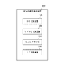
最初に、実施の形態におけるBVP信号検出装置の構成について図1を用いて説明する。図1は、本発明の実施の形態におけるBVP信号検出装置の構成を概略的に示すブロック図である。
[Device configuration]
First, the configuration of the BVP signal detection device according to the embodiment will be described with reference to FIG. FIG. 1 is a block diagram schematically showing the configuration of a BVP signal detection device according to an embodiment of the invention.
図1に示すBVP信号検出装置300は、BVP信号を検出するための装置である。BVP信号検出装置300は、ROI決定部325と、サブROI決定部340と、フィルタ設計部330と、ノイズ低減部350とを備えている。
A BVP
ROI決定部325は、人の顔の画像を含む入力動画データにおいて、ROIを決定する。サブROI決定部340は、ROI決定部325によって決定されたROIに基づいて、サブROIを決定する。
The
フィルタ設計部330は、ROIでの平均BVP信号を使用して、心拍数の生理的特性に従って、周波数領域及び/又は時間領域において分析を実行することによって、バンドパスフィルタを設計する。ノイズ低減部350は、バンドパスフィルタを用いて、各サブROIでのBVP信号を強化する。
上述したように、本実施の形態では、ROIでの平均BVP信号を用いて、周波数領域及び/又は時間領域の分析が実行されて、フィルタが設計される。そして、各サブROIでのBVP信号が、フィルタによって強化される。この結果、各サブROIでのクリーンなBVP信号の抽出が可能となる。 As described above, in this embodiment, the average BVP signal at the ROI is used to perform frequency domain and/or time domain analysis to design the filter. The BVP signal at each sub-ROI is then enhanced by the filter. As a result, clean BVP signals can be extracted at each sub-ROI.
次に、実施の形態におけるBVP信号検出装置の構成及び機能について、図2~図7を用いて詳細に説明する。図2は、本発明の実施の形態におけるBVP信号検出装置の具体的構成を示すブロック図である。 Next, the configuration and functions of the BVP signal detection device according to the embodiment will be described in detail with reference to FIGS. 2 to 7. FIG. FIG. 2 is a block diagram showing a specific configuration of the BVP signal detection device according to the embodiment of the invention.
図2に示すように、実施の形態では、BVP信号検出装置300は、ROI決定部325、サブROI決定部340、フィルタ設計部330、及びノイズ低減部350に加えて、更に、顔動画取得部310と、特徴点追跡部320と、第1BVP信号抽出部327と、第2BVP信号抽出部345と、BVP空間分布算出部360とを備えている。
As shown in FIG. 2, in the embodiment, the BVP
更に、図2に示すように、実施の形態におけるBVP信号検出装置300は、大きく2つのパートに分けられる。2つのパートは、図2に示すように、フィルタ設計パート303と、ノイズ低減パート307とである。
Furthermore, as shown in FIG. 2, the BVP
フィルタ設計パート303は、顔動画取得部310と、特徴点追跡部320と、ROI決定部325と、第1BVP信号抽出部327と、フィルタ設計部330とで構成されている。ノイズ低減パート307は、サブROI決定部340と、第2BVP信号抽出部345と、ノイズ低減部350と、BVP空間分布算出部360とで構成されている。
The
顔動画取得部310は、入力動画データ391から、人の顔画像を取得する。特徴点追跡部320は、顔を追跡し、入力動画データ391のフレーム毎に特徴点を出力する。ROI決定部325は、顔の特徴点に基づいて、ROIの選択及び決定を行う。また、同時に、サブROIが、サブROI決定部340によって、ローカライズされる。
The face moving
特徴点の取得及びROIの決定の後、第1BVP信号抽出部327は、フレーム毎に、RGB値を読み取ることによって、BVP信号を取得する。第1BVP信号抽出部327は、下記の数1を用いて、ROIにおける平均BVP信号を算出する。
After obtaining the feature points and determining the ROI, the first

上記数1において、BVPROIは、ROIにおける平均BVP信号である。BVPpiは、画素iで得られたBVP信号である。mは、ROIにおける全画素数である。piは、画素のシーケンス番号である。数1によれば、ROIにおける平均BVP信号は、フレーム毎に、ROIにおける全画素にわたってBVP信号を空間的に平均化することによって求められる。これは、ROIにおける平均BVPが結合信号であり、アーティファクト、光、顔の表情によって引き起こされるノイズが、統計的に平滑化されることを意味する。 In Equation 1 above, BVP ROI is the average BVP signal in the ROI. BVP pi is the BVP signal obtained at pixel i. m is the total number of pixels in the ROI. pi is the pixel sequence number. According to Equation 1, the average BVP signal in the ROI is obtained by spatially averaging the BVP signal over all pixels in the ROI for each frame. This means that the average BVP in the ROI is the combined signal and the noise caused by artifacts, light and facial expressions is statistically smoothed.
フィルタ設計部330は、特定期間におけるBVPROIを用いてフーリエ変換を実行することによって、周波数領域及び/又は時間領域の分析を実行する。BVPROIの周波数領域及び/又は時間領域の分析によれば、BVPROIのパワースペクトラムにおけるスペクトラムピークが追跡され、フィルタとして適切なBVP周波数の範囲が選択される。選択された、適切なBVP周波数の範囲は、ノイズ低減部350によって、各サブROIにおいてBVP信号を強化するために用いられる。
なお、このようなフィルタは、経験によって抽出された動作周波数とは異なっている。動作周波数から抽出されたフィルタは、一般的な人の心拍数15~240拍/分の範囲に応じて、0.25Hz~4Hzの範囲のような、比較的広い範囲にある。一方、フィルタ設計部330から抽出されたフィルタは、動的フィルタであり、ノイズ除去はほどほどではあるが、動作周波数から抽出されたフィルタと比較して、BVP信号を著しく損なうことはない。
It should be noted that such a filter differs from the empirically extracted operating frequency. The filter extracted from the operating frequency is in a relatively wide range, such as the range of 0.25 Hz to 4 Hz, depending on the typical human heart rate range of 15 to 240 beats per minute. On the other hand, the filter extracted from the
サブROI決定部340は、取得された顔のROIに基づいて、ROIを、それよりも小さいサブROIに分割することによって、サブROIを決定する。サブROIは、BVP空間分布の解像度を示す。なお、サブROIを得るために、ROIを均等に分割する必要はない。サブROIは、どのような形状でも良く、それぞれがROIの一部を表し、それら全てによってROIが構成される。
The
サブROI決定部340によって、サブROIが決定されると、第2BVP信号抽出部345は、サブROI毎に、BVP信号を抽出する。各サブROIにおいてBVP信号を抽出するための方法は、ROIにおいて平均BVP信号を取得するための方法と同様方法である。各サブROIにおけるBVP信号は、サブROIの範囲内の全ての画素にわたるBVP信号の空間的な平均である。
After the sub-ROI is determined by sub-ROI determining
ノイズ低減部350は、サブROI毎に、検出されたBVP信号を強化する。周波数領域におけるノイズ低減の一例においては、フーリエ変換が、サブROI毎に、特定の時間に抽出されたBVP信号に対して適用される。フィルタ設計部330から引き出されたフィルタによれば、フィルタの適用後、特定の周波数の範囲でのBVP信号のみがフィルタを通過することになる。
A
別の例として、時間領域でのノイズ低減が挙げられる。この場合、時間領域でのフィルタが、サブROI毎に、BVP信号に適用される。このフィルタもフィルタ設計部330によって設計される。周波数領域及び/又は時間領域においてフィルタが適用された後、各サブROIにおいてクリーンな信号が得られる。
Another example is noise reduction in the time domain. In this case, a filter in the time domain is applied to the BVP signal for each sub-ROI. This filter is also designed by the
図3は、本発明の実施の形態で参照するROI及びサブROIの一例を示す図である。図3において、参照番号400はフレームを示し、参照番号410は、ROIを示している。図3において、420及び430は、サブROIの例を示している。各サブROIから抽出されたBVP信号は、フーリエ変換によって時間領域及び/又は周波数領域において分析され、周波数領域におけるパワースペクトラムが取得される。
FIG. 3 is a diagram showing an example of ROIs and sub-ROIs referred to in the embodiment of the present invention. In FIG. 3,
図4は、本発明の実施の形態で参照する、時間領域及び周波数領域においてROIで得られた平均BVP信号の一例を示す図である。例えば、412をROIで得られた平均BVP信号とする。418は、ROIでの平均BVP信号の周波数領域でのパワースペクトラムである。フィルタ設計部330によれば、412で示される経時変化するBVP信号は、418で示されるように、周波数領域のパワースペクトルへと変化する。418に示されるように、狭いピークを伴う破線の矩形によって指定された、領域が存在していることが観察される。この領域が、主なBVP信号に対応していると考えられる。このパワースペクトル分析に基づいて、バンドパスフィルタが、ノイズ低減用のフィルタとして抽出される。なお、バンドパスフィルタは、動作周波数と競合すべきでない。動作周波数は、一般的な人間の心拍数の範囲である15~240拍/分の範囲に応じて、0.25Hz~4Hzといった比較的広い範囲にある。
FIG. 4 is a diagram showing an example of the average BVP signal obtained in the ROI in the time domain and frequency domain, which is referred to in the embodiment of the present invention. For example, let 412 be the average BVP signal obtained at the ROI. 418 is the power spectrum in the frequency domain of the average BVP signal at the ROI. According to the
図5は、本発明の実施の形態で参照する、時間領域及び周波数領域において各サブROIで得られたBVP信号の一例を示す図である。例えば、図5において、422及び432を、サブROI420及びサブROI430から得られた時間領域でのBVP信号のセットとする。図5において、425及び435は、それぞれ、周波数領域でのパワースペクトラムである。425及び435における心拍は、より広い範囲に広がっており、振幅のピークは、418に比べてクリーンではない。418は、ROIにおける平均BVP信号のパワースペクトラムである。
FIG. 5 is a diagram showing an example of BVP signals obtained in each sub-ROI in the time domain and frequency domain, which is referred to in the embodiment of the present invention. For example, in FIG. 5, let 422 and 432 be the set of BVP signals in the time domain obtained from
図6は、本発明の実施の形態における、ノイズ低減後に、周波数領域においてサブROIで得られたBVP信号の一例を示す図である。425及び435のノイズの多い信号のノイズ低減出力スペクトルの例は、図6における428及び438に示されている。なお、必要な信号スペクトル成分の一部がバンドパスフィルタのノイズ閾値値を下回っているため、スペクトル減算プロセスによって、それらが誤って削除されることに注意すべきである。それにもかかわらず、スペクトル減算法によれば、おそらく、シグナル-ノイズ比の改善が図られる。 FIG. 6 is a diagram showing an example of a BVP signal obtained in a sub-ROI in the frequency domain after noise reduction in an embodiment of the invention. Examples of noise-reduced output spectra of noisy signals at 425 and 435 are shown at 428 and 438 in FIG. Note that some of the desired signal spectral components are below the noise threshold value of the bandpass filter, so they are erroneously removed by the spectral subtraction process. Nonetheless, the spectral subtraction method probably provides an improved signal-to-noise ratio.
BVP空間分布算出部360は、サブROI毎に、フィルタリングされたBVP信号から、BVP空間分布を算出する。BVP空間分布算出部360は、BVP空間分布392を外部の装置に出力する。図7は、本発明において、ある時間に抽出されたBVP空間分布の一例を示す図である。
The BVP
例えば、特定のフレームでのROIにおけるBVP空間分布は、この実施の形態による得られる。BVP空間分布は、図7のように表現される。算出されたBVP空間分布に従って、他の生理的情報が更に算出可能である。 For example, the BVP spatial distribution in the ROI at a particular frame is obtained according to this embodiment. The BVP spatial distribution is expressed as shown in FIG. Other physiological information can also be calculated according to the calculated BVP spatial distribution.
[装置動作]
次に、図8を用いて、本発明の実施の形態におけるBVP信号検出装置300によって実行される処理について説明する。図8は、本発明の実施の形態におけるBVP信号検出装置によって実行される処理を示すフロー図である。以下の説明においては、必要に応じて、図1~図7が参照される。
[Device operation]
Next, processing executed by BVP
本実施の形態では、BVP信号検出方法は、BVP信号検出装置を動作させることによって実行される。従って、本実施の形態におけるBVP信号検出方法の説明は、BVP信号検出装置300によって行われる処理の以下の説明に代える。
In this embodiment, the BVP signal detection method is performed by operating a BVP signal detection device. Therefore, the description of the BVP signal detection method in the present embodiment is replaced with the following description of the processing performed by BVP
最初に、図8に示すように、顔動画取得部310が、入力動画データ391から、人の顔画像を取得する(ステップA1)。
First, as shown in FIG. 8, the face moving
次に、特徴点追跡部320が、顔を追跡し、入力動画データ391のフレーム毎に特徴点を出力する(ステップA2)。
Next, the feature
次に、ROI決定部325は、ステップA2で出力された顔の特徴点に基づいて、ROIの選択及び決定を行う(ステップA3)。
Next, the
次に、第1BVP信号抽出部327は、ステップA3で選択及び決定されたROIにおいて、上記数1を用いて、平均BVP信号を算出する(ステップA4)。
Next, the first BVP
次に、フィルタ設計部330は、ステップA4で算出された平均BVP信号を用いて、周波数領域及び/又は時間領域において分析を行って、バンドパスフィルタを設計する(ステップA5)。
Next, the
次に、サブROI決定部340は、ステップA3と同様に、サブROIをローカライズする(ステップA6)。
Next, the
次に、ステップA6において、サブROI決定部340が、サブROIを決定すると、第2BVP信号抽出部345は、サブROI毎に、BVP信号を抽出する(ステップA7)。
Next, in step A6, when sub-ROI determining
次に、ノイズ低減部350は、サブROI毎に、ステップA5で設計されたバンドパスフィルタを用いて、BVP信号を強化する(ステップA8)。この結果、BVP信号におけるノイズは低減される。
Next, the
次に、BVP空間分布算出部360は、サブROI毎に、ステップA8で処理されたBVP信号から、BVP空間分布を算出する(ステップA9)。その後、BVP空間分布算出部360は、BVP空間分布392を、外部の装置に出力する。
Next, the BVP
[実施の形態における効果]
第1の効果は、サブROI毎に、クリーンなBVP信号を抽出できるようにすることである。これは、平均BVP信号を用いて周波数領域及び/又は時間領域の分析が実行されて、フィルタが設計され、BVP信号がこのフィルタによって強化されることによる。
[Effects of Embodiment]
A first effect is to enable extraction of a clean BVP signal for each sub-ROI. This is because a frequency domain and/or time domain analysis is performed using the average BVP signal to design a filter and the BVP signal is enhanced by this filter.
第2の効果は、クリーンなBVP信号を各サブROIで抽出することによって、特定の時間におけるBVP空間分布を正確に検出できるようにすることである。その結果、BVP信号の空間分布から、多くの生体情報を読み取ることが可能となる。 The second effect is that by extracting a clean BVP signal at each sub-ROI, we can accurately detect the BVP spatial distribution at a specific time. As a result, it becomes possible to read a lot of biological information from the spatial distribution of the BVP signal.
[プログラム]
本実施の形態におけるプログラムは、コンピュータに、図8に示すステップA1~A9を実行させるプログラムであれば良い。本実施の形態におけるBVP信号検出装置及びBVP検出方法は、このプログラムをコンピュータにインストールし、それを実行することによって、実現される。この場合、コンピュータのプロセッサは、顔動画取得部310、特徴点追跡部320、ROI決定部325、第1BVP信号抽出部327、フィルタ設計部330、サブROI決定部340、第2BVP信号抽出部345、ノイズ低減部350、及びBVP空間分布算出部360として機能し、処理を実行する。
[program]
The program in this embodiment may be any program that causes a computer to execute steps A1 to A9 shown in FIG. The BVP signal detection device and the BVP detection method in this embodiment are realized by installing this program in a computer and executing it. In this case, the processor of the computer includes a face moving
本実施の形態におけるプログラムは、複数のコンピュータを用いて構成されたコンピュータシステムによって実行されても良い。この場合は、例えば、各コンピュータが、顔動画取得部310、特徴点追跡部320、ROI決定部325、第1BVP信号抽出部327、フィルタ設計部330、サブROI決定部340、第2BVP信号抽出部345、ノイズ低減部350、及びBVP空間分布算出部360のうちの、いずれかとして機能し、処理を実行する。
The program in this embodiment may be executed by a computer system configured using a plurality of computers. In this case, for example, each computer includes a facial moving
本発明の実施の形態におけるプログラムを実行することによって、BVP信号検出装置300を実現するコンピュータについて、図面を参照して説明する。図9は、本発明の実施の形態におけるBVP信号検出装置を実現するコンピュータの一例を示すブロック図である。
A computer that implements BVP
図9に示すように、コンピュータ110は、CPU(Central Processing Unit)111と、メインメモリ112と、記憶装置113と、入力インターフェイス114と、表示コントローラ115と、データリーダ/ライタ116と、通信インターフェイス117とを備える。これらの各部は、バス121を介して、互いにデータ通信可能に接続される。また、コンピュータ110は、CPU111に加えて、又はCPU111に代えて、GPU(Graphics Processing Unit)、又はFPGA(Field-Programmable Gate Array)を備えていても良い。
As shown in FIG. 9, a
CPU111は、記憶装置113に格納された、実施の形態におけるプログラム(コード群)をメインメモリ112に展開し、各コードを所定順序で実行することにより、各種の演算を実施する。メインメモリ112は、典型的には、DRAM(Dynamic Random Access Memory)等の揮発性の記憶装置である。また、実施の形態におけるプログラムは、コンピュータ読み取り可能な記録媒体120に格納された状態で提供される。なお、実施の形態におけるプログラムは、通信インターフェイス117を介して接続されたインターネット上で流通するものであっても良い。
The
また、記憶装置113の具体例としては、ハードディスクドライブの他、フラッシュメモリ等の半導体記憶装置が挙げられる。入力インターフェイス114は、CPU111と、キーボード及びマウスといった入力機器118との間のデータ伝送を仲介する。表示コントローラ115は、ディスプレイ装置119と接続され、ディスプレイ装置119での表示を制御する。
Further, as a specific example of the
データリーダ/ライタ116は、CPU111と記録媒体120との間のデータ伝送を仲介し、記録媒体120からのプログラムの読み出し、及びコンピュータ110における処理結果の記録媒体120への書き込みを実行する。通信インターフェイス117は、CPU111と、他のコンピュータとの間のデータ伝送を仲介する。
Data reader/
また、記録媒体120の具体例としては、CF(Compact Flash(登録商標))及びSD(Secure Digital)等の汎用的な半導体記憶デバイス、フレキシブルディスク(Flexible Disk)等の磁気記録媒体、又はCD-ROM(Compact Disk Read Only Memory)などの光学記録媒体が挙げられる。
Specific examples of the
実施の形態におけるBVP信号検出装置300は、プログラムがインストールされたコンピュータではなく、各部に対応したハードウェアを用いることによっても実現可能である。更に、BVP信号検出装置300は、一部がプログラムで実現され、残りの部分がハードウェアで実現されていてもよい。
BVP
上述した実施の形態の一部又は全部は、以下に記載する(付記1)~(付記15)によって表現することができるが、以下の記載に限定されるものではない。 Some or all of the above-described embodiments can be expressed by (Appendix 1) to (Appendix 15) described below, but are not limited to the following descriptions.
(付記1)
人の顔の画像を含む入力動画データにおいて、ROIを決定する、ROI決定手段と、
ROI決定手段によって決定されたROIに基づいて、サブROIを決定する、サブROI決定手段と、
ROIでの平均血液量パルス信号を使用して、心拍数の生理的特性に従って、周波数領域及び/又は時間領域において分析を実行することによって、バンドパスフィルタを設計する、フィルタ設計手段と、
前記バンドパスフィルタを用いて、各サブROIでの血液量パルス信号を強化する、ノイズ低減手段と、
を備えている、血液量パルス信号検出装置。
(Appendix 1)
ROI determination means for determining an ROI in input moving image data including an image of a person's face;
a sub-ROI determining means for determining a sub-ROI based on the ROI determined by the ROI determining means;
filter design means for designing a bandpass filter by using the average blood volume pulse signal at the ROI and performing an analysis in the frequency domain and/or the time domain according to the physiological characteristics of the heart rate;
noise reduction means for enhancing the blood volume pulse signal at each sub-ROI using the bandpass filter;
A blood volume pulse signal detection device comprising:
(付記2)
付記1に記載の血液量パルス信号検出装置であって、
各サブROIでのフィルタ後の前記血液量パルス信号から、血液量パルス空間分布を算出する、血液量パルス空間分布算出手段を更に備えている、
ことを特徴とする血液量パルス信号検出装置。
(Appendix 2)
The blood volume pulse signal detection device according to Appendix 1,
blood volume pulse spatial distribution calculating means for calculating a blood volume pulse spatial distribution from the filtered blood volume pulse signal in each sub-ROI;
A blood volume pulse signal detection device characterized by:
(付記3)
付記2に記載の血液量パルス信号検出装置であって、
前記血液量パルス空間分布算出手段は、前記サブROIを用いて、前記血液量パルス空間分布の解像度を決定する、
ことを特徴とする血液量パルス信号検出装置。
(Appendix 3)
The blood volume pulse signal detection device according to appendix 2,
The blood volume pulse spatial distribution calculation means uses the sub-ROI to determine the resolution of the blood volume pulse spatial distribution.
A blood volume pulse signal detection device characterized by:
(付記4)
付記1~3のいずれかに記載の血液量パルス信号検出装置であって、
前記フィルタ設計手段が、各サブROIでの前記血液量パルス信号が強化されるように、前記バンドパスフィルタを設計し、
前記バンドパスフィルタの上限及び下限におけるカット周波数は、前記ROIにおいて得られた時間領域及び/又は周波数領域についての前記バンドパスフィルタの分析と、人の一般的な心拍数の生理的特性と、によって決定される、
ことを特徴とする血液量パルス信号検出装置。
(Appendix 4)
The blood volume pulse signal detection device according to any one of Appendices 1 to 3,
wherein the filter design means designs the bandpass filter such that the blood volume pulse signal in each sub-ROI is enhanced;
The cut frequencies at the upper and lower limits of the bandpass filter are determined by an analysis of the bandpass filter in the time and/or frequency domain obtained in the ROI and the physiological characteristics of a person's general heart rate. It is determined,
A blood volume pulse signal detection device characterized by:
(付記5)
付記2または3に記載の血液量パルス信号検出装置であって、
前記血液量パルス空間分布算出手段は、ノイズ低減のために前記バンドパスフィルタを用いて強化された、各サブROIでの血液量パルス信号を抽出することによって、血液量パルス空間分布を算出する、
ことを特徴とする血液量パルス信号検出装置。
(Appendix 5)
The blood volume pulse signal detection device according to appendix 2 or 3,
The blood volume pulse spatial distribution calculating means calculates the blood volume pulse spatial distribution by extracting the blood volume pulse signal at each sub-ROI, which is enhanced using the bandpass filter for noise reduction.
A blood volume pulse signal detection device characterized by:
(付記6)
(a)人の顔の画像を含む入力動画データにおいて、ROIを決定する、ステップと、
(b)決定されたROIに基づいて、サブROIを決定する、ステップと、
(c)ROIでの平均血液量パルス信号を使用して、心拍数の生理的特性に従って、周波数領域及び/又は時間領域において分析を実行することによって、バンドパスフィルタを設計する、ステップと、
(d)前記バンドパスフィルタを用いて、各サブROIでの血液量パルス信号を強化する、ステップと、
を有する、血液量パルス信号検出方法。
(Appendix 6)
(a) determining a ROI in input video data containing images of human faces;
(b ) determining a sub-ROI based on the determined ROI;
(c) using the average blood volume pulse signal at the ROI to design a bandpass filter by performing an analysis in the frequency domain and/or the time domain according to the physiological characteristics of the heart rate;
(d) using the bandpass filter to enhance the blood volume pulse signal at each sub-ROI;
A blood volume pulse signal detection method comprising:
(付記7)
付記6に記載の血液量パルス信号検出方法であって、
(e)各サブROIでのフィルタ後の前記血液量パルス信号から、血液量パルス空間分布を算出する、ステップを更に有する、
ことを特徴とする血液量パルス信号検出方法。
(Appendix 7)
The blood volume pulse signal detection method according to appendix 6,
(e) calculating a blood volume pulse spatial distribution from the filtered blood volume pulse signal at each sub-ROI;
A blood volume pulse signal detection method characterized by:
(付記8)
付記7に記載の血液量パルス信号検出方法であって、
(f)前記サブROIを用いて、前記血液量パルス空間分布の解像度を決定する、ステップを更に有する、
ことを特徴とする血液量パルス信号検出方法。
(Appendix 8)
The blood volume pulse signal detection method according to appendix 7,
(f) using the sub-ROI to determine the resolution of the blood volume pulse spatial distribution;
A blood volume pulse signal detection method characterized by:
(付記9)
付記6~8のいずれかに記載の血液量パルス信号検出方法であって、
前記ステップ(c)において、各サブROIでの前記血液量パルス信号が強化されるように、前記バンドパスフィルタを設計し、
前記バンドパスフィルタの上限及び下限におけるカット周波数は、前記ROIにおいて得られた時間領域及び/又は周波数領域についての前記バンドパスフィルタの分析と、人の一般的な心拍数の生理的特性と、によって決定される、
ことを特徴とする血液量パルス信号検出方法。
(Appendix 9)
The blood volume pulse signal detection method according to any one of Appendices 6 to 8,
designing the bandpass filter in step (c) to enhance the blood volume pulse signal in each sub-ROI;
The cut frequencies at the upper and lower limits of the bandpass filter are determined by an analysis of the bandpass filter in the time and/or frequency domain obtained in the ROI and the physiological characteristics of a person's general heart rate. It is determined,
A blood volume pulse signal detection method characterized by:
(付記10)
付記7または8に記載の血液量パルス信号検出方法であって、
前記ステップ(e)において、ノイズ低減のために前記バンドパスフィルタを用いて強化された、各サブROIでの血液量パルス信号を抽出することによって、血液量パルス空間分布を算出する、
ことを特徴とする血液量パルス信号検出方法。
(Appendix 10)
The blood volume pulse signal detection method according to Appendix 7 or 8,
In step (e), calculating the blood volume pulse spatial distribution by extracting the blood volume pulse signal at each sub-ROI, enhanced with the bandpass filter for noise reduction;
A blood volume pulse signal detection method characterized by:
(付記11)
コンピュータに、
(a)人の顔の画像を含む入力動画データにおいて、ROIを決定する、ステップと、
(b)決定されたROIに基づいて、サブROIを決定する、ステップと、
(c)ROIでの平均血液量パルス信号を使用して、心拍数の生理的特性に従って、周波数領域及び/又は時間領域において分析を実行することによって、バンドパスフィルタを設計する、ステップと、
(d)前記バンドパスフィルタを用いて、各サブROIでの血液量パルス信号を強化する、ステップと、
を実行させる、プログラム。
(Appendix 11)
to the computer,
(a) determining a ROI in input video data containing images of human faces;
(b ) determining a sub-ROI based on the determined ROI;
(c) using the average blood volume pulse signal at the ROI to design a bandpass filter by performing an analysis in the frequency domain and/or the time domain according to the physiological characteristics of the heart rate;
(d) using the bandpass filter to enhance the blood volume pulse signal at each sub-ROI;
The program that causes the to run .
(付記12)
付記11に記載のプログラムであって、
前記プログラムが、前記コンピュータに、
(e)各サブROIでのフィルタ後の前記血液量パルス信号から、血液量パルス空間分布を算出する、ステップを実行させる命令を更に含む、
ことを特徴とするプログラム。
(Appendix 12)
The program according to Supplementary Note 11,
The program causes the computer to:
(e) calculating a blood volume pulse spatial distribution from the filtered blood volume pulse signal at each sub-ROI;
A program characterized by
(付記13)
付記7に記載のプログラムであって、
前記コンピュータに、
(f)前記サブROIを用いて、前記血液量パルス空間分布の解像度を決定する、ステップを更に実行させる、
ことを特徴とするプログラム。
(Appendix 13)
The program according to Supplementary Note 7,
to the computer;
(f) determining the resolution of the blood volume pulse spatial distribution using the sub-ROI;
A program characterized by
(付記14)
付記11~13のいずれかに記載のプログラムであって、
前記ステップ(c)において、各サブROIでの前記血液量パルス信号が強化されるように、前記バンドパスフィルタを設計し、
前記バンドパスフィルタの上限及び下限におけるカット周波数は、前記ROIにおいて得られた時間領域及び/又は周波数領域についての前記バンドパスフィルタの分析と、人の一般的な心拍数の生理的特性と、によって決定される、
ことを特徴とするプログラム。
(Appendix 14)
The program according to any one of Appendices 11 to 13,
designing the bandpass filter in step (c) to enhance the blood volume pulse signal in each sub-ROI;
The cut frequencies at the upper and lower limits of the bandpass filter are determined by an analysis of the bandpass filter in the time and/or frequency domain obtained in the ROI and the physiological characteristics of a person's general heart rate. It is determined,
A program characterized by
(付記15)
付記12または13に記載のプログラムであって、
前記ステップ(e)において、ノイズ低減のために前記バンドパスフィルタを用いて強化された、各サブROIでの血液量パルス信号を抽出することによって、血液量パルス空間分布を算出する、
ことを特徴とするプログラム。
(Appendix 15)
The program according to Appendix 12 or 13,
In step (e), calculating the blood volume pulse spatial distribution by extracting the blood volume pulse signal at each sub-ROI, enhanced with the bandpass filter for noise reduction;
A program characterized by
以上、実施の形態を参照して本願発明を説明したが、本願発明は上記実施の形態に限定されるものではない。本願発明の構成や詳細には、本願発明のスコープ内で当業者が理解し得る様々な変更をすることができる。 Although the present invention has been described with reference to the embodiments, the present invention is not limited to the above embodiments. Various changes that can be understood by those skilled in the art can be made to the configuration and details of the present invention within the scope of the present invention.
上述したように、本発明によれば、各サブROIにおいてクリーンな血液量パルス信号を抽出することができる。本発明は、ロバストな生理的血液量パルス信号を検出する分野において有用である。 As described above, according to the present invention, a clean blood volume pulse signal can be extracted at each sub-ROI. INDUSTRIAL APPLICABILITY The present invention is useful in the field of robust physiological blood volume pulse signal detection.
110 コンピュータ
111 CPU
112 メインメモリ
113 記憶装置
114 入力インターフェイス
115 表示コントローラ
116 データリーダ/ライタ
117 通信インターフェイス
118 入力機器
119 ディスプレイ装置
120 記録媒体
121 バス
300 BVP信号検出装置
310 顔動画取得部
320 特徴点追跡部
325 ROI決定部
327 第1BVP信号抽出部
330 フィルタ設計部
340 サブROI決定部
345 第2BVP信号抽出部
350 ノイズ低減部
360 BVP空間分布算出部
110
112
Claims (7)
ROI決定手段によって決定されたROIに基づいて、サブROIを決定する、サブROI決定手段と、
ROIでの平均血液量パルス信号を使用して、心拍数の生理的特性に従って、周波数領域及び/又は時間領域において分析を実行することによって、バンドパスフィルタを設計する、フィルタ設計手段と、
前記バンドパスフィルタを用いて、各サブROIでの血液量パルス信号を強化する、ノイズ低減手段と、
を備えている、血液量パルス信号検出装置。 ROI determination means for determining an ROI in input moving image data including an image of a person's face;
a sub-ROI determining means for determining a sub-ROI based on the ROI determined by the ROI determining means;
filter design means for designing a bandpass filter by using the average blood volume pulse signal at the ROI and performing an analysis in the frequency domain and/or the time domain according to the physiological characteristics of the heart rate;
noise reduction means for enhancing the blood volume pulse signal at each sub-ROI using the bandpass filter;
A blood volume pulse signal detection device comprising:
各サブROIでのフィルタ後の前記血液量パルス信号から、血液量パルス空間分布を算出する、血液量パルス空間分布算出手段を更に備えている、
ことを特徴とする血液量パルス信号検出装置。 The blood volume pulse signal detection device according to claim 1,
blood volume pulse spatial distribution calculating means for calculating a blood volume pulse spatial distribution from the filtered blood volume pulse signal in each sub-ROI;
A blood volume pulse signal detection device characterized by:
前記血液量パルス空間分布算出手段は、前記サブROIを用いて、前記血液量パルス空間分布の解像度を決定する、
ことを特徴とする血液量パルス信号検出装置。 The blood volume pulse signal detection device according to claim 2,
The blood volume pulse spatial distribution calculation means uses the sub-ROI to determine the resolution of the blood volume pulse spatial distribution.
A blood volume pulse signal detection device characterized by:
前記フィルタ設計手段が、各サブROIでの前記血液量パルス信号が強化されるように、前記バンドパスフィルタを設計し、
前記バンドパスフィルタの上限及び下限におけるカット周波数は、前記ROIにおいて得られた時間領域及び/又は周波数領域についての前記バンドパスフィルタの分析と、人の一般的な心拍数の生理的特性と、によって決定される、
ことを特徴とする血液量パルス信号検出装置。 The blood volume pulse signal detection device according to any one of claims 1 to 3,
wherein the filter design means designs the bandpass filter such that the blood volume pulse signal in each sub-ROI is enhanced;
The cut frequencies at the upper and lower limits of the bandpass filter are determined by an analysis of the bandpass filter in the time and/or frequency domain obtained in the ROI and the physiological characteristics of a person's general heart rate. It is determined,
A blood volume pulse signal detection device characterized by:
前記血液量パルス空間分布算出手段は、ノイズ低減のために前記バンドパスフィルタを用いて強化された、各サブROIでの血液量パルス信号を抽出することによって、血液量パルス空間分布を算出する、
ことを特徴とする血液量パルス信号検出装置。 The blood volume pulse signal detection device according to claim 2 or 3,
The blood volume pulse spatial distribution calculating means calculates the blood volume pulse spatial distribution by extracting the blood volume pulse signal at each sub-ROI, which is enhanced using the bandpass filter for noise reduction.
A blood volume pulse signal detection device characterized by:
(b)決定されたROIに基づいて、サブROIを決定する、ステップと、
(c)ROIでの平均血液量パルス信号を使用して、心拍数の生理的特性に従って、周波数領域及び/又は時間領域において分析を実行することによって、バンドパスフィルタを設計する、ステップと、
(d)前記バンドパスフィルタを用いて、各サブROIでの血液量パルス信号を強化する、ステップと、
を有する、血液量パルス信号検出方法。 (a) determining a ROI in input video data containing images of human faces;
(b ) determining a sub-ROI based on the determined ROI;
(c) using the average blood volume pulse signal at the ROI to design a bandpass filter by performing an analysis in the frequency domain and/or the time domain according to the physiological characteristics of the heart rate;
(d) using the bandpass filter to enhance the blood volume pulse signal at each sub-ROI;
A blood volume pulse signal detection method comprising:
(a)人の顔の画像を含む入力動画データにおいて、ROIを決定する、ステップと、
(b)決定されたROIに基づいて、サブROIを決定する、ステップと、
(c)ROIでの平均血液量パルス信号を使用して、心拍数の生理的特性に従って、周波数領域及び/又は時間領域において分析を実行することによって、バンドパスフィルタを設計する、ステップと、
(d)前記バンドパスフィルタを用いて、各サブROIでの血液量パルス信号を強化する、ステップと、
を実行させる、プログラム。 to the computer,
(a) determining a ROI in input video data containing images of human faces;
(b ) determining a sub-ROI based on the determined ROI;
(c) using the average blood volume pulse signal at the ROI to design a bandpass filter by performing an analysis in the frequency domain and/or the time domain according to the physiological characteristics of the heart rate;
(d) using the bandpass filter to enhance the blood volume pulse signal at each sub-ROI;
The program that causes the to run .
Applications Claiming Priority (1)
| Application Number | Priority Date | Filing Date | Title |
|---|---|---|---|
| PCT/JP2019/013425 WO2020194617A1 (en) | 2019-03-27 | 2019-03-27 | Blood volume pulse signal detection apparatus, blood volume pulse signal detection method, and computer-readable storage medium |
Publications (2)
| Publication Number | Publication Date |
|---|---|
| JP2022528223A JP2022528223A (en) | 2022-06-09 |
| JP7124974B2 true JP7124974B2 (en) | 2022-08-24 |
Family
ID=72610182
Family Applications (1)
| Application Number | Title | Priority Date | Filing Date |
|---|---|---|---|
| JP2021556659A Active JP7124974B2 (en) | 2019-03-27 | 2019-03-27 | Blood volume pulse signal detection device, blood volume pulse signal detection method, and program |
Country Status (3)
| Country | Link |
|---|---|
| US (1) | US20220167863A1 (en) |
| JP (1) | JP7124974B2 (en) |
| WO (1) | WO2020194617A1 (en) |
Families Citing this family (1)
| Publication number | Priority date | Publication date | Assignee | Title |
|---|---|---|---|---|
| CN112766094B (en) * | 2021-01-05 | 2022-10-14 | 清华大学 | Method and system for extracting PPG signal through video |
Citations (3)
| Publication number | Priority date | Publication date | Assignee | Title |
|---|---|---|---|---|
| JP2014198200A (en) | 2013-03-29 | 2014-10-23 | 富士通株式会社 | Pulse wave detection device, pulse wave detection program, and pulse wave detection method |
| JP2016220915A (en) | 2015-05-29 | 2016-12-28 | 株式会社リコー | Pulse wave detection device, pulse wave detection method, pulse wave detection system, and program |
| JP2018166929A (en) | 2017-03-30 | 2018-11-01 | 株式会社エクォス・リサーチ | Pulse wave detection device and pulse wave detection program |
-
2019
- 2019-03-27 WO PCT/JP2019/013425 patent/WO2020194617A1/en active Application Filing
- 2019-03-27 JP JP2021556659A patent/JP7124974B2/en active Active
- 2019-03-27 US US17/441,364 patent/US20220167863A1/en active Pending
Patent Citations (3)
| Publication number | Priority date | Publication date | Assignee | Title |
|---|---|---|---|---|
| JP2014198200A (en) | 2013-03-29 | 2014-10-23 | 富士通株式会社 | Pulse wave detection device, pulse wave detection program, and pulse wave detection method |
| JP2016220915A (en) | 2015-05-29 | 2016-12-28 | 株式会社リコー | Pulse wave detection device, pulse wave detection method, pulse wave detection system, and program |
| JP2018166929A (en) | 2017-03-30 | 2018-11-01 | 株式会社エクォス・リサーチ | Pulse wave detection device and pulse wave detection program |
Also Published As
| Publication number | Publication date |
|---|---|
| US20220167863A1 (en) | 2022-06-02 |
| WO2020194617A1 (en) | 2020-10-01 |
| JP2022528223A (en) | 2022-06-09 |
Similar Documents
| Publication | Publication Date | Title |
|---|---|---|
| US9795306B2 (en) | Method of estimating blood pressure based on image | |
| CN106073743B (en) | Method and system for noise cleaning of photoplethysmograph signals | |
| US9025826B2 (en) | Formation of a time-varying signal representative of at least variations in a value based on pixel values | |
| JP6115263B2 (en) | Pulse wave detection device, pulse wave detection method, and pulse wave detection program | |
| Chambino | Android-based implementation of Eulerian Video Magnification for vital signs monitoring | |
| KR101788803B1 (en) | Generation method of personal identification information using electrocardiogram and personal identification method using the information | |
| EP3217659B1 (en) | Image processing apparatus, image processing method, and program | |
| JP7099542B2 (en) | Pulse rate estimation device, pulse rate estimation method, and program | |
| JP7124974B2 (en) | Blood volume pulse signal detection device, blood volume pulse signal detection method, and program | |
| US20200178902A1 (en) | A system and method for extracting a physiological information from video sequences | |
| WO2019055919A1 (en) | Heart rate measurement for fitness exercises using video | |
| US20210244287A1 (en) | Heartbeat detection device, heartbeat detection method, and program | |
| JP2009297234A (en) | Pulse measuring apparatus, pulse measuring program and pulse measuring method | |
| Greenspan et al. | Doppler echocardiography flow-velocity image analysis for patients with atrial fibrillation | |
| Sikdar et al. | Contactless vision-based pulse rate detection of infants under neurological examinations | |
| JP2018068720A (en) | Pulse detector and pulse detection method | |
| KR20220015779A (en) | Methods and apparatuses for estimating robust body temperature using bio-signal of skin image | |
| KR101341576B1 (en) | Apparatus and method for determining region of interest based on isocontour | |
| JP7074817B2 (en) | Vital data measuring device, vital data measuring method and computer program | |
| US20220096016A1 (en) | State estimation apparatus, state estimation method, and computer-readable recording medium | |
| KR20230077984A (en) | PPG reconstruction method and device with smartphone camera image | |
| JP2010211757A (en) | Apparatus, method, and program for processing image | |
| KR101581552B1 (en) | System and method for detecting spikes whose widths are within a certain range in time-series data | |
| JP2023131271A (en) | Non-contact pulse estimation device, non-contact pulse estimation method, and program | |
| CN115294027A (en) | Heart rate detection method and device, electronic equipment and storage medium |
Legal Events
| Date | Code | Title | Description |
|---|---|---|---|
| A521 | Request for written amendment filed |
Free format text: JAPANESE INTERMEDIATE CODE: A523 Effective date: 20210917 |
|
| A621 | Written request for application examination |
Free format text: JAPANESE INTERMEDIATE CODE: A621 Effective date: 20210917 |
|
| TRDD | Decision of grant or rejection written | ||
| A01 | Written decision to grant a patent or to grant a registration (utility model) |
Free format text: JAPANESE INTERMEDIATE CODE: A01 Effective date: 20220712 |
|
| A61 | First payment of annual fees (during grant procedure) |
Free format text: JAPANESE INTERMEDIATE CODE: A61 Effective date: 20220725 |
|
| R151 | Written notification of patent or utility model registration |
Ref document number: 7124974 Country of ref document: JP Free format text: JAPANESE INTERMEDIATE CODE: R151 |