JP7124037B2 - Method, computer program product, apparatus and frequency modulated continuous wave radar system - Google Patents
Method, computer program product, apparatus and frequency modulated continuous wave radar system Download PDFInfo
- Publication number
- JP7124037B2 JP7124037B2 JP2020186310A JP2020186310A JP7124037B2 JP 7124037 B2 JP7124037 B2 JP 7124037B2 JP 2020186310 A JP2020186310 A JP 2020186310A JP 2020186310 A JP2020186310 A JP 2020186310A JP 7124037 B2 JP7124037 B2 JP 7124037B2
- Authority
- JP
- Japan
- Prior art keywords
- segment
- sequence
- segments
- interfering
- doppler image
- Prior art date
- Legal status (The legal status is an assumption and is not a legal conclusion. Google has not performed a legal analysis and makes no representation as to the accuracy of the status listed.)
- Active
Links
Images


Classifications
-
- G—PHYSICS
- G01—MEASURING; TESTING
- G01S—RADIO DIRECTION-FINDING; RADIO NAVIGATION; DETERMINING DISTANCE OR VELOCITY BY USE OF RADIO WAVES; LOCATING OR PRESENCE-DETECTING BY USE OF THE REFLECTION OR RERADIATION OF RADIO WAVES; ANALOGOUS ARRANGEMENTS USING OTHER WAVES
- G01S7/00—Details of systems according to groups G01S13/00, G01S15/00, G01S17/00
- G01S7/02—Details of systems according to groups G01S13/00, G01S15/00, G01S17/00 of systems according to group G01S13/00
- G01S7/023—Interference mitigation, e.g. reducing or avoiding non-intentional interference with other HF-transmitters, base station transmitters for mobile communication or other radar systems, e.g. using electro-magnetic interference [EMI] reduction techniques
-
- G—PHYSICS
- G01—MEASURING; TESTING
- G01S—RADIO DIRECTION-FINDING; RADIO NAVIGATION; DETERMINING DISTANCE OR VELOCITY BY USE OF RADIO WAVES; LOCATING OR PRESENCE-DETECTING BY USE OF THE REFLECTION OR RERADIATION OF RADIO WAVES; ANALOGOUS ARRANGEMENTS USING OTHER WAVES
- G01S7/00—Details of systems according to groups G01S13/00, G01S15/00, G01S17/00
- G01S7/48—Details of systems according to groups G01S13/00, G01S15/00, G01S17/00 of systems according to group G01S17/00
- G01S7/497—Means for monitoring or calibrating
-
- G—PHYSICS
- G01—MEASURING; TESTING
- G01S—RADIO DIRECTION-FINDING; RADIO NAVIGATION; DETERMINING DISTANCE OR VELOCITY BY USE OF RADIO WAVES; LOCATING OR PRESENCE-DETECTING BY USE OF THE REFLECTION OR RERADIATION OF RADIO WAVES; ANALOGOUS ARRANGEMENTS USING OTHER WAVES
- G01S13/00—Systems using the reflection or reradiation of radio waves, e.g. radar systems; Analogous systems using reflection or reradiation of waves whose nature or wavelength is irrelevant or unspecified
- G01S13/02—Systems using reflection of radio waves, e.g. primary radar systems; Analogous systems
- G01S13/06—Systems determining position data of a target
- G01S13/08—Systems for measuring distance only
- G01S13/32—Systems for measuring distance only using transmission of continuous waves, whether amplitude-, frequency-, or phase-modulated, or unmodulated
- G01S13/34—Systems for measuring distance only using transmission of continuous waves, whether amplitude-, frequency-, or phase-modulated, or unmodulated using transmission of continuous, frequency-modulated waves while heterodyning the received signal, or a signal derived therefrom, with a locally-generated signal related to the contemporaneously transmitted signal
-
- G—PHYSICS
- G01—MEASURING; TESTING
- G01S—RADIO DIRECTION-FINDING; RADIO NAVIGATION; DETERMINING DISTANCE OR VELOCITY BY USE OF RADIO WAVES; LOCATING OR PRESENCE-DETECTING BY USE OF THE REFLECTION OR RERADIATION OF RADIO WAVES; ANALOGOUS ARRANGEMENTS USING OTHER WAVES
- G01S13/00—Systems using the reflection or reradiation of radio waves, e.g. radar systems; Analogous systems using reflection or reradiation of waves whose nature or wavelength is irrelevant or unspecified
- G01S13/02—Systems using reflection of radio waves, e.g. primary radar systems; Analogous systems
- G01S13/50—Systems of measurement based on relative movement of target
- G01S13/58—Velocity or trajectory determination systems; Sense-of-movement determination systems
- G01S13/583—Velocity or trajectory determination systems; Sense-of-movement determination systems using transmission of continuous unmodulated waves, amplitude-, frequency-, or phase-modulated waves and based upon the Doppler effect resulting from movement of targets
- G01S13/584—Velocity or trajectory determination systems; Sense-of-movement determination systems using transmission of continuous unmodulated waves, amplitude-, frequency-, or phase-modulated waves and based upon the Doppler effect resulting from movement of targets adapted for simultaneous range and velocity measurements
-
- G—PHYSICS
- G01—MEASURING; TESTING
- G01S—RADIO DIRECTION-FINDING; RADIO NAVIGATION; DETERMINING DISTANCE OR VELOCITY BY USE OF RADIO WAVES; LOCATING OR PRESENCE-DETECTING BY USE OF THE REFLECTION OR RERADIATION OF RADIO WAVES; ANALOGOUS ARRANGEMENTS USING OTHER WAVES
- G01S13/00—Systems using the reflection or reradiation of radio waves, e.g. radar systems; Analogous systems using reflection or reradiation of waves whose nature or wavelength is irrelevant or unspecified
- G01S13/88—Radar or analogous systems specially adapted for specific applications
- G01S13/89—Radar or analogous systems specially adapted for specific applications for mapping or imaging
-
- G—PHYSICS
- G01—MEASURING; TESTING
- G01S—RADIO DIRECTION-FINDING; RADIO NAVIGATION; DETERMINING DISTANCE OR VELOCITY BY USE OF RADIO WAVES; LOCATING OR PRESENCE-DETECTING BY USE OF THE REFLECTION OR RERADIATION OF RADIO WAVES; ANALOGOUS ARRANGEMENTS USING OTHER WAVES
- G01S13/00—Systems using the reflection or reradiation of radio waves, e.g. radar systems; Analogous systems using reflection or reradiation of waves whose nature or wavelength is irrelevant or unspecified
- G01S13/88—Radar or analogous systems specially adapted for specific applications
- G01S13/93—Radar or analogous systems specially adapted for specific applications for anti-collision purposes
- G01S13/931—Radar or analogous systems specially adapted for specific applications for anti-collision purposes of land vehicles
-
- G—PHYSICS
- G01—MEASURING; TESTING
- G01S—RADIO DIRECTION-FINDING; RADIO NAVIGATION; DETERMINING DISTANCE OR VELOCITY BY USE OF RADIO WAVES; LOCATING OR PRESENCE-DETECTING BY USE OF THE REFLECTION OR RERADIATION OF RADIO WAVES; ANALOGOUS ARRANGEMENTS USING OTHER WAVES
- G01S7/00—Details of systems according to groups G01S13/00, G01S15/00, G01S17/00
- G01S7/02—Details of systems according to groups G01S13/00, G01S15/00, G01S17/00 of systems according to group G01S13/00
- G01S7/021—Auxiliary means for detecting or identifying radar signals or the like, e.g. radar jamming signals
-
- G—PHYSICS
- G01—MEASURING; TESTING
- G01S—RADIO DIRECTION-FINDING; RADIO NAVIGATION; DETERMINING DISTANCE OR VELOCITY BY USE OF RADIO WAVES; LOCATING OR PRESENCE-DETECTING BY USE OF THE REFLECTION OR RERADIATION OF RADIO WAVES; ANALOGOUS ARRANGEMENTS USING OTHER WAVES
- G01S7/00—Details of systems according to groups G01S13/00, G01S15/00, G01S17/00
- G01S7/02—Details of systems according to groups G01S13/00, G01S15/00, G01S17/00 of systems according to group G01S13/00
- G01S7/35—Details of non-pulse systems
- G01S7/352—Receivers
- G01S7/354—Extracting wanted echo-signals
-
- G—PHYSICS
- G01—MEASURING; TESTING
- G01S—RADIO DIRECTION-FINDING; RADIO NAVIGATION; DETERMINING DISTANCE OR VELOCITY BY USE OF RADIO WAVES; LOCATING OR PRESENCE-DETECTING BY USE OF THE REFLECTION OR RERADIATION OF RADIO WAVES; ANALOGOUS ARRANGEMENTS USING OTHER WAVES
- G01S7/00—Details of systems according to groups G01S13/00, G01S15/00, G01S17/00
- G01S7/48—Details of systems according to groups G01S13/00, G01S15/00, G01S17/00 of systems according to group G01S17/00
- G01S7/483—Details of pulse systems
- G01S7/486—Receivers
- G01S7/487—Extracting wanted echo signals, e.g. pulse detection
- G01S7/4876—Extracting wanted echo signals, e.g. pulse detection by removing unwanted signals
-
- G—PHYSICS
- G01—MEASURING; TESTING
- G01S—RADIO DIRECTION-FINDING; RADIO NAVIGATION; DETERMINING DISTANCE OR VELOCITY BY USE OF RADIO WAVES; LOCATING OR PRESENCE-DETECTING BY USE OF THE REFLECTION OR RERADIATION OF RADIO WAVES; ANALOGOUS ARRANGEMENTS USING OTHER WAVES
- G01S13/00—Systems using the reflection or reradiation of radio waves, e.g. radar systems; Analogous systems using reflection or reradiation of waves whose nature or wavelength is irrelevant or unspecified
- G01S13/02—Systems using reflection of radio waves, e.g. primary radar systems; Analogous systems
- G01S13/06—Systems determining position data of a target
- G01S13/42—Simultaneous measurement of distance and other co-ordinates
- G01S13/44—Monopulse radar, i.e. simultaneous lobing
- G01S13/4454—Monopulse radar, i.e. simultaneous lobing phase comparisons monopulse, i.e. comparing the echo signals received by an interferometric antenna arrangement
-
- G—PHYSICS
- G01—MEASURING; TESTING
- G01S—RADIO DIRECTION-FINDING; RADIO NAVIGATION; DETERMINING DISTANCE OR VELOCITY BY USE OF RADIO WAVES; LOCATING OR PRESENCE-DETECTING BY USE OF THE REFLECTION OR RERADIATION OF RADIO WAVES; ANALOGOUS ARRANGEMENTS USING OTHER WAVES
- G01S7/00—Details of systems according to groups G01S13/00, G01S15/00, G01S17/00
- G01S7/02—Details of systems according to groups G01S13/00, G01S15/00, G01S17/00 of systems according to group G01S13/00
- G01S7/35—Details of non-pulse systems
- G01S7/352—Receivers
- G01S7/356—Receivers involving particularities of FFT processing
Landscapes
- Engineering & Computer Science (AREA)
- Remote Sensing (AREA)
- Radar, Positioning & Navigation (AREA)
- Physics & Mathematics (AREA)
- Computer Networks & Wireless Communication (AREA)
- General Physics & Mathematics (AREA)
- Electromagnetism (AREA)
- Radar Systems Or Details Thereof (AREA)
- Complex Calculations (AREA)
Description
本発明は、一般に、レーダー画像化に関し、より詳細には、干渉低減されたレーダー画像を生成することに関する。 The present invention relates generally to radar imaging, and more particularly to generating interference-reduced radar images.
監視モニタリングのためにまた乗り物においてレーダーを使用することは、益々一般的になっており、なぜならば、これが、オブジェクトの距離、速度、および角度が測定されることを可能にするからである。例えば、レーダーユニットは、監視カメラに対する補完物として使用されて、シーン内のオブジェクトに関する情報を提供することができる。 The use of radar for surveillance monitoring and in vehicles is becoming increasingly popular because it allows the distance, velocity and angle of objects to be measured. For example, radar units can be used as a complement to surveillance cameras to provide information about objects in the scene.
1つのタイプのレーダーは、周波数変調連続波(FMCW:frequency-modulated-continuous-wave)レーダーである。FMCWレーダーは、「チャープ(chirp)」と呼ばれるレーダー波信号を送信する。チャープは、その周波数が、時間と共に、しばしば線形に変化する、周期的な、しばしば正弦的な信号である。FMCWレーダーは、例えば、受信アンテナによって、レーダー波信号の反射を受信し、反射は、例えば、シーン内の可動オブジェクトからやって来る。送信信号を受信信号と混合することによって、ビート信号を生成することができる。ビート信号のシーケンスを生成するために、プロセスを順次反復することができる。ビート信号のシーケンスは、その後、例えばオブジェクトまでの距離およびオブジェクトの速度の情報を含むレンジ・ドップラ画像に変換することができる。FMCWレーダーは、しばしば、チャープのシーケンスを送信し、その後、新しいチャープのシーケンスを送信する前に、しばらくの間、沈黙している。こうして、幾つかのビート信号のシーケンスを受信することができ、ビート信号の各シーケンスをフレームと呼ぶことができ、フレームは、シーンの所定の時点のスナップショット(snapshot in time)に対応する。FMCWレーダーシステムは、しばしば幾つかの受信アンテナを備える。少なくとも2つのアンテナが使用されるとき、オブジェクトに対する角度を推定することもできる。 One type of radar is frequency-modulated-continuous-wave (FMCW) radar. FMCW radar transmits a radar wave signal called a "chirp". A chirp is a periodic, often sinusoidal, signal whose frequency varies, often linearly, with time. FMCW radar receives reflections of radar wave signals, for example, by a receiving antenna, which come from, for example, moving objects in the scene. A beat signal can be generated by mixing the transmitted signal with the received signal. The process can be repeated sequentially to generate a sequence of beat signals. The sequence of beat signals can then be converted to a range-Doppler image containing, for example, distance to the object and object velocity information. FMCW radars often transmit a sequence of chirps and then are silent for some time before transmitting a new sequence of chirps. Thus, several sequences of beat signals can be received, each sequence of beat signals can be called a frame, and a frame corresponds to a snapshot in time of a scene. FMCW radar systems are often equipped with several receive antennas. The angle to the object can also be estimated when at least two antennas are used.
現在のレーダーシステムは多くの利点を有するが、改善の余地が存在する。 Although current radar systems have many advantages, there is room for improvement.
レーダーの使用がより一般的になってきているため、異なるレーダーが互いに干渉し始めるリスクの増加が存在する。例示するために、交通量をモニターするために使用されるレーダーは、そばを通過する乗り物に搭載されたレーダーからの干渉を受ける場合がある。干渉の結果として、レーダーの機能は、悪化するまたは最悪の場合完全に失敗する場合がある。 As the use of radars becomes more common, there is an increasing risk that different radars will start to interfere with each other. To illustrate, radars used to monitor traffic may be subject to interference from radars mounted on passing vehicles. As a result of the interference, the functionality of the radar deteriorates or, in the worst case, it may fail completely.
したがって、FMCWレーダーシステムからのレーダー画像における干渉を低減する方法を提供することが本発明の目的である。ターゲット検出の高い可能性および誤ったターゲット検出の低い可能性を可能にするレーダー画像を提供することが、本発明のさらなる目的である。 It is therefore an object of the present invention to provide a method of reducing interference in radar images from FMCW radar systems. It is a further object of the present invention to provide a radar image that allows a high probability of target detection and a low probability of false target detection.
本発明の上記のまた他の目的は、独立請求項において規定される発明によって少なくとも部分的に満たされる。好ましい実施形態は、従属請求項において述べられる。 These and other objects of the present invention are at least partially met by the inventions defined in the independent claims. Preferred embodiments are set out in the dependent claims.
本発明の第1の態様によれば、干渉低減されたレーダー画像を生成するための方法が提供され、方法は、
ビート信号の測定シーケンスを受信することであって、各ビート信号は複数のセグメントを含み、各セグメントは或る振幅を有し、j番目のビート信号のi番目のセグメントは、振幅Ai,jを有するセグメントi,jとして識別可能であり、ここで、i=1、…、a、j=1、…、bである、受信すること、
ビート信号の測定シーケンス内で1つまたは複数の干渉セグメントを識別することであって、干渉セグメントは干渉を受けるセグメントである、識別すること、
ビート信号の測定シーケンスの改変された表現を、要素yi,jを有する行列Y

ここで、yi,j=mi,j×Ai,jであり、mi,jはマスキング値であり、マスキング値は、セグメントi,jが干渉セグメントとして識別されるか否かに依存し、マスキング値は、セグメントi,jが干渉セグメントでない場合と比較して、セグメントi,jが干渉セグメントである場合、より低い値に設定される、改変すること、
ビート信号の測定シーケンスの改変を表す改変用マスクを作成することであって、改変用マスクは、要素mi,jを有する行列M

YおよびMから、再構成されるレンジ・ドップラ画像
![]()
を含み、
これにより、ビート信号の測定シーケンスを改変することは干渉効果を少なくとも部分的に除去し、再構成されるレンジ・ドップラ画像を推定することは改変によって作成される画像アーチファクトを少なくとも部分的に除去する。
According to a first aspect of the invention, there is provided a method for generating interference-reduced radar images, the method comprising:
Receiving a measured sequence of beat signals, each beat signal comprising a plurality of segments, each segment having an amplitude, the i-th segment of the j-th beat signal having an amplitude A i,j , where i=1, . . . , a, j=1, .
identifying one or more interfering segments within the measurement sequence of the beat signal, wherein the interfering segments are the segments subject to interference;
Let the modified representation of the measurement sequence of the beat signal be the matrix Y
where y i,j =m i,j ×A i,j and m i,j is a masking value that depends on whether segment i,j is identified as an interfering segment. and the masking value is set to a lower value when segment i,j is an interfering segment compared to when segment i,j is not an interfering segment;
creating a modification mask representing modification of the measured sequence of the beat signal, the modification mask being a matrix M
From Y and M, reconstructed range-Doppler image
![]()
Thereby, modifying the measurement sequence of the beat signal at least partially removes interference effects, and estimating the reconstructed range-Doppler image at least partially removes image artifacts created by the modification. .
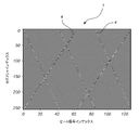
図1は、周波数変調連続波レーダーシステムからのビート信号の測定シーケンス1を概略的に示す。ビート信号の測定シーケンス1は、それぞれがセグメント3を有するb個のビート信号2のシーケンスを含む。セグメント3は、本明細書において、ビート信号の時間サンプルであって、時間サンプルが記録された時刻におけるビート信号の振幅を表す、時間サンプルとすることができる。b個のビート信号2は、第1の信号から初めて、図1の水平軸に沿って互いに隣り合うように編成される。或るビート信号は、そのビート信号インデックスjによって識別することができ、ここで、1≦j≦bである。各ビート信号2のセグメント3は、垂直軸に沿って配置される。或るセグメントは、そのセグメントインデックスiによって識別することができ、ここで、1≦i≦aである。
FIG. 1 schematically shows a
レーダーシステムが、干渉、例えば、競合するレーダーシステムからの干渉を受ける場合、セグメントの一部は、不正確な振幅、例えば、競合するレーダーシステムが周りにない状態で、レーダーシステムが単独で作動していた場合に予想されるであろう振幅を反映しない振幅を有することになる。そのため、ビート信号の測定シーケンス1内の一部のセグメントは、干渉セグメント4とすることができる。干渉セグメント4は、例えば、レーダーシステム自身によって引き起こされるレーダー反射の振幅に比べて、競合するレーダーシステムの送信振幅により強く関連する振幅を有するセグメントとすることができる。
If a radar system is subject to interference, e.g. interference from a competing radar system, some of the segments may have incorrect amplitudes, e.g. will have an amplitude that does not reflect the amplitude that would be expected if Therefore, some segments in the beat
ビート信号のシーケンス1は、時間周波数変換によってレンジ・ドップラ画像に変換することができる。これを行う1つの方法は、フーリエ変換、例えば、2Dフーリエ変換である。例えば、離散的フーリエ変換(DFT:discrete Fourier transform)が、新しい行列を作成するために各列に対して実施され、それに続いて、新しい行列の各行についてDFTが実施されて、レンジ・ドップラ画像を形成することができる。
The
レンジ・ドップラ画像内の各ピクセルは、そのレンジ・ドップラビンにおけるリターンエコーの信号に対応する振幅として見ることができる。振幅は、本明細書で複素値とすることができる。レンジ・ドップラ画像がグラフィカルに提示されると、振幅の絶対値、すなわち、そのレンジ・ドップラビンにおけるリターンエコーの信号強度が提示される。こうして、レンジ・ドップラ画像は、それぞれの軸におけるレンジおよびドップラを有し、ピクセル値が、対応する反射信号強度である、2次元画像とすることができる。 Each pixel in the range-Doppler image can be viewed as an amplitude corresponding signal of the return echo at that range-Doppler bin. Amplitude may be complex-valued herein. When the range-Doppler image is presented graphically, the absolute value of the amplitude, ie the signal strength of the return echo at that range-Doppler bin, is presented. Thus, a range-Doppler image can be a two-dimensional image with range and Doppler on each axis, with the pixel values being the corresponding reflected signal intensities.
以下において、図2~5は、概念の選択を導入し、レンジ・ドップラ画像が作成されるときに生じる場合がある問題の幾つかを例示し、発明の概念の利点の一部を例示するために使用されることになる。しかしながら、図2~5の例は、特許請求される主題の範囲を制限するものと解釈されるべきでない。図2~5で使用されるデータは、測定データではなく、シミュレーテッドデータ(simulated data)である。しかしながら、シミュレーテッドデータを参照する述べる任意の動作が、対応する方法で、測定データを参照することができることが理解されるべきである。 In the following, Figures 2-5 are presented to introduce a selection of concepts, illustrate some of the problems that may arise when range-Doppler images are produced, and illustrate some of the advantages of the inventive concepts. will be used for However, the examples of FIGS. 2-5 should not be construed as limiting the scope of the claimed subject matter. The data used in FIGS. 2-5 are simulated data, not measured data. However, it should be understood that any operations described that refer to simulated data may, in a corresponding manner, refer to measured data.
図2は、干渉がない状態での、ビート信号の測定シーケンス1のシミュレーションを示す。
FIG. 2 shows a simulation of the beat
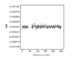
図2bは、1つの単一ビート信号2を示す。図2bのx軸は複数のセグメントを表すセグメントインデックスである。図2bのy軸はビート信号の振幅である。ビート信号の振幅は、図2bに示すように、セグメントごとに変動する場合がある。1つのセグメントの絶対振幅は、ビート信号のサンプルの、測定された信号電力レベルを表すことができる。
FIG. 2b shows one
図2aは、干渉がない、ビート信号の全体のシミュレーテッドシーケンス1を、グレースケール画像の形式で示す。図2aのx軸は複数のビート信号を表すビート信号インデックスである。図2aのy軸は、各ビート信号の複数のセグメントを表すセグメントインデックスである。図2aにおいて、ビート信号は、第1のビート信号1から初めて、x軸に沿って互いに隣り合うように編成される。各ビート信号のセグメントはy軸に沿って配置される。こうして、図2aの各列は、図2bで提示したタイプのビート信号に対応する。図2aのグレースケール画像において、各セグメントの実数部は、デシベルスケール上のグレースケール値として表される。
Figure 2a shows the entire
図2cは、図2aのビート信号の測定(シミュレーテッド)シーケンスから作成されたレンジ・ドップラ画像を示す。レンジ・ドップラ画像において、可動オブジェクトは、増加した輝度のピクセルの群によって表すことになる。レンジ・ドップラ画像の各ピクセルの輝度は、信号のエネルギーレベルを表すことができ、また、レーダー信号を反射するオブジェクトの能力を基本的に表すことができる。輝度は、この図において、右側のスケールバーに対応するグレースケールで表される。特に、図2cのx軸は速度の尺度を表し、図2cのy軸は受信機からの距離の尺度を表す。その結果、レンジ・ドップラ画像の各ピクセルは、或る速度および受信機からの或る距離を表す。ピクセルの輝度が高ければ高いほど、信号のエネルギーレベルが高い。ピクセルの輝度が低ければ低いほど、信号のエネルギーレベルが低い。図2cのレンジ・ドップラ画像において、バックグラウンドノイズフロア(background noise floor)より目立つ3つの可動オブジェクトが存在する。ノイズフロアは、この場合、-160.0dBの値を有するグレースケールに対応し、信号対雑音比(SNR)は42.3dBである。 FIG. 2c shows a range-Doppler image created from the measured (simulated) sequence of the beat signal of FIG. 2a. In range-Doppler images, moving objects will be represented by groups of pixels of increased intensity. The intensity of each pixel in the range-Doppler image can represent the energy level of the signal and can basically represent the ability of the object to reflect the radar signal. Intensity is represented in this figure by the gray scale corresponding to the scale bar on the right. In particular, the x-axis of FIG. 2c represents a measure of velocity and the y-axis of FIG. 2c represents a measure of distance from the receiver. As a result, each pixel in the range-Doppler image represents a certain velocity and a certain distance from the receiver. The brighter the pixel, the higher the energy level of the signal. The lower the brightness of the pixel, the lower the energy level of the signal. In the range-Doppler image of Figure 2c, there are three moving objects that stand out from the background noise floor. The noise floor corresponds in this case to a grayscale with a value of −160.0 dB and a signal-to-noise ratio (SNR) of 42.3 dB.
図3は、干渉を伴うビート信号の測定シーケンス1のシミュレーションを示し、干渉は、幾つかの干渉セグメント4を生じる。図3aは、干渉を伴うビート信号の全体の測定(シミュレーテッド)シーケンス1を、グレースケール画像の形式で示す。図3bは、干渉を伴うビート信号のシミュレーテッドシーケンスの1つの単一ビート信号2を示す。干渉は、異なるビート信号2内の干渉セグメント4として見られる。この例のビート信号の測定(シミュレーテッド)シーケンス1において、干渉セグメント4は対角パターンを形成する。図3cは、図3aのビート信号の測定(シミュレーテッド)シーケンスから作成されたレンジ・ドップラ画像を示す。図3のシミュレーションのために使用されるデータならびにデータの提示は、干渉の導入を除いて、図2のシミュレーションと類似する。図3において、干渉がノイズフロアを上げる場合があることを見ることができる。この場合、ノイズフロアは、-148.6dBまで上げられ、SNRは31.3dBになる。付加ノイズは、例えば、真のオブジェクト(真の反射)を曖昧にする場合があり、付加ノイズは、同様に偽りのオブジェクトを生じさせる場合があり、人間オペレータまたは機械が結果として得られるレーダー画像を解釈することを難しくする。図3cの例において、図2cのレーダー画像内のおよその座標[95,55]において以前は見えているオブジェクトは、今やバックグラウンドノイズ内に消えている。
FIG. 3 shows a simulation of a
干渉の悪い影響は、干渉を受けるセグメントをビート信号の測定シーケンス1内で識別し、これらのセグメントを、例えば、それらをゼロに設定することによってマスクすることによって、ある程度、軽減することができる。図3aの干渉を伴うビート信号のシーケンスは、こうして、例えば、干渉を受けるビート信号のシーケンスの全てのセグメントをゼロに設定することによって改変することができる。しかしながら、改変を異なるように行うこともできることが理解されるべきである。例えば、干渉を受けるビート信号のシーケンスの全てのセグメントの振幅を、或るパーセンテージ、例えば90%だけ減少させることができる。改変は、干渉を受けないセグメントに影響を及ぼす場合もある。改変は、例えば、識別された干渉セグメントに隣接するまたはそれに近いセグメントの振幅を減少させる場合がある。これは、識別ステップが必ずしも完全でない場合があるため、予防措置として行うことができる。
The negative effects of interference can be mitigated to some extent by identifying the interfered segments within the
図4は、図3からのシミュレーションの改変を示す。ビート信号の測定(シミュレーテッド)シーケンスの改変された表現6は、識別された干渉セグメントをゼロに設定することによって作成される。図4aは、グレースケール画像の形式で、Yとして参照される行列フォーマット(matrix format)で、ビート信号の測定シーケンスの全体の改変された表現6を示す。図4bは、改変後の1つの単一ビート信号を示す。図4cは、Yのレンジ・ドップラ画像20、すなわち、図4aのビート信号の測定シーケンスの改変された表現から作成されたレンジ・ドップラ画像を示す。
FIG. 4 shows a modification of the simulation from FIG. A modified
図4cに提示された、ビート信号の改変されたシーケンスに起因したレンジ・ドップラ画像は、図3cに提示された、改変前の干渉を伴うビート信号のシーケンスに起因したレンジ・ドップラ画像ほどにはノイジーでない。ノイズフロアが図4cにおいて-160.6dBまで減少し、SNRが40.9dBまで変化しているように思われる。こうして、干渉を受けるビート信号のシーケンスのセグメントをゼロに設定することによって、ビート信号の改変されたシーケンスに起因したレンジ・ドップラ画像は、バックグラウンドノイズの点、改変前のビート信号のシーケンスに起因したレンジ・ドップラ画像より明瞭になることができる。その結果、識別されるオブジェクトを表すピクセルの群とバックグラウンドノイズとの間の輝度レベルの差は、図4cのレーダー画像において大きくなることができる。こうして、干渉を伴うビート信号の改変されたシーケンスに起因したレーダー画像において、オブジェクトを識別することがより容易になることができる。 The range-Doppler image due to the modified sequence of beat signals presented in FIG. Not noisy. It appears that the noise floor has decreased to -160.6 dB in Figure 4c and the SNR has changed to 40.9 dB. Thus, by setting the segments of the beat signal sequence that are interfered with to zero, the range-Doppler image resulting from the modified sequence of beat signals is a point of background noise, can be clearer than range-Doppler images. As a result, the difference in luminance levels between the group of pixels representing the identified object and the background noise can be large in the radar image of Fig. 4c. Thus, it can be easier to identify objects in a radar image due to a modified sequence of beat signals with interference.
しかしながら、図4cのレンジ・ドップラ画像は(減少したノイズフロアの点で)図3cのレンジ・ドップラ画像より明瞭であるが、およその座標[45,235]において識別されるオブジェクトから延在する回折スパイク(diffraction spike)として見られる、図4cのレーダー画像内のアーチファクトが存在する。 However, while the range-Doppler image of FIG. 4c is clearer (in terms of the reduced noise floor) than the range-Doppler image of FIG. There are artifacts in the radar image of FIG. 4c, seen as diffraction spikes.
図4cのアーチファクトと同様のアーチファクトが、シーン内に実際には存在しないオブジュエクトとして誤って解釈される可能性があり、したがって、アーチファクトがゴーストオブジェクトを形成する場合があることが本発明の認識である。図4cのアーチファクトと同様のアーチファクトが実際のオブジェクトを曖昧にする可能性があることが本発明のさらなる認識である。アーチファクトをゴーストオブジェクトとして解釈すること、または、アーチファクトによって曖昧にされる実際のオブジェクトを識別しないことは、レンジ・ドップラ画像が、人間オペレータによってではなく、機械によって自動的に解釈されるときに、特に問題となる場合がある。 It is the realization of the present invention that artifacts similar to that of FIG. 4c may be misinterpreted as objects that are not actually present in the scene, and thus the artifacts may form ghost objects. . It is a further recognition of the present invention that artifacts similar to those of Figure 4c can obscure real objects. Interpreting artifacts as ghost objects, or not identifying real objects obscured by artifacts, is particularly problematic when range-Doppler images are automatically interpreted by machines rather than by human operators. It can be a problem.
アーチファクトを予測することができ、アーチファクトが予測されると、アーチファクトを、位置特定し、結果として得られるレンジ・ドップラ画像から除去することができることがさらなる認識である。 It is a further recognition that artifacts can be predicted, and once the artifacts are predicted, they can be located and removed from the resulting range-Doppler image.
図5は、図4のビート信号の測定(シミュレーテッド)シーケンスの改変を示す。 FIG. 5 shows a modification of the beat signal measurement (simulated) sequence of FIG.
図5aは、図4aのビート信号の測定(シミュレーテッド)シーケンスの改変を表す改変用マスク8を示す。上記で述べたように、改変用マスク8は、行列フォーマットでMと呼ばれる。図5aはバイナリー画像であり、白色エリアはマスキング値0、すなわち、図4aにおいてゼロに設定されたセグメントを表し、黒色エリアはマスキング値1、すなわち、図4aにおいて全くマスクされなかったセグメントを表す。
FIG. 5a shows a
図5bは、図5aのバイナリー画像から導出されたレンジ・ドップラ画像を示す。図5bのレンジ・ドップラ画像は、図2c、図3c、および図4cのレンジ・ドップラ画像が受けたのと同じレーダー信号処理、例えば、フーリエ変換を、図5aの改変用マスクに受けさせることによって生成することができる。 FIG. 5b shows a range Doppler image derived from the binary image of FIG. 5a. The range-Doppler image of FIG. 5b is obtained by subjecting the modified mask of FIG. 5a to the same radar signal processing, e.g. can be generated.
図5bのレーダー画像において、回折スパイクの形のアーチファクトは、画像の中央に見られる。見られるように、アーチファクトは、図4cの3つのオブジェクトのアーチファクトと同様である。そのため、図5aの改変用マスクの生成画像は、ビート信号の改変されたシーケンスによって引き起こされる、結果として得られたレンジ・ドップラ画像内のアーチファクトを予測することができる。図4cにおけるYのレンジ・ドップラ画像は、改変用マスクMのレンジ・ドップラ画像によって畳み込まれる正しいが未知のレンジ・ドップラ画像と考えることができる。 In the radar image of Fig. 5b, artifacts in the form of diffraction spikes can be seen in the center of the image. As can be seen, the artifacts are similar to those of the three objects in Figure 4c. As such, the resulting image of the modified mask of FIG. 5a can predict artifacts in the resulting range-Doppler image caused by the modified sequence of beat signals. The range-Doppler image of Y in FIG. 4c can be thought of as the correct but unknown range-Doppler image convolved with the range-Doppler image of the modification mask M. FIG.
正しいレンジ・ドップラ画像を完全に再構成することは可能でない場合があり、なぜならば、干渉によって一部の情報が取り消し不能に曖昧にされる場合があるからである。しかしながら、再構成されるレンジ・ドップラ画像の推定であって、Mを使用して逆畳み込みされるYのレンジ・ドップラ画像である、再構成されるレンジ・ドップラ画像の推定が、再構成されるレンジ・ドップラ画像の他の推定と比べて、人間および/または機械によって正しく解釈される可能性が高い画像を提供することができることが本発明の認識である。図5cは、再構成されるレンジ・ドップラ画像22のそのような推定を示す。図5cのノイズフロアは-169.9dBであり、SNRは48.5dBである。
It may not be possible to perfectly reconstruct a correct range-Doppler image because interference may irrevocably obscure some information. However, the estimate of the reconstructed range-Doppler image, which is the range-Doppler image of Y deconvolved using M, is the reconstructed range-Doppler image estimate of the reconstructed range-Doppler image. It is the realization of the present invention that it can provide images that are more likely to be interpreted correctly by humans and/or machines than other estimates of range-Doppler images. FIG. 5c shows such an estimate of the reconstructed range-
図5cを図3cと比較すると、再構成されるレンジ・ドップラ画像22の推定が、改変なしで干渉を伴うビート信号のシーケンスから直接導出されたレンジ・ドップラ画像より少ないバックグラウンドノイズを有することができることが明らかである。さらに、図4cと比較すると、再構成されるレンジ・ドップラ画像22の推定が、改変が引き起こす場合があるアーチファクトを除去することができることが明らかである。
Comparing FIG. 5c with FIG. 3c, it can be seen that the estimate of the reconstructed range-
人間および/または機械によって正しく解釈される可能性がある再構成されるレンジ・ドップラ画像の推定は、ターゲット検出の高い確率および偽りのターゲット検出の低い確率を可能にする。例えば、小さいターゲット、例えば、歩行者であって、大きいターゲット、例えば、歩行者の近くでゆっくり移動する車に近い、歩行者は、大きいターゲットからのノイズによっても、回折スパイクによっても曖昧にされることなく、再構成されるレンジ・ドップラ画像の推定において検出することができる。 Estimating the reconstructed range-Doppler image, which can be interpreted correctly by humans and/or machines, allows for a high probability of target detection and a low probability of false target detection. For example, a small target, e.g., a pedestrian, close to a large target, e.g., a slowly moving car near the pedestrian, is obscured by both noise from the large target and diffraction spikes. can be detected in the estimate of the reconstructed range-Doppler image without
発明の概念によれば、測定ビート信号を、送信レーダー信号と受信レーダー信号の混合から導出される信号とすることができることが理解されるべきである。ビート信号の測定シーケンスは、例えば、1つの測定フレームを構成するビート信号のシーケンスとすることができる。 It should be understood that according to the inventive concept the measured beat signal can be a signal derived from a mixture of transmitted and received radar signals. A measurement sequence of beat signals can be, for example, a sequence of beat signals forming one measurement frame.
さらに、干渉セグメントを識別することを多くの異なる方法で行うことができることが理解されるべきである。例えば、干渉セグメントを、ビート信号を参照ビート信号と比較することによって識別することができる。競合するレーダーシステムからのレーダー信号が、測定用レーダーシステムと比較して、時間的にオフセットするまたはわずかに異なる繰り返し周波数を有する可能性がある。その結果、ビート信号の測定シーケンスにおいて、異なるビート信号は、異なるセグメント内に分配される可能性がある。干渉セグメントは、例えば、ビート信号のシーケンス内で対角に配置することができる。したがって、ビート信号の干渉セグメントは、そのシーケンス内の異なるビート信号の対応するセグメントに関して計算される平均または中央値にほとんど影響を与えないことになる。そのため、参照ビート信号は、ビート信号のシーケンス内のビート信号の1つまたは複数の平均または中央値として計算することができる。ビート信号内のセグメントの振幅と参照ビート信号内の対応するセグメントの振幅との差が閾値より大きい場合、セグメントを干渉セグメントとして識別することができる。連続するビート信号が参照ビート信号と比較される場合、差の微分を計算することができる。差の微分が閾値より大きい場合、セグメントを干渉セグメントとして識別することができる。微分は、例えば、一次微分、二次微分、三次微分などとすることができる。 Further, it should be appreciated that identifying interfering segments can be done in many different ways. For example, interfering segments can be identified by comparing the beat signal to a reference beat signal. Radar signals from competing radar systems may be offset in time or have slightly different repetition frequencies compared to the measuring radar system. As a result, in a beat signal measurement sequence, different beat signals may be distributed in different segments. The interfering segments can, for example, be placed diagonally within the sequence of the beat signal. Thus, interfering segments of beat signals will have little effect on the mean or median calculated for corresponding segments of different beat signals in the sequence. As such, the reference beat signal may be calculated as an average or median of one or more of the beat signals in the sequence of beat signals. A segment can be identified as an interfering segment if the difference between the amplitude of the segment in the beat signal and the amplitude of the corresponding segment in the reference beat signal is greater than a threshold. If successive beat signals are compared to a reference beat signal, the derivative of the difference can be calculated. If the derivative of the difference is greater than a threshold, the segment can be identified as an interfering segment. Derivatives can be, for example, first-order derivatives, second-order derivatives, third-order derivatives, and the like.
2つ以上の干渉セグメントを、単一ビート信号内で識別することができることが理解されるべきである。一部のビート信号において、干渉セグメントが存在しない場合があることも理解されるべきである。干渉セグメントの識別を、オンザフライで(on the fly)で行うことができることが理解されるべきである。それぞれの新しいビート信号が測定されるにつれて、新しいビート信号を、例えば、参照ビート信号と比較することができ、干渉セグメントを識別することができる。こうして、それぞれの新しい測定ビート信号が利用可能になるため、Yの各列およびMの各列を作成することができる。識別は、こうして、全体のシーケンスが測定される前に行うことができる。識別が行われる前に、ビート信号の1つの測定シーケンスにおいて複数の測定ビート信号を最初に収集することができることも理解されるべきである。例えば、ビート信号の全体の測定シーケンスを、要素zi,jを有する行列Z

![]()
![]()
![]()
![]()
マスキング値を任意の小数(decimal number)とすることができることが理解されるべきである。マスキング値を0~1の任意の小数とすることができることも理解されるべきである。マスキング値を0または1の数値とすることができることも理解されるべきである。 It should be appreciated that the masking value can be any decimal number. It should also be understood that the masking value can be any decimal number between 0 and 1. It should also be understood that the masking value can be a numeric value of 0 or 1.
YおよびMからの再構成されるレンジ・ドップラ画像
![]()
![]()
ここで、
![]()
![]()
![]()
![]()
![]()
![]()
![]()
![]()
here,
![]()
![]()
![]()
![]()
![]()
![]()
1つまたは複数の干渉セグメントの少なくとも1つは、例えば、
セグメント振幅、
セグメント振幅と参照セグメント振幅との差、および、
セグメント振幅と参照セグメント振幅との差の微分
のうちの少なくとも1つを1つまたは複数の閾値と比較することによって識別することができる。
At least one of the one or more interfering segments is, for example,
segment amplitude,
the difference between the segment amplitude and the reference segment amplitude, and
Identification can be made by comparing at least one of the derivatives of the difference between the segment amplitude and the reference segment amplitude to one or more thresholds.
干渉セグメントは、例えば、閾値より大きい振幅を有する全ての要素を見出すことによって識別することができる。干渉セグメントは、例えば、参照セグメント振幅を計算し、セグメント振幅と参照セグメント振幅との差を閾値と比較することによって識別することもできる。参照セグメント振幅は、例えば、同じセグメントインデックスを有するビート信号の測定シーケンス内の全てのセグメント、または、同じセグメントインデックスを有するビート信号の測定シーケンス内のセグメントのサブセットの平均または中央値であるとすることができる。干渉セグメントは、例えば、セグメント振幅と参照セグメント振幅との差の微分を計算することによって識別することもできる。時間的に隣接する、すなわち、同じセグメントインデックスを有するが異なるビート信号インデックスを有する2つ以上のセグメントの振幅を比較することによって、差の微分を計算することができる。微分が閾値より大きい場合、2つ以上のセグメントの1つまたは複数を干渉セグメントとして識別することができる。 Interfering segments can be identified, for example, by finding all elements with amplitudes greater than a threshold. Interfering segments can also be identified, for example, by calculating a reference segment amplitude and comparing the difference between the segment amplitude and the reference segment amplitude to a threshold. The reference segment amplitude is, for example, the mean or median of all segments in the beat signal measurement sequence with the same segment index, or a subset of the segments in the beat signal measurement sequence with the same segment index. can be done. Interfering segments can also be identified, for example, by computing the derivative of the difference between the segment amplitude and the reference segment amplitude. By comparing the amplitudes of two or more temporally adjacent segments, ie having the same segment index but different beat signal indices, the derivative of the difference can be calculated. One or more of the two or more segments may be identified as interfering segments if the derivative is greater than a threshold.
これらは、干渉セグメントを識別する計算的に効率的な方法である場合がある。 These may be computationally efficient ways of identifying interfering segments.
再構成されるレンジ・ドップラ画像を推定するステップは、例えば、
YおよびMから、再構成されるレンジ・ドップラ画像
![]()
YおよびMから、再構成されるレンジ・ドップラ画像
![]()
![]()
![]()
![]()
![]()
![]()
From Y and M, reconstructed range-Doppler image
![]()
From Y and M, reconstructed range-Doppler image
![]()
![]()
![]()
![]()
![]()
![]()
これは最適化プロセスを容易にする。異なる推定
![]()
![]()
![]()
![]()
![]()
![]()
![]()
![]()
![]()
![]()
再構成されるレンジ・ドップラ画像
![]()
![]()
ウィーナー逆畳み込みは、ゼロに近い要素による分割を回避する逆畳み込み法である。したがって、ウィーナー逆畳み込みは、ノイジーなレンジ・ドップラ画像の復元に特に適する場合がある。ウィーナー逆畳み込みは、マスキング値を用いて振幅を下げることによって一部のセグメントがマスクされたビート信号の測定シーケンスの改変された表現から導出されるレンジ・ドップラ画像の復元に特に適するとすることもできる。 Wiener deconvolution is a deconvolution method that avoids splitting by elements near zero. Therefore, Wiener deconvolution may be particularly suitable for reconstructing noisy range-Doppler images. Wiener deconvolution is also particularly suitable for recovering range-Doppler images derived from a modified representation of the measured sequence of the beat signal in which some segments have been masked by lowering the amplitude using a masking value. can.
方法は、セグメントi,jが干渉セグメントとして識別される場合、マスキング値mi,jを最小値に設定することをさらに含むことができ、最小値は行列Mの最小値である。 The method may further include setting the masking value mi,j to a minimum value, where the minimum value is the minimum value of the matrix M, if segment i,j is identified as an interfering segment.
最小値は、本明細書では、ゼロに最も近い行列M内の値とすることができる。最小値に設定されたマスキング値は、干渉セグメントが、干渉セグメントとして識別されないセグメントより大きく減衰することを保証することができる。 The minimum value may here be the value in matrix M that is closest to zero. A masking value set to a minimum value can ensure that interfering segments are attenuated more than segments not identified as interfering segments.
最小値を0とすることもできることが理解されるべきである。そのため、少なくとも一部の干渉セグメントについてのマスキング値をゼロに設定することができ、これにより、これらのセグメントが、改変プロセスにおいて完全にマスクされる。これらの干渉セグメントがシーンに関する関連情報を全く含まない場合がある。そして、これらの干渉セグメントの振幅をゼロに設定することは有利である場合がある。 It should be understood that the minimum value can also be zero. As such, the masking value for at least some interfering segments can be set to zero so that these segments are completely masked in the alteration process. These interference segments may not contain any relevant information about the scene. It may then be advantageous to set the amplitude of these interference segments to zero.
干渉セグメントとして識別されるセグメントに対応する全てのマスキング値を同じ最小値に設定することができることが同様に理解されるべきである。 It should also be appreciated that all masking values corresponding to segments identified as interfering segments can be set to the same minimum value.
これは、例えば、干渉セグメントがいずれも、シーンに関する関連情報を含まないときに有利である場合がある。 This may be advantageous, for example, when none of the interfering segments contain relevant information about the scene.
方法は、セグメントi,jが干渉セグメントとして識別されない場合、マスキング値mi,jを最大値に設定することをさらに含むことができ、最大値は行列Mの最大値である。これは、非干渉セグメントについての振幅の再スケーリングが干渉セグメントについての振幅の再スケーリングと十分に異なることを保証することができる。 The method may further comprise setting the masking value mi,j to a maximum value, where the maximum value is the maximum value of the matrix M, if the segment i,j is not identified as an interfering segment. This can ensure that amplitude rescaling for non-interfering segments is sufficiently different from amplitude rescaling for interfering segments.
最大値を1とすることができることが理解されるべきである。そのため、少なくとも一部の非干渉セグメントについてのマスキング値を1に設定することができ、これにより、これらのセグメントは、改変後にそれらの振幅を保持する。 It should be understood that the maximum value can be one. As such, the masking value for at least some non-interfering segments can be set to 1 so that these segments retain their amplitude after modification.
干渉セグメントとして識別されないセグメントに対応する全てのマスキング値を同じ最大値に設定することができることも理解されるべきである。新しいアーチファクトを導入しないように、全ての非干渉セグメントを同じ方法で処理することが有利である場合がある。 It should also be appreciated that all masking values corresponding to segments not identified as interfering segments can be set to the same maximum value. It may be advantageous to treat all non-interfering segments in the same way so as not to introduce new artifacts.
マスキング値は、行列M内で少なくとも1つの窓関数を形成するように構成することができ、窓関数は、
行列Mの行i内の要素であって、行内の要素のうちの1つの要素は、干渉セグメントとして識別されるセグメントi,jに対応する要素i,jであり、窓関数は、行に沿って要素i,jの最小値から、干渉セグメントとして識別されないセグメントに対応する要素の最大値まで連続して増加する要素値を有するように構成される、行列Mの行i内の要素、または、
行列Mの列j内の要素であって、列内の要素のうちの1つの要素は、干渉セグメントとして識別されるセグメントi,jに対応する要素i,jであり、窓関数は、列に沿って要素i,jの最小値から、干渉セグメントとして識別されないセグメントに対応する要素の最大値まで連続して増加する要素値を有するように構成される、行列Mの列j内の要素
を含む。
The masking values may be arranged to form at least one window function within the matrix M, the window function being:
An element in row i of matrix M, where one element in the row is the element i,j corresponding to the segment i,j identified as the interfering segment, and the window function is along the row the elements in row i of matrix M configured to have element values that increase consecutively from the minimum value of elements i,j to the maximum value of the elements corresponding to segments not identified as interfering segments; or
An element in column j of matrix M, where one element in the column is the element i,j corresponding to the segment i,j identified as the interfering segment, and the window function is contains elements in column j of matrix M that are configured to have element values that increase successively from the minimum value of elements i,j along to the maximum value of elements corresponding to segments not identified as interfering segments. .
窓関数は、最大値から最小値への円滑な移行を提供することができる。これは、鋭利な縁がビート信号の測定シーケンスの改変された表現内に形成されることを防止することができる。本明細書の縁は、1つのセグメントから別のセグメントへの振幅の突然の変化を指す。鋭利な縁は、改変にって作成されるアーチファクトをより深刻にする場合がある。そのため、窓関数の使用は、推定され再構成されるレンジ・ドップラ画像の品質を改善することができる。行と列の両方に沿って窓関数を表示する行列の例は、

本明細書の0.0マスキング値は干渉セグメントの対角セクションをマスクし、1.0マスキング値は、セグメントであって、それらの振幅を保持するべきである、セグメントに対応する。0.5マスキング値は、0.0マスキング値から1.0マスキング値への円滑な移行を作成する。0.5マスキング値を有する行列要素は、本明細書において、干渉セグメントとして識別されないが、干渉セグメントの隣に位置するセグメントに対応することができる。 A 0.0 masking value here masks the diagonal sections of the interference segment, and a 1.0 masking value corresponds to segments whose amplitudes should be preserved. A 0.5 masking value creates a smooth transition from a 0.0 masking value to a 1.0 masking value. A matrix element with a masking value of 0.5 may correspond to a segment that is not identified as an interfering segment herein, but is located next to the interfering segment.
窓関数は、ハン窓(Hann window)、ブラックマン窓(Blackman window)、ハミング窓(Hamming window)、バートレット窓(Bartlett window)、またはフラットトップ窓(flat top whndow)を含むことができる。これらは、アーチファクト生成を効果的に低減する窓関数とすることができる。 Window functions can include a Hann window, a Blackman window, a Hamming window, a Bartlett window, or a flat top window. These can be window functions that effectively reduce artifact generation.
YおよびMから、再構成されるレンジ・ドップラ画像
![]()
![]()
![]()
![]()
![]()
![]()
![]()
![]()
![]()
逆マスクGを作成することであって、Gは要素gu,vを有する行列であり、各要素gu,vは、行列
![]()
![]()
![]()
![]()
![]()
![]()
を含む。
From Y and M, reconstructed range-Doppler image
![]()
![]()
![]()
![]()
![]()
![]()
![]()
![]()
![]()
Constructing an inverse mask G, where G is a matrix with elements g u, v , each element g u,v being the matrix
![]()
![]()
![]()
![]()
![]()
![]()
これは、フーリエ変換に基づくため、推定を実施する計算的に効率的な方法である場合がある。 Since this is based on the Fourier transform, it may be a computationally efficient way of performing the estimation.
これは、再構成されるレンジ・ドップラ画像
![]()
![]()
![]()
![]()
Gのgu,v要素を、
![]()
ここで、
![]()
![]()
![]()
![]()
here,
![]()
![]()
![]()
![]()
![]()
![]()
![]()
![]()
![]()
本発明の概念の第2の態様によれば、コンピュータ可読命令を記憶するコンピュータ可読媒体を備えるコンピュータプログラム製品が提供され、コンピュータ可読命令は、処理ユニット上で実行されると、第1の態様による方法を処理ユニットに実施させる。 According to a second aspect of the inventive concept there is provided a computer program product comprising a computer readable medium storing computer readable instructions, the computer readable instructions, when executed on a processing unit, according to the first aspect. Cause the processing unit to perform the method.
本発明の第2の態様によるコンピュータプログラム製品は、本出願の特許請求の範囲によって包含される第1の態様による方法と同じ利点または同様の利点を有することができ、また、おそらくは、将来の分割出願の主題とすることができる。 The computer program product according to the second aspect of the invention may have the same or similar advantages as the method according to the first aspect covered by the claims of the present application, and possibly future divisions. can be the subject of an application.
本発明の第3の態様によれば、干渉低減されたレーダー画像を生成するための装置が提供され、装置は制御回路を備え、制御回路は、
ビート信号の測定シーケンスを受信するように構成され、各ビート信号は複数のセグメントを含み、各セグメントは或る振幅を有し、j番目のビート信号のi番目のセグメントは、振幅Ai,jを有するセグメントi,jとして識別可能であり、ここで、i=1、…、a、j=1、…、bであり、
ビート信号の測定シーケンス内で少なくとも1つの干渉セグメントを識別するように構成され、干渉セグメントは干渉を受けるセグメントであり、
ビート信号の測定シーケンスの改変された表現を、要素yi,jを有する行列Y

ビート信号の測定シーケンスの改変を表す改変用マスクを作成するように構成され、改変用マスクは、要素mi,jを有する行列M

YおよびMから、再構成されるレンジ・ドップラ画像
![]()
これにより、ビート信号の測定シーケンスを改変することは干渉効果を少なくとも部分的に除去し、再構成されるレンジ・ドップラ画像を推定することは、改変によって作成される画像アーチファクトを少なくとも部分的に除去する。
According to a third aspect of the invention, there is provided an apparatus for generating interference-reduced radar images, the apparatus comprising a control circuit, the control circuit comprising:
configured to receive a measured sequence of beat signals, each beat signal comprising a plurality of segments, each segment having an amplitude, the i-th segment of the j-th beat signal having an amplitude A i,j where i=1, . . . , a, j=1, .
configured to identify at least one interfering segment within the measurement sequence of the beat signal, the interfering segment being the segment subject to interference;
Let the modified representation of the measurement sequence of the beat signal be the matrix Y
adapted to create a modification mask representing a modification of the measured sequence of the beat signal, the modification mask being a matrix M with elements mi,j
From Y and M, reconstructed range-Doppler image
![]()
Thereby, modifying the measurement sequence of the beat signal at least partially removes interference effects, and estimating the reconstructed range-Doppler image at least partially removes image artifacts created by the modification. do.
本発明の第3の態様による装置は、本出願の特許請求の範囲によって包含される第1および第2の態様と同じ利点または同様の利点を有することができ、また、おそらくは、将来の分割出願の主題とすることができる。 Apparatus according to the third aspect of the invention may have the same or similar advantages as the first and second aspects encompassed by the claims of the present application, and possibly future divisional applications. can be the subject of
本発明の概念の第4態様によれば、レーダーユニットおよび第3の態様による装置を備える周波数変調連続波FMCWレーダーシステムが提供され、
レーダーユニットは、
信号の第1のシーケンスを送信するように構成される送信アンテナと、
送信アンテナによって送信される信号の第1のシーケンスに応答して、信号の第2のシーケンスを受信するように構成される受信アンテナと、
ビート信号のシーケンスを生成するために信号の第1のシーケンスおよび信号の第2のシーケンスを混合するように構成されるミキサーとを備え、
レーダーユニットは、ビート信号のシーケンスをビート信号の測定シーケンスとして装置に送出するように構成され、これにより、装置は干渉低減されたレーダー画像を生成する。
According to a fourth aspect of the inventive concept there is provided a frequency modulated continuous wave FMCW radar system comprising a radar unit and an apparatus according to the third aspect,
radar unit is
a transmit antenna configured to transmit a first sequence of signals;
a receive antenna configured to receive a second sequence of signals in response to the first sequence of signals transmitted by the transmit antenna;
a mixer configured to mix the first sequence of signals and the second sequence of signals to produce a sequence of beat signals;
The radar unit is arranged to send the sequence of beat signals to the device as a measurement sequence of beat signals, whereby the device generates an interference-reduced radar image.
本発明の第4の態様によるFMCWレーダーシステムは、本出願の特許請求の範囲によって包含される第1、第2、および第3の態様と同じ利点または同様の利点を有することができ、また、おそらくは、将来の分割出願の主題とすることができる。 The FMCW radar system according to the fourth aspect of the invention may have the same or similar advantages as the first, second and third aspects encompassed by the claims of the present application, and It could possibly be the subject of a future divisional application.
本発明の第4の態様によるFMCWレーダーシステムは、費用効果的なレーダーシステムとすることができる。従来のレーダーシステムにおいて、幾つかの受信アンテナは、干渉効果を軽減するために使用することができる。複数のアンテナによって、空間的ヌルを、干渉の方向に向けて適用することができる。しかしながら、これは、大きいブラインド領域を示唆し、ブラインド領域は、少数の受信アンテナが使用されるとき大きい。そのため、満足のいく性能のために、従来のFMCWレーダーシステムは、多くの受信アンテナを必要とする場合がある。これは、ハードウェアコストの点と計算負荷の点の両方で費用がかかる場合がある。第3の態様による装置を使用して干渉効果を軽減することによって、少数のアンテナを必要とすることができ、それは、コストの一部を軽減することができる。 The FMCW radar system according to the fourth aspect of the invention can be a cost effective radar system. In conventional radar systems, several receive antennas can be used to mitigate interference effects. With multiple antennas, spatial nulls can be applied in the direction of interference. However, this implies a large blind area, which is large when a small number of receive antennas are used. As such, for satisfactory performance, conventional FMCW radar systems may require many receive antennas. This can be expensive both in terms of hardware cost and computational load. By mitigating interference effects using an apparatus according to the third aspect, fewer antennas may be required, which may mitigate some of the costs.
本発明の概念の上記のならびにさらなる目的、特徴、および利点は、添付図面を参照した、以下の例証的かつ非制限的な詳細な説明を通してより良く理解される。図面において、同様の参照符号は、別段に述べられない限り、同様の要素のために使用されることになる。 The above as well as further objects, features and advantages of the inventive concept will be better understood through the following illustrative and non-limiting detailed description with reference to the accompanying drawings. In the drawings, like reference numerals will be used for like elements unless otherwise stated.
添付図面と連携して、本発明の技術的内容および詳細な説明が、好ましい実施形態に従って以降で述べられ、好ましい実施形態は、特許請求される範囲を制限するために使用されない。本発明は、多くの異なる形態で具現化することができ、また、本明細書で述べる実施形態に限定されるものと解釈されるべきでない;むしろ、これらの実施形態は、徹底性および完全性(thoroughness and completeness)のため、また、本発明の範囲を当業者に完全に伝えるために提供される。 In conjunction with the accompanying drawings, the technical content and detailed description of the present invention are described below according to the preferred embodiments, and the preferred embodiments are not used to limit the scope of the claims. This invention may be embodied in many different forms and should not be construed as limited to the embodiments set forth herein; rather, these embodiments are intended for completeness and completeness. It is provided for thoroughness and completeness, and to fully convey the scope of the invention to those skilled in the art.
図6は、FMCWレーダーシステム200を示す。レーダーシステム200は、ビデオカメラに対する補完物として使用することができる。例えば、レーダーシステム200をビデオカメラに含むことができる。レーダーシステム200は、レーダーユニット201および干渉が低減されたレーダー画像212a、212bを生成するための1つまたは複数の装置を備える。レーダーシステムはレーダー処理デバイス214を備えることもできる。レーダーユニット201は、1つまたは複数の送信アンテナ204、1つまたは複数の受信アンテナ206a、206b、および1つまたは複数のミキサー208a、208bを備える。レーダーユニット201は、シンセサイザーを備えることもできる。
FIG. 6 shows
送信アンテナ204は、信号のシーケンスを送信するように構成される。信号のシーケンスはフレームで送信することができる。例えば、送信アンテナ204は、信号のシーケンスを第1のフレームで送出することができる。その後、送信アンテナ204は、信号のさらなるシーケンスを第2のフレームで送出する前に、しばらくの間、沈黙状態であるとすることができる。
Transmit
特に、送信アンテナ204は、信号の第1のシーケンス203を送出することができる。信号の第1のシーケンス203は第1のフレームに対応することができる。信号の第1のシーケンス203をシンセサイザー202によって生成することができる。第1のシーケンス203内の各信号は、その周波数が時間と共に線形に増加する正弦曲線とすることができる-各信号はチャープと呼ぶことができる。
In particular, a transmit
送信される信号の第1のシーケンス203内の信号は、シーン内のオブジェクトに反射する。反射信号205は、その後、各受信アンテナ206a、206bによって異なる角度で受信される。したがって、各受信アンテナ206a、206bは、送信アンテナ204によって送信される信号の第1のシーケンス203に応答して、信号の第2のシーケンス207a、207bを受信する。反射信号205に加えて、受信アンテナ206a、206bは、他のレーダーユニットの送信機など、レーダーユニット201の一部でない送信機から送信される信号を受信することができる。それらの信号は、受信アンテナ206a、206bにおいて反射信号205と重ね合わされることになる。したがって、信号の受信される各シーケンス207a、207bは、反射信号205に由来する成分、および、干渉する送信機に由来する別の成分を有することができる。ここで、2つの受信アンテナ206a、206bが示される。しかしながら、実際には、レーダーシステム200は、任意の数の受信アンテナを有することができる。
Signals in the first sequence of transmitted
受信アンテナ206a、206bによって受信される信号のシーケンス207a、207bのそれぞれは、その後、対応するミキサー208a、208bによって信号の第1のシーケンス203と混合される。原理上、各ミキサー208a、208bは、入力信号の積を計算することによって、その入力信号を混合する。ミキサー208a、208bによって生成される出力信号は、ビート信号の測定シーケンス1と呼ばれる。したがって、ビート信号のシーケンス1a、1bが、各受信アンテナ206a、206bについて生成される。ミキサー208a、208bは、その入力信号の周波数帯を変更するのに役立つ。送信機204によって送出される信号203はGHzレンジにあるとすることができるが、ビート信号は、典型的には、MHzレンジ、例えば、0~10MHzである。ビート信号の測定シーケンス1a、1bは、レーダーシステム200のベースバンドデータを構成すると言うことができる。図1に示すように、1つのフレーム内のビート信号の幾つかの測定シーケンス1a、1bは、干渉を受ける場合がある。
Each of the sequences of
受信アンテナに対応するビート信号の各測定シーケンス1a、1bは、その後、干渉が低減されたレーダー画像を生成するために装置212a、212bに入力される。干渉が低減されたレーダー画像を生成するために装置212a、212bの役割は、レーダーユニット201から離れている送信機によって引き起こされる干渉を低減することである。干渉が低減されたレーダー画像を生成するために装置212a、212bは、再構成されるレンジ・ドップラ画像の推定を出力する。
Each
再構成されるレンジ・ドップラ画像の推定を、その後、レーダー処理デバイス214に渡すことができ、レーダー処理デバイス214は、画像を処理し始める。レーダー処理デバイス214は、シーン内のオブジェクトの距離、速度、および角度を計算する周波数解析などの、任意の知られているタイプのレーダー処理を実施することができる。レーダー処理デバイス214は、再構成されるレンジ・ドップラ画像の推定の自動検査および解析などのマシンビジョンタスクを実施することもできる。レーダー処理デバイス214は、例えば、1つのフレーム内のオブジェクトを識別し、オブジェクトの位置がシーンの所定のエリア内にあるか否かをチェックし、複数の後続のフレームを使用してシーン内のオブジェクトの経路を登録し、例えば、オブジェクトの経路およびオブジェクトの速度に基づいてオブジェクトの将来の位置を予測することができる。
An estimate of the reconstructed range-Doppler image can then be passed to
図7は、干渉が低減されたレーダー画像を生成するための方法100のフローチャートを示す。
FIG. 7 shows a flowchart of a
ステップS102にて、ビート信号の測定シーケンス1が受信される。
At step S102, a
ステップS104にて、少なくとも1つの干渉セグメント4が識別される。干渉セグメント4は、例えば、閾値より大きい振幅を有する全ての要素を見出すことによって識別することができる。干渉セグメントは、例えば、参照セグメント振幅を計算し、セグメント振幅と参照セグメント振幅との差を閾値と比較することによって識別することもできる。参照セグメント振幅は、例えば、同じセグメントインデックスを有するビート信号の測定シーケンス1内の全てのセグメント、または、同じセグメントインデックスを有するビート信号の測定シーケンス1内のセグメントのサブセットの平均または中央値であるとすることができる。干渉セグメントは、例えば、セグメント振幅と参照セグメント振幅との差の微分を計算することによって識別することもできる。時間的に隣接する、すなわち、同じセグメントインデックスを有するが異なるビート信号インデックスを有する2つ以上のセグメントの振幅を比較することによって、差の微分を計算することができる。微分が閾値より大きい場合、2つ以上のセグメントの1つまたは複数を干渉セグメント4として識別することができる。
At step S104, at least one interfering
ステップS106にて、ビート信号の測定シーケンス1が改変される。識別された干渉セグメント4の振幅は、例えば、他のセグメントの振幅を維持しながら、ゼロに設定することができる、すなわち、干渉セグメントにマスキング値m=0を与え、非干渉セグメントにマスキング値m=1を与える。別の代替法は、他のセグメントの振幅を維持しながら、識別された干渉セグメント4の振幅を減少させることである、すなわち、干渉セグメント4にマスキング値0<m<1を与え、非干渉セグメントにマスキング値m=1を与えることである。もちろん、1より大きいマスキング値も可能である。セグメントインデックスiおよびビート信号インデックスjを有する各セグメントについて、セグメント振幅の改変された値を、セグメントインデックスiおよびビート信号インデックスjに対応する位置において行列Yに入力することができる。こうして、行列Yは、yi,j=mi,j×Ai,jと設定することによって形成される。こうして、Yは、ビート信号の測定シーケンスの改変された表現6を形成する。Yにおいて1つのセグメントから別のセグメントへの振幅の突然の変化を回避しながら、円滑なマスキングを提供するために、窓関数を使用することができる。例えば、インデックスi,jを有するセグメントは干渉セグメント4であるが、周囲のセグメントは非干渉セグメントであると仮定する。干渉セグメント4をマスクするために、mi,j=0と設定することができる。iインデックスに沿う円滑な移行を提供するために、セグメント(i±1,j)および(i±2,j)が干渉セグメント4として識別されない場合でも、mi±1,j=0.3、mi±2,j=0.6、mi±3,j=1と設定することができる。もちろん、同じ原理を、jインデックスに沿う円滑化に適用することができる。窓関数は、例えば、ハン窓、ブラックマン窓、ハミング窓、バートレット窓、またはフラットトップ窓、あるいは、任意の標準的な窓関数を含むことができる。
At step S106, the beat
ステップS108にて、改変用マスク8が作成される。これは、例えば、改変S106と同時に行うことができる。Y行列へのエントリーyi,j=mi,j×Ai,jが作成されるたびに、行列Mにおいて、対応するエントリーを行うことができる。すなわち、マスキング値mi,jを、改変S106中に行われた変更を記録するために、M内のインデックスi,jに入力することができる。
At step S108, a
ステップS110にて、再構成されるレンジ・ドップラ画像
![]()
![]()
![]()
![]()
![]()
![]()
![]()
![]()
![]()
逆マスクGを作成すること
によって行うことができる。ここで、Gの各要素gu,vは、行列
![]()
![]()
![]()
カーネル=np.array([[0,-1,0],[-1,4,-1],[0,-1,0]])
kappa=0.1#正規化パラメータ-先験的に選択される
Rhathat=fftshift(fft2(カーネルs=Mhat.shape))
Mhathat= fftshift(fft2(np.abs(Mhat)))
R_uv=kappa*np.abs(Rhathat)**2
G= np.conj(Mhathat)/(np.abs(Mhathat)**2+R_uv)
ここで、R_uvは、行列R(u,v)全体を表し、Mhatは
![]()
![]()
![]()
![]()
![]()
![]()
![]()
![]()
![]()
![]()
It can be done by creating an inverse mask G. where each element g u,v of G is the matrix
![]()
![]()
![]()
kernel=np. array([[0,-1,0],[-1,4,-1],[0,-1,0]])
kappa = 0.1# normalization parameter - Rhat that chosen a priori = fftshift(fft2 (kernels = Mhat.shape))
Mthatat = fftshift(fft2(np.abs(Mhat)))
R_uv=kappa * np. abs (Rhat that) ** 2
G = np. conj(Mhathat)/(np.abs(Mhathat) ** 2+R_uv)
where R_uv represents the entire matrix R(u,v) and Mhat is
![]()
Gが計算されると、Gは、
![]()
![]()
![]()
![]()
![]()
![]()
フーリエ変換は、ここでは2Dフーリエ変換とすることができる。例えば、新しい行列を作成するために、行列の各列について離散的フーリエ変換(DFT)を行い、それに続いて、新しい行列の各行についてDFTを行うことができる。 The Fourier transform can here be a 2D Fourier transform. For example, to create a new matrix, a discrete Fourier transform (DFT) can be performed on each column of the matrix, followed by a DFT on each row of the new matrix.
方法100のステップが、必ずしも提示される順序で実施されない場合があることが理解されるべきである。例えば、ビート信号の測定シーケンス1全体が、最初に受信され、行列Zによって表すことができる。干渉セグメント4は、行列演算によって識別されてS104、改変用マスクMを作成するS108ことができる。改変用マスクMは、その後、Zに適用されて、ビート信号の測定シーケンス1を改変するS106ことができる。これは、Y=M*Zと設定することによって行うことができ、*は、要素ごとの乗算を表す。別の例において、方法はオンザフライで実施される。測定された新しいビート信号が受信されるS102と、S104、S106、およびS108のステップを、その特定の測定されたビート信号について実施することができ、Mおよび/またはYおよび/またはZ内の対応するj列を埋めることができる。測定された次のビート信号が受信されると、Mおよび/またはYおよび/またはZ内の後続のj列を埋めることができる。識別ステップS104にて、参照セグメント振幅を、例えば、最後の5つの測定されたビート信号、最後の10の測定されたビート信号、または同じフレーム内の全ての先行するビート信号に基づいて計算することができる。
It should be understood that the steps of
上記において、発明の概念は、制限された数の例を参照して主に述べられた。しかしながら、当業者によって容易に認識されるように、上記で開示した例以外の例が、添付特許請求項によって規定される発明の概念の範囲内で同様に可能である。 In the above, the inventive concept has been mainly described with reference to a limited number of examples. However, as will be readily recognized by a person skilled in the art, other examples than those disclosed above are equally possible within the scope of the inventive concept defined by the appended claims.
Claims (15)
ビート信号の測定シーケンスを受信することであって、各ビート信号は複数のセグメントを含み、各セグメントは或る振幅を有し、j番目のビート信号のi番目のセグメントは、振幅Ai,jを有するセグメントi,jとして識別可能であり、ここで、i=1、…、a、j=1、…、bである、ビート信号の測定シーケンスを受信すること、
ビート信号の前記測定シーケンス内で1つまたは複数の干渉セグメントを識別することであって、干渉セグメントは干渉を受けるセグメントである、1つまたは複数の干渉セグメントを識別すること、
ビート信号の前記測定シーケンスの改変された表現を、要素yi,jを有する行列Y

ここで、yi,j=mi,j×Ai,jであり、mi,jはマスキング値であり、前記マスキング値は、セグメントi,jが干渉セグメントとして識別されるか否かに依存し、前記マスキング値は、セグメントi,jが干渉セグメントでない場合と比較して、セグメントi,jが干渉セグメントである場合、より低い値に設定される、ビート信号の前記測定シーケンスを改変すること、
ビート信号の前記測定シーケンスの前記改変を表す改変用マスクを作成することであって、前記改変用マスクは、要素mi,jを有する行列M

YおよびMから、再構成されるレンジ・ドップラ画像
を含み、
これにより、ビート信号の前記測定シーケンスを改変することは干渉効果を少なくとも部分的に除去し、再構成されるレンジ・ドップラ画像を推定することは、前記改変によって作成される画像アーチファクトを少なくとも部分的に除去する、方法。 A computer-implemented method for generating an interference-reduced radar image, the method comprising :
Receiving a measured sequence of beat signals, each beat signal comprising a plurality of segments, each segment having an amplitude, the i-th segment of the j-th beat signal having an amplitude A i,j receiving a measurement sequence of beat signals identifiable as segments i,j having i=1, . . . , a, j=1, .
identifying one or more interfering segments within the measurement sequence of beat signals, wherein the interfering segments are segments subject to interference;
Let the modified representation of said measurement sequence of the beat signal be the matrix Y
where y i,j =m i,j ×A i,j and m i,j is a masking value, said masking value depending on whether segment i,j is identified as an interfering segment. depending on, the masking value is set to a lower value when segment i,j is an interfering segment compared to when segment i,j is not an interfering segment. thing,
creating a modification mask representing said modification of said measured sequence of beat signals, said modification mask being a matrix M with elements mi,j
From Y and M, reconstructed range-Doppler image
Thereby, modifying said measured sequence of beat signals at least partially removes interference effects, and estimating a reconstructed range-Doppler image at least partially eliminates image artifacts created by said modification. method.
セグメント振幅、
前記セグメント振幅と参照セグメント振幅との差、および、
前記セグメント振幅と参照セグメント振幅との前記差の微分
のうちの少なくとも1つを、1つまたは複数の閾値と比較することによって識別される、請求項1に記載の方法。 at least one of the one or more interfering segments,
segment amplitude ,
a difference between the segment amplitude and a reference segment amplitude; and
2. The method of claim 1, identified by comparing at least one of the derivatives of the difference between the segment amplitude and a reference segment amplitude to one or more thresholds.
YおよびMから、再構成されるレンジ・ドップラ画像
YおよびMから、再構成されるレンジ・ドップラ画像
を含む、請求項1または2に記載の方法。 The step of estimating the reconstructed range-Doppler image comprises:
From Y and M, reconstructed range-Doppler image
From Y and M, reconstructed range-Doppler image
前記行列Mの行i内の要素であって、前記行内の前記要素のうちの1つの要素は、干渉セグメントとして識別されるセグメントi,jに対応する要素i,jであり、前記窓関数は、前記行に沿って要素i,jの最小値から、干渉セグメントとして識別されないセグメントに対応する要素の最大値まで連続して増加する要素値を有するように構成される、前記行列Mの行i内の要素、または、
前記行列Mの列j内の要素であって、前記列内の前記要素のうちの1つの要素は、干渉セグメントとして識別されるセグメントi,jに対応する要素i,jであり、前記窓関数は、前記列に沿って要素i,jの最小値から、干渉セグメントとして識別されないセグメントに対応する要素の最大値まで連続して増加する要素値を有するように構成される、前記行列Mの列j内の要素
を含む、請求項5~7のいずれか一項に記載の方法。 The masking values are configured to form at least one window function in the matrix M, the window function comprising:
The elements in row i of said matrix M, where one element of said elements in said row is the element i,j corresponding to segment i,j identified as an interfering segment, and said window function is , the row i of said matrix M is configured to have element values that increase successively from the minimum value of elements i,j along said row to the maximum value of the elements corresponding to segments not identified as interfering segments. an element in or
The elements in column j of said matrix M, wherein one element of said elements in said column is element i,j corresponding to segment i,j identified as an interfering segment, and said window function is configured to have element values that increase successively from the minimum value of elements i,j along said column to the maximum value of elements corresponding to segments not identified as interfering segments. A method according to any one of claims 5 to 7, comprising elements in j.
逆マスクGを作成することであって、Gは要素gu,vを有する行列であり、各要素gu,vは、行列
の逆フーリエ変換であるように
を含む、請求項1~10のいずれか一項に記載の方法。 From Y and M, reconstructed range-Doppler image
Constructing an inverse mask G, where G is a matrix with elements g u, v , each element g u,v being the matrix
as is the inverse Fourier transform of
ここで、
here,
ビート信号の測定シーケンスを受信することであって、各ビート信号は複数のセグメントを含み、各セグメントは或る振幅を有し、j番目のビート信号のi番目のセグメントは、振幅Ai,jを有するセグメントi,jとして識別可能であり、ここで、i=1、…、a、j=1、…、bである、ビート信号の測定シーケンスを受信することと、
ビート信号の前記測定シーケンス内で少なくとも1つの干渉セグメントを識別することであって、前記干渉セグメントは干渉を受けるセグメントである、少なくとも1つの干渉セグメントを識別することと、
ビート信号の前記測定シーケンスの改変された表現を、要素yi,jを有する行列Y

ここで、yi,j=mi,j×Ai,jであり、mi,jはマスキング値であり、前記マスキング値は、セグメントi,jが干渉セグメントとして識別されるか否かに依存し、前記マスキング値は、セグメントi,jが干渉セグメントでない場合と比較して、セグメントi,jが干渉セグメントである場合、より低い値に設定される、ビート信号の前記測定シーケンスを改変することと、
ビート信号の前記測定シーケンスの前記改変を表す改変用マスクを作成することであって、前記改変用マスクは、要素mi,jを有する行列M

YおよびMから、再構成されるレンジ・ドップラ画像
を行うよう構成され、
これにより、ビート信号の前記測定シーケンスを改変することは干渉効果を少なくとも部分的に除去し、再構成されるレンジ・ドップラ画像を推定することは、前記改変によって作成される画像アーチファクトを少なくとも部分的に除去する、装置。 Apparatus for generating interference-reduced radar images, the apparatus comprising a control circuit, the control circuit comprising:
Receiving a measured sequence of beat signals, each beat signal comprising a plurality of segments, each segment having an amplitude, the i-th segment of the j-th beat signal having an amplitude A i,j receiving a measurement sequence of beat signals identifiable as segments i,j having i=1, . . . , a, j=1, .
identifying at least one interference segment within said measurement sequence of beat signals, said interference segment being a segment subject to interference;
Let the modified representation of said measurement sequence of the beat signal be the matrix Y
where y i,j =m i,j ×A i,j and m i,j is a masking value, said masking value depending on whether segment i,j is identified as an interfering segment. depending on, the masking value is set to a lower value when segment i,j is an interfering segment compared to when segment i,j is not an interfering segment. and
creating a modification mask representing said modification of said measured sequence of beat signals, said modification mask being a matrix M with elements mi,j
From Y and M, reconstructed range-Doppler image
Thereby, modifying said measured sequence of beat signals at least partially removes interference effects, and estimating a reconstructed range-Doppler image at least partially eliminates image artifacts created by said modification. to remove the device.
前記レーダーユニットは、
信号の第1のシーケンスを送信するように構成された送信アンテナと、
前記送信アンテナによって送信される信号の前記第1のシーケンスに応答して、信号の第2のシーケンスを受信するように構成された受信アンテナと、
ビート信号のシーケンスを生成するために信号の前記第1のシーケンスおよび信号の前記第2のシーケンスを混合するように構成されたミキサーとを備え、
前記レーダーユニットは、ビート信号の前記シーケンスをビート信号の測定シーケンスとして前記装置に送出するように構成され、これにより、前記装置は前記干渉低減されたレーダー画像を生成する、レーダーシステム。 A frequency-modulated-continuous-wave (FMCW) radar system comprising a radar unit and a device according to claim 14,
The radar unit is
a transmit antenna configured to transmit a first sequence of signals;
a receive antenna configured to receive a second sequence of signals in response to the first sequence of signals transmitted by the transmit antenna;
a mixer configured to mix the first sequence of signals and the second sequence of signals to produce a sequence of beat signals;
The radar system of claim 1, wherein the radar unit is configured to send the sequence of beat signals as a measurement sequence of beat signals to the device, whereby the device generates the interference-reduced radar image.
Applications Claiming Priority (2)
| Application Number | Priority Date | Filing Date | Title |
|---|---|---|---|
| EP19209487.8A EP3822663B1 (en) | 2019-11-15 | 2019-11-15 | A method, a computer program product, an apparatus and a frequency-modulated continuous-wave radar system |
| EP19209487 | 2019-11-15 |
Publications (3)
| Publication Number | Publication Date |
|---|---|
| JP2021099309A JP2021099309A (en) | 2021-07-01 |
| JP2021099309A5 JP2021099309A5 (en) | 2022-03-25 |
| JP7124037B2 true JP7124037B2 (en) | 2022-08-23 |
Family
ID=68583221
Family Applications (1)
| Application Number | Title | Priority Date | Filing Date |
|---|---|---|---|
| JP2020186310A Active JP7124037B2 (en) | 2019-11-15 | 2020-11-09 | Method, computer program product, apparatus and frequency modulated continuous wave radar system |
Country Status (6)
| Country | Link |
|---|---|
| US (1) | US11448752B2 (en) |
| EP (1) | EP3822663B1 (en) |
| JP (1) | JP7124037B2 (en) |
| KR (1) | KR102466201B1 (en) |
| CN (1) | CN112816942B (en) |
| TW (1) | TWI767373B (en) |
Families Citing this family (7)
| Publication number | Priority date | Publication date | Assignee | Title |
|---|---|---|---|---|
| US11906651B2 (en) | 2021-02-25 | 2024-02-20 | Nxp B.V. | Radar-based detection using sparse array processing |
| US11927664B2 (en) | 2021-02-25 | 2024-03-12 | Nxp B.V. | Radar-based detection using angle of arrival estimation based on sparse array processing |
| US20220349986A1 (en) * | 2021-04-30 | 2022-11-03 | Nxp B.V. | Radar communication with interference suppression |
| CN114002655B (en) * | 2021-10-29 | 2024-06-25 | 中国人民解放军陆军军医大学 | Ultra-wideband continuous wave biological radar data processing method and system |
| TWI802415B (en) * | 2022-05-19 | 2023-05-11 | 國立陽明交通大學 | Fmcw radar-communication method and system |
| JP7292534B1 (en) * | 2022-07-25 | 2023-06-16 | 三菱電機株式会社 | SIGNAL PROCESSING DEVICE, SIGNAL PROCESSING METHOD AND SIGNAL PROCESSING PROGRAM |
| EP4357804A1 (en) * | 2022-10-17 | 2024-04-24 | Nxp B.V. | A method of processing radar data |
Citations (3)
| Publication number | Priority date | Publication date | Assignee | Title |
|---|---|---|---|---|
| JP2006171001A (en) | 2004-12-15 | 2006-06-29 | Valeo Raytheon Systems Inc | System and method for removing radar interference signal |
| JP2008180703A (en) | 2006-12-27 | 2008-08-07 | Denso It Laboratory Inc | Electronic scanning radar equipment |
| JP2019074527A (en) | 2017-10-13 | 2019-05-16 | インフィニオン テクノロジーズ アクチエンゲゼルシャフトInfineon Technologies AG | Radar detection using interference suppression |
Family Cites Families (15)
| Publication number | Priority date | Publication date | Assignee | Title |
|---|---|---|---|---|
| US6191726B1 (en) | 1996-10-17 | 2001-02-20 | Celsiustech Electronics Ab | Procedure for the elimination of interference in a radar unit of the FMCW type |
| DE19822957C1 (en) | 1998-05-22 | 2000-05-25 | Deutsch Zentr Luft & Raumfahrt | Method for the detection and suppression of interference signals in SAR data and device for carrying out the method |
| DE19925216C1 (en) * | 1999-06-01 | 2001-01-04 | Siemens Ag | Process for the interference-free evaluation of radar signals |
| DE112006001114T5 (en) * | 2005-05-16 | 2008-04-30 | Murata Manufacturing Co. Ltd. | radar |
| US8094063B1 (en) * | 2009-06-03 | 2012-01-10 | Lockheed Martin Corporation | Image filtering and masking method and system for improving resolution of closely spaced objects in a range-doppler image |
| US9442191B2 (en) | 2009-07-01 | 2016-09-13 | Navico Holding As | Signal processing system and method |
| CN102955150B (en) * | 2011-08-25 | 2014-07-23 | 中国科学院电子学研究所 | SAR (synthetic aperture radar) direction ambiguity suppression method based on antenna main lobe dominance intensity constraint |
| US9262808B2 (en) * | 2013-02-07 | 2016-02-16 | Mitsubishi Electric Research Laboratories, Inc. | Denoising of images with nonstationary noise |
| EP3059559A1 (en) * | 2015-02-23 | 2016-08-24 | Siemens Aktiengesellschaft | FMCW radar system |
| EP3173812B1 (en) * | 2015-11-24 | 2021-01-06 | Veoneer Sweden AB | A vehicle radar system arranged for reducing interference |
| US10445928B2 (en) * | 2017-02-11 | 2019-10-15 | Vayavision Ltd. | Method and system for generating multidimensional maps of a scene using a plurality of sensors of various types |
| CN107589407B (en) * | 2017-08-29 | 2020-06-26 | 电子科技大学 | One-step multipath suppression method for front and rear wall oscillations after multi-transmit and multi-receive through-wall radar imaging |
| DE102018102816B3 (en) * | 2018-02-08 | 2019-07-04 | Infineon Technologies Ag | RADAR WITH PHASE CORRECTION |
| US10962770B2 (en) * | 2018-11-02 | 2021-03-30 | Pony Ai Inc. | Method for controlling camera exposure to augment a wiper system of a sensor enclosure |
| US11163053B2 (en) * | 2018-11-06 | 2021-11-02 | GM Global Technology Operations LLC | Adaptive mitigation of stationary interference in a vehicular radar system |
-
2019
- 2019-11-15 EP EP19209487.8A patent/EP3822663B1/en active Active
-
2020
- 2020-10-13 KR KR1020200131631A patent/KR102466201B1/en active IP Right Grant
- 2020-10-22 TW TW109136637A patent/TWI767373B/en active
- 2020-11-09 JP JP2020186310A patent/JP7124037B2/en active Active
- 2020-11-09 US US17/092,387 patent/US11448752B2/en active Active
- 2020-11-10 CN CN202011244927.1A patent/CN112816942B/en active Active
Patent Citations (3)
| Publication number | Priority date | Publication date | Assignee | Title |
|---|---|---|---|---|
| JP2006171001A (en) | 2004-12-15 | 2006-06-29 | Valeo Raytheon Systems Inc | System and method for removing radar interference signal |
| JP2008180703A (en) | 2006-12-27 | 2008-08-07 | Denso It Laboratory Inc | Electronic scanning radar equipment |
| JP2019074527A (en) | 2017-10-13 | 2019-05-16 | インフィニオン テクノロジーズ アクチエンゲゼルシャフトInfineon Technologies AG | Radar detection using interference suppression |
Non-Patent Citations (2)
| Title |
|---|
| HE, Mi et al.,Polarimetric Extraction Technique of Atmospheric Targets Based on Double sLdr and Morphology,2011 IEEE International Geoscience and Remote Sensing Symposium,米国,IEEE,2011年10月20日,Pages: 3245-3248,インターネット: <URL: https://ieeexplore.ieee.org/stamp/stamp.jsp?tp=&arnumber=6048811><DOI: 10.1109/IGARSS.2011.6049911> |
| 小林 遼爾 ほか,ゼロ挿入補間干渉抑圧法を適用したFMCWレーダにおける検出誤り発生メカニズムと閾値設計に関する検討,電子情報通信学会技術研究報告,日本,一般社団法人電子情報通信学会,2018年08月23日,第118巻 第200号,Pages: 1-6,ISSN: 0913-5685 |
Also Published As
| Publication number | Publication date |
|---|---|
| US11448752B2 (en) | 2022-09-20 |
| TW202134682A (en) | 2021-09-16 |
| US20210149042A1 (en) | 2021-05-20 |
| TWI767373B (en) | 2022-06-11 |
| CN112816942B (en) | 2022-07-08 |
| CN112816942A (en) | 2021-05-18 |
| JP2021099309A (en) | 2021-07-01 |
| EP3822663A1 (en) | 2021-05-19 |
| KR102466201B1 (en) | 2022-11-10 |
| KR20210059608A (en) | 2021-05-25 |
| EP3822663B1 (en) | 2022-02-23 |
Similar Documents
| Publication | Publication Date | Title |
|---|---|---|
| JP7124037B2 (en) | Method, computer program product, apparatus and frequency modulated continuous wave radar system | |
| Fuchs et al. | Automotive radar interference mitigation using a convolutional autoencoder | |
| DE102016107959B4 (en) | Structured light-based multipath erasure in ToF imaging | |
| US9250323B2 (en) | Target detection utilizing image array comparison | |
| Zhan et al. | Nonlocal means method using weight refining for despeckling of ultrasound images | |
| Barjenbruch et al. | A method for interference cancellation in automotive radar | |
| Rock et al. | Deep interference mitigation and denoising of real-world FMCW radar signals | |
| US20100022878A1 (en) | Ultrasonic Image Processor | |
| CN111265246B (en) | Ultrasonic color imaging processing method and device | |
| JP2023525938A (en) | Graph-Based Array Signal Denoising for Perturbed Synthetic Aperture Radars | |
| US8500646B2 (en) | Color Doppler mode image processing in an ultrasound system | |
| US12216233B2 (en) | Systems and methods for ultrasound attenuation coefficient estimation | |
| JP2024503905A (en) | Techniques for mitigating interference in radar signals | |
| CN110251210B (en) | Puncture enhancement method and device based on block RHT | |
| Li et al. | Object representation for multi-beam sonar image using local higher-order statistics | |
| Li et al. | Interference suppression for radar signal using 2d unet based on semantic segmentation | |
| Rock et al. | CNNs for interference mitigation and denoising in automotive radar using real-world data | |
| EP4485004A1 (en) | Spatial compounding in ultrasound imaging | |
| Liu et al. | A method of SAR jamming evaluation based on blurred length | |
| Li et al. | Research on Ship Target Recognition Based on Maritime Radar Images | |
| Ullom et al. | Ultrasound speckle reduction using coded excitation, frequency compounding, and postprocessing despeckling filters | |
| JP2018124145A (en) | Radio wave environment investigation system, radio wave environment investigation method, and program | |
| Zhang et al. | A novel metric for image denoising algorithms | |
| GB2601772A (en) | Manipulation of radar readings | |
| Riaz et al. | Wavelet transform and principal component analysis based clutter reduction for through wall imaging |
Legal Events
| Date | Code | Title | Description |
|---|---|---|---|
| A521 | Request for written amendment filed |
Free format text: JAPANESE INTERMEDIATE CODE: A523 Effective date: 20220316 |
|
| A621 | Written request for application examination |
Free format text: JAPANESE INTERMEDIATE CODE: A621 Effective date: 20220316 |
|
| A871 | Explanation of circumstances concerning accelerated examination |
Free format text: JAPANESE INTERMEDIATE CODE: A871 Effective date: 20220316 |
|
| A131 | Notification of reasons for refusal |
Free format text: JAPANESE INTERMEDIATE CODE: A131 Effective date: 20220412 |
|
| A521 | Request for written amendment filed |
Free format text: JAPANESE INTERMEDIATE CODE: A523 Effective date: 20220630 |
|
| TRDD | Decision of grant or rejection written | ||
| A01 | Written decision to grant a patent or to grant a registration (utility model) |
Free format text: JAPANESE INTERMEDIATE CODE: A01 Effective date: 20220802 |
|
| A61 | First payment of annual fees (during grant procedure) |
Free format text: JAPANESE INTERMEDIATE CODE: A61 Effective date: 20220810 |
|
| R150 | Certificate of patent or registration of utility model |
Ref document number: 7124037 Country of ref document: JP Free format text: JAPANESE INTERMEDIATE CODE: R150 |