JP7121069B2 - Balanced exhaust valve for hydrofluoric acid gas - Google Patents
Balanced exhaust valve for hydrofluoric acid gas Download PDFInfo
- Publication number
- JP7121069B2 JP7121069B2 JP2020084852A JP2020084852A JP7121069B2 JP 7121069 B2 JP7121069 B2 JP 7121069B2 JP 2020084852 A JP2020084852 A JP 2020084852A JP 2020084852 A JP2020084852 A JP 2020084852A JP 7121069 B2 JP7121069 B2 JP 7121069B2
- Authority
- JP
- Japan
- Prior art keywords
- hydrofluoric acid
- acid gas
- switching member
- valve body
- valve
- Prior art date
- Legal status (The legal status is an assumption and is not a legal conclusion. Google has not performed a legal analysis and makes no representation as to the accuracy of the status listed.)
- Active
Links
- KRHYYFGTRYWZRS-UHFFFAOYSA-N Fluorane Chemical compound F KRHYYFGTRYWZRS-UHFFFAOYSA-N 0.000 title claims description 246
- 229920000573 polyethylene Polymers 0.000 claims description 28
- 239000004698 Polyethylene Substances 0.000 claims description 27
- -1 polyethylene Polymers 0.000 claims description 25
- 229910001220 stainless steel Inorganic materials 0.000 claims description 22
- 239000010935 stainless steel Substances 0.000 claims description 22
- 239000000463 material Substances 0.000 claims description 18
- 238000007789 sealing Methods 0.000 claims description 13
- 230000000903 blocking effect Effects 0.000 claims description 6
- 239000007789 gas Substances 0.000 description 134
- 238000003780 insertion Methods 0.000 description 9
- 230000037431 insertion Effects 0.000 description 9
- 239000002253 acid Substances 0.000 description 4
- 229920001343 polytetrafluoroethylene Polymers 0.000 description 3
- 239000004810 polytetrafluoroethylene Substances 0.000 description 3
- 239000000243 solution Substances 0.000 description 3
- 230000002195 synergetic effect Effects 0.000 description 3
- 239000011248 coating agent Substances 0.000 description 2
- 238000000576 coating method Methods 0.000 description 2
- 230000000694 effects Effects 0.000 description 2
- 238000002347 injection Methods 0.000 description 2
- 239000007924 injection Substances 0.000 description 2
- 238000004519 manufacturing process Methods 0.000 description 2
- PXGOKWXKJXAPGV-UHFFFAOYSA-N Fluorine Chemical compound FF PXGOKWXKJXAPGV-UHFFFAOYSA-N 0.000 description 1
- 230000009286 beneficial effect Effects 0.000 description 1
- 230000007797 corrosion Effects 0.000 description 1
- 238000005260 corrosion Methods 0.000 description 1
- 229910052731 fluorine Inorganic materials 0.000 description 1
- 239000011737 fluorine Substances 0.000 description 1
- 238000002955 isolation Methods 0.000 description 1
- 238000012423 maintenance Methods 0.000 description 1
- 238000012986 modification Methods 0.000 description 1
- 230000004048 modification Effects 0.000 description 1
- 238000000465 moulding Methods 0.000 description 1
Images


Classifications
-
- F—MECHANICAL ENGINEERING; LIGHTING; HEATING; WEAPONS; BLASTING
- F16—ENGINEERING ELEMENTS AND UNITS; GENERAL MEASURES FOR PRODUCING AND MAINTAINING EFFECTIVE FUNCTIONING OF MACHINES OR INSTALLATIONS; THERMAL INSULATION IN GENERAL
- F16K—VALVES; TAPS; COCKS; ACTUATING-FLOATS; DEVICES FOR VENTING OR AERATING
- F16K24/00—Devices, e.g. valves, for venting or aerating enclosures
- F16K24/04—Devices, e.g. valves, for venting or aerating enclosures for venting only
-
- F—MECHANICAL ENGINEERING; LIGHTING; HEATING; WEAPONS; BLASTING
- F16—ENGINEERING ELEMENTS AND UNITS; GENERAL MEASURES FOR PRODUCING AND MAINTAINING EFFECTIVE FUNCTIONING OF MACHINES OR INSTALLATIONS; THERMAL INSULATION IN GENERAL
- F16K—VALVES; TAPS; COCKS; ACTUATING-FLOATS; DEVICES FOR VENTING OR AERATING
- F16K3/00—Gate valves or sliding valves, i.e. cut-off apparatus with closing members having a sliding movement along the seat for opening and closing
- F16K3/02—Gate valves or sliding valves, i.e. cut-off apparatus with closing members having a sliding movement along the seat for opening and closing with flat sealing faces; Packings therefor
- F16K3/0263—Gate valves or sliding valves, i.e. cut-off apparatus with closing members having a sliding movement along the seat for opening and closing with flat sealing faces; Packings therefor using particular material or covering means
-
- F—MECHANICAL ENGINEERING; LIGHTING; HEATING; WEAPONS; BLASTING
- F16—ENGINEERING ELEMENTS AND UNITS; GENERAL MEASURES FOR PRODUCING AND MAINTAINING EFFECTIVE FUNCTIONING OF MACHINES OR INSTALLATIONS; THERMAL INSULATION IN GENERAL
- F16K—VALVES; TAPS; COCKS; ACTUATING-FLOATS; DEVICES FOR VENTING OR AERATING
- F16K3/00—Gate valves or sliding valves, i.e. cut-off apparatus with closing members having a sliding movement along the seat for opening and closing
- F16K3/30—Details
- F16K3/314—Forms or constructions of slides; Attachment of the slide to the spindle
Landscapes
- Engineering & Computer Science (AREA)
- General Engineering & Computer Science (AREA)
- Mechanical Engineering (AREA)
- Lift Valve (AREA)
- Valve Housings (AREA)
- Taps Or Cocks (AREA)
- Multiple-Way Valves (AREA)
Description
本発明は、フッ酸ガス用平衡排気バルブに関し、より詳細しくは、フッ酸ガス用平衡排気バルブの外部は、ステンレス鋼で、ステンレス鋼の材質の内側には、フッ酸ガスに対し耐久性に優れたポリエチレン(PE)により所定の厚さにコーティング又は挿入・結合した状態でバルブの耐久性に優れており、スイッチング部材の外側表面と、スイッチング表面に接して締結される締結溝とを球の表面と同一に設計・製作するものの、フッ酸ガスの注入口の直径を排出口の直径よりも少々小さく形成して摩擦力及び密閉力を向上させ、フッ酸ガスの流れをより完全に遮断できるように設計・製作されたフッ酸ガス用平衡排気バルブに関する。 The present invention relates to a balanced exhaust valve for hydrofluoric acid gas, more specifically, the exterior of the balanced exhaust valve for hydrofluoric acid gas is made of stainless steel, and the inside of the stainless steel material is durable against hydrofluoric acid gas. The valve is highly durable when it is coated or inserted/bonded to a predetermined thickness with excellent polyethylene (PE). Although it is designed and manufactured to be the same as the surface, the diameter of the hydrofluoric acid gas inlet is formed slightly smaller than the diameter of the outlet to improve friction and sealing force, and the flow of hydrofluoric acid gas can be blocked more completely. This invention relates to a balanced exhaust valve for hydrofluoric acid gas designed and manufactured as follows.
本発明は、フッ酸ガスが流れる配管の一側に設置されてそのフッ酸ガスを遮断したり、所定の角度で開放したりしてフッ酸ガスを供給できるように設計・製作されたフッ酸ガス用平衡排気バルブに関する。 The present invention is a hydrofluoric acid gas that is designed and manufactured to be installed on one side of a pipe through which hydrofluoric acid gas flows to block the hydrofluoric acid gas or to be opened at a predetermined angle to supply hydrofluoric acid gas. It relates to a balanced exhaust valve for gases.
従来のフッ酸ガス排気バルブは、1つの遮断バルブでは信頼性を認められずに、フッ酸ガスの流出に対する安全性を高めるため、1次遮断バルブと2次隔離壁を設置して遮断することから、コストが増加して不便さが同時に発生する問題点があった。 Conventional hydrofluoric acid gas exhaust valves are not reliable with a single shutoff valve, so in order to increase the safety of hydrofluoric acid gas outflow, a primary shutoff valve and a secondary isolation wall are installed to shut it off. Therefore, there is a problem that cost increases and inconvenience occurs at the same time.
なお、フッ酸ガスが流れる配管は、外壁をステンレス鋼で構成し、内部はフッ酸に対し耐久性に優れたポリエチレン(PE)又はこれと均等な材料を使用して、所定の厚さにコーティング又はポリエチレンで成形された管を互いに挿入・結合した構造となっている。 The outer wall of the pipe through which hydrofluoric acid gas flows is made of stainless steel, and the inside is coated with polyethylene (PE), which has excellent durability against hydrofluoric acid, or an equivalent material to a predetermined thickness. Alternatively, it has a structure in which pipes made of polyethylene are inserted and connected to each other.
このように、外部はステンレス鋼で構成され、内部はポリエチレンで製作されたフッ酸ガスの配管の場合には、フッ酸に強いポリエチレンがコーティング又は挿入された部分にスイッチング部材が位置するように設計・製作されなければならない。 In this way, in the case of a hydrofluoric acid gas pipe made of stainless steel on the outside and polyethylene on the inside, the switching member is designed to be located at the part coated or inserted with polyethylene resistant to hydrofluoric acid. - Must be manufactured.
本出願人が出願して登録された韓国登録特許第10-1587441号公報は、材料がポリエチレンよりも高価でありながら、フッ素及び酸ガスに対し耐久性の落ちるポリテトラフルオロエチレン(PTFE)の材質に対する問題点を解決するために、ステンレス鋼とポリテトラフルオロエチレンとの間にフッ酸ガスの流入を防止するための構造に関し、本発明で採択されたポリエチレンコーティングとは差がある。 Korean Patent No. 10-1587441, filed and registered by the present applicant, is a polytetrafluoroethylene (PTFE) material that is more expensive than polyethylene but has lower durability against fluorine and acid gas. In order to solve the problem of , there is a difference from the polyethylene coating adopted in the present invention regarding the structure for preventing the inflow of hydrofluoric acid gas between the stainless steel and the polytetrafluoroethylene .
本発明は、上記従来技術に鑑みてなされたものであって、本発明の目的は、ステンレス鋼を腐食させるフッ酸ガスを供給する配管の間に設置されるフッ酸ガス用平衡排気バルブを提供するためで、外側は強固なステンレス鋼の材質からなり、内部はフッ酸ガスに対し耐久性に優れたポリエチレン又はこれに均等な材質で構成されて強固でありながら、フッ酸ガスに腐食されずに、耐久性に優れたフッ酸ガス用平衡排気バルブを提供することにある。 SUMMARY OF THE INVENTION The present invention has been made in view of the above prior art, and an object of the present invention is to provide a balanced exhaust valve for hydrofluoric acid gas installed between pipes for supplying hydrofluoric acid gas, which corrodes stainless steel. The outside is made of strong stainless steel material, and the inside is made of polyethylene that has excellent durability against hydrofluoric acid gas or an equivalent material. Another object of the present invention is to provide a balanced exhaust valve for hydrofluoric acid gas with excellent durability.
本発明が解決しようとするもう1つの目的として、フッ酸ガスは、バルブの内部直径の大きいガス注入口からバルブの内部直径の小さい方に流れるように設計・製作され、スイッチング部材がガスの流れを遮断するとき、ガスが押す力によってスイッチング部材が締結溝に密着されて強固にガスを遮断できるフッ酸ガス用平衡排気バルブを提供することにある。 Another object to be solved by the present invention is that the hydrofluoric acid gas is designed and manufactured to flow from the gas inlet with the large inner diameter of the valve to the smaller inner diameter side of the valve, and the switching member is the gas flow To provide a balanced exhaust valve for hydrofluoric acid gas capable of firmly shutting off gas by a switching member being brought into close contact with a fastening groove by the force of gas pushing when shutting off gas.
本発明が解決しようとするもう1つの目的は、フッ酸ガスが注入される側面の配管の直径が大きく、排出される側面の配管の直径が小さいことから、ベルヌーイ定理によって、直径の大きい配管から直径の小さい配管へフッ酸ガスが移動するときにガスの移動速度が多少速くなり、スイッチング部材を直径の小さい配管側に密着させる力が、より強く作用する役割をするため、密閉力の効果を高めることができるフッ酸ガス用平衡排気バルブを提供することにある。 Another object to be solved by the present invention is that the diameter of the side pipe into which hydrofluoric acid gas is injected is large and the diameter of the side pipe from which hydrofluoric acid gas is discharged is small. When hydrofluoric acid gas moves to a pipe with a small diameter, the movement speed of the gas increases a little, and the force that makes the switching member adhere to the pipe with a small diameter acts more strongly, so the effect of the sealing force is reduced. To provide a balanced exhaust valve for hydrofluoric acid gas which can be enhanced.
本発明が解決しようとするもう1つの目的として、本発明によるフッ酸ガス用平衡バルブは、成形・製作されたバルブボディにスイッチング部材、スイッチング部材と締結される回転用部材などの部品を容易に組立生産することができ、迅速かつ簡単に維持・保護できるように設計・製作されたフッ酸ガス用平衡排気バルブを提供することにある。 Another object of the present invention is to provide a balance valve for hydrofluoric acid gas according to the present invention, in which parts such as a switching member and a rotating member connected to the switching member can be easily attached to the molded/manufactured valve body. To provide a balanced exhaust valve for hydrofluoric acid gas, which can be assembled and produced, and is designed and manufactured so that it can be maintained and protected quickly and easily.
本発明の課題の解決手段は、バルブを形成するためのバルブボディと、バルブボディ内部に設置されてフッ酸ガスの供給を遮断又は制御するためのスイッチング部材と、を備えるフッ酸ガス用平衡排気バルブを提供することにある。 A means for solving the problem of the present invention is a balanced exhaust for hydrofluoric acid gas comprising a valve body for forming a valve, and a switching member installed inside the valve body for blocking or controlling the supply of hydrofluoric acid gas. To provide a valve.
本発明のもう一つの課題の解決手段として、バルブボディの外側は、ステンレス鋼で構成され、バルブの内側は、フッ酸ガスに対し耐久性に優れたポリエチレン材質でコーティング又は挿入・結合されたフッ酸ガスに対し耐久性に優れたフッ酸ガス用平衡排気バルブを提供することにある。 As a means for solving another problem of the present invention, the outside of the valve body is made of stainless steel, and the inside of the valve is made of polyethylene material that is highly durable against hydrofluoric acid gas. To provide a balanced exhaust valve for hydrofluoric acid gas having excellent durability against acid gas.
本発明のもう1つの課題の解決手段として、スイッチング部材は、球の表面と同一の曲線を有する形状に形成され、スイッチング部材が締結されるバルブボディの内側は、前記スイッチング部材の表面形状に合わせて球の表面と同一の曲線を有する形状で締結溝が形成されたフッ酸ガス用平衡排気バルブを提供することにある。 As a solution to another problem of the present invention, the switching member is formed in a shape having the same curve as the surface of the sphere, and the inner side of the valve body to which the switching member is fastened conforms to the surface shape of the switching member. The object of the present invention is to provide a balanced exhaust valve for hydrofluoric acid gas in which a fastening groove is formed in a shape having the same curve as the surface of a sphere.
本発明のもう1つの課題の解決手段は、接触面積を広く形成してフッ酸ガスの遮断のときに密閉力を高め、フッ酸ガスの流れに強固に耐えられるように、スイッチング部材を基準にフッ酸ガスの排出口側ボディの内部直径が、注入口側ボディの内部直径よりも小さく形成されたフッ酸ガス用平衡排気バルブを提供することにある。 Another solution to the problem of the present invention is to increase the contact area to increase the sealing force when the hydrofluoric acid gas is shut off, and to strongly withstand the flow of the hydrofluoric acid gas, based on the switching member. To provide a balanced exhaust valve for hydrofluoric acid gas in which the inner diameter of a hydrofluoric acid gas discharge port side body is smaller than the inner diameter of an inlet side body.
本発明のもう1つの課題の解決手段として、スイッチング部材の中央には、スイッチング部材を所定の角度に回転させてフッ酸ガスの供給を遮断又は制御することができるように、回転用部材が挿入・締結される締結具が形成されたフッ酸ガス用平衡排気バルブを提供することにある。 As a means for solving another problem of the present invention, a rotating member is inserted in the center of the switching member so that the switching member can be rotated at a predetermined angle to cut off or control the supply of hydrofluoric acid gas. - To provide a balanced exhaust valve for hydrofluoric acid gas having fasteners to be fastened formed therein.
本発明のもう1つの課題の解決手段として、スイッチング部材は、回転用部材が挿入・締結される締結具が形成される中央の幅を厚く形成し、締結具から離れるほど厚さを薄く形成して、フッ酸ガスがスイッチング部材によって流れを妨げられることを最小限にするように形成されたフッ酸ガス用平衡排気バルブを提供することにある。 As a means for solving another problem of the present invention, the switching member is formed so that the width of the center where the fastener into which the rotating member is inserted and fastened is formed is thicker, and the thickness becomes thinner as the distance from the fastener is increased. Another object of the present invention is to provide a balanced exhaust valve for hydrofluoric acid gas which is formed to minimize the obstruction of flow of hydrofluoric acid gas by a switching member.
本発明のもう1つの課題の解決手段は、スイッチング部材をバルブボディの締結溝にしっかりと設置するために、スイッチング部材の締結具に挿入・締結される回転用部材は、バルブボディの内部の締結溝が位置する上部と下部に、各々形成された上部締結具及び下部挿入溝に結合されるように構成されたフッ酸ガス用平衡排気バルブを提供することにある。 Another solution to the problem of the present invention is that, in order to securely install the switching member in the fastening groove of the valve body, the rotating member inserted and fastened to the fastening member of the switching member must be fastened inside the fastening groove of the valve body. An object of the present invention is to provide a balanced exhaust valve for hydrofluoric acid gas, which is configured to be combined with upper fasteners and lower insertion grooves respectively formed in upper and lower grooves.
本発明のもう1つの課題解決手段は、スイッチング部材を基準にフッ酸ガスの注入口側ボディ内部の直径が、排出口側ボディの内部直径よりも大きく形成される場合に、ベルヌーイ定理によってスイッチング部材を基準にフッ酸ガスの流れが速くなって、密閉力が増加されたフッ酸ガス用平衡排気バルブを提供することにある。 Another problem-solving means of the present invention is to solve the switching member according to Bernoulli's theorem when the diameter of the inside of the body on the inlet side of the hydrofluoric acid gas is formed larger than the inner diameter of the body on the side of the outlet of hydrofluoric acid gas with reference to the switching member. To provide a balanced exhaust valve for hydrofluoric acid gas, in which the flow of hydrofluoric acid gas is increased based on the above, and the sealing force is increased.
本発明のもう1つの課題解決手段として回転用部材は、スイッチング部材に形成された締結具との結合のときに、空回りしないように四角形を含む多角形に形成されたフッ酸ガス用平衡排気バルブを提供することにある。 As another means for solving the problem of the present invention, the rotating member is a balanced exhaust valve for hydrofluoric acid gas formed in a polygon including a quadrangle so as not to idle when coupled with a fastener formed on the switching member. is to provide
本発明は、スイッチング部材を、直径の大きいフッ酸ガスの注入口側に強制嵌めで挿入・締結し、ガスは、直径の大きいガス注入口から直径の小さい配管側に流れるように設計・製作され、スイッチング部材がガスの流れを遮断するときに、配管内のガスの圧力によってスイッチング部材が締結溝に密着されて強固にガスを遮断できる相乗効果がある。 The present invention is designed and manufactured so that the switching member is inserted and fastened to the large-diameter hydrofluoric acid gas inlet side by force fitting, and the gas flows from the large-diameter gas inlet to the small-diameter piping side. Also, when the switching member blocks the flow of gas, the pressure of the gas in the pipe brings the switching member into close contact with the fastening groove, thereby producing a synergistic effect of firmly blocking the flow of gas.
なお、本発明は、フッ酸ガスが注入される側面の配管の内部直径が大きく、排出される側面の配管の内部直径が小さいことから、ベルヌーイ定理によって、直径の大きい配管から直径の小さい配管へフッ酸ガスが移動するときに移動速度が速くなり、スイッチング部材を、直径の小さい配管側に密着させる力が、強く作用する役割をするため、密閉効果を高めることができる相乗効果がある。 In the present invention, since the inner diameter of the side pipe into which the hydrofluoric acid gas is injected is large and the inner diameter of the side pipe from which the hydrofluoric acid gas is discharged is small, according to Bernoulli's theorem, from a pipe with a large diameter to a pipe with a small diameter When the hydrofluoric acid gas moves, the moving speed increases, and the switching member is brought into close contact with the side of the small-diameter pipe.
本発明のもう1つの利点は、バルブの外側が強固なステンレス鋼からなり、内部はフッ酸ガスに対し耐久性に優れたポリエチレン又はこれに均等な材質からなり、強固でありながらフッ酸ガスに腐食されずに、耐久性に優れたバルブを提供できる有利な効果がある。 Another advantage of the present invention is that the outside of the valve is made of strong stainless steel, and the inside is made of polyethylene or an equivalent material that is highly resistant to hydrofluoric acid gas, and is strong yet resistant to hydrofluoric acid gas. This has the advantage of providing a valve that is resistant to corrosion and has excellent durability.
本発明のもう1つの利点は、スイッチング部材の外側表面とスイッチング部材の外側表面と接する締結溝の表面を、球の表面と同一の曲面を有するように設計・製作して、互いに接触される面積を平面よりも広く形成しながらスムーズな回転が可能であり、排出口側の直径を小さく形成し、ガス供給遮断のときにフッ酸ガスの流れによって発生する圧力によって密着力を高める相乗効果がある。 Another advantage of the present invention is that the outer surface of the switching member and the surface of the fastening groove contacting the outer surface of the switching member are designed and manufactured to have the same curved surface as the surface of the sphere, so that the contact area is It is possible to rotate smoothly while forming wider than the flat surface, and forming a small diameter on the outlet side has a synergistic effect of increasing the adhesion force due to the pressure generated by the flow of hydrofluoric acid gas when the gas supply is cut off. .
本発明を実施するための具体的な内容に対して察する。 Consider specific contents for carrying out the present invention.
本発明は、外側部分がステンレス鋼であり、ステンレス鋼の材質の内側には、フッ酸ガスに対し耐久性に優れたポリエチレン(PE)材質で所定の厚さにコーティング又は挿入した状態で製作され、配管と締結されて配管を通過するフッ酸ガスを遮断又は開放させてフッ酸ガスの流れを制御するスイッチング部材を備えるフッ酸ガス用平衡排気バルブに関する。 In the present invention, the outer part is made of stainless steel, and the inside of the stainless steel material is coated or inserted with a predetermined thickness of polyethylene (PE) material, which has excellent durability against hydrofluoric acid gas. The present invention relates to a hydrofluoric acid gas balanced exhaust valve provided with a switching member that is connected to a pipe to block or open the hydrofluoric acid gas passing through the pipe to control the flow of the hydrofluoric acid gas.
なお、本発明は、フッ酸ガス用平衡排気バルブの外側はステンレス鋼であり、内側はフッ酸ガスに対し耐久性に優れたポリエチレン材質で所定の厚さにコーティング又は挿入・結合された構造を成している。 In addition, the present invention employs a structure in which the outer side of the balanced exhaust valve for hydrofluoric acid gas is made of stainless steel, and the inner side is coated or inserted/bonded with a polyethylene material having excellent durability against hydrofluoric acid gas to a predetermined thickness. is formed.
フッ酸ガス用平衡排気バルブは、配管と締結されて配管を通過するフッ酸ガスを遮断又は所定の角度に開放させて、フッ酸ガスの流れをスイッチング部材で制御することができるように設計・製作されている。 The balanced exhaust valve for hydrofluoric acid gas is designed and designed so that the flow of hydrofluoric acid gas can be controlled by a switching member by shutting off or opening the hydrofluoric acid gas passing through the pipe at a predetermined angle. It is manufactured.
本発明による具体的な実施形態を察する。 Consider specific embodiments in accordance with the present invention.
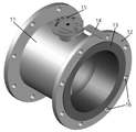
図1は、フッ酸ガス用平衡排気バルブの全体的な形状を示す。 FIG. 1 shows the overall shape of a balanced exhaust valve for hydrofluoric acid gas.
図2は、本発明の主な構成の断面を示したものである。 FIG. 2 shows a cross section of the main configuration of the present invention.
図3は、スイッチング部材に形成された長方形の締結具及び締結溝をより容易に見ることができるよう図示したものである。 FIG. 3 is an illustration so that the rectangular fasteners and fastening grooves formed in the switching member can be more easily seen.
図1で、フッ酸ガス用平衡排気バルブボディの外側は、ステンレス鋼(12)であり、バルブボディの内側は、ポリエチレン(13)の材質で構成されている。 In FIG. 1, the outside of the balanced exhaust valve body for hydrofluoric acid gas is made of stainless steel (12), and the inside of the valve body is made of polyethylene (13).
図2に、スイッチング部材は、流れるフッ酸ガスの遮断性を高めるために球の中心を基準に左右に所定の厚さに切断された形状で設計・製作され、所定の厚さに形成された球表面の形状に合わせて球の表面形状で締結溝がバルブボディの内側に形成されている。 As shown in FIG. 2, the switching member is designed and manufactured in a shape cut to a predetermined thickness on the left and right sides of the center of the sphere in order to improve the blocking performance of the flowing hydrofluoric acid gas, and is formed to a predetermined thickness. A fastening groove is formed inside the valve body with a spherical surface shape to match the shape of the spherical surface.
スイッチング部材は、フッ酸ガスが注入されるバルブボディの内側の直径が大きい方へ挿入されて強制嵌めで締結されるように構成されている。 The switching member is configured to be inserted into the larger diameter side of the inner side of the valve body into which the hydrofluoric acid gas is injected and to be fastened by force fitting.
本発明の明細書において、「バルブ」は、短縮されたものであり、「フッ酸ガス用平衡排気バルブ」と同一の意味に混用使用し、「左側」、「右側」、「上」及び「下」は、図面を基準に記載したものであり、多様な変形が可能である。 In the specification of the present invention, the term "valve" is abbreviated and is used interchangeably with the same meaning as "balanced exhaust valve for hydrofluoric acid gas", and "left side", "right side", "upper" and " "Lower" is described based on the drawings, and various modifications are possible.
本発明の明細書において、「ガス」は、短縮されたものであり、「フッ酸ガス」と同一の意味に混用使用し、図面符号は、理解を容易にするために同一の構成に対して、各々の図面に異なる符号を付与した。 In the specification of the present invention, the term "gas" is abbreviated and is used interchangeably with the same meaning as "hydrofluoric acid gas". , each drawing is given a different number.
本発明によるフッ酸ガス用平衡排気バルブと連結されるフッ酸ガスの配管の場合に、外部は、ステンレス鋼で構成され、内部は、ポリエチレンで製作され、フッ酸ガスの配管の場合にはフッ酸ガスに強いポリエチレンがコーティング又は挿入された配管の内側に、スイッチング部材が位置するように設計・製作されている。 In the case of the hydrofluoric acid gas pipe connected to the hydrofluoric acid gas balanced exhaust valve according to the present invention, the outside is made of stainless steel and the inside is made of polyethylene. It is designed and manufactured so that the switching member is positioned inside the piping that is coated or inserted with polyethylene that is strong against acid gas.
スイッチング部材の材質は、フッ酸ガスに対し耐久性に優れて強固なステンレス鋼で成形・製作することが好ましい。 As for the material of the switching member, it is preferable that the switching member is molded and manufactured from stainless steel, which has excellent durability against hydrofluoric acid gas and is strong.
スイッチング部材も、またその強固性をより高めるために、内部を金属材質のステンレス鋼の構造物に製作した後、外部をポリエチレンでコーティング又は成形・製作することもできる。 The switching member may also be manufactured by making the inside of a metallic stainless steel structure and then coating or molding the outside with polyethylene in order to further increase the strength of the switching member.
つまり、フッ酸ガス用平衡排気バルブにおいてフッ酸ガスと接触可能な部分は、すべて所定の厚さにポリエチレン材質でコーティングして、バルブの耐久性を高めることが好ましく、本発明はこれを考慮して設計・製作されている。 In other words, it is preferable that all parts of the balanced exhaust valve for hydrofluoric acid gas that can come into contact with hydrofluoric acid gas are coated with a polyethylene material to a predetermined thickness to increase the durability of the valve, and the present invention takes this into consideration. designed and manufactured by
スイッチング部材のエッジ(表面)は、球の中心を基準に左右に設定された幅(よこの長さ)ほど形成されるものの、スイッチング部材を基準にガスが注入される注入口側の配管の内部直径が大きく、ガスが排出される排出口側の配管の内部直径が多少小さくなるように形成されている。 The edge (surface) of the switching member is formed with a width (horizontal length) set to the left and right with respect to the center of the sphere, but the inside of the pipe on the side of the inlet where gas is injected with reference to the switching member It is formed so that the inner diameter of the piping on the side of the discharge port, which has a large diameter and from which gas is discharged, is slightly reduced.
その直径の差は、図2及び図3に示すようにそんなに大きくはないが、その役割又は機能は非常に重要である。 Its diameter difference is not so great as shown in FIGS. 2 and 3, but its role or function is very important.
注入口と排出口との直径の差は、図2及び図3に図示されたものよりもっと大きく、又はもっと小さく形成することもできる。 The diameter difference between the inlet and the outlet can be made larger or smaller than that shown in FIGS.
図2に示された図面に基づいてバルブを形成するバルブボディでは、スイッチング部材が挿入・締結される部分を基準に、バルブボディの左側の内部直径が大きく、右側の内部直径は小さいことが分かる。境界面にスイッチング部材の締結溝(28)が形成されている。 In the valve body forming the valve based on the drawing shown in FIG. 2, it can be seen that the internal diameter of the left side of the valve body is large and the internal diameter of the right side is small based on the part where the switching member is inserted and fastened. . A fastening groove (28) for the switching member is formed in the interface.
締結溝(28)の表面と、締結溝(28)に接するスイッチング部材の外側表面とを球の表面と同一の形状に設計・製作するため、密閉のときに互いに接する面積を広く形成することができ、接触面がスムーズな円(球の形状)で形成されて、回転が容易になり耐久性を向上させることができる。 Since the surface of the fastening groove (28) and the outer surface of the switching member in contact with the fastening groove (28) are designed and manufactured to have the same shape as the surface of the sphere, it is possible to form a wide contact area when sealing. The contact surface is formed as a smooth circle (spherical shape), which facilitates rotation and improves durability.
スイッチング部材(23)と、スイッチング部材が互いに締結される締結溝(28)とは、ガス遮断のときに密閉力を高めるために設計・製作するときの公差をゼロ(Zero)又はほぼゼロに近接するように製作することが好ましい。 The switching member (23) and the fastening groove (28) in which the switching member is fastened to each other are designed and manufactured with zero or nearly zero tolerance in order to increase the sealing force when the gas is shut off. It is preferable to manufacture
スイッチング部材(23)は、内部直径が大きく形成されたフッ酸ガスの注入口に強制嵌めで挿入・締結されるように構成されている。 The switching member (23) is configured to be inserted and fastened by force fitting into a hydrofluoric acid gas inlet having a large inner diameter.
本発明の1つの実施形態は、フッ酸ガスが、直径の大きいフッ酸ガスの注入口から直径の小さい配管側へ流れるように設計・製作されて、スイッチング部材(23)がガスの流れを遮断するとき、ガスが押す力によってスイッチング部材(23)が締結溝にさらに強く密着されて強固にガスを遮断することができる。 In one embodiment of the present invention, hydrofluoric acid gas is designed and manufactured to flow from a large diameter hydrofluoric acid gas inlet to a small diameter piping side, and the switching member (23) cuts off the gas flow. At this time, the switching member (23) is more firmly attached to the engagement groove by the force of the gas, so that the gas can be blocked.
図2で、バルブを形成するバルブボディ(21)の左側から右へフッ酸ガスが流れるように構成されている。図2の図面符号29は、ガスの流れる方向を示したものである。
In FIG. 2, the hydrofluoric acid gas is configured to flow from the left side to the right side of the valve body (21) forming the valve.
なお、フッ酸ガスが注入されるバルブボディ(21)の内側の直径が大きく、排出される内側面の直径が小さいことから、ベルヌーイ定理によって、直径の大きい配管から直径の小さい配管へフッ酸ガスが移動するときの移動速度が速くなり、スイッチング部材(23)を、直径の小さい配管側に、より強い圧力(力)で押して密着させる役割をする。 In addition, since the inner diameter of the valve body (21) into which hydrofluoric acid gas is injected is large and the diameter of the inner surface from which hydrofluoric acid gas is discharged is small, according to Bernoulli's theorem, hydrofluoric acid gas flows from a pipe with a large diameter to a pipe with a small diameter. moves faster, and the switching member (23) is pushed to the side of the pipe with a smaller diameter with a stronger pressure (force) to bring it into close contact.
本発明のもう1つの実施形態は、スイッチング部材(23)の外側及び締結溝(28)の内側を球の表面形状に形成するため、スイッチング部材(23)の回転のときに、回転をスムーズにしてバルブの耐久性を高める有利な効果を有する。 Another embodiment of the present invention is that the outer side of the switching member (23) and the inner side of the fastening groove (28) are formed into a spherical surface shape, so that when the switching member (23) rotates, the rotation is smooth. has the advantageous effect of increasing the durability of the valve.
互いに接触する面を球の表面形状に設計・製作するため、接触の表面積を平面に形成するよりは、多少広く形成することから密閉性を向上させる相乗効果がある。スイッチング部材の幅及び締結溝の幅は、互いに同一に又は異なるように形成でき、接触位置に応じて、各々互いに異なるように形成することもできる。 Since the surfaces that come into contact with each other are designed and manufactured to have a spherical surface shape, the surface area of contact is formed to be slightly wider than that of a flat surface, which has the synergistic effect of improving sealing performance. The width of the switching member and the width of the fastening groove may be the same or different, and may be different depending on the contact position.
従来のフッ酸ガスの流れを完全に遮断するために使用したバルブ構造は、密閉力が弱いため、2重に遮断する構成を使用したものの、本発明による排気バルブを使用する場合には、密閉性に優れて1つのバルブを設置できる有利な効果がある。
がある。
Since the conventional valve structure used to completely block the flow of hydrofluoric acid gas has a weak sealing force, a double blocking structure was used. There is an advantage that one valve can be installed with excellent efficiency.
There is
前記スイッチング部材(23)が締結される締結溝(28)に基づいて、フッ酸ガスが注入される側のバルブボディの内側及び排出口側の内側の直径が互いに同一に形成されることもあるが、この場合には、強制嵌めにより締結されたスイッチング部材(23)が圧力によって排出口側に離脱することもでき、締結溝(28)とスイッチング部材(23)との接触面積が小さいことから密閉効率が落ちる欠点がある。
Based on the
前記スイッチング部材(23)の中央には、スイッチング部材(23)を回転させるための回転用部材を挿入・締結するための締結具(33、締結用孔)が形成されている。 A fastener (33, fastening hole) for inserting and fastening a rotating member for rotating the switching member (23) is formed in the center of the switching member (23).
回転用部材(39)は、スイッチング部材(23)に形成された締結具(孔、図3の33)に挿入・締結されて配管を介して流れるフッ酸ガスの供給を遮断するか、又はフッ酸ガスの供給量を制御するために、所定の角度に回転させ得るように設計・製作されている。 The rotating member (39) is inserted and fastened into a fastener (hole, 33 in FIG. 3) formed in the switching member (23) to cut off the supply of hydrofluoric acid gas flowing through the pipe or It is designed and manufactured so that it can be rotated at a predetermined angle in order to control the supply of acid gas.
回転用部材(39)は、スイッチング部材(32)を所定の角度に回転させる機能と、スイッチング部材(32)をバルブボディ(31)の締結溝(38)に位置させる役割とを担う。 The rotating member (39) has the function of rotating the switching member (32) to a predetermined angle and the role of positioning the switching member (32) in the engagement groove (38) of the valve body (31).
回転用部材(39)は、スイッチング部材(32)に形成された締結具(33、締結用孔)に挿入・締結され、締結具(33)の形状に合わせて製作して挿入されるように構成されている。 The rotating member (39) is inserted and fastened into the fastener (33, fastening hole) formed in the switching member (32), and is manufactured according to the shape of the fastener (33) so as to be inserted. It is configured.
スイッチング部材(32)の回転角度は、フッ酸ガスの供給量をユーザーが制御できるように、複数の段階からなって回転角度を調節できる。通常のステッピングモータ等を利用して回転角度を制御することもできる。 The rotation angle of the switching member (32) can be adjusted in multiple steps so that the user can control the supply amount of hydrofluoric acid gas. The rotation angle can also be controlled using a normal stepping motor or the like.
スイッチング部材(32)がフッ酸ガスの流れ方向に垂直であるとき(0度)は、ガスの流れを遮断するのであり、流れ方向に平行(90度)であるときはフッ酸ガスが最も多く通過できる位置にあるのである。 When the switching member (32) is perpendicular to the direction of flow of hydrofluoric acid gas (0 degrees), it blocks the flow of gas. It is in a position where it can pass.
スイッチング部材(32)で、回転用部材(39)が挿入・締結される部分は、回転用部材が挿入さ締結される締結具(33、孔)が形成されるため、多少厚く形成し、回転用部材(39)が挿入・締結される部分を基準にエッジに行くほど薄く幅を形成することが好ましい。 The part of the switching member (32) into which the rotating member (39) is inserted and fastened is formed with a fastener (33, hole) into which the rotating member is inserted and fastened. It is preferable to form a width that becomes thinner toward the edge based on the portion where the member (39) is inserted and fastened.
図2に示すように、回転用部材(39)が挿入・締結される部分を基準にエッジに行くほど薄く幅を形成する場合には、フッ酸ガスの抵抗を最小限に抑えて、ガスの流れをよりスムーズに形成できる利点があり、耐久性を増加させる有利な効果がある。 As shown in FIG. 2, when forming the width thinner toward the edge based on the portion where the rotating member (39) is inserted and fastened, the resistance of the hydrofluoric acid gas is minimized and the gas flow is reduced. This has the advantage that the flow can be formed more smoothly, which has the beneficial effect of increasing durability.
スイッチング部材をバルブボディ(31)の締結溝に強固に設置するために、スイッチング部材に形成された締結具に挿入・締結される回転用部材は、バルブボディの内部に形成された締結溝(28)が位置する上部及び下部に、各々形成された上部締結具(35)及び下部挿入溝(36)へ、挿入・結合されるように構成されている。 In order to firmly install the switching member in the fastening groove of the valve body (31), the rotating member to be inserted and fastened to the fastener formed on the switching member is inserted into the fastening groove (28) formed inside the valve body. ) are inserted into and coupled to upper fasteners (35) and lower insertion grooves (36) respectively formed in the upper and lower parts where the .
上部締結具(35)及び下部挿入溝(36)は、回転が容易になるように円形に形成することが好ましく、下部挿入溝(36)はバルブボディ(31)を貫通しない。 The upper fastener (35) and the lower insertion groove (36) are preferably circular for easy rotation, and the lower insertion groove (36) does not pass through the valve body (31).
締結具に挿入・締結された回転用部材は、容易に離脱しないようにボルトなどの固定手段又は締結手段を使用して固定することが好ましい。 It is preferable that the rotating member inserted and fastened to the fastener is fixed using a fixing means such as a bolt or a fastening means so as not to be easily detached.
なお、このような挿入・締結の構造は、バルブの組立製作を容易にし、メンテナンスを容易にする。 In addition, such an insertion/fastening structure facilitates assembly and manufacture of the valve and facilitates maintenance.
もちろん、スイッチング部材の幅を同一の厚さに形成することもでき、多様な形状への変形が可能である。 Of course, the width of the switching member can be formed with the same thickness, and various shapes can be formed.
回転用部材(39)は、フッ酸ガスに対し耐久性に優れたポリエチレン又はこれと均等な材料を使用して製作できる。 The rotating member (39) can be made of polyethylene or an equivalent material that is highly resistant to hydrofluoric acid gas.
回転用部材(39)は、上下又は左右にスイッチング部材と締結されてバルブボディに固定されるように設計・製作されており、回転用部材は、三角形、四角形又は多角形の棒形状に形成することが好ましい。 The rotating member (39) is designed and manufactured to be fastened to the valve body by being fastened to the switching member vertically or horizontally, and the rotating member is formed in a triangular, quadrangular or polygonal rod shape. is preferred.
スイッチング部材(32)に形成された締結具(33)は、前記回転用部材の形状に合わせて長方形又は多角形の棒形状に形成して挿入・締結する場合に、摩擦力を増加させてスリップを防止することができる。 The fastener (33) formed on the switching member (32) is formed into a rectangular or polygonal rod shape according to the shape of the rotating member, and when it is inserted and fastened, the frictional force is increased to prevent slippage. can be prevented.
図3において、回転用部材(39)を成形・製作する際、挿入・締結が容易でありながら、各々の場所で所望の機能を正確に行うことができるように四角形及び円形で形成されている。
In FIG. 3, when the rotating
具体的に察すると、図3の37に挿入・結合される図3の40、及び図3の36に締結される図3の42は、回転用部材(39)を調節つまみ(14)で回転させるときに、回転を容易にする役割をする。 Specifically, 40 in FIG. 3 inserted and coupled to 37 in FIG. 3 and 42 in FIG. 3 fastened to 36 in FIG. It serves to facilitate rotation when turning.
一方、スイッチング部材(32)と締結される部分は、回転用部材(39)の図3の41に該当し、図面上の形状は、長方形の締結具(33)と、回転用部材の長方形の棒部分(41)とに締結されて調節つまみ(14)の回転に正確に反応して回転するように構成されている。 On the other hand, the part fastened with the switching member (32) corresponds to 41 in FIG. It is fastened to the rod portion (41) and configured to rotate in precise response to the rotation of the adjustment knob (14).
回転用部材(39)の上部(43)は、長方形に形成され、調節つまみに形成された長方形の挿入溝又は締結具と結合・固定されて調節つまみの回転に正確に反応して回転するように構成されている。 The upper part (43) of the rotating member (39) is formed in a rectangular shape and is coupled and fixed with a rectangular insertion groove or a fastener formed in the adjusting knob so that it can rotate in response to the rotation of the adjusting knob. is configured to
バルブボディの左側及び右側には、フッ酸ガス供給管にボルトなどの締結手段で締結することができるように、複数の締結孔(16)が形成されている。 A plurality of fastening holes (16) are formed on the left and right sides of the valve body so that the hydrofluoric acid gas supply pipe can be fastened with fastening means such as bolts.
前述した内容に基づいて、本発明の技術的構成をまとめて察することにする。 Based on the above contents, the technical structure of the present invention is summarized.
本発明によるフッ酸ガス用平衡排気バルブは、フッ酸ガスを遮断又は供給するためにバルブを形成するためのバルブボディと、バルブボディの内部に設置されてフッ酸ガスの供給を遮断又は制御するためのスイッチング部材と、を備える。 A balanced exhaust valve for hydrofluoric acid gas according to the present invention includes a valve body for forming a valve for blocking or supplying hydrofluoric acid gas, and a valve body installed inside the valve body to block or control the supply of hydrofluoric acid gas. a switching member for.
なお、本発明によるフッ酸ガス用平衡排気バルブのボディの外部は、ステンレス鋼で構成され、バルブの内側は、フッ酸ガスに対し耐久性に優れたポリエチルレンの材質でコーティング又は挿入・結合されている。 The exterior of the body of the balanced exhaust valve for hydrofluoric acid gas according to the present invention is made of stainless steel, and the inside of the valve is coated or inserted/bonded with polyethylen, which has excellent durability against hydrofluoric acid gas. there is
本発明のもう1つの実施形態は、前記スイッチング部材の表面が球の表面と同一の曲面を有する形状に形成され、スイッチング部材が締結されるバルブボディの内
側は、前記スイッチング部材の表面形状に合わせて球の表面と同一の曲面を有する形状に締結溝が形成されている。
In another embodiment of the present invention, the surface of the switching member is formed to have the same curved shape as the surface of a sphere, and the inner side of the valve body to which the switching member is fastened conforms to the surface shape of the switching member. A fastening groove is formed in a shape having the same curved surface as the surface of the sphere.
本発明のもう1つの実施形態は、スイッチング部材と締結溝の形状を球の表面形状に形成して接触面積を多少広く形成しながら、フッ酸ガス遮断の時に密閉力を高め、フッ酸ガスの流れに強固に耐えられるように、スイッチング部材を基準にフッ酸ガスの排出口側のボディの内部直径を、注入口側のボディの内部直径よりも小さく形成されている。 In another embodiment of the present invention, the shape of the switching member and the fastening groove are formed in the shape of a sphere to widen the contact area to increase the sealing force when shutting off the hydrofluoric acid gas. The internal diameter of the body on the side of the hydrofluoric acid gas discharge port is formed to be smaller than the internal diameter of the body on the side of the injection port with respect to the switching member so as to strongly withstand the flow.
本発明のもう1つの実施形態は、スイッチング部材の中央には、スイッチング部材を所定の角度に回転させてフッ酸ガスの供給を遮断するか、又は供給量を制御することができるように回転用部材が挿入・締結され得る締結具が形成されている。 In another embodiment of the present invention, a rotary valve is provided at the center of the switching member so that the switching member can be rotated at a predetermined angle to cut off the supply of hydrofluoric acid gas or to control the amount of supply. A fastener is formed into which the member can be inserted and fastened.
本発明のもう1つの実施形態として、スイッチング部材は、締結具が形成される中央の幅を厚く形成し、締結具から離れるほど厚さを薄く形成してフッ酸ガスがスイッチング部材によって、流れを妨げられることを最小限にするように形成されている。 As another embodiment of the present invention, the switching member is formed to have a large width in the center where the fastener is formed, and is formed to have a thinner thickness as the distance from the fastener is increased, so that the hydrofluoric acid gas can flow through the switching member. Constructed to minimize obstruction.
本発明のもう1つの実施形態は、スイッチング部材をバルブボディの内部の締結溝にしっかりと設置するためにスイッチング部材の締結具に挿入・締結される回転用部材が、バルブボディの締結溝が位置する上部及び下部に、各々形成された上部締結具及び下部挿入溝に結合されるように構成されている。 Another embodiment of the present invention is that the rotating member inserted and fastened to the fastener of the switching member is located at the fastening groove of the valve body in order to securely install the switching member in the fastening groove inside the valve body. It is configured to be combined with upper fasteners and lower insertion grooves respectively formed in the upper and lower parts of the housing.
本発明のもう1つの実施形態は、スイッチング部材を基準にフッ酸ガスの注入口側のボディの内部直径が、排出口側のボディの内部直径よりも大きく形成される場合に、ベルヌーイ定理によってスイッチング部材を基準にフッ酸ガスの流れが速くなって密閉力が増加されるように構成されている。 According to another embodiment of the present invention, when the internal diameter of the body on the inlet side of the hydrofluoric acid gas is formed larger than the internal diameter of the body on the outlet side with respect to the switching member, switching is performed according to Bernoulli's theorem. Based on the members, the flow of hydrofluoric acid gas is accelerated to increase the sealing force.
本発明のもう1つの実施形態は、締結具が、スイッチング部材に形成された締結具との結合のときに、空回りしないように四角形を含む多角形に形成し、フッ酸ガスの流れる量を制御するために、回転角度を制御するように構成されている。 In another embodiment of the present invention, the fastener is formed in a polygonal shape including a quadrangle so that it does not idle when it is coupled with the fastener formed on the switching member, and the amount of flow of hydrofluoric acid gas is controlled. In order to do so, it is configured to control the rotation angle.
本発明は、外側部分がステンレス鋼であり、ステンレス鋼管の内側には、フッ酸ガスに対し耐久性に優れたPE材質で所定の厚さにコーティング、又は管が挿入・結合された状態で、バルブの耐久性に優れており、スイッチング部材の外側表面と、スイッチング部材に接して締結される締結溝と、を球の表面と同一に設計・製作するものの、フッ酸ガスの注入口の直径を排出口の直径よりも多少小さく形成し、フッ酸ガスの流れをより完全に遮断できるように設計・製作されたフッ酸ガス用平衡排気バルブを提供することができるため、産業上の利用可能性が非常に高い。 In the present invention, the outer part is made of stainless steel, and the inside of the stainless steel pipe is coated with a PE material having excellent durability against hydrofluoric acid gas to a predetermined thickness, or the pipe is inserted and connected, The valve has excellent durability, and although the outer surface of the switching member and the fastening groove that is fastened in contact with the switching member are designed and manufactured to be the same as the surface of the sphere, the diameter of the hydrofluoric acid gas injection port is changed. Industrial applicability because it is possible to provide a balanced exhaust valve for hydrofluoric acid gas that is designed and manufactured to block the flow of hydrofluoric acid gas more completely by forming it slightly smaller than the diameter of the discharge port. is very high.
11 バルブボディ
12 ステンレス鋼
13 ポリエチレン(PE)
14 調節つまみ
15 調節角度
16 締結孔(フランジ、フッ酸ガス配管)
21 バルブボディ
22 スイッチング部材の表面
23 スイッチング部材
24 配管の内部直径が大きい部分
25 配管の内部直径が小さい部分
26 回転用部材の上部締結具
27 回転用部材の下部締結溝
28 締結溝(スイッチング部材)
29 フッ酸ガスの流れ方向
31 バルブボディ
32 スイッチング部材
33 回転用部材締結具
34 配管の内部直径が大きい部分
35 配管の内部直径が小さい部分
36 回転用部材の上部締結具
37 回転用部材の下部挿入溝
38 締結溝(スイッチング部材)
39 回転用部材
40 図面符号37の下部挿入溝と締結される部分
41 スイッチング部材(32)と締結される部分
42 図面符号36の締結具と締結される部分
43 図1の14(調節つまみ)と締結される部分
44 ステンレス鋼の材質
45 ポリエチレンの材質
11
14
21
29 Flow direction of
39 Rotating
Claims (3)
Applications Claiming Priority (2)
| Application Number | Priority Date | Filing Date | Title |
|---|---|---|---|
| KR1020190128156A KR102243387B1 (en) | 2019-10-16 | 2019-10-16 | Balanced Exhaust Valve for Hydrofluoric Gas |
| KR10-2019-0128156 | 2019-10-16 |
Publications (2)
| Publication Number | Publication Date |
|---|---|
| JP2021063589A JP2021063589A (en) | 2021-04-22 |
| JP7121069B2 true JP7121069B2 (en) | 2022-08-17 |
Family
ID=75488005
Family Applications (1)
| Application Number | Title | Priority Date | Filing Date |
|---|---|---|---|
| JP2020084852A Active JP7121069B2 (en) | 2019-10-16 | 2020-05-14 | Balanced exhaust valve for hydrofluoric acid gas |
Country Status (2)
| Country | Link |
|---|---|
| JP (1) | JP7121069B2 (en) |
| KR (1) | KR102243387B1 (en) |
Families Citing this family (1)
| Publication number | Priority date | Publication date | Assignee | Title |
|---|---|---|---|---|
| TR2021016514A2 (en) * | 2021-10-22 | 2021-11-22 | Dikkan Gemi Ve Enduestriyel Vana Sanayi Ticaret Anonim Sirketi | DUAL ECCENTRIC BUTTERFLY VALVE WITH NEW BODY STRUCTURE |
Citations (4)
| Publication number | Priority date | Publication date | Assignee | Title |
|---|---|---|---|---|
| JP2008210982A (en) | 2007-02-26 | 2008-09-11 | Tokyo Electron Ltd | Gas supply system and gas supply integrated unit for semiconductor manufacturing apparatus |
| JP2011047290A (en) | 2009-08-25 | 2011-03-10 | Honda Motor Co Ltd | Egr valve |
| KR101320553B1 (en) | 2013-01-22 | 2013-10-28 | (주)다리온 | Damper unit for exhaust gas pipe system |
| JP2018013165A (en) | 2016-07-20 | 2018-01-25 | 旭有機材株式会社 | Butterfly valve |
Family Cites Families (3)
| Publication number | Priority date | Publication date | Assignee | Title |
|---|---|---|---|---|
| JPH0554874U (en) * | 1991-12-26 | 1993-07-23 | 村田機械株式会社 | Resin valve body for butterfly valve |
| KR20040095902A (en) | 2003-04-29 | 2004-11-16 | 아남반도체 주식회사 | Auto fill device of hydro fluoric liquid and its method |
| KR101587441B1 (en) | 2014-08-13 | 2016-01-21 | 보성정공 주식회사 | Flange for adhesion of stainless pipe and resin pipe and its manufacturing method |
-
2019
- 2019-10-16 KR KR1020190128156A patent/KR102243387B1/en not_active Expired - Fee Related
-
2020
- 2020-05-14 JP JP2020084852A patent/JP7121069B2/en active Active
Patent Citations (4)
| Publication number | Priority date | Publication date | Assignee | Title |
|---|---|---|---|---|
| JP2008210982A (en) | 2007-02-26 | 2008-09-11 | Tokyo Electron Ltd | Gas supply system and gas supply integrated unit for semiconductor manufacturing apparatus |
| JP2011047290A (en) | 2009-08-25 | 2011-03-10 | Honda Motor Co Ltd | Egr valve |
| KR101320553B1 (en) | 2013-01-22 | 2013-10-28 | (주)다리온 | Damper unit for exhaust gas pipe system |
| JP2018013165A (en) | 2016-07-20 | 2018-01-25 | 旭有機材株式会社 | Butterfly valve |
Also Published As
| Publication number | Publication date |
|---|---|
| JP2021063589A (en) | 2021-04-22 |
| KR102243387B1 (en) | 2021-04-22 |
Similar Documents
| Publication | Publication Date | Title |
|---|---|---|
| EP2066934B1 (en) | Metal seal with flexible insert | |
| CN101889160B (en) | Butterfly valve with a rigid seal | |
| CN107013698B (en) | Valve assembly | |
| JP6752043B2 (en) | Check valve | |
| JP7121069B2 (en) | Balanced exhaust valve for hydrofluoric acid gas | |
| KR20140028120A (en) | Valve device for controlling an exhaust gas flow of an internal combustion engine | |
| TWI794389B (en) | butterfly valve | |
| WO2016099693A1 (en) | Valve body and seat with tongue and groove connection | |
| US11028943B2 (en) | Control butterfly valve | |
| US8348236B2 (en) | Butterfly valve with a rigid seal | |
| KR20110095767A (en) | Double Ball Valve for Flow Control | |
| JPWO2011128974A1 (en) | Butterfly valve body | |
| KR100609739B1 (en) | Butterfly valve disk | |
| JP7121068B2 (en) | Balanced exhaust valve for corrosive, acid and alkaline gases | |
| EP3315836A1 (en) | Valve assembly with anti-extrusion valve seat | |
| US11698148B1 (en) | Rotary ball valves with noise attenuators | |
| KR102661554B1 (en) | Plastic butterfly valve | |
| US20180128215A1 (en) | GAS RECIRCULATION VALVE FROM - 40ºC TO 700ºC | |
| JP2975549B2 (en) | Three-way butterfly valve | |
| RU190361U1 (en) | SPINDLE PIPELINE ARMATURE | |
| CN102439337A (en) | Valves with Offset Orifices | |
| KR20050014360A (en) | Flow control valve | |
| JP2984543B2 (en) | Three-way butterfly valve | |
| KR20180064177A (en) | Rotary Type Glove Valve |
Legal Events
| Date | Code | Title | Description |
|---|---|---|---|
| A621 | Written request for application examination |
Free format text: JAPANESE INTERMEDIATE CODE: A621 Effective date: 20200518 |
|
| A131 | Notification of reasons for refusal |
Free format text: JAPANESE INTERMEDIATE CODE: A131 Effective date: 20210706 |
|
| A521 | Request for written amendment filed |
Free format text: JAPANESE INTERMEDIATE CODE: A523 Effective date: 20211005 |
|
| A131 | Notification of reasons for refusal |
Free format text: JAPANESE INTERMEDIATE CODE: A131 Effective date: 20220118 |
|
| A601 | Written request for extension of time |
Free format text: JAPANESE INTERMEDIATE CODE: A601 Effective date: 20220418 |
|
| A521 | Request for written amendment filed |
Free format text: JAPANESE INTERMEDIATE CODE: A523 Effective date: 20220615 |
|
| TRDD | Decision of grant or rejection written | ||
| A01 | Written decision to grant a patent or to grant a registration (utility model) |
Free format text: JAPANESE INTERMEDIATE CODE: A01 Effective date: 20220726 |
|
| A61 | First payment of annual fees (during grant procedure) |
Free format text: JAPANESE INTERMEDIATE CODE: A61 Effective date: 20220804 |
|
| R150 | Certificate of patent or registration of utility model |
Ref document number: 7121069 Country of ref document: JP Free format text: JAPANESE INTERMEDIATE CODE: R150 |