JP7120420B2 - game machine - Google Patents
game machine Download PDFInfo
- Publication number
- JP7120420B2 JP7120420B2 JP2021150678A JP2021150678A JP7120420B2 JP 7120420 B2 JP7120420 B2 JP 7120420B2 JP 2021150678 A JP2021150678 A JP 2021150678A JP 2021150678 A JP2021150678 A JP 2021150678A JP 7120420 B2 JP7120420 B2 JP 7120420B2
- Authority
- JP
- Japan
- Prior art keywords
- display
- image data
- data
- effect
- processing
- Prior art date
- Legal status (The legal status is an assumption and is not a legal conclusion. Google has not performed a legal analysis and makes no representation as to the accuracy of the status listed.)
- Active
Links
Images


Landscapes
- Display Devices Of Pinball Game Machines (AREA)
Description
本発明は、遊技機に関するものである。 The present invention relates to gaming machines.
遊技機の一種として、パチンコ遊技機やスロットマシン等が知られている。これらの遊技機は、CPUが実装されているとともに制御プログラムが記憶されたメモリ等の素子が実装された制御手段を備えており、その制御手段において演算処理が実行されることを通じて遊技を行わせることを可能とするための制御が行われている。なお、CPUやメモリが個別に制御手段に実装されているのではなく、それらが集積化された状態で制御手段に実装された構成も知られている(例えば特許文献1参照)。 Pachinko game machines, slot machines, and the like are known as types of game machines. These gaming machines are provided with control means in which a CPU and elements such as a memory storing a control program are mounted. Controls are in place to make this possible. Note that there is also known a configuration in which the CPU and memory are not individually mounted in the control means, but are mounted in the control means in an integrated state (see, for example, Patent Document 1).
ここで、上記例示等のような遊技機においては、制御手段における演算処理を好適に実行することが可能な構成が求められており、この点について未だ改良の余地がある。 Here, in the game machines such as those exemplified above, there is a demand for a configuration that enables the control means to suitably execute arithmetic processing, and there is still room for improvement in this respect.
本発明は、上記例示した事情等に鑑みてなされたものであり、制御手段における演算処理を好適に実行することが可能な遊技機を提供することを目的とするものである。 SUMMARY OF THE INVENTION It is an object of the present invention to provide a game machine capable of suitably executing arithmetic processing in a control means.
上記課題を解決すべく請求項1記載の発明は、開始契機が発生した場合に演算用情報を利用して演算処理を開始する演算実行手段と、
前記演算処理の演算結果を利用して特定処理を実行する結果利用手段と、
を備え、
前記演算実行手段は、所定の実行回における前記演算処理の途中で終了条件が成立して当該演算処理を途中で終了させた場合、当該所定の実行回に対して次の実行回において、前記所定の実行回にて終了した途中の内容から前記演算処理を再開する再実行手段を備え、
前記結果利用手段は、前記所定の実行回において前記演算処理の途中で前記終了条件が成立して当該演算処理を途中で終了させた場合、当該所定の実行回よりも前の実行回における前記演算処理の演算結果を利用して前記特定処理を実行する構成であり、
前記演算実行手段を有する特定制御手段は、前記再実行手段による前記演算処理の再実行の設定が行われることとなる場合、再実行対応情報を送信する手段を備えていることを特徴とする。
In order to solve the above-mentioned problems, the invention according to
a result utilization means for executing a specific process using a calculation result of the calculation process;
with
When a termination condition is satisfied in the middle of the arithmetic processing in a predetermined execution time and the arithmetic processing is terminated in the middle, the arithmetic execution means performs the predetermined comprising a re-executing means for resuming the arithmetic processing from the content in the middle of the execution of
When the end condition is satisfied in the middle of the arithmetic processing in the predetermined execution time and the arithmetic processing is terminated in the middle, the result utilization means performs the arithmetic operation in the execution time before the predetermined execution time. A configuration for executing the specific process using the calculation result of the process,
The specific control means having the arithmetic execution means is characterized by comprising means for transmitting re-execution correspondence information when re-execution of the arithmetic processing by the re-execution means is set.
本発明によれば、制御手段における演算処理を好適に実行することが可能となる。 According to the present invention, it is possible to suitably execute arithmetic processing in the control means.
<第1の実施形態>
以下、遊技機の一種であるパチンコ遊技機(以下、「パチンコ機」という)の第1の実施形態を、図面に基づいて詳細に説明する。図1はパチンコ機10の斜視図である。
<First Embodiment>
A first embodiment of a pachinko game machine (hereinafter referred to as a "pachinko machine"), which is a type of game machine, will be described in detail below with reference to the drawings. FIG. 1 is a perspective view of a
パチンコ機10は、図1に示すように、当該パチンコ機10の外殻を形成する外枠11と、この外枠11に対して前方に回動可能に取り付けられた遊技機本体12とを有する。遊技機本体12は、内枠13と、その内枠13の前方に配置される前扉枠14と、内枠13の後方に配置される裏パックユニット15とを備えている。遊技機本体12のうち内枠13が外枠11に対して回動可能に支持されている。詳細には、正面視で左側を回動基端側とし右側を回動先端側として内枠13が前方へ回動可能とされている。内枠13には、前扉枠14が回動可能に支持されており、正面視で左側を回動基端側とし右側を回動先端側として前方へ回動可能とされている。また、内枠13には、裏パックユニット15が回動可能に支持されており、正面視で左側を回動基端側とし右側を回動先端側として後方へ回動可能とされている。
The
なお、遊技機本体12には、その回動先端部に施錠装置が設けられており、遊技機本体12を外枠11に対して開放不能に施錠状態とする機能を有しているとともに、前扉枠14を内枠13に対して開放不能に施錠状態とする機能を有している。これらの各施錠状態は、パチンコ機10前面にて露出させて設けられたシリンダ錠17に対して解錠キーを用いて解錠操作を行うことにより、それぞれ解除される。
The gaming machine
内枠13には遊技盤24が搭載されている。図2は遊技盤24の正面図である。
A game board 24 is mounted on the
遊技盤24には、遊技領域PAの外縁の一部を区画するようにして内レール部25と外レール部26とが取り付けられており、これら内レール部25と外レール部26とにより誘導手段としての誘導レールが構成されている。内枠13において遊技盤24の下方に取り付けられた遊技球発射機構(図示略)から発射された遊技球は誘導レールにより遊技領域PAの上部に案内されるようになっている。遊技球発射機構は、前扉枠14に設けられた発射操作装置28が手動操作されることにより遊技球の発射動作を行う。
An
遊技盤24には、前後方向に貫通する大小複数の開口部が形成されている。各開口部には一般入賞口31、特電入賞装置32、第1作動口33、第2作動口34、スルーゲート35、可変表示ユニット36、特図ユニット37及び普図ユニット38等がそれぞれ設けられている。
The game board 24 is formed with a plurality of large and small openings penetrating in the front-rear direction. Each opening is provided with a general winning
スルーゲート35への入球が発生したとしても遊技球の払い出しは実行されない。一方、一般入賞口31、特電入賞装置32、第1作動口33及び第2作動口34への入球が発生すると、所定数の遊技球の払い出しが実行される。当該賞球個数について具体的には、第1作動口33への入球が発生した場合又は第2作動口34への入球が発生した場合には、3個の賞球の払い出しが実行され、一般入賞口31への入球が発生した場合には、10個の賞球の払い出しが実行され、特電入賞装置32への入球が発生した場合には、15個の賞球の払い出しが実行される。
Even if a ball enters the through
なお、上記賞球個数は任意であり、例えば、第2作動口34の方が第1作動口33よりも賞球個数が少ない構成としてもよく、第2作動口34の方が第1作動口33よりも賞球個数が多い構成としてもよい。
In addition, the number of prize balls is arbitrary, for example, the
その他に、遊技盤24の最下部にはアウト口24aが設けられており、各種入賞口等に入らなかった遊技球はアウト口24aを通って遊技領域PAから排出される。また、遊技盤24には、遊技球の落下方向を適宜分散、調整等するために多数の釘24bが植設されているとともに、風車等の各種部材が配設されている。
In addition, an out port 24a is provided at the bottom of the game board 24, and game balls that do not enter various winning ports are discharged from the game area PA through the out port 24a. Further, the game board 24 is provided with a large number of
ここで、入球とは所定の開口部を遊技球が通過することを意味し、開口部を通過した後に遊技領域PAから排出される態様だけでなく、開口部を通過した後に遊技領域PAから排出されることなく遊技領域PAの流下を継続する態様も含まれる。但し、以下の説明では、アウト口24aへの遊技球の入球と明確に区別するために、一般入賞口31、特電入賞装置32、第1作動口33、第2作動口34及びスルーゲート35への遊技球の入球を、入賞とも表現する。
Here, the entry ball means that the game ball passes through a predetermined opening. A mode in which the liquid continues to flow down the game area PA without being discharged is also included. However, in the following description, in order to clearly distinguish from the entry of game balls into the out port 24a, the general winning
第1作動口33及び第2作動口34は、作動口装置としてユニット化されて遊技盤24に設置されている。第1作動口33及び第2作動口34は共に上向きに開放されている。また、第1作動口33が上方となるようにして両作動口33,34は鉛直方向に並んでいる。第2作動口34には、左右一対の可動片よりなるガイド片としての普電役物34aが設けられている。普電役物34aの閉鎖状態では遊技球が第2作動口34に入賞できず、普電役物34aが開放状態となることで第2作動口34への入賞が可能となる。
The
第2作動口34よりも遊技球の流下方向の上流側に、スルーゲート35が設けられている。スルーゲート35は縦方向に貫通した図示しない貫通孔を有しており、スルーゲート35に入賞した遊技球は入賞後に遊技領域PAを流下する。これにより、スルーゲート35に入賞した遊技球が第2作動口34へ入賞することが可能となっている。
A through
スルーゲート35への入賞に基づき第2作動口34の普電役物34aが閉鎖状態から開放状態に切り換えられる。具体的には、スルーゲート35への入賞をトリガとして内部抽選が行われるとともに、遊技領域PAにおいて遊技球が通過しない領域である右下の隅部に設けられた普図ユニット38の普図表示部38aにて絵柄の変動表示が行われる。そして、内部抽選の結果が電役開放当選であり当該結果に対応した停止結果が表示されて普図表示部38aの変動表示が終了された場合に普電開放状態へ移行する。普電開放状態では、普電役物34aが所定の態様で開放状態となる。
Based on the winning of the through
なお、普図表示部38aは、複数のセグメント発光部が所定の態様で配列されてなるセグメント表示器により構成されているが、これに限定されることはなく、液晶表示装置、有機EL表示装置、CRT又はドットマトリックス表示器等その他のタイプの表示装置によって構成されていてもよい。また、普図表示部38aにて変動表示される絵柄としては、複数種の文字が変動表示される構成、複数種の記号が変動表示される構成、複数種のキャラクタが変動表示される構成又は複数種の色が切り換え表示される構成などが考えられる。 In addition, the normal figure display unit 38a is composed of a segment display device in which a plurality of segment light emitting units are arranged in a predetermined manner, but is not limited to this, and may be a liquid crystal display device or an organic EL display device. , CRT or other type of display such as a dot matrix display. In addition, as the pattern variably displayed in the normal figure display unit 38a, a configuration in which a plurality of types of characters are variably displayed, a configuration in which a plurality of types of symbols are variably displayed, a configuration in which a plurality of types of characters are variably displayed, or A configuration in which a plurality of types of colors are switched and displayed can be considered.
普図ユニット38において、普図表示部38aに隣接した位置には、普図保留表示部38bが設けられている。遊技球がスルーゲート35に入賞した個数は最大4個まで保留され、普図保留表示部38bの点灯によってその保留個数が表示されるようになっている。
In the
第1作動口33又は第2作動口34への入賞をトリガとして当たり抽選が行われる。そして、当該抽選結果は特図ユニット37及び可変表示ユニット36の図柄表示装置41における表示演出を通じて明示される。
A winning lottery is performed with the winning of the
特図ユニット37について詳細には、特図ユニット37には特図表示部37aが設けられている。特図表示部37aの表示領域は図柄表示装置41の表示面Pよりも狭い。特図表示部37aでは、第1作動口33への入賞又は第2作動口34への入賞をトリガとして当たり抽選が行われることで絵柄の変動表示又は所定の表示が行われる。そして、抽選結果に対応した結果が表示される。なお、特図表示部37aは、複数のセグメント発光部が所定の態様で配列されてなるセグメント表示器により構成されているが、これに限定されることはなく、液晶表示装置、有機EL表示装置、CRT又はドットマトリックス表示器等その他のタイプの表示装置によって構成されていてもよい。また、特図表示部37aにて表示される絵柄としては、複数種の文字が表示される構成、複数種の記号が表示される構成、複数種のキャラクタが表示される構成又は複数種の色が表示される構成などが考えられる。
In detail, the
特図ユニット37において、特図表示部37aに隣接した位置には、特図保留表示部37bが設けられている。遊技球が第1作動口33又は第2作動口34に入賞した個数は最大4個まで保留され、特図保留表示部37bの点灯によってその保留個数が表示されるようになっている。
In the
図柄表示装置41について詳細には、図柄表示装置41は、液晶ディスプレイを備えた液晶表示装置として構成されており、後述する表示制御装置により表示内容が制御される。なお、図柄表示装置41は、液晶表示装置に限定されることはなく、プラズマディスプレイ装置、有機EL表示装置又はCRTといった表示面を有する他の表示装置であってもよく、ドットマトリクス表示器であってもよい。
More specifically, the
図柄表示装置41では、第1作動口33への入賞又は第2作動口34への入賞に基づき特図表示部37aにて絵柄の変動表示又は所定の表示が行われる場合にそれに合わせて図柄の変動表示又は所定の表示が行われる。すなわち、特図表示部37aにおいて変動表示が行われる場合には、それに合わせて図柄表示装置41において変動表示が行われる。そして、例えば、遊技結果が大当たり結果となる遊技回では、図柄表示装置41では予め設定されている有効ライン上に所定の組合せの図柄が停止表示される。
In the
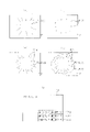
図柄表示装置41の表示内容について、図3及び図4を参照して詳細に説明する。図3は図柄表示装置41にて変動表示される図柄を個々に示す図であり、図4は図柄表示装置41の表示面Pを示す図である。
The display contents of the
図3(a)~(j)に示すように、絵柄の一種である図柄は、「1」~「9」の数字が各々付された9種類の主図柄と、貝形状の絵図柄からなる副図柄とにより構成されている。より詳しくは、タコ等の9種類のキャラクタ図柄に「1」~「9」の数字がそれぞれ付されて主図柄が構成されている。 As shown in FIGS. 3(a) to 3(j), the pattern, which is one type of pattern, consists of 9 types of main patterns to which numbers "1" to "9" are respectively attached, and a shell-shaped pattern. It is composed of a sub pattern. More specifically, nine types of character patterns, such as an octopus, are assigned numerals "1" to "9", respectively, to form the main pattern.
図4(a)に示すように、図柄表示装置41の表示面Pには、複数の表示領域として、上段・中段・下段の3つの図柄列Z1,Z2,Z3が設定されている。各図柄列Z1~Z3は、主図柄と副図柄が所定の順序で配列されて構成されている。詳細には、上図柄列Z1には、「1」~「9」の9種類の主図柄が数字の降順に配列されると共に、各主図柄の間に副図柄が1つずつ配されている。下図柄列Z3には、「1」~「9」の9種類の主図柄が数字の昇順に配列されると共に、各主図柄の間に副図柄が1つずつ配されている。
As shown in FIG. 4A, on the display surface P of the
つまり、上図柄列Z1と下図柄列Z3は18個の図柄により構成されている。これに対し、中図柄列Z2には、数字の昇順に「1」~「9」の9種類の主図柄が配列された上で「9」の主図柄と「1」の主図柄との間に「4」の主図柄が付加的に配列され、これら各主図柄の間に副図柄が1つずつ配されている。つまり、中図柄列Z2に限っては、10個の主図柄が配されて20個の図柄により構成されている。そして、表示面Pでは、これら各図柄列Z1~Z3の図柄が周期性をもって所定の向きにスクロールするように変動表示される。 That is, the upper symbol row Z1 and the lower symbol row Z3 are composed of 18 symbols. On the other hand, in the middle symbol row Z2, nine types of main symbols "1" to "9" are arranged in ascending order of numbers, and between the main symbol "9" and the main symbol "1" A main symbol of "4" is additionally arranged in the upper part, and one sub-symbol is arranged between each of these main symbols. In other words, only the middle pattern row Z2 is composed of 20 symbols with 10 main symbols arranged. Then, on the display surface P, the symbols of each of the symbol rows Z1 to Z3 are variably displayed so as to scroll in a predetermined direction with periodicity.
図4(b)に示すように、表示面Pは、図柄列毎に3個の図柄が停止表示されるようになっており、結果として3×3の計9個の図柄が停止表示されるようになっている。また、表示面Pには、5つの有効ライン、すなわち左ラインL1、中ラインL2、右ラインL3、右下がりラインL4、右上がりラインL5が設定されている。そして、上図柄列Z1→下図柄列Z3→中図柄列Z2の順に変動表示が停止し、いずれかの有効ラインに同一の数字が付された図柄の組合せが形成された状態で全図柄列Z1~Z3の変動表示が終了すれば、後述する通常大当たり結果又は15R確変大当たり結果の発生として大当たり動画が表示されるようになっている。 As shown in FIG. 4(b), on the display surface P, three symbols are stopped for each symbol row, and as a result, a total of nine symbols (3×3) are stopped and displayed. It's like Also, five effective lines are set on the display surface P, that is, a left line L1, a middle line L2, a right line L3, a right-down line L4, and a right-up line L5. Then, the variable display is stopped in the order of upper symbol row Z1→lower symbol row Z3→middle symbol row Z2, and all symbol rows Z1 are formed in a state in which a combination of symbols with the same number is formed on any of the effective lines. When the fluctuation display of ~Z3 is completed, a big win moving image is displayed as a normal big win result or a 15R probability variable big win result, which will be described later.
本パチンコ機10では、奇数番号(1,3,5,7,9)が付された主図柄は「特定図柄」に相当するとともに、偶数番号(2,4,6,8)が付された主図柄は「非特定図柄」に相当する。15R確変大当たり結果が発生する場合には、同一の特定図柄の組合せ又は同一の非特定図柄の組合せが停止表示される。また、通常大当たり結果が発生する場合には、同一の非特定図柄の組合せが停止表示される。また、後述する明示2R確変大当たり結果となる場合には、同一の図柄の組合せとは異なる所定の図柄の組合せが形成された状態で全図柄列Z1~Z3の変動表示が終了し、その後に、明示用動画が表示されるようになっている。
In this
なお、図柄表示装置41における図柄の変動表示の態様は上記のものに限定されることはなく任意であり、図柄列の数、図柄列における図柄の変動表示の方向、各図柄列の図柄数などは適宜変更可能である。また、図柄表示装置41にて変動表示される絵柄は上記のような図柄に限定されることはなく、例えば絵柄として数字のみが変動表示される構成としてもよい。
The
また、いずれかの作動口33,34への入賞に基づいて、特図表示部37a及び図柄表示装置41にて変動表示が開始され、所定の停止結果を表示し上記変動表示が停止されるまでが遊技回の1回に相当する。
Also, based on the winning of any of the
図2の説明に戻り、第1作動口33への入賞又は第2作動口34への入賞に基づく当たり抽選にて大当たり当選となった場合には、特電入賞装置32への入賞が可能となる開閉実行モードへ移行する。特電入賞装置32は、遊技盤24の背面側へと通じる図示しない大入賞口を備えているとともに、当該大入賞口を開閉する開閉扉32aを備えている。開閉扉32aは、閉鎖状態及び開放状態のいずれかに配置される。具体的には、開閉扉32aは、通常は遊技球が入賞できない閉鎖状態になっており、内部抽選において開閉実行モードへの移行に当選した場合に遊技球が入賞可能な開放状態に切り換えられるようになっている。ちなみに、開閉実行モードとは、当たり結果となった場合に移行することとなるモードである。なお、閉鎖状態では入賞が不可ではないが開放状態よりも入賞が発生しづらい状態となる構成としてもよい。また、開閉実行モードにおいては、当該開閉実行モードに対応した表示演出が図柄表示装置41にて実行される。
Returning to the description of FIG. 2, when a jackpot win is won in a winning lottery based on winning to the
図1に示すように、上記構成の遊技盤24を有する内枠13の前面側全体を覆うようにして前扉枠14が設けられている。前扉枠14には、図1に示すように、遊技領域PAのほぼ全域を前方から視認することができるようにした窓部42が形成されている。窓部42は、略楕円形状をなし、窓パネル43が嵌め込まれている。窓パネル43は、ガラスによって無色透明に形成されているが、これに限定されることはなく合成樹脂によって無色透明に形成されていてもよく、パチンコ機10前方から窓パネル43を通じて遊技領域PAを視認可能であれば有色透明に形成されていてもよい。
As shown in FIG. 1, a
窓部42の上方には表示発光部44が設けられている。また、遊技状態に応じた効果音などが出力される左右一対のスピーカ部45が設けられている。また、窓部42の下方には、手前側へ膨出した上側膨出部46と下側膨出部47とが上下に並設されている。上側膨出部46内側には上方に開口した上皿46aが設けられており、下側膨出部47内側には同じく上方に開口した下皿47aが設けられている。上皿46aは、裏パックユニット15に設けられた払出装置より払い出された遊技球を一旦貯留し、一列に整列させながら遊技球発射機構側へ導くための機能を有する。また、下皿47aは、上皿46a内にて余剰となった遊技球を貯留する機能を有する。
A display light-emitting
内枠13の背面側には、主制御装置と、音声発光制御装置と、表示制御装置とが搭載されている。また、裏パックユニット15には、払出装置を含む払出機構部と、払出制御装置と、電源・発射制御装置とが搭載されている。以下、パチンコ機10の電気的な構成について説明する。
A main control device, a sound emission control device, and a display control device are mounted on the back side of the
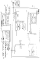
<パチンコ機10の電気的構成>
図5は、パチンコ機10の電気的構成を示すブロック図である。
<Electrical Configuration of
FIG. 5 is a block diagram showing the electrical configuration of the
<主制御装置50>
主制御装置50は、遊技の主たる制御を司る主制御基板51を具備している。なお、主制御装置50において主制御基板51などを収容する基板ボックスに対して、その開放の痕跡を残すための痕跡手段を付与する又はその開放の痕跡を残すための痕跡構造を設けておくようにしてもよい。当該痕跡手段としては、基板ボックスを構成する複数のケース体を分離不能に結合するとともにその分離に際して所定部位の破壊を要する結合部(カシメ部)の構成や、引き剥がしにして粘着層が接着対象に残ることで剥がされたことの痕跡を残す封印シールを複数のケース体間の境界を跨ぐようにして貼り付ける構成が考えられる。また、痕跡構造としては、基板ボックスを構成する複数のケース体間の境界に対して接着剤を塗布する構成が考えられる。
<
The
主制御基板51には、MPU52が搭載されている。MPU52には、当該MPU52により実行される各種の制御プログラムや固定値データを記憶したROM53と、そのROM53内に記憶される制御プログラムの実行に際して各種のデータ等を一時的に記憶するためのメモリであるRAM54と、割込回路、タイマ回路、データ入出力回路、乱数発生器としての各種カウンタ回路などが内蔵されている。
An
なお、ROM53として、制御プログラムや固定値データの読み出しに際してランダムアクセスが可能であって、記憶保持に外部からの電力供給が不要な記憶手段(すなわち、不揮発性記憶手段)が用いられている。具体的には、NOR型キャッシュメモリが用いられている。但し、これに限定されることはなく、ランダムアクセスが可能であれば、ROM53として用いるメモリの種類は任意である。また、制御及び演算部分と、ROM53と、RAM54とが1チップ化されている構成は必須ではなく、各機能がそれぞれ別チップとして搭載されている構成としてもよく、一部の機能が別チップとして搭載されている構成としてもよい。
As the
MPU52には、入力ポート及び出力ポートがそれぞれ設けられている。MPU52の入力側には、電源・発射制御装置57が接続されている。電源・発射制御装置57は、例えば、遊技場等における商用電源(外部電源)に接続されている。そして、その商用電源から供給される外部電力に基づいて主制御基板51に動作電力を供給する。ちなみに、当該動作電力は主制御基板51だけでなく、払出制御装置55や後述する表示制御装置70といった他の機器にも供給される。
The
なお、MPU52と電源・発射制御装置57との電力経路上に停電監視基板を設けてもよい。この場合、当該停電監視基板により停電の発生が監視され、停電の発生が確認された場合にはMPU52に対して停電信号が送信されるようにすることで、MPU52において停電時用の処理を実行することが可能となる。
A blackout monitoring board may be provided on the power path between the
また、MPU52の入力側には、図示しない各種センサが接続されている。当該各種センサの一部として、一般入賞口31、特電入賞装置32、第1作動口33、第2作動口34及びスルーゲート35といった入賞対応入球部に対して1対1で設けられた検知センサが含まれており、MPU52において各入球部への入賞判定(入球判定)が行われる。また、MPU52では第1作動口33及び第2作動口34への入賞に基づいて大当たり発生抽選及び大当たり結果種別抽選を実行するとともに、各遊技回のリーチ発生抽選や表示継続期間の決定抽選を実行する。
Various sensors (not shown) are connected to the input side of the
ここで、MPU52にて各種抽選を行うための構成について説明する。
Here, a configuration for performing various lotteries in the
MPU52は遊技に際し各種カウンタ情報を用いて、大当たり発生抽選、特図表示部37aの表示の設定、図柄表示装置41の図柄表示の設定、普図表示部38aの表示の設定などを行うこととしており、具体的には、図6に示すように、大当たり発生抽選に使用する当たり乱数カウンタC1と、確変大当たり結果や通常大当たり結果等の大当たり種別を判定する際に使用する大当たり種別カウンタC2と、図柄表示装置41が外れ変動する際のリーチ発生抽選に使用するリーチ乱数カウンタC3と、当たり乱数カウンタC1の初期値設定に使用する乱数初期値カウンタCINIと、特図表示部37a及び図柄表示装置41における変動表示時間を決定する変動種別カウンタCSとを用いることとしている。さらに、第2作動口34の普電役物34aを電役開放状態とするか否かの抽選に使用する普電役物開放カウンタC4を用いることとしている。なお、これら各カウンタC1~C3,CINI,CS,C4は、抽選カウンタ用バッファ54aに設けられている。
The
各カウンタC1~C3,CINI,CS,C4は、その更新の都度前回値に1が加算され、最大値に達した後「0」に戻るループカウンタとなっている。当たり乱数カウンタC1、大当たり種別カウンタC2及びリーチ乱数カウンタC3に対応した情報は、第1作動口33又は第2作動口34への入賞が発生した場合に、取得情報記憶手段としての保留格納エリア54bに格納される。
Each of the counters C1 to C3, CINI, CS, and C4 is a loop counter that adds 1 to the previous value each time it is updated and returns to "0" after reaching the maximum value. Information corresponding to the hit random number counter C1, the jackpot type counter C2, and the reach random number counter C3 is stored in the reserved
保留格納エリア54bは、保留用エリアREと、実行エリアAEとを備えている。保留用エリアREは、第1保留エリアRE1、第2保留エリアRE2、第3保留エリアRE3及び第4保留エリアRE4を備えており、第1作動口33又は第2作動口34への入賞履歴に合わせて、当たり乱数カウンタC1、大当たり種別カウンタC2及びリーチ乱数カウンタC3の各数値情報が保留情報として、いずれかの保留エリアRE1~RE4に格納される。
The reserved
第1保留エリアRE1~第4保留エリアRE4には、第1作動口33又は第2作動口34への入賞が複数回連続して発生した場合に、第1保留エリアRE1→第2保留エリアRE2→第3保留エリアRE3→第4保留エリアRE4の順に各数値情報が時系列的に格納されていく。このように4つの保留エリアRE1~RE4が設けられていることにより、第1作動口33又は第2作動口34への遊技球の入賞履歴が最大4個まで保留記憶されるようになっている。なお、保留記憶可能な数は、4個に限定されることはなく任意であり、2個、3個又は5個以上といったように他の複数であってもよく、単数であってもよい。実行エリアAEは、特図表示部37aの変動表示を開始する際に、保留用エリアREの第1保留エリアRE1に格納された各値を移動させるためのエリアであり、1遊技回の開始に際しては実行エリアAEに記憶されている各種数値情報に基づいて、当否判定などが行われる。
In the first reservation area RE1 to the fourth reservation area RE4, when the winning to the
各カウンタについて詳しくは、当たり乱数カウンタC1は、例えば0~599の範囲内で順に1ずつ加算され、最大値に達した後「0」に戻る構成となっている。特に当たり乱数カウンタC1が1周した場合、その時点の乱数初期値カウンタCINIの値が当該当たり乱数カウンタC1の初期値として読み込まれる。なお、乱数初期値カウンタCINIは、当たり乱数カウンタC1と同様のループカウンタである(値=0~599)。当たり乱数カウンタC1は定期的に更新され、遊技球が第1作動口33又は第2作動口34に入賞したタイミングで保留格納エリア54bに格納される。
More specifically, the hit random number counter C1 is configured such that it is incremented by one within the range of 0 to 599, for example, and returns to "0" after reaching the maximum value. In particular, when the winning random number counter C1 completes one cycle, the value of the random number initial value counter CINI at that time is read as the initial value of the winning random number counter C1. The random number initial value counter CINI is a loop counter similar to the winning random number counter C1 (value=0 to 599). The hit random number counter C1 is periodically updated, and stored in the
大当たり当選となる乱数の値は、ROM53に当否テーブルとして記憶されている。当否テーブルとしては、低確率モード用の当否テーブルと、高確率モード用の当否テーブルとが設定されている。つまり、本パチンコ機10は、当否抽選手段における抽選モードとして、低確率モードと高確率モードとが設定されている。
Random number values for winning a jackpot are stored in the
上記抽選に際して低確率モード用の当否テーブルが参照されることとなる遊技状態下では、大当たり当選となる乱数の数は2個である。一方、上記抽選に際して高確率モード用の当否テーブルが参照されることとなる遊技状態下では、大当たり当選となる乱数の数は20個である。なお、低確率モードよりも高確率モードの方の当選確率が高くなるのであれば、上記当選となる乱数の数は任意である。 Under the game state in which the success/failure table for the low-probability mode is referred to in the lottery, the number of random numbers for winning the jackpot is two. On the other hand, under the gaming state in which the success/failure table for the high-probability mode is referred to in the lottery, the number of random numbers that will win the jackpot is twenty. As long as the probability of winning is higher in the high-probability mode than in the low-probability mode, the number of random numbers for winning is arbitrary.
大当たり種別カウンタC2は、0~29の範囲内で順に1ずつ加算され、最大値に達した後「0」に戻る構成となっている。大当たり種別カウンタC2は定期的に更新され、遊技球が第1作動口33又は第2作動口34に入賞したタイミングで保留格納エリア54bに格納される。
The jackpot type counter C2 is configured to be incremented by 1 in order within the range of 0 to 29, and return to "0" after reaching the maximum value. The jackpot type counter C2 is periodically updated, and is stored in the
本パチンコ機10では、複数の大当たり結果が設定されている。これら複数の大当たり結果は、(1)開閉実行モードにおける特電入賞装置32の開閉制御の態様、(2)開閉実行モード終了後の当否抽選手段における抽選モード、(3)開閉実行モード終了後の第2作動口34の普電役物34aにおけるサポートモード、という3つの条件に差異を設けることにより、複数の大当たり結果が設定されている。
In this
開閉実行モードにおける特電入賞装置32の開閉制御の態様としては、開閉実行モードが開始されてから終了するまでの間における特電入賞装置32への入賞の発生頻度が相対的に高低となるように高頻度入賞モードと低頻度入賞モードとが設定されている。具体的には、高頻度入賞モードでは、開閉実行モードの開始から終了までに、大入賞口の開閉が15回行われるとともに、1回の開放は30secが経過するまで又は大入賞口への入賞個数が10個となるまで継続される。一方、低頻度入賞モードでは、開閉実行モードの開始から終了までに、大入賞口の開閉が2回行われるとともに、1回の開放は0.2secが経過するまで又は大入賞口への入賞個数が6個となるまで継続される。
As a mode of opening/closing control of the special electric
本パチンコ機10では、発射操作装置28が遊技者により操作されている状況では、0.6secに1個の遊技球が遊技領域に向けて発射されるように遊技球発射機構58が駆動制御される。これに対して、低頻度入賞モードでは、上記のとおり1回の大入賞口の開放時間は0.2secとなっている。つまり、低頻度入賞モードでは、遊技球の発射周期よりも1回の大入賞口の開放時間が短くなっている。したがって、低頻度入賞モードにかかる開閉実行モードでは実質的に遊技球の入賞が発生しない。
In the
なお、高頻度入賞モード及び低頻度入賞モードにおける大入賞口の開閉回数、1回の開放に対する開放制限時間及び1回の開放に対する開放制限個数は、高頻度入賞モードの方が低頻度入賞モードよりも、開閉実行モードが開始されてから終了するまでの間における特電入賞装置32への入賞の発生頻度が高くなるのであれば、上記の値に限定されることはなく任意である。具体的には、高頻度入賞モードの方が低頻度入賞モードよりも、開閉回数が多い、1回の開放に対する開放制限時間が長い又は1回の開放に対する開放制限個数が多く設定されていればよい。
In addition, the number of openings and closings of the large winning opening in the high frequency winning mode and the low frequency winning mode, the opening limit time for one opening, and the opening limit number for one opening are higher in the high frequency winning mode than in the low frequency winning mode. However, the value is not limited to the above value and may be any value as long as the frequency of winning to the special electric
但し、高頻度入賞モードと低頻度入賞モードとの間での特典の差異を明確にする上では、低頻度入賞モードにかかる開閉実行モードでは、実質的に特電入賞装置32への入賞が発生しない構成とするとよい。例えば、高頻度入賞モードでは、1回の開放について、遊技球の発射周期と開放制限個数との積を、開放制限時間よりも短く設定する一方、低頻度入賞モードでは、1回の開放について、遊技球の発射周期と開放制限個数との積を、開放制限時間よりも長く設定する構成としてもよい。また、遊技球の発射間隔及び1回の大入賞口の開放時間が上記のものでなかったとしても、低頻度入賞モードでは、前者よりも後者の方が短くなるように設定することで、実質的に特電入賞装置32への入賞が発生しない構成を容易に実現することができる。
However, in order to clarify the difference in benefits between the high-frequency winning mode and the low-frequency winning mode, in the opening and closing execution mode related to the low-frequency winning mode, substantially no winning to the special
第2作動口34の普電役物34aにおけるサポートモードとしては、遊技領域に対して同様の態様で遊技球の発射が継続されている状況で比較した場合に、第2作動口34の普電役物34aが単位時間当たりに開放状態となる頻度が相対的に高低となるように、低頻度サポートモードと高頻度サポートモードとが設定されている。
As the support mode in the general electric accessory 34a of the
具体的には、低頻度サポートモードと高頻度サポートモードとでは、普電役物開放カウンタC4を用いた電動役物開放抽選における電役開放状態当選となる確率は同一(例えば、共に4/5)となっているが、高頻度サポートモードでは低頻度サポートモードよりも、電役開放状態当選となった際に普電役物34aが開放状態となる回数が多く設定されており、さらに1回の開放時間が長く設定されている。この場合、高頻度サポートモードにおいて電役開放状態当選となり普電役物34aの開放状態が複数回発生する場合において、1回の開放状態が終了してから次の開放状態が開始されるまでの閉鎖時間は、1回の開放時間よりも短く設定されている。さらにまた、高頻度サポートモードでは低頻度サポートモードよりも、1回の電動役物開放抽選が行われてから次の電動役物開放抽選が行われる上で最低限確保される確保時間として短い時間が選択されるように設定されている。 Specifically, in the low-frequency support mode and the high-frequency support mode, the probability of winning the electric role open state in the electric role open lottery using the general electric role open counter C4 is the same (for example, both 4/5 ), but in the high-frequency support mode, the number of times the general electric role 34a is in the open state when the electric role open state is won is set more than in the low-frequency support mode. is set for a long time. In this case, in the high frequency support mode, when the electric role open state is won and the open state of the general electric role item 34a occurs multiple times, the time from the end of one open state to the start of the next open state The closing time is set shorter than one opening time. Furthermore, in the high-frequency support mode, the minimum time required for the next electric accessory open lottery after one electric accessory open lottery is performed is shorter than the low-frequency support mode. is set to be selected.
上記のように高頻度サポートモードでは、低頻度サポートモードよりも第2作動口34への入賞が発生する確率が高くなる。換言すれば、低頻度サポートモードでは、第2作動口34よりも第1作動口33への入賞が発生する確率が高くなるが、高頻度サポートモードでは、第1作動口33よりも第2作動口34への入賞が発生する確率が高くなる。そして、第2作動口34への入賞が発生した場合には、所定個数の遊技球の払出が実行されるため、高頻度サポートモードでは、遊技者は持ち球をあまり減らさないようにしながら遊技を行うことができる。
As described above, in the high-frequency support mode, the probability of winning the
なお、高頻度サポートモードを低頻度サポートモードよりも単位時間当たりに電役開放状態となる頻度を高くする上での構成は、上記のものに限定されることはなく、例えば電動役物開放抽選における電役開放状態当選となる確率を高くする構成としてもよい。また、1回の電動役物開放抽選が行われてから次の電動役物開放抽選が行われる上で確保される確保時間(例えば、スルーゲート35への入賞に基づき普図表示部38aにて実行される変動表示の時間)が複数種類用意されている構成においては、高頻度サポートモードでは低頻度サポートモードよりも、短い確保時間が選択され易い又は平均の確保時間が短くなるように設定されていてもよい。さらには、開放回数を多くする、開放時間を長くする、1回の電動役物開放抽選が行われてから次の電動役物開放抽選が行われる上で確保される確保時間を短くする(すなわち、普図表示部38aにおける1回の変動表示時間を短くする)、係る確保時間の平均時間を短くする及び当選確率を高くするのうち、いずれか1条件又は任意の組合せの条件を適用することで、低頻度サポートモードに対する高頻度サポートモードの有利性を高めてもよい。
In addition, the configuration for making the high frequency support mode more frequent than the low frequency support mode to be in the electric role open state per unit time is not limited to the above. It may be configured to increase the probability of winning the electric role open state. In addition, the time secured after one electric accessory open lottery is performed and the next electric accessory open lottery is performed (for example, based on the winning of the through
大当たり種別カウンタC2に対する遊技結果の振分先は、ROM53に振分テーブルとして記憶されている。そして、かかる振分先として、通常大当たり結果と、明示2R確変大当たり結果と、15R確変大当たり結果とが設定されている。
The distribution destination of the game result for the jackpot type counter C2 is stored in the
通常大当たり結果は、開閉実行モードが高頻度入賞モードとなり、さらに開閉実行モードの終了後には、当否抽選モードが低確率モードとなるとともに、サポートモードが高頻度サポートモードとなる大当たり結果である。但し、この高頻度サポートモードは、移行後において遊技回数が終了基準回数(具体的には、100回)に達した場合に低頻度サポートモードに移行する。換言すれば、通常大当たり結果は、通常大当たり状態へ遊技状態を移行させる大当たり結果である。 The normal jackpot result is a jackpot result in which the opening/closing execution mode becomes a high-frequency prize winning mode, and after the opening/closing execution mode ends, the win/fail lottery mode becomes a low-probability mode and the support mode becomes a high-frequency support mode. However, this high-frequency support mode transitions to the low-frequency support mode when the number of games reaches the end reference number of times (specifically, 100 times) after transition. In other words, the normal jackpot result is a jackpot result that shifts the gaming state to the normal jackpot state.
明示2R確変大当たり結果は、開閉実行モードが低頻度入賞モードとなり、さらに開閉実行モードの終了後には、当否抽選モードが高確率モードとなるとともに、サポートモードが高頻度サポートモードとなる大当たり結果である。これら高確率モード及び高頻度サポートモードは、当否抽選における抽選結果が大当たり状態当選となり、それによる大当たり状態に移行するまで継続する。換言すれば、明示2R確変大当たり結果は、明示2R確変大当たり状態へ遊技状態を移行させる大当たり結果である。 The explicit 2R probability variable jackpot result is a jackpot result in which the opening/closing execution mode becomes the low-frequency winning mode, and furthermore, after the opening/closing execution mode ends, the winner/failure lottery mode becomes the high-probability mode and the support mode becomes the high-frequency support mode. . These high-probability mode and high-frequency support mode are continued until the lottery result in the success/failure lottery results in a big win state winning, and the game shifts to a big win state accordingly. In other words, the explicit 2R probability variable jackpot result is a jackpot result that shifts the game state to the explicit 2R probability variable jackpot state.
15R確変大当たり結果は、開閉実行モードが高頻度入賞モードとなり、さらに開閉実行モードの終了後には、当否抽選モードが高確率モードとなるとともに、サポートモードが高頻度サポートモードとなる大当たり結果である。これら高確率モード及び高頻度サポートモードは、当否抽選における抽選結果が大当たり状態当選となり、それによる大当たり状態に移行するまで継続する。換言すれば、15R確変大当たり結果は、15R確変大当たり状態へ遊技状態を移行させる大当たり結果である。 The 15R probability variable jackpot result is a jackpot result in which the opening/closing execution mode becomes the high-frequency winning mode, and after the opening/closing execution mode ends, the winning/failure lottery mode becomes the high-probability mode and the support mode becomes the high-frequency support mode. These high-probability mode and high-frequency support mode are continued until the lottery result in the success/failure lottery results in a big win state winning, and the game shifts to a big win state accordingly. In other words, the 15R probability variable jackpot result is a jackpot result that shifts the gaming state to the 15R probability variable jackpot state.
なお、上記各遊技状態との関係で通常遊技状態とは、当否抽選モードが低確率モードであり、サポートモードが低頻度サポートモードである状態をいう。 In relation to each game state described above, the normal game state refers to a state in which the lottery mode is the low probability mode and the support mode is the low frequency support mode.
振分テーブルでは、「0~29」の大当たり種別カウンタC2の値のうち、「0~9」が通常大当たり結果に対応しており、「10~14」が明示2R確変大当たり結果に対応しており、「15~29」が15R確変大当たり結果に対応している。 In the distribution table, among the values of the jackpot type counter C2 of "0 to 29", "0 to 9" correspond to the normal jackpot results, and "10 to 14" correspond to the explicit 2R probability variable jackpot results. , and "15 to 29" corresponds to the 15R probability variable jackpot result.
上記のように、確変大当たり結果として、明示2R確変大当たり結果が設定されていることにより、確変大当たり結果の態様が多様化する。すなわち、2種類の確変大当たり結果を比較した場合、遊技者にとっての有利度合いは、開閉実行モードにおいて高頻度入賞モードとなり且つサポートモードでは高頻度サポートモードとなる15R確変大当たり結果が最も高く、開閉実行モードにおいて低頻度入賞モードとなるもののサポートモードでは高頻度サポートモードとなる明示2R確変大当たり結果が最も低くなる。これにより、遊技の単調化が抑えられ、遊技への注目度を高めることが可能となる。 As described above, since the explicit 2R probability variable jackpot result is set as the probability variable jackpot result, the aspect of the probability variable jackpot result is diversified. That is, when comparing the two types of variable probability jackpot results, the degree of advantage for the player is the highest for the 15R probability variable jackpot result, which is the high frequency winning mode in the opening and closing execution mode and the high frequency support mode in the support mode, and the opening and closing execution. Although the low-frequency winning mode is the mode, the explicit 2R probability variable jackpot result, which is the high-frequency support mode, is the lowest in the support mode. As a result, the monotony of the game can be suppressed, and it is possible to increase the degree of attention to the game.
なお、確変大当たり結果の一種として、開閉実行モードが低頻度入賞モードとなり、さらに開閉実行モードの終了後には、当否抽選モードが高確率モードとなるとともに、サポートモードがそれまでのモードに維持されることとなる非明示2R確変大当たり結果が含まれていてもよい。この場合、確変大当たり結果のさらなる多様化が図られる。 As a kind of probability variable jackpot result, the opening/closing execution mode becomes the low-frequency winning mode, and after the opening/closing execution mode ends, the win/loss lottery mode becomes the high-probability mode, and the support mode is maintained as it was before. Different implicit 2R probability variable jackpot outcomes may be included. In this case, further diversification of the probability variable jackpot results is achieved.
さらにまた、当否抽選における外れ結果の一種として、低頻度入賞モードの開閉実行モードに移行するとともに、その終了後において当否抽選モード及びサポートモードの移行が発生しない特別外れ結果が含まれていてもよい。上記のような非明示2R確変大当たり結果と当該特別外れ結果との両方が設定されている構成においては、開閉実行モードが低頻度入賞モードに移行すること、及びサポートモードがそれまでのモードに維持されることで共通しているのに対して、当否抽選モードの移行態様が異なっていることにより、例えば通常遊技状態において非明示2R確変大当たり結果又は特別外れ結果の一方が発生した場合に、それが実際にいずれの結果に対応しているのかを遊技者に予測させることが可能となる。 Furthermore, as a type of loss result in the win-fail lottery, a special loss result may be included in which transition to the open/close execution mode of the low-frequency prize-winning mode and transition to the win-fail lottery mode and the support mode do not occur after the end. . In the configuration in which both the non-explicit 2R probability variable jackpot result and the special loss result as described above are set, the opening and closing execution mode shifts to the low frequency winning mode, and the support mode is maintained in the previous mode. On the other hand, due to the difference in the transition mode of the winning lottery mode, for example, in the normal game state, if one of the non-expressed 2R probability variable jackpot result or the special loss result occurs, it It is possible to allow the player to predict which outcome actually corresponds to.
リーチ乱数カウンタC3は、例えば0~238の範囲内で順に1ずつ加算され、最大値に達した後「0」に戻る構成となっている。リーチ乱数カウンタC3は定期的に更新され、遊技球が第1作動口33又は第2作動口34に入賞したタイミングで保留格納エリア54bに格納される。
The reach random number counter C3 is configured such that it is incremented by 1 in sequence within the range of 0 to 238, for example, and returns to "0" after reaching the maximum value. The reach random number counter C3 is periodically updated, and is stored in the
ここで、本パチンコ機10には、図柄表示装置41における表示演出の一種として期待演出が設定されている。期待演出とは、図柄の変動表示を行うことが可能な図柄表示装置41を備え、特電入賞装置32の開閉実行モードが高頻度入賞モードとなる遊技回では変動表示後の停止表示結果が特別表示結果となる遊技機において、図柄表示装置41における図柄の変動表示が開始されてから停止表示結果が導出表示される前段階で、前記特別表示結果となり易い変動表示状態であると遊技者に思わせるための表示状態をいう。
Here, in the
期待演出には、上記リーチ表示と、当該リーチ表示が発生する前段階などにおいてリーチ表示の発生や特別表示結果の発生を期待させるための予告表示との2種類が設定されている。 There are two types of expectation effects: the ready-to-win display and an advance notice display for expecting the occurrence of the ready-to-win display and the special display result in a stage before the occurrence of the ready-to-win display.
リーチ表示には、図柄表示装置41の表示面Pに表示される複数の図柄列のうち一部の図柄列について図柄を停止表示させることで、高頻度入賞モードの発生に対応した大当たり図柄の組合せが成立する可能性があるリーチ図柄の組合せを表示し、その状態で残りの図柄列において図柄の変動表示を行う表示状態が含まれる。また、上記のようにリーチ図柄の組合せを表示した状態で、残りの図柄列において図柄の変動表示を行うとともに、その背景画像において所定のキャラクタなどを動画として表示することによりリーチ演出を行うものや、リーチ図柄の組合せを縮小表示させる又は非表示とした上で、表示面Pの略全体において所定のキャラクタなどを動画として表示することによりリーチ演出を行うものが含まれる。
In the ready-to-win display, the patterns of some of the plurality of pattern rows displayed on the display surface P of the
図柄の変動表示に係るリーチ表示について具体的には、図柄の変動表示を終了させる前段階として、図柄表示装置41の表示面P内の予め設定された有効ライン上に、高頻度入賞モードの発生に対応した大当たり図柄の組合せが成立する可能性のあるリーチ図柄の組合せを停止表示させることによりリーチラインを形成させ、当該リーチラインが形成されている状況下において最終停止図柄列により図柄の変動表示を行うことである。
Concretely, the ready-to-win display related to the variable display of the symbols, as a step before ending the variable display of the symbols, the high-frequency winning mode is generated on the preset active line in the display surface P of the
図4の表示内容について具体的に説明すると、最初に上段の図柄列Z1において図柄の変動表示が終了され、さらに下段の図柄列Z3において図柄の変動表示が終了された状態において、いずれかの有効ラインL1~L5に同一の数字が付された主図柄が停止表示されることでリーチラインが形成され、当該リーチラインが形成されている状況化において中段の図柄列Z2において図柄の変動表示が行われることでリーチ表示となる。そして、高頻度入賞モードが発生する場合には、リーチラインを形成している主図柄と同一の数字が付された主図柄がリーチライン上に停止表示されるようにして中段の図柄列Z2における図柄の変動表示が終了される。 Specifically, the display contents of FIG. 4 will be described. A reach line is formed by stop-displaying the main symbols having the same number on the lines L1 to L5, and in a situation where the reach line is formed, the symbols are displayed in the middle symbol row Z2. It becomes a reach display by being drawn. When the high-frequency winning mode occurs, the main symbols having the same number as the main symbols forming the reach line are stopped and displayed on the reach line in the middle symbol row Z2. The variable display of the symbol ends.
予告表示には、図柄表示装置41の表示面Pにおいて図柄の変動表示が開始されてから、全ての図柄列Z1~Z3にて図柄が変動表示されている状況において、又は一部の図柄列であって複数の図柄列にて図柄が変動表示されている状況において、図柄列Z1~Z3上の図柄とは別にキャラクタを表示させる態様が含まれる。また、背景画像をそれまでの態様とは異なる所定の態様とするものや、図柄列Z1~Z3上の図柄をそれまでの態様とは異なる所定の態様とするものも含まれる。かかる予告表示は、リーチ表示が行われる場合及びリーチ表示が行われない場合のいずれの遊技回においても発生し得るが、リーチ表示の行われる場合の方がリーチ表示の行われない場合よりも高確率で発生するように設定されている。
In the advance notice display, after the pattern display is started on the display surface P of the
リーチ表示は、開閉実行モードに移行する遊技回では、リーチ乱数カウンタC3の値に関係なく実行される。また、開閉実行モードに移行しない遊技回では、ROM53のリーチ用テーブル記憶エリアに記憶されたリーチ用テーブルを参照して、所定のタイミングで取得したリーチ乱数カウンタC3がリーチ表示の発生に対応している場合に実行される。一方、予告表示を行うか否かの決定は、主制御装置50において行うのではなく、音声発光制御装置60において行われる。
The ready-to-win display is executed regardless of the value of the ready-to-win random number counter C3 in game rounds in which the open/close execution mode is entered. In addition, in game rounds that do not shift to the open/close execution mode, the reach table stored in the reach table storage area of the
変動種別カウンタCSは、例えば0~198の範囲内で順に1ずつ加算され、最大値に達した後「0」に戻る構成となっている。変動種別カウンタCSは、特図表示部37aにおける変動表示時間と、図柄表示装置41における図柄の変動表示時間とをMPU52において決定する上で用いられる。変動種別カウンタCSは、後述するタイマ割込み処理が1回実行される毎に1回更新され、後述するメイン処理の残余時間内でも繰り返し更新される。そして、特図表示部37aにおける変動表示の開始時及び図柄表示装置41による図柄の変動開始時における変動パターン決定に際して変動種別カウンタCSのバッファ値が取得される。なお、変動表示時間の決定に際しては、ROM53の変動表示時間テーブル記憶エリアに予め記憶されている変動表示時間テーブルが参照される。
The fluctuation type counter CS is, for example, incremented by 1 in order within the range of 0 to 198, and returns to "0" after reaching the maximum value. The variation type counter CS is used for determining the variation display time in the special figure display section 37a and the variation display time of the symbol in the
普電役物開放カウンタC4は、例えば、0~250の範囲内で順に1ずつ加算され、最大値に達した後「0」に戻る構成となっている。普電役物開放カウンタC4は定期的に更新され、スルーゲート35に遊技球が入賞したタイミングで電役保留エリア54cに格納される。そして、所定のタイミングにおいて、その格納された普電役物開放カウンタC4の値によって普電役物34aを開放状態に制御するか否かの抽選が行われる。
For example, the general electric role item release counter C4 is configured to be incremented by 1 in order within the range of 0 to 250, and return to "0" after reaching the maximum value. The general electric role release counter C4 is periodically updated, and stored in the electric
MPU52の出力側には、払出制御装置55が接続されているとともに、電源・発射制御装置57が接続されている。払出制御装置55には、例えば、上記入賞対応入球部への入賞判定結果に基づいて賞球コマンドが送信される。払出制御装置55は、主制御装置50から受信した賞球コマンドに基づいて、払出装置56により賞球や貸し球の払出制御を行う。電源・発射制御装置57には、発射操作装置28が操作されていることに基づいて発射許可コマンドが送信される。電源・発射制御装置57は、主制御装置50から受信した発射許可コマンドに基づいて、遊技球発射機構58を駆動させ遊技球を遊技領域に向けて発射させる。
The output side of the
また、MPU52の出力側には、特図表示部37a及び普図表示部38aが接続されており、これら特図表示部37a及び普図表示部38aの表示制御がMPU52により直接行われる。つまり、各遊技回に際しては、MPU52において特図表示部37aの表示制御が実行される。また、普電役物34aを開放状態とするか否かの抽選結果を明示する場合に、MPU52において普図表示部38aの表示制御が実行される。
In addition, the special figure display section 37a and the general figure display section 38a are connected to the output side of the MPU52, and the display control of these special figure display section 37a and the general figure display section 38a is directly performed by the MPU52. In other words, display control of the special figure display section 37a is executed in the
MPU52の出力側には、特電入賞装置32の開閉扉を開閉動作させる特電入賞駆動部、及び第2作動口34の普電役物34aを開閉動作させる普電役物駆動部が接続されている。つまり、開閉実行モードにおいては大入賞口が開閉されるように、MPU52において特電入賞駆動部の駆動制御が実行される。また、普電役物34aの開放状態当選となった場合には、普電役物34aが開閉されるように、MPU52において普電役物駆動部の駆動制御が実行される。また、MPU52の出力側には、音声発光制御装置60が接続されており、当該音声発光制御装置60に対して演出用の各種コマンドを送信する。
The output side of the
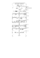
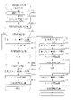
ここで、MPU52にて実行される処理について説明する。かかるMPU52の処理としては大別して、電源投入に伴い起動されるメイン処理と、定期的に(本実施の形態では4msec周期で)起動されるタイマ割込み処理とがある。
Here, processing executed by the
図7はメイン処理を示すフローチャートである。ステップS101では、電源投入ウェイト処理を実行する。当該電源投入ウェイト処理では、例えばメイン処理が起動されてからウェイト用の所定時間(具体的には1sec)が経過するまで次の処理に進行することなく待機する。かかる電源投入ウェイト処理の実行期間において図柄表示装置41の動作開始及び初期設定が完了することとなる。続くステップS102ではRAM54のアクセスを許可するとともに、ステップS103にてMPU52の内部機能レジスタの設定を行う。
FIG. 7 is a flowchart showing main processing. In step S101, power-on wait processing is executed. In the power-on wait process, for example, the process waits without proceeding to the next process until a predetermined wait time (specifically, 1 sec) elapses after the main process is activated. The operation start and initial setting of the
その後、ステップS104では、電源・発射制御装置57に設けられたRAM消去スイッチが手動操作されているか否かを判定し、続くステップS105では、RAM54の停電フラグに「1」がセットされているか否かを判定する。また、ステップS106ではチェックサムを算出するチェックサム算出処理を実行し、続くステップS107ではそのチェックサムが電源遮断時に保存したチェックサムと一致するか否か、すなわち記憶保持されたデータの有効性を判定する。
After that, in step S104, it is determined whether or not the RAM erase switch provided in the power supply/
本パチンコ機10では、例えば遊技ホールの営業開始時など、電源投入時にRAMデータを初期化する場合にはRAM消去スイッチを押しながら電源が投入される。したがって、RAM消去スイッチが押されていれば、ステップS108の処理に移行する。また、電源遮断の発生情報が設定されていない場合や、チェックサムにより記憶保持されたデータの異常が確認された場合も同様にステップS108の処理に移行する。ステップS108では、RAM54をクリアする。その後、ステップS109に進む。
In the
一方、RAM消去スイッチが押されていない場合には、停電フラグに「1」がセットされていること、及びチェックサムが正常であることを条件に、ステップS108の処理を実行することなくステップS109に進む。ステップS109では、電源投入設定処理を実行する。電源投入設定処理では、停電フラグの初期化といったRAM54の所定のエリアを初期値に設定するとともに、現状の遊技状態を認識させるために現状の遊技状態に対応したコマンドを音声発光制御装置60に送信する。
On the other hand, if the RAM erase switch has not been pressed, step S109 is performed without executing the processing of step S108 on the condition that the power failure flag is set to "1" and the checksum is normal. proceed to In step S109, power-on setting processing is executed. In the power-on setting process, a predetermined area of the
その後、ステップS110~ステップS113の残余処理に進む。つまり、MPU52はタイマ割込み処理を定期的に実行する構成であるが、1のタイマ割込み処理と次のタイマ割込み処理との間に残余時間が生じることとなる。この残余時間は各タイマ割込み処理の処理完了時間に応じて変動することとなるが、かかる不規則な時間を利用してステップS110~ステップS113の残余処理を繰り返し実行する。この点、当該ステップS110~ステップS113の残余処理は非定期的に実行される非定期処理であると言える。
After that, the process proceeds to the remaining processes of steps S110 to S113. In other words, although the
残余処理では、まずステップS110にて、タイマ割込み処理の発生を禁止するために割込み禁止の設定を行う。続くステップS111では、乱数初期値カウンタCINIの更新を行う乱数初期値更新処理を実行するとともに、ステップS112にて変動種別カウンタCSの更新を行う変動用カウンタ更新処理を実行する。これらの更新処理では、RAM54の対応するカウンタから現状の数値情報を読み出し、その読み出した数値情報を1加算する処理を実行した後に、読み出し元のカウンタに上書きする処理を実行する。この場合、カウンタ値が最大値に達した際それぞれ「0」にクリアする。その後、ステップS113にて、タイマ割込み処理の発生を禁止している状態から許可する状態へ切り換える割込み許可の設定を行う。ステップS113の処理を実行したら、ステップS110に戻り、ステップS110~ステップS113の処理を繰り返す。
In the remaining process, first, in step S110, interrupt prohibition is set to prohibit the occurrence of timer interrupt processing. In subsequent step S111, a random number initial value update process for updating the random number initial value counter CINI is executed, and in step S112, a fluctuation counter update process for updating the fluctuation type counter CS is executed. In these updating processes, the current numerical information is read out from the corresponding counter in the
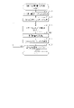
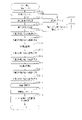
次に、図8のフローチャートを参照しながらタイマ割込み処理を説明する。タイマ割込み処理は定期的(例えば4msec周期)に実行される。まずステップS201にて停電情報記憶処理を実行する。停電情報記憶処理では、停電監視基板から電源遮断の発生に対応した停電信号を受信しているか否かを監視し、停電の発生を特定した場合には停電時処理を実行する。 Next, timer interrupt processing will be described with reference to the flowchart of FIG. Timer interrupt processing is executed periodically (for example, every 4 msec). First, in step S201, power failure information storage processing is executed. In the power failure information storage process, it is monitored whether or not a power failure signal corresponding to the occurrence of a power failure is received from the power failure monitoring board, and when the occurrence of a power failure is specified, the power failure process is executed.
続くステップS202では抽選用乱数更新処理を実行する。抽選用乱数更新処理では、当たり乱数カウンタC1、大当たり種別カウンタC2、リーチ乱数カウンタC3及び普電役物開放カウンタC4の更新を実行する。具体的には、当たり乱数カウンタC1、大当たり種別カウンタC2、リーチ乱数カウンタC3及び普電役物開放カウンタC4から現状の数値情報を順次読み出し、それら読み出した数値情報をそれぞれ1加算する処理を実行した後に、読み出し元のカウンタに上書きする処理を実行する。この場合、カウンタ値が最大値に達した際それぞれ「0」にクリアする。その後、ステップS203ではステップS111と同様に乱数初期値更新処理を実行するとともに、ステップS204にてステップS112と同様に変動用カウンタ更新処理を実行する。 In subsequent step S202, random number update processing for lottery is executed. In the lottery random number update process, the hit random number counter C1, the jackpot type counter C2, the reach random number counter C3, and the general electric accessory release counter C4 are updated. Specifically, the current numerical information is sequentially read out from the hit random number counter C1, the jackpot type counter C2, the reach random number counter C3, and the general electric role release counter C4, and the process of adding 1 to each of the read numerical information was executed. Afterwards, a process of overwriting the read source counter is executed. In this case, each counter value is cleared to "0" when it reaches the maximum value. After that, in step S203, the random number initial value update process is executed in the same manner as in step S111, and in step S204, the variation counter update process is executed in the same manner as in step S112.
続くステップS205では、不正用の監視対象として設定されている所定の事象が発生しているか否かを監視する不正検知処理を実行する。当該不正検知処理では、複数種類の事象の発生を監視し、所定の事象が発生していることを確認することで、RAM54に設けられた遊技停止用フラグに「1」をセットする。
In subsequent step S205, fraud detection processing is executed to monitor whether or not a predetermined event set as a monitoring target for fraud has occurred. In the fraud detection process, the game stop flag provided in the
続くステップS206では、上記遊技停止用フラグに「1」がセットされているか否かを判定することで、遊技の進行を停止している状態であるか否かを判定する。ステップS206にて否定判定をした場合に、ステップS207以降の処理を実行する。 In the following step S206, it is determined whether or not the progress of the game is stopped by determining whether or not the game stop flag is set to "1". If a negative determination is made in step S206, the processes after step S207 are executed.
ステップS207では、ポート出力処理を実行する。ポート出力処理では、前回のタイマ割込み処理において出力情報の設定が行われている場合に、その出力情報に対応した出力を各種駆動部に行うための処理を実行する。例えば、特電入賞装置32を開放状態に切り換えるべき情報が設定されている場合には特電入賞駆動部への駆動信号の出力を開始させ、閉鎖状態に切り換えるべき情報が設定されている場合には当該駆動信号の出力を停止させる。また、第2作動口34の普電役物34aを開放状態に切り換えるべき情報が設定されている場合には普電役物駆動部への駆動信号の出力を開始させ、閉鎖状態に切り換えるべき情報が設定されている場合には当該駆動信号の出力を停止させる。
In step S207, port output processing is executed. In the port output process, when the output information has been set in the previous timer interrupt process, a process for outputting corresponding to the output information to various drive units is executed. For example, when the information to switch the special electric
続くステップS208では、読み込み処理を実行する。読み込み処理では、停電信号及び入賞信号以外の信号の読み込みを実行し、その読み込んだ情報を今後の処理にて利用するために記憶する。 In the following step S208, read processing is executed. In the reading process, signals other than the power failure signal and the winning signal are read, and the read information is stored for use in future processing.
続くステップS209では入賞検知処理を実行する。当該入賞検知処理では、各入賞検知センサから受信している信号を読み込むとともに、一般入賞口31、特電入賞装置32、第1作動口33、第2作動口34及びスルーゲート35への入賞の有無を特定する処理を実行する。
In the subsequent step S209, winning detection processing is executed. In the winning detection process, the signal received from each winning detection sensor is read, and whether or not there is a winning to the general winning
続くステップS210では、RAM54に設けられている複数種類のタイマカウンタの数値情報をまとめて更新するためのタイマ更新処理を実行する。この場合、記憶されている数値情報が減算されて更新されるタイマカウンタを集約して扱う構成であるが、減算式のタイマカウンタの更新及び加算式のタイマカウンタの更新の両方を集約して行う構成としてもよい。
In the following step S210, a timer update process is executed to collectively update numerical information of a plurality of types of timer counters provided in the
続くステップS211では、遊技球の発射制御を行うための発射制御処理を実行する。発射操作装置28への発射操作が継続されている状況では、既に説明したとおり、所定の発射周期である0.6secに1個の遊技球が発射される。
In the subsequent step S211, a launch control process for controlling the launch of game balls is executed. In a situation where the shooting operation to the
続くステップS212では、入力状態監視処理として、ステップS208の読み込み処理にて読み込んだ情報に基づいて、各入賞検知センサの断線確認や、遊技機本体12や前扉枠14の開放確認を行う。
In the subsequent step S212, as the input state monitoring process, based on the information read in the reading process of step S208, disconnection confirmation of each winning detection sensor and open confirmation of the gaming machine
続くステップS213では、遊技回の実行制御及び開閉実行モードの実行制御を行うための特図特電制御処理を実行する。当該特図特電制御処理では、保留格納エリア54bに記憶されている保留情報の数が上限数未満である状況で第1作動口33又は第2作動口34への入賞が発生した場合に、その時点における当たり乱数カウンタC1、大当たり種別カウンタC2及びリーチ乱数カウンタC3の各数値情報を保留情報として、保留格納エリア54bに時系列的に格納していく処理を実行する。また、特図特電制御処理では、遊技回中及び開閉実行モード中ではなく且つ保留情報が記憶されていることを条件に、その保留情報が大当たり当選に対応しているか否かを判定する当否判定処理、及び大当たり当選に対応している場合にはその保留情報がいずれの大当たり結果に対応しているのかを判定する振分判定処理を実行する。また、特図特電制御処理では、当否判定処理及び振分判定処理だけでなく、その保留情報が大当たり当選に対応していない場合には、その保留情報がリーチ発生に対応しているか否かを判定するリーチ判定処理を実行するとともに、その時点における変動種別カウンタCSの数値情報を利用して遊技回の継続時間を選択する処理を実行する。この場合、大当たり当選の有無、大当たり種別及びリーチ発生の有無に対応した変動表示時間テーブルをROM53から読み出し、その読み出した変動表示時間テーブルと、そのタイミングにおける変動種別カウンタCSの数値情報とから今回の遊技回の継続時間を決定する。そして、その決定した遊技回の継続時間の情報を含む変動用コマンドと、遊技結果の情報を含む種別コマンドとを、音声発光制御装置60に送信するとともに、特図表示部37aにおける絵柄の変動表示を開始させる。これにより、1遊技回が開始された状態となり、特図表示部37a及び図柄表示装置41にて遊技回用の演出が開始される。
In the following step S213, a special figure special electric control process for performing execution control of the game round and execution control of the opening and closing execution mode is executed. In the special figure special electric control process, when the winning to the first operation opening 33 or the second operation opening 34 occurs in a situation where the number of reservation information stored in the
また、特図特電制御処理では、1遊技回の実行中にはその遊技回の終了タイミングであるか否かを判定し、終了タイミングである場合には遊技結果に対応した表示を行った状態で、その遊技回を終了させる処理を実行する。この場合、遊技回を終了させるべきことを示す最終停止コマンドを音声発光制御装置60に送信する。また、特図特電制御処理では、遊技回の結果が開閉実行モードへの移行に対応した結果である場合には、当該開閉実行モードを開始させるための処理を実行する。この開始に際しては、開閉実行モードが開始されることを示すオープニングコマンドを音声発光制御装置60に送信する。また、特図特電制御処理では、各ラウンド遊技を開始させるための処理及び各ラウンド遊技を終了させるための処理を実行する。これら各処理に際して、ラウンド遊技が開始されることを示す開放コマンドを音声発光制御装置60に送信するとともに、ラウンド遊技が終了されることを示す閉鎖コマンドを音声発光制御装置60に送信する。また、特図特電制御処理では、開閉実行モードを終了させる場合にそのことを示すエンディングコマンドを音声発光制御装置60に送信するとともに、開閉実行モード後の当否抽選モードやサポートモードを設定するための処理を実行する。
In addition, in the special figure special electric control process, it is determined whether or not it is the end timing of the game round during execution of one game round, and if it is the end timing, the display corresponding to the game result is performed. , the process of ending the game round is executed. In this case, a final stop command indicating that the game round should be ended is transmitted to the sound
タイマ割込み処理においてステップS213の特図特電制御処理を実行した後は、ステップS214にて普図普電制御処理を実行する。普図普電制御処理では、スルーゲート35への入賞が発生している場合に普図側の保留情報を取得するための処理を実行するとともに、普図側の保留情報が記憶されている場合にその保留情報について開放判定を行い、さらにその開放判定を契機として普図用の演出を行うための処理を実行する。また、開放判定の結果に基づいて、第2作動口34の普電役物34aを開閉させる処理を実行する。
After performing the special figure special electric control processing of step S213 in timer interrupt processing, the general figure general electric control processing is performed in step S214. In the general map general electric control process, when the prize to the through
続くステップS215では、直前のステップS213及びステップS214の処理結果に基づいて、特図表示部37aに係る保留情報の増減個数を特図保留表示部37bに反映させるための出力情報の設定を行うとともに、普図表示部38aに係る保留情報の増減個数を普図保留表示部38bに反映させるための出力情報の設定を行う。また、ステップS215では、直前のステップS213及びステップS214の処理結果に基づいて、特図表示部37aの表示内容を更新させるための出力情報の設定を行うとともに、普図表示部38aの表示内容を更新させるための出力情報の設定を行う。
In the following step S215, based on the processing result of step S213 and step S214 immediately before, while setting the output information for reflecting the increase or decrease number of pending information pertaining to the special figure display unit 37a to the special figure
続くステップS216では、払出制御装置55から受信したコマンド及び信号の内容を確認し、その確認結果に対応した処理を行うための払出状態受信処理を実行する。また、ステップS217では、賞球コマンドを出力対象として設定するための払出出力処理を実行する。続くステップS218では、今回のタイマ割込み処理にて実行された各種処理の処理結果に応じた外部信号の出力の開始及び終了を制御するための外部情報設定処理を実行する。その後、本タイマ割込み処理を終了する。
In the following step S216, the contents of the command and signal received from the
<音声発光制御装置60>
次に、音声発光制御装置60について説明する。
<Audio
Next, the sound
音声発光制御装置60は、図5に示すように、MPU62が搭載された音声発光制御基板61を具備している。MPU62には、当該MPU62により実行される各種の制御プログラムや固定値データを記憶したROM63と、そのROM63内に記憶される制御プログラムの実行に際して各種のデータ等を一時的に記憶するためのメモリであるRAM64と、割込回路、タイマ回路、データ入出力回路、乱数発生器としての各種カウンタ回路などが内蔵されている。
The sound
なお、ROM63として、制御プログラムや固定値データの読み出しに際してランダムアクセスが可能であって、記憶保持に外部からの電力供給が不要な記憶手段(すなわち、不揮発性記憶手段)が用いられている。具体的には、NOR型キャッシュメモリが用いられている。但し、これに限定されることはなく、ランダムアクセスが可能であれば、ROM63として用いるメモリの種類は任意である。また、制御及び演算部分と、ROM63と、RAM64とが1チップ化されている構成は必須ではなく、各機能がそれぞれ別チップとして搭載されている構成としてもよく、一部の機能が別チップとして搭載されている構成としてもよい。
As the
MPU62には、入力ポート及び出力ポートがそれぞれ設けられている。MPU62の入力側には主制御装置50が接続されているとともに、MPU62の出力側には表示発光部44及びスピーカ部45が接続されている。また、MPU62の入力側及び出力側の両方に対して、表示制御装置70の後述する表示CPU72が接続されている。つまり、MPU62は表示CPU72と双方向通信可能となるように接続されており、これらMPU62と表示CPU72との間でコマンドが双方向通信でやり取りされる。なお、当該双方向通信はシリアル通信で行われるが、これに限定されることはなくパラレル通信で行われる構成としてもよい。
The
MPU62では、主制御装置50から送信された変動用コマンドを受信することで、遊技回用の演出を開始させる必要があることを認識し、遊技回用演出開始処理を実行する。また、主制御装置50から送信された終了コマンドを受信することで、遊技回用の演出を終了させる必要があることを認識し、遊技回用演出終了処理を実行する。また、主制御装置50から送信された大当たり演出用の各種コマンドを受信することで、大当たり演出を開始させる必要があること又は進行させる必要があることを認識し、大当たり演出用処理を実行する。
By receiving the variation command transmitted from the
なお、MPU62において主制御装置50からコマンドを受信するとは、主制御装置50からコマンドを直接受信する構成に限定されることはなく、中継基板に中継されたコマンドを受信する構成も含まれる。
Note that the
遊技回用演出開始処理では、変動用コマンド及び種別コマンドの両コマンドに基づいて、該当遊技回の変動表示時間を把握する変動表示時間の把握処理と、リーチ表示の有無を把握するリーチ表示把握処理と、大当たり結果の有無を把握する大当たり結果発生の把握処理と、大当たり結果が発生する場合における大当たり種別を把握する大当たり種別の把握処理と、を実行する。また、リーチ表示把握処理、大当たり結果発生の把握処理及び大当たり種別の把握処理における把握結果に基づいて、本遊技回において図柄表示装置41の表示面Pに最終停止表示させる図柄の種類を決定する図柄種別把握処理を実行する。そして、上記各把握処理の結果に基づいて、変動表示時間の情報及び表示演出の種類の情報を含む変動パターンコマンドと、最終停止表示させる図柄の種類の情報を含む図柄指定コマンドを、表示制御装置70に送信する。
In the game cycle production start processing, based on both the command for variation and the type command, the variation display time comprehension processing for comprehending the variation display time of the corresponding game cycle, and the reach display comprehension processing for comprehending the presence or absence of the reach display. Then, a jackpot result grasping process for grasping the presence or absence of the jackpot result and a jackpot type grasping process for grasping the jackpot type when the jackpot result occurs are executed. Further, based on the grasping results in the reach display grasping process, the jackpot result grasping process, and the jackpot type grasping process, the symbol type to be finally stopped and displayed on the display surface P of the
また、遊技回用演出開始処理では、上記各把握処理の他に、予告表示を行うか否かの予告表示抽選処理を実行する。この場合、当該抽選処理では、予告表示の種別抽選についても実行される。そして、予告表示の発生当選である場合には、予告表示の種別の情報を含む予告コマンドを、表示制御装置70に送信する。
In addition, in the game cycle production start process, in addition to the above grasping processes, a notice display lottery process for determining whether or not to perform notice display is executed. In this case, in the lottery process, the type lottery for the advance notice display is also executed. Then, if it is determined that the announcement display is generated and won, an announcement command including information on the type of announcement display is transmitted to the
また、遊技回用演出開始処理では、上記各処理の処理結果に基づいて、遊技回用の表示発光テーブルと遊技回用の音声テーブルとをROM63から読み出す。遊技回用の表示発光テーブルにより、該当する遊技回の進行過程における表示発光部44の発光態様が規定される。また、遊技回用の音声テーブルにより、該当する遊技回の進行過程におけるスピーカ部45からの出力態様が規定される。
In addition, in the game round effect start process, the display light emission table for the game round and the sound table for the game round are read from the
遊技回用演出終了処理では、現状の遊技回における表示発光部44の発光制御及びスピーカ部45の音声出力制御を終了する。また、当該遊技回用演出終了処理では、遊技回用演出を終了させるべき情報を含む終了コマンドを、表示制御装置70に送信する。
In the game round effect end processing, the light emission control of the display
大当たり演出用処理では、受信している大当たり演出用の各種コマンドに基づいて、オープニング時、各ラウンド時、各ラウンド間及びエンディング時などの演出態様を把握し、その把握結果に対応した大当たり演出用のコマンドを表示制御装置70に送信する。また、当該把握結果に基づいて、大当たり演出用の表示発光テーブルと大当たり演出用の音声テーブルとをROM63から読み出し、大当たり演出中における表示発光部44の発光態様やスピーカ部45からの音声の出力態様を規定する。
In the jackpot effect processing, based on the received various commands for the jackpot effect, the effects such as the opening, each round, between rounds, and the ending are grasped, and the jackpot effect corresponding to the grasped results is obtained. command to the
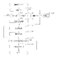
<表示制御装置70>
次に、表示制御装置70について説明する。
<
Next, the
表示制御装置70は、図5に示すように、表示CPU72と、ワークRAM73と、メモリモジュール74と、VRAM75と、ビデオディスプレイプロセッサ(VDP)76と、が搭載された表示制御基板71を備えている。
As shown in FIG. 5, the
表示CPU72は、表示制御装置70においてメイン制御部としての機能を有しており、制御プログラム等の読み出し、解釈及び実行を行う。詳細には、表示CPU72は表示制御基板71に搭載された入力ポート77に対してバスを介して接続されており、音声発光制御装置60から送信された各種コマンドは入力ポート77を通じて表示CPU72に入力される。なお、表示CPU72において音声発光制御装置60からコマンドを受信するとは、音声発光制御装置60からコマンドを直接受信する構成に限定されることはなく、中継基板に中継されたコマンドを受信する構成も含まれる。
The
表示CPU72は、バスを介してワークRAM73、メモリモジュール74及びVRAM75と接続されており、音声発光制御装置60から受信したコマンドに基づいて、メモリモジュール74に記憶された各種データをワークRAM73に転送させる転送指示を行う。また、表示CPU72は、バスを介してVDP76と接続されており、音声発光制御装置60から受信したコマンドに基づいて、図柄表示装置41に画像信号を出力させる描画指示を行う。以下、メモリモジュール74、ワークRAM73、VRAM75及びVDP76について説明する。
The
メモリモジュール74は、制御プログラム及び固定値データを含む制御用データを予め記憶しているとともに、図柄表示装置41に表示される図柄やキャラクタなどのスプライトデータ、背景データ、及び動画像データなどを含む各種画像データを予め記憶している記憶手段である。当該メモリモジュール74は、記憶保持に外部からの電力供給が不要な不揮発性の半導体メモリを有してなる。ちなみに、記憶容量は4Gビットであるが、かかる記憶容量は表示制御装置70における制御が良好に実行されるのであれば任意である。また、当該メモリモジュール74は、パチンコ機10の使用に際して、非書き込み用であって読み出し専用のメモリ(ROM)として用いられる。
The
ここで、各スプライトデータは、キャラクタの外形や模様を規定するビットマップ形式データと、ビットマップ画像の各ピクセルでの表示色を決定する際に参照されるカラーパレットテーブルとの組合せを少なくとも含んでいる。また、背景データは、静止画像データが圧縮された状態のJPEG形式データとして記憶保持されている。動画像データについては、後に詳細に説明する。 Here, each sprite data includes at least a combination of bitmap format data that defines the outline and pattern of the character and a color palette table that is referred to when determining the display color of each pixel of the bitmap image. there is The background data is stored and held as JPEG format data in which the still image data is compressed. Moving image data will be described later in detail.
ワークRAM73は、メモリモジュール74から読み出されて転送された制御用データを一時的に記憶しておくとともに、フラグ等を一時的に記憶しておくための記憶手段である。ワークRAM73は、記憶保持に外部からの電力供給が必要な揮発性の半導体メモリを有してなり、詳細には当該半導体メモリとしてDRAMが用いられている。但し、DRAMに限定されることはなくSRAMといった他のRAMを用いてもよい。なお、記憶容量は1Gビットであるが、かかる記憶容量は表示制御装置70における制御が良好に実行されるのであれば任意である。また、ワークRAM73は、パチンコ機10の使用に際して、読み書き両用として用いられる。
The
ワークRAM73には、表示CPU72からメモリモジュール74へのデータ転送指示に基づき、当該メモリモジュール74から制御用データが転送される。そして、表示CPU72は、ワークRAM73に転送された制御用データを必要に応じて内部のメモリ領域(レジスタ群)に読み込み、各種処理を実行する。
Control data is transferred from the
VRAM75は、図柄表示装置41に対して画像出力を行うために必要な各種データを一時的に記憶しておくための記憶手段である。当該VRAM75は、記憶保持に外部からの電力供給が必要な揮発性の半導体メモリを有してなり、詳細には当該半導体メモリとしてSDRAMが用いられている。但し、SDRAMに限定されることはなく、DRAM、SRAM又はデュアルポートRAMといった他のRAMを用いてもよい。なお、記憶容量は2Gビットであるが、かかる記憶容量は表示制御装置70における制御が良好に実行されるのであれば任意である。また、当該VRAM75は、パチンコ機10の使用に際して、読み書き両用として用いられる。
The
VRAM75は展開用バッファ81を備えており、展開用バッファ81には、VDP76からメモリモジュール74へのデータ転送指示に基づき、当該メモリモジュール74から画像データが転送される。また、VRAM75には、VDP76により描画データが作成されるフレームバッファ82が設けられている。なお、VRAM75がVDP76に内蔵されていてもよい。
The
VDP76は、表示CPU72からの描画指示に基づき、展開用バッファ81に記憶保持されているデータを用いて、具体的には加工することにより、図柄表示装置41に対して描画を行う画像生成デバイスであり、図柄表示装置41において液晶表示部41aを駆動制御するように組み込まれた画像処理デバイス41bを操作する一種の描画回路である。VDP76はICチップ化されているため「描画チップ」とも呼ばれ、その実体は、描画専用のファームウェアを内蔵したマイコンチップとでも言うべきものである。
The
詳細には、VDP76は、制御部91と、レジスタ92と、動画デコーダ93と、表示回路94と、を備えている。また、これら各回路はバスを介して相互に接続されているとともに、表示CPU72用のI/F95及びVRAM75用のI/F96と接続されている。
Specifically, the
VDP76では、表示CPU72から送信された描画指示情報としての描画リストをレジスタ92に記憶させる。レジスタ92に描画リストが記憶されることにより、制御部91では描画リストに従ったプログラムが起動されて予め定められた処理が実行される。なお、制御部91が動作するための制御プログラムの全てが描画リストにより提供される構成としてもよく、制御プログラムを予め記憶したメモリを制御部91に内蔵させ、当該制御プログラムと描画リストの内容とによって制御部91が所定の処理を実行する構成としてもよい。また、メモリモジュール74から制御プログラムを事前に読み出す構成としてもよい。
The
上記処理として、制御部91は、メモリモジュール74に記憶されている画像データをVRAM75の展開用バッファ81に読み出す。また、制御部91は、展開用バッファ81に読み出された画像データを用いて(又は加工することにより)、フレームバッファ82に1フレーム分の描画データを作成する。1フレーム分の描画データとは、予め定められた更新タイミングで図柄表示装置41の表示面Pにおける画像が更新される構成において、一の更新タイミングにおける画像を表示させるために必要なデータのことをいう。
As the above processing, the
ここで、フレームバッファ82には、複数のフレーム領域82a,82bが設けられている。具体的には、第1フレーム領域82aと、第2フレーム領域82bとが設けられている。これら各フレーム領域82a,82bは、それぞれ1フレーム分の描画データを記憶可能な容量に設定されている。具体的には、各フレーム領域82a,82bにはそれぞれ、液晶表示部41a(すなわち表示面P)のドット(画素)に所定の倍率で対応させた多数の単位エリアが含まれている。各単位エリアは、いずれの色を表示するかを特定するためのデータを格納可能な記憶容量を有している。より詳細には、フルカラー方式が採用されており、各ドットにおいてR(赤),G(緑),B(青)のそれぞれに256色の設定が可能となっている。これに対応させて、各単位エリアにおいては、RGB各色に1バイト(8ビット)が割り当てられている。つまり、各単位エリアは、少なくとも3バイトの記憶容量を有している。
Here, the
なお、フルカラー方式に限定されることはなく、例えば各ドットにおいて256色のみ表示可能な構成においては、各単位エリアにおいて色情報を格納するために必要な記憶容量は1バイトでよい。 It should be noted that the present invention is not limited to the full-color system, and for example, in a configuration in which each dot can display only 256 colors, the storage capacity required for storing color information in each unit area may be 1 byte.
フレームバッファ82に第1フレーム領域82a及び第2フレーム領域82bが設けられていることにより、一方のフレーム領域に作成された描画データを用いて図柄表示装置41への描画が実行されている状況において、他のフレーム領域に対して今後用いられる描画データの作成が実行される。つまり、フレームバッファ82として、ダブルバッファ方式が採用されている。
Since the
表示回路94では、第1フレーム領域82a又は第2フレーム領域82bに作成された描画データに基づいて液晶表示部41aの各ドットに対応した画像信号が生成され、その画像信号が、表示回路94に接続された出力ポート78を介して図柄表示装置41に出力される。詳細には、出力対象のフレーム領域82a,82bから表示回路94へ描画データが転送される。その転送された描画データは図柄表示装置41の解像度に対応したものとなるように、図示しないスケーラにより解像度調整が行われて階調データに変換される。そして、当該階調データに基づいて図柄表示装置41の各ドットに対応した画像信号が生成されて出力される。なお、表示回路94からは水平同期信号又は垂直同期信号などの同期信号も出力される。また、動画デコーダ93では、VRAM75の展開用バッファ81に転送された動画像データのデコードを実行する。
In the
<音声発光制御装置60のMPU62の処理構成>
次に、音声発光制御装置60のMPU62(以下、音光側MPU62という)にて実行される処理について説明する。図9は音光側MPU62にて比較的短い周期(例えば4msec)で繰り返し実行されるタイマ割込み処理を示すフローチャートである。
<Processing configuration of
Next, processing executed by the
まずステップS301にて、主制御装置50のMPU52(以下、主側MPU52という)から受信したコマンドに対応した処理を行うための主側コマンド対応処理を実行する。続くステップS302では、図柄表示装置41の表示制御の内容を表示CPU72に指示するためのコマンド選択処理を実行する。
First, in step S301, master-side command processing for performing processing corresponding to a command received from the
その後、ステップS303にて、表示発光部44の発光制御を行うための発光制御処理を実行する。当該発光制御処理では、上記ステップS301の主側コマンド対応処理にて読み出された制御パターンテーブルに従って表示発光部44の発光制御を行う。また、ステップS304では、スピーカ部45の音出力制御を行うための音出力制御処理を実行する。当該音出力制御処理では、上記ステップS301の主側コマンド対応処理にて読み出された制御パターンテーブルに従ってスピーカ部45の音出力制御を行う。その後、ステップS305にてポインタ更新処理を実行する。ポインタ更新処理では、現状の制御パターンテーブルのポインタ情報を次のポインタ情報に更新する。また、ステップS306では、表示CPU72から受信したコマンドに対応した処理を行うための表示側コマンド対応処理を実行する。
After that, in step S303, light emission control processing for controlling light emission of the display
<主側コマンド対応処理>
図10は、タイマ割込み処理(図9)のステップS301にて実行される主側コマンド対応処理を示すフローチャートである。
<Main-side command response processing>
FIG. 10 is a flow chart showing the master-side command handling process executed in step S301 of the timer interrupt process (FIG. 9).
主側MPU52から変動用コマンド及び種別コマンドを受信している場合(ステップS401:YES)、遊技結果の記憶処理を実行する(ステップS402)。具体的には、種別コマンドに含まれている情報から、今回の遊技回の開始に際して主側MPU52にて決定された当否抽選及び振分抽選の結果がいずれであるかの情報を特定し、その特定した情報をRAM64に書き込む。
If the command for variation and the type command have been received from the main MPU 52 (step S401: YES), a game result storage process is executed (step S402). Specifically, from the information contained in the type command, the information indicating the result of the win/fail lottery and the distribution lottery determined by the
続くステップS403では、予告抽選処理を実行する。予告抽選処理では、今回の遊技回において図柄表示装置41にて予告表示を行わせるか否かを抽選により決定する。かかる予告表示としては、既に説明したとおり、図柄表示装置41にて図柄の変動表示が開始されてから、全ての図柄列Z1~Z3にて図柄が変動表示されている状況において、又は一部の図柄列であって複数の図柄列にて図柄が変動表示されている状況において、図柄列Z1~Z3上の図柄とは別にキャラクタを表示させる態様とするものや、背景画面をそれまでの態様とは異なる所定の態様とするものや、図柄列Z1~Z3上の図柄をそれまでの態様とは異なる所定の態様とするものも含まれる。当該予告表示は、リーチ表示が行われる場合及びリーチ表示が行われない場合のいずれの遊技回においても発生し得るが、リーチ表示が行われる場合の方がリーチ表示が行われない場合よりも高確率で発生するように設定されている。また、予告抽選処理では、いずれかの大当たり結果に対応した遊技回の方が、外れ結果に対応した遊技回に比べ、予告表示が発生し易く、さらに出現率の低い予告表示が発生し易くなるように予告抽選を行う。
In the subsequent step S403, the advance notice lottery process is executed. In the advance notice lottery process, it is determined by lottery whether or not the
続くステップS404では、停止図柄決定処理を実行する。停止図柄決定処理では、今回の遊技回の遊技結果が通常大当たり結果及び15R確変大当たり結果のいずれかであれば、一の有効ラインL1~L5上に同一の図柄の組合せが成立する停止結果に対応した情報を、今回の停止結果の情報として決定する。この場合、同一の奇数図柄の組合せは15R確変大当たり結果の場合に選択される一方、同一の偶数図柄の組合せは通常大当たり結果及び15R確変大当たり結果のいずれにおいても選択され得る。なお、同一の図柄の組合せが停止表示される有効ラインL1~L5は抽選などによってランダムに決定される。また、通常大当たり結果であっても同一の奇数図柄の組合せが選択され得る構成としてもよい。 In the following step S404, stop symbol determination processing is executed. In the stop symbol determination process, if the game result of the current game cycle is either the normal jackpot result or the 15R probability variable jackpot result, it corresponds to the stop result that the same pattern combination is established on one effective line L1 to L5. This information is determined as the information of the current stop result. In this case, the same odd symbol combination is selected for the 15R probability variable jackpot result, while the same even symbol combination can be selected for both the normal jackpot result and the 15R probability variable jackpot result. The active lines L1 to L5 on which the same combination of symbols are stop-displayed are randomly determined by lottery or the like. Further, even if the result is a normal jackpot, the same combination of odd-numbered symbols may be selected.
停止図柄決定処理では、今回の遊技回の遊技結果が明示2R確変大当たり結果であれば、全ての有効ラインL1~L5上に同一図柄の組合せが成立しない停止結果であって、一の有効ラインL1~L5上に特定の図柄の組合せ(「3・4・1」)が成立する停止結果に対応した情報を、今回の停止結果の情報として決定する。この場合、有効ラインL1~L5は抽選などによってランダムに決定される。 In the stop symbol determination process, if the game result of the current game cycle is the explicit 2R probability variable jackpot result, the stop result is that the combination of the same symbol is not established on all the activated lines L1 to L5, and the activated line L1 Information corresponding to a stop result in which a specific combination of symbols (“3, 4, 1”) is established on L5 is determined as the current stop result information. In this case, the valid lines L1 to L5 are randomly determined by lottery or the like.
停止図柄決定処理では、今回の遊技回の遊技結果が外れ結果であれば、変動用コマンドの内容からリーチ表示の有無を特定する。そして、リーチ表示が発生する場合には、全ての有効ラインL1~L5上に同一図柄の組合せ及び上記特定の図柄の組合せが成立しない停止結果であって、一又は二の有効ラインL1~L5上にリーチ図柄の組合せが成立する停止結果に対応した情報を、今回の停止結果の情報として決定する。一方、リーチ表示が発生しない場合には、全ての有効ラインL1~L5上に同一図柄の組合せ及び上記特定の図柄の組合せが成立しない停止結果であって、全ての有効ラインL1~L5上にリーチ図柄の組合せが成立しない停止結果に対応した情報を、今回の停止結果の情報として決定する。 In the stop symbol determination process, if the game result of the current game round is a loss result, the presence or absence of the ready-to-win display is specified from the content of the variation command. Then, when the ready-to-win display occurs, it is a stop result that the combination of the same symbols and the combination of the above-mentioned specific symbols does not hold on all the effective lines L1 to L5, and on one or two of the effective lines L1 to L5 Information corresponding to a stop result in which a combination of ready-to-win symbols is established is determined as information of the current stop result. On the other hand, if the ready-to-win display does not occur, it is a stop result that the combination of the same symbols and the combination of the above-mentioned specific symbols does not hold on all the effective lines L1 to L5, and the ready-to-win display is on all the effective lines L1 to L5. Information corresponding to the stop result in which the combination of symbols is not established is determined as information of the current stop result.
続くステップS405では、今回の遊技回の演出パターンを決定するための処理を実行する。当該処理では、今回受信している変動用コマンドの内容から遊技回の継続時間の情報を特定するとともに、当該継続時間の情報、上記ステップS402にて特定した遊技結果の情報、上記ステップS403における予告抽選処理の抽選結果の情報、及び上記ステップS404にて決定した停止結果の情報の組合せに対応した演出パターンを選択する。この演出パターンの選択に際しては、ROM63に設けられたパターン決定用テーブルを参照し、今回の上記継続時間の情報、上記遊技結果の情報、上記予告抽選処理の抽選結果の情報、及び上記停止結果の情報に対応した制御パターンテーブルのROM63におけるアドレスを特定し、そのアドレスの特定結果に基づいて当該制御パターンテーブルをROM63から読み出してRAM64に書き込む。
In the subsequent step S405, a process for determining the effect pattern of the current game round is executed. In this process, the information on the duration of the game cycle is specified from the content of the variation command received this time, and the information on the duration, the information on the game result specified in step S402, and the advance notice in step S403 are transmitted. An effect pattern corresponding to the combination of the lottery result information of the lottery process and the stop result information determined in step S404 is selected. When selecting the effect pattern, the pattern determination table provided in the
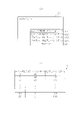
図11を参照しながら制御パターンテーブルについて、より具体的に説明する。なお、図11は15R確変大当たり結果となる場合に選択され得る制御パターンテーブルの一例である。 The control pattern table will be described more specifically with reference to FIG. In addition, FIG. 11 is an example of a control pattern table that can be selected when a 15R probability variable jackpot results.
図11に示すように制御パターンテーブルには、対象となる遊技回の継続時間に対応したフレーム数分のポインタ情報が設定されており、各ポインタ情報に対応させて、タスクの内容の情報と、コマンド出力の有無の情報と、追加データの情報とが設定されている。 As shown in FIG. 11, in the control pattern table, pointer information for the number of frames corresponding to the duration of the target game round is set. Information on presence/absence of command output and information on additional data are set.
タスクの内容の情報は今回の遊技回に対応した発光制御及び音出力制御を行うために設定されている情報であり、当該タスクの内容の情報を一切反映させないような情報が追加データとして設定されない限り、各フレームにおいてタスクの内容の情報に応じた態様で表示発光部44の発光制御が行われるとともにスピーカ部45の音出力制御が行われる。
Information about the content of the task is information that is set to perform light emission control and sound output control corresponding to the current game round, and information that does not reflect the information about the content of the task is not set as additional data. As long as, in each frame, the light emission control of the display
図11に示す制御パターンテーブルについて具体的には、「0」のポインタ情報に変動開始時のデータが設定されており、「200」のポインタ情報に予告演出開始時のデータが設定されており、「300」のポインタ情報に予告演出終了時のデータが設定されており、「400」のポインタ情報にノーマルリーチ開始時のデータが設定されており、「700」のポインタ情報に、スーパーリーチ開始時のデータが設定されており、「1000」のポインタ情報に、確定演出開始時のデータが設定されており、「1400」のポインタ情報に、変動終了時のデータが設定されている。これら各ポインタ情報は、演出の開始、演出の切り換わり、及び演出の終了といった区切りタイミングに対応している。また、これら以外のポインタ情報には、区切りタイミング間の発光制御及び音出力制御を可能とするためのデータが設定されている。 Specifically, regarding the control pattern table shown in FIG. 11, data at the start of fluctuation is set in the pointer information of "0", and data at the start of the notice effect is set in the pointer information of "200". The data at the end of the notice effect is set in the pointer information of "300", the data at the start of the normal reach is set in the pointer information of "400", and the data at the start of the super reach is set in the pointer information of "700". Data is set, data at the start of fixed effect is set in the pointer information of "1000", and data at the end of fluctuation is set in the pointer information of "1400". Each of these pieces of pointer information corresponds to delimitation timings such as the start of the presentation, the switching of the presentation, and the end of the presentation. In addition, data for enabling light emission control and sound output control between break timings is set in pointer information other than these.
コマンド出力の有無の情報は、音光側MPU62から表示CPU72へのコマンドの出力の有無、及びそのコマンドの種類を示す情報である。制御パターンテーブルに従って表示CPU72へのコマンド出力が行われることで、図柄表示装置41における画像の内容と、表示発光部44における発光内容と、スピーカ部45における音出力内容とを関連付けることが可能となる。つまり、図柄表示装置41における動画の内容に応じて、表示発光部44にて光の演出が実行されるとともに、スピーカ部45にて音出力の演出が実行される。
The information on the presence/absence of command output is information indicating the presence/absence of command output from the sound and
図11に示す制御パターンテーブルについて具体的には、タスクの内容において変動開始時のデータが設定されている「0」のポインタ情報に対して、コマンドデータが設定されている。したがって、遊技回の変動開始時には、音光側MPU62から表示CPU72へのコマンド送信に基づき、表示CPU72において表示制御が開始される。また、タスクの内容において、予告演出開始時のデータ、ノーマルリーチ開始時のデータ、スーパーリーチ開始時のデータ、確定演出開始時のデータ及び変動終了時のデータのそれぞれが設定されている各ポインタ情報、具体的には、「200」、「400」、「700」、「1000」、「1400」の各ポインタ情報に対して、コマンドデータが設定されている。したがって、主側MPU52から変動用コマンド及び種別コマンドが送信されるという所定の開始契機が発生したことにより開始される遊技回用の演出の範囲内において、遊技回用の演出に含まれる演出区分の種類が変化する場合には、音光側MPU62から表示CPU72へのコマンド送信に基づき、表示CPU72において新たな演出区分に対応する表示制御が開始される。
Specifically, in the control pattern table shown in FIG. 11, command data is set for pointer information of "0" in which data at the start of fluctuation is set in the contents of the task. Therefore, when the game cycle starts to fluctuate, display control is started in the
追加データの情報は、制御パターンテーブルの初期設定としてはブランクとして設定されており、報知の実行指示があった場合などに追加データへの書き込み処理が実行される。追加データへの書き込みが行われた場合には、当該追加データに書き込まれている情報がタスクの内容に元々設定されていた情報よりも優先される。例えば、報知として所定の文字を画像として表示することに対応した追加データが設定されている場合には、当該文字画像が、タスクの内容に対応した画像上に追加されるように画像表示がなされる。 The information of the additional data is set as blank as the initial setting of the control pattern table, and the writing process to the additional data is executed when there is an instruction to execute notification. When writing to the additional data is performed, the information written in the additional data has priority over the information originally set in the contents of the task. For example, when additional data corresponding to displaying a predetermined character as an image as notification is set, the image is displayed so that the character image is added to the image corresponding to the content of the task. be.
なお、制御パターンテーブルは遊技回用の演出以外にも、開閉実行モード用の演出や、遊技回用の演出及び開閉実行モード用の演出のいずれも実行されていない状況における演出に対応させて設けられている。このように様々な状況に対応させて制御パターンテーブルが設定されていることにより、音光側MPU62に動作電力が供給されている状況では何らかの制御パターンテーブルがRAM64に読み出された状態となっている。
In addition to the effects for the game cycle, the control pattern table is provided so as to correspond to effects for the opening and closing execution mode, and effects in situations where neither the effects for the game times nor the effects for the opening and closing execution mode are executed. It is Since the control pattern table is set to correspond to various situations in this manner, some control pattern table is read out to the
主側コマンド対応処理(図10)の説明に戻り、ステップS406では主側MPU52から報知実行コマンドを受信しているか否かを判定する。報知実行コマンドは、主側MPU52のタイマ割込み処理(図8)におけるステップS205の不正検知処理にて、不正用の監視対象として設定されている所定の事象が発生していることが特定された場合に出力されるとともに、ステップS212の入力状態監視処理にて、遊技機本体12又は前扉枠14が開放状態であることが特定された場合にも出力される。報知実行コマンドには報知対象の内容に対応したデータが含まれるため、音光側MPU62は受信した報知実行コマンドから報知対象の内容を特定することが可能である。
Returning to the description of the master side command correspondence processing (FIG. 10), in step S406, it is determined whether or not a notification execution command has been received from the
報知実行コマンドを受信している場合(ステップS406:YES)、報知開始用の設定処理を実行する(ステップS407)。報知開始用の設定処理では、現状設定されている制御パターンテーブルにおける現状のポインタ情報以降の追加データに、今回の報知実行コマンドに対応した報知を実行するためのデータを設定する。例えば、不正を検知したことに対応した報知実行コマンドを受信している場合には、不正報知を表示発光部44及びスピーカ部45にて行うためのデータを追加データとして設定する。また、遊技機本体12の開放といったパチンコ機10の状態変化に対応した報知実行コマンドを受信している場合には、状態報知を表示発光部44及びスピーカ部45にて行うためのデータを追加データとして設定する。これにより、表示発光部44及びスピーカ部45にて不正報知又は状態報知が実行される。なお、報知実行コマンドを受信した後であって報知解除コマンドを受信する前に、実行対象とする制御パターンテーブルが変更された場合にはその新たに変更された制御パターンテーブルの追加データに対して、直前の制御パターンテーブルの追加データに設定されていた内容と同様の内容の報知用データが設定される。これにより、報知の実行を継続することが可能となる。
If the notification execution command has been received (step S406: YES), setting processing for starting notification is executed (step S407). In the notification start setting process, data for executing notification corresponding to the current notification execution command is set as additional data after the current pointer information in the currently set control pattern table. For example, when a notification execution command corresponding to detection of fraud is received, data for performing fraud notification by the display
その後、ステップS408にて、今回受信した報知実行コマンドの内容に対応した報知実行コマンドを表示CPU72に送信する。これにより、報知実行コマンドに対応した報知画像が図柄表示装置41にて表示されるように、表示CPU72にて表示制御が実行される。
After that, in step S408, the notification execution command corresponding to the content of the notification execution command received this time is transmitted to the display CPU72. As a result, display control is executed by the
ステップS409では、主側MPU52から報知解除コマンドを受信しているか否かを判定する。報知解除コマンドは、主側MPU52のタイマ割込み処理(図8)におけるステップS205の不正検知処理にて、所定の事象が発生している状態が解除されたことが特定された場合に出力されるとともに、ステップS212の入力状態監視処理にて、遊技機本体12又は前扉枠14が開放されている状態から閉鎖されたことが特定された場合にも出力される。
In step S409, it is determined whether or not a notification cancellation command has been received from the
報知解除コマンドを受信している場合(ステップS409:YES)、報知解除用の設定処理を実行する(ステップS410)。報知解除用の設定処理では、現状設定されている制御パターンテーブルにおける現状のポインタ情報以降の追加データを「0」クリアする。これにより、表示発光部44及びスピーカ部45にて実行されている不正報知又は状態報知が解除される。その後、ステップS411にて、報知解除コマンドを表示CPU72に送信する。これにより、図柄表示装置41における報知画像の表示が終了される。
If the notification cancellation command has been received (step S409: YES), setting processing for notification cancellation is executed (step S410). In the notification cancellation setting process, additional data after the current pointer information in the currently set control pattern table is cleared to "0". As a result, the fraudulent notification or status notification that is being performed by the display
主側コマンド対応処理では、上記各処理以外にも、ステップS412にてその他の対応処理を実行する。その他の対応処理では、例えば、主側MPU52から最終停止コマンドを受信している場合には遊技回用の演出を終了させるための処理を実行する。また、主側MPU52からオープニングコマンドを受信している場合に開閉実行モード用の演出を実行するための制御パターンテーブルを読み出し、主側MPU52からエンディングコマンドを受信している場合には開閉実行モード用の演出を終了させるための処理を実行する。また、遊技回用の演出及び開閉実行モード用の演出のいずれもが実行されていない状況においては、待機中演出を実行するための制御パターンテーブルを読み出す。
In the master side command handling process, other handling processes are executed in step S412 in addition to the above processes. In other correspondence processing, for example, when a final stop command is received from the
<コマンド選択処理>
次に、タイマ割込み処理(図9)のステップS302にて実行されるコマンド選択処理について説明する。コマンド選択処理の説明に先立ち、音光側MPU62から表示CPU72に送信されるコマンドの内容について説明する。図12は当該コマンドの内容を説明するための説明図である。
<Command selection processing>
Next, the command selection process executed in step S302 of the timer interrupt process (FIG. 9) will be described. Before explaining the command selection process, the content of the command transmitted from the sound and
音光側MPU62から表示CPU72に送信されるコマンドは、複数バイトのデータ構成となっている。具体的には、図12(a)~図12(c)に示すように、第1コマンドデータCD1と、第2コマンドデータCD2と、第3コマンドデータCD3とを有している。第1コマンドデータCD1、第2コマンドデータCD2及び第3コマンドデータCD3は同一のバイト数となっており、具体的にはそれぞれ1バイトとなっている。但し、これに限定されることはなく各コマンドデータCD1~CD3のそれぞれが複数バイトである構成としてもよい。
A command transmitted from the sound and
第1コマンドデータCD1、第2コマンドデータCD2及び第3コマンドデータCD3のそれぞれは、上位2ビットが識別用ビットとしての機能を有し、残りの6ビットがデータ用ビットとしての機能を有する。識別用ビットには自身のコマンドデータが第1コマンドデータCD1、第2コマンドデータCD2及び第3コマンドデータCD3のうちいずれであるのかを示すデータが設定される。具体的には、第1コマンドデータCD1の識別用ビットには図12(a)に示すように「01」が設定されており、第2コマンドデータCD2の識別用ビットには図12(b)に示すように「10」が設定されており、第3コマンドデータCD3の識別用ビットには図12(c)に示すように「11」が設定されている。 In each of the first command data CD1, the second command data CD2, and the third command data CD3, the upper two bits function as identification bits, and the remaining six bits function as data bits. Data indicating which of the first command data CD1, the second command data CD2, and the third command data CD3 is the command data is set in the identification bit. Specifically, the identification bit of the first command data CD1 is set to "01" as shown in FIG. 12(a), and the identification bit of the second command data CD2 is set to "01" as shown in FIG. , and the identification bit of the third command data CD3 is set to "11" as shown in FIG. 12(c).
データ用ビットには、音光側MPU62から表示CPU72への指示内容に対応したデータが設定される。第1コマンドデータCD1のデータ用ビットには、指示内容のうち大枠の内容として第1種別の種類を表示CPU72に特定させるためのデータが設定される。具体的には、演出の実行を指示するコマンドであれば、遊技回用の演出、開閉実行モード用の演出及び待機中演出において実行される演出の種類のデータが設定されるとともに、報知の実行を指示するコマンドであれば、不正報知及び状態報知のうちいずれが実行対象であるかを示すデータが設定される。
Data corresponding to the content of the instruction from the sound and
第2コマンドデータCD2のデータ用ビットには、第1コマンドデータCD1により指定された第1種別の種類に含まれる第2種別の種類を表示CPU72に特定させるためのデータが設定される。また、第3コマンドデータCD3のデータ用ビットには、第2コマンドデータCD2により指定された第2種別の種類に含まれる第3種別の種類を表示CPU72に特定させるためのデータが設定される。
The data bits of the second command data CD2 are set with data for causing the
図13の説明図を参照しながら、演出の実行を指示するコマンドを例に挙げて、各コマンドデータCD1~CD3によりどのような内容が指示されるのかについて説明する。 With reference to the explanatory diagram of FIG. 13, the commands instructing the execution of effects will be taken as an example to explain what contents are instructed by the command data CD1 to CD3.
既に説明したとおり、本パチンコ機10では、遊技回用の演出として予告表示が発生し得る。予告表示は、図柄表示装置41にて全ての図柄列Z1~Z3にて図柄が変動表示されている状況において、又は一部の図柄列であって複数の図柄列にて図柄が変動表示されている状況において行われる演出であり、リーチ表示が行われる場合の方が行われない場合よりも予告表示が発生し易く、さらに大当たり結果に対応した遊技回の方が外れ結果に対応した遊技回に比べ予告表示が発生し易い。当該予告表示は複数種類設定されており、その一部として、ステップアップ予告及び会話予告が設定されている。
As already explained, in this
ステップアップ予告は段階的に実行される演出であり、実行対象となる段階数、演出の実行に際して表示される文字の表示色、及び表示対象となる予告キャラクタの種類の組合せによって、リーチ表示が行われる期待度及び大当たり結果が発生する期待度が示唆される。また、会話予告は第1予告キャラクタと第2予告キャラクタとの間で会話が行われているような表示が行われる演出であり、実行対象となる会話の内容、当該会話の文字の表示色、及び表示対象となる第1予告キャラクタ及び第2予告キャラクタの種類の組合せによって、リーチ表示が行われる期待度及び大当たり結果が発生する期待度が示唆される。 The step-up notice is an effect that is executed in stages, and the reach display is performed depending on the combination of the number of stages to be executed, the display color of the characters displayed when the effect is executed, and the type of notice character to be displayed. The degree of expectation to be given and the degree of expectation that a jackpot result will occur are suggested. In addition, the conversation notice is an effect in which the first notice character and the second notice character are displayed as if they are having a conversation. And the combination of the types of the first and second notice characters to be displayed suggests the degree of expectation for the ready-to-win display and the degree of expectation for the occurrence of the big win result.
第1コマンドデータCD1が16進数で表した場合において「41」である場合、ステップアップ予告に対応している。ステップアップ予告の場合、第2コマンドデータCD2によって、段階数、文字色及び予告キャラクタのいずれが指示対象であるのかが指示され、第3コマンドデータCD3によって、第2コマンドデータCD2により指示されている指示対象の具体的な内容が指示される。この場合、1種類のコマンドによって指示される内容は、ステップアップ予告に含まれる複数種類の第2種別の内容のうち1種類のみである。つまり、ステップアップ予告を実行する場合には、段階数、文字色及び予告キャラクタのそれぞれの種類を表示CPU72に指示する必要があるが、1種類のコマンドによっては1種類の第2種別の内容のみが指示される。したがって、ステップアップ予告の実行を指示する場合には、各コマンドデータCD1~CD3を含むコマンドを、第2種別の内容の種類分、具体的には3種類送信する必要がある。音光側MPU62は、ステップアップ予告の実行を指示すべく3種類のコマンドの送信を完了した場合、1バイトの終了コマンドを表示CPU72に送信する。終了コマンドは、他のコマンドにおいて使用されないデータ構成となっている。具体的には16進数で「FF」となっている。表示CPU72は、終了コマンドを受信した場合、今回の指示対象となっているコマンド群の送信が完了したことを特定する。これにより、ステップ予告の実行を指示するために第1~第3コマンドデータCD1~CD3からなるコマンドが複数種類送信される構成であったとしても、それらコマンドの全ての受信が完了したことを表示CPU72において明確に把握することが可能となる。
If the first command data CD1 is "41" in hexadecimal, it corresponds to the step-up notice. In the case of a step-up notice, the second command data CD2 indicates which of the step number, character color, and notice character is to be indicated, and the third command data CD3 indicates the second command data CD2. The specific content of the referent is indicated. In this case, the content instructed by one type of command is only one of the plurality of types of second type content included in the step-up notice. In other words, when executing the step-up notice, it is necessary to instruct the
第1コマンドデータCD1が16進数で表した場合において「42」である場合、会話予告に対応している。会話予告の場合、第2コマンドデータCD2によって、会話の内容、文字色、第1予告キャラクタ及び第2予告キャラクタのいずれが指示対象であるのかが指示され、第3コマンドデータCD3によって、第2コマンドデータCD2により指示されている指示対象の具体的な内容が指示される。この場合、会話予告の場合もステップアップ予告の場合と同様に、1種類のコマンドによって指示される内容は、会話予告に含まれる複数種類の第2種別の内容のうち1種類のみである。つまり、会話予告を実行する場合には、会話の内容、文字色、第1予告キャラクタ及び第2予告キャラクタのそれぞれの種類を表示CPU72に指示する必要があるが、1種類のコマンドによっては1種類の第2種別の内容のみが指示される。したがって、会話予告の実行を指示する場合には、各コマンドデータCD1~CD3を含むコマンドを、第2種別の内容の種類分、具体的には4種類送信する必要がある。音光側MPU62は、会話予告の実行を指示すべく4種類のコマンドの送信を完了した場合、ステップアップ予告の場合と同様に、1バイトの終了コマンドを表示CPU72に送信する。これにより、会話予告の実行を指示するために第1~第3コマンドデータCD1~CD3からなるコマンドが複数種類送信される構成であったとしても、それらコマンドの全ての受信が完了したことを表示CPU72において明確に把握することが可能となる。また、ステップアップ予告と会話予告とで音光側MPU62から送信されるコマンドの総数が相違しているとしても各演出に対応したコマンドの全ての送信が完了した場合に終了コマンドが送信されることで、各演出に対応したコマンドの全ての受信が完了したことを表示CPU72において明確に把握することが可能となる。
If the first command data CD1 is "42" in hexadecimal notation, it corresponds to a conversation announcement. In the case of a conversation notice, the second command data CD2 instructs the contents of the conversation, the character color, and which of the first notice character and the second notice character is to be indicated. The specific content of the object indicated by the data CD2 is indicated. In this case, in the case of the conversation advance notice, as in the case of the step-up advance notice, the content indicated by one type of command is only one of the plurality of types of second type content included in the conversation advance notice. In other words, when executing a conversation preview, it is necessary to instruct the
なお、他の演出の実行指示に際しても複数種類の第2種別の内容を指示すべく、所定の演出の実行を指示するコマンドの送信に際しては複数種類のコマンドが送信されるとともに、それらコマンドの送信が完了した場合には終了コマンドが送信される。また、第2種別の内容が1種類のみの演出も存在しているが、かかる演出の実行を指示する場合には各コマンドデータCD1~CD3を含む1種類のコマンドを送信するとともにその送信が完了した場合に終了コマンドを送信する。また、音光側MPU62は演出の実行指示用のコマンドだけでなく報知の実行指示用のコマンドを送信する場合にも最終的に終了コマンドを送信する。これにより、表示CPU72は終了コマンドを受信したか否かで、所定の指示を行うための音光側MPU62からのコマンドの受信が完了したか否かを把握することが可能となる。
It should be noted that, in order to instruct a plurality of types of second type content when instructing execution of other effects, a plurality of types of commands are transmitted when sending a command for instructing execution of a predetermined effect, and these commands are also transmitted. is completed, an end command is sent. In addition, there is an effect in which only one type of content of the second type exists, but when instructing execution of such effect, one type of command including each command data CD1 to CD3 is transmitted and the transmission is completed. Send the end command if Further, the sound/
所定期間において実行される予告表示の実行内容を音光側MPU62が表示CPU72に指示する場合、当該予告表示に含まれる第2段階の内容に対応させて、第1~第3コマンドデータCD1~CD3からなるコマンドが複数種類送信される。これにより、第2段階の種類数を増減させる場合や、第2段階の内容を変更する場合であっても、対応する第2段階の単位でコマンドの変更を行えばよいため、コマンドの設定の容易化が図られる。
When the sound and
また、このように第2種別の内容に1対1で対応させて複数種類のコマンドを送信する構成とすることにより、一のコマンドがノイズの影響などで伝送途中にデータが書き換えられたとしても、その影響を1種類の第2種別の内容に留めることが可能となる。 In addition, by adopting a configuration in which a plurality of types of commands are transmitted in such a one-to-one correspondence with the content of the second type, even if the data of one command is rewritten during transmission due to the influence of noise or the like, , the influence can be confined to the content of the second type.
複数のコマンドデータCD1~CD3によって段階的に指示内容を決定付ける構成とすることで、音光側MPU62から表示CPU72に指示する内容が多様化する場合であっても、パチンコ機10の設計段階におけるコマンドの設計の容易化が図られる。
By adopting a configuration in which the instruction contents are determined step by step by a plurality of command data CD1 to CD3, even if the contents instructed from the sound and
また、ステップアップ予告の実行を指示するためのコマンドにおいて第2コマンドデータCD2として利用されるデータは、会話予告の実行を指示するためのコマンドにおける第2コマンドデータCD2としてそのまま利用され、同様に、ステップアップ予告の実行を指示するためのコマンドにおいて第3コマンドデータCD3として利用されるデータは、会話予告の実行を指示するためのコマンドにおける第3コマンドデータCD3としてそのまま利用される。これら各コマンドデータCD1~CD3として利用されるデータはROM63に予め記憶されているが、上記のように第2コマンドデータCD2として利用されるデータ、及び第3コマンドデータCD3として利用されるデータが、複数種類のコマンドにおいて共通して利用される構成であることにより、ROM63においてコマンド用のデータを記憶するのに必要なデータ容量を抑えることが可能となる。
Further, the data used as the second command data CD2 in the command for instructing the execution of the step-up notice is used as it is as the second command data CD2 in the command for instructing the execution of the conversation notice. The data used as the third command data CD3 in the command for instructing the execution of the step-up notice is used as it is as the third command data CD3 in the command for instructing the execution of the conversation notice. The data used as the respective command data CD1 to CD3 are stored in advance in the
以下、上記コマンドを送信するために音光側MPU62にて実行されるコマンド選択処理について、図14のフローチャートを参照しながら説明する。
The command selection process executed by the sound and
制御パターンテーブルにおける現状のポインタ情報に対応したエリアに、表示CPU72へのコマンドの送信タイミングを示すデータが設定されている場合(ステップS501:YES)、当該制御パターンテーブルから今回の送信タイミングにおけるコマンドの種類数を読み出し、その種類数に対応する値をRAM64に設けられたコマンド種類数カウンタにセットする(ステップS502)。その後、制御パターンテーブルにおける現状のポインタ情報に対応したエリアにて指示されているROM63のコマンド用エリアのアドレスデータであって、現状のコマンド種類数カウンタの値に対応したアドレスデータを特定する。そして、その特定したアドレスデータに従って、第1コマンドデータCD1、第2コマンドデータCD2及び第3コマンドデータCD3をROM63から読み出し(ステップS503~ステップS505)、それら読み出した各コマンドデータCD1~CD3をコマンド送信対象用エリアとしてRAM64に設けられたリングバッファにセットする(ステップS506)。音光側MPU62はタイマ割込み処理(図9)とは別に定期的(例えば1msec)に起動される送信割込み処理にて、リングバッファにセットされているコマンドを順次読み出して表示CPU72に送信する。この場合、リングバッファにセットされたタイミングが早いコマンドから順に送信する。
If the area corresponding to the current pointer information in the control pattern table contains data indicating the transmission timing of the command to the display CPU 72 (step S501: YES), the command at the current transmission timing is determined from the control pattern table. The number of types is read, and a value corresponding to the number of types is set in the command type number counter provided in the RAM 64 (step S502). After that, the address data corresponding to the current value of the command type number counter, which is the address data of the command area of the
その後、コマンド種類数カウンタの値を1減算し(ステップS507)、その1減算後におけるコマンド種類数カウンタの値が「0」となっているか否かを判定する(ステップS508)。「0」となっていない場合には、更新後のコマンド種類数カウンタの値に対応したコマンドについてステップS503~ステップS506の処理を実行する。「0」となっている場合にはステップS509にて、ROM63から終了コマンドを読み出して上記リングバッファにセットする。
After that, 1 is subtracted from the value of the command type number counter (step S507), and it is determined whether or not the value of the command type number counter after the 1 subtraction is "0" (step S508). If it is not "0", the processing of steps S503 to S506 is executed for the command corresponding to the updated value of the command type number counter. If it is "0", in step S509, the end command is read from the
<表示CPU72の処理構成>
次に、表示CPU72にて実行される処理について説明する。図15は表示CPU72にて予め定められた周期、具体的には20msec周期で繰り返し起動されるV割込み処理を示すフローチャートである。
<Processing Configuration of
Next, processing executed by the
なお、VDP76は図柄表示装置41に1フレーム分の画像信号を出力する場合、表示面Pの左上の隅角部分にあるドットから画像信号の出力を始めて、当該ドットを一端に含む横ライン上に並ぶドットに対して順次画像信号を出力するとともに、各横ラインに対して上から順に左から右のドットへと画像信号を出力する。そして、表示面Pの右下の隅角部分にあるドットに対して最後に画像信号を出力する。この場合に、VDP76は当該最後のドットに対して画像信号を出力したタイミングで、表示CPU72へV割込み信号を出力して1フレームの画像の更新が完了したことを表示CPU72に認識させる。このV割込み信号の出力周期は20msecとなっている。この点、V割込み処理は、V割込み信号の受信に同期して起動されると見なすこともできる。但し、V割込み信号を受信していなくても、前回のV割込み処理が起動されてから20msecが経過している場合には、新たにV割込み処理が起動される。
When the
V割込み処理では、まずステップS601にてコマンド解析処理を実行する。コマンド解析処理では、図16(a)のフローチャートに示すように、ステップS701にて、音光側MPU62から新たなコマンドを受信しているか否かを判定する。表示CPU72は音光側MPU62からストローブ信号を受信した場合、その時点で実行されている処理が何であったとしても最優先でコマンド割込み処理を起動し、入力ポート77にて受信しているコマンドを、ワークRAM73に設けられたコマンド格納バッファ101に格納する。
In the V interrupt process, command analysis processing is first executed in step S601. In the command analysis process, as shown in the flowchart of FIG. 16A, in step S701, it is determined whether or not a new command has been received from the sound and
コマンド格納バッファ101について詳細には、図16(b)に示すように、第1未処理エリア102と、第2未処理エリア103と、第3未処理エリア104とを備えている。各未処理エリア102~104はそれぞれ、コマンド格納エリア102a~102e,103a~103e,104a~104eを5個備えている。各コマンド格納エリア102a~102e,103a~103e,104a~104eはそれぞれ、第1コマンドデータCD1、第2コマンドデータCD2及び第3コマンドデータCD3からなる1種類のコマンドを格納することが可能となるように3バイトのデータ構成となっている。また、各未処理エリア102~104に設けられているコマンド格納エリア102a~102e,103a~103e,104a~104eの数は、音光側MPU62から演出の実行指示又は報知の実行指示が1回行われる場合に送信されるコマンドの最大種類数以上となっている。これにより、各未処理エリア102~104のそれぞれにおいて1回の演出の実行指示に際して送信されるコマンド群及び1回の報知の実行指示に際して送信されるコマンド群を格納することが可能となる。また、未処理エリア102~104の数は、表示CPU72にて未処理の状態で待機し得るコマンド群の最大数以上となっている。これにより、未処理のコマンド群が待機し得る構成において、コマンド群に対応した処理の実行漏れを防止することが可能となる。
Specifically, the
コマンド割込み処理では、終了コマンドを前回受信してからコマンドを新たに受信した場合、第1未処理エリア102に未処理のコマンド群が格納されていない場合には第1未処理エリア102にそのコマンドを格納し、第1未処理エリア102に未処理のコマンド群が格納されている場合には第2未処理エリア103にそのコマンドを格納し、第2未処理エリア103に未処理のコマンド群が格納されている場合には第3未処理エリア104にそのコマンドを格納する。そして、終了コマンドを受信するまではコマンドを受信する度に、格納対象とした未処理エリアのコマンド格納エリアに対するコマンド格納処理を順次実行する。終了コマンドを受信した場合には、コマンド格納対象の未処理エリアを次の順番のエリアに設定する。なお、コマンド割込み処理ではコマンドを格納する処理を実行した場合、未処理エリア102~104においていずれのコマンド格納エリア102a~102e,103a~103e,104a~104eにコマンドが格納されているのかを特定可能とするためのデータ設定を行う。 In the command interrupt process, when a new command is received after the end command was previously received, and if an unprocessed command group is not stored in the first unprocessed area 102, the command is stored in the first unprocessed area 102. is stored in the first unprocessed area 102, the command is stored in the second unprocessed area 103, and the unprocessed command group is stored in the second unprocessed area 103. If stored, the command is stored in the third unprocessed area 104 . Each time a command is received, the command storage area of the unprocessed area to be stored is sequentially executed until the end command is received. When the end command is received, the unprocessed area for storing the command is set to the area of the next order. In the command interrupt processing, when the command storage processing is executed, it is possible to identify which of the command storage areas 102a to 102e, 103a to 103e, and 104a to 104e in the unprocessed areas 102 to 104 the command is stored. Make data settings for
コマンド解析処理(図16(a))の説明に戻り、ステップS701では未処理エリア102~104へのコマンドの格納が新たに開始されたか否かを判定する。ステップS701にて肯定判定をした場合には、コマンド群の受信中であるか否かを表示CPU72にて特定するためにワークRAM73に設けられた受信中フラグに「1」をセットする。ステップS702の処理を実行した場合、又は受信中フラグに「1」がセットされている場合(ステップS703:YES)、ステップS704にて終了コマンドを受信したか否かを判定する。終了コマンドを受信している場合(ステップS704:YES)、ワークRAM73に設けられた未処理カウンタの値を1加算するとともに(ステップS705)、受信中フラグを「0」クリアする(ステップS706)。
Returning to the description of the command analysis process (FIG. 16(a)), in step S701, it is determined whether or not command storage in the unprocessed areas 102 to 104 has newly started. If an affirmative determination is made in step S701, a receiving flag provided in the
V割込み処理(図15)の説明に戻り、ステップS601にてコマンド解析処理を実行した後は、ワークRAM73の未処理カウンタの値が1以上であることを条件として(ステップS602:YES)、ステップS603にてコマンド対応処理を実行し、ステップS604にて未処理カウンタの値を1減算する。コマンド対応処理について図17のフローチャートを参照しながら詳細に説明する。
Returning to the description of the V interrupt processing (FIG. 15), after executing the command analysis processing in step S601, on condition that the value of the unprocessed counter of the
まず今回の処理対象のコマンドの読み出し処理を実行する(ステップS801)。具体的には、ワークRAM73のコマンド格納バッファ101における第1未処理エリア102に格納されているコマンドをワークRAM73の処理対象コマンド用のエリアに書き込む。なお、当該書き込みを実行した場合には、コマンド格納バッファ101において第2未処理エリア103の各データを第1未処理エリア102に上書きした後に、第3未処理エリア104の各データを第2未処理エリア103に上書きする。
First, read processing of the command to be processed this time is executed (step S801). Specifically, the command stored in the first unprocessed area 102 in the
その後、今回の処理対象のコマンドの種類数に対応した値をワークRAM73に設けられた処理対象カウンタにセットする(ステップS802)。その後、今回の処理対象のコマンドにおける第1コマンドデータCD1に対応した参照テーブルをメモリモジュール74から読み出す(ステップS803)。参照テーブルは、第1コマンドデータCD1のデータ内容に1対1で対応させて設けられており、処理対象のコマンドに対応した画像表示を図柄表示装置41にて実行するための表示パターンテーブルを特定するためのデータが設定されている。
Thereafter, a value corresponding to the number of types of commands to be processed this time is set in the processing object counter provided in the work RAM 73 (step S802). After that, the reference table corresponding to the first command data CD1 in the command to be processed this time is read from the memory module 74 (step S803). The reference table is provided in one-to-one correspondence with the data contents of the first command data CD1, and specifies the display pattern table for executing the image display corresponding to the command to be processed on the
ステップアップ予告に対応したデータが第1コマンドデータCD1に設定されている場合の参照テーブルRTについて、図18の説明図を参照しながら説明する。 The reference table RT when data corresponding to the step-up notice is set in the first command data CD1 will be described with reference to the explanatory diagram of FIG.
参照テーブルRTには、ステップアップ予告において全ての第2種別の種類について生じ得る全ての第3種別の種類の組合せに1対1で対応させて実行対象テーブルのアドレスが設定されている。例えば、第2種別の種類が「段階数」である場合における第3種別の種類が「2」であり、第2種別の種類が「文字色」である場合における第3種別の種類が「赤色」であり、第2種別の種類が「予告キャラクタ」である場合における第3種別の種類が「第24キャラクタ」である場合、参照テーブルRTにおいて第2段階赤24テーブルのアドレスが実行対象テーブルのアドレスとして設定されている。 In the reference table RT, the addresses of the execution target table are set in a one-to-one correspondence with all possible combinations of the third type for all the types of the second type in the step-up notice. For example, when the type of the second type is "step number", the type of the third type is "2", and when the type of the second type is "character color", the type of the third type is "red and the type of the third type is "24th character" in the case where the type of the second type is "notice character", the address of the second stage red 24 table in the reference table RT is the address of the execution target table. set as an address.
実行対象テーブルは、音光側MPU62からの1回のコマンド群の送信に対応した動画を図柄表示装置41の表示面Pに表示させる場合において、画像の各更新タイミングにおける1フレーム分の画像を表示させるのに必要な処理が定められた情報群である。実行対象テーブルには、当該実行対象テーブルによる動画の表示期間に含まれる更新タイミングの数分のポインタ情報が設定されているとともに、各ポインタ情報のそれぞれに対応させて当該ポインタ情報に対応した更新タイミングにおける画像の表示を可能とするためのデータが設定されている。
The execution target table displays an image of one frame at each update timing of the image when a moving image corresponding to one transmission of the command group from the sound and
コマンド対応処理(図17)の説明に戻り、ステップS803にて参照テーブルを読み出した後は、ステップS801にてワークRAM73の処理対象コマンドのエリアに書き込んだコマンドのうち、現状の処理対象カウンタの値に対応したコマンドを読み出し、そのコマンドにおける第2コマンドデータCD2及び第3コマンドデータCD3の組合せに対応したデータを表示CPU72のレジスタに書き込む(ステップS804)。処理対象カウンタの値は、第1未処理エリア102のコマンド格納エリア102a~102eと1対1で対応しており、ステップS804では、現状の処理対象カウンタの値に対応したコマンド格納エリアから処理対象コマンド用のエリアに書き込まれたコマンドを上記データの読み出し対象とする。
Returning to the description of the command correspondence processing (FIG. 17), after reading the reference table in step S803, among the commands written in the processing target command area of the
ステップS804の処理を実行した後はステップS805にて処理対象カウンタの値を1減算する。そして、ステップS806にて、その1減算後の処理対象カウンタの値が「0」となっているか否かを判定する。「0」となっていない場合には、更新後の処理対象カウンタの値に対応したコマンドについてステップS804の処理を実行する。「0」となっている場合には、ステップS807にて実行対象テーブルの読み出し処理を実行する。当該読み出し処理では、ステップS804にて表示CPU72のレジスタに読み出したデータに対応した実行対象テーブルのアドレスを、ステップS803にて読み出した参照テーブルから特定し、メモリモジュール74におけるその特定したアドレスのエリアに記憶されている実行対象テーブルをワークRAM73に読み出す。これにより、処理対象のコマンドに対応した実行対象テーブルの読み出しが完了し、当該処理対象のコマンドに対応した動画を図柄表示装置41にて表示させることが可能となる。
After executing the processing of step S804, the value of the counter to be processed is decremented by 1 in step S805. Then, in step S806, it is determined whether or not the value of the counter to be processed after the subtraction of 1 is "0". If it is not "0", the process of step S804 is executed for the command corresponding to the updated processing target counter value. If it is "0", the read processing of the execution target table is executed in step S807. In the read processing, the address of the execution target table corresponding to the data read to the register of the
ちなみに、遊技回用の演出、開閉実行モード用の演出及び待機演出といった演出を実行するための実行対象テーブルに基づく表示制御が実行されている状況で、不正報知又は状態報知を実行するための実行対象テーブルが読み出される場合、既に読み出されている演出用の実行対象テーブルをワークRAM73に記憶保持しながら報知用の実行対象テーブルをワークRAM73に読み出す。そして、後述するタスク処理(図19)ではそれら実行対象テーブルの両方に対応した画像の表示を可能とする演算処理を実行し、後述するポインタ更新処理(ステップS607)ではそれら実行対象テーブルの各ポインタ情報の更新を行う。
By the way, in a situation where display control based on the execution target table for executing effects such as the effect for the game cycle, the effect for the opening and closing execution mode, and the standby effect is executed, the execution for executing fraud notification or status notification When the target table is read, the execution target table for notification is read to the
V割込み処理(図15)の説明に戻り、ステップS603のコマンド対応処理にて、不正報知用又は状態報知用の実行対象テーブルが新たにセットされた場合(ステップS605:YES)、又は不正報知用又は状態報知用の実行対象テーブルが新たにセットされていない場合(ステップS605:NO)であってもワークRAM73に設けられた演算完了フラグに「1」がセットされている場合(ステップS606:YES)、ステップS607にて、ポインタ更新処理を実行するとともに、演算完了フラグを「0」クリアする。ポインタ更新処理では、現状の実行対象テーブルのポインタ情報を次の更新タイミングに対応したポインタ情報に更新する。なお、コマンド対応処理(ステップS603)にて実行対象テーブルが新たにセットされた直後のステップS607では、最初の更新タイミングに対応したポインタ情報となるように当該ポインタ情報の更新処理を実行する。演算完了フラグは、一の更新タイミングに対応した画像を表示させるための各種演算処理が、V割込み処理の前回の処理実行回において完了しているか否かを表示CPU72にて特定するためのフラグである。
Returning to the description of the V interrupt process (FIG. 15), in the command handling process of step S603, if a new execution target table for fraud notification or status notification is set (step S605: YES), or Alternatively, even if the execution target table for status notification is not newly set (step S605: NO), the operation completion flag provided in the
ステップS607の処理を実行した後は、ステップS608にてタスク処理を実行する。タスク処理では、今回の更新タイミングに対応した1フレーム分の画像を表示させるために、VDP76に描画指示を行う上で必要なパラメータの演算を行う。パラメータとして具体的には、メモリモジュール74において制御対象の画像データが記憶されているエリアのアドレス情報、VRAM75において制御対象の画像データを転送するエリアのアドレス情報、制御対象の画像データを用いて描画データを作成すべき対象のフレーム領域82a,82bの情報、作成対象のフレーム領域82a,82bにおいて制御対象の画像データを書き込む際の座標の情報、当該画像データを書き込む際のスケールの情報、及び当該画像データを書き込む際の一律α値(半透明値)の情報が含まれている。
After executing the processing of step S607, task processing is executed in step S608. In the task processing, in order to display an image of one frame corresponding to the update timing of this time, parameters necessary for instructing drawing to the
その後、ステップS609にて描画リスト出力処理を実行する。描画リスト出力処理では、今回の処理回に係る更新タイミングに対応した1フレーム分の画像を表示させるための描画リストを作成し、その作成した描画リストをVDP76に送信する。この場合、当該描画リストでは、直前のタスク処理にて把握された画像が描画対象となり、さらに当該タスク処理にて更新したパラメータ情報が合わせて設定される。VDP76では、この描画リストに従ってVRAM75のフレーム領域82a,82bに描画データを作成する。このVDP76における処理については後に詳細に説明する。
Thereafter, drawing list output processing is executed in step S609. In the drawing list output process, a drawing list for displaying an image of one frame corresponding to the update timing of the current processing is created, and the created drawing list is transmitted to the
ステップS608のタスク処理について図19のフローチャートを参照しながら説明する。まずステップS901では、ワークRAM73に設けられた遅延中フラグに「1」がセットされているか否かを判定する。タスク処理では、詳細は後述するように背景用演算処理、演出用演算処理及び図柄用演算処理といった各種演算処理を実行する。この場合、図柄表示装置41に表示させる個別画像の数、個別画像の種類及び個別画像の表示態様によって各種演算処理の実行に要する期間が変動する。そして、期間が変動した結果、タスク処理において全ての演算処理の実行が完了するまでに、V割込み処理の次の処理回を開始すべきタイミングとなることが起こり得る。この場合に、V割込み処理の実行を待機すると、音光側MPU62からのコマンド送信に対して表示CPU72において迅速に対処することができなくなってしまう。そこで、タスク処理の実行途中にV割込み処理の次の処理回を開始すべきタイミングとなった場合には、タスク処理をそのまま続行するのではなく、V割込み処理の新たな処理回を開始する構成となっている。但し、V割込み処理の新たな処理回を開始する場合には、その時点におけるタスク処理の演算結果を記憶保持し、その新たな処理回のV割込み処理におけるタスク処理にてその演算途中から演算処理を再開することで、一の更新タイミング分の演算処理が実行されないままとなってしまわないようにしている。これにより、例えば所定の個別画像を表示させるためのパラメータの更新が前回の更新値からの差分により制御される構成においてパラメータの更新が1回飛んでしまいその後のパラメータの更新が正確に行えなくなってしまうといった不都合の発生を抑制することが可能となる。遅延中フラグは、上記のようにタスク処理における各種演算処理の実行が一旦中断されて遅延されている状況であるか否かを表示CPU72にて特定するためのフラグである。なお、個別画像とは、背景データといった静止画像データにより規定される一の静止画像や、図柄スプライトデータといったスプライトデータにより規定される一のスプライトのことである。
The task processing in step S608 will be described with reference to the flowchart of FIG. First, in step S901, it is determined whether or not the delay flag provided in the
遅延中フラグに「1」がセットされていない場合(ステップS901:NO)、制御開始用の設定処理を実行する(ステップS902)。制御開始用の設定処理では、まず現状設定されている実行対象テーブルに基づいて、今回の処理回で制御開始対象となる個別画像が存在しているか否かを判定する。存在している場合には、ワークRAM73において、個別画像の制御を行う上で各種演算を行うための空きバッファ領域を検索して、制御開始対象として把握されている個別画像に1対1で対応するように空きバッファ領域を確保する。さらに、確保した全ての空きバッファ領域に対して初期化処理を実行するとともに、初期化した空きバッファ領域に対して、個別画像に応じた制御開始用のパラメータ情報を設定する。
If the delay flag is not set to "1" (step S901: NO), setting processing for starting control is executed (step S902). In the control start setting process, first, based on the currently set execution target table, it is determined whether or not there is an individual image to be the control start target in this processing cycle. If it exists, the
続くステップS903では、制御更新対象を把握する。この制御更新対象は、制御開始処理が完了している個別画像であって今回の処理回以降に1フレーム分の画像に含まれる可能性がある個別画像が対象となる。 In the following step S903, the control update target is grasped. This control update target is an individual image for which control start processing has been completed and which may be included in an image for one frame after the current processing.
その後、ステップS904にてV割込み処理の新たな起動を許可し、直後のステップS905にてV割込み処理の新たな起動を禁止した後に、背景用演算処理を実行する(ステップS906)。背景用演算処理では、背景の画像を構成することとなる最背面用の静止画像や背景用スプライトのうち今回の制御更新対象を把握する。また、その把握した制御更新対象について、仮想2次元平面における座標、回転角度、スケール、一律α値及びαデータ指定などといった描画リストを作成する上で必要な各種パラメータ情報を演算して導き出す。そして、その導き出した各種パラメータ情報を、ワークRAM73において各個別画像に対応させて確保されたエリアに書き込むことで制御用の情報を更新する。
After that, in step S904, new activation of the V interrupt process is permitted, and in immediately following step S905, new activation of the V interrupt process is prohibited, and then background arithmetic processing is executed (step S906). In the background arithmetic processing, the control update target of this time among the backmost still image and the background sprite that constitute the background image is grasped. In addition, for the grasped control update target, various parameter information necessary for creating a drawing list such as coordinates on a virtual two-dimensional plane, rotation angle, scale, uniform α value and α data designation are calculated and derived. Then, the information for control is updated by writing the derived various parameter information in an area secured corresponding to each individual image in the
その後、ステップS907にてV割込み処理の新たな起動を許可し、直後のステップS908にてV割込み処理の新たな起動を禁止した後に、演出用演算処理を実行する(ステップS909)。演出用演算処理では、リーチ表示、予告表示及び大当たり演出といった各種演出において表示対象となる演出の画像を構成する演出スプライトのうち今回の制御更新対象を把握する。また、その把握した制御更新対象について、上記各種パラメータ情報を導き出す。そして、その導き出した各種パラメータ情報を、ワークRAM73において各個別画像に対応させて確保されたエリアに書き込むことで制御用の情報を更新する。
After that, in step S907, a new activation of V interrupt processing is permitted, and in step S908 immediately after, new activation of V interrupt processing is prohibited. In the effect arithmetic processing, the control update target of this time is grasped among the effect sprites constituting the image of the effect to be displayed in various effects such as ready-to-win display, advance notice display and jackpot effect. Also, the above various parameter information is derived for the grasped control update target. Then, the information for control is updated by writing the derived various parameter information in an area secured corresponding to each individual image in the
その後、ステップS910にてV割込み処理の新たな起動を許可し、直後のステップS911にてV割込み処理の新たな起動を禁止した後に、図柄用演算処理を実行する(ステップS912)。図柄用演算処理では、各遊技回において変動表示の対象となる図柄のうち、今回の制御更新対象を把握する。また、その把握した制御更新対象について、上記各種パラメータ情報を導き出す。そして、その導き出した各種パラメータ情報を、ワークRAM73において各個別画像に対応させて確保されたエリアに書き込むことで制御用の情報を更新する。
Thereafter, a new activation of the V interrupt process is permitted in step S910, and after prohibiting a new activation of the V interrupt process in step S911 immediately after, the symbol calculation process is executed (step S912). In the symbol arithmetic processing, among the symbols to be changed and displayed in each game round, the current control update target is grasped. Also, the above various parameter information is derived for the grasped control update target. Then, the information for control is updated by writing the derived various parameter information in an area secured corresponding to each individual image in the
ちなみに、ステップS906、ステップS909及びステップS912の各演算処理では、個別画像の各種パラメータ情報を画像更新タイミングとなる度に、特定のパターンに従って変化させるように設定されたアニメーション用データが用いられる。このアニメーション用データは、個別画像の種類に応じて定められている。また、図柄用演算処理では、不正報知用又は状態報知用の実行対象テーブルがワークRAM73に読み出されている場合、当該実行対象テーブルに対応した報知画像を表示するための演算処理を実行するとともにその報知画像を表示するための報知スプライト、及び当該報知スプライトに適用する各種パラメータ情報を導出する。
Incidentally, each calculation process in steps S906, S909, and S912 uses animation data set so as to change various parameter information of individual images according to a specific pattern each time the image update timing comes. This animation data is determined according to the type of individual image. Further, in the symbol arithmetic processing, when an execution object table for fraud notification or status notification is read into the
その後、ステップS913にて、ワークRAM73に設けられた演算完了フラグに「1」をセットする。演算完了フラグは、ステップS906の背景用演算処理、ステップS909の演出用演算処理及びステップS912の図柄用演算処理をそれぞれ1回ずつ実行したことを表示CPU72にて特定するためのフラグである。
After that, in step S913, the operation completion flag provided in the
その後、ステップS914にて描画指示対象の把握処理を実行する。描画指示対象の把握処理では、上記ステップS906、ステップS909及びステップS912の各演算処理により制御更新対象となった各個別画像のうち、今回の描画データの作成指示に係る1フレーム分の画像に含まれる個別画像を把握する処理を実行する。当該把握は、各種個別画像の座標、回転角度及びスケールの情報とを参照して予め定められた演算を実行することで行われる。ここで把握された個別画像が、描画リストにおいて描画対象として設定される。このように描画リストにて指定する個別画像を、制御開始済みの全ての個別画像とするのではなく、表示対象の個別画像のみとすることで、VDP76において表示対象の個別画像を選別する必要がなく、また選別しないとしても表示対象ではない個別画像について無駄に描画処理を行う必要がなくなる。これにより、VDP76の処理負荷の低減が図られる。
After that, in step S914, a drawing instruction target grasping process is executed. In the drawing instruction target grasping process, out of the individual images that have become control update targets by the respective arithmetic processing in steps S906, S909, and S912, the image included in the one-frame image related to the current drawing data creation instruction. Executes processing to grasp the individual images that are included. The grasping is performed by executing a predetermined calculation with reference to the coordinates, rotation angle and scale information of various individual images. The individual image grasped here is set as a drawing target in the drawing list. In this way, the individual images specified in the drawing list are not all the individual images for which control has been started, but only the individual images to be displayed. Moreover, even if the images are not selected, there is no need to uselessly draw the individual images that are not to be displayed. This reduces the processing load on the
ここで、V割込み処理の新たな処理回が開始された場合には当該V割込み処理の新たな起動が禁止されることとなるが、ステップS906の背景用演算処理、ステップS909の演出用演算処理及びステップS912の図柄用演算処理が実行される前の各タイミングで、V割込み処理の新たな起動が許可される(ステップS904、ステップS907及びステップS910)。これにより、ステップS904、ステップS907又はステップS910が実行された時点でV割込み処理の新たな処理回の開始タイミングとなっている場合、すなわち今回のV割込み処理が開始されてから既に20msecが経過している場合には、タスク処理がその時点で中断されて、V割込み処理の新たな処理回が開始されて上述したステップS601の処理を開始する。これにより、V割込み処理の新たな処理回の開始タイミングとなっているにも関わらずV割込み処理の新たな処理回の開始が待機されている期間を短くすることが可能となる。 Here, when a new processing cycle of the V interrupt process is started, the new activation of the V interrupt process is prohibited. And at each timing before the symbol arithmetic processing of step S912 is executed, a new start of the V interrupt processing is permitted (steps S904, S907 and S910). As a result, if it is time to start a new V interrupt process when step S904, step S907, or step S910 is executed, that is, 20 msec has already passed since the current V interrupt process started. If so, task processing is interrupted at that point, a new processing cycle of V interrupt processing is started, and the processing of step S601 described above is started. As a result, it is possible to shorten the period in which the start of a new V-interrupt process waits even though it is time to start a new V-interrupt process.
但し、このようにV割込み処理の新たな処理回が開始される場合であっても、今回のタスク処理におけるそれまでの処理結果に対応したデータはそのまま記憶保持される。また、この場合、ワークRAM73に設けられた中断時用アドレスエリア111に、当該V割込み処理の新たな処理回が開始される直前に実行されていた処理に対応したアドレスデータが書き込まれる。中断時用アドレスエリア111に書き込まれたアドレスデータが、新たな処理回のV割込み処理におけるタスク処理の開始に際して参照されることで、前回のタスク処理において中断が発生したタイミングから処理の実行を再開することが可能となる。
However, even when a new processing cycle of the V interrupt processing is started in this manner, the data corresponding to the processing results up to that point in the current task processing are stored and retained as they are. Further, in this case, address data corresponding to the process executed immediately before the start of a new process cycle of the V interrupt process is written in the interrupt
また、ステップS904、ステップS907及びステップS910にてV割込み処理の新たな起動を許可した場合、ステップS905、ステップS908及びステップS911にてその新たな起動を禁止した後にステップS906の背景用演算処理、ステップS909の演出用演算処理及びステップS912の図柄用演算処理を実行する。これにより、各種演算処理の実行途中でV割込み処理の新たな処理回が開始されてしまわないようにすることが可能となる。各種演算処理の実行途中でV割込み処理の新たな処理回が開始されると、記憶保持すべき演算途中のデータのデータ量が極端に多くなってしまうことが想定され、さらにV割込み処理の新たな処理回において演算途中の状態に復帰する場合におけるアドレスデータの内容も複雑なものとなってしまうおそれがある。これに対して、各種演算処理が開始される前にV割込み処理の新たな起動を禁止することで、各種演算処理の途中でV割込み処理の新たな処理回が開始されてしまわないようにすることが可能となる。 Further, when the new activation of the V interrupt process is permitted in steps S904, S907 and S910, after prohibiting the new activation in steps S905, S908 and S911, the background calculation process in step S906, A performance calculation process in step S909 and a symbol calculation process in step S912 are executed. As a result, it is possible to prevent a new V interrupt process from being started during the execution of various arithmetic processes. If a new processing cycle of V interrupt processing is started in the middle of execution of various arithmetic processing, it is assumed that the amount of data in the middle of the calculation that should be stored and held will become extremely large. The contents of the address data may become complicated when returning to the state in the middle of the calculation in such a processing cycle. On the other hand, by prohibiting a new activation of V interrupt processing before various arithmetic processing is started, a new processing cycle of V interrupt processing is prevented from being started in the middle of various arithmetic processing. becomes possible.
タスク処理の実行途中でV割込み処理の新たな処理回が開始された場合には、ステップS913にて演算完了フラグに「1」をセットする処理を実行することなく、V割込み処理(図15)のステップS601の処理が開始されることとなる。そうすると、演算完了フラグに「1」がセットされていないとしてステップS606にて否定判定をする。この場合、ステップS610にてワークRAM73の遅延中フラグに「1」をセットする。
If a new processing cycle of the V interrupt process is started during execution of the task processing, the V interrupt process (FIG. 15) is executed without executing the process of setting the operation completion flag to "1" in step S913. , the processing of step S601 is started. Then, a negative determination is made in step S606 because the calculation completion flag is not set to "1". In this case, the delay flag of the
遅延中フラグに「1」がセットされている場合、その後のタスク処理(図19)ではステップS901にて肯定判定をする。この場合、遅延中フラグを「0」クリアした後に(ステップS915)、ワークRAM73の中断時用アドレスエリア111からアドレスデータを読み出すことで、前回のタスク処理においてV割込み処理の新たな処理回が開始される直前に実行していた処理にジャンプする(ステップS916)。これにより、前回のタスク処理において中断が発生したタイミングから処理の実行を再開することが可能となる。
If the delay flag is set to "1", the subsequent task processing (FIG. 19) makes an affirmative determination in step S901. In this case, after the delay flag is cleared to "0" (step S915), the address data is read from the interrupt
V割込み処理(図15)においては、ステップS606にて否定判定をした場合、さらに遅延コマンドを音光側MPU62に送信する(ステップS611)。遅延コマンドには、現状の実行対象テーブルにおけるポインタ情報のデータが含まれる。音光側MPU62において遅延コマンドを受信した場合の処理は、タイマ割込み処理(図9)におけるステップS306の表示側コマンド対応処理にて実行される。
In the V interrupt process (FIG. 15), if a negative determination is made in step S606, a delay command is further transmitted to the sound and light side MPU 62 (step S611). The delayed command includes pointer information data in the current execution target table. Processing when the delay command is received in the sound and
具体的には、図20のフローチャートに示すように、遅延コマンドを受信した場合(ステップS1001:YES)、今回受信した遅延コマンドから実行対象テーブルのポインタ情報を読み出す(ステップS1002)。その後、音声発光制御装置60のRAM64に読み出されている制御パターンテーブルのポインタ情報と、上記遅延コマンドから読み出したポインタ情報とに基づいて、表示CPU72において更新タイミングの遅延が発生したことに対応する遅延分のポインタ範囲を算出する(ステップS1003)。
Specifically, as shown in the flowchart of FIG. 20, when a delay command is received (step S1001: YES), the pointer information of the execution target table is read from the delay command received this time (step S1002). After that, based on the pointer information of the control pattern table read into the
制御パターンテーブルには、表示CPU72へのコマンドの出力タイミングが設定されているため、表示CPU72における現状の実行対象テーブルに対応する演出の実行指示を行ったタイミングのポインタ情報を導出することが可能である。また、音光側MPU62において制御パターンテーブルのポインタ情報が更新される周期と、表示CPU72において実行対象テーブルのポインタ情報が更新される周期とは相違しているものの、これら周期は予め定められた周期で概ね一定となる。音光側MPU62は、制御パターンテーブルの現状のポインタ情報から表示CPU72にてタスク処理の中断が発生していない場合における実行対象テーブルの本来のポインタ情報を導出することが可能である。そして、その導出したポインタ情報と、表示CPU72の遅延コマンドから把握したポインタ情報との差分から、音光側MPU62における制御の進行具合と表示CPU72における制御の進行具合とを一致させるのに必要な、制御パターンテーブルのポインタ情報の減算値を導出することが可能である。
Since the command output timing to the
ステップS1004では、その導出した減算値を、制御パターンテーブルの現状のポインタ情報から減算することにより、当該ポインタ情報の調整処理を実行する。これにより、表示CPU72にてタスク処理の中断が発生して実行対象テーブルのポインタ情報の更新が遅延されたとしても、音光側MPU62における制御パターンテーブルのポインタ情報をその遅延が発生している実行対象テーブルのポインタ情報と対応させることが可能となる。
In step S1004, by subtracting the derived subtraction value from the current pointer information in the control pattern table, the pointer information is adjusted. As a result, even if the
タスク処理との関係で実行対象テーブルのポインタ情報の調整が行われる様子について図21のタイムチャートを参照しながら説明する。図21(a)はV割込み処理の起動タイミングを示し、図21(b)はタスク処理の実行期間を示し、図21(c)は実行対象テーブルのポインタ情報の更新タイミングを示し、図21(d)は遅延コマンドの送信タイミングを示し、図21(e)は表示CPU72が音光側MPU62から報知実行コマンドを受信したタイミングを示す。なお、以下の説明ではV割込み処理の処理回が新たに開始されたタイミングでポインタ情報が更新されるものとするが、実際にはV割込み処理の処理回が新たに開始されたタイミングよりも後であってタスク処理が開始される前のタイミングでポインタ情報が更新される。これは遅延コマンドの出力タイミングについても同様である。
How the pointer information of the execution target table is adjusted in relation to task processing will be described with reference to the time chart of FIG. 21(a) shows the start timing of V interrupt processing, FIG. 21(b) shows the execution period of task processing, FIG. 21(c) shows the update timing of the pointer information of the execution object table, and FIG. 21d) shows the transmission timing of the delay command, and FIG. 21(e) shows the timing when the
まずタスク処理の途中で中断が発生する場合であって、そのタスク処理の途中で報知実行コマンドを受信していない場合について説明する。 First, a case where an interruption occurs in the middle of task processing and the notification execution command is not received in the middle of the task processing will be described.
図21(a)に示すようにt1のタイミングでV割込み処理の新たな処理回が開始される。この場合、図21(c)に示すように実行対象テーブルのポインタ情報が更新される。その後、t2のタイミングで図21(b)に示すようにタスク処理が開始され、当該タスク処理はV割込み処理の新たな起動タイミング(t4のタイミング)よりも前のタイミングであるt3のタイミングで終了する。この場合、タスク処理の中断は発生しない。 As shown in FIG. 21(a), a new processing cycle of V interrupt processing is started at the timing of t1. In this case, the pointer information of the execution target table is updated as shown in FIG. 21(c). After that, task processing starts at timing t2 as shown in FIG. 21(b), and the task processing ends at timing t3, which is timing prior to the new activation timing (timing t4) of the V interrupt processing. do. In this case, no interruption of task processing occurs.
その後、図21(a)に示すようにt4のタイミングでV割込み処理の新たな処理回が開始されるとともに、図21(c)に示すように実行対象テーブルのポインタ情報が更新される。そして、t5のタイミングで図21(b)に示すようにタスク処理が開始される。但し、当該タスク処理の実行途中であるt6のタイミングで図21(a)に示すようにV割込み処理の新たな起動タイミングとなる。この場合、現状実行されているタスク処理は図21(b)に示すように中断され、V割込み処理の新たな処理回が開始される。 After that, as shown in FIG. 21(a), a new processing cycle of the V interrupt process is started at the timing t4, and the pointer information of the execution object table is updated as shown in FIG. 21(c). Then, at the timing of t5, task processing is started as shown in FIG. 21(b). However, at the timing of t6 during execution of the task processing, as shown in FIG. 21(a), the V interrupt processing is newly activated. In this case, the currently executed task processing is interrupted as shown in FIG. 21(b), and a new processing cycle of the V interrupt processing is started.
当該t6のタイミングではV割込み処理の新たな処理回が開始されたとしても実行対象テーブルのポインタ情報は更新されない。これにより、その新たな処理回のV割込み処理ではポインタ情報の更新が行われないままタスク処理が開始されるため、V割込み処理の前回の処理回で設定されたポインタ情報に対応するデータを利用したタスク処理を実行することが可能となる。また、t6のタイミングで図21(d)に示すように表示CPU72から音光側MPU62に遅延コマンドが送信される。これにより、表示CPU72の実行対象テーブルにおいてポインタ情報の更新が遅れた状況において、その遅れに合わせて音光側MPU62の制御パターンテーブルのポインタ情報を調整することが可能となる。
At the timing t6, the pointer information of the execution target table is not updated even if a new processing cycle of the V interrupt processing is started. As a result, the task processing starts without updating the pointer information in the V interrupt processing of the new processing cycle, so the data corresponding to the pointer information set in the previous processing cycle of the V interrupt processing is used. It is possible to execute the task processing that has been done. Further, at the timing of t6, a delay command is transmitted from the
次に、タスク処理の中断が発生する場合であって、そのタスク処理の途中で報知実行コマンドを受信している場合について説明する。 Next, a case where task processing is interrupted and a notification execution command is received during the task processing will be described.
図21(a)に示すようにt9のタイミングでV割込み処理の新たな処理回が開始されるとともに、図21(c)に示すように実行対象テーブルのポインタ情報が更新される。そして、t10のタイミングで図21(b)に示すようにタスク処理が開始される。但し、当該タスク処理の実行途中であるt12のタイミングで図21(a)に示すようにV割込み処理の新たな起動タイミングとなる。この場合、現状実行されているタスク処理は図21(b)に示すように中断され、V割込み処理の新たな処理回が開始される。 As shown in FIG. 21(a), a new processing cycle of the V interrupt process is started at the timing of t9, and the pointer information of the execution object table is updated as shown in FIG. 21(c). At the timing of t10, task processing is started as shown in FIG. 21(b). However, at the timing of t12 in the middle of execution of the task processing, as shown in FIG. 21(a), the V interrupt processing is newly activated. In this case, the currently executed task processing is interrupted as shown in FIG. 21(b), and a new processing cycle of the V interrupt processing is started.
但し、その中断対象となったタスク処理の開始タイミングであるt10のタイミングよりも後であって、V割込み処理の新たな処理回の開始タイミングであるt12のタイミングよりも前のタイミングであるt11のタイミングで、図21(e)に示すように音光側MPU62から報知実行を受信している。したがって、t12のタイミングでタスク処理が中断されてV割込み処理の新たな処理回が開始されたとしても、図21(c)に示すように実行対象テーブルのポインタ情報は更新される。また、図21(d)に示すように遅延コマンドは送信されない。
However, the timing t11, which is the timing after the timing t10, which is the start timing of the interrupted task processing, and before the timing t12, which is the start timing of the new processing cycle of the V interrupt processing. At the timing, as shown in FIG. 21(e), notification execution is received from the sound and
その後、t13のタイミングで図21(b)に示すようにタスク処理が開始される。当該タスク処理では、演出用の各種演算処理に関しては演出用の実行対象テーブルにおいてポインタ情報1個分のデータに対応した演算が実行されないままとなっているため、各種パラメータ情報の設定が正常通りに行われないことに起因して演出用の画像表示が円滑に行われない可能性がある。その一方、当該タスク処理において報知用の各種演算処理は開始されるため報知用の画像の表示を即座に開始することが可能となる。その後、当該タスク処理はV割込み処理の新たな起動タイミング(t15のタイミング)よりも前のタイミングであるt14のタイミングで終了する。この場合、タスク処理の中断は発生しない。 After that, at the timing of t13, task processing is started as shown in FIG. 21(b). In the task processing, regarding various arithmetic processing for effects, since the calculation corresponding to the data for one piece of pointer information is not executed in the execution object table for effects, the setting of various parameter information is performed normally. There is a possibility that the image display for presentation may not be performed smoothly due to the fact that it is not performed. On the other hand, since various arithmetic processing for notification is started in the task processing, it is possible to immediately start displaying an image for notification. After that, the task processing ends at the timing t14, which is the timing before the new activation timing (timing t15) of the V interrupt processing. In this case, no interruption of task processing occurs.
V割込み処理の新たな処理回が開始された場合には当該V割込み処理の新たな起動が禁止されることとなるが、ステップS906の背景用演算処理、ステップS909の演出用演算処理及びステップS912の図柄用演算処理が実行される前の各タイミングで、V割込み処理の新たな起動が許可される(ステップS904、ステップS907及びステップS910)。これにより、ステップS904、ステップS907又はステップS910が実行された時点でV割込み処理の新たな処理回の開始タイミングとなっている場合、すなわち今回のV割込み処理が開始されてから既に20msecが経過している場合には、タスク処理がその時点で中断されて、V割込み処理の新たな処理回が開始されて上述したステップS601の処理を開始する。これにより、V割込み処理の新たな処理回の開始タイミングとなっているにも関わらずV割込み処理の新たな処理回の開始が待機されている期間を短くすることが可能となる。 When a new processing cycle of V interrupt processing is started, new activation of the V interrupt processing is prohibited. A new activation of the V interrupt process is permitted at each timing before the symbol calculation process is executed (steps S904, S907 and S910). As a result, if it is time to start a new V interrupt process when step S904, step S907, or step S910 is executed, that is, 20 msec has already passed since the current V interrupt process started. If so, task processing is interrupted at that point, a new processing cycle of V interrupt processing is started, and the processing of step S601 described above is started. As a result, it is possible to shorten the period in which the start of a new V-interrupt process waits even though it is time to start a new V-interrupt process.
但し、このようにV割込み処理の新たな処理回が開始される場合であっても、今回のタスク処理におけるそれまでの処理結果に対応したデータはそのまま記憶保持される。また、この場合、ワークRAM73に設けられた中断時用アドレスエリア111に、当該V割込み処理の新たな処理回が開始される直前に実行されていた処理に対応したアドレスデータが書き込まれる。中断時用アドレスエリア111に書き込まれたアドレスデータが、新たな処理回のV割込み処理におけるタスク処理の開始に際して参照されることで、前回のタスク処理において中断が発生したタイミングから処理の実行を再開することが可能となる。
However, even when a new processing cycle of the V interrupt processing is started in this manner, the data corresponding to the processing results up to that point in the current task processing are stored and retained as they are. Further, in this case, address data corresponding to the process executed immediately before the start of a new process cycle of the V interrupt process is written in the interrupt
ステップS904、ステップS907及びステップS910にてV割込み処理の新たな起動を許可した場合、ステップS905、ステップS908及びステップS911にてその新たな起動を禁止した後に、ステップS906の背景用演算処理、ステップS909の演出用演算処理及びステップS912の図柄用演算処理を実行する。これにより、各種演算処理の実行途中でV割込み処理の新たな処理回が開始されてしまわないようにすることが可能となる。各種演算処理の実行途中でV割込み処理の新たな処理回が開始されると、記憶保持すべき演算途中のデータのデータ量が極端に多くなってしまうことが想定され、さらにV割込み処理の新たな処理回において演算途中の状態に復帰する場合におけるアドレスデータの内容も複雑なものとなってしまうおそれがある。これに対して、各種演算処理が開始される前にV割込み処理の新たな起動を禁止することで、各種演算処理の途中でV割込み処理の新たな処理回が開始されてしまわないようにすることが可能となる。 When the new activation of the V interrupt process is permitted in steps S904, S907 and S910, after prohibiting the new activation in steps S905, S908 and S911, the background calculation process in step S906, step The calculation processing for effects in S909 and the calculation processing for symbols in step S912 are executed. As a result, it is possible to prevent a new V interrupt process from being started during the execution of various arithmetic processes. If a new processing cycle of V interrupt processing is started in the middle of execution of various arithmetic processing, it is assumed that the amount of data in the middle of the calculation that should be stored and held will become extremely large. The contents of the address data may become complicated when returning to the state in the middle of the calculation in such a processing cycle. On the other hand, by prohibiting a new activation of V interrupt processing before various arithmetic processing is started, a new processing cycle of V interrupt processing is prevented from being started in the middle of various arithmetic processing. becomes possible.
表示CPU72にてタスク処理の中断が発生するとともに次回のV割込み処理においてその中断した状態からタスク処理が再開される場合には、表示CPU72から音光側MPU62に遅延コマンドが送信されることで、当該音光側MPU62において制御パターンテーブルのポインタ情報が当該遅延に対応させて調整される。これにより、当該遅延が発生する場合であったとしても、音光側MPU62における演出の実行制御の内容と、表示CPU72における演出の実行制御の内容とを同期させることが可能となる。
When task processing is interrupted in the
表示CPU72にてタスク処理の中断が発生した場合にV割込み処理(図15)のステップS606にて否定判定をすることで、実行対象テーブルのポインタ情報の更新が行われないとともに音光側MPU62への遅延コマンドの送信が行われる構成において、タスク処理の中断が発生しているとしても遅延非発生条件が成立している場合にはステップS606の判定処理が実行されないことで、実行対象テーブルのポインタ情報の更新が行われるとともに遅延コマンドが送信されない。具体的には、不正報知又は状態報知用の実行対象テーブルがワークRAM73に新たに読み出されている場合には、ステップS605にて肯定判定をすることで、ステップS606の判定処理を実行することなくステップS607の処理を実行する。これにより、演出用の画像表示を円滑に行えなくなる可能性はあるものの、不正報知又は状態報知に対応した画像の表示の開始を最優先することが可能となる。つまり、コマンド対応処理にて報知用の実行対象テーブルがワークRAM73に新たに読み出されたとしても、その後に当該実行対象テーブルについてステップS607のポインタ更新処理が実行されない限りは報知用の画像の表示が開始されない。これに対して、報知用の実行対象テーブルが新たに読み出されている場合には、タスク処理の中断が前回発生していたとしてもステップS607のポインタ更新処理を実行することで、報知用の画像表示の開始が遅れてしまわないようにすることが可能となる。
By making a negative determination in step S606 of the V interrupt process (FIG. 15) when the task processing is interrupted by the
<VDP76における基本的な処理>
次に、VDP76にて実行される基本的な処理について説明する。
<Basic processing in
Next, basic processing executed by the
VDP76では、表示CPU72から送信されたコマンドに基づいてレジスタ92の値を設定する処理、表示CPU72から送信された描画リストに基づいてフレームバッファ82のフレーム領域82a,82bに描画データを作成する処理、及びフレーム領域82a,82bに作成された描画データに基づいて図柄表示装置41に画像信号を出力する処理が実行される。
In the
上記各処理のうち、レジスタ92の値を設定する処理は、表示CPU72用のI/F95に付随する図示しない回路によって、描画リストを受信した場合にその都度実行される。また、描画データを作成する処理は、予め定められた周期(例えば、1msec)で制御部91によって繰り返し起動される。また、画像信号を出力する処理は、表示回路94によって、予め定められた画像信号の出力開始タイミングとなることで実行される。
Among the above processes, the process of setting the value of the
以下、上記描画データを作成する処理について詳細に説明する。当該処理の説明に先立ち、表示CPU72からVDP76に送信される描画リストの内容について説明する。図22(a)~(c)は描画リストの内容を説明するための説明図である。
The processing for creating the drawing data will be described in detail below. Prior to the description of this process, the contents of the drawing list transmitted from the
描画リストには、ヘッダ情報が設定されている。ヘッダ情報には、当該描画リストに係る1フレーム分の画像に対応した描画データを第1フレーム領域82a及び第2フレーム領域82bのうちいずれに描画するのかを示す情報であるターゲットバッファの情報が設定されている。また、ヘッダ情報には、デコード指定の有無及びデコード対象となる動画像データのアドレスの情報が設定されている。
Header information is set in the drawing list. In the header information, target buffer information indicating in which of the
描画リストには、上記ヘッダ情報以外にも、1フレーム分の画像を表示するために用いられる複数種類の画像データが設定されており、さらに各画像データの描画順序の情報と、各画像データのパラメータ情報とが設定されている。詳細には、描画順序の情報が連番の数値情報となるようにして設定されているとともに、各数値情報に1対1で対応させて使用する画像データの情報が設定されている。また、各画像データの情報に1対1で対応させてパラメータ情報が設定されている。 In addition to the above header information, the drawing list contains a plurality of types of image data used to display an image for one frame. Parameter information is set. More specifically, the drawing order information is set to be serial numerical information, and the image data information to be used is set in one-to-one correspondence with each numerical information. Further, parameter information is set in one-to-one correspondence with the information of each image data.
上記描画順序は、1フレーム分の画像において表示面P奥側に位置するように表示させたい個別画像から先に描画対象となるように設定されている。なお、個別画像とは、背景データといった静止画像データにより規定される一の静止画像や、図柄スプライトデータといったスプライトデータにより規定される一のスプライトのことである。図22(a)の描画リストでは、背景データが最初の描画対象として設定されているとともに、スプライトデータAが2番目、スプライトデータBが3番目、・・・として設定されている。したがって、描画対象のフレーム領域82a,82bに対して、最初に背景データが書き込まれ、その後に当該背景データに重なるようにしてスプライトデータAが書き込まれ、さらにスプライトデータBが書き込まれる。なお、1フレーム分の画像においては、背景画像→演出画像→図柄の順序で手前側となるように、各個別画像が表示される。
The drawing order is set so that individual images to be displayed so as to be positioned on the back side of the display surface P in the image for one frame are drawn first. The individual image is one still image defined by still image data such as background data, or one sprite defined by sprite data such as design sprite data. In the drawing list of FIG. 22(a), the background data is set as the first drawing target, the sprite data A is set as the second, the sprite data B is set as the third, and so on. Therefore, the background data is first written to the
パラメータ情報P(1),P(2),P(3),・・・には、複数種類のパラメータが設定されている。背景データのパラメータP(1)について具体的には、図22(b)に示すように、メモリモジュール74において背景データが記憶されているエリアのアドレスの情報と、VRAM75において背景データを転送するエリアのアドレスの情報と、背景データを書き込む場合における2次元平面上の位置を示す座標の情報と、背景データを書き込む場合における2次元平面上の回転角度を示す回転角度の情報と、背景データの初期状態として設定されているサイズに対して、フレーム領域82a,82bに書き込む際の倍率を示すスケールの情報と、背景データを書き込む場合における全体の透過情報(又は透明情報)を示す一律α値の情報と、αデータの適用有無及び適用対象を示すαデータ指定の情報とが設定されている。上記パラメータの種類は、図22(c)に示すように、スプライトデータAについても同様である。
A plurality of types of parameters are set in the parameter information P(1), P(2), P(3), . Specifically, as shown in FIG. 22(b), the parameter P(1) of the background data includes address information of the area in which the background data is stored in the
座標の情報は、画像データを構成する全ピクセルについて個別に設定されるのではなく、一の画像データに対して一の座標の情報が設定される。具体的には、座標の情報が指定される基準ピクセルとして画像データの中心の1ピクセルが設定されている。VDP76では、指定される座標の情報が画像データの中心の1ピクセルであることを認識可能となっており、画像データの配置に際してはその中心の1ピクセルが指定された座標上となるようにする。これにより、表示CPU72において一の画像データに対して指定すべき座標の情報の情報容量(すなわちデータ量)を抑えることができる。また、表示CPU72やVDP76において画像データの全ピクセルについて座標を認識可能としておく必要がないため、プログラムの簡素化も図られる。
Coordinate information is not individually set for all pixels forming image data, but one coordinate information is set for one piece of image data. Specifically, one pixel at the center of the image data is set as a reference pixel for which coordinate information is specified. The
ちなみに、上記基準ピクセルは中心の1ピクセルに限定されることはなく、例えば左上や右上といった隅角のピクセルであってもよい。スプライトデータや静止画像データは基本的に矩形状として規定されているため、隅角のピクセルを基準ピクセルとすることで、表示CPU72やVDP76において基準ピクセルの認識を行い易くなる。
Incidentally, the reference pixel is not limited to the center pixel, and may be a corner pixel such as the upper left or upper right pixel. Since sprite data and still image data are basically defined as rectangular, by using corner pixels as reference pixels, the
また、一律α値とは、一の画像データの全ピクセルに対して適用される透過情報のことであり、表示CPU72における演算結果として導出される数値情報である。当該一律α値は、画像データの全ピクセルに一律で適用される。一方、αデータとは、背景データやスプライトデータの各ピクセル単位で適用される透過情報のことであり、画像データとしてメモリモジュール74に予め記憶されている。当該αデータは、同一の背景データ又は同一のスプライトデータの範囲内において各ピクセル単位で透過情報を相違させることができる。このαデータは、一律α値を設定するためのプログラムデータに比べデータ容量が大きい。
Further, the uniform α value is transparency information applied to all pixels of one image data, and is numerical information derived as a calculation result in the
上記のように一律α値とαデータとが設定されていることにより、背景データやスプライトデータの透過度をピクセル単位で細かく制御するのではなく全ピクセルに対して一律で制御すればよい状況では一律α値で対応することができることで必要なデータ容量の削減が図られるとともに、αデータを適用することによって透過度をピクセル単位で細かく制御することも可能となる。 By setting the uniform α value and α data as described above, in situations where the transparency of background data and sprite data should be uniformly controlled for all pixels instead of finely controlling each pixel. Since the uniform α value can be applied, the necessary data volume can be reduced, and by applying the α data, it is possible to finely control the transparency in pixel units.
VDP76における描画処理について、図23のフローチャートを参照しながら説明する。
Drawing processing in the
まずステップS1101では、既に受信している描画リストにて指示された描画データの作成が完了しているか否かを判定する。描画データの作成が完了している場合には、ステップS1102にて、表示CPU72から新たな描画リストを受信しているか否かを判定する。新たな描画リストを受信している場合には、ステップS1103にて、受信時の対応処理を実行する。
First, in step S1101, it is determined whether or not the rendering data specified in the already received rendering list has been created. If the creation of drawing data has been completed, it is determined in step S1102 whether or not a new drawing list has been received from the
受信時の対応処理では、描画リストに含まれるターゲットバッファの情報から、今回受信した描画リストに対応した1フレーム分の描画データをいずれのフレーム領域82a,82bに描画するのかを把握する。
In the receiving process, from the target buffer information included in the drawing list, it is determined in which
続くステップS1104では、内容把握処理を実行する。内容把握処理では、描画リストに読み出し対象として設定されている画像データをメモリモジュール74から読み出しVRAM75の展開用バッファ81に書き込む。また、内容把握処理では、描画リストにおいて描画対象として最初に設定されている画像データの種類を把握するとともに、当該画像データの各種パラメータ情報を把握する。書き込み処理では、ステップS1104における内容把握処理の把握結果に基づいて、作成対象として設定されているフレーム領域82a,82bに今回の描画対象の画像データを書き込む。
In the subsequent step S1104, a content comprehension process is executed. In the content grasping process, the image data set as the object to be read in the drawing list is read from the
一方、ステップS1101にて、既に受信している描画リストにて指示された描画データの作成途中であると判定した場合には、ステップS1106にて描画リストのカウンタの更新処理を実行する。これにより、描画対象が次の描画順序の画像データに切り換えられる。そして、当該切り換えられた画像データについて、上記ステップS1104及びステップS1105の処理を実行する。つまり、描画処理が複数回実行されることで、一の描画リストにより指示された1フレーム分の画像の描画データが作成される。 On the other hand, if it is determined in step S1101 that the drawing data indicated by the already received drawing list is being created, the drawing list counter is updated in step S1106. As a result, the drawing target is switched to the next image data in the drawing order. Then, the processing of steps S1104 and S1105 is executed for the switched image data. In other words, by executing the drawing process a plurality of times, the drawing data of the image for one frame designated by one drawing list is created.
なお、1回の描画処理で1個の画像データのみが処理される構成に限定されることはなく、1回の描画処理で複数個の画像データが処理される構成としてもよく、また描画処理の各処理回において同一個数の画像データが処理される構成に限定されることはなく、描画処理の各処理回において異なる個数の画像データが処理される構成としてもよい。 It should be noted that the configuration is not limited to processing only one piece of image data in one drawing process, and a configuration in which a plurality of pieces of image data are processed in one drawing process may be employed. The configuration is not limited to the configuration in which the same number of image data is processed in each processing of , and a configuration in which a different number of image data is processed in each processing of the drawing processing may be employed.
ステップS1102にて否定判定した場合、又はステップS1105の処理を実行した後は、ステップS1107にて、表示回路94において1フレーム分の画像信号出力が完了しているか否かを判定する。完了していない場合にはそのまま本描画処理を終了し、完了している場合にはステップS1108にて表示CPU72にV割込み信号を出力した後に、本描画処理を終了する。
If a negative determination is made in step S1102 or after the processing of step S1105 is executed, it is determined in step S1107 whether or not the
上記1フレーム分の描画データの作成は20msec周期の範囲内で完了するように行われる。また、作成された描画データに基づいて表示回路94から図柄表示装置41に画像信号が出力されるが、既に説明したとおりダブルバッファ方式が採用されているため、当該画像信号の出力は当該出力に係るフレームに対して1フレーム分だけ後の更新タイミングに対応する描画データの作成と並行して行われる。なお、表示回路94は1フレーム分の画像信号の出力が完了する毎に参照対象とするフレーム領域82a,82bを交互に切り換えるセレクタ回路を有しており、当該セレクタ回路による切換によって、制御部91において描画データの描画対象となっているフレーム領域82a,82bが画像信号を出力するための出力対象とならないように規制されている。
The drawing data for one frame is created so as to be completed within a period of 20 msec. An image signal is output from the
<色替え演出を行うための構成>
次に、色替え演出を行うための構成について説明する。
<Configuration for performing color change effect>
Next, a configuration for performing a color change effect will be described.
図24(a)~図24(c)は色替え演出の内容を説明するための説明図である。色替え演出とは、図24(a-1)~図24(a-3)に示すように、複数の画像更新タイミングからなる所定期間において色替え演出用キャラクタCH1が所定の動作を行う動画が表示される場合において、その色替え演出用キャラクタCH1の色替え対象領域CRの表示色が遊技の状況に応じて変更される演出のことである。例えば、遊技回用の演出として色替え演出が実行される場合、色替え対象領域CRの表示色によってリーチ表示発生の期待度や、大当たり結果となる期待度が遊技者に示唆される。また、パチンコ機10ではなくスロットマシンにおいて色替え演出を適用する場合には、内部抽選で当選となった役の種類に応じた表示色で色替え対象領域CRが表示される構成としてもよい。
24(a) to 24(c) are explanatory diagrams for explaining the content of the color change effect. As shown in FIGS. 24(a-1) to 24(a-3), the color change effect is a moving image in which the character CH1 for color change effect performs a predetermined action during a predetermined period consisting of a plurality of image update timings. When displayed, it is an effect in which the display color of the color change target area CR of the color change effect character CH1 is changed according to the game situation. For example, when a color change effect is executed as an effect for a game round, the degree of expectation for occurrence of ready-to-win display and the degree of expectation for a big win result are suggested to the player by the display color of the color change target area CR. Further, when the color change performance is applied to the slot machine instead of the
色替え演出用キャラクタCH1は、顔、胴体、両手、両足を有する人が表現されていると遊技者に認識されるように表示される。色替え対象領域CRは、色替え演出用キャラクタCH1において複数箇所に設定されている。具体的には、色替え対象領域CRは、色替え演出用キャラクタCH1の頭部分、両肩部分及び胴体部分に設定されている。複数箇所の色替え対象領域CRの表示色は同一色に設定される。例えば、色替え対象領域CRの表示色が青色に設定されている場合には色替え演出用キャラクタCH1の頭部分、両肩部分及び胴体部分は青色で表示され、色替え対象領域CRの表示色が赤色に設定されている場合には色替え演出用キャラクタCH1の頭部分、両肩部分及び胴体部分は赤色で表示される。また、色替え演出の最終段階においては図24(a-3)に示すように、色替え演出用キャラクタCH1に対して色替え演出用エフェクト画像EG1が表示される。エフェクト画像とは、爆風を表す画像、水飛沫を表す画像、光源から周囲に光が照射されている様子を表す発光画像、及びキャラクタの周囲が発光しているかのにように表すオーラ画像といったように、視的効果を高めるための画像である。色替え演出用エフェクト画像EG1として、色替え演出用キャラクタCH1から周囲に光線が照射されているような画像が表示される。 The character CH1 for color change effect is displayed so that the player can recognize that it represents a person having a face, a body, both hands and both legs. A plurality of color change target areas CR are set in the color change effect character CH1. Specifically, the color change target area CR is set in the head portion, both shoulder portions, and body portion of the color change effect character CH1. The display color of the multiple color change target areas CR is set to the same color. For example, when the display color of the color change target area CR is set to blue, the head, shoulders, and body of the color change effect character CH1 are displayed in blue, and the color change target area CR is displayed in blue. is set to red, the head, both shoulders and body of the color change effect character CH1 are displayed in red. In the final stage of the color change effect, as shown in FIG. 24(a-3), the color change effect image EG1 is displayed for the color change effect character CH1. Effect images include an image representing a blast, an image representing water droplets, a light emitting image representing light emitted from a light source, and an aura image representing light emitting around the character. Secondly, it is an image for enhancing the visual effect. As the effect image EG1 for color change effect, an image is displayed in which light rays are emitted from the character CH1 for color change effect.
色替え演出を行う場合には、図24(b-1)~図24(b-3)に示すベース静止画像データBD1,BD2,BD3と、図24(c-1)~図24(c-3)に示すパーツ画像データPD1,PD2,PD3とが利用される。ベース静止画像データBD1~BD3は、色替え演出用キャラクタCH1を表示するための画像データである。パーツ画像データPD1~PD3は、ベース静止画像データBD1~BD3による色替え演出用キャラクタCH1における色替え対象領域CRに上書きするための画像データであるとともに上記色替え演出用エフェクト画像EG1を付加するための画像データである。描画対象のフレーム領域82a,82bに、図24(b-1)~図24(b-3)に示すベース静止画像データBD1~BD3を描画した後に、図24(c-1)~図24(c-3)に示すパーツ画像データPD1~PD3を描画することで、図24(a-1)~図24(a-3)に示すように、図柄表示装置41の表示面Pに色替え演出用キャラクタCH1が表示されるとともに色替え対象領域CRの表示色が状況に応じて変更される。 24(b-1) to 24(b-3) and the base still image data BD1, BD2, and BD3 shown in FIGS. The parts image data PD1, PD2, and PD3 shown in 3) are used. The base still image data BD1 to BD3 are image data for displaying the color change effect character CH1. The parts image data PD1 to PD3 are image data for overwriting the color change target area CR in the color change effect character CH1 based on the base still image data BD1 to BD3, and are used to add the color change effect image EG1. is the image data of After drawing the base still image data BD1 to BD3 shown in FIGS. By drawing the parts image data PD1 to PD3 shown in c-3), as shown in FIG. 24(a-1) to FIG. character CH1 is displayed, and the display color of the color change target area CR is changed according to the situation.
以下、色替え演出を実行するための具体的な構成を説明する。まず色替え演出を実行するためのデータ構成について説明する。図25(a)は色替え演出を実行するためのメモリモジュール74のデータ構成を説明するための説明図である。図25(a)に示すように、メモリモジュール74には、ベース静止画像データBD1~BD3の導出を可能とするためのベース動画データBMDと、第1~第nパーツ画像データPD1~PD3と、カラーパレットデータ群CPとが予め記憶されている。
A specific configuration for executing the color change effect will be described below. First, the data configuration for executing the color change effect will be described. FIG. 25(a) is an explanatory diagram for explaining the data configuration of the
ベース動画データBMDは、1フレーム分の静止画像データを基準として複数の差分データを有するようにフレーム間圧縮されて例えばMPEG2方式で符号化された画像データである。ベース動画データBMDがデコードされた場合には、複数フレーム分の静止画像データに展開される。詳細には、ベース動画データBMDは、最初のアドレスにファイルデータが設定され、それに続けて各フレームの圧縮データが設定されている。なお、各フレームの圧縮データにはフレームヘッダが付随している。圧縮データは、基準データに相当する1フレーム分のIピクチャデータと、第1の差分データに相当する複数フレーム分のPピクチャデータと、第2の差分データに相当する複数フレーム分のBピクチャデータと、を有している。Iピクチャデータは、復号に際して、当該データ単独で1フレーム分の静止画像データを作成することができるデータである。Pピクチャデータは、復号に際して、1フレーム又は複数フレーム前のIピクチャデータ若しくはPピクチャデータを参照して前方向予測を行うことで、1フレーム分の静止画像データを作成することができるデータである。Bピクチャデータは、復号に際して、1フレーム又は複数フレーム前のIピクチャデータ若しくはPピクチャデータと、1フレーム又は複数フレーム後のIピクチャデータ若しくはPピクチャデータとを参照して双方向予測を行うことで、1フレーム分の静止画像データを作成することができるデータである。ベース動画データBMDの圧縮データでは、1フレーム目のデータとしてIピクチャデータが設定されている。また、2フレーム目,・・,m―1フレーム目のデータとしてBピクチャデータが設定されている。また、mフレーム目のデータとしてPピクチャデータが設定されている。また、m+1フレーム目,・・,n―1フレーム目のデータとしてBピクチャデータが設定されている。また、nフレーム目のデータとしてPピクチャデータが設定されている。なお、ピクチャデータの配列パターンは上記のものに限定されることはなく任意である。 The base moving image data BMD is image data that is interframe-compressed so as to have a plurality of differential data based on one frame of still image data and is encoded by MPEG2, for example. When the base moving image data BMD is decoded, it is developed into still image data for a plurality of frames. Specifically, in the base moving image data BMD, file data is set at the first address, followed by compressed data of each frame. A frame header is attached to the compressed data of each frame. The compressed data consists of one frame of I-picture data corresponding to the reference data, a plurality of frames of P-picture data corresponding to the first difference data, and a plurality of frames of B-picture data corresponding to the second difference data. and have The I-picture data is data capable of creating one frame of still image data by itself when decoding. P-picture data is data capable of creating still image data for one frame by performing forward prediction with reference to I-picture data or P-picture data of one frame or a plurality of frames before when decoding. . B-picture data can be bidirectionally predicted by referring to I-picture data or P-picture data one frame or a plurality of frames before and I-picture data or P-picture data one frame or a plurality of frames later when decoding. , is data capable of creating still image data for one frame. In the compressed data of the base moving image data BMD, I picture data is set as the first frame data. Also, B picture data is set as the data of the 2nd frame, . . . , m−1th frame. Also, P picture data is set as the m-th frame data. B-picture data is set as the m+1-th, . . . , n-1-th frame data. Also, P picture data is set as the n-th frame data. Note that the arrangement pattern of picture data is not limited to the one described above and is arbitrary.
ベース動画データBMDを展開することで作成されたベース静止画像データBD1~BD3の数は、色替え演出の実行期間に含まれる全てのフレーム分となっている。ベース静止画像データBD1~BD3は、図24(b-1)~図24(b-3)に示すように、色替え演出用キャラクタCH1のみを表示する画像データである。全てのベース静止画像データBD1~BD3を利用することにより、色替え演出用キャラクタCH1が所定の動作経路に従って動作を行っているような動画を表示することが可能である。また、ベース静止画像データBD1~BD3の各ピクセルにはRGBのそれぞれについて1バイト分の色情報が設定されているとともに、不透明のα値が設定されている。 The number of base still image data BD1 to BD3 created by developing the base moving image data BMD is all the frames included in the execution period of the color change effect. The base still image data BD1 to BD3 are image data for displaying only the color change effect character CH1, as shown in FIGS. 24(b-1) to 24(b-3). By using all of the base still image data BD1 to BD3, it is possible to display a moving image in which the color change effect character CH1 moves along a predetermined movement path. Further, each pixel of the base still image data BD1 to BD3 is set with 1-byte color information for each of RGB, and an opaque α value is set.
第1~第nパーツ画像データPD1~PD3は、ベース静止画像データBD1~BD3と1対1で対応するようにベース静止画像データBD1~BD3と同じ数設けられている。第1~第nパーツ画像データPD1~PD3は、図24(c-1)~図24(c-3)に示すように、対応するベース静止画像データBD1~BD3による色替え演出用キャラクタCH1における色替え対象領域CRと同じ位置、形状及びサイズの色替え対象領域CRを表示することが可能なように設定されている。この場合、各パーツ画像データPD1~PD3は、複数の色替え対象領域CRが離れた位置にて表示されるようにデータの設定がなされているが、それら複数の色替え対象領域CRをまとめて一の画像データとして扱うことが可能なように、複数の色替え対象領域CRの間を埋める枠領域FRのデータが設定されている。枠領域FRの各ピクセルには色情報が設定されておらずさらに完全透明のα値が設定されている。その一方、色替え対象領域CRの各ピクセルには1バイト分の色情報が設定されているものの、α値は設定されていない。したがって、ベース静止画像データBD1~BD3に対してパーツ画像データPD1~PD3を上書きした場合、色替え対象領域CRについてはパーツ画像データPD1~PD3による画像が表示されることとなるが、その他の領域についてはベース静止画像データBD1~BD3による画像がそのまま表示される。 The first to n-th part image data PD1 to PD3 are provided in the same number as the base still image data BD1 to BD3 so as to correspond to the base still image data BD1 to BD3 one-to-one. As shown in FIGS. 24(c-1) to 24(c-3), the first to n-th part image data PD1 to PD3 are the corresponding base still image data BD1 to BD3 in the color change effect character CH1. It is set so that a color change target area CR having the same position, shape and size as the color change target area CR can be displayed. In this case, the parts image data PD1 to PD3 are set so that the plurality of color change target areas CR are displayed at separate positions. The data of the frame region FR that fills in between a plurality of color change target regions CR is set so that it can be handled as one piece of image data. Each pixel in the frame region FR has no color information set, but has a completely transparent α value set. On the other hand, although 1-byte color information is set for each pixel in the color change target area CR, the α value is not set. Therefore, when the parts image data PD1 to PD3 are overwritten on the base still image data BD1 to BD3, an image based on the parts image data PD1 to PD3 is displayed for the color change target area CR, but other areas are displayed. For , images based on the base still image data BD1 to BD3 are displayed as they are.
パーツ画像データPD1~PD3のうち色替え演出の終了側の途中タイミングのフレームから終了タイミングのフレームまでの複数フレーム分のパーツ画像データには、図24(c)に示すように、。色替え対象領域CRのみではなく、色替え演出用エフェクト画像EG1を表示するためのデータが設定されている。当該色替え演出用エフェクト画像EG1を表示するための各ピクセルには1バイト分の色情報が設定されているとともに半透明の値とされたα値が設定されている。かかるパーツ画像データをベース静止画像データに対して上書きした場合、色替え演出用キャラクタCH1において色替え対象領域CRが上書きされるだけでなく、図24(a-3)に示すように色替え演出用キャラクタCH1の周囲に半透明となった色替え演出用エフェクト画像EG1が表示されることとなる。そして、このように色替え演出用エフェクト画像EG1が表示された状態は、終了タイミングのフレームまでの複数フレームに亘って継続される。 Among the parts image data PD1 to PD3, the parts image data for a plurality of frames from the frame at the middle timing on the end side of the color change effect to the frame at the end timing, as shown in FIG. 24(c). Data for displaying not only the color change target area CR but also the color change rendering effect image EG1 is set. 1-byte color information is set in each pixel for displaying the effect image EG1 for color change effect, and an α value, which is a semi-transparent value, is set. When the parts image data is overwritten on the base still image data, not only is the color change target area CR overwritten in the color change effect character CH1, but also the color change effect is performed as shown in FIG. 24(a-3). A semi-transparent color change effect image EG1 is displayed around the character CH1. The state in which the effect image EG1 for color change effect is thus displayed continues over a plurality of frames until the end timing frame.
カラーパレットデータ群CPには、各パーツ画像データPD1~PD3における色替え対象領域CRの色情報に対して適用する表示色を指定するためのカラーパレットCP1,CP2が複数含まれている。カラーパレットCP1,CP2はパーツ画像データPD1~PD3の各ピクセルに設定され得るデータの全てに1対1で対応させて色情報が定められたテーブルデータであり、使用対象となっているカラーパレットCP1,CP2を参照することで各ピクセルに設定されているデータに対応した色情報が導出される。 The color palette data group CP includes a plurality of color palettes CP1 and CP2 for specifying display colors to be applied to the color information of the color change target area CR in each of the parts image data PD1 to PD3. The color palettes CP1 and CP2 are table data in which color information is defined in a one-to-one correspondence with all the data that can be set for each pixel of the parts image data PD1 to PD3. , CP2, color information corresponding to the data set in each pixel is derived.
図25(b-1)及び図25(b-2)に示すように、各カラーパレットCP1,CP2はそれぞれ異なる色が基調となるようにデータが設定されている。例えば、図25(b-1)のカラーパレットCP1の場合には赤色が基調となっており、図25(b-2)のカラーパレットCP2の場合には緑色が基調となっている。したがって、図25(b-1)のカラーパレットCP1が適用された場合には各パーツ画像データPD1~PD3による色替え対象領域CRは赤色が基調となり、図25(b-1)のカラーパレットCP1が適用された場合には各パーツ画像データPD1~PD3による色替え対象領域CRは緑色が基調となる。カラーパレットCP1,CP2は色情報と表示色との関係のみが定められたデータであるため、一のカラーパレットCP1,CP2のデータ容量は一のパーツ画像データPD1~PD3のデータ容量よりも小さく、さらにはカラーパレットデータ群CPに含まれる全てのカラーパレットCP1,CP2のデータ容量の合計は一のパーツ画像データPD1~PD3のデータ容量よりも小さい。さらにまた、色替え対象領域CRの表示色が3種類以上設定されている構成において、パーツ画像データPD1~PD3の全てのデータ容量とカラーパレットCP1,CP2の全てのデータ容量との和は、ベース動画データBMDのデータ容量を2倍した分のデータ容量よりも小さい。これにより、色替え対象領域CRの表示色の種類分、ベース動画データBMDを用意する構成に比べて、画像データを予め記憶しておくために必要なデータ容量を抑えることが可能となる。 As shown in FIGS. 25(b-1) and 25(b-2), each color palette CP1, CP2 is set with data so that different colors are based. For example, in the case of the color palette CP1 of FIG. 25(b-1), the base tone is red, and in the case of the color palette CP2 of FIG. 25(b-2), the base tone is green. Therefore, when the color palette CP1 of FIG. 25(b-1) is applied, the color change target area CR based on the parts image data PD1 to PD3 is based on red, and the color palette CP1 of FIG. is applied, the color change target area CR based on the parts image data PD1 to PD3 is based on green. Since the color palettes CP1 and CP2 are data in which only the relationship between color information and display colors is defined, the data capacity of one color palette CP1 and CP2 is smaller than the data capacity of one part image data PD1 to PD3. Furthermore, the total data capacity of all color palettes CP1 and CP2 included in the color palette data group CP is smaller than the data capacity of one part image data PD1 to PD3. Furthermore, in a configuration in which three or more types of display colors are set for the color change target area CR, the sum of the total data capacity of the parts image data PD1 to PD3 and the total data capacity of the color palettes CP1 and CP2 is the base It is smaller than the data capacity obtained by doubling the data capacity of the moving picture data BMD. This makes it possible to reduce the amount of data required for pre-storing the image data, compared to the configuration in which the base moving image data BMD is prepared for each type of display color of the color change target area CR.
以下、上記色替え演出を実行するための具体的な処理構成を説明する。図26は、表示CPU72にて実行される色替え演出用の演算処理を示すフローチャートである。色替え演出用の演算処理は、タスク処理(図19)におけるステップS909の演出用演算処理にて実行される。また、当該色替え演出用の演算処理は、現状設定されている実行対象テーブルにおいて色替え演出についての情報が設定されている場合に起動される。
A specific processing configuration for executing the color change effect will be described below. FIG. 26 is a flow chart showing arithmetic processing for color change effects executed by the
色替え演出の開始タイミングとなっている場合(ステップS1201:YES)、メモリモジュール74におけるベース動画データBMDと第1~第nパーツ画像データPD1~PD3との各アドレスを把握する(ステップS1202及びステップS1203)。また、今回の実行対象テーブルにおいて設定されている表示色に対応したカラーパレットCP1,CP2のメモリモジュール74におけるアドレスを把握する(ステップS1204)。その後、ステップS1205にて色替え演出を開始すべきことをVDP76に認識させるための色替え演出開始指定情報を表示CPU72のレジスタに記憶する。
If it is time to start the color change effect (step S1201: YES), each address of the base moving image data BMD and the first to n-th part image data PD1 to PD3 in the
ステップS1201にて否定判定をした場合、又はステップS1205の処理を実行した場合、実行対象テーブルにおいて現状のポインタ情報に設定されている今回のフレーム番号に対応した各種アドレスを把握する(ステップS1206)。具体的には、ベース動画データBMDをデコードして複数フレーム分のベース静止画像データBD1~BD3がVRAM75の展開用バッファ81に展開されている場合において、今回のフレーム番号に対応したベース静止画像データBD1~BD3が格納されているエリアのアドレスと、VRAM75の展開用バッファ81において今回のフレーム番号に対応したパーツ画像データPD1~PD3が格納されているエリアのアドレスと、VRAM75の展開用バッファ81において今回の表示色に対応したカラーパレットCP1,CP2が格納されているエリアのアドレスと、を把握する。
If a negative determination is made in step S1201, or if the process of step S1205 is executed, various addresses corresponding to the current frame number set in the current pointer information in the execution target table are grasped (step S1206). Specifically, when the base moving image data BMD is decoded and the base still image data BD1 to BD3 for a plurality of frames are expanded in the
続くステップS1207では、今回の使用対象となるベース静止画像データBD1~BD3及びパーツ画像データPD1~PD3の各種パラメータ情報を演算して導き出し、その導き出したパラメータ情報を、ワークRAM73においてこれらベース静止画像データBD1~BD3及びパーツ画像データPD1~PD3に対応させて確保されたエリアに書き込むことで制御用の情報を更新する。その後、ステップS1208にて、色替え演出を実行すべきことをVDP76に認識させるための色替え演出指定情報を表示CPU72のレジスタに記憶する。
In the subsequent step S1207, various parameter information of the base still image data BD1 to BD3 and parts image data PD1 to PD3 to be used this time are calculated and derived, and the derived parameter information is stored in the
上記のように色替え演出用の演算処理が実行された場合、その後の描画リスト出力処理(ステップS609)においてVDP76に送信される描画リストには、今回のフレーム番号に対応したベース静止画像データBD1~BD3及びパーツ画像データPD1~PD3が描画対象として設定されるとともに、今回の表示色に対応したカラーパレットCP1,CP2が使用対象として設定される。また、当該描画リストには、ベース静止画像データBD1~BD3及びパーツ画像データPD1~PD3に適用するパラメータ情報が設定されるとともに、色替え演出指定情報が設定される。なお、色替え演出の開始タイミングである場合には色替え演出開始指定情報が設定される。
When the arithmetic processing for the color change effect is executed as described above, the drawing list transmitted to the
次に、VDP76にて実行される色替え演出用の設定処理及び色替え演出用の書き込み処理について説明する。色替え演出用の設定処理は、描画処理(図23)のステップS1104にて実行される内容把握処理の一部の処理として実行され、色替え演出用の書き込み処理は、描画処理(図23)のステップS1105にて実行される書き込み処理の一部の処理として実行される。また、描画リストにおいて色替え演出指定情報が設定されている場合に、これら色替え演出用の設定処理及び色替え演出用の書き込み処理が実行される。ここで、描画リストでは、色替え演出指定情報が演出用の画像データに関連付けて設定されているため、色替え演出用の設定処理及び色替え演出用の書き込み処理は、今回の描画リストのうち、演出用の画像データの描画順序となった場合に起動される。
Next, the setting process for color change effects and the writing process for color change effects executed by the
図27は色替え演出用の設定処理を示すフローチャートである。 FIG. 27 is a flow chart showing setting processing for color change effect.
今回の描画リストに色替え演出開始指定情報が設定されている場合(ステップS1301:YES)、当該描画リストに設定されているアドレスの情報から、メモリモジュール74においてベース動画データBMDが記憶されているエリアのアドレスを把握し、その把握結果に基づきメモリモジュール74からベース動画データBMDをVRAM75の展開用バッファ81に読み出す(ステップS1302)。そして、動画デコーダ93を利用してベース動画データBMDのデコード処理を実行する(ステップS1303)。これにより、展開用バッファ81に設けられたベース動画用エリアにベース静止画像データBD1~BD3の全てが展開されて記憶保持される。
If color change effect start designation information is set in the current drawing list (step S1301: YES), the base moving image data BMD is stored in the
その後、ステップS1304にて、描画リストに設定されているアドレスの情報から、メモリモジュール74において第1~第nパーツ画像データPD1~PD3が記憶されているエリアのアドレスを把握し、その把握結果に基づきメモリモジュール74から第1~第nパーツ画像データPD1~PD3の全てを、VRAM75の展開用バッファ81に設けられたパーツ画像用エリアに読み出す。また、ステップS1305にて、描画リストに設定されているアドレスの情報から、今回の表示色に対応したカラーパレットCP1,CP2が記憶されているエリアのアドレスを把握し、その把握結果に基づきメモリモジュール74からそのカラーパレットCP1,CP2を、VRAM75の展開用バッファ81に設けられたパレット用エリアに読み出す。
Thereafter, in step S1304, the address of the area in which the first to n-th part image data PD1 to PD3 are stored in the
ステップS1301にて否定判定をした場合、又はステップS1305の処理を実行した場合、ステップS1306にて、今回の設定対象のベース静止画像データBD1~BD3が格納されているアドレスの情報を描画リストから把握するとともに、ステップS1307にて、今回の設定対象のパーツ画像データPD1~PD3が格納されているアドレスの情報を描画リストから把握する。また、ステップS1308にて、これらベース静止画像データBD1~BD3及びパーツ画像データPD1~PD3のパラメータ情報を描画リストに設定されている情報から把握する。 If a negative determination is made in step S1301, or if the process of step S1305 is executed, then in step S1306, the information of the address where the base still image data BD1 to BD3 to be set this time is stored is grasped from the drawing list. At the same time, in step S1307, the information of the addresses where the parts image data PD1 to PD3 to be set this time are stored is grasped from the drawing list. Also, in step S1308, the parameter information of the base still image data BD1 to BD3 and the parts image data PD1 to PD3 is grasped from the information set in the drawing list.
図28は色替え演出用の書き込み処理を示すフローチャートである。 FIG. 28 is a flow chart showing writing processing for color change effect.
まず描画対象のフレーム領域82a,82bに対して、今回の描画対象のベース静止画像データBD1~BD3を描画する。この描画は、描画対象のフレーム領域82a,82bにおいて描画リストにて指定された座標を基準にして行う(ステップS1401)。
First, the base still image data BD1 to BD3 to be drawn this time are drawn in the
その後、ステップS1402~ステップS1406にて、今回の描画対象のパーツ画像データPD1~PD3を今回の表示色に対応したカラーパレットPD1,PD2に従って、描画対象のフレーム領域82a,82bにおいてベース静止画像データBD1~BD3が描画された各ドットに上書きする。
Thereafter, in steps S1402 to S1406, the parts image data PD1 to PD3 to be drawn this time are converted to the base still image data BD1 in the
具体的には、まずステップS1402にて、今回の描画対象のパーツ画像データPD1~PD3におけるピクセルの総数に対応した値をレジスタ92に設けられた書き込み処理カウンタにセットする。その後、ステップS1403にて、今回の描画対象のパーツ画像データPD1~PD3において現状の書き込み処理カウンタの値に対応したピクセルに設定されているデータに対応する色情報を、今回の表示色に対応したカラーパレットPD1,PD2から読み出す。ステップS1404では、ステップS1403にて読み出した色情報を、描画対象のフレーム領域82a,82bにおいて現状の書き込み処理カウンタの値に対応したドットに上書きする。
Specifically, first, in step S1402, a write processing counter provided in the
ちなみに、今回のピクセルが色替え対象領域CR又は色替え演出用エフェクト画像EG1以外である枠領域FRに対応している場合には、いずれのカラーパレットPD1,PD2であったとしても無色の色情報が選択されるとともにその色情報が完全透明となるようにして上書きされる。この場合、描画対象のフレーム領域82a,82bに書き込まれているベース静止画像データBD1~BD3の色情報は変更されることなく維持される。また、今回のピクセルが色替え対象領域CRに対応している場合には、今回の表示色を基調とした色情報が不透明として上書きされる。また、今回のピクセルが色替え演出用エフェクト画像EG1に対応している場合には、当該エフェクト画像EG1に対応した色情報が半透明として上書きされる。
Incidentally, when the current pixel corresponds to the color change target region CR or the frame region FR other than the color change effect image EG1, colorless color information is obtained regardless of the color palette PD1 or PD2. is selected and overwritten so that its color information becomes completely transparent. In this case, the color information of the base still image data BD1 to BD3 written in the drawing
その後、ステップS1405にてレジスタ92の書き込み処理カウンタの値を1減算し、ステップS1406にてその減算後における書き込み処理カウンタの値が「0」となっているか否かを判定する。「0」となっていない場合には減算後の書き込み処理カウンタの値に対応したピクセルの書き込み処理を実行し、「0」となっている場合にはそのまま本色替え演出用の書き込み処理を終了する。
Then, in step S1405, 1 is subtracted from the value of the write processing counter of the
色替え演出用キャラクタCH1を表示するための画像データとして、ベース動画データBMDとは別にパーツ画像データPD1~PD3が設けられており、ベース動画データBMDをデコードすることにより得られたベース静止画像データBD1~BD3に対してパーツ画像データPD1~PD3を上書きするとともに当該パーツ画像データPD1~PD3に適用するカラーパレットPD1,PD2の種類を変更することにより、同一のベース動画データBMDを利用しながら色替え演出用キャラクタCH1の色替え対象領域CRの表示色を変更することが可能となる。これにより、色替え対象領域CRの表示色の種類分、ベース動画データBMDを用意する構成に比べて、画像データを予め記憶しておくために必要なデータ容量を抑えることが可能となる。 As image data for displaying the color change effect character CH1, parts image data PD1 to PD3 are provided separately from the base moving image data BMD, and base still image data obtained by decoding the base moving image data BMD. By overwriting the parts image data PD1 to PD3 on BD1 to BD3 and changing the types of the color palettes PD1 and PD2 applied to the parts image data PD1 to PD3, the same base moving image data BMD can be used. It is possible to change the display color of the color change target area CR of the character CH1 for change effect. This makes it possible to reduce the amount of data required for pre-storing the image data, compared to the configuration in which the base moving image data BMD is prepared for each type of display color of the color change target area CR.
パーツ画像データPD1~PD3は、ベース動画データBMDをデコードすることにより得られるベース静止画像データBD1~BD3と1対1で対応させて設けられている。これにより、ベース動画データBMDによる画像の表示期間の全体に亘って、色替え演出用キャラクタCH1の色替え対象領域CRの表示色を所定の色に設定することが可能となる。 The parts image data PD1 to PD3 are provided in one-to-one correspondence with the base still image data BD1 to BD3 obtained by decoding the base moving image data BMD. This makes it possible to set the display color of the color change target area CR of the color change effect character CH1 to a predetermined color over the entire display period of the image based on the base moving image data BMD.
パーツ画像データPD1~PD3に適用するカラーパレットPD1,PD2を変更することにより色替え対象領域CRの表示色を変更する構成である。これにより、変更可能な表示色の数分、パーツ画像データPD1~PD3の組合せを予め用意する構成に比べて、画像データを記憶するために必要なデータ容量を抑えることが可能となる。 The display color of the color change target area CR is changed by changing the color palettes PD1 and PD2 applied to the parts image data PD1 to PD3. This makes it possible to reduce the amount of data required for storing image data, compared to a configuration in which combinations of parts image data PD1 to PD3 are prepared in advance for the number of changeable display colors.
ベース動画データBMDをデコードすることにより得られるベース静止画像データBD1~BD3には色情報が設定されているものの完全透明又は半透明となるα値は設定されていない。完全透明又は半透明となるα値が設定された静止画像データを動画データとして圧縮するとα値が差分データに悪影響を及ぼし画質が劣化してしまうおそれがあるが、ベース静止画像データBD1~BD3として完全透明又は半透明となるα値が設定されていないことにより、このような画質の劣化を生じさせないようにしながら画像データを圧縮することが可能となる。同様に、完全透明又は半透明のα値が色情報とともに設定されたパーツ画像データPD1~PD3は動画データとして圧縮されるのではなく静止画像データとして用意されている。これにより、パーツ画像データPD1~PD3についても画質の劣化を生じさせないようにすることが可能となる。 Although color information is set in the base still image data BD1 to BD3 obtained by decoding the base moving image data BMD, the α value for complete transparency or translucency is not set. If still image data set with an α value that makes it completely transparent or semi-transparent is compressed as video data, the α value may adversely affect the differential data and degrade the image quality. Since the α value for complete transparency or semi-transparency is not set, it is possible to compress the image data while preventing such image quality deterioration. Similarly, the parts image data PD1 to PD3 in which the completely transparent or translucent α value is set together with the color information are not compressed as moving image data but are prepared as still image data. As a result, it is possible to prevent deterioration of the image quality of the parts image data PD1 to PD3 as well.
色替え演出の終了側の途中タイミングのフレームから終了タイミングのフレームまでの複数フレーム分のパーツ画像データPD3には、色替え演出用エフェクト画像EG1を表示するためのデータが設定されている。色替え演出用エフェクト画像EG1のデータは色情報だけでなく半透明のα値が設定されたデータであるため、このようなデータをベース動画データBMDとして圧縮すると、α値が差分データに悪影響を及ぼし画質が劣化してしまうおそれがある。これに対して、静止画像データであるパーツ画像データPD3に対して色替え演出用エフェクト画像EG1のデータが設定されていることにより、色替え演出用エフェクト画像EG1を表示する場合における画質を良好なものとすることが可能となる。 Data for displaying the effect image EG1 for the color change effect is set in the parts image data PD3 for a plurality of frames from the frame at the intermediate timing to the frame at the end timing of the end side of the color change effect. Since the data of the color change rendering effect image EG1 is data in which not only color information but also a translucent α value is set, if such data is compressed as the base video data BMD, the α value will adversely affect the differential data. image quality may be degraded. On the other hand, since the data of the effect image EG1 for color change effect is set in the parts image data PD3, which is still image data, the image quality when displaying the effect image EG1 for color change effect is improved. It becomes possible to do.
<色替え演出に係る構成の別形態>
・動画データをデコードすることにより作成された複数の静止画像データに対して他の画像データを重ねて設定することで追加される画像の内容は、動画データにより表示されるキャラクタの一部の領域の画像である構成に限定されることはなく、動画データにより表示されるキャラクタとは別のキャラクタが追加される構成としてもよい。この場合、動画データにおいてキャラクタが所定の動作を行うような動画表示が行われるとともに、動画データによる静止画像データに追加される画像データによって上記別のキャラクタが所定の動作を行うように動画表示が行われる構成としてもよい。
<Another form of the configuration related to the color change effect>
・The content of the image added by overlapping other image data on multiple still image data created by decoding video data is a partial area of the character displayed by the video data. The configuration is not limited to the configuration of the image, and a configuration in which a character other than the character displayed by the moving image data is added may be used. In this case, moving image display is performed such that the character performs a predetermined action in the moving image data, and moving image display is performed such that the other character performs a predetermined action by the image data added to the still image data of the moving image data. It is good also as a structure performed.
・動画データをデコードすることにより作成された複数の静止画像データに対して他の画像データを重ねて設定することで動画データにより表示される画像に対して当該他の画像データに対応する画像が追加される構成において、当該他の画像データが複数設けられていることで追加される画像の内容が変更される構成に代えて、動画データにより作成される複数の静止画像データに対して同一の画像データを重ねて設定することで動画データにより作成される動画表示に対して同一の静止画像が追加される構成としてもよい。 ・By superimposing other image data on a plurality of still image data created by decoding moving image data, an image corresponding to the other image data is displayed with respect to the image displayed by the moving image data. In the additional configuration, instead of the configuration in which the content of the added image is changed by providing a plurality of other image data, the same By setting the image data to overlap, the same still image may be added to the moving image display created from the moving image data.
・パーツ画像データPD1~PD3が静止画像データとしてそのまま記憶されている構成に限定されることはなく、パーツ画像データPD1~PD3が動画データとして圧縮させて設けられている構成としてもよい。この場合、色替え演出を行う場合には、ベース動画データBMDと、パーツ画像データPD1~PD3に対応する動画データとの両方をデコードし、ベース動画データBMDをデコードすることにより作成した静止画像データに対して後者の動画データをデコードすることにより作成した静止画像データを重ねて設定する必要がある。 The configuration in which the parts image data PD1 to PD3 are stored as they are as still image data is not limited, and a configuration in which the parts image data PD1 to PD3 are compressed and provided as moving image data may be employed. In this case, when the color change effect is performed, both the base moving image data BMD and the moving image data corresponding to the parts image data PD1 to PD3 are decoded, and the still image data created by decoding the base moving image data BMD. Still image data created by decoding the latter moving image data must be superimposed on and set.
・ベース動画データBMDをデコードすることにより作成される静止画像データと1対1で対応させてパーツ画像データPD1~PD3が設けられている構成に限定されることはなく、ベース動画データBMDをデコードすることにより作成される静止画像データの方がパーツ画像データPD1~PD3よりも多い構成としてもよい。この場合、所定の複数の更新タイミングにおいては同一のパーツ画像データPD1~PD3がベース動画データBMDから作成された各静止画像データに適用されることとなる。例えば色替え対象領域CRの表示位置、形状及びサイズが複数の更新タイミングに対して1回のみ変更される構成においては、その変更タイミングの数分、パーツ画像データPD1~PD3を設ける構成としてもよい。これにより、パーツ画像データPD1~PD3の数を抑えることが可能となる。また、ベース動画データBMDをデコードすることにより作成される静止画像データよりもパーツ画像データPD1~PD3の方が多い構成としてもよい。この場合、ベース動画データBMDから作成された同一の静止画像データに対して異なるパーツ画像データPD1~PD3を設定することが可能となり、色替え演出用キャラクタCH1を静止させた状態で色替え対象領域CRを移動させたり変形させたりすることが可能となる。 ・Decoding the base moving image data BMD is not limited to the configuration in which the parts image data PD1 to PD3 are provided in one-to-one correspondence with the still image data created by decoding the base moving image data BMD. The number of still image data created by doing this may be greater than the number of parts image data PD1 to PD3. In this case, the same parts image data PD1 to PD3 are applied to each piece of still image data created from the base moving image data BMD at a plurality of predetermined update timings. For example, in a configuration in which the display position, shape, and size of the color change target region CR are changed only once for a plurality of update timings, parts image data PD1 to PD3 may be provided for the number of change timings. . This makes it possible to reduce the number of parts image data PD1 to PD3. Further, the parts image data PD1 to PD3 may be more in number than the still image data created by decoding the base moving image data BMD. In this case, different parts image data PD1 to PD3 can be set for the same still image data created from the base moving image data BMD, and the color change object area can be set while the color change effect character CH1 is kept stationary. It becomes possible to move or transform the CR.
・ベース動画データBMDによる動画表示が行われる期間の各更新タイミングにおいて当該ベース動画データBMDから作成される静止画像データに対して適用されるパーツ画像データPD1~PD3は1個のみである構成に限定されることはなく、一の更新タイミングにおいて2個以上のパーツ画像データが適用される構成としてもよい。 The configuration is limited to only one part image data PD1 to PD3 applied to the still image data created from the base moving image data BMD at each update timing during the period in which the moving image is displayed based on the base moving image data BMD. It is also possible to adopt a configuration in which two or more pieces of parts image data are applied at one update timing.
<エフェクト演出を行うための構成>
次に、エフェクト演出を行うための構成について、図29を参照しながら説明する。図29(a)~図29(e)はエフェクト演出を説明するための説明図である。
<Configuration for producing effects>
Next, a configuration for effect production will be described with reference to FIG. FIG. 29(a) to FIG. 29(e) are explanatory diagrams for explaining the effect rendering.
エフェクト演出とは、図29(a)に示すように、エフェクト演出用キャラクタCH2の動画表示が行われている状況でエフェクト演出用キャラクタCH2に表示面Pの手前から重なるようにしてエフェクト画像EG2が表示される演出である。エフェクト画像EG2として具体的には、煙を表す画像が表示される。 As shown in FIG. 29A, the effect image EG2 is superimposed on the effect character CH2 from the front side of the display surface P in a situation where the effect character CH2 is being displayed as a moving image. This is the presentation that will be displayed. Specifically, an image representing smoke is displayed as the effect image EG2.
エフェクト演出用キャラクタCH2を表示させるための画像データとして、メモリモジュール74にはキャラクタ用静止画像データSDが予め記憶されている。キャラクタ用静止画像データSDは、エフェクト演出の実行期間においてエフェクト演出用キャラクタCH2が所定の動作を行うことが可能なように複数設けられている。キャラクタ用静止画像データSDは、図29(b)に示すように、個別画像としてエフェクト演出用キャラクタCH2を表示するためのデータと、キャラクタ用静止画像データSDによる画像を矩形状の画像として扱うことを可能とするためにエフェクト演出用キャラクタCH2の周囲を囲むように設定された枠領域FR1のデータとを備えている。
Character still image data SD is stored in advance in the
エフェクト画像EG2を表示させるための画像データとして、メモリモジュール74にはエフェクト用画像データED1が予め記憶されている。エフェクト用画像データED1はエフェクト演出の実行期間においてエフェクト画像EG2が所定の態様で変化することが可能なように複数設けられている。エフェクト用画像データED1は、図29(c)に示すように、個別画像としてエフェクト画像EG2を表示するためのデータと、エフェクト用画像データED1による画像を矩形状の画像として扱うことを可能とするためにエフェクト画像EG2の周囲を囲むように設定された枠領域FR2のデータとを備えている。
Effect image data ED1 is stored in advance in the
キャラクタ用静止画像データSDと、エフェクト用画像データED1とは、初期設定時において同一サイズ及び同一形状となるように形成されている。また、エフェクト演出用キャラクタCH2及びエフェクト画像EG2を構成するピクセルには不透明又は半透明のα値が設定されているため表示面Pへの表示対象となるが、各枠領域FR1,FR2を構成するピクセルには完全透明のα値が設定されているため表示面Pへの表示対象とならない。 The character still image data SD and the effect image data ED1 are formed to have the same size and shape at the time of initial setting. In addition, since the pixels forming the effect character CH2 and the effect image EG2 are set with an opaque or translucent α value, they are displayed on the display surface P, but they form the frame regions FR1 and FR2. Since the α value of complete transparency is set for the pixel, it is not displayed on the display surface P.
キャラクタ用静止画像データSD及びエフェクト用画像データED1が描画されるフレーム領域82a,82bには、既に説明したとおり、多数の単位エリアが含まれており、各単位エリアには色情報を格納するためのエリアが設定されている。具体的には、図29(d)に示すように、各単位エリア121には、RGBの各色に1対1で対応させて1バイトからなる色情報格納用エリア121a~121cが設定されており、RGBのそれぞれに256色の設定が可能となっている。
The
各色情報格納用エリア121a~121cに格納される数値情報の値が小さいほどRGBにおいて暗い度合いの色が最終的に表示され、最小値の場合には黒色が表示される。また、数値情報の値が大きいほどRGBにおいて明るい度合いの色が最終的に表示され、最大値の場合には白色が表示される。なお、フルカラー方式ではなく、256色のみ表示可能な構成においては、色情報格納用エリア121a~121cは1バイトのみでよい。 The smaller the value of the numerical information stored in each of the color information storage areas 121a to 121c, the darker the final color displayed in RGB, and black is displayed in the case of the minimum value. Also, the larger the value of the numerical information, the brighter the color in RGB is finally displayed, and white is displayed in the case of the maximum value. Note that in a configuration capable of displaying only 256 colors instead of a full-color system, the color information storage areas 121a to 121c need only be 1 byte.
一方、キャラクタ用静止画像データSD及びエフェクト用画像データED1の各ピクセル122にも、図29(e)に示すように、カラーパレットなどを利用して数値情報からなる色情報が設定される。各ピクセル122には、RGBの各色に1対1で対応させて1バイトからなる色情報規定用エリア122a~122cが設定されており、RGBのそれぞれに256色の表示が可能となっている。
On the other hand, each
なお、これに限定されることはなく、各単位エリア121の色情報格納用エリア121a~121cが3バイトではなく1バイトで設定されており、256色のみ表示可能な構成においては各ピクセル122の色情報規定用エリア122a~122cも1バイトで設定されている構成としてもよい。
Note that the color information storage areas 121a to 121c of each
各ピクセル122には、色情報規定用エリア122a~122cの他にα値規定用エリア122dが設定されており、α値の情報が設定されている。α値規定用エリア122dとして1バイトの記憶容量が確保されているが、実際には十進数で「0~100」のいずれかの数値情報が設定されている。また、α値の情報は「0~100」の数値情報であるが、これが「0~1」のα値に対応しており、α値を利用した演算に際しては1未満の値として扱われる。
In each
各ピクセル122の色情報を描画対象の単位エリア121に描画する場合には、各ピクセル122におけるRGBの各数値情報に対してα値を積算した各数値情報が、単位エリア121における色情報格納用エリア121a~121cのRGBのそれぞれ対応するエリアに対して格納される。この場合に、不透明のα値(具体的には「1」)が設定されている場合には、対応する単位エリア121に対してピクセル122の色情報がそのまま上書きされ、完全透明のα値(具体的には「0」)が設定されている場合には、対応する単位エリア121に対してピクセル122の色情報は書き込まれない。
When the color information of each
0<α値<1である場合には、表示面Pの奥側において重ね合わせられる画像との間で、α値を利用した所定の演算が実行され、その演算結果が単位エリア121に対して書き込まれる。キャラクタ用静止画像データSDにおいて0<α値<1となっているピクセルを単位エリア121に書き込む場合、表示面Pの奥側において重ね合わせられる画像との間でブレンド処理が実行される。ブレンド処理について詳細には、単位エリア121に既に書き込まれている色情報を「r1,g1,b1」とし、当該単位エリア121に次に書き込まれる色情報を「r2,g2,b2」とし、当該色情報に付随して設定されたα値をα1とした場合、
R:r1×(1-α1)+r2×α1
G:g1×(1-α1)+g2×α1
B:b1×(1-α1)+b2×α1
となる。
When 0<α value<1, a predetermined calculation using the α value is performed with the image superimposed on the far side of the display surface P, and the calculation result is applied to the
R: r1×(1−α1)+r2×α1
G: g1×(1−α1)+g2×α1
B: b1×(1−α1)+b2×α1
becomes.
一方、エフェクト用画像データED1の場合、エフェクト画像EG2を表示するための全ピクセルに対して半透明のα値として0<α値<1が設定されている。そして、当該ピクセルをフレーム領域82a,82bに描画する場合には、描画対象のフレーム領域82a,82bにおける各単位エリア121に対して、エフェクト画像EG2を表示するためのピクセルの加算処理が実行される。加算処理について詳細には、単位エリア121に既に書き込まれている色情報を「r3,g3,b3」とし、当該単位エリア121に書き込まれるエフェクト画像EG2の色情報を「r4,g4,b4」とし、当該色情報に付随して設定されたα値をα2とした場合、
R:r3+r4×α2
G:g3+g4×α2
B:b3+b4×α2
となる。
On the other hand, in the case of the effect image data ED1, 0<α value<1 is set as the translucent α value for all pixels for displaying the effect image EG2. When the pixels are drawn in the
R: r3+r4×α2
G: g3+g4×α2
B: b3+b4×α2
becomes.
上記加算処理が実行されることにより、エフェクト用画像データED1に対応したエフェクト画像EG2は、当該エフェクト画像EG2が重ね合わせられるエフェクト演出用キャラクタCH2の色情報や明るさの度合いが反映された状態で表示される。エフェクト画像EG2は、既に説明したとおり、煙といったように奥側のものを透過させる画像であるため、エフェクト演出用キャラクタCH2と無関係に表示されると違和感が生じる。これに対して、上記のように加算処理が実行されることで、エフェクト演出用キャラクタCH2が反映された状態でエフェクト画像EG2が表示されることとなり、上記違和感を生じさせることなく、見た目上、好ましいものとなる。 By executing the above addition process, the effect image EG2 corresponding to the effect image data ED1 reflects the color information and the degree of brightness of the effect character CH2 on which the effect image EG2 is superimposed. Is displayed. As already described, the effect image EG2 is an image such as smoke that allows objects on the far side to pass through. On the other hand, by executing the addition process as described above, the effect image EG2 is displayed in a state in which the effect character CH2 is reflected. be preferred.
このようにエフェクト画像EG2を適用する場合には加算処理が実行されることとなるが、明るい画像に対して同じく明るいエフェクト画像EG2が重ね合わせられると、フレーム領域82a,82bの単位エリア121において色情報格納用エリア121a~121cが最大値となり、設計者の意図から外れて白色表示となってしまうことがある(所謂、白とびの発生)。これに対して、本パチンコ機10では、当該白とびの発生を抑制しながらエフェクト演出が実行される。
When the effect image EG2 is applied in this way, addition processing is executed. The information storage areas 121a to 121c have the maximum value, which may result in white display that is not intended by the designer (so-called overexposure). On the other hand, in the
以下に、白とびの発生を抑制しながらエフェクト演出を実行するための具体的な処理構成を説明する。図30は、表示CPU72にて実行されるエフェクト演出用の演算処理を示すフローチャートである。エフェクト演出用の演算処理は、タスク処理(図19)におけるステップS909の演出用演算処理にて実行される。また、当該エフェクト演出用の演算処理は、現状設定されている実行対象テーブルにおいてエフェクト演出についての情報が設定されている場合に起動される。
A specific processing configuration for executing an effect presentation while suppressing the occurrence of overexposure will be described below. FIG. 30 is a flow chart showing arithmetic processing for effect rendering executed by the
まずステップS1501では、現状設定されている実行対象テーブルに基づき、表示対象となるキャラクタデータを把握する。当該キャラクタデータには、キャラクタ用静止画像データSDが含まれているとともに、今回のフレームの更新タイミングに対応した種類のキャラクタ用静止画像データSDが表示対象として把握される。ちなみに、エフェクト演出が実行される場合、エフェクト画像EG2が表示されていない状況でエフェクト演出用キャラクタCH2が複数フレームに亘って所定の動作をしているかのように動画表示され、その後に動画表示されているエフェクト演出用キャラクタCH2に対してエフェクト画像EG2が重ね合わせられた表示が複数フレームに亘って行われる。続くステップS1502では、ステップS1501にて把握したキャラクタ用静止画像データSDのパラメータ情報を演算して導き出し、その導き出したパラメータ情報を、ワークRAM73において当該キャラクタ用静止画像データSDに対応させて確保されたエリアに書き込むことで制御用の情報を更新する。
First, in step S1501, character data to be displayed is grasped based on the currently set execution target table. The character data includes character still image data SD, and the type of character still image data SD corresponding to the update timing of the current frame is grasped as a display object. Incidentally, when the effect rendering is executed, the effect rendering character CH2 is displayed as a moving image over a plurality of frames in a situation where the effect image EG2 is not displayed, as if it were performing a predetermined action, and then displayed as a moving image. Over a plurality of frames, the effect image EG2 is superimposed on the effect character CH2. In the subsequent step S1502, the parameter information of the character still image data SD grasped in step S1501 is calculated and derived, and the derived parameter information is stored in the
続くステップS1503では、現状設定されている実行対象テーブルに基づき、エフェクト用画像データED1を適用すべきか否かを判定する。エフェクト用画像データED1を適用する必要がある場合には、ステップS1504にて、今回のフレームの更新タイミングに対応した種類のエフェクト用画像データED1を表示対象として把握する。続くステップS1505では、ステップS1504にて把握したエフェクト用画像データED1のパラメータ情報を演算して導き出し、その導き出したパラメータ情報を、ワークRAM73において当該エフェクト用画像データED1に対応させて確保されたエリアに書き込むことで制御用の情報を更新する。その後、ステップS1506にて、エフェクト用画像データED1を利用すべきことをVDP76に認識させるためのエフェクト発生指定情報を表示CPU72のレジスタに記憶する。
In the subsequent step S1503, it is determined whether or not the effect image data ED1 should be applied based on the currently set execution target table. If it is necessary to apply the image data for effect ED1, in step S1504, the type of image data for effect ED1 corresponding to the update timing of the current frame is grasped as a display object. In the following step S1505, the parameter information of the effect image data ED1 grasped in step S1504 is calculated and derived, and the derived parameter information is stored in an area secured in the
続くステップS1507では、エフェクト用画像データED1を適用する場合に白とびの発生を抑制するための処理である部分加算処理の実行タイミングであるか否かを、現状設定されている実行対象テーブルに基づき判定する。部分加算処理の実行タイミングである場合には、ステップS1508にて、部分加算処理を実行すべきことをVDP76に認識させるための部分加算指定情報を表示CPU72のレジスタに記憶する。
In the subsequent step S1507, whether or not it is time to execute partial addition processing, which is processing for suppressing the occurrence of overexposure when applying the effect image data ED1, is determined based on the currently set execution target table. judge. If it is time to execute partial addition processing, partial addition designation information for making the
ステップS1503にて否定判定をした場合、ステップS1507にて否定判定をした場合、又はステップS1508の処理を実行した場合、ステップS1509に進む。ステップS1509では、エフェクト演出を実行すべきことをVDP76に認識させるためのエフェクト演出指定情報を表示CPU72のレジスタに記憶する。
If a negative determination is made in step S1503, if a negative determination is made in step S1507, or if the process of step S1508 is executed, the process advances to step S1509. In step S1509, the effect production designation information for making the
上記のようにエフェクト演出用の演算処理が実行された場合、その後の描画リスト出力処理(ステップS609)においてVDP76に送信される描画リストには、今回のフレームの更新タイミングに対応したキャラクタ用静止画像データSDが描画対象として設定されるとともに、エフェクト画像EG2を表示させる期間である場合にはエフェクト用画像データED1が描画対象として設定される。また、当該描画リストには、キャラクタ用静止画像データSD及びエフェクト用画像データED1に適用するパラメータ情報が設定される。また、当該描画リストにはエフェクト演出指定情報が設定されるとともに、エフェクト用画像EG2の表示期間であればエフェクト発生指定情報が設定され、さらに部分加算処理の実行タイミングであれば部分加算指定情報が設定される。なお、エフェクト演出の開始タイミングにおいては、メモリモジュール74においてキャラクタ用静止画像データSDが記憶されているアドレスの情報と、エフェクト用画像データED1が記憶されているアドレスの情報とが、描画リストに指定される。
When the arithmetic processing for effect production is executed as described above, the drawing list sent to the
次に、VDP76にて実行されエフェクト演出用の設定処理及びエフェクト演出用の書き込み処理について説明する。エフェクト演出用の設定処理は、描画処理(図23)のステップS1104にて実行される内容把握処理の一部の処理として実行され、エフェクト演出用の書き込み処理は、描画処理(図23)のステップS1105にて実行される書き込み処理の一部の処理として実行される。また、描画リストにおいてエフェクト演出指定情報が設定されている場合に、これらエフェクト演出用の設定処理及びエフェクト演出用の書き込み処理が実行される。ここで、描画リストでは、エフェクト演出指定情報が演出用の画像データに関連付けて設定されているため、エフェクト演出用の設定処理及びエフェクト演出用の書き込み処理は、今回の描画リストのうち、演出用の画像データの描画順序となった場合に起動される。
Next, setting processing for effect presentation and writing processing for effect presentation executed by the
図31はエフェクト演出用の設定処理を示すフローチャートである。 FIG. 31 is a flow chart showing setting processing for effect production.
ステップS1601では、描画リストにて示されている今回の描画対象のキャラクタ用静止画像データSDがVRAM75の展開用バッファ81において読み出されているエリアのアドレスを把握する。なお、エフェクト演出の開始タイミングにおいて、エフェクト演出において使用するキャラクタ用静止画像データSD及びエフェクト用画像データED1は、メモリモジュール74から読み出され、展開用バッファ81の所定のエリアに書き込まれている。続くステップS1602では、今回の描画対象のキャラクタ用静止画像データSDに適用するパラメータ情報を把握する。
In step S1601, the address of the area where the character still image data SD to be drawn this time indicated in the drawing list has been read in the
描画リストにおいてエフェクト発生指定情報が設定されている場合(ステップS1603:YES)、ステップS1604にて、描画リストにて示されている今回の描画対象のエフェクト用画像データED1がVRAM75の展開用バッファ81において読み出されているエリアのアドレスを把握する。その後、ステップS1605にて、今回の描画対象のエフェクト用画像データED1に適用するパラメータ情報を把握する。
If effect generation designation information is set in the drawing list (step S1603: YES), in step S1604, effect image data ED1 to be drawn this time indicated in the drawing list is stored in the
図32はエフェクト演出用の書き込み処理を示すフローチャートである。 FIG. 32 is a flow chart showing writing processing for effect production.
まず描画対象のフレーム領域82a,82bに対して、今回の描画対象のキャラクタ用静止画像データSDを描画する。この描画は、描画対象のフレーム領域82a,82bにおいて描画リストにて指定された座標を基準にして行う(ステップS1701)。
First, the character still image data SD to be drawn this time is drawn in the
描画リストにエフェクト発生指定情報が設定されている場合(ステップS1702:YES)、ステップS1703~ステップS1712にて、エフェクト用画像データED1を適用するための処理を実行する。具体的には、まずステップS1703にて、今回の描画対象のエフェクト用画像データED1におけるピクセルの総数に対応した値をレジスタ92に設けられた書き込み処理カウンタにセットする。その後、ステップS1704にて、描画リストに部分加算指定情報が設定されているか否かを判定する。部分加算指定情報が設定されている場合には、ステップS1705~ステップS1708に示す部分加算用の設定処理を実行した後に、ステップS1709~ステップS1711に示す加算処理を実行する。部分加算指定情報が設定されていない場合には、部分加算用の設定処理を実行することなく、加算処理を実行する。
If effect generation designation information is set in the drawing list (step S1702: YES), processing for applying the effect image data ED1 is executed in steps S1703 to S1712. Specifically, first, in step S1703, a write processing counter provided in the
部分加算用の設定処理を実行することなく加算処理を実行する場合について説明する。まず今回の描画対象のエフェクト用画像データED1において現状の書き込み処理カウンタの値に対応したピクセルに設定されているRGBの各色情報とα値とを積算する(ステップS1709)。そして、その積算結果の色情報を、描画対象のフレーム領域82a,82bにおいて現状の書き込み処理カウンタの値に対応したドットに格納されているRGBの各色情報に加算する(ステップS1710)。その後、書き込み処理カウンタの値を1減算する(ステップS1711)。これにより、キャラクタ用静止画像データSDのピクセルに設定されていた色情報に対して、エフェクト用画像データED1の対応するピクセルに設定されていた色情報とα値との積算結果がそのまま加算される。
A case of executing addition processing without executing setting processing for partial addition will be described. First, in the effect image data ED1 to be drawn this time, each color information of RGB set in the pixel corresponding to the current write processing counter value is multiplied by the α value (step S1709). Then, the color information of the integration result is added to each of the RGB color information stored in the dots corresponding to the current write processing counter values in the drawing
部分加算用の設定処理を実行した後に加算処理を実行する場合について説明する。部分加算用の設定処理に際しては、まず今回の描画対象のエフェクト用画像データED1において現状の書き込み処理カウンタの値に対応したピクセルに設定されているRGBの各色情報を読み出す(ステップS1705)。そして、その読み出した各色情報を反転させる(ステップS1706)。この反転に際しては、RGBのそれぞれについて、色情報の最大値である「255」から上記読み出した色情報を減算する。また、その反転させた結果の値、すなわち「255」から上記読み出した色情報を減算した結果の値を、色情報の最大値である「255」で除算する(ステップS1707)。その後、その除算結果の値を、描画対象のフレーム領域82a,82bにおいて現状の書き込み処理カウンタの値に対応したドットに格納されているRGBの各色情報に積算する(ステップS1708)。
A case where the addition process is executed after the setting process for partial addition is executed will be described. In the setting process for partial addition, first, each color information of RGB set to the pixel corresponding to the current value of the writing process counter in the effect image data ED1 to be drawn this time is read (step S1705). Then, each read color information is inverted (step S1706). At the time of this inversion, the read color information is subtracted from the maximum value "255" of the color information for each of RGB. Also, the value resulting from the inversion, that is, the value resulting from subtracting the read color information from "255" is divided by the maximum value of the color information "255" (step S1707). After that, the value of the division result is added to each color information of RGB stored in the dot corresponding to the current write processing counter value in the
この場合、エフェクト用画像データED1において色情報として「0」が設定されているピクセルについては上記除算結果が「1」となるため、描画対象のフレーム領域82a,82bにおいて当該除算結果が積算されたドットの色情報は変化しない。一方、エフェクト用画像データED1において色情報として1以上の値が設定されているピクセルについては上記除算結果が1未満の値となる。描画対象のフレーム領域82a,82bにおいて当該1未満の値の除算結果が積算されたドットの色情報は当初設定されていた値よりも小さい値となる。
In this case, the division result is "1" for the pixels for which "0" is set as the color information in the effect image data ED1. The dot color information does not change. On the other hand, for pixels for which a value of 1 or more is set as color information in the image data for effect ED1, the result of the division is a value of less than 1. In the
その後、今回の描画対象のエフェクト用画像データED1において現状の書き込み処理カウンタの値に対応したピクセルに設定されているRGBの各色情報とα値とを積算する(ステップS1709)。そして、その積算結果の色情報を、描画対象のフレーム領域82a,82bにおいて現状の書き込み処理カウンタの値に対応したドットに格納されているRGBの各色情報に加算する(ステップS1710)。その後、ステップS1711にて書き込み処理カウンタの値を1減算し、ステップS1712にてその減算後における書き込み処理カウンタの値が「0」となっているか否かを判定する。「0」となっていない場合には減算後の書き込み処理カウンタの値に対応したピクセルの書き込み処理を実行し、「0」となっている場合にはそのまま本エフェクト演出用の書き込み処理を終了する。
After that, in the effect image data ED1 to be drawn this time, each color information of RGB set in the pixel corresponding to the current write processing counter value is multiplied by the α value (step S1709). Then, the color information of the integration result is added to each of the RGB color information stored in the dots corresponding to the current write processing counter values in the drawing
上記のように部分加算用の設定処理が実行されることにより、フレーム領域82a,82bの各単位エリア121に既に描画されているキャラクタ用静止画像データSDの色情報が小さな値に低減される。これにより、加算処理を実行する前の状態でエフェクト用画像データED1が加算される単位エリア121の色情報の値を小さくすることが可能となり、白とびの発生を抑えることが可能となる。
By executing the setting process for partial addition as described above, the color information of the character still image data SD already drawn in each
この低減は、エフェクト用画像データED1の各色情報を反転させた結果の値を色情報の最大値で除算した値を積算することにより行われるため、フレーム領域82a,82bの各単位エリア121において、適用されるエフェクト用画像データED1の色情報が大きい単位エリア121ほど色情報が大きく低減される(つまり、小さい値が積算される)。これにより、エフェクト用画像データED1において大きな色情報のピクセルが適用される単位エリア121ほど色情報の事前の低減量が大きくなり、白とびの発生の可能性が高い単位エリア121の色情報を重点的に事前に低減することが可能となる。よって、白とびの発生の可能性が低い単位エリア121についてはキャラクタ用静止画像データSDにより設定された色情報の低減量を抑えることが可能となり、エフェクト演出用キャラクタCH2の表示内容を極力維持することが可能となる。
This reduction is performed by accumulating the values obtained by dividing the value resulting from inverting each color information of the effect image data ED1 by the maximum value of the color information. A
エフェクト用画像データED1の色情報の内容に応じた色情報の低減が当該エフェクト用画像データED1を利用して行われる。これにより、エフェクト用画像データED1とは別の部分加算用の画像データがメモリモジュール74に予め記憶されている構成に比べて、当該メモリモジュール74において画像データを記憶しておくために必要なデータ容量を抑えることが可能となる。
Reduction of the color information according to the content of the color information of the image data for effect ED1 is performed using the image data for effect ED1. As compared with the configuration in which the image data for partial addition different from the image data for effect ED1 is stored in advance in the
<エフェクト演出に係る構成の別形態>
・エフェクト用画像データED1を利用して色情報の低減が行われる構成に代えて、エフェクト用画像データED1とは別の低減用データをメモリモジュール74に予め記憶させておき、当該低減用データをキャラクタ用静止画像データSDに適用することで色情報を低減させる構成としてもよい。この場合、当該低減用データを、エフェクト用画像データED1における相対的に明るい色情報に対応するデータが適用される箇所は相対的に暗い色情報に対応するデータが適用される箇所よりも低減量が大きくなるように設定することで、上記実施形態と同様にエフェクト用画像データED1のデータ内容に応じた態様で色情報を低減させることが可能となる。
<Another form of configuration related to effect production>
In place of the configuration in which color information is reduced using the image data for effect ED1, data for reduction separate from the image data for effect ED1 is stored in advance in the
・キャラクタ用静止画像データSDにより設定された色情報においてエフェクト用画像データED1における所定の数値以上の色情報が設定されることとなる箇所については色情報を低減させる一方、キャラクタ用静止画像データSDにより設定された色情報においてエフェクト用画像データED1における所定の数値以上の色情報が設定されない箇所については色情報を低減させない構成としてもよい。 ・In the color information set by the character still image data SD, the color information is reduced for portions where color information equal to or greater than a predetermined value in the effect image data ED1 is set, while the character still image data SD is reduced. In the color information set by , a configuration may be adopted in which the color information is not reduced in a portion where color information of a predetermined numerical value or more in the image data for effect ED1 is not set.
・キャラクタ用静止画像データSDにおいてエフェクト用画像データED1における完全透明のα値(具体的には「0」)が設定されているピクセルの色情報が設定されることとなる箇所については、色情報の低減が行われない構成としてもよい。この場合、エフェクト用画像データED1の加算処理を行ったとしても確実に白とびが発生しない箇所については色情報の低減対象から除外することが可能となり、本来表示すべき内容で画像を表示することが可能となる。 In the character still image data SD, the color information is set for the pixels for which the completely transparent α value (specifically, "0") is set in the effect image data ED1. may be configured so that the reduction of is not performed. In this case, even if the effect image data ED1 is subjected to addition processing, it is possible to exclude areas where overexposure does not occur from reduction of color information. becomes possible.
・エフェクト用画像データED1に設定されている各ピクセルの色情報に対応させて色情報を低減させる対象は、キャラクタ用静止画像データSDにより設定された色情報のみに限定されることはなく、キャラクタ用静止画像データSDにより設定された色情報と、エフェクト用画像データED1に設定されている色情報との両方であってもよく、キャラクタ用静止画像データSDにより設定された色情報を低減させることなく、エフェクト用画像データED1に設定されている色情報のみを低減させる構成としてもよい。 The target for reducing the color information corresponding to the color information of each pixel set in the effect image data ED1 is not limited to only the color information set by the character still image data SD. The color information set by the character still image data SD and the color information set in the effect image data ED1 may be both, and the color information set by the character still image data SD may be reduced. Instead, only the color information set in the effect image data ED1 may be reduced.
・キャラクタ用静止画像データSDにより設定された色情報に対応させて、当該キャラクタ用静止画像データSDにより設定された色情報を低減させる構成としてもよく、キャラクタ用静止画像データSDにより設定された色情報に対応させて、エフェクト用画像データED1に設定されている色情報を低減させる構成としてもよい。 The color information set by the character still image data SD may be reduced in correspondence with the color information set by the character still image data SD. A configuration may be adopted in which the color information set in the effect image data ED1 is reduced in correspondence with the information.
<発展演出を行うための構成>
次に、発展演出を行うための構成について、図33を参照しながら説明する。図33(a)~図33(e)は発展演出を説明するための説明図である。
<Configuration for developing production>
Next, a configuration for performing development effects will be described with reference to FIG. FIGS. 33(a) to 33(e) are explanatory diagrams for explaining the development effect.
発展演出とは、適用されるエフェクト画像の種類が演出の進行に伴って変化するとともに、全体的なエフェクト画像の内容が段階的に派手なものとなるようにエフェクト画像の種類が増加していく演出である。具体的には、発展演出における第1段階の演出期間においては図33(a)に示すように中央から外側に向けて光線が照射される第1エフェクト画像EG3が動画表示され、発展演出における第2段階の演出期間においては図33(b)に示すように中央から外側に向けて粒子が移動していく第2エフェクト画像EG4が動画表示され、発展演出における第3段階の演出期間においては図33(c)に示すように第1エフェクト画像EG3及び第2エフェクト画像EG4の両方が重ね合わされた状態で動画表示され、発展演出における第4段階の演出期間においては図33(d)に示すように第1エフェクト画像EG3及び第2エフェクト画像EG4に加えて、光の輪が中央側から外側に向けて広がっていく第3エフェクト画像EG5が動画表示される。 In the advanced production, the type of effect image applied changes as the production progresses, and the type of effect image increases so that the overall effect image content becomes more flashy in stages. It is a performance. Specifically, during the first stage effect period in the development effect, as shown in FIG. As shown in FIG. 33(b), the second effect image EG4, in which particles move outward from the center, is displayed during the two-stage production period, and during the third-stage production period of the development production, the moving image is displayed. As shown in FIG. 33(c), both the first effect image EG3 and the second effect image EG4 are superimposed and displayed as a moving image. In addition to the first effect image EG3 and the second effect image EG4, a third effect image EG5 in which a ring of light spreads outward from the center side is displayed as a moving image.
発展演出は、遊技回用の演出として実行され、後側の段階まで進むほどリーチ表示の発生の期待度又は大当たり結果の発生の期待度が高くなる。つまり、第1段階のみで終了する場合、第1段階の後に第2段階まで実行されて終了する場合、第1段階~第2段階の後に第3段階まで実行されて終了する場合、及び第1段階~第3段階の後に第4段階まで実行されて終了する場合のそれぞれが発展演出の実行パターンとして設定されており、上記期待度は後側の実行パターンの発展演出が実行された場合の方が高くなる。
The development effect is executed as an effect for the game cycle, and the degree of expectation of the occurrence of the ready-to-win display or the degree of expectation of the occurrence of the jackpot result increases as the stage progresses to the rear side. That is, when only the first stage is completed, when the second stage is completed after the first stage, when the third stage is completed after the first and second stages, and when the first stage is completed
発展演出では上記のようにエフェクト画像EG3~EG5の表示内容が複数段階で変更されることとなるが、発展演出においてエフェクト画像EG3~EG5を表示させるためにメモリモジュール74に予め記憶されているエフェクト用画像データED2~ED4の数は発展演出の段階数よりも少ない数となっている。具体的には、図33(e)に示すように、メモリモジュール74には発展演出を実行するための画像データとして、第1エフェクト用画像データED2と、第2エフェクト用画像データED3と、合成エフェクト用画像データED4とが予め記憶されている。
In the development production, the display contents of the effect images EG3 to EG5 are changed in a plurality of stages as described above. The number of image data ED2 to ED4 for use is smaller than the number of stages of the development effect. Specifically, as shown in FIG. 33(e), the
第1エフェクト用画像データED2は、発展演出の各エフェクト画像EG3~EG5のうち第1エフェクト画像EG3のみを表示させるための画像データであり、第1段階の演出期間において第1エフェクト画像EG3を所定の態様で変化させることが可能なように複数設けられている。第1エフェクト用画像データED2は、個別画像として第1エフェクト画像EG3を表示するためのデータと、第1エフェクト用画像データED2による画像を矩形状の画像として扱うことを可能とするために第1エフェクト画像EG3の周囲を囲むように設定された枠領域のデータとを備えている。第1エフェクト画像EG3を構成するピクセルには半透明のα値(0<α値<1)が設定されているため表示面Pへの表示対象となるが、枠領域を構成するピクセルには完全透明のα値が設定されているため表示面Pへの表示対象とならない。 The first effect image data ED2 is image data for displaying only the first effect image EG3 among the effect images EG3 to EG5 of the development effect. A plurality are provided so as to be able to change in the aspect of. The first effect image data ED2 is data for displaying the first effect image EG3 as an individual image, and the first effect image data ED2 is used to enable the image based on the first effect image data ED2 to be treated as a rectangular image. and data of a frame area set to surround the periphery of the effect image EG3. Since the pixels forming the first effect image EG3 are set with a translucent α value (0<α value<1), they are to be displayed on the display surface P, but the pixels forming the frame region are completely transparent. Since the transparent α value is set, it is not displayed on the display surface P.
第2エフェクト用画像データED3は、発展演出の各エフェクト画像EG3~EG5のうち第2エフェクト画像EG4のみを表示させるための画像データであり、第2段階の演出期間において第2エフェクト画像EG4を所定の態様で変化させることが可能なように複数設けられている。第2エフェクト用画像データED3は、個別画像として第2エフェクト画像EG4を表示するためのデータと、第2エフェクト用画像データED3による画像を矩形状の画像として扱うことを可能とするために第2エフェクト画像EG4の周囲を囲むように設定された枠領域のデータとを備えている。第2エフェクト画像EG4を構成するピクセルには半透明のα値(0<α値<1)が設定されているため表示面Pへの表示対象となるが、枠領域を構成するピクセルには完全透明のα値が設定されているため表示面Pへの表示対象とならない。 The image data for the second effect ED3 is image data for displaying only the second effect image EG4 among the effect images EG3 to EG5 of the development effect. A plurality are provided so as to be able to change in the aspect of. The second effect image data ED3 is data for displaying the second effect image EG4 as an individual image, and second effect image data ED3 is used to enable the image based on the second effect image data ED3 to be treated as a rectangular image. and data of a frame area set to surround the effect image EG4. Since the pixels forming the second effect image EG4 are set with a translucent α value (0<α value<1), they are to be displayed on the display surface P, but the pixels forming the frame region are completely transparent. Since the transparent α value is set, it is not displayed on the display surface P.
合成エフェクト用画像データED4は、発展演出の各エフェクト画像EG3~EG5の全てを表示させるための画像データであり、第4段階の演出期間において第1エフェクト画像EG3、第2エフェクト画像EG4及び第3エフェクト画像EG5が所定の態様で変化することが可能なように複数設けられている。合成エフェクト用画像データED4は、個別画像として第1エフェクト画像EG3、第2エフェクト画像EG4及び第3エフェクト画像EG5を表示するためのデータと、合成エフェクト用画像データED4による画像を矩形状の画像として扱うことを可能とするために第1エフェクト画像EG3、第2エフェクト画像EG4及び第3エフェクト画像EG5の周囲を囲むように設定された枠領域のデータとを備えている。第1エフェクト画像EG3、第2エフェクト画像EG4及び第3エフェクト画像EG5を構成するピクセルには半透明のα値(0<α値<1)が設定されているため表示面Pへの表示対象となるが、枠領域を構成するピクセルには完全透明のα値が設定されているため表示面Pへの表示対象とならない。 The composite effect image data ED4 is image data for displaying all of the effect images EG3 to EG5 of the development effect. A plurality of effect images EG5 are provided so that they can change in a predetermined manner. The composite effect image data ED4 is data for displaying the first effect image EG3, the second effect image EG4, and the third effect image EG5 as individual images, and the image by the composite effect image data ED4 as a rectangular image. In order to be able to handle it, it is provided with frame area data set so as to surround the first effect image EG3, the second effect image EG4, and the third effect image EG5. Since the pixels forming the first effect image EG3, the second effect image EG4, and the third effect image EG5 are set with translucent α values (0<α value<1), they are not objects to be displayed on the display surface P. However, the pixels forming the frame region are not displayed on the display surface P because the α value of complete transparency is set.
ここで、発展演出の各エフェクト画像EG3~EG5を表示するための画像データとして、第1エフェクト用画像データED2、第2エフェクト用画像データED3及び合成エフェクト用画像データED4のみが予め記憶された構成においては、第3段階の演出期間に対応したエフェクト用画像データが存在していないこととなる。これに対して、第3段階の演出期間においては第1エフェクト用画像データED2と第2エフェクト用画像データED3との両方が利用されることにより、第1エフェクト画像EG3及び第2エフェクト画像EG4の両方が重ね合わされた状態で動画表示される。 Here, only the first effect image data ED2, the second effect image data ED3, and the combined effect image data ED4 are stored in advance as image data for displaying the effect images EG3 to EG5 of the developmental effect. In , there is no image data for effect corresponding to the effect period of the third stage. On the other hand, both the first effect image data ED2 and the second effect image data ED3 are used during the third stage effect period, so that the first effect image EG3 and the second effect image EG4 are produced. The animation is displayed in a state where both are superimposed.
各エフェクト用画像データED2~ED4を利用して発展演出が実行される様子について図34のタイムチャートを参照しながら説明する。図34(a)は第1エフェクト用画像データED2の使用期間を示し、図34(b)は第2エフェクト用画像データED3の使用期間を示し、図34(c)は合成エフェクト用画像データED4の使用期間を示す。 How the effect image data ED2 to ED4 are used to perform the development effect will be described with reference to the time chart of FIG. 34(a) shows the usage period of the first effect image data ED2, FIG. 34(b) shows the usage period of the second effect image data ED3, and FIG. 34(c) shows the synthetic effect image data ED4. indicates the period of use of
t1のタイミング~第2のタイミングに亘って実行される第1段階の演出期間では、図34(a)に示すように第1エフェクト用画像データED2が使用され、第2エフェクト用画像データED3及び合成エフェクト用画像データED4は使用されない。t2のタイミング~第3のタイミングに亘って実行される第2段階の演出期間では、図34(b)に示すように第2エフェクト用画像データED3が使用され、第1エフェクト用画像データED2及び合成エフェクト用画像データED4は使用されない。 In the first-stage rendering period that is executed from the timing t1 to the second timing, the first effect image data ED2 is used as shown in FIG. The composite effect image data ED4 is not used. In the second-stage rendering period that is executed from the timing t2 to the third timing, the second effect image data ED3 is used as shown in FIG. The composite effect image data ED4 is not used.
t3のタイミング~第4のタイミングに亘って実行される第3段階の演出期間では、図34(a)及び図34(b)に示すように第1エフェクト用画像データED2及び第2エフェクト用画像データED3の両方が使用され、合成エフェクト用画像データED4は使用されない。t4のタイミング~第5のタイミングに亘って実行される第4段階の演出期間では、図34(c)に示すように合成エフェクト用画像データED4が使用され、第1エフェクト用画像データED2及び第2エフェクト用画像データED3は使用されない。 In the third-stage production period that is executed from the timing t3 to the fourth timing, the first effect image data ED2 and the second effect image data ED2 are displayed as shown in FIGS. Both of the data ED3 are used, and the composite effect image data ED4 is not used. In the fourth stage presentation period that is executed from timing t4 to timing t4, as shown in FIG. 2 Effect image data ED3 is not used.
以下に、発展演出を実行するための具体的な処理構成を説明する。図35は、表示CPU72にて実行される発展演出用の演算処理を示すフローチャートである。発展演出用の演算処理は、タスク処理(図19)におけるステップS909の演出用演算処理にて実行される。当該発展演出用の演算処理は、現状設定されている実行対象テーブルにおいて発展演出についての情報が設定されている場合に起動される。
A specific processing configuration for executing the development effect will be described below. FIG. 35 is a flow chart showing arithmetic processing for development effects executed by the
発展演出の開始タイミングとなっている場合(ステップS1801:YES)、メモリモジュール74における第1エフェクト用画像データED2、第2エフェクト用画像データED3及び合成エフェクト用画像データED4の各アドレスを把握する(ステップS1802)。そして、ステップS1803にて、発展演出を開始すべきことをVDP76に認識させるための発展演出開始指定情報を表示CPU72のレジスタに記憶する。
If it is time to start the development effect (step S1801: YES), each address of the first effect image data ED2, the second effect image data ED3, and the combined effect image data ED4 in the
第1段階の演出期間である場合(ステップS1804:YES)、現状設定されている実行対象テーブルに基づき、今回の更新タイミングに対応した種類の第1エフェクト用画像データED2を把握する(ステップS1805)。また、第1エフェクト用画像データED2のパラメータ情報を演算して導き出し、その導き出したパラメータ情報を、ワークRAM73において当該第1エフェクト用画像データED2に対応させて確保されたエリアに書き込むことで制御用の情報を更新する(ステップS1806)。その後、ステップS1807にて第1段階の演出期間であることをVDP76に認識させるための第1段階指定情報を表示CPU72のレジスタに記憶する。
If it is the first stage rendering period (step S1804: YES), the first effect image data ED2 of the type corresponding to the current update timing is grasped based on the currently set execution target table (step S1805). . Further, the parameter information of the first effect image data ED2 is calculated and derived, and the derived parameter information is written in an area secured in the
第2段階の演出期間である場合(ステップS1808:YES)、現状設定されている実行対象テーブルに基づき、今回の更新タイミングに対応した種類の第2エフェクト用画像データED3を把握する(ステップS1809)。また、第2エフェクト用画像データED3のパラメータ情報を演算して導き出し、その導き出したパラメータ情報を、ワークRAM73において当該第2エフェクト用画像データED3に対応させて確保されたエリアに書き込むことで制御用の情報を更新する(ステップS1810)。その後、ステップS1811にて第2段階の演出期間であることをVDP76に認識させるための第2段階指定情報を表示CPU72のレジスタに記憶する。
If it is the second-stage presentation period (step S1808: YES), the type of second effect image data ED3 corresponding to the current update timing is grasped based on the currently set execution target table (step S1809). . Further, the parameter information of the second effect image data ED3 is calculated and derived, and the derived parameter information is written in an area secured in the
第3段階の演出期間である場合(ステップS1812:YES)、現状設定されている実行対象テーブルに基づき、今回の更新タイミングに対応した種類の第1エフェクト用画像データED2を把握するとともに(ステップS1813)、今回の更新タイミングに対応した種類の第2エフェクト用画像データED3を把握する(ステップS1814)。また、第1エフェクト用画像データED2及び第2エフェクト用画像データED3のパラメータ情報を演算して導き出し、その導き出したパラメータ情報を、ワークRAM73においてこれら第1エフェクト用画像データED2及び第2エフェクト用画像データED3に対応させて確保されたエリアに書き込むことで制御用の情報を更新する(ステップS1815)。その後、ステップS1816にて第3段階の演出期間であることをVDP76に認識させるための第3段階指定情報を表示CPU72のレジスタに記憶する。
If it is the third stage effect period (step S1812: YES), based on the currently set execution target table, the type of first effect image data ED2 corresponding to the current update timing is grasped (step S1813 ), and grasps the second effect image data ED3 of the type corresponding to the current update timing (step S1814). Further, the parameter information of the first effect image data ED2 and the second effect image data ED3 is calculated and derived, and the derived parameter information is stored in the
第3段階の演出期間ではない場合(ステップS1812:NO)、第4段階の演出期間であることを意味するため、ステップS1817に進む。ステップS1817では、現状設定されている実行対象テーブルに基づき、今回の更新タイミングに対応した種類の合成エフェクト用画像データED4を把握する。また、合成エフェクト用画像データED4のパラメータ情報を演算して導き出し、その導き出したパラメータ情報を、ワークRAM73において当該合成エフェクト用画像データED4に対応させて確保されたエリアに書き込むことで制御用の情報を更新する(ステップS1818)。その後、ステップS1819にて第4段階の演出期間であることをVDP76に認識させるための第4段階指定情報を表示CPU72のレジスタに記憶する。
If it is not the third-stage production period (step S1812: NO), it means that it is the fourth-stage production period, so the process proceeds to step S1817. In step S1817, based on the currently set execution target table, the type of image data for synthesis effect ED4 corresponding to the current update timing is grasped. Further, the parameter information of the image data for synthesis effect ED4 is calculated and derived, and the derived parameter information is written in an area secured in the
上記のように発展演出用の演算処理が実行された場合、その後の描画リスト出力処理(ステップS609)においてVDP76に送信される描画リストには、今回のフレームの更新タイミングに対応したエフェクト用画像データED2~ED4が描画対象として設定される。また、当該描画リストには、描画対象のエフェクト用画像データED2~ED4に適用するパラメータ情報が設定される。また、当該描画リストには現状の演出期間に対応させて第1段階指定情報、第2段階指定情報、第3段階指定情報及び第4段階指定情報のいずれかが設定され、さらに発展演出の開始タイミングにおいては発展演出開始指定情報が設定される。
When the arithmetic processing for the development effect is executed as described above, the drawing list transmitted to the
次に、VDP76にて実行される発展演出用の設定処理について説明する。発展演出用の設定処理は、描画処理(図23)のステップS1104にて実行される内容把握処理の一部の処理として実行される。また、描画リストにおいて第1~第4段階指定情報のいずれかが設定されている場合に、発展演出用の設定処理が実行される。ここで、描画リストでは、第1~第4演出指定情報が演出用の画像データに関連付けて設定されているため、発展演出用の設定処理は、今回の描画リストのうち、演出用の画像データの描画順序となった場合に起動される。
Next, setting processing for the development effect executed by the
今回の描画リストに発展演出開始指定情報が設定されている場合(ステップS1901:YES)、当該描画リストに設定されているアドレスの情報から、メモリモジュール74において各第1エフェクト用画像データED2が記憶されているアドレス、各第2エフェクト用画像データED3が記憶されているアドレス、及び各合成エフェクト用画像データED4が記憶されているアドレスを把握し、その把握結果に基づきメモリモジュール74からエフェクト用画像データED2~ED4の全てをVRAM75の展開用バッファ81に読み出す(ステップS1902)。
If the current drawing list has information specifying the start of the development effect (step S1901: YES), the
今回の描画リストに第1段階指定情報が設定されている場合(ステップS1903:YES)、ステップS1904にて、描画リストにて示されている今回の第1エフェクト用画像データED2がVRAM75の展開用バッファ81において読み出されているエリアのアドレスを把握する。続くステップS1905では、今回の第1エフェクト用画像データED2に適用するパラメータ情報を把握する。
If the current drawing list has the first stage designation information set (step S1903: YES), the current first effect image data ED2 indicated in the drawing list is stored in the
今回の描画リストに第2段階指定情報が設定されている場合(ステップS1906:YES)、ステップS1907にて、描画リストにて示されている今回の第2エフェクト用画像データED3がVRAM75の展開用バッファ81において読み出されているエリアのアドレスを把握する。続くステップS1908では、今回の第2エフェクト用画像データED3に適用するパラメータ情報を把握する。
If the second stage designation information is set in the current rendering list (step S1906: YES), the current second effect image data ED3 shown in the rendering list is stored in the
今回の描画リストに第3段階指定情報が設定されている場合(ステップS1909:YES)、ステップS1910にて、描画リストにて示されている今回の第1エフェクト用画像データED2がVRAM75の展開用バッファ81において読み出されているエリアのアドレスを把握するとともに、ステップS1911にて、描画リストにて示されている今回の第2エフェクト用画像データED3がVRAM75の展開用バッファ81において読み出されているエリアのアドレスを把握する。続くステップS1912では、今回の第1エフェクト用画像データED2及び第2エフェクト用画像データED3に適用するパラメータ情報を把握する。
If the third stage designation information is set in the current drawing list (step S1909: YES), the current first effect image data ED2 shown in the drawing list is stored in the
今回の描画リストに第1~第3段階指定情報が設定されていない場合(ステップS1909:NO)、第4段階の演出期間であることを意味するため、ステップS1913に進む。ステップS1913では、描画リストにて示されている今回の合成エフェクト用画像データED4がVRAM75の展開用バッファ81において読み出されているエリアのアドレスを把握する。続くステップS1914では、今回の合成エフェクト用画像データED4に適用するパラメータ情報を把握する。
If the 1st to 3rd stage designation information is not set in the current drawing list (step S1909: NO), it means that it is the
発展演出用の設定処理が実行されることにより、その後の書き込み処理(ステップS1105)にて、描画対象のフレーム領域82a,82bに対して、描画対象のエフェクト用画像データED2~ED4がパラメータ情報を適用した状態で描画される。
By executing the setting process for the development effect, the effect image data ED2 to ED4 to be drawn are set to parameter information in the subsequent writing process (step S1105) for the
第1エフェクト画像EG3及び第2エフェクト画像EG4の両方が重ね合わされた状態で動画表示される第3段階の演出期間においては、両エフェクト画像EG3,EG4がまとめて設定された合成エフェクト用画像データを予め用意しておくのではなく、第1段階の演出期間において描画対象となる第1エフェクト用画像データED2と第2段階の演出期間において描画対象となる第2エフェクト用画像データED3とを利用する構成としたことにより、エフェクト用画像データを予め記憶しておくために必要なデータ容量を抑えることが可能となる。その一方、第1エフェクト画像EG3、第2エフェクト画像EG4及び第3エフェクト画像EG5が同時に表示される第4段階の演出期間に対しては、それらエフェクト画像EG3~EG5がまとめて設定された合成エフェクト用画像データED4が予め用意されている。これにより、3種類のエフェクト用画像データを利用して各エフェクト画像EG3~EG5を同時に表示する構成に比べて処理負荷の低減を図ることが可能となる。つまり、上記構成によれば、メモリモジュール74の記憶容量と処理負荷とのバランスを取りながら、エフェクト画像EG3~EG5の種類数を段階的に増やす演出を行うことが可能となる。
In the third-stage production period in which both the first effect image EG3 and the second effect image EG4 are superimposed and displayed as a moving image, the image data for composite effect in which both the effect images EG3 and EG4 are collectively set is displayed. Instead of being prepared in advance, first effect image data ED2 to be drawn during the first stage performance period and second effect image data ED3 to be drawn during the second stage performance period are used. With this configuration, it is possible to reduce the amount of data required for pre-storing the effect image data. On the other hand, for the fourth-stage production period in which the first effect image EG3, the second effect image EG4, and the third effect image EG5 are displayed simultaneously, a synthetic effect in which these effect images EG3 to EG5 are collectively set image data ED4 is prepared in advance. This makes it possible to reduce the processing load compared to a configuration in which the effect images EG3 to EG5 are simultaneously displayed using three types of effect image data. In other words, according to the above configuration, it is possible to perform an effect that gradually increases the number of types of effect images EG3 to EG5 while balancing the storage capacity of the
<発展演出に係る構成の別形態>
・第3エフェクト画像EG5を表示するためのエフェクト用画像データがメモリモジュール74に予め記憶されている構成としてもよい。この場合、第1エフェクト画像EG3、第2エフェクト画像EG4及び第3エフェクト画像EG5のそれぞれを異なる表示期間において個別に表示させることが可能であるとともに、一の合成エフェクト用画像データED4を利用して第1エフェクト画像EG3、第2エフェクト画像EG4及び第3エフェクト画像EG5を同時に表示させることが可能である。また、本構成においては第1エフェクト画像EG3、第2エフェクト画像EG4及び第3エフェクト画像EG5のうち任意の2組の組合せの画像を表示することが可能となる。
<Another form of composition related to development production>
Effect image data for displaying the third effect image EG5 may be stored in the
<同時表示演出を行うための構成>
次に、同時表示演出を行うための構成について説明する。
<Configuration for Simultaneous Display Production>
Next, a configuration for performing a simultaneous display effect will be described.
同時表示演出とは、図37(a)の説明図に示すように、同時に表示される演出用キャラクタCH3~CH7の数が途中で増加し、さらに演出用キャラクタCH3~CH7の数が増加するタイミングで増加時用エフェクト画像EG6の表示が開始される演出である。増加時用エフェクト画像EG6は、中央から外側に向けて波が伝搬していく画像である。増加時用エフェクト画像EG6は、演出用キャラクタCH3~CH7の数が同時に増加するタイミングから、複数のフレームの更新タイミングに亘る所定期間において所定の態様で変化するように表示される。 The simultaneous display effect is, as shown in the explanatory diagram of FIG. 37(a), the timing at which the number of simultaneously displayed effect characters CH3 to CH7 increases in the middle and the number of effect characters CH3 to CH7 further increases. , the display of the increase effect image EG6 is started. The increase effect image EG6 is an image in which waves propagate outward from the center. The increase effect image EG6 is displayed so as to change in a predetermined manner in a predetermined period from the timing when the number of the production characters CH3 to CH7 increases simultaneously to the update timing of a plurality of frames.
増加時用エフェクト画像EG6を表示させるための画像データとして図37(b)の説明図に示すように、通常エフェクト用画像データED5と、簡易エフェクト用画像データED6とがメモリモジュール74に予め記憶されている。通常エフェクト用画像データED5と簡易エフェクト用画像データED6とは共に増加時用エフェクト画像EG6を表示するための画像データであるものの、簡易エフェクト用画像データED6の方が通常エフェクト用画像データED5よりもピクセル数が少ない点で相違する。また、通常エフェクト用画像データED5は演出用キャラクタCH3~CH7を表示するための画像データとピクセル数が同一となっているため、簡易エフェクト用画像データED6は演出用キャラクタCH3~CH7を表示するための画像データよりもピクセル数が少ないとも言える。
As image data for displaying the increase effect image EG6, normal effect image data ED5 and simple effect image data ED6 are stored in advance in the
当該ピクセル数について具体的には、図37(c-1)及び図37(c-2)に示すように、簡易エフェクト用画像データED6はピクセル数が通常エフェクト用画像データED5の半分となっている。したがって、同一のサイズで増加時用エフェクト画像EG6を表示させるためには、簡易エフェクト用画像データED6を描画対象とする場合には、通常エフェクト用画像データED5を描画対象とする場合に比べてスケールの情報を2倍にする必要がある。 Specifically, as shown in FIGS. 37(c-1) and 37(c-2), the simple effect image data ED6 has half the number of pixels of the normal effect image data ED5. there is Therefore, in order to display the increase effect image EG6 in the same size, when the simple effect image data ED6 is drawn, the scale is larger than when the normal effect image data ED5 is drawn. information must be doubled.
簡易エフェクト用画像データED6は1個のみ設けられているのに対して、通常エフェクト用画像データED5は増加時用エフェクト画像EG6を複数のフレームの更新タイミングに亘る所定期間において所定の態様で変化させることが可能なように複数設けられている。増加時用エフェクト画像EG6を表示する場合、詳細は後述するように、簡易エフェクト用画像データED6が先に使用対象となり、その後に複数の通常エフェクト用画像データED5が使用対象となる。この場合、複数のフレームの更新タイミングに亘る所定期間において所定の態様で増加時用エフェクト画像EG6を変化させることが可能となるように、簡易エフェクト用画像データED6により表示される増加時用エフェクト画像EG6の表示態様に対して、複数の通常エフェクト用画像データED5のうち使用順序が最初の通常エフェクト用画像データED5により表示される増加時用エフェクト画像EG6の表示態様は連続性を有している。 While only one simple effect image data ED6 is provided, the normal effect image data ED5 changes the increase effect image EG6 in a predetermined manner in a predetermined period over update timings of a plurality of frames. Multiple are provided so that it is possible. When the increase effect image EG6 is displayed, the simple effect image data ED6 is used first, and then the multiple normal effect image data ED5 are used, as will be described later in detail. In this case, the increase effect image displayed by the simple effect image data ED6 can be changed in a predetermined manner in a predetermined period over a plurality of frame update timings. With respect to the display mode of EG6, the display mode of the increase effect image EG6 displayed by the normal effect image data ED5 that is used first among the plurality of normal effect image data ED5 has continuity. .
通常エフェクト用画像データED5及び簡易エフェクト用画像データED6は、増加時用エフェクト画像EG6を表示するためのデータと、通常エフェクト用画像データED5及び簡易エフェクト用画像データED6による画像を矩形状の画像として扱うことを可能とするために増加時用エフェクト画像EG6の周囲を囲むように設定された枠領域のデータとを備えている。増加時用エフェクト画像EG6を構成するピクセルには半透明のα値(0<α値<1)が設定されているため表示面Pへの表示対象となるが、枠領域を構成するピクセルには完全透明のα値が設定されているため表示面Pへの表示対象とならない。 The normal effect image data ED5 and the simple effect image data ED6 are data for displaying the increase effect image EG6, and an image based on the normal effect image data ED5 and the simple effect image data ED6 as a rectangular image. and data of a frame area set so as to surround the increase effect image EG6 so that it can be handled. Since the pixels forming the increase effect image EG6 are set with a translucent α value (0<α value<1), they are subject to display on the display surface P, but the pixels forming the frame region Since the alpha value of complete transparency is set, it will not be displayed on the display surface P.
増加時用エフェクト画像EG6を表示するための画像データとして、通常エフェクト用画像データED5及び簡易エフェクト用画像データED6が使い分けられる様子について、図38のタイムチャートを参照しながら説明する。図38(a)は同時に表示される演出用キャラクタCH3~CH7の数が少ない期間である少数表示期間を示し、図38(b)は同時に表示される演出用キャラクタCH3~CH7の数が多い期間である多数表示期間を示し、図38(c)は増加時用エフェクト画像EG6を表示するための画像データとして簡易エフェクト用画像データED6が使用される期間を示し、図38(d)は増加時用エフェクト画像EG6を表示するための画像データとして通常エフェクト用画像データED5が使用される期間を示す。 How the normal effect image data ED5 and the simple effect image data ED6 are selectively used as image data for displaying the increase effect image EG6 will be described with reference to the time chart of FIG. FIG. 38(a) shows a minority display period in which the number of simultaneously displayed production characters CH3 to CH7 is small, and FIG. 38(b) shows a period in which the number of simultaneously displayed production characters CH3 to CH7 is large. FIG. 38(c) shows a period in which the simple effect image data ED6 is used as image data for displaying the increase effect image EG6, and FIG. 38(d) shows the increase It shows a period in which the normal effect image data ED5 is used as image data for displaying the effect image EG6.
図38(a)に示すように、t1のタイミング~t2のタイミングに亘って少数表示期間となる。少数表示期間では、図38(A)に示すように表示面Pに表示される演出用キャラクタCH3,CH4は2個のみとなっている。 As shown in FIG. 38(a), the small number display period is from timing t1 to timing t2. During the small number display period, only two characters CH3 and CH4 are displayed on the display surface P as shown in FIG. 38(A).
t2のタイミングで少数表示期間が終了することで、図38(b)に示すように多数表示期間が開始される。多数表示期間が開始されたタイミングで、図38(B)に示すように表示面Pに表示される演出用キャラクタCH3~CH7の数が5個に増加するとともに、増加時用エフェクト画像EG6の表示が開始される。この場合、多数表示期間の開始タイミングであるt2のタイミングにおいては、図38(c)に示すように増加時用エフェクト画像EG6を表示するための画像データとして簡易エフェクト用画像データED6が使用される。これにより、多数表示期間の開始タイミングにおいて演出用キャラクタCH3~CH7を表示するための画像データが複数読み出される構成において、増加時用エフェクト画像EG6を表示するための画像データの読み出しに要する時間の短縮化が図られる。よって、多数表示期間の開始タイミングにおける画像データの読み出し期間を短縮することが可能となり、多数表示期間の開始タイミングにおいて表示対象となる演出用キャラクタCH3~CH7の増加と増加時用エフェクト画像EG6の表示開始との両方を好適に行うことが可能となる。また、本構成によれば増加時用エフェクト画像EG6を表示するための画像データを多数表示期間が開始されるよりも前のタイミングでメモリモジュール74からVRAM75の展開用バッファ81に読み出しておく必要がないため、事前転送用のプログラムを設定する必要がない。
When the small number display period ends at the timing t2, the large number display period starts as shown in FIG. 38(b). At the timing when the multiple display period is started, the number of production characters CH3 to CH7 displayed on the display surface P increases to five as shown in FIG. is started. In this case, at the timing t2, which is the start timing of the multiple display period, simple effect image data ED6 is used as the image data for displaying the increase effect image EG6 as shown in FIG. 38(c). . As a result, in a configuration in which a plurality of image data for displaying the production characters CH3 to CH7 are read at the start timing of the multiple display period, the time required to read the image data for displaying the increase effect image EG6 is shortened. is planned. Therefore, it is possible to shorten the image data reading period at the start timing of the multiple display period, and increase the production characters CH3 to CH7 to be displayed at the start timing of the multiple display period and display the increase effect image EG6. It is possible to preferably perform both the start and the start. Further, according to this configuration, it is necessary to read the image data for displaying the increase effect image EG6 from the
増加時用エフェクト画像EG6を表示するための画像データとして簡易エフェクト用画像データED6が使用される状態は、複数フレームの更新タイミングに亘って継続される。その後、t3のタイミングで、図38(c)及び図38(d)に示すように増加時用エフェクト画像EG6を表示するための画像データが簡易エフェクト用画像データED6から通常エフェクト用画像データED5に切り換えられる。これにより、簡易エフェクト用画像データED6が使用されていた期間よりも増加時用エフェクト画像EG6の画質を向上させることが可能となる。その後、t4のタイミングで、図38(b)及び図38(d)に示すように多数表示期間が終了するとともに通常エフェクト用画像データED5を使用した増加時用エフェクト画像EG6の表示が終了する。 The state in which the simple effect image data ED6 is used as the image data for displaying the increase effect image EG6 continues over the update timings of a plurality of frames. Thereafter, at timing t3, as shown in FIGS. 38(c) and 38(d), the image data for displaying the increase effect image EG6 changes from the simple effect image data ED6 to the normal effect image data ED5. can be switched. This makes it possible to improve the image quality of the increase effect image EG6 more than the period in which the simple effect image data ED6 was used. After that, at the timing of t4, as shown in FIGS. 38(b) and 38(d), the multiple display period ends and the display of the increase effect image EG6 using the normal effect image data ED5 ends.
以下に、同時表示演出を実行するための具体的な処理構成を説明する。図39は、表示CPU72にて実行される同時表示演出用の演算処理を示すフローチャートである。同時表示演出用の演算処理は、タスク処理(図19)におけるステップS909の演出用演算処理にて実行される。当該同時表示演出用の演算処理は、現状設定されている実行対象テーブルにおいて同時表示演出についての情報が設定されている場合に起動される。
A specific processing configuration for executing the simultaneous display effect will be described below. FIG. 39 is a flow chart showing arithmetic processing for simultaneous display effects executed by the
少数表示期間である場合(ステップS2001:YES)、ステップS2002にて少数表示期間の開始タイミングであるか否かを判定する。少数表示期間の開始タイミングである場合(ステップS2002:YES)、少数表示期間において表示対象となる演出用キャラクタCH3,CH4を表示するための画像データのメモリモジュール74における各アドレスを把握する(ステップS2003)。そして、ステップS2004にて、同時表示演出の少数表示期間を開始すべきことをVDP76に認識させるための少数表示開始指定情報を表示CPU72のレジスタに記憶する。
If it is the minority display period (step S2001: YES), it is determined in step S2002 whether or not it is time to start the minority display period. If it is the start timing of the small number display period (step S2002: YES), each address in the
ステップS2002にて否定判定をした場合又はステップS2004の処理を実行した場合、現状設定されている実行対象テーブルに基づき今回の更新タイミングに対応した種類の画像データを把握する(ステップS2005)。また、当該画像データのパラメータ情報を演算して導き出し、その導き出したパラメータ情報を、ワークRAM73において当該画像データに対応させて確保されたエリアに書き込むことで制御用の情報を更新する(ステップS2006)。その後、ステップS2007にて少数表示期間であることをVDP76に認識させるための少数表示指定情報を表示CPU72のレジスタに記憶する。
If a negative determination is made in step S2002 or if the processing in step S2004 is executed, the type of image data corresponding to the current update timing is grasped based on the currently set execution target table (step S2005). Further, the parameter information of the image data is calculated and derived, and the derived parameter information is written in the area secured in the
多数表示期間である場合(ステップS2001:NO)、ステップS2008にて多数表示期間の開始タイミングであるか否かを判定する。多数表示期間の開始タイミングである場合(ステップS2008:YES)、多数表示期間において表示が開始される演出用キャラクタCH5,CH6,CH7を表示するための画像データ及び簡易エフェクト用画像データED6のメモリモジュール74における各アドレスを把握する(ステップS2009)。そして、ステップS2010にて、同時表示演出の多数表示期間を開始すべきことをVDP76に認識させるための多数表示開始指定情報を表示CPU72のレジスタに記憶する。
If it is the multiple display period (step S2001: NO), it is determined in step S2008 whether or not it is time to start the multiple display period. If it is the start timing of the multiple display period (step S2008: YES), the memory module of the image data for displaying the production characters CH5, CH6, and CH7 whose display is started in the multiple display period and the simple effect image data ED6. Each address in 74 is grasped (step S2009). Then, in step S2010, the register of the
多数表示期間である場合であって簡易表示期間である場合(ステップS2001:NO、ステップS2011:YES)、現状設定されている実行対象テーブルに基づき、今回の更新タイミングに対応した種類の画像データを把握する(ステップS2012)。この場合、多数表示期間において表示対象となる演出用キャラクタCH3~CH7を表示するための画像データと簡易エフェクト用画像データED6とを把握する。また、これら画像データのパラメータ情報を演算して導き出し、その導き出したパラメータ情報を、ワークRAM73においてこれら画像データに対応させて確保されたエリアに書き込むことで制御用の情報を更新する(ステップS2013)。その後、ステップS2014にて、増加時用エフェクト画像EG6を表示するための画像データとして簡易エフェクト用画像データED6を使用する簡易表示期間であることをVDP76に認識させるための簡易表示指定情報を表示CPU72のレジスタに記憶する。
In the case of the multiple display period and the simple display period (step S2001: NO, step S2011: YES), the type of image data corresponding to the current update timing is displayed based on the currently set execution target table. grasp (step S2012). In this case, the image data for displaying the effect characters CH3 to CH7 to be displayed in the multiple display period and the simple effect image data ED6 are grasped. Further, the parameter information of these image data is calculated and derived, and the derived parameter information is written in the area secured in correspondence with these image data in the
一方、簡易表示期間ではない場合、すなわち増加時用エフェクト画像EG6を表示するための画像データとして通常エフェクト用画像データED5を使用する通常表示期間である場合(ステップS2011:NO)、ステップS2015にて通常表示期間の開始タイミングであるか否かを判定する。通常表示期間の開始タイミングである場合(ステップS2015:YES)、複数の通常エフェクト用画像データED5の全てについてのメモリモジュール74におけるアドレスを把握する(ステップS2016)。そして、ステップS2017にて、通常表示期間を開始すべきことをVDP76に認識させるための通常表示開始指定情報を表示CPU72のレジスタに記憶する。
On the other hand, if it is not the simple display period, that is, if it is the normal display period in which the normal effect image data ED5 is used as the image data for displaying the increase effect image EG6 (step S2011: NO), in step S2015. It is determined whether or not it is time to start the normal display period. If it is the start timing of the normal display period (step S2015: YES), the addresses in the
多数表示期間である場合であって通常表示期間である場合(ステップS2001:NO、ステップS2011:NO)、現状設定されている実行対象テーブルに基づき、今回の更新タイミングに対応した種類の画像データを把握する(ステップS2018)。この場合、多数表示期間において表示対象となる演出用キャラクタCH3~CH7を表示するための画像データと通常エフェクト用画像データED5とを把握する。また、これら画像データのパラメータ情報を演算して導き出し、その導き出したパラメータ情報を、ワークRAM73においてこれら画像データに対応させて確保されたエリアに書き込むことで制御用の情報を更新する(ステップS2019)。その後、ステップS2020にて、増加時用エフェクト画像EG6を表示するための画像データとして通常エフェクト用画像データED5を使用する通常表示期間であることをVDP76に認識させるための通常表示指定情報を表示CPU72のレジスタに記憶する。
In the case of the multiple display period and the normal display period (step S2001: NO, step S2011: NO), the type of image data corresponding to the current update timing is displayed based on the currently set execution target table. grasp (step S2018). In this case, the image data for displaying the effect characters CH3 to CH7 to be displayed in the multiple display period and the normal effect image data ED5 are grasped. Further, the parameter information of these image data is calculated and derived, and the derived parameter information is written in the area secured in correspondence with these image data in the
上記のように同時表示演出用の演算処理が実行された場合、その後の描画リスト出力処理(ステップS609)においてVDP76に送信される描画リストには、今回のフレームの更新タイミングに対応した演出用キャラクタCH3~CH7を表示するための画像データが描画対象として設定される。また、多数表示期間であれば当該描画リストに簡易エフェクト用画像データED6及び通常エフェクト用画像データED5のいずれかが描画対象として設定される。この場合、通常エフェクト用画像データED6については該当する更新タイミングに対応する種類の通常エフェクト用画像データED6が描画対象として設定される。また、当該描画リストには、描画対象の画像データに適用するパラメータ情報が設定される。また、当該描画リストには現状の演出期間に対応させて少数表示指定情報、簡易表示指定情報及び通常表示指定情報のいずれかが設定され、さらに各表示期間の開始タイミングにおいては少数表示開始指定情報、多数表示開始指定情報及び通常表示開始指定情報のいずれかが設定される。
When the arithmetic processing for simultaneous display effects is executed as described above, the drawing list sent to the
次に、VDP76にて実行される同時表示演出用の設定処理について説明する。同時表示演出用の設定処理は、描画処理(図23)のステップS1104にて実行される内容把握処理の一部の処理として実行される。また、描画リストにおいて少数表示指定情報、簡易表示指定情報及び通常表示指定情報のいずれかが設定されている場合に、同時表示演出用の設定処理が実行される。ここで、描画リストでは、少数表示指定情報、簡易表示指定情報及び通常表示指定情報が演出用の画像データに関連付けて設定されているため、同時表示演出用の設定処理は、今回の描画リストのうち、演出用の画像データの描画順序となった場合に起動される。
Next, setting processing for the simultaneous display effect executed by the
今回の描画リストに少数表示指定情報が設定されている場合(ステップS2101:YES)、ステップS2102にて、当該描画リストにさらに少数表示開始指定情報が設定されているか否かを判定する。少数表示開始指定情報が設定されている場合(ステップS2102:YES)、当該描画リストに設定されているアドレスの情報から、メモリモジュール74において少数表示期間にて表示対象となる演出用キャラクタCH3,CH4を表示するための画像データが記憶されているエリアのアドレスを把握し、その把握結果に基づきメモリモジュール74からこれら画像データの全てをVRAM75の展開用バッファ81に読み出す(ステップS2103)。
If small number display designation information is set in the current drawing list (step S2101: YES), it is determined in step S2102 whether or not small number display start designation information is further set in the drawing list. If the small number display start designation information is set (step S2102: YES), the effect characters CH3 and CH4 to be displayed in the small number display period in the
また、少数表示指定情報が設定されている場合(ステップS2101:YES)、ステップS2104にて、描画リストにて示されている今回の画像データがVRAM75の展開用バッファ81において読み出されているエリアのアドレスを把握する。続くステップS2105では、今回の画像データに適用するパラメータ情報を把握する。
If the small number display designation information is set (step S2101: YES), the area where the current image data indicated in the drawing list is read in the
今回の描画リストに多数表示開始指定情報が設定されている場合(ステップS2106:YES)、当該描画リストに設定されているアドレスの情報から、メモリモジュール74において多数表示期間にて表示が開始される演出用キャラクタCH5,CH6,CH7を表示するための画像データが記憶されているエリアのアドレスを把握し、その把握結果に基づきメモリモジュール74からこれら画像データの全てをVRAM75の展開用バッファ81に読み出す(ステップS2107)。
If multiple display start designation information is set in the current drawing list (step S2106: YES), display is started in the multiple display period in the
また、今回の描画リストに設定されているアドレスの情報から、メモリモジュール74において簡易エフェクト用画像データED6が記憶されているエリアのアドレスを把握し、その把握結果に基づきメモリモジュール74から簡易エフェクト用画像データED6をVRAM75の展開用バッファ81に読み出す(ステップS2108)。そして、ステップS2109にて、その読み出した簡易エフェクト用画像データED6の拡大処理を実行する。拡大処理では、簡易エフェクト用画像データED6に対して色情報の補間処理を実行しながらピクセル数を増加させることで、ピクセル数が通常エフェクト用画像データED5のピクセル数と同一となる拡大処理後のエフェクト用画像データを作成し、展開用バッファ81に書き込む。
Also, from the address information set in the drawing list this time, the address of the area where the simple effect image data ED6 is stored in the
ここで、当該拡大処理にて要する処理時間は、メモリモジュール74から1個の通常エフェクト用画像データED5を読み出すのに要する時間とメモリモジュール74から1個の簡易エフェクト用画像データED6を読み出すのに要する時間との差の時間よりも短い時間となっている。これにより、簡易エフェクト用画像データED6に対して拡大処理が実行される構成であったとしても、多数表示期間の開始タイミングにおいて通常エフェクト用画像データED5を読み出す場合よりも処理時間の短縮化を図ることが可能となる。
Here, the processing time required for the enlargement processing is the time required to read one normal effect image data ED5 from the
一方、今回の描画リストに通常表示開始指定情報が設定されている場合(ステップS2110:YES)、当該描画リストに設定されているアドレスの情報から、メモリモジュール74において通常エフェクト用画像データED5が記憶されているアドレスを把握し、その把握結果に基づきメモリモジュール74から通常エフェクト用画像データED5の全てをVRAM75の展開用バッファ81に読み出す(ステップS2111)。
On the other hand, if the normal display start designation information is set in the current drawing list (step S2110: YES), the normal effect image data ED5 is stored in the
今回の描画リストに簡易表示指定情報又は通常表示指定情報が設定されている場合、ステップS2112にて、描画リストにて示されている今回の画像データがVRAM75の展開用バッファ81において読み出されているエリアのアドレスを把握する。この場合、簡易表示期間であれば展開用バッファ81において拡大処理後のエフェクト用画像データが書き込まれているエリアのアドレスを把握する。一方、通常表示期間であれば展開用バッファ81において今回の更新タイミングに対応する通常エフェクト用画像データED5が読み出されているエリアのアドレスを把握する。続くステップS2113では、今回の画像データに適用されるパラメータ情報を把握する。
If simple display designation information or normal display designation information is set in the current drawing list, the current image data indicated in the drawing list is read out to
同時表示演出用の設定処理が実行されることにより、その後の書き込み処理(ステップS1105)にて、描画対象のフレーム領域82a,82bに対して、描画対象の演出用キャラクタCH3~CH7を表示するための画像データがパラメータ情報を適用した状態で描画される。また、簡易表示期間であれば増加時用エフェクト画像EG6を表示するための画像データとして拡大処理後のエフェクト用画像データがパラメータ情報を適用した状態で描画され、通常表示期間であれば増加時用エフェクト画像EG6を表示するための通常エフェクト用画像データED5がパラメータ情報を適用した状態で描画される。
By executing the setting process for the simultaneous display effect, the effect characters CH3 to CH7 to be drawn are displayed in the
多数表示期間の開始タイミングにおいては、増加時用エフェクト画像EG6を表示するための画像データとして簡易エフェクト用画像データED6が使用される。これにより、多数表示期間の開始タイミングにおいて演出用キャラクタCH3~CH7を表示するための画像データが複数読み出される構成において、増加時用エフェクト画像EG6を表示するための画像データの読み出しに要する時間の短縮化が図られる。よって、多数表示期間の開始タイミングにおける画像データの読み出し期間を短縮することが可能となり、多数表示期間の開始タイミングにおいて表示対象となる演出用キャラクタCH3~CH7の増加と増加時用エフェクト画像EG6の表示開始との両方を好適に行うことが可能となる。また、本構成によれば増加時用エフェクト画像EG6を表示するための画像データを多数表示期間が開始されるよりも前のタイミングでメモリモジュール74からVRAM75の展開用バッファ81に読み出しておく必要がないため、事前転送用のプログラムを設定する必要がない。
At the start timing of the multiple display period, simple effect image data ED6 is used as image data for displaying the increase effect image EG6. As a result, in a configuration in which a plurality of image data for displaying the production characters CH3 to CH7 are read at the start timing of the multiple display period, the time required to read the image data for displaying the increase effect image EG6 is shortened. is planned. Therefore, it is possible to shorten the image data reading period at the start timing of the multiple display period, and increase the production characters CH3 to CH7 to be displayed at the start timing of the multiple display period and display the increase effect image EG6. It is possible to preferably perform both the start and the start. Further, according to this configuration, it is necessary to read the image data for displaying the increase effect image EG6 from the
画像データの読み出しに要する時間の短縮化を図るべくピクセル数が少なく設定された画像データは、演出用キャラクタCH3~CH7を表示するための画像データではなく、増加時用エフェクト画像EG6を表示するための画像データである。これにより、画像表示として目立つ演出用キャラクタCH3~CH7の画質を低下させないようにしながら、多数表示期間の開始タイミングにおける画像の表示を好適に行うことが可能となる。 The image data set to have a small number of pixels in order to shorten the time required to read the image data is used to display the effect image EG6 for the increase, not the image data for displaying the production characters CH3 to CH7. is the image data of As a result, it is possible to suitably display images at the start timing of the multiple display period while preventing the image quality of the production characters CH3 to CH7, which stand out in the image display, from deteriorating.
多数表示期間がある程度進行した段階で、増加時用エフェクト画像EG6を表示するための画像データが簡易エフェクト用画像データED6から通常エフェクト用画像データED5に変更される。これにより、多数表示期間の途中からは増加時用エフェクト画像EG6の画質も好適なものとすることが可能となる。 When the multiple display period has progressed to some extent, the image data for displaying the increase effect image EG6 is changed from the simple effect image data ED6 to the normal effect image data ED5. As a result, the image quality of the increase effect image EG6 can be made suitable from the middle of the multiple display period.
簡易エフェクト用画像データED6は読み出されたタイミングで拡大処理が実行され、その後の簡易表示期間においてはその拡大処理後のエフェクト用画像データが利用される。これにより、簡易表示期間において拡大処理が毎回実行される構成に比べて、処理負荷を低減することが可能となる。 The simple effect image data ED6 is subjected to enlargement processing at the timing when it is read, and the effect image data after the enlargement processing is used in the subsequent simple display period. This makes it possible to reduce the processing load compared to a configuration in which the enlargement process is executed each time during the simple display period.
<同時表示演出に係る構成の別形態>
・増加時用エフェクト画像EG6を表示するための画像データとして簡易エフェクト用画像データED6は設けられているものの通常エフェクト用画像データED5は設けられていない構成としてもよい。この場合であっても、多数表示期間の開始タイミングにおいて画像データの読み出しに要する時間の短縮化を図りながら増加時用エフェクト画像ED6を表示することが可能となる。当該構成においては、簡易エフェクト用画像データED6が演出用キャラクタCH3~CH7を表示するための画像データと同一の解像度となるように拡大処理が実行されることとなる。
<Another form of configuration related to simultaneous display effect>
The simple effect image data ED6 may be provided as image data for displaying the increase effect image EG6, but the normal effect image data ED5 may not be provided. Even in this case, it is possible to display the increase effect image ED6 while shortening the time required to read the image data at the start timing of the multiple display period. In this configuration, the enlargement processing is executed so that the simple effect image data ED6 has the same resolution as the image data for displaying the production characters CH3 to CH7.
・簡易エフェクト用画像データED6は通常エフェクト用画像データED5の半分の解像度に設定されている構成としたが、これに限定されることはなく、例えば1/4の解像度に設定されている構成としてもよく、1/3の解像度に設定されている構成としてもよく、2/3の解像度に設定されている構成としてもよい。 The simple effect image data ED6 is configured to have half the resolution of the normal effect image data ED5, but is not limited to this, and may be configured to have, for example, a quarter of the resolution. Alternatively, the resolution may be set to 1/3, or the resolution may be set to 2/3.
・簡易エフェクト用画像データED6が上記実施形態のように拡大させて使用される期間と、メモリモジュール74に記憶されている解像度のまま使用される期間とが存在している構成としてもよい。例えば、表示面Pの全体を利用して増加時用エフェクト画像EG6が表示される場合には簡易エフェクト用画像データED6を拡大して使用し、表示面Pの一部を区画するように設定された区画領域内の範囲内で増加時用エフェクト画像EG6が表示される場合には簡易エフェクト用画像データED6をそのままの解像度で使用する構成としてもよい。
A configuration may be employed in which there is a period during which the simple effect image data ED6 is used after being enlarged as in the above embodiment and a period during which the image data ED6 is used with the resolution stored in the
・簡易エフェクト用画像データED6が1個のみ設けられている構成に代えて、簡易エフェクト用画像データED6が複数設けられている構成としてもよい。これにより、簡易エフェクト用画像データED6を利用して増加時用エフェクト画像EG6を表示する場合であっても、当該増加時用エフェクト画像EG6の表示態様を変化させることが可能となる。当該構成においては、簡易エフェクト用画像データED6を利用した増加時用エフェクト画像EG6の表示を開始するタイミングにおいて全ての簡易エフェクト用画像データED6をまとめて読み出すのではなく、各更新タイミングのそれぞれにおいて使用対象となる簡易エフェクト用画像データED6を個別に読み出し、さらに読み出した簡易エフェクト用画像データED6に対して拡大処理(ステップS2109)を実行する構成とすることが好ましい。 - Instead of providing only one simple effect image data ED6, a plurality of simple effect image data ED6 may be provided. Thus, even when the increase effect image EG6 is displayed using the simple effect image data ED6, it is possible to change the display mode of the increase effect image EG6. In this configuration, all the simple effect image data ED6 is not read out collectively at the timing of starting the display of the increase effect image EG6 using the simple effect image data ED6, but is used at each update timing. It is preferable that the simple effect image data ED6 to be processed is read individually, and the enlargement processing (step S2109) is performed on the read simple effect image data ED6.
<第2の実施形態>
本実施形態では、表示制御に関する電気的構成が上記第1の実施形態と異なっている。以下、上記第1の実施形態との相違点について説明する。図41は、本実施形態における電気的構成を示すブロック図である。
<Second embodiment>
The present embodiment differs from the first embodiment in the electrical configuration regarding display control. Differences from the first embodiment will be described below. FIG. 41 is a block diagram showing the electrical configuration in this embodiment.
図41に示す構成では上記第1の実施形態と同様に、主制御装置50を備えている。また、主制御装置50には、払出装置56を制御する払出制御装置55と、主制御装置50を含めた各機器への電力供給の機能を担うとともに遊技球発射機構58を駆動制御する電源・発射制御装置57と、遊技回の結果を表示する特図ユニット37と、普電開放抽選の結果を表示する普図ユニット38と、が電気的に接続されている。また、主制御装置50から送信されるコマンドに基づいて表示発光部44及びスピーカ部45を駆動制御する音声発光制御装置60が設けられており、さらに当該音声発光制御装置60から送信されるコマンドに基づいて図柄表示装置41を制御する表示制御装置130が設けられている。
The configuration shown in FIG. 41 includes a
表示制御装置130は、図41に示すように、表示CPU131と、ワークRAM132と、メモリモジュール133と、VRAM134と、ビデオディスプレイプロセッサ(VDP)135と、が搭載された表示制御基板136を備えている。
As shown in FIG. 41, the
表示CPU131は、表示制御装置130においてメイン制御部としての機能を有しており、制御プログラム等の読み出し、解釈及び実行を行う。詳細には、表示CPU131は表示制御基板136に搭載された入力ポート137に対してバスを介して接続されており、音声発光制御装置60から送信された各種コマンドは入力ポート137を通じて表示CPU131に入力される。
The
表示CPU131は、バスを介してワークRAM132、メモリモジュール133及びVRAM134と接続されており、音声発光制御装置60から受信したコマンドに基づいて、メモリモジュール133に記憶された各種データをワークRAM132に転送させる転送指示を行う。また、表示CPU131は、バスを介してVDP135と接続されており、音声発光制御装置60から受信したコマンドに基づいて、図柄表示装置41に3次元画像(3D画像)を表示させるための描画指示を行う。以下、メモリモジュール133、ワークRAM132、VRAM134及びVDP135について説明する。
The
メモリモジュール133は、制御プログラム及び固定値データを含む制御用データを予め記憶しているとともに、3次元画像を表示するための各種画像データを予め記憶している記憶手段である。当該メモリモジュール133は、記憶保持に外部からの電力供給が不要な不揮発性の半導体メモリを有してなる。ちなみに、記憶容量は4Gビットであるが、かかる記憶容量は表示制御装置130における制御が良好に実行されるのであれば任意である。また、当該メモリモジュール133は、パチンコ機10の使用に際して、非書き込み用であって読み出し専用のメモリ(ROM)として用いられる。
The
メモリモジュール133に記憶されている各種画像データには、図柄表示装置41に表示される図柄やキャラクタなどのオブジェクトデータと、当該オブジェクトデータに貼り付けられるテクスチャデータと、1フレーム分の画像において最背面の画像を構成する背面用の画像データとが含まれている。
The various image data stored in the
ここで、オブジェクトデータとは、仮想3次元空間に相当する3次元の座標系であるワールド座標系に配置される3次元の仮想物体であり、複数のポリゴンによって構成された3次元情報である。また、ポリゴンとは、複数個の3次元座標の頂点で定義される多角形平面である。オブジェクトデータには、例えばサーフェスモデルを適用するため、オブジェクトデータ毎に予め設定された基準座標を原点として、各ポリゴンの頂点座標情報が設定されている。つまり、各オブジェクトデータでは、自己完結のローカル座標系において各ポリゴンの相対位置(すなわち、向きやサイズ)が3次元的に定義されている。 Here, object data is a three-dimensional virtual object arranged in a world coordinate system, which is a three-dimensional coordinate system corresponding to a virtual three-dimensional space, and is three-dimensional information composed of a plurality of polygons. A polygon is a polygonal plane defined by a plurality of vertices of three-dimensional coordinates. For example, since a surface model is applied to the object data, the vertex coordinate information of each polygon is set with reference coordinates preset for each object data as the origin. In other words, each object data three-dimensionally defines the relative position (that is, orientation and size) of each polygon in a self-contained local coordinate system.
テクスチャデータとは、オブジェクトデータの各ポリゴンに貼り付ける画像であり、テクスチャデータがオブジェクトデータに貼り付けられることにより、オブジェクトデータに対応する画像、例えば図柄やキャラクタなどを含む表示画像が生成される。テクスチャデータの持ち方は、任意であるが、例えばビットマップ形式データと、ビットマップ画像の各ピクセルでの表示色を決定する際に参照されるカラーパレットとの組合せを少なくとも含んでいる。 Texture data is an image to be pasted on each polygon of object data. By pasting texture data to object data, an image corresponding to the object data, such as a display image including patterns and characters, for example, is generated. Texture data may be held in any manner, but may include, for example, at least a combination of bitmap format data and a color palette that is referred to when determining the display color of each pixel of the bitmap image.
最背面の画像は、2次元画像(2D画像)を構成している。背面用の画像データの持ち方は、任意であるが、例えば2次元の静止画像データが圧縮された状態のJPEG形式データとして記憶保持されている。ちなみに、当該背面用の画像データがワールド座標系に配置される場合には板状オブジェクトデータ(すなわち板ポリゴン)が利用される。 The backmost image constitutes a two-dimensional image (2D image). The image data for the back surface may be held in any manner, but for example, the two-dimensional still image data is stored and held as compressed JPEG format data. Incidentally, when the image data for the back surface is arranged in the world coordinate system, plate-like object data (that is, plate polygons) is used.
ワークRAM132は、メモリモジュール133から読み出されて転送された制御用データを一時的に記憶しておくとともに、フラグ等を一時的に記憶しておくための記憶手段である。ワークRAM132は、記憶保持に外部からの電力供給が必要な揮発性の半導体メモリを有してなり、詳細には当該半導体メモリとしてDRAMが用いられている。但し、DRAMに限定されることはなくSRAMといった他のRAMを用いてもよい。なお、記憶容量は1Gビットであるが、かかる記憶容量は表示制御装置130における制御が良好に実行されるのであれば任意である。また、ワークRAM132は、パチンコ機10の使用に際して、読み書き両用として用いられる。
The
ワークRAM132には、表示CPU131からメモリモジュール133へのデータ転送指示に基づき、当該メモリモジュール133から制御用データが転送される。そして、表示CPU131は、ワークRAM132に転送された制御用データを必要に応じて内部のメモリ領域(レジスタ群)に読み込み、各種処理を実行する。
Control data is transferred from the
VRAM134は、図柄表示装置41に対して画像出力を行うために必要な各種データを一時的に記憶しておくための記憶手段である。当該VRAM134は、記憶保持に外部からの電力供給が必要な揮発性の半導体メモリを有してなり、詳細には当該半導体メモリとしてSDRAMが用いられている。但し、SDRAMに限定されることはなく、DRAM、SRAM又はデュアルポートRAMといった他のRAMを用いてもよい。なお、記憶容量は2Gビットであるが、かかる記憶容量は表示制御装置130における制御が良好に実行されるのであれば任意である。また、当該VRAM134は、パチンコ機10の使用に際して、読み書き両用として用いられる。
The
VRAM134は展開用バッファ141を備えており、展開用バッファ141には、VDP135からメモリモジュール133へのデータ転送指示に基づき、当該メモリモジュール133から画像データが転送される。また、VRAM134には、VDP135により描画データが作成されるフレームバッファ142が設けられている。
The
VDP135は、表示CPU131からの描画指示に基づき、展開用バッファ141に記憶保持されているデータを用いて、具体的には加工することにより、図柄表示装置41に対して描画を行う画像生成デバイスであり、図柄表示装置41において液晶表示部41aを駆動制御するように組み込まれた画像処理デバイス41bを操作する一種の描画回路である。VDP135はICチップ化されているため「描画チップ」とも呼ばれ、その実体は、描画専用のファームウェアを内蔵したマイコンチップとでも言うべきものである。
The
詳細には、VDP135は、ジオメトリ演算部151と、レンダリング部152と、レジスタ153と、表示回路155と、を備えている。また、これら各回路はバスを介して相互に接続されているとともに、表示CPU131用のI/F156及びVRAM134用のI/F157と接続されている。
Specifically, the
表示CPU131用のI/F156は、表示CPU131から送信された描画指示情報としての描画リストをレジスタ153に記憶させる。ジオメトリ演算部151は、レジスタ153に格納された描画リストに基づいて、メモリモジュール133に記憶されている各種画像データをVRAM134の展開用バッファ141に読み出す。また、ジオメトリ演算部151は、配置対象として指定されているオブジェクトデータをワールド座標系内に配置する。また、ジオメトリ演算部151は、オブジェクトデータをワールド座標系内に配置する場合及び配置した後に、各種の座標変換処理を実行する。そして、最終的に表示面Pのスクリーン座標に対応する3次元空間に対応させて、オブジェクトをクリッピングする。
The I/
レンダリング部152は、レジスタ153に格納された描画リストに基づいて、クリッピングされた各オブジェクトデータに対して光源調整や、テクスチャデータの貼付を行い、オブジェクトデータの外観を決定する。また、レンダリング部152は、各オブジェクトデータを所定の2次元平面上に投影させて2次元データを作成するとともに、深度情報に基づく各種調整を行い2次元データである1フレーム分の描画データをフレームバッファ142に作成する。1フレーム分の描画データとは、予め定められた更新タイミングで図柄表示装置41の表示面Pにおける画像が更新される構成において、一の更新タイミングにおける画像を表示させるのに必要なデータのことをいう。
Based on the drawing list stored in the
なお、ジオメトリ演算部151及びレンダリング部152が動作するための制御プログラムの全てが描画リストにより提供される構成としてもよく、制御プログラムを予め記憶したメモリをVDP135に内蔵させ、当該制御プログラムと描画リストの内容によってジオメトリ演算部151及びレンダリング部152が処理を実行する構成としてもよい。また、メモリモジュール133から制御プログラムを事前に読み出す構成としてもよい。また、ジオメトリ演算部151及びレンダリング部152がプログラムを利用することなく、描画リストに対応したハード回路の動作のみで処理を実行する構成としてもよい。
It should be noted that all of the control programs for operating the
ここで、フレームバッファ142には、複数のフレーム領域142a,142bが設けられている。具体的には、第1フレーム領域142aと、第2フレーム領域142bとが設けられている。これら各フレーム領域142a,142bは、それぞれ1フレーム分の描画データを記憶可能な容量に設定されている。具体的には、各フレーム領域142a,142bにはそれぞれ、液晶表示部41a(すなわち表示面P)のドット(画素)に所定の倍率で対応させた多数の単位エリアが含まれている。各単位エリアは、いずれの色を表示するかを特定するためのデータを格納可能な記憶容量を有している。より詳細には、フルカラー方式が採用されており、各ドットにおいてR(赤),G(緑),B(青)のそれぞれに256色の設定が可能となっている。これに対応させて、各単位エリアにおいては、RGB各色に1バイト(8ビット)が割り当てられている。つまり、各単位エリアは、少なくとも3バイトの記憶容量を有している。
Here, the
なお、フルカラー方式に限定されることはなく、例えば各ドットにおいて256色のみ表示可能な構成においては、各単位エリアにおいて色情報を格納するために必要な記憶容量は1バイトでよい。 It should be noted that the present invention is not limited to the full-color system, and for example, in a configuration in which each dot can display only 256 colors, the storage capacity required for storing color information in each unit area may be 1 byte.
フレームバッファ142に第1フレーム領域142a及び第2フレーム領域142bが設けられていることにより、一方のフレーム領域に作成された描画データを用いて図柄表示装置41への描画が実行されている状況において、他のフレーム領域に対して今後用いられる描画データの作成が実行される。つまり、フレームバッファ142として、ダブルバッファ方式が採用されている。
Since the
表示回路155では、第1フレーム領域142a又は第2フレーム領域142bに作成された描画データに基づいて液晶表示部41aの各ドットに対応した画像信号が生成され、その画像信号が、表示回路155に接続された出力ポート138を介して図柄表示装置41に出力される。詳細には、出力対象のフレーム領域142a,142bから表示回路155へ描画データが転送される。その転送された描画データは図柄表示装置41の解像度に対応したものとなるように、図示しないスケーラにより解像度調整が行われて階調データに変換される。そして、当該階調データに基づいて図柄表示装置41の各ドットに対応した画像信号が生成されて出力される。なお、表示回路155からは水平同期信号又は垂直同期信号などの同期信号も出力される。
In the
<表示CPU131における基本的な処理>
次に、表示CPU131における基本的な処理について説明する。表示CPU131ではコマンド割込み処理及びV割込み処理が実行される。コマンド割込み処理の内容は、上記第1の実施形態と同様である。また、V割込み処理の内容は、ステップS608のタスク処理を除き、上記第1の実施形態の表示CPU72にて実行されるV割込み処理(図15)と同様である。
<Basic processing in the
Next, basic processing in the
図42は、本実施形態におけるタスク処理を示すフローチャートである。 FIG. 42 is a flowchart showing task processing in this embodiment.
まずステップS2201では、ワークRAM132に設けられた遅延中フラグに「1」がセットされているか否かを判定する。遅延中フラグに「1」がセットされていない場合(ステップS2201:NO)、ステップS2202にて制御開始用の設定処理を実行する。制御開始用の設定処理では、今回の処理回で表示CPU131において新たに制御を開始する個別画像を設定するための処理を実行する。なお、本実施形態において個別画像とは、背面用の画像データなどの静止画像データにより規定される一の2D画像や、オブジェクトデータとテクスチャデータとの組合せにより規定される一の3D画像のことである。
First, in step S2201, it is determined whether or not the delay flag provided in the
制御開始用の設定処理について具体的には、まず現状設定されている実行対象テーブルに基づいて、今回の処理回で制御開始対象となる個別画像が存在しているか否かを判定する。存在している場合には、ワークRAM132において、個別画像の制御を行う上で各種演算を行うための空きバッファ領域を検索して、制御開始対象として把握されている個別画像に1対1で対応するように空きバッファ領域を確保する。さらに、確保した全ての空きバッファ領域に対して初期化処理を実行するとともに、初期化した空きバッファ領域に対して、個別画像に応じた制御開始用のパラメータ情報を設定する。
Specifically, regarding the control start setting processing, first, based on the currently set execution target table, it is determined whether or not there is an individual image to be the control start target in this processing cycle. If it exists, the
続くステップS2202では、制御更新対象を把握する。この制御更新対象は、制御開始処理が完了している個別画像であって今回の処理回以降に1フレーム分の画像に含まれる可能性がある個別画像が対象となる。 In the subsequent step S2202, the control update target is grasped. This control update target is an individual image for which control start processing has been completed and which may be included in an image for one frame after the current processing.
その後、ステップS2204にてV割込み処理の新たな起動を許可し、直後のステップS2205にてV割込み処理の新たな起動を禁止した後に、背景用演算処理を実行する(ステップS2206)。背景用演算処理では、背景の画像を構成することとなる最背面用の画像や、背景用キャラクタについて、ワールド座標系内における座標、回転角度、スケール、明暗を付けるためのライトの情報、投影を行うためのカメラの情報、及びZテスト指定などといった描画リストを作成する上で必要な各種パラメータ情報を演算して導き出す処理を実行する。 After that, in step S2204, a new activation of the V interrupt process is permitted, and in immediately following step S2205, a new activation of the V interrupt process is prohibited, and then the background calculation process is executed (step S2206). In the background calculation process, the coordinates in the world coordinate system, the rotation angle, the scale, the light information for adding contrast, and the projection for the backmost image that constitutes the background image and the background character are calculated. A process of calculating and deriving various parameter information necessary for creating a drawing list such as camera information and Z-test designation is executed.
その後、ステップS2207にてV割込み処理の新たな起動を許可し、直後のステップS2208にてV割込み処理の新たな起動を禁止した後に、演出用演算処理を実行する(ステップS2209)。演出用演算処理では、リーチ表示、予告表示及び大当たり演出といった各種演出において表示対象となる個別画像について、上記各種パラメータ情報を演算して導き出す処理を実行する。 After that, in step S2207, a new activation of V interrupt processing is permitted, and in step S2208, immediately after, new activation of V interrupt processing is prohibited, and then an effect arithmetic processing is executed (step S2209). In the performance calculation processing, processing for calculating and deriving the various parameter information described above is executed for individual images to be displayed in various performances such as ready-to-win display, advance notice display, and jackpot performance.
その後、ステップS2210にてV割込み処理の新たな起動を許可し、直後のステップS2211にてV割込み処理の新たな起動を禁止した後に、図柄用演算処理を実行する(ステップS2212)。図柄用演算処理では、各遊技回において変動表示の対象となる図柄の画像について、上記各種パラメータ情報を演算して導き出す処理を実行する。 After that, in step S2210, a new activation of the V interrupt process is permitted, and in immediately following step S2211, a new activation of the V interrupt process is prohibited, and then the symbol calculation process is executed (step S2212). In the symbol calculation process, a process of calculating and deriving the above-mentioned various parameter information is executed for the image of the symbol that is the target of the variable display in each game cycle.
ちなみに、ステップS2206、ステップS2209及びステップS2212の各処理では、ステップS2201にて設定された制御開始用のパラメータ情報を更新する処理を実行する。また、ステップS2206、ステップS2209及びステップS2212の各処理では、個別画像の各種パラメータ情報を画像更新タイミングとなる度に特定のパターンに従って変化させるように設定されたアニメーション用データが用いられる。このアニメーション用データは、個別画像の種類に応じて定められている。また、アニメーション用データは、メモリモジュール133に予め記憶されている。また、図柄用演算処理では、不正報知用又は状態報知用の実行対象テーブルがワークRAM132に読み出されている場合、当該実行対象テーブルに対応した報知画像を表示するための演算処理を実行するとともにその報知画像を表示するための報知スプライト、及び当該報知スプライトに適用する各種パラメータ情報を導出する。
Incidentally, in each of the processes of steps S2206, S2209, and S2212, a process of updating the parameter information for starting control set in step S2201 is executed. Also, in each of the processes in steps S2206, S2209, and S2212, animation data set so as to change various parameter information of the individual image according to a specific pattern each time the image is updated is used. This animation data is determined according to the type of individual image. Animation data is stored in the
その後、ステップS2213にて、ワークRAM132に設けられた演算完了フラグに「1」をセットするとともに、ステップS2214にてワールド座標系への配置対象の把握処理を実行した後に、本タスク処理を終了する。ワールド座標系への配置対象の把握処理では、上記ステップS2206、ステップS2209及びステップS2212の各処理により制御更新対象となった各個別画像のうち、今回の描画リストにおいて描画対象として設定する個別画像を把握する処理を実行する。当該把握は、現状設定されている実行対象テーブルに基づいて行われる。ここで把握された個別画像が、描画リストにおいて描画対象として設定される。
After that, in step S2213, the operation completion flag provided in the
つまり、表示CPU131にて制御対象となる個別画像の方が、VDP135にて制御対象となる個別画像よりも多く設定されているため、ステップS2214においてその調整を行っている。但し、これに限定されることはなく、表示CPU131において制御対象となる個別画像と、VDP135において制御対象となる個別画像とが同一である構成としてもよく、この場合、ステップS2214の処理を実行する必要がなくなる。
That is, since more individual images to be controlled by the
一方、遅延中フラグに「1」がセットされている場合(ステップS2201:YES)、ステップS2215にて遅延中フラグを「0」クリアした後に、前回のタスク処理においてV割込み処理の新たな処理回が開始される直前に実行していた処理にジャンプする(ステップS2216)。これにより、前回のタスク処理において中断が発生したタイミングから処理の実行を再開することが可能となる。なお、遅延中フラグ及び演算完了フラグの内容は上記第1の実施形態と同様であるとともに、タスク処理においてステップS2201、ステップS2204~ステップS2205、ステップS2207~ステップS2208、ステップS2210~ステップS2211、ステップS2213及びステップS2215~ステップS2216が実行されることによる作用効果も上記第1の実施形態と同様である。 On the other hand, if the delay flag is set to "1" (step S2201: YES), after the delay flag is cleared to "0" in step S2215, a new processing cycle of V interrupt processing is performed in the previous task processing. is jumped to the process that was being executed immediately before starting (step S2216). As a result, it is possible to restart the execution of the process from the timing at which the previous task process was interrupted. Note that the contents of the delay flag and the operation completion flag are the same as those in the first embodiment, and in task processing, steps S2201, steps S2204 to S2205, steps S2207 to S2208, steps S2210 to S2211, and steps S2213 Execution of steps S2215 and S2216 also has the same effects as in the first embodiment.
<VDP135における基本的な処理>
次に、VDP135にて実行される基本的な処理について説明する。
<Basic processing in
Next, basic processing executed by the
VDP135では、表示CPU131から送信されたコマンドに基づいてレジスタ153の値を設定する処理、表示CPU131から送信された描画リストに基づいてフレームバッファ142のフレーム領域142a,142bに描画データを作成する処理、フレーム領域142a,142bに作成された描画データに基づいて図柄表示装置41に画像信号を出力する処理が少なくとも実行される。
In the
上記各処理のうち、レジスタ153の値を設定する処理は、表示CPU131用のI/F156に付随する図示しない回路によって、描画リストを受信した場合にその都度実行される。また、描画データを作成する処理は、ジオメトリ演算部151及びレンダリング部152の協同により、予め定められた周期(例えば、20msec)で繰り返し実行される。また、画像信号を出力する処理は、表示回路155によって、予め定められた画像信号の出力開始タイミングとなることで実行される。
Among the above processes, the process of setting the value of the
以下、上記描画データを作成する処理について詳細に説明する。当該処理の説明に先立ち、表示CPU131からVDP135に送信される描画リストの内容について説明する。図43(a)~(c)は描画リストの内容を説明するための説明図である。
The processing for creating the drawing data will be described in detail below. Prior to the description of this process, the contents of the drawing list transmitted from the
描画リストには、ヘッダ情報が設定されている。ヘッダ情報には、当該描画リストに係る1フレーム分の画像を、第1フレーム領域142a及び第2フレーム領域142bのうちいずれを作成対象とするかを示す情報であるターゲットバッファの情報が設定されている。また、ヘッダ情報には、各種指定情報が設定されている。
Header information is set in the drawing list. In the header information, target buffer information indicating which of the first frame area 142a and the
描画リストには、上記ヘッダ情報以外にも、今回の描画データの作成に際してワールド座標系への配置対象となる複数種類の画像データが設定されており、さらに各画像データの描画順序の情報と、各画像データのパラメータ情報とが設定されている。詳細には、描画順序の情報が連番の数値情報となるようにして設定されているとともに、各数値情報に1対1で対応させてパラメータ情報が設定されている。 In addition to the above header information, the drawing list contains multiple types of image data to be placed in the world coordinate system when creating the drawing data this time. Parameter information of each image data is set. More specifically, the drawing order information is set to be serial numbered numerical information, and the parameter information is set in a one-to-one correspondence with each numerical information.
図43(a)の描画リストでは、背面用の画像データが最初の描画対象として設定されているとともに、背景用オブジェクトAが2番目、背景用オブジェクトBが3番目、・・・として設定されている。また、これら背景用の画像データよりも後の順番として、演出用の画像データが設定されており、例えば演出用オブジェクトAがm番目、演出用オブジェクトBがm+1番目、・・・として設定されている。また、これら演出用の画像データよりも後の順番として、図柄用の画像データが設定されており、例えば図柄用オブジェクトAがn番目、図柄用オブジェクトBがn+1番目、・・・として設定されている。 In the drawing list of FIG. 43(a), the background image data is set as the first drawing target, the background object A is set as the second, the background object B is set as the third, and so on. there is In addition, the image data for effect is set after the image data for background, for example, object A for effect is set as m-th, object B for effect is m+1, and so on. there is In addition, the image data for the design is set as the order after the image data for the effect, for example, the design object A is set as the n-th, the design object B is set as the (n+1)th, and so on. there is
なお、描画リストにおいて各画像データが設定されている順番は上記のものに限定されることはなく、設定されている順番が上記のものとは逆の順番であってもよく、図柄用の画像データの後に演出用の画像データ又は背景用の画像データが設定されていてもよく、所定の演出用の画像データと他の演出用の画像データとの間の順番に図柄用の画像データが設定されていてもよい。 The order in which each image data is set in the drawing list is not limited to the one described above, and the order in which the image data is set may be the order opposite to that described above. Image data for effect or image data for background may be set after the data, and image data for design is set in order between predetermined image data for effect and other image data for effect. may have been
パラメータ情報P(1),P(2),P(3),・・・,P(m),P(m+1),・・・,P(n),P(n+1),・・・には、複数種類のパラメータ情報が設定されている。背面用の画像データのパラメータ情報P(1)について具体的には、図43(b)に示すように、メモリモジュール133において背面用の画像データが記憶されているエリアのアドレスの情報と、背面用の画像データを設定する場合におけるワールド座標系内の位置を示す座標の情報(X値の情報,Y値の情報,Z値の情報)と、背面用の画像データを設定する場合におけるワールド座標系内の回転角度を示す回転角度の情報と、背面用の画像データの初期状態として設定されているスケールに対して、ワールド座標系に設定する際の倍率を示すスケールの情報と、背面用の画像データを設定する場合における全体の透過情報(又は透明情報)を示す一律α値の情報と、が設定されている。 In the parameter information P(1), P(2), P(3), ..., P(m), P(m+1), ..., P(n), P(n+1), ... , multiple types of parameter information are set. Specifically, regarding the parameter information P(1) of the image data for the rear surface, as shown in FIG. Coordinate information (X value information, Y value information, Z value information) indicating the position in the world coordinate system when setting the image data for the back, and world coordinates when setting the image data for the back Rotation angle information that indicates the rotation angle in the system, scale information that indicates the magnification when setting to the world coordinate system with respect to the scale that is set as the initial state of the image data for the back, and and uniform α value information indicating overall transparency information (or transparency information) when image data is set.
ここで、座標の情報は、オブジェクトデータの全頂点について個別に設定される。また、この座標の情報はオブジェクトデータに対して設定されているが、テクスチャデータには設定されていない。テクスチャデータは、各ピクセルの座標値が、オブジェクトデータの各頂点に関連付けて予め定められている。この座標値は、ワールド座標系における座標値とは異なるUV座標値であり、オブジェクトデータ及びテクスチャデータの組合せに対して付属させた状態でメモリモジュール133に記憶されている。このUV座標値はテクスチャマッピングする際にVDP135により参照される。
Here, coordinate information is individually set for all vertices of the object data. Also, this coordinate information is set for the object data, but is not set for the texture data. In the texture data, coordinate values of each pixel are predetermined in association with each vertex of the object data. This coordinate value is a UV coordinate value different from the coordinate value in the world coordinate system, and is stored in the
パラメータ情報(P1)には、背面用の画像データを描画用の仮想2次元平面上に投影する場合における仮想カメラの座標及び向きの情報を含むカメラの情報と、背面用の画像データをレンダリングする場合における陰影を決定する仮想光源の位置及び向きの情報を含むライトの情報と、が設定されている。 The parameter information (P1) includes camera information including information on the coordinates and direction of the virtual camera when projecting the image data for the back onto a virtual two-dimensional plane for rendering, and the image data for the back. and light information, including position and orientation information of a virtual light source that determines the shadow in the case.
パラメータ情報(P1)には、隠面消去を行う手法の一種であるZバッファ法の適用有無を示すZテスト指定の情報が設定されている。Zバッファ法とは、ワールド座標系内において多数のオブジェクトや2次元画像が奥行き方向(Z軸方向)に重なった場合に、Z軸上に並ぶ各ピクセル(又は各ボクセル、各画素、各ポリゴン)について視点からの距離を順次参照し、最も視点に近いピクセルに設定されている数値情報をフレーム領域142a,142bにおける対応する単位エリアに設定する深度調整用の処理方法である。
The parameter information (P1) contains Z-test designation information indicating whether or not the Z-buffer method, which is a type of method for removing hidden surfaces, is applied. In the Z-buffer method, when many objects and two-dimensional images overlap in the depth direction (Z-axis direction) in the world coordinate system, each pixel (or each voxel, each pixel, each polygon) lined up on the Z-axis This is a processing method for depth adjustment in which the distance from the viewpoint is sequentially referred to and the numerical information set in the pixel closest to the viewpoint is set in the corresponding unit areas in the
なお、上記隠面消去を行う手法としてZバッファ法以外にも、Zソート法が設定されている。Zソート法とは、Z軸上に並ぶ各ピクセルについて、各ピクセルに設定されている数値情報をフレーム領域142a,142bにおける対応する単位エリアに順次設定する深度調整用の処理方法である。当該Zソート法を適用する場合には、各ピクセルに設定されているα値が参照されて、Z軸上に並ぶ各ピクセルの色情報に対応した数値情報に対して対応するα値が適用された状態で、それら数値情報の加算処理や融合用の演算処理が実行されることとなる。Zソートによる隠面処理の具体的な処理構成の説明は省略するが、エフェクト画像を表示させる場合に起動される。
In addition to the Z-buffer method, a Z-sort method is also used as a method for removing hidden surfaces. The Z-sorting method is a processing method for depth adjustment in which numerical information set in each pixel arranged on the Z-axis is sequentially set in corresponding unit areas in the
パラメータ情報(P1)には、αデータの適用有無及び適用対象を示すαデータ指定の情報と、フォグの適用有無及び適用対象を示すフォグ指定の情報と、が設定されている。 The parameter information (P1) includes α data designation information indicating whether or not α data is to be applied and to whom it is applied, and fog designation information indicating whether or not fog is to be applied and to which fog is to be applied.
ここで、α値とは対応するピクセルの透過情報のことである。このα値の描画リスト上における設定の仕方として、上記一律α値を指定する方法と、αデータ指定を行う方法とがある。一律α値とは、一の画像データの全ピクセルに対して適用される透過情報のことであり、表示CPU131における演算結果として導出される数値情報である。当該一律α値は、画像データの全ピクセルに一律で適用される。一方、αデータとは、2次元の静止画像データやテクスチャデータの各ピクセル単位で適用される透過情報のことであり、画像データとしてメモリモジュール133に予め記憶されている。当該αデータは、同一の静止画像データ又は同一のテクスチャデータの範囲内において各ピクセル単位で透過情報を相違させることができる。このαデータは、一律α値を設定するためのプログラムデータに比べデータ容量が大きい。
Here, the α value is the transparency information of the corresponding pixel. As methods for setting the α value on the drawing list, there are a method of specifying the uniform α value and a method of specifying α data. A uniform α value is transparency information that is applied to all pixels of one image data, and is numerical information that is derived as a calculation result in the
上記のように一律α値とαデータとが設定されていることにより、2次元の静止画像データやテクスチャデータの透過度をピクセル単位で細かく制御するのではなく全ピクセルに対して一律で制御すればよい状況では一律α値で対応することができることで必要なデータ容量の削減が図られるとともに、αデータを適用することによって透過度をピクセル単位で細かく制御することも可能となる。 By setting the uniform α value and α data as described above, the transparency of two-dimensional still image data and texture data can be uniformly controlled for all pixels rather than finely controlled for each pixel. In a situation where it is sufficient, the necessary data capacity can be reduced by being able to deal with a uniform α value, and by applying the α data, it is also possible to finely control the degree of transparency for each pixel.
フォグとは、ワールド座標系において所定方向、具体的にはZ軸方向の位置に対する明るさの度合いを調整するための情報である。フォグは、霧を表現したり、洞窟内を表現したりする場合に使用される。ここで、1フレーム分の画像の全体に対して単一のフォグを適用してもよい。この場合、1フレーム分の画像に一定の態様でフォグがかかることとなる。また、これに代えて、1フレーム分の画像の全体に対して複数のフォグを適用してもよい。この場合、Z軸方向の奥側に配置されているオブジェクトに対してその他のオブジェクトと同様のフォグを適用すると暗すぎることで質感がでないような状況において、当該オブジェクトには別のフォグを設定する構成とするとよい。これにより、上記質感を損なわせないようにしつつ、フォグを設定することによる効果を得ることができる。 Fog is information for adjusting the degree of brightness with respect to a position in a predetermined direction, specifically in the Z-axis direction, in the world coordinate system. Fog is used to express fog or the inside of a cave. Here, a single fog may be applied to the entire image for one frame. In this case, the image for one frame is fogged in a certain manner. Alternatively, a plurality of fogs may be applied to the entire image for one frame. In this case, if the same fog as other objects is applied to the object located on the back side in the Z-axis direction, it will be too dark and the texture will not be obtained, so another fog is set for the object. configuration. As a result, it is possible to obtain the effect of setting the fog while not impairing the texture.
パラメータ情報P(2)といった他のパラメータでは、図43(c)に示すように、上記図43(b)の各種情報のうち、背面用の画像データの情報に代えて、オブジェクトの情報とテクスチャの情報とが設定されている。これらの情報としては、メモリモジュール133においてオブジェクトやテクスチャが記憶されているエリアのアドレスの情報が設定されている。
In other parameters such as parameter information P(2), as shown in FIG. 43(c), among the various types of information shown in FIG. information and is set. As such information, address information of areas in which objects and textures are stored in the
VDP135における描画処理について、図44のフローチャートを参照しながら説明する。なお、以下の説明では、描画処理の実行に伴い描画データが作成される様子を、図45を参照しながら説明する。
Drawing processing in the
まずステップS2301では、表示CPU131から新たな描画リストを受信しているか否かを判定する。新たな描画リストを受信している場合には、ステップS2302にて、背景用の設定処理を実行する。
First, in step S2301, it is determined whether a new drawing list has been received from the
背景用の設定処理では、今回の描画リストにて指定されている画像データのうち、背景画像を表示するための背面用の画像データ及びキャラクタを表示するためのオブジェクトデータを把握する。そして、それら画像データやオブジェクトデータが、ワールド座標系に既に配置されているか否かを判定する。 In the background setting process, the background image data for displaying the background image and the object data for displaying the character are grasped from the image data specified in the current drawing list. Then, it is determined whether or not the image data and object data are already arranged in the world coordinate system.
配置されていない場合には、ワールド座標系への配置を行うために参照する空きバッファ領域を画像データ毎に検索し、空きバッファ領域を確保した場合にはその領域の初期化処理を実行する。その後、メモリモジュール133においてその画像データが記憶されているアドレスを把握して読み出すとともに、描画リストに指定された座標、回転角度及びスケールとなるように、その画像データについてのローカル座標系の座標値をワールド座標系の座標値に変換させるワールド変換処理を実行して、上記確保したバッファ領域に設定する。
If it is not arranged, an empty buffer area to be referred to for arranging in the world coordinate system is searched for each image data, and when an empty buffer area is secured, the area is initialized. After that, the address where the image data is stored in the
配置されている場合には、既に確保されたバッファ領域に設定されている各種パラメータの更新処理を実行する。また、背景用の設定処理では、既にワールド座標系に配置されている画像データのうち、今回の描画リストに指定されていない背景用の画像データを消去する制御終了処理を実行する。 If so, the various parameters set in the already reserved buffer area are updated. In the background setting process, a control end process is executed to erase background image data not specified in the current drawing list among the image data already arranged in the world coordinate system.
続くステップS2303では、演出用の設定処理を実行する。演出用の設定処理では、今回の描画リストにて指定されている画像データのうち、演出画像を表示するためのオブジェクトデータを把握する。そして、その把握したオブジェクトデータが、ワールド座標系に既に配置されているか否かを判定する。配置されていない場合には、上記背景用の設定処理において説明した場合と同様に、配置を開始するための処理を実行する。配置されている場合には、各種パラメータの更新処理を実行する。また、演出用の設定処理では、既にワールド座標系に配置されている画像データのうち、今回の描画リストに指定されていない演出用の画像データを消去する制御終了処理を実行する。 In the following step S2303, setting processing for effect is executed. In the effect setting process, the object data for displaying the effect image is grasped from among the image data specified in the current drawing list. Then, it is determined whether or not the grasped object data has already been arranged in the world coordinate system. If it is not arranged, the process for starting arrangement is executed in the same manner as described in the background setting process. If so, update processing of various parameters is executed. Also, in the effect setting process, a control end process is executed to erase image data for effect not specified in the current drawing list among the image data already arranged in the world coordinate system.
続くステップS2304では、図柄用の設定処理を実行する。図柄用の設定処理では、今回の描画リストにて指定されている画像データのうち、図柄を表示するためのオブジェクトデータを把握する。そして、その把握したオブジェクトデータが、ワールド座標系に既に配置されているか否かを判定する。配置されていない場合には、上記背景用の設定処理において説明した場合と同様に、配置を開始するための処理を実行する。配置されている場合には、各種パラメータの更新処理を実行する。また、図柄用の設定処理では、既にワールド座標系に配置されている画像データのうち、今回の描画リストに指定されていない図柄用の画像データを消去する制御終了処理を実行する。 In the subsequent step S2304, a design setting process is executed. In the design setting process, the object data for displaying the design is grasped from the image data specified in the current drawing list. Then, it is determined whether or not the grasped object data has already been arranged in the world coordinate system. If it is not arranged, the process for starting arrangement is executed in the same manner as described in the background setting process. If so, update processing of various parameters is executed. Also, in the design setting process, a control end process is executed to erase image data for a design not specified in the current drawing list among the image data already arranged in the world coordinate system.
上記ステップS2302~ステップS2304の処理が実行されることにより、図45に示すように、X軸,Y軸,Z軸で規定されたワールド座標系内に、描画リストにより配置対象として指定されている最背面画像用の画像データPC1と、各種オブジェクトデータPC2~PC10とが、同じく描画リストにより指定されている座標、回転角度及びスケールで配置されたシーンの設定が完了する。 By executing the processing of steps S2302 to S2304, as shown in FIG. 45, the drawing list designates the drawing list as a placement target within the world coordinate system defined by the X, Y, and Z axes. The setting of the scene in which the image data PC1 for the backmost image and the various object data PC2 to PC10 are arranged at the coordinates, rotation angles and scales also designated by the drawing list is completed.
なお、図45においては、最背面画像用の画像データPC1や各種オブジェクトデータPC2~PC10が配置されている様子を簡易的に示している。また、最背面画像用の画像データPC1は、各種オブジェクトデータPC2~PC10の全てに対してZ軸方向の座標が奥側に設定されている必要はなく、例えば、最背面画像用の画像データPC1が曲げられた状態又は傾斜した状態で配置されていることにより、一部のオブジェクトデータよりもZ軸方向の座標が手前側となる構成としてもよい。但し、この一部のオブジェクトデータとX軸方向の座標及びY軸方向の座標が同一である最背面画像用の画像データPC1の領域は、そのオブジェクトデータよりもZ軸方向の座標が奥側であることにより、全てのオブジェクトデータが最背面画像用の画像データPC1により覆われない状態となる。 FIG. 45 simply shows how the image data PC1 for the backmost image and various object data PC2 to PC10 are arranged. Further, the image data PC1 for the backmost image does not need to have the coordinates in the Z-axis direction set to the far side with respect to all of the various object data PC2 to PC10. may be arranged in a bent or tilted state so that the coordinates in the Z-axis direction are closer to the user than part of the object data. However, the area of the image data PC1 for the rearmost image, which has the same coordinates in the X-axis direction and the Y-axis direction as the part of the object data, has the coordinates in the Z-axis direction behind the object data. As a result, all the object data are not covered with the image data PC1 for the rearmost image.
続くステップS2305では、カメラ座標系(カメラ空間)への変換処理を実行する。カメラ座標系への変換処理では、描画リストにより指定されたカメラの情報により、視点の座標及び向きを決定するとともに、その視点の座標及び向きに基づいて、ワールド座標系を、視点を原点としたカメラ座標系(カメラ空間)に変換する。これにより、図45に示すように、カメラ形状で示す視点PC11が設定され、それに対応した座標系が設定された状態となる。 In subsequent step S2305, conversion processing to the camera coordinate system (camera space) is executed. In the conversion process to the camera coordinate system, the coordinates and orientation of the viewpoint are determined based on the camera information specified by the drawing list, and based on the coordinates and orientation of the viewpoint, the world coordinate system is set with the viewpoint as the origin. Convert to the camera coordinate system (camera space). As a result, as shown in FIG. 45, a viewpoint PC11 indicated by a camera shape is set, and a corresponding coordinate system is set.
ここで、カメラの情報は、個別画像(最背面画像用の画像データPC1及び各種オブジェクトデータPC2~PC10)毎に設定されており、実際には個別画像毎にカメラ座標系が存在することとなる。このように個別画像毎にカメラ座標系が設定されることにより、視点切換を個別に行うことが可能となり、描画データの作成の自由度が高められる。但し、説明の便宜上、図45には全ての個別画像が単一の視点に設定されている状態を示す。 Here, the camera information is set for each individual image (image data PC1 for the backmost image and various object data PC2 to PC10), and in reality there is a camera coordinate system for each individual image. . By setting the camera coordinate system for each individual image in this way, it becomes possible to switch viewpoints individually, and the degree of freedom in creating drawing data is increased. However, for convenience of explanation, FIG. 45 shows a state in which all individual images are set to a single viewpoint.
続くステップS2306では、視野座標系(視野空間)への変換処理を実行する。視野座標系への変換処理では、上記各カメラ座標系を、視点からの視野(視野角)に対応する視野座標系に変換する。これにより、各個別画像について、対応する視点の視野内に含まれている場合にはそれが抽出されるとともに、視点から近い個別画像が拡大されるとともに、視点から遠い個別画像が縮小される。 In subsequent step S2306, conversion processing to the visual field coordinate system (visual field space) is executed. In the conversion process to the visual field coordinate system, each camera coordinate system is converted into a visual field coordinate system corresponding to the visual field (viewing angle) from the viewpoint. As a result, when each individual image is included in the field of view of the corresponding viewpoint, it is extracted, the individual image closer to the viewpoint is enlarged, and the individual image farther from the viewpoint is reduced.
続くステップS2307では、クリッピング処理を実行する。クリッピング処理では、ステップS2306にて抽出された各個別画像が、それぞれ対応する視点を共通の原点として把握される。そして、その状態で描画対象のフレーム領域142a,142b(すなわち、図柄表示装置41の表示面P)に応じたスクリーン領域PC12(図45を参照)に対応する空間を基準として、ステップS2306にて抽出された各個別画像をクリッピングする。
In subsequent step S2307, clipping processing is executed. In the clipping process, the respective individual images extracted in step S2306 are grasped with their respective corresponding viewpoints as a common origin. Then, in this state, the space corresponding to the screen area PC12 (see FIG. 45) corresponding to the
続くステップS2308では、ライティング処理を実行する。ライティング処理では、描画リストにより指定されたライトの情報により、仮想光源の種類、座標及び向きを決定するとともに、上記クリッピング処理により抽出された各オブジェクトについて上記仮想光源に基づき陰影や反射等を演算する。 In the following step S2308, lighting processing is executed. In the lighting process, the type, coordinates, and direction of the virtual light source are determined based on the light information specified by the drawing list, and shadows, reflections, etc. are calculated based on the virtual light source for each object extracted by the clipping process. .
続くステップS2309では、色情報の設定処理を実行する。色情報の設定処理では、上記クリッピング処理により抽出された各オブジェクトに対して、ピクセル単位(すなわちポリゴン単位)又は頂点単位で、色情報を設定することで、各オブジェクトの外観を決定する。かかる色情報の設定処理では、基本的に、上記クリッピング処理により抽出された各オブジェクトデータに対して、それぞれに対応するテクスチャデータを貼り付けるテクスチャマッピング処理が実行される。また、状況によっては、バンプマッピングや透明度マッピングなどの処理が実行される。 In the following step S2309, color information setting processing is executed. In the color information setting process, the appearance of each object is determined by setting color information in units of pixels (that is, in units of polygons) or in units of vertices for each object extracted by the clipping process. In such color information setting processing, basically, texture mapping processing is executed to paste texture data corresponding to each object data extracted by the clipping processing. Also, depending on the situation, processes such as bump mapping and transparency mapping are performed.
その後、ステップS2310及びステップS2311にて、ステップS2307にて抽出され、さらにライティング処理や色情報の設定処理が完了した各個別画像を、仮想2次元平面であるスクリーン領域PC12に投影(例えば、透視投影や平行投影)することで描画データを作成する。 Thereafter, in steps S2310 and S2311, each individual image extracted in step S2307 and for which lighting processing and color information setting processing have been completed is projected onto the screen region PC12, which is a virtual two-dimensional plane (for example, perspective projection). or parallel projection) to create drawing data.
具体的には、まずステップS2310にて、背景用の描画データ作成処理を実行する。背景用の描画データ作成処理では、背景画像として設定されている最背面画像用の画像データ及びオブジェクトデータに対して隠面消去を行いながらスクリーン領域PC12への投影を行うことで、背景用の描画データを作成する。 Specifically, first, in step S2310, background drawing data creation processing is executed. In the drawing data creation process for the background, the object data and the image data for the backmost image set as the background image are projected onto the screen area PC12 while performing hidden surface removal. Create data.
ここで、VRAM134には、図41に示すようにスクリーン用バッファ144が設けられており、スクリーン用バッファ144には背景用の描画データが書き込まれる背景用のバッファと、演出用の描画データ及び図柄用の描画データがまとめて書き込まれる演出及び図柄用のバッファとが設定されている。また、背景用のバッファ、演出及び図柄用のバッファには、スクリーン領域PC12のピクセル数と同一のドット数のエリアが設定されている。ステップS2310にて作成される背景用の描画データは、背景用のバッファに書き込まれる。なお、描画リストにおいて背景用の画像データが指定されていない場合には、背景用の描画データは作成されない。
Here, the
続くステップS2311では、演出及び図柄用の描画データ作成処理を実行する。演出及び図柄用の描画データ作成処理では、演出画像として設定されているオブジェクトデータ及び図柄として設定されているオブジェクトデータに対して隠面消去を行いながらスクリーン領域PC12への投影を行うことで、スクリーン用バッファ144における演出及び図柄用のバッファに演出及び図柄用の描画データを作成する。なお、描画リストにおいて演出及び図柄用の画像データが指定されていない場合には、演出及び図柄用の描画データは作成されない。
In the subsequent step S2311, drawing data creation processing for effects and symbols is executed. In the drawing data creation process for effects and patterns, the object data set as the effect image and the object data set as the pattern are projected onto the screen area PC12 while performing hidden surface removal. Drawing data for effects and patterns are created in buffers for effects and patterns in
その後、ステップS2312にて、描画データ合成処理を実行した後に、本描画処理を終了する。ステップS2312の描画データ合成処理では、ステップS2310及びステップS2311の処理によりそれぞれ個別にスクリーン用バッファ144に作成されている背景用の描画データと、演出及び図柄用の描画データとを合成して、その合成結果を描画対象のフレーム領域142a,142bに1フレーム分の描画データとして書き込む。
After that, in step S2312, the drawing data synthesizing process is executed, and then the drawing process ends. In the drawing data synthesizing process in step S2312, the drawing data for the background and the drawing data for effects and patterns, which have been individually created in the
この場合、その書き込む順序は、背景用の描画データ→演出及び図柄用の描画データの順序で奥側から手前側に並ぶように規定されている。したがって、描画対象のフレーム領域142a,142bに対して、まず背景用の描画データを書き込み、次に演出及び図柄用の描画データを書き込む。この際、描画の実行対象となったピクセルに完全透明のα値が設定されている場合には奥側の画像がそのまま利用され、半透明のα値が設定されている場合にはα値を基準とした比率での奥側の画像と手前側の画像との融合が行われ、不透明のα値が設定されている場合には奥側の画像に対する手前側の画像の上書きが行われるように、ブレンド用の演算が実行される。
In this case, the writing order is defined to be arranged from the back side to the front side in the order of drawing data for background→drawing data for effect and design. Therefore, the drawing data for the background is first written into the
ちなみに、各描画データは1フレーム分の面積を有するように規定されているが、演出及び図柄用の描画データにおいて投影が行われなかったブランク部分については完全透明のα値が設定されている。 Incidentally, although each piece of drawing data is defined to have an area of one frame, a completely transparent α value is set for the blank portion where projection is not performed in the drawing data for effects and patterns.
上記1フレーム分の描画データの作成は20msec周期の範囲内で完了するように行われる。また、作成された描画データに基づいて表示回路155から図柄表示装置41に画像信号が出力されるが、既に説明したとおりダブルバッファ方式が採用されているため、当該画像信号の出力は当該出力に係るフレームに対して1フレーム分だけ後の更新タイミングに対応する描画データの作成と並行して行われる。また、表示回路155は1フレーム分の画像信号の出力が完了する毎に参照対象とするフレーム領域142a,142bを交互に切り換えるセレクタ回路を有しており、当該セレクタ回路による切換によって、描画データの描画対象となっているフレーム領域142a,142bが画像信号を出力するための出力対象とならないように規制されている。
The drawing data for one frame is created so as to be completed within a period of 20 msec. An image signal is output from the
なお、上記ステップS2302~ステップS2307までがジオメトリ演算部151により実行される処理であり、上記ステップS2308~ステップS2312がレンダリング部152により実行される処理である。
Note that steps S2302 to S2307 are processes executed by the
<ループ演出を行うための構成>
次に、ループ演出を行うための構成について説明する。
<Configuration for performing loop production>
Next, a configuration for performing a loop effect will be described.
ループ演出とは、複数の画像更新タイミングからなる所定期間においてループ演出用キャラクタが所定の動作を行う動画が繰り返し表示される演出である。当該ループ演出用の動画において最終フレームの画像と開始フレームの画像とは連続性を有するように設定されている。具体的には、ループ演出用キャラクタの動作が連続した動作であると遊技者に認識されるように、最終フレームの画像と開始フレームの画像とは連続性を有するように設定されている。これにより、ループ演出用の動画が1周した後において同一のループ演出用の動画を再度表示する場合に、ループ演出用キャラクタの動きを滑らかなものとすることが可能となる。 A loop effect is a effect in which a moving image in which a character for loop effect performs a predetermined action is repeatedly displayed during a predetermined period of a plurality of image update timings. The image of the last frame and the image of the start frame in the moving image for the loop effect are set so as to have continuity. Specifically, the image of the last frame and the image of the start frame are set so as to have continuity so that the player recognizes that the motion of the character for loop effect is a continuous motion. As a result, when the same moving image for loop effect is displayed again after the moving image for loop effect has made one round, the movement of the character for loop effect can be made smooth.
ループ演出の内容について、図46を参照しながら詳細に説明する。図46(a)及び図46(b)はループ演出における動画表示の内容を説明するための説明図である。 The content of the loop effect will be described in detail with reference to FIG. FIGS. 46(a) and 46(b) are explanatory diagrams for explaining the content of the moving image display in the loop effect.
図46(a)及び図46(b)に示すように、ループ演出に際しては図柄表示装置41の表示面Pに複数のループ演出用キャラクタCH8,CH9が同時に表示される。具体的には、ループ演出用AキャラクタCH8とループ演出用BキャラクタCH9とが同時に表示される。図46(a)及び図46(b)においてはループ演出用キャラクタCH8,CH9を簡略化して示しているが、ループ演出用AキャラクタCH8及びループ演出用BキャラクタCH9は顔、胴体、両手、両足を有する人が表現されていると遊技者に認識されるように表示される。また、ループ演出用AキャラクタCH8とループ演出用BキャラクタCH9とは、顔の表情や服装の柄を含めた模様、外縁形状及びサイズの少なくとも一つが相違していることにより、相互に異なるキャラクタであると遊技者に認識されるように表示される。ループ演出に際しては、ループ演出用AキャラクタCH8とループ演出用BキャラクタCH9とが異なる動作を行っていると遊技者に認識されるように動画表示が行われる。
As shown in FIGS. 46(a) and 46(b), a plurality of loop effect characters CH8 and CH9 are simultaneously displayed on the display surface P of the
ループ演出として、図46(a)に示す第1ループ演出態様と、図46(b)に示す第2ループ演出態様とが設定されている。第1ループ演出態様と第2ループ演出態様とでは、図46(a)及び図46(b)に示すように、対応するループ演出用の動画の1周において行われるループ演出用AキャラクタCH8の動作内容が相違しているとともに、対応するループ演出用の動画の1周において行われるループ演出用BキャラクタCH9の動作内容が相違している。そして、ループ演出が実行される場合には、第1ループ演出態様によるループ演出用の動画が複数回繰り返される第1アニメーション期間が行われた後に、第2ループ演出態様によるループ演出用の動画が複数回繰り返される第2アニメーション期間が行われる。 As loop effects, a first loop effect mode shown in FIG. 46(a) and a second loop effect mode shown in FIG. 46(b) are set. In the first loop effect mode and the second loop effect mode, as shown in FIGS. 46(a) and 46(b), the loop effect A character CH8 performed during one round of the corresponding loop effect moving image The action contents are different, and the action contents of the loop effect B character CH9 performed in one round of the corresponding loop effect animation are also different. Then, when the loop effect is executed, after the first animation period in which the loop effect moving image in the first loop effect mode is repeated a plurality of times, the loop effect moving image in the second loop effect mode is performed. A second animation period is performed that is repeated multiple times.
ループ演出は遊技回用の演出として実行され、大当たり結果となる遊技回において発生する。第1アニメーション期間は図柄表示装置41の表示面Pにおいて大当たり結果であることを示す図柄の組合せが表示される前に発生し、第2アニメーション期間は表示面Pにおいて大当たり結果であることを示す図柄の組合せが表示された後に発生する。したがって、第1アニメーション期間においては大当たり結果となることを期待するような動作表示がループ演出用AキャラクタCH8及びループ演出用BキャラクタCH9のそれぞれにて行われ、第2アニメーション期間においては大当たり結果となったことを祝福するような動作表示がループ演出用AキャラクタCH8及びループ演出用BキャラクタCH9のそれぞれにて行われる。
A loop effect is executed as an effect for a game round, and occurs in a game round resulting in a big win. The first animation period occurs before the combination of symbols indicating the result of the big win is displayed on the display surface P of the
上記のようにループ演出が実行される場合、第1ループ演出態様及び第2演出態様のそれぞれでループ演出用の動画が繰り返される場合には、最終フレームの画像と開始フレームの画像とでループ演出用AキャラクタCH8の動作が連続性を有するとともにループ演出用BキャラクタCH9の動作が連続性を有する。それに対して、第1ループ演出態様によるループ演出用の動画における最終フレームの画像と、第2ループ演出態様によるループ演出用の動画における開始フレームの画像との間では、ループ演出用AキャラクタCH8の動作が連続性を有さないとともにループ演出用BキャラクタCH9の動作が連続性を有さない。 When the loop effect is executed as described above, when the animation for the loop effect is repeated in each of the first loop effect mode and the second loop effect mode, the loop effect is performed by the image of the final frame and the image of the start frame. The action of the A character CH8 for use has continuity, and the action of the B character CH9 for loop effect has continuity. On the other hand, between the image of the last frame in the moving image for loop effect in the first loop effect mode and the image of the start frame in the moving image for loop effect in the second loop effect mode, the loop effect A character CH8 The action does not have continuity, and the action of the loop effect B character CH9 does not have continuity.
そこで、第1アニメーション期間が行われた後に、第2アニメーション期間が行われる場合には、第1ループ演出態様によるループ演出用の動画における最終フレームの画像を表示するためのデータと第2ループ演出態様によるループ演出用の動画における開始フレームの画像を表示するためのデータとを利用して導出されたデータによる補間表示が行われる補間表示期間が実行された後に、第2アニメーション期間が開始される。以下、上記ループ演出を実行するための具体的な構成を説明する。 Therefore, when the second animation period is performed after the first animation period is performed, data for displaying the image of the last frame in the moving image for the loop effect in the first loop effect mode and the second loop effect A second animation period is started after an interpolation display period in which interpolation display is performed using data derived using the data for displaying the image of the start frame in the moving image for the loop effect according to the aspect. . A specific configuration for executing the loop effect will be described below.
まずループ演出を実行するためのデータ構成について説明する。図47(a)はループ演出を実行するためのメモリモジュール133のデータ構成を説明するための説明図である。図47(a)に示すように、メモリモジュール133には、第1ループ演出態様によるループ演出用の動画に対応した動作表示をループ演出用AキャラクタCH8に行わせるためのAキャラクタ用の第1アニメーションデータAD1と、第2ループ演出態様によるループ演出用の動画に対応した動作表示をループ演出用AキャラクタCH8に行わせるためのAキャラクタ用の第2アニメーションデータAD2と、第1ループ演出態様によるループ演出用の動画に対応した動作表示をループ演出用BキャラクタCH9に行わせるためのBキャラクタ用の第1アニメーションデータAD3と、第2ループ演出態様によるループ演出用の動画に対応した動作表示をループ演出用BキャラクタCH9に行わせるためのBキャラクタ用の第2アニメーションデータAD4と、が予め記憶されている。
First, the data configuration for executing the loop effect will be described. FIG. 47(a) is an explanatory diagram for explaining the data configuration of the
各アニメーションデータAD1~AD4は、ループ演出用AキャラクタCH8及びループ演出用BキャラクタCH9を表示するためのオブジェクトデータにおける各頂点の座標を決定付けるデータである。各アニメーションデータAD1~AD4には、連番となるようにして複数のポインタ情報が設定されており、各ポインタ情報のそれぞれには、対応するオブジェクトデータにおける各頂点の座標データが設定されている。ポインタ情報は、ループ演出が行われている状況において1フレーム分進行する場合(画像更新タイミングとなる度)に更新され、ポインタ情報の更新に伴って参照すべき座標データが次の順番のものに変更されることとなる。この場合に、それら連続する座標データは、対応するループ演出用キャラクタCH8,CH9が対応するループ演出用の動画に対応した動作表示を行うように設定されている。 Each of the animation data AD1 to AD4 is data for determining the coordinates of each vertex in the object data for displaying the loop effect A character CH8 and the loop effect B character CH9. A plurality of pieces of pointer information are set in each of the animation data AD1 to AD4 so as to have serial numbers, and each piece of pointer information is set with the coordinate data of each vertex in the corresponding object data. The pointer information is updated when progressing by one frame (each time the image update timing is reached) in the situation where the loop effect is being performed, and the coordinate data to be referred to is changed to the next one in accordance with the update of the pointer information. It will be changed. In this case, the continuous coordinate data are set so that the corresponding loop effect characters CH8 and CH9 perform motion display corresponding to the corresponding loop effect animation.
上記のとおり第1ループ演出態様によるループ演出用の動画を表示するために第1アニメーションデータAD1,AD3が設けられており、第2ループ演出態様によるループ演出用の動画を表示するために第2アニメーションデータAD2,AD4が設けられている。このように各ループ演出態様によるループ演出用の動画に対応させてアニメーションデータAD1~AD4が区別して設けられていることにより、各期間におけるループ演出用の動画の繰り返し表示を可能としながら、一度に読み出すアニメーションデータAD1~AD4のデータ量を抑えることが可能となる。一度に読み出すアニメーションデータAD1~AD4のデータ量を抑えることで、アニメーションデータAD1~AD4の読み出しに要する期間を分散することが可能となる。 As described above, the first animation data AD1 and AD3 are provided for displaying the moving image for loop effect in the first loop effect mode, and the second animation data AD1 and AD3 are provided for displaying the moving image for loop effect in the second loop effect mode. Animation data AD2 and AD4 are provided. In this way, the animation data AD1 to AD4 are separately provided in association with the loop effect moving images in each loop effect mode. It is possible to suppress the data amount of the animation data AD1 to AD4 to be read. By suppressing the data amount of the animation data AD1 to AD4 read at one time, it is possible to spread the period required for reading the animation data AD1 to AD4.
また、ループ演出用AキャラクタCH8及びループ演出用BキャラクタCH9が同時に表示されて同一の期間においてループ演出用の動画が表示される構成であっても、ループ演出用AキャラクタCH8及びループ演出用BキャラクタCH9のそれぞれに対応させてアニメーションデータAD1~AD4が設けられている。これにより、ループ演出用AキャラクタCH8を動作させるためのアニメーションデータAD1,AD3と、ループ演出用BキャラクタCH9を動作させるためのアニメーションデータAD2,AD4とを個別に扱うことが可能となる。 Further, even if the loop effect A character CH8 and the loop effect B character CH9 are displayed at the same time and the moving image for the loop effect is displayed in the same period, the loop effect A character CH8 and the loop effect B character CH8 are displayed simultaneously. Animation data AD1 to AD4 are provided corresponding to each of the characters CH9. As a result, the animation data AD1 and AD3 for moving the loop effect A character CH8 and the animation data AD2 and AD4 for moving the loop effect B character CH9 can be handled separately.
メモリモジュール133には、図47(a)に示すように、ループ演出を実行するためのデータとして上記アニメーションデータAD1~AD4以外にも配合テーブルCTが設けられている。配合テーブルCTは、補間表示期間の各更新タイミングにおける第1アニメーションデータAD1,AD3による座標データと第2アニメーションデータAD2,AD4による座標データとの配合割合を決定付けるデータである。
As shown in FIG. 47(a), the
配合テーブルCTについて図47(b)の説明図を参照しながら詳細に説明する。配合テーブルCTには、補間表示期間に含まれる全ての更新タイミングと1対1で対応させて設定されたポインタ情報と、各ポインタ情報に対応した更新タイミングにおける第1アニメーションデータAD1,AD3による座標データと第2アニメーションデータAD2,AD4による座標データとの配合割合のデータとが設定されている。具体的には、補間表示期間の開始タイミングから終了タイミングに亘って、第1アニメーションデータAD1,AD3による座標データの配合割合が徐々に小さくなるとともに第2アニメーションデータAD2,AD4による座標データの配合割合が徐々に大きくなるように、配合テーブルCTが設定されている。この場合に、配合テーブルCTによる座標テーブルの配合は、第1アニメーションデータAD1,AD3による最終タイミングの座標データと、第2アニメーションデータAD2,AD4による開始タイミングの座標データとを対象に行われる。したがって、補間表示期間においてループ演出用キャラクタCH8,CH9は、第1アニメーション期間の最終タイミングにおける表示態様から第2アニメーション期間の開始タイミングにおける表示態様に徐々に変化するように動画表示される。 The combination table CT will be described in detail with reference to the explanatory diagram of FIG. 47(b). The combination table CT includes pointer information set in one-to-one correspondence with all update timings included in the interpolation display period, and coordinate data by the first animation data AD1 and AD3 at update timings corresponding to each pointer information. and the data of the mixing ratio with the coordinate data by the second animation data AD2 and AD4 are set. Specifically, from the start timing to the end timing of the interpolation display period, the blending ratio of the coordinate data based on the first animation data AD1 and AD3 gradually decreases, and the blending ratio of the coordinate data based on the second animation data AD2 and AD4 gradually decreases. The combination table CT is set so that . In this case, the combination of the coordinate table by the combination table CT is performed for the final timing coordinate data by the first animation data AD1 and AD3 and the start timing coordinate data by the second animation data AD2 and AD4. Therefore, during the interpolated display period, the loop effect characters CH8 and CH9 are displayed as moving images so as to gradually change from the display mode at the final timing of the first animation period to the display mode at the start timing of the second animation period.
次に、ループ演出が実行される様子について図48のタイミングチャートを参照しながら説明する。図48(a)は第1アニメーション期間を示し、図48(b)は第1アニメーションデータAD1,AD3に基づく第1ループ演出態様によるループ演出用の動画が新たに開始されるタイミングを示し、図48(c)は補間表示期間を示し、図48(d)は第2アニメーション期間を示し、図48(e)は第2アニメーションデータAD2,AD4に基づく第2ループ演出態様によるループ演出用の動画が新たに開始されるタイミングを示す。 Next, how the loop effect is executed will be described with reference to the timing chart of FIG. FIG. 48(a) shows the first animation period, and FIG. 48(b) shows the timing at which the animation for loop effect is newly started in the first loop effect mode based on the first animation data AD1, AD3. 48(c) shows the interpolated display period, FIG. 48(d) shows the second animation period, and FIG. 48(e) shows the animation for the loop effect in the second loop effect mode based on the second animation data AD2, AD4. indicates the timing at which is newly started.
t1のタイミングで図48(a)に示すように第1アニメーション期間が開始され、t1のタイミング、t2のタイミング及びt3のタイミングのそれぞれで、図48(b)に示すように、第1ループ演出態様によるループ演出用の動画の表示周回が新たに開始される。その後、t3のタイミングで開始された第1ループ演出態様によるループ演出用の動画の表示周回が終了するタイミングであるt4のタイミングで、図48(a)に示すように第1アニメーション期間が終了され、図48(c)に示すように補間表示期間が開始される。補間表示期間は、t5のタイミングまで継続する。 At timing t1, the first animation period starts as shown in FIG. 48(a), and at timings t1, t2, and t3, as shown in FIG. Display laps of the moving image for loop effect according to the mode are newly started. After that, at timing t4, which is the timing at which the display cycle of the moving image for the loop effect in the first loop effect mode that started at timing t3 ends, the first animation period ends as shown in FIG. 48(a). , the interpolation display period is started as shown in FIG. 48(c). The interpolation display period continues until timing t5.
t5のタイミングで補間表示期間が終了されることで、図48(d)に示すように第2アニメーション期間が開始される。そして、t5のタイミング、t6のタイミング及びt7のタイミングのそれぞれで、図48(e)に示すように、第2ループ演出態様によるループ演出用の動画の表示周回が新たに開始される。その後、t7のタイミングで開始された第2ループ演出態様によるループ演出用の動画の表示周回が終了するタイミングであるt8のタイミングで、図48(d)に示すように第2アニメーション期間が終了される。 When the interpolated display period ends at the timing t5, the second animation period starts as shown in FIG. 48(d). Then, at each of timing t5, timing t6, and timing t7, as shown in FIG. 48(e), display circulation of the animation for loop effect in the second loop effect mode is newly started. After that, the second animation period ends as shown in FIG. be.
ちなみに、補間表示期間の継続期間T2は、第1アニメーション期間において第1ループ演出態様によるループ演出用の動画が1周するために要する期間T1及び第2アニメーション期間において第2ループ演出態様によるループ演出用の動画が1周するために要する期間T3よりも短く設定されている。 Incidentally, the duration T2 of the interpolated display period is the period T1 required for the animation for the loop effect in the first loop effect mode to make one cycle in the first animation period, and the loop effect in the second loop effect mode in the second animation period. It is set shorter than the period T3 required for the moving image for one cycle.
以下、ループ演出を実行するための具体的な処理構成を説明する。図49は、表示CPU131にて実行されるループ演出用の演算処理を示すフローチャートである。ループ演出用の演算処理は、タスク処理(図42)におけるステップS2209の演出用演算処理にて実行される。当該ループ演出用の演算処理は、現状設定されている実行対象テーブルにおいてループ演出についての情報が設定されている場合に起動される。
A specific processing configuration for executing the loop effect will be described below. FIG. 49 is a flow chart showing arithmetic processing for loop effects executed by the
第1アニメーション期間である場合(ステップS2401:YES)、ステップS2402にて第1アニメーション期間の開始タイミングであるか否かを判定する。第1アニメーション期間の開始タイミングである場合(ステップS2402:YES)、Aキャラクタ用の第1アニメーションデータAD1及びBキャラクタ用の第1アニメーションデータAD3をメモリモジュール133からワークRAM132に読み出す(ステップS2403)。続くステップS2404では、ループ演出用AキャラクタCH8及びループ演出用BキャラクタCH9を表示するための画像データのメモリモジュール133における各アドレスを把握する。当該画像データには、ループ演出用AキャラクタCH8に対応するオブジェクトデータ、ループ演出用AキャラクタCH8に対応するテクスチャデータ、ループ演出用BキャラクタCH9に対応するオブジェクトデータ、及びループ演出用BキャラクタCH9に対応するテクスチャデータが含まれる。その後、ステップS2405にて、ループ演出を開始すべきことをVDP135に認識させるためのループ演出開始指定情報を表示CPU131のレジスタに記憶する。
If it is the first animation period (step S2401: YES), it is determined in step S2402 whether or not it is time to start the first animation period. If it is time to start the first animation period (step S2402: YES), the first animation data AD1 for character A and the first animation data AD3 for character B are read from the
ステップS2402にて否定判定をした場合又はステップS2405の処理を実行した場合、現状設定されている実行対象テーブルに基づき、今回の更新タイミングに対応した種類の画像データを把握する(ステップS2406)。当該画像データには、ループ演出用AキャラクタCH8に対応するオブジェクトデータ、ループ演出用AキャラクタCH8に対応するテクスチャデータ、ループ演出用BキャラクタCH9に対応するオブジェクトデータ、及びループ演出用BキャラクタCH9に対応するテクスチャデータが含まれる。 If a negative determination is made in step S2402 or if the process of step S2405 is executed, the type of image data corresponding to the current update timing is grasped based on the currently set execution target table (step S2406). The image data includes object data corresponding to loop effect A character CH8, texture data corresponding to loop effect A character CH8, object data corresponding to loop effect B character CH9, and loop effect B character CH9. Contains the corresponding texture data.
その後、ステップS2407にて、ループ演出用AキャラクタCH8及びループ演出用BキャラクタCH9のそれぞれについて各頂点の座標データを更新する。具体的には、今回は第1アニメーション期間であるため、Aキャラクタ用の第1アニメーションデータAD1において今回の更新タイミングにおけるポインタ情報に対応させて設定されている全ての頂点の座標データを読み出すとともに、Bキャラクタ用の第1アニメーションデータAD3において今回の更新タイミングにおけるポインタ情報に対応させて設定されている全ての頂点の座標データを読み出す。そして、これら読み出した座標データを、ワークRAM132においてループ演出用AキャラクタCH8のオブジェクトデータに対応させて確保されたエリア、及びループ演出用BキャラクタCH9のオブジェクトデータに対応させて確保されたエリアに書き込むことで制御用の情報を更新する。これにより、Aキャラクタ用の第1アニメーションデータAD1に従ってループ演出用AキャラクタCH8を動作させることが可能となるとともに、Bキャラクタ用の第1アニメーションデータAD3に従ってループ演出用BキャラクタCH9を動作させることが可能となる。
After that, in step S2407, the coordinate data of each vertex is updated for each of the loop effect A character CH8 and the loop effect B character CH9. Specifically, since this time is the first animation period, the coordinate data of all the vertices set in the first animation data AD1 for the A character corresponding to the pointer information at the current update timing are read, In the first animation data AD3 for the B character, the coordinate data of all the vertices set corresponding to the pointer information at this update timing are read. Then, these read coordinate data are written in the area secured in the
続くステップS2408では、ステップS2406にて把握した各種画像データについて、座標データ以外のパラメータ情報を演算して導き出し、その導き出したパラメータ情報を、ワークRAM132においてループ演出用AキャラクタCH8のオブジェクトデータに対応させて確保されたエリア、及びループ演出用BキャラクタCH9のオブジェクトデータに対応させて確保されたエリアに書き込むことで制御用の情報を更新する。その後、ステップS2409にて、ループ演出の実行期間であることをVDP135に認識させるためのループ演出指定情報を表示CPU131のレジスタに記憶する。
In the subsequent step S2408, parameter information other than the coordinate data is calculated and derived from the various image data grasped in step S2406, and the derived parameter information is made to correspond to the object data of the loop effect A character CH8 in the
補間表示期間である場合(ステップS2401:NO、ステップS2410:YES)、ステップS2411にて補間表示期間用処理を実行する。補間表示期間用処理では、図50のフローチャートに示すように、まずステップS2501にて先側の補間表示開始タイミングであるか否かを判定する。 If it is the interpolation display period (step S2401: NO, step S2410: YES), the interpolation display period processing is executed in step S2411. In the interpolation display period processing, as shown in the flowchart of FIG. 50, first, in step S2501, it is determined whether or not it is time to start interpolation display on the front side.
補間表示期間においては、既に説明したとおり、ループ演出用AキャラクタCH8における各頂点の座標データがAキャラクタ用の第1アニメーションデータAD1とAキャラクタ用の第2アニメーションデータAD2とを所定の割合で配合することにより導出されるとともに、ループ演出用BキャラクタCH9における各頂点の座標データがBキャラクタ用の第1アニメーションデータAD3とBキャラクタ用の第2アニメーションデータAD4とを所定の割合で配合することにより導出される。この場合に、配合による座標データの導出は、ループ演出用AキャラクタCH8及びループ演出用BキャラクタCH9のそれぞれについて同時に開始されるのではなく、ループ演出用AキャラクタCH8についての配合による座標データの導出が先に開始され、その次の画像の更新タイミングにおいてループ演出用BキャラクタCH9についての配合による座標データの導出が開始される。 In the interpolated display period, as already explained, the coordinate data of each vertex of the loop effect A character CH8 is a combination of the first animation data AD1 for the character A and the second animation data AD2 for the character A at a predetermined ratio. and the coordinate data of each vertex in the loop effect B character CH9 is obtained by blending the first animation data AD3 for the B character and the second animation data AD4 for the B character at a predetermined ratio. derived. In this case, the derivation of the coordinate data by combination is not started simultaneously for each of the loop effect A character CH8 and the loop effect B character CH9, but the coordinate data for the loop effect A character CH8 is derived by combination. is started first, and at the next image update timing, the derivation of coordinate data for the loop effect B character CH9 is started.
かかる内容について図51のタイミングチャートを参照しながら説明する。図51(a)は画像の更新タイミングを示し、図51(b)はループ演出用AキャラクタCH8の第1アニメーション期間を示し、図51(c)はループ演出用AキャラクタCH8の補間表示期間を示し、図51(d)はループ演出用BキャラクタCH9の第1アニメーション期間を示し、図51(e)はループ演出用BキャラクタCH9の補間表示期間を示す。 This content will be described with reference to the timing chart of FIG. 51(a) shows the image update timing, FIG. 51(b) shows the first animation period of the loop effect A character CH8, and FIG. 51(c) shows the interpolated display period of the loop effect A character CH8. 51(d) shows the first animation period of the loop effect B character CH9, and FIG. 51(e) shows the interpolation display period of the loop effect B character CH9.
t1のタイミング、t2のタイミング、t3のタイミング及びt4のタイミングのそれぞれで図51(a)に示すように画像の更新タイミングとなる。この場合に、ループ演出用AキャラクタCH8については、t2のタイミングで、図51(b)に示すように第1アニメーション期間が終了するとともに図51(c)に示すように補間表示期間が開始される。但し、当該t2のタイミングでは、ループ演出用BキャラクタCH9については第1アニメーション期間が継続される。その後、1フレーム分だけ後の更新タイミングであるt3のタイミングで、ループ演出用BキャラクタCH9について、図51(d)に示すように第1アニメーション期間が終了するとともに図51(e)に示すように補間表示期間が開始される。 The timing of t1, the timing of t2, the timing of t3, and the timing of t4 are each the update timing of the image as shown in FIG. 51(a). In this case, for the loop effect A character CH8, the first animation period ends as shown in FIG. 51(b) and the interpolation display period starts as shown in FIG. 51(c) at time t2. be. However, at the timing t2, the first animation period continues for the loop effect B character CH9. After that, at the timing t3, which is the update timing after one frame, the first animation period for the loop effect B character CH9 ends as shown in FIG. , the interpolation display period starts.
補間表示期間用処理(図50)の説明に戻り、補間表示期間の開始タイミングは、ループ演出用AキャラクタCH8についての配合による座標データの導出の開始タイミングである。この場合、ステップS2501にて肯定判定をしてステップS2502に進む。ステップS2502では、Aキャラクタ用の第2アニメーションデータAD2をメモリモジュール133からワークRAM132に読み出す。また、ステップS2503にて、配合テーブルCTをメモリモジュール133からワークRAM132に読み出す。
Returning to the description of the interpolation display period processing (FIG. 50), the start timing of the interpolation display period is the start timing of derivation of coordinate data for loop effect A character CH8 by combination. In this case, an affirmative determination is made in step S2501 and the process proceeds to step S2502. In step S2502, the second animation data AD2 for the A character is read from the
続くステップS2504では、現状設定されている実行対象テーブルに基づき、今回の更新タイミングに対応した種類の画像データを把握する。当該画像データには、ループ演出用AキャラクタCH8に対応するオブジェクトデータ、ループ演出用AキャラクタCH8に対応するテクスチャデータ、ループ演出用BキャラクタCH9に対応するオブジェクトデータ、及びループ演出用BキャラクタCH9に対応するテクスチャデータが含まれる。 In subsequent step S2504, the type of image data corresponding to the current update timing is grasped based on the currently set execution target table. The image data includes object data corresponding to loop effect A character CH8, texture data corresponding to loop effect A character CH8, object data corresponding to loop effect B character CH9, and loop effect B character CH9. Contains the corresponding texture data.
その後、ステップS2505にて、ループ演出用AキャラクタCH8について各頂点の座標データを更新する。当該更新処理では、Aキャラクタ用の第1アニメーションデータAD1における最終タイミングの各頂点の座標データと、Aキャラクタ用の第2アニメーションデータAD2における開始タイミングの各頂点の座標データとを、配合テーブルCTにおいて最初のポインタ情報に対応した割合で配合する。具体的には、対応する頂点同士において第1アニメーションデータAD1における最終タイミングの座標データと第2アニメーションデータAD2における開始タイミングの座標データとを95対5の割合で配合する。そして、当該配合によって得られた座標データを、ワークRAM132においてループ演出用AキャラクタCH8のオブジェクトデータに対応させて確保されたエリアに書き込むことで制御用の情報を更新する。
After that, in step S2505, the coordinate data of each vertex of the loop effect A character CH8 is updated. In the updating process, the coordinate data of each vertex of the final timing in the first animation data AD1 for the A character and the coordinate data of each vertex of the start timing of the second animation data AD2 for the A character are stored in the combination table CT. Mix at a ratio corresponding to the initial pointer information. Specifically, the coordinate data of the final timing in the first animation data AD1 and the coordinate data of the start timing in the second animation data AD2 are blended at a ratio of 95:5 between corresponding vertices. Then, the control information is updated by writing the coordinate data obtained by the combination into an area secured in the
その後、ステップS2506にて、ループ演出用BキャラクタCH9について各頂点の座標データを更新する。具体的には、Bキャラクタ用の第1アニメーションデータAD3において最終タイミングの各頂点の座標データを読み出す。そして、これら読み出した座標データを、ワークRAM132においてループ演出用BキャラクタCH9のオブジェクトデータに対応させて確保されたエリアに書き込むことで制御用の情報を更新する。ここで、直前の更新タイミング、すなわち第1アニメーション期間の最終タイミングにおいても、ループ演出用BキャラクタCH9の各頂点の座標データとしてBキャラクタ用の第1アニメーションデータAD3における最終タイミングの各頂点の座標データが使用されている。したがって、補間表示期間の開始タイミングにおいてはループ演出用BキャラクタCH9における各頂点の座標データは直前の更新タイミングから変更されない。
After that, in step S2506, the coordinate data of each vertex of the loop effect B character CH9 is updated. Specifically, the coordinate data of each vertex at the final timing in the first animation data AD3 for the B character is read. Then, the control information is updated by writing the read coordinate data in an area secured in the
続くステップS2507では、ステップS2504にて把握した各種画像データについて、座標データ以外のパラメータ情報を演算して導き出し、その導き出したパラメータ情報を、ワークRAM132においてループ演出用AキャラクタCH8のオブジェクトデータに対応させて確保されたエリア、及びループ演出用BキャラクタCH9のオブジェクトデータに対応させて確保されたエリアに書き込むことで制御用の情報を更新する。その後、ステップS2508にて、ループ演出の実行期間であることをVDP135に認識させるためのループ演出指定情報を表示CPU131のレジスタに記憶する。
In the subsequent step S2507, parameter information other than the coordinate data is calculated and derived from the various image data grasped in step S2504, and the derived parameter information is made to correspond to the object data of the loop effect A character CH8 in the
補間表示期間の開始タイミングに対して次の画像の更新タイミングである場合(ステップS2501:NO、ステップS2509:YES)、Bキャラクタ用の第2アニメーションデータAD4をメモリモジュール133からワークRAM132に読み出す(ステップS2510)。また、ステップS2511にて、配合テーブルCTをメモリモジュール133からワークRAM132に読み出す。ここで、補間表示期間の開始タイミングにおいては既に説明したとおり、Aキャラクタ用のアニメーションデータAD1,AD2に適用するための配合テーブルCTが、ステップS2503にて既にワークRAM132に読み出されている。これに対して、ステップS2511にて配合テーブルCTを新たに読み出すことにより、Aキャラクタ用のアニメーションデータAD1,AD2に適用するための配合テーブルCTとBキャラクタ用のアニメーションデータAD3,AD4に適用するための配合テーブルCTとがワークRAM132に個別に読み出されることとなる。これにより、配合テーブルCTを利用した座標データの配合が、ループ演出用AキャラクタCH8とループ演出用BキャラクタCH9とで1回の更新タイミング分ずれて開始される構成であったとしても、配合テーブルCTによる最初のポインタ情報に対応した割合から座標データの配合を開始することが可能となる。
If it is the next image update timing with respect to the interpolation display period start timing (step S2501: NO, step S2509: YES), the second animation data AD4 for the B character is read from the
続くステップS2512では、現状設定されている実行対象テーブルに基づき、今回の更新タイミングに対応した種類の画像データを把握する。当該画像データには、ループ演出用AキャラクタCH8に対応するオブジェクトデータ、ループ演出用AキャラクタCH8に対応するテクスチャデータ、ループ演出用BキャラクタCH9に対応するオブジェクトデータ、及びループ演出用BキャラクタCH9に対応するテクスチャデータが含まれる。 In subsequent step S2512, the type of image data corresponding to the current update timing is grasped based on the currently set execution target table. The image data includes object data corresponding to loop effect A character CH8, texture data corresponding to loop effect A character CH8, object data corresponding to loop effect B character CH9, and loop effect B character CH9. Contains the corresponding texture data.
その後、ステップS2513にて、ループ演出用AキャラクタCH8及びループ演出用BキャラクタCH9のそれぞれについて各頂点の座標データを更新する。当該更新処理では、Aキャラクタ用の第1アニメーションデータAD1における最終タイミングの各頂点の座標データと、Aキャラクタ用の第2アニメーションデータAD2における開始タイミングの各頂点の座標データとを、ループ演出用AキャラクタCH8に対応する配合テーブルCTにおいて今回のポインタ情報に対応した割合で配合する。そして、当該配合によって得られた座標データを、ワークRAM132においてループ演出用AキャラクタCH8のオブジェクトデータに対応させて確保されたエリアに書き込むことで制御用の情報を更新する。また、Bキャラクタ用の第1アニメーションデータAD3における最終タイミングの各頂点の座標データと、Bキャラクタ用の第2アニメーションデータAD4における開始タイミングの各頂点の座標データとを、ループ演出用BキャラクタCH9に対応する配合テーブルCTにおいて今回のポインタ情報に対応した割合で配合する。そして、当該配合によって得られた座標データを、ワークRAM132においてループ演出用BキャラクタCH9のオブジェクトデータに対応させて確保されたエリアに書き込むことで制御用の情報を更新する。
After that, in step S2513, the coordinate data of each vertex is updated for each of the loop effect A character CH8 and the loop effect B character CH9. In the updating process, the coordinate data of each vertex of the final timing in the first animation data AD1 for the A character and the coordinate data of each vertex of the start timing of the second animation data AD2 for the A character are converted into the A The combination table CT corresponding to the character CH8 is blended at a ratio corresponding to the current pointer information. Then, the control information is updated by writing the coordinate data obtained by the combination into an area secured in the
続くステップS2507では、ステップS2512にて把握した各種画像データについて、座標データ以外のパラメータ情報を演算して導き出し、その導き出したパラメータ情報を、ワークRAM132においてループ演出用AキャラクタCH8のオブジェクトデータに対応させて確保されたエリア、及びループ演出用BキャラクタCH9のオブジェクトデータに対応させて確保されたエリアに書き込むことで制御用の情報を更新する。その後、ステップS2508にて、ループ演出の実行期間であることをVDP135に認識させるためのループ演出指定情報を表示CPU131のレジスタに記憶する。
In the subsequent step S2507, parameter information other than the coordinate data is calculated and derived from the various image data grasped in step S2512, and the derived parameter information is made to correspond to the object data of the loop effect A character CH8 in the
補間表示期間であって後側の補間表示開始タイミングよりも後の更新タイミングである場合(ステップS2501:NO、ステップS2509:NO)、ステップS2510及びステップS2511の処理を実行することなくステップS2512に進む。ステップS2512では、現状設定されている実行対象テーブルに基づき、今回の更新タイミングに対応した種類の画像データを把握する。当該画像データには、ループ演出用AキャラクタCH8に対応するオブジェクトデータ、ループ演出用AキャラクタCH8に対応するテクスチャデータ、ループ演出用BキャラクタCH9に対応するオブジェクトデータ、及びループ演出用BキャラクタCH9に対応するテクスチャデータが含まれる。 If it is the interpolation display period and the update timing is later than the interpolation display start timing on the rear side (step S2501: NO, step S2509: NO), the process proceeds to step S2512 without executing the processing of steps S2510 and S2511. . In step S2512, the type of image data corresponding to the current update timing is grasped based on the currently set execution target table. The image data includes object data corresponding to loop effect A character CH8, texture data corresponding to loop effect A character CH8, object data corresponding to loop effect B character CH9, and loop effect B character CH9. Contains the corresponding texture data.
その後、ステップS2513にて、ループ演出用AキャラクタCH8及びループ演出用BキャラクタCH9のそれぞれについて各頂点の座標データを更新する。当該更新処理では、Aキャラクタ用の第1アニメーションデータAD1における最終タイミングの各頂点の座標データと、Aキャラクタ用の第2アニメーションデータAD2における開始タイミングの各頂点の座標データとを、ループ演出用AキャラクタCH8に対応する配合テーブルCTにおいて今回のポインタ情報に対応した割合で配合する。そして、当該配合によって得られた座標データを、ワークRAM132においてループ演出用AキャラクタCH8のオブジェクトデータに対応させて確保されたエリアに書き込むことで制御用の情報を更新する。また、Bキャラクタ用の第1アニメーションデータAD3における最終タイミングの各頂点の座標データと、Bキャラクタ用の第2アニメーションデータAD4における開始タイミングの各頂点の座標データとを、ループ演出用BキャラクタCH9に対応する配合テーブルCTにおいて今回のポインタ情報に対応した割合で配合する。そして、当該配合によって得られた座標データを、ワークRAM132においてループ演出用BキャラクタCH9のオブジェクトデータに対応させて確保されたエリアに書き込むことで制御用の情報を更新する。
After that, in step S2513, the coordinate data of each vertex is updated for each of the loop effect A character CH8 and the loop effect B character CH9. In the updating process, the coordinate data of each vertex of the final timing in the first animation data AD1 for the A character and the coordinate data of each vertex of the start timing of the second animation data AD2 for the A character are converted into the A The combination table CT corresponding to the character CH8 is blended at a ratio corresponding to the current pointer information. Then, the control information is updated by writing the coordinate data obtained by the combination into an area secured in the
続くステップS2507では、ステップS2512にて把握した各種画像データについて、座標データ以外のパラメータ情報を演算して導き出し、その導き出したパラメータ情報を、ワークRAM132においてループ演出用AキャラクタCH8のオブジェクトデータに対応させて確保されたエリア、及びループ演出用BキャラクタCH9のオブジェクトデータに対応させて確保されたエリアに書き込むことで制御用の情報を更新する。その後、ステップS2508にて、ループ演出の実行期間であることをVDP135に認識させるためのループ演出指定情報を表示CPU131のレジスタに記憶する。
In the subsequent step S2507, parameter information other than the coordinate data is calculated and derived from the various image data grasped in step S2512, and the derived parameter information is made to correspond to the object data of the loop effect A character CH8 in the
ループ演出用の演算処理(図49)の説明に戻り、第2アニメーション期間である場合(ステップS2401及びステップS2410:NO)、現状設定されている実行対象テーブルに基づき、今回の更新タイミングに対応した種類の画像データを把握する(ステップS2406)。当該画像データには、ループ演出用AキャラクタCH8に対応するオブジェクトデータ、ループ演出用AキャラクタCH8に対応するテクスチャデータ、ループ演出用BキャラクタCH9に対応するオブジェクトデータ、及びループ演出用BキャラクタCH9に対応するテクスチャデータが含まれる。 Returning to the description of the arithmetic processing for the loop effect (FIG. 49), if it is the second animation period (steps S2401 and S2410: NO), based on the currently set execution target table, the current update timing corresponding to the The type of image data is grasped (step S2406). The image data includes object data corresponding to loop effect A character CH8, texture data corresponding to loop effect A character CH8, object data corresponding to loop effect B character CH9, and loop effect B character CH9. Contains the corresponding texture data.
その後、ステップS2407にて、ループ演出用AキャラクタCH8及びループ演出用BキャラクタCH9のそれぞれについて各頂点の座標データを更新する。具体的には、今回は第2アニメーション期間であるため、Aキャラクタ用の第2アニメーションデータAD2において今回の更新タイミングにおけるポインタ情報に対応させて設定されている全ての頂点の座標データを読み出すとともに、Bキャラクタ用の第2アニメーションデータAD4において今回の更新タイミングにおけるポインタ情報に対応させて設定されている全ての頂点の座標データを読み出す。そして、これら読み出した座標データを、ワークRAM132においてループ演出用AキャラクタCH8のオブジェクトデータに対応させて確保されたエリア、及びループ演出用BキャラクタCH9のオブジェクトデータに対応させて確保されたエリアに書き込むことで制御用の情報を更新する。これにより、Aキャラクタ用の第2アニメーションデータAD2に従ってループ演出用AキャラクタCH8を動作させることが可能となるとともに、Bキャラクタ用の第2アニメーションデータAD4に従ってループ演出用BキャラクタCH9を動作させることが可能となる。
After that, in step S2407, the coordinate data of each vertex is updated for each of the loop effect A character CH8 and the loop effect B character CH9. Specifically, since this time is the second animation period, the coordinate data of all the vertices set in the second animation data AD2 for the A character corresponding to the pointer information at the current update timing are read, In the second animation data AD4 for the B character, the coordinate data of all the vertices set corresponding to the pointer information at the current update timing are read. Then, these read coordinate data are written in the area secured in the
続くステップS2408では、ステップS2406にて把握した各種画像データについて、座標データ以外のパラメータ情報を演算して導き出し、その導き出したパラメータ情報を、ワークRAM132においてループ演出用AキャラクタCH8のオブジェクトデータに対応させて確保されたエリア、及びループ演出用BキャラクタCH9のオブジェクトデータに対応させて確保されたエリアに書き込むことで制御用の情報を更新する。その後、ステップS2409にて、ループ演出の実行期間であることをVDP135に認識させるためのループ演出指定情報を表示CPU131のレジスタに記憶する。
In the subsequent step S2408, parameter information other than the coordinate data is calculated and derived from the various image data grasped in step S2406, and the derived parameter information is made to correspond to the object data of the loop effect A character CH8 in the
上記のようにループ演出用の演算処理が実行された場合、その後の描画リスト出力処理(ステップS609)においてVDP135に送信される描画リストには、ループ演出用AキャラクタCH8に対応するオブジェクトデータ、ループ演出用AキャラクタCH8に対応するテクスチャデータ、ループ演出用BキャラクタCH9に対応するオブジェクトデータ、及びループ演出用BキャラクタCH9に対応するテクスチャデータの使用指示の情報が設定される。また、当該描画リストには、各頂点の座標データを含めて、それら画像データに適用するパラメータ情報が設定される。また、当該描画リストにはループ演出指定情報が設定され、さらにループ演出の開始タイミングにおいてはループ演出開始指定情報が設定される。
When the arithmetic processing for the loop effect is executed as described above, the drawing list transmitted to the
次に、VDP135にて実行されるループ演出用の設定処理を、図52のフローチャートを参照しながら説明する。ループ演出用の設定処理は、描画処理(図44)のステップS2303にて実行される演出用の設定処理の一部の処理として実行される。また、描画リストにおいてループ演出指定情報が設定されている場合に、ループ演出用の設定処理が実行される。
Next, the setting processing for loop effects executed by the
今回の描画リストにループ演出開始指定情報が設定されている場合(ステップS2601:YES)、当該描画リストに設定されているアドレスの情報から、メモリモジュール133においてループ演出用AキャラクタCH8に対応するオブジェクトデータ、ループ演出用AキャラクタCH8に対応するテクスチャデータ、ループ演出用BキャラクタCH9に対応するオブジェクトデータ、及びループ演出用BキャラクタCH9に対応するテクスチャデータが記憶されているアドレスを把握し、その把握結果に基づきメモリモジュール133からこれら画像データをVRAM134の展開用バッファ141に読み出す(ステップS2602)。
If loop effect start designation information is set in the current drawing list (step S2601: YES), the object corresponding to the loop effect A character CH8 in the
ステップS2601にて否定判定をした場合、又はステップS2602の処理を実行した場合、ステップS2603にて、今回の更新タイミングに対応した種類の画像データを把握する。また、ステップS2604にて、ループ演出用AキャラクタCH8を表示するためのオブジェクトデータ及びループ演出用BキャラクタCH9を表示するためのオブジェクトデータのそれぞれについてのワールド座標系における各頂点の座標データを今回の描画リストから把握し、さらにステップS2605にて、これらオブジェクトデータ及び対応するテクスチャデータの他のパラメータ情報を把握する。そして、ステップS2606にて、ステップS2603~ステップS2605の把握結果に対応した内容に従ってワールド座標系への設定処理を実行する。 If a negative determination is made in step S2601, or if the processing in step S2602 is executed, in step S2603, the type of image data corresponding to the current update timing is grasped. Also, in step S2604, the coordinate data of each vertex in the world coordinate system for each of the object data for displaying the loop effect A character CH8 and the object data for displaying the loop effect B character CH9 is converted to the current coordinate data. Grasped from the drawing list, and in step S2605, other parameter information of these object data and corresponding texture data is grasped. Then, in step S2606, setting processing to the world coordinate system is executed according to the contents corresponding to the grasped results in steps S2603 to S2605.
上記のようにループ演出用の設定処理が実行されることにより、ワールド座標系にループ演出用AキャラクタCH8のオブジェクトデータ及びループ演出用BキャラクタCH9のオブジェクトデータが配置されるとともに、それらオブジェクトデータにおける各頂点の座標データとして各アニメーションデータAD1~AD4から導出された座標データが適用される。これにより、表示面Pでは、第1アニメーション期間、補間表示期間及び第2アニメーション期間のそれぞれに対応した態様でループ演出用AキャラクタCH8及びループ演出用BキャラクタCH9が動作するように動画表示が行われる。 By executing the loop effect setting process as described above, the object data of the loop effect A character CH8 and the object data of the loop effect B character CH9 are arranged in the world coordinate system, and the object data Coordinate data derived from each animation data AD1 to AD4 is applied as the coordinate data of each vertex. As a result, on the display surface P, a moving image is displayed so that the loop effect A character CH8 and the loop effect B character CH9 move in respective modes corresponding to the first animation period, the interpolated display period, and the second animation period. will be
第1ループ演出態様によるループ演出用の動画を表示するために第1アニメーションデータAD1,AD3が設けられており、第2ループ演出態様によるループ演出用の動画を表示するために第2アニメーションデータAD2,AD4が設けられている。このように各ループ演出態様によるループ演出用の動画に対応させてアニメーションデータAD1~AD4が区別して設けられていることにより、各期間におけるループ演出用の動画の繰り返し表示を可能としながら、一度に読み出すアニメーションデータAD1~AD4のデータ量を抑えることが可能となる。一度に読み出すアニメーションデータAD1~AD4のデータ量を抑えることで、アニメーションデータAD1~AD4の読み出しに要する期間を分散することが可能となる。 First animation data AD1 and AD3 are provided for displaying the moving image for loop effect in the first loop effect mode, and second animation data AD2 are provided for displaying the moving image for loop effect in the second loop effect mode. , AD4 are provided. In this way, the animation data AD1 to AD4 are separately provided in association with the loop effect moving images in each loop effect mode. It is possible to suppress the data amount of the animation data AD1 to AD4 to be read. By suppressing the data amount of the animation data AD1 to AD4 read at one time, it is possible to spread the period required for reading the animation data AD1 to AD4.
また、ループ演出用AキャラクタCH8及びループ演出用BキャラクタCH9が同時に表示されて同一の期間においてループ演出用の動画が表示される構成であっても、ループ演出用AキャラクタCH8及びループ演出用BキャラクタCH9のそれぞれに対応させてアニメーションデータAD1~AD4が設けられている。これにより、ループ演出用AキャラクタCH8を動作させるためのアニメーションデータAD1,AD3と、ループ演出用BキャラクタCH9を動作させるためのアニメーションデータAD2,AD4とを個別に扱うことが可能となる。 Further, even if the loop effect A character CH8 and the loop effect B character CH9 are displayed at the same time and the moving image for the loop effect is displayed in the same period, the loop effect A character CH8 and the loop effect B character CH8 are displayed simultaneously. Animation data AD1 to AD4 are provided corresponding to each of the characters CH9. As a result, the animation data AD1 and AD3 for moving the loop effect A character CH8 and the animation data AD2 and AD4 for moving the loop effect B character CH9 can be handled separately.
第1ループ演出態様によるループ演出用の動画が表示される第1アニメーション期間と、第2ループ演出態様によるループ演出用の動画が表示される第2アニメーション期間との間には、第1アニメーションデータAD1,AD3による座標データと第2アニメーションデータAD2,AD4による座標データとを所定の割合で配合することにより導出された座標データを利用して動画表示を行う補間表示期間が設定されている。これにより、第1アニメーションデータAD1,AD2と第2アニメーションデータAD2,AD4との間でループ演出用キャラクタCH8,CH9の動作表示の連続性を担保しなくても、第1アニメーション期間から第2アニメーション期間への移行に際してループ演出用キャラクタCH8,CH9の動作表示の連続性を担保することが可能となる。 Between the first animation period in which the moving image for loop effect in the first loop effect mode is displayed and the second animation period in which the moving image for loop effect in the second loop effect mode is displayed, first animation data An interpolation display period is set for moving image display using the coordinate data derived by blending the coordinate data of AD1 and AD3 and the coordinate data of the second animation data AD2 and AD4 at a predetermined ratio. As a result, even if the continuity of the action display of the loop effect characters CH8 and CH9 is not ensured between the first animation data AD1 and AD2 and the second animation data AD2 and AD4, the second animation is performed from the first animation period to the second animation. It is possible to ensure the continuity of the action display of the loop effect characters CH8 and CH9 when transitioning to the period.
ループ演出用AキャラクタCH8について第1アニメーション期間が終了して補間表示期間が開始されるタイミングと、ループ演出用BキャラクタCH9について第1アニメーション期間が終了して補間表示期間が開始されるタイミングとが異なる更新タイミングとなるように設定されている。これにより、補間表示期間の開始タイミングにおける処理負荷が極端に大きくなってしまうことを防止することが可能となる。 The timing at which the first animation period ends and the interpolation display period starts for loop effect A character CH8 and the timing at which the first animation period ends and the interpolation display period starts for loop effect B character CH9 are different. They are set to have different update timings. This makes it possible to prevent the processing load from becoming extremely large at the start timing of the interpolation display period.
ループ演出用AキャラクタCH8について第1アニメーション期間が終了して補間表示期間が開始されたタイミングに対して、次の画像の更新タイミングにおいてループ演出用BキャラクタCH9について第1アニメーション期間が終了して補間表示期間が開始される。これにより、補間表示期間の開始タイミングをループ演出用AキャラクタCH8とループ演出用BキャラクタCH9とで異ならせる構成であっても、ループ演出用AキャラクタCH8において第2アニメーション期間が開始された場合にはループ演出用BキャラクタCH9における第2アニメーション期間を早期に開始することが可能となる。 With respect to the timing when the first animation period ends and the interpolation display period starts for the loop effect A character CH8, the first animation period ends and the interpolation for the loop effect B character CH9 occurs at the next image update timing. A display period begins. As a result, even if the start timing of the interpolated display period is different between the loop effect A character CH8 and the loop effect B character CH9, when the second animation period is started in the loop effect A character CH8, makes it possible to early start the second animation period in the loop effect B character CH9.
ループ演出用AキャラクタCH8についての補間表示期間及びループ演出用BキャラクタCH9についての補間表示期間のいずれであっても、同一の配合テーブルCTが利用される。これにより、補間表示期間を実行するために必要なデータ量を抑えることが可能となる。 The same combination table CT is used in both the interpolation display period for the loop effect A character CH8 and the interpolation display period for the loop effect B character CH9. This makes it possible to reduce the amount of data required to execute the interpolation display period.
<ループ演出に係る構成の別形態>
・ループ演出が実行される場合には第1アニメーション期間及び第2アニメーション期間の両方が常に発生する構成に限定されることはなく、例えば外れ結果となる遊技回では遊技回用の演出におけるリーチ表示の演出として第1アニメーション期間は発生するものの第2アニメーション期間は発生しない構成であり、大当たり結果となる遊技回では遊技回用の演出におけるリーチ表示の演出として第1アニメーション期間の後に第2アニメーション期間が発生する構成としてもよい。この場合、ループ演出として第1アニメーション期間のみが発生する場合と、第1アニメーション期間の後に第2アニメーション期間が発生する場合とのそれぞれが起こり得るため、アニメーションデータを第1アニメーションデータAD1,AD3と第2アニメーションデータAD2,AD4とで区別することが好ましい。そして、このようにアニメーションデータAD1~AD4を第1アニメーション期間用と第2アニメーション期間用とで区別して設ける構成においては上記実施形態のようにループ演出用キャラクタCH8,CH9の動作を滑らかなものとすべく補間表示期間を設定することが好ましい。
<Another form of configuration related to loop production>
・When the loop effect is executed, it is not limited to the configuration in which both the first animation period and the second animation period always occur. As the effect of the first animation period, the second animation period does not occur. may be configured to generate In this case, only the first animation period may occur as the loop effect, and the second animation period may occur after the first animation period. It is preferable to distinguish between the second animation data AD2 and AD4. In such a configuration in which the animation data AD1 to AD4 are separately provided for the first animation period and for the second animation period, the motions of the loop effect characters CH8 and CH9 can be made smooth as in the above embodiment. It is preferable to set the interpolation display period as much as possible.
・ループ演出用AキャラクタCH8について第1アニメーション期間が終了して補間表示期間が開始されたタイミングに対して、次の画像の更新タイミングにおいてループ演出用BキャラクタCH9について第1アニメーション期間が終了して補間表示期間が開始される構成に限定されることはなく、前者のタイミングに対して複数分の更新タイミングの後に、ループ演出用BキャラクタCH9について第1アニメーション期間が終了して補間表示期間が開始される構成としてもよい。 ・The first animation period for the loop effect B character CH9 ends at the next image update timing with respect to the timing when the first animation period ends and the interpolation display period starts for the loop effect A character CH8. The interpolation display period is not limited to the configuration in which the interpolation display period is started, and after a plurality of update timings with respect to the former timing, the first animation period for the loop effect B character CH9 ends and the interpolation display period starts. It may be configured to be
・第1アニメーションデータAD1,AD3による座標データと第2アニメーションデータAD2,AD4による座標データとを所定の割合で配合することにより座標データを導出する処理の開始タイミングがループ演出用AキャラクタCH8とループ演出用BキャラクタCH9とで異なる構成において、配合することにより導出された座標データが利用されることとなる補間表示期間がループ演出用AキャラクタCH8とループ演出用BキャラクタCH9とで同時に開始される構成としてもよい。これにより、処理負荷の分散を図りながら、ループ演出用AキャラクタCH8とループ演出用キャラクタCH9との見た目において補間表示期間の動作を同時に開始することが可能となる。 ・The start timing of the process of deriving the coordinate data by blending the coordinate data based on the first animation data AD1 and AD3 and the coordinate data based on the second animation data AD2 and AD4 at a predetermined ratio is looped with the effect A character CH8. In a configuration different from that of the character B for performance CH9, an interpolated display period in which the coordinate data derived by combining is used is simultaneously started for the A character CH8 for loop performance and the B character CH9 for loop performance. may be configured. As a result, it is possible to simultaneously start the actions of the interpolation display period in terms of the appearance of the loop effect A character CH8 and the loop effect character CH9 while dispersing the processing load.
<補間表示期間用処理の別形態>
上記実施形態では、第1アニメーション期間の終了するタイミングが予め定められており、第1アニメーション期間の終了タイミングにおける各ループ演出用キャラクタCH8,CH9の各頂点の座標データが、ループ演出が実行される度に一定となる構成としたが、これに代えて、第1アニメーション期間の終了するタイミングが変動し得ることにより、第1アニメーション期間の終了タイミングにおける各ループ演出用キャラクタCH8,CH9の各頂点の座標データが、ループ演出が実行される度に変動し得る構成としてもよい。このように各頂点の座標データが変動し得る具体的な構成について以下に詳細に説明する。
<Another form of interpolation display period processing>
In the above embodiment, the end timing of the first animation period is predetermined, and the coordinate data of each vertex of each of the loop effect characters CH8 and CH9 at the end timing of the first animation period is used to execute the loop effect. However, instead of this, the end timing of the first animation period can be varied, so that the vertices of the loop effect characters CH8 and CH9 at the end timing of the first animation period. The coordinate data may be configured to change each time the loop effect is executed. A specific configuration in which the coordinate data of each vertex can be changed in this way will be described in detail below.
本実施形態では、遊技者により操作される演出用操作装置が音声発光制御装置60と電気的に接続されており、第1アニメーション期間の実行途中で演出用操作装置が操作されたことが音光側MPU62にて特定された場合にはそれに対応するコマンドが表示CPU131に送信され、表示CPU131は当該コマンドを受信した場合には第1アニメーション期間を終了させて補間表示期間の実行後に第2アニメーション期間を開始させる。当該構成を、例えば外れ結果となる遊技回では遊技回用の演出におけるリーチ表示の演出として第1アニメーション期間は発生するものの第2アニメーション期間は発生しない構成であり、大当たり結果となる遊技回では遊技回用の演出におけるリーチ表示の演出として第1アニメーション期間の後に第2アニメーション期間が発生する構成に適用した場合、大当たり結果となる遊技回における第1アニメーション期間において演出用操作装置が操作されたタイミングに応じて、大当たり結果となることの確定報知となる第2アニメーション期間の開始タイミングを変動させることが可能となる。この場合、ループ演出を利用しながら、演出用操作装置の操作タイミングに対応したタイミングでの確定報知を行うことが可能となる。
In this embodiment, the operating device for effect operated by the player is electrically connected to the sound
上記のように第1アニメーション期間の終了するタイミングが変動し得る構成においては、第1アニメーション期間の終了タイミングにおけるループ演出用AキャラクタCH8の動作態様及びループ演出用BキャラクタCH9の動作態様も変動し得る。そうすると、補間表示期間の開始タイミングをループ演出用AキャラクタCH8とループ演出用BキャラクタCH9とで異なる更新タイミングとする場合において、第1アニメーション期間の終了タイミングにおけるループ演出用キャラクタCH8,CH9の動作態様に応じて補間表示期間を先に開始する対象を変動させることが好ましい。 In the configuration where the end timing of the first animation period can be changed as described above, the action mode of the loop effect A character CH8 and the action mode of the loop effect B character CH9 at the end time of the first animation period also fluctuate. obtain. Then, when the interpolation display period start timing is different between the loop effect A character CH8 and the loop effect B character CH9, the action mode of the loop effect characters CH8 and CH9 at the end timing of the first animation period. It is preferable to change the target for starting the interpolated display period first according to .
具体的には、ループ演出用AキャラクタCH8及びループ演出用BキャラクタCH9のうち、第1アニメーション期間の終了タイミングと第2アニメーション期間の開始タイミングとの間におけるループ演出用キャラクタCH8,CH9の変化動作量が多い側の方が、当該変化動作量が少ない側よりも補間表示期間における一の更新タイミングにおける動作量が多くなる。そうすると、上記変化動作量が多い側のループ演出用キャラクタCH8,CH9の方が補間表示期間における画像の更新タイミングは多い方が好ましい。これに対して、補間表示期間の開始タイミングが各ループ演出用キャラクタCH8,CH9が相違する構成であったとしても、補間表示期間の終了タイミグは各ループ演出用キャラクタCH8、CH9で同一となっているため、補間表示期間の終了タイミングが遅い側のループ演出用キャラクタCH8,CH9は早い側よりも補間表示期間において発生する画像の更新タイミングの回数が少なくなる。そこで、本別形態では、各ループ演出用キャラクタCH8,CH9のうち、第1アニメーション期間の終了タイミングとの関係で上記変化動作量が多い側から先に補間表示期間を開始させる構成となっている。 Specifically, of the loop effect A character CH8 and the loop effect B character CH9, the change operation of the loop effect characters CH8 and CH9 between the end timing of the first animation period and the start timing of the second animation period. The amount of motion at one update timing in the interpolated display period is greater on the side with the greater amount of change than on the side with the smaller amount of change motion. In this case, it is preferable that the loop effect characters CH8 and CH9, which have a larger amount of change motion, have more image update timings in the interpolated display period. On the other hand, even if the interpolation display period start timing differs between the loop effect characters CH8 and CH9, the interpolation display period end timing is the same for the loop effect characters CH8 and CH9. Therefore, the loop effect characters CH8 and CH9 whose end timing of the interpolated display period is later have fewer image update timings during the interpolated display period than the end timing of the interpolated display period which is earlier. Therefore, in this alternative embodiment, the interpolated display period is started first from the side of the loop effect characters CH8 and CH9 that has the greater amount of change in relation to the end timing of the first animation period. .
補間表示期間を先に開始させる対象のループ演出用キャラクタCH8,CH9を第1アニメーション期間の終了タイミングとの関係で決定するためのデータとして、本別形態では、メモリモジュール133に先開始対象決定用テーブルPDTが予め記憶されている。図53は、先開始対象決定用テーブルPDTを説明するための説明図である。
As the data for determining the loop effect characters CH8 and CH9 for which the interpolated display period is to be started earlier in relation to the end timing of the first animation period, in this embodiment, the
先開始対象決定用テーブルPDTには、第1アニメーション期間として発生し得るフレーム数(画像の更新タイミングの回数)の範囲と、補間表示期間を先に開始させる対象となるループ演出用キャラクタCH8,CH9との対応関係が予め定められている。当該対応関係は、パチンコ機10の設計段階において第1アニメーション期間の各更新タイミングにおける各ループ演出用キャラクタCH8,CH9の動作態様と、第2アニメーション期間の開始タイミングにおける各ループ演出用キャラクタCH8,CH9の動作態様とを比較することにより決定されている。具体的には、第1アニメーション期間におけるフレーム数が0フレーム目(開始タイミングのフレーム)~49フレーム目、100フレーム目~149フレーム目及び200フレーム目~249フレーム目に対しては先開始側のキャラクタとしてループ演出用BキャラクタCH9が設定されている。一方、第1アニメーション期間におけるフレーム数が50フレーム目~99フレーム目、150フレーム目~199フレーム目及び250フレーム目~299フレーム目(最終タイミングのフレーム)に対しては先開始側のキャラクタとしてループ演出用AキャラクタCH8が設定されている。
The first start target determination table PDT contains the range of the number of frames that can occur in the first animation period (the number of image update timings), and the loop effect characters CH8 and CH9 that are targets for starting the interpolated display period first. is determined in advance. The corresponding relationship is defined in the design stage of the
当該先開始対象決定用テーブルPDTを利用して補間表示期間を先に開始する対象のループ演出用キャラクタCH8,CH9を決定する処理構成について、図54のフローチャートを参照しながら説明する。図54は、表示CPU72にて実行される補間表示期間用処理の別形態を説明するためのフローチャートである。なお、補間表示期間用処理は第1アニメーション期間の途中で演出用操作装置が操作された後又は第1アニメーション期間の最終タイミングとなった後であって、補間表示期間の終了タイミングとなるまで、ループ演出用の演算処理(図49)が起動される度に実行される。
A processing configuration for determining the target loop effect characters CH8 and CH9 whose interpolated display period is to be started first using the first start target determination table PDT will be described with reference to the flowchart of FIG. FIG. 54 is a flowchart for explaining another form of the interpolation display period processing executed by the
補間表示期間の開始タイミングである場合(ステップS2701:YES)、メモリモジュール133から先開始対象決定用テーブルPDTを読み出し、第1アニメーション期間の現状のフレーム数が先開始側のキャラクタをループ演出用AキャラクタCH8とするフレーム数に対応しているか否かを判定する(ステップS2702)。先開始側のキャラクタをループ演出用AキャラクタCH8とするフレーム数に対応している場合(ステップS2702:YES)、Aキャラクタ用の第2アニメーションデータAD2をメモリモジュール133からワークRAM132に読み出す(ステップS2703)。一方、先開始側のキャラクタをループ演出用BキャラクタCH9とするフレーム数に対応している場合(ステップS2702:NO)、Bキャラクタ用の第2アニメーションデータAD4をメモリモジュール133からワークRAM132に読み出す(ステップS2704)。ステップS2703の処理を実行した場合又はステップS2704の処理を実行した場合、ステップS2705にて、配合テーブルCTをメモリモジュール133からワークRAM132に読み出す。
If it is the start timing of the interpolated display period (step S2701: YES), the first start target determination table PDT is read from the
続くステップS2706では、現状設定されている実行対象テーブルに基づき、今回の更新タイミングに対応した種類の画像データを把握する。その後、ステップS2707にて、補間表示期間を先に開始させる側となったループ演出用キャラクタCH8,CH9について、配合テーブルCTに従った座標データの更新処理を実行する。また、ステップS2708にて、補間表示期間を先に開始させる側とならなかったループ演出用キャラクタCH8,CH9について、直前の更新タイミングにおける座標データと同一の座標データを把握する。その後、ステップS2709にて、その他のパラメータの更新処理を実行するとともに、ステップS2710にて、ループ演出指定情報を記憶する。これらステップS2706~ステップS2710の各処理内容は、上記実施形態における補間表示期間用処理(図50)のステップS2504~ステップS2508の処理内容と同一である。 In subsequent step S2706, the type of image data corresponding to the current update timing is grasped based on the currently set execution target table. After that, in step S2707, update processing of coordinate data according to the combination table CT is executed for the loop effect characters CH8 and CH9 which are to start the interpolated display period first. Also, in step S2708, for the loop effect characters CH8 and CH9 which did not start the interpolated display period first, the same coordinate data as the coordinate data at the immediately preceding update timing is grasped. After that, in step S2709, update processing of other parameters is executed, and in step S2710, loop effect specifying information is stored. The processing contents of steps S2706 to S2710 are the same as the processing contents of steps S2504 to S2508 of the interpolation display period processing (FIG. 50) in the above embodiment.
補間表示期間の開始タイミングに対して次の画像の更新タイミングである場合(ステップS2701:NO、ステップS2711:YES)、補間表示期間を先に開始させる側とならなかったループ演出用キャラクタCH8,CH9に対応する第2アニメーションデータAD2,AD4をメモリモジュール133からワークRAM132に読み出す(ステップS2712)。具体的には、直前の補間表示期間用処理の処理回にてステップS2703の処理が実行されている場合にはBキャラクタ用の第2アニメーションデータAD4を読み出し、直前の補間表示期間用処理の処理回にてステップS2704の処理が実行されている場合にはAキャラクタ用の第2アニメーションデータAD2を読み出す。その後、ステップS2713にて、配合テーブルCTをメモリモジュール133からワークRAM132に読み出す。
If it is the next image update timing with respect to the interpolation display period start timing (step S2701: NO, step S2711: YES), the loop effect characters CH8 and CH9 that did not start the interpolation display period first. are read from the
続くステップS2714では、現状設定されている実行対象テーブルに基づき、今回の更新タイミングに対応した種類の画像データを把握する。その後、ステップS2715にて、ループ演出用AキャラクタCH8及びループ演出用BキャラクタCH9のそれぞれについて各頂点の座標データを更新する。その後、ステップS2709にて、その他のパラメータの更新処理を実行するとともに、ステップS2710にて、ループ演出指定情報を記憶する。これらステップS2709~ステップS2710及びステップS2714~ステップS2715の各処理内容は、上記実施形態における補間表示期間用処理(図50)のステップS2507~ステップS2508及びステップS2512~ステップS2513の処理内容と同一である。また、ステップS2711にて否定判定をした場合における処理内容は、上記実施形態における補間表示期間用処理(図50)のステップS2509にて否定判定をした場合における処理内容と同一である。 In subsequent step S2714, the type of image data corresponding to the current update timing is grasped based on the currently set execution target table. After that, in step S2715, the coordinate data of each vertex is updated for each of the loop effect A character CH8 and the loop effect B character CH9. After that, in step S2709, update processing of other parameters is executed, and in step S2710, loop effect specifying information is stored. The processing contents of steps S2709 to S2710 and steps S2714 to S2715 are the same as the processing contents of steps S2507 to S2508 and steps S2512 to S2513 of the interpolation display period processing (FIG. 50) in the above embodiment. . Further, the processing content when a negative determination is made in step S2711 is the same as the processing content when a negative determination is made in step S2509 of the interpolation display period processing (FIG. 50) in the above embodiment.
本別形態によれば、補間表示期間を先に開始させる対象となるループ演出用キャラクタCH8,CH9の種類が第1アニメーション期間の終了タイミングにおける各ループ演出用キャラクタCH8,CH9の動作態様に応じて変更されるため、補間表示期間の開始タイミングにおける処理負荷を低減することができるだけでなく、第1アニメーション期間の終了タイミングに応じた態様で補間表示を行うことが可能となる。よって、第1アニメーション期間の終了タイミングが変動し得る構成であったとしても、各ループ演出用キャラクタCH8,CH9の補間表示を円滑に行えるようにしながら補間表示期間の開始タイミングにおける処理負荷を低減することが可能となる。 According to this embodiment, the types of the loop effect characters CH8 and CH9 for which the interpolated display period is to be started first are determined according to the action mode of the loop effect characters CH8 and CH9 at the end timing of the first animation period. Since it is changed, it is possible not only to reduce the processing load at the start timing of the interpolation display period, but also to perform the interpolation display in a mode according to the end timing of the first animation period. Therefore, even if the end timing of the first animation period is variable, the processing load at the start timing of the interpolation display period is reduced while smoothly performing the interpolation display of the loop effect characters CH8 and CH9. becomes possible.
また、補間表示期間を先に開始させる対象となるループ演出用キャラクタCH8,CH9の第1アニメーション期間の終了タイミングに対応する種類が先開始対象決定用テーブルPDTとして予め設定されているため、補間表示期間を先に開始させる対象となるループ演出用キャラクタCH8,CH9の種類を決定する場合の処理負荷を低減することが可能となる。 In addition, since the type corresponding to the end timing of the first animation period of the loop effect characters CH8 and CH9 whose interpolation display period is to be started first is preset in the first start target determination table PDT, interpolation display is performed. It is possible to reduce the processing load when determining the types of the loop effect characters CH8 and CH9 whose periods are to be started first.
<補間表示期間用処理のさらなる別形態>
・補間表示期間を先に開始させる対象となるループ演出用キャラクタCH8,CH9の種類が先開始対象決定用テーブルPDTとして予め設定されている構成に限定されることはなく、例えば第1アニメーション期間の終了タイミングにおける各ループ演出用キャラクタCH8,CH9の各頂点の座標データと、第2アニメーション期間の開始タイミングにおける各ループ演出用キャラクタCH8,CH9の各頂点の座標データとから、第1アニメーション期間の終了タイミングから第2アニメーション期間の開始タイミングまでの各ループ演出用キャラクタCH8,CH9の動作量を演算により導出し、その導出した動作量が多い側のループ演出用キャラクタCH8,CH9から先に補間表示期間を開始させる構成としてもよい。
<Another Form of Interpolation Display Period Processing>
The type of the loop effect characters CH8 and CH9 that are targets for starting the interpolated display period first is not limited to the configuration in which the types of the loop effect characters CH8 and CH9 are preset in the first start target determination table PDT. The end of the first animation period is determined from the coordinate data of the vertices of the loop effect characters CH8 and CH9 at the end timing and the coordinate data of the vertices of the loop effect characters CH8 and CH9 at the start timing of the second animation period. The amount of motion of each of the loop effect characters CH8 and CH9 from the timing to the start timing of the second animation period is derived by calculation, and the loop effect characters CH8 and CH9 having the greater amount of motion are first displayed during the interpolation display period. may be configured to start.
・第1アニメーション期間の終了タイミングから第2アニメーション期間の開始タイミングまでの動作量が多い側のループ演出用キャラクタCH8,CH9から先に補間表示期間を開始させる構成に代えて、当該動作量が少ない側のループ演出用キャラクタCH8,CH9から先に補間表示期間を開始させる構成としてもよい。 ・Instead of starting the interpolated display period first from the loop effect characters CH8 and CH9 that have a large amount of movement from the end timing of the first animation period to the start timing of the second animation period, the movement amount is small. A configuration may be adopted in which the interpolated display period is started first from the loop effect characters CH8 and CH9 on the side.
<ボーンモデル表示演出を行うための構成>
次に、ボーンモデル表示演出を行うための構成について説明する。図55(a)及び図55(b)はボーンモデル表示の内容を説明するための説明図である。
<Configuration for performing bone model display effect>
Next, a configuration for performing a bone model display rendering will be described. 55(a) and 55(b) are explanatory diagrams for explaining the contents of the bone model display.
ボーンモデル表示とは、図55(a)に示すように人などを表現したボーン表示用キャラクタCH10を3Dで表示する場合に、オブジェクトデータとして、図55(b)に示すように、複数のボーンデータBOD及び複数のジョイントデータJODを有する骨格データFRD1と、骨格データFRD1に関連付けて設定され皮膚の部分を表す皮膚データSKD1とを利用する表示内容のことである。ボーンデータBODはボーン表示用キャラクタCH10の骨部分に対応し、ジョイントデータJODは複数のボーンデータBODを繋ぐ関節部分に対応している。したがって、ジョイントデータJODを基準としながらボーンデータBODの座標データ及び向きのデータを変更することで、骨格データFRD1に関連付けて設定された皮膚データSKD1における各頂点データTDの座標データが変更され、それに応じてボーン表示用キャラクタCH10の形態が変更されることとなる。なお、図55(b)においては皮膚データの一部を省略している。 Bone model display refers to displaying a bone display character CH10 representing a person or the like in 3D as shown in FIG. 55(a). Display content using skeleton data FRD1 including data BOD and a plurality of joint data JOD, and skin data SKD1 representing skin portions set in association with skeleton data FRD1. The bone data BOD corresponds to the bone portion of the bone display character CH10, and the joint data JOD corresponds to the joint portion connecting a plurality of bone data BOD. Therefore, by changing the coordinate data and orientation data of the bone data BOD with reference to the joint data JOD, the coordinate data of each vertex data TD in the skin data SKD1 set in association with the skeleton data FRD1 is changed. Accordingly, the form of the bone display character CH10 is changed. Note that part of the skin data is omitted in FIG. 55(b).
複数のボーンデータBODには親と子の関係が設定されており、親対象のボーンデータBODが移動した場合にはそれに追従して、当該親対象のボーンデータBODに対して子対象の関係にあるボーンデータBODが移動することとなる。ボーン表示用キャラクタCH10においては背骨部分に対応するボーンデータが最上位の親対象としてメイン親対象のボーンデータBODに設定されており、当該メイン親対象のボーンデータBODに対してジョイントデータJODを介して連結されたボーンデータBODは全て子対象のボーンデータBODに相当する。また、子対象のボーンデータBODにおいても、メイン親対象のボーンデータBODから一列に並ぶボーンデータBOD間においてはメイン親対象のボーンデータBODに対して連結が近い側のボーンデータBODが遠い側のボーンデータBODに対して親対象の関係となる。したがって、メイン親対象のボーンデータBODが移動した場合には予め定められたボーン重み付けデータBWD1に従って、他のボーンデータBODも移動することとなる。また、メイン親対象のボーンデータBODが移動しない場合であっても、当該メイン親対象のボーンデータBODから一列に並ぶ複数のボーンデータBODのうち親対象の関係にあるボーンデータBODが移動した場合にはそれに対して子対象の関係にあるボーンデータBODも予め定められたボーン重み付けデータBWD1に従って移動することとなる。 A parent-child relationship is set for a plurality of bone data BODs, and when the parent target bone data BOD moves, it follows the movement and follows the child target relationship with respect to the parent target bone data BOD. Certain bone data BOD will move. In the bone display character CH10, the bone data corresponding to the spine portion is set as the highest parent object in the bone data BOD of the main parent object, and the bone data BOD of the main parent object is set to the bone data BOD through the joint data JOD. All of the bone data BOD linked together correspond to the child target bone data BOD. Also, in the child target bone data BOD, among the bone data BODs aligned in a row from the main parent target bone data BOD, the bone data BOD on the side closer to the main parent target bone data BOD is on the far side. It becomes a parent object relationship to the bone data BOD. Therefore, when the main parent target bone data BOD is moved, the other bone data BOD are also moved according to the predetermined bone weighting data BWD1. Also, even if the main parent target bone data BOD does not move, if the bone data BOD that has a parent target relationship among a plurality of bone data BODs aligned in a row from the main parent target bone data BOD moves. Then, the bone data BOD, which is in a child object relationship with respect to it, also moves according to the predetermined bone weighting data BWD1.
皮膚データSKD1は多数の頂点データTDを有しており、3個又は4個の頂点データTDによって一のポリゴンが規定され、多数のポリゴンにより皮膚データSKD1が表現されている。各頂点データTDは、一又は複数のボーンデータBODに対して皮膚重み付けデータSWD1に従って関連付けられている。これにより、ボーンデータBODが移動した場合には皮膚重み付けデータSWD1に従って各頂点データTDの座標データが変更され、それに伴って皮膚データSKD1が変形され、最終的にボーンデータBODの動作に応じた態様でボーン表示用キャラクタCH10が動作するとともに当該ボーン表示用キャラクタCH10の皮膚部分が変形する。 The skin data SKD1 has a lot of vertex data TD, one polygon is defined by 3 or 4 pieces of vertex data TD, and the skin data SKD1 is expressed by a lot of polygons. Each vertex data TD is associated with one or more bone data BOD according to the skin weighting data SWD1. As a result, when the bone data BOD is moved, the coordinate data of each vertex data TD is changed according to the skin weighting data SWD1, the skin data SKD1 is accordingly deformed, and finally a mode corresponding to the motion of the bone data BOD is obtained. , the bone-displaying character CH10 moves, and the skin portion of the bone-displaying character CH10 is deformed.
ボーンモデル表示演出においては、ボーン表示用キャラクタCH10を含めて複数のボーン表示用キャラクタが表示される。当該ボーンモデル表示演出を実行するためのデータ構成について説明する。図56はボーンモデル表示を行うためのデータ構成を説明するための説明図である。 In the bone model display effect, a plurality of bone display characters including the bone display character CH10 are displayed. A data configuration for executing the bone model display rendering will be described. FIG. 56 is an explanatory diagram for explaining the data configuration for bone model display.
図56に示すように、メモリモジュール133には、ボーンモデル表示を行うための画像データを記憶するためのエリアとして、ボーン表示用キャラクタCH10の骨格データFRD1を含めて複数のボーン表示用キャラクタのそれぞれに対応した骨格データが予め記憶された骨格データ記憶エリア161と、ボーン表示用キャラクタCH10の皮膚データSKD1を含めて複数のボーン表示用キャラクタのそれぞれに対応した皮膚データが予め記憶された皮膚データ記憶エリア162と、ボーン表示用キャラクタCH10のテクスチャデータBTD1を含めて複数のボーン表示用キャラクタのそれぞれに対応したテクスチャデータが予め記憶されたテクスチャデータ記憶エリア163と、が設けられている。骨格データ及び皮膚データは既に説明したとおりである。テクスチャデータBTD1は、ボーン表示用キャラクタCH10の色情報を決定付けるデータであり、皮膚データSKD1の頂点データとの関係で色情報が定められている。したがって、骨格データFRD1に皮膚データSKD1を適用した後にテクスチャデータBTD1を適用することで、ボーン表示用キャラクタCH10を表示することが可能となる。これら骨格データFRD1、皮膚データSKD1及びテクスチャデータBTD1はVDP135により使用される。
As shown in FIG. 56, the
メモリモジュール133には、ボーンモデル表示を行うためのデータとして画像データ以外にも制御用データが予め記憶されている。当該制御用データを記憶するためのエリアとして、ボーン表示用キャラクタCH10のボーン重み付けデータBWD1を含めて複数のボーン表示用キャラクタのそれぞれに対応したボーン重み付けデータが予め記憶されたボーン重み付けデータ記憶エリア164と、ボーン表示用キャラクタCH10の皮膚重み付けデータSWD1を含めて複数のボーン表示用キャラクタのそれぞれに対応した皮膚重み付けデータが予め記憶された皮膚重み付けデータ記憶エリア165と、ボーン表示用キャラクタCH10のボーンアニメーションデータBAD1を含めて複数のボーン表示用キャラクタのそれぞれに対応したボーンアニメーションデータが予め記憶されたボーンアニメーションデータ記憶エリア166と、が設けられている。
The
ボーン重み付けデータBWD1は、骨格データFRD1に含まれる複数のボーンデータBODにおける親対象と子対象との関係を定めるとともに親対象のボーンデータBODが移動した場合の移動量を子対象のボーンデータBODに対して反映させる場合の割合を定める。皮膚重み付けデータSWD1は、ボーンデータBODと皮膚データSKD1の各頂点データとの対応関係を定めるとともにボーンデータBODが移動した場合の移動量を各頂点データに対して反映させる場合の割合を定める。 The bone weighting data BWD1 defines the relationship between a parent object and a child object in a plurality of bone data BOD included in the skeleton data FRD1, and indicates the amount of movement when the parent object bone data BOD moves to the child object bone data BOD. Determine the ratio of the case where it is reflected against The skin weighting data SWD1 defines the correspondence relationship between the bone data BOD and each vertex data of the skin data SKD1, and defines the ratio of reflecting the amount of movement when the bone data BOD moves to each vertex data.
ボーンアニメーションデータBAD1は、ボーン表示用キャラクタCH10に複数の更新タイミングに亘って所定の動作を行わせるために、各更新タイミングにおけるボーンデータBODの座標を決定付けるデータである。ボーンアニメーションデータBAD1には、連番となるようにして複数のポインタ情報が設定されており、各ポインタ情報のそれぞれには移動設定対象となるボーンデータBODのそれぞれについて前回の座標データからの今回の差分データが設定されている。この場合、当該差分データの設定対象となるボーンデータBODはボーン表示用キャラクタCH10の大まかな動きを決定付けるのに必要となる一部のボーンデータBODについてのみ差分データが設定されており、残りのボーンデータBODについてはボーン重み付けデータBWD1に従って座標データが決定される。また、差分データの設定対象となっているボーンデータBODであっても、他のボーンデータBODに対して子対象の関係にある場合にはボーンアニメーションデータBAD1により定められた差分データだけでなく、親対象のボーンデータBODの座標データとボーン重み付けデータBWD1に従って座標データが決定される。 The bone animation data BAD1 is data that determines the coordinates of the bone data BOD at each update timing in order to cause the bone display character CH10 to perform a predetermined action over a plurality of update timings. A plurality of pieces of pointer information are set in serial numbers in the bone animation data BAD1. Differential data is set. In this case, the bone data BOD to which the difference data is to be set is set only for some of the bone data BOD necessary to determine the rough movement of the bone display character CH10. For bone data BOD, coordinate data is determined according to bone weighting data BWD1. Also, even if the bone data BOD for which difference data is to be set is in a child target relationship with respect to other bone data BOD, not only the difference data determined by the bone animation data BAD1, The coordinate data is determined according to the coordinate data of the parent target bone data BOD and the bone weighting data BWD1.
ここで、各ボーン表示用キャラクタCH10を表示させる場合には、対応する骨格データFRD1の各ボーンデータBODの座標データが演算により決定される。骨格データFRD1には、図57(a)の説明図に示すように複数のボーンデータBOD1~BOD50が設定されている。具体的には、第1~第50ボーンデータBOD1~BOD50の50個のボーンデータが設定されている。なお、ボーンモデル表示演出において表示されるボーン表示用キャラクタCH10はいずれも最大50個の範囲内でボーンデータBOD1~BOD50を複数備えている。これら各ボーンデータBOD1~BOD50の座標データを演算するためのエリアとして、図57(b)の説明図に示すようにワークRAM132には座標演算用エリア169が設けられている。座標演算用エリア169にはボーン表示用キャラクタCH10のボーンデータBOD1~BOD50の最大数に相当する50個の単位演算用エリアが設けられており、各単位演算用エリアに1対1で対応させてアドレス(第1~第50アドレス)が設定されている。
Here, when displaying each bone display character CH10, the coordinate data of each bone data BOD of the corresponding skeleton data FRD1 is determined by calculation. A plurality of bone data BOD1 to BOD50 are set in the skeleton data FRD1 as shown in the explanatory diagram of FIG. 57(a). Specifically, fifty pieces of bone data, ie, first to fiftieth bone data BOD1 to BOD50, are set. Each of the bone display characters CH10 displayed in the bone model display rendering has a plurality of bone data BOD1 to BOD50 within a maximum range of 50 pieces. A coordinate
以下、ボーンモデル表示演出を実行するための具体的な処理構成を説明する。図58は、表示CPU131にて実行されるボーンモデル表示演出用の演算処理を示すフローチャートである。ボーンモデル表示演出用の演算処理は、タスク処理(図42)におけるステップS2209の演出用演算処理にて実行される。当該ボーンモデル表示演出用の演算処理は、現状設定されている実行対象テーブルにおいてボーンモデル表示演出についての情報が設定されている場合に起動される。
A specific processing configuration for executing the bone model display rendering will be described below. FIG. 58 is a flow chart showing arithmetic processing for bone model display effects executed by the
ボーンモデル表示演出の開始タイミングである場合(ステップS2801:YES)、今回のボーンモデル表示演出において表示されることとなる複数のボーン表示用キャラクタのそれぞれに対応した制御用データをメモリモジュール133からワークRAM132に読み出す。具体的には、表示対象となる複数のボーン表示用キャラクタのそれぞれに対応したボーン重み付けデータ、皮膚重み付けデータ及びボーンアニメーションデータを読み出す(ステップS2802)。続くステップS2803では、複数のボーン表示用キャラクタのそれぞれを表示するための画像データのメモリモジュール133における各アドレスを把握する。当該画像データには、複数のボーン表示用キャラクタのそれぞれに対応した骨格データ、皮膚データ及びテクスチャデータが含まれる。その後、ステップS2804にて、ボーンモデル表示演出を開始すべきことをVDP135に認識させるためのボーンモデル表示演出の開始指定情報を表示CPU131のレジスタに記憶する。
If it is time to start the bone model display effect (step S2801: YES), control data corresponding to each of the plurality of bone display characters to be displayed in the bone model display effect this time is transferred from the
ステップS2801にて否定判定をした場合又はステップS2804の処理を実行した場合、現状設定されている実行対象テーブルに基づき、今回の更新タイミングに対応した種類の画像データを把握する(ステップS2805)。当該画像データには、複数のボーン表示用キャラクタのそれぞれに対応した骨格データ、皮膚データ及びテクスチャデータが含まれる。 If a negative determination is made in step S2801 or if the process of step S2804 is executed, the type of image data corresponding to the current update timing is grasped based on the currently set execution target table (step S2805). The image data includes skeleton data, skin data, and texture data corresponding to each of a plurality of bone display characters.
その後、ステップS2806にて、ワークRAM132に設けられたボーンモデル数カウンタに今回の表示対象となっているボーン表示用キャラクタの数に対応した値をセットする。続くステップS2807では、ワークRAM132に設けられた単位ボーン数カウンタへのセット処理を実行する。単位ボーン数カウンタへのセット処理では、ボーンモデル数カウンタの現状の値に対応したボーン表示用キャラクタの骨格データに含まれるボーンデータの数を単位ボーン数カウンタにセットする。
Thereafter, in step S2806, a bone model number counter provided in the
その後、ステップS2808にて、ワークRAM132の座標演算用エリア169に含まれる各単位演算用エリアを「0」クリアする。続くステップS2809では、今回の座標演算対象となっているボーン表示用キャラクタにおける各ボーンデータの前回の更新タイミングにおいて設定された座標データを当該ボーン表示用キャラクタに対応させて確保されているエリアから読み出し、座標演算用エリア169の対応する各単位演算用エリアにセットする。
Thereafter, in step S2808, each unit calculation area included in the coordinate
その後、ステップS2810にて座標演算処理を実行する。座標演算処理は今回の座標演算対象となっているボーン表示用キャラクタに対応する全てのボーンデータに対して実行されるが、その実行順序はメイン親対象のボーンデータが最初であり、その後は親対象としての優先度が高いボーンデータから順に行われる。これにより、メイン親対象のボーンデータの座標データが最初に算出され、その後は当該メイン親対象のボーンデータに近い側の親対象のボーンデータから順に座標データが算出され、最後に末端の子対象のボーンデータの座標データが算出される。 After that, coordinate calculation processing is executed in step S2810. Coordinate operation processing is executed for all bone data corresponding to the bone display character that is the target of coordinate operation this time. This is done in order from the bone data with the highest priority as the target. As a result, the coordinate data of the main parent target bone data is calculated first, then the coordinate data is calculated in order from the parent target bone data closer to the main parent target bone data, and finally the terminal child target , the coordinate data of the bone data is calculated.
座標演算処理について図59のフローチャートを参照しながら説明する。単位ボーン数カウンタの現状の値に対応したボーンデータがメイン親対象のボーンデータではない場合(ステップS2901:NO)、ステップS2902にて、今回のボーンデータに対して親対象の関係にあるボーンデータについて今回の更新タイミング用に新たに算出された座標データと前回の更新タイミングにおいて設定された座標データ(すなわち座標演算用エリア169において現状の演算対象のボーンデータに対応した単位演算用エリアに書き込まれている座標データ)との差分データを算出するとともに、その算出した差分データと、ボーンモデル数カウンタの現状の値に対応したボーン表示用キャラクタに対応するボーン重み付けデータとから現状の演算対象のボーンデータに適用すべき座標データの差分データを算出する。そして、その差分データを現状の演算対象のボーンデータにおける前回の更新タイミングにおける座標データ(すなわち座標演算用エリア169において現状の演算対象のボーンデータに対応した単位演算用エリアに書き込まれている座標データ)に適用することで、新たな座標データを算出する。この算出された座標データは、座標演算用エリア169において現状の演算対象のボーンデータに対応した単位演算用エリアに書き込まれる。
The coordinate calculation process will be described with reference to the flowchart of FIG. If the bone data corresponding to the current value of the unit bone number counter is not the main parent target bone data (step S2901: NO), then in step S2902, bone data that is parent target relative to the current bone data. The coordinate data newly calculated for this update timing and the coordinate data set at the previous update timing (i.e., written in the unit calculation area corresponding to the current calculation target bone data in the coordinate
ステップS2901にて肯定判定をした場合又はステップS2902の処理を実行した場合、ステップS2903にて、ボーンモデル数カウンタの現状の値に対応したボーン表示用キャラクタに対応するボーンアニメーションデータに、現状の演算対象のボーンデータについて差分データが設定されているか否かを判定する。差分データが設定されている場合(ステップS2903:YES)、ステップS2904にて、そのボーンアニメーションデータに設定されている差分データを、座標演算用エリア169において現状の演算対象のボーンデータに対応した単位演算用エリアに書き込まれている座標データに対して適用し、その適用後の座標データを当該単位演算用エリアに書き込む。
If an affirmative determination is made in step S2901 or if the processing in step S2902 is executed, in step S2903, the current computation is applied to the bone animation data corresponding to the bone display character corresponding to the current value of the bone model number counter. It is determined whether or not difference data is set for the target bone data. If the difference data is set (step S2903: YES), in step S2904, the difference data set in the bone animation data is converted to the unit corresponding to the current target bone data for calculation in the coordinate
ボーンモデル表示演出用の演算処理(図58)の説明に戻り、ステップS2810にて座標演算処理を実行した後は、ステップS2811にて、ワークRAM132の単位ボーン数カウンタの値を1減算する。その1減算後の単位ボーン数カウンタの値が1以上である場合(ステップS2812:NO)、単位ボーン数カウンタの現状の値に対応したボーンデータについて座標演算処理(ステップS2810)を実行する。
Returning to the description of the arithmetic processing for bone model display effects (FIG. 58), after the coordinate arithmetic processing is executed in step S2810, the value of the unit bone number counter in
単位ボーン数カウンタの値が「0」である場合(ステップS2812:YES)、ボーンモデル数カウンタの現状の値に対応したボーン表示用キャラクタについて全てのボーンデータの座標演算処理が完了したことを意味する。この場合、ステップS2813にて座標データの更新処理を実行する。座標データの更新処理では、座標演算用エリア169の単位演算用エリアに書き込まれている今回の更新タイミングに対応する座標データを、ワークRAM132において今回の演算対象となったボーン表示用キャラクタに対応させて確保されたエリアに書き込む。
If the value of the unit bone number counter is "0" (step S2812: YES), it means that the coordinate operation processing of all bone data has been completed for the bone display character corresponding to the current value of the bone model number counter. do. In this case, coordinate data update processing is executed in step S2813. In the coordinate data update process, the coordinate data corresponding to the current update timing written in the unit calculation area of the coordinate
続くステップS2814では、皮膚データの座標演算処理を実行する。皮膚データの座標演算処理では、ボーンモデル数カウンタの現状の値に対応したボーン表示用キャラクタに対応する皮膚重み付けデータを参照しながら、当該ボーン表示用キャラクタの各ボーンデータの座標データに対応させて皮膚データの各頂点データの座標データを算出する。そして、それら座標データを、ワークRAM132において今回の演算対象となったボーン表示用キャラクタに対応させて確保されたエリアに書き込む。
In subsequent step S2814, coordinate calculation processing of the skin data is executed. In the skin data coordinate calculation process, while referring to the skin weighting data corresponding to the bone display character corresponding to the current value of the bone model number counter, it is made to correspond to the coordinate data of each bone data of the bone display character. Calculate the coordinate data of each vertex data of the skin data. Then, these coordinate data are written in an area in the
続くステップS2815では、ボーンモデル数カウンタの現状の値に対応したボーン表示用キャラクタについて、ボーンデータの座標データ及び皮膚データの座標データ以外のパラメータ情報を演算して導き出し、その導き出したパラメータ情報を、ワークRAM132において今回の演算対象となったボーン表示用キャラクタに対応させて確保されたエリアに書き込む。
In the subsequent step S2815, parameter information other than the coordinate data of the bone data and the coordinate data of the skin data is calculated and derived for the bone display character corresponding to the current value of the bone model number counter. In the
その後、ステップS2816にて、ワークRAM132のボーンモデル数カウンタの値を1減算する。その1減算後のボーンモデル数カウンタの値が1以上である場合(ステップS2817:NO)、ボーンモデル数カウンタの現状の値に対応したボーン表示用キャラクタについてステップS2807~ステップS2816の処理を実行する。ボーンモデル数カウンタの値が「0」である場合(ステップS2817:YES)、ステップS2818にて、ボーンモデル表示演出の実行期間であることをVDP135に認識させるためのボーンモデル表示演出の指定情報を表示CPU131のレジスタに記憶する。
After that, in step S2816, the value of the bone model number counter in
上記のようにボーンモデル表示演出用の演算処理が実行された場合、その後の描画リスト出力処理(ステップS609)においてVDP135に送信される描画リストには、表示対象となる複数のボーン表示用キャラクタに対応する骨格データ、皮膚データ及びテクスチャデータの使用指示の情報が設定される。また、当該描画リストには、各ボーン表示用キャラクタにおけるボーンデータの座標データ及び皮膚データの各頂点データの座標データを含めて、各画像データに適用するパラメータ情報が設定される。また、当該描画リストにはボーンモデル表示演出の指定情報が設定され、さらにボーンモデル表示演出の開始タイミングにおいてはボーンモデル表示演出の開始指定情報が設定される。
When the arithmetic processing for the bone model display effect is executed as described above, the drawing list sent to the
次に、VDP135にて実行されるボーンモデル表示演出用の設定処理を、図60のフローチャートを参照しながら説明する。ボーンモデル表示演出用の設定処理は、描画処理(図44)のステップS2303にて実行される演出用の設定処理の一部の処理として実行される。また、描画リストにおいてボーンモデル表示演出の指定情報が設定されている場合に、ボーンモデル表示演出用の設定処理が実行される。
Next, setting processing for bone model display effect executed by the
今回の描画リストにボーンモデル表示演出の開始指定情報が設定されている場合(ステップS3001:YES)、当該描画リストに設定されているアドレスの情報から、メモリモジュール133において今回の表示対象となっている複数のボーン表示用キャラクタに対応する骨格データ、皮膚データ及びテクスチャデータが記憶されているエリアのアドレスを把握し、その把握結果に基づきメモリモジュール133からこれら画像データをVRAM134の展開用バッファ141に読み出す(ステップS3002)。
If information specifying the start of the bone model display effect is set in the current drawing list (step S3001: YES), the address information set in the drawing list is used to determine the current display target in the
ステップS3001にて否定判定をした場合、又はステップS3002の処理を実行した場合、ステップS3003にて、今回の更新タイミングに対応した種類の画像データを把握する。また、ステップS3004にて、表示対象となっている各ボーン表示用キャラクタのそれぞれに対応する各ボーンデータのワールド座標系における座標データを今回の描画リストから把握し、ステップS3005にて、表示対象となっている各ボーン表示用キャラクタのそれぞれに対応する皮膚データの各頂点データのワールド座標系における座標データを今回の描画リストから把握し、さらにステップS3006にて、表示対象となっている各ボーン表示用キャラクタについての他のパラメータ情報を今回の描画リストから把握する。そして、ステップS3007にて、ステップS3003~ステップS3006の把握結果に対応した内容に従ってワールド座標系への設定処理を実行する。 If a negative determination is made in step S3001, or if the process in step S3002 is executed, in step S3003, the type of image data corresponding to the current update timing is grasped. Further, in step S3004, the coordinate data in the world coordinate system of each bone data corresponding to each bone display character to be displayed is grasped from the current drawing list, and in step S3005, the coordinate data to be displayed is obtained. The coordinate data in the world coordinate system of each vertex data of the skin data corresponding to each bone display character is grasped from the current drawing list. Other parameter information about the character for is grasped from this drawing list. Then, in step S3007, setting processing to the world coordinate system is executed according to the content corresponding to the grasped results in steps S3003 to S3006.
上記のようにボーンモデル表示演出用の設定処理が実行されることにより、ワールド座標系に今回の表示対象となっている複数のボーン表示用キャラクタのそれぞれに対応する骨格データ及び皮膚データが配置されるとともに、各ボーンデータ及び皮膚データの座標データとしてボーン重み付けデータ、皮膚重み付けデータ及びボーンアニメーションデータを利用して導出された座標データが適用される。これにより、表示面Pでは、複数のボーン表示用キャラクタが動作するように動画表示が行われる。 By executing the setting process for the bone model display rendering as described above, the skeleton data and skin data corresponding to each of the plurality of bone display characters to be displayed this time are arranged in the world coordinate system. In addition, coordinate data derived using bone weighting data, skin weighting data, and bone animation data are applied as coordinate data of each bone data and skin data. As a result, on the display surface P, a moving image is displayed so that a plurality of bone display characters move.
<集合単位キャラクタCHG1~CHG5の説明>
ここで、ボーン表示用キャラクタの1種として、集合キャラクタ群CHGが設定されている。図61(a)及び図61(b)は当該集合キャラクタ群CHGを説明するための説明図である。
<Description of set unit characters CHG1 to CHG5>
Here, a collective character group CHG is set as one type of bone display characters. FIGS. 61(a) and 61(b) are explanatory diagrams for explaining the collective character group CHG.
図61(a)に示すように、集合キャラクタ群CHGは、複数(具体的には5個)の集合単位キャラクタCHG1~CHG5からなる。各集合単位キャラクタCHG1~CHG5はいずれも、図61(b)に示すように、複数のボーンデータABD及び複数のジョイントデータAJDを有する集合用骨格データFRD2と、集合用皮膚データSKD2と、集合用テクスチャデータBTD2とを利用して表示される。各集合単位キャラクタCHG1~CHG5について既に説明したボーンモデル表示演出用の演算処理(図58)及びボーンモデル表示演出用の設定処理(図60)が実行されることにより、所定の座標データに設定された集合用骨格データFRD2に対して集合用皮膚データSKD2が適用され、図61(b)に示すようにワールド座標系において各集合単位キャラクタCHG1~CHG5の3D表示が行われる。そして、それに対して集合用テクスチャデータBTD2を適用しながら描画を行うことで図61(a)に示すように表示面Pにおいて各集合単位キャラクタCHG1~CHG5の画像表示が行われる。なお、これら各データFRD2,SKD2,BTD2は図56に示すようにメモリモジュール133に予め記憶されている。
As shown in FIG. 61(a), the set character group CHG consists of a plurality of (specifically, five) set unit characters CHG1 to CHG5. Each set unit character CHG1 to CHG5 has, as shown in FIG. 61(b), set skeleton data FRD2 having a plurality of bone data ABD and a plurality of joint data AJD, set skin data SKD2, and set skin data SKD2. It is displayed using the texture data BTD2. Predetermined coordinate data is set by executing the arithmetic processing for bone model display rendering (FIG. 58) and the setting processing for bone model display rendering (FIG. 60) for each set unit character CHG1 to CHG5. The set skin data SKD2 is applied to the set skeleton data FRD2, and the set unit characters CHG1 to CHG5 are displayed in 3D in the world coordinate system as shown in FIG. 61(b). Then, by performing drawing while applying the set texture data BTD2 to it, image display of the set unit characters CHG1 to CHG5 is performed on the display surface P as shown in FIG. 61(a). These data FRD2, SKD2 and BTD2 are stored in advance in the
各集合単位キャラクタCHG1~CHG5はいずれも、図61(a)に示すように、同一の形状、模様及びサイズのキャラクタであると遊技者に認識される態様で表示される。これら集合単位キャラクタCHG1~CHG5は例えばボーン表示用キャラクタCH10が所定の動作をするように表示面Pにて表示されている状況において、当該ボーン表示用キャラクタCH10の周囲で特定の動作をするように表示面Pにて表示される。この場合、ボーン表示用キャラクタCH10にて大当たり結果といった利益の付与期待度を示す動作表示が行われるのに対して、そのような付与期待度を示す動作表示が集合単位キャラクタCHG1~CHG5においては行われない。そうすると、遊技者はボーンモデル表示演出が実行された場合、ボーン表示用キャラクタCH10に注目することとなる。このような事情において、ボーン表示用キャラクタCH10においては細かな動きが必要となるのに対して、各集合単位キャラクタCHG1~CHG5においては細かな動きが必要とならない。そこで、各集合単位キャラクタCHG1~CHG5のボーンデータABDの数はボーン表示用キャラクタCH10のボーンデータBODの数よりも少なく設定されており、さらに各集合単位キャラクタCHG1~CHG5を表示するために必要なデータ量を少なくするための工夫及び各集合単位キャラクタCHG1~CHG5を表示するための処理負荷を低減するための工夫が施されている。 All of the group unit characters CHG1 to CHG5 are displayed in such a manner that the player recognizes them as characters having the same shape, pattern and size, as shown in FIG. 61(a). These group unit characters CHG1 to CHG5 are configured to perform specific actions around the bone display character CH10, for example, in a situation where the bone display character CH10 is displayed on the display surface P so as to perform a predetermined action. It is displayed on the display surface P. In this case, while the bone display character CH10 displays an action indicating the degree of expectation for giving a profit such as the result of a big win, the group unit characters CHG1 to CHG5 perform an action display indicating such an expectation for giving profit. can't break Then, when the bone model display effect is executed, the player will pay attention to the bone display character CH10. Under these circumstances, the bone display character CH10 requires fine movements, whereas the group unit characters CHG1 to CHG5 do not require fine movements. Therefore, the number of bone data ABD of each set unit character CHG1 to CHG5 is set to be smaller than the number of bone data BOD of bone display character CH10. Ingenuity has been taken to reduce the amount of data and to reduce the processing load for displaying each set unit character CHG1 to CHG5.
以下、各集合単位キャラクタCHG1~CHG5を表示するためのデータ構成について詳細に説明する。図62は各集合単位キャラクタCHG1~CHG5の骨格データFRD2を説明するための説明図であり、図63(a)~図63(c)はボーン表示用キャラクタCH10と集合単位キャラクタCHG1~CHG5との各データ量を比較するための説明図である。 The data configuration for displaying each set unit character CHG1 to CHG5 will be described in detail below. FIG. 62 is an explanatory diagram for explaining the skeleton data FRD2 of each set unit character CHG1 to CHG5, and FIGS. 63A to 63C show bone display character CH10 and set unit characters CHG1 to CHG5. FIG. 4 is an explanatory diagram for comparing each data amount;
図62に示すように、第1集合単位キャラクタCHG1のボーンデータABD1~ABD10の数、第2集合単位キャラクタCHG2のボーンデータABD11~ABD20の数、第3集合単位キャラクタCHG3のボーンデータABD21~ABD30の数、第4集合単位キャラクタCHG4のボーンデータABD31~ABD40の数、及び第5集合単位キャラクタCHG5のボーンデータABD41~ABD50の数はいずれも10個となっており、全ての集合単位キャラクタCHG1~CHG5のボーンデータABD1~ABD50の数は合計で50個となっている。そして、各集合単位キャラクタCHG1~CHG5のボーンデータABD1~ABD50は一の集合用骨格データFRD2に集約させて設定されている。 As shown in FIG. 62, the number of bone data ABD1 to ABD10 of the first set unit character CHG1, the number of bone data ABD11 to ABD20 of the second set unit character CHG2, and the number of bone data ABD21 to ABD30 of the third set unit character CHG3. number, the number of bone data ABD31 to ABD40 of the fourth set unit character CHG4, and the number of bone data ABD41 to ABD50 of the fifth set unit character CHG5 are all ten, and all of the set unit characters CHG1 to CHG5 The number of bone data ABD1 to ABD50 is 50 in total. The bone data ABD1 to ABD50 of the set unit characters CHG1 to CHG5 are aggregated and set in one set skeleton data FRD2.
各集合単位キャラクタCHG1~CHG5のボーンデータABD1~ABD50の合計数は、ボーン表示用キャラクタCH10のボーンデータBODの合計数と同一となっている。したがって、図63(a-1)及び図63(a-2)に示すように、骨格データFRD1によりボーン表示用キャラクタCH10という1キャラクタのみが表示され、集合用骨格データFRD2により第1~第5集合単位キャラクタCHG1~CHG5という5キャラクタの表示が可能であるにも関わらず、ボーン表示用キャラクタCH10を表示するための骨格データFRD1と各集合単位キャラクタCHG1~CHG5を表示するための集合用骨格データFRD2とはデータ量が同一又は略同一となっている。この場合、各集合単位キャラクタCHG1~CHG5のそれぞれに対応させてボーン表示用キャラクタCH10と同数のボーンデータを設定する構成に比べデータ容量を削減することが可能となる。また、各骨格データFRD1,FRD2にはVDP135にて参照されるヘッダデータが付随することとなるが、各集合単位キャラクタCHG1~CHG5毎に骨格データを個別に設定するのではなく一の集合用骨格データFRD2として集約することにより、そのような付随するデータを削減することが可能となる。
The total number of bone data ABD1 to ABD50 of each set unit character CHG1 to CHG5 is the same as the total number of bone data BOD of the bone display character CH10. Therefore, as shown in FIGS. 63(a-1) and 63(a-2), only one bone display character CH10 is displayed by the skeleton data FRD1, and the first to fifth bone display characters CH10 are displayed by the set skeleton data FRD2. In spite of the fact that five characters, group unit characters CHG1 to CHG5, can be displayed, the skeleton data FRD1 for displaying the bone display character CH10 and the group skeleton data for displaying the group unit characters CHG1 to CHG5. The amount of data is the same or substantially the same as that of FRD2. In this case, it is possible to reduce the data capacity compared to the configuration in which the same number of bone data as the bone display character CH10 is set corresponding to each of the group unit characters CHG1 to CHG5. Header data referenced by the
各集合単位キャラクタCHG1~CHG5のボーンデータABD1~ABD50の数が50個であり、これらボーンデータABD1~ABD50が一の集合用骨格データFRD2に集約して設定されていることにより、ボーン表示演出用の演算処理(図58)では、各ボーンデータABD1~ABD50の座標データの演算が一のボーン表示用キャラクタのボーンデータと同様にまとめて行われる。 The number of bone data ABD1 to ABD50 of each set unit character CHG1 to CHG5 is 50, and these bone data ABD1 to ABD50 are aggregated and set in one set skeleton data FRD2. 58), the coordinate data of each of the bone data ABD1 to ABD50 are collectively calculated in the same manner as the bone data of one bone display character.
詳細には、ボーン表示演出用の演算処理(図58)では、既に説明したとおり、各ボーンデータの座標データが演算に導出されることとなるが、この演算に際しては一の骨格データに含まれるボーンデータがまとめて読み出されてまとめて処理される(ステップS2808~ステップS2813)。そして、この演算処理に際しては、ワークRAM132に設けられた座標演算用エリア169を利用することとなるが、座標演算用エリア169において各ボーンデータの座標データを演算するためのデータを格納可能な単位演算用エリアの数は50個となっている。これに対して、各集合単位キャラクタCHG1~CHG5のボーンデータABD1~ABD50は上記のとおり一の集合用骨格データFRD2に集約させて設定されているとともに、当該ボーンデータABD1~ADB50の合計数は座標演算用エリア169における単位演算用エリアの合計数以下となっている。したがって、各集合単位キャラクタCHG1~CHG5のボーンデータABD1~ABD50の座標データを演算する場合にはそれらボーンデータABD1~ABD50を一度に読み出して演算処理を実行することが可能となる。よって、集合単位キャラクタCHG1~CHG5毎に個別にデータの読み出しを行い、一の集合単位キャラクタCHG1~CHG5についてのボーンデータの座標データの演算が完了した後に次の一の集合単位キャラクタCHG1~CHG5についてのボーンデータの座標データの演算を行う構成に比べて、処理負荷の低減が図られる。
Specifically, in the calculation processing for bone display effects (FIG. 58), as already explained, the coordinate data of each bone data is derived for calculation. The bone data are collectively read out and collectively processed (steps S2808 to S2813). In this calculation process, the coordinate
集合単位キャラクタCHG1~CHG5の各ボーンデータABD1~ABD50が一の集合用骨格データFRD2に集約させて設定されている構成において、各ボーンデータABD1~ABD50の親対象と子対象との関係が異なるキャラクタ間で設定されている。具体的には、図62に示すように、各集合単位キャラクタCHG1~CHG5のボーンデータABD1~ABD50の数は同一であり、さらに図61(b)に示すように、各集合単位キャラクタCHG1~CHG5におけるボーンデータABD1~ABD50の配列態様が相互に同一であることにより各集合単位キャラクタCHG1~CHG5の骨格は同一形状及び同一サイズとなっている。この場合、図62において同一のグループG1~G10に含まれる各ボーンデータABD1~ABD50は、各集合単位キャラクタCHG1~CHG5において同一の位置の骨格部分に対応している。例えば、第1グループG1に含まれる第1ボーンデータABD1、第11ボーンデータABD11、第21ボーンデータABD21、第31ボーンデータABD31及び第41ボーンデータABD41は、それぞれ対応する集合単位キャラクタCHG1~CHG5において頭の骨格部分に対応しており、第10グループG10に含まれる第10ボーンデータABD10、第20ボーンデータABD20、第30ボーンデータABD30、第40ボーンデータABD40及び第50ボーンデータABD50は、それぞれ対応する集合単位キャラクタCHG1~CHG5において右足の骨格部分に対応している。 In a configuration in which the bone data ABD1 to ABD50 of group unit characters CHG1 to CHG5 are aggregated and set in one group skeleton data FRD2, the relationship between the parent target and child target of each bone data ABD1 to ABD50 is different. is set between Specifically, as shown in FIG. 62, the number of bone data ABD1 to ABD50 of each set unit character CHG1 to CHG5 is the same, and further, as shown in FIG. Since the bone data ABD1 to ABD50 are arranged in the same manner, the skeletons of the set unit characters CHG1 to CHG5 have the same shape and size. In this case, bone data ABD1 to ABD50 included in the same group G1 to G10 in FIG. 62 correspond to skeleton parts at the same position in each set unit character CHG1 to CHG5. For example, the first bone data ABD1, the 11th bone data ABD11, the 21st bone data ABD21, the 31st bone data ABD31, and the 41st bone data ABD41 included in the first group G1 are represented in the corresponding set unit characters CHG1 to CHG5. The tenth bone data ABD10, the twentieth bone data ABD20, the thirtieth bone data ABD30, the fortieth bone data ABD40, and the fiftieth bone data ABD50 included in the tenth group G10 correspond to the skeletal portion of the head, respectively. The set unit characters CHG1 to CHG5 correspond to the skeletal portion of the right leg.
各グループG1~G10のそれぞれにおいて第1集合単位キャラクタCHG1のボーンデータABD1~ABD10が、第2~第5集合単位キャラクタCHG2~CHG5のボーンデータABD11~ABD50に対して親対象の関係に設定されている。例えば、第1グループG1においては第1集合単位キャラクタCHG1の第1ボーンデータABD1が第2~第5集合単位キャラクタCHG2~CHG5の第11ボーンデータABD11、第21ボーンデータABD21、第31ボーンデータABD31及び第41ボーンデータABD41のそれぞれに対して親対象の関係に設定されている。 In each of the groups G1 to G10, the bone data ABD1 to ABD10 of the first set unit character CHG1 are set in a parent-target relationship with respect to the bone data ABD11 to ABD50 of the second to fifth set unit characters CHG2 to CHG5. there is For example, in the first group G1, the first bone data ABD1 of the first set unit character CHG1 is the 11th bone data ABD11, the 21st bone data ABD21, and the 31st bone data ABD31 of the second to fifth set unit characters CHG2 to CHG5. and the 41st bone data ABD41 are set to a parent object relationship.
その一方、それ以外については、同一の集合単位キャラクタCHG1~CHG5のボーンデータABD1~ABD50間及び異なる集合単位キャラクタCHG1~CHG5のボーンデータABD1~ABD50間のいずれにおいても親対象と子対象との関係は設定されていない。例えば、第1集合単位キャラクタCHG1の第1~第10ボーンデータABD1~ABD10間において親対象と子対象との関係は設定されていない。また、例えば第1グループG1における第2~第5集合単位キャラクタCHG2~CHG5の第11ボーンデータABD11、第21ボーンデータABD21、第31ボーンデータABD31及び第41ボーンデータABD41間において親対象と子対象との関係は設定されていない。 On the other hand, other than that, the relationship between the parent object and the child object both between the bone data ABD1 to ABD50 of the same set unit characters CHG1 to CHG5 and between the bone data ABD1 to ABD50 of different set unit characters CHG1 to CHG5 is not set. For example, the relationship between the parent object and the child object is not set between the first to tenth bone data ABD1 to ABD10 of the first set unit character CHG1. Also, for example, between the 11th bone data ABD11, the 21st bone data ABD21, the 31st bone data ABD31, and the 41st bone data ABD41 of the 2nd to 5th set unit characters CHG2 to CHG5 in the first group G1, the parent object and child object relationship has not been established.
上記のように親対象と子対象との関係が設定されている構成において、メモリモジュール133に記憶された集合用ボーン重み付けデータBWD2(図56参照)は、第1集合単位キャラクタCHG1のボーンデータABD1~ABD10のいずれかに対して座標データの差分データが適用される場合には、その差分データの適用対象となるボーンデータABD1~ABD10と同一グループG1~G10に含まれる他の集合単位キャラクタCHG2~CHG5のボーンデータABD11~ABD50に対してそのまま適用されるように設定されている。したがって、第2~第5集合単位キャラクタCHG2~CHG5は第1集合単位キャラクタCHG1が移動する場合にはそれに追従することとなる。
In the configuration in which the relationship between the parent object and the child object is set as described above, the set bone weighting data BWD2 (see FIG. 56) stored in the
その一方、第1集合単位キャラクタCHG1のボーンデータABD1~ABD10間においては親対象と子対象との関係が設定されていないため、第1集合単位キャラクタCHG1の一のボーンデータABD1~ABD10が移動したとしても他のボーンデータABD1~ABD10がそれに追従して移動することはない。これは第2~第5集合単位キャラクタCHG2~CHG5においても同様である。また、第2~第5集合単位キャラクタCHG2~CHG5のボーンデータABD11~ABD50間においては親対象と子対象との関係が設定されていないため、例えば第2集合単位キャラクタCHG2のボーンデータABD11~ABD20が移動したとしても、第3~第5集合単位キャラクタCHG3~CHG5のボーンデータABD31~ABD50がそれに追従して移動することはない。なお、当然のことながら、第1集合単位キャラクタCHG1のボーンデータABD1~ABD10は第2集合単位キャラクタCHG2のボーンデータABD11~ABD20に対して親対象の関係にあるため、第2集合単位キャラクタCHG2のボーンデータABD11~ABD20が移動したとしても、第1集合単位キャラクタCHG1のボーンデータABD1~ABD10がそれに追従して移動することはない。 On the other hand, since the relationship between the parent object and the child object is not set between the bone data ABD1 to ABD10 of the first group unit character CHG1, one of the bone data ABD1 to ABD10 of the first group unit character CHG1 has moved. However, other bone data ABD1 to ABD10 do not move following it. The same applies to the second to fifth set unit characters CHG2 to CHG5. In addition, since the relationship between the parent object and the child object is not set between the bone data ABD11 to ABD50 of the second to fifth group unit characters CHG2 to CHG5, for example, the bone data ABD11 to ABD20 of the second group unit character CHG2 moves, the bone data ABD31 to ABD50 of the third to fifth set unit characters CHG3 to CHG5 do not move following it. As a matter of course, the bone data ABD1 to ABD10 of the first set unit character CHG1 are in a parent-target relationship with respect to the bone data ABD11 to ABD20 of the second set unit character CHG2. Even if the bone data ABD11 to ABD20 move, the bone data ABD1 to ABD10 of the first set unit character CHG1 do not move following it.
各集合単位キャラクタCHG1~CHG5を動作させるための集合用ボーンアニメーションデータBAD2及び当該集合用ボーンアニメーションデータBAD2を利用した場合における各集合単位キャラクタCHG1~CHG5の動作内容について、図64及び図65を参照しながら説明する。図64は集合用ボーンアニメーションデータBAD2を説明するための説明図であり、図65は各集合単位キャラクタCHG1~CHG5の動作内容を説明するための説明図である。 See FIGS. 64 and 65 for the set bone animation data BAD2 for moving the set unit characters CHG1 to CHG5 and the action contents of the set unit characters CHG1 to CHG5 when using the set bone animation data BAD2. I will explain while FIG. 64 is an explanatory diagram for explaining the group bone animation data BAD2, and FIG. 65 is an explanatory diagram for explaining the action contents of each of the group unit characters CHG1 to CHG5.
図64に示すように、集合用ボーンアニメーションデータBAD2には画像の一の更新タイミングに対応したポインタ情報が設定されているとともに、各ポインタ情報に対応させて差分データが設定されている。「0」~「m」のポインタ情報に対しては、第1集合単位キャラクタCHG1のボーンデータABD1~ABD10に対してのみ差分データが設定されている。当該差分データは第1集合単位キャラクタCHG1の形状を維持したまま一方向に移動させるデータに対応している。 As shown in FIG. 64, pointer information corresponding to one update timing of an image is set in set bone animation data BAD2, and difference data is set corresponding to each pointer information. Difference data is set only for the bone data ABD1 to ABD10 of the first set unit character CHG1 for the pointer information "0" to "m". The difference data corresponds to data for moving in one direction while maintaining the shape of the first set unit character CHG1.
かかる差分データが設定された期間においては、図65(a)に示すように各集合単位キャラクタCHG1~CHG5が動画表示されることとなる。具体的には、各集合単位キャラクタCHG1~CHG5の初期表示位置においては、図65(a-1)に示すように、各集合単位キャラクタCHG1~CHG5が相互に同一の形状となった状態で所定方向に等間隔で並んでいる。この場合に、「0」~「m」のポインタ情報に設定されている差分データが第1集合単位キャラクタCHG1のボーンデータABD1~ABD10に適用された場合には、当該差分データがそのまま第2~第5集合単位キャラクタCHG2~CHG5のボーンデータABD11~ABD50に適用されるため、図65(a-2)に示すように、各集合単位キャラクタCHG1~CHG5が形状及び間隔を維持したまま一方向に移動する。 During the period in which the difference data is set, the group unit characters CHG1 to CHG5 are displayed as moving images as shown in FIG. 65(a). Specifically, at the initial display positions of the group unit characters CHG1 to CHG5, as shown in FIG. They are evenly spaced in the direction. In this case, when the difference data set in the pointer information of "0" to "m" is applied to the bone data ABD1 to ABD10 of the first set unit character CHG1, the difference data is applied to the second to second bone data as it is. Since this is applied to the bone data ABD11 to ABD50 of the fifth set unit characters CHG2 to CHG5, as shown in FIG. Moving.
図64に示す集合用ボーンアニメーションデータBAD2の説明に戻り、「m+1」~「n」のポインタ情報に対しては、第1集合単位キャラクタCHG1のボーンデータABD1~ABD10に対してだけでなく、第2~第5集合単位キャラクタCHG2~CHG5のボーンデータABD11~ABD50に対しても差分データが設定されている。これら差分データは第1集合単位キャラクタCHG1についてはその形状を維持したまま一方向に移動させるデータに対応しており、第2集合単位キャラクタCHG2及び第4集合単位キャラクタCHG4についてはその形状を維持したまま上記一方向とは逆方向に移動させるデータに対応しており、第3集合単位キャラクタCHG3及び第5集合単位キャラクタCHG5についてはその形状を変更させるデータに対応している。 Returning to the explanation of the set bone animation data BAD2 shown in FIG. Difference data are also set for the bone data ABD11 to ABD50 of the second to fifth group unit characters CHG2 to CHG5. These difference data correspond to data for moving the first group unit character CHG1 in one direction while maintaining its shape, and for the second group unit character CHG2 and the fourth group unit character CHG4, the shape is maintained. It corresponds to data for moving in the direction opposite to the above-mentioned one direction, and corresponds to data for changing the shape of the third set-unit character CHG3 and the fifth set-unit character CHG5.
かかる差分データが設定された期間においては、図65(b)に示すように各集合単位キャラクタCHG1~CHG5が動画表示されることとなる。具体的には、各集合単位キャラクタCHG1~CHG5が図65(b-1)に示すように表示されている状態から、図65(b-2)に示すように第1~第5集合単位キャラクタCHG1~CHG5の全体として一方向に移動しながら、第2集合単位キャラクタCHG2と第3集合単位キャラクタCHG3との間の距離及び第4集合単位キャラクタCHG4と第5集合単位キャラクタCHG5との間の距離が短くなるとともに、第3集合単位キャラクタCHG3及び第5集合単位キャラクタCHG5の形状が変更される。 During the period in which the difference data is set, the set unit characters CHG1 to CHG5 are displayed as moving images as shown in FIG. 65(b). Specifically, from the state in which the group unit characters CHG1 to CHG5 are displayed as shown in FIG. 65(b-1), the first to fifth group unit characters are displayed as shown in FIG. 65(b-2). While moving in one direction as a whole of CHG1 to CHG5, the distance between the second set-unit character CHG2 and the third set-unit character CHG3 and the distance between the fourth set-unit character CHG4 and the fifth set-unit character CHG5 is shortened, the shapes of the third set-unit character CHG3 and the fifth set-unit character CHG5 are changed.
次に、集合用皮膚データSKD2及び集合用テクスチャデータBTD2のデータ量について説明する。 Next, the data amounts of the collective skin data SKD2 and the collective texture data BTD2 will be described.
各集合単位キャラクタCHG1~CHG5のボーンデータABD1~ABD50に対しては共通の集合用皮膚データSKD2が設定されているとともに、共通の集合用テクスチャデータBTD2が設定されている。つまり、集合用皮膚データSKD2は1個の集合単位キャラクタCHG1~CHG5のボーンデータABD1~ABD50に適用されるデータとして設定されている。さらに言うと、集合用皮膚データSKD2は10個のボーンデータに適用されるデータとして設定されている。そして、第1~第5集合単位キャラクタCHG1~CHG5のボーンデータABD1~ABD50に集合用皮膚データSKD2が適用される場合には、メモリモジュール133から読み出された一の集合用皮膚データSKD2が第1~第5集合単位キャラクタCHG1~CHG5のボーンデータABD1~ABD50のそれぞれに対して適用される。
Common set skin data SKD2 and common set texture data BTD2 are set for bone data ABD1 to ABD50 of each set unit character CHG1 to CHG5. That is, the set skin data SKD2 is set as data applied to the bone data ABD1 to ABD50 of one set unit character CHG1 to CHG5. Furthermore, the set skin data SKD2 is set as data applied to 10 bone data. When the set skin data SKD2 is applied to the bone data ABD1 to ABD50 of the first to fifth set unit characters CHG1 to CHG5, one set skin data SKD2 read from the
当該適用を行うための集合用皮膚データSKD2の各頂点データATDの座標データは、メモリモジュール133に記憶された集合用皮膚重み付けデータSWD2を参照することにより決定される。集合用皮膚重み付けデータSWD2においては、第1集合単位キャラクタCHG1のボーンデータABD1~ABD10と集合用皮膚データSKD2との対応関係、第2集合単位キャラクタCHG2のボーンデータABD11~ABD20と集合用皮膚データSKD2との対応関係、第3集合単位キャラクタCHG3のボーンデータABD21~ABD30と集合用皮膚データSKD2との対応関係、第4集合単位キャラクタCHG4のボーンデータABD31~ABD40と集合用皮膚データSKD2との対応関係、及び第5集合単位キャラクタCHG5のボーンデータABD41~ABD50と集合用皮膚データSKD2との対応関係が設定されている。
The coordinate data of each vertex data ATD of the collective skin data SKD2 for performing the application is determined by referring to the collective skin weighting data SWD2 stored in the
第1集合単位キャラクタCHG1~CHG5のボーンデータABD1~ABD50が一の集合用骨格データFRD2に集約させて設定された構成において、集合用皮膚データSKD2が1個の集合単位キャラクタCHG1~CHG5のボーンデータABD1~ABD50に適用されるデータとして設定されていることにより、図63(b-1)及び図63(b-2)に示すように、ボーン表示用キャラクタCH10を表示するための皮膚データSKD1に対して、集合用皮膚データSKD2は1/5のデータ量となっている。 In a configuration in which the bone data ABD1 to ABD50 of the first group unit characters CHG1 to CHG5 are aggregated into one group skeleton data FRD2, the group skin data SKD2 is the bone data of one group unit character CHG1 to CHG5. As shown in FIGS. 63(b-1) and 63(b-2), the skin data SKD1 for displaying the bone display character CH10 is set as the data applied to ABD1 to ABD50. On the other hand, the collection skin data SKD2 has a data amount of 1/5.
集合用テクスチャデータBTD2についても同様に、集合用テクスチャデータBTD2は1個の集合単位キャラクタCHG1~CHG5に適用されるデータとして設定されている。そして、集合単位キャラクタCHG1~CHG5を表示するために集合用テクスチャデータBTD2が適用される場合には、メモリモジュール133から読み出された一の集合用テクスチャデータBTD2が第1~第5集合単位キャラクタCHG1~CHG5のそれぞれに対して適用される。これにより、図63(c-1)及び図63(c-2)に示すように、ボーン表示用キャラクタCH10を表示するためのテクスチャデータBTD1に対して、集合用テクスチャデータBTD2は1/5のデータ量となっている。
Similarly, the set texture data BTD2 is set as data to be applied to one set unit character CHG1 to CHG5. When the set texture data BTD2 is applied to display the set unit characters CHG1 to CHG5, one set texture data BTD2 read from the
ボーンモデル表示演出用の演算処理(図58)では、複数のボーン表示用キャラクタのボーンデータの座標データを演算する場合、一の骨格データに含まれるボーンデータに対応するデータをワークRAM132の座標演算用エリア169にまとめて読み出し、これらボーンデータに対して座標データの演算が完了した後に、次の骨格データについてボーンデータの座標データの演算を行う。これにより、座標データの演算が一の骨格データの単位で行われることとなり、一の骨格データに含まれるボーンデータの座標データを演算するための各種設定が複数回に分けて実行される構成に比べて、ステップS2808及びステップS2809の処理の実行回数を抑えられる点で処理負荷を低減することが可能となる。
In the operation processing for displaying the bone model (FIG. 58), when calculating the coordinate data of the bone data of a plurality of characters for displaying bones, the data corresponding to the bone data included in one skeleton data is subjected to the coordinate operation of the
細かな動きの制御を必要としない複数の集合単位キャラクタCHG1~CHG5については各集合単位キャラクタCHG1~CHG5のボーンデータABD1~ABD50の数が少なく抑えられているとともにそれらボーンデータABD1~ABD50が一の集合用骨格データFRD2に集約して設定されている。これにより、複数の集合単位キャラクタCHG1~CHG5のボーンデータABD1~ABD50の座標データを演算する場合に、それらボーンデータABD1~ABD50の座標演算をまとめて行うことが可能となり、集合単位キャラクタCHG1~CHG5毎に座標データを演算するための各種設定が行われる構成に比べて処理負荷を低減することが可能となる。 For a plurality of set unit characters CHG1 to CHG5 that do not require fine movement control, the number of bone data ABD1 to ABD50 of each set unit character CHG1 to CHG5 is reduced, and these bone data ABD1 to ABD50 are set to a single unit. It is collectively set in the set skeleton data FRD2. As a result, when calculating the coordinate data of the bone data ABD1 to ABD50 of a plurality of group unit characters CHG1 to CHG5, it is possible to collectively perform the coordinate calculation of the bone data ABD1 to ABD50. It is possible to reduce the processing load compared to a configuration in which various settings for calculating coordinate data are performed each time.
集合単位キャラクタCHG1~CHG5のボーンデータABD1~ABD50が一の集合用骨格データFRD2に集約して設定されている構成において、第1集合単位キャラクタCHG1のボーンデータABD1~ABD10が第2~第5集合単位キャラクタCHG2~CHG5のボーンデータABD11~ABD50に対して親対象の関係に設定されている。これにより、集合用ボーンアニメーションデータBAD2において第1集合単位キャラクタCHG1のボーンデータABD1~ABD10に対する座標データの設定を行うだけで、第1~第5集合単位キャラクタCHG1~CHG5の全てを一体的に移動させることが可能となる。よって、集合用ボーンアニメーションデータBAD2のデータ量を少なく抑えながら、第1~第5集合単位キャラクタCHG1~CHG5を一体的に移動させることが可能となる。その一方、親対象のボーンデータABD1~ABD10の座標データに影響を与えないようにしながら、各子対象のボーンデータABD11~ABD50の座標データを調整することが可能である。これにより、上記のように第1集合単位キャラクタCHG1のボーンデータABD1~ABD10に対する座標データの設定を行うだけで第1~第5集合単位キャラクタCHG1~CHG5の全てを一体的に移動させることを可能としながら、第2~第5集合単位キャラクタCHG2~CHG5の表示位置を個別に変化させることが可能となる。 In a configuration in which the bone data ABD1 to ABD50 of the set unit characters CHG1 to CHG5 are collectively set in one set skeleton data FRD2, the bone data ABD1 to ABD10 of the first set unit character CHG1 are set in the second to fifth sets. It is set to have a parent object relationship with respect to the bone data ABD11 to ABD50 of the unit characters CHG2 to CHG5. As a result, all of the first to fifth group unit characters CHG1 to CHG5 are moved integrally simply by setting the coordinate data for the bone data ABD1 to ABD10 of the first group unit character CHG1 in the group bone animation data BAD2. It is possible to Therefore, it is possible to integrally move the first to fifth group unit characters CHG1 to CHG5 while suppressing the data amount of the group bone animation data BAD2. On the other hand, it is possible to adjust the coordinate data of the child target bone data ABD11 to ABD50 without affecting the coordinate data of the parent target bone data ABD1 to ABD10. As a result, all of the first to fifth group unit characters CHG1 to CHG5 can be moved integrally just by setting the coordinate data for the bone data ABD1 to ABD10 of the first group unit character CHG1 as described above. However, it is possible to individually change the display positions of the second to fifth set unit characters CHG2 to CHG5.
集合用皮膚データSKD2は1個の集合単位キャラクタCHG1~CHG5に適用されるデータとして設定されており、各集合単位キャラクタCHG1~CHG5に対しては同一の集合用皮膚データSKD2が適用される。これにより、皮膚データを予め記憶するために必要なデータ容量を抑えることが可能となる。同様に、集合用テクスチャデータBTD2は1個の集合単位キャラクタCHG1~CHG5に適用されるデータとして設定されており、各集合単位キャラクタCHG1~CHG5に対しては同一の集合用テクスチャデータBTD2が適用される。これにより、テクスチャデータを予め記憶するために必要なデータ容量を抑えることが可能となる。 The group skin data SKD2 is set as data applied to one group unit character CHG1 to CHG5, and the same group skin data SKD2 is applied to each group unit character CHG1 to CHG5. This makes it possible to reduce the amount of data required to store skin data in advance. Similarly, the set texture data BTD2 is set as data applied to one set unit character CHG1 to CHG5, and the same set texture data BTD2 is applied to each set unit character CHG1 to CHG5. be. This makes it possible to reduce the amount of data required to store texture data in advance.
<ボーンモデル表示演出に係る構成の別形態>
・集合単位キャラクタCHG1~CHG5のボーンデータABD1~ABD50の合計数が、ボーン表示用キャラクタCH10のボーンデータBODの合計数よりも少ない構成としてもよく、多い構成としてもよい。また、集合単位キャラクタCHG1~CHG5のボーンデータABD1~ABD50の合計数が、座標演算用エリア169の単位演算用エリアの数よりも少ない構成としてもよい。
<Another form of configuration related to bone model display effect>
The total number of bone data ABD1 to ABD50 of set unit characters CHG1 to CHG5 may be less than or greater than the total number of bone data BOD of bone display character CH10. Further, the total number of bone data ABD1 to ABD50 of set unit characters CHG1 to CHG5 may be smaller than the number of unit calculation areas of coordinate
・一の集合単位キャラクタCHG1~CHG5のボーンデータABD1~ABD50間においては親対象と子対象との関係が設定されている構成としてもよい。この場合、各集合単位キャラクタCHG1~CHG5の動作をよりリアルに表現することが可能となる。 ・Bone data ABD1 to ABD50 of one set unit characters CHG1 to CHG5 may be configured to have a relationship between a parent object and a child object. In this case, it is possible to more realistically express the actions of the group unit characters CHG1 to CHG5.
・第1の骨格データに含まれるボーンデータと第2の骨格データに含まれるボーンデータとの間で親対象と子対象との関係が設定されている構成としてもよい。この場合、第1の骨格データにより表示されるキャラクタ、及び第2の骨格データにより表示されるキャラクタのうち一方を移動させた場合にはそれに追従させて他方のキャラクタを移動させることが可能となる。 - The relationship between the parent object and the child object may be set between the bone data included in the first skeleton data and the bone data included in the second skeleton data. In this case, when one of the character displayed by the first skeleton data and the character displayed by the second skeleton data is moved, the other character can be moved following the movement. .
・各集合単位キャラクタCHG1~CHG5のそれぞれにおいてボーンデータABD1~ABD50の数及び配列態様が同一である構成に限定されることはなく、ボーンデータABD1~ABD50の数及び配列態様の少なくとも一方が相違するものの、数及び配列態様が略同一である構成としてもよい。 The number and arrangement of bone data ABD1 to ABD50 are not limited to the same for each set unit character CHG1 to CHG5, and at least one of the number and arrangement of bone data ABD1 to ABD50 is different. However, a configuration in which the number and arrangement manner are substantially the same may be adopted.
・表示CPU131におけるボーンモデル表示演出用の演算処理(図58)においてステップS2808及びステップS2809による導出前状態への設定の後において複数の個別画像についてまとめて算出されるパラメータ情報は骨格データの座標データに限定されることはなく、回転角度、スケール、ライトの情報、及びカメラの情報といった他のパラメータ情報であってもよい。
The parameter information collectively calculated for a plurality of individual images after setting to the pre-derivation state in steps S2808 and S2809 in the arithmetic processing for bone model display effects (FIG. 58) in the
<平面影表示を行うための構成>
次に、平面影表示を行うための構成について説明する。図66(a)及び図66(b)は平面影表示の内容を説明するための説明図である。図67は平面影表示を行うために必要なメモリモジュール133のデータ構成を説明するための説明図である。
<Configuration for performing plane shadow display>
Next, a configuration for performing plane shadow display will be described. 66(a) and 66(b) are explanatory diagrams for explaining the contents of the plane shadow display. FIG. 67 is an explanatory diagram for explaining the data structure of the
平面影表示とは、図66(a)及び図66(b)に示すように、顔、胴体、両手、両足を有する人が表現されていると遊技者に認識される演出用キャラクタCH11が歩いて移動している動画表示が行われている状況において、地面を表す地面画像BGに対して演出用キャラクタCH11の影画像CH12を表示する表示内容である。影画像CH12の表示内容は演出用キャラクタCH11の動きに合わせて変化する。具体的には、図66(a)に示すように演出用キャラクタCH11が左腕を前に出し右腕を後に出している表示内容においてはそれに対応した形状の影画像CH12が表示され、図66(b)に示すように演出用キャラクタCH11が右腕を前に出し左腕を後に出している表示内容においてはそれに対応した形状の影画像CH12が表示される。 66(a) and 66(b), the plane shadow display means that the effect character CH11, which is recognized by the player as a person having a face, body, hands and feet, is walking. This is the display content of displaying the shadow image CH12 of the effect character CH11 on the ground image BG representing the ground in a situation where the moving image is displayed. The display content of the shadow image CH12 changes according to the movement of the effect character CH11. Specifically, as shown in FIG. 66(a), when the effect character CH11 puts out its left arm forward and puts out its right arm behind, a shadow image CH12 having a corresponding shape is displayed. ), a shadow image CH12 having a shape corresponding thereto is displayed in the display content in which the performance character CH11 has its right arm forward and its left arm backward.
演出用キャラクタCH11を表示するための画像データとして、図67に示すように、メモリモジュール133にはキャラクタ用オブジェクトデータCODとキャラクタ用テクスチャデータCTDとが予め記憶されている。また、地面画像BGを表示するための画像データとして、メモリモジュール133には地面用オブジェクトデータBGDと地面用テクスチャデータBGTDとが予め記憶されている。また、影画像CH12を表示するための画像データとして、メモリモジュール133には平面影用板状オブジェクトデータBSDと平面影用テクスチャデータBST1,BST2とが予め記憶されている。
As image data for displaying the effect character CH11, as shown in FIG. 67, the
影画像CH12の表示に際しては、ワールド座標系において平面影用板状オブジェクトデータBSDが演出用キャラクタCH11を表示するためのキャラクタ用オブジェクトデータCODと地面画像BGを表示するための地面用オブジェクトデータBGDとの間に配置される。平面影用板状オブジェクトデータBSDは、肉厚のない平面状に構成され、人などのキャラクタを表示するための肉厚を有する通常オブジェクトに比べて単位表示面当たりのポリゴン数が少ないオブジェクトデータである。そして、平面影用板状オブジェクトデータBSDに対して影画像CH12を表示するための平面影用テクスチャデータBST1,BST2が適用されることにより、影画像CH12が表示される。 When displaying the shadow image CH12, in the world coordinate system, plane shadow plate-shaped object data BSD is combined with character object data COD for displaying the effect character CH11 and ground object data BGD for displaying the ground image BG. is placed between Planar shadow plate-like object data BSD is object data that is configured in a plane shape with no thickness and has a smaller number of polygons per unit display surface than a normal object having a thickness for displaying a character such as a person. be. Then, the shadow image CH12 is displayed by applying the planar shadow texture data BST1 and BST2 for displaying the shadow image CH12 to the planar shadow plate object data BSD.
平面影用板状オブジェクトデータBSDは、ワールド座標系において地面用オブジェクトデータBGDよりも距離X分(具体的には1ピクセル分)、上方に離間させた位置に配置され、当該平面影用板状オブジェクトデータBSDの上方にキャラクタ用オブジェクトデータCODが配置される。このように地面用オブジェクトデータBGDに対して上方に離間させた位置に平面影用板状オブジェクトデータBSDを配置することにより、地面画像BGの上方に影画像CH12が確実に表示される。平面影用テクスチャデータBST1,BST2は複数種類設定されており、具体的には図66(a)に示す形状の影画像CH12を表示させるための第1平面影用テクスチャデータBST1と、図66(b)に示す形状の影画像CH12を表示させるための第2平面影用テクスチャデータBST2とが設定されている。 The plane shadow plate object data BSD is arranged at a position separated above the ground object data BGD by a distance X (specifically, one pixel) in the world coordinate system. Character object data COD is arranged above object data BSD. By arranging the plane shadow plate object data BSD at a position above the ground object data BGD in this manner, the shadow image CH12 is reliably displayed above the ground image BG. A plurality of types of planar shadow texture data BST1 and BST2 are set. Specifically, the first planar shadow texture data BST1 for displaying the shadow image CH12 having the shape shown in FIG. Second plane shadow texture data BST2 for displaying the shadow image CH12 having the shape shown in b) is set.
以下、平面影表示を実行するための具体的な処理構成を説明する。図68は、表示CPU131にて実行される平面影表示用の演算処理を示すフローチャートである。平面影表示用の演算処理は、タスク処理(図42)におけるステップS2209の演出用演算処理にて実行される。当該平面影表示用の演算処理は、現状設定されている実行対象テーブルにおいて平面影表示についての情報が設定されている場合に起動される。
A specific processing configuration for executing plane shadow display will be described below. FIG. 68 is a flow chart showing arithmetic processing for plane shadow display executed by the
平面影表示の開始タイミングである場合(ステップS3101:YES)、平面影表示を行うための画像データのメモリモジュール133における各アドレスを把握する(ステップS3102)。当該画像データには、キャラクタ用オブジェクトデータCOD、キャラクタ用テクスチャデータCTD、地面用オブジェクトデータBGD、地面用テクスチャデータBGTD、平面影用板状オブジェクトデータBSD、第1平面影用テクスチャデータBST1及び第2平面影用テクスチャデータBST2が含まれる。その後、ステップS3103にて、平面影表示を開始すべきことをVDP135に認識させるための平面影表示の開始指定情報を表示CPU131のレジスタに記憶する。
If it is time to start plane shadow display (step S3101: YES), each address in the
ステップS3101にて否定判定をした場合又はステップS3103の処理を実行した場合、ステップS3104にて、現状設定されている実行対象テーブルに基づき、今回の使用対象のデータとして地面用オブジェクトデータBGD及び地面用テクスチャデータBGTDを把握する。そして、これら地面用オブジェクトデータBGD及び地面用テクスチャデータBGTDについて、パラメータ情報を演算して導き出し、その導き出したパラメータ情報を、ワークRAM132においてこれら画像データBGD,BGTDに対応させて確保されたエリアに書き込む(ステップS3105)。この場合、地面画像BGを所定範囲に亘って表示させることが可能なように、地面用オブジェクトデータBGDの各ピクセルのワールド座標系における座標データが更新される。
If a negative determination is made in step S3101 or if the processing in step S3103 is executed, then in step S3104, based on the currently set execution target table, the ground object data BGD and the ground object data BGD and Grasp the texture data BGTD. Parameter information is calculated and derived from these ground object data BGD and ground texture data BGTD, and the derived parameter information is written in an area secured in the
また、ステップS3106にて、現状設定されている実行対象テーブルに基づき、今回の使用対象のデータとしてキャラクタ用オブジェクトデータCOD及びキャラクタ用テクスチャデータCTDを把握する。そして、これらキャラクタ用オブジェクトデータCOD及びキャラクタ用テクスチャデータCTDについて、パラメータ情報を演算して導き出し、その導き出したパラメータ情報を、ワークRAM132においてこれら画像データCOD,CTDに対応させて確保されたエリアに書き込む(ステップS3107)。この場合、演出用キャラクタCH11が図66(a)に示す第1表示態様及び図66(b)に示す第2表示態様を交互に繰り返しながら移動しているかのように表示されるように、キャラクタ用オブジェクトデータCODの各ピクセルのワールド座標系における座標データが更新される。
In step S3106, character object data COD and character texture data CTD are grasped as data to be used this time based on the currently set execution target table. Parameter information is calculated and derived from these character object data COD and character texture data CTD, and the derived parameter information is written in an area secured in the
その後、ステップS3108にて、現状設定されている実行対象テーブルに基づき、今回の使用対象のデータとして平面影用板状オブジェクトデータBSDを把握する。続くステップS3109では、今回の更新タイミングが第1影表示期間であるか否かを判定する。第1影表示期間は影画像CH12を表示するためのテクスチャデータとして第1平面影用テクスチャデータBST1が使用される期間であり、第2影表示期間は影画像CH12を表示するためのテクスチャデータとして第2平面影用テクスチャデータBST2が使用される期間である。第1影表示期間である場合(ステップS3109:YES)、ステップS3110にて第1平面影用テクスチャデータBST1を把握し、第2影表示期間である場合(ステップS3109:NO)、ステップS3111にて第2平面影用テクスチャデータBST2を把握する。 After that, in step S3108, based on the currently set execution target table, plane shadow plate object data BSD is grasped as data to be used this time. In the subsequent step S3109, it is determined whether or not the current update timing is the first shadow display period. The first shadow display period is a period in which the first planar shadow texture data BST1 is used as texture data for displaying the shadow image CH12. This is the period during which the second plane shadow texture data BST2 is used. If it is the first shadow display period (step S3109: YES), the first plane shadow texture data BST1 is grasped in step S3110, and if it is the second shadow display period (step S3109: NO), step S3111 The second plane shadow texture data BST2 is grasped.
これら第1影表示期間及び第2影表示期間は、演出用キャラクタCH11が図66(a)に示すように第1表示態様となっている場合に影画像CH12を表示するための画像データとして当該第1表示態様に対応する第1平面影用テクスチャデータBST1が使用され、演出用キャラクタCH11が図66(b)に示すように第2表示態様となっている場合に影画像CH12を表示するための画像データとして当該第2表示態様に対応する第2平面影用テクスチャデータBST2が使用されるように設定されている。つまり、演出用キャラクタCH11が移動するように表示される場合において第1表示態様と第2表示態様との間で交互に表示態様が切り換えられる場合に、その表示態様の切り換わりに合わせて使用対象となる平面影用テクスチャデータBST1,BST2が切り換えられる構成となっている。 The first shadow display period and the second shadow display period are used as image data for displaying the shadow image CH12 when the effect character CH11 is in the first display mode as shown in FIG. 66(a). To display the shadow image CH12 when the first planar shadow texture data BST1 corresponding to the first display mode is used and the effect character CH11 is in the second display mode as shown in FIG. The second plane shadow texture data BST2 corresponding to the second display mode is set to be used as the image data. That is, when the display mode is alternately switched between the first display mode and the second display mode when the effect character CH11 is displayed so as to move, the object to be used is displayed in accordance with the switching of the display mode. The plane shadow texture data BST1 and BST2 are switched.
ステップS3110の処理を実行した場合又はステップS3111の処理を実行した場合、ステップS3112にて、平面影用板状オブジェクトデータBSD及び今回の使用対象の平面影用テクスチャデータBST1,BST2について、パラメータ情報を演算して導き出し、その導き出したパラメータ情報を、ワークRAM132においてこれら画像データBSD,BST1,BST2に対応させて確保されたエリアに書き込む。その後、ステップS3113にて、平面影表示の実行期間であることをVDP135に認識させるための平面影表示指定情報を表示CPU131のレジスタに記憶する。
When the process of step S3110 or the process of step S3111 is performed, in step S3112, parameter information is obtained for the plane shadow plate object data BSD and the plane shadow texture data BST1 and BST2 to be used this time. The parameters are calculated and derived, and the derived parameter information is written in areas secured in the
この場合、平面影用板状オブジェクトデータBSDのワールド座標系における座標データとして、図66(a)及び図66(b)に示すように演出用キャラクタCH11の下方に影画像CH12を表示させることが可能なように、ステップS3107にて把握したキャラクタ用オブジェクトデータCODの座標データに対応する座標データを把握する。また、この場合に把握される座標データは、地面画像BGから離れる側に1ピクセル分、離れた位置に平面影用板状オブジェクトデータBSDが配置されるように、ステップS3105にて把握した地面用オブジェクトデータBGDの座標データに対応する座標データとなる。 In this case, as the coordinate data in the world coordinate system of the planar shadow plate object data BSD, a shadow image CH12 can be displayed below the effect character CH11 as shown in FIGS. 66(a) and 66(b). As much as possible, the coordinate data corresponding to the coordinate data of the character object data COD grasped in step S3107 is grasped. Further, the coordinate data grasped in this case is the coordinate data for the ground grasped in step S3105 so that the plate-shaped object data for plane shadow BSD is arranged at a position away from the ground image BG by one pixel. It becomes the coordinate data corresponding to the coordinate data of the object data BGD.
ここで、平面影用板状オブジェクトデータBSDには既に説明したとおり、平面影用テクスチャデータBST1,BST2が適用されることとなるが、その適用位置はUV座標データを利用して決定される。詳細には、平面影用板状オブジェクトデータBSDにはベースUV座標データが設定されており、平面影用テクスチャデータBST1,BST2にはUV座標データが設定されている。そして、平面影用テクスチャデータBST1,BST2のUV座標データが平面影用板状オブジェクトデータBSDのベースUV座標データと対応するように、平面影用テクスチャデータBST1,BST2の色情報が適用される。この場合に、UV座標データは平面影用テクスチャデータBST1,BST2において固定のデータとして設定されているため表示CPU131においてUV座標データを変更することはできない。一方、平面影用板状オブジェクトデータBSDのベースUV座標データは表示CPU131において変更可能であるが、当該ベースUV座標データは平面影表示の実行期間において変更されない。例えば第1影表示期間及び第2影表示期間のいずれであってもベースUV座標データ及びUV座標データは一定である。これにより、演出用キャラクタCH11が移動するように表示されそれに合わせて平面影用板状オブジェクトデータBSDの座標データが変更されるとしても、当該平面影用板状オブジェクトデータBSDの各ピクセルにおける平面影用テクスチャデータBST1,BST2の適用対象は変更されない。
Here, as already described, the plane shadow texture data BST1 and BST2 are applied to the plane shadow plate object data BSD, and the application position is determined using the UV coordinate data. More specifically, base UV coordinate data is set in plane shadow plate object data BSD, and UV coordinate data is set in plane shadow texture data BST1 and BST2. Then, the color information of the plane shadow texture data BST1 and BST2 is applied so that the UV coordinate data of the plane shadow texture data BST1 and BST2 correspond to the base UV coordinate data of the plane shadow plate object data BSD. In this case, since the UV coordinate data is set as fixed data in the plane shadow texture data BST1 and BST2, the
上記のように平面影表示用の演算処理が実行された場合、その後の描画リスト出力処理(ステップS609)においてVDP135に送信される描画リストには、キャラクタ用オブジェクトデータCOD、キャラクタ用テクスチャデータCTD、地面用オブジェクトデータBGD、地面用テクスチャデータBGTD及び平面影用板状オブジェクトデータBSDの使用指示の情報が設定されるとともに、第1影表示期間であれば第1平面影用テクスチャデータBST1の使用指示の情報が設定され、第2影表示期間であれば第2平面影用テクスチャデータBST2の使用指示の情報が設定される。また、当該描画リストには、これら各画像データに適用するパラメータ情報が設定される。また、当該描画リストには平面影表示指定情報が設定され、さらに平面影表示の開始タイミングにおいては平面影表示の開始指定情報が設定される。
When the arithmetic processing for plane shadow display is executed as described above, the drawing list sent to the
次に、VDP135にて実行される平面影表示用の設定処理を、図69のフローチャートを参照しながら説明する。平面影表示用の設定処理は、描画処理(図44)のステップS2303にて実行される演出用の設定処理の一部の処理として実行される。また、描画リストにおいて平面影表示指定情報が設定されている場合に、平面影表示用の設定処理が実行される。
Next, setting processing for plane shadow display executed by the
今回の描画リストに平面影表示の開始指定情報が設定されている場合(ステップS3201:YES)、当該描画リストに設定されているアドレスの情報から、メモリモジュール133において今回の表示対象となっている各種画像データが記憶されているアドレスを把握し、その把握結果に基づきメモリモジュール133から各種画像データをVRAM134の展開用バッファ141に読み出す(ステップS3202)。当該画像データには、キャラクタ用オブジェクトデータCOD、キャラクタ用テクスチャデータCTD、地面用オブジェクトデータBGD、地面用テクスチャデータBGTD、平面影用板状オブジェクトデータBSD、第1平面影用テクスチャデータBST1及び第2平面影用テクスチャデータBST2が含まれる。
If information specifying the start of plane shadow display is set in the current drawing list (step S3201: YES), the current display target in the
ステップS3201にて否定判定をした場合、又はステップS3202の処理を実行した場合、ステップS3203にて、今回の描画リストに基づき地面用オブジェクトデータBGD及び地面用テクスチャデータBGTDを表示対象のデータとして把握する。また、ステップS3204にて、それら地面用オブジェクトデータBGD及び地面用テクスチャデータBGTDのパラメータ情報を今回の描画リストに基づき把握する。この場合、地面用オブジェクトデータBGDの各ピクセルのワールド座標系における座標データを含めて各種パラメータ情報を把握する。 If a negative determination is made in step S3201, or if the process of step S3202 is executed, then in step S3203 the ground object data BGD and ground texture data BGTD are grasped as data to be displayed based on the current drawing list. . In step S3204, the parameter information of the ground object data BGD and ground texture data BGTD is grasped based on the current drawing list. In this case, various parameter information including the coordinate data in the world coordinate system of each pixel of the ground object data BGD is grasped.
その後、ステップS3205にて、今回の描画リストに基づきキャラクタ用オブジェクトデータCOD及びキャラクタ用テクスチャデータCTDを表示対象のデータとして把握する。また、ステップS3206にて、それらキャラクタ用オブジェクトデータCOD及びキャラクタ用テクスチャデータCTDのパラメータ情報を今回の描画リストに基づき把握する。この場合、演出用キャラクタCH11が図66(a)に示す第1表示態様及び図66(b)に示す第2表示態様を交互に繰り返しながら移動しているかのように表示されるようにするためのキャラクタ用オブジェクトデータCODの各ピクセルのワールド座標系における座標データを含めて各種パラメータ情報を把握する。 Thereafter, in step S3205, character object data COD and character texture data CTD are grasped as data to be displayed based on the current drawing list. Also, in step S3206, the parameter information of the character object data COD and character texture data CTD is grasped based on the current drawing list. In this case, the effect character CH11 is displayed as if it were moving while alternately repeating the first display mode shown in FIG. 66(a) and the second display mode shown in FIG. 66(b). Various parameter information including the coordinate data in the world coordinate system of each pixel of the character object data COD is grasped.
その後、ステップS3207にて、今回の描画リストに基づき平面影用板状オブジェクトデータBSDを表示対象のデータとして把握する。また、ステップS3208にて、当該平面影用板状オブジェクトデータBSDの座標データを今回の描画リストに基づき把握する。この場合、図66(a)及び図66(b)に示すように演出用キャラクタCH11の下方に影画像CH12を表示させるための平面影用板状オブジェクトデータBSDの各ピクセルのワールド座標系における座標データを把握する。また、この場合に把握される座標データは、地面画像BGから離れる側に1ピクセル分、離れた位置に平面影用板状オブジェクトデータBSDが配置されるように、ステップS3204にて把握した地面用オブジェクトデータBGDの座標データに対応する座標データとなる。また、ステップS3209にて、平面影用板状オブジェクトデータBSDについて、座標データ以外のパラメータ情報を今回の描画リストに基づき把握する。この場合、平面影用板状オブジェクトデータBSDに適用される固定のベースUV座標データを描画リストに基づき把握する。 After that, in step S3207, the plate-shaped object data BSD for plane shadow is grasped as data to be displayed based on the current rendering list. Also, in step S3208, the coordinate data of the plate-shaped object data BSD for plane shadow is grasped based on the current rendering list. In this case, as shown in FIGS. 66(a) and 66(b), the coordinates in the world coordinate system of each pixel of the planar shadow plate object data BSD for displaying the shadow image CH12 below the character CH11 for presentation are Make sense of your data. Further, the coordinate data grasped in this case is the coordinate data for the ground grasped in step S3204 so that the plate-shaped object data for plane shadow BSD is arranged at a position away from the ground image BG by one pixel. It becomes the coordinate data corresponding to the coordinate data of the object data BGD. Also, in step S3209, parameter information other than the coordinate data for the plate-shaped object data for plane shadow BSD is grasped based on the current drawing list. In this case, the fixed base UV coordinate data to be applied to the planar shadow plate object data BSD is grasped based on the drawing list.
その後、ステップS3210にて、今回の描画リストに基づき今回の影表示期間に対応する平面影用テクスチャデータBST1,BST2を表示対象のデータとして把握する。また、ステップS3211にて、平面影用テクスチャデータBST1,BST2に適用される固定のUV座標データを当該テクスチャデータBST1,BST2から把握する。また、ステップS3212にて、平面影用テクスチャデータBST1,BST2に適用されるUV座標データ以外のパラメータ情報を今回の描画リストに基づき把握する。 Thereafter, in step S3210, based on the current drawing list, the plane shadow texture data BST1 and BST2 corresponding to the current shadow display period are grasped as data to be displayed. Also, in step S3211, the fixed UV coordinate data to be applied to the plane shadow texture data BST1 and BST2 are grasped from the texture data BST1 and BST2. Also, in step S3212, parameter information other than the UV coordinate data applied to the plane shadow texture data BST1 and BST2 is grasped based on the current drawing list.
その後、ステップS3213にて、ステップS3203~ステップS3212の把握結果に対応した内容に従ってワールド座標系への設定処理を実行する。 After that, in step S3213, setting processing to the world coordinate system is executed according to the contents corresponding to the grasped results in steps S3203 to S3212.
上記のように平面影表示用の設定処理が実行されることにより、ワールド座標系に地面用オブジェクトデータBGD、キャラクタ用オブジェクトデータCOD及び平面影用板状オブジェクトデータBSDが配置されるとともに、表示CPU131において演算により導出された座標データを含めて各種パラメータ情報が各オブジェクトデータBGD,COD,BSDに適用される。また、各オブジェクトデータBGD,COD,BSDには対応するテクスチャデータBGTD,CTD,BST1,BST2が適用される。これにより、表示面Pでは、図66(a)及び図66(b)に示すように、地面画像BG上を演出用キャラクタCH11が歩いて移動しているような動画表示が行われるとともに演出用キャラクタCH11の移動に合わせて影画像CH12が変形しながら追従するような動画表示が行われる。
By executing the plane shadow display setting processing as described above, the ground object data BGD, the character object data COD, and the plane shadow plate object data BSD are arranged in the world coordinate system, and the
以上のように演出用キャラクタCH11に追従するようにして影画像CH12を表示する場合に、キャラクタ用オブジェクトデータCODの下方に平面影用板状オブジェクトデータBSDを配置するとともに当該平面影用板状オブジェクトデータBSDに平面影用テクスチャデータBST1,BST2を適用する構成である。これにより、光源データとの関係で影画像の表示を演算により行う構成に比べて処理負荷の低減が図られる。また、地面用オブジェクトデータBGDに対して平面影用テクスチャデータBST1,BST2を直接適用する構成も想定されるが、地面用オブジェクトデータBGDには地面用テクスチャデータBGTDが適用されるため、影画像CH12を演出用キャラクタCH11に追従させて移動させようとするとベースUV座標データとUV座標データとの関係が複雑化してしまう。これに対して、キャラクタ用オブジェクトデータCODの位置を変化させることに対応させて平面影用板状オブジェクトデータBSDの位置を変化させるとともに、その平面影用板状オブジェクトデータBSDに平面影用テクスチャデータBST1,BST2を適用する構成とすることにより、そのような不都合を生じさせることなく影画像CH12を表示することが可能となる。 When the shadow image CH12 is displayed so as to follow the effect character CH11 as described above, the plane shadow plate-shaped object data BSD is arranged below the character object data COD, and the plane shadow plate-shaped object data BSD is arranged below the character object data COD. In this configuration, plane shadow texture data BST1 and BST2 are applied to data BSD. As a result, the processing load can be reduced as compared with the configuration in which the shadow image is displayed by calculation in relation to the light source data. Also, a configuration in which the plane shadow texture data BST1 and BST2 are directly applied to the ground object data BGD is also assumed. is moved to follow the performance character CH11, the relationship between the base UV coordinate data and the UV coordinate data becomes complicated. On the other hand, the position of plane shadow plate-shaped object data BSD is changed corresponding to the change of the position of character object data COD, and plane shadow texture data is added to the plane shadow plate-shaped object data BSD. By adopting a configuration that applies BST1 and BST2, it becomes possible to display the shadow image CH12 without causing such inconvenience.
影画像CH12を表示するために地面用オブジェクトデータBGDとは別にオブジェクトデータを設ける構成において、当該平面影用板状オブジェクトデータBSDは肉厚のない平面状に構成された平面影用板状オブジェクトデータBSDである。これにより、メモリモジュール133において画像データを予め記憶しておくために必要なデータ容量を抑えることが可能となる。
In the configuration in which object data is provided separately from the ground object data BGD for displaying the shadow image CH12, the planar shadow plate object data BSD is thin planar shadow plate object data. It is BSD. This makes it possible to reduce the amount of data required for pre-storing the image data in the
平面影用板状オブジェクトデータBSDは地面用オブジェクトデータBGDに対して1ピクセル分上方に離間させた位置に配置される。これにより、地面画像BGに埋没してしまわないようにしながら影画像CH12を表示することが可能となる。 Planar shadow plate-shaped object data BSD is arranged at a position spaced upward by one pixel from ground object data BGD. This makes it possible to display the shadow image CH12 while preventing it from being buried in the ground image BG.
演出用キャラクタCH11の表示態様の変更に合わせて影画像CH12の形状を変更させる構成において、平面影用テクスチャデータBST1,BST2が複数設けられており、演出用キャラクタCH11の表示態様に対応させて使用対象とする平面影用テクスチャデータBST1,BST2が変更される。これにより、処理負荷の低減を図りながら影画像CH12の形状を変更させることが可能となる。 In the configuration for changing the shape of the shadow image CH12 in accordance with the change in the display mode of the performance character CH11, a plurality of planar shadow texture data BST1 and BST2 are provided and used in correspondence with the display mode of the performance character CH11. The target plane shadow texture data BST1 and BST2 are changed. This makes it possible to change the shape of the shadow image CH12 while reducing the processing load.
<平面影表示に係る構成の別形態>
上記実施形態では平面影用板状オブジェクトデータBSDに適用する平面影用テクスチャデータBST1,BST2の種類を変更することにより、演出用キャラクタCH11の表示態様の変更に合わせて影画像CH12の形状を変更する構成としたが、本別形態では、図70(a)及び図70(b)に示すように、平面影用板状オブジェクトデータBSDに適用する平面影用テクスチャデータBST3の種類を変更することなく平面影用板状オブジェクトデータBSDの形状を変更することによって影画像CH12の形状を変更する構成となっている。
<Another Form of Configuration Related to Planar Shadow Display>
In the above-described embodiment, by changing the types of plane shadow texture data BST1 and BST2 applied to the plane shadow plate-shaped object data BSD, the shape of the shadow image CH12 is changed according to the change in the display mode of the effect character CH11. However, in this alternative embodiment, as shown in FIGS. 70A and 70B, the type of plane shadow texture data BST3 applied to the plane shadow plate object data BSD is changed. Instead, the shape of the shadow image CH12 is changed by changing the shape of the planar shadow plate object data BSD.
以下、平面影用板状オブジェクトデータBSDの形状を変更することで影画像CH12の形状を変更するための処理構成について説明する。図71は、本別形態における表示CPU131にて実行される平面影表示用の演算処理を示すフローチャートである。
A processing configuration for changing the shape of the shadow image CH12 by changing the shape of the planar shadow plate object data BSD will be described below. FIG. 71 is a flow chart showing arithmetic processing for plane shadow display executed by the
平面影表示の開始タイミングである場合(ステップS3301:YES)、平面影表示を行うための画像データのメモリモジュール133における各アドレスを把握する(ステップS3302)。当該画像データには、キャラクタ用オブジェクトデータCOD、キャラクタ用テクスチャデータCTD、地面用オブジェクトデータBGD、地面用テクスチャデータBGTD、平面影用板状オブジェクトデータBSD、及び平面影用テクスチャデータBST3が含まれる。その後、ステップS3303にて、平面影表示を開始すべきことをVDP135に認識させるための平面影表示の開始指定情報を表示CPU131のレジスタに記憶する。
If it is time to start plane shadow display (step S3301: YES), each address in the
ステップS3301にて否定判定をした場合又はステップS3303の処理を実行した場合、ステップS3304にて、現状設定されている実行対象テーブルに基づき、今回の使用対象のデータとして地面用オブジェクトデータBGD及び地面用テクスチャデータBGTDを把握する。そして、これら地面用オブジェクトデータBGD及び地面用テクスチャデータBGTDについて、パラメータ情報を演算して導き出し、その導き出したパラメータ情報を、ワークRAM132においてこれら画像データBGD,BGTDに対応させて確保されたエリアに書き込む(ステップS3305)。この場合、地面画像BGを所定範囲に亘って表示させることが可能なように、地面用オブジェクトデータBGDの各ピクセルのワールド座標系における座標データが更新される。
If a negative determination is made in step S3301 or if the processing in step S3303 is executed, in step S3304, the ground object data BGD and the ground object data BGD and the Grasp the texture data BGTD. Parameter information is calculated and derived from these ground object data BGD and ground texture data BGTD, and the derived parameter information is written in an area secured in the
また、ステップS3306にて、現状設定されている実行対象テーブルに基づき、今回の使用対象のデータとしてキャラクタ用オブジェクトデータCOD及びキャラクタ用テクスチャデータCTDを把握する。そして、これらキャラクタ用オブジェクトデータCOD及びキャラクタ用テクスチャデータCTDについて、パラメータ情報を演算して導き出し、その導き出したパラメータ情報を、ワークRAM132においてこれら画像データCOD,CTDに対応させて確保されたエリアに書き込む(ステップS3307)。この場合、演出用キャラクタCH11が図70(a)に示す第1表示態様及び図70(b)に示す第2表示態様を交互に繰り返しながら移動しているかのように表示されるように、キャラクタ用オブジェクトデータCODの各ピクセルのワールド座標系における座標データが更新される。
In step S3306, character object data COD and character texture data CTD are grasped as data to be used this time, based on the currently set execution target table. Parameter information is calculated and derived from these character object data COD and character texture data CTD, and the derived parameter information is written in an area secured in the
その後、ステップS3308にて、現状設定されている実行対象テーブルに基づき、今回の使用対象のデータとして平面影用板状オブジェクトデータBSDを把握する。続くステップS3309では、今回の更新タイミングが第1影表示期間であるか否かを判定する。第1影表示期間は図70(a)に示すように影画像CH12の形状が演出用キャラクタCH11の第1表示態様に対応する第1形状態様となるように平面影用板状オブジェクトデータBSDに適用する形状データとして第1形状データを使用する期間であり、第2影表示期間は図70(b)に示すように影画像CH12の形状が演出用キャラクタCH11の第2表示態様に対応する第2形状態様となるように平面影用板状オブジェクトデータBSDに適用する形状データとして第2形状データを使用する期間である。第1影表示期間である場合(ステップS3309:YES)、ステップS3310にて第1形状データを把握し、第2影表示期間である場合(ステップS3309:NO)、ステップS3311にて第2形状データを把握する。ステップS3310又はステップS3311にて把握した形状データは、ワークRAM132において平面影用板状オブジェクトデータBSD及び平面影用テクスチャデータBST3に対応させて確保されたエリアに書き込む。
After that, in step S3308, based on the currently set execution target table, plane shadow plate object data BSD is grasped as data to be used this time. In the following step S3309, it is determined whether or not the current update timing is the first shadow display period. In the first shadow display period, as shown in FIG. 70(a), the shape of the shadow image CH12 is set to the planar shadow plate object data BSD so that it has the first shape mode corresponding to the first display mode of the effect character CH11. The second shadow display period is a period in which the first shape data is used as shape data to be applied, and the second shadow display period is a second shadow display period in which the shape of the shadow image CH12 corresponds to the second display mode of the effect character CH11, as shown in FIG. 70(b). This is a period in which the second shape data is used as the shape data to be applied to the plate-shaped object data BSD for planar shadow so as to have two shape modes. If it is the first shadow display period (step S3309: YES), the first shape data is grasped in step S3310, and if it is the second shadow display period (step S3309: NO), the second shape data Grasp. The shape data ascertained in step S3310 or step S3311 is written in an area in the
ステップS3310の処理を実行した場合又はステップS3311の処理を実行した場合、ステップS3312にて、現状設定されている実行対象テーブルに基づき、今回の使用対象のデータとして平面影用テクスチャデータBST3を把握する。その後、ステップS3313にて、平面影用板状オブジェクトデータBSD及び平面影用テクスチャデータBST3について、平面影用板状オブジェクトデータBSDの形状データ以外のパラメータ情報を演算して導き出し、その導き出したパラメータ情報を、ワークRAM132においてこれら画像データBSD,BST3に対応させて確保されたエリアに書き込む。その後、ステップS3314にて、平面影表示の実行期間であることをVDP135に認識させるための平面表示指定情報を表示CPU131のレジスタに記憶する。
When the process of step S3310 or the process of step S3311 is executed, in step S3312, based on the currently set execution target table, plane shadow texture data BST3 is grasped as data to be used this time. . After that, in step S3313, parameter information other than the shape data of the planar shadow plate object data BSD is calculated and derived from the plane shadow plate object data BSD and the plane shadow texture data BST3, and the derived parameter information is calculated. are written in the areas of the
上記別形態によれば、平面影用テクスチャデータBST3の種類を変更するのではなく、平面影用板状オブジェクトデータBSDの形状を変更することで影画像CH12の形状を変更する構成であるため、平面影用テクスチャデータBST3を予め記憶しておくのに必要なデータ容量を抑えながら演出用キャラクタCH11の表示態様に合わせて影画像CH12の形状を変更することが可能となる。 According to the above another embodiment, the shape of the shadow image CH12 is changed by changing the shape of the plate-shaped object data for plane shadow BSD instead of changing the type of texture data for plane shadow BST3. It is possible to change the shape of the shadow image CH12 in accordance with the display mode of the effect character CH11 while suppressing the data capacity required for pre-storing the planar shadow texture data BST3.
<平面影表示に係る構成のさらなる別形態>
・演出用キャラクタCH11の各表示態様に対応させて平面影用テクスチャデータBST1,BST2が設けられている構成において、演出用キャラクタCH11が移動するように表示される場合の表示態様として第1表示態様及び第2表示態様以外にもこれら表示態様の間の動作経路に対応する表示態様が存在している構成としてもよい。この場合、各表示態様に1対1で対応させて平面影用テクスチャデータBST1,BST2が設定されている構成としてもよく、かかる構成によれば影画像CH12の表示態様を演出用キャラクタCH11の表示態様に対して詳細に対応付けることが可能となる。一方、所定の第1動作期間に対応する第1表示態様グループに含まれる各表示態様(第1表示態様を含む)に対して第1平面影用テクスチャデータBST1を使用対象とし、所定の第2動作期間に対応する第2表示態様グループに含まれる各表示態様(第2表示態様を含む)に対して第2平面影用テクスチャデータBST2を使用対象とする構成としてもよい。この場合、平面影用テクスチャデータBST1,BST2を予め記憶するためのデータ容量を抑えながら、影画像CH12の表示態様を演出用キャラクタCH11の表示態様にある程度対応させることが可能となる。
<Another Form of Configuration Related to Planar Shadow Display>
In a configuration in which plane shadow texture data BST1 and BST2 are provided in association with each display mode of the production character CH11, a first display mode is used as a display mode when the production character CH11 is displayed so as to move. and the second display mode, a display mode corresponding to the operation path between these display modes may be present. In this case, the plane shadow texture data BST1 and BST2 may be set in a one-to-one correspondence with each display mode. It becomes possible to correspond in detail to the aspect. On the other hand, the first plane shadow texture data BST1 is used for each display mode (including the first display mode) included in the first display mode group corresponding to the predetermined first operation period. The second plane shadow texture data BST2 may be used for each display mode (including the second display mode) included in the second display mode group corresponding to the operation period. In this case, it is possible to make the display mode of the shadow image CH12 correspond to the display mode of the effect character CH11 to some extent while suppressing the data capacity for pre-storing the planar shadow texture data BST1 and BST2.
・演出用キャラクタCH11の各表示態様に対応させて平面影用板状オブジェクトデータBSDの形状データが設けられている構成において、演出用キャラクタCH11が移動するように表示される場合の表示態様として第1表示態様及び第2表示態様以外にもこれら表示態様の間の動作経路に対応する表示態様が存在している構成としてもよい。この場合、各表示態様に1対1で対応させて平面影用板状オブジェクトデータBSDの形状データが設定されている構成としてもよく、これにより影画像CH12の表示態様を演出用キャラクタCH11の表示態様に対して詳細に対応付けることが可能となる。一方、所定の第1動作期間に対応する第1表示態様グループに含まれる各表示態様(第1表示態様を含む)に対して第1形状データを使用対象とし、所定の第2動作期間に対応する第2表示態様グループに含まれる各表示態様(第2表示態様を含む)に対して第2形状データを使用対象とする構成としてもよい。この場合、形状データを予め記憶するためのデータ容量を抑えながら、影画像CH12の表示態様を演出用キャラクタCH11の表示態様にある程度対応させることが可能となる。 In the configuration in which the shape data of the planar shadow plate-shaped object data BSD are provided corresponding to each display mode of the production character CH11, the display mode in which the production character CH11 is displayed so as to move is the following: In addition to the 1st display mode and the 2nd display mode, there may be a display mode corresponding to an operation path between these display modes. In this case, the shape data of the plane shadow plate object data BSD may be set in a one-to-one correspondence with each display mode. It becomes possible to correspond in detail to the aspect. On the other hand, the first shape data is used for each display mode (including the first display mode) included in the first display mode group corresponding to the predetermined first operation period, and the first shape data is used for the predetermined second operation period. The second shape data may be used for each display mode (including the second display mode) included in the second display mode group. In this case, it is possible to make the display mode of the shadow image CH12 correspond to the display mode of the effect character CH11 to some extent while suppressing the data capacity for pre-storing the shape data.
・影画像CH12を表示するために地面用オブジェクトデータBGDとは別に設けるオブジェクトデータは板状オブジェクトデータに限定されることはなく、キャラクタ用オブジェクトデータCODなどと同様に肉厚のある立体状に構成されたオブジェクトデータとしてもよい。 The object data provided separately from the ground object data BGD for displaying the shadow image CH12 is not limited to plate-shaped object data, and is configured in a three-dimensional shape with a thickness similar to the character object data COD. It is good also as the object data which were carried out.
・地面用オブジェクトデータBGDとは別に設けられたオブジェクトデータを利用して演出用キャラクタCH11の影画像CH12を表示する構成を、演出用キャラクタCH11が水面に反射している様子を示す反射画像を表示するために利用してもよい。 The configuration for displaying the shadow image CH12 of the production character CH11 using the object data provided separately from the ground object data BGD is used to display a reflection image showing how the production character CH11 is reflected on the surface of the water. may be used to
<段差影表示を行うための構成>
次に、段差影表示を行うための構成について説明する。図72(a)は段差影表示の内容を説明するための説明図であり、図72(b)は段差影表示を行うために必要なメモリモジュール133のデータ構成を説明するための説明図である。
<Configuration for step shadow display>
Next, a configuration for performing step shadow display will be described. FIG. 72(a) is an explanatory diagram for explaining the contents of the step shadow display, and FIG. 72(b) is an explanatory diagram for explaining the data structure of the
段差影表示とは、図72(a)に示すように、顔、胴体、両手、両足を有する人が表現されていると遊技者に認識される演出用キャラクタCH13が階段を使って移動する動画表示が行われている状況において、階段を表す階段画像SGに対して演出用キャラクタCH13の影画像CH14を表示する表示内容である。この場合、影画像CH14は階段形状に沿うようにして表示されている。具体的には、一の踏面からその直下の踏面に亘って影画像CH14が表示されているとともに、それら踏面の間に蹴上による段差が生じていることに対応させて影画像CH14は段差状に表示されている。 The step shadow display is, as shown in FIG. 72(a), a moving image in which the production character CH13, which is recognized by the player as representing a person having a face, a body, both hands and both legs, moves up the stairs. This is the display content of displaying the shadow image CH14 of the effect character CH13 with respect to the stair image SG representing the stairs in the situation where the display is being performed. In this case, the shadow image CH14 is displayed along the staircase shape. Specifically, the shadow image CH14 is displayed from one tread surface to the tread surface immediately below it, and the shadow image CH14 is stepped in correspondence with the fact that there is a step due to the rise between these tread surfaces. is displayed in
影画像CH14の表示内容は演出用キャラクタCH13の動きに合わせて変化する。具体的には、演出用キャラクタCH13が階段を上るのに合わせて一の踏面において影画像CH14が表示されている範囲が変化するとともに影画像CH14の表示対象となる踏面の種類も変化する。例えば、連続する2個の踏面とその間を繋ぐ蹴上に亘って影画像CH14が段差状に表示されている状況において演出用キャラクタCH13が階段を上るように移動するのに合わせて、下側の踏面において影画像CH14が表示されている範囲が徐々に小さくなるとともに上側の踏面において影画像CH14が表示されている範囲が徐々に大きくなる。そして、上側の踏面と当該踏面に連続する蹴上とに亘って影画像CH14が表示される状態を経由して、さらに上側の踏面に影画像CH14の一部が表示される状態となる。 The display content of the shadow image CH14 changes according to the movement of the effect character CH13. Specifically, as the effect character CH13 climbs the stairs, the range in which the shadow image CH14 is displayed on one tread changes, and the type of tread to be displayed for the shadow image CH14 also changes. For example, in a situation where the shadow image CH14 is displayed in a stepped manner over two continuous treads and the riser connecting them, as the production character CH13 moves up the stairs, the lower side The range in which the shadow image CH14 is displayed on the tread gradually decreases, and the range in which the shadow image CH14 is displayed on the upper tread gradually increases. Then, the shadow image CH14 is displayed over the upper tread surface and the riser continuous to the tread surface, and then part of the shadow image CH14 is displayed on the upper tread surface.
演出用キャラクタCH13を表示するための画像データとして、図72(b)に示すように、メモリモジュール133にはキャラクタ用オブジェクトデータCOD1とキャラクタ用テクスチャデータCTD1とが予め記憶されている。また、階段画像SGを表示するための画像データとして、メモリモジュール133には階段用オブジェクトデータSGDと階段用テクスチャデータSGTDとが予め記憶されている。また、影画像CH14を表示するための画像データとして、メモリモジュール133には段差影用板状オブジェクトデータSSDと段差影用テクスチャデータSSTとが予め記憶されている。
As image data for displaying the effect character CH13, as shown in FIG. 72(b), the
影画像CH14の表示に際しては、ワールド座標系において段差影用板状オブジェクトデータSSDが演出用キャラクタCH13を表示するためのキャラクタ用オブジェクトデータCOD1と階段画像SGを表示するための階段用オブジェクトデータSGDとの間に配置される。段差影用板状オブジェクトデータSSDは、肉厚のない平面状のオブジェクトを階段の形状に合わせて段差状とされたオブジェクトであり、人などのキャラクタを表示するための肉厚を有する通常オブジェクトに比べて単位表示面当たりのポリゴン数が少ないオブジェクトデータである。段差影用板状オブジェクトデータSSDは、階段用オブジェクトデータSGDよりも小さいサイズに設定されており、階段画像SGにより表示される階段部分のうち影画像CH14が表示され得る一部の範囲に対応させて設定されている。そして、段差影用板状オブジェクトデータSSDに対して段差影用テクスチャデータSSTが適用されることにより、影画像CH14が表示される。 When displaying the shadow image CH14, in the world coordinate system, the step shadow plate object data SSD is combined with the character object data COD1 for displaying the effect character CH13 and the stair object data SGD for displaying the stair image SG. is placed between The plate-shaped object data for step shadows SSD is an object in which a planar object with no thickness is made step-like in accordance with the shape of a staircase. This object data has a smaller number of polygons per unit display surface. The step shadow plate object data SSD is set to a size smaller than that of the stair object data SGD, and is made to correspond to a part of the stair portion displayed by the stair image SG in which the shadow image CH14 can be displayed. is set. Then, the shadow image CH14 is displayed by applying the step shadow texture data SST to the step shadow plate object data SSD.
段差影用板状オブジェクトデータSSDは、ワールド座標系において階段用オブジェクトデータSGDよりも所定距離分(具体的には1ピクセル分)、上方に離間させた位置に配置され、当該段差影用板状オブジェクトデータSSDの上方にキャラクタ用オブジェクトデータCOD1が配置される。このように階段用オブジェクトデータSGDに対して上方に離間させた位置に段差影用板状オブジェクトデータSSDを配置することにより、階段画像SGの上方に影画像CH14が確実に表示される。 The step shadow plate object data SSD is arranged at a position separated above the staircase object data SGD by a predetermined distance (specifically, one pixel) in the world coordinate system. Character object data COD1 is arranged above the object data SSD. By arranging the step shadow plate-shaped object data SSD at a position separated from the stair object data SGD in this way, the shadow image CH14 is reliably displayed above the stair image SG.
段差影用テクスチャデータSSTは1種類のみ設定されている。演出用キャラクタCH13の移動に合わせて影画像CH14を移動させる場合には、段差影用板状オブジェクトデータSSDに対して段差影用テクスチャデータSSTを適用する位置を演出用キャラクタCH13の移動に合わせて変化させる。具体的には、段差影用テクスチャデータSSTの所定の色情報を段差影用板状オブジェクトデータSSDに適用する場合、当該色情報に設定されているUV座標データに対応するベースUV座標データが設定されている段差影用板状オブジェクトデータSSDのピクセルに当該色情報を適用する構成において、段差影用板状オブジェクトデータSSDのベースUV座標データを演出用キャラクタCH13の移動に合わせて変化させることにより、段差影用板状オブジェクトデータSSDにおいて段差影用テクスチャデータSSTが適用される位置が変化することとなる。例えば、ベースUV座標データが(1,1)に設定されている段差影用板状オブジェクトデータSSDのピクセルに対して、UV座標データが(1,1)に設定されている段差影用テクスチャデータSSTの色情報が適用される構成において、ベースUV座標データが(1,1)に設定されることとなるピクセルを変化させることにより、段差影用板状オブジェクトデータSSDに対して段差影用テクスチャデータSSTが適用される位置が変化することとなる。なお、段差影用板状オブジェクトデータSSDのベースUV座標データは表示CPU131において変更可能であるが、UV座標データは段差影用テクスチャデータSSTにおいて固定のデータとして設定されているため表示CPU131において変更することができない。
Only one type of step shadow texture data SST is set. When the shadow image CH14 is moved in accordance with the movement of the effect character CH13, the position where the step shadow texture data SST is applied to the step shadow plate object data SSD is adjusted in accordance with the movement of the effect character CH13. change. Specifically, when the predetermined color information of the step shadow texture data SST is applied to the step shadow plate object data SSD, the base UV coordinate data corresponding to the UV coordinate data set in the color information is set. By changing the base UV coordinate data of the step shadow plate object data SSD according to the movement of the production character CH13, , the position to which the step shadow texture data SST is applied changes in the step shadow plate object data SSD. For example, for a pixel of step shadow plate object data SSD whose base UV coordinate data is set to (1, 1), step shadow texture data whose UV coordinate data is set to (1, 1) In the configuration to which the SST color information is applied, by changing the pixel for which the base UV coordinate data is set to (1, 1), the step shadow texture is applied to the step shadow plate object data SSD. The position where the data SST is applied will change. The base UV coordinate data of the step shadow plate-shaped object data SSD can be changed by the
段差影用板状オブジェクトデータSSDのベースUV座標データを画像の各更新タイミングにおいて変更させるためのデータとして、図72(b)に示すようにメモリモジュール133にはUV座標用アニメーションデータUADが予め記憶されている。UV座標用アニメーションデータUADには、演出用キャラクタCH13が階段上を移動するように動画表示される期間の各更新タイミングに1対1で対応させて段差影用板状オブジェクトデータSSDのベースUV座標データを変化させるためのデータが設定されている。当該変化させるためのデータとは、段差影用板状オブジェクトデータSSDの各ピクセルに設定されている各ベースUV座標データが一定の方向に同じ量だけずれるようにこれら各ベースUV座標データに対して加算する値のデータである。UV座標用アニメーションデータUADを利用することにより、段差影用板状オブジェクトデータSSDの各ピクセルのベースUV座標データが各更新タイミングにおいて一定の方向に同じ量だけずれることとなる。そして、各更新タイミングにおいて一定のUV座標データを利用して段差影用テクスチャデータSSTを適用することにより、影画像CH14が各更新タイミングにおいて一定の方向に同じ量だけずれながら移動表示されることとなる。
As data for changing the base UV coordinate data of the step shadow plate object data SSD at each update timing of the image, UV coordinate animation data UAD is stored in advance in the
以下、段差影表示を行うための具体的な処理構成を説明する。図73は、表示CPU131にて実行される段差影表示用の演算処理を示すフローチャートである。段差影表示用の演算処理は、タスク処理(図42)におけるステップS2209の演出用演算処理にて実行される。当該段差影表示用の演算処理は、現状設定されている実行対象テーブルにおいて段差影表示についての情報が設定されている場合に起動される。
A specific processing configuration for performing step shadow display will be described below. FIG. 73 is a flow chart showing arithmetic processing for step shadow display executed by the
段差影表示の開始タイミングである場合(ステップS3401:YES)、UV座標用アニメーションデータUADをメモリモジュール133からワークRAM132に読み出す(ステップS3402)。また、段差影表示を行うための画像データのメモリモジュール133における各アドレスを把握する(ステップS3403)。当該画像データには、キャラクタ用オブジェクトデータCOD1、キャラクタ用テクスチャデータCTD1、階段用オブジェクトデータSGD、階段用テクスチャデータSGTD、段差影用板状オブジェクトデータSSD及び段差影用テクスチャデータSSTが含まれる。その後、ステップS3404にて、段差影表示を開始すべきことをVDP135に認識させるための段差影表示の開始指定情報を表示CPU131のレジスタに記憶する。
If it is the step shadow display start timing (step S3401: YES), the UV coordinate animation data UAD is read from the
ステップS3401にて否定判定をした場合又はステップS3404の処理を実行した場合、ステップS3405にて、現状設定されている実行対象テーブルに基づき、今回の使用対象のデータとして階段用オブジェクトデータSGD及び階段用テクスチャデータSGTDを把握する。そして、これら階段用オブジェクトデータSGD及び階段用テクスチャデータSGTDについて、パラメータ情報を演算して導き出し、その導き出したパラメータ情報を、ワークRAM132においてこれら画像データSGD,SGTDに対応させて確保されたエリアに書き込む(ステップS3406)。この場合、階段画像SGを所定範囲に亘って表示させることが可能なように、階段用オブジェクトデータSGDの各ピクセルのワールド座標系における座標データが更新される。
If a negative determination is made in step S3401 or if the processing in step S3404 is executed, in step S3405, based on the currently set execution target table, the data to be used this time are the object data for stairs SGD and the data for stairs. Grasp the texture data SGTD. Parameter information is calculated and derived from these stair object data SGD and stair texture data SGTD, and the derived parameter information is written in an area secured in the
また、ステップS3407にて、現状設定されている実行対象テーブルに基づき、今回の使用対象のデータとしてキャラクタ用オブジェクトデータCOD1及びキャラクタ用テクスチャデータCTD1を把握する。そして、これらキャラクタ用オブジェクトデータCOD1及びキャラクタ用テクスチャデータCTD1について、パラメータ情報を演算して導き出し、その導き出したパラメータ情報を、ワークRAM132においてこれら画像データCOD1,CTD1に対応させて確保されたエリアに書き込む(ステップS3408)。この場合、演出用キャラクタCH13が階段を上る様子が動画表示されるように(図72(a)参照)、キャラクタ用オブジェクトデータCOD1の各ピクセルのワールド座標系における座標データが更新される。
In step S3407, character object data COD1 and character texture data CTD1 are grasped as data to be used this time, based on the currently set execution target table. Parameter information is calculated and derived from these character object data COD1 and character texture data CTD1, and the derived parameter information is written in an area secured in the
その後、ステップS3409にて、現状設定されている実行対象テーブルに基づき、今回の使用対象のデータとして段差影用板状オブジェクトデータSSDを把握する。続くステップS3410では、ワークRAM132に既に読み出しているUV座標用アニメーションデータUADから今回の更新タイミングに対応したベースUV座標データの増加分のデータを読み出し、その読み出したデータを現状のベースUV座標データに加算することで今回の更新タイミングに対応したベースUV座標データを導出する。そして、その導出したベースUV座標データをワークRAM132において段差影用板状オブジェクトデータSSDに対応させて確保されたエリアに書き込む。
Thereafter, in step S3409, based on the currently set execution target table, step shadow plate object data SSD is grasped as data to be used this time. In the subsequent step S3410, the increment data of the base UV coordinate data corresponding to the current update timing is read from the UV coordinate animation data UAD already read into the
その後、ステップS3411にて、現状設定されている実行対象テーブルに基づき、今回の使用対象のデータとして段差影用テクスチャデータSSTを把握する。続くステップS3412では、段差影用板状オブジェクトデータSSDにおけるベースUV座標データ以外のパラメータ情報及び段差影用テクスチャデータSSTのパラメータ情報を演算して導き出し、その導き出したパラメータ情報を、ワークRAM132においてこれら画像データSSD,SSTに対応させて確保されたエリアに書き込む。その後、ステップS3413にて、段差影表示の実行期間であることをVDP135に認識させるための段差影表示指定情報を表示CPU131のレジスタに記憶する。
Thereafter, in step S3411, step shadow texture data SST is grasped as data to be used this time based on the currently set execution target table. In the subsequent step S3412, the parameter information other than the base UV coordinate data in the step shadow plate object data SSD and the parameter information of the step shadow texture data SST are calculated and derived. Data are written in the areas secured corresponding to the data SSD and SST. After that, in step S 3413 , step shadow display specifying information for making the
この場合、段差影用板状オブジェクトデータSSDのワールド座標系における座標データとして、演出用キャラクタCH11の下方に影画像CH12を表示させることが可能なように、ステップS3408にて把握したキャラクタ用オブジェクトデータCOD1の座標データに対応する座標データを把握する。また、この場合に把握される座標データは、階段画像SGから離れる側に1ピクセル分、離れた位置に段差影用板状オブジェクトデータSSDが配置されるように、ステップS3406にて把握した階段用オブジェクトデータSGDの座標データに対応する座標データとなる。 In this case, as the coordinate data in the world coordinate system of the plate-shaped object data for step shadow SSD, the object data for the character grasped in step S3408 is used so that the shadow image CH12 can be displayed below the character for effect CH11. Coordinate data corresponding to the coordinate data of COD1 is grasped. Further, the coordinate data grasped in this case is the coordinate data for the stairs grasped in step S3406 so that the step shadow plate object data SSD is arranged at a position away from the stair image SG by one pixel. It becomes the coordinate data corresponding to the coordinate data of the object data SGD.
上記のように段差影表示用の演算処理が実行された場合、その後の描画リスト出力処理(ステップS609)においてVDP135に送信される描画リストには、キャラクタ用オブジェクトデータCOD1、キャラクタ用テクスチャデータCTD1、階段用オブジェクトデータSGD、階段用テクスチャデータSGTD、段差影用板状オブジェクトデータSSD及び段差影用テクスチャデータSSTの使用指示の情報が設定される。また、当該描画リストには、これら各画像データに適用するパラメータ情報が設定される。また、当該描画リストには段差影表示指定情報が設定され、さらに段差影表示の開始タイミングにおいては段差影表示の開始指定情報が設定される。
When the arithmetic processing for step shadow display is executed as described above, the drawing list sent to the
次に、VDP135にて実行される段差影表示用の設定処理を、図74のフローチャートを参照しながら説明する。段差影表示用の設定処理は、描画処理(図44)のステップS2303にて実行される演出用の設定処理の一部の処理として実行される。また、描画リストにおいて段差影表示指定情報が設定されている場合に、段差影表示用の設定処理が実行される。
Next, setting processing for step shadow display executed by the
今回の描画リストに段差影表示の開始指定情報が設定されている場合(ステップS3501:YES)、当該描画リストに設定されているアドレスの情報から、メモリモジュール133において今回の表示対象となっている各種画像データが記憶されているエリアのアドレスを把握し、その把握結果に基づきメモリモジュール133から各種画像データをVRAM134の展開用バッファ141に読み出す(ステップS3502)。当該画像データには、キャラクタ用オブジェクトデータCOD1、キャラクタ用テクスチャデータCTD1、階段用オブジェクトデータSGD、階段用テクスチャデータSGTD、段差影用板状オブジェクトデータSSD及び段差影用テクスチャデータSSTが含まれる。
If step shadow display start designation information is set in the current drawing list (step S3501: YES), the current display target in the
ステップS3501にて否定判定をした場合、又はステップS3502の処理を実行した場合、ステップS3503にて、今回の描画リストに基づき階段用オブジェクトデータSGD及び階段用テクスチャデータSGTDを表示対象のデータとして把握する。また、ステップS3504にて、それらデータSGD,SGTDのパラメータ情報を今回の描画リストに基づき把握する。この場合、階段用オブジェクトデータSGDの各ピクセルのワールド座標系における座標データを含めて各種パラメータ情報を把握する。 If a negative determination is made in step S3501, or if the process of step S3502 is executed, in step S3503, the stair object data SGD and the stair texture data SGTD are grasped as data to be displayed based on the current drawing list. . Also, in step S3504, the parameter information of the data SGD and SGTD is grasped based on the current drawing list. In this case, various parameter information including the coordinate data in the world coordinate system of each pixel of the stair object data SGD is grasped.
その後、ステップS3505にて、今回の描画リストに基づきキャラクタ用オブジェクトデータCOD1及びキャラクタ用テクスチャデータCTD1を表示対象のデータとして把握する。また、ステップS3506にて、それらデータCOD1,CTD1のパラメータ情報を今回の描画リストに基づき把握する。この場合、演出用キャラクタCH13が階段を上る様子が動画表示されるように(図72(a)参照)、キャラクタ用オブジェクトデータCOD1の各ピクセルのワールド座標系における座標データを含めて各種パラメータ情報を把握する。 After that, in step S3505, character object data COD1 and character texture data CTD1 are grasped as data to be displayed based on the current drawing list. Also, in step S3506, the parameter information of the data COD1 and CTD1 is grasped based on the current drawing list. In this case, various parameter information including the coordinate data in the world coordinate system of each pixel of the character object data COD1 is set so that the animation of the performance character CH13 climbing the stairs is displayed (see FIG. 72(a)). grasp.
その後、ステップS3507にて、今回の描画リストに基づき段差影用板状オブジェクトデータSSDを表示対象のデータとして把握する。また、ステップS3508にて、段差影用板状オブジェクトデータSSDのベースUV座標データを今回の描画リストに基づき把握するとともに、ステップS3509にて、当該データSSDに適用する他のパラメータ情報を把握する。この場合、演出用キャラクタCH13の下方に影画像CH14を表示させるための段差影用板状オブジェクトデータSSDの各ピクセルのワールド座標系における座標データを把握する。また、この場合に把握される座標データは、階段画像SGから離れる側に1ピクセル分、離れた位置に段差影用板状オブジェクトデータSSDが配置されるように、ステップS3504にて把握した階段用オブジェクトデータSGDの座標データに対応する座標データとなる。 After that, in step S3507, the step shadow plate object data SSD is grasped as data to be displayed based on the current rendering list. Also, in step S3508, the base UV coordinate data of the step shadow plate object data SSD is grasped based on the current drawing list, and in step S3509, other parameter information to be applied to the data SSD is grasped. In this case, the coordinate data in the world coordinate system of each pixel of the step shadow plate object data SSD for displaying the shadow image CH14 below the effect character CH13 is grasped. Further, the coordinate data grasped in this case is the coordinate data for the stairs grasped in step S3504 so that the step shadow plate object data SSD is arranged at a position away from the stair image SG by one pixel. It becomes the coordinate data corresponding to the coordinate data of the object data SGD.
その後、ステップS3510にて、今回の描画リストに基づき段差影用テクスチャデータSSTを表示対象のデータとして把握する。また、ステップS3511にて、段差影用テクスチャデータSSTの固定のUV座標データを当該テクスチャデータSSTから把握するとともに、ステップS3512にて、当該テクスチャデータSSTに適用する他のパラメータ情報を今回の描画リストに基づき把握する。 Thereafter, in step S3510, the step shadow texture data SST is grasped as data to be displayed based on the current drawing list. In step S3511, the fixed UV coordinate data of the step shadow texture data SST is grasped from the texture data SST. Grasp based on.
その後、ステップS3513にて、ステップS3503~ステップS3512の把握結果に対応した内容に従ってワールド座標系への設定処理を実行する。 After that, in step S3513, setting processing to the world coordinate system is executed according to the content corresponding to the grasped result in steps S3503 to S3512.
上記のように段差影表示用の設定処理が実行されることにより、ワールド座標系に階段用オブジェクトデータSGD、キャラクタ用オブジェクトデータCOD1及び段差影用板状オブジェクトデータSSDが配置されるとともに、表示CPU131において演算により導出された座標データを含めて各種パラメータ情報が各オブジェクトデータSGD,COD1,SSDに適用される。また、各オブジェクトデータSGD,COD1,SSDには対応するテクスチャデータSGTD,CTD1,SSTが適用される。これにより、表示面Pでは、図72(a)に示すように、階段画像SGの階段上を演出用キャラクタCH13が移動しているような動画表示が行われるとともに演出用キャラクタCH13の移動に合わせて影画像CH14が階段の形状に沿って変形しながら追従するような動画表示が行われる。
By executing the step shadow display setting processing as described above, the stair object data SGD, the character object data COD1, and the step shadow plate object data SSD are arranged in the world coordinate system, and the
以上のように階段上を移動するように演出用キャラクタCH13が表示される構成において、階段の形状に合わせて形成された段差影用板状オブジェクトデータSSDに段差影用テクスチャデータSSTを適用することで影画像CH14を表示する構成である。これにより、階段の形状に沿うようにして影画像CH14を表示することが可能となる。 In the configuration in which the effect character CH13 is displayed so as to move on the stairs as described above, the step shadow texture data SST is applied to the step shadow plate-shaped object data SSD formed in accordance with the shape of the stairs. , the shadow image CH14 is displayed. This makes it possible to display the shadow image CH14 along the shape of the stairs.
段差影用板状オブジェクトデータSSDを階段において影画像CH14が表示され得る全体の範囲に対応させて設定し、段差影用板状オブジェクトデータSSDのベースUV座標データを変更することで影画像CH14の表示位置を変更する構成とすることにより、影画像CH14の各表示位置に対応する段差影用板状オブジェクトデータを複数種類用意する構成に比べて、画像データを記憶するために必要なデータ容量を削減することが可能となる。 By setting the step shadow plate object data SSD corresponding to the entire range in which the shadow image CH14 can be displayed on the stairs, and changing the base UV coordinate data of the step shadow plate object data SSD, the shadow image CH14 can be displayed. By adopting a configuration in which the display position is changed, the data capacity required for storing the image data can be reduced compared to a configuration in which a plurality of types of step shadow plate object data corresponding to each display position of the shadow image CH14 are prepared. can be reduced.
階段用オブジェクトデータSGDに対して段差影用テクスチャデータSSTを適用するのではなく、段差影用板状オブジェクトデータSSDを別に設定して段差影用テクスチャデータSSTを適用することにより、ベースUV座標データを変更することで影画像CH14の表示位置を変更する場合において階段用テクスチャデータSGTDの表示位置に影響を与えないようにすることが可能となる。 Instead of applying the step shadow texture data SST to the stair object data SGD, the step shadow plate object data SSD is separately set and the step shadow texture data SST is applied to the base UV coordinate data. By changing , it is possible to prevent the display position of the stair texture data SGTD from being affected when the display position of the shadow image CH14 is changed.
<段差影表示に係る構成の別形態>
・テクスチャのUV座標データを変更することなくオブジェクトデータのベースUV座標データを変更することで画像の表示位置を変更する構成を、既に説明した平面状の影画像CH12を表示するために利用してもよい。この場合、平面影用板状オブジェクトデータBSDのサイズを地面用オブジェクトデータBGDの全体分に対応させるのではなく、地面用オブジェクトデータBGDにおいて影画像CH12が表示され得る一部の範囲に対応させることにより、平面影用板状オブジェクトデータBSDのデータ容量を小さくすることが可能となる。
<Another form of configuration related to step shadow display>
・The configuration for changing the display position of the image by changing the base UV coordinate data of the object data without changing the UV coordinate data of the texture is used to display the planar shadow image CH12 already described. good too. In this case, the size of the planar shadow plate-shaped object data BSD is not made to correspond to the entire ground object data BGD, but to a partial range in which the shadow image CH12 can be displayed in the ground object data BGD. As a result, it is possible to reduce the data volume of the plane shadow plate-shaped object data BSD.
・テクスチャのUV座標データを表示CPU131において変更可能な構成とした場合には、段差影用板状オブジェクトデータSSDを利用することなく、段差影用テクスチャデータSSTを階段用オブジェクトデータSGDに適用する構成としてもよい。この場合、階段用オブジェクトデータSGDに階段用テクスチャデータSGTDを適用した後に、表示CPU131において設定されたUV座標データに対応する位置に対して、段差影用テクスチャデータSSTを上書きするように適用する。本構成によれば、段差影用板状オブジェクトデータSSDが不要となる点でデータ容量の削減を図ることができるとともに、オブジェクトデータのベースUV座標データを変更しなくてもUV座標データとの関係で影画像CH14の階段形状に沿った移動表示を行うことが可能となる。
If the UV coordinate data of the texture can be changed by the
・影画像CH14を表示するために階段用オブジェクトデータSGDとは別に設けるオブジェクトデータは板状オブジェクトデータに限定されることはなく、キャラクタ用オブジェクトデータCOD1などと同様に肉厚のある立体状に構成されたオブジェクトデータとしてもよい。 The object data provided separately from the staircase object data SGD for displaying the shadow image CH14 is not limited to plate-shaped object data, and is configured in a three-dimensional shape with a thickness similar to the character object data COD1. It is good also as the object data which were carried out.
・階段用オブジェクトデータSGDとは別に設けられたオブジェクトデータを利用して演出用キャラクタCH13の影画像CH14を表示する構成を、演出用キャラクタCH13が水面に反射している様子を示す反射画像を表示するために利用してもよい。 The configuration for displaying the shadow image CH14 of the production character CH13 using the object data provided separately from the stair object data SGD is used to display a reflection image showing how the production character CH13 is reflected on the surface of the water. may be used to
<変動表示演出を行うための構成>
次に、変動表示演出を行うための構成について説明する。図75(a)は変動表示演出の内容を説明するための説明図であり、図75(b)はVRAM134の展開用バッファ141において変動表示演出の実行に際して利用されるエリアの構成を説明するための説明図である。
<Configuration for performing variable display effect>
Next, a configuration for performing a variable display effect will be described. FIG. 75(a) is an explanatory diagram for explaining the contents of the variable display effect, and FIG. 75(b) is for explaining the configuration of the area in the
変動表示演出とは、図75(a)に示すように、顔、胴体、両手、両足を有する人が表現されていると遊技者に認識される演出用キャラクタCH15が移動表示されている手前にて複数の図柄表示部CH16~CH18が変動表示される演出である。なお、変動表示演出では、第1図柄表示部CH16、第2図柄表示部CH17及び第3図柄表示部CH18の3種類が変動表示されるが、図柄表示部の数は1個でもよく、他の複数であってもよい。各図柄表示部CH16~CH18はそれぞれ同一の外観形状をしており、周回方向に並ぶ各面のそれぞれに演出図柄が付されている。一の図柄表示部CH16~CH18において周回方向に並ぶ演出図柄の種類は全て相違している一方、各図柄表示部CH16~CH18に設定されている演出図柄の種類は同一となっている。 The variable display effect means that, as shown in FIG. 75(a), the effect character CH15, which is recognized by the player as representing a person with a face, body, hands and feet, is moved and displayed in front of the player. This is an effect in which a plurality of symbol display portions CH16 to CH18 are variably displayed. In addition, in the variable display effect, three types of the first symbol display portion CH16, the second symbol display portion CH17 and the third symbol display portion CH18 are variably displayed. It may be plural. Each of the pattern display portions CH16 to CH18 has the same external shape, and each surface arranged in the direction of rotation is provided with an effect pattern. In one pattern display part CH16 to CH18, all the types of performance patterns arranged in the lap direction are different, while the types of performance patterns set in each of the pattern display parts CH16 to CH18 are the same.
変動表示演出は、開閉実行モードにおける昇格演出として実行される。昇格演出は、通常大当たり結果の場合及び15R高確大当たり結果の場合のいずれにおいても発生し得る演出である。具体的には、遊技回用の演出の終了に際しては図柄表示装置41にて通常大当たり結果に対応した偶数図柄の組合せを最終停止表示させながら、今回の開閉実行モードの契機となった大当たり結果が15R高確大当たり結果であった場合には開閉実行モード中に高確対応演出が行われ、今回の開閉実行モードの契機となった大当たり結果が通常大当たり結果であった場合には開閉実行モード中に低確対応演出が行われる演出である。変動表示演出は、開閉実行モード中に開始され、15R高確大当たり結果を契機とした開閉実行モードであれば、複数の図柄表示部CH16~CH18の変動表示が停止される場合に同一の演出図柄の組合せが停止表示され、通常大当たり結果を契機とした開閉実行モードであれば、複数の図柄表示部CH16~CH18の変動表示が停止される場合に同一の演出図柄の組合せが停止表示されない。
The variable display effect is executed as promotion effect in the opening/closing execution mode. Promotion effects are effects that can occur both in the case of a normal jackpot result and in the case of a 15R high-probability jackpot result. Specifically, at the end of the effect for the game cycle, the combination of even-numbered symbols corresponding to the normal jackpot result is displayed in the final stop on the
変動表示演出が実行される場合、少なくとも所定期間に亘って各図柄表示部CH16~CH18が半透明で表示される。この場合に、各図柄表示部CH16~CH18はメモリモジュール133に予め記憶されたオブジェクトデータとテクスチャデータとを利用して3次元画像として表示されるが、オブジェクトデータに対してそのまま半透明化処理を施すと、立体データとして設定されたオブジェクトデータの裏側の画像などがそのまま透過して見えてしまうおそれがある。これに対して、各図柄表示部CH16~CH18を表示するためのオブジェクトデータに半透明化処理を施すのではなく、演出用キャラクタCH15とは別に作成した各図柄表示部CH16~CH18の2次元描画データに対して半透明化処理を施し、それを演出用キャラクタCH15を表示するための2次元描画データに重ね合わせることで、図75(a)に示すように、演出用キャラクタCH15の手前にて半透明の各図柄表示部CH16~CH18が変動表示されるようにしている。
When the variable display effect is executed, each of the symbol display portions CH16 to CH18 is translucently displayed for at least a predetermined period. In this case, each of the pattern display sections CH16 to CH18 is displayed as a three-dimensional image using the object data and texture data pre-stored in the
当該表示制御を行うためにVRAM134の展開用バッファ141には、図75(b)に示すように描画用バッファBF1と、第1保存用バッファBF2と、第2保存用バッファBF3と、第3保存用バッファBF4と、第4保存用バッファBF5とが設けられている。これら各バッファBF1~BF5はいずれもフレームバッファ142の各フレーム領域142a,142bと同一数の単位エリアが設定されており、各単位エリアにはRGB各色に1バイトが割り当てられている。したがって、各バッファBF1~BF5にはフレーム領域142a,142bに描画される描画データと同様の描画データを描画することが可能となる。また、各単位エリアにはRBG各色のエリア以外にもα値を設定するための1バイトのエリアが設定されている。
In order to perform the display control, the
描画用バッファBF1は、演出用キャラクタCH15を表示するための2次元描画データ、各図柄表示部CH16~CH18を表示するための2次元描画データを描画する場合に利用される。第1保存用バッファBF2は、描画用バッファBF1を利用して作成された演出用キャラクタCH15の2次元描画データを一時的に記憶しておくために利用される。第2保存用バッファBF3は、描画用バッファBF1を利用して作成された第1図柄表示部CH16の2次元描画データを一時的に記憶しておくために利用される。第3保存用バッファBF4は、描画用バッファBF1を利用して作成された第2図柄表示部CH17の2次元描画データを一時的に記憶しておくために利用される。第4保存用バッファBF5は、描画用バッファBF1を利用して作成された第3図柄表示部CH18の2次元描画データを一時的に記憶しておくために利用される。 The drawing buffer BF1 is used when drawing two-dimensional drawing data for displaying the performance character CH15 and two-dimensional drawing data for displaying the symbol display portions CH16 to CH18. The first storage buffer BF2 is used to temporarily store the two-dimensional drawing data of the effect character CH15 created using the drawing buffer BF1. The second storage buffer BF3 is used to temporarily store the two-dimensional drawing data of the first pattern display portion CH16 created using the drawing buffer BF1. The third storage buffer BF4 is used to temporarily store the two-dimensional drawing data of the second pattern display portion CH17 created using the drawing buffer BF1. The fourth storage buffer BF5 is used to temporarily store the two-dimensional drawing data of the third pattern display portion CH18 created using the drawing buffer BF1.
以下、変動表示演出を実行するための具体的な処理構成を説明する。図76は、表示CPU131にて実行される変動表示演出用の演算処理を示すフローチャートである。変動表示演出用の演算処理は、タスク処理(図42)におけるステップS2209の演出用演算処理にて実行される。当該変動表示演出用の演算処理は、現状設定されている実行対象テーブルにおいて変動表示演出についての情報が設定されている場合に起動される。
A specific processing configuration for executing the variable display effect will be described below. FIG. 76 is a flow chart showing arithmetic processing for variable display effects executed by the
変動表示演出の開始タイミングである場合(ステップS3601:YES)、変動表示演出を行うための画像データのメモリモジュール133における各アドレスを把握する(ステップS3602)。当該画像データには、演出用キャラクタCH15を表示するためのキャラクタ用オブジェクトデータ及びキャラクタ用テクスチャデータと、第1図柄表示部CH16を表示するための図柄用オブジェクトデータ及び図柄用テクスチャデータと、第2図柄表示部CH17を表示するための図柄用オブジェクトデータ及び図柄用テクスチャデータと、第3図柄表示部CH18を表示するための図柄用オブジェクトデータ及び図柄用テクスチャデータと、が含まれる。その後、ステップS3603にて、変動表示演出を開始すべきことをVDP135に認識させるための変動表示演出の開始指定情報を表示CPU131のレジスタに記憶する。
If it is time to start the variable display effect (step S3601: YES), each address in the
ステップS3601にて否定判定をした場合又はステップS3603の処理を実行した場合、ステップS3604にて、現状設定されている実行対象テーブルに基づき今回の使用対象のデータとして、演出用キャラクタCH15を表示するためのキャラクタ用オブジェクトデータ及びキャラクタ用テクスチャデータを把握する。そして、これらキャラクタ用オブジェクトデータ及びキャラクタ用テクスチャデータについて、パラメータ情報を演算して導き出し、その導き出したパラメータ情報を、ワークRAM132においてこれら画像データに対応させて確保されたエリアに書き込む(ステップS3605)。この場合、演出用キャラクタCH15が表示面P手前側に向かって走っていると認識される表示内容となるように、キャラクタ用オブジェクトデータの各ピクセルのワールド座標系における座標データが更新される。
If a negative determination is made in step S3601 or if the process of step S3603 is executed, then in step S3604, the effect character CH15 is displayed as data to be used this time based on the currently set execution target table. character object data and character texture data. Then, parameter information is calculated and derived for these character object data and character texture data, and the derived parameter information is written in an area secured in the
また、ステップS3606にて、現状設定されている実行対象テーブルに基づき今回の使用対象のデータとして、各図柄表示部CH16~CH18を表示するための各図柄用オブジェクトデータ及び各図柄用テクスチャデータを把握する。そして、これら各図柄用オブジェクトデータ及び各図柄用テクスチャデータについて、パラメータ情報を演算して導き出し、その導き出したパラメータ情報を、ワークRAM132においてこれら画像データに対応させて確保されたエリアに書き込む(ステップS3607)。この場合、各図柄表示部CH16~CH18が演出用キャラクタCH15の手前にて所定方向に周回していると認識される表示内容となるように、各図柄用オブジェクトデータの各ピクセルのワールド座標系における座標データが更新される。また、変動表示演出の全期間において各図柄用オブジェクトデータに適用するα値は表示面Pの奥側にて重なることとなる画像を透過させない不透明の情報に設定される。
Further, in step S3606, as the data to be used this time based on the currently set execution object table, each symbol object data and each symbol texture data for displaying each symbol display portion CH16 to CH18 are grasped. do. Then, parameter information is calculated and derived for each symbol object data and each symbol texture data, and the derived parameter information is written in an area secured in the
その後、ステップS3608にて、現状設定されている実行対象テーブルに基づき、各図柄表示部CH16~CH18を半透明状態で表示する半透明期間であるか否かを判定する。半透明期間である場合(ステップS3608:YES)、ステップS3609にて、現状設定されている実行対象テーブルに基づき半透明値データを把握する。また、ステップS3610にて、半透明期間であることをVDP135に認識させるための半透明指定情報を表示CPU131のレジスタに記憶する。
After that, in step S3608, based on the currently set execution target table, it is determined whether or not it is a semi-transparent period in which each of the symbol display portions CH16 to CH18 is displayed in a semi-transparent state. If it is the translucent period (step S3608: YES), in step S3609, translucency value data is grasped based on the currently set execution target table. Also, in step S3610, translucent designation information for making the VDP 135 recognize that it is in the translucent period is stored in the register of the
ステップS3608にて否定判定をした場合、又はステップS3610の処理を実行した場合、ステップS3611にて、変動表示演出の実行期間であることをVDP135に認識させるための変動表示演出指定情報を表示CPU131のレジスタに記憶する。
If a negative determination is made in step S3608, or if the process of step S3610 is executed, then in step S3611, the variable display effect designation information for making the
上記のように変動表示演出用の演算処理が実行された場合、その後の描画リスト出力処理(ステップS609)においてVDP135に送信される描画リストには、演出用キャラクタCH15を表示するためのキャラクタ用オブジェクトデータ及びキャラクタ用テクスチャデータと、第1図柄表示部CH16を表示するための図柄用オブジェクトデータ及び図柄用テクスチャデータと、第2図柄表示部CH17を表示するための図柄用オブジェクトデータ及び図柄用テクスチャデータと、第3図柄表示部CH18を表示するための図柄用オブジェクトデータ及び図柄用テクスチャデータとの使用指示の情報が設定される。また、当該描画リストには、これら各画像データに適用するパラメータ情報が設定される。また、当該描画リストには変動表示演出指定情報が設定され、さらに変動表示演出の開始タイミングにおいては変動表示演出の開始指定情報が設定されるとともに、半透明期間においては半透明指定情報が設定される。さらにまた、半透明指定情報が設定される場合には、描画リストに半透明値データが設定される。
When the calculation process for the variable display effect is executed as described above, the drawing list transmitted to the
次に、VDP135にて実行される変動表示演出用の設定処理を、図77のフローチャートを参照しながら説明する。変動表示演出用の設定処理は、描画処理(図44)のステップS2303にて実行される演出用の設定処理の一部の処理として実行される。また、描画リストにおいて変動表示演出指定情報が設定されている場合に、変動表示演出用の設定処理が実行される。
Next, setting processing for variable display effects executed by the
今回の描画リストに変動表示演出の開始指定情報が設定されている場合(ステップS3701:YES)、当該描画リストに設定されているアドレスの情報から、メモリモジュール133において今回の表示対象となっている各種画像データが記憶されているアドレスを把握し、その把握結果に基づきメモリモジュール133から各種画像データをVRAM134の展開用バッファ141に読み出す(ステップS3702)。当該画像データには、演出用キャラクタCH15を表示するためのキャラクタ用オブジェクトデータ及びキャラクタ用テクスチャデータと、第1図柄表示部CH16を表示するための図柄用オブジェクトデータ及び図柄用テクスチャデータと、第2図柄表示部CH17を表示するための図柄用オブジェクトデータ及び図柄用テクスチャデータと、第3図柄表示部CH18を表示するための図柄用オブジェクトデータ及び図柄用テクスチャデータと、が含まれる。
If information specifying the start of the variable display effect is set in the current drawing list (step S3701: YES), the display target in the
ステップS3701にて否定判定をした場合、又はステップS3702の処理を実行した場合、ステップS3703にて、今回の描画リストに基づき演出用キャラクタCH15を表示するためのキャラクタ用オブジェクトデータ及びキャラクタ用テクスチャデータを表示対象のデータとして把握する。また、ステップS3704にて、それら画像データのパラメータ情報を今回の描画リストに基づき把握する。この場合、演出用キャラクタCH15が表示面P手前側に向かって走っていると認識される表示内容とするための座標データを含めて各種パラメータ情報を把握する。 If a negative determination is made in step S3701, or if the process of step S3702 is executed, then in step S3703 character object data and character texture data for displaying the effect character CH15 are generated based on the current drawing list. Grasped as data to be displayed. Also, in step S3704, the parameter information of the image data is grasped based on the current rendering list. In this case, various parameter information, including coordinate data, is grasped so as to make the display content such that the effect character CH15 is recognized as running toward the front side of the display surface P.
その後、ステップS3705にて、今回の描画リストに基づき各図柄表示部CH16~CH18を表示するための各図柄用オブジェクトデータ及び各図柄用テクスチャデータを把握する。また、ステップS3706にて、それら画像データのパラメータ情報を今回の描画リストに基づき把握する。この場合、各図柄表示部CH16~CH18が演出用キャラクタCH15の手前にて所定方向に周回していると認識される表示内容とするための座標データを含めて各種パラメータ情報を把握する。また、各図柄用オブジェクトデータに適用するα値として、表示面Pの奥側にて重なることとなる画像を透過させない不透明の情報を把握する。 After that, in step S3705, each pattern object data and each pattern texture data for displaying each pattern display portion CH16 to CH18 are grasped based on the current drawing list. Also, in step S3706, the parameter information of the image data is grasped based on the current drawing list. In this case, various parameter information, including coordinate data, is grasped so that the display contents are recognized as that the pattern display portions CH16 to CH18 are circling in a predetermined direction in front of the performance character CH15. In addition, as the α value applied to each design object data, opacity information that does not allow an image to be superimposed on the back side of the display surface P to pass through is grasped.
その後、ステップS3707にて、ステップS3703~ステップS3706の把握結果に対応した内容に従ってワールド座標系への設定処理を実行する。これにより、ワールド座標系においては、図75(a)に示すような変動表示演出用の画像に対応した描画データの作成を可能とする位置関係で、演出用キャラクタCH15のオブジェクトデータ、第1図柄表示部CH16のオブジェクトデータ、第2図柄表示部CH17のオブジェクトデータ及び第3図柄表示部CH18のオブジェクトデータが設定される。つまり、演出用キャラクタCH15のオブジェクトデータの手前に各図柄表示部CH16~CH18のオブジェクトデータが配置されるとともに、左に第1図柄表示部CH16のオブジェクトデータが配置され、中央に第2図柄表示部CH17のオブジェクトデータが配置され、右に第3図柄表示部CH18のオブジェクトデータが配置される。 After that, in step S3707, setting processing to the world coordinate system is executed according to the content corresponding to the grasped results in steps S3703 to S3706. As a result, in the world coordinate system, the object data of the effect character CH15 and the first pattern are arranged in a positional relationship that enables creation of drawing data corresponding to the image for the variable display effect as shown in FIG. 75(a). The object data of the display portion CH16, the object data of the second pattern display portion CH17, and the object data of the third pattern display portion CH18 are set. That is, the object data of each of the symbol display portions CH16 to CH18 are arranged in front of the object data of the effect character CH15, the object data of the first symbol display portion CH16 are arranged on the left, and the second symbol display portion is arranged in the center. The object data of CH17 is arranged, and the object data of the third pattern display portion CH18 is arranged on the right.
次に、VDP135にて実行される変動表示演出用の描画データ作成処理を、図78のフローチャートを参照しながら説明する。変動表示演出用の描画データ作成処理は、描画リストにおいて変動表示演出指定情報が設定されている場合に、描画処理(図44)のステップS2311にて実行される演出及び図柄用の描画データ作成処理の一部の処理として実行される。
Next, drawing data creation processing for variable display effects executed by the
なお、以下の説明では図79(a)~図79(c)及び図80(a)~図80(e)の説明図を適宜参照する。図79(a)は第2保存用バッファBF3に保存された第1図柄表示部CH16の描画データを説明するための説明図であり、図79(b)は第3保存用バッファBF4に保存された第2図柄表示部CH17の描画データを説明するための説明図であり、図79(c)は第4保存用バッファBF5に保存された第3図柄表示部CH18の描画データを説明するための説明図である。また、図80(a)~図80(e)は各保存用バッファBF2~BF5に保存された描画データを利用して変動表示演出用画像の描画データが作成される様子を説明するための説明図である。 79(a) to 79(c) and FIGS. 80(a) to 80(e) will be referred to as necessary in the following description. FIG. 79(a) is an explanatory diagram for explaining the drawing data of the first pattern display portion CH16 stored in the second storage buffer BF3, and FIG. 79(b) is a drawing data stored in the third storage buffer BF4. FIG. 79(c) is an explanatory diagram for explaining the drawing data of the second symbol display portion CH17, and FIG. 79(c) is an illustration for explaining the drawing data of the third symbol display portion CH18 saved in the fourth storage buffer BF5. It is an explanatory diagram. Also, FIGS. 80(a) to 80(e) are explanations for explaining how the drawing data of the variable display effect image is created using the drawing data saved in the respective saving buffers BF2 to BF5. It is a diagram.
まずステップS3801にて展開用バッファ141の描画用バッファBF1の初期化処理を実行する。初期化処理に際しては、描画用バッファBF1の各単位エリアを初期化する。これにより、各単位エリアにおいてRGB各色に対応した1バイトのデータが「0」クリアされるとともに、各単位エリアにおいてα値に対応した1バイトのデータが完全透明に対応するように「0」クリアされる。
First, in step S3801, the rendering buffer BF1 of the
続くステップS3802では、演出用キャラクタの描画処理を実行する。当該描画処理では、ワールド座標系において演出用キャラクタCH15に対応するオブジェクトデータ以外をマスクすることで当該オブジェクトデータのみをスクリーン領域PC12に投影する。そして、投影後の描画データを描画用バッファBF1に書き込む。この場合、演出用キャラクタCH15を表示するための表示対象データが、最終的な演出用キャラクタCH15の表示位置に対応する描画用バッファBF1の単位エリアに書き込まれる。当該表示対象データが描画される各単位エリアのα値は不透明に対応するデータに設定され、当該表示対象データが描画されない各単位エリアのα値は完全透明に対応するデータに維持される。その後、ステップS3803にて、第1保存用バッファBF2への保存処理を実行する。この場合、ステップS3802の処理後における描画用バッファBF1の各単位エリアのデータ状態がそのまま第1保存用バッファBF2に保存される。 In the subsequent step S3802, rendering processing of the character for effect is executed. In the drawing process, only the object data is projected onto the screen area PC12 by masking the object data other than the object data corresponding to the production character CH15 in the world coordinate system. Then, the drawing data after projection is written in the drawing buffer BF1. In this case, the display object data for displaying the effect character CH15 is written in the unit area of the drawing buffer BF1 corresponding to the final display position of the effect character CH15. The α value of each unit area where the display target data is drawn is set to data corresponding to opacity, and the α value of each unit area where the display target data is not drawn is maintained at data corresponding to complete transparency. After that, in step S3803, a save process to the first save buffer BF2 is executed. In this case, the data state of each unit area in the drawing buffer BF1 after the process of step S3802 is saved as it is in the first saving buffer BF2.
続くステップS3804では、ステップS3801と同様に描画用バッファBF1の初期化処理を実行する。これにより、描画用バッファBF1の各単位エリアにおいてRGB各色に対応した1バイトのデータが「0」クリアされるとともに、各単位エリアにおいてα値に対応した1バイトのデータが完全透明に対応するように「0」クリアされる。 In the subsequent step S3804, the rendering buffer BF1 is initialized in the same manner as in step S3801. As a result, the 1-byte data corresponding to each color of RGB in each unit area of the drawing buffer BF1 is cleared to "0", and the 1-byte data corresponding to the α value in each unit area corresponds to complete transparency. is cleared to "0".
その後、ステップS3805にて、第1図柄表示部の描画処理を実行する。当該描画処理では、ワールド座標系において第1図柄表示部CH16に対応するオブジェクトデータ以外をマスクすることで当該オブジェクトデータのみをスクリーン領域PC12に投影する。そして、投影後の描画データを描画用バッファBF1に書き込む。この場合、図79(a-1)に示すように第1図柄表示部CH16を表示するための表示対象データが、最終的な第1図柄表示部CH16の表示位置に対応する描画用バッファBF1の単位エリアに書き込まれる。当該表示対象データが描画される各単位エリアのα値は、図79(a-2)に示すように不透明に対応するデータに設定され、当該表示対象データが描画されない各単位エリアのα値は完全透明に対応するデータに維持される。その後、ステップS3806にて、第2保存用バッファBF3への保存処理を実行する。この場合、ステップS3805の処理後における描画用バッファBF1の各単位エリアのデータ状態がそのまま第2保存用バッファBF3に保存される。 After that, in step S3805, drawing processing of the first symbol display section is executed. In the drawing process, by masking the object data other than the object data corresponding to the first pattern display portion CH16 in the world coordinate system, only the object data is projected onto the screen area PC12. Then, the drawing data after projection is written in the drawing buffer BF1. In this case, as shown in FIG. 79(a-1), the display object data for displaying the first symbol display portion CH16 is stored in the rendering buffer BF1 corresponding to the final display position of the first symbol display portion CH16. Written in unit area. The α value of each unit area where the display target data is drawn is set to data corresponding to opacity as shown in FIG. 79(a-2), and the α value of each unit area where the display target data is not drawn is The data corresponding to full transparency is maintained. After that, in step S3806, a save process to the second save buffer BF3 is executed. In this case, the data state of each unit area in the drawing buffer BF1 after the process of step S3805 is saved as it is in the second saving buffer BF3.
続くステップS3807では、ステップS3801と同様に描画用バッファBF1の初期化処理を実行する。これにより、描画用バッファBF1の各単位エリアにおいてRGB各色に対応した1バイトのデータが「0」クリアされるとともに、各単位エリアにおいてα値に対応した1バイトのデータが完全透明に対応するように「0」クリアされる。 In the subsequent step S3807, the rendering buffer BF1 is initialized in the same manner as in step S3801. As a result, 1-byte data corresponding to each color of RGB in each unit area of the drawing buffer BF1 is cleared to "0", and 1-byte data corresponding to the α value in each unit area corresponds to complete transparency. is cleared to "0".
その後、ステップS3808にて、第2図柄表示部の描画処理を実行する。当該描画処理では、ワールド座標系において第2図柄表示部CH17に対応するオブジェクトデータ以外をマスクすることで当該オブジェクトデータのみをスクリーン領域PC12に投影する。そして、投影後の描画データを描画用バッファBF1に書き込む。この場合、図79(b-1)に示すように第2図柄表示部CH17を表示するための表示対象データが、最終的な第2図柄表示部CH17の表示位置に対応する描画用バッファBF1の単位エリアに書き込まれる。当該表示対象データが描画される各単位エリアのα値は、図79(b-2)に示すように不透明に対応するデータに設定され、当該表示対象データが描画されない各単位エリアのα値は完全透明に対応するデータに維持される。その後、ステップS3809にて、第3保存用バッファBF4への保存処理を実行する。この場合、ステップS3808の処理後における描画用バッファBF1の各単位エリアのデータ状態がそのまま第3保存用バッファBF4に保存される。 After that, in step S3808, drawing processing of the second symbol display section is executed. In the drawing process, by masking the object data other than the object data corresponding to the second pattern display portion CH17 in the world coordinate system, only the object data is projected onto the screen area PC12. Then, the drawing data after projection is written in the drawing buffer BF1. In this case, as shown in FIG. 79(b-1), the display object data for displaying the second symbol display portion CH17 is stored in the rendering buffer BF1 corresponding to the final display position of the second symbol display portion CH17. Written in unit area. The α value of each unit area where the display target data is drawn is set to data corresponding to opacity as shown in FIG. 79(b-2), and the α value of each unit area where the display target data is not drawn is The data corresponding to full transparency is maintained. After that, in step S3809, save processing to the third save buffer BF4 is executed. In this case, the data state of each unit area in the drawing buffer BF1 after the process of step S3808 is saved as it is in the third saving buffer BF4.
続くステップS3810では、ステップS3801と同様に描画用バッファBF1の初期化処理を実行する。これにより、描画用バッファBF1の各単位エリアにおいてRGB各色に対応した1バイトのデータが「0」クリアされるとともに、各単位エリアにおいてα値に対応した1バイトのデータが完全透明に対応するように「0」クリアされる。 In the following step S3810, the rendering buffer BF1 is initialized in the same manner as in step S3801. As a result, the 1-byte data corresponding to each color of RGB in each unit area of the drawing buffer BF1 is cleared to "0", and the 1-byte data corresponding to the α value in each unit area corresponds to complete transparency. is cleared to "0".
その後、ステップS3811にて、第3図柄表示部の描画処理を実行する。当該描画処理では、ワールド座標系において第3図柄表示部CH18に対応するオブジェクトデータ以外をマスクすることで当該オブジェクトデータのみをスクリーン領域PC12に投影する。そして、投影後の描画データを描画用バッファBF1に書き込む。この場合、図79(c-1)に示すように第3図柄表示部CH18を表示するための表示対象データが、最終的な第3図柄表示部CH18の表示位置に対応する描画用バッファBF1の単位エリアに書き込まれる。当該表示対象データが描画される各単位エリアのα値は、図79(c-2)に示すように不透明に対応するデータに設定され、当該表示対象データが描画されない各単位エリアのα値は完全透明に対応するデータに維持される。その後、ステップS3812にて、第4保存用バッファBF5への保存処理を実行する。この場合、ステップS3811の処理後における描画用バッファBF1の各単位エリアのデータ状態がそのまま第4保存用バッファBF5に保存される。 After that, in step S3811, drawing processing of the third pattern display section is executed. In the drawing process, only the object data is projected onto the screen area PC12 by masking the object data other than the object data corresponding to the third pattern display portion CH18 in the world coordinate system. Then, the drawing data after projection is written in the drawing buffer BF1. In this case, as shown in FIG. 79(c-1), the display object data for displaying the third symbol display portion CH18 is stored in the rendering buffer BF1 corresponding to the final display position of the third symbol display portion CH18. Written in unit area. The α value of each unit area where the display target data is drawn is set to data corresponding to opacity as shown in FIG. 79(c-2), and the α value of each unit area where the display target data is not drawn is The data corresponding to full transparency is preserved. After that, in step S3812, a save process to the fourth save buffer BF5 is executed. In this case, the data state of each unit area in the drawing buffer BF1 after the process of step S3811 is saved as it is in the fourth saving buffer BF5.
続くステップS3813では、第1保存用バッファBF2に保存されている描画データをスクリーン用バッファ144における演出及び図柄用のバッファに書き込む。この場合、演出用キャラクタCH15を表示するための表示対象データが、最終的な演出用キャラクタCH15の表示位置に対応する演出及び図柄用のバッファの単位エリアに書き込まれる。当該表示対象データが描画される各単位エリアのα値は不透明に対応するデータに設定され、当該表示対象データが描画されない各単位エリアのα値は完全透明に対応するデータに維持される。
In the subsequent step S3813, the drawing data stored in the first storage buffer BF2 is written to the rendering and pattern buffers in the
その後、ステップS3814にて今回の描画リストに半透明指定情報が設定されているか判定をする。半透明指定情報が設定されている場合には、ステップS3815にて今回の描画リストから半透明値データを読み出す。 After that, in step S3814, it is determined whether translucent designation information is set in the current drawing list. If translucent designation information is set, translucency value data is read from the current rendering list in step S3815.
ステップS3814にて否定判定をした場合又はステップS3815の処理を実行した場合、ステップS3816にて、第2~第4保存用バッファBF3~BF5に保存されている各描画データをスクリーン用バッファ144における演出及び図柄用のバッファに書き込む。この場合、各描画データのそれぞれに対応した図柄表示部CH16~CH18を表示するための表示対象データが、最終的な各図柄表示部CH16~CH18の各表示位置に対応する演出及び図柄用のバッファの単位エリアに書き込まれる。
If a negative determination is made in step S3814 or if the process of step S3815 is executed, then in step S3816 each drawing data stored in the second to fourth storage buffers BF3 to BF5 is displayed in the
ここで、ステップS3815の処理が実行されていない場合には、書き込み対象の各描画データにおいて対応する表示対象データには不透明のα値が設定されているとともに、対応する表示対象データ以外には完全透明のα値が設定されている。したがって、既に書き込まれている演出用キャラクタCH15を表示するための表示対象データのうち各図柄表示部CH16~CH18の表示対象データと重なる部分については各図柄表示部CH16~CH18の表示対象データが演出用キャラクタCH15の表示対象データに対して上書きされ、各図柄表示部CH16~CH18の表示対象データと重ならない部分については演出用キャラクタCH15を表示するための表示対象データがそのまま維持される。また、各図柄表示部CH16~CH18の表示対象データにおいて演出用キャラクタCH15の表示対象データと重ならない部分については、各図柄表示部CH16~CH18の表示対象データが不透明のα値が付加された状態で設定される。なお、演出及び図柄用のバッファの各単位エリアにおいて演出用キャラクタCH15の表示対象データ及び図柄表示部CH16~CH18の表示対象データのいずれもが書き込まれない単位エリアは完全透過のα値が設定された状態となる。 Here, if the process of step S3815 has not been executed, the opaque α value is set for the corresponding display target data in each drawing data to be written, and other than the corresponding display target data is completely A transparent alpha value is set. Therefore, of the display target data for displaying the performance character CH15 that has already been written, the display target data of each of the symbol display portions CH16 to CH18 overlaps with the display target data of each of the symbol display portions CH16 to CH18. The display object data for the display character CH15 is overwritten, and the display object data for displaying the performance character CH15 is maintained as it is for the portions that do not overlap the display object data of the pattern display portions CH16 to CH18. In addition, in the display target data of each of the pattern display portions CH16 to CH18, the display target data of each of the pattern display portions CH16 to CH18 is added with an opaque α value for portions that do not overlap with the display target data of the effect character CH15. is set by In each unit area of the effect and pattern buffer, a unit area in which neither the display object data of the effect character CH15 nor the display object data of the pattern display portions CH16 to CH18 is written is set with a completely transparent α value. state.
一方、ステップS3815の処理が実行されている場合には、書き込み対象の各描画データにおいて対応する表示対象データには半透明のα値(例えば「0.5」)が設定されているとともに、対応する表示対象データ以外には完全透明のα値が設定されている。したがって、既に書き込まれている演出用キャラクタCH15を表示するための表示対象データのうち各図柄表示部CH16~CH18の表示対象データと重なる部分については前者の表示対象データと後者の表示対象データとで上記半透明のα値によるブレンド処理が実行される。例えば、所定の単位エリアにおける前者の表示対象データの色情報を「r10,g10,b10」とし、後者の表示対象データの色情報を「r20,g20,b20」とし、さらに半透明のα値を「α20」とした場合、
R:r10×(1-α20)+r20×α20
G:g10×(1-α20)+g20×α20
B:b10×(1-α20)+b20×α20
となる。
On the other hand, if the process of step S3815 has been executed, a translucent α value (for example, “0.5”) is set for the corresponding display target data in each drawing data to be written, and the corresponding A completely transparent α value is set for data other than the data to be displayed. Therefore, of the display object data for displaying the performance character CH15 that has already been written, the portions overlapping the display object data of the pattern display portions CH16 to CH18 are the former display object data and the latter display object data. A blending process is performed using the translucent α value. For example, let the color information of the former display target data in a predetermined unit area be "r10, g10, b10", let the color information of the latter display target data be "r20, g20, b20", and further, let the translucent α value be In the case of "α20",
R: r10×(1−α20)+r20×α20
G: g10 x (1-α20) + g20 x α20
B: b10×(1−α20)+b20×α20
becomes.
また、既に書き込まれている演出用キャラクタCH15を表示するための表示対象データのうち各図柄表示部CH16~CH18の表示対象データと重ならない部分については演出用キャラクタCH15を表示するための表示対象データがそのまま維持される。また、各図柄表示部CH16~CH18の表示対象データにおいて演出用キャラクタCH15の表示対象データと重ならない部分については、各図柄表示部CH16~CH18の表示対象データが上記半透明のα値が付加された状態で設定される。なお、演出及び図柄用のバッファの各単位エリアにおいて演出用キャラクタCH15の表示対象データ及び図柄表示部CH16~CH18の表示対象データのいずれもが書き込まれない単位エリアは完全透明のα値が設定された状態となる。 In addition, of the display object data for displaying the performance character CH15 that has already been written, the display object data for displaying the performance character CH15 is displayed for a portion that does not overlap with the display object data of the pattern display portions CH16 to CH18. is maintained as is. In addition, in the display object data of each of the symbol display portions CH16 to CH18, the semi-transparent α value is added to the display object data of each of the symbol display portions CH16 to CH18 for portions that do not overlap with the display object data of the effect character CH15. is set as is. In each unit area of the effect and pattern buffer, a unit area in which none of the display object data of the effect character CH15 and the display object data of the pattern display portions CH16 to CH18 is written is set to a completely transparent α value. state.
上記描画データ作成処理が実行されることにより、図80(a)~図80(d)に示すように第1~第4保存用バッファBF2~BF5に保存された各描画データが合成されて図80(e)に示すように変動表示演出用の画像が表示されることとなる。この場合、図80(b)~図80(d)に示すように不透明のα値が設定されたオブジェクトデータから各図柄表示部CH16~CH18を表示するための表示対象データを作成し、その表示対象データに対して半透明のα値を設定して演出用キャラクタCH15の表示対象データへの重ね合わせを行う構成である。これにより、オブジェクトデータの本来表示すべきではない裏側の画像などがそのまま透過して見えてしまうといった事象の発生を防止しながら、半透明の状態で図柄表示部CH16~CH18を表示することが可能となる。 By executing the drawing data creation process, the drawing data stored in the first to fourth storage buffers BF2 to BF5 are synthesized as shown in FIGS. As shown in 80(e), an image for variable display effects is displayed. In this case, as shown in FIGS. 80(b) to 80(d), display object data for displaying each of the pattern display portions CH16 to CH18 is created from the object data in which the opaque α value is set, and the display data is displayed. It is configured to superimpose the performance character CH15 on the display target data by setting a translucent α value for the target data. As a result, it is possible to display the pattern display sections CH16 to CH18 in a translucent state while preventing the phenomenon that the image on the back side of the object data, which should not be originally displayed, is seen through as it is. becomes.
演出用キャラクタCH15及び各図柄表示部CH16~CH18の描画データを個別に作成するためのバッファとして描画用バッファBF1を兼用することにより、描画データの作成に際して作成先の描画用バッファBF1を変更する必要がないため、処理設計の容易化が図られる。 By also using the drawing buffer BF1 as a buffer for separately creating the drawing data for the effect character CH15 and each of the pattern display portions CH16 to CH18, there is no need to change the destination drawing buffer BF1 when creating the drawing data. Therefore, the process design can be simplified.
演出用キャラクタCH15及び各図柄表示部CH16~CH18の描画データを描画用バッファBF1に作成する前に、当該描画用バッファBF1の各単位エリアのα値を完全透明に対応する「0」とする構成であることにより、描画用バッファBF1への作成後の描画データにおいて演出用キャラクタCH15及び各図柄表示部CH16~CH18を表示するための単位エリア以外の単位エリアについては後処理を要することなくα値を完全透明に対応する「0」とすることが可能となる。 Prior to creating the drawing data of the effect character CH15 and the pattern display portions CH16 to CH18 in the drawing buffer BF1, the α value of each unit area of the drawing buffer BF1 is set to "0" corresponding to complete transparency. As a result, in the drawing data after being created in the drawing buffer BF1, the unit area other than the unit area for displaying the effect character CH15 and the pattern display portions CH16 to CH18 does not require post-processing, and the α value can be set to "0", which corresponds to complete transparency.
<変動表示演出に係る構成の別形態>
・描画用バッファBF1に対する各図柄表示部CH16~CH18の表示対象データの作成を個別に行い、それぞれに対応した表示対象データを異なる保存用バッファBF3~BF5に保存する構成としたが、これに限定されることはなく、描画用バッファBF1に各図柄表示部CH16~CH18の表示対象データをまとめて作成し、そのまとめて作成した表示対象データを一の保存用バッファに保存する構成としてもよい。これにより、描画用バッファの初期化処理、表示対象データの作成処理及び表示対象データの保存処理を実行する回数を少なくすることが可能となり、処理負荷を低減することが可能となる。
<Another form of the configuration related to the variable display effect>
・Although the data to be displayed for each of the pattern display portions CH16 to CH18 for the drawing buffer BF1 is created individually, and the data to be displayed corresponding to each is stored in different storage buffers BF3 to BF5, the present invention is limited to this. Instead, the display object data of each of the pattern display portions CH16 to CH18 may be collectively created in the drawing buffer BF1, and the collectively created display object data may be stored in one storage buffer. This makes it possible to reduce the number of times the rendering buffer initialization process, the display target data creation process, and the display target data storage process are executed, thereby reducing the processing load.
・第2保存用バッファBF3、第3保存用バッファBF4及び第4保存用バッファBF5のそれぞれに別保存した描画データに対して同一の半透明値データを設定する構成に限定されることはなく、設定する半透明値データを描画データ毎に異ならせてもよい。 The configuration is not limited to setting the same translucent value data for the drawing data separately stored in the second storage buffer BF3, the third storage buffer BF4, and the fourth storage buffer BF5. Translucent value data to be set may be changed for each drawing data.
<歪み背景表示を行うための構成>
次に、歪み背景表示を行うための構成について説明する。図81(a)及び図81(b)は歪み背景表示の内容を説明するための説明図である。図82(a)~図82(c)は歪み背景表示を行うための画像データを説明するための説明図である。
<Configuration for Displaying Distorted Background>
Next, a configuration for performing distorted background display will be described. 81(a) and 81(b) are explanatory diagrams for explaining the contents of the distorted background display. FIGS. 82(a) to 82(c) are explanatory diagrams for explaining image data for displaying a distorted background.
歪み背景表示とは、図81(a-1)に示すように歪みが生じていないと遊技者に認識されるように表示されている背景画像BGGを、図81(a-2)に示すように歪みが生じていると遊技者に認識されるように表示することである。この場合、X軸、Y軸及びZ軸のうちの2軸(具体的にはX軸及びY軸)において歪みが生じていると遊技者に認識されるように、歪み背景表示が行われる。 The distorted background display is a background image BGG that is displayed so that the player can recognize that there is no distortion as shown in FIG. 81(a-1). It is to display so that the player recognizes that there is distortion in the image. In this case, the distorted background display is performed so that the player recognizes that there is distortion in two of the X, Y, and Z axes (specifically, the X and Y axes).
背景画像BGGは、図82(a)に示すようにメモリモジュール133に予め記憶された背景用板状オブジェクトデータGSDと背景用テクスチャデータGTD1とが利用される。背景用板状オブジェクトデータGSDは、肉厚のない平面状に構成され、人などのキャラクタを表示するための肉厚を有する通常オブジェクトに比べて単位表示面当たりのポリゴン数が少ないオブジェクトデータである。そして、ワールド座標系に設定された背景用板状オブジェクトデータGSDに対して背景用テクスチャデータGTD1が適用されて背景用の描画データが作成されることにより、背景画像BGGを表示することが可能となる。
For the background image BGG, background plate-shaped object data GSD and background texture data GTD1 pre-stored in the
歪み背景表示は、背景用板状オブジェクトデータGSDをワールド座標系において図81(a-2)に示すように歪ませることで行われるのではなく、背景用テクスチャデータGTD1のデータを調整することで行われる。具体的には、背景用テクスチャデータGTD1が図81(b-1)に示すような色情報として設定されていると仮定した場合に、図81(b-2)に示すように所定の縦列の色情報の横幅が広くなるように色情報を調整することで、図81(a-2)に示すように歪みが生じていると遊技球に認識されるように背景画像BGGを表示する。このように3次元データである背景用板状オブジェクトデータGSDを歪ませるのではなく、2次元データである背景用テクスチャデータGTD1の色情報を調整することによって歪み背景表示を行う構成とすることにより、当該歪み背景表示を行う場合に調整すべきデータを2次元データに留めることが可能となり、処理負荷を低減することが可能となる。 The distorted background display is not performed by distorting the plate-shaped background object data GSD in the world coordinate system as shown in FIG. 81(a-2), but by adjusting the background texture data GTD1. done. Specifically, assuming that the background texture data GTD1 is set as color information as shown in FIG. By adjusting the color information so that the horizontal width of the color information is increased, the background image BGG is displayed so that the game ball recognizes that it is distorted as shown in FIG. 81(a-2). In this way, the distorted background display is performed by adjusting the color information of the background texture data GTD1, which is two-dimensional data, instead of distorting the three-dimensional background plate-shaped object data GSD. , the data to be adjusted when performing the distorted background display can be limited to two-dimensional data, and the processing load can be reduced.
歪み背景表示を行うための背景用テクスチャデータGTD1の色情報の調整態様は、当該背景用テクスチャデータGTD1とは別に設けられたテクスチャデータに設定されている。当該テクスチャデータとして、図82(a)に示すようにメモリモジュール133に第1屈折用テクスチャデータGTD2及び第2屈折用テクスチャデータGTD3が予め記憶されている。
The adjustment mode of the color information of the background texture data GTD1 for displaying the distorted background is set in texture data provided separately from the background texture data GTD1. As the texture data, first refraction texture data GTD2 and second refraction texture data GTD3 are stored in advance in the
これら第1屈折用テクスチャデータGTD2及び第2屈折用テクスチャデータGTD3はピクセル数が、背景用テクスチャデータGTD1のピクセル数と同一であり、各屈折用テクスチャデータGTD2,GTD3の各ピクセルと背景用テクスチャデータGTD1の各ピクセルとは1対1で対応している。背景用テクスチャデータGTD1の各ピクセルには、図82(b)に示すようにRGB各色に1対1で対応する1バイトのエリアが設定されており、屈折用テクスチャデータGTD2,GTD3にも、図82(c)に示すようにRGB各色に1対1で対応する1バイトのエリアが設定されている。つまり、各ピクセルに設定されている内容は各テクスチャデータGTD1~GTD3で個々に相違するものの、基本的なデータ構成は背景用テクスチャデータGTD1と各屈折用テクスチャデータGTD2,GTD3とで同一となっている。 The number of pixels of the first refraction texture data GTD2 and the second refraction texture data GTD3 is the same as the number of pixels of the background texture data GTD1. There is a one-to-one correspondence with each pixel of GTD1. In each pixel of the background texture data GTD1, as shown in FIG. 82(b), a 1-byte area corresponding to each RGB color on a one-to-one basis is set. As shown in 82(c), a 1-byte area corresponding to each color of RGB on a one-to-one basis is set. In other words, although the contents set in each pixel are different for each of the texture data GTD1 to GTD3, the basic data configuration is the same for the background texture data GTD1 and the refraction texture data GTD2 and GTD3. there is
各屈折用テクスチャデータGTD2,GTD3の各ピクセルに設定されているRGB各色に対応したデータ(以下、R値、G値、B値ともいう)は、色情報として利用されるのではなく、歪ませる度合の情報として利用される。具体的には、R値はX軸に歪ませる度合の情報として利用され、G値はY軸に歪ませる度合の情報として利用され、B値はZ軸に歪ませる度合の情報として利用される。但し、背景画像BGGの歪みをX軸、Y軸及びZ軸の全てに対して生じさせるのではなく、既に説明したとおりX軸及びY軸の2軸に対してのみ生じさせる。したがって、各屈折用テクスチャデータGTD2,GTD3の各ピクセルにおいてR値及びG値には歪み用のデータが設定されているが、B値は全ビットが「0」となるように一定のデータが設定されている。 Data corresponding to each RGB color (hereinafter also referred to as R value, G value, and B value) set in each pixel of each refraction texture data GTD2 and GTD3 are not used as color information but are distorted. Used as degree information. Specifically, the R value is used as information on the degree of distortion along the X axis, the G value is used as information on the degree of distortion along the Y axis, and the B value is used as information on the degree of distortion along the Z axis. . However, the background image BGG is not distorted for all of the X, Y, and Z axes, but is distorted only for the X and Y axes, as already described. Therefore, in each pixel of the refraction texture data GTD2 and GTD3, the R value and G value are set to distortion data, but the B value is set to constant data so that all bits are "0". It is
第1屈折用テクスチャデータGTD2と第2屈折用テクスチャデータGTD3とは、背景用テクスチャデータGTD1の色情報の調整態様が相違するように各ピクセルのR値及びG値が設定されている。具体的には、第1屈折用テクスチャデータGTD2は、図81(a-2)に示すように背景画像BGGにおいて横方向の中央側が後方に凹むとともにその左右両側が前方に膨らんでいると遊技者に認識されるようにするための色情報の調整態様が設定されているのに対して、第2屈折用テクスチャデータGTD3は背景画像BGGにおいて横方向の中央側が前方に膨らむとともにその左右両側が後方に凹んでいると遊技者に認識されるようにするための色情報の調整態様が設定されている。当該構成であることにより、背景用テクスチャデータGTD1への適用対象の屈折用テクスチャデータとして第1屈折用テクスチャデータGTD2と第2屈折用テクスチャデータGTD3とを交互に切り換えることにより、背景画像BGGが一定のパターンで前後に波打っていると遊技者に認識させるような表示を行うことが可能となる。 The first refraction texture data GTD2 and the second refraction texture data GTD3 are such that the R value and G value of each pixel are set so that the adjustment mode of the color information of the background texture data GTD1 is different. Specifically, as shown in FIG. 81(a-2), the first texture data for refraction GTD2 is such that the background image BGG is recessed backward at the center in the horizontal direction and bulges forward at both left and right sides. On the other hand, the second texture data for refraction GTD3 has the center side in the horizontal direction bulging forward in the background image BGG and the left and right sides of the background image BGG bulging backward. The adjustment mode of the color information is set so that the player recognizes that it is recessed. With this configuration, the background image BGG is kept constant by alternately switching between the first texture data for refraction GTD2 and the second texture data for refraction GTD3 as texture data for refraction to be applied to the texture data for background GTD1. It is possible to perform a display that makes the player recognize that the pattern is wavy back and forth.
以下、歪み背景表示を行うための具体的な処理構成を説明する。図83は、表示CPU131にて実行される歪み背景表示用の演算処理を示すフローチャートである。歪み背景表示用の演算処理は、タスク処理(図42)におけるステップS2206の背景用演算処理にて実行される。当該歪み背景表示用の演算処理は、現状設定されている実行対象テーブルにおいて歪み背景表示についての情報が設定されている場合に起動される。
A specific processing configuration for displaying a distorted background will be described below. FIG. 83 is a flow chart showing arithmetic processing for displaying a distorted background, which is executed by the
歪み背景表示の開始タイミングである場合(ステップS3901:YES)、歪み背景表示を行うための画像データのメモリモジュール133における各アドレスを把握する(ステップS3902)。当該画像データには、背景用板状オブジェクトデータGSD、背景用テクスチャデータGTD1、第1屈折用テクスチャデータGTD2及び第2屈折用テクスチャデータGTD3が含まれる。その後、ステップS3903にて、歪み背景表示を開始すべきことをVDP135に認識させるための歪み背景表示の開始指定情報を表示CPU131のレジスタに記憶する。
If it is time to start displaying the distorted background (step S3901: YES), each address in the
ステップS3901にて否定判定をした場合又はステップS3903の処理を実行した場合、ステップS3904及びステップS3905にて、現状設定されている実行対象テーブルに基づき、今回の使用対象のデータとして背景用板状オブジェクトデータGSD及び背景用テクスチャデータGTD1を把握する。そして、これら背景用板状オブジェクトデータGSD及び背景用テクスチャデータGTD1について、パラメータ情報を演算して導き出し、その導き出したパラメータ情報を、ワークRAM132においてこれら画像データGSD,GTD1に対応させて確保されたエリアに書き込む(ステップS3906)。この場合、背景用板状オブジェクトデータGSDのワールド座標系における形状データ(すなわち各ピクセル相互の相対的な位置)は歪み背景表示が行われる期間において一定とされる。
If a negative determination is made in step S3901 or if the processing in step S3903 is executed, in steps S3904 and S3905, based on the currently set execution target table, the background plate-shaped object is used as data to be used this time. Data GSD and background texture data GTD1 are grasped. Parameter information is calculated and derived from these background plate-shaped object data GSD and background texture data GTD1, and the derived parameter information is stored in the
その後、ステップS3907にて、現状設定されている実行対象テーブルに基づき今回の更新タイミングが第1歪み表示期間であるか否かを判定する。第1歪み表示期間は屈折用テクスチャデータとして第1屈折用テクスチャデータGTD2を使用する期間であり、第2歪み表示期間は屈折用テクスチャデータとして第2屈折用テクスチャデータGTD3を使用する期間である。第1歪み表示期間である場合(ステップS3907:YES)、ステップS3908にて第1屈折用テクスチャデータGTD2を把握し、第2歪み表示期間である場合(ステップS3907:NO)、ステップS3909にて第2屈折用テクスチャデータGTD3を把握する。ステップS3908又はステップS3909の処理を実行した場合、ステップS3910にて、歪み背景表示の実行期間であることをVDP135に認識させるための歪み背景表示指定情報を表示CPU131のレジスタに記憶する。
After that, in step S3907, it is determined whether or not the current update timing is the first distortion display period based on the currently set execution target table. The first distortion display period is a period in which the first refraction texture data GTD2 is used as refraction texture data, and the second distortion display period is a period in which the second refraction texture data GTD3 is used as refraction texture data. If it is the first distortion display period (step S3907: YES), the first refraction texture data GTD2 is grasped in step S3908, and if it is the second distortion display period (step S3907: NO), the 2 Grasp the refraction texture data GTD3. When the process of step S3908 or step S3909 is executed, in step S3910, distorted background display designation information for making the
上記のように歪み背景表示用の演算処理が実行された場合、その後の描画リスト出力処理(ステップS609)においてVDP135に送信される描画リストには、背景用板状オブジェクトデータGSD及び背景用テクスチャデータGTD1の使用指示の情報が設定されるとともに、第1屈折用テクスチャデータGTD2及び第2屈折用テクスチャデータGTD3のうち今回の使用対象となっている側の使用指示の情報が設定される。また、当該描画リストには、これら各画像データに適用するパラメータ情報が設定される。また、当該描画リストには歪み背景表示指定情報が設定され、さらに歪み背景表示の開始タイミングにおいては歪み背景表示の開始指定情報が設定される。
When the arithmetic processing for displaying the distorted background is executed as described above, the drawing list sent to the
次に、VDP135にて実行される歪み背景表示用の設定処理を、図84のフローチャートを参照しながら説明する。歪み背景表示用の設定処理は、描画処理(図44)のステップS2302にて実行される背景用の設定処理の一部の処理として実行される。また、描画リストにおいて歪み背景表示指定情報が設定されている場合に、歪み背景表示用の設定処理が実行される。
Next, setting processing for distorted background display executed by the
今回の描画リストに歪み背景表示の開始指定情報が設定されている場合(ステップS4001:YES)、当該描画リストに設定されているアドレスの情報から、メモリモジュール133において今回の表示対象となっている各種画像データが記憶されているエリアのアドレスを把握し、その把握結果に基づきメモリモジュール133から各種画像データをVRAM134の展開用バッファ141に読み出す(ステップS4002)。当該画像データには、背景用板状オブジェクトデータGSD、背景用テクスチャデータGTD1、第1屈折用テクスチャデータGTD2及び第2屈折用テクスチャデータGTD3が含まれる。
If information specifying the start of the distorted background display is set in the current drawing list (step S4001: YES), the address information set in the drawing list indicates that the current display target in the
ステップS4001にて否定判定をした場合、又はステップS4002の処理を実行した場合、ステップS4003及びステップS4004にて、今回の描画リストに基づき背景用板状オブジェクトデータGTD1及び背景用テクスチャデータGTD1を表示対象のデータとして把握する。また、ステップS4005にて、今回の描画リストに基づき今回の歪み表示期間に対応する屈折用テクスチャデータGTD2,GTD3を表示対象のデータとして把握する。その後、ステップS4006にて、上記各種画像データのパラメータ情報を把握する。 If a negative determination is made in step S4001, or if the process of step S4002 is executed, then in steps S4003 and S4004, the background plate object data GTD1 and the background texture data GTD1 are displayed based on the current rendering list. as the data of Also, in step S4005, the refraction texture data GTD2 and GTD3 corresponding to the current distortion display period are grasped as data to be displayed based on the current rendering list. After that, in step S4006, the parameter information of the various image data is grasped.
続くステップS4007では、今回の使用対象となっている屈折用テクスチャデータGTD2,GTD3を背景用テクスチャデータGTD1に適用するための屈折適用処理を実行する。 In the following step S4007, a refraction application process is executed for applying the refraction texture data GTD2 and GTD3 to be used this time to the background texture data GTD1.
屈折適用処理では、図85のフローチャートに示すように、まず背景用テクスチャデータGTD1をVRAM134の展開用バッファ141に設けられた背景用別保存エリア141aに別保存する(ステップS4101)。これにより、展開用バッファGTD1に背景用テクスチャデータGTD1が既に読み出されている状況において当該背景用テクスチャデータGTD1と同一のデータが背景用別保存エリア141aに記憶保持されることとなる。なお、以下の説明では、メモリモジュール133からVRAM134の展開用バッファ141に読み出された背景用テクスチャデータGTD1を描画対象の背景用テクスチャデータGTD1といい、背景用別保存エリア141aに書き込まれた背景用テクスチャデータGTD1を別保存対象の背景用テクスチャデータGTD1という。その後、ステップS4102にて、VDP135のレジスタ153に設けられた適用カウンタに、背景用テクスチャデータGTD1の総ピクセル数と同一数をセットする。
In the refraction application process, as shown in the flowchart of FIG. 85, the background texture data GTD1 is first separately stored in the separate background storage area 141a provided in the
続くステップS4103では、今回の使用対象となっている屈折用テクスチャデータGTD2,GTD3において現状の適用カウンタに対応する一のピクセルからR値及びG値を抽出する。そして、ステップS4104にて、それら抽出したR値及びG値を利用した屈折用演算処理を実行する。 In the subsequent step S4103, the R value and the G value are extracted from one pixel corresponding to the current application counter in the refraction texture data GTD2 and GTD3 that are currently used. Then, in step S4104, calculation processing for refraction using the extracted R value and G value is executed.
屈折用演算処理では、背景用テクスチャデータGTD1において現状の適用カウンタの値に対応したピクセルを基準ピクセルとした場合に基準ピクセルから連続する何個分のピクセルをブレンド処理の実行対象とするかを決定付けるデータと、それらブレンド処理の実行対象となった各ピクセルを基準ピクセルからの距離との関係でどのような重み付けでブレンド処理を実行するかを決定付けるデータとを、ステップS4103にて抽出したR値及びG値を利用して所定の演算式から算出する。この場合、ブレンド処理の実行対象となるピクセルは、基準ピクセルに対して1軸上(具体的には図81(a)においてX軸)に並ぶピクセルに限られ、他の1軸上(具体的には図81(a)においてZ軸)に並ぶピクセルは含まれない。当該屈折用演算処理は、VDP135において専用回路として設けられた屈折用演算部154により行われる。また、既に説明したとおり、R値はX軸に歪ませる度合の情報として利用されるとともにG値はY軸に歪ませる度合の情報として利用され、R値及びG値のそれぞれは1バイトのデータ量となっているため、0~255の値を取り得る。屈折用演算部154では、Y軸に歪ませる度合の情報に対応するG値に基づきブレンド処理の実行対象として含めるピクセルを特定するための対象ピクセルデータを導出し、X軸に歪ませる度合の情報に対応するR値に基づき基準ピクセルからの距離との関係でのブレンド処理の重み付けを特定するための重み付けデータを導出する。
In the calculation process for refraction, when the pixel corresponding to the current application counter value in the background texture data GTD1 is set as the reference pixel, it is determined how many consecutive pixels from the reference pixel are to be subjected to the blending process. data to be added and data determining with what kind of weighting the blending process should be performed on each pixel to be subjected to the blending process in relation to the distance from the reference pixel, extracted in step S4103. It is calculated from a predetermined arithmetic expression using the value and the G value. In this case, the pixels to be blended are limited to pixels aligned on one axis (specifically, the X axis in FIG. 81(a)) with respect to the reference pixel, does not include pixels aligned with the Z axis in FIG. 81(a). The calculation processing for refraction is performed by a
ステップS4104にて屈折用演算処理を実行した後は、ステップS4105にて、ステップS4104の屈折用演算処理の演算結果に対応したピクセルの色情報を、上記対象ピクセルデータを利用して、別保存対象の背景用テクスチャデータGTD1から抽出する。そして、それら各ピクセルの色情報に対して上記重み付けデータに対応する各ブレンド値を積算し、積算後の各値の和を算出する(ステップS4106)。この場合、当該ブレンド処理は、各ピクセルのRGB各色について個別に行われる。その後、ステップS4106にて算出したRGBの各値を、描画対象の背景用テクスチャデータGTD1において現状の適用カウンタの値に対応するピクセルに上書きする。これにより、現状の適用カウンタの値に対応する描画対象の背景用テクスチャデータGTD1のピクセルについて、使用対象の屈折用テクスチャデータGTD2,GTD3に対応する色情報の調整処理が実行される。 After executing the calculation processing for refraction in step S4104, in step S4105, the color information of the pixel corresponding to the calculation result of the calculation processing for refraction in step S4104 is stored as another storage object using the target pixel data. is extracted from the background texture data GTD1. Then, each blend value corresponding to the weighting data is integrated with respect to the color information of each pixel, and the sum of the integrated values is calculated (step S4106). In this case, the blending process is individually performed for each RGB color of each pixel. After that, each value of RGB calculated in step S4106 is overwritten on the pixel corresponding to the current value of the application counter in the background texture data GTD1 to be drawn. As a result, the adjustment processing of the color information corresponding to the refraction texture data GTD2 and GTD3 to be used is executed for the pixel of the background texture data GTD1 to be drawn corresponding to the current application counter value.
その後、ステップS4108にてレジスタ153の適用カウンタの値を1減算し、その1減算後の適用カウンタの値が「0」となっているか否かを判定する(ステップS4109)。適用カウンタの値が1以上である場合(ステップS4109:NO)、その更新後の適用カウンタの値に対応したピクセルについてステップS4103~ステップS4107の処理を実行する。
After that, in step S4108, 1 is subtracted from the value of the application counter of the
歪み背景表示用の設定処理の説明に戻り、ステップS4007にて屈折適用処理を実行した後は、ステップS4008にて、ステップS4003~ステップS4007の処理結果に対応した内容に従ってワールド座標系への設定処理を実行する。 Returning to the explanation of the setting process for the distorted background display, after executing the refraction application process in step S4007, in step S4008, the world coordinate system is set according to the contents corresponding to the process results of steps S4003 to S4007. to run.
上記のように歪み背景表示用の設定処理が実行されることにより、ワールド座標系に背景用板状オブジェクトデータGSDが配置されるとともに、表示CPU131において演算により導出された各種パラメータ情報が当該背景用板状オブジェクトデータGSDに適用される。また、今回の使用対象となっている屈折用テクスチャデータGTD2,GTD3を利用して色情報の調整処理が実行された後の背景用テクスチャデータGTD1が、背景用板状オブジェクトデータGSDに適用される。これにより、表示面Pでは、X軸及びY軸に歪みが生じていると遊技者に認識されるように背景画像BGGが表示される。
By executing the setting process for the distorted background display as described above, the plate-shaped object data for background GSD is arranged in the world coordinate system, and various parameter information derived by calculation in the
以上のように屈折を適用するためのデータがテクスチャデータとして設けられていることにより、テクスチャデータのデータ構成をそのまま利用して画像に対して屈折効果を生じさせることが可能となる。この場合、屈折を生じさせるための専用のデータ構成となったデータをメモリモジュール133に記憶させる必要がない点で、他のテクスチャデータを読み出す場合と同様の扱いで屈折を適用するためのデータをメモリモジュール133から読み出すことが可能となる。例えば、屈折を生じさせるための専用のデータ構成となっている場合には、展開用バッファ141にデータを展開するための処理内容がテクスチャデータとは異なるものとなるが、屈折を適用するためのデータがテクスチャデータとして設けられていることにより、当該展開するための処理内容を通常のテクスチャデータの場合と同一のものとすることが可能となる。よって、処理構成の簡素化が図られる。
Since the data for applying refraction is provided as texture data as described above, it is possible to use the data structure of the texture data as it is to produce a refraction effect on the image. In this case, since it is not necessary to store in the
テクスチャデータにはRGB各色に対応したデータが設定されている構成において、屈折用演算部154はそれら全てのデータを利用するのではなく一部のデータとしてR値及びG値のみを利用して背景用テクスチャデータGTD1の色情報の調整処理を実行する。これにより、RGBの各データを利用する構成に比べて処理を簡素化することが可能となり、背景用テクスチャデータGTD1の色情報の調整処理に要する時間を短縮化することが可能となる。
In a configuration in which data corresponding to RGB colors are set in the texture data, the
3次元データである背景用板状オブジェクトデータGSDを歪ませるのではなく、2次元データである背景用テクスチャデータGTD1の色情報を調整することによって歪み背景表示を行う構成とすることにより、当該歪み背景表示を行う場合に調整すべきデータを2次元データに留めることが可能となり、処理負荷を低減することが可能となる。 Instead of distorting the background plate-shaped object data GSD, which is three-dimensional data, the distorted background display is performed by adjusting the color information of the background texture data GTD1, which is two-dimensional data. The data to be adjusted when displaying the background can be limited to two-dimensional data, and the processing load can be reduced.
<歪み背景表示に係る構成の別形態>
・屈折用テクスチャデータGTD2,GTD3を利用して背景用テクスチャデータGTD1の色情報を調整する構成に代えて、屈折用テクスチャデータGTD2,GTD3を利用して背景用板状オブジェクトデータGSDの各ピクセルの座標データを調整することにより当該背景用板状オブジェクトデータGSDを歪ませ、その結果として歪み背景表示を行う構成としてもよい。
<Another form of configuration related to distorted background display>
Instead of adjusting the color information of the background texture data GTD1 using the refraction texture data GTD2 and GTD3, the refraction texture data GTD2 and GTD3 are used to adjust each pixel of the background plate object data GSD. The background plate object data GSD may be distorted by adjusting the coordinate data, resulting in a distorted background display.
・背景用テクスチャデータGTD1に対して屈折用テクスチャデータGTD2,GTD3が常に適用される構成に代えて、屈折用テクスチャデータGTD2,GTD3を適用することなく背景用テクスチャデータGTD1がそのまま描画対象となる期間が歪み背景表示期間よりも前又は後に設定されている構成としてもよい。この場合、背景画像BGGが歪んでいることを遊技者に認識させ易くなる。 A period during which the background texture data GTD1 is rendered as it is without applying the refraction texture data GTD2 and GTD3 instead of applying the refraction texture data GTD2 and GTD3 to the background texture data GTD1. may be set before or after the distorted background display period. In this case, it becomes easier for the player to recognize that the background image BGG is distorted.
・テクスチャデータのR値、G値及びB値のうち2個の値を利用して画像を屈折させるためのパラメータ情報を導出する構成に代えて、1個の値又は全ての値を利用して当該パラメータ情報を導出する構成としてもよい。 ・Instead of deriving parameter information for refracting an image by using two values out of the R value, G value, and B value of texture data, one value or all values are used. The configuration may be such that the parameter information is derived.
・テクスチャデータを利用して画像を屈折するためのパラメータ情報を導出する構成に代えて、テクスチャデータを利用して画像の透明値といった他のパラメータ情報を導出する構成としてもよい。 - Instead of using texture data to derive parameter information for refracting an image, texture data may be used to derive other parameter information such as the transparency value of an image.
<他の実施形態>
なお、上述した実施形態の記載内容に限定されず、本発明の趣旨を逸脱しない範囲内で種々の変形改良が可能である。例えば以下のように変更してもよい。ちなみに、以下の別形態の構成を、上記実施形態の構成に対して、個別に適用してもよく、組合せて適用してもよい。
<Other embodiments>
It should be noted that the present invention is not limited to the description of the above-described embodiment, and various modifications and improvements are possible without departing from the spirit of the present invention. For example, it may be changed as follows. Incidentally, the configurations of the following different forms may be applied individually or in combination with the configuration of the above-described embodiment.
(1)音光側MPU62が表示CPU72に演出の実行指示をする場合、第1コマンドデータCD1、第2コマンドデータCD2及び第3コマンドデータCD3からなるコマンドによって第2段階の演出内容を指示する構成としたが、第2段階の演出の実行有無が指示される構成としてもよく、演出内容が指示される場合と第2段階の演出の実行有無が指示される場合とが存在している構成としてもよい。
(1) When the sound and
(2)第1コマンドデータCD1、第2コマンドデータCD2及び第3コマンドデータCD3からなる一のコマンドが、一の演出に含まれる複数種類の第2段階の内容のそれぞれに対応させて送信される構成に代えて、一の演出に含まれる複数種類の第2段階の内容のそれぞれに対応するコマンドデータを含む一のコマンドが送信される構成としてもよい。具体的には、第1段階の演出内容に対応した一のコマンドデータと、各第2段階の内容のそれぞれに対応した各コマンドデータとを含むコマンドが送信される構成としてもよい。この場合であっても、各第2段階の内容のそれぞれがバイト単位で区別されていることが好ましい。 (2) One command consisting of first command data CD1, second command data CD2 and third command data CD3 is transmitted corresponding to each of a plurality of types of second stage content included in one effect. Instead of the configuration, a configuration may be adopted in which one command including command data corresponding to each of a plurality of types of content of the second stage included in one presentation is transmitted. Specifically, a command including one command data corresponding to the contents of the first stage effect and each command data corresponding to each contents of the second stage may be transmitted. Even in this case, it is preferable that the contents of each second stage are distinguished in units of bytes.
(3)第1コマンドデータCD1、第2コマンドデータCD2及び第3コマンドデータCD3からなる一のコマンドが、一の演出に含まれる複数種類の第2段階の内容のそれぞれに対応させて送信される構成において、終了コマンドが送信されるまでに送信された各コマンドの第1コマンドデータCD1が一致しない場合には表示CPU72から音光側MPU62にコマンドの再送信が要求され、当該再要求があった場合には音光側MPU62から表示CPU72に同一のコマンドが再度送信される構成としてもよい。これにより、電気的なノイズによりコマンドが書き換えられてしまった場合であってもコマンドを再送信することで、演出や報知の実行を正確に行うことが可能となる。
(3) One command consisting of the first command data CD1, the second command data CD2 and the third command data CD3 is transmitted corresponding to each of the plurality of second stage contents included in one effect. In the configuration, when the first command data CD1 of each command transmitted until the end command is transmitted does not match, the
(4)第1コマンドデータCD1、第2コマンドデータCD2及び第3コマンドデータCD3からなる一のコマンドが、一の演出に含まれる複数種類の第2段階の内容のそれぞれに対応させて送信される構成において、一の演出に対応した複数種類のコマンドが送信される前に開始コマンドが送信される構成としてもよい。これにより、一の演出に対応したコマンドが送信されている状況であるか否かを表示CPU72において明確に把握することが可能となる。
(4) One command consisting of the first command data CD1, the second command data CD2 and the third command data CD3 is transmitted corresponding to each of the plurality of second stage contents included in one effect. In the configuration, the start command may be transmitted before multiple types of commands corresponding to one effect are transmitted. This makes it possible for the
(5)タスク処理(図19)に含まれるステップS906の背景用演算処理、ステップS909の演出用演算処理及びステップS912の図柄用演算処理の実行途中であっても、V割込み処理(図15)の新たな処理回が開始され得る構成としてもよい。この場合、V割込み処理の次回の処理回において中断された演算処理の途中からタスク処理が再開される構成としてもよく、中断された演算処理の最初からタスク処理が再開される構成としてもよい。かかる構成によれば、V割込み処理の新たな処理回を早期に開始することが可能となる。 (5) V interrupt processing (FIG. 15) even during execution of the background calculation processing of step S906, the effect calculation processing of step S909, and the design calculation processing of step S912 included in the task processing (FIG. 19) A new processing cycle may be started. In this case, the task processing may be restarted from the middle of the interrupted arithmetic processing in the next processing of the V interrupt processing, or the task processing may be restarted from the beginning of the interrupted arithmetic processing. According to such a configuration, it is possible to early start a new processing cycle of V interrupt processing.
(6)表示CPU72において報知用の実行対象テーブルが実行対象として読み出されている場合には、タスク処理(図19)の実行途中でV割込み処理(図15)の新たな処理回が開始されたとしても、次回のタスク処理の実行回では中断した途中から処理を再開するのではなく、実行対象テーブルにおける新たなポインタ情報に対応した情報を利用してタスク処理を実行する構成としてもよい。これにより、報知の内容の進行を優先することが可能となる。
(6) When the
(7)タスク処理(図19)の実行途中でV割込み処理(図15)の新たな処理回が開始されるとともに次回のタスク処理の実行回において中断した途中から処理が再開される場合には、表示CPU72から音光側MPU62に遅延コマンドが送信されることで、音光側MPU62において制御パターンテーブルのポインタ情報の調整が行われる構成としたが、当該調整が行われない構成としてもよい。
(7) When a new V interrupt process (FIG. 15) is started during the execution of the task process (FIG. 19) and the process is resumed from the interrupted process in the next execution of the task process. Although the delay command is transmitted from the
(8)上記第2の実施形態では、カメラ(視点)がワールド座標系に配置される画像データ毎に個別に設定される構成としたが、これに代えて、ワールド座標系に配置される全画像データに対して単一のカメラが共通して設定される構成としてもよい。 (8) In the second embodiment, the cameras (viewpoints) are individually set for each image data arranged in the world coordinate system. A single camera may be set in common for image data.
(9)上記第2の実施形態では、ワールド座標系に配置された画像データは、背景画像、演出画像及び図柄画像の単位で投影される構成としたが、背景画像及び演出画像の単位でまとめて投影される構成としてもよく、演出画像及び図柄画像の単位でまとめて投影される構成としてもよく、全てがまとめて投影される構成としてもよい。 (9) In the second embodiment, the image data arranged in the world coordinate system is projected in units of the background image, effect image, and pattern image. may be projected together, may be configured to be projected collectively in units of effect images and symbol images, or may be configured to be collectively projected.
(10)上記第2の実施形態において、色情報の設定処理(ステップS2309)を行う場合に、投影される面のみにテクスチャの貼り付けといった色情報の設定を行う構成としてもよい。この場合、レンダリングの処理負荷を低減させることができる。また、これに代えて、投影前にテクスチャマッピングといった色情報の設定を行うのではなく、投影後にテクスチャマッピングといった色情報の設定を行う構成としてもよい。この場合、投影に際して、投影平面を構成する各ピクセルの座標情報を記憶しておくようにして、その座標情報を元にテクスチャマッピングといった色情報の設定を行うようにすればよい。 (10) In the second embodiment, when the color information setting process (step S2309) is performed, the configuration may be such that the color information is set such that the texture is applied only to the surface to be projected. In this case, the processing load of rendering can be reduced. Alternatively, instead of setting color information such as texture mapping before projection, the configuration may be such that color information such as texture mapping is set after projection. In this case, upon projection, the coordinate information of each pixel forming the projection plane is stored, and color information such as texture mapping is set based on the coordinate information.
(11)主制御装置50から送信されるコマンドに基づいて、音声発光制御装置60により表示制御装置90が制御される構成に代えて、主制御装置50から送信されるコマンドに基づいて、表示制御装置90が音声発光制御装置60を制御する構成としてもよい。また、音声発光制御装置60と表示制御装置90とが別々に設けられた構成に代えて、両制御装置が一の制御装置として設けられた構成としてもよく、それら両制御装置のうち一方の機能が主制御装置50に集約されていてもよく、それら両制御装置の両機能が主制御装置50に集約されていてもよい。また、主制御装置50から音声発光制御装置60に送信されるコマンドの構成や、音声発光制御装置60から表示制御装置90に送信されるコマンドの構成も任意である。
(11) Display control based on a command sent from the
(12)上記各実施形態とは異なる他のタイプのパチンコ機等、例えば特別装置の特定領域に遊技球が入ると電動役物が所定回数開放するパチンコ機や、特別装置の特定領域に遊技球が入ると権利が発生して大当たりとなるパチンコ機、他の役物を備えたパチンコ機、アレンジボール機、雀球等の遊技機にも、本発明を適用できる。 (12) Other types of pachinko machines different from the above embodiments, such as a pachinko machine in which an electric accessory is released a predetermined number of times when a game ball enters a specific area of a special device, or a game ball in a specific area of a special device The present invention can also be applied to a pachinko machine in which a right is generated and a jackpot is obtained when a coin is entered, a pachinko machine equipped with other accessories, an arrangement ball machine, a mahball, or the like.
また、弾球式でない遊技機、例えば、複数種の図柄が周方向に付された複数のリールを備え、メダルの投入及びスタートレバーの操作によりリールの回転を開始し、ストップスイッチが操作されるか所定時間が経過することでリールが停止した後に、表示窓から視認できる有効ライン上に特定図柄又は特定図柄の組合せが成立していた場合にはメダルの払い出し等といった特典を遊技者に付与するスロットマシンにも本発明を適用できる。 In addition, a non-ball game machine, for example, equipped with a plurality of reels on which a plurality of types of patterns are attached in the circumferential direction, the rotation of the reels is started by inserting medals and operating the start lever, and the stop switch is operated. or after the reels are stopped by the lapse of a predetermined time, if a specific pattern or a combination of specific patterns is formed on an effective line that can be visually recognized from the display window, a privilege such as payout of medals is given to the player. The present invention can also be applied to slot machines.
また、外枠に開閉可能に支持された遊技機本体に貯留部及び取込装置を備え、貯留部に貯留されている所定数の遊技球が取込装置により取り込まれた後にスタートレバーが操作されることによりリールの回転を開始する、パチンコ機とスロットマシンとが融合された遊技機にも、本発明を適用できる。 In addition, the game machine main body which is openably and closably supported by the outer frame is provided with a storage portion and a take-in device, and after a predetermined number of game balls stored in the storage portion are taken in by the take-in device, the start lever is operated. The present invention can also be applied to a gaming machine that combines a pachinko machine and a slot machine, in which the reels start rotating.
<上記各実施形態から抽出される発明群について>
以下、上述した各実施形態から抽出される発明群の特徴について、必要に応じて効果等を示しつつ説明する。なお以下においては、理解の容易のため、上記各実施形態において対応する構成を括弧書き等で適宜示すが、この括弧書き等で示した具体的構成に限定されるものではない。
<Invention groups extracted from the above embodiments>
Hereinafter, the features of the group of inventions extracted from each of the above-described embodiments will be described, showing effects and the like as necessary. In the following description, for ease of understanding, configurations corresponding to the above-described embodiments are appropriately shown in parentheses or the like, but are not limited to the specific configurations shown in parentheses or the like.
<特徴A群>
特徴A1.表示部(表示面P)を有する表示手段(図柄表示装置41)と、
データ生成手段(表示CPU131、ジオメトリ演算部151及びレンダリング部152)によって生成された生成データ(描画データ)を用いて前記表示部に画像を表示させる表示制御手段(VDP135)と、
を備え、
前記データ生成手段は、前記生成データを生成するために用いられる制御情報(座標データ)を導出する情報導出手段(表示CPU131におけるステップS2807~ステップS2815の処理を実行する機能)を備え、
当該情報導出手段は、
導出用記憶手段(座標演算用エリア169)を導出前状態に設定する導出前設定手段(表示CPU131におけるステップS2808及びステップS2809の処理を実行する機能)と、
前記導出前状態に設定された前記導出用記憶手段を利用して前記制御情報を導出する導出実行手段(表示CPU131におけるステップS2810の処理を実行する機能)と、を備え、
前記導出前設定手段による前記導出前状態への設定は、一の画像の更新タイミングにおける前記生成データを生成するために複数回実行され得る構成であり、
前記導出実行手段は、前記導出前設定手段により前記導出前状態の設定が行われた後であって当該導出前状態の設定が新たに行われる前に、複数種類の個別画像(集合単位キャラクタCHG1~CHG5)に対応した前記制御情報を導出する複数対応導出手段(集合用骨格データFRD2についての座標データを導出する場合における表示CPU131のステップS2810の処理を実行する機能)を備えていることを特徴とする遊技機。
<Characteristic group A>
Feature A1. a display means (symbol display device 41) having a display portion (display surface P);
Display control means (VDP 135) for displaying an image on the display section using generated data (drawing data) generated by data generation means (
with
The data generation means includes information derivation means (function for executing the processing of steps S2807 to S2815 in the display CPU 131) for deriving control information (coordinate data) used to generate the generation data,
The information derivation means is
Pre-derivation setting means (function for executing the processing of steps S2808 and S2809 in the display CPU 131) for setting the derivation storage means (coordinate calculation area 169) to the pre-derivation state;
Derivation execution means (function for executing the processing of step S2810 in the display CPU 131) for deriving the control information using the derivation storage means set to the pre-derivation state;
The setting to the pre-derivation state by the pre-derivation setting means is a configuration that can be executed multiple times to generate the generated data at the update timing of one image,
The derivation execution means sets the pre-derivation state by the pre-derivation setting means and before the pre-derivation state is newly set. to CHG5) for deriving the control information (a function of executing the process of step S2810 of the
特徴A1によれば、制御情報を利用して画像表示用の生成データを生成することにより、制御情報を変化させることで生成データの内容を変化させることが可能となり、画像の表示態様を多様化することが可能となる。また、制御情報を導出する場合には導出用記憶手段を利用するとともに導出用記憶手段を導出前状態に設定した後に制御情報の導出を開始することにより、制御情報の導出を好適に行うことが可能となる。 According to feature A1, by generating generation data for image display using control information, it is possible to change the content of the generation data by changing the control information, thereby diversifying the display mode of the image. It becomes possible to Further, when deriving the control information, the derivation storage means is used, and the control information derivation is started after the derivation storage means is set to the pre-derivation state, thereby deriving the control information favorably. It becomes possible.
この場合に、導出用記憶手段に対して導出前状態の設定が行われた後であって当該導出前状態の設定が新たに行われる前に、複数種類の個別画像に対応した制御情報が導出される。これにより、一の個別画像毎に導出前状態の設定が行われる構成に比べて、制御情報を導出するための処理負荷を低減することが可能となる。よって、表示制御を好適に行うことが可能となる。 In this case, the control information corresponding to the plurality of types of individual images is derived after the pre-derivation state is set in the derivation storage means and before the pre-derivation state is newly set. be done. This makes it possible to reduce the processing load for deriving the control information compared to a configuration in which the pre-derivation state is set for each individual image. Therefore, display control can be preferably performed.
特徴A2.前記導出前設定手段は、前記導出用記憶手段を初期化した後に前記制御情報の導出対象となる個別画像についての導出前情報をその初期化後の導出用記憶手段に設定することで、当該導出用記憶手段を前記導出前状態に設定することを特徴とする特徴A1に記載の遊技機。 Feature A2. The pre-derivation setting means, after initializing the derivation storage means, sets pre-derivation information about an individual image from which the control information is to be derived in the post-initialization derivation storage means. The game machine according to feature A1, characterized in that the storage means for use is set to the pre-derivation state.
特徴A2によれば、制御情報が導出される場合、導出用記憶手段の初期化と導出前情報の設定とが行われることにより、制御情報の導出を適切に行うことが可能となる。この場合に、導出前状態の設定が行われた後であって導出前状態の設定が新たに行われる前に、複数種類の個別画像に対して制御情報が導出されるため、導出用記憶手段の初期化及び導出前情報の設定回数を少なくすることが可能となり、制御情報を導出するための処理負荷を低減することが可能となる。 According to feature A2, when the control information is derived, the control information can be appropriately derived by initializing the derivation storage means and setting the pre-derivation information. In this case, after the pre-derivation state is set and before the pre-derivation state is newly set, the control information is derived for the plurality of types of individual images. It is possible to reduce the number of times of initialization and setting of pre-derivation information, and it is possible to reduce the processing load for deriving control information.
特徴A3.前記データ生成手段は、前記複数対応導出手段により前記制御情報がまとめて導出される対象となる前記複数種類の個別画像を表示するために、一の画像データ(集合用骨格データFRD2)を利用することを特徴とする特徴A1又はA2に記載の遊技機。 Feature A3. The data generating means uses one piece of image data (set skeleton data FRD2) to display the plurality of types of individual images from which the control information is collectively derived by the plurality of correspondence deriving means. The gaming machine according to feature A1 or A2, characterized by:
特徴A3によれば、一の画像データによって複数種類の個別画像を表示する構成であることにより、まとめて導出した制御情報を複数の画像データに適用するのではなくその一の画像データに適用すればよい。したがって、制御情報の適用対象となる画像データを特定するための処理を簡素化することが可能となる。 According to the feature A3, since a plurality of types of individual images are displayed by one image data, the collectively derived control information is not applied to a plurality of image data, but is applied to the one image data. Just do it. Therefore, it is possible to simplify the processing for specifying the image data to which the control information is applied.
特徴A4.前記データ生成手段は、個別画像が動作する画像を表示するための生成データを作成する場合に、当該個別画像に対応させて設定されたデータであって動きの基準となる基準データ(骨格データFRD1、集合用骨格データFRD2)と、当該基準データに応じて変形する変形データ(皮膚データSKD1、集合用皮膚データSKD2)と、当該変形データに適用する色情報が定められた色データ(テクスチャデータBTD1、集合用テクスチャデータBTD2)とを用いることが可能な構成であり、
前記複数対応導出手段により前記制御情報がまとめて導出される対象となる前記複数種類の個別画像のそれぞれは、前記基準データ、前記変形データ及び前記色データを利用することで表示可能となる画像であり、
前記制御情報により、前記複数種類の個別画像の動作態様が変化するようにそれら複数種類の個別画像に対応した前記基準データの内容が変更されることを特徴とする特徴A1乃至A3のいずれか1に記載の遊技機。
Feature A4. The data generating means generates reference data (skeletal data FRD1 , set skeleton data FRD2), deformation data (skin data SKD1, set skin data SKD2) to be deformed according to the reference data, and color data (texture data BTD1 , set texture data BTD2), and
Each of the plurality of types of individual images from which the control information is collectively derived by the plurality of correspondence deriving means is an image that can be displayed by using the reference data, the deformation data, and the color data. can be,
Any one of the features A1 to A3, wherein the control information changes the contents of the reference data corresponding to the plurality of types of individual images so that the operation modes of the plurality of types of individual images are changed. The gaming machine described in .
特徴A4によれば、基準データ、変形データ及び色データを利用して複数種類の個別画像の動画表示が行われる構成であるため、複数種類の個別画像の動画表示をリアルに表現することが可能となる。この場合に、基準データの内容を変更するための制御情報が複数種類の個別画像についてまとめて導出されるため、基準データ、変形データ及び色データを利用する構成であったとしても処理負荷が極端に高くなってしまうことを防止することが可能となる。 According to the feature A4, since the moving image display of multiple types of individual images is performed using the reference data, the deformation data, and the color data, it is possible to realistically express the moving image display of the multiple types of individual images. becomes. In this case, since the control information for changing the content of the reference data is collectively derived for a plurality of types of individual images, even if the configuration uses the reference data, the deformation data, and the color data, the processing load is extremely high. It becomes possible to prevent it from becoming too high.
特徴A5.前記データ生成手段は、特定の個別画像(ボーン表示用キャラクタCH10)が動作する画像を表示するための生成データを作成する場合、前記基準データ、前記変形データ及び前記色データを利用する構成であり、
前記複数種類の個別画像を表示するための前記基準データの合計のデータ容量が、前記特定の個別画像を表示するための前記基準データの合計のデータ容量以下であることを特徴とする特徴A4に記載の遊技機。
Feature A5. The data generation means is configured to use the reference data, the deformation data, and the color data when generating generation data for displaying an image in which a specific individual image (bone display character CH10) moves. ,
The feature A4, wherein the total data capacity of the reference data for displaying the plurality of types of individual images is equal to or less than the total data capacity of the reference data for displaying the specific individual image. The game machine described.
特徴A5によれば、基準データ、変形データ及び色データを利用して複数種類の個別画像を同時に表示する場合であっても、それら複数種類の個別画像を表示するための基準データの合計のデータ容量が特定の個別画像を表示するための基準データの合計のデータ容量以下となっているため、制御情報の導出及びその導出した制御情報の適用に関して対象となるデータ量を抑えることが可能となり処理負荷を低減することが可能となる。 According to the feature A5, even when a plurality of types of individual images are displayed simultaneously using the reference data, deformation data, and color data, the total data of the reference data for displaying the plurality of types of individual images. Since the capacity is less than the total data capacity of the reference data for displaying a specific individual image, it is possible to reduce the amount of data to be processed regarding the derivation of control information and the application of the derived control information. It becomes possible to reduce the load.
特徴A6.前記基準データは、複数の単位基準データ(ボーンデータBOD1~BOD50,ABD1~ABD50)を有し、それら複数の単位基準データの相対的な位置関係が変更されることにより当該基準データに対応する個別画像の動作態様が変更される構成であり、
前記複数の単位基準データは、メイン単位基準データの位置データが変更された場合にサブ単位基準データの位置データがそれに追従して変更されるようにデータ関係が設定されており、
前記複数種類の個別画像のうちサブ個別画像に対応する単位基準データは、メイン個別画像に対応する単位基準データに対してサブ単位基準データの関係に設定されていることを特徴とする特徴A4又はA5に記載の遊技機。
Feature A6. The reference data has a plurality of unit reference data (bone data BOD1 to BOD50, ABD1 to ABD50), and by changing the relative positional relationship of the plurality of unit reference data, individual A configuration in which the operation mode of the image is changed,
the plurality of unit reference data have a data relationship set such that when the position data of the main unit reference data is changed, the position data of the sub unit reference data is changed accordingly;
Characteristic A4, wherein the unit reference data corresponding to the sub-individual image among the plurality of types of individual images is set to have a sub-unit reference data relationship with respect to the unit reference data corresponding to the main individual image; or The gaming machine described in A5.
特徴A6によれば、メイン単位基準データの位置データが変更された場合にはサブ単位基準データの位置データが変更されるため、一の基準データによって一の個別画像の動作態様が決定される構成においてはその個別画像の動作態様をよりリアルに表現することが可能となる。この場合に、複数種類の個別画像のうちサブ個別画像に対応する単位基準データは、メイン個別画像に対応する単位基準データに対してサブ単位基準データの関係に設定されている。これにより、メイン個別画像とサブ個別画像とをまとめて移動させる場合には、基準データにおけるメイン単位基準データとサブ単位基準データとのデータ関係を利用することで、メイン単位基準データについての位置データを変更するように制御情報を調整するだけで足りる。 According to feature A6, when the position data of the main unit reference data is changed, the position data of the sub-unit reference data is changed, so that the operation mode of one individual image is determined by one reference data. In , it is possible to more realistically express the operation mode of the individual image. In this case, the unit reference data corresponding to the sub-individual image among the plurality of types of individual images is set to have a sub-unit reference data relationship with respect to the unit reference data corresponding to the main individual image. As a result, when moving the main individual image and the sub individual image together, position data for the main unit reference data can be obtained by utilizing the data relationship between the main unit reference data and the sub unit reference data in the reference data. It is sufficient to adjust the control information to change .
特徴A7.前記メイン単位基準データの位置データに影響を与えることなく、前記サブ単位基準データの位置データを変更することが可能であることを特徴とする特徴A6に記載の遊技機。 Feature A7. The gaming machine according to feature A6, wherein the position data of the sub unit reference data can be changed without affecting the position data of the main unit reference data.
特徴A7によれば、メイン個別画像とサブ個別画像とでメイン単位基準データとサブ単位基準データとのデータ関係が設定されている構成であっても、メイン個別画像とは無関係にサブ個別画像を動作させることが可能となる。 According to feature A7, even in a configuration in which the data relationship between the main unit reference data and the sub unit reference data is set for the main individual image and the sub individual image, the sub individual image is generated independently of the main individual image. It is possible to operate.
特徴A8.前記メイン個別画像に対応する単位基準データと、前記サブ個別画像に対応する単位基準データとは1対1で対応しており、それぞれ対応する単位基準データ間においてメイン個別画像の単位基準データがメイン単位基準データとなりサブ個別画像の単位基準データがサブ単位基準データとなるようにデータ関係が設定されていることを特徴とする特徴A6又はA7に記載の遊技機。 Feature A8. The unit reference data corresponding to the main individual image and the unit reference data corresponding to the sub individual image are in one-to-one correspondence, and between the corresponding unit reference data, the unit reference data of the main individual image is the main unit reference data. The gaming machine according to feature A6 or A7, wherein the data relationship is set so that the unit reference data and the unit reference data of the sub individual image become the sub unit reference data.
特徴A8によれば、メイン個別画像とサブ個別画像との関連付けを単位基準データの単位で詳細に行うことが可能となる。 According to feature A8, it is possible to associate main individual images and sub-individual images in detail in units of unit reference data.
特徴A9.前記メイン個別画像と前記サブ個別画像とは、単位基準データの数及び配列が同一又は略同一であり、
前記変形データ及び前記色データのうち少なくとも一方が前記メイン個別画像及び前記サブ個別画像間において兼用されることを特徴とする特徴A6乃至A8のいずれか1に記載の遊技機。
Feature A9. The main individual image and the sub individual image have the same or substantially the same number and arrangement of unit reference data,
The gaming machine according to any one of features A6 to A8, wherein at least one of the deformation data and the color data is shared between the main individual image and the sub individual image.
特徴A9によれば、メイン個別画像とサブ個別画像とで、変形データ及び色データのうち少なくとも一方が兼用されるため、各種データを記憶するために必要なデータ容量を抑えることが可能となる。 According to feature A9, since at least one of deformation data and color data is shared between the main individual image and the sub individual image, it is possible to reduce the data capacity required to store various data.
なお、特徴A1~A9のいずれか1の構成に対して、特徴A1~A9、特徴B1~B6、特徴C1~C8、特徴D1~D7、特徴E1~E6、特徴F1~F5、特徴G1~G7、特徴H1~H8、特徴I1~I7、特徴J1~J2、特徴K1~K6、特徴L1~L9のうちいずれか1又は複数の構成を適用してもよい。これにより、その組合せた構成による相乗的な効果を奏することが可能となる。 In addition, for the configuration of any one of the features A1 to A9, features A1 to A9, features B1 to B6, features C1 to C8, features D1 to D7, features E1 to E6, features F1 to F5, features G1 to G7 , features H1 to H8, features I1 to I7, features J1 to J2, features K1 to K6, and features L1 to L9. As a result, it is possible to obtain a synergistic effect due to the combined configuration.
<特徴B群>
特徴B1.表示部(表示面P)を有する表示手段(図柄表示装置41)と、
データ生成手段(表示CPU131、ジオメトリ演算部151及びレンダリング部152)によって生成された生成データ(描画データ)を用いて前記表示部に画像を表示させる表示制御手段(VDP135)と、
を備え、
前記データ生成手段は、個別画像が動作する画像を表示するための生成データを作成する場合に、当該個別画像に対応させて設定されたデータであって動きの基準となる基準データ(集合用骨格データFRD2)と、当該基準データに応じて変形する変形データ(集合用皮膚データSKD2)と、当該変形データに適用する色情報が定められた色データ(集合用テクスチャデータBTD2)とを用いることが可能な構成であり、
前記基準データは、複数の単位基準データ(ボーンデータABD1~ABD50)を有し、それら複数の単位基準データの相対的な位置関係が変更されることにより当該基準データに対応する個別画像の動作態様が変更される構成であり、
前記複数の単位基準データは、メイン単位基準データの位置データが変更された場合にサブ単位基準データの位置データがそれに追従して変更されるようにデータ関係が設定されており、
複数種類の個別画像のうちサブ個別画像(第2~第5集合単位キャラクタCHG2~CHG5)に対応する単位基準データは、メイン個別画像(第1集合単位キャラクタCHG1)に対応する単位基準データに対して前記サブ単位基準データの関係に設定されていることを特徴とする遊技機。
<Characteristic group B>
Feature B1. a display means (symbol display device 41) having a display portion (display surface P);
Display control means (VDP 135) for displaying an image on the display section using generated data (drawing data) generated by data generation means (
with
When generating data for displaying an image in which an individual image moves, the data generation means is data set corresponding to the individual image and serving as a reference for movement (set skeleton). data FRD2), deformation data (collective skin data SKD2) that is deformed according to the reference data, and color data (collective texture data BTD2) in which color information to be applied to the deformation data is defined. is a possible configuration,
The reference data has a plurality of unit reference data (bone data ABD1 to ABD50), and the operation mode of the individual image corresponding to the reference data by changing the relative positional relationship of the plurality of unit reference data. is the configuration to be changed, and
the plurality of unit reference data have a data relationship set such that when the position data of the main unit reference data is changed, the position data of the sub unit reference data is changed accordingly;
Of the multiple types of individual images, the unit reference data corresponding to the sub-individual images (second to fifth group unit characters CHG2 to CHG5) are compared to the unit reference data corresponding to the main individual image (first group unit character CHG1). and is set in the relationship of the sub-unit reference data.
特徴B1によれば、メイン単位基準データの位置データが変更された場合にはサブ単位基準データの位置データが変更されるため、一の基準データによって一の個別画像の動作態様が決定される構成においてはその個別画像の動作態様をよりリアルに表現することが可能となる。この場合に、複数種類の個別画像のうちサブ個別画像に対応する単位基準データは、メイン個別画像に対応する単位基準データに対してサブ単位基準データの関係に設定されている。これにより、メイン個別画像とサブ個別画像とをまとめて移動させる場合には、基準データにおけるメイン単位基準データとサブ単位基準データとのデータ関係を利用することで、メイン単位基準データについての位置データを変更するように制御情報を調整するだけで足りる。 According to the feature B1, when the position data of the main unit reference data is changed, the position data of the sub unit reference data is changed, so that the operation mode of one individual image is determined by one reference data. In , it is possible to more realistically express the operation mode of the individual image. In this case, the unit reference data corresponding to the sub-individual image among the plurality of types of individual images is set to have a sub-unit reference data relationship with respect to the unit reference data corresponding to the main individual image. As a result, when moving the main individual image and the sub individual image together, position data for the main unit reference data can be obtained by utilizing the data relationship between the main unit reference data and the sub unit reference data in the reference data. It is sufficient to adjust the control information to change .
特徴B2.前記メイン単位基準データの位置データに影響を与えることなく、前記サブ単位基準データの位置データを変更することが可能であることを特徴とする特徴B1に記載の遊技機。 Feature B2. The gaming machine according to feature B1, wherein the position data of the sub unit reference data can be changed without affecting the position data of the main unit reference data.
特徴B2によれば、メイン個別画像とサブ個別画像とでメイン単位基準データとサブ単位基準データとのデータ関係が設定されている構成であっても、メイン個別画像とは無関係にサブ個別画像を動作させることが可能となる。 According to feature B2, even in a configuration in which the data relationship between the main unit reference data and the sub unit reference data is set for the main individual image and the sub individual image, the sub individual image is generated independently of the main individual image. It is possible to operate.
特徴B3.前記メイン個別画像に対応する単位基準データと、前記サブ個別画像に対応する単位基準データとは1対1で対応しており、それぞれ対応する単位基準データ間においてメイン個別画像の単位基準データがメイン単位基準データとなりサブ個別画像の単位基準データがサブ単位基準データとなるようにデータ関係が設定されていることを特徴とする特徴B1又はB2に記載の遊技機。 Feature B3. The unit reference data corresponding to the main individual image and the unit reference data corresponding to the sub individual image are in one-to-one correspondence, and between the corresponding unit reference data, the unit reference data of the main individual image is the main unit reference data. The game machine according to feature B1 or B2, wherein the data relationship is set so that the unit reference data and the unit reference data of the sub-individual image become the sub-unit reference data.
特徴B3によれば、メイン個別画像とサブ個別画像との関連付けを単位基準データの単位で詳細に行うことが可能となる。 According to feature B3, it is possible to associate the main individual image and the sub individual image in detail in units of unit reference data.
特徴B4.前記メイン個別画像と前記サブ個別画像とは、単位基準データの数及び配列が同一又は略同一であり、
前記変形データ及び前記色データのうち少なくとも一方が前記メイン個別画像及び前記サブ個別画像間において兼用されることを特徴とする特徴B1乃至B3のいずれか1に記載の遊技機。
Feature B4. The main individual image and the sub individual image have the same or substantially the same number and arrangement of unit reference data,
The gaming machine according to any one of features B1 to B3, wherein at least one of the deformation data and the color data is shared between the main individual image and the sub individual image.
特徴B4によれば、メイン個別画像とサブ個別画像とで、変形データ及び色データのうち少なくとも一方が兼用されるため、各種データを記憶するために必要なデータ容量を抑えることが可能となる。 According to the feature B4, at least one of the deformation data and the color data is shared between the main individual image and the sub individual image, so it is possible to reduce the data capacity required for storing various data.
特徴B5.前記複数種類の個別画像のそれぞれに対応する単位基準データは、一の基準データに含まれていることを特徴とする特徴B1乃至B4のいずれか1に記載の遊技機。 Feature B5. The gaming machine according to any one of features B1 to B4, wherein the unit reference data corresponding to each of the plurality of types of individual images is included in one reference data.
特徴B5によれば、複数種類の個別画像のそれぞれに対応する単位基準データが一の基準データに集約されているため、基準データを読み出すための処理及び基準データを利用する処理に関して処理負荷を低減することが可能となる。 According to the feature B5, since the unit reference data corresponding to each of the plurality of types of individual images are aggregated into one reference data, the processing load for the processing for reading the reference data and the processing for using the reference data is reduced. It becomes possible to
特徴B6.前記データ生成手段は、特定の個別画像(ボーン表示用キャラクタCH10)が動作する画像を表示するための生成データを作成する場合、前記基準データ、前記変形データ及び前記色データを利用する構成であり、
前記複数種類の個別画像を表示するための前記基準データの合計のデータ容量が、前記特定の個別画像を表示するための前記基準データの合計のデータ容量以下であることを特徴とする特徴B1乃至B5のいずれか1に記載の遊技機。
Feature B6. The data generation means is configured to use the reference data, the deformation data, and the color data when generating generation data for displaying an image in which a specific individual image (bone display character CH10) moves. ,
Characteristic features B1 to B1, wherein the total data capacity of the reference data for displaying the plurality of types of individual images is equal to or less than the total data capacity of the reference data for displaying the specific individual image. The gaming machine according to any one of B5.
特徴B6によれば、基準データ、変形データ及び色データを利用して複数種類の個別画像を同時に表示する場合であっても、それら複数種類の個別画像を表示するための基準データの合計のデータ容量が特定の個別画像を表示するための基準データの合計のデータ容量以下となっているため、基準データを制御するための情報の導出及びその導出した情報の適用に関して対象となるデータ量を抑えることが可能となり処理負荷を低減することが可能となる。 According to the feature B6, even when a plurality of types of individual images are displayed simultaneously using the reference data, the deformation data, and the color data, the total data of the reference data for displaying the plurality of types of individual images. Since the capacity is less than or equal to the total data capacity of the reference data for displaying a specific individual image, the amount of data subject to the derivation of information for controlling the reference data and the application of the derived information is suppressed. It becomes possible to reduce the processing load.
なお、特徴B1~B6のいずれか1の構成に対して、特徴A1~A9、特徴B1~B6、特徴C1~C8、特徴D1~D7、特徴E1~E6、特徴F1~F5、特徴G1~G7、特徴H1~H8、特徴I1~I7、特徴J1~J2、特徴K1~K6、特徴L1~L9のうちいずれか1又は複数の構成を適用してもよい。これにより、その組合せた構成による相乗的な効果を奏することが可能となる。 For the configuration of any one of the features B1 to B6, features A1 to A9, features B1 to B6, features C1 to C8, features D1 to D7, features E1 to E6, features F1 to F5, features G1 to G7 , features H1 to H8, features I1 to I7, features J1 to J2, features K1 to K6, and features L1 to L9. As a result, it is possible to obtain a synergistic effect due to the combined configuration.
<特徴C群>
特徴C1.仮想3次元空間内に3次元情報であるオブジェクトデータを配置する配置手段(VDP135におけるステップS2302~ステップS2304の処理を実行する機能)と、前記仮想3次元空間に視点を設定する視点設定手段(VDP135におけるステップS2306の処理を実行する機能)と、前記視点に基づいて設定される投影平面に前記オブジェクトデータを投影し、当該投影平面に投影されたデータに基づいて生成データ(描画データ)を生成する描画用設定手段(VDP135におけるステップS2310~ステップS2312の処理を実行する機能)と、を有するデータ生成手段(表示CPU131、ジオメトリ演算部151及びレンダリング部152)によって生成された生成データを記憶する生成データ記憶手段(フレームバッファ142)と、
当該生成データ記憶手段に記憶された生成データに対応した画像を表示手段(図柄表示装置41)に表示させる表示制御手段(VDP135)と、
を備えている遊技機において、
前記配置手段は、第1個別画像(演出用キャラクタCH11,CH13)の影画像及び反射画像のうちいずれかである対応画像(影画像CH12,CH14)を第2個別画像(地面画像BG、階段画像SG)の一部に対して重ねるようにして表示する場合、前記対応画像を表示するためのオブジェクトデータである対応オブジェクトデータ(平面影用板状オブジェクトデータBSD、段差影用板状オブジェクトデータSSD)を、前記第2個別画像を表示するためのオブジェクトデータ(地面用オブジェクトデータBGD、階段用オブジェクトデータSGD)とは別に前記仮想3次元空間に配置することを特徴とする遊技機。
<Characteristic group C>
Feature C1. Layout means for arranging object data, which is 3D information, in the virtual 3D space (function for executing the processing of steps S2302 to S2304 in the VDP 135); ), projecting the object data onto a projection plane set based on the viewpoint, and generating generation data (rendering data) based on the data projected onto the projection plane. Generated data for storing generated data generated by data generation means (
Display control means (VDP 135) for displaying an image corresponding to the generated data stored in the generated data storage means on display means (symbol display device 41);
In a game machine equipped with
The arranging means arranges corresponding images (shadow images CH12, CH14), which are either shadow images or reflection images of the first individual images (drawing characters CH11, CH13), with second individual images (ground image BG, staircase image). SG), corresponding object data (planar shadow plate object data BSD, step shadow plate object data SSD), which is object data for displaying the corresponding image. are arranged in the virtual three-dimensional space separately from object data (ground object data BGD, stair object data SGD) for displaying the second individual image.
特徴C1によれば、第2個別画像を表示するためのオブジェクトデータとは別に対応画像を表示するためのオブジェクトデータである対応オブジェクトデータが設定されていることにより、第2個別画像を表示するためのデータ設定とは独立して、対応画像を表示するためのデータ設定を行うことが可能となる。これにより、第1個別画像の影画像及び反射画像のうちいずれかである対応画像を第2個別画像の一部に対して重ねるようにして表示する場合であっても、対応画像の表示内容とは無関係に第2個別画像を表示するためのデータ設定を行うことが可能となり、これら画像を表示させるための設計の容易化が図られる。よって、表示制御を好適に行うことが可能となる。 According to the feature C1, the corresponding object data, which is the object data for displaying the corresponding image, is set separately from the object data for displaying the second individual image, thereby displaying the second individual image. Data setting for displaying the corresponding image can be performed independently of the data setting of . As a result, even when the corresponding image, which is one of the shadow image and the reflection image of the first individual image, is displayed so as to be superimposed on a part of the second individual image, the display content of the corresponding image and the Therefore, it is possible to set data for displaying the second individual image regardless of the image, thereby facilitating the design for displaying these images. Therefore, display control can be preferably performed.
特徴C2.前記対応オブジェクトデータは、板状ポリゴンであることを特徴とする特徴C1に記載の遊技機。 Feature C2. The gaming machine according to feature C1, wherein the corresponding object data is a plate-shaped polygon.
特徴C2によれば、オブジェクトデータを記憶するために必要なデータ容量の増加を抑えながら、既に説明したような優れた効果を奏することが可能となる。 According to feature C2, it is possible to obtain the excellent effects already described while suppressing an increase in the data capacity required for storing object data.
特徴C3.前記配置手段は、前記対応オブジェクトデータを、前記第2個別画像を表示するためのオブジェクトデータに対して表示位置が手前となる側に離間させて配置することを特徴とする特徴C1又はC2に記載の遊技機。 Feature C3. Characteristic feature C1 or C2, wherein the arranging means arranges the corresponding object data so as to be spaced from the object data for displaying the second individual image on the side where the display position is in front of the object data. game machine.
特徴C3によれば、仮想3次元空間において対応オブジェクトデータは第2個別画像を表示するためのオブジェクトデータに対して重ねて配置されるのではなく、表示位置が手前となる側に離間させて配置されるため、仮想3次元空間における配置位置との関係で表示対象の画像を決定する構成を利用しながら、対応画像を第2個別画像に重ねて表示することが可能となる。 According to feature C3, in the virtual three-dimensional space, the corresponding object data is not arranged overlapping with the object data for displaying the second individual image, but is arranged so as to be spaced from the display position toward the front. Therefore, it is possible to superimpose the corresponding image on the second individual image and display it while using the configuration for determining the image to be displayed in relation to the arrangement position in the virtual three-dimensional space.
特徴C4.前記データ生成手段は、前記第1個別画像を表示するためのオブジェクトデータの前記仮想3次元空間における位置を変更する場合、それに合わせて前記対応オブジェクトデータの前記仮想3次元空間における位置を変更する手段(表示CPU131におけるステップS3112及びステップS3313の処理を実行する機能)を備えていることを特徴とする特徴C1乃至C3のいずれか1に記載の遊技機。 Feature C4. When the position of the object data for displaying the first individual image in the virtual three-dimensional space is changed, the data generating means changes the position of the corresponding object data in the virtual three-dimensional space accordingly. (a function of executing the processing of steps S3112 and S3313 in the display CPU 131).
特徴C4によれば、仮想3次元空間における対応オブジェクトデータの表示位置を変更するだけで、第1個別画像の移動表示に追従させて対応画像を移動表示させることが可能となる。 According to the feature C4, by simply changing the display position of the corresponding object data in the virtual three-dimensional space, it is possible to move and display the corresponding image following the moving display of the first individual image.
特徴C5.前記データ生成手段は、前記オブジェクトデータに対してテクスチャデータを設定するテクスチャ設定手段(VDP135におけるステップS2309の処理を実行する機能)を備え、
当該テクスチャ設定手段は、前記第1個別画像の表示態様が第1表示態様である場合、前記対応画像を表示するためのテクスチャデータとして第1対応テクスチャデータ(第1平面影用テクスチャデータBST1)を前記対応オブジェクトデータに設定し、前記第2個別画像の表示態様が第2表示態様である場合、前記対応画像を表示するためのテクスチャデータとして第2対応テクスチャデータ(第2平面影用テクスチャデータBST2)を前記対応オブジェクトデータに設定することを特徴とする特徴C1乃至C4のいずれか1に記載の遊技機。
Feature C5. The data generating means includes texture setting means (function for executing the processing of step S2309 in the VDP 135) for setting texture data for the object data,
When the display mode of the first individual image is the first display mode, the texture setting means sets first corresponding texture data (first plane shadow texture data BST1) as texture data for displaying the corresponding image. When it is set in the corresponding object data and the display mode of the second individual image is the second display mode, the second corresponding texture data (second plane shadow texture data BST2) is used as the texture data for displaying the corresponding image. ) is set as the corresponding object data.
特徴C5によれば、対応オブジェクトデータに設定するテクスチャデータを切り換えるだけで、対応画像の表示態様を第1個別画像の表示態様に合わせることが可能となる。 According to feature C5, it is possible to match the display mode of the corresponding image with the display mode of the first individual image simply by switching the texture data set in the corresponding object data.
特徴C6.前記データ生成手段は、前記第1個別画像の表示態様が第1表示態様である場合、前記対応オブジェクトデータの形状を決定付ける形状データとして第1形状データを利用し、前記第1個別画像の表示態様が第2表示態様である場合、前記対応オブジェクトデータの形状を決定付ける形状データとして第2形状データを利用する手段(表示CPU131におけるステップS3309~ステップS3311の処理を実行する機能)を備えていることを特徴とする特徴C1乃至C5のいずれか1に記載の遊技機。 Feature C6. When the display mode of the first individual image is the first display mode, the data generating means displays the first individual image by using the first shape data as shape data for determining the shape of the corresponding object data. When the mode is the second display mode, means for using the second shape data as shape data for determining the shape of the corresponding object data (function for executing the processing of steps S3309 to S3311 in the display CPU 131) is provided. The gaming machine according to any one of features C1 to C5, characterized by:
特徴C6によれば、対応オブジェクトデータに対して利用する形状データを変更することで、対応画像の表示態様を第1個別画像の表示態様に合わせることが可能となる。 According to the feature C6, by changing the shape data used for the corresponding object data, it is possible to match the display mode of the corresponding image with the display mode of the first individual image.
特徴C7.前記データ生成手段は、前記オブジェクトデータに対してテクスチャデータを設定するテクスチャ設定手段(VDP135におけるステップS2309の処理を実行する機能)を備え、
当該テクスチャ設定手段は、前記第1個別画像の表示位置が変更される場合、前記仮想3次元空間における前記対応オブジェクトデータの位置が変更されない状況において前記対応画像を表示するためのテクスチャデータの前記対応オブジェクトデータに対する設定位置関係を変更する設定位置変更手段(表示CPU131におけるステップS3410の処理を実行する機能)を備えていることを特徴とする特徴C1乃至C6のいずれか1に記載の遊技機。
Feature C7. The data generating means includes texture setting means (function for executing the processing of step S2309 in the VDP 135) for setting texture data for the object data,
When the display position of the first individual image is changed, the texture setting means sets the correspondence of the texture data for displaying the corresponding image in a situation where the position of the corresponding object data in the virtual three-dimensional space is not changed. The gaming machine according to any one of the features C1 to C6, further comprising setting position changing means (a function of executing the processing of step S3410 in the display CPU 131) for changing the setting position relationship with respect to the object data.
特徴C7によれば、対応オブジェクトデータに対するテクスチャデータの設定位置関係を変更することによって第1個別画像の移動表示に対応画像を追従させることにより、仮想3次元空間における対応オブジェクトデータの位置を変更することが好ましくない状況であっても対応画像の移動表示を行うことが可能となる。 According to feature C7, the position of the corresponding object data in the virtual three-dimensional space is changed by causing the corresponding image to follow the moving display of the first individual image by changing the set positional relationship of the texture data with respect to the corresponding object data. It is possible to move and display the corresponding image even in a situation in which it is not preferable.
特徴C8.前記第2個別画像において前記対応画像が重ねて表示される領域に対応する当該第2個別画像を表示するためのオブジェクトデータの形状データに対応させて、前記対応オブジェクトデータの形状データが設定されていることを特徴とする特徴C1乃至C7のいずれか1に記載の遊技機。 Feature C8. The shape data of the corresponding object data is set so as to correspond to the shape data of the object data for displaying the second individual image corresponding to the area in which the corresponding image is superimposed and displayed in the second individual image. The game machine according to any one of features C1 to C7, characterized in that
特徴C8によれば、対応オブジェクトデータが第2個別画像を表示するためのオブジェクトデータの形状に対応させて設定されているため、対応オブジェクトデータを利用して対応画像を表示する構成であっても第2個別画像に対する対応画像の重ね合わせを好適に行うことが可能となる。 According to feature C8, since the corresponding object data is set in correspondence with the shape of the object data for displaying the second individual image, even if the corresponding image is displayed using the corresponding object data, It is possible to suitably superimpose the corresponding image on the second individual image.
また、当該特徴C8の構成において上記特徴C7にて限定した構成を適用することにより、対応画像の移動表示は対応オブジェクトデータに対するテクスチャデータの設定位置関係の変更により行われることとなり、第2個別画像を表示するためのオブジェクトデータの形状に対応させて設定された対応オブジェクトデータを仮想3次元空間において複雑に移動させなくても対応画像の移動表示を行うことが可能となる。 Further, by applying the configuration limited by the feature C7 to the configuration of the feature C8, the moving display of the corresponding image is performed by changing the setting positional relationship of the texture data with respect to the corresponding object data. It is possible to move and display the corresponding image without complicatedly moving the corresponding object data set corresponding to the shape of the object data for displaying the .
なお、特徴C1~C8のいずれか1の構成に対して、特徴A1~A9、特徴B1~B6、特徴C1~C8、特徴D1~D7、特徴E1~E6、特徴F1~F5、特徴G1~G7、特徴H1~H8、特徴I1~I7、特徴J1~J2、特徴K1~K6、特徴L1~L9のうちいずれか1又は複数の構成を適用してもよい。これにより、その組合せた構成による相乗的な効果を奏することが可能となる。 For the configuration of any one of the features C1 to C8, features A1 to A9, features B1 to B6, features C1 to C8, features D1 to D7, features E1 to E6, features F1 to F5, features G1 to G7 , features H1 to H8, features I1 to I7, features J1 to J2, features K1 to K6, and features L1 to L9. As a result, it is possible to obtain a synergistic effect due to the combined configuration.
<特徴D群>
特徴D1.表示部(表示面P)を有する表示手段(図柄表示装置41)と、
画像データを予め記憶した表示用記憶手段(メモリモジュール74)と、
当該表示用記憶手段に記憶されている画像データを用いて前記表示部に画像を表示させる表示制御手段(表示CPU72、VDP76)と、
を備え、
前記表示用記憶手段は、動画像を再生するために用いられる圧縮された動画像データ(ベース動画データBMD)を記憶しており、
前記表示制御手段は、
前記動画像データを展開用領域(展開用バッファ81)に展開して、その動画像データに対応した画像について複数の更新タイミング分の静止画像データを作成する展開手段(VDP76におけるステップS1303の処理を実行する機能、動画デコーダ93)と、
当該展開手段により展開された複数の更新タイミング分の静止画像データを、前記動画像データにおいて定められている順序で用いることで、当該動画像データに対応した動画対応画像(色替え演出用キャラクタCH1)を表示させる動画像表示実行手段(表示CPU72におけるステップS1206の処理を実行する機能、VDP76におけるステップS1306の処理を実行する機能)と、
前記表示用記憶手段から追加画像データ(第1~第nパーツ画像データPD1~PD3)を読み出し、前記静止画像データを利用する場合に当該追加画像データを利用することにより、当該追加画像データに対応する追加個別画像(色替え対象領域CR)を前記動画対応画像に追加する追加実行手段(表示CPU72におけるステップS1206の処理を実行する機能、VDP76におけるステップS1307の処理を実行する機能)と、
を備えていることを特徴とする遊技機。
<Characteristic group D>
Feature D1. a display means (symbol display device 41) having a display portion (display surface P);
display storage means (memory module 74) storing image data in advance;
display control means (
with
The display storage means stores compressed moving image data (base moving image data BMD) used for reproducing moving images,
The display control means is
Developing means for developing the moving image data in the developing area (developing buffer 81) and creating still image data for a plurality of update timings for the image corresponding to the moving image data (the process of step S1303 in the
By using the still image data for a plurality of update timings developed by the development means in the order determined in the moving image data, a moving image corresponding to the moving image data (color change effect character CH1 ) (the function of executing the processing of step S1206 in the
By reading additional image data (first to n-th parts image data PD1 to PD3) from the display storage means and using the additional image data when using the still image data, the additional image data can be handled. additional execution means (function of executing the process of step S1206 in the
A game machine characterized by comprising:
特徴D1によれば、一の更新タイミングにおける画像を表示する場合に、動画像データを展開することで得られる静止画像データだけを利用するのではなく、追加画像データも利用することで、動画対応画像に対して追加個別画像を追加表示する構成である。これにより、例えば動画対応画像の一部を変更する必要が生じた場合であっても、追加画像データを利用してその一部の変更に対応することで、動画像データをそのまま利用することが可能となる。また、例えば動画対応画像の一部の内容が異なる複数種類の動画が必要となった場合であっても、追加画像データを利用してその一部の内容を異ならせることで、動画像データを複数種類用意する必要がなくなる。よって、表示制御を好適に行うことが可能となる。 According to the feature D1, when displaying an image at one update timing, not only the still image data obtained by expanding the moving image data but also the additional image data are used to display the moving image. It is configured to additionally display an additional individual image to an image. As a result, for example, even if it becomes necessary to change a part of the moving image corresponding image, the moving image data can be used as it is by using the additional image data to cope with the partial change. It becomes possible. In addition, for example, even if a plurality of types of moving images with partially different contents of the moving image corresponding images are required, by using the additional image data to change the contents of the part, it is possible to reproduce the moving image data. There is no need to prepare multiple types. Therefore, display control can be preferably performed.
特徴D2.前記追加個別画像を複数の更新タイミングにおいて変化させることが可能なように、複数の更新タイミングにおいて異なる前記追加画像データを利用可能な構成であることを特徴とする特徴D1に記載の遊技機。 Feature D2. The gaming machine according to feature D1, wherein the additional image data can be used at a plurality of update timings so that the additional individual image can be changed at a plurality of update timings.
特徴D2によれば、複数の更新タイミングにおいて異なる追加画像データを利用可能な構成であることにより、動画対応画像の内容に合わせて追加個別画像の内容を変化させることが可能となる。 According to the feature D2, the configuration is such that different additional image data can be used at a plurality of update timings, so that the content of the additional individual image can be changed in accordance with the content of the moving image corresponding image.
特徴D3.前記複数の更新タイミング分の静止画像データのそれぞれに対応する前記追加画像データを利用可能な構成であることを特徴とする特徴D1又はD2に記載の遊技機。 Feature D3. The gaming machine according to feature D1 or D2, wherein the additional image data corresponding to each of the still image data corresponding to the plurality of update timings can be used.
特徴D3によれば、動画対応画像の表示期間の全体に亘って、当該動画対応画像の内容に応じた追加個別画像を表示することが可能となる。 According to feature D3, it is possible to display an additional individual image corresponding to the content of the moving image corresponding to the entire display period of the moving image corresponding to the moving image.
特徴D4.複数の更新タイミング分の前記追加画像データは、動画像データとして圧縮されることなく前記表示用記憶手段に予め記憶されていることを特徴とする特徴D2又はD3に記載の遊技機。 Feature D4. The gaming machine according to feature D2 or D3, wherein the additional image data for a plurality of update timings are pre-stored in the display storage means without being compressed as moving image data.
特徴D4によれば、追加画像データが動画像データとして圧縮されることなく記憶されていることにより、動画対応画像に追加個別画像を追加表示させる場合に複数種類の動画像データの展開処理を同時に行う必要が生じない。 According to feature D4, since the additional image data is stored as moving image data without being compressed, when the additional individual image is additionally displayed on the moving image corresponding image, expansion processing of a plurality of types of moving image data can be performed at the same time. no need to do it.
特徴D5.前記追加画像データには半透明又は透明に対応する透明値のデータが設定されていることを特徴とする特徴D4に記載の遊技機。 Feature D5. The game machine according to feature D4, wherein data of a transparency value corresponding to semi-transparency or transparency is set in the additional image data.
特徴D5によれば、追加画像データに半透明又は透明に対応する透明値のデータが設定されていることにより、追加個別画像の追加表示に際して透明値を利用した表示を行うことが可能となる。例えば、追加個別画像としてエフェクト画像を表示することが可能となり、それ以外にも追加個別画像として所定の部分が透明又は半透明の画像を表示することが可能となる。また、上記特徴D4の構成を備え、半透明又は透明に対応する透明値データが設定された追加画像データが動画像データとして圧縮されることなく記憶されていることにより、追加個別画像の画質が劣化してしまわないようにすることが可能となる。 According to the feature D5, the transparency value data corresponding to semi-transparency or transparency is set in the additional image data, so that the additional display of the additional individual image can be performed using the transparency value. For example, it is possible to display an effect image as an additional individual image, and it is also possible to display an image in which a predetermined portion is transparent or translucent as an additional individual image. In addition, since the additional image data having the configuration of the feature D4 and in which the transparency value data corresponding to translucent or transparent is set is stored as moving image data without being compressed, the image quality of the additional individual image is improved. It is possible to prevent deterioration.
特徴D6.前記追加個別画像は、前記動画対応画像の一部の画像部分に対応していることを特徴とする特徴D1乃至D5のいずれか1に記載の遊技機。 Feature D6. The gaming machine according to any one of features D1 to D5, wherein the additional individual image corresponds to a partial image portion of the moving image corresponding image.
特徴D6によれば、追加個別画像を利用して動画対応画像の一部の画像部分の内容を変更することが可能となる。 According to feature D6, it is possible to change the content of a part of the moving image corresponding image using the additional individual image.
特徴D7.前記表示制御手段は、前記追加画像データに適用する色情報を変更する色情報変更手段(表示CPU72におけるステップS1204の処理を実行する機能、VDP76におけるステップS1305及びステップS1403~ステップS1406の処理を実行する機能)を備えていることを特徴とする特徴D1乃至D6のいずれか1に記載の遊技機。
Feature D7. The display control means is a color information change means for changing the color information applied to the additional image data (a function of executing the processing of step S1204 in the
特徴D7によれば、追加画像データに適用する色情報が変更される構成であるため、複数種類の色情報のそれぞれに対応させて追加画像データを設ける構成に比べて、画像データを記憶するために必要な記憶容量を抑えることが可能となる。 According to the feature D7, since the color information applied to the additional image data is changed, the image data is stored compared to the configuration in which the additional image data is provided corresponding to each of the plurality of types of color information. It is possible to reduce the storage capacity required for
なお、特徴D1~D7のいずれか1の構成に対して、特徴A1~A9、特徴B1~B6、特徴C1~C8、特徴D1~D7、特徴E1~E6、特徴F1~F5、特徴G1~G7、特徴H1~H8、特徴I1~I7、特徴J1~J2、特徴K1~K6、特徴L1~L9のうちいずれか1又は複数の構成を適用してもよい。これにより、その組合せた構成による相乗的な効果を奏することが可能となる。 For the configuration of any one of the features D1 to D7, features A1 to A9, features B1 to B6, features C1 to C8, features D1 to D7, features E1 to E6, features F1 to F5, features G1 to G7 , features H1 to H8, features I1 to I7, features J1 to J2, features K1 to K6, and features L1 to L9. As a result, it is possible to obtain a synergistic effect due to the combined configuration.
<特徴E群>
特徴E1.表示部(表示面P)を有する表示手段(図柄表示装置41)と、
画像データを予め記憶した表示用記憶手段(メモリモジュール74)と、
複数の単位設定領域(単位エリア121)を有する設定用記憶手段(フレームバッファ82)に前記画像データを設定することで当該設定用記憶手段に描画データを作成し、当該描画データに応じた画像信号を前記表示手段に出力することに基づき前記表示部に画像を表示させる表示制御手段(表示CPU72、VDP76)と、
を備え、
前記表示制御手段は、
複数の個別画像(エフェクト演出用キャラクタCH2、エフェクト画像EG2)を前記表示部の奥行き方向に重なるように表示する場合において、それら複数の個別画像が前記表示部の奥行き方向に重なることとなる前記単位設定領域のデータについて、奥側個別画像(エフェクト演出用キャラクタCH2)の重なり箇所の画像データである奥側画像データが手前側個別画像(エフェクト画像EG2)の重なり箇所の画像データである手前側画像データに対して反映された状態となるようにする重複反映手段(VDP76におけるステップS1701、ステップS1709及びステップS1710の処理を実行する機能)と、
当該重複反映手段により前記手前側画像データに対して前記奥側画像データが反映される場合に、手前側画像データ及び奥側画像データのうち少なくとも一方の反映割合を低減させる反映低減手段(VDP76におけるステップS1705~ステップS1708の処理を実行する機能)と、
を備え、
当該反映低減手段は、前記手前側画像データ及び前記奥側画像データのうち一方の低減対象画像データの反映割合を低減する場合、前記手前側画像データ及び前記奥側画像データのうち一方の低減量参照画像データの内容に応じて当該反映割合の低減量を異ならせることを特徴とする遊技機。
<Characteristic group E>
Features E1. a display means (symbol display device 41) having a display portion (display surface P);
display storage means (memory module 74) storing image data in advance;
Drawing data is created in the setting storage means (frame buffer 82) by setting the image data in the setting storage means (frame buffer 82) having a plurality of unit setting areas (unit area 121), and an image signal corresponding to the drawing data is generated. Display control means (
with
The display control means is
When displaying a plurality of individual images (effect character CH2, effect image EG2) so as to overlap in the depth direction of the display unit, the unit in which the plurality of individual images overlap in the depth direction of the display unit Regarding the set area data, the back side image data, which is the image data of the overlapping portion of the back side individual image (effect character CH2), is the front side image, which is the image data of the overlapping portion of the front side individual image (effect image EG2). Duplicate reflection means (function for executing the processes of steps S1701, S1709 and S1710 in the VDP 76) for making the data reflected;
Reflection reduction means (in the VDP 76) for reducing the reflection ratio of at least one of the foreground image data and the background image data when the background image data is reflected on the foreground image data by the duplicate reflection means. a function to execute the processing of steps S1705 to S1708;
with
When reducing the reflection ratio of one of the front side image data and the back side image data, the reflection reduction means reduces the reduction amount of one of the front side image data and the back side image data. A gaming machine characterized in that the reduction amount of the reflection ratio is varied according to the content of the reference image data.
特徴E1によれば、低減対象画像データを反映させる割合を低減させた状態で、手前側画像データ及び奥側画像データの重複反映が行われる。これにより、例えば手前側画像データ及び奥側画像データをそのまま重複反映させると画像の表示を良好に行えない場合などにおいては少なくとも一方の画像データの反映割合を低減させて、重複反映させた画像の表示を良好に行うことが可能となる。 According to the feature E1, the foreground image data and the background image data are reflected in duplicate while reducing the ratio of reflection of the reduction target image data. As a result, for example, when the images cannot be displayed satisfactorily if the image data on the front side and the image data on the back side are reflected in duplicate as they are, the reflection rate of at least one of the image data is reduced, and the image data that is reflected in duplicate is reduced. Good display is possible.
この場合に、低減量参照画像データの内容に応じて、低減対象画像データの反映割合の低減量を異ならせる構成である。これにより、低減対象画像データの反映割合を一律で低減する構成に比べて、低減量参照画像データの内容に応じた態様で低減対象画像データを低減させることが可能となり、画像データの重複反映を行う場合において表示効果をより高めるための細かな調整を行うことが可能となる。 In this case, the reduction amount of the reflection rate of the reduction target image data is changed according to the content of the reduction amount reference image data. This makes it possible to reduce the reduction target image data in a manner corresponding to the content of the reduction amount reference image data, compared to a configuration in which the reflection ratio of the reduction target image data is uniformly reduced. When it is performed, fine adjustments can be made to further enhance the display effect.
以上より、表示制御を好適に行うことが可能となる。 As described above, display control can be preferably performed.
なお、、重複反映手段の構成として具体的には、「前記画像データは、色情報を規定する数値情報が対応付けられた単位画像データ(ピクセル122)を複数有しており、前記重複反映手段は、前記複数の個別画像において相互に重なる各単位画像データの数値情報を用いて予め定められた演算処理を実行する演算処理実行手段と、当該演算処理の演算結果のデータを、前記設定用記憶手段において前記相互に重なる各単位画像データに対応した単位設定領域に設定する設定処理実行手段と、を備えている」という構成が挙げられ、さらにより具体的な構成として「前記各単位設定領域は、限界数値までの範囲内において数値情報を設定可能な構成であり、前記表示制御手段は、当該数値情報として大きな数値が設定されているほどその単位設定領域に対応したドットにおいて明るい色が表示されるように前記画像信号を出力する構成であり、前記演算処理実行手段は、前記予め定められた演算処理として、前記複数の個別画像において相互に重なる各単位画像データの数値情報を加算する加算処理を実行する」という構成が挙げられる。 In addition, specifically, as a configuration of the overlap reflection means, "the image data has a plurality of unit image data (pixels 122) associated with numerical information defining color information, and the overlap reflection means is arithmetic processing execution means for executing a predetermined arithmetic processing using numerical information of each unit image data overlapping each other in the plurality of individual images; and a setting process execution means for setting unit setting areas corresponding to the unit image data that overlap each other in the means", and as a more specific configuration, "each unit setting area is , the numerical value information can be set within the range up to the limit numerical value, and the display control means displays a brighter color in the dot corresponding to the unit setting area as the numerical value is set as the numerical value information. and the arithmetic processing executing means performs, as the predetermined arithmetic processing, addition processing for adding numerical information of unit image data overlapping each other in the plurality of individual images. "execute" can be mentioned.
特徴E2.前記画像データは、色情報を規定する数値情報が対応付けられた単位画像データ(ピクセル122)を複数有しており、
前記単位設定領域は、限界数値までの範囲内において数値情報を設定可能な構成であり、
前記表示制御手段は、当該数値情報として大きな数値が設定されているほどその単位設定領域に対応した前記表示部のドットにおいて明るい色が表示されるように前記画像信号を出力する構成であり、
前記反映低減手段は、前記数値情報が相対的に大きい前記低減量参照画像データの単位画像データに対応する前記低減対象画像データの単位画像データの方が、前記数値情報が相対的に小さい前記低減量参照画像データの単位画像データに対応する前記低減対象画像データの単位画像データよりも、前記反映割合の低減量を大きくすることを特徴とする特徴E1に記載の遊技機。
Feature E2. The image data has a plurality of unit image data (pixels 122) associated with numerical information defining color information,
The unit setting area is configured so that numerical information can be set within the range up to the limit numerical value,
The display control means is configured to output the image signal such that the larger the numerical value is set as the numerical information, the brighter the dot of the display section corresponding to the unit setting area is displayed,
The reflection reduction means is configured such that the unit image data of the reduction target image data corresponding to the unit image data of the reduction amount reference image data of which the numerical information is relatively large is the reduction of which the numerical information is relatively small. The gaming machine according to feature E1, wherein the reduction amount of the reflection ratio is made larger than the unit image data of the reduction target image data corresponding to the unit image data of the amount reference image data.
特徴E2によれば、大きな数値の数値情報が設定されている単位設定領域に対応したドットほど明るい色が表示される構成であるため、当該ドットの表示制御の複雑化が抑えられる。この場合に、数値情報が相対的に大きい低減量参照画像データの単位画像データに対応する低減対象画像データの単位画像データの方が、数値情報が相対的に小さい低減量参照画像データの単位画像データに対応する低減対象画像データの単位画像データよりも反映割合の低減量が大きい。これにより、各個別画像の画像データを重複反映させると単位設定領域の限界数値に達する可能性がある部分については限界数値に達しないようにすることを優先して反映割合の低減量を大きくし、限界数値に達する可能性がない部分については各個別画像の画像データの内容を重複反映させることを優先して反映割合の低減量を小さくすることが可能となる。 According to the characteristic E2, since the dot corresponding to the unit setting area in which the numerical information of the larger numerical value is set is displayed in a brighter color, the complexity of the display control of the dot can be suppressed. In this case, the unit image data of the reduction target image data corresponding to the unit image data of the reduction amount reference image data having relatively large numerical information is the unit image of the reduction amount reference image data having relatively small numerical information. The amount of reduction in the reflection ratio is greater than that of the unit image data of the reduction target image data corresponding to the data. As a result, if the image data of each individual image is repeatedly reflected, the reduction amount of the reflection ratio is increased in order not to reach the limit value of the unit setting area for the part that may reach the limit value. , it is possible to reduce the reduction amount of the reflection rate by prioritizing overlapping reflection of the content of the image data of each individual image for a portion where there is no possibility of reaching the limit numerical value.
特徴E3.前記画像データは、色情報を規定する数値情報が対応付けられた単位画像データ(ピクセル122)を複数有しており、
前記反映低減手段は、前記低減量参照画像データに含まれる前記単位画像データの数値情報のそれぞれに応じた前記反映割合の低減量により、前記低減対象画像データの反映割合を低減させることを特徴とする特徴E1又はE2に記載の遊技機。
Feature E3. The image data has a plurality of unit image data (pixels 122) associated with numerical information defining color information,
The reflection reduction means reduces the reflection ratio of the reduction target image data by the reduction amount of the reflection ratio according to each of the numerical information of the unit image data included in the reduction amount reference image data. The gaming machine according to feature E1 or E2.
特徴E3によれば、単位画像データの単位で反映割合の低減量を調整することが可能となるため、反映割合の低減を優先させる箇所と重複反映を優先させる箇所との調整を細かく行うことが可能となる。 According to feature E3, since it is possible to adjust the reduction amount of the reflection ratio for each unit of image data, it is possible to finely adjust the portion where priority is given to reduction of the reflection ratio and the portion where priority is given to overlapping reflection. It becomes possible.
特徴E4.前記単位設定領域は、限界数値までの範囲内において数値情報を設定可能な構成であり、
前記画像データは、前記限界数値までの範囲内において色情報を規定する数値情報が対応付けられた単位画像データを複数有しており、
前記反映低減手段は、前記低減量参照画像データに含まれる前記単位画像データの色情報を前記限界数値から引き算した結果の値を当該限界数値で除算した結果の値を、その単位画像データが設定される前記単位設定領域に対応する前記低減対象画像データの単位画像データに積算することにより、当該低減対象画像データの反映割合を低減させることを特徴とする特徴E1乃至E3のいずれか1に記載の遊技機。
Feature E4. The unit setting area is configured so that numerical information can be set within the range up to the limit numerical value,
The image data has a plurality of unit image data associated with numerical information defining color information within the range up to the limit numerical value,
The reflection reduction means sets a value obtained by dividing a value obtained by subtracting the color information of the unit image data included in the reduction amount reference image data from the limit numerical value by the limit numerical value to the unit image data. According to any one of features E1 to E3, wherein the unit image data of the reduction target image data corresponding to the unit setting area to be reduced is reduced, thereby reducing the reflection ratio of the reduction target image data. game machine.
特徴E4によれば、重複反映の対象となる各画像データ自体を利用して、低減量参照画像データの内容に応じた反映割合の低減を行うことが可能となる。よって、各種データを事前に記憶しておくためのデータ容量を抑えながら、既に説明したような優れた効果を奏することが可能となる。 According to the feature E4, it is possible to reduce the reflection rate according to the content of the reduction amount reference image data by using each image data itself that is the target of overlapping reflection. Therefore, while suppressing the data capacity for pre-storing various data, it is possible to obtain the excellent effects already described.
特徴E5.前記低減量参照画像データを利用して前記反映割合が低減される前記低減対象画像データは、前記手前側画像データ及び前記奥側画像データのうち前記低減対象画像データとは異なる側の画像データであることを特徴とする特徴E1乃至E4のいずれか1に記載の遊技機。 Feature E5. The reduction target image data whose reflection ratio is reduced using the reduction amount reference image data is image data on a side different from the reduction target image data, out of the front side image data and the back side image data. The gaming machine according to any one of features E1 to E4, characterized in that
特徴E5によれば、重複反映の相手側の画像データの内容に応じて画像データの反映割合を低減することが可能となる。 According to the feature E5, it is possible to reduce the reflection rate of the image data according to the content of the image data on the other side of the duplicate reflection.
特徴E6.前記低減量参照画像データは前記手前側画像データであり、前記低減対象画像データは前記奥側画像データであることを特徴とする特徴E1乃至E5のいずれか1に記載の遊技機。 Feature E6. The gaming machine according to any one of features E1 to E5, wherein the reduction amount reference image data is the front side image data, and the reduction target image data is the back side image data.
特徴E6によれば、奥側画像データの反映割合を一律で低減する構成に比べて、手前側個別画像の内容に応じた態様で奥側画像データを反映させることが可能となり、画像データの重複反映を行う場合において表示効果をより高めるための細かな調整を行うことが可能となる。 According to the feature E6, compared to a configuration in which the reflection ratio of the back side image data is uniformly reduced, it is possible to reflect the back side image data in a manner corresponding to the content of the front side individual image, and the image data overlaps. When reflecting, it is possible to make fine adjustments to further enhance the display effect.
なお、特徴E1~E6のいずれか1の構成に対して、特徴A1~A9、特徴B1~B6、特徴C1~C8、特徴D1~D7、特徴E1~E6、特徴F1~F5、特徴G1~G7、特徴H1~H8、特徴I1~I7、特徴J1~J2、特徴K1~K6、特徴L1~L9のうちいずれか1又は複数の構成を適用してもよい。これにより、その組合せた構成による相乗的な効果を奏することが可能となる。 For the configuration of any one of features E1 to E6, features A1 to A9, features B1 to B6, features C1 to C8, features D1 to D7, features E1 to E6, features F1 to F5, features G1 to G7 , features H1 to H8, features I1 to I7, features J1 to J2, features K1 to K6, and features L1 to L9. As a result, it is possible to obtain a synergistic effect due to the combined configuration.
<特徴F群>
特徴F1.仮想3次元空間内に3次元情報であるオブジェクトデータを配置する配置手段(VDP135におけるステップS2302~ステップS2304の処理を実行する機能)と、前記仮想3次元空間に視点を設定する視点設定手段(VDP135におけるステップS2306の処理を実行する機能)と、前記視点に基づいて設定される投影平面に前記オブジェクトデータを投影し、当該投影平面に投影された投影データに基づいて生成データ(描画データ)を生成する描画用設定手段(VDP135におけるステップS2310~ステップS2312の処理を実行する機能)と、を有するデータ生成手段(表示CPU131、ジオメトリ演算部151及びレンダリング部152)によって生成された生成データを記憶する生成データ記憶手段(フレームバッファ142)と、
当該生成データ記憶手段に記憶された生成データに対応した画像を表示手段(図柄表示装置41)の表示部(表示面P)に表示させる表示制御手段(VDP135)と、
を備えている遊技機において、
前記データ生成手段は、前記投影データに対して半透明に対応する透明値を設定する透明値設定手段(VDP135におけるステップS3815の処理を実行する機能)を備えていることを特徴とする遊技機。
<Feature group F>
Feature F1. Layout means for arranging object data, which is 3D information, in the virtual 3D space (function for executing the processing of steps S2302 to S2304 in the VDP 135); ), projecting the object data onto a projection plane set based on the viewpoint, and generating generation data (rendering data) based on the projection data projected onto the projection plane. Rendering setting means (function for executing the processing of steps S2310 to S2312 in the VDP 135) and data generation means (
Display control means (VDP 135) for displaying an image corresponding to the generated data stored in the generated data storage means on the display portion (display surface P) of the display means (symbol display device 41);
In a game machine equipped with
The gaming machine, wherein the data generating means comprises transparency value setting means (function for executing the processing of step S3815 in the VDP 135) for setting a transparency value corresponding to semi-transparency for the projection data.
特徴F1によれば、投影データの作成後に半透明に対応する透明値が設定される構成であるため、オブジェクトデータを半透明な状態としなくても最終的に半透明の画像表示を行うことが可能となる。オブジェクトデータを半透明な状態とした後に投影データを作成すると、オブジェクトデータとして本来表示したくない裏側の画像部分が表示されてしまう可能性があり、それを回避しながら投影データを作成しようとすると処理が複雑化してしまう可能性がある。これに対して、オブジェクトデータを半透明な状態としなくても最終的に半透明の画像表示を行うことが可能であるため、当該半透明の画像表示を好適に行うことが可能となる。よって、表示制御を好適に行うことが可能となる。 According to the feature F1, since the transparency value corresponding to translucency is set after the projection data is created, it is possible to finally display a translucent image without making the object data translucent. It becomes possible. If you create projection data after making the object data semi-transparent, there is a possibility that the back side image part that you do not want to display as object data will be displayed. Processing may become complicated. On the other hand, since it is possible to finally display a semi-transparent image without setting the object data to a semi-transparent state, it is possible to suitably perform the semi-transparent image display. Therefore, display control can be preferably performed.
特徴F2.前記データ生成手段は、前記透明値設定手段による前記半透明に対応する透明値の設定対象となる個別画像(図柄表示部CH16~CH18)を表示するためのオブジェクトデータに対して、前記半透明に対応する透明値を設定しないことを特徴とする特徴F1に記載の遊技機。 Feature F2. The data generation means converts the object data for displaying the individual images (symbol display parts CH16 to CH18) for which the transparency value corresponding to the translucency is set by the transparency value setting means into the semitransparency. The gaming machine according to feature F1, wherein no corresponding transparency value is set.
特徴F2によれば、オブジェクトデータを半透明な状態としない構成であることにより、オブジェクトデータとして本来表示したくない裏側の画像部分が表示されてしまわないようにすることが可能となる。そして、上記特徴F1の構成を備え、投影データに対して半透明に対応する透明値を設定する構成であるため、上記のような不都合が生じしないようにしながら、半透明の画像表示を行うことが可能となる。 According to the feature F2, since the object data is not translucent, it is possible to prevent the back side image portion, which is originally not desired to be displayed as the object data, from being displayed. Since the configuration of feature F1 is provided and the transparency value corresponding to translucency is set for the projection data, translucent image display can be performed while avoiding the above-described inconvenience. becomes possible.
特徴F3.前記データ生成手段は、
複数の個別画像(演出用キャラクタCH15、図柄表示部CH16~CH18)を表示する場合、これら複数の個別画像の一部の個別画像に対応する所定投影データを作成し、それとは別に、前記複数の個別画像のうち前記所定投影データに含まれない個別画像に対応する前記特定投影データを作成する個別作成手段(VDP135におけるステップS3802、ステップS3803、ステップS3805、ステップS3806、ステップS3808、ステップS3809、ステップS3811及びステップS3812の処理を実行する機能)と、
前記特定投影データが設定された記憶領域に対して前記透明値に応じた態様で前記所定投影データを設定する生成実行手段(VDP135におけるステップS3816の処理を実行する機能)と、
を備えていることを特徴とする特徴F1又はF2に記載の遊技機。
Feature F3. The data generation means is
When displaying a plurality of individual images (drawing character CH15, pattern display portions CH16 to CH18), predetermined projection data corresponding to a part of the plurality of individual images is created, Individual creation means for creating the specific projection data corresponding to the individual images that are not included in the predetermined projection data among the individual images (steps S3802, S3803, S3805, S3806, S3808, S3809, and S3811 in the
generation execution means (function for executing the process of step S3816 in the VDP 135) for setting the predetermined projection data in a manner corresponding to the transparency value in the storage area in which the specific projection data is set;
The gaming machine according to feature F1 or F2, characterized by comprising:
特徴F3によれば、投影データを複数回に亘って作成し、一部の投影データに対して半透明に対応する透明値の設定を行いながら複数の投影データを合成するだけで、複数の個別画像が表示部の奥行き方向に重なるように表示されるとともに奥側個別画像の重なり箇所の内容が手前側個別画像の重なり箇所に反映された状態となるようにすることが可能となる。 According to the feature F3, the projection data are created a plurality of times, and a plurality of pieces of projection data are synthesized while setting a transparency value corresponding to semi-transparency for a part of the projection data. It is possible to display the images so as to overlap each other in the depth direction of the display unit, and to reflect the content of the overlapped portion of the back side individual image on the overlapped portion of the front side individual image.
特徴F4.前記個別作成手段は、
前記所定投影データ及び前記特定投影データを含めた各投影データを投影データ用記憶手段(描画用バッファBF1)に順次作成するデータ作成手段(VDP135におけるステップS3802、ステップS3805、ステップS3808及びステップS3811の処理を実行する機能)と、
前記投影データ用記憶手段に作成した投影データを保存記憶手段(第1~第4保存用バッファBF2~BF5)に書き込む手段(VDP135におけるステップS3803、ステップS3806、ステップS3809及びステップS3812の処理を実行する機能)と、
を備えていることを特徴とする特徴F3に記載の遊技機。
Feature F4. The individual creation means is
Data creation means (processes in steps S3802, S3805, S3808 and S3811 in the VDP 135) for sequentially creating each projection data including the predetermined projection data and the specific projection data in the projection data storage means (rendering buffer BF1). function) and
A means for writing the projection data created in the projection data storage means to the storage storage means (first to fourth storage buffers BF2 to BF5) (executing the processing of steps S3803, S3806, S3809 and S3812 in the VDP 135). function) and
The gaming machine according to feature F3, characterized by comprising:
特徴F4によれば、投影データを複数作成した後にそれら投影データを合成することで生成データを生成する構成において、投影データの作成先となる記憶手段を投影データ用記憶手段に集約することが可能となる。これにより、投影データの作成に際して作成先の記憶手段を変更する必要がないため、処理設計の容易化が図られる。また、投影データ用記憶手段に作成された投影データを保存する保存記憶手段が設けられているため、作成済みの投影データを合成実行時まで別保存しておくことが可能となる。 According to feature F4, in a configuration in which generated data is generated by synthesizing a plurality of projection data after generating a plurality of projection data, storage means for generating projection data can be integrated into the projection data storage means. becomes. As a result, there is no need to change the destination storage means when creating projection data, so the process design can be facilitated. Further, since the projection data storage means is provided with a storage means for storing the created projection data, it is possible to separately store the created projection data until the execution of synthesis.
特徴F5.前記個別作成手段は、前記所定投影データ及び前記特定投影データを含めた各投影データを投影データ用記憶手段(描画用バッファBF1)に作成するものであり、
前記投影データ用記憶手段は複数の投影単位記憶エリアを有し、
それら各投影単位記憶エリアは、色情報と透明値の情報とを設定可能な構成であり、
前記個別作成手段は、前記投影データ用記憶手段における各投影単位記憶エリアの透明値の情報として透明に対応する透明値の情報を設定した後に前記所定投影データを作成し、当該所定投影データにおいて表示対象の個別画像に対応するデータが書き込まれる投影単位記憶エリアには透明値の情報として不透明に対応する透明値の情報が設定されそれ以外の投影単位記憶エリアには透明値の情報として前記透明に対応する透明値の情報が維持されるようにすることを特徴とする特徴F3又はF4に記載の遊技機。
Feature F5. The individual creation means creates each projection data including the predetermined projection data and the specific projection data in projection data storage means (rendering buffer BF1),
The projection data storage means has a plurality of projection unit storage areas,
Each projection unit storage area has a configuration in which color information and transparency value information can be set,
The individual creation means creates the predetermined projection data after setting transparency value information corresponding to transparency as transparency value information in each projection unit storage area in the projection data storage means, and displays the predetermined projection data. Transparency value information corresponding to opacity is set as transparency value information in the projection unit storage area in which data corresponding to the target individual image is written. A gaming machine according to feature F3 or F4, characterized in that the corresponding transparency value information is maintained.
特徴F5によれば、投影データ用記憶手段における各投影単位エリアに透明に対応する透明値の情報が設定された後に当該投影データ用記憶手段に投影データが作成される構成であるため、投影データにおいて個別画像が描画されない部分の透明値の情報を投影データの作成後の後処理を実行することなく透明とすることが可能となる。これにより、最終的に複数の投影データを単に重ね合わせることで生成データを生成する構成であっても、各投影データにおいて投影対象となった個別画像のデータ部分がブランクのデータ部分によって上書きされてしまわないようにすることが可能となる。 According to the feature F5, the projection data is created in the projection data storage means after the transparency value information corresponding to transparency is set in each projection unit area in the projection data storage means. , the transparency value information of the portion where the individual image is not drawn can be rendered transparent without performing post-processing after the creation of the projection data. As a result, even in a configuration in which generated data is generated by simply superimposing a plurality of projection data, the data portion of the individual image to be projected in each projection data is overwritten with the blank data portion. It is possible to prevent it from being lost.
なお、特徴F1~F5のいずれか1の構成に対して、特徴A1~A9、特徴B1~B6、特徴C1~C8、特徴D1~D7、特徴E1~E6、特徴F1~F5、特徴G1~G7、特徴H1~H8、特徴I1~I7、特徴J1~J2、特徴K1~K6、特徴L1~L9のうちいずれか1又は複数の構成を適用してもよい。これにより、その組合せた構成による相乗的な効果を奏することが可能となる。 For the configuration of any one of the features F1 to F5, features A1 to A9, features B1 to B6, features C1 to C8, features D1 to D7, features E1 to E6, features F1 to F5, features G1 to G7 , features H1 to H8, features I1 to I7, features J1 to J2, features K1 to K6, and features L1 to L9. As a result, it is possible to obtain a synergistic effect due to the combined configuration.
<特徴G群>
特徴G1.表示部(表示面P)を有する表示手段(図柄表示装置41)と、
画像データを予め記憶した表示用記憶手段(メモリモジュール74)と、
当該表示用記憶手段に記憶されている画像データを用いて前記表示部に画像を表示させる表示制御手段(表示CPU72、VDP76)と、
を備え、
前記表示用記憶手段には、所定画像(増加時用エフェクト画像EG6)を表示するための画像データとして、第1所定画像データ(通常エフェクト用画像データED5)と、当該第1所定画像データよりも解像度が低く設定された第2所定画像データ(簡易エフェクト用画像データED6)と、が記憶されており、
前記表示制御手段は、前記第2所定画像データを用いる場合であっても前記第1所定画像データを用いる場合と同様のサイズで前記所定画像が表示されるように当該第2所定画像データを拡大させる画像拡大手段(VDP76におけるステップS2109の処理を実行する機能)を備えていることを特徴とする遊技機。
<Characteristic group G>
Feature G1. a display means (symbol display device 41) having a display portion (display surface P);
display storage means (memory module 74) storing image data in advance;
display control means (
with
The display storage means stores first predetermined image data (normal effect image data ED5) as image data for displaying a predetermined image (increase effect image EG6), and second predetermined image data (simple effect image data ED6) with a low resolution is stored,
The display control means enlarges the second predetermined image data so that even when the second predetermined image data is used, the predetermined image is displayed in the same size as when the first predetermined image data is used. A game machine characterized by comprising an image enlarging means (a function of executing the processing of step S2109 in the VDP 76).
特徴G1によれば、所定画像を表示するための画像データとして第1所定画像データだけでなく、当該第1所定画像データよりも解像度が低く設定された第2所定画像データが記憶されている。そして、第2所定画像データを利用する場合には第1所定画像データを用いる場合と同様のサイズで所定画像が表示されるように第2所定画像データが拡大して使用される。これにより、画質が高い状態で所定画像を表示する場合には第1所定画像データを利用し、画質が低下したとしても画像データの読み出しに要する時間を短縮化する必要がある場合には第2所定画像データを利用することが可能となる。よって、状況に応じた態様で所定画像を表示するためのデータ設定を行うことが可能となり、表示制御を好適に行うことが可能となる。 According to the feature G1, not only the first predetermined image data but also the second predetermined image data whose resolution is set lower than that of the first predetermined image data are stored as the image data for displaying the predetermined image. When using the second predetermined image data, the second predetermined image data is enlarged and used so that the predetermined image is displayed in the same size as when the first predetermined image data is used. As a result, the first predetermined image data is used when displaying a predetermined image with high image quality, and the second predetermined image data is used when it is necessary to shorten the time required to read the image data even if the image quality is degraded. Predetermined image data can be used. Therefore, it is possible to perform data setting for displaying the predetermined image in a manner according to the situation, and it is possible to perform display control appropriately.
特徴G2.前記第1所定画像データを読み出すのに要する処理時間と前記第2所定画像データを読み出すのに要する処理時間との差分よりも、前記画像拡大手段において前記第2所定画像データを拡大するのに要する処理時間の方が短いことを特徴とする特徴G1に記載の遊技機。 Feature G2. The time required for enlarging the second predetermined image data in the image enlarging means is greater than the difference between the processing time required for reading the first predetermined image data and the processing time required for reading the second predetermined image data. The gaming machine according to feature G1, wherein the processing time is shorter.
特徴G2によれば、第2所定画像データを読み出してそれを拡大した後に使用する場合の処理時間を、第1所定画像データを読み出して使用する処理時間よりも短くすることが可能となる。これにより、処理負荷が大きい状況においては第2所定画像データを敢えて使用することで、処理負荷が大きい状況であっても所定画像を表示することが可能となる。 According to feature G2, the processing time required to read out the second predetermined image data and use it after enlarging it can be made shorter than the processing time required to read out and use the first predetermined image data. Thus, by intentionally using the second predetermined image data in a situation in which the processing load is heavy, it is possible to display the predetermined image even in a situation in which the processing load is heavy.
特徴G3.前記画像拡大手段は、前記第2所定画像データを拡大させた後の拡大後画像データを所定記憶手段(展開用バッファ81)に記憶させ、
前記表示制御手段は、前記第2所定画像データを利用して前記所定画像を表示する期間においては、前記所定記憶手段に記憶された前記拡大後画像データを使用することを特徴とする特徴G1又はG2に記載の遊技機。
Feature G3. The image enlarging means stores the enlarged image data obtained by enlarging the second predetermined image data in a predetermined storage means (development buffer 81),
Characteristic G1, wherein the display control means uses the enlarged image data stored in the predetermined storage means during a period in which the predetermined image is displayed using the second predetermined image data; or A gaming machine described in G2.
特徴G3によれば、第2所定画像データを拡大させた後は拡大後画像データが所定記憶手段において記憶保持されるため、第2所定画像データを複数の更新タイミングに亘って使用する場合における処理負荷を低減することが可能となる。 According to feature G3, after the second predetermined image data is enlarged, the enlarged image data is stored and held in the predetermined storage means. It becomes possible to reduce the load.
特徴G4.前記表示制御手段は、前記所定画像を表示するための画像データとして、前記第2所定画像データの前記画像拡大手段による拡大後の拡大後画像データを使用する状態から前記第1所定画像データを使用する状態に切り換える使用対象設定手段(表示CPU72におけるステップS2015~ステップS2020の処理を実行する機能、VDP76におけるステップS2111の処理を実行する機能)を備えていることを特徴とする特徴G1乃至G3のいずれか1に記載の遊技機。
Feature G4. The display control means uses, as image data for displaying the predetermined image, the first predetermined image data from a state in which the image data after being enlarged by the image enlarging means of the second predetermined image data is used. Any one of features G1 to G3, characterized in that use target setting means for switching to a state to be used (a function of executing the processing of steps S2015 to S2020 in the
特徴G4によれば、所定画像の表示を継続しながら、処理負荷を低減すべく第2所定画像データを使用する状況から画質を向上させるべく第1所定画像データを使用する状況に切り換えることが可能となる。 According to feature G4, it is possible to switch from using the second predetermined image data to reduce the processing load to using the first predetermined image data to improve image quality while continuing to display the predetermined image. becomes.
特徴G5.前記使用対象設定手段は、前記表示部に表示される個別画像の数が増加するタイミングにおいて前記所定画像の表示を開始する場合、前記所定画像を表示するための画像データとして、前記拡大後画像データを使用し、その後に前記所定画像を表示するための画像データを前記第1所定画像データに切り換えることを特徴とする特徴G4に記載の遊技機。 Feature G5. When the display of the predetermined image is started at the timing when the number of individual images displayed on the display unit increases, the use target setting means selects the enlarged image data as image data for displaying the predetermined image. is used, and thereafter the image data for displaying the predetermined image is switched to the first predetermined image data.
特徴G5によれば、個別画像の数が増加するタイミングにおいて所定画像の表示を開始しようとする場合、そのタイミングにおける画像データの読み出しに要する時間が局所的に長時間化するおそれがあるが、当該タイミングにおいては第2所定画像データを拡大した後の拡大後画像データを使用して所定画像を表示することで、当該読み出しに要する時間の長時間化を抑えることが可能となる。その一方、当該タイミングよりも後において第1所定画像データを使用することにより、画像データの読み出しに要する時間に余裕がある状況において第1所定画像データを読み出して所定画像の画質を高めることが可能となる。 According to feature G5, when the display of a predetermined image is to be started at the timing when the number of individual images increases, the time required to read the image data at that timing may locally increase. By displaying the predetermined image using the enlarged image data obtained by enlarging the second predetermined image data at the timing, it is possible to suppress the lengthening of the time required for the reading. On the other hand, by using the first predetermined image data after the timing, it is possible to improve the image quality of the predetermined image by reading the first predetermined image data in a situation where there is enough time to read the image data. becomes.
特徴G6.前記表示制御手段は、前記第1所定画像データを用いて前記所定画像を表示する場合、複数の更新タイミングにおいて異なる前記第1所定画像データを用いることで前記所定画像の表示態様を変化させ、前記第2所定画像データを用いて前記所定画像を表示する場合、当該所定画像の表示態様を変化させないことを特徴とする特徴G1乃至G5のいずれか1に記載の遊技機。 Feature G6. When displaying the predetermined image using the first predetermined image data, the display control means changes a display mode of the predetermined image by using different first predetermined image data at a plurality of update timings, and The gaming machine according to any one of features G1 to G5, wherein when the predetermined image is displayed using the second predetermined image data, the display mode of the predetermined image is not changed.
特徴G6によれば、第1所定画像データを用いて所定画像を表示する場合には当該所定画像の表示態様を変化させることで表示内容が画一化してしまわないようにすることができる一方、第2所定画像データを用いて所定画像を表示する場合には処理負荷の低減を優先させることが可能となる。 According to feature G6, when the predetermined image is displayed using the first predetermined image data, it is possible to prevent the display contents from becoming uniform by changing the display mode of the predetermined image. When the predetermined image is displayed using the second predetermined image data, priority can be given to reducing the processing load.
特徴G7.前記第1所定画像データは前記所定画像の表示態様を複数の更新タイミングに亘って変化させることができるように複数設けられており、前記第2所定画像データは1個のみ設けられていることを特徴とする特徴G1乃至G6のいずれか1に記載の遊技機。 Feature G7. A plurality of the first predetermined image data are provided so that the display mode of the predetermined image can be changed over a plurality of update timings, and only one second predetermined image data is provided. The gaming machine according to any one of the characterizing features G1 to G6.
特徴G7によれば、第1所定画像データが複数設けられていることにより所定画像の表示態様を変化させることができるようにしながら、第2所定画像データは1個のみ設けられているため第2所定画像データを利用して所定画像を表示する場合の処理構成を簡素化することが可能となる。 According to the characteristic G7, since a plurality of first predetermined image data are provided, the display mode of the predetermined image can be changed, while only one second predetermined image data is provided. It is possible to simplify the processing configuration when displaying the predetermined image using the predetermined image data.
なお、特徴G1~G7のいずれか1の構成に対して、特徴A1~A9、特徴B1~B6、特徴C1~C8、特徴D1~D7、特徴E1~E6、特徴F1~F5、特徴G1~G7、特徴H1~H8、特徴I1~I7、特徴J1~J2、特徴K1~K6、特徴L1~L9のうちいずれか1又は複数の構成を適用してもよい。これにより、その組合せた構成による相乗的な効果を奏することが可能となる。 For the configuration of any one of the features G1 to G7, features A1 to A9, features B1 to B6, features C1 to C8, features D1 to D7, features E1 to E6, features F1 to F5, features G1 to G7 , features H1 to H8, features I1 to I7, features J1 to J2, features K1 to K6, and features L1 to L9. As a result, it is possible to obtain a synergistic effect due to the combined configuration.
<特徴H群>
特徴H1.表示部(表示面P)を有する表示手段(図柄表示装置41)と、
データ生成手段(表示CPU131、ジオメトリ演算部151及びレンダリング部152)によって生成された生成データ(描画データ)を用いて前記表示部に画像を表示させ、更新タイミングとなることで画像の内容を更新させる表示制御手段(VDP135)と、
を備え、
前記データ生成手段は、前記表示部に第1特定個別画像(ループ演出用AキャラクタCH8)及び第2特定個別画像(ループ演出用BキャラクタCH9)を含めて複数の個別画像が表示されている状況において、前記第1特定個別画像の表示態様を変更するために必要な第1表示情報(座標データ)を導出すべく情報導出処理(補間表示期間用処理)の実行を開始し、前記第2特定個別画像の表示態様を変更するために必要な第2表示情報を導出すべく前記情報導出処理の実行を開始する導出処理実行手段(表示CPU131における補間表示期間用処理を実行する機能)を備え、
当該導出処理実行手段は、一の更新タイミングから次の更新タイミングまでの期間を特定期間とした場合に、前記第1表示情報及び前記第2表示情報のうち一方である所定表示情報を導出するための前記情報導出処理の実行を所定の特定期間において開始し、前記第1表示情報及び前記第2表示情報のうち他方である特定表示情報を導出するための前記情報導出処理の実行を前記所定の特定期間よりも後の前記特定期間において開始することを特徴とする遊技機。
<Characteristic group H>
Feature H1. a display means (symbol display device 41) having a display portion (display surface P);
An image is displayed on the display unit using the generated data (drawing data) generated by the data generating means (the
with
The data generation means is configured to generate a plurality of individual images including a first specific individual image (A character for loop effect CH8) and a second specific individual image (B character for loop effect CH9) on the display unit. in starting execution of information derivation processing (interpolation display period processing) to derive first display information (coordinate data) necessary for changing the display mode of the first specific individual image; Derivation processing execution means (function for executing interpolation display period processing in the display CPU 131) for starting execution of the information derivation processing to derive the second display information necessary for changing the display mode of the individual image;
The derivation process executing means derives the predetermined display information, which is one of the first display information and the second display information, when the period from one update timing to the next update timing is set as the specific period. starting the execution of the information derivation process in a predetermined specific period, and performing the information derivation process for deriving the other specific display information of the first display information and the second display information in the predetermined period A gaming machine characterized in that the game is started during the specified period after the specified period.
特徴H1によれば、表示部に第1特定個別画像及び第2特定個別画像を含めて複数の個別画像が表示されている状況においてそれら第1特定個別画像及び第2特定個別画像の表示態様が変更される場合、当該表示態様を変更するために必要な第1表示情報の導出開始と、第2表示情報の導出開始とが異なる特定期間において行われる。これにより、第1表示情報の導出開始と第2表示情報の導出開始とが同一の特定期間において行われる構成に比べ、一の特定期間において処理負荷が極端に高くなってしまう事象が発生しないようにすることが可能となる。よって、第1特定個別画像及び第2特定個別画像の表示態様の変更を好適に行うことが可能となり、表示制御を好適に行うことが可能となる。 According to the feature H1, in a situation where a plurality of individual images including the first specific individual image and the second specific individual image are displayed on the display unit, the display mode of the first specific individual image and the second specific individual image is When changing, the start of deriving the first display information necessary for changing the display mode and the start of deriving the second display information are performed in different specific periods. As a result, compared to the configuration in which the derivation of the first display information and the derivation of the second display information are started in the same specific period, an event that the processing load becomes extremely high in one specific period does not occur. It becomes possible to Therefore, it is possible to suitably change the display mode of the first specific individual image and the second specific individual image, and it is possible to suitably perform display control.
特徴H2.前記導出処理実行手段は、前記特定表示情報を導出するための前記情報導出処理の実行を前記所定の特定期間に対して次の前記特定期間において開始することを特徴とする特徴H1に記載の遊技機。 Feature H2. The game according to feature H1, wherein the derivation process executing means starts execution of the information derivation process for deriving the specific display information in the specific period following the predetermined specific period. machine.
特徴H2によれば、第1表示情報の導出開始タイミングと第2表示情報の導出開始タイミングとのずれを最小限に抑えながら、一の特定期間において処理負荷が極端に高くなってしまう事象が発生しないようにすることが可能となる。 According to feature H2, an event occurs in which the processing load becomes extremely high in one specific period while minimizing the lag between the derivation start timing of the first display information and the derivation start timing of the second display information. It is possible to avoid it.
特徴H3.前記表示制御手段は、前記所定表示情報を導出するための前記情報導出処理の実行が開始された場合、前記特定表示情報を導出するための前記情報導出処理の実行が開始されていなくても、前記第1特定個別画像及び前記第2特定個別画像のうち前記所定表示情報の使用対象となる側において当該所定表示情報を使用した表示を開始することを特徴とする特徴H1又はH2に記載の遊技機。 Feature H3. The display control means, when execution of the information derivation process for deriving the predetermined display information is started, even if execution of the information derivation process for deriving the specific display information is not started, The game according to feature H1 or H2, characterized in that the display using the predetermined display information is started on the side of the first specific individual image and the second specific individual image that is to be used for the predetermined display information. machine.
特徴H3によれば、第1表示情報の導出開始タイミングと第2表示情報の導出開始タイミングとを意図的にずらした構成であっても、第1特定個別画像及び第2特定個別画像の表示態様の変更を早期に開始することが可能となる。 According to the characteristic H3, even if the derivation start timing of the first display information and the derivation start timing of the second display information are intentionally shifted, the display mode of the first specific individual image and the second specific individual image changes can be started early.
特徴H4.前記表示制御手段は、前記第1特定個別画像が第1所定動作表示(ループ演出用AキャラクタCH8の第1ループ演出態様)に続けて第1特定動作表示(ループ演出用AキャラクタCH8の補間表示期間の態様)を行い、前記第2特定個別画像が前記第2所定動作表示(ループ演出用BキャラクタCH9の第1ループ演出態様)に続けて第2特定動作表示(ループ演出用BキャラクタCH9の補間表示期間の態様)を行うように画像の内容を更新し、
前記第1表示情報は前記第1特定動作表示を行わせるための情報であり、前記第2表示情報は前記第2特定動作表示を行わせるための情報であることを特徴とする特徴H1乃至H3のいずれか1に記載の遊技機。
Feature H4. The display control means causes the first specific individual image to display the first specific action display (the first loop effect mode of the loop effect A character CH8) followed by the first specific action display (interpolation display of the loop effect A character CH8). period mode), and the second specific individual image displays the second predetermined action display (the first loop effect mode of the loop effect B character CH9) followed by the second specific action display (the loop effect B character CH9 update the content of the image so as to perform interpolation display period mode),
Features H1 to H3, wherein the first display information is information for causing the first specific action display, and the second display information is information for causing the second specific action display. The gaming machine according to any one of 1.
特徴H4によれば、各表示情報の導出を開始する特定期間をずらすことで第1特定個別画像及び第2特定個別画像の特定動作表示の開始タイミングがずれたとしても、第1特定個別画像及び第2特定個別画像のそれぞれが所定動作表示に続けて特定動作表示を行う構成であるため、そのずれの内容も動作表示の一連の内容であると遊技者に認識させることが可能となる。よって、遊技者に違和感を与えないようにしながら処理負荷を分散させることが可能となる。 According to the feature H4, even if the start timing of the specific action display of the first specific individual image and the second specific individual image is shifted by shifting the specific period for starting derivation of each display information, the first specific individual image and Since each of the second specific individual images is configured to perform the specific action display following the predetermined action display, it is possible for the player to recognize that the content of the deviation is also the content of the series of action displays. Therefore, it is possible to disperse the processing load while preventing the player from feeling uncomfortable.
特徴H5.前記所定表示情報を導出するための前記情報導出処理の実行を開始するタイミングにおける前記第1特定個別画像の動作態様と前記第2特定個別画像の動作態様とが相違していることを特徴とする特徴H4に記載の遊技機。 Feature H5. An operation mode of the first specific individual image and an operation mode of the second specific individual image are different at a timing of starting execution of the information deriving process for deriving the predetermined display information. The gaming machine according to feature H4.
特徴H5によれば、各表示情報の導出を開始する特定期間をずらすことで第1特定個別画像及び第2特定個別画像の特定動作表示の開始タイミングがずれたとしても、情報導出処理の実行を開始するタイミングにおける第1特定個別画像の動作態様と第2特定個別画像の動作態様とが相違していることにより、その動作態様の相違によって開始タイミングのずれが目立たなくなる。よって、遊技者に違和感を与えないようにしながら処理負荷を分散させることが可能となる。 According to the feature H5, even if the start timing of the specific action display of the first specific individual image and the second specific individual image is shifted by shifting the specific period for starting derivation of each display information, the information derivation process can be executed. Since the operation mode of the first specific individual image and the operation mode of the second specific individual image are different at the start timing, the difference in the operation modes makes the difference in the start timing less noticeable. Therefore, it is possible to disperse the processing load while preventing the player from feeling uncomfortable.
特徴H6.前記第1所定動作表示が終了するタイミングにおける前記第1特定個別画像の動作態様は予め定められた態様であり、前記第2所定動作表示が終了するタイミングにおける前記第2特定個別画像の動作態様は予め定められた態様であり、
前記所定表示情報は前記第1表示情報であり、前記特定表示情報は前記第2表示情報であることを特徴とする特徴H4又はH5に記載の遊技機。
Feature H6. The action mode of the first specific individual image at the timing when the first predetermined action display ends is a predetermined mode, and the action mode of the second specific individual image at the timing when the second predetermined action display ends is a predetermined aspect,
The gaming machine according to feature H4 or H5, wherein the predetermined display information is the first display information, and the specific display information is the second display information.
特徴H6によれば、第1表示情報及び第2表示情報のうちいずれから情報導出処理を開始するのかが予め定められていることにより、情報導出処理を先に開始する対象を状況に応じて変更する必要がない点で処理構成の簡素化が図られる。また、所定動作表示が終了するタイミングにおける各特定個別画像の動作態様が定められているため、第1表示情報及び第2表示情報のうちいずれから情報導出処理を開始するのかが予め定められていたとしても、表示内容を視認した遊技者に違和感を与えないようにすることが可能となる。 According to feature H6, it is determined in advance from which of the first display information and the second display information the information derivation process is started, so that the target for starting the information derivation process first can be changed according to the situation. The processing configuration can be simplified in that there is no need to Further, since the action mode of each specific individual image at the timing when the predetermined action display ends is determined, which of the first display information and the second display information the information derivation process is to be started is determined in advance. Even so, it is possible to prevent the player viewing the display content from feeling uncomfortable.
特徴H7.前記第1特定個別画像が前記第1所定動作表示を行い前記第2特定個別画像が前記第2所定動作表示を行っている状況において不規則に発生する切換契機が発生したことに基づいて、前記第1特定動作表示及び前記第2特定動作表示が開始される構成であり、
前記導出処理実行手段は、前記切換契機が発生したタイミングに応じて、前記第1表示情報及び前記第2表示情報のうち前記情報導出処理を先に開始する対象を決定する先開始決定手段(表示CPU131におけるステップS2702の処理を実行する機能)を備えていることを特徴とする特徴H4又はH5に記載の遊技機。
Feature H7. Based on the occurrence of a switching opportunity that occurs irregularly in a situation where the first specific individual image performs the first predetermined action display and the second specific individual image performs the second predetermined action display. A configuration in which a first specific action display and the second specific action display are started,
The derivation process execution means is a first start determination means (display A gaming machine according to feature H4 or H5, characterized by comprising a function of executing the process of step S2702 in the
特徴H7によれば、所定動作表示を行っている状況から特定動作表示を行っている状況への切換契機が不規則に発生する構成であるため、表示内容を多様化することが可能となる。この場合に、切換契機が発生したタイミングに応じて、第1表示情報及び第2表示情報のうちいずれから情報導出処理を開始するのかが決定されるため、遊技者に違和感を与えづらい順序で特定動作表示を開始することが可能となる。 According to the characteristic H7, since the situation in which the predetermined action is displayed is switched to the situation in which the specific action is displayed is triggered irregularly, it is possible to diversify the display contents. In this case, since it is determined from which of the first display information and the second display information the information derivation process is to be started according to the timing at which the switching opportunity occurs, the information is specified in an order in which it is difficult for the player to feel uncomfortable. It becomes possible to start the operation display.
特徴H8.前記データ生成手段は、
予め記憶された第1所定動作情報(Aキャラクタ用の第1アニメーションデータAD1)に従って、前記第1特定個別画像に前記第1所定動作表示を行わせるための情報を導出する手段(表示CPU131におけるステップS2407の処理を実行する機能)と、
予め記憶された第1特別動作情報(Aキャラクタ用の第2アニメーションデータAD2)に従って、前記第1特定個別画像に第1特別動作表示(ループ演出用AキャラクタCH8の第2ループ演出態様)を行わせるための情報を導出する手段(表示CPU131におけるステップS2407の処理を実行する機能)と、
予め記憶された第2所定動作情報(Bキャラクタ用の第1アニメーションデータAD3)に従って、前記第2特定個別画像に前記第2所定動作表示を行わせるための情報を導出する手段(表示CPU131におけるステップS2407の処理を実行する機能)と、
予め記憶された第2特別動作情報(Bキャラクタ用の第2アニメーションデータAD4)に従って、前記第2特定個別画像に第2特別動作表示(ループ演出用BキャラクタCH9の第2ループ演出態様)を行わせるための情報を導出する手段(表示CPU131におけるステップS2407の処理を実行する機能)と、
を備え、
前記第1特定動作表示は前記第1所定動作表示が行われた後であって前記第1特別動作表示が行われる前に行われ、
前記第2特定動作表示は前記第2所定動作表示が行われた後であって前記第2特別動作表示が行われる前に行われ、
前記導出処理実行手段は、前記第1所定動作情報と前記第1特別動作情報とを使用して前記情報導出処理を実行することにより前記第1表示情報を導出し、前記第2所定動作情報と前記第2特別動作情報とを使用して前記情報導出処理を実行することにより前記第2表示情報を導出することを特徴とする特徴H4乃至H7のいずれか1に記載の遊技機。
Feature H8. The data generation means is
Means (step in display CPU 131) for deriving information for causing the first specific individual image to display the first predetermined action according to prestored first predetermined action information (first animation data AD1 for character A) a function to execute the processing of S2407);
A first special action display (second loop effect mode of A character CH8 for loop effect) is performed on the first specific individual image in accordance with prestored first special action information (second animation data AD2 for character A). a means for deriving information for making the
Means (step in display CPU 131) for deriving information for causing said second specific individual image to display said second predetermined action according to pre-stored second predetermined action information (first animation data AD3 for character B) a function to execute the processing of S2407);
A second special action display (second loop effect mode of B character CH9 for loop effect) is performed on the second specific individual image in accordance with prestored second special action information (second animation data AD4 for B character). a means for deriving information for making the
with
the first specific action display is performed after the first predetermined action display is performed and before the first special action display is performed;
the second specific action display is performed after the second predetermined action display is performed and before the second special action display is performed;
The derivation process executing means derives the first display information by executing the information derivation process using the first predetermined action information and the first special action information, and derives the first display information and the second predetermined action information. The gaming machine according to any one of features H4 to H7, wherein the second display information is derived by executing the information deriving process using the second special action information.
特徴H8によれば、各所定動作表示と各特別動作表示との間において、予め記憶された所定動作情報及び特別動作情報を利用して導出された情報に基づき特定動作表示が行われることにより、予め情報を記憶しておくのに必要な情報量を抑えながら、所定動作表示を行っている状態から特別動作表示を行っている状態に表示内容を滑らかに変化させることが可能となる。但し、所定動作情報及び特別動作情報を利用して表示情報を導出する処理を一の特定期間においてまとめて行おうとすると処理負荷が極端に大きくなってしまうおそれがあるが、上記特徴H1にて記載した構成を備え、第1特定個別画像と第2特定個別画像とで異なる特定期間において表示情報の導出が開始されるため、処理負荷を分散することが可能となる。 According to feature H8, between each predetermined action display and each special action display, a specific action display is performed based on information derived using pre-stored predetermined action information and special action information. It is possible to smoothly change display contents from a state in which a predetermined action is displayed to a state in which a special action is displayed, while suppressing the amount of information required to store information in advance. However, if the process of deriving the display information using the predetermined action information and the special action information is performed collectively in one specific period, the processing load may become extremely large, but this is described in feature H1. With this configuration, the derivation of the display information is started in different specific periods for the first specific individual image and the second specific individual image, so it is possible to distribute the processing load.
なお、特徴H1~H8のいずれか1の構成に対して、特徴A1~A9、特徴B1~B6、特徴C1~C8、特徴D1~D7、特徴E1~E6、特徴F1~F5、特徴G1~G7、特徴H1~H8、特徴I1~I7、特徴J1~J2、特徴K1~K6、特徴L1~L9のうちいずれか1又は複数の構成を適用してもよい。これにより、その組合せた構成による相乗的な効果を奏することが可能となる。 In addition, for the configuration of any one of the features H1 to H8, features A1 to A9, features B1 to B6, features C1 to C8, features D1 to D7, features E1 to E6, features F1 to F5, features G1 to G7 , features H1 to H8, features I1 to I7, features J1 to J2, features K1 to K6, and features L1 to L9. As a result, it is possible to obtain a synergistic effect due to the combined configuration.
<特徴I群>
特徴I1.表示部(表示面P)を有する表示手段(図柄表示装置41)と、
データ生成手段(表示CPU131、ジオメトリ演算部151及びレンダリング部152)によって生成された生成データ(描画データ)を用いて前記表示部に画像を表示させる表示制御手段(VDP135)と、
を備え、
前記データ生成手段は、色情報を規定する数値情報が対応付けられた単位データを複数有する色規定画像データ(背景用テクスチャデータGTD1)を表示用記憶手段(メモリモジュール133)から読み出して利用することにより前記生成データを生成する構成であり、
前記表示用記憶手段は、前記色規定画像データと同様に前記単位データを複数有する調整用データ(第1屈折用テクスチャデータGTD2、第2屈折用テクスチャデータGTD3)を予め記憶しており、
前記データ生成手段は、前記調整用データの前記単位データから導出される数値情報を色情報とは異なる所定調整情報として利用することにより、前記色規定画像データを用いて表示される対応個別画像の表示内容を調整する内容調整手段(VDP135におけるステップS4103~ステップS4107の処理を実行する機能)を備えていることを特徴とする遊技機。
<Characteristic group I>
Features I1. a display means (symbol display device 41) having a display portion (display surface P);
Display control means (VDP 135) for displaying an image on the display section using generated data (drawing data) generated by data generation means (
with
The data generating means reads and uses color defining image data (background texture data GTD1) having a plurality of unit data associated with numerical information defining color information from the display storage means (memory module 133). A configuration for generating the generated data by
The display storage means pre-stores adjustment data (first refraction texture data GTD2, second refraction texture data GTD3) having a plurality of unit data in the same manner as the color defining image data,
The data generation means utilizes numerical information derived from the unit data of the adjustment data as predetermined adjustment information different from color information to generate corresponding individual images displayed using the color defining image data. A gaming machine characterized by comprising content adjustment means for adjusting display content (function for executing the processing of steps S4103 to S4107 in the VDP 135).
特徴I1によれば、所定調整情報を利用することにより対応個別画像の表示内容が調整されるため、同一の色規定画像データを利用しながら表示内容を多様化させることが可能となる。この場合に、所定調整情報は、色規定画像データと同様に複数の単位データを有する調整用データを利用して導出される。これにより、色規定画像データと同様のデータとして表示用記憶手段に記憶されている調整用データを利用して対応個別画像の表示内容を調整することが可能となり、色規定画像データとはデータ形式が異なるデータとして調整用データを用意する構成に比べ、データを読み出すための処理及び読み出した後の一時記憶するための処理内容を共通化しながら対応個別画像の表示内容を調整することが可能となる。よって、表示制御を好適に行うことが可能となる。 According to feature I1, the display content of the corresponding individual image is adjusted by using the predetermined adjustment information, so it is possible to diversify the display content while using the same color defining image data. In this case, the predetermined adjustment information is derived using adjustment data having a plurality of unit data, like the color-specifying image data. As a result, it is possible to adjust the display contents of the corresponding individual image using the adjustment data stored in the display storage means as data similar to the color-specifying image data. Compared to the configuration in which adjustment data is prepared as different data, it is possible to adjust the display content of the corresponding individual image while sharing the processing content for reading the data and the processing content for temporarily storing after reading. . Therefore, display control can be preferably performed.
特徴I2.前記単位データは、ベース色に対応したベース色対応データ(R値、G値、B値)を複数有しており、
前記内容調整手段は、前記調整用データの前記単位データに設定されている複数のベース色対応データから導出される数値情報を利用して前記所定調整情報を特定することを特徴とする特徴I1に記載の遊技機。
Feature I2. The unit data has a plurality of base color correspondence data (R value, G value, B value) corresponding to the base color,
The content adjustment means specifies the predetermined adjustment information using numerical information derived from a plurality of base color correspondence data set in the unit data of the adjustment data. The game machine described.
特徴I2によれば、調整用データの単位データに設定されている複数のベース色対応情報を利用して所定調整情報を導出することにより、所定調整情報の内容を細かく制御することが可能となる。 According to feature I2, by deriving the predetermined adjustment information using a plurality of base color correspondence information set in the unit data of the adjustment data, it is possible to finely control the content of the predetermined adjustment information. .
特徴I3.前記単位データは、ベース色に対応したベース色対応データ(R値、G値、B値)を複数有しており、
前記内容調整手段は、前記調整用データの前記単位データに設定されている複数のベース色対応データのうち一部のデータから導出される数値情報を利用して前記所定調整情報を特定することを特徴とする特徴I1又はI2に記載の遊技機。
Feature I3. The unit data has a plurality of base color correspondence data (R value, G value, B value) corresponding to the base color,
The content adjustment means specifies the predetermined adjustment information using numerical information derived from a part of the plurality of base color correspondence data set in the unit data of the adjustment data. The gaming machine according to characterizing feature I1 or I2.
特徴I3によれば、調整用データの単位データに設定されている複数のベース色対応データのうち一部のデータを利用して所定調整情報を導出することにより、全てのベース色対応データを利用して所定調整情報を導出する構成に比べて所定調整情報を導出するための処理負荷を低減することが可能となる。 According to feature I3, all of the base color correspondence data is used by deriving the predetermined adjustment information using a part of the plurality of base color correspondence data set in the unit data of the adjustment data. It is possible to reduce the processing load for deriving the predetermined adjustment information compared to the configuration in which the predetermined adjustment information is derived by
特徴I4.前記データ生成手段は、
仮想3次元空間内に3次元情報であるオブジェクトデータを配置する配置手段(VDP135におけるステップS2302~ステップS2304の処理を実行する機能)と、
前記仮想3次元空間に視点を設定する視点設定手段(VDP135におけるステップS2306の処理を実行する機能)と、
前記視点に基づいて設定される投影平面に前記オブジェクトデータを投影し、当該投影平面に投影されたデータに基づいて生成データを生成する描画用設定手段(VDP135におけるステップS2310~ステップS2312の処理を実行する機能)と、
を有し、
前記色規定画像データは、前記オブジェクトデータに対して設定されるテクスチャデータであることを特徴とする特徴I1乃至I3のいずれか1に記載の遊技機。
Feature I4. The data generation means is
Arranging means for arranging object data, which is three-dimensional information, in a virtual three-dimensional space (function for executing the processing of steps S2302 to S2304 in the VDP 135);
viewpoint setting means for setting a viewpoint in the virtual three-dimensional space (function for executing the processing of step S2306 in the VDP 135);
Rendering setting means for projecting the object data onto a projection plane set based on the viewpoint and generating generated data based on the data projected onto the projection plane (executing steps S2310 to S2312 in VDP 135) function) and
has
The gaming machine according to any one of features I1 to I3, wherein the color defining image data is texture data set for the object data.
特徴I4によれば、テクスチャデータとして用意されている調整用データを利用して所定調整情報を導出することが可能となる。 According to feature I4, it is possible to derive predetermined adjustment information using adjustment data prepared as texture data.
特徴I5.前記内容調整手段は、前記所定調整情報を利用することにより前記オブジェクトデータの内容を調整するのではなく、前記テクスチャデータにおける前記単位データの内容を調整することを特徴とする特徴I4に記載の遊技機。 Feature I5. The game according to feature I4, wherein the content adjustment means adjusts the content of the unit data in the texture data rather than adjusting the content of the object data by using the predetermined adjustment information. machine.
特徴I5によれば、所定調整情報を利用してオブジェクトデータの内容を調整するのではなく、テクスチャデータにおける単位データの内容を調整する構成であるため、調整する対象を3次元情報ではなく2次元情報とすることが可能となり、調整を行うための処理負荷を低減することが可能となる。 According to the feature I5, the content of the unit data in the texture data is adjusted instead of adjusting the content of the object data using the predetermined adjustment information. information, and the processing load for making adjustments can be reduced.
特徴I6.前記内容調整手段は、前記オブジェクトデータに設定する前の状態において前記所定調整情報を利用して前記テクスチャデータの内容を調整することを特徴とする特徴I5に記載の遊技機。 Feature I6. The gaming machine according to feature I5, wherein the content adjustment means adjusts the content of the texture data using the predetermined adjustment information before setting the texture data in the object data.
特徴I6によれば、テクスチャデータをオブジェクトデータに設定した後におけるデータ状態に影響を受けることなく所定調整情報を利用した調整を行うことが可能であるため、当該調整を行い易くなる。 According to feature I6, it is possible to perform adjustment using the predetermined adjustment information without being affected by the data state after the texture data is set to the object data, so that the adjustment can be easily performed.
特徴I7.前記内容調整手段は、前記所定調整情報を利用することにより、前記色規定画像データを用いて表示される対応個別画像の歪み表示を行わせることを特徴とする特徴I1乃至I6のいずれか1に記載の遊技機。 Feature I7. According to any one of features I1 to I6, wherein the content adjustment means uses the predetermined adjustment information to display a distortion of the corresponding individual image displayed using the color defining image data. The game machine described.
特徴I7によれば、色規定画像データと同様のデータとして表示用記憶手段に記憶されている調整用データを利用して対応個別画像の歪み表示を行うことが可能となる。 According to the feature I7, it is possible to perform distortion display of the corresponding individual image by using the adjustment data stored in the display storage means as data similar to the color defining image data.
なお、特徴I1~I7のいずれか1の構成に対して、特徴A1~A9、特徴B1~B6、特徴C1~C8、特徴D1~D7、特徴E1~E6、特徴F1~F5、特徴G1~G7、特徴H1~H8、特徴I1~I7、特徴J1~J2、特徴K1~K6、特徴L1~L9のうちいずれか1又は複数の構成を適用してもよい。これにより、その組合せた構成による相乗的な効果を奏することが可能となる。 In addition, for the configuration of any one of the features I1 to I7, the features A1 to A9, the features B1 to B6, the features C1 to C8, the features D1 to D7, the features E1 to E6, the features F1 to F5, and the features G1 to G7 , features H1 to H8, features I1 to I7, features J1 to J2, features K1 to K6, and features L1 to L9. As a result, it is possible to obtain a synergistic effect due to the combined configuration.
<特徴J群>
特徴J1.仮想3次元空間内に3次元情報であるオブジェクトデータを配置する配置手段(VDP135におけるステップS2302~ステップS2304の処理を実行する機能)と、前記仮想3次元空間に視点を設定する視点設定手段(VDP135におけるステップS2306の処理を実行する機能)と、前記視点に基づいて設定される投影平面に前記オブジェクトデータを投影し、当該投影平面に投影されたデータに基づいて生成データ(描画データ)を生成する描画用設定手段(VDP135におけるステップS2310~ステップS2312の処理を実行する機能)と、を有するデータ生成手段によって生成された生成データを記憶する生成データ記憶手段(フレームバッファ142)と、
当該生成データ記憶手段に記憶された生成データに対応した画像を表示手段(図柄表示装置41)に表示させる表示制御手段(VDP135)と、
を備えている遊技機において、
前記データ生成手段は、所定調整情報に基づいてオブジェクトデータ(背景用板状オブジェクトデータGSD)の内容を調整するのではなく、当該オブジェクトデータに対して設定されるテクスチャデータ(背景用テクスチャデータGTD1)の内容を前記所定調整情報に基づき調整することにより、これらオブジェクトデータ及びテクスチャデータを用いて表示される対応個別画像の表示内容を調整する内容調整手段(VDP135におけるステップS4103~ステップS4107の処理を実行する機能)を備えていることを特徴とする遊技機。
<Characteristic group J>
Feature J1. Layout means for arranging object data, which is 3D information, in the virtual 3D space (function for executing the processing of steps S2302 to S2304 in the VDP 135); ), projecting the object data onto a projection plane set based on the viewpoint, and generating generation data (rendering data) based on the data projected onto the projection plane. Drawing setting means (a function of executing the processing of steps S2310 to S2312 in the VDP 135); generated data storage means (frame buffer 142) for storing generated data generated by the data generation means;
Display control means (VDP 135) for displaying an image corresponding to the generated data stored in the generated data storage means on display means (symbol display device 41);
In a game machine equipped with
The data generating means does not adjust the contents of the object data (background plate-shaped object data GSD) based on the predetermined adjustment information, but rather texture data (background texture data GTD1) set for the object data. is adjusted based on the predetermined adjustment information to adjust the display contents of the corresponding individual image displayed using the object data and the texture data (executing steps S4103 to S4107 in the VDP 135). A game machine characterized by having a function to play.
特徴J1によれば、所定調整情報を利用してオブジェクトデータの内容を調整するのではなく、テクスチャデータにおける単位データの内容を調整する構成であるため、調整する対象を3次元情報ではなく2次元情報とすることが可能となり、調整を行うための処理負荷を低減することが可能となる。よって、表示制御を好適に行うことが可能となる。 According to the feature J1, the content of the object data is not adjusted using the predetermined adjustment information, but the content of the unit data in the texture data is adjusted. information, and the processing load for making adjustments can be reduced. Therefore, display control can be preferably performed.
特徴J2.前記内容調整手段は、前記オブジェクトデータに設定する前の状態において前記所定調整情報を利用して前記テクスチャデータの内容を調整することを特徴とする特徴J1に記載の遊技機。 Feature J2. The gaming machine according to feature J1, wherein the content adjustment means adjusts the content of the texture data using the predetermined adjustment information before setting the texture data in the object data.
特徴J2によれば、テクスチャデータをオブジェクトデータに設定した後におけるデータ状態に影響を受けることなく所定調整情報を利用した調整を行うことが可能であるため、当該調整を行い易くなる。 According to the feature J2, since it is possible to perform adjustment using the predetermined adjustment information without being affected by the data state after texture data is set as object data, it becomes easier to perform the adjustment.
なお、特徴J1~J2のいずれか1の構成に対して、特徴A1~A9、特徴B1~B6、特徴C1~C8、特徴D1~D7、特徴E1~E6、特徴F1~F5、特徴G1~G7、特徴H1~H8、特徴I1~I7、特徴J1~J2、特徴K1~K6、特徴L1~L9のうちいずれか1又は複数の構成を適用してもよい。これにより、その組合せた構成による相乗的な効果を奏することが可能となる。 In addition, for the configuration of any one of the features J1 to J2, features A1 to A9, features B1 to B6, features C1 to C8, features D1 to D7, features E1 to E6, features F1 to F5, features G1 to G7 , features H1 to H8, features I1 to I7, features J1 to J2, features K1 to K6, and features L1 to L9. As a result, it is possible to obtain a synergistic effect due to the combined configuration.
上記特徴A群~上記特徴J群の各発明は、以下の課題を解決することが可能である。 Each of the above feature group A to feature group J can solve the following problems.
遊技機の一種として、パチンコ遊技機やスロットマシン等が知られている。これらの遊技機としては、例えば液晶表示装置といった表示装置を備えたものが知られている。当該遊技機では、画像用のデータが予め記憶されたメモリが搭載されており、当該メモリから読み出された画像用のデータを用いて表示装置の表示部にて所定の画像が表示されることとなる。 Pachinko game machines, slot machines, and the like are known as types of game machines. As these game machines, those equipped with a display device such as a liquid crystal display device are known. The game machine is equipped with a memory in which image data is stored in advance, and a predetermined image is displayed on the display unit of the display device using the image data read from the memory. becomes.
ここで、上記例示等のような遊技機においては、表示制御を好適に行うことが可能な構成が求められており、この点について未だ改良の余地がある。 Here, in the game machines such as those exemplified above, there is a demand for a configuration capable of appropriately performing display control, and there is still room for improvement in this respect.
<特徴K群>
特徴K1.演出の実行内容を決定する第1制御手段(音光側MPU62)と、
当該第1制御手段が送信した送信情報に基づいて演出実行手段(図柄表示装置41)を制御する第2制御手段(表示CPU72)と、
を備え、
所定実行契機が発生した場合に前記演出実行手段において契機対応演出(予告表示)が実行される構成であり、
当該契機対応演出は、実行有無及び内容の少なくとも一方である変動対象内容が変動する演出要素(第2種別の内容)を複数有し、
それら複数の演出要素についての変動対象内容の組合せパターンにより前記契機対応演出の実行パターンが相違する構成であり、
前記第1制御手段は、前記契機対応演出を実行させるための送信情報を送信する場合、所定の演出要素の前記変動対象内容に対応する対応送信情報(第1コマンドデータCD1、第2コマンドデータCD2、第3コマンドデータCD3)と、他の演出要素の前記変動対象内容に対応する対応送信情報(第1コマンドデータCD1、第2コマンドデータCD2、第3コマンドデータCD3)とを区別して送信する情報送信手段(音光側MPU62におけるコマンド選択処理を実行する機能)を備えていることを特徴とする遊技機。
<Characteristic group K>
Features K1. A first control means (sound and light side MPU 62) that determines the execution content of the production,
Second control means (display CPU 72) for controlling effect execution means (symbol display device 41) based on transmission information transmitted by the first control means;
with
When a predetermined execution opportunity occurs, the production execution means executes an opportunity corresponding production (announcement display),
The opportunity response effect has a plurality of effect elements (second type of content) in which at least one of execution/non-execution and content varies,
A configuration in which the execution pattern of the opportunity response effect is different depending on the combination pattern of the variable content of the plurality of effect elements,
When transmitting the transmission information for executing the opportunity corresponding production, the first control means transmits corresponding transmission information (first command data CD1, second command data CD2 , third command data CD3) and the corresponding transmission information (first command data CD1, second command data CD2, third command data CD3) corresponding to the variable contents of other effect elements, and information to be transmitted separately. A game machine characterized by comprising transmission means (a function for executing command selection processing in the sound and light side MPU 62).
特徴K1によれば、複数の演出要素についての変動対象内容の組合せパターンにより契機対応演出の実行パターンが相違する構成であるため、契機対応演出の演出内容を多様化することが可能となる。この場合に、所定の演出要素の変動対象内容に対応する第1対応送信情報と、他の演出要素の変動対象内容に対応する第2対応送信情報とが区別して送信される構成であるため、演出要素の数を増減させる場合や、変動対象内容を変更する場合であっても、対応する演出要素の単位で対応送信情報の変更を行えばよいため、送信情報の設計の容易化が図られる。 According to the feature K1, since the execution pattern of the opportunity-responsive presentation differs depending on the combination pattern of the variation target contents of the plurality of presentation elements, it is possible to diversify the presentation contents of the opportunity-based presentation. In this case, since the first corresponding transmission information corresponding to the variation target content of the predetermined effect element and the second corresponding transmission information corresponding to the variation target content of the other effect element are separately transmitted, Even when increasing or decreasing the number of effect elements, or when changing the contents to be changed, it is only necessary to change the corresponding transmission information for each corresponding effect element, so the design of the transmission information can be facilitated. .
特徴K2.前記所定の演出要素及び前記他の演出要素のそれぞれは同時に実行される演出内容を決定付けることを特徴とする特徴K1に記載の遊技機。 Feature K2. The gaming machine according to feature K1, wherein each of the predetermined effect element and the other effect element determines the contents of effects to be executed simultaneously.
特徴K2によれば、同時に実行される演出内容を決定付ける複数の演出要素であっても、それら演出要素の変動対象内容を第2制御手段に特定させるための対応送信情報が演出要素の種類毎に送信される構成であるため、送信情報の設計の容易化が図られる。 According to feature K2, even if there are a plurality of effect elements that determine the effect contents to be executed at the same time, the corresponding transmission information for causing the second control means to specify the change target contents of these effect elements is provided for each type of effect element. , it is possible to facilitate the design of the transmission information.
特徴K3.前記第1制御手段は、前記契機対応演出を実行させるために必要な対応送信情報の全てを送信したことを示す終了送信情報(終了コマンド)を送信する終了送信手段(音光側MPU62におけるステップS509の処理を実行する機能)を備えていることを特徴とする特徴K1又はK2に記載の遊技機。 Feature K3. The first control means is an end transmission means (step S509 in the sound and light side MPU 62) that transmits end transmission information (end command) indicating that all of the corresponding transmission information necessary for executing the opportunity response effect has been transmitted. A gaming machine according to feature K1 or K2, characterized in that it has a function of executing the process of
特徴K3によれば、演出要素の単位で対応送信情報が送信される構成において契機対応演出を実行させるために必要な対応送信情報の全てが送信された場合には終了送信情報が送信されるため、契機対応演出に含まれる演出要素の数を固定しなくても契機対応演出を実行するために必要な全ての対応送信情報の送信が完了したことを第2制御手段に認識させることが可能となる。 According to feature K3, in the configuration in which the corresponding transmission information is transmitted in units of effect elements, the end transmission information is transmitted when all of the corresponding transmission information necessary for executing the opportunity-response effect is transmitted. , it is possible to make the second control means recognize that transmission of all correspondence transmission information necessary for executing the opportunity response performance is completed without fixing the number of performance elements included in the opportunity response performance. Become.
特徴K4.前記第2制御手段は、
受信した前記対応送信情報を情報格納手段(コマンド格納バッファ101)に格納する格納実行手段(表示CPU72におけるコマンド割込み処理を実行する機能)と、
前記終了送信情報を受信した場合に、前記情報格納手段に格納されている複数の対応送信情報に対応する前記契機対応演出を実行するために用いられる参照情報(実行対象テーブル)を設定する参照情報設定手段(表示CPU72におけるコマンド対応処理を実行する機能)と、
を備えていることを特徴とする特徴K3に記載の遊技機。
Feature K4. The second control means is
storage execution means (function for executing command interrupt processing in display CPU 72) for storing the received corresponding transmission information in information storage means (command storage buffer 101);
Reference information for setting reference information (execution target table) used for executing the trigger corresponding effect corresponding to the plurality of corresponding transmission information stored in the information storage means when the end transmission information is received. setting means (function for executing command-based processing in the display CPU 72);
The gaming machine according to feature K3, characterized by comprising:
特徴K4によれば、第2制御手段は契機対応演出を実行するために必要な全ての対応送信情報を受信した後に、契機対応演出を実行するために用いられる参照情報を設定する構成であるため、演出要素の変動対象内容のそれぞれに対応する参照情報を設定するのではなく、全ての演出要素の変動対象内容の全てに対応する一の参照情報を設定することが可能となる。 According to feature K4, the second control means is configured to set the reference information used for executing the opportunity-responsive production after receiving all the corresponding transmission information necessary for executing the opportunity-responsive production. Instead of setting reference information corresponding to each of the variable contents of the effect elements, it is possible to set one reference information corresponding to all the variable contents of all the effect elements.
特徴K5.前記対応送信情報は、当該対応送信情報に対応する演出要素の大枠の内容を特定するための大枠情報(第1コマンドデータCD1)と、当該大枠情報に対応する大枠の内容に含まれる分岐内容のうちいずれを実行するのかを特定するための分岐情報(第2コマンドデータCD2、第3コマンドデータCD3)と、を含むことを特徴とする特徴K1乃至K4のいずれか1に記載の遊技機。 Feature K5. The corresponding transmission information includes outline information (first command data CD1) for specifying outline contents of the effect element corresponding to the corresponding transmission information, and branch contents included in outline contents corresponding to the outline information. and branch information (second command data CD2, third command data CD3) for specifying which of them is to be executed.
特徴K5によれば、一の対応送信情報においても大枠情報と分岐情報とに区分けされているため、一の対応送信情報についても設計の容易化が図られる。 According to the feature K5, even one piece of correspondence transmission information is divided into outline information and branch information, so that the design of one piece of correspondence transmission information is also facilitated.
特徴K6.前記第2制御手段は、同一の前記分岐情報の内容であっても前記大枠情報の内容により前記分岐情報から異なる内容を把握することを特徴とする特徴K5に記載の遊技機。 Feature K6. The gaming machine according to feature K5, wherein the second control means grasps different contents from the branch information depending on the contents of the outline information even if the contents of the branch information are the same.
特徴K6によれば、複数の対応送信情報間において分岐情報が共通して使用される構成であるため、送信対応情報を予め記憶しておくために必要な記憶容量を抑えることが可能となる。 According to the feature K6, since the branch information is commonly used among a plurality of corresponding transmission information, it is possible to reduce the storage capacity required for pre-storing the transmission correspondence information.
なお、特徴K1~K6のいずれか1の構成に対して、特徴A1~A9、特徴B1~B6、特徴C1~C8、特徴D1~D7、特徴E1~E6、特徴F1~F5、特徴G1~G7、特徴H1~H8、特徴I1~I7、特徴J1~J2、特徴K1~K6、特徴L1~L9のうちいずれか1又は複数の構成を適用してもよい。これにより、その組合せた構成による相乗的な効果を奏することが可能となる。 For the configuration of any one of the features K1 to K6, features A1 to A9, features B1 to B6, features C1 to C8, features D1 to D7, features E1 to E6, features F1 to F5, features G1 to G7 , features H1 to H8, features I1 to I7, features J1 to J2, features K1 to K6, and features L1 to L9. As a result, it is possible to obtain a synergistic effect due to the combined configuration.
上記特徴K群の発明は、以下の課題を解決することが可能である。 The invention of the above characteristic group K can solve the following problems.
遊技機の一種として、パチンコ機やスロットマシン等が知られている。これらの遊技機では、一の制御手段から送信されたコマンドを利用して他の制御手段にて当該コマンドに対応した制御が実行される構成が知られている。 Pachinko machines, slot machines, and the like are known as types of gaming machines. In these gaming machines, a configuration is known in which a command transmitted from one control means is used and control corresponding to the command is executed by another control means.
例えば、パチンコ機においては遊技の進行を制御する主制御手段から送信されたコマンドに基づいて演出用の制御手段にて演出の実行制御が行われる構成や、一の演出用の制御手段から送信されたコマンドに基づいて他の演出用の制御手段にて演出の実行制御が行われる構成が知られている。 For example, in a pachinko machine, a configuration in which execution control of performance is performed by a control means for performance based on a command transmitted from a main control means for controlling the progress of a game, or a control means for one performance is transmitted from a control means for performance. A configuration is known in which performance execution control is performed by another control means for performance based on the command.
ここで、上記例示等のような遊技機においては、演出を実行させるために一の制御手段から他の制御手段に送信される送信情報の構成の好適化を図る必要があり、この点について未だ改良の余地がある。 Here, in a game machine such as the above example, it is necessary to optimize the configuration of transmission information transmitted from one control means to another control means in order to execute an effect. There is room for improvement.
<特徴L群>
特徴L1.開始契機が発生した場合に演算用情報(実行対象テーブル)を利用して演算処理を開始する演算実行手段(表示CPU72におけるタスク処理を実行する機能)と、
前記演算処理の演算結果を利用して特定処理を実行する結果利用手段(表示CPU72におけるステップS609の処理を実行する機能、VDP76)と、
を備え、
前記演算実行手段は、所定の実行回における前記演算処理の途中で終了条件が成立して当該演算処理を途中で終了させた場合、当該所定の実行回に対して次の実行回において当該所定の実行回にて利用対象として設定された前記演算用情報を利用した前記演算処理を実行するための再実行手段(表示CPU72におけるステップS606、ステップS610及びステップS916の処理を実行する機能)を備えていることを特徴とする遊技機。
<Characteristic group L>
Feature L1. Calculation execution means (function for executing task processing in the display CPU 72) that starts calculation processing using calculation information (execution target table) when a start trigger occurs;
Result utilization means (function for executing the processing of step S609 in the
with
When the end condition is satisfied in the middle of the arithmetic processing in a predetermined execution time and the arithmetic processing is terminated in the middle, the arithmetic execution means performs the predetermined re-execution means (function for executing the processing of steps S606, S610 and S916 in the display CPU 72) for executing the arithmetic processing using the arithmetic information set as the utilization target in the execution time; A game machine characterized by
特徴L1によれば、演算処理の途中で終了条件が成立した場合には当該演算処理が途中で終了される構成であるため、演算処理の処理時間が変動して他の処理の実行が大きく制限されてしまうという事象の発生を阻止することが可能となる。また、演算処理が途中で終了された場合には次の実行回の演算処理において、その途中で終了した演算処理にて利用対象とされた演算用情報を利用した演算処理が再度実行される。これにより、演算処理が途中で終了され得る構成であったとしても、各演算用情報を利用した演算処理の実行を完了させることが可能となる。 According to the characteristic L1, when the end condition is satisfied in the middle of the arithmetic processing, the arithmetic processing is terminated in the middle. Therefore, the processing time of the arithmetic processing varies and the execution of other processing is greatly restricted It is possible to prevent the occurrence of the event that the Further, when the arithmetic processing is terminated in the middle, the arithmetic processing using the arithmetic information used in the arithmetic processing terminated in the middle is executed again in the arithmetic processing of the next execution. This makes it possible to complete the execution of the arithmetic processing using each piece of information for arithmetic operation even if the arithmetic processing can be terminated in the middle.
特徴L2.前記再実行手段は、前記所定の実行回に対して次の実行回において、前記所定の実行回にて終了した途中の内容から前記演算処理を再開することを特徴とする特徴L1に記載の遊技機。 Feature L2. The game according to feature L1, wherein the re-executing means restarts the arithmetic processing from the contents in the middle of the execution in the execution round next to the predetermined execution round. machine.
特徴L2によれば、前回の実行回において利用対象となった演算用情報を利用した演算処理が再度実行される場合には、前回の実行回にて終了した途中の内容から演算処理が再開されるため、新たな実行回において再開した演算処理を終了するのに要する時間を短縮することが可能となる。 According to the feature L2, when the arithmetic processing using the arithmetic information that was used in the previous execution is re-executed, the arithmetic processing is resumed from the contents in the middle of the last execution. Therefore, it is possible to shorten the time required to complete the arithmetic processing resumed in the new execution cycle.
特徴L3.前記演算処理は複数種類の個別演算処理(ステップS902、ステップS903、ステップS906、ステップS909、ステップS912~ステップS914)を含み、前記演算処理の各実行回においてそれら複数種類の個別演算処理が順次実行対象となる構成であり、
前記演算実行手段は、前記個別演算処理の実行途中において前記終了させる条件が成立したとしても当該個別演算処理の終了後に今回の前記演算処理を終了させることを特徴とする特徴L2に記載の遊技機。
Feature L3. The arithmetic processing includes a plurality of types of individual arithmetic processing (step S902, step S903, step S906, step S909, step S912 to step S914), and the plurality of types of individual arithmetic processing are sequentially executed in each execution of the arithmetic processing. The target configuration is
The gaming machine according to feature L2, wherein the arithmetic execution means terminates the current arithmetic processing after the end of the individual arithmetic processing even if the condition for terminating the individual arithmetic processing is satisfied during execution of the individual arithmetic processing. .
特徴L3によれば、演算処理が途中で終了される場合であっても個別演算処理の途中で終了されることはないため、演算処理を途中から再開するための情報の設定処理の複雑化を抑えることが可能となる。 According to the feature L3, even if the arithmetic processing is terminated in the middle, the individual arithmetic processing is not terminated in the middle. can be suppressed.
特徴L4.前記演算処理は定期的に実行条件が成立する定期処理(V割込み処理)の一部の処理として実行され、
前記演算実行手段は、前記演算処理の途中で前記終了条件として前記実行条件が成立することで、当該演算処理を途中で終了させることを特徴とする特徴L1乃至L3のいずれか1に記載の遊技機。
Feature L4. The arithmetic processing is periodically executed as a part of periodic processing (V interrupt processing) in which execution conditions are satisfied,
The game according to any one of features L1 to L3, wherein the arithmetic execution means terminates the arithmetic processing in the middle of the arithmetic processing when the execution condition is met as the end condition during the arithmetic processing. machine.
特徴L4によれば、定期処理の定期的な実行を担保しながら、各演算用情報を利用した演算処理の実行を完了させることが可能となる。 According to feature L4, it is possible to complete the execution of arithmetic processing using each piece of arithmetic information while ensuring regular execution of periodic processing.
特徴L5.前記演算実行手段は、前記所定の実行回において前記演算処理を途中で終了させた場合であっても優先事象(報知用の実行対象テーブルのセット)が発生している場合には、当該所定の実行回に対して次の実行回において、前記所定の実行回にて利用対象として設定された前記演算用情報を利用するのではなく、前記優先事象に対応する前記演算用情報を利用した前記演算処理を実行することを特徴とする特徴L1乃至L4のいずれか1に記載の遊技機。 Feature L5. Even if the arithmetic processing is terminated midway in the predetermined execution times, the arithmetic execution means, when a priority event (set of an execution target table for notification) has occurred, In the execution time following the execution time, the calculation is performed using the calculation information corresponding to the priority event, instead of using the calculation information set to be used in the predetermined execution time. The game machine according to any one of features L1 to L4, characterized by executing processing.
特徴L5によれば、途中で終了した演算処理にて演算用情報を利用した演算処理の再開よりも、優先事象に対応する演算用情報を利用した演算処理の実行が優先されるため、優先事象に対応する演算用情報を利用した演算処理の実行を遅延させないようにしながら既に説明したような優れた効果を奏することが可能となる。 According to the feature L5, since the execution of the arithmetic processing using the arithmetic information corresponding to the priority event is prioritized over the resuming of the arithmetic processing using the arithmetic information in the arithmetic processing terminated in the middle, the priority event It is possible to achieve the excellent effects already described without delaying the execution of the arithmetic processing using the arithmetic information corresponding to .
特徴L6.前記演算実行手段を有する特定制御手段は、前記再実行手段による前記演算処理の再実行の設定が行われることとなる場合、再実行対応情報(遅延コマンド)を送信する再実行対応送信手段(表示CPU72におけるステップS611の処理を実行する機能)を備えていることを特徴とする特徴L1乃至L5のいずれか1に記載の遊技機。
Feature L6. The specific control means having the arithmetic execution means is a re-execution correspondence transmission means (display A gaming machine according to any one of features L1 to L5, characterized by comprising a function of executing the processing of step S611 in the
特徴L6によれば、所定の実行回における演算処理が途中で終了されるとともにその次の実行回において当該演算処理が再度実行される場合には再実行対応情報が送信されるため、特定制御手段以外の動作を当該演算処理の再実行に対応させることが可能となる。 According to the feature L6, when the arithmetic processing in a predetermined execution cycle is terminated in the middle and the arithmetic processing is executed again in the next execution cycle, the re-execution correspondence information is transmitted. It is possible to make other operations correspond to the re-execution of the arithmetic processing.
特徴L7.前記特定制御手段とは別に所定制御手段(音光側MPU62)を備え、
当該所定制御手段は、前記再実行対応情報を受信した場合、所定処理の実行内容を調整する処理調整手段(音光側MPU62における表示側コマンド対応処理を実行する機能)を備えていることを特徴とする特徴L6に記載の遊技機。
Feature L7. A predetermined control means (sound and light side MPU 62) is provided separately from the specific control means,
The predetermined control means is characterized in that it comprises a process adjusting means (function for executing the display side command corresponding process in the sound and light side MPU 62) for adjusting the execution contents of the predetermined process when the re-execution corresponding information is received. The game machine according to feature L6.
特徴L7によれば、演算処理の再実行が行われる場合には所定制御手段における所定処理の実行内容が調整されるため、特定処理の処理内容と所定処理の処理内容とを対応させることが可能となる。 According to the characteristic L7, when the arithmetic processing is re-executed, the execution content of the predetermined processing in the predetermined control means is adjusted, so that the processing content of the specific processing and the processing content of the predetermined processing can be made to correspond. becomes.
特徴L8.前記結果利用手段は、前記特定処理として、前記演算処理の演算結果を利用して特定演出実行手段(図柄表示装置41)における演出の実行制御を行い、
前記所定制御手段は、前記所定処理として、所定演出実行手段(表示発光部44、スピーカ部45)における演出の実行制御を行うことを特徴とする特徴L7に記載の遊技機。
Feature L8. The result utilization means uses the calculation result of the calculation process as the specific process to control the execution of the specific effect execution means (symbol display device 41),
The gaming machine according to feature L7, wherein the predetermined control means performs execution control of an effect in a predetermined effect execution means (the display
特徴L8によれば、特定演出実行手段における演出の実行制御を行うために実行される演算処理において演算結果の導出が遅延した場合には、所定演出実行手段における演出の実行制御を行うために実行される所定処理の処理内容も調整されるため、各演出実行手段における演出の内容を相互に対応させることが可能となる。 According to the feature L8, when the derivation of the calculation result is delayed in the arithmetic processing executed to control the execution of the production by the specific production execution means, the predetermined production execution means executes to control the execution of the production. Since the processing content of the predetermined processing to be performed is also adjusted, it is possible to make the content of the effects in each effect executing means correspond to each other.
特徴L9.前記結果利用手段は、前記所定の実行回において前記演算処理の途中で前記終了条件が成立して当該演算処理を途中で終了させた場合、当該所定の実行回よりも前の実行回における前記演算処理の演算結果を利用して前記特定処理を実行することを特徴とする特徴L1乃至L8のいずれか1に記載の遊技機。 Feature L9. When the end condition is satisfied in the middle of the arithmetic processing in the predetermined execution time and the arithmetic processing is terminated in the middle, the result utilization means performs the arithmetic operation in the execution time before the predetermined execution time. The game machine according to any one of features L1 to L8, characterized in that the specific processing is executed using the calculation result of the processing.
特徴L9によれば、演算処理が途中で終了される場合にはその演算途中の内容を利用して特定処理が実行されるのではなく、それよりも前に完了している演算処理の演算結果を利用して特定処理が実行されるため、特定処理の実行内容が異常な内容となってしまわないようにすることが可能となる。 According to the characteristic L9, when the arithmetic processing is terminated in the middle, the specific processing is not executed using the content of the arithmetic processing in the middle, but the arithmetic result of the arithmetic processing completed before it is executed. is used to execute the specific process, it is possible to prevent the execution content of the specific process from becoming abnormal.
なお、特徴L1~L9のいずれか1の構成に対して、特徴A1~A9、特徴B1~B6、特徴C1~C8、特徴D1~D7、特徴E1~E6、特徴F1~F5、特徴G1~G7、特徴H1~H8、特徴I1~I7、特徴J1~J2、特徴K1~K6、特徴L1~L9のうちいずれか1又は複数の構成を適用してもよい。これにより、その組合せた構成による相乗的な効果を奏することが可能となる。 For the configuration of any one of the features L1 to L9, features A1 to A9, features B1 to B6, features C1 to C8, features D1 to D7, features E1 to E6, features F1 to F5, features G1 to G7 , features H1 to H8, features I1 to I7, features J1 to J2, features K1 to K6, and features L1 to L9. As a result, it is possible to obtain a synergistic effect due to the combined configuration.
上記特徴L群の発明は、以下の課題を解決することが可能である。 The invention having the characteristic group L can solve the following problems.
遊技機の一種として、パチンコ遊技機やスロットマシン等が知られている。これらの遊技機は、CPUが実装されているとともに制御プログラムが記憶されたメモリ等の素子が実装された制御手段を備えており、その制御手段において演算処理が実行されることを通じて遊技を行わせることを可能とするための制御が行われている。なお、CPUやメモリが個別に制御手段に実装されているのではなく、それらが集積化された状態で制御手段に実装された構成も知られている。 Pachinko game machines, slot machines, and the like are known as types of game machines. These gaming machines are provided with control means in which a CPU and an element such as a memory storing a control program are mounted, and a game is played through the execution of arithmetic processing in the control means. Controls are in place to make this possible. Note that there is also known a configuration in which the CPU and memory are not individually mounted in the control means, but are mounted in the control means in an integrated state.
ここで、上記例示等のような遊技機においては、制御手段における演算処理を好適に実行することが可能な構成が求められており、この点について未だ改良の余地がある。 Here, in the game machines such as those exemplified above, there is a demand for a configuration that enables the control means to suitably execute arithmetic processing, and there is still room for improvement in this regard.
以下に、以上の各特徴を適用し得る又は各特徴に適用される遊技機の基本構成を示す。 The basic configuration of a gaming machine to which each of the above features can be applied or to which each feature is applied is shown below.
パチンコ遊技機:遊技者が操作する操作手段と、その操作手段の操作に基づいて遊技球を発射する遊技球発射手段と、その発射された遊技球を所定の遊技領域に導く球通路と、遊技領域内に配置された各遊技部品とを備え、それら各遊技部品のうち所定の通過部を遊技球が通過した場合に遊技者に特典を付与する遊技機。 Pachinko machine: an operation means operated by a player, a game ball shooting means for shooting game balls based on the operation of the operation means, a ball passage for guiding the shot game balls to a predetermined game area, and a game This game machine is provided with game parts arranged in an area, and gives a privilege to a player when a game ball passes through a predetermined passing part of the game parts.
スロットマシン等の回胴式遊技機:複数の絵柄を可変表示させる絵柄表示装置を備え、始動操作手段の操作に起因して前記複数の絵柄の可変表示が開始され、停止操作手段の操作に起因して又は所定時間経過することにより前記複数の絵柄の可変表示が停止され、その停止後の絵柄に応じて遊技者に特典を付与する遊技機。 A game machine such as a slot machine: equipped with a pattern display device for variably displaying a plurality of patterns, the variable display of the plurality of patterns is started by the operation of the start operation means, and the operation of the stop operation means is caused by the operation of the stop operation means. The game machine stops the variable display of the plurality of pictures after a predetermined period of time has passed, and gives a privilege to the player according to the pictures after the stop.
10…パチンコ機、41…図柄表示装置、44…表示発光部、45…スピーカ部、62…音光側MPU、72…表示CPU、74…メモリモジュール、76…VDP、81…展開用バッファ、82…フレームバッファ、93…動画デコーダ、101…コマンド格納バッファ、121…単位エリア、122…ピクセル、131…表示CPU、133…メモリモジュール、135…VDP、142…フレームバッファ、151…ジオメトリ演算部、152…レンダリング部、169…座標演算用エリア、ABD1~ABD50…ボーンデータ、AD1~AD4…アニメーションデータ、BF1…描画用バッファ、BF2~BF5…保存用バッファ、BG…地面画像、BGD…地面用オブジェクトデータ、BMD…ベース動画データ、BOD1~BOD50…ボーンデータ、BSD…平面影用板状オブジェクトデータ、BST1…第1平面影用テクスチャデータ、BST2…第2平面影用テクスチャデータ、BTD1…テクスチャデータ、BTD2…集合用テクスチャデータ、CD1~CD3…コマンドデータ、CH1…色替え演出用キャラクタ、CH2…エフェクト演出用キャラクタ、CH8…ループ演出用Aキャラクタ、CH9…ループ演出用Bキャラクタ、CH10…ボーン表示用キャラクタ、CH11…演出用キャラクタ、CH12…影画像、CH13…演出用キャラクタ、CH14…影画像、CH15…演出用キャラクタ、CH16~CH18…図柄表示部、CHG1~CHG5…集合単位キャラクタ、CR…色替え対象領域、ED5…通常エフェクト用画像データ、ED6…簡易エフェクト用画像データ、EG2…エフェクト画像、EG6…増加時用エフェクト画像、FRD1…骨格データ、FRD2…集合用骨格データ、GSD…背景用板状オブジェクトデータ、GTD1…背景用テクスチャデータ、GTD2,GTD3…屈折用テクスチャデータ、P…表示面、PD1~PD3…パーツ画像データ、SG…階段画像、SGD…階段用オブジェクトデータ、SKD1…皮膚データ、SKD2…集合用皮膚データ、SSD…段差影用板状オブジェクトデータ。
DESCRIPTION OF
Claims (1)
前記演算処理の演算結果を利用して特定処理を実行する結果利用手段と、
を備え、
前記演算実行手段は、所定の実行回における前記演算処理の途中で終了条件が成立して当該演算処理を途中で終了させた場合、当該所定の実行回に対して次の実行回において、前記所定の実行回にて終了した途中の内容から前記演算処理を再開する再実行手段を備え、
前記結果利用手段は、前記所定の実行回において前記演算処理の途中で前記終了条件が成立して当該演算処理を途中で終了させた場合、当該所定の実行回よりも前の実行回における前記演算処理の演算結果を利用して前記特定処理を実行する構成であり、
前記演算実行手段を有する特定制御手段は、前記再実行手段による前記演算処理の再実行の設定が行われることとなる場合、再実行対応情報を送信する手段を備えていることを特徴とする遊技機。 calculation execution means for starting calculation processing using calculation information when a start trigger occurs;
a result utilization means for executing a specific process using a calculation result of the calculation process;
with
When a termination condition is satisfied in the middle of the arithmetic processing in a predetermined execution time and the arithmetic processing is terminated in the middle, the arithmetic execution means performs the predetermined comprising a re-executing means for resuming the arithmetic processing from the content in the middle of the execution of
When the end condition is satisfied in the middle of the arithmetic processing in the predetermined execution time and the arithmetic processing is terminated in the middle, the result utilization means performs the arithmetic operation in the execution time before the predetermined execution time. A configuration for executing the specific process using the calculation result of the process,
A game characterized in that the specific control means having the arithmetic execution means comprises means for transmitting re-execution correspondence information when the re-execution of the arithmetic processing by the re-execution means is set. machine.
Priority Applications (1)
| Application Number | Priority Date | Filing Date | Title |
|---|---|---|---|
| JP2021150678A JP7120420B2 (en) | 2020-10-19 | 2021-09-16 | game machine |
Applications Claiming Priority (2)
| Application Number | Priority Date | Filing Date | Title |
|---|---|---|---|
| JP2020175080A JP2021003654A (en) | 2020-10-19 | 2020-10-19 | Game machine |
| JP2021150678A JP7120420B2 (en) | 2020-10-19 | 2021-09-16 | game machine |
Related Parent Applications (1)
| Application Number | Title | Priority Date | Filing Date |
|---|---|---|---|
| JP2020175080A Division JP2021003654A (en) | 2020-10-19 | 2020-10-19 | Game machine |
Publications (2)
| Publication Number | Publication Date |
|---|---|
| JP2021184968A JP2021184968A (en) | 2021-12-09 |
| JP7120420B2 true JP7120420B2 (en) | 2022-08-17 |
Family
ID=74097788
Family Applications (2)
| Application Number | Title | Priority Date | Filing Date |
|---|---|---|---|
| JP2020175080A Pending JP2021003654A (en) | 2020-10-19 | 2020-10-19 | Game machine |
| JP2021150678A Active JP7120420B2 (en) | 2020-10-19 | 2021-09-16 | game machine |
Family Applications Before (1)
| Application Number | Title | Priority Date | Filing Date |
|---|---|---|---|
| JP2020175080A Pending JP2021003654A (en) | 2020-10-19 | 2020-10-19 | Game machine |
Country Status (1)
| Country | Link |
|---|---|
| JP (2) | JP2021003654A (en) |
Citations (4)
| Publication number | Priority date | Publication date | Assignee | Title |
|---|---|---|---|---|
| JP2005073762A (en) | 2003-08-28 | 2005-03-24 | Takeya Co Ltd | Game machine |
| JP2010184153A (en) | 2010-06-03 | 2010-08-26 | Sanyo Product Co Ltd | Game machine |
| JP2010264145A (en) | 2009-05-17 | 2010-11-25 | Daito Giken:Kk | Game machine |
| JP2012050492A (en) | 2010-08-31 | 2012-03-15 | Kyoraku Sangyo Kk | Game machine |
Family Cites Families (3)
| Publication number | Priority date | Publication date | Assignee | Title |
|---|---|---|---|---|
| JP4122705B2 (en) * | 2000-12-04 | 2008-07-23 | 株式会社大万 | Image display device installed in gaming machine |
| JP5093553B2 (en) * | 2006-05-25 | 2012-12-12 | 株式会社大一商会 | Game machine |
| JP6170670B2 (en) * | 2012-12-10 | 2017-07-26 | 大森機械工業株式会社 | Package |
-
2020
- 2020-10-19 JP JP2020175080A patent/JP2021003654A/en active Pending
-
2021
- 2021-09-16 JP JP2021150678A patent/JP7120420B2/en active Active
Patent Citations (4)
| Publication number | Priority date | Publication date | Assignee | Title |
|---|---|---|---|---|
| JP2005073762A (en) | 2003-08-28 | 2005-03-24 | Takeya Co Ltd | Game machine |
| JP2010264145A (en) | 2009-05-17 | 2010-11-25 | Daito Giken:Kk | Game machine |
| JP2010184153A (en) | 2010-06-03 | 2010-08-26 | Sanyo Product Co Ltd | Game machine |
| JP2012050492A (en) | 2010-08-31 | 2012-03-15 | Kyoraku Sangyo Kk | Game machine |
Also Published As
| Publication number | Publication date |
|---|---|
| JP2021003654A (en) | 2021-01-14 |
| JP2021184968A (en) | 2021-12-09 |
Similar Documents
| Publication | Publication Date | Title |
|---|---|---|
| JP2015226691A (en) | Game machine | |
| JP6036749B2 (en) | Game machine | |
| JP2018164742A (en) | Game machine | |
| JP6060936B2 (en) | Game machine | |
| JP6287593B2 (en) | Game machine | |
| JP7120420B2 (en) | game machine | |
| JP7120421B2 (en) | game machine | |
| JP7120419B2 (en) | game machine | |
| JP7120418B2 (en) | game machine | |
| JP7243781B2 (en) | game machine | |
| JP7120422B2 (en) | game machine | |
| JP7235091B2 (en) | game machine | |
| JP7107416B2 (en) | game machine | |
| JP6446841B2 (en) | Game machine | |
| JP6648846B2 (en) | Gaming machine | |
| JP2022118162A (en) | game machine | |
| JP6354826B2 (en) | Game machine | |
| JP2020114463A (en) | Game machine | |
| JP6532194B2 (en) | Gaming machine | |
| JP6492421B2 (en) | Game machine | |
| JP2015226690A (en) | Game machine | |
| JP2015226683A (en) | Game machine | |
| JP2019081080A (en) | Game machine | |
| JP2019063647A (en) | Game machine | |
| JP2019063648A (en) | Game machine |
Legal Events
| Date | Code | Title | Description |
|---|---|---|---|
| A621 | Written request for application examination |
Free format text: JAPANESE INTERMEDIATE CODE: A621 Effective date: 20210916 |
|
| TRDD | Decision of grant or rejection written | ||
| A01 | Written decision to grant a patent or to grant a registration (utility model) |
Free format text: JAPANESE INTERMEDIATE CODE: A01 Effective date: 20220705 |
|
| A61 | First payment of annual fees (during grant procedure) |
Free format text: JAPANESE INTERMEDIATE CODE: A61 Effective date: 20220718 |
|
| R150 | Certificate of patent or registration of utility model |
Ref document number: 7120420 Country of ref document: JP Free format text: JAPANESE INTERMEDIATE CODE: R150 |