JP7120316B2 - hammer - Google Patents

hammer Download PDF

Info

Publication number
JP7120316B2
JP7120316B2 JP2020548468A JP2020548468A JP7120316B2 JP 7120316 B2 JP7120316 B2 JP 7120316B2 JP 2020548468 A JP2020548468 A JP 2020548468A JP 2020548468 A JP2020548468 A JP 2020548468A JP 7120316 B2 JP7120316 B2 JP 7120316B2
Authority
JP
Japan
Prior art keywords
transmission
striking
rotating member
wheel
engaging portion
Prior art date
Legal status (The legal status is an assumption and is not a legal conclusion. Google has not performed a legal analysis and makes no representation as to the accuracy of the status listed.)
Active
Application number
JP2020548468A
Other languages
Japanese (ja)
Other versions
JPWO2020059666A1 (en
Inventor
貴士 上田
光司 塩屋
宗太郎 相澤
俊徳 安富
Current Assignee (The listed assignees may be inaccurate. Google has not performed a legal analysis and makes no representation or warranty as to the accuracy of the list.)
Koki Holdings Co Ltd
Original Assignee
Koki Holdings Co Ltd
Priority date (The priority date is an assumption and is not a legal conclusion. Google has not performed a legal analysis and makes no representation as to the accuracy of the date listed.)
Filing date
Publication date
Application filed by Koki Holdings Co Ltd filed Critical Koki Holdings Co Ltd
Publication of JPWO2020059666A1 publication Critical patent/JPWO2020059666A1/en
Application granted granted Critical
Publication of JP7120316B2 publication Critical patent/JP7120316B2/en
Active legal-status Critical Current
Anticipated expiration legal-status Critical

Links

Images

Classifications

    • BPERFORMING OPERATIONS; TRANSPORTING
    • B25HAND TOOLS; PORTABLE POWER-DRIVEN TOOLS; MANIPULATORS
    • B25CHAND-HELD NAILING OR STAPLING TOOLS; MANUALLY OPERATED PORTABLE STAPLING TOOLS
    • B25C1/00Hand-held nailing tools; Nail feeding devices
    • B25C1/04Hand-held nailing tools; Nail feeding devices operated by fluid pressure, e.g. by air pressure
    • B25C1/047Mechanical details
    • BPERFORMING OPERATIONS; TRANSPORTING
    • B25HAND TOOLS; PORTABLE POWER-DRIVEN TOOLS; MANIPULATORS
    • B25CHAND-HELD NAILING OR STAPLING TOOLS; MANUALLY OPERATED PORTABLE STAPLING TOOLS
    • B25C1/00Hand-held nailing tools; Nail feeding devices
    • B25C1/06Hand-held nailing tools; Nail feeding devices operated by electric power

Description

本発明は、止具を打撃する打撃部を備えた打込機に関する。 BACKGROUND OF THE INVENTION 1. Field of the Invention The present invention relates to a fastening tool having a striking portion for striking a fastener.

従来、止具を打撃する打撃部を備えた打込機は、特許文献1に記載されている。特許文献1に記載された打込機は、電動モータ、打撃部、蓄圧室、動力機構、射出部、マガジン、バッテリ、コントローラ、トリガを有する。打撃部は、蓄圧室の圧力を受けるピストンと、ピストンに固定されたドライバブレードを、を有する。ドライバブレードは第1伝達部としてのラックを有する。ラックは、複数の突起部により構成されている。動力機構は、ホイール及び第2伝達部を有する。ホイールは、電動モータの回転力で回転する。第2伝達部は、ホイールの回転方向に沿って設けた複数の係合部を有する。マガジンから射出部に釘が供給される。 Japanese Laid-Open Patent Application Publication No. 2002-100002 discloses a conventional driving tool having a striking portion that strikes a fastener. The driving tool described in Patent Document 1 has an electric motor, a striking part, an accumulator, a power mechanism, an ejection part, a magazine, a battery, a controller, and a trigger. The striking part has a piston that receives pressure from the accumulator, and a driver blade that is fixed to the piston. The driver blade has a rack as a first transmission. The rack is composed of a plurality of protrusions. The power mechanism has a wheel and a second transmission. The wheel is rotated by the rotational force of the electric motor. The second transmission portion has a plurality of engaging portions provided along the rotation direction of the wheel. Nails are supplied from the magazine to the ejection section.

特許文献1に記載された打込機は、トリガに操作力が付加されると、コントローラがバッテリの電力を電動モータに供給し、電動モータが回転する。電動モータの回転力でホイールが回転し、かつ、ホイールに設けた係合部が、ドライバブレードに設けた突起部に係合すると、打撃部が上死点に向けて作動する。ホイールに設けた係合部が、ドライバブレードに設けた突起部から解放されると、打撃部は、蓄圧室の圧力で下死点に向けて作動し、ドライバブレードは、射出部の釘を打撃する。 In the fastening tool described in Patent Document 1, when an operating force is applied to the trigger, the controller supplies the electric power of the battery to the electric motor, and the electric motor rotates. When the wheel is rotated by the rotational force of the electric motor and the engaging portion provided on the wheel engages the projection provided on the driver blade, the striking portion operates toward the top dead center. When the engaging portion provided on the wheel is released from the protrusion provided on the driver blade, the striking portion operates toward the bottom dead center due to the pressure of the accumulator, and the driver blade strikes the nail of the injection portion. do.

国際公開第2016-199670号International Publication No. 2016-199670

本願発明者は、第2伝達部が第1伝達部から解放される過程で、第1伝達部または第2伝達部の少なくとも一方の負荷が増加する、という課題を認識した。 The inventors of the present application have recognized the problem that the load on at least one of the first transmission section and the second transmission section increases in the process of releasing the second transmission section from the first transmission section.

本発明の目的は、第1伝達部または第2伝達部の少なくとも一方の負荷が増加することを抑制可能な打込機を提供することである。 An object of the present invention is to provide a fastening tool capable of suppressing an increase in the load on at least one of the first transmission section and the second transmission section.

一実施の形態の打込機は、第1方向及び前記第1方向とは逆の第2方向に作動可能であり、かつ、前記第1方向に作動して止具を打撃可能な打撃部と、前記打撃部に設けられた第1伝達部と、所定方向に回転する回転部材と、前記回転部材に設けられ、かつ、前記第1伝達部に係合及び解放可能な第2伝達部と、を有し、前記打撃部は、前記第2伝達部が前記第1伝達部に係合していると前記第2方向に作動可能であり、かつ、前記第2伝達部が前記第1伝達部から解放されていると前記第1方向に作動可能である打込機であって、前記第2伝達部は、前記回転部材の回転方向に沿って配置され、かつ、所定方向に回動して前記第1伝達部に係合することで、前記打撃部を前記第2方向に作動させる第1係合部と、前記所定方向に作動することにより、前記第1伝達部に係合され、かつ、前記所定方向とは異なる別方向に作動することにより、前記第1伝達部から係合が解放される第2係合部と、を有し、前記第2係合部は、前記第1伝達部と接触した状態において、前記回転部材を前記所定方向に回転させる回転力の反力として、前記第1伝達部から受ける荷重によって前記別方向に作動して、前記第1伝達部から解放され、前記第1伝達部から解放された前記第2係合部を、前記初期位置へ戻す戻し機構が設けられている。
A driving tool according to one embodiment includes a striking portion that is operable in a first direction and a second direction opposite to the first direction, and that is operable in the first direction to strike a fastener. a first transmission portion provided in the striking portion; a rotating member rotating in a predetermined direction; a second transmission portion provided in the rotating member and capable of engaging and disengaging with the first transmission portion; wherein the striking portion is operable in the second direction when the second transmission portion is engaged with the first transmission portion, and the second transmission portion is engaged with the first transmission portion wherein the second transmission part is arranged along the direction of rotation of the rotating member and rotates in a predetermined direction. a first engaging portion that operates the striking portion in the second direction by engaging with the first transmission portion; and a second engaging portion that is disengaged from the first transmitting portion by operating in a direction different from the predetermined direction, wherein the second engaging portion is the first transmitting portion. in the state of contact with the portion, the rotating member is operated in the other direction by the load received from the first transmission portion as a reaction force of the rotational force that rotates the rotating member in the predetermined direction, and is released from the first transmission portion; A return mechanism is provided for returning the second engaging portion released from the first transmission portion to the initial position.

一実施形態の打込機は、第1伝達部または第2伝達部の少なくとも一方の負荷が増加することを抑制可能である。 The fastening tool of one embodiment can suppress an increase in the load on at least one of the first transmission section and the second transmission section.

本発明の打込機の一実施形態を示す側面断面図である。It is a side sectional view showing one embodiment of the fastening tool of the present invention. (A)は、打込機の要部を示す側面断面図、(B)は、ホイールに設けた可動片の一例を示す側面図、(C)は、ホイールに設けた可動片の変更例を示す側面図である。(A) is a side cross-sectional view showing the essential parts of the tool, (B) is a side view showing an example of a movable piece provided on the wheel, and (C) is a modified example of the movable piece provided on the wheel. is a side view showing. (A)、(B)は、図1の打込機に設ける変換部の第1実施例の作動過程の前半を示す図である。2(A) and 2(B) are diagrams showing the first half of the operation process of the first embodiment of the converting portion provided in the fastening tool of FIG. 1; FIG. (A)、(B)は、変換部の第1実施例の作動過程の後半を示す断面図である。(A) and (B) are cross-sectional views showing the latter half of the operation process of the first embodiment of the conversion unit. (A)、(B)、(C)、(D)は、変換部の第1実施例の他の構成の作動過程を示す断面図である。(A), (B), (C), and (D) are cross-sectional views showing the operation process of another configuration of the conversion unit of the first embodiment. (A)、(B)は、図1の打込機に設けた変換部の第2実施例の作動過程の前半を示す断面図である。4A and 4B are cross-sectional views showing the first half of the operation process of a second embodiment of a converting portion provided in the fastening tool of FIG. 1; FIG. (A)、(B)は、変換部の第2実施例の作動過程の後半を示す断面図である。(A) and (B) are cross-sectional views showing the latter half of the operation process of the second embodiment of the conversion unit. (A)、(B)は、変換部の第2実施例の平面断面図である。(A) and (B) are plan cross-sectional views of a second embodiment of the conversion unit. 変換部の第2実施例の他の構成を示す断面図である。FIG. 11 is a cross-sectional view showing another configuration of the second embodiment of the conversion section; (A)、(B)は、変換部の第2実施例の更に他の例における作動過程の前半を示す断面図である。(A) and (B) are cross-sectional views showing the first half of the operation process in still another example of the second embodiment of the conversion section. (A)、(B)は、変換部の第2実施例の更に他の例における作動過程の後半を示す断面図である。(A) and (B) are cross-sectional views showing the second half of the operation process in still another example of the second embodiment of the conversion unit. (A)、(B)は、変換部の第3実施例における作動過程の前半を示す断面図である。(A) and (B) are cross-sectional views showing the first half of the operation process in the third embodiment of the conversion unit. (A)、(B)は、変換部の第3実施例における作動過程の後半を示す断面図である。(A) and (B) are cross-sectional views showing the second half of the operation process in the third embodiment of the conversion unit. (A)、(B)は、図13(B)の要部を示す拡大図である。13(A) and 13(B) are enlarged views showing the main part of FIG. 13(B).

本発明の打込機に含まれるいくつかの実施形態のうち、代表的な実施形態について図面を参照して説明する。 Among several embodiments included in the fastening tool of the present invention, representative embodiments will be described with reference to the drawings.

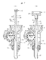
図1及び図2に示す打込機10は、ハウジング11、打撃部12、ノーズ部13、電源部14、電動モータ15、減速機構16、変換部17及び蓄圧容器18を有する。ハウジング11は、打込機10の外殻要素であり、ハウジング11は、シリンダケース19と、シリンダケース19に接続されたハンドル20と、シリンダケース19に接続されたモータケース21と、ハンドル20及びモータケース21に接続された装着部22と、を有する。 The driving tool 10 shown in FIGS. 1 and 2 has a housing 11, a striking portion 12, a nose portion 13, a power supply portion 14, an electric motor 15, a speed reduction mechanism 16, a conversion portion 17, and a pressure accumulator container . The housing 11 is an outer shell element of the tool 10. The housing 11 includes a cylinder case 19, a handle 20 connected to the cylinder case 19, a motor case 21 connected to the cylinder case 19, the handle 20 and and a mounting portion 22 connected to the motor case 21 .

電源部14は、装着部22に取り付け及び取り外しが可能である。電動モータ15はモータケース21内に配置されている。蓄圧容器18は、キャップ23と、キャップ23が取り付けられるホルダ24と、を有する。ヘッドカバー25がシリンダケース19に取り付けられており、蓄圧容器18は、シリンダケース19内及びヘッドカバー25内に亘って配置されている。 The power supply unit 14 can be attached to and removed from the mounting unit 22 . The electric motor 15 is arranged inside the motor case 21 . The pressure accumulator container 18 has a cap 23 and a holder 24 to which the cap 23 is attached. A head cover 25 is attached to the cylinder case 19 , and the pressure accumulating vessel 18 is arranged over the inside of the cylinder case 19 and the inside of the head cover 25 .

シリンダ27がシリンダケース19内に収容されている。シリンダ27は金属製、例えば、アルミニウム合金製または鉄製である。シリンダ27はシリンダケース19に対して中心線A1方向及び径方向に位置決めされている。圧力室26が、蓄圧容器18内及びシリンダ27内に亘って形成される。圧力室26に圧縮性気体が充填されている。圧縮性気体は、空気の他、不活性ガスを用いることができる。不活性ガスは、一例として、窒素ガス、希ガスを含む。本実施形態では、圧力室26に空気が充填されている例を説明する。 A cylinder 27 is housed in the cylinder case 19 . The cylinder 27 is made of metal, for example aluminum alloy or iron. The cylinder 27 is positioned with respect to the cylinder case 19 in the direction of the center line A1 and in the radial direction. A pressure chamber 26 is formed within the pressure accumulator vessel 18 and within the cylinder 27 . The pressure chamber 26 is filled with compressible gas. Compressible gas can use inert gas other than air. Inert gas includes, for example, nitrogen gas and rare gas. In this embodiment, an example in which the pressure chamber 26 is filled with air will be described.

打撃部12は、ハウジング11の内部から外部に亘って配置されている。打撃部12は、ピストン28及びドライバブレード29を有する。ピストン28は、シリンダ27内で中心線A1方向に作動可能である。ピストン28の外周面にシール部材114が取り付けられている。シール部材114の外周面は、シリンダ27の内周面に接触してシール面を形成する。 The striking part 12 is arranged from the inside to the outside of the housing 11 . The striking part 12 has a piston 28 and a driver blade 29 . The piston 28 is operable within the cylinder 27 in the direction of the center line A1. A seal member 114 is attached to the outer peripheral surface of the piston 28 . The outer peripheral surface of the seal member 114 contacts the inner peripheral surface of the cylinder 27 to form a seal surface.

ドライバブレード29は、一例として金属製である。ピストン28とドライバブレード29とが別部材で設けられ、ピストン28とドライバブレード29とが連結されている。ドライバブレードは、図3(A)に示すラック84を有する。ラック84は、中心線A1方向に間隔をおいて配置した複数の突起部85を有する。打撃部12は、中心線A1方向に作動可能である。 The driver blade 29 is made of metal as an example. The piston 28 and the driver blade 29 are provided as separate members, and the piston 28 and the driver blade 29 are connected. The driver blade has a rack 84 shown in FIG. 3(A). The rack 84 has a plurality of protrusions 85 spaced apart in the direction of the center line A1. The hitting part 12 can operate in the direction of the center line A1.

ノーズ部13は、シリンダケース19の内外に亘って配置されている。ノーズ部13は、バンパ支持部31、射出部32及び筒部33を有する。バンパ支持部31は筒形状であり、かつ、ガイド孔34を有する。ガイド孔34は中心線A1を中心として配置されている。 The nose portion 13 is arranged inside and outside the cylinder case 19 . The nose portion 13 has a bumper support portion 31 , an injection portion 32 and a cylinder portion 33 . The bumper support portion 31 is cylindrical and has a guide hole 34 . The guide holes 34 are arranged around the center line A1.

バンパ支持部31内にバンパ35が配置されている。バンパ35は合成ゴム製、シリコンゴム製の何れでもよい。バンパ35は環状であり、バンパ35はガイド孔36を有する。ガイド孔36は中心線A1を中心として設けられている。ドライバブレード29は、ガイド孔34,36内で中心線A1方向に作動可能である。バンパ35は、ピストン28から荷重を受けて弾性変形する。 A bumper 35 is arranged in the bumper support portion 31 . The bumper 35 may be made of either synthetic rubber or silicone rubber. The bumper 35 is annular and has a guide hole 36 . The guide hole 36 is provided around the center line A1. The driver blade 29 is operable in the guide holes 34, 36 in the direction of the center line A1. The bumper 35 receives a load from the piston 28 and elastically deforms.

射出部32はバンパ支持部31に接続され、かつ、バンパ支持部31から中心線A1方向に突出している。射出部32は射出路37を有し、射出路37は中心線A1に沿って設けられている。ドライバブレード29は、射出路37内で中心線A1方向に移動可能である。 The injection part 32 is connected to the bumper support part 31 and protrudes from the bumper support part 31 in the direction of the center line A1. The injection part 32 has an injection path 37, and the injection path 37 is provided along the center line A1. The driver blade 29 is movable within the injection path 37 in the direction of the center line A1.

図1のように、モータケース21内に電動モータ15が配置されている。電動モータ15は、ロータ39及びステータ40を有する。ステータ40は、モータケース21に取り付けられている。ロータ39はロータ軸41に取り付けられ、ロータ軸41の第1端部は、軸受42を介してモータケース21により回転可能に支持されている。電動モータ15は、ブラシレスモータであり、電動モータ15に電圧が印加されると、ロータ39が正回転または逆回転可能である。 As shown in FIG. 1, the electric motor 15 is arranged inside the motor case 21 . The electric motor 15 has a rotor 39 and a stator 40 . The stator 40 is attached to the motor case 21 . The rotor 39 is attached to a rotor shaft 41 , and a first end of the rotor shaft 41 is rotatably supported by the motor case 21 via a bearing 42 . The electric motor 15 is a brushless motor, and when voltage is applied to the electric motor 15, the rotor 39 can rotate forward or backward.

モータケース21内にギヤケース43が設けられている。ギヤケース43は筒形状であり、中心線A2を中心として配置されている。減速機構16はギヤケース43内に設けられている。減速機構16は、複数組のプラネタリギヤ機構を備えている。 A gear case 43 is provided inside the motor case 21 . The gear case 43 has a cylindrical shape and is arranged around the center line A2. The reduction mechanism 16 is provided inside the gear case 43 . The speed reduction mechanism 16 includes multiple sets of planetary gear mechanisms.

減速機構16の入力要素は、動力伝達軸44を介してロータ軸41に連結されている。動力伝達軸44は、軸受45により回転可能に支持されている。回転軸46が筒部33内に設けられている。回転軸46は軸受48,49により回転可能に支持されている。ロータ軸41、動力伝達軸44、減速機構16及び回転軸46は、中心線A2を中心として同心状に配置されている。減速機構16の出力要素77と回転軸46とが同心状に配置され、かつ、出力要素77と回転軸46とが一体回転する。減速機構16は、電動モータ15から回転軸46に至る動力伝達経路に配置されている。 An input element of the speed reduction mechanism 16 is connected to the rotor shaft 41 via a power transmission shaft 44 . The power transmission shaft 44 is rotatably supported by bearings 45 . A rotating shaft 46 is provided inside the cylindrical portion 33 . The rotating shaft 46 is rotatably supported by bearings 48 and 49 . The rotor shaft 41, the power transmission shaft 44, the speed reduction mechanism 16, and the rotating shaft 46 are arranged concentrically about the center line A2. The output element 77 and the rotating shaft 46 of the reduction mechanism 16 are arranged concentrically, and the output element 77 and the rotating shaft 46 rotate together. The speed reduction mechanism 16 is arranged in a power transmission path from the electric motor 15 to the rotating shaft 46 .

変換部17は、筒部33内に設けられている。変換部17は、回転軸46の回転力を、打撃部12の作動力に変換する。 The converting portion 17 is provided inside the cylindrical portion 33 . The converting portion 17 converts the rotational force of the rotary shaft 46 into the operating force of the striking portion 12 .

(変換部の第1実施例) 変換部17は、図3(A)のように、回転軸46に固定されたホイール50と、ホイール50の外周面に形成した歯部78と、を有する。ホイール50及び歯部78は、一例として金属材料で一体成形されている。歯部78は、ホイール50の回転方向に間隔をおいて複数設けられている。歯部78は、ホイール50の回転方向で所定角度の範囲内、一例として、270度の範囲内に配置されている。 (First Embodiment of Converting Portion) The converting portion 17 has a wheel 50 fixed to the rotating shaft 46 and a tooth portion 78 formed on the outer peripheral surface of the wheel 50, as shown in FIG. 3(A). The wheel 50 and the teeth 78 are, for example, integrally formed of a metal material. A plurality of tooth portions 78 are provided at intervals in the rotation direction of the wheel 50 . The tooth portion 78 is arranged within a predetermined angle range, for example, within a range of 270 degrees in the rotational direction of the wheel 50 .

また、可動片79がホイール50に取り付けられている。可動片79は、ホイール50の回転方向で、複数の歯部78が配置された範囲外に設けられている。可動片79は、支持軸80を中心として所定角度の範囲内で作動可能である。可動片79は、係合部81及び接触部82を有する。可動片79は、一例として金属製である。図2(B)のように、係合部81及び接触部82は、支持軸80の中心線A3方向で同じ範囲内に設けられている。中心線A3は、中心線A2と平行である。 A movable piece 79 is also attached to the wheel 50 . The movable piece 79 is provided outside the range in which the plurality of teeth 78 are arranged in the rotation direction of the wheel 50 . The movable piece 79 can operate within a predetermined angle range around the support shaft 80 . The movable piece 79 has an engaging portion 81 and a contact portion 82 . The movable piece 79 is made of metal as an example. As shown in FIG. 2B, the engaging portion 81 and the contact portion 82 are provided within the same range in the direction of the center line A3 of the support shaft 80. As shown in FIG. Centerline A3 is parallel to centerline A2.

図3(A)に示すガイド部83が、ホイール50の径方向で回転軸46の外側に配置されている。ガイド部83は回転しないように設けられている。ガイド部83は、ホイール50の回転方向で所定角度の範囲内に設けられている。ガイド部83の外周面は、中心線A2を中心とする円弧状である。ガイド部83は、ホイール50の径方向で支持軸80よりも内側に配置されている。 A guide portion 83 shown in FIG. 3A is arranged outside the rotating shaft 46 in the radial direction of the wheel 50 . The guide portion 83 is provided so as not to rotate. The guide portion 83 is provided within a range of a predetermined angle in the rotation direction of the wheel 50 . The outer peripheral surface of the guide portion 83 is arcuate around the center line A2. The guide portion 83 is arranged inside the support shaft 80 in the radial direction of the wheel 50 .

ホイール50が図3(A)で反時計回りに回転し、少なくとも1つの歯部78が、突起部85に係合すると、図1に示す打撃部12は、ホイール50の回転力で第2方向D2に作動、つまり、上昇する。 As wheel 50 rotates counterclockwise in FIG. 3A and at least one tooth 78 engages projection 85, striking portion 12 shown in FIG. Actuate at D2, that is, rise.

ホイール50が回転すると、ホイール50の回転方向でガイド部83が配置された範囲内において、接触部82がガイド部83の外周面に接触する。接触部82がガイド部83の外周面に接触していると、係合部81の外接円は、歯部78の外接円と共通である。つまり、係合部81は突起部85に係合可能である。ホイール50が回転し、かつ、係合部81が突起部85に係合していると、打撃部12は第2方向D2で作動する。 When the wheel 50 rotates, the contact portion 82 contacts the outer peripheral surface of the guide portion 83 within the range where the guide portion 83 is arranged in the rotation direction of the wheel 50 . When the contact portion 82 is in contact with the outer peripheral surface of the guide portion 83 , the circumscribed circle of the engaging portion 81 is common to the circumscribed circle of the tooth portion 78 . That is, the engaging portion 81 can be engaged with the projecting portion 85 . When the wheel 50 rotates and the engagement portion 81 is engaged with the protrusion 85, the striking portion 12 operates in the second direction D2.

歯部78が突起部85から解放されると、ホイール50の回転力は、歯部78から打撃部12に伝達されない。また、ホイール50の回転方向でガイド部83が形成された範囲外において、接触部82はガイド部83の外周面から離間する。接触部82がガイド部83の外周面から離間すると、可動片79は、突起部85の荷重を受けて図4(B)で時計回りに作動し、係合部81は突起部85から解放される。したがって、ホイール50の回転力は、打撃部12に伝達されない。 When tooth 78 is released from protrusion 85 , the rotational force of wheel 50 is not transmitted from tooth 78 to striking portion 12 . Further, the contact portion 82 is separated from the outer peripheral surface of the guide portion 83 outside the range in which the guide portion 83 is formed in the rotation direction of the wheel 50 . When the contact portion 82 separates from the outer peripheral surface of the guide portion 83 , the movable piece 79 receives the load of the protrusion 85 and operates clockwise in FIG. be. Therefore, the rotational force of the wheel 50 is not transmitted to the striking portion 12 .

打撃部12は、図1に示す圧力室26の圧力で第1方向D1に常に付勢されている。打撃部12が図1で第2方向D2に作動することを上昇と定義する。第1方向D1及び第2方向D2は中心線A1と平行であり、かつ、第2方向D2は第1方向D1とは逆向きである。打撃部12は、圧力室26の圧力に抗して第2方向D2で作動する。打撃部12が圧力室26の圧力で第1方向D1に作動することを下降と定義する。 The striking part 12 is constantly urged in the first direction D1 by the pressure in the pressure chamber 26 shown in FIG. The movement of the striking part 12 in the second direction D2 in FIG. 1 is defined as rising. The first direction D1 and the second direction D2 are parallel to the centerline A1, and the second direction D2 is opposite to the first direction D1. The striking part 12 acts against the pressure in the pressure chamber 26 in the second direction D2. The actuation of the striking part 12 in the first direction D1 by the pressure in the pressure chamber 26 is defined as descending.

図1のように、回転規制機構53がギヤケース43内に設けられている。回転規制機構53は、電動モータ15が正回転した際の回転力で、回転軸46が図3(A)において反時計回りに回転することを可能にする。回転規制機構53は、打撃部12の第1方向D1の作動力がホイール50に伝達されると、回転軸46が図3(B)で時計回りに回転することを阻止する。 As shown in FIG. 1 , a rotation restricting mechanism 53 is provided inside the gear case 43 . The rotation restricting mechanism 53 allows the rotation shaft 46 to rotate counterclockwise in FIG. The rotation restricting mechanism 53 prevents the rotation shaft 46 from rotating clockwise in FIG.

図1に示すように、トリガ54及びトリガセンサ57が、ハンドル20に設けられている。トリガセンサ57は、トリガ54に加わる操作力の有無を検出し、かつ、検出結果に応じた信号を出力する。 A trigger 54 and a trigger sensor 57 are provided on the handle 20 as shown in FIG. The trigger sensor 57 detects the presence or absence of an operating force applied to the trigger 54, and outputs a signal according to the detection result.

電源部14は、収容ケース58と、収容ケース58内に収容した複数の電池セルとを有する。電池セルは、充電及び放電が可能な二次電池であり、電池セルは、リチウムイオン電池、ニッケル水素電池、リチウムイオンポリマー電池、ニッケルカドミウム電池等、公知の電池セルを任意に用いることができる。 The power supply unit 14 has a housing case 58 and a plurality of battery cells housed in the housing case 58 . The battery cell is a secondary battery that can be charged and discharged, and any known battery cell such as a lithium-ion battery, a nickel-hydrogen battery, a lithium-ion polymer battery, or a nickel-cadmium battery can be used as the battery cell.

また、図1のようにマガジン60が設けられ、マガジン60は射出部32及び装着部22により支持されている。マガジン60内に釘59が複数本収容される。マガジン60はフィーダを有し、フィーダは、マガジン60内の釘59を射出路37へ送る。 A magazine 60 is provided as shown in FIG. A plurality of nails 59 are stored in the magazine 60 . The magazine 60 has a feeder that feeds the nails 59 in the magazine 60 to the ejection path 37 .

射出部32は、金属製または合成樹脂製である。射出部32にプッシュレバー64が取り付けられている。プッシュレバー64は、射出部32に対して中心線A1方向の所定範囲内で作動可能である。プッシュレバー64を中心線A1方向に付勢する弾性部材66が設けられている。弾性部材66は圧縮バネであり、弾性部材66は、プッシュレバー64をバンパ支持部31から離れる向きで付勢する。プッシュレバー64はストッパに接触して停止する。 The injection part 32 is made of metal or synthetic resin. A push lever 64 is attached to the injection section 32 . The push lever 64 can operate within a predetermined range in the direction of the center line A1 with respect to the ejection portion 32 . An elastic member 66 is provided to bias the push lever 64 in the direction of the center line A1. The elastic member 66 is a compression spring, and biases the push lever 64 away from the bumper support portion 31 . The push lever 64 comes into contact with the stopper and stops.

制御部67が装着部22内に設けられている。制御部67は、基板113に取り付けられたマイクロプロセッサを有する。マイクロプロセッサは、入出力インタフェース、制御回路、演算処理部及び記憶部を有する。 A control section 67 is provided within the mounting section 22 . The controller 67 has a microprocessor attached to the substrate 113 . The microprocessor has an input/output interface, a control circuit, an arithmetic processing section, and a storage section.

また、モータ基板86がモータケース21内に設けられている。インバータ回路がモータ基板86に設けられている。インバータ回路は、電動モータ15のステータ40と電源部14とを接続及び遮断する。インバータ回路は、複数のスイッチング素子を備え、複数のスイッチング素子はそれぞれオン・オフが可能である。制御部67は、インバータ回路を制御することにより、電動モータ15の回転及び停止、電動モータ15の回転数、電動モータ15の回転方向を制御する。 A motor board 86 is provided inside the motor case 21 . An inverter circuit is provided on the motor board 86 . The inverter circuit connects and disconnects the stator 40 of the electric motor 15 and the power supply unit 14 . The inverter circuit has a plurality of switching elements, and each of the plurality of switching elements can be turned on and off. The control unit 67 controls the rotation and stoppage of the electric motor 15, the rotation speed of the electric motor 15, and the rotation direction of the electric motor 15 by controlling the inverter circuit.

また、プッシュセンサ、位置検出センサがハウジング11に設けられている。プッシュセンサは、プッシュレバー64が被打込材W1に押し付けられているか否かを検出して信号を出力する。位置検出センサは、ホイール50の回転方向の位置を検出して信号を出力する。さらに、電動モータ15のロータ39の回転速度を検出する速度センサ、ロータの回転方向の位相を検出する位相センサが設けられている。 Also, a push sensor and a position detection sensor are provided in the housing 11 . The push sensor detects whether the push lever 64 is pressed against the workpiece W1 and outputs a signal. The position detection sensor detects the rotational position of the wheel 50 and outputs a signal. Furthermore, a speed sensor for detecting the rotation speed of the rotor 39 of the electric motor 15 and a phase sensor for detecting the phase of the rotor in the direction of rotation are provided.

トリガセンサ57、プッシュセンサ、位置検出センサ、位相センサから出力される信号は、制御部67に入力される。制御部67は、入力される信号を処理して、インバータ回路を制御する。このように、制御部67は、電動モータ15の停止、回転、回転方向および回転速度を制御する。 Signals output from the trigger sensor 57 , push sensor, position detection sensor, and phase sensor are input to the control section 67 . The control unit 67 processes the input signal and controls the inverter circuit. Thus, the control unit 67 controls the stop, rotation, rotation direction, and rotation speed of the electric motor 15 .

次に、打込機10の使用例を説明する。制御部67は、トリガ54に操作力が加えられていないこと、またはプッシュレバー64が被打込材W1に押し付けられていないこと、のうち、少なくとも一方を検出すると、電動モータ15に対する電力の供給を停止する。このため、電動モータ15は停止し、打撃部12は待機位置で停止している。本実施形態において、打撃部12の待機位置は、図3(A)のように、ピストン28がバンパ35に接触している状態、つまり、下死点であるものとして説明する。圧力室26の圧力は、常に打撃部12に加わっており、打撃部12は第1方向D1に付勢されている。打撃部12が待機位置で停止していると、接触部82はガイド部83の外周面に接触している。 Next, a usage example of the fastening tool 10 will be described. The control unit 67 supplies electric power to the electric motor 15 when it detects at least one of the fact that no operation force is applied to the trigger 54 and the fact that the push lever 64 is not pressed against the driven material W1. to stop. Therefore, the electric motor 15 is stopped and the striking portion 12 is stopped at the standby position. In the present embodiment, the standby position of the striking portion 12 will be described assuming that the piston 28 is in contact with the bumper 35, that is, the bottom dead center, as shown in FIG. 3(A). The pressure of the pressure chamber 26 is always applied to the striking portion 12, and the striking portion 12 is biased in the first direction D1. When the striking portion 12 is stopped at the standby position, the contact portion 82 is in contact with the outer peripheral surface of the guide portion 83 .

制御部67は、トリガ54に操作力が加えられていること、及びプッシュレバー64が被打込材W1に押し付けられていること、を検出すると、電源部14から電動モータ15に電圧を印加させ、電動モータ15を正回転させる。電動モータ15の回転力は、減速機構16を経由して回転軸46に伝達される。すると、回転軸46及びホイール50は、図3(A)で反時計回りに回転する。減速機構16は、ホイール50の回転速度を、電動モータ15の回転速度よりも低速にする。 When the control unit 67 detects that an operation force is applied to the trigger 54 and that the push lever 64 is pressed against the driven material W1, the control unit 67 causes the power supply unit 14 to apply voltage to the electric motor 15. , the electric motor 15 is rotated forward. The rotational force of the electric motor 15 is transmitted to the rotary shaft 46 via the speed reduction mechanism 16 . Then, the rotating shaft 46 and the wheel 50 rotate counterclockwise in FIG. 3(A). The reduction mechanism 16 makes the rotational speed of the wheel 50 lower than the rotational speed of the electric motor 15 .

少なくとも1つの歯部78が突起部85に係合すると、ホイール50の回転力は、打撃部12に伝達され、打撃部12が上昇する。打撃部12が上昇すると圧力室26の圧力が上昇する。ホイール50の回転により、複数の歯部78は、突起部85にそれぞれ係合及び解放される。そして、図3(B)のように、可動片79の係合部81が突起部85に係合した後、全ての歯部78が突起部85から解放された状態で、打撃部12の上昇が継続する。打撃部12が上死点に到達する前に、図4(A)のように、可動片79の接触部82は、ガイド部83から離間する。すると、ドライバブレード29の突起部85から係合部81に加わる力により、可動片79が図4(A)で時計回りに作動する。その結果、係合部81が突起部85から解放され、打撃部12は上死点から、圧力室26の圧力で図4(B)のように下降する。打撃部12が下降すると、ドライバブレード29は、射出路37に位置する釘59を打撃し、釘59は被打込材W1に打ち込まれる。 When at least one tooth 78 engages projection 85, the rotational force of wheel 50 is transmitted to striking portion 12, causing striking portion 12 to rise. As the striking part 12 rises, the pressure in the pressure chamber 26 rises. Rotation of wheel 50 causes teeth 78 to engage and disengage projections 85, respectively. After the engaging portion 81 of the movable piece 79 is engaged with the protrusion 85 as shown in FIG. continues. Before the striking portion 12 reaches the top dead center, the contact portion 82 of the movable piece 79 is separated from the guide portion 83 as shown in FIG. 4(A). Then, the force applied to the engaging portion 81 from the protrusion 85 of the driver blade 29 causes the movable piece 79 to move clockwise in FIG. As a result, the engaging portion 81 is released from the protrusion 85, and the striking portion 12 is lowered from the top dead center by the pressure of the pressure chamber 26 as shown in FIG. 4(B). When the striking part 12 descends, the driver blade 29 strikes the nail 59 located in the injection path 37, and the nail 59 is driven into the driven material W1.

また、ピストン28は、釘59が被打込材W1に打ち込まれた後、バンパ35に衝突する。バンパ35は中心線A1方向の荷重を受けて弾性変形し、バンパ35は打撃部12の運動エネルギの一部を吸収する。制御部67は、打撃部12が下死点に到達した時点で、電動モータ15を停止させる。 Further, the piston 28 collides with the bumper 35 after the nail 59 is driven into the driven material W1. The bumper 35 receives a load in the direction of the center line A<b>1 and elastically deforms, and the bumper 35 absorbs a part of the kinetic energy of the striking portion 12 . The control section 67 stops the electric motor 15 when the striking section 12 reaches the bottom dead center.

打撃部12が圧力室26から受ける中心線A1方向の荷重は、打撃部12が上死点に位置すると最大である。そして、可動片79の接触部82がガイド部83の外周面から離間すると、ドライバブレード29の力で可動片79が図4(A)で時計回りに作動し、係合部81が突起部85から解放される。つまり、係合部81は、ドライバブレード29の突起部85の作動領域外へ移動する。 The load in the direction of the center line A1 that the striking portion 12 receives from the pressure chamber 26 is maximum when the striking portion 12 is positioned at the top dead center. When the contact portion 82 of the movable piece 79 separates from the outer peripheral surface of the guide portion 83, the force of the driver blade 29 causes the movable piece 79 to move clockwise in FIG. be released from In other words, the engaging portion 81 moves out of the working area of the protrusion 85 of the driver blade 29 .

このため、打撃部12が最大の荷重を受け、かつ、係合部81が突起部85から離間する過程で、係合部81と突起部85との接触箇所における摩擦力が増加することを抑制できる。したがって、係合部81または突起部85の少なくとも一方の摩耗を低減でき、かつ、可動片79またはドライバブレード29の少なくとも一方の製品寿命を向上できる。 Therefore, in the process in which the striking portion 12 receives the maximum load and the engaging portion 81 separates from the projecting portion 85, an increase in the frictional force at the contact portion between the engaging portion 81 and the projecting portion 85 is suppressed. can. Therefore, the wear of at least one of the engaging portion 81 and the protrusion 85 can be reduced, and the product life of at least one of the movable piece 79 and the driver blade 29 can be improved.

また、可動片79が、ホイール50に対して単独で取り付け及び取り外しが可能であると、係合部81が摩耗した場合に、可動片79を交換すれば済み、ホイール50全体を交換せずに済む。 Further, if the movable piece 79 can be attached to and detached from the wheel 50 independently, when the engaging portion 81 wears, the movable piece 79 can be replaced without replacing the entire wheel 50. done.

さらに、図2(B)のように、係合部81及び接触部82が支持軸80の中心線A3方向で同じ範囲に設けられている。したがって、接触部82がガイド部83に接触し、かつ、係合部81が突起部85に係合している場合に、支持軸80が中心線A3に対して傾斜することを抑制可能である。 Furthermore, as shown in FIG. 2B, the engaging portion 81 and the contact portion 82 are provided in the same range in the direction of the center line A3 of the support shaft 80. As shown in FIG. Therefore, when the contact portion 82 is in contact with the guide portion 83 and the engaging portion 81 is engaged with the projecting portion 85, it is possible to prevent the support shaft 80 from tilting with respect to the center line A3. .

図2(C)は、可動片79の変更例である。図2(C)に示す可動片79は、中心線A3方向で、係合部81の配置範囲と、接触部82の配置範囲とが異なる。図2(C)に示す可動片79の作動原理は、図2(B)に示す可動片79の作動原理と同じである。 FIG. 2C shows a modification of the movable piece 79. FIG. In the movable piece 79 shown in FIG. 2C, the arrangement range of the engaging portion 81 and the arrangement range of the contact portion 82 are different in the direction of the center line A3. The operating principle of the movable piece 79 shown in FIG. 2(C) is the same as the operating principle of the movable piece 79 shown in FIG. 2(B).

変換部17の第1実施例の他の構成が、図5(A)に示されている。図5(A)の構成において、図3(A)と同じ構成は、図3(A)と同じ符号を付してある。 Another configuration of the first embodiment of the conversion unit 17 is shown in FIG. 5(A). In the configuration of FIG. 5(A), the same configurations as in FIG. 3(A) are denoted by the same reference numerals as in FIG. 3(A).

溝99が、ホイール50に設けられている。溝99は、ホイール50の回転方向において、歯部78が設けられていない箇所に設けられている。溝99は、ホイール50の径方向に沿い、かつ、中心線A2に向かうように設けられている。可動片100が、ホイール50に取り付けられている。可動片100は、ピン101、歯部102及び接触部115を有する。 A groove 99 is provided in the wheel 50 . The groove 99 is provided at a location where the toothed portion 78 is not provided in the direction of rotation of the wheel 50 . The groove 99 is provided along the radial direction of the wheel 50 and toward the centerline A2. A movable piece 100 is attached to the wheel 50 . The movable piece 100 has a pin 101 , a tooth portion 102 and a contact portion 115 .

ピン101は溝99内に配置され、かつ、溝99内でホイール50の径方向に沿い、かつ、中心線A2に接近及び離間する方向に移動可能である。さらに、ピン101は、付勢部材によりホイール50の径方向で外側に向けて付勢されている。付勢部材は図示されていないが、一例として金属製のねじりスプリングを用いることができる。このため、可動片100は、ホイール50の径方向に溝99の範囲内で移動可能であり、かつ、ピン101を中心として所定角度の範囲内で回転可能である。 Pin 101 is disposed within groove 99 and is movable within groove 99 along the radial direction of wheel 50 and toward and away from centerline A2. Further, the pin 101 is biased outward in the radial direction of the wheel 50 by a biasing member. Although the biasing member is not shown, a metal torsion spring can be used as an example. Therefore, the movable piece 100 can move in the radial direction of the wheel 50 within the range of the groove 99 and can rotate about the pin 101 within a predetermined angle range.

打込機10を使用中に、釘59が射出路37で詰まると、打撃部12は下死点と上死点との間で停止する。つまり、打撃部12は、ピストン28がバンパ35から離間した状態で停止する。すると、変換部17のホイール50で打撃部12をD2方向に移動させる時に、図5(A)のように歯部102の先端が、突起部85の先端に押し付けられた状態になる場合がある。なお、接触部115は、ガイド部83の外周面に接触している。 If the nail 59 jams in the ejection path 37 while the driving tool 10 is in use, the striking part 12 stops between the bottom dead center and the top dead center. That is, the striking portion 12 stops with the piston 28 separated from the bumper 35 . Then, when the wheel 50 of the converting portion 17 moves the striking portion 12 in the D2 direction, the tip of the tooth portion 102 may be pressed against the tip of the protrusion 85 as shown in FIG. 5(A). . Note that the contact portion 115 is in contact with the outer peripheral surface of the guide portion 83 .

本実施形態の打込機10では、ホイール50を反時計回りに回転させると、歯部102が突起部85に押し付けられている反力により、ピン101がホイール50の径方向で内側に向けて付勢され、ピン101は、付勢部材の付勢力に抗して、図5(B)のように、溝99内でホイール50の径方向で内側に向けて移動する。 In the fastening tool 10 of the present embodiment, when the wheel 50 is rotated counterclockwise, the pin 101 is directed radially inward of the wheel 50 due to the reaction force of the teeth 102 being pressed against the projection 85 . When biased, the pin 101 moves radially inwardly of the wheel 50 within the groove 99 against the biasing force of the biasing member, as shown in FIG. 5(B).

また、歯部102の先端は、突起部85の先端に接触した状態で滑り、歯部102の先端が、突起部85の先端を超えると、付勢部材の付勢力でピン101が押され、歯部102の先端は、図5(C)のように、突起部85と突起部85との間へ移動する。さらに、ホイール50の回転に伴い、歯部102が図5(D)のように突起部85に係合すると、ドライバブレード29は第2方向D2に作動する。このように、打込機10の使用中に、釘59が射出路37で詰まった場合等において、ドライバブレード29が中心線A1方向でどの位置にあっても、ドライバブレード29の突起部85と、歯部102とを係合させて、ドライバブレード29を第2方向D2に作動させることができる。このため、作業者は、詰まっている釘59を射出路37から除去することができる。 Further, the tip of the tooth portion 102 slides in contact with the tip of the protrusion 85, and when the tip of the tooth portion 102 exceeds the tip of the protrusion 85, the pin 101 is pushed by the biasing force of the biasing member. The tip of the tooth portion 102 moves between the protrusions 85 as shown in FIG. 5(C). Further, as the wheel 50 rotates, the toothed portion 102 engages the protrusion 85 as shown in FIG. 5(D), causing the driver blade 29 to move in the second direction D2. As described above, when the nail 59 is clogged in the injection path 37 during use of the driving tool 10, the protrusion 85 of the driver blade 29 and the projection 85 of the driver blade 29 can be displaced regardless of the position of the driver blade 29 in the direction of the center line A1. , toothing 102 to actuate the driver blade 29 in the second direction D2. This allows the operator to remove the jammed nail 59 from the injection path 37 .

なお、接触部115がガイド部83の外周面から離間する時には、次の歯部78と突起部85とが係合し、可動片100の歯部102と、突起部85の係合は解除される。以上のように、ホイール50が回転を開始すると、可動片100の歯部102が初めに突起部85に係合する。したがって、歯部102の先端が突起部85の先端に接触するような状態になっても、正常に歯部78と突起部85を係合させることができる。 When the contact portion 115 is separated from the outer peripheral surface of the guide portion 83, the next tooth portion 78 and the protrusion portion 85 are engaged, and the engagement between the tooth portion 102 of the movable piece 100 and the protrusion portion 85 is released. be. As described above, when the wheel 50 starts rotating, the teeth 102 of the movable piece 100 first engage with the protrusion 85 . Therefore, even if the tip of the tooth 102 comes into contact with the tip of the protrusion 85, the tooth 78 and the protrusion 85 can be engaged normally.

(変換部の第2実施例) 変換部17の第2実施例は、図6(A)、図6(B)、図7(A)、図7(B)、図8(A)、図8(B)に示されている。 (Second Embodiment of Conversion Section) A second embodiment of the conversion section 17 is shown in FIGS. 8(B).

回転軸46は、2つの支持部87によって回転可能に支持されている。2つの支持部87は、射出部に固定されており、2つの支持部87は、非円形の支持孔88をそれぞれ有する。2つの支持部87は、中心線A2方向に間隔をおいて配置されている。回転軸46の長手方向の一部は、2つの支持孔88にそれぞれ配置されている。回転軸46は、図8(A)、図8(B)のように、2つの支持孔88内で、中心線A2に対して交差する方向に移動可能である。回転軸46はボス部89を有し、ボス部89は、中心線A2を通る直線状の溝90を有する。 The rotary shaft 46 is rotatably supported by two support portions 87 . Two support parts 87 are fixed to the injection part, and the two support parts 87 each have a non-circular support hole 88 . The two support portions 87 are spaced apart in the direction of the center line A2. A part of the rotation shaft 46 in the longitudinal direction is arranged in each of the two support holes 88 . As shown in FIGS. 8A and 8B, the rotating shaft 46 can move in two support holes 88 in a direction crossing the center line A2. The rotating shaft 46 has a boss portion 89, and the boss portion 89 has a linear groove 90 passing through the center line A2.

出力要素77はボス部91を有し、ボス部91はピン92を有する。ピン92は中心線A2から偏心した箇所に設けられている。ピン92の先端は溝90に配置されている。出力要素77が回転すると、ピン92が溝90内に沿って移動し、回転軸46が回転する。また、回転軸46は、支持孔88内で中心線A2に対して交差する方向に移動する。つまり、ホイール50は、中心線A2に対して交差する方向に移動可能である。ホイール50が、中心線A2に対して交差する方向に移動すると、ホイール50は、ドライバブレード29に接近または離間する。 The output element 77 has a boss portion 91 and the boss portion 91 has a pin 92 . The pin 92 is provided at a location eccentric from the center line A2. The tip of the pin 92 is arranged in the groove 90 . As output element 77 rotates, pin 92 moves along groove 90 and rotating shaft 46 rotates. Further, the rotating shaft 46 moves in the direction crossing the center line A2 within the support hole 88 . That is, the wheel 50 can move in a direction intersecting the centerline A2. Wheel 50 moves toward or away from driver blade 29 as wheel 50 moves in a direction transverse to centerline A2.

さらに、位置決め部材93が筒部33内に設けられている。位置決め部材93は、弾性変形が可能である。位置決め部材93は、一例として金属製の板バネであり、位置決め部材93の両端は、筒部33により保持されている。位置決め部材93は、中心線A1に対して交差する方向、及び中心線A1方向の何れにも移動しない。位置決め部材93は、回転軸46に向けて突出した規制部94を有する。位置決め部材93は、回転軸46の外周面に押し付けられている。回転軸46が中心線A2に対して交差する方向に作動しようとする力が所定値以下であると、規制部94が回転軸46に押し付けられることで、回転軸46が支持孔88内で移動することを阻止する。 Further, a positioning member 93 is provided inside the tubular portion 33 . The positioning member 93 is elastically deformable. The positioning member 93 is, for example, a leaf spring made of metal, and both ends of the positioning member 93 are held by the tubular portion 33 . The positioning member 93 does not move either in the direction crossing the center line A1 or in the direction of the center line A1. The positioning member 93 has a restricting portion 94 projecting toward the rotating shaft 46 . The positioning member 93 is pressed against the outer peripheral surface of the rotary shaft 46 . When the force with which the rotating shaft 46 acts in the direction crossing the center line A2 is less than or equal to a predetermined value, the restricting portion 94 is pressed against the rotating shaft 46, thereby moving the rotating shaft 46 within the support hole 88. prevent you from doing

回転軸46が中心線A2に対して交差する方向に作動しようとする力が所定値を超えると、位置決め部材93が弾性変形して回転軸46が規制部94を乗り越え、回転軸46が支持孔88内で移動することが可能である。 When the force with which the rotating shaft 46 acts in the direction crossing the center line A2 exceeds a predetermined value, the positioning member 93 is elastically deformed, the rotating shaft 46 overcomes the restricting portion 94, and the rotating shaft 46 moves toward the support hole. It is possible to move within 88.

また、筒部の内面から突出した戻し部95が設けられている。ホイール50は、回転軸46を中心とする同一円周上に配置した複数のピン96を有する。複数のピン96は、一例として金属製である、かつ、ホイール50にそれぞれ固定されている。複数のピン96は、ホイール50の回転方向に等間隔で配置されている。複数のピン96の数は、突起部85の数よりも多い。 Also, a return portion 95 protruding from the inner surface of the cylindrical portion is provided. The wheel 50 has a plurality of pins 96 arranged on the same circumference around the rotation axis 46 . The plurality of pins 96 are made of metal, for example, and fixed to the wheel 50 respectively. The plurality of pins 96 are evenly spaced in the direction of rotation of the wheel 50 . The number of pins 96 is greater than the number of protrusions 85 .

ドライバブレード29は付勢部97を有する。複数の突起部85のうち、中心線A1方向でドライバブレード29の先端に最も近い位置に設けられている突起部85と、ドライバブレード29の先端との間に付勢部97が設けられている。付勢部97は中心線A1方向に沿った平坦面である。なお、複数の突起部85の先端は、それぞれ湾曲している。 Driver blade 29 has a biasing portion 97 . A biasing portion 97 is provided between the protrusion 85 that is closest to the tip of the driver blade 29 in the direction of the center line A1 among the plurality of protrusions 85 and the tip of the driver blade 29. . The biasing portion 97 is a flat surface along the direction of the center line A1. Note that the tips of the plurality of protrusions 85 are each curved.

打撃部12が待機位置で停止し、かつ、電動モータ15が停止している状態において、回転軸46及びホイール50は、図6(A)のように、初期位置で停止している。つまり、回転軸46及びホイール50は、中心線A2に対して交差する方向で、ドライバブレード29に最も接近した位置で停止している。また、全てのピン96は、戻し部95から離間している。 In a state where the striking part 12 is stopped at the standby position and the electric motor 15 is stopped, the rotating shaft 46 and the wheel 50 are stopped at the initial positions as shown in FIG. 6(A). That is, the rotating shaft 46 and the wheel 50 are stopped at the position closest to the driver blade 29 in the direction intersecting the center line A2. Also, all the pins 96 are spaced apart from the return portion 95 .

図6(A)において、ホイール50が反時計回りに回転し、何れかのピン96が突起部85に係合すると、打撃部12が上死点に向けて作動する。そして、図6(B)のように、何れかのピン96が付勢部97に押し付けられると、ピン96が付勢部97に押し付けられた反力で、回転軸46に対して中心線A2と交差する付勢力が増加する。付勢力は、回転軸46をドライバブレード29から離間させる向きの荷重である。回転軸46が受ける荷重が所定値を超えると、回転軸46は規制部94を乗り越え、図7(A)のように、回転軸46は支持孔88内で移動する。そして、回転軸46及びホイール50は、ドライバブレード29から離間した作動位置で停止する。 In FIG. 6A, when the wheel 50 rotates counterclockwise and one of the pins 96 engages with the projection 85, the striking part 12 moves toward the top dead center. Then, as shown in FIG. 6B, when any pin 96 is pressed against the biasing portion 97, the reaction force of the pin 96 pressed against the biasing portion 97 causes the center line A2 with respect to the rotation shaft 46. The biasing force crossing with increases. The biasing force is a load in a direction that separates the rotating shaft 46 from the driver blade 29 . When the load applied to the rotating shaft 46 exceeds a predetermined value, the rotating shaft 46 climbs over the restricting portion 94 and moves within the support hole 88 as shown in FIG. 7(A). Then, the rotating shaft 46 and the wheel 50 stop at the operating position separated from the driver blade 29 .

ホイール50が作動位置で停止すると、全てのピン96は、突起部85の作動領域外に移動する。つまり、全てのピン96は、図7(B)のように突起部85から解放される。したがって、打撃部12が蓄圧室の圧力で下死点に向けて作動し、ドライバブレードが止具を打撃する。 When the wheel 50 stops in the actuated position, all pins 96 move out of the actuated area of projection 85 . That is, all the pins 96 are released from the protrusions 85 as shown in FIG. 7(B). Therefore, the striking part 12 is operated toward the bottom dead center by the pressure in the accumulator, and the driver blade strikes the fastener.

打撃部が下死点に到達した後、何れかのピン96が戻し部95に押し付けられると、その反力で回転軸46をドライバブレード29に接近させる向きの付勢力が生じる。この付勢力が所定値を超えると、回転軸46は支持孔88内で移動し、回転軸46及びホイール50は初期位置で停止する。 When any pin 96 is pressed against the return portion 95 after the striking portion reaches the bottom dead center, the reaction force of the pin 96 generates an urging force in the direction to bring the rotating shaft 46 closer to the driver blade 29 . When this biasing force exceeds a predetermined value, the rotary shaft 46 moves within the support hole 88, and the rotary shaft 46 and wheel 50 stop at the initial positions.

このため、ピン96は戻し部95から離間し、何れかのピン96が、突起部85の作動領域内に移動し、制御部が電動モータを停止させる。したがって、打撃部12は下死点で停止する。 As a result, the pins 96 are separated from the return portion 95, one of the pins 96 moves into the working area of the projection portion 85, and the control portion stops the electric motor. Therefore, the striking part 12 stops at the bottom dead center.

変換部17の第2実施例は、ピン96が突起部85から離間する過程で、ホイール50が回転軸46と共にドライバブレード29から離間する方向に移動する。したがって、ピン96またはドライバブレード29の少なくとも一方の摩耗を抑制でき、かつ、ピン96またはドライバブレード29の少なくとも一方の寿命が向上する。 In the second embodiment of the converting portion 17 , the wheel 50 moves away from the driver blade 29 together with the rotating shaft 46 while the pin 96 moves away from the protrusion 85 . Therefore, wear of at least one of the pin 96 and the driver blade 29 can be suppressed, and the life of at least one of the pin 96 and the driver blade 29 is improved.

また、ピン96の数が、突起部85の数を超えているため、打撃部12が上死点に到達した時点で、打撃部12の作動力を受けるピン96が、打撃部12を下死点から上死点に向けて作動させる回毎に替わる。このため、打撃部12の作動力に対応する最大負荷を、異なるピン96に分散できる。したがって、ピン96の寿命が一層向上する。 Further, since the number of pins 96 exceeds the number of projections 85, the pins 96 that receive the operating force of the striking portion 12 move the striking portion 12 downward when the striking portion 12 reaches the top dead center. It changes every time it is operated from the point toward the top dead center. Therefore, the maximum load corresponding to the operating force of the striking portion 12 can be distributed to different pins 96 . Therefore, the life of the pin 96 is further improved.

図9は、打込機10に設ける変換部17の第2実施例の変更例である。ホイール50に設けたピン96の数は、ドライバブレード29に設けた突起部85の数よりも少ない。図9に示す変換部17の作用効果は、図6(A)、図6(B)、図7(A)、図7(B)に示す変換部17の作用効果と同じである。また、図9に示す変換部17は、ホイール50に設けたピン96の数が、ドライバブレード29に設けた突起部85の数よりも少ないため、ホイール50の直径の増加を抑制できる。したがって、図1に示す打込機10の小型化、軽量化を図ることができる。 FIG. 9 shows a modification of the second embodiment of the conversion section 17 provided in the fastening tool 10. As shown in FIG. The number of pins 96 on wheel 50 is less than the number of projections 85 on driver blade 29 . The effects of the conversion unit 17 shown in FIG. 9 are the same as those of the conversion unit 17 shown in FIGS. 6A, 6B, 7A, and 7B. 9, the number of pins 96 provided on the wheel 50 is smaller than the number of protrusions 85 provided on the driver blade 29, so an increase in the diameter of the wheel 50 can be suppressed. Therefore, the size and weight of the fastening tool 10 shown in FIG. 1 can be reduced.

図10(A)は、変換部17の第2実施例における他の変更例である。ホイール50の外周面に歯部98が複数設けられている。歯部98及びホイール50は、一例として金属材料で一体化されている。複数の歯部98は、ホイール50の回転方向に等間隔で設けられている。歯部98の数は、突起部85の数よりも多い。図10(A)に示す変換部17の他の構成は、図6(A)に示す変換部17の構成と同じである。 FIG. 10A shows another modification of the conversion unit 17 in the second embodiment. A plurality of tooth portions 98 are provided on the outer peripheral surface of the wheel 50 . The tooth portion 98 and the wheel 50 are, for example, integrated with a metal material. A plurality of tooth portions 98 are provided at equal intervals in the rotation direction of the wheel 50 . The number of teeth 98 is greater than the number of protrusions 85 . Other configurations of the conversion unit 17 shown in FIG. 10A are the same as those of the conversion unit 17 shown in FIG. 6A.

打撃部12が、図10(A)のように待機位置で停止している場合に、回転軸46は支持孔88内でドライバブレード29に最も近い初期位置で停止している。 When the striking part 12 is stopped at the standby position as shown in FIG. 10A, the rotating shaft 46 is stopped at the initial position closest to the driver blade 29 within the support hole 88 .

そして、ホイール50が回転し、かつ、歯部98と突起部85とが係合すると、ホイール50の回転力が打撃部12に伝達され、図10(B)のように打撃部12が上昇する。 When the wheel 50 rotates and the toothed portion 98 and the protrusion 85 engage with each other, the rotational force of the wheel 50 is transmitted to the striking portion 12, and the striking portion 12 rises as shown in FIG. 10(B). .

さらに、歯部98が付勢部97に押し付けられると、その反力に対応する荷重が回転軸46に伝達される。このため、回転軸46は、図11(A)のように、支持孔88内でドライバブレード29から離間する方向にスライドする。そして、回転軸46は、ドライバブレード29から最も離れた位置、つまり、作動位置で停止する。全ての歯部98は、突起部85の作動領域外に位置する。 Furthermore, when the tooth portion 98 is pressed against the biasing portion 97 , a load corresponding to the reaction force is transmitted to the rotating shaft 46 . Therefore, the rotary shaft 46 slides in the direction away from the driver blade 29 within the support hole 88 as shown in FIG. 11(A). Then, the rotating shaft 46 stops at the farthest position from the driver blade 29, that is, the operating position. All teeth 98 are located outside the active area of projection 85 .

全ての歯部98が突起部85から解放されると、図11(B)のように、打撃部12が、圧力室26の圧力で上死点から下死点に向けて作動する。また、歯部98が戻し部95に押し付けられ、その反力で回転軸46が作動位置から支持孔88内で移動し、回転軸46が初期位置に戻って停止する。制御部67は、打撃部12が下死点に到達した後、電動モータ15を停止させる。 When all the teeth 98 are released from the protrusion 85, the striking part 12 moves from the top dead center to the bottom dead center by the pressure of the pressure chamber 26 as shown in FIG. 11(B). Further, the tooth portion 98 is pressed against the return portion 95, and the reaction force moves the rotating shaft 46 from the operating position within the support hole 88, and the rotating shaft 46 returns to the initial position and stops. The control section 67 stops the electric motor 15 after the striking section 12 reaches the bottom dead center.

図10(A)に示す変換部17は、図6(A)に示す変換部17と同様の効果を得ることが可能である。なお、ホイール50に設ける歯部98の数は、突起部85の数より少なくてもよい。 The conversion unit 17 shown in FIG. 10A can obtain the same effect as the conversion unit 17 shown in FIG. 6A. The number of teeth 98 provided on the wheel 50 may be less than the number of protrusions 85 .

(変換部の第3実施例) 図12(A)は、変換部17の第3実施例を示す。ピン103がホイール50に設けられている。ピン103は、ホイール50の回転方向に間隔をおいて複数配置されている。ピン103は、ホイール50の回転方向で、所定角度、一例として270度の範囲内に配置されている。 (Third Embodiment of Conversion Section) FIG. 12A shows a third embodiment of the conversion section 17 . A pin 103 is provided on the wheel 50 . A plurality of pins 103 are arranged at intervals in the rotation direction of the wheel 50 . The pin 103 is arranged within a range of a predetermined angle, for example 270 degrees, in the direction of rotation of the wheel 50 .

ホイール50にガイド孔104が設けられている。ガイド孔104は、ホイール50の回転方向でピン103が配置されている角度範囲外に配置されている。ガイド孔104は、ホイール50の径方向に配置されている。可動ピン105がホイール50に取り付けられている。可動ピン105は、一例として金属製である。可動ピン105は、ガイド孔104内でホイール50の径方向に作動可能である。可動ピン105の長さ方向の一部は、中心線A2方向で、ホイール50の配置範囲外に位置する。図14(A)に示す付勢部材110が設けられており、付勢部材110は可動ピン105を、ホイール50の径方向で外側に付勢する。付勢部材110は、一例として金属製の圧縮スプリングである。 A guide hole 104 is provided in the wheel 50 . The guide hole 104 is arranged outside the angular range in which the pin 103 is arranged in the rotation direction of the wheel 50 . The guide holes 104 are arranged in the radial direction of the wheel 50 . A movable pin 105 is attached to the wheel 50 . The movable pin 105 is made of metal as an example. The movable pin 105 can move in the radial direction of the wheel 50 within the guide hole 104 . A part of the movable pin 105 in the longitudinal direction is located outside the arrangement range of the wheel 50 in the direction of the center line A2. A biasing member 110 shown in FIG. 14A is provided, and the biasing member 110 biases the movable pin 105 outward in the radial direction of the wheel 50 . The biasing member 110 is, for example, a metal compression spring.

ピンホルダ106がホイール50に取り付けられている。ピンホルダ106は、一例として金属製である。ピンホルダ106は、ホイール50の回転方向でピン103が配置されている角度範囲外に配置されている。ピンホルダ106は、中心線A2方向でホイール50の配置範囲外であり、かつ、ドライバブレード29の作動範囲外に配置されている。ピンホルダ106は、支持軸107を中心として所定の角度範囲内で作動可能である。 A pin holder 106 is attached to the wheel 50 . The pin holder 106 is made of metal as an example. The pin holder 106 is arranged outside the angular range in which the pin 103 is arranged in the rotational direction of the wheel 50 . The pin holder 106 is arranged outside the arrangement range of the wheel 50 and outside the operation range of the driver blade 29 in the direction of the center line A2. The pin holder 106 can operate within a predetermined angular range around the support shaft 107 .

ピンホルダ106はフック108を有する。ホイール50において、ガイド孔104とピンホルダ106との間にストッパ109が設けられている。図14(A)に示す付勢部材111が設けられ、付勢部材111は、ピンホルダ106を図12(A)で反時計回りに付勢する。付勢部材111は、一例として金属製の圧縮スプリングである。付勢部材111の付勢力は、付勢部材110の付勢力よりも低い。 A pin holder 106 has a hook 108 . A stopper 109 is provided between the guide hole 104 and the pin holder 106 in the wheel 50 . A biasing member 111 shown in FIG. 14A is provided, and the biasing member 111 biases the pin holder 106 counterclockwise in FIG. 12A. The biasing member 111 is, for example, a metal compression spring. The biasing force of biasing member 111 is lower than the biasing force of biasing member 110 .

筒部33の内面から突出した戻し部112が設けられている。戻し部112は、ホイール50の外周面から離間している。 A return portion 112 protruding from the inner surface of the cylindrical portion 33 is provided. The return portion 112 is spaced apart from the outer peripheral surface of the wheel 50 .

次に、変換部17の第3実施例の作用を説明する。まず、制御部67が電動モータ15を停止させ、打撃部12が、図1に示す待機位置で停止している。打撃部12が待機位置で停止していると、可動ピン105は付勢部材110により付勢され、可動ピン105はフック108に保持されて停止している。つまり、可動ピン105は突起部85に係合していない。ピンホルダ106は、ストッパ109に接触して停止している。 Next, the operation of the conversion section 17 of the third embodiment will be described. First, the control section 67 stops the electric motor 15, and the striking section 12 is stopped at the standby position shown in FIG. When the striking portion 12 is stopped at the standby position, the movable pin 105 is biased by the biasing member 110, and the movable pin 105 is held by the hook 108 and stopped. In other words, the movable pin 105 is not engaged with the protrusion 85 . The pin holder 106 comes into contact with the stopper 109 and stops.

制御部67が電動モータ15を回転させ、ホイール50が図12(A)で反時計回りに回転し、かつ、ピン103が突起部85に係合すると、打撃部12がD2方向に作動、つまり、上昇する。 When the controller 67 rotates the electric motor 15, the wheel 50 rotates counterclockwise in FIG. ,Rise.

ホイール50の回転に伴い、図12(A)のように、戻し部112がピンホルダ106に係合すると、ピンホルダ106がホイール50に対して時計回りに作動し、ピンホルダ106はストッパ109から離間する。すると、可動ピン105は、付勢部材110の付勢力でガイド孔104内で作動し、可動ピン105は、ホイール50の径方向で最も外側の位置、つまり、初期位置で停止する。 As the wheel 50 rotates, the return portion 112 engages the pin holder 106 as shown in FIG. Then, the movable pin 105 is actuated in the guide hole 104 by the biasing force of the biasing member 110, and the movable pin 105 stops at the radially outermost position of the wheel 50, ie, the initial position.

ホイール50の回転に伴い、複数のピン103は、突起部85に対してそれぞれ単独で係合及び解放される。全てのピン103が突起部85から解放される前に、可動ピン105が突起部85に係合する。 As the wheel 50 rotates, the pins 103 independently engage and disengage from the projections 85 . Movable pin 105 engages protrusion 85 before all pins 103 are released from protrusion 85 .

打撃部12が上死点に到達する前に、全てのピン103が、図12(B)のように突起部85から解放される。次いで、突起部85から可動ピン105に加わる荷重の分力が増加すると、分力で押される可動ピン105が、図13(A)のように、ガイド孔104内でホイール50の径方向で内側に向けて作動し、可動ピン105が突起部85から解放される。 Before the striking part 12 reaches the top dead center, all the pins 103 are released from the protrusions 85 as shown in FIG. 12(B). Next, when the component force of the load applied to the movable pin 105 from the protrusion 85 increases, the movable pin 105 pushed by the component force moves radially inward of the wheel 50 within the guide hole 104 as shown in FIG. , and the movable pin 105 is released from the protrusion 85 .

また、可動ピン105がガイド孔104内で作動すると、ピンホルダ106が付勢部材111の付勢力で反時計回りに作動し、ピンホルダ106がストッパ109に接触して停止する。このため、可動ピン105が、付勢部材110の付勢力、及び可動ピン105がガイド孔104の内壁面に衝突して生じる反動により、初期位置に向けて作動すると、図13(B)のように、フック108が可動ピン105を支持する。つまり、フック108は、可動ピン105が突起部85に衝突することを阻止する。 Further, when the movable pin 105 operates within the guide hole 104, the pin holder 106 operates counterclockwise due to the biasing force of the biasing member 111, and the pin holder 106 comes into contact with the stopper 109 and stops. Therefore, when the movable pin 105 moves toward the initial position due to the biasing force of the biasing member 110 and the recoil caused by the collision of the movable pin 105 with the inner wall surface of the guide hole 104, as shown in FIG. Also, the hook 108 supports the movable pin 105 . That is, the hook 108 prevents the movable pin 105 from colliding with the protrusion 85 .

打撃部12は圧力室26の圧力で第1方向D1に作動、つまり、下降し、打撃部12は下死点に到達する。制御部67は、打撃部12が下死点に到達した後、電動モータ15を停止させる。 The striking part 12 is moved in the first direction D1 by the pressure in the pressure chamber 26, that is, descends, and the striking part 12 reaches the bottom dead center. The control section 67 stops the electric motor 15 after the striking section 12 reaches the bottom dead center.

突起部85に係合している可動ピン105が、突起部85から解放される作用を、図14(A)、図14(B)を参照して説明する。可動ピン105が突起部85に係合していると、突起部85と可動ピン105との接触位置P1に荷重F1が加わる。荷重F1は、第1方向D1と平行である。また、可動ピン105は、荷重F1の分力F2,F3を受ける。分力F2は、ガイド孔104の長手方向の成分であり、分力F3は、ガイド孔104の長手方向に対して直角な方向の成分である。 The action of releasing the movable pin 105 engaged with the protrusion 85 from the protrusion 85 will be described with reference to FIGS. 14(A) and 14(B). When the movable pin 105 is engaged with the protrusion 85 , a load F 1 is applied to the contact position P 1 between the protrusion 85 and the movable pin 105 . The load F1 is parallel to the first direction D1. Further, the movable pin 105 receives component forces F2 and F3 of the load F1. The force component F2 is a component in the longitudinal direction of the guide hole 104, and the force component F3 is a component in a direction perpendicular to the longitudinal direction of the guide hole 104. FIG.

分力F2が、図14(A)のように、可動ピン105をドライバブレード29に近づける向きであると、可動ピン105は初期位置で停止している。つまり、可動ピン105が突起部85に係合し、かつ、ホイール50の回転力は、可動ピン105を介して突起部85に伝達される。 When the force component F2 is directed to bring the movable pin 105 closer to the driver blade 29 as shown in FIG. 14A, the movable pin 105 stops at the initial position. That is, the movable pin 105 is engaged with the protrusion 85 and the rotational force of the wheel 50 is transmitted to the protrusion 85 via the movable pin 105 .

これに対して、ホイール50の回転に伴い、接触位置P1が、図14(B)のように、突起部85の先端側に移動すると、荷重F1に対応して可動ピン105に荷重F4が加わる。可動ピン105は、荷重F4の分力F21,31を受ける。分力F21は、ガイド孔104の長手方向の成分であり、分力F31は、ガイド孔104の長手方向に対して直角な方向の成分である。ここで、分力F21は、ドライバブレード29から離間する向きである。このため、可動ピン105は、付勢部材110の付勢力に抗して初期位置から作動し、可動ピン105が突起部85から離間、つまり、解放される。 On the other hand, as the wheel 50 rotates, the contact position P1 moves to the tip side of the protrusion 85 as shown in FIG. . The movable pin 105 receives force components F21 and F31 of the load F4. The force component F21 is a component in the longitudinal direction of the guide hole 104, and the force component F31 is a component in a direction perpendicular to the longitudinal direction of the guide hole 104. FIG. Here, the force component F21 is directed away from the driver blade 29 . Therefore, the movable pin 105 is moved from the initial position against the biasing force of the biasing member 110, and the movable pin 105 is separated from the protrusion 85, that is, released.

このように、突起部85から可動ピン105に加わる荷重F4の分力F21により、可動ピン105が初期位置から作動する。つまり、可動ピン105が突起部85の作動領域外に移動し、かつ、可動ピン105が突起部85から解放される。このため、可動ピン105が突起部85から解放される過程で、可動ピン105と突起部85との接触位置P1における摩擦力が増加することを抑制できる。したがって、可動ピン105または突起部85の少なくとも一方の摩耗を低減でき、かつ、可動ピン105またはドライバブレード29の少なくとも一方の製品寿命を向上できる。 In this way, the force component F21 of the load F4 applied from the protrusion 85 to the movable pin 105 causes the movable pin 105 to move from the initial position. In other words, the movable pin 105 moves out of the working area of the protrusion 85 and the movable pin 105 is released from the protrusion 85 . Therefore, it is possible to suppress an increase in the frictional force at the contact position P1 between the movable pin 105 and the protrusion 85 in the process of releasing the movable pin 105 from the protrusion 85 . Therefore, the wear of at least one of the movable pin 105 and the protrusion 85 can be reduced, and the product life of at least one of the movable pin 105 and the driver blade 29 can be improved.

また、可動ピン105が、ホイール50に対して単独で取り付け及び取り外しが可能であると、可動ピン105が摩耗した場合に、可動ピン105を交換すれば済み、ホイール50全体を交換せずに済む。 In addition, if the movable pin 105 can be attached to and removed from the wheel 50 independently, when the movable pin 105 wears out, the movable pin 105 can be replaced without replacing the entire wheel 50. .

さらに、フック108が可動ピン105を支持するため、可動ピン105が突起部85に衝突することを防止でき、突起部85及び可動ピン105の耐久性を向上できる。 Furthermore, since the hook 108 supports the movable pin 105, the movable pin 105 can be prevented from colliding with the protrusion 85, and the durability of the protrusion 85 and the movable pin 105 can be improved.

各実施例において、打撃部の待機位置は、ピストン28がバンパ35から離間した状態でもよい。さらに、図3(A)、図3(B)、図4(A)、図4(B)に示す変換部17において、可動片79を時計回りに付勢する付勢部材を設けることも可能である。この場合、接触部82がガイド部83から離間すると、可動片79は、初期位置から付勢部材の付勢力で時計回りに作動し、係合部81が突起部85から解放される。 In each embodiment, the standby position of the striking portion may be a state in which the piston 28 is spaced apart from the bumper 35 . Furthermore, in the converting portion 17 shown in FIGS. 3A, 3B, 4A, and 4B, it is possible to provide a biasing member that biases the movable piece 79 clockwise. is. In this case, when the contact portion 82 separates from the guide portion 83 , the movable piece 79 is actuated clockwise from the initial position by the biasing force of the biasing member, and the engaging portion 81 is released from the projecting portion 85 .

打込機10の実施形態で開示した事項と、請求項に記載されている事項との関係の一例は、次のとおりである。第1方向D1は、第1方向の一例であり、第2方向D2は、第2方向の一例である。打撃部12は、打撃部の一例である。釘59は、止具の一例である。ラック84は、第1伝達部の一例である。中心線A2を中心として円弧状にして移動することが、所定方向に回転することの一例である。歯部78、ピン96,103、可動片79、可動ピン105が、第2伝達部の一例である。 An example of the relationship between the matters disclosed in the embodiment of the fastening tool 10 and the matters described in the claims is as follows. The first direction D1 is an example of a first direction, and the second direction D2 is an example of a second direction. The hitting part 12 is an example of a hitting part. Nail 59 is an example of a fastener. The rack 84 is an example of a first transmission section. Moving in an arc about the center line A2 is an example of rotating in a predetermined direction. The tooth portion 78, the pins 96 and 103, the movable piece 79, and the movable pin 105 are examples of the second transmission portion.

歯部78、ピン103が、第1係合部の一例である。可動片79の係合部81、可動ピン105が、第2係合部の一例である。 The tooth portion 78 and the pin 103 are examples of the first engaging portion. The engaging portion 81 of the movable piece 79 and the movable pin 105 are examples of the second engaging portion.

図6(A)、図6(B)、図7(A)、図7(B)及び図9において、ピン96が付勢部97に押し付けられていない状態で、突起部85に係合及び解放するピン96が、第1係合部の一例である。ピン96が付勢部97に押し付けられている状態で、突起部85に係合及び解放するピン96が、第2係合部の一例である。 6(A), 6(B), 7(A), 7(B) and 9, the pin 96 is not pressed against the biasing portion 97, and the projection 85 is engaged with and engaged with. The releasing pin 96 is an example of a first engaging portion. The pin 96 that engages and releases the protrusion 85 while the pin 96 is pressed against the biasing portion 97 is an example of the second engaging portion.

図10(A)において、歯部98が付勢部97に押し付けられていない状態で、突起部85に係合及び解放する歯部98が、第1係合部の一例である。図10(B)において、歯部98が付勢部97に押し付けられている状態で、突起部85に係合及び解放する歯部98が、第2係合部の一例である。 In FIG. 10A, the toothed portion 98 that engages and releases the projection portion 85 in a state where the toothed portion 98 is not pressed against the biasing portion 97 is an example of the first engaging portion. In FIG. 10B, the toothed portion 98 that engages and releases the protrusion 85 while the toothed portion 98 is pressed against the biasing portion 97 is an example of the second engaging portion.

図4(A)、図4(B)に示す可動片79の係合部81が、ホイール50の径方向で内側に向けて作動する方向が、別方向の一例である。図7(A)のように、ホイール50及び回転軸46が支持孔88に沿って作動することにより、ピン96がドライバブレード29から離間する方向に作動する方向が、別方向の一例である。 The direction in which the engaging portion 81 of the movable piece 79 shown in FIGS. 4A and 4B operates inward in the radial direction of the wheel 50 is an example of another direction. An example of another direction is the direction in which the pin 96 moves away from the driver blade 29 as the wheel 50 and the rotating shaft 46 move along the support hole 88, as shown in FIG. 7A.

図9に示すホイール50及び回転軸46が支持孔88に沿って作動することにより、ピン96がドライバブレード29から離間する方向に作動する方向が、別方向の一例である。 The direction in which the pin 96 moves away from the driver blade 29 as the wheel 50 and the rotating shaft 46 move along the support hole 88 shown in FIG. 9 is an example of another direction.

図11(A)に示すように、ホイール50及び回転軸46が支持孔88に沿って作動することにより、歯部98がドライバブレード29から離間する方向に作動する方向が、別方向の一例である。 As shown in FIG. 11A, the direction in which the toothed portion 98 moves away from the driver blade 29 by operating the wheel 50 and the rotating shaft 46 along the support hole 88 is an example of another direction. be.

図13(A)に示すように、可動ピン105がガイド孔104内でホイール50の内側に向けて作動する方向が、別方向の一例である。 As shown in FIG. 13A, the direction in which the movable pin 105 operates toward the inner side of the wheel 50 within the guide hole 104 is an example of another direction.

図3(B)に接触部82がガイド部83の外周面に接触することにより、係合部81が、突起部85に係合可能である位置が、初期位置の一例である。図6(A)に示す回転軸46が初期位置にあり、ピン96が突起部85に係合可能である位置が、初期位置の一例である。図9に示す回転軸46が初期位置にあり、ピン96が突起部85に係合可能である位置が、初期位置の一例である。図10(A)に示す回転軸46が初期位置にあり、歯部98が突起部85に係合可能である位置が、初期位置の一例である。図12(A)のように、可動ピン105が付勢部材110に付勢されてホイール50の最も外側で停止している位置が、初期位置である。 The position in FIG. 3B where the contact portion 82 contacts the outer peripheral surface of the guide portion 83 so that the engagement portion 81 can engage with the projection portion 85 is an example of the initial position. An example of the initial position is the position shown in FIG. 6A where the rotating shaft 46 is in the initial position and the pin 96 can be engaged with the protrusion 85 . A position where the rotating shaft 46 shown in FIG. 9 is in the initial position and the pin 96 can be engaged with the protrusion 85 is an example of the initial position. An example of the initial position is a position where the rotating shaft 46 is in the initial position and the tooth portion 98 can be engaged with the projection portion 85 as shown in FIG. 10(A). As shown in FIG. 12A, the position where the movable pin 105 is biased by the biasing member 110 and stopped at the outermost position of the wheel 50 is the initial position.

ガイド部83、戻し部95、付勢部材110が、戻し機構の一例である。戻し部95,112は、張り出し部の一例である。筒部33は、ケースの一例である。歯部78,98は、歯部の一例である。ピン96、可動ピン105は、ピンの一例である。支持軸80は、支持軸の一例である。ホイール50は、回転部材の一例である。 The guide portion 83, return portion 95, and biasing member 110 are an example of a return mechanism. The return portions 95 and 112 are examples of overhanging portions. The tubular portion 33 is an example of a case. The teeth 78 and 98 are examples of teeth. The pin 96 and the movable pin 105 are examples of pins. The support shaft 80 is an example of a support shaft. Wheel 50 is an example of a rotating member.

付勢部97は、荷重受け部の一例である。位置決め部材93が、第1ストッパの一例である。ガイド孔104は、ガイド部の一例である。ピンホルダ106は、第2ストッパの一例である。 The biasing portion 97 is an example of a load receiving portion. The positioning member 93 is an example of a first stopper. The guide hole 104 is an example of a guide portion. The pin holder 106 is an example of a second stopper.

本実施形態で開示した打込機は、回転部材を一方向に回転させている状態で、第2係合部を第1伝達部材に係合させ、かつ、回転部材を一方向に回転させている状態で、第2係合部を別方向に作動させることにより、第2係合部を第1伝達部材から解放させる。 The driving tool disclosed in this embodiment engages the second engaging portion with the first transmission member while rotating the rotating member in one direction, and rotates the rotating member in one direction. In this state, the second engaging portion is released from the first transmission member by operating the second engaging portion in another direction.

打込機は、上記実施形態に限定されるものではなく、その要旨を逸脱しない範囲で種々変更可能である。例えば、打撃部の待機位置は、ピストン28がバンパ35から離間した位置でもよい。この場合、電動モータ15が停止している場合に、回転規制機構53がホイール50の回転を阻止し、打撃部12が待機位置で停止する。 The fastening tool is not limited to the above embodiment, and can be modified in various ways without departing from the scope of the invention. For example, the standby position of the striking part may be a position where the piston 28 is separated from the bumper 35 . In this case, when the electric motor 15 is stopped, the rotation restricting mechanism 53 prevents the wheel 50 from rotating, and the striking portion 12 stops at the standby position.

さらに、図3(A)、図3(B)、図4(A)及び図4(B)に示す変換部17において、可動片79を時計回りに付勢する付勢部材を設けることも可能である。この場合、接触部82がガイド部83から離間すると、可動片79は、初期位置から付勢部材の付勢力で時計回りに作動し、係合部81が突起部85から解放される。 Furthermore, in the converting portion 17 shown in FIGS. 3(A), 3(B), 4(A) and 4(B), it is possible to provide a biasing member that biases the movable piece 79 clockwise. is. In this case, when the contact portion 82 is separated from the guide portion 83 , the movable piece 79 is actuated clockwise from the initial position by the biasing force of the biasing member, and the engaging portion 81 is released from the protrusion 85 .

さらに、図3(A)、図3(B)、図4(A)及び図4(B)に示すドライバブレード29に設ける第1伝達部は、中心線A1方向に間隔をおいてドライバブレード29に取り付けた複数のピンでもよい。そして、ホイール50が回転すると、歯部78がピンに対してそれぞれ単独で係合及び解放可能である。さらに、係合部81は、ピンに対して係合及び解放可能である。さらに、ピンから係合部81に加わる荷重により、可動片79が時計回りに作動して、係合部81がピンから解放される。 3A, 3B, 4A and 4B, the driver blade 29 is spaced apart in the direction of the center line A1. It can also be multiple pins attached to the Then, as the wheel 50 rotates, the teeth 78 are individually engageable and disengageable from the pin. Further, the engaging portion 81 is engageable and disengageable with respect to the pin. Furthermore, the load applied from the pin to the engaging portion 81 causes the movable piece 79 to operate clockwise, releasing the engaging portion 81 from the pin.

支持孔88は、回転軸46の作動方向を別方向に規制するガイド部であり、回転軸46の作動方向を別方向に規制するガイド部は、孔の他、溝、レール、切り欠きを含む。 The support hole 88 is a guide portion that restricts the operating direction of the rotating shaft 46 in another direction, and the guide portion that restricts the operating direction of the rotating shaft 46 in another direction includes grooves, rails, and cutouts in addition to holes. .

ガイド孔104は、可動ピン105の作動方向を別方向に規制するガイド部であり、可動ピン105の作動方向を別方向に規制するガイド部は、孔の他、溝、レール、切り欠きを含む。 The guide hole 104 is a guide portion that regulates the direction in which the movable pin 105 operates. .

本実施形態において、“作動方向が別方向”は、回転軸46の中心線A2に対して垂直な平面内における作動方向である。 In the present embodiment, "another operating direction" is an operating direction within a plane perpendicular to the centerline A2 of the rotating shaft 46. As shown in FIG.

さらに、打撃部を第1方向に作動させる付勢機構は、圧縮性気体が封入された圧力室の他、固体スプリング、合成ゴム、磁気スプリングでもよい。固体スプリングは、一例として、金属製の圧縮スプリングまたは引張スプリングを含む。固体スプリング及び合成ゴムは、弾性復元力で打撃部を第1方向に作動させる。磁気スプリングは、同極の磁石同士の反発力により、打撃部を第1方向に作動させる。 Furthermore, the urging mechanism for actuating the striking portion in the first direction may be a pressure chamber filled with compressible gas, a solid spring, synthetic rubber, or a magnetic spring. Solid springs include, by way of example, metallic compression or tension springs. The solid spring and synthetic rubber actuate the striking portion in the first direction with elastic restoring force. The magnetic spring actuates the striking portion in the first direction by repulsive force between magnets of the same polarity.

電動モータ15に電圧を印加する電源部は、直流電源または交流電源の何れでもよい。打撃部を第2方向に作動させるモータは、電動モータに代えて、油圧モータ、空気圧モータ、エンジンの何れかを用いることも可能である。 A power source that applies voltage to the electric motor 15 may be either a DC power source or an AC power source. Any one of a hydraulic motor, a pneumatic motor, and an engine can be used instead of the electric motor as the motor for operating the striking portion in the second direction.

第1伝達部及び第2伝達部は、互いに係合及び解放が可能であれば、形状及び構造は問わない。ギヤ、ピン、突起部、ラックの他、凹部、溝、爪などを組み合わせて、第1伝達部及び第2伝達部を構成することも可能である。回転部材は、ホイールの他、ギヤ、プーリ、回転軸、ドラム、円筒部材等を含む。 The first transmission part and the second transmission part may have any shape and structure as long as they can be engaged and released from each other. In addition to gears, pins, protrusions, and racks, recesses, grooves, claws, and the like may be combined to form the first transmission section and the second transmission section. Rotating members include wheels, gears, pulleys, rotating shafts, drums, cylindrical members, and the like.

回転部材が回転すると、第1係合部及び第2係合部は、中心線を中心としてそれぞれ回動、つまり、公転する。 When the rotating member rotates, the first engaging portion and the second engaging portion rotate, that is, revolve around the center line.

本実施形態には、次の第1の構成及び第2の構成が記載されている。 The present embodiment describes the following first configuration and second configuration.

第1の構成は、第1方向及び前記第1方向とは逆の第2方向に作動可能であり、かつ、前記第1方向に作動して止具を打撃可能な打撃部と、前記打撃部を前記第1方向に作動させる付勢機構と、前記打撃部を支持するハウジングと、前記ハウジングに支持されたモータと、前記モータの回転力で所定方向に回転する回転部材と、前記打撃部に設けられた第1伝達部と、前記回転部材に設けられ、かつ、前記第1伝達部に係合及び解放可能な第2伝達部と、を有し、前記回転部材が回転し、かつ、前記第2伝達部が前記第1伝達部に係合していると、前記打撃部が前記付勢機構の力に抗して前記第2方向に作動し、前記第2伝達部が前記第1伝達部から解放されていると、前記打撃部が前記付勢機構の力で前記第2方向に作動する。 A first configuration includes a striking portion that is operable in a first direction and a second direction opposite to the first direction, and that is operable in the first direction to strike a fastener, and the striking portion. in the first direction; a housing that supports the striking portion; a motor supported by the housing; a rotating member that rotates in a predetermined direction by the rotational force of the motor; and a second transmission portion provided on the rotating member and capable of being engaged with and disengaged from the first transmitting portion, wherein the rotating member rotates and the When the second transmission portion is engaged with the first transmission portion, the striking portion acts in the second direction against the force of the biasing mechanism, and the second transmission portion engages the first transmission portion. When released from the portion, the striking portion is actuated in the second direction by the force of the biasing mechanism.

第2の構成は、第1の構成における前記モータが、電圧が印加されて回転する電動モータであり、前記電動モータに電圧を印加する電源部が、前記ハウジングに設けられている。 In a second configuration, the motor in the first configuration is an electric motor that rotates when a voltage is applied, and a power source that applies voltage to the electric motor is provided in the housing.

10…打込機、33…筒部、50…ホイール、78,98…歯部、79…可動片、80…支持軸、81…係合部、83…ガイド部、84…ラック、93…位置決め部材、95,112…戻し部、96,103…ピン、97…付勢部、104…ガイド孔、105…可動ピン、106…ピンホルダ、110…付勢部材、D1…第1方向、D2…第2方向 DESCRIPTION OF SYMBOLS 10... Driving machine, 33... Cylindrical part, 50... Wheel, 78, 98... Tooth part, 79... Movable piece, 80... Support shaft, 81... Engagement part, 83... Guide part, 84... Rack, 93... Positioning Member 95, 112 Return portion 96, 103 Pin 97 Biasing portion 104 Guide hole 105 Movable pin 106 Pin holder 110 Biasing member D1 First direction D2 Third 2 directions

Claims (10)

第1方向及び前記第1方向とは逆の第2方向に作動可能であり、かつ、前記第1方向に作動して止具を打撃可能な打撃部と、
前記打撃部に設けられた第1伝達部と、
所定方向に回転する回転部材と、
前記回転部材に設けられ、かつ、前記第1伝達部に係合及び解放可能な第2伝達部と、を有し、
前記打撃部は、前記第2伝達部が前記第1伝達部に係合していると前記第2方向に作動可能であり、かつ、前記第2伝達部が前記第1伝達部から解放されていると前記第1方向に作動可能である打込機であって、
前記第2伝達部は、前記回転部材の回転方向に沿って配置され、かつ、所定方向に回動して前記第1伝達部に係合することで、前記打撃部を前記第2方向に作動させる第1係合部と、前記所定方向に作動することにより、前記第1伝達部に係合され、かつ、前記所定方向とは異なる別方向に作動することにより、前記第1伝達部から係合が解放される第2係合部と、を有し、
前記第2係合部は、前記第1伝達部と接触した状態において、前記回転部材を前記所定方向に回転させる回転力の反力として、前記第1伝達部から受ける荷重によって初期位置から前記別方向に作動して、前記第1伝達部から解放され、前記第1伝達部から解放された前記第2係合部を、前記初期位置へ戻す戻し機構が設けられている、打込機。
a striking portion operable in a first direction and a second direction opposite to the first direction, and operable in the first direction to strike the fastener;
a first transmission portion provided in the striking portion;
a rotating member that rotates in a predetermined direction;
a second transmission section provided on the rotating member and capable of being engaged with and released from the first transmission section;
The striking portion is operable in the second direction when the second transmission portion is engaged with the first transmission portion, and the second transmission portion is disengaged from the first transmission portion. a tool operable in the first direction when the
The second transmission portion is arranged along the rotation direction of the rotating member, and rotates in a predetermined direction to engage with the first transmission portion, thereby operating the hitting portion in the second direction. and a first engaging portion that engages with the first transmission portion by operating in the predetermined direction, and engages from the first transmission portion by operating in a direction different from the predetermined direction. a second engaging portion from which the engagement is released;
When the second engaging portion is in contact with the first transmitting portion, the load received from the first transmitting portion acts as a reaction force against the rotational force that rotates the rotating member in the predetermined direction. A driving tool, further comprising a return mechanism that is actuated in a direction to be released from the first transmission portion and returns the second engaging portion released from the first transmission portion to the initial position.
前記回転部材を収容するケースが設けられ、前記戻し機構は、前記ケースの内面に設けた張り出し部である、請求項1記載の打込機。 2. The driving tool according to claim 1, wherein a case is provided to accommodate said rotating member, and said return mechanism is a projecting portion provided on an inner surface of said case. 前記第2係合部はピンまたは歯部である、請求項1または2記載の打込機。 3. The driving tool according to claim 1, wherein said second engaging portion is a pin or tooth. 前記第2係合部は、前記回転部材に対して支持軸を中心として回動可能であり、前記第2係合部は、前記支持軸を中心として前記別方向に作動することにより、前記第1伝達部から解放される、請求項1記載の打込機。 The second engaging portion is rotatable about the support shaft with respect to the rotating member, and the second engaging portion operates about the support shaft in the different direction to rotate the second engaging portion. 2. A tool according to claim 1, free from one transmission. 前記回転部材は、前記第伝達部に接近する方向及び前記第伝達部から離間する方向に作動可能であり、前記回転部材が前記第伝達部から離間する方向に作動すると、前記第2係合部が前記別方向に作動し、かつ、前記第2係合部が前記第1伝達部から解放される、請求項1乃至3の何れか1項記載の打込機。 The rotating member is operable in a direction approaching the first transmitting section and a direction away from the first transmitting section, and when the rotating member operates in a direction away from the first transmitting section, the second The driving tool according to any one of claims 1 to 3, wherein the engaging portion operates in the different direction and the second engaging portion is released from the first transmitting portion. 前記打撃部は、前記第1係合部が押し付けられる荷重受け部を有し、前記回転部材は、前記第1係合部を前記荷重受け部に押し付けた反力により、前記第伝達部から離間する方向に作動する、請求項5記載の打込機。 The striking portion has a load receiving portion against which the first engaging portion is pressed, and the rotating member receives a force from the first transmitting portion by a reaction force of pressing the first engaging portion against the load receiving portion. 6. The tool of claim 5, which operates in a spaced apart direction. 前記回転部材が前記第1伝達部から離間する方向に作動した後、前記回転部材が前記第1伝達部に接近する方向に作動することを阻止する第1ストッパが設けられている、請求項5または6記載の打込機。 6. A first stopper is provided to prevent the rotating member from moving in the direction of approaching the first transmitting portion after the rotating member moves away from the first transmitting portion. 7. or the driving tool according to 6 above. 前記回転部材にガイド部が設けられ、前記第2係合部は、前記ガイド部に沿って前記別方向に作動可能である、請求項1記載の打込機。 2. The driving tool according to claim 1, wherein said rotating member is provided with a guide portion, and said second engaging portion is operable in said different direction along said guide portion. 前記第2係合部が前記別方向に作動した後、前記第2係合部が前記第1伝達部に係合する位置に戻ることを阻止する第2ストッパが設けられている、請求項8記載の打込機。 8. A second stopper is provided to prevent the second engaging portion from returning to a position where the second engaging portion engages with the first transmitting portion after the second engaging portion operates in the different direction. The hammer described. 第1方向及び前記第1方向とは逆の第2方向に作動可能であり、かつ、前記第1方向に作動して止具を打撃可能な打撃部と、
前記打撃部に設けられた第1伝達部と、
所定方向に回転する回転部材と、
前記回転部材に設けられ、かつ、前記第1伝達部に係合及び解放可能な第2伝達部と、を有し、
前記打撃部は、前記第2伝達部が前記第1伝達部に係合していると前記第2方向に作動可能であり、かつ、前記第2伝達部が前記第1伝達部から解放されていると前記第1方向に作動可能である打込機であって、
前記第2伝達部は、初期位置と、作動位置に移動可能に設けられていて、前記第2伝達部は、前記打撃部に設けられている付勢部材によって、前記初期位置から、前記作動位置に移動し、ノーズ部には、さらに戻し部を有し、前記第2伝達部は、前記作動位置に移動後、前記戻し部によって、前記初期位置に移動することを特徴とする打込機。
a striking portion operable in a first direction and a second direction opposite to the first direction, and operable in the first direction to strike the fastener;
a first transmission portion provided in the striking portion;
a rotating member that rotates in a predetermined direction;
a second transmission section provided on the rotating member and capable of being engaged with and released from the first transmission section;
The striking portion is operable in the second direction when the second transmission portion is engaged with the first transmission portion, and the second transmission portion is disengaged from the first transmission portion. a tool operable in the first direction when the
The second transmission portion is movably provided between an initial position and an operating position, and the second transmission portion moves from the initial position to the operating position by an urging member provided on the striking portion. and the nose portion further includes a return portion, wherein the second transmission portion is moved to the initial position by the return portion after being moved to the operating position.
JP2020548468A 2018-09-21 2019-09-13 hammer Active JP7120316B2 (en)

Applications Claiming Priority (3)

Application Number Priority Date Filing Date Title
JP2018176893 2018-09-21
PCT/JP2019/036146 WO2020059666A1 (en) 2018-09-21 2019-09-13 Driving machine

Publications (2)

Publication Number Publication Date
JPWO2020059666A1 JPWO2020059666A1 (en) 2021-08-30
JP7120316B2 true JP7120316B2 (en) 2022-08-17

Family

ID=69887392

Family Applications (1)

Application Number Title Priority Date Filing Date
JP2020548468A Active JP7120316B2 (en) 2018-09-21 2019-09-13 hammer

Country Status (5)

Country Link
US (1) US11926027B2 (en)
EP (1) EP3854530B8 (en)
JP (1) JP7120316B2 (en)
CN (1) CN112584978A (en)
WO (1) WO2020059666A1 (en)

Families Citing this family (13)

* Cited by examiner, † Cited by third party
Publication number Priority date Publication date Assignee Title
JP6485544B2 (en) * 2015-06-10 2019-03-20 工機ホールディングス株式会社 Driving machine
US11331781B2 (en) * 2019-06-14 2022-05-17 Milwaukee Electric Tool Corporation Lifter mechanism for a powered fastener driver
US20220219301A1 (en) * 2019-06-14 2022-07-14 Milwaukee Electric Tool Corporation Lifter mechanism for a powered fastener driver
US11951601B2 (en) 2019-06-14 2024-04-09 Milwaukee Electric Tool Corporation Lifter mechanism for a powered fastener driver
CN113070849A (en) * 2020-01-06 2021-07-06 朱益民 Nailing tool
US20210299835A1 (en) * 2020-03-25 2021-09-30 Milwaukee Electric Tool Corporation Powered fastener driver
US11772250B2 (en) * 2020-04-16 2023-10-03 Nanjing Chervon Industry Co., Ltd. Nail gun
CN114248234B (en) * 2020-09-21 2024-04-05 重庆弘愿工具(集团)有限公司 Nailing tool
CN115229735A (en) * 2021-04-25 2022-10-25 重庆弘愿工具(集团)有限公司 Fastener driving tool
CN115366050A (en) * 2021-05-20 2022-11-22 株式会社牧田 Driving tool
JP2023064260A (en) * 2021-10-26 2023-05-11 株式会社マキタ driving tool
WO2023146894A1 (en) * 2022-01-25 2023-08-03 Milwaukee Electric Tool Corporation Lifter mechanism for a powered fastener driver
US20230364762A1 (en) 2022-05-13 2023-11-16 Makita Corporation Driving tools

Citations (2)

* Cited by examiner, † Cited by third party
Publication number Priority date Publication date Assignee Title
WO2015182508A1 (en) 2014-05-30 2015-12-03 日立工機株式会社 Driving machine
WO2016199670A1 (en) 2015-06-10 2016-12-15 日立工機株式会社 Driving machine

Family Cites Families (13)

* Cited by examiner, † Cited by third party
Publication number Priority date Publication date Assignee Title
CN101367206B (en) * 2007-08-14 2010-06-02 南京德朔实业有限公司 Nailing gun
US8763874B2 (en) * 2007-10-05 2014-07-01 Senco Brands, Inc. Gas spring fastener driving tool with improved lifter and latch mechanisms
TWI671169B (en) * 2014-06-30 2019-09-11 日商工機控股股份有限公司 Driving machine
WO2016127101A1 (en) * 2015-02-06 2016-08-11 Milwaukee Electric Tool Corporation Gas spring-powered fastener driver
AU2016243144B2 (en) * 2015-03-30 2018-12-13 Kyocera Senco Industrial Tools, Inc. Lift mechanism for framing nailer
CN105818099B (en) * 2016-05-26 2017-11-17 杭州科龙电器工具股份有限公司 Use the electric nail gun of gas spring
JP6794663B2 (en) * 2016-06-02 2020-12-02 工機ホールディングス株式会社 Driving machine
EP3321036B1 (en) * 2016-11-09 2021-02-24 TTI (Macao Commercial Offshore) Limited Jam release and lifter mechanism for gas spring fastener driver
CN110248772B (en) * 2017-03-29 2022-07-19 工机控股株式会社 Driving machine
CN206952919U (en) * 2017-05-03 2018-02-02 昆山汉升达传动科技有限公司 Electric nail gun
TWI744560B (en) * 2017-11-02 2021-11-01 鑽全實業股份有限公司 Pneumatic nail gun and its firing pin device
CN110450108A (en) * 2018-05-08 2019-11-15 创科(澳门离岸商业服务)有限公司 Pneumatic tool
TW202039176A (en) * 2019-04-25 2020-11-01 鑽全實業股份有限公司 Pneumatic nail gun and lifting wheel thereof including a wheel body, multiple fixed teeth and a movable tooth

Patent Citations (2)

* Cited by examiner, † Cited by third party
Publication number Priority date Publication date Assignee Title
WO2015182508A1 (en) 2014-05-30 2015-12-03 日立工機株式会社 Driving machine
WO2016199670A1 (en) 2015-06-10 2016-12-15 日立工機株式会社 Driving machine

Also Published As

Publication number Publication date
EP3854530A4 (en) 2021-12-29
EP3854530B1 (en) 2023-04-12
US11926027B2 (en) 2024-03-12
TW202012123A (en) 2020-04-01
JPWO2020059666A1 (en) 2021-08-30
EP3854530B8 (en) 2023-05-17
WO2020059666A1 (en) 2020-03-26
EP3854530A1 (en) 2021-07-28
CN112584978A (en) 2021-03-30
US20210308852A1 (en) 2021-10-07

Similar Documents

Publication Publication Date Title
JP7120316B2 (en) hammer
JP6627990B2 (en) Driving machine
JP7081595B2 (en) Driving machine
EP2716409B1 (en) Activation system having multi-angled arm and stall release mechanism
JP7452624B2 (en) driving machine
EP3269512B1 (en) Driving tool
JP7205617B2 (en) hammer
JP6790598B2 (en) Driving machine
JP6852570B2 (en) Driving machine
CN114851137A (en) Driving tool
JP7115544B2 (en) hammer
TWI833787B (en) nailing machine
JP7359219B2 (en) driving machine
JP6766727B2 (en) Driving machine
JP7115260B2 (en) hammer
JP2019198943A (en) Driving machine
JP2018043294A (en) Driving machine
JP7156497B2 (en) hammer
JP2019098443A (en) Driving machine
WO2023176711A1 (en) Work machine
JP2021098256A (en) Driving machine
JP2019198935A (en) Driving machine

Legal Events

Date Code Title Description
A521 Request for written amendment filed

Free format text: JAPANESE INTERMEDIATE CODE: A523

Effective date: 20210127

A621 Written request for application examination

Free format text: JAPANESE INTERMEDIATE CODE: A621

Effective date: 20210127

A131 Notification of reasons for refusal

Free format text: JAPANESE INTERMEDIATE CODE: A131

Effective date: 20220315

A521 Request for written amendment filed

Free format text: JAPANESE INTERMEDIATE CODE: A523

Effective date: 20220418

TRDD Decision of grant or rejection written
A01 Written decision to grant a patent or to grant a registration (utility model)

Free format text: JAPANESE INTERMEDIATE CODE: A01

Effective date: 20220705

A61 First payment of annual fees (during grant procedure)

Free format text: JAPANESE INTERMEDIATE CODE: A61

Effective date: 20220718

R150 Certificate of patent or registration of utility model

Ref document number: 7120316

Country of ref document: JP

Free format text: JAPANESE INTERMEDIATE CODE: R150