JP7119444B2 - ranging system, ranging method, in-vehicle device, vehicle - Google Patents
ranging system, ranging method, in-vehicle device, vehicle Download PDFInfo
- Publication number
- JP7119444B2 JP7119444B2 JP2018045944A JP2018045944A JP7119444B2 JP 7119444 B2 JP7119444 B2 JP 7119444B2 JP 2018045944 A JP2018045944 A JP 2018045944A JP 2018045944 A JP2018045944 A JP 2018045944A JP 7119444 B2 JP7119444 B2 JP 7119444B2
- Authority
- JP
- Japan
- Prior art keywords
- distance
- distance information
- unit
- light
- resolution
- Prior art date
- Legal status (The legal status is an assumption and is not a legal conclusion. Google has not performed a legal analysis and makes no representation as to the accuracy of the status listed.)
- Active
Links
Images


Classifications
-
- G—PHYSICS
- G01—MEASURING; TESTING
- G01S—RADIO DIRECTION-FINDING; RADIO NAVIGATION; DETERMINING DISTANCE OR VELOCITY BY USE OF RADIO WAVES; LOCATING OR PRESENCE-DETECTING BY USE OF THE REFLECTION OR RERADIATION OF RADIO WAVES; ANALOGOUS ARRANGEMENTS USING OTHER WAVES
- G01S17/00—Systems using the reflection or reradiation of electromagnetic waves other than radio waves, e.g. lidar systems
- G01S17/86—Combinations of lidar systems with systems other than lidar, radar or sonar, e.g. with direction finders
-
- G—PHYSICS
- G01—MEASURING; TESTING
- G01S—RADIO DIRECTION-FINDING; RADIO NAVIGATION; DETERMINING DISTANCE OR VELOCITY BY USE OF RADIO WAVES; LOCATING OR PRESENCE-DETECTING BY USE OF THE REFLECTION OR RERADIATION OF RADIO WAVES; ANALOGOUS ARRANGEMENTS USING OTHER WAVES
- G01S17/00—Systems using the reflection or reradiation of electromagnetic waves other than radio waves, e.g. lidar systems
- G01S17/88—Lidar systems specially adapted for specific applications
- G01S17/89—Lidar systems specially adapted for specific applications for mapping or imaging
- G01S17/894—3D imaging with simultaneous measurement of time-of-flight at a 2D array of receiver pixels, e.g. time-of-flight cameras or flash lidar
-
- G—PHYSICS
- G01—MEASURING; TESTING
- G01S—RADIO DIRECTION-FINDING; RADIO NAVIGATION; DETERMINING DISTANCE OR VELOCITY BY USE OF RADIO WAVES; LOCATING OR PRESENCE-DETECTING BY USE OF THE REFLECTION OR RERADIATION OF RADIO WAVES; ANALOGOUS ARRANGEMENTS USING OTHER WAVES
- G01S17/00—Systems using the reflection or reradiation of electromagnetic waves other than radio waves, e.g. lidar systems
- G01S17/02—Systems using the reflection of electromagnetic waves other than radio waves
- G01S17/06—Systems determining position data of a target
- G01S17/08—Systems determining position data of a target for measuring distance only
- G01S17/10—Systems determining position data of a target for measuring distance only using transmission of interrupted, pulse-modulated waves
-
- G—PHYSICS
- G01—MEASURING; TESTING
- G01S—RADIO DIRECTION-FINDING; RADIO NAVIGATION; DETERMINING DISTANCE OR VELOCITY BY USE OF RADIO WAVES; LOCATING OR PRESENCE-DETECTING BY USE OF THE REFLECTION OR RERADIATION OF RADIO WAVES; ANALOGOUS ARRANGEMENTS USING OTHER WAVES
- G01S17/00—Systems using the reflection or reradiation of electromagnetic waves other than radio waves, e.g. lidar systems
- G01S17/88—Lidar systems specially adapted for specific applications
- G01S17/93—Lidar systems specially adapted for specific applications for anti-collision purposes
- G01S17/931—Lidar systems specially adapted for specific applications for anti-collision purposes of land vehicles
-
- G—PHYSICS
- G01—MEASURING; TESTING
- G01S—RADIO DIRECTION-FINDING; RADIO NAVIGATION; DETERMINING DISTANCE OR VELOCITY BY USE OF RADIO WAVES; LOCATING OR PRESENCE-DETECTING BY USE OF THE REFLECTION OR RERADIATION OF RADIO WAVES; ANALOGOUS ARRANGEMENTS USING OTHER WAVES
- G01S7/00—Details of systems according to groups G01S13/00, G01S15/00, G01S17/00
- G01S7/48—Details of systems according to groups G01S13/00, G01S15/00, G01S17/00 of systems according to group G01S17/00
- G01S7/483—Details of pulse systems
- G01S7/484—Transmitters
Description
本発明は、測距システム、測距方法、車載装置、及び車両に関する。 The present invention relates to a ranging system, a ranging method, an in-vehicle device, and a vehicle.
ステレオカメラの視差計算アルゴリズムとして、特徴点のブロックマッチング方式やSGM(Semi-Global-Matching)伝播方式などが知られている。これらの方式は、左右の画像の特徴点が探索される際の視差ごとにコストを算出する方式であり、探索視差空間においてコスト最小を与える視差を検出して、視差Dと距離Zの対応式(Z=BF/D)により各画素に対応する距離を計算する方式である(Bは基線長、Fは焦点距離)。 Known parallax calculation algorithms for stereo cameras include a feature point block matching method and an SGM (Semi-Global-Matching) propagation method. These methods are methods for calculating the cost for each parallax when the feature points of the left and right images are searched. This method calculates the distance corresponding to each pixel by (Z=BF/D) (B is the baseline length, F is the focal length).
しかし、これらの視差計算アルゴリズムで決定された視差から計算される距離は、遠方領域の距離分解能を確保することが難しく、また、測距値のばらつき(分散)も大きくなる傾向がある。 However, distances calculated from parallaxes determined by these parallax calculation algorithms have difficulty in ensuring distance resolution in the far-field, and there is a tendency for the variation (dispersion) of distance measurement values to increase.
例えば、車載業界では、自動運転に代表されるように遠方での測距性能の向上が求められている。そこで、空間分解能は低いが距離分解能は高いLiDAR(Light Detection and Ranging、Laser Imaging Detection and Ranging)と、空間分解能は高いが遠方の距離分解能が低いステレオカメラとの測定結果を統合(これをフュージョンと呼ぶ場合がある)する試みが知られている(例えば、特許文献1参照。)。特許文献1には、LiDARの距離情報を、撮像画像を構成する画素と関連付けておき、画素に関連付けられた距離情報に基づく値を、撮像画像を構成する画素の視差演算に用いて視差画像を生成する視差演算システムが開示されている。このようなフュージョンにより、3次元高分解能測距結果出力、物体測距値の低分散化、不連続面の検出高度化、小型化、及び、環境ロバスト性の向上等を図ることができる。
For example, in the in-vehicle industry, there is a demand for improved distance measurement performance over long distances, as typified by autonomous driving. Therefore, the measurement results of LiDAR (Light Detection and Ranging, Laser Imaging Detection and Ranging), which has low spatial resolution but high distance resolution, and a stereo camera with high spatial resolution but low distance distance resolution are integrated (this is called fusion). Attempts to do so are known (see, for example, Patent Document 1). In
しかしながら、従来の技術では、フュージョンのためにステレオカメラとLiDARが搭載される測距システムの小型化が困難であるという問題がある。まず、LiDARでは発光パルスが物体で反射して得られる受光信号が大きいほど受光信号に含まれるノイズが少なくなる。このため、LiDARは発光素子や受光素子の搭載数が多く、大きい発光素子や受光素子を有することが好ましい。しかし、車両など何らかの装置に搭載されることを考えると、発光素子や受光素子の搭載数には限りがあるし、そもそも大きい発光素子や受光素子は搭載できない。受光素子の大きさや数に制限がある場合、受光信号は微弱であり、ノイズレベルと受光信号のレベルとが比較的近くなる(S/Nが小さくなる)。このような受光信号から求められた距離は当然ながら精度が悪くなる傾向がある。 However, with the conventional technology, there is a problem that it is difficult to miniaturize a ranging system equipped with a stereo camera and LiDAR for fusion. First, in LiDAR, the noise contained in the light receiving signal decreases as the light receiving signal obtained by reflecting the light emission pulse from an object increases. For this reason, the LiDAR preferably has a large number of light-emitting elements and light-receiving elements, and has large light-emitting elements and light-receiving elements. However, considering that it is mounted on some device such as a vehicle, the number of light emitting elements and light receiving elements to be mounted is limited, and large light emitting elements and light receiving elements cannot be mounted in the first place. If the size and number of light-receiving elements are limited, the light-receiving signal is weak, and the noise level and the light-receiving signal level are relatively close (S/N becomes small). Of course, the accuracy of the distance obtained from such a light reception signal tends to be poor.
発光パルスを短パルス化すると距離の精度が向上するが、発光パルスが短くなりすぎると受光信号をA/D変換するために高速なサンプリング周波数が必要となる。このため、技術的に製造が困難であったり、製造できるとしてもコスト増となったりするおそれがある。 If the light emission pulse is shortened, the accuracy of the distance is improved, but if the light emission pulse is too short, a high sampling frequency is required for A/D conversion of the received light signal. Therefore, it may be technically difficult to manufacture, or even if it can be manufactured, the cost may increase.
また、ステレオカメラに関しては、小型化によりステレオカメラの基線長も短くなるため、遠方の距離分解能が粗くなり、また、キャリブレーションに要する手間が格段に上がってしまう。このように、従来は小型化の要請があっても測距システムを小型化することは困難であった。 In addition, with respect to the stereo camera, since the base line length of the stereo camera is shortened due to the miniaturization, the distance resolution at a long distance becomes coarse, and the trouble required for calibration is greatly increased. As described above, conventionally, it has been difficult to miniaturize the distance measuring system even if there is a demand for miniaturization.
本発明は、上記課題に鑑み、小型化が可能な測距システムを提供することを目的とする。 SUMMARY OF THE INVENTION An object of the present invention is to provide a distance measuring system that can be miniaturized.
上記課題に鑑み、本発明は、TOF(Time Of Flight)方式で第一の距離情報を検出する距離情報取得部と、複数の撮像部により撮像された複数の撮像画像を画像処理して得た第二の距離情報に、前記距離情報取得部が取得した前記第一の距離情報を統合する画像処理部と、を有する測距システムであって、発光パルスを照射する照射部と、前記発光パルスが対象物で反射した受光信号を検出する受光部と、を有し、前記照射部が照射する発光パルスの幅をA、前記受光部が前記受光信号をサンプリングするサンプリング周期をBとした場合、A≧Bの関係があり、前記画像処理部は、閾値未満の近距離側において前記第二の距離情報の距離分解能で前記第一の距離情報と前記第二の距離情報を結合し、前記閾値以上の遠距離において前記第二の距離情報の距離分解能より大きい分解能で前記第一の距離情報と前記第二の距離情報を結合することを特徴とする。
In view of the above problems, the present invention provides a distance information acquisition unit that detects first distance information by a TOF (Time Of Flight) method, and a plurality of captured images captured by a plurality of imaging units. A ranging system comprising: an image processing unit that integrates the first distance information acquired by the distance information acquisition unit into second distance information, wherein the irradiation unit emits a light emission pulse; and the light emission pulse. and a light-receiving unit that detects a light-receiving signal reflected by an object, and the width of the light-emitting pulse emitted by the irradiation unit is A, and the sampling period at which the light-receiving unit samples the light-receiving signal is B, There is a relationship of A≧B, and the image processing unit combines the first distance information and the second distance information with the distance resolution of the second distance information on the short distance side less than the threshold, and The first distance information and the second distance information are combined with a resolution higher than the distance resolution of the second distance information at a long distance equal to or greater than a threshold .
小型化が可能な測距システムを提供することができる。 It is possible to provide a distance measuring system that can be miniaturized.
以下、本発明を実施するための形態の一例として測距システム及び測距システムが行う測距方法について説明する。 Hereinafter, a distance measurement system and a distance measurement method performed by the distance measurement system will be described as an example of embodiments for carrying out the present invention.
<LiDARを小型化することに関する補足>
小型化されたLiDAR(Light Detection and Ranging、Laser Imaging Detection and Ranging)の受光信号は微弱であり、受光信号のS/N比が小さくなり、距離の精度が低下するおそれがある。そこで、精度の低下を補うために発光パルスを短パルス化することが検討される。以下、発光パルスの幅が短い場合の不都合を説明する。
<Supplementary information on miniaturizing LiDAR>
The light reception signal of a miniaturized LiDAR (Light Detection and Ranging, Laser Imaging Detection and Ranging) is weak, and the S/N ratio of the light reception signal becomes small, which may reduce the distance accuracy. Therefore, shortening the light emission pulse is considered in order to compensate for the decrease in accuracy. In the following, the inconvenience caused when the width of the light emission pulse is short will be described.
図1は、LiDARの発光パルスTXと受光信号RXを模式的に示す図の一例である。測距システムは、LiDARが発光パルスTXを出力してから、受信信号が受信されるまでの時間から距離を求める。実際には受光信号RXがいつ受光されるかは分からないので、発光パルスTXの出力の直後から受光信号RXのサンプリングを開始する。図1の受光信号RXの黒丸がサンプリングされた受光信号RXである。 FIG. 1 is an example of a diagram schematically showing a light emission pulse TX and a light reception signal RX of LiDAR. The ranging system obtains the distance from the time from when the LiDAR outputs the light emission pulse TX to when the received signal is received. Since it is not known when the light reception signal RX is actually received, the sampling of the light reception signal RX is started immediately after the light emission pulse TX is output. The black circles of the received light signal RX in FIG. 1 are sampled received light signals RX.
図1では、短パルス化された発光パルスTXに対し、十分な戻り光量が受光信号RXに認められる。戻り光量とは受光信号RXのパルスの大きさである。発光パルスTXが例えば車両に当たって戻ってくる受光信号RXのFWHM(Full Width at Half Maximum)は、発光パルスTXのFWHMとほとんど変わらない。光から見た車両の速度は止まって見えるのでドップラー効果は考慮しなくてよいためである。 In FIG. 1, a sufficient amount of return light is recognized in the received light signal RX with respect to the short-pulsed light emission pulse TX. The amount of returned light is the size of the pulse of the received light signal RX. The FWHM (Full Width at Half Maximum) of the light reception signal RX, which the light emission pulse TX hits the vehicle and returns, is almost the same as the FWHM of the light emission pulse TX. This is because the Doppler effect does not need to be taken into account because the speed of the vehicle seen from the light appears to have stopped.
図2は、戻り光量が微弱な場合におけるLiDARの発光パルスTXと受光信号RXを模式的に示す図の一例である。対象物の光の反射率が小さいか、又は、遠距離にある場合、図2(a)に示すように受光信号RXの戻り光量が微弱になる。図2では、受光信号RXのピークが小さくなり戻り光量が小さくなっている。この場合、S/N比が小さくなり距離の精度が低下するおそれがある。 FIG. 2 is an example of a diagram schematically showing the light emission pulse TX and the light reception signal RX of the LiDAR when the amount of return light is weak. When the reflectance of the light of the object is small or the object is at a long distance, the amount of return light of the received light signal RX becomes weak as shown in FIG. 2(a). In FIG. 2, the peak of the received light signal RX becomes smaller and the amount of returned light becomes smaller. In this case, the S/N ratio becomes small, and there is a possibility that the precision of the distance is lowered.
また、例えば、西日などの影響で生じるノイズと受信信号のレベルが同程度の場合、戻り光量は大きくても受光信号RXの特定が困難になる。図2(b)では、発光パルスTXの反射分に加え、西日などによるノイズを受光信号RXが含むため、発光パルスTXの反射分と同等以上のピークが得られている。このような波形では、発光パルスTXが出力されてから受光信号RXが受光されるまでの時間の精度が低下するおそれがある。 Further, for example, when the level of noise caused by the influence of the afternoon sun and the level of the received signal are about the same, it becomes difficult to specify the received light signal RX even if the amount of returned light is large. In FIG. 2B, in addition to the reflected portion of the light emission pulse TX, the received light signal RX includes noise due to the afternoon sun, etc., so a peak equal to or greater than the reflected portion of the light emission pulse TX is obtained. With such a waveform, there is a possibility that the precision of the time from the output of the light emission pulse TX to the reception of the light reception signal RX may be degraded.
<本実施形態のLiDARの発光パルスTXと受光信号RX>
図2のような受信信号に対しては、受光信号RXのサンプリング周期を短くすることで、受光信号RXの波形の復元がしやすくなる。しかし、演算負荷が高くなりLiDARの製造難易度が上がり製造できるとしてもコスト増をもたらす。
<Emission pulse TX and light reception signal RX of LiDAR according to the present embodiment>
For the received signal as shown in FIG. 2, shortening the sampling period of the received light signal RX makes it easier to restore the waveform of the received light signal RX. However, the calculation load increases, the difficulty of manufacturing LiDAR increases, and even if it can be manufactured, the cost increases.
そこで、比較的広いFWHMの発光パルスTXを採用することが検討される。これにより、受光信号RXのFWHMも広くなるため、A/D変換のサンプリング周波数はそれほど速くなくてよい。つまり、比較的長いサンプリング周期でも受光信号RXの復元が可能になる。この結果、FWHMが狭いLiDARよりも、比較的安価なものを使用できる。 Therefore, it is considered to employ a light emission pulse TX with a relatively wide FWHM. As a result, the FWHM of the received light signal RX is also widened, so the sampling frequency for A/D conversion need not be so high. That is, it is possible to restore the received light signal RX even with a relatively long sampling period. As a result, relatively cheaper LiDARs can be used than narrow FWHM LiDARs.
図3は、FWHMが比較的広い発光パルスTXと受光信号RXを模式的に示す図の一例である。まず、図3(a)では、受光信号RXの戻り光量が大きいので、精度のよい距離を算出できる。図3(b)は、対象物の光の反射率が小さいか、又は、遠距離にあるため、戻り光量が微弱な場合の、LiDARの発光パルスTXと受光信号RXを模式的に示す図の一例である。受光信号RXの強さは図3(a)よりも低下しているが、FWHMが広く比較的容易に受光信号RXの波形を復元できるため、距離の精度が低下しにくい。 FIG. 3 is an example of a diagram schematically showing a light emission pulse TX and a light reception signal RX with a relatively wide FWHM. First, in FIG. 3A, the amount of returned light in the received light signal RX is large, so the distance can be calculated with high accuracy. FIG. 3B is a diagram schematically showing the light emission pulse TX and the light reception signal RX of the LiDAR when the return light amount is weak because the target has a low light reflectance or is located at a long distance. An example. Although the strength of the received light signal RX is lower than that in FIG. 3A, the FWHM is wide and the waveform of the received light signal RX can be restored relatively easily, so the accuracy of the distance does not easily decrease.
図3(c)は、西日などの影響でノイズが多いLiDARの発光パルスTXと受光信号RXを模式的に示す図の一例である。ノイズの影響で受光信号RX以外のピークが見られるが、FWHMが広いため、受信信号とは関係なくピークを示すノイズをサンプリングする可能性が低下し、距離の精度が低下しにくいと考えられる。 FIG. 3C is an example of a diagram schematically showing the light emission pulse TX and the light reception signal RX of LiDAR, which have a lot of noise due to the influence of the setting sun. Although peaks other than the received light signal RX can be seen due to the influence of noise, the wide FWHM reduces the possibility of sampling the noise showing the peak regardless of the received signal, and it is considered that the accuracy of the distance is less likely to decrease.
本実施形態の測距システムは、図3(b)図3(c)に示すように、発光パルスTXの幅よりもサンプリング周期が短いことが特徴の1つとなる。発光パルスTXの幅で少なくとも1つ以上の受光信号RXをサンプリングし、好ましくは3点以上の受光信号をサンプリングする。受光信号RXのパルス幅を広く取れるため、受光素子の数や大きさの制限が少なくなり、測距システムの小型化が容易になる。 As shown in FIGS. 3(b) and 3(c), one of the features of the ranging system of this embodiment is that the sampling period is shorter than the width of the light emission pulse TX. At least one light reception signal RX is sampled with the width of the light emission pulse TX, preferably three or more light reception signals are sampled. Since the pulse width of the received light signal RX can be widened, there are fewer restrictions on the number and size of the light receiving elements, which facilitates miniaturization of the distance measuring system.
また、受光信号RXのパルス幅を広く取れるため、A/D変換のサンプリング周波数もそれほど速くなくて済み、コスト増となりにくい。サンプリング周波数がそれほど早くないため、距離分解能を粗くすることが可能となり、距離演算時の演算負荷を低減できる。 In addition, since the pulse width of the received light signal RX can be widened, the sampling frequency for A/D conversion does not have to be so high, and the cost does not increase easily. Since the sampling frequency is not so fast, it is possible to coarsen the distance resolution and reduce the calculation load during distance calculation.
更に、発光パルスが広くて受光信号も広ければA/D変換のサンプリング周波数はそれほど速くなくて済むので、例えば、ノイズレベルと信号レベルが同程度の場合でも、ノイズレベル信号を取らずに済む可能性が上がる。 Furthermore, if the light emission pulse is wide and the light reception signal is wide, the sampling frequency of A/D conversion does not need to be so fast, so even if the noise level and signal level are about the same, it is possible to avoid obtaining the noise level signal. sexuality increases.
<用語について>
TOF(Time Of Flight)方式は、出力した信号が戻って来るまでの時間で距離を測定する方式を言う。
<Terms>
The TOF (Time Of Flight) method is a method of measuring distance by the time it takes for an output signal to return.
サンプリングとは、連続したデータから一部を抽出することをいう。本実施形態では更にA/D変換することを含む。 Sampling means extracting a part from continuous data. This embodiment further includes A/D conversion.
コストとは、このコストが算出された距離(あるいは視差)の選択されやすさの指標である。 A cost is an index of the ease of selection of the distance (or parallax) for which this cost is calculated.
<LiDARとステレオカメラのフュージョン>
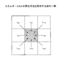
図4は、一般的な視差空間を用いた場合に得られる距離Zを説明する図の一例である。図4(a)はブロックマッチング及びSGM伝播方式により得られるコストC(p,d)と伝播コストLr(p,Z)を示す。横軸は視差dを単位とするシフト量である。図4(a)では探索範囲を64画素とする。pは注目画素、dは基準画像と比較画像のシフト量(探索視差)である。64画素の探索範囲で最も小さいコストC(p、d)又は伝播コストLr(p,Z)が注目している画素pの視差(整数視差)として採用される。
<Fusion of LiDAR and stereo camera>
FIG. 4 is an example of a diagram explaining the distance Z obtained when using a general parallax space. FIG. 4(a) shows the cost C(p, d) and the propagation cost Lr(p, Z) obtained by the block matching and SGM propagation schemes. The horizontal axis is the amount of shift in units of parallax d. In FIG. 4A, the search range is assumed to be 64 pixels. p is the target pixel, and d is the shift amount (search parallax) between the reference image and the comparison image. The smallest cost C(p, d) or propagation cost Lr(p, Z) in the search range of 64 pixels is adopted as the parallax (integer parallax) of the pixel p of interest.
図4(b)はZ空間におけるコストC(p,d)又は伝播コストLr(p,Z)を示す。図4(a)の視差dから式(1)により距離Zが求められる。
Z=BF/d …(1)
なお、Bはステレオカメラにおける左右のカメラの光軸間距離、Fは左右のカメラの焦点距離である。図4(b)に示すように、Z空間では、コストC(p,d)又は伝播コストLr(p,Z)が得られる距離Zに疎密が生じる。これは距離Zを算出する式(1)の分母にdが含まれているため、距離Zがdに反比例し、dが0に近いと距離Zが大きく変化するためである。
FIG. 4(b) shows the cost C(p, d) or propagation cost Lr(p, Z) in Z space. The distance Z is obtained from the parallax d in FIG. 4(a) by Equation (1).
Z=BF/d (1)
B is the distance between the optical axes of the left and right cameras in the stereo camera, and F is the focal length of the left and right cameras. As shown in FIG. 4(b), in the Z space, the distance Z at which the cost C(p, d) or the propagation cost Lr(p, Z) is obtained varies. This is because d is included in the denominator of the formula (1) for calculating the distance Z, the distance Z is inversely proportional to d, and when d is close to 0, the distance Z changes greatly.
したがって、一般的なブロックマッチングは遠距離側で粗いコスト伝播をしているのと同義になり、遠距離で高精度を得ることが困難になる。 Therefore, general block matching is synonymous with rough cost propagation on the long-distance side, making it difficult to obtain high accuracy over long distances.
図5はLiDAR9の距離情報とステレオカメラ8の距離画像の従来のフュージョン方法を説明する図の一例である。従来は、ステレオカメラ8がブロックマッチング等で距離画像を出力した後に、LiDAR9が測定する距離情報を後発的に追加するフュージョン方法が一般的であった。このフュージョン方法では、図4で説明したようにステレオカメラ8の距離画像にそもそも多くの誤差が含まれているため、LiDARの距離情報を加えても精度の向上に限界があった。
FIG. 5 is an example of a diagram for explaining a conventional fusion method of distance information of
そこで、本実施形態では、図6に示すようにステレオカメラ8がブロックマッチング等で距離画像を出力する前にLiDAR9が測定した距離情報をフュージョンさせる。図6(a)は本実施形態におけるLiDAR9の距離情報とステレオカメラ8の距離画像のフュージョン方法を説明する図の一例である。ステレオカメラ8は距離画像を出力する前にLiDAR9が出力する距離情報をコストC(p,d)にフュージョンさせる。
Therefore, in this embodiment, as shown in FIG. 6, the distance information measured by the
そして、図6(b)に示すように、このフュージョンの際、ステレオカメラ8はZ空間でコストC(p,Z)を演算する。図6(b)はZ空間におけるコストC(p,Z)及び伝播コストLr(p,Z)の一例を示す。ブロックマッチング等で得られたコストをZ空間でフュージョンさせるため、測距システムはZ空間のコストを疎密の少なくなるように補間する。そして、このZ空間でステレオカメラ8が算出したコストC(p,Z)とLiDARが検出したコストをフュージョンする。
Then, as shown in FIG. 6B, during this fusion, the
したがって、Z空間においてコストが最小の距離Zを特定でき、近傍と遠方の距離分解能が高い距離画像が得られる。また、距離画像はもともと空間分解能が高いため、高密度かつ高分解能な距離画像が得られる。 Therefore, the distance Z with the minimum cost can be specified in the Z space, and a range image with high near and far range resolution can be obtained. Also, since the range image originally has a high spatial resolution, a high-density and high-resolution range image can be obtained.
このように、本実施形態の測距システム100は、ステレオカメラがブロックマッチング等で距離画像を出力する前に、Z空間でLiDARが測定した距離情報をフュージョンさせることで高密度かつ高分解能な距離画像を実現できる。
In this way, the
<測距システムの適用例>
図7を用いて、測距システム100の適用例について説明する。図7は、移動体の一例である自動車200に搭載された測距システム100を示す図である。図7では、自動車200のフロントウィンドウの内側中央位置に、測距システム100が設定されている。測距システム100は、レーザレーダ測距部110とステレオ画像演算部120とを有する。レーザレーダ測距部110とステレオ画像演算部120はいずれも前方が測距範囲となるように設置されている。レーザレーダ測距部110は、ステレオ画像演算部120が有するステレオカメラ(2つの撮像部)の間(好ましくは中央)に配置されるものとする。
<Application example of distance measuring system>
An application example of the ranging
なお、レーザレーダ測距部110は上記のLiDARと同等の機能を有する。本実施形態では特に断らない限り両者を区別しない。レーザレーダ測距部110は、レーザーダイオードを使って可視スペクトル外の光のパルスを発射し、そのパルスが戻ってくる時間を計測することで距離を算出する。このような距離の算出方法をTOF方式という。ある瞬間のパルスが反射した方向と距離を、レーザレーダ測距部110を中心とした3D地図の中の点として記録する。
Note that the laser
<レーザレーダ測距部のレーザの照射範囲>
図8は、レーザレーダ測距部110によるレーザ光の照射範囲について説明する図の一例である。図8(a)は、自動車200を上方から見た上面図であり、図8(b)は、自動車200を側方から見た側面図である。
<Laser irradiation range of the laser radar rangefinder>
FIG. 8 is an example of a diagram for explaining the irradiation range of the laser beam by the laser radar
図8(a)に示すように、レーザレーダ測距部110は、自動車200の進行方向の前方の所定範囲(横方向の照射範囲)を水平方向に走査しながらレーザ光を照射する。なお、レーザ光は光と捉えてもよいし電磁波と捉えてもよい。
As shown in FIG. 8A, the laser
また、図8(b)に示すように、レーザレーダ測距部110は、自動車200の進行方向の前方の所定範囲に向かってレーザ光を照射する。どの程度遠方までレーザが到達するかはレーザレーダ測距部110の出力によるが数百メートル程度の範囲で測距可能である。近い側の検出範囲は1メートル未満から検出可能であるが、通常、これほどの近距離領域では測距の必要性が低いため適宜、距離を検出する範囲が設定されていてよい。
In addition, as shown in FIG. 8B, the laser
レーザレーダ測距部110は、レーザ光の照射方向を、仰角方向に回転させながら水平方向に走査させることができるよう構成されている。これにより、レーザレーダ測距部110の設置位置を基準として、近傍から遠方までの照射範囲を照射することができる。
The
<測距システムの大きさについて>
例えば車載されるような測距システム100は可能な限り小さいサイズであることが好ましい。ステレオカメラ8は車両の前方を撮像する必要があるため、設置位置が限られるためである。一般乗用車では車室内に設置されることも多く、限られたスペースに乗員の邪魔にならないように設置される。例えば、ルームミラーよりも前方でウィンドウガラス内に設置されることを考えると、ルームミラーを見たり操作したりする運転者が意識しないようなサイズであことが好ましい。
<Regarding the size of the ranging system>
It is preferable that the ranging
図9は、ルームミラー501の前方に車載された測距システム100の外観図の一例である。車幅方向の中央、かつ、ルームミラー501とウィンドウガラスの間のシーリングに測距システム100が設置されている。また、右カメラと左カメラの間にレーザレーダ測距部110が配置されている。つまり、右カメラ、左カメラ、レーザレーダ測距部110が直線上に配置されている。このようにレーザレーダ測距部110とステレオ画像演算部120が1つの筐体に収納されることで、組み立て工程の数を低減できる。
FIG. 9 is an example of an external view of the
運転者が測距システム100を意識しないためには、測距システム100の幅がルームミラー501の幅よりも狭いことが好ましい。ルームミラー501のサイズは様々であるが、例えば、一般的なルームミラーが30〔cm〕であるとすると、測距システム100の幅も30〔cm〕以下であることが好ましい。
It is preferable that the width of the
測距システム100の幅の下限として、右カメラと左カメラの間にレーザレーダ測距部110が配置されている形態では、レーザレーダ測距部110の幅より大きいことが必要になる。したがって、測距システム100の幅は、以下のようになる。
レーザレーダ測距部110の幅 < 測距システム100の幅 ≦ 30〔cm〕
レーザレーダ測距部110の幅は、設計、製造技術、及び要求する精度などによって変わると言えるが、例えば、4、5〔cm〕以上は必要であると考えられる。したがって、測距システム100の幅は、以下のようになる。
The lower limit of the width of the
Width of laser
Although it can be said that the width of the laser radar
4~5〔cm〕 ≦ 測距システム100の幅 ≦ 30〔cm〕
一方、ステレオカメラの基線長があまり短いと遠方の距離分解能が粗くなることが知られている(距離分解能は画素ピッチ、焦点距離にも影響されるため一概に決まらない)。例えば、好ましい性能が得られるステレオカメラの基線長を8cmとすると、測距システム100の幅もこれ以上となる。したがって、測距システム100の幅は、以下のようになる。
4 to 5 [cm] ≤ Width of
On the other hand, it is known that if the base line length of the stereo camera is too short, the distance resolution at a long distance becomes coarse (the distance resolution is also affected by the pixel pitch and the focal length, so it cannot be determined unconditionally). For example, if the baseline length of a stereo camera that provides desirable performance is 8 cm, the width of the
8〔cm〕 ≦ 測距システム100の幅 ≦ 30〔cm〕
このように、本実施形態の測距システム100は従来よりも大幅に小型化されたサイズで実現することができる。
8 [cm] ≤ Width of
Thus, the
<ステレオ画像演算部の撮像範囲>
図10は、ステレオ画像演算部120によるステレオ画像の撮像範囲を説明するための図である。図10(a)は、自動車200の上面図である。ステレオ画像演算部120は、2つの撮像装置(カメラ)が自動車200の進行方向の前方に光軸を向けて設置されており、進行方向の所定範囲の画像を撮像する。レーザ光の照射範囲とステレオカメラ8の撮像範囲は少なくとも一部が重複している。
<Imaging range of the stereo image calculation unit>
FIG. 10 is a diagram for explaining the imaging range of the stereo image by the stereo
図10(b-1)と図10(b-2)は、ステレオカメラ8により撮像された基準画像(右カメラの画像データ)と比較画像(左カメラの画像データ)を示す。右カメラ11と左カメラ12は互いに、所定の間隔を介して水平に設置されている。このため、基準画像と比較画像は重複部分を有するが、撮像画像内のオブジェクトの位置が、左右方向にずれることになる。
10(b-1) and 10(b-2) show a reference image (image data of the right camera) and a comparison image (image data of the left camera) captured by the
ステレオ画像演算部120は、基準画像と比較画像の各オブジェクトのずれ量(これが視差となる)を算出することで、距離画像を生成し出力する。
The stereo
<レーザ光の照射位置とステレオ画像の画素位置との関係>
次に、図11を用いて、レーザレーダ測距部110によるレーザ光の照射位置とステレオ画像演算部120により撮像されたステレオ画像(基準画像)の画素位置との関係について説明する。図11(a)は、レーザ光の照射位置とステレオ画像(基準画像)の画素位置との関係を説明する図の一例である。
<Relationship Between Laser Beam Irradiation Position and Stereo Image Pixel Position>
Next, with reference to FIG. 11, the relationship between the irradiation position of the laser beam by the laser
レーザレーダ測距部110によるレーザの照射方向と、基準画像の画素位置は予め対応付けておくことができる。図11(a)では側方から見た2つのオブジェクトO1、O2が示されており、図11(b)はオブジェクトO1、O2が撮像された基準画像の一例である。オブジェクトO2,O1はレーザレーダ測距部110と右カメラ11の光軸に対し直線上にあるため、重なって撮像される。
The direction of laser irradiation by the laser
オブジェクトO2の高さh2がオブジェクトO1の高さh1のちょうど2倍で、オブジェクトO2の自動車200からの距離L2がオブジェクトO1の自動車200からの距離L1のちょうど2倍であるとする。オブジェクトO1とO2のサイズと距離が比例関係にあるため、画像データにはオブジェクトO1とO2が同じサイズで写り、また、オブジェクトO1とO2と自動車200の位置関係から重なって写る。したがって、レーザ光がオブジェクトO1とO2の上端を通過した場合、レーザ光はステレオ画像演算部120により撮像された基準画像のオブジェクトO1、O2の上端に写るはずである(可視光でないため実際には写らない)。このようにオブジェクトまでの距離に関係なく、レーザ光の照射方向と、基準画像の画素位置は1対1に対応するので、両者を予め対応付けておくことができる。
Assume that the height h2 of object O2 is exactly twice the height h1 of object O1, and the distance L2 of object O2 from
図11(c)は、基準画像の画素P1~P4に対応する距離情報を示す。例えば、P1(x1,y1)の画素は水平方向θ1、仰角φ1の照射方向と対応し、P2(x2,y2)の画素は水平方向θ2、仰角φ2の照射方向と対応し、P3(x3,y3)の画素は水平方向θ3、仰角φ3の照射方向と対応し、P4(x4,y4)の画素は水平方向θ4、仰角φ4の照射方向と対応する。 FIG. 11(c) shows distance information corresponding to pixels P1 to P4 of the reference image. For example, the pixel P1 (x1, y1) corresponds to the irradiation direction of horizontal direction θ1 and elevation angle φ1, the pixel P2 (x2, y2) corresponds to the irradiation direction of horizontal direction θ2 and elevation angle φ2, and pixel P3 (x3, y3) corresponds to a horizontal direction .theta.3 and an elevation angle of .phi.3, and a pixel of P4(x4, y4) corresponds to a horizontal direction .theta.4 and an elevation angle of .phi.4.
このため、レーザレーダ測距部110から照射方向と距離情報が出力されると、ステレオ画像演算部120は測定された距離情報を画素に関連付けることができる。
Therefore, when the irradiation direction and distance information are output from the laser
<レーザレーダ測距部の機能構成>
次に、図12は、レーザレーダ測距部110の機能構成図の一例である。レーザレーダ測距部110は信号処理部601、仰角方向スキャンドライブユニット602、モータ603、仰角方向スキャンミラー604、レーザ受光部605、信号増幅器606、時間間隔カウンタ607、ADCサンプリング部610、レーザ出力部608、及び、レーザドライバ609を有する。
<Functional configuration of laser radar rangefinder>
Next, FIG. 12 is an example of a functional configuration diagram of the laser
信号処理部601からの指示に基づいて、仰角方向スキャンドライブユニット602が、仰角方向スキャンミラー604を仰角方向に回転させるためのモータ603を駆動する。これにより、仰角方向スキャンミラー604は、仰角方向に回転する。
Based on an instruction from the
また、信号処理部601からの指示に基づいて、レーザドライバ609が駆動し、レーザ出力部608からレーザ光が出力される。このとき、レーザ光の出力タイミングは、時間間隔カウンタ607に一時的に保持される。レーザ出力部608から出力されたレーザ光は、仰角方向スキャンミラー604を介して、外部に出力されるため、所定の照射範囲を照射することになる。
A
外部に出力されたレーザ光は、照射方向の物体(対象物)で反射し、その反射光が仰角方向スキャンミラー604を介して、レーザ受光部605において受光される。レーザ受光部605は、垂直方向に配列された複数のフォトディテクタ(PD:Photo Detector)を有しており、レーザ光はいずれかのフォトディテクタで受光され電気信号に変換される。
The laser beam output to the outside is reflected by an object (object) in the irradiation direction, and the reflected light is received by the laser
変換された電気信号は、信号増幅器606において増幅され、ADCサンプリング部610に入力される。ADCサンプリング部610は、信号処理部601がレーザ光を出力させたことを契機に、信号処理部601からの指示により、信号処理部601から指示されたサンプリング周期で電気信号(受光信号RX)のサンプリング(A/D変換)を開始する。A/D変換された受光信号RXは時間間隔カウンタ607に入力される。
The converted electrical signal is amplified in
時間間隔カウンタ607では、レーザ出力部608より出力されたレーザ光の出力タイミングと、ADCサンプリング部610によりサンプリングされた受光信号RXの受光タイミングとに基づいて、時間間隔を算出する。
The
時間間隔カウンタ607において算出された時間間隔は、信号処理部601において距離情報に変換され、照射方向を示す情報と共に、ステレオ画像演算部120に出力される。
The time interval calculated by the
<ADCサンプリング部のサンプリング周期について>
本実施の測距システム100は、発光パルスTXの幅よりもサンプリング周期が短いことが特徴の1つだが、サンプリング周期が短すぎると演算負荷が増大し、サンプリング周期が長いと距離分解能が粗くなり物体の距離の精度が低下してしまう。したがって、発光パルスTXの幅に対し、適切なサンプリング周期を設定することが好ましい。
<Regarding the sampling cycle of the ADC sampling unit>
One of the features of the ranging
図13はサンプリング周期と距離分解能の関係を説明する図の一例である。図13(a)はサンプリング周期に対応する距離分解能の算出例を示す。図13(a)ではサンプリング周期と、サンプリング周波数と、距離分解能がそれぞれ対応付けられている。例えば、サンプリング周期が1〔nsec〕であっても光の速度から算出すると0.3〔m〕の距離分解能でしか測距できないことを示している。逆に、サンプリング周期が34〔nsec〕の場合、光の速度から算出すると10.2〔m〕の距離分解能になる。 FIG. 13 is an example of a diagram explaining the relationship between the sampling period and the distance resolution. FIG. 13(a) shows a calculation example of the distance resolution corresponding to the sampling period. In FIG. 13A, the sampling period, the sampling frequency, and the distance resolution are associated with each other. For example, even if the sampling period is 1 [nsec], the distance can be measured only with a distance resolution of 0.3 [m] when calculated from the speed of light. Conversely, when the sampling period is 34 [nsec], the distance resolution is 10.2 [m] calculated from the speed of light.
どの程度の距離分解能が必要とされるかは状況にもよるが、近距離側ではステレオ画像演算部120が密な距離分解能で測距できるため、遠距離側で実用的と考えられる距離分解能があることが好ましい。例えば、100〔m〕先にある物体では距離分解能が10〔m〕でも大きな支障がない場合もあるし、100〔m〕先でも3〔m〕程度の距離分解能が欲しいと考えらえる状況もありうる。 How much distance resolution is required depends on the situation. Preferably. For example, there are cases where a range resolution of 10 [m] does not pose a major problem for an object located 100 [m] ahead, and there are situations where a range resolution of about 3 [m] is desired even at 100 [m] ahead. Possible.
図13(b)はいくつかの想定される発光パルスTXの幅と距離分解能の対応を示す図の一例である。図13(b)では、発光パルスTXの幅、受光信号RXの幅、発光パルスTXの幅の間に3点の受光信号RXをサンプリングする場合のサンプリング周期、サンプリング周波数、及び、距離分解能が対応付けられている。ここで、3点の受光信号RXをサンプリングする場合のサンプリング周期が示されているのは、受光信号RXを復元するために3点程度の値があると復元が容易であるためである。 FIG. 13(b) is an example of a diagram showing the correspondence between the width of some assumed light emission pulses TX and the distance resolution. In FIG. 13(b), the width of the light emission pulse TX, the width of the light reception signal RX, and the sampling period, sampling frequency, and distance resolution when sampling the light reception signal RX at three points during the width of the light emission pulse TX correspond. attached. Here, the reason why the sampling period for sampling the light receiving signal RX at three points is shown is that it is easy to restore the light receiving signal RX if there are values for about three points.
例えば、発光パルスTXの幅が40〔nsec〕の場合に、3点の受光信号RXをサンプリングするためには、サンプリング周期が20〔nsec〕以下である必要がある。また、この時の距離分解能は6〔m〕である。 For example, when the width of the light emission pulse TX is 40 [nsec], the sampling period must be 20 [nsec] or less in order to sample the light receiving signal RX at three points. Also, the distance resolution at this time is 6 [m].
また、発光パルスTXの幅が3.3〔nsec〕の場合に、3点の受光信号RXをサンプリングするためには、サンプリング周期が1.67〔nsec〕以下である必要がある。また、この時の距離分解能は0.5〔m〕である。 Further, when the width of the light emission pulse TX is 3.3 [nsec], the sampling period must be 1.67 [nsec] or less in order to sample the light receiving signal RX at three points. Further, the distance resolution at this time is 0.5 [m].
このように、3点の受光信号RXをサンプリングするためのサンプリング周期は発光パルスTXの幅によって変わるが、いずれの場合も、発光パルスTXの幅はサンプリング周期以上である。また、3点の受光信号RXをサンプリングする場合は、一例に過ぎず、発光パルスTXの幅の間に少なくとも1つ以上の受光信号RXがサンプリングされればよい(発光周期は少なくとも1つ以上の受光信号RXをサンプリングするために必要な時間以上である。)
設計者などは、発光パルスTXの幅が所定値以上になるように先に決定し、1つ以上又は好ましくは3つ以上のサンプリングが可能なサンプリング周期を決定してよい。あるいは、距離分解能が所定値以下になるように先に決定し、この場合に1つ以上又は好ましくは3つ以上のサンプリングが可能な発光パルスTXの幅を決定してもよい。
As described above, the sampling period for sampling the three light receiving signals RX varies depending on the width of the light emission pulse TX, but in any case, the width of the light emission pulse TX is equal to or longer than the sampling period. Also, the case of sampling the light receiving signals RX at three points is merely an example, and at least one or more light receiving signals RX may be sampled during the width of the light emission pulse TX (the light emission cycle is at least one or more). This is longer than the time required to sample the received light signal RX.)
A designer or the like may determine in advance such that the width of the light emission pulse TX is equal to or greater than a predetermined value, and may determine a sampling period in which one or more, or preferably three or more, samplings are possible. Alternatively, the width of the light emission pulse TX may be determined in advance such that the distance resolution is equal to or less than a predetermined value, and in this case, one or more, or preferably three or more samplings are possible.
<ステレオ画像演算部の機能構成>
図14は、測距システム100の構成図を示す。また、図14ではステレオ画像演算部120の機能をブロック状に示している。測距システム100は測距する装置であるため測距装置ということができる。この他、距離測定装置、測距部などと呼ばれてもよい。
<Functional Configuration of Stereo Image Calculator>
FIG. 14 shows a configuration diagram of the ranging
図14に示すように、ステレオ画像演算部120は、右カメラ11、左カメラ12、歪み補正部13、及び、距離演算部14を有する。右カメラ11及び左カメラ12によりステレオカメラが形成されている。なお、本実施形態において、右カメラ11により撮像される撮像画像を基準画像として用い、左カメラ12により撮像される撮像画像を比較画像として用いる。
As shown in FIG. 14 , the
歪み補正部13、及び、距離演算部14は専用の電子回路を用いて実現してもよいし、各部を実現するためのプログラムがCPU(コンピュータ)によって実行されることで実現されてもよい。したがって、ステレオ画像演算部120は情報処理装置の機能を有する。また、画像処理を行うという点から画像処理装置でもある。
The
歪み補正部13は、基準画像と比較画像に一般的な歪み補正を行う。この画像補正により、基準画像と比較画像は視差以外の差異が生じないように補正される。画像補正は事前のキャリブレーションにより可能になる。左カメラ12と右カメラ11は設置される際に、例えば、校正用の被写体(例えば市松模様のチャート)を撮像する。2つの画像を比較して、カメラのレンズ歪み、光軸ずれ、焦点距離ずれ及び撮像素子歪み等のハード的な内部誤差要因が最小になるように画像データを変換する幾何変換用のLUT(Look Up Table)が生成されている。歪み補正部13はこのようなLUTを参照して画像補正を行う。
The
距離演算部14は基準画像と比較画像にブロックマッチングやSGM伝播方式などのアルゴリズムを適用して視差を算出する。また、詳細は後述するが距離演算部14は、距離画像を出力する前にレーザレーダ測距部110が出力する距離情報で特定されるステレオマッチングコストCST(p,Z)と、LiDARコストCLI(p,Z)をフュージョン(統合)する。
The
このため、距離演算部14は、ブロックマッチングで視差を算出するステレオマッチング部14a、SGM伝播方式で視差を算出するSGM部14b、ステレオマッチングコストCST(p,Z)と、LiDARコストCLI(p,Z)をフュージョンするフュージョン部14c、エネルギーコストS(p,d)を算出するエネルギーコスト算出部14d、及び、基準画像の画素に距離値が対応付けられた距離画像を生成する距離画像生成部14eを有している。
Therefore, the
図14では一例として、距離画像と基準画像がECU20(Electronic Control Unit:電子制御ユニット)に送出されている。ECU20は車両の電子制御ユニットである。なお、車載された測距システム100を車載装置という。ECU20は、測距システム100が出力する距離画像と基準画像を用いて各種の運転支援を行う。基準画像については種々のパターンマッチングを行い先行車両、歩行者、白線、信号機の状態の認識等を行う。
In FIG. 14, as an example, the distance image and the reference image are sent to the ECU 20 (Electronic Control Unit). The
運転支援は車両によって様々であるが、例えば、対象物の横位置が自車両の車幅と重なる場合、距離と相対速度から算出されるTTC(Time To Collision)に応じて警報や制動などを行う。また、衝突までの停止が困難な場合、衝突を回避する方向にステアリングを操舵する。 Driving assistance varies depending on the vehicle. For example, when the lateral position of an object overlaps the width of the own vehicle, warnings and braking are performed according to the TTC (Time To Collision) calculated from the distance and relative speed. . Also, if it is difficult to stop until a collision occurs, the steering is steered in the direction to avoid the collision.
また、ECU20は、車速に応じた車間距離で先行車に追従走行する全車速車間距離制御を行う。先行車が停車したら自車両も停車させ、先行車が発進したら自車両も発進する。また、ECU20が白線認識などを行う場合、走行レーンの中央を走行するように操舵するレーンキーピング制御や走行レーンから逸脱するおそれがあると走行方向を走行レーンに向けて変更する逸脱防止制御等を行うことができる。
Further, the
また、停車時に進行方向に障害物がある場合、急発進を抑制することができる。例えば、シフトレバーの操作位置により判断される進行方向に障害物があり、かつ、アクセルペダルの操作量が大きい場合、エンジン出力を制限したり警報したりすることで被害を軽減する。 Also, if there is an obstacle in the traveling direction when the vehicle is stopped, it is possible to suppress sudden start. For example, if there is an obstacle in the traveling direction determined by the operating position of the shift lever and the amount of operation of the accelerator pedal is large, damage can be reduced by limiting the engine output or giving an alarm.
なお、図14の構成は一例にすぎず、レーザレーダ測距部110とステレオ画像演算部120が一体に構成されていてもよい。あるいはレーザレーダ測距部110の一部の機能をステレオ画像演算部120が有していてよい。例えば、レーザの送信側をレーザレーダ測距部110に配置し、レーザ受光部605、信号増幅器606、ADCサンプリング部610をステレオ画像演算部120に配置する。また、ECU20がステレオ画像演算部120の機能を有していてもよい。
Note that the configuration of FIG. 14 is merely an example, and the laser
<ブロックマッチングによる整数視差の演算>
図15を用いてブロックマッチングによる整数視差の演算について説明する。図15は、右カメラ11により撮像された基準画像420と、左カメラ12により撮像された比較画像410における、注目している画素p=(Px3,Py5)のコストとして、SAD(Sum of Absolute Difference)を算出する例を示した図である。
<Calculation of integer parallax by block matching>
Calculation of integer parallax by block matching will be described with reference to FIG. FIG. 15 shows SAD (Sum of Absolute Difference ) is a diagram showing an example of calculating .
基準画像420と比較画像410では、撮像位置が異なるため、撮像画像上の同じ位置の注目している画素p=(Px3,Py5)であっても、同じオブジェクトを指し示すことはなく、左右方向にずれた位置を指し示すことになる。このため、ブロックサイズを1×1画素とした場合のSADである、基準画像420上の注目している画素p=(Px3,Py5)の輝度値と、比較画像410上の注目している画素p=(Px3,Py5)の輝度値との差分値は、大きな値となる。
Since the imaging positions of the
ここで、比較画像410上の注目している画素pを1画素分、右方向にシフトさせる。つまり、視差d=1としたときのSADを算出する。具体的には、比較画像410上の注目している画素p=(Px3+1,Py5)の輝度値と、基準画像420上の注目している画素p=(Px3,Py5)の輝度値との差分値を算出する。なお、図15の例では、d=1の場合も、SADは大きな値となる。
Here, the pixel p of interest on the
以下、同様に、d=2、3、・・・と変化させていき、それぞれにおいてSADを算出する。図15の例では、d=3の場合に、基準画像420の注目している画素p=(Px3,Py5)が指し示すオブジェクトと比較画像410の注目している画素p=(Px3+3,Py5)が指し示すオブジェクトとが同じとなる。このため、d=3とした場合のSADは、d=3とした場合以外のSADと比べて小さくなる。
Thereafter, similarly, d is changed to 2, 3, . . . and the SAD is calculated for each. In the example of FIG. 15, when d=3, the object indicated by the pixel of interest p=(Px3, Py5) of the
図16(a)は、ある注目している画素pの視差ごとのSADの一例を示す。SADがコストC(p,d)の一例となる。この注目している画素pではd=3において、SADが最小なため、視差dは3であると算出される。 FIG. 16A shows an example of SAD for each parallax of a pixel p of interest. SAD is an example of cost C(p, d). At this pixel p of interest, the SAD is the smallest at d=3, so the parallax d is calculated to be 3.
図16(b)は、別の注目している画素pの視差ごとのSADの一例を示す。図16(b)では視差dの変化に対するSADの変化が小さいため、距離演算部14が視差を抽出することができない。このように、ブロックマッチングだけでは、視差を特定することができない画素が生じえるため、距離演算部14は、視差を顕在化させるためにエネルギ計算処理(SGM伝播方式)を行う。
FIG. 16B shows an example of SAD for each parallax of another target pixel p. In FIG. 16B, the change in SAD with respect to the change in parallax d is small, so the
なお、図16のように視差ごとのSAD(コストC(p,d))が算出されたら、小数視差を求めることが好適である。小数視差を求める方法として高次多項式推定(6次)、高次多項式推定(4次)、又はパラボラフィッティング等を使用する算出方法がある。 Note that it is preferable to calculate the decimal parallax after the SAD (cost C(p, d)) for each parallax is calculated as shown in FIG. As a method for obtaining the decimal parallax, there are calculation methods using high-order polynomial estimation (sixth order), high-order polynomial estimation (fourth order), parabolic fitting, or the like.
<SGM伝播方式>
距離演算部14は、SGM伝播方式と称されるアルゴリズムを用いて、伝播コストLrを算出し、当該伝播コストLrを用いて注目している画素pのエネルギーコストS(p,d)を算出するエネルギ計算処理を行う。なお、SGM伝播方式はデンスアルゴリズムの一形態である。
<SGM propagation method>
The
まず、図17を用いて、SGM伝播方式を用いて伝播コストLrを算出する処理について説明する。図17は、SGM伝播方式を用いて伝播コストLrを算出する処理を模式的に示した図である。 First, processing for calculating the propagation cost Lr using the SGM propagation method will be described with reference to FIG. FIG. 17 is a diagram schematically showing processing for calculating the propagation cost Lr using the SGM propagation method.
図17の例では、注目している画素pである画素1100に対して、4方向の伝播コストLrを求める場合を示している。具体的には、画素1100に対して、矢印1111方向の伝播コストL1と、矢印1112方向の伝播コストL2と、矢印1113方向の伝播コストL3と、矢印1114方向の伝播コストL4とを求める場合を示している。なお、画素1100に対して求める伝播コストの方向(r)は、4方向に限定されるものではなく、例えば、8方向であっても、あるいは2方向であってもよい。
The example of FIG. 17 shows a case where propagation costs Lr in four directions are obtained for a
図17に示すように、矢印1111方向の伝播コストL1は、下式により求めることができる。
As shown in FIG. 17, the propagation cost L1 in the direction of

ただし、pは画素1100の座標を、dは視差を表している。このように、伝播コストL1(p,d)は、画素1100のコストC(p,d)と、画素1100の左側1画素に位置する画素の各視差(d-1~d+1)での伝播コストとによって算出することができる。つまり、矢印1111方向の伝播コストは、左方向から右方向へと順次、伝播コストが算出されていくことになる。なお、左方向から右方向へと伝播コストを伝播させていく際の伝播間隔は、1画素に限定されるものではない。つまり、画素1100の左側a画素に位置する画素の各視差での伝播コストを用いて、伝播コストL1(p,d)を算出するように構成してもよい。
However, p represents the coordinates of the
同様に、矢印1112方向の伝播コストL2は、上方向から下方向へと順次算出されていくことになる。また、矢印1113方向の伝播コストL3は、右方向から左方向へと順次算出され、矢印1114方向の伝播コストL4は、下方向から上方向へと順次算出されていくことになる。
Similarly, the propagation cost L2 in the direction of the
つづいて、エネルギ計算処理のうち、当該伝播コストLrを用いて注目している画素pのエネルギーコストS(p,d)を算出する処理について説明する。 Next, among the energy calculation processes, the process of calculating the energy cost S(p, d) of the pixel p of interest using the propagation cost Lr will be described.
上記のようにして、各画素について算出された各方向からの伝播コストに基づいて、各画素のエネルギーコストS(p,d)が下式により算出される。 Based on the propagation cost from each direction calculated for each pixel as described above, the energy cost S(p, d) of each pixel is calculated by the following equation.

したがって、図17の例では、S(p,d)=L1(p,d)+L2(p,d)+L3(p,d)+L4(p,d)により算出することができる。
Therefore, in the example of FIG. 17, it can be calculated by S(p, d)=L1(p, d)+L2(p, d)+L3(p, d)+L4(p, d).
<本実施形態における距離の算出方法>
続いて、図18を参照して本実施形態の測距システム100が距離画像を生成する手順を説明する。図18は、測距システム100の動作手順を説明するフローチャート図の一例である。
<Distance calculation method in this embodiment>
Next, a procedure for generating a range image by the
(ステップS1~S4)
ステップS1に示すように、レーザレーダ測距部110が距離情報を取得する。レーザレーダ測距部110は右カメラ11及び左カメラ12の撮像範囲の重複部を少なくとも含むように走査して撮像範囲の距離情報を取得する。これと並行してステレオ画像演算部120の右カメラ11が基準画像を、左カメラ12が比較画像を撮像する(S2)。歪み補正部13は視差以外の相違がなくなるようにそれぞれに歪み補正を行う(S3)。次に、ステレオ画像演算部120がステレオマッチングコストCST(p、Z)を算出する(S4)。
(Steps S1 to S4)
As shown in step S1, the laser
なお、ステップS1~S4は同期して行われてもよいが、ステレオ画像演算部120はレーザレーダ測距部110の最新の距離情報を用いることにして非同期に行われてもよい。
Although steps S1 to S4 may be performed synchronously, the stereo
図19は、ステレオマッチングコストCST(p,Z)の一例を示す図である。図19では、ステレオマッチングで得た視差空間のコストがZ空間のステレオマッチングコストCST(p,Z)に変換されている。図4で説明したように、Z空間の等間隔にステレオマッチングコストCST(p,Z)は得られない。そこで、距離演算部14はステレオマッチングで得たコストを等距離ごとに補間する。図19では丸がステレオマッチングで得たコストであり、四角形が補間で得たコストである。補間方法は、曲線近似に適した方法であればよく、例えば放物線fitting、高次多項式、スプライン曲線などを適用できる。図19では、補間により例えば3メートルごとにステレオマッチングコストCST(p,Z)が算出されている。
FIG. 19 is a diagram showing an example of stereo matching cost C ST (p, Z). In FIG. 19, the cost in the parallax space obtained by stereo matching is converted into the stereo matching cost C ST (p, Z) in the Z space. As explained in FIG. 4, the stereo matching cost C ST (p, Z) cannot be obtained at equal intervals in the Z space. Therefore, the
補間を3メートルとするのは一例であり、この間隔はLiDARの距離分解能と同程度とすることが1つの選択方法になる。 An interpolation of 3 meters is an example, and one selection method is to set this interval to the same extent as the distance resolution of LiDAR.
図20は、LiDARコストCLI(p,Z)の算出方法を説明する図の一例である。図20(a)は発光パルスTXを模式的に示し、図20(b)は定期的にサンプリングされた受光信号RXを示し、図20(c)はLiDARコストCLI(p,Z)の一例を示す。レーザレーダ測距部110は発光パルスTXの出力を開始すると、受光信号RXの定期的なサンプリングを開始する。1回の発光パルスTXの出力に対しADCサンプリング部610がサンプリングを継続する時間は予め決まっている。例えば、距離にして120〔m〕等に相当する時間である。
FIG. 20 is an example of a diagram illustrating a method of calculating the LiDAR cost C LI (p, Z). FIG. 20(a) schematically shows the light emission pulse TX, FIG. 20(b) shows the regularly sampled light reception signal RX, and FIG. 20(c) is an example of the LiDAR cost C LI (p, Z). indicates When the
時間間隔カウンタ607は発光パルスTXが出力されてから受光信号RXの各サンプリング点がサンプリングされるまでの時間Tを測定する。時間Tと物体までの距離との間には以下の関係がある。
物体までの距離=光の速度×T/2
したがって、信号処理部601は時間Tを距離情報に変換できる。
A
Distance to object = speed of light x T/2
Therefore, the
図20(b)に示す受光信号RXと距離の関係は、受光信号RXが大きいほどその距離に物体が存在する確率が高いことを意味する。一方、ステレオマッチングコストは、物体が存在する可能性が最も高い距離で最も小さくなる。したがって、フュージョンするには、受光信号RXが小さいほど物体が存在する確率が高くなるような波形にすることが好ましい。このため、信号処理部601は、図20(b)の受光信号RXを図20(c)に示すLiDARコストCLI(p,Z)に変換する。変換には種々の方法があるが、受光信号RXが最も大きい距離で、LiDARコストCLI(p,Z)が最も小さくなればよい。簡単な例としては、例えば、受光信号RXの一定値を中心に上下を反転させるような変換がある。
The relationship between the received light signal RX and the distance shown in FIG. 20B means that the greater the received light signal RX, the higher the probability that an object exists at that distance. On the other hand, the stereo matching cost is lowest at the distances where the objects are most likely to be. Therefore, for fusion, it is preferable to form a waveform such that the smaller the received light signal RX, the higher the probability that an object exists. Therefore, the
図20では、受光信号RXが小さいほど物体が存在する確率が高くなるような波形に受光信号RXが変換されているが、ステレオマッチングコストの波形を、物体が存在する可能性が最も高い距離で最も大きくなるようにステレオ画像演算部120が変形してもよい。
In FIG. 20, the received light signal RX is converted into a waveform such that the smaller the received light signal RX, the higher the probability that an object exists. The stereo
(ステップS5)
次に、距離演算部14は、ステレオマッチングコストCST(p,Z)とLiDARコストCLI(p,Z)をフュージョンして、コストC(p,Z)を算出する。式では以下のように表すことができる。
C(p,Z)=A×CLI(p,Z)+B×CST(p,Z) …(4)
A:LiDARコストの係数(重み)
B:ステレオマッチングコストの係数(重み)
係数Aと係数BはLiDARコストとステレオマッチングコストのどちらをフュージョンにおいて強く影響させるかという点で重要である。LiDARとステレオマッチングにはそれぞれ精度がよい条件があるため、実験的に決定されてよい。また、環境条件(時間帯、天候、現在地等)ごとに係数A,Bが予め定められているテーブルから読み出して係数Aと係数Bを設定してもよい。また、ステレオ画像演算部120が基準画像を物体認識することで基準画像の範囲ごとに写っているオブジェクトが分かるので、この範囲ごとに係数A,係数Bを切り替えてもよい。
(Step S5)
Next, the
C(p, Z)=A×C LI (p, Z)+B×C ST (p, Z) (4)
A: LiDAR cost coefficient (weight)
B: Coefficient (weight) of stereo matching cost
Coefficient A and coefficient B are important in terms of which of the LiDAR cost and the stereo matching cost strongly influences the fusion. Since LiDAR and stereo matching each have conditions for good accuracy, they may be determined experimentally. Alternatively, coefficients A and B may be set by reading from a table in which coefficients A and B are predetermined for each environmental condition (time zone, weather, current location, etc.). Further, since the stereo
図21は、ステレオマッチングコストCST(p,Z)とLiDARコストCLI(p,Z)のフュージョンを模式的に示す図の一例である。図21(a)はLiDARコストCLI(p,Z)を示し、図21(b)はステレオマッチングコストCST(p,Z)を示す。距離演算部14は、LiDARコストCLI(p,Z)に係数Aを乗じ、ステレオマッチングコストCST(p,Z)に係数Bを乗じて、同じ距離ごとに加算する。上記したステレオマッチングコストCST(p,Z)の補間と、ADCサンプリング部610のサンプリング周期により、ステレオマッチングコストCST(p,Z)とLiDARコストCLI(p,Z)はほぼ同じ距離にコスト値が得られている。必要であれば、LiDARコストCLI(p,Z)も同様に補間されてよい。
FIG. 21 is an example of a diagram schematically showing the fusion of the stereo matching cost C ST (p, Z) and the LiDAR cost CLI (p, Z). FIG. 21(a) shows the LiDAR cost C LI (p, Z), and FIG. 21(b) shows the stereo matching cost C ST (p, Z). The
これにより、図21(c)に示すように、ステレオマッチングコストCST(p,Z)とLiDARコストCLI(p,Z)をフュージョンさせることができる。 Thereby, as shown in FIG. 21(c), the stereo matching cost C ST (p, Z) and the LiDAR cost CLI (p, Z) can be fused.
(ステップS6)
次に、距離演算部14は伝播コストLr(p,Z)を算出する。伝播コストLr(p,Z)の算出式を以下に示す。
(Step S6)
Next, the

伝播コストLr(p,Z)の第1項はステップS5で算出された、ステレオマッチングコストCST(p,Z)とLiDARコストCLI(p,Z)がフュージョンされたコストC(p,Z)である。第2項はZ空間で行われるSGM伝播方式による伝播コストである。第1項と第2項により、伝播コストLr(p,Z)が算出される。
The first term of the propagation cost Lr (p, Z) is the cost C (p, Z ). The second term is the propagation cost due to the SGM propagation scheme done in Z-space. The propagation cost Lr(p, Z) is calculated from the first and second terms.
なお、本実施形態において、Z空間で行われるSGM伝播方式による伝播コストは必須でなく、SGM伝播方式による伝播コストは算出されなくてもよい。 In this embodiment, the propagation cost by the SGM propagation method performed in Z space is not essential, and the propagation cost by the SGM propagation method may not be calculated.
(ステップS7)
距離演算部14は、全ての画素で伝播コストLr(p,Z)を算出したか否かを判断する。全ての画素の処理が終了するまでは、ステップS5,S6を繰り返し実行する。
(Step S7)
The
(ステップS8)
全ての画素で伝播コストLr(p,Z)を算出すると、距離演算部14はエネルギーコストS(p,Z)を算出する。
S(p,Z)=ΣLr(p,Z) …(6)
図22、23は、エネルギーコストS(p,Z)の算出方法を説明する図の一例である。画素ごとに伝播コストLr(p,Z)が算出されたが、ある画素には周囲の伝播コストLr(p,Z)が影響していると考えられる。そこで、注目している画素の周囲の伝播コストLr(p,Z)を重ね合わせることで、注目している画素のより正確な伝播コストLr(p,Z)を算出する。
(Step S8)
After calculating the propagation cost Lr(p, Z) for all pixels, the
S(p, Z)=ΣLr(p, Z) (6)
22 and 23 are examples of diagrams illustrating a method of calculating the energy cost S(p, Z). Although the propagation cost Lr(p, Z) was calculated for each pixel, it is considered that a certain pixel is affected by the surrounding propagation cost Lr(p, Z). Therefore, by superimposing the propagation costs Lr(p, Z) around the pixel of interest, a more accurate propagation cost Lr(p, Z) of the pixel of interest is calculated.
図22では周囲8画素の伝播コストLr(p,Z)が重ね合わされている。この場合、図23に示すように距離ごとに以下の計算が行われる。
S(p,Z)=L0(p,Z)+L45(p,Z)+L90(p,Z)+L135(p,Z)+L180(p,Z)+L225(p,Z)+L270(p,Z)+L315(p,Z)、 …(7)
図23と式(7)が示すのは、注目している画素の周囲8画素の伝播コストLr(p,Z)をZ空間で重ね合わせることである。これにより、注目している画素のエネルギーコストS(p,Z)が得られる。
In FIG. 22, the propagation costs Lr(p, Z) of eight surrounding pixels are superimposed. In this case, the following calculations are performed for each distance as shown in FIG.
S(p,Z)= L0 (p,Z)+ L45 (p,Z)+ L90 (p,Z)+ L135(p,Z)+L180(p,Z)+L225 ( p ,Z)+L 270 (p, Z) + L 315 (p, Z), … (7)
FIG. 23 and equation (7) show that the propagation costs Lr(p,Z) of eight pixels surrounding the pixel of interest are superimposed in Z space. This gives the energy cost S(p,Z) of the pixel of interest.
なお、周囲8画素の伝播コストLr(p,Z)の重ね合わせは一例に過ぎず、4画素、5画素、又は16画素などの周囲の何画素の伝播コストLr(p,Z)を重ね合わせるかは、演算負荷と距離の正確さを考慮して決定されてよい。また、伝播コストLr(p,Z)の重ね合わせを一切行わなくてもよい。 Note that the superposition of the propagation costs Lr(p, Z) of the surrounding 8 pixels is only an example, and the propagation costs Lr(p, Z) of the surrounding pixels such as 4 pixels, 5 pixels, or 16 pixels are superimposed. may be determined in consideration of computation load and distance accuracy. Moreover, it is not necessary to superimpose the propagation costs Lr(p, Z) at all.
(ステップS9)
距離演算部14は、エネルギーコストS(p,Z)が最小となる距離Z0を決定する。距離Z0が注目している画素の距離値である。
(Step S9)
The
図24はエネルギーコストS(p,Z)が最小となる距離Z0の算出方法を説明する図の一例である。エネルギーコストS(p,Z)が最小となるZは注目している画素の距離値として最も確からしいと推定される。 FIG. 24 is an example of a diagram illustrating a method of calculating the distance Z0 that minimizes the energy cost S(p, Z). Z that minimizes the energy cost S(p, Z) is estimated to be the most probable distance value of the pixel of interest.
なお、高次多項式推定(6次)、高次多項式推定(4次)、又はパラボラフィッティング等を使用して、少数以下の距離Zを算出してもよい。 Note that the distance Z less than or equal to a decimal number may be calculated using high-order polynomial estimation (sixth order), high-order polynomial estimation (fourth order), parabolic fitting, or the like.
(ステップS10)
全ての画素で算出されると図18の処理は終了する。
(Step S10)
When all the pixels have been calculated, the processing in FIG. 18 ends.
<Z空間の分解能について>
図25を用いてZ空間の距離分解能について補足する。図25(a)は距離分解能が密なZ空間を示し、図25(b)は比較のために示された距離分解能が粗いZ空間を示す。上記のようにステレオマッチングコストは補間されるため、LiDARコストとステレオマッチングコストは同程度の距離分解能になる。図25(a)の距離分解能は一例として3メートルであり、図25(b)では0.5メートルとなっている。なお、3メートルと0.5メートルは一例である。
<Resolution of Z space>
FIG. 25 is used to supplement the range resolution of the Z space. FIG. 25(a) shows the Z space with fine range resolution, and FIG. 25(b) shows the Z space with coarse range resolution shown for comparison. Since the stereo matching cost is interpolated as described above, the LiDAR cost and the stereo matching cost have similar distance resolution. As an example, the distance resolution in FIG. 25(a) is 3 meters, and in FIG. 25(b) it is 0.5 meters. Note that 3 meters and 0.5 meters are examples.
図25(a)では114メートルの間に38個のコストが得られ、図25(b)では228個のコストが得られる。したがって、図25(b)の距離分解能の方が高くて好ましいが、3メートルの距離分解能でも遠方ではステレオマッチングコストの距離分解能よりも高分解能となっている(図4参照)。また、図25(a)のようにZ空間の分解能を粗くすることで、レーザレーダ測距部110の演算負荷を低減できる。また、レーザレーダ測距部110に搭載されるマイコンなども小型なものでよく、測距システム100を小型化しやすくなる。
38 costs are obtained over 114 meters in FIG. 25(a), and 228 costs are obtained in FIG. 25(b). Therefore, although the distance resolution in FIG. 25B is higher and preferable, even the distance resolution of 3 meters is higher than the distance resolution of the stereo matching cost in the long distance (see FIG. 4). Also, by roughening the resolution of the Z space as shown in FIG. Also, a microcomputer or the like mounted on the laser radar
このように、3メートル程度の距離分解能であれば、受光信号RXのサンプリング周期を長くできるため、発光パルスTXの幅も長くてよく、測距システム100の小型化が容易になる。
In this way, if the distance resolution is about 3 meters, the sampling period of the received light signal RX can be lengthened, so the width of the light emission pulse TX can be long, and the
<<距離範囲に応じた距離分解能の変更>>
一方、距離分解能は全ての距離範囲で一定である必要はない。近距離側ではステレオ画像演算部120の距離分解能が高いことが知られており、近距離側もレーザレーダ測距部110の距離分解能に一致させると、高密度な距離情報を破棄することになる。
<<Change of distance resolution according to distance range>>
On the other hand, the distance resolution need not be constant over the entire distance range. It is known that the distance resolution of the stereo
図26は、レーザレーダ測距部110とステレオ画像演算部120それぞれの、低距離側と高距離側の距離分解能をに示す図の一例である。図26(a)は距離と距離分解能の関係の一例を示す。なお、図26ではステレオカメラの基線長を16〔cm〕とした。この場合、距離が12〔m〕以下ではステレオ画像演算部120の距離分解能が0.5〔m〕以下である。レーザレーダ測距部110の距離分解能が0.5〔m〕である場合、12〔m〕以下ではステレオ画像演算部120の距離分解能の方が密である。
FIG. 26 is an example of a diagram showing distance resolutions on the low-distance side and the high-distance side of the laser radar
ステレオ画像演算部120の距離分解能が0.5〔m〕の場合、レーザレーダ測距部110が120〔m〕までの距離を測定できるとすると、コスト空間数は120/0.5=240個である。
When the distance resolution of the stereo
図26(b)は一例として17〔m〕を境に空間分解能を変更した場合の距離分解能を示す。つまり、17〔m〕以下では0.5〔m〕を距離分解能としてフュージョンし、17〔m〕超では1.0〔m〕を距離分解能としてフュージョンする。この場合のコスト空間は、17/0.5+(120-17)/1.0=137個である。したがって、低距離側では高密度な距離分解能が得られ、演算負荷も低減できる。 FIG. 26(b) shows, as an example, the range resolution when the spatial resolution is changed with 17 [m] as the boundary. That is, fusion is performed with a range resolution of 0.5 [m] for 17 [m] or less, and with a range resolution of 1.0 [m] for more than 17 [m]. The cost space in this case is 17/0.5+(120-17)/1.0=137. Therefore, high-density distance resolution can be obtained on the low-distance side, and the computational load can also be reduced.
ステレオマッチングコストCST(p,Z)とLiDARコストCLI(p,Z)をフュージョンさせるため、ステレオ画像演算部120は、17〔m〕を境にして補間間隔を変更する。すなわち、17〔m〕以下では補間しないか補間間隔を密にして、17〔m〕超ではLiDARコストCLI(p,Z)と距離分解能と同程度の間隔で補間する。なお、17〔m〕以下では、ステレオマッチングコストが得られている距離とLiDARコストが得られている距離が一致しないので、ステレオマッチングコストが得られている距離でLiDARコストが得られるようにLiDARコストを補間するとよい。
In order to fuse the stereo matching cost C ST (p, Z) and the LiDAR cost C LI (p, Z), the stereo
図26(c)は一例として24〔m〕を境に空間分解能を変更した場合の距離分解能を示す。つまり、24〔m〕以下では0.5〔m〕を距離分解能としてフュージョンし、24〔m〕超では2.0〔m〕を距離分解能としてフュージョンする。この場合のコスト空間は、24/0.5+(120-24)/2.0=96個である。したがって、低距離側では高密度な距離分解能が得られ、演算負荷も更に低減できる。 FIG. 26(c) shows, as an example, the distance resolution when the spatial resolution is changed with 24 [m] as the boundary. That is, fusion is performed with a range resolution of 0.5 [m] for 24 [m] or less, and with a range resolution of 2.0 [m] for over 24 [m]. The cost space in this case is 24/0.5+(120-24)/2.0=96. Therefore, high-density distance resolution can be obtained on the low-distance side, and the computational load can be further reduced.
なお、近距離側と遠距離側の保管方法には他にも以下のような方法がある。以下のある距離は閾値の一例である。
(i) ある距離から近距離側(閾値未満)ではステレオ分解能を使い、ある距離から遠距離(閾値以上)では所定分解能1を使う。
(ii) ある距離から近距離側(閾値未満)では所定分解能1を使い、ある距離から遠距離(閾値以上)では所定分解能2を使う(所定分解能1の密度>所定分解能2の密度)。
(iii) ある距離から近距離側(閾値未満)ではステレオ分解能を使い、ある距離1から遠距離では所定分解能1を使い、更にある距離2(>距離1)から遠距離側では所定分解能2を使う。
(iv) ある距離1から近距離側では所定分解能1を使い、ある距離1から遠距離では所定分解能2を使い、更にある距離2から遠距離側では所定分解能3を使う。
In addition, there are other storage methods for the short distance side and the long distance side as follows. Some distance below is an example of a threshold.
(i) Stereo resolution is used from a certain distance to the short distance side (below the threshold), and
(ii) From a certain distance to the short distance side (less than the threshold value), a
(iii) Stereo resolution is used from a certain distance to the short distance side (less than the threshold), predetermined
(iv) A
<ステレオマッチングコストとLiDARコストのフュージョンの別の例>
本実施形態では、ステレオマッチングコストとLiDARコストをフュージョンさせる際にSGMを使用した。しかし、これらのフュージョンではSGMを使わなくても良い伝播の方法もある。例えば、伝播の別の例として伝播コストLrの計算を省く以下の方法を用いてもよい。
C(p,Z)=A×CLI(p,Z)+B×CST(p,Z)
S(p,Z)=ΣC(p,Z) …(8)
距離ベースのSGMでは伝播コストLrの処理の負荷が高かった。これに対し、本実施形態ではLiDARコストにピークがあるため、式(8)のように式(5)の伝播コストLrの計算を省き、負荷を低減できる。
<Another example of fusion of stereo matching cost and LiDAR cost>
In the present embodiment, SGM was used to fuse the stereo matching cost and the LiDAR cost. However, there are ways of propagation for these fusions that do not require the use of SGM. For example, as another example of propagation, the following method that omits calculation of propagation cost Lr may be used.
C(p,Z)=A* CLI (p,Z)+B* CST (p,Z)
S(p, Z)=ΣC(p, Z) (8)
Distance-based SGM has a high processing load for the propagation cost Lr. On the other hand, in this embodiment, since the LiDAR cost has a peak, the load can be reduced by omitting the calculation of the propagation cost Lr in Equation (5) as in Equation (8).
<効果について>
図27は、本実施形態の測距システム100による測距結果の効果を説明する図の一例である。図27において、チャートとは看板状の物体を意味する。チャートは、測距システム100から80、60、30の実測された位置に置かれている。本実施形態の測距システム100による測距平均値はそれぞれ80.26、61.14、30.89であり、測距標準偏差はそれぞれ0.25、2.02、0.25である。
<About effect>
FIG. 27 is an example of a diagram illustrating the effect of the distance measurement result by the
従来技術であるステレオマッチングのみによる測距平均値はそれぞれ87.86、60.98、28.96であり、測距標準偏差はそれぞれ6.07、2.89、1.77である。したがって、60〔m〕のチャートの測距平均値以外で、本実施形態の測距システム100の精度が向上していることが確認される。
The distance measurement average values by the conventional stereo matching alone are 87.86, 60.98, and 28.96, respectively, and the distance measurement standard deviations are 6.07, 2.89, and 1.77, respectively. Therefore, it is confirmed that the accuracy of the
<まとめ>
本実施形態の測距システム100は、ステレオカメラによる測距方法から見ると以下のような効果がある。
・測距精度:物体面の低分散化、物体面のその周囲の面不連続性が向上するため遠方測距や遠方物体検出が行ないやすくなる。
・耐物標性:繰返しパタンや低テクスチャでの誤マッチングにより使えなかった画素が、フュージョンすることによって使えるようになる。
・耐環境性:夜間であっても遠方高精度測距が可能になる。
・SGMで伝播して物体が膨れるところがLiDARによる測距値で埋まる。
<Summary>
The
・Range measurement accuracy: Distance measurement and detection of distant objects become easier due to the low dispersion of the object surface and the improvement of surface discontinuity around the object surface.
・Target resistance: Pixels that could not be used due to repeated patterns or mismatching with low textures can be used by fusion.
・Environmental resistance: Enables long-distance high-precision ranging even at night.
- Where the object swells due to propagation by SGM, it is filled with the distance measurement value by LiDAR.
また、LiDARによる測距方法から見ると以下のような効果がある。
・空間分解能が増える。
Also, from the viewpoint of the distance measurement method by LiDAR, there are the following effects.
・Spatial resolution is increased.
更に、受光信号RXのパルス幅を広く取れるため、受光素子の数や大きさの制限が少なくなり、測距システムの小型化が容易になる。また、例えば、レーザレーダ測距部110の距離分解能を3〔m〕とした場合、コスト空間数を粗くすることが可能となり、距離演算時の処理の負荷を低減できる。
Furthermore, since the pulse width of the received light signal RX can be widened, there are fewer restrictions on the number and size of the light receiving elements, which facilitates miniaturization of the distance measuring system. Further, for example, when the range resolution of the laser
更に、発光パルスTXが広くて受光信号RXの幅も広ければADCサンプリング部610のサンプリング周波数をそれほど速くなくて済むので、例えば、ノイズレベルと信号レベルが同程度の場合でも、ノイズレベル信号を取らずに済む可能性が上がる。
Furthermore, if the light emission pulse TX is wide and the light reception signal RX is wide, the sampling frequency of the
<その他の適用例>
以上、本発明を実施するための最良の形態について実施例を用いて説明したが、本発明はこうした実施例に何等限定されるものではなく、本発明の要旨を逸脱しない範囲内において種々の変形及び置換を加えることができる。
<Other application examples>
Although the best mode for carrying out the present invention has been described above using examples, the present invention is by no means limited to such examples, and various modifications can be made without departing from the scope of the present invention. and substitutions can be added.
例えば、測距システム100が搭載される移動体として自動車200を挙げたが、測距システム100は移動体に広く適用できる。例えば、少なくとも一部において人間が操作しなくても自律的に移動する移動体に有効である。例えば、飛行機、ドローン、船舶、ロボット等に適用できる。
For example, although the
また、測距システム100は移動体の前方に限られず、側方又は後方の距離画像を生成することもできる。前方、側方及び後方の全周囲の距離画像を生成することもできる。
Further, the ranging
また、距離画像はカラーでもモノクロでもよい。 Further, the distance image may be color or monochrome.
また、レーザ光の波長については、測距に適した波長域の光を使用すればよく、可視光、赤外光、紫外光(人体に影響がない範囲で)でもよいし、光を電磁波と捉えてもよい。 As for the wavelength of the laser light, it is sufficient to use light in a wavelength range suitable for distance measurement. You can catch it.
また、本実施形態では、距離分解能の高い測距方式としてLIDARを説明したが、ミリ波又は超音波などを用いてもよい。 Also, in the present embodiment, LIDAR has been described as a ranging method with high distance resolution, but millimeter waves, ultrasonic waves, or the like may also be used.
なお、ステレオ画像演算部120は画像処理部の一例であり、レーザレーダ測距部110は距離情報取得部の一例であり、図20のような距離に対する受光信号は第一の距離情報の一例であり、ステレオマッチングコストは第二の距離情報の一例であり、レーザ出力部608は照射部の一例であり、レーザ受光部605と信号増幅器606とADCサンプリング部610は受光部の一例である。
Note that the stereo
8 ステレオカメラ
9 LiDAR
20 ECU
100 測距システム
110 レーザレーダ測距部
120 ステレオ画像演算部
200 自動車
8
20 ECUs
100 Ranging
Claims (16)
複数の撮像部により撮像された複数の撮像画像を画像処理して得た第二の距離情報に、前記距離情報取得部が取得した前記第一の距離情報を統合する画像処理部と、を有する測距システムであって、
発光パルスを照射する照射部と、
前記発光パルスが対象物で反射した受光信号を検出する受光部と、を有し、
前記照射部が照射する発光パルスの幅をA、
前記受光部が前記受光信号をサンプリングするサンプリング周期をBとした場合、A≧Bの関係があり、
前記画像処理部は、閾値未満の近距離側において前記第二の距離情報の距離分解能で前記第一の距離情報と前記第二の距離情報を結合し、前記閾値以上の遠距離において前記第二の距離情報の距離分解能より大きい分解能で前記第一の距離情報と前記第二の距離情報を結合することを特徴とする測距システム。 a distance information acquisition unit that detects first distance information by a TOF (Time Of Flight) method;
an image processing unit that integrates the first distance information acquired by the distance information acquisition unit with second distance information obtained by image processing a plurality of captured images captured by the plurality of imaging units. A ranging system,
an irradiation unit that emits a light emission pulse;
a light-receiving unit that detects a light-receiving signal that the light emission pulse is reflected by an object;
A is the width of the light emission pulse emitted by the irradiation unit;
When the sampling period at which the light receiving unit samples the light receiving signal is B, there is a relationship of A≧B ,
The image processing unit combines the first distance information and the second distance information with a distance resolution of the second distance information on the short distance side of less than the threshold, and combines the second distance information on the long distance of the threshold or more. A distance measuring system, wherein said first distance information and said second distance information are combined with a resolution higher than the distance resolution of said distance information .
前記受光部が前記受光信号を少なくとも1つ以上、サンプリングするために必要な時間以上であることを特徴とする請求項1又は2に記載の測距システム。 The width of the light emission pulse emitted by the irradiation unit is
3. The distance measuring system according to claim 1, wherein the light receiving unit has at least one or more of the light receiving signals, and is longer than the time required for sampling.
前記第一の距離情報の距離分解能が所定値以下になるように決定されていることを特徴とする請求項1~4のいずれか1項に記載の測距システム。 The width of the light emission pulse emitted by the irradiation unit is, under the relationship of A≧B,
5. The distance measuring system according to any one of claims 1 to 4, wherein the distance resolution of said first distance information is determined to be equal to or less than a predetermined value.
前記第一の距離情報の距離分解能が約3メートルになるように決定されていることを特徴とする請求項5に記載の測距システム。 The width of the light emission pulse emitted by the irradiation unit is
6. The distance measuring system according to claim 5 , wherein the distance resolution of said first distance information is determined to be about 3 meters.
前記画像処理部は、前記距離情報に対する前記受光信号を値が大きいほど小さくなるコストに変換した後、前記画像処理により得たステレオマッチングコストと統合するか、又は、
前記画像処理により得たステレオマッチングコストを値が小さいほど大きくなるコストに変換して、前記距離情報取得部が出力した前記距離情報に対する前記受光信号と統合することを特徴とする請求項1~6のいずれか1項に記載の測距システム。 The distance information acquisition unit converts the time until each light reception signal is acquired into distance information and outputs the light reception signal corresponding to the distance information to the image processing unit,
The image processing unit converts the light reception signal for the distance information into a cost that decreases as the value increases, and then integrates it with the stereo matching cost obtained by the image processing, or
6. The stereo matching cost obtained by the image processing is converted into a cost that increases as the value decreases, and is integrated with the received light signal corresponding to the distance information output by the distance information acquisition unit. The ranging system according to any one of 1.
補間したステレオマッチングコストと、前記距離情報に対する前記受光信号の値が大きいほど小さくなるように変換されたコストとを統合することを特徴とする請求項7に記載の測距システム。 The image processing unit interpolates the stereo matching cost at distance resolution intervals determined by the sampling period,
8. The distance measuring system according to claim 7 , wherein the interpolated stereo matching cost and the cost converted so as to decrease as the value of the received light signal with respect to the distance information increases are integrated.
前記複数の撮像部と前記距離情報取得部を含む前記直線上の方向の全幅は、前記距離情報取得部の前記直線上の方向の幅より大きく、約30〔cm〕以下であることを特徴とする請求項11に記載の測距システム。 the plurality of imaging units and the distance information acquiring unit are arranged on a straight line,
A total width in the straight line direction including the plurality of imaging units and the distance information acquisition unit is larger than a width of the distance information acquisition unit in the straight line direction and is about 30 cm or less. 12. The ranging system according to claim 11 .
前記複数の撮像部と前記距離情報取得部を含む前記直線上の方向の全幅は、約8〔cm〕以上、約30〔cm〕以下であることを特徴とする請求項11又は12に記載の測距システム。 the plurality of imaging units and the distance information acquiring unit are arranged on a straight line,
13. The method according to claim 11 or 12 , wherein the total width in the linear direction including the plurality of imaging units and the distance information acquisition unit is about 8 cm or more and about 30 cm or less. ranging system.
複数の撮像部により撮像された複数の撮像画像を画像処理して得た第二の距離情報に、前記距離情報取得部が取得した前記第一の距離情報を統合する画像処理部と、を有する測距システムが行う測距方法であって、
照射部が、発光パルスを照射するステップと、
受光部が、前記発光パルスが対象物で反射した受光信号を検出するステップと、
前記画像処理部が、閾値未満の近距離側において前記第二の距離情報の分解能で前記第一の距離情報と前記第二の距離情報を結合し、前記閾値以上の遠距離において前記第二の距離情報の分解能より大きい分解能で前記第一の距離情報と前記第二の距離情報を結合するステップと、を有し、
前記照射部が照射する発光パルスの幅をA、
前記受光部が前記受光信号をサンプリングするサンプリング周期をBとした場合、A≧Bの関係があることを特徴とする測距方法。 a distance information acquisition unit that detects first distance information by a TOF (Time Of Flight) method;
an image processing unit that integrates the first distance information acquired by the distance information acquisition unit with second distance information obtained by image processing a plurality of captured images captured by the plurality of imaging units. A ranging method performed by a ranging system,
a step in which the irradiating unit irradiates a light emission pulse;
a step in which the light-receiving unit detects a light-receiving signal in which the light-emitting pulse is reflected by an object;
The image processing unit combines the first distance information and the second distance information at a resolution of the second distance information on the short distance side of less than the threshold, and combines the second distance information on the long distance of the threshold or more. combining the first range information and the second range information with a resolution greater than the resolution of the range information ;
A is the width of the light emission pulse emitted by the irradiation unit;
A distance measuring method, wherein A≧B, where B is a sampling period at which the light receiving section samples the light receiving signal.
TOF(Time Of Flight)方式で第一の距離情報を検出する距離情報取得部と、
複数の撮像部により撮像された複数の撮像画像を画像処理して得た第二の距離情報に、前記距離情報取得部が取得した前記第一の距離情報を統合する画像処理部と、
発光パルスを照射する照射部と、
前記発光パルスが対象物で反射した受光信号を検出する受光部と、を有し、
前記照射部が照射する発光パルスの幅をA、
前記受光部が前記受光信号をサンプリングするサンプリング周期をBとした場合、A≧Bの関係があり、
前記画像処理部は、閾値未満の近距離側において前記第二の距離情報の分解能で前記第一の距離情報と前記第二の距離情報を結合し、前記閾値以上の遠距離において前記第二の距離情報の分解能より大きい分解能で前記第一の距離情報と前記第二の距離情報を結合し、
撮像画像の画素に距離値が対応付けられた距離画像を生成して車両の制御ユニットに送出する車載装置。 An in-vehicle device,
a distance information acquisition unit that detects first distance information by a TOF (Time Of Flight) method;
an image processing unit that integrates the first distance information acquired by the distance information acquisition unit with second distance information obtained by image processing a plurality of captured images captured by a plurality of imaging units;
an irradiation unit that emits a light emission pulse;
a light-receiving unit that detects a light-receiving signal that the light emission pulse is reflected by an object;
A is the width of the light emission pulse emitted by the irradiation unit;
When the sampling period at which the light receiving unit samples the light receiving signal is B, there is a relationship of A≧B,
The image processing unit combines the first distance information and the second distance information at a resolution of the second distance information on the short distance side of less than the threshold, and combines the second distance information on the long distance of the threshold or more. combining the first distance information and the second distance information with a resolution greater than the resolution of the distance information;
An in-vehicle device that generates a distance image in which distance values are associated with pixels of a captured image and sends the image to a control unit of the vehicle.
複数の撮像部により撮像された複数の撮像画像を画像処理して得た第二の距離情報に、前記距離情報取得部が取得した前記第一の距離情報を統合する画像処理部と、
発光パルスを照射する照射部と、
前記発光パルスが対象物で反射した受光信号を検出する受光部と、を有し、
前記照射部が照射する発光パルスの幅をA、
前記受光部が前記受光信号をサンプリングするサンプリング周期をBとした場合、A≧Bの関係があり、
前記画像処理部は、閾値未満の近距離側において前記第二の距離情報の分解能で前記第一の距離情報と前記第二の距離情報を結合し、前記閾値以上の遠距離において前記第二の距離情報の分解能より大きい分解能で前記第一の距離情報と前記第二の距離情報を結合し、
撮像画像の画素に距離値が対応付けられた距離画像を使って車両を制御する制御ユニットを有する車両。 a distance information acquisition unit that detects first distance information by a TOF (Time Of Flight) method;
an image processing unit that integrates the first distance information acquired by the distance information acquisition unit with second distance information obtained by image processing a plurality of captured images captured by a plurality of imaging units;
an irradiation unit that emits a light emission pulse;
a light-receiving unit that detects a light-receiving signal that the light emission pulse is reflected by an object;
A is the width of the light emission pulse emitted by the irradiation unit;
When the sampling period at which the light receiving unit samples the light receiving signal is B, there is a relationship of A≧B,
The image processing unit combines the first distance information and the second distance information at a resolution of the second distance information on the short distance side of less than the threshold, and combines the second distance information on the long distance of the threshold or more. combining the first distance information and the second distance information with a resolution greater than the resolution of the distance information ;
A vehicle having a control unit that controls the vehicle using a distance image in which distance values are associated with pixels of a captured image.
Priority Applications (2)
| Application Number | Priority Date | Filing Date | Title |
|---|---|---|---|
| JP2018045944A JP7119444B2 (en) | 2018-03-13 | 2018-03-13 | ranging system, ranging method, in-vehicle device, vehicle |
| EP19161978.2A EP3540467B1 (en) | 2018-03-13 | 2019-03-11 | Range finding system, range finding method, in-vehicle device, and vehicle |
Applications Claiming Priority (1)
| Application Number | Priority Date | Filing Date | Title |
|---|---|---|---|
| JP2018045944A JP7119444B2 (en) | 2018-03-13 | 2018-03-13 | ranging system, ranging method, in-vehicle device, vehicle |
Publications (2)
| Publication Number | Publication Date |
|---|---|
| JP2019158616A JP2019158616A (en) | 2019-09-19 |
| JP7119444B2 true JP7119444B2 (en) | 2022-08-17 |
Family
ID=65763392
Family Applications (1)
| Application Number | Title | Priority Date | Filing Date |
|---|---|---|---|
| JP2018045944A Active JP7119444B2 (en) | 2018-03-13 | 2018-03-13 | ranging system, ranging method, in-vehicle device, vehicle |
Country Status (2)
| Country | Link |
|---|---|
| EP (1) | EP3540467B1 (en) |
| JP (1) | JP7119444B2 (en) |
Families Citing this family (2)
| Publication number | Priority date | Publication date | Assignee | Title |
|---|---|---|---|---|
| JP2020003236A (en) * | 2018-06-25 | 2020-01-09 | 株式会社リコー | Distance measurement device, moving body, distance measurement method, and distance measurement system |
| JP2021148746A (en) * | 2020-03-23 | 2021-09-27 | 株式会社リコー | Distance measuring device and distance measuring method |
Citations (4)
| Publication number | Priority date | Publication date | Assignee | Title |
|---|---|---|---|---|
| JP2000028719A (en) | 1998-07-14 | 2000-01-28 | Minolta Co Ltd | Range finder |
| US20120314037A1 (en) | 2010-02-23 | 2012-12-13 | Ben-Gurion University Of The Negev | System and method for providing 3d imaging |
| JP2013120083A (en) | 2011-12-06 | 2013-06-17 | Honda Motor Co Ltd | Environment recognition apparatus |
| JP2018017506A (en) | 2016-07-25 | 2018-02-01 | 株式会社リコー | Parallax computation system, mobile entity and program |
Family Cites Families (5)
| Publication number | Priority date | Publication date | Assignee | Title |
|---|---|---|---|---|
| JPH0933653A (en) * | 1995-07-19 | 1997-02-07 | Nissan Motor Co Ltd | Radar device |
| JP6476831B2 (en) | 2013-12-26 | 2019-03-06 | 株式会社リコー | Parallax calculation system, information processing apparatus, information processing method, and program |
| US10036801B2 (en) * | 2015-03-05 | 2018-07-31 | Big Sky Financial Corporation | Methods and apparatus for increased precision and improved range in a multiple detector LiDAR array |
| JP6772639B2 (en) * | 2016-08-02 | 2020-10-21 | 株式会社リコー | Parallax calculation system, mobiles and programs |
| JP6504468B2 (en) | 2016-09-16 | 2019-04-24 | トヨタ自動車株式会社 | Removal support device |
-
2018
- 2018-03-13 JP JP2018045944A patent/JP7119444B2/en active Active
-
2019
- 2019-03-11 EP EP19161978.2A patent/EP3540467B1/en active Active
Patent Citations (4)
| Publication number | Priority date | Publication date | Assignee | Title |
|---|---|---|---|---|
| JP2000028719A (en) | 1998-07-14 | 2000-01-28 | Minolta Co Ltd | Range finder |
| US20120314037A1 (en) | 2010-02-23 | 2012-12-13 | Ben-Gurion University Of The Negev | System and method for providing 3d imaging |
| JP2013120083A (en) | 2011-12-06 | 2013-06-17 | Honda Motor Co Ltd | Environment recognition apparatus |
| JP2018017506A (en) | 2016-07-25 | 2018-02-01 | 株式会社リコー | Parallax computation system, mobile entity and program |
Also Published As
| Publication number | Publication date |
|---|---|
| JP2019158616A (en) | 2019-09-19 |
| EP3540467A2 (en) | 2019-09-18 |
| EP3540467A3 (en) | 2019-12-25 |
| EP3540467B1 (en) | 2020-12-30 |
Similar Documents
| Publication | Publication Date | Title |
|---|---|---|
| JP2020003236A (en) | Distance measurement device, moving body, distance measurement method, and distance measurement system | |
| US10891751B2 (en) | Range image generating method, range image generating apparatus, and on-board device having range image generating function | |
| JP4809019B2 (en) | Obstacle detection device for vehicle | |
| US9151626B1 (en) | Vehicle position estimation system | |
| US10215860B2 (en) | Vehicle environment scanning by a phase-controlled laser | |
| US11427193B2 (en) | Methods and systems for providing depth maps with confidence estimates | |
| WO2017181638A1 (en) | Systems and methods for unified mapping of an environment | |
| JP7176406B2 (en) | image processing method, image processing device, in-vehicle device, moving object, system | |
| US11366229B2 (en) | Range finding method, range finding apparatus, and range finding system | |
| US11507789B2 (en) | Electronic device for vehicle and method of operating electronic device for vehicle | |
| JPWO2017145945A1 (en) | Stereo camera device, vehicle, and parallax calculation method | |
| Jang et al. | Design factor optimization of 3D flash lidar sensor based on geometrical model for automated vehicle and advanced driver assistance system applications | |
| JP7119444B2 (en) | ranging system, ranging method, in-vehicle device, vehicle | |
| US11520019B2 (en) | Light signal detection device, range finding device, and detection method | |
| WO2016035272A1 (en) | Driving assist device | |
| JP2019145021A (en) | Information processing device, imaging device, and imaging system | |
| JP5580062B2 (en) | Obstacle detection alarm device | |
| US20220413144A1 (en) | Signal processing device, signal processing method, and distance measurement device | |
| CN110799853B (en) | Environment sensing system and mobile platform | |
| US20230328403A1 (en) | Compact perception device | |
| US20220381915A1 (en) | Vehicle-mounted sensing system and vehicle | |
| US20230305161A1 (en) | Real-time monitoring dc offset of adc data of lidar system | |
| US20230341532A1 (en) | Dynamic calibration method of avalanche photodiodes on lidar | |
| WO2023079944A1 (en) | Control device, control method, and control program | |
| US20220163675A1 (en) | Methods of Using Background Images from a Light Detection and Ranging (LIDAR) Device |
Legal Events
| Date | Code | Title | Description |
|---|---|---|---|
| A621 | Written request for application examination |
Free format text: JAPANESE INTERMEDIATE CODE: A621 Effective date: 20210118 |
|
| A977 | Report on retrieval |
Free format text: JAPANESE INTERMEDIATE CODE: A971007 Effective date: 20211217 |
|
| A131 | Notification of reasons for refusal |
Free format text: JAPANESE INTERMEDIATE CODE: A131 Effective date: 20220118 |
|
| A521 | Request for written amendment filed |
Free format text: JAPANESE INTERMEDIATE CODE: A523 Effective date: 20220309 |
|
| TRDD | Decision of grant or rejection written | ||
| A01 | Written decision to grant a patent or to grant a registration (utility model) |
Free format text: JAPANESE INTERMEDIATE CODE: A01 Effective date: 20220705 |
|
| A61 | First payment of annual fees (during grant procedure) |
Free format text: JAPANESE INTERMEDIATE CODE: A61 Effective date: 20220718 |
|
| R151 | Written notification of patent or utility model registration |
Ref document number: 7119444 Country of ref document: JP Free format text: JAPANESE INTERMEDIATE CODE: R151 |