JP7118640B2 - Spark plug for internal combustion engine - Google Patents
Spark plug for internal combustion engine Download PDFInfo
- Publication number
- JP7118640B2 JP7118640B2 JP2017253620A JP2017253620A JP7118640B2 JP 7118640 B2 JP7118640 B2 JP 7118640B2 JP 2017253620 A JP2017253620 A JP 2017253620A JP 2017253620 A JP2017253620 A JP 2017253620A JP 7118640 B2 JP7118640 B2 JP 7118640B2
- Authority
- JP
- Japan
- Prior art keywords
- insulator
- housing
- inclined surface
- plug
- tip
- Prior art date
- Legal status (The legal status is an assumption and is not a legal conclusion. Google has not performed a legal analysis and makes no representation as to the accuracy of the status listed.)
- Active
Links
Images


Classifications
-
- H—ELECTRICITY
- H01—ELECTRIC ELEMENTS
- H01T—SPARK GAPS; OVERVOLTAGE ARRESTERS USING SPARK GAPS; SPARKING PLUGS; CORONA DEVICES; GENERATING IONS TO BE INTRODUCED INTO NON-ENCLOSED GASES
- H01T13/00—Sparking plugs
- H01T13/20—Sparking plugs characterised by features of the electrodes or insulation
- H01T13/32—Sparking plugs characterised by features of the electrodes or insulation characterised by features of the earthed electrode
-
- H—ELECTRICITY
- H01—ELECTRIC ELEMENTS
- H01T—SPARK GAPS; OVERVOLTAGE ARRESTERS USING SPARK GAPS; SPARKING PLUGS; CORONA DEVICES; GENERATING IONS TO BE INTRODUCED INTO NON-ENCLOSED GASES
- H01T13/00—Sparking plugs
- H01T13/20—Sparking plugs characterised by features of the electrodes or insulation
- H01T13/34—Sparking plugs characterised by features of the electrodes or insulation characterised by the mounting of electrodes in insulation, e.g. by embedding
Description
本発明は、内燃機関用のスパークプラグに関する。 The present invention relates to spark plugs for internal combustion engines.
スパークプラグは、自動車のエンジン等の内燃機関における着火手段として用いられる。スパークプラグとして、中心電極と接地電極とを対向させて放電ギャップを形成したものがある。かかるスパークプラグは、放電ギャップに放電を生じさせ、この放電により、燃焼室内の混合気に着火している。 Spark plugs are used as ignition means in internal combustion engines such as automobile engines. Some spark plugs have a discharge gap formed by opposing a center electrode and a ground electrode. Such a spark plug causes an electric discharge in the discharge gap, and the electric discharge ignites the air-fuel mixture in the combustion chamber.
燃焼室内においては、例えばタンブル流といった混合気の気流が形成されており、この気流が放電ギャップにおいても適度に流れることにより、放電火花を気流で引き伸ばすことができる。放電火花が引き伸ばされることにより、放電火花と燃焼室内の混合気との接触面積を稼ぎ、混合気への着火性を確保することができる。 An airflow of an air-fuel mixture, such as a tumble flow, is formed in the combustion chamber, and this airflow appropriately flows even in the discharge gap, so that the discharge spark can be extended by the airflow. By stretching the discharge spark, the contact area between the discharge spark and the air-fuel mixture in the combustion chamber is increased, and the ignitability of the air-fuel mixture can be ensured.
ここで、特許文献1に記載のスパークプラグは、気流を放電ギャップへ導きやすくすべく、燃焼室内に露出するハウジングの先端部の外周面を、プラグ軸方向の先端側へ向かうほど縮径するよう傾斜した傾斜面としている。これにより、燃焼室内の気流は、ハウジングの前記傾斜面にガイドされ、放電ギャップに向かいやすくなる。
Here, in the spark plug disclosed in
しかしながら、特許文献1に記載のスパークプラグにおいては、絶縁碍子の先端部がハウジングの先端側に露出しないよう構成されている。それゆえ、絶縁碍子の先端部とハウジングとの間の空間に、燃焼室内の不完全燃焼により発生した導電性を有するカーボンが流入しやすい。そのため、絶縁碍子の先端部の表面にカーボンが堆積しやすい。そうなると、絶縁碍子の先端部の表面に堆積したカーボンを介して、中心電極とハウジングとの間に放電が生じてしまう、いわゆる横飛び火の問題が生じる。
However, in the spark plug disclosed in
また、特許文献1に記載のスパークプラグにおいては、燃焼室内の混合気への着火性向上の観点からも改善の余地がある。
Further, the spark plug described in
本発明は、かかる課題に鑑みてなされたものであり、横飛び火が生じにくく、かつ、燃焼室内の混合気への着火性を向上させやすい内燃機関用のスパークプラグを提供しようとするものである。 SUMMARY OF THE INVENTION The present invention has been made in view of such problems, and an object thereof is to provide a spark plug for an internal combustion engine in which side sparks are less likely to occur and the ignitability of an air-fuel mixture in a combustion chamber is easily improved. .
本発明の一態様は、筒状のハウジング(2)と、
前記ハウジングの内側に保持された筒状の絶縁碍子(3)と、
前記絶縁碍子の内側に保持された中心電極(4)と、
前記中心電極の先端面との間に火花放電を生じさせる放電ギャップ(G)を形成するギャップ形成面(521)を有する接地電極(5)と、を有し、
前記絶縁碍子の内側面と前記中心電極の外側面とは、互いに直接対向しており、
前記絶縁碍子は、前記ハウジングの先端側に突出した碍子突出部(31)を有し、
前記碍子突出部の外周面は、プラグ中心軸を通るとともにプラグ軸方向(Z)に平行な断面のうち少なくとも1つの断面である軸平行断面において、プラグ軸方向の先端側に向かうにつれて内周側に向かう、直線状となる碍子傾斜面(311)を有し、
前記軸平行断面において、前記碍子傾斜面の両端を通る仮想直線(L1)は、前記ギャップ形成面を通り、
前記接地電極は、前記碍子傾斜面とは反対側を向く接地傾斜面(522)を有し、
前記接地傾斜面は、前記軸平行断面において前記碍子傾斜面と平行であり、
前記ハウジングは、燃焼室(16)に露出するハウジング露出部(221)を有し、前記ハウジング露出部の外周面は、プラグ軸方向の先端側に向かうにつれて内周側に向かうよう傾斜したハウジング傾斜面(221a)を有し、前記軸平行断面において、前記ハウジング傾斜面の両端を通るハウジング側仮想直線(L2)は、前記ギャップ形成面を通り、
前記ハウジング傾斜面、前記碍子傾斜面及び前記接地傾斜面が同一直線上に配されている、
内燃機関の燃焼室内に設けられて放電火花により前記燃焼室内の混合気への着火を行う内燃機関用のスパークプラグ(1)にある。
One aspect of the present invention is a tubular housing (2),
a cylindrical insulator (3) held inside the housing;
a center electrode (4) held inside the insulator;
a ground electrode (5) having a gap forming surface (521) that forms a discharge gap (G) that causes spark discharge between itself and the tip surface of the center electrode;
the inner surface of the insulator and the outer surface of the center electrode directly face each other,
The insulator has an insulator protruding portion (31) protruding toward the tip side of the housing,
The outer peripheral surface of the insulator protruding portion is arranged on an axis-parallel cross section, which is at least one of cross sections passing through the central axis of the plug and parallel to the axial direction (Z) of the plug, toward the tip end side in the axial direction of the plug. has a rectilinear insulator inclined surface (311) facing
In the axis-parallel cross section, an imaginary straight line (L1) passing through both ends of the insulator inclined surface passes through the gap forming surface ,
the ground electrode has a ground sloped surface (522) facing away from the insulator sloped surface;
The ground contact inclined surface is parallel to the insulator inclined surface in the axis-parallel cross section,
The housing has a housing exposed portion (221) exposed to the combustion chamber (16), and the outer peripheral surface of the housing exposed portion is inclined toward the inner peripheral side toward the tip side in the axial direction of the plug. A housing-side imaginary straight line (L2) having a surface (221a) and passing through both ends of the housing inclined surface in the axially parallel section passes through the gap forming surface,
The housing inclined surface, the insulator inclined surface, and the ground contact inclined surface are arranged on the same straight line,
A spark plug (1) for an internal combustion engine that is provided in a combustion chamber of an internal combustion engine and ignites an air-fuel mixture in the combustion chamber with a discharge spark.
前記内燃機関用のスパークプラグにおいて、絶縁碍子の碍子突出部は、ハウジングの先端側に突出している。それゆえ、絶縁碍子の碍子突出部の表面にカーボンが堆積しにくい。それゆえ、横飛び火が発生することを抑制することができる。 In the spark plug for an internal combustion engine, the insulator protruding portion of the insulator protrudes toward the tip side of the housing. Therefore, carbon is less likely to deposit on the surface of the insulator protruding portion of the insulator. Therefore, it is possible to suppress the occurrence of side sparks.
また、碍子突出部の外周面は、前記軸平行断面において、プラグ軸方向の先端側に向かうにつれて内周側に向かう、直線状或いは内周側に凸の曲線状となる碍子傾斜面を有する。さらに、軸平行断面において、碍子傾斜面の両端を通る仮想直線は、接地電極のギャップ形成面を通るよう形成されている。それゆえ、燃焼室内の気流は、碍子傾斜面を沿うように流れて、放電ギャップを吹き抜けるよう導かれる。それゆえ、放電ギャップに気流が適度に流れるようにすることができる。それゆえ、放電火花を引き伸ばしやすく、燃焼室内の混合気への着火性を向上させやすい。 Further, the outer peripheral surface of the insulator protruding portion has an insulator inclined surface which, in the axis-parallel cross section, has a linear shape or a curve convex to the inner peripheral side toward the inner peripheral side toward the tip side in the axial direction of the plug. Furthermore, in the axis-parallel cross section, an imaginary straight line passing through both ends of the insulator inclined surface is formed so as to pass through the gap forming surface of the ground electrode. Therefore, the airflow in the combustion chamber flows along the sloped surface of the insulator and is guided to blow through the discharge gap. Therefore, it is possible to allow the airflow to flow appropriately in the discharge gap. Therefore, it is easy to extend the discharge spark, and it is easy to improve the ignitability of the air-fuel mixture in the combustion chamber.
また、燃焼室内の気流は放電ギャップを斜め先端側に向って流れるよう、碍子傾斜面によって導かれる。それゆえ、放電火花は、気流によって斜め先端側、すなわち燃焼室の中央側に向かって引き伸ばされる。換言すると、放電火花は、エンジンヘッドから遠ざかるように引き伸ばされる。それゆえ、放電火花から混合気へ着火されることにより生じた火炎の熱がエンジンヘッドに奪われることを抑制しやすく、火炎を成長させやすい。 Also, the airflow in the combustion chamber is guided by the insulator slope so as to flow in the discharge gap toward the oblique tip side. Therefore, the discharge spark is stretched toward the oblique tip side, ie, the central side of the combustion chamber, by the airflow. In other words, the discharge spark is stretched away from the engine head. Therefore, it is easy to suppress the loss of the heat of the flame generated by the ignition of the air-fuel mixture from the discharge spark to the engine head, and the flame is easy to grow.
さらに、前記内燃機関用のスパークプラグにおいては、ハウジングよりも放電ギャップに近い位置にある絶縁碍子に形成された碍子傾斜面によって、気流の進行方向をガイドする。それゆえ、放電ギャップに向かって気流をプラグ軸方向に近い角度で流入させることが可能となる。そのため、放電火花を一層先端側に向かって引き伸ばしやすく、一層着火性を向上させやすい。 Further, in the spark plug for the internal combustion engine, the direction of movement of the airflow is guided by the insulator inclined surface formed on the insulator located closer to the discharge gap than the housing. Therefore, it is possible to cause the airflow to flow into the discharge gap at an angle close to the axial direction of the plug. Therefore, it is easier to extend the discharge spark further toward the tip side, and it is easier to improve the ignitability.
以上のごとく、前記態様によれば、横飛び火が生じにくく、かつ、燃焼室内の混合気への着火性を向上させやすい内燃機関用のスパークプラグを提供することができる。
なお、特許請求の範囲及び課題を解決する手段に記載した括弧内の符号は、後述する実施形態に記載の具体的手段との対応関係を示すものであり、本発明の技術的範囲を限定するものではない。
As described above, according to the above aspect, it is possible to provide a spark plug for an internal combustion engine that is less likely to cause side sparks and more likely to improve the ignitability of the air-fuel mixture in the combustion chamber.
It should be noted that the symbols in parentheses described in the claims and the means for solving the problems indicate the corresponding relationship with the specific means described in the embodiments described later, and limit the technical scope of the present invention. not a thing
(実施形態1)
内燃機関用のスパークプラグの実施形態につき、図1~図6を用いて説明する。
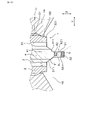
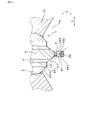
本実施形態の内燃機関用のスパークプラグ1は、図1に示すごとく、ハウジング2と絶縁碍子3と中心電極4と接地電極5とを有する。ハウジング2は筒状を呈している。絶縁碍子3は、ハウジング2の内側に保持されている。また、絶縁碍子3は、筒状を呈している。中心電極4は、絶縁碍子3の内側に保持されている。図1~図3に示すごとく、接地電極5は、中心電極4の先端面421との間に放電ギャップGを形成するギャップ形成面521を有する。
(Embodiment 1)
An embodiment of a spark plug for an internal combustion engine will be described with reference to FIGS. 1 to 6. FIG.
A
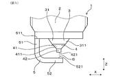
図2、図3に示すごとく、絶縁碍子3は、ハウジング2の先端側に突出した碍子突出部31を有する。ここで、プラグ中心軸を通るとともにプラグ軸方向Zに平行な断面のうち少なくとも1つの断面を軸平行断面という。このとき、図2に示すごとく、碍子突出部31の外周面は、軸平行断面において、プラグ軸方向Zの先端側に向かうにつれて内周側に向かう、直線状或いは内周側に凸の曲線状となる碍子傾斜面311を有する。軸平行断面において、碍子傾斜面311の両端を通る仮想直線L1は、ギャップ形成面521を通る。なお、図2は軸平行断面の一例である。以後、本実施形態につき詳説する。
As shown in FIGS. 2 and 3 , the
なお、本明細書において、プラグ中心軸は、スパークプラグ1の中心軸を意味するものとする。また、プラグ軸方向Zは、スパークプラグ1の軸方向を意味するものとする。また、プラグ径方向といったときは、スパークプラグ1の径方向を意味しているものとする。また、単に内周側といったときは、プラグ径方向の内周側を意味し、単に外周側といったときは、プラグ径方向の外周側を意味するものとする。
In this specification, the plug central axis means the central axis of the
スパークプラグ1は、例えば、自動車、コージェネレーション等の内燃機関における着火手段として用いることができる。プラグ軸方向Zにおいて、スパークプラグ1の一端は、図示しない点火コイルと接続され、他端は、図2に示すごとく、内燃機関の燃焼室16内に配される。本明細書においては、プラグ軸方向Zにおける点火コイルと接続される側を基端側とし、燃焼室16内に配される側を先端側という。
The
図2に示すごとく、ハウジング2は、その先端部に、エンジンヘッド15に設けられた雌ネジ孔11に取り付けるための取付ネジ部21を有する。また、ハウジング2は、取付ネジ部21よりも先端側に突出する円環状のハウジング先端部22を有する。ハウジング先端部22の先端は、燃焼室16内に露出したハウジング露出部221を構成している。ハウジング露出部221の先端面は、プラグ軸方向Zに直交する面である。
As shown in FIG. 2 , the
絶縁碍子3は、例えばアルミナを略円筒形状に形成してなる。図1に示すごとく、絶縁碍子3は、プラグ軸方向Zに貫通するよう形成された軸孔30を有する。絶縁碍子3は、先端部(すなわち碍子突出部31)をハウジング2のプラグ軸方向Zの先端側に突出させている。また、絶縁碍子3は、基端部をハウジング2の基端に突出させている。
The
図2に示すごとく、碍子突出部31の外周面は、軸平行断面において、先端側に向かうにつれて内周側に向かうよう直線状に形成された碍子傾斜面311を有する。碍子突出部31の外周面は、少なくともプラグ軸方向Zと横方向Yとの双方に平行な軸平行断面において、碍子傾斜面311を有する。図4に示すごとく、本実施形態において、碍子突出部31の外周面は、その全周に碍子傾斜面311を有する。すなわち、碍子突出部31の外周面は、プラグ中心軸を通るとともにプラグ軸方向Zに平行なあらゆる断面において、碍子傾斜面311を有する。本実施形態においては、碍子突出部31の露出面のすべてが碍子傾斜面311を構成している。
As shown in FIG. 2, the outer peripheral surface of the
図2に示すごとく、碍子傾斜面311は、軸平行断面において、プラグ軸方向Zの寸法がプラグ径方向の寸法よりも大きくなるよう形成されている。本実施形態において、碍子傾斜面311は、絶縁碍子3の軸孔30に連なるよう形成されている。
As shown in FIG. 2, the insulator
絶縁碍子3の軸孔30の先端部に、中心電極4が挿通保持されている。中心電極4は、その中心軸をプラグ中心軸と略一致させるよう配されている。
The
図2、図3に示すごとく、中心電極4は、中心電極母材41と中心電極チップ42とを有する。中心電極母材41の先端部は、碍子突出部31よりも先端側に突出した中心電極突出部411を構成している。中心電極突出部411は、先端側へ向かうほど縮径する円錐台形状を呈している。そして、中心電極突出部411の先端面に、中心電極チップ42が接合されている。
As shown in FIGS. 2 and 3, the
図2、図3に示すごとく、中心電極チップ42は、中心電極突出部411の先端面と略同径の円柱状である。中心電極チップ42は、その中心軸をスパークプラグ1の中心軸と一致させている。中心電極チップ42の先端面421が、接地電極5のギャップ形成面521とプラグ軸方向Zに対向して、放電ギャップGを形成している。
As shown in FIGS. 2 and 3, the
図3に示すごとく、接地電極5は、立設部51及び内向部52を有する。立設部51は、基端側の端部に、ハウジング2の先端面に接続された接地接続部511を有する。本実施形態において、接地接続部511はプラグ軸方向Zに直交する。立設部51は、ハウジング2の先端面から先端側へプラグ軸方向Zに立設している。
As shown in FIG. 3 , the
内向部52は、立設部51の先端側の端部から、プラグ径方向の内周側に延設されている。以後、内向部52の延設方向を縦方向Xといい、縦方向X及びプラグ軸方向Zの双方に直交する方向を横方向Yという。図2、図4に示すごとく、内向部52は、その一部が中心電極チップ42の先端面421とプラグ軸方向Zに重なる位置に配されている。内向部52の基端側の面が、前述のギャップ形成面521である。
The
図2に示すごとく、軸平行断面において、碍子傾斜面311の両端を通る仮想直線L1は、接地電極5のギャップ形成面521を通る。具体的には、軸平行断面において、碍子傾斜面311の両端を通る仮想直線L1は、ギャップ形成面521における横方向Yの当該碍子傾斜面311側と反対側の領域を通る。
As shown in FIG. 2, an imaginary straight line L1 passing through both ends of the insulator
なお、接地電極5は、例えば、長尺な金属板材をその厚み方向に曲げ加工してなる。接地電極5を形成する際は、このような金属板材を、長手方向の一箇所において直角に屈曲させる。これにより、この屈曲部を挟む両側の部位が、それぞれ、立設部51及び内向部52となる。
The
図1に示すごとく、絶縁碍子3の軸孔30内において、中心電極4の基端側には、導電性を有するガラスシール12を介して抵抗体13が配置されている。抵抗体13は、カーボン又はセラミック粉末等の抵抗材及びガラス粉末を含むレジスタ組成物を加熱封着することにより形成する、或いはカートリッジ型抵抗体を挿入することによって構成することができる。ガラスシール12は、ガラスに銅粉を混入させてなる銅ガラスからなる。また、抵抗体13の基端側には、銅ガラスからなるガラスシール12を介して端子金具14が配されている。端子金具14は、例えば鉄合金からなる。
As shown in FIG. 1, a
次に、図2を用いて、本実施形態のスパークプラグ1を内燃機関に取り付けてなる点火装置について説明する。
Next, an ignition device in which the
スパークプラグ1は、取付ネジ部21において、エンジンヘッド15に設けられた雌ネジ孔11に螺合されている。これにより、スパークプラグ1がエンジンヘッド15に締結固定されている。さらに、スパークプラグ1の先端部分が燃焼室16内に配される。このとき、スパークプラグ1は、先端部分に対して燃焼室内の気流が横方向Yに流入するような姿勢で配される。
The
次に、図5を用いて、放電ギャップG周辺の混合気の気流Fの流れの様子について説明する。 Next, with reference to FIG. 5, the flow of the airflow F of the air-fuel mixture around the discharge gap G will be described.
スパークプラグ1の先端部分の上流側付近においては、エンジンヘッド15の表面に沿って気流Fが流れる。具体的には、スパークプラグ1の先端部分よりも上流側付近においては、スパークプラグ1の先端部分に向かって、略横方向Yに気流Fが流れる。
An airflow F flows along the surface of the
そして、スパークプラグ1の先端部分に対して略横方向Yに流入してきた気流Fは、絶縁碍子3の碍子傾斜面311に沿ってその方向が斜め先端側に変えられ、碍子傾斜面311の延長線上にある接地電極5のギャップ形成面521に向かう。その後、気流Fは、放電ギャップGを斜め先端側に向かって吹き抜ける。このように、気流Fは、放電ギャップGに近い絶縁碍子3の碍子傾斜面311によってその方向が変えられる。それゆえ、放電ギャップGを流れる気流Fは、プラグ軸方向Zに近い角度で流れる。
Then, the direction of the airflow F that has flowed into the tip portion of the
次に、本実施形態の作用効果につき説明する。 Next, the effects of this embodiment will be described.
本実施形態の内燃機関用のスパークプラグ1において、絶縁碍子3の碍子突出部31は、ハウジング2の先端側に突出している。それゆえ、絶縁碍子3の碍子突出部31の表面にカーボンが堆積しにくい。それゆえ、横飛び火が発生することを抑制することができる。
In the
また、碍子突出部31の外周面は、軸平行断面において、プラグ軸方向Zの先端側に向かうにつれて内周側に向かう、直線状或いは内周側に凸の曲線状となる碍子傾斜面311を有する。さらに、軸平行断面において、碍子傾斜面311の両端を通る仮想直線L1は、接地電極5のギャップ形成面521を通るよう形成されている。それゆえ、図5に示すごとく、燃焼室16内の気流Fは、碍子傾斜面311を沿うように流れて、放電ギャップGを吹き抜けるよう導かれる。それゆえ、放電ギャップGに気流Fが適度に流れるようにすることができる。それゆえ、図6に示すごとく、放電火花Sを引き伸ばしやすく、燃焼室16内の混合気への着火性を向上させやすい。
Further, the outer peripheral surface of the
また、図5に示すごとく、燃焼室16内の気流Fは放電ギャップGを斜め先端側に向って流れるよう、碍子傾斜面311によって導かれる。それゆえ、図6に示すごとく、放電火花Sは、気流によって斜め先端側、すなわち燃焼室16の中央側に向かって引き伸ばされる。換言すると、放電火花Sは、エンジンヘッド15から遠ざかるように引き伸ばされる。それゆえ、放電火花Sから混合気へ着火されることにより生じた火炎の熱がエンジンヘッド15に奪われることを抑制しやすく、火炎を成長させやすい。
Further, as shown in FIG. 5, the airflow F in the
さらに、図5に示すごとく、本実施形態の内燃機関用のスパークプラグ1においては、ハウジング2よりも放電ギャップGに近い位置にある絶縁碍子3に形成された碍子傾斜面311によって、気流Fの進行方向をガイドする。それゆえ、放電ギャップGに向かって気流Fをプラグ軸方向Zに近い角度で流入させることが可能となる。そのため、図6に示すごとく、放電火花Sを一層先端側に向かって引き伸ばしやすく、一層着火性を向上させやすい。
Further, as shown in FIG. 5, in the
また、碍子突出部31の外周面は、その全周に碍子傾斜面311を有する。それゆえ、スパークプラグ1の先端部分に横方向Yのいずれから気流Fが流入しても、碍子傾斜面311によって気流Fを放電ギャップGに導くことができる。また、碍子突出部31の形状を簡易にしやすい。
In addition, the outer peripheral surface of the
以上のごとく、本実施形態によれば、横飛び火が生じにくく、かつ、燃焼室内の混合気への着火性を向上させやすい内燃機関用のスパークプラグを提供することができる。 As described above, according to the present embodiment, it is possible to provide a spark plug for an internal combustion engine in which side sparks are less likely to occur and the ignitability of the air-fuel mixture in the combustion chamber is easily improved.
(実施形態2)
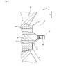
本実施形態は、図7、図8に示すごとく、実施形態1に対してハウジング2の形状を変更した実施形態である。
(Embodiment 2)
As shown in FIGS. 7 and 8, this embodiment is an embodiment in which the shape of the
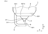
実施形態1と同様、図7に示すごとく、ハウジング2は、燃焼室16に露出するハウジング露出部221を有する。図7、図8に示すごとく、本実施形態において、ハウジング露出部221の外周面は、プラグ軸方向Zの先端側に向かうにつれて内周側に向かうよう傾斜したハウジング傾斜面221aを有する。図7に示すごとく、軸平行断面において、ハウジング傾斜面221aの両端を通るハウジング側仮想直線L2は、ギャップ形成面521を通る。
As in the first embodiment, the
図7に示すごとく、ハウジング傾斜面221aは、軸平行断面において、先端側に向かうにつれて内周側に向かうよう直線状に形成されている。ハウジング露出部221の外周面は、少なくともプラグ軸方向Zと横方向Yとの双方に直交な軸平行断面において、ハウジング傾斜面221aを有する。本実施形態において、ハウジング露出部221の外周面は、その全周にハウジング傾斜面221aを有する。すなわち、ハウジング露出部221の外周面は、プラグ中心軸を通るとともにプラグ軸方向Zに平行なあらゆる断面において、ハウジング傾斜面221aを有する。
As shown in FIG. 7, the housing slanted
ハウジング傾斜面221aは、軸平行断面において、プラグ軸方向Zの寸法がプラグ径方向の寸法よりも大きくなるよう形成されている。本実施形態において、ハウジング傾斜面221aは、ハウジング2の内周面に連なるよう形成されている。
The housing inclined
図7に示すごとく、軸平行断面において、ハウジング傾斜面221aの両端を通るハウジング側仮想直線L2は、接地電極5のギャップ形成面521を通る。具体的には、軸平行断面において、ハウジング側仮想直線L2は、ギャップ形成面521における横方向Yの当該ハウジング傾斜面221a側と反対側の領域を通る。
As shown in FIG. 7, the housing-side virtual straight line L2 passing through both ends of the housing inclined
図8に示すごとく、接地電極5は、ハウジング傾斜面221aに接合されている。接地電極5の接地接続部511は、ハウジング傾斜面221aと平行に形成されている。
As shown in FIG. 8, the
その他は、実施形態1と同様である。
なお、実施形態2以降において用いた符号のうち、既出の実施形態において用いた符号と同一のものは、特に示さない限り、既出の実施形態におけるものと同様の構成要素等を表す。
Others are the same as those of the first embodiment.
It should be noted that, of the reference numerals used in the second and subsequent embodiments, the same reference numerals as those used in the previous embodiments represent the same components and the like as those in the previous embodiments, unless otherwise specified.
本実施形態においては、碍子突出部31の碍子傾斜面311に加え、ハウジング2のハウジング傾斜面221aによっても、気流を放電ギャップGに導くことができる。それゆえ、一層放電火花を引き伸ばしやすい。
その他、実施形態1と同様の作用効果を有する。
In this embodiment, the airflow can be guided to the discharge gap G by the housing inclined
In addition, it has the same effects as those of the first embodiment.
(実施形態3)
本実施形態は、図9~図14に示すごとく、実施形態2に対して、接地電極5の形状を変更した実施形態である。
(Embodiment 3)
As shown in FIGS. 9 to 14, this embodiment is an embodiment in which the shape of the
図9に示すごとく、内向部52の基端側の面であるギャップ形成面521は、プラグ軸方向Zに直交する平坦面523と、平坦面523の横方向Yの両側に形成された一対の接地傾斜面522と、を有する。接地傾斜面522は、碍子傾斜面311とは反対側を向く面である。本実施形態においては、プラグ軸方向Z及び横方向Yの双方に平行な軸平行断面において、接地傾斜面522は、仮想直線L1上に位置している。接地傾斜面522は、軸平行断面において、碍子傾斜面311と平行である。図10に示すごとく、接地傾斜面522は、縦方向Xにおける内向部52の略全体に形成されている。
As shown in FIG. 9, the
次に、図11を用いて、本実施形態において、放電ギャップGを通過した気流Fの流れの様子について説明する。 Next, with reference to FIG. 11, how the airflow F passes through the discharge gap G in this embodiment will be described.
本実施形態においては、放電ギャップGを通過した気流Fは、接地傾斜面522に沿うように流れる。これにより、放電ギャップGを通過した気流Fは、接地傾斜面522と平行に、すなわち斜め先端側に向かって流れるようになる。
In this embodiment, the airflow F that has passed through the discharge gap G flows along the ground inclined
次に、図12~図14を用いて、本実施形態において、放電火花Sが混合気の気流によって引き伸ばされる様子について説明する。 Next, with reference to FIGS. 12 to 14, how the discharge spark S is stretched by the airflow of the air-fuel mixture in this embodiment will be described.
まず、図12に示すごとく、中心電極4と接地電極5との間に所定の電圧を印加することにより、放電ギャップGに火花放電が生じる。ここで、初期の放電火花Sは、接地電極5におけるギャップ形成面521の平坦面523の端縁において生じやすい。平坦面523は中心電極チップ42の先端面421との距離が近く、かつ平坦面523の端縁は周囲の電界が集中しやすいからである。
First, as shown in FIG. 12, spark discharge is generated in the discharge gap G by applying a predetermined voltage between the
そして、初期の放電火花Sは、混合気の気流によって、図13、図14に示すように下流側に引き伸ばされる。ここで、前述のごとく、放電ギャップGを通過した混合気の気流は、接地傾斜面522に沿って、斜め先端側に向かって流れる。そのため、放電火花Sは、横方向Yだけではなく、先端側に向っても引き伸ばされる。
Then, the initial discharge spark S is stretched downstream by the airflow of the air-fuel mixture, as shown in FIGS. 13 and 14 . Here, as described above, the airflow of the air-fuel mixture that has passed through the discharge gap G flows along the ground inclined
そして、放電火花Sが下流側に引き伸ばされている間、放電火花Sの接地電極5側の起点(以後、接地側起点S1という。)は、気流に押され、平坦面523の端縁から、接地傾斜面522を這うように斜め先端側に移動する。そして、接地側起点S1の移動に伴い、放電火花Sは、両起点間の直線距離を拡大するとともに、両起点間の部位が下流側、すなわち斜め先端側に大きく引き伸ばされる。そして、引き伸ばされている間に、放電火花Sによって混合気が着火される。
その他は、実施形態2と同様である。
While the discharge spark S is extended downstream, the starting point of the discharge spark S on the side of the ground electrode 5 (hereinafter referred to as the ground side starting point S1) is pushed by the air flow, and from the edge of the
Others are the same as those of the second embodiment.
本実施形態において、接地電極5は、碍子傾斜面311とは反対側を向く接地傾斜面522を有する。それゆえ、放電ギャップGを通過した気流Fは、接地傾斜面522によって、斜め先端側へ向かうよう導かれる。これにより、一層放電火花Sを先端側に引き伸ばしやすい。
In this embodiment, the
さらに、本実施形態においては、前述のごとく、放電火花Sの接地側起点S1が移動し、放電火花Sの両起点間の直線距離が拡大される。このように、放電火花Sの両起点間の直線距離を大きくすることで、引き伸ばされた放電火花Sの一部と他の一部とが短絡することを防ぎやすく、放電火花Sを大きく引き伸ばしやすい。 Furthermore, in the present embodiment, as described above, the ground-side starting point S1 of the discharge spark S is moved, and the linear distance between the two starting points of the discharge spark S is increased. In this way, by increasing the linear distance between both starting points of the discharge spark S, it is easy to prevent a short circuit between a part of the stretched discharge spark S and the other part, and it is easy to stretch the discharge spark S greatly. .
また、碍子傾斜面311は、軸平行断面において直線状となるよう形成されており、接地傾斜面522は、軸平行断面において碍子傾斜面311と平行である。それゆえ、碍子傾斜面311と接地傾斜面522との双方によって、放電ギャップGを斜め先端側に吹き抜ける気流Fを、滑らかにしやすい。
その他、実施形態2と同様の作用効果を有する。
Further, the insulator
In addition, it has the same effects as those of the second embodiment.
(実施形態4)
本実施形態は、図15に示すごとく、プラグ軸方向Z及び横方向Yに平行な軸平行断面において、ハウジング傾斜面221a、碍子傾斜面311、及び接地傾斜面522が同一直線上に配されている実施形態である。
(Embodiment 4)
In this embodiment, as shown in FIG. 15, the housing inclined
碍子突出部31の表面は、後述の碍子突出側面312、碍子傾斜面311、及び後述の碍子先端面313を有する。碍子突出側面312は、先端側に向かうほど内周側に向かうよう、若干傾斜している。軸平行断面において、碍子突出側面312の両端を通る直線は、接地電極5のギャップ形成面521を通らない。
The surface of the
そして、碍子突出側面312の先端から、碍子突出側面312よりも傾斜した碍子傾斜面311が形成されている。前述のごとく、碍子傾斜面311の両端を通る仮想直線L1は、接地電極5のギャップ形成面521を通る。そして、碍子傾斜面311の先端から内周側に、プラグ軸方向Zに平行に碍子先端面313が形成されている。
An insulator inclined
本実施形態においては、軸平行断面において、碍子傾斜面311の両端を通る仮想直線L1と、ハウジング側仮想直線L2とは同一直線である。
その他は、実施形態3と同様である。
In this embodiment, in the axis-parallel cross section, the imaginary straight line L1 passing through both ends of the insulator
Others are the same as those of the third embodiment.
本実施形態においては、プラグ軸方向Z及び横方向Yに平行な軸平行断面において、ハウジング傾斜面221a、碍子傾斜面311、及び接地傾斜面522が同一直線上に配されているため、一層、放電ギャップGに気流Fを向かわせやすい。
その他、実施形態3と同様の作用効果を有する。
In this embodiment, since the housing inclined
In addition, it has the same effects as those of the third embodiment.
(実施形態5)
本実施形態は、図16、図17に示すごとく、実施形態4に対して碍子傾斜面311、ハウジング傾斜面221a、及び接地傾斜面522の形成位置を変更した実施形態である。
(Embodiment 5)
As shown in FIGS. 16 and 17, this embodiment is an embodiment in which the insulator
碍子傾斜面311及びハウジング傾斜面221aは、放電ギャップGよりも、横方向Yにおける気流Fの上流側にのみ、形成されている。図17に示すごとく、碍子傾斜面311は、碍子突出部31の略120°の範囲に形成されている。同様に、ハウジング傾斜面221aは、ハウジング露出面221の略120°の範囲に形成されている。碍子傾斜面311とハウジング傾斜面221aとは、プラグ径方向に重なる位置に形成されている。そして、接地傾斜面522は、放電ギャップGよりも、横方向Yにおける気流Fの下流側にのみ、形成されている。
その他は、実施形態4と同様である。
The insulator inclined
Others are the same as those of the fourth embodiment.
本実施形態においても、実施形態4と同様の作用効果を有する。 This embodiment also has the same effects as those of the fourth embodiment.
(実施形態6)
本実施形態は、図18に示すごとく、実施形態4に対して中心電極4の形状を変更した実施形態である。
(Embodiment 6)
As shown in FIG. 18, this embodiment is an embodiment in which the shape of the
本実施形態において、中心電極4は、中心電極チップ(実施形態1~実施形態5の符号42参照)を有さない。中心電極4における碍子突出部31よりも先端側に突出した中心電極突出部411の外周面411aは、軸平行断面において、先端側へ向かうほど内周側へ向かうよう傾斜した直線状に形成されている。そして、プラグ軸方向Z及び横方向Yの双方に直交する軸平行断面において、ハウジング傾斜面221aと碍子傾斜面311と中心電極突出部411の外周面411aと接地傾斜面522とは、同一直線上に配されている。なお、碍子傾斜面311の形状については、実施形態3と同様である。
その他は、実施形態4と同様である。
In this embodiment, the
Others are the same as those of the fourth embodiment.
本実施形態においては、プラグ軸方向Z及び横方向Yに平行な軸平行断面において、ハウジング傾斜面221a、碍子傾斜面311、中心電極突出部411の外周面411a及び接地傾斜面522が同一直線上に配されているため、放電ギャップGに気流を一層向かわせやすい。
その他、実施形態4と同様の作用効果を有する。
In this embodiment, in an axis-parallel cross-section parallel to the plug axial direction Z and lateral direction Y, the housing inclined
In addition, it has the same effects as those of the fourth embodiment.
本発明は、前記各実施形態に限定されるものではなく、その要旨を逸脱しない範囲において種々の実施形態に適用することが可能である。例えば、図19に示すごとく、碍子傾斜面311は、軸平行断面において、内周側に凸の曲線状に形成することもできる。同様に、図20に示すごとく、ハウジング傾斜面221aを、内周側に凸の曲線状に形成することもできる。
The present invention is not limited to the embodiments described above, and can be applied to various embodiments without departing from the scope of the invention. For example, as shown in FIG. 19, the insulator
1 内燃機関用のスパークプラグ
2 ハウジング
3 絶縁碍子
31 碍子突出部
311 碍子傾斜面
4 中心電極
421 中心電極の先端面(中心チップの先端面)
5 接地電極
521 ギャップ形成面
L1 仮想直線
REFERENCE SIGNS
5
Claims (2)
前記ハウジングの内側に保持された筒状の絶縁碍子(3)と、
前記絶縁碍子の内側に保持された中心電極(4)と、
前記中心電極の先端面との間に火花放電を生じさせる放電ギャップ(G)を形成するギャップ形成面(521)を有する接地電極(5)と、を有し、
前記絶縁碍子の内側面と前記中心電極の外側面とは、互いに直接対向しており、
前記絶縁碍子は、前記ハウジングの先端側に突出した碍子突出部(31)を有し、
前記碍子突出部の外周面は、プラグ中心軸を通るとともにプラグ軸方向(Z)に平行な断面のうち少なくとも1つの断面である軸平行断面において、プラグ軸方向の先端側に向かうにつれて内周側に向かう、直線状となる碍子傾斜面(311)を有し、
前記軸平行断面において、前記碍子傾斜面の両端を通る仮想直線(L1)は、前記ギャップ形成面を通り、
前記接地電極は、前記碍子傾斜面とは反対側を向く接地傾斜面(522)を有し、
前記接地傾斜面522は、前記軸平行断面において前記碍子傾斜面311と平行であり、
前記ハウジングは、燃焼室(16)に露出するハウジング露出部(221)を有し、前記ハウジング露出部の外周面は、プラグ軸方向の先端側に向かうにつれて内周側に向かうよう傾斜したハウジング傾斜面(221a)を有し、前記軸平行断面において、前記ハウジング傾斜面の両端を通るハウジング側仮想直線(L2)は、前記ギャップ形成面を通り、
前記ハウジング傾斜面、前記碍子傾斜面及び前記接地傾斜面が同一直線上に配されている、
内燃機関の燃焼室内に設けられて放電火花により前記燃焼室内の混合気への着火を行う内燃機関用のスパークプラグ(1)。 a cylindrical housing (2);
a cylindrical insulator (3) held inside the housing;
a center electrode (4) held inside the insulator;
a ground electrode (5) having a gap forming surface (521) that forms a discharge gap (G) that causes spark discharge between itself and the tip surface of the center electrode;
the inner surface of the insulator and the outer surface of the center electrode directly face each other,
The insulator has an insulator protruding portion (31) protruding toward the tip side of the housing,
The outer peripheral surface of the insulator protruding portion is arranged on an axis-parallel cross section, which is at least one of cross sections passing through the central axis of the plug and parallel to the axial direction (Z) of the plug, toward the tip end side in the axial direction of the plug. has a rectilinear insulator inclined surface (311) facing
In the axis-parallel cross section, an imaginary straight line (L1) passing through both ends of the insulator inclined surface passes through the gap forming surface ,
the ground electrode has a ground sloped surface (522) facing away from the insulator sloped surface;
The ground contact inclined surface 522 is parallel to the insulator inclined surface 311 in the axis-parallel cross section,
The housing has a housing exposed portion (221) exposed to the combustion chamber (16), and the outer peripheral surface of the housing exposed portion is inclined toward the inner peripheral side toward the tip side in the axial direction of the plug. A housing-side imaginary straight line (L2) having a surface (221a) and passing through both ends of the housing inclined surface in the axially parallel section passes through the gap forming surface,
The housing inclined surface, the insulator inclined surface, and the ground contact inclined surface are arranged on the same straight line,
A spark plug (1) for an internal combustion engine, which is provided in a combustion chamber of an internal combustion engine and ignites an air-fuel mixture in the combustion chamber with a discharge spark.
Priority Applications (4)
| Application Number | Priority Date | Filing Date | Title |
|---|---|---|---|
| JP2017253620A JP7118640B2 (en) | 2017-12-28 | 2017-12-28 | Spark plug for internal combustion engine |
| DE112018006646.0T DE112018006646T5 (en) | 2017-12-28 | 2018-12-24 | Spark plug for internal combustion engines |
| PCT/JP2018/047406 WO2019131565A1 (en) | 2017-12-28 | 2018-12-24 | Spark plug for internal combustion engines |
| US16/912,751 US10951011B2 (en) | 2017-12-28 | 2020-06-26 | Spark plug for internal combustion engines |
Applications Claiming Priority (1)
| Application Number | Priority Date | Filing Date | Title |
|---|---|---|---|
| JP2017253620A JP7118640B2 (en) | 2017-12-28 | 2017-12-28 | Spark plug for internal combustion engine |
Publications (3)
| Publication Number | Publication Date |
|---|---|
| JP2019121446A JP2019121446A (en) | 2019-07-22 |
| JP2019121446A5 JP2019121446A5 (en) | 2020-11-26 |
| JP7118640B2 true JP7118640B2 (en) | 2022-08-16 |
Family
ID=67067242
Family Applications (1)
| Application Number | Title | Priority Date | Filing Date |
|---|---|---|---|
| JP2017253620A Active JP7118640B2 (en) | 2017-12-28 | 2017-12-28 | Spark plug for internal combustion engine |
Country Status (4)
| Country | Link |
|---|---|
| US (1) | US10951011B2 (en) |
| JP (1) | JP7118640B2 (en) |
| DE (1) | DE112018006646T5 (en) |
| WO (1) | WO2019131565A1 (en) |
Citations (3)
| Publication number | Priority date | Publication date | Assignee | Title |
|---|---|---|---|---|
| JP2008108479A (en) | 2006-10-24 | 2008-05-08 | Denso Corp | Spark plug for internal combustion engine |
| JP2013513928A (en) | 2009-12-15 | 2013-04-22 | フェデラル−モーグル・イグニション・カンパニー | Spark ignition device for internal combustion engine and center electrode assembly therefor |
| WO2016013615A1 (en) | 2014-07-24 | 2016-01-28 | イマジニアリング株式会社 | Sparking plug |
Family Cites Families (3)
| Publication number | Priority date | Publication date | Assignee | Title |
|---|---|---|---|---|
| JP3461637B2 (en) * | 1995-11-02 | 2003-10-27 | 日本特殊陶業株式会社 | Spark plug for internal combustion engine |
| JP5208033B2 (en) | 2009-03-30 | 2013-06-12 | 株式会社日本自動車部品総合研究所 | Spark plug |
| JP5719419B2 (en) * | 2013-01-31 | 2015-05-20 | 日本特殊陶業株式会社 | Spark plug and manufacturing method thereof |
-
2017
- 2017-12-28 JP JP2017253620A patent/JP7118640B2/en active Active
-
2018
- 2018-12-24 DE DE112018006646.0T patent/DE112018006646T5/en active Pending
- 2018-12-24 WO PCT/JP2018/047406 patent/WO2019131565A1/en active Application Filing
-
2020
- 2020-06-26 US US16/912,751 patent/US10951011B2/en active Active
Patent Citations (3)
| Publication number | Priority date | Publication date | Assignee | Title |
|---|---|---|---|---|
| JP2008108479A (en) | 2006-10-24 | 2008-05-08 | Denso Corp | Spark plug for internal combustion engine |
| JP2013513928A (en) | 2009-12-15 | 2013-04-22 | フェデラル−モーグル・イグニション・カンパニー | Spark ignition device for internal combustion engine and center electrode assembly therefor |
| WO2016013615A1 (en) | 2014-07-24 | 2016-01-28 | イマジニアリング株式会社 | Sparking plug |
Also Published As
| Publication number | Publication date |
|---|---|
| WO2019131565A1 (en) | 2019-07-04 |
| US20200335950A1 (en) | 2020-10-22 |
| DE112018006646T5 (en) | 2020-09-10 |
| US10951011B2 (en) | 2021-03-16 |
| JP2019121446A (en) | 2019-07-22 |
Similar Documents
| Publication | Publication Date | Title |
|---|---|---|
| US9166377B2 (en) | Spark plug for internal combustion engine | |
| JP6731230B2 (en) | Spark plug for internal combustion engine and ignition device equipped with the same | |
| JP6948904B2 (en) | Spark plug for internal combustion engine | |
| JP6840574B2 (en) | Internal combustion engine ignition system | |
| JP7118640B2 (en) | Spark plug for internal combustion engine | |
| JP7275530B2 (en) | Spark plug | |
| JP2008311185A (en) | Spark plug for internal combustion engine | |
| JP2008171646A (en) | Spark plug for internal combustion engine | |
| JP6731298B2 (en) | Spark plugs for internal combustion engines | |
| US10951012B2 (en) | Spark plug for internal combustion engines and internal combustion engine | |
| JP7006233B2 (en) | Spark plug | |
| JP7113714B2 (en) | Spark plug for internal combustion engine | |
| US10693280B2 (en) | Spark plug | |
| US10777974B2 (en) | Spark plug for internal combustion engine that makes re-discharge less prone to occur | |
| JP7194550B2 (en) | Spark plug for internal combustion engine | |
| JP7122860B2 (en) | Spark plug for internal combustion engine | |
| JP6680043B2 (en) | Spark plugs for internal combustion engines | |
| US9377001B2 (en) | Spark plug for internal combustion engine | |
| US10333282B2 (en) | Spark plug for internal combustion engine | |
| JP7165644B2 (en) | Spark plug | |
| US10886709B1 (en) | Spark plug that prevents gas turbulence in the discharge space | |
| JP6836907B2 (en) | Spark plug for internal combustion engine | |
| JP6925301B2 (en) | Spark plug | |
| JP2019046742A (en) | Spark plug for internal combustion |
Legal Events
| Date | Code | Title | Description |
|---|---|---|---|
| A521 | Request for written amendment filed |
Free format text: JAPANESE INTERMEDIATE CODE: A523 Effective date: 20201014 |
|
| A621 | Written request for application examination |
Free format text: JAPANESE INTERMEDIATE CODE: A621 Effective date: 20201014 |
|
| A131 | Notification of reasons for refusal |
Free format text: JAPANESE INTERMEDIATE CODE: A131 Effective date: 20211005 |
|
| A521 | Request for written amendment filed |
Free format text: JAPANESE INTERMEDIATE CODE: A523 Effective date: 20211125 |
|
| A131 | Notification of reasons for refusal |
Free format text: JAPANESE INTERMEDIATE CODE: A131 Effective date: 20220405 |
|
| A521 | Request for written amendment filed |
Free format text: JAPANESE INTERMEDIATE CODE: A523 Effective date: 20220502 |
|
| TRDD | Decision of grant or rejection written | ||
| A01 | Written decision to grant a patent or to grant a registration (utility model) |
Free format text: JAPANESE INTERMEDIATE CODE: A01 Effective date: 20220705 |
|
| A61 | First payment of annual fees (during grant procedure) |
Free format text: JAPANESE INTERMEDIATE CODE: A61 Effective date: 20220803 |
|
| R150 | Certificate of patent or registration of utility model |
Ref document number: 7118640 Country of ref document: JP Free format text: JAPANESE INTERMEDIATE CODE: R150 |