JP7118386B2 - game machine - Google Patents
game machine Download PDFInfo
- Publication number
- JP7118386B2 JP7118386B2 JP2017033184A JP2017033184A JP7118386B2 JP 7118386 B2 JP7118386 B2 JP 7118386B2 JP 2017033184 A JP2017033184 A JP 2017033184A JP 2017033184 A JP2017033184 A JP 2017033184A JP 7118386 B2 JP7118386 B2 JP 7118386B2
- Authority
- JP
- Japan
- Prior art keywords
- special
- game
- jackpot
- pattern
- effect
- Prior art date
- Legal status (The legal status is an assumption and is not a legal conclusion. Google has not performed a legal analysis and makes no representation as to the accuracy of the status listed.)
- Active
Links
Images


Description
本発明は、パチンコ遊技機等の遊技機に関する。 The present invention relates to a game machine such as a pachinko game machine.
下記特許文献1には、始動口(入球口)への入賞に基づいて、大入賞口(特別入賞口)を開放させる大当たり遊技(特別遊技)を行い、大入賞口内の特定領域に遊技球が通過すると、特典を付与する遊技機が記載されている。なおこの文献では、特典は、大当たり遊技後の遊技状態を確変状態(特典遊技状態)に制御することである。
In the following
ところで上記文献に記載の遊技機では、特定領域への通過の可否は、シャッター(振分部材)によって切り替えられている。このシャッターは、大当たり遊技中の所定の開始タイミングから、時間で管理された一定の動作で駆動されている。シャッター(振分部材)をどのように動作させるかは遊技性に関わる事項であるため、シャッターの制御手法には見直しの余地がある。 By the way, in the gaming machine described in the above document, whether or not the player can pass through the specific area is switched by a shutter (distribution member). This shutter is driven by a constant operation controlled by time from a predetermined start timing during a jackpot game. How to operate the shutter (distribution member) is a matter related to game playability, so there is room for reviewing the control method of the shutter.
本発明の遊技機は、
特別入賞口を開放するラウンド遊技を含む特別遊技を実行可能であり、前記特別入賞口に入賞した遊技球が特定領域を通過したことに基づいて特典を付与可能な遊技機であって、
前記特定領域に遊技球を通過させる第1状態と前記特定領域に遊技球を通過させない第2状態とをとり得る振分部材を制御可能な振分部材制御手段を備え、
前記振分部材の作動パターンには、前記第1状態への制御期間を含む作動パターンとして複数の作動パターンがあり、
前記振分部材制御手段は、
特定のラウンド遊技における前記特別入賞口への入賞個数が第1の変化点個数になったことに基づいて、前記振分部材を、前記複数の作動パターンのうちの特定作動パターンで作動させ、
当該特定のラウンド遊技における前記特別入賞口への入賞個数が前記第1の変化点個数よりも大きい第2の変化点個数になったことに基づいて、前記振分部材を、前記複数の作動パターンのうちの他の作動パターンで作動させ、
当該特定のラウンド遊技における前記特別入賞口への入賞個数が前記第2の変化点個数よりも大きい第3の変化点個数になった場合に、前記振分部材を前記他の作動パターンと異なる作動パターンで作動させることが可能であり、
前記特定のラウンド遊技を含む特別遊技の実行契機となる特定の大当たりに当選した場合、前記特定のラウンド遊技を含む特別遊技が実行されることを示唆する第1態様で演出図柄を停止表示するときと、前記特定のラウンド遊技を含まない特別遊技が実行される可能性があることを示唆する第2態様で演出図柄を停止表示するときとがあることを特徴とする。
The gaming machine of the present invention is
A gaming machine capable of executing a special game including a round game in which a special winning opening is opened, and granting a privilege based on the fact that a game ball that has won the special winning opening passes through a specific area,
Distributing member control means capable of controlling a distributing member that can take a first state in which game balls pass through the specific region and a second state in which game balls do not pass through the specific region,
The operation pattern of the distribution member includes a plurality of operation patterns including a control period to the first state,
The distribution member control means is
operating the sorting member in a specific operation pattern out of the plurality of operation patterns based on the number of winning prizes in the special winning opening in a specific round game becoming the first change point number;
Based on the fact that the number of winning prizes in the special winning slot in the specific round game has reached a second number of changing points larger than the number of first changing points, the sorting member is operated in the plurality of operation patterns. operate with other operating patterns of
When the number of winning prizes in the special winning hole in the specific round game becomes a third change point number larger than the second change point number, the sorting member is operated in a different operation pattern from the other operation patterns. It is possible to operate in a pattern,
When the performance symbols are stopped and displayed in the first mode suggesting that the special game including the specific round game will be performed when the specific jackpot that triggers the execution of the special game including the specific round game is won. and when the performance symbols are stopped and displayed in a second mode suggesting that a special game not including the specific round game may be executed.
本発明によれば、新たな振分部材の制御手法が提供される。 ADVANTAGE OF THE INVENTION According to this invention, the control method of a new distribution member is provided.
1.遊技機の構造
本発明の一実施形態であるパチンコ遊技機について、図面に基づいて説明する。なお、以下の説明において遊技機の一例としてのパチンコ遊技機の各部の上下方向及び左右方向は、そのパチンコ遊技機に対面する遊技者から見た上下方向及び左右方向に一致させて説明する。また、パチンコ遊技機の各部の前方向をパチンコ遊技機に対面する遊技者に近づく方向とし、パチンコ遊技機の各部の後方向をパチンコ遊技機に対面する遊技者から離れる方向として説明する。
1. Structure of Gaming Machine A pachinko gaming machine, which is an embodiment of the present invention, will be described with reference to the drawings. In the following description, the vertical direction and horizontal direction of each part of a pachinko game machine as an example of the game machine will be described by matching the vertical direction and horizontal direction seen from the player facing the pachinko game machine. Also, the front direction of each part of the pachinko game machine is defined as the direction toward the player facing the pachinko game machine, and the rear direction of each part of the pachinko game machine is defined as the direction away from the player facing the pachinko game machine.
図1に示すように、実施形態のパチンコ遊技機1は、遊技機枠50と、遊技機枠50内に取り付けられた遊技盤2とを備えている。遊技機枠50のうちの前面枠51には、回転角度に応じた発射強度で遊技球を発射させるためのハンドル60、遊技球を貯留する打球供給皿(上皿)61、及び打球供給皿61に収容しきれない遊技球を貯留する余剰球受皿(下皿)62が設けられている。また前面枠51には、遊技の進行に伴って実行される演出時などに遊技者が操作し得る演出ボタン63およびセレクトボタン64が設けられている。また前面枠51には、装飾用の枠ランプ66およびスピーカ67が設けられている。
As shown in FIG. 1 , the
図2に示すように、遊技盤2には、ハンドル60の操作により発射された遊技球が流下する遊技領域3が、レール部材4で囲まれて形成されている。また遊技盤2には、装飾用の盤ランプ5(図7参照)が設けられている。遊技領域3には、遊技球を誘導する複数の遊技くぎ(図示せず)が突設されている。
As shown in FIG. 2, the
また遊技領域3の中央付近には、液晶表示装置である画像表示装置(表示手段)7が設けられている。画像表示装置7の表示画面(表示部)7aには、後述の第1特別図柄および第2特別図柄の可変表示(変動表示)に同期した演出図柄(装飾図柄)8L,8C,8Rの可変表示(変動表示)を行う演出図柄表示領域がある。なお、演出図柄8L,8C,8Rを表示する演出を演出図柄変動演出という。演出図柄変動演出を「装飾図柄変動演出」や単に「変動演出」と称することもある。
Further, near the center of the
演出図柄表示領域は、例えば「左」「中」「右」の3つの図柄表示エリアからなる。左の図柄表示エリアには左演出図柄8Lが表示され、中の図柄表示エリアには中演出図柄8Cが表示され、右の図柄表示エリアには右演出図柄8Rが表示される。演出図柄はそれぞれ、例えば「1」~「8」までの数字をあらわした複数の図柄からなる。画像表示装置7は、左、中、右の演出図柄の組み合わせによって、後述の第1特別図柄表示器41aおよび第2特別図柄表示器41b(図5参照)にて表示される第1特別図柄および第2特別図柄の可変表示の結果(つまりは大当たり抽選の結果)を、わかりやすく表示する。
The performance symbol display area is composed of, for example, three symbol display areas of "left", "middle" and "right". A left pattern display area displays a
例えば大当たりに当選した場合には「777」などのゾロ目で演出図柄を停止表示する。また、はずれであった場合には「637」などのバラケ目で演出図柄を停止表示する。これにより、遊技者による遊技の進行状況の把握が容易となる。つまり遊技者は、一般的には大当たり抽選の結果を第1特別図柄表示器41aや第2特別図柄表示器41bにより把握するのではなく、画像表示装置7にて把握する。なお、図柄表示エリアの位置は固定的でなくてもよい。また、演出図柄の変動表示の態様としては、例えば上下方向にスクロールする態様がある。
For example, when a jackpot is won, the production pattern is stopped and displayed with double numbers such as "777". In addition, when it is a miss, the production pattern is stopped and displayed with a separate pattern such as "637". This makes it easier for the player to grasp the progress of the game. That is, the player generally grasps the result of the jackpot lottery by the image display device 7 rather than by the first special
画像表示装置7は、上記のような演出図柄を用いた演出図柄変動演出のほか、大当たり遊技(特別遊技の一例)に並行して行われる大当たり演出や、客待ち用のデモ演出などを表示画面7aに表示する。なお演出図柄変動演出では、数字等の演出図柄のほか、背景画像やキャラクタ画像などの演出図柄以外の演出画像も表示される。 The image display device 7 displays, in addition to the effect symbol variation effect using the effect symbol as described above, a big win effect that is performed in parallel with the big win game (an example of the special game), a demonstration effect for waiting for customers, and the like. 7a. In addition, in the effect symbol variation effect, effect images other than effect symbols such as background images and character images are displayed in addition to effect symbols such as numbers.
また画像表示装置7の表示画面7aには、後述の第1特図保留や第2特図保留の記憶数に応じて演出保留画像9を表示する演出保留表示エリアがある。演出保留画像9の表示により、後述の第1特図保留表示器43a(図5参照)にて表示される第1特図保留の記憶数や第2特図保留表示器43bにて表示される第2特図保留の記憶数を、遊技者にわかりやすく示すことができる。
Further, the
遊技領域3の中央付近であって画像表示装置7の前方には、センター装飾体10が配されている。センター装飾体10の下部には、上面を転動する遊技球を、後述の第1始動口20へと誘導可能なステージ部11が形成されている。またセンター装飾体10の左部には、入口から遊技球を流入させ、出口からステージ部11へ遊技球を流出させるワープ部12が設けられている。またセンター装飾体10の上部には、盤可動体15が格納状態にて配されている。
A
遊技領域3における画像表示装置7の下方には、遊技球の入球し易さが常に変わらない第1始動口(入球口の一例、第1入球口、固定入球口、固定始動口、第1始動入賞口ともいう)20を備える固定入賞装置19が設けられている。第1始動口20への遊技球の入賞は、第1特別図柄の抽選(大当たり抽選、すなわち大当たり乱数等の取得と判定)の契機となっている。
Below the image display device 7 in the
また遊技領域3における第1始動口20の下方には、第2始動口(入球口の一例、第2入球口、可変入球口、可変始動口、第2始動入賞口ともいう)21を備える普通可変入賞装置(いわゆる電チュー)22が設けられている。電チュー22を普通電動役物(普通電役)ともいう。第2始動口21への遊技球の入賞は、第2特別図柄の抽選(大当たり抽選)の契機となっている。
In addition, below the
電チュー22は、可動部材(入球口開閉部材)23を備え、可動部材23の作動によって第2始動口21を開閉するものである。可動部材23は、電チューソレノイド24(図6参照)により駆動される。第2始動口21は、可動部材23が開状態にあるときのみ遊技球が入球可能となる。つまり、第2始動口21は、遊技球の入球し易さが変化可能な始動口である。なお、電チュー22は、可動部材23が開状態にあるときの方が閉状態にあるときよりも第2始動口21への入球を容易にするものであれば、閉状態にあるときに第2始動口21への入球を不可能とするものでなくてもよい。
The
また、遊技領域3における第1始動口20の右上方には、遊技球が通過可能なゲート(通過領域)28が設けられている。ゲート28への遊技球の通過は、電チュー22を開放するか否かを決める普通図柄抽選(すなわち普通図柄乱数(当たり乱数)の取得と判定)の実行契機となっている。
In addition, a gate (passing area) 28 through which a game ball can pass is provided on the upper right side of the
また、遊技領域3におけるゲート28の下方には、第1大入賞口(特別入賞口の一例、第1特別入賞口ともいう)30を備えた第1大入賞装置(特別入賞手段の一例)31が設けられている。第1大入賞装置31を、第1特別入賞手段、第1特別可変入賞装置、又は第1特別電動役物(第1特別電役)ともいう。第1大入賞装置31は、開閉部材(第1の特別入賞口開閉部材)32を備え、開閉部材32の作動により第1大入賞口30を開閉するものである。開閉部材32は、第1大入賞口ソレノイド33(図6参照)により駆動される。つまり、第1大入賞口ソレノイド33は開閉部材32の駆動源である。第1大入賞口30は、開閉部材32が開いているときだけ遊技球が入球可能となる。
In addition, below the
また、遊技領域3における第1大入賞口30の右上方には、第2大入賞口(特別入賞口の一例、第2特別入賞口ともいう)35を備えた第2大入賞装置(特別入賞手段の一例)36が設けられている。第2大入賞装置36を、第2特別入賞手段、第2特別可変入賞装置、又は第2特別電動役物(第2特別電役)ともいう。第2大入賞装置36は、開閉部材(第2の特別入賞口開閉部材)37を備え、開閉部材37の作動により第2大入賞口35を開閉するものである。開閉部材37は、第2大入賞口ソレノイド38(図6参照)により駆動される。第2大入賞口ソレノイド38は開閉部材37の駆動源である。第2大入賞口35は、開閉部材37が開いているときだけ遊技球が入球可能となる。
In addition, a second large winning device (special winning An example of means) 36 is provided. The second big winning
より詳細には、図3(A)に示すように、第1大入賞装置31の内部には、第1大入賞口30を通過した遊技球が通過可能な特定領域(V領域)39および非特定領域(非V領域)70が形成されている。なお、第1大入賞装置31において、特定領域39および非特定領域70の上流には、第1大入賞口30への遊技球の入賞を検知する第1大入賞口センサ30aが配されている。また、特定領域39には、特定領域39への遊技球の通過を検知する特定領域センサ39aが配されている。また、非特定領域70には、非特定領域70への遊技球の通過を検知する非特定領域センサ70aが配されている。
More specifically, as shown in FIG. 3A, inside the first big winning
また、第1大入賞装置31は、第1大入賞口30を通過した遊技球を特定領域39または非特定領域70のいずれかに振り分ける振分部材71と、振分部材71を駆動する振分部材ソレノイド73とを備えている。振分部材ソレノイド73は、振分部材71の駆動源である。なお、振分部材71は、振分部材ソレノイド73の通電時には、遊技球を特定領域39に振り分ける第1状態をとり、振分部材ソレノイド73の非通電時には、遊技球を非特定領域70に振り分ける第2状態をとる。なお振分部材71は、言い換えれば、特定領域39を開閉するシャッター部材である。
In addition, the first big winning
図3(A)は、振分部材ソレノイド73の通電時を示している。図3(A)に示すように、振分部材ソレノイド73の通電時には、振分部材71は特定領域39への遊技球の通過を許容する第1状態(通過許容状態)にある。振分部材71が第1状態にあるときは、第1大入賞口30に入賞した遊技球は、第1大入賞口センサ30aを通過したあと特定領域39を通過する。この遊技球のルートを第1のルートという。
FIG. 3(A) shows when the
図3(B)は、振分部材ソレノイド73の非通電時を示している。図3(B)に示すように、振分部材ソレノイド73の非通電時には、振分部材71は特定領域39への遊技球の通過を妨げる第2状態(通過阻止状態)にある。振分部材71が第2状態にあるときは、第1大入賞口30に入賞した遊技球は、第1大入賞口センサ30aを通過したあと振分部材71の上面を転動して非特定領域70を通過する。この遊技球のルートを第2のルートという。
FIG. 3(B) shows that the
なお本パチンコ遊技機1では、特定領域39への遊技球の通過が後述の高確率状態への移行の契機となっている。つまり特定領域39は、確変作動口(確変領域)となっている。これに対して非特定領域70は、確変作動口ではない。また、第2大入賞装置36には、確変作動口は設けられていない。つまり本形態では第1大入賞装置31は所謂Vアタッカーであり、第2大入賞装置36はノーマルアタッカーである。
In addition, in the
ここで、遊技盤2の前面側における第1大入賞装置31の配置箇所6A(第1配置領域6Aともいう)および第2大入賞装置36の配置箇所6B(第2配置領域6Bともいう)には、図4に示すような装飾が施されている。第1配置領域6Aに施されている装飾を、一般装飾16といい、第2配置領域に施されている装飾を、特殊装飾17という。特殊装飾17は一般装飾16よりも遊技者の注意を引くようなデザインとなっており、この特殊装飾17により、見た目上、第1大入賞装置31よりも第2大入賞装置36に特別感が醸し出されている。つまり本形態では、Vアタッカーよりもノーマルアタッカーに特別感が醸し出されている。
Here, in the
具体的には一般装飾16は「狼」の文字をデザインした装飾文字の印刷層を有する装飾シートを遊技盤2の前面と第1大入賞装置31の前面等とにわたって配したものである。また、特殊装飾17は「XX CHANCE」の文字をデザインした装飾文字の印刷層を有する装飾シートを遊技盤2の前面と第2大入賞装置36の前面等とにわたって配したものである。なお、本形態のパチンコ遊技機1では後述するように、大当たり遊技における第2大入賞装置36の開放時に「XX CHANCE」の文字画像が表示画面7aに表示されることがある(図65(A)参照)。これは、遊技者に対して特殊装飾17を想起させて、第2大入賞装置36への入賞を狙って遊技球を打ち込むべき旨を伝えるための演出である。なお、特殊装飾17や一般装飾16の施し方は、遊技盤2や入賞装置等に所望のデザインのシールを貼付したり、遊技盤2や入賞装置等に直接インキを塗装したりするなど、どのような方法であってもよい。
Specifically, the
また、遊技盤面(遊技盤2の前面)における振分部材71の前方の箇所には、星のマークの装飾18が施されており、特定領域39への通過の可否を切り替える振分部材71の位置を示唆している。但し、この装飾18は特殊装飾17に比べればそれほど目立つ装飾ではない。
In addition, a
図2に戻り、遊技領域3の下部には、普通入賞口27や、いずれの入賞口にも入賞しなかった遊技球を遊技領域3外へ排出するアウト口6が設けられている。
Returning to FIG. 2 , at the bottom of the
このように各種の入賞口等が配されている遊技領域3には、左右方向の中央より左側の左遊技領域3Aと、右側の右遊技領域3Bとがある。左遊技領域3Aを遊技球が流下するように遊技球を発射する打方を、左打ちという。一方、右遊技領域3Bを遊技球が流下するように遊技球を発射する打方を、右打ちという。本形態のパチンコ遊技機1では、左打ちにて遊技したときに遊技球が流下する流路を、第1流路R1といい、右打ちにて遊技したときに遊技球が流下する流路を、第2流路R2という。
As described above, the
第1流路R1上には、第1始動口20と、電チュー22と、アウト口6とが設けられている。遊技者は第1流路R1を流下するように遊技球を打ち込むことで、第1始動口20への入賞を狙うことができる。
A
一方、第2流路R2上には、第2大入賞装置36と、ゲート28と、第1大入賞装置31と、電チュー22と、アウト口6とが設けられている。遊技者は第2流路R2を流下するように遊技球を打ち込むことで、ゲート28への通過や、第2始動口21、第1大入賞口30、及び第2大入賞口35への入賞を狙うことができる。
On the other hand, the second big winning
また図2に示すように、遊技盤2の右側中央には表示器類40が配置されている。表示器類40には、図5に示すように、第1特別図柄を可変表示する第1特別図柄表示器41a、第2特別図柄を可変表示する第2特別図柄表示器41b、及び、普通図柄を可変表示する普通図柄表示器42が含まれている。また表示器類40には、第1特別図柄表示器41aの作動保留(第1特図保留)の記憶数を表示する第1特図保留表示器43a、第2特別図柄表示器41bの作動保留(第2特図保留)の記憶数を表示する第2特図保留表示器43b、および普通図柄表示器42の作動保留(普図保留)の記憶数を表示する普図保留表示器44が含まれている。
Further, as shown in FIG. 2, a
第1特別図柄の可変表示は、第1始動口20への遊技球の入賞を契機として行われる。第2特別図柄の可変表示は、第2始動口21への遊技球の入賞を契機として行われる。なお以下の説明では、第1特別図柄および第2特別図柄を総称して特別図柄ということがある。また、第1特別図柄表示器41aおよび第2特別図柄表示器41bを総称して特別図柄表示器41ということがある。また、第1特図保留表示器43aおよび第2特図保留表示器43bを総称して特図保留表示器43ということがある。
The variable display of the first special symbol is triggered by the winning of the game ball to the
特別図柄表示器41では、特別図柄を可変表示(変動表示)したあと停止表示することにより、第1始動口20又は第2始動口21への入賞に基づく抽選(特別図柄抽選、大当たり抽選)の結果を報知する。停止表示される特別図柄(停止図柄、可変表示の表示結果として導出表示される特別図柄)は、特別図柄抽選によって複数種類の特別図柄の中から選択された一つの特別図柄である。停止図柄が予め定めた特定特別図柄(特定の停止態様の特別図柄すなわち大当たり図柄)である場合には、停止表示された特定特別図柄の種類(つまり当選した大当たりの種類)に応じた開放パターンにて第1大入賞口30又は第2大入賞口35を開放させる特別遊技(大当たり遊技)が行われる。なお、特別遊技における大入賞口(第1大入賞口30および第2大入賞口35)の開放パターンについては後述する。
In the special symbol display device 41, the special symbols are variably displayed (variable display) and then stopped, so that a lottery (special symbol lottery, jackpot lottery) based on the winning of the
具体的には特別図柄表示器41は、例えば横並びに配された8個のLEDから構成されており、その点灯態様によって大当たり抽選の結果に応じた特別図柄を表示するものである。例えば大当たり(後述の複数種類の大当たりのうちの一つ)に当選した場合には、「○○●●○○●●」(○:点灯、●:消灯)というように左から1,2,5,6番目にあるLEDが点灯した大当たり図柄を表示する。また、ハズレである場合には、「●●●●●●●○」というように一番右にあるLEDのみが点灯したハズレ図柄を表示する。ハズレ図柄として全てのLEDを消灯させる態様を採用してもよい。なおハズレ図柄は、特定特別図柄ではない。また、特別図柄が停止表示される前には所定の変動時間にわたって特別図柄の変動表示がなされるが、その変動表示の態様は、例えば左から右へ光が繰り返し流れるように各LEDが点灯するという態様である。なお変動表示の態様は、各LEDが停止表示(特定の態様での点灯表示)されていなければ、全LEDが一斉に点滅するなどなんでもよい。 Specifically, the special symbol display device 41 is composed of, for example, eight LEDs arranged side by side, and displays a special symbol according to the result of the jackpot lottery by the lighting mode thereof. For example, if you win a jackpot (one of the multiple types of jackpots described later), ``○○●●○○●●'' (○: lights up, ●: lights out) 1, 2, from the left A jackpot pattern in which the fifth and sixth LEDs are lit is displayed. In addition, if the game is lost, a lost pattern is displayed in which only the rightmost LED lights up, such as "●●●●●●●○". A mode in which all the LEDs are extinguished may be adopted as the lost pattern. In addition, the lost design is not a specific special design. In addition, before the special symbols are stopped and displayed, the special symbols are variably displayed for a predetermined variable time. It is a mode. It should be noted that the variable display mode may be anything, such as blinking all the LEDs all at once, unless each LED is stopped (lighted up in a specific mode).
本パチンコ遊技機1では、第1始動口20または第2始動口21への遊技球の入賞(入球)があると、その入賞に対して取得した大当たり乱数等の各種乱数の値(数値情報、判定情報ともいう)は、特図保留記憶部85(図6参照)に一旦記憶される。詳細には、第1始動口20への入賞であれば第1特図保留として第1特図保留記憶部85a(図6参照)に記憶され、第2始動口21への入賞であれば第2特図保留として第2特図保留記憶部85b(図6参照)に記憶される。各々の特図保留記憶部85に記憶可能な特図保留の数には上限があり、本形態における上限値はそれぞれ「4」となっている。
In this
特図保留記憶部85に記憶された特図保留は、その特図保留に基づく特別図柄の可変表示が可能となったときに消化される。特図保留の消化とは、その特図保留に対応する大当たり乱数等を判定して、その判定結果を示すための特別図柄の可変表示を実行することをいう。従って本パチンコ遊技機1では、第1始動口20または第2始動口21への遊技球の入賞に基づく特別図柄の可変表示がその入賞後にすぐに行えない場合、すなわち特別図柄の可変表示の実行中や特別遊技の実行中に入賞があった場合であっても、所定個数を上限として、その入賞に対する大当たり抽選の権利を留保することができるようになっている。
The special figure reservation stored in the special figure
そしてこのような特図保留の数は、特図保留表示器43に表示される。具体的には特図保留表示器43はそれぞれ、例えば4個のLEDで構成されており、特図保留の数だけLEDを点灯させることにより特図保留の数を表示する。 And the number of such special figure reservations is displayed on the special figure reservation display 43. Specifically, each special figure reservation indicator 43 is composed of, for example, four LEDs, and displays the number of special figure reservations by lighting the LEDs by the number of special figure reservations.
普通図柄の可変表示は、ゲート28への遊技球の通過を契機として行われる。普通図柄表示器42では、普通図柄を可変表示(変動表示)したあと停止表示することにより、ゲート28への遊技球の通過に基づく普通図柄抽選の結果を報知する。停止表示される普通図柄(普図停止図柄、可変表示の表示結果として導出表示される普通図柄)は、普通図柄抽選によって複数種類の普通図柄の中から選択された一つの普通図柄である。停止表示された普通図柄が予め定めた特定普通図柄(所定の停止態様の普通図柄すなわち普通当たり図柄)である場合には、現在の遊技状態に応じた開放パターンにて第2始動口21を開放させる補助遊技が行われる。なお、第2始動口21の開放パターンについては後述する。
The variable display of normal symbols is performed with the passage of the game ball to the
具体的には普通図柄表示器42は、例えば2個のLEDから構成されており(図5参照)、その点灯態様によって普通図柄抽選の結果に応じた普通図柄を表示するものである。例えば抽選結果が当たりである場合には、「○○」(○:点灯、●:消灯)というように両LEDが点灯した普通当たり図柄を表示する。また抽選結果がハズレである場合には、「●○」というように右のLEDのみが点灯した普通ハズレ図柄を表示する。普通ハズレ図柄として全てのLEDを消灯させる態様を採用してもよい。なお普通ハズレ図柄は、特定普通図柄ではない。普通図柄が停止表示される前には所定の変動時間にわたって普通図柄の変動表示がなされるが、その変動表示の態様は、例えば両LEDが交互に点灯するという態様である。なお変動表示の態様は、各LEDが停止表示(特定の態様での点灯表示)されていなければ、全LEDが一斉に点滅するなどなんでもよい。
Specifically, the
本パチンコ遊技機1では、ゲート28への遊技球の通過があると、その通過に対して取得した普通図柄乱数(当たり乱数)の値は、普図保留記憶部86(図6参照)に普図保留として一旦記憶される。普図保留記憶部86に記憶可能な普図保留の数には上限があり、本形態における上限値は「4」となっている。
In the
普図保留記憶部86に記憶された普図保留は、その普図保留に基づく普通図柄の可変表示が可能となったときに消化される。普図保留の消化とは、その普図保留に対応する普通図柄乱数(当たり乱数)を判定して、その判定結果を示すための普通図柄の可変表示を実行することをいう。従って本パチンコ遊技機1では、ゲート28への遊技球の通過に基づく普通図柄の可変表示がその通過後にすぐに行えない場合、すなわち普通図柄の可変表示の実行中や補助遊技の実行中に入賞があった場合であっても、所定個数を上限として、その通過に対する普通図柄抽選の権利を留保することができるようになっている。
The normal pattern reservation stored in the normal pattern
そしてこのような普図保留の数は、普図保留表示器44に表示される。具体的には普図保留表示器44は、例えば4個のLEDで構成されており、普図保留の数だけLEDを点灯させることにより普図保留の数を表示するものである。
And the number of such normal map reservations is displayed on the normal
2.遊技機の電気的構成
次に図6及び図7に基づいて、本パチンコ遊技機1における電気的な構成を説明する。図6及び図7に示すようにパチンコ遊技機1は、大当たり抽選や遊技状態の移行などの遊技利益に関する制御を行う主制御基板(遊技制御基板)80、遊技の進行に伴って実行する演出に関する制御を行うサブ制御基板(演出制御基板)90、遊技球の払い出しに関する制御を行う払出制御基板110等を備えている。主制御基板80は、メイン制御部を構成し、サブ制御基板90は、後述する画像制御基板100、ランプ制御基板107、および音声制御基板106とともにサブ制御部を構成する。なお、サブ制御部は、少なくともサブ制御基板90を備え、演出手段(画像表示装置7や盤ランプ5、枠ランプ66、スピーカ67、盤可動体15等)を用いた遊技演出を制御可能であればよい。
2. Electrical Configuration of Gaming Machine Next, the electrical configuration of the
またパチンコ遊技機1は、電源基板150を備えている。電源基板150は、主制御基板80、サブ制御基板90、及び払出制御基板110に対して電力を供給するとともに、これらの基板を介してその他の機器に対して必要な電力を供給する。電源基板150には、バックアップ電源回路151が設けられている。バックアップ電源回路151は、本パチンコ遊技機1に対して電力が供給されていない場合に、後述する主制御基板80のRAM84やサブ制御基板90のRAM94に対して電力を供給する。従って、主制御基板80のRAM84やサブ制御基板90のRAM94に記憶されている情報は、パチンコ遊技機1の電断時であっても保持される。また、電源基板150には、電源スイッチ155が接続されている。電源スイッチ155のON/OFF操作により、電源の投入/遮断が切り換えられる。なお、主制御基板80のRAM84に対するバックアップ電源回路を主制御基板80に設けたり、サブ制御基板90のRAM94に対するバックアップ電源回路をサブ制御基板90に設けたりしてもよい。
The
主制御基板80には、プログラムに従ってパチンコ遊技機1の遊技の進行を制御する遊技制御用ワンチップマイコン(以下「遊技制御用マイコン」)81が実装されている。遊技制御用マイコン81には、遊技の進行を制御するためのプログラム等を記憶したROM83、ワークメモリとして使用されるRAM84、ROM83に記憶されたプログラムを実行するCPU82、データや信号の入出力を行うためのI/Oポート部(入出力回路)87が含まれている。なお、ROM83は外付けであってもよい。
The main control board 80 is mounted with a game control one-chip microcomputer (hereinafter referred to as "game control microcomputer") 81 for controlling the progress of the game of the
RAM84には、上述した特図保留記憶部85(第1特図保留記憶部85aおよび第2特図保留記憶部85b)と普図保留記憶部86とが設けられている。第1特図保留記憶部85aや第2特図保留記憶部85bは記憶手段と言える。さらに詳細には第1特図保留記憶部85aは、図8(a)に示すように、記憶可能な第1特図保留の数に対応した4つの記憶領域からなる。また図8(b)に示すように、第2特図保留記憶部85bは記憶可能な第2特図保留の数に対応した4つの記憶領域からなる。各記憶領域は図8(c)に示すように、さらに4つの記憶領域に分かれている。これらの4つの記憶領域とは、後述の大当たり乱数を記憶する領域、大当たり種別乱数を記憶する領域、リーチ乱数を記憶する領域、及び変動パターン乱数を記憶する領域である。
The
また主制御基板80には、図6に示すように、中継基板88を介して各種センサやソレノイドが接続されている。そのため、主制御基板80には各センサから信号が入力され、各ソレノイドには主制御基板80から信号が出力される。具体的にはセンサ類としては、第1始動口センサ20a、第2始動口センサ21a、ゲートセンサ28a、第1大入賞口センサ30a、第2大入賞口センサ35a、特定領域センサ39a、非特定領域センサ70a、および普通入賞口センサ27aが接続されている。
Various sensors and solenoids are connected to the main control board 80 via a
第1始動口センサ20aは、第1始動口20内に設けられて、第1始動口20に入賞した遊技球を検出するものである。第2始動口センサ21aは、第2始動口21内に設けられて、第2始動口21に入賞した遊技球を検出するものである。ゲートセンサ28aは、ゲート28内に設けられてゲート28を通過した遊技球を検出するものである。第1大入賞口センサ30aは、第1大入賞口30内に設けられて第1大入賞口30に入賞した遊技球を検出するものである。第2大入賞口センサ35aは、第2大入賞口35内に設けられて第2大入賞口35に入賞した遊技球を検出するものである。特定領域センサ39aは、第1大入賞口30内の特定領域39に設けられて特定領域39を通過した遊技球を検出するものである。非特定領域センサ70aは、第1大入賞口30内の非特定領域70に設けられて非特定領域70を通過した遊技球を検出するものである。普通入賞口センサ27aは、各普通入賞口27内に設けられて普通入賞口27に入賞した遊技球を検出するものである。
The first
またソレノイド類としては、電チューソレノイド24、第1大入賞口ソレノイド33、第2大入賞口ソレノイド38、および振分部材ソレノイド73が接続されている。電チューソレノイド24は、電チュー22の可動部材23を駆動するものである。第1大入賞口ソレノイド33は、第1大入賞装置31の開閉部材32を駆動するものである。第2大入賞口ソレノイド38は、第2大入賞装置36の開閉部材37を駆動するものである。振分部材ソレノイド73は、第1大入賞装置31の振分部材71を駆動するものである。
Also, as the solenoids, the
さらに主制御基板80には、特別図柄表示器41、普通図柄表示器42、特図保留表示器43、および普図保留表示器44が接続されている。すなわち、これらの表示器類40の表示制御は、遊技制御用マイコン81によりなされる。
Further, the main control board 80 is connected with a special symbol display 41 , a
また主制御基板80は、払出制御基板110に各種コマンドを送信するとともに、払い出し監視のために払出制御基板110から信号を受信する。払出制御基板110には、賞球払出装置120、貸球払出装置130およびカードユニット135(パチンコ遊技機1に隣接して設置され、挿入されているプリペイドカード等の情報に基づいて球貸しを可能にするもの)が接続されているとともに、発射制御回路111を介して発射装置112が接続されている。発射装置112には、ハンドル60(図1参照)が含まれる。
Further, the main control board 80 transmits various commands to the
払出制御基板110は、遊技制御用マイコン81からの信号や、パチンコ遊技機1に接続されたカードユニット135からの信号に基づいて、賞球払出装置120の賞球モータ121を駆動して賞球の払い出しを行ったり、貸球払出装置130の球貸モータ131を駆動して貸球の払い出しを行ったりする。払い出される賞球は、その計数のため賞球センサ122により検知される。また払い出される貸球は、その計数のため球貸センサ132により検知される。なお遊技者による発射装置112のハンドル60(図1参照)の操作があった場合には、タッチスイッチ114がハンドル60への接触を検知し、発射ボリューム115がハンドル60の回転量を検知する。そして、発射ボリューム115の検知信号の大きさに応じた強さで遊技球が発射されるよう発射モータ113が駆動されることとなる。なお本パチンコ遊技機1においては、0.6秒程度で一発の遊技球が発射されるようになっている。
The
また主制御基板80は、サブ制御基板90に対し各種コマンドを送信する。主制御基板80とサブ制御基板90との接続は、主制御基板80からサブ制御基板90への信号の送信のみが可能な単方向通信接続となっている。すなわち、主制御基板80とサブ制御基板90との間には、通信方向規制手段としての図示しない単方向性回路(例えばダイオードを用いた回路)が介在している。
The main control board 80 also transmits various commands to the
図7に示すように、サブ制御基板90には、プログラムに従ってパチンコ遊技機1の演出を制御する演出制御用ワンチップマイコン(以下「演出制御用マイコン」)91が実装されている。演出制御用マイコン91には、遊技の進行に伴って演出を制御するためのプログラム等を記憶したROM93、ワークメモリとして使用されるRAM94、ROM93に記憶されたプログラムを実行するCPU92、データや信号の入出力を行うためのI/Oポート部(入出力回路)97が含まれている。なお、ROM93は外付けであってもよい。
As shown in FIG. 7, the
RAM94には、図9(a)に示すように、第1始動口20への入賞に基づいて特定された第1始動入賞コマンド(後に詳述)等を記憶可能な第1特図保留演出記憶部95aと、第2始動口21への入賞に基づいて特定された第2始動入賞コマンド(後に詳述)等を記憶可能な第2特図保留演出記憶部95bと、第1特別図柄および第2特別図柄に共通の当該変動用演出記憶部(第0記憶領域)95cとが設けられている。第1特図保留演出記憶部95aは、図9(b)に示すように、記憶可能な第1特図保留の数に対応して4つの記憶領域(第1記憶領域~第4記憶領域)からなる。また第2特図保留演出記憶部95bは、図9(c)に示すように、記憶可能な第2特図保留の数に対応して4つの記憶領域(第1記憶領域~第4記憶領域)からなる。
As shown in FIG. 9A, the
各記憶領域は、図9(d)に示すように、始動入賞コマンド記憶領域を含む複数の記憶領域に分かれている。始動入賞コマンド記憶領域は、始動入賞コマンドを記憶する記憶領域である。なお当該変動用演出記憶部95cも、同様の記憶領域を含んでいる。
Each storage area is divided into a plurality of storage areas including a starting winning command storage area, as shown in FIG. 9(d). The start winning command storage area is a storage area for storing the starting winning command. Note that the variation
サブ制御基板90には、図7に示すように、画像制御基板100、音声制御基板106、ランプ制御基板107が接続されている。サブ制御基板90の演出制御用マイコン91は、主制御基板80から受信したコマンドに基づいて、画像制御基板100のCPU102に画像表示装置7の表示制御を行わせる。画像制御基板100のRAM104は、画像データを展開するためのメモリである。画像制御基板100のROM103には、画像表示装置7に表示される静止画データや動画データ、具体的にはキャラクタ、アイテム、図形、文字、数字および記号等(演出図柄を含む)や背景画像等の画像データが格納されている。画像制御基板100のCPU102は、演出制御用マイコン91からの指令に基づいてROM103から画像データを読み出す。そして、読み出した画像データに基づいて表示制御を実行する。
An
また演出制御用マイコン91は、主制御基板80から受信したコマンドに基づいて、音声制御基板106を介してスピーカ67から音声、楽曲、効果音等を出力する。スピーカ67から出力する音声等の音響データは、サブ制御基板90のROM93に格納されている。なお、音声制御基板106にCPUを実装してもよく、その場合、そのCPUに音声制御を実行させてもよい。さらにこの場合、音声制御基板106にROMを実装してもよく、そのROMに音響データを格納してもよい。また、スピーカ67を画像制御基板100に接続し、画像制御基板100のCPU102に音声制御を実行させてもよい。さらにこの場合、画像制御基板100のROM103に音響データを格納してもよい。
Also, the performance control microcomputer 91 outputs sounds, music, sound effects, etc. from the
また演出制御用マイコン91は、主制御基板80から受信したコマンドに基づいて、ランプ制御基板107を介して、遊技機枠50に設けられている枠ランプ66、および遊技盤2に設けられている盤ランプ5の点灯制御を行う。詳細には演出制御用マイコン91は、枠ランプ66や盤ランプ5等のランプの発光態様を決める発光パターンデータ(点灯/消灯や発光色等を決めるデータ、ランプデータともいう)を作成し、発光パターンデータに従って枠ランプ66や盤ランプ5などのランプの発光を制御する。なお、発光パターンデータの作成にはサブ制御基板90のROM93に格納されているデータを用いる。
Also, the effect control microcomputer 91 is provided on the
さらに演出制御用マイコン91は、主制御基板80から受信したコマンドに基づいて、ランプ制御基板107に接続された盤可動体15(図2参照)を動作させる。盤可動体15は、センター装飾体10の上部に設けられた可動式のいわゆるギミックのことである。盤可動体15は、表示画面7aの周辺部(本形態では上部)でコンパクトに折り畳まれて格納されている格納状態(図2参照)から、その折り畳みを解除されて表示画面7aの中央部を含む略全域の前方で露出している露出状態(図示省略)に変位可能なものである。
Furthermore, the production control microcomputer 91 operates the board movable body 15 (see FIG. 2) connected to the
詳細には演出制御用マイコン91は、盤可動体15の動作態様を決める動作パターンデータ(駆動データともいう)を作成し、動作パターンデータに従って盤可動体15の動作を制御する。動作パターンデータの作成にはサブ制御基板90のROM93に格納されているデータを用いる。なお、ランプ制御基板107にCPUを実装してもよく、その場合、そのCPUにランプの点灯制御や盤可動体15の動作制御を実行させてもよい。さらにこの場合、ランプ制御基板107にROMを実装してもよく、そのROMに発光パターンや動作パターンに関するデータを格納してもよい。
Specifically, the effect control microcomputer 91 creates motion pattern data (also called drive data) that determines the motion mode of the board
またサブ制御基板90には、枠中継基板98を介して演出ボタン検出スイッチ(SW)63a及びセレクトボタン検出スイッチ64aが接続されている。演出ボタン検出スイッチ63aは、演出ボタン63(図1参照)が押下操作されたことを検出するものである。演出ボタン63が押されると演出ボタン検出スイッチ63aからサブ制御基板90に対して検知信号が出力される。また、セレクトボタン検出スイッチ64aは、セレクトボタン64(図1参照)が押下操作されたことを検出するものである。セレクトボタン64が押されるとセレクトボタン検出スイッチ64aからサブ制御基板90に対して検知信号が出力される。
Also, the
3.大当たり等の説明
本形態のパチンコ遊技機1では、大当たり抽選(特別図柄抽選)の結果として、「大当たり」と「はずれ」がある。「大当たり」のときには、特別図柄表示器41に「大当たり図柄」が停止表示される。「はずれ」のときには、特別図柄表示器41に「ハズレ図柄」が停止表示される。大当たりに当選すると、停止表示された特別図柄の種類(大当たりの種類)に応じた開放パターンにて、大入賞口(第1大入賞口30および第2大入賞口35)を開放させる「特別遊技」が実行される。大当たりに当選して実行される特別遊技を大当たり遊技という。
3. Explanation of Jackpots, etc. In the
大当たり遊技は、本形態では、複数回のラウンド遊技(単位開放遊技)と、初回のラウンド遊技が開始される前のオープニング(OPとも表記する)と、最終回のラウンド遊技が終了した後のエンディング(EDとも表記する)とを含んでいる。各ラウンド遊技は、OPの終了又は前のラウンド遊技の終了によって開始し、次のラウンド遊技の開始又はEDの開始によって終了する。ラウンド遊技間の大入賞口の閉鎖の時間(ラウンド間インターバル)は、その閉鎖前の開放のラウンド遊技に含まれる。 In this form, the jackpot game includes multiple round games (unit open games), the opening (also referred to as OP) before the first round game starts, and the ending after the final round game ends. (also referred to as ED). Each round game starts with the end of the OP or the end of the previous round game and ends with the start of the next round game or the start of the ED. The closing time of the big winning hole between round games (inter-round interval) is included in the open round game before closing.
大当たりには複数の種別がある。大当たりの種別については図10に示す通りである。図10に示すように、本形態では大当たりの種別としては、大きく分けて2つある。V通過大当たり(特図1_大当たり図柄1~3及び特図2_大当たり図柄5、これらの図柄は通過用当たり図柄に相当)と、V非通過大当たり(特図1_大当たり図柄4、この図柄は非通過用当たり図柄に相当)である。
There are multiple types of jackpots. The types of jackpots are as shown in FIG. As shown in FIG. 10, in this embodiment, there are roughly two types of jackpots. V passing jackpot (special
V通過大当たりは、その大当たりへの当選に基づく大当たり遊技中に特定領域39への通過が可能となる大当たりである。これに対して、V非通過大当たりは、その大当たりへの当選に基づく大当たり遊技中に特定領域39への通過が不可能又は困難な大当たりである。本形態のパチンコ遊技機1は、特定領域39への通過に基づいて高確率状態に制御される遊技機である。よって、V通過大当たりは、高確率状態に制御されることが予定される大当たりであり、V非通過大当たりは、高確率状態に制御されないことが予定される大当たりである。特定領域39の通過の可否を切り替える振分部材71の作動制御については後述する。
The V passage jackpot is a jackpot that allows passage to the
なお、特図1の抽選では、大当たり当選時に55%の割合でV通過大当たりに振り分けられ、残りの45%の割合でV非通過大当たりに振り分けられる。一方、特図2の抽選では、大当たり当選時は必ずV通過大当たりに振り分けられる。つまり本形態では、第1始動口20への入賞に基づく大当たり抽選(特図1の抽選)よりも、第2始動口21への入賞に基づく大当たり抽選(特図2の抽選)の方が、遊技者にとって有利となるように設定されている。 Incidentally, in the lottery of the special figure 1, when the jackpot is won, it is distributed to the V passing jackpot at a rate of 55%, and is distributed to the V non-passing jackpot at a rate of the remaining 45%. On the other hand, in the lottery of the special figure 2, when the jackpot is won, it is always distributed to the V passage jackpot. In other words, in this form, the jackpot lottery (lottery of special figure 2) based on the winning of the second start opening 21 than the jackpot lottery (lottery of special figure 1) based on the winning of the first start opening 20 It is set to be advantageous for the player.
特図1の抽選で当選可能な「V通過大当たり」には、2つの種類がある。16RのV通過大当たり(特図1_大当たり図柄1及び2)と、実質13RのV通過大当たり(特図1_大当たり図柄3)である。なお、実質的なラウンド数とは、1回のラウンド遊技における大入賞口への最大入賞球数(本形態では10個)に及ぶ入賞が可能なラウンド遊技の回数のことである。本形態では大当たりは全て形式的には16Rであるが、実質的には13Rの大当たりも含まれている。ちなみに、V非通過大当たり(特図1_大当たり図柄4)は、実質13Rの大当たりである。また、特図2の抽選で当選可能なV通過大当たり(特図2_大当たり図柄5)は、形式的にも実質的にも16Rの大当たりである。
There are two types of "V passing jackpot" that can be won in the
[大入賞口の開放制御]図11に示すように、本形態では各大当たりにおいて、1R目~13R目及び15R目は第1大入賞口30を開放させ、14R目及び16R目は第2大入賞口35を開放させる。第1大入賞口30の開放態様には、図12に示すようにロング開放(開放態様1)とショート開放(開放態様2)とがある。また、第2大入賞口35の開放態様にも、同様にロング開放(開放態様3)とショート開放(開放態様4)とがある。
[Opening Control of Big Winning Hole] As shown in FIG. The winning
第1大入賞口30のロング開放(開放態様1)は、まず最長27500msにわたって第1大入賞口30を開放し、1000msの閉塞期間を経て再び第1大入賞口30を1000msにわたって開放する開放態様である。ラウンド間インターバルの時間は2000msである。普通に遊技が行われていれば、初めの27500msの開放期間が終わるまでの間に最大入賞球数に及ぶ入賞がなされ、ラウンド間インターバルを経て次のラウンド遊技が実行される。そのため、2回目の1000msの開放が実行されることはほとんどない。なお、ラウンド間インターバルの時間はどの開放態様でも同じ2000msである。
The long opening of the first big prize winning port 30 (opening mode 1) is an opening mode in which the first big
第1大入賞口30のショート開放(開放態様2)は、60msという極めて短時間だけ第1大入賞口30を1回開放する開放態様である。この開放時に遊技球が第1大入賞口30に入球することは稀である。
The short opening (opening mode 2) of the first big winning
第2大入賞口35のロング開放(開放態様3)は、最長28500msにわたって第2大入賞口35を1回開放する開放態様である。この開放時には最大入賞球数に及ぶ入賞が十分に可能である。
The long opening (opening mode 3) of the second big winning
第2大入賞口35のショート開放(開放態様4)は、60msという極めて短時間だけ第2大入賞口35を1回開放する開放態様である。この開放時に遊技球が第2大入賞口35に入球することは稀である。
The short-opening of the second large prize winning port 35 (opening mode 4) is an opening mode in which the second large
図11に示すように、特図1_大当たり図柄1、特図1_大当たり図柄2、及び特図2_大当たり図柄5では、全てのラウンドでロング開放の開放制御を行う。なお、特図1_大当たり図柄1および特図2_大当たり図柄5は、大当たり当選の判定結果を報知する変動演出においてV通過大当たりであることが報知される大当たり図柄である。具体的には、図10に示すように、演出図柄の最終的な停止態様として金図柄(本形態では3又は7)のゾロ目が選択される大当たり図柄である。
As shown in FIG. 11, in special
これに対して、特図1_大当たり図柄2は、大当たり当選の判定結果を報知する変動演出においてV通過大当たりであることが報知されない大当たり図柄である。具体的には、演出図柄の最終的な停止態様として銀図柄(本形態では1,2,4,5,6,又は8)のゾロ目が選択される大当たり図柄である。特図1_大当たり図柄2に当選した場合には、大当たり遊技中に勝利のバトル演出が実行されることでV通過大当たりであることが遊技者に報知される。なお、特図1_大当たり図柄3あるいは4に当選した場合にも、演出図柄の最終的な停止態様として銀図柄のゾロ目が選択される。
On the other hand, the special
また図11に示すように、特図1_大当たり図柄3(実質13RのV通過大当たり)では、1R目~13R目まではロング開放の開放制御を行い、14R目~16R目ではショート開放の開放制御を行う。この大入賞口の開放制御は、特図1_大当たり図柄4(V非通過大当たり)に当選した場合と同じである。よって、大入賞口の開放態様を見ていてもどちらの大当たりに当選したのかはわからない。 Also, as shown in FIG. 11, in the special figure 1_jackpot pattern 3 (substantially 13R V passing jackpot), open control of long opening is performed from 1R to 13R, and short opening is controlled at 14R to 16R. I do. The opening control of this big winning opening is the same as when special figure 1_jackpot pattern 4 (V non-passing jackpot) is won. Therefore, it is impossible to know which jackpot has been won by looking at the opening state of the big prize openings.
また、V通過大当たりである特図1_大当たり図柄3に当選した場合にも、V非通過大当たりである特図1_大当たり図柄4に当選した場合にも、大当たり遊技中に敗北のバトル演出が実行される(図10参照)。敗北のバトル演出が実行されると遊技者は、V通過大当たりではなく、V非通過大当たりに当選したと通常は認識する。つまり、特図1_大当たり図柄3に当選しても、その当選に基づく大当たり遊技中には、V通過大当たりであることは遊技者には報知されない。後に詳述するが、大当たり遊技後にSゾーンという演出モードに制御されることで遊技者は実質13RのV通過大当たりに当選していたことを認識する。このように本形態のパチンコ遊技機1は、所謂V確機(特定領域39への通過に基づき高確率状態に制御される遊技機)でありながら高確率状態の潜伏を実現している。これが本形態のパチンコ遊技機1の大きな特徴の1つとなっている。
In addition, even when special
[振分部材の作動制御]次に各大当たりにおける振分部材71の作動制御(特定領域39の開閉制御)について説明する。本形態では、振分部材71が作動するラウンド(「振分部材作動ラウンド」あるいは単に「作動ラウンド」という)は、各大当たりにおける2R,4R,6R,8R,10R,及び12Rに決められている(図11参照)。このように作動ラウンドの実行間隔を1ラウンド以上離しているのは、前のラウンド遊技における特定領域39の開放期間が次のラウンド遊技における特定領域39の開放期間に重ならないようにするためである。また本形態では、振分部材作動ラウンド以外の期間は、振分部材71は特定領域39への通過を妨げる第2状態(図3(B))に制御されている。
[Operation Control of Distribution Member] Next, the operation control of the distribution member 71 (opening/closing control of the specific area 39) for each jackpot will be described. In this embodiment, the rounds in which the
本形態では、振分部材71の作動パターンに、図13に示す2種類の作動パターン(第1の作動パターンと第2の作動パターン)がある。第1の作動パターンは、24msの開放制御(特定領域39への通過が可能な第1状態(図3(A))への制御)と、10秒の閉塞制御(特定領域39への通過が不可能な第2状態(図3(B))への制御)とを交互に繰り返す作動パターンである。第2の作動パターンは、振分部材71を最長31秒間、通過許容状態(第1状態)に制御する作動パターンである。
In this embodiment, the operation pattern of the
第1の作動パターンで振分部材71が制御されている間は、遊技球が特定領域39を通過することはほぼない。振分部材71が通過許容状態(第1状態)をとる期間がおよそ10秒毎に24msと極めて短いからである。これに対して、第2の作動パターンで振分部材71が制御されている間は、遊技球が特定領域39を容易に通過できる。振分部材71が通過阻止状態(第2状態)をとる期間がなく、最長31秒にわたり通過許容状態をとり続けるからである。なお、振分部材71は、各ラウンド遊技の終了時に通過許容状態(特定領域39を開放している開放状態)に制御されていれば、通過阻止状態(特定領域39を閉塞している閉塞状態)に制御される。
While the
作動ラウンド(各大当たりにおける2R,4R,6R,8R,10R,及び12R)において、振分部材71は、まず、第1の作動パターンで駆動される。そして、作動ラウンドにおける第1大入賞口30への入賞個数が予め定められている変化点個数に到達すると、第2の作動パターンで駆動される。変化点個数とは、振分部材71の作動パターンが切り替わる契機となる入賞個数のことである。変化点個数は、図14に示すように、大当たり図柄の種類と、何ラウンド目の作動ラウンドであるかに応じて設定されている。
In the actuation rounds (2R, 4R, 6R, 8R, 10R, and 12R in each jackpot), the
具体的には、大当たり図柄1,2及び5(V通過予定且つ高確率状態への制御を潜伏させない大当たり図柄)については、10R及び12Rの変化点個数が「3」であり、2R,4R,6R,及び8Rの変化点個数が「無し」である。つまり、10R及び12Rでは、第1大入賞口30への入賞個数が3個になった時点で、振分部材71の作動パターンが第1の作動パターンから第2の作動パターンに切り替えられる。よって、これらの図柄に当選した場合には、10Rと12Rとにおいて特定領域39への通過が容易に発生する。但し、2R,4R,6R,及び8Rにおいては、変化点個数が「無し」に設定されているため、第1大入賞口30に何球入賞しても、第2の作動パターンに切り替えられることはなく、振分部材71は第1の作動パターンで制御される。よって、作動ラウンドといえども、2R,4R,6R,及び8Rにおいて特定領域39への通過が生じることは、イレギュラーなケースを除いてない。
Specifically, for the
また、大当たり図柄3(V通過予定且つ高確率状態への制御を潜伏させる大当たり図柄)については、2Rの変化点個数が「7」であり、6Rの変化点個数が「3」であり、4R,8R,10R,及び12Rの変化点個数が「無し」である。つまり、2Rでは、第1大入賞口30への入賞個数が7個になった時点で、振分部材71の作動パターンが第1の作動パターンから第2の作動パターンに切り替えられ、6Rでは、第1大入賞口30への入賞個数が3個になった時点で、振分部材71の作動パターンが第1の作動パターンから第2の作動パターンに切り替えられる。よって、大当たり図柄3に当選した場合には、2Rと6Rとにおいて特定領域39への通過が容易に発生する。但し、4R,8R,10R,及び12Rにおいては、変化点個数が「無し」に設定されているため、第1大入賞口30に何球入賞しても、第2の作動パターンに切り替えられることはない。よって、大当たり図柄3に当選した場合には、4R,8R,10R,及び12Rにおいて特定領域39への通過が生じることは、イレギュラーなケースを除いてない。
In addition, with respect to the jackpot pattern 3 (the jackpot pattern that is scheduled to pass through V and hides the control to the high probability state), the number of change points for 2R is "7", the number of change points for 6R is "3", and the number of change points for 6R is "3". , 8R, 10R, and 12R are "absent". That is, in 2R, when the number of prizes entered into the first
ここで、大当たり図柄3について、2R目の変化点個数を6R目の変化点個数よりも大きな数にしているのは、2R目における特定領域39への通過を遊技者から認識され難くするためである。また、6R目の変化点個数を2R目と同じ数にしていないのは、2R目で遊技球を特定領域39に通過させ損ねた場合を考慮し、2R目よりも特定領域39への通過を生じさせ易くするためである。また、大当たり図柄3と、大当たり図柄1,2及び5とで、変化点個数が設定されているラウンドが何ラウンド目かを変えているのは、特定領域39への通過のタイミングをワンパターンにしないことで、特定領域39への通過を遊技者に認識され難くするためである。
Here, the reason why the number of changing points in the 2nd round of the
また、大当たり図柄4(V非通過予定の大当たり図柄)については、2R、4R,6R、8R,10R,及び12Rの全ての作動ラウンドの変化点個数が「無し」に設定されている。つまり、この図柄に当選した場合には、どの作動ラウンドにおいても、第2の作動パターンに切り替えられることはなく振分部材71は第1の作動パターンで制御される。よって、大当たり図柄4に当選した場合には、特定領域39への通過が生じることは、イレギュラーなケースを除いてない。
In addition, regarding the jackpot pattern 4 (the jackpot pattern scheduled to not pass through V), the number of change points in all the operation rounds of 2R, 4R, 6R, 8R, 10R, and 12R is set to "none". That is, when this symbol is won, the
なお、第1の作動パターンが実行されると、第1大入賞口30が開放されるのと同時にまず24msだけ特定領域39が開放される。第1大入賞口30の開放と同時に遊技球が入球したとしても、その遊技球が振分部材71の配置位置に到達するまでには、振分部材71は通過阻止状態(第2状態)に戻されている。その後、10秒の閉塞期間がある。10秒あれば、10個の遊技球が第1大入賞口30を通過できる。本形態では1回のラウンド遊技における大入賞口の最大入賞球数は「10」に設定されている。よって、遊技者が遊技球を発射し続けているのであれば、変化点個数が「無し」に設定されているラウンドでは、次に振分部材71が通過許容状態(第1状態)に至るタイミングを迎えることなく、そのラウンドが終了する。ここで、変化点個数が3個に設定された作動パターンを、第1の通過容易作動パターンと称し、変化点個数が7個に設定された作動パターンを、第2の通過容易作動パターンと称し、変化点個数が無い作動パターンを、通過困難作動パターンと称することとする。
When the first operation pattern is executed, the
また本パチンコ遊技機1では、作動ラウンドにおいて特定領域39への通過球が1球となった時点で、振分部材71を通過阻止状態(第2状態)に制御して特定領域39を閉塞し、その後は同じラウンドにおいて振分部材71を通過許容状態(第1状態)に制御することはない。言い換えれば本形態では、図15に示すように、各大当たり図柄における各作動ラウンド(2R、4R、6R、8R、10R、12R)において、振分部材71の作動終了となる特定領域39への通過球数(終了点個数という)が、「1」に定められている。このことを説明する図が図16である。
In addition, in the
図16に示すタイミングチャートは、変化点個数が3個に設定された作動ラウンド(例えば大当たり図柄1の第10ラウンド等)における振分部材71等の動作を示している。図16に示すタイミングチャートの期間Aは、作動ラウンド中に特定領域39への通過(特定領域センサ39aによる検知)が生じなかった場合を示している。また、図16に示すタイミングチャートの期間Bは、第2作動パターンで振分部材71を作動させているときに、特定領域39への通過が生じた場合を示している。また、図16に示すタイミングチャートの期間Cは、イレギュラーなケースではあるが、第1作動パターンで振分部材71を作動させているときに、特定領域39への通過が生じた場合を示している。
The timing chart shown in FIG. 16 shows the operation of the sorting
期間Aとして示した例では、第1大入賞口30への入賞個数が3球に到達すると振分部材71の作動パターンは第1の作動パターンから第2の作動パターンに変化するが、特定領域39への通過は発生していないため、第1大入賞口30が閉じられるのと同時に、特定領域39も閉塞される(振分部材71が通過許容状態から通過阻止状態に切り替わる)。
In the example shown as period A, when the number of winning balls into the first big winning
また、期間Bとして示した例では、第1大入賞口30への入賞個数が3球に到達すると振分部材71の作動パターンは第1の作動パターンから第2の作動パターンに変化する。そして、第2の作動パターンでの作動中に特定領域39への通過が発生すると、第2の作動パターンにおける通過許容状態への制御時間(31000ms、図13参照)は未だ経過していないが、特定領域39が閉塞される(振分部材71が通過許容状態から通過阻止状態に切り替わる)。以後、このラウンド中は、振分部材71が通過許容状態に制御されることはない。
Further, in the example shown as period B, when the number of winning balls into the first big winning
また、期間Cとして示した例では、振分部材71が第1の作動パターンで制御されているとき、具体的には初めの24msの通過許容状態への制御時間の経過前に、特定領域39への通過が発生すると、特定領域39が閉塞され(振分部材71が通過許容状態から通過阻止状態に切り替わり)、以後、このラウンド中は、振分部材71が通過許容状態に制御されることはない。つまり、このラウンドにおける第1大入賞口30への入賞個数が3球になっても(つまり変化点個数に到達しても)、第2の作動パターンで振分部材71が作動することはない。
Further, in the example shown as period C, when the
本形態では、このように作動ラウンドにおいて特定領域39への有効な通過が1球生じた時点で、その作動ラウンドにおける振分部材71の作動を終了(停止)することとしている。これにより、何球も遊技球が特定領域39を通過可能な構成と比べて、遊技者から特定領域39への通過を認識され難くすることが可能となっている。また本形態では、振分部材作動ラウンドを図11に示すように設け、各振分部材作動ラウンドにおける変化点個数を図14に示すように設定しているため、遊技者がV通過(特定領域39への通過)のタイミングを想定し、目視にてV通過を確認することが非常に困難になっている。こうして、基本的には遊技の進行に伴って実行される種々の遊技演出を頼りに、高確率状態に制御されるのかされないのかを判断するという遊技性が実現されている。
In this embodiment, when one ball effectively passes through the
[各種乱数]ここで本パチンコ遊技機1では、大当たりか否かの抽選は「大当たり乱数」に基づいて行われ、当選した大当たりの種別の抽選は「大当たり種別乱数」に基づいて行われる。図17(A)に示すように、大当たり乱数は0~65535までの範囲で値をとる。大当たり種別乱数は、0~99までの範囲で値をとる。なお、第1始動口20又は第2始動口21への入賞に基づいて取得される乱数には、大当たり乱数および大当たり種別乱数の他に、「リーチ乱数」および「変動パターン乱数」がある。
[Various Random Numbers] Here, in the
リーチ乱数は、大当たり判定の結果がはずれである場合に、その結果を示す演出図柄変動演出においてリーチを発生させるか否かを決める乱数である。リーチとは、複数の演出図柄(装飾図柄)のうち変動表示されている演出図柄が残り一つとなっている状態であって、変動表示されている演出図柄がどの図柄で停止表示されるか次第で大当たり当選を示す演出図柄の組み合わせとなる状態(例えば「7↓7」の状態)のことである。なお、リーチ状態において停止表示されている演出図柄は、表示画面7a内で多少揺れているように表示されていたり拡大と縮小を繰り返すように表示されていたりしてもよい。このリーチ乱数は、0~255までの範囲で値をとる。
The ready-to-win random number is a random number that determines whether or not to generate a ready-to-win in the effect symbol variation effect indicating the result when the result of the big hit determination is a loss. Reach is a state in which only one of the plurality of production patterns (decorative patterns) that is variably displayed remains, and it depends on which design the variably displayed production pattern is stopped and displayed. It is a state (for example, the state of "7↓7") that is a combination of performance symbols indicating a big hit. Incidentally, the effect symbols stopped and displayed in the ready-to-win state may be displayed as if they are slightly swaying within the
また、変動パターン乱数は、変動時間を含む変動パターンを決めるための乱数である。変動パターン乱数は、0~99までの範囲で値をとる。また、ゲート28の通過に基づいて取得される乱数には、図17(B)に示す普通図柄乱数(当たり乱数)がある。普通図柄乱数は、電チュー22を開放させる補助遊技を行うか否かの抽選(普通図柄抽選)のための乱数である。普通図柄乱数は、0~65535までの範囲で値をとる。
Also, the fluctuation pattern random number is a random number for determining a fluctuation pattern including fluctuation time. The fluctuation pattern random number takes a value in the range of 0-99. Random numbers acquired based on passing through the
4.遊技状態の説明
次に、本形態のパチンコ遊技機1の遊技状態に関して説明する。パチンコ遊技機1の特別図柄表示器41および普通図柄表示器42には、それぞれ、確率変動機能と変動時間短縮機能がある。特別図柄表示器41の確率変動機能が作動している状態を「高確率状態」といい、作動していない状態を「通常確率状態(非高確率状態)」という。高確率状態では、大当たり確率が通常確率状態よりも高くなっている。すなわち、大当たりと判定される大当たり乱数の値が通常確率状態で用いる大当たり判定テーブルよりも多い大当たり判定テーブルを用いて、大当たり判定を行う(図18(A)参照)。つまり、特別図柄表示器41の確率変動機能が作動すると、作動していないときに比して、特別図柄表示器41による特別図柄の可変表示の表示結果(すなわち停止図柄)が大当たり図柄となる確率が高くなる。なお、高確率状態は、特典遊技状態に相当する。
4. Explanation of Game State Next, the game state of the
また、特別図柄表示器41の変動時間短縮機能が作動している状態を「時短状態」といい、作動していない状態を「非時短状態」という。時短状態では、特別図柄の変動時間(変動表示開始時から表示結果の導出表示時までの時間)が、非時短状態よりも短くなっている。すなわち、変動時間の短い変動パターンが選択されることが非時短状態よりも多くなるように定められた変動パターンテーブルを用いて、変動パターンの判定を行う(図19参照)。つまり、特別図柄表示器41の変動時間短縮機能が作動すると、作動していないときに比して、特別図柄の可変表示の変動時間として短い変動時間が選択されやすくなる。その結果、時短状態では、特図保留の消化のペースが速くなり、始動口への有効な入賞(特図保留として記憶され得る入賞)が発生しやすくなる。そのため、スムーズな遊技の進行のもとで大当たりを狙うことができる。 Moreover, the state in which the variable time shortening function of the special symbol display 41 is operating is called "shortening of working hours", and the state in which it is not operating is called "non-shortening of working hours". In the time saving state, the fluctuation time of the special symbol (the time from the start of the fluctuation display to the time of derivation display of the display result) is shorter than in the non-working time saving state. That is, the variation pattern is determined using a variation pattern table that is determined so that a variation pattern with a short variation time is selected more than in the non-time saving state (see FIG. 19). That is, when the variable time shortening function of the special symbol display 41 is activated, a shorter variable time is likely to be selected as the variable display of the special symbols compared to when it is not activated. As a result, in the time-saving state, the pace of digestion of the special figure reservation becomes faster, and the effective winning to the starting opening (the winning that can be stored as the special figure reservation) is likely to occur. Therefore, it is possible to aim for a big hit under the smooth progress of the game.
特別図柄表示器41の確率変動機能と変動時間短縮機能とは同時に作動することもあるし、片方のみが作動することもある。そして、普通図柄表示器42の確率変動機能および変動時間短縮機能は、特別図柄表示器41の変動時間短縮機能に同期して作動するようになっている。すなわち、普通図柄表示器42の確率変動機能および変動時間短縮機能は、時短状態において作動し、非時短状態において作動しない。よって、時短状態では、普通図柄抽選における当選確率が非時短状態よりも高くなっている。すなわち、当たりと判定される普通図柄乱数(当たり乱数)の値が非時短状態で用いる普通図柄当たり判定テーブルよりも多い普通図柄当たり判定テーブルを用いて、当たり判定(普通図柄の判定)を行う(図18(C)参照)。つまり、普通図柄表示器42の確率変動機能が作動すると、作動していないときに比して、普通図柄表示器42による普通図柄の可変表示の表示結果が、普通当たり図柄となる確率が高くなる。
The probability variation function and the variation time shortening function of the special symbol display 41 may operate simultaneously, or only one of them may operate. The probability variation function and the variation time shortening function of the
また時短状態では、普通図柄の変動時間が非時短状態よりも短くなっている。本形態では、普通図柄の変動時間は非時短状態では10秒であるが、時短状態では1秒である(図18(D)参照)。さらに時短状態では、補助遊技における電チュー22の開放時間が、非時短状態よりも長くなっている(図20参照)。すなわち、電チュー22の開放時間延長機能が作動している。加えて時短状態では、補助遊技における電チュー22の開放回数が非時短状態よりも多くなっている(図20参照)。すなわち、電チュー22の開放回数増加機能が作動している。
In addition, in the time saving state, the fluctuation time of the normal pattern is shorter than in the non-working time saving state. In the present embodiment, the variation time of normal symbols is 10 seconds in the non-time saving state, but is 1 second in the time saving state (see FIG. 18(D)). Furthermore, in the time saving state, the opening time of the
普通図柄表示器42の確率変動機能と変動時間短縮機能、および電チュー22の開放時間延長機能と開放回数増加機能が作動している状況下では、これらの機能が作動していない場合に比して、電チュー22が頻繁に開放され、第2始動口21へ遊技球が頻繁に入賞することとなる。その結果、発射球数に対する賞球数の割合であるベースが高くなる。従って、これらの機能が作動している状態を「高ベース状態」といい、作動していない状態を「低ベース状態」という。高ベース状態では、手持ちの遊技球を大きく減らすことなく大当たりを狙うことができる。なお、高ベース状態とは、いわゆる電サポ制御(電チュー22により第2始動口21への入賞をサポートする制御)が実行されている状態である。よって、高ベース状態を電サポ制御状態や入球サポート状態ともいう。これに対して、低ベース状態を非電サポ制御状態や非入球サポート状態ともいう。
When the probability variation function and variation time reduction function of the
高ベース状態は、上記の全ての機能が作動するものでなくてもよい。すなわち、普通図柄表示器42の確率変動機能、普通図柄表示器42の変動時間短縮機能、電チュー22の開放時間延長機能、および電チュー22の開放回数増加機能のうち一つ以上の機能の作動によって、その機能が作動していないときよりも電チュー22が開放され易くなっていればよい。また、高ベース状態は、時短状態に付随せずに独立して制御されるようにしてもよい。
A high base state may not be one in which all of the above functions are active. That is, operation of one or more of the probability variation function of the normal
本形態のパチンコ遊技機1では、有効な特定領域39への通過がなされた大当たり遊技後の遊技状態は、高確率状態かつ時短状態かつ高ベース状態である。この遊技状態を特に、「高確高ベース状態」という。高確高ベース状態は、所定回数(本形態では161回)の特別図柄の可変表示が実行されるか、又は、大当たりに当選してその大当たり遊技が実行されることにより終了する。
In the
また、有効な特定領域39への通過がなされなかった大当たり遊技後の遊技状態は、通常確率状態(非高確率状態すなわち低確率の状態)かつ時短状態かつ高ベース状態である。この遊技状態を特に、「低確高ベース状態」という。低確高ベース状態は、所定回数(本形態では100回)の特別図柄の可変表示が実行されるか、又は、大当たりに当選してその大当たり遊技が実行されることにより終了する。
In addition, the game state after the jackpot game in which passage to the effective
なお、パチンコ遊技機1を初めて遊技する場合において電源投入後の遊技状態は、通常確率状態かつ非時短状態かつ低ベース状態である。この遊技状態を特に、「低確低ベース状態」という。低確低ベース状態を「通常遊技状態」と称することもある。また、特別遊技(大当たり遊技)の実行中の状態を「特別遊技状態(大当たり遊技状態)」と称することとする。さらに、高確率状態および高ベース状態のうち少なくとも一方の状態に制御されている状態を、「有利遊技状態」と称することとする。
When the
高確高ベース状態や低確高ベース状態といった高ベース状態では、右打ちにより右遊技領域3B(図2参照)へ遊技球を進入させた方が有利に遊技を進行できる。電サポ制御により低ベース状態と比べて電チュー22が開放されやすくなっており、第1始動口20への入賞よりも第2始動口21への入賞の方が容易となっているからである。そのため、普通図柄抽選の契機となるゲート28へ遊技球を通過させつつ、第2始動口21へ遊技球を入賞させるべく右打ちを行う。これにより左打ちをするよりも、多数の始動入賞(始動口への入賞)を得ることができる。なお本パチンコ遊技機1では、大当たり遊技中も右打ちにて遊技を行う。
In high-base states such as high-probability-high base state and low-probability-high base state, it is possible to advance the game more advantageously by entering the game ball into the
これに対して、低ベース状態では、左打ちにより左遊技領域3A(図2参照)へ遊技球を進入させた方が有利に遊技を進行できる。電サポ制御が実行されていないため、高ベース状態と比べて電チュー22が開放されにくくなっており、第2始動口21への入賞よりも第1始動口20への入賞の方が容易となっているからである。そのため、第1始動口20へ遊技球を入賞させるべく左打ちを行う。これにより右打ちするよりも、多数の始動入賞を得ることができる。
On the other hand, in the low base state, the game can be played more advantageously by entering the game ball into the
5.始動入賞コマンドについて
本形態のパチンコ遊技機1は、後述するように所謂先読み演出を実行可能である。先読み演出とは、始動入賞によって取得された数値情報(大当たり乱数等の乱数値)に基づいて特定された始動入賞コマンドを利用して、その始動入賞に基づく特図変動(特別図柄の変動表示)の開始直前の当否判定よりも前にその始動入賞に対する大当たり期待度を示唆する演出である。図21に示すように、本形態において生成される始動入賞コマンドには、大当たりか否かの当否情報が含まれている。また本形態の始動入賞コマンドには、第1始動口20と第2始動口21とのどちらの始動口に入賞したのかの始動口情報、通常確率状態と高確率状態とのどちらの遊技状態で入賞したのかの遊技状態情報が含まれている。始動入賞コマンドは、少なくとも大当たりか否かの当否情報を含むものであればよく、始動入賞コマンドにどのような情報を含ませるかは適宜変更可能である。
5. About Start Winning Command The
6.遊技制御用マイコン81の動作
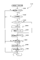
[主制御メイン処理]次に図22~図45に基づいて遊技制御用マイコン81の動作について説明する。なお、遊技制御用マイコン81の動作説明にて登場するカウンタ、タイマ、フラグ、ステータス、バッファ等は、RAM84に設けられている。主制御基板80に備えられた遊技制御用マイコン81は、パチンコ遊技機1の電源がオンされると、ROM83から図22に示した主制御メイン処理のプログラムを読み出して実行する。同図に示すように、主制御メイン処理では、まず初期設定を行う(ステップS001)。初期設定では例えば、スタックの設定、定数設定、割り込み時間の設定、CPU82の設定、SIO、PIO、CTC(割り込み時間の管理のための回路)の設定や、各種のフラグ、ステータス、カウンタ、及びタイマ等のリセット等を行う。なお初期設定(S001)は、電源投入後に一度だけ実行され、それ以降は実行されない。
6. Operation of Game Control Microcomputer 81 [Main Control Main Processing] Next, the operation of the game control microcomputer 81 will be described with reference to FIGS. Note that the counter, timer, flag, status, buffer, etc. appearing in the explanation of the operation of the game control microcomputer 81 are provided in the
初期設定(S001)に次いで、割り込みを禁止し(S002)、普通図柄・特別図柄主要乱数更新処理(S003)を実行する。この普通図柄・特別図柄主要乱数更新処理(S003)では、図17に示した種々の乱数カウンタ値を1加算して更新する。各乱数カウンタ値は上限値に至ると「0」に戻って再び加算される。なお各乱数カウンタの初期値は「0」以外の値であってもよく、ランダムに変更されるものであってもよい。また各乱数は、カウンタIC等からなる公知の乱数生成回路を利用して生成される所謂ハードウェア乱数であってもよい。この場合、ソフトウェアによる乱数の更新処理は必要ない。 After the initial setting (S001), interrupts are prohibited (S002), and the normal design/special design main random number update process (S003) is executed. In this normal symbol/special symbol main random number update process (S003), various random number counter values shown in FIG. 17 are updated by adding one. When each random number counter value reaches the upper limit, it returns to "0" and is added again. The initial value of each random number counter may be a value other than "0", or may be changed randomly. Also, each random number may be a so-called hardware random number generated using a known random number generation circuit such as a counter IC. In this case, there is no need to update random numbers by software.
普通図柄・特別図柄主要乱数更新処理(S003)が終了すると、割り込みを許可する(S004)。割り込み許可中は、メイン側タイマ割り込み処理(S005)の実行が可能となる。メイン側タイマ割り込み処理(S005)は、例えば4msec周期でCPU82に繰り返し入力される割り込みパルスに基づいて実行される。すなわち、例えば4msec周期で実行される。そして、メイン側タイマ割り込み処理(S005)が終了してから、次にメイン側タイマ割り込み処理(S005)が開始されるまでの間に、普通図柄・特別図柄主要乱数更新処理(S003)による各種カウンタ値の更新処理が繰り返し実行される。なお、割り込み禁止状態のときにCPU82に割り込みパルスが入力された場合は、メイン側タイマ割り込み処理(S005)はすぐには開始されず、割り込み許可(S004)がされてから開始される。
When the normal design/special design main random number update process (S003) ends, the interrupt is permitted (S004). While interrupts are enabled, it is possible to execute main-side timer interrupt processing (S005). The main-side timer interrupt processing (S005) is executed based on an interrupt pulse that is repeatedly input to the
[メイン側タイマ割り込み処理]次に、メイン側タイマ割り込み処理(S005)について説明する。図23に示すように、メイン側タイマ割り込み処理(S005)では、まず出力処理(S101)を実行する。出力処理(S101)では、以下に説明する各処理において主制御基板80のRAM84に設けられた出力バッファにセットされたコマンド等を、サブ制御基板90や払出制御基板110等に出力する。
[Main Side Timer Interrupt Processing] Next, the main side timer interrupt processing (S005) will be described. As shown in FIG. 23, in the main side timer interrupt process (S005), first, the output process (S101) is executed. In the output process (S101), commands set in the output buffer provided in the
出力処理(S101)に次いで行われる入力処理(S102)では、主にパチンコ遊技機1に取り付けられている各種センサ(第1始動口センサ20a,第2始動口センサ21a、第1大入賞口センサ30a、第2大入賞口センサ35a、普通入賞口センサ27a等(図6参照))が検知した検出信号を読み込む。また、入力処理(S102)では、下皿62の満杯を検出する下皿満杯スイッチからの検出信号も取り込み、下皿満杯データとしてRAM84の出力バッファに記憶する。
In the input process (S102) that follows the output process (S101), various sensors mainly attached to the pachinko game machine 1 (
次にセキュリティ制御処理(S103)を実行する。セキュリティ制御処理(S103)では、不正行為の有無を検知して、その検知結果に基づいて不正行為の発生を報知する等の処理を行う。不正行為としては、例えば、電チュー22(つまり普通電役)、第1大入賞口30、あるいは第2大入賞口35への不正な入賞、特定領域39への不正な通過、磁気を利用した不正行為(不図示の磁気検知センサによって検知される行為)、電波を利用した不正行為(不図示の電波検知センサによって検知される行為)、パチンコ遊技機1を振動させる不正行為(不図示の振動検知センサによって検知される行為)等がある。またセキュリティ制御処理(S103)では、補助遊技における電チュー22に対する入排出球数の不一致や、ラウンド遊技における第1大入賞口30あるいは第2大入賞口35に対する入排出球数の不一致を確認し、不一致が生じればその旨を報知する。
Next, security control processing (S103) is executed. In the security control process (S103), the presence or absence of fraud is detected, and based on the detection result, processing such as notifying the occurrence of fraud is performed. Examples of fraudulent acts include fraudulent prize winning to the electric chew 22 (that is, ordinary electric role), the first
次にタイマ更新処理(S104)を実行する。タイマ更新処理(S104)では、作動中の各種タイマの値の更新(減算)を行う。次いで賞球制御処理(S105)を行う。賞球制御処理(S105)では、入力処理(S102)で読み込んだ各種センサの検出信号に基づいて、入賞口の種類に応じた賞球を払い出すための払出コマンドをRAM84の出力バッファにセットする。払出コマンドは、払出制御基板110に対して出力されるコマンドである。
Next, timer update processing (S104) is executed. In the timer update process (S104), the values of various timers in operation are updated (subtracted). Next, a prize ball control process (S105) is performed. In the prize ball control process (S105), based on the detection signals of various sensors read in the input process (S102), a payout command for paying out the prize balls corresponding to the type of winning hole is set in the output buffer of the RAM84. . The payout command is a command output to the
次に普通図柄・特別図柄主要乱数更新処理(S106)を行う。普通図柄・特別図柄主要乱数更新処理(S106)は、図22の主制御メイン処理で行われる普通図柄・特別図柄主要乱数更新処理(S003)と同じである。即ち、図17に示した各種乱数カウンタ値(普通図柄乱数カウンタ値も含む)の更新処理は、メイン側タイマ割り込み処理(S005)の実行期間と、それ以外の期間(メイン側タイマ割り込み処理(S005)の終了後、次のメイン側タイマ割り込み処理(S005)が開始されるまでの期間)との両方で行われている。 Next, a normal symbol/special symbol main random number update process (S106) is performed. The normal design/special design main random number update process (S106) is the same as the normal design/special design main random number update process (S003) performed in the main control main process of FIG. That is, the update processing of various random number counter values (including the normal symbol random number counter value) shown in FIG. ) until the start of the next main-side timer interrupt process (S005)).
普通図柄・特別図柄主要乱数更新処理(S106)に次いで、後述する始動口センサ検出処理(S107)、普通動作処理(S108)、特別動作処理(S109)、および特定領域センサ検出処理(S110)を実行する。その後、大入賞口ソレノイド(第1大入賞口ソレノイド33又は第2大入賞口ソレノイド38)の駆動データを出力する処理を行う(S111)。つまり第1大入賞口30又は第2大入賞口35を開放したり閉塞したりする。それから、振分部材71を第1状態(通過許容状態)にしたり第2状態(通過阻止状態)にしたりする振分部材制御処理(S112)を行い、その他の処理(S113)を実行して、メイン側タイマ割り込み処理(S005)を終了する。振分部材制御処理(S112)については後述する。その他の処理(S113)としては、後述の特図2保留球数に基づいて第2特図保留表示器43bをその数を示す表示態様に制御したり、後述の特図1保留球数に基づいて第1特図保留表示器43aをその数を示す表示態様に制御したりする。また、後述の普図保留球数に基づいて普図保留表示器44をその数を示す表示態様に制御したりする。
After the normal symbol/special symbol main random number update process (S106), the later-described start opening sensor detection process (S107), normal operation process (S108), special operation process (S109), and specific area sensor detection process (S110) are performed. Run. After that, a process of outputting drive data for the big winning opening solenoid (first big winning
そして、次にCPU82に割り込みパルスが入力されるまでは主制御メイン処理のステップS002~S004の処理が繰り返し実行され(図22参照)、割り込みパルスが入力されると(約4msec後)、再びメイン側タイマ割り込み処理(S005)が実行される。再び実行されたメイン側タイマ割り込み処理(S005)の出力処理(S101)においては、前回のメイン側タイマ割り込み処理(S005)にてRAM84の出力バッファにセットされたコマンド等が出力される。
Then, the processing of steps S002 to S004 of the main control main processing is repeatedly executed until the next interrupt pulse is input to the CPU 82 (see FIG. 22). A side timer interrupt process (S005) is executed. In the output processing (S101) of the main timer interrupt processing (S005) executed again, the commands set in the output buffer of the
[始動口センサ検出処理]次にメイン側タイマ割り込み処理(S005)で実行される始動口センサ検出処理(S107)について説明する。図24に示すように、始動口センサ検出処理(S107)ではまず、ゲート28に遊技球が通過したか否か、即ち、ゲートセンサ28aによって遊技球が検出されたか否か判定する(S201)。ゲート28を遊技球が通過していれば(S201でYES)、後述のゲート通過処理(S202)を行う。一方、遊技球がゲート28を通過していなければ(S201でNO)、ゲート通過処理(S202)をパスしてステップS203に進む。
[Starting opening sensor detection process] Next, the starting opening sensor detection process (S107) executed in the main side timer interrupt process (S005) will be described. As shown in FIG. 24, in the start sensor detection process (S107), first, it is determined whether or not the game ball has passed through the
ステップS203では、第2始動口21に遊技球が入賞したか否か、即ち、第2始動口センサ21aによって遊技球が検出されたか否か判定する(S203)。第2始動口21に遊技球が入賞していない場合(S203でNO)にはステップS209に進むが、第2始動口21に遊技球が入賞した場合には(S203でYES)、特図2保留球数(第2特図保留の数、具体的にはRAM84に設けた第2特図保留の数をカウントするカウンタの数値)が「4」(上限記憶数)に達しているか否か判定する(S204)。そして、特図2保留球数が「4」に達している場合(S204でYES)には、ステップS209に進むが、特図2保留球数が「4」未満である場合には(S204でNO)、特図2保留球数に1を加算する(S205)。
In step S203, it is determined whether or not a game ball has entered the
続いて特図2関係乱数取得処理(S206)を行う。特図2関係乱数取得処理(S206)では、大当たり乱数カウンタ値(ラベル-TRND-A)、大当たり種別乱数カウンタ値(ラベル-TRND-AS)、リーチ乱数カウンタ値(ラベル-TRND-RC)及び変動パターン乱数カウンタ値(ラベル-TRND-T1)を取得し(つまり図17(A)に示す乱数値群を取得し)、それら取得乱数値を第2特図保留記憶部85bのうち現在の特図2保留球数に応じた第2特図保留記憶部85bの記憶領域に格納する。
Then special figure 2 relation random number acquisition processing (S206) it does. In the special figure 2 random number acquisition process (S206), the jackpot random number counter value (label-TRND-A), jackpot type random number counter value (label-TRND-AS), reach random number counter value (label-TRND-RC) and fluctuation Acquire the pattern random number counter value (label-TRND-T1) (that is, acquire the random value group shown in FIG. 17 (A)), and store the obtained random values in the second special figure
続いて第2始動入賞コマンド特定処理(S207)を行う。第2始動入賞コマンド特定処理(S207)では、ステップS206で格納した乱数値群に基づき、図21に示す始動入賞コマンド特定テーブルを用いて第2始動入賞コマンドを特定する。具体的には、現在の遊技状態が高確率状態であり、大当たり乱数が「1」であれば、図21の始動入賞コマンド特定テーブルにおける第2始動口且つ高確率状態の箇所を参照して、第2始動入賞コマンドとして「E2H21H」というコマンドを特定する。なおコマンドは、2バイトの情報(1バイトの上位コマンド(例えばE2H)と1バイトの下位コマンド(例えば21H))からなっている。 Subsequently, a second starting winning command specifying process (S207) is performed. In the second starting winning command specifying process (S207), the second starting winning command is specified using the starting winning command specifying table shown in FIG. 21 based on the random value group stored in step S206. Specifically, if the current gaming state is a high-probability state and the jackpot random number is "1", refer to the second start port and high-probability state location in the start winning command specific table of FIG. The command "E2H21H" is specified as the second starting winning command. The command consists of 2-byte information (1-byte upper command (eg, E2H) and 1-byte lower command (eg, 21H)).
図21に示すテーブルにおける大当たり乱数の区分けは、大当たり判定テーブル(図18(A)参照)における区分けと対応している。従って、特定された第2始動入賞コマンドには、大当たりの当否を示す当否情報が含まれている。 The division of the jackpot random numbers in the table shown in FIG. 21 corresponds to the division in the jackpot determination table (see FIG. 18A). Therefore, the identified second start winning command includes win/fail information indicating win/fail of the jackpot.
なお本形態の始動入賞コマンドでは、16進数で二桁の上位コマンドのうち上の桁の値は、コマンドの種類(始動入賞コマンドであること)を指定する情報である。また、上位コマンドのうち下の桁の値は、始動口の種類(第1始動口20への入賞か第2始動口21への入賞か)を指定する始動口情報である。また、16進数で二桁の下位コマンドのうち、上の桁の値は、遊技状態(通常確率状態か高確率状態か)を指定する遊技状態情報である。また、下位コマンドのうち下の桁の値は、大当たりの当否を示す当否情報である。なお、このような始動入賞コマンドの生成に関するルールは、一例であり、任意に変更可能である。
In the starting winning command of this embodiment, the value of the upper digit of the two-digit hexadecimal command is information specifying the type of the command (that it is the starting winning command). Also, the value of the lower digit in the higher order command is starting point information that designates the type of starting point (whether the
続いて遊技制御用マイコン81は、ステップS207で特定した第2始動入賞コマンドをRAM84の出力バッファにセットする(S208)。 Subsequently, the game control microcomputer 81 sets the second starting winning command specified in step S207 to the output buffer of the RAM 84 (S208).
続いて始動口センサ検出処理(S107)では、第1始動口20に遊技球が入賞したか否か、即ち、第1始動口センサ20aによって遊技球が検出されたか否かを判定する(S209)。第1始動口20に遊技球が入賞していない場合(S209でNO)には処理を終えるが、第1始動口20に遊技球が入賞した場合には(S209でYES)、特図1保留球数(第1特図保留の数、具体的にはRAM84に設けた第1特図保留の数をカウントするカウンタの数値)が「4」(上限記憶数)に達しているか否か判定する(S210)。そして、特図1保留球数が「4」に達している場合(S210でYES)には、処理を終えるが、特図1保留球数が「4」未満である場合には(S210でNO)、特図1保留球数に「1」を加算する(S211)。
Subsequently, in the starting hole sensor detection process (S107), it is determined whether or not the game ball has entered the
続いて特図1関係乱数取得処理(S212)を行う。特図1関係乱数取得処理(S212)では、特図2関係乱数取得処理(S206)と同様に、大当たり乱数カウンタ値(ラベル-TRND-A)、当たり種別乱数カウンタ値(ラベル-TRND-AS)、リーチ乱数カウンタ値(ラベル-TRND-RC)及び変動パターン乱数カウンタ値(ラベル-TRND-T1)を取得し(つまり図17(A)に示す乱数値群を取得し)、それら取得乱数値を第1特図保留記憶部85aのうち現在の特図1保留球数に応じた第1特図保留記憶部85aの記憶領域に格納する。
Then special figure 1 relation random number acquisition processing (S212) it does. In the special figure 1 related random number acquisition process (S212), like the special figure 2 related random number acquisition process (S206), the jackpot random number counter value (label-TRND-A), the hit type random number counter value (label-TRND-AS) , Obtain the reach random number counter value (label-TRND-RC) and the fluctuation pattern random number counter value (label-TRND-T1) (that is, obtain the random value group shown in FIG. 17 (A)), and obtain the obtained random value Stored in the storage area of the first special figure
続いて第1始動入賞コマンド特定処理(S213)を行う。第1始動入賞コマンド特定処理(S213)では、ステップS212で格納した乱数値群に基づき、図21に示す始動入賞コマンド特定テーブルを用いて第1始動入賞コマンドを特定する。具体的には、現在の遊技状態が通常確率状態であり、大当たり乱数が「1」であれば、図21の始動入賞コマンド特定テーブルにおける第1始動口且つ通常確率状態の箇所を参照して、第1始動入賞コマンドとして「E1H11H」というコマンドを特定する。特定された第1始動入賞コマンドには、大当たりの当否を示す当否情報が含まれている。 Subsequently, the first start winning command specifying process (S213) is performed. In the first starting winning command identification process (S213), the first starting winning command identification table shown in FIG. 21 is used to identify the first starting winning command based on the random value group stored in step S212. Specifically, if the current gaming state is the normal probability state and the jackpot random number is "1", refer to the first start port and the normal probability state in the start winning command specific table of FIG. The command "E1H11H" is specified as the first starting winning command. The identified first start winning command includes win/fail information indicating win/fail of the jackpot.
続いて遊技制御用マイコン81は、ステップS213で特定した第1始動入賞コマンドをRAM84の出力バッファにセットして(S214)、処理を終える。 Subsequently, the game control microcomputer 81 sets the first start winning command specified in step S213 to the output buffer of the RAM 84 (S214), and finishes the process.
[ゲート通過処理]図25に示すようにゲート通過処理(S202)では、普通図柄保留球数(普図保留の数、具体的にはRAM84に設けた普図保留の数をカウントするカウンタの値)が4以上であるか否か判定し(S301)、普通図柄保留球数が4以上であれば(S301でYES)、処理を終了する。一方、普通図柄保留球数が4以上でなければ(S301でNO)、普通図柄保留球数に「1」を加算し(S302)、普通図柄乱数取得処理(S303)を行う。普通図柄乱数取得処理(S303)では、普通図柄乱数カウンタ値(ラベル-TRND-Hの値、図17(B))を取得し、その取得乱数値をRAM84の普図保留記憶部86のうち現在の普通図柄保留球数に応じた記憶領域に格納する。 [Gate Passing Process] As shown in FIG. 25, in the gate passing process (S202), the number of normal design reserved balls (the number of normal design reservations, specifically the value of the counter that counts the number of normal design reservations provided in the RAM 84 ) is 4 or more (S301), and if the number of normal symbol reserved balls is 4 or more (YES in S301), the process is terminated. On the other hand, if the number of normal design reserved balls is not 4 or more (NO in S301), "1" is added to the normal number of reserved design balls (S302), and normal design random number acquisition processing (S303) is performed. In the normal symbol random number acquisition process (S303), the normal symbol random number counter value (label-TRND-H value, FIG. 17 (B)) is acquired, and the acquired random value is currently Stored in the storage area according to the number of normal design holding balls.
[普通動作処理]遊技制御用マイコン81は、始動口センサ検出処理(S107)に次いで普通動作処理(S108)を行う。図26に示すように、普通動作処理(S108)ではまず、電チュー22の作動中か否かを判定する(S401)。電チュー22の作動中でなければ(S401でNO)、続いて、普通図柄の停止表示中か否かを判定する(S402)。普通図柄の停止表示中でなければ(S402でNO)、続いて、普通図柄の変動表示中か否かを判定する(S403)。普通図柄の変動表示中でなければ(S403でNO)、続いて、普通図柄の保留球数が「0」であるか否かを判定する(S404)。普通図柄の保留球数が「0」であれば(S404でYES)、本処理を終える。
[Normal operation process] The game control microcomputer 81 performs the normal operation process (S108) following the starting opening sensor detection process (S107). As shown in FIG. 26, in the normal operation process (S108), first, it is determined whether or not the
ステップS404において普通図柄の保留球数が「0」でなければ(S404でNO)、当たり判定処理(S405)を行う。当たり判定処理(S405)では、普図保留記憶部86に格納されている普通図柄乱数カウンタ値(ラベル-TRND-Hの値)を読み出し、図18(C)に示す普通図柄当たり判定テーブルに基づいて当たりか否か判定する。そして、当たり判定の結果に応じた普図停止図柄データをRAM84の所定の記憶領域にセットする図柄決定処理を行う(S406)。つまり図柄決定処理(S406)では、「ハズレ」であれば「普図ハズレ図柄」に応じたデータをセットし、「当たり」であれば「普通当たり図柄」に応じたデータをセットする。
In step S404, if the number of reserved balls of normal symbols is not "0" (NO in S404), hit determination processing (S405) is performed. In the hit determination process (S405), the normal symbol random number counter value (label-TRND-H value) stored in the normal pattern
続いて遊技制御用マイコン81は、普通図柄変動時間決定処理(S407)を行う。普通図柄変動時間決定処理(S407)では、図18(D)に示す普通図柄変動パターン選択テーブルを参照して、遊技状態が時短状態であれば、普通図柄の変動時間が1秒の普通図柄変動パターンを選択する。一方、遊技状態が非時短状態であれば、普通図柄の変動時間が10秒の普通図柄変動パターンを選択する。 Subsequently, the game control microcomputer 81 performs normal symbol variation time determination processing (S407). In normal design fluctuation time determination processing (S407), referring to the normal design fluctuation pattern selection table shown in FIG. Choose a pattern. On the other hand, if the game state is a non-time-saving state, a normal design variation pattern in which the normal design variation time is 10 seconds is selected.
次いで遊技制御用マイコン81は、普通図柄保留球数を1ディクリメントする(S408)。そして、普図保留記憶部86における各普図保留の格納場所(記憶領域)を現在の位置から読み出される側に一つシフトするとともに、普図保留記憶部86における保留4個目に対応する記憶領域(読み出される側から最も遠い記憶領域)をクリアする(S409)。このようにして、普図保留が保留された順に消化されるようにしている。その後、遊技制御用マイコン81は、ステップS407で選択した普通図柄変動パターンにて普通図柄の変動表示を開始する(S410)。なおこれに伴い、サブ制御基板90に普通図柄の変動開始を知らせるため、普通図柄変動開始コマンドをセットする。
Next, the game control microcomputer 81 decrements the number of normal symbol reserved balls by one (S408). Then, the storage location (storage area) of each general pattern reservation in the general pattern
上述のステップS403にて普通図柄の変動表示中であれば(S403でYES)、続いて、普通図柄の変動時間が経過したか否か判定し(S411)、経過していなければ処理を終える。一方、経過していれば(S411でYES)、普通図柄の変動表示を、普通図柄乱数の判定結果に応じた表示結果(普通当たり図柄又は普通ハズレ図柄)で停止させる(S412)。そして、サブ制御基板90に普通図柄の変動停止を知らせるための普通図柄変動停止コマンドをセットするとともに(S413)、普通図柄の停止時間をセットして(S414)本処理を終える。
If it is during the fluctuation display of the normal design in the above step S403 (YES in S403), then it is determined whether or not the fluctuation time of the normal design has passed (S411), and if it has not passed, the process is finished. On the other hand, if it has passed (YES in S411), the variable display of normal symbols is stopped with the display result (normal winning symbol or normal losing symbol) according to the determination result of the normal symbol random number (S412). Then, the normal symbol variation stop command for informing the
また、上述のステップS402にて普通図柄の停止表示中であれば(S402でYES)、続いて、ステップS414でセットした普通図柄の停止時間が経過したか否か判定し(S415)、経過していなければ処理を終える。一方、経過していれば(S415でYES)、普通当たり図柄の普図停止図柄データがセットされているか否かを判定し(S416)、普通当たり図柄のデータでなければ(つまり当たりでなければ(S416でNO))、本処理を終える。一方、普通当たり図柄のデータであれば(つまり当たりであれば(S416でYES))、電チュー22の開放パターンをセットする(S417)。詳細には、時短状態中であれば、電チュー22の開放パターンとして時短状態中の開放パターン(図20の電チュー開放TBL2参照)をセットする。これに対して、非時短状態中であれば、電チュー22の開放パターンとして非時短状態中の開放パターン(図20の電チュー開放TBL1参照)をセットする。そして、ステップS417でセットした開放パターンに従って、電チュー22を作動させる(S418)。
Also, if the stop display of the normal design is in progress at step S402 described above (YES at S402), then it is determined whether or not the stop time of the normal design set at step S414 has passed (S415). If not, terminate the process. On the other hand, if it has passed (YES in S415), it is determined whether or not the normal pattern stop pattern data of the normal winning pattern is set (S416), and if it is not the data of the normal winning pattern (that is, if it is not a hit (NO in S416)), and this processing ends. On the other hand, if it is normal winning pattern data (that is, if it is winning (YES in S416)), the opening pattern of
また、上述のステップS401にて電チュー22の作動中であれば(S401でYES)、続いて、電チュー22の作動時間が経過したか否かを判定し(S419)、経過していなければ処理を終える。一方、経過していれば(S419でYES)、電チュー22の作動を終了させる(S420)。
Also, if the
[特別動作処理]遊技制御用マイコン81は、普通動作処理(S108)に次いで特別動作処理(S109)を行う。特別動作処理(S109)は、特別図柄表示器41および大入賞装置(第1大入賞装置31および第2大入賞装置36)に関する処理である。特別動作処理(S109)では、図27に示すように、特別動作ステータスの値を読み出して(S1001)、この値に応じたいずれかの処理(S1002~S1008のうちのいずれかの処理)を実行する。
[Special Action Processing] The game control microcomputer 81 performs special action processing (S109) following normal action processing (S108). The special action process (S109) is a process related to the special symbol display 41 and the big winning device (the first big winning
具体的には、特別動作ステータスの値が「1」である場合には、特別図柄待機処理(S1002)を行う。また、特別動作ステータスの値が「2」である場合には、特別図柄変動中処理(S1003)を行う。また、特別動作ステータスの値が「3」である場合には、特別図柄確定処理(S1004)を行う。また、特別動作ステータスの値が「4」である場合には、大当たり開始処理(S1005)を行う。また、特別動作ステータスの値が「5」である場合には、大当たり開放処理(S1006)を行う。また、特別動作ステータスの値が「6」である場合には、大当たり閉鎖処理(S1007)を行う。また、特別動作ステータスの値が「7」である場合には、大当たり終了処理(S1008)を行う。これらの各処理(S1002~S1008)については後述する。なお、特別動作ステータスの初期値は「1」である。 Specifically, when the value of the special action status is "1", a special symbol standby process (S1002) is performed. Moreover, when the value of the special action status is "2", the process during special symbol fluctuation (S1003) is performed. Also, when the value of the special action status is "3", a special design determination process (S1004) is performed. Also, when the value of the special action status is "4", a jackpot start process (S1005) is performed. Also, when the value of the special action status is "5", the jackpot opening process (S1006) is performed. Also, when the value of the special action status is "6", the jackpot closing process (S1007) is performed. Also, when the value of the special action status is "7", the jackpot ending process (S1008) is performed. Each of these processes (S1002 to S1008) will be described later. Note that the initial value of the special action status is "1".
[特別図柄待機処理]図28に示すように、特別図柄待機処理(S1002)ではまず、第2始動口21の保留球数(即ち特図2保留球数)が「0」であるか否かを判定する(S1401)。特図2保留球数が「0」である場合(S1401でYES)、即ち、第2始動口21への入賞に起因して取得した乱数カウンタ値群の記憶がない場合には、第1始動口20の保留球数(即ち特図1保留球数)が「0」であるか否かを判定する(S1407)。そして、特図1保留球数も「0」である場合(S1407でYES)、即ち、第1始動口20への入賞に起因して取得した乱数カウンタ値群の記憶もない場合には、既に画像表示装置7の表示画面7aを待機画面(客待ち用のデモ画面)としたか否かを判定し(S1413)、そうであれば(S1413でYES)処理を終え、そうでなければ(S1413でNO)、所定の待機時間の経過を待って、待機画面を表示させるための客待ち待機コマンドをセットする(S1414)。
[Special Symbol Standby Processing] As shown in FIG. 28, in the special symbol standby processing (S1002), first, whether or not the number of reserved balls in the second starting port 21 (that is, the number of special figure 2 reserved balls) is "0". is determined (S1401). If the special figure 2 reserved ball number is "0" (YES in S1401), that is, if there is no memory of the random number counter value group acquired due to the winning of the
ステップS1401において特図2保留球数が「0」でない場合(S1401でNO)、即ち、第2始動口21への入賞に起因して取得した乱数カウンタ値群の記憶(特図2の保留情報)が1つ以上ある場合には、後述の特図2大当たり判定処理(S1402)及び特図2変動パターン選択処理(S1403)を行う。その後、遊技制御用マイコン81は、特図2保留球数を1ディクリメントする(S1404)。そして、第2特図保留記憶部85bにおける各種カウンタ値の格納場所(記憶領域)を、現在の位置から読み出される側に一つシフトするとともに、第2特図保留記憶部85bにおける保留1個目に対応する記憶領域をクリアする(S1405)。続いて遊技制御用マイコン81は、特図2変動開始処理(S1406)を実行する。特図2変動開始処理(S1406)では、特別動作ステータスを「2」にセットするとともに変動開始コマンドをRAM84の出力バッファにセットして、第2特別図柄の変動表示を開始する。なお、特図2変動開始処理(S1406)でセットされる変動開始コマンド(特図2変動開始コマンドともいう)には、特図2大当たり判定処理(S1402)でセットされた特図停止図柄データの情報や特図2変動パターン選択処理(S1403)でセットされた変動パターンの情報(変動時間の情報を含む情報)が含まれている。
If the number of special figure 2 reserved balls is not "0" in step S1401 (NO in S1401), that is, the storage of the random number counter value group acquired due to the winning of the second start port 21 (reservation information of special figure 2 ), if there is one or more, special figure 2 jackpot determination processing (S1402) and special figure 2 variation pattern selection processing (S1403) to be described later are performed. After that, the game control microcomputer 81 decrements the number of special figure 2 reserved balls by 1 (S1404). Then, the storage location (storage area) of various counter values in the second special figure
また、特図2保留球数が「0」であるが特図1保留球数が「0」でない場合(S1401でYES且つS1407でNO)、即ち、特図2の保留情報はないが、第1始動口20への入賞に起因して取得した乱数カウンタ値群の記憶(特図1の保留情報)が1つ以上ある場合には、後述の特図1大当たり判定処理(S1408)及び特図1変動パターン選択処理(S1409)を行う。その後、遊技制御用マイコン81は、特図1保留球数を1ディクリメントする(S1410)。そして、第1特図保留記憶部85aにおける各種カウンタ値の格納場所(記憶領域)を、現在の位置から読み出される側に一つシフトするとともに、第1特図保留記憶部85aにおける保留4個目に対応する記憶領域(読み出される側から最も遠い記憶領域)をクリアする(S1411)。このようにして、第1特図保留が保留された順に消化されるようにしている。続いて遊技制御用マイコン81は、特図1変動開始処理(S1412)を実行する。特図1変動開始処理(S1412)では、特別動作ステータスを「2」にセットするとともに変動開始コマンドをRAM84の出力バッファにセットして、第1特別図柄の変動表示を開始する。なお、特図1変動開始処理(S1412)でセットされる変動開始コマンド(特図1変動開始コマンドともいう)には、特図1大当たり判定処理(S1408)でセットされた特図停止図柄データの情報や特図1変動パターン選択処理(S1409)でセットされた変動パターンの情報(変動時間の情報を含む情報)が含まれている。
Also, if the number of special 2 reserved balls is "0" but the number of special 1 reserved balls is not "0" (YES in S1401 and NO in S1407), that is, there is no reservation information of special 2, If there is one or more memories of the random number counter value group acquired due to the winning of the 1 start port 20 (reservation information of special figure 1), special figure 1 jackpot determination processing (S1408) and special figure described later 1 fluctuation pattern selection processing (S1409) is performed. After that, the game control microcomputer 81 decrements the number of special figure 1 reserved balls by 1 (S1410). Then, the storage location (storage area) of various counter values in the first special figure
上記のように本形態では、第1特図保留に基づく特別図柄の変動表示は、第2特図保留が「0」の場合(S1401でYESの場合)に限って行われる。すなわち第2特図保留の消化は、第1特図保留の消化に優先して実行される。そして本形態では、第2特図保留に基づく抽選の方が、第1特図保留に基づく抽選よりも、遊技者にとって利益の大きい大当たり(V通過大当たり)に当選しやすくなっている(図10参照)。 As described above, in this embodiment, the variable display of the special symbols based on the first special figure reservation is performed only when the second special figure reservation is "0" (YES in S1401). That is, digestion of the second special figure reservation is executed with priority over digestion of the first special figure reservation. And in this form, the lottery based on the second special reservation is more likely to win the jackpot (V passing jackpot) that is more profitable for the player than the lottery based on the first special reservation (Fig. 10) reference).
[特図2大当たり判定処理(特図1大当たり判定処理)]特図2大当たり判定処理(S1402)と特図1大当たり判定処理(S1408)とは、処理の流れが同じであるため図29に基づいてまとめて説明する。図29に示すように、特図2大当たり判定処理(S1402)又は特図1大当たり判定処理(S1408)ではまず、判定値として、大当たり乱数カウンタ値(ラベル-TRND-Aの値)を読み出す(S1501)。詳細には、特図2大当たり判定処理(S1402)では、RAM84の第2特図保留記憶部85bの第1記憶領域(即ち第2特図保留の1個目に対応する記憶領域)に記憶されている大当たり乱数カウンタ値を読み出す。また特図1大当たり判定処理(S1408)では、RAM84の第1特図保留記憶部85aの第1記憶領域(即ち第1特図保留の1個目に対応する記憶領域)に記憶されている大当たり乱数カウンタ値を読み出す。
[Special figure 2 jackpot determination process (special figure 1 jackpot determination process)] Special figure 2 jackpot determination process (S1402) and special figure 1 jackpot determination process (S1408) have the same processing flow, so based on FIG. will be explained together. As shown in FIG. 29, in the special figure 2 jackpot determination process (S1402) or the special figure 1 jackpot determination process (S1408), first, as the determination value, the jackpot random number counter value (label-TRND-A value) is read (S1501 ). Specifically, in the special figure 2 jackpot determination process (S1402), the first storage area of the second special figure
次に、大当たり判定テーブル(図18(A))をセットする(S1502)。次いで、確変フラグがONであるか否か、すなわち高確率状態であるか否かを判定する(S1503)。そして、高確率状態でなければ(S1503でNO)、すなわち通常確率状態(非高確率状態)であれば、大当たり判定テーブル(図18(A))のうち非高確率状態用のテーブル(大当たり判定値が「0」~「164」)に基づいて大当たりか否かを判定する(S1504)。一方、高確率状態であれば(S1503でYES)、大当たり判定テーブル(図18(A))のうち高確率状態用のテーブル(大当たり判定値が「0」~「649」)に基づいて大当たりか否かを判定する(S1505)。 Next, the jackpot determination table (FIG. 18(A)) is set (S1502). Next, it is determined whether or not the probability variation flag is ON, that is, whether or not the state is a high probability state (S1503). Then, if it is not a high probability state (NO in S1503), that is, if it is a normal probability state (non-high probability state), the table for the non-high probability state (jackpot judgment It is determined whether or not it is a big hit based on the value "0" to "164") (S1504). On the other hand, if it is in a high probability state (YES in S1503), whether it is a big hit based on the table for the high probability state (jackpot judgment value is "0" to "649") out of the big hit judgment table (Fig. 18 (A)) It is determined whether or not (S1505).
大当たり判定(S1504,S1505)の結果が「大当たり」であれば、大当たり種別乱数カウンタ値(ラベル-TRND-ASの値)を読み出して、図10に示す大当たり種別判定テーブルに基づいて大当たり図柄の種別を判定する(S1506)。大当たり図柄の種別を判定した後は、大当たりフラグをONにするとともに(S1507)、大当たり図柄の種別に応じた特図停止図柄データ(図10参照)を、RAM84に設けた特図バッファにセットして(S1508)、本処理を終える。一方、大当たり判定(S1504,S1505)の結果が「ハズレ」であれば、ハズレ図柄に応じた特図停止図柄データ(01H)を特図バッファにセットして(S1508)、本処理を終える。
If the result of the jackpot determination (S1504, S1505) is "jackpot", the jackpot type random number counter value (label-TRND-AS value) is read, and the jackpot design type is based on the jackpot type determination table shown in FIG. is determined (S1506). After judging the type of the jackpot pattern, the jackpot flag is turned ON (S1507), and the special pattern stop pattern data (see FIG. 10) corresponding to the jackpot pattern type is set in the special pattern buffer provided in the
[特図2変動パターン選択処理(特図1変動パターン選択処理)]特図2変動パターン選択処理(S1403)と特図1変動パターン選択処理(S1409)とは、処理の流れが同じであるため図30及び図31に基づいてまとめて説明する。図30に示すように、特図2変動パターン選択処理(S1403)又は特図1変動パターン選択処理(S1409)ではまず、遊技状態が時短状態か否か(時短フラグがONか否か)を判定する(S1601)。 [Special figure 2 variation pattern selection process (special figure 1 variation pattern selection process)] Special figure 2 variation pattern selection process (S1403) and special figure 1 variation pattern selection process (S1409) are the same because the flow of processing is the same A collective description will be given with reference to FIGS. 30 and 31. FIG. As shown in FIG. 30, in the special figure 2 variation pattern selection process (S1403) or special figure 1 variation pattern selection process (S1409), first, it is determined whether the gaming state is a time saving state (whether the time saving flag is ON) (S1601).
時短状態でなければ(S1601でNO)、すなわち非時短状態であれば、続いて大当たりフラグがONか否かを判定する(S1602)。ONであれば(S1602でYES)、非時短状態中大当たりテーブル(図19に示す変動パターン判定テーブルのうち非時短状態且つ大当たりに該当する部分)を参照して、変動パターン乱数カウンタ値(ラベル-TRND-T1の値)に基づいて変動パターンを選択する(S1603)。図19に示すように、変動パターンが決まれば変動時間も決まる。ここでSPリーチ(スーパーリーチ)とは、ノーマルリーチよりもリーチ後の変動時間が長いリーチであり、当選期待度(大当たり当選に対する期待度)がノーマルリーチよりも高くなるようにテーブルの振分率が設定されている。本形態では、スーパーリーチはノーマルリーチを経て発展的に実行される。 If it is not a time saving state (NO in S1601), that is, if it is a non time saving state, then it is determined whether or not the jackpot flag is ON (S1602). If it is ON (YES in S1602), referring to the non-time-saving state jackpot table (the part corresponding to the non-time-saving state and jackpot of the variation pattern determination table shown in FIG. 19), the variation pattern random number counter value (label- A variation pattern is selected based on (TRND-T1 value) (S1603). As shown in FIG. 19, when the variation pattern is determined, the variation time is also determined. Here, SP reach (super reach) is a reach with a longer fluctuation time after reach than normal reach, and the table distribution rate is set so that the winning expectation (expectation for winning a jackpot) is higher than normal reach It is In this form, super reach is performed progressively through normal reach.
ステップS1602において、大当たりフラグがONでなければ、リーチ乱数カウンタ値(ラベル-TRND-RCの値)がリーチ成立乱数値か否かを判定する(S1604)。なお、図18(B)に示すように、リーチ成立乱数値は非時短状態であれば「0」~「27」であり、時短状態であれば「0」~「11」である。すなわち、時短状態の方が非時短状態よりもハズレ時のリーチがかかりにくくなっている。これは、時短状態において変動時間の短いリーチ無しハズレがより多く選択されようにすることで、特図保留の消化スピードを早めるためである。 In step S1602, if the jackpot flag is not ON, it is determined whether or not the reach random number counter value (label-TRND-RC value) is a reach establishment random value (S1604). In addition, as shown in FIG. 18(B), the reach establishment random number is "0" to "27" if it is a non-time saving state, and is "0" to "11" if it is a time saving state. That is, the time-saving state is less likely to reach when losing than the non-time-saving state. This is in order to speed up the digestion speed of the special figure pending by making it possible to select more short reach no loss with short fluctuation time in the time saving state.
リーチ乱数カウンタ値がリーチ成立乱数値である場合(S1604でYES)、即ち、リーチ有りハズレの場合には、非時短状態中リーチ有りハズレテーブル(図19に示す変動パターン判定テーブルのうち非時短状態且つリーチ有りハズレに該当する部分)を参照して、変動パターン乱数カウンタ値に基づいて変動パターンを選択する(S1605)。 If the reach random number counter value is a reach establishment random value (YES in S1604), that is, if there is a reach loss, there is a reach during the non-time-saving state Loss table (non-time-saving state out of the variation pattern determination table shown in FIG. 19 And the part corresponding to the loss with reach) is referred to, and a variation pattern is selected based on the variation pattern random number counter value (S1605).
一方、リーチ乱数カウンタ値がリーチ成立乱数値でない場合(S1604でNO)、即ち、リーチ無しハズレの場合には、非時短状態中リーチ無しハズレテーブル(図19に示す変動パターン判定テーブルのうち非時短状態且つリーチ無しハズレに該当する部分)を参照して、変動パターン乱数カウンタ値に基づいて変動パターンを選択する(S1606)。このリーチ無しハズレ時には、保留球数に応じた短縮変動の機能が働くようになっている。すなわち、特別図柄の保留球数が「3」又は「4」であるときは、特別図柄の保留球数が「0」~「2」であるときに比して変動時間の短い変動パターンが選択されるようになっている。 On the other hand, if the reach random number counter value is not a reach establishment random value (NO in S1604), that is, in the case of reach no loss, the reach no loss table in the non-time saving state (non-time saving out of the variation pattern determination table shown in FIG. 19 The part corresponding to the state and no reach loss) is referred to, and a variation pattern is selected based on the variation pattern random number counter value (S1606). At the time of loss without reach, the function of shortening variation according to the number of held balls works. That is, when the number of reserved balls in the special design is "3" or "4", a variation pattern with a shorter fluctuation time than when the number of reserved balls in the special design is "0" to "2" is selected. It is designed to be
またステップS1601において、遊技状態が時短状態であると判定した場合(S1601でYES)には、図31に示すように、参照する変動パターン判定テーブルを時短状態中のテーブル(図19に示す変動パターン判定テーブルのうち時短状態に該当する部分)にする事以外は上記ステップS1602~S1606と同様の流れで処理(S1607~S1611)を行う。 Also, in step S1601, if it is determined that the gaming state is the time saving state (YES in S1601), as shown in FIG. The process (S1607 to S1611) is performed in the same flow as the above steps S1602 to S1606 except for the part corresponding to the time saving state of the determination table).
すなわち大当たりであれば(S1607でYES)、図19の時短状態中且つ大当たりに該当する部分を参照して、変動パターン乱数カウンタ値に基づいて変動パターンを選択する(S1608)。またリーチ有りハズレであれば(S1607でNO且つS1609でYES)、図19の時短状態中且つリーチ有りハズレに該当する部分を参照して、変動パターン乱数カウンタ値に基づいて変動パターンを選択する(S1610)。またリーチ無しハズレであれば(S1607及びS1609でNO)、図19の時短状態中且つリーチ無しハズレに該当する部分を参照して、変動パターン乱数カウンタ値に基づいて変動パターンを選択する(S1611)。 That is, if it is a jackpot (YES in S1607), referring to the portion corresponding to the jackpot in the time saving state of FIG. 19, a variation pattern is selected based on the variation pattern random number counter value (S1608). Also, if there is a reach loss (NO in S1607 and YES in S1609), referring to the part corresponding to the loss with reach in the time saving state of FIG. S1610). Also, if there is no reach (NO in S1607 and S1609), referring to the portion corresponding to the loss without reach in the time saving state of FIG. 19, the variation pattern is selected based on the variation pattern random number counter value (S1611) .
なお、時短状態中の変動パターン判定テーブル(図19に示す変動パターン判定テーブルのうち時短状態に該当する部分)では、リーチ無しハズレ時の保留球数に応じた短縮変動の機能が保留球数「2」~「4」のときに働く。すなわち、非時短状態中よりも短縮変動が選択され易くなっている。また、短縮変動としての変動時間は、時短状態中の方が非時短状態中よりも短くなっている。つまり、時短状態中の変動パターン判定テーブルは、非時短状態中の変動パターン判定テーブルよりも変動時間が短くなるようなテーブルとなっている。 In addition, in the variation pattern determination table during the time saving state (the part corresponding to the time saving state of the variation pattern determination table shown in FIG. 19), the function of shortening variation according to the number of pending balls when there is no reach is the number of pending balls " 2" to "4". That is, shortening variation is more likely to be selected than during the non-time saving state. In addition, the fluctuation time as shortening fluctuation is shorter during the time saving state than during the non-working time saving state. That is, the variation pattern determination table during the time saving state is a table such that the variation time is shorter than the variation pattern determination table during the non-time saving state.
上記のようにして変動パターンの選択を行った後は、図30に示すように、選択した変動パターンをセットして(S1612)、本処理を終える。ステップS1612でセットした変動パターンの情報は、特別図柄待機処理(S1002)におけるステップS1406又はS1412でセットされる変動開始コマンドに含められて、出力処理(S101)によりサブ制御基板90に送られる。
After selecting the variation pattern as described above, as shown in FIG. 30, the selected variation pattern is set (S1612), and this process ends. Information on the variation pattern set in step S1612 is included in the variation start command set in step S1406 or S1412 in the special symbol standby process (S1002), and is sent to the
[特別図柄変動中処理]図32に示すように、特別図柄変動中処理(S1003)ではまず、特別図柄の変動時間(ステップS1403又はS1409で選択された変動パターンに応じて決まる変動時間、図19参照)が経過したか否かを判定する(S1701)。経過していなければ(S1701でNO)、直ちにこの処理を終える。これにより特別図柄の変動表示が継続される。 [Special symbol fluctuation process] As shown in FIG. 32, in the special symbol fluctuation process (S1003), first, the special symbol fluctuation time (variation time determined according to the fluctuation pattern selected in step S1403 or S1409, FIG. 19 See) has passed (S1701). If it has not passed (NO in S1701), this processing ends immediately. As a result, the variable display of the special symbols is continued.
一方、変動時間が経過していれば(S1701でYES)、変動停止コマンドをセットするとともに(S1702)、特別動作ステータスを「3」にセットする(S1703)。そして、特別図柄の変動表示を、セットされている特図停止図柄データに応じた図柄(大当たり図柄又はハズレ図柄)で停止させる等のその他の処理を行ってから(S1704)、この処理を終える。 On the other hand, if the fluctuation time has elapsed (YES in S1701), a fluctuation stop command is set (S1702), and the special action status is set to "3" (S1703). Then, after performing other processing such as stopping the variable display of the special symbols with a symbol (big hit symbol or losing symbol) corresponding to the set special symbol stop symbol data (S1704), this process is finished.
[特別図柄確定処理]図33に示すように、特別図柄確定処理(S1004)ではまず、特別図柄の停止時間(ステップS1403又はS1409で選択された変動パターンに応じて決まる停止時間、図19参照)が経過したか否かを判定する(S1801)。経過していなければ(S1801でNO)、直ちにこの処理を終える。これにより特別図柄の停止表示が継続される。一方、停止時間が経過していれば(S1801でYES)、後述の遊技状態管理処理を行う(S1802)。 [Special symbol determination process] As shown in FIG. 33, in the special symbol determination process (S1004), first, the special symbol stop time (stop time determined according to the variation pattern selected in step S1403 or S1409, see FIG. 19) (S1801). If it has not elapsed (NO in S1801), this process is terminated immediately. As a result, the stop display of the special symbols is continued. On the other hand, if the stop time has elapsed (YES in S1801), a game state management process, which will be described later, is performed (S1802).
次に、大当たりフラグがONであるか否かを判定する(S1803)。大当たりフラグがONであれば(S1803でYES)、後述の遊技状態リセット処理を行う(S1804)。その後、特別動作ステータスを「4」にセットする(S1805)。そして大当たり遊技を開始するべく、大当たりのオープニング設定を行うとともに(S1806)、大当たりのオープニングコマンド(図10参照)をセットする(S1807)。オープニング設定では大当たり遊技のオープニングの時間が所定のタイマにセットされる。 Next, it is determined whether or not the jackpot flag is ON (S1803). If the jackpot flag is ON (YES in S1803), a game state reset process, which will be described later, is performed (S1804). After that, the special action status is set to "4" (S1805). Then, in order to start the jackpot game, the jackpot opening setting is performed (S1806), and the jackpot opening command (see FIG. 10) is set (S1807). In the opening setting, the opening time of the jackpot game is set to a predetermined timer.
続いて、特別電役作動有効カウンタの値を「16」にセットして(S1808)、本処理を終える。特別電役作動有効カウンタは、大当たり遊技におけるラウンド遊技の残回数を示すカウンタである。このカウンタを残ラウンド数カウンタともいう。 Subsequently, the value of the special electric service operation effective counter is set to "16" (S1808), and this processing is finished. The special electric role operation effective counter is a counter indicating the remaining number of round games in the jackpot game. This counter is also called a remaining round number counter.
また、ステップS1803において大当たりフラグがONでなければ(S1803でNO)、大当たり遊技を開始しないため、特別動作ステータスを「1」にセットして(S1809)、本処理を終える。 Also, if the jackpot flag is not ON in step S1803 (NO in S1803), the jackpot game is not started, so the special action status is set to "1" (S1809), and this process is finished.
[遊技状態管理処理]図34に示すように、遊技状態管理処理(S1802)ではまず、確変フラグがONか否かを判定する(S2001)。ONであれば(S2001でYES)、高確率状態中に実行した特別図柄の変動表示の実行回数を減算方式でカウントする確変カウンタの値を1ディクリメントして(S2002)、確変カウンタの値が「0」であるか否かを判定する(S2003)。「0」であれば(S2003でYES)、確変フラグをOFFする(S2004)。ステップS2001又はS2003の判定結果がNOであれば、ステップS2005に進む。なお、本パチンコ遊技機1では、高確率状態への移行時には確変カウンタの値が「161」にセットされるようになっている。この点については後述する。
[Playing State Management Processing] As shown in FIG. 34, in the playing state management processing (S1802), first, it is determined whether or not the variable probability flag is ON (S2001). If it is ON (YES in S2001), the value of the probability variable counter that counts the number of times of execution of the variable display of the special symbol executed during the high probability state is decremented by 1 (S2002), and the value of the probability variable counter is It is determined whether or not it is "0" (S2003). If it is "0" (YES in S2003), the variable probability flag is turned OFF (S2004). If the determination result of step S2001 or S2003 is NO, the process proceeds to step S2005. In addition, in the
続いて、時短フラグがONか否か判定する(S2005)。ONであれば(S2005でYES)、時短状態中に実行した特別図柄の変動表示の実行回数を減算方式でカウントする時短カウンタの値を1ディクリメントして(S2006)、時短カウンタの値が「0」であるか否かを判定する(S2007)。「0」であれば(S2007でYES)、時短フラグをOFFする(S2008)。ステップS2005又はS2007の判定結果がNOであれば、ステップS2009に進む。なお、本パチンコ遊技機1では、時短状態への移行時には低確高ベース状態であれば時短カウンタの値が「100」にセットされ、高確高ベース状態であれば時短カウンタの値が「161」にセットされるようになっている。この点については後述する。
Subsequently, it is determined whether or not the time saving flag is ON (S2005). If it is ON (YES in S2005), the value of the time saving counter that counts the number of times of execution of the variable display of the special symbol executed during the time saving state is decremented by 1 (S2006), and the value of the time saving counter is " 0” (S2007). If it is "0" (YES in S2007), the time saving flag is turned OFF (S2008). If the determination result of step S2005 or S2007 is NO, the process proceeds to step S2009. In addition, in this
ステップS2009では、遊技制御用マイコン81は、今設定した遊技状態の情報(高確率状態か否かの情報、時短状態か否かの情報等)を含む遊技状態指定コマンドをRAM84の出力バッファにセットして、本処理を終える。
In step S2009, the game control microcomputer 81 sets the game state designation command including the information of the game state just set (information as to whether or not the high probability state, information as to whether or not the time saving state, etc.) to the output buffer of the
[遊技状態リセット処理]図35に示すように、遊技状態リセット処理(S1804)ではまず、確変フラグがONか否かを判定し(S2101)、ONであれば確変フラグをOFFする(S2102)。また、時短フラグがONか否かを判定し(S2103)、ONであれば時短フラグをOFFする(S2104)。つまり、大当たり遊技の実行中は、非高確率状態且つ非時短状態に制御される。本形態では非時短状態時は常に低ベース状態であるので、大当たり遊技の実行中は低ベース状態に制御されることにもなる。なお、本形態における低ベース状態とは、電チュー22が頻繁に開放されることによる入賞サポートがないという意味での低ベース状態であり、大入賞装置の作動に基づくベースアップを考慮したものではない。
[Game State Reset Processing] As shown in FIG. 35, in the game state reset processing (S1804), first, it is determined whether or not the variable probability flag is ON (S2101), and if it is ON, the variable probability flag is turned OFF (S2102). Further, it is determined whether or not the time saving flag is ON (S2103), and if it is ON, the time saving flag is turned OFF (S2104). In other words, during execution of the jackpot game, it is controlled to a non-high probability state and a non-time saving state. Since it is always in a low base state at the time of non-time-saving state in this form, it will also be controlled by a low base state during execution of a jackpot game. It should be noted that the low base state in this embodiment is a low base state in the sense that there is no prize winning support due to frequent opening of the
[大当たり開始処理]図36に示すように、大当たり開始処理(S1005)ではまず、大当たりのオープニングの時間が経過したか否かを判定する(S2301)。経過していなければ、直ちに本処理を終える。経過していれば、大入賞口動作設定処理(S2302)を行う。 [Jackpot Start Processing] As shown in FIG. 36, in the jackpot start processing (S1005), first, it is determined whether or not the jackpot opening time has passed (S2301). If the time has not elapsed, the processing ends immediately. If it has passed, the big winning opening operation setting process (S2302) is performed.
[大入賞口動作設定処理]図37に示すように、大入賞口動作設定処理(S2302又はS2809)ではまず、特別動作ステータスの値を「5」にセットする(S2401)。次いで、1R分の大入賞口の動作設定を行う(S2402)。つまり、当選した大当たり図柄の種別に応じた開放パターン(図11参照)で大入賞口が開放されるように、これから実行するラウンドに応じた開放態様をセットする。具体的には例えば、特図1_大当たり図柄1に当選しており、これから1ラウンド目を開始する場合には、図12の開放態様1の動作を開始するための駆動データを設定する。ステップS2402の実行後に、図23のステップS111の処理(大入賞口ソレノイドの駆動データ出力処理)が実行されると、大入賞口(第1大入賞口30又は第2大入賞口35)が開放される。
[Big Winning Opening Operation Setting Process] As shown in FIG. 37, in the big winning opening operation setting process (S2302 or S2809), first, the value of the special action status is set to "5" (S2401). Next, the operation setting of the big winning opening for 1R is performed (S2402). In other words, the opening mode according to the round to be executed is set so that the big winning opening is opened according to the opening pattern (see FIG. 11) according to the type of the winning jackpot symbol. Specifically, for example, when special
続いて、特別電役作動有効カウンタ(残ラウンド数カウンタ)の値を1減算する(S2403)。そして、これから実行するラウンド遊技が何ラウンド目のラウンド遊技かを示す情報を含むラウンド指定コマンド(図10参照)を、RAM84の出力バッファにセットする(S2404)。次いで、特別電役作動回数カウンタの値を1加算する(S2405)。特別電役作動回数カウンタは、実行したラウンド遊技の回数をカウントするカウンタである。このカウンタを、実行ラウンド数カウンタともいう。 Subsequently, 1 is subtracted from the value of the special electric service operation valid counter (remaining round number counter) (S2403). Then, a round specifying command (see FIG. 10) including information indicating what round the round game to be executed is set in the output buffer of the RAM 84 (S2404). Next, 1 is added to the value of the special electric service operation frequency counter (S2405). The special electric role operation number counter is a counter that counts the number of round games that have been executed. This counter is also called an execution round number counter.
続いて遊技制御用マイコン81は、これから実行するラウンド遊技が、振分部材作動ラウンド(振分部材71を作動させるラウンド)であるか否かを判定する(S2406)。具体的には、2R目、4R目、6R目、8R目、10R目、あるいは12R目のラウンド遊技であれば、振分部材作動ラウンドであると判定し、1R目、3R目、5R目、7R目、9R目、11R目、あるいは13R~16R目のラウンド遊技であれば、振分部材作動ラウンドではないと判定する(図11参照)。
Subsequently, the game control microcomputer 81 determines whether or not the round game to be executed is the distribution member operation round (the round in which the
ステップS2406の判定結果がNOであれば、本処理を終える。これに対して、ステップS2406の判定結果がYESであれば、振分部材作動フラグの値を「1」にセットして(S2407)、本処理を終える。振分部材作動フラグは、振分部材71の作動に係るフラグであり、図37中の表に示すように、非作動中は「0」に設定され、第1の作動パターン(図13参照)で作動させるときには「1」に設定され、第2の作動パターン(図13参照)で作動させるときには「2」に設定される。
If the determination result in step S2406 is NO, this processing ends. On the other hand, if the determination result of step S2406 is YES, the value of the distribution member operation flag is set to "1" (S2407), and this processing ends. The distribution member operation flag is a flag related to the operation of the
[大当たり開放処理]図38に示すように、大当たり開放処理(S1006)ではまず、第1大入賞口30の開放中か否かを判定する(S2501)。第1大入賞口30の開放中であれば(S2501でYES)、後述する第1大入賞口センサ検出処理(S2502)を行ってステップS2504に進む。一方、第1大入賞口30の開放中でなければ(S2501でNO)、つまり第2大入賞口35の開放中又はいずれの大入賞口も閉鎖中であれば、第2大入賞口センサ検出処理(S2503)を行ってステップS2504に進む。
[Big Win Opening Process] As shown in FIG. 38, in the big winning opening process (S1006), first, it is determined whether or not the first big winning
ステップS2504では、大入賞口入賞カウンタの値が「10」以上であるか否かを判定する。大入賞口入賞カウンタは、1回のラウンド遊技における大入賞口への総入賞球数を加算方式にてカウントするカウンタである。このカウンタのカウントアップは、ステップS2502やS2503で行われる。 In step S2504, it is determined whether or not the value of the big winning opening winning counter is "10" or more. The big winning opening prize counter is a counter that counts the total number of winning balls to the big winning opening in one round game by an addition method. This counter counts up in steps S2502 and S2503.
ステップS2504の判定結果がNOであれば、続いて、大入賞口動作タイマの値が「0」でないか否かを判定する(S2505)。大入賞口動作タイマは、大入賞口の動作時間(開放時間や閉鎖時間、図12参照)を計測するためのタイマである。ステップS2505において大入賞口動作タイマの値が「0」でなければ(S2505でYES)、直ちに本処理を終える。 If the determination result in step S2504 is NO, then it is determined whether or not the value of the big winning opening operation timer is not "0" (S2505). The big winning opening operation timer is a timer for measuring the operating time (opening time and closing time, see FIG. 12) of the big winning opening. If the value of the big winning opening operation timer is not "0" in step S2505 (YES in S2505), this process is finished immediately.
これに対して、大入賞口動作タイマの値が「0」であれば(S2505でNO)、大入賞口動作カウンタの値を1減算して(S2506)、大入賞口動作カウンタの値が「0」であるか否かを判定する(S2507)。大入賞口動作カウンタは、大入賞口の動作の進行を管理するためのカウンタであり、例えば図12の開放態様1であれば、1回目の27500msの開放動作にはカウンタ値「3」が割り当てられており、1000msの閉塞動作(閉鎖動作)にはカウンタ値「2」が割り当てられており、2回目の1000msの開放動作にはカウンタ値「1」が割り当てられている。ステップS2507において大入賞口動作カウンタの値が「0」であれば(S2507でYES)、1回のラウンド遊技における大入賞口の動作の全てが終了していることになるため、ステップS2509に進む。
On the other hand, if the value of the large winning opening operation timer is "0" (NO in S2505), the value of the large winning opening operation counter is subtracted by 1 (S2506), and the value of the large winning opening operation counter becomes " 0” (S2507). The large winning opening operation counter is a counter for managing the progress of the operation of the large winning opening. For example, in the case of opening
これに対して、ステップS2507における判定結果がNOであれば、大入賞口の次の動作を設定して(S2508)、本処理を終える。ステップS2508では例えば、ステップS2506の処理により大入賞口動作カウンタの値が「2」に更新された場合であれば、大入賞口を1000msにわたって閉鎖する動作を行うためのデータを設定する。 On the other hand, if the determination result in step S2507 is NO, the operation next to the big winning opening is set (S2508), and this process ends. In step S2508, for example, if the value of the large winning opening operation counter is updated to "2" by the process of step S2506, data for closing the large winning opening for 1000 ms is set.
また、ステップS2504又はS2507の何れか一方でYESと判定された場合(つまり大入賞口の閉鎖条件が満たされた場合)には、ステップS2509に進む。ステップS2509では、第1大入賞口30の開放中か否かを判定し、判定結果がYESであれば、第1大入賞口30の閉鎖設定を行う(S2510)。この処理により第1大入賞口30は閉鎖される。また、ステップS2509の判定結果がNOであれば、第2大入賞口35の閉鎖設定を行う(S2511)。この処理により第2大入賞口35は閉鎖される。
Also, if it is determined YES in either step S2504 or S2507 (that is, if the condition for closing the big winning opening is satisfied), the process proceeds to step S2509. In step S2509, it is determined whether or not the first big winning
続くステップS2512では、特別動作ステータスの値を「6」にセットする。そして、大入賞口の球ハケ時間(つまりラウンド間インターバルの時間、本形態では2000ms(図12参照))を、大入賞口動作タイマにセットして(S2513)、本処理を終える。 In the subsequent step S2512, the special action status value is set to "6". Then, the ball brushing time of the big winning opening (that is, the interval time between rounds, 2000 ms in this embodiment (see FIG. 12)) is set in the big winning opening operation timer (S2513), and this processing ends.
[第1大入賞口センサ検出処理]図39に示すように、第1大入賞口センサ検出処理(S2502又はS2802)ではまず、第1大入賞口30への通過があったか否か(つまり第1大入賞口センサ30aによる遊技球の通過検知があったか否か)を判定する(S2601)。通過検知がなければ(S2601でNO)、直ちに本処理を終える。一方、通過検知があれば(S2601でYES)、第1大入賞口30への入賞があったことをサブ制御基板90に通知するための第1大入賞口入賞コマンドを出力バッファにセットする(S2602)。
[First big winning hole sensor detection process] As shown in FIG. 39, in the first big winning hole sensor detection process (S2502 or S2802), first, whether or not there was passage to the first big winning hole 30 (that is, the first It is determined whether or not the passage of the game ball has been detected by the large winning
続いて、大入賞口入賞カウンタの値が「10」以上か否かを判定する(S2603)。10以上であれば(S2603でYES)、オーバー入賞であるため直ちに本処理を終える。これに対して、10未満であれば(S2603でNO)、大入賞口入賞カウンタの値を1加算する(S2604)。そして、振分部材作動フラグの値が「1」であるか否かを判定する(S2605)。つまり、振分部材71が第1の作動パターンで作動されているか否かを判定する。
Subsequently, it is determined whether or not the value of the big winning opening winning counter is greater than or equal to "10" (S2603). If the number is 10 or more (YES in S2603), the processing is finished immediately because it is over winning. On the other hand, if it is less than 10 (NO in S2603), 1 is added to the value of the big winning opening winning counter (S2604). Then, it is determined whether or not the value of the distribution member operation flag is "1" (S2605). That is, it is determined whether or not the
この判定結果がNOであれば、直ちに本処理を終えるが、YESであれば続いて、大入賞口入賞カウンタの値が、変化点個数であるか否かを判定する(S2606)。図14に示したように、変化点個数は、大当たり図柄の種類と、何ラウンド目のラウンド遊技であるかとの組み合わせに応じて決まっている。具体的には例えば、大当たり図柄1に当選したことに基づく10R目のラウンド遊技であれば、ステップS2606では大入賞口入賞カウンタの値が「3」であるか否かを判定する。
If the determination result is NO, this process is immediately terminated, but if YES, it is determined whether or not the value of the big winning opening winning counter is the number of change points (S2606). As shown in FIG. 14, the number of change points is determined according to the combination of the type of jackpot symbol and the number of rounds of the round game. Specifically, for example, in the case of the 10Rth round game based on winning the
ステップS2606の判定結果がNOであれば、直ちに本処理を終えるが、YESであれば、振分部材71の作動パターンを第1の作動パターンから第2の作動パターンに変えるため、振分部材作動フラグの値を「2」に設定する(S2607)。 If the determination result in step S2606 is NO, this process is immediately terminated. The flag value is set to "2" (S2607).
[第2大入賞口センサ検出処理]図40に示すように、第2大入賞口センサ検出処理(S2503又はS2803)ではまず、第2大入賞口35への通過があったか否か(つまり第2大入賞口センサ35aによる遊技球の通過検知があったか否か)を判定する(S2701)。通過検知がなければ(S2701でNO)、直ちに本処理を終える。一方、通過検知があれば(S2701でYES)、第2大入賞口35への入賞があったことをサブ制御基板90に通知するための第2大入賞口入賞コマンドを出力バッファにセットする(S2702)。
[Second Big Winning Gate Sensor Detection Processing] As shown in FIG. 40, in the second big winning gate sensor detection processing (S2503 or S2803), first, whether or not there was passage through the second big winning gate 35 (that is, the second It is determined whether or not the passage of the game ball has been detected by the large winning
続いて、大入賞口入賞カウンタの値が「10」以上か否かを判定する(S2703)。10以上であれば(S2703でYES)、オーバー入賞であるため直ちに本処理を終える。これに対して、10未満であれば(S2703でNO)、大入賞口入賞カウンタの値を1加算して(S2704)、本処理を終える。 Subsequently, it is determined whether or not the value of the big winning opening winning counter is greater than or equal to "10" (S2703). If the number is 10 or more (YES in S2703), this process is finished immediately because it is over winning. On the other hand, if it is less than 10 (NO at S2703), 1 is added to the value of the big winning opening winning counter (S2704), and this processing ends.
[大当たり閉鎖処理]図41に示すように、大当たり閉鎖処理(S1007)ではまず、第1大入賞口30を開放させていたラウンド遊技の球ハケ期間(つまりラウンド間インターバル)であるか否かを判定する(S2801)。判定結果がYESであれば、図39に示した第1大入賞口センサ検出処理を行って(S2802)、ステップS2804に進む。一方、ステップS2801の判定結果がNOであれば、図40に示した第2大入賞口センサ検出処理を行って(S2803)、ステップS2804に進む。このようにしているのは、球ハケ期間に第1大入賞口センサ30a又は第2大入賞口センサ35aに遊技球が検知されることがあるのを考慮してのことである。
[Big Win Closing Process] As shown in FIG. 41, in the big winning closing process (S1007), first, it is determined whether or not it is the ball brushing period (that is, the interval between rounds) of the round game in which the first big winning
続いてステップS2804では、大入賞口の球ハケ時間が経過したか否かを判定する。経過していなければ(S2804でNO)、直ちに本処理を終える。一方、経過していれば(S2804でYES)、続いて、振分部材作動フラグの値が、非作動に対応した値「0」でないかどうかを判定する(S2805)。振分部材作動フラグの値が「0」でなければ、「0」に設定して(S2806)、ステップS2807に進む。一方、振分部材作動フラグの値が「0」であれば、直ちにステップS2807に進む。 Subsequently, in step S2804, it is determined whether or not the ball brushing time of the big winning opening has passed. If it has not passed (NO in S2804), this processing ends immediately. On the other hand, if it has passed (YES in S2804), then it is determined whether the value of the distribution member operation flag is not the value "0" corresponding to non-operation (S2805). If the value of the distribution member operation flag is not "0", it is set to "0" (S2806) and the process proceeds to step S2807. On the other hand, if the value of the distribution member operation flag is "0", the process immediately proceeds to step S2807.
ステップS2807では、大入賞口入賞カウンタの値を「0」にクリアする。そして遊技制御用マイコン81は、特別電役作動有効カウンタ(残ラウンド数カウンタ)の値が「0」であるか否かを判定する(S2808)。「0」でなければ(S2808でNO)、まだ未実行のラウンド遊技が残っているため、既に図37に基づいて説明した大入賞口動作設定処理を行って(S2809)、本処理を終える。 In step S2807, the value of the big winning opening winning counter is cleared to "0". Then, the game control microcomputer 81 determines whether or not the value of the special electric role activation effective counter (remaining round number counter) is "0" (S2808). If it is not "0" (NO in S2808), there are still unexecuted round games, so the big winning opening operation setting process already described based on FIG. 37 is performed (S2809), and this process ends.
一方、ステップS2808で「0」であると判定した場合には、実行中の大当たり遊技における全てのラウンド遊技が終わっているため、特別動作ステータスを「7」にセットする(S2810)。そして、この大当たり遊技の実行中に特定領域39への通過があったか否かを判定する(S2811)。この判定は、後述するVフラグの値を参照して行う。
On the other hand, if it is determined to be "0" in step S2808, since all round games in the jackpot game being executed have ended, the special action status is set to "7" (S2810). Then, it is determined whether or not there is passage to the
ステップS2811の判定結果がYESであれば、V通過時の大当たりエンディング設定を行うとともに(S2812)、V通過時のエンディングコマンド(図10参照)を出力バッファにセットする(S2813)。一方、ステップS2811の判定結果がNOであれば、V未通過時の大当たりエンディング設定を行うとともに(S2814)、V未通過時のエンディングコマンド(図10参照)を出力バッファにセットする(S2815)。なお、大当たりエンディング設定では、大当たり遊技のエンディングの時間が所定のタイマにセットされる。 If the determination result of step S2811 is YES, the jackpot ending setting when passing V is performed (S2812), and the ending command when passing V (see FIG. 10) is set in the output buffer (S2813). On the other hand, if the determination result in step S2811 is NO, the jackpot ending setting when V is not passed is performed (S2814), and the ending command when V is not passed (see FIG. 10) is set in the output buffer (S2815). In the jackpot ending setting, the time for the jackpot game ending is set in a predetermined timer.
[大当たり終了処理]図42に示すように、大当たり終了処理(S1008)ではまず、大当たり遊技のエンディングの時間が経過したか否かを判定し(S3001)、エンディング時間が経過していなければ(S3001でNO)、直ちに本処理を終える。一方、エンディング時間が経過していれば(S3001でYES)、大当たりフラグをOFFし(S3002)、特別動作ステータスを「1」にセットする(S3003)。これにより、次回のメイン側タイマ割り込み処理において、特別動作処理(図27)として再び特別図柄待機処理(S1002)が実行されることになる。その後、遊技状態設定処理(S3004)を行って本処理を終える。 [Jackpot end processing] As shown in FIG. 42, in the jackpot end processing (S1008), first, it is determined whether or not the time for the ending of the jackpot game has passed (S3001), and if the ending time has not passed (S3001 NO), the process ends immediately. On the other hand, if the ending time has passed (YES in S3001), the jackpot flag is turned OFF (S3002), and the special action status is set to "1" (S3003). As a result, in the next main side timer interrupt process, the special symbol standby process (S1002) is executed again as the special action process (FIG. 27). After that, the game state setting process (S3004) is performed, and this process ends.
[遊技状態設定処理]図43に示すように、遊技状態設定処理(S3004)ではまず、VフラグがONか否かを判定する(S3101)。Vフラグは特定領域39への有効な通過があったことを示すフラグであり、後述する特定領域センサ検出処理(図44)でONされるフラグである。VフラグがONでなければ(S3101でNO)、時短フラグをONするとともに(S3102)、時短カウンタに「100」をセットして(S3103)、ステップS3109に進む。これにより、今回の大当たり遊技後の遊技状態が非高確率状態且つ時短状態且つ高ベース状態(すなわち低確高ベース状態)になる。この低確高ベース状態は、特別図柄の可変表示が100回行われること、又は次の大当たりに当選することのいずれかの条件の成立により終了する。
[Game State Setting Processing] As shown in FIG. 43, in the game state setting processing (S3004), first, it is determined whether or not the V flag is ON (S3101). The V flag is a flag indicating valid passage through the
一方、ステップS3101においてVフラグがONであれば、確変フラグをONするとともに(S3104)、確変カウンタに「161」をセットする(S3105)。その後、VフラグをOFFする(S3106)。続いて、時短フラグをONするとともに(S3107)、時短カウンタに「161」をセットして(S3108)、ステップS3109に進む。これにより、今回の大当たり遊技後の遊技状態が、高確率状態且つ時短状態且つ高ベース状態(すなわち高確高ベース状態)になる。この高確高ベース状態は、特別図柄の可変表示が161回行われること、又は次の大当たりに当選することのいずれかの条件の成立により終了する。 On the other hand, if the V flag is ON in step S3101, the variable probability flag is turned ON (S3104), and "161" is set to the variable probability counter (S3105). After that, the V flag is turned off (S3106). Subsequently, the time saving flag is turned ON (S3107), "161" is set to the time saving counter (S3108), and the process proceeds to step S3109. As a result, the game state after the current jackpot game becomes a high-probability state, a time-saving state, and a high-base state (that is, a high-probability-high-base state). This high-probability/high-base state ends when either the condition that the variable display of the special symbol is performed 161 times or that the next jackpot is won is established.
ステップS3109では、遊技制御用マイコン81は、今設定した遊技状態の情報を含む遊技状態指定コマンドをRAM84の出力バッファにセットする。そして、遊技状態設定処理を終える。 In step S3109, the game control microcomputer 81 sets the game state designation command including the information of the game state just set in the output buffer of the RAM84. Then, the game state setting process is finished.
[特定領域センサ検出処理]遊技制御用マイコン81は、特別動作処理(S109)に次いで特定領域センサ検出処理(S110)を行う。特定領域センサ検出処理(S110)では図44に示すように、まず、特定領域センサ39aによる遊技球の検知があったか否かを判定する(S3201)。ステップS3201にて検知なしと判定した場合には(S3201でNO)、直ちに本処理を終了する。一方、検知ありと判定した場合には(S3201でYES)、続いて、V有効期間中か否かを判定する(S3202)。なお、特定領域39(V領域)の有効、無効の設定については後述する。
[Specific area sensor detection process] The game control microcomputer 81 performs the specific area sensor detection process (S110) following the special action process (S109). In the specific area sensor detection process (S110), as shown in FIG. 44, first, it is determined whether or not a gaming ball has been detected by the
V有効期間中でなければ(S3202でNO)、直ちに本処理を終える。これに対して、V有効期間中であれば(S3202でYES)、続いて、VフラグがOFFであるか否かを判定する(S3203)。VフラグがOFFであれば(ステップS3203でYES)、VフラグをONするとともに(S3204)、V通過コマンドをセットして(S3205)、ステップS3206に進む。ステップS3203の判定結果がNOであれば(つまり既にVフラグがONであれば)、ステップS3204及びS3205を行うことなく、ステップS3206に進む。V通過コマンドは、サブ制御基板90にV通過があったことを通知するためのコマンドである。
If it is not within the V valid period (NO in S3202), this processing ends immediately. On the other hand, if it is during the V valid period (YES in S3202), then it is determined whether or not the V flag is OFF (S3203). If the V flag is OFF (YES in step S3203), the V flag is turned ON (S3204), the V passage command is set (S3205), and the process proceeds to step S3206. If the determination result in step S3203 is NO (that is, if the V flag is already ON), the process proceeds to step S3206 without performing steps S3204 and S3205. The V pass command is a command for notifying the
ステップS3206では、特定領域通過カウンタの値を1加算する。特定領域通過カウンタは、有効に特定領域39を通過した遊技球の数をカウントするためのカウンタである。続くステップS3207では、特定領域通過カウンタの値が、終了点個数であるか否かを判定する。図15に示したように、終了点個数は、何ラウンド目のラウンド遊技であるかに応じて決まっている。本形態では、全ての振分部材作動ラウンド(2R、4R、6R、8R、10R、及び12Rのラウンド遊技)において、終了点個数は「1」に設定されている。よって、ステップS3207では特定領域通過カウンタの値が「1」であるか否かを判定する。
In step S3206, 1 is added to the value of the specific area passing counter. The specific area passing counter is a counter for counting the number of game balls that have effectively passed through the
ステップS3207の判定結果がNOであれば、直ちに本処理を終える。これに対して、ステップS3207の判定結果がYESであれば、振分部材作動フラグの値を、非作動に対応する値「0」に設定するとともに(S3208)、特定領域通過カウンタの値をクリアする(S3209)。すなわち、振分部材作動ラウンドにおいて特定領域39への通過が1球生じた場合には、振分部材71の作動制御を終了する。このように本形態では、1ラウンド遊技中に特定領域39に何球も遊技球が通過しないようにしている。これにより、遊技球の特定領域39への通過(V通過)を遊技者が目視し難くなっている。
If the determination result in step S3207 is NO, this process is immediately terminated. On the other hand, if the determination result of step S3207 is YES, the value of the distribution member operation flag is set to the value "0" corresponding to non-operation (S3208), and the value of the specific area passing counter is cleared. (S3209). That is, when one ball passes through the
[振分部材制御処理]振分部材制御処理(S112)では図45に示すように、まず、振分部材作動フラグの値が「0」であるか否かを判定する(S3301)。この判定結果がYESであれば、特定領域閉塞処理(S3302)を行う。特定領域閉塞処理(S3302)では、振分部材ソレノイド73がONであれば(すなわち振分部材71が通過許容状態に制御されていれば)、振分部材ソレノイド73をOFFにする(すなわち振分部材71を通過阻止状態に制御する)。なお、振分部材ソレノイド73が既にOFFであればそのままOFFにし続ける。
[Distribution member control processing] As shown in Fig. 45, in the distribution member control processing (S112), first, it is determined whether or not the value of the distribution member operation flag is "0" (S3301). If the result of this determination is YES, specific area closing processing (S3302) is performed. In the specific area blocking process (S3302), if the
続いて特定領域の無効化処理(S3303)を行う。特定領域の無効化処理(S3303)は、ステップS3302において振分部材ソレノイド73をOFFにしてから所定時間の経過後にV無効期間に設定する(特定領域39を無効に設定する)処理である。
Subsequently, invalidation processing of the specific area (S3303) is performed. The specific area invalidation process (S3303) is a process of setting the V invalid period (setting the
ステップS3301において振分部材作動フラグの値が「0」でないと判定した場合には、続いて、振分部材作動フラグの値が「1」であるか否かを判定する(S3304)。「1」である場合には(S3304でYES)、第1の作動パターンで振分部材71を作動させる期間であるため、続いて、振分部材71の状態の切り替えのタイミングであるか否か(すなわち、この切り替えタイミングを計るための特定領域タイマの値が0であるか否か)を判定する(S3305)。判定結果がYESであれば、振分部材ソレノイド73のON/OFFを切り替える(S3306)。これにより、振分部材71の状態が通過許容状態と通過阻止状態との間で変化する。そして、次の動作に備えて、特定領域タイマの値を設定する(S3307)。なお特定領域タイマの値は、ステップS104にて更新される。
If it is determined in step S3301 that the value of the distribution member operation flag is not "0", then it is determined whether or not the value of the distribution member operation flag is "1" (S3304). If it is "1" (YES in S3304), it is a period in which the
具体的には、ステップS3306において振分部材71を通過許容状態に制御した場合には、24ms後に振分部材71を通過阻止状態に戻す必要があるため(図13参照)、24msに対応した値を特定領域タイマの値に設定する。一方、振分部材71を通過阻止状態に制御した場合には、10000ms後に振分部材71を通過許容状態にする必要があるため(図13参照)、10000msに対応した値を特定領域タイマの値に設定する。
Specifically, when the
続くステップS3308では、ステップS3306で振分部材ソレノイド73をONにしたか否かを判定する。この判定結果がYESであれば、特定領域の有効化処理(S3309)を行う。特定領域の有効化処理(S3309)では、直ちにV有効期間に設定する(特定領域39を有効に設定する)。一方、ステップS3308の判定結果がNOであれば、特定領域の無効化処理(S3310)を行う。特定領域の無効化処理(S3310)では、ステップS3306において振分部材ソレノイド73をOFFにしてから所定時間の経過後にV無効期間に設定する(特定領域39を無効に設定する)。
In subsequent step S3308, it is determined whether or not the
このようなステップS3304~S3310の処理により、第1の作動パターンが実現される。すなわち、第1大入賞口30の開放とともに振分部材71が通過許容状態に制御され、その24ms後に、振分部材71が通過阻止状態に制御される。そして、10000ms経過後に、再び振分部材71が通過許容状態に制御され、その24ms後に、振分部材71が10000msにわたって通過阻止状態に制御される。このような振分部材71の開放と閉塞が繰り返されることとなる(図13及び図16参照)。
The processing of steps S3304 to S3310 implements the first operation pattern. That is, the
ステップS3304においてNOと判定した場合、続いて、振分部材作動フラグの値が「2」であるか否かを判定する(S3311)。「2」である場合には(S3311でYES)、第2の作動パターンで振分部材71を作動させる期間であるため、続いて、振分部材71の状態の切り替えのタイミングであるか否か(すなわち特定領域タイマの値が0であるか否か)を判定する(S3312)。判定結果がYESであれば、振分部材ソレノイド73のON/OFFを切り替える(S3313)。これにより、振分部材71の状態が通過許容状態と通過阻止状態との間で変化する。そして、特定領域タイマの値を設定する(S3314)。
If NO in step S3304, then it is determined whether or not the value of the distribution member operation flag is "2" (S3311). If it is "2" (YES in S3311), it is a period in which the
具体的には、振分部材71を通過許容状態に制御した場合には、31000ms後に振分部材71を通過阻止状態に戻す必要があるため(図13参照)、31000msに対応した値を特定領域タイマの値に設定する。
Specifically, when the
続くステップS3315では、ステップS3313で振分部材ソレノイド73をONにしたか否かを判定する。この判定結果がYESであれば、特定領域の有効化処理(S3316)を行う。特定領域の有効化処理(S3316)では、直ちにV有効期間に設定する(特定領域39を有効に設定する)。一方、ステップS3315の判定結果がNOであれば、特定領域の無効化処理(S3317)を行う。特定領域の無効化処理(S3317)では、ステップS3313において振分部材ソレノイド73をOFFにしてから所定時間の経過後にV無効期間に設定する(特定領域39を無効に設定する)。
In the subsequent step S3315, it is determined whether or not the
このようなステップS3311~S3317の処理により、第2の作動パターンが実現される。すなわち、最長31000msにわたって振分部材71が通過許容状態に制御される(図13及び図16参照)。
The processing of steps S3311 to S3317 implements the second operation pattern. That is, the
7.演出制御用マイコン91の動作
[サブ制御メイン処理]次に図46~図64に基づいて演出制御用マイコン91の動作について説明する。なお、演出制御用マイコン91の動作説明にて登場するカウンタ、タイマ、フラグ、ステータス、バッファ等は、RAM94に設けられている。サブ制御基板90に備えられた演出制御用マイコン91は、パチンコ遊技機1の電源がオンされると、ROM93から図46に示したサブ制御メイン処理のプログラムを読み出して実行する。同図に示すように、サブ制御メイン処理では、まずCPU初期化処理を行う(S4001)。CPU初期化処理(S4001)では、スタックの設定、定数設定、CPU92の設定、SIO、PIO、CTC(割り込み時間の管理のための回路)等の設定等を行う。
7. Operation of Effect Control Microcomputer 91 [Sub Control Main Processing] Next, the operation of the effect control microcomputer 91 will be described with reference to FIGS. 46 to 64. FIG. In addition, a counter, a timer, a flag, a status, a buffer, etc. appearing in the description of the performance control microcomputer 91 are provided in the
続いて、電源断信号がONで且つRAM94の内容が正常であるか否かを判定する(S4002)。そしてこの判定結果がNOであれば、RAM94の初期化をして(S4003)、ステップS4004に進む。一方、判定結果がYESであれば(S4002でYES)、RAM94の初期化をせずにステップS4004に進む。すなわち、電源断信号がONでない場合、又は電源断信号がONであってもRAM94内容が正常でない場合には(S4002でNO)、RAM94を初期化するが、停電などで電源断信号がONとなったがRAM94内容が正常に保たれている場合には(S4002でYES)、RAM94を初期化しない。なお、RAM94を初期化すれば、各種のフラグ、ステータス及びカウンタ等の値はリセットされる。また、このステップS4001~S4003は、電源投入後に一度だけ実行され、それ以降は実行されない。
Subsequently, it is determined whether or not the power-off signal is ON and the contents of the
ステップS4004では、割り込みを禁止する。次いで、乱数シード更新処理を実行する(S4005)。乱数シード更新処理(S4005)では、種々の演出決定用乱数カウンタの値を更新する。なお、演出決定用乱数には、変動演出パターンを決定するための変動演出パターン決定用乱数、種々の予告演出を決定するための予告演出決定用乱数、連続演出の実行抽選のための連続演出乱数等がある。乱数の更新方法は、前述の主制御基板80が行う乱数更新処理と同様の方法をとることができる。更新に際して乱数値を1ずつ加算するのではなく、2ずつ加算するなどしてもよい。これは、前述の主制御基板80が行う乱数更新処理においても同様である。 In step S4004, interrupts are prohibited. Next, random number seed update processing is executed (S4005). In the random number seed update process (S4005), the values of various effect determination random number counters are updated. In addition, the random number for determining the effect includes the random number for determining the variable effect pattern for determining the variable effect pattern, the random number for determining the notice effect for determining various notice effects, and the continuous effect random number for the execution lottery of the continuous effect. etc. The random number update method can be the same method as the random number update process performed by the main control board 80 described above. Instead of adding 1 to the random value at the time of updating, it is also possible to add 2 at a time. This also applies to the random number update process performed by the main control board 80 described above.
乱数シード更新処理(S4005)が終了すると、コマンド送信処理を実行する(S4006)。コマンド送信処理では、サブ制御基板90のRAM94内の出力バッファに格納されている各種のコマンドを、画像制御基板100に送信する。コマンドを受信した画像制御基板100は、コマンドに従い画像表示装置7を用いて各種の演出(演出図柄変動演出や、大当たり遊技に伴う大当たり演出(オープニング演出、ラウンド演出、エンディング演出)等)を実行する。なお、画像制御基板100による各種の演出の実行に伴ってサブ制御基板90は、音声制御基板106を介してスピーカ67から音声を出力したり、ランプ制御基板107を介して盤ランプ5や枠ランプ66を発光させたり、盤可動体15を駆動させたりする。演出制御用マイコン91は続いて、割り込みを許可する(S4007)。以降、ステップS4004~S4007をループさせる。割り込み許可中においては、受信割り込み処理(S4008)、1msタイマ割り込み処理(S4009)、および10msタイマ割り込み処理(S4010)の実行が可能となる。
When the random number seed update process (S4005) ends, the command transmission process is executed (S4006). In the command transmission process, various commands stored in the output buffer within the
[受信割り込み処理]受信割り込み処理(S4008)では、図47に示すように、ストローブ信号(STB信号)がONか否か、すなわち主制御基板80から送られるストローブ信号が演出制御用マイコン91の外部INT入力部に入力されたか否かを判定する(S4101)。そして、ストローブ信号がONでなければ処理を終え、ONであれば主制御基板80から送信されてきた各種のコマンドをRAM94の受信バッファに格納する(S4102)。この受信割り込み処理は、他の割り込み処理(S4009、S4010)に優先して実行される処理である。 [Receive Interrupt Processing] In the receive interrupt processing (S4008), as shown in FIG. It is determined whether or not an input has been made to the INT input section (S4101). If the strobe signal is not ON, the process is terminated, and if it is ON, various commands transmitted from the main control board 80 are stored in the reception buffer of the RAM 94 (S4102). This reception interrupt process is a process that is executed with priority over other interrupt processes (S4009, S4010).
[1msタイマ割り込み処理]1msタイマ割り込み処理(S4009)は、サブ制御基板90に1msec周期の割り込みパルスが入力される度に実行される。図48に示すように、1msタイマ割り込み処理(S4009)ではまず、入力処理(S4201)を行う。入力処理(S4201)では、演出ボタン検出スイッチ63aからの検知信号に基づいてスイッチデータ(エッジデータ及びレベルデータ)を作成する。
[1 ms Timer Interrupt Processing] The 1 ms timer interrupt processing (S4009) is executed each time an interrupt pulse with a period of 1 msec is input to the
続いて、ランプデータ出力処理(S4202)を行う。ランプデータ出力処理(S4202)では、演出に合うタイミングで盤ランプ5や枠ランプ66を発光させるべく、後述の10msタイマ割り込み処理におけるランプ処理(S4304)や他の処理で作成したランプデータをランプ制御基板107に出力する。つまり、ランプデータに従って盤ランプ5や枠ランプ66を所定の発光態様で発光させる。
Subsequently, lamp data output processing (S4202) is performed. In the lamp data output process (S4202), the lamp data created by the lamp process (S4304) in the 10 ms timer interrupt process described later and other processes are used for lamp control so that the
次いで、駆動制御処理(S4203)を行う。駆動制御処理(S4203)では、演出に合うタイミングで盤可動体15を駆動させるべく、駆動データ(盤可動体15の駆動ためのデータ)を作成したり、出力したりする。つまり、駆動データに従って、盤可動体15を所定の動作態様で駆動させる。
Next, drive control processing (S4203) is performed. In the drive control process (S4203), drive data (data for driving the movable board 15) is created and output in order to drive the
そして、ウォッチドッグタイマのリセット設定を行うウォッチドッグタイマ処理(S4204)を行って、本処理を終える。 Then, watchdog timer processing (S4204) for resetting the watchdog timer is performed, and this processing ends.
[10msタイマ割り込み処理]10msタイマ割り込み処理(S4010)は、サブ制御基板90に10msec周期の割り込みパルスが入力される度に実行される。図49に示すように、10msタイマ割り込み処理(S4010)ではまず、後述する受信コマンド解析処理(S4301)を行う。次いで、1msタイマ割り込み処理で作成したスイッチデータを10msタイマ割り込み処理用のスイッチデータとしてRAM94に格納するスイッチ状態取得処理を行う(S4302)。続いて、スイッチ状態取得処理にて格納したスイッチデータに基づいて表示画面7aの表示内容等を設定するスイッチ処理(S4303)を行う。
[10 ms Timer Interrupt Processing] The 10 ms timer interrupt processing (S4010) is executed each time an interrupt pulse with a period of 10 msec is input to the
その後、ランプ処理(S4304)を行う。ランプ処理(S4304)では、ランプデータ(盤ランプ5や枠ランプ66の発光を制御するデータ)の作成や発光演出の時間管理等を行う。続いて、音声制御処理(S4305)を行う。音声制御処理(S4305)では、音声データ(スピーカ67からの音声の出力を制御するデータ)の作成及び音声制御基板106への出力や、音声演出の時間管理等を行う。これにより、実行する演出に合った音声がスピーカ67から出力される。
Thereafter, ramp processing (S4304) is performed. In the lamp processing (S4304), lamp data (data for controlling the light emission of the
そして、演出決定用乱数を更新したりするなどのその他の処理を実行して(S4306)、本処理を終える。 Then, other processing such as updating the effect determination random number is executed (S4306), and this processing ends.
[受信コマンド解析処理]図50に示すように、受信コマンド解析処理(S4301)ではまず、演出制御用マイコン91は、主制御基板80から遊技状態指定コマンドを受信したか否か判定し(S4401)、受信していれば後述するサブ側遊技状態設定処理(S4402)を行う。 [Received Command Analysis Processing] As shown in FIG. 50, in the received command analysis processing (S4301), the effect control microcomputer 91 first determines whether or not a game state designation command is received from the main control board 80 (S4401). , If received, the sub-side game state setting process (S4402), which will be described later, is performed.
続いて、演出制御用マイコン91は、主制御基板80からオープニングコマンド(図10参照)を受信したか否か判定し(S4403)、受信していればオープニング演出選択処理(S4404)を行う。オープニング演出選択処理(S4404)では、オープニングコマンドを解析して、その解析結果に基づいて、大当たり遊技のオープニング中に実行するオープニング演出のパターン(内容)を選択する。そして、選択したオープニング演出パターンにてオープニング演出を開始するためのオープニング演出開始コマンドをRAM94の出力バッファにセットする。 Subsequently, the effect control microcomputer 91 determines whether or not an opening command (see FIG. 10) is received from the main control board 80 (S4403), and if received, performs an opening effect selection process (S4404). In the opening effect selection process (S4404), the opening command is analyzed, and based on the analysis result, the pattern (contents) of the opening effect to be executed during the opening of the jackpot game is selected. Then, an opening performance start command for starting the opening performance with the selected opening performance pattern is set in the output buffer of the RAM94.
続いて、演出制御用マイコン91は、主制御基板80からラウンド指定コマンド(図10参照)を受信したか否か判定し(S4405)、受信していれば後述するラウンド演出選択処理(S4406)を行う。 Subsequently, the effect control microcomputer 91 determines whether or not a round designation command (see FIG. 10) is received from the main control board 80 (S4405), and if received, performs a round effect selection process (S4406) which will be described later. conduct.
続いて、演出制御用マイコン91は、主制御基板80から第2大入賞口入賞コマンドを受信したか否か判定し(S4407)、受信していれば後述する第2大入賞口入賞時処理(S4408)を行う。 Subsequently, the effect control microcomputer 91 determines whether or not it has received a second large winning opening winning command from the main control board 80 (S4407). S4408).
続いて、演出制御用マイコン91は、主制御基板80からエンディングコマンド(図10参照)を受信したか否か判定し(S4409)、受信していれば後述するエンディング演出選択処理(S4410)を行う。 Subsequently, the effect control microcomputer 91 determines whether or not an ending command (see FIG. 10) has been received from the main control board 80 (S4409). .
続いて、演出制御用マイコン91は、主制御基板80から始動入賞コマンド(第1始動入賞コマンド又は第2始動入賞コマンド)を受信したか否か判定し(S4411)、受信していれば後述する先読み演出判定処理(S4412)を行う。 Subsequently, the effect control microcomputer 91 determines whether or not a starting winning command (first starting winning command or second starting winning command) is received from the main control board 80 (S4411), and if received, will be described later. A look-ahead effect determination process (S4412) is performed.
続いて、演出制御用マイコン91は、主制御基板80から変動開始コマンド(特図1変動開始コマンド又は特図2変動開始コマンド)を受信したか否か判定し(S4413)、受信していれば後述する変動演出開始処理(S4414)を行う。 Subsequently, the production control microcomputer 91 determines whether or not the fluctuation start command (special figure 1 fluctuation start command or special figure 2 fluctuation start command) is received from the main control board 80 (S4413), and if received After-mentioned fluctuation production start processing (S4414) it does.
続いて、演出制御用マイコン91は、主制御基板80から変動停止コマンドを受信したか否か判定し(S4415)、受信していれば後述する変動演出終了処理(S4416)を行う。 Subsequently, the production control microcomputer 91 determines whether or not the fluctuation stop command is received from the main control board 80 (S4415), and if received, the fluctuation production end processing (S4416) to be described later is performed.
続いて、演出制御用マイコン91は、主制御基板80からV通過コマンドを受信したか否か判定し(S4417)、受信していればV通過フラグをONにする(S4418)。なお本形態では、V通過が生じたタイミング(つまり演出制御用マイコン91がV通過コマンドを受信したタイミング)でV通過があった旨の報知を行うことはない。 Subsequently, the effect control microcomputer 91 determines whether or not the V passage command is received from the main control board 80 (S4417), and if received, turns on the V passage flag (S4418). In addition, in this form, there is no notification that V passage occurred at the timing when V passage occurred (that is, the timing when the effect control microcomputer 91 received the V passage command).
続いて、その他の処理(S4419)として、上記のコマンド以外の受信コマンドに基づく処理(例えば、普通図柄変動開始コマンドや普通図柄変動停止コマンドに基づく処理等)を行って、受信コマンド解析処理を終える。 Subsequently, as other processing (S4419), processing based on the received command other than the above command (for example, processing based on the normal design fluctuation start command and normal design fluctuation stop command, etc.) to finish the received command analysis processing .
[サブ側遊技状態設定処理]図51に示すように、サブ側遊技状態設定処理(S4402)ではまず、演出制御用マイコン91は、受信した遊技状態指定コマンドを解析する(S4501)。そして遊技状態指定コマンドに含まれている情報に基づき、遊技状態フラグを設定する。遊技状態フラグは、現時点で設定されている遊技状態を示すフラグである。図51中の表に示すように、遊技状態フラグが「1」であれば、非高確率状態且つ非時短状態(通常遊技状態)を示し、遊技状態フラグが「2」であれば、非高確率状態且つ時短状態(低確高ベース状態)を示し、遊技状態フラグが「3」であれば、高確率状態且つ時短状態(高確高ベース状態)を示している。 [Sub-Side Game State Setting Process] As shown in FIG. 51, in the sub-side game state setting process (S4402), the effect control microcomputer 91 first analyzes the received game state designation command (S4501). Then, the game state flag is set based on the information included in the game state designation command. The game state flag is a flag indicating the currently set game state. As shown in the table in FIG. 51, if the game state flag is "1", it indicates a non-high probability state and non-time saving state (normal game state), and if the game state flag is "2", it is non-high It shows the probability state and time saving state (low probability high base state), and if the game state flag is "3", it indicates the high probability state and time saving state (high probability high base state).
ステップS4502で遊技状態が時短状態でないと判定すれば(S4502でNO)、通常遊技状態であるため、遊技状態フラグの値を「1」にセットして(S4503)、本処理を終える。一方、遊技状態が時短状態であると判定すれば(S4502でYES)、次に高確率状態か否かを判定する(S4504)。高確率状態でなければ(S4504でNO)、低確高ベース状態であるため、遊技状態フラグの値を「2」にセットして(S4505)、本処理を終える。これに対して、高確率状態であれば(S4504でYES)、高確高ベース状態であるため、遊技状態フラグの値を「3」にセットして(S4506)、本処理を終える。 If it is determined in step S4502 that the gaming state is not the time-saving state (NO in S4502), the value of the gaming state flag is set to "1" (S4503), and this processing is finished because it is the normal gaming state. On the other hand, if it is determined that the gaming state is the time saving state (YES in S4502), then it is determined whether or not the high probability state (S4504). If it is not a high probability state (NO in S4504), it is a low probability high base state, so the value of the game state flag is set to "2" (S4505), and this processing ends. On the other hand, if it is a high probability state (YES in S4504), since it is a high probability high base state, the value of the game state flag is set to "3" (S4506), and this processing ends.
[ラウンド演出選択処理]図52に示すように、ラウンド演出選択処理(S4406)ではまず、演出制御用マイコン91は、実行中の大当たり遊技が高ベース状態(高確高ベース状態又は低確高ベース状態)での当選に基づくものか否かを判定する(S5001)。当選時の遊技状態に関する情報は、ラウンド指定コマンドに含まれているものとする。なお、当選時の遊技状態に関する情報の取得は、遊技状態フラグを参照すること等により行ってもよい。 [Round effect selection process] As shown in FIG. 52, in the round effect selection process (S4406), the effect control microcomputer 91 first determines that the jackpot game being executed is in a high base state (high probability high base state or low probability high base state). It is determined whether or not it is based on winning in the state) (S5001). Information about the game state at the time of winning is assumed to be included in the round designation command. It should be noted that acquisition of information about the game state at the time of winning may be performed by referring to the game state flag or the like.
ステップS5001でNOであれば、すなわち低ベース状態(非時短状態)での当選である場合には、ステップS5002に進む。これに対して、ステップS5001でYESであれば、すなわち高ベース状態での当選である場合には、図53のステップS5035に進む。 If NO in step S5001, that is, in the case of winning in the low base state (non-time saving state), the process proceeds to step S5002. On the other hand, if YES in step S5001, that is, if winning in the high base state, the process proceeds to step S5035 in FIG.
[低ベース状態(非時短状態)での当選時]低ベース状態で大当たりに当選した場合のラウンド演出は、当選した大当たり図柄の種別に応じて様々に異なる。当選した大当たり図柄の種別の情報はラウンド指定コマンドに含まれている(図10参照)。 [When winning in a low-base state (non-time-saving state)] The round effect when winning a jackpot in a low-base state varies depending on the type of winning jackpot pattern. Information on the type of the winning jackpot symbol is included in the round designation command (see FIG. 10).
図52中のステップS5002~S5009は、「特図1_大当たり図柄1」又は「特図2_大当たり図柄5」に当選した場合の処理である。これらの図柄は、大当たり遊技前の変動演出において金図柄のゾロ目が停止表示され、そのことによりV通過大当たりであることが報知される図柄である。これらの図柄に当選した場合には(S5002でYES)、1R目から12R目までであれば(S5003及びS5005でNO、S5008でYES)、楽曲演出を選択する(S5009)。楽曲演出は、予め定められた楽曲又は遊技者が任意に選択した楽曲を所定の演出画像とともに出力する演出である。
Steps S5002 to S5009 in FIG. 52 are processing when "special
また、13R目又は14R目であれば(S5003でYES)、「XX CHANCE」の文字画像を含む演出画像を表示画面7aに表示する特殊演出を選択する(S5004)。特殊演出は、図65(A)~(C)に示す演出である。本形態では、第2大入賞口35の配置箇所6Bには「XX CHANCE」の文字をデザインした特殊装飾17が施されている(図4参照)。よって、この特殊演出の実行により、遊技者に特殊装飾17を想起させることが可能であり、第2大入賞口35への入賞を狙って遊技球を打ち込むべき旨を指示することが可能である。
If it is the 13th R or 14th R (YES in S5003), a special effect of displaying an effect image including a character image of "XX CHANCE" on the
また、15R目又は16R目である場合には(S5005でYES)、まず、RUSH表示済みフラグがONか否かを判定する(S5006)。RUSH表示済みフラグは、「YY RUSH」の文字画像を含む第1特別示唆画像250(図65(D)参照)又は「ZZ RUSH」の文字画像を含む第2特別示唆画像251(図65(E)参照)が既に表示されたことを示すフラグであり、後述の第2大入賞口入賞時処理(図54のステップS5109)においてONにされるフラグである。RUSH表示済みフラグがONでなければ(S5006でNO)、13R目及び14R目と同様、特殊演出を選択する(S5007)。一方、RUSH表示済みフラグがONであれば(S5006でYES)、第1特別示唆画像250又は第2特別示唆画像251の表示演出を継続するため、新たな演出を選択しない。
Also, if it is the 15th or 16th R (YES in S5005), it is first determined whether or not the RUSH display completion flag is ON (S5006). The RUSH displayed flag is the first special suggestive image 250 (see FIG. 65(D)) including the character image of "YY RUSH" or the second special suggestive image 251 (see FIG. 65(E)) including the character image of "ZZ RUSH". )) has already been displayed, and is a flag that is turned ON in the later-described second prize winning opening processing (step S5109 in FIG. 54). If the RUSH display completion flag is not ON (NO in S5006), a special effect is selected (S5007) as in the 13th and 14th Rs. On the other hand, if the RUSH display completion flag is ON (YES in S5006), the display effect of the first specially
なお本形態では、画像表示装置7での表示演出等の演出モードを遊技状態に応じたものに制御することとしており、上述の「YY RUSH」とは、高確高ベース状態に対応する演出モードの呼称であり、「ZZ RUSH」とは、低確高ベース状態に対応する演出モードの呼称である。但し本形態では、高確高ベース状態に制御された場合の一部の場合でも、「ZZ RUSH」に演出モードが制御されることがある。この点については後述する。なお、「ZZ RUSH」は、特定の演出モードに相当する。 In addition, in this embodiment, the effect mode such as the display effect on the image display device 7 is controlled according to the game state. "ZZ RUSH" is the name of the production mode corresponding to the low probability high base state. However, in this form, even in some cases when it is controlled to the high-probability-high base state, the production mode may be controlled to "ZZ RUSH". This point will be described later. "ZZ RUSH" corresponds to a specific production mode.
上述の第1特別示唆画像250(図65(D)参照)は、「YY RUSH」に演出モードが制御されることを示唆する画像となっている。また、第2特別示唆画像251(図65(E)参照)は、「ZZ RUSH」に演出モードが制御されることを示唆する画像となっている。第1特別示唆画像250を表示する演出は、大当たり遊技中に有効な特定領域39への通過が生じた場合にしか実行されることはない。このことから、第1特別示唆画像250を表示する演出は通過示唆演出と言える。これに対して、第2特別示唆画像251を表示する演出は通過示唆演出ではない。
The above-described first special suggestion image 250 (see FIG. 65(D)) is an image that suggests that the production mode will be controlled to "YY RUSH". Also, the second special suggestive image 251 (see FIG. 65(E)) is an image suggesting that the effect mode will be controlled to "ZZ RUSH". The effect of displaying the first
図52中のステップS5010~S5019は、「特図1_大当たり図柄2」に当選した場合の処理である。この図柄は、大当たり遊技中にバトル演出を行って、その結果でV通過大当たりであることを報知する図柄である。バトル演出とは、本パチンコ遊技機1のモチーフとなっている原作に登場する味方キャラクタと敵キャラクタとが戦う演出である。味方キャラクタが勝利するバトル演出が実行されると、V通過大当たりであることが報知される。これに対して、V非通過大当たりに当選した場合には、味方キャラクタが敗北するバトル演出が実行される。
Steps S5010 to S5019 in FIG. 52 are processing when "special
「特図1_大当たり図柄2」に当選した場合(S5010でYES)、バトルラウンド(本形態では1R~6R)であれば(S5011でYES)、ラウンド毎に定められているバトル演出を選択する(S5012)。バトル結果が味方キャラクタの勝利又は敗北に分岐する分岐ラウンド(本形態では6R)では、味方キャラクタが勝利する演出を選択する。これにより、1Rから6Rまでの全体で味方キャラクタが敵キャラクタに勝利するようにバトル演出が実行される。
If you win the "special figure 1 _
また、7R目から12R目までであれば(S5011,S5013及びS5015でNO、S5018でYES)、楽曲演出を選択する(S5019)。13R目から16R目までの処理(S5013~S5017)は、上述した特図1_大当たり図柄1に当選した場合の処理(S5003~S5007)と同様である。つまり、「XX CHANCE」の特殊演出(図65(A)~(C))を適宜選択する。13R目から16R目までの処理についての詳しい説明は省略する。
Also, if it is from the 7th R to the 12th R (NO in S5011, S5013 and S5015, YES in S5018), music production is selected (S5019). The processing from the 13th R to the 16th R (S5013 to S5017) is the same as the processing (S5003 to S5007) when winning the special
図53中のステップS5029~S5033は、「特図1_大当たり図柄3」あるいは「特図1_大当たり図柄4」に当選した場合の処理である。これらの大当たり図柄のうち大当たり図柄3は、V通過大当たりである(図10参照)。大当たり図柄4は、V非通過大当たりである。これらの図柄は、大当たり遊技中に敗北のバトル演出を行う図柄である。よって、V通過大当たりに当選していても、演出からはそのことはわからない。むしろ敗北のバトル演出が実行され、後述するように「XX CHANCE」の特殊演出は実行されないことから、V非通過大当たりに当選したと遊技者が認識する可能性が高い。
Steps S5029 to S5033 in FIG. 53 are processing when "special
「特図1_大当たり図柄3」又は「特図1_大当たり図柄4」に当選した場合(S5029でYES)、バトルラウンド(1R~6R)であれば(S5030でYES)、1Rから6Rまでの全体で味方キャラクタが敵キャラクタに敗北するように、ラウンド毎のバトル演出を選択する(S5031)。また、7R目から16R目までであれば(S5030でNO、S5032でYES)、楽曲演出を選択する(S5033)。なお、14R~16Rは大入賞口の開放態様がショート開放であるため、これらのラウンドのラウンド遊技の実行時間は非常に短い。このように「特図1_大当たり図柄3」又は「特図1_大当たり図柄4」に当選した場合には、「XX CHANCE」の特殊演出は実行されない。
If you win "Special Figure 1 _
低ベース状態で当選した大当たり遊技の実行中は、上記のようにしてラウンド演出を選択する。その後、演出制御用マイコン91は、RUSH表示カウンタの値を「0」にクリアして(S5034)、ステップS5038に進む。RUSH表示カウンタは、上述の特別示唆画像(図65(D)の第1特別示唆画像250又は図65(E)の第2特別示唆画像251)の表示タイミングを計るためのカウンタであり、後述する第2大入賞口入賞時処理(図54のステップS5104)でカウントアップされるカウンタである。
During execution of the jackpot game won in the low base state, the round presentation is selected as described above. Thereafter, the effect control microcomputer 91 clears the value of the RUSH display counter to "0" (S5034), and proceeds to step S5038. The RUSH display counter is a counter for measuring the display timing of the above-described special suggestive image (the first specially
[高ベース状態(時短状態)での当選時]高ベース状態で大当たりに当選した場合には(S5001でYES)、まず、Sゾーン中の当選であるか否かを判定する(S5035)。Sゾーンは、潜伏確変用大当たり(特図1_大当たり図柄3)に当選した場合に「ZZ RUSH」から移行される演出モードであり、高確率状態であることを報知するための演出モードである。Sゾーン中の当選でなければ(S5035でNO)、各ラウンドのラウンド演出として楽曲演出を選択して(S5036)、ステップS5038に進む。 [When winning in high base state (time saving state)] If you win a jackpot in high base state (YES in S5001), first, it is determined whether or not you won in the S zone (S5035). The S zone is a production mode that is shifted from "ZZ RUSH" when winning a latent probability variable jackpot (special figure 1_jackpot pattern 3), and is a production mode for notifying a high probability state. If it is not won in the S zone (NO in S5035), a music presentation is selected as the round presentation of each round (S5036), and the process proceeds to step S5038.
これに対して、Sゾーン中の当選であれば(S5035でYES)、各ラウンドのラウンド演出として特殊ラウンド演出を選択して(S5037)、ステップS5038に進む。特殊ラウンド演出は、Sゾーンで表示される特殊キャラクタ332(図70(D)参照)を表示する演出である。ラウンド演出において特殊キャラクタ332が表示されるのは、特殊ラウンド演出が選択された場合だけである。このため、特殊ラウンド演出が用意されていることは、Sゾーン中の大当たり当選に対する遊技意欲の増大効果を発揮する。
On the other hand, if winning in the S zone (YES in S5035), a special round effect is selected as the round effect of each round (S5037), and the process proceeds to step S5038. The special round effect is a effect of displaying a special character 332 (see FIG. 70(D)) displayed in the S zone. The
[共通の処理]ステップS5038以降の処理は、高ベース状態で当選した場合と低ベース状態で当選した場合とに共通する処理である。ステップS5038では、2回目のV通過予定ラウンドであるか否かを判定する。V通過予定ラウンドとは、振分部材71が第2の作動パターンで作動される予定のラウンド(図14に示す変化点個数が3個または7個に設定されたラウンド)のことである。本形態では、どのV通過大当たりにも、V通過予定ラウンドが2つ設けられている(図11参照)。2つ設けているのは、初めのV通過予定ラウンドでV通過させられなかった場合の補填のためである。
[Common processing] The processing after step S5038 is common to the case of winning in the high base state and the case of winning in the low base state. In step S5038, it is determined whether or not it is the second V passage scheduled round. The scheduled V-passing round is a round in which the
ステップS5038の判定結果がNOであれば、直ちにステップS5041に進む。一方、ステップS5038の判定結果がYESであれば、続いて、V通過フラグがONか否かを判定する(S5039)。V通過フラグがONであれば(S5039でYES)、1回目のV通過予定ラウンドでV通過がなされているため、ステップS5040を行うことなくステップS5041に進む。 If the determination result in step S5038 is NO, the process immediately proceeds to step S5041. On the other hand, if the determination result in step S5038 is YES, then it is determined whether or not the V passage flag is ON (S5039). If the V passage flag is ON (YES in S5039), the V passage has been made in the first V passage scheduled round, so the process proceeds to step S5041 without performing step S5040.
これに対して、V通過フラグがONでなければ(S5039でNO)、第1大入賞口30への打込報知を設定して(S5040)、ステップS5041に進む。第1大入賞口30への打込報知とは、第1大入賞口30への入賞を狙って遊技球を打ち込むべき旨の報知のことである。本形態では、「狼アタッカーを狙え!」の文字画像を表示画面7aに表示する報知態様を採用している。なお、第1大入賞口30への入賞を促すアナウンスをスピーカ67から発するようにするなど、打込報知の態様は任意に変更可能である。このように本形態では、V通過がなされずに2回目のV通過予定ラウンドに至った場合には、上述の処理で選択したラウンド演出に加えて打込報知を行うようにしている。
On the other hand, if the V passage flag is not ON (NO in S5039), the driving notification to the first big winning
ステップS5041では、上述の処理で選択したラウンド演出の実行開始を指示するラウンド演出開始コマンドを、RAM94の出力バッファにセットする。ステップS5041でセットされたラウンド演出開始コマンドが、コマンド送信処理(S4006)により画像制御基板100に送信されると、画像制御基板100は、ラウンド演出開始コマンドに応じた演出画像をROM103から読み出して、画像表示装置7の表示画面7aに表示する。
In step S5041, a round effect start command for instructing the execution start of the round effect selected in the above process is set in the output buffer of the RAM94. When the round effect start command set in step S5041 is transmitted to the
[第2大入賞口入賞時処理]第2大入賞口入賞時処理は、上述の第1特別示唆画像250(図65(D)参照)又は第2特別示唆画像251(図65(E)参照)を表示するための処理である。図54に示すように、第2大入賞口入賞時処理(S4408)ではまず、演出制御用マイコン91は、実行中の大当たり遊技が高ベース状態(高確高ベース状態又は低確高ベース状態)での当選に基づくものか否かを判定する(S5101)。当選時の遊技状態に関する情報の取得は、例えば遊技状態フラグを参照することにより行う。 [Second Special Winning Opening Processing] The second special winning opening winning processing includes the above-described first special suggestive image 250 (see FIG. 65(D)) or second special suggestive image 251 (see FIG. 65(E)). ) is displayed. As shown in FIG. 54, in the second big winning opening winning process (S4408), the effect control microcomputer 91 first determines that the jackpot game being executed is in a high base state (high probability high base state or low probability high base state). It is determined whether or not it is based on winning at (S5101). Acquisition of information about the game state at the time of winning is performed, for example, by referring to the game state flag.
ステップS5101でNOであれば、すなわち低ベース状態(非時短状態)での当選である場合には、続いて、RUSH表示済みフラグがONか否かを判定する(S5102)。ONでなければ(S5102でNO)、続いて、現在のラウンドが特別示唆画像(図65(D)又は(E))の表示演出の対象となるラウンドであるか否かを判定する。つまり、特図1_大当たり図柄1、2、若しくは特図2_大当たり図柄5の14R目若しくは16R目であるか否かを判定する(S5103)。
If NO in step S5101, that is, if it is elected in the low base state (non-time saving state), then it is determined whether or not the RUSH display completed flag is ON (S5102). If it is not ON (NO in S5102), then it is determined whether or not the current round is the target of the display effect of the special suggestion image (FIG. 65(D) or (E)). That is, it is determined whether it is the 14th R or 16Rth special
判定結果がYESであれば、RUSH表示カウンタの値を1加算して(S5104)、RUSH表示カウンタの値が「5」であるか否かを判定する(S5105)。カウンタ値が「5」であれば(S5105でYES)、続いて、V通過フラグがONか否かを判定する(S5106)。V通過フラグがONであれば(S5106でYES)、大当たり遊技後の遊技状態は高確高ベース状態であり、演出モードが「YY RUSH」に制御されるため、その旨を示唆する「YY RUSH」の画像(第1特別示唆画像250)の表示演出の演出コマンドを出力バッファにセットして(S5107)、ステップS5109に進む。 If the determination result is YES, 1 is added to the value of the RUSH display counter (S5104), and it is determined whether or not the value of the RUSH display counter is "5" (S5105). If the counter value is "5" (YES in S5105), then it is determined whether or not the V passage flag is ON (S5106). If the V passage flag is ON (YES in S5106), the game state after the jackpot game is a high probability high base state, and the production mode is controlled to "YY RUSH", so "YY RUSH" suggesting that (first special suggestive image 250) is set in the output buffer (S5107), and the process proceeds to step S5109.
一方、V通過フラグがONでなければ(S5106でNO)、大当たり遊技後の遊技状態は低確高ベース状態であり、演出モードが「ZZ RUSH」に制御されるため、その旨を示唆する「ZZ RUSH」の画像(第2特別示唆画像251)の表示演出の演出コマンドを出力バッファにセットして(S5108)、ステップS5109に進む。ステップS5109では、RUSH表示済みフラグをONにする。なお、ステップS5101でYESの場合、ステップS5102でYESの場合、ステップS5103でNOの場合、及びステップS5105でNOの場合は、特別示唆画像の表示タイミングではないため、本処理を終える。 On the other hand, if the V passage flag is not ON (NO in S5106), the game state after the jackpot game is a low probability high base state, and the production mode is controlled to "ZZ RUSH", suggesting that ZZ RUSH" image (second specially suggestive image 251) is set in the output buffer (S5108), and the process proceeds to step S5109. In step S5109, the RUSH display completed flag is turned ON. If YES in step S5101, YES in step S5102, NO in step S5103, and NO in step S5105, it is not the time to display a special suggestive image, so this process ends.
ステップS5107又はS5108でセットされた演出コマンドが、コマンド送信処理(S4006)により画像制御基板100に送信されると、画像制御基板100は、受信した演出コマンドに応じた特別示唆画像の表示演出を表示画面7aに表示する(図65(D)及び(E)参照)。このように本形態では、特殊装飾17が施された第2大入賞口35への入賞球数が5球に至ったタイミングで、特別示唆画像が表示されるようになっている。表示される特別示唆画像はV通過の有無に応じて選択される。よって、V通過大当たり(特図1_大当たり図柄1や2等)に当選したが、V通過予定ラウンドで遊技球の発射をしていなかった等の事情でV通過が発生しなかったとしても、遊技結果に合った演出が実行されることとなる。
When the effect command set in step S5107 or S5108 is transmitted to the
[エンディング演出選択処理]図55に示すように、エンディング演出選択処理(S4410)ではまず、演出制御用マイコン91は、実行中の大当たり遊技が高ベース状態(高確高ベース状態又は低確高ベース状態)での当選に基づくものか否かを判定する(S5201)。当選時の遊技状態に関する情報は、エンディングコマンドに含まれているものとする。なお、当選時の遊技状態に関する情報の取得は、遊技状態フラグを参照すること等により行ってもよい。 [Ending effect selection process] As shown in FIG. 55, in the ending effect selection process (S4410), the effect control microcomputer 91 first determines that the jackpot game being executed is in a high base state (high probability high base state or low probability high base state). It is determined whether or not it is based on winning in the state) (S5201). It is assumed that the information regarding the game state at the time of winning is included in the ending command. It should be noted that acquisition of information about the game state at the time of winning may be performed by referring to the game state flag or the like.
ステップS5201でYESであればステップS5203に進む。一方NOであればステップS5202に進む。ステップS5202では、当選した大当たり図柄が特図1_大当たり図柄3であるか否かを判定する。この図柄でなければ、潜伏確変用の大当たりではないため、ステップS5203に進む。一方この図柄であれば、潜伏確変用の大当たりであるため、ステップS5212に進む。
If YES in step S5201, the process proceeds to step S5203. On the other hand, if NO, the process proceeds to step S5202. In step S5202, it is determined whether or not the winning jackpot pattern is the special
ステップS5203では、実行中の大当たり遊技においてV通過があったか否かを判定する。V通過の有無の情報はエンディングコマンドに含まれている(図10参照)。V通過があれば、「YY RUSH」(高確高ベース状態に対応する演出モード)に制御される旨を報知するエンディング演出(YYラッシュ突入演出)を設定する(S5204)。YYラッシュ突入演出は、「YY RUSH突入!」の文字画像を含む演出画像を表示画面7aに表示する演出である(図66(A)参照)。なお、本形態ではV非通過大当たりにおいてV通過があった場合(イレギュラーな場合)でも、演出モードを「YY RUSH」に制御することとしている。
In step S5203, it is determined whether or not there is V passage in the jackpot game being executed. Information on the presence or absence of V passage is included in the ending command (see FIG. 10). If there is a V passage, an ending effect (YY rush rush effect) is set to inform that control is to be made to "YY RUSH" (a effect mode corresponding to the high-precision high base state) (S5204). The YY rush rush effect is a effect in which a effect image including a character image of "YY RUSH rush!" is displayed on the
続いて演出制御用マイコン91は、演出モードフラグの値を「YY RUSH」に対応する値「3」にセットする(S5205)。演出モードフラグは、実行中の演出モードを示すフラグである。図56(A)に示すように、演出モードフラグは、通常演出モードに制御されているときは「1」に設定され、「ZZ RUSH」に制御されているときは「2」に設定され、「YY RUSH」に制御されているときは「3」に設定され、「Sゾーン」に制御されているときは「4」に設定される。なお、通常演出モードは通常遊技状態に対応する演出モードである。 Subsequently, the effect control microcomputer 91 sets the value of the effect mode flag to the value "3" corresponding to "YY RUSH" (S5205). The production mode flag is a flag indicating the production mode being executed. As shown in FIG. 56(A), the effect mode flag is set to "1" when the normal effect mode is controlled, and is set to "2" when controlled to "ZZ RUSH". When controlled to "YY RUSH", it is set to "3", and when controlled to "S zone", it is set to "4". In addition, the normal production mode is a production mode corresponding to the normal game state.
続いて演出制御用マイコン91は、背景フラグの値をST開始直後背景に対応する値「3」にセットするとともに(S5206)、背景移行のタイミングを計るための背景カウンタの値を「61」にセットして(S5207)、ステップS5215に進む。背景フラグは、現時点の滞在背景を示すフラグである。本形態では、図56(B)に示すように滞在背景には、「通常背景」と、「時短共通背景」と、「ST開始直後背景」と、「潜伏報知背景」とがある。 Subsequently, the effect control microcomputer 91 sets the value of the background flag to the value "3" corresponding to the background immediately after ST starts (S5206), and sets the value of the background counter for measuring the timing of the transition to the background to "61". set (S5207) and proceed to step S5215. The background flag is a flag indicating the stay background at the present time. In the present embodiment, as shown in FIG. 56(B), the stay background includes a "normal background", a "time saving common background", a "ST start background", and a "latency notification background".
通常背景は、通常遊技状態における滞在背景である。時短共通背景、ST開始直後背景、及び潜伏報知背景は、高ベース状態における滞在背景である。詳細には、演出モードが「YY RUSH」に制御された場合、大当たり遊技後に実行された特図変動(特別図柄の変動表示)の回数が61回以下の時にはST開始直後背景に設定され、62回以上161回以下の時(高ベース状態の残回数が100回以下の時)には時短共通背景に設定される。 The normal background is the staying background in the normal game state. The time saving common background, the background immediately after ST start, and the latent notification background are stay backgrounds in the high base state. Specifically, when the performance mode is controlled to "YY RUSH", when the number of times of special figure fluctuation (variation display of special symbols) executed after the jackpot game is 61 times or less, it is set to the background immediately after the start of ST, and 62 When it is more than 161 times or less (when the remaining number of times in the high base state is 100 times or less), it is set to the time saving common background.
また、遊技状態が低確率状態で演出モードが「ZZ RUSH」に制御された場合には、時短共通背景に設定される。また、遊技状態が高確率状態で演出モードが「ZZ RUSH」に制御された場合(高確率状態が潜伏している場合)には、原則としては時短共通背景に設定されるが、演出モードが「Sゾーン」に移行している間に限って潜伏報知背景に設定される。なお、潜伏報知背景の最長継続期間は、特図変動が61回実行されるまでであり、これが過ぎると再び時短共通背景に設定される。勿論、演出モードもSゾーンから「ZZ RUSH」に戻される。 In addition, when the game state is a low probability state and the production mode is controlled to "ZZ RUSH", it is set to the time saving common background. In addition, when the game state is a high probability state and the production mode is controlled to "ZZ RUSH" (when the high probability state is latent), in principle it is set to the time saving common background, but the production mode is It is set to the latent notification background only while shifting to the "S zone". In addition, the maximum duration of the latent notification background is until the special figure fluctuation is executed 61 times, and when this is over, it is set to the time saving common background again. Of course, the production mode is also returned from the S zone to "ZZ RUSH".
図56(B)に示すように、滞在背景を通常背景に制御するときには、背景フラグの値を「1」にセットする。また、滞在背景を時短共通背景に制御するときには、背景フラグの値を「2」にセットする。また、滞在背景をST開始直後背景に制御するときには、背景フラグの値を「3」にセットする。また、滞在背景を潜伏報知背景に制御するときには、背景フラグの値を「4」にセットする。 As shown in FIG. 56B, when controlling the staying background to be the normal background, the value of the background flag is set to "1". Moreover, when controlling the staying background to the time-saving common background, the value of the background flag is set to "2". Also, when the stay background is controlled to be the background immediately after ST start, the value of the background flag is set to "3". Also, when the stay background is controlled to the latent notification background, the value of the background flag is set to "4".
ステップS5203でV通過なしと判定した場合には(S5203でNO)、「ZZ RUSH」に制御される旨を報知するエンディング演出(ZZラッシュ突入演出)を設定する(S5208)。ZZラッシュ突入演出は、「ZZ RUSH突入!」の文字画像を含む演出画像を表示画面7aに表示する演出である(図66(B)参照)。
If it is determined in step S5203 that there is no V passage (NO in S5203), an ending effect (ZZ rush rush effect) is set to notify that control will be made to "ZZ RUSH" (S5208). The ZZ rush rush effect is a effect in which a effect image including a character image of "ZZ RUSH rush!" is displayed on the
ステップS5208に続いて演出制御用マイコン91は、演出モードフラグの値を「ZZ RUSH」に対応する値「2」にセットする(S5209)。次に演出制御用マイコン91は、背景フラグの値を時短共通背景に対応する値「2」にセットするとともに(S5210)、背景カウンタの値を「100」にセットして(S5211)、ステップS5215に進む。 Following step S5208, the effect control microcomputer 91 sets the value of the effect mode flag to the value "2" corresponding to "ZZ RUSH" (S5209). Next, the effect control microcomputer 91 sets the value of the background flag to the value "2" corresponding to the time saving common background (S5210), sets the value of the background counter to "100" (S5211), and step S5215. proceed to
またステップS5202で潜伏確変用の大当たりへの当選と判定された場合には(S5202でYES)、続いて、今回の大当たり遊技中の有効なV通過の有無を判定する(S5212)。V通過があれば(S5212でYES)、Sゾーン移行フラグの値を「1」にセットする(S5213)。一方、V通過がなければ(S5212でNO)、Sゾーン移行フラグの値を「0」にクリアする(S5214)。Sゾーン移行フラグは、後述するSゾーンへの移行制御を管理するためのフラグである。Sゾーン移行フラグの値と移行制御の進度との関係は、図56(C)の表に示す通りである。なお本形態では、Sゾーンへの移行は事前判定に基づく連続演出を経て実行される。これについては後述する。 In addition, when it is determined that the winning to the jackpot for latency probability variation is determined in step S5202 (YES in S5202), subsequently, it is determined whether or not there is valid V passage during the current jackpot game (S5212). If there is V passage (YES in S5212), the value of the S zone transition flag is set to "1" (S5213). On the other hand, if there is no V passage (NO in S5212), the value of the S zone shift flag is cleared to "0" (S5214). The S zone transition flag is a flag for managing transition control to the S zone, which will be described later. The relationship between the value of the S zone shift flag and the progress of the shift control is as shown in the table of FIG. 56(C). In addition, in this form, the transition to the S zone is executed through a continuous effect based on the prior determination. This will be discussed later.
ステップS5213又はS5214の実行後は、ステップS5208~S5211の処理を行ってステップS5215に進む。つまり、潜伏確変用の大当たりに当選した場合には、V通過があっても、演出モードが「ZZ RUSH」に制御される。遊技者にしてみれば、V非通過大当たりに当選してV通過がなかったことで「ZZ RUSH」に制御された場合と演出上区別がつかない。かくして高確率状態の潜伏が実現されることとなる。 After executing step S5213 or S5214, the process of steps S5208 to S5211 is performed and the process proceeds to step S5215. In other words, when the jackpot for the latency probability variation is won, the production mode is controlled to "ZZ RUSH" even if there is V passage. From the player's point of view, the effect is indistinguishable from the case of being controlled to "ZZ RUSH" because the V non-passing jackpot was won and the V was not passed. Thus, high-probability state latency is realized.
ステップS5215では、上記の処理により設定されたエンディング演出の実行開始を指示するためのエンディング演出開始コマンドを、RAM94の出力バッファにセットする。その後、V通過フラグがONであればOFFし(S5216及びS5217)、RUSH表示済みフラグがONであればOFFして(S5218及びS5219)、エンディング演出選択処理を終える。ステップS5215でセットされたエンディング演出開始コマンドが、コマンド送信処理(S4006)により画像制御基板100に送信されると、画像制御基板100は、エンディング演出開始コマンドに応じた演出画像をROM103から読み出して、画像表示装置7の表示画面7aに表示する。
In step S5215, the ending effect start command for instructing the execution start of the ending effect set by the above processing is set in the output buffer of the RAM94. After that, if the V passage flag is ON, it is turned OFF (S5216 and S5217), and if the RUSH display completion flag is ON, it is turned OFF (S5218 and S5219), and the ending effect selection process is finished. When the ending effect start command set in step S5215 is transmitted to the
[先読み演出判定処理]図57に示すように、先読み演出判定処理(S4412)ではまず、演出制御用マイコン91は、RAM94の受信バッファに格納されている始動入賞コマンドをRAM94の特図保留演出記憶部(図9に示す第1特図保留演出記憶部95a又は第2特図保留演出記憶部95b)に記憶する(S5301)。詳細には、受信したのが第1始動入賞コマンドであれば、第1特図保留演出記憶部95a(図9(b)参照)に記憶し、第2始動入賞コマンドであれば、第2特図保留演出記憶部95b(図9(c)参照)に記憶する。なお、始動入賞コマンドは、各特図保留演出記憶部において第1~第4まである記憶領域のうち当該コマンドが記憶されていない最も番号の小さい記憶領域に記憶される。これにより、特図保留の記憶順に対応した順で始動入賞コマンドが記憶されていくことになる。
[Read-ahead Effect Determination Processing] As shown in FIG. 57, in the look-ahead effect determination processing (S4412), first, the effect control microcomputer 91 stores the start winning command stored in the reception buffer of the
続くステップS5302では、ステップS5301で記憶した始動入賞コマンドが第1始動入賞コマンドであれば、RAM94に設けられた第1特図保留演出カウンタの値を「1」加算して更新し、第2始動入賞コマンドであれば、RAM94に設けられた第2特図保留演出カウンタの値を「1」加算して更新する。なお、第1特図保留演出カウンタは、第1特図保留の数を計数するサブ側(サブ制御基板90側)のカウンタである。同様に、第2特図保留演出カウンタは、第2特図保留の数を計数するサブ側のカウンタである。
In the following step S5302, if the starting winning command stored in step S5301 is the first starting winning command, the value of the first special figure pending effect counter provided in the RAM94 is updated by adding "1", and the second starting If it is a winning command, the value of the second special figure pending effect counter provided in the
続いて演出制御用マイコン91は、連続演出フラグがONか否かを判定する(S5303)。連続演出フラグは、Sゾーンへの移行に関係する連続演出(連続予告)の実行中であることを示すフラグである。連続演出とは、先読み演出の1つであり、複数回の特図変動にわたって実行され得る予告演出である。連続演出フラグがONであれば(S5303でYES)、その他の処理(S5316)を行って本処理を終える。その他の処理(S5316)は、先読み演出のうちSゾーンへの移行に関係する連続演出以外の演出に関する処理である。 Subsequently, the effect control microcomputer 91 determines whether or not the continuous effect flag is ON (S5303). The continuous effect flag is a flag indicating that the continuous effect (continuous notice) related to the transition to the S zone is being executed. The continuous effect is one of the look-ahead effects, and is an advance notice effect that can be executed over a plurality of special figure fluctuations. If the continuous effect flag is ON (YES in S5303), other processing (S5316) is performed and this processing ends. Other processing (S5316) is processing related to effects other than continuous effects related to transition to the S zone among the look-ahead effects.
ステップS5303において連続演出フラグがONでなければ、演出モードフラグの値が「2」であるか否か、即ち「ZZ RUSH」中か否かを判定する(S5304)。判定結果がNOであればステップS5316に進むが、YESであれば、遊技状態フラグを参照して高確率状態か否かを判定する(S5305)。高確率状態であれば(S5305でYES)、続いて、Sゾーン移行フラグの値が「移行待機」を示す「1」であるか否かを判定する(S5306)。「1」でなければステップS5316に進むが、「1」であれば、ステップS5301で格納した始動入賞コマンドに基づいて、その始動入賞コマンドに係る数値情報(その始動入賞コマンドの特定に利用した各種乱数値の情報)が、当否判定(ステップS1504又はS1505)において大当たり当選と判定される特定の数値情報であるか否かを判定する(S5307)。この判定は事前判定に当たる。 If the continuous effect flag is not ON in step S5303, it is determined whether or not the value of the effect mode flag is "2", that is, whether or not "ZZ RUSH" is in progress (S5304). If the determination result is NO, the process proceeds to step S5316, but if YES, the gaming state flag is referred to determine whether or not the high probability state (S5305). If it is in a high probability state (YES in S5305), then it is determined whether or not the value of the S zone transition flag is "1" indicating "transition standby" (S5306). If not "1", the process proceeds to step S5316, but if "1", based on the start winning command stored in step S5301, numerical information related to the starting winning command (various types used to identify the starting winning command) Random number information) determines whether or not it is specific numerical information that is determined to be a big hit in the success/failure determination (step S1504 or S1505) (S5307). This judgment corresponds to a preliminary judgment.
既に述べたように、始動入賞コマンドには、図21のテーブルのコマンド解析内容の欄に示した情報(当否情報)等が含まれている。従って、始動入賞コマンドを解析すれば、演出制御用マイコン91は、その始動入賞コマンドに係る数値情報が当否判定において大当たり当選と判定される特定の数値情報であるか否かがわかる。具体的には図21に示すように、始動入賞コマンドは、その下位コマンドの下の桁が「1」であれば大当たりと判定されることを示している。そのため、ここでは始動入賞コマンドの下位コマンドの下の桁に基づいて特定の数値情報か否かを判定する。 As already described, the starting winning command includes information (win/fail information) shown in the command analysis content column of the table in FIG. Therefore, if the start winning command is analyzed, the effect control microcomputer 91 can know whether or not the numerical information related to the starting winning command is specific numerical information determined as a jackpot winning in the win/loss determination. Specifically, as shown in FIG. 21, the start winning command indicates that if the lower digit of the lower command is "1", it is determined to be a big win. Therefore, here, it is determined whether or not it is specific numerical information based on the lower digit of the lower command of the start winning command.
ステップS5307の判定結果がYESであれば、高確高ベース状態下における大当たり用移行抽選テーブル(図58に示す連続演出乱数判定テーブルのうち高確高ベース状態且つ大当たりの部分)に基づいてSゾーンの移行抽選を行う(S5308)。つまり、連続演出乱数を取得して、これを高確高ベース状態下における大当たり用移行抽選テーブルに基づいて判定する。一方、ステップS5307の判定結果がNOであれば、高確高ベース状態下におけるハズレ用移行抽選テーブル(図58に示す連続演出乱数判定テーブルのうち高確高ベース状態且つハズレの部分)に基づいてSゾーンの移行抽選を行う(S5309)。 If the determination result of step S5307 is YES, S zone based on the transition lottery table for jackpot under the high-probability-high base state (high-probability-high base state and jackpot part of the continuous effect random number determination table shown in FIG. 58) A lottery for migration is performed (S5308). In other words, a continuous performance random number is acquired, and this is determined based on a large winning transition lottery table under a high probability high base state. On the other hand, if the determination result of step S5307 is NO, based on the transition lottery table for losing under the high probability high base state (high probability high base state and losing portion of the continuous effect random number determination table shown in FIG. 58) S zone transfer lottery is performed (S5309).
本形態のSゾーンの移行抽選では、Sゾーンに移行させるか否かと、煽り演出(移行煽り演出)を行うか否かを同時に決定する。煽り演出は、移行有りの場合には必ず実行され、移行なしの場合であっても実行される場合がある。煽り演出とは、Sゾーンへの移行に関係する連続演出であり、Sゾーンへの移行がなされることを遊技者に期待させる演出である。煽り演出には、Sゾーンに移行されることを報知する成功態様の煽り演出と、報知しない失敗態様の煽り演出とがある。つまり、失敗態様の煽り演出が実行されてもSゾーンに移行しないが、成功態様の煽り演出が実行されるとSゾーンに移行する。 In the lottery for transition to the S zone in this embodiment, it is determined at the same time whether or not to shift to the S zone and whether or not to perform a fan effect (transition fan effect). The fanning effect is always executed when there is a transition, and may be executed even when there is no transition. The fanning effect is a continuous effect related to the shift to the S zone, and is a effect that makes the player expect the shift to the S zone. The fanning effect includes a successful mode fanning effect that notifies the shift to the S zone and a failure mode not notifying the moving effect. In other words, the game does not move to the S zone even if the fanning effect of the failure mode is executed, but moves to the S zone when the fanning effect of the success mode is executed.
具体的には、失敗態様の煽り演出は、図67(B)及び(C)に示すように、特殊キャラクタ332(図67(H)参照)の手332aが残回数示唆表示310の演出画像を掴もうとするが掴めない動画を表示画面7aに表示する演出である。また、成功態様の煽り演出は、図67(E)及び(F)に示すように、特殊キャラクタ332の手332aが残回数示唆表示310の演出画像を掴む動画を表示画面7aに表示する演出である。
Specifically, as shown in FIGS. 67(B) and 67(C), the failure mode hype effect is such that the
残回数示唆表示310とは、本形態では、遊技者に有利な有利遊技状態(低確高ベース状態又は高確高ベース状態)が終了するまでに実行可能な特図変動の残回数(残変動回数という)を示唆し得る表示のことである。残回数示唆表示310には、特図変動が実行される度に減算される通常表示態様の残回数示唆表示311(図67(A)参照)と、特図変動が実行されても減算されないで表示回数が維持される特殊表示態様の残回数示唆表示312(図67(H)参照)とがある。残回数示唆表示310は、時短共通背景の表示中およびST開始直後背景の表示中には通常表示態様で表示画面7aの左上部に表示される。これに対して、潜伏報知背景の表示中には特殊表示態様で表示画面7aの左上部に表示される。成功態様の煽り演出を経て、背景画像が潜伏報知背景に変わるとともに残回数示唆表示が特殊表示態様に変わる(つまりSゾーンに移行する)ことで、遊技者は高確率状態であることを認識する。
The remaining
このような煽り演出は連続演出として実行される。そのため、実際にSゾーンに移行する際の演出例としては、失敗態様の煽り演出が複数回実行されてから、成功態様の煽り演出が実行されて、Sゾーンへ移行するといった具合になる。勿論、一度も失敗態様の煽り演出が実行されずに、成功態様の煽り演出が実行されてSゾーンへ移行する場合もある。また、失敗態様の煽り演出だけが1回又は複数回実行されて、結局Sゾーンには移行しない場合もある。つまり、連続演出は、移行ガセ演出として実行されることがある。 Such a fanning production is executed as a continuous production. Therefore, as an example of the performance when actually shifting to the S zone, after the failure mode of the encouragement performance is executed a plurality of times, the success mode of the encouragement performance is executed, and the transition to the S zone is performed. Of course, there is also a case where the success mode of the encouragement effect is executed without executing the failure mode of the encouragement effect even once, and the game shifts to the S zone. In addition, there are cases where only the fanning effect of the failure mode is executed once or a plurality of times, and the game does not move to the S zone after all. That is, the continuous effect may be executed as a transition false effect.
図58に示すように、高確高ベース状態における連続演出乱数判定テーブルは、大当たり用であれば、70%の割合でSゾーンに移行するように定められている。これに対して、ハズレ用は移行率が5%に定められている。つまり本形態では、事前判定結果が大当たりである場合の方がSゾーンに移行され易くなっている。このため、Sゾーンに移行されると、高確率状態であることが示されるだけでなく、現在の特図保留内に、大当たりと判定される保留(以下「当たり保留」という)がある可能性が高いことが示されることとなる。このような構成は、Sゾーン移行時の高揚感を高める効果を発揮する。 As shown in FIG. 58, the continuous effect random number determination table in the high-probability/high-base state is defined to shift to the S zone at a rate of 70% for big wins. On the other hand, the transfer rate is set at 5% for the loser. In other words, in the present embodiment, it is easier to move to the S zone when the result of prior determination is a big hit. For this reason, when it is shifted to the S zone, it is not only indicated that it is in a high probability state, but there is a possibility that there is a hold (hereinafter referred to as "hit hold") that is determined to be a big hit in the current special figure hold. is high. Such a configuration exhibits the effect of enhancing the feeling of exhilaration when shifting to the S zone.
また、高確高ベース状態におけるハズレ用の連続演出乱数判定テーブルには、Sゾーンには移行させないが煽り演出は行うという抽選結果となる場合が5%の割合で設けられている。つまり、本当は高確率状態である場合でも移行ガセ演出が実行されることがある。そのため、移行ガセ演出が実行された後でも、次に煽り演出が実行されたときにはSゾーンに移行されるのではないかという期待を持たせ続けることが可能である。 In addition, in the continuous effect random number determination table for losing in the high-probability-high base state, there is a 5% chance of a lottery result in which the game is not shifted to the S zone, but the boost effect is performed. In other words, even in the case of a high-probability state, the transition fake effect may be executed. Therefore, it is possible to keep the expectation that the player will be shifted to the S zone the next time the fanning effect is executed even after the transition false effect is executed.
なお、低確高ベース状態における連続演出乱数判定テーブルは、大当たり用であれば、10%の割合で移行ガセ演出として煽り演出が実行されるように定められている。また、ハズレ用であれば、5%の割合で移行ガセ演出として煽り演出が実行されるように定められている。このため、高確率状態ではない場合(つまり低確高ベース状態である場合)でも、煽り演出が実行される度にSゾーンへの移行に期待させることが可能となっている。つまり、本当は高確率状態かもしれないと期待させることが可能となっている。その結果、低確高ベース状態における遊技興趣を従来よりも飛躍的に向上させることが可能となっている。 In addition, the continuous effect random number determination table in the low probability high base state is defined so that if it is for a big win, the swaying effect is executed as a transition fake effect at a rate of 10%. In addition, if it is for losing, it is determined that the inciting effect is executed as a transition fake effect at a rate of 5%. Therefore, even if it is not in a high-probability state (that is, in a low-probability-high base state), it is possible to expect a transition to the S zone every time the fanning effect is executed. In other words, it is possible to make the user expect that it may actually be in a high-probability state. As a result, it is possible to dramatically improve the game interest in the low-probability-high base state than before.
なお、低確高ベース状態においても、事前判定の結果が大当たりであるときの方が、煽り演出が実行され易い(図58参照)。よって、たとえSゾーンに移行することはないとしても、煽り演出の実行によって大当たり当選期待度が高いことを遊技者に認識させることが可能となっており、これによっても低確高ベース状態における遊技興趣が高められている。 It should be noted that even in the low-probability-high base state, when the result of the prior determination is a jackpot, the fan effect is more likely to be executed (see FIG. 58). Therefore, even if it does not shift to the S zone, it is possible to make the player recognize that the expectation of winning the jackpot is high by executing the fanning effect, and this also allows the game to be played in the low-probability-high base state. Interest is heightened.
図57のフローチャートに戻って説明を続ける。上述の移行抽選(S5308又はS5309)にてSゾーンへの移行が決定されれば(S5310でYES)、Sゾーン移行フラグの値を「移行決定後」を示す「2」にセットして(S5311)、ステップS5312に進む。一方、Sゾーンへの移行が決定されなければ(S5310でNO)、ステップS5311を行うことなく、ステップS5312に進む。 Returning to the flow chart of FIG. 57, the description continues. If the transition to the S zone is determined in the above transition lottery (S5308 or S5309) (YES in S5310), the value of the S zone transition flag is set to "2" indicating "after the transition is determined" (S5311 ), and proceed to step S5312. On the other hand, if the transition to the S zone is not determined (NO at S5310), the process proceeds to step S5312 without performing step S5311.
ステップS5312では、上述の移行抽選において煽り演出を実行すると決定されたか否かを判定する。ステップS5312の判定結果がNOであればステップS5316に進む。これに対して、ステップS5312の判定結果がYESであれば、現在の特図保留球数に基づいて、煽り演出回数(煽り演出の実行回数)を決定する(S5313)。特図保留球数の情報は、特図保留演出カウンタの値を参照することで取得する。 In step S5312, it is determined whether or not it is determined to execute the fan effect in the transition lottery described above. If the determination result in step S5312 is NO, the process proceeds to step S5316. On the other hand, if the determination result of step S5312 is YES, based on the current number of special figure pending balls, the number of times of fanning effect (the number of times of fanning effect execution) is determined (S5313). Information on the number of special figure holding balls is obtained by referring to the value of the special figure holding effect counter.
ステップS5313では、移行有りの場合には、何個目の特図保留でSゾーンに移行させるのかと、Sゾーン移行までに何回の煽り演出を行うのかの両方を抽選により決定する。また、移行無しの場合には、何回の煽り演出を行うのかを抽選により決定する。例えば、保留4(4個目の特図保留)が演出契機保留(連続演出の実行契機となった特図保留、演出契機記憶ともいう)であり、移行有りの抽選結果であった場合、まず、保留1(1個目の特図保留)~保留4のどこでSゾーンに移行させるかを決定する。そして、例えば保留3(3個目の特図保留)でSゾーンに移行させると決定された場合には、続いて、保留1や保留2(2個目の特図保留)で失敗態様の煽り演出を行うかどうかを決定する。保留1でも保留2でも煽り演出をすると決定されると、図68に示す演出例のように煽り演出が実行されてSゾーンに移行することとなる。つまり、保留1で1回目の失敗態様の煽り演出が実行され、保留2で2回目の失敗態様の煽り演出が実行され、保留3で成功態様の煽り演出が実行されて、保留3に基づく特図変動からSゾーンに移行することとなる。この場合、煽り演出の実行回数(煽り演出回数)は「3」となる。なお、図68に示す演出例では、保留4は当たり保留であり、Sゾーン移行の次の変動で大当たりに当選することとなる。
In step S5313, if there is a shift, it is determined by lottery both of how many special figure reservations to shift to the S zone and how many times of the fanning effect to be performed before the shift to the S zone. In addition, in the case of no transition, the number of times the fanning effect is to be performed is determined by lottery. For example, if the reservation 4 (4th special figure reservation) is the production opportunity reservation (special figure reservation that triggered the execution of continuous production, also called production opportunity memory) and the lottery result with transition, first , Hold 1 (1st special drawing hold) ~
なお、Sゾーンに移行させる場合、演出契機保留を含むこれより前の全ての保留のどこで移行させてもよい。また、Sゾーンの移行前に煽り演出を何回行ってもよい。また、Sゾーンに移行させないが煽り演出を行う場合、演出契機保留を含む1又は連像する複数の保留で失敗態様の煽り演出を実行することが可能である。 In addition, when shifting to the S zone, the shift may be made at any point of all the suspensions before this, including the presentation opportunity suspension. In addition, the fan effect may be performed any number of times before the transition to the S zone. Also, in the case of not shifting to the S zone but performing the fanning effect, it is possible to execute the fanning effect of the failure mode with one or a plurality of suspensions including the performance opportunity suspension.
上記のようにしてステップS5313で煽り演出回数を決定した後は、その値を連続演出カウンタにセットするとともに(S5314)、連続演出フラグをONにする(S5315)。そして、その他の処理(S5316)を行って、本処理を終える。 After determining the number of fanning performances in step S5313 as described above, the value is set in the continuous performance counter (S5314), and the continuous performance flag is turned ON (S5315). Then, other processing (S5316) is performed, and this processing ends.
また、ステップS5305で高確率状態ではないと判定された場合(S5305でNO)、つまり低確高ベース状態である場合には、ステップS5317に進む。ステップS5317では、ステップS5301で格納した始動入賞コマンドに基づいて、その始動入賞コマンドに係る数値情報が、当否判定において大当たり当選と判定される特定の数値情報であるか否かを判定する。この判定も事前判定に当たる。 Also, if it is determined in step S5305 that it is not a high probability state (NO in S5305), that is, if it is in a low probability high base state, the process proceeds to step S5317. In step S5317, based on the starting winning command stored in step S5301, it is determined whether or not the numerical information relating to the starting winning command is specific numerical information that is determined to be a big hit in the success/failure determination. This judgment also corresponds to a preliminary judgment.
ステップS5317の判定結果がYESであれば、低確高ベース状態下における大当たり用移行抽選テーブル(図58に示す連続演出乱数判定テーブルのうち低確高ベース状態且つ大当たりの部分)に基づいてSゾーンの移行抽選を行う(S5318)。一方、ステップS5317の判定結果がNOであれば、低確高ベース状態下におけるハズレ用移行抽選テーブル(図58に示す連続演出乱数判定テーブルのうち低確高ベース状態且つハズレの部分)に基づいてSゾーンの移行抽選を行う(S5319)。なお、低確率状態における移行抽選の抽選結果が、Sゾーンへの移行有りになることはない。つまり、ステップS5318又はS5319では、Sゾーンへの移行を伴わない移行ガセ演出として煽り演出を行うか否かを決めているに過ぎない。ステップS5318又はS5319を実行した後は、ステップS5312に進む。 If the determination result of step S5317 is YES, S zone based on the jackpot transition lottery table under the low probability base state (low probability height base state and jackpot part of the continuous effect random number determination table shown in FIG. 58) (S5318). On the other hand, if the determination result of step S5317 is NO, based on the transition lottery table for losing under the low probability high base state (low probability high base state and losing portion of the continuous effect random number determination table shown in FIG. 58) S zone transfer lottery is performed (S5319). It should be noted that the lottery result of the transition lottery in the low-probability state will never indicate that there is a transition to the S zone. In other words, in step S5318 or S5319, it is only determined whether or not to perform the fanning effect as a transition mock effect that does not accompany the transition to the S zone. After executing step S5318 or S5319, the process proceeds to step S5312.
[変動演出開始処理]図59に示すように、変動演出開始処理(S4414)ではまず、演出制御用マイコン91は、変動開始コマンドを解析する(S5401)。変動開始コマンドには、特図2変動パターン選択処理(S1403)でセットされた変動パターンの情報、又は、特図1変動パターン選択処理(S1409)でセットされた変動パターンの情報が含まれている。 [Variation Production Start Processing] As shown in FIG. 59, in the variation production start processing (S4414), the production control microcomputer 91 first analyzes the fluctuation start command (S5401). The variation start command includes information on the variation pattern set in the special figure 2 variation pattern selection process (S1403) or information on the variation pattern set in the special figure 1 variation pattern selection process (S1409) .
続くステップS5402では、ステップS5401で解析した変動開始コマンドが特図1変動開始コマンドであれば、第1特図保留演出カウンタのカウンタ値を「1」減算し、特図2変動開始コマンドであれば、第2特図保留演出カウンタのカウンタ値を「1」減算する。そして、特図保留演出記憶部(第1特図保留演出記憶部95a又は第2特図保留演出記憶部95b)に記憶されているデータのシフト処理を行う(S5403)。
In the following step S5402, if the fluctuation start command analyzed in step S5401 is a special figure 1 fluctuation start command, the counter value of the first special figure pending effect counter is subtracted "1", and if it is a special figure 2 fluctuation start command , "1" is subtracted from the counter value of the second special figure holding effect counter. Then, shift processing of the data stored in the special figure reservation effect storage unit (first special figure reservation
シフト処理では、第1記憶領域~第4記憶領域に記憶されている始動入賞コマンド等の各データを1つ前の記憶領域にシフトさせるとともに、第4記憶領域をクリアする。例えば、第1特図保留演出記憶部95aの第4記憶領域に記憶されているデータは、第1特図保留演出記憶部95aの第3記憶領域にシフトされ、第4記憶領域はクリアされる。また、第1特図保留演出記憶部95aの第1記憶領域に記憶されているデータは、第1特図保留演出記憶部95aおよび第2特図保留演出記憶部95bに共通の当該変動用演出記憶部(第0記憶領域)95c(図9(a))にシフトされ、当該変動用演出記憶部95cに記憶されていたデータは消去される。
In the shift process, each data such as the start winning command stored in the first to fourth storage areas is shifted to the previous storage area, and the fourth storage area is cleared. For example, the data stored in the fourth storage area of the first special figure pending
次に、変動演出において最終的に停止表示させる演出図柄8L,8C,8Rの組み合わせを選択する(S5404)。具体的には、「特図1_大当たり図柄1」に当選していれば、例えば金図柄である「7」のゾロ目を選択する。また、「特図1_大当たり図柄2」に当選していれば、例えば銀図柄である「8」のゾロ目を選択する。
Next, a combination of
続いて、後述する背景処理(S5405)、予告演出選択処理(S5406)および残回数示唆表示処理(S5407)を行う。なお背景処理(S5405)は、滞在背景(現在の背景画像)に関する処理である。次いで、背景フラグを参照する(S5408)。そして、背景フラグが示す滞在背景および変動開始コマンドが示す変動パターンに応じて分類されている複数のテーブルの中から、現時点での背景フラグの値と、取得した変動パターンの情報とに基づいて、一つのテーブルを選択する(S5409)。そして、変動演出パターン選択処理(S5410)を行う。 Subsequently, background processing (S5405), advance notice effect selection processing (S5406), and remaining count indication display processing (S5407), which will be described later, are performed. The background processing (S5405) is processing related to the staying background (current background image). Next, the background flag is referenced (S5408). Then, from among a plurality of tables classified according to the staying background indicated by the background flag and the fluctuation pattern indicated by the fluctuation start command, based on the current background flag value and the acquired fluctuation pattern information, Select one table (S5409). Then, the variation effect pattern selection process (S5410) is performed.
変動演出パターン選択処理(S5410)では、変動演出パターン決定用乱数を取得し、その取得した乱数値を、ステップS5409で選択したテーブルを用いて判定することにより、変動演出パターンを選択する。ここで図69に示すように、時短共通背景、ST開始直後背景、潜伏報知背景のいずれに制御されているかによって、SPリーチ時の変動演出パターン判定テーブルの内容が異なっている。 In the fluctuation production pattern selection process (S5410), a fluctuation production pattern is selected by obtaining a random number for determining the fluctuation production pattern and determining the obtained random value using the table selected in step S5409. Here, as shown in FIG. 69, the contents of the fluctuation effect pattern determination table at the time of SP reach differ depending on which one of the time reduction common background, the background immediately after ST start, and the latent notification background is controlled.
時短共通背景では、第1の通常キャラクタ(キャラクタA)が敵キャラクタと闘う画像を表示するバトル演出が選択される。図70(A)は、第1の通常キャラクタ(キャラクタA)331を表示するSPリーチ中の表示画面7aを示している。第1の通常キャラクタ(キャラクタA)331は、時短共通背景に伴って表示されるキャラクタである(図67(A)参照)。また、ST開始直後背景では、第2の通常キャラクタ(キャラクタB)が所有するアイテムの画像を表示する成否演出が選択される。図70(B)は、第2の通常キャラクタ(キャラクタB)のアイテムを表示するSPリーチ中の表示画面7aを示している。第2の通常キャラクタ(キャラクタB)は、ST開始直後背景に伴って表示されるキャラクタである(図70(C)参照)。また、潜伏報知背景では、特殊キャラクタ(キャラクタC)が敵キャラクタと闘う画像を表示するバトル演出が選択される。図70(D)は、特殊キャラクタ(キャラクタC)332を表示するSPリーチ中の表示画面7aを示している。特殊キャラクタ(キャラクタC)332は、潜伏報知背景に伴って表示されるキャラクタである(図67(H)参照)。
In the time-saving common background, a battle effect is selected in which an image in which the first normal character (character A) fights an enemy character is displayed. FIG. 70(A) shows the
このように本形態では、潜伏報知背景に制御された場合には、この期間しか実行され得ない特別なSPリーチの演出が実行される。これにより、単に「YY RUSH」に制御された場合には感じられない特別な興趣を遊技者に与えることが可能となっている。つまり、潜伏報知背景(Sゾーン)の特別感を増大させることが可能となっている。なお本形態では、時短共通背景中とST開始直後背景中とで用いられる変動演出パターン選択テーブルの内容を変えたが(図69参照)、両背景において同じテーブルを用いる構成としてもよい。「YY RUSH」中に用いられる変動演出パターン選択テーブルを、第1の演出パターン決定テーブルといい、「Sゾーン」中に用いられる変動演出パターン選択テーブルを、第2の演出パターン決定テーブルということとする。 As described above, in this embodiment, when controlled by the hiding notification background, a special SP ready-to-win effect that can only be performed during this period is performed. As a result, it is possible to give the player a special interest that cannot be felt if the game is simply controlled to "YY RUSH". In other words, it is possible to increase the special feeling of the hiding notification background (S zone). In the present embodiment, the contents of the variable effect pattern selection table used in the time saving common background and in the background immediately after ST start are changed (see FIG. 69), but the same table may be used in both backgrounds. The variable effect pattern selection table used during "YY RUSH" is called the first effect pattern determination table, and the variable effect pattern selection table used during "S zone" is called the second effect pattern determination table. do.
図59に戻って説明を続ける。ステップS5410に続いて演出制御用マイコン91は、ステップS5410で選択した変動演出パターンにて変動演出を開始するための変動演出開始コマンドを、RAM94の出力バッファにセットして(S5411)、変動演出開始処理を終える。 Returning to FIG. 59, the description continues. Subsequent to step S5410, the effect control microcomputer 91 sets a variable effect start command for starting the variable effect in the variable effect pattern selected in step S5410 to the output buffer of the RAM 94 (S5411), and starts the variable effect. Finish processing.
ステップS5411でセットされた変動演出開始コマンドが、コマンド送信処理(S4006)により画像制御基板100に送信されると、画像制御基板100は、受信した変動演出開始コマンドに基づいて画像表示装置7の表示画面7aにて変動演出を行う。例えば画像制御基板100が受信した変動演出開始コマンドが特殊キャラクタ(キャラクタC)332のSPリーチ演出の実行を指示するコマンドであれば、特殊キャラクタ332のSPリーチ演出を含む変動演出を表示画面7aに表示させる。
When the variable effect start command set in step S5411 is transmitted to the
[背景処理]図60に示すように、背景処理(S5405)ではまず、演出制御用マイコン91は、背景フラグを参照し(S5501)、参照した背景フラグの値が通常背景を示す「1」であるか否か、すなわち現在の滞在背景が通常背景であるか否かを判定する(S5502)。通常背景であれば、ステップS5514に進む。 [Background Processing] As shown in FIG. 60, in the background processing (S5405), the effect control microcomputer 91 first refers to the background flag (S5501). It is determined whether or not there is, that is, whether or not the current stay background is the normal background (S5502). If it is the normal background, the process proceeds to step S5514.
これに対して、通常背景でなければ(S5502でNO)、後述する強制移行処理(S5503)を行う。その後、RAM94に設けた背景カウンタの値が「0」であるか否かを判定する(S5504)。背景カウンタとは、特定の背景(通常背景以外の背景)における特別図柄の変動表示の実行回数をカウントするためのカウンタである。本形態では、背景カウンタを用いたカウントにより、特定の背景への滞在期間を管理している。なお、背景カウンタの値は、「ST開始直後背景」又は「潜伏報知背景」への制御開始時に「61」にセットされ、「時短共通背景」への制御開始時に「100」にセットされる。
On the other hand, if it is not the normal background (NO in S5502), forced transition processing (S5503), which will be described later, is performed. After that, it is determined whether or not the value of the background counter provided in the
ステップS5504において背景カウンタの値が「0」でなければ、ステップS5514に進む。これに対して、背景カウンタの値が「0」であれば(S5504でYES)、滞在背景の変更タイミングであるため、現在の滞在背景が時短共通背景であるか否か、即ち、背景フラグの値が時短共通背景を示す「2」であるか否かを判定する(S5505)。滞在背景が時短共通背景であれば(S5505でYES)、滞在背景を通常背景にセットする、すなわち、背景フラグの値を通常背景を示す値「1」にセットする(S5506)。そして、演出モードフラグの値を通常演出モードに対応する「1」にセットして(S5507)、ステップS5514に進む。 If the value of the background counter is not "0" in step S5504, the process proceeds to step S5514. On the other hand, if the value of the background counter is "0" (YES in S5504), it is time to change the stay background, so whether the current stay background is the time saving common background, that is, the background flag It is determined whether or not the value is "2" indicating the time saving common background (S5505). If the stay background is the time saving common background (YES in S5505), the stay background is set to the normal background, that is, the value of the background flag is set to the value "1" indicating the normal background (S5506). Then, the value of the production mode flag is set to "1" corresponding to the normal production mode (S5507), and the process proceeds to step S5514.
これに対して、ステップS5505でNOであれば、続いて、現在の滞在背景がST開始直後背景であるか否か、即ち、背景フラグの値がST開始直後背景を示す「3」であるか否かを判定する(S5508)。判定結果がYESであれば、滞在背景を時短共通背景にセットする、すなわち、背景フラグの値を時短共通背景を示す値「2」にセットする(S5509)。そして、背景カウンタの値を「100」にセットして(S5510)、ステップS5514に進む。 On the other hand, if NO in step S5505, then whether or not the current staying background is the background immediately after ST start, that is, whether the value of the background flag is "3" indicating the background immediately after ST start It is determined whether or not (S5508). If the determination result is YES, the stay background is set to the time saving common background, that is, the value of the background flag is set to the value "2" indicating the time saving common background (S5509). Then, the value of the background counter is set to "100" (S5510), and the process proceeds to step S5514.
これに対して、ステップS5508の判定結果がNOであれば、現在の滞在背景は潜伏報知背景であるため、滞在背景を時短共通背景にセットするとともに(S5511)、RAM94の残回数退避領域からSゾーン移行時の残変動回数(後述するステップS5711で格納される値)を読み出して、その値を背景カウンタの値としてセットする(S5512)。そして、演出モードフラグの値を「ZZ RUSH」に対応する値「2」にセットして(S5513)、ステップS5514に進む。つまり、Sゾーン中に大当たりに当選しなかった場合には、潜伏報知背景(Sゾーン)から時短共通背景(「ZZ RUSH」)に戻されるとともに、潜伏報知背景への移行時(Sゾーンへの移行時)に残っていた背景カウンタの値から再びカウントダウンが進行することとなる。 On the other hand, if the determination result in step S5508 is NO, the current stay background is the latent notification background, so the stay background is set to the time saving common background (S5511), and from the remaining number of times save area of RAM94 S The number of remaining fluctuations at the time of zone transition (value stored in step S5711, which will be described later) is read, and that value is set as the value of the background counter (S5512). Then, the value of the production mode flag is set to the value "2" corresponding to "ZZ RUSH" (S5513), and the process proceeds to step S5514. In other words, if you do not win the jackpot during the S zone, you will be returned from the latent notification background (S zone) to the time saving common background ("ZZ RUSH"), and when transitioning to the latent notification background (to the S zone At the time of transition), the countdown proceeds again from the value of the background counter that remained.
ステップS5514では、背景フラグの値に対応する滞在背景を表示画面7aに表示するための背景指定コマンドを、RAM94の出力バッファにセットする。セットした背景指定コマンドがコマンド送信処理(S4006)によって画像制御基板100に送信されると、画像制御基板100は、指定された背景画像が表示画面7aに表示されるように表示制御を実行する。
In step S5514, a background specifying command for displaying the staying background corresponding to the value of the background flag on the
[強制移行処理]強制移行処理(S5503)は、高ベース状態で「ZZ RUSH」に制御されているが、Sゾーンへの移行抽選にハズレ続けている場合に、強制的にSゾーンに移行させる処理である。本形態では、「ZZ RUSH」中の特図変動の実行回数が80回に達したとき(表示上の残変動回数が20回に至ったとき)に、Sゾーンに移行させることとしている。 [Forced transition processing] Forced transition processing (S5503) is controlled to "ZZ RUSH" in the high base state, but if the lottery for transition to S zone continues to be lost, it is forcibly shifted to S zone. processing. In this embodiment, when the number of executions of the special figure variation in "ZZ RUSH" reaches 80 times (when the number of remaining variations on the display reaches 20 times), the game is moved to the S zone.
図61に示すように、強制移行処理(S5503)ではまず、演出制御用マイコン91は、現在の滞在背景が時短共通背景であるか否かを判定する(S5601)。判定結果がYESであれば、続いて、背景カウンタの値が「20」であるか否かを判定する(S5602)。この判定結果がYESであれば、続いて、Sゾーン移行フラグの値が「移行待機」に対応する「1」であるか否かを判定する(S5603)。この判定結果がYESであれば、Sゾーン移行フラグの値を「移行決定後」に対応する「2」にセットするとともに(S5604)、連続演出フラグをONにする(S5605)。そして、連続演出カウンタの値に「1」をセットして(S5606)、強制移行処理を終える。なお、ステップS5601、S5602、又はS5603のいずれかの判定結果がNOであれば、Sゾーンへの強制移行のための設定を行うことなく、本処理を終える。 As shown in FIG. 61, in the forced transition process (S5503), first, the effect control microcomputer 91 determines whether or not the current stay background is the common background for reducing working hours (S5601). If the determination result is YES, then it is determined whether or not the value of the background counter is "20" (S5602). If the determination result is YES, then it is determined whether or not the value of the S zone transition flag is "1" corresponding to "shift standby" (S5603). If the determination result is YES, the value of the S zone shift flag is set to "2" corresponding to "after shift determination" (S5604), and the continuous effect flag is turned ON (S5605). Then, "1" is set to the value of the continuous effect counter (S5606), and the forced transition process ends. It should be noted that if the determination result in any one of steps S5601, S5602, or S5603 is NO, this processing ends without making settings for forced transition to the S zone.
[予告演出選択処理]図62に示すように、予告演出選択処理(S5406)ではまず、演出制御用マイコン91は、連続演出フラグがONであるか否かを判定する(S5701)。OFFであれば、ステップS5717に進む。これに対して、連続演出フラグがONであれば、連続演出カウンタの値を1減算して(S5702)、その値が「0」であるか否かを判定する(S5703)。「0」でなければ、次の特図変動時も煽り演出を実行するため今回の特図変動では、連続演出(連続予告)として失敗態様の煽り演出を設定する(S5704)。そして、ステップS5715に進む。 [Notice Effect Selection Process] As shown in FIG. 62, in the notice effect selection process (S5406), the effect control microcomputer 91 first determines whether or not the continuous effect flag is ON (S5701). If it is OFF, proceed to step S5717. On the other hand, if the continuous effect flag is ON, 1 is subtracted from the value of the continuous effect counter (S5702), and it is determined whether or not the value is "0" (S5703). If it is not "0", in order to execute the fanning production even at the time of the next special figure fluctuation, in this special figure fluctuation, the fanning production of the failure mode is set as continuous production (continuous notice) (S5704). Then, the process proceeds to step S5715.
これに対して、連続演出カウンタの値が「0」であれば(S5703でYES)、続いて、Sゾーン移行フラグの値が「移行決定後」に対応する「2」であるか否かを判定する(S5705)。判定結果がNOであれば、Sゾーンへの移行は行わない。そのため、失敗態様の煽り演出を設定して(S5706)、ステップS5714に進む。これに対して、ステップS5705の判定結果がYESであれば、Sゾーンへの移行を行う。そのため、成功態様の煽り演出を設定する(S5707)。 On the other hand, if the value of the continuous effect counter is "0" (YES in S5703), then it is determined whether the value of the S zone transition flag is "2" corresponding to "after transition determination". Judge (S5705). If the determination result is NO, the transition to the S zone is not performed. Therefore, the fan effect of the failure mode is set (S5706), and the process proceeds to step S5714. On the other hand, if the determination result of step S5705 is YES, the transition to the S zone is performed. Therefore, the fanning effect of the success mode is set (S5707).
そして、Sゾーン移行フラグの値を「移行直後」に対応する「3」にセットするとともに(S5708)、演出モードフラグの値を「Sゾーン」に対応する「4」にセットする(S5709)。次いで、背景フラグの値を潜伏報知背景に対応する「4」にセットするとともに(S5710-1)、潜伏報知背景を示す背景指定コマンドにセットし直す(S5710-2)。その後、現在の背景カウンタの値をRAM94に設けられた残回数退避領域に格納する(S5711)。つまり、Sゾーン移行時の表示上の残変動回数(Sゾーン移行時の時短共通背景の残変動回数)を退避させる。ここで退避させた値は、上述した通り、潜伏報知背景から時短共通背景に戻される場合に利用される(図60のステップS5512参照)。 Then, the value of the S zone transition flag is set to "3" corresponding to "immediately after transition" (S5708), and the value of the effect mode flag is set to "4" corresponding to "S zone" (S5709). Next, the value of the background flag is set to "4" corresponding to the concealment notification background (S5710-1), and the background designation command indicating the concealment notification background is reset (S5710-2). After that, the current background counter value is stored in the remaining count save area provided in the RAM 94 (S5711). In other words, the number of residual fluctuations on the display when shifting to the S zone (the number of residual fluctuations of the time-saving common background when shifting to the S zone) is saved. The value saved here is used when returning from the latency notification background to the time saving common background as described above (see step S5512 in FIG. 60).
続いて演出制御用マイコン91は、背景カウンタの値を「61」にセットする(S5712)。そして、残回数示唆表示のホールドコマンドを、RAM94の出力バッファにセットする(S5713)。ホールドコマンドは、残回数示唆表示の表示態様を、減算表示が行われる通常表示態様から、減算表示がなされずに表示回数の値が維持される特殊表示態様に変更させることを指示するコマンドである。セットされたホールドコマンドがコマンド送信処理(S4006)によって画像制御基板100に送信されると、画像制御基板100は、残回数示唆表示の表示態様を通常表示態様から特殊表示態様に変更する。つまり本形態では、滞在背景が潜伏報知背景に変更されるのに伴って、残回数示唆表示が特殊表示態様に変更されることとなる。
Subsequently, the effect control microcomputer 91 sets the value of the background counter to "61" (S5712). Then, the hold command for indicating the remaining number of times is set in the output buffer of the RAM 94 (S5713). The hold command is a command to change the display mode of the indication of the remaining number of times from the normal display mode in which the subtraction display is performed to the special display mode in which the value of the display count is maintained without the subtraction display. . When the set hold command is transmitted to the
ステップS5714では連続演出フラグをOFFする。続くステップS5715では、Sゾーンへの移行に関係する連続演出(連続予告)以外の他の予告演出の抽選を行う。他の予告演出としては、いわゆるステップアップ予告演出やチャンスアップ予告演出などがある。予告演出の抽選では、予告演出決定用乱数を取得し、これを所定の予告演出決定用テーブルに基づいて判定することにより、実行すべき予告演出を決定する。 In step S5714, the continuous effect flag is turned OFF. In the subsequent step S5715, lottery for notice effects other than continuous effects (continuous notice) related to the transition to the S zone is performed. Other notice effects include so-called step-up notice effects and chance-up notice effects. In the lottery for the notice performance, the notice performance to be executed is determined by acquiring a random number for deciding the notice performance and determining it based on a predetermined table for deciding the notice performance.
次いで演出制御用マイコン91は、上記の処理で設定した種々の予告演出を行うための予告演出開始コマンドを、RAM94の出力バッファにセットする(S5716)。セットされた予告演出開始コマンドがコマンド送信処理(S4006)によって画像制御基板100に送信されると、画像制御基板100は、予告演出開始コマンドが示す予告演出の演出画像を表示画面7aに表示する。つまり、煽り演出(図67参照)等の種々の予告演出が実行されることとなる。
Next, the effect control microcomputer 91 sets, in the output buffer of the
またステップS5717では、Sゾーン移行フラグの値が「移行直後」に対応する「3」であるか否かを判定する。判定結果がNOであれば、直ちにステップS5715に進む。これに対して、判定結果がYESであれば、Sゾーン突入演出を設定するとともに(S5718)、Sゾーン移行フラグの値を「移行なし」に対応する「0」に戻して(S5719)、ステップS5715に進む。Sゾーン突入演出とは、Sゾーンに制御されたことを遊技者に明確に示す演出である。具体的には、図67(G)に示すように、「Sゾーン」の文字画像を表示画面7aに表示する演出である。本形態では、Sゾーン突入演出は、Sゾーンに移行する特図変動の次の特図変動に伴って実行される。
Also, in step S5717, it is determined whether or not the value of the S zone transition flag is "3" corresponding to "immediately after transition". If the determination result is NO, the process immediately proceeds to step S5715. On the other hand, if the determination result is YES, the S zone entry effect is set (S5718), the value of the S zone transition flag is returned to "0" corresponding to "no transition" (S5719), and step Proceed to S5715. The S zone entry effect is a effect that clearly shows to the player that the S zone is controlled. Specifically, as shown in FIG. 67(G), the effect is to display a character image of "S zone" on the
[残回数示唆表示処理]図63に示すように、残回数示唆表示処理(S5407)ではまず、演出制御用マイコン91は、現在の滞在背景が通常背景であるか否か、すなわち背景フラグタグの値が「1」であるか否かを判定する(S5801)。通常背景であれば本処理を終えるが、通常背景でなければ、続いて、滞在背景が潜伏報知背景であるか否か、すなわち背景フラグの値が「4」であるか否かを判定する(S5802)。そして、潜伏報知背景であれば本処理を終えるが、潜伏報知背景でなければ、つまり時短共通背景又はST開始直後背景であれば、残回数示唆表示の更新コマンドを、RAM94の出力バッファにセットする(S5803)。セットされた更新コマンドがコマンド送信処理(S4006)によって画像制御基板100に送信されると、画像制御基板100は、残回数示唆表示310の表示回数の更新(減算)表示を行う。つまり、残回数示唆表示310の表示回数を1小さい値に変更する(図67(A)及び(B)参照)。
[Remaining Times Suggestion Display Processing] As shown in FIG. 63, in the remaining times suggestion display processing (S5407), first, the effect control microcomputer 91 determines whether or not the current stay background is the normal background, that is, the value of the background flag tag. is "1" (S5801). If it is the normal background, this process is finished. If it is not the normal background, then it is determined whether or not the staying background is the hiding notification background, that is, whether or not the value of the background flag is "4" ( S5802). If it is the latent information background, this process is finished, but if it is not the latent information background, that is, if it is the time saving common background or the background immediately after ST start, the update command of the remaining number suggestive display is set in the output buffer of the RAM 94 (S5803). When the set update command is transmitted to the
なお、時短共通背景に制御された場合には、残回数示唆表示310の初期値は「100」であり、特図変動が実行される度に1減算される。また、ST開始直後背景に制御された場合には、残回数示唆表示310の初期値は「161」であり、特図変動が実行される度に1減算される。上述の通り、時短共通背景から潜伏報知背景に背景が移行された場合には、残回数示唆表示310の表示態様は、減算が進行する通常表示態様から、減算の進行が止まる特殊表示態様に変更される。なお、潜伏報知背景から時短共通背景に滞在背景が戻された場合には、残回数示唆表示310の表示態様は再び通常表示態様に変更される。つまり残回数示唆表示310の減算が再び進行することとなる。
In addition, when it is controlled to the time saving common background, the initial value of the remaining number of
[変動演出終了処理]図64に示すように、変動演出終了処理(S4416)ではまず、演出制御用マイコン91は、変動停止コマンドを解析するとともに(S5901)、背景フラグを参照する(S5902)。そして、背景フラグの値が「1」か否か、即ち滞在背景が通常背景か否かを判定する(S5903)。そして、滞在背景が通常背景であれば(S5903でYES)、ステップS5905に進む。 [Variation Production End Processing] As shown in FIG. 64, in the variation production end processing (S4416), the production control microcomputer 91 first analyzes the fluctuation stop command (S5901) and refers to the background flag (S5902). Then, it is determined whether or not the value of the background flag is "1", that is, whether or not the staying background is the normal background (S5903). Then, if the stay background is the normal background (YES in S5903), the process proceeds to step S5905.
一方、滞在背景が通常背景でなければ(S5903でNO)、背景カウンタの値を1ディクリメントしてから(S5904)、ステップS5905に進む。ステップS5905では、演出制御用マイコン91は、変動演出を終了させるための変動演出終了コマンドを、RAM94の出力バッファにセットする。セットした変動演出終了コマンドがコマンド送信処理(S4006)によって画像制御基板100に送信されると、画像制御基板100は、表示画面7aにて演出図柄8L,8C,8Rを所定の停止態様で確定的に停止表示する。
On the other hand, if the staying background is not the normal background (NO in S5903), the value of the background counter is decremented by 1 (S5904), and the process proceeds to step S5905. In step S5905, the effect control microcomputer 91 sets a variable effect end command for ending the variable effect in the output buffer of the RAM94. When the set variable effect end command is transmitted to the
8.Sゾーン移行時の表示画面7aの遷移の例
次に、上記した処理によって実現されるSゾーン移行時の表示画面7aの遷移の例について図67に基づいて説明する。なお、本形態のパチンコ遊技機1は、V通過大当たりの一部に高確率状態を潜伏させる大当たりが含まれている。特図1_大当たり図柄3(図10参照)がそれである。この大当たり図柄に当選すると、大当たり遊技中に高確率状態への移行報知がなされず、大当たり遊技後には非高確率状態に制御された場合と同じ演出モード(「ZZ RUSH」)に制御される。その後、「ZZ RUSH」からSゾーンに演出モードが変更されることで、高確率状態であることが報知される。Sゾーンへの移行は、事前判定に基づく連続演出(煽り演出)を経て行われる。
8. Example of Transition of
図67に示すSゾーンへの移行制御の実行例は、失敗態様の煽り演出を1回行った後、成功態様の煽り演出を行って、Sゾーンに移行する例である。まず、図67(A)に示すように、表示画面7aには時短共通背景301が表示されている。特図変動が開始されると、図67(B)及び(C)に示すように、失敗態様の煽り演出が実行される(図62のステップS5704参照)。失敗態様の煽り演出は、特殊キャラクタ332(図67(H)参照)の手332aが残回数示唆表示310の演出画像を掴もうとするが掴めない動画を表示画面7aに表示する演出である。失敗態様の煽り演出が実行されても、図67(D)に示すように、残回数示唆表示310の表示態様は通常表示態様(減算が進行する態様)のまま変更されない。つまり、減算表示は止まらない。このような煽り演出が繰り返し実行されることで、遊技者のSゾーン移行への期待感を高めることが可能となっている。
The execution example of the transition control to the S zone shown in FIG. 67 is an example in which after performing the failure mode fanning effect once, the success mode fanning effect is performed, and the transition to the S zone is performed. First, as shown in FIG. 67(A), a time saving
次の特図変動が実行されると、図67(E)及び(F)に示すように、成功態様の煽り演出を行う(図62のステップS5707参照)。成功態様の煽り演出は、特殊キャラクタ332の手332aが残回数示唆表示310の演出画像を掴む動画を表示画面7aに表示する演出である。成功態様の煽り演出が実行されると、図67(F)及び(G)に示すように、残回数示唆表示310の表示態様が通常表示態様から特殊表示態様(減算が進まない態様)に変更される(図62のステップS5713参照)。つまりSゾーンに制御されると、背景画像が潜伏報知背景に変更されるが(図62のステップS5710-1参照)、この潜伏報知背景における残回数示唆表示310の表示態様は特殊表示態様となっている。
When the next special figure variation is executed, as shown in FIGS. 67(E) and (F), a successful mode of fanning effect is performed (see step S5707 in FIG. 62). The effect of the success mode is an effect of displaying on the
なお、図67(G)は、Sゾーン突入の特図変動の次の特図変動が実行された時の表示画面7aを示しており、本形態ではこのタイミングで「Sゾーン」の文字画像を表示画面7aに表示するようにしている(図62のステップS5718参照)。また本形態では、特殊表示態様の残回数示唆表示312は、通常表示態様の残回数示唆表示311を鎖で縛った演出画像(通常表示態様の残回数示唆表示311に鎖の演出画像(減算停止画像312a)を加えた演出画像)であり、残回数示唆表示の減算が止まることをわかりやすく表現したものとなっている。
In addition, FIG. 67 (G) shows the
Sゾーンに制御されている間は、図67(H)に示すように、背景画像の他にも、上述の通り残回数示唆表示310の表示態様が変更されたり、大当たりの連チャン回数を示すBONUS回数表示320の表示態様が変更されたりする。「ZZ RUSH」に制御されているときを示す図67(A)と、Sゾーンに制御されているときを示す図67(H)とを対比すれば、背景画像、残回数示唆表示310、及びBONUS回数表示320の各表示態様が変更されていることがわかる。
While being controlled to the S zone, as shown in FIG. 67(H), in addition to the background image, the display mode of the remaining
つまり、背景画像が時短共通背景301から潜伏報知背景302に変更され、通常表示態様の残回数示唆表示311が特殊表示態様の残回数示唆表示312に変更され、通常表示態様のBONUS回数表示321が特殊表示態様のBONUS回数表示322に変更されているのがわかる。なお、図67(A)において時短共通背景301とともに表示されているキャラクタは、第1の通常キャラクタ(キャラクタA)331であり、図67(H)において潜伏報知背景302とともに表示されているキャラクタは、特殊キャラクタ(キャラクタC)332である。
That is, the background image is changed from the time saving
9.本形態の効果
以上詳細に説明したように、本形態のパチンコ遊技機1では、第1大入賞口30内の特定領域39に遊技球が通過すると、振分部材71が通過許容状態(図3(A)参照)から通過阻止状態(図3(B)参照)に切り替えられる(図16参照)。よって、第1大入賞口30に入賞した遊技球が何球も特定領域39を通過するのを防ぐことが可能となっている。そしてこのことにより、特定領域39に遊技球が通過したのを見過ごし易くなり、大当たり遊技の終了後の遊技状態が高確率状態になるかどうかがバレ難くなっている。
9. Effect of the present embodiment As described above in detail, in the
特に本形態のパチンコ遊技機1によれば、終了点個数を「1」に設定している(図15参照)。よって、終了点個数を2以上の値に設定するよりも、特定領域39を通過したかどうかを認識し難くなっている。
In particular, according to the
また本形態のパチンコ遊技機1によれば、特定領域39を通過しても振分部材71を通過阻止状態(図3(B)参照)に切り替えない構成と比べて、特定領域39が通過許容状態(図3(A)参照)に制御されている期間を短くすることが可能である。そのため、特定領域39が通過許容状態(図3(A)参照)に制御されている間にこの状態を不正に維持しようとする行為(ワイヤーや棒状の部材等で振分部材71が通過阻止状態に戻れないようにする行為)をなされ難くすることが可能である。
Further, according to the
また本形態のパチンコ遊技機1では、振分部材作動ラウンドにおいて終了点個数分(すなわち1個)の遊技球が特定領域39を通過した後は、第1大入賞口30への入賞個数が変化点個数(例えば3個)に到達しても、振分部材71を通過許容状態(図3(A)参照)に制御することがない(図16の期間C参照)。よって、振分部材71の作動パターンの変化(第1の作動パターンから第2の作動パターンへの変化)によって特定領域39への通過の可否をコントロールしつつ、特定領域39への通過の発生を認識し難くさせたり、不正行為のなされ難さを向上させたりすることが可能となっている。
In addition, in the
また本形態のパチンコ遊技機1では、1回のラウンド遊技中の第1大入賞口30への入賞個数に基づいて、振分部材71の作動パターンが第1の作動パターン(1の作動パターン)から第2の作動パターン(他の作動パターン)に変化する。よって実施形態のように、特定領域39へ通過し易い第2の作動パターンと、これよりも特定領域39へ通過し難い第1の作動パターンとを設けることで、第1大入賞口30への入賞個数に応じて特定領域39への通過のし易さが変わる新たな遊技性となっている。つまり、1回のラウンド遊技中の第1大入賞口30への入賞個数に応じて、特定領域39へ遊技球が通過し易い期間(つまり高確率状態への移行を確定させ易い期間)と、特定領域39へ遊技球が通過し難い期間(つまり高確率状態への移行を確定させ難い期間)とが変わる新たな遊技性となっている。
In addition, in the
また本形態のパチンコ遊技機1では、大当たり図柄の種類と、何ラウンド目のラウンド遊技であるかの組み合わせに応じて、変化点個数が定められている(図14参照)。よって、変化点個数が必ず3個など、1通りである構成に比べて、振分部材71の作動パターンが変更されるタイミングを遊技者に予測され難くすることが可能となっている。
In addition, in the
また本形態のパチンコ遊技機1では、特定領域39への通過に基づいて振分部材71の作動を停止することで特定領域39への通過の発生を遊技者に視認され難くするだけでなく、「大当たり図柄3」に当選した場合には一旦「ZZ RUSH」に制御することにより、演出モードの点からも高確率状態に制御されているかどうかを認識され難くし、その上で、Sゾーンに移行させることで実は高確率状態に制御されていたことを報知するようにしている(図67、図68参照)。よって、一見、高確率状態に制御されていないと思わせておき、実は高確率状態に制御されていたことが報知されることとなるため、大当たり遊技後の興趣を向上させることが可能となっている。
In addition, in the
また本形態のパチンコ遊技機1では、第1大入賞口30をロング開放の開放パターン(図12の開放態様1)で開放させつつ、振分部材71を通過困難の作動パターン(変化点個数が「無し」の作動パターン、図11及び図14参照)で動作させることにより、振分部材作動ラウンドにおいて特定領域39への通過を生じさせることなく、最大入賞球数(10球)に及ぶ第1大入賞口30への入賞を生じさせることが可能となっている。すなわち、振分部材71が第1の作動パターンでは作動されるが、第2の作動パターンでは作動されない非通過ラウンド遊技(通過困難の作動パターンで振分部材71が作動されるラウンド遊技)においても、第1の通過容易の作動パターン(変化点個数が「3」の作動パターン、図11及び図14参照)で作動されるラウンド遊技(第1通過ラウンド遊技)や、第2の通過容易の作動パターン(変化点個数が「7」の作動パターン、図11及び図14参照)で作動されるラウンド遊技(第2通過ラウンド遊技)と同様に、最大入賞球数(10球)に及ぶ第1大入賞口30への入賞を生じさせることが可能となっている。よって、遊技者に十分な賞球を獲得させることが可能となっている。
In addition, in the
また本形態のパチンコ遊技機1では、通過ラウンド遊技(第2の作動パターンで動作されることが予定されているラウンド遊技)の実行ラウンド(何ラウンド目で実行されるか)が異なる複数の大当たり図柄がある(図11、図13、図14参照)。よって、いつ特定領域39に通過するのか見当をつけ難い遊技機とすることが可能となっている。
In addition, in the
また本形態のパチンコ遊技機1では、特定領域39への通過が見込めるV通過大当たりの大当たり遊技(通過大当たり遊技)では、通過ラウンド遊技が2回実行される上(図11参照)、特定領域39への通過が生じることなく2回目の通過ラウンド遊技が実行された場合には、第1大入賞装置31へ遊技球を入賞させるべき旨が報知される(図53のステップS5040)。つまり初回の通過ラウンド遊技で特定領域39に通過させ損なった場合には注意喚起がなされる。よって、確実に高確率状態への移行を生じさせることが可能となっている。なお、通過大当たり遊技には、第1通過ラウンド遊技を含む第1通過大当たり遊技(第1通過特別遊技)と、第2通過ラウンド遊技を含む第2通過大当たり遊技(第2通過特別遊技)とがある。また、非通過ラウンド遊技を含むが通過ラウンド遊技を含まない大当たり遊技を、非通過大当たり遊技(非通過特別遊技)ということとする。
In addition, in the
また本形態のパチンコ遊技機1では、「特図1_大当たり図柄3」に当選した場合には、2回目の通過ラウンド遊技では初回の通過ラウンド遊技よりもラウンド遊技内の早いタイミング(少ない入賞球数)で特定領域39への通過が可能となる(図11、図13、図14参照)。よって、2回目の通過ラウンド遊技の方が初回の通過ラウンド遊技よりも特定領域39へ遊技球を通過させ易い。従って、初回の通過ラウンド遊技で特定領域39に通過させ損なっても、より確実に高確率状態への移行を生じさせることが可能となっている。
In addition, in the
10.変更例
以下、変更例について説明する。なお、変更例の説明において、上記形態のパチンコ遊技機1と同様の構成については、同じ符号を付して説明を省略する。勿論、変更例に係る構成同士を適宜組み合わせて構成してもよい。また、上記形態および下記変更例中の技術的特徴は、本明細書において必須なものとして説明されていなければ、適宜、削除することが可能である。
10. Modifications Modifications will be described below. In addition, in the description of the modified example, the same reference numerals are given to the same configurations as those of the
上記形態では、大当たり遊技中に開閉する大入賞口として、第1大入賞口30と第2大入賞口35とを設けたが、第1大入賞口30(つまり特定領域39を内部に備える大入賞口)だけでもよい。この場合、全ラウンドを振分部材作動ラウンドにし、全ラウンドにおいて、終了点個数を1個に定めてもよい。またこの場合、全ラウンドを振分部材作動ラウンドにし、全ラウンドにおいて、変化点個数を3個に定めてもよい。
In the above embodiment, the first big winning
また、終了点個数は、1回のラウンド遊技中の最大入賞個数(実施形態では「10」)を超えない範囲であれば、2以上の任意の値に定めてもよい。また、変化点個数は、1ラウンド中の最大入賞個数(実施形態では「10」)を超えない範囲であれば、3や7以外の任意の値に定めてもよい。 Also, the number of end points may be set to an arbitrary value of 2 or more as long as it does not exceed the maximum winning number ("10" in the embodiment) during one round game. Also, the number of change points may be set to any value other than 3 or 7 as long as it does not exceed the maximum winning number ("10" in the embodiment) in one round.
また、終了点個数は、図71(A)に示すように、大当たり図柄の種類(大当たり図柄10、大当たり図柄11、大当たり図柄12)と、ラウンド数(1ラウンド~16ラウンド)との組み合わせに応じて、複数の値から決定される構成としてもよい。勿論、図71(B)に示すように、「ラウンド数に応じた終了点個数の変化はないが、大当たり図柄の種類(大当たり図柄20、大当たり図柄21、大当たり図柄22)が異なると終了点個数が変わる構成」や、図71(C)に示すように、「大当たり図柄の種類に応じた終了点個数の変化はないが、ラウンド数(1ラウンド~16ラウンド)が異なると終了点個数が変わる構成」としてもよい。
Also, as shown in FIG. 71(A), the number of end points depends on the combination of the types of jackpot patterns (10 jackpot patterns, 11 jackpot patterns, 12 jackpot patterns) and the number of rounds (
大当たり図柄の種類や、何ラウンド目のラウンド遊技であるかに応じて、終了点個数を変化させれば、振分部材71の挙動(特に特定領域39の閉塞タイミング)を遊技者に予測され難くすることが可能となる。その結果、振分部材71の作動パターンを推測するのを遊技者が諦めることが期待できる。これにより、特定領域39への通過を目視され難くすることが可能となる。なおこの効果を最も発揮できるのは、大当たり図柄の種類と、何ラウンド目のラウンド遊技であるかの両方に応じて終了点個数を変化させる構成である。
If the number of end points is changed according to the type of jackpot pattern and the number of rounds of the round game, it is difficult for the player to predict the behavior of the distribution member 71 (especially the closing timing of the specific area 39). It becomes possible to As a result, it can be expected that the player will give up guessing the operation pattern of the
また、変化点個数は、図72(A)に示すように、大当たり図柄の種類(大当たり図柄30、大当たり図柄31、大当たり図柄32)と、ラウンド数(1ラウンド~16ラウンド)との組み合わせに応じて、複数の値から決定される構成としてもよい。勿論、図72(B)に示すように、「ラウンド数に応じた変化点個数の変化はないが、大当たり図柄の種類(大当たり図柄40、大当たり図柄41、大当たり図柄42)が異なると変化点個数が変わる構成」や、図72(C)に示すように、「大当たり図柄の種類に応じた変化点個数の変化はないが、ラウンド数(1ラウンド~16ラウンド)が異なると変化点個数が変わる構成」としてもよい。
Also, as shown in FIG. 72(A), the number of change points depends on the combination of the types of jackpot patterns (30 jackpot patterns, 31 jackpot patterns, 32 jackpot patterns) and the number of rounds (
大当たり図柄の種類や、何ラウンド目のラウンド遊技であるかに応じて変化点個数を変化させれば、振分部材71の作動パターンが変更されるタイミングを遊技者に予測され難くすることが可能となる。なおこの効果を最も発揮できるのは、大当たり図柄の種類と、何ラウンド目のラウンド遊技であるかの両方に応じて変化点個数を変化させる構成である。
By changing the number of change points according to the type of jackpot pattern and the number of rounds of the round game, it is possible to make it difficult for the player to predict the timing at which the operation pattern of the
また上記形態では、1回のラウンド遊技において振分部材71の作動パターンが切り替わる変化点は1つとしたが、2以上としてもよい。具体的には例えば、図73~図76に示す構成としてもよい。この例では、図73に示すように、振分部材71の作動パターンが3種類設けられている。第1の作動パターンと第2の作動パターンは上記形態における作動パターン(図13参照)と同じである。第3の作動パターンは、500msにわたって振分部材71を第2状態(通過阻止状態)に制御する閉塞制御と、500msにわたって振分部材71を第1状態(通過許容状態)に制御する開放制御とを繰り返す作動パターンである。
In the above embodiment, the number of change points at which the operation pattern of the
1回のラウンド遊技における第1大入賞口30への入賞個数が、第1の変化点個数(1番目の変化点個数)に到達すると、振分部材71の作動パターンが第1の作動パターンから第2の作動パターンに変更され、第2の変化点個数(2番目の変化点呼数)に到達すると、振分部材71の作動パターンが第2の作動パターンから第3の作動パターンに変更される。図74に示すように、大当たり図柄1、大当たり図柄2、及び大当たり図柄5に係る10Rと12Rと、大当たり図柄3に係る6Rについては、第1の変化点個数が3個に設定され、第2の変化点個数が7個に設定されている。よって、例えば大当たり図柄1に当選し、10R目のラウンド遊技において第1大入賞口30への入賞個数が3個になると、第1の作動パターンから第2の作動パターンに切り替わり、第1大入賞口30への入賞個数が7個になると、第2の作動パターンから第3の作動パターンに切り替わる(図75の期間A参照)。なお、大当たり図柄1への当選に基づく10R目のラウンド遊技において、第1大入賞口30に対する3個目の入賞が生じなければ、図75の期間Bに示すように、そのラウンド遊技が終わるまで振分部材71の作動パターンは第1の作動パターンのまま変更されない。
When the number of winning prizes in the first
また、大当たり図柄3に係る2Rについては、第1の変化点個数が7個に設定され、第2の変化点個数が9個に設定されている(図74参照)。よって、例えば大当たり図柄3に当選し、2R目のラウンド遊技において第1大入賞口30への入賞個数が7個になると、第1の作動パターンから第2の作動パターンに切り替わり、第1大入賞口30への入賞個数が9個になると、第2の作動パターンから第3の作動パターンに切り替わる。
For 2R related to the
このように振分部材71の作動パターンとして第1の作動パターン、第2の作動パターン、及び第3の作動パターンを設けた場合には、遊技制御用マイコン81は、図39に示した第1大入賞口センサ検出処理(S2502,S2802)に代えて、図76に示す第1大入賞口センサ検出処理を実行する。この処理では、ステップS2605において振分部材作動フラグの値が、第1の作動パターンに対応した値「1」であると判定した場合には、続いて、大入賞口入賞カウンタの値が第1の変化点個数であるか否かを判定し(S2611)、判定結果がYESであれば、振分部材作動フラグの値を、第2の作動パターンに対応する値「2」に設定する(S2607)。なお、ステップS2611の判定結果がNOである場合には、第1大入賞口センサ検出処理を終える。また、ステップS2605における判定結果がNOである場合には、続いて振分部材作動フラグの値が「2」であるか否かを判定する(S2612)。「2」であれば、続いて、大入賞口入賞カウンタの値が第2の変化点個数であるか否かを判定し(S2613)、判定結果がYESであれば、振分部材作動フラグの値を、第3の作動パターンに対応する値「3」に設定する(S2614)。なお、ステップS2612の判定結果がNOである場合や、ステップS2613の判定結果がNOである場合には、第1大入賞口センサ検出処理を終える。
When the first operation pattern, the second operation pattern, and the third operation pattern are provided as the operation pattern of the
このような第1大入賞口センサ検出処理(図76)の実行により、振分部材作動フラグの値が変更される。そして、遊技制御用マイコン81は、ステップS112の振分部材制御処理(図23)において、振分部材作動フラグの値に応じた作動パターンで振分部材71が動作するように、振分部材ソレノイドのON/OFFを制御する。
The value of the distribution member operation flag is changed by executing the first big winning hole sensor detection process (FIG. 76). Then, the game control microcomputer 81 controls the distribution member solenoid so that the
以上、図73~図76に基づいて説明した変更例の遊技機によれば、振分部材71の作動パターンが1回のラウンド遊技中に複数回変化するため、振分部材71の動作が複雑化され、振分部材71の挙動や、これに関係する特定領域39への通過のタイミングを一層、遊技者に予測され難くすることが可能となる。
As described above, according to the modified gaming machine described with reference to FIGS. 73 to 76, since the operation pattern of the
なお、第1の変化点個数および第2の変化点個数に加えて、第3の変化点個数や第4の変化点個数等があってもよい。また、第1の変化点個数で、第1の作動パターンから第2の作動パターンに変更し、第2の変化点個数で、第2の作動パターンから第1の作動パターンに戻す構成としてもよい。 In addition to the first change point number and the second change point number, there may be a third change point number, a fourth change point number, and the like. Alternatively, the first operation pattern may be changed to the second operation pattern at the first number of change points, and the second operation pattern may be returned to the first operation pattern at the second number of change points. .
また上記形態では、変化点個数を「無し」に設定した振分部材作動ラウンドを設けたが(図14参照)、これらのラウンドにおいて変化点個数を10(1回のラウンド遊技における大入賞口の最大入賞個数)に設定するとともに、遊技球が第1大入賞口30を通過してから振分部材71に到達するまでに要する時間以上の閉塞時間の経過後に振分部材71を開放させる開放パターンを、第2の作動パターンとしてもよい。このような構成によっても、特定領域39への通過が困難な作動パターンを構成することが可能だからである。
In addition, in the above embodiment, a distribution member operation round is provided in which the number of change points is set to "none" (see FIG. 14). (maximum number of winning prizes), and an opening pattern in which the
また上記形態では、変化点個数を「無し」に設定した振分部材作動ラウンドを設けたが、これらのラウンドを振分部材作動ラウンドとしなくてもよい。 Further, in the above embodiment, the distribution member operation rounds are provided in which the number of change points is set to "none", but these rounds may not be used as the distribution member operation rounds.
また上記形態では、振分部材71の作動パターンを複数設け、第1大入賞口30への入賞個数が変化点個数に到達すると、作動パターンを変更するよう構成した。これに対して、振分部材71の作動パターンを1つのみにしてもよい。具体的には例えば、3秒にわたる第1状態(通過許容状態)への制御と、1秒にわたる第2状態(通過阻止状態)への制御とを繰り返す作動パターンのみとしてもよい。この場合も、第1大入賞口30への入賞個数が終了点個数に到達すると、振分部材71の作動を終了するとよい。
Further, in the above embodiment, a plurality of operation patterns of the
また振分部材71の作動パターンは、上記形態の第1の作動パターンや第2の作動パターンに限られるものではなく、特定領域39への通過率を考慮して、任意に変更可能である。なお、振分部材71の作動パターンには、振分部材71を第1状態(通過許容状態)に制御することなく第2状態(通過阻止状態)に維持し続けるパターンも含まれるものとする。
Further, the operation pattern of the
また上記形態では、第1大入賞口30内の特定領域39への通過に基づいて高確率状態に制御可能な遊技機(所謂V確機)としたが、始動口への入賞に基づいて、内部に特定領域を有する大入賞装置を開放させる小当たり遊技を実行し、この特定領域に遊技球が通過すると大当たり遊技を実行する遊技機(所謂1種2種混合機やハネモノタイプの遊技機)としてもよい。この場合、小当たり遊技が「特別遊技」に相当し、大当たり遊技を実行することが「特典を付与」することに相当する。
In the above embodiment, the game machine (so-called V probability machine) that can be controlled to a high probability state based on passing through the
また上記形態では、大当たり図柄3に当選した場合には高確率状態を潜伏させる構成(大当たり遊技の終了後に特図変動が何回か実行されてから高確率状態であることを報知する構成)としたが、このような潜伏確変用の大当たりのない構成としてもよい。
Further, in the above-described form, when the
また上記形態では、第1大入賞口30内の特定領域39に遊技球が通過したことに基づいて、振分部材71を第1状態(通過許容状態)から第2状態(通過阻止状態)に制御したが、特定領域39以外の領域を遊技球が通過したことに基づいて、振分部材71を第1状態から第2状態に制御してもよい。特定領域以外の領域としては例えば、ゲート28、第1始動口20、第2始動口21、第1大入賞口30等が挙げられる。この場合、特定領域以外の領域に遊技球が通過することが特別切替条件に相当する。
Further, in the above embodiment, the
また上記形態では、第1の作動パターンは特定領域39への通過がほぼ生じないパターン、第2の作動パターンは特定領域39への通過が極めて簡単に生じるパターンとした(図13参照)。これに対して、第1の作動パターンは特定領域39への通過が生じ難いパターン、第2の作動パターンは第1の作動パターンよりも特定領域への通過が生じ易いが、ほぼ必ず生じるとは言えない作動パターンとしてもよい。つまり、特定領域39への通過が可能な作動ラウンドといえども、必ず特定領域39を通過するとは限らない構成としてもよい。この場合、変化点個数の値を小さい値(例えば3個)にすることで特定領域39を通過し易い作動ラウンドにすることができ、逆に変化点個数の値を大きい値(例えば7個)にすることで特定領域39を通過し難い作動ラウンドにすることが可能である。この場合、潜伏確変用の大当たりを設ける必要はない。
Further, in the above embodiment, the first operation pattern is a pattern in which passage through the
また、このように構成した場合には、振分部材作動ラウンドにおいて第1大入賞口30への入賞球数が変化点個数(例えば3個)に達したことを契機に演出を変化させてもよい。具体的には例えば、振分部材作動ラウンドにおいて第1大入賞口30への入賞球数が変化点個数に到達したときに、V通過を狙うチャンスであることを示す「Vチャンス!」の文字画像を表示画面7aに表示するようにしてもよい(図77(B)参照)。このためには、遊技制御用マイコン81が図39のステップS2606でYESと判定したときに変化点個数に到達したことを通知するためのコマンド(変化点個数到達コマンド)をサブ制御基板90に送信し、これを受信したサブ制御基板90(演出制御用マイコン91)が、図77(B)に示す画像を表示する処理を行うようにすればよい。これにより、今が特定領域39に遊技球を通過させるチャンスであることを遊技者に認識させることが可能である。なお、第1大入賞口30への入賞個数が変化点個数に到達する前は、図77(A)に示すように、「Vチャンス!」の文字画像は表示していないものとする。
In addition, when configured in this way, even if the production is changed when the number of winning balls into the first big winning
また、1回の振分部材作動ラウンドにおいて変化点個数が複数設定されており、各変化点個数に到達する毎に振分部材71の作動パターンを変化させる構成(例えば、第1の変化点個数(3個)に到達すると第1の作動パターンから第2の作動パターンに切り替え、第2の変化点個数(7個)に到達すると第2の作動パターンから第3の作動パターンに切り替える構成)の場合には、各変化点個数毎に演出を変化させる構成としてもよい。具体的には例えば、第3の作動パターンを、第1の作動パターンよりも特定領域39を通過し易いが、第2の作動パターンよりも特定領域39を通過し難い作動パターンとした場合には(例えば第1の作動パターンを、24msの開放と10000msの閉塞とを繰り返すパターンとし、第2の作動パターンを、500msの開放と500msの閉塞とを繰り返すパターンとし、第3の作動パターンを、500msの開放と1500msの閉塞とを繰り返すパターンとした場合には)、第1の変化点個数(3個)に到達したときに、図77(A)に示す画面から図77(B)に示す画面に切り替え、第2の変化点個数(7個)に到達したときに、図77(B)に示す画面から図77(C)に示す画面に切り替えるようにしてもよい。このためには、遊技制御用マイコン81が図76のステップS2611でYESと判定したときに第1の変化点個数に到達したことを通知するためのコマンド(第1の変化点個数到達コマンド)をサブ制御基板90に送信し、ステップS2613でYESと判定したときにまだV通過が生じていなければ第2の変化点個数に到達したことを通知するためのコマンド(第2の変化点個数到達コマンド)をサブ制御基板90に送信する。そして、第1の変化点個数到達コマンドを受信したサブ制御基板90(演出制御用マイコン91)が、図77(B)に示す画像を表示する処理を行い、第2の変化点個数到達コマンドを受信したサブ制御基板90(演出制御用マイコン91)が、図77(C)に示す画像を表示する処理を行うようにすればよい。
In addition, a plurality of change point numbers are set in one distribution member operation round, and a configuration in which the operation pattern of the
なお、図77(C)に示す画面では、「Vに球をぶち込め!!」の文字画像を表示画面7aに表示している。この演出は、図77(B)に示す演出よりも強く、遊技者に特定領域39への通過を促す演出である。つまり図77(C)に示す演出によって遊技者を煽ることで、遊技興趣が向上される。ちなみに、振分部材71の作動パターンの変化は、第1大入賞口30への入賞個数が多くなるにつれて、特定領域39への通過し易さが、徐々に上がるような変化であってもよいし、徐々に下がるような変化であってもよいし、上がったり下がったりを繰り返すような変化であってもよい。どのような作動パターンの変化を採用した場合でも、各作動パターンの変化に合った演出を実行することで、遊技者を煽ったり、遊技者に安心感を与えたりすることが可能であるため、遊技興趣の向上が期待できる。
In the screen shown in FIG. 77(C), a character image of "Hit the ball into the V!!" is displayed on the
なお、図77(B)に示す「Vチャンス!」の文字画像や図77(C)に示す「Vに球をぶち込め!!」の文字画像を表示するように構成した場合には、特定領域39への通過があったタイミング(あるいは特定領域39への通過球数が終了点個数に到達したタイミング)で、このような文字画像の表示を止めるように構成するとよい。このためには、遊技制御用マイコン81が図44のステップS3207でYESと判定したときに終了点個数に到達したことを通知するためのコマンド(終了点個数到達コマンド)をサブ制御基板90に送信し、これを受信したサブ制御基板90(演出制御用マイコン91)が、図77(B)や図77(C)に示す画像を表示していれば、その表示を止める処理を行うようにすればよい。このように構成すれば、特定領域39が閉塞されているのにV通過が可能な状態が続いていると遊技者に誤解させるのを防止可能である。
Note that when the character image "V Chance!" shown in FIG. The display of such a character image may be stopped at the timing when the ball passes through the specific area 39 (or when the number of balls passing through the
また上記形態では、1回の大当たり遊技において通過ラウンド遊技を2回設けたが、3回以上設けてもよいし、1回だけ設けてもよい。 Further, in the above embodiment, the passing round game is provided twice in one jackpot game, but it may be provided three times or more, or may be provided only once.
また上記形態では、潜伏確変用の大当たり(特図1_大当たり図柄3)では、2回目の通過ラウンド遊技の変化点個数を、初回の通過ラウンド遊技の変化点個数よりも小さい値に設定したが、初回の通過ラウンド遊技の変化点個数と同じ値に設定してもよい。 Further, in the above-described form, in the latent probability variation jackpot (special figure 1_jackpot pattern 3), the number of change points in the second passing round game is set to a value smaller than the number of change points in the first passing round game. It may be set to the same value as the number of change points in the first passing round game.
また上記形態では、1回の「ラウンド遊技」中の大入賞口への入賞個数が変化点個数に到達すると、振分部材71の作動パターンを変更することとしたが、1回の「大当たり遊技」中の大入賞口への入賞個数が変化点個数に到達すると、振分部材71の作動パターンを変更する構成としてもよい。
In addition, in the above embodiment, when the number of winning prizes in the big winning opening during one "round game" reaches the number of change points, the operation pattern of the
また上記形態では、所謂ST機(確変の回数切りの遊技機)として構成したが、所謂確変ループ機として構成してもよい。 Further, in the above embodiment, the game machine is configured as a so-called ST machine (a game machine that cuts the number of times of variable probability), but it may be configured as a so-called variable loop machine.
また上記形態では、遊技球の入球し易さが変化しない第1始動口20と、遊技球の入球し易さが変化可能な第2始動口21とを設けたが、第1始動口20又は第2始動口21の一方を備えていない構成としてもよい。第1始動口20を備えていない構成とする場合、電チュー22が閉状態にあるときでも、電チュー22に係る第2始動口21へ遊技球が入球するように構成する。
Further, in the above embodiment, the
また上記形態では、第1始動口20又は第2始動口21への入賞に基づいて取得する乱数(数値情報)として、大当たり乱数等の4つの乱数を取得することとしたが、一つの乱数を取得してその乱数に基づいて、大当たりか否か、大当たりの種類、リーチの有無、及び変動パターンの種類を決めるようにしてもよい。すなわち、始動入賞に基づいて取得する乱数の個数および各乱数において何を決定するようにするかは任意に設定可能である。
Further, in the above embodiment, four random numbers such as a jackpot random number are obtained as the random numbers (numerical information) obtained based on the winning of the
また上記形態では、始動入賞コマンドに当否情報は含まれるがリーチの有無の情報は含まれていなかった(図21参照)。これに対して、始動入賞コマンドにリーチの有無の情報も含めるようにしてもよい。そして、リーチ無しハズレ(ドハズレ)のときにしか失敗対応の煽り演出が実行されないように禁則制御を行うとよい。また、事前判定の結果が大当たりであるときが移行抽選の当選確率が最も高く、リーチ有りハズレであるときが次に高く、リーチ無しハズレであるときが最も低くなるように、連続演出乱数判定テーブルを設定するとよい。 Further, in the above-described form, the starting prize winning command includes win/fail information, but does not include information on the presence or absence of reach (see FIG. 21). On the other hand, the start winning command may also include information on the presence or absence of reach. Then, it is preferable to perform prohibition control so that the fanning production for failure is executed only when the reach-less failure (doesn't fail) is performed. In addition, the continuous effect random number determination table is set so that the winning probability of the transition lottery is the highest when the result of the preliminary determination is a jackpot, the next highest when the result is a loss with reach, and the lowest when the result is a loss without reach. should be set.
11.上記した実施の形態に示されている発明
上記した実施の形態には、以下の各手段の発明が示されている。以下に記す手段の説明では、上記した実施の形態における対応する構成名や表現、図面に使用した符号を参考のためにかっこ書きで付記している。但し、各発明の構成要素はこの付記に限定されるものではない。
11. Inventions Shown in the Above-described Embodiments The above-described embodiments show inventions of the following means. In the description of the means described below, the corresponding structural names and expressions in the above-described embodiments and the reference numerals used in the drawings are added in parentheses for reference. However, the constituent elements of each invention are not limited to this appendix.
〈A〉
手段1Aに係る発明は、
遊技球が流下可能な遊技領域(3)に配されている入球口(第1始動口20又は第2始動口21)と、
前記遊技領域に配されている特別入賞口(第1大入賞口30)と、前記特別入賞口を開閉する開閉部材(32)と、前記特別入賞口を通過した遊技球が通過可能な特定領域(39)及び非特定領域(70)と、第1状態(図3(A)に示す状態)にあるときには前記特定領域に遊技球を振り分け、第2状態(図3(B)に示す状態)にあるときには前記非特定領域に遊技球を振り分ける振分部材(71)と、を有する特別入賞手段(第1大入賞装置31)と、
前記入球口への入球に基づいて、前記開閉部材を開放する特別遊技を実行可能な特別遊技実行手段(ステップS111等を実行する遊技制御用マイコン81)と、
前記特別遊技中の前記特定領域への遊技球の通過に基づいて特典を付与可能(高確率状態に制御可能)な特典付与手段(ステップS3104等を実行する遊技制御用マイコン81)と、
前記振分部材の状態を前記第1状態と前記第2状態との間で切り替え可能な振分部材制御手段(ステップS112等を実行する遊技制御用マイコン81)と、を備えている遊技機(パチンコ遊技機1)であって、
前記振分部材制御手段は、所定の特別切替条件(実施形態では特定領域39に遊技球が通過すること)の成立に基づいて、前記振分部材を前記第1状態から前記第2状態に切り替え可能なものであることを特徴とする遊技機である。
<A>
The invention according to means 1A is
A ball entrance (
A special winning hole (first big winning hole 30) arranged in the game area, an opening/closing member (32) for opening and closing the special winning hole, and a specific area through which a game ball passing through the special winning hole can pass. (39) and a non-specific area (70), and when in the first state (state shown in FIG. 3(A)), game balls are distributed to the specific area, and in the second state (state shown in FIG. 3(B)) Special winning means (first big winning device 31) having a distribution member (71) that distributes game balls to the non-specific area when in
special game execution means (game control microcomputer 81 for executing step S111 and the like) capable of executing a special game for opening the opening/closing member based on the ball entering the ball entrance;
Benefit granting means (game control microcomputer 81 for executing step S3104 etc.) capable of granting a benefit (controllable to a high probability state) based on the passage of the game ball to the specific area during the special game,
A game machine (including a distribution member control means (game control microcomputer 81 that executes step S112 etc.) capable of switching the state of the distribution member between the first state and the second state A pachinko machine 1),
The distribution member control means switches the distribution member from the first state to the second state based on establishment of a predetermined special switching condition (in the embodiment, the game ball passes through the specific area 39). The gaming machine is characterized in that it is possible.
この構成の遊技機によれば、特別切替条件の設定次第で、特定領域に遊技球が通過したのを遊技者が見過ごし易くなり、特典が付与されるか否かをわかり難くすることが可能となる。 According to the gaming machine with this configuration, depending on the setting of the special switching condition, it becomes easy for the player to overlook the passage of the game ball through the specific area, and it is possible to make it difficult to understand whether or not the privilege is granted. Become.
手段2Aに係る発明は、
手段1Aに記載の遊技機であって、
前記特別切替条件は、前記特定領域への遊技球の通過であることを特徴とする遊技機である。
The invention according to means 2A is
The gaming machine according to means 1A,
The gaming machine is characterized in that the special switching condition is passage of the game ball to the specific area.
この構成の遊技機によれば、特別入賞口内の特定領域に遊技球が通過すると、振分部材が第1状態から第2状態に切り替えられる。よって、特別入賞口に入賞した遊技球が何球も特定領域を通過するのを防ぐことが可能となる。そしてこのことにより、特定領域に遊技球が通過したのを見過ごし易くなり、特典が付与されるか否かをわかり難くすることが可能となる。 According to the gaming machine having this configuration, when the game ball passes through the specific area in the special winning hole, the distribution member is switched from the first state to the second state. Therefore, it is possible to prevent many game balls that have entered the special winning hole from passing through the specific area. As a result, it becomes easy to overlook the fact that the game ball has passed through the specific area, and it is possible to make it difficult to know whether or not the privilege is given.
また、特定領域を通過しても振分部材を第2状態に切り替えない構成と比べて、特定領域が第1状態に制御されている期間を短くすることが可能である。そのため、特定領域が第1状態に制御されている間にこの状態を不正に維持しようとする行為をなされ難くすることが可能である。 Moreover, compared with the structure which does not switch a distribution member to a 2nd state, even if it passes through a specific area, it is possible to shorten the period when a specific area is controlled by the 1st state. Therefore, it is possible to make it difficult to illegally maintain this state while the specific region is being controlled to the first state.
手段3Aに係る発明は、
手段2Aに記載の遊技機であって、
前記特別遊技には、複数回のラウンド遊技が含まれており、
前記振分部材制御手段は、1回の前記ラウンド遊技中に前記特定領域を通過した遊技球の数があらかじめ定められた終了点個数(例えば1個)に到達すると、前記振分部材を前記第1状態から前記第2状態に切り替え得るものであることを特徴とする遊技機である。
The invention according to means 3A is
The gaming machine according to means 2A,
The special game includes multiple round games,
When the number of game balls passing through the specific area during one round game reaches a predetermined end point number (for example, one), the distribution member control means moves the distribution member to the third The game machine is characterized in that it can be switched from
この構成の遊技機によれば、終了点個数の設定次第で、特定領域を通過させる遊技球の数を変えることが可能であり、特定領域を通過したかどうかの認識し易さを変更することが可能である。 According to the game machine of this configuration, it is possible to change the number of game balls to pass through the specific area depending on the setting of the number of end points, and to change the easiness of recognizing whether or not the specific area has been passed. is possible.
手段4Aに係る発明は、
手段3Aに記載の遊技機であって、
前記入球口への入球に基づいて、当否判定を行う当否判定手段(ステップS1402又はS1408を実行する遊技制御用マイコン81)と、
前記当否判定の結果を示す図柄(特別図柄)を変動表示を経て停止表示させる図柄表示制御手段(ステップS1406,S1412,S1704等を実行する遊技制御用マイコン81)と、を備え、
前記特別遊技実行手段は、前記図柄が当選を示す当たり図柄(大当たり図柄)で停止表示されると、前記特別遊技を実行するものであり、
前記終了点個数は、複数の値の中から、前記当たり図柄の種類に応じた値に設定される(図71(B)参照)ことを特徴とする遊技機である。
The invention according to means 4A is
The gaming machine according to means 3A,
Based on the entrance ball into the ball entrance, success or failure determination means (game control microcomputer 81 that executes step S1402 or S1408),
Symbol display control means (game control microcomputer 81 for executing steps S1406, S1412, S1704, etc.) for stopping and displaying the symbol (special symbol) indicating the result of the success/failure determination through variable display,
The special game executing means executes the special game when the symbols are stop-displayed as winning symbols (jackpot symbols) indicating winning,
The game machine is characterized in that the number of end points is set to a value corresponding to the type of winning symbol from among a plurality of values (see FIG. 71(B)).
この構成の遊技機によれば、当たり図柄の種類に応じて終了点個数が変化するため、振分部材の挙動を遊技者に予測され難くすることが可能となる。その結果、振分部材の作動パターンを推測するのを遊技者が諦めることが期待可能となる。これにより、特定領域への通過を目視され難くすることが可能となる。 According to the gaming machine with this configuration, the number of end points changes according to the type of winning symbol, so it is possible to make it difficult for the player to predict the behavior of the sorting member. As a result, it can be expected that the player will give up guessing the operation pattern of the sorting member. As a result, it is possible to make the passage to the specific area difficult to see.
手段5Aに係る発明は、
手段3Aに記載の遊技機であって、
前記終了点個数は、複数の値の中から、1回の前記特別遊技における何回目のラウンド遊技であるかに応じた値に設定される(図71(C)参照)ことを特徴とする遊技機である。
The invention according to means 5A is
The gaming machine according to means 3A,
A game characterized in that the number of end points is set to a value according to the number of the round game in one special game from among a plurality of values (see FIG. 71(C)). machine.
この構成の遊技機によれば、何ラウンド目のラウンド遊技であるかに応じて終了点個数が変化するため、振分部材の挙動を遊技者に予測され難くすることが可能となる。その結果、振分部材の作動パターンを推測するのを遊技者が諦めることが期待可能となる。これにより、特定領域への通過を目視され難くすることが可能となる。 According to the gaming machine having this configuration, the number of end points changes depending on the number of rounds of the round game, so it is possible to make it difficult for the player to predict the behavior of the distribution member. As a result, it can be expected that the player will give up guessing the operation pattern of the sorting member. As a result, it is possible to make the passage to the specific area difficult to see.
手段6Aに係る発明は、
手段3Aに記載の遊技機であって、
前記入球口への入球に基づいて、当否判定を行う当否判定手段(ステップS1402又はS1408を実行する遊技制御用マイコン81)と、
前記当否判定の結果を示す図柄(特別図柄)を変動表示を経て停止表示させる図柄表示制御手段(ステップS1406,S1412,S1704等を実行する遊技制御用マイコン81)と、を備え、
前記特別遊技実行手段は、前記図柄が当選を示す当たり図柄(大当たり図柄)で停止表示されると、前記特別遊技を実行するものであり、
前記終了点個数は、複数の値の中から、当たり図柄の種類と、1回の前記特別遊技における何回目のラウンド遊技であるかとの組み合わせに応じた値に設定される(図71(A)参照)ことを特徴とする遊技機である。
The invention according to means 6A is
The gaming machine according to means 3A,
Based on the entrance ball into the ball entrance, success or failure determination means (game control microcomputer 81 that executes step S1402 or S1408),
Symbol display control means (game control microcomputer 81 for executing steps S1406, S1412, S1704, etc.) for stopping and displaying the symbol (special symbol) indicating the result of the success/failure determination through variable display,
The special game executing means executes the special game when the symbols are stop-displayed as winning symbols (jackpot symbols) indicating winning,
The number of end points is set to a value corresponding to a combination of the type of winning symbol and the number of round games in one special game (FIG. 71(A)). See) is a gaming machine characterized by
この構成の遊技機によれば、当たり図柄の種類と、何ラウンド目のラウンド遊技であるかの両方に応じて終了点個数が変化するため、どちらか一方に応じて終了点個数を変化させる構成に比べて一層、振分部材の挙動を遊技者に予測され難くすることが可能となる。その結果、振分部材の作動パターンを推測するのを遊技者が諦めることが期待可能となる。これにより、特定領域への通過を目視され難くすることが可能となる。 According to the gaming machine of this configuration, the number of end points changes according to both the type of winning symbol and the number of rounds of the round game, so the number of end points is changed according to either one. Compared to , it is possible to make it even more difficult for the player to predict the behavior of the sorting member. As a result, it can be expected that the player will give up guessing the operation pattern of the sorting member. As a result, it is possible to make the passage to the specific area difficult to see.
手段7Aに係る発明は、
手段3Aから手段6Aまでのいずれかに記載の遊技機であって、
前記振分部材制御手段は、
1回の前記ラウンド遊技中の前記特別入賞口への入賞個数が予め定められた変化点個数に到達すると、前記振分部材の作動パターンを複数種類の作動パターンのうちの1の作動パターン(第1の作動パターン)から他の作動パターン(第2の作動パターン)に変えるものであり、
前記1の作動パターンでの作動中に、前記特定領域を通過した遊技球の数が前記終了点個数に到達した場合には、その後に前記入賞個数が前記変化点個数に到達しても前記他の作動パターンでの作動を行わない(図16の期間C参照)ものであることを特徴とする遊技機である。
The invention according to means 7A is
The gaming machine according to any one of
The distribution member control means is
When the number of winning prizes in the special winning openings during one round game reaches a predetermined number of change points, the operating pattern of the sorting member is set to one of a plurality of types of operating patterns (first 1 operation pattern) to another operation pattern (second operation pattern),
When the number of game balls passing through the specific area reaches the end point number during the operation with the
この構成の遊技機によれば、1回のラウンド遊技中に終了点個数分の遊技球が特定領域を通過した後は、特別入賞口への入賞個数が変化点個数に到達しても、振分部材を第1状態に制御することがないため、振分部材の作動パターンの変化によって特定領域への通過の可否をコントロールしつつ、特定領域への通過の発生を認識し難くさせることが可能となる。 According to the gaming machine of this configuration, after the game balls for the number of end points pass through the specific area during one round game, even if the number of winning prizes to the special winning opening reaches the number of change points, Since the sorting member is not controlled to the first state, it is possible to control whether or not passage through the specific area is permitted by changing the operation pattern of the sorting member, while making it difficult to recognize the occurrence of passage through the specific area. becomes.
手段8Aに係る発明は、
手段3Aから手段7Aまでのいずれかに記載の遊技機であって、
前記特典は、前記特別遊技の終了後の遊技状態を通常遊技状態よりも前記特別遊技が実行され易い特典遊技状態(高確率状態)に制御することであることを特徴とする遊技機である。
The invention according to means 8A is
The gaming machine according to any one of
The privilege is to control the game state after the special game is finished to a privilege game state (high probability state) in which the special game is more likely to be executed than the normal game state.
この構成の遊技機によれば、特別遊技の終了後の遊技状態が特典遊技状態に制御されるかどうかを、遊技者に認識させ難くすることが可能となる。 According to the gaming machine with this configuration, it is possible to make it difficult for the player to recognize whether or not the game state after the end of the special game is controlled to the privilege game state.
手段9Aに係る発明は、
手段8Aに記載の遊技機であって、
前記特別遊技中に前記特定領域への通過が生じても、前記特定領域への通過が生じなかった場合と同じ特定の演出モード(ZZ RUSH)に制御可能な演出モード制御手段(ステップS5202及びS5212で共にYESの場合にS5209を実行する演出制御用マイコン91)と、
前記特定の演出モードに制御されている場合に、前記特典遊技状態に制御されていることを報知可能な報知手段(Sゾーンに関するS5710-1,S5713,S5718等の処理を行う演出制御用マイコン91)と、を備えていることを特徴とする遊技機である。
The invention according to means 9A is
The gaming machine according to means 8A,
Even if passage to the specific area occurs during the special game, production mode control means (steps S5202 and S5212) capable of controlling the same specific production mode (ZZ RUSH) as when passage to the specific area does not occur If both are YES, the effect control microcomputer 91) that executes S5209,
When it is controlled to the specific production mode, informing means capable of informing that it is controlled to the privilege game state (S5710-1, S5713, S5718 etc. related to S zone production control microcomputer 91 ), and is a gaming machine characterized by comprising:
この構成の遊技機によれば、特定領域への通過の発生を遊技者に視認され難くするとともに、演出モードの点からも特典遊技状態に制御されているかどうかを認識され難くし、その上で、特典遊技状態に制御されていることを報知するようにしている。よって、一見、特典遊技状態に制御されていないと思わせておき、実は特典遊技状態に制御されていたことを報知することとなるため、特別遊技後の興趣を向上させることが可能である。 According to the gaming machine of this configuration, it is made difficult for the player to visually recognize the occurrence of passing through the specific area, and it is made difficult for the player to recognize whether or not the special game state is being controlled from the point of view of the performance mode. , to notify that it is controlled to the privilege game state. Therefore, it is possible to make the players think that they are not controlled to the privilege game state at a glance, but to inform them that they are actually controlled to the privilege game state, so that the interest after the special game can be improved.
手段10Aに係る発明は、
遊技球が流下可能な遊技領域(3)に配されている入球口(第1始動口20又は第2始動口21)と、
前記遊技領域に配されている特別入賞口(第1大入賞口30)と、前記特別入賞口を開閉する開閉部材(32)と、前記特別入賞口を通過した遊技球が通過可能な特定領域(39)及び非特定領域(70)と、第1状態(図3(A)に示す状態)にあるときには前記特定領域に遊技球を振り分け、第2状態(図3(B)に示す状態)にあるときには前記非特定領域に遊技球を振り分ける振分部材(71)と、を有する特別入賞手段(第1大入賞装置31)と、
前記入球口への入球に基づいて、当否判定を行う当否判定手段(ステップS1402又はS1408を実行する遊技制御用マイコン81)と、
前記当否判定の結果を示す図柄(特別図柄)を変動表示を経て停止表示させる図柄表示制御手段(ステップS1406,S1412,S1704等を実行する遊技制御用マイコン81)と、
前記図柄が当選を示す当たり図柄(大当たり図柄)で停止表示されると、前記開閉部材を開放するラウンド遊技を含む特別遊技を実行可能な特別遊技実行手段(ステップS111等を実行する遊技制御用マイコン81)と、
前記特別遊技中の前記特定領域への遊技球の通過に基づいて、前記特別遊技の終了後の遊技状態を通常遊技状態よりも前記当否判定における当選確率が高い高確率状態に制御可能な高確率状態制御手段(ステップS3104等を実行する遊技制御用マイコン81)と、
前記振分部材の状態を前記第1状態と前記第2状態との間で切り替え可能な振分部材制御手段(ステップS112等を実行する遊技制御用マイコン81)と、を備え、
前記当たり図柄には、前記特別遊技中に遊技球が前記特定領域を通過可能な通過用当たり図柄(大当たり図柄1、大当たり図柄2、大当たり図柄3又は大当たり図柄5)と、前記特別遊技中に遊技球が前記特定領域を通過し難い非通過用当たり図柄(大当たり図柄4)とがあり、
前記振分部材制御手段は、前記通過用当たり図柄に当選して振分部材を作動させる場合も、前記非通過用当たり図柄に当選して振分部材を作動させる場合も、1回の前記ラウンド遊技中に前記特定領域を通過した遊技球の数があらかじめ定められた終了点個数(例えば1個)に到達すると、前記振分部材を前記第1状態から前記第2状態に切り替え得る(ステップS3208等を行う)ものであることを特徴とする遊技機である。
The invention according to means 10A is
A ball entrance (
A special winning hole (first big winning hole 30) arranged in the game area, an opening/closing member (32) for opening and closing the special winning hole, and a specific area through which a game ball passing through the special winning hole can pass. (39) and a non-specific area (70), and when in the first state (state shown in FIG. 3(A)), game balls are distributed to the specific area, and in the second state (state shown in FIG. 3(B)) Special winning means (first big winning device 31) having a distribution member (71) that distributes game balls to the non-specific area when in
Based on the entrance ball into the ball entrance, success or failure determination means (game control microcomputer 81 that executes step S1402 or S1408),
Symbol display control means (game control microcomputer 81 for executing steps S1406, S1412, S1704, etc.) for stopping and displaying symbols (special symbols) indicating the results of the success/failure determination through variable display;
When the symbol is stopped and displayed as a winning symbol (jackpot symbol) indicating winning, a special game executing means (game control microcomputer for executing step S111 etc.) capable of executing a special game including a round game that opens the opening and closing member 81) and
Based on the passing of the game ball to the specific area during the special game, a high probability that the game state after the end of the special game can be controlled to a high probability state in which the winning probability in the win/fail judgment is higher than that in the normal game state. State control means (game control microcomputer 81 that executes step S3104 etc.),
A distribution member control means (game control microcomputer 81 for executing step S112 etc.) capable of switching the state of the distribution member between the first state and the second state,
The winning symbols include passing winning symbols (
The sorting member control means operates the sorting member when winning the winning symbol for passing and operating the sorting member when winning the winning symbol for non-passing. When the number of game balls that have passed through the specific area during the game reaches a predetermined end point number (for example, one), the distribution member can be switched from the first state to the second state (step S3208). etc.).
この構成の遊技機によれば、通過用当たり図柄と非通過用当たり図柄のどちらの図柄に当選した場合でも、高確率状態への移行を決める特定領域に遊技球が通過することに基づいて、振分部材の状態が特定領域へ遊技球を振り分けない状態に切り替わる。よって、このような構成としない場合と比較して、特定領域に遊技球が通過したのを見過ごし易くなり、高確率状態に移行するか否かをわかり難くすることが可能となる。 According to the gaming machine of this configuration, regardless of whether the symbol for passing or the winning symbol for non-passing is won, based on the game ball passing through the specific area that determines the transition to the high probability state, The state of the distribution member is switched to a state in which the game balls are not distributed to the specific area. Therefore, compared with the case where such a configuration is not used, it becomes easier to overlook that the game ball has passed through the specific area, and it becomes possible to make it difficult to understand whether or not to shift to the high-probability state.
〈B〉
手段1Bに係る発明は、
遊技球が流下可能な遊技領域(3)に配されている入球口(第1始動口20又は第2始動口21)と、
前記遊技領域に配されている特別入賞口(第1大入賞口30)と、前記特別入賞口を開閉する開閉部材(32)と、前記特別入賞口を通過した遊技球が通過可能な特定領域(39)及び非特定領域(70)と、第1状態(図3(A)に示す状態)にあるときには前記特定領域に遊技球を振り分け、第2状態(図3(B)に示す状態)にあるときには前記非特定領域に遊技球を振り分ける振分部材(71)と、を有する特別入賞手段(第1大入賞装置31)と、
前記入球口への入球に基づいて、前記開閉部材を開放する特別遊技を実行可能な特別遊技実行手段(ステップS111等を実行する遊技制御用マイコン81)と、
前記特別遊技中の前記特定領域への遊技球の通過に基づいて特典を付与可能(高確率状態に制御可能)な特典付与手段(ステップS3104等を実行する遊技制御用マイコン81)と、
前記振分部材の状態を前記第1状態と前記第2状態との間で切り替え可能な振分部材制御手段(ステップS112等を実行する遊技制御用マイコン81)と、を備えている遊技機(パチンコ遊技機1)であって、
前記振分部材制御手段は、前記特別入賞口への入賞個数に基づいて、前記振分部材の動作を制御するものである(図16参照)ことを特徴とする遊技機である。
<B>
The invention according to means 1B is
A ball entrance (
A special winning hole (first big winning hole 30) arranged in the game area, an opening/closing member (32) for opening and closing the special winning hole, and a specific area through which a game ball passing through the special winning hole can pass. (39) and a non-specific area (70), and when in the first state (state shown in FIG. 3(A)), game balls are distributed to the specific area, and in the second state (state shown in FIG. 3(B)) Special winning means (first big winning device 31) having a distribution member (71) that distributes game balls to the non-specific area when in
special game execution means (game control microcomputer 81 for executing step S111 and the like) capable of executing a special game for opening the opening/closing member based on the ball entering the ball entrance;
Benefit granting means (game control microcomputer 81 for executing step S3104 etc.) capable of granting a benefit (controllable to a high probability state) based on the passage of the game ball to the specific area during the special game,
A game machine (including a distribution member control means (game control microcomputer 81 that executes step S112 etc.) capable of switching the state of the distribution member between the first state and the second state A pachinko machine 1),
The distribution member control means is a gaming machine characterized in that it controls the operation of the distribution member based on the number of prizes awarded to the special prize winning opening (see FIG. 16).
この構成の遊技機によれば、特別入賞口への入賞個数に基づいて振分部材の動作が制御される新たな遊技性を提供することが可能となる。 According to the gaming machine with this configuration, it is possible to provide a new game feature in which the operation of the sorting member is controlled based on the number of winnings in the special winning opening.
手段2Bに係る発明は、
手段1Bに記載の遊技機であって、
前記振分部材制御手段は、前記特別遊技中の所定期間(1回のラウンド遊技の実行期間)における前記特別入賞口への入賞個数が予め定められた変化点個数(例えば3個、図14参照)に到達すると、前記振分部材の作動パターンを複数種類の作動パターンのうちの1の作動パターン(第1の作動パターン)から他の作動パターン(第2の作動パターン)に変えるものである(図16参照)ことを特徴とする遊技機である。
The invention according to means 2B is
The gaming machine according to means 1B,
The distribution member control means controls the number of change points (for example, 3, see FIG. 14) in which the number of winnings to the special winning opening in a predetermined period during the special game (execution period of one round game) is predetermined. ), the actuation pattern of the sorting member is changed from one actuation pattern (first actuation pattern) out of a plurality of actuation patterns (first actuation pattern) to another actuation pattern (second actuation pattern) ( See FIG. 16).
この構成の遊技機によれば、特別入賞口への入賞個数に基づいて、振分部材の作動パターンが1の作動パターンから他の作動パターンに変化する。よって、特定領域へ通過し易い作動パターンと、これよりも特定領域へ通過し難い作動パターンとを設ければ、特別入賞口への入賞個数に応じて特定領域への通過のし易さが変わる新たな遊技性を提供可能となる。 According to the gaming machine having this configuration, the operating pattern of the sorting member changes from one operating pattern to another operating pattern based on the number of winnings in the special winning opening. Therefore, if an operation pattern that makes it easier to pass through the specific area and an operation pattern that makes it harder to pass through the specific area than this, the ease of passing through the specific area changes according to the number of prizes won in the special winning opening. It becomes possible to provide new playability.
手段3Bに係る発明は、
手段2Bに記載の遊技機であって、
前記特別遊技には、複数回のラウンド遊技が含まれており、
前記振分部材制御手段は、1回の前記ラウンド遊技における前記特別入賞口への入賞個数が前記変化点個数に到達すると、前記振分部材の作動パターンを変える(ステップS2606でYESになるとS2607を行う)ものであることを特徴とする遊技機である。
The invention according to
The gaming machine according to means 2B,
The special game includes multiple round games,
The distribution member control means changes the operation pattern of the distribution member when the number of winning prizes to the special winning opening in one round game reaches the number of change points (if YES in step S2606, S2607 It is a gaming machine characterized in that it is a game machine.
この構成の遊技機によれば、1回のラウンド遊技中の特別入賞口への入賞個数に応じて、振分部材の作動パターンが切り替えられる。よって、振分部材の作動パターン次第では、1回のラウンド遊技中に特定領域へ遊技球が通過し易い期間と特定領域へ遊技球が通過し難い期間とを設けることが可能となる。 According to the gaming machine having this configuration, the operation pattern of the distribution member is switched according to the number of winnings to the special winning opening during one round game. Therefore, depending on the operation pattern of the distribution member, it is possible to provide a period during which game balls are likely to pass through the specific area and a period during which game balls are difficult to pass through the specific area during one round game.
手段4Bに係る発明は、
手段3Bに記載の遊技機であって、
前記入球口への入球に基づいて、当否判定を行う当否判定手段(ステップS1402又はS1408を実行する遊技制御用マイコン81)と、
前記当否判定の結果を示す図柄(特別図柄)を変動表示を経て停止表示させる図柄表示制御手段(ステップS1406,S1412,S1704等を実行する遊技制御用マイコン81)と、を備え、
前記特別遊技実行手段は、前記図柄が当選を示す当たり図柄(大当たり図柄)で停止表示されると、前記特別遊技を実行するものであり、
前記変化点個数は、複数の値の中から、前記当たり図柄の種類に応じた値に設定される(図72(B)参照)ことを特徴とする遊技機である。
The invention according to means 4B is
The gaming machine according to means 3B,
Based on the entrance ball into the ball entrance, success or failure determination means (game control microcomputer 81 that executes step S1402 or S1408),
Symbol display control means (game control microcomputer 81 for executing steps S1406, S1412, S1704, etc.) for stopping and displaying the symbol (special symbol) indicating the result of the success/failure determination through variable display,
The special game executing means executes the special game when the symbols are stop-displayed as winning symbols (jackpot symbols) indicating winning,
The game machine is characterized in that the number of change points is set to a value corresponding to the type of winning symbol from among a plurality of values (see FIG. 72(B)).
この構成の遊技機によれば、当たり図柄の種類に応じて変化点個数が変化するため、このような変化点個数の変化がない構成と比べて、振分部材の作動パターンが変更されるタイミングを遊技者に予測され難くすることが可能となる。 According to the game machine with this configuration, the number of change points changes according to the type of the winning symbol, so the timing at which the operation pattern of the sorting member is changed, compared to a configuration where there is no change in the number of change points. can be made difficult for the player to predict.
手段5Bに係る発明は、
手段3Bに記載の遊技機であって、
前記変化点個数は、複数の値の中から、1回の前記特別遊技における何回目のラウンド遊技であるかに応じた値に設定される(図72(C)参照)ことを特徴とする遊技機である。
The invention according to means 5B is
The gaming machine according to means 3B,
A game characterized in that the number of change points is set to a value corresponding to the number of round games in one special game (see FIG. 72(C)) from among a plurality of values. machine.
この構成の遊技機によれば、何ラウンド目のラウンド遊技であるかに応じて変化点個数が変化するため、このような変化点個数の変化がない構成と比べて、振分部材の作動パターンが変更されるタイミングを遊技者に予測され難くすることが可能となる。 According to the gaming machine with this configuration, the number of change points changes depending on the number of rounds of the round game. It is possible to make it difficult for the player to predict the timing at which is changed.
手段6Bに係る発明は、
手段3Bに記載の遊技機であって、
前記入球口への入球に基づいて、当否判定を行う当否判定手段(ステップS1402又はS1408を実行する遊技制御用マイコン81)と、
前記当否判定の結果を示す図柄(特別図柄)を変動表示を経て停止表示させる図柄表示制御手段(ステップS1406,S1412,S1704等を実行する遊技制御用マイコン81)と、を備え、
前記特別遊技実行手段は、前記図柄が当選を示す当たり図柄(大当たり図柄)で停止表示されると、前記特別遊技を実行するものであり、
前記変化点個数は、複数の値の中から、当たり図柄の種類と、1回の前記特別遊技における何回目のラウンド遊技であるかとの組み合わせに応じた値に設定される(図72(A)参照)ことを特徴とする遊技機である。
The invention according to
The gaming machine according to means 3B,
Based on the entrance ball into the ball entrance, success or failure determination means (game control microcomputer 81 that executes step S1402 or S1408),
Symbol display control means (game control microcomputer 81 for executing steps S1406, S1412, S1704, etc.) for stopping and displaying the symbol (special symbol) indicating the result of the success/failure determination through variable display,
The special game executing means executes the special game when the symbols are stop-displayed as winning symbols (jackpot symbols) indicating winning,
The number of change points is set to a value corresponding to a combination of the type of winning symbol and the number of round games in one special game from among a plurality of values (FIG. 72 (A) See) is a gaming machine characterized by
この構成の遊技機によれば、当たり図柄の種類と、何ラウンド目のラウンド遊技であるかの両方に応じて変化点個数が変化するため、どちらか一方に応じて変化点個数を変化させる構成に比べて一層、振分部材の作動パターンが変更されるタイミングを遊技者に予測され難くすることが可能となる。 According to the gaming machine of this configuration, since the number of change points changes according to both the type of winning symbol and the number of rounds of the round game, the number of change points is changed according to either one. Compared to , it is possible to make it even more difficult for the player to predict the timing at which the operation pattern of the distribution member is changed.
手段7Bに係る発明は、
手段3Bから手段6Bまでのいずれかに記載の遊技機であって、
前記振分部材制御手段は、1回の前記ラウンド遊技中の前記特別入賞口への入賞個数が第1の変化点個数(例えば3個、図75参照)と第2の変化点個数(例えば7個、図75参照)とを含む複数の値の各々に到達した場合に、前記振分部材の作動パターンを変えるものであることを特徴とする遊技機である。
The invention according to means 7B is
The gaming machine according to any one of
The distribution member control means determines that the number of winning prizes in the special winning opening during one round game is the first change point number (for example, 3, see FIG. 75) and the second change point number (for example, 7). , see FIG. 75), the operation pattern of the distribution member is changed.
この構成の遊技機によれば、振分部材の作動パターンが1回のラウンド遊技中に複数回変化するため、振分部材の動作が複雑化され、振分部材の挙動や、これに関係する特定領域への通過のタイミングを一層、遊技者に予測され難くすることが可能となる。 According to the game machine of this configuration, the operation pattern of the distribution member changes multiple times during one round game, so the operation of the distribution member is complicated, and the behavior of the distribution member and its related It is possible to make it even more difficult for the player to predict the timing of passing through the specific area.
手段8Bに係る発明は、
手段3Bから手段7Bまでのいずれかに記載の遊技機であって、
前記特典は、前記特別遊技の終了後の遊技状態を通常遊技状態よりも前記特別遊技が実行され易い特典遊技状態(高確率状態)に制御することであることを特徴とする遊技機である。
The invention according to means 8B is
The gaming machine according to any one of
The privilege is to control the game state after the special game is finished to a privilege game state (high probability state) in which the special game is more likely to be executed than the normal game state.
この構成の遊技機によれば、振分部材の作動パターンとして、特定領域へ通過し易い作動パターンと、これよりも特定領域へ通過し難い作動パターンとを設ければ、1回のラウンド遊技中に特典遊技状態への制御を確定させ易い期間とさせ難い期間とを設けることが可能となる。 According to the game machine of this configuration, if the operation pattern of the distribution member is provided with an operation pattern that easily passes through the specific area and an operation pattern that makes it difficult to pass through the specific area, during one round game It is possible to provide a period in which it is easy to determine the control to the privilege game state and a period in which it is difficult to determine the control to the privilege game state.
手段9Bに係る発明は、
手段8Bに記載の遊技機であって、
前記特別遊技中に前記特定領域への通過が生じても、前記特定領域への通過が生じなかった場合と同じ特定の演出モード(ZZ RUSH)に制御可能な演出モード制御手段(ステップS5202及びS5212で共にYESの場合にS5209を実行する演出制御用マイコン91)と、
特定の演出モードに制御されている場合に、前記特典遊技状態に制御されていることを報知可能な報知手段(Sゾーンに関するS5710-1,S5713,S5718等の処理を行う演出制御用マイコン91)と、を備えていることを特徴とする遊技機である。
The invention according to means 9B is
The gaming machine according to means 8B,
Even if passage to the specific area occurs during the special game, production mode control means (steps S5202 and S5212) capable of controlling the same specific production mode (ZZ RUSH) as when passage to the specific area does not occur If both are YES, the effect control microcomputer 91) that executes S5209,
When it is controlled to a specific production mode, an informing means capable of informing that it is controlled to the privilege game state (S5710-1, S5713, S5718 etc. processing related to S zone production control microcomputer 91) and a gaming machine characterized by comprising:
この構成の遊技機によれば、演出モードの点から特典遊技状態に制御されているかどうかを認識され難くし、その上で、特典遊技状態に制御されていることを報知するようにしている。よって、一見、特典遊技状態に制御されていないと思わせておき、実は特典遊技状態に制御されていたことを報知することとなるため、特別遊技後の興趣を向上させることが可能である。 According to the game machine of this configuration, it is made difficult to recognize whether or not the player is being controlled to the privilege game state from the point of view of the performance mode, and the fact that the player is being controlled to the privilege game state is notified. Therefore, it is possible to make the players think that they are not controlled to the privilege game state at a glance, but to inform them that they are actually controlled to the privilege game state, so that the interest after the special game can be improved.
手段10Bに係る発明は、
遊技球が流下可能な遊技領域(3)に配されている入球口(第1始動口20又は第2始動口21)と、
前記遊技領域に配されている特別入賞口(第1大入賞口30)と、前記特別入賞口を開閉する開閉部材(32)と、前記特別入賞口を通過した遊技球が通過可能な特定領域(39)及び非特定領域(70)と、第1状態(図3(A)に示す状態)にあるときには前記特定領域に遊技球を振り分け、第2状態(図3(B)に示す状態)にあるときには前記非特定領域に遊技球を振り分ける振分部材(71)と、を有する特別入賞手段(第1大入賞装置31)と、
前記入球口への入球に基づいて、当否判定を行う当否判定手段(ステップS1402又はS1408を実行する遊技制御用マイコン81)と、
前記当否判定の結果を示す図柄(特別図柄)を変動表示を経て停止表示させる図柄表示制御手段(ステップS1406,S1412,S1704等を実行する遊技制御用マイコン81)と、
前記図柄が当選を示す当たり図柄(大当たり図柄)で停止表示されると、前記開閉部材を開放するラウンド遊技を含む特別遊技を実行可能な特別遊技実行手段(ステップS111等を実行する遊技制御用マイコン81)と、
前記特別遊技中の前記特定領域への遊技球の通過に基づいて、前記特別遊技の終了後の遊技状態を通常遊技状態よりも前記当否判定における当選確率が高い高確率状態に制御可能な高確率状態制御手段(ステップS3104等を実行する遊技制御用マイコン81)と、
前記振分部材の状態を前記第1状態と前記第2状態との間で切り替え可能な振分部材制御手段(ステップS112等を実行する遊技制御用マイコン81)と、を備え、
前記当たり図柄には、前記特別遊技中に遊技球が前記特定領域を通過可能な通過用当たり図柄(大当たり図柄1、大当たり図柄2、大当たり図柄3又は大当たり図柄5)と、前記特別遊技中に遊技球が前記特定領域を通過し難い非通過用当たり図柄(大当たり図柄4)とがあり、
前記振分部材制御手段は、前記通過用当たり図柄に当選して振分部材を作動させる場合も、前記非通過用当たり図柄に当選して振分部材を作動させる場合も、1回の前記ラウンド遊技における前記特別入賞口への入賞個数が予め定められた変化点個数(例えば3個)に到達すると、前記振分部材の作動パターンを複数種類の作動パターンのうちの1の作動パターン(第1の作動パターン)から他の作動パターン(第2の作動パターン)に変えるものであることを特徴とする遊技機である。
The invention according to means 10B is
A ball entrance (
A special winning hole (first big winning hole 30) arranged in the game area, an opening/closing member (32) for opening and closing the special winning hole, and a specific area through which a game ball passing through the special winning hole can pass. (39) and a non-specific area (70), and when in the first state (state shown in FIG. 3(A)), game balls are distributed to the specific area, and in the second state (state shown in FIG. 3(B)) Special winning means (first big winning device 31) having a distribution member (71) that distributes game balls to the non-specific area when in
Based on the entrance ball into the ball entrance, success or failure determination means (game control microcomputer 81 that executes step S1402 or S1408),
Symbol display control means (game control microcomputer 81 for executing steps S1406, S1412, S1704, etc.) for stopping and displaying symbols (special symbols) indicating the results of the success/failure determination through variable display;
When the symbol is stopped and displayed as a winning symbol (jackpot symbol) indicating winning, a special game executing means (game control microcomputer for executing step S111 etc.) capable of executing a special game including a round game that opens the opening and closing member 81) and
Based on the passing of the game ball to the specific area during the special game, a high probability that the game state after the end of the special game can be controlled to a high probability state in which the winning probability in the win/fail judgment is higher than that in the normal game state. State control means (game control microcomputer 81 that executes step S3104 etc.),
A distribution member control means (game control microcomputer 81 for executing step S112 etc.) capable of switching the state of the distribution member between the first state and the second state,
The winning symbols include passing winning symbols (
The sorting member control means operates the sorting member when winning the winning symbol for passing and operating the sorting member when winning the winning symbol for non-passing. When the number of winnings to the special winning opening in the game reaches a predetermined number of change points (for example, 3), the operating pattern of the sorting member is set to one of a plurality of types of operating patterns (first This is a gaming machine characterized in that it changes from one operation pattern (operation pattern) to another operation pattern (second operation pattern).
この構成の遊技機によれば、通過用当たり図柄と非通過用当たり図柄のどちらの図柄に当選した場合でも、特別入賞口への入賞個数が変化点個数に到達した時点で、振分部材の作動パターンが変更されるため、振分部材の作動パターンと変化点個数の設定次第で、高確率状態に制御され易い当たりと、高確率状態に制御され難い当たりとを設けることが可能となる。 According to the gaming machine of this configuration, regardless of whether the symbol for passing or the winning symbol for non-passing is won, when the number of winning prizes in the special winning opening reaches the number of change points, the distribution member is moved. Since the operation pattern is changed, depending on the setting of the operation pattern of the distribution member and the number of change points, it is possible to provide a hit that is easily controlled to a high probability state and a hit that is difficult to be controlled to a high probability state.
1…パチンコ遊技機
3…遊技領域
7…画像表示装置
20…第1始動口(入球口)
21…第2始動口(入球口)
30…第1大入賞口(特別入賞口)
31…第1大入賞装置(特別入賞手段)
32…開閉部材
39…特定領域
70…非特定領域
71…振分部材
81…遊技制御用マイコン
91…演出制御用マイコン
100…画像制御基板
1...
21... Second starting port (entrance)
30... 1st Grand Prize Opening (Special Prize Opening)
31... First big winning device (special winning means)
32... Opening/closing
Claims (1)
前記特定領域に遊技球を通過させる第1状態と前記特定領域に遊技球を通過させない第2状態とをとり得る振分部材を制御可能な振分部材制御手段を備え、
前記振分部材の作動パターンには、前記第1状態への制御期間を含む作動パターンとして複数の作動パターンがあり、
前記振分部材制御手段は、
特定のラウンド遊技における前記特別入賞口への入賞個数が第1の変化点個数になったことに基づいて、前記振分部材を、前記複数の作動パターンのうちの特定作動パターンで作動させ、
当該特定のラウンド遊技における前記特別入賞口への入賞個数が前記第1の変化点個数よりも大きい第2の変化点個数になったことに基づいて、前記振分部材を、前記複数の作動パターンのうちの他の作動パターンで作動させ、
当該特定のラウンド遊技における前記特別入賞口への入賞個数が前記第2の変化点個数よりも大きい第3の変化点個数になった場合に、前記振分部材を前記他の作動パターンと異なる作動パターンで作動させることが可能であり、
前記特定のラウンド遊技を含む特別遊技の実行契機となる特定の大当たりに当選した場合、前記特定のラウンド遊技を含む特別遊技が実行されることを示唆する第1態様で演出図柄を停止表示するときと、前記特定のラウンド遊技を含まない特別遊技が実行される可能性があることを示唆する第2態様で演出図柄を停止表示するときとがあることを特徴とする遊技機。 A gaming machine capable of executing a special game including a round game in which a special winning opening is opened, and granting a privilege based on the fact that a game ball that has won the special winning opening passes through a specific area,
Distributing member control means capable of controlling a distributing member that can take a first state in which game balls pass through the specific region and a second state in which game balls do not pass through the specific region,
The operation pattern of the distribution member includes a plurality of operation patterns including a control period to the first state,
The distribution member control means is
operating the sorting member in a specific operation pattern out of the plurality of operation patterns based on the number of winning prizes in the special winning opening in a specific round game becoming the first change point number;
Based on the fact that the number of winning prizes in the special winning slot in the specific round game has reached a second number of changing points larger than the number of first changing points, the sorting member is operated in the plurality of operation patterns. operate with other operating patterns of
When the number of winning prizes in the special winning hole in the specific round game becomes a third change point number larger than the second change point number, the sorting member is operated in a different operation pattern from the other operation patterns. It is possible to operate in a pattern,
When the performance symbols are stopped and displayed in the first mode suggesting that the special game including the specific round game will be performed when the specific jackpot that triggers the execution of the special game including the specific round game is won. and when the performance symbols are stop-displayed in a second mode suggesting that a special game not including the specific round game may be executed.
Priority Applications (1)
| Application Number | Priority Date | Filing Date | Title |
|---|---|---|---|
| JP2017033184A JP7118386B2 (en) | 2017-02-24 | 2017-02-24 | game machine |
Applications Claiming Priority (1)
| Application Number | Priority Date | Filing Date | Title |
|---|---|---|---|
| JP2017033184A JP7118386B2 (en) | 2017-02-24 | 2017-02-24 | game machine |
Publications (3)
| Publication Number | Publication Date |
|---|---|
| JP2018138080A JP2018138080A (en) | 2018-09-06 |
| JP2018138080A5 JP2018138080A5 (en) | 2020-04-23 |
| JP7118386B2 true JP7118386B2 (en) | 2022-08-16 |
Family
ID=63450776
Family Applications (1)
| Application Number | Title | Priority Date | Filing Date |
|---|---|---|---|
| JP2017033184A Active JP7118386B2 (en) | 2017-02-24 | 2017-02-24 | game machine |
Country Status (1)
| Country | Link |
|---|---|
| JP (1) | JP7118386B2 (en) |
Cited By (1)
| Publication number | Priority date | Publication date | Assignee | Title |
|---|---|---|---|---|
| JP2021191536A (en) * | 2017-11-15 | 2021-12-16 | 株式会社サンセイアールアンドディ | Game machine |
Citations (4)
| Publication number | Priority date | Publication date | Assignee | Title |
|---|---|---|---|---|
| JP2016187610A (en) | 2016-07-06 | 2016-11-04 | 株式会社サンセイアールアンドディ | Game machine |
| JP6070879B1 (en) | 2016-03-03 | 2017-02-01 | 株式会社サンセイアールアンドディ | Game machine |
| JP6074880B1 (en) | 2015-10-06 | 2017-02-08 | 株式会社サンセイアールアンドディ | Game machine |
| JP2017176431A (en) | 2016-03-30 | 2017-10-05 | 株式会社平和 | Game machine |
Family Cites Families (1)
| Publication number | Priority date | Publication date | Assignee | Title |
|---|---|---|---|---|
| JP6324863B2 (en) * | 2014-09-29 | 2018-05-16 | 株式会社ニューギン | Game machine |
-
2017
- 2017-02-24 JP JP2017033184A patent/JP7118386B2/en active Active
Patent Citations (4)
| Publication number | Priority date | Publication date | Assignee | Title |
|---|---|---|---|---|
| JP6074880B1 (en) | 2015-10-06 | 2017-02-08 | 株式会社サンセイアールアンドディ | Game machine |
| JP6070879B1 (en) | 2016-03-03 | 2017-02-01 | 株式会社サンセイアールアンドディ | Game machine |
| JP2017176431A (en) | 2016-03-30 | 2017-10-05 | 株式会社平和 | Game machine |
| JP2016187610A (en) | 2016-07-06 | 2016-11-04 | 株式会社サンセイアールアンドディ | Game machine |
Cited By (2)
| Publication number | Priority date | Publication date | Assignee | Title |
|---|---|---|---|---|
| JP2021191536A (en) * | 2017-11-15 | 2021-12-16 | 株式会社サンセイアールアンドディ | Game machine |
| JP7224680B2 (en) | 2017-11-15 | 2023-02-20 | 株式会社サンセイアールアンドディ | game machine |
Also Published As
| Publication number | Publication date |
|---|---|
| JP2018138080A (en) | 2018-09-06 |
Similar Documents
| Publication | Publication Date | Title |
|---|---|---|
| JP6074880B1 (en) | Game machine | |
| JP6176745B2 (en) | Game machine | |
| JP6176676B2 (en) | Game machine | |
| JP6249464B1 (en) | Game machine | |
| JP6761157B2 (en) | Game machine | |
| JP7118386B2 (en) | game machine | |
| JP7050262B2 (en) | Pachinko machine | |
| JP7224680B2 (en) | game machine | |
| JP7281234B2 (en) | game machine | |
| JP6226410B1 (en) | Game machine | |
| JP6561298B2 (en) | Game machine | |
| JP6561297B2 (en) | Game machine | |
| JP7051075B2 (en) | Pachinko machine | |
| JP2019010274A (en) | Game machine | |
| JP7055445B2 (en) | Pachinko machine | |
| JP6582195B2 (en) | Game machine | |
| JP6481145B2 (en) | Game machine | |
| JP6700535B2 (en) | Amusement machine | |
| JP6700534B2 (en) | Amusement machine | |
| JP6607612B2 (en) | Game machine | |
| JP6606712B2 (en) | Game machine | |
| JP6606711B2 (en) | Game machine | |
| JP6792866B2 (en) | Game machine | |
| JP6372869B2 (en) | Game machine | |
| JP6281794B2 (en) | Game machine |
Legal Events
| Date | Code | Title | Description |
|---|---|---|---|
| A621 | Written request for application examination |
Free format text: JAPANESE INTERMEDIATE CODE: A621 Effective date: 20200219 |
|
| A521 | Request for written amendment filed |
Free format text: JAPANESE INTERMEDIATE CODE: A523 Effective date: 20200312 |
|
| A131 | Notification of reasons for refusal |
Free format text: JAPANESE INTERMEDIATE CODE: A131 Effective date: 20201117 |
|
| A977 | Report on retrieval |
Free format text: JAPANESE INTERMEDIATE CODE: A971007 Effective date: 20201120 |
|
| A521 | Request for written amendment filed |
Free format text: JAPANESE INTERMEDIATE CODE: A523 Effective date: 20210114 |
|
| A02 | Decision of refusal |
Free format text: JAPANESE INTERMEDIATE CODE: A02 Effective date: 20210622 |
|
| A521 | Request for written amendment filed |
Free format text: JAPANESE INTERMEDIATE CODE: A523 Effective date: 20210922 |
|
| C60 | Trial request (containing other claim documents, opposition documents) |
Free format text: JAPANESE INTERMEDIATE CODE: C60 Effective date: 20210922 |
|
| A911 | Transfer to examiner for re-examination before appeal (zenchi) |
Free format text: JAPANESE INTERMEDIATE CODE: A911 Effective date: 20211004 |
|
| C21 | Notice of transfer of a case for reconsideration by examiners before appeal proceedings |
Free format text: JAPANESE INTERMEDIATE CODE: C21 Effective date: 20211005 |
|
| A912 | Re-examination (zenchi) completed and case transferred to appeal board |
Free format text: JAPANESE INTERMEDIATE CODE: A912 Effective date: 20211203 |
|
| C211 | Notice of termination of reconsideration by examiners before appeal proceedings |
Free format text: JAPANESE INTERMEDIATE CODE: C211 Effective date: 20211207 |
|
| C22 | Notice of designation (change) of administrative judge |
Free format text: JAPANESE INTERMEDIATE CODE: C22 Effective date: 20220222 |
|
| C23 | Notice of termination of proceedings |
Free format text: JAPANESE INTERMEDIATE CODE: C23 Effective date: 20220607 |
|
| C03 | Trial/appeal decision taken |
Free format text: JAPANESE INTERMEDIATE CODE: C03 Effective date: 20220705 |
|
| C30A | Notification sent |
Free format text: JAPANESE INTERMEDIATE CODE: C3012 Effective date: 20220705 |
|
| A61 | First payment of annual fees (during grant procedure) |
Free format text: JAPANESE INTERMEDIATE CODE: A61 Effective date: 20220727 |
|
| R150 | Certificate of patent or registration of utility model |
Ref document number: 7118386 Country of ref document: JP Free format text: JAPANESE INTERMEDIATE CODE: R150 |