JP7112886B2 - loading device - Google Patents
loading device Download PDFInfo
- Publication number
- JP7112886B2 JP7112886B2 JP2018099770A JP2018099770A JP7112886B2 JP 7112886 B2 JP7112886 B2 JP 7112886B2 JP 2018099770 A JP2018099770 A JP 2018099770A JP 2018099770 A JP2018099770 A JP 2018099770A JP 7112886 B2 JP7112886 B2 JP 7112886B2
- Authority
- JP
- Japan
- Prior art keywords
- loading
- sheets
- stacking
- size
- lifter
- Prior art date
- Legal status (The legal status is an assumption and is not a legal conclusion. Google has not performed a legal analysis and makes no representation as to the accuracy of the status listed.)
- Active
Links
Images


Description
本発明は、積載装置に関する。 The present invention relates to a loading device.
複写機、プリンタ等の画像形成装置には、シート収納部と、シート収納部に収納されたシートを送り出す給送ローラ等の給送手段とを備え、シート収納部に収納されたシートを給送手段により画像形成部に給送する構成を備えたものが知られている。近年、数千枚もの大量のシートを補給可能な大容量のシート収納部を備えたものが増えてきている。また、近年、印刷市場において、A3、A4などの普通サイズ紙よりも長い、長尺紙に印刷するニーズが増えてきている。長尺紙は、例えば、ブックカバー、カタログの見開きページ、POP広告に用いられる。 2. Description of the Related Art Image forming apparatuses such as copiers and printers are provided with a sheet storage section and feeding means such as a feeding roller for feeding the sheets stored in the sheet storage section. It is known to have a configuration for feeding the paper to the image forming section by a means. In recent years, there has been an increase in the number of apparatuses equipped with a large-capacity sheet storage section capable of supplying a large number of sheets, such as several thousand sheets. Further, in recent years, in the printing market, there is an increasing need for printing on long paper, which is longer than normal size paper such as A3 and A4. Long paper is used, for example, for book covers, double pages of catalogs, and POP advertisements.
従来の長尺紙対応の給紙装置は、複数の用紙積載リフターを並べて配置し、常用では、取り外し可能な仕切り板を設け、それぞれ独立して動作させる。この仕切り板を取り外し、それぞれの積載トレイが連動して動くことにより、長尺紙の積載、及び給紙を可能としている(特許文献1)。 A conventional paper feeding device for long paper has a plurality of paper stacking lifters arranged side by side, and in common use, a removable partition plate is provided so that each lifter operates independently. By removing the partition plate and moving the respective stacking trays in conjunction with each other, it is possible to stack and feed long paper (Patent Document 1).
また、従来の長尺紙対応の給紙装置として、普通紙及び長尺紙に対応可能とするために、常用の用紙積載リフターの大きさを越える長尺紙を満載にしても動作できるような動力源を備えるものがあった。しかしながら、常用サイズの用紙使用時にも同じ動力源を使用するので、電力を必要以上に消費してしまう。そこで、例えば普通紙は3000枚まで、長尺紙は1000枚までしか積載できないといった、普通紙と長尺紙とで積載可能枚数を物理的に変更する給紙装置がある。 In addition, in order to be able to handle plain paper and long paper as a paper feeder for conventional long paper, it is possible to operate even when full of long paper exceeding the size of a commonly used paper stacking lifter. Some had a power source. However, since the same power source is used when using normal size paper, power is consumed more than necessary. Therefore, there is a paper feeder that physically changes the number of sheets that can be loaded between plain paper and long paper, such as 3000 sheets of plain paper and 1000 long paper sheets.
例えば、普通紙を積載するためのメインリフターと、長尺紙を積載するための延長リフターを備える構成では、メインリフターは例えば3000枚の積載位置までの範囲で上昇/下降が可能である。一方、延長リフターは例えば1000枚の積載位置までの範囲で上昇/下降が可能である。そのような構成では、1000枚以下の積載枚数時には、メインリフターと延長リフターは同期して上昇/下降を行うが、1000枚以上積載した場合には、延長リフターは1000枚位置に待機し、メインリフターだけが上昇/下降を行う。 For example, in a configuration including a main lifter for stacking plain paper and an extension lifter for stacking long paper, the main lifter can be raised/lowered within a range up to a stacking position of, for example, 3000 sheets. On the other hand, the extension lifter can be raised/lowered within a range up to a stacking position of, for example, 1000 sheets. In such a configuration, when the number of sheets to be loaded is 1000 or less, the main lifter and the extension lifter move up/down synchronously. Only the lifter raises/lowers.
上記のような構成で、普通紙が例えば1000枚以上積載されている状態で長尺紙に切り換えようとした場合にはメインリフターと延長リフターとの間には段差が生じている。従って、長尺紙を積載することができないので、段差を解消させる必要がある。この段差を解消するためには、メインリフターを上昇させる必要があるが、一般的には、ユーザの怪我防止のため、収納庫を閉じてからリフターが上昇するように構成されている。そのため、リフター間の段差を解消するためにユーザが積載していた普通紙を取り除いて収納庫を閉めると、普通紙が取り除かれているかを確認し、メインリフターと延長リフターを同期させて段差を解消する動作が必要となる。 With the above configuration, when an attempt is made to switch to the long paper in a state where 1,000 or more sheets of plain paper are stacked, there is a step between the main lifter and the extension lifter. Therefore, long sheets cannot be stacked, so it is necessary to eliminate the level difference. In order to eliminate this step, it is necessary to raise the main lifter, but in general, the lifter is raised after the storage is closed in order to prevent injury to the user. Therefore, when the user removes the loaded plain paper and closes the storage to eliminate the gap between the lifters, the system checks whether the plain paper has been removed and synchronizes the main lifter and the extension lifter to remove the gap. Action to resolve is required.
特許文献2には、リフターに普通紙が残留していないかを判定するための構成として、給紙時に積載手段が所定の高さ以上の位置にある場合に、給紙位置においてシートが積載されているかどうかを検知する構成が記載されている。 Japanese Patent Application Laid-Open No. 2002-200003 discloses a configuration for determining whether or not plain paper remains in a lifter, in which sheets are stacked at a paper feeding position when a stacking means is positioned at a predetermined height or higher during paper feeding. It describes a configuration for detecting whether or not
しかしながら、特許文献2のように、給紙位置において残留シートが積載されているかどうかを検知する構成では、リフターが給紙位置にある紙有無センサ位置まで上昇したときに、残留シートが取り除かれていないことが検知される。つまり、そのときにはじめて、再度収納庫を開けて紙を取除くことをユーザに促すことになるので、結果として、ユーザの待ち時間が長くなってしまう。また、メインリフターと延長リフターを有する構成において、残留シートを取り除いた後にメインリフターと延長リフターとの間に段差が生じている状態で長尺紙を積載されてしまうと、積載エラーとなってしまい、ユーザにエラー解除等の手間をかけさせてしまうため、ユーザビリティが良くない。 However, in the configuration disclosed in Japanese Patent Application Laid-Open No. 2002-300003, in which it is detected whether or not the residual sheets are stacked at the paper feed position, the residual sheets are removed when the lifter is raised to the position of the paper presence/absence sensor at the paper feed position. It is detected that there is no In other words, it is only then that the user is urged to open the container again and remove the paper, resulting in a longer waiting time for the user. In addition, in a configuration having a main lifter and an extension lifter, if a long sheet is loaded with a step between the main lifter and the extension lifter after the residual sheet is removed, a stacking error occurs. , the usability is not good because the user has to spend time and effort to clear the error.
本発明の目的は、このような従来の問題点に鑑み、シート入れ替え時のユーザビリティを向上させる積載装置を提供することを目的とする。 SUMMARY OF THE INVENTION An object of the present invention is to provide a stacking device that improves usability when replacing sheets.
上記課題を解決するため、本発明に係る積載装置は、上限位置と下限位置の間を上下方向に移動可能かつ第1サイズのシートを積載する第1積載手段と、前記上限位置より下方かつ前記下限位置より上方である位置を所定位置とし、前記第1積載手段が前記所定位置から前記上限位置までの間にあるときに、前記第1積載手段と連結されていて、前記第1積載手段が前記所定位置より下方にあるときに、前記第1積載手段との連結が解除されている第2積載手段であって、前記第1積載手段と連結された状態で、前記第1積載手段が上下方向へ移動することによって、前記第1積載手段と共に、前記第1サイズよりも大きい第2サイズのシートを積載しながら上下方向に移動可能である前記第2積載手段と、前記第1積載手段が前記所定位置にあることを検出する第1検出手段と、前記第2積載手段が前記所定位置にあることを検出する第2検出手段と、前記第1積載手段に積載されたシート及び前記第1積載手段の上面を検出する上面検出手段と、前記第1サイズのシート及び前記第2サイズのシートを含む複数のサイズのシートのうち、どのサイズのシートを積載するかを設定する設定手段と、前記設定手段が前記第2サイズのシートを積載するように設定しているときに、前記上面検出手段が前記第1積載手段に積載されているシートを検出した場合で且つ、前記第1積載手段が前記所定位置になく、前記第2積載手段が前記所定位置にある場合に、エラーと判定する判定手段とを有することを特徴とする。 In order to solve the above problems, a stacking device according to the present invention includes first stacking means that is vertically movable between an upper limit position and a lower limit position and stacks sheets of a first size; A position below and above the lower limit position is defined as a predetermined position , and when the first loading means is between the predetermined position and the upper limit position, the first loading means is connected , A second loading means that is disconnected from the first loading means when the first loading means is below the predetermined position, and in a state of being coupled with the first loading means , the a second stacking means capable of moving vertically while stacking sheets of a second size larger than the first size together with the first stacking means by moving the first stacking means in the vertical direction; first detection means for detecting that the first loading means is at the predetermined position; second detection means for detecting that the second loading means is at the predetermined position ; a top surface detecting means for detecting the top surface of the stacked sheets and the first stacking means; a setting means for setting whether or not a sheet of the second size is to be stacked, and when the upper surface detecting means detects the sheet stacked on the first stacking means when the setting means is set to stack the sheet of the second size. and determining means for determining an error when the first loading means is not at the predetermined position and the second loading means is at the predetermined position .
本発明によれば、シート入れ替え時のユーザビリティを向上させることができる。 According to the present invention, it is possible to improve usability at the time of sheet replacement.
以下、添付図面を参照して本発明の実施形態を詳しく説明する。尚、以下の実施形態は特許請求の範囲に係る本発明を限定するものでなく、また本実施形態で説明されている特徴の組み合わせの全てが本発明の解決手段に必須のものとは限らない。なお、同一の構成要素には同一の参照番号を付して、説明を省略する。 BEST MODE FOR CARRYING OUT THE INVENTION Hereinafter, embodiments of the present invention will be described in detail with reference to the accompanying drawings. In addition, the following embodiments do not limit the present invention according to the claims, and not all combinations of features described in the embodiments are essential for the solution of the present invention. . In addition, the same reference numbers are given to the same components, and the description thereof is omitted.
[第1の実施形態]
図1は、本実施形態における給紙装置を備えた画像形成装置(画像形成システム)を示す概略断面図である。画像形成装置1000は、画像形成装置本体(以下、装置本体という)900と、装置本体900の上面に配置されたスキャナ装置2000と、装置本体900に接続されたペーパーデッキ3000とを備える。
[First embodiment]
FIG. 1 is a schematic cross-sectional view showing an image forming apparatus (image forming system) equipped with a sheet feeding device according to this embodiment. The
スキャナ装置2000は、走査光学系光源201、プラテンガラス202、開閉可能な原稿圧板203、レンズ204、受光素子(光電変換素子)205、画像処理部206、及びメモリ部208を備え、原稿を光学的に読み取る。メモリ部208は、画像処理部206で処理された画像処理信号を記憶する。スキャナ装置2000は、原稿を読み取る際に、プラテンガラス202上に載置された原稿(不図示)に走査光学系光源201から光を照射して読み取るように構成されている。そして、読み取られた原稿画像は、画像処理部206で画像処理された後、電気的に符号化された電気信号207に変換されて、装置本体900内のレーザスキャナ111に伝送される。
The
なお、画像処理部206で処理され、符号化された画像情報をメモリ部208に一旦記憶させ、後述するコントローラ120からの信号により、必要に応じてレーザスキャナ111に伝送させることもできる。また、ペーパーデッキ3000内には、コントローラ120からの指令に従ってペーパーデッキ3000を制御する制御部41が構成されている。制御部41は、CPU、RAM、ROMを有し、ペーパーデッキ3000を統括的に制御する。
Note that the image information processed and encoded by the
装置本体900は、シートSを給送する給紙カセット1001、1002、1003、1004と、給紙カセット1001~1004から給送されたシートSを画像形成部901に搬送するシート搬送装置902とを備えている。装置本体900は、画像形成装置1000の各部を統括的に制御する、CPU、RAM、ROMを有するコントローラ120を備えている。コントローラ120と制御部41とが連携することにより、画像形成装置1000の全体動作が実現される。
An apparatus
ここで、給紙カセット1001~1004は、それぞれシートSを収納する収納部10と、ピックアップローラ11と、フィードローラ22及びリタードローラ23から構成される分離搬送ローラ対25とを備えている。収納部10内に収納されたシートSは、所定のタイミングで昇降動作して回転するピックアップローラ11と分離搬送ローラ対25とによって1枚ずつ分離されて給送される。また、フィードローラ22とリタードローラ23とのシート給送方向の下流側近傍には給送センサ24が配置されており、給送センサ24によりシートSの通過が検出され、その検知信号がコントローラ120に送信される。
Here, each of the
シート搬送装置902は、搬送ローラ対15、プレレジストローラ対130、及びレジストローラ対110を備えている。給紙カセット1001~1004から給送されたシートSは、搬送ローラ対15及びプレレジストローラ対130により、シート搬送路108を通過した後、レジストローラ対110に導かれる。この後、シートSは、レジストローラ対110によって、所定のタイミングで画像形成部901に供給される。
The
画像形成部901は、感光ドラム112、レーザスキャナ111、現像器114、転写帯電器115、及び分離帯電器116を備えている。そして、画像形成時には、レーザスキャナ111からのレーザ光がミラー113で反射し、時計回り方向に回転する感光ドラム112に照射されることで、感光ドラム112上に静電潜像が形成される。さらに、感光ドラム112上に形成された静電潜像は、現像器114によってトナー像として顕像化される。
The
感光ドラム112上のトナー像は、転写部112bにおいて転写帯電器115によりシートSに転写される。センサ112aは、転写帯電器115前のシートを検知する。さらに、このようにトナー像が転写されたシートSは、分離帯電器116により感光ドラム112から静電分離された後、搬送ベルト117により定着装置118に搬送されてトナー像の定着が行われ、排出ローラ119によって排出される。なお、画像形成部901及び定着装置118により、シート給送装置(給紙装置)30或いは給紙カセット1001~1004から給送されたシートSに画像が形成される。
The toner image on the
また、定着装置118と排出ローラ119との間の搬送経路中に排出センサ122が配置されており、コントローラ120は、排出センサ122の検知信号に基づき、排出されるシートSの通過を検出する。
A
なお、本実施形態では、装置本体900とスキャナ装置2000とは別体として構成されているが、装置本体900とスキャナ装置2000とが一体化されて構成されても良い。また、装置本体900はスキャナ装置2000と別体としても一体としても、レーザスキャナ111にスキャナ装置2000の処理信号を入力すれば複写機として機能し、FAXの送信信号を入力すればFAX装置として機能する。さらに、パーソナルコンピュータ(PC)からの信号を入力すれば、プリンタとして機能する。また、スキャナ装置2000の画像処理部206の処理信号を、他のFAX装置に送信すれば、FAX装置として機能する。また、スキャナ装置2000において、圧板203に代えて、二点鎖線で示すような原稿自動給送装置(ADF)250を構成すれば、複数の原稿(不図示)を連続的に読み取ることも可能となる。
In this embodiment, the
次に、本実施形態における画像形成装置1000のシート給送装置30について、大容量デッキであるペーパーデッキ3000を例として説明する。図2(a)は、外装カバーを取り外した状態でのペーパーデッキ3000の要部の構成を示す斜視図である。
Next, the
図1及び図2(a)に示すように、ペーパーデッキ3000は、装置本体3000aと、装置本体3000a内に収容された大容量デッキ収納庫62と、シート給送装置30とを有している。シート給送装置30は、大容量デッキ収納庫62内に積載・収容されたシートSを画像形成部901に向けて送り出す。
As shown in FIGS. 1 and 2A, the
シート給送装置30は、メインリフター(メイントレイ)61aと延長リフター(延長トレイ)61b(以下、総称してリフター61と呼ぶ)に積載されたシートSを送り出すピックアップローラ51と、分離搬送ローラ対31とを備える。ここで、分離搬送ローラ対31は、フィードローラ12及びリタードローラ13を含んで構成される。メインリフター61aは、常用サイズ紙のシートSS(以下、例えば普通紙とする)を積載する。延長リフター61bは、メイントレイ上の積載領域を拡張して大型サイズ紙のシートSL(以下、例えば長尺紙とする)を給紙したい時に使用する。ピックアップローラ51は、シート給送方向(図2(a)の矢印b方向)の先端部の近傍に、リフター61上の最上位シートに適宜の力が印加されることで圧接可能となるように配置されている。なお、ピックアップローラ51は、リフター61の上方に設けられ、上昇したリフター61に積載されたシートSの最上位シートと当接し、最上位シートを給送する。
The
リフター61は、シートを積載可能であり、図7に示すような、昇降モータを含む駆動機構により積載方向(上下方向、昇降方向)に昇降可能なように支持されている。また、リフター61の上側におけるピックアップローラ51の上流側には上面検知センサ50が配置されている。上面検知センサ50は、リフター61の上方に位置し、シートの給送を行なう際の高さで積載部材上のシートS又はシートSが積載されていない状態のリフター61を検知する(上面検出の一例)。また、本実施形態においては、上述したシートの給送を行なう際の高さをリフター61の上昇可能な上限位置としている。
The
シート給送装置30は、リフター61と、二対のサイド規制部材80及び83を備えている。サイド規制部材80及び83は、リフター61に積載されたシートSの給送方向(図2(a)の矢印b方向)と直交する幅方向(図2(a)の矢印h方向)の側端位置を規制可能且つ双方が幅方向に移動可能に構成されている。
The
本実施形態では、ピックアップローラ51が積載部材上のシートSの最上位のシートに適正な力が印加されることで圧接可能となるように構成されている。リフター61上のシートSは、所定のタイミングで昇降動作して回転するピックアップローラ51と分離搬送ローラ対31とにより1枚ずつ分離給送される。
In this embodiment, the
ペーパーデッキ3000における装置本体900との接続部には、ペーパーデッキ3000側から装置本体900側のプレレジストローラ対130にシートSを送り出す接続搬送路32が構成されている。センサ14は、搬送路32上のシートを検知する。大容量デッキ収納庫62内には、シート給送方向(図2(a)の矢印b方向)と直交する方向(図2(a)の矢印h(幅)方向)の両側に、二対のサイド規制部材80及び83が配置されている。二対のサイド規制部材80及び83は、仕様上対応した全てのシートサイズ幅までスライドして、リフター61上のシートSをガイド可能なように構成されている。即ち、サイド規制部材80及び83は、幅方向に移動可能に支持され、積載されたシートSの両端部に当接してシートSの両側位置を規制する。なお、図2(a)中の前端規制部86は、リフター61上のシートSの前端部を規制する。また、リフター61上のシートSの後端部を規制するように後端規制部材87が配置されている。後端規制部材87は、シート給送方向(矢印b方向)と平行に移動可能に支持されており、シートSの後端位置を規制している。この後端規制部材87は、リフター61の中央部に形成された位置決め長穴部61cに沿って移動可能である。
A connecting portion of the
図2(a)に示すように、ピックアップローラ51が駆動し、シートSを給送する方向(図2(a)の矢印a方向)に回転すると、最上位のシートSが矢印b方向に送り出される。これにより、シートSは、ピックアップローラ51の出口側に隣接している分離搬送ローラ対31のニップ部に当接する。
As shown in FIG. 2A, when the
ピックアップローラ51で送り出されるシートSに重送が発生すると、以下のように動作する。つまり、矢印aと同じ方向(矢印c方向)に回転するフィードローラ12とは逆方向に従動回転するリタードローラ13が、ニップ部に2枚以上のシートSが介在することでフィードローラ12と同じ方向に回転する。すると、このリタードローラ13により、ニップ部内の2枚目以降のシートSがリフター61の方向に押し戻され、フィードローラ12により最上位の1枚のシートSだけが矢印b方向に送り出される。
When the sheets S sent out by the
以上の構成を有するペーパーデッキ3000或いは給紙カセット1001~1004の何れかからシートSが給送されると、シートSの先端は、プレレジストローラ対130のニップ部に突き当たる。プレレジストローラ対130は、一対の対向ローラで構成され、図2(a)中の矢印dの方向に回転可能に、シートSの搬送路上に配置されている。プレレジストローラ対130のニップ部に一旦突き当たったシートSは、給送タイミングに合わせて回転するプレレジストローラ対130により、装置本体900内部に搬送される。
When the sheet S is fed from either the
図2(b)は、ペーパーデッキ3000から大容量デッキ収納庫62が手前側に引き出された様子を示す図である。例えば、ユーザがシートを補給するときや、リフター61内に残留するシートを取り除くとき、後述するモードの切り替えを行うときに、図2(b)に示すように、大容量デッキ収納庫62が引き出される。ペーパーデッキ3000には、後述する、メインリフター61aと延長リフター61bの状態を通知するためのLED400と、大容量デッキ収納庫62を引き出す指示を受け付ける開閉指示ボタン74が構成されている。ユーザが開閉指示ボタン74を押下することにより、大容量デッキ収納庫62が引き出し可能となる。
FIG. 2(b) is a diagram showing how the large-
次に、リフター61の構成について説明する。
Next, the configuration of the
リフター61は、メインリフター61aと延長リフター61bとで構成されている。メインリフター61aは、図3に示すように、複数のワイヤーがメインリフター61aの各ワイヤー支点に接続され、ワイヤーによってメインリフター61aが吊り下げられている。昇降モータ55に接続された巻取り部90によって、ワイヤーが巻き取られると、メインリフター61aが上昇動作し、ワイヤーが送り出されるとメインリフター61aが下降動作する機構となっている。
The
延長リフター61bは、図3に示すように、延長リフター支持部材305と大容量デッキ収納庫62に支持されて設置されている。但し、図3では、大容量デッキ収納庫62の図示は省略している。延長リフター61bは、メインリフター61aと支持高さの位置以上且つ上限位置以下で連結して協働可能であり、メインリフター61aに従動可能なように構成されている。つまり、延長リフター61b自体には駆動力は無く、例えば、メインリフター61aが延長リフター61bの支持高さより上方であれば、延長リフター61bは、メインリフター61aと連結して連動する。逆に、メインリフター61aが延長リフター61bの支持高さより下方(支持高さの位置未満且つ下限位置以上)であれば、延長リフター61bは、支持高さに待機する。ここで、支持高さは、リフター61の駆動力や強度を鑑みて設定されている所定高さであり、このリフター間の段差により長尺紙SLの積載枚数をシート給送装置30の許容範囲に収められる。
The
本実施形態では、メインリフター61aの軌道上で延長リフター61bを連動可能なように構成されている。図3では、延長リフター61bと給紙方向に対して最上流に位置するワイヤー306と延長リフター61bの重心を一点鎖線で示している。給紙方向に対して最上流に位置するワイヤー306は、延長リフター61bの重心よりも右側に設置されている。そのような構成により、延長リフター61bの姿勢が安定し、メインリフター61aとの接触時及び離間時に発生する動作音を低減させることができる。
In this embodiment, the
ここで、積載されるシートの種類によるシート給送装置30の2つのモードについて説明する。本実施形態ではシートの種類を大きく2つに分類している。1つは、A3、A4等の普通紙、1つは、普通紙よりも給紙搬送方向に長い長尺紙、である。そして、リフター61へ積載されるシートを、後端規制部材87の位置によって普通紙と長尺紙とに切り分けている。後端規制部材87の位置は、図4中の後端規制部材位置検知センサ302により検知される。また、本実施形態においては上述した後端規制部材87の位置によって普通紙と長尺紙とのモードを切り分けているが、これらのモードは操作パネル40を操作することによってユーザに設定されるようにしても良い。
Here, two modes of the
図5(a)に示すように、後端規制部材87が図5(a)中の一点鎖線よりも左側にある場合、リフター61へ積載されるシートは普通紙であると判定される。本実施形態では、この状態を普通紙モードと呼ぶ。普通紙モードの場合は、図4(a)に示すように、リフター61が下限位置検知センサ301により検出可能な最下限の位置まで下降可能であり、大量のシートを積載することが可能である。
As shown in FIG. 5A, when the trailing
一方、図5(b)に示すように、後端規制部材87が図5(b)中の一点鎖線よりも右側にある場合、リフター61へ積載されるシートは長尺紙であると判定される。本実施形態では、この状態を長尺紙モードと呼ぶ。長尺紙モードの場合は、図4(b)に示すように、リフター61が延長リフターHPセンサ304により検出可能な位置までしか下降することができなくなり、シートの積載可能枚数が普通紙モードと比較し制限される。
On the other hand, as shown in FIG. 5B, when the trailing
ユーザが後端規制部材87を図5(a)に示すように一点鎖線の右側から左側へ移動することで、長尺紙モードから普通紙モードへのモードの切り替えが行われる。また、ユーザが後端規制部材87を図5(b)に示すように一点鎖線の左側から右側へ移動することで、普通紙モードからから長尺紙モードへのモードの切り替えが行われる。本実施形態では、普通紙モードと長尺紙モードとして説明するが、第1のサイズのシートと、第1のサイズより大きい第2のサイズのシートの関係であれば、普通紙や長尺紙に限定されるものではない。
When the user moves the trailing
次に、図4を参照しながら、シート給送装置30に設けられたセンサの配置位置を説明する。メインリフター位置検知センサ303は、メインリフター61a上の積載枚数が1000枚の場合に対応する位置に設けられ、その位置においてメインリフター61aを検知する。延長リフターHPセンサ304は、延長リフター61b上の積載枚数が1000枚の場合に対応する位置に設けられ、その位置において延長リフター61b又はシートを検知する。また、メインリフター61a及び延長リフター61b上の積載枚数が1000枚の場合に対応する位置は、上述した支持高さの位置でもある。中継ぎセンサ48は、メインリフター61a上の積載枚数が1000枚よりも少ない、例えば850枚の場合に対応する位置に設けられ、その位置においてメインリフター61a又はシートを検知する。異物検知センサ49は、延長リフター61b上のシートや異物の有無を検知する。また、紙有無検知センサ300は、メインリフター61a上のシートや異物の有無を検知する。ユーザが収納庫(カバー)を開けると、シートを補充しやすいように、リフターの上面が中継ぎセンサ48の位置まで下降して止まる。その際、仮にリフター上にシートが積載されていた場合、シートの上面が中継ぎセンサ48の位置まで下降して止まる。
Next, the arrangement positions of the sensors provided in the
メインリフター位置検知センサ303及び延長リフターHPセンサ304は、例えば、図10及び図11に示すような、インタラプタを用いたコの字型のセンサとして構成される。図10は、メインリフター61a及び延長リフター61bに設けられたフラグを斜めから見た図であり、図11は、上面から見た図である。図11は、コの字型の中にフラグが通っている状態が示されている。
The main lifter
図6に示すように、メインリフター位置検知センサ303と延長リフターHPセンサ304のON/OFFの組合せによって、メインリフター61aと延長リフター61bとが同期しているか否かが判定可能である。ここで、同期しているとは、メインリフター61aと延長リフター61bとの間に段差がない状態を意味し、同期していないとは、メインリフター61aと延長リフター61bとの間に段差がある状態を意味する。
As shown in FIG. 6, it is possible to determine whether or not the
図6(a)は、メインリフター61a及び延長リフター61bが連動して、メインリフター位置検知センサ303及び延長リフターHPセンサ304の上方にある場合である。本例では、積載枚数が1000枚の位置よりも上方にある場合である。その場合、両センサともにオフとなる。図6(b)は、メインリフター61a及び延長リフター61bが延長リフター支持部材305の支持高さにある場合である。本例では、積載枚数が1000枚の位置にある場合である。その場合、両センサともにオンとなる。図6(c)は、メインリフター61aが延長リフター支持部材305の支持高さより下方にあり、延長リフター61bがその支持高さにある場合である。本例では、メインリフター61aが積載枚数1000枚の位置よりも下方にある場合である。その場合、メインリフター位置検知センサ303はオフとなり、延長リフターHPセンサ304はオンとなる。
6A shows a case where the
リフター間の段差は、例えば、収納庫内に残った残留シートの積載量に応じて生じる。図7(a)に示すように、残留枚数が所定量未満(例えば150枚未満)の場合、メインリフター61aと延長リフター61bとは同期し、段差のない水平な状態である。この状態では、ユーザは、残留シートを取り除いて(除去)、後端規制部材87を後端規制部材位置検知センサ302よりも後ろ側(図中の右側)にスライドさせることで、長尺紙をセットすることができる。
A step between the lifters is generated according to, for example, the load amount of residual sheets remaining in the storage. As shown in FIG. 7A, when the number of remaining sheets is less than a predetermined amount (for example, less than 150 sheets), the
一方、図7(b)に示すように、残留枚数が所定量以上(例えば150枚以上)の場合、メインリフター61aと延長リフター61bとは同期しておらず、段差のある状態である。この状態では、ユーザは、まず、残留シートを取り除いて後端規制部材87を後端規制部材位置検知センサ302よりも後ろ側(図中の右側)にスライドさせる。そして、ユーザが収納庫を閉めると、リフター間の同期動作が行われ、長尺紙を積載可能な状態となる。なお、本実施形態では150枚を閾値としたが、上記に限らず、閾値は構成によって種々の変更が可能である。例えば、シートを1枚ずつ検知できる構成とした場合には、メインリフター61aと延長リフター61bの段差の有無に加えて、残留紙の有無を判定することが可能である。
On the other hand, as shown in FIG. 7B, when the number of remaining sheets is a predetermined amount or more (for example, 150 sheets or more), the
上記のように、シート給送装置30内の多量の残留シートによってリフター間に段差が生じたため、長尺紙をセット可能な状態とするために、リフター間を同期させる処理が必要となる。従って、本実施形態のシート給送装置30では、所定量以上の残留シートが積載されているかどうかの確認が行われる。
As described above, a large amount of residual sheets in the
本実施形態では、残留シートの確認は、メインリフター位置検知センサ303と中継ぎセンサ48の反応順(検出順)に基づいて判定される。図8(b)に示すように、ユーザが多量(例えば150枚以上)の残留シートを取り除いて収納庫を閉めると、メインリフター61aが同期動作のため上昇していく。すると、上昇時において、メインリフター位置検知センサ303、中継ぎセンサ48の順で反応する。つまり、中継ぎセンサ48による検出は、メインリフター位置検知センサ303による検出以降となる。一方、図8(a)に示すように、残留シートを取り除き忘れた場合、上昇時において、中継ぎセンサ48が先に反応する。つまり、本実施形態では、中継ぎセンサ48が先に反応した時点でユーザにシートを取り除くように通知する。その結果、ユーザへ迅速に通知が行われ、ユーザの待機時間を短縮することができる。
In this embodiment, confirmation of remaining sheets is determined based on the reaction order (detection order) of the main lifter
図12は、本実施形態における残留シートの判定処理を示すフローチャートである。図12の各処理は、例えば、制御部41のCPU(以下、単にCPUとする)がROMに記憶されたプログラムをRAMに読み出して実行することにより実現される。図12の処理は、ユーザがモードを切り替えようとするときやシート給送装置30内の残留シートを取り除こうとして収納庫を開ける際に開始される。
FIG. 12 is a flowchart showing remaining sheet determination processing according to the present embodiment. Each process in FIG. 12 is realized by, for example, reading a program stored in the ROM into the RAM and executing it by the CPU of the control unit 41 (hereinafter simply referred to as CPU). The process of FIG. 12 is started when the user attempts to switch modes or removes residual sheets in the
S101において、CPUは、収納庫のオープンの指示を待機する。この判定は、開閉指示ボタン74が押下されたか否かに基づいて行われる。収納庫のオープンの指示を受け付けると、S102において、CPUは、後端規制部材87の位置に基づいて、普通紙モードであるか否かを判定する。ここで、普通紙モードであると判定された場合、S103に進み、普通紙モードでないと判定された場合、S114に進む。
In S101, the CPU waits for an instruction to open the storage. This determination is made based on whether or not the opening/
S103、S104、S105において、CPUは、メインリフター61aを下降させ、中継ぎセンサ48がオフとなると、メインリフター61aを停止させる。S106において、CPUは、収納庫をオープンする。この時点で、ユーザは、収納庫内の残留シートを取り除きやモードの切り替え、シートの挿入が可能である。S107で、CPUは、収納庫のクローズを待機する。収納庫がクローズされると、S108に進む。
In S103, S104, and S105, the CPU lowers the
S108において、CPUは、後端規制部材87の位置に基づいて、長尺紙モードであるか否かを判定する。ここで、長尺紙モードであると判定された場合、即ち、モードの切り替えが行われた場合、S109に進む。一方、長尺紙モードでないと判定された場合、例えば普通紙モードのままでシートが挿入された場合、S117に進む。S117において、CPUは、シート給送装置30からのシート(普通紙)の給紙動作を開始する。
In S108, the CPU determines whether or not the long paper mode is set based on the position of the trailing
S109に進む場合、普通紙モードから長尺紙モードへの切り替えが行われた場合であり、本実施形態では、以下に説明するように、メインリフター61aの移動による各センサの反応順序に基づいて、所定量以上の残留シートが積載されているかどうかを判定する。 If the process proceeds to S109, it means that the mode has been switched from the plain paper mode to the long paper mode. , determines whether or not a predetermined amount or more of residual sheets are stacked.
S109において、CPUは、メインリフター61aを上昇させる。S110において、CPUは、中継ぎセンサ48がオフであるか否かを判定する。ここで、中継ぎセンサ48がオフであると判定された場合、S111に進み、中継ぎセンサ48がオフでない、即ちオンであると判定された場合、S113に進む。S113に進む場合、メインリフター61a上に残留シートが積載されているために中継ぎセンサ48が先に反応したということであるので、CPUは、操作パネル40に残留シートがある旨を警告表示等により残留エラー通知させる。その際、収納庫のオープンを促す旨を合わせて表示させるようにしても良い。S113の後、S106からの処理を繰り返す。
In S109, the CPU raises the
S111において、CPUは、メインリフター位置検知センサ303がオンであるか否かを判定する。ここで、メインリフター位置検知センサ303がオンであると判定された場合、S112に進み、メインリフター位置検知センサ303がオンでない、即ちオフであると判定された場合、S110からの処理を繰り返す。S112に進む場合、メインリフター61a上に残留シートが積載されていないために、メインリフター61aの上昇に伴い、メインリフター位置検知センサ303、中継ぎセンサ48の順で反応したということである。S112において、CPUは、メインリフター61aの上昇を停止させる。この時点で、長尺紙モードでスタンバイ(長尺紙挿入可能)の状態である。
In S111, the CPU determines whether or not the main lifter
S112の後、若しくはS102で普通紙モードでないと判定された場合、S114において、CPUは、収納庫をオープンする。この時点で、ユーザは、収納庫内の残留シートを取り除きやモードの切り替え、シートの挿入が可能である。S115で、CPUは、収納庫のクローズを待機する。収納庫がクローズされると、S116に進む。 After S112, or if it is determined in S102 that the normal paper mode is not set, the CPU opens the storage in S114. At this point, the user can remove the remaining sheets in the storage, switch modes, and insert sheets. In S115, the CPU waits for the storage to be closed. When the storage is closed, the process proceeds to S116.
S116において、CPUは、後端規制部材87の位置に基づいて、長尺紙モードであるか否かを判定する。ここで、長尺紙モードであると判定された場合、S117に進む。S117において、CPUは、シート給送装置30からのシート(長尺紙)の給紙動作を開始する。一方、長尺紙モードでないと判定された場合、即ち、普通紙モードであると判定された場合、S103に進む。
At S<b>116 , the CPU determines based on the position of the trailing
S112の後、S116で長尺紙モードと判定される場合とは、長尺紙モードでスタンバイの状態で長尺紙が挿入された状態であるので、S117で長尺紙の給紙動作が開始される。また、S112の後、S116で長尺紙モードでないと判定される場合とは、長尺紙モードでスタンバイの状態から、普通紙モードへの切り替えが行われた状態である。その場合、S103以降の処理が再び行われ、普通紙が挿入された等により普通紙モードのままであるならば、S108からS117に進み、普通紙の給紙動作が開始される。また、再度、長尺紙モードへの切り替えが行われたならば、長尺紙モードでのスタンバイの状態とするためにS109以降で所定量以上の残留シートが積載されているかどうかの判定が行われる。 After S112, if the long paper mode is determined in S116, it means that the long paper is inserted in the standby state in the long paper mode. be done. Further, after S112, when it is determined in S116 that the long paper mode is not set, it means that the standby state in the long paper mode has been switched to the plain paper mode. In this case, the processing after S103 is performed again, and if the normal paper mode remains as it is because the normal paper has been inserted, the process advances from S108 to S117 to start feeding the normal paper. Further, if switching to the long paper mode is performed again, it is determined whether or not a predetermined amount or more of residual sheets are stacked after S109 in order to set the standby state in the long paper mode. will be
S102の後、S116で長尺紙モードと判定される場合とは、前回に長尺紙の給紙動作が行われたことを意味しているので、収納庫をオープンさせることで、収納庫内の残留シートを取り除きやモードの切り替え、シートの挿入を可能とさせる。長尺紙の挿入によりS116で長尺紙モードと判定された場合は、S117で長尺紙の給紙動作が行われる。また、普通紙モードへの切り替えが行われたならば、S116で普通紙モードと判定され、S103からの処理が行われる。 After S102, if the long paper mode is determined in S116, it means that the feeding operation of the long paper was performed last time. It is possible to remove residual sheets, switch modes, and insert sheets. If the long paper mode is determined in S116 due to the insertion of the long paper, the operation of feeding the long paper is performed in S117. Also, if the mode has been switched to the plain paper mode, the plain paper mode is determined in S116, and the processing from S103 is performed.
以上のように、本実施形態によれば、中継ぎセンサ48とメインリフター位置検知センサ303の反応順に基づいて、メインリフター61a上の残留シートの確認を行なうので、所定量以上の残留シートが積載されている場合に迅速にユーザに通知を行うことができる。
As described above, according to this embodiment, the number of remaining sheets on the
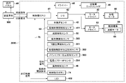
図9は、本実施形態の動作を実現するための画像形成装置1000のブロック構成を示す図である。図9には、ペーパーデッキ3000と装置本体900と操作パネル40とが示されている。操作パネル40は、装置情報や設定画面、ジョブ情報等、各種のユーザインタフェース画面を表示し、また、ユーザからの指示や設定操作を受け付ける。操作パネル40は、例えば装置本体900に構成されている。装置本体900は、ペーパーデッキ3000の制御部41に対して印刷要求し、制御部41は、装置本体900から印刷要求を受信すると、装置本体900に対して給紙動作を行う。
FIG. 9 is a diagram showing the block configuration of the
制御部41は、ペーパーデッキ3000を統括的に制御する。例えば、制御部41は、開閉指示ボタン74の押下による開閉要求信号を受信すると、ドライバ45を介して、収納庫ロックソレノイド46のロック状態を解除し、収納庫をオープン状態とする。制御部41は、入出力インタフェース(I/O)42に接続されたモータドライバ43を介して、シートの搬送路上の各種モータ44を駆動する。また、制御部41は、入出力インタフェース(I/O)42に接続されたモータドライバ53を介して、メインリフター61a及び延長リフター61bを昇降動作させる駆動機構54を制御する。駆動機構54は、昇降モータ55を含む。昇降モータ55は、図3の巻取り部90を駆動する。
The
中継ぎセンサ48、収納庫開閉検知センサ401、上面検知センサ50、紙有無検知センサ300からの検知信号は、制御部41に送信される。ここで、収納庫開閉検知センサ401は、収納庫の開閉状態を検知するセンサである。下限位置検知センサ301、後端規制部材位置検知センサ302、メインリフター位置検知センサ303、延長リフターHPセンサ304、異物検知センサ49からの検知信号は、制御部41に送信される。また、開閉指示ボタン74の押下による収納庫の開放要求信号は、制御部41に送信される。
Detection signals from the
制御部41は、LED400の点灯制御信号により、LED400の点灯を制御する。LEDの400の点灯制御については、第2の実施形態において説明する。
The
[第2の実施形態]
本実施形態では、メインリフター61aと延長リフター61bとの間が同期しているか否か、即ち、段差があるか否かの状態(位置関係についての情報)をユーザに通知する構成について説明する。以下、第1の実施形態と異なる点について説明する。
[Second embodiment]
In this embodiment, a configuration for notifying the user of whether or not the
図2(b)に示すように、シート給送装置30には、LED400が設けられており、LED400の複数種類の点灯表示パターンにより、メインリフター61aと延長リフター61bとの間の状態をユーザに通知する。
As shown in FIG. 2B, the
ここで、LED400の点灯パターンについて説明する。表1は、各モードについてのLED400の全点灯パターンを示したものである。
Here, the lighting pattern of the

また、LED400は、前述の各モードと、メインリフター61aと延長リフター61bとが同期しているか否かとを、後端規制部材延長検知センサ302、メインリフター位置検知センサ303、延長リフターHPセンサ304に基づいて判定する。そして、その判定結果を点灯/消灯/点滅の3パターンの点灯方法により、ユーザに収納庫の状態を識別可能とする。つまり、メインリフター位置検知センサ303と延長リフターHPセンサ304のオン/オフの組合せによって、メインリフター61aと延長リフター61bとの間の状態が判定される。
In addition, the
表1に示すように、メインリフター61aと延長リフター61bとが同期しているか否かに関わらず、普通紙モードの状態では、LED400は消灯する。これは、メインリフター61aと延長リフター61bとが同期しているか否かに関わらず、普通紙から普通紙への用紙セット交換は可能であるからである。ユーザは、LED400の消灯により、普通紙から普通紙への用紙セット交換は可能であることを認識することができる。
As shown in Table 1, regardless of whether the
また、メインリフター61aと延長リフター61bとが同期しており、且つ長尺紙モードの状態では、LED400は点灯する。ユーザは、LED400の点灯により、長尺紙から長尺紙、長尺紙から普通紙への用紙セット交換が可能であることを認識することができる。
Also, when the
また、メインリフター61aと延長リフター61bとが同期しておらず、且つ長尺紙モードの状態では、LED400は点滅する。この状態では、メインリフター61aと延長リフター61bとが同期していないので、普通紙から長尺紙への用紙セット交換はできない。従って、ユーザに収納庫を閉じさせ、メインリフター61aと延長リフター61bとを同期させる動作を行う必要がある。ユーザは、LED400の点滅により、メインリフター61aと延長リフター61bとが同期していない状態であることを認識することができる。表1に示すような情報は、例えば、制御部41のROMに格納されている。
Further, when the
図13は、本実施形態における、長尺紙をセットするまでの処理を示すフローチャートである。図13の各処理は、例えば、制御部41のCPU(以下、単にCPUとする)がROMに記憶されたプログラムをRAMに読み出して実行することにより実現される。図13の処理は、後端規制部材位置検知センサ302がオン、即ち、長尺紙モードであることを検出した場合に開始される。
FIG. 13 is a flow chart showing the processing up to the setting of the long sheet in this embodiment. Each process in FIG. 13 is realized by, for example, reading a program stored in the ROM into the RAM and executing it by the CPU of the control unit 41 (hereinafter simply referred to as CPU). The processing in FIG. 13 is started when the trailing edge regulating member
S201において、CPUは、メインリフター位置検知センサ303と延長リフターHPセンサ304の検出結果の組み合わせを確認する。ここで、メインリフター位置検知センサ303がオフで延長リフターHPセンサ304がオンである場合には、段差がある状態を示しているので、S202へ進み、CPUは、LED400を点滅状態とする。一方、メインリフター位置検知センサ303及び延長リフターHPセンサ304がオンである場合には、段差がない状態を示しているので、S215へ進み、CPUは、LED400を点灯状態とする。S215の後、S216において、長尺紙のセットを受け付ける。S215の後、図13の処理を終了する。
In S<b>201 , the CPU confirms a combination of detection results of the main lifter
S202の後、S203において、CPUは、操作パネル40に、長尺紙をセットさせるためのメッセージを表示する。例えば、「長尺紙セットの前準備のため、紙を取り除いて収納庫を閉めて下さい。通常サイズをご使用の場合は、後端規制板の位置をご確認下さい。」とのメッセージが表示される。
After S202, in S203, the CPU displays a message for setting the long paper on the
S204において、CPUは、収納庫が閉じられたことを検出すると、S205において、メインリフター61aを上昇させる。そして、S206において、CPUは、中継ぎセンサ48とメインリフター位置検知センサ303との検出結果の組み合わせを確認する。ここで、中継ぎセンサ48がオンで、メインリフター位置検知センサ303がオフである場合、S207に進み、CPUは、操作パネル40に、残留シートを取り除く操作を促すメッセージを表示する。例えば、「収納庫を開けて紙を取り除き、収納庫を閉めて下さい。」とのメッセージが表示される。S207の後、S204からの処理を繰り返す。これは、第1の実施形態で説明したように、メインリフター61a上に残留シートがあるために、中継ぎセンサ48がメインリフター位置検知センサ303よりも前にオンとなったことによるものである。
In S204, when the CPU detects that the storage is closed, in S205, the
一方、中継ぎセンサ48がオフで、メインリフター位置検知センサ303がオフである場合には、S208へ進む。S208において、CPUは、メインリフター位置検知センサ303がオフ→オン→オフと変化することを待機する。メインリフター位置検知センサ303がオフ→オン→オフと変化すると、S209において、CPUは、メインリフター61aの移動を反転(即ち、下降)させる。
On the other hand, if the
S210及びS211において、CPUは、メインリフター位置検知センサ303がオンで、延長リフターHPセンサ304がオンとなるまで、メインリフター61aを下降させる。メインリフター位置検知センサ303がオンで、延長リフターHPセンサ304がオンとなった場合、S212において、CPUは、操作パネル40に、収納庫のオープンを促すメッセージを表示する。S213において、CPUは、収納庫をオープンし、S214において、長尺紙のセットを受け付ける。その後、図13の処理を終了する。
In S210 and S211, the CPU lowers the
また、本実施形態においては、メインリフター61a及び延長リフター61b上の積載枚数が1000枚の場合に対応する位置に対応する上述した支持高さでメインリフター位置検知センサ303と延長リフターHPセンサ304がメインリフター61a及び延長リフター61bを検知する構成とした。しかしながら、他の構成としても良い。例えば、上記の支持高さにおいて、少なくとも延長リフターHPセンサ304によって延長リフター61bを検知するようにしても良い。そして、支持高さよりも高い位置で、メインリフター61a及び延長リフター61bが確実に一体的に接続されて長尺紙を積載できる状態であるとする位置を定める。つまり、その位置は、延長リフターHPセンサ304がオフとなる位置となる。そのような構成において、延長リフターHPセンサ304の検知結果に基づいて、メインリフター61a及び延長リフター61bが同期しているかどうかを判定するようにしてもよい。延長リフターHPセンサ304は、延長リフター61bの下限位置に設けられているので、延長リフター61bは、延長リフターHPセンサ304の検知位置よりも下方には移動しない。従って、メインリフター61aが延長リフター61bよりも下方の位置にある場合には、リフター同士は接続せず、延長リフターHPセンサ304は、オンのままとなる。また、メインリフター61aが延長リフター61bの下限位置と同じ高さの位置にある場合でも、メインリフター61aと延長リフター61bとの接続は、まだ完了しておらず、且つ延長リフターHPセンサ304は、オンである。そのような構成とすることで、延長リフターHPセンサ304が延長リフター61bを検知(センサがオン)している場合はメインリフター61aと延長リフター61bとが完全に接続されずにリフター同士に段差があるため、長尺紙を積載できる状態ではないと判定することができる。一方、延長リフターHPセンサ304が延長リフター61bを検知していない場合は、メインリフター61aと延長リフター61bは、共にリフター同士が接続完了する位置、もしくは接続完了する位置よりも上方の位置にあり、メインリフター61aと延長リフター61bとが完全に接続されてリフター同士に段差が無いため、長尺紙を積載できる状態であると判定することができる。このように、延長リフターHPセンサ304の検知結果のみで、メインリフター61aと延長リフター61bとが確実に接続されているかどうか、すなわち、長尺紙を積載可能か否かをユーザに通知することが出来る。このような場合の通知の一例として、LED400を用いた点灯パターンを表2に示す。表2において、点滅は長尺紙積載不可を示し、点灯は長尺紙積載可能を示す。
Further, in this embodiment, the main lifter

図14は、上述した構成における、長尺紙をセットするまでの処理を示すフローチャートである。図14の各処理は、例えば、制御部41のCPU(以下、単にCPUとする)がROMに記憶されたプログラムをRAMに読み出して実行することにより実現される。図14の処理は、後端規制部材位置検知センサ302がオン、即ち、長尺紙モードであることを検出した場合に開始される。
FIG. 14 is a flow chart showing the processing up to the setting of the long paper in the configuration described above. Each process in FIG. 14 is realized by, for example, reading a program stored in the ROM into the RAM and executing it by the CPU of the control unit 41 (hereinafter simply referred to as CPU). The processing in FIG. 14 is started when the trailing end regulating member
S301において、CPUは、延長リフターHPセンサ304の検出結果を確認する。ここで、延長リフターHPセンサ304がオンである場合には、上述したように、メインリフター61aと延長リフター61bとが完全に接続されておらず、長尺紙をセットできない状態を示しているので、S302へ進み、CPUは、LED400を点滅状態とする。一方、延長リフターHPセンサ304がオフである場合には、メインリフター61aと延長リフター61bとが完全に接続されており、長尺紙をセットできる状態を示しているので、S310へ進み、CPUは、LED400を点灯状態(長尺紙が設置可能であることを示す)とする。S310の後、長尺紙のセットを受け付け、図14の処理を終了する。
In S<b>301 , the CPU confirms the detection result of the extension
S302の後、S303において、CPUは、操作パネル40に、長尺紙をセットさせるためのメッセージを表示する。例えば、「長尺紙セットの前準備のため、紙を取り除いて収納庫を閉めて下さい。通常サイズをご使用の場合は、後端規制板の位置をご確認下さい。」とのメッセージが表示される。
After S302, in S303, the CPU displays a message for setting the long paper on the
S304において、CPUは、収納庫が閉じられたことを検出すると、S305において、メインリフター61aを上昇させる。そして、S306において、CPUは、延長リフターHPセンサ304がオン→オフと変化することを待機する。延長リフターHPセンサ304がオン→オフと変化すると、S307において、CPUは、メインリフター61aの上昇を停止させる。その後、S308において、CPUは、操作パネル40に、収納庫のオープンを促すメッセージを表示する。S309において、CPUは、収納庫をオープンし、長尺紙のセットを受け付ける。その後、図14の処理を終了する。
When the CPU detects that the storage is closed in S304, it raises the
以上のように、本実施形態によれば、LED400の点灯パターンにより、ユーザに、リフター61の状態を識別可能に認識させることができ、普通紙を取り除いた後に長尺紙をセットする場合などにおいて、段差が生じた状態で長尺紙をセットされてエラーを発生させることが無くなり、ユーザによるエラー解除等の手間を解消することができる。
As described above, according to the present embodiment, the lighting pattern of the
30 シート給送装置: 41 制御部: 48 中継ぎセンサ: 61a メインリフター: 61b 延長リフター: 303 メインリフター位置検知センサ: 304 延長リフターHPセンサ 30 Sheet feeding device: 41 Control unit: 48 Intermediate sensor: 61a Main lifter: 61b Extension lifter: 303 Main lifter position detection sensor: 304 Extension lifter HP sensor
Claims (12)
前記上限位置より下方かつ前記下限位置より上方である位置を所定位置とし、前記第1積載手段が前記所定位置から前記上限位置までの間にあるときに、前記第1積載手段と連結されていて、前記第1積載手段が前記所定位置より下方にあるときに、前記第1積載手段との連結が解除されている第2積載手段であって、前記第1積載手段と連結された状態で、前記第1積載手段が上下方向へ移動することによって、前記第1積載手段と共に、前記第1サイズよりも大きい第2サイズのシートを積載しながら上下方向に移動可能である前記第2積載手段と、
前記第1積載手段が前記所定位置にあることを検出する第1検出手段と、
前記第2積載手段が前記所定位置にあることを検出する第2検出手段と、
前記第1積載手段に積載されたシート及び前記第1積載手段の上面を検出する上面検出手段と、
前記第1サイズのシート及び前記第2サイズのシートを含む複数のサイズのシートのうち、どのサイズのシートを積載するかを設定する設定手段と、
前記設定手段が前記第2サイズのシートを積載するように設定しているときに、前記上面検出手段が前記第1積載手段に積載されているシートを検出した場合で且つ、前記第1積載手段が前記所定位置になく、前記第2積載手段が前記所定位置にある場合に、エラーと判定する判定手段と、
を有することを特徴とする積載装置。 a first stacking means that is vertically movable between an upper limit position and a lower limit position and stacks sheets of a first size;
A position below the upper limit position and above the lower limit position is defined as a predetermined position, and when the first loading means is between the predetermined position and the upper limit position, it is connected to the first loading means. , a second loading means that is disconnected from the first loading means when the first loading means is below the predetermined position, wherein the second loading means is connected to the first loading means, a second stacking means capable of moving vertically while stacking sheets of a second size larger than the first size together with the first stacking means by moving the first stacking means in the vertical direction; ,
a first detection means for detecting that the first loading means is at the predetermined position;
a second detection means for detecting that the second loading means is at the predetermined position;
upper surface detection means for detecting the upper surface of the sheets stacked on the first stacking means and the first stacking means;
setting means for setting which size sheet to stack among a plurality of size sheets including the first size sheet and the second size sheet;
When the upper surface detecting means detects the sheets stacked on the first stacking means when the setting means is set to stack the sheets of the second size, and the first stacking means is not at the predetermined position and the second loading means is at the predetermined position;
A loading device comprising:
前記上限位置より下方かつ前記下限位置より上方である位置を所定位置とし、前記第1積載手段が前記所定位置から前記上限位置までの間にあるときに、前記第1積載手段と連結されていて、前記第1積載手段が前記所定位置より下方にあるときに、前記第1積載手段との連結が解除されている第2積載手段であって、前記第1積載手段と連結された状態で、前記第1積載手段が上下方向へ移動することによって、前記第1積載手段と共に、前記第1サイズよりも大きい第2サイズのシートを積載しながら上下方向に移動可能である前記第2積載手段と、
前記所定位置よりも上方、かつ前記上限位置よりも下方の位置である第1の位置に、前記第1積載手段に積載されたシートがあること、および前記第1の位置に前記第1積載手段があることを検出結果として出力する第1検出手段と、
前記第2積載手段が前記所定位置にあることを検出可能な第2検出手段と、
前記第1サイズのシート及び前記第2サイズのシートを含む複数のサイズのシートのうち、どのサイズのシートを積載するかを設定する設定手段と、
前記設定手段が前記第2サイズのシートを積載するように設定している状態で、前記所定位置よりも下方から前記第1積載手段が上昇しているときに、前記第2検出手段が前記第2積載手段を検出している状態で前記第1検出手段が前記検出結果を出力した場合に、エラーと判定する判定手段と、
を有することを特徴とする積載装置。 a first stacking means that is vertically movable between an upper limit position and a lower limit position and stacks sheets of a first size;
A position below the upper limit position and above the lower limit position is defined as a predetermined position, and when the first loading means is between the predetermined position and the upper limit position, it is connected to the first loading means. , a second loading means that is disconnected from the first loading means when the first loading means is below the predetermined position, wherein the second loading means is connected to the first loading means, a second stacking means capable of moving vertically while stacking sheets of a second size larger than the first size together with the first stacking means by moving the first stacking means in the vertical direction; ,
The sheets stacked on the first stacking means are at a first position above the predetermined position and below the upper limit position, and the first stacking means is at the first position. a first detection means for outputting as a detection result that there is
a second detection means capable of detecting that the second loading means is at the predetermined position;
setting means for setting which size sheet to stack among a plurality of size sheets including the first size sheet and the second size sheet;
When the first stacking means is raised from below the predetermined position in a state where the setting means is set to stack the sheets of the second size, the second detecting means 2 determination means for determining an error when the first detection means outputs the detection result while detecting the loading means;
A loading device comprising:
前記上限位置より下方かつ前記下限位置より上方である位置を所定位置とし、前記第1積載手段が前記所定位置から前記上限位置までの間にあるときに、前記第1積載手段と連結されていて、前記第1積載手段が前記所定位置より下方にあるときに、前記第1積載手段との連結が解除されている第2積載手段であって、前記第1積載手段と連結された状態で、前記第1積載手段が上下方向へ移動することによって、前記第1積載手段と共に、前記第1サイズよりも大きい第2サイズのシートを積載しながら上下方向に移動可能である前記第2積載手段と、
前記第1積載手段が前記所定位置にあることを検出する第1検出手段と、
前記第2積載手段が前記所定位置にあることを検出する第2検出手段と、
前記第1検出手段の検出結果と前記第2検出手段の検出結果とに応じて、前記第2サイズのシートが積載可能か否かをユーザに通知する通知手段と、
を有することを特徴とする積載装置。 a first stacking means that is vertically movable between an upper limit position and a lower limit position and stacks sheets of a first size;
A position below the upper limit position and above the lower limit position is defined as a predetermined position, and when the first loading means is between the predetermined position and the upper limit position, it is connected to the first loading means. , a second loading means that is disconnected from the first loading means when the first loading means is below the predetermined position, wherein the second loading means is connected to the first loading means, a second stacking means capable of moving vertically while stacking sheets of a second size larger than the first size together with the first stacking means by moving the first stacking means in the vertical direction; ,
a first detection means for detecting that the first loading means is at the predetermined position;
a second detection means for detecting that the second loading means is at the predetermined position;
notification means for notifying a user whether or not the sheet of the second size can be stacked according to the detection result of the first detection means and the detection result of the second detection means ;
A loading device comprising:
前記通知手段は、前記第2サイズのシートを積載するように前記設定手段によって設定されている場合に、前記第1検出手段の検出結果と前記第2検出手段の検出結果とに応じた通知を行うことを特徴とする請求項7に記載の積載装置。 setting means for setting which size of sheets to stack among a plurality of size sheets including the first size sheet and the second size sheet;
The notification means notifies in accordance with the detection result of the first detection means and the detection result of the second detection means when the setting means sets to stack the sheets of the second size. 8. The loading device according to claim 7 , wherein:
前記上限位置より下方かつ前記下限位置より上方である位置を所定位置とし、前記第1積載手段が前記所定位置から前記上限位置までの間にあるときに、前記第1積載手段と連結されていて、前記第1積載手段が前記所定位置より下方にあるときに、前記第1積載手段との連結が解除されている第2積載手段であって、前記第1積載手段と連結された状態で、前記第1積載手段が上下方向へ移動することによって、前記第1積載手段と共に、前記第1サイズよりも大きい第2サイズのシートを積載しながら上下方向に移動可能である前記第2積載手段と、
前記第2積載手段が前記所定位置にあることを検出する検出手段と、
前記検出手段が前記第2積載手段を検出していないことに応じて前記第2サイズのシートが積載可能であることをユーザに通知する通知手段と、
を有することを特徴とする積載装置。 a first stacking means that is vertically movable between an upper limit position and a lower limit position and stacks sheets of a first size;
A position below the upper limit position and above the lower limit position is defined as a predetermined position, and when the first loading means is between the predetermined position and the upper limit position, it is connected to the first loading means. , a second loading means that is disconnected from the first loading means when the first loading means is below the predetermined position, wherein the second loading means is connected to the first loading means, a second stacking means capable of moving vertically while stacking sheets of a second size larger than the first size together with the first stacking means by moving the first stacking means in the vertical direction; ,
a detecting means for detecting that the second loading means is at the predetermined position ;
notification means for notifying a user that the sheet of the second size can be loaded in response to the fact that the detection means has not detected the second stacking means ;
A loading device comprising:
前記通知手段は、前記第2サイズのシートを積載するように前記設定手段によって設定されている場合に、前記検出手段の検出結果に応じた通知を行うことを特徴とする請求項9又は10に記載の積載装置。 setting means for setting which size of sheets to stack among a plurality of size sheets including the first size sheet and the second size sheet;
11. The apparatus according to claim 9 , wherein said notification means notifies according to the detection result of said detection means when said setting means sets to stack sheets of said second size. Loading device as described.
Priority Applications (3)
| Application Number | Priority Date | Filing Date | Title |
|---|---|---|---|
| EP18176946.4A EP3421397A1 (en) | 2017-06-29 | 2018-06-11 | Stacking apparatus |
| US16/010,787 US10549936B2 (en) | 2017-06-29 | 2018-06-18 | Stacking apparatus |
| CN201810673187.XA CN109205350B (en) | 2017-06-29 | 2018-06-27 | Stacking device |
Applications Claiming Priority (2)
| Application Number | Priority Date | Filing Date | Title |
|---|---|---|---|
| JP2017127813 | 2017-06-29 | ||
| JP2017127813 | 2017-06-29 |
Publications (3)
| Publication Number | Publication Date |
|---|---|
| JP2019011196A JP2019011196A (en) | 2019-01-24 |
| JP2019011196A5 JP2019011196A5 (en) | 2021-04-22 |
| JP7112886B2 true JP7112886B2 (en) | 2022-08-04 |
Family
ID=65227199
Family Applications (1)
| Application Number | Title | Priority Date | Filing Date |
|---|---|---|---|
| JP2018099770A Active JP7112886B2 (en) | 2017-06-29 | 2018-05-24 | loading device |
Country Status (1)
| Country | Link |
|---|---|
| JP (1) | JP7112886B2 (en) |
Families Citing this family (2)
| Publication number | Priority date | Publication date | Assignee | Title |
|---|---|---|---|---|
| JP7114261B2 (en) * | 2018-01-19 | 2022-08-08 | キヤノン株式会社 | sheet feeder |
| JP7206994B2 (en) * | 2019-02-19 | 2023-01-18 | コニカミノルタ株式会社 | Paper feeder and image forming system |
Citations (5)
| Publication number | Priority date | Publication date | Assignee | Title |
|---|---|---|---|---|
| JP2002037468A (en) | 2000-07-26 | 2002-02-06 | Sharp Corp | Sheet feeder |
| JP2011042495A (en) | 2009-08-24 | 2011-03-03 | Kyocera Mita Corp | Image forming device |
| JP2013256092A (en) | 2012-06-14 | 2013-12-26 | Canon Inc | Sheet processing apparatus, method for controlling sheet processing apparatus and program |
| JP2015105977A (en) | 2013-11-28 | 2015-06-08 | 京セラドキュメントソリューションズ株式会社 | Image forming apparatus |
| JP2016088667A (en) | 2014-10-31 | 2016-05-23 | 京セラドキュメントソリューションズ株式会社 | Paper feeding device and image forming apparatus |
Family Cites Families (2)
| Publication number | Priority date | Publication date | Assignee | Title |
|---|---|---|---|---|
| JPH11292306A (en) * | 1998-02-13 | 1999-10-26 | Tohoku Ricoh Co Ltd | Paper supply device |
| JP4979483B2 (en) * | 2007-06-28 | 2012-07-18 | キヤノン株式会社 | Sheet stacking apparatus and control method thereof |
-
2018
- 2018-05-24 JP JP2018099770A patent/JP7112886B2/en active Active
Patent Citations (5)
| Publication number | Priority date | Publication date | Assignee | Title |
|---|---|---|---|---|
| JP2002037468A (en) | 2000-07-26 | 2002-02-06 | Sharp Corp | Sheet feeder |
| JP2011042495A (en) | 2009-08-24 | 2011-03-03 | Kyocera Mita Corp | Image forming device |
| JP2013256092A (en) | 2012-06-14 | 2013-12-26 | Canon Inc | Sheet processing apparatus, method for controlling sheet processing apparatus and program |
| JP2015105977A (en) | 2013-11-28 | 2015-06-08 | 京セラドキュメントソリューションズ株式会社 | Image forming apparatus |
| JP2016088667A (en) | 2014-10-31 | 2016-05-23 | 京セラドキュメントソリューションズ株式会社 | Paper feeding device and image forming apparatus |
Also Published As
| Publication number | Publication date |
|---|---|
| JP2019011196A (en) | 2019-01-24 |
Similar Documents
| Publication | Publication Date | Title |
|---|---|---|
| CN109205350B (en) | Stacking device | |
| CN109019128B (en) | Stacking device, feeding device, and image forming apparatus | |
| JP2001302064A (en) | Image forming device | |
| JP3751293B2 (en) | Sheet feeding apparatus, image reading apparatus, and image forming apparatus | |
| JP7112886B2 (en) | loading device | |
| JP2024026841A (en) | Sheet feeding device, image reading device, and image forming device | |
| JP5230241B2 (en) | Image forming apparatus | |
| CN108388091B (en) | Image processing apparatus | |
| JP6980064B2 (en) | Feeding device | |
| JP2010037099A (en) | Paper feeder and image system | |
| CN109422126B (en) | Stacking device and feeding device | |
| JP4535833B2 (en) | Sheet processing apparatus and image forming apparatus having the same | |
| JP2017024841A (en) | Sheet feeding device and image forming apparatus | |
| JP6728284B2 (en) | Loading device, feeding device, and image forming device | |
| JP2020055651A (en) | Loader, feeder and image forming apparatus | |
| US20240109743A1 (en) | Sheet conveyance apparatus, image reading apparatus, and image forming apparatus | |
| JP2016088747A (en) | Sheet feeder and image formation device | |
| JP2020001914A (en) | Loading device, feeding device, and image forming device | |
| JP2019218178A (en) | Image forming system and control method thereof | |
| JP2019034829A (en) | Loading device and method for controlling the same, and feeding device and image forming apparatus including the loading device | |
| JP2022041695A (en) | Document feeder, image reading device and image forming device with the same | |
| JP2020007147A (en) | Sheet stacking device | |
| JP2006111425A (en) | Sheet processing device and image forming device equipped with the sheet processing device | |
| JP2020196599A (en) | Sheet conveyance device, document reading apparatus and image formation apparatus | |
| JP2017193392A (en) | Sheet discharge device, image reading device and image formation device |
Legal Events
| Date | Code | Title | Description |
|---|---|---|---|
| RD02 | Notification of acceptance of power of attorney |
Free format text: JAPANESE INTERMEDIATE CODE: A7422 Effective date: 20210203 |
|
| A521 | Request for written amendment filed |
Free format text: JAPANESE INTERMEDIATE CODE: A523 Effective date: 20210305 |
|
| A621 | Written request for application examination |
Free format text: JAPANESE INTERMEDIATE CODE: A621 Effective date: 20210305 |
|
| A977 | Report on retrieval |
Free format text: JAPANESE INTERMEDIATE CODE: A971007 Effective date: 20220111 |
|
| A131 | Notification of reasons for refusal |
Free format text: JAPANESE INTERMEDIATE CODE: A131 Effective date: 20220204 |
|
| A521 | Request for written amendment filed |
Free format text: JAPANESE INTERMEDIATE CODE: A523 Effective date: 20220330 |
|
| TRDD | Decision of grant or rejection written | ||
| A01 | Written decision to grant a patent or to grant a registration (utility model) |
Free format text: JAPANESE INTERMEDIATE CODE: A01 Effective date: 20220627 |
|
| A61 | First payment of annual fees (during grant procedure) |
Free format text: JAPANESE INTERMEDIATE CODE: A61 Effective date: 20220725 |
|
| R150 | Certificate of patent or registration of utility model |
Ref document number: 7112886 Country of ref document: JP Free format text: JAPANESE INTERMEDIATE CODE: R150 |