JP7112655B2 - lighting system - Google Patents

lighting system Download PDF

Info

Publication number
JP7112655B2
JP7112655B2 JP2018128573A JP2018128573A JP7112655B2 JP 7112655 B2 JP7112655 B2 JP 7112655B2 JP 2018128573 A JP2018128573 A JP 2018128573A JP 2018128573 A JP2018128573 A JP 2018128573A JP 7112655 B2 JP7112655 B2 JP 7112655B2
Authority
JP
Japan
Prior art keywords
lighting
light
unit
color
information
Prior art date
Legal status (The legal status is an assumption and is not a legal conclusion. Google has not performed a legal analysis and makes no representation as to the accuracy of the status listed.)
Active
Application number
JP2018128573A
Other languages
Japanese (ja)
Other versions
JP2020009594A5 (en
JP2020009594A (en
Inventor
知基 貞照
真一 杉田
Current Assignee (The listed assignees may be inaccurate. Google has not performed a legal analysis and makes no representation or warranty as to the accuracy of the list.)
Toshiba Lighting and Technology Corp
Original Assignee
Toshiba Lighting and Technology Corp
Priority date (The priority date is an assumption and is not a legal conclusion. Google has not performed a legal analysis and makes no representation as to the accuracy of the date listed.)
Filing date
Publication date
Application filed by Toshiba Lighting and Technology Corp filed Critical Toshiba Lighting and Technology Corp
Priority to JP2018128573A priority Critical patent/JP7112655B2/en
Publication of JP2020009594A publication Critical patent/JP2020009594A/en
Publication of JP2020009594A5 publication Critical patent/JP2020009594A5/ja
Application granted granted Critical
Publication of JP7112655B2 publication Critical patent/JP7112655B2/en
Active legal-status Critical Current
Anticipated expiration legal-status Critical

Links

Images

Description

本発明は、照明システムに関する。 The present invention relates to lighting systems.

近年、LED(Light emitting diode)モジュールを光源に用いた照明器具の普及が進んでいる。また、舞台やスタジオの現場で用いられるこのような照明器具は、調光操作卓によって照明光の調光が行われることが慣例となっている。 In recent years, lighting fixtures using LED (Light Emitting Diode) modules as light sources have become widespread. In addition, it is customary for such lighting fixtures used in the field of stages and studios to adjust the illumination light using a light control console.

LEDモジュールを光源に用いた照明器具は、赤色光、緑色光、及び青色光といった各色光を発光する発光素子を複数備えている。しかし、それら各色光の割合を任意に調整した光色の照明光を得たい場合は照明器具の操作が煩雑になるという課題があった。 A lighting fixture using an LED module as a light source includes a plurality of light-emitting elements that emit light of each color such as red light, green light, and blue light. However, there is a problem that the operation of the lighting equipment becomes complicated when it is desired to obtain illumination light of light colors in which the ratio of each color light is arbitrarily adjusted.

特開2014-120351号公報JP 2014-120351 A

本発明が解決しようとする課題は、操作性に優れた照明システムを提供することである。 The problem to be solved by the present invention is to provide a lighting system with excellent operability.

本発明の実施形態である照明システムは、複数色の発光素子からなる光源部と、光源部が有する光色の出力割合である発光色情報を含む点灯条件情報を記憶する記憶部と、を備える照明器具と、照明器具から送信された、複数色の発光素子からなる発光色情報を含む点灯条件情報を一つの単位情報として一つの出力操作部に割り当て、この出力操作部によって操作された出力レベルを出力可能な制御部と、を備える。照明器具は、制御部から出力レベルを取得し、出力操作部に対応して記憶された点灯条件情報および出力レベルに基づき光源部を制御するA lighting system according to an embodiment of the present invention includes a light source unit composed of light-emitting elements of a plurality of colors, and a storage unit that stores lighting condition information including emission color information that is the output ratio of the light colors of the light source unit. A lighting fixture and lighting condition information including light emission color information composed of light emitting elements of a plurality of colors transmitted from the lighting fixture are assigned to one output operation unit as one unit information, and the output level is operated by this output operation unit. and a control unit capable of outputting The lighting fixture acquires the output level from the control section and controls the light source section based on the lighting condition information and the output level stored corresponding to the output operation section .

本発明によれば、操作性に優れた照明システムを提供できる。 ADVANTAGE OF THE INVENTION According to this invention, the lighting system excellent in operability can be provided.

本発明の実施形態である照明システムを表すブロック図である。1 is a block diagram representing a lighting system that is an embodiment of the present invention; FIG. 本発明の実施形態である照明システムに備えられる照明器具の構成を表すブロック図である。It is a block diagram showing the structure of the lighting fixture with which the lighting system which is embodiment of this invention is equipped. 本発明の第一の実施形態である照明システムに備えられる調光卓の構成を表すブロック図である。1 is a block diagram showing the configuration of a light control console provided in the lighting system that is the first embodiment of the present invention; FIG. 本発明の第二の実施形態である照明システムに備えられる調光卓および外部端末の構成を表すブロック図である。FIG. 4 is a block diagram showing the configuration of a light control console and an external terminal provided in the lighting system according to the second embodiment of the present invention; 本発明の実施形態である照明システムにおける発光色情報の設定または呼び出しを行う際の表示部の一例を示す図である。FIG. 5 is a diagram showing an example of a display unit when setting or calling emission color information in the lighting system according to the embodiment of the present invention; 本発明の実施形態である照明システムにおいてそれぞれのチャンネルに任意の混色光を割り当てた場合における発光色を構成する各発光素子の出力割合算出方法を表す図である。FIG. 4 is a diagram showing a method of calculating the output ratio of each light-emitting element that constitutes an emission color when arbitrary mixed-color light is assigned to each channel in the lighting system according to the embodiment of the present invention;

以下、図1ないし図6を参照して本発明の実施形態である照明システムについて説明する。 A lighting system according to an embodiment of the present invention will be described below with reference to FIGS. 1 to 6. FIG.

図1は、第一の実施形態における照明システムの全体構成を示すブロック図である。本発明の実施形態である照明システムは、出力操作部14としての調光卓10および外部端末40と通信可能に設けられる複数の照明器具30をバトン20によって支持するよう有している。なお、図1では説明の簡略化のためそれぞれ一つの調光卓10、一つのバトン20、外部端末40、と、四台の照明器具30を示しているが、これらの設けられる数は任意であり、例えば一つの調光卓10に後述するスプリッタやノード等を介して複数の照明器具30が接続されてもよいし、複数のバトン20にそれぞれ異なる台数の照明器具30が接続されてもよい。 FIG. 1 is a block diagram showing the overall configuration of a lighting system according to the first embodiment. The lighting system according to the embodiment of the present invention has a lighting console 10 as an output operation unit 14 and a plurality of lighting fixtures 30 provided to communicate with an external terminal 40 so as to be supported by a baton 20 . In FIG. 1, one light control console 10, one baton 20, one external terminal 40, and four lighting fixtures 30 are shown for simplification of explanation, but the number of these provided is arbitrary. For example, a plurality of lighting fixtures 30 may be connected to a single light control console 10 via a splitter, a node, etc., which will be described later, or a different number of lighting fixtures 30 may be connected to a plurality of batons 20. .

また、本発明の実施形態である照明システムは、外部端末40を備えず調光卓10のみによって後述の照明器具30を制御する種々の設定を行う場合を第一の実施形態とする。第一の実施形態に用いられる調光卓10は、後述する調光卓10aである。また、本発明の実施形態である照明システムは、図1に示す外部端末40を備える場合を第二の実施形態とする。 バトン20は、昇降装置等によって昇降可能なレール状の器具であり、照明器具30を複数台吊り下げて支持する。照明器具30は、DMX512規格(以下、DMXと呼ぶ)の通信線を接続可能な形状のポートを有する。照明器具30は、調光卓10および(または)外部端末40とDMX等の調光信号を通信可能な通信線によって接続される。 Further, the lighting system according to the embodiment of the present invention is a first embodiment in which various settings for controlling lighting fixtures 30, which will be described later, are performed only by the light control console 10 without the external terminal 40. FIG. The light control console 10 used in the first embodiment is a light control console 10a described later. Moreover, the illumination system which is embodiment of this invention makes the case where the external terminal 40 shown in FIG. 1 is provided a 2nd embodiment. The baton 20 is a rail-shaped device that can be raised and lowered by a lifting device or the like, and supports a plurality of lighting fixtures 30 by suspending them. The luminaire 30 has a port shaped to connect a DMX512 standard (hereinafter referred to as DMX) communication line. The luminaire 30 is connected to the light control console 10 and/or the external terminal 40 via a communication line such as DMX that can communicate a light control signal.

なお、バトン20は、DMX等の調光信号を通信可能な通信線によって接続されるポートを複数設けられて後述するスプリッタやノード等の機能を有していてもよいし、同じバトン20に吊り下げられた照明器具30同士をカスケード接続可能な様態として構成されていてもよい。 The baton 20 may be provided with a plurality of ports connected by a communication line capable of communicating a dimming signal such as DMX, and may have functions such as a splitter and a node, which will be described later. The lowered lighting fixtures 30 may be configured to be cascade-connectable.

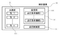
照明器具30は、例えば図2に示すように、複数色のLED等の発光素子311を複数備える光源部31と、光源部31から照射される光の発光色である発光素子311の各色ごとの出力割合を定める発光色情報を含む点灯条件情報321を複数(図2ではn個)記憶可能な記憶部32と、対応する点灯条件情報321に基づいて光源部31を点灯制御する点灯制御部33を有する。 For example, as shown in FIG. 2, the lighting device 30 includes a light source unit 31 including a plurality of light emitting elements 311 such as LEDs of multiple colors, and a light emitting element 311 for each color of the light emitted from the light source unit 31. A storage unit 32 capable of storing a plurality of (n in FIG. 2) lighting condition information 321 including luminescent color information that determines the output ratio, and a lighting control unit 33 that controls lighting of the light source unit 31 based on the corresponding lighting condition information 321. have

光源部31は、点灯制御部33によって記憶部32に記憶された発光色情報を含む点灯条件情報321に基づいて各発光素子311の出力割合を算出し、各発光素子311からの出力光が合成された光を外部に向けて出力する。この各発光素子311からの出力光が合成された光の色を発光色と呼ぶ。 The light source unit 31 calculates the output ratio of each light emitting element 311 based on the lighting condition information 321 including the luminescent color information stored in the storage unit 32 by the lighting control unit 33, and combines the output light from each light emitting element 311. The emitted light is output to the outside. The color of light obtained by synthesizing the output light from each light emitting element 311 is called a light emission color.

点灯条件情報321は、DMXで通信される制御チャンネルに割り当てられて記憶される。例えば、発光素子311の各色ごとの出力割合を定めた発光色情報は、光源部31が備える全ての色ごとの出力割合を一つの制御チャンネルに一つの単位情報として割り当てて記憶することが可能である。つまり、光源部31が色1~色nまでのn色分の発光素子を備えている場合、色1をx%で出力し、色2をy%で出力し、…色nをz%で出力するというn種類の出力割合情報を一つの単位情報である点灯条件情報321-1として一つの制御チャンネルに記憶することができる。 The lighting condition information 321 is assigned to a control channel communicated by DMX and stored. For example, the emission color information that defines the output ratio for each color of the light emitting element 311 can be stored by allocating the output ratio for each color of all the colors provided in the light source unit 31 to one control channel as one piece of unit information. be. In other words, when the light source unit 31 has light emitting elements for n colors from color 1 to color n, color 1 is output at x%, color 2 is output at y%, . . . color n is output at z%. The n types of output ratio information to be output can be stored in one control channel as lighting condition information 321-1, which is one unit of information.

点灯条件情報321は、光源部31に備えられた発光素子311の各色ごとの出力割合である発光色情報の他、照明器具30がパン方向やチルト方向にどの程度傾いて照射されるかという角度を定めた角度情報、点灯・消灯のタイミングおよびスピード等を定めた時間情報、それら全てを複合的に一つの情報として記憶したシーン情報等を含む。 The lighting condition information 321 includes light emission color information, which is the output ratio for each color of the light emitting element 311 provided in the light source unit 31, and angle indicating how much the lighting fixture 30 is tilted in the pan direction and the tilt direction. time information that defines the timing and speed of turning on/off, and scene information that stores all of them as a single piece of information.

ここでいう一つの情報とは、例えばDMXの通信線によって通信可能な512チャンネルの内の1チャンネルを使用して通信可能な情報である。例えば図2に示す照明器具30が図1のように調光卓10や外部端末40と通信線で接続された場合では、点灯条件情報321-1~321-nまでのn個のチャンネルが使用されて通信線を介し調光卓10や外部端末40と通信される。 Here, one piece of information is, for example, information that can be communicated using one of 512 channels that can be communicated through a DMX communication line. For example, when the lighting fixture 30 shown in FIG. 2 is connected to the light control console 10 or the external terminal 40 via a communication line as shown in FIG. 1, n channels of lighting condition information 321-1 to 321-n are used. and communicated with the light control console 10 and the external terminal 40 via a communication line.

DMX信号によって照明器具30が制御される場合、DMXの通信線は1系統につき最大512チャンネルの制御チャンネルを有するため、記憶部32に記憶可能な点灯条件情報321の数は、512個未満に設定される。DMXの通信線1系統にバトン20等を介して複数の照明器具30が接続される場合、複数の照明器具30の記憶部32に記憶可能な点灯条件情報321の数は、その合計が512個未満となるよう設定される。 When the lighting fixture 30 is controlled by a DMX signal, one DMX communication line has a maximum of 512 control channels, so the number of lighting condition information 321 that can be stored in the storage unit 32 is set to less than 512. be done. When a plurality of lighting fixtures 30 are connected to one system of DMX communication line via a baton 20 or the like, the total number of lighting condition information 321 that can be stored in the storage units 32 of the plurality of lighting fixtures 30 is 512. is set to be less than

光源部31は、それぞれ異なる色である色1~色nを発光する発光素子311を複数有する。異なる色とは、例えば赤色、緑色、青色、琥珀色、ライム色、シアン色、ロイヤルブルー色等である。 The light source unit 31 has a plurality of light emitting elements 311 that emit light of colors 1 to n, which are different colors. Different colors are, for example, red, green, blue, amber, lime, cyan, royal blue, and the like.

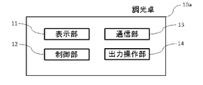
図3に示すように本発明の第一の実施形態に備えられる調光卓10aは、表示部11と制御部12と通信部13と出力操作部14を有する。表示部11は、液晶パネルなどで構成される文字や色、図柄を表示可能な部材である。 As shown in FIG. 3, the light control console 10a provided in the first embodiment of the present invention has a display section 11, a control section 12, a communication section 13, and an output operation section . The display unit 11 is a member configured by a liquid crystal panel or the like and capable of displaying characters, colors, and patterns.

制御部12は、図2で示す照明器具30の有する複数の点灯条件情報321-1~321-nにそれぞれフェーダ等の任意の出力操作部14を割り当てる。すなわち、各制御チャンネルに割り当てられた出力操作部14をそれぞれ操作することにより、記憶部32に記憶された各点灯条件情報321をそれぞれ一つの単位情報として一つの出力操作部14によって操作することができる。また、制御部12は、異なる複数の照明器具30に対応するよう複数の出力操作部14をそれぞれの照明器具30割り当てることも可能である。 The control unit 12 assigns an arbitrary output operation unit 14 such as a fader to each of the plurality of lighting condition information 321-1 to 321-n possessed by the lighting device 30 shown in FIG. That is, by operating the output operation unit 14 assigned to each control channel, each lighting condition information 321 stored in the storage unit 32 can be operated by one output operation unit 14 as one unit information. can. Also, the control unit 12 can allocate a plurality of output operation units 14 to each of the lighting fixtures 30 so as to correspond to a plurality of different lighting fixtures 30 .

通信部13は、DMX線やイーサネット(登録商標)を通じて照明器具30と通信可能に設けられる。具体的には、DMX線と接続される場合であれば、通信部13はスプリッタと呼ばれるDMX信号を分配する機器を介して複数の照明器具30と接続される。 The communication unit 13 is provided so as to be able to communicate with the lighting fixture 30 via DMX lines or Ethernet (registered trademark). Specifically, when connecting to a DMX line, the communication unit 13 is connected to a plurality of lighting fixtures 30 via a device called a splitter that distributes DMX signals.

また、イーサネット(登録商標)により接続される場合であれば、通信部13はノードと呼ばれるイーサネット(登録商標)用の調光信号をDMX信号に変換して分配する機器を介して複数の照明器具30と接続される。 In the case of Ethernet (registered trademark) connection, the communication unit 13 is connected to a plurality of lighting fixtures via a device called a node that converts a dimming signal for Ethernet (registered trademark) into a DMX signal and distributes it. Connected with 30.

なお、調光信号の分配は複数の照明器具30同士を互いに通信線でカスケード接続することによって行われてもよい。 Note that the distribution of the dimming signal may be performed by cascading a plurality of lighting fixtures 30 to each other via communication lines.

出力操作部14は、段階的にレベル値を手動で増減可能なフェーダやホイール等を備える。出力操作部14は、表示部41に表示される仮想フェーダ表示等であってもよいし、ボタンやタッチパネルにより任意の値を選択するものであってもよい。 The output operation unit 14 includes a fader, wheel, etc. that can manually increase or decrease the level value in stages. The output operation unit 14 may be a virtual fader display or the like displayed on the display unit 41, or may be a unit for selecting an arbitrary value using buttons or a touch panel.

出力操作部14 本発明の実施形態である照明システムにおいて、表示部11(41)に表示される内容および照明器具30への任意の発光色の設定方法について説明する。 Output Operation Unit 14 In the lighting system according to the embodiment of the present invention, the content displayed on the display unit 11 (41) and the method of setting an arbitrary emission color for the lighting device 30 will be described.

照明器具30に接続された調光卓10aまたは外部端末40は、制御部12(42)によって照明器具30に出荷時に設定されている固有の器具IDを識別する。固有の器具IDは、照明器具30ごとのメーカー名や機種名、製造年数、照明器具30が光源部31に備える発光素子311の種類等である器具情報と紐付けられる。器具情報は調光卓10aまたは外部端末40に記憶されていてもよいし、ネットワークを介してサーバやクラウドに保存されていてもよい。表示部11(41)は、調光卓10aまたは外部端末40に所定の操作を行うことにより固有の器具IDと紐付けられた器具情報を表示する。 The control unit 10a or the external terminal 40 connected to the lighting fixture 30 identifies the unique fixture ID set to the lighting fixture 30 at the time of shipment by the control unit 12 (42). The unique fixture ID is associated with fixture information such as the manufacturer name, model name, year of manufacture, type of light emitting element 311 provided in the light source section 31 of the lighting fixture 30, and the like for each lighting fixture 30. FIG. The appliance information may be stored in the light control console 10a or the external terminal 40, or may be stored in a server or cloud via a network. The display unit 11 (41) displays appliance information associated with a unique appliance ID by performing a predetermined operation on the light control console 10a or the external terminal 40. FIG.

表示部11(41)に表示される器具情報の一例について図5を参照して説明する。 An example of the appliance information displayed on the display section 11 (41) will be described with reference to FIG.

表示部11(41)は、バトン20を介して接続された照明器具30の固有の器具IDおよび記憶部32に記憶された複数の点灯条件情報321を読み出して表示することができる。 The display unit 11 (41) can read and display the unique fixture ID of the lighting fixture 30 connected via the baton 20 and a plurality of lighting condition information 321 stored in the storage section 32. FIG.

表示部11(41)は、例えば接続された照明器具30のメーカー名や機種名を表示する器具種別表示111と、照明器具30が有する複数の仮想制御チャンネルの内一つのチャンネルに割り当て可能な基本制御を示す基本制御表示112、照明器具30が有する複数の仮想制御チャンネルの内訳を操作する操作表示113、照明器具30が有する複数の仮想制御チャンネル全体に対しての操作を行う全体操作表示114、操作者が任意に設定可能な照明器具30の名称を表示する名称表示部115、照明器具30が有する複数の仮想制御チャンネルとその内容を一覧表示する器具チャンネル表示116、照明器具30が有する複数の仮想制御チャンネルの内、発光色を割り当てられたチャンネルを選択した際に表示される発光色プレビュー117を表示する。 The display unit 11 (41) includes, for example, a fixture type display 111 that displays the manufacturer name and model name of the connected lighting fixture 30, and a basic display that can be assigned to one of a plurality of virtual control channels that the lighting fixture 30 has. A basic control display 112 indicating control, an operation display 113 for operating details of a plurality of virtual control channels possessed by the lighting fixture 30, an overall operation display 114 for operating all of the plurality of virtual control channels possessed by the lighting fixture 30, A name display section 115 that displays the name of the lighting fixture 30 that can be arbitrarily set by the operator, a fixture channel display 116 that displays a list of a plurality of virtual control channels of the lighting fixture 30 and their contents, and a plurality of virtual control channels of the lighting fixture 30. A luminous color preview 117 is displayed when a channel to which a luminous color is assigned is selected from virtual control channels.

器具種別表示111および基本制御表示112に表示される内容は、接続された照明器具30からDMX通信線等を介して受信した固有の器具IDと記憶部32またはネットワークに記憶された情報とが制御部12(42)によって紐付けられた器具情報に基づく。基本制御表示112は、接続された照明器具30が光源部31に有している発光素子311の全ての色を一覧で表示する。 The contents displayed on the fixture type display 111 and the basic control display 112 are controlled by the unique fixture ID received from the connected lighting fixture 30 via the DMX communication line or the like and the information stored in the storage unit 32 or network. Based on instrument information linked by unit 12 (42). The basic control display 112 displays a list of all colors of the light emitting elements 311 included in the light source section 31 of the connected lighting fixture 30 .

例えば、照明器具30が赤、緑、青の三色分の発光素子を有している場合、照明器具30のIDから器具情報を読み取り、基本制御表示112には1行ずつ赤、緑、青の項目が表示される。 For example, if the lighting fixture 30 has light-emitting elements for three colors of red, green, and blue, the fixture information is read from the ID of the lighting fixture 30, and the basic control display 112 displays red, green, and blue lines one by one. items are displayed.

また、基本制御表示112は、ズーム機能やストロボ機能、光出力カーブ等の照明器具30が備えている任意の操作制御が可能な機能を全て一覧で表示する。 In addition, the basic control display 112 displays a list of all the functions of the lighting fixture 30 such as a zoom function, a strobe function, and a light output curve that can be arbitrarily controlled.

操作表示113は、器具チャンネル表示116に表示される複数のチャンネルの内1チャンネルごとに行う操作の種類を表示している。例えば複数の色である複数の発光素子311によって出力される発光色(以下、混色光と呼ぶ)を照明器具30の仮想制御チャンネルの内の1つのチャンネルに作成する場合、器具チャンネル表示116からどのチャンネルに求める混色光を設定するかを選択し、操作表示113の中から混色光を作成するMix Colorボタンを選択する。 The operation display 113 displays the type of operation to be performed for each channel out of the plurality of channels displayed in the appliance channel display 116 . For example, when the luminescence colors (hereinafter referred to as mixed-color light) output by the plurality of light-emitting elements 311 of a plurality of colors are created in one of the virtual control channels of the lighting fixture 30 , which Select whether to set the desired mixed color light for the channel, and select the Mix Color button for creating the mixed color light from the operation display 113 .

すると表示部11(41)に発光色プレビュー117が表示され、任意の色を選択可能となる。発光色プレビュー117は、実際の発光色に近い色彩を表す色プレビューと、R ( Red) 、G( Green)、B ( Blue) 等の発光色を構成する発光素子311の色ごとの割合および全体輝度の割合、横軸が色度で縦軸が彩度を表す色マップ等を表示する。 Then, a luminescent color preview 117 is displayed on the display section 11 (41), and an arbitrary color can be selected. The luminous color preview 117 is a color preview representing a color close to the actual luminous color, and the ratio of each color of the light emitting elements 311 constituting the luminous colors such as R (Red), G (Green), B (Blue) and the total color. It displays a luminance ratio, a color map in which the horizontal axis represents chromaticity and the vertical axis represents saturation, and the like.

発光色プレビュー117により任意の色を決定すると、決定した色の発光色を構成する発光素子311の色ごとの割合および全体輝度の割合が選択した仮想制御チャンネルに設定され、器具チャンネル表示116に表示されるとともに対応する照明器具30の制御チャンネルにも決定した各発光素子311の色ごとの割合および全体輝度の割合である発光色情報が記憶部32に記憶される。 When an arbitrary color is determined by the luminescent color preview 117, the ratio of each color of the light emitting elements 311 constituting the luminescent color of the determined color and the ratio of the overall luminance are set in the selected virtual control channel and displayed in the fixture channel display 116. At the same time, the control channel of the corresponding lighting device 30 is also stored in the storage unit 32 with the light emission color information, which is the ratio of each color of each light emitting element 311 and the ratio of the overall luminance determined.

操作表示113は、任意の混色光を設定するMix Colorボタン以外に、例えばDeleteボタン、Insertボタン、Eraseボタンを有する。 The operation display 113 has, for example, a Delete button, an Insert button, and an Erase button in addition to a Mix Color button for setting arbitrary mixed color light.

Deleteボタンは、選択した器具チャンネル表示116の内1つのチャンネルに設定された情報(図5では器具チャンネル表示116のチャンネル4に設定されたMix Color情報)を削除し、該当チャンネルの情報を空欄に戻す。 The Delete button deletes the information set for one channel of the selected fixture channel display 116 (Mix Color information set for channel 4 of the fixture channel display 116 in FIG. 5) and clears the information for the corresponding channel. return.

Insertボタンは、選択した器具チャンネル表示116の内1つのチャンネルに新たに設定可能な空欄を挿入する(図5では、器具チャンネル表示116のチャンネル4に新たな空欄を挿入し、元チャンネル4に設定されていたMix Color情報はチャンネル5へ、元チャンネル5に設定されていたMix Color情報はチャンネル6へ、元チャンネル6に設定されていたMix Color情報はチャンネル7へとそれぞれ繰り下がるように設定されて表示される)。 The Insert button inserts a new configurable blank into one of the selected fixture channel displays 116 (in FIG. 5 inserts a new blank into channel 4 of the fixture channel display 116 and sets it to original channel 4). The original Mix Color information is set to channel 5, the original Mix Color information set to channel 5 is set to channel 6, and the original Mix Color information set to channel 6 is set to be set to channel 7. displayed).

Eraseボタンは、選択した器具チャンネル表示116の内1つのチャンネルに設定された情報を削除し、該当チャンネル以下のチャンネルを1つずつ繰り上げ表示する(図5では、器具チャンネル表示116のチャンネル4を選択してEraseボタンを決定すると、元チャンネル4に設定されていたMix Color情報は削除され、元チャンネル5のMix Colorがチャンネル4に、元チャンネル6のMix Colorがチャンネル5に設定される)。 The Erase button deletes the information set in one channel of the selected fixture channel display 116, and moves up and displays the channels below the corresponding channel one by one (in FIG. 5, channel 4 of the fixture channel display 116 is selected). When the Erase button is selected, the Mix Color information set in the original channel 4 is deleted, the original channel 5 Mix Color is set in the channel 4, and the original channel 6 Mix Color is set in the channel 5).

全体操作表示114は、例えばAll CopyボタンとAll Deleteボタンを有する。 The overall operation display 114 has, for example, an All Copy button and an All Delete button.

All Copyボタンは、選択決定されると調光卓10aまたは外部端末40と接続されたある照明器具30が有する器具チャンネル表示116に表示される発光色情報を含む点灯条件情報321を全てコピーする。コピーされた点灯条件情報321は同一の照明器具30の記憶部32にさらに記憶させることもできるし、コピーした点灯条件情報321を別の照明器具30の記憶部32にそのまま記憶させてもよい。 The All Copy button, when selected and determined, copies all lighting condition information 321 including luminescent color information displayed on the fixture channel display 116 of a certain lighting fixture 30 connected to the light control console 10a or the external terminal 40. The copied lighting condition information 321 can be further stored in the storage unit 32 of the same lighting device 30, or the copied lighting condition information 321 can be stored in the storage unit 32 of another lighting device 30 as it is.

All Deleteボタンは、選択決定されると照明器具30が有する器具チャンネル表示116に表示される発光色情報を含む点灯条件情報321を全て削除する。 名称表示部115は、操作者が任意に設定する照明器具30ごとの名称または番号を表示する。設定される名称は、日本語や英数字、その他の記号を含むものであってもよい。 The All Delete button deletes all the lighting condition information 321 including the light emission color information displayed in the fixture channel display 116 of the lighting fixture 30 when it is selected and determined. The name display section 115 displays the name or number of each lighting device 30 arbitrarily set by the operator. The set name may include Japanese, alphanumeric characters, and other symbols.

これらの構成により、照明器具30を複数台用いる場合であっても任意に設定した点灯条件情報321をそのままコピーして多数の照明器具30に設定することが可能である。また、照明器具30は記憶部32に任意の発光色情報を制御チャンネルごとに一つの情報として割り当てられて記憶されているため、発光色の設定機能がない調光卓10bと接続されても、出力操作部14に任意の対応する制御チャンネルを割り当てることで照明器具30から簡易に目的の混色光を照射させることが可能である。また、設定した任意の混色光を構成する各光色の比を変えずに出力操作部14からの入力をマスター値として出力レベル値を操作することが可能であるため、複数の光色によって再現される発光色をより少ない個数の出力操作部14で出力操作することが容易に可能である。また、任意の光色割合である混色光の情報を発光色情報として複数照明器具30に記憶させることが可能であるから、使用頻度の高い混色光を複数記憶部32に記憶させておけば、簡単に目的の発光色を得ることが出来る。 With these configurations, even when a plurality of lighting fixtures 30 are used, it is possible to copy arbitrarily set lighting condition information 321 as it is and set it to a large number of lighting fixtures 30 . In addition, since the lighting device 30 stores arbitrary light emission color information in the storage unit 32 as one piece of information assigned to each control channel, even if the lighting device 30 is connected to the light control console 10b that does not have a light emission color setting function, By assigning an arbitrary corresponding control channel to the output operation unit 14, it is possible to easily irradiate the desired mixed color light from the lighting device 30. FIG. In addition, since it is possible to operate the output level value using the input from the output operation unit 14 as the master value without changing the ratio of each light color that constitutes the set arbitrary mixed light, the output level value can be reproduced by a plurality of light colors. It is possible to easily perform the output operation of the emitted light colors with a smaller number of output operation units 14 . In addition, since it is possible to store information on mixed light with an arbitrary light color ratio as light emission color information in a plurality of lighting fixtures 30, if a plurality of frequently used mixed lights are stored in the storage unit 32, A desired emission color can be easily obtained.

また、照明器具30が調光卓10a(または外部端末40)に通信線によって接続されたとき、接続された照明器具30の有する個別の器具IDおよび発光色情報を含む点灯条件情報321は、接続されている調光卓10a(または外部端末40)の制御部12(42)に送信される。送信された点灯条件情報321を受信した調光卓10a(または外部端末40)の制御部12(42)は、それらの点灯条件情報321全てまたは一部を任意に表示部11(41)に呼び出して表示させることができる。このとき、点灯条件情報321は、何の情報も設定されていない空の情報であってもよく、そのような空の点灯条情報321が含まれる場合、表示部11(41)には、例えば対応する照明器具30の記憶部32に残りどれだけの制御チャンネルに対応した情報を設定できるかという残り枠の表示を行う。 Further, when the lighting fixture 30 is connected to the light control console 10a (or the external terminal 40) via the communication line, the lighting condition information 321 including the individual fixture ID and the luminescent color information of the connected lighting fixture 30 is is transmitted to the control unit 12 (42) of the light control console 10a (or the external terminal 40). The control unit 12 (42) of the lighting control console 10a (or the external terminal 40) that has received the transmitted lighting condition information 321 arbitrarily calls all or part of the lighting condition information 321 to the display unit 11 (41). can be displayed. At this time, the lighting condition information 321 may be empty information in which no information is set. A remaining frame indicating how much information corresponding to the remaining control channels can be set in the storage unit 32 of the corresponding lighting device 30 is displayed.

また、表示された点灯条件情報321の変更や追加、削除といった操作を調光卓10a(または外部端末40)から行うと、対応する照明器具30に該当する操作信号が送信され、記憶部32の中の点灯条件情報321の変更や追加、削除がなされる。 Further, when an operation such as changing, adding, or deleting the displayed lighting condition information 321 is performed from the light control console 10a (or the external terminal 40), a corresponding operation signal is transmitted to the corresponding lighting fixture 30, and the storage unit 32 The lighting condition information 321 inside is changed, added, or deleted.

照明器具30が発光色情報を含む点灯条件情報321を記憶できることにより、照明器具30を別のスタジオ等に移動させて使用したい場合にも容易に目的のシーンに合わせた発光色や照射角度、発光出力である点灯制御を行うことが可能である。
(発光色の設定)
Since the lighting device 30 can store the lighting condition information 321 including the light emission color information, it is possible to easily change the light emission color, irradiation angle, and light emission according to the target scene even when the lighting device 30 is moved to another studio or the like. It is possible to perform lighting control, which is an output.
(Emitting color setting)

図6を参照して本発明の実施形態である照明システムにおいて照明器具30からの発光色を設定する仕組みを説明する。 A mechanism for setting the color of light emitted from the lighting fixture 30 in the lighting system according to the embodiment of the present invention will be described with reference to FIG.

図6において、調光卓10aまたは外部端末40には、制御チャンネル1(CH1)~制御チャンネルn(CHn)にそれぞれ割り当てられた複数の出力操作部14を有する。 In FIG. 6, the light control console 10a or the external terminal 40 has a plurality of output operation units 14 assigned to control channel 1 (CH1) to control channel n (CHn), respectively.

出力操作部14は、それぞれ0%~100%までの間の任意の出力レベル値1~出力レベル値nを操作者の操作によって設定可能である。この出力レベル値1~出力レベル値nに設定される任意のパーセンテージをそれぞれx1%~xn%とおく。 The output operation unit 14 can set any output level value 1 to output level value n between 0% and 100% by the operation of the operator. Arbitrary percentages set for the output level value 1 to the output level value n are set to x1% to xn%, respectively.

また、調光卓10aまたは外部端末40と接続された少なくとも1台以上の照明器具30における記憶部32において、記憶された発光色情報1~発光色情報nがそれぞれ制御チャンネル1~制御チャンネルnに割り当てられて設定されているとする。 Further, in the storage unit 32 of at least one or more lighting fixtures 30 connected to the light control console 10a or the external terminal 40, the stored luminescent color information 1 to luminescent color information n are stored in the control channel 1 to control channel n, respectively. Assume it is assigned and set.

また、発光色情報1~nは、それぞれ発光色を構成する光色であるR、G、Bの割合を記憶しており、それら各光色ごとの出力割合を例えば発光色情報1であればR1%、G1%、B1%と置き、発光色情報nであればRn%、Gn%、Bn%と置く。 Further, the emission color information 1 to n each store the ratio of R, G, and B, which are the light colors constituting the emission color. R1%, G1%, and B1% are set, and if the emission color information is n, Rn%, Gn%, and Bn% are set.

この場合、制御チャンネル1に割り当てられた出力操作部14を操作することによって発光色情報1の発光色を出力しようとすると、発光色情報1を記憶部32に記憶している照明器具30の点灯制御部33では、出力操作部14から入力された出力レベル値1と発光色情報1の各光色ごとの割合を掛け合わせ、光色RがR1x1%、光色GがG1x1%、光色BがB1x1%の割合で出力されるように点灯制御を行う。 In this case, when an attempt is made to output the luminescent color of the luminescent color information 1 by operating the output operation unit 14 assigned to the control channel 1, the lighting device 30 having the luminescent color information 1 stored in the storage unit 32 is turned on. The control unit 33 multiplies the output level value 1 input from the output operation unit 14 by the ratio of each light color in the emission color information 1, and obtains light color R as R1×1%, light color G as G1×1%, and light color B. is output at a rate of B1×1%.

同様に、制御チャンネル2~nに割り当てられた出力操作部14の出力レベル値2~nと制御チャンネル2~nに割り当てられた発光色情報2~nの各光色割合がそれぞれ掛け合わされ、制御チャンネル2に対応する照明器具30は、光色RがR2x2%、光色GがG2x2%、光色BがB2x2%、制御チャンネルnに対応する照明器具30は、光色RがRnxn%、光色GがGnxn%、光色BがBnxn%となる割合で発光色を出力する。なお、ここで例示した光色の種類および数は任意であり、R、G、B色の代わりに琥珀色等他の光色を備えてもよいし、光色の種数が3色より多くとも少なくともよい。 Similarly, the output level values 2 to n of the output operation unit 14 assigned to the control channels 2 to n are multiplied by the light color ratios of the emission color information 2 to n assigned to the control channels 2 to n, respectively. The lighting fixture 30 corresponding to channel 2 has a light color R of R2x2%, a light color G of G2x2%, and a light color B of B2x2%. Emission colors are output at a ratio of Gnxn% for color G and Bnxn% for light color B. Note that the types and number of light colors exemplified here are arbitrary, and other light colors such as amber may be provided instead of R, G, and B colors, and the number of types of light colors is more than three. At least good.

次に、図6点線括弧内に示す、同一の照明器具30に複数の制御チャンネルを割り当て、その複数の制御チャンネルに割り当てられた出力操作部14を同時に操作する場合の発光色がどのように設定されるかについて説明する。 Next, how to set the emission color when a plurality of control channels are assigned to the same lighting fixture 30 and the output operation units 14 assigned to the plurality of control channels are simultaneously operated, as shown in parentheses with dotted lines in FIG. explain how

例えば、同一の照明器具30に制御チャンネル1~nに割り当てられた発光色情報1~nが記憶されているとする。この照明器具30を制御チャンネル1~nに割り当てられた複数の出力操作部14で同時に操作すると、それぞれの制御チャンネル1~nに対して、対応するそれぞれの光色割合R1x1~Rnxn%、G1x1~Gnxn%、B1x1~Bnxn%が算出される。これら光色割合の内で各光色ごとに最も高い出力値となる割合が点灯制御部33で抽出される。例えば図6では、制御チャンネル1~nの内で光色Rの出力割合が最も高くなるのは制御チャンネル1のR1x1%であり、光色Gの出力割合が最も高くなるのは制御チャンネル1のG1x1%、光色Bの出力割合が最も高くなるのは制御チャンネルnのBnxn%である。このとき、照明器具30は光色R、G、BをそれぞれR1x1%、G1x1%,Bnxn%の出力割合で発光するよう点灯制御される。 For example, it is assumed that the same lighting device 30 stores luminescent color information 1 to n assigned to control channels 1 to n. When this lighting device 30 is simultaneously operated by a plurality of output operation units 14 assigned to control channels 1 to n, corresponding light color ratios R1x1 to Rnxn%, G1x1 to Gnxn% and B1x1 to Bnxn% are calculated. The lighting control unit 33 extracts the ratio of the highest output value for each light color among these light color ratios. For example, in FIG. 6, control channel 1 has the highest output ratio of light color R among control channels 1 to n, and control channel 1 has the highest output ratio of light color G. G1x1%, the highest output ratio of light color B is Bnxn% of control channel n. At this time, the lighting fixture 30 is controlled to emit light of R, G, and B at output ratios of R1x1%, G1x1%, and Bnxn%, respectively.

これにより、同一の照明器具30に割り当てられる複数の制御チャンネルに異なる光色割合の混色光を設定しても、その複数の制御チャンネルに対応する複数の出力操作部14を直感的に操作して任意の混色光および発光色を得られる。 As a result, even if mixed light with different light color ratios is set for a plurality of control channels assigned to the same lighting device 30, the plurality of output operation units 14 corresponding to the plurality of control channels can be intuitively operated. Arbitrary mixed colors and emitted colors can be obtained.

(第二の実施形態) (Second embodiment)

第二の実施形態に用いられる調光卓10は、図4に示す表示部11および制御部12を有さない調光卓10bとして説明を行ったが、これは調光卓10aであってもよい。なお、調光卓10aまたは10bを総称して調光卓10と呼ぶ。 The light control console 10 used in the second embodiment has been described as the light control console 10b that does not have the display unit 11 and the control unit 12 shown in FIG. good. The light control console 10a or 10b is generically referred to as the light control console 10. FIG.

図4に示す本発明の第二の実施形態である調光卓10bは、少なくとも通信部13及び出力操作部14を有する。第二の実施形態においては、第一の実施形態における表示部11および制御部12の機能の一部又は全部をパーソナルコンピュータやリモートコントローラ、スマートフォン等の外部端末40が表示部41および制御部42として有する。外部端末40は、本発明の実施形態である照明システムに関する設定を行う専用端末であってもよいし、設定用アプリケーションをインストールした汎用端末であってもよい。 A light control console 10b, which is a second embodiment of the present invention shown in FIG. 4, has at least a communication section 13 and an output operation section . In the second embodiment, some or all of the functions of the display unit 11 and the control unit 12 in the first embodiment are performed by an external terminal 40 such as a personal computer, a remote controller, or a smartphone as the display unit 41 and the control unit 42. have. The external terminal 40 may be a dedicated terminal for setting the lighting system according to the embodiment of the present invention, or a general-purpose terminal installed with a setting application.

本発明の実施形態を説明したが、この実施形態は、例として提示したものであり、発明の範囲を限定することは意図していない。この実施形態は、その他の様々な形態で実施されることが可能であり、発明の要旨を逸脱しない範囲で、種々の省略、置き換え、変更を行うことができる。これらの実施形態やその変形は、発明の範囲や要旨に含まれると同様に、特許請求の範囲に記載された発明とその均等の範囲に含まれるものである。 While embodiments of the invention have been described, the embodiments have been presented by way of example and are not intended to limit the scope of the invention. This embodiment can be implemented in various other forms, and various omissions, replacements, and modifications can be made without departing from the scope of the invention. These embodiments and their modifications are included in the scope and spirit of the invention, as well as the scope of the invention described in the claims and equivalents thereof.

10…調光卓
11…表示部
12…制御部
13…通信部
14…出力操作部
20…バトン
30…照明器具
31…光源部
32…記憶部
33…点灯制御部
40…外部端末
41…表示部
42…制御部
10…Dimmer console
11…Display
12... Control unit
13…Communication part
14…Output operation unit
20…Baton
30…Lighting equipment
31…Light source
32... Storage unit
33…Lighting control unit
40…External terminal
41 Display
42 ... control part

Claims (4)

複数色の発光素子からなる光源部と、前記光源部が有する光色の出力割合である発光色情報を含む点灯条件情報を記憶する記憶部と、を備える照明器具と;
前記照明器具から送信された、複数色の発光素子からなる発光色情報を含む前記点灯条件情報を一つの単位情報として一つの出力操作部に割り当て、この出力操作部によって操作された出力レベルを出力可能な制御部と;
を備え、前記照明器具は、前記制御部から出力レベルを取得し、前記出力操作部に対応して記憶された前記点灯条件情報および前記出力レベルに基づき前記光源部を制御することを特徴とする照明システム。
A lighting fixture comprising: a light source unit composed of light-emitting elements of a plurality of colors;
The lighting condition information including the luminescent color information of light emitting elements of a plurality of colors transmitted from the lighting fixture is assigned to one output operation unit as one unit information, and the output level is operated by this output operation unit. with a control unit capable of outputting
wherein the lighting equipment acquires an output level from the control unit and controls the light source unit based on the lighting condition information and the output level stored corresponding to the output operation unit lighting system.
前記点灯条件情報は、前記照明器具から照射される光の照射方向を示す角度情報もしくは前記照明器具から照射される光の点灯・消灯のタイミングおよびスピードを定めた時間情報を含むことを特徴とする請求項1記載の照明システム。 The lighting condition information is characterized in that it includes angle information indicating an irradiation direction of the light emitted from the lighting device or time information defining timing and speed of turning on/off the light emitted from the lighting device. 11. The lighting system of claim 1. 前記記憶部は、前記点灯条件情報に基づく出力割合をDMXで通信される1つの制御チャンネルに割り当てて記憶することを特徴とする請求項1または2に記載の照明システム。 3. The lighting system according to claim 1, wherein the storage unit assigns and stores the output ratio based on the lighting condition information to one control channel communicated by DMX. 前記照明器具から送信された前記点灯条件情報を表示する表示部を備え、前記表示部に表示された前記点灯条件情報の変更操作が行われた場合、前記点灯条件情報を記憶する照明装置へ操作信号が送信され、前記記憶部が記憶する前記点灯条件情報の変更が行われることを特徴とする請求項1から3のいずれか1つに記載の照明システム。A display unit for displaying the lighting condition information transmitted from the lighting fixture is provided, and when an operation to change the lighting condition information displayed on the display unit is performed, an operation is performed on the lighting device that stores the lighting condition information. 4. The lighting system according to any one of claims 1 to 3, wherein a signal is transmitted to change the lighting condition information stored in the storage unit.
JP2018128573A 2018-07-05 2018-07-05 lighting system Active JP7112655B2 (en)

Priority Applications (1)

Application Number Priority Date Filing Date Title
JP2018128573A JP7112655B2 (en) 2018-07-05 2018-07-05 lighting system

Applications Claiming Priority (1)

Application Number Priority Date Filing Date Title
JP2018128573A JP7112655B2 (en) 2018-07-05 2018-07-05 lighting system

Publications (3)

Publication Number Publication Date
JP2020009594A JP2020009594A (en) 2020-01-16
JP2020009594A5 JP2020009594A5 (en) 2021-04-15
JP7112655B2 true JP7112655B2 (en) 2022-08-04

Family

ID=69152064

Family Applications (1)

Application Number Title Priority Date Filing Date
JP2018128573A Active JP7112655B2 (en) 2018-07-05 2018-07-05 lighting system

Country Status (1)

Country Link
JP (1) JP7112655B2 (en)

Citations (2)

* Cited by examiner, † Cited by third party
Publication number Priority date Publication date Assignee Title
WO2017195310A1 (en) 2016-05-12 2017-11-16 Pioneer DJ株式会社 Illumination control device, illumination control method and illumination control program
JP2017224406A (en) 2016-06-13 2017-12-21 東芝ライテック株式会社 Lighting control device and lighting control system

Patent Citations (2)

* Cited by examiner, † Cited by third party
Publication number Priority date Publication date Assignee Title
WO2017195310A1 (en) 2016-05-12 2017-11-16 Pioneer DJ株式会社 Illumination control device, illumination control method and illumination control program
JP2017224406A (en) 2016-06-13 2017-12-21 東芝ライテック株式会社 Lighting control device and lighting control system

Also Published As

Publication number Publication date
JP2020009594A (en) 2020-01-16

Similar Documents

Publication Publication Date Title
US8427721B2 (en) Device and method for dynamically changing color
JP2014099289A (en) Illumination control device
US7703944B2 (en) Lighting control system
US9510419B2 (en) Temperature adjusted dimming controller
JP2011035422A (en) User interface for controlling light emitting diodes
TW200624706A (en) Illumination source, illumination system, and dimming control method
TW202107940A (en) Selecting parameters in a color-tuning application
JP2020047508A (en) Illumination system and illumination system setting method
JPH0448585A (en) Toning control apparatus
JP2007250350A (en) Continuously variable color temperature lighting system and continuously variable color temperature lighting method
JP7112655B2 (en) lighting system
EP2838320A1 (en) A universal color control matrix
JP2010157454A (en) Led luminaire, led remote controller, and led lighting system
WO2009069070A1 (en) Method and device for the programming of dynamic light scenarios
JP2013073837A (en) Illumination device
JP2023072997A (en) Illuminating device
JP2024048533A (en) Lighting System
JP2010009790A (en) Led lighting system
JP2024048534A (en) Lighting System
JP7415372B2 (en) lighting control system
TWI813891B (en) User interface device and parameter setting method
JP4635950B2 (en) LED production lighting system
JP2018206690A (en) Lighting fixture and lighting system
JP6772923B2 (en) Lighting controller and lighting system
JP2023148228A (en) Lighting control device and lighting control system

Legal Events

Date Code Title Description
RD04 Notification of resignation of power of attorney

Free format text: JAPANESE INTERMEDIATE CODE: A7424

Effective date: 20200401

A521 Request for written amendment filed

Free format text: JAPANESE INTERMEDIATE CODE: A523

Effective date: 20210302

A621 Written request for application examination

Free format text: JAPANESE INTERMEDIATE CODE: A621

Effective date: 20210302

A977 Report on retrieval

Free format text: JAPANESE INTERMEDIATE CODE: A971007

Effective date: 20220222

A131 Notification of reasons for refusal

Free format text: JAPANESE INTERMEDIATE CODE: A131

Effective date: 20220309

RD03 Notification of appointment of power of attorney

Free format text: JAPANESE INTERMEDIATE CODE: A7423

Effective date: 20220405

A521 Request for written amendment filed

Free format text: JAPANESE INTERMEDIATE CODE: A523

Effective date: 20220425

TRDD Decision of grant or rejection written
A01 Written decision to grant a patent or to grant a registration (utility model)

Free format text: JAPANESE INTERMEDIATE CODE: A01

Effective date: 20220623

A61 First payment of annual fees (during grant procedure)

Free format text: JAPANESE INTERMEDIATE CODE: A61

Effective date: 20220706

R151 Written notification of patent or utility model registration

Ref document number: 7112655

Country of ref document: JP

Free format text: JAPANESE INTERMEDIATE CODE: R151