JP7111149B2 - Exposure apparatus and exposure method, and flat panel display manufacturing method - Google Patents
Exposure apparatus and exposure method, and flat panel display manufacturing method Download PDFInfo
- Publication number
- JP7111149B2 JP7111149B2 JP2020216094A JP2020216094A JP7111149B2 JP 7111149 B2 JP7111149 B2 JP 7111149B2 JP 2020216094 A JP2020216094 A JP 2020216094A JP 2020216094 A JP2020216094 A JP 2020216094A JP 7111149 B2 JP7111149 B2 JP 7111149B2
- Authority
- JP
- Japan
- Prior art keywords
- heads
- measurement
- grating
- head
- exposure method
- Prior art date
- Legal status (The legal status is an assumption and is not a legal conclusion. Google has not performed a legal analysis and makes no representation as to the accuracy of the status listed.)
- Active
Links
- 238000000034 method Methods 0.000 title claims description 80
- 238000004519 manufacturing process Methods 0.000 title claims description 19
- 239000000758 substrate Substances 0.000 claims description 428
- 238000005259 measurement Methods 0.000 claims description 309
- 230000003287 optical effect Effects 0.000 claims description 75
- 238000005286 illumination Methods 0.000 claims description 41
- 238000012937 correction Methods 0.000 claims description 16
- 230000001678 irradiating effect Effects 0.000 claims description 11
- 238000012546 transfer Methods 0.000 claims description 10
- 239000004973 liquid crystal related substance Substances 0.000 description 47
- 238000010586 diagram Methods 0.000 description 26
- 230000000737 periodic effect Effects 0.000 description 11
- 238000001514 detection method Methods 0.000 description 9
- 239000011521 glass Substances 0.000 description 9
- 230000008569 process Effects 0.000 description 9
- 238000012545 processing Methods 0.000 description 8
- PXFBZOLANLWPMH-UHFFFAOYSA-N 16-Epiaffinine Natural products C1C(C2=CC=CC=C2N2)=C2C(=O)CC2C(=CC)CN(C)C1C2CO PXFBZOLANLWPMH-UHFFFAOYSA-N 0.000 description 7
- 230000009466 transformation Effects 0.000 description 7
- 238000006073 displacement reaction Methods 0.000 description 6
- 238000001459 lithography Methods 0.000 description 5
- 239000004065 semiconductor Substances 0.000 description 5
- 235000012431 wafers Nutrition 0.000 description 5
- 230000007704 transition Effects 0.000 description 4
- VYPSYNLAJGMNEJ-UHFFFAOYSA-N Silicium dioxide Chemical compound O=[Si]=O VYPSYNLAJGMNEJ-UHFFFAOYSA-N 0.000 description 3
- 230000008859 change Effects 0.000 description 3
- 239000000428 dust Substances 0.000 description 3
- 230000000694 effects Effects 0.000 description 3
- 238000005530 etching Methods 0.000 description 3
- 238000012986 modification Methods 0.000 description 3
- 230000004048 modification Effects 0.000 description 3
- 229910052691 Erbium Inorganic materials 0.000 description 2
- 230000001133 acceleration Effects 0.000 description 2
- 238000004378 air conditioning Methods 0.000 description 2
- 239000000919 ceramic Substances 0.000 description 2
- 238000010276 construction Methods 0.000 description 2
- 230000001419 dependent effect Effects 0.000 description 2
- 238000013461 design Methods 0.000 description 2
- 238000005401 electroluminescence Methods 0.000 description 2
- UYAHIZSMUZPPFV-UHFFFAOYSA-N erbium Chemical compound [Er] UYAHIZSMUZPPFV-UHFFFAOYSA-N 0.000 description 2
- 239000000835 fiber Substances 0.000 description 2
- 239000000463 material Substances 0.000 description 2
- NJPPVKZQTLUDBO-UHFFFAOYSA-N novaluron Chemical group C1=C(Cl)C(OC(F)(F)C(OC(F)(F)F)F)=CC=C1NC(=O)NC(=O)C1=C(F)C=CC=C1F NJPPVKZQTLUDBO-UHFFFAOYSA-N 0.000 description 2
- 230000009467 reduction Effects 0.000 description 2
- 238000005096 rolling process Methods 0.000 description 2
- 238000000018 DNA microarray Methods 0.000 description 1
- XUIMIQQOPSSXEZ-UHFFFAOYSA-N Silicon Chemical compound [Si] XUIMIQQOPSSXEZ-UHFFFAOYSA-N 0.000 description 1
- 229910052769 Ytterbium Inorganic materials 0.000 description 1
- 239000003795 chemical substances by application Substances 0.000 description 1
- 239000013078 crystal Substances 0.000 description 1
- 238000011161 development Methods 0.000 description 1
- 238000010894 electron beam technology Methods 0.000 description 1
- 239000010408 film Substances 0.000 description 1
- 238000002347 injection Methods 0.000 description 1
- 239000007924 injection Substances 0.000 description 1
- 238000007689 inspection Methods 0.000 description 1
- 238000002955 isolation Methods 0.000 description 1
- QSHDDOUJBYECFT-UHFFFAOYSA-N mercury Chemical compound [Hg] QSHDDOUJBYECFT-UHFFFAOYSA-N 0.000 description 1
- 229910052753 mercury Inorganic materials 0.000 description 1
- 230000002441 reversible effect Effects 0.000 description 1
- 239000000523 sample Substances 0.000 description 1
- 229910052710 silicon Inorganic materials 0.000 description 1
- 239000010703 silicon Substances 0.000 description 1
- 230000001360 synchronised effect Effects 0.000 description 1
- 239000010409 thin film Substances 0.000 description 1
- NAWDYIZEMPQZHO-UHFFFAOYSA-N ytterbium Chemical compound [Yb] NAWDYIZEMPQZHO-UHFFFAOYSA-N 0.000 description 1
Images


Classifications
-
- G—PHYSICS
- G03—PHOTOGRAPHY; CINEMATOGRAPHY; ANALOGOUS TECHNIQUES USING WAVES OTHER THAN OPTICAL WAVES; ELECTROGRAPHY; HOLOGRAPHY
- G03F—PHOTOMECHANICAL PRODUCTION OF TEXTURED OR PATTERNED SURFACES, e.g. FOR PRINTING, FOR PROCESSING OF SEMICONDUCTOR DEVICES; MATERIALS THEREFOR; ORIGINALS THEREFOR; APPARATUS SPECIALLY ADAPTED THEREFOR
- G03F7/00—Photomechanical, e.g. photolithographic, production of textured or patterned surfaces, e.g. printing surfaces; Materials therefor, e.g. comprising photoresists; Apparatus specially adapted therefor
- G03F7/70—Microphotolithographic exposure; Apparatus therefor
- G03F7/70691—Handling of masks or workpieces
- G03F7/70775—Position control, e.g. interferometers or encoders for determining the stage position
-
- G—PHYSICS
- G03—PHOTOGRAPHY; CINEMATOGRAPHY; ANALOGOUS TECHNIQUES USING WAVES OTHER THAN OPTICAL WAVES; ELECTROGRAPHY; HOLOGRAPHY
- G03F—PHOTOMECHANICAL PRODUCTION OF TEXTURED OR PATTERNED SURFACES, e.g. FOR PRINTING, FOR PROCESSING OF SEMICONDUCTOR DEVICES; MATERIALS THEREFOR; ORIGINALS THEREFOR; APPARATUS SPECIALLY ADAPTED THEREFOR
- G03F7/00—Photomechanical, e.g. photolithographic, production of textured or patterned surfaces, e.g. printing surfaces; Materials therefor, e.g. comprising photoresists; Apparatus specially adapted therefor
- G03F7/70—Microphotolithographic exposure; Apparatus therefor
- G03F7/70483—Information management; Active and passive control; Testing; Wafer monitoring, e.g. pattern monitoring
- G03F7/7055—Exposure light control in all parts of the microlithographic apparatus, e.g. pulse length control or light interruption
-
- G—PHYSICS
- G01—MEASURING; TESTING
- G01D—MEASURING NOT SPECIALLY ADAPTED FOR A SPECIFIC VARIABLE; ARRANGEMENTS FOR MEASURING TWO OR MORE VARIABLES NOT COVERED IN A SINGLE OTHER SUBCLASS; TARIFF METERING APPARATUS; MEASURING OR TESTING NOT OTHERWISE PROVIDED FOR
- G01D5/00—Mechanical means for transferring the output of a sensing member; Means for converting the output of a sensing member to another variable where the form or nature of the sensing member does not constrain the means for converting; Transducers not specially adapted for a specific variable
- G01D5/26—Mechanical means for transferring the output of a sensing member; Means for converting the output of a sensing member to another variable where the form or nature of the sensing member does not constrain the means for converting; Transducers not specially adapted for a specific variable characterised by optical transfer means, i.e. using infrared, visible, or ultraviolet light
- G01D5/32—Mechanical means for transferring the output of a sensing member; Means for converting the output of a sensing member to another variable where the form or nature of the sensing member does not constrain the means for converting; Transducers not specially adapted for a specific variable characterised by optical transfer means, i.e. using infrared, visible, or ultraviolet light with attenuation or whole or partial obturation of beams of light
- G01D5/34—Mechanical means for transferring the output of a sensing member; Means for converting the output of a sensing member to another variable where the form or nature of the sensing member does not constrain the means for converting; Transducers not specially adapted for a specific variable characterised by optical transfer means, i.e. using infrared, visible, or ultraviolet light with attenuation or whole or partial obturation of beams of light the beams of light being detected by photocells
- G01D5/347—Mechanical means for transferring the output of a sensing member; Means for converting the output of a sensing member to another variable where the form or nature of the sensing member does not constrain the means for converting; Transducers not specially adapted for a specific variable characterised by optical transfer means, i.e. using infrared, visible, or ultraviolet light with attenuation or whole or partial obturation of beams of light the beams of light being detected by photocells using displacement encoding scales
-
- G—PHYSICS
- G02—OPTICS
- G02F—OPTICAL DEVICES OR ARRANGEMENTS FOR THE CONTROL OF LIGHT BY MODIFICATION OF THE OPTICAL PROPERTIES OF THE MEDIA OF THE ELEMENTS INVOLVED THEREIN; NON-LINEAR OPTICS; FREQUENCY-CHANGING OF LIGHT; OPTICAL LOGIC ELEMENTS; OPTICAL ANALOGUE/DIGITAL CONVERTERS
- G02F1/00—Devices or arrangements for the control of the intensity, colour, phase, polarisation or direction of light arriving from an independent light source, e.g. switching, gating or modulating; Non-linear optics
- G02F1/01—Devices or arrangements for the control of the intensity, colour, phase, polarisation or direction of light arriving from an independent light source, e.g. switching, gating or modulating; Non-linear optics for the control of the intensity, phase, polarisation or colour
- G02F1/13—Devices or arrangements for the control of the intensity, colour, phase, polarisation or direction of light arriving from an independent light source, e.g. switching, gating or modulating; Non-linear optics for the control of the intensity, phase, polarisation or colour based on liquid crystals, e.g. single liquid crystal display cells
- G02F1/1303—Apparatus specially adapted to the manufacture of LCDs
-
- G—PHYSICS
- G03—PHOTOGRAPHY; CINEMATOGRAPHY; ANALOGOUS TECHNIQUES USING WAVES OTHER THAN OPTICAL WAVES; ELECTROGRAPHY; HOLOGRAPHY
- G03F—PHOTOMECHANICAL PRODUCTION OF TEXTURED OR PATTERNED SURFACES, e.g. FOR PRINTING, FOR PROCESSING OF SEMICONDUCTOR DEVICES; MATERIALS THEREFOR; ORIGINALS THEREFOR; APPARATUS SPECIALLY ADAPTED THEREFOR
- G03F7/00—Photomechanical, e.g. photolithographic, production of textured or patterned surfaces, e.g. printing surfaces; Materials therefor, e.g. comprising photoresists; Apparatus specially adapted therefor
- G03F7/0005—Production of optical devices or components in so far as characterised by the lithographic processes or materials used therefor
- G03F7/0007—Filters, e.g. additive colour filters; Components for display devices
-
- G—PHYSICS
- G03—PHOTOGRAPHY; CINEMATOGRAPHY; ANALOGOUS TECHNIQUES USING WAVES OTHER THAN OPTICAL WAVES; ELECTROGRAPHY; HOLOGRAPHY
- G03F—PHOTOMECHANICAL PRODUCTION OF TEXTURED OR PATTERNED SURFACES, e.g. FOR PRINTING, FOR PROCESSING OF SEMICONDUCTOR DEVICES; MATERIALS THEREFOR; ORIGINALS THEREFOR; APPARATUS SPECIALLY ADAPTED THEREFOR
- G03F7/00—Photomechanical, e.g. photolithographic, production of textured or patterned surfaces, e.g. printing surfaces; Materials therefor, e.g. comprising photoresists; Apparatus specially adapted therefor
- G03F7/20—Exposure; Apparatus therefor
- G03F7/2002—Exposure; Apparatus therefor with visible light or UV light, through an original having an opaque pattern on a transparent support, e.g. film printing, projection printing; by reflection of visible or UV light from an original such as a printed image
-
- G—PHYSICS
- G03—PHOTOGRAPHY; CINEMATOGRAPHY; ANALOGOUS TECHNIQUES USING WAVES OTHER THAN OPTICAL WAVES; ELECTROGRAPHY; HOLOGRAPHY
- G03F—PHOTOMECHANICAL PRODUCTION OF TEXTURED OR PATTERNED SURFACES, e.g. FOR PRINTING, FOR PROCESSING OF SEMICONDUCTOR DEVICES; MATERIALS THEREFOR; ORIGINALS THEREFOR; APPARATUS SPECIALLY ADAPTED THEREFOR
- G03F7/00—Photomechanical, e.g. photolithographic, production of textured or patterned surfaces, e.g. printing surfaces; Materials therefor, e.g. comprising photoresists; Apparatus specially adapted therefor
- G03F7/20—Exposure; Apparatus therefor
- G03F7/2022—Multi-step exposure, e.g. hybrid; backside exposure; blanket exposure, e.g. for image reversal; edge exposure, e.g. for edge bead removal; corrective exposure
-
- G—PHYSICS
- G03—PHOTOGRAPHY; CINEMATOGRAPHY; ANALOGOUS TECHNIQUES USING WAVES OTHER THAN OPTICAL WAVES; ELECTROGRAPHY; HOLOGRAPHY
- G03F—PHOTOMECHANICAL PRODUCTION OF TEXTURED OR PATTERNED SURFACES, e.g. FOR PRINTING, FOR PROCESSING OF SEMICONDUCTOR DEVICES; MATERIALS THEREFOR; ORIGINALS THEREFOR; APPARATUS SPECIALLY ADAPTED THEREFOR
- G03F7/00—Photomechanical, e.g. photolithographic, production of textured or patterned surfaces, e.g. printing surfaces; Materials therefor, e.g. comprising photoresists; Apparatus specially adapted therefor
- G03F7/20—Exposure; Apparatus therefor
- G03F7/2051—Exposure without an original mask, e.g. using a programmed deflection of a point source, by scanning, by drawing with a light beam, using an addressed light or corpuscular source
- G03F7/2057—Exposure without an original mask, e.g. using a programmed deflection of a point source, by scanning, by drawing with a light beam, using an addressed light or corpuscular source using an addressed light valve, e.g. a liquid crystal device
-
- G—PHYSICS
- G03—PHOTOGRAPHY; CINEMATOGRAPHY; ANALOGOUS TECHNIQUES USING WAVES OTHER THAN OPTICAL WAVES; ELECTROGRAPHY; HOLOGRAPHY
- G03F—PHOTOMECHANICAL PRODUCTION OF TEXTURED OR PATTERNED SURFACES, e.g. FOR PRINTING, FOR PROCESSING OF SEMICONDUCTOR DEVICES; MATERIALS THEREFOR; ORIGINALS THEREFOR; APPARATUS SPECIALLY ADAPTED THEREFOR
- G03F7/00—Photomechanical, e.g. photolithographic, production of textured or patterned surfaces, e.g. printing surfaces; Materials therefor, e.g. comprising photoresists; Apparatus specially adapted therefor
- G03F7/20—Exposure; Apparatus therefor
- G03F7/22—Exposing sequentially with the same light pattern different positions of the same surface
-
- G—PHYSICS
- G03—PHOTOGRAPHY; CINEMATOGRAPHY; ANALOGOUS TECHNIQUES USING WAVES OTHER THAN OPTICAL WAVES; ELECTROGRAPHY; HOLOGRAPHY
- G03F—PHOTOMECHANICAL PRODUCTION OF TEXTURED OR PATTERNED SURFACES, e.g. FOR PRINTING, FOR PROCESSING OF SEMICONDUCTOR DEVICES; MATERIALS THEREFOR; ORIGINALS THEREFOR; APPARATUS SPECIALLY ADAPTED THEREFOR
- G03F7/00—Photomechanical, e.g. photolithographic, production of textured or patterned surfaces, e.g. printing surfaces; Materials therefor, e.g. comprising photoresists; Apparatus specially adapted therefor
- G03F7/70—Microphotolithographic exposure; Apparatus therefor
- G03F7/70216—Mask projection systems
- G03F7/70258—Projection system adjustments, e.g. adjustments during exposure or alignment during assembly of projection system
-
- G—PHYSICS
- G03—PHOTOGRAPHY; CINEMATOGRAPHY; ANALOGOUS TECHNIQUES USING WAVES OTHER THAN OPTICAL WAVES; ELECTROGRAPHY; HOLOGRAPHY
- G03F—PHOTOMECHANICAL PRODUCTION OF TEXTURED OR PATTERNED SURFACES, e.g. FOR PRINTING, FOR PROCESSING OF SEMICONDUCTOR DEVICES; MATERIALS THEREFOR; ORIGINALS THEREFOR; APPARATUS SPECIALLY ADAPTED THEREFOR
- G03F7/00—Photomechanical, e.g. photolithographic, production of textured or patterned surfaces, e.g. printing surfaces; Materials therefor, e.g. comprising photoresists; Apparatus specially adapted therefor
- G03F7/70—Microphotolithographic exposure; Apparatus therefor
- G03F7/70216—Mask projection systems
- G03F7/70308—Optical correction elements, filters or phase plates for manipulating imaging light, e.g. intensity, wavelength, polarisation, phase or image shift
-
- G—PHYSICS
- G03—PHOTOGRAPHY; CINEMATOGRAPHY; ANALOGOUS TECHNIQUES USING WAVES OTHER THAN OPTICAL WAVES; ELECTROGRAPHY; HOLOGRAPHY
- G03F—PHOTOMECHANICAL PRODUCTION OF TEXTURED OR PATTERNED SURFACES, e.g. FOR PRINTING, FOR PROCESSING OF SEMICONDUCTOR DEVICES; MATERIALS THEREFOR; ORIGINALS THEREFOR; APPARATUS SPECIALLY ADAPTED THEREFOR
- G03F7/00—Photomechanical, e.g. photolithographic, production of textured or patterned surfaces, e.g. printing surfaces; Materials therefor, e.g. comprising photoresists; Apparatus specially adapted therefor
- G03F7/70—Microphotolithographic exposure; Apparatus therefor
- G03F7/70425—Imaging strategies, e.g. for increasing throughput or resolution, printing product fields larger than the image field or compensating lithography- or non-lithography errors, e.g. proximity correction, mix-and-match, stitching or double patterning
- G03F7/70475—Stitching, i.e. connecting image fields to produce a device field, the field occupied by a device such as a memory chip, processor chip, CCD, flat panel display
-
- G—PHYSICS
- G03—PHOTOGRAPHY; CINEMATOGRAPHY; ANALOGOUS TECHNIQUES USING WAVES OTHER THAN OPTICAL WAVES; ELECTROGRAPHY; HOLOGRAPHY
- G03F—PHOTOMECHANICAL PRODUCTION OF TEXTURED OR PATTERNED SURFACES, e.g. FOR PRINTING, FOR PROCESSING OF SEMICONDUCTOR DEVICES; MATERIALS THEREFOR; ORIGINALS THEREFOR; APPARATUS SPECIALLY ADAPTED THEREFOR
- G03F7/00—Photomechanical, e.g. photolithographic, production of textured or patterned surfaces, e.g. printing surfaces; Materials therefor, e.g. comprising photoresists; Apparatus specially adapted therefor
- G03F7/70—Microphotolithographic exposure; Apparatus therefor
- G03F7/70483—Information management; Active and passive control; Testing; Wafer monitoring, e.g. pattern monitoring
-
- G—PHYSICS
- G03—PHOTOGRAPHY; CINEMATOGRAPHY; ANALOGOUS TECHNIQUES USING WAVES OTHER THAN OPTICAL WAVES; ELECTROGRAPHY; HOLOGRAPHY
- G03F—PHOTOMECHANICAL PRODUCTION OF TEXTURED OR PATTERNED SURFACES, e.g. FOR PRINTING, FOR PROCESSING OF SEMICONDUCTOR DEVICES; MATERIALS THEREFOR; ORIGINALS THEREFOR; APPARATUS SPECIALLY ADAPTED THEREFOR
- G03F7/00—Photomechanical, e.g. photolithographic, production of textured or patterned surfaces, e.g. printing surfaces; Materials therefor, e.g. comprising photoresists; Apparatus specially adapted therefor
- G03F7/70—Microphotolithographic exposure; Apparatus therefor
- G03F7/70691—Handling of masks or workpieces
- G03F7/70716—Stages
- G03F7/70725—Stages control
-
- G—PHYSICS
- G03—PHOTOGRAPHY; CINEMATOGRAPHY; ANALOGOUS TECHNIQUES USING WAVES OTHER THAN OPTICAL WAVES; ELECTROGRAPHY; HOLOGRAPHY
- G03F—PHOTOMECHANICAL PRODUCTION OF TEXTURED OR PATTERNED SURFACES, e.g. FOR PRINTING, FOR PROCESSING OF SEMICONDUCTOR DEVICES; MATERIALS THEREFOR; ORIGINALS THEREFOR; APPARATUS SPECIALLY ADAPTED THEREFOR
- G03F7/00—Photomechanical, e.g. photolithographic, production of textured or patterned surfaces, e.g. printing surfaces; Materials therefor, e.g. comprising photoresists; Apparatus specially adapted therefor
- G03F7/70—Microphotolithographic exposure; Apparatus therefor
- G03F7/70691—Handling of masks or workpieces
- G03F7/70758—Drive means, e.g. actuators, motors for long- or short-stroke modules or fine or coarse driving
-
- G—PHYSICS
- G03—PHOTOGRAPHY; CINEMATOGRAPHY; ANALOGOUS TECHNIQUES USING WAVES OTHER THAN OPTICAL WAVES; ELECTROGRAPHY; HOLOGRAPHY
- G03F—PHOTOMECHANICAL PRODUCTION OF TEXTURED OR PATTERNED SURFACES, e.g. FOR PRINTING, FOR PROCESSING OF SEMICONDUCTOR DEVICES; MATERIALS THEREFOR; ORIGINALS THEREFOR; APPARATUS SPECIALLY ADAPTED THEREFOR
- G03F7/00—Photomechanical, e.g. photolithographic, production of textured or patterned surfaces, e.g. printing surfaces; Materials therefor, e.g. comprising photoresists; Apparatus specially adapted therefor
- G03F7/70—Microphotolithographic exposure; Apparatus therefor
- G03F7/708—Construction of apparatus, e.g. environment aspects, hygiene aspects or materials
- G03F7/70808—Construction details, e.g. housing, load-lock, seals or windows for passing light in or out of apparatus
- G03F7/70833—Mounting of optical systems, e.g. mounting of illumination system, projection system or stage systems on base-plate or ground
-
- G—PHYSICS
- G03—PHOTOGRAPHY; CINEMATOGRAPHY; ANALOGOUS TECHNIQUES USING WAVES OTHER THAN OPTICAL WAVES; ELECTROGRAPHY; HOLOGRAPHY
- G03F—PHOTOMECHANICAL PRODUCTION OF TEXTURED OR PATTERNED SURFACES, e.g. FOR PRINTING, FOR PROCESSING OF SEMICONDUCTOR DEVICES; MATERIALS THEREFOR; ORIGINALS THEREFOR; APPARATUS SPECIALLY ADAPTED THEREFOR
- G03F7/00—Photomechanical, e.g. photolithographic, production of textured or patterned surfaces, e.g. printing surfaces; Materials therefor, e.g. comprising photoresists; Apparatus specially adapted therefor
- G03F7/70—Microphotolithographic exposure; Apparatus therefor
- G03F7/708—Construction of apparatus, e.g. environment aspects, hygiene aspects or materials
- G03F7/7085—Detection arrangement, e.g. detectors of apparatus alignment possibly mounted on wafers, exposure dose, photo-cleaning flux, stray light, thermal load
-
- G—PHYSICS
- G01—MEASURING; TESTING
- G01D—MEASURING NOT SPECIALLY ADAPTED FOR A SPECIFIC VARIABLE; ARRANGEMENTS FOR MEASURING TWO OR MORE VARIABLES NOT COVERED IN A SINGLE OTHER SUBCLASS; TARIFF METERING APPARATUS; MEASURING OR TESTING NOT OTHERWISE PROVIDED FOR
- G01D5/00—Mechanical means for transferring the output of a sensing member; Means for converting the output of a sensing member to another variable where the form or nature of the sensing member does not constrain the means for converting; Transducers not specially adapted for a specific variable
- G01D5/26—Mechanical means for transferring the output of a sensing member; Means for converting the output of a sensing member to another variable where the form or nature of the sensing member does not constrain the means for converting; Transducers not specially adapted for a specific variable characterised by optical transfer means, i.e. using infrared, visible, or ultraviolet light
- G01D5/32—Mechanical means for transferring the output of a sensing member; Means for converting the output of a sensing member to another variable where the form or nature of the sensing member does not constrain the means for converting; Transducers not specially adapted for a specific variable characterised by optical transfer means, i.e. using infrared, visible, or ultraviolet light with attenuation or whole or partial obturation of beams of light
- G01D5/34—Mechanical means for transferring the output of a sensing member; Means for converting the output of a sensing member to another variable where the form or nature of the sensing member does not constrain the means for converting; Transducers not specially adapted for a specific variable characterised by optical transfer means, i.e. using infrared, visible, or ultraviolet light with attenuation or whole or partial obturation of beams of light the beams of light being detected by photocells
- G01D5/347—Mechanical means for transferring the output of a sensing member; Means for converting the output of a sensing member to another variable where the form or nature of the sensing member does not constrain the means for converting; Transducers not specially adapted for a specific variable characterised by optical transfer means, i.e. using infrared, visible, or ultraviolet light with attenuation or whole or partial obturation of beams of light the beams of light being detected by photocells using displacement encoding scales
- G01D5/34746—Linear encoders
Description
本発明は、露光装置及び露光方法、並びにフラットパネルディスプレイ製造方法に係り、更に詳しくは、液晶表示素子等のマイクロデバイスを製造するリソグラフィ工程で用いられる露光装置及び露光方法、並びに露光装置又は露光方法を用いるフラットパネルディスプレイ製造方法に関する。 The present invention relates to an exposure apparatus, an exposure method, and a flat panel display manufacturing method, and more particularly, an exposure apparatus, an exposure method, an exposure apparatus, and an exposure method used in a lithography process for manufacturing microdevices such as liquid crystal display elements. It relates to a method of manufacturing a flat panel display using
従来、液晶表示素子、半導体素子(集積回路等)等の電子デバイス(マイクロデバイス)を製造するリソグラフィ工程では、マスク(フォトマスク)又はレチクル(以下、「マスク」と総称する)と、ガラスプレート又はウエハ(以下、「基板」と総称する)とを所定の走査方向(スキャン方向)に沿って同期移動させつつ、エネルギビームで照明されるマスクに形成されたパターンを基板上に転写するステップ・アンド・スキャン方式の露光装置(いわゆるスキャニング・ステッパ(スキャナとも呼ばれる))などが用いられている。 Conventionally, in the lithography process for manufacturing electronic devices (microdevices) such as liquid crystal display elements and semiconductor elements (integrated circuits, etc.), a mask (photomask) or reticle (hereinafter collectively referred to as "mask"), a glass plate or A step and transfer of the pattern formed on the mask illuminated by the energy beam onto the substrate while synchronously moving the wafer (hereinafter collectively referred to as the “substrate”) along a predetermined scanning direction (scanning direction). A scanning type exposure device (so-called scanning stepper (also called a scanner)) is used.
この種の露光装置としては、基板ステージ装置が有するバーミラー(長尺の鏡)を用いて露光対象基板の水平面内の位置情報を求める光干渉計システムを備えるものが知られている(例えば、特許文献1参照)。 As this type of exposure apparatus, there is known one equipped with an optical interferometer system that uses a bar mirror (elongated mirror) of a substrate stage device to obtain positional information of a substrate to be exposed in a horizontal plane (see, for example, Patent Reference 1).
ここで、光干渉計システムを用いて基板の位置情報を求める場合、いわゆる空気揺らぎの影響を無視することができない。また、上記空気揺らぎの影響は、エンコーダシステムを用いることにより低減できるが、近年の基板の大型化により、基板の全移動範囲をカバーすることができるスケールを用意することが困難である。 Here, when the substrate position information is obtained using an optical interferometer system, the influence of so-called air fluctuation cannot be ignored. Further, although the influence of the air fluctuation can be reduced by using an encoder system, it is difficult to prepare a scale capable of covering the entire moving range of the substrate due to the recent increase in size of the substrate.
本発明の第1の態様によれば、光学系を介して物体に照明光を照射する露光装置であって、前記光学系の下方に配置され、前記物体を保持する移動体と、前記光学系の光軸と直交する所定平面内で互いに直交する第1、第2方向に関して前記移動体を移動可能な駆動系と、前記第1方向に関して複数の格子領域が互いに離れて配置される格子部材と、前記格子部材に対してそれぞれ計測ビームを照射しかつ前記第2方向に関して移動可能な複数のヘッドと、前記複数のヘッドのうち1つ又は複数のヘッドをそれぞれ保持する複数の可動部を有し、前記格子部材と前記複数のヘッドとの一方が前記移動体に設けられるとともに、前記格子部材と前記複数のヘッドとの他方が前記移動体と対向するように前記複数の可動部に設けられ、前記第2方向に関する前記複数のヘッドの位置情報を計測する計測装置を有し、前記複数のヘッドのうち、前記計測ビームが前記複数の格子領域の少なくとも1つに照射される少なくとも3つのヘッドの計測情報と、前記計測装置の計測情報と、に基づき、少なくとも前記所定平面内の3自由度方向に関する前記移動体の位置情報を計測する計測系と、前記計測系で計測される位置情報に基づいて前記駆動系を制御する制御系と、を備え、前記複数のヘッドはそれぞれ、前記第1方向への前記移動体の移動中、前記計測ビームが前記複数の格子領域の1つから外れるとともに、前記1つの格子領域に隣接する別の格子領域に乗り換え、前記複数のヘッドは少なくとも4つのヘッドを有し、前記少なくとも4つのヘッドのうち1つのヘッドで前記計測ビームが前記複数の格子領域から外れている間、残りの少なくとも3つのヘッドは前記計測ビームが前記複数の格子領域の少なくとも1つに照射されるとともに、前記第1方向への前記移動体の移動によって、前記少なくとも4つのヘッドの中で前記計測ビームが前記複数の格子領域から外れる前記1つのヘッドが切り換わり、前記少なくとも4つのヘッドは、前記第1方向に関して互いに前記計測ビームの位置が異なる2つのヘッドと、前記第2方向に関して前記2つのヘッドの少なくとも一方と前記計測ビームの位置が異なるとともに、前記第1方向に関して互いに前記計測ビームの位置が異なる2つのヘッドと、を含み、前記2つのヘッドは、前記第1方向に関して、前記複数の格子領域のうち隣接する一対の格子領域の間隔よりも広い間隔で前記計測ビームを照射する露光装置が、提供される。 According to a first aspect of the present invention, there is provided an exposure apparatus for irradiating an object with illumination light via an optical system, comprising: a moving body arranged below the optical system and holding the object; a driving system capable of moving the movable body in first and second directions perpendicular to each other within a predetermined plane perpendicular to the optical axis of the grating member, and a grating member in which a plurality of grating regions are arranged apart from each other in the first direction; , a plurality of heads that irradiate the grating member with measurement beams and are movable in the second direction; and a plurality of movable parts that hold one or more of the plurality of heads. one of the grid member and the plurality of heads is provided on the moving body, and the other of the grid member and the plurality of heads is provided on the plurality of movable sections so as to face the moving body; a measurement device for measuring positional information of the plurality of heads in the second direction, wherein at least three heads among the plurality of heads irradiate at least one of the plurality of grating regions with the measurement beam; a measurement system for measuring positional information of the moving body in at least directions with three degrees of freedom within the predetermined plane based on the measurement information and the measurement information of the measurement device; and based on the positional information measured by the measurement system and a control system for controlling the driving system, wherein each of the plurality of heads deviates from one of the plurality of grating areas while the moving body moves in the first direction, and switching to another grating region adjacent to the one grating region, the plurality of heads having at least four heads, and one of the at least four heads causing the measurement beam to deviate from the plurality of grating regions; while the remaining at least three heads irradiate at least one of the plurality of grating areas with the measurement beam, and the movement of the moving body in the first direction causes the at least four heads to , the one head in which the measurement beam deviates from the plurality of grating regions is switched, and the at least four heads are divided into two heads having different positions of the measurement beam with respect to the first direction, and two heads with different positions of the measurement beam with respect to the second direction. at least one of the two heads and two heads having different positions of the measurement beams and different positions of the measurement beams with respect to the first direction, the two heads having different positions with respect to the first direction; An interval wider than an interval between a pair of adjacent lattice regions among the plurality of lattice regions An exposure apparatus is provided for irradiating the measurement beam at .
本発明の第2の態様によれば、フラットパネルディスプレイ製造方法であって、第1の態様に係る露光装置を用いて基板を露光することと、露光された基板を現像することと、を含むフラットパネルディスプレイ製造方法が、提供される。 According to a second aspect of the present invention, there is provided a method of manufacturing a flat panel display, including exposing a substrate using the exposure apparatus according to the first aspect, and developing the exposed substrate. A flat panel display manufacturing method is provided.
本発明の第3の態様によれば、光学系を介して物体に照明光を照射する露光方法であって、前記光学系の光軸と直交する所定平面内の第1方向に関して複数の格子領域が互いに離れて配置される格子部材と、前記格子部材に対してそれぞれ計測ビームを照射しかつ前記所定平面内で前記第1方向と直交する第2方向に関して移動可能な複数のヘッドと、前記複数のヘッドのうち1つ又は複数のヘッドをそれぞれ保持する複数の可動部を有し、前記格子部材と前記複数のヘッドとの一方が前記物体を保持する移動体に設けられるとともに、前記格子部材と前記複数のヘッドとの他方が前記移動体と対向するように前記複数の可動部に設けられ、前記第2方向に関する前記複数のヘッドの位置情報を計測する計測装置を有する計測系によって、前記複数のヘッドのうち、前記計測ビームが前記複数の格子領域の少なくとも1つに照射される少なくとも3つのヘッドの計測情報と、前記計測装置の計測情報と、に基づき、少なくとも前記所定平面内の3自由度方向に関する前記移動体の位置情報を計測することと、前記計測系で計測される位置情報に基づいて前記移動体を移動することと、含み、前記複数のヘッドはそれぞれ、前記第1方向への前記移動体の移動中、前記計測ビームが前記複数の格子領域の1つから外れるとともに、前記1つの格子領域に隣接する別の格子領域に乗り換え、前記複数のヘッドは少なくとも4つのヘッドを有し、前記少なくとも4つのヘッドのうち1つのヘッドで前記計測ビームが前記複数の格子領域から外れている間、残りの少なくとも3つのヘッドは前記計測ビームが前記複数の格子領域の少なくとも1つに照射されるとともに、前記第1方向への前記移動体の移動によって、前記少なくとも4つのヘッドの中で前記計測ビームが前記複数の格子領域から外れる前記1つのヘッドが切り換え、前記少なくとも4つのヘッドは、前記第1方向に関して互いに前記計測ビームの位置が異なる2つのヘッドと、前記第2方向に関して前記2つのヘッドの少なくとも一方と前記計測ビームの位置が異なるとともに、前記第1方向に関して互いに前記計測ビームの位置が異なる2つのヘッドと、を含み、前記2つのヘッドは、前記第1方向に関して、前記複数の格子領域のうち隣接する一対の格子領域の間隔よりも広い間隔で前記計測ビームを照射する露光方法が、提供される。 According to a third aspect of the present invention, there is provided an exposure method for irradiating an object with illumination light via an optical system, comprising: are arranged apart from each other; a plurality of heads that irradiate the grating members with measurement beams and are movable in a second direction perpendicular to the first direction within the predetermined plane ; one of the grid member and the plurality of heads is provided on a moving body that retains the object, and the grid member and A measurement system having a measurement device that is provided in the plurality of movable portions so that the other of the plurality of heads faces the moving body and measures positional information of the plurality of heads in the second direction measures the plurality of heads. three heads in at least the predetermined plane based on the measurement information of at least three heads that irradiate the measurement beams onto at least one of the plurality of grating regions and the measurement information of the measurement device, measuring position information of the moving body in a degree direction; and moving the moving body based on the position information measured by the measurement system, wherein each of the plurality of heads moves in the first direction. during movement of said moving body, said measurement beam deviates from one of said plurality of grating areas and transfers to another grating area adjacent to said one grating area, said plurality of heads having at least four heads; and while the measurement beam is deviated from the plurality of grating regions in one of the at least four heads, the remaining at least three heads irradiate at least one of the plurality of grating regions with the measurement beam. and the movement of the movable body in the first direction switches the one head among the at least four heads in which the measurement beam deviates from the plurality of grating areas, and the at least four heads are: two heads having different positions of the measurement beams with respect to the first direction, at least one of the two heads having different positions of the measurement beams with respect to the second direction, and having different positions of the measurement beams with respect to the first direction. and two heads located at different positions, wherein the two heads irradiate the measurement beam at an interval wider than an interval between a pair of adjacent grating regions among the plurality of grating regions in the first direction. A method is provided.
本発明の第4の態様によれば、フラットパネルディスプレイ製造方法であって、第3の態様に係る露光方法を用いて基板を露光することと、露光された基板を現像することと、を含むフラットパネルディスプレイ製造方法が、提供される。 According to a fourth aspect of the present invention, a flat panel display manufacturing method includes exposing a substrate using the exposure method according to the third aspect, and developing the exposed substrate. A flat panel display manufacturing method is provided.
《第1の実施形態》
以下、第1の実施形態について、図1~図16(B)を用いて説明する。
<<1st Embodiment>>
The first embodiment will be described below with reference to FIGS. 1 to 16B.
図1には、第1の実施形態に係る液晶露光装置10の構成が概略的に示されている。液晶露光装置10は、例えば液晶表示装置(フラットパネルディスプレイ)などに用いられる矩形(角型)のガラス基板P(以下、単に基板Pと称する)を露光対象物とするステップ・アンド・スキャン方式の投影露光装置、いわゆるスキャナである。
FIG. 1 schematically shows the configuration of a liquid
液晶露光装置10は、照明系12、回路パターンなどが形成されたマスクMを保持するマスクステージ装置14、投影光学系16、装置本体18、表面(図1で+Z側を向いた面)にレジスト(感応剤)が塗布された基板Pを保持する基板ステージ装置20、及びこれらの制御系等を有している。以下、走査露光時に照明光ILに対してマスクMと基板Pとがそれぞれ相対走査される方向を、投影光学系16の光軸(本実施形態では照明系12の光軸と一致)と直交する所定平面(XY平面、図1では水平面)内のX軸方向とし、水平面内でX軸に直交する方向をY軸方向、X軸及びY軸に直交する方向をZ軸方向とし、X軸、Y軸、及びZ軸回りの回転方向をそれぞれθx、θy、及びθz方向として説明を行う。また、X軸、Y軸、及びZ軸方向に関する位置をそれぞれX位置、Y位置、及びZ位置として説明を行う。
The liquid
照明系12は、例えば米国特許第5,729,331号明細書などに開示される照明系と同様に構成されている。照明系12は、図示しない光源(例えば、水銀ランプ)から射出された光を、それぞれ図示しない反射鏡、ダイクロイックミラー、シャッター、波長選択フィルタ、各種レンズなどを介して、露光用照明光(照明光)ILとしてマスクMに照射する。照明光ILとしては、例えばi線(波長365nm)、g線(波長436nm)、およびh線(波長405nm)の少なくとも1つを含む光(本実施形態では、上記i線、g線、h線の合成光)が用いられる。照明系12は、Y軸方向に関して位置が異なる複数の照明領域にそれぞれ照明光ILを照射する複数の光学系を有し、この複数の光学系は後述の投影光学系16の複数の光学系と同数である。
The
マスクステージ装置14は、マスクMを、例えば真空吸着により保持するマスクホルダ(スライダ、可動部材とも呼ぶ)40、マスクホルダ40を走査方向(X軸方向)に所定の長ストロークで駆動するとともに、Y軸方向、及びθz方向に適宜微少駆動するためのマスク駆動系91(図1では不図示。図8参照)、及びマスクホルダ40の少なくともXY平面内の位置情報(X軸及びY軸方向とθz方向を含む3自由度方向の位置情報で、θz方向は回転(ヨーイング)情報)。以下、同じ)を計測するためのマスク位置計測系を含む。マスクホルダ40は、例えば米国特許出願公開第2008/0030702号明細書に開示されるような、平面視矩形の開口部が形成された枠状部材から成る。マスクホルダ40は、装置本体18の一部である上架台部18aに固定された一対のマスクガイド42上に、例えばエアベアリング(不図示)を介して載置されている。マスク駆動系91は、例えばリニアモータ(不図示)を含む。以下では、マスクホルダ40を移動するものとして説明を行うが、マスクMの保持部を有するテーブルあるいはステージを移動するものとしても良い。すなわち、マスクを保持するマスクホルダを、マスクテーブル又はマスクステージとは別に必ずしも設ける必要はなく、マスクテーブル又はマスクステージ上にマスクを真空吸着等により保持しても良く、その場合には、マスクを保持するマスクテーブル又はマスクステージがXY平面内の3自由度方向に移動されることとなる。
The
マスク位置計測系は、一対のエンコーダヘッドユニット44(以下、単にヘッドユニット44と称する)と、ヘッドユニット44を介して計測ビームが照射される複数のエンコーダスケール46(図1では紙面奥行き方向に重なっている。図3(A)参照)との一方がマスクホルダ40に設けられ、エンコーダヘッド44と複数のエンコーダスケール46との他方がマスクホルダ40と対向するように設けられるマスクエンコーダシステム48を備える。本実施形態では、エンコーダヘッド44がエンコーダベース43を介して上架台部18aに設けられ、複数のエンコーダスケール46がそれぞれ一対のエンコーダヘッド44と対向するようにマスクホルダ40の下面側に設けられる。なお、上架台部18aではなく、例えば投影光学系16の上端側にエンコーダヘッド44を設けても良い。マスクエンコーダシステム48の構成については、後に詳しく説明する。
The mask position measurement system includes a pair of encoder head units 44 (hereinafter simply referred to as head units 44) and a plurality of encoder scales 46 (in FIG. 3A) is provided on the
投影光学系(投影系)16は、上架台部18aに支持され、マスクステージ装置14の下方に配置されている。投影光学系16は、例えば米国特許第6,552,775号明細書などに開示される投影光学系と同様な構成の、いわゆるマルチレンズ投影光学系であり、例えば両側テレセントリックな等倍系で正立正像を形成する複数(本実施形態では、例えば11本。図3(A)参照)の光学系(投影光学系)を備えている。
A projection optical system (projection system) 16 is supported by an
液晶露光装置10では、照明系12からの照明光ILによってマスクM上の照明領域が照明されると、マスクMを通過した照明光により、投影光学系16を介してその照明領域内のマスクMの回路パターンの投影像(部分正立像)が、基板P上の照明領域に共役な照明光の照射領域(露光領域)に形成される。そして、照明領域(照明光IL)に対してマスクMが走査方向に相対移動するとともに、露光領域(照明光IL)に対して基板Pが走査方向に相対移動することで、基板P上の1つのショット領域の走査露光が行われ、そのショット領域にマスクMに形成されたパターンが転写される。
In the liquid
装置本体(本体部、フレーム構造などとも呼ぶ)18は、上記マスクステージ装置14、投影光学系16、及び基板ステージ装置20を支持しており、複数の防振装置19を介してクリーンルームの床11上に設置されている。装置本体18は、例えば米国特許出願公開第2008/0030702号明細書に開示される装置本体と同様に構成されている。本実施形態では、上記投影光学系16を支持する上架台部18a(光学定盤などとも称される)、基板ステージ装置20が配置される一対の下架台部18b(図1では、紙面奥行き方向に重なっているため一方は不図示。図2参照。)、及び一対の中架台部18cを有している。
An apparatus main body (also referred to as a main body, a frame structure, etc.) 18 supports the
基板ステージ装置20は、走査露光において、投影光学系16を介して投影される、マスクパターンの複数の部分像(露光光IL)に対して基板Pを高精度に位置決めするためのものであり、基板Pを6自由度方向(X軸、Y軸及びZ軸方向とθx、θy及びθz方向)に駆動する。基板ステージ装置20の構成は、特に限定されないが、例えば米国特許出願公開第2008/129762号明細書、あるいは米国特許出願公開第2012/0057140号明細書などに開示されるような、ガントリタイプの2次元粗動ステージと、該2次元粗動ステージに対して微少駆動される微動ステージとを含む、いわゆる粗微動構成のステージ装置を用いることができる。この場合、粗動ステージによって基板Pが水平面内の3自由度方向に移動可能、かつ微動ステージによって基板Pが6自由度方向に微動可能となっている。
The
図2には、本実施形態の液晶露光装置10で用いられる、いわゆる粗微動構成の基板ステージ装置20の一例が示されている。基板ステージ装置20は、一対のベースフレーム22、Y粗動ステージ24、X粗動ステージ26、重量キャンセル装置28、Yステップガイド30、微動ステージ32を備えている。
FIG. 2 shows an example of a
ベースフレーム22は、Y軸方向に延びる部材から成り、装置本体18と振動的に絶縁された状態で、床11上に設置されている。また、装置本体18の一対の下架台部18bの間には、補助ベースフレーム23が配置されている。Y粗動ステージ24は、一対のベースフレーム22間に架設された一対(図2では一方は不図示)のXビーム25を有している。前述した補助ベースフレーム23は、Xビーム25の長手方向中間部を下方から支持している。Y粗動ステージ24は、基板Pを6自由度方向に駆動するための基板駆動系93(図2では不図示。図8参照)の一部である複数のYリニアモータを介して一対のベースフレーム22上でY軸方向に所定の長ストロークで駆動される。X粗動ステージ26は、一対のXビーム25間に架設された状態でY粗動ステージ24上に載置されている。X粗動ステージ26は、基板駆動系93の一部である複数のXリニアモータを介してY粗動ステージ24上でX軸方向に所定の長ストロークで駆動される。また、X粗動ステージ26は、Y粗動ステージ24に対するY軸方向への相対移動が機械的に制限されており、Y粗動ステージ24と一体的にY軸方向に移動する。
The
重量キャンセル装置28は、一対のXビーム25間に挿入され、且つX粗動ステージ26に機械的に接続されている。これにより、重量キャンセル装置28は、X粗動ステージ26と一体的にX軸及び/又はY軸方向に所定の長ストロークで移動する。Yステップガイド30は、X軸方向に延びる部材から成り、Y粗動ステージ24に機械的に接続されている。これにより、Yステップガイド30は、Y粗動ステージ24と一体的にY軸方向に所定の長ストロークで移動する。上記重量キャンセル装置28は、複数のエアベアリングを介してYステップガイド30上に載置されている。重量キャンセル装置28は、X粗動ステージ26がX軸方向にのみ移動する場合、静止状態のYステップガイド30上をX軸方向に移動し、X粗動ステージ26がY軸方向に移動する場合(X軸方向への移動を伴う場合も含む)、Yステップガイド30と一体的に(Yステップガイド30から脱落しないように)Y軸方向に移動する。
A
微動ステージ32は、平面視矩形の板状(あるいは箱形)の部材から成り、中央部が球面軸受け装置29を介してXY平面に対して揺動自在な状態で重量キャンセル装置28に下方から支持されている。微動ステージ32の上面には、基板ホルダ34が固定され、該基板ホルダ34上に基板Pが載置される。なお、基板を保持する基板ホルダを、基板の保持部が設けられたテーブル又はステージ、ここでは微動ステージ32とは別に必ずしも設ける必要はなく、テーブル又はステージ上に基板を真空吸着等により保持しても良い。微動ステージ32は、X粗動ステージ26が有する固定子と微動ステージ32が有する可動子とを含み、上記基板駆動系93(図2では不図示。図8参照)の一部を構成する複数のリニアモータ33(例えば、ボイスコイルモータ)により、X粗動ステージ26に対して6自由度方向に微少駆動される。また、微動ステージ32は、上記複数のリニアモータ33を介してX粗動ステージ26から付与される推力により、該X粗動ステージ26とともにX軸及び/又はY軸方向に所定の長ストロークで移動する。以上説明した基板ステージ装置20の構成(ただし、計測系を除く)は、例えば米国特許出願公開第2012/0057140号明細書に開示されている。
The
また、基板ステージ装置20は、微動ステージ32(すなわち基板ホルダ34、及び基板P)の6自由度方向の位置情報を計測するための基板位置計測系を有している。基板位置計測系は、図8に示されるように、基板PのZ軸、θx、θy方向(以下、Z・チルト方向と称する)の位置情報を求めるためのZ・チルト位置計測系98、及び基板PのXY平面内の3自由度方向の位置情報を求めるための基板エンコーダシステム50を含む。Z・チルト位置計測系98は、図2に示されるように、微動ステージ32の下面に取り付けられたプローブ36aと、重量キャンセル装置28に取り付けられたターゲット36bとを含むZセンサ36を複数備えている。複数のZセンサ36は、例えば微動ステージ32の中心を通るZ軸に平行な軸線回りに所定間隔で、例えば4つ(少なくとも3つ)配置されている。主制御装置90(図8参照)は、上記複数のZセンサ36の出力に基づいて、微動ステージ32のZ位置情報、及びθx、及びθy方向の回転量情報を求める。上記Zセンサ36を含み、Z・チルト位置計測系98の構成については、例えば米国特許出願公開第2010/0018950号明細書に詳しく開示されている。基板エンコーダシステム50の構成は、後述する。
The
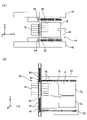
次に、図3(A)及び図3(B)を用いてマスクエンコーダシステム48の構成について説明する。図3(A)に模式的に示されるように、マスクホルダ40におけるマスクM(より詳細には、マスクMを収容するための不図示の開口部)の+Y側、及び-Y側の領域には、それぞれ複数のエンコーダスケール46(格子部材、格子部、グリッド部材などとも呼ぶが、以下、単にスケール46と称する)が配置されている。なお、理解を容易にするために、図3(A)では、複数のスケール46が実線で図示され、マスクホルダ40の上面に配置されているように図示されているが、複数のスケール46は、実際には、図1に示されるように、複数のスケール46それぞれの下面のZ位置と、マスクMの下面(パターン面)のZ位置とが一致するように、マスクホルダ40の下面側に配置されている。複数のスケール46はそれぞれ、反射型の2次元格子または配列方向(周期方向)が異なる(例えば直交する)2つの反射型の1次元格子が形成される格子領域(格子部)を有し、マスクホルダ40の下面側でY軸方向に関してマスクMの載置領域(前述の開口部を含む)の両側にそれぞれ、X軸方向に関して格子領域が互いに離れて配置されるように複数のスケール46が設けられる。なお、X軸及びY軸方向ともスケール46の全域に渡って格子を形成しても良いが、スケール46の端部で精度良く格子を形成するのが困難であるため、本実施形態ではスケール46において格子領域の周囲が余白部となるように格子を形成する。このため、X軸方向に関して隣接する一対のスケール46の間隔よりも格子領域の間隔の方が広くなっており、計測ビームが格子領域外に照射されている間は位置計測が不能な非計測期間(非計測区間とも呼ぶが、以下では非計測期間と総称する)となる。
Next, the configuration of the
本実施形態のマスクホルダ40において、マスクMの載置領域の+Y側、及び-Y側の領域には、それぞれスケール46がX軸方向に所定間隔で、例えば3つ配置されている。すなわち、マスクホルダ40は、合計で、例えば6つのスケール46を有している。複数のスケール46それぞれは、マスクMの+Y側と-Y側とで紙面上下対称に配置されている点を除き、実質的に同じものである。スケール46は、例えば石英ガラスにより形成されたX軸方向に延びる平面視矩形の板状(帯状)の部材から成る。マスクホルダ40は、例えばセラミックスにより形成され、複数のスケール46は、マスクホルダ40に固定されている。本実施形態では、X軸方向に関して互いに離れて配置される複数のスケール46の代わりに1つ(単一)のスケールをマスクホルダ用スケールとして用いても良い。この場合、格子領域も1つで良いが、複数の格子領域をX軸方向に離して1つのスケールに形成しても良い。
In the
図3(B)に示されるように、スケール46の下面(本実施形態では、-Z側を向いた面)における、幅方向一側(図3(B)では、-Y側)の領域には、Xスケール47xが形成されている。また、スケール46の下面における、幅方向他側(図3(B)では、+Y側)の領域には、Yスケール47yが形成されている。Xスケール47xは、X軸方向に所定ピッチで形成された(X軸方向を周期方向とする)Y軸方向に延びる複数の格子線を有する反射型の回折格子(Xグレーティング)によって構成されている。同様に、Yスケール47yは、Y軸方向に所定ピッチで形成された(Y軸方向を周期方向とする)X軸方向に延びる複数の格子線を有する反射型の回折格子(Yグレーティング)によって構成されている。本実施形態のXスケール47x、及びYスケール47yにおいて、複数の格子線は、例えば10nm以下の間隔で形成されている。なお、図3(A)及び図3(B)では、図示の便宜上、格子間の間隔(ピッチ)は、実際よりも格段に広く図示されている。その他の図も同様である。
As shown in FIG. 3(B), on the lower surface of the scale 46 (in this embodiment, the surface facing the -Z side), in the region on one side in the width direction (the -Y side in FIG. 3(B)) has an
また、図1に示されるように、上架台部18aの上面には、一対のエンコーダベース43が固定されている。一対のエンコーダベース43は、一方が+X側のマスクガイド42の-X側、他方が-X側のマスクガイド42の+X側(すなわち一対のマスクガイド42の間の領域)に配置されている。また、上記投影光学系16の一部が、一対のエンコーダベース43の間に配置されている。エンコーダベース43は、図3(A)に示されるように、X軸方向に延びる部材から成る。一対のエンコーダベース43それぞれの長手方向中央部には、エンコーダヘッドユニット44(以下、単にヘッドユニット44と称する)が固定されている。すなわち、ヘッドユニット44は、エンコーダベース43を介して装置本体18(図1参照)に固定されている。一対のヘッドユニット44は、マスクMの+Y側と-Y側とで紙面上下対称に配置されている点を除き、実質的に同じものであるので、以下、一方(-Y側)についてのみ説明する。
Further, as shown in FIG. 1, a pair of
図3(B)に示されるように、ヘッドユニット44は、X軸方向に配置される複数のスケール46の少なくとも1つに照射される計測ビームの位置がX軸及びY軸方向の少なくとも一方に関して異なる複数のヘッドを有し、平面視矩形の板状部材から成るユニットベース45を有している。ユニットベース45には、X軸方向に関して隣接する一対のXスケール47x(格子領域)の間隔よりも広い間隔で計測ビームを照射し、互いに離間して配置された一対のXヘッド49x、及びX軸方向に関して隣接する一対のYスケール47y(格子領域)の間隔よりも広い間隔で計測ビームを照射し、互いに離間して配置された一対のYヘッド49yが固定されている。すなわち、マスクエンコーダシステム48は、Xヘッド49xを、例えばY軸方向に関してマスクホルダ40のマスクMの載置領域の両側にそれぞれ一対ずつ、計4つ有するとともに、Yヘッド49yを、例えばY軸方向に関してマスクMの載置領域の両側にそれぞれ一対ずつ、計4つ有している。なお、一対のXヘッド49x又は一対のYヘッド49yはそれぞれ、一対のXスケール49x又は一対のYスケール49yの間隔よりも広く離間して配置されている必要はなく、スケール間隔と同程度以下の間隔で配置されていても、あるいは互いに接触して配置されていても良く、要はX軸方向に関して一対の計測ビームがスケール間隔よりも広い間隔で配置されていれば良い。また、図3(B)では、一方のXヘッド49xと一方のYヘッド49yとが1つの筐体内に収容され、他方のXヘッド49xと他方のYヘッド49yとが別の1つの筐体内に収容されているが、上記一対のXヘッド49x、及び一対のYヘッド49yは、それぞれ独立して配置されていても良い。また、図3(B)では、理解を容易にするため、一対のXヘッド49xと一対のYヘッド49yとがスケール46の上方(+Z側)に配置されたように図示されているが、実際には、一対のXヘッド49xは、Xスケール47yの下方に、一対のYヘッド49yは、Yスケール47yの下方にそれぞれ配置されている(図1参照)。
As shown in FIG. 3(B), the
一対のXヘッド49x、及び一対のYヘッド49yは、例えば振動などに起因して一対のXヘッド49x(計測ビーム)の少なくとも一方の位置(特に計測方向(X軸方向)の位置)あるいはヘッド(計測ビーム)間隔、及び一対のYヘッド49y(計測ビーム)の少なくとも一方の位置(特に計測方向(Y軸方向)の位置)あるいはヘッド(計測ビーム)間隔が変化しないように、ユニットベース45に対して固定されている。また、ユニットベース45自体も、一対のXヘッド49xの位置や間隔、及び一対のYヘッド49yの位置や間隔が、例えば温度変化などに起因して変化しないように、熱膨張率がスケール46より低い(あるいはスケール46と同等の)材料で形成されている。
The pair of X heads 49x and the pair of Y heads 49y may move due to, for example, vibration, at least one position of the pair of X heads 49x (measurement beams) (especially the position in the measurement direction (X-axis direction)) or the head ( In order not to change the measurement beam) interval and the position of at least one of the pair of Y heads 49y (measurement beams) (especially the position in the measurement direction (Y-axis direction)) or the head (measurement beam) interval, is fixed. The
Xヘッド49x、及びYヘッド49yは、例えば米国特許出願公開第2008/0094592号明細書に開示されるような、いわゆる回折干渉方式のエンコーダヘッドであり、対応するスケール(Xスケール47x、Yスケール47y)に計測ビームを照射し、そのスケールからのビームを受光することにより、マスクホルダ40(すなわち、マスクM。図3(A)参照)の変位量情報を主制御装置90(図8参照)に供給する。すなわち、マスクエンコーダシステム48では、例えば4つのXヘッド49xと、該Xヘッド49xに対向するXスケール47x(マスクホルダ40のX位置によって異なる)とによって、マスクMのX軸方向の位置情報を求めるための、例えば4つのXリニアエンコーダ92x(図3(B)では不図示。図8参照)が構成され、例えば4つのYヘッド49yと、該Yヘッド49yに対向するYスケール47y(マスクホルダ40のX位置によって異なる)とによって、マスクMのY軸方向の位置情報を求めるための、例えば4つのYリニアエンコーダ92y(図3(B)では不図示。図8参照)が構成される。本実施形態では、XY平面内の異なる2方向(本実施形態ではX軸及びY軸方向と一致)の一方を計測方向とするヘッドを用いているが、計測方向がX軸及びY軸方向の一方と異なるヘッドを用いても良い。例えば、XY平面内でX軸又はY軸方向に対して45度回転した方向を計測方向とするヘッドを用いても良い。また、XY平面内の異なる2方向の一方を計測方向とする1次元ヘッド(Xヘッド又はYヘッド)の代わりに、例えばX軸及びY軸方向の一方とZ軸方向との2方向を計測方向とする2次元ヘッド(XZヘッド又はYZヘッド)を用いても良い。この場合、上記3自由度方向(X軸及びY軸方向とθz方向)と異なる3自由度方向(Z軸方向とθx及びθy方向を含み、θx方向はローリング情報、θy方向はピッチング情報)に関するマスクホルダ40の位置情報も計測可能となる。
The
主制御装置90は、図8に示されるように、例えば4つのXリニアエンコーダ92x、及び、例えば4つのYリニアエンコーダ92yの出力に基づいてマスクホルダ40(図3(A)参照)のX軸方向、及びY軸方向の位置情報を、例えば10nm以下の分解能で求める。また、主制御装置90は、例えば4つのXリニアエンコーダ92x(あるいは、例えば4つのYリニアエンコーダ92y)のうちの少なくとも2つの出力に基づいてマスクホルダ40のθz位置情報(回転量情報)を求める。主制御装置90は、上記マスクエンコーダシステム48の計測値から求められたマスクホルダ40のXY平面内の3自由度方向の位置情報に基づき、マスク駆動系91を用いてマスクホルダ40のXY平面内の位置を制御する。
As shown in FIG. 8, the
ここで、図3(A)に示されるように、マスクホルダ40には、上述したように、マスクMの+Y側、及び-Y側の領域それぞれにスケール46がX軸方向に所定間隔で、例えば3つ配置されている。また、少なくとも基板Pの走査露光において、上記X軸方向に所定間隔で配置された、例えば3つのスケール46のうち、最も+X側のスケール46にヘッドユニット44(一対のXヘッド49x、一対のYヘッド49y(それぞれ図3(B)参照)の全て)が対向する位置と、最も-X側のスケール46にヘッドユニット44が対向する位置との間で、マスクホルダ40がX軸方向に駆動される。なお、マスクMの交換動作とプリアライメント動作との少なくとも一方において、X軸方向に関して照明光ILが照射される照明領域から離れるようにマスクホルダ40を移動し、ヘッドユニット44の少なくとも1つのヘッドがスケール46から外れる場合には、X軸方向に関してヘッドユニット44から離れて配置される少なくとも1つのヘッドを設け、交換動作やプリアライメント動作においてもマスクエンコーダシステム48によるマスクホルダ40の位置計測を継続可能としても良い。
Here, as shown in FIG. 3A, as described above, the
そして、本実施形態のマスクステージ装置14では、図3(B)に示されるように、1つのヘッドユニット44が有する一対のXヘッド49x、及び一対のYヘッド49yそれぞれの間隔が、複数のスケール46のうち隣接する一対のスケール46の間隔よりも広く設定されている。これにより、マスクエンコーダシステム48では、一対のXヘッド49xのうち常に少なくとも一方がXスケール47xに対向するとともに、一対のYヘッド49yのうちの少なくとも一方が常にYスケール47yに対向する。従って、マスクエンコーダシステム48は、マスクホルダ40(図3(A)参照)の位置情報を途切れさせることなく主制御装置90(図8参照)に供給することができる。
In the
具体的に説明すると、例えばマスクホルダ40(図3(A)参照)が+X側に移動する場合、マスクエンコーダシステム48は、隣接する一対のXスケール47xのうちの+X側のXスケール47xに対して一対のヘッド49xの両方が対向する第1の状態(図3(B)に示される状態)、-X側のXヘッド49xが上記隣接する一対のXスケール47xの間の領域に対向し(いずれのXスケール47xにも対向せず)、+X側のXヘッド49xが上記+X側のXスケール47xに対向する第2の状態、-X側のXヘッド49xが-X側のXスケール47xに対向し、且つ+X側のXヘッド49xが+X側のXスケール47xに対向する第3の状態、-X側のXヘッド49xが-X側のスケール47xに対向し、+X側のXヘッド49xが一対のXスケール47xの間の領域に対向する(いずれのXスケール47xにも対向しない)第4の状態、及び-X側のXスケール47xに対して一対のヘッド49xの両方が対向する第5の状態、を上記順序で移行する。従って、常に少なくとも一方のXヘッド49xがXスケール47xに対向する。
Specifically, for example, when the mask holder 40 (see FIG. 3A) moves to the +X side, the
主制御装置90(図8参照)は、上記第1、第3、及び第5の状態では、一対のXヘッド49xの出力の平均値に基づいてマスクホルダ40のX位置情報を求める。また、主制御装置90は、上記第2の状態では、+X側のXヘッド49xの出力のみに基づいてマスクホルダ40のX位置情報を求め、上記第4の状態では、-X側のXヘッド49xの出力のみに基づいてマスクホルダ40のX位置情報を求める。したがって、マスクエンコーダシステム48の計測値が途切れることがない。なお、第1、第3、第5の状態でも一対のXヘッド49xの一方の出力のみを用いてX位置情報を求めても良い。ただし、第2、第4の状態では、一対のヘッドユニット44の両方において一対のXヘッド49xの一方および一対のYヘッド49yの一方がスケール46から外れてマスクホルダ40のθz方向の位置情報(回転情報)を取得できなくなる。そこで、マスクMの載置領域に対して+Y側に配置される3つのスケール46と-Y側に配置される3つのスケール46とで、隣接する一対のスケール46の間隔(格子が形成されていない非格子領域)がX軸方向に関して重ならないように互いにずらして配置し、+Y側に配置される3つのスケール46と-Y側に配置される3つのスケール46との一方で、Xヘッド49xおよびYヘッド49yがスケール46から外れても、他方でXヘッド49xおよびYヘッド49yがスケール46から外れないようにすることが好ましい。または、X軸方向に関して一対のヘッドユニット44を、隣接する一対のスケール46の間隔(非格子領域の幅)よりも広い距離だけずらして配置しても良い。これにより、+Y側に配置される一対のXヘッド49xおよび-Y側に配置される一対のXヘッド49xの計4つのヘッドにおいて、X軸方向に関して計測ビームがスケール46の格子領域から外れる(計測不能な)非計測期間が重ならず、少なくとも走査露光においてマスクホルダ40のθz方向の位置情報を常時計測可能となる。なお、一対のヘッドユニット44の少なくとも一方において、一対のXヘッド49xおよび一対のYヘッド49yの少なくとも一方に対してX軸方向に関して離れて配置される少なくとも1つのヘッドを配置し、第2、第4の状態でもXヘッド49xおよびYヘッド49yの少なくとも一方で2つのヘッドがスケール46と対向するようにしても良い。
The main controller 90 (see FIG. 8) obtains the X position information of the
次に、基板エンコーダシステム50の構成について説明する。基板エンコーダシステム50は、図1に示されるように、基板ステージ装置20に配置された複数のエンコーダスケール52(図1では紙面奥行き方向に重なっている。図4(A)参照)、上架台部18aの下面に固定されたエンコーダベース54、エンコーダベース54の下面に固定された複数のエンコーダスケール56、及び一対のエンコーダヘッドユニット60を備えている。
Next, the configuration of the
図4(A)に模式的に示されるように、本実施形態の基板ステージ装置20において、基板P(基板載置領域)の+Y側、及び-Y側の領域には、それぞれエンコーダスケール52(以下、単にスケール52と称する)がX軸方向に所定間隔で、例えば5つ配置されている。すなわち、基板ステージ装置20は、合計で、例えば10のスケール52を有している。複数のスケール52それぞれは、基板Pの+Y側と-Y側とで紙面上下対称に配置されている点を除き、実質的に同じものである。スケール52は、上記マスクエンコーダシステム48のスケール46(それぞれ図3(A)参照)と同様に、例えば石英ガラスにより形成されたX軸方向に延びる平面視矩形の板状(帯状)の部材から成る。また、複数のスケール52はそれぞれ、反射型の2次元格子または配列方向(周期方向)が異なる(例えば直交する)2つの反射型の1次元格子が形成される格子領域(格子部)を有し、Y軸方向に関して基板載置領域の両側にそれぞれ、X軸方向に関して格子領域が互いに離れて配置されるように5つのスケール52が設けられる。
As schematically shown in FIG. 4A, in the
なお、図1及び図4(A)では、理解を容易にするために、複数のスケール52が基板ホルダ34の上面に固定されているように図示されているが、複数のスケール52は、実際には、図2に示されるように、基板ホルダ34とは離間した状態で、微動ステージ32にスケールベース51を介して固定されている(なお、図2には、複数のスケール52が基板Pの+X側及び-X側に配置される場合が示されている)。ただし、場合によっては、実際に基板ホルダ34上に複数のスケール52が固定されても良い。以下の説明では、複数のスケール52が基板ホルダ34上に配置されているのものとして説明を行う。なお、複数のスケール52は、基板ホルダ34を有し、少なくともZ軸方向とθxおよびθy方向に関して微動可能な基板テーブルの上面、あるいは基板テーブルを微動可能に支持する基板ステージの上面などに配置しても良い。
In FIGS. 1 and 4A, for ease of understanding, the plurality of
図4(B)に示されるように、スケール52の上面における、幅方向一側(図4(B)では、-Y側)の領域には、Xスケール53xが形成されている。また、スケール52の上面における、幅方向他側(図4(B)では、+Y側)の領域には、Yスケール53yが形成されている。Xスケール53x、及びYスケール53yの構成は、上記マスクエンコーダシステム48のスケール46(それぞれ図3(A)参照)に形成されたXスケール47x、及びYスケール47y(それぞれ図3(B)参照)と同じであるので説明を省略する。
As shown in FIG. 4(B), an
エンコーダベース54は、図5及び図6から分かるように、上架台部18aの下面に固定されたY軸方向に延びる板状の部材から成る第1部分54aと、第1部分54aの下面に固定されたY軸方向に延びるXZ断面U字状の部材から成る第2部分54bとを備え、全体的にY軸方向に延びる筒状に形成されている。図4(A)に示されるように、エンコーダベース54のX位置は、投影光学系16の中心のX位置と概ね一致しているが、エンコーダベース54と投影光学系16とが接触しないように配置されている。なお、エンコーダベース54は、投影光学系16と+Y側と-Y側とで分離して配置されていても良い。エンコーダベース54の下面には、図6に示されるように、一対Yリニアガイド63aが固定されている。一対のYリニアガイド63aは、それぞれY軸方向に延びる部材から成り、X軸方向に所定間隔で互いに平行に配置されている。
As can be seen from FIGS. 5 and 6, the
エンコーダベース54の下面には、複数のエンコーダスケール56(以下、単にスケール56と称する)が固定されている。本実施形態において、スケール56は、図1に示されるように、投影光学系16よりも+Y側の領域に、例えば2つ、投影光学系16よりも-Y側の領域に、例えば2つ、それぞれY軸方向に離間して配置されている。すなわち、エンコーダベース54には、合計で、例えば4つのスケール56が固定されている。複数のスケール56それぞれは、実質的に同じものである。スケール56は、Y軸方向に延びる平面視矩形の板状(帯状)の部材から成り、基板ステージ装置20に配置されたスケール52と同様に、例えば石英ガラスにより形成されている。複数のスケール56はそれぞれ、反射型の2次元格子または配列方向(周期方向)が異なる(例えば直交する)2つの反射型の1次元格子が形成される格子領域(格子部)を有しており、本実施形態ではスケール46、52と同様、X軸方向を配列方向(周期方向)とする1次元格子が形成されるXスケールと、Y軸方向を配列方向(周期方向)とする1次元格子が形成されるYスケールを有し、Y軸方向に関して投影光学系16の両側にそれぞれ、Y軸方向に関して格子領域が互いに離れて2つのスケール56が設けられる。なお、理解を容易にするために、図4(A)では、複数のスケール56が実線で図示され、エンコーダベース54の上面に配置されているように図示されているが、複数のスケール56は、実際には、図1に示されるようにエンコーダベース54の下面側に配置されている。なお、本実施形態では投影光学系16の+Y側と-Y側にそれぞれ2つのスケール56を設けるものとしたが、2つではなく1つあるいは3つ以上のスケール56を設けても良い。また、本実施形態では格子面を下方に向けて(格子領域がXY平面と平行になるように)スケール56を設けるものとしたが、例えば格子領域がYZ平面と平行になるようにスケール56を設けても良い。
A plurality of encoder scales 56 (hereinafter simply referred to as scales 56) are fixed to the bottom surface of the
図4(C)に示されるように、スケール56の下面における、幅方向一側(図4(C)では、+X側)の領域には、Xスケール57xが形成されている。また、スケール56の下面における、幅方向他側(図4(C)では、-X側)の領域には、Yスケール57yが形成されている。Xスケール57x、及びYスケール57yの構成は、上記マスクエンコーダシステム48のスケール46(それぞれ図3(A)参照)に形成されたXスケール47x、及びYスケール47y(それぞれ図3(B)参照)と同じであるので説明を省略する。
As shown in FIG. 4(C), an
図1に戻り、一対のエンコーダヘッドユニット60(以下、単にヘッドユニット60と称する)は、エンコーダベース54の下方にY軸方向に離間して配置されている。一対のヘッドユニット60それぞれは、図1で紙面左右対称に配置されている点を除き実質的に同じものであるので、以下一方(-Y側)について説明する。ヘッドユニット60は、図5に示されるように、Yスライドテーブル62、一対のXヘッド64x、一対のYヘッド64y(図5では一対のXヘッド64xの紙面奥側に隠れているため不図示。図4(C)参照)、一対のXヘッド66x(図5では一方のXヘッド66xは不図示。図4(B)参照)、一対のYヘッド66y(図5では一方のYヘッド66yは不図示。図4(B)参照)、及びYスライドテーブル62をY軸方向に駆動するためのベルト駆動装置68を備えている。なお、本実施形態の一対のヘッドユニット60は、90度回転している点を除き、マスクエンコーダシステム48の一対のヘッドユニット44と同一構成となっている。
Returning to FIG. 1, a pair of encoder head units 60 (hereinafter simply referred to as head units 60) are arranged below the
Yスライドテーブル62は、平面視矩形の板状の部材から成り、エンコーダベース54の下方に、該エンコーダベース54に対して所定のクリアランスを介して配置されている。また、Yスライドテーブル62のZ位置は、基板ステージ装置20が有する基板ホルダ34(それぞれ図1参照)のZ・チルト位置に関わらず、該基板ホルダ34よりも+Z側となるように設定されている。
The Y slide table 62 is made of a plate-like member that is rectangular in plan view, and is arranged below the
Yスライドテーブル62の上面には、図6に示されるように、上記Yリニアガイド63aに対して不図示の転動体(例えば循環式の複数のボール)を介してY軸方向にスライド自在に係合するYスライド部材63bが複数(1本のYリニアガイド63aに対して、例えば2つ(図5参照))固定されている。Yリニアガイド63aと、該Yリニアガイド63aに対応するYスライド部材63bとは、例えば米国特許第6,761,482号明細書に開示されるように機械的なYリニアガイド装置63を構成しており、Yスライドテーブル62は、一対のYリニアガイド装置63を介してエンコーダベース54に対してY軸方向に直進案内される。
As shown in FIG. 6, the upper surface of the Y slide table 62 is engaged with the Y
ベルト駆動装置68は、図5に示されるように、回転駆動装置68a、プーリ68b、及びベルト68cを備えている。なお、-Y側のYスライドテーブル62駆動用と+Y側のYスライドテーブル62(図5では不図示。図4(A)参照)駆動用とで、独立してベルト駆動装置68が配置されても良いし、ひとつのベルト駆動装置68で一対のYスライドテーブル62を一体的に駆動しても良い。
The
回転駆動装置68aは、エンコーダベース54に固定され、不図示の回転モータを備えている。該回転モータの回転数、回転方向は、主制御装置90(図8参照)により制御される。プーリ68bは、回転駆動装置68aによりX軸に平行な軸線回りに回転駆動される。また、不図示であるが、ベルト駆動装置68は、上記プーリ68bに対してY軸方向に離間して配置され、X軸に平行な軸線回りに回転自在の状態でエンコーダベース54に取り付けられた別のプーリを有している。ベルト68cは、一端、及び他端がYスライドテーブル62に接続されるとともに、長手方向の中間部の2箇所が上記プーリ68b、及び上記別のプーリ(不図示)に所定の張力が付与された状態で巻き掛けられている。ベルト68cの一部は、エンコーダベース54内に挿通されており、例えばベルト68cからの粉塵がスケール52、56に付着することなどが抑制されている。Yスライドテーブル62は、プーリ68bが回転駆動されることにより、ベルト68cに牽引されてY軸方向に所定のストロークで往復移動する。
The
主制御装置90(図8参照)は、一方(+Y側)のヘッドユニット60を投影光学系16よりも+Y側に配置された、例えば2つのスケール56の下方で、他方(-Y側)のヘッドユニット60を投影光学系16よりも-Y側に配置された、例えば2つのスケール56の下方で、Y軸方向に所定のストロークで適宜同期駆動する。ここで、基板ステージ装置20のY軸方向への移動に同期して一対のヘッドユニット60をそれぞれ移動しても良いが、本実施形態では、一対のヘッドユニット60でそれぞれ、Y軸方向に関して一対のXヘッド66xおよび一対のYヘッド66yの計測ビームが全てスケール52の格子領域から外れない(少なくとも1つの計測ビームの格子領域への照射が維持される)ように一対のヘッドユニット60を移動する。なお、Yスライドテーブル62を駆動するアクチュエータとして、本実施形態では、歯付きのプーリ68bと、歯付きのベルト68cとを含むベルト駆動装置68が用いられているが、これに限られず、歯無しプーリとベルトとを含む摩擦車装置が用いられても良い。また、Yスライドテーブル62を牽引する可撓性部材は、ベルトに限られず、例えばロープ、ワイヤ、チェーンなどであっても良い。また、Yスライドテーブル62を駆動するためのアクチュエータの種類は、ベルト駆動装置68に限られず、例えばリニアモータ、送りネジ装置などの他の駆動装置であっても良い。
The main controller 90 (see FIG. 8) controls one (+Y side)
Xヘッド64x、Yヘッド64y(図5では不図示。図6参照)、Xヘッド66x、及びYヘッド66yそれぞれは、上述したマスクエンコーダシステム48が有するXヘッド49x、Yヘッド49yと同様の、いわゆる回折干渉方式のエンコーダヘッドであり、Yスライドテーブル62に固定されている。ここで、ヘッドユニット60において、一対のYヘッド64y、一対のXヘッド64x、一対のYヘッド66y、及び一対のXヘッド66xは、それぞれの相互間の距離が、例えば振動などに起因して変化しないように、Yスライドテーブル62に対して固定されている。また、Yスライドテーブル62自体も、一対のYヘッド64y、一対のXヘッド64x、一対のYヘッド66y、及び一対のXヘッド66xそれぞれの相互間の距離が、例えば温度変化に起因して変化しないように、熱膨張率がスケール52、56より低い(あるいはスケール52、56と同等の)材料で形成されている。
The
図7に示されるように、一対のXヘッド64xそれぞれは、Xスケール57xの上のY軸方向に互いに離間した2箇所(2点)に計測ビームを照射し、一対のYヘッド64yそれぞれは、Yスケール57y上のY軸方向に互いに離間した2箇所(2点)に計測ビームを照射する。基板エンコーダシステム50では、上記Xヘッド64x、及びYヘッド64yが対応するスケールからのビームを受光することにより、Yスライドテーブル62(図7では不図示。図5及び図6参照)の変位量情報を主制御装置90(図8参照)に供給する。すなわち、基板エンコーダシステム50では、例えば4つのXヘッド64xと、該Xヘッド64xに対向するXスケール57x(Yスライドテーブル62のY位置によって異なる)とによって、一対のYスライドテーブル62(すなわち一対のヘッドユニット60(図1参照))それぞれのY軸方向の位置情報を求めるための、例えば4つのXリニアエンコーダ96x(図7では不図示。図8参照)が構成され、例えば4つのYヘッド64yと、該Yヘッド64yに対向するYスケール57y(Yスライドテーブル62のY位置によって異なる)とによって、一対のYスライドテーブル62それぞれのY軸方向の位置情報を求めるための、例えば4つのYリニアエンコーダ96y(図7では不図示。図8参照)が構成される。
As shown in FIG. 7, each of the pair of X heads 64x irradiates measurement beams at two locations (two points) separated from each other in the Y-axis direction on the
主制御装置90は、図8に示されるように、例えば4つのXリニアエンコーダ96x、及び、例えば4つのYリニアエンコーダ96yの出力に基づいて、一対のヘッドユニット60(図1参照)それぞれのX軸方向、及びY軸方向の位置情報を、例えば10nm以下の分解能で求める。また、主制御装置90は、一方のヘッドユニット60に対応する、例えば2つのXリニアエンコーダ96x(あるいは、例えば2つのYリニアエンコーダ96y)の出力に基づいて該一方のヘッドユニット60のθz位置情報(回転量情報)を、他方のヘッドユニット60に対応する、例えば2つのXリニアエンコーダ96x(あるいは、例えば2つのYリニアエンコーダ96y)の出力に基づいて該他方のヘッドユニット60のθz位置情報(回転量情報)をそれぞれ求める。主制御装置90は、一対のヘッドユニット60それぞれのXY平面内の位置情報に基づき、ベルト駆動装置68を用いてヘッドユニット60のY軸方向の位置を制御する。
As shown in FIG. 8, the
ここで、図4(A)に示されるように、エンコーダベース54には、上述したように、投影光学系16の+Y側、及び-Y側の領域それぞれにスケール56がY軸方向に所定間隔で、例えば2つ配置されている。また、上記Y軸方向に所定間隔で配置された、例えば2つのスケール56のうち、+Y側のスケール56にヘッドユニット60(一対のXヘッド64x、一対のYヘッド64y(それぞれ図4(C)参照)の全て)が対向する位置と、-Y側のスケール56にヘッドユニット60が対向する位置との間で、Yスライドテーブル62がY軸方向に駆動される。
Here, as shown in FIG. 4A, the
そして、上記マスクエンコーダシステム48と同様に、基板エンコーダシステム50においても、ひとつのヘッドユニット60が有する一対のXヘッド64x、及び一対のYヘッド64yそれぞれの間隔は、図4(C)に示されるように、隣接するスケール56間の間隔よりも広く設定されている。これにより、基板エンコーダシステム50では、一対のXヘッド64xのうち常に少なくとも一方がXスケール57xに対向するとともに、一対のYヘッド64yのうちの少なくとも一方が常にYスケール57yに対向する。従って、基板エンコーダシステム50は、計測値を途切れさせることなくYスライドテーブル62(ヘッドユニット60)の位置情報を求めることができる。
Similarly to the
また、図7に示されるように、一対のXヘッド66xそれぞれは、Xスケール53xの上のX軸方向に互いに離間した2箇所(2点)に計測ビームを照射し、一対のYヘッド66yそれぞれは、Yスケール53y上のX軸方向に互いに離間した2箇所(2点)に計測ビームを照射する。基板エンコーダシステム50では、上記Xヘッド66x、及びYヘッド66yが対応するスケールからのビームを受光することにより、基板ホルダ34(図7では不図示。図2参照)の変位量情報を主制御装置90(図8参照)に供給する。すなわち、基板エンコーダシステム50では、例えば4つのXヘッド66xと、該Xヘッド66xに対向するXスケール53x(基板ホルダ34のX位置によって異なる)とによって、基板PのX軸方向の位置情報を求めるための、例えば4つのXリニアエンコーダ94x(図7では不図示。図8参照)が構成され、例えば4つのYヘッド66yと、該Yヘッド66yに対向するYスケール53y(基板ホルダ34のX位置によって異なる)とによって、基板PのY軸方向の位置情報を求めるための、例えば4つのYリニアエンコーダ94y(図7では不図示。図8参照)が構成される。
Also, as shown in FIG. 7, each of the pair of X heads 66x irradiates the measurement beams to two points (two points) separated from each other in the X-axis direction on the
主制御装置90は、図8に示されるように、例えば4つのXリニアエンコーダ94x、及び、例えば4つのYリニアエンコーダ94yの出力、並びに上記4つのXリニアエンコーダ96x、及び、例えば4つのYリニアエンコーダ96yの出力(すなわち、一対のヘッドユニット60それぞれのXY平面内の位置情報)に基づいて基板ホルダ34(図2参照)のX軸方向、及びY軸方向の位置情報を、例えば10nm以下の分解能で求める。また、主制御装置90は、例えば4つのXリニアエンコーダ94x(あるいは、例えば4つのYリニアエンコーダ94y)のうちの少なくとも2つの出力に基づいて基板ホルダ34のθz位置情報(回転量情報)を求める。主制御装置90は、上記基板エンコーダシステム50の計測値から求められた基板ホルダ34のXY平面内の位置情報に基づき、基板駆動系93を用いて基板ホルダ34のXY平面内の位置を制御する。
また、図4(A)に示されるように、基板ホルダ34には、上述したように、基板Pの+Y側、及び-Y側の領域それぞれにスケール52がX軸方向に所定間隔で、例えば5つ配置されている。また、上記X軸方向に所定間隔で配置された、例えば5つのスケール52のうち、最も+X側のスケール52にヘッドユニット60(一対のXヘッド66x、一対のYヘッド66y(それぞれ図4(B)参照)の全て)が対向する位置と、最も-X側のスケール52にヘッドユニット60が対向する位置との間で、基板ホルダ34がX軸方向に駆動される。
Further, as shown in FIG. 4A, the
そして、上記マスクエンコーダシステム48と同様に、ひとつのヘッドユニット60が有する一対のXヘッド66x、及び一対のYヘッド66yそれぞれの間隔は、図4(B)に示されるように、隣接するスケール52間の間隔よりも広く設定されている。これにより、基板エンコーダシステム50では、一対のXヘッド66xのうち常に少なくとも一方がXスケール53xに対向するとともに、一対のYヘッド66yのうちの少なくとも一方が常にYスケール53yに対向する。従って、基板エンコーダシステム50は、計測値を途切れさせることなく基板ホルダ34(図4(A)参照)の位置情報を求めることができる。
Then, similarly to the
なお、基板エンコーダシステム50の一対のヘッドユニット60のそれぞれが有する一対のYヘッド64y、一対のXヘッド64x、一対のYヘッド66y、及び一対のXヘッド66x、並びにこれらのヘッドからの計測ビームが照射されるスケール56、52について、前述したマスクエンコーダシステム48を構成するヘッド、スケールに関して説明した全ての説明(なお書き含む)の構成を同様に適用することができる。
A pair of Y heads 64y, a pair of X heads 64x, a pair of Y heads 66y, and a pair of X heads 66x possessed by each of the pair of
図6に戻り、防塵カバー55は、XZ断面U字状に形成されたY軸方向に延びる部材から成り、一対の対向面間に上述したエンコーダベース54の第2部分54b、及びYスライドテーブル62が所定のクリアランスを介して挿入されている。防塵カバー55の下面には、Xヘッド66x、及びYヘッド66yを通過させる開口部が形成されている。これにより、Yリニアガイド装置63、ベルト68cなどから発生する粉塵がスケール52に付着することが抑制される。また、エンコーダベース54の下面には、一対の防塵板55a(図5では不図示)が固定されている。スケール56は、一対の防塵板55a間に配置されており、Yリニアガイド装置63などから発生する粉塵がスケール56に付着することが抑制される。
Returning to FIG. 6, the
図8には、液晶露光装置10(図1参照)の制御系を中心的に構成し、構成各部を統括制御する主制御装置90の入出力関係を示すブロック図が示されている。主制御装置90は、ワークステーション(又はマイクロコンピュータ)等を含み、液晶露光装置10の構成各部を統括制御する。
FIG. 8 shows a block diagram showing the input/output relationship of a
上述のようにして構成された液晶露光装置10(図1参照)では、主制御装置90(図8参照)の管理の下、不図示のマスクローダによって、マスクステージ装置14上へのマスクMのロードが行われるとともに、不図示の基板ローダによって、基板ステージ装置20(基板ホルダ34)上への基板Pのロードが行われる。その後、主制御装置90により、不図示のアライメント検出系を用いてアライメント計測(基板Pの複数のアライメントマークの検出)が実行され、そのアライメント計測の終了後、基板P上に設定された複数のショット領域に逐次ステップ・アンド・スキャン方式の露光動作が行われる。なお、アライメント計測動作においても基板エンコーダシステム50によって基板ホルダ34の位置情報が計測される。
In the liquid crystal exposure apparatus 10 (see FIG. 1) configured as described above, a mask loader (not shown) loads the mask M onto the
次に、露光動作時におけるマスクステージ装置14、及び基板ステージ装置20の動作の一例を、図9(A)~図16(B)を用いて説明する。なお、以下の説明では、1枚の基板P上に4つのショット領域が設定された場合(いわゆる4面取りの場合)を説明するが、1枚の基板P上に設定されるショット領域の数、及び配置は、適宜変更可能である。
Next, an example of operations of the
図9(A)には、アライメント動作が完了した後のマスクステージ装置14が、図9(B)には、アライメント動作が完了した後の基板ステージ装置20(ただし基板ホルダ34以外の部材は不図示。以下、同じ)がそれぞれ示されている。露光処理は、一例として、図9(B)に示されるように、基板Pの-Y側かつ+X側に設定された第1ショット領域S1から行われる。マスクステージ装置14では、図9(A)に示されるように、照明系12からの照明光IL(それぞれ図1参照)が照射される照明領域(ただし、図9(A)に示される状態では、まだマスクMに対し照明光ILは照射されていない)よりもマスクMの+X側の端部が幾分-X側に位置するように、マスクエンコーダシステム48(図8参照)の出力に基づいてマスクMの位置決めがされる。具体的には、例えば、照明領域に対してマスクMのパターン領域の+X側の端部が、所定の速度で走査露光するために必要な助走距離(すなわち、所定の速度に達するために必要な加速距離)だけ-X側に配置され、その位置においてマスクエンコーダシステム48によりマスクMの位置が計測できるようにスケール46が設けられている。また、基板ステージ装置20では、図9(B)に示されるように、投影光学系16からの照明光IL(図1参照)が照射される露光領域(ただし、図9(B)に示される状態では、まだ基板Pに対し照明光ILは照射されていない)よりも第1ショット領域S1の+X側の端部が幾分-X側に位置するように、基板エンコーダシステム50(図8参照)の出力に基づいて基板Pの位置決めがされる。具体的には、例えば、露光領域に対して基板Pの第1ショット領域S1の+X側の端部が、所定の速度で走査露光するために必要な助走距離(すなわち、所定の速度に達するために必要な加速距離)だけ-X側に配置され、その位置において基板エンコーダシステム50により基板Pの位置が計測できるようにスケール52が設けられている。なお、ショット領域の走査露光を終えてマスクMおよび基板Pをそれぞれ減速する側においても、同様に走査露光時の速度から所定の速度まで減速させるために必要な減速距離だけマスクMおよび基板Pをさらに移動させるまでマスクエンコーダシステム48、基板エンコーダシステム50によりそれぞれマスクM、基板Pの位置を計測可能なようにスケール46,52が設けられている。あるいは、加速中および減速中の少なくとも一方の動作中には、マスクエンコーダシステム48、基板エンコーダシステム50とは別の計測系によってマスクMおよび基板Pの位置をそれぞれ計測できるようにしても良い。
9A shows the
次いで、図10(A)に示されるように、マスクホルダ40が+X方向に駆動(加速、等速駆動、及び減速)されるとともに、該マスクホルダ40に同期して、図10(B)に示されるように、基板ホルダ34が+X方向に駆動(加速、等速駆動、及び減速)される。マスクホルダ40が駆動される際、主制御装置90(図8参照)は、マスクエンコーダシステム48(図8参照)の出力に基づいてマスクMの位置制御を行うとともに、基板エンコーダシステム50(図8参照)の出力に基づいて基板Pの位置制御を行う。基板ホルダ34がX軸方向に駆動される際、一対のヘッドユニット60は、静止状態とされる。マスクホルダ40、及び基板ホルダ34がX軸方向に等速駆動される間、基板Pには、マスクM及び投影光学系16を通過した照明光IL(それぞれ図1参照)が照射され、これによりマスクMが有するマスクパターンがショット領域S1に転写される。
Next, as shown in FIG. 10A, the
基板P上の第1ショット領域S1に対するマスクパターンの転写が完了すると、基板ステージ装置20では、図11(B)に示されるように、第1ショット領域S1の+Y側の設定された第2ショット領域S2への露光動作のために、基板ホルダ34が-Y方向に所定距離(基板Pの幅方向寸法のほぼ半分の距離)、基板エンコーダシステム50(図8参照)の出力に基づいて駆動(Yステップ)される。上記基板ホルダ34のYステップ動作時において、マスクホルダ40は、図11(A)に示されるように、マスクMの-X側の端部が照明領域(ただし、図11(A)に示される状態では、マスクMは照明されない)よりも幾分+X側に位置した状態で静止している。
When the transfer of the mask pattern to the first shot area S1 on the substrate P is completed, the
ここで、図11(B)に示されるように、上記基板ホルダ34のYステップ動作時において、基板ステージ装置20では、一対のヘッドユニット60が、基板ホルダ34に同期してY軸方向に駆動される。すなわち、主制御装置90(図8参照)は、基板エンコーダシステム50(図8参照)のうち、Yリニアエンコーダ94yの出力に基づいて、基板ホルダ34を基板駆動系93(図8参照)を介して目標位置までY軸方向に駆動しつつ、Yリニアエンコーダ96y(図8参照)の出力に基づいて、一対のヘッドユニット60を対応するベルト駆動装置68(図8参照)を介してY軸方向に駆動する。この際、主制御装置90は、一対のヘッドユニット60と基板ホルダ34とを同期して(一対のヘッドユニット60が基板ホルダ34に追従するように)駆動する。従って、基板ホルダ34のY位置(基板ホルダ34の移動中も含む)に関わらず、Xヘッド66x、Yヘッド66y(それぞれ図7参照)から照射される計測ビームそれぞれが、Xスケール53x、Yスケール53y(それぞれ図7参照)から外れることがない。換言すると、基板ホルダ34をY軸方向に移動中(Yステップ動作中)にXヘッド66x、Yヘッド66yから照射される計測ビームそれぞれがXスケール53x、Yスケール53yから外れない程度、すなわちXヘッド66x、Yヘッド66yからの計測ビームによる計測が途切れない(計測を継続できる)程度に、一対のヘッドユニット60と基板ホルダ34とをY軸方向へ移動させれば良い。すなわち、一対のヘッドユニット60と基板ホルダ34とのY軸方向への移動は、同期、追従移動でなくても良い。
Here, as shown in FIG. 11B, during the Y step movement of the
基板ホルダ34のYステップ動作が完了すると、図12(A)に示されるように、マスクエンコーダシステム48(図8参照)の出力に基づいてマスクホルダ40が-X方向に駆動されるとともに、該マスクホルダ40に同期して、図12(B)に示されるように、基板エンコーダシステム50(図8参照)の出力に基づいて基板ホルダ34が-X方向に駆動される。これにより、第2ショット領域S2にマスクパターンが転写される。この際も一対のヘッドユニット60は、静止状態とされる。
When the Y step motion of the
第2ショット領域S2への露光動作が完了すると、マスクステージ装置14では、図13(A)に示されるように、マスクホルダ40が+X方向に駆動され、照明領域よりもマスクMの-X側の端部が幾分+X側に位置するように、マスクエンコーダシステム48(図8参照)の出力に基づいてマスクMの位置決めがされる。また、基板ステージ装置20では、図13(B)に示されるように、第2ショット領域S2の-X側に設定された第3ショット領域S3への露光動作のために、基板ホルダ34が+X方向に駆動され、露光領域よりも第3ショット領域S3の-X側の端部が幾分+X側に位置するように、基板エンコーダシステム50(図8参照)の出力に基づいて基板Pの位置決めがされる。図13(A)及び図13(A)に示されるマスクホルダ40、及び基板ホルダ34の移動動作時において、照明系12(図1参照)からは、照明光ILがマスクM(図13(A)参照)及び基板P(図13(B)参照)に対して照射されない。すなわち、図13(A)及び図13(B)に示されるマスクホルダ40、及び基板ホルダ34の移動動作は、単なるマスクM、及び基板Pの位置決め動作(Xステップ動作)である。
When the exposure operation to the second shot area S2 is completed, in the
マスクM、及び基板PのXステップ動作が完了すると、マスクステージ装置14では、図14(A)に示されるように、マスクエンコーダシステム48(図8参照)の出力に基づいてマスクホルダ40が-X方向に駆動されるとともに、該マスクホルダ40に同期して、図14(B)に示されるように、基板エンコーダシステム50(図8参照)の出力に基づいて基板ホルダ34が-X方向に駆動される。これにより、第3ショット領域S3にマスクパターンが転写される。この際も一対のヘッドユニット60は、静止状態とされる。
When the X step motion of the mask M and the substrate P is completed, the
第3ショット領域S3への露光動作が完了すると、基板ステージ装置20では、図15(B)に示されるように、第3ショット領域S3の-Y側の設定された第4ショット領域S4への露光動作のために、基板ホルダ34が+Y方向に所定距離、駆動(Yステップ駆動)される。この際、図11(B)に示される基板ホルダ34のYステップ動作時と同様に、マスクホルダ40は静止状態とされる(図15(A)参照)。また、一対のヘッドユニット60は、基板ホルダ34に同期して(基板ホルダ34に追従するように)+Y方向に駆動される。
When the exposure operation to the third shot area S3 is completed, the
基板ホルダ34のYステップ動作が完了すると、図16(A)に示されるように、マスクエンコーダシステム48(図8参照)の出力に基づいてマスクホルダ40が+X方向に駆動されるとともに、該マスクホルダ40に同期して、図16(B)に示されるように、基板エンコーダシステム50(図8参照)の出力に基づいて基板ホルダ34が+X方向に駆動される。これにより、第4ショット領域S4にマスクパターンが転写される。この際も一対のヘッドユニット60は、静止状態とされる。
When the Y step movement of the
以上説明したように、本実施形態に係る液晶露光装置10によれば、マスクMのXY平面内の位置情報を求めるためのマスクエンコーダシステム48、及び基板PのXY平面内の位置情報を求めるための基板エンコーダシステム50(それぞれ図1参照)それぞれは、対応するスケールに対して照射される計測ビームの光路長が短いので、例えば従来の干渉計システムに比べて空気揺らぎの影響を低減できる。従って、マスクM、及び基板Pの位置決め精度が向上する。また、空気揺らぎの影響が小さいので、従来の干渉計システムを用いる場合に必須となる部分空調設備を省略でき、コストダウンが可能となる。
As described above, according to the liquid
さらに、干渉計システムを用いる場合には、大きくて重いバーミラーをマスクステージ装置14、及び基板ステージ装置20に備える必要があったが、本実施形態に係るマスクエンコーダシステム48、及び基板エンコーダシステム50では、上記バーミラーが不要となるので、マスクホルダ40を含む系(例えば、マスクステージ装置)、及び基板ホルダ34を含む系(例えば、基板ステージ装置)それぞれが小型・軽量化するとともに重量バランスが良くなり、これによりマスクM、基板Pの位置制御性が向上する。また、干渉計システムを用いる場合に比べ、調整箇所が少なくて済むので、マスクステージ装置14、及び基板ステージ装置20のコストダウンし、さらにメンテナンス性も向上する。また、組み立て時の調整も容易(あるいは不要)となる。
Furthermore, when using an interferometer system, it was necessary to equip the
また、本実施形態に係る基板エンコーダシステム50では、Y軸方向への基板Pの移動(例えばステップ動作)において、一対のヘッドユニット60をY軸方向に駆動することにより、基板PのY位置情報を求める構成であるため、基板ステージ装置20側にY軸方向に延びるスケールを配置する、またはX軸方向に延びるスケールの幅をY軸方向に広げる必要(あるいは装置本体18側にY軸方向に複数のヘッドを配列する必要)がない。従って、基板位置計測系の構成をシンプルにすることができ、コストダウンが可能となる。
Further, in the
また、本実施形態に係るマスクエンコーダシステム48では、隣接する一対のエンコーダヘッド(Xヘッド49x、Yヘッド49y)の出力をマスクホルダ40のX位置に応じて適宜切り換えながら該マスクホルダ40のXY平面内の位置情報を求める構成であるので、複数のスケール46をX軸方向に所定間隔で(互いに離間して)配置しても、マスクホルダ40の位置情報を途切れることなく求めることができる。従って、マスクホルダ40の移動ストロークと同等の長さ(本実施形態のスケール46の約3倍の長さ)のスケールを用意する必要がなく、コストダウンが可能であり、特に本実施形態のような大型のマスクMを用いる液晶露光装置10に好適である。本実施形態に係る基板エンコーダシステム50も同様に、複数のスケール52がX軸方向に、複数のスケール56がY軸方向に、それぞれ所定間隔で配置されるので、基板Pの移動ストロークと同等の長さのスケールを用意する必要がなく、大型の基板Pを用いる液晶露光装置10に好適である。
Further, in the
なお、上記第1の実施形態では、一対のヘッドユニット60が、それぞれ基板ホルダ34の位置を計測するための4つのヘッド(各一対のXヘッド66x及びYヘッド66y)を有し、合計で8つの基板ホルダ位置計測用のヘッドが設けられた場合について説明したが、基板ホルダ位置計測用のヘッドの数は、8つより少なくても良い。以下では、このような実施形態について説明する。
In the first embodiment, each pair of
《第2の実施形態》
次に、第2の実施形態について図17~図20(C)に基づいて説明する。本第2の実施形態に係る液晶露光装置の構成は、基板エンコーダシステム50の一部の構成を除き、前述の第1の実施形態と同じなので、以下、相違点についてのみ説明し、第1の実施形態と同じ構成及び機能を有する要素については、第1の実施形態と同じ符号を付してその説明を省略する。
<<Second embodiment>>
Next, a second embodiment will be described with reference to FIGS. 17 to 20(C). The configuration of the liquid crystal exposure apparatus according to the second embodiment is the same as that of the above-described first embodiment, except for the configuration of a part of the
図17には、本第2の実施形態に係る基板ホルダ34及び基板エンコーダシステム50の一対のヘッドユニット60が、投影光学系16とともに平面図にて示されている。図17では、説明をわかり易くするため、エンコーダベース54等の図示が省略されている。また、図17では、ヘッドユニット60(Yスライドテーブル62)が点線で図示されるとともに、Yスライドテーブル62の上面に設けられたXヘッド64x、Yヘッド64yの図示も省略されている。
FIG. 17 shows a plan view of the
本第2の実施形態に係る液晶露光装置では、図17に示されるように、基板ホルダ34の基板載置領域を挟む+Y側、及び-Y側の領域に、それぞれエンコーダスケール152(以下、単にスケール152と称する)がX軸方向に関して格子領域が互いに離れて配置されるようにX軸方向に所定間隔で、例えば5つ配置されている。基板載置領域の+Y側に配置された5つのスケール152と、-Y側の領域に配置された5つのスケール152では、隣接するスケール152(格子領域)間の間隔は、同じであるが、その配置位置が、+Y側の5つのスケール152に対して、-Y側の5つのスケール152が全体的に、所定距離D(隣接するスケール152(格子領域)の間隔より幾分大きな距離)+X側にずれて配置されている。これは、基板ホルダ34の位置情報を計測する後述する2つのXヘッド66x及び2つのYヘッド66yの合計4つのヘッドのうちの2つ以上がいずれのスケールにも対向しない状態が発生しない(すなわち、4つのヘッドで計測ビームがスケールから外れる非計測期間が重ならない)ようにするためである。
In the liquid crystal exposure apparatus according to the second embodiment, as shown in FIG. 17, encoder scales 152 (hereinafter simply referred to as Scales 152) are arranged at predetermined intervals in the X-axis direction, for example five, such that the grid areas are arranged apart from each other in the X-axis direction. The five
各スケール152は、例えば石英ガラスにより形成されたX軸方向に延びる平面視矩形の板状(帯状)の部材から成る。各スケール152の上面には、X軸方向及びY軸方向を周期方向とする所定ピッチ(例えば1μm)の反射型の2次元回折格子(2次元グレーティング)RGが形成されている。以下では、前述の格子領域を単に2次元グレーティングRGとも呼ぶ。なお、図17では、図示の便宜上、2次元グレーティングRGの格子線間の間隔(ピッチ)は、実際よりも格段に広く図示されている。以下で説明するその他の図においても同様である。以下では、基板ホルダ34の+Y側の領域に配置された5つのスケール152を、第1格子群と称し、基板ホルダ34の-Y側の領域に配置された5つのスケール152を、第2格子群と称するものとする。
Each
+Y側に位置する一方のヘッドユニット60のYスライドテーブル62の下面(-Z側の面)には、スケール152にそれぞれ対向する状態で、Xヘッド66xとYヘッド66yがX軸方向に所定間隔(隣接するスケール152の間隔より大きな距離)離れて固定されている。同様に、-Y側に位置する他方のヘッドユニット60のYスライドテーブル62の下面(-Z側の面)には、スケール152にそれぞれ対向する状態で、Yヘッド66yとXヘッド66xがX軸方向に所定間隔離れて固定されている。すなわち、第1格子群と対向するXヘッド66xおよびYヘッド66yと、第2格子群と対向するXヘッド66xおよびYヘッド66yはそれぞれ、隣接するスケール152の格子領域の間隔よりも広い間隔で計測ビームをスケール152に照射する。以下では、説明の便宜上、一方のヘッドユニット60が有するXヘッド66x、Yヘッド66yを、それぞれヘッド66a、ヘッド66bと呼び、他方のヘッドユニット60が有するYヘッド66y、Xヘッド66xを、それぞれヘッド66c、ヘッド66dとも呼ぶものとする。
On the lower surface of the Y slide table 62 of one of the
この場合、ヘッド66aとヘッド66cが、同一のX位置(Y軸方向と平行な同一直線上)に配置され、ヘッド66bとヘッド66dが、ヘッド66aとヘッド66cのX位置と異なる、同一のX位置(Y軸方向と平行な同一直線上)に配置されている。ヘッド66a、66dとそれぞれ対向する2次元グレーティングRGとによって、一対のXリニアエンコーダが構成され、ヘッド66b、66cとそれぞれ対向する2次元グレーティングRGとによって、一対のYリニアエンコーダが構成されている。
In this case, the
本第2の実施形態に係る液晶露光装置では、ヘッドユニット60の残りの部分を含み、その他の部分の構成は、主制御装置90の基板エンコーダシステムを用いた基板ホルダ34の駆動制御(位置制御)を除き、前述した第1の実施形態に係る液晶露光装置10と同様になっている。
The liquid crystal exposure apparatus according to the second embodiment includes the remaining portion of the
本第2の実施形態に係る液晶露光装置では、図18(A)に示される、基板ホルダ34の+X端部に一対のヘッドユニット60が対向する第1位置と、図18(B)に示される、基板ホルダ34の-X端部に一対のヘッドユニット60が対向する第2位置との間で、基板ホルダ34がX軸方向に移動する範囲内で、一対のヘッドユニット60のヘッド66a~66d、すなわち一対のXリニアエンコーダ及び一対のYリニアエンコーダによる基板ホルダ34の位置計測が可能である。図18(A)は、ヘッド66bのみがいずれのスケール152にも対向していない状態を示し、図18(B)は、ヘッド66cのみがいずれのスケール152にも対向していない状態を示している。
In the liquid crystal exposure apparatus according to the second embodiment, the first position where the pair of
図18(A)に示される第1位置と図18(B)に示される第2位置との間で基板ホルダ34がX軸方向に移動する過程で、一対のヘッドユニット60とスケール152との位置関係は、図19(A)~図19(D)にそれぞれ示される第1の状態~第4の状態と、4つのヘッド66a~66dの全てが、いずれかのスケール152の2次元グレーティングRGに対向する(すなわち、4つのヘッド66a~66dの全てで計測ビームが2次元グレーティングRGに照射される)第5の状態との5つの状態の間で遷移する。以下では、ヘッドがスケール152の2次元グレーティングRGに対向する、あるいは計測ビームがスケール152の2次元グレーティングRGに照射されると言う代わりに、単にヘッドがスケールに対向すると表現する。
During the process of moving the
ここでは、説明の便宜上、6つのスケール152を取り上げ、各スケールにそれぞれ識別のための記号a~fを付して、スケール152a~152fと表記する(図19(A)参照)。
Here, for convenience of explanation, six
図19(A)の第1の状態は、ヘッド66aがスケール152bに対向し、且つヘッド66c、66dがスケール152eに対向し、ヘッド66bのみが、いずれのスケールにも対向しない状態を示し、図19(B)の第2の状態は、図19(A)の状態から基板ホルダ34が+X方向に所定距離移動してヘッド66a、66bがスケール152bに対向し、且つヘッド66dがスケール152eに対向し、ヘッド66cのみがいずれのスケールにも対向しなくなった状態を示す。図19(A)の状態から図19(B)の状態に遷移する過程で、ヘッド66a、66bがスケール152bに対向し、且つヘッド66c,66dが、スケール152eに対向する第5の状態を経由する。
FIG. 19A shows a first state in which
図19(C)の第3の状態は、図19(B)の状態から基板ホルダ34が+X方向に所定距離移動してヘッド66aのみがいずれのスケールにも対向しなくなった状態を示す。図19(B)の状態から図19(C)の状態に遷移する過程で、ヘッド66a、66bがスケール152bに対向し、且つヘッド66cがスケール152dに対向し、且つヘッド66dがスケール152eに対向する第5の状態を経由する。
A third state in FIG. 19C shows a state in which the
図19(D)の第4の状態は、図19(C)の状態から基板ホルダ34が+X方向に所定距離移動してヘッド66dのみがいずれのスケールにも対向しなくなった状態を示す。図19(C)の状態から図19(D)の状態に遷移する過程で、ヘッド66aがスケール152aに対向し、且つヘッド66bがスケール152bに対向し、且つヘッド66cがスケール152dに対向し、且つヘッド66dがスケール152eに対向する第5の状態を経由する。
A fourth state in FIG. 19D shows a state in which the
図19(D)の状態から、基板ホルダ34が所定距離+X方向に移動すると、ヘッド66aがスケール152aに対向し、且つヘッド66bがスケール152bに対向し、且つヘッド66c、66dがスケール152dに対向する第5の状態を経由した後、ヘッド66aがスケール152aに対向し、且つヘッド66c、66dがスケール152dに対向し、ヘッド66bのみが、いずれのスケールにも対向しない第1の状態となる。
When the
以上は、基板ホルダ34の±Y側にそれぞれ5つ配置されたスケール152のうちの各3つのスケール152と、一対のヘッドユニット60との間の状態(位置関係)の遷移についての説明であるが、10のスケール152と一対のヘッドユニット60との間でも、基板ホルダ34の±Y側にそれぞれ配置された5つのスケールのうちの隣接する各3つのスケール152について見れば、一対のヘッドユニット60との位置関係は、上述と同様の順序で遷移する。
The above is a description of the transition of the state (positional relationship) between each of the three
このように、本第2の実施形態では、基板ホルダ34がX軸方向に移動されても、2つのXヘッド66x、すなわちヘッド66a、66dと2つのYヘッド66y、すなわちヘッド66b、66cとの合計4つのうちの少なくとも3つが、常にいずれかのスケール152(2次元グレーティングRG)に対向する。さらに、基板ホルダ34がY軸方向に移動されても、4つのヘッドともY軸方向に関して計測ビームがスケール152(2次元グレーティングRG)から外れないように一対のYスライドテーブル62がY軸方向に駆動されるため、4つのヘッドの少なくとも3つが常にいずれかのスケール152に対向する。したがって、主制御装置90は、常時、ヘッド66a~66dのうちの3つを用いて、基板ホルダ34のX軸方向、Y軸方向及びθz方向の位置情報を管理することが可能である。以下、この点についてさらに説明する。
As described above, in the second embodiment, even if the
Xヘッド66x、Yヘッド66yの計測値を、それぞれCX、CYとすると、計測値CX,CYは、それぞれ、次式(1a)、(1b)で表すことができる。
Assuming that the measured values of the X
CX= (pi-X)cosθz+(qi-Y)sinθz ……(1a)
CY=-(pi-X)sinθz+(qi-Y)cosθz ……(1b)
ここで、X、Y、θzは、それぞれ基板ホルダ34のX軸方向、Y軸方向及びθz方向の位置を示す。また、pi、qiは、ヘッド66a~66dそれぞれのX位置(X座標値)、Y位置(Y座標値)である。本実施形態では、ヘッド66a、66b、66c、66dそれぞれのX座標値pi及びY座標値qi(i=1、2、3、4)は、前述の4つのXリニアエンコーダ96xと、4つのYリニアエンコーダ96yの出力から算出される一対のヘッドユニット60(図1参照)それぞれのX軸方向、及びY軸方向の位置情報(Yスライドテーブル62の中心のX軸方向、及びY軸方向の位置)から、各ヘッドのYスライドテーブル62の中心に対する既知の位置関係に基づいて簡単に算出することができる。
C X = (p i −X)cos θz+(q i −Y)sin θz (1a)
C Y =−(p i −X) sin θz+(q i −Y) cos θz (1b)
Here, X, Y, and θz indicate positions of the
したがって、基板ホルダ34と一対のヘッドユニット60とが図18(A)に示されるような位置関係にあり、このとき基板ホルダ34のXY平面内の3自由度方向の位置が(X、Y、θz)であるものとすると、3つのヘッド66a、66c、66dの計測値は、理論上、次の式(2a)~(2c)(アフィン変換の関係とも呼ぶ)で表すことができる。
Therefore, the
C1= (p1-X)cosθz+(q1-Y)sinθz ……(2a)
C3=-(p3-X)sinθz+(q3-Y)cosθz ……(2b)
C4= (p4-X)cosθz+(q4-Y)sinθz ……(2c)
基板ホルダ34が座標原点(X,Y、θz)=(0,0,0)にある基準状態では、連立方程式(2a)~(2c)より、C1=p1,C3=q3,C4=p4となる。基準状態は、例えば投影光学系16による投影領域の中心に、基板ホルダ34中心(基板Pの中心にほぼ一致)が一致し、θz回転がゼロの状態である。したがって、基準状態では、ヘッド66bによる基板ホルダ34のY位置の計測も可能となっており、ヘッド66bによる計測値C2は、式(1b)に従い、C2=q2となる。
C 1 = (p 1 −X)cos θz+(q 1 −Y)sin θz (2a)
C 3 =−(p 3 −X) sin θz+(q 3 −Y)cos θz (2b)
C 4 = (p 4 −X)cos θz+(q 4 −Y)sin θz (2c)
In the reference state where the
従って、基準状態において、3つのヘッド66a、66c、66dの計測値を、それぞれp1,q3,p4と初期設定すれば、以降基板ホルダ34の変位(X,Y,θz)に対して、3つのヘッド66a、66c、66dは、式(2a)~(2c)で与えられる理論値を提示することになる。
Therefore, if the measured values of the three
なお、基準状態において、ヘッド66a、66c、66dのいずれか1つ、例えばヘッド66cに代えて、ヘッド66bの計測値C2を、q2に初期設定しても良い。
In the reference state, one of the
この場合には、以降基板ホルダ34の変位(X,Y,θz)に対して、3つのヘッド66a、66b、66dは、式(2a)、(2c)、(2d)で与えられる理論値を提示することになる。
In this case, the three
C1= (p1-X)cosθz+(q1-Y)sinθz ……(2a)
C4= (p4-X)cosθz+(q4-Y)sinθz ……(2c)
C2=-(p2-X)sinθz+(q2-Y)cosθz ……(2d)
連立方程式(2a)~(2c)及び連立方程式(2a)、(2c)、(2d)では、変数が3つ(X,Y,θz)に対して3つの式が与えられている。従って、逆に、連立方程式(2a)~(2c)における従属変数C1,C3,C4、あるいは連立方程式(2a)、(2c)、(2d)における従属変数C1,C4,C2が与えられれば、変数X,Y,θzを求めることができる。ここで、近似sinθz≒θzを適用すると、あるいはより高次の近似を適用しても、容易に方程式を解くことができる。従って、ヘッド66a、66c、66d(又はヘッド66a、66b、66d)の計測値C1,C3,C4(又はC1,C2,C4)よりウエハステージWSTの位置(X,Y,θz)を算出することができる。
C 1 = (p 1 −X)cos θz+(q 1 −Y)sin θz (2a)
C 4 = (p 4 −X)cos θz+(q 4 −Y)sin θz (2c)
C 2 =−(p 2 −X) sin θz+(q 2 −Y) cos θz (2d)
In the simultaneous equations (2a) to (2c) and the simultaneous equations (2a), (2c) and (2d), three equations are given for three variables (X, Y, θz). Therefore, conversely, the dependent variables C 1 , C 3 , C 4 in the system of equations (2a) to (2c), or the dependent variables C 1 , C 4 , C in the system of equations (2a), (2c), (2d) Given 2 , the variables X, Y, and .theta.z can be determined. Here, applying the approximation sin θz≈θz, or even applying a higher order approximation, the equation can be easily solved. Therefore , the position ( X , Y , θz) can be calculated.
次に、本第2の実施形態に係る液晶露光装置で行われる、基板ホルダ34の位置情報を計測する、基板エンコーダシステムのヘッドの切り換え時におけるつなぎ処理、すなわち計測値の初期設定について、主制御装置90の動作を中心として説明する。
Next, the main control performs the connection processing at the time of switching the head of the substrate encoder system for measuring the position information of the
本第2の実施形態では、前述の如く、基板ホルダ34の有効ストローク範囲では常に3つのエンコーダ(Xヘッド及びYヘッド)が基板ホルダ34の位置情報を計測しており、エンコーダ(Xヘッド又はYヘッド)の切り換え処理を行う際には、例えば図20(B)に示されるように、4つのヘッド66a~66dのそれぞれが、いずれかのスケール152に対向し、基板ホルダ34の位置を計測可能な状態(前述の第5の状態)となる。図20(B)は、図20(A)に示されるように、ヘッド66a、66b及び66dで基板ホルダ34の位置を計測していた状態から、基板ホルダ34が+X方向に移動して、図20(C)に示されるように、ヘッド66b、66c、66dで基板ホルダ34の位置を計測する状態に遷移する途中で出現する第5の状態の一例を示す。すなわち、図20(B)は、基板ホルダ34の位置情報の計測に用いられる3つのヘッドが、ヘッド66a、66b、66dからヘッド66b、66c、66dに切り換えられている最中の状態を示す。
In the second embodiment, as described above, three encoders (X head and Y head) always measure the positional information of the
基板ホルダ34のXY平面内の位置制御(位置情報の計測)に用いられるヘッド(エンコーダ)の切り換え処理(つなぎ)を行おうとする瞬間において、図20(B)に示されるように、ヘッド66a、66b、66c及び66dが、それぞれスケール152b、152b、152d、152eに対向している。図20(A)から図20(C)を一見すると、図20(B)においてヘッド66aからヘッド66cに切り換えようとしているように見えるが、ヘッド66aとヘッド66cとでは、計測方向が異なることからも明らかなように、つなぎを行おうとするタイミングにおいてヘッド66aの計測値(カウント値)をそのままヘッド66cの計測値の初期値として与えても何の意味もない。
20(B), the
そこで、本実施形態では、主制御装置90が、3つのヘッド66a、66b及び66dを用いる基板ホルダ34の位置情報の計測(及び位置制御)から、3つのヘッド66b、66c、66dを用いる基板ホルダ34の位置情報の計測(及び位置制御)に切り換えるようになっている。すなわち、この方式は通常のエンコーダつなぎの概念とは異なり、あるヘッドから別のヘッドにつなぐというのではなく、3つのヘッド(エンコーダ)の組み合わせから別の3つのヘッド(エンコーダ)の組み合わせにつなぐものである。
Therefore, in the present embodiment, the
主制御装置90は、まず、ヘッド66a、66d及び66bの計測値C1,C4,C2に基づいて、連立方程式(2a)、(2c)、(2d)を解き、基板ホルダのXY平面内の位置情報(X,Y,θz)を算出する。
次に、主制御装置90は、次式(3)のアフィン変換の式に、上で算出したX,θzを代入して、ヘッド66cの計測値の初期値(ヘッド66cが計測すべき値)を求める。
Next,
C3=-(p3-X)sinθz+(q3-Y)cosθz ……(3)
上式(3)において、p3,q3は、ヘッド66cの計測点のX座標値、Y座標値である。本実施形態では、X座標値p3及びY座標値q3は、前述した通り、4つのXリニアエンコーダ96xと、4つのYリニアエンコーダ96yの出力から算出される一対のヘッドユニット60それぞれのYスライドテーブル62の中心のX軸方向、及びY軸方向の位置から、ヘッド66cのYスライドテーブル62の中心に対する既知の位置関係に基づいて算出された値が用いられる。
C 3 =−(p 3 −X) sin θz+(q 3 −Y) cos θz (3)
In the above equation (3), p 3 and q 3 are the X coordinate value and Y coordinate value of the measurement point of the
上記初期値C3をヘッド66cの初期値として与えることで、基板ホルダ34の3自由度方向の位置(X,Y,θz)を維持したまま、矛盾なくつなぎが完了することになる。それ以降は、切り換え後に使用するヘッド66b、66c、66dの計測値C2,C3,C4を用いて、次の連立方程式(2b)~(2d)を解いて、ウエハステージWSTの位置座標(X,Y,θz)を算出する。
By giving the initial value C3 as the initial value of the
C3=-(p3-X)sinθz+(q3-Y)cosθz ……(2b)
C4= (p4-X)cosθz+(q4-Y)sinθz ……(2c)
C2=-(p2-X)sinθz+(q2-Y)cosθz ……(2d)
なお、上では、3つのヘッドから、この3つのヘッドと異なる別のヘッドを1つ含む異なる3つのヘッドへの切り換えについて説明したが、これは切り換え前の3つのヘッドの計測値から求まる基板ホルダ34の位置(X、Y、θz)を用いて、切り換え後に用いられる別のヘッドで計測すべき値を、アフィン変換の原理に基づいて、算出し、その算出した値を、切り換え後に用いられる別のヘッドの初期値として設定しているため、このように説明した。しかしながら、切り換え後に用いられる別のヘッドで計測すべき値の算出等の手順には触れず、切り換え及びつなぎ処理の直接の対象である2つのヘッドにのみ注目すれば、切り換え前に使用している3つのヘッドのうちの1つのヘッドを別の1つのヘッドに切り換えているとも言える。いすれにしても、ヘッドの切り換えは、切り換え前に基板ホルダの位置情報の計測及び位置制御に用いられているヘッドと、切り換え後に用いられるヘッドとが、ともに、いずれかのスケール152に同時に対向している状態で行われる。
C 3 =−(p 3 −X) sin θz+(q 3 −Y)cos θz (2b)
C 4 = (p 4 −X)cos θz+(q 4 −Y)sin θz (2c)
C 2 =−(p 2 −X) sin θz+(q 2 −Y) cos θz (2d)
In the above description, switching from three heads to three different heads including one other head different from these three heads has been described. Using the positions (X, Y, θz) of 34, values to be measured by another head to be used after switching are calculated based on the principle of affine transformation, and the calculated values are applied to another head to be used after switching. Since it is set as the initial value of the head of , it was explained in this way. However, if we focus only on the two heads that are the direct targets of the switching and linking processing, without mentioning the procedure for calculating values to be measured by another head that is used after switching, It can also be said that one of the three heads is switched to another one. In any case, when the heads are switched, both the head used for measuring and controlling the position information of the substrate holder before switching and the head used after switching face one of the
なお、上の説明は、ヘッド66a~66dの切り換えの一例であるが、いずれの3つのヘッドから別の3つのヘッドへの切り換え、あるいはいずれのヘッドから別のヘッドへの切り換えにおいても、上記の説明と同様の手順でヘッドの切り換えが行われる。
The above description is an example of switching of the
以上説明した本第2の実施形態に係る液晶露光装置は、前述した第1の実施形態と同等の作用効果を奏する。これに加え、本第2の実施形態に係る液晶露光装置によると、基板ホルダ34の駆動中に、基板エンコーダシステム50のXヘッド66x(Xリニアエンコーダ)とYヘッド66y(Yリニアエンコーダ)とを少なくとも各1つ含む3つのヘッド(エンコーダ)によりXY平面内における基板ホルダ34の位置情報(θz回転を含む)が計測される。そして、主制御装置90により、XY平面内における基板ホルダ34の位置が切り換えの前後で維持されるように、XY平面内における基板ホルダ34の位置情報の計測に用いるヘッド(エンコーダ)が、切り換え前に基板ホルダ34の位置計測及び位置制御に用いられていた3つのヘッド(エンコーダ)のうちのいずれかのヘッド(エンコーダ)から別のヘッド(エンコーダ)に切り換えられる。このため、基板ホルダ34の位置の制御に用いるエンコーダの切り換えが行われているにもかかわらず、切り換えの前後で基板ホルダ34のXY平面内の位置が維持され、正確なつなぎが可能になる。したがって、複数のヘッド(エンコーダ)間でヘッドの切り換え及びつなぎ(計測値のつなぎ処理)を行いながら、所定の経路に沿って正確に基板ホルダ34(基板P)をXY平面に沿って移動させることが可能になる。
The liquid crystal exposure apparatus according to the second embodiment described above has the same effects as those of the first embodiment described above. In addition, according to the liquid crystal exposure apparatus according to the second embodiment, the
また、本第2の実施形態に係る液晶露光装置によると、例えば基板の露光中、主制御装置90により、基板ホルダ34の位置情報の計測結果と該位置情報の計測に用いられた3つのヘッドのXY平面内における位置情報((X,Y)座標値)とに基づいて、XY平面内で基板ホルダ34が駆動される。この場合、主制御装置90は、アフィン変換の関係を利用してXY平面内における基板ホルダ34の位置情報を算出しながらXY平面内で基板ホルダ34を駆動する。これにより、複数のYヘッド66y又は複数のXヘッド66xをそれぞれ有するエンコーダシステムを用いて基板ホルダ34の移動中に制御に用いるヘッド(エンコーダ)を切り換えながら、基板ホルダ34(基板P)の移動を精度良く制御することが可能になる。
Further, according to the liquid crystal exposure apparatus according to the second embodiment, for example, during exposure of the substrate, the
なお、上記第2実施形態において、隣接する一対のスケールの1つから外れて計測ビームが他方のスケールに乗り換えるヘッド(上記別のヘッドに相当)を用いて基板ホルダの移動を制御するための補正情報(前述した別のヘッドの初期値)を、少なくとも1つのスケール152と対向する3つのヘッドで計測される位置情報に基づいて取得するものとしたが、この補正情報は、別のヘッドの計測ビームが他方のスケールに乗り換えた後で、少なくとも1つのスケール152と対向する3つのヘッドの1つが2次元グレーティングRGから外れる前までに取得すれば良い。また、少なくとも1つのスケール152と対向する3つのヘッドを、上記別のヘッドを含む異なる3つのヘッドに切り換えて基板ホルダの位置計測あるいは位置制御を行う場合、その切換は、上記補正情報が取得された後で、少なくとも1つのスケール152と対向する3つのヘッドの1つが2次元グレーティングRGから外れる前までに行えば良い。なお、補正情報の取得と切換とを実質的に同時に行っても良い。
In the above-described second embodiment, correction for controlling the movement of the substrate holder using a head (corresponding to the above-described another head) that deviates from one of the pair of adjacent scales and transfers the measurement beam to the other scale. The information (the initial values of the different heads described above) is obtained based on the position information measured by the three heads facing at least one
なお、上記第2の実施形態では、X軸方向(第1方向)に関して、第1格子群の2次元グレーティングRGがない領域(非格子領域)が第2格子群の2次元グレーティングRGがない領域(非格子領域)と重ならないように、言い換えれば、計測ビームが2次元グレーティングRGから外れる非計測期間が4つのヘッドで重ならないように、第1格子群、第2格子群の各5つのスケール152が基板ホルダ34上に配置されている。この場合、+Y側のヘッドユニット60が有するヘッド66a、66bは、X軸方向に関して第1格子群の2次元グレーティングRGのない領域の幅よりも広い間隔で配置され、-Y側のヘッドユニット60が有するヘッド66c、66dは、X軸方向に関して第2格子群の2次元グレーティングRGのない領域の幅よりも広い間隔で配置されている。しかしながら、複数の2次元格子を含む格子部とこれに対向可能な複数のヘッドとの組み合わせがこれに限定されるものではない。要は、X軸方向への移動体の移動中、2次元グレーティングRGから計測ビームが外れる(計測不能な)非計測期間が4つのヘッド66a、66b、66c、66dで重ならないように、ヘッド66a、66bの間隔及びヘッド66c、66dの間隔、位置、第1、第2格子群の格子部の位置や長さ又は格子部の間隔やその位置を設定すれば良い。例えば、第1格子群と第2格子群とで、X軸方向に関して非格子領域の位置および幅が同一であっても、第1格子群の少なくとも1つのスケール152(2次元グレーティングRG)と対向する2つのヘッドと、第2格子群の少なくとも1つのスケール152(2次元グレーティングRG)と対向する2つのヘッドを、X軸方向に関して非格子領域の幅よりも広い距離だけずらして配置しても良い。この場合、第1格子群と対向する2つのヘッドのうち+X側に配置されるヘッドと、第2格子群と対向する2つのヘッドのうち-X側に配置されるヘッドとの間隔を、非格子領域の幅よりも広い間隔としても良いし、第1格子群と対向する2つのヘッドと、第2格子群と対向する2つのヘッドを、X軸方向に関して交互に配置し、かつ隣接する一対のヘッドの間隔を非格子領域の幅よりも広く設定しても良い。
In the above-described second embodiment, with respect to the X-axis direction (first direction), the area (non-lattice area) where there is no two-dimensional grating RG in the first grating group is the area where there is no two-dimensional grating RG in the second grating group. (non-grating area), in other words, so that the four heads do not overlap the non-measurement period during which the measurement beam deviates from the two-dimensional grating RG. 152 are positioned on the
また、上記第2の実施形態では、基板ホルダ34の+Y側の領域に第1格子群が配置され、かつ基板ホルダ34の-Y側の領域に第2格子群が配置される場合について説明したが、第1格子群及び第2格子群の一方、例えば第1格子群に代えて、X軸方向に延びる2次元格子が形成された単一のスケール部材を用いても良い。この場合において、その単一のスケール部材には、1つのヘッドが常時対向することとしても良い。この場合には、第2格子群に対向して3つのヘッドを設け、該3つのヘッドのX軸方向の間隔(計測ビームの照射位置間の間隔)を、隣接するスケール152上の2次元グレーティングRG間の間隔より広くすることで、基板ホルダ34のX軸方向の位置によらず、第2格子群に対向する3つのヘッドのうちの少なくとも2つが第2格子群の少なくとも1つの2次元グレーティングRGに対向可能な構成としても良い。あるいは、基板ホルダ34のX軸方向の位置によらず、上記の単一のスケール部材に常時少なくとも2つのヘッドが対向可能な構成を採用し、併せて第2格子群の少なくとも1つの2次元グレーティングRGに少なくとも2つのヘッドが対向可能な構成としても良い。この場合には、その少なくとも2つのヘッドはそれぞれ、X軸方向への基板ホルダ34の移動中、計測ビームが複数のスケール152(2次元グレーティングRG)の1つから外れるとともに、1つのスケール152(2次元グレーティングRG)に隣接する別のスケール152(2次元グレーティングRG)に乗り換えることになる。しかしながら、少なくとも2つのヘッドのX軸方向の間隔を、隣接するスケール152の2次元グレーティングRGの間隔より広くすることで、少なくとも2つのヘッドで非計測期間が重ならない、すなわち常に少なくとも1つのヘッドで計測ビームがスケール152に照射される。これらの構成では常に少なくとも3つのヘッドが少なくとも1つのスケール152と対向して3自由度方向の位置情報を計測可能である。
Further, in the above-described second embodiment, the case where the first lattice group is arranged in the region on the +Y side of the
なお、第1格子群と第2格子群とで、スケールの数、隣接するスケールの間隔などが異なっても良い。この場合、第1格子群と対向する少なくとも2つのヘッドと第2格子群と対向する少なくとも2つのヘッドで、ヘッド(計測ビーム)の間隔、位置などが異なっても良い。 Note that the number of scales, the interval between adjacent scales, and the like may differ between the first grating group and the second grating group. In this case, at least two heads facing the first grating group and at least two heads facing the second grating group may have different spacings, positions, etc. of the heads (measurement beams).
なお、上記第2の実施形態では、ヘッド66a~66dのX軸方向及びY軸方向の位置は、4つのXリニアエンコーダ96xと、4つのYリニアエンコーダ96yの出力から算出される一対のヘッドユニット60それぞれのYスライドテーブル62の中心のX軸方向、及びY軸方向の位置から、各ヘッドのYスライドテーブル62の中心に対する既知の位置関係に基づいて算出されるものとした。すなわち、ヘッド66a~66dのX軸方向及びY軸方向の位置の計測に、エンコーダシステムが用いられるものとした。しかしながら、これに限らず、ヘッド66a~66d(一対のヘッドユニット60)は、Y軸方向にのみ移動可能であるから、ヘッド66a~66dのY軸方向の位置情報のみをエンコーダシステム等を用いて計測しても良い。すなわち、上記第2の実施形態では、4つのXリニアエンコーダ96xは、必ずしも設けなくても良い。この場合、ヘッド66a~66dについて、前述の式(2a)~(2d)等の適用に際して、p1~P4(X位置)として設計値(固定値)が用いられ、q1~q4(Y位置)は、4つのYリニアエンコーダ96yの出力から算出される値が用いられる。なお、アフィン変換の関係を利用しない場合、ヘッド66b、66cにより基板ホルダ34のY軸方向に関する位置情報を計測するに際して、4つのYリニアエンコーダ96yの計測情報が用いられ、ヘッド66a、66dにより基板ホルダ34のX軸方向に関する位置情報を計測する際には、4つのYリニアエンコーダ96yの計測情報を用いなくても良い。
In the second embodiment, the positions of the
なお、上記第2の実施形態では、単一の2次元グレーティングRG(格子領域)がそれぞれ形成された複数のスケール152を用いることとしたが、これに限らず、2つ以上の格子領域が、X軸方向に離れて形成されたスケール152を、第1格子群又は第2格子群の少なくとも一方に含んでいても良い。
In the above-described second embodiment, a plurality of
なお、上記第2の実施形態では、常に3つのヘッドにより基板ホルダ34の位置(X、Y、θz)を計測、制御するため、同一構成の各5つのスケール152を含む第1格子群と第2格子群とで、X軸方向に関して所定距離ずらして配置する場合について説明したが、これに限らず、第1格子群と第2格子群とで、X軸方向に関してずらすことなく(互いにほぼ完全に対向してスケール152の列を配置し)、一方のヘッドユニット60と他方のヘッドユニット60とで、基板ホルダ34の位置計測用のヘッド(ヘッド66x、66y)の配置をX軸方向に関して異ならせても良い。この場合にも、常に3つのヘッドにより基板ホルダ34の位置(X、Y、θz)を計測、制御することが可能になる。
In the second embodiment, since the position (X, Y, θz) of the
なお、上記第2の実施形態では、ヘッド66a、66bとヘッド66c、66dとの合計4つのヘッドを用いる場合について説明したが、これに限らず、5つ以上のヘッドを用いることとしても良い。すなわち、第1格子群、第2格子群にそれぞれ対向する各2つのヘッドの少なくとも一方に、少なくとも1つの冗長ヘッドを加えても良い。この構成について以下の第3の実施形態で説明する。
In the above-described second embodiment, the case of using a total of four heads, ie, the
《第3の実施形態》
次に、第3の実施形態にについて図21に基づいて説明する。本第3の実施形態に係る液晶露光装置の構成は、基板エンコーダシステム50の一部の構成を除き、前述の第1及び第2の実施形態と同じなので、以下、相違点についてのみ説明し、第1及び第2の実施形態と同じ構成及び機能を有する要素については、第1及び第2の実施形態と同じ符号を付してその説明を省略する。
<<Third embodiment>>
Next, a third embodiment will be described with reference to FIG. The configuration of the liquid crystal exposure apparatus according to the third embodiment is the same as the above-described first and second embodiments, except for the configuration of a part of the
図21には、本第3の実施形態に係る基板ホルダ34及び基板エンコーダシステム50の一対のヘッドユニット60が、投影光学系16とともに平面図にて示されている。図21では、説明をわかり易くするため、エンコーダベース54等の図示が省略されている。また、図21では、ヘッドユニット60(Yスライドテーブル62)が点線で図示されるとともに、Yスライドテーブル62の上面に設けられたXヘッド64x、Yヘッド64yの図示も省略されている。
FIG. 21 shows a plan view of the
本第3の実施形態に係る液晶露光装置では、図21に示されるように、基板ホルダ34の基板載置領域を挟んで+Y側、及び-Y側の領域に、それぞれスケール152がX軸方向に所定間隔で、例えば5つ配置されている。基板載置領域の+Y側に配置された5つのスケール152と、-Y側の領域に配置された5つのスケール152では、隣接するスケール152間の間隔は、同じであり、かつ基板載置領域の+Y側、及び-Y側の各5つのスケール152同士は、互いに対向して同一のX位置に配置されている。したがって、隣接するスケール152間の隙間の位置が、ほぼ同一のY軸方向の所定線幅の直線上に位置している。
In the liquid crystal exposure apparatus according to the third embodiment, as shown in FIG. 21, scales 152 are arranged in the +Y side and the -Y side with respect to the substrate mounting area of the
+Y側に位置する一方のヘッドユニット60のYスライドテーブル62の下面(-Z側の面)には、スケール152にそれぞれ対向する状態で、Yヘッド66y、Xヘッド66x及びYヘッド66yの合計3つのヘッドが-X側から順にX軸方向に所定間隔(隣接するスケール152相互の間隔より大きな距離)離れて固定されている。-Y側に位置する他方のヘッドユニット60のYスライドテーブル62の下面(-Z側の面)には、スケール152にそれぞれ対向する状態で、Yヘッド66yとXヘッド66xがX軸方向に所定間隔離れて固定されている。以下では、説明の便宜上、一方のヘッドユニット60が有する3つのヘッドを、-X側から順にそれぞれヘッド66e、ヘッド66a、ヘッド66bと呼び、他方のヘッドユニット60が有するYヘッド66y、Xヘッド66xを、それぞれヘッド66c、ヘッド66dとも呼ぶものとする。
On the lower surface of the Y slide table 62 of one of the
この場合、ヘッド66aとヘッド66cが、同一のX位置(同一のY軸方向の直線上)に配置され、ヘッド66bとヘッド66dが、同一のX位置(同一のY軸方向の直線上)に配置されている。ヘッド66a、66dとそれぞれ対向する2次元グレーティングRGとによって、一対のXリニアエンコーダが構成され、ヘッド66b、66c、66eとそれぞれ対向する2次元グレーティングRGとによって、3つのYリニアエンコーダが構成されている。
In this case, the
本第3の実施形態に係る液晶露光装置では、その他の部分の構成は、前述の第2の実施形態に係る液晶露光装置と同様になっている。 The configuration of other portions of the liquid crystal exposure apparatus according to the third embodiment is the same as that of the liquid crystal exposure apparatus according to the second embodiment.
本第3の実施形態では、+Y側と-Y側のスケール152の列の配置を、X軸方向に関してずらしていないにも拘らず、一対のヘッドユニット60が基板ホルダ34に同期してY軸方向に移動している(又は一対のヘッドユニット60とスケール152の列とが対向する位置で基板ホルダ34のY位置が維持されている)限り、ヘッド66a~66eのうちの3つが、基板ホルダ34のX位置によらず、常にスケール152(2次元グレーティングRG)に対向する。
In the third embodiment, although the columns of the +Y side and -Y side scales 152 are not displaced in the X-axis direction, the pair of
以上説明した本第3の実施形態に係る液晶露光装置は、前述した第2の実施形態に係る液晶露光装置と同様の作用効果を奏する。 The liquid crystal exposure apparatus according to the third embodiment described above has the same effect as the liquid crystal exposure apparatus according to the second embodiment described above.
なお、上記第3の実施形態は、基板ホルダ34の位置情報計測用の複数のヘッドは、ヘッドの切り換えに必要な4つのヘッド、例えばヘッド66e、66b、66c、66dに加え、その4つのヘッドのうちの1つのヘッド66cと非計測期間が一部重なる1つのヘッド66aを含んでいるとも捉えることができる。そして、本第3の実施形態では、基板ホルダ34の位置情報(X、Y、θz)の計測において、4つのヘッド66e、66b、66c、66dと、1つのヘッド66cと、を含む5つのヘッドのうち、計測ビームが複数の格子領域(2次元グレーティングRG)の少なくとも1つに照射される少なくとも3つのヘッドの計測情報が用いられる。
In the third embodiment, the plurality of heads for position information measurement of the
なお、上記第3の実施形態は、複数のヘッドのうち、少なくとも2つのヘッドで非計測期間が重なる場合、例えば2つのヘッドが同時にスケール152(格子領域、例えば2次元グレーティングRG)から外れ、同時に隣接するスケール152(格子領域、例えば2次元グレーティングRG)に乗り換える場合の一例である。この場合、少なくとも2つのヘッドの計測が切れても、計測を継続するために少なくとも3つのヘッドが格子部の格子領域(2次元グレーティング)と対向している必要がある。しかも、その少なくとも3つのヘッドは、計測が切れた少なくとも2つのヘッドの1つ以上が隣接する格子領域に乗り換えるまでは計測が切れないことが前提である。すなわち、非計測期間が重なる少なくとも2つのヘッドがあっても、それに加えて少なくとも3つのヘッドがあれば、格子領域が間隔を空けて配置されていても計測を継続できる。 In the above-described third embodiment, when the non-measurement periods of at least two heads overlap among a plurality of heads, for example, two heads are out of the scale 152 (grating area, for example, two-dimensional grating RG) at the same time. This is an example of switching to an adjacent scale 152 (grating area, eg, two-dimensional grating RG). In this case, at least three heads need to face the grating area (two-dimensional grating) of the grating section in order to continue the measurement even if at least two heads stop measuring. Moreover, it is premised that the at least three heads do not complete measurement until one or more of the at least two heads for which measurement has failed switches over to an adjacent grating area. That is, even if there are at least two heads whose non-measurement periods overlap, if there are at least three heads in addition, measurement can be continued even if the grid areas are spaced apart.
《第4の実施形態》
次に、第4の実施形態について図22に基づいて説明する。本第4の実施形態に係る液晶露光装置の構成は、図22に示されるように、基板ホルダ34の基板載置領域の+Y側と-Y側にそれぞれ配置されたスケール52の列が、第3の実施形態と同様に対向配置され、且つ-Y側に位置する一方のヘッドユニット60が、前述の第1の実施形態と同様に各2つのXヘッド66x、Yヘッド66yを有している点が、前述の第2の実施形態に係る液晶露光装置の構成と相違するが、その他の部分の構成は第2の実施形態に係る液晶露光装置と同様になっている。
<<Fourth Embodiment>>
Next, a fourth embodiment will be described with reference to FIG. As shown in FIG. 22, the configuration of the liquid crystal exposure apparatus according to the fourth embodiment is such that rows of
一方のヘッドユニット60のYスライドテーブル62の下面(-Z側の面)には、Yヘッド66y(ヘッド66c)の-Y側に隣接してXヘッド66x(以下、適宜、ヘッド66eと呼ぶ)が設けられるとともに、Xヘッド66x(ヘッド66d)の-Y側に隣接してYヘッド66y(以下、適宜、ヘッド66fと呼ぶ)が設けられている。
On the bottom surface of the Y slide table 62 of one head unit 60 (surface on the -Z side), an
本実施形態に係る液晶露光装置では、一対のヘッドユニット60がY軸方向に移動している状態(又は一対のヘッドユニット60とスケール152の列とが対向する位置で基板ホルダ34のY位置が維持されている状態)において、基板ホルダ34のX軸方向の移動に伴い、3つのヘッド66a、66c、66e(第1グループのヘッドと称する)及び3つのヘッド66b,66d、66f(第2グループのヘッドと称する)の一方が、いずれのスケールにも対向しなくなる場合があるが、そのときには、必ず第1グループのヘッドと第2グループのヘッドとの他方が、スケール152(2次元グレーティングRG)に対向する。すなわち、本第4の実施形態に係る液晶露光装置では、+Y側と-Y側のスケール152の列の配置を、X軸方向に関してずらしていないにも拘らず、基板ホルダ34のX軸方向への移動において、一対のヘッドユニット60がY軸方向に移動している(又は一対のヘッドユニット60とスケール152の列とが対向する位置で基板ホルダ34のY位置が維持されている)限り、第1グループのヘッドと第2グループのヘッドの少なくとも一方に含まれる3つのヘッドによって、基板ホルダ34のX位置によらず、基板ホルダ34の位置(X、Y、θz)の計測が可能になっている。
In the liquid crystal exposure apparatus according to the present embodiment, the Y position of the
ここで、例えば第1グループのヘッド(ヘッド66a、66c、66e)がいずれのスケールにも対向しなくなって計測不能となった後に、再度、スケール152に対向した場合に、それらのヘッド66a、66c、66eを復帰させる(計測を再開させる)場合について考える。この場合、第1グループのヘッド(ヘッド66a、66c、66e)による計測が再開される前の時点では、第2グループのヘッド(ヘッド66b,66d、66f)によって、基板ホルダ34の位置(X、Y、θz)の計測、制御が続行されている。そこで、主制御装置90は、図22に示されるように、一対のヘッドユニット60が、+Y側、-Y側にそれぞれ配置された隣接する2つのスケール152を跨ぎ、第1グループのヘッドと第2グループのヘッドとが、隣接する2つのスケール152の一方と他方に対向した時点で、前述した第2実施形態で詳述した手法により、第2グループのヘッド(ヘッド66b,66d、66f)の計測値に基づき、基板ホルダの位置(X、Y、θz)を算出し、この算出した基板ホルダの位置(X、Y、θz)を、前述したアフィン変換の式に代入することで、第1のグループのヘッド(ヘッド66a、66c、66e)の初期値を同時に算出して設定する。これにより、簡単に、第1グループのヘッドを復帰させて、これらのヘッドによる基板ホルダ34の位置の計測、制御を再開させることができる。
Here, for example, when the heads of the first group (
以上説明した本第4の実施形態に係る液晶露光装置によると、前述した第2の実施形態に係る液晶露光装置と同様の作用効果を奏する。 According to the liquid crystal exposure apparatus according to the fourth embodiment described above, the same effects as those of the liquid crystal exposure apparatus according to the second embodiment described above can be obtained.
《第4の実施形態の変形例》
この変形例は、第4の実施形態に係る液晶露光装置において、+Y側に位置する他方のヘッドユニット60として、一方のヘッドユニット60と同じ構成(又は紙面上下方向に関して対称な構成)のヘッドユニットが用いられる場合である。
<<Modified example of the fourth embodiment>>
In this modified example, in the liquid crystal exposure apparatus according to the fourth embodiment, the
この場合、上述と同様に、同一のY軸方向の直線状に配置された各4つのヘッドが属する第1グループのヘッドと、第2グループのヘッドとに8つのヘッドをグループ分けする。 In this case, in the same manner as described above, the eight heads are grouped into a first group of heads to which each of the four heads arranged in the same Y-axis direction belongs, and a second group of heads.
第1グループのヘッドがいずれのスケールにも対向しなくなって計測不能となった後に、再度、スケール152に対向した場合に、第1グループのヘッドを復帰させ、それらのヘッドによる計測を再開させる場合について考える。
When the heads of the first group face the
この場合、第1グループのヘッドによる計測が再開される前の時点では、第2グループのヘッドのうちの3つのヘッドによって、基板ホルダ34の位置(X、Y、θz)の計測、制御が続行されている。そこで、主制御装置90は、前述と同様、一対のヘッドユニット60が、+Y側、-Y側にそれぞれ配置された隣接する2つのスケール152を跨ぎ、第1グループのヘッドと第2グループのヘッドとが、隣接する2つのスケール152の一方と他方に対向した時点で、第1グループのヘッドそれぞれの計測値の初期値を算出するが、この場合は、第1グループの4つのヘッドの全ての初期値を同時に算出することはできない。その理由は、計測に復帰させるヘッドが3つ(XヘッドとYヘッドとを合わせた数)であれば、前述と同様の手順でそれら3つのヘッドの計測値の初期値を設定した場合に、それらの初期値を前述の計測値C1、C2、C3等として、前述の連立方程式を解くことで、基板ホルダの位置(X、Y、θ)が一意に定まるので、特に問題はない。しかし、基板ホルダの位置(X、Y、θ)を一意に定めることのできる、4つのヘッドの計測値を用いる、アフィン変換の関係を利用した連立方程式を観念できないからである。
In this case, three of the heads of the second group continue to measure and control the position (X, Y, θz) of the
そこで、本変形例では、復帰させる第1グループを、別のヘッドをそれぞれ含む3つヘッドが属する、2つのグループにグループ分けし、グループ毎に前述と同様の手法で、3つのヘッドについて、初期値を同時に算出して設定する。初期値の設定後は、いずれかのグループの3つのヘッドの計測値を、基板ホルダ34の位置制御に用いれば良い。位置制御に用いない方のグループのヘッドによる基板ホルダ34の位置計測を、基板ホルダ34の位置制御と並行して実行しても良い。なお、復帰させる第1のグループの各ヘッドの初期値を、前述の手法により、順次個別に算出することも可能である。
Therefore, in this modification, the first group to be restored is divided into two groups, each of which includes three heads each including another head. Calculate and set the value at the same time. After setting the initial values, the measured values of the three heads in any group may be used for position control of the
なお、以上説明した第1~第4実施形態の構成は、適宜変更が可能である。例えば、上記第1実施形態のマスクエンコーダシステム48、基板エンコーダシステム50において、エンコーダヘッド、及びスケールの配置は逆であっても良い。すなわち、例えばマスクホルダ40の位置情報を求めるためのXリニアエンコーダ92x、Yリニアエンコーダ92yは、マスクホルダ40にエンコーダヘッドが取り付けられ、エンコーダベース43にスケールが取り付けられる構成であっても良い。また、基板ホルダ34の位置情報を求めるためのXリニアエンコーダ94x、Yリニアエンコーダ94yは、基板ホルダ34にエンコーダヘッドが取り付けられ、Yスライドテーブル62にスケールが取り付けられても良い。その場合、基板ホルダ34に取り付けられるエンコーダヘッドは、例えばX軸方向に沿って複数配置され、相互に切り換え動作可能に構成されると良い。また、基板ホルダ34に設けられるエンコーダヘッドを可動にし、かつそのエンコーダヘッドの位置情報を計測するセンサを設け、エンコーダベース43にスケールを設けても良い。この場合、エンコーダベース43に設けられるスケールは、は固定となる。同様に、Yスライドテーブル62の位置情報を求めるためのXリニアエンコーダ96x、Yリニアエンコーダ96yは、Yスライドテーブル62にスケールが取り付けられ、エンコーダベース54(装置本体18)にエンコーダヘッドが取り付けられても良い。その場合、エンコーダベース54に取り付けられるエンコーダヘッドは、例えばY軸方向に沿って複数配置され、相互に切り換え動作可能に構成されると良い。基板ホルダ34、及びエンコーダベース54にエンコーダヘッドが固定される場合、Yスライドテーブル62に固定されるスケールを共通化しても良い。
It should be noted that the configurations of the first to fourth embodiments described above can be modified as appropriate. For example, in the
また、基板エンコーダシステム50において、基板ステージ装置20側にX軸方向に延びるスケール52が複数固定され、装置本体18(エンコーダベース54)側にY軸方向に延びるスケール56が複数固定される場合について説明したが、これに限られず、基板ステージ装置20側にY軸方向に延びるスケール、装置本体18側にX軸方向に延びるスケールがそれぞれ複数固定されても良い。この場合、ヘッドユニット60は、基板Pの露光動作などにおける基板ホルダ34の移動中にX軸方向に駆動される。
In the
また、マスクエンコーダシステム48では、例えば3つのスケール46がX軸方向に離間して配置され、基板エンコーダシステム50では、例えば2つのスケール52がY軸方向、例えば5つのスケール56がX軸方向にそれぞれ離間して配置される場合を説明したが、スケールの数は、これに限られず、例えばマスクM、基板Pの大きさ、あるいは移動ストロークに応じて適宜変更が可能である。また、必ずしも複数のスケールが離間して配置されていなくても良く、例えばより長いひとつのスケール(上記実施形態の場合では、例えばスケール46の約3倍の長さのスケール、スケール52の約2倍の長さのスケール、スケール56の約5倍の長さのスケール)を用いても良い。また、長さの異なる複数のスケールを用いても良いし、X軸方向又はY軸方向に並んで配置された複数の格子領域をそれぞれの格子部に含むのであれば、格子部を構成するスケールの数は、特に問わない。
In the
また、Yスライドテーブル62、ベルト駆動装置68は、装置本体18の上架台部18aの下面(図4参照)に設けるよう構成しているが、下架台部18bや中架台部18cに設けるようにしても良い。
Further, the Y slide table 62 and the
また、上記第1の実施形態では、スケール46、52、56それぞれの表面にXスケールとYスケールとが独立に形成された場合を説明したが、これに限られず、前述の第2なし第4の実施形態と同様に、2次元グレーティングが形成されたスケールを用いても良い。この場合、エンコーダヘッドもXY2次元ヘッドを用いることができる。また、基板ホルダ34上に形成されているスケール52内において、Xスケール53xとYスケール53yとがX軸方向に同一長さで形成されているが、これらの長さを互いに異ならせるようにしても良い。また両者をX軸方向に相対的にずらして配置するようにしても良い。また、回折干渉方式のエンコーダシステムを用いる場合について説明したが、これに限られず、いわゆるピックアップ方式、磁気方式などの他のエンコーダも用いることができ、例えば米国特許第6,639,686号明細書などに開示されるいわゆるスキャンエンコーダなども用いることができる。また、Yスライドテーブル62の位置情報は、エンコーダシステム以外の計測システム(例えば光干渉計システム)により求められても良い。
In the first embodiment, the X scale and the Y scale are independently formed on the surfaces of the
なお、上記第2~第4の実施形態及びその変形例(以下、第4の実施形態と略記する)では、ヘッドを少なくとも4つ設ける場合について説明したが、かかる場合、第1方向に関して並んで配置された複数の格子領域を格子部に含むのであれば、格子部を構成するスケール152の数は、特に問わない。その複数の格子領域は、基板ホルダ34の基板Pを挟むY軸方向の一側及び他側の両方に配置する必要はなく、一方にのみ配置されていても良い。ただし、少なくとも基板Pの露光動作中、基板ホルダ34の位置(X、Y、θz)を継続して制御するためには、以下の条件を満足する必要がある。
In the second to fourth embodiments and their modifications (hereinafter abbreviated as the fourth embodiment), the case where at least four heads are provided has been described. The number of
すなわち、少なくとも4つのヘッドのうち1つのヘッドで計測ビームが複数の格子領域(例えば、前述の2次元グレーティングRG)から外れている間、残りの少なくとも3つのヘッドは計測ビームが複数の格子領域の少なくとも1つに照射されるとともに、X軸方向(第1方向)への基板ホルダ34の移動によって、上述の少なくとも4つのヘッドの中で計測ビームが複数の格子領域から外れる上記1つのヘッドが切り換わる。この場合において、少なくとも4つのヘッドは、X軸方向(第1方向)に関して互いに計測ビームの位置(照射位置)が異なる2つのヘッドと、Y軸方向(第2方向)に関して前記2つのヘッドの少なくとも一方と計測ビームの位置が異なるとともに、X軸方向に関して互いに計測ビームの位置(照射位置)が異なる2つのヘッドと、を含み、前記2つのヘッドは、X軸方向に関して、複数の格子領域のうち隣接する一対の格子領域の間隔よりも広い間隔で計測ビームを照射する。
That is, while the measurement beam of one of the at least four heads is out of the plurality of grating regions (for example, the two-dimensional grating RG described above), the remaining at least three heads are out of the plurality of grating regions. At least one of the heads is irradiated and the measurement beam deviates from a plurality of grating regions among the at least four heads by moving the
なお、X軸方向に並んだ格子領域(例えば2次元グレーティングRG)の列を、Y軸方向に関して3列以上配置しても良い。例えば、上記第4の実施形態では、-Y側の5つのスケール152に代えて、その5つのスケール152のそれぞれをY軸方向に2等分したような面積をそれぞれ有する10個の格子領域(例えば2次元グレーティングRG)から成る、Y軸方向に隣接した2つの格子領域(例えば2次元グレーティングRG)の列を設け、一方の列の2次元グレーティングRGにヘッド66e、66fが対向可能、且つ他方の列の2次元グレーティングRGにヘッド66c、66dが対向可能となるような構成を採用しても良い。また、上記第4の実施形態の変形例では、+Y側の5つのスケール152についても、上述と同様の10個の格子領域から成る、Y軸方向に隣接した2つの格子領域(例えば2次元グレーティングRG)の列を設け、一方の列の2次元グレーティングRGに一対のヘッドが対向可能、且つ他方の列の2次元グレーティングRGに残りの一対のヘッドが対向可能となるような構成を採用しても良い。
Note that three or more rows of grating regions (for example, two-dimensional gratings RG) arranged in the X-axis direction may be arranged in the Y-axis direction. For example, in the fourth embodiment, instead of the five
なお、上記第2~第4の実施形態では、X軸方向(第1方向)への基板ホルダ34の移動において、少なくとも4つのヘッド相互間で、いずれの2つのヘッドについてみても、計測ビームがいずれの2次元グレーティングRGにも照射されない(格子領域から外れる)、すなわちヘッドでの計測が不能となる(非計測区間)が重ならないように、スケール及びヘッドの少なくとも一方の位置あるいは間隔、あるいは位置及び間隔などを設定することが重要である。
In the above-described second to fourth embodiments, when the
なお、上記第2ないし第4の実施形態において、基板ホルダ34の位置情報を計測する各Xヘッド66xに代えて、X軸方向及びZ軸方向を計測方向とするエンコーダヘッド(XZヘッド)を用いるとともに、各Yヘッド66yに代えて、Y軸方向及びZ軸方向を計測方向とするエンコーダヘッド(YZヘッド)を用いても良い。これらのヘッドとしては、例えば米国特許第7,561,280号明細書に開示される変位計測センサヘッドと同様の構成のセンサヘッドを用いることができる。かかる場合には、主制御装置90は、前述のヘッドの切り換え及びつなぎ処理に際して、切り換え前に基板ホルダ34の位置制御に用いられる3つのヘッドの計測値を用いて、所定の演算を行うことで、XY平面内の3自由度方向(X、Y、θz)に関する基板ホルダ34の位置の計測結果の連続性を保証するためのつなぎ処理に加えて、前述と同様の手法により、残りの3自由度方向(Z、θx、θy)に関する基板ホルダ34の位置の計測結果の連続性を保証するためのつなぎ処理をも行っても良い。代表的に第2の実施形態を例にとって具体的に説明すると、主制御装置90は、4つのヘッド66a、66b、66c、66dのうち、計測ビームが1つの2次元グレーティングRG(格子領域)から外れて別の2次元グレーティングRG(格子領域)に乗り換える1つのヘッドを用いて残りの3自由度方向(Z、θx、θy)に関する基板ホルダ34の移動を制御するための補正情報を、残りの3つのヘッドによるZ軸方向(第3方向)の計測情報、あるいはその残りの3つのヘッドを用いて計測される残りの3自由度方向(Z、θx、θy)に関する基板ホルダ34の位置情報に基づいて取得することとすれば良い。
In the second to fourth embodiments, instead of each
なお、上記第2ないし第4の実施形態において、計測ビームが1つのスケールから外れて別のスケールに乗り換える別のヘッドの初期値を設定するものとしたが、これに限らず、別のヘッドの計測値の補正情報など、別のヘッドを用いて基板ホルダの移動を制御するための補正情報を取得しても良い。別のヘッドを用いて基板ホルダの移動を制御するための補正情報には、初期値は勿論含まれるが、これに限らず、その別のヘッドが計測を再開できるための情報であれば良く、計測再開後に計測すべき値からのオフセット値などでも良い。 In the above-described second to fourth embodiments, the initial value is set for another head in which the measurement beam deviates from one scale and transfers to another scale. Correction information for controlling the movement of the substrate holder may be acquired using another head, such as correction information for measured values. The correction information for controlling the movement of the substrate holder using another head includes, of course, the initial value, but is not limited to this. An offset value or the like from a value to be measured after resuming measurement may be used.
なお、上記第1~第4実施形態において、Z・チルト位置計測系98及び基板エンコーダシステム50によって基板位置計測系を構成するものとしたが、例えばX、Yヘッドの代わりにXZ、YZヘッドを用いることで、基板エンコーダシステム50のみで基板位置計測系を構成しても良い。
In the first to fourth embodiments, the Z/tilt
また、上記第1~第4実施形態において、基板エンコーダシステム50の一対のヘッドユニット60とは別に、X軸方向に関してヘッドユニット60から離れて配置される少なくとも1つのヘッドを設けても良い。例えば、X軸方向に関して投影光学系16から離れて配置され、基板Pのアライメントマークを検出するマーク検出系(アライメント系)に対して±Y側にそれぞれヘッドユニット60と同じ可動のヘッドユニットを設け、基板マークの検出動作においてマーク検出系の±Y側に配置される一対のヘッドユニットを用いて基板ホルダ34の位置情報を計測しても良い。この場合、マーク検出動作において、一対のヘッドユニット60で全ての計測ビームがスケール152(又は52)から外れても、基板エンコーダシステム50(別の一対のヘッドユニット)による基板ホルダ34の位置情報の計測が継続可能となり、マーク検出系の位置など、露光装置の設計の自由度を高められる。なお、Z軸方向に関する基板Pの位置情報を計測する基板位置計測系をマーク検出系に近傍に配置することで、基板のZ位置の検出動作においても基板エンコーダシステム50による基板ホルダ34の位置情報の計測が可能となる。または、基板位置計測系を投影光学系16の近傍に配置し、基板のZ位置の検出動作において一対のヘッドユニット60で基板ホルダ34の位置情報を計測しても良い。また、本実施形態では、投影光学系16から離れて設定される基板交換位置に基板ホルダ34が配置されると、一対のヘッドユニット60の全てのヘッドで計測ビームがスケール152(又は52)から外れる。そこで、基板交換位置に配置される基板ホルダ34の複数のスケール152(又は52)の少なくとも1つと対向する少なくとも1つのヘッド(可動のヘッド又は固定のヘッドのいずれでも良い)を設け、基板交換動作においても基板エンコーダシステム50による基板ホルダ34の位置情報の計測を可能としても良い。ここで、基板ホルダ34が基板交換位置に到達する前、言い換えれば、基板交換位置に配置される少なくとも1つのヘッドがスケール152(又は52)に対向する前に、一対のヘッドユニット60の全てのヘッドで計測ビームがスケール152(又は52)から外れる場合は、基板ホルダ34の移動経路の途中に少なくとも1つのヘッドを追加で配置し、基板エンコーダシステム50による基板ホルダ34の位置情報の計測を継続可能としても良い。なお、一対のヘッドユニット60とは別に設けられる少なくとも1つのヘッドを用いる場合、一対のヘッドユニット60の計測情報を用いて前述のつなぎ処理を行っても良い。
Further, in the first to fourth embodiments described above, in addition to the pair of
また、上記第1~第4実施形態において、マスクエンコーダシステム48の各Xヘッドに代えて、前述したXZヘッドを用いるとともに、各Yヘッドに代えて、前述のYZヘッドを用いても良い。あるいは、上記第1~第4実施形態において、マスクエンコーダシステムを、基板エンコーダシステム50の基板ホルダ34の位置計測用のエンコーダと同様に、複数のヘッドがY軸方向に関してスケール46に対して相対移動可能な構成としても良い。また、スケール46に代えて、前述したスケール152と同様の2次元グレーティングRGが形成されたスケールを用いても良い。
Further, in the first to fourth embodiments, the XZ heads described above may be used instead of the X heads of the
同様に、上記第1~第4実施形態において、各Xヘッド64xに代えて、前述のXZヘッドを用いるとともに、各Yヘッド64yに代えて、前述のYZヘッドを用いても良い。かかる場合において、また、スケール56に代えて、前述したスケール152と同様の2次元グレーティングRGが形成されたスケールを用いても良い。かかる場合、一対のXZヘッドと一対のYZヘッドと、これらが対向可能なエンコーダシステムでは、複数のヘッド66x、66yの回転(θz)と傾斜(θx及びθyの少なくとも一方)との少なくとも一方に関する位置情報を計測することとしても良い。
Similarly, in the first to fourth embodiments, the XZ heads described above may be used instead of the X heads 64x, and the YZ heads described above may be used instead of the Y heads 64y. In such a case, instead of the
なお、スケール46,52,56,152などでは表面に格子が形成される(表面が格子面である)ものとしたが、例えば格子を覆うカバー部材(ガラス又は薄膜など)を設け、格子面をスケールの内部としても良い。
In the
なお、上記第1~第4の実施形態では、各一対のXヘッド64x及びYヘッド64yが、基板ホルダ34の位置を計測するためのヘッドとともに、Yスライドテーブル62に設けられる場合について説明したが、各一対のXヘッド64x及びYヘッド64yは、Yスライドテーブルを介することなく、基板ホルダ34の位置を計測するためのヘッドに設けられていても良い。
In the first to fourth embodiments, the case where each pair of
なお、これまでの説明では、マスクエンコーダシステム、基板エンコーダシステムがそれぞれ備える各ヘッドのXY平面内における計測方向が、X軸方向又はY軸方向である場合について説明したが、これに限らず、例えば上記第2~第4の実施形態の場合、2次元グレーティングRGに代えて、XY平面内で、X軸方向及びY軸方向に交差し、かつ互いに直交する2方向(便宜上、α方向、β方向と呼ぶ)を周期方向とする2次元格子を用いても良く、これに対応して前述の各ヘッドとして、α方向(及びZ軸方向)又はβ方向(及びZ軸方向)をそれぞれの計測方向とするヘッドを用いることとしても良い。また、前述の第1の実施形態では、各Xスケール、Yスケールに代えて、例えばα方向、β方向を周期方向とする1次元格子を用いるとともに、これに対応して前述の各ヘッドとして、α方向(及びZ軸方向)又はβ方向(及びZ軸方向)をそれぞれの計測方向とするヘッドを用いることとしても良い。 In the above description, the measurement direction of each head provided in the mask encoder system and the substrate encoder system in the XY plane is the X-axis direction or the Y-axis direction. In the case of the second to fourth embodiments, instead of the two-dimensional grating RG, in the XY plane, two directions that intersect the X-axis direction and the Y-axis direction and are orthogonal to each other (for convenience, ) may be used as the periodic direction. It is also possible to use a head of In the above-described first embodiment, instead of each X scale and Y scale, for example, one-dimensional gratings having periodic directions in the α direction and β direction are used. It is also possible to use a head whose respective measurement directions are the α direction (and Z-axis direction) or the β direction (and Z-axis direction).
なお、上記第2~第4の実施形態において、第1格子群を前述のXスケールの列で構成し、第2格子群を前述のYスケールの列で構成し、これに対応して、Xスケールの列に対向可能に複数のXヘッド(又はXZヘッド)を所定の間隔(隣接するXスケール間の間隔より大きな間隔)で配置するとともに、Yスケールの列に対向可能に複数のYヘッド(又はYZヘッド)を所定の間隔(隣接するYスケール間の間隔より大きな間隔)で配置することとしても良い。 In the above-described second to fourth embodiments, the first grating group is composed of the above-described X scale rows, the second grating group is composed of the above-described Y scale rows, and correspondingly, the X A plurality of X heads (or XZ heads) are arranged at predetermined intervals (greater than the interval between adjacent X scales) so as to be able to face the rows of scales, and a plurality of Y heads (or XZ heads) are arranged so as to be able to face the rows of Y scales. Alternatively, YZ heads) may be arranged at a predetermined interval (an interval larger than the interval between adjacent Y scales).
なお、上記第1~第4の実施形態において、X軸方向又はY軸方向に並んで配置される各スケールとして、長さの異なる複数のスケールを用いても勿論良い。この場合において、周期方向が同じ、あるいは直交するスケールの列を2列以上、並んで設ける場合には、スケール間のスペースが、お互いに重ならないように設定可能な長さのスケールを選択することとしても良い。すなわち、一列のスケール列を構成するスケール間のスペースの配置間隔は、等間隔でなくても良い。また、例えば、基板ホルダ34上のスケール列において、X軸方向における両端部寄りにそれぞれ配置されるスケール(スケール列において、各端部に配置されるスケール)のX軸方向の長さよりも、中央部に配置されるスケールの方を物理的に長くしても良い。
In the first to fourth embodiments, a plurality of scales having different lengths may of course be used as the scales arranged side by side in the X-axis direction or the Y-axis direction. In this case, when two or more rows of scales with the same or orthogonal periodic direction are arranged side by side, select scales with a length that can be set so that the spaces between the scales do not overlap each other. It is good as In other words, the arrangement interval of the spaces between the scales forming one scale row may not be equal. Further, for example, in the scale row on the
なお、上記第1~第4実施形態において、可動ヘッド用エンコーダは、少なくとも可動ヘッドの移動方向(上記実施形態ではY軸方向)の位置情報を計測すれば良いが、移動方向と異なる少なくとも1つの方向(X、Z、θx、θy、θzの少なくとも1つ)の位置情報も計測して良い。例えば、計測方向がX軸方向のヘッド(Xヘッド)のX軸方向の位置情報も計測し、このX情報とXヘッドの計測情報とでX軸方向の位置情報を求めても良い。ただし、計測方向がY軸方向のヘッド(Yヘッド)では、計測方向と直交するX軸方向の位置情報を用いなくても良い。同様に、Xヘッドでは、計測方向と直交するY軸方向の位置情報を用いなくても良い。要は、ヘッドの計測方向と異なる少なくとも1つの方向の位置情報を計測し、この計測情報とヘッドの計測情報とで計測方向に関する基板ホルダ34の位置情報を求めても良い。また、例えばX軸方向に関して位置が異なる2本の計測ビームを使って可動ヘッドのθz方向の位置情報(回転情報)を計測し、この回転情報を用いてX、Yヘッドの計測情報とでX軸、Y軸方向の位置情報を求めても良い。この場合、XヘッドとYヘッドとの一方を2つ、他方を1つ、計測方向が同じ2つのヘッドが計測方向と直交する方向に関して同一位置とならないように配置することで、X、Y、θz方向の位置情報を計測可能となる。もう1つのヘッドは、2つのヘッドと異なる位置に計測ビームを照射すると良い。さらに、可動ヘッド用エンコーダのヘッドがXZ又はYZヘッドであれば、例えばXZヘッドとYZヘッドの一方を2つ、他方を1つ、同一直線上とならないように配置することで、Z情報だけでなくθx及びθy方向の位置情報(傾斜情報)も計測できる。θx及びθy方向の位置情報の少なくとも一方と、X、Yヘッドの計測情報とでX軸、Y軸方向の位置情報を求めても良い。同様に、XZ又はYZヘッドでも、Z軸方向と異なる方向に関する可動ヘッドの位置情報を計測し、この計測情報とヘッド計測情報とでZ軸方向の位置情報を求めても良い。なお、可動ヘッドの位置情報を計測するエンコーダのスケールが単一のスケール(格子領域)であれば、XYθzもZθxθyも3つのヘッドで計測できるが、複数のスケール(格子領域)が離れて配置される場合は、X、Yヘッドを2つずつ、あるいはXZ、YZヘッドを2つずつ配置し、4つのヘッドで非計測期間が重ならないようにX軸方向の間隔を設定すれば良い。この説明は、格子領域がXY平面と平行に配置されるスケールを前提としたが、格子領域がYZ平面と平行に配置されるスケールでも同様に適用できる。
In the above-described first to fourth embodiments, the movable head encoder may measure positional information in at least the moving direction of the movable head (the Y-axis direction in the above-described embodiments). Position information in a direction (at least one of X, Z, θx, θy, and θz) may also be measured. For example, positional information in the X-axis direction of a head whose measurement direction is the X-axis direction (X head) may also be measured, and positional information in the X-axis direction may be obtained from this X information and the measurement information of the X head. However, in a head whose measurement direction is the Y-axis direction (Y head), it is not necessary to use the position information in the X-axis direction perpendicular to the measurement direction. Similarly, the X head does not need to use positional information in the Y-axis direction perpendicular to the measurement direction. In short, the positional information in at least one direction different from the head measurement direction may be measured, and the positional information of the
また、上記第1~第4実施形態において、可動ヘッドの位置情報を計測する計測装置としてエンコーダを用いるものとしたが、エンコーダ以外、例えば干渉計などを用いても良い。この場合、例えば可動ヘッド(又はその保持部)に反射面を設け、Y軸方向と平行に計測ビームを反射面に照射すれば良い。特に可動ヘッドがY軸方向のみに移動される場合は反射面を大きくする必要がなく、空気揺らぎを低減するための干渉計ビームの光路の局所的な空調も容易となる。 Further, in the first to fourth embodiments, the encoder is used as the measuring device for measuring the position information of the movable head, but other than the encoder, for example, an interferometer may be used. In this case, for example, the movable head (or its holding portion) may be provided with a reflecting surface, and the measuring beam may be irradiated onto the reflecting surface in parallel with the Y-axis direction. In particular, when the movable head is moved only in the Y-axis direction, there is no need to increase the size of the reflecting surface, and local air conditioning of the optical path of the interferometer beams for reducing air fluctuations is facilitated.
また、上記第1~第4実施形態において、基板ホルダのスケールに計測ビームを照射する可動ヘッドを、Y軸方向に関して投影系の両側に1つずつ設けるものとしたが、複数ずつ可動ヘッドを設けても良い。例えば、Y軸方向に関して複数の可動ヘッドで計測期間が一部重なるように隣接する可動ヘッド(計測ビーム)を配置すれば、基板ホルダがY軸方向に移動しても、複数の可動ヘッドによって位置計測を継続できる。この場合、複数の可動ヘッドでつなぎ処理が必要となる。そこで、投影系の±Y側の一方のみに配置され、少なくとも1つのスケールに計測ビームが照射される複数のヘッドの計測情報を用いて、計測ビームがスケールに入る別のヘッドに関する補正情報を取得しても良いし、±Y側の一方だけでなく他側に配置される少なくとも1つのヘッドの計測情報を用いても良い。要は、±Y側にそれぞれ配置される複数のヘッドのうち、スケールに計測ビームが照射されている少なくとも3つのヘッドの計測情報を用いれば良い。 In addition, in the above-described first to fourth embodiments, one movable head for irradiating the scale of the substrate holder with the measurement beam is provided on each side of the projection system in the Y-axis direction. can be For example, if adjacent movable heads (measurement beams) are arranged so that the measurement periods of a plurality of movable heads partially overlap in the Y-axis direction, even if the substrate holder moves in the Y-axis direction, the plurality of movable heads can be positioned. Measurement can be continued. In this case, connection processing is required for a plurality of movable heads. Therefore, by using the measurement information of a plurality of heads that are arranged only on one of the ±Y sides of the projection system and that irradiate at least one scale with the measurement beam, correction information regarding another head whose measurement beam enters the scale is obtained. Alternatively, the measurement information of at least one head arranged on the other side as well as one of the ±Y sides may be used. In short, it suffices to use the measurement information of at least three heads whose scale is irradiated with the measurement beam among the plurality of heads respectively arranged on the ±Y sides.
また、上記第1~第4実施形態の基板エンコーダシステム50において、走査露光において基板Pが移動される走査方向(X軸方向)に関して複数のスケール(格子領域)を互いに離して配置するとともに、複数のヘッドを基板Pのステップ方向(Y軸方向)に移動可能としたが、これとは逆に、ステップ方向(Y軸方向)に関して複数のスケールを互いに離して配置するとともに、複数のヘッドを走査方向(X軸方向)に移動可能としても良い。
Further, in the
また、上記第1~第4実施形態において、マスクエンコーダシステム48および基板エンコーダシステム50のヘッドは、光源からのビームをスケールに照射する光学系の全てを有している必要はなく、光学系の一部、例えば射出部のみを有するものとしても良い。
Further, in the first to fourth embodiments, the heads of the
また、上記第2~第4実施形態において、一対のヘッドユニット60のヘッドは図17の配置(Xヘッド及びYヘッドが±Y側にそれぞれ配置されかつ±Y側の一方と他方とでX軸方向に関してX、Yヘッドの配置が逆)に限られるものではなく、例えばXヘッド及びYヘッドが±Y側にそれぞれ配置され、かつ±Y側の一方と他方とでX軸方向に関してX、Yヘッドの配置が同一でも良い。ただし、2つのYヘッドのX位置が同一であると、2つのXヘッドの一方で計測が切れると、θz情報が計測できなくなるため、2つのYヘッドのX位置を異ならせることが好ましい。
In the above-described second to fourth embodiments, the heads of the pair of
また、上記第1~第4の実施形態において、エンコーダシステムのヘッドから計測ビームが照射されるスケール(スケール部材、格子部)を、投影光学系16側に設ける場合、投影光学系16を支持する装置本体18(フレーム部材)の一部に限らず、投影光学系16の鏡筒部分に設けても良い。
Further, in the first to fourth embodiments, when the scale (scale member, grating portion) to which the measurement beam is emitted from the head of the encoder system is provided on the side of the projection
また、上記第1~第4の実施形態では、走査露光時のマスクM及び基板Pの移動方向(走査方向)がX軸方向である場合について説明したが、走査方向をY軸方向としても良い。この場合、マスクステージの長ストローク方向をZ軸回りに90度回転させた向きに設定するとともに、投影光学系16の向きもZ軸回りに90度回転させるなどする必要がある。
Further, in the first to fourth embodiments described above, the moving direction (scanning direction) of the mask M and the substrate P during scanning exposure is the X-axis direction, but the scanning direction may be the Y-axis direction. . In this case, it is necessary to rotate the direction of the long stroke of the mask stage by 90 degrees around the Z-axis and rotate the direction of the projection
なお、上記第1~第4の実施形態において、基板ホルダ34上において、X軸方向に複数のスケールが、所定間隔の隙間を介しながら連なって配置されたスケール群(スケール列)を、複数列、互いにY軸方向に離れた異なる位置(例えば投影光学系16に対して一方の側(+Y側)の位置と、他方(-Y側)の位置)に配置する場合に、この複数のスケール群(複数のスケール列)を、基板上におけるショットの配置(ショットマップ)に基づいて使い分け出来るように構成しても良い。たとえば、複数のスケール列の全体としての長さを、スケール列間で互いに異ならせておけば、異なるショットマップに対応でき、4面取りの場合と6面取りの場合など、基板上に形成するショット領域の数の変化にも対応できる。またこのように配置すると共に、各スケール列の隙間の位置をX軸方向において互いに異なる位置にすれば、複数のスケール列にそれぞれ対応するヘッドが同時に計測範囲外になることがないので、繋ぎ処理において不定値とされるセンサの数を減らすことができ、繋ぎ処理を高精度に行うことができる。
In the first to fourth embodiments, a scale group (scale row) in which a plurality of scales are arranged in series in the X-axis direction with a gap of a predetermined interval on the
また、基板ホルダ34上で、X軸方向に複数のスケールが、所定間隔の隙間を介しながら連なって配置されたスケール群(スケール列)において、1つのスケール(X軸計測用のパターン)のX軸方向の長さを、1ショット領域の長さ(基板ホルダ上の基板をX軸方向に移動させながらスキャン露光を行う際に、デバイスパターンが照射されて基板上に形成される長さ)分だけ連続して測定できるような長さにしても良い。このようにすれば、1ショット領域のスキャン露光中に、複数スケールに対するヘッドの乗継制御を行わずに済むため、スキャン露光中の基板P(基板ホルダ)の位置計測(位置制御)を容易にできる。
In a scale group (scale row) in which a plurality of scales are arranged in series in the X-axis direction on the
また、上記第1~第4の実施形態において、基板エンコーダシステムは、基板ステージ装置20が基板ローダとの基板交換位置まで移動する間の位置情報を取得するために、基板ステージ装置20又は別のステージ装置に基板交換用のスケールを設け、下向きのヘッド(Xヘッド66xなど)を使って基板ステージ装置20の位置情報を取得しても良い。あるいは、基板ステージ装置20又は別のステージ装置に基板交換用のヘッドを設け、スケール56や基板交換用のスケールを計測することによって基板ステージ装置20の位置情報を取得しても良い。
Further, in the first to fourth embodiments, the substrate encoder system uses the
また、各実施形態に係るマスクエンコーダシステムは、マスクステージ装置14がマスクローダとのマスク交換位置まで移動する間の位置情報を取得するために、マスクステージ装置14又は別のステージ装置にマスク交換用のスケールを設け、ヘッドユニット44を使ってマスクステージ装置14の位置情報を取得しても良い。
In addition, the mask encoder system according to each embodiment provides the mask exchange device to the
またエンコーダシステムとは別の位置計測系(たとえばステージ上のマークとそれを観察する観察系)を設けてステージの交換位置制御(管理)を行っても良い。 Alternatively, a position measurement system (for example, a mark on the stage and an observation system for observing the mark) may be provided separately from the encoder system to control (manage) the replacement position of the stage.
また、上記各実施形態では、基板ホルダ34上にスケールを設けるように構成しているが、スケールを露光処理で基板Pに直接形成するようにしても良い。たとえばショット領域間のスクライブライン上に形成するようにしても良い。このようにすれば、基板上に形成されたスケールを計測し、その位置計測結果に基づいて、基板上の各ショット領域ごとの非線形成分誤差を求めることができ、またその誤差に基づいて露光の際の重ね精度を向上させることもできる。
Further, in each of the above-described embodiments, the scale is provided on the
なお、基板ステージ装置20は、少なくとも基板Pを水平面に沿って長ストロークで駆動できれば良く、場合によっては6自由度方向の微少位置決めができなくても良い。このような2次元ステージ装置に対しても上記第1~第4の実施形態に係る基板エンコーダシステムを好適に適用できる。
It should be noted that the
また、照明光は、ArFエキシマレーザ光(波長193nm)、KrFエキシマレーザ光(波長248nm)などの紫外光や、F2レーザ光(波長157nm)などの真空紫外光であっても良い。また、照明光としては、例えばDFB半導体レーザ又はファイバーレーザから発振される赤外域、又は可視域の単一波長レーザ光を、例えばエルビウム(又はエルビウムとイッテルビウムの両方)がドープされたファイバーアンプで増幅し、非線形光学結晶を用いて紫外光に波長変換した高調波を用いても良い。また、固体レーザ(波長:355nm、266nm)などを使用しても良い。 The illumination light may be ultraviolet light such as ArF excimer laser light (wavelength 193 nm), KrF excimer laser light (wavelength 248 nm), or vacuum ultraviolet light such as F 2 laser light (wavelength 157 nm). As the illumination light, for example, infrared or visible single-wavelength laser light emitted from a DFB semiconductor laser or fiber laser is amplified by a fiber amplifier doped with, for example, erbium (or both erbium and ytterbium). Alternatively, a harmonic wavelength-converted into ultraviolet light using a nonlinear optical crystal may be used. Alternatively, a solid-state laser (wavelength: 355 nm, 266 nm) or the like may be used.
また、投影光学系16が複数本の光学系を備えたマルチレンズ方式の投影光学系である場合について説明したが、投影光学系の本数はこれに限らず、1本以上あれば良い。また、マルチレンズ方式の投影光学系に限らず、オフナー型の大型ミラーを用いた投影光学系などであっても良い。また、投影光学系16としては、拡大系、又は縮小系であっても良い。
Also, the case where the projection
また、露光装置の用途としては角型のガラスプレートに液晶表示素子パターンを転写する液晶用の露光装置に限定されることなく、例えば有機EL(Electro-Luminescence)パネル製造用の露光装置、半導体製造用の露光装置、薄膜磁気ヘッド、マイクロマシン及びDNAチップなどを製造するための露光装置にも広く適用できる。また、半導体素子などのマイクロデバイスだけでなく、光露光装置、EUV露光装置、X線露光装置、及び電子線露光装置などで使用されるマスク又はレチクルを製造するために、ガラス基板又はシリコンウエハなどに回路パターンを転写する露光装置にも適用できる。 Further, the application of the exposure apparatus is not limited to the exposure apparatus for liquid crystals that transfers the liquid crystal display element pattern to a rectangular glass plate, but for example, the exposure apparatus for manufacturing organic EL (Electro-Luminescence) panels, semiconductor manufacturing, etc. It can also be widely applied to exposure apparatuses for manufacturing thin film magnetic heads, micromachines, DNA chips, and the like. In addition to microdevices such as semiconductor elements, glass substrates, silicon wafers, etc. are also used for manufacturing masks or reticles used in optical exposure apparatuses, EUV exposure apparatuses, X-ray exposure apparatuses, electron beam exposure apparatuses, and the like. It can also be applied to an exposure apparatus that transfers a circuit pattern to a substrate.
また、露光対象となる物体はガラスプレートに限られず、例えばウエハ、セラミック基板、フィルム部材、あるいはマスクブランクスなど、他の物体でも良い。また、露光対象物がフラットパネルディスプレイ用の基板である場合、その基板の厚さは特に限定されず、例えばフィルム状(可撓性を有するシート状の部材)のものも含まれる。なお、本実施形態の露光装置は、一辺の長さ、又は対角長が500mm以上の基板が露光対象物である場合に特に有効である。 Also, the object to be exposed is not limited to a glass plate, and may be other objects such as a wafer, a ceramic substrate, a film member, or mask blanks. Moreover, when the exposure target is a substrate for a flat panel display, the thickness of the substrate is not particularly limited, and includes, for example, a film-like (flexible sheet-like member). Note that the exposure apparatus of the present embodiment is particularly effective when the exposure target is a substrate having a side length or a diagonal length of 500 mm or more.
液晶表示素子(あるいは半導体素子)などの電子デバイスは、デバイスの機能・性能設計を行うステップ、この設計ステップに基づいたマスク(あるいはレチクル)を製作するステップ、ガラス基板(あるいはウエハ)を製作するステップ、上述した各実施形態の露光装置、及びその露光方法によりマスク(レチクル)のパターンをガラス基板に転写するリソグラフィステップ、露光されたガラス基板を現像する現像ステップ、レジストが残存している部分以外の部分の露出部材をエッチングにより取り去るエッチングステップ、エッチングが済んで不要となったレジストを取り除くレジスト除去ステップ、デバイス組み立てステップ、検査ステップ等を経て製造される。この場合、リソグラフィステップで、上記実施形態の露光装置を用いて前述の露光方法が実行され、ガラス基板上にデバイスパターンが形成されるので、高集積度のデバイスを生産性良く製造することができる。 For electronic devices such as liquid crystal display elements (or semiconductor elements), a step of designing the function and performance of the device, a step of manufacturing a mask (or reticle) based on this design step, and a step of manufacturing a glass substrate (or wafer) , a lithography step of transferring the pattern of the mask (reticle) to the glass substrate by the exposure apparatus and exposure method of each embodiment described above, a development step of developing the exposed glass substrate, and a portion other than the portion where the resist remains. It is manufactured through an etching step for removing exposed members by etching, a resist removal step for removing unnecessary resist after etching, a device assembly step, an inspection step, and the like. In this case, in the lithography step, the above-described exposure method is executed using the exposure apparatus of the above-described embodiment, and the device pattern is formed on the glass substrate, so highly integrated devices can be manufactured with high productivity. .
なお、上記実施形態で引用した露光装置などに関する米国特許出願公開明細書及び米国特許明細書の開示を援用して本明細書の記載の一部とする。 The disclosures of US patent application publication specifications and US patent specifications relating to the exposure apparatus and the like cited in the above embodiments are incorporated into the description of this specification.
以上説明したように、本発明の露光装置及び露光方法は、リソグラフィ工程において物体に照明光を照射して露光するのに適している。また、本発明のフラットパネルディスプレイ製造方法は、フラットパネルディスプレイの生産に適している。 INDUSTRIAL APPLICABILITY As described above, the exposure apparatus and exposure method of the present invention are suitable for irradiating an object with illumination light for exposure in a lithography process. Also, the flat panel display manufacturing method of the present invention is suitable for the production of flat panel displays.
10…液晶露光装置、14…マスクステージ装置、20…基板ステージ装置、34…基板ホルダ、40…マスクホルダ、44…ヘッドユニット、46…スケール、48…マスクエンコーダシステム、50…基板エンコーダシステム、52…スケール、56…スケール、60…ヘッドユニット、90…主制御装置、M…マスク、P…基板。
DESCRIPTION OF
Claims (57)
前記光学系の下方に配置され、前記物体を保持する移動体と、
前記光学系の光軸と直交する所定平面内で互いに直交する第1、第2方向に関して前記移動体を移動可能な駆動系と、
前記第1方向に関して複数の格子領域が互いに離れて配置される格子部材と、前記格子部材に対してそれぞれ計測ビームを照射しかつ前記第2方向に関して移動可能な複数のヘッドと、前記複数のヘッドのうち1つ又は複数のヘッドをそれぞれ保持する複数の可動部を有し、前記格子部材と前記複数のヘッドとの一方が前記移動体に設けられるとともに、前記格子部材と前記複数のヘッドとの他方が前記移動体と対向するように前記複数の可動部に設けられ、前記第2方向に関する前記複数のヘッドの位置情報を計測する計測装置を有し、前記複数のヘッドのうち、前記計測ビームが前記複数の格子領域の少なくとも1つに照射される少なくとも3つのヘッドの計測情報と、前記計測装置の計測情報と、に基づき、少なくとも前記所定平面内の3自由度方向に関する前記移動体の位置情報を計測する計測系と、
前記計測系で計測される位置情報に基づいて前記駆動系を制御する制御系と、を備え、
前記複数のヘッドはそれぞれ、前記第1方向への前記移動体の移動中、前記計測ビームが前記複数の格子領域の1つから外れるとともに、前記1つの格子領域に隣接する別の格子領域に乗り換え、
前記複数のヘッドは少なくとも4つのヘッドを有し、
前記少なくとも4つのヘッドのうち1つのヘッドで前記計測ビームが前記複数の格子領域から外れている間、残りの少なくとも3つのヘッドは前記計測ビームが前記複数の格子領域の少なくとも1つに照射されるとともに、前記第1方向への前記移動体の移動によって、前記少なくとも4つのヘッドの中で前記計測ビームが前記複数の格子領域から外れる前記1つのヘッドが切り換わり、
前記少なくとも4つのヘッドは、前記第1方向に関して互いに前記計測ビームの位置が異なる2つのヘッドと、前記第2方向に関して前記2つのヘッドの少なくとも一方と前記計測ビームの位置が異なるとともに、前記第1方向に関して互いに前記計測ビームの位置が異なる2つのヘッドと、を含み、前記2つのヘッドは、前記第1方向に関して、前記複数の格子領域のうち隣接する一対の格子領域の間隔よりも広い間隔で前記計測ビームを照射する露光装置。 An exposure apparatus that irradiates an object with illumination light through an optical system,
a moving body arranged below the optical system and holding the object;
a drive system capable of moving the movable body in first and second directions perpendicular to each other within a predetermined plane perpendicular to the optical axis of the optical system;
a grid member in which a plurality of grid regions are arranged apart from each other in the first direction; a plurality of heads that irradiate the grid member with measurement beams and are movable in the second direction; and the plurality of heads. one of the grid member and the plurality of heads is provided on the moving body, and one of the grid member and the plurality of heads a measuring device for measuring positional information of the plurality of heads with respect to the second direction; position of the moving body with respect to at least three degrees of freedom in the predetermined plane, based on the measurement information of at least three heads irradiated onto at least one of the plurality of grating regions and the measurement information of the measurement device a measurement system for measuring information;
a control system that controls the drive system based on the position information measured by the measurement system;
Each of the plurality of heads, during the movement of the movable body in the first direction, moves the measurement beams out of one of the plurality of grating regions and switches to another grating region adjacent to the one grating region. ,
the plurality of heads has at least four heads;
While the measurement beam is deviated from the plurality of grating areas in one of the at least four heads, at least one of the plurality of grating areas is irradiated with the measurement beam in the remaining at least three heads. At the same time, the movement of the movable body in the first direction switches the one head among the at least four heads in which the measurement beam deviates from the plurality of grating areas,
The at least four heads include two heads having different positions of the measurement beams with respect to the first direction, at least one of the two heads having different positions of the measurement beams with respect to the second direction, and the first two heads in which the positions of the measurement beams are different from each other with respect to the direction, and the two heads are spaced apart from each other with respect to the first direction at an interval wider than an interval between a pair of adjacent grating regions among the plurality of grating regions. An exposure apparatus that irradiates the measurement beam.
前記複数のヘッドはそれぞれ、前記所定平面内で互いに交差する2方向の一方を計測方向とし、
前記計測系で計測に用いられる前記少なくとも3つのヘッドは、前記2方向の一方を計測方向とする少なくとも1つのヘッドと、前記2方向の他方を計測方向とする少なくとも2つのヘッドと、を含む露光装置。 The exposure apparatus according to claim 1,
each of the plurality of heads has one of two directions that intersect each other within the predetermined plane as a measurement direction;
The at least three heads used for measurement in the measurement system include at least one head whose measurement direction is one of the two directions and at least two heads whose measurement direction is the other of the two directions. Device.
前記複数のヘッドは、前記所定平面内で前記第1方向と異なる方向を計測方向とするヘッドを含み、
前記計測系は、前記計測方向が前記第1方向と異なるヘッドを用いて前記移動体の位置情報を計測するために前記計測装置の計測情報を用いる露光装置。 3. The exposure apparatus according to claim 1, wherein
the plurality of heads includes a head whose measurement direction is a direction different from the first direction within the predetermined plane;
The measurement system uses the measurement information of the measurement device to measure the position information of the moving body using a head whose measurement direction is different from the first direction.
前記複数のヘッドは、前記第1方向を計測方向とする少なくとも2つのヘッドと、前記第2方向を計測方向とする少なくとも2つのヘッドと、を含む露光装置。 The exposure apparatus according to claim 2 or 3,
The plurality of heads includes at least two heads whose measurement directions are in the first direction, and at least two heads whose measurement directions are in the second direction.
前記複数のヘッドは、前記第2方向に関して前記移動体と相対移動可能である露光装置。 In the exposure apparatus according to any one of claims 1 to 4,
The exposure apparatus, wherein the plurality of heads are movable relative to the moving body in the second direction.
前記複数のヘッドは、前記第1方向に関して、前記複数の格子領域のうち隣接する一対の格子領域の間隔よりも広い間隔で前記計測ビームを照射する2つのヘッドと、前記第2方向に関して前記2つのヘッドの少なくとも一方と前記計測ビームの位置が異なる少なくとも1つのヘッドと、を含む露光装置。 In the exposure apparatus according to any one of claims 1 to 5,
The plurality of heads includes two heads that irradiate the measurement beam at an interval wider than an interval between a pair of adjacent lattice regions among the plurality of lattice regions in the first direction, and two heads that emit the measurement beam in the second direction. an exposure apparatus including at least one head and at least one head in which the position of the measurement beam is different.
前記複数の格子領域はそれぞれ、反射型の2次元格子あるいは互いに配列方向が異なる2つの1次元格子を有する露光装置。 In the exposure apparatus according to any one of claims 1 to 6,
In the exposure apparatus, each of the plurality of grating regions has a reflective two-dimensional grating or two one-dimensional gratings arranged in different directions.
前記格子部材は、前記複数の格子領域がそれぞれ形成される複数のスケールを有する露光装置。 In the exposure apparatus according to any one of claims 1 to 6,
The grating member has a plurality of scales on which the plurality of grating regions are respectively formed.
前記計測系は、前記複数のヘッドを前記第2方向に移動可能な駆動部を有し、
前記制御系は、前記移動体の移動中、前記計測系で計測に用いられる前記少なくとも3つのヘッドでそれぞれ、前記第2方向に関して前記計測ビームが前記複数の格子領域から外れないように前記駆動部を制御する露光装置。 In the exposure apparatus according to any one of claims 1 to 8,
The measurement system has a driving unit capable of moving the plurality of heads in the second direction,
The control system controls the drive unit so that the measurement beams do not deviate from the plurality of grating areas in the second direction with the at least three heads used for measurement in the measurement system during movement of the moving body. An exposure device that controls the
前記複数のヘッドはそれぞれ、前記所定平面内で互いに交差する2方向の一方と、前記所定平面と直交する第3方向との2方向を計測方向とし、
前記計測系は、前記少なくとも3つのヘッドを用いて、前記第3方向を含む、前記3自由度方向と異なる3自由度方向に関する前記移動体の位置情報を計測可能である露光装置。 In the exposure apparatus according to any one of claims 1 to 9 ,
each of the plurality of heads has two measurement directions, one of two directions intersecting each other in the predetermined plane and a third direction perpendicular to the predetermined plane;
The measurement system uses the at least three heads to measure the position information of the moving object in directions with three degrees of freedom, including the third direction, which are different from the directions with three degrees of freedom.
前記格子部材は、前記第2方向に関して互いに離れて配置される少なくとも2つの前記複数の格子領域を有し、前記少なくとも2つの前記複数の格子領域にそれぞれ、前記第1方向に関して互いに前記計測ビームの位置が異なる少なくとも2つのヘッドを介して前記計測ビームが照射され、
前記少なくとも2つのヘッドは、前記第1方向に関して、前記複数の格子領域のうち隣接する一対の格子領域の間隔よりも広い間隔で前記計測ビームを照射する露光装置。 The exposure apparatus according to any one of claims 1 to 10 ,
The grating member has at least two of the plurality of grating regions that are spaced apart from each other with respect to the second direction, and each of the at least two of the plurality of grating regions is arranged with respect to the measurement beam from each other with respect to the first direction. the measurement beam is irradiated via at least two heads at different positions;
The at least two heads irradiate the measurement beam at an interval wider than an interval between a pair of adjacent grating regions among the plurality of grating regions in the first direction.
前記格子部材は、前記移動体に設けられ、
前記少なくとも2つの前記複数の格子領域は、前記第2方向に関して前記移動体の物体載置領域の両側に配置される一対の前記複数の格子領域を含む露光装置。 12. The exposure apparatus according to claim 11 ,
The grid member is provided on the moving body,
The at least two of the plurality of lattice areas include a pair of the plurality of lattice areas arranged on both sides of the object placement area of the moving body in the second direction.
前記第1方向への前記移動体の移動において、前記少なくとも4つのヘッドで前記計測ビームが前記複数の格子領域から外れる非計測区間が重ならない露光装置。 The exposure apparatus according to any one of claims 1 to 12 ,
In the exposure apparatus, non-measurement sections in which the measurement beams deviate from the plurality of grating areas do not overlap with the at least four heads during the movement of the moving body in the first direction.
前記複数のヘッドは、前記少なくとも4つのヘッドの少なくとも1つと前記非計測区間が少なくとも一部重なる少なくとも1つのヘッドを含み、
前記移動体の位置情報の計測において、前記少なくとも4つのヘッドと、前記少なくとも1つのヘッドと、を含む少なくとも5つのヘッドのうち、前記計測ビームが前記複数の格子領域の少なくとも1つに照射される少なくとも3つのヘッドの計測情報が用いられる露光装置。 14. The exposure apparatus according to claim 13 ,
the plurality of heads includes at least one head at least partially overlapping with at least one of the at least four heads and the non-measurement section;
In measuring the position information of the moving body, at least one of the plurality of grating regions is irradiated with the measurement beam among at least five heads including the at least four heads and the at least one head. An exposure apparatus in which measurement information of at least three heads is used.
前記制御系は、前記少なくとも4つのヘッドのうち、前記計測ビームが前記1つの格子領域から外れて前記別の格子領域に乗り換える1つのヘッドを用いて前記移動体の移動を制御するための補正情報を、残りの少なくとも3つのヘッドの計測情報、あるいは前記残りの少なくとも3つのヘッドを用いて計測される前記移動体の位置情報に基づいて取得する露光装置。 The exposure apparatus according to any one of claims 1 to 14 ,
The control system provides correction information for controlling the movement of the moving body using one of the at least four heads in which the measurement beam deviates from the one grating area and changes over to the other grating area. based on the measurement information of the remaining at least three heads or the position information of the moving body measured using the remaining at least three heads.
前記補正情報は、前記少なくとも4つのヘッドでそれぞれ前記計測ビームが前記複数の格子領域の少なくとも1つに照射されている間に取得される露光装置。 16. The exposure apparatus according to claim 15 ,
The correction information is obtained while the at least four heads are irradiating at least one of the plurality of grating areas with the measurement beam.
前記残りの少なくとも3つのヘッドの1つで前記計測ビームが前記複数の格子領域の1つから外れる前に、前記残りの少なくとも3つのヘッドの1つの代わりに、前記補正情報が取得された前記1つのヘッドを含む少なくとも3つのヘッドを用いて前記移動体の位置情報が計測される露光装置。 17. The exposure apparatus according to claim 15 or 16 ,
The one in which the correction information is acquired instead of one of the at least three remaining heads before the measurement beam deviates from one of the plurality of grating regions in one of the at least three remaining heads. An exposure apparatus in which position information of the moving body is measured using at least three heads including three heads.
前記複数のヘッドはそれぞれ、前記所定平面内で互いに交差する2方向の一方と、前記所定平面と直交する第3方向との2方向を計測方向とし、
前記計測系は、前記少なくとも3つのヘッドを用いて、前記第3方向を含む、前記3自由度方向と異なる3自由度方向に関する前記移動体の位置情報を計測し、
前記制御系は、前記少なくとも4つのヘッドのうち、前記計測ビームが前記1つの格子領域から外れて前記別の格子領域に乗り換える1つのヘッドを用いて前記異なる3自由度方向に関する前記移動体の移動を制御するための補正情報を、残りの少なくとも3つのヘッドの前記第3方向の計測情報、あるいは前記残りの少なくとも3つのヘッドを用いて計測される前記異なる3自由度方向に関する前記移動体の位置情報に基づいて取得する露光装置。 The exposure apparatus according to any one of claims 15 to 17 ,
each of the plurality of heads has two measurement directions, one of two directions intersecting each other in the predetermined plane and a third direction perpendicular to the predetermined plane;
The measurement system uses the at least three heads to measure the position information of the moving body in a 3-degree-of-freedom direction different from the 3-degree-of-freedom direction, including the third direction;
The control system moves the moving body in directions of the different three degrees of freedom using one of the at least four heads in which the measurement beam deviates from the one grating area and transfers to the other grating area. is the measurement information of the remaining at least three heads in the third direction, or the position of the moving body in the different directions of three degrees of freedom measured using the remaining at least three heads An exposure device that acquires based on information.
前記光学系を支持するフレーム部材を、さらに備え、
前記格子部材と前記複数のヘッドとの他方は、前記フレーム部材に設けられる露光装置。 The exposure apparatus according to any one of claims 1 to 18 ,
further comprising a frame member that supports the optical system,
The other of the lattice member and the plurality of heads is an exposure device provided on the frame member.
前記移動体および前記物体を浮上支持する支持部を有し、前記駆動系によって、前記浮上支持される物体を少なくとも前記3自由度方向に移動するステージシステムを、さらに備える露光装置。 The exposure apparatus according to any one of claims 1 to 19 ,
An exposure apparatus, further comprising a stage system having a supporting portion that levitates and supports the moving body and the object, and that moves the levitated and supported object in at least the directions of the three degrees of freedom by the drive system.
前記計測装置は、前記複数のヘッドにスケール部材と第2ヘッドとの一方が設けられるとともに、前記スケール部材と前記第2ヘッドとの他方が前記複数のヘッドに対向するように設けられ、前記第2ヘッドを介して前記スケール部材に計測ビームを照射し、前記第2方向に関する前記複数のヘッドの位置情報を計測する露光装置。 The exposure apparatus according to any one of claims 1 to 20 ,
In the measuring device, one of a scale member and a second head is provided on each of the plurality of heads, and the other of the scale member and the second head is provided so as to face the plurality of heads. 2. An exposure apparatus for irradiating the scale member with a measurement beam via two heads and measuring position information of the plurality of heads in the second direction.
前記光学系を支持するフレーム部材を、さらに備え、
前記計測装置は、前記スケール部材と前記第2ヘッドとの一方が前記複数のヘッドに設けられ、前記スケール部材と前記第2ヘッドとの他方が前記光学系または前記フレーム部材に設けられる露光装置。 22. The exposure apparatus according to claim 21 , wherein
further comprising a frame member that supports the optical system,
The measurement apparatus is an exposure apparatus in which one of the scale member and the second head is provided on the plurality of heads, and the other of the scale member and the second head is provided on the optical system or the frame member.
前記計測系は、前記格子部材が前記移動体に設けられるとともに、前記複数のヘッドが前記フレーム部材に設けられ、
前記計測装置は、前記第2ヘッドが前記複数のヘッドに設けられるとともに、前記スケール部材が前記フレーム部材に設けられる露光装置。 23. The exposure apparatus according to claim 22 , wherein
In the measurement system, the grating member is provided on the moving body, and the plurality of heads are provided on the frame member,
The measuring device is an exposure device in which the second head is provided on the plurality of heads, and the scale member is provided on the frame member.
前記スケール部材は、前記第2方向に関して互いに離れて配置される複数の格子部を有し、
前記計測装置は、前記第2方向に関して前記計測ビームの位置が異なる少なくとも2つの前記第2ヘッドを含む複数の前記第2ヘッドを有し、
前記少なくとも2つの第2ヘッドは、前記第2方向に関して、前記複数の格子部のうち隣接する一対の格子部の間隔よりも広い間隔で前記計測ビームを照射する露光装置。 The exposure apparatus according to any one of claims 21 to 23 ,
the scale member has a plurality of grid portions spaced apart from each other in the second direction;
The measuring device has a plurality of the second heads including at least two of the second heads with different positions of the measurement beams in the second direction,
The at least two second heads irradiate the measurement beam at an interval wider than an interval between a pair of adjacent grating portions among the plurality of grating portions in the second direction.
前記複数の第2ヘッドは、前記第1方向と、前記所定平面と直交する第3方向との一方に関して、前記少なくとも2つの第2ヘッドの少なくとも1つと前記計測ビームの位置が異なる少なくとも1つの第2ヘッドを含む露光装置。 25. The exposure apparatus according to claim 24 , wherein
The plurality of second heads includes at least one second head whose position of the measurement beam is different from that of at least one of the at least two second heads in one of the first direction and a third direction orthogonal to the predetermined plane. An exposure device containing two heads.
前記計測装置は、前記スケール部材に対して互いに異なる位置に複数の前記計測ビームを照射し、前記第2方向と異なる方向に関する前記複数のヘッドの位置情報を計測する露光装置。 The exposure apparatus according to any one of claims 22 to 25 ,
The measurement device is an exposure device that irradiates the scale member with a plurality of measurement beams at mutually different positions and measures positional information of the plurality of heads in a direction different from the second direction.
前記計測装置は、前記複数のヘッドの回転と傾斜との少なくとも一方に関する位置情報を計測する露光装置。 The exposure apparatus according to any one of claims 22 to 26 ,
The measurement device is an exposure device that measures position information regarding at least one of rotation and tilt of the plurality of heads.
前記スケール部材は、反射型の2次元格子あるいは互いに配列方向が異なる2つの1次元格子の少なくとも一方を有する露光装置。 The exposure apparatus according to any one of claims 22 to 27 ,
The scale member has at least one of a reflective two-dimensional grating or two one-dimensional gratings arranged in directions different from each other.
請求項1~28のいずれか一項に記載の露光装置を用いて基板を露光することと、
前記露光された基板を現像することと、を含むフラットパネルディスプレイ製造方法。 A flat panel display manufacturing method comprising:
exposing a substrate using the exposure apparatus according to any one of claims 1 to 28 ;
and developing the exposed substrate.
前記光学系の光軸と直交する所定平面内の第1方向に関して複数の格子領域が互いに離れて配置される格子部材と、前記格子部材に対してそれぞれ計測ビームを照射しかつ前記所定平面内で前記第1方向と直交する第2方向に関して移動可能な複数のヘッドと、前記複数のヘッドのうち1つ又は複数のヘッドをそれぞれ保持する複数の可動部を有し、前記格子部材と前記複数のヘッドとの一方が前記物体を保持する移動体に設けられるとともに、前記格子部材と前記複数のヘッドとの他方が前記移動体と対向するように前記複数の可動部に設けられ、前記第2方向に関する前記複数のヘッドの位置情報を計測する計測装置を有する計測系によって、前記複数のヘッドのうち、前記計測ビームが前記複数の格子領域の少なくとも1つに照射される少なくとも3つのヘッドの計測情報と、前記計測装置の計測情報と、に基づき、少なくとも前記所定平面内の3自由度方向に関する前記移動体の位置情報を計測することと、
前記計測系で計測される位置情報に基づいて前記移動体を移動することと、含み、
前記複数のヘッドはそれぞれ、前記第1方向への前記移動体の移動中、前記計測ビームが前記複数の格子領域の1つから外れるとともに、前記1つの格子領域に隣接する別の格子領域に乗り換え、
前記複数のヘッドは少なくとも4つのヘッドを有し、
前記少なくとも4つのヘッドのうち1つのヘッドで前記計測ビームが前記複数の格子領域から外れている間、残りの少なくとも3つのヘッドは前記計測ビームが前記複数の格子領域の少なくとも1つに照射されるとともに、前記第1方向への前記移動体の移動によって、前記少なくとも4つのヘッドの中で前記計測ビームが前記複数の格子領域から外れる前記1つのヘッドが切り換え、
前記少なくとも4つのヘッドは、前記第1方向に関して互いに前記計測ビームの位置が異なる2つのヘッドと、前記第2方向に関して前記2つのヘッドの少なくとも一方と前記計測ビームの位置が異なるとともに、前記第1方向に関して互いに前記計測ビームの位置が異なる2つのヘッドと、を含み、前記2つのヘッドは、前記第1方向に関して、前記複数の格子領域のうち隣接する一対の格子領域の間隔よりも広い間隔で前記計測ビームを照射する露光方法。 An exposure method for irradiating an object with illumination light through an optical system,
a grating member in which a plurality of grating regions are arranged apart from each other in a first direction within a predetermined plane perpendicular to the optical axis of the optical system; a plurality of heads movable in a second direction perpendicular to the first direction; and a plurality of movable portions each holding one or more of the plurality of heads; one of the heads is provided on a moving body that holds the object, and the other of the grid member and the plurality of heads is provided on the plurality of movable parts so as to face the moving body, Measurement information of at least three heads among the plurality of heads that irradiate at least one of the plurality of grating areas with the measurement beam by a measurement system having a measurement device that measures positional information of the plurality of heads with respect to and measurement information of the measuring device, measuring position information of the moving object in at least directions of three degrees of freedom within the predetermined plane;
moving the moving object based on the position information measured by the measurement system;
Each of the plurality of heads, during the movement of the movable body in the first direction, moves the measurement beams out of one of the plurality of grating regions and switches to another grating region adjacent to the one grating region. ,
the plurality of heads has at least four heads;
While the measurement beam is deviated from the plurality of grating areas in one of the at least four heads, at least one of the plurality of grating areas is irradiated with the measurement beam in the remaining at least three heads. and switching the one head among the at least four heads in which the measurement beam deviates from the plurality of grating areas by the movement of the moving body in the first direction,
The at least four heads include two heads having different positions of the measurement beams with respect to the first direction, at least one of the two heads having different positions of the measurement beams with respect to the second direction, and the first two heads in which the positions of the measurement beams are different from each other with respect to the direction, and the two heads are spaced apart from each other with respect to the first direction at an interval wider than an interval between a pair of adjacent grating regions among the plurality of grating regions. An exposure method for irradiating the measurement beam.
前記複数のヘッドはそれぞれ、前記所定平面内で互いに交差する2方向の一方を計測方向とし、
前記計測系で計測に用いられる前記少なくとも3つのヘッドは、前記2方向の一方を計測方向とする少なくとも1つのヘッドと、前記2方向の他方を計測方向とする少なくとも2つのヘッドと、を含む露光方法。 31. The exposure method of claim 30 ,
each of the plurality of heads has one of two directions that intersect each other within the predetermined plane as a measurement direction;
The at least three heads used for measurement in the measurement system include at least one head whose measurement direction is one of the two directions and at least two heads whose measurement direction is the other of the two directions. Method.
前記複数のヘッドは、前記所定平面内で前記第1方向と異なる方向を計測方向とするヘッドを含み、
前記計測方向が前記第1方向と異なるヘッドを用いて前記移動体の位置情報を計測するために、前記計測装置の計測情報が用いられる露光方法。 In the exposure method according to claim 30 or 31 ,
the plurality of heads includes a head whose measurement direction is a direction different from the first direction within the predetermined plane;
An exposure method, wherein the measurement information of the measurement device is used to measure the position information of the moving body using a head whose measurement direction is different from the first direction.
前記複数のヘッドは、前記第1方向を計測方向とする少なくとも2つのヘッドと、前記第2方向を計測方向とする少なくとも2つのヘッドと、を含む露光方法。 In the exposure method according to claim 31 or 32 ,
The exposure method, wherein the plurality of heads includes at least two heads whose measurement directions are in the first direction, and at least two heads whose measurement directions are in the second direction.
前記複数のヘッドは、前記第2方向に関して前記移動体と相対移動可能である露光方法。 In the exposure method according to any one of claims 30 to 33 ,
The exposure method, wherein the plurality of heads are movable relative to the moving body in the second direction.
前記複数のヘッドは、前記第1方向に関して、前記複数の格子領域のうち隣接する一対の格子領域の間隔よりも広い間隔で前記計測ビームを照射する2つのヘッドと、前記第2方向に関して前記2つのヘッドの少なくとも一方と前記計測ビームの位置が異なる少なくとも1つのヘッドと、を含む露光方法。 In the exposure method according to any one of claims 30 to 34 ,
The plurality of heads includes two heads that irradiate the measurement beam at an interval wider than an interval between a pair of adjacent lattice regions among the plurality of lattice regions in the first direction, and two heads that emit the measurement beam in the second direction. and at least one head having a different position of the measurement beam.
前記複数の格子領域はそれぞれ、反射型の2次元格子あるいは互いに配列方向が異なる2つの1次元格子を有する露光方法。 In the exposure method according to any one of claims 30 to 35 ,
The exposure method wherein each of the plurality of grating areas has a reflective two-dimensional grating or two one-dimensional gratings arranged in different directions.
前記複数の格子領域はそれぞれ互いに異なる複数のスケールに形成される露光方法。 In the exposure method according to any one of claims 30 to 35 ,
The exposure method, wherein the plurality of grating regions are formed on a plurality of scales different from each other.
前記移動体の移動中、前記計測系で計測に用いられる前記少なくとも3つのヘッドでそれぞれ、前記第2方向に関して前記計測ビームが前記複数の格子領域から外れないように、前記少なくとも3つのヘッドが移動される露光方法。 In the exposure method according to any one of claims 30 to 37 ,
During movement of the moving body, the at least three heads used for measurement in the measurement system move such that the measurement beams do not deviate from the plurality of grating regions in the second direction. exposure method.
前記複数のヘッドはそれぞれ、前記所定平面内で互いに交差する2方向の一方と、前記所定平面と直交する第3方向との2方向を計測方向とし、
前記少なくとも3つのヘッドを用いて、前記第3方向を含む、前記3自由度方向と異なる3自由度方向に関する前記移動体の位置情報が計測される露光方法。 In the exposure method according to any one of claims 30 to 38 ,
each of the plurality of heads has two measurement directions, one of two directions intersecting each other in the predetermined plane and a third direction perpendicular to the predetermined plane;
The exposure method, wherein the position information of the moving body is measured in directions of three degrees of freedom different from the directions of three degrees of freedom, including the third direction, using the at least three heads.
前記格子部材は、前記第2方向に関して互いに離れて配置される少なくとも2つの前記複数の格子領域を有し、前記少なくとも2つの前記複数の格子領域にそれぞれ、前記第1方向に関して互いに前記計測ビームの位置が異なる少なくとも2つのヘッドを介して前記計測ビームが照射され、
前記少なくとも2つのヘッドは、前記第1方向に関して、前記複数の格子領域のうち隣接する一対の格子領域の間隔よりも広い間隔で前記計測ビームを照射する露光方法。 In the exposure method according to any one of claims 30 to 39 ,
The grating member has at least two of the plurality of grating regions that are spaced apart from each other with respect to the second direction, and each of the at least two of the plurality of grating regions is arranged with respect to the measurement beam from each other with respect to the first direction. the measurement beam is irradiated via at least two heads at different positions;
The exposure method, wherein the at least two heads irradiate the measurement beams at an interval wider than an interval between a pair of adjacent grating regions among the plurality of grating regions in the first direction.
前記格子部材は、前記移動体に設けられ、
前記少なくとも2つの前記複数の格子領域は、前記第2方向に関して前記移動体の物体載置領域の両側に配置される一対の前記複数の格子領域を含む露光方法。 41. The exposure method of claim 40 ,
The grid member is provided on the moving body,
The exposure method, wherein the at least two of the plurality of lattice areas include a pair of the plurality of lattice areas arranged on both sides of the object placement area of the moving body with respect to the second direction.
前記第1方向への前記移動体の移動において、前記少なくとも4つのヘッドで前記計測ビームが前記複数の格子領域から外れる非計測区間が重ならない露光方法。 In the exposure method according to any one of claims 30 to 41 ,
An exposure method, wherein non-measurement sections in which the measurement beams of the at least four heads deviate from the plurality of grating areas do not overlap in the movement of the moving body in the first direction.
前記複数のヘッドは、前記少なくとも4つのヘッドの少なくとも1つと前記非計測区間が少なくとも一部重なる少なくとも1つのヘッドを含み、
前記移動体の位置情報の計測において、前記少なくとも4つのヘッドと、前記少なくとも1つのヘッドと、を含む少なくとも5つのヘッドのうち、前記計測ビームが前記複数の格子領域の少なくとも1つに照射される少なくとも3つのヘッドの計測情報が用いられる露光方法。 43. The exposure method of claim 42 ,
the plurality of heads includes at least one head at least partially overlapping with at least one of the at least four heads and the non-measurement section;
In measuring the position information of the moving body, at least one of the plurality of grating regions is irradiated with the measurement beam among at least five heads including the at least four heads and the at least one head. An exposure method in which measurement information of at least three heads is used.
前記少なくとも4つのヘッドのうち、前記計測ビームが前記1つの格子領域から外れて前記別の格子領域に乗り換える1つのヘッドを用いて前記移動体の移動を制御するための補正情報が、残りの少なくとも3つのヘッドの計測情報、あるいは前記残りの少なくとも3つのヘッドを用いて計測される前記移動体の位置情報に基づいて取得される露光方法。 In the exposure method according to any one of claims 30 to 43 ,
Correction information for controlling the movement of the moving body using one of the at least four heads in which the measurement beam deviates from the one grating area and changes over to the other grating area is provided by at least the remaining four heads. An exposure method that is acquired based on measurement information of three heads or position information of the moving body that is measured using the remaining at least three heads.
前記補正情報は、前記少なくとも4つのヘッドでそれぞれ前記計測ビームが前記複数の格子領域の少なくとも1つに照射されている間に取得される露光方法。 45. The exposure method of claim 44 ,
The exposure method according to claim 1, wherein the correction information is obtained while the at least four heads are irradiating at least one of the plurality of grating areas with the measurement beam.
前記残りの少なくとも3つのヘッドの1つで前記計測ビームが前記複数の格子領域の1つから外れる前に、前記残りの少なくとも3つのヘッドの1つの代わりに、前記補正情報が取得された前記1つのヘッドを含む少なくとも3つのヘッドを用いて前記移動体の位置情報が計測される露光方法。 46. The exposure method according to claim 44 or 45 ,
The one in which the correction information is acquired instead of one of the at least three remaining heads before the measurement beam deviates from one of the plurality of grating regions in one of the at least three remaining heads. An exposure method in which the position information of the moving body is measured using at least three heads including three heads.
前記複数のヘッドはそれぞれ、前記所定平面内で互いに交差する2方向の一方と、前記所定平面と直交する第3方向との2方向を計測方向とし、前記少なくとも3つのヘッドを用いて、前記第3方向を含む、前記3自由度方向と異なる3自由度方向に関する前記移動体の位置情報が計測され、
前記少なくとも4つのヘッドのうち、前記計測ビームが前記1つの格子領域から外れて前記別の格子領域に乗り換える1つのヘッドを用いて前記異なる3自由度方向に関する前記移動体の移動を制御するための補正情報が、残りの少なくとも3つのヘッドの前記第3方向の計測情報、あるいは前記残りの少なくとも3つのヘッドを用いて計測される前記異なる3自由度方向に関する前記移動体の位置情報に基づいて取得される露光方法。 In the exposure method according to any one of claims 44 to 46 ,
Each of the plurality of heads has one of two directions intersecting each other within the predetermined plane and a third direction orthogonal to the predetermined plane as measurement directions, and the at least three heads are used to measure the third direction. Positional information of the moving body in directions of three degrees of freedom different from the directions of three degrees of freedom, including three directions, is measured;
for controlling the movement of the moving body in the different three-degree-of-freedom directions using one of the at least four heads in which the measurement beam deviates from the one grating area and transfers to the other grating area; Correction information is obtained based on the measurement information of the remaining at least three heads in the third direction, or the position information of the moving body in the different directions of three degrees of freedom measured using the remaining at least three heads. exposure method.
前記格子部材と前記複数のヘッドとの他方は、投影光学系を支持するフレーム部材に設けられる露光方法。 In the exposure method according to any one of claims 30 to 47 ,
The exposure method, wherein the other of the grating member and the plurality of heads is provided on a frame member that supports a projection optical system.
前記複数のヘッドにスケール部材と第2ヘッドとの一方が設けられるとともに、前記スケール部材と前記第2ヘッドとの他方が前記複数のヘッドに対向するように設けられ、前記第2ヘッドを介して前記スケール部材に計測ビームを照射する前記計測装置によって、前記複数のヘッドの位置情報が計測される露光方法。 In the exposure method according to any one of claims 30 to 48 ,
One of a scale member and a second head is provided on the plurality of heads, and the other of the scale member and the second head is provided so as to face the plurality of heads, through the second head. An exposure method in which the positional information of the plurality of heads is measured by the measurement device that irradiates the scale member with a measurement beam.
前記スケール部材と前記第2ヘッドとの一方は、前記複数のヘッドに設けられ、前記スケール部材と前記第2ヘッドとの他方は、前記投影光学系または前記投影光学系を支持するフレーム部材に設けられる露光方法。 50. The exposure method of claim 49 ,
One of the scale member and the second head is provided on the plurality of heads, and the other of the scale member and the second head is provided on the projection optical system or a frame member that supports the projection optical system. exposure method.
前記格子部材は前記移動体に設けられ、前記複数のヘッドは前記フレーム部材に設けられ、
前記第2ヘッドは前記複数のヘッドに設けられ、前記スケール部材が前記フレーム部材に設けられる露光方法。 51. The exposure method of claim 50 ,
the lattice member is provided on the moving body, the plurality of heads are provided on the frame member,
The exposure method, wherein the second head is provided on the plurality of heads, and the scale member is provided on the frame member.
前記スケール部材は、前記第2方向に関して互いに離れて配置される複数の格子部を有し、
前記第2方向に関して前記計測ビームの位置が異なる少なくとも2つの前記第2ヘッドを含む複数の前記第2ヘッドを有する前記計測装置によって、前記複数のヘッドの位置情報が計測され、
前記少なくとも2つの第2ヘッドは、前記第2方向に関して、前記複数の格子部のうち隣接する一対の格子部の間隔よりも広い間隔で前記計測ビームを照射する露光方法。 In the exposure method according to any one of claims 49 to 51 ,
the scale member has a plurality of grid portions spaced apart from each other in the second direction;
positional information of the plurality of heads is measured by the measuring device having a plurality of the second heads including at least two of the second heads having different positions of the measurement beams in the second direction;
The exposure method, wherein the at least two second heads irradiate the measurement beam at an interval wider than an interval between a pair of adjacent grating portions among the plurality of grating portions in the second direction.
前記複数の第2ヘッドは、前記第1方向と、前記所定平面と直交する第3方向との一方に関して、前記少なくとも2つの第2ヘッドの少なくとも1つと前記計測ビームの位置が異なる少なくとも1つの第2ヘッドを含む露光方法。 53. The exposure method of claim 52 ,
The plurality of second heads includes at least one second head whose position of the measurement beam is different from that of at least one of the at least two second heads in one of the first direction and a third direction orthogonal to the predetermined plane. An exposure method involving two heads.
前記スケール部材に対して互いに異なる位置に複数の前記計測ビームが照射され、前記第2方向と異なる方向に関する前記複数のヘッドの位置情報が計測される露光方法。 In the exposure method according to any one of claims 50 to 53 ,
An exposure method in which a plurality of measurement beams are irradiated on the scale member at mutually different positions, and positional information of the plurality of heads is measured in a direction different from the second direction.
前記計測装置によって、前記複数のヘッドの回転と傾斜との少なくとも一方に関する位置情報が計測される露光方法。 In the exposure method according to any one of claims 51 to 54 ,
An exposure method in which position information relating to at least one of rotation and tilt of the plurality of heads is measured by the measurement device.
前記スケール部材は、反射型の2次元格子あるいは互いに配列方向が異なる2つの1次元格子の少なくとも一方を有する露光方法。 In the exposure method according to any one of claims 50 to 55 ,
The exposure method wherein the scale member has at least one of a reflective two-dimensional grating or two one-dimensional gratings arranged in different directions.
請求項30~56のいずれか一項に記載の露光方法を用いて基板を露光することと、
前記露光された基板を現像することと、を含むフラットパネルディスプレイ製造方法。 A flat panel display manufacturing method comprising:
exposing a substrate using the exposure method according to any one of claims 30 to 56 ;
and developing the exposed substrate.
Applications Claiming Priority (2)
| Application Number | Priority Date | Filing Date | Title |
|---|---|---|---|
| JP2015195268 | 2015-09-30 | ||
| JP2015195268 | 2015-09-30 |
Related Parent Applications (1)
| Application Number | Title | Priority Date | Filing Date |
|---|---|---|---|
| JP2017543541A Division JP6819887B2 (en) | 2015-09-30 | 2016-09-29 | Exposure equipment and exposure method, and flat panel display manufacturing method |
Publications (2)
| Publication Number | Publication Date |
|---|---|
| JP2021056533A JP2021056533A (en) | 2021-04-08 |
| JP7111149B2 true JP7111149B2 (en) | 2022-08-02 |
Family
ID=58427582
Family Applications (2)
| Application Number | Title | Priority Date | Filing Date |
|---|---|---|---|
| JP2017543541A Active JP6819887B2 (en) | 2015-09-30 | 2016-09-29 | Exposure equipment and exposure method, and flat panel display manufacturing method |
| JP2020216094A Active JP7111149B2 (en) | 2015-09-30 | 2020-12-25 | Exposure apparatus and exposure method, and flat panel display manufacturing method |
Family Applications Before (1)
| Application Number | Title | Priority Date | Filing Date |
|---|---|---|---|
| JP2017543541A Active JP6819887B2 (en) | 2015-09-30 | 2016-09-29 | Exposure equipment and exposure method, and flat panel display manufacturing method |
Country Status (7)
| Country | Link |
|---|---|
| US (2) | US10732517B2 (en) |
| JP (2) | JP6819887B2 (en) |
| KR (1) | KR20180059811A (en) |
| CN (2) | CN108139694B (en) |
| HK (1) | HK1249196A1 (en) |
| TW (2) | TWI721023B (en) |
| WO (1) | WO2017057546A1 (en) |
Families Citing this family (4)
| Publication number | Priority date | Publication date | Assignee | Title |
|---|---|---|---|---|
| KR20180059813A (en) | 2015-09-30 | 2018-06-05 | 가부시키가이샤 니콘 | EXPOSURE DEVICE, METHOD OF MANUFACTURING FLAT PANEL DISPLAY, DEVICE MANUFACTURING METHOD, |
| WO2019188274A1 (en) * | 2018-03-30 | 2019-10-03 | 株式会社ニコン | Holding apparatus, light exposure apparatus, flat panel display production method, device production method, and holding method |
| WO2020009762A1 (en) * | 2018-07-03 | 2020-01-09 | Applied Materials, Inc. | A system and method for making accurate grating patterns using multiple writing columns each making multiple scans |
| JP2022038959A (en) * | 2020-08-27 | 2022-03-10 | キヤノン株式会社 | Exposure unit, and manufacturing method of article |
Citations (3)
| Publication number | Priority date | Publication date | Assignee | Title |
|---|---|---|---|---|
| JP2007266581A (en) | 2006-02-22 | 2007-10-11 | Asml Netherlands Bv | Lithographic apparatus and device manufacturing method |
| WO2009013903A1 (en) | 2007-07-24 | 2009-01-29 | Nikon Corporation | Mobile object driving method, mobile object driving system, pattern forming method and apparatus, exposure method and apparatus and device manufacturing method |
| WO2014054690A1 (en) | 2012-10-02 | 2014-04-10 | 株式会社ニコン | Exposure device and exposure method, and device-manufacturing method |
Family Cites Families (14)
| Publication number | Priority date | Publication date | Assignee | Title |
|---|---|---|---|---|
| US5729331A (en) | 1993-06-30 | 1998-03-17 | Nikon Corporation | Exposure apparatus, optical projection apparatus and a method for adjusting the optical projection apparatus |
| JPH07270122A (en) * | 1994-03-30 | 1995-10-20 | Canon Inc | Displacement detection device, aligner provided with said displacement detection device and manufacture of device |
| JP2001215718A (en) | 1999-11-26 | 2001-08-10 | Nikon Corp | Exposure system and exposure method |
| US6639686B1 (en) | 2000-04-13 | 2003-10-28 | Nanowave, Inc. | Method of and apparatus for real-time continual nanometer scale position measurement by beam probing as by laser beams and the like of atomic and other undulating surfaces such as gratings or the like relatively moving with respect to the probing beams |
| JP2003004040A (en) | 2001-06-19 | 2003-01-08 | Thk Co Ltd | Rolling guide apparatus |
| US7956876B2 (en) | 2005-03-15 | 2011-06-07 | Sharp Kabushiki Kaisha | Drive method of display device, drive unit of display device, program of the drive unit and storage medium thereof, and display device including the drive unit |
| WO2006104127A1 (en) | 2005-03-29 | 2006-10-05 | Nikon Corporation | Exposure apparatus, method for manufacturing exposure apparatus, and method for manufacturing microdevice |
| EP3064999B1 (en) * | 2006-08-31 | 2017-07-26 | Nikon Corporation | Exposure apparatus, exposure method, and device manufacturing method |
| JP5448070B2 (en) | 2007-03-05 | 2014-03-19 | 株式会社ニコン | MOBILE BODY DEVICE, PATTERN FORMING APPARATUS, PATTERN FORMING METHOD, DEVICE MANUFACTURING METHOD, AND MOBILE BODY DRIVING METHOD |
| US7561280B2 (en) | 2007-03-15 | 2009-07-14 | Agilent Technologies, Inc. | Displacement measurement sensor head and system having measurement sub-beams comprising zeroth order and first order diffraction components |
| US8665455B2 (en) * | 2007-11-08 | 2014-03-04 | Nikon Corporation | Movable body apparatus, pattern formation apparatus and exposure apparatus, and device manufacturing method |
| JP5126594B2 (en) * | 2008-04-04 | 2013-01-23 | 株式会社ニコン | Calibration method, exposure method, device manufacturing method, and exposure apparatus |
| KR102051842B1 (en) * | 2009-05-15 | 2019-12-04 | 가부시키가이샤 니콘 | Mobile apparatus, power transmission apparatus, exposure apparatus, and device manufacturing method |
| US8988655B2 (en) | 2010-09-07 | 2015-03-24 | Nikon Corporation | Exposure apparatus, movable body apparatus, flat-panel display manufacturing method, and device manufacturing method |
-
2016
- 2016-09-29 JP JP2017543541A patent/JP6819887B2/en active Active
- 2016-09-29 KR KR1020187009703A patent/KR20180059811A/en not_active Application Discontinuation
- 2016-09-29 WO PCT/JP2016/078778 patent/WO2017057546A1/en active Application Filing
- 2016-09-29 CN CN201680058222.6A patent/CN108139694B/en active Active
- 2016-09-29 US US15/763,432 patent/US10732517B2/en active Active
- 2016-09-29 CN CN202110788294.9A patent/CN113485076B/en active Active
- 2016-09-30 TW TW105131970A patent/TWI721023B/en active
- 2016-09-30 TW TW110103290A patent/TW202127152A/en unknown
-
2018
- 2018-07-09 HK HK18108880.6A patent/HK1249196A1/en unknown
-
2020
- 2020-06-25 US US16/911,748 patent/US11086236B2/en active Active
- 2020-12-25 JP JP2020216094A patent/JP7111149B2/en active Active
Patent Citations (3)
| Publication number | Priority date | Publication date | Assignee | Title |
|---|---|---|---|---|
| JP2007266581A (en) | 2006-02-22 | 2007-10-11 | Asml Netherlands Bv | Lithographic apparatus and device manufacturing method |
| WO2009013903A1 (en) | 2007-07-24 | 2009-01-29 | Nikon Corporation | Mobile object driving method, mobile object driving system, pattern forming method and apparatus, exposure method and apparatus and device manufacturing method |
| WO2014054690A1 (en) | 2012-10-02 | 2014-04-10 | 株式会社ニコン | Exposure device and exposure method, and device-manufacturing method |
Also Published As
| Publication number | Publication date |
|---|---|
| KR20180059811A (en) | 2018-06-05 |
| TWI721023B (en) | 2021-03-11 |
| JP6819887B2 (en) | 2021-01-27 |
| CN113485076B (en) | 2023-05-23 |
| US20180275533A1 (en) | 2018-09-27 |
| JP2021056533A (en) | 2021-04-08 |
| TW201721302A (en) | 2017-06-16 |
| JPWO2017057546A1 (en) | 2018-07-19 |
| TW202127152A (en) | 2021-07-16 |
| WO2017057546A1 (en) | 2017-04-06 |
| US20200326638A1 (en) | 2020-10-15 |
| CN108139694B (en) | 2021-08-03 |
| US10732517B2 (en) | 2020-08-04 |
| CN113485076A (en) | 2021-10-08 |
| US11086236B2 (en) | 2021-08-10 |
| HK1249196A1 (en) | 2018-10-26 |
| CN108139694A (en) | 2018-06-08 |
Similar Documents
| Publication | Publication Date | Title |
|---|---|---|
| JP7120353B2 (en) | Exposure apparatus, flat panel display manufacturing method, and device manufacturing method | |
| JP7111149B2 (en) | Exposure apparatus and exposure method, and flat panel display manufacturing method | |
| JP7140219B2 (en) | Exposure apparatus and flat panel display manufacturing method | |
| JP7176605B2 (en) | Exposure apparatus, flat panel display manufacturing method, and device manufacturing method | |
| JP7230937B2 (en) | EXPOSURE APPARATUS AND FLAT PANEL DISPLAY MANUFACTURING METHOD | |
| JP6791154B2 (en) | Exposure equipment, flat panel display manufacturing method, and device manufacturing method | |
| JP2020173472A (en) | Exposure apparatus, exposure method and manufacturing method of flat panel display | |
| US20210048754A1 (en) | Movable body apparatus, moving method, exposure apparatus, exposure method, flat-panel display manufacturing method, and device manufacturing method |
Legal Events
| Date | Code | Title | Description |
|---|---|---|---|
| A621 | Written request for application examination |
Free format text: JAPANESE INTERMEDIATE CODE: A621 Effective date: 20201225 |
|
| RD03 | Notification of appointment of power of attorney |
Free format text: JAPANESE INTERMEDIATE CODE: A7423 Effective date: 20210108 |
|
| RD04 | Notification of resignation of power of attorney |
Free format text: JAPANESE INTERMEDIATE CODE: A7424 Effective date: 20210303 |
|
| A977 | Report on retrieval |
Free format text: JAPANESE INTERMEDIATE CODE: A971007 Effective date: 20211020 |
|
| A131 | Notification of reasons for refusal |
Free format text: JAPANESE INTERMEDIATE CODE: A131 Effective date: 20211026 |
|
| A601 | Written request for extension of time |
Free format text: JAPANESE INTERMEDIATE CODE: A601 Effective date: 20211223 |
|
| A521 | Request for written amendment filed |
Free format text: JAPANESE INTERMEDIATE CODE: A523 Effective date: 20220225 |
|
| TRDD | Decision of grant or rejection written | ||
| A01 | Written decision to grant a patent or to grant a registration (utility model) |
Free format text: JAPANESE INTERMEDIATE CODE: A01 Effective date: 20220621 |
|
| A61 | First payment of annual fees (during grant procedure) |
Free format text: JAPANESE INTERMEDIATE CODE: A61 Effective date: 20220704 |
|
| R150 | Certificate of patent or registration of utility model |
Ref document number: 7111149 Country of ref document: JP Free format text: JAPANESE INTERMEDIATE CODE: R150 |