JP7110490B2 - Wraparound padding method for omnidirectional media encoding and decoding - Google Patents
Wraparound padding method for omnidirectional media encoding and decoding Download PDFInfo
- Publication number
- JP7110490B2 JP7110490B2 JP2021531786A JP2021531786A JP7110490B2 JP 7110490 B2 JP7110490 B2 JP 7110490B2 JP 2021531786 A JP2021531786 A JP 2021531786A JP 2021531786 A JP2021531786 A JP 2021531786A JP 7110490 B2 JP7110490 B2 JP 7110490B2
- Authority
- JP
- Japan
- Prior art keywords
- padding
- sub
- regions
- image
- wrap
- Prior art date
- Legal status (The legal status is an assumption and is not a legal conclusion. Google has not performed a legal analysis and makes no representation as to the accuracy of the status listed.)
- Active
Links
Images


Classifications
-
- H—ELECTRICITY
- H04—ELECTRIC COMMUNICATION TECHNIQUE
- H04N—PICTORIAL COMMUNICATION, e.g. TELEVISION
- H04N19/00—Methods or arrangements for coding, decoding, compressing or decompressing digital video signals
- H04N19/50—Methods or arrangements for coding, decoding, compressing or decompressing digital video signals using predictive coding
- H04N19/503—Methods or arrangements for coding, decoding, compressing or decompressing digital video signals using predictive coding involving temporal prediction
- H04N19/51—Motion estimation or motion compensation
- H04N19/563—Motion estimation with padding, i.e. with filling of non-object values in an arbitrarily shaped picture block or region for estimation purposes
-
- H—ELECTRICITY
- H04—ELECTRIC COMMUNICATION TECHNIQUE
- H04N—PICTORIAL COMMUNICATION, e.g. TELEVISION
- H04N19/00—Methods or arrangements for coding, decoding, compressing or decompressing digital video signals
- H04N19/10—Methods or arrangements for coding, decoding, compressing or decompressing digital video signals using adaptive coding
- H04N19/102—Methods or arrangements for coding, decoding, compressing or decompressing digital video signals using adaptive coding characterised by the element, parameter or selection affected or controlled by the adaptive coding
- H04N19/119—Adaptive subdivision aspects, e.g. subdivision of a picture into rectangular or non-rectangular coding blocks
-
- H—ELECTRICITY
- H04—ELECTRIC COMMUNICATION TECHNIQUE
- H04N—PICTORIAL COMMUNICATION, e.g. TELEVISION
- H04N19/00—Methods or arrangements for coding, decoding, compressing or decompressing digital video signals
- H04N19/10—Methods or arrangements for coding, decoding, compressing or decompressing digital video signals using adaptive coding
- H04N19/169—Methods or arrangements for coding, decoding, compressing or decompressing digital video signals using adaptive coding characterised by the coding unit, i.e. the structural portion or semantic portion of the video signal being the object or the subject of the adaptive coding
- H04N19/17—Methods or arrangements for coding, decoding, compressing or decompressing digital video signals using adaptive coding characterised by the coding unit, i.e. the structural portion or semantic portion of the video signal being the object or the subject of the adaptive coding the unit being an image region, e.g. an object
- H04N19/172—Methods or arrangements for coding, decoding, compressing or decompressing digital video signals using adaptive coding characterised by the coding unit, i.e. the structural portion or semantic portion of the video signal being the object or the subject of the adaptive coding the unit being an image region, e.g. an object the region being a picture, frame or field
-
- H—ELECTRICITY
- H04—ELECTRIC COMMUNICATION TECHNIQUE
- H04N—PICTORIAL COMMUNICATION, e.g. TELEVISION
- H04N19/00—Methods or arrangements for coding, decoding, compressing or decompressing digital video signals
- H04N19/46—Embedding additional information in the video signal during the compression process
-
- H—ELECTRICITY
- H04—ELECTRIC COMMUNICATION TECHNIQUE
- H04N—PICTORIAL COMMUNICATION, e.g. TELEVISION
- H04N19/00—Methods or arrangements for coding, decoding, compressing or decompressing digital video signals
- H04N19/50—Methods or arrangements for coding, decoding, compressing or decompressing digital video signals using predictive coding
- H04N19/503—Methods or arrangements for coding, decoding, compressing or decompressing digital video signals using predictive coding involving temporal prediction
- H04N19/51—Motion estimation or motion compensation
-
- H—ELECTRICITY
- H04—ELECTRIC COMMUNICATION TECHNIQUE
- H04N—PICTORIAL COMMUNICATION, e.g. TELEVISION
- H04N19/00—Methods or arrangements for coding, decoding, compressing or decompressing digital video signals
- H04N19/50—Methods or arrangements for coding, decoding, compressing or decompressing digital video signals using predictive coding
- H04N19/597—Methods or arrangements for coding, decoding, compressing or decompressing digital video signals using predictive coding specially adapted for multi-view video sequence encoding
-
- H—ELECTRICITY
- H04—ELECTRIC COMMUNICATION TECHNIQUE
- H04N—PICTORIAL COMMUNICATION, e.g. TELEVISION
- H04N19/00—Methods or arrangements for coding, decoding, compressing or decompressing digital video signals
- H04N19/70—Methods or arrangements for coding, decoding, compressing or decompressing digital video signals characterised by syntax aspects related to video coding, e.g. related to compression standards
-
- H—ELECTRICITY
- H04—ELECTRIC COMMUNICATION TECHNIQUE
- H04N—PICTORIAL COMMUNICATION, e.g. TELEVISION
- H04N19/00—Methods or arrangements for coding, decoding, compressing or decompressing digital video signals
- H04N19/90—Methods or arrangements for coding, decoding, compressing or decompressing digital video signals using coding techniques not provided for in groups H04N19/10-H04N19/85, e.g. fractals
- H04N19/91—Entropy coding, e.g. variable length coding [VLC] or arithmetic coding
Description
関連出願の相互参照
本出願は米国特許法第119条のもと、米国特許商標庁に2018年12月31日に出願された米国仮特許出願第62/787,063号、及び米国特許商標庁に2019年12月11日に出願された米国特許出願第16/710,936号の優先権を主張し、これらの特許の開示内容は、参照することによってその全体が本明細書に組み込まれる。
CROSS-REFERENCE TO RELATED APPLICATIONS This application is filed in the United States Patent and Trademark Office on December 31, 2018 under 35 U.S.C. No. 16/710,936, filed Dec. 11, 2019 on Dec. 11, 2019, the disclosures of these patents are hereby incorporated by reference in their entireties.
開示する主題は、映像の符号化及び復号に関し、より詳細には、360度無指向性媒体符号化のためにラップアラウンドパディング処理を含めることに関する。 TECHNICAL FIELD The disclosed subject matter relates to video encoding and decoding, and more particularly to including wrap-around padding for 360-degree omni-directional media encoding.
動き補償を伴ったインター画像予測を使用する、映像の符号化及び復号の例は、数十年前から知られている。圧縮されていないデジタル映像は一連の画像からなっていてもよく、各画像は、例えば、1920×1080のルミナンスサンプルと、関連するクロミナンスサンプルの空間次元を有する。一連の画像は、例えば、1秒毎に60画像、又は60Hzの固定又は可変の画像レート(非公式にはフレームレートとしても知られている)を有することができる。圧縮されていない映像は、かなりのビットレート要件を有する。例えば、サンプル当り8ビットの1080p60 4:2:0の映像(60 Hzのフレームレートで1920×1080ルミナンスサンプル解像度)は、1.5ギガビット/秒近い帯域幅を必要とする。このような映像は1時間分で、600ギガバイトを超える記憶空間を必要とする。 Examples of video encoding and decoding using inter-image prediction with motion compensation have been known for decades. An uncompressed digital video may consist of a sequence of images, each image having spatial dimensions of, for example, 1920×1080 luminance samples and associated chrominance samples. A sequence of images can have, for example, 60 images per second, or a fixed or variable image rate of 60 Hz (also informally known as frame rate). Uncompressed video has significant bitrate requirements. For example, 1080p60 4:2:0 video with 8 bits per sample (1920 x 1080 luminance sample resolution at 60 Hz frame rate) requires nearly 1.5 Gbit/s bandwidth. An hour of such footage would require over 600 gigabytes of storage space.
映像の符号化及び復号は、圧縮によって入力映像信号の冗長性を低減することを1つの目的とすることができる。圧縮は、前述した帯域幅又は記憶空間要件を、場合によっては100倍以上低減するのに役立ち得る。可逆圧縮及び非可逆圧縮の両方、並びにこれらの組合せが使用されてもよい。可逆圧縮とは、圧縮された原信号から、原信号の完全なコピーを再構築できる技術のことをいう。非可逆圧縮を使用すると、再構築された信号は原信号と同一にならない場合があるが、原信号と再構築された信号との間の歪みは、再構築された信号が意図した用途に充分に役立つほど小さくなる。映像に関しては、非可逆圧縮が広く使用されている。歪み量は用途に応じて許容され、例えば、いくつかの消費者ストリーミングアプリケーションのユーザは、テレビに寄与するアプリケーションのユーザよりも高次の歪みを許容し得る。達成可能な圧縮比は、可能な/許容可能な歪みが高次になるほど高い圧縮比が得られるということを反映し得る。 One goal of video encoding and decoding can be to reduce the redundancy of an input video signal by compression. Compression can help reduce the aforementioned bandwidth or storage space requirements by a factor of 100 or more in some cases. Both lossless and lossy compression, as well as combinations thereof, may be used. Lossless compression refers to a technique that allows a perfect copy of the original signal to be reconstructed from the compressed original signal. Using lossy compression, the reconstructed signal may not be identical to the original signal, but the distortion between the original and reconstructed signals is sufficient to ensure that the reconstructed signal is sufficient for its intended use. small enough to be useful. For video, lossy compression is widely used. The amount of distortion is acceptable depending on the application, for example, users of some consumer streaming applications may tolerate a higher order of distortion than users of applications that contribute to television. The achievable compression ratio may reflect that higher orders of allowable/acceptable strain yield higher compression ratios.
映像エンコーダ及びデコーダは、例えば、動き補償、変換、量子化、及びエントロピー符号化を含む、いくつかの幅広い範疇の技術を使用でき、これらの一部が以下で紹介される。 Video encoders and decoders can use several broad categories of techniques, including, for example, motion compensation, transforms, quantization, and entropy coding, some of which are introduced below.
パケットネットワークでの伝送用に、符号化映像ビットストリームをパケットに分割する例が数十年前から使用されている。早期には、映像符号化の標準及び技術は、その大半がボット指向の伝送用に最適化され、ビットストリームが定義されていた。システム層インターフェースで生じるパケット化は、例えば、リアルタイム伝送プロトコル-(Real-time Transport Protocol、RTP-)ペイロード形式で指定された。インターネット上での映像の大量利用に適したインターネット接続の出現により、映像符号化標準は、映像符号化層(VCL)とネットワーク抽象層(NAL)とを概念的に区別することによって、その突出した使用事例を反映したものになった。NALユニットは2003年のH.264に導入され、以来わずかな修正を加えたのみで、いくつかの映像符号化標準及び技術で保持されている。 The example of dividing an encoded video bitstream into packets for transmission over a packet network has been used for decades. In the early days, video coding standards and techniques were mostly optimized for bot-oriented transmission and defined bitstreams. The packetization occurring at the system layer interface was specified, for example, in the Real-time Transport Protocol (RTP) payload format. With the advent of Internet connectivity suitable for mass use of video on the Internet, video coding standards have taken their prominence by conceptually distinguishing between the video coding layer (VCL) and the network abstraction layer (NAL). It reflects a use case. The NAL unit is the 2003 H. 264 and has since been retained in several video coding standards and techniques with only minor modifications.
NALユニットは多くの場合、符号化された映像シーケンスのすべての先行するNALユニットを復号する必要なくデコーダが作用できる、最小のエンティティとみなすことができる。この限りにおいて、選択的転送ユニット(SFU)又はマルチポイント制御ユニット(MCU)などの媒体アウェアネットワーク要素(MANE)によって、ビットストリームプルーニングを含めるために、NALユニットではいくつかのエラー耐性技術、並びにいくつかのビットストリーム操作技術が可能になる。 A NAL unit can often be considered the smallest entity that a decoder can work with without having to decode all preceding NAL units of an encoded video sequence. To this extent, in order to include bitstream pruning by media-aware network elements (MANEs) such as Selective Forwarding Units (SFUs) or Multipoint Control Units (MCUs), several error resilience techniques are used in NAL units, as well as some Any bitstream manipulation technique becomes possible.
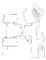
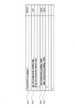
図1は、H.264(101)及びH.265(102)による、NALユニットヘッダの構文解析図の関連部分を示し、両方の事例において、それぞれの拡張子はない。両方の事例において、forbidden_zero_bitは、いくつかのシステム層環境で開始符号エミュレーション防止に使用されるゼロビットである。nal_unit_type構文要素は、NALユニットが保持するデータの種類を示し、例えば、いくつかのスライス種別、パラメータ設定種別、補足拡張情報(SEI-)メッセージなどのうちの1つであってもよい。H.265 NALユニットヘッダは、nuh_layer_id及びnuh_temporal_id_plus1をさらに含み、これらはNALユニットが属する符号化画像の空間的/SNR及び時間層を示す。 Figure 1 shows the H. 264(101) and H. 265(102) shows the relevant part of the NAL unit header parse diagram, in both cases without the respective extensions. In both cases, forbidden_zero_bit is the zero bit used for start code emulation prevention in some system layer environments. The nal_unit_type syntax element indicates the type of data the NAL unit holds, and may be, for example, one of several slice types, parameter setting types, supplemental enhancement information (SEI-) messages, and so on. H. 265 NAL unit header further includes nuh_layer_id and nuh_temporal_id_plus1, which indicate the spatial/SNR and temporal layer of the coded picture to which the NAL unit belongs.
NALユニットヘッダは、容易に解析可能な固定長の符号語のみを含み、これはビットストリーム内の他のデータ、例えば、他のNALユニットヘッダ、パラメータセットなどに対し、いかなる解析依存性ももたないことが観察できる。NALユニット内では、NALユニットヘッダが最初のオクテットなので、MANEはこれらを容易に抽出し、解析し、かつこれらに対して作用することができる。これとは対照的に、他の上位構文要素、例えば、スライス又はタイルヘッダは、パラメータセットコンテキストを保持したり、可変長又は算術符号化されたコードポイントを処理したりすることが必要になるため、MANEにとってアクセスしにくい。 NAL unit headers contain only easily parsable fixed-length codewords, which do not have any parsing dependencies on other data in the bitstream, e.g., other NAL unit headers, parameter sets, etc. It can be observed that there is no Within a NAL unit, the NAL unit header is the first octet, so MANEs can easily extract, parse, and act on them. In contrast, other high-level syntactic elements, e.g. slice or tile headers, would need to hold parameter set context or handle variable-length or arithmetic-coded codepoints. , inaccessible to MANE.
図1に示すNALユニットヘッダは、NALユニットを複数のNALユニットからなる符号化画像に関連付けることが可能な情報を含まない、ということがさらに観察され得る(例えば、複数のタイル又はスライスを含み、その少なくともいくつかは個別のNALユニットでパケット化される)。 It can further be observed that the NAL unit header shown in FIG. 1 does not contain information that can associate a NAL unit with a coded image consisting of multiple NAL units (e.g., it contains multiple tiles or slices, at least some of which are packetized in separate NAL units).
RTP(RFC 3550)、MPEGシステム標準、ISOファイル形式などのいくつかの伝送技術は、いくつかの情報を、しばしば提示時間(MPEG及びISOファイル形式の場合)又は捕捉時間(RTPの場合)などのタイミング情報の形式で含む場合があり、このような形式はMANEが容易にアクセスでき、かつそのそれぞれの伝送ユニットを符号化画像に関連付けるのを補助することができる。しかしながら、これらの情報のセマンティクスは伝送/記憶技術ごとに異なる場合があり、かつ映像符号化に使用される画像構造と直接関係がない場合がある。したがって、このような情報はヒューリスティクスでしかなく、また、NALユニットストリーム内のNALユニットが同じ符号化画像に属するかどうかを特定するのに、特によく適しているとは言えない場合がある。 Some transmission technologies, such as RTP (RFC 3550), the MPEG system standard, and the ISO file format, often pass some information, such as presentation time (for MPEG and ISO file formats) or capture time (for RTP). It may be included in the form of timing information, such form can be easily accessed by the MANE and assist in associating its respective transmission unit with the encoded image. However, the semantics of these information may differ between transmission/storage technologies and may not be directly related to the image structure used for video coding. Therefore, such information is only a heuristic and may not be particularly well suited for identifying whether NAL units within a NAL unit stream belong to the same coded image.
実施形態では、少なくとも1つのプロセッサを使用して映像を復号するために、符号化された現画像を再構築する方法であって、方法は、現画像に対応する画像分割情報を復号するステップと、画像分割情報を使用して、現画像の複数のサブ領域にパディングが適用されるかどうかを決定するステップと、パディングが適用されないという決定に基づき、複数のサブ領域をパディングせずに複数のサブ領域を復号するステップと、パディングが適用されるという決定に基づき、画像分割情報を使用して、パディングがラップアラウンドパディングを含むかどうかを決定するステップと、パディングがラップアラウンドパディングを含まないという決定に基づき、複数のサブ領域に反復パディングを適用し、反復パディングを使用して複数のサブ領域を復号するステップと、パディングがラップアラウンドパディングを含むという決定に基づき、複数のサブ領域にラップアラウンドパディングを適用し、ラップアラウンドパディングを使用して複数のサブ領域を復号するステップと、復号された複数のサブ領域に基づき、現画像を再構築するステップとを含む、方法が提供される。 In an embodiment, a method of reconstructing an encoded current image for decoding video using at least one processor, the method comprising decoding image segmentation information corresponding to the current image. , using image segmentation information to determine whether padding is applied to the plurality of sub-regions of the current image; Decoding the sub-region; determining, using image segmentation information, whether the padding includes wrap-around padding based on the determination that padding is applied; applying iterative padding to the plurality of sub-regions based on the determination and decoding the plurality of sub-regions using the iterative padding; and wrapping around the plurality of sub-regions based on the determination that the padding includes the wrap-around padding. A method is provided that includes applying padding and decoding multiple sub-regions using wrap-around padding, and reconstructing a current image based on the decoded multiple sub-regions.
実施形態では、映像を復号するために、符号化された現画像を再構築する装置であって、装置は、プログラムコードを記憶するように構成された、少なくとも1つのメモリと、プログラムコードを読み出し、プログラムコードによって命令された通りに動作するように構成された、少なくとも1つのプロセッサとを備え、プログラムコードは、少なくとも1つのプロセッサに、現画像に対応する画像分割情報を復号させるように構成された、第1の復号コードと、画像分割情報を使用して、少なくとも1つのプロセッサに、現画像の複数のサブ領域にパディングが適用されるかどうかを決定させるように構成された、第1の決定コードと、パディングが適用されないという決定に基づいて、少なくとも1つのプロセッサに、複数のサブ領域をパディングせずに複数のサブ領域を復号させるように構成された、第2の復号コードと、パディングが適用されるという決定に基づき、画像分割情報を使用して、パディングがラップアラウンドパディングを含むかどうかを決定するように構成された、第2の決定コードと、パディングがラップアラウンドパディングを含まないという決定に基づき、少なくとも1つのプロセッサに、複数のサブ領域に反復パディングを適用し、反復パディングを使用して複数のサブ領域を復号させるように構成された、第1の反復コードと、パディングがラップアラウンドパディングを含むという決定に基づき、少なくとも1つのプロセッサに、複数のサブ領域にラップアラウンドパディングを適用し、ラップアラウンドパディングを使用して複数のサブ領域を復号させるように構成された、第2の反復コードと、復号された複数のサブ領域に基づき、少なくとも1つのプロセッサに現画像を再構築させるように構成された、再構築コードとを含む、装置が提供される。 In an embodiment, an apparatus for reconstructing a current encoded image for decoding video, the apparatus comprising: at least one memory configured to store program code; , and at least one processor configured to operate as directed by the program code, the program code configured to cause the at least one processor to decode image segmentation information corresponding to the current image. Also, a first decoding code and configured to cause at least one processor to determine whether padding is applied to a plurality of sub-regions of a current image using the first decoding code and image segmentation information. second decoding code configured to cause at least one processor to decode the plurality of sub-regions without padding the plurality of sub-regions based on the decision code and the determination that padding is not applied; is applied, a second decision code configured to use the image segmentation information to determine whether the padding includes wrap-around padding, and the padding does not include wrap-around padding a first iteration code configured to cause at least one processor to apply iteration padding to a plurality of sub-regions and decode the plurality of sub-regions using the iteration padding; a second processor configured to cause at least one processor to apply wrap-around padding to the plurality of sub-regions and decode the plurality of sub-regions using the wrap-around padding based on the determination to include the wrap-around padding; and reconstruction code configured to cause at least one processor to reconstruct a current image based on the decoded plurality of sub-regions.
実施形態では、命令を記憶する非一時的なコンピュータ可読媒体であって、命令は、映像を復号するために符号化された現画像を再構築する装置の1つ以上のプロセッサによって実行されると、1つ以上のプロセッサに、現画像に対応する画像分割情報を復号させ、画像分割情報を使用して、現画像の複数のサブ領域にパディングが適用されるかどうかを決定させ、パディングが適用されないという決定に基づき、複数のサブ領域をパディングせずに複数のサブ領域を復号させ、パディングが適用されるという決定に基づき、画像分割情報を使用して、パディングがラップアラウンドパディングを含むかどうかを決定させ、パディングがラップアラウンドパディングを含まないという決定に基づき、複数のサブ領域に反復パディングを適用し、反復パディングを使用して複数のサブ領域を復号させ、パディングがラップアラウンドパディングを含むという決定に基づき、複数のサブ領域にラップアラウンドパディングを適用し、ラップアラウンドパディングを使用して複数のサブ領域を復号させ、復号された複数のサブ領域に基づき、現画像を再構築させる、1つ以上の命令を含む、非一時的なコンピュータ可読媒体が提供される。 In an embodiment, a non-transitory computer-readable medium storing instructions to be executed by one or more processors of an apparatus for reconstructing an encoded current image for decoding video. , causing one or more processors to decode image segmentation information corresponding to a current image, using the image segmentation information to determine whether padding is applied to multiple sub-regions of the current image, and the padding being applied Based on the determination that the sub-regions are not padded, let the multiple sub-regions be decoded, and based on the determination that the padding is applied, use the image segmentation information to determine whether the padding includes wrap-around padding. and applying repeat padding to multiple sub-regions based on the determination that the padding does not include wrap-around padding, having the multiple sub-regions decoded using the repeat padding, and determining that the padding includes wrap-around padding. Based on the determination, apply wrap-around padding to the multiple sub-regions, have the multiple sub-regions decoded using the wrap-around padding, and reconstruct a current image based on the decoded multiple sub-regions, A non-transitory computer-readable medium is provided containing the above instructions.
本開示の主題のさらなる特徴、性質、及びさまざまな利点は、以下の詳細な説明、及び添付の図面でより明らかになるであろう。 Further features, properties and various advantages of the disclosed subject matter will become more apparent from the following detailed description and accompanying drawings.
発明が解決しようとする課題
360度映像は、正距円筒投影(equirectangular projection、ERP)などの3D-2D投影方法を使用して、2D映像上にマッピングされる。投影された映像は、従来の2D映像エンコーダによって符号化及び復号され、2D映像を3D表面に再投影することによってレンダリングされる。その後、符号化された領域を個別につなぎ合わせることによって、再投影プロセスからシームの視覚的アーティファクトが生じる。
Problems to be Solved by the Invention
A 360-degree image is mapped onto a 2D image using a 3D-2D projection method such as equirectangular projection (ERP). The projected image is encoded and decoded by a conventional 2D image encoder and rendered by reprojecting the 2D image onto a 3D surface. By then individually stitching the encoded regions together, the visual artifact of the seam results from the reprojection process.
詳細な説明
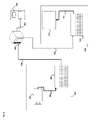
図2は、本開示の実施形態による、通信システム(200)の簡素化されたブロック図を示す。システム(200)は、ネットワーク(250)を介して相互接続された、少なくとも2つの端末(210、220)を含んでもよい。データの一方向伝送の場合、第1の端末(210)は、ネットワーク(250)を介してもう一方の端末(220)に送信する映像データをローカル位置で符号化してもよい。第2の端末(220)は、ネットワーク(250)からもう一方の端末の符号化された映像データを受信し、符号化されたデータを復号して、回復された映像データを表示してもよい。一方向のデータ伝送は、媒体供給用途などにおいて一般的であろう。
DETAILED DESCRIPTION FIG. 2 shows a simplified block diagram of a communication system (200), according to an embodiment of the present disclosure. The system (200) may include at least two terminals (210, 220) interconnected via a network (250). For unidirectional transmission of data, the first terminal (210) may locally encode video data for transmission over the network (250) to the other terminal (220). A second terminal (220) may receive the encoded video data of the other terminal from the network (250), decode the encoded data, and display the recovered video data. . One-way data transmission may be common in media feeding applications and the like.
図2は、例えば、ビデオ会議中に生じる場合がある、符号化された映像の双方向伝送をサポートするために提供される、第2の対の端末(230、240)を示す。データの双方向伝送の場合、各端末(230、240)は、ネットワーク(250)を介してもう一方の端末に送信する、ローカル位置で捕捉した映像データを符号化してもよい。各端末(230、240)は、もう一方の端末によって送信された符号化された映像データを受信してもよく、符号化されたデータを復号してもよく、かつ回復された映像データをローカルの表示装置に表示してもよい。 FIG. 2 shows a second pair of terminals (230, 240) provided to support two-way transmission of encoded video, as may occur, for example, during a video conference. For bidirectional transmission of data, each terminal (230, 240) may encode video data captured at its local location for transmission to the other terminal over the network (250). Each terminal (230, 240) may receive the encoded video data transmitted by the other terminal, may decode the encoded data, and store the recovered video data locally. may be displayed on the display device.
図2では、端末(210~240)は、サーバ、パソコン、及びスマートフォンとして示されてもよいが、本開示の原理はそのように限定されない場合がある。本開示の実施形態は、ノートパソコン、タブレットコンピュータ、メディアプレーヤ、及び/又は専用のビデオ会議機器にも適用される。ネットワーク(250)は、符号化された映像データを端末(210~240)間に伝達する、有線及び/又は無線通信ネットワークなどを含む任意の数のネットワークを表す。通信ネットワーク(250)は、回線交換チャネル及び/又はパケット交換チャネルでデータを交換してもよい。代表的なネットワークは、電気通信ネットワーク、ローカルエリアネットワーク、広域ネットワーク、及び/又はインターネットを含む。本考察の目的のために、ネットワーク(250)のアーキテクチャ及びトポロジは、以下で説明されない限り、本開示の運用には無関係な場合がある。 In FIG. 2, the terminals (210-240) may be depicted as servers, personal computers, and smart phones, although the principles of the disclosure may not be so limited. Embodiments of the present disclosure also apply to laptops, tablet computers, media players, and/or dedicated video conferencing equipment. Network (250) represents any number of networks, including wired and/or wireless communication networks, that convey encoded video data between terminals (210-240). The communication network (250) may exchange data over circuit-switched channels and/or packet-switched channels. Typical networks include telecommunications networks, local area networks, wide area networks, and/or the Internet. For the purposes of this discussion, the architecture and topology of network (250) may be irrelevant to the operation of this disclosure unless described below.
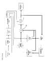
図3は、開示される主題の適用例として、ストリーミング環境における映像エンコーダ及びデコーダの配置を示す。開示される主題は、例えば、ビデオ会議や、デジタルテレビや、CD、DVD、メモリスティックなどのデジタル媒体への圧縮映像の記憶などを含む、他の映像使用用途に等しく適用することができる。 FIG. 3 shows an arrangement of video encoders and decoders in a streaming environment as an example application of the disclosed subject matter. The disclosed subject matter is equally applicable to other video usage applications including, for example, video conferencing, digital television, and storage of compressed video on digital media such as CDs, DVDs, memory sticks, and the like.
ストリーミングシステムは捕捉サブシステム(313)を含んでもよく、捕捉サブシステム(313)は、例えば、圧縮されていない映像サンプルストリーム(302)を作成する、デジタルカメラなどの映像ソース(301)を含むことができる。符号化映像ビットストリームと比較してデータ量が大きいことを強調するために太線で示されているサンプルストリーム(302)は、カメラ(301)に結合されたエンコーダ(303)によって処理することができる。以下でより詳細に説明するように、エンコーダ(303)は、開示される主題の態様を可能にする、又は実施するために、ハードウェア、ソフトウェア、又はこれらの組合せを含むことができる。サンプルストリームと比較してデータ量が小さいことを強調するために細線で示されている符号化映像ビットストリーム(304)は、後で使用するためにストリーミングサーバ(305)に記憶することができる。1つ以上のストリーミングクライアント(306、308)は、符号化映像ビットストリーム(304)のコピー(307、309)を検索するために、ストリーミングサーバ(305)にアクセスすることができる。クライアント(306)は、着信した符号化映像ビットストリームのコピー(307)を復号して、発信する映像サンプルストリーム(311)を生成する、映像デコーダ(310)を含むことができ、映像サンプルストリーム(311)は、表示装置(312)、又は他の表示装置(図示せず)に表示することができる。一部のストリーミングシステムでは、映像ビットストリーム(304、307、309)は、いくつかの映像符号化/圧縮標準に従って符号化することができる。このような標準の例は、ITU-T勧告H.265を含む。非公式には汎用映像符号化(Versatile Video Coding、即ちVVC)として知られる、映像符号化標準が開発中である。開示されている主題は、VVCとの関連において使用されてもよい。 The streaming system may include a capture subsystem (313) that includes a video source (301), such as a digital camera, that produces an uncompressed video sample stream (302). can be done. The sample stream (302), shown in bold to emphasize the large amount of data compared to the encoded video bitstream, can be processed by an encoder (303) coupled to the camera (301). . As described in more detail below, encoder (303) may include hardware, software, or a combination thereof to enable or implement aspects of the disclosed subject matter. The encoded video bitstream (304), shown in thin lines to emphasize the small amount of data compared to the sample stream, can be stored in the streaming server (305) for later use. One or more streaming clients (306, 308) can access the streaming server (305) to retrieve copies (307, 309) of the encoded video bitstream (304). The client (306) may include a video decoder (310) that decodes a copy of the incoming encoded video bitstream (307) to produce an outgoing video sample stream (311), the video sample stream ( 311) can be displayed on a display device (312), or another display device (not shown). In some streaming systems, the video bitstreams (304, 307, 309) can be encoded according to some video encoding/compression standard. An example of such a standard is ITU-T Recommendation H. Including 265. A video coding standard, informally known as Versatile Video Coding (VVC), is under development. The disclosed subject matter may be used in the context of VVC.
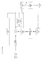
図4は、本開示の実施形態による、映像デコーダ(310)の機能ブロック図である。 FIG. 4 is a functional block diagram of a video decoder (310), according to an embodiment of the present disclosure.
受信機(410)は、デコーダ(310)によって復号される1つ以上のコーデック映像シーケンスを受信してもよく、同一又は別の実施形態では、1つの符号化された映像シーケンスを同時に受信してもよく、符号化された映像シーケンスそれぞれの復号は、他の符号化された映像シーケンスから独立している。符号化された映像シーケンスは、チャネル(412)から受信されてもよく、チャネル(412)は、符号化された映像データを記憶する記憶装置と連結する、ハードウェア/ソフトウェアであってもよい。受信機(410)は、符号化された音声データ及び/又は補助データストリームなどの他のデータとともに符号化された映像データを受信してもよく、これはそれぞれが使用するエンティティ(図示せず)に転送されてもよい。受信機(410)は、符号化された映像シーケンスを他のデータから分離してもよい。ネットワークのジッタに対抗するために、受信機(410)とエントロピーデコーダ/構文解析器(420)(以下「構文解析器」とする)との間にバッファメモリ(415)が結合されてもよい。受信機(410)が、帯域幅及び制御性が充分な記憶装置/転送装置から、又はアイソシンクロナスネットワークからデータを受信しているときは、バッファ(415)は必要でない場合がある、或いは小さくすることができる。バッファ(415)は、インターネットなどのベストエフォートのパケットネットワークで使用するために必要とされる場合があり、比較的大型で、好適には適応可能なサイズにすることができる。 The receiver (410) may receive one or more codec video sequences to be decoded by the decoder (310), and in the same or another embodiment simultaneously receiving one encoded video sequence. Also, the decoding of each encoded video sequence is independent of other encoded video sequences. The encoded video sequence may be received from a channel (412), which may be hardware/software coupled to a storage device that stores the encoded video data. The receiver (410) may receive the encoded video data along with other data such as encoded audio data and/or ancillary data streams, each of which uses an entity (not shown). may be transferred to A receiver (410) may separate the encoded video sequence from other data. A buffer memory (415) may be coupled between the receiver (410) and the entropy decoder/parser (420) (hereinafter "the parser") to combat network jitter. When the receiver (410) is receiving data from a storage/transport device with sufficient bandwidth and controllability, or from an isosynchronous network, the buffer (415) may not be needed or may be small. can do. The buffer (415) may be required for use in best effort packet networks such as the Internet and may be relatively large and preferably adaptively sized.
映像デコーダ(310)は、エントロピー符号化された映像シーケンスからシンボル(421)を再構築するために、構文解析器(420)を備えてもよい。図3に示されていたように、このようなシンボルの分類は、デコーダ(310)の動作を管理するのに使用される情報、及びデコーダの一体部品ではないがこれに結合できる表示装置(312)などの、表示装置を制御するための潜在的な情報を含む。(複数の)表示装置のための制御情報は、補助拡張情報(Supplementary Enhancement Information)(SEIメッセージ)、又は映像有用性情報(Video Usability Information、VUI)パラメータ集合フラグメント(図示せず)の形態にされてもよい。構文解析器(420)は、受信した符号化された映像シーケンスを、構文解析/エントロピー復号してもよい。符号化された映像シーケンスの符号は、映像符号化技術又は標準に従っていてもよく、可変長符号化、ハフマン符号化、文脈依存又は非文脈依存の算術符号化などを含む、当業者によく知られている原理に従っていてもよい。構文解析器(420)は、符号化された映像シーケンスから、グループに対応する少なくとも1つのパラメータに基づいて、映像デコーダ内の、画素のサブグループの少なくとも1つに対する、一群のサブグループパラメータを抽出してもよい。サブグループは、画像のグループ(GOP)、画像、サブ画像、タイル、スライス、ブリック、マクロブロック、符号化ツリーユニット(CTU)、符号化ユニット(CU)、ブロック、変換ユニット(TU)、予測ユニット(PU)などを含むことができる。タイルは、画像における特定のタイルの列及び行内の、CU/CTUの長方形領域を示し得る。ブリックは、特定のタイル内CU/CTU行の長方形領域を示し得る。スライスは、画像の1つ以上のブリックを示してもよく、これらはNALユニットに含まれる。サブ画像は、画像内の1つ以上のスライスの長方形領域を示し得る。また、エントロピーデコーダ/構文解析器は、符号化された映像シーケンスから、変換係数、量子化器パラメータ値、動きベクトルなどの情報を抽出してもよい。 The video decoder (310) may comprise a parser (420) to reconstruct the symbols (421) from the entropy-encoded video sequence. As was shown in FIG. 3, such symbol classification is information used to manage the operation of the decoder (310) and a display device (312) that is not an integral part of the decoder but can be coupled thereto. ), including potential information for controlling the display device. Control information for the display device(s) is in the form of Supplementary Enhancement Information (SEI messages) or Video Usability Information (VUI) parameter set fragments (not shown). may A parser (420) may parse/entropy decode the received encoded video sequence. The coding of the encoded video sequence may conform to any video coding technique or standard and is well known to those skilled in the art, including variable length coding, Huffman coding, context-sensitive or non-context-dependent arithmetic coding, and the like. may follow the principle of A parser (420) extracts a set of subgroup parameters for at least one of the subgroups of pixels in the video decoder from the encoded video sequence based on at least one parameter corresponding to the group. You may A subgroup is a group of pictures (GOP), picture, subpicture, tile, slice, brick, macroblock, coding tree unit (CTU), coding unit (CU), block, transform unit (TU), prediction unit (PU), etc. A tile may represent a rectangular area of CU/CTU within a particular tile column and row in the image. A brick may indicate a rectangular area of CU/CTU rows within a particular tile. A slice may represent one or more bricks of an image, which are contained in a NAL unit. A sub-image may represent a rectangular region of one or more slices within an image. The entropy decoder/parser may also extract information such as transform coefficients, quantizer parameter values, motion vectors, etc. from the encoded video sequence.
構文解析器(420)は、シンボル(421)を生成するために、バッファ(415)から受信した映像シーケンスにエントロピー復号/構文解析動作を実行してもよい。 A parser (420) may perform entropy decoding/parsing operations on the video sequence received from the buffer (415) to generate symbols (421).
シンボル(421)の再構築は、符号化された映像又はその部分の種別(例えば、インター画像及びイントラ画像、インターブロック及びイントラブロック)、並びに他の要素に応じて、複数の異なるユニットを含むことができる。どのユニットがどのように含まれるかについては、構文解析器(420)によって符号化された映像シーケンスから構文解析された、サブグループ制御情報によって制御することができる。構文解析器(420)と、以下の複数のユニットとの間のこのようなサブグループ制御情報の流れは、明確にするために図示されていない。 Reconstruction of the symbol (421) may include different units depending on the type of video or portion thereof encoded (e.g., inter- and intra-pictures, inter-block and intra-block), and other factors. can be done. Which units are included and how can be controlled by subgroup control information parsed from the encoded video sequence by the parser (420). The flow of such subgroup control information between the Parser (420) and the following units is not shown for clarity.
すでに述べた機能ブロック以外に、デコーダ310は、以下で説明するように、概念的にいくつかの機能ユニットに再分割することができる。商業的な制約の下で運用される実際の実施では、このようなユニットの多くは互いに密接に相互作用し、少なくとも部分的に互いに統合することができる。しかしながら、開示する主題を説明する目的のためには、以下の機能ユニットに概念的に再分割するのが適切である。
Besides the functional blocks already mentioned,
第1のユニットは、スケーラ/逆変換ユニット(451)である。スケーラ/逆変換ユニット(451)は、量子化変換係数、並びに制御情報を受信し、これには、構文解析器(420)からの(複数の)シンボル(421)として、使用する変換、ブロックサイズ、量子化因子、量子化スケーリング行列などが含まれている。スケーラ/逆変換ユニット(451)はサンプル値を含むブロックを出力でき、これを集約装置(455)に入力することができる。 The first unit is the scaler/inverse transform unit (451). The scaler/inverse transform unit (451) receives the quantized transform coefficients as well as control information, including the transform to use, block size, as symbol(s) (421) from the parser (420) , quantization factors, quantization scaling matrices, etc. The scaler/inverse transform unit (451) can output a block containing sample values, which can be input to the aggregator (455).
場合によっては、スケーラ/逆変換(451)の出力サンプルは、イントラ符号化されたブロックに関係することができ、つまり、以前に再構築された画像からの予測情報を使用していないブロックは、現画像の以前に再構築された部分からの予測情報を使用することができる。このような予測情報は、イントラ画像予測ユニット(452)によって提供することができる。場合によっては、イントラ画像予測ユニット(452)は、現在の(部分的に再構築された)画像(458)から取り出した、周囲のすでに再構築された情報を使用して、再構築中のブロックと同じサイズ及び形状のブロックを生成する。集約装置(455)は、場合により、イントラ予測ユニット(452)が生成した予測情報をサンプル毎に、スケーラ/逆変換ユニット(451)によって提供された出力サンプル情報に追加する。 In some cases, the output samples of the scaler/inverse transform (451) can relate to intra-coded blocks, i.e. blocks that do not use prediction information from a previously reconstructed image Predictive information from previously reconstructed portions of the current image can be used. Such prediction information can be provided by an intra-picture prediction unit (452). In some cases, the intra-picture prediction unit (452) uses the surrounding already-reconstructed information taken from the current (partially reconstructed) picture (458) to predict the block under reconstruction. produces a block of the same size and shape as The aggregator (455) optionally adds the prediction information generated by the intra prediction unit (452), sample by sample, to the output sample information provided by the scaler/inverse transform unit (451).
他の事例では、スケーラ/逆変換ユニット(451)の出力サンプルはインター符号化され、かつ潜在的には動き補償されたブロックに関係することができる。このような事例では、動き補償予測ユニット(453)が、予測に使用するサンプルを取り出すために、参照画像メモリ(457)にアクセスすることができる。ブロックに関連するシンボル(421)に従って、取り出されたサンプルを動き補償した後に、これらのサンプルは、出力サンプル情報を生成するように、集約装置(455)によってスケーラ/逆変換ユニットの出力(この場合は残差サンプル又は残差信号と呼ばれる)に追加することができる。動き補償ユニットが予測サンプルを取り出す参照画像メモリ内のアドレスは、動きベクトルによって制御することができ、シンボル(421)の形態で動き補償ユニットに使用可能で、例えば、X、Y、及び参照画像成分を有することができる。また動き補償は、サブサンプルの正確な動きベクトルが使用されているときに参照画像メモリから取り出されたサンプル値の補間、動きベクトル予測機構などを含むことができる。 In other cases, the output samples of the scaler/inverse transform unit (451) may relate to inter-coded and potentially motion compensated blocks. In such cases, the motion compensated prediction unit (453) can access the reference picture memory (457) to retrieve samples for use in prediction. After motion compensating the retrieved samples according to the symbols (421) associated with the block, these samples are output (in this case are called residual samples or residual signals). The addresses in the reference picture memory from which the motion compensation unit retrieves the prediction samples can be controlled by motion vectors and are available to the motion compensation unit in the form of symbols (421), e.g. can have Motion compensation can also include interpolation of sample values retrieved from reference picture memory, motion vector prediction mechanisms, etc. when sub-sample accurate motion vectors are used.
集約装置(455)の出力サンプルは、ループフィルタユニット(456)のさまざまなループフィルタリング技術にかけることができる。映像圧縮技術は、符号化映像ビットストリームに含まれるパラメータによって制御され、構文解析器(420)からのシンボル(421)としてループフィルタユニット(456)に対して使用可能になる、ループ内フィルタ技術を含むことができるが、さらに、符号化された画像又は符号化された映像シーケンスの以前の(復号順で)部分の復号中に取得されたメタ情報にも応答し、同様に以前に再構築されてループフィルタリングされたサンプル値にも応答することができる。 The output samples of the aggregator (455) can be subjected to various loop filtering techniques of the loop filter unit (456). The video compression technique includes an in-loop filter technique controlled by parameters contained in the encoded video bitstream and made available to the loop filter unit (456) as symbols (421) from the parser (420). but also responsive to meta-information obtained during decoding of a previous (in decoding order) portion of the encoded image or encoded video sequence, also previously reconstructed. It can also respond to loop-filtered sample values.
ループフィルタユニット(456)の出力は、表示装置(312)に出力でき、かつ以後のインター画像予測に使用するために参照画像メモリに記憶できる、サンプルストリームであってもよい。 The output of the loop filter unit (456) may be a sample stream that can be output to the display device (312) and stored in a reference picture memory for use in subsequent inter-picture prediction.
いくつかの符号化画像は、いったん完全に再構築されると、以後の予測用の参照画像として使用することができる。符号化画像が完全に再構築され、符号化された画像が(例えば、構文解析器(420)によって)参照画像として特定されていると、現在の参照画像(458)が参照画像バッファ(457)の一部になることができ、後続の符号化された画像の再構築を開始する前に、新しい現画像メモリを再配分することができる。 Some coded images, once completely reconstructed, can be used as reference images for future predictions. Once the encoded image has been fully reconstructed and the encoded image has been identified (eg, by the parser (420)) as a reference image, the current reference image (458) is stored in the reference image buffer (457). and reallocate the new current image memory before starting reconstruction of subsequent encoded images.
映像デコーダ420は、ITU-T Rec.H.265などの標準に記述され得る所定の映像圧縮技術に従って、復号動作を実行してもよい。符号化された映像シーケンスは、映像圧縮技術又は標準の構文を遵守しているという意味において、映像圧縮技術文書又は標準で、かつ具体的にはそこに記述されているプロファイルで指定される通りに、使用される映像圧縮技術又は標準によって指定される構文に従っているといえる。遵守のためにさらに必要なことは、符号化された映像シーケンスの複雑性が、映像圧縮技術又は標準のレベルによって規定される範囲内にあることであろう。場合によっては、水準によって最大画像サイズ、最大フレームレート、最大再構築サンプルレート(例えば、メガサンプル/秒で測定される)、最大参照画像サイズなどが制限される。水準によって設定される制限は、場合によっては、仮想参照デコーダ(Hypothetical Reference Decoder、HRD)仕様、及び符号化された映像シーケンスで信号送信されたHRDバッファ管理のメタデータによってさらに制限される可能性がある。
The
実施形態では、受信機(410)は、符号化された映像とともに追加(冗長)データを受信してもよい。追加データは、(複数の)符号化された映像シーケンスの一部として含められてもよい。追加データは、映像デコーダ(420)によって、データを適切に復号するため、かつ/又は元の映像データをより正確に再構築するために使用されてもよい。追加データは、例えば、時間的、空間的、又はSNR強化層、冗長スライス、冗長画像、転送エラー修正コードなどの形態であってもよい。 In embodiments, the receiver (410) may receive additional (redundant) data along with the encoded video. Additional data may be included as part of the encoded video sequence(s). The additional data may be used by the video decoder (420) to properly decode the data and/or reconstruct the original video data more accurately. Additional data may be, for example, in the form of temporal, spatial, or SNR enhancement layers, redundant slices, redundant images, transmission error correction codes, and the like.
図5は、本開示の実施形態による、映像エンコーダ(303)の機能ブロック図である。 Figure 5 is a functional block diagram of a video encoder (303), according to an embodiment of the present disclosure.
エンコーダ(303)は、エンコーダ(303)によって符号化される(複数の)映像を捕捉し得る映像ソース(301)(エンコーダの一部ではない)から、映像サンプルを受信してもよい。 The encoder (303) may receive video samples from a video source (301) (not part of the encoder) that may capture the video(s) to be encoded by the encoder (303).
映像ソース(301)は、エンコーダ(303)によって符号化されるソース映像シーケンスを、任意の適切なビット深度(8ビット、10ビット、12ビット~など)、任意の色空間(BT.601 Y CrCB、RGBなど)、及び任意の適切なサンプリング構造(Y CrCb 4:2:0、Y CrCb 4:4:4など)にすることが可能なデジタル映像サンプルストリームの形態で提供し得る。媒体供給システムでは、映像ソース(301)は、以前に準備した映像を記憶している記憶装置であってもよい。ビデオ会議システムでは、映像ソース(303)は、ローカル画像情報を映像シーケンスとして捕捉するカメラであってもよい。映像データは、シーケンスで見たときに動きを伝える複数の個別の画像として提供されてもよい。画像自体は画素の空間的配列として編成されてもよく、各画素は、使用時のサンプリング構造、色空間などに応じて1つ以上のサンプルを含むことができる。当業者であれば、画素とサンプルとの関係を容易に理解できるであろう。以下、サンプルを中心に説明する。 The video source (301) converts the source video sequence encoded by the encoder (303) into any suitable bit depth (8-bit, 10-bit, 12-bit, etc.), any color space (BT.601 Y CrCB , RGB, etc.), and in the form of a digital video sample stream that can be of any suitable sampling structure (Y CrCb 4:2:0, Y CrCb 4:4:4, etc.). In a media delivery system, the video source (301) may be a storage device storing previously prepared video. In a videoconferencing system, the video source (303) may be a camera that captures local image information as a video sequence. The video data may be provided as multiple individual images that convey motion when viewed in sequence. The image itself may be organized as a spatial array of pixels, where each pixel may contain one or more samples depending on the sampling structure, color space, etc. in use. Those skilled in the art will readily understand the relationship between pixels and samples. A sample will be mainly described below.
実施形態によれば、エンコーダ(303)は、リアルタイムで、又は用途によって必要とされる他の時間制約下で、ソース映像シーケンスの画像を符号化し圧縮して、符号化された映像シーケンス(543)にし得る。適切な符号化速度にすることが、コントローラ(550)の1つの機能である。コントローラは、後述するように他の機能ユニットを制御し、かつこれらのユニットに機能的に結合される。明確にするために、結合については図示しない。コントローラによって設定されたパラメータは、レート制御関連パラメータ(画像スキップ、量子化、レート-歪み最適化技術のラムダ値など)、画像サイズ、画像のグループ(GOP)のレイアウト、最大動きベクトル検索範囲などを含むことができる。当業者であれば、コントローラ(550)の他の機能は、いくつかのシステム設計用に最適化された映像エンコーダ(303)に関連し得るため、容易に特定することができる。 According to embodiments, the encoder (303) encodes and compresses the images of the source video sequence in real time, or under other time constraints required by the application, to produce the encoded video sequence (543) can be Proper encoding rate is one function of the controller (550). The controller controls and is operatively coupled to other functional units as described below. Couplings are not shown for clarity. Parameters set by the controller include rate control related parameters (image skipping, quantization, lambda value for rate-distortion optimization techniques, etc.), image size, group of images (GOP) layout, maximum motion vector search range, etc. can contain. Other functions of the controller (550) can be readily identified by those skilled in the art, as they may relate to the optimized video encoder (303) for some system designs.
いくつかの映像エンコーダは、当業者には「符号化ループ」として容易に認識されるもので動作する。過度に単純化した説明になるが、符号化ループは、エンコーダ(530)(以後「ソースエンコーダ」)(符号化される入力画像、及び(複数の)参照画像に基づくシンボルの生成に関与する)の符号化部と、(シンボル及び符号化映像ビットストリーム間の圧縮は、開示されている主題で考慮される映像圧縮技術において可逆であるために)(リモート)デコーダも生成するサンプルデータを生成するために、シンボルを再構築するエンコーダ(303)に組み込まれた、(ローカル)デコーダ(533)と、からなっていてもよい。再構築されたサンプルストリームは、参照画像メモリ(534)に入力される。シンボルストリームの復号が、デコーダの位置(ローカル又はリモート)とは無関係に、結果としてビットパーフェクト(bit-exact)になると、参照画像バッファのコンテンツもまた、ローカルエンコーダとリモートエンコーダとの間でビットパーフェクトになる。言い換えれば、エンコーダの予測部は、参照画像サンプルを、復号中に予測を使用しているときにデコーダが「みなす」ものとまったく同じサンプル値と「みなす」。参照画像共時性のこの基本原理(及び、例えばチャネルエラーのために共時性を維持できない場合は、結果として生じるドリフト)は、当業者にはよく知られている。 Some video encoders operate in what is readily recognized by those skilled in the art as an "encoding loop". An overly simplistic description, the encoding loop is an encoder (530) (hereafter "source encoder") (responsible for generating symbols based on the input image to be encoded and the reference image(s)). and the sample data that the (remote) decoder also produces (because the compression between the symbols and the encoded video bitstream is lossless in the video compression techniques considered in the disclosed subject matter). a (local) decoder (533) embedded in the encoder (303) for reconstructing the symbols. The reconstructed sample stream is input to the reference image memory (534). If the decoding of the symbol stream results in bit-perfect regardless of the decoder's position (local or remote), then the content of the reference picture buffer is also bit-perfect between the local and remote encoders. become. In other words, the encoder's predictor "sees" the reference image samples to be exactly the same sample values that the decoder "sees" when using prediction during decoding. This basic principle of reference image synchronicity (and the resulting drift if synchronicity cannot be maintained, for example due to channel error) is well known to those skilled in the art.
「ローカル」デコーダ(533)の動作は、「リモート」デコーダ(310)と同じであってもよく、これについては、図4に関連してすでに詳細に上述した。しかしながら、一時的に図4も参照すると、シンボルが使用可能であり、かつエントロピーエンコーダ(545)及び構文解析器(420)によって、シンボルを符号化された映像シーケンスに可逆的に符号化/復号できるので、チャネル(412)、受信機(410)、バッファ(415)、及び構文解析器(420)を含むデコーダ(310)のエントロピー復号部は、ローカルデコーダ(533)で完全に実施されなくてもよい。 The operation of the 'local' decoder (533) may be the same as the 'remote' decoder (310), which has already been described in detail above in connection with FIG. However, referring also momentarily to FIG. 4, the symbols are available and can be reversibly encoded/decoded into an encoded video sequence by the entropy encoder (545) and parser (420). So the entropy decoding part of the decoder (310), including the channel (412), the receiver (410), the buffer (415), and the parser (420) is not fully implemented in the local decoder (533). good.
現時点で考えられることは、デコーダ内に存在する、構文解析/エントロピー復号を除くデコーダ技術はいずれも、対応するエンコーダ内にもほぼ同一の機能的形態で存在することが当然必要になる。このため、開示される主題はデコーダの動作に重点を置いている。エンコーダ技術の説明は、包括的に述べられているデコーダ技術の逆なので、省略することができる。いくつかの領域においてのみ、より詳細な説明が必要とされ以下で説明される。 It is currently conceivable that any decoder technique, other than parsing/entropy decoding, present in the decoder should also be present in the corresponding encoder in substantially the same functional form. For this reason, the disclosed subject matter focuses on decoder operation. A description of the encoder technique can be omitted as it is the inverse of the generically described decoder technique. Only some areas require more detailed explanation and are described below.
ソースエンコーダ(530)は、その動作の一部として動き補償された予測符号化を実行してもよく、「参照フレーム」として指定された映像シーケンスから、1つ以上の以前に符号化されたフレームに関して、入力フレームを予測的に符号化する。この方法では、符号化エンジン(532)は、入力フレームの画素ブロックと、入力フレームに対する(複数の)予測参照として選択され得る(複数の)参照フレームの画素ブロックとの差異を符号化する。 The source encoder (530) may perform motion-compensated predictive encoding as part of its operation, using one or more previously encoded frames from a video sequence designated as "reference frames". Predictively encode the input frame with respect to . In this method, the encoding engine (532) encodes differences between pixel blocks of an input frame and pixel blocks of reference frame(s) that may be selected as prediction reference(s) for the input frame.
ローカル映像デコーダ(533)は、ソースエンコーダ(530)によって生成されたシンボルに基づいて、参照フレームとして指定され得るフレームの符号化された映像データを復号してもよい。符号化エンジン(532)の動作は、好適には非可逆の工程であってもよい。符号化された映像データが、映像デコーダ(図5には図示せず)で復号されてもよいときは、再構築された映像シーケンスは、通常はいくつかのエラーを伴う、ソース映像シーケンスの複製であってもよい。ローカル映像デコーダ(533)は、映像デコーダによって参照フレームに対して実行されてもよく、かつ再構築された参照フレームが参照画像キャッシュ(534)に記憶されるようにし得る、復号工程を複製する。この方法では、エンコーダ(303)は、遠端の映像デコーダ(伝送エラーのない)によって取得される、再構築された参照フレームと共通のコンテンツを有する、再構築された参照フレームのコピーを局所的に記憶してもよい。 A local video decoder (533) may decode encoded video data for frames that may be designated as reference frames based on the symbols generated by the source encoder (530). The operation of the encoding engine (532) may preferably be a non-reversible process. When the encoded video data may be decoded in a video decoder (not shown in Figure 5), the reconstructed video sequence is a duplicate of the source video sequence, usually with some errors. may be The local video decoder (533) replicates the decoding process that may be performed by the video decoder on the reference frames and cause the reconstructed reference frames to be stored in the reference picture cache (534). In this method, the encoder (303) locally creates a copy of the reconstructed reference frame that has content in common with the reconstructed reference frame obtained by the far-end video decoder (without transmission errors). may be stored in
予測子(535)は、符号化エンジン(532)用の予測検索を実行してもよい。つまり、予測子(535)は、符号化される新しいフレームに対して、参照画像メモリ(534)からサンプルデータ(候補参照画素ブロックとしての)、又は参照画像動きベクトル、ブロック形状などのいくつかのメタデータを検索してもよく、これは新しい画像の適切な予測参照として機能する。予測子(535)は、適切な予測参照を見つけるために、ブロック×画素ブロックを基準として、サンプルで動作してもよい。場合によっては、予測子(535)によって取得された検索結果によって決定されるように、入力画像は、参照画像メモリ(534)に記憶された複数の参照画像から引き出された予測参照を有してもよい。 A predictor (535) may perform a predictive search for the encoding engine (532). That is, the predictor (535) receives sample data (as candidate reference pixel blocks) from the reference image memory (534) for a new frame to be encoded, or some number of reference image motion vectors, block shapes, etc. Metadata may be searched, which serves as a good predictive reference for new images. The predictor (535) may operate on the samples on a block by pixel block basis to find a suitable prediction reference. In some cases, the input image has prediction references drawn from multiple reference images stored in the reference image memory (534), as determined by the search results obtained by the predictor (535). good too.
コントローラ(550)は、例えば、映像データの符号化に使用される、パラメータ及びサブグループパラメータの設定を含む、映像エンコーダ(530)の符号化動作を管理してもよい。 The controller (550) may manage the encoding operations of the video encoder (530), including, for example, setting parameters and subgroup parameters used to encode video data.
前述した全機能ユニットの出力は、エントロピーエンコーダ(545)でエントロピー符号化されてもよい。エントロピーエンコーダは、さまざまな機能ユニットによって生成されると、ハフマン符号化、可変長符号化、算術符号化などとして当業者に知られている技術でシンボルを可逆圧縮することによって、シンボルを符号化された映像シーケンスに変換する。 The outputs of all functional units described above may be entropy encoded in an entropy encoder (545). Entropy encoders, as produced by various functional units, encode symbols by losslessly compressing them with techniques known to those skilled in the art as Huffman coding, variable length coding, arithmetic coding, etc. converted into a video sequence.
送信機(540)は、通信チャネル(560)を介した送信に備えるために、エントロピーエンコーダ(545)によって生成された際に、(複数の)符号化された映像シーケンスをバッファリングしてもよく、これは、符号化された映像データを記憶する記憶装置に対するハードウェア/ソフトウェア連携であってもよい。送信機(540)は、映像エンコーダ(530)の符号化された映像データを、送信される他のデータ、例えば、符号化された音声データ及び/又は補助データストリーム(ソースは図示せず)とマージしてもよい。 The transmitter (540) may buffer the encoded video sequence(s) as produced by the entropy encoder (545) in preparation for transmission over the communication channel (560). , which may be a hardware/software linkage to the storage device that stores the encoded video data. The transmitter (540) combines the encoded video data of the video encoder (530) with other data to be transmitted, such as encoded audio data and/or auxiliary data streams (sources not shown). May be merged.
コントローラ(550)は、エンコーダ(303)の動作を管理してもよい。符号化中に、コントローラ(550)は、符号化された画像のそれぞれにいくつかの符号化画像種別を割り当ててもよく、これは、各画像に適用され得る符号化技術に影響を及ぼす場合がある。例えば、画像は、以下のフレーム種別のうちの1つに割り当てられることが多い。 A controller (550) may govern the operation of the encoder (303). During encoding, the controller (550) may assign a number of encoded image types to each encoded image, which may affect the encoding technique that may be applied to each image. be. For example, images are often assigned to one of the following frame types.
イントラ画像(Iピクチャ)は、予測のソースとしてシーケンス内の他のフレームを使用せずに符号化及び復号され得るものである。いくつかの映像コーデックは、例えば、即時デコーダリフレッシュ(Independent Decoder Refresh)画像を含む、異なる種類のイントラ画像を許容する。当業者には、このようなIピクチャの変形、並びにその各用途及び特徴が知られている。 Intra pictures (I pictures) are those that can be encoded and decoded without using other frames in the sequence as a source of prediction. Some video codecs allow different types of intra pictures, including for example Independent Decoder Refresh pictures. Those skilled in the art are familiar with such variations of I-pictures and their respective uses and characteristics.
予測画像(Pピクチャ)は、各ブロックのサンプル値を予測するために、最大で1つの動きベクトル及び参照インデックスを使用して、イントラ予測又はインター予測を用いて符号化及び復号され得るものである。 A predicted picture (P-picture) can be coded and decoded using intra- or inter-prediction, using at most one motion vector and reference index to predict the sample values of each block. .
双方向予測画像(Bピクチャ)は、各ブロックのサンプル値を予測するために、最大で2つの動きベクトル及び参照インデックスを使用して、イントラ予測又はインター予測を用いて符号化及び復号され得るものである。同様に多重予測画像は、1つのブロックを再構築するために、2つよりも多い参照画像、及び関連するメタデータを使用することができる。 Bi-predictive pictures (B-pictures) can be coded and decoded using intra-prediction or inter-prediction, using at most two motion vectors and reference indices to predict the sample values of each block. is. Similarly, multi-predicted images can use more than two reference images and associated metadata to reconstruct one block.
ソース画像は、通常は空間的に複数のサンプルブロック(例えば、それぞれ4×4、8×8、4×8、又は16×16サンプルのブロック)に再分割されて、ブロック毎に符号化されてもよい。ブロックは、ブロックの各画像に適用された符号割当てによって決定される際に、他の(すでに符号化された)ブロックを参照して予測的に符号化されてもよい。例えば、Iピクチャのブロックは、非予測的に符号化されてもよく、或いは同じ画像のすでに符号化されたブロックを参照して、予測的に符号化されてもよい(空間予測又はイントラ予測)。Pピクチャの画素ブロックは、1つの以前に符号化された参照画像を参照して、空間予測によって、又は時間予測によって、非予測的に符号化されてもよい。Bピクチャのブロックは、1つ又は2つの以前に符号化された参照画像を参照して、空間予測によって、又は時間予測によって、非予測的に符号化されてもよい。 A source image is typically spatially subdivided into multiple sample blocks (e.g., blocks of 4x4, 8x8, 4x8, or 16x16 samples each) and encoded block by block. good too. A block may be predictively coded with reference to other (already coded) blocks as determined by the code allocation applied to each image of the block. For example, blocks of I pictures may be coded non-predictively, or they may be coded predictively (spatial prediction or intra prediction) with reference to already coded blocks of the same picture. . A pixel block of a P picture may be coded non-predictively, by spatial prediction with reference to one previously coded reference picture, or by temporal prediction. Blocks of B pictures may be coded non-predictively, by spatial prediction with reference to one or two previously coded reference pictures, or by temporal prediction.
映像エンコーダ(303)は、ITU-T Rec.H.265などの所定の映像符号化技術又は標準に従って、符号化動作を実行してもよい。その動作において、映像エンコーダ(303)はさまざまな圧縮動作を実行してもよく、これには入力映像シーケンスで時間的及び空間的冗長性を利用する予測符号化動作が含まれる。したがって符号化された映像データは、使用される映像符号化技術又は標準によって指定された構文に従っていてもよい。 The video encoder (303) conforms to ITU-T Rec. H. The encoding operations may be performed according to a predetermined video encoding technology or standard, such as H.265. In its operation, the video encoder (303) may perform various compression operations, including predictive encoding operations that exploit temporal and spatial redundancies in the input video sequence. The encoded video data may thus conform to the syntax specified by the video encoding technology or standard used.
実施形態では、送信機(540)は、符号化された映像とともに追加データを送信してもよい。映像エンコーダ(530)は、符号化された映像シーケンスの一部としてこのようなデータを含んでもよい。追加データは、時間/空間/SNR強化層、冗長画像及びスライス、補足拡張情報(Supplementary Enhancement Information、SEI)メッセージ、視覚的有用性情報(Visual Usability Information、VUI)パラメータ集合フラグメントなどの他の形式の冗長データを含んでもよい。 In embodiments, the transmitter (540) may transmit additional data along with the encoded video. A video encoder (530) may include such data as part of an encoded video sequence. Additional data may be in other forms such as temporal/spatial/SNR enhancement layers, redundant images and slices, Supplementary Enhancement Information (SEI) messages, Visual Usability Information (VUI) parameter set fragments, etc. May contain redundant data.
図6~図7を参照すると、実施形態において、360度映像は、一組のカメラ、又は複数のレンズを有するカメラ装置によって捕捉される。カメラは、カメラセットの中心点の周囲を無指向にカバーし得る。同じ時間インスタンスの画像がつなぎ合わされ、場合によっては回転され、投影され、画像にマッピングされる。パッキングされた画像は、符号化映像ビットストリームに符号化されるものとして符号化され、特定の媒体コンテナファイル形式に従って配信される。ファイルは、投影及びパッキング情報などのメタデータを含む。 Referring to FIGS. 6-7, in an embodiment, a 360-degree video is captured by a set of cameras, or a camera device with multiple lenses. The cameras may cover omnidirectionally around the center point of the camera set. Images of the same time instance are stitched together, possibly rotated, projected and mapped to the image. The packed images are encoded as encoded video bitstreams and delivered according to a specific media container file format. The file contains metadata such as projection and packing information.
実施形態において、360度映像は、正距円筒投影(ERP)を使用して、2D映像に投影されてもよい。ERP投影は、シームアーティファクトの原因になる場合がある。パディングされたERP(PERP)形式は、ERP画像の左右の境界を囲んでいる、再構築されたビューポートのシームアーティファクトを効果的に削減し得る。しかしながら、パディング及びブレンディングは、シームの問題を完全に解決するのに充分でない場合がある。 In embodiments, the 360-degree video may be projected onto the 2D video using Equirectangular Projection (ERP). ERP projection can cause seam artifacts. The padded ERP (PERP) format can effectively reduce the reconstructed viewport seam artifacts surrounding the left and right boundaries of the ERP image. However, padding and blending may not be sufficient to completely solve the seam problem.
実施形態では、シームアーティファクトを削減するために、ERP又はPERPに水平形状パディングが適用されてもよい。PERPのパディングのプロセスは、パディングされる領域の大きさを考慮するために、オフセットが画像幅ではなくパディングされていないERP幅に基づく場合があること以外は、ERPと同じであってもよい。参照ブロックが左(右)参照画像境界の外部にある場合は、ERP幅によって右(左)にシフトされる「ラップアラウンド」参照ブロックと置き換えられてもよい。垂直方向に、従来の反復パディングが使用されてもよい。左右のパディングされた領域のブレンディングは、後処理動作としてループには関与しない。 In embodiments, horizontal shape padding may be applied to the ERP or PERP to reduce seam artifacts. The process of padding for PERP may be the same as for ERP, except that the offset may be based on the unpadded ERP width rather than the image width to account for the size of the padded region. If the reference block is outside the left (right) reference image boundary, it may be replaced with a "wrap-around" reference block that is shifted to the right (left) by the ERP width. In the vertical direction, traditional repeat padding may be used. Blending left and right padded regions does not participate in the loop as a post-processing operation.
実施形態では、ERP及びPERP形式の参照画像の水平形状パディングを可能にするseq_parameter_set_rbsp()(601)などの構文が図6に示されている。 In an embodiment, syntaxes such as seq_parameter_set_rbsp() (601) that enable horizontal shape padding of reference images in ERP and PERP formats are shown in FIG.
実施形態では、sps_ref_wraparound_enabled_flag(602)が1の場合は、インター予測に水平ラップアラウンド動き補償が使用されることを指定する。実施形態では、sps_ref_wraparound_enabled_flag(602)が0の場合は、この動き補償方法が適用されないことを指定する。 In embodiments, if sps_ref_wraparound_enabled_flag (602) is 1, it specifies that horizontal wraparound motion compensation is used for inter prediction. In embodiments, if sps_ref_wraparound_enabled_flag (602) is 0, it specifies that this motion compensation method is not applied.
実施形態では、ref_wraparound_offset(603)は、水平ラップアラウンド位置の計算に使用されるルマサンプルのオフセットを指定する。実施形態では、ref_wraparound_offset(603)は、pic_width_in_luma_samples-1より大きくなるものとし、pic_width_in_luma_samplesより大きくなることはなく、かつMinCbSizeYの整数倍になるものとする。 In an embodiment, ref_wraparound_offset (603) specifies the offset of luma samples used to calculate the horizontal wraparound position. In embodiments, ref_wraparound_offset (603) shall be greater than pic_width_in_luma_samples-1, shall be no greater than pic_width_in_luma_samples, and shall be an integer multiple of MinCbSizeY.
実施形態では、ERP及びPERP形式の参照画像の水平形状パディングを可能にするseq_parameter_set_rbsp()(701)などの構文が図7に示されている。 In an embodiment, syntaxes such as seq_parameter_set_rbsp() (701) that enable horizontal shape padding of reference images in ERP and PERP formats are shown in FIG.
実施形態では、sps_ref_wraparound_enabled_flag(702)が1の場合は、インター予測に水平ラップアラウンド動き補償が使用されることを指定する。sps_ref_wraparound_enabled_flag(702)が0の場合は、この動き補償方法が適用されないことを指定する。 In embodiments, if sps_ref_wraparound_enabled_flag (702) is 1, it specifies that horizontal wraparound motion compensation is used for inter prediction. If sps_ref_wraparound_enabled_flag (702) is 0, it specifies that this motion compensation method is not applied.
実施形態では、left_wraparound_padding_width(703)は、ルマサンプルの左側パディング領域の幅を指定する。実施形態では、ref_wraparound_offsetは0以上になるものとし、pic_width_in_luma_samples/2より大きくなることはなく、かつMinCbSizeYの整数倍になるものとする。 In an embodiment, left_wraparound_padding_width (703) specifies the width of the left padding region of luma samples. In embodiments, ref_wraparound_offset shall be greater than or equal to 0, shall be no greater than pic_width_in_luma_samples/2, and shall be an integer multiple of MinCbSizeY.
実施形態では、right_wraparound_padding_width(704)は、ルマサンプルの右側パディング領域の幅を指定する。実施形態では、ref_wraparound_offsetは0以上になるものとし、pic_width_in_luma_samples/2より大きくなることはなく、かつMinCbSizeYの整数倍になるものとする。 In an embodiment, right_wraparound_padding_width (704) specifies the width of the right padding area for luma samples. In embodiments, ref_wraparound_offset shall be greater than or equal to 0, shall be no greater than pic_width_in_luma_samples/2, and shall be an integer multiple of MinCbSizeY.
実施形態では、ラップアラウンドのオフセット値は、以下の導出プロセスによって取得されてもよい。
if ref_wraparound_offset is present
wrapAroundOffset=ref_wraparound_offset
else if left_wraparound_padding_width and right_wraparound_padding_width are present
wrapAroundOffset=pic_width_in_luma_samples-(left_wraparound_padding_width+right_wraparound_padding_width)
else
wrapAroundOffset=pic_width_in_luma_samples
In embodiments, the wraparound offset value may be obtained by the following derivation process.
if ref_wraparound_offset is present
wrapAroundOffset = ref_wraparound_offset
else if left_wraparound_padding_width and right_wraparound_padding_width are present
wrapAroundOffset = pic_width_in_luma_samples - (left_wraparound_padding_width + right_wraparound_padding_width)
else
wrapAroundOffset = pic_width_in_luma_samples
実施形態では、ERP及びPERP形式の参照画像の水平形状パディングを可能にするために、ルマ及びクロマサンプル補間プロセスが修正されてもよい。


実施形態によるルマサンプル補間プロセスの例、及び実施形態によるクロマサンプル補間プロセスの例が以下で説明される。
ルマサンプル補間プロセス
このプロセスに対する入力は、
-完全サンプルユニット(xIntL,yIntL)におけるルマ位置
-分数サンプルユニット(xFracL,yFracL)におけるルマ位置
-ルマ参照サンプル配列refPicLXL
このプロセスの出力は、予測されたルマサンプル値predSampleLXL
変数shift1、shift2、及びshift3は、以下の通り導出される。
-変数shift1はMin(4,BitDepthY-8)に設定され、変数shift2は6に設定され、変数shift3はMax(2,14-BitDepthY)に設定される。
-変数picWはpic_width_in_luma_samplesに設定され、変数picHはpic_height_in_luma_samplesに設定される。
-変数xOffsetはwrapAroundOffsetに設定される。
xFracL又はyFracLと等しいそれぞれの1/16分数サンプル位置pに対するルマ補間フィルタ係数fL[p]を以下に指定する。
予測されるルマサンプル値predSampleLXLは、以下の通り導出される。
-xFracL及びyFracLの両方が0であれば、以下が適用される。
-sps_ref_wraparound_enabled_flagが0であれば、predSampleLXLの値は以下の通り導出される。
predSampleLXL=refPicLXL[Clip3(0,picW-1,xIntL)][Clip3(0,picH-1,yIntL)]<<shift3
-或いは、predSampleLXLの値は以下の通り導出される。
predSampleLXL=refPicLXL[ClipH(xOffset,picW,xIntL)][Clip3(0,picH-1,yIntL)]<<shift3
-或いはxFracLが0でなく、yFracLが0であれば、以下が適用される。
-yPosLの値は、以下の通り導出される。
yPosL=Clip3(0,picH-1,yIntL)
-sps_ref_wraparound_enabled_flagが0であれば、predSampleLXLの値は以下の通り導出される。
predSampleLXL=(fL[xFracL][0]*refPicLXL[Clip3(0,picW-1,xIntL-3)][yPosL]+
fL[xFracL][1]*refPicLXL[Clip3(0,picW-1,xIntL-2)][yPosL]+
fL[xFracL][2]*refPicLXL[Clip3(0,picW-1,xIntL-1)][yPosL]+
fL[xFracL][3]*refPicLXL[Clip3(0,picW-1,xIntL)][yPosL]+
fL[xFracL][4]*refPicLXL[Clip3(0,picW-1,xIntL+1)][yPosL]+
fL[xFracL][5]*refPicLXL[Clip3(0,picW-1,xIntL+2)][yPosL]+
fL[xFracL][6]*refPicLXL[Clip3(0,picW-1,xIntL+3)][yPosL]+
fL[xFracL][7]*refPicLXL[Clip3(0,picW-1,xIntL+4)][yPosL])>>shift1
-或いはpredSampleLXLの値は以下の通り導出される。
predSampleLXL=(fL[xFracL][0]*refPicLXL[ClipH(xOffset,picW,xIntL-3)][yPosL]+
fL[xFracL][1]*refPicLXL[ClipH(xOffset,picW,xIntL-2)][yPosL]+
fL[xFracL][2]*refPicLXL[ClipH(xOffset,picW,xIntL-1)][yPosL]+
fL[xFracL][3]*refPicLXL[ClipH(xOffset,picW,xIntL)][yPosL]+
fL[xFracL][4]*refPicLXL[ClipH(xOffset,picW,xIntL+1)][yPosL]+
fL[xFracL][5]*refPicLXL[ClipH(xOffset,picW,xIntL+2)][yPosL]+
fL[xFracL][6]*refPicLXL[ClipH(xOffset,picW,xIntL+3)][yPosL]+
fL[xFracL][7]*refPicLXL[ClipH(xOffset,picW,xIntL+4)][yPosL])>>shift1
-或いはxFracLが0であり、yFracLが0でない場合は、predSampleLXLの値は以下の通り導出される。
-sps_ref_wraparound_enabled_flagが0であれば、xPosLの値は以下の通り導出される。
xPosL=Clip3(0,picW-1,xIntL)
-或いは、xPosLの値は以下の通り導出される。
xPosL=ClipH(xOffset,picW,xIntL)
-予測されるルマサンプル値predSampleLXLは以下の通り導出される。
predSampleLXL=(fL[yFracL][0]*refPicLXL[xPosL][Clip3(0,picH-1,yIntL-3)]+
fL[yFracL][1]*refPicLXL[xPosL][Clip3(0,picH-1,yIntL-2)]+
fL[yFracL][2]*refPicLXL[xPosL][Clip3(0,picH-1,yIntL-1)]+
fL[yFracL][3]*refPicLXL[xPosL][Clip3(0,picH-1,yIntL)]+
fL[yFracL][4]*refPicLXL[xPosL][Clip3(0,picH-1,yIntL+1)]+
fL[yFracL][5]*refPicLXL[xPosL][Clip3(0,picH-1,yIntL+2)]+
fL[yFracL][6]*refPicLXL[xPosL][Clip3(0,picH-1,yIntL+3)]+
fL[yFracL][7]*refPicLXL[xPosL][Clip3(0,picH-1,yIntL+4)])>>shift1
-或いはxFracLが0でなく、yFracLが0でない場合は、predSampleLXLの値は以下の通り導出される。
-sps_ref_wraparound_enabled_flagが0であれば、n=0~7のサンプル配列temp[n]は以下の通り導出される。
yPosL=Clip3(0,picH-1,yIntL+n-3)
temp[n]=(fL[xFracL][0]*refPicLXL[Clip3(0,picW-1,xIntL-3)][yPosL]+
fL[xFracL][1]*refPicLXL[Clip3(0,picW-1,xIntL-2)][yPosL]+
fL[xFracL][2]*refPicLXL[Clip3(0,picW-1,xIntL-1)][yPosL]+
fL[xFracL][3]*refPicLXL[Clip3(0,picW-1,xIntL)][yPosL]+
fL[xFracL][4]*refPicLXL[Clip3(0,picW-1,xIntL+1)][yPosL]+
fL[xFracL][5]*refPicLXL[Clip3(0,picW-1,xIntL+2)][yPosL]+
fL[xFracL][6]*refPicLXL[Clip3(0,picW-1,xIntL+3)][yPosL]+
fL[xFracL][7]*refPicLXL[Clip3(0,picW-1,xIntL+4)][yPosL])>>shift1
-或いは、n=0~7のサンプル配列temp[n]は以下の通り導出される。
yPosL=Clip3(0,picH-1,yIntL+n-3)
temp[n]=(fL[xFracL][0]*refPicLXL[ClipH(xOffset,picW,xIntL-3)][yPosL]+
fL[xFracL][1]*refPicLXL[ClipH(xOffset,picW,xIntL-2)][yPosL]+
fL[xFracL][2]*refPicLXL[ClipH(xOffset,picW,xIntL-1)][yPosL]+
fL[xFracL][3]*refPicLXL[ClipH(xOffset,picW,xIntL)][yPosL]+
fL[xFracL][4]*refPicLXL[ClipH(xOffset,picW,xIntL+1)][yPosL]+
fL[xFracL][5]*refPicLXL[ClipH(xOffset,picW,xIntL+2)][yPosL]+
fL[xFracL][6]*refPicLXL[ClipH(xOffset,picW,xIntL+3)][yPosL]+
fL[xFracL][7]*refPicLXL[ClipH(xOffset,picW,xIntL+4)][yPosL])>>shift1
-予測されるルマサンプル値predSampleLXLは以下の通り導出される。
predSampleLXL=(fL[yFracL][0]*temp[0]+
fL[yFracL][1]*temp[1]+
fL[yFracL][2]*temp[2]+
fL[yFracL][3]*temp[3]+
fL[yFracL][4]*temp[4]+
fL[yFracL][5]*temp[5]+
fL[yFracL][6]*temp[6]+
fL[yFracL][7]*temp[7])>>shift2
クロマサンプル補間プロセス
このプロセスに対する入力は、
-完全サンプルユニット(xIntC,yIntC)におけるクロマ位置
-1/32分数サンプルユニット(xFracC,yFracC)におけるクロマ位置
-クロマ参照サンプル配列refPicLXC
である。
このプロセスの出力は、予測されたクロマサンプル値predSampleLXC
変数shift1、shift2、及びshift3は、以下の通り導出される。
-変数shift1はMin(4,BitDepthC-8)に設定され、変数shift2は6に設定され、変数shift3はMax(2,14-BitDepthC)に設定される。
-変数picWCはpic_width_in_luma_samples/SubWidthCに設定され、変数picHCはpic_height_in_luma_samples/SubHeightCに設定される。
-変数xOffsetCはwrapAroundOffset/SubWidthCに設定される。
xFracC又はyFracCと等しいそれぞれの1/32分数サンプル位置pに対するルマ補間フィルタ係数fC[p]を以下に指定する。
予測されるクロマサンプル値predSampleLXCは、以下の通り導出される。
-xFracC及びyFracCの両方が0であれば、以下が適用される。
-sps_ref_wraparound_enabled_flagが0であれば、predSampleLXCの値は以下の通り導出される。
predSampleLXC=refPicLXC[Clip3(0,picWC-1,xIntC)][Clip3(0,picHC-1,yIntC)]<<shift3
-或いは、predSampleLXCの値は以下の通り導出される。
predSampleLXC=refPicLXC[ClipH(xOffsetC,picWC,xIntC)][Clip3(0,picHC-1,yIntC)]<<shift3
-或いはxFracCが0でなく、yFracCが0であれば以下が適用される。
-yPosCの値は以下の通り導出される。
yPosC=Clip3(0,picHC-1,yIntC)
-sps_ref_wraparound_enabled_flagが0であれば、predSampleLXCの値は以下の通り導出される。
predSampleLXC=(fC[xFracC][0]*refPicLXC[Clip3(0,picWC-1,xIntC-1)][yIntC]+
fC[xFracC][1]*refPicLXC[Clip3(0,picWC-1,xIntC)][yIntC]+
fC[xFracC][2]*refPicLXC[Clip3(0,picWC-1,xIntC+1)][yIntC]+
fC[xFracC][3]*refPicLXC[Clip3(0,picWC-1,xIntC+2)][yIntC])>>shift1
-或いは、predSampleLXCの値は以下の通り導出される。
predSampleLXC=(fC[xFracC][0]*refPicLXC[ClipH(xOffsetC,picWC,xIntC-1)][yPosC]+
fC[xFracC][1]*refPicLXC[ClipH(xOffsetC,picWC,xIntC)][yPosC]+
fC[xFracC][2]*refPicLXC[ClipH(xOffsetC,picWC,xIntC+1)][yPosC]+
fC[xFracC][3]*refPicLXC[ClipH(xOffsetC,picWC,xIntC+2)][yPosC])>>shift1
-或いはxFracCが0であり、yFracCが0でなければ、predSampleLXCの値は以下の通り導出される。
-sps_ref_wraparound_enabled_flagが0であれば、xPosCの値は以下の通り導出される。
xPosC=Clip3(0,picWC-1,xIntC)
-或いは、xPosCの値は以下の通り導出される。
xPosC=ClipH(xOffsetC,picWC,xIntC)
-予測されるクロマサンプル値predSampleLXCは以下の通り導出される。
predSampleLXC=(fC[yFracC][0]*refPicLXC[xPosC][Clip3(0,picHC-1,yIntC-1)]+
fC[yFracC][1]*refPicLXC[xPosC][Clip3(0,picHC-1,yIntC)]+
fC[yFracC][2]*refPicLXC[xPosC][Clip3(0,picHC-1,yIntC+1)]+
fC[yFracC][3]*refPicLXC[xPosC][Clip3(0,picHC-1,yIntC+2)])>>shift1
-或いはxFracCが0でなく、かつyFracCが0でなければ、predSampleLXCの値は以下の通り導出される。
-sps_ref_wraparound_enabled_flagが0であれば、n=0~3のサンプル配列temp[n]は以下の通り導出される。
yPosC=Clip3(0,picHC-1,yIntC+n-1)
temp[n]=(fC[xFracC][0]*refPicLXC[Clip3(0,picWC-1,xIntC-1)][yPosC]+
fC[xFracC][1]*refPicLXC[Clip3(0,picWC-1,xIntC)][yPosC]+
fC[xFracC][2]*refPicLXC[Clip3(0,picWC-1,xIntC+1)][yPosC]+
fC[xFracC][3]*refPicLXC[Clip3(0,picWC-1,xIntC+2)][yPosC])>>shift1
-或いは、n=0~3のサンプル配列temp[n]は以下の通り導出される。
yPosC=Clip3(0,picHC-1,yIntC+n-1)
temp[n]=(fC[xFracC][0]*refPicLXC[ClipH(xOffsetC,picWC,xIntC-1)][yPosC]+
fC[xFracC][1]*refPicLXC[ClipH(xOffsetC,picWC,xIntC)][yPosC]+
fC[xFracC][2]*refPicLXC[ClipH(xOffsetC,picWC,xIntC+1)][yPosC]+
fC[xFracC][3]*refPicLXC[ClipH(xOffsetC,picWC,xIntC+2)][yPosC])>>shift1
-予測されるクロマサンプル値predSampleLXCは、以下の通り導出される。
predSampleLXC=(fC[yFracC][0]*temp[0]+
fC[yFracC][1]*temp[1]+
fC[yFracC][2]*temp[2]+
fC[yFracC][3]*temp[3])>>shift2
An example luma sample interpolation process according to an embodiment and an example chroma sample interpolation process according to an embodiment are described below.
Luma Sample Interpolation Process The inputs to this process are:
- luma position in full sample unit (xInt L , yInt L ) - luma position in fractional sample unit (xFrac L , yFrac L ) - luma reference sample array refPicLX L
The output of this process is the predicted luma sample value predSampleLX L
The variables shift1, shift2 and shift3 are derived as follows.
- Variable shift1 is set to Min(4, BitDepth Y -8), variable shift2 is set to 6, variable shift3 is set to Max(2, 14 - BitDepth Y ).
- The variable picW is set to pic_width_in_luma_samples and the variable picH is set to pic_height_in_luma_samples.
- The variable xOffset is set to wrapAroundOffset.
The luma interpolation filter coefficient fL [p] for each 1/16 fractional sample position p equal to xFracL or yFracL is specified below.
The predicted luma sample value predSampleLX L is derived as follows.
- if both xFrac L and yFrac L are 0, then the following applies.
- If sps_ref_wraparound_enabled_flag is 0, the value of predSampleLXL is derived as follows.
predSampleLX L = refPicLX L [Clip3 (0, picW - 1, xInt L )] [Clip3 (0, picH - 1, yInt L )] << shift3
- Alternatively, the value of predSampleLX L is derived as follows.
predSampleLX L = refPicLX L [ClipH (xOffset, picW, xInt L )] [Clip3 (0, picH - 1, yInt L )] << shift3
- or if xFrac L is not 0 and yFrac L is 0 then the following applies.
- The value of yPos L is derived as follows.
yPosL = Clip3(0, picH-1, yIntL )
- If sps_ref_wraparound_enabled_flag is 0, the value of predSampleLXL is derived as follows.
predSampleLX L = (f L [xFrac L ] [0] * refPicLX L [Clip3 (0, picW - 1, xInt L - 3)] [yPos L ] +
fL [ xFracL ][1]* refPicLXL [ Clip3 (0, picW-1, xIntL -2)][ yPosL ]+
fL [ xFracL ][2]* refPicLXL [ Clip3 (0, picW-1, xIntL -1)][ yPosL ]+
fL [ xFracL ][3]* refPicLXL [ Clip3 (0, picW-1, xIntL )][ yPosL ]+
fL [ xFracL ][4]* refPicLXL [ Clip3 (0, picW-1, xIntL +1)][ yPosL ]+
fL [ xFracL ][5]* refPicLXL [ Clip3 (0, picW-1, xIntL +2)][ yPosL ]+
fL [ xFracL ][6]* refPicLXL [ Clip3 (0, picW-1, xIntL +3)][ yPosL ]+
f L [xFrac L ] [7] * refPicLX L [Clip3 (0, picW - 1, xInt L + 4)] [yPos L ]) >> shift1
- or the value of predSampleLX L is derived as follows.
predSampleLXL = (fL [ xFracL ] [0] * refPicLXL [ ClipH (xOffset, picW, xIntL - 3)] [ yPosL ] +
fL [ xFracL ] [1]* refPicLXL [ ClipH (xOffset, picW, xIntL - 2)] [ yPosL ] +
fL [ xFracL ] [2]* refPicLXL [ ClipH (xOffset, picW, xIntL - 1)] [ yPosL ] +
fL [ xFracL ] [3]* refPicLXL [ ClipH (xOffset, picW, xIntL )] [ yPosL ] +
fL [ xFracL ] [4]* refPicLXL [ ClipH (xOffset, picW, xIntL + 1)] [ yPosL ] +
fL [ xFracL ] [5]* refPicLXL [ ClipH (xOffset, picW, xIntL + 2)] [ yPosL ] +
fL [ xFracL ] [6]* refPicLXL [ ClipH (xOffset, picW, xIntL + 3)] [ yPosL ] +
fL [ xFracL ] [7]* refPicLXL [ ClipH (xOffset, picW, xIntL + 4)] [ yPosL ])>>shift1
- or if xFracL is 0 and yFracL is not 0, then the value of predSampleLXL is derived as follows.
- If sps_ref_wraparound_enabled_flag is 0, the value of xPos L is derived as follows.
xPosL = Clip3(0, picW-1, xIntL )
- Alternatively, the value of xPos L is derived as follows.
xPosL = ClipH(xOffset, picW, xIntL )
- The predicted luma sample value predSampleLX L is derived as follows.
predSampleLX L = (f L [yFrac L ] [0] * refPicLX L [xPos L ] [Clip3 (0, picH - 1, yInt L - 3)] +
fL [ yFracL ][1]* refPicLXL [ xPosL ][ Clip3 (0, picH-1, yIntL -2)]+
fL [ yFracL ][2]* refPicLXL [ xPosL ][ Clip3 (0, picH-1, yIntL -1)]+
fL [ yFracL ] [3]* refPicLXL [ xPosL ] [ Clip3 (0, picH-1, yIntL )] +
fL [ yFracL ][4]* refPicLXL [ xPosL ][ Clip3 (0, picH-1, yIntL +1)]+
fL [ yFracL ] [5]* refPicLXL [ xPosL ] [ Clip3 (0, picH-1, yIntL +2)] +
fL [ yFracL ][6]* refPicLXL [ xPosL ][ Clip3 (0, picH-1, yIntL +3)]+
f L [yFrac L ] [7]*refPicLX L [xPos L ] [Clip3 (0, picH-1, yInt L +4)]) >> shift1
- or if xFrac L is non-zero and yFrac L is non-zero, then the value of predSampleLX L is derived as follows.
- If sps_ref_wraparound_enabled_flag is 0, the sample array temp[n] for n=0 to 7 is derived as follows.
yPosL = Clip3(0, picH-1, yIntL + n-3)
temp[n]=(fL[ xFracL ][0]* refPicLXL [ Clip3 (0,picW-1, xIntL -3)][ yPosL ]+
fL [ xFracL ][1]* refPicLXL [ Clip3 (0, picW-1, xIntL -2)][ yPosL ]+
fL [ xFracL ][2]* refPicLXL [ Clip3 (0, picW-1, xIntL -1)][ yPosL ]+
fL [ xFracL ][3]* refPicLXL [ Clip3 (0, picW-1, xIntL )][ yPosL ]+
fL [ xFracL ][4]* refPicLXL [ Clip3 (0, picW-1, xIntL +1)][ yPosL ]+
fL [ xFracL ][5]* refPicLXL [ Clip3 (0, picW-1, xIntL +2)][ yPosL ]+
fL [ xFracL ][6]* refPicLXL [ Clip3 (0, picW-1, xIntL +3)][ yPosL ]+
f L [xFrac L ] [7] * refPicLX L [Clip3 (0, picW - 1, xInt L + 4)] [yPos L ]) >> shift1
- Alternatively, a sample array temp[n] for n=0 to 7 is derived as follows.
yPosL = Clip3(0, picH-1, yIntL + n-3)
temp [n] = (fL [ xFracL ] [0] * refPicLXL [ ClipH (xOffset, picW, xIntL - 3)] [ yPosL ] +
fL [ xFracL ] [1]* refPicLXL [ ClipH (xOffset, picW, xIntL - 2)] [ yPosL ] +
fL [ xFracL ] [2]* refPicLXL [ ClipH (xOffset, picW, xIntL - 1)] [ yPosL ] +
fL [ xFracL ] [3]* refPicLXL [ ClipH (xOffset, picW, xIntL )] [ yPosL ] +
fL [ xFracL ] [4]* refPicLXL [ ClipH (xOffset, picW, xIntL + 1)] [ yPosL ] +
fL [ xFracL ] [5]* refPicLXL [ ClipH (xOffset, picW, xIntL + 2)] [ yPosL ] +
fL [ xFracL ] [6]* refPicLXL [ ClipH (xOffset, picW, xIntL + 3)] [ yPosL ] +
fL [ xFracL ] [7]* refPicLXL [ ClipH (xOffset, picW, xIntL + 4)] [ yPosL ])>>shift1
- The predicted luma sample value predSampleLX L is derived as follows.
predSampleLXL = (fL[ yFracL ][0]*temp[0]+
fL [ yFracL ] [ 1 ] * temp [1] +
fL [ yFracL ] [2] * temp [2] +
fL [ yFracL ] [3] * temp [3] +
fL [ yFracL ] [4] * temp [4] +
fL [ yFracL ] [5] * temp [5] +
fL [ yFracL ] [6] * temp [6] +
fL [ yFracL ][7]*temp[7])>>shift2
Chroma Sample Interpolation Process The input to this process is
- chroma position in full sample unit (xInt C , yInt C ) - chroma position in 1/32 fractional sample unit (xFrac C , yFrac C ) - chroma reference sample array refPicLX C
is.
The output of this process is the predicted chroma sample value predSampleLX C
The variables shift1, shift2 and shift3 are derived as follows.
- Variable shift1 is set to Min(4, BitDepth C -8), variable shift2 is set to 6, variable shift3 is set to Max(2, 14 - BitDepth C ).
- The variable picW C is set to pic_width_in_luma_samples/SubWidthC and the variable picH C is set to pic_height_in_luma_samples/SubHeightC.
- The variable xOffset C is set to wrapAroundOffset/SubWidthC.
The luma interpolation filter coefficients fC [p] for each 1/32nd fractional sample position p equal to xFracC or yFracC are specified below.
The predicted chroma sample value predSampleLX C is derived as follows.
- if both xFrac C and yFrac C are 0, then the following applies.
- If sps_ref_wraparound_enabled_flag is 0, the value of predSampleLX C is derived as follows.
predSampleLX C = refPicLX C [Clip3 (0, picW C -1, xInt C )] [Clip3 (0, picH C -1, yInt C )] << shift3
- Alternatively, the value of predSampleLX C is derived as follows.
predSampleLX C = refPicLX C [ClipH (xOffset C , picW C , xInt C )] [Clip3 (0, picH C -1, yInt C )] << shift3
– or if xFrac C is not 0 and yFrac C is 0 then the following applies:
- The value of yPos C is derived as follows.
yPosC = Clip3(0,
- If sps_ref_wraparound_enabled_flag is 0, the value of predSampleLX C is derived as follows.
predSampleLX C = (f C [xFrac C ] [0] * refPicLX C [Clip3 (0, picW C -1, xInt C -1)] [yInt C ] +
f C [xFrac C ][1]*refPicLX C [Clip3 (0, picW C -1, xInt C )] [yInt C ]+
f C [xFrac C ][2]*refPicLX C [Clip3 (0, picW C -1, xInt C +1)] [yInt C ]+
f C [xFrac C ] [3] * refPicLX C [Clip3 (0, picW C -1, xInt C + 2)] [yInt C ]) >> shift1
- Alternatively, the value of predSampleLX C is derived as follows.
predSampleLX C = (f C [xFrac C ] [0] * refPicLX C [ClipH (xOffset C , picW C , xInt C - 1)] [yPos C ] +
f C [xFrac C ] [1] * refPicLX C [ClipH (xOffset C , picW C , xInt C )] [yPos C ] +
f C [xFrac C ] [2] * refPicLX C [ClipH (xOffset C , picW C , xInt C + 1)] [yPos C ] +
f C [xFrac C ] [3] * refPicLX C [ClipH (xOffset C , picW C , xInt C + 2)] [yPos C ]) >> shift1
- or if xFrac C is 0 and yFrac C is not 0, the value of predSampleLX C is derived as follows.
- If sps_ref_wraparound_enabled_flag is 0, the value of xPos C is derived as follows.
xPos C = Clip3(0, picW C -1, xInt C )
- Alternatively, the value of xPos C is derived as follows.
xPosC = ClipH( xOffsetC , picWC , xIntC )
- The predicted chroma sample value predSampleLX C is derived as follows.
predSampleLX C = (f C [yFrac C ] [0] * refPicLX C [xPos C ] [Clip3 (0, picH C -1, yInt C -1)] +
f C [yFrac C ] [1] * refPicLX C [xPos C ] [Clip3 (0, picH C -1, yInt C )] +
f C [yFrac C ] [2] * refPicLX C [xPos C ] [Clip3 (0, picH C -1, yInt C +1)] +
f C [yFrac C ] [3]*refPicLX C [xPos C ] [Clip3 (0, picH C -1, yInt C +2)]) >> shift1
- or if xFrac C is non-zero and yFrac C is non-zero, the value of predSampleLX C is derived as follows.
- If sps_ref_wraparound_enabled_flag is 0, sample array temp[n] with n=0 to 3 is derived as follows.
yPos C = Clip3(0, picH C -1, yInt C + n - 1)
temp [n] = (f C [xFrac C ] [0] * refPicLX C [Clip3 (0, picW C -1, xInt C -1)] [yPos C ] +
f C [xFrac C ] [1]*refPicLX C [Clip3 (0, picW C -1, xInt C )] [yPos C ] +
f C [xFrac C ] [2] * refPicLX C [Clip3 (0, picW C -1, xInt C + 1)] [yPos C ] +
f C [xFrac C ] [3] * refPicLX C [Clip3 (0, picW C -1, xInt C + 2)] [yPos C ]) >> shift1
- Alternatively, a sample array temp[n] for n=0 to 3 is derived as follows.
yPos C = Clip3(0, picH C -1, yInt C + n - 1)
temp [n] = (f C [xFrac C ] [0] * refPicLX C [ClipH (xOffset C , picW C , xInt C - 1)] [yPos C ] +
f C [xFrac C ] [1] * refPicLX C [ClipH (xOffset C , picW C , xInt C )] [yPos C ] +
f C [xFrac C ] [2] * refPicLX C [ClipH (xOffset C , picW C , xInt C + 1)] [yPos C ] +
f C [xFrac C ] [3] * refPicLX C [ClipH (xOffset C , picW C , xInt C + 2)] [yPos C ]) >> shift1
- The predicted chroma sample value predSampleLX C is derived as follows.
predSampleLXC = (fC [ yFracC ] [ 0 ] * temp [0] +
fC [ yFracC ] [1] * temp [1] +
fC [ yFracC ] [2] * temp [2] +
fC[ yFracC ][ 3 ]*temp[3])>>shift2
実施形態では、sps_ref_wraparound_enabled_flag(601)が0である、又はsps_ref_wraparound_enabled_flag(601)が存在しない場合は、従来の反復パディングが適用されてもよい。或いは、ラップアラウンドパディングが適用されてもよい。 In embodiments, if sps_ref_wraparound_enabled_flag (601) is 0 or sps_ref_wraparound_enabled_flag (601) is absent, conventional repeat padding may be applied. Alternatively, wraparound padding may be applied.
実施形態では、水平境界及び垂直境界の両方でラップアラウンドパディングが適用されてもよい。上位構文構造におけるフラグは、ラップアラウンドパディングが水平及び垂直の両方に適用されたことを示す場合がある。 In embodiments, wraparound padding may be applied at both horizontal and vertical boundaries. A flag in the high-level syntactic structure may indicate that wraparound padding has been applied both horizontally and vertically.
実施形態では、ブリック、タイル、スライス、又はサブ画像境界でラップアラウンドパディングが適用されてもよい。実施形態では、タイルグループ境界でラップアラウンドパディングが適用されてもよい。上位構文構造におけるフラグは、ラップアラウンドパディングが水平及び垂直の両方に適用されたことを示す場合がある。
実施形態では、参照画像は、動き補償予測用の現画像と同一であってもよい。現画像が参照画像のときは、現画像の境界にラップアラウンドパディングが適用されてもよい。
In embodiments, wrap-around padding may be applied at brick, tile, slice, or sub-image boundaries. In embodiments, wrap-around padding may be applied at tile group boundaries. A flag in the high-level syntactic structure may indicate that wraparound padding has been applied both horizontally and vertically.
In embodiments, the reference image may be the same as the current image for motion compensated prediction. When the current image is the reference image, wraparound padding may be applied to the borders of the current image.
図8は、中間候補を使用してマージ候補リストを生成するための、例示的なプロセス800のフローチャートである。いくつかの実施では、デコーダ310によって図8の1つ以上のプロセスブロックが実行され得る。いくつかの実施では、エンコーダ303等の、デコーダ310とは別の装置、又はデコーダ310を含む一群の装置によって、図8の1つ以上のプロセスブロックが実行されてもよい。
FIG. 8 is a flowchart of an exemplary process 800 for generating a merge candidate list using intermediate candidates. In some implementations,
図8に示すように、プロセス800は、現画像に対応する画像分割情報を復号するステップ(ブロック810)を含み得る。 As shown in FIG. 8, process 800 may include decoding image segmentation information corresponding to the current image (block 810).
図8にさらに示すように、プロセス800は、画像分割情報を使用して、現画像の複数のサブ領域にパディングが適用されるかどうかを決定するステップ(ブロック820)を含み得る。 As further shown in FIG. 8, process 800 may include using the image segmentation information to determine whether padding is to be applied to multiple sub-regions of the current image (block 820).
図8にさらに示すように、パディングが適用されないという決定に基づいて、プロセス800は、複数のサブ領域をパディングせずに複数のサブ領域を復号するステップを含んでもよい(ブロック830)。プロセス800は、次に、復号された複数のサブ領域に基づいて、現画像を再構築するステップ(ブロック870)に進んでもよい。 As further shown in FIG. 8, based on the determination that padding is not applied, process 800 may include decoding the plurality of sub-regions without padding the plurality of sub-regions (block 830). Process 800 may then proceed to reconstruct the current image based on the decoded multiple sub-regions (block 870).
図8にさらに示すように、プロセス800は、パディングが適用されるという決定に基づいて、画像分割情報を使用して、パディングがラップアラウンドパディングを含むかどうかを決定するステップ(ブロック840)を含んでもよい。 As further shown in FIG. 8, process 800 includes determining whether the padding includes wrap-around padding using image segmentation information based on the determination that padding is to be applied (block 840). It's okay.
図8にさらに示すように、パディングがラップアラウンドパディングを含まないという決定に基づいて、プロセス800は、複数のサブ領域に反復パディングを適用し、反復パディングを使用して複数のサブ領域を復号するステップ(ブロック850)を含んでもよい。プロセス800は、次に、復号された複数のサブ領域に基づいて、現画像を再構築するステップ(ブロック870)に進んでもよい。 As further shown in FIG. 8, based on the determination that the padding does not include wrap-around padding, process 800 applies iterative padding to the multiple sub-regions and decodes the multiple sub-regions using the iterative padding. A step (block 850) may be included. Process 800 may then proceed to reconstruct the current image based on the decoded multiple sub-regions (block 870).
図8にさらに示すように、プロセス800は、パディングがラップアラウンドパディングを含むという決定に基づいて、複数のサブ領域にラップアラウンドパディングを適用し、ラップアラウンドパディングを使用して複数のサブ領域を復号するステップ(ブロック860)を含んでもよい。プロセス800は、次に、復号された複数のサブ領域に基づいて、現画像を再構築するステップ(ブロック870)に進んでもよい。 As further shown in FIG. 8, process 800 applies wrap-around padding to multiple sub-regions based on a determination that the padding includes wrap-around padding, and decodes multiple sub-regions using wrap-around padding. (block 860). Process 800 may then proceed to reconstruct the current image based on the decoded multiple sub-regions (block 870).
実施形態では、画像分割情報は、現画像に対応する画像パラメータセットに含まれてもよい。 In embodiments, the image segmentation information may be included in the image parameter set corresponding to the current image.
実施形態では、画像分割情報は、画像パラメータセットに含まれる少なくとも1つのフラグを含む。 In embodiments, the image segmentation information includes at least one flag included in the image parameter set.
実施形態では、複数のサブ領域は、ブリック、タイル、スライス、タイルグループ、サブ画像、又はサブ層のうちの少なくとも1つを含む。 In embodiments, the plurality of sub-regions includes at least one of bricks, tiles, slices, tile groups, sub-images, or sub-layers.
実施形態では、パディングは、複数のサブ領域のうち、サブ領域の境界に適用されてもよい。 In embodiments, padding may be applied to boundaries of sub-regions of a plurality of sub-regions.
実施形態では、境界は、サブ領域の垂直境界であってもよい。 In embodiments, the boundaries may be vertical boundaries of the sub-regions.
実施形態では、境界は、サブ領域の水平境界であってもよい。 In embodiments, the boundaries may be horizontal boundaries of the sub-regions.
実施形態では、パディングは、複数のサブ領域のうちのサブ領域の垂直境界、及びサブ領域の水平境界に適用されてもよい。 In embodiments, padding may be applied to vertical boundaries of sub-regions of the plurality of sub-regions and to horizontal boundaries of sub-regions.
実施形態では、画像分割情報は、ラップアラウンドパディングのオフセット値を示し得る。 In embodiments, the image segmentation information may indicate an offset value for wraparound padding.
実施形態では、画像分割情報は、左パディング幅情報及び右パディング幅情報を示し得る。 In embodiments, the image segmentation information may indicate left padding width information and right padding width information.
図8はプロセス800の例示的なブロックを示しているが、いくつかの実施では、プロセス800は、追加のブロック、より少ないブロック、異なるブロック、又は図8に示すものとは異なるように配置されたブロックを含んでもよい。これに加えて、又はこれに代えて、プロセス800の2つ以上のブロックが並行して実行されてもよい。 Although FIG. 8 shows exemplary blocks of process 800, in some implementations, process 800 may be arranged with additional blocks, fewer blocks, different blocks, or differently than shown in FIG. may contain blocks Additionally or alternatively, two or more blocks of process 800 may be executed in parallel.
また、提案されている方法は、処理回路(例えば、1つ以上のプロセッサ又は1つ以上の集積回路)によって実施されてもよい。一例では、1つ以上のプロセッサは、提案されている方法の1つ以上を実行するために、非一時的なコンピュータ可読媒体に記憶されているプログラムを実行する。 Also, the proposed method may be performed by processing circuitry (eg, one or more processors or one or more integrated circuits). In one example, one or more processors execute a program stored on a non-transitory computer-readable medium to perform one or more of the proposed methods.
前述した技術は、コンピュータ可読命令を使用するコンピュータソフトウェアとして実施でき、1つ以上のコンピュータ可読媒体に物理的に記憶される。例えば、図9は、開示される主題のいくつかの実施形態の実施に適したコンピュータシステム900を示す。 The techniques described above can be implemented as computer software using computer-readable instructions, physically stored on one or more computer-readable media. For example, FIG. 9 illustrates a computer system 900 suitable for implementing some embodiments of the disclosed subject matter.
コンピュータソフトウェアは、任意の適切な機械コード又はコンピュータ言語を使用して符号化でき、これは、コンピュータ中央処理ユニット(CPU)、グラフィック処理ユニット(GPU)などによって、直接、又は解釈、マイクロコードの実行などを介して実行できる命令を含むコードを作成するために、アセンブリ、コンパイル、リンクなどの機構に従ってもよい。 Computer software can be encoded using any suitable machine code or computer language, which can be directly or interpreted, executed in microcode by a computer central processing unit (CPU), graphics processing unit (GPU), etc. Mechanisms such as assembly, compilation, and linking may be followed to create code containing instructions that can be executed via, for example.
命令は、パソコン、タブレットコンピュータ、サーバ、スマートフォン、ゲーム機、IoT(internet of things)装置など、さまざまな種類のコンピュータ又はその構成要素で実行することができる。 Instructions can be executed by various types of computers or components thereof, such as personal computers, tablet computers, servers, smart phones, game consoles, Internet of things (IoT) devices, and the like.
図9に示すコンピュータシステム900の構成要素は本来例示的であって、本開示の実施形態を実施するコンピュータソフトウェアの使用又は機能の範囲に対して、限定を示唆することは意図されていない。構成要素の構成は、コンピュータシステム900の例示的な実施形態に示されている構成要素のいずれか1つ、又は構成要素の組合せに関して、依存性を有するものとも要件を有するものとも解釈されてはならない。 The components of computer system 900 shown in FIG. 9 are exemplary in nature and are not intended to suggest any limitation as to the scope of use or functionality of the computer software implementing embodiments of the present disclosure. The configuration of the components should not be interpreted as having any dependency or requirement relating to any one or combination of components shown in the exemplary embodiment of computer system 900. not.
コンピュータシステム900は、いくつかの人的インターフェース入力装置を備えてもよい。このような人的インターフェース入力装置は、例えば、触覚入力(キーを押す、スワイプする、データグローブを動かすなど)、音声入力(声、手をたたくなど)、視覚入力(身振りなど)、嗅覚入力(図示せず)による、1人以上のユーザによる入力に応答し得る。人的インターフェース装置は、音声(発話、音楽、周囲音など)、画像(走査画像、静止画カメラで取得される写真画像など)、映像(二次元映像、立体映像を含む三次元映像など)などの人による意識的な入力に必ずしも直接関与しない、いくつかの媒体の捕捉にさらに使用することができる。 Computer system 900 may include a number of human interface input devices. Such human interface input devices include, for example, tactile input (key presses, swipes, data glove movement, etc.), voice input (voice, hand clapping, etc.), visual input (gestures, etc.), olfactory input ( (not shown) can respond to input by one or more users. Human interface devices are used for audio (speech, music, ambient sounds, etc.), images (scanned images, photographic images obtained by still cameras, etc.), and video (2D video, 3D video including 3D video, etc.), etc. It can further be used to capture several media that do not necessarily directly involve conscious human input of the human body.
入力人的インターフェース装置は、キーボード901、マウス902、トラックパッド903、タッチスクリーン910、関連したグラフィックアダプタ950、データグローブ1204、ジョイスティック905、マイク906、スキャナ907、カメラ908のうちの1つ以上を含んでもよい(それぞれ1つのみが図示されている)。
Input human interface devices include one or more of
コンピュータシステム900は、いくつかの人的インターフェース出力装置を備えてもよい。このような人的インターフェース出力装置は、触覚出力、音声、光、及び臭い/味など、1人以上のユーザの感覚を刺激し得る。このような人的インターフェース出力装置は、触覚出力装置(例えば、タッチスクリーン910、データグローブ1204、又はジョイスティック905による触覚フィードバック、ただし入力装置として機能しない触覚フィードバック装置もあり得る)、音声出力装置(スピーカ909、ヘッドホン(図示せず))、視覚出力装置(それぞれがタッチスクリーン入力能力を有するか又は有さず、それぞれが触覚フィードバック能力を有するか又は有さず、そのうちのいくつかは二次元映像出力、又は立体出力などの手段によって三次元を上回る出力を出力可能であってもよい、ブラウン管(CRT)スクリーン、液晶表示(LCD)スクリーン、プラズマスクリーン、有機発光ダイオード(OLED)スクリーンを含むスクリーン910など、VRグラス(図示せず)、ホログラフィック表示、煙発生装置(smoke tank(図示せず))、並びにプリンタ(図示せず))を含んでもよい。
Computer system 900 may include a number of human interface output devices. Such human interface output devices may stimulate one or more of the user's senses, such as haptic output, sound, light, and smell/taste. Such human interface output devices may include haptic output devices (e.g., haptic feedback via
コンピュータシステム900は、人的にアクセス可能な記憶装置、及びCD/DVDなどの媒体921を含むCD/DVD ROM/RW920、USBメモリ(thumb-drive)922、取り外し可能なハードドライブ又はソリッドステートドライブ923、テープ及びフロッピーディスクなどのレガシー磁気媒体(図示せず)、セキュリティドングルなどの専門化されたROM/ASIC/PLDに基づく装置(図示せず)を含む光学媒体などの、その関連媒体をさらに含むことができる。
Computer system 900 includes human accessible storage and
ここで開示されている主題に関して使用される「コンピュータ可読媒体」という用語は、伝送媒体、搬送波その他の一時的な信号は含まないことを当業者にはさらに理解されたい。 Those of ordinary skill in the art should further appreciate that the term "computer-readable medium" as used in connection with the subject matter disclosed herein does not include transmission media, carrier waves, or other transitory signals.
コンピュータシステム900は、1つ以上の通信ネットワーク955に対するインターフェースをさらに備えることができる。ネットワークは、例えば、無線、有線、光であってもよい。ネットワークはさらに、ローカル、広域、メトロポリタン、車載及び産業用、リアルタイム、遅延耐性などであってもよい。ネットワークの例は、イーサネットなどのローカルエリアネットワーク、無線LAN、汎欧州デジタル移動電話方式(GSM)、第3世代(3G)、第4世代(4G)、第5世代(5G)、ロングタームエボリューション(LTE)などを含む移動体通信ネットワーク、ケーブルテレビ、衛星テレビ、及び地上波テレビを含む有線テレビ又は無線の広域デジタルネットワーク、車載及びCANBusを含む産業用ネットワークなどを含む。いくつかのネットワークは一般に、いくつかの汎用データポート又は周辺バス(949)(例えば、コンピュータシステム900のユニバーサルシリアルバス(USB)ポート)に取り付けられる外部ネットワークインターフェースアダプタ(954)を必要とし、他のネットワークは一般に、後述するようにシステムバスに取り付けることによって(例えば、イーサネットインターフェースをPCコンピュータシステムに、又は移動体通信ネットワークインターフェースをスマートフォンのコンピュータシステムに)、コンピュータシステム900のコアに統合される。例として、ネットワーク955は、ネットワークインターフェース954を使用して、周辺バス949に接続されてもよい。このような任意のネットワークを使用して、コンピュータシステム900は他のエンティティと通信することができる。このような通信は、一方向通信、受信専用通信(例えば、テレビ放送)、一方向送信専用通信(例えば、CANbusからCANbusに送信する装置)、或いは、例えば、ローカル又は広域デジタルネットワークを使用する、他のコンピュータシステムに対する双方向通信であってもよい。前述したように、いくつかのプロトコル及びプロトコルスタックをこのような各ネットワーク及び各ネットワークインターフェース(954)に使用することができる。
Computer system 900 can further include interfaces to one or
前述した人的インターフェース装置、人的にアクセス可能な記憶装置、及びネットワークインターフェースは、コンピュータシステム900のコア940に取り付けることができる。
The aforementioned human interface devices, human accessible storage devices, and network interfaces may be attached to
コア940は、1つ以上の中央処理ユニット(CPU)941、グラフィック処理ユニット(GPU)942、FPGA(Field Programmable Gate Areas)の形態の専門化されたプログラム可能処理ユニット943、いくつかのタスク用のハードウェアアクセラレータ944などを含むことができる。このような装置は、読出し専用メモリ(ROM)945、ランダムアクセスメモリ(RAM)946、内部のユーザがアクセスできないハードドライブ、ソリッドステートドライブ(SSD)など947の内部大容量記憶装置とともに、システムバス1248を介して接続されてもよい。いくつかのコンピュータシステムでは、システムバス1248は、追加のCPU、GPUなどによる拡張が可能なように、1つ以上の物理プラグの形態でアクセスすることができる。周辺装置は、コアのシステムバス1248に直接取り付ける、又は周辺バス949を介して取り付けることができる。周辺バスのアーキテクチャは、周辺機器内部接続(PCI)、USBなどを含む。
The
CPU941、GPU942、FPGA943、及びアクセラレータ944は、前述したコンピュータコードを作成できるいくつかの命令を、組み合わせて実行することができる。コンピュータコードは、ROM945又はRAM946に記憶させることができる。過渡的なデータもRAM946に記憶でき、これに反し永続的なデータは、例えば、内部大容量記憶装置947に記憶することができる。キャッシュメモリを使用することによって、任意のメモリ装置に素早く記憶し検索することが可能になり、1つ以上のCPU941、GPU942、大容量記憶装置947、ROM945、RAM946などに密接に関連付けることができる。
コンピュータ可読媒体は、さまざまなコンピュータ実施動作を実行するためのコンピュータコードを有することができる。媒体及びコンピュータコードは、本開示の目的のために特別に設計され構築されたものにすることができ、或いはコンピュータソフトウェアの分野の当業者によく知られ、当業者が使用可能な種類のものであってもよい。 The computer-readable medium can have computer code for performing various computer-implemented operations. The media and computer code may be those specially designed and constructed for the purposes of the present disclosure, or they may be of the kind well known and usable by those of ordinary skill in the computer software arts. There may be.
例として、かつ制限する目的ではなく、アーキテクチャ900、具体的にはコア940を有するコンピュータシステムは、1つ以上の有形のコンピュータ可読媒体に具体化されたソフトウェアを実行する、(複数の)プロセッサ(CPU、GPU、FPGA、アクセラレータなど)の結果としての機能性を提供することができる。このようなコンピュータ可読媒体は、先に紹介したようなユーザがアクセス可能な大容量記憶装置、並びにコア内部大容量記憶装置947又はROM945などの、非一時的な性質をもつ、コア940のいくつかの記憶装置に関連する媒体であってもよい。本開示のさまざまな実施形態を実施するソフトウェアは、このような装置に記憶させて、コア940によって実行することができる。コンピュータ可読媒体は、特定の需要に従って、1つ以上のメモリ装置又はチップを含むことができる。ソフトウェアは、コア940及び具体的にはその中のプロセッサ(CPU、GPU、FPGAなどを含む)に、RAM946に記憶されているデータ構造の定義、及びソフトウェアによって定義された工程に従ったこのようなデータ構造の変更を含む、本明細書で説明する特定の工程、又は特定の工程の特定の部分を実行させることができる。これに加えて、又はこれに代えて、コンピュータシステムは、回路(例えば、アクセラレータ944)に配線された、或いは回路で具体化された論理の結果としての機能性を提供でき、本明細書で説明する特定の工程、又は特定の工程の特定の部分を実行するために、ソフトウェアの代わりに、又はソフトウェアとともに動作させることができる。ソフトウェアに対する言及は、必要に応じて論理を包含することができ、その逆もまた可能である。コンピュータ可読媒体に対する言及は、必要に応じて実行するソフトウェアを記憶する(集積回路(IC)などの)回路、実行する論理を具体化する回路、又はその両方を包含することができる。本開示は、ハードウェア及びソフトウェアの任意の適切な組合せを包含する。
By way of example, and not for purposes of limitation, a computer system having architecture 900, specifically core 940, executes software embodied in one or more tangible computer-readable media, including processor(s) ( (CPU, GPU, FPGA, accelerator, etc.). Such computer-readable media include user-accessible mass storage devices such as those previously introduced, as well as core internal
本開示は、いくつかの例示的な実施形態について説明してきたが、変更、置換、及びさまざまな代替的な等価物があり、これらは本開示の範囲内に含まれる。したがって当業者であれば、本明細書に明確に図示又は説明されていなくても、本開示の原理を具体化し、したがってその原理と範囲内に含まれる多くのシステム及び方法を考案できることは理解されよう。 Although this disclosure has described several exemplary embodiments, there are modifications, permutations, and various alternative equivalents that fall within the scope of this disclosure. It is thus understood that one skilled in the art could devise numerous systems and methods that embody the principles of the present disclosure and thus fall within its principles and scope, even if not explicitly illustrated or described herein. Yo.
101 H.264によるNALユニットヘッダの構文解析図
102 H.265によるNALユニットヘッダの構文解析図
200 通信システム
210 第1の端末
220 第2の端末
230 端末
240 端末
250 通信ネットワーク
301 映像ソース(カメラ)
302 映像サンプルストリーム
303 エンコーダ
304 映像ビットストリーム
305 ストリーミングサーバ
306 ストリーミングクライアント
307 映像ビットストリームのコピー
308 ストリーミングクライアント
309 映像ビットストリームのコピー
310 デコーダ
311 映像サンプルストリーム
312 表示装置
313 捕捉サブシステム
410 受信機
412 チャネル
415 バッファメモリ
420 構文解析器(映像デコーダ)
421 シンボル
451 スケーラ/逆変換ユニット
452 イントラ画像予測ユニット
453 動き補償予測ユニット
455 集約装置
456 ループフィルタユニット
457 参照画像バッファ、参照画像メモリ
458 現在の参照画像
530 ソースエンコーダ、映像エンコーダ
532 符号化エンジン
533 ローカル映像デコーダ
534 参照画像メモリ、参照画像キャッシュ
535 予測子
540 送信機
543 映像シーケンス
545 エントロピーエンコーダ
550 コントローラ
560 通信チャネル
601 seq_parameter_set_rbsp()
602 sps_ref_wraparound_enabled_flag
603 ref_wraparound_offset
701 seq_parameter_set_rbsp()
702 sps_ref_wraparound_enabled_flag
703 left_wraparound_padding_width
704 right_wraparound_padding_width
800 プロセス
900 コンピュータシステム
901 キーボード
902 マウス
903 トラックパッド
905 ジョイスティック
906 マイク
907 スキャナ
908 カメラ
909 音声出力装置
910 タッチスクリーン
920 光学媒体
921 CD/DVDなどの媒体
922 USBメモリ
923 ソリッドステートドライブ
940 コア
941 中央処理ユニット(CPU)
942 グラフィック処理ユニット(GPU)
943 FPGA
944 アクセラレータ
945 読出し専用メモリ(ROM)
946 ランダムアクセスメモリ(RAM)
947 大容量記憶装置
949 周辺バス
950 グラフィックアダプタ
954 ネットワークインターフェース
955 通信ネットワーク
1248 システムバス
101 H. H.264 NAL unit header parse diagram
102 H. 265 NAL unit header parse diagram
200 communication system
210 first terminal
220 second terminal
230 terminals
240 terminals
250 communication network
301 video source (camera)
302 video sample stream
303 Encoder
304 video bitstream
305 Streaming Server
306 streaming client
307 video bitstream copy
308 streaming client
309 video bitstream copy
310 decoder
311 video sample stream
312 Display Device
313 Acquisition Subsystem
410 Receiver
412 channels
415 buffer memory
420 parser (video decoder)
421 symbols
451 Scaler/Inverse Transform Unit
452 Intra Image Prediction Unit
453 Motion Compensated Prediction Unit
455 Aggregator
456 Loop Filter Unit
457 reference image buffer, reference image memory
458 Current reference image
530 source encoder, video encoder
532 encoding engine
533 Local Video Decoder
534 reference image memory, reference image cache
535 Predictors
540 Transmitter
543 video sequence
545 entropy encoder
550 controller
560 communication channels
601 seq_parameter_set_rbsp()
602 sps_ref_wraparound_enabled_flag
603 ref_wraparound_offset
701 seq_parameter_set_rbsp()
702 sps_ref_wraparound_enabled_flag
703 left_wraparound_padding_width
704 right_wraparound_padding_width
800 processes
900 computer system
901 keyboard
902 mouse
903 trackpad
905 Joystick
906 Mike
907 Scanner
908 camera
909 Audio output device
910 touch screen
920 optical media
921 Media such as CD/DVD
922 USB memory
923 solid state drive
940 cores
941 central processing unit (CPU)
942 graphics processing unit (GPU)
943 FPGAs
944 Accelerator
945 Read Only Memory (ROM)
946 random access memory (RAM)
947 mass storage
949 Peripheral Bus
950 graphics adapter
954 network interface
955 Communications Network
1248 system bus
Claims (13)
前記現画像に対応する画像分割情報を復号するステップと、
前記画像分割情報を使用して、前記現画像の複数のサブ領域にパディングが適用されるかどうかを決定するステップと、
パディングが適用されないという決定に基づき、前記複数のサブ領域をパディングせずに前記複数のサブ領域を復号するステップと、
パディングが適用されるという決定に基づき、前記画像分割情報を使用して、前記パディングがラップアラウンドパディングを含むかどうかを決定するステップと、
前記パディングがラップアラウンドパディングを含まないという決定に基づき、前記複数のサブ領域に反復パディングを適用し、前記反復パディングを使用して前記複数のサブ領域を復号するステップと、
前記パディングがラップアラウンドパディングを含むという決定に基づき、前記複数のサブ領域に前記ラップアラウンドパディングを適用し、前記ラップアラウンドパディングを使用して前記複数のサブ領域を復号するステップと、
前記復号された複数のサブ領域に基づき、前記現画像を再構築するステップとを含む、方法。 A method, performed by a decoder, of reconstructing a current coded image for decoding video, the method comprising:
decoding image segmentation information corresponding to the current image;
determining whether padding is applied to sub-regions of the current image using the image segmentation information;
decoding the plurality of sub-regions without padding the plurality of sub-regions based on a determination that no padding is applied;
based on the determination that padding is applied, using the image segmentation information to determine whether the padding includes wrap-around padding;
applying iterative padding to the plurality of sub-regions based on determining that the padding does not include wrap-around padding, and decoding the plurality of sub-regions using the iterative padding;
applying the wrap-around padding to the plurality of sub-regions based on determining that the padding includes wrap-around padding, and decoding the plurality of sub-regions using the wrap-around padding;
and reconstructing the current image based on the decoded plurality of sub-regions.
前記パディングがラップアラウンドパディングを含むという決定に基づき、前記画像分割情報からオフセット値を取得し、前記オフセット値に基づいて、前記複数のサブ領域に前記ラップアラウンドパディングを適用するステップを含み、 obtaining an offset value from the image segmentation information based on determining that the padding includes wrap-around padding, and applying the wrap-around padding to the plurality of sub-regions based on the offset value;
前記オフセット値は、インター予測における動き補償のためのラップアラウンド位置を計算するために使用されるルマサンプルのオフセットを指定する、請求項1から10のいずれか一項に記載の方法。 11. The method of any one of claims 1 to 10, wherein the offset value specifies an offset of luma samples used to calculate wraparound positions for motion compensation in inter-prediction.
前記現画像に対応する画像分割情報を復号させ、
前記画像分割情報を使用して、前記現画像の複数のサブ領域にパディングが適用されるかどうかを決定させ、
パディングが適用されないという決定に基づき、前記複数のサブ領域をパディングせずに前記複数のサブ領域を復号させ、
パディングが適用されるという決定に基づき、前記画像分割情報を使用して、前記パディングがラップアラウンドパディングを含むかどうかを決定させ、
前記パディングがラップアラウンドパディングを含まないという決定に基づき、前記複数のサブ領域に反復パディングを適用し、前記反復パディングを使用して前記複数のサブ領域を復号させ、
前記パディングがラップアラウンドパディングを含むという決定に基づき、前記複数のサブ領域に前記ラップアラウンドパディングを適用し、前記ラップアラウンドパディングを使用して前記複数のサブ領域を復号させ、
前記復号された複数のサブ領域に基づき、前記現画像を再構築させる、1つ以上の命令を含む、コンピュータプログラム。 A computer program containing instructions which, when executed by one or more processors of an apparatus for reconstructing a current encoded image for decoding video, causes the one or more processors to ,
decoding image segmentation information corresponding to the current image;
using the image segmentation information to determine whether padding is applied to multiple sub-regions of the current image;
decoding the plurality of sub-regions without padding the plurality of sub-regions based on a determination that no padding is applied;
based on determining that padding is applied, using the image segmentation information to determine whether the padding includes wrap-around padding;
applying iterative padding to the plurality of sub-regions based on determining that the padding does not include wrap-around padding, and decoding the plurality of sub-regions using the iterative padding;
applying the wrap-around padding to the plurality of sub-regions based on determining that the padding includes wrap-around padding, and decoding the plurality of sub-regions using the wrap-around padding;
A computer program product comprising one or more instructions for reconstructing the current image based on the decoded plurality of sub-regions.
Priority Applications (2)
| Application Number | Priority Date | Filing Date | Title |
|---|---|---|---|
| JP2022115640A JP7342210B2 (en) | 2018-12-31 | 2022-07-20 | Wraparound padding method for omnidirectional media encoding and decoding |
| JP2023140481A JP2023162361A (en) | 2018-12-31 | 2023-08-30 | Method for wrap-around padding for omnidirectional media coding |
Applications Claiming Priority (5)
| Application Number | Priority Date | Filing Date | Title |
|---|---|---|---|
| US201862787063P | 2018-12-31 | 2018-12-31 | |
| US62/787,063 | 2018-12-31 | ||
| US16/710,936 | 2019-12-11 | ||
| US16/710,936 US11252434B2 (en) | 2018-12-31 | 2019-12-11 | Method for wrap-around padding for omnidirectional media coding |
| PCT/US2019/068678 WO2020142360A1 (en) | 2018-12-31 | 2019-12-27 | Method for wrap-around padding for omnidirectional media coding |
Related Child Applications (1)
| Application Number | Title | Priority Date | Filing Date |
|---|---|---|---|
| JP2022115640A Division JP7342210B2 (en) | 2018-12-31 | 2022-07-20 | Wraparound padding method for omnidirectional media encoding and decoding |
Publications (2)
| Publication Number | Publication Date |
|---|---|
| JP2022513715A JP2022513715A (en) | 2022-02-09 |
| JP7110490B2 true JP7110490B2 (en) | 2022-08-01 |
Family
ID=71121895
Family Applications (3)
| Application Number | Title | Priority Date | Filing Date |
|---|---|---|---|
| JP2021531786A Active JP7110490B2 (en) | 2018-12-31 | 2019-12-27 | Wraparound padding method for omnidirectional media encoding and decoding |
| JP2022115640A Active JP7342210B2 (en) | 2018-12-31 | 2022-07-20 | Wraparound padding method for omnidirectional media encoding and decoding |
| JP2023140481A Pending JP2023162361A (en) | 2018-12-31 | 2023-08-30 | Method for wrap-around padding for omnidirectional media coding |
Family Applications After (2)
| Application Number | Title | Priority Date | Filing Date |
|---|---|---|---|
| JP2022115640A Active JP7342210B2 (en) | 2018-12-31 | 2022-07-20 | Wraparound padding method for omnidirectional media encoding and decoding |
| JP2023140481A Pending JP2023162361A (en) | 2018-12-31 | 2023-08-30 | Method for wrap-around padding for omnidirectional media coding |
Country Status (5)
| Country | Link |
|---|---|
| US (2) | US11252434B2 (en) |
| EP (1) | EP3906673A4 (en) |
| JP (3) | JP7110490B2 (en) |
| KR (1) | KR102656160B1 (en) |
| WO (1) | WO2020142360A1 (en) |
Families Citing this family (10)
| Publication number | Priority date | Publication date | Assignee | Title |
|---|---|---|---|---|
| TWI822863B (en) * | 2018-09-27 | 2023-11-21 | 美商Vid衡器股份有限公司 | Sample derivation for 360-degree video coding |
| US11095916B2 (en) * | 2019-07-23 | 2021-08-17 | Qualcomm Incorporated | Wraparound motion compensation in video coding |
| US20220385888A1 (en) * | 2019-09-20 | 2022-12-01 | Electronics And Telecommunications Research Institute | Image encoding/decoding method and device, and recording medium storing bitstream |
| WO2021060505A1 (en) * | 2019-09-27 | 2021-04-01 | パナソニック インテレクチュアル プロパティ コーポレーション オブ アメリカ | Encoding device, decoding device, encoding method, and decoding method |
| US20220400287A1 (en) * | 2019-11-15 | 2022-12-15 | Hfi Innovation Inc. | Method and Apparatus for Signaling Horizontal Wraparound Motion Compensation in VR360 Video Coding |
| US20220408114A1 (en) * | 2019-11-22 | 2022-12-22 | Sharp Kabushiki Kaisha | Systems and methods for signaling tiles and slices in video coding |
| WO2021127118A1 (en) * | 2019-12-17 | 2021-06-24 | Alibaba Group Holding Limited | Methods for performing wrap-around motion compensation |
| US11425420B2 (en) * | 2019-12-27 | 2022-08-23 | Qualcomm Incorporated | Wraparound offsets for reference picture resampling in video coding |
| KR20220160038A (en) | 2020-03-26 | 2022-12-05 | 알리바바 그룹 홀딩 리미티드 | Methods for Signaling Video Coding Data |
| JP2023524000A (en) * | 2020-05-19 | 2023-06-08 | グーグル エルエルシー | Dynamic Parameter Selection for Quality Normalized Video Transcoding |
Citations (2)
| Publication number | Priority date | Publication date | Assignee | Title |
|---|---|---|---|---|
| JP2022500914A (en) | 2018-09-14 | 2022-01-04 | ヴィド スケール インコーポレイテッド | Methods and equipment for flexible grid regions |
| JP2022501905A (en) | 2018-09-27 | 2022-01-06 | ヴィド スケール インコーポレイテッド | Sample derivation for 360 degree video coding |
Family Cites Families (9)
| Publication number | Priority date | Publication date | Assignee | Title |
|---|---|---|---|---|
| EP2606646A1 (en) * | 2010-10-01 | 2013-06-26 | General Instrument Corporation | Coding and decoding utilizing picture boundary padding in flexible partitioning |
| US9641866B2 (en) | 2011-08-18 | 2017-05-02 | Qualcomm Incorporated | Applying partition-based filters |
| US20150071357A1 (en) * | 2013-09-12 | 2015-03-12 | Qualcomm Incorporated | Partial intra block copying for video coding |
| KR102301352B1 (en) | 2016-02-09 | 2021-09-14 | 프라운호퍼 게젤샤프트 쭈르 푀르데룽 데어 안겐반텐 포르슝 에. 베. | Concept for picture/video data streams allowing efficient reducibility or efficient random access |
| FI20165256A (en) * | 2016-03-24 | 2017-09-25 | Nokia Technologies Oy | Hardware, method and computer program for video encoding and decoding |
| US11778231B2 (en) * | 2016-05-26 | 2023-10-03 | Vid Scale, Inc. | Geometric conversion for 360-degree video coding |
| EP3378229A4 (en) * | 2016-08-23 | 2018-12-26 | SZ DJI Technology Co., Ltd. | System and method for improving efficiency in encoding/decoding a curved view video |
| US10728573B2 (en) * | 2017-09-08 | 2020-07-28 | Qualcomm Incorporated | Motion compensated boundary pixel padding |
| US11689724B2 (en) * | 2018-11-02 | 2023-06-27 | Sharp Kabushiki Kaisha | Systems and methods for reference offset signaling in video coding |
-
2019
- 2019-12-11 US US16/710,936 patent/US11252434B2/en active Active
- 2019-12-27 WO PCT/US2019/068678 patent/WO2020142360A1/en unknown
- 2019-12-27 EP EP19907708.2A patent/EP3906673A4/en active Pending
- 2019-12-27 JP JP2021531786A patent/JP7110490B2/en active Active
- 2019-12-27 KR KR1020217016175A patent/KR102656160B1/en active IP Right Grant
-
2021
- 2021-12-23 US US17/560,831 patent/US20220116642A1/en active Pending
-
2022
- 2022-07-20 JP JP2022115640A patent/JP7342210B2/en active Active
-
2023
- 2023-08-30 JP JP2023140481A patent/JP2023162361A/en active Pending
Patent Citations (2)
| Publication number | Priority date | Publication date | Assignee | Title |
|---|---|---|---|---|
| JP2022500914A (en) | 2018-09-14 | 2022-01-04 | ヴィド スケール インコーポレイテッド | Methods and equipment for flexible grid regions |
| JP2022501905A (en) | 2018-09-27 | 2022-01-06 | ヴィド スケール インコーポレイテッド | Sample derivation for 360 degree video coding |
Non-Patent Citations (9)
| Title |
|---|
| Byeongdoo Choi, et al.,"AHG12: On padding processing with subpictures",JVET-P0220 (version 1),[online], Joint Video Experts Team (JVET) of ITU-T SG 16 WP 3 and ISO/IEC JTC 1/SC 29/WG 11,2019年09月27日,Pages 1-3,[令和4年6月11日検索], インターネット, <URL: http://phenix.it-sudparis.eu/jvet/doc_end_user/current_document.php?id=8009> and <URL: http://phenix.it-sudparis.eu/jvet/doc_end_user/documents/16_Geneva/wg11/JVET-P0220-v1.zip>. |
| Jianle Chen, et al.,"Algorithm description for Versatile Video Coding and Test Model 3 (VTM 3)",JVET-L1002 (version 2),[online], Joint Video Experts Team (JVET) of ITU-T SG 16 WP 3 and ISO/IEC JTC 1/SC 29/WG 11,2018年12月24日,Pages 1 and 46-48,[令和4年6月11日検索], インターネット, <URL: http://phenix.it-sudparis.eu/jvet/doc_end_user/current_document.php?id=4835> and <URL: http://phenix.it-sudparis.eu/jvet/doc_end_user/documents/12_Macao/wg11/JVET-L1002-v2.zip>. |
| Philippe Hanhart, et al.,"AHG8: Geometry padding for PERP",JVET-J0044 (version 2),[online], Joint Video Exploration Team (JVET) of ITU-T SG 16 WP 3 and ISO/IEC JTC 1/SC 29/WG 11,2018年04月11日,Pages 1-5,[令和4年6月11日検索], インターネット, <URL: http://phenix.it-sudparis.eu/jvet/doc_end_user/current_document.php?id=3452> and <URL: http://phenix.it-sudparis.eu/jvet/doc_end_user/documents/10_San%20Diego/wg11/JVET-J0044-v2.zip>. |
| Philippe Hanhart, et al.,"AHG8: Horizontal geometry padding for PERP",JVET-K0333 (version 3),[online], Joint Video Experts Team (JVET) of ITU-T SG 16 WP 3 and ISO/IEC JTC 1/SC 29/WG 11,2018年07月10日,Pages 1-4,[令和4年6月11日検索], インターネット, <URL: http://phenix.it-sudparis.eu/jvet/doc_end_user/current_document.php?id=3847> and <URL: http://phenix.it-sudparis.eu/jvet/doc_end_user/documents/11_Ljubljana/wg11/JVET-K0333-v3.zip>. |
| Philippe Hanhart, et al.,"CE13: PERP with horizontal geometry padding of reference pictures (Test 3.3)",Document: JVET-L0231-r1,JVET-L0231 (version 4),[online], Joint Video Experts Team (JVET) of ITU-T SG 16 WP 3 and ISO/IEC JTC 1/SC 29/WG 11,2018年10月11日,Pages 1-8,[令和4年6月11日検索], インターネット, <URL: http://phenix.it-sudparis.eu/jvet/doc_end_user/current_document.php?id=4322> and <URL: http://phenix.it-sudparis.eu/jvet/doc_end_user/documents/12_Macao/wg11/JVET-L0231-v4.zip>,(JVET-L0231-v4.zip内のファイルJVET-L0231_r1.docx) |
| Philippe Hanhart, et al.,"CE13: PERP with horizontal geometry padding of reference pictures (Test 3.3)",Document: JVET-L0231-r2,JVET-L0231 (version 4),[online], Joint Video Experts Team (JVET) of ITU-T SG 16 WP 3 and ISO/IEC JTC 1/SC 29/WG 11,2018年10月11日,Pages 1-8,[令和4年6月11日検索], インターネット, <URL: http://phenix.it-sudparis.eu/jvet/doc_end_user/current_document.php?id=4322> and <URL: http://phenix.it-sudparis.eu/jvet/doc_end_user/documents/12_Macao/wg11/JVET-L0231-v4.zip>, (JVET-L0231-v4.zip内のファイルJVET-L0231_r2.docx). |
| Xiaoyu Xiu, et al.,"Description of SDR, HDR, and 360° video coding technology proposal by InterDigital Communications and Dolby Laboratories",JVET-J0015 (version 3),[online], Joint Video Experts Team (JVET) of ITU-T SG 16 WP 3 and ISO/IEC JTC 1/SC 29/WG 11,2018年04月14日,Pages 16-24 (section 2.2),[令和4年6月11日検索], インターネット, <URL: http://phenix.it-sudparis.eu/jvet/doc_end_user/current_document.php?id=3455> and <URL: http://phenix.it-sudparis.eu/jvet/doc_end_user/documents/10_San%20Diego/wg11/JVET-J0015-v3.zip>. |
| Yuwen He, et al.,"AHG8: Geometry padding for 360 video coding",JVET-D0075 (version 3),[online], Joint Video Exploration Team (JVET) of ITU-T SG 16 WP 3 and ISO/IEC JTC 1/SC 29/WG 11,2016年10月15日,Pages 1-10,[令和4年6月11日検索], インターネット, <URL: http://phenix.it-sudparis.eu/jvet/doc_end_user/current_document.php?id=2771> and <URL: http://phenix.it-sudparis.eu/jvet/doc_end_user/documents/4_Chengdu/wg11/JVET-D0075-v3.zip>. |
| Yuwen He, et al.,"Motion Compensated Prediction with Geometry Padding for 360 Video Coding",Proceedings of 2017 IEEE Visual Communications and Image Processing (VCIP 2017),IEEE,2017年12月13日,Pages 1-4,ISBN:978-1-5386-0462-5, <DOI: 10.1109/VCIP.2017.8305088>. |
Also Published As
| Publication number | Publication date |
|---|---|
| US20220116642A1 (en) | 2022-04-14 |
| US20200213617A1 (en) | 2020-07-02 |
| CN113228633A (en) | 2021-08-06 |
| JP7342210B2 (en) | 2023-09-11 |
| KR20210077769A (en) | 2021-06-25 |
| KR102656160B1 (en) | 2024-04-11 |
| JP2022141847A (en) | 2022-09-29 |
| JP2022513715A (en) | 2022-02-09 |
| EP3906673A1 (en) | 2021-11-10 |
| JP2023162361A (en) | 2023-11-08 |
| EP3906673A4 (en) | 2022-03-16 |
| US11252434B2 (en) | 2022-02-15 |
| WO2020142360A1 (en) | 2020-07-09 |
Similar Documents
| Publication | Publication Date | Title |
|---|---|---|
| JP7110490B2 (en) | Wraparound padding method for omnidirectional media encoding and decoding | |
| JP7108138B2 (en) | Random access point and picture type identification method | |
| JP7234373B2 (en) | Splitting tiles and sub-images | |
| JP2023126347A (en) | Method for padding processing with sub-region partition in video stream | |
| US11677972B2 (en) | Identifying tile from network abstraction unit header | |
| US11317104B2 (en) | Method and apparatus for video coding | |
| JP2023165926A (en) | Method, apparatus, medium, and computer program for video coding | |
| US20230075516A1 (en) | System and method for decoding including network abstraction layer unit structure with picture header | |
| US10904545B2 (en) | Method for syntax controlled decoded picture buffer management | |
| CN113228633B (en) | Video encoding and decoding method and device | |
| KR102660034B1 (en) | Method for padding processing using sub-region segmentations in a video stream | |
| KR20240051290A (en) | Method, device, and computer-readable medium for wrap-around padding for omnidirectional media coding | |
| KR20240056776A (en) | Method for padding processing with sub-region partitions in video stream |
Legal Events
| Date | Code | Title | Description |
|---|---|---|---|
| A521 | Request for written amendment filed |
Free format text: JAPANESE INTERMEDIATE CODE: A523 Effective date: 20210603 |
|
| A621 | Written request for application examination |
Free format text: JAPANESE INTERMEDIATE CODE: A621 Effective date: 20210603 |
|
| TRDD | Decision of grant or rejection written | ||
| A01 | Written decision to grant a patent or to grant a registration (utility model) |
Free format text: JAPANESE INTERMEDIATE CODE: A01 Effective date: 20220620 |
|
| A61 | First payment of annual fees (during grant procedure) |
Free format text: JAPANESE INTERMEDIATE CODE: A61 Effective date: 20220720 |
|
| R150 | Certificate of patent or registration of utility model |
Ref document number: 7110490 Country of ref document: JP Free format text: JAPANESE INTERMEDIATE CODE: R150 |