JP7110323B2 - Stand, extreme ultraviolet light generation system, and device manufacturing method - Google Patents
Stand, extreme ultraviolet light generation system, and device manufacturing method Download PDFInfo
- Publication number
- JP7110323B2 JP7110323B2 JP2020505984A JP2020505984A JP7110323B2 JP 7110323 B2 JP7110323 B2 JP 7110323B2 JP 2020505984 A JP2020505984 A JP 2020505984A JP 2020505984 A JP2020505984 A JP 2020505984A JP 7110323 B2 JP7110323 B2 JP 7110323B2
- Authority
- JP
- Japan
- Prior art keywords
- generation device
- target
- chamber
- target generation
- euv light
- Prior art date
- Legal status (The legal status is an assumption and is not a legal conclusion. Google has not performed a legal analysis and makes no representation as to the accuracy of the status listed.)
- Active
Links
Images


Classifications
-
- G—PHYSICS
- G03—PHOTOGRAPHY; CINEMATOGRAPHY; ANALOGOUS TECHNIQUES USING WAVES OTHER THAN OPTICAL WAVES; ELECTROGRAPHY; HOLOGRAPHY
- G03F—PHOTOMECHANICAL PRODUCTION OF TEXTURED OR PATTERNED SURFACES, e.g. FOR PRINTING, FOR PROCESSING OF SEMICONDUCTOR DEVICES; MATERIALS THEREFOR; ORIGINALS THEREFOR; APPARATUS SPECIALLY ADAPTED THEREFOR
- G03F7/00—Photomechanical, e.g. photolithographic, production of textured or patterned surfaces, e.g. printing surfaces; Materials therefor, e.g. comprising photoresists; Apparatus specially adapted therefor
- G03F7/70—Microphotolithographic exposure; Apparatus therefor
- G03F7/70691—Handling of masks or workpieces
- G03F7/70775—Position control, e.g. interferometers or encoders for determining the stage position
-
- G—PHYSICS
- G03—PHOTOGRAPHY; CINEMATOGRAPHY; ANALOGOUS TECHNIQUES USING WAVES OTHER THAN OPTICAL WAVES; ELECTROGRAPHY; HOLOGRAPHY
- G03F—PHOTOMECHANICAL PRODUCTION OF TEXTURED OR PATTERNED SURFACES, e.g. FOR PRINTING, FOR PROCESSING OF SEMICONDUCTOR DEVICES; MATERIALS THEREFOR; ORIGINALS THEREFOR; APPARATUS SPECIALLY ADAPTED THEREFOR
- G03F7/00—Photomechanical, e.g. photolithographic, production of textured or patterned surfaces, e.g. printing surfaces; Materials therefor, e.g. comprising photoresists; Apparatus specially adapted therefor
- G03F7/70—Microphotolithographic exposure; Apparatus therefor
- G03F7/708—Construction of apparatus, e.g. environment aspects, hygiene aspects or materials
- G03F7/70975—Assembly, maintenance, transport or storage of apparatus
-
- G—PHYSICS
- G03—PHOTOGRAPHY; CINEMATOGRAPHY; ANALOGOUS TECHNIQUES USING WAVES OTHER THAN OPTICAL WAVES; ELECTROGRAPHY; HOLOGRAPHY
- G03F—PHOTOMECHANICAL PRODUCTION OF TEXTURED OR PATTERNED SURFACES, e.g. FOR PRINTING, FOR PROCESSING OF SEMICONDUCTOR DEVICES; MATERIALS THEREFOR; ORIGINALS THEREFOR; APPARATUS SPECIALLY ADAPTED THEREFOR
- G03F7/00—Photomechanical, e.g. photolithographic, production of textured or patterned surfaces, e.g. printing surfaces; Materials therefor, e.g. comprising photoresists; Apparatus specially adapted therefor
- G03F7/20—Exposure; Apparatus therefor
-
- G—PHYSICS
- G03—PHOTOGRAPHY; CINEMATOGRAPHY; ANALOGOUS TECHNIQUES USING WAVES OTHER THAN OPTICAL WAVES; ELECTROGRAPHY; HOLOGRAPHY
- G03F—PHOTOMECHANICAL PRODUCTION OF TEXTURED OR PATTERNED SURFACES, e.g. FOR PRINTING, FOR PROCESSING OF SEMICONDUCTOR DEVICES; MATERIALS THEREFOR; ORIGINALS THEREFOR; APPARATUS SPECIALLY ADAPTED THEREFOR
- G03F7/00—Photomechanical, e.g. photolithographic, production of textured or patterned surfaces, e.g. printing surfaces; Materials therefor, e.g. comprising photoresists; Apparatus specially adapted therefor
- G03F7/70—Microphotolithographic exposure; Apparatus therefor
- G03F7/70008—Production of exposure light, i.e. light sources
- G03F7/70033—Production of exposure light, i.e. light sources by plasma extreme ultraviolet [EUV] sources
-
- G—PHYSICS
- G03—PHOTOGRAPHY; CINEMATOGRAPHY; ANALOGOUS TECHNIQUES USING WAVES OTHER THAN OPTICAL WAVES; ELECTROGRAPHY; HOLOGRAPHY
- G03F—PHOTOMECHANICAL PRODUCTION OF TEXTURED OR PATTERNED SURFACES, e.g. FOR PRINTING, FOR PROCESSING OF SEMICONDUCTOR DEVICES; MATERIALS THEREFOR; ORIGINALS THEREFOR; APPARATUS SPECIALLY ADAPTED THEREFOR
- G03F7/00—Photomechanical, e.g. photolithographic, production of textured or patterned surfaces, e.g. printing surfaces; Materials therefor, e.g. comprising photoresists; Apparatus specially adapted therefor
- G03F7/70—Microphotolithographic exposure; Apparatus therefor
- G03F7/70691—Handling of masks or workpieces
- G03F7/70716—Stages
- G03F7/70725—Stages control
-
- G—PHYSICS
- G03—PHOTOGRAPHY; CINEMATOGRAPHY; ANALOGOUS TECHNIQUES USING WAVES OTHER THAN OPTICAL WAVES; ELECTROGRAPHY; HOLOGRAPHY
- G03F—PHOTOMECHANICAL PRODUCTION OF TEXTURED OR PATTERNED SURFACES, e.g. FOR PRINTING, FOR PROCESSING OF SEMICONDUCTOR DEVICES; MATERIALS THEREFOR; ORIGINALS THEREFOR; APPARATUS SPECIALLY ADAPTED THEREFOR
- G03F7/00—Photomechanical, e.g. photolithographic, production of textured or patterned surfaces, e.g. printing surfaces; Materials therefor, e.g. comprising photoresists; Apparatus specially adapted therefor
- G03F7/70—Microphotolithographic exposure; Apparatus therefor
- G03F7/708—Construction of apparatus, e.g. environment aspects, hygiene aspects or materials
- G03F7/70808—Construction details, e.g. housing, load-lock, seals or windows for passing light in or out of apparatus
- G03F7/70825—Mounting of individual elements, e.g. mounts, holders or supports
-
- G—PHYSICS
- G21—NUCLEAR PHYSICS; NUCLEAR ENGINEERING
- G21K—TECHNIQUES FOR HANDLING PARTICLES OR IONISING RADIATION NOT OTHERWISE PROVIDED FOR; IRRADIATION DEVICES; GAMMA RAY OR X-RAY MICROSCOPES
- G21K5/00—Irradiation devices
- G21K5/08—Holders for targets or for other objects to be irradiated
-
- H—ELECTRICITY
- H05—ELECTRIC TECHNIQUES NOT OTHERWISE PROVIDED FOR
- H05G—X-RAY TECHNIQUE
- H05G2/00—Apparatus or processes specially adapted for producing X-rays, not involving X-ray tubes, e.g. involving generation of a plasma
Description
本開示は、架台、極端紫外光生成システム、及びデバイスの製造方法に関する。 The present disclosure relates to mounts, extreme ultraviolet light generation systems, and methods of manufacturing devices.
近年、半導体プロセスの微細化に伴って、半導体プロセスの光リソグラフィにおける転写パターンの微細化が急速に進展している。次世代においては、20nm以下の微細加工が要求されるようになる。このため、波長13nm程度の極端紫外(EUV:extreme ultraviolet)光を生成するための装置と縮小投影反射光学系とを組み合わせた露光装置の開発が期待されている。 2. Description of the Related Art In recent years, along with miniaturization of semiconductor processes, miniaturization of transfer patterns in optical lithography of semiconductor processes has rapidly progressed. In the next generation, fine processing of 20 nm or less will be required. Therefore, development of an exposure apparatus that combines an apparatus for generating extreme ultraviolet (EUV) light with a wavelength of about 13 nm and a reduction projection reflection optical system is expected.
EUV光生成装置としては、ターゲット物質にレーザ光を照射することによって生成されるプラズマが用いられるLPP(laser produced plasma)式の装置と、放電によって生成されるプラズマが用いられるDPP(discharge produced plasma)式の装置と、軌道放射光が用いられるSR(synchrotron radiation)式の装置との3種類の装置が提案されている。 As the EUV light generation device, there is an LPP (laser produced plasma) type device that uses plasma generated by irradiating a target material with laser light, and a DPP (discharge produced plasma) type device that uses plasma generated by electric discharge. Three types of devices have been proposed, namely, an SR type device and an SR (synchrotron radiation) type device using orbital radiation.
本開示の1つの観点に係る架台は、以下を備える:
A.極端紫外光生成用のターゲット物質をチャンバ内に液滴として出力するターゲット生成装置を着脱自在に保持する保持部を有する架台本体;
B.保持部に設けられ、チャンバに対するターゲット生成装置の相対位置を調整するターゲット位置調整部;及び
C.架台本体を少なくとも水平方向に移動する移動機構。A cradle according to one aspect of the disclosure comprises:
A. A pedestal body having a holding part that detachably holds a target generation device that outputs droplets of a target material for generating extreme ultraviolet light into a chamber;
B. B. a target position adjustment part provided in the holding part for adjusting the relative position of the target generation device with respect to the chamber; A movement mechanism that moves the gantry body at least horizontally.
本開示の1つの観点に係る極端紫外光生成システムは、以下を備える:
F.上記架台;及び
G.前記架台に保持された前記ターゲット生成装置が装着されるチャンバ。An extreme ultraviolet light generation system according to one aspect of the present disclosure comprises:
F. G. the cradle; A chamber in which the target generation device held by the pedestal is mounted.
本開示の1つの観点に係るデバイスの製造方法は、以下のステップを含む:
上記極端紫外光生成システムから出力されるレーザ光によりワークピースに露光するステップ。A method of manufacturing a device according to one aspect of the disclosure includes the following steps:
A step of exposing the workpiece with a laser beam output from the extreme ultraviolet light generation system.
本開示のいくつかの実施形態を、単なる例として、添付の図面を参照して以下に説明する。
<内容>
1.比較例
1.1 EUV光生成装置
1.1.1 構成
1.1.2 動作
1.2 ターゲット生成装置
1.2.1 構成
1.2.2 動作
1.3 チャンバの移動機構
1.4 ターゲット生成装置の交換方法
1.5 課題
2.第1の実施形態
2.1 構成
2.1.1 全体構成
2.1.2 ステージ
2.2 動作
2.3 効果
3.第2の実施形態
3.1 構成
3.2 動作
3.3 効果
4.第3の実施形態
4.1 構成
4.2 効果<Contents>
1. Comparative Example 1.1 EUV Light Generation Device 1.1.1 Configuration 1.1.2 Operation 1.2 Target Generation Device 1.2.1 Configuration 1.2.2 Operation 1.3 Chamber Moving Mechanism 1.4 Target Replacement method of generation device 1.5
以下、本開示の実施形態について、図面を参照しながら詳しく説明する。以下に説明される実施形態は、本開示のいくつかの例を示すものであって、本開示の内容を限定するものではない。また、各実施形態で説明される構成及び動作の全てが本開示の構成及び動作として必須であるとは限らない。なお、同一の構成要素には同一の参照符号を付して、重複する説明を省略する。 Hereinafter, embodiments of the present disclosure will be described in detail with reference to the drawings. The embodiments described below show some examples of the present disclosure and do not limit the content of the present disclosure. Also, not all the configurations and operations described in each embodiment are essential as the configurations and operations of the present disclosure. In addition, the same reference numerals are given to the same components, and redundant explanations are omitted.
1.比較例
1.1 EUV光生成装置
1.1.1 構成
EUV光生成装置1は、レーザビームをターゲット物質に照射して励起させることによりEUV光を生成するレーザ生成プラズマ(LPP)方式を採用している。図1において、EUV光生成装置1は、チャンバ10と、ドライバレーザ11と、ターゲット生成装置12と、制御部13と、を含んでいる。1. Comparative Example 1.1 EUV Light Generation Apparatus 1.1.1 Configuration The EUV
チャンバ10は、密閉可能な容器である。ドライバレーザ11は、ターゲット物質を励起させるために用いられる駆動用のパルスレーザ光11aを生成する発振増幅型レーザ装置である。ターゲット生成装置12は、ターゲット物質をチャンバ10内部に供給するよう構成されている。また、ターゲット生成装置12には、ターゲット生成装置12のチャンバ10に対する相対位置を調整するステージ18が接続されている。ターゲット生成装置12は、チャンバ10に設けられた装着部16に、ステージ18を介して接続される。
ターゲット物質の状態は、固体、液体、気体の何れでも良い。ターゲット生成装置12は、ターゲット物質を、噴流や液滴等の公知の何れの態様でチャンバ10内に供給しても良い。本比較例では、ターゲット生成装置12は、ターゲット物質を液滴DLとしてチャンバ10内に供給する。ターゲット生成装置12は、ターゲット物質として、例えば、溶融された錫(Sn)を用いる。ターゲット物質の材料は、錫に限られず、テルビウム、ガドリニウム、リチウム、キセノンであってもよく、さらには、2つ以上の材料の組合せを含んでもよい。 The state of the target material may be solid, liquid, or gas. The
チャンバ10の壁には、少なくとも1つの貫通孔が設けられている。その貫通孔は、ウインドウ17によって塞がれている。ドライバレーザ11から出力されるパルスレーザ光11aは、ウインドウ17を透過する。チャンバ10の内部には、例えば、回転楕円面形状の反射面を有するEUV集光ミラー20が配置される。EUV集光ミラー20は、第1及び第2の焦点を有する。EUV集光ミラー20の表面には、例えば、モリブデンとシリコンとが交互に積層された多層反射膜が形成される。EUV集光ミラー20は、例えば、その第1の焦点がプラズマ生成領域21に位置し、その第2の焦点が中間集光点(IF)22に位置するように配置されている。EUV集光ミラー20の中央部には貫通孔23が設けられている。 The wall of
チャンバ10の内部には、さらにレーザ光集光ミラー24が設けられている。ドライバレーザ11からウインドウ17を介してチャンバ10の内部に入射したパルスレーザ光11aは、レーザ光集光ミラー24により反射されて貫通孔23を通過する。 A laser
また、EUV光生成装置1は、チャンバ10の内部と、後述する露光装置2の内部とを連通させる接続部25を含む。接続部25は、プラズマ生成領域21から中間集光点22に向かうに従って径が小さくなる略円錐状に形成されている。接続部25の先端部には、アパーチャ25aが形成された壁26が設けられる。壁26は、アパーチャ25aが中間集光点22に位置するように配置されている。 The EUV
制御部13は、ドライバレーザ11とターゲット生成装置12とに接続されている。制御部13は、ドライバレーザ11によるパルスレーザ光11aの出力のタイミングと、ターゲット生成装置12による液滴DLの出力のタイミングとを同期させる。また、制御部13は、ステージ18に接続されている。制御部13は、ターゲット生成装置12による液滴DLの出力中に、液滴DLの位置を検出する不図示の位置センサの検出値に基づいてステージ18を制御し、ターゲット生成装置12のチャンバ10に対する相対位置を調整する。 The
また、EUV光生成装置1は、チャンバ10に接続されたエッチンガス供給装置14及び排気装置15を含んでいる。 The EUV
さらに、EUV光生成装置1は、チャンバ10の形状に合わせたチャンバ台10aを含む。チャンバ台10aは、EUV集光ミラー20から射出されるEUV光の光軸が重力方向に対して斜めの姿勢にチャンバ10を保持する。これは、露光装置2の光軸が重力方向に対して斜めであるためである。仮に、EUV光生成装置1内に傾斜ミラーを設けて、EUV光の光軸を露光装置2の光軸と一致させれば、チャンバ10を傾斜させる必要はない。しかし、傾斜ミラーによるEUV光の反射率は約60%であるので、傾斜ミラーを設けることによりEUV光の利用効率が低下してしまうので、傾斜ミラーは設けず、チャンバ10を傾斜させている。 Furthermore, the EUV
チャンバ10は、チャンバ台10aに嵌まることにより、EUV光の光軸が露光装置2の光軸と一致する姿勢で正しく保持される。 The
以下、EUV集光ミラー20から射出されるEUV光の光軸方向をZ方向、ターゲット生成装置12から出力される液滴DLの出力方向をY方向と言う。Z方向とY方向とは直交している。また、Z方向とY方向とのそれぞれに直交する方向をX方向と言う。X方向は、重力方向に直交している。 Hereinafter, the optical axis direction of the EUV light emitted from the
本比較例では、装着部16は、液滴DLの出力方向であるY方向が、重力方向に非平行でかつ非直交となる姿勢でターゲット生成装置12を保持するようにチャンバ10に設けられている。 In this comparative example, the mounting
1.1.2 動作
図1を参照して、EUV光生成装置1の動作を説明する。ドライバレーザ11から出力されたパルスレーザ光11aは、ウインドウ17を透過してチャンバ10内に入射する。パルスレーザ光11aは、レーザ光集光ミラー24で反射されて貫通孔23を通過し、プラズマ生成領域21に集光される。1.1.2 Operation The operation of the EUV
ターゲット生成装置12は、液滴DLをプラズマ生成領域21に向けて出力する。液滴DLには、パルスレーザ光11aに含まれる少なくとも1つのパルスが照射される。パルスレーザ光11aが照射された液滴DLはプラズマ化し、そのプラズマから放射光が放射される。放射光に含まれるEUV光は、EUV集光ミラー20によって選択的に反射される。EUV集光ミラー20によって反射されたEUV光は、中間集光点22で集光され、露光装置2に出力さる。 The
また、上記の動作を繰り返すと、チャンバ10内のEUV集光ミラー20等に液滴DLのデブリ等が徐々に堆積されるので、適宜、デブリを除去するためのクリーニング動作が行われる。このクリーニング動作は、EUV光の生成動作中に行われてもよいし、EUV光の生成動作を停止した状態で行われてもよい。クリーニング動作には、エッチンガス供給装置14からチャンバ10内にエッチングガスが供給される。液滴DLが錫の場合には、エッチングガスが水素を含むことが好ましい。エッチングガスがデブリ等と反応して生成されたスタナンや、デブリ等と反応しなかったエッチングガスは、排気装置15により排気される。排気装置15は、チャンバ10内を低圧に維持する。 Further, when the above operation is repeated, debris of the droplets DL and the like are gradually deposited on the
1.2 ターゲット生成装置
1.2.1 構成
図2において、ターゲット生成装置12は、タンク30と、ノズル31と、蓋32と、配管33aと、ヒータ35と、温度センサ36と、ピエゾ素子37と、を含む。タンク30は、例えば、モリブデンにより形成された筒状の部材であって、内部にターゲット物質を収容している。ノズル31は、例えば、モリブデンにより形成され、タンク30の一端に接続されている。ノズル31の先端部には、ターゲット物質を液滴DLとして出力するためのノズル孔31aが形成されている。1.2 Target Generation Device 1.2.1 Configuration In FIG. and including. The
蓋32は、例えば、モリブデンにより形成され、タンク30の他端に接続されている。蓋32は、円盤状であって、Oリング32aを介してタンク30の端部に接合されている。また、蓋32には、不活性ガスを流通させるためのガス流路32bが形成されている。さらに、蓋32には、配管33aの端部に設けられたフランジ34が、Oリング34aを介して接続されている。配管33aは、ガス流路32bに連通している。配管33aは、継ぎ手38を介して、図示しない圧力調整器に接続された配管33bに接続されている。圧力調整器に含まれるガスボンベから配管33b、配管33a、及びガス流路32bを介して、タンク30内に不活性ガスが供給される。蓋32とタンク30の端部とが、後述する接続部39を構成している。 The
ヒータ35は、タンク30の外周面に設けられており、タンク30を加熱することにより、タンク30内の錫からなるターゲット物質を溶融させる。温度センサ36は、タンク30の外周面におけるノズル31の近傍に配置されており、タンク30の温度センサ36の設置位置近傍の温度を検出する。ピエゾ素子37は、ノズル31の外周面に設けられており、ノズル31に振動を与える。ヒータ35、温度センサ36、及びピエゾ素子37は、前述の制御部13に接続されている。 The
1.2.2 動作
制御部13は、温度センサ36から出力される温度の検出信号に基づいて、タンク30内のターゲット物質を所定温度に保つようにヒータ35の温度を制御する。また、制御部13は、圧力調整器を制御することにより、タンク30内を不活性ガスによって所定圧力まで加圧することにより、溶融された錫からなるターゲット物質をノズル孔31aから出力させる。このときのタンク30内の圧力は、例えば約40MPaである。1.2.2 Operation The
さらに、制御部13は、ピエゾ素子37に所定波形の電力を供給してノズル31に振動を与え、ノズル孔31aから出力されたターゲット物質に擾乱を与えることにより、液滴DLを生成させる。液滴DLの速度、間隔、生成周波数は、タンク30内の圧力と、ピエゾ素子37に与えられる波形によって制御される。 Further, the
1.3 チャンバの移動機構
前述のようにEUV光生成装置1を斜めに設置した場合には、EUV光生成装置1のメンテナンスのために、チャンバ10又はチャンバ10の一部を取り外し、メンテナンス領域へ移動することが容易でなくなる。このため、チャンバ10を露光装置2に対して位置決めされた位置からメンテナンス領域へ移動させるための移動機構が設けられる。1.3 Chamber Movement Mechanism When the EUV
図3において、露光装置2は、マスク照射部40とワークピース照射部41とを含む。マスク照射部40は、EUV光生成装置1から入射したEUV光を、反射光学系を介してマスクテーブルMTのマスクパターン上に照明させる。ワークピース照射部41は、マスクテーブルMTから反射されたEUV光を、反射光学系を介してワークピーステーブルWT上に配置された図示しない半導体ウエハ等のワークピースに結像させる。露光装置2は、マスクテーブルMTとワークピーステーブルWTとを同時に平行移動させることにより、マスクパターンをワークピースに露光させる。 In FIG. 3 , the
チャンバ10を移動させるための移動機構42と、チャンバ10を露光装置2に対して位置決めするための位置決め機構43とが設けられている。位置決め機構43は、EUV光生成装置1から射出されるEUV光の光軸がマスク照射部40の光軸と一致する所定位置にチャンバ10が位置決めされるように、チャンバ台10aを位置決めする。図3には、チャンバ10が、マスク照射部40の光軸と一致する所定位置に位置決めされた状態が、実線で示されている。 A moving
移動機構42は、位置決め機構43によって位置決めされた位置と、メンテナンス可能なメンテナンス領域との間で、チャンバ10を移動させる。移動機構42は、例えば、図示しないレールと、レールに摺動自在に設けられたスライダとにより構成されている。なお、移動機構42には、スライダに代えて、車輪が設けられていてもよい。図3には、チャンバ10がメンテナンス領域に移動された状態が、破線で示されている。 The moving
1.4 ターゲット生成装置の交換方法
メンテナンス領域で行われるメンテナンスの一つに、ターゲット生成装置12の交換がある。ターゲット生成装置12は、タンク30内に収容されたターゲット物質が全てノズル31から出力されるか、或いは残量が所定量以下となった場合に、交換する必要がある。1.4 Method of Replacing Target Generation Device One of the maintenance performed in the maintenance area is the replacement of the
ターゲット生成装置12を交換するには、まず、移動機構42によりチャンバ10をメンテナンス領域に移動させる。そして、メンテナンス領域において、チャンバ10の装着部16に現在装着されているターゲット生成装置12を取り外す。 To replace the
図4は、ターゲット生成装置12の取り付け方法を説明する図である。ターゲット生成装置12をチャンバ10の装着部16に取り付ける際には、まず、図4Aに示すように、クレーン44により、タンク30内にターゲット物質が充填されたターゲット生成装置12を吊り下げる。クレーン44は、メンテナンス領域におけるチャンバ10の周辺に配置されている。クレーン44によりターゲット生成装置12を吊り下げた状態で、作業者は、ターゲット生成装置12を補助的に保持しながら、図4Bに示すように、ターゲット生成装置12を装着部16に装着する。そして、作業者は、図示しないOリング等により、ターゲット生成装置12と装着部16との間の気密性を保持しながら、ターゲット生成装置12を装着部16に、図示しないボルト等で固定する。 FIG. 4 is a diagram illustrating a method of attaching the
以上のようにターゲット生成装置12の交換が行われたチャンバ10は、移動機構42により、位置決め機構43によって位置決めされる位置に移動される。 The
1.5 課題
EUV光生成装置1の稼働時間を可能な限り延長することが望まれている。EUV光生成装置1の稼働時間は、ターゲット生成装置12のタンク30の容量に依存するので、稼働時間を延長するためには、タンク30を大容量化する必要がある。例えば現在は、タンク30の容量は約800ccであるが、稼働時間を延長するために、タンク30の容量を約3200ccとすることが考えられている。1.5 Issues It is desired to extend the operation time of the EUV
また、EUV光生成装置1からのEUV光の高出力化が望まれている。EUV光を高出力化するためには、ドライバレーザ11からのパルスレーザ光11aを高出力化する必要がある。パルスレーザ光11aが高出力化されると、プラズマ生成領域21において液滴DLにパルスレーザ光11aが照射されることにより生じたプラズマからの飛散物の影響範囲が大きくなる。この飛散物の影響範囲が大きくなると、次にプラズマ生成領域21に飛来する液滴DLの軌道を乱し、プラズマ生成領域21においてパルスレーザ光11aにより当該液滴DLが適正に照射されない恐れがある。この結果、EUV光の出力が不安定化する。これを抑制するためには、液滴DLの間隔を広げることが考えられる。単純に液滴DLの間隔を広げると、EUV光の発光時間間隔が長くなるため、これを抑制するために、不活性ガスによるタンク30内の圧力を高め、液滴DLを高速化する必要がある。タンク30内を高圧化するには、タンク30の耐圧性能を向上させるために、タンク30の壁の厚みを増加させる必要がある。この結果、タンク30の重量が増加する。 In addition, it is desired to increase the output of EUV light from the EUV
例えば現在のタンク30の容量は約800ccであり、重量は95kgであるが、上記事情によってタンク30の容量を約3200ccとした場合には、重量は約300kgとなる。このようにタンク30が大容量化して重量が増加した場合には、クレーン44により吊り下げたターゲット生成装置12を作業者が補助的に保持しながら行うターゲット生成装置12の交換方法には限界があり、困難となるといった課題が生じる。 For example, the current capacity of the
また、ターゲット生成装置12が大型化することに伴って、ステージ18を大型化する必要がある。したがって、ステージ18の大型化により、ターゲット生成装置12のチャンバ10への取り付け及び取り外しがさらに困難となる。 Further, as the
さらに、ターゲット生成装置12が大型化することによって、ターゲット生成装置12及びステージ18からの荷重でチャンバ10が変形し、チャンバ10に対するターゲット生成装置12の位置精度が低下するという課題が生じる。 Furthermore, as the
2.第1の実施形態
次に、本開示の第1の実施形態に係るEUV光生成システムについて説明する。以下では、比較例の構成要素と同じ部分については、同一の符号を付し、適宜説明を省略する。2. First Embodiment Next, an EUV light generation system according to a first embodiment of the present disclosure will be described. Below, the same reference numerals are given to the same parts as the components of the comparative example, and the description thereof will be omitted as appropriate.
2.1 構成
2.1.1 全体構成
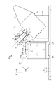
図5及び図6は、第1の実施形態に係るEUV光生成システム100の構成を概略的に示す。図5において、EUV光生成システム100は、EUV光生成装置1と、架台110と、を含む。EUV光生成装置1は、比較例のEUV光生成装置1と同様の構成である。2.1 Configuration 2.1.1 Overall Configuration FIGS. 5 and 6 schematically show the configuration of the EUV
架台110は、架台本体111と、ターゲット位置調整部としてのステージ18と、を含む。架台本体111は、台座部120と、保持部130と、を含む。台座部120は、複数の第1の梁121と、複数の柱122と、複数の第2の梁123と、を含む。第1の梁121は、柱122により支持されている。柱122は、第2の梁123により支持されている。第2の梁123には、複数のスライダ124が設けられている。 The
前述のチャンバ10を移動させるための移動機構42は、床上に設置されたベース42aと、このベース42a上に設置された1つ又は複数のリニアレール42bと、を含む。リニアレール42bは、重力方向に直交する水平平面内で、かつX方向に直交する方向に延在している。リニアレール42bには、前述のチャンバ台10aが移動自在に設けられている。 A moving
架台本体111に設けられたスライダ124は、リニアレール42bに摺動自在に係合している。移動機構42により、架台本体111は、重力方向に直交する水平面内で、かつX方向に直交する方向に移動可能となっている。なお、架台本体111には、スライダ124に代えて、リニアレール42bと係合する車輪が設けられていてもよい。 A
第1の梁121には、保持部130が接続されている。保持部130は、台座部120に固定される第1の部材131と、ターゲット生成装置12を保持する第2の部材132と、を含む。第1の部材131と第2の部材132は接合されている。第1の部材131は、固定ボルト131aによって台座部120に固定されている。本実施形態では、第1の部材131は、第1の梁121に接合されている。なお、本実施形態では、保持部130は、架台本体111と一体に形成されていてもよい。 A holding
第2の部材132には、ターゲット生成装置12が挿通される開口部132aが形成されている。開口部132aには、ターゲット生成装置12をチャンバ10の装着部16に取り付けるための取付フランジ133が接続されている。取付フランジ133には、液滴DLの出力方向となる姿勢でターゲット生成装置12が取り付けられる。また、取付フランジ133の一端には、前述のステージ18が接続されている。取付フランジ133の他端は、チャンバ10の装着部16に接続される。 The
ステージ18は、ターゲット生成装置12の接続部39と、取付フランジ133との間に接続される。ステージ18は、取付フランジ133に対してターゲット生成装置12を、液滴DLの射出軸であるY軸に直交するX方向及びZ方向にそれぞれ移動させる。X方向及びZ方向は、それぞれ第1の方向及び第2の方向に対応する。 The
2.1.2 ステージ
図7は、ステージ18の構成を示す断面図である。ステージ18は、X軸ステージ181aと、X軸リニアガイド181bと、X軸サドル181cと、Z軸ステージ182aと、Z軸リニアガイド182bと、Z軸サドル182cと、ベース部材183と、を含む。ステージ18は、2次元ステージである。2.1.2 Stage FIG. 7 is a sectional view showing the configuration of the
X軸ステージ181aは、制御部13からの制御に基づき、X方向に駆動される。X軸リニアガイド181bは、X軸ステージ181aに接続されている。X軸サドル181cは、X軸リニアガイド181bをX方向に摺動自在に保持する。X軸サドル181cは、ベース部材183に固定されている。ベース部材183は、固定ボルト140によって取付フランジ133に固定されている。取付フランジ133は、固定ボルト141によって第2の部材132に固定されている。 The
Z軸ステージ182aは、制御部13からの制御に基づき、Z方向に駆動される。Z軸リニアガイド182bは、Z軸ステージ182aに接続されている。Z軸サドル182cは、Z軸リニアガイド182bをZ方向に摺動自在に保持する。Z軸サドル182cは、X軸ステージ181a上に固定されている。 The Z-
Z軸ステージ182a上には、ターゲット生成装置12が取り付けられる円環状の取付部143が固定されている。取付部143には、ターゲット生成装置12の接続部39が着脱自在に取り付けられる。取付部143と取付フランジ133との間には、ベローズ142が接続されている。ベローズ142と取付フランジ133とは、ターゲット生成装置12のタンク30の周囲を覆っている。取付フランジ133がチャンバ10の装着部16に装着された状態において、タンク30及びノズル31は、ベローズ142と取付フランジ133と接続部39とにより、チャンバ10内に連通し、気密に封止される。 An
2.2 動作
図5及び図6を参照して、EUV光生成システム100におけるターゲット生成装置12の取り付け及び取り外し方法について説明する。まず、図5に示すように、架台本体111をチャンバ10から離間させた状態で、架台本体111にターゲット生成装置12を取り付ける。具体的には、タンク30をベローズ142及び取付フランジ133内に挿通させる。2.2 Operation A method of attaching and detaching the
次に、移動機構42により、架台本体111をチャンバ10に近接する方向に水平移動させ、図6に示すように、架台本体111をチャンバ10に近接させた状態で、取付フランジ133をチャンバ10の装着部16に取り付ける。そして、ターゲット生成装置12の接続部39を取付部143に取り付ける。EUV光生成システム100は、図6に示す状態で、ターゲット生成装置12による液滴DLの出力と、ドライバレーザ11によるパルスレーザ光11aの出力とを行わせ、EUV光を生成させる。したがって、ステージ18は、架台本体111により保持されたターゲット生成装置12をチャンバ10に取り付けた状態で、ターゲット生成装置12とチャンバ10との相対位置を調整する。 Next, the moving
この後、ターゲット生成装置12を交換する場合には、取付フランジ133とチャンバ10の装着部16との接続を解除し、ターゲット生成装置12の接続部39と取付部143との接続を解除する。そして、ターゲット生成装置12をチャンバ10から取り外し、移動機構42により、架台本体111をチャンバ10から離間する方向に水平移動させる。そして、図5に示す状態で、ターゲット生成装置12を架台本体111から取り外し、新たなターゲット生成装置12と交換する。 After that, when replacing the
2.3 効果
第1の実施形態では、架台本体111にターゲット生成装置12を保持したままターゲット生成装置12をチャンバ10に接続して、ターゲット生成装置12を動作させる。このため、ターゲット生成装置12が大型化した場合であっても、ターゲット生成装置12のチャンバ10への取り付け及び取り外しを容易に行うことができる。これにより、メンテナンス性が向上する。2.3 Effect In the first embodiment, the
また、第1の実施形態では、ターゲット生成装置12を架台本体111で保持したままターゲット生成装置12のチャンバ10に対する位置合わせを行うことができるので、位置合わせ精度が向上する。 Further, in the first embodiment, alignment of the
また、第1の実施形態では、架台本体111にステージ18を設けているので、ターゲット生成装置12の大型化に伴ってステージ18が大型化したとしても、ターゲット生成装置12のチャンバ10への取り付け及び取り外しを容易に行うことができる。さらに、架台本体111によりターゲット生成装置12及びステージ18を保持しているので、ターゲット生成装置12及びステージ18からの荷重でチャンバ10が変形することを抑制することができる。これにより、チャンバ10に対するターゲット生成装置12の位置精度が向上する。 Further, in the first embodiment, since the
3.第2の実施形態
次に、本開示の第2の実施形態に係るEUV光生成システムについて説明する。以下では、比較例の構成要素と同じ部分については、同一の符号を付し、適宜説明を省略する。3. Second Embodiment Next, an EUV light generation system according to a second embodiment of the present disclosure will be described. Below, the same reference numerals are given to the same parts as the components of the comparative example, and the description thereof will be omitted as appropriate.
3.1 構成
第2の実施形態に係るEUV光生成システム100aは、EUV光生成装置1と、架台110aと、を含む。EUV光生成装置1は、比較例のEUV光生成装置1と同様の構成である。3.1 Configuration An EUV
架台110aは、架台本体111aと、ステージ18と、を含む。ステージ18は、第1の実施形態と同様の構成である。架台本体111aは、台座部120aと、保持部130aと、を含む。また、チャンバ10及び架台本体111aを移動させるための移動機構42は、第1の実施形態と同様の構成である。 The
第1の梁121には、保持部130aが接続されている。保持部130aは、第1の部材131と、第2の部材132と、を含む。第1の部材131と第2の部材132は接合されている。本実施形態では、第1の部材131と第2の部材132との接合部には、回転軸134が設けられている。回転軸134は、X方向に平行である。なお、回転軸134は、ターゲット生成装置12の姿勢を変化させる姿勢可変機構を構成している。本実施形態では、固定ボルト131aを外して、第1の部材131と台座部120aとの固定を解除することにより、保持部130aを、回転軸134を中心として回転させることができる。 A holding
本実施形態では、第1の部材131と台座部120aとの固定は解除可能とされている。具体的には、第1の部材131と台座部120aとは、図示しない固定ボルトにより固定されており、この固定ボルトを外すことにより、第1の部材131と台座部120aとの固定を解除することができる。第1の部材131と台座部120aとの固定を解除した状態において、保持部130aを、回転軸134を中心として回転させることができる。 In this embodiment, the fixation between the
台座部120aは、基本的に第1の実施形態の台座部120と同様の構成である。本実施形態の台座部120aの構成は、垂直位置決めブラケット135が設けられている点のみが、第1の実施形態の台座部120の構成と異なる。垂直位置決めブラケット135は、図10に示すように、保持部130aを回転させた場合に、液滴の射出軸である中心軸Lが垂直方向となる状態でターゲット生成装置12を位置決めする位置に設けられた位置決め部材である。 The
3.2 動作
図8~図11を参照して、EUV光生成システム100aにおけるターゲット生成装置12の取り付け及び取り外し方法について説明する。まず、図10に示すように、第1の部材131と台座部120aとの固定を解除し、保持部130aを回転軸134を中心として回転させ、保持部130aを垂直位置決めブラケット135に当接させる。この状態で、ターゲット生成装置12を、クレーン等を用いて上方から垂直方向に降下させることにより、保持部130aに装着する。3.2 Operation A method of attaching and detaching the
次に、保持部130aを回転させ、第1の部材131と台座部120aとを固定することにより、図8に示すように、ターゲット生成装置12を斜めの状態とする。そして、第1の実施形態と同様に、移動機構42により、架台本体111aをチャンバ10に近接する方向に水平移動させ、図9に示すように、架台本体111aをチャンバ10に近接させた状態で、取付フランジ133をチャンバ10の装着部16に取り付ける。この後、第1の実施形態と同様に、EUV光生成システム100aの動作を行わせる。 Next, by rotating the holding
ターゲット生成装置12を交換する場合には、第1の実施形態と同様の方法でターゲット生成装置12をチャンバ10から取り外し、移動機構42により、架台本体111aをチャンバ10から離間する方向に水平移動させる。そして、図8に示す状態で、第1の部材131と台座部120aとの固定を解除し、保持部130aを回転軸134を中心として回転させ、保持部130aを垂直位置決めブラケット135に当接させる。 When replacing the
この後、図11に示すように、クレーン等を用いてターゲット生成装置12を垂直方向に上昇させることにより、ターゲット生成装置12を架台本体111aから取り外し、新たなターゲット生成装置12と交換する。 Thereafter, as shown in FIG. 11, the
3.3 効果
第1の実施形態では、保持部130aを回動可能としているので、架台本体111aは、ステージ18とターゲット生成装置12とを保持したまま、ターゲット生成装置12の姿勢を変化させ、中心軸Lが垂直方向となる状態とすることができる。このため、ターゲット生成装置12を斜めに引き出す場合に必要となる専用の交換治具を用いることなく、一般的なクレーン等によりターゲット生成装置12交換することができる。3.3 Effect In the first embodiment, since the holding
なお、本実施形態では、架台本体111aに垂直位置決めブラケット135を設けているが、この垂直位置決めブラケット135を架台本体111aから取り外し可能としてもよい。図10及び図11に示すように、保持部130aを回転させる場合にのみ、垂直位置決めブラケット135を架台本体111aに取り付けてもよい。 In this embodiment, the
4.第3の実施形態
次に、本開示の第3の実施形態に係るEUV光生成システムについて説明する。以下では、比較例の構成要素と同じ部分については、同一の符号を付し、適宜説明を省略する。4. Third Embodiment Next, an EUV light generation system according to a third embodiment of the present disclosure will be described. Below, the same reference numerals are given to the same parts as the components of the comparative example, and the description thereof will be omitted as appropriate.
4.1 構成
図12及び図13は、第3の実施形態に係るEUV光生成システムに含まれる架台110bの構成を示す。架台110bは、ステージ18のチャンバ10に対する接続位置を調整するアライメント調整機構を含むこと以外は、第2の実施形態の架台110aと同様の構成である。4.1 Configuration FIGS. 12 and 13 show the configuration of the
架台110bは、架台本体111bと、ステージ18と、を含む。ステージ18は、第1の実施形態と同様の構成である。架台本体111bは、台座部120bと、保持部130bと、を含む。台座部120bは、第2の実施形態の台座部120aと同様の構成である。本実施形態では、保持部130bは、より具体的に示されている。保持部130bは、第1の部材131と、第2の部材132と、回転軸134と、を含む。なお、本実施形態では、第1の部材131と第2の部材132とは分離さており、回転軸134は、第1の部材131に設けられている。 The
本実施形態では、保持部130bには、第1のアライメント調整機構と、第2のアライメント調整機構と、第3のアライメント調整機構と、が含まれる。第1のアライメント調整機構は、第1の固定ボルト150と、第1の調整シム151とにより構成されている。第1の固定ボルト150は、第1の部材131と第2の部材132とを垂直方向に接続する。第1の調整シム151は、第1の固定ボルト150により接続される第1の部材131と第2の部材132との部分に介装される。すなわち、第1の固定ボルト150は、第1の調整シム151を介して、第1の部材131と第2の部材132との間に締結される。したがって、第1の調整シム151の厚みや数を変更することにより、ステージ18の垂直方向に関する位置を調整することができる。本実施形態では、図13に示すように、第1の固定ボルト150は、4箇所に設けられている。 In this embodiment, the holding
第2のアライメント調整機構は、第2の固定ボルト152と、第2の調整シム153とにより構成されている。第2の固定ボルト152は、第1の部材131と第2の部材132とを水平方向に接続する。第2の調整シム153は、第2の固定ボルト152により接続される第1の部材131と第2の部材132との部分に介装される。すなわち、第2の固定ボルト152は、第2の調整シム153を介して、第1の部材131と第2の部材132との間に締結される。したがって、第2の調整シム153の厚みや数を変更することにより、ステージ18の水平方向に関する位置を調整することができる。本実施形態では、図13に示すように、第2の固定ボルト152は、2箇所に設けられている。 A second alignment adjustment mechanism is composed of a
図14及び図15は、第3のアライメント調整機構の構成を示す。第3のアライメント調整機構は、アライメントブロック160と、第1の押しボルト161と、第2の押しボルト162と、を含む。これらは、それぞれ、ステージ18に接続された取付フランジ133に対して、左右対称な位置に複数設けられている。 14 and 15 show the configuration of the third alignment adjustment mechanism. A third alignment adjustment mechanism includes an
アライメントブロック160は、第2の部材132に接続されている。なお、アライメントブロック160は、第2の部材132と一体に設けられていてもよい。第1の押しボルト161は、ロックナット161aを介して、アライメントブロック160に形成されたネジ孔に螺合されており、先端部が、取付フランジ133に形成された凸部133aをZ方向に押圧する。第1の押しボルト161及びロックナット161aは、凸部133aを挟み込むように、凸部133aに対して2つずつ設けられている。凸部133aは、取付フランジ133の左右に1つずつ設けられている。
第2の押しボルト162は、ロックナット162aを介して、アライメントブロック160に形成されたネジ孔に螺合されており、先端部が、凸部133aをX方向に押圧する。第2の押しボルト162及びロックナット162aは、取付フランジ133に対して左右対称な位置に設けられている。 The
また、ステージ18は、複数のステージ固定ネジ163により第2の部材132に固定されている。 Also, the
第1の押しボルト161の押し込み量を変更することにより、ステージ18のZ方向に関する位置を調整することができる。また、第2の押しボルト162の押し込み量を変更することにより、ステージ18のX方向に関する位置を調整することができる。 By changing the pushing amount of the
第1の押しボルト161及び第2の押しボルト162の押し込み量の変更は、ステージ固定ネジ163の締結を緩めた状態で行われる。押し込み量の変更後に、ステージ固定ネジ163を締結し、ステージ18を第2の部材132に固定すればよい。 The pushing amounts of the
4.2 効果
第3の実施形態では、保持部130bにアライメント調整機構を設けているので、ステージ18のチャンバ10に対する接続位置を調整することができる。例えば、第1~第3のアライメント調整機構によりステージ18の位置調整を行うことによって、液滴DLの射出軸である中心軸Lと、チャンバ10の装着部16の中心軸との同軸度や、取付フランジ133と装着部16との間隔を調整することができる。これにより、ターゲット生成装置12の交換時における液滴DLの射出軸の位置精度を高めることができる。4.2 Effect In the third embodiment, since the holding
5.露光装置
次に、露光装置2の構成について説明する。図16において、露光装置2は、照明光学系200と投影光学系210とを含む。照明光学系200は、EUV光生成システム100から入射した極端紫外光によって、レチクルステージRTのレチクルパターンを照明する。投影光学系210は、レチクルを透過した極端紫外光を、縮小投影してワークピーステーブルWT上に配置された図示しないワークピースに結像させる。ワークピースはフォトレジストが塗布された半導体ウエハ等の感光基板である。
5. Exposure Apparatus Next, the configuration of the
露光装置2は、レチクルステージRTとワークピーステーブルWTとを同期して平行移動させることにより、レチクルパターンを反映した極端紫外光をワークピースに露光する。以上のような露光工程を利用して半導体デバイスを製造する。以上のような露光工程によって半導体ウエハにデバイスパターンを転写し、加工することで半導体デバイスを製造することができる。
The
第1の実施形態に係るEUV光生成システム100に代えて、第2の実施形態に係るEUV光生成システム100aや、第3の実施形態に係るEUV光生成システム100bを用いてもよい。 The EUV
上記の説明は、制限ではなく単なる例示を意図したものである。従って、添付の特許請求の範囲を逸脱することなく本開示の各実施形態に変更を加えることができることは、当業者には明らかであろう。 The descriptions above are intended to be illustrative only, not limiting. Accordingly, it will be apparent to those skilled in the art that modifications can be made to the embodiments of the present disclosure without departing from the scope of the appended claims.
本明細書及び添付の特許請求の範囲全体で使用される用語は、「限定的でない」用語と解釈されるべきである。例えば、「含む」又は「含まれる」という用語は、「含まれるものとして記載されたものに限定されない」と解釈されるべきである。「有する」という用語は、「有するものとして記載されたものに限定されない」と解釈されるべきである。また、本明細書及び添付の特許請求の範囲に記載される修飾句「1つの」は、「少なくとも1つ」又は「1又はそれ以上」を意味すると解釈されるべきである。 The terms used throughout this specification and the appended claims should be interpreted as “non-limiting” terms. For example, the terms "including" or "included" should be interpreted as "not limited to what is stated to be included." The term "having" should be interpreted as "not limited to what is described as having". Also, the modifier "a," as used in this specification and the appended claims, should be interpreted to mean "at least one" or "one or more."
Claims (15)
A.極端紫外光生成用のターゲット物質をチャンバ内に液滴として出力するターゲット生成装置を着脱自在に保持する保持部を有し、チャンバと離間した架台本体;
B.前記保持部に設けられ、前記チャンバに対する前記ターゲット生成装置の相対位置を調整するターゲット位置調整部;及び
C.前記架台本体を水平方向に移動して前記保持部に保持された前記ターゲット生成装置を前記チャンバから離す移動機構。 A cradle comprising:
A. A gantry main body separated from the chamber, having a holding part detachably holding a target generation device for outputting droplets of a target material for generating extreme ultraviolet light into the chamber;
B. B. a target position adjustment part provided in the holding part for adjusting the relative position of the target generation device with respect to the chamber; A moving mechanism for moving the gantry body in a horizontal direction to separate the target generation device held by the holding part from the chamber .
前記ターゲット位置調整部は、液滴の射出軸に直交する2方向に前記ターゲット生成装置を移動させるステージである。The pedestal according to claim 1,
The target position adjustment unit is a stage that moves the target generation device in two directions orthogonal to the droplet ejection axis.
前記移動機構は、前記架台本体に設けられたスライダと、前記スライダが摺動自在に係合するリニアレールとを含む。The pedestal according to claim 1,
The moving mechanism includes a slider provided on the gantry body and a linear rail with which the slider is slidably engaged.
D.前記ターゲット生成装置の姿勢を変化させる姿勢可変機構。10. The cradle of claim 1, further comprising:
D. An attitude variable mechanism that changes the attitude of the target generation device.
前記姿勢可変機構は、前記保持部を回転させる回転軸により構成される。The pedestal according to claim 4,
The attitude variable mechanism is configured by a rotating shaft that rotates the holding section.
前記姿勢可変機構は、前記ターゲット生成装置を、液滴の射出軸が垂直方向となる姿勢に位置決めする位置決め部材を含む。The pedestal according to claim 5,
The posture variable mechanism includes a positioning member that positions the target generation device in a posture in which the droplet ejection axis is vertical.
前記位置決め部材は、前記架台本体に設けられ、前記保持部が当接するブラケットである。The gantry according to claim 6,
The positioning member is a bracket provided on the gantry main body and with which the holding portion abuts.
E.前記ターゲット位置調整部の前記チャンバに対する接続位置を調整するアライメント調整機構。10. The cradle of claim 1, further comprising:
E. An alignment adjustment mechanism that adjusts a connection position of the target position adjustment unit with respect to the chamber.
前記保持部は、第1の部材と、前記第1の部材とは分離され、前記ターゲット位置調整部及び前記ターゲット生成装置を保持する第2の部材とを含み、
前記アライメント調整機構は、前記第1の部材と前記第2の部材とを接続する固定ボルトと、前記第1の部材と前記第2の部材との間に配置される調整シムとを含む。The pedestal according to claim 8,
The holding section includes a first member and a second member separated from the first member and holding the target position adjusting section and the target generating device,
The alignment adjustment mechanism includes a fixing bolt that connects the first member and the second member, and an adjustment shim that is arranged between the first member and the second member.
前記固定ボルトは、前記第1の部材と前記第2の部材とを垂直方向に接続する第1の固定ボルトと、前記第1の部材と前記第2の部材とを水平方向に接続する第2の固定ボルトとを含み、
前記調整シムは、前記第1の固定ボルトにより接続される前記第1の部材と前記第2の部材との部分に介装される第1の調整シムと、前記第2の固定ボルトにより接続される前記第1の部材と前記第2の部材との部分に介装される第2の調整シムとを含む。The pedestal according to claim 9,
The fixing bolt includes a first fixing bolt vertically connecting the first member and the second member, and a second fixing bolt horizontally connecting the first member and the second member. fixing bolts of
The adjusting shim is connected by the second fixing bolt to a first adjusting shim interposed between the first member and the second member connected by the first fixing bolt. and a second adjusting shim interposed between the first member and the second member.
前記アライメント調整機構は、前記保持部と前記ターゲット位置調整部との間に接続され、前記ターゲット位置調整部を押圧する押しボルトを含む。The pedestal according to claim 8,
The alignment adjustment mechanism includes a push bolt connected between the holding section and the target position adjustment section to press the target position adjustment section.
前記押しボルトは、前記ターゲット位置調整部を、液滴の射出軸と直交する方向に押圧する。A cradle according to claim 11, comprising:
The push bolt presses the target position adjustment section in a direction perpendicular to the droplet ejection axis.
前記押しボルトは、前記ターゲット位置調整部を前記射出軸と直交する第1の方向に押圧する第1の押しボルトと、前記ターゲット位置調整部を前記射出軸及び前記第1の方向と直交する第2の方向に押圧する第2の押しボルトとを含む。A cradle according to claim 12, comprising:
The push bolts include a first push bolt that presses the target position adjustment section in a first direction perpendicular to the injection axis, and a first push bolt that pushes the target position adjustment section in a first direction perpendicular to the injection axis and the first direction. and a second push bolt that pushes in two directions.
F.請求項1に記載の架台;及び
G.前記架台に保持された前記ターゲット生成装置が装着されるチャンバ。An extreme ultraviolet light generating system comprising:
F. G. A cradle according to claim 1; A chamber in which the target generation device held by the pedestal is mounted.
請求項14に記載の極端紫外光生成システムから出力される極端紫外光によりワークピースに露光するステップ。 A method of manufacturing a device, comprising the steps of:
15. Exposing a workpiece with extreme ultraviolet light output from the extreme ultraviolet light generating system of claim 14.
Applications Claiming Priority (1)
| Application Number | Priority Date | Filing Date | Title |
|---|---|---|---|
| PCT/JP2018/009728 WO2019175964A1 (en) | 2018-03-13 | 2018-03-13 | Frame, extreme ultraviolet light generation system, and method for manufacturing device |
Publications (2)
| Publication Number | Publication Date |
|---|---|
| JPWO2019175964A1 JPWO2019175964A1 (en) | 2021-03-18 |
| JP7110323B2 true JP7110323B2 (en) | 2022-08-01 |
Family
ID=67906545
Family Applications (1)
| Application Number | Title | Priority Date | Filing Date |
|---|---|---|---|
| JP2020505984A Active JP7110323B2 (en) | 2018-03-13 | 2018-03-13 | Stand, extreme ultraviolet light generation system, and device manufacturing method |
Country Status (3)
| Country | Link |
|---|---|
| US (1) | US11061340B2 (en) |
| JP (1) | JP7110323B2 (en) |
| WO (1) | WO2019175964A1 (en) |
Citations (11)
| Publication number | Priority date | Publication date | Assignee | Title |
|---|---|---|---|---|
| JP2010080941A (en) | 2008-08-29 | 2010-04-08 | Komatsu Ltd | Extreme ultraviolet light source device |
| JP2011165943A (en) | 2010-02-10 | 2011-08-25 | Komatsu Ltd | Extreme ultraviolet light source device |
| JP2013069655A (en) | 2011-03-30 | 2013-04-18 | Gigaphoton Inc | Extreme ultraviolet light generation apparatus |
| JP2014517980A (en) | 2011-04-05 | 2014-07-24 | イーティーエイチ・チューリッヒ | Droplet supply device and light source including the droplet supply device |
| JP2014175474A (en) | 2013-03-08 | 2014-09-22 | Gigaphoton Inc | Chamber for extreme ultraviolet light generation apparatus and extreme ultraviolet light generation apparatus |
| WO2017042974A1 (en) | 2015-09-11 | 2017-03-16 | ギガフォトン株式会社 | Extreme ultraviolet light generation device |
| JP2017097382A (en) | 2017-02-20 | 2017-06-01 | ギガフォトン株式会社 | Target supply apparatus |
| WO2017130346A1 (en) | 2016-01-28 | 2017-08-03 | ギガフォトン株式会社 | Extreme ultraviolet light generation device |
| WO2017154528A1 (en) | 2016-03-08 | 2017-09-14 | ギガフォトン株式会社 | Extreme ultraviolet light generating apparatus |
| WO2017164251A1 (en) | 2016-03-23 | 2017-09-28 | ギガフォトン株式会社 | Extreme ultraviolet light generator and method for controlling centroid of extreme ultraviolet light |
| WO2018092227A1 (en) | 2016-11-17 | 2018-05-24 | ギガフォトン株式会社 | Carriage for replacing target generation device, target generation device replacement system, and method for replacing target generation device |
Family Cites Families (9)
| Publication number | Priority date | Publication date | Assignee | Title |
|---|---|---|---|---|
| JP2001350000A (en) * | 2000-06-09 | 2001-12-21 | Mitsubishi Heavy Ind Ltd | Target truck for neutron scattering facility |
| JP4943121B2 (en) | 2006-11-07 | 2012-05-30 | 株式会社小松製作所 | Extreme ultraviolet light source device and collector mirror replacement method |
| JP2009006802A (en) | 2007-06-27 | 2009-01-15 | Miura Co Ltd | Parent and child wheeled cart |
| FI120418B (en) | 2007-12-27 | 2009-10-15 | Sandvik Mining & Constr Oy | Method and equipment for low-input mining |
| JP5474522B2 (en) | 2009-01-14 | 2014-04-16 | ギガフォトン株式会社 | Extreme ultraviolet light source system |
| JP6080481B2 (en) * | 2012-01-26 | 2017-02-15 | ギガフォトン株式会社 | Extreme ultraviolet light generator |
| JP6099241B2 (en) * | 2012-06-28 | 2017-03-22 | ギガフォトン株式会社 | Target supply device |
| JP6448661B2 (en) * | 2014-11-20 | 2019-01-09 | ギガフォトン株式会社 | Extreme ultraviolet light generator |
| US10211589B2 (en) | 2015-04-20 | 2019-02-19 | Mitsubishi Electric Corporation | Laser apparatus and extreme ultraviolet light generation apparatus |
-
2018
- 2018-03-13 WO PCT/JP2018/009728 patent/WO2019175964A1/en active Application Filing
- 2018-03-13 JP JP2020505984A patent/JP7110323B2/en active Active
-
2020
- 2020-08-04 US US16/985,148 patent/US11061340B2/en active Active
Patent Citations (11)
| Publication number | Priority date | Publication date | Assignee | Title |
|---|---|---|---|---|
| JP2010080941A (en) | 2008-08-29 | 2010-04-08 | Komatsu Ltd | Extreme ultraviolet light source device |
| JP2011165943A (en) | 2010-02-10 | 2011-08-25 | Komatsu Ltd | Extreme ultraviolet light source device |
| JP2013069655A (en) | 2011-03-30 | 2013-04-18 | Gigaphoton Inc | Extreme ultraviolet light generation apparatus |
| JP2014517980A (en) | 2011-04-05 | 2014-07-24 | イーティーエイチ・チューリッヒ | Droplet supply device and light source including the droplet supply device |
| JP2014175474A (en) | 2013-03-08 | 2014-09-22 | Gigaphoton Inc | Chamber for extreme ultraviolet light generation apparatus and extreme ultraviolet light generation apparatus |
| WO2017042974A1 (en) | 2015-09-11 | 2017-03-16 | ギガフォトン株式会社 | Extreme ultraviolet light generation device |
| WO2017130346A1 (en) | 2016-01-28 | 2017-08-03 | ギガフォトン株式会社 | Extreme ultraviolet light generation device |
| WO2017154528A1 (en) | 2016-03-08 | 2017-09-14 | ギガフォトン株式会社 | Extreme ultraviolet light generating apparatus |
| WO2017164251A1 (en) | 2016-03-23 | 2017-09-28 | ギガフォトン株式会社 | Extreme ultraviolet light generator and method for controlling centroid of extreme ultraviolet light |
| WO2018092227A1 (en) | 2016-11-17 | 2018-05-24 | ギガフォトン株式会社 | Carriage for replacing target generation device, target generation device replacement system, and method for replacing target generation device |
| JP2017097382A (en) | 2017-02-20 | 2017-06-01 | ギガフォトン株式会社 | Target supply apparatus |
Also Published As
| Publication number | Publication date |
|---|---|
| US11061340B2 (en) | 2021-07-13 |
| US20200363733A1 (en) | 2020-11-19 |
| JPWO2019175964A1 (en) | 2021-03-18 |
| WO2019175964A1 (en) | 2019-09-19 |
Similar Documents
| Publication | Publication Date | Title |
|---|---|---|
| US9429847B2 (en) | Extreme ultraviolet light source apparatus | |
| JP4799620B2 (en) | Radiation system and lithographic apparatus | |
| US8884257B2 (en) | Chamber apparatus and extreme ultraviolet light generation system | |
| US9894743B2 (en) | Extreme ultraviolet light generation apparatus | |
| Tichenor et al. | System integration and performance of the EUV engineering test stand | |
| JP7356439B2 (en) | Spatial modulation of a light beam | |
| JP2011029587A (en) | Extreme ultraviolet light source system | |
| NL2004085A (en) | Radiation source, lithographic apparatus, and device manufacturing method. | |
| WO2020148155A1 (en) | Target delivery system | |
| JP2013175431A (en) | Extreme ultraviolet radiation generation apparatus | |
| US10455679B2 (en) | Extreme ultraviolet light generation device | |
| US10698316B2 (en) | Target generation device replacement trolley, target generation device replacement system, and target generation device replacement method | |
| KR101959369B1 (en) | Radiation source | |
| JP7110323B2 (en) | Stand, extreme ultraviolet light generation system, and device manufacturing method | |
| JP2022532840A (en) | Extreme UV light source protection system | |
| US11533799B1 (en) | System and method for supplying target material in an EUV light source | |
| JP7473534B2 (en) | Target Formation Equipment | |
| KR20230013038A (en) | Hybrid Droplet Generator for EUV Light Sources in Lithography Radiation Systems | |
| JP6314257B2 (en) | Extreme ultraviolet light generator | |
| JP6976334B2 (en) | Extreme UV light generator and maintenance method |
Legal Events
| Date | Code | Title | Description |
|---|---|---|---|
| A621 | Written request for application examination |
Free format text: JAPANESE INTERMEDIATE CODE: A621 Effective date: 20210201 |
|
| A131 | Notification of reasons for refusal |
Free format text: JAPANESE INTERMEDIATE CODE: A131 Effective date: 20211209 |
|
| A601 | Written request for extension of time |
Free format text: JAPANESE INTERMEDIATE CODE: A601 Effective date: 20211210 |
|
| A521 | Request for written amendment filed |
Free format text: JAPANESE INTERMEDIATE CODE: A523 Effective date: 20220329 |
|
| TRDD | Decision of grant or rejection written | ||
| A01 | Written decision to grant a patent or to grant a registration (utility model) |
Free format text: JAPANESE INTERMEDIATE CODE: A01 Effective date: 20220705 |
|
| A61 | First payment of annual fees (during grant procedure) |
Free format text: JAPANESE INTERMEDIATE CODE: A61 Effective date: 20220720 |
|
| R150 | Certificate of patent or registration of utility model |
Ref document number: 7110323 Country of ref document: JP Free format text: JAPANESE INTERMEDIATE CODE: R150 |