JP7106397B2 - hot air heater - Google Patents
hot air heater Download PDFInfo
- Publication number
- JP7106397B2 JP7106397B2 JP2018162222A JP2018162222A JP7106397B2 JP 7106397 B2 JP7106397 B2 JP 7106397B2 JP 2018162222 A JP2018162222 A JP 2018162222A JP 2018162222 A JP2018162222 A JP 2018162222A JP 7106397 B2 JP7106397 B2 JP 7106397B2
- Authority
- JP
- Japan
- Prior art keywords
- angle
- blades
- blade
- full
- detection signal
- Prior art date
- Legal status (The legal status is an assumption and is not a legal conclusion. Google has not performed a legal analysis and makes no representation as to the accuracy of the status listed.)
- Active
Links
Images


Classifications
-
- Y—GENERAL TAGGING OF NEW TECHNOLOGICAL DEVELOPMENTS; GENERAL TAGGING OF CROSS-SECTIONAL TECHNOLOGIES SPANNING OVER SEVERAL SECTIONS OF THE IPC; TECHNICAL SUBJECTS COVERED BY FORMER USPC CROSS-REFERENCE ART COLLECTIONS [XRACs] AND DIGESTS
- Y02—TECHNOLOGIES OR APPLICATIONS FOR MITIGATION OR ADAPTATION AGAINST CLIMATE CHANGE
- Y02B—CLIMATE CHANGE MITIGATION TECHNOLOGIES RELATED TO BUILDINGS, e.g. HOUSING, HOUSE APPLIANCES OR RELATED END-USER APPLICATIONS
- Y02B30/00—Energy efficient heating, ventilation or air conditioning [HVAC]
Landscapes
- Direct Air Heating By Heater Or Combustion Gas (AREA)
Description
本発明は、温風を発生させて室内を暖房する温風暖房装置に関するものである。 TECHNICAL FIELD The present invention relates to a warm air heating device that heats a room by generating warm air.
従来、この種の暖房装置としては、例えば、本体内にバーナ等の熱発生手段を備え、バーナで発生した燃焼ガスと本体に取り込んだ室内の空気とを混合して温風とし、この温風を本体前面に設けた吹出口から吹き出して室内を暖房するものが知られている。そして、この吹出口には、上下に回動可能な羽根を設けて、吹出される温風の風量に応じて羽根を上下に回動(スイング)させることにより、室内の温度分布を均一にして、暖房効果を高めるようにしたものがある。また、このときの羽根の回動角度は、バーナでの燃焼量が大きくなるほど角度を大にして略水平状態に近づくように制御されている。 Conventionally, as this type of heating device, for example, a heat generating means such as a burner is provided in the main body, and the combustion gas generated by the burner and the indoor air taken into the main body are mixed to generate warm air. It is known to heat the room by blowing out from an outlet provided on the front surface of the main body. The air outlet is provided with blades that can be rotated up and down, and by swinging the blades up and down according to the amount of hot air that is blown out, the temperature distribution in the room is made uniform. , there are those designed to increase the heating effect. Further, the angle of rotation of the blades at this time is controlled so that the greater the amount of combustion in the burner, the greater the angle, and the closer to a substantially horizontal state.
このように、可動する羽根を備える暖房装置においては、例えば本体の前面に障害物があって羽根の動きが制限されたり、羽根を駆動するモータの故障などにより、羽根が正しく動作しないような場合には、温風の吹き出しが阻害されて本体や床面を加熱してしまうという問題が発生する。そこで、羽根が正しく動作しているかをチェックして、その動作が確認できない時には運転を停止することで、機器の安全性を確保するようになっている。 In this way, in a heating device equipped with movable blades, for example, if there is an obstacle in front of the main body and the movement of the blades is restricted, or if the blades do not operate properly due to a failure of the motor that drives the blades, etc. However, there is a problem in that hot air blowout is blocked and the main body and the floor surface are heated. Therefore, the safety of the equipment is ensured by checking whether the blades are operating correctly and stopping the operation when the operation cannot be confirmed.
そして、羽根の動作チェック方法としては、一旦羽根を基準点、例えば全開の状態まで回動させた後、元の位置まで復帰させることが提案されており、羽根が全開位置に到達したことはリミットスイッチなどの検知手段によって検知されるようになっている(例えば、特許文献1)。 As a method for checking the operation of the blades, it has been proposed to once rotate the blades to a reference point, for example, a fully open state, and then return them to the original position. It is designed to be detected by detecting means such as a switch (for example, Patent Document 1).
ところで、上述の羽根の動作チェックの際には、検知手段(リミットスイッチ)が正常に動作しているかの判定も同時に行うことができる。具体的には、羽根が元の位置に復帰したときに検知手段が羽根の全開を検知していなければ、検知手段は正常に動作していると判断することができる。 By the way, when checking the operation of the blades described above, it is also possible to simultaneously determine whether the detection means (limit switch) is operating normally. Specifically, if the detection means does not detect that the blades are fully opened when the blades return to their original positions, it can be determined that the detection means is operating normally.
しかしながら、全開の羽根の位置と、元の羽根の位置とが近い場合、検知手段の誤差や取り付け位置のばらつきなどによっては、羽根が元の位置に復帰していても検知手段が全開を検知してしまうことが起こり得る。この場合、検知手段には異常がないにもかかわらず、エラー判定が頻発して運転を停止してしまうため、使用者の快適性が損なわれてしまうおそれがある。 However, if the position of the fully opened blade is close to the original position of the blade, the detection means may not detect the full opening even if the blade returns to its original position due to errors in the detection means and variations in the mounting position. can happen. In this case, even though there is no abnormality in the detection means, the error determination occurs frequently and the operation is stopped, which may impair the user's comfort.
本発明は、検知手段の誤差などに起因する不要なエラー判定を回避して、安全性と快適性に優れた温風暖房装置を提供することを目的とする。 SUMMARY OF THE INVENTION It is an object of the present invention to provide a hot air heating apparatus that avoids unnecessary error determinations due to errors in detection means and that is excellent in safety and comfort.
本発明は、熱を発生する熱発生手段と、
温風を吹き出す吹出口と、
前記吹出口に設けられた回動可能な複数の羽根と、
前記羽根を回動させるモータと、
前記モータを駆動して前記羽根の動作を制御するとともに、前記羽根を全開位置まで開く全開動作を実行可能な制御部と、
前記全開動作の実行中において、前記羽根が所定角度に到達したときに全開検知信号を出力する角度検知手段と、を備え
前記制御部は、前記全開動作の実行後、前記羽根を目標角度に移動させるよう前記モータを制御し、前記羽根が前記目標角度に到達したときに前記角度検知手段から全開検知信号が出力されているかを判定し、前記角度検知手段が全開検知信号を出力している場合には、前記角度検知手段が全開検知信号を出力しなくなるまで前記羽根を回動するよう前記モータを制御し、そのときの前記羽根の位置を羽根回動動作の基点とする補正動作を実行する温風暖房装置である。
The present invention provides heat generating means for generating heat;
an outlet for blowing out hot air;
a plurality of rotatable blades provided at the outlet;
a motor for rotating the blades;
a control unit capable of driving the motor to control the operation of the blades and executing a fully open operation to open the blades to a fully open position;
angle detection means for outputting a full-open detection signal when the blade reaches a predetermined angle during execution of the full-open operation, wherein the control unit moves the blade to a target angle after the full-open operation is executed. and determining whether or not the angle detection means outputs a full-open detection signal when the blade reaches the target angle, and the angle detection means outputs the full-open detection signal. the motor is controlled to rotate the blades until the angle detecting means stops outputting the fully open detection signal, and a correction operation is performed using the position of the blades at that time as a base point of the blade rotation operation. It is a warm air heater.
上述のように構成することにより、不要なエラー判定を回避することができるため、安全性と快適性に優れた温風暖房装置となる。 By configuring as described above, unnecessary error determination can be avoided, so that the hot air heating device is excellent in safety and comfort.
好適と考える本発明の実施形態を、本発明の作用を示して簡単に説明する。 A preferred embodiment of the present invention will now be briefly described to illustrate the operation of the present invention.
本発明は、温風を吹き出す吹出口に、モータの駆動により回動する複数の羽根を備え、運転中に羽根を全開位置まで開く全開動作を実行する温風暖房装置であって、全開動作の実行中に全開検知信号を出力する角度検知手段が、全開動作の非実行中においても全開検知信号を出力している場合には、補正動作を実行して羽根の回動動作の基点を変更する。これにより、全開動作の非実行中に全開検知信号が出力されても、それが角度検知手段の検知誤差や取り付け位置のばらつきによって発生したものである場合には、羽根の回動動作の基点を変更することで運転を継続することができるため、異常がないにもかかわらず運転を停止してしまうという不要な異常判定を回避することができ、暖房装置を安全かつ快適に使用することができる。 The present invention is a hot air heating device that includes a plurality of blades rotated by driving a motor at an air outlet for blowing out hot air, and performs a fully open operation to open the blades to a fully open position during operation. When the angle detection means that outputs a full-open detection signal during execution outputs a full-open detection signal even during non-execution of the full-open operation, a correction operation is performed to change the base point of the rotation operation of the blades. . As a result, even if a full-open detection signal is output while the full-open operation is not being executed, if it is caused by a detection error of the angle detection means or a variation in the mounting position, the base point of the blade rotation operation can be detected. Since it is possible to continue operation by changing, it is possible to avoid unnecessary abnormality judgments such as stopping operation even though there is no abnormality, and it is possible to use the heating system safely and comfortably. .
また、補正動作におけるモータの制御量には上限値を設ける。角度検知手段の誤差や取り付け位置のばらつきとして許容される角度を制御量の上限値とし、モータを上限値で駆動したときに角度検知手段が全開検知信号を出力している場合は、異常と判定して運転を停止することで、不要な異常判定を確実に回避し安全に使用することができる。 Also, an upper limit value is set for the motor control amount in the correction operation. The upper limit of the control amount is the angle that is allowed as the error of the angle detection means and the variation in the mounting position. If the angle detection means outputs a fully open detection signal when the motor is driven at the upper limit, it is judged to be abnormal. and stop the operation, it is possible to reliably avoid unnecessary abnormality determinations and use the system safely.
また、制御部は全開動作の実行後、羽根を目標角度に移動させるようモータを制御し、羽根が目標角度に到達したときに角度検知手段から全開検知信号が出力されているかを判定する。角度検知手段が正常に動作しているかを判定するタイミングを、目標角度に到達したときに限定することで、不要な異常判定をより確実に回避することができる。 After the full-open operation, the control unit controls the motor to move the blades to the target angle, and determines whether the angle detection means outputs a full-open detection signal when the blades reach the target angle. By limiting the timing for determining whether the angle detection means is operating normally to when the target angle is reached, unnecessary abnormality determination can be more reliably avoided.
また、羽根を設定された角度範囲内で上下に回動させる可動モードでは、角度範囲の下端角度を目標角度とする。これにより、目標角度に羽根が到達したときに角度検知手段が全開検知信号を出力してしまうことを抑制し、不要な異常判定をより確実に回避することができる。 In addition, in the movable mode in which the blades are rotated up and down within a set angle range, the lower end angle of the angle range is set as the target angle. As a result, it is possible to prevent the angle detection means from outputting the fully open detection signal when the blade reaches the target angle, and to more reliably avoid unnecessary abnormality determination.
また、全開動作は、角度検知手段が全開検知信号を出力した後、さらに羽根を機械的に回動可能な上限位置まで開く動作であり、全開動作の実行後に補正動作が行われない場合は、この上限位置を羽根の回動動作の基点とする。これにより、角度検知手段の誤差の影響を受けることなく、羽根の角度のズレを修正することができる。 Further, the full-open operation is an operation in which the blades are further opened to the mechanically rotatable upper limit position after the angle detection means outputs the full-open detection signal. This upper limit position is set as the base point of the rotational movement of the blades. As a result, it is possible to correct the angle deviation of the blade without being affected by the error of the angle detection means.
以下、本発明の一実施例を図面により説明する。 An embodiment of the present invention will be described below with reference to the drawings.
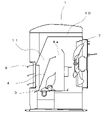
図1は、温風暖房装置の内部構成図であり、図2は、温風暖房装置の断面構成図である。なお、本実施形態では、温風暖房装置の一例として燃料を燃焼させて暖房を行うファンヒーターを例に説明する。 FIG. 1 is an internal configuration diagram of the warm air heating device, and FIG. 2 is a sectional configuration diagram of the warm air heating device. In this embodiment, a fan heater that performs heating by burning fuel will be described as an example of a warm air heating device.
本体1内には、灯油を加熱して気化ガスとする気化器2と、気化器2で発生した気化ガスを燃焼して熱を発生させる熱発生手段としてのバーナ3と、バーナ3の上方に設けられた燃焼室4と、図示しない給油タンクから供給された灯油を貯留する油受皿5と、油受皿5上に載置され気化器2へ灯油を汲み上げる電磁ポンプ6を備えている。
The
そして本体1の背面には、室内の空気を本体1内部に取り入れる送風機7が取り付けられる。また、本体1の正面には、暖房装置の動作を指示するための多数のスイッチが設けられた操作部15と、温風を吹出す吹出口8が取り付けられており、この吹出口8は複数の羽根9を備えている。
An
燃焼室4は、その上部に、バーナ3で発生した燃焼排ガスが排出される開口4aを有し、さらに燃焼室4を覆うように遮熱板10が設けられている。燃焼室4と遮熱板10の間は、燃焼排ガスと送風機7からの空気とを混合して温風とする温風通路11として構成されている。
The
このように構成される温風暖房装置では、バーナ3の燃焼により発生した燃焼排ガスと、送風機7によって本体1内に取り込まれた空気とを温風通路11を通過する間に混合させて温風とし、吹出口8の羽根9の間から室内に排出することで室内を暖房するようになっている。
In the hot-air heating device configured as described above, the combustion exhaust gas generated by the combustion of the
図3は、吹出口の拡大断面図であり、図3(A)は可動羽根を閉じた状態を示し、図3(B)は可動羽根を所定角度開いた状態を示す断面図である。本実施形態の温風暖房装置においては、吹出口8は上下に回動可能な3枚の可動羽根12と、この可動羽根12の間に配置されて水平方向に延びる回動しない2枚の固定羽根13を備えている。運転が停止しているときは、図3(A)のように可動羽根12は閉じられており、運転を開始(バーナ3での燃焼を開始)すると、後述する羽根駆動モータ23が回転して可動羽根12を駆動して、図3(B)のように可動羽根12が開いた状態となる。なお、以降の説明において、可動羽根12の角度とは、図中のθで示す角度を指すものとする。
3A and 3B are enlarged cross-sectional views of the outlet, FIG. 3A showing a state in which the movable blades are closed, and FIG. 3B a cross-sectional view showing a state in which the movable blades are opened at a predetermined angle. In the warm-air heating device of this embodiment, the
可動羽根12はバーナ3での燃焼量に応じて上下方向に回動させることができ、温風の吹き出す角度を調節する。一方、固定羽根13は、温風通路11を通過した温風を前方に誘導する役割を有する。可動羽根12の縦方向の長さ(図3(A)における上下方向の長さ)が長い場合には、羽根と羽根の間隔が広くなるため、温風通路11を通過した温風が羽根の間から下方に向かって流れやすくなってしまうが、固定羽根13を設けることで、本体1の前方に向けて温風を吹き出すことができるため、意図する方向へ効率よく温風を排出することができる。とくに、本実施形態のように、温風通路11が下方に向かっていて、温風が吹き下ろされる構造である場合には、固定羽根13がより効果を発揮する。なお、固定羽根13を設けない構造であってもかまわない。
The
図4は、可動羽根を駆動する機構の斜視図であり、図5は、同機構の正面図である。可動羽根12を備えた吹出口8は、支持金具20によって本体1に取り付けられるようになっている。
FIG. 4 is a perspective view of a mechanism for driving the movable vanes, and FIG. 5 is a front view of the same mechanism. A
支持金具20には、回動軸21を介して可動羽根12と連結された連携カム22と、可動羽根12を駆動するための羽根駆動モータ23と、羽根駆動モータ23と連結された駆動用カム24と、可動羽根12の角度を検知する角度検知手段25が取り付けられており、さらに、回動軸21を中心とした連携カム22の回転動作を案内するガイド孔26が設けられている。
The supporting
連携カム22は、二つのピン(第1ピン221、第2ピン222)を備えている。第1ピン221は前述の回動軸21と連結し、第2ピン222は、支持金具20に対して摺動自在に設けられる駆動板27と連結している。そしてこの駆動板27には、駆動用カム24から延びる駆動軸241が係止されるとともに、駆動軸241の先端に取り付けられたバネ部材28の一端が取り付けられている。また、駆動板27の下部には後述する角度検知手段25に対応する遮蔽片29が設けられている。
The
羽根駆動モータ23は正逆回転可能なステッピングモータで構成され、後述する制御部30からの指示に基づいて回転が制御される。そして、羽根駆動モータ23の回転によって駆動用カム24が回動すると駆動板27が上下に移動し、この駆動板27の上下動が連携カム22を介して可動羽根12を上下に回動させる。つまり、駆動板27が下方に移動すると、連携カム22が矢印Aの方向に回転して可動羽根12は上向きに回動する。反対に、駆動板27が上方に移動すると、連携カム22が矢印Bの方向に回転して可動羽根12は下向きに回動することとなる。可動羽根12が上向きに回動して所定角度に到達したことは、角度検知手段25により検知される。
The
角度検知手段25は、例えば発光部251と、発光部251に対向して配置された受光部252を備えるフォトインタラプタで構成される。羽根駆動モータ23を回転させて可動羽根12を上向きに回動させると、駆動板27が下方に移動する。そして、可動羽根12の角度が所定角度になると遮蔽片29が発光部251と受光部252の間に入り込んで発光部251からの光を遮断する。つまり、受光部252が光を検知できなくなると、可動羽根12が所定角度に到達したと判定される。なお、角度検知手段25の構成はこれに限らず、他の検知方式を用いてもよい。
The angle detection means 25 is composed of, for example, a photointerrupter having a
図6は、温風暖房装置の構成を示すブロック図である。マイクロコンピュータからなる制御部30は、室内の温度を検知する温度検知手段16、操作部15に設けられた各種設定手段(例えば、温度を設定する室温設定手段17、運転モードを設定する運転モード設定手段18)、可動羽根12の角度を検知する角度検知手段25、からの入力を受ける。そして、気化器2を加熱するヒータ14、電磁ポンプ6、送風機7、羽根駆動モータ23への制御信号を出力し、暖房運転を制御する。
FIG. 6 is a block diagram showing the configuration of the warm air heating device. A
また、制御部30は、バーナ3での燃焼量を演算して決定する燃焼量制御手段31、送風機7の回転を制御する送風機制御手段32、羽根駆動モータ23の回転を制御する羽根駆動モータ制御手段33、羽根駆動モータ23や角度検知手段25など可動羽根12の回動に関連する部品の異常を判定する異常判定手段34、とを含んで構成される。なお、図の構成は本実施形態にかかる温風暖房装置の一実施例であって、図示される以外のその他の構成要素を含んでいても構わない。
The
上述の構成からなる暖房装置において、運転の開始を指示すると、まずヒータ14への通電を開始して気化器2が加熱される。気化器2が液体燃料を気化することができる温度に到達すると、電磁ポンプ6を駆動して気化器2に液体燃料を供給し、気化器2に供給された液体燃料は加熱気化されて気化ガスとなる。気化ガスは気化器2の先端からバーナ3に供給され、バーナ3で燃焼が行われる。燃焼により発生した燃焼排ガスは、送風機7からの空気と混合されて温風となり、吹出口8から排出される。
In the heating device configured as described above, when the start of operation is instructed, first, energization to the
また、本実施形態の温風暖房装置は、複数の運転モードを切替可能に備えており、運転モードは操作部15の運転モード設定手段18を操作することで選択される。そして、この運転モードには、可動羽根12を予め設定された角度範囲内で上下方向に回動させる可動モードと、可動羽根12を予め設定された角度に固定する固定モードを有しており、いずれのモードにおいても可動羽根12の角度は燃焼量制御手段31によって決定された燃焼量に応じて設定される。羽根駆動モータ制御手段33は、設定された角度に応じて羽根駆動モータ23の駆動ステップを制御する。
Moreover, the warm air heating device of this embodiment is provided with a plurality of switchable operation modes, and the operation mode is selected by operating the operation mode setting means 18 of the
例えば、燃焼量が大火力のときの可動羽根12は、可動モードでは70~80度の間で上下動を繰り返し、固定モードでは75度に固定される。また、燃焼量が小火力のときの可動羽根12は、可動モードでは60~75度の間で上下動を繰り返し、固定モードでは65度に固定される。中間火力のときは、大火力と小火力の間の角度に設定される。なお、上述の角度は一例であって、適宜設定することができる。また、運転モードは可動モードのみであってもよい。
For example, when the amount of combustion is large, the
可動羽根12は、運転モードによらず、燃焼量が大きいときのほうが、燃焼量が小さいときよりも角度が大きくなるように設定される。つまり、燃焼量が大きい場合には、温風の吹き出し角度を大きくして温風を遠くまで運ぶとともに、開口面積を大きくすることで本体1内に熱がこもってしまうことを有効に防止することができる。また、燃焼量が小さい場合に吹出開口を下に向けることで、足元を温めることができ、これにより暖房効率をあげることができる。
The
また、暖房運転中には、可動羽根12を全開位置まで開く全開動作を実行する。この全開動作は所定時間ごとに実行することができる。なお、ここでいう全開位置とは、可動羽根12の通常動作時の最大角度と同じか、若しくはそれ以上の角度に開いた位置のことであって、本実施形態では、通常動作時の可動羽根12の最大角度は80度(可動モード時における最大角度)に設定されているので、全開位置は可動羽根12の角度が80度以上となる位置であればよい。そしてこの全開動作は、可動モード、固定モードのいずれの場合においても実行することができる。
Further, during the heating operation, a full-open operation is performed to open the
全開動作を実行し、可動羽根12が所定の第1角度(例えば80度)に到達すると、角度検知手段25はこれを検知して、制御部30に全開検知信号を出力する。本実施形態では、角度検知手段25はフォトインタラプタで構成されており、全開検知信号とは、発光部251が発する光を受光部252が検知しなくなったことにより発生する信号である。異常判定手段34はこの全開検知信号を受けることで、可動羽根12が正しく動作していると判定する。
When the
本体1の前面に障害物があって可動羽根12の動きが制限されたり、羽根駆動モータ23の故障などにより、可動羽根12が設定された角度で動作しない場合、温風の吹出しが阻害されてしまい、本体1内の温度が異常上昇するという問題が発生する。そこで、運転中には全開動作を実行し、可動羽根12が正しく動作しているかをチェックして、その動作が確認できない時には運転を停止する。これにより、暖房装置を安全に使用することができる。
If the movement of the
また、可動モードでは可動羽根12を上下に回動させる動作を繰り返すことにより、実際の可動羽根12の角度と、羽根駆動モータ制御手段33から出力する制御信号との間に誤差が発生する。その他にも、使用者が手などで可動羽根12の角度を変更してしまい、実際の角度との間にズレが発生することも考えられる。したがって、可動羽根12の動作に関わらず、暖房運転中に全開動作を実行することで、全開位置を可動羽根12の回動動作の基点とし、可動羽根12の角度の誤差を修正したり、手などで操作されてしまった可動羽根12を正しい位置に戻したりすることができる。
Further, in the movable mode, an error occurs between the actual angle of the
本実施形態の全開動作では、可動羽根12が第1角度に到達したことを角度検知手段25が検知した後、さらに羽根駆動モータ23を回転させて可動羽根12を機械的に回動可能な上限位置まで開く動作を行うようになっている。例えば、第1角度を80度とした場合、上限位置での可動羽根12の角度は85度であり、この上限位置が全開位置に相当する。各運転モードにおける可動羽根12の回動動作は、全開位置(85度)を基点として羽根駆動モータ23の駆動ステップを制御することで実行される。このように、可動羽根12を上限位置まで開くように羽根駆動モータ23を制御することで、機械的な上限位置を可動羽根12の回動動作の基点とし、これにより、角度検知手段25の検知角度に誤差があったとしても、誤差の影響を受けることなく可動羽根12の角度を修正することができる。
In the fully open operation of this embodiment, after the
全開動作が終了すると、可動羽根12は選択されている運転モードの動作に復帰する。可動羽根12が下方に回動してその角度が第1角度よりも小さくなると、角度検知手段25からの全開検知信号の出力が停止する。もし、全開動作を実行していない非実行中において、角度検知手段25から全開検知信号が出力されていた場合は、羽根駆動モータ23または角度検知手段25に異常が発生している可能性がある。異常判定手段34では、これら可動羽根12の回動に関連する部品の異常の有無を判定し、異常ありと判定した場合には運転が停止される。
When the fully open operation is finished, the
しかしながら、角度検知手段25の検知誤差や取り付け位置のばらつきなどによっては、可動羽根12が運転モードの動作に復帰していても角度検知手段25が全開検知信号を出力してしまうことが起こり得る。特に、大火力での燃焼時は、可動羽根12の角度が全開位置に近いためこのような状況が起こり易く、角度検知手段25は正常に動作しているにもかかわらず異常と判定されて運転が停止してしまうことになる。そこで、このような不要な異常判定を回避するため、全開動作の非実行中において角度検知手段25が全開検知信号を出力している場合には、可動羽根12の回動動作の基点を補正する補正動作を実行する。
However, due to a detection error of the angle detection means 25 and variations in the mounting position, the angle detection means 25 may output a fully open detection signal even when the
補正動作では、角度検知手段25が全開を検知しなくなる位置を確認するため、可動羽根12をさらに下方に回動させるよう羽根駆動モータ23を回転させる。可動羽根12が回動していき、角度検知手段25からの全開検知信号の出力が停止すると、制御部30はそのときの可動羽根12の位置を記憶し、この位置を可動羽根12の回動動作の新たな基点に設定する。以降はこの位置を基点として、羽根駆動モータ23の駆動ステップを制御することで可動羽根12の回動動作が実行される。
In the correcting operation, the
本実施形態では、可動羽根12の角度が第1角度(80度)に到達すると角度検知手段25が全開検知信号を出力するように設定されている。全開動作が終了して運転モードの動作に復帰した、つまり可動羽根の角度が80度以下になっているにもかかわらず、全開検知信号が出力されていたときには、補正動作が実行される。補正動作では、可動羽根12をさらに下方に回動し、例えば70度の位置になったときに全開検知信号の出力が停止したとすると、このときの位置(実際の角度は70度)を80度に修正して記憶するとともに、可動羽根12の回動動作の基点として羽根駆動モータ23の駆動ステップが制御される。このように、補正動作を実行することで、可動羽根12の回動動作の基点を修正して運転を継続することができるので、異常がないにもかかわらず運転を停止してしまうという不要な異常判定をしてしまうことが回避される。
In this embodiment, the angle detection means 25 is set to output a fully open detection signal when the angle of the
なお、補正動作では、羽根駆動モータ23の制御量に上限値を設けることができ、角度検知手段25の誤差や取り付け位置のばらつきとして許容される角度を制御量の上限値に設定する。本実施形態のように羽根駆動モータ23がステッピングモータで構成されている場合、モータの駆動ステップ数に上限を設ける。そして、補正動作を開始して羽根駆動モータ23をステップ数の上限まで回転させたとしても、角度検知手段25が全開検知信号を出力し続けている場合は、異常が発生していると判断して運転を停止する。
In the correction operation, an upper limit value can be set for the control amount of the
また、制御部30は、全開動作が終了すると可動羽根12を目標角度に向けて移動させるよう羽根駆動モータ23の駆動ステップを制御する。補正動作を実行するか否かは、可動羽根12がこの目標角度に到達した時点で、角度検知手段25からの全開検知信号が出力されているかを確認することによって判断することができる。このように、判断のタイミングを、可動羽根12が目標角度に到達したときに限定することで、不要な異常判定を効果的に回避することができる。
Further, the
上述の目標角度は、各運転モードにおいて燃焼量に応じて設定されている可動羽根12の角度のことである。可動モードでは、可動羽根12には回動する角度範囲が設定されているため、目標角度はその角度範囲の下端角度とするのがよい。上述の例では、燃焼量が大火力のとき、固定モードでは75度、可動モードでは角度範囲の下端である70度が目標角度となる。なお、可動モードでは目標角度を下端角度に設定することで、第1角度との差が大きくなるため、可動羽根12が目標角度に到達したときに角度検知手段25が全開検知信号を出力してしまうことが抑えられる。
The above-mentioned target angle is the angle of the
図7は、全開動作および補正動作の制御の一例を示すフローチャートである。全開動作は所定の間隔で実行されるようになっており、前回の全開動作から所定時間が経過したかを判定し(ステップ1)、所定時間が経過したことを検知すると、全開動作を開始する(ステップ2)。 FIG. 7 is a flow chart showing an example of control of the full-open operation and correction operation. The full-open operation is performed at predetermined intervals, and it is determined whether or not a predetermined time has passed since the previous full-open operation (step 1), and when it is detected that the predetermined time has passed, the full-open operation is started. (Step 2).
全開動作を開始すると、可動羽根12が全開位置となるよう羽根駆動モータ23を回転させ(ステップ3)、可動羽根12が第1角度まで到達したかを角度検知手段25の検知結果によって判定する(ステップ4)。可動羽根12が第1角度に到達したことが検知された場合(ステップ4でYes)、可動羽根12が正しく動作していると判断することができ、ここからさらに可動羽根12が機械的に駆動可能な上限位置になるまで羽根駆動モータ23を回転させる(ステップ5)。可動羽根12が上限位置に到達すると、全開動作が終了する(ステップ6)。全開動作の終了後は、全開位置を基点として、可動羽根12が目標角度になるよう羽根駆動モータを回転させる(ステップ7)。
When the fully open operation is started, the
ここでの目標角度とは、各運転モードにおいて燃焼量に応じて設定されている角度のことであり、可動羽根12が目標角度に到達したかを判定し(ステップ8)、目標角度に到達した場合には、角度検知手段25から全開検知信号が出力されているかを判定する(ステップ9)。ここで、角度検知手段25から全開検知信号が出力されていなければ(ステップ9でNo)、角度検知手段25および羽根駆動モータ23は正常に動作していると判断できるため、ステップ1に戻り、選択された運転モードで暖房運転を行いながら次の全開動作の指示を待つ。
The target angle here is an angle that is set according to the amount of combustion in each operation mode. If so, it is determined whether a fully open detection signal is output from the angle detection means 25 (step 9). Here, if the fully open detection signal is not output from the angle detection means 25 (No in step 9), it can be determined that the angle detection means 25 and the
一方、角度検知手段25から全開検知信号が出力されている場合(ステップ9でYes)、補正動作を開始する(ステップ10)。補正動作が開始されると、羽根駆動モータ23の回転を1ステップ追加して可動羽根12をさらに下方に回動させ(ステップ11)、全開検知信号の出力が停止したかを判定する(ステップ12)。
On the other hand, when the fully open detection signal is output from the angle detection means 25 (Yes in step 9), correction operation is started (step 10). When the correction operation is started, the rotation of the
全開検知信号の出力が継続している場合(ステップ12でNo)、羽根駆動モータ23の追加ステップ数が上限値であるかを判定し(ステップ13)、上限値に到達していなければステップ11に戻ってさらに羽根駆動モータ23の回転を1ステップ追加する。羽根駆動モータ23の追加ステップ数が上限値に達していた場合には(ステップ13でYes)、角度検知手段25または羽根駆動モータ23に異常が発生していると判断して運転を停止する。
When the output of the fully open detection signal continues (No in step 12), it is determined whether the number of additional steps of the
ステップ12で全開検知信号の出力が停止したことを検知した場合は(判定がYes)、このときの可動羽根12の位置を記憶して、回動動作の基点に設定し(ステップ14)、補正動作が終了する(ステップ15)。補正動作を終了すると、ステップ1に戻り、選択された運転モードで暖房運転を行いながら次の全開動作の指示を待つ。その間、可動羽根12の回動動作は、ステップ14で設定された基点に基づき制御される。
When it is detected in
このように、本実施形態の暖房装置は、全開動作の非実行中において角度検知手段25が全開検知信号を出力している場合には、可動羽根12の回動動作の基点を補正する補正動作を実行するので、角度検知手段25の検知誤差や取り付け位置のばらつきによって全開検知信号が発生している場合には、可動羽根12の回動動作の基点を変更することで運転を継続することができる。これにより、異常がないにもかかわらず運転を停止してしまうという不要な異常判定を回避することができるため、暖房装置を安全かつ快適に使用することができる。
As described above, the heating device of the present embodiment corrects the base point of the rotation operation of the
3 バーナ(熱発生手段)
8 吹出口
12 可動羽根(羽根)
23 モータ(羽根駆動モータ)
25 角度検知手段
30 制御部
3 burner (heat generating means)
8
23 motor (blade drive motor)
25 angle detection means 30 control unit
Claims (4)
温風を吹き出す吹出口と、
前記吹出口に設けられた回動可能な複数の羽根と、
前記羽根を回動させるモータと、
前記モータを駆動して前記羽根の動作を制御するとともに、前記羽根を全開位置まで開く全開動作を実行可能な制御部と、
前記全開動作の実行中において、前記羽根が所定角度に到達したときに全開検知信号を出力する角度検知手段と、を備え
前記制御部は、前記全開動作の実行後、前記羽根を目標角度に移動させるよう前記モータを制御し、前記羽根が前記目標角度に到達したときに前記角度検知手段から全開検知信号が出力されているかを判定し、前記角度検知手段が全開検知信号を出力している場合には、前記角度検知手段が全開検知信号を出力しなくなるまで前記羽根を回動するよう前記モータを制御し、そのときの前記羽根の位置を羽根回動動作の基点とする補正動作を実行する温風暖房装置。 a heat generating means for generating heat;
an outlet for blowing out hot air;
a plurality of rotatable blades provided at the outlet;
a motor for rotating the blades;
a control unit capable of driving the motor to control the operation of the blades and executing a fully open operation to open the blades to a fully open position;
angle detection means for outputting a full-open detection signal when the blade reaches a predetermined angle during execution of the full-open operation, wherein the control unit moves the blade to a target angle after the full-open operation is executed. and determining whether or not the angle detection means outputs a full-open detection signal when the blade reaches the target angle, and the angle detection means outputs the full-open detection signal. the motor is controlled to rotate the blades until the angle detecting means stops outputting the fully open detection signal, and a correction operation is performed using the position of the blades at that time as a base point of the blade rotation operation. Warm air heater.
前記制御部は、前記全開動作の実行後に前記羽根が前記目標角度に到達したときに、前記角度検知手段が全開検知信号を出力していなかった場合、前記上限位置を羽根回動動作の基点とする請求項1から3のいずれかに記載の温風暖房装置。 The full-open operation is an operation in which the blade is further opened to a mechanically rotatable upper limit position after the angle detection means outputs a full-open detection signal,
If the angle detecting means does not output a fully open detection signal when the blade reaches the target angle after execution of the fully open operation, the control unit regards the upper limit position as a base point of the blade rotating operation. The warm air heating device according to any one of claims 1 to 3 .
Priority Applications (1)
| Application Number | Priority Date | Filing Date | Title |
|---|---|---|---|
| JP2018162222A JP7106397B2 (en) | 2018-08-31 | 2018-08-31 | hot air heater |
Applications Claiming Priority (1)
| Application Number | Priority Date | Filing Date | Title |
|---|---|---|---|
| JP2018162222A JP7106397B2 (en) | 2018-08-31 | 2018-08-31 | hot air heater |
Publications (2)
| Publication Number | Publication Date |
|---|---|
| JP2020034241A JP2020034241A (en) | 2020-03-05 |
| JP7106397B2 true JP7106397B2 (en) | 2022-07-26 |
Family
ID=69667741
Family Applications (1)
| Application Number | Title | Priority Date | Filing Date |
|---|---|---|---|
| JP2018162222A Active JP7106397B2 (en) | 2018-08-31 | 2018-08-31 | hot air heater |
Country Status (1)
| Country | Link |
|---|---|
| JP (1) | JP7106397B2 (en) |
Family Cites Families (3)
| Publication number | Priority date | Publication date | Assignee | Title |
|---|---|---|---|---|
| JPH02246796A (en) * | 1989-03-20 | 1990-10-02 | Yaskawa Electric Mfg Co Ltd | Original point resetting method for stepping motor |
| JP2890996B2 (en) * | 1992-10-05 | 1999-05-17 | 松下電器産業株式会社 | Hot air heater |
| JPH0869326A (en) * | 1994-08-30 | 1996-03-12 | Keyence Corp | Positioning controller |
-
2018
- 2018-08-31 JP JP2018162222A patent/JP7106397B2/en active Active
Also Published As
| Publication number | Publication date |
|---|---|
| JP2020034241A (en) | 2020-03-05 |
Similar Documents
| Publication | Publication Date | Title |
|---|---|---|
| KR100644423B1 (en) | Electromotive valve gear | |
| JP6934341B2 (en) | Cooker | |
| CA2027506A1 (en) | Two stage furnace control | |
| JP7106397B2 (en) | hot air heater | |
| CN1040576C (en) | Hot-air type heater | |
| KR0173829B1 (en) | Warm wind air conditioner | |
| US20190093888A1 (en) | Combustion device | |
| KR100283131B1 (en) | A complex hot water-supply device | |
| JP7051636B2 (en) | Hot air heating device | |
| JP2020051711A (en) | Hot air heating device | |
| JP7118805B2 (en) | Combustion device | |
| JP7106394B2 (en) | hot air heater | |
| JP5851454B2 (en) | Hot water heating system | |
| JP2013217604A (en) | Hot water heating device | |
| JP6720621B2 (en) | Hot air heater | |
| JP2004011937A (en) | Combustion apparatus | |
| JP2017044360A (en) | Hot air heater | |
| JP7827993B2 (en) | heating equipment | |
| JP2004271112A (en) | Liquid fuel combustion device | |
| JPH05340609A (en) | Hot air heater | |
| JP3681909B2 (en) | heater | |
| JP3167912B2 (en) | Hot air heater | |
| JP6716991B2 (en) | Hot air heater | |
| JPH11125469A (en) | Variable blade drive control device for hot air heater | |
| JP5841907B2 (en) | Heating system |
Legal Events
| Date | Code | Title | Description |
|---|---|---|---|
| A621 | Written request for application examination |
Free format text: JAPANESE INTERMEDIATE CODE: A621 Effective date: 20210210 |
|
| A977 | Report on retrieval |
Free format text: JAPANESE INTERMEDIATE CODE: A971007 Effective date: 20220222 |
|
| A131 | Notification of reasons for refusal |
Free format text: JAPANESE INTERMEDIATE CODE: A131 Effective date: 20220301 |
|
| A521 | Request for written amendment filed |
Free format text: JAPANESE INTERMEDIATE CODE: A523 Effective date: 20220419 |
|
| TRDD | Decision of grant or rejection written | ||
| A01 | Written decision to grant a patent or to grant a registration (utility model) |
Free format text: JAPANESE INTERMEDIATE CODE: A01 Effective date: 20220712 |
|
| A61 | First payment of annual fees (during grant procedure) |
Free format text: JAPANESE INTERMEDIATE CODE: A61 Effective date: 20220713 |
|
| R150 | Certificate of patent or registration of utility model |
Ref document number: 7106397 Country of ref document: JP Free format text: JAPANESE INTERMEDIATE CODE: R150 |
|
| R250 | Receipt of annual fees |
Free format text: JAPANESE INTERMEDIATE CODE: R250 |