JP7105567B2 - Coaxial gear mechanism with positive transmission ratio - Google Patents
Coaxial gear mechanism with positive transmission ratio Download PDFInfo
- Publication number
- JP7105567B2 JP7105567B2 JP2018010444A JP2018010444A JP7105567B2 JP 7105567 B2 JP7105567 B2 JP 7105567B2 JP 2018010444 A JP2018010444 A JP 2018010444A JP 2018010444 A JP2018010444 A JP 2018010444A JP 7105567 B2 JP7105567 B2 JP 7105567B2
- Authority
- JP
- Japan
- Prior art keywords
- teeth
- tooth
- gear mechanism
- tooth carrier
- internal
- Prior art date
- Legal status (The legal status is an assumption and is not a legal conclusion. Google has not performed a legal analysis and makes no representation as to the accuracy of the status listed.)
- Active
Links
Images

Classifications
-
- F—MECHANICAL ENGINEERING; LIGHTING; HEATING; WEAPONS; BLASTING
- F16—ENGINEERING ELEMENTS AND UNITS; GENERAL MEASURES FOR PRODUCING AND MAINTAINING EFFECTIVE FUNCTIONING OF MACHINES OR INSTALLATIONS; THERMAL INSULATION IN GENERAL
- F16H—GEARING
- F16H55/00—Elements with teeth or friction surfaces for conveying motion; Worms, pulleys or sheaves for gearing mechanisms
- F16H55/02—Toothed members; Worms
- F16H55/17—Toothed wheels
-
- F—MECHANICAL ENGINEERING; LIGHTING; HEATING; WEAPONS; BLASTING
- F16—ENGINEERING ELEMENTS AND UNITS; GENERAL MEASURES FOR PRODUCING AND MAINTAINING EFFECTIVE FUNCTIONING OF MACHINES OR INSTALLATIONS; THERMAL INSULATION IN GENERAL
- F16H—GEARING
- F16H49/00—Other gearings
- F16H49/001—Wave gearings, e.g. harmonic drive transmissions
-
- F—MECHANICAL ENGINEERING; LIGHTING; HEATING; WEAPONS; BLASTING
- F16—ENGINEERING ELEMENTS AND UNITS; GENERAL MEASURES FOR PRODUCING AND MAINTAINING EFFECTIVE FUNCTIONING OF MACHINES OR INSTALLATIONS; THERMAL INSULATION IN GENERAL
- F16H—GEARING
- F16H25/00—Gearings comprising primarily only cams, cam-followers and screw-and-nut mechanisms
- F16H25/04—Gearings comprising primarily only cams, cam-followers and screw-and-nut mechanisms for conveying rotary motion
- F16H25/06—Gearings comprising primarily only cams, cam-followers and screw-and-nut mechanisms for conveying rotary motion with intermediate members guided along tracks on both rotary members
-
- F—MECHANICAL ENGINEERING; LIGHTING; HEATING; WEAPONS; BLASTING
- F16—ENGINEERING ELEMENTS AND UNITS; GENERAL MEASURES FOR PRODUCING AND MAINTAINING EFFECTIVE FUNCTIONING OF MACHINES OR INSTALLATIONS; THERMAL INSULATION IN GENERAL
- F16H—GEARING
- F16H49/00—Other gearings
-
- F—MECHANICAL ENGINEERING; LIGHTING; HEATING; WEAPONS; BLASTING
- F16—ENGINEERING ELEMENTS AND UNITS; GENERAL MEASURES FOR PRODUCING AND MAINTAINING EFFECTIVE FUNCTIONING OF MACHINES OR INSTALLATIONS; THERMAL INSULATION IN GENERAL
- F16H—GEARING
- F16H55/00—Elements with teeth or friction surfaces for conveying motion; Worms, pulleys or sheaves for gearing mechanisms
- F16H55/02—Toothed members; Worms
- F16H55/08—Profiling
-
- F—MECHANICAL ENGINEERING; LIGHTING; HEATING; WEAPONS; BLASTING
- F16—ENGINEERING ELEMENTS AND UNITS; GENERAL MEASURES FOR PRODUCING AND MAINTAINING EFFECTIVE FUNCTIONING OF MACHINES OR INSTALLATIONS; THERMAL INSULATION IN GENERAL
- F16H—GEARING
- F16H55/00—Elements with teeth or friction surfaces for conveying motion; Worms, pulleys or sheaves for gearing mechanisms
- F16H55/02—Toothed members; Worms
- F16H55/14—Construction providing resilience or vibration-damping
- F16H55/16—Construction providing resilience or vibration-damping relating to teeth only
-
- F—MECHANICAL ENGINEERING; LIGHTING; HEATING; WEAPONS; BLASTING
- F16—ENGINEERING ELEMENTS AND UNITS; GENERAL MEASURES FOR PRODUCING AND MAINTAINING EFFECTIVE FUNCTIONING OF MACHINES OR INSTALLATIONS; THERMAL INSULATION IN GENERAL
- F16H—GEARING
- F16H55/00—Elements with teeth or friction surfaces for conveying motion; Worms, pulleys or sheaves for gearing mechanisms
- F16H55/02—Toothed members; Worms
- F16H55/17—Toothed wheels
- F16H2055/176—Ring gears with inner teeth
Description
本発明は歯車機構及び歯車機構の製造方法に関する。 The present invention relates to a gear mechanism and a method of manufacturing the gear mechanism.
径方向に移動可能に歯キャリアに取り付けられた歯を備える歯車機構は、先行技術から公知である。歯を駆動するために、例えばカムディスクのようなプロファイルを有する駆動要素が使用される。歯は、歯部(toothing)の内歯と噛み合う。このため、歯を有する歯キャリヤと歯部との間で相対運動が生じる。この場合の歯部と歯との間の相対運動は、プロファイルを有する駆動要素の運動よりも少なくとも一桁小さい。このようにして、高い速度伝達比を達成することが可能である。このような歯車機構の例が、独国特許出願公開第102007011175号に開示されている。 Gear mechanisms with teeth mounted radially displaceably on tooth carriers are known from the prior art. A drive element with a profile, such as a cam disc, is used to drive the teeth. The teeth mesh with the internal teeth of toothing. This results in a relative movement between the tooth carrier with teeth and the toothing. The relative movement between tooth and tooth in this case is at least an order of magnitude smaller than the movement of the profiled drive element. In this way it is possible to achieve high transmission ratios. An example of such a gear mechanism is disclosed in DE 102007011175 A1.
この歯車機構の重要なポイントは、カムディスクへの歯の取り付け及び歯キャリヤにおける軸受面に作用する力である。例えば、歯車機構の耐用年数又は最大伝達可能トルクを高めるために、トルクを変化させずに力を減少させる、又は力を変化させずに歯車機構によって伝達されるトルクを増加させることが望ましい。さらに、トルクに変化がない弱い力は、いくつかの状況下で摩擦を低減させるため、歯車機構の効率を高めることができる。 The key points of this gear mechanism are the attachment of the teeth to the cam disc and the forces acting on the bearing surfaces on the tooth carrier. For example, to increase the service life or maximum transmittable torque of a gear train, it is desirable to decrease the force without changing the torque, or to increase the torque transmitted by the gear train without changing the force. In addition, the weak force with no change in torque can reduce friction under some circumstances, thus increasing the efficiency of the gear mechanism.
本発明の目的は、先行技術から公知の歯車機構に関連して改良された歯車機構を特定することであり、摩擦の低減及びこれによる少ない発熱、又は最大許容トルクの増加や内力の低減を達成しようとすることである。本発明の更なる目的は、この種の歯車機構の製造方法を特定することである。 The object of the present invention is to specify an improved gear mechanism in relation to the gear mechanisms known from the prior art, which achieves reduced friction and thus less heat generation, or increased maximum permissible torque and reduced internal forces. is to try. A further object of the invention is to specify a method of manufacturing a gear mechanism of this kind.
上記の目的は、請求項1に係る歯車機構によって達成され、また同等の請求項に係る歯車機構の製造方法によって達成される。従属請求項及び本願明細書から、有利な改良点及び実施形態が明らかになる。
The above objects are achieved by a gear mechanism according to
本発明の一側面は、歯車機構、特に同軸歯車機構に関する。この歯車機構は、内側に向いた歯部を有する内歯車と、前記内歯車に対して同軸上に配置され、前記歯部と噛み合うための多数の歯が収容された歯キャリヤであって、前記歯が前記歯キャリヤにおいて径方向に移動可能に取り付けられた前記歯キャリヤと、前記径方向に移動可能に取り付けられた歯を径方向に駆動するためのプロファイルを有する駆動要素であって、前記プロファイルがその周囲に少なくとも2つの凸部を有する前記駆動要素と、を備え、前記駆動要素による駆動部と前記歯キャリヤによる出力部との間に正の速度伝達比を有するように構成される。 One aspect of the present invention relates to gear mechanisms, particularly coaxial gear mechanisms. The gear mechanism comprises an internal gear having inwardly directed toothing and a tooth carrier coaxially disposed with respect to the internal gear and containing a number of teeth for meshing with the toothing, a tooth carrier having teeth radially movably mounted on the tooth carrier; and a drive element having a profile for radially driving the radially movably mounted teeth, the profile said drive element having at least two ridges around its perimeter, configured to have a positive transmission ratio between drive by said drive element and output by said tooth carrier.
本発明の更なる側面は、本明細書に記載の典型的な実施形態の1つにおける歯車機構の製造方法に関する。 A further aspect of the invention relates to a method of manufacturing a gear mechanism in one of the exemplary embodiments described herein.
本発明の実施形態は、特に同軸歯車機構に関する。軸方向は、通常、歯車機構の長手方向の軸を指す。内歯車の歯部への歯の噛み合わせは、通常、歯部の内歯への歯の噛み合わせを指し、典型的な実施形態では円形である。 Embodiments of the present invention relate particularly to coaxial gear mechanisms. Axial generally refers to the longitudinal axis of the gear mechanism. Tooth meshing on the toothing of the internal gear generally refers to toothing on the internal toothing of the toothing, which in typical embodiments is circular.
典型的な実施形態では、駆動要素は、カムディスクを備えるか、又はカムディスクによって形成される。「カムディスク」の表現は、対応する部品がディスクに似ていることが必須ではないことを意味する、と一般的に解釈されるのが通常である。むしろ、カムディスクは、特に多くの部分を有する、駆動軸の一部であってもよく、細長い形状を有していてもよい。1つ以上のこのような部分が様々な半径を有するので、カムディスクの機能が果たされる。更なる部分は、他の機能を有していてもよく、例えばトルクの伝達のために、円筒状であったり、あるいはエッジを備えてもよい。通常、「カムディスク」の表現は、主として前記部品の機能に関係し、具体的には、例えば駆動軸ひいてはカムディスクの角度位置によって決まる方法で、径方向に歯を駆動する又は案内部において歯を後退させるための環状のプロファイルの条件に関する。 In a typical embodiment, the drive element comprises or is formed by a cam disc. The expression "cam disc" is usually taken to mean that it is not essential that the corresponding part resembles a disc. Rather, the cam disc may be part of a drive shaft, in particular having many parts, and may have an elongated shape. One or more such portions have varying radii so that the function of a cam disc is fulfilled. Further portions may have other functions, such as being cylindrical or provided with edges, for example for transmission of torque. Usually, the expression "cam disk" mainly relates to the function of said part, in particular for driving teeth radially or in guides, for example in a manner determined by the angular position of the drive shaft and thus of the cam disk. Regarding the condition of the annular profile for retracting the .
歯部は、通常、環状の歯部である。歯又は歯の歯先が歯部の内歯と噛み合う。 歯は通常、歯キャリヤに対して径方向に直線的に移動可能なように取り付けられる。ここで、「径方向に直線的に」とは、通常、径方向に案内部が設けられ、この案内部によって歯が径方向にのみ移動可能になるということを意味する。通常、案内部によって、歯を正確に一方向に直線的に移動させることができる。これは、例えば特定の長さの範囲に亘って移動方向に一定の断面を有する歯によって達成することができる。一定の断面を有する歯に対し、歯キャリヤも同じく開口部を有する。通常、歯はいずれの場合にも正確に一方向に、典型的には歯の長手方向の軸の方向に移動することが可能なように、歯キャリヤに取り付けられる。更に、典型的な実施形態では、歯車機構の長手方向の軸周りの歯キャリヤに対する歯の回転自由度が妨げられる。これについては、例えば歯キャリヤにおける径方向の歯の直線状の案内部によって実現可能である。このようにして、歯は、歯キャリヤと共に歯車機構の長手方向の軸周りを回転するが、歯キャリヤに対して回転しない。 The teeth are typically annular teeth. A tooth or a tooth tip of a tooth meshes with an internal tooth of a tooth portion. The teeth are typically mounted for linear radial movement relative to the tooth carrier. Here, "radially linearly" usually means that a guide is provided in the radial direction, which allows the tooth to move only in the radial direction. Typically, guides allow linear movement of the teeth in exactly one direction. This can be achieved, for example, by teeth having a constant cross-section in the direction of movement over a certain length range. For teeth with a constant cross-section, the tooth carrier also has openings. Usually the tooth is mounted on the tooth carrier so that it can be moved in exactly one direction in each case, typically in the direction of the longitudinal axis of the tooth. Further, in typical embodiments, rotational freedom of the teeth relative to the tooth carrier about the longitudinal axis of the gear mechanism is prevented. This can be achieved, for example, by means of a straight guide of the radial teeth on the tooth carrier. In this way, the tooth rotates about the longitudinal axis of the gear mechanism with the tooth carrier, but not with respect to the tooth carrier.
本発明に係る歯車機構の典型的な実施形態では、少なくとも歯の一部に曲げ剛性がある設計となっている。ここで、「曲げ剛性がある」という表現は、歯の材料の剛性により、歯の曲げモーメントが小さく、少なくとも歯車機構の運動学にとって実質的に取るに足らないという技術的な意味であると一般的に解釈される。曲げ剛性がある歯には、特に金属合金、具体的には鋼若しくはチタン合金、ニッケル合金、又は他の合金から製造される歯が含まれる。更に、特に内歯車又は歯車の歯部、歯キャリヤ及び駆動要素のうち少なくとも1つの部品がプラスチックから同様に製造される歯車機構の場合、プラスチックからなる曲げ剛性のある歯を備えることも可能である。本発明の典型的な実施形態では、歯キャリヤ及び歯は金属合金から製造され、更に歯部も、又は駆動要素までもが金属合金から製造される。このような歯車機構は、ねじりに対して非常に強く、高負荷に適応できるという利点をもたらす。少なくとも部分的にプラスチックからなる歯車機構、又はプラスチックからなる部品を備える歯車機構は、重量が小さくなるという利点をもたらす。「曲げ剛性のある」という表現は、特に、歯の長手方向の軸周りの曲げ剛性を意味すると解釈される。 In a typical embodiment of the gear mechanism according to the invention, at least some of the teeth are designed to be bending stiff. Here, the expression "flexurally rigid" is generally taken to mean in the technical sense that due to the stiffness of the material of the teeth, the bending moments of the teeth are small and at least substantially insignificant for the kinematics of the gear mechanism. interpreted Bending-rigid teeth include in particular teeth made from metal alloys, in particular steel or titanium alloys, nickel alloys or other alloys. Furthermore, it is also possible to provide flexurally rigid teeth made of plastic, especially in the case of gear mechanisms in which at least one part of the internal gear or gear teeth, the tooth carrier and the drive element is likewise manufactured from plastic. . In a typical embodiment of the invention, the tooth carrier and the teeth are made from a metal alloy, and the tooth parts, or even the drive elements, are made from a metal alloy. Such a gear mechanism offers the advantage of being very torsionally torsion resistant and able to accommodate high loads. A gear mechanism made at least partially of plastic, or a gear mechanism with parts made of plastic, offers the advantage of low weight. The expression "flexurally rigid" is taken to mean, in particular, a flexural rigidity about the longitudinal axis of the tooth.
典型的な実施形態では、歯とカムディスクとの間において、転がり軸受部に取り付けられ、カムディスク上に位置する枢動セグメントが配置される。有利な実施形態は、カムディスクといずれの場合にも少なくとも一つの歯との間に配置される枢動セグメントを有する。枢動セグメントにより、歯は、カムディスクの表面に対して、又は枢動セグメントに対して傾斜可能になる。典型的には、少なくとも2つの歯が枢動セグメントに取り付けられる。更なる実施形態では、例えば丸歯又は平歯など、完全に1つの歯が、いずれの場合にも枢動セグメントの1つに取り付けられる。平歯は、転がり軸受部におけるそれぞれの歯の軸周りの回転に対して固定可能である。枢動セグメントに取り付けられた多数の歯は、通常、軸方向に互いに隣り合うように1列に並べて配置される。このような多数の歯の配置又は平歯によって、枢動セグメントの動作の滑らかさを高めることができる。 In a typical embodiment, a pivot segment mounted on a rolling bearing and located on the cam disc is arranged between the tooth and the cam disc. An advantageous embodiment has a pivot segment arranged between the cam disc and in each case at least one tooth. The pivot segment allows the tooth to tilt with respect to the surface of the cam disc or with respect to the pivot segment. Typically at least two teeth are attached to the pivot segment. In a further embodiment a complete tooth, for example a round tooth or a flat tooth, is in each case attached to one of the pivot segments. The spur teeth can be fixed against rotation about the respective tooth axis in the rolling bearing. A number of teeth attached to the pivot segment are typically arranged in a row axially next to each other. Such multiple tooth arrangements or spur teeth can increase the smoothness of the movement of the pivot segment.
本発明の典型的な実施形態は、駆動要素としてカムディスクを備える。カムディスクは、非円形又は非楕円形の弓形の形状又は曲線を有することが好ましい。非円形又は非楕円形の弓形の形状は、例えば異なる速度伝達比を設定するために、異なるカムを使用できるという利点をもたらす。本願の文脈において、偏心円は、通常、円形又は楕円形に分類される、なぜならば、偏心円の場合、円形が存在するにもかかわらず、単に回転軸が円形の中心軸に対応しない場合にすぎないからである。典型的なカムディスクは、通常、周囲に均一に分配されるように配置された、少なくとも又はちょうど2つの凸部を有する。凸部は、極大点(maxima)とも称される。多数の凸部によって、より多くの歯が歯部と噛み合うようになる。 A typical embodiment of the invention comprises a cam disc as drive element. The cam disc preferably has a non-circular or non-elliptical arcuate shape or curve. A non-circular or non-elliptical arcuate shape provides the advantage that different cams can be used, for example to set different transmission ratios. In the context of the present application, eccentric circles are usually classified as either circular or elliptical, because in the case of eccentric circles, even though there is a circle, only if the axis of rotation does not correspond to the central axis of the circle. Because it is not too much. A typical cam disc usually has at least or exactly two lobes arranged so as to be evenly distributed around the circumference. A ridge is also called a maxima. A large number of projections allows more teeth to mesh with the teeth.
典型的な実施形態では、歯キャリヤ又は歯部は円形である。これにより、歯キャリヤ及び歯部に単純な幾何形状の利点がもたらされる。力の伝達は、通常、歯部と歯キャリヤとの間の歯車機構の動きが遅い方で発生する。これにより、力の伝達の経路が極めて短いという利点がもたらされるので、極めて高い剛性を達成できる。 In a typical embodiment the tooth carrier or tooth is circular. This provides the advantage of simple geometry for the tooth carrier and toothing. Force transmission usually occurs on the slower side of the gear mechanism between the toothing and the tooth carrier. This provides the advantage of a very short path for the transmission of forces and thus a very high stiffness can be achieved.
歯部の内歯及び歯は、通常、湾曲したフランク面を有する。典型的な実施形態では、内歯及び歯のそれぞれは、断面において、いずれの場合にも湾曲したフランク面を有し、頂部が平面で切断されたピラミッド又はピラミッドに相当する形状の歯先を有する。対数螺旋状の湾曲に対する1つの可能な実施形態として、独国特許出願公開第102007011175号を参照する。湾曲した表面は、噛み合うフランク面が直線状又は点状に接触するだけでなく、面状に接触するという利点をもたらす。これにより、多数の歯に対する良好な荷重配分や、歯部と歯との間の力の伝達における極めて高い剛性が達成される。 The inner teeth and teeth of the toothing usually have curved flank surfaces. In a typical embodiment, each of the inner teeth and the teeth, in cross-section, has in each case curved flanks and a tip of a shape corresponding to a pyramid or a pyramid with a flat truncated apex. . As one possible embodiment for logarithmic helical curvature, reference is made to DE 102007011175 A1. A curved surface provides the advantage that the mating flanks are not only in linear or point contact, but areal contact. This achieves good load distribution over a large number of teeth and very high stiffness in the transmission of forces between toothing and toothing.
典型的な実施形態は、プロファイルと歯との間に、枢動セグメント及び転動体を有する軸受部を備える。典型的には、互いに隣り合って配置された、具体的には軸方向に並設されるか又はオフセットされた少なくとも2つの歯が、枢動セグメント毎に配置される。このようにして、枢動セグメントは、その軌道に又はそれぞれの滑走面上に固定することができる。枢動セグメントの径方向の軸周りの回転は防止可能である。通常、実施形態の転動体は、円筒ころ又は針状ころとして形成される。 A typical embodiment comprises a bearing with pivot segments and rolling elements between the profile and the teeth. Typically, at least two teeth arranged next to each other, in particular axially juxtaposed or offset, are arranged per pivot segment. In this way, the pivot segments can be fixed on their tracks or on their respective running surfaces. Rotation about the radial axis of the pivot segment can be prevented. Typically, the rolling elements of embodiments are formed as cylindrical rollers or needle rollers.
本発明の典型的な歯車機構は、駆動要素による駆動部と歯キャリヤによる出力部との間に正の速度伝達比が存在するように構成される。正の速度伝達比とは、通常、駆動要素と歯キャリヤとが同じ方向に回転する場合の速度伝達比のことを指す。 A typical gear mechanism of the present invention is constructed such that there is a positive transmission ratio between the drive by the drive element and the output by the tooth carrier. A positive transmission ratio generally refers to a transmission ratio in which the drive element and tooth carrier rotate in the same direction.
典型的な実施形態では、歯の歯キャリヤの歯ピッチ角度(tooth carrier tooth angle of the teeth) 、又は歯キャリヤにおける歯の軸受部の歯キャリアの歯ピッチ角度は、内歯車の歯部の内歯における内歯車の歯ピッチ角度(internal gear tooth pitch angle of the internal teeth of the toothing of the internal gear)よりも小さい。「歯ピッチ」又は「歯ピッチ角度」は、通常、仮想変数を意味すると解釈される。したがい、歯キャリヤにおいて、歯ピッチ角度によって予め規定された全ての位置に、実際に歯を備える必要はない。歯ピッチ角度は、いずれの場合にも周方向において、360°を歯キャリヤにおいて理論上可能な歯の位置の数、又は歯部に実際に備える歯の数で割ることにより計算される。 In a typical embodiment, the tooth carrier tooth angle of the teeth or the tooth pitch angle of the tooth bearing portion of the tooth carrier is the internal tooth of the tooth portion of the internal gear. is smaller than the internal gear tooth pitch angle of the internal teeth of the toothing of the internal gear. "Tooth pitch" or "tooth pitch angle" is usually taken to mean a virtual variable. Therefore, it is not necessary to actually provide teeth on the tooth carrier at all positions predefined by the tooth pitch angle. The tooth pitch angle is calculated by dividing 360° by the number of theoretically possible tooth positions on the tooth carrier or the number of teeth actually provided on the toothing, in any case in the circumferential direction.
典型的な実施形態では、歯キャリヤにおいて、歯ピッチ角度の全ての位置に歯が設けられているわけではない。それどころか、例えば、1つおき、2つおき又は3つおきの位置にのみ歯が設けられる場合がある。このようにして、歯が設けられない位置に歯キャリヤの材料を供給することができるため、歯及び歯キャリヤの材料に対する十分な間隔を利用可能である。例えば、位置因子が2の場合、歯キャリヤを十分に硬化させるために、歯の間の歯キャリヤのウェブに対して、2つの歯の間又は歯の案内部の間に十分な間隔がある。典型的な実施形態では、歯の案内部の数は、歯キャリヤに収容される歯の数に相当する。典型的な実施形態では、歯の歯ピッチ角度によって予め規定された位置の1つおきの位置が空いている。歯キャリヤにおいて使用される位置の密度は、位置因子に反映される。例えば、位置因子が2とは、歯ピッチ角度によって予め規定された歯キャリヤの1つおきの位置にのみ歯が設けられることを意味する。したがって、位置因子が3とは、2つおきの位置を意味する。歯キャリヤに取り付けられる歯の間の実際の角度間隔は、通常、歯又は歯キャリヤの歯ピッチ角度の2倍、3倍、又は4倍になる。更なる実施形態では、4倍を超える間隔が設けられることも可能である。よって、隣り合う歯の間の実際の角度間隔は、歯ピッチ角度に位置因子を乗じることによって計算される。通常の位置因子は1以上の正数であり、更に通常の位置因子は2以上の正数である。 In a typical embodiment, the tooth carrier is not provided with teeth at all positions of the tooth pitch angle. Instead, for example, only every other, every second or every third position may be provided with teeth. In this way, sufficient spacing for the teeth and tooth carrier material is available, as the material of the tooth carrier can be fed to locations where no teeth are provided. For example, if the position factor is 2, there is sufficient spacing between the two teeth or between the tooth guides relative to the web of the tooth carrier between the teeth to sufficiently harden the tooth carrier. In a typical embodiment, the number of tooth guides corresponds to the number of teeth contained in the tooth carrier. In a typical embodiment, every other position predefined by the tooth pitch angle of the tooth is free. The density of positions used in the tooth carrier is reflected in the position factor. For example, a position factor of 2 means that only every other position of the tooth carrier predefined by the tooth pitch angle is provided with teeth. Therefore, a position factor of 3 means every two positions. The actual angular spacing between the teeth attached to the tooth carrier is typically two, three or four times the tooth pitch angle of the tooth or tooth carrier. In further embodiments, more than four times the spacing may be provided. The actual angular spacing between adjacent teeth is then calculated by multiplying the tooth pitch angle by the position factor. A normal position factor is a positive number of 1 or greater, and a further normal position factor is a positive number of 2 or greater.
理論的に可能な歯の位置の数は、通常、内歯車の歯部の内歯の数よりも、少なくとも又はちょうど凸部の数だけ大きい。歯キャリヤにおいて1つおきの位置にのみ設けられているのであれば、2つの凸部を有するプロファイルの場合、歯キャリヤにおける歯の数は、歯部の内歯の数に凸部の数を足して位置因子で割った数に相当し、この場合は2になる。通常、実施形態において、歯の数は下記の式に従い計算される。 The number of theoretically possible tooth positions is usually at least or exactly by the number of lobes greater than the number of internal teeth of the toothing of the internal gear. In the case of a profile with two lobes, the number of teeth on the tooth carrier is the number of internal teeth of the toothing plus the number of lobes, provided that they are only provided at every other position on the tooth carrier. , divided by the location factor, which is 2 in this case. Generally, in embodiments, the number of teeth is calculated according to the formula below.

ZI=内歯車の内歯の数
E=駆動要素のプロファイルの凸部の数、又はカムディスクの凸部の数
PF=位置因子
駆動要素を回転させる駆動部と、本発明に係る歯車機構の実施形態の歯キャリヤに接続される出力部との間の速度伝達比を計算する場合、次の式が用いられる。式中、内歯車の内歯の数は必ず負の値で計算しなければならない。

通常、実施形態では、歯キャリヤにおける歯の数は整数である。プロファイルが2つの凸部を有し、内歯車の歯の数が46であり、歯キャリヤの歯ピッチ角度によって予め規定された位置の1つおきの位置にのみ歯が設けられている典型的な実施形態、すなわち位置因子が2である典型的な実施形態において、歯キャリヤにおける歯の数は24になる。上記式のiに関し、駆動要素の駆動部と歯キャリヤの出力部との間では、i=+24の速度伝達比が得られる。

2つの凸部を有し、内歯車の歯の数が46であり、位置因子が3である更なる実施形態において、歯キャリヤにおける歯の数は16になる。内歯車の歯の数が45で、歯キャリヤの歯ピッチ角度によって予め規定された位置の1つおきの位置にのみ歯が設けられている別の実施形態、すなわち位置因子が2である別の実施形態は、凸部が3つの場合に、歯キャリヤに24の歯を有する。 In a further embodiment with two lobes, the number of teeth of the internal gear is 46 and the position factor is 3, the number of teeth on the tooth carrier will be 16. Another embodiment in which the number of teeth of the internal gear is 45 and teeth are provided only at every other position predefined by the tooth pitch angle of the tooth carrier, i.e. a position factor of 2. The embodiment has 24 teeth on the tooth carrier for 3 lobes.
典型的な歯車機構は、プロファイル上に配置される転動体と、歯を取り付けるための多数の枢動セグメントとを備える。この場合、枢動セグメントは、転動体上に配置される。また、転動体は、プロファイル上に、カムディスクの回転方向に並設された少なくとも2列の転動体の列を成して配置される。典型的な実施形態は、1列又は少なくとも2列の転動体の列を備え、これらは通常、枢動セグメントの環状の列毎に、軸方向に互いに隣り合うように及び/又は並進するように配置される。枢動セグメントは、環状に並進する少なくとも2列の転動体上に取り付けられてもよい。ここで、並設された2列以上の歯の場合、いずれの場合にも1列の転動体が1列の歯の下に配置されていてもよく、これにより枢動セグメントが各歯の列に支持される。典型的な配置は、例えば、枢動セグメントを介して転動体の列に径方向に重ねた歯の列の配置である。各歯の中心軸は、通常、各転動体上の80%台半ば、又は50%台半ば、又は20%台半ば、又は少なくとも実質的に中心に位置する。このように、複数の転動体は実質的に中心に装着される。典型的な実施形態では、転動体の列のうちの1列は、歯の列のうちの1列と共に軸平面に配置される。通常、いずれの場合でも、1つの軸平面に1つの列がある。同じ軸平面とは、例えば中心が少なくとも実質的に同一である、及び/又は、歯が各転動体の列の軸方向に延長された領域内に全て配置されることを意味する。 A typical gear mechanism comprises rolling elements arranged on a profile and a number of pivot segments for mounting teeth. In this case, the pivot segments are arranged on rolling bodies. Also, the rolling elements are arranged on the profile in at least two rows of rolling elements arranged side by side in the direction of rotation of the cam disc. Typical embodiments comprise one or at least two rows of rolling elements, typically axially adjacent to each other and/or in translation for each annular row of pivot segments. placed. The pivot segment may be mounted on at least two rows of annularly translating rolling elements. Here, in the case of two or more rows of teeth arranged side by side, in each case one row of rolling elements may be arranged under one row of teeth, so that the pivot segments are arranged in each row of teeth. supported by A typical arrangement is, for example, that of a row of teeth radially superimposed on a row of rolling elements via a pivot segment. The central axis of each tooth is typically located in the mid-80s, or mid-50s, or mid-20s, or at least substantially centered on each rolling element. Thus, the plurality of rolling elements are substantially centrally mounted. In a typical embodiment, one of the rows of rolling elements is arranged in the axial plane with one of the rows of teeth. Typically, there is one column in one axial plane in any case. The same axial plane means, for example, that the centers are at least substantially identical and/or that the teeth are all arranged within the axially extending region of each row of rolling bodies.
通常、プロファイルは、転がり軸受の少なくとも1列に対する滑走面を有する。通常、プロファイルは、少なくとも2つの並設された滑走面を備える。典型的な実施形態では、いずれの場合でも転動体の列のうち1列が、並設された滑走面の1つに又はその上に配置される。このように、並進する転動体は、専用の滑走面を有する、つまり転動体の各列は、区画された専用の滑走面において案内可能である。 Usually the profile has a running surface for at least one row of rolling bearings. Usually the profile comprises at least two side-by-side running surfaces. In a typical embodiment, in each case one of the rows of rolling bodies is arranged on or on one of the juxtaposed running surfaces. Thus, the rolling bodies in translation have a dedicated running surface, ie each row of rolling bodies can be guided in a dedicated running surface which is defined.
プロファイルは、通常、少なくとも1つの環状の中央リブにより分割される。このように、実施形態では、並設された滑走面が、通常は中央リブの両側に作り出される。2列以上の歯を有する典型的な実施形態では、2つ以上の並設された滑走面を作り出すために、多数の並設された中央リブを設けることが可能である。 The profile is usually divided by at least one annular central rib. Thus, in embodiments, juxtaposed running surfaces are typically created on either side of the central rib. In typical embodiments having two or more rows of teeth, multiple side-by-side central ribs can be provided to create two or more side-by-side running surfaces.
カムディスクは、通常、2つの環状の縁リブを備える。通常、その縁リブによって、いずれの場合にも軸方向外側の方向における1つの外側滑走面が区切られる。中央においては、通常、中央リブによって滑走面は区切られる。典型的な実施形態では、ちょうど1つの中央リブと共に縁リブによって2つの滑走面が区切られる。更なる実施形態では、多数の中央リブによる2つを超える滑走面と、そして場合によっては2列を超える転動体が設けられる。 Cam discs are usually provided with two annular edge ribs. Usually, the edge ribs delimit one outer running surface in the axially outward direction in each case. In the middle, the running surface is usually delimited by a central rib. In a typical embodiment, the two running surfaces are separated by edge ribs with just one central rib. In further embodiments, more than two running surfaces with multiple central ribs and possibly more than two rows of rolling elements are provided.
中央リブ及び/又は縁リブのそれぞれは、転動体の直径に少なくとも実質的に相当する高さを有する。更なる実施形態では、それらは、例えば0%~10%、又は0%~5%の分だけ、転動体の直径よりもわずかに低い高さを有する。更なる実施形態では、中央リブ及び/又は縁リブの高さは、転動体の直径の50%~80%又は50%~95%しかない。中央リブ及び縁リブは異なる高さを有していてもよい。例えば、中央リブは縁リブより低くてもよい。実施形態では、縁リブは、枢動セグメントを固定する面としても使用される。更なる実施形態では、例えば、中央リブが枢動セグメントの動きの滑らかさを安定させるために使用される場合、中央リブは縁リブよりも高くなる。 Each of the central ribs and/or the edge ribs has a height corresponding at least substantially to the diameter of the rolling element. In a further embodiment they have a height slightly lower than the diameter of the rolling elements, eg by 0% to 10% or 0% to 5%. In further embodiments, the height of the central and/or edge ribs is only 50% to 80% or 50% to 95% of the diameter of the rolling element. The central ribs and edge ribs may have different heights. For example, the central rib may be lower than the edge ribs. In embodiments, the edge ribs are also used as surfaces to secure the pivot segments. In a further embodiment, the central rib is higher than the edge ribs, for example when the central rib is used to stabilize the smoothness of the movement of the pivot segment.
通常、枢動セグメントは、いずれの場合にも転がり軸受面(rolling bearing surface)と共に、転動体の少なくとも一部の片側に位置し、いずれの場合にも1つの歯支持面(tooth bearing surface)を転がり軸受面の反対側に有する。通常、少なくとも2つの歯が歯支持面に一纏めにして取り付けられる。典型的な実施形態において、歯支持面は、歯支持面が少なくとも2つの歯に対して共通の回転軸を形成するように形成される。実施形態の典型的な歯支持面は、いずれの場合にも軸方向に並設された少なくとも1つの歯及び/又は多数の歯に対して1つの円形の表面部を備える。円形の表面部の半径の中心点は、転がり軸受面と少なくとも実質的に一致する。通常、歯支持面によって形成された歯支持部の回転軸は、転がり軸受面と少なくとも実質的に一致する。歯支持面は、歯支持部の領域において、ビード及び/又は円形セグメントとして形成されてもよい。 Usually, the pivot segment is located on one side of at least a portion of the rolling element, in each case with a rolling bearing surface, and in each case with one tooth bearing surface. on the opposite side of the rolling bearing surface. Usually at least two teeth are attached together on the tooth bearing surface. In a typical embodiment, the tooth bearing surface is formed such that it forms a common axis of rotation for at least two teeth. A typical tooth bearing surface of an embodiment comprises a circular surface portion for at least one tooth and/or a number of teeth which are in each case axially arranged side by side. The center point of the radius of the circular surface portion is at least substantially coincident with the rolling bearing surface. Usually, the axis of rotation of the tooth support formed by the tooth support surface coincides at least substantially with the rolling bearing surface. The tooth bearing surfaces may be formed as beads and/or circular segments in the region of the tooth bearing.
実施形態の典型的な歯車機構は、環状に並設された歯の列を備える。通常、少なくとも又はちょうど2列の歯が設けられる。歯は、通常、歯キャリヤの案内部に、環状に並設された列に並べられる。 A typical gear mechanism of the embodiment comprises an annular array of teeth. Usually at least or exactly two rows of teeth are provided. The teeth are normally arranged in annular side-by-side rows in the guide portion of the tooth carrier.
典型的な実施形態では、いずれの場合にも少なくとも2つの並設された歯が枢動セグメント上に配置される。通常、並設された2つの歯は、並設された2列の歯に属し、例えば歯キャリヤの案内部において案内される。実施形態では、並設された歯の列の並設された2つの歯は、枢動セグメント上の軸方向において、一方が他方の背後に位置するように、通常、ビード又は枢動セグメントのくぼみに配置される。 In a typical embodiment, in each case at least two side-by-side teeth are arranged on the pivot segment. Usually, two teeth arranged side by side belong to two rows of teeth arranged side by side and are guided, for example, in a guide of a tooth carrier. In an embodiment, the two side-by-side teeth of the side-by-side row of teeth are typically located on the bead or pivot segment indentation, one behind the other in the axial direction on the pivot segment. placed in
実施形態の典型的な歯キャリヤは、径方向内側又は径方向外側に延び、軸方向において少なくとも部分的に枢動セグメントと噛み合う少なくとも1つのランオンフランジ(run-on flange)を備える。このようにして、追加のランオンディスク(run-on disk)を省略することも可能である。ランオンフランジは、歯キャリヤと一体的に形成されてもよく、歯キャリヤに固定されてもよい。典型的な実施形態は、ランオンディスクを有さない。いくつかの実施形態は、少なくとも片側が枢動セグメントと軸方向に隣り合い、及び/又は枢動セグメントを案内するための転動体に隣り合うランオンディスクを備える。 A typical tooth carrier of the embodiment comprises at least one run-on flange that extends radially inwardly or radially outwardly and axially at least partially mates with the pivot segment. In this way it is also possible to omit an additional run-on disk. The run-on flange may be integrally formed with the tooth carrier or may be fixed to the tooth carrier. A typical embodiment does not have a run-on disk. Some embodiments comprise a run-on disc axially adjacent to the pivot segment on at least one side and/or adjacent to rolling elements for guiding the pivot segment.
歯キャリヤにランオンフランジを有する実施形態では、少なくとも1つのランオンフランジが、駆動軸受転動体(drive bearing rolling bodies)に直接作用する駆動軸受面(drive bearing surface)を備えるのが通常である。通常、軸受は、歯キャリヤとカムディスク又はカムディスクに接続されるシャフトとの間に一体的に形成される。このような実施形態は、コンパクトな設計となり得る。通常、駆動軸受転動体は、カムディスク上に直接取り付けられる。更なる実施形態では、軌道輪を有する軸受が、歯キャリヤとカムディスクとの間に設けられる。これにより、製造を簡略化できる。 In embodiments having run-on flanges on the tooth carrier, at least one run-on flange typically provides a drive bearing surface that directly acts on the drive bearing rolling bodies. Usually the bearing is integrally formed between the tooth carrier and the cam disc or a shaft connected to the cam disc. Such an embodiment can be of compact design. Usually the drive bearing rolling elements are mounted directly on the cam disc. In a further embodiment, a bearing with races is provided between the tooth carrier and the cam disc. This simplifies manufacturing.
通常、1つのリブ支持面(rib bearing surface)は、軸方向において、いずれの場合にも枢動セグメント上の両側に及び/又は枢動セグメントの縁側に配置される。更なる実施形態では、リブ支持面は、枢動セグメントの軸方向中央に配置され、このリブ支持面は、例えば中央リブを支持するために設けられる。2つのリブ支持面を両側及び/又は縁側に有する実施形態では、リブ支持面は、カムディスクの縁リブに少なくとも部分的に位置していてもよい。このようにして、枢動セグメントの傾斜を防止でき、滑らかな動きを確保可能である。 Typically, one rib bearing surface is axially located in each case on either side of the pivot segment and/or on the edge of the pivot segment. In a further embodiment, a rib bearing surface is arranged axially centrally of the pivot segment, this rib bearing surface being provided, for example, for supporting a central rib. In embodiments with two rib bearing surfaces on both sides and/or edges, the rib bearing surfaces may rest at least partially on the edge ribs of the cam disc. In this way tilting of the pivot segment can be prevented and smooth movement can be ensured.
典型的な実施形態の利点は、増加した負荷容量、長い耐用年数、又はよりコンパクトな設計である。本発明に係る歯車機構の典型的な実施形態では、カムディスク又は駆動要素における周方向の力が内歯車の周方向の力と同じ方向に働くことで、先行技術から公知の歯車機構に比べて、歯の案内部における反力の減少につながる。実施形態では、歯キャリヤにおいて歯を案内するための力が、歯キャリヤの外側の歯の接触では約10%低下し、歯キャリヤの内側の歯の接触では約50%低下する。摩擦力の低下は、静止摩擦が働く間、つまり、カムディスクによって動きを与えられる際に、カムディスクの軸受部の反力も低下させる。静止摩擦が働く間、合計で約12%低下する。この軸受部は、一般的に、歯車機構の最大トルク又は耐用年数の決定的な要素であるため、歯車機構のトルク又は耐用年数を増加させることができる。更に、効率性も約1%~3%高めることができる。 Advantages of exemplary embodiments are increased load capacity, longer service life, or more compact design. In a typical embodiment of the gear mechanism according to the invention, the circumferential forces on the cam discs or drive elements act in the same direction as the circumferential forces on the internal gear, which makes the gear mechanism known from the prior art , leading to a reduction in reaction forces in the tooth guide. In an embodiment, the force for guiding the tooth on the tooth carrier is reduced by about 10% for tooth contact on the outside of the tooth carrier and by about 50% for tooth contact on the inside of the tooth carrier. The reduction in frictional force also reduces the reaction force of the cam disc bearings during static friction, ie when motion is imparted by the cam disc. A total drop of about 12% during static friction. Since this bearing is generally the determining factor for the maximum torque or service life of the gear train, the torque or service life of the gear train can be increased. Furthermore, the efficiency can also be increased by about 1% to 3%.
以下、添付の図面に基づき、本発明について詳細に説明する。
以下、図面に基づき、本発明の典型的な実施形態について説明する。本発明は例示の実施形態に限定されるものではなく、むしろ、本発明の範囲は、特許請求の範囲によって規定される。実施形態の説明、場合によっては異なる図面及び異なる実施形態の説明において、説明を明確にするために同一又は類似の部品に対し同じ参照記号が使用される。しかしながら、これは、本発明の対応する部品が実施形態に図示されるバリエーションに限定されるという意味ではない。 A typical embodiment of the present invention will now be described with reference to the drawings. The invention is not limited to the illustrated embodiments, but rather the scope of the invention is defined by the claims. In the description of the embodiments, possibly different drawings and descriptions of different embodiments, the same reference symbols are used for the same or similar parts for clarity of description. However, this does not mean that the corresponding parts of the invention are limited to the variations shown in the embodiments.
一般的な歯車機構の歯キャリヤは、例えば独国特許出願公開第102015105524号に開示されている。このような歯車機構は、歯の歯キャリヤの歯ピッチ角度を有しており、これは通常、内歯車の歯部の内歯における内歯車の歯ピッチ角度よりも大きい。このような構造なので、駆動要素と歯キャリヤとの間で、大きな負の速度伝達比を実現可能である。このような歯車機構に基づき、本発明の歯車機構がどのようにして駆動要素と歯キャリヤとの間に正の速度伝達比を有するように構成されるのかについて、以下に説明する。 A tooth carrier for a generic gear train is disclosed, for example, in DE 102015105524 A1. Such a gear mechanism has a tooth pitch angle of the tooth carrier of the tooth, which is usually greater than the tooth pitch angle of the internal gear at the internal tooth of the toothing of the internal gear. Due to this construction, a large negative transmission ratio can be realized between the drive element and the tooth carrier. Based on such a gear mechanism, it will be explained below how the gear mechanism of the present invention is configured to have a positive transmission ratio between the drive element and the tooth carrier.
図1は、四分割した部分的な概略断面図で例示の実施形態を示す。図1は、四分割したうちの1つの部分において、内側に位置する環状歯部5を具備した内歯車3を有する歯車機構1を概略的に示す。歯車機構1の四分割した他の3つの部分は、断面において、図示された部分に対して鏡に映したような類似の構造を有する。
FIG. 1 shows an exemplary embodiment in a partial schematic sectional view into four quarters. FIG. 1 schematically shows a
歯7は歯部5と噛み合う。より明確にするため、図1の全ての歯7が参照符号7で示されているわけではない。通常、個々の歯7を有し、軸方向に並設された2つの歯輪(rings of teeth)が設けられる。歯7は、歯キャリヤ11において径方向に移動可能に取り付けられる。このため、歯キャリヤ11は、径方向に方向付けられた、チャンネル状の、円形の又はスロット状の開口部を有し、これにより歯キャリヤ11において歯7を確実に径方向に案内する。この開口部による径方向の案内により、歯7はその長手方向の軸に沿った径方向のみに移動可能になる。具体的には、歯キャリヤ11に対する歯車機構1の長手方向の軸周りの回転が防止される。
歯の長手方向の軸とは、通常、歯元から歯先に至る軸を意味するのに対し、歯車機構の長手方向の軸とは、歯車機構の回転軸の方向を指す。これは、例えば出力部として使用可能な歯キャリヤの回転軸、又はカムディスクの回転軸等であってもよい。 The longitudinal axis of a tooth usually means the axis from the root to the tip of the tooth, whereas the longitudinal axis of a gear mechanism refers to the direction of the axis of rotation of the gear mechanism. This can be, for example, the axis of rotation of a tooth carrier that can be used as an output, or the axis of rotation of a cam disc or the like.
歯7は、中空のカムディスク20として設計されたカムディスク20の形態の駆動要素によって駆動される。カムディスク20は、歯7を径方向に駆動するためのプロファイル22を有する。プロファイル22は、周囲に2つの凸部がある輪郭を有するので、いずれの場合にも、対向して位置する歯7が最も遠い歯部5の歯の隙間に噛み合う(図1の四分割された断面図では見ることができない)。
The
図1に示す歯車機構1において、歯7は、駆動要素のプロファイル上に転がり軸受部と共に配置される。転がり軸受部は、転動体23を備え、これらは例示する実施形態において、針状ころとして設計されている。
In the
図1の例示の実施形態では、歯キャリヤで出力部が無くなっており、歯部を有する内歯車は固定されている。 In the exemplary embodiment of FIG. 1, the tooth carrier lacks an output and the internal gear with teeth is fixed.
歯車機構1は、歯7に対して分割された軸受部を備える。分割された軸受部は、枢動セグメント24を備える。枢動セグメント24は、いずれの場合にも歯7に面する側に、丸みを帯びた、具体的には部分的に円柱状の歯支持面を有する(図2参照)。これにより、歯7の歯元、又は典型的な実施形態では歯車機構1の軸方向において2つ、3つ又は4つの隣り合った歯が配置され得るビードを形成する。各歯7の歯元のビード及びこれに対応する凹部により、枢動セグメント24上での歯7の滑りが防止される。
The
ビードによって各歯7の歯元の連結部が形成されるので、非拘束の案内を確実にするため、歯7は枢動セグメント24に対して傾斜可能である。複数の枢動セグメント24は、互いに対して周方向に移動可能であるので、複数の枢動セグメント24の間の間隔は変化し得る。このようにすることで、枢動セグメント24の周方向の自由度も妨げられない。これにより、カムディスク20のプロファイル22によって、枢動セグメント24の実質的に非拘束の案内及び実質的に非拘束の径方向の駆動が可能になる。プロファイル22と枢動セグメント24との間の摩擦抵抗を最小化するために、転動体23が針状ころとして設けられる。更なる実施形態では、枢動セグメントを取り付けるために円筒ころ又は他の転がり軸受が設けられる。
Since the bead forms the root connection of each
図1から分かるように、歯キャリヤ11における歯7の歯キャリヤの歯ピッチ角度は、内歯車の歯部5の内歯における内歯車の歯ピッチ角度よりも小さい。これについては、図1において、2倍に拡大した歯キャリヤの歯ピッチ角度30及び2倍に拡大した内歯車の歯ピッチ角度31により示される。ここで、歯キャリヤの歯ピッチ角度によって予め規定された位置の1つおきの位置にのみ歯キャリヤ11に歯7が設けられることを考慮しなければならない。
As can be seen from FIG. 1, the tooth pitch angle of the tooth carrier of the
要するに、図1において四分割した1つの部分のみが断面で示される歯車機構は、数が26の歯と、数が50の内歯と、プロファイルの2つの凸部とを有する。したがって、例示の実施形態では、歯の数は内歯の数の2分の1よりも1だけ大きい。例示の実施形態の位置因子は、合計2になる。つまり、理論上の歯キャリヤの歯ピッチ角度によって予め規定された歯キャリヤにおける位置の1つおきの位置にのみ歯が設けられる。これにより、i=+26の正の速度伝達比が得られる。 In summary, the gear mechanism, shown in cross-section in only one quadrant in FIG. 1, has twenty-six teeth, fifty internal teeth and two projections of the profile. Thus, in the illustrated embodiment, the number of teeth is one-half greater than the number of internal teeth. The location factors in the illustrated embodiment add up to two. That is, teeth are provided only at alternate positions on the tooth carrier predetermined by the tooth pitch angle of the theoretical tooth carrier. This gives a positive transmission ratio of i=+26.
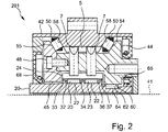
図2は、片側断面図で更なる実施形態を示す。図2の実施形態の特徴は、図1の実施形態の特徴と組み合わせてもよい。具体的には、長手方向の軸に垂直な断面における歯の配置及び数は、図1の実施形態に対応するので、図2の歯車機構は、同様に正の速度伝達比を有する。図1及び図2に示される特徴によって、高い負荷容量で極めてコンパクトな構造形態が得られるという事実から、組み合わせることによる特有の利点が生じる。同一又は類似の部品については、同じ参照符号を使用する。 FIG. 2 shows a further embodiment in half section view. Features of the embodiment of FIG. 2 may be combined with features of the embodiment of FIG. Specifically, the arrangement and number of teeth in the cross-section perpendicular to the longitudinal axis correspond to the embodiment of FIG. 1, so that the gear mechanism of FIG. 2 likewise has a positive transmission ratio. Particular advantages of the combination result from the fact that the features shown in FIGS. 1 and 2 result in a very compact construction with high load capacity. The same reference numbers are used for identical or similar parts.
図2の歯車機構201は、駆動軸と一体的に形成されることで、軸方向に細長い形状を有する、駆動要素としてのカムディスク20を備える。カムディスク20は、軌道又はピボット軸受軌道とも称される2つのプロファイル22を備える。このプロファイル22は、その周囲に亘って半径が変化する。具体的には、プロファイル22は、いずれの場合にも、凸部とも称される2つの極大点(maxima)と、2つの極小点(minima)とを有する。2つのプロファイル22は、変化する半径に対して同じ角度位置を有する。
The
更なる実施形態は、1つの軌道又は1つのプロファイルのみを有する。別の実施形態では、転動体に対し、3つ以上のプロファイル又は軌道を設けることも可能である。 Further embodiments have only one trajectory or one profile. In other embodiments, it is also possible to provide more than two profiles or tracks for the rolling elements.
転動体23は、プロファイル22上に取り付けられている。転動体23上には、枢動セグメント24が取り付けられている。図2の断面図では、1つの枢動セグメント24のみが図示されている。枢動セグメント24は、2列の環状の転動体23上に位置する。
枢動セグメント24は、枢動セグメント24の径方向外側にビードを備える。このビードは、2つの歯7の溝に噛み合う。歯7は、歯車機構1の長手方向の軸41に対する軸方向の位置に関して、転動体23によって少なくとも実質的に中央に取り付けられている。いずれの場合にも1つの歯7は、2つの転動体23のうちの1つによって取り付けられている。このように、枢動セグメント24によって継続的な力の伝達が実現される。更に、針状ころとして設計された転動体23は、略中央に荷重がかけられる。さらに、転動体23自体の構造上の長さは、この手段によって短くすることができ、動きの安定性を高めることができる。
The
プロファイル22を区切るため、カムディスク20はリブ32、34及び36を有する。リブ34は、転動体23の間の中央に位置するのに対して、2つのリブ32及び36は、いずれの場合にも軸方向外側への転動体23の動きの自由を制限する。枢動セグメント24は、いずれの場合にもリブ32及び36で支持可能なリブ支持面33及び37を有する。更なる実施形態において、枢動セグメントは、中央リブで支持される。このようにして、枢動セグメント24の動きの滑らかさが高められている。
To delimit the
歯7は、歯車機構1のハウジング42と一体的に形成された共通の歯部5に噛み合う。このように、歯部を有する内歯車がハウジング内で一体的に形成されることにより、コンパクトな設計及び単純生産を目的として、個々の部品を省略可能である。更なる実施形態では、内歯車とハウジングとが別々に形成される。
The
歯7は、歯キャリヤの第2の歯キャリヤ部品44において、径方向に方向付けられた案内部に受け入れられている。歯キャリヤは更に、ねじ状の接続手段48によって第2の歯キャリヤ部品44に接続されている第1の歯キャリヤ部品45を備える。多数の接続手段48が、歯キャリヤの周囲に亘って設けられ、図2の例示の実施形態では、合計6つ設けられている。
The
更なる実施形態では、異なる数の接続手段を設けることも可能であり、奇数個設けることも可能である。接続手段は、歯キャリヤの周囲に均一に分配されてもよいが、例えば2つの歯キャリヤ部品をある特定の角度位置のみで連結可能にするために、異なる角度間隔を設けることも可能である。例示の図2の実施形態において、歯キャリヤの歯キャリヤ部品を互いにある特定の相対的な角度位置のみで組み立て直せるようにするため、接続手段の間の角度は均一でない。更なる実施形態において、溝、ピン、又は他の輪郭を設けることも可能であるし、又はある特定の角度位置のみで組み立て直すことを許す若しくは可能にするためのマーキングが設けられてもよい。このように、歯キャリヤの機械加工はワンチャックで可能である。加工後、歯キャリヤ部品は互いに取り外され、歯車機構において再び互いに接続される。 In further embodiments, a different number of connection means may be provided, even an odd number. The connecting means may be uniformly distributed around the tooth carrier, but it is also possible to provide different angular spacings, for example to allow coupling of two tooth carrier parts only at certain angular positions. In the exemplary embodiment of FIG. 2, the angles between the connecting means are not uniform so that the tooth carrier parts of the tooth carrier can only be reassembled at certain angular positions relative to each other. In further embodiments, grooves, pins, or other contours may be provided, or markings may be provided to allow or enable reassembly only at certain angular positions. In this way, machining of the tooth carrier is possible with one chuck. After machining, the tooth carrier parts are removed from each other and connected to each other again in the gear mechanism.
ハウジング42に歯キャリヤを取り付けるため、歯車機構1の長手方向の軸41に対して60°の角度で取り付けられた転動体50が設けられる。ここで、転動体50の角度位置は、ハウジング42に歯キャリヤを確実に取り付けることを実現するため、歯車機構1の軸方向断面に対して鏡対称である。更なる実施形態では、軸方向の力を与えるのか、どの程度の軸方向の力を与えるのかによって、60°よりも大きい又は小さい角度も用いられる。
For mounting the tooth carrier on the
転動体50は、いずれの場合にも第1の歯キャリヤ部品44及び第2の歯キャリヤ部品45の歯キャリヤ支持面54及び55に直接取り付けられている。ハウジング側では、転動体50は、ハウジング42のハウジング支持面(housing bearing surfaces)58に取り付けられている。したがい、転動体50は、いずれの場合にも歯キャリヤ支持面(tooth carrier bearing surfaces)54及び55上、並びにハウジング支持面58上で回転する。このように、構造空間を殆ど占めないコンパクトな一体化された軸受部(integral bearing arrangement)が実現される。
The rolling
さらに、図2の例示の実施形態では、駆動軸受は一体化された軸受としても形成されている。歯キャリヤ又は図2の実施形態の第2の歯キャリヤ部品44は、ローラーとして形成されている駆動軸受転動体62が直接転動する駆動軸受面60を有する。カムディスク上には、同様に駆動軸受転動体62と直接作用する駆動軸受面64が更に形成されている。このように、駆動軸受転動体は、カムディスク20上で直接転動する。このようにして、コンパクトな構造形態を目的として一体化された軸受が作り出される。
Furthermore, in the exemplary embodiment of FIG. 2 the drive bearing is also formed as an integrated bearing. The tooth carrier or the second
第2の歯キャリヤ部品44の駆動軸受面60は、出力部側のランオンフランジ66の一部であり、出力部側方向の枢動セグメント24のたわみを防止する。ランオンフランジ66と第2の歯キャリヤ部品44との一体的な設計によって、コンパクトな構造形態及び高い剛性が達成される。
The
第1の歯キャリヤ部品45も同様に、反対方向の枢動セグメント24のたわみを防止する更なるランオンフランジ68を有する。
The first
通常は、出力部の反対側、つまり駆動軸受の反対側に、駆動軸と一体的に形成されたカムディスク20に対して、更なる軸受が設けられる。しかしながら、前記更なる軸受は、図2に示された領域の外側に位置する。駆動部側には、ある状況下で、径方向に比較的大きな構造空間を利用できるので、駆動部側軸受は、場合によって独立した滑走面を有する軸受として設計可能である。更なる実施形態では、駆動軸受は、一体化された軸受として形成されてもよい。
A further bearing is normally provided for the
Claims (9)
前記内歯車に対して同軸上に配置され、前記歯部(5)と噛み合うための多数の歯(7)が収容された歯キャリヤ(11)であって、前記歯(7)が前記歯キャリヤ(11)において径方向に移動可能に取り付けられた前記歯キャリヤ(11)と、
前記径方向に移動可能に取り付けられた歯(7)を径方向に駆動するためのプロファイル(22)を有する駆動要素(20)であって、前記プロファイル(22)がその周囲に少なくとも2つの凸部を有する前記駆動要素(20)と、
前記プロファイル(22)上に配置された転動体(23)と、
前記歯(7)を取り付けるための多数の枢動セグメント(24)であって、前記複数の転動体(23)上に配置された前記枢動セグメント(24)と、を備え、
前記駆動要素(20)による駆動部と前記歯キャリヤ(11)による出力部との間に正の速度伝達比を有するように構成され、
前記歯(7)の数が下記の式に従い計算される、
ことを特徴とする同軸歯車機構である歯車機構(1、201)。

A tooth carrier (11) arranged coaxially to said internal gear and containing a number of teeth (7) for meshing with said toothing (5), said teeth (7) said tooth carrier (11) mounted for radial movement at (11);
A drive element (20) having a profile (22) for radially driving said radially movably mounted tooth (7), said profile (22) having at least two convexities on its circumference. said drive element (20) having a portion;
rolling bodies (23) arranged on said profile (22);
a number of pivot segments (24) for mounting said teeth (7), said pivot segments (24) being arranged on said plurality of rolling bodies (23);
configured to have a positive transmission ratio between drive by said drive element (20) and output by said tooth carrier (11);
The number of said teeth (7) is calculated according to the formula:
A gear mechanism (1, 201) which is a coaxial gear mechanism characterized by:
Applications Claiming Priority (2)
| Application Number | Priority Date | Filing Date | Title |
|---|---|---|---|
| DE102017101565.5 | 2017-01-26 | ||
| DE102017101565.5A DE102017101565A1 (en) | 2017-01-26 | 2017-01-26 | COAXIAL GEARBOX WITH POSITIVE TRANSLATION |
Publications (3)
| Publication Number | Publication Date |
|---|---|
| JP2018151063A JP2018151063A (en) | 2018-09-27 |
| JP2018151063A5 JP2018151063A5 (en) | 2021-02-18 |
| JP7105567B2 true JP7105567B2 (en) | 2022-07-25 |
Family
ID=61027593
Family Applications (1)
| Application Number | Title | Priority Date | Filing Date |
|---|---|---|---|
| JP2018010444A Active JP7105567B2 (en) | 2017-01-26 | 2018-01-25 | Coaxial gear mechanism with positive transmission ratio |
Country Status (10)
| Country | Link |
|---|---|
| US (1) | US10830328B2 (en) |
| EP (1) | EP3354934B1 (en) |
| JP (1) | JP7105567B2 (en) |
| KR (1) | KR102595196B1 (en) |
| CN (1) | CN108386515B (en) |
| BR (1) | BR102018001689A8 (en) |
| DE (1) | DE102017101565A1 (en) |
| ES (1) | ES2809196T3 (en) |
| RU (1) | RU2757102C2 (en) |
| TW (1) | TWI761436B (en) |
Families Citing this family (11)
| Publication number | Priority date | Publication date | Assignee | Title |
|---|---|---|---|---|
| DE102019129667A1 (en) * | 2019-11-04 | 2021-05-06 | Wittenstein Se | transmission |
| AU2021355824A1 (en) * | 2020-10-06 | 2023-06-08 | Vestas Wind Systems A/S | Wind turbine power transmission system |
| DE102020132794A1 (en) * | 2020-12-09 | 2022-06-09 | Wittenstein Se | coaxial gear |
| DE102021111364A1 (en) * | 2021-05-03 | 2022-11-03 | Wittenstein Se | transmission |
| EP4253793A1 (en) | 2022-03-29 | 2023-10-04 | Vestas Wind Systems A/S | Transmission for a wind turbine |
| EP4253804A1 (en) | 2022-03-29 | 2023-10-04 | Vestas Wind Systems A/S | Transmission for a wind turbine |
| EP4253795A1 (en) | 2022-03-29 | 2023-10-04 | Vestas Wind Systems A/S | Transmission for a wind turbine |
| EP4253803A1 (en) | 2022-03-29 | 2023-10-04 | Vestas Wind Systems A/S | Transmission for a wind turbine |
| EP4253796A1 (en) | 2022-03-29 | 2023-10-04 | Vestas Wind Systems A/S | Transmission for a wind turbine |
| WO2023186275A1 (en) | 2022-03-29 | 2023-10-05 | Vestas Wind Systems A/S | Wind turbine power transmission system |
| EP4253794A1 (en) | 2022-03-29 | 2023-10-04 | Vestas Wind Systems A/S | Transmission for a wind turbine |
Citations (3)
| Publication number | Priority date | Publication date | Assignee | Title |
|---|---|---|---|---|
| JP2010520426A (en) | 2007-03-06 | 2010-06-10 | ヴィッテンシュタイン アーゲー | Coaxial gear device |
| CN101956789A (en) | 2010-06-23 | 2011-01-26 | 重庆大学 | Universal speed reducer of sliding gear meshing pair |
| JP2013015218A (en) | 2011-07-01 | 2013-01-24 | Wittenstein Ag | Transmission |
Family Cites Families (19)
| Publication number | Priority date | Publication date | Assignee | Title |
|---|---|---|---|---|
| GB153982A (en) * | 1919-08-27 | 1920-11-25 | Walter Charles Pitter | Improvements in transmission gearing |
| BE396107A (en) * | 1932-04-20 | |||
| US3258994A (en) * | 1963-06-03 | 1966-07-05 | Alex M Gorfin | Speed changing device |
| US3468175A (en) | 1967-08-15 | 1969-09-23 | Jan W Rabek | Transmission |
| US5662008A (en) * | 1993-08-30 | 1997-09-02 | Teijin Seiki Boston, Inc. | Extended contact harmonic drive devices |
| RU2296897C1 (en) * | 2005-12-12 | 2007-04-10 | Альберт Всеволодович Шолохов | Reduction gear |
| JP4777792B2 (en) * | 2006-02-09 | 2011-09-21 | 株式会社ハーモニック・ドライブ・システムズ | Wave gear device having continuous meshing high ratcheting torque tooth profile |
| DE102007016189B4 (en) | 2007-04-02 | 2011-12-08 | Wittenstein Ag | transmission |
| DE102010016581B4 (en) | 2010-04-22 | 2024-03-07 | Wittenstein Se | transmission |
| DE102012102802B4 (en) * | 2012-03-30 | 2016-07-07 | Wittenstein Ag | transmission |
| US9470301B2 (en) * | 2013-10-21 | 2016-10-18 | Hiwin Technologies Corp. | Harmonic drive gear reduction mechanism |
| DE102015105520A1 (en) * | 2015-04-10 | 2016-10-13 | Wittenstein Ag | transmission |
| DE102015105523B4 (en) * | 2015-04-10 | 2024-05-02 | Wittenstein Se | transmission |
| DE102015105525B4 (en) * | 2015-04-10 | 2024-05-02 | Wittenstein Se | Swivel segment |
| DE102015105524B4 (en) * | 2015-04-10 | 2024-01-18 | Wittenstein Se | transmission |
| TWI558935B (en) | 2015-07-07 | 2016-11-21 | Prodrives & Motions Co Ltd | A gear reducer with a self-locking function, a cam profile and a socket profile forming method, and a compound reduction gear |
| EP3135954A1 (en) | 2015-08-25 | 2017-03-01 | Shenzhen Volmen Precision Mechanical Technology Co., Ltd | Reduction bearing and electric motor |
| DE102015119584A1 (en) * | 2015-11-12 | 2017-05-18 | Wittenstein Se | transmission |
| DE102015119582A1 (en) * | 2015-11-12 | 2017-05-18 | Wittenstein Se | transmission |
-
2017
- 2017-01-26 DE DE102017101565.5A patent/DE102017101565A1/en not_active Withdrawn
-
2018
- 2018-01-25 EP EP18153511.3A patent/EP3354934B1/en active Active
- 2018-01-25 ES ES18153511T patent/ES2809196T3/en active Active
- 2018-01-25 TW TW107102706A patent/TWI761436B/en active
- 2018-01-25 JP JP2018010444A patent/JP7105567B2/en active Active
- 2018-01-25 RU RU2018102966A patent/RU2757102C2/en active
- 2018-01-26 CN CN201810075694.3A patent/CN108386515B/en active Active
- 2018-01-26 US US15/880,814 patent/US10830328B2/en active Active
- 2018-01-26 KR KR1020180010084A patent/KR102595196B1/en active IP Right Grant
- 2018-01-26 BR BR102018001689A patent/BR102018001689A8/en active Search and Examination
Patent Citations (3)
| Publication number | Priority date | Publication date | Assignee | Title |
|---|---|---|---|---|
| JP2010520426A (en) | 2007-03-06 | 2010-06-10 | ヴィッテンシュタイン アーゲー | Coaxial gear device |
| CN101956789A (en) | 2010-06-23 | 2011-01-26 | 重庆大学 | Universal speed reducer of sliding gear meshing pair |
| JP2013015218A (en) | 2011-07-01 | 2013-01-24 | Wittenstein Ag | Transmission |
Also Published As
| Publication number | Publication date |
|---|---|
| RU2018102966A (en) | 2019-07-26 |
| RU2018102966A3 (en) | 2021-05-21 |
| US10830328B2 (en) | 2020-11-10 |
| CN108386515A (en) | 2018-08-10 |
| EP3354934B1 (en) | 2020-06-24 |
| ES2809196T3 (en) | 2021-03-03 |
| KR102595196B1 (en) | 2023-10-26 |
| CN108386515B (en) | 2022-10-14 |
| US20180209530A1 (en) | 2018-07-26 |
| BR102018001689A2 (en) | 2018-10-30 |
| RU2757102C2 (en) | 2021-10-11 |
| TWI761436B (en) | 2022-04-21 |
| TW201829938A (en) | 2018-08-16 |
| EP3354934A1 (en) | 2018-08-01 |
| JP2018151063A (en) | 2018-09-27 |
| DE102017101565A1 (en) | 2018-07-26 |
| KR20180088316A (en) | 2018-08-03 |
| BR102018001689A8 (en) | 2022-11-16 |
Similar Documents
| Publication | Publication Date | Title |
|---|---|---|
| JP7105567B2 (en) | Coaxial gear mechanism with positive transmission ratio | |
| US10683922B2 (en) | Gearing | |
| JP6825883B2 (en) | Gear mechanism | |
| CN103363027B (en) | Actuating device | |
| US9360098B2 (en) | Strain wave drive with improved performance | |
| US8881615B2 (en) | Transmission | |
| TWI680244B (en) | Gearing | |
| US11674574B2 (en) | Coaxial gear | |
| JP6797001B2 (en) | Gear mechanism | |
| CN114382859A (en) | Coaxial gear box | |
| CN106051110B (en) | Swing section | |
| US11619292B2 (en) | Gearing | |
| JP2023544207A (en) | Coaxial gearbox with sliding bearing | |
| US20220349457A1 (en) | Gear mechanism | |
| CN106051109B (en) | Driving element | |
| CN117693642A (en) | Flexible gear disc and flexible gear for high reduction gear mechanism and high reduction gear mechanism of this type | |
| CN115899193A (en) | Coaxial gear mechanism |
Legal Events
| Date | Code | Title | Description |
|---|---|---|---|
| A521 | Request for written amendment filed |
Free format text: JAPANESE INTERMEDIATE CODE: A523 Effective date: 20210106 |
|
| A621 | Written request for application examination |
Free format text: JAPANESE INTERMEDIATE CODE: A621 Effective date: 20210106 |
|
| A977 | Report on retrieval |
Free format text: JAPANESE INTERMEDIATE CODE: A971007 Effective date: 20211206 |
|
| A131 | Notification of reasons for refusal |
Free format text: JAPANESE INTERMEDIATE CODE: A131 Effective date: 20211214 |
|
| A131 | Notification of reasons for refusal |
Free format text: JAPANESE INTERMEDIATE CODE: A131 Effective date: 20220524 |
|
| A521 | Request for written amendment filed |
Free format text: JAPANESE INTERMEDIATE CODE: A523 Effective date: 20220607 |
|
| TRDD | Decision of grant or rejection written | ||
| A01 | Written decision to grant a patent or to grant a registration (utility model) |
Free format text: JAPANESE INTERMEDIATE CODE: A01 Effective date: 20220621 |
|
| A61 | First payment of annual fees (during grant procedure) |
Free format text: JAPANESE INTERMEDIATE CODE: A61 Effective date: 20220712 |
|
| R150 | Certificate of patent or registration of utility model |
Ref document number: 7105567 Country of ref document: JP Free format text: JAPANESE INTERMEDIATE CODE: R150 |