JP7105507B2 - Abrasive tool and its manufacturing method - Google Patents
Abrasive tool and its manufacturing method Download PDFInfo
- Publication number
- JP7105507B2 JP7105507B2 JP2020570622A JP2020570622A JP7105507B2 JP 7105507 B2 JP7105507 B2 JP 7105507B2 JP 2020570622 A JP2020570622 A JP 2020570622A JP 2020570622 A JP2020570622 A JP 2020570622A JP 7105507 B2 JP7105507 B2 JP 7105507B2
- Authority
- JP
- Japan
- Prior art keywords
- lamina
- teeth
- tooth
- abrasive
- flaky
- Prior art date
- Legal status (The legal status is an assumption and is not a legal conclusion. Google has not performed a legal analysis and makes no representation as to the accuracy of the status listed.)
- Active
Links
Images


Classifications
-
- B—PERFORMING OPERATIONS; TRANSPORTING
- B24—GRINDING; POLISHING
- B24D—TOOLS FOR GRINDING, BUFFING OR SHARPENING
- B24D3/00—Physical features of abrasive bodies, or sheets, e.g. abrasive surfaces of special nature; Abrasive bodies or sheets characterised by their constituents
- B24D3/02—Physical features of abrasive bodies, or sheets, e.g. abrasive surfaces of special nature; Abrasive bodies or sheets characterised by their constituents the constituent being used as bonding agent
- B24D3/20—Physical features of abrasive bodies, or sheets, e.g. abrasive surfaces of special nature; Abrasive bodies or sheets characterised by their constituents the constituent being used as bonding agent and being essentially organic
- B24D3/22—Rubbers synthetic or natural
-
- B—PERFORMING OPERATIONS; TRANSPORTING
- B24—GRINDING; POLISHING
- B24D—TOOLS FOR GRINDING, BUFFING OR SHARPENING
- B24D7/00—Bonded abrasive wheels, or wheels with inserted abrasive blocks, designed for acting otherwise than only by their periphery, e.g. by the front face; Bushings or mountings therefor
- B24D7/06—Bonded abrasive wheels, or wheels with inserted abrasive blocks, designed for acting otherwise than only by their periphery, e.g. by the front face; Bushings or mountings therefor with inserted abrasive blocks, e.g. segmental
-
- B—PERFORMING OPERATIONS; TRANSPORTING
- B24—GRINDING; POLISHING
- B24D—TOOLS FOR GRINDING, BUFFING OR SHARPENING
- B24D7/00—Bonded abrasive wheels, or wheels with inserted abrasive blocks, designed for acting otherwise than only by their periphery, e.g. by the front face; Bushings or mountings therefor
- B24D7/10—Bonded abrasive wheels, or wheels with inserted abrasive blocks, designed for acting otherwise than only by their periphery, e.g. by the front face; Bushings or mountings therefor with cooling provisions
-
- B—PERFORMING OPERATIONS; TRANSPORTING
- B24—GRINDING; POLISHING
- B24D—TOOLS FOR GRINDING, BUFFING OR SHARPENING
- B24D13/00—Wheels having flexibly-acting working parts, e.g. buffing wheels; Mountings therefor
- B24D13/02—Wheels having flexibly-acting working parts, e.g. buffing wheels; Mountings therefor acting by their periphery
- B24D13/04—Wheels having flexibly-acting working parts, e.g. buffing wheels; Mountings therefor acting by their periphery comprising a plurality of flaps or strips arranged around the axis
-
- B—PERFORMING OPERATIONS; TRANSPORTING
- B24—GRINDING; POLISHING
- B24D—TOOLS FOR GRINDING, BUFFING OR SHARPENING
- B24D13/00—Wheels having flexibly-acting working parts, e.g. buffing wheels; Mountings therefor
- B24D13/14—Wheels having flexibly-acting working parts, e.g. buffing wheels; Mountings therefor acting by the front face
- B24D13/16—Wheels having flexibly-acting working parts, e.g. buffing wheels; Mountings therefor acting by the front face comprising pleated flaps or strips
-
- B—PERFORMING OPERATIONS; TRANSPORTING
- B24—GRINDING; POLISHING
- B24D—TOOLS FOR GRINDING, BUFFING OR SHARPENING
- B24D13/00—Wheels having flexibly-acting working parts, e.g. buffing wheels; Mountings therefor
- B24D13/18—Wheels having flexibly-acting working parts, e.g. buffing wheels; Mountings therefor with cooling provisions
-
- B—PERFORMING OPERATIONS; TRANSPORTING
- B24—GRINDING; POLISHING
- B24D—TOOLS FOR GRINDING, BUFFING OR SHARPENING
- B24D18/00—Manufacture of grinding tools or other grinding devices, e.g. wheels, not otherwise provided for
-
- B—PERFORMING OPERATIONS; TRANSPORTING
- B24—GRINDING; POLISHING
- B24D—TOOLS FOR GRINDING, BUFFING OR SHARPENING
- B24D18/00—Manufacture of grinding tools or other grinding devices, e.g. wheels, not otherwise provided for
- B24D18/009—Tools not otherwise provided for
-
- B—PERFORMING OPERATIONS; TRANSPORTING
- B24—GRINDING; POLISHING
- B24D—TOOLS FOR GRINDING, BUFFING OR SHARPENING
- B24D5/00—Bonded abrasive wheels, or wheels with inserted abrasive blocks, designed for acting only by their periphery; Bushings or mountings therefor
- B24D5/06—Bonded abrasive wheels, or wheels with inserted abrasive blocks, designed for acting only by their periphery; Bushings or mountings therefor with inserted abrasive blocks, e.g. segmental
-
- B—PERFORMING OPERATIONS; TRANSPORTING
- B24—GRINDING; POLISHING
- B24D—TOOLS FOR GRINDING, BUFFING OR SHARPENING
- B24D5/00—Bonded abrasive wheels, or wheels with inserted abrasive blocks, designed for acting only by their periphery; Bushings or mountings therefor
- B24D5/10—Bonded abrasive wheels, or wheels with inserted abrasive blocks, designed for acting only by their periphery; Bushings or mountings therefor with cooling provisions, e.g. with radial slots
-
- B—PERFORMING OPERATIONS; TRANSPORTING
- B24—GRINDING; POLISHING
- B24D—TOOLS FOR GRINDING, BUFFING OR SHARPENING
- B24D7/00—Bonded abrasive wheels, or wheels with inserted abrasive blocks, designed for acting otherwise than only by their periphery, e.g. by the front face; Bushings or mountings therefor
- B24D7/06—Bonded abrasive wheels, or wheels with inserted abrasive blocks, designed for acting otherwise than only by their periphery, e.g. by the front face; Bushings or mountings therefor with inserted abrasive blocks, e.g. segmental
- B24D7/066—Grinding blocks; their mountings or supports
-
- B—PERFORMING OPERATIONS; TRANSPORTING
- B24—GRINDING; POLISHING
- B24D—TOOLS FOR GRINDING, BUFFING OR SHARPENING
- B24D7/00—Bonded abrasive wheels, or wheels with inserted abrasive blocks, designed for acting otherwise than only by their periphery, e.g. by the front face; Bushings or mountings therefor
- B24D7/16—Bushings; Mountings
Description
本発明は、研磨工具技術分野に関するもので、特に研磨工具及びその製造方法に関するものである。 TECHNICAL FIELD The present invention relates to the field of abrasive tool technology, and more particularly to abrasive tools and methods of making the same.
一般に、金属結合剤ダイヤモンド研削砥石は、粉末冶金焼結プロセスで作られる。 Generally, metal bond diamond grinding wheels are made by a powder metallurgy sintering process.
ダイヤモンド研削砥石作業時の切れ味を向上させるためには、作業中のダイヤモンド研削砥石の切りくず収納、切りくず排出、冷却能力を向上させるが必要不可欠であるが、槽体付き歯型研削砥石を用いて断続(衝撃)研磨機能を利用して研磨効率を有効的に向上させることができる。通常、ダイヤモンドの作業層に切りくず排出(切りくず収納)、通水(水収納)に有利な槽体構造を備え、また、一般的に金型プリセット方式で一度に成形することで実現され、槽体付き歯型ダイヤモンド研削砥石を製造する。 In order to improve the sharpness of the diamond grinding wheel during operation, it is essential to improve the chip storage, chip discharge, and cooling capacity of the diamond grinding wheel during operation. The intermittent (impact) polishing function can be used to effectively improve the polishing efficiency. Normally, the diamond working layer has a tank structure that is advantageous for chip evacuation (chip storage) and water flow (water storage). Manufacture tooth type diamond grinding wheel with tank body.
粉末冶金プロセスは、金型によるホットプレス焼結成形が必要であるため、高い金型の熱状態強度が要求される。槽体は、一般的に黒鉛、鋳鉄、合金などの材料で作られたランナー端材を金型にプリセットし、ホットプレス焼結後、ランナー端材を取り外し(撤去)して成形したものである。 Since the powder metallurgy process requires hot press sintering with a mold, high heat state strength of the mold is required. The tank body is generally made by presetting runner ends made of materials such as graphite, cast iron, and alloys in a mold, hot press sintering, and then removing (removing) the runner ends. .
一般に金属や合金のランナー端材は、変形しにくいものや型抜き(撤去)ときには破断しにくいものである。黒鉛製ランナー端材は、壊れやすいものであり、強度の要求を満たすために、ランナー端材の各方向に、特に主受圧面には、十分な実体断面積を有する必要がある。従って、ランナー端材の体積は必然的に大きくなり、ダイヤモンド歯と歯との間の間隔が大きくなることを招く(すなわち、槽体の幅が比較的に大きい)。槽体の幅が大きくなると、被加工材料の冷却に有利であるが、ダイヤモンド作業層への冷却作用は非常に限られており、研削砥石が断続研磨過程において衝撃力が大きく、振れも大きく、これにより、ワークの表面粗さを増大させるおそれがある。 In general, runner ends of metals and alloys are difficult to deform and difficult to break during die-cutting (removal). Graphite runner ends are fragile and need to have sufficient solid cross-sectional area in each direction of the runner ends, especially in the main pressure-bearing surface, to meet strength requirements. Therefore, the volume of the runner ends is inevitably large, which leads to a large spacing between the diamond teeth (that is, the width of the bath body is relatively large). The larger the width of the tank body, the better the cooling of the material to be processed. This may increase the surface roughness of the workpiece.
研削砥石の幾何サイズが制限されている場合には、槽体の占める体積が大きいほど、数は多くなり、ダイヤモンド作業層の体積も小さくなる。従って、ランナー端材の体積も強度などの製造プロセス条件により制限され、ダイヤモンド作業層には十分な体積量(すなわち、十分な使用寿命を確保すること)を保証するためには、客観的に設置槽体の数が制限されている。 If the geometry of the grinding wheel is limited, the larger the volume occupied by the trough body, the greater the number and the smaller the volume of the diamond working layers. Therefore, the volume of runner offcuts is also limited by manufacturing process conditions such as strength. The number of tank bodies is limited.
槽体の数が制限されると、さらにダイヤモンド作業歯は周方向に空間が小さくなるため、より薄くなることが制限されている。このように、周方向の切りくず排出経路が長く、切りくずの蓄積量が大きく、研削砥石作業時の発熱量も大きく、特に高速や高速送り加工の場合、さらに深刻になる! 一般、ダイヤモンドの粒径を大きくすることで切りくず収納空間を改善し、上記の問題を緩和する必要があるが、粒径の増大はワーク表面粗さの低下に不利である。 The limited number of trough bodies also limits the diamond working teeth from being thinner due to the smaller space in the circumferential direction. In this way, the chip discharge path in the circumferential direction is long, the amount of accumulated chips is large, and the amount of heat generated during grinding wheel operation is large. In general, it is necessary to improve the chip storage space by increasing the grain size of diamond to alleviate the above problem, but an increase in grain size is disadvantageous in reducing the surface roughness of the workpiece.
槽体が広いほど量は少なくなり、研削砥石作業層本体の外表面面積(研磨面および非研磨面を含む)が小さくなる。すなわち、冷却水に作用される面積が小さいほど冷却効果が悪くなる。 The wider the tank body, the smaller the amount, and the smaller the outer surface area (including the abrasive surface and the non-abrasive surface) of the grinding wheel working layer body. That is, the smaller the area affected by the cooling water, the worse the cooling effect.
一般に金属結合剤ダイヤモンド研削砥石は、粉末冶金プロセスで作られ、高温高圧の製造過程では金属粉体(結合剤)の流動性が悪く、金型構造が複雑すぎると、圧力の伝達に影響を与えて、ダイヤモンド研削砥石の密着度が不均一になり、性能ばらつきが生じるおそれがある。そのため、一部分複雑な構造を有するものは、粉末冶金プロセスで製造できない。一部分特殊な構造、例えば、薄、鋭、長、細、メッシュなどの形状を有する歯は、熱圧条件下で、金型材料の性能はプロセスの要求を満たすことができず、金型プリセット方式で実現、または経済的な製造を実現できない。 In general, metal binder diamond grinding wheels are made by powder metallurgy process, and the fluidity of metal powder (bonding agent) is poor in the high temperature and high pressure manufacturing process. As a result, the degree of adhesion of the diamond grinding wheel may become uneven, resulting in variations in performance. Therefore, some parts with complicated structures cannot be manufactured by the powder metallurgy process. Some teeth with special structures, such as thin, sharp, long, fine, mesh and other shapes, under hot and pressing conditions, the performance of the mold material cannot meet the process requirements, and the mold preset method or cannot be produced economically.
従来の技術的解決手段で作られたダイヤモンド研削砥石製品は、金型プリセットにより設置された槽体の数が少なく、槽体の占める体積が大きく、ダイヤモンド歯の形状が簡単で、粗大、作用が非常に限られている。後加工方式を採用すると、通常に加工の難度が高く、コストも高くなるという問題が指摘されている。
技術の発展に伴い、高品質高速高効率の加工は、すでに必然的であり、従来の技術的解決手段で作られた製品は適用しにくくなってしまう。
Diamond grinding wheel products made by conventional technical solutions have a small number of tank bodies installed by mold presetting, occupy a large volume of the tank bodies, and have simple diamond tooth shapes, large coarseness, and low action. very limited. It has been pointed out that the use of the post-processing method usually makes the processing more difficult and increases the cost.
With the development of technology, high-quality, high-speed and high-efficiency processing is already inevitable, and the products made by conventional technical solutions are difficult to apply.
上述した技術的背景に記載された状況、金属結合剤研削砥石には存在するだけでなく、セラミック結合剤、樹脂結合剤、ゴム結合剤、有機結合剤のダイヤモンド研削砥石または普通研磨材研削砥石またはバフ砥石、有基材方式または無基材方式のいずれにおいても類同の問題がある。セラミック結合剤研削砥石は、優れた自体の耐熱性を有するが、高速、高効率および研磨接触面積が比較的に大きい加工を行う場合には、ワークの冷却が制限されている。 The situations described in the Technical Background above exist not only for metal bond grinding wheels, but also for ceramic bond, resin bond, rubber bond, organic bond diamond or normal abrasive grinding wheels or There are similar problems with buffing wheels, either substrate-based or non-substrate-based. Ceramic bonded grinding wheels have excellent inherent heat resistance, but have limited cooling of the workpiece when performing high speed, high efficiency and relatively large abrasive contact area machining.
樹脂結合剤とゴム結合剤研削砥石(バフ砥石を含む)の耐熱性が悪く、高速、高効率加工を行う場合には、研磨能力を高める必要があり、そのため、より良い研磨材を把持する能力が必要であり、同時により良い冷却が必要である。弾性と空隙率を増大させることは、寿命と剛性に不利であり、各要素間の相互制約により、高速、高効率加工への応用がさらに制限されている。 Resin bond and rubber bond grinding wheels (including buffing wheels) have poor heat resistance, and when performing high-speed, high-efficiency processing, it is necessary to increase the grinding capacity, so the ability to grip the abrasives better. is needed and at the same time better cooling is needed. Increasing elasticity and porosity is detrimental to life and stiffness, and mutual constraints between elements further limit their application to high-speed, high-efficiency processing.
従来の技術的解決手段の上記欠陥や不備を解消するために、本発明は、製造プロセスが可信頼で、構造が簡単で、機能実現が容易で、製造コストが安価で、効率的で省エネルギーで安全な研磨工具及びその製造方法を提供することを目的とする。 In order to overcome the above deficiencies and inadequacies of the conventional technical solutions, the present invention has a reliable manufacturing process, simple structure, easy function realization, low manufacturing cost, efficient and energy-saving. An object of the present invention is to provide a safe abrasive tool and a manufacturing method thereof.
上記目的を実現するために、本発明の用いる技術方案は、以下のとおりである。 In order to achieve the above objects, the technical solution used by the present invention is as follows.
複数の薄片歯を含み、複数の前記薄片歯を順次に接合して環状構造を接合構成し、隣接する2つの前記薄片歯が固定接続され、隣接する2つの前記薄片歯の間に槽体が形成されていることを特徴とする研磨工具。 comprising a plurality of lamina teeth, wherein the plurality of lamina teeth are sequentially bonded to form a ring structure, two adjacent lamina teeth are fixedly connected, and a cistern is formed between the two adjacent lamina teeth. A polishing tool, characterized in that:
さらに、環状構造基体と、押さえ板とをさらに含み、複数の前記薄片歯からなる環状構造は基体に固定されている。前記押さえ板は環状構造を呈し、かつ、前記押さえ板はボルトにより前記基体に接続され、複数の前記薄片歯を押圧する。 Further, it further includes an annular structure base and a pressing plate, wherein the annular structure composed of the plurality of lamina teeth is fixed to the base. The pressing plate has an annular structure and is connected to the base body by bolts to press the plurality of lamina teeth.
さらに、複数の前記薄片歯は複数の薄片歯Aおよび複数の薄片歯Bを含み、複数の前記薄片歯Aは複数の薄片歯Bとが交錯するように設置されているか、または複数の弾性薄片歯Aと1つの弾性薄片歯Bとが交錯するように設置されているか、または複数の弾性薄片歯Aが弾性薄片歯A群を構成し、複数の弾性薄片歯Bが弾性薄片歯B群を構成し、弾性薄片歯A群と弾性薄片歯B群との間に交錯するように設置されている、
薄片歯Aと薄片歯Bとが隣接して組み合わされると、薄片歯Aの下部と薄片歯Bの下部とがインターロック構造を構成している。
さらに、前記弾性薄片歯Aは、第1結合剤および研磨材からなり、前記弾性薄片歯Bは、第2結合剤および研磨材からなる。
Further, the plurality of lamina teeth includes a plurality of lamina teeth A and a plurality of lamina teeth B, and the plurality of lamina teeth A are installed so as to intersect with the plurality of lamina teeth B, or a plurality of elastic lamina Tooth A and one elastic lamina tooth B are installed so as to intersect, or a plurality of elastic lamina teeth A constitute a group of elastic lamina teeth A, and a plurality of elastic lamina teeth B constitute a group of elastic lamina teeth B. It is installed so as to intersect between the elastic lamina tooth A group and the elastic lamina tooth B group,
When lamina tooth A and lamina tooth B are combined adjacently, the lower portion of lamina tooth A and the lower portion of lamina tooth B form an interlock structure.
Further, the elastic flaky tooth A consists of a first binder and an abrasive, and the elastic flaky tooth B consists of a second binder and an abrasive.
さらに、前記基体には、基体リング内縁に沿って配置された制限溝が設けられ、複数の前記薄片歯の下部は、いずれも前記制限溝に嵌め込まれ、複数の前記薄片歯の上部は、いずれも研磨材層で作られる。
さらに、前記研磨材層はダイヤモンドで作られる。
Further, the base body is provided with a limiting groove arranged along the inner edge of the base ring, the lower parts of the plurality of lamina teeth are all fitted into the limiting groove, and the upper parts of the plurality of lamina teeth are are also made with an abrasive layer.
Further, said abrasive layer is made of diamond.
さらに、前記押さえ板の薄片歯に近い端面が傾斜状を呈し、薄片歯の端面に合わせて近接しており、前記押さえ板の薄片歯に近い環状端面には、押さえ板に接合する充填体が設けられている。 Furthermore, the end surface of the presser plate near the lamina tooth has an inclined shape and is close to the end surface of the lamina tooth. is provided.
さらに、複数の前記槽体は、前記環状構造に沿って環状に配置され、かつ各前記槽体は、前記環状構造の径方向から相対的にずれて配置されている。 Furthermore, the plurality of tank bodies are arranged in a ring along the ring structure, and each of the tank bodies is arranged relatively displaced from the radial direction of the ring structure.
さらに、各薄片歯は、基体リング内の端部から離れており、その端部の一側には、それに接続された第1突出ブロックが設けられている。 Furthermore, each lamina tooth is spaced from an end in the base ring, and one side of the end is provided with a first protruding block connected thereto.
さらに、各薄片歯の別の薄片歯に近い側壁には、複数の第1凸紋が接続されている。
さらに、各薄片歯の一側壁には、複数の第2突出ブロックが接続されている。
Furthermore, a plurality of first ridges are connected to the side wall of each flaky tooth near another flaky tooth.
Furthermore, a plurality of second protruding blocks are connected to one side wall of each lamina tooth.
さらに、複数の前記薄片歯は、複数の薄片歯Cと複数の薄片歯Dとを含み、複数の薄片歯Cを連続接合されて第1研磨材を構成し、複数の薄片歯Dを連続接合されて第2研磨材を構成している。複数の第1研磨材および複数の第2研磨材を環状構造体なるように基体に交錯接合されている。前記薄片歯Cの基体の一端に近い幅は、その他端の幅よりも大きく、前記薄片歯Dの基体の一端に近い幅は、その他端の幅よりも小さい。 Further, the plurality of flaky teeth includes a plurality of flaky teeth C and a plurality of flaky teeth D, the plurality of flaky teeth C are continuously bonded to form the first abrasive, and the plurality of flaky teeth D are continuously bonded. and constitutes the second abrasive. A plurality of first abrasives and a plurality of second abrasives are cross-bonded to the base so as to form an annular structure. The width of the flaky tooth C near one end of the substrate is larger than the width of the other end, and the width of the flaky tooth D near the one end of the substrate is smaller than the width of the other end.
さらに、前記環状構造の端面は、前記基体の縁に密着され、前記押さえ板は、前記基体の上端に環状に配置されている、 Further, the end surface of the annular structure is in close contact with the edge of the base, and the holding plate is annularly arranged on the upper end of the base.
前記薄片歯の基体リング内の一端に近い側壁には、噛合位が設けられ、隣接する2つの薄片歯は、噛合位を介して互いに噛み合う。前記押さえ板の下端面は、押さえ板のリング内からリング外へ傾斜して下向きにされ、複数の前記薄片歯を制限する。各前記薄片歯の前記基体リング内から離れている一端には、研磨構造が設けられている。 A side wall near one end in the base ring of said lamina tooth is provided with a meshing position, and two adjacent lamina teeth mesh with each other via the meshing position. The lower end surface of the presser plate is inclined downward from the inside of the ring of the presser plate to the outside of the ring to limit the plurality of lamina teeth. An abrasive structure is provided at one end of each lamina tooth remote from within the base ring.
さらに、前記薄片歯上の研磨構造の軸方向の各点の弧長は、その点における加工量と順方向関係になる。 Further, the arc length at each axial point of the abrasive structure on the flaky tooth is in a forward relationship with the amount of machining at that point.
さらに、各薄片歯の上端部には、環状構造の径方向に沿って複数の溝が設けられ、複数の前記溝と複数の槽体とがメッシュ構造を構成し、網面研磨面を形成している。 Furthermore, a plurality of grooves are provided along the radial direction of the annular structure at the upper end of each lamina tooth, and the plurality of grooves and the plurality of tank bodies form a mesh structure, forming a net-polished surface. ing.
さらに、隣接する2つの前記薄片歯は、接着および/または締結具で固定接続されている。
さらに、薄片歯の結合剤は、有機結合剤、無機結合剤または複合結合剤である。
さらに、前記研磨工具は、薄片歯接合式ダイヤモンド研削砥石である。
Furthermore, two adjacent said lamina teeth are fixedly connected with glue and/or fasteners.
Furthermore, the binder of the flaky teeth is an organic binder, an inorganic binder or a composite binder.
Further, the abrasive tool is a lamina-tooth bonded diamond grinding wheel.
S1.薄片歯の径方向平均長さと周方向平均幅との比が2.5倍より大きくなるように薄片歯を設定構造に基づいて製造するステップと、
S2.薄片歯のメインプレス面を非研磨作業面とし、かつ、メインプレス面が薄片歯の面積が最大となる面とするステップと、
S1. manufacturing the flaky teeth based on the set configuration such that the ratio of the mean radial length to the mean circumferential width of the flaky teeth is greater than 2.5 times;
S2. the main pressing surface of the flaky teeth being the non-abrasive working surface and the main pressing surface being the surface with the largest area of the flaky teeth;
S3.複数の薄片歯をメインプレス面間に接合して固定接続されて環状構造を接合構成しているステップと、 S3. joining a plurality of lamina teeth fixedly connected between the main pressing surfaces to form an annular structure;
さらに、複数の薄片歯を押さえ板およびボルトにより基体に固定されるステップS4とをさらに含む研磨工具の製造方法。 Further, the method of manufacturing a polishing tool further includes a step S4 of fixing the plurality of flaky teeth to the base body by means of a pressing plate and bolts.
本発明の有益な効果:
1、研磨材作業層本体の体積に影響を与えない条件下では、槽体が狭くほど数量は多くなり、研削砥石作業層本体の外表面面積(研磨面および非研磨面を含む)が大きいほど、冷却水に作用される面積は大きくなり、冷却効果がより良くなる。
Beneficial Effects of the Invention:
1. Under conditions that do not affect the volume of the abrasive working layer body, the narrower the tank body, the greater the number of abrasives. , the area affected by the cooling water is larger and the cooling effect is better.
2、槽体の数が多いほど、研磨歯の周方向幅が狭くなり、切りくず排出経路が短くなり、切りくず蓄積量が小さくなり、研磨材に対する結合剤の研磨量が小さくなり、研磨熱が比較的に低くなり、高速高効率加工に有利であり、不耐高温配合への応用に広げるのに有利である。 2. The greater the number of tank bodies, the narrower the circumferential width of the grinding tooth, the shorter the chip evacuation path, the smaller the amount of chip accumulation, the smaller the amount of binder that is ground against the abrasive, and the greater the grinding heat. is relatively low, which is advantageous for high-speed and high-efficiency processing, and is advantageous for extending the application to intolerant high-temperature formulations.
3、槽体の数が多く、切りくず排出経路が短く、切りくず蓄積量が小さく、切りくずの研磨抵抗が小さく、所要の切りくず収納空間が小さく、研磨材の突起高さに対する要求が低く、 これらの特性は、相対的に細い研磨材を用いて高品質加工を得ることもまた有利であり、これらの特性も相対的に速い加工速度或いはより大きい切り込み量を用いて高効率加工を得ることに有利である。 3. Large number of tank bodies, short chip discharge path, small chip accumulation, low chip grinding resistance, small chip storage space, low requirements for abrasive protrusion height These properties are also advantageous for obtaining high quality machining using relatively fine abrasives, and these properties also provide high efficiency machining using relatively high machining speeds or larger depths of cut. especially advantageous.
4、薄片歯の構造加工により、研磨材層の使用中に研磨面が部分的に摩耗速いことによる周方向ブローチを形成することができ、このブローチが研磨面に新たな槽体を構成し、接合された槽体と研磨面にメッシュ槽体を構成し、網面研磨面をさらに形成し、切りくず径方向排出経路を短縮させ、研磨時の研磨面の圧力を向上させ、研削砥石の切れ味と使用寿命をさらに向上させることが容易にする。
5、乾式研磨加工に有利である。
4. The structural processing of the flaky teeth can form a circumferential broach due to the rapid wear of the polishing surface in the use of the abrasive layer, and the broach forms a new tank body on the polishing surface, A mesh tank body is formed on the bonded tank body and polishing surface to further form a mesh surface polishing surface, shorten the chip radial direction discharge path, improve the pressure on the polishing surface during polishing, and improve the sharpness of the grinding wheel. And make it easier to further improve the service life.
5. It is advantageous for dry polishing processing.
6、製造プロセスの特徴について、研磨材層の類似秩序ある配列構造の実現が容易であり、研削砥石の切れ味と使用寿命を向上させ、粗研磨加工に更に適している。
7、2環式または多環式構造機能を呈し、従来の技術的解決手段の有益効果を発揮・超える。
8、全体加工が困難な薄片歯形研削砥石を薄片単歯に分解して接合固結することにより容易に実現できる。
6. With respect to the characteristics of the manufacturing process, it is easy to achieve a similar and ordered arrangement structure of the abrasive layer, which improves the sharpness and service life of the grinding wheel, and is more suitable for rough grinding.
7. It exhibits bicyclic or polycyclic structural functions, and exerts and exceeds the beneficial effects of conventional technical solutions.
8. It can be easily realized by disassembling the thin piece tooth profile grinding wheel, which is difficult to process as a whole, into thin piece single teeth and joining and consolidating them.
9、プレス面に複数の密集突起を設けることにより、隣接する2つの薄片歯間を互いに支持させ、薄片歯の周方向の薄くなることを容易に実現するとともに、薄片歯の耐力破断、変位および振動の強度を強化し、研削砥石の作業面全体に必要な剛性を有することを保障する。
10、プレス面に複数の突起を設けて対応する制限溝とを歯み合ってインターロックすることにより、構造的な飛散防止構造を形成する。
9. By providing a plurality of dense protrusions on the pressing surface, two adjacent flaky teeth are supported by each other, making it easy to thin the flaky teeth in the circumferential direction. It enhances the intensity of vibration and ensures that the entire working surface of the grinding wheel has the necessary rigidity.
10. A structural anti-splash structure is formed by providing a plurality of projections on the pressing surface and interlocking them with corresponding restricting grooves.
11、薄歯の周方向弧長が短く、薄片歯は多種の直径同環幅と同環高の構造との噛合に適応し、直径に応じて1つずつ対応する金型を製造することが不要になり、原料投入難度及び金型の加工難度を大幅に低減し、自動化大量生産の実施に有利である。 11. The thin tooth has a short arc length in the circumferential direction, and the thin tooth is suitable for meshing with structures with the same ring width and ring height of various diameters. This greatly reduces the difficulty of inputting raw materials and the difficulty of mold processing, which is advantageous for the implementation of automated mass production.
12、研磨区域にて密集内部冷給水を介して冷却モードの実現を容易にする。
13、作業層歯と歯間の冷却水の滞留の実現を容易にし、冷却効果を向上させる。
12. Facilitates the realization of cooling mode through dense internal cold water supply in the polishing area.
13, facilitate the realization of the cooling water retention between the working layer teeth and teeth, and improve the cooling effect.
14、薄片歯間の冷却水は一体に貫通し、更に冷却水源に相通し、研削砥石空隙又は人造孔が達成しにくい容量、冷却及び切りくず収納効果を有する。
15、上記の原理を利用すると、研磨盤、研磨塊などの非環状研磨工具にも適用可能である。
14. The cooling water between the lamina teeth is integrally penetrated and further connected to the cooling water source, and has the capacity, cooling and chip storage effect that grinding wheel gaps or artificial holes are difficult to achieve.
15. Using the above principle, it can also be applied to non-circular abrasive tools such as abrasive discs and abrasive blocks.
16、上記の原理を利用すると、他の無機結合剤および有機結合剤の研削砥石や研磨盤、研磨塊などの研磨工具にも適用可能である。金属結合剤、セラミック結合剤、菱苦土結合剤などの無機結合剤、樹脂結合剤、ゴム結合剤などの有機結合剤。 16. By using the above principle, it can also be applied to abrasive tools such as grinding wheels, abrasive discs, and abrasive blocks with other inorganic and organic binders. Inorganic binders such as metal binders, ceramic binders, and magma binders, and organic binders such as resin binders and rubber binders.
17、上記の原理を利用すると、比較的に良い切りくず収納および冷却機能を提供し、元の研磨工具本体に必要な機能を構造機能に移行させたので、有機結合剤の弾性研磨工具にとって、自鋭性を満たした条件下で、研磨工具の空隙率と弾性を適度に低減し、研磨材を把持する能力を増強させることができ、研磨工具の使用寿命の向上に有利であり、高速、高効率加工への応用をさらに広げる。 17. Using the above principle, it can provide better chip storage and cooling function, and the function required by the original abrasive tool body has been transferred to the structural function, so for the organic binder elastic abrasive tool, Under the conditions of self-sharpness, the porosity and elasticity of the abrasive tool can be moderately reduced, and the ability to grip the abrasive material can be enhanced, which is advantageous for improving the service life of the abrasive tool. Further expand application to high-efficiency machining.
18、上記の原理を利用すると、製品加工の同時期と比較する負荷が低下し、消費電力の低減、省エネ環境保護、コスト低減に有効である。 18.Using the above principle, compared with the same period of product processing, the load is reduced, which is effective in reducing power consumption, energy saving and environmental protection, and cost reduction.
以下、図面と実施例を参照して、本発明の特定の実施例をさらに詳細に説明する。以下の実施例は、本発明を説明するために使用されるが、本発明の範囲を限定するものではない。 Specific embodiments of the invention will now be described in greater detail with reference to the drawings and examples. The following examples are used to illustrate the invention but are not intended to limit the scope of the invention.
研磨工具は研磨、研削及びバフ研磨用の工具であり、ダイヤモンド研削砥石と、普通研磨材研削砥石と、バフ砥石とを含む。研磨工具は、研磨塊、研磨盤などの多種の形式であることができる、
薄片歯接合式ダイヤモンド研削砥石の技術的解決手段にも同様にダイヤモンド研削砥石と、普通研磨材研削砥石とバフ砥石に応用可能である。
実施例1:
Abrasive tools are tools for polishing, grinding and buffing, and include diamond grinding wheels, normal abrasive grinding wheels, and buffing wheels. Abrasive tools can be in a variety of forms, such as abrasive globs, abrasive discs, etc.
The technical solution of the diamond grinding wheel with lamina tooth bonding can also be applied to the diamond grinding wheel, the ordinary abrasive grinding wheel and the buffing wheel.
Example 1:
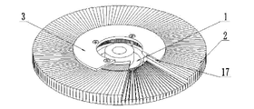
図1~図7に示すように、環状構造を呈している基体1と、複数の薄片歯2と、押さえ板3とを含む研磨工具であって、前記基体1には、基体1のリング内縁に沿って配置された制限溝5が設けられ、複数の前記薄片歯2は、前記基体1の径方向に沿って前記基体1に環状構造を接合構成し、複数の前記薄片歯2の下部がいずれも前記制限溝5に嵌め込まれている、
As shown in FIGS. 1 to 7, the polishing tool includes a
隣接する2つの前記薄片歯2の上部の間に槽体4が構成され、前記押え板3は、環状構造を呈し、かつ、前記押さえ板3は、ボルトにより前記基体1に接続され、複数の前記薄片歯2を押圧する、
複数の前記薄片歯2の上部は、研磨材層からなり、前記研磨材層は、ダイヤモンドからなる。
複数の単一の薄片歯2は、研磨材に接合固結されている。前記研磨材は、環状構造を呈している。
槽体4は、冷却水を流通させる水槽、切りくず収納槽、又は切りくず排出槽、気流槽等の機能槽である。
ここで、槽体4は、径方向型、軸方向型、傾角型、周方向型、格子型又は複合型のものである。
A
The upper portions of the plurality of
A plurality of
The
Here, the
薄片歯2の各面は、平面または曲面であってもよいし、凸紋または凹紋、凸紋または凹紋の両方が結合された複合面であってもよいし、穿孔を有する面であってもよい。
Each surface of the
各実施例では、薄片歯2の面に設けられた凸紋または凹紋は、点式、塊式、線式、条式またはメッシュ式であってもよいし、点式、塊式、線式、条式、およびメッシュ式の複合式であってもよい。各実施例の槽体4は、2つの隣接する薄歯片2上の平紋、凹紋、凸紋、または凹凸複合紋から構成されている。
In each embodiment, the convex or concave pattern provided on the surface of the
本実施例での研削砥石のサイズ:直径:152mm、内径:118mm、リング幅:17mm、高さ:20mm。薄片歯2の高さ:14mm。ここで、薄片歯2上部の高さは、8mmであり、薄片歯2下部の高さは、6mmである。
The size of the grinding wheel in this example: diameter: 152 mm, inner diameter: 118 mm, ring width: 17 mm, height: 20 mm. Height of flaky tooth 2: 14mm. Here, the height of the upper portion of the
複数の前記薄片歯2は、具体的には180歯であり、槽体4の幅は0.5mmである。薄片歯2の平均歯幅:((152π-180*0.5)/180+(118π-180*0.5)/180)/2=1.856mm。
研削砥石の端面面積:7210mm2、槽体4の面積:1530mm2、槽体4の端面占める比:21.2%。
The plurality of
The end face area of the grinding wheel: 7210 mm 2 , the area of the tank body 4: 1530 mm 2 , and the ratio of the end face of the
前記薄片歯2は、粉末冶金プロセスで作られたものであり、原料投入方向面とメインプレス面が同様の最大面積の面であり、薄片歯2の平均厚さが1.856mmしかないため、簡単な一方向プレスを採用すればよく、反対に、従来の金型プリセット全体の製造技術は双方向プレスが必要であり、金型の高さを大幅に縮小し、原料投入が簡単である。
The
図2~図7に示すように、前記薄片歯2の形状に基づいて、組立・固結が容易であり、薄片歯2を接合することにより、基体1に環状構造なるように固結されている、
複数の前記薄片歯2の間が接合された後、隣接する2つの薄片歯2の上部間に槽体4を構成し、ここで、槽体4の幅は0.5mmである。
As shown in FIGS. 2 to 7, it is easy to assemble and consolidate based on the shape of the
After joining between a plurality of said
複数の前記薄片歯2は複数の薄片歯Aおよび複数の薄片歯Bを含み、複数の前記薄片歯Aは複数の薄片歯Bとが交錯するように設置されているか、または複数の弾性薄片歯Aと1つの弾性薄片歯Bとが交錯するように設置されているか、または複数の弾性薄片歯Aが弾性薄片歯A群を構成し、複数の弾性薄片歯Bが弾性薄片歯B群を構成し、弾性薄片歯A群と弾性薄片歯B群との間に交錯するように設置されている、
薄片歯Aと薄片歯Bとが隣接して組み合わされると、薄片歯Aの下部と薄片歯Bの下部とがインターロック構造を構成している。
The plurality of
When lamina tooth A and lamina tooth B are combined adjacently, the lower portion of lamina tooth A and the lower portion of lamina tooth B form an interlock structure.
前記弾性薄片歯Aは、第1結合剤および研磨材からなり、前記弾性薄片歯Bは、第2結合剤および研磨材からなる。第1結合剤および研磨材からなる弾性薄片歯Aは、硬度が高く、使用寿命が長く、第2結合剤および研磨材からなる弾性薄片歯Bは、弾性が大きく、変形しやすく、総合効果が良く、高圧力加工時の冷却要求を満たすことができるとともに、バフ研磨装置が長い有効使用寿命を与える。 The elastic flake tooth A consists of a first binder and an abrasive, and the elastic flake tooth B consists of a second binder and an abrasive. The elastic flaky tooth A, which consists of the first binder and abrasive, has high hardness and a long service life. Well, it can meet the cooling requirements during high pressure machining, and the buffing equipment provides a long useful life.
前記押さえ板3の薄片歯2に近い端面は、傾斜状を呈し、薄片歯2の端面に合わせて近接しており、前記押さえ板3の薄片歯2に近い環状端面には、押さえ板3に接合する充填体6が設けられている。前記充填体6は、塑性変形能力を持ち、更に、充填体6は、アルミニウム合金、銅合金等の材料からなる、
押さえ板3は、ボルト又は接着剤により基体1に固結され、研削砥石が整形開刃等加工を経て完成品を形成する。
The end surface of the
The
従来の技術的解決手段との比較:
従来の技術的解決手段1、従来金型プリセット全体製造技術の比較的に良いレベルであって、槽体4の平均幅は、経済性条件下では1.5mm程度に制御でき、歯数は64歯であれば、その平均歯幅は、(152π-64*1.5)/64+(118π-64*1.5)/64)/2=5.127mmであり、研削砥石端面の面積は、7210mm2であり、槽体4面積は、1632mm2であり、槽体4の端面占める比は22.6%に達する。
Comparison with traditional technical solutions:
Conventional
従来の技術的解決手段2、歯数が120歯に向上させると、その平均歯幅は((152π-120*1.5)/120+(118π-120*1.5)/120)/2=2.034mmであり、研削砥石端面の面積は、7210mm2であり、槽体4面積は、1632mm2であり、槽体4の端面占める比は42.4%に達する。明らかに、従来の技術的解決手段2は、槽体4の幅の製造難度が制限されたため、歯数だけを高めると、槽体4の占有比を増大し、研磨材層の実体空間を占有し、工具寿命に直接影響を与えることおそれがある。
Conventional
対比説明:
従来の技術的解決手段1の歯幅と本実施例の歯幅との比は、5.127/1.856=2.76倍であり、すなわち、従来の技術的解決手段1の切りくず排出経路は、本実施例の切りくず排出経路の2.76倍に等しい。本実施例の歯数と従来の技術的解決手段1の歯数との比は、180/64=2.81倍であり、すなわち、本実施例の歯周方向受冷面面積は、従来の技術的解決手段1の歯周方向受冷面面積の2.81倍に等しい。
Contrast description:
The ratio of the face width of the conventional
本実施例の製造プロセスが簡易化されたため、切りくず排出が速く、冷却が良く、製造が容易であり、性能を大幅に向上している。図8に示すように、本発明の製造方法で得られた薄片歯2面には、局所支持構造が設けられていないため、研磨量が小さく、薄片歯2に対する強度要求があまり高くない研削砥石に適している。
実施例2:
Since the manufacturing process of this embodiment is simplified, chip evacuation is fast, cooling is good, manufacturing is easy, and performance is greatly improved. As shown in FIG. 8, since the
Example 2:
図8~図10に示すように、本実施例では、環状構造を呈している基体1と、複数の薄片歯2と、押さえ板3とを含む研磨工具であって、前記基体1には、基体1のリング内縁に沿って配置された制限溝5が設けられ、複数の前記薄片歯2は、前記基体1の径方向に沿って前記基体1に環状構造を接合構成し、複数の前記薄片歯2の下部がいずれも前記制限溝5に嵌め込まれている、
As shown in FIGS. 8 to 10, in this embodiment, the polishing tool includes a
隣接する2つの前記薄片歯2の上部の間に槽体4が構成され、前記押え板3は、環状構造を呈し、かつ、前記押さえ板3は、ボルトにより前記基体1に接続され、複数の前記薄片歯2を押圧する、
複数の前記薄片歯2の上部は、研磨材層からなり、前記研磨材層は、ダイヤモンドからなる。
各薄片歯2は、基体1リング内の端部から離れており、その端部の一側には、それに接続された第1突出ブロック7が設けられている。
A
The upper portions of the plurality of
Each
本実施例での研削砥石のサイズ:直径:152mm、内径:118mm、リング幅:17mm、高さ:20mm。第1突出ブロック7の径方向幅:2mm、第1突出ブロック7の突出高さ:0.5mm。第1突出ブロック7は、隣接する2つの薄片歯2に対して局部支持機能を発揮することができる、
薄片歯2歯数:180歯、槽体4の幅:0.5mm。
The size of the grinding wheel in this example: diameter: 152 mm, inner diameter: 118 mm, ring width: 17 mm, height: 20 mm. The radial width of the first projecting block 7: 2 mm, the projecting height of the first projecting block 7: 0.5 mm. The first
Number of flaky teeth 2: 180 teeth, width of tank body 4: 0.5 mm.
前記薄片歯2は、粉末冶金プロセスで作られたものであり、原料投入方向面とメインプレス面が同様の最大面積の面であり、簡単な一方向プレスを採用している、
前記薄片歯2の形状に基づいて、組立・固結が容易であり、薄片歯2を接合することにより、基体1に環状構造なるように固結されている、
複数の前記薄片歯2の間が接合された後、基体1に固結され、整形開刃などの後加工を経て、工具完成品を形成する。
The
Based on the shape of the
After joining between the plurality of
対比説明:
本発明の実施例での技術的解決手段によれば、実施例1での技術的解決手段と比較して、その第1突出ブロック7は、隣接する2つの薄片歯2に対して局部支持構造を構成し、連続歯構造と等価であり、断続研磨による振れおよび衝撃を除去することができる。その局部支持構造は、複数の前記薄片歯2が環状構造を構成する外径にある。加工を行う際に、まずワークに接触するのは、本実施例での研削砥石の外径に近づく部分であるため、薄片歯2の外径における耐衝撃強度が大きくなり、粗研磨、強力加工に有利である。
Contrast description:
According to the technical solution in the embodiment of the present invention, compared with the technical solution in the first embodiment, its first
本発明の実施例での技術的解決手段によれば、複数の薄片歯2が接合されたときに槽体4を形成し、更に内歯構造を構成し、冷却水が槽体4に滞留しやすく、より良い冷却効果を達成する。
According to the technical solution in the embodiment of the present invention, when a plurality of
実施例3:
図11~図14に示すように、本実施例では、環状構造を呈している基体1と、複数の薄片歯2と、押さえ板3とを含む研磨工具であって、前記基体1には、基体1のリング内縁に沿って配置された制限溝5が設けられ、複数の前記薄片歯2は、前記基体1の径方向に沿って前記基体1に環状構造を接合構成し、複数の前記薄片歯2の下部がいずれも前記制限溝5に嵌め込まれている、
Example 3:
As shown in FIGS. 11 to 14, in this embodiment, the polishing tool includes a
隣接する2つの前記薄片歯2の上部の間に槽体4が構成され、前記押え板3は、環状構造を呈し、かつ、前記押さえ板3は、ボルトにより前記基体1に接続され、複数の前記薄片歯2を押圧する、
A
複数の前記薄片歯2の上部は、研磨材層からなり、前記研磨材層は、ダイヤモンドからなる。各薄片歯2の他方の薄片歯2に近い側壁には、いずれも複数の第1凸紋8が接続されている。
The upper portions of the plurality of
本実施例での研削砥石のサイズ:直径:152mm、内径:118mm、リング幅:17mm、高さ:20mm。前記第1凸紋8は、垂直三角紋である。その三角紋の突起高さは、0.6mmであり、各薄片歯2の三角紋突起頂点からなる平面と隣接する薄片歯2の周方向平面との距離は、0.3mmであり、薄片歯2の歯数は、180歯であり、槽体4の最も狭い部分は0.3mmである。
The size of the grinding wheel in this example: diameter: 152 mm, inner diameter: 118 mm, ring width: 17 mm, height: 20 mm. The first
各薄片歯2の上端部には、複数の溝9が設けられている。各溝9は、前記薄片歯2の2つの端面を貫通し、複数の前記薄片歯2上の溝が異なる円周半径に沿って配列されて複数の円形通溝を構成し、複数の前記円形通溝が複数の槽体4と交差してメッシュ構造を構成し、網面研磨面を形成している。
The upper end of each
複数の薄片歯2が接合固結して構成された環状構造であって、径方向各点に沿って円周上に、含まれる薄片歯2上部の研磨材層の累積円周全長が不均一かつ波動的に変化するものであるため、研磨材層の累積円周全長が短いほど、ここで先に摩耗しやすく、各薄片歯2が環状構造の径方向に沿って各点の円周上に、薄片歯2上端には摩耗速く形成された溝9を構成している。この溝9は、排水および切りくずの径方向にある排出経路の短縮両方を実現することができる。溝9がそれに隣接する槽体4とメッシュ構造を構成し、網面研磨面を形成し、冷却切りくず排出効果を向上させる。溝9が形成されると、研磨材層が消費されるまで常に存在する。複数の溝9は、同径である場合、環状構造を構成することができ、複数の溝9は、異なる径である場合、複数の溝9は一部分のリングに区分的に分布され、軸方向微量周波数振動式研磨役割を果たすことができる。
An annular structure formed by joining and solidifying a plurality of
対比説明:
従来の技術的解決手段との比較から分かるように、摩耗による溝9から構成されたメッシュ構造で形成された網面研磨面は、従来の技術的解決手段の金型全体成形により周方向槽体の製造による薄片類歯の強度への影響を回避し、薄片歯2の強度を保証し、研削砥石の放熱能力を大幅に向上させ、研削砥石を高速加工により適している。この構造は、冷却水無しの研磨加工工具の開発に対して大きな意義を持ち、その構造原理も様々な研磨材研磨盤上の研磨塊への応用にも適している。
実施例4:
Contrast description:
As can be seen from the comparison with the conventional technical solution, the mesh surface polishing surface formed by the mesh structure composed of the
Example 4:
図15~図17に示すように、本実施例では、環状構造を呈している基体1と、複数の薄片歯2と、押さえ板3とを含む研磨工具であって、前記基体1には、基体1のリング内縁に沿って配置された制限溝5が設けられ、複数の前記薄片歯2は、前記基体1の径方向に沿って前記基体1に環状構造を接合構成し、複数の前記薄片歯2の下部がいずれも前記制限溝5に嵌め込まれている、
As shown in FIGS. 15 to 17, in this embodiment, the polishing tool includes a
隣接する2つの前記薄片歯2の上部の間に槽体4が構成され、前記押え板3は、環状構造を呈し、かつ、前記押さえ板3は、ボルトにより前記基体1に接続され、複数の前記薄片歯2を押圧する、
A
複数の前記薄片歯2の上部は、研磨材層からなり、前記研磨材層は、ダイヤモンドからなる。各薄片歯2の一側壁には、いずれも複数の第2突出ブロック10が接続され、複数の第2突出ブロック10は、円形または半円形を呈している。
The upper portions of the plurality of
本実施例での研削砥石のサイズ:直径:152mm、内径:118mm、リング幅:17mm、高さ:20mm。第2突出ブロック10の突起高さ:0.4mm、直径:1mm。薄片歯2の複数の第2突出ブロック10の突起高さ頂点は、隣接する薄片歯2に接触し、隣接する2つの薄片歯2は、複数の第2突出ブロック10を介して互いに支持されている、
The size of the grinding wheel in this example: diameter: 152 mm, inner diameter: 118 mm, ring width: 17 mm, height: 20 mm. The protrusion height of the second protrusion block 10: 0.4 mm, diameter: 1 mm. The protrusion height vertices of the plurality of second protruding blocks 10 of the
薄片歯2の歯数は、240歯であり、槽体4の最も広い部分の幅は、0.4mmであり、その場合、平均歯幅:((152π-240*0.4)/240+(118π-240*0.4)/240)/2=1.367 mm。
研削砥石の端面面積:7210mm2、槽体4の面積:約1632mm2、槽体4の端面占める比:22.6%。
上述技術的解決手段との比較:
The number of teeth of the
The end face area of the grinding wheel: 7210 mm 2 , the area of the tank body 4: about 1632 mm 2 , the ratio of the end face of the
Comparison with above technical solutions:
従来の技術的解決手段1、従来金型プリセット全体製造技術の比較的に良いレベルであって、槽体4の平均幅は、経済性条件下では1.5mm程度に制御でき、歯数は64歯であれば、その平均歯幅は、((152π-64*1.5)/64+(118π-64*1.5)/64)/2=5.127mmであり、研削砥石端面の面積は、7210mm2であり、槽体4面積は、約1632mm2であり、槽体4の端面占める比は22.6%に達する。
Conventional
従来の技術的解決手段1の歯幅と本実施例の歯幅との比は、5.127/1.367=3.75倍であり、すなわち、従来の技術的解決手段1の切りくず排出経路は、本実施例の切りくず排出経路の3.75倍に等しい。ここで、切りくず排出経路は槽体4である。本実施例の歯数と従来の技術的解決手段1の歯数との比は、240/64=3.75倍であり、すなわち、本実施例の歯周方向受冷面面積は、従来の技術的解決手段1の歯周方向受冷面面積の3.75倍に等しい。
The ratio of the face width of the conventional
本実施例の薄片歯2の平均厚さは、1.367mmである。薄板歯2は、第2突出ブロック10を介して隣接する薄板歯2の平面に接触し、互いに支持されていることを実現し、研削砥石の剛性を大幅に改善することができる。本実施例では、複数の突出ブロック構造や溝構造、または両者の複合構造を採用することができる。
The average thickness of the
計算から分かるように、本実施例技術的解決手段での切りくず排除経路は、実施例1に対して26.4%縮小され、本実施例技術的解決手段での周方向受冷面面積は、実施例1に対して33.3%向上している。直径152mmの場合、薄片歯2は、240歯であり、槽体4の幅は、0.4mmである。これは、従来の全体製作技術によって完成困難なものと思われる。上記の利点から見ると、本実施例は、微粒子研磨材研削砥石への応用空間及び応用分野をさらに広げる可能性がある。
実施例5:
As can be seen from the calculation, the chip removal path in the technical solution of this example is reduced by 26.4% compared to Example 1, and the circumferential cooling surface area in the technical solution of this example is It is 33.3% better than Example 1. For a diameter of 152 mm, the
Example 5:
図18~図20に示すように、本実施例では、環状構造を呈している基体1と、複数の薄片歯2と、押さえ板3とを含む研磨工具であって、前記基体1には、基体1のリング内縁に沿って配置された制限溝5が設けられ、複数の前記薄片歯2は、前記基体1の径方向に沿って前記基体1に環状構造を接合構成し、複数の前記薄片歯2の下部がいずれも前記制限溝5に嵌め込まれている、
As shown in FIGS. 18 to 20, in this embodiment, the polishing tool includes a
隣接する2つの前記薄片歯2の上部の間に槽体4が構成され、前記押え板3は、環状構造を呈し、かつ、前記押さえ板3は、ボルトにより前記基体1に接続され、複数の前記薄片歯2を押圧する、
複数の前記薄片歯2の上部は、研磨材層からなり、前記研磨材層は、ダイヤモンドからなる。
A
The upper portions of the plurality of
複数の前記薄片歯2は、複数の薄片歯Cと複数の薄片歯Dとを含み、複数の薄片歯Cを連続接合されて第1研磨材11を構成し、複数の薄片歯Dを連続接合されて第2研磨材12を構成している。複数の第1研磨材11および複数の第2研磨材12を環状構造体なるように基体1に交錯接合されている。前記薄片歯Cの基体1の一端に近い幅は、その他端の幅よりも大きく、前記薄片歯Dの基体1の一端に近い幅は、その他端の幅よりも小さい
本実施例での研削砥石のサイズ:直径:152mm、内径:118mm、リング幅:17mm、高さ:20mm。
The plurality of
薄片歯2の歯数は、180歯であり、槽体4の最も広い部分の幅は、1mmであり、最も狭い部分の幅は、0.5mmである。5つの薄片歯Cを連続接合されて第1研磨材11を構成し、5つの薄片歯Dを連続接合されて第2研磨材12を構成し、18個の第1研磨材11と18個の第2研磨材12とを接合交錯して基体1上に環状構造が形成されている。
The number of
上述技術的解決手段との比較、
本出願の技術的解決手段によれば、複数の薄片歯Cを連続接合されて第1研磨材11を構成し、複数の薄片歯Dを連続接合されて第2研磨材12を構成し、複数の第1研磨材11および複数の第2研磨材12を環状構造体なるように基体1に交錯接合されていることにより、1つの複合研磨リングを構成し、顕在的または潜在的な2環または多環の構造を実現することができる。
comparison with the above technical solutions,
According to the technical solution of the present application, a plurality of flaky teeth C are continuously joined to form a first
構成された複合研磨リングの各段の内リング部分と外リング部分との面積は、第1研磨体11と第2研磨体12との研磨面上の形状によって異なり、各第1研磨体11または第2研磨体12の作業時の圧力、摩耗の違いが、複合研磨リングの研磨面には、顕在的な形状段差が生じさせる。同時に薄片歯Cと薄片歯Dには、異なる結合剤を用いる場合には、複合研磨リングの各段の内リング部分と外リング部分の研磨時の受力も性能によって異なり、複合研磨リングの研磨面には、潜在的な受力強弱差が生じる。高低差と強弱差は、いずれも径方向と軸方向の周波数振動研磨を形成し、2環または多環の構造機能を呈し、従来技術的解決手段の技術効果を発揮・超える。
The area of the inner ring portion and the outer ring portion of each stage of the composite polishing ring thus constructed differs depending on the shape of the polishing surfaces of the
実施例6:
図21~図24に示すように、本実施例では、環状構造を呈している基体1と、複数の薄片歯2と、押さえ板3とを含む研磨工具であって、複数の前記薄片歯2は、前記基体1に沿って前記基体1に環状構造を接合構成し、かつ、前記環状構造の研磨材端面が前記基体1の縁部に密着されている、
Example 6:
As shown in FIGS. 21 to 24, in this embodiment, the polishing tool includes a
隣接する2つの前記薄片歯2の間の中央は、槽体4を構成している。前記薄片歯2上の研磨構造14の軸方向の各点の弧長は、その点における加工量と順方向関係になり、その点の加工量が大きい場合、その点の摩耗量も大きくなり、摩耗変形しやすくなり、その点の周方向弧長を相対的に長く設定し、その点の加工量が小さい場合、その点の周方向弧長を相対的に短く設定し、相対的にバランスのある摩耗を実現し、耐変形能力を向上させることができる。前記押さえ板3は、前記基体1の上端に環状に配置され、かつ、前記押さえ板3は、ボルトにより前記基体1に接続され、複数の前記薄片歯2を押圧する。
The center between two
本実施例での研削砥石のサイズ:直径:150mm、研削砥石の環状構造のリング幅:10mm、開口:12mm、加工できるワーク:10mm、高さ:23mm。
研削砥石がワークに接触した場合、槽体4の最も狭い部分は、0.2mmである。
研削砥石の歯数は、276歯である。その場合、歯周方向作業幅は、
((150π-276*0.2)/276+(130π-276*0.2)/276)/2=1.394mmである。
The size of the grinding wheel in this example: diameter: 150 mm, ring width of the annular structure of the grinding wheel: 10 mm, opening: 12 mm, workpiece that can be processed: 10 mm, height: 23 mm.
When the grinding wheel contacts the work, the narrowest part of the
The grinding wheel has 276 teeth. Then the periodontal working width is
((150π-276*0.2)/276+(130π-276*0.2)/276)/2 = 1.394 mm.
前記薄片歯2は、粉末冶金プロセスで作られたものであり、原料投入方向面とメインプレス面が同様の最大面積の面であり、前記薄片歯2の平均厚さが1.394mmしかないため、簡単な一方向プレスを採用すればよく、反対に、従来の金型プリセット全体の製造技術は双方向プレスが必要であり、金型の高さを大幅に縮小し、原料投入が簡単である。前記薄片歯2の形状に基づいて、組立・固結が容易であり、複数の前記薄片歯2の間が接合された後、隣接する2つの薄片歯2の中部に槽体4を構成し、ワークと接触するときに、槽体4の最も狭い部分は0.2mmである。前記薄片歯2の基体1リング内の一端に近い側壁には、噛合位13が設けられ、隣接する2つの薄片歯2は、噛合位13を介して互いに噛み合う。前記押さえ板3の下端面は、押さえ板3のリング内からリング外へ傾斜して下向きにされ、研磨過程において前記薄片歯2の飛び出しを防止するために、複数の前記薄片歯2に対して制限をする。充填体6、補助具、接着剤等により複数の前記薄片歯2を基体1に固結され、整形開刃等後加工を経て、工具完成品を形成する。
The
各前記薄片歯2の前記基体1のリング内から離れた一端には、研磨構造14が設けられ、対応する研磨必要なワークは凹面である場合には、各前記薄片歯2の別の薄片歯2に近い端面は、凸紋構造であり、対応する研磨必要なワークは凸面である場合には、各前記薄片歯2の別の薄片歯2に近い端面は、凹紋構造15である。研削構造14は、凹紋、凸紋または凹凸複合紋であってもよい。
従来技術的解決手段との比較:
At one end of each
Comparison with prior art solutions:
本実施例での技術的解決手段の製造プロセスが簡易化され、全体的にブリセットによって製造困難な薄片歯2を実現することができ、切りくず排出経路を大幅に短縮する狭歯構造を実現することができ、急速冷凍の槽体4を実現することができ、研磨領域に密集した内冷給水冷却モードを容易に実現することができ、研削砥石製品の性能をさらに大幅に向上させることができる。
実施例7:
The manufacturing process of the technical solution in the present embodiment is simplified, and the
Example 7:
図25~図27に示すように、本実施例では、環状構造を呈している基体1と、押さえ板3とを含む研磨工具であって、前記薄片歯2によって構成された環状構造は、基体1に固定され、前記押え板3は環状構造を呈し、かつ、前記押さえ板3は、ボルトにより前記基体1に接続され、複数の前記薄片歯2を押圧する、
複合の前記槽体4は、前記環状構造に沿って環状に配置され、かつ、各前記槽体4は、前記環状構造の径方向から相対的にずれて配置されている。
実施例8:
As shown in FIGS. 25 to 27, in this embodiment, the polishing tool includes a
The
Example 8:
図28~図33に示すように、本実施例では、環状構造を呈している基体1と、複数の薄片歯2とを含む研磨工具であって、前記基体1には、基体1のリング内縁に沿って配置された制限溝5が設けられ、複数の前記薄片歯2は、前記基体1の径方向に沿って前記基体1に環状構造を接合構成し、複数の前記薄片歯2の下部がいずれも前記制限溝5に嵌め込まれて、接着剤で基体1に接着されている、
隣接する2つの前記薄片歯2の上部の間に槽体4が構成されている、
使用時、押さえ板で取付底板16へ押圧し、さらにボルトにより電機軸上のフランジに接続され、複数の前記薄片歯2を押圧する、
複数の前記薄片歯2の上部は、いずれも研磨材層からなる。
As shown in FIGS. 28 to 33, in this embodiment, the polishing tool includes a
A
When used, the pressing plate is pressed against the mounting
The upper portions of the plurality of
前記研磨材層は、有機結合剤、無機結合剤または複合結合剤と研磨材とからなり、研磨材層には、異なる値を有する空隙率が設けられている。研磨材層も作業層であり、無機結合剤は、金属、セラミック、菱苦土などがあり、有機結合剤は、樹脂、ゴム結合剤があり、複合結合剤は、セラミック樹脂である。 The abrasive layer is composed of an organic binder, an inorganic binder or a composite binder and an abrasive, and the abrasive layer is provided with porosities having different values. The abrasive layer is also a working layer, inorganic binders include metals, ceramics, and magnesia, organic binders include resins and rubber binders, and composite binders include ceramic resins.
各薄片歯2は、環状構造の端部から離れ、その端部の一側には、それに接続された第3突出ブロック18が設けられ、各薄片歯2の一側壁には、いずれも複数の第4突出ブロック19が接続され、複数の第4突出ブロック19は、円形または半円形を呈している、
隣接する2つの薄片歯2は、複数の第4突出ブロック19を介して互いに押圧されて支持されている。
本実施例では、複数の突出ブロックまたは溝、または両方の複合構造を用いて、互いに支持または飛散防止構造17を形成することができる。
前記薄片歯2は、有機結合剤で作られたものであり、原料投入方向面とメインプレス面が同様の最大面積の面であり、簡単な一方向プレスを採用している、
前記薄片歯2の形状に基づいて、組立・固結が容易であり、複数の薄片歯2を接合することにより、基体1に環状構造なるように固結されている、
整形などの後加工を経て、工具完成品を形成する。
隣接する2つの前記薄片歯2は、補助部品を介して接着剤で接着連結される。
対比説明:
Each
Two
In this embodiment, multiple protruding blocks or grooves, or a composite structure of both, can be used to form a supporting or
The
It is easy to assemble and consolidate based on the shape of the
After undergoing post-processing such as shaping, the finished tool is formed.
Two
Contrast description:
本発明の実施例での技術的解決手段によれば、複数の薄片歯2が接合された場合に、槽体4を形成し、更に内歯構造を構成し、冷却水が槽体4に滞留しやすく、より良い冷却効果を達成する。
According to the technical solution in the embodiment of the present invention, when a plurality of
本発明の実施例での技術的解決手段によれば、複数の第4突出ブロック19を介して互いに押圧されて支持されていることにより、有機結合剤研磨輪の剛性を満足することができ、従来技術的解決手段の溝開孔後の研磨輪剛性が悪いための変形しやすいという問題を解決した。
According to the technical solution in the embodiment of the present invention, the rigidity of the organic binder polishing wheel can be satisfied by pressing and supporting each other through a plurality of fourth projecting
本発明の実施例での技術的解決手段によれば、第4突出ブロック19の構造形状、数量、大きさによって、一定の程度上に製品の全体弾性を調整することができる。
According to the technical solution in the embodiment of the present invention, the overall elasticity of the product can be adjusted to a certain extent by adjusting the structural shape, quantity and size of the fourth projecting
本発明の実施例での技術的解決手段によれば、構造機能によって製品の全体の耐熱性を向上させ、本来結合剤内部に配置される必要が一部分の孔構造を置換することができ、さらに空隙率を低下させ、研磨材を把持する能力を向上させ、高速、高効率加工能力を大幅に向上させる。
実施例9:
According to the technical solution in the embodiment of the present invention, the structural function can improve the overall heat resistance of the product, replace the part of the pore structure that should be located inside the binder, and further It reduces the porosity, improves the ability to grip the abrasive, and greatly improves the high-speed, high-efficiency processing capability.
Example 9:
図34~図36に示すように、本実施例では、環状構造を呈している基体1と、複数の薄片歯2とを含む研磨工具であって、薄片歯2は、薄片歯Eと、薄片歯Fとを含み、複数の薄片歯Eと複数の薄片歯Fとが交錯配置されている、
As shown in FIGS. 34 to 36, in this embodiment, the polishing tool includes a
前記基体1には、基体1のリング内縁に沿って配置された制限溝5が設けられ、複数の前記薄片歯2は、基体1に沿って径方向に接合して環状構造を形成している。隣接する2つの前記薄片歯2の間に槽体4を構成し、すなわち、薄片歯Eと薄片歯Fとの間に槽体4を構成している、
The
環状構造の下端部には、飛散防止構造17が設けられ、基体1の制限溝5は、環状構造上の飛散防止構造17とを噛み合い、基体1と押さえ板3とを介して環状構造を挟んで固結されている。押さえ板3により複数の前記薄片歯2を押圧し、複数の前記薄片歯2は、研磨材層からなる、
A
前記薄片歯Eは、平面状薄片歯であり、前記薄片歯Fは、波浪状薄片歯であり、薄片歯Eと薄片歯Fの軸方向各点における周方向の厚さが等しく、すなわち、薄片歯Eと薄片歯Fとの軸方向各点における円周総累積弧長が等しく、研削砥石研磨面で開溝加工を行う際に、良好な変形抵抗能力を与える。
実施例10:
The lamina tooth E is a planar lamina tooth, and the lamina tooth F is a wavy lamina tooth. The circumferential total cumulative arc length at each point in the axial direction of the tooth E and the flaky tooth F is equal, giving good deformation resistance capability when performing open groove processing with a grinding wheel polishing surface.
Example 10:
図37~図39に示すように、本実施例では、環状構造を呈している基体1と、複数の薄片歯2とを含む研磨工具であって、前記基体1には、基体1のリング内縁に沿って配置された制限溝5が設けられ、複数の前記薄片歯2は、前記基体1に沿って径方向に傾斜して環状構造を接合構成し、前記環状構造は、接着剤で接着されている、
As shown in FIGS. 37 to 39, in this embodiment, the polishing tool includes a
隣接する2つの前記薄片歯2の間に槽体4を構成し、環状構造の端面には、飛散防止構造17が設けられ、基体1と押さえ板3とを介して環状構造を挟んで固結されている。押さえ板3により複数の前記薄片歯2を押圧し、複数の前記薄片歯2は、研磨材層からなる、
A
基体1の制限溝5は、環状構造上の飛散防止構造17とを噛み合う。押さえ板3により複数の前記薄片歯2を押圧し、複数の前記薄片歯2は、研磨材層からなる。
本発明はまた、
S1.薄片歯2の径方向平均長さと周方向平均幅との比が2.5倍より大きくなるように薄片歯2を設定構造に基づいて製造するステップと、
S2.薄片歯のメインプレス面を非研磨作業面とし、かつ、メインプレス面が薄片歯の面積が最大となる面とするステップと、
S3.複数の薄片歯2をメインプレス面間に接合して固定接続されて環状構造を接合構成しているステップと、
さらに、上述実施例では、複数の薄片歯2を押さえ板3およびボルトにより基体1に固定されるステップS4とをさらに含む研磨工具の製造方法を提供する。
The limiting
The present invention also provides
S1. manufacturing the
S2. the main pressing surface of the flaky teeth being the non-abrasive working surface and the main pressing surface being the surface with the largest area of the flaky teeth;
S3. joining a plurality of
Furthermore, the above-described embodiment provides a method of manufacturing a polishing tool, further including step S4 of fixing the plurality of
上記実施例は、本発明の好ましい実施形態であるが、本発明の実施形態は、上記実施例に制限されず、本発明の精神及び原理から逸脱することなく行われる他の変更、修正、置換、組み合わせ及び簡略化は、いずれも同等の置換方法であるべきであり、すべて本発明の特許請求の範囲内として保護されるべきものである。 Although the above examples are preferred embodiments of the present invention, the embodiments of the present invention are not limited to the above examples, and other changes, modifications, and substitutions may be made without departing from the spirit and principles of the present invention. , combinations and simplifications should all be equivalent permutations and should all be protected within the scope of the claims of the present invention.
1、基体、2、薄片歯、薄片歯A、薄片歯B、薄片歯C、薄片歯D、薄片歯E、薄片歯F、3、押さえ板、4、槽体、5、制限溝、6、充填体、7、第1突出ブロック、8、第1凸紋、9、溝、10、第2突出ブロック、11、第1研磨材、12、第2研磨材、13、噛合位、14、研磨構造、15、凹紋構造、16、取付底板、17、飛散防止構造、18、第3突出ブロック、19、第4突出ブロック
1,
Claims (13)
複数の前記薄片歯(2)を順次に接合して環状構造を接合構成し、隣接する2つの前記薄片歯(2)が固定接続され、隣接する2つの前記薄片歯(2)の間に槽体(4)が形成され、
複数の前記薄片歯(2)からなる環状構造は、前記基体(1)に固定され、
前記押さえ板(3)は、環状構造を呈し、かつ、前記押さえ板(3)は、ボルトにより前記基体(1)に接続され、複数の前記薄片歯(2)を押圧し、
各前記薄片歯(2)の一側壁には、複数の第2突出ブロック(10)が接続されている、ことを特徴とする研磨工具。 comprising an annular structural base (1), a plurality of lamina teeth (2) , and a pressing plate (3) ;
A plurality of said lamina teeth (2) are successively joined to form a jointed annular structure, two adjacent said lamina teeth (2) are fixedly connected, and a cistern is formed between two adjacent said lamina teeth (2). body (4) is formed,
an annular structure consisting of a plurality of said lamina teeth (2) is fixed to said base body (1);
the pressing plate (3) has a ring structure, and the pressing plate (3) is connected to the base (1) by bolts to press the plurality of lamina teeth (2);
An abrasive tool, characterized in that a plurality of second protruding blocks (10) are connected to one side wall of each said lamina tooth (2) .
前記薄片歯(2)の基体(1)リング内の一端に近い側壁には、噛合位(13)が設けられ、隣接する2つの薄片歯(2)は、噛合位(13)を介して互いに噛み合い
前記押さえ板(3)の下端面は、押さえ板(3)のリング内からリング外へ傾斜して下向きにされ、複数の前記薄片歯(2)を制限し、
各前記薄片歯(2)の前記基体(1)リング内から離れている一端には、研磨構造(14)が設けられている、ことを特徴とする請求項1に記載の研磨工具。 The end face of the annular structure is in close contact with the edge of the base (1), the holding plate (3) is annularly arranged on the upper end of the base (1),
Said lamina tooth (2) is provided with a meshing position (13) on its side wall near one end in the base (1) ring, and two adjacent lamina teeth (2) are connected to each other via the meshing position (13). Engagement The lower end surface of the pressing plate (3) is slanted downward from the inside of the ring of the pressing plate (3) to the outside of the ring to limit the plurality of lamina teeth (2),
Abrasive tool according to claim 1 , characterized in that each lamina tooth (2) is provided with an abrasive structure (14) at one end remote from within the base body (1) ring.
Applications Claiming Priority (5)
| Application Number | Priority Date | Filing Date | Title |
|---|---|---|---|
| CN201820334241.3 | 2018-03-12 | ||
| CN201820334241.3U CN207629869U (en) | 2018-03-12 | 2018-03-12 | A kind of thin slice tooth split type skive |
| CN201810201963.6A CN108188945B (en) | 2018-03-12 | 2018-03-12 | Slice tooth split type diamond grinding wheel and manufacturing method |
| CN201810201963.6 | 2018-03-12 | ||
| PCT/CN2019/077870 WO2019174580A1 (en) | 2018-03-12 | 2019-03-12 | Abrasive tool and fabrication method therefor |
Publications (2)
| Publication Number | Publication Date |
|---|---|
| JP2021516170A JP2021516170A (en) | 2021-07-01 |
| JP7105507B2 true JP7105507B2 (en) | 2022-07-25 |
Family
ID=67907327
Family Applications (1)
| Application Number | Title | Priority Date | Filing Date |
|---|---|---|---|
| JP2020570622A Active JP7105507B2 (en) | 2018-03-12 | 2019-03-12 | Abrasive tool and its manufacturing method |
Country Status (5)
| Country | Link |
|---|---|
| US (1) | US20210370472A1 (en) |
| EP (2) | EP3766636A4 (en) |
| JP (1) | JP7105507B2 (en) |
| KR (1) | KR102396879B1 (en) |
| WO (2) | WO2019174580A1 (en) |
Families Citing this family (4)
| Publication number | Priority date | Publication date | Assignee | Title |
|---|---|---|---|---|
| CN212095976U (en) * | 2020-03-30 | 2020-12-08 | 桂林创源金刚石有限公司 | High-rotation-speed cup-shaped grinding wheel |
| EP4151364A1 (en) * | 2020-05-15 | 2023-03-22 | Guilin Champion Union Diamond Co., Ltd. | Special-shaped wheel having positive correlation water passing structure for full-grinding surface |
| CN112792751A (en) * | 2021-01-21 | 2021-05-14 | 上海橄榄精密工具有限公司 | Integrated grinding wheel matrix machining process and grinding wheel |
| CN115781542B (en) * | 2022-11-24 | 2023-08-29 | 金锐(广东)新材料股份有限公司 | Mould of diamond resin grinding wheel and manufacturing method |
Citations (3)
| Publication number | Priority date | Publication date | Assignee | Title |
|---|---|---|---|---|
| JP2009061071A (en) | 2007-09-06 | 2009-03-26 | Three M Innovative Properties Co | Linear polishing brush member, method for manufacturing this linear polishing brush member, and polishing brush |
| CN103223647A (en) | 2013-05-14 | 2013-07-31 | 桂林创源金刚石有限公司 | Split type diamond specially-shaped grinding wheel and manufacturing technology thereof |
| CN205588162U (en) | 2016-05-10 | 2016-09-21 | 桂林创源金刚石有限公司 | Lead to cup -shaped edging emery wheel of diamond that tooth and internal tooth combine |
Family Cites Families (28)
| Publication number | Priority date | Publication date | Assignee | Title |
|---|---|---|---|---|
| DE595219C (en) * | 1932-05-04 | 1934-04-04 | Max Findeisen | Grinding wheel with a working surface perpendicular to the axis |
| US2229019A (en) * | 1939-09-05 | 1941-01-14 | Norton Co | Grinding ring |
| US4212137A (en) * | 1978-07-20 | 1980-07-15 | Norton Company | Segmental grinding wheel and composite abrading segments therefor |
| JPS58196061U (en) * | 1982-06-22 | 1983-12-27 | 山崎 齊 | elastic whetstone |
| JPH0333061U (en) * | 1989-08-10 | 1991-04-02 | ||
| JPH10138151A (en) * | 1996-11-01 | 1998-05-26 | Ichiguchi:Kk | Polishing tool |
| JP2000094342A (en) * | 1998-09-25 | 2000-04-04 | Okamoto Machine Tool Works Ltd | Cup wheel-type grinding wheel and surface grinding device having it |
| JP2001205560A (en) * | 2000-01-28 | 2001-07-31 | Disco Abrasive Syst Ltd | Grinding wheel and manufacturing method for grinding wheel |
| US7658666B2 (en) * | 2004-08-24 | 2010-02-09 | Chien-Min Sung | Superhard cutters and associated methods |
| US7066795B2 (en) * | 2004-10-12 | 2006-06-27 | Applied Materials, Inc. | Polishing pad conditioner with shaped abrasive patterns and channels |
| DE102006026285A1 (en) * | 2005-06-09 | 2006-12-14 | Lapport Dcs Gmbh | Grinding tool for grinding blanks is formed as a grinding screw conveyor, blades of which have teeth, and with grooves in carrier body |
| CN201095076Y (en) * | 2006-12-31 | 2008-08-06 | 郑州人造金刚石及制品工程技术研究中心 | V-shaped chip room diamond edge grinding wheel |
| US7465222B1 (en) * | 2007-12-10 | 2008-12-16 | Storm Pneumtic Tool Co., Ltd. | Grinding wheel |
| WO2011072298A2 (en) * | 2009-12-11 | 2011-06-16 | Saint-Gobain Abrasives, Inc. | Abrasive article for use with a grinding wheel |
| US8246425B2 (en) * | 2010-01-15 | 2012-08-21 | J. Walter Company Ltd. | Abrasive wheel comprising a fan-like structure |
| ES2806994T3 (en) * | 2010-07-12 | 2021-02-19 | Saint Gobain Abrasives Inc | Abrasive article for shaping industrial materials |
| US9259855B2 (en) * | 2011-07-13 | 2016-02-16 | Tae Ung Um | Diamond tool |
| CN102672629A (en) * | 2012-05-23 | 2012-09-19 | 桂林创源金刚石有限公司 | Double-ring composite type diamond cup-shaped grinding wheel |
| KR101366640B1 (en) * | 2012-06-21 | 2014-02-25 | (주)인성다이아몬드 | Grinding wheel |
| JP2015139859A (en) * | 2014-01-30 | 2015-08-03 | 株式会社ニートレックス本社 | Grinding fluid supply tool and grinding wheel |
| KR101560502B1 (en) * | 2014-11-19 | 2015-10-14 | 세유특강(주) | Abrasive wheel and mirror-like finishing apparatus using the abrasive wheel |
| TWI690391B (en) * | 2015-03-04 | 2020-04-11 | 美商聖高拜磨料有限公司 | Abrasive article and method of use |
| CN104907943B (en) * | 2015-06-25 | 2017-12-08 | 珠海市世创金刚石工具制造有限公司 | Diamond-resin grinding wheel |
| KR101832873B1 (en) * | 2015-08-25 | 2018-02-27 | (주)유영기업 | Grinding wheel |
| CN105773459B (en) * | 2016-03-18 | 2017-12-29 | 扬中市博威磨具有限公司 | A kind of high-performance elastic blinds sander and its production technology |
| CN206663014U (en) * | 2017-03-28 | 2017-11-24 | 盐城市久恒工贸有限公司 | A kind of flap wheel of easy heat radiation |
| CN108188945B (en) * | 2018-03-12 | 2023-08-01 | 桂林创源金刚石有限公司 | Slice tooth split type diamond grinding wheel and manufacturing method |
| CN207629869U (en) * | 2018-03-12 | 2018-07-20 | 桂林创源金刚石有限公司 | A kind of thin slice tooth split type skive |
-
2019
- 2019-03-12 JP JP2020570622A patent/JP7105507B2/en active Active
- 2019-03-12 EP EP19767319.7A patent/EP3766636A4/en active Pending
- 2019-03-12 EP EP19767677.8A patent/EP3766637B1/en active Active
- 2019-03-12 KR KR1020207026595A patent/KR102396879B1/en active IP Right Grant
- 2019-03-12 WO PCT/CN2019/077870 patent/WO2019174580A1/en unknown
- 2019-03-12 US US16/979,853 patent/US20210370472A1/en active Pending
- 2019-03-12 WO PCT/CN2019/077871 patent/WO2019174581A1/en unknown
Patent Citations (3)
| Publication number | Priority date | Publication date | Assignee | Title |
|---|---|---|---|---|
| JP2009061071A (en) | 2007-09-06 | 2009-03-26 | Three M Innovative Properties Co | Linear polishing brush member, method for manufacturing this linear polishing brush member, and polishing brush |
| CN103223647A (en) | 2013-05-14 | 2013-07-31 | 桂林创源金刚石有限公司 | Split type diamond specially-shaped grinding wheel and manufacturing technology thereof |
| CN205588162U (en) | 2016-05-10 | 2016-09-21 | 桂林创源金刚石有限公司 | Lead to cup -shaped edging emery wheel of diamond that tooth and internal tooth combine |
Also Published As
| Publication number | Publication date |
|---|---|
| EP3766637A4 (en) | 2022-01-12 |
| EP3766636A4 (en) | 2021-12-08 |
| WO2019174581A1 (en) | 2019-09-19 |
| EP3766637A1 (en) | 2021-01-20 |
| US20210370472A1 (en) | 2021-12-02 |
| JP2021516170A (en) | 2021-07-01 |
| EP3766637B1 (en) | 2024-04-17 |
| KR20210003090A (en) | 2021-01-11 |
| KR102396879B1 (en) | 2022-05-12 |
| WO2019174580A1 (en) | 2019-09-19 |
| EP3766636A1 (en) | 2021-01-20 |
Similar Documents
| Publication | Publication Date | Title |
|---|---|---|
| JP7105507B2 (en) | Abrasive tool and its manufacturing method | |
| CN108188945B (en) | Slice tooth split type diamond grinding wheel and manufacturing method | |
| KR100486429B1 (en) | Ultra abrasive grain wheel f0r mirror finish | |
| CN100509292C (en) | Multi-layer cutter blade and manufacturing method thereof | |
| CN101870092B (en) | Millstone for processing crystal and manufacturing method thereof | |
| JP4271865B2 (en) | Method for producing sintered articles and products produced thereby | |
| CN203125339U (en) | Dual-ring composite type cup grinding wheel | |
| CN206404845U (en) | A kind of ceramic-metal composites compression roller | |
| CN105215795B (en) | Non-crystaline amorphous metal product abnormity method for processing surface | |
| CN204565932U (en) | A kind of Metal Substrate Split-type grinding wheel | |
| CN105751086A (en) | Metal bond grinding tool and manufacturing method thereof | |
| CN105751087A (en) | Ceramic metal bonding agent grinding tool and manufacturing method thereof | |
| CN103659626B (en) | Split type diamond wheel and manufacture craft thereof | |
| CN206519847U (en) | A kind of molding gear disc sharpener roller | |
| CN207629869U (en) | A kind of thin slice tooth split type skive | |
| CN105945738A (en) | Resin binder grinding tool and manufacturing method thereof | |
| US4971602A (en) | Method for grinding gear teeth | |
| CN103009271A (en) | One side tapered diamond resin grinding wheel and production process thereof | |
| CN2558491Y (en) | Diamond grinding disk | |
| CN206838934U (en) | High-performance carbide screw nut mould with multilayered and graded structure | |
| CN219725843U (en) | Composite grinding wheel | |
| CN204565941U (en) | A kind of novel diamond hobboing cutter | |
| CN205097065U (en) | Helical -lobe compressor female rotor shaping CBN emery wheel | |
| CN205835064U (en) | Ceramic tile biscuit rubbing down emery wheel and polishing and grinding apparatus | |
| CN215433155U (en) | Automatic chip removal grinds three-dimensional mould |
Legal Events
| Date | Code | Title | Description |
|---|---|---|---|
| A621 | Written request for application examination |
Free format text: JAPANESE INTERMEDIATE CODE: A621 Effective date: 20200909 |
|
| A977 | Report on retrieval |
Free format text: JAPANESE INTERMEDIATE CODE: A971007 Effective date: 20211028 |
|
| A131 | Notification of reasons for refusal |
Free format text: JAPANESE INTERMEDIATE CODE: A131 Effective date: 20211130 |
|
| A521 | Request for written amendment filed |
Free format text: JAPANESE INTERMEDIATE CODE: A523 Effective date: 20220225 |
|
| TRDD | Decision of grant or rejection written | ||
| A01 | Written decision to grant a patent or to grant a registration (utility model) |
Free format text: JAPANESE INTERMEDIATE CODE: A01 Effective date: 20220628 |
|
| A61 | First payment of annual fees (during grant procedure) |
Free format text: JAPANESE INTERMEDIATE CODE: A61 Effective date: 20220705 |
|
| R150 | Certificate of patent or registration of utility model |
Ref document number: 7105507 Country of ref document: JP Free format text: JAPANESE INTERMEDIATE CODE: R150 |