JP7105062B2 - Image processing device, content processing device, content processing system, and image processing method - Google Patents
Image processing device, content processing device, content processing system, and image processing method Download PDFInfo
- Publication number
- JP7105062B2 JP7105062B2 JP2017244861A JP2017244861A JP7105062B2 JP 7105062 B2 JP7105062 B2 JP 7105062B2 JP 2017244861 A JP2017244861 A JP 2017244861A JP 2017244861 A JP2017244861 A JP 2017244861A JP 7105062 B2 JP7105062 B2 JP 7105062B2
- Authority
- JP
- Japan
- Prior art keywords
- image
- depth image
- data
- depth
- distance
- Prior art date
- Legal status (The legal status is an assumption and is not a legal conclusion. Google has not performed a legal analysis and makes no representation as to the accuracy of the status listed.)
- Active
Links
Images


Classifications
-
- H—ELECTRICITY
- H04—ELECTRIC COMMUNICATION TECHNIQUE
- H04N—PICTORIAL COMMUNICATION, e.g. TELEVISION
- H04N19/00—Methods or arrangements for coding, decoding, compressing or decompressing digital video signals
- H04N19/10—Methods or arrangements for coding, decoding, compressing or decompressing digital video signals using adaptive coding
- H04N19/102—Methods or arrangements for coding, decoding, compressing or decompressing digital video signals using adaptive coding characterised by the element, parameter or selection affected or controlled by the adaptive coding
- H04N19/124—Quantisation
-
- H—ELECTRICITY
- H04—ELECTRIC COMMUNICATION TECHNIQUE
- H04N—PICTORIAL COMMUNICATION, e.g. TELEVISION
- H04N13/00—Stereoscopic video systems; Multi-view video systems; Details thereof
- H04N13/10—Processing, recording or transmission of stereoscopic or multi-view image signals
- H04N13/106—Processing image signals
- H04N13/161—Encoding, multiplexing or demultiplexing different image signal components
-
- H—ELECTRICITY
- H04—ELECTRIC COMMUNICATION TECHNIQUE
- H04N—PICTORIAL COMMUNICATION, e.g. TELEVISION
- H04N13/00—Stereoscopic video systems; Multi-view video systems; Details thereof
- H04N13/10—Processing, recording or transmission of stereoscopic or multi-view image signals
- H04N13/194—Transmission of image signals
-
- H—ELECTRICITY
- H04—ELECTRIC COMMUNICATION TECHNIQUE
- H04N—PICTORIAL COMMUNICATION, e.g. TELEVISION
- H04N13/00—Stereoscopic video systems; Multi-view video systems; Details thereof
- H04N13/20—Image signal generators
- H04N13/271—Image signal generators wherein the generated image signals comprise depth maps or disparity maps
-
- H—ELECTRICITY
- H04—ELECTRIC COMMUNICATION TECHNIQUE
- H04N—PICTORIAL COMMUNICATION, e.g. TELEVISION
- H04N19/00—Methods or arrangements for coding, decoding, compressing or decompressing digital video signals
- H04N19/10—Methods or arrangements for coding, decoding, compressing or decompressing digital video signals using adaptive coding
- H04N19/102—Methods or arrangements for coding, decoding, compressing or decompressing digital video signals using adaptive coding characterised by the element, parameter or selection affected or controlled by the adaptive coding
- H04N19/124—Quantisation
- H04N19/126—Details of normalisation or weighting functions, e.g. normalisation matrices or variable uniform quantisers
-
- H—ELECTRICITY
- H04—ELECTRIC COMMUNICATION TECHNIQUE
- H04N—PICTORIAL COMMUNICATION, e.g. TELEVISION
- H04N19/00—Methods or arrangements for coding, decoding, compressing or decompressing digital video signals
- H04N19/10—Methods or arrangements for coding, decoding, compressing or decompressing digital video signals using adaptive coding
- H04N19/134—Methods or arrangements for coding, decoding, compressing or decompressing digital video signals using adaptive coding characterised by the element, parameter or criterion affecting or controlling the adaptive coding
- H04N19/136—Incoming video signal characteristics or properties
-
- H—ELECTRICITY
- H04—ELECTRIC COMMUNICATION TECHNIQUE
- H04N—PICTORIAL COMMUNICATION, e.g. TELEVISION
- H04N19/00—Methods or arrangements for coding, decoding, compressing or decompressing digital video signals
- H04N19/10—Methods or arrangements for coding, decoding, compressing or decompressing digital video signals using adaptive coding
- H04N19/134—Methods or arrangements for coding, decoding, compressing or decompressing digital video signals using adaptive coding characterised by the element, parameter or criterion affecting or controlling the adaptive coding
- H04N19/167—Position within a video image, e.g. region of interest [ROI]
-
- H—ELECTRICITY
- H04—ELECTRIC COMMUNICATION TECHNIQUE
- H04N—PICTORIAL COMMUNICATION, e.g. TELEVISION
- H04N19/00—Methods or arrangements for coding, decoding, compressing or decompressing digital video signals
- H04N19/10—Methods or arrangements for coding, decoding, compressing or decompressing digital video signals using adaptive coding
- H04N19/169—Methods or arrangements for coding, decoding, compressing or decompressing digital video signals using adaptive coding characterised by the coding unit, i.e. the structural portion or semantic portion of the video signal being the object or the subject of the adaptive coding
- H04N19/17—Methods or arrangements for coding, decoding, compressing or decompressing digital video signals using adaptive coding characterised by the coding unit, i.e. the structural portion or semantic portion of the video signal being the object or the subject of the adaptive coding the unit being an image region, e.g. an object
- H04N19/172—Methods or arrangements for coding, decoding, compressing or decompressing digital video signals using adaptive coding characterised by the coding unit, i.e. the structural portion or semantic portion of the video signal being the object or the subject of the adaptive coding the unit being an image region, e.g. an object the region being a picture, frame or field
-
- H—ELECTRICITY
- H04—ELECTRIC COMMUNICATION TECHNIQUE
- H04N—PICTORIAL COMMUNICATION, e.g. TELEVISION
- H04N19/00—Methods or arrangements for coding, decoding, compressing or decompressing digital video signals
- H04N19/50—Methods or arrangements for coding, decoding, compressing or decompressing digital video signals using predictive coding
- H04N19/587—Methods or arrangements for coding, decoding, compressing or decompressing digital video signals using predictive coding involving temporal sub-sampling or interpolation, e.g. decimation or subsequent interpolation of pictures in a video sequence
-
- H—ELECTRICITY
- H04—ELECTRIC COMMUNICATION TECHNIQUE
- H04N—PICTORIAL COMMUNICATION, e.g. TELEVISION
- H04N19/00—Methods or arrangements for coding, decoding, compressing or decompressing digital video signals
- H04N19/50—Methods or arrangements for coding, decoding, compressing or decompressing digital video signals using predictive coding
- H04N19/597—Methods or arrangements for coding, decoding, compressing or decompressing digital video signals using predictive coding specially adapted for multi-view video sequence encoding
-
- H—ELECTRICITY
- H04—ELECTRIC COMMUNICATION TECHNIQUE
- H04N—PICTORIAL COMMUNICATION, e.g. TELEVISION
- H04N19/00—Methods or arrangements for coding, decoding, compressing or decompressing digital video signals
- H04N19/90—Methods or arrangements for coding, decoding, compressing or decompressing digital video signals using coding techniques not provided for in groups H04N19/10-H04N19/85, e.g. fractals
- H04N19/98—Adaptive-dynamic-range coding [ADRC]
-
- H—ELECTRICITY
- H04—ELECTRIC COMMUNICATION TECHNIQUE
- H04N—PICTORIAL COMMUNICATION, e.g. TELEVISION
- H04N2213/00—Details of stereoscopic systems
- H04N2213/003—Aspects relating to the "2D+depth" image format
-
- H—ELECTRICITY
- H04—ELECTRIC COMMUNICATION TECHNIQUE
- H04N—PICTORIAL COMMUNICATION, e.g. TELEVISION
- H04N2213/00—Details of stereoscopic systems
- H04N2213/005—Aspects relating to the "3D+depth" image format
-
- H—ELECTRICITY
- H04—ELECTRIC COMMUNICATION TECHNIQUE
- H04N—PICTORIAL COMMUNICATION, e.g. TELEVISION
- H04N23/00—Cameras or camera modules comprising electronic image sensors; Control thereof
- H04N23/60—Control of cameras or camera modules
- H04N23/698—Control of cameras or camera modules for achieving an enlarged field of view, e.g. panoramic image capture
Description
本発明は、画像データの圧縮を含む処理を行う画像処理装置、画像データを利用した処理を行うコンテンツ処理装置、それらを含むコンテンツ処理システム、および、それらでなされる画像処理方法に関する。 The present invention relates to an image processing apparatus that performs processing including compression of image data, a content processing apparatus that performs processing using image data, a content processing system including them, and an image processing method performed by them.
VR(Virtual Reality: 仮想現実)やAR(Augmented Reality: 拡張現実)の技術の発展に伴い、立体視を実現するステレオ画像などのカラー画像に加え、撮像面から被写体までの距離の情報、いわゆるデプス情報が重要視されるようになってきた。デプス情報により、実物体をポリゴンで表現したり、視線が動いても違和感のない立体映像を表示したりできるようになり、より臨場感、没入感のあるコンテンツを実現できる。またデプス情報は、映像として表された空間に仮想オブジェクトとしてのボールを投げ込むなど、VR空間、AR空間でのユーザの行動に対するインタラクションの実現においても重要である。 Along with the development of VR (Virtual Reality) and AR (Augmented Reality) technologies, in addition to color images such as stereo images that realize stereoscopic vision, information on the distance from the imaging surface to the subject, so-called depth Information has become important. Depth information makes it possible to represent real objects with polygons, and to display 3D images without any discomfort even when the line of sight moves, making it possible to create content with a more realistic and immersive feeling. Depth information is also important in realizing interactions with user actions in VR and AR spaces, such as throwing a ball as a virtual object into a space represented by an image.
精度の高いデプス情報を得るため、近赤外線などの参照光を照射し、その反射光を検出するまでの時間に基づきデプス情報を得る手法や、反射光の分布のひずみや強度に基づきデプス情報を得る手法など、様々な測定手法が提案されている。 In order to obtain highly accurate depth information, there are methods for obtaining depth information based on the time it takes to irradiate a reference light such as near-infrared rays and detect the reflected light, and methods for obtaining depth information based on the distortion and intensity of the distribution of reflected light. Various measurement methods have been proposed, such as a method for obtaining
一方、そのような測距センサにより得たデプス情報を、表示などに用いるカラーの撮影画像のデータとともにホスト端末などに伝送するようにすると、通信帯域の制限により即時性が損なわれたり画質が劣化したりすることが考えられる。例えば従来、カラー画像のデータのみを伝送していた通信帯域を用いてデプス情報をも送信しようとすれば、当然、カラー画像の解像度を低下させたり圧縮率を高めたりする措置が必要となり、画質が劣化しやすくなる。このような問題は、インターネットなどの大規模ネットワークを利用したり、無線通信を利用したりする場合には顕在化しやすい。 On the other hand, if the depth information obtained by such a distance measuring sensor is transmitted to the host terminal or the like together with the color image data used for display, immediacy is lost and image quality is degraded due to communication band limitations. It is conceivable to For example, if you try to transmit depth information using a communication band that has conventionally transmitted only color image data, naturally you will need to take steps to lower the resolution of the color image or increase the compression rate, which will reduce the image quality. deteriorates easily. Such problems are likely to occur when using a large-scale network such as the Internet or when using wireless communication.
本発明はこうした課題に鑑みてなされたものであり、その目的は、実測されたデプス情報を用いた高精度な処理を、伝送するデータサイズを増大させずに実現できる技術を提供することにある。 The present invention has been made in view of these problems, and its object is to provide a technique that can realize highly accurate processing using actually measured depth information without increasing the size of data to be transmitted. .
本発明のある態様は画像処理装置に関する。この画像処理装置は、被写体の距離を測定するカメラが実測した、当該距離を画素値とするデプス画像のデータを取得するデプス画像取得部と、被写体を異なる視点から撮影してなる複数の撮影画像のデータを取得する撮影画像取得部と、デプス画像のデータを、複数の撮影画像のデータを用いて圧縮するデプス画像圧縮部と、複数の撮影画像のデータと、圧縮されたデプス画像のデータを出力する出力部と、を備えたことを特徴とする。 One aspect of the present invention relates to an image processing device. This image processing device includes a depth image acquisition unit that acquires depth image data having pixel values corresponding to the distance actually measured by a camera that measures the distance of the subject, and a plurality of captured images obtained by capturing the subject from different viewpoints. a captured image acquisition unit that acquires the data of the depth image, a depth image compression unit that compresses the data of the depth image using the data of the plurality of captured images, and the data of the plurality of captured images and the compressed depth image data and an output unit for outputting.
ここで「画像処理装置」は、情報処理端末、情報処理装置、ネットワークで各種装置に接続可能なサーバなど、画像処理を実施する装置そのもの、およびそれらの装置の一部を構成する集積回路などのいずれでもよい。あるいは「画像処理装置」は、撮像装置であってもよいし、その一部を構成する集積回路でもよい。 Here, the term "image processing device" refers to devices that perform image processing, such as information processing terminals, information processing devices, and servers that can be connected to various devices via a network, as well as integrated circuits that constitute part of these devices. Either is fine. Alternatively, the "image processing device" may be an imaging device or an integrated circuit forming part of it.
本発明の別の態様はコンテンツ処理装置に関する。このコンテンツ処理装置は、被写体を異なる視点から撮影してなる複数の撮影画像のデータと、被写体の距離を測定するカメラが実測した、当該距離を画素値とするデプス画像の圧縮後のデータを取得する画像データ取得部と、圧縮後のデプス画像のデータを、複数の撮影画像のデータを用いて伸張するデプス画像伸張部と、少なくとも伸張されたデプス画像のデータを用いて所定の処理を行い結果を出力する出力部と、を備えたことを特徴とする。 Another aspect of the invention relates to a content processing device. This content processing device acquires the data of a plurality of photographed images obtained by photographing a subject from different viewpoints, and the compressed data of a depth image whose pixel value is the distance actually measured by a camera that measures the distance of the subject. a depth image expansion unit that expands the compressed depth image data using data of a plurality of captured images; and at least the expanded depth image data is used to perform predetermined processing, resulting and an output unit that outputs the
ここで「コンテンツ処理装置」は、ヘッドマウントディスプレイ、情報端末、情報処理装置、ネットワークで各種装置に接続可能なサーバなど、コンテンツを処理する装置そのもの、およびそれらの装置の一部を構成する集積回路などのいずれでもよい。 Here, the "content processing device" refers to devices that process content themselves, such as head-mounted displays, information terminals, information processing devices, servers that can be connected to various devices via a network, and integrated circuits that constitute a part of these devices. and so on.
本発明のさらに別の態様はコンテンツ処理システムに関する。このコンテンツ処理システムは、被写体の距離を測定するカメラが実測した、当該距離を画素値とするデプス画像のデータと、被写体を異なる視点から撮影してなる複数の撮影画像のデータを伝送する画像処理装置と、デプス画像のデータと撮影画像のデータを用いて情報処理を実施するコンテンツ処理装置と、を含むコンテンツ処理システムであって、画像処理装置は、デプス画像のデータを、複数の撮影画像のデータを用いて圧縮するデプス画像圧縮部と、複数の撮影画像のデータと、圧縮後のデプス画像のデータを出力する出力部と、を備え、コンテンツ処理装置は、圧縮後のデプス画像のデータを、複数の撮影画像のデータを用いて伸張するデプス画像伸張部と、少なくとも伸張された前記デプス画像のデータを用いて所定の処理を行い結果を出力する出力部と、を備えたことを特徴とする。 Yet another aspect of the invention relates to a content processing system. This content processing system is an image processing system that transmits depth image data whose pixel value is the distance actually measured by a camera that measures the subject's distance, and data of a plurality of photographed images obtained by photographing the subject from different viewpoints. and a content processing device that performs information processing using depth image data and photographed image data, wherein the image processing device converts the depth image data into a plurality of photographed images. The content processing device includes a depth image compression unit that compresses using data, and an output unit that outputs the data of a plurality of captured images and the compressed depth image data. a depth image decompression unit that decompresses data of a plurality of photographed images; and an output unit that performs predetermined processing using at least the decompressed depth image data and outputs the result. do.
本発明のさらに別の態様は画像処理方法に関する。この画像処理方法は画像処理装置が、被写体の距離を測定するカメラが実測した、当該距離を画素値とするデプス画像のデータを取得するステップと、被写体を異なる視点から撮影してなる複数の撮影画像のデータを取得するステップと、デプス画像のデータを、複数の撮影画像のデータを用いて圧縮するステップと、複数の撮影画像のデータと、圧縮されたデプス画像のデータを出力するステップと、を含むことを特徴とする。 Yet another aspect of the present invention relates to an image processing method. This image processing method includes the step of acquiring depth image data having pixel values corresponding to the distance actually measured by a camera that measures the distance of an object, and performing a plurality of shooting operations in which the object is photographed from different viewpoints. a step of acquiring image data, a step of compressing depth image data using data of a plurality of captured images, a step of outputting the data of the plurality of captured images and the compressed depth image data; characterized by comprising
本発明のさらに別の態様も画像処理方法に関する。この画像処理方法はコンテンツ処理装置が、被写体を異なる視点から撮影してなる複数の撮影画像のデータと、被写体の距離を測定するカメラが実測した、当該距離を画素値とするデプス画像の圧縮後のデータを取得するステップと、圧縮後のデプス画像のデータを、前記複数の撮影画像のデータを用いて伸張するステップと、少なくとも伸張されたデプス画像のデータを用いて所定の処理を行い結果を出力するステップと、を含むことを特徴とする。 Yet another aspect of the present invention also relates to an image processing method. In this image processing method, a content processing device compresses data of a plurality of photographed images obtained by photographing a subject from different viewpoints, and a depth image whose pixel value is the distance actually measured by a camera that measures the distance of the subject. decompressing the data of the compressed depth image using the data of the plurality of captured images; performing predetermined processing using at least the data of the decompressed depth image, and obtaining a result; and outputting.
なお、以上の構成要素の任意の組合せ、本発明の表現を方法、装置、システム、コンピュータプログラム、コンピュータプログラムを記録した記録媒体などの間で変換したものもまた、本発明の態様として有効である。 Any combination of the above constituent elements, and any conversion of the expression of the present invention between a method, an apparatus, a system, a computer program, a recording medium recording a computer program, and the like are also effective as aspects of the present invention. .
本発明によると、伝送するデータサイズを増大させずに撮影画像を用いた高精度な情報処理を実現できる。 According to the present invention, highly accurate information processing using captured images can be realized without increasing the size of data to be transmitted.
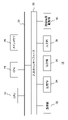
図1は本実施の形態を適用できるコンテンツ処理システムの構成例を示す。コンテンツ処理システム1は、実空間を撮影する撮像装置12、撮影画像を処理し伝送する形態に変換する画像処理装置10、伝送された撮影画像を用いて所定の情報処理を実施するコンテンツ処理装置14、および情報処理の結果を出力する表示装置16を含む。画像処理装置10とコンテンツ処理装置14は必要に応じてネットワーク8を介し通信を確立する。
FIG. 1 shows a configuration example of a content processing system to which this embodiment can be applied. The
画像処理装置10と撮像装置12、コンテンツ処理装置14と表示装置16はそれぞれ、有線ケーブルで接続されてよく、また無線LAN(Local Area Network)などにより無線接続されてもよい。あるいは画像処理装置10と撮像装置12、コンテンツ処理装置14と表示装置16はそれぞれ、一体的な装置であってもよい。例えば画像処理装置10と撮像装置12を合わせて、ネットワーク8への伝送機能を有する撮像装置としてもよいし、コンテンツデータを配信するサーバとしてもよい。またコンテンツ処理装置14と表示装置16を合わせて、携帯端末やヘッドマウントディスプレイとしてもよい。
The
さらに画像処理装置10とコンテンツ処理装置14を接続するネットワーク8は、インターネットのように大規模ネットワークでもよいし、有線あるいは無線により確立されたLANなどのローカルなネットワークでもよい。このように撮像装置12、画像処理装置10、コンテンツ処理装置14、および表示装置16の外観形状や接続形態は図示するものに限らない。
Furthermore, the
撮像装置12は、被写空間を所定のフレームレートで撮影するステレオカメラ18と、同じ被写空間における被写体までの距離の情報を所定のフレームレートで取得するデプスカメラ19を備える。ステレオカメラ18はCMOS(Complementary Metal Oxide Semiconductor)センサなどの撮像素子と、その出力データにデモザイク処理、レンズ歪み補正、色補正などを施し、撮影画像のデータを生成する画像処理機構を含むビデオカメラを、所定の間隔で左右に配置した構造を有する。
The
デプスカメラ19は被写空間に近赤外線などの参照光を照射する機構と、その反射光を検出するCMOSセンサとで構成され、照射から検出までの時間や、反射光の分布のひずみなどにより被写体までの距離を導出する。前者の手法はToF(Time of Flight)方式、後者の手法はパターン照射方式として一般に知られる技術である。ただしデプスカメラの構成や距離の導出手法をこれに限る趣旨ではない。いずれにしろ撮像装置12は、左右の視点から撮影された一対のカラー画像からなるステレオ画像と、それに対応するデプス画像のデータを、所定のレートで画像処理装置10に供給する。
The
なおデプス画像は、被写体の像の画素値として距離値を表した画像である。また同図の撮像装置12は、ステレオカメラ18のセンサの中間にデプスカメラ19のセンサを配置しているが、各センサの配置や数はこれに限定されない。例えばデプスカメラも左右の視点から撮影するステレオカメラとして、カラー画像を撮影するステレオカメラと上下に近接するように配置してもよいし、カラー画像を撮影するステレオカメラがデプス画像を撮影するカメラを兼ねていてもよい。なお以後の説明では、デプス画像でない一般的な撮影画像の対を「ステレオ画像」と呼ぶ。
Note that the depth image is an image representing a distance value as a pixel value of the image of the subject. In addition, although the
画像処理装置10は、撮像装置12から供給された画像のデータを圧縮して伝送形態としたうえ、所定のレートでコンテンツ処理装置14に送信する。具体的にはステレオ画像とデプス画像が有する冗長性を利用することで、デプス画像のデータサイズを軽減させる。例えばステレオ画像を用いて演算によりデプス画像を求め、デプスカメラにより実測された結果であるデプス画像との差分画像を圧縮後のデプス情報のデータとする。
The
コンテンツ処理装置14は、そのように送信されたデータのうち圧縮されているデプス情報を伸張することによりデプス画像を復元する。すなわちデプス情報として上述の差分画像が送信された場合、ステレオ画像を用いて演算によりデプス画像を求め、差分画像に加算することで実測されたデプス画像を復元する。コンテンツ処理装置14は復元したデプス画像とステレオ画像を用いて情報処理を実施したり、表示画像や音声などの出力データを生成したりする。
The
ここで出力データの内容は特に限定されず、ユーザがシステムに求める機能や起動させたアプリケーションの内容などによって様々であってよい。コンテンツ処理装置14は例えば、表示装置16の左右の領域にステレオ画像が表示されるように画像を接続したうえ、被写体とインタラクションする仮想オブジェクトを、デプス画像が表す距離値に基づき描画する。あるいは被写体の実空間での動きをデプス画像から取得し、それをコマンド入力に変換することでゲームを進捗させ、当該ゲーム画面を生成してもよい。
Here, the content of the output data is not particularly limited, and may vary depending on the functions that the user desires of the system, the content of the activated application, and the like. For example, the
表示装置16は、画像を出力する液晶、プラズマ、有機ELなどのディスプレイと、音声を出力するスピーカーを備え、コンテンツ処理装置14から供給された出力データを画像や音声として出力する。表示装置16は、テレビ受像器、各種モニター、携帯端末の表示画面、カメラの電子ファインダなどでもよいし、ユーザの頭に装着してその眼前に画像を表示するヘッドマウントディスプレイでもよい。
The
一般的に、デプス画像をステレオ画像から生成する手法は広く知られている。具体的には、ステレオ画像における同じ像の対応点をブロックマッチングなどにより求め、その水平方向のずれ量から三角測量の原理により距離を導出する。しかしながらこの手法では、両画像の対応がブロックの単位となるため、デプス画像の解像度が低くなる。また被写体表面の特徴点の多少によって、マッチング精度、ひいてはデプス画像の精度が大きく変動する。 In general, techniques for generating depth images from stereo images are widely known. Specifically, the corresponding points of the same image in the stereo image are obtained by block matching or the like, and the distance is derived from the horizontal shift amount by the principle of triangulation. However, with this method, the resolution of the depth image is low because the correspondence between the two images is in units of blocks. Also, the accuracy of matching, and thus the accuracy of the depth image, varies greatly depending on the number of feature points on the surface of the subject.
本実施の形態では、実測されたデプス画像の利用を基本とするため、情報処理の精度を高く維持できる。また、同時に伝送されるステレオ画像などを利用してデータ圧縮を実現することにより、デプス画像の伝送に必要な帯域を抑えることができる。これにより、多くの帯域をカラーのステレオ画像の送信に利用できるため、画質を劣化させることなく高精度な処理を実現できる。 Since the present embodiment is based on the use of actually measured depth images, high accuracy of information processing can be maintained. In addition, by realizing data compression using a stereo image or the like that is transmitted simultaneously, it is possible to suppress the band required for transmission of the depth image. As a result, since many bands can be used for transmitting color stereo images, highly accurate processing can be achieved without degrading image quality.
図2は画像処理装置10の内部回路構成を示している。画像処理装置10は、CPU(Central Processing Unit)23、GPU(Graphics Processing Unit)24、メインメモリ26を含む。これらの各部は、バス30を介して相互に接続されている。バス30にはさらに入出力インターフェース28が接続されている。入出力インターフェース28には、USBやIEEE1394などの周辺機器インターフェースや、有線又は無線LANのネットワークインターフェースからなる通信部32、ハードディスクドライブや不揮発性メモリなどの記憶部34、外部の機器へデータを出力する出力部36、撮像装置12や図示しない入力装置からデータを入力する入力部38、磁気ディスク、光ディスクまたは半導体メモリなどのリムーバブル記録媒体を駆動する記録媒体駆動部40が接続される。
FIG. 2 shows the internal circuit configuration of the
CPU23は、記憶部34に記憶されているオペレーティングシステムを実行することにより画像処理装置10の全体を制御する。CPU23はまた、リムーバブル記録媒体から読み出されてメインメモリ26にロードされた、あるいは通信部32を介してダウンロードされた各種プログラムを実行する。GPU24は、ジオメトリエンジンの機能とレンダリングプロセッサの機能とを有し、CPU23からの描画命令に従って描画処理を行い、出力部36に出力する。メインメモリ26はRAM(Random Access Memory)により構成され、処理に必要なプログラムやデータを記憶する。なおコンテンツ処理装置14の内部回路構成もこれと同様でよい。
The
図3は画像処理装置10とコンテンツ処理装置14の機能ブロックの構成を示している。同図に示す各機能ブロックは、ハードウェア的には、図2で示した各種回路によりで実現でき、ソフトウェア的には、記録媒体からメインメモリにロードした、画像解析機能、情報処理機能、画像描画機能、データ入出力機能などの諸機能を発揮するプログラムで実現される。したがって、これらの機能ブロックがハードウェアのみ、ソフトウェアのみ、またはそれらの組合せによっていろいろな形で実現できることは当業者には理解されるところであり、いずれかに限定されるものではない。
FIG. 3 shows the configuration of functional blocks of the
画像処理装置10は、撮像装置12からステレオ画像のデータを取得するステレオ画像取得部50、デプス画像のデータを取得するデプス画像取得部52、ステレオ画像を用いてデプス画像のデータを圧縮するデプス画像圧縮部54、および、ステレオ画像と圧縮後のデプス画像のデータを出力する出力部56を含む。ステレオ画像取得部50、デプス画像取得部52はいずれも、図2の入力部38、CPU23、メインメモリ26などで実現され、前者はステレオ画像のデータを、後者はデプス画像のデータを、撮像装置12から所定のフレームレートで順次取得する。ここでステレオ画像取得部50は、被写体を異なる視点から撮影してなる複数の撮影画像のデータを取得する撮影画像取得部を構成している。
The
ステレオ画像取得部50、デプス画像取得部52はそれぞれ、撮像装置12において露光が完了した行から順に、ストリーム形式でデータを取得してもよい。デプス画像圧縮部54は、図2のCPU23、GPU24、メインメモリ26などで実現され、デプス画像のデータサイズを圧縮する。具体的には上述のように、ステレオ画像を用いて演算より求めたデプス画像と、デプス画像取得部52が取得したデプス画像との差分画像を生成する。あるいはデプス画像圧縮部54は、被写体までの距離に応じて距離値を表すデータの、単位距離当たりの階調数を変化させて量子化してもよい。
Each of the stereo
この際、デプス画像圧縮部54は、ステレオ画像のいずれかにおける被写体の像を抽出し、被写体ごとにその距離範囲に応じた適切な階調数を割り当ててもよい。またデプス画像圧縮部54は、ステレオ画像を用いて演算により求めたデプス画像と実測されたデプス画像との差分画像に対し、距離に応じた階調数の調整を実施してもよい。以後、差分画像や、単位距離当たりの階調数の調整がなされた画像およびそれに付随するデータを「圧縮後のデプス画像」と総称する。
At this time, the depth
出力部56は、図2のCPU23、メインメモリ26、通信部32などで実現され、ステレオ画像取得部50が取得したステレオ画像のデータと、デプス画像圧縮部54が生成した圧縮後のデプス画像のデータを出力する。出力先はコンテンツ処理装置14でもよいし、コンテンツ処理装置14が読み取り可能な記録媒体でもよい。あるいは画像処理装置10の記憶部34に一旦格納しておき、コンテンツ処理装置14からの要求に応じて送信するようにしてもよい。なお出力部56は、出力対象のデータを一般的な手法により圧縮符号化したり、パケット化したりしてもよい。
The
コンテンツ処理装置14は、ステレオ画像と圧縮後のデプス画像のデータを取得する画像データ取得部60、圧縮後のデプス画像を伸張するデプス画像伸張部62、ステレオ画像とデプス画像のデータを用いて所定の情報処理を実施する情報処理部64、および、情報処理の結果生成された表示画像や音声のデータを出力する出力部66を含む。
The
画像データ取得部60は、図2の通信部32、CPU23、メインメモリ26などで実現され、画像処理装置10からステレオ画像と圧縮後のデプス画像のデータを所定のフレームレートで順次取得する。記録媒体を介する場合は、画像データ取得部60は記録媒体駆動部40によりそれらの画像データを順次読み出す。記録媒体を用いる場合も、本実施の形態によって格納されるデータサイズを抑えることができる。なお画像データ取得部60は、取得した画像のデータが一般的な手法により圧縮符号化されている場合は、それを復号することにより2次元の画像データに戻しておく。
The image
デプス画像伸張部62は、図2のCPU23、GPU24、メインメモリ26などで実現され、圧縮後のデプス画像を伸張して元のデプス画像を生成する。伸張処理の内容は基本的に、画像処理装置10においてデプス画像圧縮部54が行う圧縮処理を逆に辿る処理である。具体例は後述する。
The depth
情報処理部64は、図2のCPU23、GPU24、メインメモリ26などで実現され、ステレオ画像と伸張後のデプス画像を用いて所定の情報処理を実施し、出力データを生成する。上述のとおり情報処理部64が行う処理の内容は特に限定されない。出力部66は図2のCPU23、メインメモリ26、出力部36などで実現され、そのようにして生成された表示画像などの出力データを表示装置16に出力する。なおコンテンツ処理装置14のデプス画像伸張部62は、ゲームや表示に係る処理を実施する装置とは独立した、画像データ伸張装置としてもよい。
The
次に本実施の形態におけるデプス画像の圧縮手法/伸張手法について詳述する。図4は、本実施の形態の一態様として、ステレオ画像を用いて演算より求めたデプス画像と、デプスカメラにより実測されたデプス画像との差分画像を利用する場合の、デプス画像圧縮部54とデプス画像伸張部62の機能ブロックの構成と処理の流れを示している。この場合の画像処理装置10におけるデプス画像圧縮部54aは、デプス画像演算部70と差分画像取得部72を含む。デプス画像演算部70はステレオ画像80を入力データとし、演算によりデプス画像を生成する。
Next, a depth image compression method/expansion method according to the present embodiment will be described in detail. FIG. 4 shows, as one aspect of the present embodiment, a depth
具体的には上述のとおり、ステレオマッチングにより両者の対応点を特定し、それらの視差から三角測量の原理により被写体までの距離を導出する。この際、一般的には、ステレオ画像の一方の画像に参照ブロックを設定し、他方の画像においてそれとの類似度が高いブロックを水平方向に探索する。その結果得られた視差に基づき距離値を算出し、参照ブロックを設定した方の画像にマッピングすることにより、対応する視点におけるデプス画像が生成される。 Specifically, as described above, the corresponding points between the two are specified by stereo matching, and the distance to the subject is derived from the parallax between them by the principle of triangulation. At this time, in general, one image of the stereo images is set as a reference block, and the other image is horizontally searched for blocks having a high degree of similarity therewith. A depth image at the corresponding viewpoint is generated by calculating a distance value based on the parallax obtained as a result and mapping it to the image in which the reference block is set.
差分画像取得部72は、デプスカメラにより撮影されたデプス画像82、およびデプス画像演算部70が生成したデプス画像を入力データとし、両者の画素値の差を表した差分画像84を生成する。差分画像取得部72は実際には、従来の差分パルス符号変調(DPCM:Differential Pulse-Code Modulation)の技術に用いられる、動画像のフレーム間の差分を取得するのと同様の回路で実現できる。以降の図における差分画像取得部72も同様である。画像処理装置10は、このようにして生成された差分画像84を圧縮後のデプス画像として、ステレオ画像80のデータとともに出力する。
The difference
一方、コンテンツ処理装置14のデプス画像伸張部62aは、デプス画像演算部74と差分画像加算部76を含む。デプス画像演算部74はステレオ画像80を入力データとし、演算によりデプス画像を生成する。この処理は、画像処理装置10のデプス画像圧縮部54aにおけるデプス画像演算部70が行う処理と同様である。差分画像加算部76は、圧縮後のデプス画像である差分画像84、およびデプス画像演算部74が生成したデプス画像を入力データとし、両者の画素値を加算して、撮像装置12が実測したデプス画像82と同等のデプス画像86を生成する。差分画像加算部76は実際には、上述の差分パルス符号変調において動画像のフレームをデコードする回路と同様の回路で実現できる。以降の図における差分画像加算部76も同様である。
On the other hand, the depth
デプス画像演算部70、74が上記の手法により生成するデプス画像は一般に、演算に用いたステレオ画像より解像度が低く、被写体表面における特徴点の多少によって精度がばらつきやすい。デプスカメラにより実測されたデプス画像82との差分画像84は、そのような解像度や精度の低下を補うものである。結果として差分画像84を送信対象とすることにより、実測されたデプス画像82より小さいデータサイズで、当該デプス画像82と同等の情報を伝送できることになる。
The depth images generated by the depth
なお図では全ての画像が同じサイズで示されているが、ステレオ画像80、デプス画像82、差分画像84のサイズや解像度は独立に設定してよい。差分画像の生成や加算に用いる画像のサイズ(解像度)が異なる場合は、既存の補間技術により適宜拡大、縮小した後、同じ位置の画素同士を演算すればよい。また撮像装置12において、デプスカメラもステレオカメラで構成することにより、実測するデプス画像82を左右視点からのステレオ画像としてもよい。
Note that although all images are shown to have the same size in the drawing, the size and resolution of the
この場合、デプス画像演算部70が演算により生成した1つのデプス画像と、左右視点のデプス画像のそれぞれとの差分を計算することにより、差分画像84も左右視点からのステレオ画像としてよい。すなわちデプス画像圧縮部54aは、差分画像84を、複数のデプス画像のそれぞれに対し生成する。左右視点のデプス画像を実測することにより、一方の視点からは死角になる部分であっても他方の視点から距離が判明し、実世界のより広い範囲の距離情報を用いて精度の高い情報処理を行える。このような態様でも、双方のデプス画像を差分画像に圧縮すれば、送信データのサイズの増大を抑えることができる。
In this case, the
あるいは、デプス画像演算部70が演算により生成した1つのデプス画像における各被写体の像を、デプスカメラの左右の視点から見た状態となるようにずらすことで、実測された2つのデプス画像に対応する2つのデプス画像を生成してもよい。すなわちデプス画像圧縮部54aは、視差に基づく1つのデプス画像を、圧縮対象のデプス画像が実測された際の視点からの2つのデプス画像に変換したうえで、当該圧縮対象のデプス画像との差分を生成する。この場合、対応する視点のデプス画像同士を演算することで、差分ステレオ画像を生成できる。
Alternatively, by shifting the image of each subject in one depth image generated by the calculation by the depth
このように演算により求めたデプス画像における像を、デプスカメラの視点から見た状態となるようにずらす手法は、ステレオカメラとデプスカメラの位置関係が既知であれば、デプスカメラの数や位置によらず適用可能である。この処理により、実測したデプス画像と演算により求めたデプス画像の差分が小さくなり、データサイズをより抑えられる。被写体の距離情報に基づき、異なる視点からの画像を生成する手法には、一般的なコンピュータグラフィクスの技術を適用できる。 If the positional relationship between the stereo camera and the depth camera is known, the method of shifting the image in the depth image obtained by calculation in this way to the state seen from the viewpoint of the depth camera can be changed depending on the number and position of the depth camera. applicable regardless of By this processing, the difference between the actually measured depth image and the calculated depth image is reduced, and the data size can be further suppressed. General computer graphics technology can be applied to the method of generating images from different viewpoints based on the distance information of the subject.
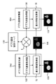
図5は、本実施の形態の別の態様として、被写体の距離に応じてデプス画像の画素値である距離値の階調数を変化させる場合の、デプス画像圧縮部54とデプス画像伸張部62の機能ブロックの構成と処理の流れを示している。この場合の画像処理装置10におけるデプス画像圧縮部54bは、被写体認識部90と階調割り当て部92を含む。被写体認識部90は、ステレオ画像のうち少なくとも一方の画像100を用いて、画像として映る被写体を認識する。
FIG. 5 shows, as another aspect of the present embodiment, depth
被写体認識部90は例えば、エッジ抽出フィルタを用いて画像100における輪郭線を抽出することで、被写体の像の領域を特定する。図示する例では、画像100から顔、木、その他の背景領域が特定される。画像において被写体の像の領域を分離するセグメンテーション技術には、その他にも様々な手法が提案されており、本実施の形態においてそのうちのいずれを採用してもよい。例えば顔の領域には顔認識技術を導入してもよいし、既知形状の被写体にはテンプレートマッチングを導入してもよい。あるいはオプティカルフローなどの手法を利用し前の画像フレームからの物体追跡を行ってもよい。
For example, the
採用する認識手法によっては、実測されたデプス画像102やステレオ画像の双方を適宜利用してよい。なお被写体認識部90による被写体認識は上述のとおり、距離に応じてデプス画像の画素値の階調数を割り当てることを目的としているため、厳密に全ての被写体の像を分離する必要はない。例えば複数の被写体が接している場合、両者を区別しなくても構わない。
Depending on the adopted recognition method, both the actually measured
階調割り当て部92は、デプスカメラにより撮影されたデプス画像102、および被写体認識部90により認識された、各被写体の像の領域に基づき、デプス画像の画素値として表される距離値の単位距離当たりの階調数を、被写体ごとに決定する。デプス情報を利用した情報処理では、撮像装置から近くにある被写体ほどそのデプス情報に精度が求められる。つまり実世界では同じ移動量でも、画像上での移動量は撮像装置に近いほど大きくなる。また一般的な環境においては、ユーザなど主たる対象は他の被写体より撮像装置の近くに存在する可能性が高い。
The
そのような実世界での状況を情報処理に正確に反映させるには、近くの被写体についての距離情報の分解能を高くすることが望ましい。換言すれば、遠い被写体であれば距離情報の分解能を抑えても情報処理の精度への影響が小さい。したがって階調割り当て部92は、近い被写体ほど多くの階調数を割り当ててデプス画像102の画素値を量子化する。例えばデプス画像の画素値を表すビット深度に対し、顔の像の画素値には5割、背後の木の画素値には3割、それ以外の部分には2割、といった割合でビット数を割り当てる。このような割り当ては当然、距離が異なる被写体の数によっても変化する。
In order to accurately reflect such situations in the real world in information processing, it is desirable to increase the resolution of distance information on nearby subjects. In other words, if the object is far away, even if the resolution of the distance information is suppressed, the accuracy of the information processing is less affected. Therefore, the
これにより、デプス画像全体のデータサイズを増大させることなく、後段の情報処理おいて重要となる近距離の被写体については高い分解能での距離情報を提供できる。階調割り当て部92は、オブジェクトごとに適切な階調数が割り当てられ量子化されたデプス画像104と、量子化前後の画素値の対応情報106とを、圧縮後のデプス画像のデータとする。画像処理装置10は、当該圧縮後のデプス画像のデータとステレオ画像のデータを出力する。
As a result, it is possible to provide high-resolution distance information for a short-distance subject, which is important in subsequent information processing, without increasing the data size of the entire depth image. The
一方、コンテンツ処理装置14のデプス画像伸張部62bはデプス値取得部96を含む。デプス値取得部96は、圧縮後のデプス画像のデータ、すなわち距離に応じて階調数が調整されたデプス画像104と、量子化前後の画素値の対応情報106とを入力データとして、元のデプス画像108を復元する。すなわち画像処理装置10から送信されたデプス画像104に表されている、距離によって分解能の異なる画素値のデータを、均等な分解脳でのデータに変換する。変換には、量子化前後の画素値の対応情報106を用いる。
On the other hand, the depth
図6は、デプス画像の伸張に用いる、量子化前後の画素値の対応情報を説明するための図である。(a)に示す例は、上述のとおり認識した被写体の距離に基づき階調数を割り当てる場合の、実測された距離に対する量子化後の距離の変化を示している。なお厳密には、量子化後の値は離散的となるが、同図では連続した値として模式的に示している。また同グラフをもって対応情報の形式を限定する趣旨ではない。すなわちコンテンツ処理装置14において、量子化後の値から量子化前の値を取得できれば、関数やルックアップテーブルなどデータ形式は限定されない。
FIG. 6 is a diagram for explaining correspondence information of pixel values before and after quantization, which is used for decompression of a depth image. The example shown in (a) shows the change in the distance after quantization with respect to the actually measured distance when the number of gradations is assigned based on the recognized distance of the subject as described above. Strictly speaking, the values after quantization are discrete, but they are schematically shown as continuous values in FIG. Also, the graph is not intended to limit the format of correspondence information. That is, if the
一般的な技術においては、(a)において一点鎖線で示した変化180のように、実測距離の値に正比例するように量子化後の距離が決定する。一方、本実施の形態では実線で示した変化182のように、被写体の存在する距離範囲に多くの階調を割り当て、かつ撮像装置12からの距離が近いほど多くの階調を割り当てる。
In a general technique, the distance after quantization is determined so as to be directly proportional to the value of the measured distance, like the
例えば図5で示した画像構成においては、最も撮像装置側にある顔の距離範囲、その背後にある木の距離範囲、最も背後にある壁などの距離範囲に、それぞれ階調数A、B、Cを、A>B>Cとなるように割り当てる。また被写体間の距離範囲(被写体の存在しない距離範囲)については階調数Cより小さい所定の階調数を割り当てる。これは被写体表面の凹凸や被写体同士の距離と比較し、被写体間の距離の刻みの重要性が低いことによる。 For example, in the image configuration shown in FIG. 5, gradation numbers A, B, Assign C such that A>B>C. A predetermined number of gradations smaller than the number of gradations C is assigned to the distance range between subjects (distance range in which no subject exists). This is because the increments of the distance between objects are less important than the unevenness of the surface of the object and the distance between the objects.
なお「距離範囲」は、デプス画像において被写体の像の画素値として実際に表れる距離の範囲でもよいし、厚みなどを考慮して被写体の種類ごとにあらかじめ設定しておいてもよい。例えば被写体認識部90が顔認識をした場合、顔面の凹凸の深さや頭部の厚さに係る一般的なデータを用いて設定してもよい。あるいは距離が近いほど距離範囲を大きくすることにより、移動や誤差の発生を当該範囲内で吸収できるようにしてもよい。階調数A、B、Cの比率は例えば、被写体ごとの平均距離の逆数によって決定する。ただし被写体の距離範囲と、割り当てる階調数の決定規則はこれに限らない。
The "distance range" may be the range of distances that actually appear as pixel values of the image of the subject in the depth image, or may be set in advance for each type of subject in consideration of thickness and the like. For example, when the
いずれにしろデプス画像の画素値のビット深度を一般的な値DからD’に削減させたとしても、重要な被写体に与えられる階調数を増加させることができる。画像処理装置10の階調割り当て部92は、被写体の認識結果と距離範囲に応じて割り当てる階調数A、B、Cを決定すれば、図示するように量子化前後の距離値を一意に対応づける情報を生成できる。コンテンツ処理装置14のデプス値取得部96は、当該情報を参照して、送信されたデプス画像が表す量子化後の距離から、実測された距離を取得することにより、元のデプス画像と同等の画像を生成できる。
In any case, even if the bit depth of the pixel value of the depth image is reduced from the general value D to D', it is possible to increase the number of gradations given to the important subject. If the number of gradations A, B, and C to be assigned is determined according to the object recognition result and the distance range, the
図6の(b)は(a)の変形例として、被写体の存在やその距離にかかわらず、実測された距離に対する量子化後の距離の変化を固定とする場合の、当該変化の例を示している。この場合も定性的には、距離が近いほど多くの階調が割り当てられるようにしているが、実測距離に対し量子化後の距離を曲線状に変化させることにより、被写体の位置や数によらず適用できるようにしている。このようにすると、撮像装置の近傍に被写体がなくても一律に多くの階調が割り当てられてしまう可能性がある一方、被写体認識部90の処理を省略できる。したがって、ユーザが撮像装置のすぐ前にいることが多いゲームなど、撮影環境や情報処理の内容によっては精度を維持したまま処理の高速化を図れる。
(b) of FIG. 6 shows an example of a variation of (a) in which the change in the distance after quantization with respect to the actually measured distance is fixed regardless of the existence of the subject and its distance. ing. In this case as well, qualitatively, the closer the distance, the more gray scales are assigned. It can be applied without In this way, even if there is no subject in the vicinity of the imaging device, there is a possibility that a large number of gradations will be assigned uniformly, but the processing of the
図7は、本実施の形態のさらに別の態様として、図4で示した差分画像の画素値の階調数を、図5で示したように調整する場合の、デプス画像圧縮部54とデプス画像伸張部62の機能ブロックの構成と処理の流れを示している。この場合の画像処理装置10におけるデプス画像圧縮部54cは、デプス画像演算部70、差分画像取得部72、および階調割り当て部92を含む。デプス画像演算部70と差分画像取得部72は、図4で示したデプス画像演算部70と差分画像取得部72と同じ機能を有する。
FIG. 7 shows, as still another aspect of the present embodiment, the depth
すなわちデプス画像演算部70はステレオ画像112からデプス画像を演算により求め、差分画像取得部72は、実測されたデプス画像114と演算により求められたデプス画像との差分画像を生成する。階調割り当て部92は、図5で示した階調割り当て部92と同様の機能を有するが、差分画像取得部72が生成した差分画像を処理対象とする。実測されたデプス画像と、ステレオ画像から演算して得られたデプス画像との差分においても、撮像装置12からの距離が近い被写体ほど、その精度が情報処理の精度に影響を与えやすい。
That is, the depth
そのため差分画像についても、距離が近い被写体ほど多くの階調数を割り当てることで、主たる被写体に関する処理精度を向上させたり、画素値のビット深度を下げ差分画像のデータサイズをさらに圧縮したりすることができる。画像処理装置10は、階調の調整がなされた差分画像116と量子化前後の画素値の対応情報118とを、圧縮後のデプス画像のデータとして、ステレオ画像112のデータとともに出力する。
Therefore, for the difference image as well, by allocating a larger number of gradations to a subject at a closer distance, the processing accuracy of the main subject can be improved, and the bit depth of pixel values can be lowered to further compress the data size of the difference image. can be done. The
一方、コンテンツ処理装置14のデプス画像伸張部62cは、デプス画像演算部74、差分値取得部110、および差分画像加算部76を含む。デプス画像演算部74と差分画像加算部76は、図4で示したデプス画像演算部74と差分画像加算部76と同じ機能を有する。すなわちデプス画像演算部74は、ステレオ画像112からデプス画像を演算により求め、差分画像加算部76は、当該デプス画像と差分画像を加算することにより、元のデプス画像119を生成する。
On the other hand, the depth
差分値取得部110は図5で示したデプス値取得部96と同様の機能を有するが、単位差分当たりの階調数が調整された差分画像を処理対象とする。すなわち量子化前後の画素値の対応情報118を参照し、差分画像116が表す量子化後の差分値から実際の差分値を画素ごとに取得する。これにより復元された差分画像を差分画像加算部76に入力することにより、図4で示したのと同様に、元のデプス画像119を生成できる。なお図7に示す例では、量子化前後の画素値の対応情報118を図6の(b)に示した態様としたが、当然、(a)に示した態様としてもよい。この場合、デプス画像圧縮部54cには被写体認識部90を設ければよい。
The difference
これまで例示したデプス画像圧縮部54とデプス画像伸張部62の機能の一部を、ネットワークを介して接続した別の装置が担うようにしてもよい。図8は、デプス画像圧縮部54およびデプス画像伸張部62が、サーバから取得できるデータを利用してデプス画像を圧縮/伸張する場合の機能ブロックを示している。この態様では、ネットワーク8にデプス画像提供サーバ120が接続されている。デプス画像提供サーバ120は、ネットワークを介して送信された撮影画像から、それに対応するデプス画像を生成し返信する機能を有する。
A part of the functions of the depth
近年、ニューラルネットワークを用いた機械学習としてディープラーニング(深層学習)の技術が実用化されつつある。当該技術を導入し、被写体の属性、色やその変化、像の形状、大きさ、画面構成などの撮影画像上の特性と、デプス情報との対応づけを、大量の撮影画像に基づき学習させておけば、1枚の撮影画像からデプス画像を推定することも可能である。デプス画像提供サーバ120はそのような機能により、画像処理装置10およびコンテンツ処理装置14から送信された撮影画像に基づきデプス画像を生成し、送信元に返信する。
In recent years, deep learning technology is being put to practical use as machine learning using neural networks. By introducing this technology, we have learned, based on a large number of captured images, how to associate the characteristics of the captured image, such as subject attributes, colors and their changes, image shape, size, and screen composition, with depth information. , it is also possible to estimate the depth image from one photographed image. With such a function, the depth
この場合、差分画像の生成やデプス画像の復元においては、ステレオ画像は必須でないため、撮像装置12は、場合によっては単眼のカラー画像撮影用カメラとデプスカメラで構成することもできる。ただし表示にステレオ画像を利用する場合はこの限りではない。画像処理装置10のデプス画像圧縮部54dはデプス画像取得部122と差分画像取得部72を含む。デプス画像取得部122は、撮像装置12から取得した撮影画像のデータをデプス画像提供サーバ120に送信し、それに応じて返信されたデプス画像を取得する。
In this case, since a stereo image is not essential in generating a differential image or restoring a depth image, the
差分画像取得部72は、図4で示した差分画像取得部72と同じ機能を有し、実測されたデプス画像126と、デプス画像提供サーバ120から送信されたデプス画像との差分画像128を生成する。なおこの態様においても図7で示した階調割り当て部92を導入し、被写体の距離に応じて差分画像の階調数を調整してもよい。画像処理装置10は、圧縮後のデプス画像のデータとカラーの撮影画像のデータを出力する。
The difference
コンテンツ処理装置14のデプス画像伸張部62dは、デプス画像取得部130と差分画像加算部76を含む。デプス画像取得部130は、カラーの撮影画像のデータをデプス画像提供サーバ120に送信し、それに応じて返信されたデプス画像を取得する。差分画像加算部76は、図4で示した差分画像加算部76と同じ機能を有する。すなわち差分画像加算部76は、デプス画像提供サーバ120から送信されたデプス画像と画像処理装置10から送信された差分画像128を加算することにより、元のデプス画像132を生成する。なお画像処理装置10において、被写体の距離に応じた階調数の調整を行う場合は、デプス画像伸張部62dに、図7で示した差分値取得部110の機能を導入する。
The depth
これまで述べた態様は基本的に、ステレオ画像とデプス画像を同じフレームレートで取得、伝送していたが、デプス画像のフレームレートを低くすることにより、伝送データのサイズをさらに圧縮してもよい。図9は、デプス画像のフレームレートをステレオ画像より低くする態様における、コンテンツ処理装置14のデプス画像伸張部62の機能ブロックの構成と処理の流れを示している。
In the embodiments described so far, stereo images and depth images are basically acquired and transmitted at the same frame rate, but the size of the transmission data may be further compressed by lowering the frame rate of the depth images. . FIG. 9 shows the functional block configuration and processing flow of the depth
この態様において画像処理装置10は、コンテンツ処理装置14に、ステレオ画像のデータを所定のフレームレートで送信するとともに、それより低いフレームレートで、圧縮されたデプス画像のデータを送信する。同図では圧縮されたデプス画像のデータとして、演算されたデプス画像との差分画像を想定しているが、被写体の距離に応じてデプス画像または差分画像の階調数が調整されたデータでもよい。デプス画像伸張部62eは、デプス画像演算部74、差分画像加算部76、動き取得部140、および補間部142を含む。
In this aspect, the
デプス画像演算部74および差分画像加算部76は、図4で示したデプス画像演算部74および差分画像加算部76と同じ機能を有する。すなわちデプス画像演算部74は、ステレオ画像144からデプス画像を演算により求め、差分画像加算部76は、当該デプス画像と差分画像146を加算することにより、元のデプス画像を生成する。ただしデプス画像演算部74は、差分画像146と対応する時刻の画像フレームについてのみデプス画像を求めればよい。例えば差分画像146のフレームレートをステレオ画像の1/2倍とする場合、デプス画像演算部74は、1フレームおきのステレオ画像を用いてデプス画像を求める。
The depth
そして差分画像加算部76が差分画像146と加算することにより、当該差分画像146と同じフレームレートで元のデプス画像を得ることができる。一方、動き取得部140は、ステレオ画像144のうち一方の画像のフレーム間差分をとることにより、被写体の動きベクトルを取得する。動画における被写体の動きベクトルを取得する手法は一般的な技術である。そして補間部142は、過去の動きベクトルを用いて次の時間ステップまでの動きを予測したうえ、差分画像加算部76が生成した、低いフレームレートでのデプス画像に適用することにより、時間軸上でデプス画像を補間する。
Then, the
例えば差分画像146のフレームレートをステレオ画像の1/2倍とする場合、差分画像加算部76により復元されたデプス画像の時間Δtのフレーム間に、時間Δt/2分の予測される動きを与えたデプス画像のフレームを1つ生成して挿入する。これにより、伝送するデータのサイズをさらに少なくしながら、ステレオ画像144と同じフレームレートで精度の高いデプス画像148を生成できる。
For example, when the frame rate of the
またステレオ画像とデプス画像のフレームレートを独立して設定できることから、各画像を撮影するカメラの撮影原理の差も加味してそれぞれに最適なフレームレートを選択でき、両者の画質を向上させることができる。なおフレームレートを独立に設定することによりステレオ画像とデプス画像の撮影タイミングが一致しない場合、デプス画像の撮影タイミングに最も近いタイミングで撮影されたステレオ画像を用いて差分画像を生成したりデプス画像を復元したりしてよい。 In addition, since the frame rate for stereo images and depth images can be set independently, it is possible to select the optimum frame rate for each, taking into account the differences in the shooting principles of the cameras used to capture each image, improving the image quality of both images. can. By setting the frame rate independently, if the shooting timing of the stereo image and the depth image do not match, the stereo image shot at the timing closest to the shooting timing of the depth image is used to generate the difference image or the depth image. You can restore it.
一方、デプス画像演算部74は、動きベクトルを取得する目的で、ステレオ画像144の全ての画像フレームについてデプス画像を生成してもよい。すなわち動き取得部140は、ステレオ画像の代わりに、演算により求められたデプス画像のフレーム間差分をとることにより動きベクトルを求める。この場合も補間部142の処理は上述と同様である。
On the other hand, the
以上述べた本実施の形態によれば、撮影されたステレオ画像とデプス画像を用いて情報処理を行うシステムにおいて、データを送出する画像処理装置は、ステレオ画像から演算により求められるデプス画像を利用して、実測されたデプス画像のデータを圧縮する。圧縮データを取得したコンテンツ処理装置は、ステレオ画像から演算により求められるデプス画像を用いて、実測されたデプス画像を復元する。演算により求められるデプス画像と実測されたデプス画像は高い類似性を有するため、その差分画像は元の画素値より格段に少ない階調数で表すことができる。当該データを送信対象とすることにより、限られた伝送帯域を利用して、実測されたデプス画像に基づく高精度な情報処理を実現できる。 According to the present embodiment described above, in a system that performs information processing using photographed stereo images and depth images, the image processing device that transmits data uses depth images that are calculated from stereo images. to compress the actually measured depth image data. The content processing device that has acquired the compressed data restores the actually measured depth image using the depth image that is calculated from the stereo image. Since the depth image obtained by calculation and the depth image actually measured have a high degree of similarity, the difference image can be expressed with a significantly smaller number of gradations than the original pixel values. By using the data as a transmission target, highly accurate information processing based on the actually measured depth image can be realized using a limited transmission band.
また、実測されたデプス画像が示す被写体の距離に応じて、デプス画像あるいは差分画像の画素値を表す階調数を調整する。これによりビット深度を増大させることなく、情報処理において重要かつ精度に影響を与えやすい近距離の被写体について高い分解能での距離情報を伝送させることができる。さらに、圧縮されたデプス画像をステレオ画像より低いフレームレートで伝送させ、情報処理に用いる段階で、ステレオ画像を利用した動き補償により補間することで、伝送データのサイズをより小さくできる。 Also, the number of gradations representing the pixel values of the depth image or the difference image is adjusted according to the distance of the subject indicated by the actually measured depth image. As a result, without increasing the bit depth, it is possible to transmit distance information with high resolution for a short-distance subject that is important in information processing and that tends to affect accuracy. Furthermore, the compressed depth image is transmitted at a frame rate lower than that of the stereo image, and interpolation is performed by motion compensation using the stereo image at the stage of use for information processing, thereby making it possible to further reduce the size of the transmission data.
以上のことから、表示に用いるカラー画像のデータや主たる被写体の距離情報など、重要なデータに優先して伝送帯域を割り当てることができ、高精度な情報処理や画像表示を、通信状況によらず安定的に実現できる。 Based on the above, it is possible to assign transmission bandwidth to important data such as color image data used for display and distance information of the main subject with priority, enabling high-precision information processing and image display regardless of communication conditions. It can be stably realized.
以上、本発明を実施の形態をもとに説明した。上記実施の形態は例示であり、それらの各構成要素や各処理プロセスの組合せにいろいろな変形例が可能なこと、またそうした変形例も本発明の範囲にあることは当業者に理解されるところである。 The present invention has been described above based on the embodiments. It should be understood by those skilled in the art that the above embodiments are merely examples, and that various modifications can be made to combinations of each component and each treatment process, and that such modifications are within the scope of the present invention. be.
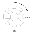
例えば本実施の形態では、撮像装置12を一対のステレオカメラとデプスカメラからなる構成としたが、ステレオ画像とデプス画像を同時期に撮影できれば、撮像装置の構成は限定されない。また少なくとも演算によりデプス画像を生成できれば、デプス画像とともに撮影する画像はステレオ画像、カラー画像に限定されない。以下、撮像装置の変形例につい説明する。図10は、変形例における撮像装置の俯瞰図を模式的に示している。
For example, in the present embodiment, the
図示する例で撮像装置150は、図と平行な水平面において光軸が放射状となるように複数のビデオカメラ(例えばビデオカメラ152)を環状に接続した構成を有する。運用時には撮像装置150を、環の中心を軸として水平面上で所定方向(例えば矢印の方向)に回動させる。なお同図では回動のための駆動機構について図示を省略している。このような構成により、各時刻において周囲の360°にある全ての被写体をいずれかのカメラの視野内に収めることができるうえ、視野が重ならない領域の被写体であっても、僅かな時間のずれで後続のカメラの視野に入れることができる。
In the illustrated example, the
結果として、全方位にある被写体に対し、異なる視点からの画像が撮影されることを保証できる。例えば、図示するような構成のカラービデオカメラとデプスカメラを図の奥行き方向に対応する垂直方向に重ねてなる撮像装置を導入すれば、本実施の形態と同様にデプス画像を圧縮でき、より広域での画像をデータサイズの増大を抑えつつ伝送できる。なお周囲360°の画像が必要ない場合、撮像装置を構成するカメラの台数を減らすことができる。場合によっては1つのカメラを移動させることにより異なる視点からの画像を撮影していき、時間的に前後して撮影された2つの画像を、平均時刻におけるステレオ画像としてもよい。 As a result, it is possible to ensure that images from different viewpoints are captured for subjects in all directions. For example, if an imaging device is introduced in which a color video camera and a depth camera configured as shown in the figure are stacked in the vertical direction corresponding to the depth direction in the figure, the depth image can be compressed in the same manner as in the present embodiment, and a wider range of images can be obtained. image can be transmitted while suppressing an increase in data size. Note that if a 360° surrounding image is not required, the number of cameras constituting the imaging device can be reduced. In some cases, one camera may be moved to capture images from different viewpoints, and the two images captured at different times may be used as the stereo image at the average time.
図11は、別の変形例における撮像装置の素子構造を示している。なお同図は素子断面の機能的な構造を模式的に示しており、層間絶縁膜や配線などの詳細な構造は省略している。また同図では隣接した2画素分の断面構造を例示している。画素210はマイクロレンズ層212、カラーフィルタ層214、偏光子層216、および光電変換層218を含む。マイクロレンズ層212は画素ごとに設けられ入射した光を集光する。
FIG. 11 shows the element structure of an imaging device in another modified example. The figure schematically shows the functional structure of the cross section of the element, and the detailed structures such as the interlayer insulating film and the wiring are omitted. In addition, in the figure, the cross-sectional structure for two adjacent pixels is illustrated.
カラーフィルタ層214は、画素ごとに異なる色の光を透過する。偏光子層216は、複数の線状の導体部材、例えばタングステンやアルミなどの部材(ワイヤ)を入射光の波長より小さい間隔でストライプ状に配列させたワイヤグリッド型偏光子を含む。マイクロレンズ層212により集光されカラーフィルタ層214を透過した光が偏光子層216に入射すると、偏光子のラインと平行な方向の偏光成分は反射され、垂直な偏光成分のみが透過する。
The
透過した偏光成分を光電変換層218で電荷に変換することにより偏光輝度が取得される。図示するようなワイヤグリッド型偏光子を用いた画像取得技術については、例えば特開2012-80065号公報などに開示されている。ただし偏光子はワイヤグリッド型に限らず、線二色性偏光子など実用化されているもののいずれでもよい。なお同図では偏光子として、図面の奥行き方向に伸張するワイヤの断面を表しているが、偏光子の主軸角度は4通りとし、それに応じてワイヤの向きも異なる。
Polarized luminance is obtained by converting the transmitted polarized light component into an electric charge in the
また図示するように偏光子層216には、画素によって偏光子を備える領域と備えない領域があってよい。偏光子を設けない領域では、カラーフィルタ層214を透過した光がそのまま光電変換層218に入射する。光電変換層218は一般的なフォトダイオードを含み、入射した光を電荷として出力する。図示するように1つのマイクロレンズに対しフォトダイオードを複数設けることにより、合焦レンズの異なる領域を透過した光を別々に電荷に変換する。そのようにして検出した光の位相差に基づき焦点検出を行う技術は位相差オートフォーカスの一手法として実用化されている(例えば特開2013-106194号公報参照)。
Also, as shown, the
また1画素に設けた複数のフォトダイオードによる検出値を合計すれば、一般的な撮像装置における1画素分の輝度が得られる。すなわち図11に示した画素の素子構造によれば、一般的なカラー画像、複数方位の偏光画像、位相差画像を同時に得ることができる。ここで位相差画像は、画素ごとに設けた2つのフォトダイオードのうち一方の検出値のみを画素とする画像の対である。位相差画像における像の位置のずれ量は、焦点距離においては0となり、焦点距離から離れるほど大きくなる。また焦点距離より遠いか近いかでずれる方向が逆転する。 Further, by summing the detection values obtained by a plurality of photodiodes provided in one pixel, the luminance for one pixel in a general imaging device can be obtained. That is, according to the element structure of the pixel shown in FIG. 11, a general color image, polarization images in a plurality of directions, and phase contrast images can be obtained simultaneously. Here, the phase-contrast image is a pair of images in which only the detection value of one of the two photodiodes provided for each pixel is used as a pixel. The image position shift amount in the phase difference image is 0 at the focal length, and increases with increasing distance from the focal length. Also, the direction of deviation is reversed depending on whether it is farther or closer than the focal length.
画像処理装置はこの関係を利用して、位相差画像における像のずれ量から被写体の距離を取得できる。ただしずれ量を特定できることが前提となるため、距離が得られるのは被写体の輪郭線など特徴点の存在する部分に限定される。そこで、複数方位の偏光画像を用いて既存の手法により被写体表面の法線ベクトルを取得し、その結果から得られる表面の傾きに基づき距離値を補間すれば、被写体全体の距離値が得られる。 Using this relationship, the image processing apparatus can acquire the distance of the subject from the image shift amount in the phase difference image. However, since it is premised that the amount of deviation can be specified, the distance can be obtained only in areas where feature points such as the outline of the object exist. Therefore, the normal vector of the object surface is obtained by an existing technique using polarized images in multiple directions, and the distance value of the entire object can be obtained by interpolating the distance value based on the surface inclination obtained from the obtained result.
すなわち図示する素子構造によれば、参照光の照射機構などを設けずとも、カラー画像と同一視点のデプス画像を取得できる。差分画像の生成に用いる、演算によるデプス画像の生成のためには、図示するような素子構造のカメラとは別に、一般的なカメラを導入して異なる視点から撮影させることによりステレオ画像を取得してもよい。あるいは図示するような素子構造を有する複数のカメラによりステレオ画像を取得してもよい。この場合、図10で示したような構造の撮像装置としてもよい。 That is, according to the element structure shown in the figure, it is possible to acquire a depth image from the same viewpoint as that of a color image without providing a reference light irradiation mechanism or the like. In order to generate the depth image by calculation, which is used to generate the difference image, a stereo image is obtained by introducing a general camera in addition to the camera with the device structure shown in the figure and shooting from a different viewpoint. may Alternatively, stereo images may be acquired by a plurality of cameras having element structures as shown. In this case, an imaging device having a structure as shown in FIG. 10 may be used.
また図示するような素子構造を有する1つのカメラを移動させてステレオ画像を取得したり、図8で示したデプス画像提供サーバ120を利用して、1つのカラー画像からデプス画像を取得したりしてもよい。いずれの場合も、本実施の形態で述べた画像処理装置およびコンテンツ処理装置を適用し同様の効果を得ることができる。
Also, a stereo image is acquired by moving one camera having an element structure as shown in the drawing, or a depth image is acquired from one color image using the depth
1 コンテンツ処理システム、 10 画像処理装置、 12 撮像装置、 14 コンテンツ処理装置、 16 表示装置、 18 ステレオカメラ、 19 デプスカメラ、 23 CPU、 24 GPU、 26 メインメモリ、 32 通信部、 34 記憶部、 36 出力部、 38 入力部、40 記録媒体駆動部、 50 ステレオ画像取得部、 52 デプス画像取得部、 54 デプス画像圧縮部、 56 出力部、 60 画像データ取得部、 62 デプス画像伸張部、 64 情報処理部、 66 出力部。
1
Claims (17)
前記被写体の撮影画像のデータを取得する撮影画像取得部と、
前記デプス画像の実測されたデータを、前記撮影画像に基づき得られるデプス画像のデータを用いて圧縮するデプス画像圧縮部と、
前記撮影画像のデータと、圧縮されたデプス画像のデータを出力する出力部と、
を備え、
前記デプス画像圧縮部は、圧縮後のデータとして、圧縮対象のデプス画像と、前記撮影画像に基づき得られるデプス画像との差分画像を生成したうえ、前記圧縮対象のデプス画像における画素値が表す距離に応じて、単位距離当たりの階調数を異ならせて、前記差分画像における画素値を量子化することを特徴とする画像処理装置。 a depth image acquisition unit that acquires data of a depth image whose pixel value is the distance actually measured by a camera that measures the distance of the subject;
a captured image acquisition unit that acquires data of a captured image of the subject;
a depth image compression unit that compresses the actually measured data of the depth image using depth image data obtained based on the captured image;
an output unit that outputs the captured image data and the compressed depth image data;
with
The depth image compression unit generates, as data after compression, a difference image between a depth image to be compressed and a depth image obtained based on the captured image, and a distance represented by a pixel value in the depth image to be compressed. , quantizing the pixel values in the difference image by varying the number of gradations per unit distance according to .
前記デプス画像圧縮部は、前記差分画像を、前記複数のデプス画像のそれぞれに対し生成することを特徴とする請求項1に記載の画像処理装置。 The depth image acquisition unit acquires data of a plurality of depth images actually measured by the camera from different viewpoints,
2. The image processing apparatus according to claim 1, wherein the depth image compression section generates the difference image for each of the plurality of depth images.
前記デプス画像圧縮部は、前記サーバに前記撮影画像のデータを送信することにより、対応するデプス画像のデータを取得し、当該デプス画像と圧縮対象のデプス画像との差分画像を生成することを特徴とする請求項1に記載の画像処理装置。 further comprising a communication unit connected to a server that provides corresponding depth image data based on the captured image data by providing a machine learning function,
The depth image compression unit acquires data of the corresponding depth image by transmitting the data of the captured image to the server, and generates a difference image between the depth image and the depth image to be compressed. The image processing apparatus according to claim 1, wherein:
前記差分画像に、前記撮影画像に基づき得られるデプス画像を加算することにより、前記カメラが実測したデプス画像のデータを取得するデプス画像伸張部と、
少なくとも前記カメラが実測した前記デプス画像のデータを用いて所定の処理を行い結果を出力する出力部と、
を備え、
前記画像データ取得部は、前記撮影画像のデータより小さいフレームレートで、画素値が量子化された前記差分画像のデータと量子化前後の画素値の対応関係を表す情報とを取得し、
前記デプス画像伸張部は、前記差分画像の画素値を、前記対応関係を表す情報に基づき量子化前の画素値に戻し、前記撮影画像から取得した動きベクトルまたは前記撮影画像のデータに基づき得られるデプス画像から取得した動きベクトルに基づき、前記カメラが実測したデプス画像を時間軸上で補間することを特徴とするコンテンツ処理装置。 Acquiring data of a photographed image of a subject and data of a difference image between a depth image having a pixel value of the distance actually measured by a camera that measures the distance of the subject and a depth image obtained based on the photographed image. an image data acquisition unit;
a depth image decompression unit that acquires data of a depth image actually measured by the camera by adding a depth image obtained based on the captured image to the difference image;
an output unit that performs predetermined processing using at least the data of the depth image actually measured by the camera and outputs a result;
with
The image data acquisition unit acquires , at a frame rate smaller than the data of the captured image, the data of the difference image in which pixel values are quantized and information representing the correspondence relationship between the pixel values before and after quantization,
The depth image decompression unit restores the pixel values of the difference image to the pixel values before quantization based on the information representing the correspondence relationship, and restores the pixel values based on the motion vector acquired from the captured image or the data of the captured image. A content processing device that interpolates a depth image actually measured by the camera on a time axis based on a motion vector acquired from the depth image obtained from the captured depth image .
前記デプス画像伸張部は、前記サーバに前記撮影画像のデータを送信することにより、対応するデプス画像のデータを取得し、当該デプス画像と前記差分画像を加算することにより、前記カメラが実測したデプス画像のデータを取得することを特徴とする請求項10に記載のコンテンツ処理装置。 further comprising a communication unit connected to a server that provides corresponding depth image data based on the captured image data by providing a machine learning function,
The depth image decompression unit acquires data of the corresponding depth image by transmitting the data of the captured image to the server, and adds the depth image and the difference image to obtain the depth actually measured by the camera. 11. The content processing apparatus according to claim 10, wherein image data is acquired.
前記画像処理装置は、
前記カメラが実測したデプス画像と、前記撮影画像に基づき得られるデプス画像との差分画像を生成したうえ、前記カメラが実測したデプス画像における画素値が表す距離に応じて、単位距離当たりの階調数を異ならせて、前記差分画像における画素値を量子化するデプス画像圧縮部と、
前記撮影画像のデータと、前記差分画像のデータと、を出力する出力部と、
を備え、
前記コンテンツ処理装置は、
前記差分画像に、前記撮影画像に基づき得られるデプス画像を加算することにより、前記カメラが実測したデプス画像のデータを取得するデプス画像伸張部と、
少なくとも前記カメラが実測した前記デプス画像のデータを用いて所定の処理を行い結果を出力する出力部と、
を備え、
前記デプス画像伸張部は、前記差分画像のデータとともに取得した、量子化前後の画素値の対応関係を表す情報に基づき、前記差分画像の画素値を量子化前の値に戻すことを特徴とするコンテンツ処理システム。 An image processing device that transmits data of a depth image whose pixel value is the distance actually measured by a camera that measures the distance of the subject, and data of the photographed image of the subject, and performs information processing using the transmitted data. A content processing system comprising a content processing device that
The image processing device is
After generating a difference image between the depth image actually measured by the camera and the depth image obtained based on the captured image, the gradation per unit distance is calculated according to the distance represented by the pixel value in the depth image actually measured by the camera. a depth image compression unit that quantizes the pixel values in the difference image by varying the number;
an output unit that outputs the data of the captured image and the data of the difference image;
with
The content processing device is
a depth image decompression unit that acquires data of a depth image actually measured by the camera by adding a depth image obtained based on the captured image to the difference image;
an output unit that performs predetermined processing using at least the data of the depth image actually measured by the camera and outputs a result;
with
The depth image decompression unit restores the pixel values of the difference image to the values before quantization based on information indicating the correspondence relationship between the pixel values before and after quantization, which is acquired together with the data of the difference image. Content processing system.
前記被写体の撮影画像のデータを取得するステップと、
前記デプス画像の実測されたデータを、前記撮影画像に基づき得られるデプス画像のデータを用いて圧縮するステップと、
前記撮影画像のデータと、圧縮されたデプス画像のデータを出力するステップと、
を含み、
前記圧縮するステップは、圧縮後のデータとして、圧縮対象のデプス画像と、前記撮影画像に基づき得られるデプス画像との差分画像を生成したうえ、前記圧縮対象のデプス画像における画素値が表す距離に応じて、単位距離当たりの階調数を異ならせて、前記差分画像における画素値を量子化することを特徴とする、画像処理装置による画像処理方法。 a step of obtaining data of a depth image having a pixel value of the distance actually measured by a camera that measures the distance of the subject;
a step of acquiring data of a photographed image of the subject;
compressing the actually measured data of the depth image using depth image data obtained based on the captured image;
outputting the captured image data and the compressed depth image data;
including
In the compressing step, as data after compression, a difference image between a depth image to be compressed and a depth image obtained based on the captured image is generated, and a distance represented by a pixel value in the depth image to be compressed is calculated. An image processing method by an image processing device, wherein the number of gradation levels per unit distance is changed according to the difference, and pixel values in the difference image are quantized.
前記差分画像に、前記撮影画像に基づき得られるデプス画像を加算することにより、前記カメラが実測したデプス画像のデータを取得するステップと、
少なくとも前記カメラが実測した前記デプス画像のデータを用いて所定の処理を行い結果を出力するステップと、
を含み、
前記差分画像のデータを取得するステップは、前記撮影画像のデータより小さいフレームレートで、画素値が量子化された前記差分画像のデータと量子化前後の画素値の対応関係を表す情報とを取得し、
前記カメラが実測したデプス画像のデータを取得するステップは、前記差分画像の画素値を、前記対応関係を表す情報に基づき量子化前の画素値に戻し、前記撮影画像から取得した動きベクトルまたは前記撮影画像のデータに基づき得られるデプス画像から取得した動きベクトルに基づき、前記カメラが実測したデプス画像を時間軸上で補間することを特徴とする、コンテンツ処理装置による画像処理方法。 Acquiring data of a photographed image of a subject and data of a difference image between a depth image having a pixel value of the distance actually measured by a camera that measures the distance of the subject and a depth image obtained based on the photographed image. a step;
a step of acquiring depth image data actually measured by the camera by adding a depth image obtained based on the captured image to the difference image;
a step of performing predetermined processing using at least the data of the depth image actually measured by the camera and outputting the result;
including
The step of acquiring the data of the differential image acquires the data of the differential image whose pixel values are quantized and information representing the correspondence relationship between the pixel values before and after quantization at a frame rate lower than that of the data of the captured image. death,
The step of acquiring the data of the depth image actually measured by the camera includes returning the pixel values of the differential image to the pixel values before quantization based on the information representing the correspondence relationship, An image processing method by a content processing device, characterized in that the depth image actually measured by the camera is interpolated on the time axis based on the motion vector obtained from the depth image obtained based on the data of the captured image .
前記被写体の撮影画像のデータを取得する機能と、
前記デプス画像の実測されたデータを、前記撮影画像に基づき得られるデプス画像のデータを用いて圧縮する機能と、
前記撮影画像のデータと、圧縮されたデプス画像のデータを出力する機能と、
をコンピュータに実現させ、
前記圧縮する機能は、圧縮後のデータとして、圧縮対象のデプス画像と、前記撮影画像に基づき得られるデプス画像との差分画像を生成したうえ、前記圧縮対象のデプス画像における画素値が表す距離に応じて、単位距離当たりの階調数を異ならせて、前記差分画像における画素値を量子化することを特徴とするコンピュータプログラム。 A function to acquire data of a depth image whose pixel value is the distance actually measured by a camera that measures the distance of the subject;
a function of acquiring data of the photographed image of the subject;
a function of compressing the actually measured data of the depth image using depth image data obtained based on the captured image;
a function of outputting the captured image data and the compressed depth image data;
is realized on a computer,
The compressing function generates, as data after compression, a differential image between a depth image to be compressed and a depth image obtained based on the captured image, and calculates a distance represented by a pixel value in the depth image to be compressed. A computer program characterized by quantizing pixel values in the difference image by varying the number of gradations per unit distance according to the number of gradations.
前記差分画像に、前記撮影画像に基づき得られるデプス画像を加算することにより、前記カメラが実測したデプス画像のデータを取得する機能と、
少なくとも前記カメラが実測した前記デプス画像のデータを用いて所定の処理を行い結果を出力する機能と、
をコンピュータに実現させ、
前記差分画像のデータを取得する機能は、前記撮影画像のデータより小さいフレームレートで、画素値が量子化された前記差分画像のデータと量子化前後の画素値の対応関係とを表す情報を取得し、
前記カメラが実測したデプス画像のデータを取得する機能は、前記差分画像の画素値を、前記対応関係を表す情報に基づき量子化前の画素値に戻し、前記撮影画像から取得した動きベクトルまたは前記撮影画像のデータに基づき得られるデプス画像から取得した動きベクトルに基づき、前記カメラが実測したデプス画像を時間軸上で補間することを特徴とするコンピュータプログラム。 Acquiring data of a photographed image of a subject and data of a difference image between a depth image having a pixel value of the distance actually measured by a camera that measures the distance of the subject and a depth image obtained based on the photographed image. function and
a function of acquiring depth image data actually measured by the camera by adding a depth image obtained based on the captured image to the difference image;
a function of performing predetermined processing using at least the data of the depth image actually measured by the camera and outputting the result;
is realized on a computer,
The function of acquiring the data of the differential image acquires information representing the correspondence relationship between the data of the differential image whose pixel values are quantized and the pixel values before and after quantization at a frame rate smaller than the data of the captured image. death,
The function of acquiring the data of the depth image actually measured by the camera restores the pixel values of the differential image to the pixel values before quantization based on the information representing the correspondence relationship, and the motion vector or A computer program for interpolating a depth image actually measured by the camera on a time axis based on a motion vector obtained from the depth image obtained based on the data of the captured image .
Priority Applications (4)
| Application Number | Priority Date | Filing Date | Title |
|---|---|---|---|
| JP2017244861A JP7105062B2 (en) | 2017-12-21 | 2017-12-21 | Image processing device, content processing device, content processing system, and image processing method |
| PCT/JP2018/046100 WO2019124248A1 (en) | 2017-12-21 | 2018-12-14 | Image processing device, content processing device, content processing system, and image processing method |
| EP18891483.2A EP3731528A4 (en) | 2017-12-21 | 2018-12-14 | Image processing device, content processing device, content processing system, and image processing method |
| US16/771,908 US11503267B2 (en) | 2017-12-21 | 2018-12-14 | Image processing device, content processing device, content processing system, and image processing method |
Applications Claiming Priority (1)
| Application Number | Priority Date | Filing Date | Title |
|---|---|---|---|
| JP2017244861A JP7105062B2 (en) | 2017-12-21 | 2017-12-21 | Image processing device, content processing device, content processing system, and image processing method |
Publications (3)
| Publication Number | Publication Date |
|---|---|
| JP2019114842A JP2019114842A (en) | 2019-07-11 |
| JP2019114842A5 JP2019114842A5 (en) | 2020-08-13 |
| JP7105062B2 true JP7105062B2 (en) | 2022-07-22 |
Family
ID=66992666
Family Applications (1)
| Application Number | Title | Priority Date | Filing Date |
|---|---|---|---|
| JP2017244861A Active JP7105062B2 (en) | 2017-12-21 | 2017-12-21 | Image processing device, content processing device, content processing system, and image processing method |
Country Status (4)
| Country | Link |
|---|---|
| US (1) | US11503267B2 (en) |
| EP (1) | EP3731528A4 (en) |
| JP (1) | JP7105062B2 (en) |
| WO (1) | WO2019124248A1 (en) |
Families Citing this family (6)
| Publication number | Priority date | Publication date | Assignee | Title |
|---|---|---|---|---|
| JP7247327B2 (en) * | 2019-04-01 | 2023-03-28 | グーグル エルエルシー | Techniques for Capturing and Editing Dynamic Depth Images |
| TW202131671A (en) | 2019-10-07 | 2021-08-16 | 日商索尼半導體解決方案公司 | Electronic device |
| JPWO2021166707A1 (en) * | 2020-02-21 | 2021-08-26 | ||
| CN112164017B (en) * | 2020-09-27 | 2023-11-17 | 中国兵器工业集团第二一四研究所苏州研发中心 | Polarization colorization method based on deep learning |
| US20230029900A1 (en) * | 2021-07-30 | 2023-02-02 | Zoox, Inc. | Three-dimensional object detection based on image data |
| WO2024057902A1 (en) * | 2022-09-12 | 2024-03-21 | ソニーグループ株式会社 | Information processing device, method, and program |
Citations (4)
| Publication number | Priority date | Publication date | Assignee | Title |
|---|---|---|---|---|
| JP2009163717A (en) | 2007-12-10 | 2009-07-23 | Fujifilm Corp | Distance image processing apparatus and method, distance image reproducing apparatus and method, and program |
| US20130222534A1 (en) | 2011-08-29 | 2013-08-29 | Nokia Corporation | Apparatus, a Method and a Computer Program for Video Coding and Decoding |
| EP2693753A1 (en) | 2012-07-31 | 2014-02-05 | Samsung Electronics Co., Ltd | Method of converting 2-dimension images into 3-dimension images and display apparatus thereof |
| JP6351006B2 (en) | 2015-05-19 | 2018-07-04 | 株式会社エアロネクスト | Rotorcraft |
Family Cites Families (12)
| Publication number | Priority date | Publication date | Assignee | Title |
|---|---|---|---|---|
| JP3159230B2 (en) | 1993-06-10 | 2001-04-23 | 日本電信電話株式会社 | Variable rate coding device for image signals |
| US20100185093A1 (en) * | 2009-01-19 | 2010-07-22 | James Hamilton | System and method for processing a real-time ultrasound signal within a time window |
| US20090148038A1 (en) * | 2007-12-10 | 2009-06-11 | Youichi Sawachi | Distance image processing apparatus and method |
| KR101367282B1 (en) * | 2007-12-21 | 2014-03-12 | 삼성전자주식회사 | Method and Apparatus for Adaptive Information representation of 3D Depth Image |
| KR101158491B1 (en) * | 2008-12-08 | 2012-06-20 | 한국전자통신연구원 | Apparatus and method for encoding depth image |
| JP5682437B2 (en) | 2010-09-07 | 2015-03-11 | ソニー株式会社 | Solid-state imaging device, solid-state imaging device, imaging apparatus, and polarizing element manufacturing method |
| JP5755111B2 (en) | 2011-11-14 | 2015-07-29 | キヤノン株式会社 | Driving method of imaging apparatus |
| US20130287093A1 (en) * | 2012-04-25 | 2013-10-31 | Nokia Corporation | Method and apparatus for video coding |
| US9462164B2 (en) * | 2013-02-21 | 2016-10-04 | Pelican Imaging Corporation | Systems and methods for generating compressed light field representation data using captured light fields, array geometry, and parallax information |
| WO2014165244A1 (en) * | 2013-03-13 | 2014-10-09 | Pelican Imaging Corporation | Systems and methods for synthesizing images from image data captured by an array camera using restricted depth of field depth maps in which depth estimation precision varies |
| JP6672070B2 (en) * | 2016-05-17 | 2020-03-25 | キヤノン株式会社 | Imaging apparatus using compressed sensing, imaging method, and imaging program |
| CN108389226A (en) | 2018-02-12 | 2018-08-10 | 北京工业大学 | A kind of unsupervised depth prediction approach based on convolutional neural networks and binocular parallax |
-
2017
- 2017-12-21 JP JP2017244861A patent/JP7105062B2/en active Active
-
2018
- 2018-12-14 WO PCT/JP2018/046100 patent/WO2019124248A1/en unknown
- 2018-12-14 EP EP18891483.2A patent/EP3731528A4/en active Pending
- 2018-12-14 US US16/771,908 patent/US11503267B2/en active Active
Patent Citations (4)
| Publication number | Priority date | Publication date | Assignee | Title |
|---|---|---|---|---|
| JP2009163717A (en) | 2007-12-10 | 2009-07-23 | Fujifilm Corp | Distance image processing apparatus and method, distance image reproducing apparatus and method, and program |
| US20130222534A1 (en) | 2011-08-29 | 2013-08-29 | Nokia Corporation | Apparatus, a Method and a Computer Program for Video Coding and Decoding |
| EP2693753A1 (en) | 2012-07-31 | 2014-02-05 | Samsung Electronics Co., Ltd | Method of converting 2-dimension images into 3-dimension images and display apparatus thereof |
| JP6351006B2 (en) | 2015-05-19 | 2018-07-04 | 株式会社エアロネクスト | Rotorcraft |
Non-Patent Citations (2)
| Title |
|---|
| Ayan Chakrabarti, et al.,"Depth from a Single Image by Harmonizing Overcomplete Local Network Predictions",arXiv:1605.07081v2,version v2,[online], arXiv (Cornell University),2016年09月07日,Pages 1-9,[令和3年6月14日検索], インターネット, <URL: https://arxiv.org/abs/1605.07081v2>. |
| David Eigen, et al.,"Depth Map Prediction from a Single Image using a Multi-Scale Deep Network",arXiv:1406.2283v1,version v1,[online], arXiv (Cornell University),2014年06月09日,Pages 1-9,[令和3年6月14日検索], インターネット, <URL: https://arxiv.org/abs/1406.2283v1>. |
Also Published As
| Publication number | Publication date |
|---|---|
| US20200404238A1 (en) | 2020-12-24 |
| US11503267B2 (en) | 2022-11-15 |
| WO2019124248A1 (en) | 2019-06-27 |
| JP2019114842A (en) | 2019-07-11 |
| EP3731528A1 (en) | 2020-10-28 |
| EP3731528A4 (en) | 2021-08-11 |
Similar Documents
| Publication | Publication Date | Title |
|---|---|---|
| JP7105062B2 (en) | Image processing device, content processing device, content processing system, and image processing method | |
| JP7277372B2 (en) | 3D model encoding device, 3D model decoding device, 3D model encoding method, and 3D model decoding method | |
| JP7320352B2 (en) | 3D model transmission method, 3D model reception method, 3D model transmission device, and 3D model reception device | |
| US20210352323A1 (en) | Three-dimensional data encoding method, three-dimensional data decoding method, three-dimensional data encoding device, and three-dimensional data decoding device | |
| JP5763184B2 (en) | Calculation of parallax for 3D images | |
| JP5575908B2 (en) | Depth map generation technique for converting 2D video data to 3D video data | |
| CN108520232B (en) | Method and device for generating three-dimensional panoramic film | |
| US11159824B1 (en) | Methods for full parallax light field compression | |
| KR101210625B1 (en) | Method for filling common hole and 3d video system thereof | |
| WO2011163603A1 (en) | Multi-resolution, multi-window disparity estimation in 3d video processing | |
| JP7202087B2 (en) | Video processing device | |
| WO2015098948A1 (en) | Video coding method, video decoding method, video coding device, video decoding device, video coding program, and video decoding program | |
| EP3922032A1 (en) | Quantization step parameter for point cloud compression | |
| JP4815004B2 (en) | Multi-view image encoding device | |
| JPWO2015056712A1 (en) | Moving picture encoding method, moving picture decoding method, moving picture encoding apparatus, moving picture decoding apparatus, moving picture encoding program, and moving picture decoding program | |
| JP2013150071A (en) | Encoder, encoding method, program and storage medium | |
| JP2018207356A (en) | Image compression program, image compression device, and image compression method | |
| JP4764516B1 (en) | Multi-view image encoding device | |
| JP4860763B2 (en) | Image encoding apparatus, image encoding apparatus control method, control program, and recording medium | |
| US10257488B2 (en) | View synthesis using low resolution depth maps | |
| US20230412831A1 (en) | Method for encoding and decoding a multi-view video | |
| JP7382186B2 (en) | Encoding device, decoding device, and program | |
| JP7417388B2 (en) | Encoding device, decoding device, and program | |
| Kum et al. | Reference stream selection for multiple depth stream encoding |
Legal Events
| Date | Code | Title | Description |
|---|---|---|---|
| A521 | Request for written amendment filed |
Free format text: JAPANESE INTERMEDIATE CODE: A523 Effective date: 20200618 |
|
| A621 | Written request for application examination |
Free format text: JAPANESE INTERMEDIATE CODE: A621 Effective date: 20200618 |
|
| A131 | Notification of reasons for refusal |
Free format text: JAPANESE INTERMEDIATE CODE: A131 Effective date: 20210622 |
|
| A521 | Request for written amendment filed |
Free format text: JAPANESE INTERMEDIATE CODE: A523 Effective date: 20210819 |
|
| A131 | Notification of reasons for refusal |
Free format text: JAPANESE INTERMEDIATE CODE: A131 Effective date: 20220201 |
|
| A521 | Request for written amendment filed |
Free format text: JAPANESE INTERMEDIATE CODE: A523 Effective date: 20220328 |
|
| TRDD | Decision of grant or rejection written | ||
| A01 | Written decision to grant a patent or to grant a registration (utility model) |
Free format text: JAPANESE INTERMEDIATE CODE: A01 Effective date: 20220628 |
|
| A61 | First payment of annual fees (during grant procedure) |
Free format text: JAPANESE INTERMEDIATE CODE: A61 Effective date: 20220711 |
|
| R150 | Certificate of patent or registration of utility model |
Ref document number: 7105062 Country of ref document: JP Free format text: JAPANESE INTERMEDIATE CODE: R150 |