JP7102215B2 - Blower cooling device, image heating device, and image forming device - Google Patents
Blower cooling device, image heating device, and image forming device Download PDFInfo
- Publication number
- JP7102215B2 JP7102215B2 JP2018088693A JP2018088693A JP7102215B2 JP 7102215 B2 JP7102215 B2 JP 7102215B2 JP 2018088693 A JP2018088693 A JP 2018088693A JP 2018088693 A JP2018088693 A JP 2018088693A JP 7102215 B2 JP7102215 B2 JP 7102215B2
- Authority
- JP
- Japan
- Prior art keywords
- paper
- louver
- fan
- shutter
- rotating body
- Prior art date
- Legal status (The legal status is an assumption and is not a legal conclusion. Google has not performed a legal analysis and makes no representation as to the accuracy of the status listed.)
- Active
Links
Images


Classifications
-
- G—PHYSICS
- G03—PHOTOGRAPHY; CINEMATOGRAPHY; ANALOGOUS TECHNIQUES USING WAVES OTHER THAN OPTICAL WAVES; ELECTROGRAPHY; HOLOGRAPHY
- G03G—ELECTROGRAPHY; ELECTROPHOTOGRAPHY; MAGNETOGRAPHY
- G03G15/00—Apparatus for electrographic processes using a charge pattern
- G03G15/20—Apparatus for electrographic processes using a charge pattern for fixing, e.g. by using heat
- G03G15/2003—Apparatus for electrographic processes using a charge pattern for fixing, e.g. by using heat using heat
- G03G15/2014—Apparatus for electrographic processes using a charge pattern for fixing, e.g. by using heat using heat using contact heat
- G03G15/2017—Structural details of the fixing unit in general, e.g. cooling means, heat shielding means
-
- G—PHYSICS
- G03—PHOTOGRAPHY; CINEMATOGRAPHY; ANALOGOUS TECHNIQUES USING WAVES OTHER THAN OPTICAL WAVES; ELECTROGRAPHY; HOLOGRAPHY
- G03G—ELECTROGRAPHY; ELECTROPHOTOGRAPHY; MAGNETOGRAPHY
- G03G15/00—Apparatus for electrographic processes using a charge pattern
- G03G15/20—Apparatus for electrographic processes using a charge pattern for fixing, e.g. by using heat
- G03G15/2003—Apparatus for electrographic processes using a charge pattern for fixing, e.g. by using heat using heat
- G03G15/2014—Apparatus for electrographic processes using a charge pattern for fixing, e.g. by using heat using heat using contact heat
- G03G15/2039—Apparatus for electrographic processes using a charge pattern for fixing, e.g. by using heat using heat using contact heat with means for controlling the fixing temperature
- G03G15/2042—Apparatus for electrographic processes using a charge pattern for fixing, e.g. by using heat using heat using contact heat with means for controlling the fixing temperature specially for the axial heat partition
-
- G—PHYSICS
- G03—PHOTOGRAPHY; CINEMATOGRAPHY; ANALOGOUS TECHNIQUES USING WAVES OTHER THAN OPTICAL WAVES; ELECTROGRAPHY; HOLOGRAPHY
- G03G—ELECTROGRAPHY; ELECTROPHOTOGRAPHY; MAGNETOGRAPHY
- G03G15/00—Apparatus for electrographic processes using a charge pattern
- G03G15/20—Apparatus for electrographic processes using a charge pattern for fixing, e.g. by using heat
- G03G15/2003—Apparatus for electrographic processes using a charge pattern for fixing, e.g. by using heat using heat
- G03G15/2014—Apparatus for electrographic processes using a charge pattern for fixing, e.g. by using heat using heat using contact heat
- G03G15/206—Structural details or chemical composition of the pressure elements and layers thereof
-
- G—PHYSICS
- G03—PHOTOGRAPHY; CINEMATOGRAPHY; ANALOGOUS TECHNIQUES USING WAVES OTHER THAN OPTICAL WAVES; ELECTROGRAPHY; HOLOGRAPHY
- G03G—ELECTROGRAPHY; ELECTROPHOTOGRAPHY; MAGNETOGRAPHY
- G03G15/00—Apparatus for electrographic processes using a charge pattern
- G03G15/20—Apparatus for electrographic processes using a charge pattern for fixing, e.g. by using heat
- G03G15/2003—Apparatus for electrographic processes using a charge pattern for fixing, e.g. by using heat using heat
- G03G15/2014—Apparatus for electrographic processes using a charge pattern for fixing, e.g. by using heat using heat using contact heat
- G03G15/2064—Apparatus for electrographic processes using a charge pattern for fixing, e.g. by using heat using heat using contact heat combined with pressure
-
- G—PHYSICS
- G03—PHOTOGRAPHY; CINEMATOGRAPHY; ANALOGOUS TECHNIQUES USING WAVES OTHER THAN OPTICAL WAVES; ELECTROGRAPHY; HOLOGRAPHY
- G03G—ELECTROGRAPHY; ELECTROPHOTOGRAPHY; MAGNETOGRAPHY
- G03G21/00—Arrangements not provided for by groups G03G13/00 - G03G19/00, e.g. cleaning, elimination of residual charge
- G03G21/20—Humidity or temperature control also ozone evacuation; Internal apparatus environment control
- G03G21/206—Conducting air through the machine, e.g. for cooling, filtering, removing gases like ozone
-
- G—PHYSICS
- G03—PHOTOGRAPHY; CINEMATOGRAPHY; ANALOGOUS TECHNIQUES USING WAVES OTHER THAN OPTICAL WAVES; ELECTROGRAPHY; HOLOGRAPHY
- G03G—ELECTROGRAPHY; ELECTROPHOTOGRAPHY; MAGNETOGRAPHY
- G03G2221/00—Processes not provided for by group G03G2215/00, e.g. cleaning or residual charge elimination
- G03G2221/16—Mechanical means for facilitating the maintenance of the apparatus, e.g. modular arrangements and complete machine concepts
- G03G2221/1645—Mechanical means for facilitating the maintenance of the apparatus, e.g. modular arrangements and complete machine concepts for conducting air through the machine, e.g. cooling
Description
本発明は、画像加熱装置に用いられる送風冷却機構、画像加熱装置、及び画像形成装置に関する。画像加熱装置は、例えば、記録材上に形成されたトナー画像を加熱定着する定着装置として用い得る。画像形成装置は、例えば、電子写真方式等を用いた、複写機、プリンタ、FAX、及びそれらの機能を複数備えた複合機等が挙げられる。 The present invention relates to a blower cooling mechanism, an image heating device, and an image forming device used in an image heating device. The image heating device can be used, for example, as a fixing device for heating and fixing a toner image formed on a recording material. Examples of the image forming apparatus include a copying machine, a printer, a fax machine using an electrophotographic method, and a multifunction device having a plurality of these functions.
例えば電子写真画像形成装置は、作像手段によりシート状の記録材(以下、用紙又は紙と記す)上に未定着トナー像を形成した後、定着手段により、該トナー像を固着像として定着させている。 For example, in an electrophotographic image forming apparatus, an unfixed toner image is formed on a sheet-shaped recording material (hereinafter referred to as paper or paper) by an image forming means, and then the toner image is fixed as a fixed image by a fixing means. ing.
定着手段には様々な方式が提案されているが、トナー像を加熱・加圧して定着させる熱圧定着方式の定着装置が一般に用いられている。この定着装置は、加熱手段で加熱される加熱回転体(定着ローラ、定着フィルムなど)と、これと圧接して定着ニップ部を形成する加圧回転体(加圧ローラ、加圧ベルトなど)を有している。そして、この両回転体を回転させ、定着ニップ部に未定着トナー像を担持させた用紙を導入して挟持搬送させることで、トナー像を加熱回転体の熱とニップ圧で用紙面に定着させる。 Various methods have been proposed for the fixing means, but a thermal pressure fixing type fixing device for fixing the toner image by heating and pressurizing it is generally used. This fixing device combines a heating rotating body (fixing roller, fixing film, etc.) that is heated by the heating means and a pressure rotating body (pressurizing roller, pressure belt, etc.) that presses against the heating rotating body to form a fixing nip. Have. Then, the two rotating bodies are rotated, and the paper carrying the unfixed toner image is introduced into the fixing nip portion and sandwiched and conveyed, so that the toner image is fixed on the paper surface by the heat and nip pressure of the heated rotating body. ..
このような定着装置においては、装置に通紙可能な最大幅を有する最大サイズ用紙よりも幅が小さい小サイズ用紙を連続的に通紙して定着を実行させた場合に、加熱回転体の非通紙領域(用紙との非接触領域)において、表面温度が過度に上昇する。 In such a fixing device, when small size paper having a width smaller than the maximum size paper having the maximum width that can be passed through the device is continuously passed and fixing is performed, the heating rotating body is not formed. The surface temperature rises excessively in the paper-passing region (non-contact region with paper).
ここで、非通紙領域(非通紙部)とは、加熱回転体の長手方向に関し、小サイズ用紙を通紙させるときに用紙と接触しない加熱回転体の領域のことである。これは、小サイズ用紙を連続的に通紙すると、定着ニップ部の用紙が通過しない非通紙域では、用紙による奪熱が無い分だけ、部分的に蓄熱されるためである。この現象は、定着装置の端部昇温あるいは非通紙部昇温と称され、この端部昇温が高温になりすぎると、ホットオフセットの発生や装置構成部品の熱劣化につながる。 Here, the non-passing paper region (non-passing paper portion) is a region of the heating rotating body that does not come into contact with the paper when passing small-sized paper in the longitudinal direction of the heating rotating body. This is because when small-sized paper is continuously passed through, heat is partially stored in the non-passing area where the paper in the fixing nip portion does not pass because the heat is not taken by the paper. This phenomenon is referred to as temperature rise at the edge of the fixing device or temperature rise at the non-passing sheet portion, and if the temperature rise at the edge becomes too high, hot offset occurs and thermal deterioration of the device components occurs.
この非通紙部昇温の対策の一つとして、非通紙部を冷却する冷却ファンを配置する機構が知られている。特許文献1では、定着ローラの長手方向の左右に冷却ファンの風を送風するダクトを設け、ダクトの開口部を開け閉めできるシャッタを配置する構成が開示されている。特許文献1では、このシャッタを用紙の幅サイズに応じた位置に移動させ、定着ローラの非通紙領域部分の温度を検知する素子によって検知した温度に応じて、冷却ファンで送風する。このように、シャッタの移動によって冷却範囲を調整することで、非通紙部昇温を抑制している。
As one of the measures for raising the temperature of the non-passing paper portion, a mechanism for arranging a cooling fan for cooling the non-passing paper portion is known.
そして、特許文献1では、ファンを備えるダクトから、定着装置内部の定着ローラに対して冷却風を吹き付ける構成である。
Then,
特許文献1に挙げた構成で用いる定着ローラは、直径で30mm以上のサイズが主流である。ファンの送風方向から被冷却部材(定着ローラ)を見た時に、被冷却部材の直径が比較的大きい場合は、ファンから被冷却部材に至るまでの送風経路上にルーバーなどの風路形成部材が無くても冷却風を被冷却部材に当てやすい。
The fixing roller used in the configuration described in
一方で、近年、画像形成装置のダウンサイジングや、コストダウンといった観点から、定着ローラや定着フィルムといった定着部材には、直径で30mmよりも小さい小径の部材が使用されることもある。 On the other hand, in recent years, from the viewpoint of downsizing of an image forming apparatus and cost reduction, a member having a diameter smaller than 30 mm may be used as a fixing member such as a fixing roller or a fixing film.
このような小径の定着部材を冷却する場合においては、特許文献1のような風路形成部材が無い構成においては、効率的に定着部材を冷却することが出来ないことがあった。
In the case of cooling such a small-diameter fixing member, it may not be possible to efficiently cool the fixing member in a configuration without an air passage forming member as in
また、画像形成装置全体でエアフローシステムを考えた場合、冷却するために送風した風を回収して機外に排出しなければならない。定着部材を冷却した後の風は、定着部材の回転方向の上流側と下流側とに分かれて定着装置内部を流れ、定着装置外に排出されていく。上流側と下流側に流れる風を回収するエアフローシステムが異なる場合、定着部材の回転方向の上流側と下流側とに流れる風量の割合を制御しないと、送風から回収までのエアフローシステムが成り立たないことがあった。 In addition, when considering an airflow system for the entire image forming apparatus, it is necessary to collect the blown air for cooling and discharge it to the outside of the machine. The wind after cooling the fixing member is divided into an upstream side and a downstream side in the rotation direction of the fixing member, flows inside the fixing device, and is discharged to the outside of the fixing device. If the airflow system that collects the air flowing to the upstream side and the downstream side is different, the airflow system from blowing to collecting must be controlled unless the ratio of the air volume flowing to the upstream side and the downstream side in the rotation direction of the fixing member is controlled. was there.
本発明の目的は、ファンにより加熱回転体を冷却する装置構成において、小径の定着部材を効率的に冷却する送風冷却装置を提供することである。 An object of the present invention is to provide a blower cooling device that efficiently cools a small-diameter fixing member in a device configuration for cooling a heating rotating body by a fan.
上記の目的を達成するための本発明に係る送風冷却機構の代表的な構成は、
記録材上のトナー画像をニップ部にて加熱する加熱回転体を有する画像加熱装置に用いられる送風冷却機構であって、
送風口を有するダクトと、
前記加熱回転体の所定の領域を冷却するために、前記ダクトを介して前記送風口に向かって空気を吹き込むファンと、
前記ダクトの内部に前記送風口に向かって前記ファンからの風を整流する第1のルーバー部材と、
前記加熱回転体の冷却範囲を制限するシャッタ部材と、を有し、
前記シャッタ部材は、前記加熱回転体の長手方向に沿って移動することで、前記加熱回転体の冷却範囲を制限し、
前記ファンの送風方向において前記シャッタ部材の下流側に第2のルーバー部材が配置され、前記ファンから前記加熱回転体に至るまでに、前記ファンの送風方向に対して、前記ファン、前記第1のルーバー部材、前記シャッタ部材、前記第2のルーバー部材、前記加熱回転体、の順に配置され、
前記シャッタ部材による前記冷却範囲の制限にかかわらず、前記第1のルーバー部材と前記第2のルーバー部材は、前記シャッタ部材の移動方向に沿って且つ前記加熱回転体の前記冷却範囲に渡って設けられていることを特徴とする。
A typical configuration of the blower cooling mechanism according to the present invention for achieving the above object is
A blower cooling mechanism used in an image heating device having a heating rotating body that heats a toner image on a recording material at a nip.
A duct with an air outlet and
A fan that blows air toward the air outlet through the duct to cool a predetermined area of the heating rotating body.
Inside the duct, a first louver member that rectifies the air from the fan toward the air outlet, and
It has a shutter member that limits the cooling range of the heating rotating body, and has.
The shutter member limits the cooling range of the heating rotating body by moving along the longitudinal direction of the heating rotating body.
A second louver member is arranged on the downstream side of the shutter member in the blowing direction of the fan, and the fan, the first, with respect to the blowing direction of the fan from the fan to the heating rotating body. The louver member, the shutter member, the second louver member, and the heating rotating body are arranged in this order.
Regardless of the limitation of the cooling range by the shutter member, the first louver member and the second louver member are provided along the moving direction of the shutter member and over the cooling range of the heating rotating body. It is characterized by being.
本発明によれば、加熱回転体が小径になっても、確実に加熱回転体を冷却しつつ、冷却したあとの冷却風の方向をコントロールすることが可能な冷却装置を提供することができる。 According to the present invention, it is possible to provide a cooling device capable of controlling the direction of the cooling air after cooling while reliably cooling the heating rotating body even if the heating rotating body has a small diameter.
以下に図面を参照して、この発明を実施するための最良の形態を例示的に詳しく説明する。ただし、この実施の形態に記載されている構成部品の寸法、材質、形状それらの相対配置などは、発明が適用される装置の構成や各種条件により適宜変更されるべきものであり、この発明の範囲を以下の実施の形態に限定する趣旨のものではない。 The best embodiments for carrying out the present invention will be illustrated in detail below with reference to the drawings. However, the dimensions, materials, shapes, etc. of the components described in this embodiment should be appropriately changed depending on the configuration of the apparatus to which the invention is applied and various conditions, and the invention of the present invention. It is not intended to limit the scope to the following embodiments.
《実施例》
(画像形成装置)
図2は電子写真技術を用いた画像形成装置Aの一例の概略構成を示す模式的断面図である。本実施例では画像形成装置Aはパソコン等の外部ホスト装置200から制御回路部(CPU)100に入力したプリントジョブ(画像形成ジョブ)に対応した画像形成動作を実行してトナー像を形成した画像形成物をプリントアウトするモノクロプリンタである。
"Example"
(Image forming device)
FIG. 2 is a schematic cross-sectional view showing a schematic configuration of an example of an image forming apparatus A using electrophotographic technology. In this embodiment, the image forming apparatus A executes an image forming operation corresponding to a print job (image forming job) input to the control circuit unit (CPU) 100 from an
画像形成装置Aにおいて、記録材P(シート:以下、用紙又は紙と記す)にトナー像を形成する画像形成部A1は、像担持体としてのドラム型の電子写真感光体(以下、ドラムと記す)1を有する。ドラム1は矢印の時計方向に所定の周速度で回転駆動される。また、画像形成部A1はドラム1の周囲にドラム回転方向に沿ってドラム1に作用するプロセス機器としての、帯電ローラ1a、レーザスキャナ1b、現像装置1c、転写ローラ1d、クリーニング装置1eを有する。以上の画像形成部A1の電子写真プロセスや作像動作は周知であるからその説明は省略する。
In the image forming apparatus A, the image forming portion A1 for forming a toner image on a recording material P (sheet: hereinafter referred to as paper or paper) is a drum-type electrophotographic photosensitive member (hereinafter referred to as a drum) as an image carrier. ) Has 1. The
尚、記録材Pは、画像形成装置によってトナー像が形成され得るシート状の記録媒体(メディア)である。便宜上、記録材(シート)Pの扱いを、通紙、給紙、排紙、通紙部、非通紙部など紙に纏わる用語を用いて説明するが記録材は紙に限定されるものではない。 The recording material P is a sheet-shaped recording medium on which a toner image can be formed by an image forming apparatus. For convenience, the handling of the recording material (sheet) P will be described using terms related to paper such as paper passing, paper feeding, paper ejection, paper passing part, and non-paper passing part, but the recording material is not limited to paper. do not have.
用紙カセット2に収納されている用紙Pが給送ローラ3の回転によって所定の制御タイミングにて1枚分離給送される。その用紙Pが、搬送路a、レジストローラ対4、搬送路bの経路を通ってドラム1と転写ローラ1dの当接部である転写部(転写ニップ部)5に所定の制御タイミングにて導入される。用紙Pは転写部5にて挟持搬送される過程でドラム1の表面に形成されているトナー像の転写を順次に受ける。
One sheet of paper P stored in the
転写部5を出た用紙Pはドラム1の面から分離されて搬送路cを通って定着装置(加熱定着装置:画像加熱装置)6に導入されて用紙上(記録材上)トナー像(画像)の熱圧定着処理を受ける。定着装置6を出た用紙Pは搬送路dを通って画像形成物(成果物)として排出トレイ7に排出される。Paは用紙搬送方向である。
The paper P leaving the
(定着装置)
ここで、定着装置6について、正面(前面)とは用紙Pの導入口側の面、背面(後面)とはその反対側の面、左右とは定着装置6を正面から見て左(L)又は右(R)である。長手方向とは回転体の軸線方向又は母線方向、短手方向とは長手方向に直交する方向である。上下とは重力方向において上又は下である。定着装置6の構成部材についても同様である。
(Fixing device)
Here, regarding the fixing
また、上流側と下流側は用紙搬送方向Paにおいて上流側と下流側である。一端側と他端側は長手方向において一端側と他端側であり、本実施例においては、左側を一端側(非駆動側、手前側)とし、右側を他端側(駆動側(駆動力を受ける側)、奥側)としている。用紙Pの幅とは用紙面における用紙搬送方向Paに直交する方向の用紙寸法である。 Further, the upstream side and the downstream side are the upstream side and the downstream side in the paper transport direction Pa. One end side and the other end side are one end side and the other end side in the longitudinal direction. In this embodiment, the left side is the one end side (non-driving side, the front side), and the right side is the other end side (driving force (driving force)). The receiving side) and the back side). The width of the paper P is a paper size in a direction orthogonal to the paper transport direction Pa on the paper surface.
図3は定着装置6の外観斜視模式図であり、背面側と一端側と上面側とから見ている。図4は同装置6の他端側部分の外観斜視模式図である。図5は図3の定着装置6から装置フレームの上面側に配設されている送風冷却機構30を取り除いた状態を示した図である。図6は図3における(6)-(6)線矢視の断面模式図である。図7は図5の装置の一部切り欠きの正面模式図である。図8は定着アセンブリの分解斜視模式図である。図9は主として定着装置についての制御系統のブロック図である。
FIG. 3 is a schematic external perspective view of the fixing
この定着装置6はフィルム加熱方式の画像加熱装置である。この定着装置6は、大別して、定着フィルム13を備えた定着アセンブリ(定着部材)10と、弾性を有する加圧ローラ(定着部材)20と、これらを収容した装置フレーム(装置筐体)25と、送風冷却機構30と、を有する。以下、定着アセンブリ10を単にアセンブリ10と記す。一対の回転体としての定着フィルム13(加熱回転体:第1の回転体)と加圧ローラ20(加圧回転体:第2の回転体)との協働によりニップ部(定着ニップ部)Nが形成される(図6、図7)。
The fixing
ニップ部Nは未定着トナー像を担持している用紙Pを挟持搬送してトナー像を熱と圧力で定着する部分である。ニップ部Nにおいて定着フィルム(定着ベルト)13が用紙Pの未定着トナー像を担持している面に対して接触する。 The nip portion N is a portion that sandwiches and conveys the paper P carrying the unfixed toner image and fixes the toner image by heat and pressure. At the nip portion N, the fixing film (fixing belt) 13 comes into contact with the surface of the paper P carrying the unfixed toner image.
アセンブリ10は、図6に示すように、円筒状(無端状:エンドレスベルト状)の定着フィルム13、ヒータ11、ヒータ11を保持する断熱ホルダ12、加圧ステイ(金属ステイ)14、定着フランジ15(L・R)などによる組立体である。図8はこのアセンブリ10の分解斜視模式図であり、加圧ローラ20も一緒に描いてある。
As shown in FIG. 6, the
(1)定着フィルム
加熱回転体としての定着フィルム(定着ベルト、可撓性スリーブ:以下、フィルムと記す)13は、可撓性・耐熱性を有する薄肉無端状の伝熱部材であり、自由状態においては自身の弾性によりほぼ円筒状を呈する。
(1) Fixing film The fixing film (fixing belt, flexible sleeve: hereinafter referred to as a film) 13 as a heating rotating body is a thin-walled endless heat transfer member having flexibility and heat resistance, and is in a free state. In, it is almost cylindrical due to its own elasticity.
フィルム13は、クイックスタートを可能にするために、総厚200μm以下の厚みの耐熱性フィルムである。ポリイミド・ポリアミドイミド・PEEK(ポリエーテルエーテルケトン)等の耐熱性樹脂、あるいは耐熱性、高熱伝導性を有するSUS(ステインレス鋼)・Al・Ni・Cu・Zn等の純金属、あるいは合金を基層として形成されている。
The
樹脂製の基層の場合は熱伝導性を向上させるために、BN・アルミナ・Al等の高熱伝導性粉末を混入してあってもよい。また、長寿命の定着装置を構成するために充分な強度を持ち、耐久性に優れたフィルム13として、総厚100μm以上の厚みが好ましい。よって、フィルム13の総厚としては100μm以上200μm以下が最適である。
In the case of a resin base layer, a high thermal conductive powder such as BN, alumina, or Al may be mixed in order to improve the thermal conductivity. Further, the
また、フィルム13の径が小さいほど、材料費の観点ではコストが安く、さらに低熱容量になるためフィルム13が所定温度になるまでの時間が短縮される。本実施例では外径25mmのフィルムを採用している。
Further, the smaller the diameter of the
さらに、オフセット防止や用紙の分離性の確保のために表層にはPTFE・PFA・FEP・ETFE・CTFE・PVDF等のフッ素樹脂、シリコーン樹脂等の離型性の良好な耐熱樹脂が混合ないし単独で被覆され離型性層(離型層)が形成される。本実施例では、表層は、PTFE及びPFAを少なくとも含む材料で構成している。 Furthermore, in order to prevent offset and ensure paper separability, fluororesin such as PTFE, PFA, FEP, ETFE, CTFE, PVDF, and heat-resistant resin with good releasability such as silicone resin are mixed or used alone on the surface layer. It is coated and a releasable layer (removable layer) is formed. In this embodiment, the surface layer is composed of a material containing at least PTFE and PFA.
ここで、PTFEはポリテトラフルオロエチレンであり、PFAはテトラフルオロエチレンパーフルオロアルキルビニルエーテル共重合体であり、FEPはテトラフルオロエチレンヘキサフルオロプロピレン共重合体である。また、ETFEはエチレンテトラフルオロエチレン共重合体であり、CTFEはポリクロロトリフルオロエチレンであり、PVDFはポリビニリデンフルオライドである。 Here, PTFE is polytetrafluoroethylene, PFA is a tetrafluoroethylene perfluoroalkyl vinyl ether copolymer, and FEP is a tetrafluoroethylene hexafluoropropylene copolymer. In addition, ETFE is an ethylene tetrafluoroethylene copolymer, CTFE is polychlorotrifluoroethylene, and PVDF is polyvinylidene fluoride.
被覆の方法としては、フィルム13の外面をエッチング処理した後に離型性層をディッピングするか、粉体スプレー等の塗布であってもよい。あるいは、チューブ状に形成された樹脂をフィルム13の表面に被せる方式であってもよい。又は、フィルム13の外面をブラスト処理した後に、接着剤であるプライマ層を塗布し、離型性層を被覆する方法であってもよい。
As a coating method, the release layer may be dipped after the outer surface of the
(2)ヒータ
ヒータ11は通電により有効発熱領域幅W11(図7)の全長部が急峻に昇温する低熱容量の細長の板状発熱体であり、本実施例ではセラミックヒータである。このヒータ11は、細長薄板状の熱伝導が良好なAlN(窒化アルミニウム)などの基板上(セラミック基板)にAg・Pdなどの導電ペーストを厚膜印刷し焼成することで発熱体(抵抗発熱体、通電発熱抵抗層)を形成する。
(2) Heater The
そして、発熱体の上に摺動絶縁部材として50~60μm程度の厚さのガラスコーティング層が一体となって設けられたセラミックヒータを構成する。本実施例においてはガラスコーティング層側がヒータ表面側であり、フィルム内面に接する。 Then, a ceramic heater is configured in which a glass coating layer having a thickness of about 50 to 60 μm is integrally provided on the heating element as a sliding insulating member. In this embodiment, the glass coating layer side is the heater surface side and is in contact with the inner surface of the film.
発熱体は基板の長手に沿って装置に使用可能な最大幅サイズの用紙の幅に対応する長さもしくはそれよりも所定に長い長さにて形成されている。この発熱体の長さ範囲がヒータ11の有効発熱領域幅W11である。ヒータ11において、基板を挟んで発熱体が設けられている側と反対側の基板上(ヒータ背面側)には、温度検知素子としてのチップ状のサーミスタ(第1のサーミスタ)18(図6・図8)が設けられている。このサーミスタ18はバネ等の加圧手段(不図示)により基板(ヒータ背面)に対して所定の圧力で固定されている。
The heating element is formed along the length of the substrate with a length corresponding to the width of the maximum width size paper that can be used for the device, or a predetermined length longer than that. The length range of this heating element is the effective heat generation region width W11 of the
(3)断熱ホルダ
断熱ホルダ(ヒータ保持部材:以下、ホルダと記す)12は、フィルム13の長手方向(幅方向)に沿って長い部材であり、液晶ポリマー・フェノール樹脂・PPS・PEEK等の耐熱性樹脂により形成さる。熱伝導率が低いほどヒータ11の熱を奪熱する事がなく、効率的にフィルム13に熱を伝えることができるので、樹脂層中にガラスバルーンやシリカバルーン等のフィラーを内包してあってもよい。ヒータ11はホルダ12の下面にホルダ長手に沿って形成されている溝部12a(図8)に表面側を外向きにして嵌め込まれて保持されている。また、ホルダ12はフィルム13の回転を案内する役目も持つ。
(3) Insulation holder The insulation holder (heater holding member: hereinafter referred to as a holder) 12 is a member long along the longitudinal direction (width direction) of the
(4)加圧ステイ
加圧ステイ(以下、ステイと記す)14は、フィルム13の長手方向に沿って長く、加圧ローラ20からの反力を受ける剛性部材であり、高い圧力を掛けられても撓みにくい材質であることが望ましい。本実施例においては金属ステイであり、横断面U字形のSUS304の型材を用いている。ステイ14は、ホルダ12の上面側に配設されてホルダ12と接触し、アセンブリ10全体の撓みや捩れを抑制する。
(4) Pressurized stay The pressurized stay (hereinafter referred to as stay) 14 is a rigid member that is long along the longitudinal direction of the
(5)定着フランジ
フィルム13は、上記のヒータ11、ホルダ12、ステイ14の組立体に対してルーズに外嵌(外挿)されている。ステイ14の両端部14a(図8)はそれぞれフィルム13の両端部の開口部から外方に突出している。そのステイ14の両端部14aに対してそれぞれ一端側と他端側の定着フランジ(以下、フランジと記す)15(L・R)が嵌着されている。フィルム13はその嵌着されたフランジ15(L・R)の対向する端部規制面(鍔座部)15a間に位置している。
(5) The fixing
フランジ15(L・R)はアセンブリ10におけるフィルム13の長手方向への移動および周方向の形状を規制する規制部材であり、PPS・液晶ポリマー・フェノール樹脂等の耐熱樹脂のモールド形成品である。フランジ15(L・R)は、それぞれ、端部規制面15a、内周規制面15b、被押圧部(加圧受部)15cを有する。
The flange 15 (L / R) is a regulating member that regulates the movement of the
(6)加圧ローラ
加圧ローラ20は、SUS・SUM(硫黄及び硫黄複合快削鋼鋼材)・Al等の金属製芯金21の外側に、弾性ソリッドゴム層、弾性スポンジゴム層、あるいは弾性気泡ゴム層等の弾性層22からなる弾性ローラである。
(6) Pressurized roller The
ここで、弾性ソリッドゴム層は、シリコーンゴムやフッ素ゴム等の耐熱ゴムで形成したものである。また、弾性スポンジゴム層は、より断熱効果を持たせるためにシリコーンゴムを発泡して形成したものである。また、弾性気泡ゴム層は、シリコーンゴム層内に中空のフィラー(マイクロバルーン等)を分散させ、硬化物内に気体部分を持たせて断熱効果を高めたものである。この上にパーフルオロアルコキシ樹脂(PFA)、ポリテトラフルオロエチレン樹脂(PTFE)等の離型性層を形成してあってもよい。 Here, the elastic solid rubber layer is formed of heat-resistant rubber such as silicone rubber or fluororubber. Further, the elastic sponge rubber layer is formed by foaming silicone rubber in order to have a more heat insulating effect. Further, the elastic bubble rubber layer is formed by dispersing a hollow filler (microballoon or the like) in the silicone rubber layer and providing a gas portion in the cured product to enhance the heat insulating effect. A releasable layer such as a perfluoroalkoxy resin (PFA) or a polytetrafluoroethylene resin (PTFE) may be formed on the releasable layer.
加圧ローラ20は装置フレーム(以下、フレームと記す)25の一端側と他端側の側板25(L・R)の間において、芯金21の一端側と他端側がそれぞれ軸受23を介して回転可能に支持されている。
In the
アセンブリ10は側板25(L・R)との間において、加圧ローラ20の上側にヒータ11の側を加圧ローラ20に対向させて加圧ローラ20に平行に配列されている。アセンブリ10におけるフランジ15(L・R)はそれぞれの被押圧部15cが側板25(L・R)に対称に形成されたガイド穴25aに対して加圧ローラ20の方向へスライド移動可能に係合されている。
The
そして、フランジ15(L・R)は、それぞれ、被押圧部15cにおいて一端側と他端側の加圧機構26(L・R)の加圧アーム26aにより加圧ローラ20に向かう方向へ所定の加圧力を受ける。その加圧力により、アセンブリ10のフランジ15(L・R)、ステイ14、ホルダ12、ヒータ11の全体が加圧ローラ20の方向に加圧される。そのため、ヒータ11とホルダ12の一部とがフィルム13を介して加圧ローラ20に対して弾性層22の弾性に抗して所定の加圧力で押圧される。これによりフィルム13と加圧ローラ20との間に用紙搬送方向Paに関して所定幅のニップ部Nが形成される。
Then, the flanges 15 (L / R) are predetermined in the direction toward the
図3・図4を参照して、フレーム25の一端側と他端側の側板25(L・R)の外側には、それぞれ、一端側と他端側の加圧機構26(L・R)が配設されている。この両加圧機構26(L・R)は鏡面対称構成の同一機構である。
With reference to FIGS. 3 and 4, on the outside of the side plates 25 (L / R) on one end side and the other end side of the
加圧機構26(L・R)はそれぞれ加圧レバー(以下、レバーと記す)26aと加圧ばね(以下、ばねと記す)26bを有する。レバー26aは基部側が側板26(L・R)に対して軸部26cを中心に揺動可能に取り付けられている。レバー26aは軸部26cからフランジ15(L・R)の被押圧部15cの上側を経由して軸部26c側とは反対側に延びている。
The pressurizing mechanism 26 (L / R) has a pressurizing lever (hereinafter referred to as a lever) 26a and a pressurizing spring (hereinafter referred to as a spring) 26b, respectively. The
ばね26bはレバー26aをフランジ15(L・R)の被押圧部15cに当接させて加圧する方向に軸部26cを中心に回動付勢する弾性部材である。本実施例においては、ばね26bはレバー26aの自由端部26dと側板26(L・R)に植設されたピン軸26eとの間に張設されている。従って、レバー26aはばね26bの引っ張り力によりフランジ15(L・R)の被押圧部15cに対して当接して所定の加圧力を与える。
The
レバー26aは側板25(L・R)に対して回動自在に支持されているのでばね26bの引っ張り力によって軸部26cまわりに回動モーメントが発生して、フランジ15(L・R)が加圧ローラ20方向へ所定の加圧力で押圧される。
Since the
(7)定着動作
加圧ローラ20の芯金21の他端側(駆動側)には同心一体に駆動ギア27(図4・図8)が配設されている。このギア27に対して、制御回路部100(図9)により制御される定着モータ駆動回路111にて駆動される定着モータ(駆動源)M1の駆動力が駆動伝達機構(不図示)を介して伝達される。これにより、加圧ローラ20が駆動回転体として図6において矢印R20の反時計方向に所定の速度で回転駆動される。
(7) Fixing operation Drive gears 27 (FIGS. 4 and 8) are concentrically arranged on the other end side (drive side) of the
加圧ローラ20が回転駆動されることで、ニップ部Nにおいてフィルム13に加圧ローラ20との摩擦力で回転トルクが作用する。加圧ローラ20は、フィルム13を回転させる回転体として機能する。フィルム13は、加圧ローラ20に従動回転する。これにより、フィルム13はその内面がニップ部Nにおいてヒータ11とホルダ12の一部に密着して摺動(摺接)しながら、ヒータ11・ホルダ12・ステイ14の組み立て体の外回りを図6において矢印R13の時計方向に従動回転する。フィルム13の回転周速度は加圧ローラ20の回転周速度とほぼ対応している。
When the
フランジ15(L・R)の端部規制面15aは回転するフィルム13の端面(コバ面)13a(図8)と接触することでフィルム13の長手方向(スラスト方向)への移動を規制する。内周規制面15bはフィルム13の端部の内周面を内側から支持するガイド面であり、フランジ15(L・R)の内面側に円弧状の凸縁部として配設されている。フィルム13とヒータ11との間には、フッ素系やシリコーン系の耐熱性グリース等の潤滑材を介在させることにより、摩擦抵抗を低く抑え、滑らかにフィルム13が回転可能(移動可能)となる。
The
また、制御回路部100はヒータ駆動回路112を制御してヒータ11に対する通電を開始する。ヒータ駆動回路112からヒータ11への給電経路は図には省略したけれども、ヒータ駆動回路112とヒータ11とを電気的に接続させた配線とコネクタ28(図7)を介してなされる。この通電によりヒータ11はその有効発熱領域W11(図7)の全長域が急峻に昇温する。
Further, the
このヒータ11の温度がヒータ11の背面に配設されている第1のサーミスタ18により検知され、その検知温度情報がA/D変換器103を介して制御回路部100に入力する。また、ヒータ11で加熱されながら回転しているフィルム13の内面の温度が第2と第3のサーミスタ19a・19b(図7・図8)で検知され、それらの検知温度情報がそれぞれA/D変換器103を介して制御回路部100に入力する。
The temperature of the
制御回路部100は第1~第3のサーミスタ18・19a・19bから入力する検知温度情報(出力)に応じてヒータ駆動回路112からヒータ11の発熱体に印加する電圧のデューティー比や波数等を決定し適切に制御する。これにより、ニップ部Nにおける温度が所定の定着設定温度に立ち上げられて、温調される。
The
上記の定着装置状態において、画像形成部A1から未定着トナー像が形成された用紙Pがフレーム25の正面側の導入口25b(図6)から定着装置内に導入され、ニップ部Nで挟持搬送される。用紙Pはニップ部Nを挟持搬送される過程でヒータ11の熱がフィルム13を介して付与される。未定着トナー像はヒータ11の熱によって溶融され、ニップ部Nにかかっている圧力によって用紙Pに対して固着像として熱圧定着される。そして、ニップ部Nを出た用紙Pは装置フレーム25の背面側の排出口25cから定着装置外に排出される。
In the above fixing device state, the paper P on which the unfixed toner image is formed from the image forming portion A1 is introduced into the fixing device from the
なお、フレーム25の内部には、導入口25bからニップ部Nへ至る間に用紙ガイド部材、用紙センサ等が配設されており、ニップ部Nから排出口25bへ至る間に用紙ガイド部材、排紙ローラ対、用紙センサ等が配設されているが、図には省略した。
Inside the
ここで、本実施例において、定着装置6に対する用紙Pの搬送はいわゆる中央基準搬送でなされる。ここで、中央基準搬送とは、サイズの異なる用紙を搬送する際に、各用紙の幅方向(記録材の搬送方向と直交する方向)の用紙の中心(記録材の幅方向の中心)が略一致するように搬送する方法のことである。図7において、Oはその基準線(中央基準線:仮想線)である。
Here, in this embodiment, the paper P is transported to the
WPmaxは装置に使用可能な最大幅の用紙の通紙領域幅(通過領域幅)である。本実施例において、装置に使用可能な最大幅の用紙の幅は330mmである。WPminは装置に使用可能な最小幅の用紙の通紙領域幅である。本実施例において、装置に使用可能な最小幅の用紙の幅ははがき幅100mmである。中央基準通紙で最小幅の用紙を搬送する場合、幅方向においてWPminの両外側(一端側と他端側の両方)に、非通紙部が存在する。 WPmax is the paper passing area width (passing area width) of the maximum width paper that can be used in the apparatus. In this embodiment, the maximum width of paper that can be used in the apparatus is 330 mm. WPmin is the width of the paper passing area of the minimum width paper that can be used in the device. In this embodiment, the width of the minimum width paper that can be used for the device is a postcard width of 100 mm. When the minimum width of the paper is conveyed by the central reference paper, there are non-passing portions on both outer sides (both one end side and the other end side) of WPmin in the width direction.
ヒータ11の有効発熱領域幅W11は、通紙領域幅WPmaxと等しいか、通紙領域幅WPmaxよりも所定に大きい設定である。第1のサーミスタ18は中央基準線Oにほぼ対応するヒータ背面位置にヒータ背面に接触させて配設させてある。
The effective heat generation region width W11 of the
第2のサーミスタ19aはフィルム13のニップ部Nよりもフィルム回転方向下流側の内面であって、中央基準線Oにほぼ対応する位置のフィルム内面に接してフィルム温度を検知する。第3のサーミスタ19bはフィルム13のニップ部Nよりもフィルム回転方向下流側の内面であって、通紙領域幅WPmaxの端部の内側に対応する位置のフィルム内面に接してフィルム温度を検知する。
The
即ち、第2のサーミスタ19aは装置に使用可能な大小各種幅サイズのどの用紙も通紙部となる通紙領域幅WPmin内に対応するフィルム部分の温度を検知する。第3のサーミスタ19bは最大幅の用紙よりも幅狭の用紙を通紙したときの非通紙部に対応するフィルム部分の温度を検知する(図7)。
That is, the
第2と第3のサーミスタ19a・19bはそれぞれ細長いばね部材19c・19d(図8)の先端部に支持されている。ばね部材19c・19dの基部はそれぞれホルダ12に固定されている。即ち、第2と第3のサーミスタ19a・19bはそれぞれフィルム13の内面に弾性的に接触して摺動するようにばね部材19c・19dにより支持されている。そして、第2と第3のサーミスタ19a・19bは自然状態においてフィルム13の取り付け時の投影形状外側に先端がばね性を持って突出するように取り付けられている。
The second and
さらに、金属製のステイ14にはフィルム13のアースをとる目的で、第2のサーミスタ19aの近傍においてフィルム13の内面に接触するアース部材19e(図8)が設けられる。アース部材19eは細長いばね部材であり、基部がステイ14に電気的に導通しており、先端部がフィルム13の内面に弾性的に接触して摺動する。このアース部材19eも第2と第3のサーミスタ19a、19bと同様に自然状態においてフィルム13の取り付け時の投影形状外側に先端がばね性を持って突出するように取り付けられている。
Further, the
ここで、上記の定着装置6は、送風冷却機構30を除いて、定着アセンブリ10と加圧ローラ20を包含する装置フレーム25が後述の第2のルーバー部材38aも含めて画像形成装置本体に対して取り外し可能に装着されるユニットされている。装置フレーム25がユニットとして画像形成装置本体から取り外されても送風冷却機構30は画像形成装置本体側に残される。
Here, in the
(送風冷却機構)
送風冷却機構30を説明する。送風冷却機構30は、装置に使用可能な最大幅の用紙よりも小さい幅(幅狭)の用紙を連続通紙した際に生じる、アセンブリ10の非通紙部昇温を送風により冷却する冷却手段である。
(Blower cooling mechanism)
The
この送風冷却機構30は、送風口31(L・R)を有するダクト32(L・R)と、加熱回転体であるフィルム13の所定の領域を冷却するために、ダクト32(L・R)を介して送風口31(L・R)に向かって空気を吹き込むファン33(L・R)を有する。
The
また、送風冷却機構30は、送風口31(L・R)を閉じるための閉じ位置にて送風口31(L・R)を閉じるための第1の面を有する第1のシャッタ部材37(L・R)を有する。また、送風冷却機構30は、送風口31(L・R)を閉じるための閉じ位置にて送風口31(L・R)を閉じるための第2の面を有する第2のシャッタ部材36(L・R)を有する。
Further, the
ダクト32は左側と右側にそれぞれ左右方向に長い2つのダクト32(L・R)を有する。ダクト32(L・R)は下面側にそれぞれ上面板25Uの窓穴38(L・R)に対応する左右方向に長い送風口(排気口)31(L・R)を有する(図12・図14)。ダクト32(L・R)の上面側はそれぞれ吸気口面として開放されている。
The duct 32 has two ducts 32 (LR) long in the left-right direction on the left side and the right side, respectively. The ducts 32 (L / R) have air outlets (exhaust ports) 31 (L / R) long in the left-right direction corresponding to the window holes 38 (L / R) of the
ダクト32には、ファン33から送風された冷却風を整流するための、第1のルーバー部材としてのダクト側ルーバー311(L・R)が備えられている。ダクト側ルーバー311(L・R)は、ダクト32内のファン送風部先端から送風口31(L・R)にかけて、ファン33の送風方向に平行または所定角度を持って配設されたリブ形状である。このダクト側ルーバー311(L・R)のリブ形状と、送風口31の開口面積とを適切に設定することで、送風冷却機構30から定着装置6に対して、冷却風の風速や風量をコントロールしている。
The duct 32 is provided with a duct-side louver 311 (LR) as a first louver member for rectifying the cooling air blown from the fan 33. The duct-side louver 311 (L / R) has a rib shape arranged parallel to the ventilation direction of the fan 33 or at a predetermined angle from the tip of the fan ventilation portion in the duct 32 to the ventilation port 31 (L / R). be. By appropriately setting the rib shape of the duct side louver 311 (LR) and the opening area of the air outlet 31, the
送風冷却機構30はフレーム25の上面板(天板)25Uの上側に支持部材(不図示)に支持されて所定に近設されている。送風冷却機構30は、上面側が吸気口面であり、下面側が送風口面とされており、送風口面を上面板25Uの上面に所定に対向させて近設されている。
The
図10は図3における送風冷却機構30の分解斜視図であり、吸気口面から見ている。図11は図3における送風冷却機構30を裏返して送風口面側を上向きにして見た斜視図であり、後述するシャッタ機構34(L・R)はシャッタ閉状態となっている。図12は図11の裏返しの送風冷却機構30の分解斜視図である。図13はシャッタ機構34(L・R)のみの斜視図であり、シャッタ機構34(L・R)の内側を見ている。
FIG. 10 is an exploded perspective view of the
図14は図11の送風冷却機構30からシャッタ機構34(L・R)のシャッタ部材36L・37L、36R・37Rを取り除いた送風冷却機構部分を示す斜視図であり、送風口側を見ている。図15はシャッタ機構の全開状態、全閉状態を示す図である。
FIG. 14 is a perspective view showing a portion of the blower cooling mechanism in which the
図5に示すように、上面板25Uは左半部側と右半部側とにそれぞれアセンブリ10の非通紙部に対して送風冷却機構30により冷却風を作用させるための左右方向に長い2つの窓穴38(L・R)を有する。この2つの窓穴38(L・R)は用紙Pの中央基準搬送の基準線に対して左右に対称的に配置されている。
As shown in FIG. 5, the
窓穴38(L・R)は、図7に示すように、それぞれ、アセンブリ10の上面部に対向して位置しており、且つ、装置に使用可能な最小幅の用紙を通紙した際における左側の非通紙領域幅WLと右側の非通紙領域幅WRとに対応して位置している。本実施例において、窓穴38(L・R)の幅寸法(長さ寸法)W38はそれぞれ115mm[(330mm-100mm)/2]である。
As shown in FIG. 7, the window holes 38 (LR) are located facing the upper surface of the
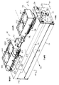
38a(図1、5~7)は窓穴38(L・R)にそれぞれ配設した、第2のルーバー部材としての複数枚の定着側ルーバーである。送風冷却機構30により窓穴38(L・R)からフレーム25内に吹き込まれる冷却風を整流する役目をしている。本実施例において定着側ルーバー38aは窓穴38(L・R)の長手に沿って延在している。
38a (FIGS. 1, 5 to 7) are a plurality of fixing side louvers as the second louver member arranged in the window holes 38 (L and R), respectively. The
本実施例において、定着側ルーバー38a同士の最小間隔Wは、15mm以下が望ましい。理由を以下に述べる。定着装置6に備えられた定着側ルーバー38aは、定着装置6が画像形成装置本体から外された時に、装置の状態によっては定着フィルム13がまだ熱を有している可能性がある。そのため、サービスマンやユーザーが意図せず定着側ルーバー38aから指を入れてしまい、熱を有したフィルム13に触る可能性を避ける目的のためである。
In this embodiment, the minimum distance W between the fixing
本実施例では、Wを3.5mmに設定している。10mmより小さく設定しているのは、フィルム13に対して所定の範囲を冷却するために整流し、かつ、風路を狭く設定することで風速を上昇させるためである。図6に、図1に対してシャッタを開口した図を示す。
In this embodiment, W is set to 3.5 mm. The reason why the
ここまで説明したように、ダクト32の内部にファン33を備えており、ファン33からの送風は、まずダクト側ルーバー311を通過することで整流され、定着装置6に向かって送風される。さらに、冷却風は、定着装置6内の上天面25Uに設けられた窓穴38を通って、定着側ルーバー38aを通過してさらに整流され、フィルム13にあたることで冷却される。ダクト側ルーバー311から定着側ルーバー32に至るまでに風路を徐々に狭めていくことによって、風路形成による損失を極力少なくしつつ、風速を上昇させ、フィルム13を効率的に冷却することができる。
As described above, the fan 33 is provided inside the duct 32, and the air blown from the fan 33 is rectified by first passing through the duct side louver 311 and is blown toward the fixing
このような構成をとることで、フィルム13が小径になったとしても、フィルム13に至るまでの風路によってフィルム13に効率的に冷却風を当てることが可能である。さらに、フィルム13の回転方向の上流側と下流側の風量をコントロールすることが可能となる。
With such a configuration, even if the
図6では、背面側、すなわちフィルム13の回転方向の下流側の風量が多くなるように設定されている。これは、定着装置6から発生する熱を画像形成装置の機外に排出するためのエアフローシステム(本実施例では不図示)が、背面側に配置されているためである。
In FIG. 6, the air volume on the back surface side, that is, on the downstream side in the rotation direction of the
また、シャッタ部材36はダクト側ルーバー311と定着側ルーバー38aの間に配置されている。例えばファン33とダクト側ルーバー311の間にシャッタ部材36を配置することも考えられるが、シャッタ部材36の大きさがファン33全域を覆うことが好ましいため、シャッタ部材36の形状が大きくなってしまう。
Further, the shutter member 36 is arranged between the duct side louver 311 and the fixing
また、シャッタ部材36が定着側ルーバー38aとフィルム13の間に配置された場合、シャッタ部材36は定着装置内に配置されることになる。この場合。例えば定着装置の寿命等での定着装置の交換の際に、不要なシャッタ部材とともに定着装置6が交換され、ランニングコストが高くなる恐れがある。さらにフィルム13の円筒形状に沿ったシャッタ形状とすると、シャッタ形状が複雑になるなどの恐れもある。
Further, when the shutter member 36 is arranged between the fixing
(1)シャッタと冷却ファン構成
冷却装置30のシャッタ部材と冷却ファンの配置は、駆動ピニオンギア(駆動部材)41の回転中心を通る直線に対して対称関係にあるため、代表して右半部側を説明する。特に説明がない場合、左半部と右半部は同様の構成である。
(1) Shutter and cooling fan configuration Since the arrangement of the shutter member and cooling fan of the
右側ダクト32Rの内部には、このダクト32Rに冷却風を送風する2つの右側冷却ファン33(R1・R2)が左と右に並べて配設されている。また、右側ダクト32Rには、それぞれの冷却ファン33(R1・R2)の風を送風口へ31Rに導入するように、冷却ファン33(R1・R2)の間に対応する位置に仕切りが設けられている。
Inside the
また、送風冷却機構30は左側ダクト32Lの送風口31Lと右側ダクト32Rの送風口31Rの開口幅をそれぞれ調節する開口幅調節機構としてのシャッタ機構34を有する。シャッタ機構34は、左側ダクト32Lから送風される冷却風の冷却範囲を制限するための左側シャッタ機構34Lと、右側ダクト32Rから送風される冷却風の冷却範囲を制限するための右側シャッタ機構34Rで構成されている。
Further, the
右側シャッタ機構34Rは、アセンブリ10の長手方向外側に配置された外シャッタ部材37R(第1のシャッタ部材)と、アセンブリ10の長手中央側に配置された内シャッタ部材36R(第2のシャッタ部材)と、の2枚のシャッタ部材を有する。また、右側シャッタ機構34Rは、内シャッタ部材36Rに回転可能に支持されたシャッターピニオンギア35Rと、駆動ピニオンギア41と、ダクト32Rに形成されたラック形状(ラック歯)43Rと、シャッターモータM2と、で構成されている。
The
内シャッタ部材36Rは、送風口31Rの長手に沿って形成された内シャッタ部材規制部46Rに嵌合してダクト32Rに配設されており、内シャッタ部材規制部46Rの長手方向に沿ってスライド移動可能である。また、外シャッタ部材37Rは、内シャッタ部材36Rの長手方向に形成されたつば状の外シャッタ部材規制部49Rに嵌合している。
The
左側部側も同様である。 The same applies to the left side.
上記の左右のシャッタ機構34(L・R)において、駆動ピニオンギア41とシャッターモータM2は両機構34(L・R)で共通の構成部材である。シャッタ機構34(L・R)の駆動ピニオンギア41の駆動源となるシャッターモータM2は左側ダクト32Lと右側ダクト32Rとの間の中央付近に配置されている。内シャッタ部材36(L・R)にはラック形状42(L・R)が設けられており、各々のラック形状42L・42Rは駆動ピニオンギア41と噛み合っている。
In the left and right shutter mechanisms 34 (LR), the
また、左右のダクト32(L・R)に設けられたラック形状43(L・R)は、各々の内シャッタ部材36(L・R)に回転可能に支持されるシャッターピニオンギア35(L・R)と噛み合うように配置されている。 Further, the rack shapes 43 (L / R) provided in the left and right ducts 32 (L / R) are rotatably supported by the respective inner shutter members 36 (L / R), and the shutter pinion gear 35 (L / R) is supported. It is arranged so as to mesh with R).
シャッターモータ(パルスモータ)M2の出力ギアMGにより駆動ピニオンギア41が正逆回転駆動される。このギア41の正逆回転駆動に連動して左右のダクト32(L・R)の送風口31(L・R)を開閉するように左右のシャッタ機構34(L・R)のそれぞれの内外のシャッタ部材36(L・R)、37(L・R)が後述するように開閉移動する。即ち、本実施例においては駆動ピニオンギア41が左右のシャッタ機構34(L・R)の内外のシャッタ部材36(L・R)、37(L・R)に対して駆動源となるシャッターモータM2(出力ギアMG)の駆動を伝達する駆動部材である。
The
左右のシャッタ機構34(L・R)の内外のシャッタ部材36(L・R)、37(L・R)は、通紙される用紙Pの幅に対応した位置に移動するように制御される。これにより、左右のダクト32(L・R)の送風口31(L・R)、即ち、上面板25Uにおける左右の窓穴38(L・R)が通紙される用紙幅に対応した最適な開口幅に調整されて、アセンブリ10の非通紙部昇温する範囲に対して送風冷却がなされる。
The inner and outer shutter members 36 (L / R) and 37 (L / R) of the left and right shutter mechanisms 34 (L / R) are controlled to move to positions corresponding to the width of the paper P to be passed. .. As a result, the air outlets 31 (L / R) of the left and right ducts 32 (L / R), that is, the left and right window holes 38 (L / R) in the
(2)シャッタの開閉動作
シャッタ開閉動作に関して説明する。右側のシャッタ機構34Rの外シャッタ部材37Rには、折り曲げ縁部において、各種幅サイズの用紙に対応して決められた複数のセンサフラグ39(図3・図10において破線で囲まれている部分)が設けられている。また、そのセンサフラグ39のエッジ部を検出する第1と第2のフォトセンサ40A・40Bが右側ダクト32Rに固定して配置されている。その第1と第2のフォトセンサ40A・40Bによるセンサフラグ39のエッジ部検知情報が図9のようにA/Dコンバータ300を介して制御回路部100に入力される。
(2) Shutter opening / closing operation The shutter opening / closing operation will be described. On the
本実施例において、上記のセンサフラグ39と第1と第2のフォトセンサ40A・40Bがシャッタの開口位置を検知する検知手段である。制御回路部100は外部ホスト装置200等から入力した、使用する用紙の幅サイズ情報に対応したセンサフラグ39のエッジ部が第2のフォトセンサ40Bで検出されるようにシャッターモータM2をシャッターモータ駆動回路400によって制御する。即ち、シャッターモータM2を正回転制御(CW)または逆回転制御(CCW)して、左右のシャッタ機構34L・34Rを駆動させる。
In this embodiment, the
そして、第2のフォトセンサ40Bにより、通紙使用される用紙Pの幅サイズ情報に対応したセンサフラグ39のエッジ部が検出された時点で、その時間を起点として数msec間だけシャッターモータM2の駆動し、停止させる。これにより、左右のシャッタ機構34(L・R)の外シャッタ部材37(L・R)の外側のエッジ部が、通紙使用される用紙の幅に対応した位置に移動される。
Then, when the
次に、本実施例の定着装置6における左右の冷却ファン33(L1・L2、R1・R2)の動作について説明する。画像形成時に、定着装置6に通紙使用可能な最大幅の用紙Pのサイズよりも幅の小さいサイズの用紙を連続定着した場合、非通紙域の温度が上昇する。第3サーミスタ19bは、非通紙部域に対応するフィルム部分の内面温度を検知している。
Next, the operations of the left and right cooling fans 33 (L1, L2, R1 and R2) in the
制御回路部100は第3サーミスタ19bが予め定めた閾値温度以上の温度を検知したら、シャッターモータ駆動回路400(図9)を制御する。即ち、シャッターモータM2により左右のシャッタ機構34(L・R)の内外のシャッタ部材36(L・R)、37(L・R)を連続通紙されている幅狭用紙の幅に対応した位置に移動させる。また、制御回路部100は、冷却ファン駆動回路500(図9)を制御して、左右のダクト32(L・R)における冷却ファン33(L1・L2、R1・R2)の動作を開始させる。
When the
これにより、アセンブリ10の非通紙部が冷却ファンの冷却風により冷却されることで、定着装置6の非通紙域の温度上昇が抑制される。
As a result, the non-paper-passing portion of the
そして、第3のサーミスタ19bの検知温度が予め定めた閾値温度よりも下降したら、冷却ファン33(L1・L2、R1・R2)の動作を停止させる。この冷却ファンの第3のサーミスタ19bの検知温度によるON-OFF制御の温度レンジは、冷却ファンの動作状況により、変更するように制御されている。
Then, when the detection temperature of the
本実施例での冷却ファン33(L1・L2、R1・R2)のON-OFF制御の温度レンジは、例えば、B4サイズ用紙(縦送り:257mm×364mm)を連続通紙した場合には次のように制御している。 The temperature range of ON-OFF control of the cooling fan 33 (L1, L2, R1 and R2) in this embodiment is as follows when, for example, B4 size paper (vertical feed: 257 mm × 364 mm) is continuously passed. It is controlled like this.
すなわち、通紙中に、第3のサーミスタ19bの検知温度が200℃(動作開始温度)になったら冷却ファン33(L1・L2、R1・R2)の動作を開始させる。そして、アセンブリ10の非通紙部が冷却ファンの冷却風により冷却されて、第3のサーミスタ19bの検知温度が190℃(動作停止温度)に降温したら冷却ファンの動作を停止させる。
That is, when the detection temperature of the
以上説明した実施例における送風冷却機構30の特徴構成をまとめると次のとおりである。用紙上(記録材上)のトナー画像をニップ部Nにて加熱するフィルム(加熱回転体)13を有する定着装置(画像加熱装置)6に用いられる送風冷却機構30である。送風口31を有するダクト32と、フィルム13の所定の領域を冷却するために、ダクト32を介して送風口31に向かって空気を吹き込むファン33を有する。また、ダクト32の内部に送風口31に向かってファン33からの風を整流する第1のルーバー部材311と、フィルム13の冷却範囲を制限するシャッタ部材36・37を有する。
The characteristic configuration of the
そして、ファン33の送風方向においてシャッタ部材36・37の下流側に第2のルーバー部材38aが配置されている。ファン33からフィルム13に至るまでに、ファン33の送風方向に対して、ファン33、第1のルーバー部材311、シャッタ部材36・37、第2のルーバー部材38a、フィルム13、の順に配置されている。
A
この機構構成によれば、加熱回転体であるフィルム13が小径になっても、確実にフィルム13を冷却しつつ、冷却したあとの冷却風の方向をコントロールすることが可能な送風冷却装置を提供することができる。
According to this mechanism configuration, even if the
また、上記の送風冷却機構30を用いた定着装置(画像加熱装置)6を搭載した画像形成装置Aの特徴構成をまとめると次のとおりである。加熱回転体であるフィルム13と第2のルーバー部材38aは画像形成装置本体に対して取り外し可能に装着されるユニットに包含されている。送風冷却機構30の、ダクト32、ファン33、第1のルーバー部材311、シャッタ部材36・37は画像形成装置本体に配置されている。
Further, the feature configuration of the image forming apparatus A equipped with the fixing device (image heating device) 6 using the
この機構構成によれば、送風冷却機構30は画像形成装置本体側に残してユニットだけを交換することができ、画像形成装置のダウンサイジングや、コストダウンを図ることができる。
According to this mechanism configuration, the
《その他の実施例》
(1)以上、本発明の実施例について説明したが、各実施例で例示した寸法・条件等の数値は一例であって、この数値に限定されるものではない。本発明を適用できる範囲において、数値は適宜選択できる。また、本発明を適用できる範囲において実施例に記載の構成を適宜変更してもよい。例えばローラ定着方式、IH定着方式の定着装置と実施例の様な送風冷却機構とを組み合わせても良い。
<< Other Examples >>
(1) Although the examples of the present invention have been described above, the numerical values such as dimensions and conditions illustrated in each example are only examples and are not limited to these numerical values. Numerical values can be appropriately selected within the range to which the present invention can be applied. Further, the configuration described in the examples may be appropriately changed to the extent to which the present invention can be applied. For example, a roller fixing type or IH fixing type fixing device and a ventilation cooling mechanism as in the embodiment may be combined.
(2)本実施例では冷却機構のシャッタ構成として、左右それぞれに2枚ずつのシャッタを持つ構成で説明したが、シャッタは1枚でも複数枚でも良い。 (2) In the present embodiment, the shutter configuration of the cooling mechanism has been described with two shutters on each of the left and right sides, but the number of shutters may be one or a plurality.
(3)実施例に示したフィルム加熱方式の定着装置6におけるフィルム13は、ヒータ11と断熱ホルダ12によってその内面を支持され、加圧ローラ20によって駆動される構成に限られない。例えば、フィルム13は、複数のローラに架け渡されてこれらの複数のローラのいずれかによって駆動されるユニット方式であってもよい。
(3) The
(4)フィルム13とニップ部Nを形成する加圧部材20は、ローラ部材には限られない。例えば、複数のローラにベルトを架け渡した加圧ベルトユニット(これも定着部材である)を用いてもよい。
(4) The
(5)実施例では、定着装置6に対する用紙Pの搬送は用紙幅中心の所謂中央基準搬送でなされる。即ち、用紙Pの通紙領域がアセンブリ10の長手中央位置を基準として通紙される。片側端部を基準に用紙の通紙領域がある場合(用紙の搬送が用紙の一側端を基準とするいわゆる片側基準搬送)においても、実施例と同様に、アセンブリ10の非通紙部昇温が発生する。
(5) In the embodiment, the paper P is transported to the
この場合においても、実施例と同様に送風冷却機構部30を配置することで非通紙部昇温の抑制が可能となる。但し、実施例とは異なり、片側他方のみにダクト32が必要となるために、シャッタ機構34も片側のみで十分となる。
Also in this case, it is possible to suppress the temperature rise of the non-paper-passing portion by arranging the ventilation
(6)定着装置6として用紙上に形成された未定着トナー像を加熱して定着する装置を例にして説明したがこれに限られない。例えば、用紙に仮定着されたトナー像を加熱し再定着することにより画像のグロス(光沢度)を増大させる装置(この場合も定着装置と呼ぶことにする)であってもよい。即ち、例えば、半定着済みのトナー画像を用紙に定着させる装置や、定着済みの画像に対して加熱処理を施す装置であってもよい。したがって、画像形成装置に搭載される定着装置6は、例えば、画像の光沢や表面性を調節する表面加熱装置であってもよい。
(6) As the
(7)プリンタAを例に説明した画像形成装置は、モノクロの画像を形成する画像形成装置に限られず、カラーの画像を形成する画像形成装置でもよい。また画像形成装置は、必要な機器、装備、筐体構造を加えて、複写機、FAX、及び、これらの機能を複数備えた複合機等、種々の用途で実施できる。 (7) The image forming apparatus described using the printer A as an example is not limited to the image forming apparatus for forming a monochrome image, and may be an image forming apparatus for forming a color image. Further, the image forming apparatus can be implemented in various applications such as a copying machine, a fax machine, and a multifunction device having a plurality of these functions by adding necessary equipment, equipment, and a housing structure.
(8)以上の説明では、便宜上、記録材(シート)Pの扱いを、通紙、給紙、排紙、通紙部、非通紙部など紙に纏わる用語を用いて説明するが記録材は紙に限定されるものではない。記録材Pは、画像形成装置によってトナー像が形成され得るシート状の記録媒体(メディア)である。例えば、定型あるいは不定型の普通紙、薄紙、厚紙、上質紙、コート紙、封筒、葉書、シール、樹脂シート、OHPシート、印刷用紙、フォーマット紙等が挙げられる。 (8) In the above description, for convenience, the handling of the recording material (sheet) P will be described using terms related to paper such as paper passing, paper feeding, paper ejection, paper passing portion, and non-passing portion. Is not limited to paper. The recording material P is a sheet-shaped recording medium (media) on which a toner image can be formed by an image forming apparatus. Examples thereof include standard or non-standard plain paper, thin paper, thick paper, high-quality paper, coated paper, envelopes, leaflets, stickers, resin sheets, transparencies, printing papers, format papers and the like.
6・・定着装置、10・・フィルムアセンブリ(定着部材)、30・・送風冷却機構、32・・ダクト、31・・送風口、36・37・・複数枚のシャッタ部材(シャッタ)、
33・・冷却ファン
6 ... Fixing device, 10 ... Film assembly (fixing member), 30 ... Blower cooling mechanism, 32 ... Duct, 31 ... Blower, 36.37 ... Multiple shutter members (shutter),
33 ... Cooling fan
Claims (8)
送風口を有するダクトと、
前記加熱回転体の所定の領域を冷却するために、前記ダクトを介して前記送風口に向かって空気を吹き込むファンと、
前記ダクトの内部に前記送風口に向かって前記ファンからの風を整流する第1のルーバー部材と、
前記加熱回転体の冷却範囲を制限するシャッタ部材と、を有し、
前記シャッタ部材は、前記加熱回転体の長手方向に沿って移動することで、前記加熱回転体の冷却範囲を制限し、
前記ファンの送風方向において前記シャッタ部材の下流側に第2のルーバー部材が配置され、前記ファンから前記加熱回転体に至るまでに、前記ファンの送風方向に対して、前記ファン、前記第1のルーバー部材、前記シャッタ部材、前記第2のルーバー部材、前記加熱回転体、の順に配置され、
前記シャッタ部材による前記冷却範囲の制限にかかわらず、前記第1のルーバー部材と前記第2のルーバー部材は、前記シャッタ部材の移動方向に沿って且つ前記加熱回転体の前記冷却範囲に渡って設けられていることを特徴とする送風冷却機構。 A blower cooling mechanism used in an image heating device having a heating rotating body that heats a toner image on a recording material at a nip.
A duct with an air outlet and
A fan that blows air toward the air outlet through the duct to cool a predetermined area of the heating rotating body.
Inside the duct, a first louver member that rectifies the air from the fan toward the air outlet, and
It has a shutter member that limits the cooling range of the heating rotating body, and has.
The shutter member limits the cooling range of the heating rotating body by moving along the longitudinal direction of the heating rotating body.
A second louver member is arranged on the downstream side of the shutter member in the blowing direction of the fan, and the fan, the first, with respect to the blowing direction of the fan from the fan to the heating rotating body. The louver member, the shutter member, the second louver member, and the heating rotating body are arranged in this order.
Regardless of the limitation of the cooling range by the shutter member, the first louver member and the second louver member are provided along the moving direction of the shutter member and over the cooling range of the heating rotating body. A louver cooling mechanism characterized by being louvered.
請求項1乃至5の何れか1項に記載の送風冷却機構と、を有する
ことを特徴とする画像加熱装置。 A heating rotating body that heats the image on the recording material at the nip, and
An image heating device comprising the blower cooling mechanism according to any one of claims 1 to 5.
Priority Applications (2)
| Application Number | Priority Date | Filing Date | Title |
|---|---|---|---|
| JP2018088693A JP7102215B2 (en) | 2018-05-02 | 2018-05-02 | Blower cooling device, image heating device, and image forming device |
| US16/400,440 US11042108B2 (en) | 2018-05-02 | 2019-05-01 | Air blowing cooling mechanism, image heating apparatus and image forming apparatus |
Applications Claiming Priority (1)
| Application Number | Priority Date | Filing Date | Title |
|---|---|---|---|
| JP2018088693A JP7102215B2 (en) | 2018-05-02 | 2018-05-02 | Blower cooling device, image heating device, and image forming device |
Publications (3)
| Publication Number | Publication Date |
|---|---|
| JP2019194641A JP2019194641A (en) | 2019-11-07 |
| JP2019194641A5 JP2019194641A5 (en) | 2021-06-17 |
| JP7102215B2 true JP7102215B2 (en) | 2022-07-19 |
Family
ID=68384848
Family Applications (1)
| Application Number | Title | Priority Date | Filing Date |
|---|---|---|---|
| JP2018088693A Active JP7102215B2 (en) | 2018-05-02 | 2018-05-02 | Blower cooling device, image heating device, and image forming device |
Country Status (2)
| Country | Link |
|---|---|
| US (1) | US11042108B2 (en) |
| JP (1) | JP7102215B2 (en) |
Families Citing this family (1)
| Publication number | Priority date | Publication date | Assignee | Title |
|---|---|---|---|---|
| JP7268470B2 (en) * | 2019-04-26 | 2023-05-08 | 株式会社リコー | Fixing device and image forming device |
Citations (5)
| Publication number | Priority date | Publication date | Assignee | Title |
|---|---|---|---|---|
| JP2002258647A (en) | 2001-03-05 | 2002-09-11 | Konica Corp | Image fixing device and image forming device |
| JP2012032501A (en) | 2010-07-29 | 2012-02-16 | Canon Inc | Fixation device |
| JP2012234067A (en) | 2011-05-02 | 2012-11-29 | Canon Inc | Image heating device |
| US20130272739A1 (en) | 2012-04-16 | 2013-10-17 | Toshiba Tec Kabushiki Kaisha | Image forming apparatus and control method thereof |
| JP2015200814A (en) | 2014-04-09 | 2015-11-12 | キヤノン株式会社 | Image forming apparatus and fixing device |
Family Cites Families (4)
| Publication number | Priority date | Publication date | Assignee | Title |
|---|---|---|---|---|
| JP6102291B2 (en) | 2012-10-24 | 2017-03-29 | 株式会社リコー | Fixing device and image forming apparatus |
| JP5677601B2 (en) * | 2013-04-26 | 2015-02-25 | キヤノン株式会社 | Image forming apparatus |
| JP6324107B2 (en) | 2014-02-24 | 2018-05-16 | キヤノン株式会社 | Image heating device |
| JP6929033B2 (en) * | 2016-08-31 | 2021-09-01 | キヤノン株式会社 | Image forming device |
-
2018
- 2018-05-02 JP JP2018088693A patent/JP7102215B2/en active Active
-
2019
- 2019-05-01 US US16/400,440 patent/US11042108B2/en active Active
Patent Citations (5)
| Publication number | Priority date | Publication date | Assignee | Title |
|---|---|---|---|---|
| JP2002258647A (en) | 2001-03-05 | 2002-09-11 | Konica Corp | Image fixing device and image forming device |
| JP2012032501A (en) | 2010-07-29 | 2012-02-16 | Canon Inc | Fixation device |
| JP2012234067A (en) | 2011-05-02 | 2012-11-29 | Canon Inc | Image heating device |
| US20130272739A1 (en) | 2012-04-16 | 2013-10-17 | Toshiba Tec Kabushiki Kaisha | Image forming apparatus and control method thereof |
| JP2015200814A (en) | 2014-04-09 | 2015-11-12 | キヤノン株式会社 | Image forming apparatus and fixing device |
Also Published As
| Publication number | Publication date |
|---|---|
| JP2019194641A (en) | 2019-11-07 |
| US11042108B2 (en) | 2021-06-22 |
| US20190339645A1 (en) | 2019-11-07 |
Similar Documents
| Publication | Publication Date | Title |
|---|---|---|
| JP7472357B2 (en) | Image Heating Device | |
| US7684724B2 (en) | Image heating apparatus | |
| US7536145B2 (en) | Image heating apparatus | |
| JP7062413B2 (en) | Image heating device | |
| JP5832134B2 (en) | Image heating device | |
| JP5258386B2 (en) | Image heating device | |
| US8254802B2 (en) | Image heating apparatus | |
| US8855516B2 (en) | Image forming apparatus including air blowing member configured to blow air toward a pressing member forming a nip portion with a fixing member | |
| JP7086689B2 (en) | Image heating device | |
| US10558151B2 (en) | Image forming apparatus and fixing device | |
| JP6234139B2 (en) | Fixing device | |
| JP6176960B2 (en) | Fixing device | |
| JP7102215B2 (en) | Blower cooling device, image heating device, and image forming device | |
| JP7046707B2 (en) | Blower cooling mechanism, image heating device, and image forming device | |
| JP2016206256A (en) | Fixing device and image formation device | |
| JP2019095533A (en) | Fixation device | |
| JP6415651B2 (en) | Fixing device | |
| JP4769527B2 (en) | Image heating device | |
| JP2019095532A (en) | Fixation device |
Legal Events
| Date | Code | Title | Description |
|---|---|---|---|
| RD03 | Notification of appointment of power of attorney |
Free format text: JAPANESE INTERMEDIATE CODE: A7423 Effective date: 20181108 |
|
| RD04 | Notification of resignation of power of attorney |
Free format text: JAPANESE INTERMEDIATE CODE: A7424 Effective date: 20181116 |
|
| A521 | Request for written amendment filed |
Free format text: JAPANESE INTERMEDIATE CODE: A523 Effective date: 20190418 |
|
| RD02 | Notification of acceptance of power of attorney |
Free format text: JAPANESE INTERMEDIATE CODE: A7422 Effective date: 20200206 |
|
| RD04 | Notification of resignation of power of attorney |
Free format text: JAPANESE INTERMEDIATE CODE: A7424 Effective date: 20200207 |
|
| A521 | Request for written amendment filed |
Free format text: JAPANESE INTERMEDIATE CODE: A523 Effective date: 20210427 |
|
| A621 | Written request for application examination |
Free format text: JAPANESE INTERMEDIATE CODE: A621 Effective date: 20210427 |
|
| A977 | Report on retrieval |
Free format text: JAPANESE INTERMEDIATE CODE: A971007 Effective date: 20220210 |
|
| A131 | Notification of reasons for refusal |
Free format text: JAPANESE INTERMEDIATE CODE: A131 Effective date: 20220222 |
|
| A521 | Request for written amendment filed |
Free format text: JAPANESE INTERMEDIATE CODE: A523 Effective date: 20220421 |
|
| TRDD | Decision of grant or rejection written | ||
| A01 | Written decision to grant a patent or to grant a registration (utility model) |
Free format text: JAPANESE INTERMEDIATE CODE: A01 Effective date: 20220607 |
|
| A61 | First payment of annual fees (during grant procedure) |
Free format text: JAPANESE INTERMEDIATE CODE: A61 Effective date: 20220706 |
|
| R151 | Written notification of patent or utility model registration |
Ref document number: 7102215 Country of ref document: JP Free format text: JAPANESE INTERMEDIATE CODE: R151 |