JP7101859B2 - Systems, catheters, and methods for treatment along the central nervous system - Google Patents
Systems, catheters, and methods for treatment along the central nervous system Download PDFInfo
- Publication number
- JP7101859B2 JP7101859B2 JP2021500092A JP2021500092A JP7101859B2 JP 7101859 B2 JP7101859 B2 JP 7101859B2 JP 2021500092 A JP2021500092 A JP 2021500092A JP 2021500092 A JP2021500092 A JP 2021500092A JP 7101859 B2 JP7101859 B2 JP 7101859B2
- Authority
- JP
- Japan
- Prior art keywords
- pump
- controller
- filter
- fluid line
- threshold
- Prior art date
- Legal status (The legal status is an assumption and is not a legal conclusion. Google has not performed a legal analysis and makes no representation as to the accuracy of the status listed.)
- Active
Links
- 238000000034 method Methods 0.000 title claims description 153
- 238000011282 treatment Methods 0.000 title description 32
- 210000003169 central nervous system Anatomy 0.000 title description 25
- 210000001175 cerebrospinal fluid Anatomy 0.000 claims description 200
- 239000012530 fluid Substances 0.000 claims description 166
- 238000005259 measurement Methods 0.000 claims description 55
- 239000002699 waste material Substances 0.000 claims description 45
- 238000011144 upstream manufacturing Methods 0.000 claims description 32
- 238000005086 pumping Methods 0.000 claims description 21
- 238000009295 crossflow filtration Methods 0.000 claims description 11
- 230000033001 locomotion Effects 0.000 claims description 8
- 238000001914 filtration Methods 0.000 description 139
- 230000008569 process Effects 0.000 description 82
- 230000007246 mechanism Effects 0.000 description 46
- 229940079593 drug Drugs 0.000 description 21
- 239000003814 drug Substances 0.000 description 21
- 230000002757 inflammatory effect Effects 0.000 description 19
- 239000000126 substance Substances 0.000 description 17
- 208000035895 Guillain-Barré syndrome Diseases 0.000 description 16
- 206010049567 Miller Fisher syndrome Diseases 0.000 description 16
- 230000008859 change Effects 0.000 description 16
- 102000004127 Cytokines Human genes 0.000 description 14
- 108090000695 Cytokines Proteins 0.000 description 14
- 239000002246 antineoplastic agent Substances 0.000 description 11
- 238000010586 diagram Methods 0.000 description 11
- 210000004556 brain Anatomy 0.000 description 10
- 238000002560 therapeutic procedure Methods 0.000 description 10
- 241000894006 Bacteria Species 0.000 description 9
- 239000000427 antigen Substances 0.000 description 9
- 108091007433 antigens Proteins 0.000 description 9
- 102000036639 antigens Human genes 0.000 description 9
- 229940127089 cytotoxic agent Drugs 0.000 description 9
- 230000009467 reduction Effects 0.000 description 9
- 210000002330 subarachnoid space Anatomy 0.000 description 9
- APKFDSVGJQXUKY-KKGHZKTASA-N Amphotericin-B Natural products O[C@H]1[C@@H](N)[C@H](O)[C@@H](C)O[C@H]1O[C@H]1C=CC=CC=CC=CC=CC=CC=C[C@H](C)[C@@H](O)[C@@H](C)[C@H](C)OC(=O)C[C@H](O)C[C@H](O)CC[C@@H](O)[C@H](O)C[C@H](O)C[C@](O)(C[C@H](O)[C@H]2C(O)=O)O[C@H]2C1 APKFDSVGJQXUKY-KKGHZKTASA-N 0.000 description 8
- 241000233866 Fungi Species 0.000 description 8
- 206010027202 Meningitis bacterial Diseases 0.000 description 8
- 206010028980 Neoplasm Diseases 0.000 description 8
- APKFDSVGJQXUKY-INPOYWNPSA-N amphotericin B Chemical compound O[C@H]1[C@@H](N)[C@H](O)[C@@H](C)O[C@H]1O[C@H]1/C=C/C=C/C=C/C=C/C=C/C=C/C=C/[C@H](C)[C@@H](O)[C@@H](C)[C@H](C)OC(=O)C[C@H](O)C[C@H](O)CC[C@@H](O)[C@H](O)C[C@H](O)C[C@](O)(C[C@H](O)[C@H]2C(O)=O)O[C@H]2C1 APKFDSVGJQXUKY-INPOYWNPSA-N 0.000 description 8
- 229960003942 amphotericin b Drugs 0.000 description 8
- 201000009904 bacterial meningitis Diseases 0.000 description 8
- 241000725303 Human immunodeficiency virus Species 0.000 description 7
- 206010027236 Meningitis fungal Diseases 0.000 description 7
- 201000010056 fungal meningitis Diseases 0.000 description 7
- 238000007913 intrathecal administration Methods 0.000 description 7
- 201000006417 multiple sclerosis Diseases 0.000 description 7
- 230000001590 oxidative effect Effects 0.000 description 7
- 244000052769 pathogen Species 0.000 description 7
- 230000004083 survival effect Effects 0.000 description 7
- 208000024891 symptom Diseases 0.000 description 7
- 102100025248 C-X-C motif chemokine 10 Human genes 0.000 description 6
- 208000000903 Herpes simplex encephalitis Diseases 0.000 description 6
- FBOZXECLQNJBKD-ZDUSSCGKSA-N L-methotrexate Chemical compound C=1N=C2N=C(N)N=C(N)C2=NC=1CN(C)C1=CC=C(C(=O)N[C@@H](CCC(O)=O)C(O)=O)C=C1 FBOZXECLQNJBKD-ZDUSSCGKSA-N 0.000 description 6
- 201000009906 Meningitis Diseases 0.000 description 6
- 239000003242 anti bacterial agent Substances 0.000 description 6
- 229940088710 antibiotic agent Drugs 0.000 description 6
- 201000011510 cancer Diseases 0.000 description 6
- 210000004027 cell Anatomy 0.000 description 6
- 230000006870 function Effects 0.000 description 6
- 230000006872 improvement Effects 0.000 description 6
- 208000015181 infectious disease Diseases 0.000 description 6
- 238000004519 manufacturing process Methods 0.000 description 6
- 229960000485 methotrexate Drugs 0.000 description 6
- 230000007170 pathology Effects 0.000 description 6
- 102000004169 proteins and genes Human genes 0.000 description 6
- 108090000623 proteins and genes Proteins 0.000 description 6
- 102100040247 Tumor necrosis factor Human genes 0.000 description 5
- 244000052616 bacterial pathogen Species 0.000 description 5
- 230000008499 blood brain barrier function Effects 0.000 description 5
- 210000001218 blood-brain barrier Anatomy 0.000 description 5
- 210000004698 lymphocyte Anatomy 0.000 description 5
- 238000005096 rolling process Methods 0.000 description 5
- 102000019034 Chemokines Human genes 0.000 description 4
- 108010012236 Chemokines Proteins 0.000 description 4
- 102100031051 Cysteine and glycine-rich protein 1 Human genes 0.000 description 4
- 101000858088 Homo sapiens C-X-C motif chemokine 10 Proteins 0.000 description 4
- 101000611183 Homo sapiens Tumor necrosis factor Proteins 0.000 description 4
- 108090001005 Interleukin-6 Proteins 0.000 description 4
- 102000004889 Interleukin-6 Human genes 0.000 description 4
- 230000001154 acute effect Effects 0.000 description 4
- 108091006374 cAMP receptor proteins Proteins 0.000 description 4
- 239000003795 chemical substances by application Substances 0.000 description 4
- 239000000356 contaminant Substances 0.000 description 4
- 208000037265 diseases, disorders, signs and symptoms Diseases 0.000 description 4
- 238000009826 distribution Methods 0.000 description 4
- 102000009634 interleukin-1 receptor antagonist activity proteins Human genes 0.000 description 4
- 108040001669 interleukin-1 receptor antagonist activity proteins Proteins 0.000 description 4
- 210000000265 leukocyte Anatomy 0.000 description 4
- 210000004705 lumbosacral region Anatomy 0.000 description 4
- 239000000463 material Substances 0.000 description 4
- 239000012528 membrane Substances 0.000 description 4
- 230000001717 pathogenic effect Effects 0.000 description 4
- 230000037361 pathway Effects 0.000 description 4
- 210000001519 tissue Anatomy 0.000 description 4
- 206010019233 Headaches Diseases 0.000 description 3
- 208000036110 Neuroinflammatory disease Diseases 0.000 description 3
- 208000007400 Relapsing-Remitting Multiple Sclerosis Diseases 0.000 description 3
- 230000009471 action Effects 0.000 description 3
- 230000003110 anti-inflammatory effect Effects 0.000 description 3
- 230000003115 biocidal effect Effects 0.000 description 3
- 230000015572 biosynthetic process Effects 0.000 description 3
- 210000002987 choroid plexus Anatomy 0.000 description 3
- 238000004891 communication Methods 0.000 description 3
- 201000010099 disease Diseases 0.000 description 3
- 238000012377 drug delivery Methods 0.000 description 3
- 239000002158 endotoxin Substances 0.000 description 3
- 238000011010 flushing procedure Methods 0.000 description 3
- 244000053095 fungal pathogen Species 0.000 description 3
- 231100000869 headache Toxicity 0.000 description 3
- 238000002347 injection Methods 0.000 description 3
- 239000007924 injection Substances 0.000 description 3
- 238000007917 intracranial administration Methods 0.000 description 3
- 238000001990 intravenous administration Methods 0.000 description 3
- 230000003959 neuroinflammation Effects 0.000 description 3
- 230000002314 neuroinflammatory effect Effects 0.000 description 3
- 201000001119 neuropathy Diseases 0.000 description 3
- 230000007823 neuropathy Effects 0.000 description 3
- 239000002245 particle Substances 0.000 description 3
- 208000033808 peripheral neuropathy Diseases 0.000 description 3
- 230000009103 reabsorption Effects 0.000 description 3
- 239000003642 reactive oxygen metabolite Substances 0.000 description 3
- 210000000278 spinal cord Anatomy 0.000 description 3
- 230000001225 therapeutic effect Effects 0.000 description 3
- 238000012384 transportation and delivery Methods 0.000 description 3
- 210000004881 tumor cell Anatomy 0.000 description 3
- 206010048962 Brain oedema Diseases 0.000 description 2
- 101710098275 C-X-C motif chemokine 10 Proteins 0.000 description 2
- 208000005443 Circulating Neoplastic Cells Diseases 0.000 description 2
- 208000031886 HIV Infections Diseases 0.000 description 2
- 208000037357 HIV infectious disease Diseases 0.000 description 2
- 206010065042 Immune reconstitution inflammatory syndrome Diseases 0.000 description 2
- 206010061218 Inflammation Diseases 0.000 description 2
- XEEYBQQBJWHFJM-UHFFFAOYSA-N Iron Chemical compound [Fe] XEEYBQQBJWHFJM-UHFFFAOYSA-N 0.000 description 2
- 206010027476 Metastases Diseases 0.000 description 2
- 206010029240 Neuritis Diseases 0.000 description 2
- 208000006011 Stroke Diseases 0.000 description 2
- 102000008221 Superoxide Dismutase-1 Human genes 0.000 description 2
- 108010021188 Superoxide Dismutase-1 Proteins 0.000 description 2
- 230000004913 activation Effects 0.000 description 2
- 208000027137 acute motor axonal neuropathy Diseases 0.000 description 2
- 239000000556 agonist Substances 0.000 description 2
- 230000001668 ameliorated effect Effects 0.000 description 2
- 238000004458 analytical method Methods 0.000 description 2
- 229940121375 antifungal agent Drugs 0.000 description 2
- 239000003429 antifungal agent Substances 0.000 description 2
- 238000013459 approach Methods 0.000 description 2
- 238000005452 bending Methods 0.000 description 2
- 230000008901 benefit Effects 0.000 description 2
- 230000000903 blocking effect Effects 0.000 description 2
- 208000006752 brain edema Diseases 0.000 description 2
- YZBQHRLRFGPBSL-RXMQYKEDSA-N carbapenem Chemical compound C1C=CN2C(=O)C[C@H]21 YZBQHRLRFGPBSL-RXMQYKEDSA-N 0.000 description 2
- 210000004289 cerebral ventricle Anatomy 0.000 description 2
- 150000001875 compounds Chemical class 0.000 description 2
- 238000013461 design Methods 0.000 description 2
- 238000009792 diffusion process Methods 0.000 description 2
- 230000000694 effects Effects 0.000 description 2
- 238000011043 electrofiltration Methods 0.000 description 2
- 230000003492 excitotoxic effect Effects 0.000 description 2
- 231100000063 excitotoxicity Toxicity 0.000 description 2
- 230000007717 exclusion Effects 0.000 description 2
- 208000033519 human immunodeficiency virus infectious disease Diseases 0.000 description 2
- 208000003906 hydrocephalus Diseases 0.000 description 2
- 210000002865 immune cell Anatomy 0.000 description 2
- 238000000338 in vitro Methods 0.000 description 2
- 230000004054 inflammatory process Effects 0.000 description 2
- 238000001802 infusion Methods 0.000 description 2
- 208000014674 injury Diseases 0.000 description 2
- 238000007914 intraventricular administration Methods 0.000 description 2
- 238000007726 management method Methods 0.000 description 2
- 230000009401 metastasis Effects 0.000 description 2
- 239000000203 mixture Substances 0.000 description 2
- 238000012986 modification Methods 0.000 description 2
- 230000004048 modification Effects 0.000 description 2
- 210000001616 monocyte Anatomy 0.000 description 2
- 210000000440 neutrophil Anatomy 0.000 description 2
- 230000004792 oxidative damage Effects 0.000 description 2
- 230000001575 pathological effect Effects 0.000 description 2
- 210000003446 pia mater Anatomy 0.000 description 2
- 238000002616 plasmapheresis Methods 0.000 description 2
- 208000037821 progressive disease Diseases 0.000 description 2
- 230000000750 progressive effect Effects 0.000 description 2
- 206010036807 progressive multifocal leukoencephalopathy Diseases 0.000 description 2
- 238000000746 purification Methods 0.000 description 2
- 230000004044 response Effects 0.000 description 2
- 230000007480 spreading Effects 0.000 description 2
- 238000003892 spreading Methods 0.000 description 2
- 238000001356 surgical procedure Methods 0.000 description 2
- QTBSBXVTEAMEQO-UHFFFAOYSA-M Acetate Chemical compound CC([O-])=O QTBSBXVTEAMEQO-UHFFFAOYSA-M 0.000 description 1
- 241000589291 Acinetobacter Species 0.000 description 1
- 208000029483 Acquired immunodeficiency Diseases 0.000 description 1
- 208000024827 Alzheimer disease Diseases 0.000 description 1
- 241000239290 Araneae Species 0.000 description 1
- 208000035143 Bacterial infection Diseases 0.000 description 1
- 206010005098 Blastomycosis Diseases 0.000 description 1
- OYPRJOBELJOOCE-UHFFFAOYSA-N Calcium Chemical compound [Ca] OYPRJOBELJOOCE-UHFFFAOYSA-N 0.000 description 1
- 241000589875 Campylobacter jejuni Species 0.000 description 1
- 229930186147 Cephalosporin Natural products 0.000 description 1
- 206010059109 Cerebral vasoconstriction Diseases 0.000 description 1
- 206010057645 Chronic Inflammatory Demyelinating Polyradiculoneuropathy Diseases 0.000 description 1
- 208000030939 Chronic inflammatory demyelinating polyneuropathy Diseases 0.000 description 1
- 241000223205 Coccidioides immitis Species 0.000 description 1
- 208000019736 Cranial nerve disease Diseases 0.000 description 1
- 201000007336 Cryptococcosis Diseases 0.000 description 1
- 241001337994 Cryptococcus <scale insect> Species 0.000 description 1
- 241001522864 Cryptococcus gattii VGI Species 0.000 description 1
- 241000221204 Cryptococcus neoformans Species 0.000 description 1
- UHDGCWIWMRVCDJ-CCXZUQQUSA-N Cytarabine Chemical compound O=C1N=C(N)C=CN1[C@H]1[C@@H](O)[C@H](O)[C@@H](CO)O1 UHDGCWIWMRVCDJ-CCXZUQQUSA-N 0.000 description 1
- 208000016192 Demyelinating disease Diseases 0.000 description 1
- 206010012305 Demyelination Diseases 0.000 description 1
- 206010019909 Hernia Diseases 0.000 description 1
- 241000228402 Histoplasma Species 0.000 description 1
- 208000023105 Huntington disease Diseases 0.000 description 1
- 206010061598 Immunodeficiency Diseases 0.000 description 1
- 108060003951 Immunoglobulin Proteins 0.000 description 1
- 102000008394 Immunoglobulin Fragments Human genes 0.000 description 1
- 108010021625 Immunoglobulin Fragments Proteins 0.000 description 1
- 102100026720 Interferon beta Human genes 0.000 description 1
- 108090000467 Interferon-beta Proteins 0.000 description 1
- 241000588748 Klebsiella Species 0.000 description 1
- WHUUTDBJXJRKMK-VKHMYHEASA-N L-glutamic acid Chemical compound OC(=O)[C@@H](N)CCC(O)=O WHUUTDBJXJRKMK-VKHMYHEASA-N 0.000 description 1
- 206010048294 Mental status changes Diseases 0.000 description 1
- 208000016285 Movement disease Diseases 0.000 description 1
- 102000006386 Myelin Proteins Human genes 0.000 description 1
- 108010083674 Myelin Proteins Proteins 0.000 description 1
- 208000012902 Nervous system disease Diseases 0.000 description 1
- 102000008763 Neurofilament Proteins Human genes 0.000 description 1
- 108010088373 Neurofilament Proteins Proteins 0.000 description 1
- 208000018737 Parkinson disease Diseases 0.000 description 1
- 206010035551 Pleocytosis Diseases 0.000 description 1
- 206010035664 Pneumonia Diseases 0.000 description 1
- 206010036105 Polyneuropathy Diseases 0.000 description 1
- 241000589516 Pseudomonas Species 0.000 description 1
- 206010059604 Radicular pain Diseases 0.000 description 1
- FTALBRSUTCGOEG-UHFFFAOYSA-N Riluzole Chemical compound C1=C(OC(F)(F)F)C=C2SC(N)=NC2=C1 FTALBRSUTCGOEG-UHFFFAOYSA-N 0.000 description 1
- 206010040047 Sepsis Diseases 0.000 description 1
- FOCVUCIESVLUNU-UHFFFAOYSA-N Thiotepa Chemical compound C1CN1P(N1CC1)(=S)N1CC1 FOCVUCIESVLUNU-UHFFFAOYSA-N 0.000 description 1
- 101710120037 Toxin CcdB Proteins 0.000 description 1
- 102000040945 Transcription factor Human genes 0.000 description 1
- 108091023040 Transcription factor Proteins 0.000 description 1
- 208000030886 Traumatic Brain injury Diseases 0.000 description 1
- 108060008682 Tumor Necrosis Factor Proteins 0.000 description 1
- 208000036142 Viral infection Diseases 0.000 description 1
- 241000700605 Viruses Species 0.000 description 1
- 208000027418 Wounds and injury Diseases 0.000 description 1
- 241000907316 Zika virus Species 0.000 description 1
- 230000002159 abnormal effect Effects 0.000 description 1
- 230000005856 abnormality Effects 0.000 description 1
- 150000001413 amino acids Chemical class 0.000 description 1
- 229940126575 aminoglycoside Drugs 0.000 description 1
- 206010002026 amyotrophic lateral sclerosis Diseases 0.000 description 1
- 238000010171 animal model Methods 0.000 description 1
- 238000005349 anion exchange Methods 0.000 description 1
- 125000000129 anionic group Chemical group 0.000 description 1
- 230000000844 anti-bacterial effect Effects 0.000 description 1
- 230000003172 anti-dna Effects 0.000 description 1
- 230000000840 anti-viral effect Effects 0.000 description 1
- 229940034982 antineoplastic agent Drugs 0.000 description 1
- 238000011225 antiretroviral therapy Methods 0.000 description 1
- 210000000576 arachnoid Anatomy 0.000 description 1
- 210000003050 axon Anatomy 0.000 description 1
- 230000003376 axonal effect Effects 0.000 description 1
- 208000022362 bacterial infectious disease Diseases 0.000 description 1
- 230000006399 behavior Effects 0.000 description 1
- 210000005098 blood-cerebrospinal fluid barrier Anatomy 0.000 description 1
- 208000037815 bloodstream infection Diseases 0.000 description 1
- 208000029028 brain injury Diseases 0.000 description 1
- 229910052791 calcium Inorganic materials 0.000 description 1
- 239000011575 calcium Substances 0.000 description 1
- 238000005341 cation exchange Methods 0.000 description 1
- 125000002091 cationic group Chemical group 0.000 description 1
- 230000030833 cell death Effects 0.000 description 1
- 230000004663 cell proliferation Effects 0.000 description 1
- 208000015114 central nervous system disease Diseases 0.000 description 1
- 229940124587 cephalosporin Drugs 0.000 description 1
- 150000001780 cephalosporins Chemical class 0.000 description 1
- 230000009920 chelation Effects 0.000 description 1
- 230000001684 chronic effect Effects 0.000 description 1
- 201000003486 coccidioidomycosis Diseases 0.000 description 1
- 230000000295 complement effect Effects 0.000 description 1
- 239000002131 composite material Substances 0.000 description 1
- 230000003750 conditioning effect Effects 0.000 description 1
- 238000007596 consolidation process Methods 0.000 description 1
- 239000000599 controlled substance Substances 0.000 description 1
- 238000011461 current therapy Methods 0.000 description 1
- 229960000684 cytarabine Drugs 0.000 description 1
- 230000016396 cytokine production Effects 0.000 description 1
- 230000006378 damage Effects 0.000 description 1
- 230000000991 decompressive effect Effects 0.000 description 1
- 230000006735 deficit Effects 0.000 description 1
- 230000003210 demyelinating effect Effects 0.000 description 1
- 230000008021 deposition Effects 0.000 description 1
- 238000011161 development Methods 0.000 description 1
- 206010012601 diabetes mellitus Diseases 0.000 description 1
- LDCRTTXIJACKKU-ONEGZZNKSA-N dimethyl fumarate Chemical compound COC(=O)\C=C\C(=O)OC LDCRTTXIJACKKU-ONEGZZNKSA-N 0.000 description 1
- 229960004419 dimethyl fumarate Drugs 0.000 description 1
- 208000035475 disorder Diseases 0.000 description 1
- 238000007876 drug discovery Methods 0.000 description 1
- QELUYTUMUWHWMC-UHFFFAOYSA-N edaravone Chemical compound O=C1CC(C)=NN1C1=CC=CC=C1 QELUYTUMUWHWMC-UHFFFAOYSA-N 0.000 description 1
- 229950009041 edaravone Drugs 0.000 description 1
- 206010014599 encephalitis Diseases 0.000 description 1
- 230000007613 environmental effect Effects 0.000 description 1
- 230000002255 enzymatic effect Effects 0.000 description 1
- XRECTZIEBJDKEO-UHFFFAOYSA-N flucytosine Chemical compound NC1=NC(=O)NC=C1F XRECTZIEBJDKEO-UHFFFAOYSA-N 0.000 description 1
- 229960004413 flucytosine Drugs 0.000 description 1
- 238000009472 formulation Methods 0.000 description 1
- 150000002270 gangliosides Chemical group 0.000 description 1
- 230000002068 genetic effect Effects 0.000 description 1
- 229930195712 glutamate Natural products 0.000 description 1
- 230000000848 glutamatergic effect Effects 0.000 description 1
- 150000004676 glycans Chemical class 0.000 description 1
- 244000000058 gram-negative pathogen Species 0.000 description 1
- 239000008187 granular material Substances 0.000 description 1
- 208000035474 group of disease Diseases 0.000 description 1
- 230000012010 growth Effects 0.000 description 1
- 244000005709 gut microbiome Species 0.000 description 1
- 230000036541 health Effects 0.000 description 1
- 208000019691 hematopoietic and lymphoid cell neoplasm Diseases 0.000 description 1
- 230000002008 hemorrhagic effect Effects 0.000 description 1
- 230000002209 hydrophobic effect Effects 0.000 description 1
- 230000028993 immune response Effects 0.000 description 1
- 102000018358 immunoglobulin Human genes 0.000 description 1
- 230000001506 immunosuppresive effect Effects 0.000 description 1
- 238000009169 immunotherapy Methods 0.000 description 1
- 230000006698 induction Effects 0.000 description 1
- 230000008595 infiltration Effects 0.000 description 1
- 238000001764 infiltration Methods 0.000 description 1
- 230000028709 inflammatory response Effects 0.000 description 1
- 230000000977 initiatory effect Effects 0.000 description 1
- 230000003993 interaction Effects 0.000 description 1
- 208000001286 intracranial vasospasm Diseases 0.000 description 1
- 229910052742 iron Inorganic materials 0.000 description 1
- 238000002955 isolation Methods 0.000 description 1
- 201000010901 lateral sclerosis Diseases 0.000 description 1
- 230000003902 lesion Effects 0.000 description 1
- 206010024378 leukocytosis Diseases 0.000 description 1
- 150000002632 lipids Chemical class 0.000 description 1
- 210000004324 lymphatic system Anatomy 0.000 description 1
- 210000003563 lymphoid tissue Anatomy 0.000 description 1
- 210000002540 macrophage Anatomy 0.000 description 1
- 238000012423 maintenance Methods 0.000 description 1
- 230000014759 maintenance of location Effects 0.000 description 1
- 230000010534 mechanism of action Effects 0.000 description 1
- 210000002418 meninge Anatomy 0.000 description 1
- 239000002207 metabolite Substances 0.000 description 1
- 208000037819 metastatic cancer Diseases 0.000 description 1
- 208000011575 metastatic malignant neoplasm Diseases 0.000 description 1
- 244000005700 microbiome Species 0.000 description 1
- 230000004065 mitochondrial dysfunction Effects 0.000 description 1
- 208000005264 motor neuron disease Diseases 0.000 description 1
- 230000003387 muscular Effects 0.000 description 1
- 210000005012 myelin Anatomy 0.000 description 1
- 239000002105 nanoparticle Substances 0.000 description 1
- 230000037125 natural defense Effects 0.000 description 1
- 230000017074 necrotic cell death Effects 0.000 description 1
- 230000007107 neurocognitive deficit Effects 0.000 description 1
- 230000004770 neurodegeneration Effects 0.000 description 1
- 230000003287 optical effect Effects 0.000 description 1
- 238000011369 optimal treatment Methods 0.000 description 1
- 238000005457 optimization Methods 0.000 description 1
- 210000000056 organ Anatomy 0.000 description 1
- 230000008520 organization Effects 0.000 description 1
- 230000036542 oxidative stress Effects 0.000 description 1
- 230000001769 paralizing effect Effects 0.000 description 1
- 230000002572 peristaltic effect Effects 0.000 description 1
- 238000013439 planning Methods 0.000 description 1
- 208000019629 polyneuritis Diseases 0.000 description 1
- 229920000098 polyolefin Polymers 0.000 description 1
- 229920001282 polysaccharide Polymers 0.000 description 1
- 239000005017 polysaccharide Substances 0.000 description 1
- 230000037457 pro-inflammatory mechanism Effects 0.000 description 1
- 230000003244 pro-oxidative effect Effects 0.000 description 1
- 238000012545 processing Methods 0.000 description 1
- 238000004393 prognosis Methods 0.000 description 1
- 230000005180 public health Effects 0.000 description 1
- 230000003134 recirculating effect Effects 0.000 description 1
- 238000011084 recovery Methods 0.000 description 1
- 238000004064 recycling Methods 0.000 description 1
- 230000031337 regulation of inflammatory response Effects 0.000 description 1
- 238000002271 resection Methods 0.000 description 1
- 230000008261 resistance mechanism Effects 0.000 description 1
- 229960004181 riluzole Drugs 0.000 description 1
- 238000005070 sampling Methods 0.000 description 1
- 231100000161 signs of toxicity Toxicity 0.000 description 1
- 210000003625 skull Anatomy 0.000 description 1
- 208000020431 spinal cord injury Diseases 0.000 description 1
- 230000001954 sterilising effect Effects 0.000 description 1
- 238000004659 sterilization and disinfection Methods 0.000 description 1
- 230000003319 supportive effect Effects 0.000 description 1
- 230000009885 systemic effect Effects 0.000 description 1
- 238000009121 systemic therapy Methods 0.000 description 1
- 230000002123 temporal effect Effects 0.000 description 1
- 210000003478 temporal lobe Anatomy 0.000 description 1
- UTNUDOFZCWSZMS-YFHOEESVSA-N teriflunomide Chemical compound C\C(O)=C(/C#N)C(=O)NC1=CC=C(C(F)(F)F)C=C1 UTNUDOFZCWSZMS-YFHOEESVSA-N 0.000 description 1
- 229960000331 teriflunomide Drugs 0.000 description 1
- 229960001196 thiotepa Drugs 0.000 description 1
- 229940041007 third-generation cephalosporins Drugs 0.000 description 1
- 231100000816 toxic dose Toxicity 0.000 description 1
- 231100000419 toxicity Toxicity 0.000 description 1
- 230000001988 toxicity Effects 0.000 description 1
- 239000003053 toxin Substances 0.000 description 1
- 231100000765 toxin Toxicity 0.000 description 1
- 108700012359 toxins Proteins 0.000 description 1
- 238000002054 transplantation Methods 0.000 description 1
- 230000008733 trauma Effects 0.000 description 1
- 230000009529 traumatic brain injury Effects 0.000 description 1
- 230000007306 turnover Effects 0.000 description 1
- 230000009385 viral infection Effects 0.000 description 1
- 230000003612 virological effect Effects 0.000 description 1
Images


Classifications
-
- A—HUMAN NECESSITIES
- A61—MEDICAL OR VETERINARY SCIENCE; HYGIENE
- A61M—DEVICES FOR INTRODUCING MEDIA INTO, OR ONTO, THE BODY; DEVICES FOR TRANSDUCING BODY MEDIA OR FOR TAKING MEDIA FROM THE BODY; DEVICES FOR PRODUCING OR ENDING SLEEP OR STUPOR
- A61M27/00—Drainage appliance for wounds or the like, i.e. wound drains, implanted drains
- A61M27/002—Implant devices for drainage of body fluids from one part of the body to another
- A61M27/006—Cerebrospinal drainage; Accessories therefor, e.g. valves
-
- A—HUMAN NECESSITIES
- A61—MEDICAL OR VETERINARY SCIENCE; HYGIENE
- A61M—DEVICES FOR INTRODUCING MEDIA INTO, OR ONTO, THE BODY; DEVICES FOR TRANSDUCING BODY MEDIA OR FOR TAKING MEDIA FROM THE BODY; DEVICES FOR PRODUCING OR ENDING SLEEP OR STUPOR
- A61M1/00—Suction or pumping devices for medical purposes; Devices for carrying-off, for treatment of, or for carrying-over, body-liquids; Drainage systems
- A61M1/71—Suction drainage systems
- A61M1/74—Suction control
-
- A—HUMAN NECESSITIES
- A61—MEDICAL OR VETERINARY SCIENCE; HYGIENE
- A61M—DEVICES FOR INTRODUCING MEDIA INTO, OR ONTO, THE BODY; DEVICES FOR TRANSDUCING BODY MEDIA OR FOR TAKING MEDIA FROM THE BODY; DEVICES FOR PRODUCING OR ENDING SLEEP OR STUPOR
- A61M1/00—Suction or pumping devices for medical purposes; Devices for carrying-off, for treatment of, or for carrying-over, body-liquids; Drainage systems
- A61M1/88—Draining devices having means for processing the drained fluid, e.g. an absorber
-
- A—HUMAN NECESSITIES
- A61—MEDICAL OR VETERINARY SCIENCE; HYGIENE
- A61M—DEVICES FOR INTRODUCING MEDIA INTO, OR ONTO, THE BODY; DEVICES FOR TRANSDUCING BODY MEDIA OR FOR TAKING MEDIA FROM THE BODY; DEVICES FOR PRODUCING OR ENDING SLEEP OR STUPOR
- A61M2202/00—Special media to be introduced, removed or treated
- A61M2202/04—Liquids
- A61M2202/0464—Cerebrospinal fluid
-
- A—HUMAN NECESSITIES
- A61—MEDICAL OR VETERINARY SCIENCE; HYGIENE
- A61M—DEVICES FOR INTRODUCING MEDIA INTO, OR ONTO, THE BODY; DEVICES FOR TRANSDUCING BODY MEDIA OR FOR TAKING MEDIA FROM THE BODY; DEVICES FOR PRODUCING OR ENDING SLEEP OR STUPOR
- A61M2205/00—General characteristics of the apparatus
- A61M2205/33—Controlling, regulating or measuring
- A61M2205/3331—Pressure; Flow
- A61M2205/3334—Measuring or controlling the flow rate
-
- A—HUMAN NECESSITIES
- A61—MEDICAL OR VETERINARY SCIENCE; HYGIENE
- A61M—DEVICES FOR INTRODUCING MEDIA INTO, OR ONTO, THE BODY; DEVICES FOR TRANSDUCING BODY MEDIA OR FOR TAKING MEDIA FROM THE BODY; DEVICES FOR PRODUCING OR ENDING SLEEP OR STUPOR
- A61M2205/00—General characteristics of the apparatus
- A61M2205/33—Controlling, regulating or measuring
- A61M2205/3331—Pressure; Flow
- A61M2205/3355—Controlling downstream pump pressure
-
- A—HUMAN NECESSITIES
- A61—MEDICAL OR VETERINARY SCIENCE; HYGIENE
- A61M—DEVICES FOR INTRODUCING MEDIA INTO, OR ONTO, THE BODY; DEVICES FOR TRANSDUCING BODY MEDIA OR FOR TAKING MEDIA FROM THE BODY; DEVICES FOR PRODUCING OR ENDING SLEEP OR STUPOR
- A61M2205/00—General characteristics of the apparatus
- A61M2205/75—General characteristics of the apparatus with filters
Landscapes
- Health & Medical Sciences (AREA)
- Heart & Thoracic Surgery (AREA)
- Biomedical Technology (AREA)
- Engineering & Computer Science (AREA)
- Animal Behavior & Ethology (AREA)
- Anesthesiology (AREA)
- Hematology (AREA)
- Life Sciences & Earth Sciences (AREA)
- General Health & Medical Sciences (AREA)
- Public Health (AREA)
- Veterinary Medicine (AREA)
- Vascular Medicine (AREA)
- Neurology (AREA)
- Ophthalmology & Optometry (AREA)
- Otolaryngology (AREA)
- External Artificial Organs (AREA)
Description
関連出願の相互参照
本願は、米国特許法第119条の下で2018年7月2日に出願された米国仮特許出願第62/693,225号に対する優先権の利益を主張し、参照によりその全体が本明細書に組み込まれる。
Cross-reference to related applications This application claims the priority benefit to US Provisional Patent Application No. 62 / 693,225 filed on July 2, 2018 under Article 119 of the US Patent Act, which by reference. The whole is incorporated herein.
本発明は、中枢神経系に沿って治療を行うためのシステム、カテーテル、及び方法に関する。 The present invention relates to systems, catheters, and methods for performing treatment along the central nervous system.
種々様々な医療用デバイスが医療用に開発されてきた。これらのデバイスのうちのいくつかは、ガイドワイヤ、カテーテルなどを備えている。これらのデバイスは様々な異なる製造方法のうち任意の1つによって製造され、かつ様々な方法のうち任意の1つに従って使用されうる。既知の医療用デバイス及び方法のうち、各々がある一定の長所及び欠点を有している。代替的医療用デバイス並びに医療用デバイスを製造及び使用するための代替法を提供することが、現在もなお必要とされている。 A wide variety of medical devices have been developed for medical use. Some of these devices are equipped with guide wires, catheters and the like. These devices are manufactured by any one of a variety of different manufacturing methods and can be used according to any one of a variety of methods. Each of the known medical devices and methods has certain advantages and disadvantages. There is still a need to provide alternative medical devices and alternative methods for manufacturing and using medical devices.
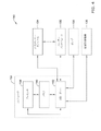
この開示は、医療用デバイスの構成、材料、製造方法、およびの使用代替物を提供する。例1。脳脊髄液の流れ制御システムが開示される。該システムは、流体回路に沿って脳脊髄液をポンプ輸送するように構成されたポンプと、前記ポンプと連通する流体ラインであって、患者から脳脊髄液を受け取るように構成された入口と、状態調整された脳脊髄液を患者に供給するように構成された出口と、前記流体ラインの入口からポンプまでおよび前記ポンプから前記流体ラインの出口までの前記流体回路に沿った脳脊髄液の移動を可能にするように構成されたルーメンと、を有する前記流体ラインと、前記流体ラインのルーメンと連通するセンサーであって、前記ポンプの下流の位置にある前記流体ラインのルーメン内の圧力に関連する測定値を検知するように構成される前記センサーと、前記センサーおよび前記ポンプと通信するコントローラと、を含む。前記コントローラは、前記センサーによって検知された測定値に基づいて前記ポンプの動作を制御するように構成されていることができる。 This disclosure provides configurations, materials, manufacturing methods, and use alternatives for medical devices. Example 1. A cerebrospinal fluid flow control system is disclosed. The system includes a pump configured to pump cerebrospinal fluid along a fluid circuit, and a fluid line communicating with the pump, an inlet configured to receive cerebrospinal fluid from a patient. An outlet configured to supply condition-adjusted cerebrospinal fluid to the patient and movement of cerebrospinal fluid along the fluid circuit from the inlet of the fluid line to the pump and from the pump to the outlet of the fluid line. A sensor that communicates with the fluid line having a lumen configured to enable the pump and is associated with pressure in the lumen of the fluid line located downstream of the pump. Includes said sensor configured to detect measurements to be made, and a controller that communicates with said sensor and said pump. The controller can be configured to control the operation of the pump based on the measured values detected by the sensor.
上記の実施形態のうちいずれかの代替として、又は追加として、前記コントローラは、前記センサーによって検知された測定値に基づくデルタ値に基づいて前記ポンプの動作を制御するように構成され、前記デルタ値は、時刻Tにおいて前記センサーによって検知された測定値に基づく値と、時刻Tから時間間隔Nを引いた前の時刻において前記センサーによって検知された測定値に基づく値との差分であることができる。 As an alternative or in addition to any of the above embodiments, the controller is configured to control the operation of the pump based on a delta value based on the measured value detected by the sensor, said delta value. Can be the difference between the value based on the measured value detected by the sensor at time T and the value based on the measured value detected by the sensor at the time before the time interval N is subtracted from the time T. ..
上記の実施形態のうちいずれかの代替として、又は追加として、時間間隔Nは5分に等しくてもよい。
上記の実施形態のうちいずれかの代替として、又は追加として、コントローラは、時刻Tにおいて前記センサーによって検知された前記測定値に基づく値が閾値に達していないときの第1の制御プロトコルと、時刻Tにおいて前記センサーによって検知された前記測定値に基づく値が前記閾値に達したかまたはそれを超えたときの第1の制御プロトコルとは異なる第2の制御プロトコルと、に従って前記ポンプの動作を制御するように構成されていることができる。
As an alternative or in addition to any of the above embodiments, the time interval N may be equal to 5 minutes.
As an alternative or in addition to any of the above embodiments, the controller has a first control protocol and a time when the value based on the measured value detected by the sensor at time T has not reached the threshold. The operation of the pump is controlled according to a second control protocol different from the first control protocol when the value based on the measured value detected by the sensor in T reaches or exceeds the threshold value. Can be configured to.
上記の実施形態のうちいずれかの代替として、又は追加として、前記コントローラは、前記デルタ値に基づいて前記閾値を決定するように構成されていることができる。
上記の実施形態のうちいずれかの代替として、又は追加として、前記コントローラは、前記ポンプが動作している連続時間の長さに基づいて前記閾値を調整するように構成されていることができる。
As an alternative or in addition to any of the above embodiments, the controller may be configured to determine the threshold value based on the delta value.
As an alternative or in addition to any of the above embodiments, the controller may be configured to adjust the threshold based on the length of continuous time the pump is operating.
上記の実施形態のうちいずれかの代替として、又は追加として、前記コントローラは、前記第1の制御プロトコルに従って前記ポンプの動作を制御するとき、前記閾値が第1の閾値であり、前記コントローラは、前記センサーによって検知された測定値に基づく値を、前記デルタ値に基づく第2の閾値と比較するように構成されていることができる。前記センサーによって検知された測定値に基づく値が前記第2の閾値に達していないかまたはそれを超えていない場合、前記コントローラは、前記ポンプのポンプ輸送速度を第1の所定量で増加させることができる。前記センサーによって検知された測定値に基づく値が前記第2の閾値に達したかまたはそれを超えた場合、前記コントローラは、前記ポンプのポンプ輸送速度を第2の所定量で増加させることができる。 As an alternative or in addition to any of the above embodiments, the threshold is the first threshold when the controller controls the operation of the pump according to the first control protocol. A value based on the measured value detected by the sensor can be configured to be compared with a second threshold value based on the delta value. If the value based on the measured value detected by the sensor does not reach or exceed the second threshold, the controller increases the pump transport rate of the pump by a first predetermined amount. Can be done. If the value based on the measured value detected by the sensor reaches or exceeds the second threshold value, the controller can increase the pump transport speed of the pump by a second predetermined amount. ..
上記の実施形態のうちいずれかの代替として、又は追加として、前記第1の所定量および前記第2の所定量は、前記デルタ値に基づくことができる。
上記の実施形態のうちいずれかの代替として、又は追加として、前記システムは、前記コントローラが前記第1の制御プロトコルに従って前記ポンプの動作を制御していた時間量を計時するタイマーを含むことができ、前記コントローラが、前記ポンプの前記コントローラが前記第1の制御プロトコルに従って前記ポンプの動作を制御している時間量を計時するタイマーをさらに備え、第1の所定量および第2の所定量の一方で増加させ且つ前記ポンプ輸送速度の増加がゼロ以下である場合、前記コントローラは、前記タイマーを停止し、前記デルタ値を再計算するように構成されていることができる。
As an alternative or in addition to any of the above embodiments, the first predetermined amount and the second predetermined amount can be based on the delta value.
As an alternative or in addition to any of the above embodiments, the system may include a timer that measures the amount of time the controller has controlled the operation of the pump according to the first control protocol. The controller further comprises a timer that measures the amount of time the controller of the pump controls the operation of the pump according to the first control protocol, one of a first predetermined amount and a second predetermined amount. The controller may be configured to stop the timer and recalculate the delta value if the increase in pump transport rate is less than or equal to zero.
上記の実施形態のうちいずれかの代替として、又は追加として、前記コントローラが、前記ポンプのポンプ輸送速度を第1の所定量および第2の所定量の一方で増加させ且つ前記ポンプ輸送速度の増加がゼロよりも大きい場合、前記コントローラは、前記タイマーが動作しているかどうかを判定し、前記コントローラが、前記タイマーが動作していないと判定すると、前記コントローラは、前記タイマーを起動して前記デルタ値を再計算するように構成されていることができる。 As an alternative or in addition to any of the above embodiments, the controller increases the pump transport rate of the pump by either a first predetermined amount and a second predetermined amount and increases the pump transport rate. Is greater than zero, the controller determines if the timer is running, and if the controller determines that the timer is not running, the controller activates the timer and the delta. It can be configured to recalculate the value.
上記の実施形態のうちいずれかの代替として、又は追加として、前記コントローラが、前記タイマーが動作していると判定すると、前記コントローラは、前記タイマーが満了したかどうかを判定し、前記コントローラが、前記タイマーが満了していないと判定すると、前記コントローラは、前記デルタ値を再計算するように構成されており、前記コントローラが、前記タイマーが満了したと判定すると、前記コントローラは、前記センサーによって検知された測定値に基づく値が前記第2の閾値に達したかまたは到達していないかまたはそれを超えたかまたは超えていないかに基づいて、前記第1の所定量および前記第2の所定量の一方で前記ポンプ輸送速度を増加させるように構成されていることができる。 As an alternative or in addition to any of the above embodiments, when the controller determines that the timer is running, the controller determines if the timer has expired and the controller determines whether the timer has expired. If the controller determines that the timer has not expired, the controller is configured to recalculate the delta value, and if the controller determines that the timer has expired, the controller detects it by the sensor. The first predetermined amount and the second predetermined amount are based on whether the value based on the measured value has reached or has not reached the second threshold value, or has exceeded or has not exceeded the second threshold value. On the other hand, it can be configured to increase the pump transport speed.
上記の実施形態のうちいずれかの代替として、又は追加として、前記タイマーは第1のタイマーであり、前記システムは第2のタイマーをさらに含み、前記第2の制御プロトコルに従って前記ポンプの動作を制御するとき、前記第2のタイマーは、前記コントローラが前記第2の制御プロトコルに従って前記ポンプの動作を制御していた時間量を計時するように構成されており、前記コントローラは、前記第2のタイマーが動作しているかどうかを判定し、前記コントローラが、前記第2のタイマーが動作していないと判定すると、前記コントローラは、前記第2のタイマーを起動して前記デルタ値を再計算するように構成されていることができる。 As an alternative or in addition to any of the above embodiments, the timer is a first timer, the system further comprises a second timer, and controls the operation of the pump according to the second control protocol. Then, the second timer is configured to time the amount of time that the controller was controlling the operation of the pump according to the second control protocol, and the controller is configured to time the second timer. If the controller determines that the second timer is not operating, the controller activates the second timer to recalculate the delta value. Can be configured.
上記の実施形態のうちいずれかの代替として、又は追加として、前記コントローラが、前記第2のタイマーが動作していると判定すると、前記コントローラは、前記第2のタイマーが満了したかどうかを判定し、前記コントローラが、前記第2のタイマーが満了していないと判定すると、前記コントローラは、前記デルタ値を再計算するように構成されており、前記コントローラが、前記第2のタイマーが満了したと判定すると、前記コントローラは、前記ポンプ輸送速度を第3の所定量で低下させるように構成されていることができる。 As an alternative or in addition to any of the above embodiments, if the controller determines that the second timer is running, the controller determines if the second timer has expired. Then, when the controller determines that the second timer has not expired, the controller is configured to recalculate the delta value, and the controller has expired the second timer. If it is determined, the controller can be configured to reduce the pump transport speed by a third predetermined amount.
上記の実施形態のうちいずれかの代替として、又は追加として、前記コントローラが、前記第2のタイマーが満了したと判定すると、前記コントローラは、前記第2のタイマーを再起動するように構成されていることができる。 As an alternative or in addition to any of the above embodiments, if the controller determines that the second timer has expired, the controller is configured to restart the second timer. Can be.
上記の実施形態のうちいずれかの代替として、又は追加として、前記コントローラは、前記第2のタイマーを再起動した後に前記デルタ値を再計算するように構成されることができる。 As an alternative or in addition to any of the above embodiments, the controller can be configured to recalculate the delta value after restarting the second timer.
上記の実施形態のうちいずれかの代替として、又は追加として、前記コントローラは、前記デルタ値に基づいて前記第3の所定量を決定するように構成されていることができる。 As an alternative or in addition to any of the above embodiments, the controller may be configured to determine the third predetermined amount based on the delta value.
上記の実施形態のうちいずれかの代替として、又は追加として、前記第3の所定量は、前記ポンプのポンプ輸送速度のパーセンテージの値であることができる。
上記の実施形態のうちいずれかの代替として、又は追加として、前記システムはタイマーをさらに含み、前記第2の制御プロトコルに従って前記ポンプの動作を制御するとき、前記タイマーは、前記コントローラが前記第2の制御プロトコルに従って前記ポンプの動作を制御していた時間量を計時するように構成されており、前記コントローラは、前記タイマーが動作しているかどうかを判定し、前記コントローラが、前記タイマーが動作していないと判定すると、前記コントローラは、前記タイマーを起動して前記デルタ値を再計算するように構成されていることができる。
As an alternative or in addition to any of the above embodiments, the third predetermined amount can be a percentage of the pump transport rate of the pump.
As an alternative or in addition to any of the above embodiments, when the system further comprises a timer and controls the operation of the pump according to the second control protocol, the timer is such that the controller causes the second. The controller is configured to measure the amount of time during which the operation of the pump was controlled according to the control protocol of the above, the controller determines whether or not the timer is operating, and the controller operates the timer. If not determined, the controller may be configured to activate the timer and recalculate the delta value.
上記の実施形態のうちいずれかの代替として、又は追加として、前記コントローラが、前記タイマーが動作していると判定すると、前記コントローラは、前記タイマーが満了したかどうかを判定し、前記コントローラが、前記タイマーが満了していないと判定すると、前記コントローラは、前記デルタ値を再計算するように構成されており、前記コントローラが、前記タイマーが満了したと判定すると、前記コントローラは、前記ポンプのポンプ輸送速度を所定量で低下させるように構成されていることができる。 As an alternative or in addition to any of the above embodiments, if the controller determines that the timer is running, the controller determines if the timer has expired, and the controller determines whether the timer has expired. If the timer determines that the timer has not expired, the controller is configured to recalculate the delta value, and if the controller determines that the timer has expired, the controller pumps the pump. It can be configured to reduce the transport rate by a predetermined amount.
上記の実施形態のうちいずれかの代替として、又は追加として、前記コントローラが、前記タイマーが満了したと判定すると、前記コントローラは、前記タイマーを再起動するように構成されていることができる。 As an alternative or in addition to any of the above embodiments, the controller may be configured to restart the timer if it determines that the timer has expired.
上記の実施形態のうちいずれかの代替として、又は追加として、前記コントローラは、前記タイマーを再起動した後に前記デルタ値を再計算するように構成されることができる。 As an alternative or in addition to any of the above embodiments, the controller may be configured to recalculate the delta value after restarting the timer.
上記の実施形態のうちいずれかの代替として、又は追加として、前記コントローラは、前記デルタ値に基づく動作ゾーンに従って前記ポンプを動作させるように構成されていることができる。 As an alternative or in addition to any of the above embodiments, the controller may be configured to operate the pump according to an operating zone based on the delta value.
上記の実施形態のうちいずれかの代替として、又は追加として、前記コントローラは、前記動作ゾーンおよびルックアップテーブル内の複数の値に基づいて前記ポンプのポンプ輸送速度を制御するように構成されていることができる。 As an alternative or in addition to any of the above embodiments, the controller is configured to control the pump transport rate of the pump based on a plurality of values in the operating zone and the look-up table. be able to.
上記の実施形態のうちいずれかの代替として、又は追加として、前記システムは、前記センサーの下流の位置で前記流体ラインのルーメンから脳脊髄液を受け取るように構成されたフィルターモジュールをさらに備えることができる。 As an alternative or in addition to any of the above embodiments, the system may further comprise a filter module configured to receive cerebrospinal fluid from the lumen of the fluid line at a location downstream of the sensor. can.
上記の実施形態のうちいずれかの代替として、又は追加として、前記フィルターモジュールは、1つまたは複数の接線流濾過を含むことができる。
上記の実施形態のうちいずれかの代替として、又は追加として、前記フィルターモジュールは、状態調整された脳脊髄液の第1の出力を出力し、第1の廃棄物流体を出力するように構成された第1のフィルターと、前記第1のフィルターの下流にある第2のフィルターであって、第1の廃棄物流体を受け取り、状態調整された脳脊髄液の第2の出力を出力し、最終廃棄物流体を出力するように構成された前記第2のフィルターと、を含むことができる。
As an alternative or in addition to any of the above embodiments, the filter module may include one or more tangential flow filtration.
As an alternative or in addition to any of the above embodiments, the filter module is configured to output a first output of condition-adjusted cerebrospinal fluid and a first output of waste fluid. A first filter and a second filter downstream of the first filter that receives the first waste fluid, outputs a second output of condition-adjusted cerebrospinal fluid, and finally. The second filter, which is configured to output waste fluid, can be included.
上記の実施形態のうちいずれかの代替として、又は追加として、前記システムは、前記流体ラインと連通し、前記第2のフィルターの下流に配置された廃棄ポンプをさらに備え、前記廃棄ポンプは、前記最終廃棄物流体が前記第2のフィルターから出力される前記廃棄ポンプの輸送速度を少なくとも部分的に制御するように構成されていることができる。 As an alternative or in addition to any of the above embodiments, the system further comprises a waste pump that communicates with the fluid line and is located downstream of the second filter, wherein the waste pump is said. The final waste fluid can be configured to at least partially control the transport rate of the waste pump as it is output from the second filter.
上記の実施形態のうちいずれかの代替として、又は追加として、前記システムは、前記流体ラインと連通し、前記フィルターモジュールの下流に配置された廃棄ポンプをさらに備え、前記廃棄ポンプは、前記廃棄物流体が前記フィルターモジュールから出力される廃棄ポンプ輸送速度を少なくとも部分的に制御するように構成されていることができる。 As an alternative or in addition to any of the above embodiments, the system further comprises a waste pump that communicates with the fluid line and is located downstream of the filter module, wherein the waste pump is the waste distribution. The body can be configured to at least partially control the waste pump transport rate output from the filter module.
上記の実施形態のうちいずれかの代替として、又は追加として、前記流体ラインは、前記流体回路内の所望の圧力を維持することを可能にするように構成された複数の管状構成要素を含むことができる。 As an alternative or in addition to any of the above embodiments, the fluid line comprises a plurality of tubular components configured to be capable of maintaining the desired pressure in the fluid circuit. Can be done.
脳脊髄液の状態調整システムが開示される。該システムは、ポンプ輸送速度を有し、流体回路に沿って脳脊髄液をポンプ輸送するように構成されたポンプと、前記流体回路に沿ってポンプ輸送される脳脊髄液を受け取るように構成されたフィルターモジュールと、前記ポンプと連通する流体ラインであって、患者から脳脊髄液を受け取るように構成された入口と、濾過された脳脊髄液を前記フィルターモジュールから患者に供給するように構成された出口と、前記流体ラインの入口から前記フィルターモジュールまでおよび前記フィルターモジュールから前記流体ラインの出口までの前記流体回路に沿った脳脊髄液の移動を可能にするように構成されたルーメンと、を有する前記流体ラインと、前記フィルターモジュールの上流の位置で前記流体ラインのルーメンと連通するフィルター圧力センサーであって、前記フィルターモジュールの上流の位置で前記流体ラインのルーメン内の圧力に関連する測定値を検知するように構成されている前記フィルター圧力センサーと、前記フィルター圧力センサーおよび前記ポンプと通信するコントローラと、を備え、前記コントローラは、前記フィルター圧力センサーによって検知された測定値に基づく値および前記コントローラによって計算されたデルタ値のうちの1つまたは両方に基づいて前記ポンプの動作を制御するように構成され、前記デルタ値は、時刻Tにおいて前記フィルター圧力センサーによって検知された測定値に基づく値と、時刻Tから時間間隔Nを引いた前の時刻において前記フィルター圧力センサーによって検知された測定値に基づく値との差分である。 A system for adjusting the condition of cerebrospinal fluid is disclosed. The system has a pumping speed and is configured to receive a pump configured to pump the cerebrospinal fluid along the fluid circuit and a pumped cerebrospinal fluid along the fluid circuit. A filter module, a fluid line communicating with the pump, an inlet configured to receive cerebrospinal fluid from the patient, and a fluid line configured to supply filtered cerebrospinal fluid from the filter module to the patient. An outlet and a lumen configured to allow the movement of cerebrospinal fluid along the fluid circuit from the inlet of the fluid line to the filter module and from the filter module to the exit of the fluid line. A filter pressure sensor that communicates with the fluid line having the fluid line and the lumen of the fluid line at a position upstream of the filter module, and is a measured value related to the pressure in the lumen of the fluid line at a position upstream of the filter module. The filter pressure sensor is configured to detect, and the filter pressure sensor and a controller that communicates with the pump, wherein the controller is a value based on a measured value detected by the filter pressure sensor and the controller. It is configured to control the operation of the pump based on one or both of the delta values calculated by the controller, which is based on the measured value detected by the filter pressure sensor at time T. And the difference from the value based on the measured value detected by the filter pressure sensor at the time before the time interval N is subtracted from the time T.
上記の実施形態のうちいずれかの代替として、又は追加として、前記フィルターモジュールは、濾過された脳脊髄液の第1の出力を出力し、第1の廃棄物流体を出力するように構成された第1のフィルターと、前記第1のフィルターの下流にある第2のフィルターであって、第1の廃棄物流体を受け取り、濾過された脳脊髄液の第2の出力を出力し、最終廃棄物流体を出力するように構成された前記第2のフィルターと、を含むことができる。 As an alternative or in addition to any of the above embodiments, the filter module is configured to output a first output of filtered cerebrospinal fluid and a first output of waste fluid. A first filter and a second filter downstream of the first filter that receives the first waste fluid, outputs the second output of the filtered cerebrospinal fluid, and is the final waste distribution. The second filter, which is configured to output the body, can be included.
上記の実施形態のうちいずれかの代替として、又は追加として、前記フィルターモジュールは、第1の接線流濾過および第2の接線流濾過を含み、前記第2の接線流濾過が、前記第1の接線流濾過の下流の位置で流体ラインに沿って配置されることができる。
上記の実施形態のうちいずれかの代替として、又は追加として、前記システムは、前記流体ラインと連通し、前記流体ラインの下流に配置された廃棄ポンプをさらに備え、前記廃棄ポンプは、前記廃棄物流体が前記流体ラインから出力される廃棄ポンプ輸送速度を少なくとも部分的に制御するように構成されていることができる。
As an alternative or in addition to any of the above embodiments, the filter module comprises a first tangential flow filtration and a second tangential flow filtration, wherein the second tangential flow filtration is the first. It can be placed along the fluid line at a location downstream of tangential flow filtration.
As an alternative or in addition to any of the above embodiments, the system further comprises a waste pump that communicates with the fluid line and is located downstream of the fluid line, wherein the waste pump is the waste distribution. The body can be configured to at least partially control the waste pump transport rate output from the fluid line.
上記の実施形態のうちいずれかの代替として、又は追加として、前記ポンプは、前記フィルターモジュールの上流の位置で前記流体ラインに沿って配置されることができる。
上記の実施形態のうちいずれかの代替として、又は追加として、前記フィルター圧力センサーが前記流体ラインのルーメンと連通している前記フィルターモジュールの上流の位置は、前記ポンプの下流であることができる。
As an alternative or in addition to any of the above embodiments, the pump can be placed along the fluid line at a position upstream of the filter module.
As an alternative or in addition to any of the above embodiments, the location upstream of the filter module in which the filter pressure sensor communicates with the lumen of the fluid line can be downstream of the pump.
上記の実施形態のうちいずれかの代替として、又は追加として、前記システムは、前記コントローラと通信し、前記ポンプおよび前記フィルターモジュールの上流の位置で前記流体ラインのルーメンと連通する入口圧力センサーをさらに備え、前記コントローラは、前記入口圧力センサーによって検知された測定値に基づく値が所定の閾値に達したかまたはそれを超えたときに前記ポンプをシャットダウンするように構成されていることができる。 As an alternative or in addition to any of the above embodiments, the system further provides an inlet pressure sensor that communicates with the controller and communicates with the lumen of the fluid line at a location upstream of the pump and filter module. The controller may be configured to shut down the pump when a value based on the measured value detected by the inlet pressure sensor reaches or exceeds a predetermined threshold.
上記の実施形態のうちいずれかの代替として、又は追加として、前記システムは、前記コントローラと通信し、前記ポンプおよび前記フィルターモジュールの下流の位置で前記流体ラインのルーメンと連通する出口圧力センサーをさらに備え、前記コントローラは、前記出口圧力センサーによって検知された測定値に基づく値が所定の閾値に達したかまたはそれを超えたときに前記ポンプをシャットダウンするように構成されていることができる。 As an alternative or in addition to any of the above embodiments, the system further provides an outlet pressure sensor that communicates with the controller and communicates with the lumen of the fluid line at a location downstream of the pump and filter module. The controller may be configured to shut down the pump when a value based on the measured value detected by the outlet pressure sensor reaches or exceeds a predetermined threshold.
上記の実施形態のうちいずれかの代替として、又は追加として、前記コントローラは、時刻Tにおいて前記フィルター圧力センサーによって検知された前記測定値に基づく値が閾値に達していないときの第1の制御プロトコルに従って、および時刻Tにおいて前記フィルター圧力センサーによって検知された前記測定値に基づく値が前記閾値に達したかまたはそれを超えたときの第1の制御プロトコルとは異なる第2の制御プロトコルに従って前記ポンプの動作を制御するように構成されていることができる。 As an alternative or in addition to any of the above embodiments, the controller is a first control protocol when the value based on the measured value detected by the filter pressure sensor at time T has not reached the threshold. According to, and according to a second control protocol different from the first control protocol when the value based on the measured value detected by the filter pressure sensor reaches or exceeds the threshold at time T, the pump. Can be configured to control the behavior of.
上記の実施形態のうちいずれかの代替として、又は追加として、前記コントローラは、前記第1の制御プロトコルに従って前記ポンプの動作を制御するとき、前記閾値が第1の閾値であり、前記コントローラは、前記フィルター圧力センサーによって検知された測定値に基づく値を、前記デルタ値に基づく第2の閾値と比較し、前記フィルター圧力センサーによって検知された測定値に基づく値が前記第2の閾値に達していないかまたはそれを超えていない場合、前記コントローラは、前記ポンプのポンプ輸送速度を第1の所定量で増加させ、前記フィルター圧力センサーによって検知された測定値に基づく値が前記第2の閾値に達したかまたはそれを超えた場合、前記コントローラは、前記ポンプのポンプ輸送速度を第2の所定量で増加させるように構成されていることができる。 As an alternative or in addition to any of the above embodiments, when the controller controls the operation of the pump according to the first control protocol, the threshold is the first threshold and the controller is: The value based on the measured value detected by the filter pressure sensor is compared with the second threshold value based on the delta value, and the value based on the measured value detected by the filter pressure sensor reaches the second threshold value. If not, or not exceeded, the controller increases the pump transport rate of the pump by a first predetermined amount, and a value based on the measured value detected by the filter pressure sensor becomes the second threshold. When reached or exceeded, the controller may be configured to increase the pump transport rate of the pump by a second predetermined amount.
上記の実施形態のうちいずれかの代替として、又は追加として、前記システムは、前記コントローラが前記第1の制御プロトコルに従って前記ポンプの動作を制御していた時間量を計時するタイマーをさらに備え、前記コントローラが、前記ポンプのポンプ輸送速度を第1の所定量および第2の所定量の一方で増加させ且つ前記ポンプ輸送速度の増加がゼロ以下である場合、前記コントローラは、前記タイマーを停止し、前記デルタ値を再計算するように構成されていることができる。 As an alternative or in addition to any of the above embodiments, the system further comprises a timer that measures the amount of time the controller has controlled the operation of the pump according to the first control protocol. If the controller increases the pump transport rate of the pump by one of a first predetermined amount and a second predetermined amount and the increase in the pump transport speed is less than or equal to zero, the controller stops the timer. It can be configured to recalculate the delta value.
上記の実施形態のうちいずれかの代替として、又は追加として、前記コントローラが、前記ポンプのポンプ輸送速度を第1の所定量および第2の所定量の一方で増加させ且つ前記ポンプ輸送速度の増加がゼロよりも大きい場合、前記コントローラは、前記タイマーが動作しているかどうかを判定し、前記コントローラが、前記タイマーが動作していないと判定すると、前記コントローラは、前記タイマーを起動して前記デルタ値を再計算するように構成されていることができる。 As an alternative or in addition to any of the above embodiments, the controller increases the pump transport rate of the pump by either a first predetermined amount and a second predetermined amount and increases the pump transport rate. Is greater than zero, the controller determines if the timer is running, and if the controller determines that the timer is not running, the controller activates the timer and the delta. It can be configured to recalculate the value.
上記の実施形態のうちいずれかの代替として、又は追加として、前記コントローラが、前記タイマーが動作していると判定すると、前記コントローラは、前記タイマーが満了したかどうかを判定し、前記コントローラが、前記タイマーが満了していないと判定すると、前記コントローラは、前記デルタ値を再計算するように構成されており、前記コントローラが、前記タイマーが満了したと判定すると、前記コントローラは、前記フィルター圧力センサーによって検知された測定値に基づく値が前記第2の閾値に達したかまたは到達していないかまたはそれを超えたかまたは超えていないかに基づいて、前記第1の所定量および前記第2の所定量の一方で前記ポンプ輸送速度を増加させるように構成されていることができる。 As an alternative or in addition to any of the above embodiments, when the controller determines that the timer is running, the controller determines if the timer has expired and the controller determines whether the timer has expired. If the controller determines that the timer has not expired, the controller is configured to recalculate the delta value, and if the controller determines that the timer has expired, the controller determines that the filter pressure sensor. The first predetermined amount and the second place based on whether the value based on the measured value detected by is reached, not reached, exceeded, or exceeded the second threshold. It can be configured to increase the pump transport rate while quantifying.
上記の実施形態のうちいずれかの代替として、又は追加として、前記タイマーは第1のタイマーであり、前記システムは第2のタイマーをさらに含み、前記第2の制御プロトコルに従って前記ポンプの動作を制御するとき、前記第2のタイマーは、前記コントローラが前記第2の制御プロトコルに従って前記ポンプの動作を制御していた時間量を計時するように構成されており、前記コントローラは、前記第2のタイマーが動作しているかどうかを判定し、前記コントローラが、前記第2のタイマーが動作していないと判定すると、前記コントローラは、前記第2のタイマーを起動して前記デルタ値を再計算するように構成されていることができる。 As an alternative or in addition to any of the above embodiments, the timer is a first timer, the system further comprises a second timer, and controls the operation of the pump according to the second control protocol. Then, the second timer is configured to time the amount of time that the controller was controlling the operation of the pump according to the second control protocol, and the controller is configured to time the second timer. If the controller determines that the second timer is not operating, the controller activates the second timer to recalculate the delta value. Can be configured.
上記の実施形態のうちいずれかの代替として、又は追加として、前記コントローラが、前記第2のタイマーが動作していると判定すると、前記コントローラは、前記第2のタイマーが満了したかどうかを判定し、前記コントローラが、前記第2のタイマーが満了していないと判定すると、前記コントローラは、前記デルタ値を再計算するように構成されており、前記コントローラが、前記第2のタイマーが満了したと判定すると、前記コントローラは、前記ポンプ輸送速度を第3の所定量で低下させるように構成されていることができる。 As an alternative or in addition to any of the above embodiments, if the controller determines that the second timer is running, the controller determines if the second timer has expired. Then, when the controller determines that the second timer has not expired, the controller is configured to recalculate the delta value, and the controller has expired the second timer. If it is determined, the controller can be configured to reduce the pump transport speed by a third predetermined amount.
上記の実施形態のうちいずれかの代替として、又は追加として、前記第3の所定量は、前記ポンプのポンプ輸送速度のパーセンテージの値であることができる。
上記の実施形態のうちいずれかの代替として、又は追加として、前記コントローラが、前記第2のタイマーが満了したと判定すると、前記コントローラは、前記第2のタイマーを再起動するように構成されていることができる。
As an alternative or in addition to any of the above embodiments, the third predetermined amount can be a percentage of the pump transport rate of the pump.
As an alternative or in addition to any of the above embodiments, if the controller determines that the second timer has expired, the controller is configured to restart the second timer. Can be.
上記の実施形態のうちいずれかの代替として、又は追加として、前記コントローラは、前記第2のタイマーを再起動した後に前記デルタ値を再計算するように構成されることができる。 As an alternative or in addition to any of the above embodiments, the controller can be configured to recalculate the delta value after restarting the second timer.
脳脊髄液フィルターモジュールを通る脳脊髄液の流れを制御する方法が開示される。該方法は、ポンプを用いてポンプ輸送速度で流体ラインを介して第1のフィルターモジュールを通して脳脊髄液をポンプ輸送することであって、前記流体ラインは、患者から脳脊髄液を受け取るように構成された入口と、濾過された脳脊髄液を前記フィルターモジュールから患者に供給するように構成された出口と、前記流体ラインの入口から前記フィルターモジュールまでおよび前記フィルターモジュールから前記流体ラインの出口までの脳脊髄液の移動を可能にするように構成されたルーメンと、を有する、前記脳脊髄液をポンプ輸送すること、前記フィルターモジュールの上流の位置で前記流体ラインのルーメン内の圧力に関連する測定値を検知すること、前記フィルターモジュールの上流位置で検知された前記流体ラインのルーメン内の圧力に関連する測定値に基づく値およびデルタ値の一方又は両方に基づいて前記ポンプの動作を自動的に制御することであって、前記デルタ値は、時刻Tにおいて前記フィルターモジュールの上流の位置で検知された前記流体ラインのルーメン内の圧力に関連する測定値に基づく値と、時刻Tから時間間隔Nを引いた前の時刻において前記フィルターモジュールの上流の位置で検知された前記流体ラインのルーメン内の圧力に関連する測定値に基づく値との差分である、前記ポンプの動作を自動的に制御すること、を備える。 Disclosed are methods of controlling the flow of cerebrospinal fluid through the cerebrospinal fluid filter module. The method is to pump the cerebrospinal fluid through a first filter module through a fluid line at pumping speed using a pump, said fluid line configured to receive cerebrospinal fluid from a patient. An inlet, an outlet configured to pump filtered cerebrospinal fluid from the filter module to the patient, and from the inlet of the fluid line to the filter module and from the filter module to the outlet of the fluid line. Pumping the cerebrospinal fluid, with a lumen configured to allow movement of the cerebrospinal fluid, measurements related to pressure in the lumen of the fluid line at a location upstream of the filter module. Detecting the value, automatically operating the pump based on one or both of the measured values and / or delta values associated with the pressure in the lumen of the fluid line detected upstream of the filter module. To control, the delta value is a value based on the measured value related to the pressure in the lumen of the fluid line detected at the position upstream of the filter module at time T, and the time interval N from time T. Automatically controls the operation of the pump, which is the difference from the measured value related to the pressure in the lumen of the fluid line detected at the upstream position of the filter module at the time before subtraction. Be prepared.
上記の実施形態のうちいずれかの代替として、又は追加として、前記ポンプの動作を自動的に制御することは、時刻Tにおいて前記流体ラインのルーメン内の圧力に関連する測定値に基づく値が閾値に達しない場合、第1の制御プロトコルに従って前記ポンプの動作を制御すること、時刻Tにおいて前記流体ラインのルーメン内の圧力に関連する測定値に基づく値が前記閾値に達したかまたはそれを超えた場合、前記第1の制御プロトコルと異なる第2の制御プロトコルに従って前記ポンプの動作を制御すること、を含むことができる。 As an alternative or in addition to any of the above embodiments, the automatic control of the operation of the pump is thresholded at time T based on the measured values associated with the pressure in the lumen of the fluid line. If not, the operation of the pump is controlled according to the first control protocol, the value based on the pressure-related measurements in the lumen of the fluid line at time T reaches or exceeds the threshold. If so, it can include controlling the operation of the pump according to a second control protocol different from the first control protocol.
上記の実施形態のうちいずれかの代替として、又は追加として、前記方法は、前記デルタ値に基づいて前記閾値を自動的に決定すること、をさらに備えることができる。
上記の実施形態のうちいずれかの代替として、又は追加として、前記方法は、前記ポンプが動作していた連続時間の長さに基づいて前記閾値を自動的に調整すること、をさらに備えることができる。
As an alternative or in addition to any of the above embodiments, the method may further comprise automatically determining the threshold based on the delta value.
As an alternative or in addition to any of the above embodiments, the method may further comprise automatically adjusting the threshold based on the length of continuous time the pump has been operating. can.
上記の実施形態のうちいずれかの代替として、又は追加として、前記第1の制御プロトコルに従って前記ポンプの動作を制御するとき、前記閾値が第1の閾値であり、前記方法は、時刻Tにおける前記流体ラインのルーメン内の圧力に関連する測定値に基づく値を、前記デルタ値に基づく第2の閾値と比較すること、時刻Tにおける前記流体ラインのルーメン内の圧力に関連する測定値に基づく値が前記第2の閾値に達していないかまたはそれを超えていない場合、前記ポンプのポンプ輸送速度を第1の所定量で増加させること、時刻Tにおける前記流体ラインのルーメン内の圧力に関連する測定値に基づく値が前記第2の閾値に達したかまたはそれを超えた場合、前記ポンプのポンプ輸送速度を第2の所定量で増加させること、をさらに備えることができる。 As an alternative or in addition to any of the above embodiments, when controlling the operation of the pump according to the first control protocol, the threshold is the first threshold and the method is the method at time T. Comparing a value based on the pressure-related measurement in the lumen of the fluid line with a second threshold based on the delta value, a value based on the pressure-related measurement in the lumen of the fluid line at time T. Is not reaching or exceeding the second threshold, increasing the pump transport rate of the pump by a first predetermined amount, related to the pressure in the lumen of the fluid line at time T. If the value based on the measured value reaches or exceeds the second threshold, the pump transport rate of the pump may be further increased by a second predetermined amount.
上記の実施形態のうちいずれかの代替として、又は追加として、前記方法は、前記第1の所定量および前記第2の所定量を前記デルタ値に基づいて自動的に決定すること、をさらに備えることができる。 As an alternative or in addition to any of the above embodiments, the method further comprises automatically determining the first predetermined amount and the second predetermined amount based on the delta value. be able to.
上記の実施形態のうちいずれかの代替として、又は追加として、前記方法は、前記第1の制御プロトコルに従って前記ポンプが制御されていた時間量をタイマーを用いて自動的に計時すること、前記ポンプのポンプ輸送速度が前記第1の所定量および前記第2の所定量の一方で増加され、前記ポンプ輸送速度の増加がゼロ以下である場合、前記第1の制御プロトコルに従って前記ポンプが制御されていた時間量の計時を停止し、前記デルタ値を再計算すること、をさらに備えることができる。 As an alternative or in addition to any of the above embodiments, the method is to automatically time the amount of time the pump has been controlled according to the first control protocol using a timer, said pump. If the pump transport rate of the pump is increased by one of the first and second predetermined quantities and the increase in the pump transport rate is less than or equal to zero, then the pump is controlled according to the first control protocol. It is possible to further prepare to stop the time counting and recalculate the delta value.
上記の実施形態のうちいずれかの代替として、又は追加として、前記ポンプのポンプ輸送速度が前記第1の所定量および前記第2の所定量の一方で増加され、前記ポンプ輸送速度の増加がゼロより大きい場合、前記方法は、前記タイマーが動作しているかどうかを判定すること、前記タイマーが動作していないと判定された場合、前記タイマーを起動して前記デルタ値を再計算すること、をさらに備えることができる。 As an alternative or in addition to any of the above embodiments, the pump transport rate of the pump is increased by either the first predetermined amount and the second predetermined amount, and the increase in the pump transport rate is zero. If it is larger, the method determines whether the timer is running, and if it is determined that the timer is not running, activates the timer and recalculates the delta value. You can prepare further.
上記の実施形態のうちいずれかの代替として、又は追加として、前記方法は、前記タイマーが満了したかどうかを判定すること、前記タイマーが満了したと判定された場合、前記デルタ値を再計算すること、前記タイマーが満了したと判定された場合、前記時刻Tにおける前記流体ラインのルーメン内の圧力に関連する測定値に基づく値が前記第2の閾値に達したかまたは達していないかまたはそれを超えたかまたは超えていないかに基づいて、前記第1の所定量および前記第2の所定量の一方で前記ポンプ輸送速度を増加させること、をさらに備えることができる。 As an alternative or in addition to any of the above embodiments, the method determines if the timer has expired and, if so, recalculates the delta value. That, when it is determined that the timer has expired, the value based on the measured value related to the pressure in the lumen of the fluid line at the time T has reached or has not reached the second threshold. It may further be provided to increase the pump transport rate on the one hand of the first predetermined amount and the second predetermined amount based on whether or not the amount exceeds or does not exceed.
上記の実施形態のうちいずれかの代替として、又は追加として、前記タイマーは第1のタイマーであり、前記方法は、前記第2の制御プロトコルに従って前記ポンプが制御された時間量を前記第2のタイマーで計時すること、前記第2のタイマーが動作しているかどうかを判定することであって、前記第2のタイマーは、前記第2の制御プロトコルに従って前記ポンプが制御されていた時間量を計時するように構成されている、前記判定すること、前記第2のタイマーが動作していないと判定された場合、前記第2のタイマーを起動して前記デルタ値を再計算すること、をさらに備えることができる。 As an alternative or in addition to any of the above embodiments, the timer is a first timer, the method of which is the amount of time the pump is controlled according to the second control protocol. Measuring with a timer, determining whether or not the second timer is operating, the second timer measures the amount of time the pump was controlled according to the second control protocol. The determination is further provided, and if it is determined that the second timer is not operating, the second timer is activated to recalculate the delta value. be able to.
上記の実施形態のうちいずれかの代替として、又は追加として、前記方法は、前記第2のタイマーが動作していると判定された後に前記第2のタイマーが満了したかどうかを判定すること、前記第2のタイマーが満了していないと判定した場合、前記デルタ値を再計算すること、前記第2のタイマーが満了したと判定した場合、前記ポンプ輸送速度を第3の所定量で低下させること、をさらに備えることができる。 As an alternative or in addition to any of the above embodiments, the method determines if the second timer has expired after it has been determined that the second timer is running. If it is determined that the second timer has not expired, the delta value is recalculated, and if it is determined that the second timer has expired, the pump transport speed is reduced by a third predetermined amount. That can be further prepared.
上記の実施形態のうちいずれかの代替として、又は追加として、前記方法は、前記第2のタイマーが満了したと判定された場合、前記第2のタイマーを再起動すること、をさらに備えることができる。 As an alternative or in addition to any of the above embodiments, the method may further comprise restarting the second timer if it is determined that the second timer has expired. can.
上記の実施形態のうちいずれかの代替として、又は追加として、前記方法は、前記第2のタイマーを再起動した後に前記デルタ値を再計算すること、をさらに備えることができる。 As an alternative or in addition to any of the above embodiments, the method can further comprise recalculating the delta value after restarting the second timer.
上記の実施形態のうちいずれかの代替として、又は追加として、前記方法は、前記デルタ値に基づいて前記第3の所定量を決定すること、をさらに備えることができる。
上記の実施形態のうちいずれかの代替として、又は追加として、前記方法は、前記第3の所定量を、前記ポンプのポンプ輸送速度のパーセンテージの値に基づいて決定すること、をさらに備えることができる。
As an alternative or in addition to any of the above embodiments, the method may further comprise determining the third predetermined amount based on the delta value.
As an alternative or in addition to any of the above embodiments, the method may further comprise determining the third predetermined amount based on the value of a percentage of the pump transport rate of the pump. can.
上記の実施形態のうちいずれかの代替として、又は追加として、前記第2の制御プロトコルに従って前記ポンプの動作を制御する場合、前記方法は、タイマーが現在、前記第2の制御プロトコルに従って前記ポンプが制御されていた時間量を計時しているかどうかを判定すること、前記タイマーが動作していないと判定された場合、前記タイマーを起動して前記デルタ値を再計算すること、をさらに備えることができる。 If, as an alternative or in addition to any of the above embodiments, the operation of the pump is controlled according to the second control protocol, the method is such that the timer is now according to the second control protocol. Further, it may be provided to determine whether or not the controlled time amount is being clocked, and if it is determined that the timer is not operating, to activate the timer and recalculate the delta value. can.
上記の実施形態のうちいずれかの代替として、又は追加として、前記方法は、前記タイマーが動作していると判定された場合、前記タイマーが満了したかどうかを判定すること、前記タイマーが満了していないと判定された場合、前記デルタ値を再計算すること、前記タイマーが満了したと判定された場合、前記ポンプ輸送速度を所定量で低下させること、をさらに備えることができる。 As an alternative or in addition to any of the above embodiments, the method determines if the timer has expired if it is determined that the timer has expired. If it is determined not, the delta value may be recalculated, and if it is determined that the timer has expired, the pump transport speed may be further reduced by a predetermined amount.
上記の実施形態のうちいずれかの代替として、又は追加として、前記方法は、前記ポンプおよび前記フィルターモジュールの上流の位置で前記流体ラインのルーメン内の圧力に関連する測定値を検知すること、前記ポンプおよび前記フィルターモジュールの上流の位置で前記流体ラインのルーメン内の圧力に関連する測定値に基づく値が所定値に達したかまたはそれを超えた場合、前記ポンプをシャットダウンすること、をさらに備えることができる。 As an alternative or in addition to any of the above embodiments, the method is to detect pressure-related measurements in the lumen of the fluid line at positions upstream of the pump and filter module. Further comprising shutting down the pump if a pressure-related measured value in the lumen of the fluid line reaches or exceeds a predetermined value at a position upstream of the pump and the filter module. be able to.
上記の実施形態のうちいずれかの代替として、又は追加として、前記方法は、前記ポンプおよび前記フィルターモジュールの下流の位置で前記流体ラインのルーメン内の圧力に関連する測定値を検知すること、前記ポンプおよび前記フィルターモジュールの下流の位置における前記流体ラインのルーメン内の圧力に関連する測定値に基づく値が所定の閾値に達したかまたはそれを超えた場合、前記ポンプをシャットダウンすること、をさらに備えることができる。 As an alternative or in addition to any of the above embodiments, the method detects pressure-related measurements in the lumen of the fluid line at downstream positions of the pump and the filter module. Further shutting down the pump if the pressure-related measured value in the lumen of the fluid line at a position downstream of the pump and the filter module reaches or exceeds a predetermined threshold. Can be prepared.
上記の実施形態のうちいずれかの代替として、又は追加として、前記ポンプの動作を自動的に制御することは、時間の経過とともに繰り返される制御ループを使用して前記ポンプの動作を制御することを含むことができる。 To automatically control the operation of the pump, as an alternative or in addition to any of the above embodiments, is to control the operation of the pump using a control loop that repeats over time. Can include.
コンピュータ可読媒体はコンピューティングデバイスによって使用するためのプログラムコードを非一時的な状態で格納し、前記プログラムコードは、前記コンピューティングデバイスに脳脊髄液フィルターモジュールを通る流体の流れを制御する方法を実行させる。前記方法は、脳脊髄液をポンプ輸送して流体ラインを介してフィルターモジュールを通過させるために制御信号をポンプに出力すること、前記フィルターモジュールの上流の位置における前記流体ラインのルーメン内の圧力に関連する測定値に基づく値を決定すること、前記制御信号を設定して前記ポンプのポンプ輸送速度を調整することであって、前記制御信号の設定は、前記フィルターモジュールの上流の位置における前記流体ラインのルーメン内の圧力に関連する測定値に基づく値およびデルタ値の一方又は両方に基づいており、前記デルタ値は、時刻Tにおいて前記フィルターモジュールの上流の位置で検知された前記流体ラインのルーメン内の圧力に関連する測定値に基づく値と、時刻Tから時間間隔Nを引いた前の時刻において前記フィルターモジュールの上流の位置で検知された前記流体ラインのルーメン内の圧力に関連する測定値に基づく値との差分である、前記ポンプのポンプ輸送速度を調整すること、を備える。 The computer-readable medium stores the program code for use by the computing device in a non-temporary state, and the program code performs a method of controlling the flow of fluid through the cerebrospinal fluid filter module to the computing device. Let me. The method is to pump a control signal to the pump to pump the cerebrospinal fluid and pass it through the filter module through the fluid line, to the pressure in the lumen of the fluid line at a position upstream of the filter module. Determining a value based on the relevant measurement, setting the control signal to adjust the pump transport rate of the pump, the control signal setting is the fluid at a position upstream of the filter module. Based on one or both of the measured values and / or delta values associated with the pressure in the lumen of the line, the delta value is the lumen of the fluid line detected upstream of the filter module at time T. Values based on pressure-related measurements and measurements related to pressure in the lumen of the fluid line detected upstream of the filter module at the time prior to time T minus time interval N. It is provided with adjusting the pump transport speed of the pump, which is a difference from the value based on.
上記の実施形態のうちいずれかの代替として、又は追加として、前記制御信号を設定することは、時刻Tにおける前記流体ラインのルーメン内の圧力に関連する測定値に基づく値が閾値に達していない場合、第1の制御プロトコルに従って前記制御信号を設定すること、時刻Tにおける前記流体ラインのルーメン内の圧力に関連する測定値に基づく値が前記閾値に達したかまたはそれを超えた場合、前記第1の制御プロトコルと異なる第2の制御プロトコルに従って前記制御信号を設定すること、を含むことができる。 Setting the control signal as an alternative or in addition to any of the above embodiments does not reach the threshold value based on the measured values associated with the pressure in the lumen of the fluid line at time T. If the control signal is set according to the first control protocol, the value based on the measured value related to the pressure in the lumen of the fluid line at time T reaches or exceeds the threshold, said. It can include setting the control signal according to a second control protocol different from the first control protocol.
上記の実施形態のうちいずれかの代替として、又は追加として、前記方法は、前記デルタ値に基づいて前記閾値を自動的に決定すること、をさらに備えることができる。
上記の実施形態のうちいずれかの代替として、又は追加として、前記方法は、前記ポンプが動作していた連続時間の長さに基づいて前記閾値を自動的に調整すること、をさらに備えることができる。
As an alternative or in addition to any of the above embodiments, the method may further comprise automatically determining the threshold based on the delta value.
As an alternative or in addition to any of the above embodiments, the method may further comprise automatically adjusting the threshold based on the length of continuous time the pump has been operating. can.
上記の実施形態のうちいずれかの代替として、又は追加として、前記閾値が第1の閾値であり、前記第1の制御プロトコルに従って前記制御信号を設定することは、時刻Tにおける前記流体ラインのルーメン内の圧力に関連する測定値に基づく値を、前記デルタ値に基づく第2の閾値と比較すること、時刻Tにおける前記流体ラインのルーメン内の圧力に関連する測定値に基づく値が前記第2の閾値に達していないかまたはそれを超えていない場合、前記ポンプのポンプ輸送速度を第1の所定量で増加させること、時刻Tにおける前記流体ラインのルーメン内の圧力に関連する測定値に基づく値が前記第2の閾値に達したかまたはそれを超えた場合、前記ポンプのポンプ輸送速度を第2の所定量で増加させること、をさらに含むことができる。 As an alternative or in addition to any of the above embodiments, setting the control signal according to the first control protocol, wherein the threshold is the first threshold, is the lumen of the fluid line at time T. The value based on the measured value related to the pressure in is compared with the second threshold value based on the delta value, and the value based on the measured value related to the pressure in the lumen of the fluid line at time T is the second. If the threshold of is not reached or exceeded, the pump transport rate of the pump is increased by a first predetermined amount, based on measurements related to the pressure in the lumen of the fluid line at time T. If the value reaches or exceeds the second threshold, it can further include increasing the pump transport rate of the pump by a second predetermined amount.
上記の実施形態のうちいずれかの代替として、又は追加として、前記方法は、前記第1の所定量および前記第2の所定量を前記デルタ値に基づいて自動的に決定すること、をさらに備えることができる。 As an alternative or in addition to any of the above embodiments, the method further comprises automatically determining the first predetermined amount and the second predetermined amount based on the delta value. be able to.
上記の実施形態のうちいずれかの代替として、又は追加として、前記方法は、前記第1の制御プロトコルに従って前記ポンプが制御されていた時間量をタイマーを用いて自動的に計時すること、前記ポンプのポンプ輸送速度を前記第1の所定量および前記第2の所定量の一方で増加させ、前記ポンプ輸送速度の増加がゼロ以下である場合、前記第1の制御プロトコルに従って前記ポンプが制御されていた時間量の計時を停止し、前記デルタ値を再計算すること、をさらに備えることができる。 As an alternative or in addition to any of the above embodiments, the method is to automatically time the amount of time the pump has been controlled according to the first control protocol using a timer, said pump. If the pump transport rate of the pump is increased by one of the first predetermined amount and the second predetermined amount, and the increase in the pump transport rate is zero or less, the pump is controlled according to the first control protocol. It is possible to further prepare to stop the time counting and recalculate the delta value.
上記の実施形態のうちいずれかの代替として、又は追加として、前記制御信号が、前記ポンプのポンプ輸送速度が前記第1の所定量および前記第2の所定量の一方で増加させるように設定され、前記ポンプ輸送速度の増加がゼロより大きい場合、前記方法は、前記タイマーが動作しているかどうかを判定すること、前記タイマーが動作していないと判定された場合、前記タイマーを起動して前記デルタ値を再計算すること、をさらに備えることができる。 As an alternative or in addition to any of the above embodiments, the control signal is set so that the pump transport rate of the pump is increased by either the first predetermined amount and the second predetermined amount. If the increase in pump transport speed is greater than zero, the method determines if the timer is operating, and if it is determined that the timer is not operating, activates the timer. You can further prepare to recalculate the delta value.
上記の実施形態のうちいずれかの代替として、又は追加として、前記方法は、前記タイマーが満了したかどうかを判定すること、前記タイマーが満了したと判定された場合、前記デルタ値を再計算すること、前記タイマーが満了した場合、前記時刻Tにおける前記流体ラインのルーメン内の圧力に関連する測定値に基づく値が前記第2の閾値に達したかまたは達していないかまたはそれを超えたまたは超えていないかに基づいて、前記第1の所定量および前記第2の所定量の一方で前記ポンプ輸送速度を増加させるように前記制御信号を設定すること、をさらに備えることができる。 As an alternative or in addition to any of the above embodiments, the method determines if the timer has expired and, if so, recalculates the delta value. That, when the timer expires, the value based on the measured value related to the pressure in the lumen of the fluid line at the time T has reached, has not reached, or exceeded the second threshold. It may further be provided that the control signal is set to increase the pump transport rate while the first predetermined amount and the second predetermined amount are not exceeded.
上記の実施形態のうちいずれかの代替として、又は追加として、前記タイマーは第1のタイマーであり、前記方法は、前記第2のタイマーが動作しているかどうかを判定することであって、前記第2のタイマーは、前記第2の制御プロトコルに従って前記ポンプが制御されていた時間量を計時するように構成されている、前記判定すること、前記第2のタイマーが動作していないと判定した場合、前記第2のタイマーを起動して前記デルタ値を再計算すること、をさらに備えることができる。 As an alternative or in addition to any of the above embodiments, the timer is a first timer, the method of which is to determine if the second timer is operating. The second timer is configured to time the amount of time the pump was controlled according to the second control protocol, said determination, and determined that the second timer is not operating. In the case, the second timer may be activated to recalculate the delta value.
上記の実施形態のうちいずれかの代替として、又は追加として、前記方法は、前記第2のタイマーが動作していると判定された後に前記第2のタイマーが満了したかどうかを判定すること、前記第2のタイマーが満了していないと判定した場合、前記デルタ値を再計算すること、前記第2のタイマーが満了したと決定された場合、前記ポンプ輸送速度を第3の所定の量で低下させるように前記制御信号を設定すること、をさらに備えることができる。 As an alternative or in addition to any of the above embodiments, the method determines if the second timer has expired after it has been determined that the second timer is running. If it is determined that the second timer has not expired, the delta value should be recalculated, and if it is determined that the second timer has expired, the pump transport speed should be set to a third predetermined amount. It can be further provided to set the control signal so as to decrease it.
上記の実施形態のうちいずれかの代替として、又は追加として、前記方法は、前記第2のタイマーが満了したと判定された場合、前記第2のタイマーを再起動すること、をさらに備えることができる。 As an alternative or in addition to any of the above embodiments, the method may further comprise restarting the second timer if it is determined that the second timer has expired. can.
上記の実施形態のうちいずれかの代替として、又は追加として、前記方法は、前記第2のタイマーを再起動した後に前記デルタ値を再計算すること、をさらに備えることができる。 As an alternative or in addition to any of the above embodiments, the method can further comprise recalculating the delta value after restarting the second timer.
上記の実施形態のうちいずれかの代替として、又は追加として、前記方法は、前記デルタ値に基づいて前記第3の所定量を決定すること、をさらに備えることができる。
上記の実施形態のうちいずれかの代替として、又は追加として、前記方法は、前記第3の所定量を、前記ポンプのポンプ輸送速度のパーセンテージの値に基づいて決定すること、をさらに備えることができる。
As an alternative or in addition to any of the above embodiments, the method may further comprise determining the third predetermined amount based on the delta value.
As an alternative or in addition to any of the above embodiments, the method may further comprise determining the third predetermined amount based on the value of a percentage of the pump transport rate of the pump. can.
上記の実施形態のうちいずれかの代替として、又は追加として、前記制御信号が、前記第2の制御プロトコルに従って前記ポンプの動作を制御するように設定された場合、前記方法は、タイマーが現在、前記第2の制御プロトコルに従って前記ポンプが制御されていた時間量を計時しているかどうかを判定すること、前記タイマーが動作していないと判定された場合、前記タイマーを起動して前記デルタ値を再計算すること、をさらに備えることができる。 If, as an alternative or in addition to any of the above embodiments, the control signal is set to control the operation of the pump according to the second control protocol, the method is that the timer is now present. To determine whether the pump is measuring the controlled time according to the second control protocol, and if it is determined that the timer is not operating, activate the timer to set the delta value. It can be further prepared to recalculate.
上記の実施形態のうちいずれかの代替として、又は追加として、前記方法は、前記タイマーが動作していると判定された場合、前記タイマーが満了したかどうかを判定すること、前記タイマーが満了していないと判定された場合、前記デルタ値を再計算すること、前記タイマーが満了したと判定された場合、前記ポンプ輸送速度を所定量で低下させるように前記制御信号を設定すること、をさらに備えることができる。 As an alternative or in addition to any of the above embodiments, the method determines if the timer has expired if it is determined that the timer has expired. If it is determined that the delta value has not expired, the delta value is recalculated, and if it is determined that the timer has expired, the control signal is set so as to reduce the pump transport speed by a predetermined amount. Can be prepared.
上記の実施形態のうちいずれかの代替として、又は追加として、前記方法は、前記ポンプおよび前記フィルターモジュールの上流の位置における前記流体ラインのルーメン内の圧力に関連する測定値に基づく値が所定値に達したかまたはそれを超えた場合、前記ポンプをシャットダウンするように前記制御信号を設定すること、をさらに備えることができる。 As an alternative or in addition to any of the above embodiments, the method has predetermined values based on measurements related to pressure in the lumen of the fluid line at positions upstream of the pump and filter module. The control signal may be further configured to shut down the pump if it reaches or exceeds.
上記の実施形態のうちいずれかの代替として、又は追加として、前記方法は、前記ポンプおよび前記フィルターモジュールの下流の位置における前記流体ラインのルーメン内の圧力に関連する測定値に基づく値が所定の閾値に達したかまたはそれを超えた場合、前記ポンプをシャットダウンするように前記制御信号を設定すること、をさらに備えることができる。 As an alternative or in addition to any of the above embodiments, the method is defined by a value based on measurements related to pressure in the lumen of the fluid line at a location downstream of the pump and the filter module. Further comprising setting the control signal to shut down the pump if the threshold is reached or exceeded.
上記の実施形態のうちいずれかの代替として、又は追加として、前記ポンプの動作を自動的に制御することは、時間の経過とともに繰り返される制御ループを使用して前記ポンプの動作を制御することを含むことができる。 To automatically control the operation of the pump, as an alternative or in addition to any of the above embodiments, is to control the operation of the pump using a control loop that repeats over time. Can include.
脳脊髄液のポンプおよび濾過システムを通る脳脊髄液の流れを制御する方法が開示される。該方法は、ポンプを用いてポンプ輸送速度で流体ラインを通して脳脊髄液をポンプ輸送する前記流体ラインを加圧すること、前記ポンプの下流の位置で前記流体ラインのルーメン内の圧力に関連する測定値を検知すること、前記ポンプの下流の位置で検知された前記流体ラインのルーメン内の圧力に関連する測定値に基づいて、前記流体ライン内の圧力減衰率を決定すること、決定された圧力減衰率を閾値圧力減衰と比較すること、前記決定された圧力減衰率が前記閾値圧力減衰に達したかまたはそれを超えた場合、前記流体ラインの漏洩を示すための制御信号を出力すること、を備えることができる。 Disclosed are methods of controlling the flow of cerebrospinal fluid through a pump and filtration system of cerebrospinal fluid. The method is to pressurize the fluid line, which pumps cerebrospinal fluid through the fluid line at pumping speed using a pump, and measurements related to the pressure in the lumen of the fluid line at a location downstream of the pump. To determine the pressure decay rate in the fluid line, based on the measured values associated with the pressure in the lumen of the fluid line detected downstream of the pump. Comparing the rate with the threshold pressure attenuation, and outputting a control signal to indicate leakage of the fluid line when the determined pressure attenuation rate reaches or exceeds the threshold pressure attenuation. Can be prepared.
脳脊髄液のポンプおよび濾過システムを通る脳脊髄液の流れを制御する方法が開示される。該方法は、第1のセンサーで、脳脊髄液のポンプおよび濾過システムの流体ラインのルーメン内の圧力に関連する第1の測定値を検知することであって、前記第1のセンサーは、前記流体ラインに沿った第1の位置に配置されている、前記第1の測定値を検知すること、第2のセンサーで、前記流体ラインのルーメン内の圧力に関連する第2の測定値を検知することであって、前記第2のセンサーは、前記流体ラインに沿った第2の位置に配置されている、前記第2の測定値を検知すること、前記第1の測定値と前記第2の測定値との差分を決定すること、前記第1の測定値と前記第2の測定値との差分と、閾値差分とを比較すること、前記第1の測定値と前記第2の測定値との差分が前記閾値差分に達したかまたはそれを超えた場合に、漏洩または障害物の位置を示す制御信号を出力すること、を備える。 Disclosed are methods of controlling the flow of cerebrospinal fluid through a pump and filtration system of cerebrospinal fluid. The method is to detect a first measurement in a lumen of a fluid line of a cerebrospinal fluid pump and filtration system with a first sensor, wherein the first sensor is said. Detecting the first measurement value located at the first position along the fluid line, the second sensor detects the second measurement value related to the pressure in the lumen of the fluid line. That is, the second sensor detects the second measurement value, which is arranged at the second position along the fluid line, the first measurement value and the second measurement value. To determine the difference from the measured value of, compare the difference between the first measured value and the second measured value, and the threshold difference, the first measured value and the second measured value. The present invention comprises outputting a control signal indicating the position of a leak or an obstacle when the difference between the two and the above reaches or exceeds the threshold difference.
脳脊髄液のポンプおよび濾過システムのフィルターモジュールを洗い流す方法が開示される。該方法は、前記脳脊髄液のポンプおよび濾過システムのポンプのポンプ速度で、前記脳脊髄液のポンプおよび濾過システムの流体ラインを通して流体をポンプ輸送すること、廃棄制御機構の廃棄ポンプ速度を前記ポンプのポンプ速度に等しくなるように設定すること、前記廃棄ポンプ機構の前記廃棄ポンプ速度を前記ポンプのポンプ速度に等しくなるように設定した後の所定の期間において、前記廃棄制御機構の前記廃棄ポンプ速度を前記ポンプのポンプ速度よりも遅い値に設定すること、を備える。 Disclosed are methods of flushing cerebrospinal fluid pumps and filter modules of filtration systems. The method pumps fluid through the fluid lines of the cerebrospinal fluid pump and filtration system at the pump speed of the cerebrospinal fluid pump and filtration system, and pumps the disposal pump speed of the disposal control mechanism. The waste pump speed of the waste control mechanism is set to be equal to the pump speed of the waste pump mechanism, and in a predetermined period after the waste pump speed of the waste pump mechanism is set to be equal to the pump speed of the pump. Is set to a value slower than the pump speed of the pump.
いくつかの実施形態の上記した要約は、本開示の開示された各実施形態またはすべての実装を説明することを意図していない。以下の図面および詳細な説明は、これらの実施形態をより具体的に例示する。 The above summaries of some embodiments are not intended to account for each of the disclosed embodiments or all implementations of the present disclosure. The drawings and detailed description below exemplify these embodiments more specifically.
本開示は、添付の図面に関連して以下の詳細な説明を考慮すると、より完全に理解され得る。
本開示は、様々な修正形態および代替形態が可能であるが、その詳細は、例として図面に示されており、詳細に説明される。しかしながら、その意図は、記載された特定の実施形態に本開示を限定することではないことを理解されたい。それどころか、その意図は、本開示の趣旨および範囲に含まれるすべての修正、均等物、および代替物を網羅することである。 Various modifications and alternatives are possible in the present disclosure, the details of which are shown in the drawings by way of example and are described in detail. However, it should be understood that the intent is not to limit the disclosure to the particular embodiments described. On the contrary, its intent is to cover all modifications, equivalents, and alternatives contained within the intent and scope of this disclosure.
脳脊髄液(Cerebrospinal fluid : CSF)は、脳内の脳室、具体的には脈絡叢で生産される、一般に透明で無色の流体である。脈絡叢は、1日に数回生じる毒素及び代謝産物を除去するためのCSFの洗い流し(flushing)又は再利用(recycling)に対応するために、毎日およそ500ミリリットルのCSFを生産する。脈絡叢から、CSFは流路(管)を通って脳及び脊柱を取り囲む空間に入り、その後身体内へと、ゆっくり流れる。CSFは、脳軟膜とクモ膜との間の、クモ膜下腔として知られる空間に見出される。CSFはさらに、脊髄の中心管と連続している脳内の脳室系の中及び周囲においても見出される。脳卒中又はその他の脳損傷の場合には、ある1つの位置(例えば脊柱の頚部、又は脳室)からCSFを取り出し、これを濾過し、かつそれを第2の位置(例えば脊柱の腰部)においてCSF腔に返戻することが望ましい可能性がある。しかしながら、CSF腔に医療機器を正確に送り込むことは非常に難易度が高い可能性がある。 Cerebrospinal fluid (CSF) is a generally clear, colorless fluid produced in the ventricles of the brain, specifically the choroid plexus. The choroid plexus produces approximately 500 milliliters of CSF daily to accommodate flushing or recycling of CSF to remove toxins and metabolites that occur several times daily. From the choroid plexus, the CSF slowly flows through the flow path (tube) into the space surrounding the brain and spinal column and then into the body. CSF is found in the space between the pia mater and the arachnoid membrane, known as the subarachnoid space. CSF is also found in and around the ventricular system in the brain, which is continuous with the central canal of the spinal cord. In the case of a stroke or other brain injury, the CSF is removed from one location (eg, the neck of the spinal column, or the ventricles), filtered, and it is filtered at a second location (eg, the lumbar region of the spinal column). It may be desirable to return it to the cavity. However, it can be very difficult to accurately deliver a medical device into the CSF cavity.
本開示は、脳脊髄液(CSF)の取り出し、交換及び再循環に関する。本明細書中に開示されるデバイス、システム及び方法は、CSFが身体を流れる場である脳及び脊髄並びにその周囲の空間(CSF腔としても知られる)を、安全かつ効率的に通行するために使用される。専用のデバイス及びシステムは、出入りが困難な場所であること、及びもし誤りがあれば生命を脅かす結果となる可能性から、CSF腔を通行するために有用であり場合によっては必須である。安全性及び効能の向上は、手術室で費やされる時間及び合併症の可能性を縮小し、患者の手術からの回復を向上させる。 The present disclosure relates to the removal, exchange and recirculation of cerebrospinal fluid (CSF). The devices, systems and methods disclosed herein are for safe and efficient passage through the brain and spinal cord, where the CSF flows through the body, and the space around it (also known as the CSF cavity). used. Dedicated devices and systems are useful and in some cases essential for passage through CSF cavities due to their difficult access and potentially life-threatening consequences if mistakes are made. Improved safety and efficacy reduce the time spent in the operating room and the potential for complications and improve the patient's recovery from surgery.
Neurapheresis(商標)治療及び他の濾過治療は、CSFからの物質(例えば微生物、細胞、ウイルス、外来物質、薬物、これらの組み合わせなど)の除去をもたらし得る。これらの濾過治療及びその他の治療技法は、多くの神経系の疾患又は状態、例えばアルツハイマー病、パーキンソン病、ハンチントン舞踏病、筋萎縮性側索硬化症(ALS)、様々な原因による脳炎、様々な原因による髄膜炎、ギラン‐バレー症候群(GBS)、多発性硬化症(MS)、HIV関連神経認知障害、脊髄損傷、外傷性脳損傷、脳血管痙攣、卒中及びその他の疾患又は状態、を治療するために使用可能である。 Neurophalesis ™ treatment and other filtration treatments can result in the removal of substances from the CSF, such as microorganisms, cells, viruses, foreign substances, drugs, combinations thereof, etc. These filtration treatments and other treatment techniques include many nervous system disorders or conditions such as Alzheimer's disease, Parkinson's disease, Huntington's chorea, muscular atrophic lateral sclerosis (ALS), encephalitis due to various causes, and various. Treatment of causative meningitis, Guillain-Barré syndrome (GBS), polysclerosis (MS), HIV-related neurocognitive impairment, spinal cord injury, traumatic brain injury, cerebrovascular spasm, stroke and other disorders or conditions. Can be used to.
精製、状態調整、及び化合物除去のうち少なくともいずれかのスキーマ又はシステム(例えば、濾過治療)は、広範囲にわたる生化学的なパラメータ及び流動に合わせて調整可能である。例えば、スキーマおよび/またはシステムは、具体的な疾患又は疾患群に合わせて適切に、大きさ、親和性、生化学的性質、温度、及びその他の特徴のようないくつかの特徴に基づいて、策定されることが可能である。精製スキーマは、拡散、サイズ排除、固定化された抗体又は抗体フラグメントを使用するex‐vivoの免疫療法、疎水性/親水性、陰イオン性/陽イオン性、高/低結合親和性、キレート化剤、抗菌性、抗ウイルス性、抗DNA/RNA/アミノ酸、酵素系、及び磁気系のシステム並びにナノ粒子を用いるシステムのうち少なくともいずれかに基づくことができる。 The schema or system of at least one of purification, conditioning, and compound removal (eg, filtration therapy) can be tailored to a wide range of biochemical parameters and flows. For example, the schema and / or system may be appropriate for a particular disease or group of diseases, based on several features such as size, affinity, biochemical properties, temperature, and other features. It can be formulated. Purification schemes include diffusion, size exclusion, ex-vivo immunotherapy using immobilized antibody or antibody fragment, hydrophobic / hydrophilic, anionic / cationic, high / low binding affinity, chelation. It can be based on at least one of agents, antibacterial, antiviral, anti-DNA / RNA / amino acid, enzymatic, and magnetic systems as well as systems using nanoparticles.
CSF濾過療法(例えば、Neurapheresis療法)で使用するシステムに関して、開示されるシステムは、CSF流の妨げを最小限として安全かつ迅速にCSF腔にアクセスするために使用可能である。本明細書中に開示されるシステム及びデバイスは、安全かつ迅速な流動回路を提供し、かつ濾過を提供する。 With respect to the system used in CSF filtration therapy (eg, Neuraphysis therapy), the disclosed system can be used to access the CSF cavity safely and quickly with minimal obstruction of CSF flow. The systems and devices disclosed herein provide a safe and rapid flow circuit and provide filtration.
本明細書中に開示されたシステム及びデバイスは、安全かつ効率的に、ある1つの位置(例えば脊柱の頚部、又は脳室)からCSFを取り出すためにCSF腔にアクセスし、該CSFを濾過又はその他の方法で処理し、そしてそれをCSF腔に、例えば第2の位置(例えば脊柱の腰部)において返戻するために使用可能である。様々な態様において、本明細書中に開示されたシステム及びデバイスは、内因性の頭蓋内又は脊髄内圧力を生理的範囲内に、例えば、約5~約20mmHg、又は約0~約10mmHg、又は約-5~約10mmHg、又は約-5~約25mmHgに、維持する。本システムはこのようにして、例えば水頭症(脳の脳室内におけるCSFの異常滞留)による脊髄性頭痛を軽減する。本システムはさらに、圧力低下(例えばドレナージ過剰、ヘルニア形成などに起因するもの)によって引き起こされた脊髄性頭痛を軽減するために使用されてもよい。いくつかの態様では、システムは、システム内の障害物又は遮断物を検知するためにカテーテル内又は流動回路内にセンサーを備え、これにより閉ループの圧力制御を提供することができる。様々な態様において、本明細書中に開示されたシステム及びデバイスはさらに、再循環する流動ループの縮小又は削除によりシステムが効率的に働くのを支援する。システム及びデバイスは、入口と出口との間の間隔を、例えば約10cm~約40cmの範囲内に維持する。ある実装では、間隔は約10cm~約30cmの範囲内である。入口及び出口はCSF腔の中の適所に位置付けられて、ポンプの作動又はその他のシステム内における陽圧若しくは陰圧の生成が、カテーテル中に組織が引き込まれる原因となったり引き込まれるのを助長したりしないようになっている。いくつかの局面において、入口および出口は、組織がカテーテルに引き込まれるのを防ぐために、腰椎頸椎槽の近くに配置される。いくつかの態様では、組織がいくつかの穴を塞いでいる場合に備えて、冗長性のために入口および出口に沿って複数の穴があり得る。特定の実施形態では、カテーテルのねじれを低減するために、カテーテル内のコイル状ワイヤの特定のコイルピッチを選択することができる。特定の態様では、入口と出口の間隔は、患者の頸部のレベルより下にとどまりながら最大になるように選択することができる。特定の態様では、入口と出口の間隔は、椎骨の間隔に基づいて選択することができる。例えば、間隔は、入口と出口の間隔が約5つの椎骨から約12の椎骨までの長さの範囲内にあるように選択され得る。ある実装では、椎骨およそ10個の間隔が選択されうるが;しかしながら、その他の構成(本明細書中他所に記述されるものなど)が利用されてもよい。そのような間隔を設計する場合、椎骨はおよそ2~3cmの長さであると仮定されてよいが、また一方でその他の計測値及び設計が使用されてもよい。ある実装では、ルーメンの特定の大きさ、形状、及び他の構成のうち少なくともいずれかは、カテーテルの障害物除去及びカテーテルが閉塞状態に抵抗する能力のうち少なくともいずれか一方を促進するように、選択可能である。例えば、およそ1.52ミリメートル(0.060インチ)~およそ1.78ミリメートル(0.070インチ)の範囲内の、基端側のルーメン外径、及びおよそ0.635ミリメートル(0.025インチ)~およそ1.52ミリメートル(0.060インチ)の範囲内の基端側の内径が、選択されてもよいが;また一方で、その他の構成(本明細書中他所に記述されるものなど)が利用されてもよい。 The systems and devices disclosed herein safely and efficiently access the CSF cavity to remove the CSF from one location (eg, the neck of the spinal column, or the ventricles) and filter or filter the CSF. It can be otherwise processed and used to return it to the CSF cavity, eg, in a second position (eg, the lumbar region of the spinal column). In various embodiments, the systems and devices disclosed herein exert an endogenous intracranial or intraspinal pressure within a physiological range, eg, about 5 to about 20 mmHg, or about 0 to about 10 mmHg, or. Maintain at about -5 to about 10 mmHg, or about -5 to about 25 mmHg. In this way, the system alleviates spinal headache, for example due to hydrocephalus (abnormal retention of CSF in the ventricles of the brain). The system may also be used to relieve spinal headaches caused by reduced pressure (eg, due to excessive drainage, hernia formation, etc.). In some embodiments, the system may include a sensor in the catheter or in a flow circuit to detect obstacles or blockages in the system, thereby providing closed-loop pressure control. In various embodiments, the systems and devices disclosed herein further assist the system in working efficiently by reducing or eliminating recirculating flow loops. The system and device maintain the distance between the inlet and the outlet, eg, within the range of about 10 cm to about 40 cm. In some implementations, the spacing is in the range of about 10 cm to about 30 cm. The inlet and outlet are positioned in place within the CSF cavity to help pump operation or other positive or negative pressure generation within the system cause or draw tissue into the catheter. It is designed not to do. In some aspects, the inlet and outlet are placed near the lumbar cervical cistern to prevent tissue from being drawn into the catheter. In some embodiments, there may be multiple holes along the inlet and exit for redundancy, in case the tissue is blocking some holes. In certain embodiments, a particular coil pitch of the coiled wire within the catheter can be selected to reduce twisting of the catheter. In certain embodiments, the distance between the entrance and the exit can be selected to stay below the level of the patient's neck and be maximized. In certain embodiments, the distance between the entrance and the exit can be selected based on the distance between the vertebrae. For example, the spacing can be selected such that the spacing between the inlet and the outlet is within the length range from about 5 vertebrae to about 12 vertebrae. In some implementations, intervals of approximately 10 vertebrae may be selected; however, other configurations (such as those described elsewhere herein) may be utilized. When designing such spacing, the vertebrae may be assumed to be approximately 2-3 cm in length, while other measurements and designs may be used. In some implementations, a particular size, shape, and other configuration of lumens facilitates at least one of the catheter's clearing of obstacles and the ability of the catheter to resist obstruction. It is selectable. For example, proximal lumen outer diameter, and approximately 0.635 mm (0.025 inch), ranging from approximately 1.52 mm (0.060 inch) to approximately 1.78 mm (0.070 inch). Base end inner diameters within the range of approximately 1.52 millimeters (0.060 inches) may be selected; on the other hand, other configurations (such as those described elsewhere herein). May be used.
開示されたシステム及びデバイスは、CSF腔にアクセスするために使用され、かつ脊柱の頚部(C1‐C7)、胸部(T1‐T12)、又は腰部(L1‐L5)のうち任意のアクセスポイントで使用可能である。頚部のアクセス部位は、脳内の脳室系にアクセスするために使用可能である。1つの実施形態では、システム及びデバイスは腰部にアクセスするために使用される。いくつかの実施形態では、入口及び出口は、ドレナージのプロセスにより組織がカテーテル中に引き込まれることのないように、脊柱の適所に位置付けられる。例えば、患者が手術台に横たわっている場合、進入は、脊柱にアクセスするために例えば約90度のような適切な角度で行われるとよい。従来のカテーテルは、L4‐L6領域における90度の屈曲部を通して押し込まれるはずである。本明細書中に開示されたカテーテル及び関連する送達デバイスは、それらがこの角度をなした屈曲部についてより容易かつ効率的にアクセス及び通行することが可能であるように、湾曲していてもよい。 The disclosed systems and devices are used to access the CSF cavity and are used at any access point in the neck (C1-C7), chest (T1-T12), or lumbar (L1-L5) of the spinal column. It is possible. The cervical access site can be used to access the ventricular system in the brain. In one embodiment, the system and device are used to access the lumbar region. In some embodiments, the inlet and outlet are positioned in place in the spinal column to prevent tissue from being drawn into the catheter by the drainage process. For example, if the patient is lying on the operating table, the approach may be at an appropriate angle, for example about 90 degrees, to access the spinal column. A conventional catheter should be pushed through a 90 degree bend in the L4-L6 region. The catheters and related delivery devices disclosed herein may be curved so that they can be more easily and efficiently accessed and passed through the bends at this angle. ..
図に目を向けると、図1は、ポンプ/濾過システム100を概略的に示している。ポンプ/濾過システム100は、カテーテル(例えば、図3または他の適切なカテーテルに関して以下で説明されるカテーテル200)に接続し得る入口流体経路102を有し得る。ポンプ/濾過システム100は、直接的に(例えば、ポンプ/濾過システム上のコネクタおよび/またはカテーテル上のコネクタを介して)または中間管または機構を介してカテーテルに接続し得る。
Turning to the figure, FIG. 1 schematically shows the pump /
ポンプ104は、流体(例えば、CSFまたは他の流体)を、ポンプ/濾過システム100の流体回路に、それに沿って、および/またはそれを通してポンプ輸送することができる。例えば、ポンプ104は、流体を入口流体経路102におよび経路106に沿ってセンサー108にポンプ輸送し得る。ポンプ104は、追加のポンプ機構の有無にかかわらず、ポンプ/濾過システム100を通してCSFをポンプ輸送するように構成され得る。ポンプ/濾過システム100を通って移動するCSFは、その内部にルーメンを有する流体ライン(例えば、ルーメンを形成し、(存在する場合)複数の接続点での流体気密接続によって流体回路内に所望の圧力を維持することを可能にするように構成された管または他の適切な機構)を介して、本明細書に記載された様々な経路(例えば、経路102,106等)を通って流体回路に沿って移動し得る。ここでは、ルーメンは、流体ラインの入口からポンプ104へ、ポンプ104から流体ラインの出口へ、流体回路に沿ったCSFの移動を可能にするように構成され得る。
The
ポンプ104は、ポンプ/濾過システム100を通してCSFをポンプ輸送する任意の適切なタイプのポンプであり得る。例えば、ポンプ104は、患者からポンプ/濾過システム100を通してCSFをポンプ輸送し、患者に戻すように流体ラインに圧力を加えるように構成された蠕動ポンプ(peristaltic pump)または他の適切なポンプであり得る。ポンプ104は、流体ライン内で所望の圧力および/または流量を達成するように構成された単一のポンプまたは複数のポンプであり得る。ポンプ104は、フィルターモジュール112の上流にあるものとして図1に示されているが、ポンプ104は、フィルターモジュール112に対して1つまたは複数の他の位置に全体的または少なくとも部分的に配置されてもよい。
Pump 104 can be any suitable type of pump pumping CSF through the pump /
CSFは、ポンプ104から経路106に沿って、ポンプ104の下流のセンサー108に流れることができる。センサー108は、経路106から延びる流体ラインのルーメン内の測定値を検知するように構成され得る。図1は、単一のセンサー(例えば、センサー108)を備えたポンプ/濾過システム100を示しているが、ポンプ/濾過システム100は、ポンプ/濾過システム100の流体ラインに沿ったまたはそれを通って移動する複数の位置に、必要に応じて、2つのセンサー、3つのセンサー、または複数のセンサーを利用することができる。
The CSF can flow from the
センサー108は、経路106と経路110との間の流体ラインのルーメン内の圧力に関連する測定値を検知するように構成された任意の適切なセンサーであり得る。例えば、圧力に関連する測定値を検知するように構成されているものとして本明細書に記載されたセンサー108および/または他のセンサーは、圧力センサー、フローセンサー、または流体ラインのルーメン内の圧力に関連する測定値を検知する他の適切なセンサーであり得る。一例では、センサー108は、流体ラインのルーメンと連通し(例えば、流体ラインの壁を介するなどの直接的な連通および/または間接的な連通)、ポンプ104の下流の位置での流体ラインのルーメン内の圧力に関連する測定値を検知するように構成された圧力センサーであり得る。圧力センサーの複数の例は、任意の適切なタイプの圧力センサー要素を含む。一例では、複数の圧力センサー要素は、必要に応じて、絶対圧力検知素子、ゲージ圧力検知素子、または他の圧力検知素子などのMEMS(マイクロエレクトロメカニカルシステム)圧力センサー素子であり得る。
The
流体は、センサー108から経路110に沿ってフィルターモジュール112に流れることができる。フィルターモジュール112は、1つまたは複数のフィルターを有し得る。一例では、フィルターモジュール112は、第1のフィルター114および第2のフィルター116を有し得る。いくつかの事例では、第1のフィルター114および/または第2のフィルター116はそれぞれ、接線流濾過(tangential flow filter : TFF)または他の適切なタイプのフィルターであり得る。例えば、第1のフィルター114および/または第2のフィルター116は、5kDaのTFF、100kDaのTFF、0.2μmのTFF、0.45μmのTFFなどを備えることができる。代替的または追加的には、第1のフィルター114および/または第2のフィルター116は、デッドエンド型フィルター(例えば、5kDaのデッドエンド型フィルター)および/またはエレクトロフィルター(例えば電荷に基づいて物質を除外するフィルター)を備えてもよい。
The fluid can flow from the
少なくともいくつかの実例では、第1のフィルター114及び第2のフィルター116は、大きさ及び種類のうち少なくともいずれか一方が同じであり得る(例えば、第1のフィルター114及び第2のフィルター116はいずれも100kDaのTFFであり得る)。他の実例では、第1のフィルター114及び第2のフィルター116は大きさ及び種類のうち少なくともいずれか一方が異なっていてもよい(例えば、第1のフィルター114は5kDaのフィルターであり、第2のフィルター116は100kDaのTFFフィルターであり得る)。
In at least some embodiments, the
いくつかの実例では、フィルターモジュール112は、特定のフィルター(例えば第1のフィルター114)のみを含み得る。例えば、第1のフィルター114は5kDaのフィルターであってよく、かつ第1のフィルター114が唯一のフィルターであってよい。代替的には、フィルターモジュール112は、3つ以上のフィルター(例えば、第1のフィルター114、第2のフィルター116、および1つまたは複数の追加のフィルター)を含み得る。
In some embodiments, the
第1のフィルター114は、CSFが受け取られた流体である場合、CSFを第1の清浄なCSF118(例えば、状態調整されたCSF)および第1のCSFの廃棄物120に分離するように構成され得る。図1に示すように、第1のフィルター114からの第1の清浄なCSF118は、経路122を通って清浄CSF出口経路124に進み、第1のフィルター114からの第1のCSFの廃棄物120は、第1の廃棄CSF経路126を通って第2のフィルター116に進むことができる。清浄なCSFの出口経路124は、カテーテルの入口またはポンプ/濾過システム100に接続された別のカテーテルに接続し得る。清浄なCSFの出口経路124間の接続は、直接的な接続(例えば、ポンプ/濾過システム100上のコネクタおよび/またはカテーテル上のコネクタを介した)または中間管または機構を介したものであり得る。
The
第2のフィルター116は、受け取った第1のCSFの廃棄物120を清浄なCSF128(例えば、状態調整されたCSF)とCSFの廃棄物130(例えば、最終廃棄物流体)に分離するように構成され得る。図1に示されるように、第2のフィルター116からの清浄なCSF128は、経路132を通って清浄CSF出口経路124に進み、第2のフィルター116からのCSFの廃棄物130は、経路134を通って(例えば、コントローラ、廃棄ポンプ、またはその他の適切な廃棄制御機構を用いた手動または自動化された)廃棄制御機構136に進むことができる。廃棄制御機構136(例えば、廃棄制御機構136が、弁、背圧弁、ピンチ弁(pinch valve)、流量計測機構、ポンプなどであるか、またはそれらを含み得る)は、CSFの廃棄物が廃棄出口経路138に沿って廃棄のために収集装置140に送られる速度(例えば、CSFの廃棄物がフィルターモジュール112から出力される速度)を制御することができる。廃棄制御機構は、手動および/または自動化された方法で制御され得る。
The
図2は、ポンプ/濾過システム100を介してCSFを輸送するためのポンプ/濾過システム100の構成要素間の複数の経路に沿った複数の流体ライン(例えば、経路102、106、110、122、124、126、132、134、136、138)を示すポンプ/濾過システム100のさらなる概略図を示す。図2に示されるポンプ/濾過システム100では、4つのセンサーが、ポンプ/濾過システム100の制御を可能にするために利用される。図2に示される例では、センサー142(例えば、圧力に関連するパラメータを検知するように構成された圧力センサーまたは他のセンサー)は、ポンプ104の上流に配置されて、経路102の流体ラインにおけるポンプ/濾過システムの入口圧力に関連する測定値を検知し、センサー108は、ポンプ104の下流および第1のフィルター114の上流に配置されて、経路106,110に隣接する流体ラインにおける第1のフィルターの入口圧力に関連する測定値を検知し、センサー144(例えば、圧力に関連するパラメータを検知するように構成された圧力センサーまたは他のセンサー)は、第1のフィルター114の下流および第2のフィルター116の上流に配置されて、第1の廃棄CSF経路126に隣接する流体ラインにおける第2のフィルターの入口圧力に関連する測定値を検知し、第4のセンサー146(例えば、圧力に関連するパラメータを検知するように構成された圧力センサーまたは他のセンサー)は、第2のフィルター116の下流に配置されて、清浄CSF出口経路124に隣接するポンプ/濾過システムの出口圧力に関連する測定値を検知し得る。以下でより詳細に説明されるように、ポンプ/濾過システム100の複数のセンサーおよび/または他の複数のセンサーからの1つまたは複数の測定値を利用して、ポンプ104の動作を制御し得る。
FIG. 2 shows a plurality of fluid lines (eg,
図3は、ポンプ/濾過システム100と共に利用可能なカテーテル200の実施形態を示す。カテーテル200は本明細書において説明されているが、CSFをポンプ輸送および/または濾過するためにポンプ/濾過システム100と共に使用可能な例示的なカテーテルの追加の説明は、2018年6月18日に出願され、「中枢神経系に沿って治療するためのシステム、カテーテル、および方法(SYSTEMS, CATHETERS, AND METHODS FOR TREATING ALONG THE CENTRAL NERVOUS SYSTEM)」と題する米国特許出願第62 / 286,413号(弁護士整理番号1421.1010120)に記載されており、あらゆる目的のために参照により本明細書に組み込まれる。
FIG. 3 shows an embodiment of the
図3は、Yコネクタ部分202、基端側サブアセンブリ240、及び先端側サブアセンブリ260を有するカテーテル200を示す。Yコネクタ部分202は、コネクタ204、206、機構208、210、212、ポジションマーカー214、及び/またはその他の好適な構成要素を備えることができる。追加的または代替的に、必要に応じて、他のカテーテル構成は、ポンプ/濾過システム100と共に使用することができる。
FIG. 3 shows a
コネクタ204、206は様々な形態をとることができる。例えば、図示されるように、コネクタ204、206はそれぞれメス型及びオス型のルアーロック式コネクタであるが、これに必須ではない。機構208、210、212は、張力緩和かつ耐キンク性(kink resistance)の機構であってよい。機構208は、Yコネクタ部分202の中央合流点付近の部分におけるカテーテル200の撓み又は変形を可能にするように構成されうる。機構210、212は、コネクタ204、206の近くにおけるカテーテル200の撓み又は変形を可能にするように構成されうる。ある実装では、機構210、212は、コネクタ204、206がマルチルーメンカテーテルのどのルーメンに対応しているかを表示するために色分けされてもよい。ある実施形態では、機構208、210、212は、およそ3.18mm(1/8”)のポリオレフィン製熱収縮チューブの形態であってもよいが、これは必須ではない。
The
カテーテル200の長さL1はおよそ1,300mm、併せて作業長さL2はおよそ1,150mmであってよい。作業長さL2は様々な用途及び設計を考慮して規定されうる。図示されるように、作業長さL2は、先端側サブアセンブリ260の先端部から機構208の先端部までの距離である。機構208の先端部からコネクタ206の基端部までの距離D1は、およそ150mmであってよい。機構208はおよそ35mmの長さL3を有してもよく、機構210、212はおよそ7mmの長さL4を有してもよい。ある実装では、カテーテル200はおよそ400mm~およそ1200mmの長さL1と、併せて様々な度合で適宜変更される作業長さL2及びその他の寸法を有することができる。
The length L 1 of the
使用時、カテーテル200は、脳脊髄腔内に(例えば腰部の脳脊髄腔に沿って)配置可能である。CSFは、カテーテル200、ポンプ/濾過システム100、および/または流れ制御プロセス300を使用して採取/吸引されうる。吸引された流体はポンプ/濾過システム100および流れ制御プロセス300を使用して濾過されることが可能であり、濾過/状態調整がなされたCSFは、カテーテル200、ポンプ/濾過システム100および流れ制御プロセス300を使用して、患者に返戻されることが可能である。いくつかの実例では、第2のカテーテル200(形態及び機能についてカテーテル200と類似していてよい)が、脳室内など頭蓋のCNSの一部分に配置されてもよい。第2のカテーテル200は、頭蓋領域(例えば脳室)から脳脊髄液を採取/吸引し、ポンプ/濾過システム100を使用して脳脊髄液の状態調整/濾過を行い、状態調整/濾過がなされた脳脊髄液を頭蓋領域又は隣接している領域に返戻するために、使用可能である。これらのうちのいくつか及びその他の実例では、第2のカテーテル200は、頭蓋領域へ薬物(例えばメトトレキセートのような化学療法薬)を注入するために使用可能である。カテーテル200(例えば脳脊髄腔内のもの)及び第2のカテーテル200(脳室内のもの)は一緒に使用されてもよいし、それらが交代で使用されてもよい。脳脊髄腔内及び脳室内の両方で、吸引及び注入の両方のためにカテーテル200を使用することにより、CNS全体にわたる脳脊髄液の循環を改善する可能性のある頭蓋‐腰部ループが形成されうる。
At the time of use, the
図4は、ポンプ/濾過システム100の概略的な制御システム150を示している。概略的な制御システム150は、コントローラ152、コントローラ152と通信するポンプ104、コントローラ152と通信する圧力検知モジュール154、コントローラ152と通信するユーザーインタフェース156、および/または1つまたは複数の他の構成要素またはシステムを含み得る。いくつ場合によっては、圧力検知モジュール154およびユーザーインタフェース156は、含まれる場合、互いに直接通信することができるが、このことは必須ではない。
FIG. 4 shows a
コントローラ152は、1つまたは複数の構成要素を含み得る。一例では、コントローラ152は、プロセッサ158、プロセッサ158と通信するメモリ160、プロセッサ158および/またはメモリ160と通信する入力/出力(I/O)ポート162、および/または制御システム150の1つまたは複数の他のより適切な構成要素を含み得る。いくつかの事例では、メモリ160は、フィルター圧力を所望の範囲内に維持しながら、ポンプ/濾過システム100を通る流量を最適化するために、および/または他の所望の目的のために、コントローラ152が、自動化された方法で動作して、圧力検知モジュール154および/またはユーザーインタフェース156からI/Oポート162において受信した入力に基づいてI/Oポート162を介してポンプ104および/または廃棄制御機構136に制御信号を出力することを可能にするプロセッサ158によって実行されるソフトウェアまたは他の複数の命令を含むかまたは含むようにプログラムされる非時的なコンピュータ可読媒体であるかまたはそれを含み得る。追加的または代替的に、コントローラ152は、ポンプ104および/または廃棄制御機構136から情報を受信し、および/または制御信号を圧力検知モジュール154および/またはユーザーインタフェース156に出力するように構成され得る。
The
プロセッサ158は、単一のプロセッサまたは個別にまたは互いに動作する複数のプロセッサを含み得る。例示的な複数のプロセッサコンポーネントは、マイクロプロセッサ、マイクロコントローラ、マルチコアプロセッサ、グラフィカル処理ユニット、および/または他の適切なプロセッサを含み得るが、これらに限定されない。
メモリ160は、単一のメモリコンポーネントまたは個別にまたは互いに動作する複数のメモリコンポーネントを含み得る。メモリの複数の例示的なタイプは、RAM、ROM、EEPROM、FLASH、その他の揮発性または不揮発性メモリ、またはコントローラ152に適したその他のメモリを含み得る。メモリ160は、非一時的なコンピュータ可読媒体であり得るか、またはそれを含み得る。
The
複数のI/Oポート162は、圧力検知モジュール154、ユーザーインタフェース156、ポンプ104、廃棄制御機構136、および/またはポンプ/濾過システム100の1つ以上の他の構成要素と通信するように構成された任意のタイプの通信ポートとすることができる。例示的なI/Oポートタイプは、有線ポート、ワイヤレスポート、無線周波数(radio frequency : RF)ポート、Bluetoothポート、近距離無線通信(Near-Field Communication : NFC)ポート、HDMIポート、イーサネットポート、VGAポート、シリアルポート、パラレルポート、コンポーネントビデオポート、Sビデオポート、複合オーディオ/ビデオポート、DVIポート、USBポート、光ポート、および/またはその他の適切なポートを含み得る。
The plurality of I /
圧力検知モジュール154は、上記で説明されたセンサー108、142、144、146のうちの1つまたは複数、および/または流体ラインのルーメン内の圧力に関連する測定値を検知するように構成された他のセンサーを含み得る。一例では、圧力検知モジュール154は、センサー108,142,144,146のうちの1つまたは複数からの読み取り値をコントローラ152に送り、プロセッサ158は、受け取った読み取り値に基づいて制御信号をポンプ104及び/又は廃棄制御機構136に出力し得る。
The
ユーザーインタフェース156は、ユーザーがポンプ/濾過システム100と相互作用することを可能にするように構成された任意の適切なタイプのユーザーインタフェースであり得る。例えば、ユーザーインタフェース156は、ワークステーション、コンピュータ、コンピューティングデバイス、タブレットコンピュータ、電話、ディスプレイ、キーパッド、タッチスクリーン、マウス、および/またはユーザーがポンプ/濾過システム100と対話することを可能にする1つまたは複数の他の適切な構成要素を含み得る。
The
制御システム150は、廃棄制御機構136に制御信号を送り、廃棄制御機構136の動作を制御するように構成され得る。例えば、制御システム150は、流れ制御プロセスを利用して、廃棄制御機構136を通る流体の流量を最適化して、フィルターモジュール112からの廃棄物除去を最適化し得るいくつかの事例では、制御システム150は、圧力検知モジュールから受信した測定値に関連する値が閾値レベルに達するかまたはそれを超える場合に、廃棄制御機構136に制御信号を送信して廃棄制御機構をシャットダウンするように構成され得る。
The
制御システム150は、ポンプ104に制御信号を送信して、ポンプ104の動作を制御するように構成され得る。いくつかの事例では、制御システム150は、流れ制御プロセスを利用して、ポンプ104のポンプ速度を最適化して、ポンプ/濾過システム100を通る流体の流れを最大化しつつ、汚染物質の時間的に変化する性質(例えば、髄液の濃度または物質組成は経時的に変化し得る)に適応し、フィルター圧力(例えば、フィルターモジュール112の上流で測定されたフィルター圧力または他の適切なフィルター圧力)を所望の境界内に維持し得る。一例では、制御システムによって利用される制御フロー(control flow)は、ポンプ104のために指定された最適なポンプ速度設定ポイントを持たずに、および/または最適なフィルター圧力設定ポイントを持たずに作用し得る。フィルター圧力はフィルターモジュール112内のCSF中の汚染物質の濃度に比例し得るので、最適なフィルター圧力設定ポイントを利用しないことは、CSF中の汚染物質濃度が時間とともに変化するため、制御フローを使用してCSFをポンプ輸送および濾過することを可能にする。
The
制御システム150は、メモリ160および/または他のメモリ内に保存され、圧力検知モジュール154および/またはユーザーインタフェース156からの入力に応答してプロセッサ158によって実行される一組の命令を含み得る1つ以上の流れ制御プロセスを利用し得る。いくつかの事例では、流れ制御システム150の流れ制御プロセスは、任意のまたは限られたユーザー対話無しで、制御システム150からの入力に基づいて、ポンプの動作をリアルタイムで(例えば、治療中に)調整するように構成された自動化された流れ制御プロセスであり得る。そのような場合、流れ制御は自動化された流れ制御プロセスであり得る。
The
図5は、例示的な流れ制御プロセス300の概略フロー図である。図5に示される流れ制御プロセス300は、特に明記しない限り、図5に示されるものと同様または異なる順序で追加または代替のステップを含み得る。いくつかの事例では、流れ制御プロセス300は、自動化された方法でコントローラ150によって実行され、流れ制御プロセス300は、時間とともに繰り返される制御ループと見なされ得る。さらに、流れ制御プロセス300は、複数の命令(例えば、制御アルゴリズムまたは他の複数の命令)を有するコンピュータ可読媒体(例えば、メモリ160、他のメモリ、または他のコンピュータ可読媒体)に実質的に完全に存在し、複数の命令は、プロセッサ(例えば、プロセッサ158または他のプロセッサ)によって実行可能であり、非一時的な状態でコンピュータ可読媒体に格納され得る。
FIG. 5 is a schematic flow diagram of an exemplary
流れ制御プロセス300は、流れ制御プロセス300の開始302から始めることができる。本明細書では詳細には説明しないが、流れ制御プロセス300は、ポンプ/濾過システム100を起動し、次に流れ制御プロセス300の開始302に移行するように構成された起動段階を含み得る。代替的または追加的には、ポンプ/濾過システム100を起動するように構成された起動段階は、流れ制御プロセス300から分離され得る。
The
流れ制御プロセス300が開始すると(302)、流れ制御プロセス300は、ポンプ104の下流でフィルターモジュール112を通過する流体ライン内の圧力に関連する測定値に少なくとも部分的に基づいて、ポンプ/濾過システム100の安定性を決定し得る。
When the
ポンプ104の下流でフィルターモジュール112を通過する流体ライン内の圧力に関連する測定値は、圧力(例えば、フィルター圧力)または圧力に関連する他の測定値であり得るが、この測定値をフィルター圧力と呼称する。フィルター圧力は、本明細書では、ポンプ104の下流でフィルターモジュール112の上流に配置されたセンサー108によって検知される測定値であるとして主に説明されているが、フィルター圧力は、ポンプ/濾過システムの1つまたは複数の代替センサーまたは追加センサーによって検知される測定値に基づいて決定される値であってもよい。
The pressure-related measurement in the fluid line passing through the
いくつかの事例では、動作中(例えば、治療中)のポンプ/濾過システム100の安定性は、フィルター圧力に基づいて決定され得る。他の複数の技術における、ポンプ/濾過システム100の安定性を決定する一例の技術は、ポンプ/濾過システム100のゾーン(zone)を決定し、フィルター圧力および/または他の測定値がそのゾーンに対して指定された範囲内にあるかどうかを決定することである。フィルター圧力がゾーンによって指定された最大フィルター圧力よりも低い場合、ポンプ/濾過システム100は安定していると考えられ、フィルター圧力がゾーンによって指定された最大フィルター圧力よりも高い場合、ポンプ/濾過システム100は安定していないと考えられる。
In some cases, the stability of the pump /
ポンプ/濾過システム100のゾーンは、フィルターモジュール112のフィルター圧力に基づいて決定され得る。フィルター圧力は、単一のセンサーによって検知される測定値に関連する圧力、複数のセンサーによって検知される測定値に関連する圧力の加重平均、1つまたは複数のセンサーによって検知される測定値に関連する圧力のローリング平均(rolling average)、および/または1つまたは複数のセンサーによって検知される測定値に関連する圧力に基づく他の値とすることができる。フィルター圧力は、適切な時間間隔でサンプリング、取得、またはその他の方法で決定され得る。いくつかの事例では、フィルター圧力は、約0.5Hz、約1.0Hz、約1.5Hz、約2Hzのレート(rate)で、または1つまたは複数の他の適切なサンプリングレート(sampling rate)でサンプリングされ得る。一例では、フィルター圧力は、約1.0Hzでサンプリングされ得る。さらに、フィルター圧力は、サンプリングされたフィルター圧力のローリング平均であってもよく、フィルター圧力は、フィルター圧力の最新の設定された数の平均、設定された期間にわたって決定された最新の複数のフィルター圧力、および/またはフィルター圧力の他の適切なローリング平均であってもよい。一例では、フィルター圧力は、ポンプ/濾過システム100のセンサー108によって検知された複数の測定値に基づく圧力の1分間のローリング平均であり得る。1分間のローリング平均の圧力が参照されるが、フィルター圧力は、約1分未満または約1分を超える期間にわたる平均であってもよい。
The zone of the pump /
ポンプ/濾過システム100のゾーンは、適切な方法で決定され得る。一例では、ポンプ/濾過システム100のゾーンは、時刻Tで測定された圧力検知モジュール154からの複数の測定値に基づいて最新または現在のフィルター圧力値を取得し(304)、N時間単位前(例えば、TからNを引いた時間)からフィルター圧力値を取得すること(306)によって決定され得る。Nは、ノイズおよび/またはポンプ/濾過システム100におけるフィルター圧力への他の無意味な寄与に起因する可能性が低い圧力の有意な変化がその時間にわたって存在し得るような適切な数の時間単位であり得る。例えば、N時間単位は、約1分未満、約1分、約2分、約3分、約4分、約5分、約6分、約10分、約10分よりも大きい、または約1分~約10分の範囲の他の値に設定され得る。一例では、Nは、5分であり得る。
The zone of the pump /
N単位時間前からフィルター圧力を取得した(304)後、フィルター圧力の変化(例えば、デルタフィルター圧力)が決定または計算され得る(308)。例えば、フィルター圧力の変化は、現在のフィルター圧力FP(n)からN単位時間前からのフィルター圧力を差し引くことによって決定および/または計算され得る(308)。フィルター圧力がN単位時間にわたって低下した場合、フィルター圧力の変化はゼロ(0)に設定され得るが、このことは必須ではない。 After the filter pressure is obtained from N units of time (304), the change in filter pressure (eg, delta filter pressure) can be determined or calculated (308). For example, the change in filter pressure can be determined and / or calculated by subtracting the filter pressure from N unit hours ago from the current filter pressure FP (n) (308). If the filter pressure drops over N units of time, the change in filter pressure can be set to zero (0), but this is not required.
圧力の変化が決定されると、ゾーンは、図6の流れ制御テーブル350または他のテーブルまたはデータベースなどの流れ制御テーブルを参照し、フィルター圧力の変化を流れ制御テーブル352の行350に見られる値と比較する(310)ことによって決定され得る。例えば、流れ制御テーブル350の行352は、ポンプ/濾過システム100の様々なゾーンに関連するフィルター圧力変化の範囲をリスト化してもよく、ポンプ/濾過システム100のゾーンは、決定された圧力変化が該当するフィルター圧力範囲に関連する変化を有するゾーンであると決定されてもよい。図6に示される例では、ゾーンゼロ(0)は(例えば、N単位時間当たり)0~5mmHg/5minの範囲を有し、ゾーン1は5mmHg/5minよりも大きく10mmHg/5min以内の範囲を有し、ゾーン2は10mmHg/5minよりも大きく20mmHg/5min以内の範囲を有し、ゾーン3は20mmHg/5minよりも大きく25mmHg/5min以内の範囲を有し、ゾーン4は25mmHg/5minよりも大きく30mmHg/5min以内の範囲を有し、ゾーン5は30mmHg/5minよりも大きい全ての圧力変化の範囲を有し得る。図6には6つのゾーンが示されており、各ゾーンは、それに関連するフィルター圧力値の特定の範囲の変化を有するが、異なる数のゾーンおよび/またはゾーンに関連するフィルター圧力値の異なる範囲を、必要に応じて利用することができる。いくつかの事例では、ゾーン0は「安定ゾーン(stable zone)」と見なされ得るが、このことは必須ではない。
Once the pressure change is determined, the zone refers to the flow control table 350 in FIG. 6 or a flow control table such as another table or database and the value of the filter pressure change found in
流れ制御テーブル350は、コントローラ152のメモリ160または他のメモリに保存され、プロセッサ158によってアクセスされ得る。いくつかの事例では、流れ制御テーブル350はルックアップテーブルであり得るが、このことは必須ではない。いくつかの事例では、流れ制御テーブル350は、ポンプ/濾過システム100の様々なゾーンを、ポンプ/濾過システム100の動作に関連する様々なパラメータと関連付けることを可能にするテーブル以外のフォーマットであってもよい。流れ制御テーブル350は、複数の制御パラメータに関連する複数のゾーンを示しているが、流れ制御テーブル350は、複数のゾーンに関連する追加のおよび/または代替の複数のパラメータ、および/または経時的なフィルター圧力または他の圧力の変化を含む。
The flow control table 350 is stored in
流れ制御プロセス300で使用される複数のポンプ速度調整は、決定されたゾーンについて決定され得る(312)。複数のポンプ速度調整は、流れ制御テーブル350の行358、360、362に見出されることができる。各ゾーンについて、流れ制御テーブルの行358は、「ポンプ速度のわずかな増加」の値を提供し、流れ制御テーブル350の行360は、「ポンプ速度の大幅な増加」の値を提供し、流れ制御テーブル350の行362は、「ポンプ速度の低下」の値を提供し得る。行358では、ポンプ速度のわずかな増加は、ゾーンゼロ(0)からゾーン4では0.01ml/minであり、ゾーン5ではゼロ(0)ml/minであり得る。行360では、ポンプ速度の大幅な増加は、ゾーンゼロ(0)では0.01ml/minであり、ゾーン1からゾーン5ではゼロ(0)ml/minであり得る。行362において、ポンプ速度の低下は、ゾーンゼロ(0)では0.01ml/minであり、ゾーン1では現在のポンプ速度の5パーセントであり、ゾーン2では現在のポンプ速度の10%であり、ゾーン3では現在のポンプ速度の20%であり、ゾーン4では現在のポンプ速度の30%であり、ゾーン5では現在のポンプ速度の50%であり得る。例示的な流れ制御テーブル350には3つの異なるポンプ速度指定が提供されているが、3つより少ないまたは多いポンプ速度指定を利用することができる。追加的または代替的に、行358、360、362の値は、図6の流れ制御テーブル350に示されているものおよび/または本明細書に記載されているものとは異なっていてもよい。
Multiple pump velocity adjustments used in the
テーブル350は複数のポンプ速度調整を規定しているが、流れ制御プロセス300または他のプロセスは、ポンプ104のポンプ速度を最小ポンプ速度値および最大ポンプ速度値内に維持するように構成されてもよい。最小ポンプ速度値は、約0.1ミリリットル/分(ml/min)から約1.0ml/minの範囲内、または他の適切な値の範囲内であり、最大ポンプ速度値は、約3.5mil/minから約4.5mil/minの範囲内、または他の適切な値の範囲内であり得る。一例では、最小ポンプ速度値は約0.5ml/minであり、最大ポンプ速度値は約4.0ml/minであってもよいが、他の最小ポンプ速度値および最大ポンプ速度値が企図される。
Although Table 350 specifies multiple pump speed adjustments, the
フィルター圧力変化および/またはゾーンが決定されると(308、310)、現在のフィルター圧力FP(n)は、第1のフィルター圧力閾値(例えば、最大フィルター圧力FP(max)などの最大閾値)と比較され(314)、第1のフィルター圧力閾値は、決定(308、310)されたフィルター圧力変化および/またはゾーンに関連付けられ、流れ制御テーブル350の行356に見出される。行356において、フィルター圧力最大値FP(max)(例えば、最大閾値等の第1のフィルター圧力閾値)は、ゾーンゼロ(0)について200mmHgであり、ゾーン1について190mmHgであり、ゾーン2について180mmHgであり、ゾーン3について170mmHgであり、ゾーン4について160mmHgであり、ゾーン5について50mmHgであり得る。いくつかの事例では、流れ制御テーブル350内のフィルター圧力最大値FP(max)は、時間とともに調整され得る。一例では、流れ制御テーブル350内の各フィルター圧力最大値FP(max)は、治療中にポンプ/濾過システム100が使用されている8時間ごとに50mmHg増加され得る。追加的または代替的に、行356の値は、図6の流れ制御テーブル350に示されているものおよび/または本明細書に記載されているものとは異なっていてもよい。
Once the filter pressure change and / or zone has been determined (308, 310), the current filter pressure FP (n) is with the first filter pressure threshold (eg, maximum threshold such as maximum filter pressure FP (max)). Compared (314), the first filter pressure threshold is associated with the determined (308, 310) filter pressure change and / or zone and is found in
現在のフィルター圧力が、ポンプ/濾過システム100の現在特定されたフィルター圧力の変化および/またはゾーンに関連する第1のフィルター圧力閾値よりも小さい場合、第1の流れ制御プロトコル400を使用して、ポンプ104の流量を制御し得る。現在のフィルター圧力FP(n)が、ポンプ/濾過システム100の現在特定されたフィルター圧力の変化および/またはゾーンに関連するフィルター圧力閾値に到達するかまたは超えた場合、第2の流れ制御プロトコル500を使用して、ポンプ104の流量を制御し得る。第1の流れ制御プロトコル400および第2の流れ制御プロトコル500のいずれかを実行した後、流れ制御プロセス300は、流れ制御プロセス300の開始302に戻り、制御ループを生成し得る。いくつかの事例では、第1の流れ制御プロトコル400と第2の流れ制御プロトコル500の範囲が重複することがあるが、このことは必須ではない。
If the current filter pressure is less than the first filter pressure threshold associated with the currently identified filter pressure change and / or zone of the pump /
図7は、第1の流れ制御プロトコル400の概略フロー図を示している。図7に示される第1の流れ制御プロトコル400は、特に明記しない限り、図7に示されるものと同様または異なる順序で追加または代替のステップを含み得る。
FIG. 7 shows a schematic flow diagram of the first
図7に示されるように、現在のフィルター圧力FP(n)が、決定された(308,310)ポンプ/濾過システム100のフィルター圧力の変化および/またはゾーンについての第1のフィルター圧力閾値に到達しないかまたはそれを超えない場合、第1の流れ制御プロトコル400を利用して、ポンプ/濾過システム100のポンプ104を制御し得る。流れ制御プロセス300が第1の流れ制御プロトコル400に従うと、ポンプ104の可能なポンプ速度増加値は、ステップ312に関して上述した方法と同様の方法で、以前に決定された(308,310)フィルター圧力の変化および/またはゾーンに基づいて決定され得る(402)。一例では、ポンプ/濾過システム100がゾーンゼロ(0)で動作していると決定された場合(310)、コントローラ152は、ポンプ104のポンプ速度を0.01ml/minのポンプ速度の小さな増加(410)または0.01ml/minのポンプ速度の大きな増加(408)のいずれかで調節することを決定する(402)ように構成され得る。(例えば、流れ制御プロセス300のステップ312において)ポンプのポンプ速度増加値が既に決定されている場合、第1の流れ制御プロトコル400の一部分としてポンプ速度増加を決定すること(402)は省略されてもよいが、このことは必須ではない。
As shown in FIG. 7, the current filter pressure FP (n) reaches the first filter pressure threshold for the determined (308,310) pump /
コントローラ152は、ダウンタイマー(down timer)を含んでもよく、第1の流れ制御プロトコル400の一部分として、動作していた場合にはダウンタイマーが停止されてリセットされてもよい(404)。コントローラ152のダウンタイマーは、ポンプ/濾過システム100のフィルター圧力が第1のフィルター圧力閾値(例えば、コントローラ152が、第1の流れ制御プロトコル400に従ってポンプ/濾過システム100の動作を制御することなく、第2の流れ制御プロトコル500に従ってポンプ/濾過システム100の動作を制御していた連続したまたは途切れない時間量)に到達したか又はそれを超えた時間を記録し得る。このように、コントローラ152は、現在のフィルター圧力FP(n)が第1のフィルター圧力閾値に達していないかまたはそれを超えていないという決定(314)に応答して第1の流れ制御プロトコル400に進む場合、コントローラ152が第1の流れ制御プロトコル400に従って開始すると、ダウンタイマーがリセットされて停止されてもよい。
The
いくつかの事例では、ダウンタイマーは、カウントダウンタイマーであってもよく、所定の時間からカウントダウンするように構成されてもよい。例えば、ダウンタイマーは、30秒、1分、2分、3分、5分、10分又は他の適当な時間量からカウントダウンするように構成され得る。他の例では、ダウンタイマーは、カウントダウンタイマーではなく、ゼロ(0)単位時間の時刻から計時を開始し得る。このようなタイマーは、存在する場合、所定の設定された時間の後に満了する(expire)ことができる。一例では、ダウンタイマーを利用して、所望よりも速くポンプ輸送速度(pumping rate)を低下させないようにしてもよい。 In some cases, the down timer may be a countdown timer or may be configured to count down from a predetermined time. For example, the down timer may be configured to count down from 30 seconds, 1 minute, 2 minutes, 3 minutes, 5 minutes, 10 minutes or any other suitable amount of time. In another example, the down timer may start timing from a time of zero (0) unit time instead of a countdown timer. Such timers, if present, can expire after a predetermined set time. In one example, a down timer may be utilized to prevent the pumping rate from dropping faster than desired.
図6の流れ制御テーブル350を使用する場合、流れ制御テーブル350の行366は、各ゾーンについてダウンタイマーが満了するまでの時間の値を提供し得る。行366において、時間の値は、ゾーンゼロ(0)からゾーン4までの各ゾーンについて60秒であり、ゾーン5について30秒であり得る。上述したように、追加のまたは代替的な時間が企画される。
When using the flow control table 350 of FIG. 6,
第1の流れ制御プロトコル400に従う場合、コントローラ152は、現在のフィルター圧力FP(n)が、決定された(308,310)圧力変化および/またはゾーンについて、第2のフィルター圧力閾値(例えば、フィルター圧力最小FP(min)などの最小閾値)を超えたかどうかを判定する(406)ように構成され得る。現在のフィルター圧力FP(n)が第2のフィルター圧力閾値を超えた場合、コントローラ152は、I/Oポート162を介してポンプ104に信号を出力し、以前に決定された(402)(および/または312)大きなポンプ速度の増加によってポンプ速度を増加する(408)。現在のフィルター圧力FP(n)が第2のフィルター圧力閾値を超えていない場合、コントローラ152は、I/Oポート162を介してポンプ104に信号を出力し、以前に決定された(402)(および/または312)小さなポンプ速度の増加によってポンプ速度を増加する(410)。
When following the first
フィルター圧力の最小FP(min)(例えば、最小閾値等の第2のフィルター圧力閾値)は、決定された(308,310)フィルター圧力の変化及び/又はゾーンに関連付けられ、流れ制御テーブル350の行354に見出され得る。行354において、フィルター圧力の最小値FP(min)は、ゾーンゼロ(0)からゾーン5までについて50mmHgであり得る。追加的または代替的に、行354の値は、図6の流れ制御テーブル350に示されているものおよび/または本明細書に記載されているものとは異なっていてもよい。
The minimum FP (min) of the filter pressure (eg, a second filter pressure threshold such as the minimum threshold) is associated with the determined (308,310) filter pressure change and / or zone and row in the flow control table 350. Can be found in 354. In
ポンプ104のポンプ速度が、小さいポンプ速度の増加および大きいポンプ速度の増加のいずれかに従って調節された後、コントローラ152は、ポンプ速度の増加がポンプ速度の増加閾値よりも大きいかどうかを判定し得る(412)。一例において、ポンプ速度の増加閾値は、ゼロ(0)、現在のポンプ速度の関数、または他の適切なポンプ速度の増加閾値であってもよい。ポンプ速度の増加がポンプ速度の増加閾値よりも大きかった場合、コントローラ152は、アップタイマー(up timer)が作動しているかどうかを判定する(414)ように構成され得る。アップタイマーが動作していない場合、コントローラ152は、アップタイマーを始動し(416)、次いで、流れ制御プロセス300を再び始動する(302)ように構成され得る。
After the pumping speed of the
コントローラ152のアップタイマーは、ポンプ/濾過システム100のフィルター圧力が第1のフィルター圧力閾値(例えば、コントローラ152が、第2の流れ制御プロトコル500に従ってポンプ/濾過システム100の動作を制御することなく、第1の流れ制御プロトコル400に従ってポンプ/濾過システム100の動作を制御していた連続したまたは途切れない時間量)に到達していないか又はそれを超えていない時間を記録し得る。いくつかの事例では、アップタイマーは、カウントダウンタイマーであってもよく、所定の時間からカウントダウンするように構成されてもよい。例えば、アップタイマーは、30秒、1分、2分、3分、5分、10分又は他の適当な時間量からカウントダウンするように構成され得る。一例では、アップタイマーを利用して、所望よりも速くポンプ輸送速度を増加させないようにしてもよい。他の例では、アップタイマーは、カウントダウンタイマーではなく、ゼロ(0)単位時間の時刻から計時を開始し得る。このようなタイマーは、存在する場合、所定の設定された時間の後に満了することができる。
The uptimer of the
図6の流れ制御テーブル350を使用する場合、流れ制御テーブル350の行364は、各ゾーンについてアップタイマーが満了し得る時間の値を提供し得る。行364において、時間の値は、ゾーンゼロ(0)からゾーン5までの各ゾーンについて60秒であり得る。上述したように、追加のまたは代替的な時間が企画される。
When using the flow control table 350 of FIG. 6,
アップタイマーが作動している場合、コントローラ152は、アップタイマーが満了したかどうかを判定する(418)。アップタイマーが満了していない場合、コントローラ152は、流れ制御プロセス300を再び開始する(302)ように構成され得る。
If the uptimer is running, the
アップタイマーが満了した場合、コントローラ152は、複数のI/Oポート162を介してポンプ104に制御信号を出力して、ポンプ104のポンプ速度を、現在のフィルター圧力FP(n)が、決定された(308,310)フィルター圧力の変化および/またはゾーンについて第2のフィルター圧力閾値を超えたかどうかの決定(406)に基づいて、小さなポンプ速度増加または大きなポンプ速度増加のいずれかで増加させる(420)ことができ、ポンプ速度は、現在のフィルター圧力FP(n)が第2のフィルター圧力閾値を超えた場合には大きなポンプ速度増加(例えば、第1の所定量)によって調節され、現在のフィルター圧力FP(n)が第2のフィルター圧力閾値を超えていない場合には小さなポンプ速度増加(例えば、第2の所定量)によって調節される(410)ことができる。アップタイマーが満了するまで待機することによって、所望の間隔でポンプ104のポンプ輸送速度を増加させることを可能にする。コントローラがポンプ104のポンプ速度を増加させた(420)後、コントローラ152は、アップタイマーをリセットして再起動し(422)、次いで、流れ制御プロセス300を再び開始する(302)。
When the uptimer expires, the
ポンプ速度増加がポンプ速度増加閾値よりも大きいかどうかの判定(412)に戻り、ポンプ速度増加がポンプ速度増加閾値よりも大きくない場合、コントローラは、アップタイマーを停止する(424)ように構成され得る。アップタイマーを停止した(424)後、コントローラは、流れ制御プロセス300を再び開始する(302)ことができる。 Returning to the determination of whether the pump speed increase is greater than the pump speed increase threshold (412) and if the pump speed increase is not greater than the pump speed increase threshold, the controller is configured to stop the uptimer (424). obtain. After stopping the uptimer (424), the controller can restart the flow control process 300 (302).
図8は、第2の流れ制御プロトコル500の概略フロー図を示している。図8に示される第2の流れ制御プロトコル500は、特に明記しない限り、図8に示されるものと同様または異なる順序で追加または代替のステップを含み得る。
FIG. 8 shows a schematic flow diagram of the second
図8に示されるように、現在のフィルター圧力FP(n)が、決定された(308,310)ポンプ/濾過システム100のフィルター圧力変化および/またはゾーンについての第1のフィルター圧力閾値に到達するかまたはそれを超える場合、第2の流れ制御プロトコル500を利用して、ポンプ/濾過システム100のポンプ104を制御し得る。流れ制御プロセス300が第2の流れ制御プロトコル500に従うと、ポンプ104の可能なポンプ速度低下値は、ステップ312に関して上述した方法と同様の方法で、以前に決定された(308,310)フィルター圧力変化および/またはゾーンに基づいて決定され得る(502)。一例では、ポンプ/濾過システム100がゾーンゼロ(0)で動作していると決定された場合(310)、コントローラ152は、ポンプ104のポンプ速度を0.01ml/minで低下させることを決定する(502)ように構成され得る。別の例では、ポンプ/濾過システム100がゾーン2で動作していると決定された場合、コントローラ152は、ポンプ104のポンプ速度をポンプ104が現在ポンプ輸送しているポンプ速度の10パーセントで低下させることを決定する(502)ように構成され得る。(例えば、流れ制御プロセス300のステップ312において)ポンプのポンプ速度低下値が既に決定されている場合、第2の流れ制御プロトコル500の一部分としてポンプ速度低下を決定すること(502)は省略されてもよいが、このことは必須ではない。
As shown in FIG. 8, the current filter pressure FP (n) reaches the first filter pressure threshold for the determined (308,310) pump /
第1の流れ制御フローに関して説明したように、コントローラ152は、アップタイマーを含み、第2の流れ制御プロトコル500の一部分として、動作していた場合にはアップタイマーが停止されてもよい(504)。追加的または代替的に、コントローラ152は、ダウンタイマーが実行されているかどうかを判定する(506)ように構成され得る。ダウンタイマーが動作していない場合、コントローラ152は、ダウンタイマーを起動し(508)、次いで、流れ制御プロセス300を再び開始する(302)ように構成され得る。
As described with respect to the first flow control flow, the
ダウンタイマーが動作している場合、コントローラ152は、ダウンタイマーが満了したかどうかを判定する(510)。ダウンタイマーが満了していない場合、コントローラ152は、流れ制御プロセス300を再び開始する(302)ように構成され得る。
When the down timer is operating, the
ダウンタイマーが満了した場合、コントローラ152は、複数のI/Oポート162を介してポンプ104に制御信号を出力して、ポンプ速度値の決定された(502)低下によってポンプ104のポンプ速度を低下させる(512)ことができる。ポンプ105のポンピング速度を低下させるためにダウンタイマーが満了するまで待機することは、所望の間隔でポンプ104のポンプ輸送速度を低下させてポンプ輸送速度が所望されるよりも早く低下しないことを確実にすることを可能にし得る。コントローラ152がポンプ104のポンプ速度を低下させた(512)後、コントローラ152は、ダウンタイマーをリセットして再開し(514)、次いで、流れ制御プロセス300を再び開始する(302)。
When the down timer expires, the
流れ制御プロセス300、第1の流れ制御プロトコル400、および第2の流れ制御プロトコル500の説明で示唆されているように、(例えば、流れ制御プロセス300、第1の流れ制御プロトコル400、第2の流れ制御プロトコル500、および/または他の流れ制御手順を含む)複数の流れ制御手順をリアルタイムで繰り返すことができる。動作中、流れ制御プロセス300は、ポンプ/濾過システム100の動作中に自動化された方法で絶えず実行されて、特にフィルターモジュール112に関して、流体ライン内の圧力変化に応答してポンプ104のポンプ速度を調整し得る。CSF中の汚染物質の異なる濃度および/またはフィルターモジュール112の状態に経時的に応答するそのような構成は、フィルター圧力を許容範囲内に維持しながら、CSFのポンプ輸送速度を最適化することを可能にし得る。
As suggested in the description of the
流れ制御プロセス300の複数の機能に加えてまたはその代替として、コントローラ152は、1つまたは複数の他の制御動作を行うことができる。例えば、コントローラ152は、他の複数の動作の中でもとりわけ、1つまたは複数の安全ポンプシャットダウン動作(safety pump shut down action)を実行するように構成され得る。一例では、コントローラ152は、圧力検知モジュール154の1つ以上のセンサーから(例えば、ポンプ104およびフィルターモジュール112の上流の位置、ポンプ104およびフィルターモジュール112の下流の位置、および/または1つ以上の他の適切な位置における流体ラインのルーメン内の圧力に関連する測定値を検知する1つ以上のセンサーから)測定値を受信し、受信した1つまたは複数の測定値に基づく値が所定の値または閾値に到達および/またはそれを超える場合、コントローラは、ポンプ104の動作をシャットダウンし、廃棄制御機構136をシャットダウンし、および/または1つ以上の他の制御動作を行うように構成され得る。
In addition to or as an alternative to the plurality of functions of the
追加的または代替的に、さらなる例では、コントローラ152は、圧力検知モジュール154から受信した測定値を監視して、ポンプ/濾過システム100を通る流体ラインに沿った開通性(patency)および/または漏洩を判定するように構成され得る。一例では、流体ラインがポンプ104および/または廃棄制御機構136によって加圧されると、コントローラ152は、存在する場合、流体ライン内の圧力減衰の速度(rate of pressure decay)を決定および監視して、ポンプ/濾過システム100の開通性および/または漏洩を判定することができる。圧力減衰は、ポンプ104の下流にある1つまたは複数のセンサーの圧力検知モジュール154から経時的に受け取られる1つまたは複数の測定値に基づくことができる。いくつかの事例では、コントローラ152は、決定された圧力減衰の1つまたは複数の速度を閾値圧力減衰(threshold pressure decay)と比較することができ、監視された圧力減衰の速度が閾値圧力減衰に達するかまたはそれを超える場合、コントローラ152は、警報を開始すること、ポンプ104および廃棄制御機構136の一方または両方の動作を停止すること、および/または他の適切な制御動作を含み得るが、これらに限定されない1つ以上の制御動作を行うことができる。閾値圧力減衰は、ポンプ/濾過システム100にプログラムされた所定の値、圧力検知モジュール154から受信した測定値の関数、および/または1つ以上の他の適切な方法で決定された値であり得る。
Additional or alternative, in a further example, the
追加的または代替的に、さらなる例では、コントローラ152は、圧力検知モジュール154からの受信した複数の測定値を監視して、ポンプ/濾過システム100を通る流体ラインに沿った潜在的な漏洩および/または障害物の位置を決定するように構成され得る。一例では、(例えば、流量センサー、圧力センサー等の)2つ以上のセンサー、ポンプ104および少なくとも1つのセンサー、廃棄制御機構136および少なくとも1つのセンサー、および/または廃棄制御機構136およびポンプ104からの測定値が監視され、ポンプ/濾過システム100の流体ラインにおける潜在的な漏洩または障害物の位置を決定するために利用され得る。例えば、2つのセンサー間で(例えば、流体ラインに沿った第1の位置にある第1のセンサーと流体ラインに沿った第2の位置にある第2のセンサーとの間等で)測定値が、期待される量(例えば閾値量)を上回るかおよび/または超える量で異なる場合、コントローラ152は、2つのセンサー間に漏洩または障害物が存在することを決定し得る。同様に、センサーからの測定値が、ポンプ104および/または廃棄制御機構136のポンプ速度についての期待値を上回るかおよび/または超える量で異なる場合、コントローラ152は、ポンプ104および/または廃棄制御機構136とセンサーとの間に漏洩または障害物が存在すると判定し得る。コントローラ152が漏洩または障害物の位置を特定するとき、コントローラ152は、警報を開始すること、ポンプ104および廃棄制御機構136の一方または両方の動作を停止すること、その位置をユーザーインタフェース156に提示すること、および/または他の適切な制御動作を含むが、これらに限定されない1つ以上の制御動作を行うことができる。
Additionally or additionally, in a further example, the
追加的または代替的に、さらなる例において、コントローラ152は、フィルターモジュール112のフィルターを洗い流すように構成され得る。一例では、コントローラ152は、廃棄制御機構136を、流体ラインを通ってCSFをポンプ輸送するポンプ104のポンプ速度に一致するポンプ速度で動作させるように構成されてもよく、その結果、フィルターモジュール112の複数のフィルターにわたる接線流(tangential flow)は、最小であるかまたは全くない。フィルターモジュール112の複数のフィルターにわたる接線流が最小であるかまたは全くない場合、CSFから濾過された比較的大きな粒子(例えば、濾過中にCSFから除去され、フィルターの膜を通過できない粒子)は、ポンプ104から廃棄制御機構136に流れる流れを用いてフィルターモジュール112の複数のフィルターから取り除かれる(brushed away)ことができる。ポンプ104のポンプ速度が廃棄制御機構136の廃棄ポンプ速度に等しい所定の時間の後、コントローラは、廃棄ポンプ速度をポンプ104のポンプ速度未満の値に低下させることができる。このような洗い流し処理(flushing procedure)は、粒子がフィルターモジュール112内の複数のフィルターの膜を通過できないことによって生じるフィルターモジュールの複数のフィルターの背圧を低下させるように構成されることができる。
Additionally or optionally, in a further example, the
ポンプ/濾過システム100、カテーテル200、および流れ制御プロセス300を使用して、いくつかの状態を治療することができる。企図される複数の状態のうちのいくつかは、がんを含む。例えば、軟膜転移(LM)は、原発性の固形腫瘍又は血液系腫瘍由来の細胞が転移し、クモ膜下腔(SAS)に侵入し、かつ脳脊髄液(CSF)全体に広がって、結果として中枢神経系(CNS)の表面に沿った軟膜への播種が生じる状態である。LMは、がんの進行の後期イベントに相当し、最も多く現れる症状には、多発性の脳神経障害、運動障害、精神状態の変化、頭痛、及び神経根痛が含まれる。LMの発生率はがん患者の3~5%と概算され、がん患者の全生存期間がより長くなることで増加してきた。LMは転移がん治療計画における困難な課題を提示し、有効な接近手段及び治療法が無いために悲惨な予後及び4か月の平均生存期間という結果をもたらす。メトトレキセート(MTX)、シタラビン及びチオテパなどの抗がん剤を用いた全身療法は、血液脳関門(BBB)の通過率が不十分なため効果的ではない。オマヤ貯留槽を含む髄腔内(IT)薬物送達システムは全生存期間をより長くしてきたが;しかしながら該システムは度重なる注射を必要とし、また受動拡散に依存している。CNS全体を対象とし、かつIT投与薬物の分布を増強する将来の治療法であれば、生存をさらに改善するということも考えられる。CSFはおよそ20ml/hrで生産され、全体積は~150mlであり、その結果として1日当たり平均で3回代謝回転する。CSFの生産速度は頭蓋内圧(ICP)に依存しない。LMはCSFの流出路を閉鎖する可能性があるので、患者は水頭症及びICP上昇の深刻なリスクに直面する。加えて、BBB及び血液‐CSF関門によりCSFが比較的孤立していることが、腫瘍生存のための特有の環境を提供する。
A pump /
ポンプ/濾過システム100、カテーテル200、および流れ制御プロセス300は、CSF中の多数の病原体及び細胞を迅速に取り除き、またCSF中薬物送達を増強する能力を有しうる。例えば、ポンプ/濾過システム100、カテーテル200、および流れ制御プロセス300は、LMの転帰を、1)SAS全体にわたる特定の抗がん剤(オマヤ貯留槽により、カテーテル200により、又は両方により送達されるMTX)の曝露及び循環の増強、(2)がんを広げている循環腫瘍細胞(CTC)を除去するためのCSFの局所的濾過、(3)CSFドレナージによるICPの制御、(4)腫瘍細胞(例えば、クモ膜顆粒及びリンパ系を介したCSFの自然な再吸収を妨げる場合のある生きた腫瘍細胞及び死んだ腫瘍細胞のうち少なくともいずれか)の濾別、によって改善するために、使用可能である。ポンプ/濾過システム100、カテーテル200、および流れ制御プロセス300はさらに、CSF中の薬物(例えばメトトレキセートのような化学療法剤)の濃度を(例えば、過剰な薬物の除去、毒性の低減などを行うために)低減するために使用されてもよい。
The pump /
本明細書中で示唆されるように、患者に化学療法剤を注入することを含む治療方法が企図される。いくつかの実例では、化学療法剤はメトトレキセートである。その他の化学療法剤も企図される。化学療法剤は、これらの患者における標準治療と同じように、患者の脳室に移植されたオマヤ貯留槽(及び同様のデバイス(例えばリッカム(Rickham)デバイスなど)のうち少なくともいずれか一方)によってCNSに注入されてもよい。追加として、又は別例として、化学療法剤はカテーテル200を使用して患者に注入されてもよい。例えば、化学療法剤は、清浄CSF出口経路124へ、カテーテル200のポートのうちの1つへ、別個のデバイスに配置された作用薬を介してカテーテル200へ、又は他の適切な方法で、添加されることが可能である。ポンプ/濾過システム100、カテーテル200、および流れ制御プロセス300によるCSFの循環は、脳脊髄腔及びCNSのうち少なくともいずれかの全体に化学療法剤を循環させるのを支援することができる。
As suggested herein, therapeutic methods comprising injecting a chemotherapeutic agent into a patient are contemplated. In some examples, the chemotherapeutic agent is methotrexate. Other chemotherapeutic agents are also planned. Chemotherapeutic agents are CNS by Omaya reservoirs (and at least one of similar devices (eg, Rickham devices)) implanted in the patient's ventricles, similar to standard of care in these patients. May be injected into. In addition, or as an alternative, the chemotherapeutic agent may be infused into the patient using the
治療にポンプ/濾過システム100、カテーテル200、および流れ制御プロセス300を使用することが可能な別の企図される状態は、筋萎縮性側索硬化症(ALS)である。例えば、ALSの病理は、グルタミン酸作動性の機能/経路の過剰刺激とこれに伴う興奮毒性、カルシウムレベルの上昇、及び活性酸素種の生成、のうち少なくともいずれかと相関している可能性がある。酸化ストレスは、細胞死に関連した酸化促進性化合物及び酸化還元活性鉄の放出、ミトコンドリアの機能不全、炎症、並びに興奮毒性を介して、ALSの病理学的メカニズムに関与している可能性がある。カテーテル200、ポンプ/濾過システム100、および/または流れ制御プロセス300は、CSFについて、ALSの病理に関連するもののような酸化性物質及び炎症性物質のうち少なくともいずれか(例えば、フリーラジカル、サイトカイン、ケモカイン、白血球を含む)の低減/除去を行う助けとなるように、使用可能である。ALSの治療の一部として低減/除去されうる物質のいくつかの例には、不溶性のスーパーオキシドジスムターゼ‐1(SOD1)、グルタメート、ニューロフィラメントタンパク質、及び抗GM1ガングリオシド抗体のうち1以上が含まれうる。
Another conceived condition in which the pump /
いくつかの実例では、酸化性物質及び炎症性物質のうち少なくともいずれかは電荷を帯びている場合がある。そのような物質の除去は、エレクトロフィルトレーション(例えば電荷を有するフィルター)を利用して増強されうる。従って、少なくともいくつかの実例では、第1のフィルター114、第2のフィルター116、その両方、および/または1つまたは複数のフィルターが、帯電フィルター(エレクトロフィルター)を備えていてもよい。上記のうちのいくつか、及びその他の実例において、第1のフィルター114、第2のフィルター116、又は両方は、免疫親和性カラム、サイズ排除カラム、陰イオン交換カラム、陽イオン交換カラム、及びプロテインA又はプロテインGのカラムを備えていてもよい。
In some examples, at least one of the oxidizing and inflammatory substances may be charged. Removal of such substances can be enhanced by utilizing electrofiltration (eg, charged filters). Thus, in at least some embodiments, the
CSF中にあるALS関連の病理学的メディエータの除去に加えて、ポンプ/濾過システム100、カテーテル200、および流れ制御プロセス300はさらに、CSFに1以上の薬物を送達するために使用されてもよい。そのような治療は、酸化性物質及び炎症性物質のうち少なくともいずれかをさらに低減する助けとなりうる。いくつかの実例では、薬物は、清浄CSF出口経路124(例えば、返戻用出口)へ、カテーテル200のポートのうちの1つへ、別個のデバイスに配置された作用薬を介してカテーテル200へ、又は他の適切な方法で、添加されることが可能である。ポンプ/濾過システム100、カテーテル200、および流れ制御プロセス300によるCSFの循環は、脳脊髄腔及びCNSのうち少なくともいずれかの全体に薬物を循環させるのを支援することができる。利用可能ないくつかの薬物の例には、リルゾール、エダラボンなどが挙げられる。
In addition to the removal of ALS-related pathological mediators in the CSF, the pump /
治療にポンプ/濾過システム100、カテーテル200、および流れ制御プロセス300を使用することが可能な別の企図される状態は、単純ヘルペス脳炎(HSE)である。HSEは、重症の神経炎症、脳浮腫及び出血性壊死を引き起こしてその結果頭蓋内圧(ICP)の上昇を伴うことが知られている。医学的管理は標準化されているが、減圧開頭術及び側頭葉切除術のうち少なくともいずれか一方を含む積極的な内科的かつ外科的合同管理が、制御不良なICP、神経炎症及び脳浮腫に起因して実施されることが多い。活性酸素種(ROS)の生産は、ウイルス感染に対する自然防御の構成要素であるとも考えられている。しかしながら、CNSの脂質に富んだ環境は酸化損傷を受けやすいかもしれない。よって、酸化損傷はHSE感染と関連している可能性がある。
Another conceived condition in which the pump /
ポンプ/濾過システム100、カテーテル200、および流れ制御プロセス300は、HSEの病理に関連するもののような酸化性物質及び炎症性物質のうち少なくともいずれか(例えば、フリーラジカル、サイトカイン、ケモカイン、白血球を含む)を除去するために使用可能である。いくつかの実例では、酸化性物質及び炎症性物質のうち少なくともいずれかは電荷を帯びている場合がある。そのような物質の除去は、エレクトロフィルトレーション(例えば電荷を有するフィルター)を利用して増強されうる。従って、少なくともいくつかの実例では、第1のフィルター114、第2のフィルター116、又は両方が、帯電フィルター(エレクトロフィルター)を備えていてもよい。
The pump /
治療にポンプ/濾過システム100、カテーテル200、および流れ制御プロセス300を使用することが可能な別の企図される状態は、ヒト免疫不全ウイルス(HIV)及び後天性免疫不全システム(AIDS)である。CNSのHIV感染は、髄膜炎、急性炎症性多発根神経症(AIDP)、抗レトロウイルス療法の導入により引き起こされる免疫再構築症候群(IRIS)、慢性炎症性多発神経炎(CIDP)、糖尿病性多発神経障害(DSP)、進行性多巣性白質脳症(PML)、及びHIV関連神経認知障害(HAND)を含む多くの合併症をもたらす可能性がある。ポンプ/濾過システム100、カテーテル200、および流れ制御プロセス300は、CNSからいくつかの異なるHIV株を濾別/低減/除去するように設計されることが可能である。これにより、CSF中のウイルス負荷の低減及びCNS中のHIV感染に関連した合併症の低減のうち少なくともいずれか一方を行うことが可能である。加えて、ポンプ/濾過システム100、カテーテル200、および流れ制御プロセス300は、CNSからHIVに関連した多くの様々な炎症性物質を濾別/低減/除去するために設計されてもよい。
Another conceived condition in which the pump /
治療にポンプ/濾過システム100、カテーテル200、および流れ制御プロセス300を使用することが可能な別の企図される状態は、多発性硬化症(MS)である。2つのサブタイプすなわち臨床的に初発の段階(CIS)及び再発寛解型多発性硬化症(RRMS)は進行を伴わない疾患を表す一方、一次性進行型(PPMS)及び二次性進行型(SPMS)はそれぞれ発症時から又はRRMS後の、進行性疾患の患者を表している。多巣性病変の形成をもたらす神経炎症、脱髄、軸索損傷及び結果として生じる神経変性が、この疾患の特徴である。現行の治療は、(1)抗炎症性の天然に存在する分子(IFN‐β)、(2)分子であって抗炎症性の細胞の増殖を刺激するもの(グラチラマー酢酸塩)又は自己反応性の細胞の増殖を阻害するもの(テリフルノミド)、(3)免疫抑制性のモノクローナル抗体(ナタリズマブ)、(4)転写因子に結合して抗炎症メカニズムを増強するか又は炎症促進メカニズムを抑制する分子(フマル酸ジメチル)、及び(5)リンパ系組織からCNSへのリンパ球の移出を阻害する作用薬(フィンゴロモド(fingolomod))、などに分類されうる。いくつかの実例では、ポンプ/濾過システム100、カテーテル200、および流れ制御プロセス300は、免疫細胞を含むMSに関連したいくつかの異なる炎症性作用因子(イムノグロビン(immunoglobin)、好中球、リンパ球、単球など)、MSの病理に関連するもののような酸化性及び炎症性のうち少なくともいずれかの作用因子(例えば、フリーラジカル、サイトカイン、ケモカイン、白血球など)、並びに同様のものを、濾別/低減/除去するために設計されてもよい。これにより、MSの治療及びMSの症状の改善のうち少なくともいずれかを支援することが可能である。
Another conceived condition in which the pump /
治療にポンプ/濾過システム100、カテーテル200、および流れ制御プロセス300を使用することが可能な別の企図される状態は、ギラン‐バレー症候群(GBS)である。GBSは世界中の急性麻痺性神経障害の最も一般的な原因である。急性運動性軸索型神経障害(AMAN)及び急性炎症性脱髄性多発性神経障害(AIDP)が主要な表現型である。GBSは、宿主の遺伝学的要因及び環境要因と、先行するカンピロバクター・ジェジュニ(Campylobacter jejuni)及びジカウイルスなどの病原体による感染との組み合わせにより、個体において発症する可能性がある。広く知られている作用機序は、外来抗原とガングリオシド残基との分子相同性がその結果として、ミエリン又は軸索の構成成分を認識してマクロファージ及びリンパ球のうち少なくともいずれかの浸潤、補体沈着、並びにサイトカイン生産を含む炎症性免疫応答を開始させる自己抗体を発生せしめている、と暗に示している。CSFの分析は、患者の90%における、タンパク質の増加(>400mg/L)、及び髄液細胞増加(pleocytosis)の欠如を示す。その病理に関与する神経炎症性サイトカイン及びその他のタンパク質のレベル上昇については注目されてきたが、GBSのCSFの具体的な免疫タンパク質のプロファイルは不均一である。上記のうちのいくつかにおいて、及びその他の実例において、第2のカテーテル(例えば、形態及び機能においてカテーテル200、オマヤ貯留槽などに類似していてよい)が頭蓋領域に薬物を注入するために使用されてもよい。
Another conceived condition in which the pump /
現行のGBS治療には、血漿交換療法(PE)又は免疫グロブリン静注療法(IVIg)に支持療法を伴うものが含まれうる。GBS患者におけるCSFのタンパク質異常、例えば高レベルの炎症性サイトカインTNF‐α及びIL‐67、抗ガングリオシド抗体、並びに補体成分の活性化に基づき、炎症性のものを低減/除去するためのCSFの濾過は、GBSシステムの低減及びGBSの治療のうち少なくともいずれか一方を行う助けとなりうる。いくつかの実例では、カテーテル200、ポンプ/濾過システム100、および/または流れ制御プロセス300は、免疫細胞を含むGBSに関連したいくつかの異なる炎症性作用因子(イムノグロビン(immunoglobin)、好中球、リンパ球、単球など)、GBSの病理に関連するもののような酸化性及び炎症性のうち少なくともいずれかの作用因子(例えば、フリーラジカル、サイトカイン、ケモカイン、白血球など)を濾別/低減/除去するために設計されてもよい。これにより、GBSの治療及びGBSの症状の改善のうち少なくともいずれかを支援することが可能である。いくつかの実例では、ポンプ/濾過システム100、カテーテル200及び流れ制御プロセス300は、GBSの治療に使用される時に5kDaのフィルターを備えることができる。本明細書中に開示されたものを含めてその他のフィルターサイズも企図される。例えば、ポンプ/濾過システム100、カテーテル200及び流れ制御プロセス300は、5kDaの接線流濾過、100kDaの接線流濾過、エレクトロフィルター、又はこれらの組み合わせを備えることができる。
Current GBS treatments may include plasmapheresis (PE) or intravenous immunoglobulin (IVIg) with supportive care. CSF for reducing / eliminating inflammatory proteins based on protein abnormalities in CSF in GBS patients, such as high levels of inflammatory cytokines TNF-α and IL - 67, anti-ganglioside antibodies, and activation of complement components. Filtering can help reduce the GBS system and at least one of the treatments for GBS. In some embodiments, the
治療にポンプ/濾過システム100、カテーテル200、および流れ制御プロセス300を使用することが可能な別の企図される状態は、髄膜炎(meningitis)である。細菌性髄膜炎は、病原細菌がクモ膜下腔に入って化膿性の炎症反応を引き起こしたときに生じる。グラム陰性細菌性髄膜炎(GBM)は、グラム陰性細菌が中枢神経系(CNS)に侵入した場合に生じる悲惨な状態である。毎年GBMについては30,000の米国の症例及び世界で100万以上の症例がある。細菌感染がGBMとして現われる場合、GBMは、多くの場合30%を超える死亡率、及び病的状態という極めて重い負担を患者に与え、かつ標準的な抗生物質に弱い細菌によって引き起こされた場合ですら治療するのは臨床医にとって非常に困難である。GBMは、小児又は免疫不全の患者、例えばHIV患者、臓器移植処置後若しくは脳外科的処置後の患者などにおいて最も多く見られる。現行の治療ガイドラインには、少なくとも10日間~2週間のセファロスポリン又はカルバペネム又はポリマイシン(polymycin)の静脈内投与が含まれている。昔から外傷及び脳外科的処置を中心として生じている、グラム陰性の腸内細菌性髄膜炎が存在する状態では、耐性の高い細菌が疾患を引き起こす可能性がある。治療のためにはアミノグリコシド及びポリマイシン(polymycin)のような抗生物質が考えられるが、CNS疾患では全身に使用されるこれらの作用薬については治療‐毒性の比率が不十分であり、最適な治療は存在しないかもしれない。
Another conceived condition in which the pump /
重要な優先事項と考えられてきた3種の主要なグラム陰性の病原体には、シュードモナス属菌、アシネトバクター属菌及びおよびクレブシエラ属菌(PAK)が含まれる。これらのグラム陰性細菌は、肺炎、血流感染及びとりわけ院内感染髄膜炎のような、重症かつ多くの場合致命的な感染症を引き起こす可能性がある。これらの細菌は、カルバペネム及び第3世代セファロスポリン(多剤耐性細菌性髄膜炎を治療するために利用可能な最高の抗生物質)を含む多くの抗生物質に対し耐性を獲得してきた。世界保健機関は、多面的な手法が必要であること、並びに、手を打たなければさらなる公衆衛生問題を引き起こして患者のケア及び生存に劇的な影響を与えるであろうことを、認めている。このことは、目下利用可能な抗生物質では治療できないGBM感染症の極めて現実的な見込みを提起している。この抗生物質発見以前の時代への逆戻りは、不幸にも世界の多くの地域において現実となっている。 The three major Gram-negative pathogens that have been considered important priorities include Pseudomonas, Acinetobacter and Klebsiella (PAK). These Gram-negative bacteria can cause severe and often fatal infections such as pneumonia, bloodstream infections and especially nosocomial meningitis. These bacteria have acquired resistance to many antibiotics, including carbapenem and third-generation cephalosporins, the best antibiotics available to treat multidrug-resistant bacterial meningitis. The World Health Organization acknowledges the need for multifaceted approaches and that if left unchecked, it could cause further public health problems and have dramatic impacts on patient care and survival. There is. This raises a highly realistic prospect for GBM infections that cannot be treated with currently available antibiotics. This reversion to the pre-discovery era is unfortunately a reality in many parts of the world.
CSFの汚染生物体量の低減は、生存に影響を及ぼすただ一つの最も重要な要因であって、より良好な全体的臨床転帰に結びつく。最初の24時間におけるCSFの滅菌を用いる、CSFの汚染生物体量の迅速な低減は、重要である。抗生物質の効果の最適化は、存在する生物体負荷量に、及び感染初期に開始されようとしている抗生物質治療の直接的活性に、直に左右される。どの抗生物質製剤が最も有効であろうかを判定することは、PAKのような薬物耐性細菌に直面してますます困難となっている。細菌性髄膜炎のための新しい抗生物質についての臨床データは、耐性の出現に簡単に歩調を合わせてきたわけではなく、また新しい治療手法の開発は切に必要とされている。加えて、実験動物モデルは、細菌性髄膜炎の転帰がクモ膜下腔(SAS)における炎症の重症度と関係しており、炎症性反応の調節によって改善される可能性が考えられることを示している。 Reducing the amount of contaminated organisms in CSF is the only most important factor affecting survival and leads to better overall clinical outcomes. Rapid reduction of CSF contaminated organisms using CSF sterilization in the first 24 hours is important. Optimization of antibiotic efficacy depends directly on the biological load present and the direct activity of antibiotic therapy that is about to begin early in infection. Determining which antibiotic formulation is most effective is becoming increasingly difficult in the face of drug-resistant bacteria such as PAK. Clinical data on new antibiotics for bacterial meningitis have not easily kept pace with the emergence of resistance, and the development of new treatments is urgently needed. In addition, experimental animal models indicate that the outcome of bacterial meningitis is associated with the severity of inflammation in the subarachnoid space (SAS) and may be ameliorated by the regulation of inflammatory responses. Shows.
ポンプ/濾過システム100、カテーテル200及び流れ制御プロセス300は、CSFへの直接的な接近手段を提供し、かつ標的病原体の除去と併せた能動的な循環を作り出す、革新的な新しい治療オプションを提供することができる。これは、CFU及びCSFの汚染細菌量を迅速に低減し、かつ細菌性髄膜炎の罹患率及び死亡率の低減につなげる、新規な治療手法を提供することができる。
The pump /
従って、本方法は、ポンプ/濾過システム100、カテーテル200及び流れ制御プロセス300を使用してCSF中の病原性細菌及び/又は該細菌の関連するエンドトキシン及び/又はサイトカインのうち1以上の存在を低減又は排除することにより、細菌性髄膜炎の症状の改善又は低減をもたらす。該方法は、患者からCSFを取り出すステップ、病原性細菌、及び/又は該病原性細菌に関連したエンドトキシン、及び/又はサイトカイン、のうち少なくとも1つをCSFから取り出すステップ、並びに、この内生のCSFを患者に返戻するステップを含み、取り出すステップ及び返戻するステップは、治療の少なくとも一部分の間に同時に実施される。いくつかの実施形態では、サイトカインは、IL‐1ra、IL‐6、TNF、CRP、及びCXCL10、又はこれらの組み合わせで構成されている群から選択される。
Accordingly, the method uses a pump /
上記のうちのいくつかにおいて、及びその他の実例において、該方法は、脊柱のアクセス部位を通じて患者の脊柱のCSF腔の中へとカテーテル200を導入するステップ、脊柱のCSF腔を通して脳に向かってカテーテル200を、カテーテル200の複数の開口部がCSF腔の内部に、かつ予め選択された距離の間隔を置かれるか又は適切な距離に調整されて配置されるように、前進させるステップ、カテーテル200の開口部のうち少なくともいくつかを通してCSFを抜き出すステップ、抜き出したCSFからポンプ及び濾過システム100および流れ制御プロセス300を用いて病原性細菌及び/又は該細菌の関連するエンドトキシン及び/又はサイトカインのうち少なくとも1つを取り出す(それによりCSFの状態調整を行う)ステップ、並びに、状態調整がなされたCSFをカテーテル200の開口部のうち他のものを通して返戻するステップ、によって細菌性髄膜炎の症状の改善又は低減をもたらす。
In some of the above, and in other embodiments, the method involves introducing the
真菌性髄膜炎(FM)は、脳脊髄液(CSF)を介したクモ膜下腔(SAS)への任意の主要な真菌病原体の播種から生じる、中枢神経系の髄膜の感染症である。クリプトコックス性髄膜炎(CM)はクリプトコックス・ネオフォルマンス(Cryptococcus neoformans)によって引き起こされ、成人における真菌性髄膜炎の最も一般的な原因である。真菌性髄膜炎の原因となる他の病原体には、C.ガッティ(C. Gattii)、ブラストミセス属菌、ヒストプラスマ属菌、コクシジオイデス属菌が含まれる。CMのための治療は、抗真菌剤を用いた導入、地固め、及び維持の手法に基礎を置いており、他所で明確に定められているが、罹患率及び死亡率は継続して高い。創薬の計画は、血液脳関門(BBB)の通過に乏しいため限定されている。このため、本発明者らは、感染したCSFの濾過のための、代替のカテーテルを用いる体外濾過システム(Neurapheresis療法)を開発した。ここで本発明者らは、感染したCSFからのC.ネオフォルマンス細胞、多糖類抗原、及び炎症伝達物質の濾別のための代替の機械的治療介入としての、Neurapheresis療法のin vitroの特徴解析について説明する。 Fungal meningitis (FM) is an infection of the central nervous system meninges that results from the dissemination of any major fungal pathogen into the subarachnoid space (SAS) via cerebrospinal fluid (CSF). .. Cryptococcus meningitis (CM) is caused by Cryptococcus neoformans and is the most common cause of fungal meningitis in adults. Other pathogens that cause fungal meningitis include C.I. Includes C. Gattii, Blastomycosis, Histoplasma, and Coccidioidomycosis. Treatment for CM is based on induction, consolidation, and maintenance techniques with antifungal agents and is well defined elsewhere, but morbidity and mortality continue to be high. Drug discovery plans are limited due to poor crossing of the blood-brain barrier (BBB). For this reason, the inventors have developed an in vitro filtration system (Neurapheresis therapy) using an alternative catheter for filtering infected CSF. Here, we present C.I. from infected CSF. Described is an in vitro feature analysis of Neuropheresis therapy as an alternative mechanical intervention for the filtration of neoformance cells, polysaccharide antigens, and inflammatory mediators.
ポンプ/濾過システム100、カテーテル200及び流れ制御プロセス300は、CSFへの直接的な接近手段を提供し、かつ標的病原体の除去と併せた能動的な循環を作り出す、革新的な新しい治療オプションを提供することができる。これは、CFU及びCSFの汚染真菌量を迅速に低減し、かつ真菌性髄膜炎の罹患率及び死亡率の低下につなげる、新規な治療手法を提供することができる。少なくともいくつかの実例では、ポンプ/濾過システム100およびカテーテル200は、C.ネオフォルマンスのような真菌が通過することを全く許さないように設計された1以上のフィルター(例えばフィルター114/116)を備えることができる。上記のうちのいくつかにおいて、及びその他の実例において、ポンプ/濾過システム100およびカテーテル200は、真菌(例えばC.ネオフォルマンス)、関連する抗原、及び炎症性物質のうち少なくともいずれかを取り除くように設計された1以上のフィルター(例えばフィルター114/116)を備えることができる。少なくともいくつかの実例では、5kDaのTFF及び100kDaのTFFのうち少なくともいずれか一方をCSFが1回通過することが、CSF中のC.ネオフォルマンスを取り除くか又はそうでなければ(other)C.ネオフォルマンスのCFUを低減するのに十分である可能性がある。加えて、5kDaのTFF及び100kDaのTFFのうち少なくともいずれか一方は、CSFからC.ネオフォルマンス抗原を取り除くか又はそうでなければ低減するのに十分である可能性がある。更に、5kDa及び100kDaのうち少なくともいずれか一方のTFFはさらに、CSFからいくつかの神経炎症性物質、例えばIL‐1ra、IL‐6、TNF、CRP、及びCXCL10/IP‐10のうち少なくともいずれかを取り除くことも可能である。
The pump /
従って、本方法は、ポンプ/濾過システム100、カテーテル200及び流れ制御プロセス300を使用して、CSF中の病原性真菌及び/又は該真菌の関連抗原(クリプトコックス抗原)及び/又はサイトカインのうち1以上の存在を低減又は排除することにより、真菌性髄膜炎の症状の改善又は低減をもたらす。該方法は、本明細書中に記載されるように患者からCSFを取り出すステップと;CSFから、病原体真菌、及び/又は該病原体真菌の関連抗原、及び/又はサイトカインのうち少なくとも1つを取り出すステップと、この内生のCSFを患者に返戻するステップと、を含み、取り出すステップ及び返戻するステップは、治療の少なくとも一部分の間に同時に実施される。いくつかの実施形態では、サイトカインは、IL‐1ra、IL‐6、TNF、CRP、及びCXCL10、又はこれらの組み合わせで構成されている群から選択される。真菌及び/又は抗原及び/又はサイトカインは、1以上の濾過システムを使用してCSFから取り出すことが可能である。5kDa及び100kDaのうち少なくともいずれか一方のTFFはさらに、いくつかの神経炎症性物質、例えばIL‐1ra、IL‐6、TNF、CRP、及びCXCL10/IP‐10のうち少なくともいずれかを取り除くことも可能である。
Accordingly, the method uses a pump /
上記のうちのいくつかにおいて、及びその他の実例において、該方法は、脊柱のアクセス部位を通じて患者の脊柱のCSF腔の中へとカテーテル200を導入するステップ、脊柱のCSF腔を通して脳に向かってカテーテル200を、カテーテル200の複数の開口部がCSF腔の内部に、かつ予め選択された距離の間隔を置かれるか又は適切な距離に調整されて配置されるように、前進させるステップ、カテーテル200の開口部のうち少なくともいくつかを通してCSFを抜き出すステップ、抜き出したCSFからポンプ及び濾過システム100および流れ制御プロセス300を用いて病原性真菌及び/又は該真菌の関連する抗原及び/又はサイトカインのうち少なくとも1つを取り出す(それによりCSFの状態調整を行う)ステップ、並びに、状態調整がなされたCSFをカテーテル200の開口部のうち他のものを通して返戻するステップ、によって真菌性髄膜炎の症状の改善又は低減をもたらす。
In some of the above, and in other embodiments, the method is a step of introducing the
少なくともいくつかの実例では、ポンプ/濾過システム100、カテーテル200及び流れ制御プロセス300はCNSの一部に薬物を送達するために使用されてもよい。例えば、CMのためのいくつかの治療には、アムホテリシンB(AmB)及びフルシトシンのような静脈内及び経口用の抗真菌剤の投与が含まれうる。一般に、髄腔内(IT)AmBボーラス投与は、注射部位付近における神経に有毒な薬物濃度を伴う可能性がある。ポンプ/濾過システム100、カテーテル200及び流れ制御プロセス300の使用は、AmB及びその他の薬物のうち少なくともいずれかのIT注入を可能にするかもしれない。予想外にも、ポンプ/濾過システム100、カテーテル200及び流れ制御プロセス300は、AmBのようないくつかの薬物を低減し、濾別し(例えば第1のフィルター114、第2のフィルター116、若しくは両方を用いる)、又はその他の方法で除去するために使用されることも可能である。このために、AmBの用量を、所望の用量まで正確に漸増することが可能である。AmBのレベルが望ましからぬレベル(例えば望ましからぬ高レベル)に達した場合、ポンプ/濾過システム100、カテーテル200及び流れ制御プロセス300は、CSFから不要な量のAmBを迅速に除去するために使用することが可能である。
In at least some embodiments, the pump /
ポンプ/濾過システム100、カテーテル200及び流れ制御プロセス300は、治療用量と毒性用量との差が比較的小さい薬物を含むいくつかの他の薬物を送達するために使用することも可能である。例えば、薬物はポンプ/濾過システム100、カテーテル200及び流れ制御プロセス300を使用してCSFに注入されることが可能である。毒性の徴候が観察された場合、又はCSF中の薬物濃度の計測値が所望されるよりも高い場合、ポンプ/濾過システム100、カテーテル200及び流れ制御プロセス300を、CSFから薬物を迅速に除去するために使用することが可能である。このように、ポンプ/濾過システム100、カテーテル200及び流れ制御プロセス300は、所望の通りに、患者のCSF中への制御された薬物送達及びCSFからの薬物の迅速な除去のために使用することが可能である。
The pump /
ポンプ/濾過システム100、カテーテル200及び流れ制御プロセス300はさらに、いくつかの状態に伴うICPを低減する助けとなることも可能である。例えば、いくつかの状態(例えば、がん、HSE、及びその他など)は、CSFの再吸収のための天然の経路を遮断するか、閉塞するか、又はその他のかたちで影響を与えている、細胞(例えば腫瘍細胞など)、炎症性物質、及び同様なものによる、ICPの上昇を伴う場合がある。ポンプ/濾過システム100、カテーテル200及び流れ制御プロセス300を使用することにより、天然の再吸収経路を遮断しているかもしれない物質を除去/低減せしめ、それによりCSFの体積に望ましい影響を及ぼしてICPを低減することが可能である。
The pump /
脳脊髄腔及びCNSのうち少なくともいずれか一方に第1の位置でアクセスするための第1のポート、並びに脳脊髄腔及びCNSのうち少なくともいずれか一方に第2の位置でアクセスするための第2のポートを利用するシステムも、企図される。そのようなポートは、急性期に移植されてもよいし、長期間にわたって移植されてもよい。いくつかの実例では、ポートは、脳脊髄腔及びCNSのうち少なくともいずれか一方への物質の注入、脳脊髄腔及びCNSのうち少なくともいずれか一方からの物質の除去、又は両方を可能にすることができる。ポートのうち一方又は両方が、オマヤ貯留槽であるか又はそうでなければオマヤ貯留槽に類似したものであってよい。ポートは、チューブ/カテーテル、ポンプ/濾過システム100、カテーテル200及び流れ制御プロセス300のうち少なくともいずれかと共に使用されるように設計可能である。例えば、第1のチューブ及び第1のカテーテル200のうち少なくともいずれか一方はポートのうちの1つに接続されているか又はそうでなければ接続可能であってよく、かつ第2のチューブ及び第2のカテーテル200のうち少なくともいずれか一方は他方のポートに接続されているか又はそうでなければ接続可能であってよい。CSFは、患者から(例えば、チューブ、第1若しくは第2のカテーテル200のうちいずれか、又はその他同種のものを使用して)取り出されて、流れ制御プロセス300を用いてポンプ/濾過システム100によって濾過されることが可能である。いくつかの実例では、濾過されたCSFは、同じチューブ/カテーテルを使用して患者に返戻されてもよい。他の実例では、濾過されたCSFは、別のチューブ/カテーテルを使用して患者に返戻されてもよい。換言すれば、CSFは第1のポートでカテーテルを使用して患者から取り出され、かつ次に第2のポートでカテーテルを使用して患者に返戻されることが可能である。これにより、脳脊髄腔及びCNSのうち少なくともいずれか一方を通してCSFを循環させる助けとなるループ様の経路を形成することができる。ポートは、CSFの循環を促進する助けとなるかたちで患者に沿って位置決めされることが可能である。例えば、ポートのうちの一方は患者の頭蓋に位置付けられてもよく(例えば、脳の脳室へのアクセスを提供することを含みうる)、他方は脊柱の腰部領域に沿って位置付けられてもよい(例えば、腰部脳脊髄腔に隣接する位置での脳脊髄腔へのアクセスを提供してもよい)。その他の位置も企図される。
A first port for accessing at least one of the cerebrospinal cavity and CNS in a first position, and a second port for accessing at least one of the cerebrospinal cavity and CNS in a second position. A system that utilizes the port of is also conceived. Such ports may be transplanted in the acute phase or over a long period of time. In some embodiments, the port allows injection of material into at least one of the cerebrospinal cavity and CNS, removal of material from at least one of the cerebrospinal cavity and CNS, or both. Can be done. One or both of the ports may be Omaya reservoirs or otherwise similar to Omaya reservoirs. The port can be designed to be used with at least one of a tube / catheter, a pump /
方向についての言及(例えば、基端側、先端側、上側、下側、上方向、下方向、左、右、側方、前方、後方、上部、底部、上方、下方、垂直、水平、時計回り、及び反時計回り)は全て、本開示についての読者の理解を助けるための識別を目的として使用されているにすぎず、特に本開示の配置状態、配向、又は使用に関して、限定を設けるものではない。接続についての言及(例えば、添着した、結合した、接続した、及び連結した)は広く解釈されるべきであり、かつ別途指示のないかぎり、一群の要素の間の媒介部材、及び要素間の相対的運動を含むことができる。そのため、接続についての言及は、2つの要素が直接接続されて互いに固定された関係にあることを必ずしも暗示するものではない。なお、送達用シース及び送達用カテーテルはこの説明の目的のためには互換的に使用可能である。例示の図面は単に例証を目的としており、本明細書に添付された図面において反映された寸法、配置状態、順序及び相対的大きさは、変更可能である。 References to direction (eg, proximal side, tip side, upper, lower, up, down, left, right, side, front, back, top, bottom, up, down, vertical, horizontal, clockwise, clockwise , And counterclockwise) are all used for identification purposes only to aid the reader's understanding of the present disclosure, and are not particularly limited with respect to the placement, orientation, or use of the present disclosure. do not have. References to connections (eg, attached, combined, connected, and connected) should be broadly construed, and unless otherwise indicated, mediators between a group of elements, and relatives between elements. Can include movements. Therefore, the reference to connection does not necessarily imply that the two elements are directly connected and in a fixed relationship with each other. It should be noted that the delivery sheath and the delivery catheter can be used interchangeably for the purposes of this description. The illustrated drawings are for illustration purposes only and the dimensions, arrangement, order and relative size reflected in the drawings attached herein are variable.
米国特許出願公開第2016/0051801号明細書は参照により本願に組込まれる。米国特許第8,435,204号明細書は参照により本願に組込まれる。米国特許出願第62/568,412号明細書(特許弁護士整理番号1421.1010100)は参照により本願に組込まれる。米国特許出願第62/598,846号明細書(特許弁護士整理番号1421.1011100)は参照により本願に組込まれる。 US Patent Application Publication No. 2016/0051801 is incorporated herein by reference. US Pat. No. 8,435,204 is incorporated herein by reference. US Patent Application No. 62 / 568,412 (Patent Attorney Reference No. 1421.1010100) is incorporated herein by reference. US Patent Application No. 62 / 598,846 (Patent Attorney Reference No. 1421.1011100) is incorporated herein by reference.
上記の明細書、実施例及びデータは、以降の特許請求の範囲に示されるような開示内容の典型的な実施形態の構造及び使用についての完全な説明を提供する。特許請求の範囲に示されるような開示内容の様々な実施形態について、ある程度具体的に、又は1以上の個々の実施形態に関して、上述してきたが、当業者が、本開示の思想又は範囲から逸脱することなく、開示された実施形態に多くの変更を加えるということも考えられる。したがって他の実施形態も企図される。意図されているのは、上記の説明に含まれかつ添付図面に示されている全ての事柄は単に特定の実施形態の例証にすぎず、かつ限定的なものではない、と解釈されるべきであるということである。細部又は構造の変更は、本開示の基本的な要素を逸脱しなければ為されることが可能である。 The above specification, examples and data provide a complete description of the structure and use of typical embodiments of the disclosure as set forth in the claims below. Although various embodiments of the disclosure content as set forth in the claims have been described above to some extent specifically or with respect to one or more individual embodiments, those skilled in the art deviate from the ideas or scope of the present disclosure. It is also conceivable to make many changes to the disclosed embodiments without doing so. Therefore, other embodiments are also contemplated. It is intended that all matters contained in the above description and shown in the accompanying drawings are merely illustrations of a particular embodiment and should be construed as not limiting. It means that there is. Changes in detail or structure can be made without departing from the basic elements of the present disclosure.
Claims (20)
流体回路に沿って脳脊髄液をポンプ輸送するように構成されたポンプと、
前記ポンプと連通する流体ラインであって、患者から脳脊髄液を受け取るように構成された入口と、状態調整された脳脊髄液を患者に供給するように構成された出口と、前記流体ラインの入口からポンプまでおよび前記ポンプから前記流体ラインの出口までの前記流体回路に沿った脳脊髄液の移動を可能にするように構成されたルーメンと、を有する前記流体ラインと、
前記流体ラインのルーメンと連通するセンサーであって、前記ポンプの下流の位置にある前記流体ラインのルーメン内の圧力に関連する測定値を検知するように構成される前記センサーと、
前記センサーおよび前記ポンプと通信するコントローラと、を備え、
前記コントローラは、前記センサーによって検知された測定値に基づくデルタ値に基づいて前記ポンプの動作を制御するように構成され、前記デルタ値は、時刻Tにおいて前記センサーによって検知された測定値に基づく値と、時刻Tから時間間隔Nを引いた前の時刻において前記センサーによって検知された測定値に基づく値との差分であり、
前記コントローラは、
時刻Tにおいて前記センサーによって検知された前記測定値に基づく値が閾値に達していないときの第1の制御プロトコルと、
時刻Tにおいて前記センサーによって検知された前記測定値に基づく値が前記閾値に達したかまたはそれを超えたときの第1の制御プロトコルとは異なる第2の制御プロトコルと、に従って前記ポンプの動作を制御するように構成されており、
前記コントローラは、前記デルタ値に基づいて前記閾値を決定するように構成されている、流れ制御システム。 A cerebrospinal fluid flow control system
With a pump configured to pump cerebrospinal fluid along a fluid circuit,
A fluid line communicating with the pump, an inlet configured to receive cerebrospinal fluid from the patient, an outlet configured to supply condition-adjusted cerebrospinal fluid to the patient, and the fluid line. The fluid line having a lumen configured to allow the movement of cerebrospinal fluid along the fluid circuit from the inlet to the pump and from the pump to the outlet of the fluid line.
A sensor that communicates with the lumen of the fluid line and is configured to detect a pressure-related measurement in the lumen of the fluid line located downstream of the pump.
A controller that communicates with the sensor and the pump.
The controller is configured to control the operation of the pump based on a delta value based on the measured value detected by the sensor, and the delta value is a value based on the measured value detected by the sensor at time T. And the difference from the value based on the measured value detected by the sensor at the time before the time interval N is subtracted from the time T.
The controller
The first control protocol when the value based on the measured value detected by the sensor at time T does not reach the threshold value, and
The operation of the pump is performed according to a second control protocol different from the first control protocol when the value based on the measured value detected by the sensor at time T reaches or exceeds the threshold value. It is configured to control and
The controller is a flow control system configured to determine the threshold value based on the delta value .
前記センサーによって検知された測定値に基づく値を、前記デルタ値に基づく第2の閾値と比較し、
前記センサーによって検知された測定値に基づく値が前記第2の閾値に達していないかまたはそれを超えていない場合、前記コントローラは、前記ポンプのポンプ速度を第1の所定量で増加させ、
前記センサーによって検知された測定値に基づく値が前記第2の閾値に達したかまたはそれを超えた場合、前記コントローラは、前記ポンプのポンプ輸送速度を第2の所定量で増加させるように構成されている、請求項1~3のいずれか一項に記載の流れ制御システム。 When the controller controls the operation of the pump according to the first control protocol, the threshold is the first threshold, and the controller is a controller.
The value based on the measured value detected by the sensor is compared with the second threshold value based on the delta value.
If the value based on the measured value detected by the sensor does not reach or exceed the second threshold, the controller increases the pump speed of the pump by a first predetermined amount.
When a value based on a measured value detected by the sensor reaches or exceeds the second threshold, the controller is configured to increase the pump transport rate of the pump by a second predetermined amount. The flow control system according to any one of claims 1 to 3 .
前記コントローラが、前記ポンプのポンプ輸送速度を第1の所定量および第2の所定量の一方で増加させ且つ前記ポンプ輸送速度の増加がゼロ以下である場合、前記コントローラは、前記タイマーを停止し、前記デルタ値を再計算するように構成されている、請求項4に記載の流れ制御システム。 Further comprising a timer to time the amount of time the controller controls the operation of the pump according to the first control protocol.
When the controller increases the pump transport speed of the pump by one of a first predetermined amount and a second predetermined amount and the increase in the pump transport speed is zero or less, the controller stops the timer. The flow control system according to claim 4 , wherein the delta value is configured to be recalculated.
前記第2の制御プロトコルに従って前記ポンプの動作を制御するとき、前記タイマーは、前記コントローラが前記第2の制御プロトコルに従って前記ポンプの動作を制御していた時間量を計時するように構成されており、
前記コントローラは、前記タイマーが動作しているかどうかを判定し、
前記コントローラが、前記タイマーが動作していないと判定すると、前記コントローラは、前記タイマーを起動して前記デルタ値を再計算するように構成されている、請求項1~4のいずれか一項に記載の流れ制御システム。 With more timers
When controlling the operation of the pump according to the second control protocol, the timer is configured to time the amount of time the controller was controlling the operation of the pump according to the second control protocol. ,
The controller determines whether the timer is running and
According to any one of claims 1 to 4 , the controller determines that the timer is not operating, the controller activates the timer and recalculates the delta value. The flow control system described.
ポンプ輸送速度を有し、流体回路に沿って脳脊髄液をポンプ輸送するように構成されたポンプと、
前記流体回路に沿ってポンプ輸送される脳脊髄液を受け取るように構成されたフィルターモジュールと、
前記ポンプと連通する流体ラインであって、患者から脳脊髄液を受け取るように構成された入口と、濾過された脳脊髄液を前記フィルターモジュールから患者に供給するように構成された出口と、前記流体ラインの入口から前記フィルターモジュールまでおよび前記フィルターモジュールから前記流体ラインの出口までの前記流体回路に沿った脳脊髄液の移動を可能にするように構成されたルーメンと、を有する前記流体ラインと、
前記フィルターモジュールの上流の位置で前記流体ラインのルーメンと連通するフィルター圧力センサーであって、前記フィルターモジュールの上流の位置で前記流体ラインのルーメン内の圧力に関連する測定値を検知するように構成されている前記フィルター圧力センサーと、
前記フィルター圧力センサーおよび前記ポンプと通信するコントローラと、を備え、
前記コントローラは、前記フィルター圧力センサーによって検知された測定値に基づく値および前記コントローラによって計算されたデルタ値のうちの1つまたは両方に基づいて前記ポンプの動作を制御するように構成され、前記デルタ値は、時刻Tにおいて前記フィルター圧力センサーによって検知された測定値に基づく値と、時刻Tから時間間隔Nを引いた前の時刻において前記フィルター圧力センサーによって検知された測定値に基づく値との差分であり、
前記コントローラは、
時刻Tにおいて前記フィルター圧力センサーによって検知された前記測定値に基づく値が閾値に達していないときの第1の制御プロトコルと、
時刻Tにおいて前記フィルター圧力センサーによって検知された前記測定値に基づく値が前記閾値に達したかまたはそれを超えたときの第1の制御プロトコルとは異なる第2の制御プロトコルと、に従って前記ポンプの動作を制御するように構成されており、
前記コントローラは、前記デルタ値に基づいて前記閾値を決定するように構成されている、状態調整システム。 It is a condition adjustment system for cerebrospinal fluid.
With a pump that has a pumping speed and is configured to pump cerebrospinal fluid along a fluid circuit,
A filter module configured to receive cerebrospinal fluid pumped along the fluid circuit,
A fluid line communicating with the pump, including an inlet configured to receive cerebrospinal fluid from the patient and an outlet configured to supply filtered cerebrospinal fluid from the filter module to the patient. With the fluid line having a lumen configured to allow the movement of cerebrospinal fluid along the fluid circuit from the inlet of the fluid line to the filter module and from the filter module to the exit of the fluid line. ,
A filter pressure sensor that communicates with the lumen of the fluid line at a position upstream of the filter module and is configured to detect pressure-related measurements in the lumen of the fluid line at a position upstream of the filter module. With the filter pressure sensor
A controller that communicates with the filter pressure sensor and the pump.
The controller is configured to control the operation of the pump based on one or both of a value based on the measured value detected by the filter pressure sensor and a delta value calculated by the controller. The value is the difference between the value based on the measured value detected by the filter pressure sensor at time T and the value based on the measured value detected by the filter pressure sensor at the time before the time interval N is subtracted from the time T. And
The controller
The first control protocol when the value based on the measured value detected by the filter pressure sensor at time T does not reach the threshold value, and
According to a second control protocol that is different from the first control protocol when the value based on the measured value detected by the filter pressure sensor at time T reaches or exceeds the threshold value of the pump. It is configured to control movement and
The controller is a state adjustment system configured to determine the threshold value based on the delta value .
濾過された脳脊髄液の第1の出力を出力し、第1の廃棄物流体を出力するように構成された第1のフィルターと、
前記第1のフィルターの下流にある第2のフィルターであって、第1の廃棄物流体を受け取り、濾過された脳脊髄液の第2の出力を出力し、最終廃棄物流体を出力するように構成された前記第2のフィルターと、を含む、請求項8に記載の状態調整システム。 The filter module is
A first filter configured to output a first output of filtered cerebrospinal fluid and a first waste fluid,
A second filter downstream of the first filter that receives the first waste fluid, outputs the second output of the filtered cerebrospinal fluid, and outputs the final waste fluid. The state adjusting system according to claim 8 , further comprising the second filter configured.
前記コントローラは、前記出口圧力センサーによって検知された測定値に基づく値が所定の閾値に達したかまたはそれを超えたときに前記ポンプをシャットダウンするように構成されている、請求項8~12のいずれか一項に記載の状態調整システム。 Further equipped with an outlet pressure sensor that communicates with the controller and communicates with the lumen of the fluid line downstream of the pump and filter module.
The controller is configured to shut down the pump when a value based on a measured value detected by the outlet pressure sensor reaches or exceeds a predetermined threshold. The state adjustment system described in any one of the items.
前記フィルター圧力センサーによって検知された測定値に基づく値を、前記デルタ値に基づく第2の閾値と比較し、
前記フィルター圧力センサーによって検知された測定値に基づく値が前記第2の閾値に達していないかまたはそれを超えていない場合、前記コントローラは、前記ポンプのポンプ輸送速度を第1の所定量で増加させ、
前記フィルター圧力センサーによって検知された測定値に基づく値が前記第2の閾値に達したかまたはそれを超えた場合、前記コントローラは、前記ポンプのポンプ輸送速度を第2の所定量で増加させるように構成されている、請求項8~13のいずれか一項に記載の状態調整システム。 When the controller controls the operation of the pump according to the first control protocol, the threshold is the first threshold, and the controller is a controller.
The value based on the measured value detected by the filter pressure sensor is compared with the second threshold value based on the delta value.
If the value based on the measured value detected by the filter pressure sensor does not reach or exceed the second threshold, the controller increases the pump transport speed of the pump by a first predetermined amount. Let me
When the value based on the measured value detected by the filter pressure sensor reaches or exceeds the second threshold value, the controller causes the pump transport speed of the pump to be increased by a second predetermined amount. The state adjustment system according to any one of claims 8 to 13 , which is configured in the above.
脳脊髄液をポンプ輸送して流体ラインを介してフィルターモジュールを通過させるために制御信号をポンプに出力すること、
前記フィルターモジュールの上流の位置における前記流体ラインのルーメン内の圧力に関連する測定値に基づく値を決定すること、
前記制御信号を設定して前記ポンプのポンプ輸送速度を調整することであって、前記制御信号の設定は、前記フィルターモジュールの上流の位置における前記流体ラインのルーメン内の圧力に関連する測定値に基づく値およびデルタ値の一方又は両方に基づいており、前記デルタ値は、時刻Tにおいて前記フィルターモジュールの上流の位置で検知された前記流体ラインのルーメン内の圧力に関連する測定値に基づく値と、時刻Tから時間間隔Nを引いた前の時刻において前記フィルターモジュールの上流の位置で検知された前記流体ラインのルーメン内の圧力に関連する測定値に基づく値との差分である、前記ポンプのポンプ輸送速度を調整すること、
前記デルタ値に基づいて閾値を自動的に決定すること、を備え、
前記制御信号を設定することは、
時刻Tにおける前記流体ラインのルーメン内の圧力に関連する測定値に基づく値が前記閾値に達していない場合、第1の制御プロトコルに従って前記制御信号を設定すること、
時刻Tにおける前記流体ラインのルーメン内の圧力に関連する測定値に基づく値が前記閾値に達したかまたはそれを超えた場合、前記第1の制御プロトコルと異なる第2の制御プロトコルに従って前記制御信号を設定すること、を含む、コンピュータ可読媒体。 A computer-readable medium in which program code for use by a computing device is stored in a non-temporary state, wherein the program code controls the flow of fluid through the cerebrospinal fluid filter module to the computing device. And the above method
Pumping control signals to pump cerebrospinal fluid to pass through a filter module through a fluid line,
Determining a value based on a pressure-related measurement in the lumen of the fluid line at a position upstream of the filter module.
The control signal is set to adjust the pump transport rate of the pump, wherein the control signal is set to a measured value related to the pressure in the lumen of the fluid line at a position upstream of the filter module. Based on one or both of the base value and the delta value, the delta value is a value based on the pressure-related measurement in the lumen of the fluid line detected at a position upstream of the filter module at time T. , The difference from the value based on the measured value related to the pressure in the lumen of the fluid line detected at the position upstream of the filter module at the time before subtracting the time interval N from the time T. Adjusting the pumping speed,
The threshold is automatically determined based on the delta value .
Setting the control signal is
If the value based on the pressure-related measurements in the lumen of the fluid line at time T has not reached the threshold, set the control signal according to the first control protocol.
If the value based on the pressure-related measurements in the lumen of the fluid line at time T reaches or exceeds the threshold, the control signal follows a second control protocol different from the first control protocol. To set, including computer-readable media.
前記ポンプが動作していた連続時間の長さに基づいて前記閾値を自動的に調整すること、をさらに備える、請求項15に記載のコンピュータ可読媒体。 The method is
The computer-readable medium of claim 15 , further comprising automatically adjusting the threshold value based on the length of continuous time the pump has been operating.
前記第1の制御プロトコルに従って前記制御信号を設定することは、
時刻Tにおける前記流体ラインのルーメン内の圧力に関連する測定値に基づく値を、前記デルタ値に基づく第2の閾値と比較すること、
時刻Tにおける前記流体ラインのルーメン内の圧力に関連する測定値に基づく値が前記第2の閾値に達していないかまたはそれを超えていない場合、前記ポンプのポンプ輸送速度を第1の所定量で増加させること、
時刻Tにおける前記流体ラインのルーメン内の圧力に関連する測定値に基づく値が前記第2の閾値に達したかまたはそれを超えた場合、前記ポンプのポンプ輸送速度を第2の所定量で増加させること、をさらに含む、請求項15または16に記載のコンピュータ可読媒体。 The threshold is the first threshold,
Setting the control signal according to the first control protocol
Comparing a value based on a measurement related to the pressure in the lumen of the fluid line at time T with a second threshold based on the delta value.
If the value based on the pressure-related measurements in the lumen of the fluid line at time T does not reach or exceed the second threshold, the pump transport rate of the pump is set to a first predetermined amount. To increase with
If the value based on the pressure-related measurements in the lumen of the fluid line at time T reaches or exceeds the second threshold, the pump transport rate of the pump is increased by a second predetermined amount. The computer-readable medium of claim 15 or 16 , further comprising:
前記ポンプおよび前記フィルターモジュールの上流の位置における前記流体ラインのルーメン内の圧力に関連する測定値に基づく値が所定値に達したかまたはそれを超えた場合、前記ポンプをシャットダウンするように前記制御信号を設定すること、をさらに備える、請求項15~17のいずれか一項に記載のコンピュータ可読媒体。 The method is
The control to shut down the pump when a pressure-related measured value in the lumen of the fluid line at an upstream position of the pump and filter module reaches or exceeds a predetermined value. The computer-readable medium according to any one of claims 15 to 17 , further comprising setting a signal.
前記ポンプおよび前記フィルターモジュールの下流の位置における前記流体ラインのルーメン内の圧力に関連する測定値に基づく値が所定の閾値に達したかまたはそれを超えた場合、前記ポンプをシャットダウンするように前記制御信号を設定すること、をさらに備える、請求項15~18のいずれか一項に記載のコンピュータ可読媒体。 The method is
The pump should be shut down if a pressure-related measured value in the lumen of the fluid line at a location downstream of the pump and filter module reaches or exceeds a predetermined threshold. The computer-readable medium according to any one of claims 15 to 18 , further comprising setting a control signal.
Priority Applications (1)
| Application Number | Priority Date | Filing Date | Title |
|---|---|---|---|
| JP2022108260A JP7408730B2 (en) | 2018-07-02 | 2022-07-05 | Systems, catheters, and methods for treating along the central nervous system |
Applications Claiming Priority (3)
| Application Number | Priority Date | Filing Date | Title |
|---|---|---|---|
| US201862693225P | 2018-07-02 | 2018-07-02 | |
| US62/693,225 | 2018-07-02 | ||
| PCT/US2019/040285 WO2020010074A1 (en) | 2018-07-02 | 2019-07-02 | Systems, catheters, and methods for treating along the central nervous system |
Related Child Applications (1)
| Application Number | Title | Priority Date | Filing Date |
|---|---|---|---|
| JP2022108260A Division JP7408730B2 (en) | 2018-07-02 | 2022-07-05 | Systems, catheters, and methods for treating along the central nervous system |
Publications (2)
| Publication Number | Publication Date |
|---|---|
| JP2021529619A JP2021529619A (en) | 2021-11-04 |
| JP7101859B2 true JP7101859B2 (en) | 2022-07-15 |
Family
ID=67441643
Family Applications (2)
| Application Number | Title | Priority Date | Filing Date |
|---|---|---|---|
| JP2021500092A Active JP7101859B2 (en) | 2018-07-02 | 2019-07-02 | Systems, catheters, and methods for treatment along the central nervous system |
| JP2022108260A Active JP7408730B2 (en) | 2018-07-02 | 2022-07-05 | Systems, catheters, and methods for treating along the central nervous system |
Family Applications After (1)
| Application Number | Title | Priority Date | Filing Date |
|---|---|---|---|
| JP2022108260A Active JP7408730B2 (en) | 2018-07-02 | 2022-07-05 | Systems, catheters, and methods for treating along the central nervous system |
Country Status (7)
| Country | Link |
|---|---|
| US (2) | US11992637B2 (en) |
| EP (1) | EP3817801A1 (en) |
| JP (2) | JP7101859B2 (en) |
| CN (1) | CN112654387B (en) |
| AU (2) | AU2019298242B2 (en) |
| CA (1) | CA3105395A1 (en) |
| WO (1) | WO2020010074A1 (en) |
Families Citing this family (4)
| Publication number | Priority date | Publication date | Assignee | Title |
|---|---|---|---|---|
| EP4157388A1 (en) | 2020-05-28 | 2023-04-05 | Minnetronix Neuro, Inc. | Filtering systems and filtering manifolds for use with filtering systems |
| US11744939B2 (en) | 2020-10-29 | 2023-09-05 | Medtronic, Inc. | Cyclic intrathecal drug delivery system and biomarker monitoring |
| CN115025376B (en) * | 2022-04-24 | 2024-01-16 | 中山大学附属第三医院 | Cerebrospinal fluid immunoadsorption device and control method |
| WO2024135626A1 (en) * | 2022-12-22 | 2024-06-27 | テルモ株式会社 | Medical device |
Citations (2)
| Publication number | Priority date | Publication date | Assignee | Title |
|---|---|---|---|---|
| US20150094644A1 (en) | 2013-10-01 | 2015-04-02 | Md Start Sa | Systems and methods for moving and circulating fluid to treat alzheimer's disease |
| WO2017023419A1 (en) | 2015-08-05 | 2017-02-09 | Minnetronix, Inc. | Tangential flow filter system for the filtration of materials from biologic fluids |
Family Cites Families (22)
| Publication number | Priority date | Publication date | Assignee | Title |
|---|---|---|---|---|
| US4904237A (en) * | 1988-05-16 | 1990-02-27 | Janese Woodrow W | Apparatus for the exchange of cerebrospinal fluid and a method of treating brain and spinal cord injuries |
| US6689085B1 (en) * | 1996-07-11 | 2004-02-10 | Eunoe, Inc. | Method and apparatus for treating adult-onset dementia of the Alzheimer's type |
| US7311690B2 (en) * | 2002-02-25 | 2007-12-25 | Novashunt Ag | Implantable fluid management system for the removal of excess fluid |
| JP2004344299A (en) | 2003-05-21 | 2004-12-09 | Japan Science & Technology Agency | Automatic marrow perfusing collection method and its apparatus |
| US7206715B2 (en) * | 2003-12-31 | 2007-04-17 | Cardinal Health 303, Inc. | Empty container detection using container side pressure sensing |
| US6973375B2 (en) * | 2004-02-12 | 2005-12-06 | Mykrolis Corporation | System and method for flow monitoring and control |
| JP4557789B2 (en) | 2005-05-10 | 2010-10-06 | セイコーエプソン株式会社 | Fluid transportation system, fluid discharge rate setting method |
| US10478555B2 (en) * | 2006-08-17 | 2019-11-19 | Milan Radojicic | Systems and methods for lumbar cerebrospinal fluid access and treatment |
| US20160051801A1 (en) | 2014-08-19 | 2016-02-25 | Minnetronix, Inc. | Devices and Systems for Access and Navigation of Cerebrospinal Fluid Space |
| US10632237B2 (en) | 2006-10-09 | 2020-04-28 | Minnetronix, Inc. | Tangential flow filter system for the filtration of materials from biologic fluids |
| JP2010505556A (en) | 2006-10-09 | 2010-02-25 | ニューロフルーディクス, インコーポレイテッド | Cerebrospinal fluid purification system |
| US10850235B2 (en) * | 2006-10-09 | 2020-12-01 | Minnetronix, Inc. | Method for filtering cerebrospinal fluid (CSF) including monitoring CSF flow |
| US10695545B2 (en) * | 2006-10-09 | 2020-06-30 | Minnetronix, Inc. | Systems and methods for the conditioning of cerebrospinal fluid |
| CN201333213Y (en) * | 2009-01-06 | 2009-10-28 | 王拥军 | Filter for ncurolymph purifying device and pipeline system |
| WO2010123558A1 (en) * | 2009-04-22 | 2010-10-28 | Neurofluidics, Inc. | Programmable system for conditioning of cerebrospinal fluid |
| US20120259265A1 (en) * | 2009-09-25 | 2012-10-11 | Neuroenterprises, Llc | Regulated Gravity-Based Cerebral Spinal Fluid Drainage Device |
| US20120302938A1 (en) | 2010-03-19 | 2012-11-29 | University Of Washington | Drainage systems for excess body fluids and associated methods |
| CN102133096B (en) * | 2011-03-09 | 2012-09-26 | 深圳市德普施科技有限公司 | Treatment instrument for intracranial pressure monitoring and drainage and replacement of cerebrospinal fluid |
| US20140066884A1 (en) * | 2012-08-30 | 2014-03-06 | Medtronic Minimed, Inc. | Sensor model supervisor for a closed-loop insulin infusion system |
| EP2968881B8 (en) * | 2013-03-14 | 2019-10-09 | Incube Labs, LLC | Apparatus for delivery of medication to the brain to treat neurological conditions |
| JP6698091B2 (en) * | 2014-12-30 | 2020-05-27 | スミス アンド ネフュー インコーポレイテッド | System and method for delivering reduced pressure therapy |
| CN114042204B (en) * | 2015-12-08 | 2024-10-01 | 深圳迈瑞科技有限公司 | Infusion pump and blocking alarm method and device on infusion pipeline thereof |
-
2019
- 2019-07-02 AU AU2019298242A patent/AU2019298242B2/en active Active
- 2019-07-02 JP JP2021500092A patent/JP7101859B2/en active Active
- 2019-07-02 WO PCT/US2019/040285 patent/WO2020010074A1/en unknown
- 2019-07-02 CN CN201980057174.2A patent/CN112654387B/en active Active
- 2019-07-02 US US16/460,090 patent/US11992637B2/en active Active
- 2019-07-02 EP EP19745401.0A patent/EP3817801A1/en active Pending
- 2019-07-02 CA CA3105395A patent/CA3105395A1/en active Pending
-
2022
- 2022-07-05 JP JP2022108260A patent/JP7408730B2/en active Active
- 2022-12-09 AU AU2022283781A patent/AU2022283781B2/en active Active
-
2024
- 2024-04-25 US US18/645,549 patent/US20240293649A1/en active Pending
Patent Citations (2)
| Publication number | Priority date | Publication date | Assignee | Title |
|---|---|---|---|---|
| US20150094644A1 (en) | 2013-10-01 | 2015-04-02 | Md Start Sa | Systems and methods for moving and circulating fluid to treat alzheimer's disease |
| WO2017023419A1 (en) | 2015-08-05 | 2017-02-09 | Minnetronix, Inc. | Tangential flow filter system for the filtration of materials from biologic fluids |
Also Published As
| Publication number | Publication date |
|---|---|
| WO2020010074A1 (en) | 2020-01-09 |
| CA3105395A1 (en) | 2020-01-09 |
| CN112654387B (en) | 2023-08-15 |
| JP2021529619A (en) | 2021-11-04 |
| JP7408730B2 (en) | 2024-01-05 |
| CN112654387A (en) | 2021-04-13 |
| AU2019298242A1 (en) | 2021-01-28 |
| US20200001059A1 (en) | 2020-01-02 |
| JP2022130700A (en) | 2022-09-06 |
| US11992637B2 (en) | 2024-05-28 |
| AU2022283781A1 (en) | 2023-02-09 |
| US20240293649A1 (en) | 2024-09-05 |
| EP3817801A1 (en) | 2021-05-12 |
| AU2019298242B2 (en) | 2022-09-15 |
| AU2022283781B2 (en) | 2024-02-22 |
Similar Documents
| Publication | Publication Date | Title |
|---|---|---|
| JP7101859B2 (en) | Systems, catheters, and methods for treatment along the central nervous system | |
| EP3827841B1 (en) | Cerebrospinal fluid purification system | |
| JP7472232B2 (en) | Systems, catheters, and methods for delivering therapy along the central nervous system | |
| AU2022271486B2 (en) | Systems, catheters, and methods for treating along the central nervous system |
Legal Events
| Date | Code | Title | Description |
|---|---|---|---|
| A621 | Written request for application examination |
Free format text: JAPANESE INTERMEDIATE CODE: A621 Effective date: 20210224 |
|
| A977 | Report on retrieval |
Free format text: JAPANESE INTERMEDIATE CODE: A971007 Effective date: 20220207 |
|
| A131 | Notification of reasons for refusal |
Free format text: JAPANESE INTERMEDIATE CODE: A131 Effective date: 20220222 |
|
| A521 | Request for written amendment filed |
Free format text: JAPANESE INTERMEDIATE CODE: A523 Effective date: 20220518 |
|
| TRDD | Decision of grant or rejection written | ||
| A01 | Written decision to grant a patent or to grant a registration (utility model) |
Free format text: JAPANESE INTERMEDIATE CODE: A01 Effective date: 20220607 |
|
| A61 | First payment of annual fees (during grant procedure) |
Free format text: JAPANESE INTERMEDIATE CODE: A61 Effective date: 20220705 |
|
| R150 | Certificate of patent or registration of utility model |
Ref document number: 7101859 Country of ref document: JP Free format text: JAPANESE INTERMEDIATE CODE: R150 |