JP7100570B2 - Information processing equipment for modeling equipment, modeling data combination method and modeling data combination program - Google Patents
Information processing equipment for modeling equipment, modeling data combination method and modeling data combination program Download PDFInfo
- Publication number
- JP7100570B2 JP7100570B2 JP2018224553A JP2018224553A JP7100570B2 JP 7100570 B2 JP7100570 B2 JP 7100570B2 JP 2018224553 A JP2018224553 A JP 2018224553A JP 2018224553 A JP2018224553 A JP 2018224553A JP 7100570 B2 JP7100570 B2 JP 7100570B2
- Authority
- JP
- Japan
- Prior art keywords
- modeling
- modeling data
- data
- combined
- modeled
- Prior art date
- Legal status (The legal status is an assumption and is not a legal conclusion. Google has not performed a legal analysis and makes no representation as to the accuracy of the status listed.)
- Active
Links
Images


Classifications
-
- B—PERFORMING OPERATIONS; TRANSPORTING
- B29—WORKING OF PLASTICS; WORKING OF SUBSTANCES IN A PLASTIC STATE IN GENERAL
- B29C—SHAPING OR JOINING OF PLASTICS; SHAPING OF MATERIAL IN A PLASTIC STATE, NOT OTHERWISE PROVIDED FOR; AFTER-TREATMENT OF THE SHAPED PRODUCTS, e.g. REPAIRING
- B29C64/00—Additive manufacturing, i.e. manufacturing of three-dimensional [3D] objects by additive deposition, additive agglomeration or additive layering, e.g. by 3D printing, stereolithography or selective laser sintering
- B29C64/30—Auxiliary operations or equipment
- B29C64/386—Data acquisition or data processing for additive manufacturing
-
- B—PERFORMING OPERATIONS; TRANSPORTING
- B33—ADDITIVE MANUFACTURING TECHNOLOGY
- B33Y—ADDITIVE MANUFACTURING, i.e. MANUFACTURING OF THREE-DIMENSIONAL [3D] OBJECTS BY ADDITIVE DEPOSITION, ADDITIVE AGGLOMERATION OR ADDITIVE LAYERING, e.g. BY 3D PRINTING, STEREOLITHOGRAPHY OR SELECTIVE LASER SINTERING
- B33Y50/00—Data acquisition or data processing for additive manufacturing
-
- G—PHYSICS
- G05—CONTROLLING; REGULATING
- G05B—CONTROL OR REGULATING SYSTEMS IN GENERAL; FUNCTIONAL ELEMENTS OF SUCH SYSTEMS; MONITORING OR TESTING ARRANGEMENTS FOR SUCH SYSTEMS OR ELEMENTS
- G05B19/00—Program-control systems
- G05B19/02—Program-control systems electric
- G05B19/18—Numerical control [NC], i.e. automatically operating machines, in particular machine tools, e.g. in a manufacturing environment, so as to execute positioning, movement or co-ordinated operations by means of program data in numerical form
- G05B19/4097—Numerical control [NC], i.e. automatically operating machines, in particular machine tools, e.g. in a manufacturing environment, so as to execute positioning, movement or co-ordinated operations by means of program data in numerical form characterised by using design data to control NC machines, e.g. CAD/CAM
- G05B19/4099—Surface or curve machining, making three-dimensional [3D] objects, e.g. desktop manufacturing
-
- G—PHYSICS
- G05—CONTROLLING; REGULATING
- G05B—CONTROL OR REGULATING SYSTEMS IN GENERAL; FUNCTIONAL ELEMENTS OF SUCH SYSTEMS; MONITORING OR TESTING ARRANGEMENTS FOR SUCH SYSTEMS OR ELEMENTS
- G05B2219/00—Program-control systems
- G05B2219/30—Nc systems
- G05B2219/49—Nc machine tool, till multiple
- G05B2219/49023—3-D printing, layer of powder, add drops of binder in layer, new powder
Landscapes
- Engineering & Computer Science (AREA)
- Manufacturing & Machinery (AREA)
- Chemical & Material Sciences (AREA)
- Materials Engineering (AREA)
- Physics & Mathematics (AREA)
- Mechanical Engineering (AREA)
- Optics & Photonics (AREA)
- Human Computer Interaction (AREA)
- General Physics & Mathematics (AREA)
- Automation & Control Theory (AREA)
Description
本発明は、造形装置用情報処理装置、造形データ結合方法及び造形データ結合プログラムに関する。 The present invention relates to an information processing device for a modeling device, a modeling data combination method, and a modeling data combination program.
近年、いわゆる3Dプリンタが普及し始め、立体の造形物の造形が簡易に可能となっている。 In recent years, so-called 3D printers have begun to spread, and it has become possible to easily model three-dimensional objects.
ここで、特許文献1には、立体の造形物を造形する3Dプリンタと、3Dプリンタに造形用データを送信するPCと、によって構成される3D造形システムが開示されている。このPCは、ネットワークを介して3Dデータが入力され、入力された3Dデータを解析して3Dデータを変換し、造形用データを作成する。そして、3Dプリンタはこの造形用データに基づいて立体物を造形する。
Here, Patent Document 1 discloses a 3D modeling system including a 3D printer for modeling a three-dimensional model and a PC for transmitting modeling data to the 3D printer. This
特許文献1に開示されているようなPCは、3Dデータをジョブ毎に取得してジョブ毎に造形用データを作成する。ここで3Dプリンタは、一つの立体の造形物の造形に数時間以上要する場合もあり、一つのジョブが完了するまでに時間を要していた。 A PC as disclosed in Patent Document 1 acquires 3D data for each job and creates modeling data for each job. Here, the 3D printer may take several hours or more to form one three-dimensional model, and it takes time to complete one job.
また、造形される造形物が小さく、造形装置が備える造形台の領域に対して余白(造形物の造形が行われない領域)が大きいジョブであっても、従来の造形装置では一つのジョブが完了するまで次のジョブを実行できず、ジョブの滞留をまねいていた。このような場合、余白が大きい複数のジョブを結合して一つのジョブとすることが考えられる。しかしながら、ジョブの結合作業は特許文献1のようなPCではできず、当該PCに3Dデータを送信した情報処理装置で行う必要があり、これが作業の手戻りとなり非効率であった。 Further, even if the job to be modeled is small and the margin (the area where the modeled object is not modeled) is large with respect to the area of the modeling table provided by the modeling device, one job can be performed by the conventional modeling device. The next job could not be executed until it was completed, causing the job to stay. In such a case, it is conceivable to combine a plurality of jobs having a large margin into one job. However, the job combination work cannot be performed by a PC as in Patent Document 1, and must be performed by an information processing device that has transmitted 3D data to the PC, which is a rework and inefficiency.
そこで本発明は、造形装置により効率良く造形物を造形させることができる造形装置用情報処理装置、造形データ結合方法及び造形データ結合プログラムを提供することを目的とする。 Therefore, an object of the present invention is to provide an information processing device for a modeling device, a modeling data binding method, and a modeling data binding program that can efficiently model a modeled object by the modeling device.
本発明の造形装置用情報処理装置は、造形装置によって造形される造形物を示す3次元データがジョブ毎に入力される造形装置用情報処理装置であって、前記ジョブに基づいて造形データを生成する造形データ生成手段と、前記造形装置の造形可能領域に対して前記造形物の造形が行われない余白領域を埋めるように、複数の前記造形データを結合して結合造形データを生成する造形データ結合手段と、前記結合造形データを前記造形装置へ送信する送信手段と、を備える。 The information processing device for a modeling device of the present invention is an information processing device for a modeling device in which three-dimensional data indicating a modeled object to be modeled by the modeling device is input for each job, and the modeling data is generated based on the job. Modeling data for generating combined modeling data by combining a plurality of the modeling data so as to fill a margin area in which the modeling object is not modeled with respect to the modeling data generation means to be processed and the modelable area of the modeling device. It includes a coupling means and a transmission means for transmitting the coupled modeling data to the modeling device.
この構成により造形装置用情報処理装置は、造形物を示す3次元データが含まれるジョブに基づいて造形データを生成し、造形可能領域に対する余白領域を埋めるように、複数の造形データを結合して結合造形データを生成する。そして、結合造形データに応じて造形装置が造形物を造形する。これにより、複数の造形データが一つの造形データとして扱われるので、ジョブの滞留が抑制される。したがって、本発明の造形装置用情報処理装置は、造形装置により効率良く造形物を造形させることができる。 With this configuration, the information processing device for a modeling device generates modeling data based on a job that includes three-dimensional data indicating a modeled object, and combines a plurality of modeling data so as to fill a margin area for a modelable area. Generate combined modeling data. Then, the modeling device models the modeled object according to the combined modeling data. As a result, since a plurality of modeling data are treated as one modeling data, the retention of jobs is suppressed. Therefore, the information processing device for a modeling device of the present invention can efficiently model a modeled object by the modeling device.
本発明の造形装置用情報処理装置は、前記造形データ結合手段が前記余白領域をより狭くできる前記造形データを選択し、複数の前記造形データを結合して前記結合造形データを生成してもよい。本構成によれば、造形装置により効率良く造形物を造形させることができる。 In the information processing apparatus for a modeling device of the present invention, the modeling data combining means may select the modeling data whose margin area can be narrowed and combine a plurality of the modeling data to generate the combined modeling data. .. According to this configuration, a modeled object can be efficiently modeled by the modeling device.
本発明の造形装置用情報処理装置は、前記造形データ結合手段が前記結合造形データにより示される前記造形物の配置を所定条件に基づいて決定してもよい。本構成によれば、ユーザの要望に応じた条件に適合した造形を行える。 In the information processing apparatus for a modeling device of the present invention, the modeling data combining means may determine the arrangement of the modeled object indicated by the combined modeling data based on predetermined conditions. According to this configuration, it is possible to perform modeling that meets the conditions according to the user's request.
本発明の造形装置用情報処理装置は、前記所定条件を前記造形物の造形順番、造形時間、及び前記造形物の造形に用いられるサポート材の少なくとも一つとしてもよい。本構成によれば、ユーザの要望に応じた条件に適合した造形を行える。 In the information processing apparatus for a modeling device of the present invention, the predetermined conditions may be at least one of the modeling order of the modeled object, the modeling time, and the support material used for modeling the modeled object. According to this configuration, it is possible to perform modeling that meets the conditions according to the user's request.
本発明の造形装置用情報処理装置は、前記結合造形データに設定される造形モードを、結合される複数の前記造形データのうち所定の前記造形データに設定されているモードとしてもよい。本構成によれば、結合造形データで示される造形物の造形モードが統一されるので、造形装置は効率良く造形物を造形することができる。 In the information processing apparatus for a modeling device of the present invention, the modeling mode set in the combined modeling data may be set to the predetermined modeling data among the plurality of combined modeling data. According to this configuration, since the modeling mode of the modeled object indicated by the combined modeling data is unified, the modeling apparatus can efficiently model the modeled object.
本発明の造形装置用情報処理装置は、前記造形データ結合手段が前記造形データを複数に分割し、複数に分割した前記造形データも含んで、前記余白領域を埋めるように前記造形データを選択し、複数の前記造形データを結合して前記結合造形データを生成してもよい。本構成によれば、造形装置により効率良く造形物を造形させることができる。 In the information processing apparatus for a modeling device of the present invention, the modeling data combining means divides the modeling data into a plurality of parts, and the modeling data is selected so as to fill the margin area including the modeling data divided into the plurality of parts. , The combined modeling data may be generated by combining a plurality of the modeling data. According to this configuration, a modeled object can be efficiently modeled by the modeling device.
本発明の造形装置用情報処理装置は、前記造形データ結合手段が前記造形装置へ送信したものの未だ造形が行われていない前記造形データも含んで、前記余白領域を埋めるように前記造形データを選択し、複数の前記造形データを結合して前記結合造形データを生成してもよい。本構成によれば、造形装置により効率良く造形物を造形させることができる。 The information processing apparatus for a modeling device of the present invention includes the modeling data that has been transmitted to the modeling device by the modeling data combining means but has not yet been modeled, and selects the modeling data so as to fill the margin area. Then, a plurality of the above-mentioned modeling data may be combined to generate the above-mentioned combined modeling data. According to this configuration, a modeled object can be efficiently modeled by the modeling device.
本発明の造形データ結合方法は、造形装置によって造形される造形物を示す3次元データがジョブ毎に入力される造形装置用情報処理装置の造形データ結合方法であって、前記ジョブに基づいて造形データを生成する第1工程と、前記造形装置の造形可能領域に対して前記造形物の造形が行われない余白領域を埋めるように、複数の前記造形データを結合して結合造形データを生成する第2工程と、前記結合造形データを前記造形装置へ送信する第3工程と、を有する。本発明の造形データ結合方法は、造形装置により効率良く造形物を造形させることができる。 The modeling data combination method of the present invention is a modeling data combination method of an information processing device for a modeling device in which three-dimensional data indicating a modeled object to be modeled by the modeling device is input for each job, and modeling is based on the job. The first step of generating data and the combined modeling data are generated by combining a plurality of the modeling data so as to fill the margin area where the modeling of the modeled object is not performed with respect to the modelable area of the modeling device. It has a second step and a third step of transmitting the combined modeling data to the modeling apparatus. The modeling data combination method of the present invention can efficiently model a modeled object by a modeling device.
本発明の造形データ結合プログラムは、造形装置によって造形される造形物を示す3次元データがジョブ毎に入力される造形装置用情報処理装置が有するコンピュータを、前記ジョブに基づいて造形データを生成する造形データ生成手段と、前記造形装置の造形可能領域に対して前記造形物の造形が行われない余白領域を埋めるように、複数の前記造形データを結合して結合造形データを生成する造形データ結合手段と、前記結合造形データを前記造形装置へ送信する送信手段と、して機能させる。本発明の造形データ結合プログラムは、造形装置により効率良く造形物を造形させることができる。 The modeling data combination program of the present invention generates modeling data based on the computer of the information processing apparatus for the modeling device in which three-dimensional data indicating the modeled object to be modeled by the modeling device is input for each job. Combined modeling data generation means and a combination of a plurality of the modeling data so as to fill a margin area in which the modeling object is not modeled with respect to the modelingable area of the modeling device. It functions as a means and a transmission means for transmitting the combined modeling data to the modeling apparatus. The modeling data combination program of the present invention can efficiently model a modeled object by a modeling device.
本発明の造形装置用情報処理装置、造形データ結合方法及び造形データ結合プログラムは、造形装置により効率良く造形物を造形させることができる、という効果を有する。 The information processing device for a modeling device, the modeling data combining method, and the modeling data combining program of the present invention have an effect that a modeled object can be efficiently modeled by the modeling device.
以下、本発明の実施の形態の造形装置用情報処理装置、造形データ結合方法及び造形データ結合プログラムについて、図面を参照しながら説明する。 Hereinafter, the information processing apparatus for a modeling device, the modeling data combining method, and the modeling data combining program according to the embodiment of the present invention will be described with reference to the drawings.
(第1実施形態)
本発明の第1実施形態について説明する。図1は、本実施形態の3D造形システム10の概略構成図である。3D造形システム10は、情報処理装置である造形準備用PC12、外付けPC14、及び3Dプリンタ16で構成される。なお、本実施形態の3D造形システム10は、一例として、複数の造形準備用PC12を備え、外付けPC14と3Dプリンタ16とが一対一の関係にある。また、外付けPC14は、一例として、3Dプリンタ16に併設されている。
(First Embodiment)
The first embodiment of the present invention will be described. FIG. 1 is a schematic configuration diagram of the
造形準備用PC12は、3Dプリンタ16で造形される造形物を示す3次元データ(以下「3Dデータ」という。)をジョブ(以下「3Dジョブ」という。)毎に外付けPC14へ送信する。3Dデータは、造形物の形状およびその表面色等を示すデータであり、例えば、3DCADデータや製造すべき造形物を撮影した外観のデータ等に基づいて作成される。なお、本実施形態の3Dデータは、造形準備用PC12とは異なる情報処理装置で作成されるが、造形準備用PC12で3Dデータが作成されてもよい。また、3Dジョブに含まれる3Dデータは一つの造形物を示すデータだけではなく、複数の造形物を示すデータであってもよい。
The modeling preparation PC 12 transmits 3D data (hereinafter referred to as “3D data”) indicating a modeled object to be modeled by the
外付けPC14は、入力された3Dジョブに基づいて造形データ(以下「3D造形データ」という。)を生成し、3Dプリンタ16へ送信する。3D造形データは、3Dデータに基づいて造形物を構成する材料や色等を定義すると共に、その造形物を積層する各層においてどの位置にどのインクを吐出するかを規定したデータである。そして、外付けPC14は、造形に使用するインク量や造形時間等に基づいて、3Dプリンタ16によって造形される造形物のレイアウト(造形台における配置位置)を決定し、レイアウトを決定した3D造形データを3Dプリンタ16へ送信する。
The
3Dプリンタ16は、入力された造形データに基づいて造形物を造形する。なお、本実施形態の3Dプリンタ16は、一例として、複数の層を重ねて造形する積層造形法により、造形物を造形する。また、造形物の材料としては、一例として、紫外線を照射することによって硬化する紫外線硬化型インク(以下「UVインク」という。)が用いられる。
The
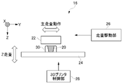
図2を参照して、3Dプリンタ16の構成について説明する。図2に示されるように3Dプリンタ16は、ヘッド部22、造形台24、走査駆動部26、及び3Dプリンタ制御部28を備える。
The configuration of the
ヘッド部22は、造形物20の材料となるUVインクを液滴として吐出する。なお、ヘッド部22は、各色(シアン(C),マゼンタ(M),イエロー(Y),ブラック(K)等)に対応する複数のインクジェットヘッド、UVインクを硬化させる紫外線光源、各層の上面を平坦化させる平坦化ローラ等を有する。また、ヘッド部22は、サポート層30を形成するためのサポート材を造形物20の周囲に吐出する。サポート層30とは、例えば、造形中の造形物20の外周を囲むことで造形物20を支持する積層構造物のことである。サポート層30は、造形物20の造形時において、必要に応じて造形され、造形の完了後に除去される。
The
造形台24は、造形中の造形物20を載置する平面状の部材であり、ヘッド部22が備えるインクジェットヘッドのUVインクの吐出口と対向する位置に配設される。また、造形台24は、少なくとも上面が積層方向に移動可能とされ、走査駆動部26によって駆動されることにより、造形物20の造形の進行に合わせて上面が移動する。なお、本実施形態の積層方向は、3Dプリンタ16において予め設定される主走査方向(図中のY方向)及び副走査方向(図中のY方向)と直交する方向(図中のZ方向)である。
The modeling table 24 is a flat member on which the
走査駆動部26は、に対して、造形物20に対してヘッド部22を相対的に移動(以下「走査動作」という。)させる駆動部である。走査駆動部26は、走査動作として、主走査動作(Y走査)、副走査動作(X走査)、及び積層方向走査(Z走査)をヘッド部22に行わせる。ここで、主走査動作とは、ヘッド部22を主走査方向(Y方向)へ移動しつつ、ヘッド部22からインクを吐出する動作である。
The
3Dプリンタ制御部28は、例えば3Dプリンタ16のCPU(Central Processing Unit)であり、3Dプリンタ16の各部を制御することにより、造形物20の造形動作を制御する。すなわち、3Dプリンタ制御部28は、外付けPC14から入力された3D造形データに基づいて3Dプリンタ16の各部を制御することで、UVインクを積層方向へ重ねると共に硬化させて造形物20を造形する。
The 3D
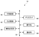
図3は、外付けPC14の電気的構成を示すブロック図である。外付けPC14は、主制御部40、主記憶部42、補助記憶部44、ディスプレイ46、操作部48、及び通信部50を備える。
FIG. 3 is a block diagram showing an electrical configuration of the
主制御部40は、例えば、CPUであり、外付けPC14の動作を制御する。
The
主記憶部42は、例えば、RAM(Random Access Memory)やDRAM(Dynamic Random Access Memory)等であり、主制御部40による各種プログラムに基づく処理の実行時のワークエリアや一時的にデータを記憶する記憶領域等として用いられる。補助記憶部44は、例えば、フラッシュメモリやHDD(Hard Disk Drive)等の不揮発性メモリであり、各種データ及び主制御部40の処理に利用されるプログラム等を保存する。補助記憶部44に記憶されるプログラムは、例えば、外付けPC14のOS(Operating System)、各種ハードウェア制御するためのドライバ等である。
The
ディスプレイ46は、例えばLCD(Liquid Crystal Display)等であり、主制御部40による処理に基づいて画像を表示する。操作部48は、外付けPC14に対して各種入力操作を行うものであり、例えば、タッチパネルやキーボード、マウス、タッチパッド、及びボタン等である。なお、ディスプレイ46及び操作部48は、3Dプリンタ16が備えるディスプレイや操作部と共用とされてもよい。
The
通信部50は、造形準備用PC12や3Dプリンタ16、その他の情報処理装置等とデータの送受信を行う機能を有する。すなわち、通信部50は、造形準備用PC12から3Dデータを受信し、3Dプリンタ16へ3D造形データを送信する。
The
これら主制御部40、主記憶部42、補助記憶部44、ディスプレイ46、操作部48、及び通信部50は、システムバス52を介して相互に電気的に接続されている。従って、主制御部40は、主記憶部42及び補助記憶部44へのアクセス、ディスプレイ46に対する画像の表示、操作部48に対する操作状態の把握、及び通信部50を介した造形準備用PC12や3Dプリンタ16、その他の情報処理装置へのアクセス等を行える。
The
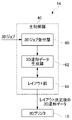
図4は、外付けPC14が有する3D造形データの生成に関する機能ブロック図である。外付けPC14の主制御部40は、3Dジョブ受付部60、3D造形データ生成部62、及びレイアウト部64を備える。主制御部40が備える各機能は、補助記憶部44に記憶されているプログラムによって実現される。
FIG. 4 is a functional block diagram relating to the generation of 3D modeling data possessed by the
3Dジョブ受付部60は、造形準備用PC12から通信部50を介して受信した3Dジョブを受け付け、一例として主記憶部42に記憶させる。
The 3D
3D造形データ生成部62は、3Dジョブに基づいて3D造形データを生成し、レイアウト部64へ出力する。なお、3D造形データ生成部62は、入力された3Dデータが多く、生成した3D造形データの入力をレイアウト部64が受け付けない場合には一時的に3D造形データを主記憶部42に記憶させる。
The 3D modeling
レイアウト部64は、3D造形データに基づいて、3Dプリンタ16の造形台24上で造形される造形物20の配置を決定する。そして、レイアウトが決定された3D造形データは、通信部50を介して3Dプリンタ16へ送信される。すなわち、レイアウト部64は、3D造形データに基づいた造形物20の造形に使用するインク量や造形時間等を算出する。そして、レイアウト部64は、使用インク量がより少なく、造形時間がより短くなるように造形台24上における造形物20の配置(以下「レイアウト」という。)を決定する。なお、使用インク量にはサポート材の量も含まれる。このため、レイアウト部64は、サポート材の量が少なくなるように、レイアウトとして造形時の造形物20の向きも決定する。
The
そして、本実施形態の外付けPC14は、造形データ結合機能を有する。造形データ結合機能は、3Dプリンタ16の造形可能領域に対して造形物20の造形が行われない余白領域を埋めるように、複数の3D造形データを結合して結合造形データを生成する機能である。なお、造形可能領域とは、換言すると、3Dプリンタ16が備える造形台24上において造形物20を造形可能な最大領域である。そして、余白領域は、造形可能領域に対して造形物20が造形されない領域である。なお、造形可能領域から余白領域を除いた領域は、造形物20の造形が行われる造形領域である。
The
本実施形態の造形データ結合機能は主としてレイアウト部64によって実行される。このため、レイアウト部64は、一例として、レイアウトが決定された3D造形データに基づいて余白領域及び造形領域の大きさを算出する。そして、余白領域の大きさが造形可能領域に対して所定値以上であった場合、余白領域を埋めるように、複数の3D造形データを結合して結合造形データを生成する。
The modeling data combination function of the present embodiment is mainly executed by the
より具体的には、レイアウト決定後の3D造形データの余白領域が所定値以上(例えば10%以上)であった場合、レイアウト部64は、他の3D造形データが主記憶部42に記憶されているか否かを3D造形データ生成部62に問い合わせる。すなわち、他の3D造形データは、未だレイアウト部64に出力されずに滞留している3Dジョブである。そして、他の3D造形データがある場合、レイアウト部64は、他の3D造形データの余白領域又は造形領域を判定する。そして、レイアウト部64は、先に入力されている3D造形データと結合させることで余白領域を埋めることが可能な他の3D造形データを選択し、先の3D造形データと結合させて結合造形データとし、3Dプリンタ16へ送信する。これにより、複数の3D造形データが一つの3D造形データとして扱われるので、3Dジョブの滞留が抑制される。従って、外付けPC14は、3Dプリンタ16により効率良く造形物20を造形させることができる。
More specifically, when the margin area of the 3D modeling data after the layout is determined is a predetermined value or more (for example, 10% or more), the
なお、余白領域を埋めるとは、レイアウト部64に先に入力された3D造形データの余白領域が小さくなるように、他の3D造形データの造形領域を結合させることであり、先の3D造形データの造形領域と他の3D造形データの造形領域の和は100%を超えない。
It should be noted that filling the margin area means combining the modeling areas of other 3D modeling data so that the margin area of the 3D modeling data previously input to the
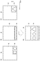
図5を参照して、造形データ結合機能について説明する。図5(A)~(D)は、3D造形データの模式図であり、造形台24上に造形物20が造形された場合の上面図(xy平面図)に相当する。図5において実線は造形物20に対応するデータを示し、破線は造形可能領域70を示し、一点鎖線は余白領域72を示し、二点鎖線は造形領域74を示す。なお、図5に示されるように余白領域72は、一例として、造形物20から一定以上の長さで離れて規定される矩形状とされ、同様に造形領域74は、造形物20から一定以上の長さで離れて囲むように規定される矩形状であるが、これに限らず、余白領域72及び造形領域74の規定の手法は他の手法でもよい。
The modeling data combination function will be described with reference to FIG. 5 (A) to 5 (D) are schematic views of 3D modeling data, and correspond to a top view (xy plan view) when the modeled
また、図5では、造形可能領域70と余白領域72と造形領域74との周囲が離間しているが、これは各々の領域が図面において明確に区別できるように便宜的に離間させているものである。実際には造形可能領域70、余白領域72、造形領域74の周囲は接しており、余白領域72と造形領域74の和は造形可能領域70となる。なお、図5の例では、3Dプリンタ16はヘッド部22を(X,Y)=(0,0)を原点として走査動作を行うことで、造形物20を造形する。
Further, in FIG. 5, the peripheries of the
図5(A)の3D造形データは、レイアウト部64に先に入力された3D造形データであり、余白領域72は造形可能領域70の80%であり、上記所定値(10%)よりも広い。このため、レイアウト部64は、他の3D造形データが存在する場合、他の3D造形データの余白領域72(造形領域74)を判定する。図5(B),(C)は、図5(A)の3D造形データと結合可能であると判定された他の3D造形データであり、各々の余白領域72は80%、換言すると造形領域74は20%である。このため、図5(B),(C)の3D造形データは、図5(A)の3D造形データと結合させることで、図5(A)3D造形データの余白領域72を埋めることができる。このようにして生成された結合造形データが図5(D)に示されるものであり、余白領域72は40%となっている。
The 3D modeling data in FIG. 5A is the 3D modeling data previously input to the
また、レイアウト部64は、余白領域72をより狭くできる3D造形データを選択して、結合造形データを生成する。例えば、余白領域72が80%の3D造形データに結合させる他の3D造形データとして、余白領域72が30%(造形領域74が70%)の3D造形データAと余白領域72が50%(造形領域74が50%)の3D造形データBが存在する場合、余白領域72がより狭い、換言すると造形領域74がより広い3D造形データAが選択される。
Further, the
また、本実施形態のレイアウト部64は、結合造形データにより示される複数の造形物20のレイアウトを所定条件(以下「レイアウト決定条件」という。)に基づいて決定する。レイアウト決定条件は、例えば、造形物20の造形順番、造形時間、及び造形物20の造形に用いられるサポート材の量の少なくとも一つである。なお、造形時間は、結合造形データにより示される複数の造形物20を全て造形するために要する時間である。これにより、ユーザの要望に応じた条件に適合した造形が可能となる。レイアウト決定条件は、一例として、ユーザによって選択される。なお、レイアウト決定条件は、上記の条件に限らず、他の条件が含まれてもよい。
Further, the
図6は、造形物20の造形順番をレイアウト決定条件とする場合の模式図である。図6に示される造形物20Aは図5(A)の造形物20に対応し、造形物20Bは図5(B)の造形物20に対応し、造形物20Cは図5(C)の造形物に対応する。上述したように、3Dプリンタ16は、(X,Y)=(0,0)を原点としてヘッド部22を走査して造形物20を造形する。従って、図6(A)に示す造形物20のレイアウトでは、造形物20A、造形物20B、造形物20Cの順番で造形が行われる。また、図6(B)の例では造形物20B、造形物20C、造形物20Aの順番で造形が行われ、図6(C)の例では造形物20A、造形物20C、造形物20Bの順番で造形が行われる。
FIG. 6 is a schematic diagram when the modeling order of the modeled
また、造形時間に基づいてレイアウトを決定する場合、一例として、レイアウト部64は想定される複数のレイアウトを導出し、各々について造形時間を算出して最も造形時間が短いレイアウトをユーザへ提示し、ユーザにレイアウトを選択させる。図6の例では、X方向へのヘッド部22の移動が最も大きい図6(A)のレイアウトが最も造形時間が長い一方、図6(B),(C)の造形時間が同じであるため、ユーザへは図6(B)又は図6(C)のレイアウトが造形時間の短いレイアウトであるとして提示される。また、レイアウト部64は、造形時間を短くするために造形物20が造形される向きを変えてもよい。例えば、Z方向へ縦長の造形物20を造形する3D造形データは、ヘッド部22のZ方向への移動量が大きくなるために造形時間が長くなる可能性がある。このような場合、レイアウト部64は、当該造形物20をX方向又はY方向へ倒すようにレイアウトすることでZ方向への移動量を小さくし、造形時間を短くしてもよい。
Further, when the layout is determined based on the modeling time, as an example, the
また、造形物20の造形に用いられるサポート材の量によってレイアウトを決定する場合、レイアウト部64は想定される複数のレイアウトを導出し、各々についてサポート材の量を算出し、サポート材の量が少ないレイアウトをユーザへ提示し、ユーザにレイアウトを選択させる。
Further, when the layout is determined by the amount of the support material used for modeling the modeled
さらに、結合造形データに設定される造形モードは、結合される複数の3D造形データのうち所定の3D造形データに設定されている造形モードとされる。なお、造形モードとは、造形物20を造形する場合における3Dプリンタ16の動作モードであり、例えば、造形精度が低い替わりに造形時間が短くなる短時間造形モードや、造形精度が高い替わりに造形時間が長くなる高精度造形モードである。そして、所定の3D造形データとは、例えば、最初に造形が完了する3D造形データや、ユーザが指定した3D造形データである。すなわち、最初に造形が完了する3D造形データに設定されている造形モードが短時間造形モードである場合、結合造形データの造形モードは短時間造形モードに設定される。これにより、結合造形データにより示される造形物20の造形モードが統一されるので、3Dプリンタ16は効率良く造形物を造形することができる。
Further, the modeling mode set in the combined modeling data is the modeling mode set in the predetermined 3D modeling data among the plurality of 3D modeling data to be combined. The modeling mode is an operation mode of the
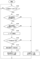
図7は、レイアウト部64で実行される造形データ結合処理の流れを示すフローチャートである。
FIG. 7 is a flowchart showing the flow of the modeling data combination process executed by the
まず、ステップS100では、3D造形データが入力されたか否かを判定し、肯定判定の場合はステップS102へ移行する一方、否定判定の場合は3D造形データが入力されるまで待ち状態となる。 First, in step S100, it is determined whether or not 3D modeling data has been input, and in the case of an affirmative determination, the process proceeds to step S102, while in the case of a negative determination, a waiting state is set until the 3D modeling data is input.
ステップS102では、入力された3D造形データに含まれる余白領域72が所定値以上であるか否かを判定し、肯定判定の場合はステップS104へ移行し、否定判定の場合はステップS114へ移行する。
In step S102, it is determined whether or not the
ステップS104では、結合可能な他の3D造形データがあるか否かを判定し、肯定判定の場合はステップS106へ移行し、否定判定の場合はステップS114へ移行する。 In step S104, it is determined whether or not there is other 3D modeling data that can be combined, and if a positive determination is made, the process proceeds to step S106, and if a negative determination is made, the process proceeds to step S114.
ステップS106では、3D造形データを結合可能であることをユーザへ報知する。この報知は、例えば外付けPC14又は3Dプリンタ16のディスプレイや3D造形データの元となる3Dデータを送信した造形準備用PC12になされてもよいし、予め定められたメールアドレスへメッセージが送信されることで報知されてもよい。また、この報知は、3D造形データの結合の了承をユーザから得ることも目的とする。
In step S106, the user is notified that the 3D modeling data can be combined. This notification may be sent to, for example, the display of the
次のステップS108では、ユーザによる結合了承の有無を判定し、肯定判定の場合はステップS110へ移行し、否定判定の場合はステップS114へ移行する。なお、ユーザは、結合を了承する場合、レイアウト決定条件も入力する。 In the next step S108, it is determined whether or not the user approves the combination, and in the case of an affirmative determination, the process proceeds to step S110, and in the case of a negative determination, the process proceeds to step S114. If the user approves the combination, the user also inputs the layout determination condition.
ステップS110では、ステップS100で入力された3D造形データとステップS104で判定(選択)した3D造形データを結合させて結合造形データを生成する。なお、ステップS110では、入力されたレイアウト決定条件に応じて結合造形データのレイアウトも決定する。 In step S110, the 3D modeling data input in step S100 and the 3D modeling data determined (selected) in step S104 are combined to generate combined modeling data. In step S110, the layout of the combined modeling data is also determined according to the input layout determination conditions.
次のステップS112では、レイアウトが決定された結合造形データを、通信部50を介して3Dプリンタ16へ送信し、ステップS100へ戻る。
In the next step S112, the combined modeling data whose layout is determined is transmitted to the
一方、ステップS102,S104,S108で否定判定となった場合に移行するステップS114では、結合造形データを生成することなく、ステップS100でレイアウト部64に入力された3D造形データを、通信部50を介して3Dプリンタ16へ送信し、ステップS100へ戻る。
On the other hand, in step S114, which shifts to the case where a negative determination is made in steps S102, S104, and S108, the 3D modeling data input to the
また、レイアウト部64は、3D造形データを複数の3D造形データに分割させる分割機能を有している。この分割機能は、造形物20を複数に分割して造形可能な場合に機能するものである。例えば、3D造形データにより示される造形物20が大き過ぎて造形台24に載置できない場合、すなわち造形される造形物20の大きさが造形可能領域70を超える場合、レイアウト部64は当該3D造形データを複数の造形データに分割し、3Dプリンタ16へ送信する。なお、3D造形データを分割可能か否かは、例えば、レイアウト部64が3D造形データを解析することにより判定されてもよいし、3Dデータの作成時に分割可能な部分が予め設定されることにより判定されてもよい。
Further, the
そして、レイアウト部64が有する造形データ結合機能は、分割可能に設定されている3D造形データを複数に分割し、複数に分割した3D造形データをも含んで、余白領域72を埋める3D造形データを選択し、複数の3D造形データを結合して結合造形データを生成してもよい。より詳しくは、レイアウト部64に所定値以上の余白領域72を有する3D造形データが入力され、滞留している他の3D造形データに分割可能な3D造形データが含まれている場合に当該3D造形データを分割する。そして、造形データ結合機能は、分割した3D造形データを含む複数の3D造形データの中からレイアウト部64に入力された3D造形データと結合させる3D造形データを選択し、造形結合データを生成する。これにより、造形データ結合機能は、3Dプリンタ16により効率良く造形物20を造形させることができる。
Then, the modeling data combination function of the
また、レイアウト部64は、複数に分割した3D造形データのうち、最後に3Dプリンタ16へ送信される3D造形データをレイアウトする場合、当該3D造形データの余白領域72を埋めるように他の3D造形データを結合させてもよい。
Further, when the
さらに、レイアウト部64は、3Dプリンタ16へ送信したものの未だ造形が行われていない3D造形データも含んで、余白領域72を埋めるように3D造形データを選択し、複数の3D造形データを結合して結合造形データを生成してもよい。これにより、造形データ結合機能は、3Dプリンタ16により効率良く造形物20を造形させることができる。
Further, the
より具体的には、3Dプリンタ16は3D造形データを一つずつ処理していくため、送信されたものの未だ処理が行われていない3D造形データが3Dプリンタ16に記憶されている場合がある。そこで、レイアウト部64に入力された3D造形データに所定値以上の余白領域72がある場合、レイアウト部64は、3Dプリンタ16に送信済みで未だ造形が行われていない3D造形データを3Dプリンタ16から読み出して、結合可能であるか否かを判定し、結合可能であれば結合造形データを生成する。
More specifically, since the
なお、3Dプリンタ16に送信済みの3D造形データを結合して結合造形データを生成する場合、レイアウト部64は、当該送信済みの3D造形データにより示される造形物20が先に造形されるようにレイアウトを決定する。
When the combined 3D modeling data is combined with the
(第2実施形態)
以下、本発明の第2実施形態について説明する。なお、第2実施形態の構成のうち第1実施形態の構成と同一の部分については同一の符号を付して、その説明を省略する。
(Second Embodiment)
Hereinafter, a second embodiment of the present invention will be described. Of the configurations of the second embodiment, the same parts as those of the first embodiment are designated by the same reference numerals, and the description thereof will be omitted.
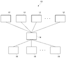
図8は、本実施形態の3D造形システム10の構成を示す。図8に示される本実施形態の3D造形システム10は、一つの外付けPC14と複数の3Dプリンタ16とがデータ通信可能に接続される。
FIG. 8 shows the configuration of the
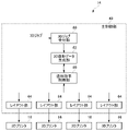
図9は、本実施形態の造形データ結合機能に関する機能ブロック図である。主制御部40は、3Dジョブ受付部60、3D造形データ生成部62、及びレイアウト部64に加え、造形指示制御部80を備える。また、レイアウト部64は、3Dプリンタ16毎に対応して備えられる。
FIG. 9 is a functional block diagram relating to the modeling data combination function of the present embodiment. The
造形指示制御部80は、3D造形システム10に設けられる各3Dプリンタ16の能力、稼働状態、及びインクの残量等を3Dプリンタ情報として把握する。なお、3Dプリンタ16の能力とは、例えば、積層ピッチ間隔や再現可能な色等であり、稼働状態とは、各3Dプリンタ16が稼働中であるか否か、3Dプリンタに送信されている3D造形データの数及びその造形時間等である。造形指示制御部80は、3Dプリンタ情報に基づいて3D造形データ毎に適した3Dプリンタ16を選択し、選択した3Dプリンタ16に対応するレイアウト部64に3D造形データを出力する。例えば、3D造形データが高い解像度の造形機能を必要としている場合、造形指示制御部80は、積層ピッチ間隔の小さい3Dプリンタ16に対応するレイアウト部64に当該3D造形データを出力する。また、例えば、造形指示制御部80は、稼働していない3Dプリンタ16に対応するレイアウト部64に対して優先的に3D造形データを出力する。
The modeling
本実施形態のレイアウト部64は、入力された3D造形データに所定値以上の余白領域72がある場合、造形指示制御部80を介して3D造形データ生成部62に他の3D造形データの有無を問い合わせる。そして、対応する3Dプリンタ16で造形可能な他の3D造形データが存在する場合に、レイアウト部64は、先に入力された3D造形データの余白領域72を埋めるように他の3D造形データを結合して結合造形データを生成する。
When the
(第3実施形態)
以下、本発明の第3実施形態について説明する。本実施形態の3D造形システム10は、第2実施形態と同様に一つの外付けPC14と複数の3Dプリンタ16とがデータ通信可能に接続される。なお、第3実施形態の構成のうち第1実施形態及び第2実施形態の構成と同一の部分については同一の符号を付して、その説明を省略する。
(Third Embodiment)
Hereinafter, a third embodiment of the present invention will be described. In the
図10は、本実施形態の造形データ結合機能に関する機能ブロック図である。主制御部40は、3Dジョブ受付部60、3D造形データ生成部62、レイアウト部64、造形指示制御部80を備える。また、レイアウト部64は、複数の3Dプリンタ16に対して一つが備えられ、造形指示制御部80を介して3Dプリンタ16へ3D造形データを送信する。
FIG. 10 is a functional block diagram relating to the modeling data combination function of the present embodiment. The
レイアウト部64は、3D造形データ生成部62から入力される3D造形データに対してインク使用量や造形時間に基づいてレイアウトを決定し、造形指示制御部80に出力する。造形指示制御部80は、入力された3D造形データに対して適した3Dプリンタ16を選択し、選択した3Dプリンタ16へ3D造形データを送信する。
The
造形指示制御部80は、適した3Dプリンタ16へ送信する3D造形データに所定値以上の余白領域72がある場合、レイアウト部64にレイアウトの変更要求を送る。レイアウト部64は、レイアウトの変更要求を受け付けると、当該3D造形データと結合可能な他の3D造形データの有無を判定し、結合可能な他の3D造形データがある場合に結合造形データを作成し、造形指示制御部80へ出力する。造形指示制御部80は、適した3Dプリンタ16へ結合造形データを送信する。
When the 3D modeling data to be transmitted to the
以上、本発明を、上記各実施形態を用いて説明したが、本発明の技術的範囲は上記各実施形態に記載の範囲には限定されない。発明の要旨を逸脱しない範囲で上記各実施形態に多様な変更又は改良を加えることができ、該変更又は改良を加えた形態も本発明の技術的範囲に含まれる。また、上記各実施形態を適宜組み合わせてもよい。 Although the present invention has been described above using each of the above embodiments, the technical scope of the present invention is not limited to the scope described in each of the above embodiments. Various changes or improvements can be made to each of the above embodiments without departing from the gist of the invention, and the modified or improved embodiments are also included in the technical scope of the present invention. In addition, each of the above embodiments may be combined as appropriate.
また、上記各実施形態で説明した処理の流れも一例であり、本発明の主旨を逸脱しない範囲内において不要なステップを削除したり、新たなステップを追加したり、処理順序を入れ替えたりしてもよい。 Further, the processing flow described in each of the above embodiments is also an example, and unnecessary steps are deleted, new steps are added, or the processing order is changed within a range that does not deviate from the gist of the present invention. May be good.
(実施の形態の効果)
(1)本実施形態の外付けPC14は、3Dプリンタ16によって造形される造形物20を示す3Dデータが3Dジョブ毎に入力される外付けPC14であって、3Dジョブに基づいて造形データを生成する3D造形データ生成部62と、3Dプリンタ16の造形可能領域70に対して造形物20の造形が行われない余白領域72を埋めるように、複数の造形データを結合して結合造形データを生成するレイアウト部64と、結合造形データを3Dプリンタ16へ送信する通信部50と、を備える。
(Effect of embodiment)
(1) The
この構成により外付けPC14は、造形物20を示す3Dデータが含まれる3Dジョブに基づいて造形データを生成し、造形可能領域70に対する余白領域72を埋めるように、複数の造形データを結合して結合造形データを生成する。そして、結合造形データに応じて3Dプリンタ16が造形物20を造形する。これにより、複数の造形データが一つの造形データとして扱われるので、3Dジョブの滞留が抑制される。したがって、本発明の外付けPC14は、3Dプリンタ16により効率良く造形物20を造形させることができる。
With this configuration, the
(2)本実施形態の外付けPC14は、レイアウト部64が余白領域72をより狭くできる造形データを選択し、複数の造形データを結合して結合造形データを生成してもよい。本構成によれば、3Dプリンタ16により効率良く造形物20を造形させることができる。
(2) In the
(3)本実施形態の外付けPC14は、レイアウト部64が結合造形データにより示される造形物20の配置を所定条件に基づいて決定してもよい。本構成によれば、ユーザの要望に応じた条件に適合した造形を行える。
(3) In the
(4)本実施形態の外付けPC14は、所定条件を造形物20の造形順番、造形時間、及び造形物20の造形に用いられるサポート材の少なくとも一つとしてもよい。本構成によれば、ユーザの要望に応じた条件に適合した造形を行える。
(4) The
(5)本実施形態の外付けPC14は、結合造形データに設定される造形モードを、結合される複数の造形データのうち所定の造形データに設定されているモードとしてもよい。本構成によれば、結合造形データで示される造形物20の造形モードが統一されるので、3Dプリンタ16は効率良く造形物20を造形することができる。
(5) In the
(6)本実施形態の外付けPC14は、レイアウト部64が造形データを複数に分割し、複数に分割した造形データも含んで、余白領域72を埋めるように造形データを選択し、複数の造形データを結合して結合造形データを生成してもよい。本構成によれば、3Dプリンタ16により効率良く造形物20を造形させることができる。
(6) In the
(7)本実施形態の外付けPC14は、レイアウト部64が3Dプリンタ16へ送信したものの未だ造形が行われていない造形データも含んで、余白領域72を埋めるように造形データを選択し、複数の造形データを結合して結合造形データを生成してもよい。本構成によれば、3Dプリンタ16により効率良く造形物20を造形させることができる。
(7) The
(8)本実施形態の造形データ結合方法は、3Dプリンタ16によって造形される造形物20を示す3Dデータが3Dジョブ毎に入力される外付けPC14の造形データ結合方法であって、3Dジョブに基づいて造形データを生成する第1工程と、3Dプリンタ16の造形可能領域70に対して造形物20の造形が行われない余白領域72を埋めるように、複数の造形データを結合して結合造形データを生成する第2工程と、結合造形データを3Dプリンタ16へ送信する第3工程と、を有する。
(8) The modeling data combining method of the present embodiment is a modeling data combining method of the
(9)本実施形態の造形データ結合プログラムは、3Dプリンタ16によって造形される造形物20を示す3Dデータが3Dジョブ毎に入力される外付けPC14が有する主制御部40を、3Dジョブに基づいて造形データを生成する3D造形データ生成部62と、3Dプリンタ16の造形可能領域70に対して造形物20の造形が行われない余白領域72を埋めるように、複数の造形データを結合して結合造形データを生成するレイアウト部64と、結合造形データを3Dプリンタ16へ送信する通信部50と、して機能させる。
(9) In the modeling data combination program of the present embodiment, the
本発明は、立体的な造形物を造形する造形装置等の情報処理装置として有用である。 The present invention is useful as an information processing device such as a modeling device for modeling a three-dimensional modeled object.
14 外付けPC(造形装置用情報処理装置)
16 3Dプリンタ(造形装置)
50 通信部(送信手段)
62 3D造形データ生成部(造形データ生成手段)
64 レイアウト部(造形データ結合手段)
14 External PC (information processing device for modeling equipment)
16 3D printer (modeling device)
50 Communication unit (transmission means)
62 3D modeling data generation unit (modeling data generation means)
64 Layout section (modeling data combination means)
Claims (10)
前記ジョブに基づいて造形データを生成する造形データ生成手段と、
前記造形装置の造形可能領域に対して前記造形物の造形が行われない余白領域を埋めるように、複数の前記造形データを結合して前記造形物のレイアウトを示す結合造形データを生成する造形データ結合手段と、
前記結合造形データを前記造形装置へ送信する送信手段と、
を備え、
前記造形データは、造形中の前記造形物の外周を囲むことで造形物を支持するサポート材の造形データを含み、
前記サポート材は、造形の完了後に除去されるものであり、
前記造形データ結合手段は、想定される複数の前記レイアウトを導出し、各々について前記サポート材を形成する材料の量を算出す る造形装置用情報処理装置。 An information processing device for a modeling device in which three-dimensional data indicating a modeled object to be modeled by the modeling device is input for each job.
A modeling data generation means that generates modeling data based on the job,
A plurality of the modeling data are combined so as to fill a margin area in which the modeling object is not modeled with respect to the modelable area of the modeling device.The layout of the modeled object is shown.Forming data combining means to generate combined modeling data,
A transmission means for transmitting the combined modeling data to the modeling device, and
Equipped with,
The modeling data includes modeling data of a support material that supports the modeled object by surrounding the outer periphery of the modeled object during modeling.
The support material is removed after the modeling is completed.
The modeling data coupling means derives a plurality of expected layouts and calculates the amount of material forming the support material for each of them. Information processing equipment for modeling equipment.
前記ジョブに基づいて造形データを生成する第1工程と、
前記造形装置の造形可能領域に対して前記造形物の造形が行われない余白領域を埋めるように、複数の前記造形データを結合して前記造形物のレイアウトを示す結合造形データを生成する第2工程と、
前記結合造形データを前記造形装置へ送信する第3工程と、
を有し、
前記造形データは、造形中の前記造形物の外周を囲むことで造形物を支持するサポート材の造形データを含み、
前記サポート材は、造形の完了後に除去されるものであり、
前記第2工程において、想定される複数の前記レイアウトを導出し、各々について前記サポート材を形成する材料の量を算出する造形データ結合方法。 It is a modeling data combination method of an information processing device for a modeling device in which three-dimensional data indicating a modeled object to be modeled by the modeling device is input for each job.
The first step of generating modeling data based on the job,
A plurality of the modeling data are combined so as to fill a margin area in which the modeling object is not modeled with respect to the modelable area of the modeling device.The layout of the modeled object is shown.The second step of generating combined modeling data,
A third step of transmitting the combined modeling data to the modeling apparatus, and
Havedeath,
The modeling data includes modeling data of a support material that supports the modeled object by surrounding the outer periphery of the modeled object during modeling.
The support material is removed after the molding is completed.
In the second step, a plurality of assumed layouts are derived, and the amount of the material forming the support material is calculated for each of them.How to combine modeling data.
前記ジョブに基づいて造形データを生成する造形データ生成手段と、
前記造形装置の造形可能領域に対して前記造形物の造形が行われない余白領域を埋めるように、複数の前記造形データを結合して前記造形物のレイアウトを示す結合造形データを生成する造形データ結合手段と、
前記結合造形データを前記造形装置へ送信する送信手段と、
して機能させるための造形データ結合プログラムであって、
前記造形データは、造形中の前記造形物の外周を囲むことで造形物を支持するサポート材の造形データを含み、
前記サポート材は、造形の完了後に除去されるものであり、
想定される複数の前記レイアウトを導出し、各々について前記サポート材を形成する材料の量を算出する 造形データ結合プログラム。 A computer owned by an information processing device for a modeling device, in which three-dimensional data indicating a modeled object to be modeled by the modeling device is input for each job.
A modeling data generation means that generates modeling data based on the job, and
A plurality of the modeling data are combined so as to fill a margin area in which the modeling object is not modeled with respect to the modelable area of the modeling device.The layout of the modeled object is shown.Forming data combining means to generate combined modeling data,
A transmission means for transmitting the combined modeling data to the modeling apparatus, and
To make it workIt is a modeling data combination program
The modeling data includes modeling data of a support material that supports the modeled object by surrounding the outer periphery of the modeled object during modeling.
The support material is removed after the molding is completed.
Derive a plurality of assumed layouts and calculate the amount of material forming the support material for each. Modeling data combination program.
Priority Applications (2)
| Application Number | Priority Date | Filing Date | Title |
|---|---|---|---|
| JP2018224553A JP7100570B2 (en) | 2018-11-30 | 2018-11-30 | Information processing equipment for modeling equipment, modeling data combination method and modeling data combination program |
| US16/689,093 US11693389B2 (en) | 2018-11-30 | 2019-11-20 | Information processing device for shaping device, shaping data combining method, and shaping data combining program |
Applications Claiming Priority (1)
| Application Number | Priority Date | Filing Date | Title |
|---|---|---|---|
| JP2018224553A JP7100570B2 (en) | 2018-11-30 | 2018-11-30 | Information processing equipment for modeling equipment, modeling data combination method and modeling data combination program |
Publications (2)
| Publication Number | Publication Date |
|---|---|
| JP2020082648A JP2020082648A (en) | 2020-06-04 |
| JP7100570B2 true JP7100570B2 (en) | 2022-07-13 |
Family
ID=70848672
Family Applications (1)
| Application Number | Title | Priority Date | Filing Date |
|---|---|---|---|
| JP2018224553A Active JP7100570B2 (en) | 2018-11-30 | 2018-11-30 | Information processing equipment for modeling equipment, modeling data combination method and modeling data combination program |
Country Status (2)
| Country | Link |
|---|---|
| US (1) | US11693389B2 (en) |
| JP (1) | JP7100570B2 (en) |
Families Citing this family (2)
| Publication number | Priority date | Publication date | Assignee | Title |
|---|---|---|---|---|
| JP2022084528A (en) * | 2020-11-26 | 2022-06-07 | 株式会社リコー | Management system and management device |
| EP4006672A1 (en) * | 2020-11-26 | 2022-06-01 | Ricoh Company, Ltd. | Management system and management apparatus |
Citations (2)
| Publication number | Priority date | Publication date | Assignee | Title |
|---|---|---|---|---|
| JP2017047538A (en) | 2015-08-31 | 2017-03-09 | 株式会社リコー | Control system, information processing apparatus, modeling system, and program |
| JP2018039262A (en) | 2016-08-31 | 2018-03-15 | キヤノン株式会社 | Data processor, shaping device, data processing method, program, storage medium, and three-dimensional article manufacturing method |
Family Cites Families (12)
| Publication number | Priority date | Publication date | Assignee | Title |
|---|---|---|---|---|
| JP4732029B2 (en) * | 2005-06-29 | 2011-07-27 | キヤノン株式会社 | Layout determining method, information processing apparatus, and layout determining program |
| US8515826B2 (en) * | 2006-05-18 | 2013-08-20 | Bryan C. Norman | Made-to-order direct digital manufacturing enterprise |
| JP4436851B2 (en) * | 2007-05-22 | 2010-03-24 | シャープ株式会社 | Printer driver program and image forming apparatus |
| US9495484B2 (en) * | 2012-09-18 | 2016-11-15 | Autodesk, Llp | Nesting using rigid body simulation |
| US9636871B2 (en) * | 2013-08-21 | 2017-05-02 | Microsoft Technology Licensing, Llc | Optimizing 3D printing using segmentation or aggregation |
| KR101944737B1 (en) * | 2014-08-14 | 2019-02-01 | 삼성에스디에스 주식회사 | Apparatus and method for control of three-dimensional printing |
| JP6383488B2 (en) * | 2014-08-29 | 2018-08-29 | ヒューレット−パッカード デベロップメント カンパニー エル.ピー.Hewlett‐Packard Development Company, L.P. | Generation of 3D objects |
| US10518473B2 (en) * | 2015-07-31 | 2019-12-31 | Hewlett-Packard Development Company, L.P. | Parts arrangement determination for a 3D printer build envelope |
| JP2017109478A (en) | 2015-12-14 | 2017-06-22 | 株式会社リコー | Information processing apparatus, 3D printer system, information processing method, and computer program |
| US11325313B2 (en) * | 2017-04-26 | 2022-05-10 | Hewlett-Packard Development Company, L.P. | Assigning object generation tasks |
| EP3681701A4 (en) * | 2018-01-19 | 2021-05-05 | Hewlett-Packard Development Company, L.P. | 3D PRINTING PART PLACEMENT |
| US11914932B2 (en) * | 2018-04-27 | 2024-02-27 | Hewlett-Packard Development Company, L.P. | User-assisted parts packing optimization |
-
2018
- 2018-11-30 JP JP2018224553A patent/JP7100570B2/en active Active
-
2019
- 2019-11-20 US US16/689,093 patent/US11693389B2/en active Active
Patent Citations (2)
| Publication number | Priority date | Publication date | Assignee | Title |
|---|---|---|---|---|
| JP2017047538A (en) | 2015-08-31 | 2017-03-09 | 株式会社リコー | Control system, information processing apparatus, modeling system, and program |
| JP2018039262A (en) | 2016-08-31 | 2018-03-15 | キヤノン株式会社 | Data processor, shaping device, data processing method, program, storage medium, and three-dimensional article manufacturing method |
Also Published As
| Publication number | Publication date |
|---|---|
| JP2020082648A (en) | 2020-06-04 |
| US20200174450A1 (en) | 2020-06-04 |
| US11693389B2 (en) | 2023-07-04 |
Similar Documents
| Publication | Publication Date | Title |
|---|---|---|
| JP7040236B2 (en) | 3D shape data editing device, 3D modeling device, 3D modeling system, and 3D shape data editing program | |
| JP5615667B2 (en) | Setting data creation device for 3D modeling apparatus, setting data creation method for 3D modeling apparatus, setting data creation program for 3D modeling apparatus, and computer-readable recording medium | |
| US11048232B2 (en) | Three-dimensional data generating apparatus, recording medium, and method using a curve indicating a relationship between height and distance | |
| US8643897B2 (en) | Image processing device, image processing method, and image processing program | |
| KR20160112482A (en) | 3d printer | |
| US8675254B2 (en) | Image processing device, image processing method and program for same, and printing system | |
| JP7100570B2 (en) | Information processing equipment for modeling equipment, modeling data combination method and modeling data combination program | |
| JP6714102B2 (en) | Data converter and additive manufacturing system | |
| EP3323593A1 (en) | Method for printing colored object by 3d printer | |
| EP3530436A1 (en) | Molding system, molding method, method for manufacturing molded object, and molded object | |
| WO2017069245A1 (en) | Shaping system, method for controlling shaping operation, shaping control device, and program | |
| JP2019098736A (en) | Slice method of color 3d object, renewal method of slice data, and printing system using slice data | |
| JP2017109320A (en) | Information processing device, 3d printer system, information processing method, and computer program | |
| US8643898B2 (en) | Device, method, system, and computer program product for determining amount of ink to be formed in a region of a medium based on a computed deformation ratio | |
| JP2016173730A (en) | Program, information processing apparatus, and progress display method | |
| JP2015217538A (en) | 3D modeling apparatus, 3D modeling method, and program | |
| US10518479B2 (en) | Three-dimensional object modeling device, method of molding three-dimensional object, and control program for three-dimensional object modeling device | |
| CN108274735B (en) | Layer-cutting printing method for multicolor 3D object | |
| JP2017094587A (en) | 3D modeling equipment | |
| US20180281290A1 (en) | Three-dimensional object modeling device, method of molding three-dimensional object, and control program for three-dimensional object modeling device | |
| JP2002251209A (en) | Data processor, data processing method, recording medium and its program | |
| JP6532378B2 (en) | Modeling system, control method of modeling operation, modeling control apparatus, and program | |
| US20180281291A1 (en) | 3d object forming device and 3d object forming method | |
| JP2016068552A (en) | Printing apparatus and printing method | |
| JP5673154B2 (en) | Image processing apparatus, image processing method, and program thereof |
Legal Events
| Date | Code | Title | Description |
|---|---|---|---|
| A621 | Written request for application examination |
Free format text: JAPANESE INTERMEDIATE CODE: A621 Effective date: 20210628 |
|
| A977 | Report on retrieval |
Free format text: JAPANESE INTERMEDIATE CODE: A971007 Effective date: 20220411 |
|
| A131 | Notification of reasons for refusal |
Free format text: JAPANESE INTERMEDIATE CODE: A131 Effective date: 20220419 |
|
| A521 | Request for written amendment filed |
Free format text: JAPANESE INTERMEDIATE CODE: A523 Effective date: 20220617 |
|
| TRDD | Decision of grant or rejection written | ||
| A01 | Written decision to grant a patent or to grant a registration (utility model) |
Free format text: JAPANESE INTERMEDIATE CODE: A01 Effective date: 20220628 |
|
| A61 | First payment of annual fees (during grant procedure) |
Free format text: JAPANESE INTERMEDIATE CODE: A61 Effective date: 20220701 |
|
| R150 | Certificate of patent or registration of utility model |
Ref document number: 7100570 Country of ref document: JP Free format text: JAPANESE INTERMEDIATE CODE: R150 |
|
| R250 | Receipt of annual fees |
Free format text: JAPANESE INTERMEDIATE CODE: R250 |