JP7099970B2 - Vehicle control device - Google Patents
Vehicle control device Download PDFInfo
- Publication number
- JP7099970B2 JP7099970B2 JP2019021799A JP2019021799A JP7099970B2 JP 7099970 B2 JP7099970 B2 JP 7099970B2 JP 2019021799 A JP2019021799 A JP 2019021799A JP 2019021799 A JP2019021799 A JP 2019021799A JP 7099970 B2 JP7099970 B2 JP 7099970B2
- Authority
- JP
- Japan
- Prior art keywords
- steering
- reaction force
- vehicle
- control
- driver
- Prior art date
- Legal status (The legal status is an assumption and is not a legal conclusion. Google has not performed a legal analysis and makes no representation as to the accuracy of the status listed.)
- Active
Links
- 238000006243 chemical reaction Methods 0.000 claims description 161
- 238000012544 monitoring process Methods 0.000 claims description 20
- 230000004044 response Effects 0.000 claims description 12
- 238000000418 atomic force spectrum Methods 0.000 description 39
- 238000001514 detection method Methods 0.000 description 35
- 230000007704 transition Effects 0.000 description 19
- 230000009471 action Effects 0.000 description 17
- 230000006870 function Effects 0.000 description 16
- 238000000034 method Methods 0.000 description 16
- 238000004891 communication Methods 0.000 description 14
- 230000007246 mechanism Effects 0.000 description 14
- 238000010586 diagram Methods 0.000 description 12
- 230000001133 acceleration Effects 0.000 description 11
- 230000008859 change Effects 0.000 description 10
- 230000002093 peripheral effect Effects 0.000 description 8
- 230000008569 process Effects 0.000 description 7
- 230000001052 transient effect Effects 0.000 description 5
- 230000005540 biological transmission Effects 0.000 description 4
- 230000010365 information processing Effects 0.000 description 3
- 238000013459 approach Methods 0.000 description 2
- 230000004888 barrier function Effects 0.000 description 2
- 230000007423 decrease Effects 0.000 description 2
- 230000008030 elimination Effects 0.000 description 2
- 238000003379 elimination reaction Methods 0.000 description 2
- 238000012545 processing Methods 0.000 description 2
- 208000019901 Anxiety disease Diseases 0.000 description 1
- 230000003044 adaptive effect Effects 0.000 description 1
- 238000004458 analytical method Methods 0.000 description 1
- 230000036506 anxiety Effects 0.000 description 1
- 230000001413 cellular effect Effects 0.000 description 1
- 238000002485 combustion reaction Methods 0.000 description 1
- 238000012937 correction Methods 0.000 description 1
- 230000000694 effects Effects 0.000 description 1
- 238000005401 electroluminescence Methods 0.000 description 1
- 230000008921 facial expression Effects 0.000 description 1
- 238000003384 imaging method Methods 0.000 description 1
- 230000010354 integration Effects 0.000 description 1
- 239000004973 liquid crystal related substance Substances 0.000 description 1
- 238000012423 maintenance Methods 0.000 description 1
- 238000012806 monitoring device Methods 0.000 description 1
- 238000002360 preparation method Methods 0.000 description 1
- 230000001172 regenerating effect Effects 0.000 description 1
- 239000004065 semiconductor Substances 0.000 description 1
- 238000000926 separation method Methods 0.000 description 1
- 230000003313 weakening effect Effects 0.000 description 1
Images


Classifications
-
- B—PERFORMING OPERATIONS; TRANSPORTING
- B62—LAND VEHICLES FOR TRAVELLING OTHERWISE THAN ON RAILS
- B62D—MOTOR VEHICLES; TRAILERS
- B62D15/00—Steering not otherwise provided for
- B62D15/02—Steering position indicators ; Steering position determination; Steering aids
- B62D15/025—Active steering aids, e.g. helping the driver by actively influencing the steering system after environment evaluation
-
- B—PERFORMING OPERATIONS; TRANSPORTING
- B62—LAND VEHICLES FOR TRAVELLING OTHERWISE THAN ON RAILS
- B62D—MOTOR VEHICLES; TRAILERS
- B62D6/00—Arrangements for automatically controlling steering depending on driving conditions sensed and responded to, e.g. control circuits
- B62D6/008—Control of feed-back to the steering input member, e.g. simulating road feel in steer-by-wire applications
-
- B—PERFORMING OPERATIONS; TRANSPORTING
- B60—VEHICLES IN GENERAL
- B60W—CONJOINT CONTROL OF VEHICLE SUB-UNITS OF DIFFERENT TYPE OR DIFFERENT FUNCTION; CONTROL SYSTEMS SPECIALLY ADAPTED FOR HYBRID VEHICLES; ROAD VEHICLE DRIVE CONTROL SYSTEMS FOR PURPOSES NOT RELATED TO THE CONTROL OF A PARTICULAR SUB-UNIT
- B60W30/00—Purposes of road vehicle drive control systems not related to the control of a particular sub-unit, e.g. of systems using conjoint control of vehicle sub-units, or advanced driver assistance systems for ensuring comfort, stability and safety or drive control systems for propelling or retarding the vehicle
- B60W30/10—Path keeping
- B60W30/12—Lane keeping
-
- B—PERFORMING OPERATIONS; TRANSPORTING
- B60—VEHICLES IN GENERAL
- B60W—CONJOINT CONTROL OF VEHICLE SUB-UNITS OF DIFFERENT TYPE OR DIFFERENT FUNCTION; CONTROL SYSTEMS SPECIALLY ADAPTED FOR HYBRID VEHICLES; ROAD VEHICLE DRIVE CONTROL SYSTEMS FOR PURPOSES NOT RELATED TO THE CONTROL OF A PARTICULAR SUB-UNIT
- B60W50/00—Details of control systems for road vehicle drive control not related to the control of a particular sub-unit, e.g. process diagnostic or vehicle driver interfaces
- B60W50/08—Interaction between the driver and the control system
- B60W50/10—Interpretation of driver requests or demands
-
- B—PERFORMING OPERATIONS; TRANSPORTING
- B60—VEHICLES IN GENERAL
- B60W—CONJOINT CONTROL OF VEHICLE SUB-UNITS OF DIFFERENT TYPE OR DIFFERENT FUNCTION; CONTROL SYSTEMS SPECIALLY ADAPTED FOR HYBRID VEHICLES; ROAD VEHICLE DRIVE CONTROL SYSTEMS FOR PURPOSES NOT RELATED TO THE CONTROL OF A PARTICULAR SUB-UNIT
- B60W50/00—Details of control systems for road vehicle drive control not related to the control of a particular sub-unit, e.g. process diagnostic or vehicle driver interfaces
- B60W50/08—Interaction between the driver and the control system
- B60W50/14—Means for informing the driver, warning the driver or prompting a driver intervention
- B60W50/16—Tactile feedback to the driver, e.g. vibration or force feedback to the driver on the steering wheel or the accelerator pedal
-
- B—PERFORMING OPERATIONS; TRANSPORTING
- B60—VEHICLES IN GENERAL
- B60W—CONJOINT CONTROL OF VEHICLE SUB-UNITS OF DIFFERENT TYPE OR DIFFERENT FUNCTION; CONTROL SYSTEMS SPECIALLY ADAPTED FOR HYBRID VEHICLES; ROAD VEHICLE DRIVE CONTROL SYSTEMS FOR PURPOSES NOT RELATED TO THE CONTROL OF A PARTICULAR SUB-UNIT
- B60W60/00—Drive control systems specially adapted for autonomous road vehicles
- B60W60/001—Planning or execution of driving tasks
-
- B—PERFORMING OPERATIONS; TRANSPORTING
- B62—LAND VEHICLES FOR TRAVELLING OTHERWISE THAN ON RAILS
- B62D—MOTOR VEHICLES; TRAILERS
- B62D15/00—Steering not otherwise provided for
- B62D15/02—Steering position indicators ; Steering position determination; Steering aids
- B62D15/025—Active steering aids, e.g. helping the driver by actively influencing the steering system after environment evaluation
- B62D15/0255—Automatic changing of lane, e.g. for passing another vehicle
-
- B—PERFORMING OPERATIONS; TRANSPORTING
- B60—VEHICLES IN GENERAL
- B60W—CONJOINT CONTROL OF VEHICLE SUB-UNITS OF DIFFERENT TYPE OR DIFFERENT FUNCTION; CONTROL SYSTEMS SPECIALLY ADAPTED FOR HYBRID VEHICLES; ROAD VEHICLE DRIVE CONTROL SYSTEMS FOR PURPOSES NOT RELATED TO THE CONTROL OF A PARTICULAR SUB-UNIT
- B60W2420/00—Indexing codes relating to the type of sensors based on the principle of their operation
- B60W2420/40—Photo or light sensitive means, e.g. infrared sensors
- B60W2420/403—Image sensing, e.g. optical camera
-
- B60W2420/408—
-
- B—PERFORMING OPERATIONS; TRANSPORTING
- B60—VEHICLES IN GENERAL
- B60W—CONJOINT CONTROL OF VEHICLE SUB-UNITS OF DIFFERENT TYPE OR DIFFERENT FUNCTION; CONTROL SYSTEMS SPECIALLY ADAPTED FOR HYBRID VEHICLES; ROAD VEHICLE DRIVE CONTROL SYSTEMS FOR PURPOSES NOT RELATED TO THE CONTROL OF A PARTICULAR SUB-UNIT
- B60W2540/00—Input parameters relating to occupants
- B60W2540/18—Steering angle
-
- B—PERFORMING OPERATIONS; TRANSPORTING
- B60—VEHICLES IN GENERAL
- B60W—CONJOINT CONTROL OF VEHICLE SUB-UNITS OF DIFFERENT TYPE OR DIFFERENT FUNCTION; CONTROL SYSTEMS SPECIALLY ADAPTED FOR HYBRID VEHICLES; ROAD VEHICLE DRIVE CONTROL SYSTEMS FOR PURPOSES NOT RELATED TO THE CONTROL OF A PARTICULAR SUB-UNIT
- B60W2554/00—Input parameters relating to objects
-
- B—PERFORMING OPERATIONS; TRANSPORTING
- B60—VEHICLES IN GENERAL
- B60W—CONJOINT CONTROL OF VEHICLE SUB-UNITS OF DIFFERENT TYPE OR DIFFERENT FUNCTION; CONTROL SYSTEMS SPECIALLY ADAPTED FOR HYBRID VEHICLES; ROAD VEHICLE DRIVE CONTROL SYSTEMS FOR PURPOSES NOT RELATED TO THE CONTROL OF A PARTICULAR SUB-UNIT
- B60W2710/00—Output or target parameters relating to a particular sub-units
- B60W2710/20—Steering systems
-
- B—PERFORMING OPERATIONS; TRANSPORTING
- B62—LAND VEHICLES FOR TRAVELLING OTHERWISE THAN ON RAILS
- B62D—MOTOR VEHICLES; TRAILERS
- B62D6/00—Arrangements for automatically controlling steering depending on driving conditions sensed and responded to, e.g. control circuits
-
- G—PHYSICS
- G05—CONTROLLING; REGULATING
- G05D—SYSTEMS FOR CONTROLLING OR REGULATING NON-ELECTRIC VARIABLES
- G05D1/00—Control of position, course or altitude of land, water, air, or space vehicles, e.g. automatic pilot
- G05D1/0088—Control of position, course or altitude of land, water, air, or space vehicles, e.g. automatic pilot characterized by the autonomous decision making process, e.g. artificial intelligence, predefined behaviours
Description
本発明は、例えば自動車の自動運転や運転支援を行うための車両制御装置に関する。 The present invention relates to, for example, a vehicle control device for performing automatic driving and driving support of an automobile.
四輪車をはじめとする車両の自動運転または運転支援では、車両の特定の方向または全方向をセンサで監視し、またドライバーの状態や車両の走行状態を監視し、それらの監視結果に応じて適切な経路や適切な速度での車両の自動運転を制御したり、または運転者による運転を支援したりする。この様な自動運転機能を有する車両であってもドライバーが運転に主体的に関わる要求があり、またそのような状況や事態が生じ得る。そのような場合には、自動運転中であってドライバーは手動で運転に介入することができる。このような自動運転とドライバーによる手動運転とを両立させるための技術として特許文献1などが提案されている。特許文献1では、ハンドルの操作量に基づいて車両の自動運転制御状態を自動運転から手動運転に切り替えるとともに、ドライバーのハンドル把持状態に応じて自動運転制御状態に応じた操舵に対するステアリング反力を設定する。
In the automatic driving or driving support of vehicles such as four-wheeled vehicles, sensors monitor a specific direction or all directions of the vehicle, and the driver's condition and the driving condition of the vehicle are monitored, and according to the monitoring results. Control the autonomous driving of the vehicle on the right route and at the right speed, or assist the driver in driving. Even in a vehicle having such an automatic driving function, there is a demand that the driver is actively involved in driving, and such a situation or situation may occur. In such a case, the driver can manually intervene in the driving during automatic driving.
自動運転においては、車両が走行する目標の軌跡を決定し、それに沿って走行するよう制御される。その走行目標軌跡は、通常は車線の中央に沿うものとなる場合が多いが、車線中央から外れた軌跡が選択される場合もある。たとえば路肩に障害物がある場合や、隣接車線を走行する車両を追い越す場合、カーブに沿って曲がる場合などである。このような車線中央から外れたいわゆるオフセット走行は、障害物を回避するためだけではなく、車線中央を走行しても支障がない場合であっても行われることがある。それはたとえば、運転者や同乗者などの、障害物や車両への接近による緊張感や不安感を緩和するためや、またカーブ走行の快適性の向上のためなどを目的としている。このような場合のオフセット走行は必ずしも必要ではなく、車線中央を走行することを好む運転者もいる。 In automatic driving, the trajectory of the target on which the vehicle travels is determined, and the vehicle is controlled to travel along the trajectory. The travel target trajectory is usually along the center of the lane, but a trajectory deviating from the center of the lane may be selected. For example, when there is an obstacle on the shoulder, when overtaking a vehicle traveling in an adjacent lane, or when turning along a curve. Such so-called offset traveling off the center of the lane may be performed not only to avoid obstacles but also even when traveling in the center of the lane does not hinder. The purpose is, for example, to alleviate tension and anxiety caused by approaching obstacles and vehicles such as drivers and passengers, and to improve the comfort of driving on curves. Offset driving is not always necessary in such cases, and some drivers prefer to drive in the center of the lane.
しかし自動運転中の車両では、自動的に選択された走行軌跡から逸脱するような運転者の操作は望ましくないとして、その操作の障壁となるような制御が行われることもある。このため、許容されてもよい運転者による操作についても、自動運転からの逸脱への障壁が機能してしまう。 However, in a vehicle during automatic driving, it is not desirable for the driver to operate the vehicle so as to deviate from the automatically selected travel locus, and control may be performed so as to be a barrier to the operation. For this reason, the barrier to deviation from the automatic driving also functions for the operation by the driver, which may be permitted.
本発明は上記従来例に鑑みて成されたもので、自動運転とそれに介入する運転者による手動運転とを適切に両立させる車両制御装置を提供することを目的とする。 The present invention has been made in view of the above-mentioned conventional example, and an object of the present invention is to provide a vehicle control device that appropriately balances automatic driving and manual driving by a driver who intervenes in the automatic driving.
上記目的を達成するために本発明は以下の構成を有する。
すなわち、本発明の一側面によれば、自車両の運転支援もしくは自動運転を実施する車両制御装置であって、
周辺の監視結果に基づいて、走行中の車線内の走行経路となる目標位置を設定する設定手段と、
前記目標位置に基づいて操舵制御を行う操舵制御手段とを有し、
前記操舵制御手段は、
前記目標位置に基づいて操舵制御が行われている場合でも、運転者による手動操作による操舵入力を受け付け可能であり、
前記操舵入力を受け付けた際には、前記手動操作に対して所定の操舵反力を発生し、
前記車線の幅方向について、前記目標位置が、自車両が走行している車線の中央付近となる第1基準位置から離間している場合には、前記操舵入力を受け付けた際に、或る舵角の手動操作に対して、前記目標位置から前記第1基準位置に向けた第1の方向への手動操作に対する前記操舵反力が、前記第1の方向とは異なる第2の方向への手動操作に対する前記操舵反力よりも小さくなるよう操舵反力特性を制御し、
前記第1の方向への前記操舵反力特性は、前記目標位置から前記第1基準位置までの、前記目標位置に基づく操舵角から手動操作による操舵角までの舵角差に対する前記操舵反力の増加率が、前記第1基準位置を超えてからの前記舵角差に対する前記操舵反力の増加率よりも小さい
ことを特徴とする車両制御装置が提供される。
In order to achieve the above object, the present invention has the following configurations.
That is, according to one aspect of the present invention, it is a vehicle control device that provides driving support or automatic driving of the own vehicle.
Based on the monitoring results of the surrounding area, a setting means for setting a target position to be a driving route in the driving lane, and a setting means.
It has a steering control means that performs steering control based on the target position.
The steering control means is
Even when steering control is performed based on the target position, it is possible to accept steering input manually operated by the driver.
When the steering input is received, a predetermined steering reaction force is generated in response to the manual operation.
When the target position is separated from the first reference position near the center of the lane in which the own vehicle is traveling in the width direction of the lane, a certain rudder is used when the steering input is received. With respect to the manual operation of the corner, the steering reaction force for the manual operation in the first direction from the target position to the first reference position is manually in a second direction different from the first direction. The steering reaction force characteristics are controlled so as to be smaller than the steering reaction force with respect to the operation.
The steering reaction force characteristic in the first direction is the steering reaction force with respect to the steering angle difference from the target position to the first reference position , from the steering angle based on the target position to the steering angle by manual operation . Provided is a vehicle control device characterized in that the rate of increase is smaller than the rate of increase of the steering reaction force with respect to the difference in steering angle after the first reference position is exceeded.
本発明によれば、自動運転とそれに介入するドライバーによる手動運転とを適切に両立させることができる。 According to the present invention, automatic driving and manual driving by a driver who intervenes in the automatic driving can be appropriately compatible with each other.
[第一実施形態]
●自動運転および走行支援の概要
まず自動運転についてその一例の概略を説明する。自動運転では一般的に、ドライバーは走行前に、車両に搭載されたナビゲーションシステムから目的地を設定し、サーバやナビゲーションシステムによって目的地までの経路を決定しておく。車両が発進されると、車両の有するECUなどで構成される車両制御装置(或いは運転制御装置)は、その経路に沿って車両を目的地まで運転する。その間に、経路や道路状況などの外部環境、ドライバー(或いは運転者と呼ぶこともある。)の状態などに応じて適時に適切な行動を決定し、その行動のためにたとえば駆動制御、操舵制御、制動制御などを行って車両を走行させる。これらの制御をまとめて走行制御とよぶこともある。
[First Embodiment]
● Outline of autonomous driving and driving support First, an outline of an example of autonomous driving will be explained. In autonomous driving, the driver generally sets a destination from a navigation system mounted on the vehicle and determines a route to the destination by a server or a navigation system before driving. When the vehicle is started, the vehicle control device (or operation control device) composed of the ECU or the like of the vehicle drives the vehicle to the destination along the route. In the meantime, appropriate actions are determined in a timely manner according to the external environment such as routes and road conditions, and the state of the driver (or sometimes called the driver), and for those actions, for example, drive control and steering control. , Braking control, etc. is performed to drive the vehicle. These controls are sometimes collectively called running control.
自動運転には、自動化率(もしくはドライバーに要求するタスクの量)によっていくつかの制御状態(自動運転制御状態あるいは単に状態とも呼ぶ)がある。一般に自動運転制御状態のレベルが高く、したがって自動化レベルが高いほどドライバーが要求されるタスク(すなわち負荷)が軽減される。たとえば本例における最上位の制御状態(第3制御状態)では、ドライバーは運転以外のことに注意を向けていてもよい。これはたとえば高速道路上の渋滞で前走車に追従する場合など、あまり複雑でない環境で行われる。また、その下位の第2制御状態では、ドライバーはハンドルを持たずともよいが、周囲の状況などに注意を払う必要がある。この第2制御状態はたとえば、障害物が少ない高速道路などを巡航走行する場合などに適用してよい。なお運転者が周囲に注意していることはドライバー状態検知カメラ41a(図1参照)により、ハンドルを持っていることはハンドル把持センサにより検知できる。ドライバー状態検知カメラ41aでは、たとえばドライバーの瞳を認識して見ている方向を判定してよいが、簡易的には顔を認識し、顔の向いている方向をドライバーが見ている方向であると推定してもよい。
There are several control states (also called autonomous driving control states or simply states) in automated driving, depending on the automation rate (or the amount of tasks required of the driver). Generally, the higher the level of automated driving control state, and therefore the higher the level of automation, the less the task (ie, load) required by the driver. For example, in the highest control state (third control state) in this example, the driver may pay attention to something other than driving. This is done in a less complex environment, for example when following a vehicle in front in a traffic jam on a freeway. Further, in the lower second control state, the driver does not have to hold the steering wheel, but it is necessary to pay attention to the surrounding situation and the like. This second control state may be applied, for example, to the case of cruising on a highway having few obstacles. It should be noted that the driver's attention to the surroundings can be detected by the driver
さらにその下位の第1制御状態では、ドライバーはハンドル操作やスロットル操作を行わなくともよいが、車両からドライバーへの運転制御の引き渡し(テイクオーバ)に備えてハンドルを持ち、走行環境に注意を払う必要がある。さらにその下位の第0制御状態は手動運転であるが、自動化した運転支援を含む。第1制御状態と第0制御状態との相違は、第1制御状態は自動運転の制御状態の一つであり、外部環境や走行状態、ドライバー状態等に応じて第2、第3制御状態との間で車両1による制御の下で遷移し得るのに対して、第0制御状態ではドライバーによる自動運転への切り替え指示がない限り第0制御状態にとどまる点で相違する。
In the first control state below that, the driver does not have to operate the steering wheel or throttle, but it is necessary to hold the steering wheel and pay attention to the driving environment in preparation for handing over the driving control from the vehicle to the driver (takeover). There is. Further, the 0th control state below it is manual operation, but includes automated driving support. The difference between the first control state and the 0th control state is that the first control state is one of the control states of automatic driving, and is the second and third control states according to the external environment, the driving state, the driver state, and the like. The difference is that the transition between the two can be made under the control of the
上述した第0制御状態における運転支援とは、運転の主体となるドライバーによる運転操作を、周辺の監視や部分的な自動化により支援する機能である。たとえばLKAS(車線維持補助機能)やACC(適合型巡航制御)を含む。さらに前方のみを監視して障害を検知したなら制動をかける自動ブレーキ機能や、斜め後方の車両を検知してドライバーに注意を促す後方監視機能、駐車スペースへの駐車機能などがある。いずれも自動運転の第1制御状態においても実現される機能であってよい。なおLKASは例えば道路の白線などを認識して車線を維持する機能、ACCは前走車をその速度に合わせて追尾する機能である。 The above-mentioned driving support in the 0th control state is a function of supporting the driving operation by the driver who is the main body of the driving by monitoring the surroundings and partial automation. For example, it includes LKAS (Lane Keeping Assistance Function) and ACC (Adaptive Cruise Control). In addition, it has an automatic braking function that monitors only the front and applies braking when an obstacle is detected, a rear monitoring function that detects a vehicle diagonally behind and alerts the driver, and a parking function in a parking space. Both may be functions realized even in the first control state of automatic operation. LKAS is a function of recognizing a white line on a road and maintaining a lane, and ACC is a function of tracking a vehicle in front according to the speed.
なお、自動運転中であってドライバーによる運転への介入あるいは補正操作があってもよい。これをオーバーライドと呼ぶ。たとえば、自動運転中にドライバーが操舵やアクセル操作を行うと、ドライバーによる運転操作を優先させてよい。この場合には、ドライバーが操作を止めてもその時点から自動運転を再開できるよう、自動運転機能は継続されて働いている。したがってオーバーライド中であっても自動運転制御状態の変動はあり得る。また、ドライバーがブレーキ操作をした場合には、自動運転をキャンセルして手動運転(第0制御状態)へと移行してよい。ただし、たとえば操舵については、操舵角や操舵速度が所定の閾値を越えると、自動運転から手動運転へとテイクオーバーされることもある。 It should be noted that the driver may intervene in the driving or perform a correction operation during the automatic driving. This is called an override. For example, if the driver steers or operates the accelerator during automatic driving, the driving operation by the driver may be prioritized. In this case, the automatic driving function is continuously working so that the automatic driving can be restarted from that point even if the driver stops the operation. Therefore, the automatic operation control state may change even during overriding. Further, when the driver operates the brake, the automatic operation may be canceled and the operation may be shifted to the manual operation (0th control state). However, for steering, for example, when the steering angle or steering speed exceeds a predetermined threshold value, the automatic operation may be taken over to the manual operation.
自動運転制御状態(あるいは自動化状態)が切り替えられる場合には、そのことは車両からドライバーへと音声や表示、振動などによって通知される。例えば自動運転が上述した第1制御状態から第2制御状態へと切り替えられる場合には、ドライバーに対してハンドルを離してもよい旨が通知される。逆の場合には、ドライバーに対してハンドルを把持するよう通知される。この通知はハンドル把持センサ(例えば図3のセンサ210I)によりドライバーがハンドルを把持したことが検知されるまで繰り返され出される。そしてたとえば制限時間内あるいは自動運転制御状態の切り替えの限界点までにハンドルが把持されなければ、安全な場所に停車させるなどの操作が行われてよい。第2制御状態から第3制御状態への切り替えも同様であるが、第3制御状態ではドライバーの周辺監視義務が解かれるので、その旨のメッセージがドライバーに対して通知される。逆の場合には、ドライバーに対し周辺監視するよう通知される。この通知はドライバー状態検知カメラ41aによりドライバーが周辺の監視を行っていることが検知されるまで繰り返され出される。自動運転は概ね上述したように行われ、そのための構成及び制御について以下で説明する。
When the automatic driving control state (or the automated state) is switched, the vehicle notifies the driver by voice, display, vibration, or the like. For example, when the automatic driving is switched from the first control state to the second control state described above, the driver is notified that the steering wheel may be released. In the opposite case, the driver is informed to grab the steering wheel. This notification is repeated until it is detected by the steering wheel grip sensor (for example, the sensor 210I in FIG. 3) that the driver has gripped the steering wheel. Then, for example, if the steering wheel is not gripped within the time limit or by the limit point of switching the automatic driving control state, an operation such as stopping the vehicle in a safe place may be performed. The same applies to switching from the second control state to the third control state, but since the driver's peripheral monitoring obligation is released in the third control state, a message to that effect is notified to the driver. In the opposite case, the driver is notified to monitor the surrounding area. This notification is repeated until it is detected by the driver
●車両制御装置の構成
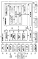
図1は、本発明の一実施形態に係る車両用制御装置のブロック図であり、車両1を制御する。図1において、車両1はその概略が平面図と側面図とで示されている。車両1は一例としてセダンタイプの四輪の乗用車である。
● Configuration of Vehicle Control Device FIG. 1 is a block diagram of a vehicle control device according to an embodiment of the present invention, and controls
図1の制御装置は、制御ユニット2を含む。制御ユニット2は車内ネットワークにより通信可能に接続された複数のECU20~29を含む。各ECUは、CPUに代表されるプロセッサ、半導体メモリ等の記憶デバイス、外部デバイスとのインタフェース等を含む。記憶デバイスにはプロセッサが実行するプログラムやプロセッサが処理に使用するデータ等が格納される。各ECUはプロセッサ、記憶デバイスおよびインタフェース等を複数備えていてもよい。
The control device of FIG. 1 includes a
以下、各ECU20~29が担当する機能等について説明する。なお、ECUの数や、担当する機能については、車両1の適宜設計可能であり、本実施形態よりも細分化したり、あるいは、統合することが可能である。
Hereinafter, the functions and the like that each
ECU20は、車両1の自動運転に関わる制御を実行する。自動運転においては、車両1の操舵と、加減速の少なくともいずれか一方を自動制御する。後述する制御例では、操舵と加減速の双方を自動制御する。
The
ECU21は、ステアリング装置3を制御するステアリングECUである。ステアリング装置3は、ステアリングホイール(ハンドルとも呼ぶ)31に対する運転者の運転操作(操舵操作)に応じて前輪を操舵する機構を含む。また、ステアリング装置3は電動パワーステアリング装置であり、操舵操作をアシストしたり、あるいは、前輪を自動操舵するための駆動力を発揮するモータや、操舵角を検知するセンサ等を含む。車両1の運転状態が自動運転の場合、ECU21は、ECU20からの指示に対応してステアリング装置3を自動制御し、車両1の進行方向を制御する。
The
ECU22および23は、車両の周囲状況を検知する検知ユニット41~43の制御および検知結果の情報処理を行う。周囲状況のことは周囲状態や外部環境などとも呼び、それらを検知して得られる情報は周囲状況情報や周囲状態情報あるいは外部環境情報などと呼ぶ。またこれら周囲状態のための検知ユニットおよびその制御を行うECUをまとめて周辺監視装置または周辺監視部などとも呼ぶ。検知ユニット41は、車両1の前方を撮影するカメラであり(以下、カメラ41と表記する場合がある。)、本実施形態の場合、車両1の室内に2つ設けられている。カメラ41が撮影した画像の解析により、物標の輪郭抽出や、道路上の車線の区画線(白線等)を抽出可能である。検知ユニット41aは、ドライバーの状態を検知するためのカメラであり(以下、ドライバー状態検知カメラ41aと表記する場合がある。)、ドライバーの表情をとらえられるように設置されており、不図示ではあるが、その画像データの処理を行うECUに接続されている。またドライバー状態を検知するためのセンサとして、不図示のハンドル把持センサがある。これによりドライバーがハンドルを握っているか否かを検知できる。ドライバー状態検知カメラ41aとハンドル把持センサ210Iとを含めてドライバー状態検知部とも呼ぶ。
The
検知ユニット42は、ライダ(LiDAR:Light Detection and Ranging、或いはLaser Imaging Detection and Ranging)であり(以下、ライダ42と表記する場合がある)、車両1の周囲の物標を検知したり、物標との距離を測距する。本実施形態の場合、ライダ42は5つ設けられており、車両1の前部の各隅部に1つずつ、後部中央に1つ、後部各側方に1つずつ設けられている。検知ユニット43は、ミリ波レーダであり(以下、レーダ43と表記する場合がある)、車両1の周囲の物標を検知したり、物標との距離を測距する。本実施形態の場合、レーダ43は5つ設けられており、車両1の前部中央に1つ、前部各隅部に1つずつ、後部各隅部に一つずつ設けられている。
The
ECU22は、一方のカメラ41と、各ライダ42の制御および検知結果の情報処理を行う。ECU23は、他方のカメラ41と、各レーダ43の制御および検知結果の情報処理を行う。車両の周囲状況を検知する装置を二組備えたことで、検知結果の信頼性を向上でき、また、カメラ、ライダ、レーダといった種類の異なる検知ユニットを備えたことで、車両の周辺環境(周辺状態とも呼ぶ。)の解析を多面的に行うことができる。
The
ECU24は、ジャイロセンサ5、GPSセンサ24b、通信装置24cの制御および検知結果あるいは通信結果の情報処理を行う。ジャイロセンサ5は車両1の回転運動を検知する。ジャイロセンサ5の検知結果や、車輪速等により車両1の進路を判定することができる。GPSセンサ24bは、車両1の現在位置を検知する。通信装置24cは、地図情報や交通情報を提供するサーバと無線通信を行い、これらの情報を取得する。ECU24は、記憶デバイスに構築された地図情報のデータベース24aにアクセス可能であり、ECU24は現在地から目的地へのルート探索等を行う。
The
ECU25は、車車間通信用の通信装置25aを備える。通信装置25aは、周辺の他車両と無線通信を行い、車両間での情報交換を行う。
The
ECU26は、パワープラント(すなわち走行駆動力出力装置)6を制御する。パワープラント6は車両1の駆動輪を回転させる駆動力を出力する機構であり、例えば、エンジンと変速機とを含む。ECU26は、例えば、アクセルペダル7Aに設けた操作検知センサ(すなわちアクセル開度センサ)7aにより検知した運転者の運転操作(アクセル操作あるいは加速操作)に対応してエンジンの出力を制御したり、車速センサ7cが検知した車速等の情報に基づいて変速機の変速段を切り替える。車両1の運転状態が自動運転の場合、ECU26は、ECU20からの指示に対応してパワープラント6を自動制御し、車両1の加減速を制御する。なお、ジャイロセンサ5により検知される各方向の加速度や角軸周りの角加速度、車速センサ7cで検知される車速などは車両の走行状態を示す情報であり、これらのセンサをまとめて走行状態監視部とも呼ぶ。さらにアクセルペダル7Aの操作検知センサ7aや後述するブレーキペダル7Bの操作検知センサ(すなわちブレーキ踏力センサ)7bを走行状態監視部に含めてもよいが、本例ではこれらは、他のデバイスに対する操作状態を検知する不図示の検知部とともに、操作状態検知部と呼ぶことにする。
The
ECU27は、方向指示器8を含む灯火器(ヘッドライト、テールライト等)を制御する。図1の例の場合、方向指示器8は車両1の前部、ドアミラーおよび後部に設けられている。
The
ECU28は、入出力装置9の制御を行う。入出力装置9は運転者に対する情報の出力と、運転者からの情報の入力の受け付けを行う。音声出力装置91は運転者に対して音声により情報を報知する。表示装置92は運転者に対して画像の表示により情報を報知する。表示装置92は例えば運転席表面に配置され、インストルメントパネル等を構成する。なお、ここでは、音声と表示を例示したが振動や光により情報を報知してもよい。また、音声、表示、振動または光のうちの複数を組み合わせて情報を報知してもよい。更に、報知すべき情報の制御状態(例えば緊急度)に応じて、組み合わせを異ならせたり、報知態様を異ならせたりしてもよい。入力装置93は運転者が操作可能な位置に配置され、車両1に対する指示を行うスイッチ群であるが、音声入力装置も含まれてもよい。入力装置93には、自動運転制御状態のレベルを手動で引き下げるためのキャンセルスイッチも備えられている。また手動運転から自動運転に切り替えるための自動運転切り替えスイッチも備えられる。自動運転制御状態のレベルを引き下げたいドライバーは、キャンセルスイッチを操作することでレベルを引き下げることができる。本実施形態では、自動運転制御状態がどのレベルであろうとも同一のキャンセルスイッチでレベルを引き下げることができる。
The
ECU29は、ブレーキ装置10やパーキングブレーキ(不図示)を制御する。ブレーキ装置10は例えばディスクブレーキ装置であり、車両1の各車輪に設けられ、車輪の回転に抵抗を加えることで車両1を減速あるいは停止させる。ECU29は、例えば、ブレーキペダル7Bに設けた操作検知センサ7bにより検知した運転者の運転操作(ブレーキ操作)に対応してブレーキ装置10の作動を制御する。車両1の運転状態が自動運転の場合、ECU29は、ECU20からの指示に対応してブレーキ装置10を自動制御し、車両1の減速および停止を制御する。ブレーキ装置10やパーキングブレーキは車両1の停止状態を維持するために作動することもできる。また、パワープラント6の変速機がパーキングロック機構を備える場合、これを車両1の停止状態を維持するために作動することもできる。
The
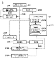
●車両制御システム
図2に本実施形態における制御ユニット2の機能的な構成を示す。制御ユニット2は車両制御システムとも呼び、ECU20をはじめとする各ECUがプログラムを実行することなどによって図2に示す各機能ブロックを実現する。図2において、車両1には、カメラ41、ライダ42、レーダ43などを含む検知デバイスDDと、ナビゲーション装置50と、通信装置24b,24c,25aと、ジャイロセンサ5やハンドル把持センサ、ドライバー状態検知カメラ41aなどを含む車両センサ60と、アクセルペダル7Aと、アクセル開度センサ7aと、ブレーキペダル7Bと、ブレーキ踏量センサ7bと、表示装置92と、スピーカ91と、自動運転切替スイッチを含むスイッチ93と、車両制御システム2と、走行駆動力出力装置6と、ステアリング装置3と、ブレーキ装置220とが搭載される。これらの装置や機器は、CAN(Controller Area Network)通信線等の多重通信線やシリアル通信線、無線通信網等によって互いに接続される。
● Vehicle control system FIG. 2 shows the functional configuration of the
ナビゲーション装置50は、GNSS(Global Navigation Satellite System)受信機や地図情報(ナビ地図)、ユーザインターフェースとして機能するタッチパネル式表示装置、スピーカ、マイク等を有する。ナビゲーション装置50は、GNSS受信機によって自車両1の位置を特定し、その位置からユーザによって指定された目的地までの経路を導出する。ナビゲーション装置50により導出された経路は、車両制御システム2の目標車線決定部110に提供される。なお、自車両1の位置を特定するための構成は、ナビゲーション装置50とは独立して設けられてもよい。
The
通信装置24b,24c,25aは、例えば、セルラー網やWi-Fi網、Bluetooth(登録商標)、DSRC(Dedicated Short Range Communication)などを利用した無線通信を行う。
The
車両センサ60は、車速を検出する車速センサ、加速度を検出する加速度センサ、鉛直軸回りの角速度を検出するヨーレートセンサ、自車両1の向きを検出する方位センサ等を含む。これらの全部または一部はジャイロセンサ5により実現される。また、不図示のハンドル把持センサやドライバー状態検知カメラ41aを車両センサ60に含めてもよい。
The
アクセルペダル7Aは、ドライバーによる加速指示(或いは戻し操作による減速指示)を受け付けるための操作子である。アクセル開度センサ7aは、アクセルペダル7Aの踏み込み量を検出し、踏み込み量を示すアクセル開度信号を車両制御システム2に出力する。なお、車両制御システム2に出力するのに代えて、走行駆動力出力装置6、ステアリング装置3、またはブレーキ装置220に直接出力することがあってもよい。以下に説明する他の運転操作系の構成についても同様である。
The
ブレーキペダル7Bは、ドライバーによる減速指示を受け付けるための操作子である。ブレーキ踏量センサ7bは、ブレーキペダル7Bの踏み込み量(或いは踏み込み力)を検出し、検出結果を示すブレーキ信号を車両制御システム2に出力する。
The
表示装置92は、例えば、インストルメントパネルの各部、助手席や後部座席に対向する任意の箇所などに取り付けられる、LCD(Liquid Crystal Display)や有機EL(Electroluminescence)表示装置などである。また、表示装置92は、フロントウインドシールドやその他のウインドウに画像を投影するHUD(Head Up Display)であってもよい。スピーカ91は、音声を出力する。
The
走行駆動力出力装置6は、車両が走行するための走行駆動力(トルク)を駆動輪に出力する。走行駆動力出力装置6は、例えば、エンジン、変速機、およびエンジンを制御するエンジンECU(Electronic Control Unit)を備える。なお、走行駆動力出力装置6は、電気モータや、内燃機関と電気モータとを組み合わせたハイブリッド機関であってもよい。
The traveling driving
ブレーキ装置220は、例えば、ブレーキキャリパーと、ブレーキキャリパーに油圧を伝達するシリンダと、シリンダに油圧を発生させる電動モータと、制動制御部とを備える電動サーボブレーキ装置である。電動サーボブレーキ装置の制動制御部は、走行制御部160から入力される情報に従って電動モータを制御し、制動操作に応じたブレーキトルクが各車輪に出力されるようにする。また、ブレーキ装置220は、走行駆動力出力装置6に含まれ得る走行用モータによる回生ブレーキを含んでもよい。
The
●ステアリング装置
次にステアリング装置3について説明する。ステアリング装置3は、例えば、ステアリングECU21と、電動モータとを備える。電動モータは、例えば、ラックアンドピニオン機構に力を作用させて転舵輪の向きを変更する。ステアリングECU21は、車両制御システム2から入力される情報、或いは入力されるステアリング操舵角またはステアリングトルクの情報に従って電動モータを駆動し、転舵輪の向きを変更させる。
● Steering device Next, the
図3は、本実施形態によるステアリング装置3の構成例を示す図である。ステアリング装置3は、ステアリングホイール(ハンドルとも呼ぶ)31と、ステアリング軸210Bと、ステアリング操舵角センサ210Cと、ステアリングトルクセンサ210Dと、反力モータ210Eと、アシストモータ210Fと、転舵機構210Gと、転舵角センサ210Hと、ハンドル把持センサ210Iと、転舵輪210Jと、ステアリングECU21とを含んでよいが、これに限定されない。また、ステアリングECU21は、ステアリング反力設定部210Mと、記憶部210Nとの各々を有している。
FIG. 3 is a diagram showing a configuration example of the
ステアリングホイール31は、ドライバーによる操舵指示を受け付ける操作デバイスの一例である。ステアリングホイール31に対して与えられた操舵入力すなわちステアリング操作は、ステアリング軸210Bに伝達される。ステアリング軸210Bには、ステアリング操舵角センサ210Cと、ステアリングトルクセンサ210Dとが取り付けられる。ステアリング操舵角センサ210Cは、ステアリングホイール31が操作された角度を検出し、ステアリングECU21に出力する。ステアリングトルクセンサ210Dは、ステアリング軸210Bに作用しているトルク(ステアリングトルク)を検出し、ステアリングECU21に出力する。すなわちステアリングトルクは、ドライバーがステアリングホイール31を回すことによりステアリング軸210Bに作用するトルクである。反力モータ210Eは、ステアリングECU21の制御によって、ステアリング軸210Bにトルクを出力することで、ステアリングホイール31に対してステアリング反力を出力する。すなわち、反力モータ210Eは、ステアリングECU21の制御により、それぞれの自動運転制御状態において、自動運転における操舵(システム操舵とも呼ぶ)を維持するための所定のステアリング反力を、ステアリング軸210Bに対して印加する。ステアリング反力は、ドライバーのステアリング操作に対して抵抗するトルクとして作用する。したがってドライバーは、システム操舵に対してオーバーライドする場合には、操舵入力に応じて生じるステアリング反力を超えるトルクをステアリング軸210Bに与えなければならない。
The
アシストモータ210Fは、ステアリングECU21の制御によって、転舵機構210Gに対してトルクを出力することで、転舵をアシストする。アシストとは単に手動運転時にドライバーの操作を補助するだけでなく、自動運転時には走行制御部160による制御に応じてドライバーによる操作なしで操舵を行う。転舵機構210Gは、例えば、ラックアンドピニオン機構である。転舵角センサ210Hは、転舵機構210Gが転舵輪210Jを駆動制御した角度(転舵角)を示す量(例えばラックストローク)を検出し、ステアリングECU21に出力する。ステアリング軸210Bと転舵機構210Gとの間は、固定的に連結されてもよいし、切り離されてもよいし、クラッチ機構などを介して連結されてもよい。
The assist
ハンドル把持センサ210Iは、ステアリングホイール31のリム部の所定の位置に設けられ、ドライバーがステアリングホイール31のリムを把持する際、このドライバーの手による静電容量の変動を検知する静電容量センサであってよい。或いは、ドライバーの把持によってリムに印加される圧力(以下、把持力ともいう)を測定する圧力センサであってもよい。ハンドル把持センサ210Iは、測定した把持力を、ステアリングECU21に出力する。ステアリングECU21は、上記各種制御を、車両制御システム2と協調して行う。
The steering wheel grip sensor 210I is provided at a predetermined position on the rim portion of the
ステアリング反力設定部210Mは、自動運転制御状態では、ステアリング操舵角センサ210Cで検知された操舵角(オーバーライド舵角)と、車両制御システム2から取得したシステム舵角(たとえば走行制御部160により決定された舵角)との差分を操舵入力の指標値として、ステアリングECU21内の記憶部210Nの反力プロファイル情報210Pを参照する。この反力プロファイル情報210Pは、例えば、オーバーライド舵角とシステム舵角との舵角差とステアリング反力との対応関係を示す反力テーブルとして構成されている。そして、ステアリング反力設定部210Mは、上記舵角差に対応するステアリング反力を、記憶部210Nにおける反力プロファイル情報210Pの反力テーブルから読み込む。また、ステアリングECU21は、ステアリング反力設定部210Mが記憶部210Nから読み込んだ数値に基づき、この数値のステアリング反力がステアリング軸210Bに印加されるように反力モータ210Eを駆動制御する。なお手動運転制御状態においては、手動運転のために予め定めた反力プロファイル情報が用意され、それに従って反力が与えられる。本例のように、ステアリング軸210Bが転舵機構210Gに接続されている場合には、転舵輪210Jからの機械的な反力がステアリングホイール31に伝わるため、反力は特に付与しなくともよい。ただし、ステアリング軸が機械的には転舵機構210Gに接続されていない、完全なステアバイワイヤが実現されている場合には、操舵感をドライバーに与えるために、機械的反力をシミュレートした反力プロファイルに従って反力が生成されてよい。本例では、反力は自動運転の自動運転制御状態に応じた特性を持つように与えられる。なお反力の設定については、図3乃至9を参照して改めて説明する。なお操舵の舵角やトルク、操舵のスピード等をまとめて操舵量と呼び、走行制御部160により決定された操舵量をシステム操舵量と呼ぶことがある。
In the automatic driving control state, the steering reaction
上述した構成により、自動運転制御状態におけるドライバーのステアリングホイール31のオーバーライド操作による舵角とシステム舵角との差分、および自動運転制御状態に応じてステアリングホイール31に印加されるステアリング反力を与える。このとき自動運転制御状態のレベルが高いほど反力を大きくする。こうすることで、自動運転制御状態に応じて、自動運転制御状態のレベルが高ければオーバーライドをし難くし、自動運転制御状態のレベルが低ければオーバーライドをし易くすることができる。
With the above-described configuration, the difference between the steering angle and the system steering angle due to the override operation of the driver's
ステアリング反力設定部210Mは、自動運転制御状態において、ステアリングECU21がシステム舵角及びオーバーライド舵角を読み込む毎に、記憶部210Nの反力プロファイル情報210Pを参照する。そして、ステアリング反力設定部210Mは、読み込まれたシステム舵角とオーバーライド舵角との差と、自動運転制御状態とに応じたステアリング反力読み取り、そのステアリング反力を付与する制御信号を反力モータ210Eに出力する。
The steering reaction
●車両制御システム(続き)
図2に戻り、車両制御システム2は、例えば、目標車線決定部110と、自動運転制御部120と、走行制御部160と、HMI(human machine interface)制御部170と、記憶部180とを備える。自動運転制御部120は、例えば、自動運転状態制御部130と、自車位置認識部140と、外界認識部142と、行動計画生成部144と、軌道生成部146と、切替制御部150とを備える。目標車線決定部110、自動運転制御部120の各部、および走行制御部160、HMI制御部170のうち一部または全部は、プロセッサがプログラム(ソフトウェア)を実行することにより実現される。また、これらのうち一部または全部は、LSI(Large Scale Integration)やASIC(Application Specific Integrated Circuit)等のハードウェアによって実現されてもよいし、ソフトウェアとハードウェアの組み合わせによって実現されてもよい。
● Vehicle control system (continued)
Returning to FIG. 2, the
記憶部180には、例えば、車線の中央の情報あるいは車線の境界の情報等を含んでいる高精度地図情報182、目標車線情報184、行動計画情報186などの情報が格納される。目標車線決定部110は、ナビゲーション装置50から提供された経路を複数のブロックに分割し(例えば、車両進行方向に関して100[m]毎に分割し)、高精度地図情報182を参照してブロックごとに目標車線を決定する。目標車線決定部110は、例えば、左から何番目の車線を走行するといった決定を行う。目標車線決定部110は、例えば、経路において分岐箇所や合流箇所などが存在する場合、自車両1が、分岐先に進行するための合理的な走行経路を走行できるように、目標車線を決定する。目標車線決定部110により決定された目標車線は、目標車線情報184として記憶部180に記憶される。
The
自動運転状態制御部130は、自動運転制御部120が実施する自動運転の自動運転制御状態(各状態の自動化率に着目して自動化状態とも呼ぶ。)を決定する。本実施形態における自動運転制御状態には、以下の制御状態が含まれる。なお、以下はあくまで一例であり、自動運転の制御状態の数は任意に決定されてよい。図4に自動運転制御状態の遷移図を示す。
The automatic operation
●自動運転制御状態の遷移
図4に示すように、本実施形態では自動運転制御状態として第0制御状態から第3制御状態まで持ち、自動化率はこの順で高くなる。なお図4において、矢印は状態の遷移を示している。そのうち白矢印は、車両制御システム2(特にECU20)が例えばプログラムを実行して実現する自動運転による、すなわち車両1が主体となる、自動運転制御状態の遷移を示す。一方黒矢印は、ドライバーの操作をきっかけとして行われる自動運転制御状態の遷移を示す。ここで各自動運転制御状態について改めて説明する。
● Transition of automatic operation control state As shown in FIG. 4, in the present embodiment, the automatic operation control state is held from the 0th control state to the 3rd control state, and the automation rate increases in this order. In FIG. 4, the arrow indicates the transition of the state. Among them, the white arrow indicates the transition of the automatic driving control state by the automatic driving realized by the vehicle control system 2 (particularly the ECU 20) by executing a program, for example, that is, the
第0制御状態は手動運転の制御状態であり、0制御状態は、運転支援等が一切なくドライバーによるマニュアル運転が必要な制御状態である。この第0制御状態においてドライバーが例えばスイッチ操作によって明示的に自動運転を指示すると、そのときの条件、たとえば外部環境や車両情報などに応じて、自動運転制御状態が第1制御状態または第2制御状態へと遷移する。いずれの制御状態に遷移するかは、制御ユニット2が外部環境情報や走行状態情報などを参照して決定する。
The 0th control state is a control state for manual operation, and the 0th control state is a control state in which manual operation by a driver is required without any driving support or the like. When the driver explicitly instructs automatic driving by operating a switch in this 0th control state, the automatic driving control state is changed to the first control state or the second control according to the conditions at that time, for example, the external environment and vehicle information. Transition to the state. The
第1制御状態は自動運転のうちで最も低い自動運転制御状態の状態である(自動化率が最も低い)。自動運転が指示された際に、たとえば現在地を認識できないような場合、また認識できても第2制御状態が適用できない環境(たとえば一般道など)では、第1制御状態で自動運転が開始される。第1制御状態で実現される自動化機能はLKASやACCなどを含む。また第1制御状態に遷移する際には、ドライバー状態検知部によりドライバーが外部、特に前方を監視していること、またハンドルを把持していることを検知してもよい。その場合には、条件が満たされた場合に遷移することになる。また第1制御状態に留まっている間も継続的にこのドライバーの監視が行われてよい。なお自動運転制御状態を低レベルから高レベルへと遷移させる際には、ドライバーに課されるタスクは変わらないかあるいは減少するので、ドライバーの状態を遷移の条件にしなくともよい。なお、第0制御状態と第1制御状態との差は上述したものとは限らず、例えば第0制御状態ではLKASもしくはACCのどちらか一方のみを利用できるが、第1制御状態ではその両方を利用できる、といった場合もあり得る。また、第1制御状態では、第0制御状態のLKAS,ACCに対して作動シーンが広い、といった場合もあり得る。 The first control state is the state of the lowest automatic operation control state among the automatic operations (the lowest automation rate). When automatic driving is instructed, for example, when the current location cannot be recognized, or in an environment where the second control state cannot be applied even if it can be recognized (for example, a general road), automatic driving is started in the first control state. .. The automation functions realized in the first control state include LKAS and ACC. Further, when transitioning to the first control state, the driver state detection unit may detect that the driver is monitoring the outside, particularly the front, and that the driver is holding the steering wheel. In that case, the transition will occur when the conditions are met. Further, the driver may be continuously monitored while remaining in the first control state. When the automatic driving control state is changed from the low level to the high level, the task imposed on the driver does not change or decreases, so that the driver state does not have to be a condition for the transition. The difference between the 0th control state and the 1st control state is not limited to the above. For example, in the 0th control state, only one of LKAS and ACC can be used, but in the 1st control state, both of them can be used. It may be available. Further, in the first control state, the operation scene may be wider than that of the LKAS and ACC in the 0th control state.
第2制御状態は第1制御状態の直上の自動運転制御状態である。たとえば第0制御状態で自動運転の指示を受け付け、その時の外部環境が所定の環境(たとえば高速道路の走行中など)であれば、第2制御状態に遷移する。あるいは、第1制御状態で自動運転中に、外部環境が上述した所定の環境であることが検知されたなら、第2制御状態へと自動的に遷移する。外部環境の判定は、たとえばカメラ等を含む周辺監視部の監視結果のほか、現在位置と地図情報とを参照して行ってもよい。第2制御状態では、車線維持のほか、周囲の車両等の物標に応じて車線変更などを行う機能も提供される。第2制御状態を維持する条件が失われると、制御ユニット2により第1制御状態へと、車両1の自動化状態は変更される。第2制御状態ではドライバーはハンドルを保持しなくともよく(これをハンズオフと呼ぶ)、ドライバーには周囲の監視のみが課される。このため第2制御状態ではドライバー状態検知カメラ41aによりドライバーが外部を監視しているかが監視され、それを怠るとたとえば警告が出力される。
The second control state is the automatic operation control state directly above the first control state. For example, if an instruction for automatic driving is received in the 0th control state and the external environment at that time is a predetermined environment (for example, while driving on a highway), the process transitions to the second control state. Alternatively, if it is detected that the external environment is the above-mentioned predetermined environment during the automatic operation in the first control state, the process automatically transitions to the second control state. The determination of the external environment may be performed by referring to, for example, the monitoring result of the peripheral monitoring unit including the camera, the current position, and the map information. In the second control state, in addition to maintaining the lane, a function of changing lanes according to a target such as a surrounding vehicle is also provided. When the condition for maintaining the second control state is lost, the automation state of the
第3制御状態は第2制御状態の直上の自動運転制御状態である。第3制御状態へは第2制御状態から遷移でき、第2制御状態をスキップして第0制御状態や第1制御状態から遷移することはない。また、第3制御状態への遷移がドライバーの指示をトリガとして行われることはなく、制御ユニット2による自動制御によって一定の条件が満たされたと判定した場合に遷移する。たとえば、第2制御状態で自動運転中に、渋滞に遭遇して低速で前車を追尾する状態になると、第2制御状態から第3制御状態へと切り替えられる。この場合の判定は、カメラ等の周辺監視部による出力や車速等に基づいて行われる。第2制御状態の条件を満たしている場合、例えば高速道路を走行している場合には、第2制御状態と第3制御状態との間で、自動運転制御状態の遷移が行われることになる。第3制御状態ではドライバーは、ハンドルを把持する必要も、周辺を監視する必要もない。しかしながら、ドライバーが運転を引き継がなければならない状況はいつでも、どの制御状態であっても生じ得る。そこでドライバーが運転を正常に引き継げるか、を判定するために、例えばドライバーの視線が定められた範囲(例えばナビゲーションやメータの表示部)に視線があることは、自動運転中に常時監視され、検出されている。このドライバーの状態の監視は、マニュアル運転中に行われてもよい。
The third control state is the automatic operation control state directly above the second control state. The transition to the third control state can be performed from the second control state, and the transition from the 0th control state or the first control state is not performed by skipping the second control state. Further, the transition to the third control state is not performed by the instruction of the driver as a trigger, and the transition is made when it is determined that a certain condition is satisfied by the automatic control by the
自動運転状態制御部130は、上記運転操作系の構成の各々に対するドライバーの操作、行動計画生成部144により決定されたイベント、軌道生成部146により決定された走行態様などに基づいて自動運転の制御状態を決定し、図4に示した白矢印に従って決定した制御状態へと遷移させる。自動運転制御状態は、HMI制御部170に通知される。いずれの制御状態においても、運転操作系の構成の各々に対する操作によって、手動運転により自動運転を上書きすること(オーバーライド)が可能である。
The automatic driving
自動運転制御部120の自車位置認識部140は、記憶部180に格納された高精度地図情報182と、ライダ42、レーダ43、カメラ41、ナビゲーション装置50、または車両センサ60から入力される情報とに基づいて、自車両1が走行している車線(走行車線)、および、走行車線に対する自車両1の相対位置(あるいは現在の走行ライン)を認識する。
The vehicle
自車位置認識部140は、例えば、高精度地図情報182から認識される道路区画線のパターン(例えば実線と破線の配列)と、カメラ41によって撮像された画像から認識される自車両1の周辺の道路区画線のパターンとを比較することで、走行車線を認識する。この認識において、ナビゲーション装置50から取得される自車両1の位置や、もしあれば慣性誘導システムによる処理結果が加味されてもよい。走行制御部160は、軌道生成部146によって生成された軌道を、予定の時刻通りに自車両1が通過するように、走行駆動力出力装置6、ステアリング装置3、およびブレーキ装置220を制御する。HMI制御部170は、表示装置92に映像及び画像を表示させたり、スピーカ91に音声を出力させたりする。走行制御部160はたとえば、行動計画情報186に沿った自動運転のためにステアリング舵角(システム舵角)を決定し、それをステアリング装置3に入力して、操舵制御をおこなわせる。なお、走行中の車線がカーブすることなどは、例えば高精度地図情報182や、この後述べる外界認識部142により認識できる。
The own vehicle
外界認識部142は、カメラ41、ライダ42、レーダ43等から入力される情報に基づいて、周辺車両等の物標の位置、および速度、加速度等の状態を認識する。また、外界認識部142は、周辺車両に加えて、ガードレールや電柱、駐車車両、歩行者その他の物体の位置を認識してもよい。
The outside
行動計画生成部144は、自動運転のスタート地点、および/または自動運転の目的地を設定する。自動運転のスタート地点は、自車両1の現在位置であってもよいし、自動運転を指示する操作がなされた地点でもよい。行動計画生成部144は、そのスタート地点と自動運転の目的地との間の区間において、行動計画を生成する。なお、これに限らず、行動計画生成部144は、任意の区間について行動計画を生成してもよい。
The action
行動計画は、例えば、順次実行される複数のイベントで構成される。イベントには、例えば、自車両1を減速させる減速イベントや、自車両1を加速させる加速イベント、走行車線を逸脱しないように自車両1を走行させるレーンキープイベント、走行車線を変更させる車線変更イベント、自車両1に前走車両を追い越させる追い越しイベント、分岐ポイントにおいて所望の車線に変更させたり、現在の走行車線を逸脱しないように自車両1を走行させたりする分岐イベント、本線に合流するための合流車線において自車両1を加減速させ、走行車線を変更させる合流イベント、自動運転の終了予定地点で自動運転制御状態から手動運転制御状態に移行させたりするハンドオーバイベント等が含まれる。行動計画生成部144は、目標車線決定部110により決定された目標車線が切り替わる箇所において、車線変更イベント、分岐イベント、または合流イベントを設定する。行動計画生成部144によって生成された行動計画を示す情報は、行動計画情報186として記憶部180に格納される。
An action plan consists of, for example, a plurality of events that are executed sequentially. The events include, for example, a deceleration event for decelerating the
●目標走行位置の設定
軌道生成部146は、車線内の目標となる点の位置すなわち目標走行位置(または目標位置)を決定し、ひいては連続する目標走行位置を結んだ軌道(目標軌道または目標ラインまたは目標走行ラインとも呼ぶ。)を決定し、行動計画情報186の一部として記憶することで、目標走行位置を設定する。目標位置としては、たとえば特に避けるべき物標がなければ、走行中の車線の中央位置を通る位置(これを基準位置または第1基準位置または点列をラインとみて第1基準ラインとも呼ぶ)が選択される。障害物があればそれを避ける目標位置が設定される。また、走行中の車線内の障害物ではなくとも、ドライバーや乗員の心理的負担を軽減するために、隣接車線を走行している車両から離間するような目標位置を設定することがある。さらに、走行位置の曲率を小さくして快適性を維持するために、カーブでは車線の中央位置よりも内側に目標位置を設定することがある。切替制御部150は、自動運転切替スイッチ93から入力される信号に基づいて自動運転制御状態と手動運転制御状態とを相互に切り替える。
● Setting the target driving position The
さらに、目標位置を設定する際に、過去のオーバーライド操作の履歴に基づいてもよい。たとえば操舵に関して、自動運転による走行ラインから車線中央に向けてオーバーライド操作が行われると、その操作が行われたことを記憶しておく。そして目標位置を設定する際にその記憶を参照し、該当のオーバーライド操作が行われていると、車線の中央位置から目標位置をずらすオフセット走行の際に、設定した目標位置を、中央位置からのずれの量を低減するように変更する。あるいは、当初からそのような目標位置を設定してもよい。こうすることで、ドライバーが介入する機会が減少する。 Further, when setting the target position, it may be based on the history of past override operations. For example, regarding steering, when an override operation is performed from the traveling line by automatic driving toward the center of the lane, it is remembered that the operation is performed. Then, when setting the target position, the memory is referred to, and if the corresponding override operation is performed, the set target position is set from the center position during offset driving that shifts the target position from the center position of the lane. Change to reduce the amount of deviation. Alternatively, such a target position may be set from the beginning. This reduces the chances of the driver intervening.
また、切替制御部150は、ブレーキペダル7Bの操作に基づいて、自動運転(第3~1制御状態)から手動運転(第0制御状態)に切り替える。本例では、ブレーキ操作がされると、その時の自動化制御状態に応じた猶予時間および警告の後に、切替制御部150は自動運転制御状態から手動運転制御状態に切り替える。またステアリング操作やアクセル操作に対しては、自動運転は維持しつつ、マニュアル操作に従ってオーバーライド制御が行われる。ここで、オーバーライド制御により、たとえばステアリングの操作量が所定のオーバーライド閾値を超えると、あたかも手動運転に切り替えられたかのような走行制御を実現する。次にオーバーライド制御について説明する。
Further, the switching
●オーバーライド制御
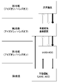
次に本実施形態に係るオーバーライド制御、特にステアリングのオーバーライド制御について説明する。その前に自動運転におけるステアリング制御の特性を、図5を参照して説明する。図5(A)は、自動運転による経路維持特性を説明する図である。この制御イメージは、経路を維持しようとする特性を、たとえば道路の断面形状として示したものである。この制御イメージは、高さ方向については車線中央を維持しようとする制御の強さを示すものと読むこともできる。これらの図はもちろん本当の道路の断面形状を示すものではなく、形状になぞらえて特性を説明するためのイメージ図である。また図5では省略したが、中間的な制御状態があってもよい。
● Override control Next, the override control according to the present embodiment, particularly the steering override control, will be described. Before that, the characteristics of steering control in automatic driving will be described with reference to FIG. FIG. 5A is a diagram illustrating a route maintenance characteristic by automatic operation. This control image shows, for example, the cross-sectional shape of a road, which is a characteristic of maintaining a route. This control image can also be read as showing the strength of control to maintain the center of the lane in the height direction. Of course, these figures do not show the true cross-sectional shape of the road, but are image diagrams for explaining the characteristics by comparing them to the shape. Further, although omitted in FIG. 5, there may be an intermediate control state.
図5(A)は、特に避けるべき物標などがない場合に設定される目標位置の例を示す。左白線位置と右白線位置との間が走行車線であり、目標位置Tが、車線中央位置Cと一致している。この場合には、目標位置Tを中心として左右のそれぞれの所定幅ML,MRの範囲内では、操舵反力が比較的大きい反力プロファイルが設定される。これによりオーバーライドをし難くしてオーバーライドによる目標位置からのずれを抑制する。位置ML,MRよりも車線の外側では、反力が弱くなるようなプロファイルが設定される。これにより、明らかに目標位置からの逸脱を目的とした手動操作を妨げないようにしている。なお図5に示したように、道路の横断方向の成分について位置に着目している場合には、その位置を特に横位置と呼ぶことにする。本実施形態で単に位置と呼んでいる場合であっても、文脈上道路の横断方向の成分に着目している場合には、それは横位置を示している。 FIG. 5A shows an example of a target position set when there is no target to be avoided. The traveling lane is between the left white line position and the right white line position, and the target position T coincides with the lane center position C. In this case, a reaction force profile having a relatively large steering reaction force is set within the range of the left and right predetermined widths ML and MR centered on the target position T. This makes it difficult to override and suppresses deviation from the target position due to override. A profile is set so that the reaction force becomes weaker outside the lane than the positions ML and MR. This clearly does not interfere with manual operation aimed at deviating from the target position. As shown in FIG. 5, when the position is focused on the component in the crossing direction of the road, the position is particularly referred to as the horizontal position. Even if it is simply called a position in the present embodiment, when the component in the crossing direction of the road is focused on in the context, it indicates a horizontal position.
図5(B)は、目標位置が車線中央位置からずれたいわゆるオフセット走行の際の反力プロファイルの設定の概略を示す。ただし、図5(B)は、走行中の車線内に障害物がない場合の例である。走行中の車線内に障害物があってそれを避けてオフセット走行する場合には。中央位置Cと目標位置T'とがずれている点を除けば、図5(A)と同じプロファイルを採用する。その場合には自動運転による目標走行位置を逸脱すると危険だからである。図5(B)では、目標位置Tより左側は図5(A)と同様に、オーバーライドをし難く設定している。しかしながら、目標位置T'から中央位置Cまでの間は、目標位置T'の左側での反力よりも小さくなるような反力特性が設定され、中央位置まで戻すオーバーライド操作は比較的しやすい。しかし車線中央位置Cを越えて右側へ行くオーバーライド操作に対しては、図5(A)の目標位置Tと右所定位置MRとの間と同様の反力プロファイルが適用される。このため中央位置Cより右へは行きにくい。さらに位置MR'を超えると、図5(A)と同様に、反力を小さくする反力プロファイル501が適用される。ただしこの場合であっても、車線境界となる右白線位置のさらに右に障害物が検知されているような場合には、より大きな反力を発生する反力プロファイル502が設定されてもよい。
FIG. 5B shows an outline of setting a reaction force profile during so-called offset running in which the target position deviates from the center position of the lane. However, FIG. 5B is an example in the case where there is no obstacle in the traveling lane. If there is an obstacle in the driving lane and you avoid it when driving offset. The same profile as in FIG. 5 (A) is adopted except that the center position C and the target position T'are deviated from each other. In that case, it is dangerous to deviate from the target driving position by automatic driving. In FIG. 5B, the left side of the target position T is set so as to be difficult to override, as in FIG. 5A. However, between the target position T'and the center position C, a reaction force characteristic is set so as to be smaller than the reaction force on the left side of the target position T', and the override operation for returning to the center position is relatively easy. However, for the override operation going to the right beyond the center position C of the lane, the same reaction force profile as between the target position T in FIG. 5A and the predetermined right position MR is applied. Therefore, it is difficult to go to the right of the center position C. Further beyond the position MR', a
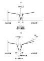
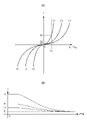
このような制御を実現するためのステアリング反力(操舵反力とも呼ぶ)の特性を図6に示す。図6(A)において、縦軸はステアリング反力を示し、横軸は、目標位置(特に目標横位置)を維持するためのシステム舵角θsysと、手動による手動舵角θmとの差分(θm-θsys)を示す。曲線L1,L2,L3はそれぞれステアリング反力の特性曲線(反力プロファイルとも呼ぶ。)を示す。たとえばシステム舵角がθsysであるときに、ドライバーがステアリング操作を行うと、角度差θm-θsysの増大に応じて、ステアリング反力設定部210Mは、ステアリング反力を曲線L3にそって増大させ、反力モータ210Eは曲線L3にしたがって反力を増大させる。曲線L1,L2,L3は、図示したような特性を持つならば離散値であっても構わない。ドライバーはそのステアリング反力に抗ってステアリング操作を行わねばならない。たとえば角度差θm-θsysがθThであると、設定されている反力プロファイルがL3であれば反力F3を、L2であれば反力F2を、L1であれば反力F1を発生させる。このように、同じ舵角差に対して発生するステアリング反力は、設定されている反力プロファイルに応じてことなる。
FIG. 6 shows the characteristics of the steering reaction force (also referred to as steering reaction force) for realizing such control. In FIG. 6A, the vertical axis indicates the steering reaction force, and the horizontal axis is the difference (θm) between the system steering angle θsys for maintaining the target position (particularly the target lateral position) and the manual steering angle θm. -Θsys) is shown. Curves L1, L2, and L3 show characteristic curves of steering reaction force (also referred to as reaction force profile), respectively. For example, when the driver performs a steering operation when the system steering angle is θsys, the steering reaction
図6(B)は過渡特性の一例を示す。後述するように、反力プロファイルは、目標位置Tや中央位置Cに対する現在の車両の位置に応じて設定される。すなわち走行中に反力プロファイルは切り替えられる。たとえば図6(A)に示したように、舵角差θThのまま反力プロファイルがL3からL2に切り替えられると、ステアリング反力はF3からF2へと変わり、突然ステアリングが軽くなる。これはステアリングの過剰操作をまねきかねないため、反力プロファイルの変更時には、たとえば図6(B)のような過渡特性が与えられる。たとえば、舵角θThのまま反力プロファイルがL3からL2へと変更されると、ステアリングECU21は、図6(B)に示すように、発生させるステアリング反力を、F3からF2へと時間t1かけて連続的に変化させる。この間に更に別のプロファイルに変更された場合にも、切り替えられた時点で発生しているステアリング反力から新たなプロファイルで発生させるステアリング反力まで、過渡特性に応じて連続的に変化させる。
FIG. 6B shows an example of transient characteristics. As will be described later, the reaction force profile is set according to the current position of the vehicle with respect to the target position T and the center position C. That is, the reaction force profile is switched during running. For example, as shown in FIG. 6A, when the reaction force profile is switched from L3 to L2 with the steering angle difference θTh, the steering reaction force changes from F3 to F2, and the steering suddenly becomes lighter. Since this may lead to excessive steering operation, when the reaction force profile is changed, a transient characteristic as shown in FIG. 6B is given, for example. For example, when the reaction force profile is changed from L3 to L2 with the steering angle θTh, the steering
このように、反力プロファイル情報210Pには、図6(A)に示したとおり、自動運転制御状態ごとにシステム舵角θsysと手動舵角θmとの角度差(θm-θsys)とステアリング反力とを対応付けたテーブルと、図6(B)に示した、過渡特性のテーブルとが保存されている。そして、ステアリング反力設定部210Mは、例えば図7の手順にしたがって反力プロファイルを設定する。過渡特性は図6(B)のように所定のものを設定しておいてよい。このようにして、舵角差と設定された反力プロファイルに応じたステアリング反力を与える。
As described above, as shown in FIG. 6A, the reaction
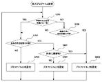
図7に本実施形態におけるステアリング反力設定部210Mによる反力プロファイルの設定手順を示す。図3には示していないが、ステアリング反力設定部210Mは、自車位置認識部140が認識している車線上における現在の位置(以下の説明では自車位置と呼ぶ)と、軌道生成部146が生成した現在の目標位置とを参照することができる。図7の手順は、たとえば図示したようにステアリング反力設定部210Mが継続的に実行してもよいし、繰り返しのループを行わずに、反力プロファイルを切り替えるトリガを受信したときに実行するようにしてもよい。その場合トリガは、たとえば自車位置が、図5に示した左所定位置ML,目標位置T,中央位置C,右所定位置MRのそれぞれをまたいで移動したことであってよい。
FIG. 7 shows a procedure for setting a reaction force profile by the steering reaction
図7において、まず車線中央と目標位置とが一致しているか判定する(S701)。一致していれば、自車位置が、目標位置の左右それぞれの所定位置(図5のMR,MLに相当するプロファイルの切り替え位置)の外側であるか判定する(S703)。外側であれば、一定の舵角差に対して発生する反力が最も弱い反力プロファイルL1を設定する(S707)。一方、そうでない場合、すなわち自車位置が、目標位置から所定範囲内にある場合には、一定の舵角差に対して発生する反力が最も強い反力プロファイルL3を設定する(S705)。またステップS701において、車線中央と目標位置とが一致していないと判定した場合には、自車位置が車線中央と目標位置との間であるか判定する(S709)。該当する場合には、車線中央側をL2、その反対側をL3とした反力プロファイルを設定する(S711)。図6(A)を参照すると、例えば自車位置から車線中央側への操舵の舵角差が正となる場合、正の舵角差に対する反力プロファイルとしてL2を、その反対側即ち負の舵角差に対する反力プロファイルとしてL3を設定する。自車位置から車線中央側への操舵の舵角差が負となる場合にはその逆となる。ステップS709で、自車位置が車線中央と目標位置との間ではないと判定した場合には、ステップS703に分岐して自車位置に応じた反力プロファイルを設定する。 In FIG. 7, it is first determined whether the center of the lane and the target position match (S701). If they match, it is determined whether the position of the own vehicle is outside the predetermined positions on the left and right of the target position (the switching positions of the profiles corresponding to MR and ML in FIG. 5) (S703). If it is on the outside, the reaction force profile L1 in which the reaction force generated for a constant steering angle difference is the weakest is set (S707). On the other hand, if this is not the case, that is, if the vehicle position is within a predetermined range from the target position, the reaction force profile L3 having the strongest reaction force generated for a certain steering angle difference is set (S705). If it is determined in step S701 that the center of the lane and the target position do not match, it is determined whether the position of the own vehicle is between the center of the lane and the target position (S709). If applicable, a reaction force profile is set with L2 on the center side of the lane and L3 on the opposite side (S711). Referring to FIG. 6A, for example, when the steering angle difference of steering from the own vehicle position to the center side of the lane is positive, L2 is used as a reaction force profile for the positive steering angle difference, and the opposite side, that is, the negative steering. L3 is set as the reaction force profile for the angle difference. The opposite is true when the steering angle difference from the vehicle position to the center of the lane is negative. If it is determined in step S709 that the position of the own vehicle is not between the center of the lane and the target position, the vehicle branches to step S703 and a reaction force profile corresponding to the position of the own vehicle is set.
以上のように反力プロファイルを設定することで、例えば図5(B)に示したように、目標位置から車線中央に向けてのオーバーライド操作に対しては発生する反力を弱めることができる。なおステップS711では、反力プロファイルL2を設定してもよい。L2を設定しても、自車位置と、左所定位置ML,目標位置T,中央位置C,右所定位置MRなどとの位置関係で反力プロファイルは切り替えられるため、図5(B)のような反力プロファイルの切り替えは実現できるためである。 By setting the reaction force profile as described above, for example, as shown in FIG. 5B, the reaction force generated for the override operation from the target position toward the center of the lane can be weakened. In step S711, the reaction force profile L2 may be set. Even if L2 is set, the reaction force profile can be switched depending on the positional relationship between the vehicle position and the left predetermined position ML, the target position T, the center position C, the right predetermined position MR, etc., as shown in FIG. 5 (B). This is because it is possible to switch the reaction force profile.
[第2実施形態]
図8に、図7に代えて適用される反力プロファイルの設定手順を示す。図8の手順は、図5(B)で説明したように、障害物に対する反力特性502を実現するための手順である。図7と共通の部分については説明を省略する。ステップS703で自車位置が左右の所定位置MR、MLの外側と判定した場合、走行している車線の外側の所定距離の位置に、他の車両などの障害物があるか判定する(S801)。なければ反力プロファイルL1を設定する(S707)。しかしもしあれば、反力プロファイルL1よりも、一定の舵角に対する反力がより大きな反力プロファイルL2を設定する(S803)。このようにすることで、ドライバーによる、障害物に対して接近するオーバーライド操作を行われにくくすることができる。なお障害物の判定はたとえば外界認識部142から取得した情報に基づいて行うことができる。
[Second Embodiment]
FIG. 8 shows a procedure for setting a reaction force profile to be applied instead of FIG. 7. As described in FIG. 5B, the procedure of FIG. 8 is a procedure for realizing the reaction force characteristic 502 against an obstacle. The description of the parts common to FIG. 7 will be omitted. When it is determined in step S703 that the position of the own vehicle is outside the left and right predetermined positions MR and ML, it is determined whether there is an obstacle such as another vehicle at a predetermined distance outside the traveling lane (S801). .. If not, the reaction force profile L1 is set (S707). However, if there is, a reaction force profile L2 having a larger reaction force with respect to a constant steering angle than the reaction force profile L1 is set (S803). By doing so, it is possible to make it difficult for the driver to perform an override operation approaching an obstacle. The obstacle can be determined based on the information acquired from the outside
●実施形態のまとめ
以上説明した本実施形態をまとめると以下のとおりである。
● Summary of Embodiments The following is a summary of the present embodiments described above.
(1)本発明の第1の態様によれば、自車両の運転支援もしくは自動運転を実施する車両制御装置であって、
周辺の監視結果に基づいて、走行中の車線内の走行経路となる目標位置を設定する設定手段と、
前記目標位置に基づいて操舵制御を行う操舵制御手段とを有し、
前記操舵制御手段は、
前記目標位置に基づいて操舵制御が行われている場合でも、運転者による手動操作による操舵入力を受け付け可能であり、
前記操舵入力を受け付けた際には、前記手動操作に対して所定の反力を発生し、
前記車線の幅方向について、前記目標位置が、自車両が走行している車線の中央付近となる第1基準位置から離間している場合には、前記操舵入力を受け付けた際に、或る舵角の手動操作に対して、前記目標位置から前記第1基準位置に向けた第1の方向への手動操作に対する前記操舵反力が、前記第1の方向とは異なる第2の方向への手動操作に対する前記操舵反力よりも小さくなるよう操舵反力特性を制御することを特徴とする車両制御装置が提供される。
この構成により、中央位置に向けて、オフセット解消する際に、ステリング反力を弱めることで、ユーザー介入のしやすさを向上しつつ、反対側への間違った介入に対して路外逸脱抑制を高めることが可能となる。
(1) According to the first aspect of the present invention, the vehicle control device that supports the driving of the own vehicle or automatically drives the vehicle.
Based on the monitoring results of the surrounding area, a setting means for setting a target position to be a driving route in the driving lane, and a setting means.
It has a steering control means that performs steering control based on the target position.
The steering control means is
Even when steering control is performed based on the target position, it is possible to accept steering input manually operated by the driver.
When the steering input is received, a predetermined reaction force is generated in response to the manual operation.
When the target position is separated from the first reference position near the center of the lane in which the own vehicle is traveling in the width direction of the lane, a certain rudder is used when the steering input is received. With respect to the manual operation of the corner, the steering reaction force for the manual operation in the first direction from the target position to the first reference position is manually in a second direction different from the first direction. Provided is a vehicle control device characterized in that the steering reaction force characteristic is controlled so as to be smaller than the steering reaction force with respect to the operation.
This configuration improves the ease of user intervention by weakening the stelling reaction force when eliminating the offset toward the center position, while suppressing off-road deviation against incorrect intervention on the opposite side. It will be possible to increase.
(2)本発明の第2の態様によれば、(1)に記載の車両制御装置であって、
前記操舵反力特性は、前記目標位置に基づく操舵角から手動操作による操舵角までの差である舵角差と前記操舵反力との間の特性であり、前記舵角差がより大きくなれば、前記操舵反力もより大きくなることを特徴とする車両制御装置が提供される。
この構成により、反力特性を傾きとして定義し、操舵角が増加するたびに反力が大きくなる・小さくなる特性により、ドライバーが直感的に理解することが可能となる。
(2) According to the second aspect of the present invention, the vehicle control device according to (1).
The steering reaction force characteristic is a characteristic between the steering angle difference, which is the difference from the steering angle based on the target position to the steering angle by manual operation, and the steering reaction force, and if the steering angle difference becomes larger. Provided is a vehicle control device characterized in that the steering reaction force is also larger.
With this configuration, the reaction force characteristic is defined as the inclination, and the characteristic that the reaction force increases or decreases as the steering angle increases enables the driver to intuitively understand.
(3)本発明の第2の態様によれば、(2)に記載の車両制御装置であって、
前記第1の方向への前記操舵反力特性は、前記目標位置から前記第1基準位置までの前記舵角差に対する前記操舵反力の増加率が、前記第1基準位置を超えてからの前記舵角差に対する前記操舵反力の増加率よりも小さい
ことを特徴とする請求項1ないし2記載の車両制御装置が提供される。
この構成により、中央位置を通過してさらなる反力増加した場合には、通常反力にて対応することで、ユーザーの過大介入操作に対して適切に反力発生が可能となる。
(3) According to the second aspect of the present invention, the vehicle control device according to (2).
The steering reaction force characteristic in the first direction is the steering reaction force after the rate of increase of the steering reaction force with respect to the steering angle difference from the target position to the first reference position exceeds the first reference position. The vehicle control device according to
With this configuration, when the reaction force further increases after passing through the central position, the reaction force can be appropriately generated in response to the user's excessive intervention operation by responding with the normal reaction force.
(4)本発明の第4の態様によれば、(2)または(3)に記載の車両制御装置であって、
前記操舵制御手段は、前記目標位置から外れる方向への前記操舵入力に対する前記操舵反力を、周辺の監視結果に基づいて、障害物に接近しない場合に比べて障害物に接近する場合に大きくするよう前記前記操舵反力特性を制御することを特徴とする車両制御装置が提供される。
この構成により、障害物接近に対しては、操舵反力を高めることで、障害物接近を抑制することが可能となる。
(4) According to the fourth aspect of the present invention, the vehicle control device according to (2) or (3).
The steering control means increases the steering reaction force with respect to the steering input in a direction deviating from the target position when approaching the obstacle as compared with the case where the obstacle is not approached, based on the monitoring results of the surroundings. As described above, a vehicle control device characterized by controlling the steering reaction force characteristic is provided.
With this configuration, it is possible to suppress the approach of obstacles by increasing the steering reaction force against the approach of obstacles.
(5)本発明の第5の態様によれば、(2)乃至(4)のいずれかに記載の車両制御装置であって、
前記設定手段は、前記周辺監視に基づいて、障害物に対して離間する様に前記走行位置を設定する第1のオフセット制御と、走行中の車線の曲率に基づいて前記第1基準位置から離間する様に前記走行位置を設定する第2のオフセット制御とを行い、
前記操舵制御手段は、前記第1のオフセット制御が行われた場合における前記第1方向への前記舵角差に対する前記操舵反力の増加率よりも、前記第2のオフセット制御が行われた場合における前記第1方向への前記舵角差に対する
前記操舵反力の増加率を小さくするよう前記操舵反力特性を制御することを特徴とする車両制御装置が提供される。
この構成により、カーブでのオフセット解消を低反力、障害物に対するオフセット解消を高反力とし、障害物に対するリスクを反力特性から表現することが可能となる。
(5) According to the fifth aspect of the present invention, the vehicle control device according to any one of (2) to (4).
The setting means has a first offset control for setting the traveling position so as to be separated from an obstacle based on the peripheral monitoring, and a separation from the first reference position based on the curvature of the traveling lane. The second offset control that sets the traveling position is performed so as to be performed.
The steering control means is used when the second offset control is performed rather than the rate of increase of the steering reaction force with respect to the steering angle difference in the first direction when the first offset control is performed. Provided is a vehicle control device characterized in that the steering reaction force characteristic is controlled so as to reduce the rate of increase of the steering reaction force with respect to the steering angle difference in the first direction.
With this configuration, it is possible to express the risk for obstacles from the reaction force characteristics, with the offset elimination on the curve as low reaction force and the offset elimination for obstacles as high reaction force.
(6)本発明の第6の態様によれば、(1)乃至(5)のいずれかに記載の車両制御装置であって、
前記設定手段は、前記操舵制御手段により前記操舵反力を発生させた場合には、新たな目標位置を設定する際に、前記第1基準位置からのずれを低減するように前記新たな目標位置を設定することを特徴とする車両制御装置が提供される。
この構成により、オフセット解消操作が所定以上となる場合に、次回以降もしくは現状のオフセットを解消することでドライバーの嗜好を反映することが可能となる。
(6) According to the sixth aspect of the present invention, the vehicle control device according to any one of (1) to (5).
When the steering reaction force is generated by the steering control means, the setting means sets the new target position so as to reduce the deviation from the first reference position when setting the new target position. A vehicle control device is provided, which comprises setting.
With this configuration, when the offset cancellation operation exceeds a predetermined value, it is possible to reflect the driver's preference from the next time onward or by canceling the current offset.
2 制御ユニット、31 ステアリングホイール、21 ステアリングECU、210M ステアリング反力設定部、210E 反力モータ 2 Control unit, 31 steering wheel, 21 steering ECU, 210M steering reaction force setting unit, 210E reaction force motor
Claims (5)
周辺の監視結果に基づいて、走行中の車線内の走行経路となる目標位置を設定する設定手段と、
前記目標位置に基づいて操舵制御を行う操舵制御手段とを有し、
前記操舵制御手段は、
前記目標位置に基づいて操舵制御が行われている場合でも、運転者による手動操作による操舵入力を受け付け可能であり、
前記操舵入力を受け付けた際には、前記手動操作に対して所定の操舵反力を発生し、
前記車線の幅方向について、前記目標位置が、自車両が走行している車線の中央付近となる第1基準位置から離間している場合には、前記操舵入力を受け付けた際に、或る舵角の手動操作に対して、前記目標位置から前記第1基準位置に向けた第1の方向への手動操作に対する前記操舵反力が、前記第1の方向とは異なる第2の方向への手動操作に対する前記操舵反力よりも小さくなるよう操舵反力特性を制御し、
前記第1の方向への前記操舵反力特性は、前記目標位置から前記第1基準位置までの、前記目標位置に基づく操舵角から手動操作による操舵角までの舵角差に対する前記操舵反力の増加率が、前記第1基準位置を超えてからの前記舵角差に対する前記操舵反力の増加率よりも小さい
ことを特徴とする車両制御装置。 It is a vehicle control device that supports the driving of the own vehicle or automatically drives it.
Based on the monitoring results of the surrounding area, a setting means for setting a target position to be a driving route in the driving lane, and a setting means.
It has a steering control means that performs steering control based on the target position.
The steering control means is
Even when steering control is performed based on the target position, it is possible to accept steering input manually operated by the driver.
When the steering input is received, a predetermined steering reaction force is generated in response to the manual operation.
When the target position is separated from the first reference position near the center of the lane in which the own vehicle is traveling in the width direction of the lane, a certain rudder is used when the steering input is received. With respect to the manual operation of the corner, the steering reaction force for the manual operation in the first direction from the target position to the first reference position is manually in a second direction different from the first direction. The steering reaction force characteristics are controlled so as to be smaller than the steering reaction force with respect to the operation.
The steering reaction force characteristic in the first direction is the steering reaction force with respect to the steering angle difference from the target position to the first reference position , from the steering angle based on the target position to the steering angle by manual operation . A vehicle control device characterized in that the rate of increase is smaller than the rate of increase of the steering reaction force with respect to the difference in steering angle after the first reference position is exceeded.
前記操舵反力特性は、前記舵角差と前記操舵反力との間の特性であり、前記舵角差がより大きくなれば、前記操舵反力もより大きくなる
ことを特徴とする車両制御装置。 The vehicle control device according to claim 1.
The steering reaction force characteristic is a characteristic between the steering angle difference and the steering reaction force, and the vehicle control device is characterized in that the larger the steering angle difference, the larger the steering reaction force. ..
前記操舵制御手段は、前記目標位置から外れる方向への前記操舵入力に対する前記操舵反力を、周辺の監視結果に基づいて、障害物に接近しない場合に比べて障害物に接近する場合に大きくするよう前記操舵反力特性を制御する
ことを特徴とする車両制御装置。 The vehicle control device according to claim 2.
The steering control means increases the steering reaction force with respect to the steering input in a direction deviating from the target position when approaching the obstacle as compared with the case where the obstacle is not approached, based on the monitoring results of the surroundings. A vehicle control device characterized by controlling the steering reaction force characteristic.
前記設定手段は、周辺の監視結果に基づいて、障害物に対して離間する様に走行位置を設定する第1のオフセット制御と、走行中の車線の曲率に基づいて前記第1基準位置から離間する様に前記走行位置を設定する第2のオフセット制御とを行い、
前記操舵制御手段は、前記第1のオフセット制御が行われた場合における前記第1の方向への前記舵角差に対する前記操舵反力の増加率よりも、前記第2のオフセット制御が行われた場合における前記第1の方向への前記舵角差に対する前記操舵反力の増加率を小さくするよう前記操舵反力特性を制御する
ことを特徴とする車両制御装置。 The vehicle control device according to claim 2 or 3.
The setting means has a first offset control for setting a traveling position so as to be separated from an obstacle based on the monitoring result of the surroundings , and the first reference position based on the curvature of the traveling lane. A second offset control that sets the traveling position so as to be separated from the vehicle is performed.
The steering control means performed the second offset control rather than the rate of increase of the steering reaction force with respect to the steering angle difference in the first direction when the first offset control was performed. A vehicle control device comprising controlling the steering reaction force characteristic so as to reduce the rate of increase of the steering reaction force with respect to the steering angle difference in the first direction in the case.
前記設定手段は、前記操舵制御手段により前記操舵反力を発生させた場合には、新たな目標位置を設定する際に、前記第1基準位置からのずれを低減するように前記新たな目標位置を設定する
ことを特徴とする車両制御装置。 The vehicle control device according to any one of claims 1 to 4.
When the steering reaction force is generated by the steering control means, the setting means sets the new target position so as to reduce the deviation from the first reference position when setting the new target position. A vehicle control device characterized by setting.
Priority Applications (3)
| Application Number | Priority Date | Filing Date | Title |
|---|---|---|---|
| JP2019021799A JP7099970B2 (en) | 2019-02-08 | 2019-02-08 | Vehicle control device |
| US16/775,731 US11225248B2 (en) | 2019-02-08 | 2020-01-29 | Vehicle control apparatus |
| CN202010078605.8A CN111547130B (en) | 2019-02-08 | 2020-02-03 | Vehicle control device |
Applications Claiming Priority (1)
| Application Number | Priority Date | Filing Date | Title |
|---|---|---|---|
| JP2019021799A JP7099970B2 (en) | 2019-02-08 | 2019-02-08 | Vehicle control device |
Publications (3)
| Publication Number | Publication Date |
|---|---|
| JP2020128167A JP2020128167A (en) | 2020-08-27 |
| JP2020128167A5 JP2020128167A5 (en) | 2022-01-20 |
| JP7099970B2 true JP7099970B2 (en) | 2022-07-12 |
Family
ID=71945824
Family Applications (1)
| Application Number | Title | Priority Date | Filing Date |
|---|---|---|---|
| JP2019021799A Active JP7099970B2 (en) | 2019-02-08 | 2019-02-08 | Vehicle control device |
Country Status (3)
| Country | Link |
|---|---|
| US (1) | US11225248B2 (en) |
| JP (1) | JP7099970B2 (en) |
| CN (1) | CN111547130B (en) |
Families Citing this family (8)
| Publication number | Priority date | Publication date | Assignee | Title |
|---|---|---|---|---|
| JP7256982B2 (en) | 2018-12-28 | 2023-04-13 | スズキ株式会社 | Vehicle travel control device |
| JP7205768B2 (en) * | 2019-03-08 | 2023-01-17 | スズキ株式会社 | Vehicle travel control device |
| JP7393730B2 (en) | 2019-09-26 | 2023-12-07 | スズキ株式会社 | Vehicle travel control device |
| JP2022150613A (en) * | 2021-03-26 | 2022-10-07 | トヨタ自動車株式会社 | travel control device |
| US20220371585A1 (en) * | 2021-05-21 | 2022-11-24 | Robert Bosch Gmbh | Customizable lane biasing for an automated vehicle |
| JP2022185937A (en) * | 2021-06-03 | 2022-12-15 | 株式会社デンソー | Seat control device, seat control program, state estimation device, and state estimation program |
| JP2022187850A (en) * | 2021-06-08 | 2022-12-20 | 日立Astemo株式会社 | Travelling support device |
| US20230174086A1 (en) * | 2021-12-01 | 2023-06-08 | GM Global Technology Operations LLC | Methods and systems for adaptive blending of driver and automated steering commands under external threat |
Citations (2)
| Publication number | Priority date | Publication date | Assignee | Title |
|---|---|---|---|---|
| JP2012232704A (en) | 2011-05-09 | 2012-11-29 | Jtekt Corp | Vehicle steering device |
| JP2017218020A (en) | 2016-06-07 | 2017-12-14 | 本田技研工業株式会社 | Vehicle control device, vehicle control method and vehicle control program |
Family Cites Families (11)
| Publication number | Priority date | Publication date | Assignee | Title |
|---|---|---|---|---|
| CN104602989B (en) * | 2012-09-04 | 2016-03-16 | 日产自动车株式会社 | Control device for stability |
| CN104703862B (en) * | 2012-10-01 | 2017-05-24 | 日产自动车株式会社 | Stability control device |
| JP6082415B2 (en) * | 2015-03-03 | 2017-02-15 | 富士重工業株式会社 | Vehicle travel control device |
| EP3281845B1 (en) * | 2015-04-09 | 2020-01-01 | Nissan Motor Co., Ltd. | Lane maintaining assistance device |
| JP6376352B2 (en) * | 2015-08-07 | 2018-08-22 | トヨタ自動車株式会社 | Vehicle travel control device |
| JP6573643B2 (en) * | 2017-03-27 | 2019-09-11 | 株式会社Subaru | Vehicle travel control device |
| JP6643297B2 (en) * | 2017-11-16 | 2020-02-12 | 株式会社Subaru | Driving support device |
| JP7074600B2 (en) * | 2018-07-18 | 2022-05-24 | トヨタ自動車株式会社 | Driving support device |
| JP6637553B1 (en) * | 2018-07-26 | 2020-01-29 | 株式会社Subaru | Vehicle control device |
| JP7211149B2 (en) * | 2019-02-21 | 2023-01-24 | トヨタ自動車株式会社 | electric power steering device |
| JP7348775B2 (en) * | 2019-08-28 | 2023-09-21 | 株式会社Subaru | Vehicle lane departure prevention control device |
-
2019
- 2019-02-08 JP JP2019021799A patent/JP7099970B2/en active Active
-
2020
- 2020-01-29 US US16/775,731 patent/US11225248B2/en active Active
- 2020-02-03 CN CN202010078605.8A patent/CN111547130B/en active Active
Patent Citations (2)
| Publication number | Priority date | Publication date | Assignee | Title |
|---|---|---|---|---|
| JP2012232704A (en) | 2011-05-09 | 2012-11-29 | Jtekt Corp | Vehicle steering device |
| JP2017218020A (en) | 2016-06-07 | 2017-12-14 | 本田技研工業株式会社 | Vehicle control device, vehicle control method and vehicle control program |
Also Published As
| Publication number | Publication date |
|---|---|
| CN111547130A (en) | 2020-08-18 |
| CN111547130B (en) | 2022-06-07 |
| JP2020128167A (en) | 2020-08-27 |
| US11225248B2 (en) | 2022-01-18 |
| US20200255007A1 (en) | 2020-08-13 |
Similar Documents
| Publication | Publication Date | Title |
|---|---|---|
| JP7144947B2 (en) | vehicle controller | |
| JP7099970B2 (en) | Vehicle control device | |
| US10386838B2 (en) | Vehicle control device, vehicle control method, and vehicle control program | |
| US11008016B2 (en) | Display system, display method, and storage medium | |
| JP7177862B2 (en) | positioning device | |
| US11267484B2 (en) | Vehicle control system, vehicle control method, and vehicle control program | |
| US20190071075A1 (en) | Vehicle control system, vehicle control method, and vehicle control program | |
| JP6947849B2 (en) | Vehicle control device | |
| WO2021005645A1 (en) | Control system for vehicle, control method for vehicle, and program | |
| JP2019138773A (en) | Display device | |
| US11348463B2 (en) | Travel control device, travel control method, and storage medium storing program | |
| CN111532269B (en) | Vehicle control device | |
| US20180074498A1 (en) | Travel control device | |
| JPWO2019106788A1 (en) | Vehicle control device, vehicle, and vehicle control method | |
| JP7213149B2 (en) | VEHICLE CONTROL DEVICE, VEHICLE, OPERATING METHOD AND PROGRAM OF VEHICLE CONTROL DEVICE | |
| JP7073313B2 (en) | Vehicle control unit | |
| JP6982083B2 (en) | Driving control device and vehicle | |
| JP7220192B2 (en) | VEHICLE CONTROL DEVICE, VEHICLE CONTROL METHOD, AND PROGRAM | |
| JP7138133B2 (en) | VEHICLE CONTROL DEVICE, VEHICLE, OPERATING METHOD AND PROGRAM OF VEHICLE CONTROL DEVICE | |
| JP7189088B2 (en) | VEHICLE CONTROL DEVICE, VEHICLE, OPERATING METHOD AND PROGRAM OF VEHICLE CONTROL DEVICE | |
| JP2022152607A (en) | Driving support device, driving support method, and program | |
| JP7104649B2 (en) | Vehicle control systems, vehicle control methods, and programs | |
| US20230147987A1 (en) | Vehicle control system, vehicle control method, and storage medium | |
| US20230311875A1 (en) | Control device, method for operating control device, and non-transitory computer-readable storage medium | |
| JP7393258B2 (en) | Control device and vehicle |
Legal Events
| Date | Code | Title | Description |
|---|---|---|---|
| RD02 | Notification of acceptance of power of attorney |
Free format text: JAPANESE INTERMEDIATE CODE: A7422 Effective date: 20210103 |
|
| A521 | Request for written amendment filed |
Free format text: JAPANESE INTERMEDIATE CODE: A523 Effective date: 20210125 |
|
| A621 | Written request for application examination |
Free format text: JAPANESE INTERMEDIATE CODE: A621 Effective date: 20210329 |
|
| A521 | Request for written amendment filed |
Free format text: JAPANESE INTERMEDIATE CODE: A523 Effective date: 20220112 |
|
| A871 | Explanation of circumstances concerning accelerated examination |
Free format text: JAPANESE INTERMEDIATE CODE: A871 Effective date: 20220112 |
|
| A131 | Notification of reasons for refusal |
Free format text: JAPANESE INTERMEDIATE CODE: A131 Effective date: 20220311 |
|
| A521 | Request for written amendment filed |
Free format text: JAPANESE INTERMEDIATE CODE: A523 Effective date: 20220414 |
|
| TRDD | Decision of grant or rejection written | ||
| A01 | Written decision to grant a patent or to grant a registration (utility model) |
Free format text: JAPANESE INTERMEDIATE CODE: A01 Effective date: 20220624 |
|
| A61 | First payment of annual fees (during grant procedure) |
Free format text: JAPANESE INTERMEDIATE CODE: A61 Effective date: 20220630 |
|
| R150 | Certificate of patent or registration of utility model |
Ref document number: 7099970 Country of ref document: JP Free format text: JAPANESE INTERMEDIATE CODE: R150 |