JP7098739B2 - Devices and Methods for Performing Power Compensation in Wireless Power Transfer Systems - Google Patents
Devices and Methods for Performing Power Compensation in Wireless Power Transfer Systems Download PDFInfo
- Publication number
- JP7098739B2 JP7098739B2 JP2020544732A JP2020544732A JP7098739B2 JP 7098739 B2 JP7098739 B2 JP 7098739B2 JP 2020544732 A JP2020544732 A JP 2020544732A JP 2020544732 A JP2020544732 A JP 2020544732A JP 7098739 B2 JP7098739 B2 JP 7098739B2
- Authority
- JP
- Japan
- Prior art keywords
- power
- wireless power
- packet
- wireless
- correction
- Prior art date
- Legal status (The legal status is an assumption and is not a legal conclusion. Google has not performed a legal analysis and makes no representation as to the accuracy of the status listed.)
- Active
Links
- 238000000034 method Methods 0.000 title description 196
- 238000012546 transfer Methods 0.000 title description 67
- 230000005540 biological transmission Effects 0.000 claims description 521
- 238000012937 correction Methods 0.000 claims description 505
- 230000006854 communication Effects 0.000 claims description 170
- 238000004891 communication Methods 0.000 claims description 170
- 238000006243 chemical reaction Methods 0.000 claims description 16
- 238000001514 detection method Methods 0.000 description 78
- 230000004044 response Effects 0.000 description 78
- 230000008859 change Effects 0.000 description 65
- 230000008878 coupling Effects 0.000 description 64
- 238000010168 coupling process Methods 0.000 description 64
- 238000005859 coupling reaction Methods 0.000 description 64
- 102100036409 Activated CDC42 kinase 1 Human genes 0.000 description 48
- 108091006146 Channels Proteins 0.000 description 46
- 230000008569 process Effects 0.000 description 22
- 239000003999 initiator Substances 0.000 description 18
- 238000003780 insertion Methods 0.000 description 18
- 230000037431 insertion Effects 0.000 description 18
- 238000010586 diagram Methods 0.000 description 17
- 230000006870 function Effects 0.000 description 17
- 238000005259 measurement Methods 0.000 description 15
- 230000006698 induction Effects 0.000 description 10
- 239000003990 capacitor Substances 0.000 description 9
- 230000001965 increasing effect Effects 0.000 description 9
- 239000000126 substance Substances 0.000 description 9
- 230000007704 transition Effects 0.000 description 9
- 238000001914 filtration Methods 0.000 description 8
- 238000005516 engineering process Methods 0.000 description 7
- 238000011088 calibration curve Methods 0.000 description 6
- 238000001646 magnetic resonance method Methods 0.000 description 6
- 238000012795 verification Methods 0.000 description 6
- 230000000977 initiatory effect Effects 0.000 description 5
- 238000012544 monitoring process Methods 0.000 description 5
- 238000012545 processing Methods 0.000 description 5
- 235000001537 Ribes X gardonianum Nutrition 0.000 description 4
- 235000001535 Ribes X utile Nutrition 0.000 description 4
- 235000016919 Ribes petraeum Nutrition 0.000 description 4
- 244000281247 Ribes rubrum Species 0.000 description 4
- 235000002355 Ribes spicatum Nutrition 0.000 description 4
- 208000015228 acquired partial lipodystrophy Diseases 0.000 description 4
- 238000012790 confirmation Methods 0.000 description 4
- 238000013459 approach Methods 0.000 description 3
- 238000004364 calculation method Methods 0.000 description 3
- 230000001419 dependent effect Effects 0.000 description 3
- 230000009977 dual effect Effects 0.000 description 3
- 230000014509 gene expression Effects 0.000 description 3
- 101000741965 Homo sapiens Inactive tyrosine-protein kinase PRAG1 Proteins 0.000 description 2
- 102100038659 Inactive tyrosine-protein kinase PRAG1 Human genes 0.000 description 2
- 230000003044 adaptive effect Effects 0.000 description 2
- 230000006399 behavior Effects 0.000 description 2
- 230000002457 bidirectional effect Effects 0.000 description 2
- 230000007423 decrease Effects 0.000 description 2
- 230000003247 decreasing effect Effects 0.000 description 2
- 230000000694 effects Effects 0.000 description 2
- 230000005672 electromagnetic field Effects 0.000 description 2
- 230000007613 environmental effect Effects 0.000 description 2
- 230000001976 improved effect Effects 0.000 description 2
- 238000009434 installation Methods 0.000 description 2
- 238000012986 modification Methods 0.000 description 2
- 230000004048 modification Effects 0.000 description 2
- 230000010363 phase shift Effects 0.000 description 2
- 238000012797 qualification Methods 0.000 description 2
- 230000001360 synchronised effect Effects 0.000 description 2
- 238000004804 winding Methods 0.000 description 2
- 229910000859 α-Fe Inorganic materials 0.000 description 2
- 208000017457 Autosomal erythropoietic protoporphyria Diseases 0.000 description 1
- RYGMFSIKBFXOCR-UHFFFAOYSA-N Copper Chemical compound [Cu] RYGMFSIKBFXOCR-UHFFFAOYSA-N 0.000 description 1
- 240000007594 Oryza sativa Species 0.000 description 1
- 235000007164 Oryza sativa Nutrition 0.000 description 1
- 206010000210 abortion Diseases 0.000 description 1
- 230000004913 activation Effects 0.000 description 1
- 230000006978 adaptation Effects 0.000 description 1
- 230000007175 bidirectional communication Effects 0.000 description 1
- 230000015572 biosynthetic process Effects 0.000 description 1
- 230000001364 causal effect Effects 0.000 description 1
- 230000001413 cellular effect Effects 0.000 description 1
- 239000004020 conductor Substances 0.000 description 1
- 239000000470 constituent Substances 0.000 description 1
- 238000009795 derivation Methods 0.000 description 1
- 201000008220 erythropoietic protoporphyria Diseases 0.000 description 1
- 230000004907 flux Effects 0.000 description 1
- 239000011521 glass Substances 0.000 description 1
- 230000001939 inductive effect Effects 0.000 description 1
- 238000009440 infrastructure construction Methods 0.000 description 1
- 238000012886 linear function Methods 0.000 description 1
- 239000002184 metal Substances 0.000 description 1
- 229910052751 metal Inorganic materials 0.000 description 1
- 239000005300 metallic glass Substances 0.000 description 1
- 238000013021 overheating Methods 0.000 description 1
- 230000000737 periodic effect Effects 0.000 description 1
- 230000035699 permeability Effects 0.000 description 1
- 229920002578 polythiourethane polymer Polymers 0.000 description 1
- 230000002250 progressing effect Effects 0.000 description 1
- 238000009774 resonance method Methods 0.000 description 1
- 235000009566 rice Nutrition 0.000 description 1
- 229920006395 saturated elastomer Polymers 0.000 description 1
- 230000011218 segmentation Effects 0.000 description 1
- 239000004984 smart glass Substances 0.000 description 1
- 230000003068 static effect Effects 0.000 description 1
- 230000008093 supporting effect Effects 0.000 description 1
- 238000012800 visualization Methods 0.000 description 1
Images


Classifications
-
- H—ELECTRICITY
- H02—GENERATION; CONVERSION OR DISTRIBUTION OF ELECTRIC POWER
- H02J—CIRCUIT ARRANGEMENTS OR SYSTEMS FOR SUPPLYING OR DISTRIBUTING ELECTRIC POWER; SYSTEMS FOR STORING ELECTRIC ENERGY
- H02J50/00—Circuit arrangements or systems for wireless supply or distribution of electric power
- H02J50/10—Circuit arrangements or systems for wireless supply or distribution of electric power using inductive coupling
-
- H—ELECTRICITY
- H02—GENERATION; CONVERSION OR DISTRIBUTION OF ELECTRIC POWER
- H02J—CIRCUIT ARRANGEMENTS OR SYSTEMS FOR SUPPLYING OR DISTRIBUTING ELECTRIC POWER; SYSTEMS FOR STORING ELECTRIC ENERGY
- H02J50/00—Circuit arrangements or systems for wireless supply or distribution of electric power
- H02J50/40—Circuit arrangements or systems for wireless supply or distribution of electric power using two or more transmitting or receiving devices
-
- H—ELECTRICITY
- H02—GENERATION; CONVERSION OR DISTRIBUTION OF ELECTRIC POWER
- H02J—CIRCUIT ARRANGEMENTS OR SYSTEMS FOR SUPPLYING OR DISTRIBUTING ELECTRIC POWER; SYSTEMS FOR STORING ELECTRIC ENERGY
- H02J50/00—Circuit arrangements or systems for wireless supply or distribution of electric power
- H02J50/60—Circuit arrangements or systems for wireless supply or distribution of electric power responsive to the presence of foreign objects, e.g. detection of living beings
-
- H—ELECTRICITY
- H02—GENERATION; CONVERSION OR DISTRIBUTION OF ELECTRIC POWER
- H02J—CIRCUIT ARRANGEMENTS OR SYSTEMS FOR SUPPLYING OR DISTRIBUTING ELECTRIC POWER; SYSTEMS FOR STORING ELECTRIC ENERGY
- H02J50/00—Circuit arrangements or systems for wireless supply or distribution of electric power
- H02J50/80—Circuit arrangements or systems for wireless supply or distribution of electric power involving the exchange of data, concerning supply or distribution of electric power, between transmitting devices and receiving devices
-
- H—ELECTRICITY
- H04—ELECTRIC COMMUNICATION TECHNIQUE
- H04L—TRANSMISSION OF DIGITAL INFORMATION, e.g. TELEGRAPHIC COMMUNICATION
- H04L1/00—Arrangements for detecting or preventing errors in the information received
- H04L1/12—Arrangements for detecting or preventing errors in the information received by using return channel
- H04L1/16—Arrangements for detecting or preventing errors in the information received by using return channel in which the return channel carries supervisory signals, e.g. repetition request signals
-
- H—ELECTRICITY
- H02—GENERATION; CONVERSION OR DISTRIBUTION OF ELECTRIC POWER
- H02J—CIRCUIT ARRANGEMENTS OR SYSTEMS FOR SUPPLYING OR DISTRIBUTING ELECTRIC POWER; SYSTEMS FOR STORING ELECTRIC ENERGY
- H02J50/00—Circuit arrangements or systems for wireless supply or distribution of electric power
- H02J50/10—Circuit arrangements or systems for wireless supply or distribution of electric power using inductive coupling
- H02J50/12—Circuit arrangements or systems for wireless supply or distribution of electric power using inductive coupling of the resonant type
Description
本発明は、無線充電に関し、より詳しくは、無線電力送信システムにおける電力補正を実行する装置及び方法に関する。 The present invention relates to wireless charging, and more particularly to devices and methods for performing power correction in wireless power transfer systems.
無線電力送信技術は、電源ソースと電子機器との間に無線で電力を伝達する技術である。一例として、無線電力送信技術は、スマートフォンやタブレットなどの無線端末を単に無線充電パッド上に置くことだけで無線端末のバッテリが充電されるようにすることによって、既存の有線充電コネクタを利用する有線充電環境に比べて優れた移動性と便宜性、そして安全性を提供することができる。無線電力送信技術は、無線端末の無線充電以外にも、電気自動車、ブルートゥースイヤホンや3Dメガネなど、各種ウェアラブルデバイス(wearable device)、家電機器、家具、地中施設物、建物、医療機器、ロボット、レジャーなどの多様な分野で既存の有線電力送信環境を代替することと注目を浴びている。 Wireless power transmission technology is a technology for transmitting power wirelessly between a power source and an electronic device. As an example, wireless power transfer technology utilizes existing wired charging connectors by allowing wireless terminals such as smartphones and tablets to be charged by simply placing them on a wireless charging pad. It can provide superior mobility, convenience, and safety compared to the charging environment. In addition to wireless charging of wireless terminals, wireless power transmission technology includes various wearable devices such as electric vehicles, Bluetooth earphones and 3D glasses, home appliances, furniture, underground facilities, buildings, medical equipment, robots, etc. It is attracting attention as an alternative to the existing wired power transmission environment in various fields such as leisure.
無線電力送信方式を非接触(contactless)電力送信方式または無接点(no point of contact)電力送信方式、無線充電(wireless charging)方式ともいう。無線電力送信システムは、無線電力送信方式に電気エネルギーを供給する無線電力送信装置と、前記無線電力送信装置から無線で供給される電気エネルギーを受信してバッテリセル等の受電装置に電力を供給する無線電力受信装置と、で構成されることができる。 The wireless power transmission method is also referred to as a contactless power transmission method, a no point of contact power transmission method, or a wireless charging method. The wireless power transmission system receives electric energy supplied wirelessly from the wireless power transmission device and a wireless power transmission device that supplies electric energy to the wireless power transmission method, and supplies power to a power receiving device such as a battery cell. It can consist of a wireless power receiver and.
無線電力送信技術は、磁気カップリング(magnetic coupling)を介して電力を伝達する方式、無線周波数(radio frequency:RF)を介して電力を伝達する方式、マイクロウェイブ(microwave)を介して電力を伝達する方式、超音波を介して電力を伝達する方式など、多様である。また、磁気カップリングに基づく方式は、磁気誘導(magnetic induction)方式と磁気共振(magnetic resonance)方式に分類される。磁気誘導方式は、送信側のコイルと受信側のコイルとの間の電磁気結合によって送信側コイルバッテリセルで発生させた磁場によって受信側コイルに誘導される電流を利用してエネルギーを送信する方式である。磁気共振方式は、磁場を利用するという点で磁気誘導方式と類似する。しかし、磁気共振方式は、送信側のコイルと受信側のコイルに特定共振周波数が印加される時に共振が発生し、それによって、送信側と受信側の両端に磁場が集中する現象によりエネルギーが伝達される側面で磁気誘導とは異なる。 The wireless power transmission technology includes a method of transmitting power via magnetic coupling, a method of transmitting power via radio frequency (RF), and a method of transmitting power via microwave. There are various methods such as the method of transmitting electric power and the method of transmitting electric power via ultrasonic waves. Further, the method based on the magnetic coupling is classified into a magnetic induction method and a magnetic resonance method. The magnetic induction method is a method of transmitting energy by using a current induced in a receiving coil by a magnetic field generated in a transmitting coil battery cell by an electromagnetic coupling between a transmitting coil and a receiving coil. be. The magnetic resonance method is similar to the magnetic induction method in that a magnetic field is used. However, in the magnetic resonance method, resonance occurs when a specific resonance frequency is applied to the coil on the transmitting side and the coil on the receiving side, and as a result, energy is transmitted by the phenomenon that the magnetic field is concentrated at both ends of the transmitting side and the receiving side. It is different from magnetic induction in the aspect of being.
無線電力送信装置と無線電力受信装置は、その内部に多数の回路部品で構成されており、互いに独立的な装置を構成するが、これらの間に磁気カップリングにより無線電力送信が行われる。したがって、無線電力送信装置と無線電力受信装置は、一つの無線電力送信システムを構成する。しかし、無線電力送信システムの固有な物理的特性だけでなく、TxとRxの実際使用環境(無線電力送信システムに印加される信号の大きさ、周波数、デューティサイクル、TxとRxとの間の距離/位置整列等)による磁気カップリングの変化によって送信電力と受信電力に誤差が発生できる。このような誤差は、精巧な異物検出に障害要素になることがある。 The wireless power transmitting device and the wireless power receiving device are composed of a large number of circuit components inside the device and constitute devices independent of each other, and wireless power transmission is performed between them by magnetic coupling. Therefore, the wireless power transmitting device and the wireless power receiving device constitute one wireless power transmitting system. However, not only the unique physical characteristics of the wireless power transmission system, but also the actual usage environment of Tx and Rx (the magnitude, frequency, duty cycle, distance between Tx and Rx of the signal applied to the wireless power transmission system). An error can occur between the transmission power and the reception power due to changes in the magnetic coupling due to (/ position alignment, etc.). Such an error can be an obstacle to sophisticated foreign matter detection.
したがって、無線電力送信システムの固有な特性と実際使用環境の変化を反映して送信電力と受信電力を補正し、これに基づいてより精巧なFODを実行する方法が要求される。 Therefore, there is a need for a method of correcting transmission power and reception power to reflect changes in the unique characteristics of the wireless power transmission system and the actual usage environment, and performing more elaborate FOD based on this.
本発明の技術的課題は、無線電力送信システムにおける電力補正を実行する装置及び方法を提供することにある。 A technical object of the present invention is to provide a device and a method for performing power correction in a wireless power transmission system.
本発明の他の技術的課題は、負荷変化に適応的に電力を補正し、異物検出を実行する装置及び方法を提供することにある。 Another technical object of the present invention is to provide a device and a method for adaptively correcting power to change a load and performing foreign matter detection.
本発明の他の技術的課題は、無線電力送信装置と無線電力受信装置との間の磁気カップリング変化に適応的に電力を補正し、異物検出を実行する装置及び方法を提供することにある。 Another technical object of the present invention is to provide an apparatus and a method for performing foreign matter detection by adaptively compensating for a change in magnetic coupling between a wireless power transmitting device and a wireless power receiving device. ..
本発明の課題は、以上で言及した課題に制限されるものではなく、言及されない他の課題は、以下の記載から当業者が明確に理解することができる。 The problems of the present invention are not limited to the problems mentioned above, and other problems not mentioned can be clearly understood by those skilled in the art from the following description.
本発明の一実施例に係る無線電力送信装置は、電力送信段階(power transfer phase)で、磁気カップリング(magnetic coupling)に基づいて生成された無線電力を無線電力受信装置に送信するように構成された電力変換ユニット(power conversion unit)、及び前記無線電力受信装置から電力補正に関連した第1の受信電力パケットと第2の受信電力パケットを受信して前記第1の受信電力パケットと前記第2の受信電力パケットに基づいて第1の電力補正カーブを構成し、前記無線電力受信装置から電力補正に関連した第3の受信電力パケットと第4の受信電力パケットを受信して前記第3の受信電力パケットと前記第4の受信電力パケットに基づいて第2の電力補正カーブを構成する通信/コントロールユニット(communication/control unit)を含む。 The wireless power transmitting device according to an embodiment of the present invention is configured to transmit wireless power generated based on magnetic coupling to a wireless power receiving device in a power transfer phase. A first received power packet and a second received power packet related to power correction are received from the power conversion unit and the radio power receiving device, and the first received power packet and the first received power packet are received. The first power correction curve is configured based on the received power packet of 2, and the third received power packet and the fourth received power packet related to the power correction are received from the wireless power receiving device to receive the third received power packet. It includes a communication / control unit that constitutes a second power correction curve based on the received power packet and the fourth received power packet.
本発明の一実施例に係る無線電力受信装置は、電力送信段階(power transfer phase)で、磁気カップリング(magnetic coupling)に基づいて生成された無線電力を無線電力送信装置から受信するように構成された電力変換ユニット(power conversion unit)、及び第1の作動モード(operating mode)で電力補正に関連した第1の受信電力パケットと第2の受信電力パケットを前記無線電力送信装置に送信し、第2の作動モード(operating mode)で電力補正に関連した第3の受信電力パケットと第4の受信電力パケットを前記無線電力送信装置に送信する通信/コントロールユニット(communication/control unit)を含む。 The wireless power receiving device according to an embodiment of the present invention is configured to receive wireless power generated based on magnetic coupling from the wireless power transmitting device in the power transfer phase. In the power conversion unit and the operating mode, the first received power packet and the second received power packet related to the power correction are transmitted to the wireless power transmission device. It includes a communication / control unit that transmits a third received power packet and a fourth received power packet related to power correction to the radio power transmission device in a second operating mode.
本発明の一実施例に係る無線電力送信装置は、電力送信段階(power transfer phase)で、磁気カップリング(magnetic coupling)に基づいて生成された無線電力を無線電力受信装置に送信するように構成された電力変換ユニット(power conversion unit)、及び第1の動作点で作動する前記無線電力受信装置から電力補正に関連した第1の動作点の第1の受信電力パケットと第1の動作点の第2の受信電力パケットを受信して前記第1の動作点の第1の受信電力パケットと前記第1の動作点の第2の受信電力パケットに基づいて第1の電力補正カーブを構成し、第2の動作点で作動する前記無線電力受信装置から電力補正に関連した第2の動作点の第1の受信電力パケットと第2の動作点の第2の受信電力パケットを受信して前記第2の動作点の第1の受信電力パケットと前記第2の動作点の第2の受信電力パケットに基づいて第2の電力補正カーブを構成する通信/コントロールユニット(communication/control unit)を含む。 The wireless power transmitting device according to an embodiment of the present invention is configured to transmit wireless power generated based on magnetic coupling to a wireless power receiving device in a power transfer phase. Power conversion unit, and the first received power packet and the first operating point of the first operating point related to power correction from the wireless power receiving device operating at the first operating point. The second received power packet is received to form a first power correction curve based on the first received power packet at the first operating point and the second received power packet at the first operating point. The second received power packet of the second operating point and the second received power packet of the second operating point related to the power correction are received from the wireless power receiving device operating at the second operating point. It includes a communication / control unit that constitutes a second power correction curve based on the first received power packet of the second operating point and the second received power packet of the second operating point.
本発明の一実施例に係る無線電力受信装置は、電力送信段階(power transfer phase)で、磁気カップリング(magnetic coupling)に基づいて生成された無線電力を無線電力送信装置から受信するように構成された電力変換ユニット(power conversion unit)、及び第1の動作点で作動して電力補正に関連した第1の動作点の第1の受信電力パケットと第1の動作点の第2の受信電力パケットを前記無線電力送信装置に送信し、動作点が第1の動作点から第2の動作点へ変更される場合に電力補正に関連した第2の動作点の第1の受信電力パケットと第2の動作点の第2の受信電力パケットを前記無線電力送信装置に送信する通信/コントロールユニット(communication/control unit)を含む。
The wireless power receiving device according to an embodiment of the present invention is configured to receive wireless power generated based on magnetic coupling from the wireless power transmitting device in the power transfer phase. Power conversion unit, and the first received power packet of the first operating point and the second received power of the first operating point that are operating at the first operating point and related to power correction. When the packet is transmitted to the wireless power transmission device and the operating point is changed from the first operating point to the second operating point, the first received power packet and the second received power packet of the second operating point related to the power correction. The communication / control unit (communication / control unit) for transmitting the second received power packet of the
本発明のその他の具体的な事項は、詳細な説明及び図面に含まれている。 Other specific matters of the present invention are included in the detailed description and drawings.
新しく変化された無線充電環境に適応的に反応して送信電力と受信電力を補正し、これに基づいて電力損失を検知することによって精巧な異物検出が可能になる。 By adaptively reacting to the newly changed wireless charging environment and correcting the transmission power and reception power, and detecting the power loss based on this, sophisticated foreign matter detection becomes possible.
本発明による効果は、以上で例示した内容により制限されるものではなく、一層多様な効果が本明細書内に含まれている。 The effects according to the present invention are not limited by the contents exemplified above, and more various effects are included in the present specification.
本明細書において“AまたはB(A or B)”は、“Aのみ”、“Bのみ”または“AとBの両方とも”を意味することができる。他の表現として、本明細書において“AまたはB(A or B)”は“A及び/またはB(A and/or B)”と解釈できる。例えば、本明細書において“A、BまたはC(A,B or C)”は“Aのみ”、“Bのみ”、“Cのみ”、または“A、B及びCの任意の全ての組み合わせ(any combination of A,B and C)”を意味することができる。 As used herein, "A or B (A or B)" can mean "A only", "B only" or "both A and B". As another expression, "A or B (A or B)" can be construed as "A and / or B (A and / or B)" herein. For example, in the present specification, "A, B or C (A, B or C)" is "A only", "B only", "C only", or any combination of "A, B and C" ( It can mean "any combination of A, Band C)".
本明細書で使われるスラッシュ(/)やコンマ(comma)は“及び/または(and/or)”を意味することができる。例えば、“A/B”は“A及び/またはB”を意味することができる。それによって“A/B”は“Aのみ”、“Bのみ”、または“AとBの両方とも”を意味することができる。例えば、“A、B、C”は“A、BまたはC”を意味することができる。 As used herein, the slash (/) and comma (comma) can mean "and / or (and / or)". For example, "A / B" can mean "A and / or B". Thereby, "A / B" can mean "A only", "B only", or "both A and B". For example, "A, B, C" can mean "A, B or C".
本明細書において“少なくとも一つのA及びB(at least one of A and B)”は、“Aのみ”、“Bのみ”または“AとBの両方とも”を意味することができる。また、本明細書において“少なくとも一つのAまたはB(at least one of A or B)”や“少なくとも一つのA及び/またはB(at least one of A and/or B)”という表現は“少なくとも一つのA及びB(at least one of A and B)”と同じく解釈できる。 As used herein, "at least one A and B (at least one of A and B)" can mean "A only", "B only" or "both A and B". Further, in the present specification, the expressions "at least one A or B (at least one of A or B)" and "at least one A and / or B (at least one of A and / or B)" are referred to as "at least one A and / or B". It can be interpreted in the same way as one A and B (at least one of A and B).
また、本明細書において“少なくとも一つのA、B及びC(at least one of A,B and C)”は、“Aのみ”、“Bのみ”、“Cのみ”、または“A、B及びCの任意の全ての組み合わせ(any combination of A,B and C)”を意味することができる。また、“少なくとも一つのA、BまたはC(at least one of A,B or C)”や“少なくとも一つのA、B及び/またはC(at least one of A,B and/or C)”は“少なくとも一つのA、B及びC(at least one of A,B and C)”を意味することができる。 Further, in the present specification, "at least one A, B and C (at least one of A, Band C)" means "A only", "B only", "C only", or "A, B and". It can mean any combination of C (any combination of A, Band C) ”. Also, "at least one A, B or C (at least one of A, B or C)" or "at least one A, B and / or C (at least one of A, Band / or C)" It can mean "at least one A, B and C (at least one of A, Band C)".
また、本明細書で使われる括弧は“例えば(for example)”を意味することができる。具体的に、“制御情報(PDCCH)”で表示された場合、“制御情報”の一例として“PDCCH”が提案されたものである。他の表現として、本明細書の“制御情報”は“PDCCH”に制限(limit)されるものではなく、“PDDCH”が“制御情報”の一例として提案されたものである。また、“制御情報(即ち、PDCCH)”で表示された場合も、“制御情報”の一例として“PDCCH”が提案されたものである。 Also, the parentheses used herein can mean "for example". Specifically, when displayed as "control information (PDCCH)", "PDCCH" has been proposed as an example of "control information". As another expression, the "control information" herein is not limited to "PDCCH", but "PDDCH" is proposed as an example of "control information". Further, even when the information is displayed as "control information (that is, PDCCH)", "PDCCH" is proposed as an example of "control information".
本明細書において、一つの図面内で個別的に説明される技術的特徴は、個別的に具現されることもでき、同時に具現されることもできる。以下で使われる“無線電力”という用語は、物理的な電磁気伝導体の使用なしに無線電力送信機(wireless power transmitter)から無線電力受信装置(wireless power receiver)に伝達される電場、磁場、電磁場などと関連した任意の形態のエネルギーを意味するように使われる。無線電力は、無線電力信号(wireless power signal)とも呼ばれ、1次コイルと2次コイルにより囲まれる(enclosed)振動する磁束(oscillating magnetic flux)を意味することができる。例えば、移動電話、コードレス電話、iPod、MP3プレイヤ、ヘッドセットなどを含むデバイスを無線で充電するためにシステムでの電力変換がここに説明される。一般的に、無線電力送信の基本的な原理は、例えば、磁気カップリング(magnetic coupling)を介して電力を伝達する方式、無線周波数(radio frequency:RF)を介して電力を伝達する方式、マイクロウェイブ(microwave)を介して電力を伝達する方式、超音波を介して電力を伝達する方式を全部含む。 In the present specification, the technical features individually described in one drawing can be embodied individually or simultaneously. The term "wireless power" as used below refers to electric, magnetic, and electromagnetic fields transmitted from a wireless power transmitter to a wireless power receiver without the use of physical electromagnetic conductors. Used to mean any form of energy associated with such. Wireless power, also referred to as wireless power signal, can mean an oscillatord magnetic flux that is enclosed by a primary coil and a secondary coil. For example, power conversion in a system is described here for wirelessly charging devices including mobile phones, cordless phones, iPods, MP3 players, headsets and the like. In general, the basic principles of radio power transmission are, for example, a method of transmitting power via magnetic coupling, a method of transmitting power via radio frequency (RF), and a micro. It includes all the methods of transmitting electric power via a wave and the method of transmitting electric power via ultrasonic waves.
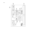
図1は、一実施例に係る無線電力システム10のブロック図である。
FIG. 1 is a block diagram of a
図1を参照すると、無線電力システム10は、無線電力送信装置100と無線電力受信装置200を含む。
Referring to FIG. 1, the
無線電力送信装置100は、外部の電源ソース(S)から電源の印加を受けて磁場を発生させる。無線電力受信装置200は、発生された磁場を利用して電流を発生させることで無線で電力の受信を受ける。
The wireless
また、無線電力システム10において、無線電力送信装置100と無線電力受信装置200は、無線電力送信に必要な多様な情報を送受信することができる。ここで、無線電力送信装置100と無線電力受信装置200との間の通信は、無線電力送信に利用される磁場を利用するイン-バンド通信(in-band communication)や別途の通信キャリアを利用するアウト-バンド通信(out-band communication)のうちいずれか一つの方式によって実行されることができる。アウト-バンド通信は、アウト-オブ-バンド(out-of-band)通信とも呼ばれる。以下、用語アウト-バンド通信に統一して記述する。アウト-バンド通信の例として、NFC、ブルートゥース(bluetooth)、BLE(bluetooth low energy)などを含むことができる。
Further, in the
ここで、無線電力送信装置100は、固定型または移動型で提供されることができる。固定型の例として、室内の天井や壁面またはテーブルなどの家具に埋め込まれる(embedded)形態、室外の駐車場、バス停留場や地下鉄駅などにインプラント形式に設置される形態、車両や汽車などの運送手段に設置される形態などがある。移動型である無線電力送信装置100は、移動可能な重さや大きさの移動型装置やノートブックコンピュータのカバーなどのように他の装置の一部で具現されることができる。
Here, the wireless
また、無線電力受信装置200は、バッテリを具備する各種電子機器及び電源ケーブルの代わりに無線で電源の供給を受けて駆動される各種家電機器を含む包括的な概念と解釈されなければならない。無線電力受信装置200の代表的な例として、移動端末(portable terminal)、携帯電話(cellular phone)、スマートフォン(smart phone)、個人情報端末(PDA:Personal Digital Assistant)、携帯メディアプレイヤ(PMP:Portable Media Player)、ワイブロ端末(Wibro terminal)、タブレット(tablet)、ファブレット(phablet)、ノートブック(notebook)、デジタルカメラ、ナビゲーション端末、テレビ、電気自動車(EV:Electronic Vehicle)などがある。
Further, the wireless
図2は、他の実施例に係る無線電力システム10のブロック図である。
FIG. 2 is a block diagram of the
図2を参照すると、無線電力システム10において、無線電力受信装置200は、一つまたは複数である。図1では無線電力送信装置100と無線電力受信装置200が一対一で電力をやり取りすると表現されているが、図2のように一つの無線電力送信装置100が複数の無線電力受信装置200-1、200-2、...、200-Mに電力を伝達することも可能である。特に、磁気共振方式に無線電力送信を実行する場合は、一つの無線電力送信装置100が同時送信方式や時分割送信方式を応用して同時に複数の無線電力受信装置200-1、200-2、...、200-Mに電力を伝達することができる。
Referring to FIG. 2, in the
また、図1には無線電力送信装置100が無線電力受信装置200に直接電力を伝達する方式が示されているが、無線電力送信装置100と無線電力受信装置200との間に無線電力送信距離を増大させるためのリレイ(relay)または中継器(repeater)のような別途の無線電力送受信装置が備えられる場合もある。この場合、無線電力送信装置100から無線電力送受信装置に電力が伝達され、無線電力送受信装置が再び無線電力受信装置200に電力を伝達することができる。
Further, although FIG. 1 shows a method in which the wireless
以下、本明細書で言及される無線電力受信機、電力受信機、受信機は、無線電力受信装置200を指す。また、本明細書で言及される無線電力送信機、電力送信機、送信機は、無線電力受信送信装置100を指す。
Hereinafter, the wireless power receiver, the power receiver, and the receiver referred to in the present specification refer to the
図3aは、無線電力送信システムが導入される多様な電子機器の実施例を示す。 FIG. 3a shows examples of various electronic devices into which a wireless power transmission system is introduced.
図3aには無線電力送信システムで送信及び受信する電力量によって電子機器を分類して示す。図3aを参照すると、スマート時計(Smart watch)、スマートグラス(Smart Glass)、HMD(Head Mounted Display)、及びスマートリング(Smart ring)のようなウェアラブル機器及びイヤホン、リモコン、スマートフォン、PDA、タブレットPCなどのモバイル電子機器(または、ポータブル電子機器)には小電力(約5W以下または約20W以下)無線充電方式が適用されることができる。 FIG. 3a shows the electronic devices classified according to the amount of power transmitted and received by the wireless power transmission system. Referring to FIG. 3a, wearable devices such as smart watches, smart glasses, HMDs (Head Mounted Display), and smart rings, earphones, remote controls, smartphones, PDA, tablet PCs. A low power (about 5 W or less or about 20 W or less) wireless charging method can be applied to such mobile electronic devices (or portable electronic devices).
ノートブック、ロボット清掃機、TV、音響機器、清掃機、モニタのような中/小型家電機器には中電力(約50W以下または約200W以下)無線充電方式が適用されることができる。ミキサー、電子レンジ、電気炊飯器のようなキッチン用家電機器、車椅子、電気キックボード、電気自転車、電気自動車などの個人用移動機器(または、電子機器/移動手段)は、大電力(約2kW以下または22kW以下)無線充電方式が適用されることができる。 Medium power (about 50 W or less or about 200 W or less) wireless charging method can be applied to small and medium-sized home appliances such as notebooks, robot cleaners, TVs, audio equipment, cleaners, and monitors. Kitchen appliances such as mixers, microwave ovens and electric rice cookers, personal mobile devices (or electronic devices / means of transportation) such as wheelchairs, electric kickboards, electric bicycles and electric vehicles have high power (about 2 kW or less). Or 22 kW or less) Wireless charging method can be applied.
前述した(または、図1に示す)電子機器/移動手段は、後述する無線電力受信機を各々含むことができる。したがって、前述した電子機器/移動手段は、無線電力送信機から無線で電力を受信して充電されることができる。 The above-mentioned (or shown in FIG. 1) electronic device / transportation means can each include a wireless power receiver described later. Therefore, the above-mentioned electronic device / transportation means can be charged by receiving electric power wirelessly from the wireless power transmitter.
以下では電力無線充電方式が適用されるモバイル機器を中心に説明するが、これは実施例に過ぎず、本明細書による無線充電方法は、前述した多様な電子機器に適用されることができる。 Hereinafter, the mobile device to which the power wireless charging method is applied will be mainly described, but this is only an embodiment, and the wireless charging method according to the present specification can be applied to the various electronic devices described above.
無線電力送信に対する標準(standard)は、WPC(wireless power consortium)、AFA(air fuel alliance)、PMA(power matters alliance)を含む。 Standards for wireless power transmission include WPC (wireless power consortium), AFA (air feel alliance), PMA (power matters alliance).
WPC標準は、基本電力プロファイル(baseline power profile:BPP)と拡張電力プロファイル(extended power profile:EPP)を定義する。BPPは、5Wの電力送信をサポートする無線電力送信装置と受信装置に関し、EPPは、5Wより大きい且つ30Wより小さい範囲の電力送信をサポートする無線電力送信装置と受信装置に関する。 The WPC standard defines a baseline power profile (BPP) and an extended power profile (EPP). BPP relates to wireless power transmitters and receivers that support 5 W power transmission, and EPP relates to wireless power transmitters and receivers that support power transmission in the range greater than 5 W and less than 30 W.
互いに異なる電力レベル(power level)を使用する多様な無線電力送信装置と受信装置が各標準別にカバーされ、互いに異なる電力クラス(power class)またはカテゴリに分類されることができる。 Various wireless power transmitters and receivers that use different power levels are covered by each standard and can be classified into different power classes or categories.
例えば、WPCは、無線電力送信装置と受信装置を電力クラス(power class:PC)-1、PC0、PC1、PC2に分類し、各PCに対する標準文書を提供する。PC-1標準は、5W未満の保障電力(guaranteed power)を提供する無線電力送信装置と受信装置に関する。PC-1のアプリケーションは、スマート時計のようなウェアラブル機器を含む。 For example, the WPC classifies wireless power transmitters and receivers into power classes (PC) -1, PC0, PC1, and PC2, and provides standard documents for each PC. The PC-1 standard relates to wireless power transmitters and receivers that provide guaranteed power of less than 5 W. PC-1 applications include wearable devices such as smart watches.
PC0標準は、5Wの保障電力を提供する無線電力送信装置と受信装置に関する。PC0標準は、保障電力が30WまでであるEPPを含む。イン-バンド(in-band:IB)通信がPC0の必須な(mandatory)通信プロトコルや、オプションのバックアップチャネルとして使われるアウト-バンド(out-band:OB)通信も使われることができる。無線電力受信装置は、OBのサポート可否を構成パケット(configuration packet)内のOBフラグを設定することによって識別できる。OBをサポートする無線電力送信装置は、前記構成パケットに対する応答として、OBハンドオーバのためのビットパターン(bit-pattern)を送信することによってOBハンドオーバ段階(handover phase)に進入できる。前記構成パケットに対する応答は、NAK、NDまたは新しく定義される8ビットのパターンである。PC0のアプリケーションは、スマートフォンを含む。 The PC0 standard relates to wireless power transmitters and receivers that provide guaranteed power of 5 W. The PC0 standard includes EPPs with guaranteed power up to 30W. An in-band (IB) communication is a mandatory communication protocol for PC0, and an out-band (OB) communication, which is used as an optional backup channel, can also be used. The wireless power receiving device can identify whether or not the OB is supported by setting the OB flag in the configuration packet. A wireless power transmission device that supports OB can enter the OB handover stage (handover phase) by transmitting a bit pattern (bit-pattern) for OB handover as a response to the configuration packet. The response to the configuration packet is NAK, ND or a newly defined 8-bit pattern. PC0 applications include smartphones.
PC1標準は、30W~150Wの保障電力を提供する無線電力送信装置と受信装置に関する。OBは、PC1のための必須な通信チャネルであり、IBは、OBへの初期化及びリンク確立(link establishment)として使われる。無線電力送信装置は、構成パケットに対する応答として、OBハンドオーバのためのビットパターンを利用してOBハンドオーバ段階に進入できる。PC1のアプリケーションは、ラップトップや電動工具(power tool)を含む。 The PC1 standard relates to wireless power transmitters and receivers that provide guaranteed power of 30 W to 150 W. The OB is an essential communication channel for the PC1, and the IB is used as initialization and link establishment to the OB. The wireless power transmission device can enter the OB handover stage by using the bit pattern for the OB handover as a response to the constituent packet. PC1 applications include laptops and power tools.
PC2標準は、200W~2kWの保障電力を提供する無線電力送信装置と受信装置に関し、そのアプリケーションは、キッチン家電を含む。 The PC2 standard relates to wireless power transmitters and receivers that provide guaranteed power of 200 W to 2 kW, the applications of which include kitchen appliances.
このように電力レベルによってPCが区別されることができ、同じPC間互換性(compatibility)をサポートするかどうかは、選択または必須事項である。ここで、同じPC間互換性は、同じPC間には電力送受信が可能であることを意味する。例えば、PCxである無線電力送信装置が、同じPCxを有する無線電力受信装置の充電が可能な場合、同じPC間互換性が維持されると判断することができる。同様に、互いに異なるPC間互換性もサポート可能である。ここで、互いに異なるPC間互換性は、互いに異なるPC間にも電力送受信が可能であることを意味する。例えば、PCxである無線電力送信装置が、PCyを有する無線電力受信装置の充電が可能な場合、互いに異なるPC間互換性が維持されると判断することができる。 In this way, PCs can be distinguished by power level, and whether or not they support the same compatibility between PCs is a choice or a requirement. Here, the same compatibility between PCs means that power can be transmitted and received between the same PCs. For example, if the wireless power transmitting device which is PCx can charge the wireless power receiving device having the same PCx, it can be determined that the same compatibility between PCs is maintained. Similarly, compatibility between different PCs can be supported. Here, compatibility between different PCs means that power can be transmitted and received between different PCs. For example, when the wireless power transmitting device which is PCx can charge the wireless power receiving device having PCy, it can be determined that the compatibility between PCs different from each other is maintained.
PC間互換性のサポートは、ユーザ経験(User Experience)及びインフラ構築側面で相当重要な問題である。ただし、PC間互換性維持には技術的に下記のような多数の問題点が存在する。 Supporting PC-to-PC compatibility is a fairly important issue in terms of user experience and infrastructure construction. However, there are many technical problems in maintaining compatibility between PCs as described below.
同じPC間互換性の場合、例えば、連続的に電力が送信される場合にのみ安定的に充電が可能なラップ-トップ充電(lap-top charging)方式の無線電力受信装置は、同じPCの無線電力送信装置であるとしても、不連続的に電力を送信する電動ツール方式の無線電力送信装置から電力を安定的に供給を受けるときに問題がある。また、互いに異なるPC間互換性の場合、例えば、最小保障電力が200Wである無線電力送信装置は、最大保障電力が5Wである無線電力受信装置に電力を送信する場合、過電圧によって無線電力受信装置が破損される危険がある。その結果、PCは、互換性を代表/指示する指標/基準として定めにくい。 In the case of compatibility between the same PCs, for example, a laptop-top charging wireless power receiver that can be stably charged only when power is continuously transmitted is a wireless power receiver of the same PC. Even if it is a power transmission device, there is a problem when power is stably supplied from an electric tool type wireless power transmission device that transmits power discontinuously. Further, in the case of compatibility between PCs different from each other, for example, when a wireless power transmitting device having a minimum guaranteed power of 200W transmits power to a wireless power receiving device having a maximum guaranteed power of 5W, the wireless power receiving device is caused by an overvoltage. Is in danger of being damaged. As a result, the PC is difficult to determine as an index / standard that represents / indicates compatibility.
無線電力送信及び受信装置は、相当便利なユーザ経験とインターフェース(UX/UI)を提供することができる。即ち、スマート無線充電サービスが提供されることができる。スマート無線充電サービスは、無線電力送信装置を含むスマートフォンのUX/UIに基づいて具現されることができる。このようなアプリケーションのために、スマートフォンのプロセッサと無線充電受信装置との間のインターフェースは、無線電力送信装置と受信装置との間の“ドロップアンドプレー(drop and play)”双方向通信を許容する。 Wireless power transmission and reception devices can provide a fairly convenient user experience and interface (UX / UI). That is, a smart wireless charging service can be provided. The smart wireless charging service can be embodied based on the UX / UI of a smartphone including a wireless power transfer device. For such applications, the interface between the smartphone's processor and wireless charge receiver allows for "drop and play" bidirectional communication between the wireless power transmitter and receiver. ..
一例として、ユーザは、ホテルでスマート無線充電サービスを経験することができる。ユーザがホテルルームに入ってルームの無線充電器上にスマートフォンを置くと、無線充電器はスマートフォンに無線電力を送信し、スマートフォンは無線電力を受信する。この過程で、無線充電器は、スマート無線充電サービスに対する情報をスマートフォンに送信する。スマートフォンが無線充電器上に位置することを検知し、または無線電力の受信を検知し、またはスマートフォンが無線充電器からスマート無線充電サービスに対する情報を受信すると、スマートフォンは、ユーザに付加的特徴への同意(opt-in)を問い合わせする状態に進入する。そのために、スマートフォンは、アラームを含んだり含まない方式にスクリーン上にメッセージをディスプレーすることができる。メッセージの一例は、“Welcome to ### hotel.Select“Yes”to activate smart charging functions:Yes|No Thanks.”のようなテキストを含むことができる。スマートフォンは、YesまたはNo Thanksを選択するユーザの入力を受け、ユーザにより選択された次の手順を実行する。もし、Yesが選択された場合、スマートフォンは、無線充電器に該当情報を送信する。そして、スマートフォンと無線充電器は、スマート充電機能を共に実行する。 As an example, a user can experience a smart wireless charging service at a hotel. When the user enters the hotel room and places the smartphone on the wireless charger in the room, the wireless charger sends wireless power to the smartphone and the smartphone receives the wireless power. In this process, the wireless charger sends information about the smart wireless charging service to the smartphone. When the smartphone detects that it is located on the wireless charger, or detects the reception of wireless power, or the smartphone receives information about the smart wireless charging service from the wireless charger, the smartphone gives the user additional features. Enter the state of asking for consent (opt-in). To that end, smartphones can display messages on the screen in a manner that includes or does not include alarms. An example of a message can include text such as "Welcome to ### hotel.Select" Yes "to activate smart charging functions: Yes | No Thanks." The smartphone receives the input of the user who selects Yes or No Thanks, and executes the next procedure selected by the user. If Yes is selected, the smartphone sends the relevant information to the wireless charger. And the smartphone and the wireless charger execute the smart charging function together.
また、スマート無線充電サービスは、WiFi資格(wifi credentials)自動入力(auto-filled)を受信するものを含むことができる。例えば、無線充電器は、WiFi資格をスマートフォンに送信し、スマートフォンは、適切なAPPを実行することで無線充電器から受信されたWiFi資格を自動的に入力する。 In addition, smart wireless charging services can include those that receive WiFi credentials and auto-filled. For example, the wireless charger sends the WiFi qualification to the smartphone, and the smartphone automatically inputs the WiFi qualification received from the wireless charger by executing an appropriate APP.
また、スマート無線充電サービスは、ホテルプロモーションを提供するホテルアプリケーションを実行し、または遠隔チェックイン/チェックアウト及びコンタクト情報を取得するものを含むことができる。 Smart wireless charging services can also include those that run hotel applications that provide hotel promotions or obtain remote check-in / check-out and contact information.
他の例として、ユーザは、車両内でスマート無線充電サービスを経験することができる。ユーザが車両に搭乗してスマートフォンを無線充電器上に置くと、無線充電器はスマートフォンに無線電力を送信し、スマートフォンは無線電力を受信する。このような過程で、無線充電器は、スマート無線充電サービスに対する情報をスマートフォンに送信する。スマートフォンが無線充電器上に位置することを検知し、または無線電力の受信を検知し、またはスマートフォンが無線充電器からスマート無線充電サービスに対する情報を受信すると、スマートフォンは、ユーザにID(identity)確認を問い合わせする状態に進入する。 As another example, the user can experience a smart wireless charging service in the vehicle. When the user gets in the vehicle and puts the smartphone on the wireless charger, the wireless charger sends wireless power to the smartphone and the smartphone receives the wireless power. In such a process, the wireless charger sends information about the smart wireless charging service to the smartphone. When the smartphone detects that it is located on the wireless charger, or detects the reception of wireless power, or the smartphone receives information about the smart wireless charging service from the wireless charger, the smartphone confirms the ID (identity) to the user. Enter the state of inquiring.
この状態で、スマートフォンは、WiFi及び/またはブルートゥースを介して自動的に自動車と接続される。スマートフォンは、アラームを含んだり含まない方式にスクリーン上にメッセージをディスプレーすることができる。メッセージの一例は、“Welcome to your car.Select“Yes”to synch device with in-car controls:Yes|No Thanks.”のようなテキストを含むことができる。スマートフォンは、YesまたはNo Thanksを選択するユーザの入力を受け、ユーザにより選択された次の手順を実行する。もし、Yesが選択された場合、スマートフォンは、無線充電器に該当情報を送信する。そして、スマートフォンと無線充電器は、車両内のアプリケーション/ディスプレーソフトウェアを駆動することで、車両内のスマート制御機能を共に実行することができる。ユーザは、所望の音楽を楽しむことができ、正規的なマップ位置を確認することができる。車両内のアプリケーション/ディスプレーソフトウェアは、通行者のための同期化接近を提供する性能を含むことができる。 In this state, the smartphone is automatically connected to the car via WiFi and / or Bluetooth. Smartphones can display messages on the screen in a way that includes or does not include alarms. An example of a message can include text such as "Welcome to your car. Select" Yes "to sync device with in-car controls: Yes | No Thanks." The smartphone receives the input of the user who selects Yes or No Thanks, and executes the next procedure selected by the user. If Yes is selected, the smartphone sends the relevant information to the wireless charger. Then, the smartphone and the wireless charger can execute the smart control function in the vehicle together by driving the application / display software in the vehicle. The user can enjoy the desired music and can confirm the regular map position. In-vehicle application / display software can include performance that provides synchronized access for passers-by.
他の例として、ユーザは、スマート無線充電をホーム内で経験することができる。ユーザが部屋へ入って方案の無線充電器上にスマートフォンを置くと、無線充電器はスマートフォンに無線電力を送信し、スマートフォンは無線電力を受信する。この過程で、無線充電器は、スマート無線充電サービスに対する情報をスマートフォンに送信する。スマートフォンが無線充電器上に位置することを検知し、または無線電力の受信を検知し、またはスマートフォンが無線充電器からスマート無線充電サービスに対する情報を受信すると、スマートフォンは、ユーザに付加的特徴への同意(opt-in)を問い合わせする状態に進入する。そのために、スマートフォンは、アラームを含んだり含まない方式にスクリーン上にメッセージをディスプレーすることができる。メッセージの一例は、“Hi xxx,Would you like to activate night mode and secure the building?:Yes|No Thanks.”のようなテキストを含むことができる。スマートフォンは、YesまたはNo Thanksを選択するユーザの入力を受け、ユーザにより選択された次の手順を実行する。もし、Yesが選択された場合、スマートフォンは、無線充電器に該当情報を送信する。スマートフォンと無線充電器は、少なくともユーザのパターンを認知し、ユーザにドアと窓をかけたり電源をオフにしたり、アラームを設定したりするように勧誘できる。 As another example, the user can experience smart wireless charging in the home. When the user enters the room and places the smartphone on the wireless charger of the plan, the wireless charger sends wireless power to the smartphone and the smartphone receives the wireless power. In this process, the wireless charger sends information about the smart wireless charging service to the smartphone. When the smartphone detects that it is located on the wireless charger, or detects the reception of wireless power, or the smartphone receives information about the smart wireless charging service from the wireless charger, the smartphone gives the user additional features. Enter the state of asking for consent (opt-in). To that end, smartphones can display messages on the screen in a manner that includes or does not include alarms. An example of a message can include text such as "Hi xxx, World you like to activate night mode and secure the building ?: Yes | No Thanks." The smartphone receives the input of the user who selects Yes or No Thanks, and executes the next procedure selected by the user. If Yes is selected, the smartphone sends the relevant information to the wireless charger. Smartphones and wireless chargers can at least recognize the user's pattern and invite the user to close doors and windows, turn off the power, and set alarms.
以下、互換性を代表/指示する指標/基準として‘プロファイル(profile)’を新しく定義する。即ち、同じ‘プロファイル’を有する無線電力送受信装置間には互換性が維持されて安定した電力送受信が可能であり、互いに異なる‘プロファイル’を有する無線電力送受信装置間には電力送受信が不可であると解釈されることができる。プロファイルは、電力クラスと関係なく(または、独立的に)互換可能可否及び/またはアプリケーションによって定義されることができる。 Hereinafter,'profile' is newly defined as an index / standard that represents / indicates compatibility. That is, compatibility is maintained between wireless power transmission / reception devices having the same'profile'and stable power transmission / reception is possible, and power transmission / reception is not possible between wireless power transmission / reception devices having different'profiles'. Can be interpreted as. Profiles can be defined by compatibility and / or application regardless of power class (or independently).
プロファイルは、大いにi)モバイル及びコンピュータ、ii)電動ツール、及びiii)キッチン、このように三つに区分されることができる。 Profiles can be broadly divided into three categories: i) mobile and computer, ii) electric tools, and iii) kitchen.
または、プロファイルは、大いに、i)モバイル、ii電動ツール、iii)キッチン、及びiv)ウェアラブル、このように四つに区分されることができる。 Alternatively, the profile can be broadly divided into four categories: i) mobile, ii electric tools, iii) kitchen, and iv) wearables.
‘モバイル’プロファイルの場合、PCはPC0及び/またはPC1、通信プロトコル/方式はIB及びOB、動作周波数は87~205kHzに定義されることができ、アプリケーションの例示として、スマートフォン、ラップ-トップなどが存在できる。 For the'mobile'profile, the PC can be defined as PC0 and / or PC1, the communication protocol / method can be defined as IB and OB, the operating frequency can be defined as 87-205 kHz, and examples of applications include smartphones, laptops, etc. Can exist.
‘電動ツール’プロファイルの場合、PCはPC1、通信プロトコル/方式はIB、動作周波数は87~145kHzに定義されることができ、アプリケーションの例示として電動ツールなどが存在できる。 In the case of the'electric tool'profile, the PC can be defined as PC1, the communication protocol / method can be defined as IB, the operating frequency can be defined as 87 to 145 kHz, and an electric tool or the like can exist as an example of the application.
‘キッチン’プロファイルの場合、PCはPC2、通信プロトコル/方式はNFC-基盤、動作周波数は100kHz未満に定義されることができ、アプリケーションの例示としてキッチン/家電機器などが存在できる。 In the case of the'kitchen'profile, the PC can be defined as PC2, the communication protocol / method can be defined as NFC-base, the operating frequency can be defined as less than 100 kHz, and a kitchen / home appliance can exist as an example of the application.
電動ツールとキッチンプロファイルの場合、無線電力送信装置と受信装置との間にNFC通信が使われることができる。無線電力送信装置と受信装置は、WPC NDEF(NFC Data Exchange Profile Format)を交換することによって相互間にNFC機器であることを確認することができる。 In the case of electric tools and kitchen profiles, NFC communication can be used between the wireless power transmitter and receiver. The wireless power transmitting device and the receiving device can be confirmed to be NFC devices between each other by exchanging the WPC NDEF (NFC Data Exchange Profile Form).
図3bは、無線電力送信システムにおけるWPC NDEFの一例を示す。 FIG. 3b shows an example of a WPC NDEF in a wireless power transfer system.
図3bを参照すると、WPC NDEFは、例えば、アプリケーションプロファイル(application profile)フィールド(例えば、1B)、バージョンフィールド(例えば、1B)、及びプロファイル特定データ(profile specific data、例えば、1B)を含むことができる。アプリケーションプロファイルフィールドは、該当装置がi)モバイル及びコンピュータ、ii)電動ツール、及びiii)キッチンのうちいずれのものであるかを指示し、バージョンフィールドの上位ニブル(upper nibble)は、メジャーバージョン(major version)を指示し、下位ニブル(lower nibble)は、マイナーバージョン(minor version)を指示する。また、プロファイル特定データは、キッチンのためのコンテンツを定義する。 Referring to FIG. 3b, the WPC NDEF may include, for example, an application profile field (eg, 1B), a version field (eg, 1B), and profile specific data (eg, 1B). can. The application profile field indicates whether the device is i) mobile and computer, ii) electric tool, and iii) kitchen, and the upper nibble in the version field is the major version (major). Version) is indicated, and the lower nibble indicates a minor version. The profile specific data also defines the content for the kitchen.
‘ウェアラブル’プロファイルの場合、PCはPC-1、通信プロトコル/方式はIB、動作周波数は87~205kHzに定義されることができ、アプリケーションの例示としてユーザの身体に着用するウェアラブル機器などが存在できる。 In the case of the'wearable'profile, the PC can be defined as PC-1, the communication protocol / method can be defined as IB, the operating frequency can be defined as 87 to 205 kHz, and a wearable device worn on the user's body can exist as an example of the application. ..
同じプロファイル間の互換性維持は必須事項であり、異なるプロファイル間の互換性維持は選択事項である。 Maintaining compatibility between the same profiles is a requirement, and maintaining compatibility between different profiles is an option.
前述したプロファイル(モバイルプロファイル、電動ツールプロファイル、キッチンプロファイル及びウェアラブルプロファイル)は、第1乃至第nのプロファイルで一般化されて表現されることができ、WPC規格及び実施例によって新しいプロファイルが追加/代替されることができる。 The profiles described above (mobile profile, electric tool profile, kitchen profile and wearable profile) can be generalized and represented by the first to nth profiles, and new profiles are added / replaced by WPC standards and examples. Can be done.
このようにプロファイルが定義される場合、無線電力送信装置が自分と同じプロファイルの無線電力受信装置に対してのみ選択的に電力送信を実行することで、より安定的に電力送信が可能である。また、無線電力送信装置の負担が減って、互換が不可能な無線電力受信装置への電力送信を試みないようになるため、無線電力受信装置の破損危険が減るという効果が発生する。 When the profile is defined in this way, the wireless power transmitting device selectively executes power transmission only to the wireless power receiving device having the same profile as itself, so that the power transmission can be performed more stably. In addition, the burden on the wireless power transmitting device is reduced, and power transmission to an incompatible wireless power receiving device is not attempted, so that the risk of damage to the wireless power receiving device is reduced.
‘モバイル’プロファイル内のPC1は、PC0に基づいてOBのような選択的拡張を借用することによって定義されることができ、‘電動ツール’プロファイルの場合は、PC1‘モバイル’プロファイルが単純に変更されたバージョンとして定義されることができる。また、現在までは同じプロファイル間の互換性維持を目的として定義されたが、今後互いに異なるプロファイル間の互換性維持方向に技術が発展することができる。無線電力送信装置または無線電力受信装置は、多様な方式を介して自分のプロファイルを相手に知らせることができる。 PC1 in the'mobile'profile can be defined by borrowing a selective extension like OB based on PC0, and in the case of the'electric tools' profile, the PC1'mobile' profile is simply modified. Can be defined as a version. In addition, until now, it was defined for the purpose of maintaining compatibility between the same profiles, but in the future, technology can be developed in the direction of maintaining compatibility between different profiles. A wireless power transmitter or a wireless power receiver can inform the other party of its profile via various methods.
AFA標準は、無線電力送信装置をPTU(power transmitting circuit)といい、無線電力受信装置をPRU(power receiving circuit)という。PTUは、表1のように多数のクラスに分類され、PRUは、表2のように多数のカテゴリに分類される。 In the AFA standard, the wireless power transmitting device is called a PTU (power transferring circuit), and the wireless power receiving device is called a PRU (power receiving circuit). PTUs are classified into a large number of categories as shown in Table 1, and PRUs are classified into a large number of categories as shown in Table 2.


表1のように、クラスn PTUの最大出力電力性能(capability)は、該当クラスのPTX_IN_MAX値より大きいまたは同じである。PRUは、該当カテゴリで明細な(specified)電力より大きい電力を引き寄せる(draw)ことはできない。 As shown in Table 1, the maximum output power performance (capacity) of the class n PTU is larger than or equal to the PTX_IN_MAX value of the corresponding class. The PRU cannot draw more power than the specified power in the category.
図4aは、他の実施例に係る無線電力送信システムのブロック図である。 FIG. 4a is a block diagram of a wireless power transmission system according to another embodiment.
図4aを参照すると、無線電力送信システム10は、無線で電力を受信するモバイル機器(Mobile Device)450及び無線で電力を送信するベースステーション(Base Station)400を含む。
Referring to FIG. 4a, the wireless
ベースステーション400は、誘導電力または共振電力を提供する装置であって、少なくとも一つの無線電力送信装置(power transmitter)100及びシステム回路405を含むことができる。無線電力送信装置100は、誘導電力または共振電力を送信し、送信を制御することができる。無線電力送信装置100は、1次コイル(primary coil(s))を介して磁場を生成することによって電気エネルギーを電力信号に変換する電力変換回路(power conversion circuit)110及び適切なレベルで電力を伝達するように無線電力受信装置200との通信及び電力伝達をコントロールする通信/コントロール回路(communications&control circuit)120を含むことができる。システム回路405は、入力電力プロビジョニング(provisioning)、複数の無線電力送信装置のコントロール、及びユーザインターフェース制御のようなベースステーション400のその他の動作制御を実行することができる。
The
1次コイルは、交流電力(または電圧または電流)を利用して電磁場を発生させることができる。1次コイルは、電力変換回路110で出力される特定周波数の交流電力(または電圧または電流)の印加を受け、それによって、特定周波数の磁場を発生させることができる。磁場は、非放射形または放射形で発生でき、無線電力受信装置200は、これを受信して電流を生成するようになる。即ち、1次コイルは、無線で電力を送信する。
The primary coil can use AC power (or voltage or current) to generate an electromagnetic field. The primary coil is subject to the application of AC power (or voltage or current) of a specific frequency output by the
磁気誘導方式で、1次コイルと2次コイルは、任意の適した形態を有することができ、例えば、フェライトまたは非晶質金属のような高透磁率の形成物の周囲に巻かれた銅線である。1次コイルは、送信コイル(transmitting coil)、1次コア(primary core)、1次ワインディング(primary winding)、1次ループアンテナ(primary loop antenna)などと呼ばれることもある。一方、2次コイルは、受信コイル(receiving coil)、2次コア(secondary core)、2次ワインディング(secondary winding)、2次ループアンテナ(secondary loop antenna)、ピックアップアンテナ(pickup antenna)などと呼ばれることもある。 In a magnetic induction scheme, the primary and secondary coils can have any suitable form, for example copper wire wound around a high magnetic permeability formation such as ferrite or amorphous metal. Is. The primary coil may be referred to as a transmission coil, a primary core, a primary winding, a primary loop antenna, or the like. On the other hand, the secondary coil is called a receiving coil, a secondary core, a secondary winding, a secondary loop antenna, a pick-up antenna, or the like. There is also.
磁気共振方式を利用する場合、1次コイルと2次コイルは、各々、1次共振アンテナと2次共振アンテナの形態で提供されることができる。共振アンテナは、コイルとキャパシタを含む共振構造を有することができる。このとき、共振アンテナの共振周波数は、コイルのインダクタンスとキャパシタのキャパシタンスにより決定される。ここで、コイルは、ループの形態からなることができる。また、ループの内部にはコアが配置されることができる。コアは、フェライトコア(ferrite core)のような物理的なコアや空心コア(air core)を含むことができる。 When the magnetic resonance method is used, the primary coil and the secondary coil can be provided in the form of a primary resonant antenna and a secondary resonant antenna, respectively. The resonant antenna can have a resonant structure that includes a coil and a capacitor. At this time, the resonance frequency of the resonance antenna is determined by the inductance of the coil and the capacitance of the capacitor. Here, the coil can be in the form of a loop. Also, a core can be placed inside the loop. The core can include a physical core such as a ferrite core or an air core.
1次共振アンテナと2次共振アンテナとの間のエネルギー送信は、磁場の共振現象を介して行われることができる。共振現象とは、一つの共振アンテナで共振周波数に該当する近接場が発生する時、周囲に他の共振アンテナが位置する場合、両共振アンテナが互いにカップリングされて共振アンテナ間で高い効率のエネルギー伝達が発生する現象を意味する。1次共振アンテナと2次共振アンテナとの間で共振周波数に該当する磁場が発生すると、1次共振アンテナと2次共振アンテナが互いに共振する現象が発生し、それによって、一般的な場合、1次共振アンテナで発生した磁場が自由空間に放射される場合に比べて高い効率で2次共振アンテナに向かって磁場が執束され、したがって、1次共振アンテナから2次共振アンテナへ高い効率でエネルギーが伝達されることができる。磁気誘導方式は、磁気共振方式と類似するように具現されることができるが、このとき、磁場の周波数が共振周波数である必要はない。その代わりに、磁気誘導方式では1次コイルと2次コイルを構成するループ間の整合が必要であり、ループ間の間隔が相当近接しなければならない。 Energy transmission between the primary resonant antenna and the secondary resonant antenna can be done via the resonant phenomenon of the magnetic field. Resonance phenomenon is when a close field corresponding to the resonance frequency is generated by one resonance antenna, and when another resonance antenna is located around, both resonance antennas are coupled to each other and high efficiency energy is generated between the resonance antennas. It means a phenomenon in which transmission occurs. When a magnetic field corresponding to the resonance frequency is generated between the primary resonance antenna and the secondary resonance antenna, a phenomenon occurs in which the primary resonance antenna and the secondary resonance antenna resonate with each other, whereby, in a general case, 1 The magnetic field is bound toward the secondary resonant antenna with higher efficiency than when the magnetic field generated by the secondary resonant antenna is radiated into free space, and therefore the energy from the primary resonant antenna to the secondary resonant antenna is higher. Can be transmitted. The magnetic induction method can be embodied in a manner similar to the magnetic resonance method, but at this time, the frequency of the magnetic field does not have to be the resonance frequency. Instead, the magnetic induction method requires matching between the loops constituting the primary coil and the secondary coil, and the intervals between the loops must be fairly close.
図面には示されていないが、無線電力送信装置100は、通信アンテナをさらに含むこともできる。通信アンテナは、磁場通信以外の通信キャリアを利用して通信信号を送受信することができる。例えば、通信アンテナは、ワイファイ(Wi-Fi)、ブルートゥース(Bluetooth)、ブルートゥースLE、ジグビー(ZigBee)、NFCなどの通信信号を送受信することができる。
Although not shown in the drawings, the wireless
通信/コントロール回路120は、無線電力受信装置200と情報を送受信することができる。通信/コントロール回路120は、IB通信モジュールまたはOB通信モジュールのうち少なくとも一つを含むことができる。
The communication /
IB通信モジュールは、特定周波数を中心周波数にする磁気波を利用して情報を送受信することができる。例えば、通信/コントロール回路120は、無線電力送信の動作周波数に通信情報を含ませて1次コイルを介して送信し、または情報が含まれている動作周波数を1次コイルを介して受信することによってイン-バンド通信を実行することができる。このとき、二進位相変位(BPSK:binary phase shift keying)、周波数変位(FSK:Frequency Shift Keying)または振幅変位(ASK:amplitude shift keying)などの変調方式と、マンチェスター(Manchester)コーディングまたはノンゼロ復帰レベル(NZR-L:non-return-to-zero level)コーディングなどのコーディング方式を利用して磁気波に情報を含んだり情報が含まれている磁気波を解釈することができる。このようなIB通信を利用すると、通信/コントロール回路120は、数kbpsのデータ送信率で数メートルに達する距離まで情報を送受信することができる。
The IB communication module can transmit and receive information by using a magnetic wave having a specific frequency as a center frequency. For example, the communication /
OB通信モジュールは、通信アンテナを介してアウト-バンド通信を実行することもできる。例えば、通信/コントロール回路120は、近距離通信モジュールで提供されることができる。近距離通信モジュールの例として、ワイファイ(Wi-Fi)、ブルートゥース(Bluetooth)、ブルートゥースLE、ジグビー(ZigBee)、NFCなどの通信モジュールがある。
The OB communication module can also perform out-band communication via the communication antenna. For example, the communication /
通信/コントロール回路120は、無線電力送信装置100の全般的な動作を制御することができる。通信/コントロール回路120は、各種情報の演算及び処理を実行し、無線電力送信装置100の各構成要素を制御することができる。
The communication /
通信/コントロール回路120は、ハードウェア、ソフトウェアまたはこれらの組み合わせを利用してコンピュータやこれと類似した装置で具現されることができる。ハードウェア的に、通信/コントロール回路120は、電気的な信号を処理して制御機能を遂行する電子回路形態で提供されることができ、ソフトウェア的に、ハードウェア的な通信/コントロール回路120を駆動させるプログラム形態で提供されることができる。
The communication /
通信/コントロール回路120は、動作ポイント(operating point)をコントロールすることによって送信電力をコントロールすることができる。コントロールする動作ポイントは、周波数(または、位相)、デューティサイクル(duty cycle)、デューティ比(duty ratio)、及び電圧振幅の組み合わせに該当することができる。通信/コントロール回路120は、周波数(または、位相)、デューティサイクル、デューティ比、及び電圧振幅のうち少なくとも一つを調節して送信電力をコントロールすることができる。また、無線電力送信装置100は、一定の電力を供給し、無線電力受信装置200が共振周波数をコントロールすることによって受信電力をコントロールすることもできる。
The communication /
モバイル機器450は、2次コイル(Secondary Coil)を介して無線電力を受信する無線電力受信装置(power receiver)200と無線電力受信装置200で受信された電力の伝達を受けて蓄電して機器に供給する負荷(load)455を含む。
The
無線電力受信装置200は、電力ピックアップ回路(power pick-up circuit)210及び通信/コントロール回路(communications&control circuit)220を含むことができる。電力ピックアップ回路210は、2次コイルを介して無線電力を受信して電気エネルギーに変換できる。電力ピックアップ回路210は、2次コイルを介して得られる交流信号を整流して直流信号に変換する。通信/コントロール回路220は、無線電力の送信と受信(電力伝達及び受信)を制御することができる。
The wireless
2次コイルは、無線電力送信装置100で送信される無線電力を受信することができる。2次コイルは、1次コイルで発生する磁場を利用して電力を受信することができる。ここで、特定周波数が共振周波数である場合、1次コイルと2次コイルとの間に磁気共振現象が発生することで、より効率的に電力の伝達を受けることができる。
The secondary coil can receive the wireless power transmitted by the wireless
図4aには示されていないが、通信/コントロール回路220は、通信アンテナをさらに含むこともできる。通信アンテナは、磁場通信以外の通信キャリアを利用して通信信号を送受信することができる。例えば、通信アンテナは、ワイファイ(Wi-Fi)、ブルートゥース(Bluetooth)、ブルートゥースLE、ジグビー(ZigBee)、NFCなどの通信信号を送受信することができる。
Although not shown in FIG. 4a, the communication /
通信/コントロール回路220は、無線電力送信装置100と情報を送受信することができる。通信/コントロール回路220は、IB通信モジュールまたはOB通信モジュールのうち少なくとも一つを含むことができる。
The communication /
IB通信モジュールは、特定周波数を中心周波数にする磁気波を利用して情報を送受信することができる。例えば、通信/コントロール回路220は、磁気波に情報を含ませて2次コイルを介して送信し、または情報が含まれている磁気波を2次コイルを介して受信することによってIB通信を実行することができる。このとき、二進位相変位(BPSK:binary phase shift keying)、周波数変位(FSK:Frequency Shift Keying)または振幅変位(ASK:amplitude shift keying)などの変調方式と、マンチェスター(Manchester)コーディングまたはノンゼロ復帰レベル(NZR-L:non-return-to-zero level)コーディングなどのコーディング方式を利用して磁気波に情報を含んだり情報が含まれている磁気波を解釈することができる。このようなIB通信を利用すると、通信/コントロール回路220は、数kbpsのデータ送信率で数メートルに達する距離まで情報を送受信することができる。
The IB communication module can transmit and receive information by using a magnetic wave having a specific frequency as a center frequency. For example, the communication /
OB通信モジュールは、通信アンテナを介してアウト-バンド通信を実行することもできる。例えば、通信/コントロール回路220は、近距離通信モジュールで提供されることができる。
The OB communication module can also perform out-band communication via the communication antenna. For example, the communication /
近距離通信モジュールの例として、ワイファイ(Wi-Fi)、ブルートゥース(Bluetooth)、ブルートゥースLE、ジグビー(ZigBee)、NFCなどの通信モジュールがある。 Examples of short-range communication modules include communication modules such as Wi-Fi, Bluetooth, Bluetooth LE, ZigBee, and NFC.
通信/コントロール回路220は、無線電力受信装置200の全般的な動作を制御することができる。通信/コントロール回路220は、各種情報の演算及び処理を実行し、無線電力受信装置200の各構成要素を制御することができる。
The communication /
通信/コントロール回路220は、ハードウェア、ソフトウェアまたはこれらの組み合わせを利用してコンピュータやこれと類似した装置で具現されることができる。ハードウェア的に、通信/コントロール回路220は、電気的な信号を処理して制御機能を遂行する電子回路形態で提供されることができ、ソフトウェア的に、ハードウェア的な通信/コントロール回路220を駆動させるプログラム形態で提供されることができる。
The communication /
通信/コントロール回路120と通信/コントロール回路220がOB通信モジュールまたは近距離通信モジュールとしてブルートゥースまたはブルートゥースLEである場合、通信/コントロール回路120と通信/コントロール回路220は、各々、図4bのような通信アーキテクチャで具現されて動作できる。
When the communication /
図4bは、本明細書による一実施例が適用されることができるブルートゥース通信アーキテクチャ(Architecture)の一例を示す。 FIG. 4b shows an example of a Bluetooth communication architecture (Architecture) to which one embodiment according to the present specification can be applied.
図4bを参考すると、図4bの(a)は、GATTをサポートするブルートゥースBR(Basic Rate)/EDR(Enhanced Data Rate)のプロトコルスタックの一例を示し、(b)は、ブルートゥースLE(Low Energy)のプロトコルスタックの一例を示す。 With reference to FIG. 4b, FIG. 4b (a) shows an example of a Bluetooth BR (Basic Rate) / EDR (Enhanced Data Rate) protocol stack that supports GATT, and FIG. 4b (b) shows Bluetooth LE (Low Energy). Here is an example of the protocol stack of.
具体的に、図4bの(a)に示すように、ブルートゥースBR/EDRプロトコルスタックは、ホストコントローラインターフェース(Host Controller Interface、HCI)18を基準にして上部のコントローラスタック(Controller stack)460と下部のホストスタック(Host Stack)470を含むことができる。 Specifically, as shown in FIG. 4b (a), the Bluetooth BR / EDR protocol stack has a controller stack 460 at the top and a controller stack 460 at the bottom with respect to the Host Controller Interface (HCI) 18. It can include a Host Stack 470.
前記ホストスタック(または、ホストモジュール)470は、2.4GHzのブルートゥース信号を受ける無線送受信モジュールとブルートゥースパケットを送信または受信するためのハードウェアを意味し、前記コントローラスタック460は、ブルートゥースモジュールと接続してブルートゥースモジュールを制御して動作を実行する。 The host stack (or host module) 470 means a wireless transmission / reception module that receives a 2.4 GHz Bluetooth signal and hardware for transmitting or receiving a Bluetooth packet, and the controller stack 460 is connected to the Bluetooth module. Controls the Bluetooth module to perform operations.
前記ホストスタック470は、BR/EDR PHY階層12、BR/EDR Baseband階層14、リンクマネジャ階層(Link Manager)16を含むことができる。
The host stack 470 can include a BR / EDR PHY layer 12, a BR /
前記BR/EDR PHY階層12は、2.4GHz無線信号を送受信する階層であり、GFSK(Gaussian Frequency Shift Keying)modulationを使用する場合、79個のRFチャネルをhoppingしてデータを送信することができる。 The BR / EDR PHY layer 12 is a layer for transmitting and receiving 2.4 GHz radio signals, and when GFSK (Gaussian Frequency Shift Keying) modulation is used, 79 RF channels can be popped and data can be transmitted. ..
前記BR/EDR Baseband階層14は、Digital Signalを送信する役割を担当し、秒当たり1400回hoppingするチャネルシーケンスを選択し、各チャネル別625us長さのtime slotを送信する。
The BR /
前記リンクマネジャ階層16は、LMP(Link Manager Protocol)を活用してBluetooth Connectionの全般的な動作(link setup、control、security)を制御する。
The
前記リンクマネジャ階層16は、下記のような機能を遂行することができる。
The
-ACL/SCO logical transport、logical link setup及びcontrolをする。 -ACL / SCO logical transport, logical link setup and control.
-Detach:connectionを中断し、中断理由を相手デバイスに知らせる。 -Datch: Interrupts the connection and informs the other device of the reason for the interruption.
-Power control及びRole switchをする。 -Do Power control and Role switch.
-Security(authentication、pairing、encryption)機能を遂行する。 -Performs Security (atentionation, pailing, encryption) functions.
前記ホストコントローラインターフェース階層18は、HostモジュールとControllerモジュールとの間のインターフェースを提供してHostがcommandとDataをControllerに提供するようにし、ControllerがeventとDataをHostに提供可能にする。 The host controller interface layer 18 provides an interface between the Host module and the Controller module so that the Host provides the command and Data to the Controller, and the Controller can provide the event and Data to the Host.
前記ホストスタック(または、ホストモジュール)20は、論理的リンク制御及び適応プロトコル(L2CAP)21、属性プロトコル(Protocol)22、一般属性プロファイル(Generic Attribute Profile、GATT)23、一般接近プロファイル(Generic Access Profile、GAP)24、BR/EDRプロファイル25を含む。 The host stack (or host module) 20 includes a logical link control and adaptive protocol (L2CAP) 21, an attribute protocol (Protocol) 22, a general attribute profile (Generic Attribute Profile, GATT) 23, and a general access profile (Generic Access Profile). , GAP) 24, BR / EDR profile 25.
前記論理的リンク制御及び適応プロトコル(L2CAP)21は、特定プロトコルまたはプロファイルにデータを送信するための一つの双方向チャネルを提供することができる。 The Logical Link Control and Adaptive Protocol (L2CAP) 21 can provide one bidirectional channel for transmitting data to a particular protocol or profile.
前記L2CAP21は、ブルートゥース上位で提供する多様なプロトコル、プロファイルなどをマルチプレキシング(multiplexing)することができる。 The L2CAP 21 can multiplexing various protocols, profiles, etc. provided on the upper level of Bluetooth.
ブルートゥースBR/EDRのL2CAPではdynamicチャネルを使用し、protocol service multiplexer、retransmission、streaming modeをサポートし、Segmentation及びreassembly、per-channel flow control、error controlを提供する。 The Bluetooth BR / EDR L2CAP uses a dynamic channel, supports protocol service multiplexer, retransmission, and streaming mode, and provides Segmentation and errorbly, per-channel flow.
前記一般属性プロファイル(GATT)23は、サービスの構成時に前記属性プロトコル22がどのように利用されるかを説明するプロトコルとして動作可能である。例えば、前記一般属性プロファイル23は、ATT属性がどのようにサービスで共にグループ化されるかを規定するように動作可能であり、サービスと関連した特徴を説明するように動作可能である。
The general attribute profile (GATT) 23 can operate as a protocol explaining how the
したがって、前記一般属性プロファイル23及び前記属性プロトコル(ATT)22は、デバイスの状態とサービスを説明し、特徴が互いにどのように関連し、これらがどのように利用されるかを説明するために、特徴を使用することができる。
Thus, the
前記属性プロトコル22及び前記BR/EDRプロファイル25は、ブルートゥースBR/EDRを利用するサービス(profile)の定義及びこれらのデータをやり取りするためのapplicationプロトコルを定義し、前記一般接近プロファイル(Generic Access Profile、GAP)24は、デバイス発見、接続、及び保安水準を定義する。
The
図4bの(b)に示すように、ブルートゥースLEプロトコルスタックは、タイミングが重要な無線装置インターフェースを処理するように動作可能なコントローラスタック(Controller stack)480と高レベル(high level)データを処理するように動作可能なホストスタック(Host stack)490を含む。 As shown in FIG. 4b (b), the Bluetooth LE protocol stack processes controller stack 480 and high level data that can operate to handle timing-critical radio device interfaces. Includes a Host stack 490 that can operate in such a manner.
まず、コントローラスタック480は、ブルートゥース無線装置を含むことができる通信モジュール、例えば、マイクロプロセッサのようなプロセシングデバイスを含むことができるプロセッサモジュールを利用して具現されることができる。 First, the controller stack 480 can be embodied by utilizing a communication module that can include a Bluetooth radio device, eg, a processor module that can include a processing device such as a microprocessor.
ホストスタック490は、プロセッサモジュール上で作動されるOSの一部として、またはOS上のパッケージ(package)のインスタンス生成(instantiation)として具現されることができる。 The host stack 490 can be embodied as part of an OS running on a processor module or as an instantiation of a package on the OS.
一部事例において、コントローラスタック及びホストスタックは、プロセッサモジュール内の同じプロセシングデバイス上で作動または実行されることができる。 In some cases, the controller stack and host stack can be run or run on the same processing device within the processor module.
前記コントローラスタック480は、物理階層(Physical Layer、PHY)32、リンクレイヤ(Link Layer)34、及びホストコントローラインターフェース(Host Controller Interface)36を含む。 The controller stack 480 includes a physical layer (PHY) 32, a link layer (Link Layer) 34, and a host controller interface (Host Controller Interface) 36.
前記物理階層(PHY、無線送受信モジュール)32は、2.4GHz無線信号を送受信する階層であり、GFSK(Gaussian Frequency Shift Keying)modulationと40個のRFチャネルで構成されたfrequency hopping技法を使用する。 The physical layer (PHY, wireless transmission / reception module) 32 is a layer for transmitting / receiving 2.4 GHz radio signals, and uses a frequency hopping technique composed of a GFSK (Gaussian Frequency Shift Keying) module and 40 RF channels.
ブルートゥースパケットを送信または受信する役割をする前記リンクレイヤ34は、3個のAdvertisingチャネルを利用してAdvertising、Scanning機能を遂行した後にデバイス間接続を生成し、37個のDataチャネルを介して最大257bytesのデータパケットをやり取りする機能を提供する。 The link layer 34, which is responsible for transmitting or receiving Bluetooth packets, generates a device-to-device connection after performing an advertising and scanning function using three data channels, and has a maximum of 257 bytes via 37 data channels. Provides the function of exchanging data packets.
前記ホストスタックは、GAP(Generic Access Profile)40、論理的リンク制御及び適応プロトコル(L2CAP)41、保安マネジャ(Security Manager、SM)42、属性プロトコル(Attribute Protocol、ATT)440、一般属性プロファイル(Generic Attribute Profile、GATT)44、一般接近プロファイル(Generic Access Profile)25、LTプロファイル46を含むことができる。ただし、前記ホストスタック490は、これに限定されるものではなく、多様なプロトコル及びプロファイルを含むことができる。
The host stack includes a GAP (Generic Access Protocol) 40, a logical link control and adaptation protocol (L2CAP) 41, a security manager (SM) 42, an attribute protocol (Attribute Protocol, ATT) 440, and a general attribute profile (Generic). The Property Profile (GATT) 44, the Generic Access Profile 25, and the
ホストスタックは、L2CAPを使用してブルートゥース上位で提供する多様なプロトコル、プロファイルなどを多重化(multiplexing)する。 The host stack uses L2CAP to multiplex various protocols, profiles, etc. provided on the upper level of Bluetooth.
まず、L2CAP(Logical Link Control and Adaptation Protocol)41は、特定プロトコルまたはプロファイルにデータを送信するための一つの双方向チャネルを提供することができる。 First, the L2CAP (Logical Link Control and Adjustment Protocol) 41 can provide one bidirectional channel for transmitting data to a particular protocol or profile.
前記L2CAP41は、上位階層プロトコル間でデータを多重化(multiplex)し、パッケージ(package)を分割(segment)及び再組み立て(reassemble)し、マルチキャストデータ送信を管理するように動作可能である。 The L2CAP 41 can operate to multiplex data between higher-level protocols, segment and reassemble the package, and manage multicast data transmission.
ブルートゥースLEでは3個の固定チャネル(signaling CHのために1個、Security Managerのために1個、Attribute protocolのために1個)を基本的に使用する。そして、必要によって動的チャネルを使用することもできる。 Bluetooth LE basically uses 3 fixed channels (1 for signing CH, 1 for Security Manager, 1 for Attribute protocol). And dynamic channels can also be used if desired.
それに対して、BR/EDR(Basic Rate/Enhanced Data Rate)では動的なチャネルを基本的に使用し、protocol service multiplexer、retransmission、streaming modeなどをサポートする。 On the other hand, BR / EDR (Basic Rate / Enhanced Data Rate) basically uses a dynamic channel and supports protocol service multiplexer, retransmission, streaming mode, and the like.
SM(Security Manager)42は、デバイスを認証し、キー分配(key distribution)を提供するためのプロトコルである。 SM (Security Manager) 42 is a protocol for authenticating a device and providing key distribution.
ATT(Attribute Protocol)43は、サーバ-クライアント(Server-Client)構造で相手デバイスのデータを接近するための規則を定義する。ATTには下記の六つのメッセージ類型(Request、Response、Command、Notification、Indication、Confirmation)がある。 The ATT (Attribute Protocol) 43 defines a rule for approaching the data of the other device in a server-client structure. The ATT has the following six message types (Request, Response, Command, Notification, Instruction, Connection).
(1)Request及びResponseメッセージ:Requestメッセージは、クライアントデバイスからサーバデバイスに特定情報要求及び伝達するためのメッセージであり、Responseメッセージは、Requestメッセージに対する応答メッセージであり、サーバデバイスからクライアントデバイスに送信する用途として使用することができるメッセージを意味する。 (1) Request and Response message: The Request message is a message for requesting and transmitting specific information from the client device to the server device, and the Response message is a response message to the Request message and is transmitted from the server device to the client device. Means a message that can be used as a purpose.
(2)Commandメッセージ:クライアントデバイスからサーバデバイスに主に特定動作の命令を指示するために送信するメッセージであり、サーバデバイスは、Commandメッセージに対する応答をクライアントデバイスに送信しない。 (2) Command message: A message transmitted from a client device mainly for instructing a server device to instruct a specific operation, and the server device does not transmit a response to the command message to the client device.
(3)Notificationメッセージ:サーバデバイスからクライアントデバイスにイベントなどのような通知のために送信するメッセージであり、クライアントデバイスは、Notificationメッセージに対する確認メッセージをサーバデバイスに送信しない。 (3) Notification message: A message sent from the server device to the client device for notification such as an event, and the client device does not send a confirmation message for the Notification message to the server device.
(4)Indication及びConfirmメッセージ:サーバデバイスからクライアントデバイスにイベントなどのような通知のために送信するメッセージであり、Notificationメッセージとは違って、クライアントデバイスは、Indicationメッセージに対する確認メッセージ(Confirm message)をサーバデバイスに送信する。 (4) Instruction and Configuration message: A message sent from the server device to the client device for notification such as an event. Unlike the Notification message, the client device sends a confirmation message (Confirm message) to the Instruction message. Send to the server device.
本明細書は、前記属性プロトコル(ATT)43を使用するGATTプロファイルで長いデータ要求時にデータ長さに対する値を送信することで、クライアントがデータ長さを明確に知るようにし、UUIDを利用してサーバから特性(Characteristic)値の送信を受けることができる。 The present specification makes it possible for a client to clearly know the data length by transmitting a value for the data length at the time of a long data request in the GATT profile using the attribute protocol (ATT) 43, and the UUID is used. It is possible to receive the transmission of the characteristic value from the server.
前記一般接近プロファイル(GAP)45は、ブルートゥースLE技術のために新しく具現された階層であり、ブルートゥースLEデバイス間の通信のための役割選択、マルチプロファイル作動がどのように発生するかを制御するときに使われる。 The General Approach Profile (GAP) 45 is a newly embodied hierarchy for Bluetooth LE technology, when controlling role selection for communication between Bluetooth LE devices, how multi-profile activation occurs. Used for.
また、前記一般接近プロファイル45は、デバイス発見、接続生成及び保安手順部分に主に使われ、ユーザに情報を提供する方案を定義し、下記のようなattributeのtypeを定義する。 Further, the general approach profile 45 is mainly used for device discovery, connection generation, and security procedure parts, defines a method for providing information to a user, and defines a type of attribute as described below.
(1)Service:データと関連したbehaviorの組み合わせでデバイスの基本的な動作を定義 (1) Service: The basic operation of the device is defined by the combination of behavior related to data.
(2)Include:サービス間の関係を定義 (2) Incude: Define the relationship between services
(3)Characteristics:サービスで使われるdata値 (3) Charactics: Data value used in the service
(4)Behavior:UUID(Universal Unique Identifier、value type)に定義されたコンピュータが読み取ることができるフォーマット (4) Behavior: A format that can be read by a computer defined in UUID (Universal Unique Identifier, value type).
前記LEプロファイル46は、GATTに依存性を有するprofileであり、主にブルートゥースLEデバイスに適用される。LEプロファイル46は、例えば、Battery、Time、FindMe、Proximity、Timeなどがあり、GATT-based Profilesの具体的な内容は、下記の通りである。
The
(1)Battery:バッテリ情報交換方法 (1) Battery: Battery information exchange method
(2)Time:時間情報交換方法 (2) Time: Time information exchange method
(3)FindMe:距離によるアラームサービス提供 (3) FindMe: Providing alarm service by distance
(4)Proximity:バッテリ情報交換方法 (4) Proxicity: Battery information exchange method
(5)Time:時間情報交換方法 (5) Time: Time information exchange method
前記一般属性プロファイル(GATT)44は、サービスの構成時に前記属性プロトコル43がどのように利用されるかを説明するプロトコルとして動作可能である。例えば、前記一般属性プロファイル44は、ATT属性がどのようにサービスで共にグループ化されるかを規定するように動作可能であり、サービスと関連した特徴を説明するように動作可能である。
The general attribute profile (GATT) 44 can operate as a protocol that describes how the attribute protocol 43 is used when configuring a service. For example, the
したがって、前記一般属性プロファイル44及び前記属性プロトコル(ATT)43は、デバイスの状態とサービスを説明し、特徴が互いにどのように関連し、これらがどのように利用されるかを説明するために、特徴を使用することができる。
Thus, the
以下、ブルートゥース低電力エネルギー(Bluetooth Low Energy:BLE)技術の手順(Procedure)に対して簡略に説明する。 Hereinafter, the procedure of the Bluetooth Low Energy (BLE) technique will be briefly described.
BLE手順は、デバイスフィルタリング手順(Device Filtering Procedure)、広告手順(Advertising Procedure)、スキャニング手順(Scanning Procedure)、ディスカバーリング手順(Discovering Procedure)、接続手順(Connecting Procedure)などに区分されることができる。 The BLE procedure can be divided into a device filtering procedure, an advertising procedure, a scanning procedure, a discovering procedure, a connecting procedure, and the like.
デバイスフィルタリング手順(Device Filtering Procedure) Device Filtering Procedure
デバイスフィルタリング手順は、コントローラスタックで要求、指示、お知らせなどに対する応答を実行するデバイスの数を減らすための方法である。 Device filtering procedures are a way to reduce the number of devices that respond to requests, instructions, announcements, etc. in the controller stack.
全てのデバイスで要求受信時、これに対して応答することが不必要であるため、コントローラスタックは、要求を送信する個数を減らして、BLEコントローラスタックで電力消費が減るように制御できる。 Since it is not necessary for all devices to respond to a request when it is received, the controller stack can control the number of requests sent to reduce the power consumption of the BLE controller stack.
広告デバイスまたはスキャニングデバイスは、広告パケット、スキャン要求または接続要求を受信するデバイスを制限するために、前記デバイスフィルタリング手順を実行することができる。 The advertising device or scanning device can perform the device filtering procedure to limit the devices that receive advertising packets, scan requests or connection requests.
ここで、広告デバイスは、広告イベントを送信する、即ち、広告を実行するデバイスを意味し、アドバタイザー(Advertiser)で表現されることもある。 Here, the advertising device means a device that sends an advertising event, that is, executes an advertisement, and may be represented by an advertiser.
スキャニングデバイスは、スキャニングを実行するデバイス、スキャン要求を送信するデバイスを意味する。 A scanning device means a device that performs scanning, a device that sends a scan request.
BLEでは、スキャニングデバイスが一部広告パケットを広告デバイスから受信する場合、前記スキャニングデバイスは、前記広告デバイスにスキャン要求を送信しなければならない。 In BLE, if the scanning device receives some advertising packets from the advertising device, the scanning device must send a scan request to the advertising device.
しかし、デバイスフィルタリング手順が使われてスキャン要求送信が不必要な場合、前記スキャニングデバイスは、広告デバイスから送信される広告パケットを無視することができる。 However, if the device filtering procedure is used and the scan request transmission is unnecessary, the scanning device can ignore the advertising packet sent from the advertising device.
接続要求過程でもデバイスフィルタリング手順が使われることができる。もし、接続要求過程でデバイスフィルタリングが使われる場合、接続要求を無視することによって前記接続要求に対する応答を送信する必要がなくなる。 Device filtering procedures can also be used in the connection request process. If device filtering is used in the connection request process, ignoring the connection request eliminates the need to send a response to the connection request.
広告手順(Advertising Procedure) Advertising Procedure
広告デバイスは、領域内のデバイスで非指向性のブロードキャストを実行するために広告手順を実行する。 The advertising device performs an advertising procedure to perform an omnidirectional broadcast on the devices in the area.
ここで、非指向性のブロードキャスト(Undirected Advertising)は、特定デバイスに向かうブロードキャストでない全(全ての)デバイスに向かう広告(Advertising)であり、全てのデバイスが広告(Advertising)をスキャン(Scan)して追加情報要求や接続要求をすることができる。 Here, omnidirectional broadcasting (Undirected Advertising) is advertisement (Advertising) directed to all (all) devices that are not broadcasts directed to a specific device, and all devices scan (Scan) the advertisement (Advertising). You can make additional information requests and connection requests.
これと違って、指向性ブロードキャスト(Directed advertising)は、受信デバイスに指定されたデバイスのみが広告(Advertising)をスキャン(Scan)して追加情報要求や接続要求をすることができる。 In contrast, directed broadcasting allows only the device designated as the receiving device to scan the advertising and request additional information or connection.
広告手順は、近くの開始デバイスとブルートゥース接続を確立するために使われる。 Advertising procedures are used to establish a Bluetooth connection with a nearby launching device.
または、広告手順は、広告チャネルでリスニングを実行しているスキャニングデバイスにユーザデータの周期的なブロードキャストを提供するために使われることができる。 Alternatively, the advertising procedure can be used to provide a periodic broadcast of user data to scanning devices that are listening on the advertising channel.
広告手順で全ての広告(または、広告イベント)は、広告物理チャネルを介してブロードキャストされる。 In the advertising procedure, all advertisements (or advertising events) are broadcast via the ad physical channel.
広告デバイスは、広告デバイスから追加的なユーザデータを得るためにリスニングを実行しているリスニングデバイスからスキャン要求を受信することができる。広告デバイスは、スキャン要求を受信した広告物理チャネルと同じ広告物理チャネルを介して、スキャン要求を送信したデバイスにスキャン要求に対する応答を送信する。 The advertising device can receive scan requests from the listening device that is performing the listening to obtain additional user data from the advertising device. The advertising device sends a response to the scan request to the device that sent the scan request through the same advertising physical channel that received the scan request.
広告パケットの一部分として送られるブロードキャストユーザデータは、動的なデータであり、それに対して、スキャン応答データは、一般的に静的なデータである。 Broadcast user data sent as part of an advertising packet is dynamic data, whereas scan response data is generally static data.
広告デバイスは、広告(ブロードキャスト)物理チャネル上で開始デバイスから接続要求を受信することができる。もし、広告デバイスが接続可能な広告イベントを使用し、開始デバイスがデバイスフィルタリング手順によりフィルタリングされない場合、広告デバイスは、広告を止めて接続モード(connected mode)に進入する。広告デバイスは、接続モード以後に再び広告を始めることができる。 The advertising device can receive a connection request from the initiating device on the advertising (broadcast) physical channel. If the ad device uses a connectable ad event and the starting device is not filtered by the device filtering procedure, the ad device stops the ad and enters the connected mode. The advertising device can start advertising again after the connection mode.
スキャニング手順(Scanning Procedure) Scanning Procedure
スキャニングを実行するデバイス、即ち、スキャニングデバイスは、広告物理チャネルを使用する広告デバイスからユーザデータの非指向性ブロードキャストを聴取するためにスキャニング手順を実行する。 A device that performs scanning, i.e., a scanning device, performs a scanning procedure to listen to an omnidirectional broadcast of user data from an advertising device that uses an advertising physical channel.
スキャニングデバイスは、広告デバイスから追加的なデータを要求するために、広告物理チャネルを介してスキャン要求を広告デバイスに送信する。広告デバイスは、広告物理チャネルを介してスキャニングデバイスで要求した追加的なデータを含んで前記スキャン要求に対する応答であるスキャン応答を送信する。 The scanning device sends a scanning request to the advertising device over the advertising physical channel in order to request additional data from the advertising device. The advertising device sends a scan response, which is a response to the scan request, including additional data requested by the scanning device via the advertising physical channel.
前記スキャニング手順は、BLEピコネットで他のBLEデバイスと接続する間に使われることができる。 The scanning procedure can be used while connecting to other BLE devices via BLE piconet.
もし、スキャニングデバイスがブロードキャストされる広告イベントを受信し、接続要求を開始することができるイニシィエイタモード(initiator mode)である場合、スキャニングデバイスは、広告物理チャネルを介して広告デバイスに接続要求を送信することによって広告デバイスとブルートゥース接続を始めることができる。 If the scanning device is in an initiator mode capable of receiving a broadcast advertising event and initiating a connection request, the scanning device makes a connection request to the advertising device via the ad physical channel. You can initiate a Bluetooth connection with your advertising device by sending.
スキャニングデバイスが広告デバイスに接続要求を送信する場合、スキャニングデバイスは、追加的なブロードキャストのためのイニシィエイタモードスキャニングを中止し、接続モードに進入する。 When the scanning device sends a connection request to the advertising device, the scanning device aborts the initiator mode scanning for additional broadcasts and enters the connection mode.
ディスカバーリング手順(Discovering Procedure) Discovering Procedure
ブルートゥース通信が可能なデバイス(以下、‘ブルートゥースデバイス’という。)は、近くに存在するデバイスを発見するために、または与えられた領域内で他のデバイスにより発見されるために、広告手順とスキャニング手順を実行する。 Devices capable of Bluetooth communication (hereinafter referred to as'Bluetooth devices') are advertising procedures and scanning in order to discover nearby devices or by other devices within a given area. Perform the procedure.
ディスカバーリング手順は、非対称的に実行される。周囲の他のデバイスをさがそうとするブルートゥースデバイスをディスカバーリングデバイス(discovering device)といい、スキャン可能な広告イベントを広告するデバイスを探すためにリスニングする。他のデバイスから発見されて利用可能なブルートゥースデバイスをディスカバラブルデバイス(discoverable device)といい、積極的に広告(ブロードキャスト)物理チャネルを介して他のデバイスがスキャン可能なように広告イベントをブロードキャストする。 The discovering procedure is performed asymmetrically. A Bluetooth device that seeks to find other devices around it is called a discovering device, and it listens to find devices that advertise scannable advertising events. A Bluetooth device that is discovered and available from other devices is called a discoverable device, and actively broadcasts advertising events so that other devices can scan through the advertising (broadcast) physical channel.
ディスカバーリングデバイスとディスカバラブルデバイスの両方ともは、ピコネットで他のブルートゥースデバイスと既に接続されていることがある。 Both discovering and discoverable devices may already be connected to other Bluetooth devices via piconet.
接続手順(Connecting Procedure) Connecting Procedure
接続手順は、非対称的であり、接続手順は、特定ブルートゥースデバイスが広告手順を実行する間に、他のブルートゥースデバイスがスキャニング手順を実行することを要求する。 The connection procedure is asymmetric and the connection procedure requires that another Bluetooth device perform the scanning procedure while the particular Bluetooth device performs the advertising procedure.
即ち、広告手順が目的になることができ、その結果、ただ一つのデバイスのみが広告に応答する。広告デバイスから接続可能な広告イベントを受信した以後、広告(ブロードキャスト)物理チャネルを介して広告デバイスに接続要求を送信することによって接続を開始することができる。 That is, the advertising procedure can be the goal, so that only one device responds to the advertisement. After receiving a connectable advertising event from the advertising device, the connection can be initiated by sending a connection request to the advertising device via the advertising (broadcast) physical channel.
次に、BLE技術での動作状態、即ち、広告状態(Advertising State)、スキャニング状態(Scanning State)、開始状態(Initiating State)、接続状態(connection state)に対して簡略に説明する。 Next, the operating state in the BLE technique, that is, the advertising state (Advertising State), the scanning state (Scanning State), the starting state (Initiating State), and the connection state (connection state) will be briefly described.
広告状態(Advertising State) Advertising State
リンク階層(LL)は、ホスト(スタック)の指示により、広告状態に入る。リンク階層が広告状態である場合、リンク階層は、広告イベントで広告PDU(Packet Data Circuit)を送信する。 The link hierarchy (LL) enters the advertising state according to the instruction of the host (stack). When the link hierarchy is in the advertising state, the link hierarchy sends an advertisement PDU (Packet Data Circuit) at the advertisement event.
各々の広告イベントは、少なくとも一つの広告PDUで構成され、広告PDUは、使われる広告チャネルインデックスを介して送信される。広告イベントは、広告PDUが使われる広告チャネルインデックスを介して各々送信された場合、終了されたり広告デバイスが他の機能実行のために空間を確保する必要がある場合、早く広告イベントを終了することができる。 Each advertising event consists of at least one advertising PDU, and the advertising PDU is transmitted via the ad channel index used. The ad event should be terminated early if the ad event is sent via the ad channel index in which the ad PDU is used, if it is terminated or if the ad device needs space to perform other functions. Can be done.
スキャニング状態(Scanning State) Scanning State
リンク階層は、ホスト(スタック)の指示によりスキャニング状態に入る。スキャニング状態で、リンク階層は、広告チャネルインデックスをリスニングする。 The link hierarchy enters the scanning state according to the instruction of the host (stack). In the scanning state, the link hierarchy listens to the ad channel index.
スキャニング状態には受動的スキャニング(passive scanning)、積極的スキャニング(active scanning)の二つのタイプがあり、各スキャニングタイプは、ホストにより決定される。 There are two types of scanning states, passive scanning and active scanning, and each scanning type is determined by the host.
スキャニングを実行するための別途の時間や広告チャネルインデックスは定義されない。 No separate time or ad channel index is defined to perform scanning.
スキャニング状態の間に、リンク階層は、スキャンウィンドウ(scanWindow)区間(duration)の間に広告チャネルインデックスをリスニングする。スキャンインターバル(scan Interval)は、二つの連続的なスキャンウィンドウの開始点間の間隔(インターバル)として定義される。 During the scanning state, the link hierarchy listens to the ad channel index during the scanWindow interval. The scan interval is defined as the interval between the start points of two consecutive scan windows.
リンク階層は、スケジューリングの衝突がない場合、ホストにより指示されたように、スキャンウィンドウの全てのスキャンインターバル完成のためにリスニングしなければならない。各スキャンウィンドウで、リンク階層は、他の広告チャネルインデックスをスキャンしなければならない。リンク階層は、使用可能な全ての広告チャネルインデックスを使用する。 The link hierarchy must listen for the completion of all scan intervals in the scan window, as directed by the host, in the absence of scheduling conflicts. In each scan window, the link hierarchy must scan other ad channel indexes. The link hierarchy uses all available ad channel indexes.
受動的なスキャニングである時、リンク階層は、パケットのみを受信し、どのようなパケットも送信できない。 When passively scanning, the link hierarchy receives only packets and cannot send any packets.
能動的なスキャニングである時、リンク階層は、広告デバイスに広告PDUと広告デバイス関連追加的な情報を要求することができる広告PDUタイプに依存するためにリスニングを実行する。 When active scanning, the link hierarchy performs listening because it depends on the advertising PDU type that can request the advertising device for additional information related to the advertising PDU and advertising device.
開始状態(Initiating State) Starting State
リンク階層は、ホスト(スタック)の指示により開始状態に入る。 The link hierarchy enters the start state according to the instruction of the host (stack).
リンク階層が開始状態である時、リンク階層は、広告チャネルインデックスに対するリスニングを実行する。 When the link hierarchy is in the started state, the link hierarchy performs listening to the ad channel index.
開始状態の間に、リンク階層は、スキャンウィンドウ区間の間に広告チャネルインデックスをリスニングする。 During the start state, the link hierarchy listens to the ad channel index during the scan window interval.
接続状態(connection state) Connection state
リンク階層は、接続要求を実行するデバイス、即ち、開始デバイスがCONNECT_REQ PDUを広告デバイスに送信する時または広告デバイスが開始デバイスからCONNECT_REQ PDUを受信する時、接続状態に入る。 The link hierarchy enters the connection state when the device executing the connection request, i.e., the starting device sends a CONNECT_RET PDU to the advertising device, or when the advertising device receives the CONNECT_CHECK PDU from the starting device.
接続状態に入る以後、接続が生成されると考慮される。ただし、接続が接続状態に入る時点で確立されるように考慮される必要はない。新しく生成された接続と既確立された接続間の唯一の相違点は、リンク階層接続監督タイムアウト(supervision timeout)値だけである。 After entering the connection state, it is considered that a connection is created. However, it does not need to be considered to be established when the connection enters the connection state. The only difference between a newly generated connection and an established connection is the link hierarchy connection timeout value.
二つのデバイスが接続されている時、二つのデバイスは、他の役割として活動する。 When two devices are connected, the two devices act as other roles.
マスター役割を遂行するリンク階層は、マスターと呼ばれ、スレーブ役割を遂行するリンク階層は、スレーブと呼ばれる。マスターは、接続イベントのタイミングを調節し、接続イベントは、マスターとスレーブとの間の同期化される時点を意味する。 The link hierarchy that fulfills the master role is called the master, and the link hierarchy that fulfills the slave role is called the slave. The master adjusts the timing of the connection event, which means the point in time when it is synchronized between the master and the slave.
以下、ブルートゥースインターフェースで定義されるパケットに対して簡略に説明する。BLEデバイスは、下記で定義されるパケットを使用する。 Hereinafter, a packet defined by the Bluetooth interface will be briefly described. The BLE device uses the packets defined below.
パケットフォーマット(Packet Format) Packet format (Packet Form)
リンク階層(Link Layer)は、広告チャネルパケットとデータチャネルパケットの両方とものために使われるただ一つのパケットフォーマットのみを有する。 The Link Layer has only one packet format used for both advertising channel packets and data channel packets.
各パケットは、プリアンブル(Preamble)、アクセスアドレス(Access Address)、PDU、及びCRC4個のフィールドで構成される。 Each packet consists of four fields: preamble, access address, PDU, and CRC.
一つのパケットが広告チャネルで送信される時、PDUは、広告チャネルPDUになり、一つのパケットがデータチャネルで送信される時、PDUは、データチャネルPDUになる。 When one packet is transmitted on the advertising channel, the PDU becomes the advertising channel PDU, and when one packet is transmitted on the data channel, the PDU becomes the data channel PDU.
広告チャネルPDU(Advertising Channel PDU) Advertising Channel PDU (Advertising Channel PDU)
広告チャネルPDU(Packet Data Circuit)は、16ビットヘッダと多様な大きさのペイロードを有する。 The advertising channel PDU (Packet Data Circuit) has a 16-bit header and a payload of various sizes.
ヘッダに含まれる広告チャネルPDUのPDUタイプフィールドは、下記表3で定義されたようなPDUタイプを示す。 The PDU type field of the advertising channel PDU included in the header indicates the PDU type as defined in Table 3 below.

広告PDU(Advertising PDU) Advertising PDU (Advanced PDU)
下記の広告チャネルPDUタイプは、広告PDUと呼ばれ、具体的なイベントで使われる。 The following advertising channel PDU types are called advertising PDUs and are used in specific events.
ADV_IND:接続可能な非指向性広告イベント ADV_IND: Connectable omnidirectional advertising event
ADV_DIRECT_IND:接続可能な指向性広告イベント ADV_DIRECT_IND: Connectable directional advertising event
ADV_NONCONN_IND:接続可能でない非指向性広告イベント ADV_NONCONN_IND: Non-directional advertising event that is not connectable
ADV_SCAN_IND:スキャン可能な非指向性広告イベント ADV_SCAN_IND: Scannable omnidirectional advertising event
前記PDUは、広告状態でリンク階層(Link Layer)により送信され、スキャニング状態または開始状態(Initiating State)でリンク階層により受信される。 The PDU is transmitted by the link layer (Link Layer) in the advertising state, and is received by the link layer in the scanning state or the starting state (Intitating State).
スキャニングPDU(Scanning PDU) Scanning PDU (Scanning PDU)
下記の広告チャネルPDUタイプは、スキャニングPDUと呼ばれ、下記で説明される状態で使われる。 The advertising channel PDU type below is called a scanning PDU and is used as described below.
SCAN_REQ:スキャニング状態でリンク階層により送信され、広告状態でリンク階層により受信される。 SCAN_REP: Sent by the link hierarchy in the scanning state and received by the link hierarchy in the advertising state.
SCAN_RSP:広告状態でリンク階層により送信され、スキャニング状態でリンク階層により受信される。 SCAN_RSP: Sent by the link hierarchy in the advertising state and received by the link hierarchy in the scanning state.
開始PDU(Initiating PDU) Starting PDU (Initiating PDU)
下記の広告チャネルPDUタイプは、開始PDUと呼ばれる。 The following advertising channel PDU types are referred to as initiation PDUs.
CONNECT_REQ:開始状態でリンク階層により送信され、広告状態でリンク階層により受信される。 CONNECT_RET: Sent by the link hierarchy in the start state and received by the link hierarchy in the advertising state.
データチャネルPDU(Data Channel PDU) Data Channel PDU (Data Channel PDU)
データチャネルPDUは、16ビットヘッダ、多様な大きさのペイロードを有し、メッセージ無欠点チェック(Message Integrity Check:MIC)フィールドを含むことができる。 The data channel PDU has a 16-bit header, payloads of various sizes, and can include a Message Integrity Check (MIC) field.
前記説明した、BLE技術での手順、状態、パケットフォーマットなどは、本明細書で提案する方法を実行するために適用されることができる。 The procedures, states, packet formats, etc. in the BLE technique described above can be applied to carry out the methods proposed herein.
再び、図4aを参照すると、負荷455はバッテリである。バッテリは、電力ピックアップ回路210から出力される電力を利用してエネルギーを保存することができる。一方、モバイル機器450にバッテリが必ず含まれるべきものではない。例えば、バッテリは、脱着が可能な形態の外部構成で提供されることができる。他の例として、無線電力受信装置200には電子機器の多様な動作を駆動する駆動手段がバッテリの代わりに含まれることもできる。
Again, referring to FIG. 4a, the
モバイル機器450は、無線電力受信装置200を含むと図示されており、ベースステーション400は、無線電力送信装置100を含むと図示されているが、広い意味で、無線電力受信装置200は、モバイル機器450と同一視されることができ、無線電力送信装置100は、ベースステーション400と同一視されることもできる。
The
通信/コントロール回路120と通信/コントロール回路220がIB通信モジュール以外にOB通信モジュールまたは近距離通信モジュールとしてブルートゥースまたはブルートゥースLEを含む場合、通信/コントロール回路120を含む無線電力送信装置100と通信/コントロール回路220を含む無線電力受信装置200は、図4Cのような単純化されたブロック図で表現されることができる。
When the communication /
図4cは、一例に係るBLE通信を使用する無線電力送信システムを示すブロック図である。 FIG. 4c is a block diagram showing a wireless power transmission system using BLE communication according to an example.
図4cを参照すると、無線電力送信装置100は、電力変換回路110と通信/コントロール回路120を含む。通信/コントロール回路120は、インバンド通信モジュール121及びBLE通信モジュール122を含む。
Referring to FIG. 4c, the wireless
一方、無線電力受信装置200は、電力ピックアップ回路210と通信/コントロール回路220を含む。通信/コントロール回路220は、インバンド通信モジュール221及びBLE通信モジュール222を含む。
On the other hand, the wireless
一側面において、BLE通信モジュール122、222は、図4bによるアーキテクチャ及び動作を実行する。例えば、BLE通信モジュール122、222は、無線電力送信装置100と無線電力受信装置200との間の接続を確立し、無線電力送信に必要な制御情報とパケットを交換するときに使われることもできる。
In one aspect, the
他の側面において、通信/コントロール回路120は、無線充電のためのプロファイルを動作させるように構成されることができる。ここで、無線充電のためのプロファイルは、BLE送信を使用するGATTである。
In another aspect, the communication /
図4dは、他の例に係るBLE通信を使用する無線電力送信システムを示すブロック図である。 FIG. 4d is a block diagram showing a wireless power transmission system using BLE communication according to another example.
図4dを参照すると、通信/コントロール回路120、220は、各々、インバンド通信モジュール121、221のみを含み、BLE通信モジュール122、222は、通信/コントロール回路120、220と分離されて備えられる形態も可能である。
Referring to FIG. 4d, the communication /
以下、コイルまたはコイル部は、コイル及びコイルと近接した少なくとも一つの素子を含んでコイルアセンブリ、コイルセルまたはセルとも呼ばれる。 Hereinafter, the coil or the coil portion includes the coil and at least one element in the vicinity of the coil, and is also referred to as a coil assembly, a coil cell, or a cell.
図5は、無線電力送信手順を説明するための状態遷移図である。 FIG. 5 is a state transition diagram for explaining a wireless power transmission procedure.
図5を参照すると、本明細書の一実施例に係る無線電力送信装置から受信機へのパワー送信は、大いに、選択段階(selection phase)510、PING段階(ping phase)520、識別及び構成段階(identification and configuration phase)530、交渉段階(negotiation phase)540、補正段階(calibration phase)550、電力送信段階(power transfer phase)560、及び再交渉段階(renegotiation phase)570に区分されることができる。
Referring to FIG. 5, the power transmission from the wireless power transmitter to the receiver according to an embodiment of the present specification is largely a
選択段階510は、パワー送信を開始したりパワー送信を維持したりする間に特定エラーまたは特定イベントが検知されると、遷移される段階-例えば、図面符号S502、S504、S508、S510、及びS512を含む-である。ここで、特定エラー及び特定イベントは、以下の説明を介して明確になる。また、選択段階510において、無線電力送信装置は、インターフェース表面に物体が存在するかをモニタリングすることができる。もし、無線電力送信装置がインターフェース表面に物体が置かれたと検知される場合、PING段階520に遷移できる。選択段階510において、無線電力送信装置は、相当短い区間(duration)に該当する電力信号(または、パルス)であるアナログPING(Analog Ping)信号を送信し、送信コイルまたは1次コイル(Primary Coil)の電流変化に基づいてインターフェース表面の活性領域(Active Area)に物体が存在するかを検知することができる。
The
選択段階510において、物体が検知される場合、無線電力送信装置は、無線電力共振回路(例えば、電力送信コイル及び/または共振キャパシタ)の品質因子を測定することができる。本明細書の一実施例では、選択段階510で物体が検知されると、充電領域に異物と共に無線電力受信装置が置かれたかどうかを判断するために品質因子を測定することができる。無線電力送信装置に備えられるコイルは、環境変化によりインダクタンス及び/またはコイル内の直列抵抗成分が減少されることができ、それによって、品質因子値が減少するようになる。測定された品質因子値を利用して異物の存在可否を判断するために、無線電力送信装置は、充電領域に異物が配置されない状態であらかじめ測定された基準品質因子値を無線電力受信装置から受信することができる。交渉段階540で受信された基準品質因子値と測定された品質因子値を比較して異物存在可否を判断することができる。しかし、基準品質因子値が低い無線電力受信装置の場合-一例として、無線電力受信装置のタイプ、用途及び特性などによって、特定無線電力受信装置は、低い基準品質因子値を有することができる-、異物が存在する場合に測定される品質因子値と基準品質因子値との間の大きな差がなくて異物存在可否を判断しにくい問題が発生できる。したがって、他の判断要素をさらに考慮し、または他の方法を利用して異物存在可否を判断しなければならない。
If an object is detected in
本明細書の他の実施例では、選択段階510で物体が検知されると、充電領域に異物と共に配置されたかどうかを判断するために特定周波数領域内(例えば、動作周波数領域)品質因子値を測定することができる。無線電力送信装置のコイルは、環境変化によりインダクタンス及び/またはコイル内の直列抵抗成分が減少されることができ、それによって、無線電力送信装置のコイルの共振周波数が変更(シフト)されることができる。即ち、動作周波数帯域内の最大品質因子値が測定される周波数である品質因子ピーク(peak)周波数が移動することができる。
In another embodiment of the specification, when an object is detected in
段階520において、無線電力送信装置は、物体が検知されると、受信機を活性化(Wake up)させて、検知された物体が無線電力受信機であるかを識別するためのデジタルPING(Digital Ping)を送信する。PING段階520において、無線電力送信装置は、デジタルPINGに対する応答シグナル-例えば、信号強度パケット-を受信機から受信することができない場合、再び選択段階510に遷移できる。また、PING段階520において、無線電力送信装置は、受信機からパワー送信が完了したことを指示する信号-即ち、充電完了パケット-を受信すると、選択段階510に遷移することもできる。
In
PING段階520が完了すると、無線電力送信装置は、受信機を識別し、受信機構成及び状態情報を収集するための識別及び構成段階530に遷移できる。
Upon completion of the
識別及び構成段階530において、無線電力送信装置は、所望しないパケットが受信され(unexpected packet)、またはあらかじめ定義された時間の間に所望のパケットが受信されない(time out)、またはパケット送信エラーがあり(transmission error)、またはパワー送信契約が設定されない場合(no power transfer contract)、選択段階510に遷移できる。
At the identification and
無線電力送信装置は、識別及び構成段階530で受信された構成パケット(Configuration packet)の交渉フィールド(Negotiation Field)値に基づいて交渉段階540への進入が必要かどうかを確認することができる。確認結果、交渉が必要である場合、無線電力送信装置は、交渉段階540に進入して所定FO検出手順を実行することができる。それに対して、確認結果、交渉が必要でない場合、無線電力送信装置は、直接電力送信段階560に進入することもできる。
The wireless power transmission device can confirm whether or not entry to the
交渉段階540において、無線電力送信装置は、基準品質因子値が含まれているFOD(Foreign Object Detection)状態パケットを受信することができる。または、基準ピーク周波数値が含まれているFOD状態パケットを受信することができる。または、基準品質因子値及び基準ピーク周波数値が含まれている状態パケットを受信することができる。このとき、無線電力送信装置は、基準品質因子値に基づいてFO検出のための品質係数閾値を決定することができる。無線電力送信装置は、基準ピーク周波数値に基づいてFO検出のためのピーク周波数閾値を決定することができる。
At the
無線電力送信装置は、決定されたFO検出のための品質係数閾値及び現在測定された品質因子値(PING段階以前に測定された品質因子値)を利用して充電領域にFOが存在するかを検出することができ、FO検出結果によって電力送信を制御することができる。一例として、FOが検出された場合、電力送信が中断されることができるが、これに限定されるものではない。 The wireless power transmitter utilizes the determined quality factor threshold for FO detection and the currently measured quality factor value (quality factor value measured before the PING stage) to determine if the FO is present in the charging region. It can be detected, and power transmission can be controlled by the FO detection result. As an example, if FO is detected, power transmission can be interrupted, but is not limited to this.
無線電力送信装置は、決定されたFO検出のためのピーク周波数閾値及び現在測定されたピーク周波数値(PING段階以前に測定されたピーク周波数値)を利用して充電領域にFOが存在するかを検出することができ、FO検出結果によって電力送信を制御することができる。一例として、FOが検出された場合、電力送信が中断されることができるが、これに限定されるものではない。 The wireless power transmitter utilizes the determined peak frequency threshold for FO detection and the currently measured peak frequency value (peak frequency value measured before the PING stage) to determine if FO is present in the charging region. It can be detected, and power transmission can be controlled by the FO detection result. As an example, if FO is detected, power transmission can be interrupted, but is not limited to this.
FOが検出された場合、無線電力送信装置は、選択段階510に回帰できる。それに対して、FOが検出されない場合、無線電力送信装置は、補正段階550を経て電力送信段階560に進入することもできる。詳しくは、無線電力送信装置は、FOが検出されない場合、無線電力送信装置は、補正段階550で受信端に受信された電力の強度を決定し、送信端で送信した電力の強度を決定するために受信端と送信端での電力損失を測定することができる。即ち、無線電力送信装置は、補正段階550で送信端の送信パワーと受信端の受信パワーとの間の差に基づいて電力損失を予測することができる。一実施例に係る無線電力送信装置は、予測された電力損失を反映してFO検出のための閾値を補正することもできる。
If the FO is detected, the wireless power transfer device can return to the
電力送信段階560において、無線電力送信装置は、所望しないパケットが受信され(unexpected packet)、またはあらかじめ定義された時間の間に所望のパケットが受信されない(time out)、または既設定されたパワー送信契約に対する違反が発生され(power transfer contract violation)、または充電が完了した場合、選択段階510に遷移できる。
At
また、電力送信段階560において、無線電力送信装置は、無線電力送信装置の状態変化などによってパワー送信契約を再構成する必要がある場合、再交渉段階570に遷移できる。このとき、再交渉が正常に完了すると、無線電力送信装置は、電力送信段階560に回帰できる。
Further, in the
本実施例では、補正段階550と電力送信段階560を別個の段階に区分したが、補正段階550は、電力送信段階560に統合されることができる。この場合、補正段階550での動作は、電力送信段階560で実行されることができる。
In this embodiment, the
前記パワー送信契約は、無線電力送信装置と受信機の状態及び特性情報に基づいて設定されることができる。一例として、無線電力送信装置の状態情報は、最大送信可能なパワー量に対する情報、最大収容可能な受信機個数に対する情報などを含むことができ、受信機の状態情報は、要求電力に対する情報などを含むことができる。 The power transmission contract can be set based on the state and characteristic information of the wireless power transmission device and the receiver. As an example, the state information of the wireless power transmitter can include information on the maximum amount of power that can be transmitted, information on the maximum number of receivers that can be accommodated, and the state information of the receiver includes information on the required power. Can include.
図6は、一実施例に係る電力制御コントロール方法を示す。 FIG. 6 shows a power control control method according to an embodiment.
図6において、電力送信段階560で、無線電力送信装置100及び無線電力受信装置200は、電力送受信と共に通信を並行することによって、伝達される電力の量をコントロールすることができる。無線電力送信装置及び無線電力受信装置は、特定コントロールポイントで動作する。コントロールポイントは、電力伝達が実行される時、無線電力受信装置の出力端(output)で提供される電圧及び電流の組み合わせ(combination)を示す。
In FIG. 6, at the
より詳細に説明すると、無線電力受信装置は、所望のコントロールポイント(desired Control Point)-所望の出力電流/電圧、モバイル機器の特定位置の温度などを選択し、追加で現在動作している実際コントロールポイント(actual control point)を決定する。無線電力受信装置は、所望のコントロールポイントと実際コントロールポイントを使用し、コントロールエラー値(control error value)を算出し、これをコントロールエラーパケットとして無線電力送信装置に送信できる。 More specifically, the wireless power receiver selects the desired control point (desired Control Point) -desired output current / voltage, temperature at a specific position of the mobile device, etc., and additionally controls the actual operation currently in operation. Determine the point (actual control point). The wireless power receiving device can calculate a control error value (control error value) using a desired control point and an actual control point, and transmit this as a control error packet to the wireless power transmitting device.
そして、無線電力送信装置は、受信したコントロールエラーパケットを使用して新しい動作ポイント-振幅、周波数及びデューティサイクル-を設定/コントロールして電力伝達を制御することができる。したがって、コントロールエラーパケットは、電力伝達段階で一定時間の間隔に送信/受信され、実施例として、無線電力受信装置は、無線電力送信装置の電流を低減しようとする場合、コントロールエラー値を負数に設定し、電流を増加させようとする場合、コントロールエラー値を正数に設定して送信できる。このように誘導モードでは無線電力受信装置がコントロールエラーパケットを無線電力送信装置に送信することによって電力伝達を制御することができる。 The wireless power transmitter can then use the received control error packets to set / control new operating points-amplitude, frequency and duty cycle-to control power transmission. Therefore, the control error packet is transmitted / received at regular time intervals in the power transfer stage, and as an embodiment, when the wireless power receiving device tries to reduce the current of the wireless power transmitting device, the control error value becomes a negative number. If you set it and try to increase the current, you can set the control error value to a positive number and send it. In this way, in the inductive mode, the wireless power receiving device can control the power transmission by transmitting the control error packet to the wireless power transmitting device.
以下で説明する共振モードでは誘導モードとは異なる方式に動作できる。共振モードでは一つの無線電力送信装置が複数の無線電力受信装置を同時にサービング可能でなければならない。ただし、前述した誘導モードのように電力伝達をコントロールする場合、伝達される電力が一つの無線電力受信装置との通信によりコントロールされるため、追加的な無線電力受信装置に対する電力伝達はコントロールしにくい。したがって、本明細書の共振モードで、無線電力送信装置は基本電力を共通的に伝達し、無線電力受信装置が自体の共振周波数をコントロールすることによって、受信する電力量をコントロールする方法を使用する。ただし、このような共振モードの動作でも図6で説明した方法が完全に排除されるものではなく、追加的な送信電力の制御を図6の方法で実行することもできる。 The resonance mode described below can operate in a different manner from the induction mode. In resonance mode, one radio power transmitter must be able to serve multiple radio power receivers at the same time. However, when power transmission is controlled as in the induction mode described above, it is difficult to control power transmission to an additional wireless power receiver because the transmitted power is controlled by communication with one wireless power receiver. .. Therefore, in the resonance mode of the present specification, the wireless power transmitting device commonly transmits basic power, and the wireless power receiving device uses a method of controlling the amount of received power by controlling its own resonance frequency. .. However, even in such an operation in the resonance mode, the method described with FIG. 6 is not completely excluded, and additional transmission power control can be performed by the method of FIG.
図7は、他の実施例に係る無線電力送信装置のブロック図である。これは磁気共振方式または共有モード(shared mode)の無線電力送信システムに属することができる。共有モードは、無線電力送信装置と無線電力受信装置との間に一対多通信及び充電を実行するモードを指すことができる。共有モードは、磁気誘導方式または共振方式に具現されることができる。 FIG. 7 is a block diagram of a wireless power transmission device according to another embodiment. It can belong to a magnetic resonance system or a shared mode wireless power transfer system. The shared mode can refer to a mode in which one-to-many communication and charging are performed between the wireless power transmitting device and the wireless power receiving device. The shared mode can be embodied in a magnetic induction method or a resonance method.
図7を参照すると、無線電力送信装置700は、コイルアセンブリを覆うカバー720、電力送信機740に電力を供給する電力アダプタ730、無線電力を送信する電力送信機740または電力伝達進行及び他の関連情報を提供するユーザインターフェース750のうち少なくとも一つを含むことができる。特に、ユーザインターフェース750は、オプショナルに含まれ、または無線電力送信装置700の他のユーザインターフェース750として含まれることもできる。
Referring to FIG. 7, the
電力送信機740は、コイルアセンブリ760、インピーダンスマッチング回路770、インバータ780、通信回路790またはコントロール回路710のうち少なくとも一つを含むことができる。
The
コイルアセンブリ760は、磁場を生成する少なくとも一つの1次コイルを含み、コイルセとも呼ばれる。
The
インピーダンスマッチング回路770は、インバータと1次コイル(ら)との間のインピーダンスマッチングを提供することができる。インピーダンスマッチング回路770は、1次コイル電流をブースト(boost)するに適した(suitable)周波数で共振(resonance)を発生させることができる。多重-コイル(multi-coil)電力送信機740でインピーダンスマッチング回路は、インバータで1次コイルのサブセットで信号をルーティングするマルチプレックスを追加で含むこともできる。インピーダンスマッチング回路は、タンク回路(tank circuit)とも呼ばれる。
インピーダンスマッチング回路770は、キャパシタ、インダクタ、及びこれらの接続をスイッチングするスイッチング素子を含むことができる。インピーダンスのマッチングは、コイルアセンブリ760を介して送信される無線電力の反射波を検出し、検出された反射波に基づいてスイッチング素子をスイッチングすることで、キャパシタやインダクタの接続状態を調整したり、キャパシタのキャパシタンスを調整したり、インダクタのインダクタンスを調整したりすることによって実行されることができる。場合によって、インピーダンスマッチング回路770は、省略されて実施されることもでき、本明細書は、インピーダンスマッチング回路770が省略された無線電力送信装置700の実施例も含む。
インバータ780は、DCインプットをAC信号に転換できる。インバータ780は、可変(adjustable)周波数のパルスウェイブ及びデューティサイクルを生成するようにハーフ-ブリッジまたはフル-ブリッジで駆動されることができる。また、インバータは、入力電圧レベルを調整するように複数のステージを含むこともできる。
通信回路790は、電力受信機との通信を実行することができる。電力受信機は、電力送信機に対する要求及び情報を通信するためにロード(load)変調を実行する。したがって、電力送信機740は、通信回路790を使用して電力受信機が送信するデータを復調するために1次コイルの電流及び/または電圧の振幅及び/または位相をモニタリングすることができる。
The
また、電力送信機740は、通信回路790を介してFSK(Frequency Shift Keying)方式などを使用してデータを送信するように出力電力をコントロールすることもできる。
Further, the
コントロール回路710は、電力送信機740の通信及び電力伝達をコントロールすることができる。コントロール回路710は、前述した動作ポイントを調整して電力送信を制御することができる。動作ポイントは、例えば、動作周波数、デューティサイクル、及び入力電圧のうち少なくとも一つにより決定されることができる。
The
通信回路790及びコントロール回路710は、別個の回路/素子/チップセットで備えられ、または一つの回路/素子/チップセットで備えられることもできる。
The
図8は、他の実施例に係る無線電力受信装置を示す。これは磁気共振方式または共有モード(shared mode)の無線電力送信システムに属することができる。 FIG. 8 shows a wireless power receiving device according to another embodiment. It can belong to a magnetic resonance system or a shared mode wireless power transfer system.
図8において、無線電力受信装置800は、電力伝達進行及び他の関連情報を提供するユーザインターフェース820、無線電力を受信する電力受信機830、ロード回路(load circuit)840またはコイルアセンブリを支えてカバーするベース850のうち少なくとも一つを含むことができる。特に、ユーザインターフェース820は、オプショナルに含まれ、または電力受信装備の他のユーザインターフェース820として含まれることもできる。
In FIG. 8, the
電力受信機830は、電力コンバータ860、インピーダンスマッチング回路870、コイルアセンブリ880、通信回路890またはコントロール回路810のうち少なくとも一つを含むことができる。
The
電力コンバータ860は、2次コイルから受信するAC電力をロード回路に適した電圧及び電流に転換(convert)できる。実施例として、電力コンバータ860は、整流器(rectifier)を含むことができる。整流器は、受信された無線電力を整流して交流から直流に変換できる。整流器は、ダイオードやトランジスターを利用して交流を直流に変換し、キャパシタと抵抗を利用してこれを平滑化することができる。整流器として、ブリッジ回路などで具現される全波整流器、半波整流器、電圧乗算器などが利用されることができる。追加で、電力コンバータは、電力受信機の反射(reflected)インピーダンスを適用(adapt)することもできる。
The
インピーダンスマッチング回路870は、電力コンバータ860及びロード回路840の組み合わせと2次コイル間のインピーダンスマッチングを提供することができる。実施例として、インピーダンスマッチング回路は、電力伝達を強化することができる100kHz付近の共振を発生させることができる。インピーダンスマッチング回路870は、キャパシタ、インダクタ、及びこれらの組み合わせをスイッチングするスイッチング素子で構成されることができる。インピーダンスの整合は、受信される無線電力の電圧値や電流値、電力値、周波数値などに基づいてインピーダンスマッチング回路870を構成する回路のスイッチング素子を制御することによって実行されることができる。場合によって、インピーダンスマッチング回路870は、省略されて実施されることもでき、本明細書は、インピーダンスマッチング回路870が省略された無線電力受信装置200の実施例も含む。
コイルアセンブリ880は、少なくとも一つの2次コイルを含み、オプショナルには磁場から受信機の金属部分をシールド(shield)するエレメント(element)をさらに含むこともできる。
The
通信回路890は、電力送信機に要求(request)及び他の情報を通信するためにロード変調を実行することができる。
The
そのために、電力受信機830は、反射インピーダンスを変更するように抵抗またはキャパシタをスイッチングすることもできる。
To that end, the
コントロール回路810は、受信電力をコントロールすることができる。そのために、コントロール回路810は、電力受信機830の実際動作ポイントと所望の動作ポイントとの差を決定/算出することができる。そして、コントロール回路810は、電力送信機の反射インピーダンスの調整及び/または電力送信機の動作ポイント調整要求を実行することによって実際動作ポイントと所望の動作ポイントとの差を調整/低減することができる。この差を最小化する場合、最適の電力受信を実行することができる。
The
通信回路890及びコントロール回路810は、別個の素子/チップセットで備えられ、または一つの素子/チップセットで備えられることもできる。
The
図9は、一実施例に係る通信フレーム構造を示す。これは共有モード(shared mode)での通信フレーム構造である。 FIG. 9 shows a communication frame structure according to an embodiment. This is a communication frame structure in a shared mode.
図9を参照すると、共有モードでは、互いに異なる形態のフレームが共に使われることができる。例えば、前記共有モードでは、(A)のような複数のスロットを有するスロットフレーム(slotted frame)及び(B)のような特定形態がない自由形式フレーム(free format frame)を使用することができる。より具体的に、スロットフレームは、無線電力受信装置200から、無線電力送信装置100に短いデータパケットの送信のためのフレームであり、自由形式フレームは、複数のスロットを具備しなくて、長いデータパケットの送信が可能なフレームである。
Referring to FIG. 9, in the shared mode, frames having different forms can be used together. For example, in the shared mode, a slotted frame having a plurality of slots such as (A) and a free form frame having no specific form such as (B) can be used. More specifically, the slot frame is a frame for transmitting a short data packet from the wireless
一方、スロットフレーム及び自由形式フレームは、当業者により多様な名称に変更されることができる。例えば、スロットフレームはチャネルフレームに、自由形式フレームはメッセージフレームに変更されて命名されることができる。 On the other hand, slot frames and free-form frames can be changed to various names by those skilled in the art. For example, slot frames can be renamed to channel frames and free-form frames can be renamed to message frames.
より具体的に、スロットフレームは、スロットの開始を示すシンクパターン、測定スロット、9個のスロット、及び前記9個のスロットの前に、各々、同じ時間の間隔を有する追加的なシンクパターンを含むことができる。 More specifically, the slot frame comprises a sync pattern indicating the start of a slot, a measurement slot, nine slots, and an additional sync pattern, each with the same time interval, prior to the nine slots. be able to.
ここで、前記追加的なシンクパターンは、前記説明したフレームの開始を示すシンクパターンと異なるシンクパターンである。より具体的に、前記追加的なシンクパターンは、フレームの開始を示さずに、隣接したスロット(即ち、シンクパターンの両側に位置した連続する二つのスロット)と関連した情報を示すことができる。 Here, the additional sync pattern is a sync pattern different from the sync pattern indicating the start of the frame described above. More specifically, the additional sync pattern can show information associated with adjacent slots (ie, two consecutive slots located on either side of the sync pattern) without indicating the start of the frame.
前記9個のスロットのうち連続する二つのスロット間には、各々シンクパターンが位置できる。この場合、前記シンクパターンは、前記連続する二つのスロットと関連した情報を提供することができる。 A sink pattern can be located between two consecutive slots out of the nine slots. In this case, the sink pattern can provide information associated with the two consecutive slots.
また、前記9個のスロット及び前記9個のスロットの前に、各々、提供されるシンクパターンは、各々同じ時間の間隔を有することができる。例えば、前記9個のスロットは、50msの時間の間隔を有することができる。また、前記9個のシンクパターンも50msの時間長さを有することができる。 Also, each of the nine slots and the sink patterns provided prior to the nine slots can have the same time interval. For example, the nine slots can have a time interval of 50 ms. Further, the nine sink patterns can also have a time length of 50 ms.
一方、(B)のような自由形式フレームは、フレームの開始を示すシンクパターン及び測定スロット以外に、具体的な形態を有しない。即ち、前記自由形式フレームは、前記スロットフレームと異なる役割を遂行するためのものであり、例えば、前記無線電力送信装置と無線電力受信装置との間に長いデータパケット(例えば、追加所有者情報パケット)の通信を実行し、または複数のコイルで構成された無線電力送信装置において、複数のコイルのうちいずれか一つのコイルを選択する役割のために使われることができる。 On the other hand, the free-form frame as shown in (B) has no specific form other than the sink pattern and the measurement slot indicating the start of the frame. That is, the free-form frame is for performing a role different from that of the slot frame, for example, a long data packet (for example, an additional owner information packet) between the radio power transmitting device and the radio power receiving device. ) Can be used to perform communication or to select one of a plurality of coils in a radio power transmitter composed of a plurality of coils.
以下、各フレームに含まれているシンクパターン(sync pattern)に対して図面と共により具体的に説明する。 Hereinafter, the sync pattern included in each frame will be described more specifically together with the drawings.
図10は、一実施例に係るシンクパターンの構造である。 FIG. 10 is a structure of a sink pattern according to an embodiment.
図10を参照すると、シンクパターンは、プリアンブル(preamble)、開始ビット(start bit)、応答フィールド(Resonse field)、タイプフィールド(type field)、情報フィールド(info field)、及びパリティビット(parity bit)で構成されることができる。図10では開始ビットがZEROで示されている。 Referring to FIG. 10, the sync pattern is a preamble, a start bit, a response field, a type field, an information field, and a parity bit. Can be composed of. In FIG. 10, the start bit is indicated by ZERO.
より具体的に、プリアンブルは、連続されるビットからなっており、全て0に設定されることができる。即ち、プリアンブルは、シンクパターンの時間長さを合わせるためのビットである。 More specifically, the preamble consists of consecutive bits, all of which can be set to zero. That is, the preamble is a bit for matching the time length of the sync pattern.
プリアンブルを構成するビットの個数は、シンクパターンの長さが50msに最も近くなるように、しかし、50msを超過しない範囲内で、動作周波数に従属することができる。例えば、動作周波数が100kHzである場合、シンクパターンは2個のプリアンブルビットで構成され、動作周波数が105kHzである場合、シンクパターンは3個のプリアンブルビットで構成されることができる。 The number of bits constituting the preamble can be dependent on the operating frequency so that the length of the sync pattern is closest to 50 ms, but does not exceed 50 ms. For example, when the operating frequency is 100 kHz, the sync pattern can be composed of two preamble bits, and when the operating frequency is 105 kHz, the sync pattern can be composed of three preamble bits.
開始ビットは、プリアンブルの次にくるビットであり、ゼロ(ZERO)を意味することができる。前記ゼロ(ZERO)は、シンクパターンの種類を示すビットである。ここで、シンクパターンの種類は、フレームと関連した情報を含むフレームシンク(frame sync)とスロットの情報を含むスロットシンク(slot sync)を含むことができる。即ち、前記シンクパターンは、連続するフレーム間に位置し、フレームの開始を示すフレームシンクであり、またはフレームを構成する複数のスロットのうち連続するスロット間に位置し、前記連続するスロットと関連した情報を含むスロットシンクである。 The start bit is the bit that follows the preamble and can mean zero (ZERO). The zero (ZERO) is a bit indicating the type of sync pattern. Here, the type of sync pattern can include a frame sync containing information related to the frame and a slot sync containing slot information. That is, the sink pattern is a frame sync located between consecutive frames and indicates the start of the frame, or is located between consecutive slots among a plurality of slots constituting the frame and is associated with the continuous slots. It is a slot sink that contains information.
例えば、前記ゼロが0である場合、該当スロットがスロットとスロットとの間に位置したスロットシンクであることを意味し、1である場合、該当シンクパターンがフレームとフレームとの間に位置したフレームシンクであることを意味することができる。 For example, if the zero is 0, it means that the slot is a slot sink located between slots, and if it is 1, the slot pattern is a frame located between frames. It can mean that it is a sink.
パリティビットは、シンクパターンの最後のビットであり、シンクパターンのデータフィールド(即ち、応答フィールド、タイプフィールド、情報フィールド)を構成するビットの個数情報を示すことができる。例えば、既パリティビットは、シンクパターンのデータフィールドを構成するビットの個数が偶数である場合、1になり、その他の場合(即ち、奇数である場合)、0になることができる。 The parity bit is the last bit of the sync pattern and can indicate the number of bits constituting the data field (that is, the response field, the type field, the information field) of the sync pattern. For example, the existing parity bit can be 1 if the number of bits constituting the data field of the sync pattern is even, and 0 in other cases (that is, if it is odd).
応答(Response)フィールドは、シンクパターン以前のスロット内で、無線電力受信装置との通信に対する、無線電力送信装置の応答情報を含むことができる。例えば、応答フィールドは、無線電力受信装置と通信の実行が検知されない場合、‘00’を有することができる。また、前記応答フィールドは、無線電力受信装置との通信に通信エラー(communication error)が検知された場合、‘01’を有することができる。通信エラーは、二つまたはそれ以上の無線電力受信装置が一つのスロットに接近を試みることで、二つまたはそれ以上の無線電力受信装置間の衝突が発生した場合である。 The Response field can include the response information of the wireless power transmitting device to the communication with the wireless power receiving device in the slot before the sink pattern. For example, the response field can have '00' if no execution of communication with the wireless power receiver is detected. Further, the response field may have '01' when a communication error (communication error) is detected in the communication with the wireless power receiving device. A communication error is when two or more wireless power receivers attempt to approach a slot, resulting in a collision between two or more wireless power receivers.
また、応答フィールドは、無線電力受信装置からデータパケットを正確に受信したかどうかを示す情報を含むことができる。より具体的に、応答フィールドは、無線電力送信装置がデータパケットを拒否(deni)した場合、“10”(10-not acknowledge、NAK)になり、無線電力送信装置が前記データパケットを確認(confirm)した場合、“11”(11-acknowledge、ACK)になることができる。 The response field can also contain information indicating whether or not the data packet was accurately received from the wireless power receiver. More specifically, the response field becomes "10" (10-not acknowledgedge, NAK) when the wireless power transmitter rejects the data packet (deni), and the wireless power transmitter confirms the data packet (confirm). ), It can be "11" (11-acknowledged, ACK).
タイプフィールドは、シンクパターンの種類を示すことができる。より具体的に、タイプフィールドは、シンクパターンがフレームの1番目のシンクパターンである場合(即ち、フレームの1番目のシンクパターンであり、測定スロット以前に位置した場合)、フレームシンクであることを示す‘1’を有することができる。 The type field can indicate the type of sync pattern. More specifically, the type field is a frame sink if the sink pattern is the first sink pattern in the frame (ie, the first sink pattern in the frame and located before the measurement slot). Can have the indicated '1'.
また、タイプフィールドは、スロットフレームで、シンクパターンがフレームの1番目のシンクパターンでない場合、スロットシンクであることを示す‘0’を有することができる。 Further, the type field may have a '0' indicating that it is a slot sink in the slot frame and the sink pattern is not the first sink pattern of the frame.
また、情報フィールドは、タイプフィールドが示すシンクパターンの種類によって、その値の意味が決定されることができる。例えば、タイプフィールドが1である場合(即ち、フレームシンクを示す場合)、情報フィールドの意味は、フレームの種類を示すことができる。即ち、情報フィールドは、現在フレームがスロットフレーム(slotted frame)であるか、または自由形式フレーム(free-format frame)であるかを示すことができる。例えば、情報フィールドが‘00’である場合、スロットフレームを示し、情報フィールドが‘01’である場合、自由形式フレームを示すことができる。 Further, the meaning of the value of the information field can be determined by the type of the sync pattern indicated by the type field. For example, if the type field is 1 (ie, indicate frame sync), the meaning of the information field can indicate the type of frame. That is, the information field can indicate whether the current frame is a slotted frame or a free-form frame. For example, if the information field is '00', it may indicate a slot frame, and if the information field is '01', it may indicate a free-form frame.
これと違って、タイプフィールドが0である場合(即ち、スロットシンクである場合)、情報フィールドは、シンクパターンの後に位置した次のスロット(next slot)の状態を示すことができる。より具体的に、情報フィールドは、次のスロットが特定(specific)無線電力受信装置に割り当てられた(allocated)スロットである場合‘00’を有し、特定無線電力受信装置が一時的に使用するためにロックされているスロットである場合‘01’を有し、または任意の無線電力受信装置が自由に使用可能なスロットである場合‘10’を有することができる。 In contrast, if the type field is 0 (ie, slot sink), the information field can indicate the state of the next slot (next slot) located after the sync pattern. More specifically, the information field has '00' if the next slot is an allocated slot, which is temporarily used by the specific radio power receiver. It can have a '01' if it is a locked slot for, or a '10' if it is a freely available slot for any wireless power receiver.
図11は、一実施例に係る共有モードで無線電力送信装置及び無線電力受信装置の動作状態を示す。 FIG. 11 shows the operating state of the wireless power transmitting device and the wireless power receiving device in the shared mode according to the embodiment.
図11を参照すると、共有モードで動作する無線電力受信装置は、選択状態(Selection Phase)1100、導入状態(Introduction Phase)1110、設定状態(Configuration Phase)1120、交渉状態(Negotiation Phase)1130、及び電力送信状態(Power Transfer Phase)1140のうちいずれか一つの状態で動作できる。 Referring to FIG. 11, the wireless power receivers operating in the shared mode are selected state (Selection Phase) 1100, introduction state (Introduction Phase) 1110, setting state (Connection Phase) 1120, negotiation state (Negotiation Phase) 1130, and It can operate in any one of the power transmission states (Power Transfer Phase) 1140.
まず、一実施例に係る無線電力送信装置は、無線電力受信装置を検知するために、無線電力信号を送信することができる。即ち、無線電力信号を利用して無線電力受信装置を検知する過程をアナログPING(Analog ping)という。 First, the wireless power transmitting device according to the embodiment can transmit a wireless power signal in order to detect the wireless power receiving device. That is, the process of detecting a wireless power receiving device using a wireless power signal is called analog ping.
一方、無線電力信号を受信した無線電力受信装置は、選択状態1100に進入できる。選択状態1100に進入した無線電力受信装置は、前記説明した通り、前記無線電力信号上にFSK信号の存在を検知することができる。
On the other hand, the wireless power receiving device that has received the wireless power signal can enter the selected
即ち、無線電力受信装置は、FSK信号の存在可否によって占有モードまたは共有モードのうちいずれか一つの方式に通信を実行することができる。 That is, the wireless power receiving device can execute communication in any one of the occupied mode and the shared mode depending on the presence or absence of the FSK signal.
より具体的に、無線電力受信装置は,無線電力信号にFSK信号が含まれている場合、共有モードで動作し、そうでない場合、占有モードで動作できる。 More specifically, the wireless power receiving device can operate in the shared mode if the wireless power signal includes an FSK signal, and in the occupied mode otherwise.
無線電力受信装置が共有モードで動作する場合、前記無線電力受信装置は、導入状態1110に進入できる。導入状態1110で、無線電力受信装置は、設定状態、交渉状態及び電力送信状態で、制御情報パケット(CI、Control Information packet)を送信するために、無線電力送信装置に制御情報パケットを送信することができる。制御情報パケットは、ヘッダ(Header)及び制御と関連した情報を有することができる。例えば、制御情報パケットは、ヘッダが0X53である。
When the wireless power receiving device operates in the shared mode, the wireless power receiving device can enter the
導入状態1110で、無線電力受信装置は、制御情報(control information:CI)パケットを送信するために自由スロット(free slot)を要求する試みを次の構成、交渉、電力送信段階にわたって実行する。このとき、無線電力受信装置は、自由スロットを選択して最初CIパケットを送信する。もし、無線電力送信装置が該当CIパケットにACKとして応答する場合、無線電力送信装置は、構成段階に進入する。もし、無線電力送信装置がNAKとして応答する場合、他の無線電力受信装置が構成及び交渉段階を介して進行している場合である。この場合、無線電力受信装置は、自由スロットの要求を再び試みる。
At
もし、無線電力受信装置がCIパケットに対する応答としてACKを受信する場合、無線電力受信装置は、最初フレームシンクまで残りのスロットシンクをカウンティングすることでUフレーム内の個人スロット(private slot)の位置を決定する。全ての後続スロットベースのフレームで、無線電力受信装置は、該当スロットを介してCIパケットを送信する。 If the radio power receiver receives an ACK in response to a CI packet, the radio power receiver counts the remaining slot syncs up to the first frame sync to locate the private slot in the U-frame. decide. In all subsequent slot-based frames, the radio power receiver sends a CI packet through that slot.
もし、無線電力送信装置が無線電力受信装置に構成段階に進行することを許諾する場合、無線電力送信装置は、無線電力受信装置の排他的使用のためのロックスロット(locked slot)シリーズを提供する。これは無線電力受信装置が衝突なしに構成段階を進行することを確実にする。 If the wireless power transmitter permits the wireless power receiver to proceed to the configuration stage, the wireless power transmitter provides a locked slot series for exclusive use of the wireless power receiver. .. This ensures that the wireless power receiver goes through the configuration steps without collision.
無線電力受信装置は、2個の識別データパケット(IDHIとIDLO)のようなデータパケットのシーケンスをロックスロットを使用して送信する。本段階を完了すると、無線電力受信装置は、交渉段階に進入する。交渉段階で、無線電力送信装置が無線電力受信装置に排他的使用のためのロックスロットを提供し続ける。これは無線電力受信装置が衝突なしに交渉段階を進行することを確実にする。 The wireless power receiver uses a lock slot to transmit a sequence of data packets such as two identification data packets (IDHI and IDLO). Upon completion of this stage, the wireless power receiver enters the negotiation stage. During the negotiation phase, the wireless power transmitter will continue to provide the wireless power receiver with a lock slot for exclusive use. This ensures that the wireless power receiver goes through the negotiation phase without collision.
無線電力受信装置は、該当ロックスロットを使用して一つまたはそれ以上の交渉データパケットを送信し、これは私的データパケットと混ざることもできる。結局該当シーケンスは、特定要求(specific request(SRQ))パケットと共に終了される。該当シーケンスを完了すると、無線電力受信装置は電力送信段階に進入し、無線電力送信装置はロックスロットの提供を中断する。 The wireless power receiver uses the lock slot to send one or more negotiated data packets, which can also be mixed with private data packets. Eventually, the sequence is terminated with a specific request (SRQ) packet. Upon completion of the sequence, the wireless power receiver enters the power transfer stage and the wireless power transfer device interrupts the provision of the lock slot.
電力送信状態で、無線電力受信装置は、割り当てられたスロットを使用してCIパケットの送信を実行し、電力を受信する。無線電力受信装置は、レギュレータ回路を含むことができる。レギュレータ回路は、通信/制御回路に含まれることができる。無線電力受信装置は、レギュレータ回路を介して無線電力受信装置の反射インピーダンスをセルフ-調節(self-regulate)することができる。即ち、無線電力受信装置は、外部負荷により要求される量のパワーを送信するために反射されるインピーダンスを調整することができる。これは過度な電力の受信と過熱を防止することができる。 In the power transfer state, the wireless power receiver uses the allocated slots to transmit CI packets and receive power. The wireless power receiver can include a regulator circuit. The regulator circuit can be included in the communication / control circuit. The wireless power receiver can self-regulate the reflected impedance of the wireless power receiver via a regulator circuit. That is, the wireless power receiver can adjust the impedance reflected to transmit the amount of power required by the external load. This can prevent excessive power reception and overheating.
共有モードで、無線電力送信装置は、受信されるCIパケットに対する応答として電力を調整することを実行しない場合もあるため(動作モードによって)、この場合は過電圧状態を防止のための制御が必要である。 In shared mode, the wireless power transfer device may not perform power adjustment in response to the received CI packet (depending on the operating mode), which requires control to prevent overvoltage conditions. be.
以下、無線電力送信装置と無線電力受信装置との間に認証(authentication)に対して開示する。 Hereinafter, the authentication will be disclosed between the wireless power transmitting device and the wireless power receiving device.
インバンド通信を使用する無線電力送信システムは、USB-C認証を使用することができる。認証は、無線電力受信装置による無線電力送信装置の認証と、無線電力送信装置による無線電力受信装置の認証と、を含む。 Wireless power transfer systems that use in-band communication can use USB-C authentication. Authentication includes authentication of a wireless power transmitting device by a wireless power receiving device and authentication of a wireless power receiving device by a wireless power transmitting device.
図12は、一実施例に係る無線充電認証書フォーマットを示すブロック図である。 FIG. 12 is a block diagram showing a wireless charging certificate format according to an embodiment.
図12を参照すると、無線充電認証書フォーマットは、認証書構造バージョン(Certificate Structure Version)、予備ビット、認証書タイプ(certificate type)、署名オフセット(signature offset)、シリアル番号(serial number)、発行者ID(issuer ID)、サブジェクトID(subject ID)、公共キー(public key)及び署名(signature)を含む。 Referring to FIG. 12, the wireless charging certificate format includes certificate structure version (Certificate Structure Version), spare bit, certificate type (certificate type), signature offset, serial number, issuer. It includes an ID (auther ID), a subject ID (subject ID), a public key (public key), and a signature (signature).
認証書タイプは、例えば、3ビットであり、該当認証書がルート認証書/中間認証書/最終認証書のうちいずれか一つであることを示すことができ、無線電力送信装置に対する認証書または無線電力受信装置に対する認証書であることを示すことができ、これらを全て示すこともできる。 The certificate type is, for example, 3 bits and can indicate that the certificate is one of root certificate / intermediate certificate / final certificate, and is a certificate for a wireless power transmitter or a certificate. It can be shown that it is a certificate for a wireless power receiver, and all of these can also be shown.
例えば、認証書タイプは、3ビットであり、Root Certificate、Manufacturer/Secondary Certificate、Product Unit Certificate(for the Power Transmitter)などに対する情報を各々示すことができる。より具体的に、認証書タイプが‘001’bの場合はルート認証書を示し、‘010'bの場合は中間認証書(Manufacturer/Secondary Certificate)を示し、‘111’bの場合は最終認証書である無線電力送信装置のプロダクトユニット認証書(Product Unit Certificate for the Power Transmitter)を示すことができる。 For example, the certificate type is 3 bits, and can indicate information for Root Certificate, Manufacturer / Standard Certificate, Product Unit Certificate (for the Power Transfer), and the like. More specifically, if the certificate type is '001'b, it indicates a root certificate, if it is '010'b, it indicates an intermediate certificate (Manufacturer / Transmitry Certificate), and if it is '111'b, it indicates a final certificate. It is possible to show the product unit certificate (Product Unit Certificate for the Power Transferr) of the wireless power transmitter which is a document.
無線電力送信装置は、性能パケット(capability packet)を利用して無線電力受信装置に認証機能をサポートするかを知らせることができる(無線電力受信装置による無線電力送信装置の認証(authentication of PTx by PRx)の場合)。一方、無線電力受信装置は、構成パケット(configuration packet)を利用して無線電力送信装置に認証機能をサポートするかを知らせることができる(無線電力送信装置による無線電力受信装置の認証(authentication of PRx by PTx)の場合)。以下、認証機能サポート可否に対する指示情報(性能パケットと構成パケット)の構造に対してより詳細に開示する。 The wireless power transmitter can use a performance packet to inform the wireless power receiver whether it supports the authentication function (authentication of PTx by PRx by the wireless power receiver). )in the case of). On the other hand, the wireless power receiving device can inform the wireless power transmitting device whether or not to support the authentication function by using the configuration packet (authentication of PRx of the wireless power receiving device by the wireless power transmitting device). In the case of by PTx)). Hereinafter, the structure of the instruction information (performance packet and configuration packet) for whether or not the authentication function is supported will be disclosed in more detail.
図13は、一実施例に係る無線電力送信装置の性能パケット構造である。 FIG. 13 is a performance packet structure of the wireless power transmission device according to the embodiment.
図13を参照すると、対応するヘッダ(header)値が0X31である性能パケットは、3バイトであり、1番目のバイト(B0)は電力クラス、保障された電力値(guaranteed power value)を含み、2番目のバイト(B1)は予備(reserved)、潜在的電力値(potential power value)を含み、3番目のバイト(B2)は、認証イニシィエイタ(Authentication Initiator:AI)、認証応答者(Authentication Responder:AR)、予備、WPID、Not Res Sensを含む。具体的に、認証イニシィエイタは1ビットであり、例えば、その値が‘1b’である場合、該当無線電力送信装置は、認証イニシィエイタとして動作できることを指示する。また、認証応答者は1ビットであり、例えば、その値が‘1b’である場合、該当無線電力送信装置は、認証応答者として動作できることを指示する。 Referring to FIG. 13, the performance packet having the corresponding header value of 0X31 is 3 bytes, the first byte (B 0 ) includes the power class and the guaranteed power value. The second byte (B 1 ) contains the reserved, potential power value (potential power value), and the third byte (B 2 ) is the Authentication Initiator (AI), the authentication responder (AI). Includes Authentication Responder: AR), Reserve, WPID, Not Res Sens. Specifically, the authentication initiator is 1 bit, and when the value is, for example, '1b', it is instructed that the corresponding wireless power transmission device can operate as the authentication initiator. Further, the authentication responder is 1 bit, and when the value is, for example, '1b', it is instructed that the corresponding wireless power transmission device can operate as the authentication responder.
図14は、一実施例に係る無線電力受信装置の構成パケット構造である。 FIG. 14 is a configuration packet structure of the wireless power receiving device according to the embodiment.
図14を参照すると、対応するヘッダ(header)値が0X51である構成パケットは、5バイトであり、1番目のバイト(B0)は電力クラス、最大電力値(maximum power value)を含み、2番目のバイト(B1)はAI、AR、予備を含み、3番目のバイト(B2)はProp、予備、ZERO、Countを含み、4番目のバイト(B3)はウィンドウ大きさ(Window size)、ウィンドウオフセットを含み、5番目のバイト(B4)はNeg、極性(polarity)、深さ(Depth)、認証(Auth)、予備を含む。具体的に、認証イニシィエイタは1ビットであり、例えば、その値が‘1b’である場合、該当無線電力受信装置は、認証イニシィエイタとして動作できることを指示する。また、認証応答者は1ビットであり、例えば、その値が‘1b’である場合、該当無線電力受信装置は、認証応答者として動作できることを指示する。 Referring to FIG. 14, the configuration packet having the corresponding header value of 0X51 is 5 bytes, the first byte (B 0 ) contains the power class, the maximum power value, and 2 The third byte (B 1 ) contains AI, AR, and spare, the third byte (B 2 ) contains Prop, spare, ZERO, and Count, and the fourth byte (B 3 ) contains window size. ), The window offset is included, and the fifth byte (B 4 ) includes Neg, polarity, Header, Authentication, and reserve. Specifically, the authentication initiator is 1 bit, and when the value is, for example, '1b', it is instructed that the corresponding wireless power receiving device can operate as the authentication initiator. Further, the authentication responder is 1 bit, and when the value is, for example, '1b', it is instructed that the corresponding wireless power receiving device can operate as the authentication responder.
認証手順(authentication procedure)で使われるメッセージを認証メッセージという。認証メッセージは、認証に関連した情報を運搬するときに使われる。認証メッセージには二つのタイプが存在する。一つは、認証要求(authentication request)であり、他の一つは、認証応答(authentication response)である。認証要求は、認証イニシィエイタにより送信され、認証応答は、認証応答者により送信される。無線電力送信装置と受信装置は、認証イニシィエイタまたは認証応答者になることができる。例えば、無線電力送信装置が認証イニシィエイタである場合、無線電力受信装置は認証応答者になり、無線電力受信装置が認証イニシィエイタである場合、無線電力送信装置が認証応答者になる。 The message used in the authentication procedure is called an authentication message. Authentication messages are used to carry information related to authentication. There are two types of authentication messages. One is an authentication request and the other is an authentication response. The authentication request is sent by the authentication initiator and the authentication response is sent by the authentication responder. Wireless power transmitters and receivers can be authentication initiators or authentication responders. For example, if the wireless power transmitter is an authentication initiator, the wireless power receiver is the authentication responder, and if the wireless power receiver is the authentication initiator, the wireless power transmitter is the authentication responder.
認証要求メッセージは、GET_DIGESTS(例えば、4バイト)、GET_CERTIFICATE(例えば、8バイト)、CHALLENGE(例えば、36バイト)を含む。 The authentication request message includes GET_DIGESTS (eg, 4 bytes), GET_CERTIFICATE (eg, 8 bytes), CHALLENGE (eg, 36 bytes).
認証応答メッセージは、DIGESTS(例えば、4+32バイト)、CERTIFICATE(例えば、4+認証書チェイン(3×512バイト)=1540バイト)、CHALLENGE_AUTH(例えば、168バイト)、ERROR(例えば、4バイト)を含む。 The authentication response message includes DIGESTS (eg, 4 + 32 bytes), CERTIFICATE (eg, 4+ certificate chain (3 x 512 bytes) = 1540 bytes), CHALLENGE_AUTOH (eg, 168 bytes), ERROR (eg, 4 bytes).
認証メッセージは、認証パケットとも呼ばれ、認証データ、認証制御情報とも呼ばれる。また、GET_DIGEST、DIGESTS等のメッセージは、GET_DIGESTパケット、DIGESTパケット等と呼ばれることもある。 The authentication message is also called an authentication packet, and is also called authentication data or authentication control information. Further, messages such as GET_DIGEST and DIGESTS may be referred to as GET_DIGEST packets, DIGEST packets and the like.
図15は、一例に係る無線電力送信装置と受信装置との間にアプリケーションレベルのデータストリームを示す。 FIG. 15 shows an application-level data stream between a wireless power transmitter and a receiver according to an example.
図15を参照すると、データストリームは、補助データ制御(auxiliary data control:ADC)データパケット及び/または補助データ送信(auxiliary data transport:ADT)データパケットを含むことができる。 Referring to FIG. 15, the data stream can include auxiliary data control (ADC) data packets and / or auxiliary data transmission (auxiliary data transport: ADT) data packets.
ADCデータパケットは、データストリームを開始(opening)するときに使われる。ADCデータパケットは、ストリームに含まれているメッセージのタイプと、データバイトの個数を指示することができる。それに対して、ADTデータパケットは、実際メッセージを含むデータのシーケンスである。ストリームの終了を知らせる時にはADC/endデータパケットが使われる。例えば、データ送信ストリーム内のデータバイトの最大個数は、2047に制限されることができる。 ADC data packets are used when opening a data stream. The ADC data packet can indicate the type of message contained in the stream and the number of data bytes. An ADT data packet, on the other hand, is a sequence of data that actually contains a message. ADC / end data packets are used to signal the end of the stream. For example, the maximum number of data bytes in a data transmission stream can be limited to 2047.
ADCデータパケットとADTデータパケットの正常な受信可否を知らせるために、ACKまたはNAC(NACK)が使われる。ADCデータパケットとADTデータパケットの送信タイミング間に、制御エラーパケット(CE)またはDSRなど、無線充電に必要な制御情報が送信されることができる。 ACK or NAC (NACK) is used to indicate the normal reception of ADC data packets and ADT data packets. Control information necessary for wireless charging, such as a control error packet (CE) or DSR, can be transmitted between the transmission timings of the ADC data packet and the ADT data packet.
このようなデータストリーム構造を利用し、認証関連情報またはその他のアプリケーションレベルの情報が無線電力送信装置と受信装置との間に送受信されることができる。 Such a data stream structure can be used to send and receive authentication-related information or other application-level information between the radio power transmitter and receiver.
以下、異物検出と電力の補正方法に対して説明する。 Hereinafter, a method for detecting foreign matter and correcting power will be described.
無線電力送信装置が磁場を利用して無線電力受信装置に無線電力を送出する時、異物がその周辺に存在すると、一部の磁場が異物として吸収される。即ち、無線電力送信装置が送信した無線電力のうち一部が異物として供給され、残りが無線電力受信装置に供給される。電力送信の効率観点で見ると、異物が吸収した電力またはエネルギーほど送信電力の損失が発生する。このように異物の存在と電力損失(Ploss)との間には因果関係が成立できるため、無線電力送信装置は、電力損失がどれくらい発生するかを介して異物を検出することができる。このような異物検出方法を電力損失に基づく異物検出方法と呼ぶことができる。 When the wireless power transmitting device uses a magnetic field to transmit wireless power to the wireless power receiving device, if a foreign substance is present in the vicinity thereof, a part of the magnetic field is absorbed as the foreign substance. That is, a part of the wireless power transmitted by the wireless power transmitting device is supplied as a foreign substance, and the rest is supplied to the wireless power receiving device. From the viewpoint of power transmission efficiency, the more power or energy absorbed by a foreign substance, the more the transmission power is lost. Since a causal relationship can be established between the presence of foreign matter and the power loss (Ploss) in this way, the wireless power transmission device can detect the foreign matter through how much power loss occurs. Such a foreign matter detecting method can be called a foreign matter detecting method based on power loss.
異物により損失された電力は、無線電力送信装置により送信された電力(Ptransmitted)から無線電力受信装置が実際受信した電力(Preceived)を引いた値に定義されることができる。無線電力送信装置の立場で、自分が送信した電力(Ptransmitted)は知っているため、無線電力受信装置が実際受信した電力(Preceived)のみを知るようになると、損失電力を求めることができる。そのために無線電力受信装置は、無線電力送信装置に受信電力パケット(received power packet:RPP)を送信することによって、無線電力送信装置に受信電力(Preceived)を知らせることができる。 The power lost by the foreign matter can be defined as the value obtained by subtracting the power actually received by the wireless power receiving device (Preceded) from the power transmitted by the wireless power transmitting device (Ptlanstitted). From the standpoint of the wireless power transmitting device, since the power transmitted by oneself (Ptranstitted) is known, the lost power can be obtained when the wireless power receiving device only knows the power actually received (Preceded). Therefore, the wireless power receiving device can notify the wireless power transmitting device of the received power (Preceived) by transmitting a received power packet (RPP) to the wireless power transmitting device.
一方、無線電力送信装置と無線電力受信装置は、その内部が多数の回路部品で構成されており、互いに独立的な装置を構成するが、これらの間に磁気カップリングにより無線電力送信が行われるため、無線電力送信装置と無線電力受信装置は、一つの無線電力送信システムを構成する。そして、無線電力送信装置が送信する電力の量(送信電力)と無線電力受信装置が受信する電力の量(受信電力)は、電力送信特性により固有に決定される。一例として、電力送信特性は、送信電力と受信電力の比率または関数と見ることができる。したがって、無線電力送信装置が電力送信特性をあらかじめ知っている場合、自分が送信した電力のうちどれくらいの電力が無線電力受信装置により受信されるかを予測することができる。もし、無線電力受信装置により報告された実際受信電力が、電力送信特性に基づいて予測された受信電力より小さい場合、電力送信過程で電力の損失が発生したと判断できる。電力損失に基づく異物検出方法は、前記のような場合に異物が存在すると判断できる。このように異物判断に使われる電力損失も電力送信特性を基準にして決定されるため、異物検出の信頼度を高めるためには、電力送信特性が正確に把握される必要がある。 On the other hand, the wireless power transmitting device and the wireless power receiving device are composed of a large number of circuit components inside, and constitute devices independent of each other, and wireless power transmission is performed by magnetic coupling between them. Therefore, the wireless power transmitting device and the wireless power receiving device constitute one wireless power transmitting system. The amount of power transmitted by the wireless power transmitting device (transmission power) and the amount of power received by the wireless power receiving device (received power) are uniquely determined by the power transmission characteristics. As an example, the power transmission characteristic can be seen as a ratio or function of transmission power to reception power. Therefore, if the wireless power transmitting device knows the power transmission characteristics in advance, it is possible to predict how much of the power transmitted by the wireless power transmitting device will be received by the wireless power receiving device. If the actual received power reported by the wireless power receiving device is smaller than the received power predicted based on the power transmission characteristics, it can be determined that a power loss has occurred in the power transmission process. The foreign matter detection method based on the power loss can determine that the foreign matter is present in the above case. Since the power loss used for determining foreign matter is also determined based on the power transmission characteristics, it is necessary to accurately grasp the power transmission characteristics in order to improve the reliability of foreign matter detection.
電力送信特性は、無線電力を送信する環境または機器の固有な特性に依存的である。無線電力送信装置と受信装置は、現在与えられた任意の無線充電環境で電力送信特性を把握するために、一般的に無線電力送信の開始時点に電力補正(calibration)を利用することができる。電力補正により電力送信特性が把握または設定されると、それによって、異物検出が実行される。 The power transmission characteristics depend on the unique characteristics of the environment or device that transmits the wireless power. The wireless power transmitting device and the receiving device can generally utilize power correction at the start of wireless power transmission in order to grasp the power transmission characteristics in any given wireless charging environment. When the power transmission characteristic is grasped or set by the power correction, the foreign matter detection is performed thereby.
電力送信特性は、負荷の変化または磁気カップリング程度の変化によっても依存的である。例えば、無線電力受信装置が多数の負荷段階(multiple load steps)や負荷可変(または、負荷増加)を使用し、または無線電力送信装置と受信装置との間の位置変化などによって磁気カップリングの程度が変わる場合、電力送信特性の少なくとも一部が変わることができる。電力送信特性の少なくとも一部が変わると、以前の電力送信特性によって設定された電力補正の少なくとも一部は有効でなくなる。そして、前記設定された少なくとも一部の電力補正による電力損失及び異物検出もそれ以上有効でなくなる。したがって、変化された電力送信特性に合う追加的な電力補正が必要である。 The power transmission characteristics are also dependent on changes in load or changes in the degree of magnetic coupling. For example, the degree of magnetic coupling due to the wireless power receiver using multiple load steps, variable load (or load increase), or the position change between the wireless power transmitter and the receiver. If, at least some of the power transfer characteristics can change. If at least part of the power transmission characteristic changes, at least part of the power compensation set by the previous power transmission characteristic will no longer be valid. Then, the power loss and foreign matter detection due to at least a part of the power correction set above are no longer effective. Therefore, additional power correction is needed to match the changed power transmission characteristics.
負荷変更による電力補正(1)Power correction by load change (1)
図16は、一実施例に係る電力補正及び異物検出の実行方法を示す流れ図である。 FIG. 16 is a flow chart showing an execution method of power correction and foreign matter detection according to an embodiment.
図16を参照すると、無線電力受信装置は、軽負荷条件(light-load condition)で無線電力送信装置から送信電力(以下、第1の軽負荷送信電力という;Ptr_light)を受信及び測定した後、軽負荷条件で受信電力値を指示する第1の受信電力パケット(received power packet:RPP)を無線電力送信装置に送信する(S1400)。第1の受信電力パケットは、例えば、図17のフォーマットを有することができる。 Referring to FIG. 16, the wireless power receiving device receives and measures a transmission power (hereinafter referred to as a first light load transmission power; Ptr_light) from the wireless power transmission device under a light load condition (light-load condition), and then the wireless power receiving device receives and measures the transmission power. A first received power packet (RPP) indicating a received power value under a light load condition is transmitted to a wireless power transmission device (S1400). The first received power packet can have, for example, the format of FIG.
図17は、一例に係る受信電力パケットのフォーマットである。 FIG. 17 is a format of a received power packet according to an example.
図17を参照すると、受信電力パケットは、例えば、総24ビットであり、推定された(estimated)受信電力値を指示するフィールド(例えば、8ビット)とモードフィールド(例えば、3ビット)を含むことができる。モードフィールドは、受信電力値の解釈方法を指示する。表4は、モードフィールドの一例である。 Referring to FIG. 17, the received power packet is, for example, a total of 24 bits and includes a field (eg, 8 bits) and a mode field (eg, 3 bits) that indicate an estimated received power value. Can be done. The mode field indicates how to interpret the received power value. Table 4 is an example of a mode field.

表4を参照すると、モードフィールド=‘000’である場合、受信電力値が一般的な電力値であるものを指示し(RP/0で表示されることができる)、モードフィールド=‘001’または‘010’である場合、受信電力パケットが電力補正に関連したものであることを指示することができる(各々、RP/1、RP/2で表示されることができる)。即ち、無線電力受信装置は、モードフィールド=‘001’または‘010’である受信電力パケットを無線電力送信装置に送信することによって電力補正を指示することができる。具体的に、モードフィールド=‘001’(即ち、RP/1)である場合、受信電力パケットは電力補正カーブを構成するための1番目の情報を意味し、一般的に無線電力受信装置が軽負荷(light-load)条件である時、無線電力受信装置により受信された電力値(以下、軽負荷補正値(light-load calibration value)という、Prec_light)を指示することができる。また、モードフィールド=‘010’(即ち、RP/2)である場合、受信電力パケットは電力補正カーブを構成するための追加的な情報を意味し、一般的に無線電力受信装置が接続負荷(connected-load)条件である時、無線電力受信装置により受信された電力値(以下、接続負荷補正値(connected-load calibration value)という、Prec_connected)を指示することができる。軽負荷条件は、無線電力受信装置に負荷(例えば、バッテリ)が電気的に接続されない条件を意味することができ、接続負荷条件は、無線電力受信装置に負荷が接続された条件を意味することができる。一方、無線電力送信装置は、モードフィールド=‘001’または‘010’である受信電力パケットを無線電力受信装置から受信することによって、電力補正が進行中であることを知ることができる。再び、図16を参照すると、第1の受信電力パケットは、軽負荷条件で測定された受信電力値(即ち、軽負荷補正値、Prec_light)を指示するため、第1の受信電力パケットのモードフィールド=‘001’(即ち、RP/1)である。したがって、段階S1400は、無線電力受信装置がモードフィールド=‘001’に設定する段階をさらに含むことができる。モードフィールド=‘001’であることを確認すると、無線電力送信装置は、第1の受信電力パケットにより指示される受信電力値が電力補正カーブを構成するための1番目の情報であることを識別することができ、電力補正カーブを構成するための1番目の情報は軽負荷補正値(Prec_light)である。無線電力送信装置は、電力補正を実行するために、前記軽負荷補正値(Prec_light)をメモリに格納することができる。図面には示されていないが、無線電力送信装置は、第1の受信電力パケットに対する応答としてACKまたはNAKを無線電力受信装置に送信できる。また、第1の受信電力パケットは、無線電力送信装置からACK応答を受ける時まで複数回連続的に送信されることができる。この場合、連続的に送信される第1の受信電力パケット(即ち、RP/1)は、一つの受信電力パケット(即ち、単一RP/1)として取り扱われる。 Referring to Table 4, when the mode field = '000', it indicates that the received power value is a general power value (can be displayed as RP / 0), and the mode field = '001'. Or, if it is '010', it can indicate that the received power packet is related to power correction (it can be displayed as RP / 1 and RP / 2, respectively). That is, the wireless power receiving device can instruct the power correction by transmitting the received power packet having the mode field = '001' or '010' to the wireless power transmitting device. Specifically, when the mode field = '001' (ie, RP / 1), the received power packet means the first information for constructing the power correction curve, and the wireless power receiver is generally light. When the load (light-load) condition is set, the power value received by the wireless power receiving device (hereinafter referred to as a light-load correction value (Prec_light)) can be instructed. Also, when the mode field = '010' (ie, RP / 2), the received power packet means additional information for constructing the power correction curve, and the wireless power receiver generally has a connection load (ie, RP / 2). When it is a connected-load condition, it is possible to instruct the power value received by the wireless power receiving device (hereinafter referred to as a connected-load calibration value, Prec_connected). The light load condition can mean the condition that the load (for example, the battery) is not electrically connected to the wireless power receiver, and the connection load condition means the condition that the load is connected to the wireless power receiver. Can be done. On the other hand, the wireless power transmitting device can know that the power correction is in progress by receiving the received power packet having the mode field = '001' or '010' from the wireless power receiving device. Referring again to FIG. 16, the first received power packet indicates the received power value measured under the light load condition (ie, light load correction value, Prec_light), so that the mode field of the first received power packet = '001' (that is, RP / 1). Therefore, step S1400 can further include a step in which the wireless power receiver sets the mode field = '001'. Upon confirming that the mode field = '001', the wireless power transmitter identifies that the received power value indicated by the first received power packet is the first information to form the power correction curve. The first piece of information for constructing the power correction curve is the light load correction value (Pack_light). The wireless power transmission device can store the light load correction value (Prec_light) in the memory in order to execute the power correction. Although not shown in the drawings, the radio power transmitter can transmit ACK or NAK to the radio power receiver in response to the first received power packet. Further, the first received power packet can be continuously transmitted a plurality of times until the ACK response is received from the wireless power transmitting device. In this case, the first received power packet (ie, RP / 1) transmitted continuously is treated as one received power packet (ie, single RP / 1).
一側面において、無線電力送信装置は、RP/1受信時に無線電力受信装置が該当電力レベルに安定的に到達する時まで(CE値をモニタリングしながら)NAK送信し、前記電力レベルが安定した以後はACKを送信し、その時のRP1値を取る。 In one aspect, the wireless power transmitting device transmits NAK until the wireless power receiving device stably reaches the corresponding power level (while monitoring the CE value) at the time of receiving RP / 1, and after the power level becomes stable. Sends an ACK and takes the RP1 value at that time.
無線電力受信装置は、第1の接続負荷条件(connected-load condition)で無線電力送信装置から第1の接続負荷送信電力(Ptr_connected(1))を受信及び測定した後、第1の接続負荷補正値(Prec_connected(1))を指示する第2の受信電力パケット(即ち、RP/2)を無線電力送信装置に送信する(S1405)。 The wireless power receiving device receives and measures the first connection load transmission power (Ptr_connected (1)) from the wireless power transmission device under the first connection load condition (connected-load connection), and then performs the first connection load correction. A second received power packet (ie, RP / 2) indicating a value (Prec_connected (1)) is transmitted to the wireless power transmitter (S1405).
段階S1405は、無線電力受信装置がモードフィールド=‘010’に設定する段階をさらに含むことができる。モードフィールド=‘010’であることを確認すると、無線電力送信装置は、第2の受信電力パケットにより指示される受信電力値が第1の接続負荷補正値(Prec_connected(1))であることを識別する。無線電力送信装置は、電力補正を実行するために、前記第1の接続負荷補正値(Prec_connected(1))をメモリに格納することができる。 Step S1405 may further include a step in which the wireless power receiver sets the mode field = '010'. Upon confirming that the mode field = '010', the wireless power transmission device determines that the received power value indicated by the second received power packet is the first connection load correction value (Prec_connected (1)). Identify. The wireless power transmission device can store the first connection load correction value (Prec_connected (1)) in the memory in order to execute the power correction.
図面には示されていないが、無線電力送信装置は、第2の受信電力パケット(RP/2)に対する応答としてACKまたはNAKを無線電力受信装置に送信できる。また、第2の受信電力パケット(RP/2)は、複数回連続的に送信されることができる。この場合、連続的に送信される第2の受信電力パケット(RP/2)は、一つの受信電力パケット(即ち、単一RP/2)として取り扱われる。無線電力送信装置は、RP/2受信時に無線電力受信装置が該当電力レベルに安定的に到達する時まで(CE値をモニタリングしながら)NAKを送信し、前記電力レベルが安定した以後はACKを送信し、その時のRP2値を取る。 Although not shown in the drawings, the wireless power transmitter can transmit an ACK or NAK to the wireless power receiver in response to a second received power packet (RP / 2). Further, the second received power packet (RP / 2) can be continuously transmitted a plurality of times. In this case, the second received power packet (RP / 2) transmitted continuously is treated as one received power packet (that is, a single RP / 2). The wireless power transmitter transmits NAK until the wireless power receiver stably reaches the corresponding power level (while monitoring the CE value) at the time of receiving RP / 2, and then ACKs after the power level stabilizes. Send and take the RP2 value at that time.
段階S1400とS1405にわたって得られる軽負荷送信電力(Ptr_light)、軽負荷補正値(Prec_light)、第1の接続負荷送信電力(Ptr_connected(1)))、第1の接続負荷補正値(Prec_connected(1))を電力補正データという。電力補正データにより、電力送信特性が導出または設定されることができる。導出される電力送信特性は、補正カーブ(calibration curve)とも呼ばれる。本明細書にわたって電力送信特性を計算したり導出または設定する動作、または補正カーブを導出したり設定または計算する動作を一般的に電力補正(power calibration)という。本実施例では電力送信段階の開始時に行われる電力補正を初期電力補正という。したがって、無線電力送信装置は、ACKを送った時点のRP1とRP2を利用して初期電力補正を実行する。 Light load transmission power (Ptr_light), light load correction value (Prec_light), first connection load transmission power (Ptr_connected (1)), first connection load correction value (Prec_connected (1)) obtained over steps S1400 and S1405. ) Is called power correction data. Power transmission characteristics can be derived or set by the power correction data. The derived power transmission characteristic is also called a calibration curve. The operation of calculating, deriving, or setting the power transmission characteristic, or the operation of deriving, setting, or calculating the correction curve throughout the present specification is generally referred to as power calibration. In this embodiment, the power correction performed at the start of the power transmission stage is referred to as initial power correction. Therefore, the wireless power transmission device performs the initial power correction using RP1 and RP2 at the time when the ACK is transmitted.
図18は、一実施例に係る電力送信特性または補正カーブである。 FIG. 18 is a power transmission characteristic or a correction curve according to an embodiment.
図18を参照すると、電力補正データ(軽負荷送信電力(Ptr_light)、軽負荷補正値(Prec_light)、第1の接続負荷送信電力(Ptr_connected(1)))、第1の接続負荷補正値(Prec_connected(1)))を送信電力と受信電力の対で構成された座標(x,y)形態で表現すると、一つは軽負荷条件下での第1の座標(Ptr_light,Prec_light)であり、他の一つは第1の接続負荷条件下での第2の座標(Ptr_connected(1),Prec_connected(1))である。 Referring to FIG. 18, power correction data (light load transmission power (Ptr_coordinate), light load correction value (Prec_light), first connection load transmission power (Ptr_connected (1))), first connection load correction value (Prec_connected). When (1))) is expressed in the form of coordinates (x, y) composed of a pair of transmission power and reception power, one is the first coordinate (Ptr_light, Prec_light) under a light load condition, and the other. One of the second coordinates (Ptr_connected (1), Prec_connected (1)) under the first connection load condition.
第1及び第2の座標に基づいて線形補間(linear interpolation)によりグラフで表現すると、図18のような電力送信特性または補正カーブが導出されることができる。電力送信特性(または、補正カーブ)は傾き(gradient)aであり、y軸オフセット(offset)がbにより設定される。ここで、aは第1の補正定数といい、bは第2の補正定数という。 When represented graphically by linear interpolation based on the first and second coordinates, the power transmission characteristic or correction curve as shown in FIG. 18 can be derived. The power transmission characteristic (or correction curve) is gradient a, and the y-axis offset (offset) is set by b. Here, a is referred to as a first correction constant, and b is referred to as a second correction constant.
補正定数a、bの導出過程を数式で表現すると、以下の通りである。 The process of deriving the correction constants a and b is expressed by a mathematical formula as follows.


図18による電力送信特性(または、補正カーブ)は、二つの負荷条件による2個の座標を利用して導出されたものであるため、2ポイント補正(2 point calibration)とも呼ばれる。 Since the power transmission characteristic (or correction curve) according to FIG. 18 is derived by using two coordinates under two load conditions, it is also called 2-point calibration.
一方、電力補正は、電力補正データの範囲内(即ち、送信電力PtrがPtr_light≦Ptr≦Ptr_connected(1)である範囲)で有効である。即ち、電力補正データとして第1の接続負荷送信電力が電力補正に使われた場合、該当電力補正は、第1の接続負荷送信電力より小さいまたは同じ範囲内で有効であり、それに対して、第1の接続負荷送信電力より大きい範囲(例えば、Ptr_connected(1)<Ptrである範囲)では有効でない。無線電力送信装置が、前記補正カーブがカバーしない範囲をエキストラポレーション(extrapolation)して電力補正を実行した場合、異物の誤検出(false detection)や未検出を引き起こすことができる。 On the other hand, the power correction is effective within the range of the power correction data (that is, the range in which the transmission power Ptr is Ptr_light ≦ Ptr ≦ Ptr_connected (1)). That is, when the first connection load transmission power is used for the power correction as the power correction data, the corresponding power correction is effective within the range smaller than or within the same range as the first connection load transmission power, whereas the first connection load transmission power is effective. It is not valid in a range larger than the connection load transmission power of 1 (for example, a range in which Ptr_connected (1) <Ptr). When the wireless power transmission device performs power correction by extrapolating a range not covered by the correction curve, false detection or non-detection of foreign matter can be caused.
再び、図16を参照すると、無線電力受信装置は、接続負荷を変更する(S1410)。接続負荷の変更は、接続負荷の増加または減少を含むことができる。接続負荷の変更は、無線電力受信装置の目標整流電圧(target Vrec)またはターゲット電力が以前の接続負荷対比増加または減少することを意味することができる。接続負荷が変更される状況は、無線電力受信装置がターゲット電力に到達するために多重負荷段階(multiple load steps)を使用する場合を含むことができる。接続負荷が変更される場合、既存に設定された電力送信特性の少なくとも一部が変更され、または既存に設定された電力送信特性を維持したまま追加的な電力送信特性が設定されることができる。例えば、接続負荷の増加によって送信電力PtrがPtr_connected(1)<Ptrである範囲まで増加する場合、図18の電力送信特性はこの状況をカバーすることができない。 Referring again to FIG. 16, the wireless power receiver changes the connection load (S1410). Changing the connection load can include increasing or decreasing the connection load. Changing the connection load can mean that the target rectified voltage (target voltage) or target power of the wireless power receiver increases or decreases relative to the previous connection load. The situation where the connection load is changed can include the case where the wireless power receiver uses multiple load steps to reach the target power. If the connection load changes, at least some of the existing set power transmission characteristics may change, or additional power transmission characteristics may be set while preserving the existing set power transmission characteristics. .. For example, if the transmission power Ptr increases to the range where Ptr_connected (1) <Ptr due to an increase in the connection load, the power transmission characteristic of FIG. 18 cannot cover this situation.
したがって、接続負荷が変更された状態を電力補正に反映するために追加的な電力補正データが必要である。そのために、無線電力受信装置は、第2の接続負荷条件で無線電力送信装置から第2の接続負荷送信電力(Ptr_connected(2))を受信及び測定した後、第2の接続負荷補正値(Prec_connected(2))を指示する第3の受信電力パケットを無線電力送信装置に送信する(S1415)。段階S1410において、第2の受信電力パケット(RP/2)に対して無線電力送信装置がACKとして応答する場合、無線電力受信装置の追加的なRP/2送信は許容されない場合がある。しかし、電力損失ベースの異物検出機能を向上させるために、電力補正のタイミングに対する制限を除去し、2ポイント以上の多重ポイント電力補正が要求され、したがって、段階S1415のように第3の受信電力パケットの送信を許容することができる。 Therefore, additional power correction data is required to reflect the changed state of the connection load in the power correction. Therefore, the wireless power receiving device receives and measures the second connection load transmission power (Ptr_connected (2)) from the wireless power transmission device under the second connection load condition, and then the second connection load correction value (Prec_connected (2)). A third received power packet instructing (2)) is transmitted to the wireless power transmission device (S1415). In step S1410, if the radio power transmitter responds as an ACK to the second received power packet (RP / 2), additional RP / 2 transmission of the radio power receiver may not be allowed. However, in order to improve the power loss-based foreign object detection function, the limitation on the timing of power correction is removed, and multiple point power correction of 2 points or more is required, and therefore, a third received power packet as in step S1415. Can be tolerated.
段階S1415は、無線電力受信装置がモードフィールド=‘010’に設定する段階をさらに含むことができる。モードフィールド=‘010’であることを確認すると、無線電力送信装置は、第3の受信電力パケットにより指示される受信電力値が第2の接続負荷補正値(Prec_connected(2))であることを識別する。モードフィールド=‘010’であるため、無線電力送信装置は、追加電力補正が必要であることを知ることができる。 Step S1415 may further include a step in which the wireless power receiver sets the mode field = '010'. Upon confirming that the mode field = '010', the wireless power transmission device determines that the received power value indicated by the third received power packet is the second connection load correction value (Prec_connected (2)). Identify. Since the mode field = '010', the wireless power transmitter can know that additional power correction is required.
無線電力送信装置は、電力補正を実行するために、前記第2の接続負荷補正値(Prec_connected(2))をメモリに格納することができる。 The wireless power transmission device can store the second connection load correction value (Prec_connected (2)) in the memory in order to execute the power correction.
段階S1400乃至S1415にわたって得られる電力補正データに基づいて、電力送信特性が導出または設定されることができる。導出される電力送信特性を補間技法によりグラフで表現すると、図19の通りである。 Power transmission characteristics can be derived or set based on the power correction data obtained over steps S1400 to S1415. FIG. 19 shows the derived power transmission characteristics graphically represented by the interpolation technique.
図19は、他の実施例に係る電力送信特性または補正カーブである。 FIG. 19 is a power transmission characteristic or correction curve according to another embodiment.
図19を参照すると、電力補正データ(軽負荷送信電力(Ptr_light)、軽負荷補正値(Prec_light)、第1の接続負荷送信電力(Ptr_connected(1)))、第1の接続負荷補正値(Prec_connected(1))、第2の接続負荷送信電力(Ptr_connected(2)))、第2の接続負荷補正値(Prec_connected(2)))を送信電力と受信電力の対で構成された座標(x,y)形態で表現すると、第1の座標(Ptr_light,Prec_light)、第2の座標(Ptr_connected(1),Prec_connected(1))、及び第3の座標(Ptr_connected(2),Prec_connected(2))である。 Referring to FIG. 19, power correction data (light load transmission power (Ptr_coordinate), light load correction value (Prec_light), first connection load transmission power (Ptr_connected (1))), first connection load correction value (Prec_connected). (1)), the second connection load transmission power (Ptr_connected (2))), and the second connection load correction value (Prec_connected (2))) are coordinates (x,) composed of a pair of transmission power and reception power. y) Expressed in the form, the first coordinate (Ptr_light, Prec_light), the second coordinate (Ptr_connected (1), Prec_connected (1)), and the third coordinate (Ptr_connected (2), Prec_connected (2)). be.
第1乃至第3の座標に基づいて線形補間によりグラフで表現すると、図19のように区間別に傾きが異なる電力送信特性または補正カーブが導出されることができる。説明の便宜のために、第1乃至第3の座標を各々(x0,y0)、(x1,y1)、(x2,y2)とする。 When represented graphically by linear interpolation based on the first to third coordinates, power transmission characteristics or correction curves having different slopes for each section can be derived as shown in FIG. For convenience of explanation, the first to third coordinates are set to (x0, y0), (x1, y1), and (x2, y2), respectively.
第1の区間(x0~x1)での電力送信特性(または、補正カーブ)は、傾きがa0であり、y軸オフセットがb0により導出される。また、第2の区間(x1~x2)での電力送信特性(または、補正カーブ)は、傾きがa1であり、y軸オフセットがb1により導出される。補正定数a0、b0、a1、b1の導出過程を数式で表現すると、以下の通りである。 The power transmission characteristic (or correction curve) in the first section (x0 to x1) has a slope of a0 and a y-axis offset derived from b0. Further, the power transmission characteristic (or correction curve) in the second section (x1 to x2) has a slope of a1 and a y-axis offset derived from b1. The derivation process of the correction constants a0, b0, a1 and b1 is expressed by a mathematical formula as follows.
![]()
![]()
![]()
![]()
![]()
![]()
![]()
![]()
図19による電力送信特性(または、補正カーブ)は、三つの負荷条件による3個の座標を利用して導出されたものであるため、3ポイント補正(3 point calibration)または多重補正(multiple calibration)とも呼ばれる。 Since the power transmission characteristic (or correction curve) according to FIG. 19 is derived by using three coordinates under three load conditions, it is a three-point calibration or a multiple calibration. Also called.
図19と図18を比較すると、3ポイント補正は、2ポイント補正に比べて補正の範囲がPtr_connected(2)まで増加されることを知ることができる。したがって、送信電力がPtr_connected(1)<Ptr≦ Ptr_connected(2)である区間でも異物の検出が可能である。 Comparing FIGS. 19 and 18, it can be seen that the 3-point correction increases the range of correction to Ptr_connected (2) as compared to the 2-point correction. Therefore, foreign matter can be detected even in the section where the transmission power is Ptr_connected (1) <Ptr ≦ Ptr_connected (2).
以後、無線電力送信装置により送信された電力Ptransmittedに対して、無線電力受信装置がそれ以上電力補正に関連した受信電力パケット(例えば、モードフィールド=‘001’bまたは‘010b’)でない、一般値(例えば、モードフィールド=‘000’b)Preceivedを指示する受信電力パケットを受信すると(S1420)、無線電力送信装置は、電力補正を終了して送信電力Ptransmittedと受信電力Preceivedに基づいて異物検出を実行する(S1425)。例えば、段階S1425は、無線電力送信装置が図20による電力損失ベースの異物検出を実行する段階を含むことができる。 Subsequent, with respect to the power Pttransmitted transmitted by the wireless power transmitter, the wireless power receiver is no longer a received power packet (eg, mode field = '001'b or '010b') associated with power correction, a general value. (For example, mode field = '000'b) When the received power packet indicating Preceed is received (S1420), the wireless power transmission device finishes the power correction and detects a foreign object based on the transmitted power Pttransmitted and the received power Presented. Execute (S1425). For example, step S1425 may include a step in which the wireless power transmitter performs power loss based foreign object detection according to FIG.
図面には示されていないが、無線電力送信装置は、電力補正に関連した受信電力パケットを受信したことに対する応答としてACKまたはNAKを無線電力受信装置に送信する。 Although not shown in the drawings, the wireless power transmitter sends an ACK or NAK to the wireless power receiver in response to receiving a received power packet associated with power correction.
具体的に、無線電力送信装置は、所望の動作点で制御が行われる時まで、NAKを無線電力受信装置に送信する動作を繰り返しすることができる。 Specifically, the wireless power transmitting device can repeat the operation of transmitting NAK to the wireless power receiving device until control is performed at a desired operating point.
例えば、図16による実施例によると、無線電力受信装置は、第1の受信電力パケットを無線電力送信装置に送信した後(S1400)、NAKを受信すると、動作点を変更しながら制御エラーパケットを無線電力送信装置に送信できる。無線電力送信装置は、所望の動作点で制御が行われた時、ACKを無線電力受信装置に送信する。無線電力送信装置の立場で見ると、無線電力送信装置は、受信された制御エラーパケットに基づいて、無線電力受信装置の状態が安定した状態で前記第1の受信電力パケットを送信したかどうかを判断する。即ち、無線電力送信装置は、無線電力受信装置がまだ安定化されていないと判断されると、第1の受信電力パケットに対してNAKを送信し、動作点を変更して所望の動作点で制御が行われた時、ACKを無線電力受信装置に送信する。 For example, according to the embodiment according to FIG. 16, when the wireless power receiving device transmits the first received power packet to the wireless power transmitting device (S1400) and then receives NAK, the wireless power receiving device sends a control error packet while changing the operating point. Can be transmitted to a wireless power transmitter. The wireless power transmitter transmits an ACK to the wireless power receiver when control is performed at a desired operating point. From the standpoint of the wireless power transmitting device, whether or not the wireless power transmitting device transmits the first received power packet in a stable state of the wireless power receiving device based on the received control error packet. to decide. That is, when it is determined that the wireless power receiving device is not yet stabilized, the wireless power transmitting device transmits NAK to the first received power packet, changes the operating point, and at the desired operating point. When control is performed, ACK is transmitted to the radio power receiver.
第1の受信電力パケットに対する応答としてACKを受信すると、無線電力受信装置は、第2の受信電力パケットを無線電力送信装置に送信する(S1405)。無線電力受信装置は、受信電力パケット間に制御エラーパケットを無線電力送信装置に送信することによって無線電力受信装置の動作点がターゲット動作点(target operation point)から外れた程度を無線電力送信装置に知らせることができる。このような動作は、無線電力受信装置が第2の受信電力パケットに対する応答としてNAKを受信するたびに繰り返され、無線電力送信装置が所望の動作点で制御が行われた時、ACKを無線電力受信装置に送信する場合になってはじめて終了される。 Upon receiving ACK as a response to the first received power packet, the radio power receiving device transmits the second received power packet to the radio power transmitting device (S1405). The wireless power receiving device sends a control error packet between received power packets to the wireless power transmitting device to the extent that the operating point of the wireless power receiving device deviates from the target operating point (target operation point). I can tell you. Such an operation is repeated every time the wireless power receiving device receives NAK as a response to the second received power packet, and when the wireless power transmitting device is controlled at a desired operating point, the ACK is wirelessly powered. It is terminated only when it is transmitted to the receiving device.
以後、接続負荷変更(S1410)により無線電力受信装置が第3の受信電力パケットを無線電力送信装置に送信し(S1415)、制御エラーパケットを無線電力送信装置に送信できる。このような動作は、無線電力受信装置が第2の受信電力パケットに対する応答としてNAKを受信するたびに繰り返され、無線電力送信装置が所望の動作点で制御が行われた時、ACKを無線電力受信装置に送信すると、無線電力送信装置は電力補正を終了する。 After that, by changing the connection load (S1410), the wireless power receiving device can transmit the third received power packet to the wireless power transmitting device (S1415), and the control error packet can be transmitted to the wireless power transmitting device. Such an operation is repeated every time the wireless power receiving device receives NAK as a response to the second received power packet, and when the wireless power transmitting device is controlled at a desired operating point, the ACK is wirelessly powered. Upon transmission to the receiving device, the wireless power transmitting device ends the power correction.
以後、無線電力受信装置がそれ以上電力補正に関連した受信電力パケット(例えば、モードフィールド=‘001’bまたは‘010b’)でない、一般値(例えば、モードフィールド=‘000’b)Preceivedを指示する受信電力パケットを受信すると(S1420)、無線電力送信装置は、電力補正に基づいてPreceivedを補正した後、電力損失を計算し、電力損失に基づいて異物検出を実行する(S1425)。 After that, the wireless power receiver indicates a general value (eg, mode field = '000'b) Preceded, which is no longer a received power packet (eg, mode field = '001'b or '010b') associated with power correction. Upon receiving the received power packet to be received (S1420), the wireless power transmission device corrects the Pressived based on the power correction, calculates the power loss, and executes foreign matter detection based on the power loss (S1425).
一方、他の実施例は、認証手順と関連した電力補正を実行する無線電力送信装置及び方法、そして無線電力受信装置及び方法を含む。 On the other hand, other embodiments include wireless power transmitters and methods, and wireless power receivers and methods, which perform power correction associated with the authentication procedure.
一例として、認証をサポートする無線電力受信装置は、無線電力送信装置の認証可否または認証進行段階別に電力補正を適応的に実行することができる。 As an example, a wireless power receiving device that supports authentication can adaptively perform power correction according to whether or not the wireless power transmitting device can be authenticated or according to the authentication progress stage.
例えば、本実施例は、初期電力送信段階に進入時に基本電力プロファイル(BPPまたは5W)に該当する接続負荷を使用して電力補正を実行する段階、無線電力送信装置が認証された(例えば、Qi-certified)拡張電力プロファイル(EPPまたは5W以上)をサポートすることを検証する(verifying)段階、前記検証結果、認証が成功裏に遂行されると、所望のターゲット電力値(例えば、8Wまたは15W)で電力送信契約を結ぶ段階、及び接続負荷条件で電力補正に対する受信電力パケットを無線電力送信装置に送信する段階を実行する無線電力受信装置及び方法を含む。 For example, in this embodiment, the wireless power transmission device is certified at the stage of performing power correction using the connection load corresponding to the basic power profile (BPP or 5W) at the time of entering the initial power transmission stage (for example, Qi). -Certified) The verification step to support the extended power profile (EPP or 5W or higher), the verification result, if the authentication is successfully performed, the desired target power value (eg 8W or 15W). Includes a wireless power receiving device and method that performs a step of concluding a power transmission contract with, and a step of transmitting a received power packet for power compensation to the wireless power transmitting device under connection load conditions.
それによって、無線電力送信装置が追加電力補正を実行することができるように制御される。ここで、ターゲット電力値(例えば、8Wまたは15W)で電力送信契約を結ぶ段階は、再交渉段階で実行されることができる。軽負荷条件の受信電力パケット(RP/1)または接続負荷条件の受信電力パケット(RP/2)を受信すると、無線電力送信装置は、制御エラーパケット値を参考にして所望の動作点で制御された時、RP(1)またはRP(2)に対してACK信号を送って電力補正動作が正常に実行されたことを無線電力受信装置に知らせることができる。 Thereby, the wireless power transmission device is controlled so that the additional power correction can be performed. Here, the step of concluding a power transmission contract with the target power value (for example, 8W or 15W) can be executed in the renegotiation stage. Upon receiving the received power packet (RP / 1) under the light load condition or the received power packet (RP / 2) under the connection load condition, the wireless power transmission device is controlled at a desired operating point with reference to the control error packet value. At that time, an ACK signal can be sent to the RP (1) or the RP (2) to notify the wireless power receiving device that the power correction operation has been normally executed.
図20は、一実施例に係る異物検出方法を示す流れ図である。 FIG. 20 is a flow chart showing a foreign matter detecting method according to an embodiment.
図20を参照すると、無線電力送信装置は、送信電力Ptransmittedと電力補正データx0、x1、x2を比較して送信電力がどの補正区間に属するかを判断する(S1800、S1820)。仮に、送信電力Ptransmittedがx0とx1との間に存在する場合(S1800)、無線電力送信装置は、補正定数a0、b0を利用して補正された送信電力値Pcalibratedを計算する(S1805)。仮に、送信電力Ptransmittedがx1とx2との間に存在する場合(S1820)、無線電力送信装置は、補正定数a1、b1を利用して補正された送信電力値Pcalibratedを計算する(S1825)。 Referring to FIG. 20, the wireless power transmission device compares the transmission power Pttransmitted with the power correction data x0, x1 and x2 to determine which correction section the transmission power belongs to (S1800, S1820). If the transmission power Pttransmitted exists between x0 and x1 (S1800), the wireless power transmission device calculates the corrected transmission power value Pcalibrated using the correction constants a0 and b0 (S1805). If the transmission power Pttransmitted exists between x1 and x2 (S1820), the wireless power transmission device calculates the corrected transmission power value Pcalibrated using the correction constants a1 and b1 (S1825).
補正された送信電力値Ptransmittedが計算されると、無線電力送信装置は、補正された送信電力値Ptransmittedと受信電力Preceivedとの差から電力損失Plossを計算する(S1810)。そして、無線電力送信装置は、電力損失Plossに基づいて異物を検出する(S1815)。 When the corrected transmission power value Pttransmitted is calculated, the wireless power transmission device calculates the power loss Plus from the difference between the corrected transmission power value Pttransmitted and the received power Pressed (S1810). Then, the wireless power transmission device detects the foreign matter based on the power loss Plus (S1815).
補正範囲が増加するため、より広い範囲の電力値を補正することができ、このように補正の信頼度が増加することによって電力損失に基づく異物検出の信頼度も増加できる。 Since the correction range is increased, it is possible to correct a wider range of power values, and by increasing the reliability of the correction in this way, the reliability of foreign matter detection based on the power loss can also be increased.
本実施例は、電力補正に関連した3個の受信電力パケットが連続的に送信及び受信される場合を記載しているが、本発明は、前記実施例に限定されるものではない。即ち、本発明による実施例は、接続負荷の変更回数または多重負荷段階の個数によって電力補正に関連したより多くの受信電力パケット(例えば、電力補正計算のための受信電力パケットRP/1とRP/2)が連続的に送信及び受信される場合も含む。 The present embodiment describes a case where three received power packets related to power correction are continuously transmitted and received, but the present invention is not limited to the above-mentioned embodiment. That is, in the embodiment according to the present invention, more received power packets related to power correction (for example, received power packets RP / 1 and RP / for power correction calculation) depending on the number of changes in the connection load or the number of multiple load stages. This includes the case where 2) is continuously transmitted and received.
また、本実施例によると、電力送信段階で無線電力受信装置の負荷が変化する場合、電力送信段階途中に電力補正が実行される動作を含む。即ち、段階S1400乃至段階S1425にわたって、無線電力送信装置と無線電力受信装置は、電力送信段階で動作しており、無線電力送信装置は、無線電力を送信し続けることができる。 Further, according to this embodiment, when the load of the wireless power receiving device changes in the power transmission stage, the operation of performing the power correction in the middle of the power transmission stage is included. That is, from step S1400 to step S1425, the wireless power transmitting device and the wireless power receiving device are operating in the power transmitting stage, and the wireless power transmitting device can continue to transmit wireless power.
このような図16乃至図20による実施例での無線電力送信装置は、図1乃至図15に開示された無線電力送信装置または無線電力送信機または電力送信部に該当する。したがって、本実施例での無線電力送信装置の動作は、図1乃至図15での無線電力送信装置の各構成要素のうち一つまたは二つ以上の組み合わせにより具現される。例えば、本実施例において、無線電力を送信する動作は、電力変換ユニット110により実行されることができる。また、本実施例において、受信電力パケットを受信する動作、電力補正を実行する動作、電力送信特性を導出または計算する動作、FODを実行する動作などは、通信/コントロールユニット120により実行されることができる。
The wireless power transmission device in the embodiment according to FIGS. 16 to 20 corresponds to the wireless power transmission device, the wireless power transmitter, or the power transmission unit disclosed in FIGS. 1 to 15. Therefore, the operation of the wireless power transmission device in this embodiment is embodied by one or a combination of one or more of the respective components of the wireless power transmission device shown in FIGS. 1 to 15. For example, in this embodiment, the operation of transmitting wireless power can be executed by the
また、図16乃至図20による実施例での無線電力受信装置は、図1乃至図15に開示された無線電力受信装置または無線電力受信機または電力受信部に該当する。したがって、本実施例での無線電力受信装置の動作は、図1乃至図15での無線電力受信装置の各構成要素のうち一つまたは二つ以上の組み合わせにより具現される。例えば、本実施例において、無線電力を受信する動作は、電力ピックアップユニット210により実行されることができる。また、本実施例において、受信電力パケットを生成及び送信する動作、電力補正を実行する動作、FODを実行する動作などは、通信/コントロールユニット220により実行されることができる。
Further, the wireless power receiving device in the embodiment shown in FIGS. 16 to 20 corresponds to the wireless power receiving device, the wireless power receiver, or the power receiving unit disclosed in FIGS. 1 to 15. Therefore, the operation of the wireless power receiving device in this embodiment is embodied by one or a combination of one or more of the respective components of the wireless power receiving device shown in FIGS. 1 to 15. For example, in this embodiment, the operation of receiving wireless power can be executed by the
図21は、他の実施例に係る電力補正及び異物検出の実行方法を示す流れ図である。本実施例は、再交渉(renegotiation)段階以後に電力補正を再び実行する電力再補正(re-calibration)に関する。 FIG. 21 is a flow chart showing an execution method of power correction and foreign matter detection according to another embodiment. The present embodiment relates to power re-calibration, which re-executes power correction after the renegotiation stage.
図21を参照すると、交渉段階で無線電力送信装置と無線電力受信装置は、初期(initial)基本電力契約(例えば、5W)を確立した後、電力送信段階の開始時、無線電力送信装置と受信装置は、電力補正を実行する(S1900)。このとき、電力補正は、図16乃至図20で説明された実施例に係る電力補正を含むことができる。 Referring to FIG. 21, at the negotiation stage, the wireless power transmitting device and the wireless power receiving device receive with the wireless power transmitting device at the start of the power transmitting stage after establishing the initial basic power contract (for example, 5W). The device performs power correction (S1900). At this time, the power correction can include the power correction according to the embodiment described with reference to FIGS. 16 to 20.
一側面において、段階S1900による電力補正は、無線電力受信装置が電力補正に関連した複数の受信電力パケットを無線電力送信装置に送信する段階、及び無線電力送信装置が前記複数の受信電力パケットによる電力補正データを利用して多重補正を実行する段階を含む。一例として、複数の受信電力パケットが2個である場合、多重補正は2ポイント補正である。2ポイント補正の場合、段階S1900によって導出される補正カーブまたは電力送信特性は、図18の通りである。他の例として、複数の受信電力パケットが3個である場合、多重補正は3ポイント補正である。3ポイント補正の場合、段階S1900によって導出される補正カーブまたは電力送信特性は、図19の通りである。 In one aspect, the power correction according to the step S1900 is a step in which the wireless power receiving device transmits a plurality of received power packets related to the power correction to the wireless power transmitting device, and the wireless power transmitting device performs power by the plurality of received power packets. Includes the stage of performing multiple corrections using the correction data. As an example, when the plurality of received power packets is two, the multiplex correction is a two-point correction. In the case of 2-point correction, the correction curve or power transmission characteristic derived by step S1900 is as shown in FIG. As another example, when the plurality of received power packets is three, the multiplex correction is a three-point correction. In the case of 3-point correction, the correction curve or power transmission characteristic derived by step S1900 is as shown in FIG.
無線電力受信装置は、モードフィールドを‘000’bまたは‘100’b(一般値)に設定した第1の受信電力パケットを無線電力送信装置に送信する(S1905)。無線電力送信装置は、第1の受信電力パケットに基づいてFODを実行して異物可否を確認し(S1910)、異物が検出されない場合、第1の受信電力パケットに対してACK応答を無線電力受信装置に送信する(S1915)。無線電力受信装置は、ACK応答に基づいて異物がないと確認すると、再交渉パケットを無線電力送信装置に送信する(S1920)。一側面において、認証をサポートする無線電力受信装置は、認証をサポートする無線電力送信装置に対して検証を実行することで認証された無線電力送信装置であることを確認した後に再交渉を要求することもできる。無線電力受信装置は、再交渉パケットを送信することによって既存電力契約を更新(例えば、より高い電力に増加)するために再交渉を要求する。再交渉段階の間に、無線電力送信装置と無線電力受信装置は、電力契約を更新することができる。このとき、電力契約は、既存の電力より高い要求電力(GP)(即ち、5Wより大きい)に更新されることができる。 The wireless power receiving device transmits the first received power packet in which the mode field is set to '000'b or '100' b (general value) to the wireless power transmitting device (S1905). The wireless power transmission device executes FOD based on the first received power packet to confirm the presence or absence of foreign matter (S1910), and if no foreign matter is detected, receives a ACK response to the first received power packet by wireless power. It is transmitted to the device (S1915). When the wireless power receiving device confirms that there is no foreign matter based on the ACK response, it transmits a renegotiation packet to the wireless power transmitting device (S1920). In one aspect, a wireless power receiver that supports authentication requests renegotiation after confirming that it is a certified wireless power transmitter by performing a verification against the wireless power transmitter that supports authentication. You can also do it. The wireless power receiver requests renegotiation to renew (eg, increase to higher power) an existing power contract by transmitting a renegotiation packet. During the renegotiation phase, the wireless power transmitter and wireless power receiver can renew the power contract. At this time, the power contract can be renewed to a required power (GP) (that is, larger than 5 W) higher than the existing power.
再交渉段階以後、無線電力受信装置は、モードフィールドを‘010’bに設定した第2の受信電力パケットを無線電力送信装置に送信する(S1925)。即ち、第2の受信電力パケットは、電力調整に関連し、無線電力送信装置は、第2の受信電力パケットを受信すると、再交渉により更新された要求電力(または、ターゲット電力)下で電力調整を再び実行することができる。 After the renegotiation stage, the wireless power receiving device transmits a second received power packet with the mode field set to '010' b to the wireless power transmitting device (S1925). That is, the second received power packet is related to power adjustment, and when the wireless power transmission device receives the second received power packet, the power adjustment is performed under the required power (or target power) updated by renegotiation. Can be executed again.
モードフィールド=‘010’であることを確認すると、無線電力送信装置は、第2の受信電力パケットにより指示される受信電力値をメモリに格納し、電力補正を実行することができる。電力補正を介して、例えば、図19のような電力送信特性(または、補正カーブ)が導出されることができる。即ち、電力補正により電力補正データ(軽負荷送信電力(Ptr_light)、軽負荷補正値(Prec_light)、第1の接続負荷送信電力(Ptr_connected(1)))、第1の接続負荷補正値(Prec_connected(1))、第2の接続負荷送信電力(Ptr_connected(2)))、第2の接続負荷補正値(Prec_connected(2)))を送信電力と受信電力の対で構成された座標(x,y)形態で表現すると、第1の座標(Ptr_light,Prec_light)、第2の座標(Ptr_connected(1),Prec_connected(1))、及び第3の座標(Ptr_connected(2),Prec_connected(2))が導出される場合、図19のように区間別に傾きが異なる電力送信特性または補正カーブが導出されることができる。 After confirming that the mode field = '010', the wireless power transmission device can store the received power value indicated by the second received power packet in the memory and execute the power correction. Through the power correction, for example, the power transmission characteristic (or correction curve) as shown in FIG. 19 can be derived. That is, the power correction data (light load transmission power (Ptr_coordinate), light load correction value (Prec_light), first connection load transmission power (Ptr_connected (1))), first connection load correction value (Prec_connected (Prec_connected)) by power correction. 1)), the second connection load transmission power (Ptr_connected (2))), and the second connection load correction value (Prec_connected (2))) are coordinates (x, y) composed of a pair of transmission power and reception power. ), The first coordinate (Ptr_limited, Prec_light), the second coordinate (Ptr_connected (1), Prec_connected (1)), and the third coordinate (Ptr_connected (2), Prec_connected (2)) are derived. If this is the case, as shown in FIG. 19, a power transmission characteristic or a correction curve having a different inclination for each section can be derived.
一方、段階S1920とS1925は、繰り返し実行されることができる。 On the other hand, steps S1920 and S1925 can be repeated.
以後、無線電力送信装置により送信された電力Ptransmittedに対して、無線電力受信装置がそれ以上電力補正に関連した受信電力パケット(例えば、モードフィールド=‘001’bまたは‘010b’)でない、一般値(例えば、モードフィールド=‘000’b)Preceivedを指示する受信電力パケットを受信すると(S1930)、無線電力送信装置は、送信電力Ptransmittedと受信電力Preceivedに基づいて異物検出を実行する(S1935)。例えば、段階S1935は、無線電力送信装置が図20による電力損失ベースの異物検出を実行する段階を含むことができる。 Subsequent, with respect to the power Pttransmitted transmitted by the wireless power transmitter, the wireless power receiver is no longer a received power packet (eg, mode field = '001'b or '010b') associated with power correction, a general value. (For example, mode field = '000'b) Upon receiving a received power packet indicating Preceed (S1930), the wireless power transmission device performs foreign object detection based on the transmitted power Ptranstitted and the received power Preceed (S1935). For example, step S1935 may include a step in which the wireless power transmitter performs power loss based foreign object detection according to FIG.
一方、他の実施例は、認証手順と関連した電力補正を実行する無線電力送信装置及び方法、そして無線電力受信装置及び方法を含む。 On the other hand, other embodiments include wireless power transmitters and methods, and wireless power receivers and methods, which perform power correction associated with the authentication procedure.
一例として、認証をサポートする無線電力受信装置は、無線電力送信装置の認証可否または認証進行段階別に電力補正を適応的に実行することができる。 As an example, a wireless power receiving device that supports authentication can adaptively perform power correction according to whether or not the wireless power transmitting device can be authenticated or according to the authentication progress stage.
例えば、本実施例は、初期電力送信段階に進入時に基本電力プロファイル(BPPまたは5W)に該当する接続負荷を使用して電力補正を実行する段階、無線電力送信装置が認証された(例えば、Qi-certified)拡張電力プロファイル(EPPまたは5W以上)をサポートすることを検証する(verifying)段階、前記検証結果、認証が成功裏に遂行されると、所望のターゲット電力値(例えば、8Wまたは15W)で電力送信契約を結ぶ段階、及び接続負荷条件で電力補正に対する受信電力パケットを無線電力送信装置に送信する段階を実行する無線電力受信装置及び方法を含む。 For example, in this embodiment, the wireless power transmission device is certified at the stage of performing power correction using the connection load corresponding to the basic power profile (BPP or 5W) at the time of entering the initial power transmission stage (for example, Qi). -Certified) The verification step to support the extended power profile (EPP or 5W or higher), the verification result, if the authentication is successfully performed, the desired target power value (eg 8W or 15W). Includes a wireless power receiving device and method that performs a step of concluding a power transmission contract with, and a step of transmitting a received power packet for power compensation to the wireless power transmitting device under connection load conditions.
それによって、無線電力送信装置が追加電力補正を実行することができるように制御される。ここで、ターゲット電力値(例えば、8Wまたは15W)で電力送信契約を結ぶ段階は、再交渉段階で実行されることができる。軽負荷条件の受信電力パケット(RP/1)または接続負荷条件の受信電力パケット(RP/2)を受信すると、無線電力送信装置は、制御エラーパケット値を参考にして所望の動作点で制御された時、RP(1)またはRP(2)に対してACK信号を送って電力補正動作が正常に実行されたことを無線電力受信装置に知らせることができる。 Thereby, the wireless power transmission device is controlled so that the additional power correction can be performed. Here, the step of concluding a power transmission contract with the target power value (for example, 8W or 15W) can be executed in the renegotiation stage. Upon receiving the received power packet (RP / 1) under the light load condition or the received power packet (RP / 2) under the connection load condition, the wireless power transmission device is controlled at a desired operating point with reference to the control error packet value. At that time, an ACK signal can be sent to the RP (1) or the RP (2) to notify the wireless power receiving device that the power correction operation has been normally executed.
このような図21による実施例での無線電力送信装置は、図1乃至図15に開示された無線電力送信装置または無線電力送信機または電力送信部に該当する。したがって、本実施例での無線電力送信装置の動作は、図1乃至図15での無線電力送信装置の各構成要素のうち一つまたは二つ以上の組み合わせにより具現される。例えば、本実施例において、無線電力を送信する動作は、電力変換ユニット110により実行されることができる。また、本実施例において、受信電力パケットを受信する動作、電力補正を実行する動作、電力送信特性を導出または計算する動作、FODを実行する動作などは、通信/コントロールユニット120により実行されることができる。
The wireless power transmission device in the embodiment according to FIG. 21 corresponds to the wireless power transmission device, the wireless power transmitter, or the power transmission unit disclosed in FIGS. 1 to 15. Therefore, the operation of the wireless power transmission device in this embodiment is embodied by one or a combination of one or more of the respective components of the wireless power transmission device shown in FIGS. 1 to 15. For example, in this embodiment, the operation of transmitting wireless power can be executed by the
また、図21による実施例での無線電力受信装置は、図1乃至図15に開示された無線電力受信装置または無線電力受信機または電力受信部に該当する。したがって、本実施例での無線電力受信装置の動作は、図1乃至図15での無線電力受信装置の各構成要素のうち一つまたは二つ以上の組み合わせにより具現される。例えば、本実施例において、無線電力を受信する動作は、電力ピックアップユニット210により実行されることができる。また、本実施例において、受信電力パケットを生成及び送信する動作、電力補正を実行する動作、FODを実行する動作などは、通信/コントロールユニット220により実行されることができる。
Further, the wireless power receiving device in the embodiment according to FIG. 21 corresponds to the wireless power receiving device, the wireless power receiver, or the power receiving unit disclosed in FIGS. 1 to 15. Therefore, the operation of the wireless power receiving device in this embodiment is embodied by one or a combination of one or more of the respective components of the wireless power receiving device shown in FIGS. 1 to 15. For example, in this embodiment, the operation of receiving wireless power can be executed by the
前記のように、無線電力送信装置と無線電力受信装置は、電力送信段階に進入する時、RP/1、RP/2を利用して初期電力補正を実行する。以後、無線電力受信装置が負荷電力をRP/2以上に増加させる場合に追加的な電力補正を進行することができる。ただし、無線電力受信装置は、無線電力送信装置が追加的な電力補正モードをサポートする場合(例えば、WPC ver.1.3以上)に追加的な電力補正のためのRP/2パケットを無線電力送信装置に送信できる。ここで、無線電力送信装置の追加的な電力補正サポート可否は、無線電力送信装置がサポートする規格のバージョン番号(version number)により確認されることができる。例えば、WPC Qi無線電力送信装置は、ver.1.3以上でのみ追加的な電力補正をサポートすることができる。一方、上位バージョン(例えば、WPC ver.1.3以上)をサポートする無線電力送信装置に対して、無線電力受信装置は、追加的な電力補正のためのRP/2パケットを既存RP/2と区別するために、表5のようにRP/3で表示して送信できる。 As described above, the wireless power transmitting device and the wireless power receiving device perform initial power correction using RP / 1 and RP / 2 when entering the power transmission stage. After that, when the wireless power receiving device increases the load power to RP / 2 or more, additional power correction can proceed. However, the wireless power receiver wirelessly powers the RP / 2 packet for additional power correction if the wireless power transmitter supports an additional power correction mode (eg, WPC ver. 1.3 or higher). Can be sent to the transmitter. Here, whether or not the additional power correction support of the wireless power transmission device is possible can be confirmed by the version number (version number) of the standard supported by the wireless power transmission device. For example, the WPC Qi wireless power transmitter is described in ver. Only 1.3 and above can support additional power compensation. On the other hand, for a wireless power transmitter that supports a higher version (eg, WPC ver. 1.3 or higher), the wireless power receiver will replace the RP / 2 packet for additional power correction with the existing RP / 2. In order to distinguish them, they can be displayed and transmitted by RP / 3 as shown in Table 5.
カップリング変更及び/または異物挿入による電力補正(1)Power correction by changing the coupling and / or inserting a foreign object (1)
無線電力受信装置の位置は、ユーザの意思により変更され、またはユーザの意思と関係なしに変更されることもできる。そして、このような無線電力受信装置の位置変更は、結局無線電力送信装置と受信装置との間のカップリング変更を引き起こす。例えば、送信電力が増加したにもかかわらず、受信電力は、それに相応する増加がない場合、これはカップリング変更または異物の挿入による場合がある。または、制御エラー(CE)が0に収束した以後、無線電力受信装置の負荷に対する意図的変更が無いにもかかわらず、CEが突然変更される場合、これはカップリング変更または異物の挿入による場合がある。無線電力送信装置は、電力送信段階で異物挿入とカップリング変更を区別することができない。無線電力送信装置がカップリング変更や異物挿入に関連したどのような現象を検知する時、無線電力送信装置は、はじめから全ての異物検知手順を再開始することができる。 The position of the wireless power receiver can be changed at the user's will or without regard to the user's will. Then, such a position change of the wireless power receiving device eventually causes a coupling change between the wireless power transmitting device and the receiving device. For example, if the transmit power has increased but the received power does not have a corresponding increase, this may be due to a coupling change or the insertion of a foreign object. Or, if the CE suddenly changes after the control error (CE) converges to 0, even though there is no intentional change to the load of the wireless power receiver, this is due to a coupling change or foreign object insertion. There is. The wireless power transfer device cannot distinguish between foreign object insertion and coupling change at the power transmission stage. When the wireless power transmitter detects any phenomenon associated with coupling changes or foreign object insertion, the wireless power transmitter can restart all foreign object detection procedures from the beginning.
カップリングが変更されると、既存の電力補正は、それ以上有効でなくなり、これは軽負荷/接続負荷での電力送信特性が特定のカップリング条件に依存するためである。即ち、特定のカップリング条件下で導出される電力送信特性は、該当カップリング条件が変更されると、それ以上有効でなくなる。 When the coupling is changed, the existing power compensation is no longer valid because the power transmission characteristics at light / connected loads depend on the specific coupling conditions. That is, the power transmission characteristic derived under a specific coupling condition becomes no longer effective when the corresponding coupling condition is changed.
以下、カップリング変更及び/または異物挿入を検知する方法と、カップリング変更及び/または異物挿入によってFODの再実行及び/または電力補正を実行する方法に対してより詳細に説明する。以下、説明の便宜のためにカップリング変更及び/または異物挿入をカップリング変更に通称する。このような本実施例に係る無線電力送信装置と受信装置の動作を流れ図で表現すると、図22の通りである。 Hereinafter, the method of detecting the coupling change and / or the foreign matter insertion and the method of executing the FOD re-execution and / or the power correction by the coupling change and / or the foreign matter insertion will be described in more detail. Hereinafter, for convenience of explanation, the coupling change and / or the insertion of a foreign object is commonly referred to as a coupling change. FIG. 22 shows the operation of the wireless power transmitting device and the receiving device according to the present embodiment in a flow chart.
図22は、一実施例に係るカップリング変更に基づく無線電力送信装置と受信装置の動作を示す流れ図である。 FIG. 22 is a flow chart showing the operation of the wireless power transmission device and the reception device based on the coupling change according to the embodiment.
図22を参照すると、無線電力送信装置は、電力送信段階で無線電力を無線電力受信装置に送信する(S2000)。電力送信段階で、無線電力受信装置は、受信電力パケット(RPP)と制御エラーパケット(control error packet:CEP)などを無線電力送信装置に送信する(S2005)。 Referring to FIG. 22, the wireless power transmitting device transmits wireless power to the wireless power receiving device at the power transmission stage (S2000). At the power transmission stage, the wireless power receiving device transmits a received power packet (RPP), a control error packet (control error packet: CEP), and the like to the wireless power transmitting device (S2005).
無線電力送信装置は、電力送信段階で送信された電力に対する情報及び/または無線電力受信装置から受信された情報(または、パケット)をモニタリングし、前記モニタリング結果に基づいてカップリング変更の発生を検知する(S2010)。 The wireless power transmitter monitors the information on the power transmitted in the power transmission stage and / or the information (or packet) received from the wireless power receiver, and detects the occurrence of the coupling change based on the monitoring result. (S2010).
一例として、受信電力の増加が無いにもかかわらず、送信された電力(Ptransmitted)が増加する場合、無線電力送信装置は、カップリング変更イベントが発生したと判断し、または異物が挿入されたと判断できる。 As an example, if the transmitted power (Pttransmitted) increases even though there is no increase in the received power, the wireless power transmission device determines that a coupling change event has occurred, or determines that a foreign object has been inserted. can.
他の例として、制御エラー(control error:CE)が略0に収束した以後、RP/0の受信中に無線電力受信装置での意図的な負荷変更が無いにもかかわらず、CEが急激に変化された場合、無線電力送信装置は、カップリング変更イベントが発生したと判断し、または異物が挿入されたと判断できる。このとき、無線電力送信装置は、CEの変化が無線電力受信装置の意図的な負荷条件の変化によることかどうかを受信電力パケット(RPP)のモードフィールドを介して確認することができる。即ち、無線電力送信装置は、CEPとRPPに基づいてカップリング変更イベントの発生可否を判断することができる。 As another example, after the control error (CE) converges to almost 0, the CE suddenly changes even though there is no intentional load change in the wireless power receiver during reception of RP / 0. If changed, the wireless power transfer device can determine that a coupling change event has occurred, or that a foreign object has been inserted. At this time, the wireless power transmitting device can confirm whether or not the change in CE is due to a change in the intentional load condition of the wireless power receiving device via the mode field of the received power packet (RPP). That is, the wireless power transmission device can determine whether or not a coupling change event has occurred based on CEP and RPP.
段階S2010において、カップリング変更(または、異物挿入)を検知すると、無線電力送信装置は、全体的なFOD手順を再び実行して(QファクタベースのFOD及びAPLD)異物を検出し、または電力補正を実行する。ここで、電力補正は、カップリング変更以前に設定された電力補正を再び新しく(renew)する動作を含む。 Upon detecting a coupling change (or foreign object insertion) in step S2010, the wireless power transfer device performs the overall FOD procedure again (Q-factor based FOD and APLD) to detect foreign objects or power correction. To execute. Here, the power correction includes an operation of renewing the power correction set before the coupling change.
無線電力送信装置は、カップリング変更が発生したことを無線電力受信装置に知らせるために、段階S2005で受信された受信電力パケットに対する応答として特定のビットパターン応答を無線電力受信装置に送信する動作を実行することができる(S2015)。 The wireless power transmitter performs an operation of transmitting a specific bit pattern response to the wireless power receiver as a response to the received power packet received in step S2005 in order to notify the wireless power receiver that a coupling change has occurred. It can be executed (S2015).
ビットパターン応答の送信のためにFSK変調が使われることができる。例えば、ビットパターン応答は8ビットであり、ATN(attention)またはRFC(request for communication)という。無線電力送信装置は、ビットパターン応答を特定ビット値に設定して無線電力受信装置に送信することによって、無線電力受信装置がDSR(Poll)パケットを送信するように要求し、または電力関連パケットを送信するように要求し、または無線電力受信装置の注意を引いたり、特定パケット(例えば、EPTパケット)の送信を要求し、または無線電力受信装置から受信されたパケットに対する応答を提供することができる。ここで、電力関連パケットは、EPTパケット、または再PING開始パケットである。電力関連パケットがEPTパケットの場合、前記EPTパケットは、EPT/rst(0x0B)を含むことができる。 FSK modulation can be used to transmit the bit pattern response. For example, the bit pattern response is 8 bits and is called ATN (attention) or RFC (request for communication). The wireless power transmitter requests the wireless power receiver to transmit a DSR (Poll) packet by setting the bit pattern response to a specific bit value and transmitting it to the wireless power receiver, or sends a power-related packet. It can request to transmit, or draw the attention of a wireless power receiver, request the transmission of a particular packet (eg, an EPT packet), or provide a response to a packet received from a wireless power receiver. .. Here, the power-related packet is an EPT packet or a re-PING start packet. When the power-related packet is an EPT packet, the EPT packet can include EPT / rst (0x0B).
一例として、要求承認を指示するACK応答は、‘11111111’のビットパターンで表し、要求を拒絶するNAK応答は、‘00000000’のビットパターンで表し、認識不可能なまたは有効でない要求であることを指示するND応答は、‘01010101’ビットパターンで表すことができる。また、ATNは、前記ACK/NAK/ND応答のために定義されたビットパターンを除外した多様な8-bitサイズのビットパターンに定義されることができる。例えば、ATNは、‘00001111’、‘11110000’、‘10101010’、‘10110110’、‘00110011’または‘01001001’に定義されることができる。しかし、これは実施例に過ぎず、多様なビットパターンでATNを構成することができる。 As an example, an ACK response indicating request approval is represented by a bit pattern of '11111111', and a NAK response rejecting a request is represented by a bit pattern of '0000000000', indicating that the request is unrecognizable or ineffective. The indicated ND response can be represented by a '01010101' bit pattern. In addition, ATN can be defined in various 8-bit size bit patterns excluding the bit patterns defined for the ACK / NAK / ND response. For example, ATN can be defined as '00001111', '1110000', '101101010', '10110110', '00110011' or '01001001'. However, this is only an embodiment, and ATN can be configured with various bit patterns.
ATNビットパターン応答は、一般的に無線電力送信装置が送るメッセージがあるということを無線電力受信装置に知らせる。したがって、無線電力受信装置は、ATNビットパターン応答を受信した後、具体的にどのような理由で無線電力送信装置がATNビットパターン応答を送ったかを把握するために、DSR(poll)パケットを無線電力送信装置に送信する(S2020)。 The ATN bit pattern response generally informs the radio power receiver that there is a message sent by the radio power transmitter. Therefore, after receiving the ATN bit pattern response, the wireless power receiving device wirelessly sends a DSR (poll) packet in order to understand specifically why the wireless power transmitting device sent the ATN bit pattern response. It is transmitted to the power transmission device (S2020).
このとき、無線電力送信装置は、DSR(poll)パケットに対する応答として無線電力受信装置に電力関連要求パケットを送信することによって、再PING(re-ping)または電力送信中断(EPT)を誘導する(S2025)。これはカップリング変更による電力補正を再び実行するためである。段階S2025は、無線電力受信装置が再PINGまたは電力送信中断をするように、無線電力送信装置が無線電力受信装置に要求する動作に該当する。一例として、電力関連要求パケットは、無線電力送信装置が無線電力受信装置に送信するパケットであり、電力送信中断要求(end power transfer request:EPTR)パケットとも呼ばれる。一側面において、電力送信中断要求パケットは、無線電力受信装置が無線電力送信装置に送信する電力送信中断(EPT)パケットと同じ構造を有することができる。例えば、電力送信中断要求パケットは、下記のような値を指示することができる。 At this time, the wireless power transmitting device induces re-ping or power transmission interruption (EPT) by transmitting a power-related request packet to the wireless power receiving device in response to the DSR (poll) packet ( S2025). This is to re-execute the power correction by changing the coupling. Step S2025 corresponds to the operation required by the wireless power transmitting device from the wireless power receiving device so that the wireless power receiving device re-PINGs or interrupts the power transmission. As an example, a power-related request packet is a packet transmitted by a wireless power transmitting device to a wireless power receiving device, and is also referred to as an end power transfer request (EPTR) packet. In one aspect, the power transmission interruption request packet can have the same structure as the power transmission interruption (EPT) packet transmitted by the wireless power receiving device to the wireless power transmitting device. For example, the power transmission interruption request packet can specify the following values.
0x00―EPT/nul―use if none of the other codes is appropriate. 0x00-EPT / null-use if none of the codes is apply.
0x01―EPT/cc―charge complete;use to indicate that the battery is full. 0x01-EPT / cc-charge complete; use to indicate that the battery is full.
0x02―EPT/if―internal fault;use if an internal logic error has been encountered. 0x02-EPT / if-internal fact; use if an international logical error has been enclosed.
0x03―EPT/otover temperature;use if(e.g.)the battery temperature exceeds a limit. 0x03-EPT / Otover temperature excerture; use if (eg.) The battery temperature exceeds a limit.
0x04―EPT/ov―over voltage;use if a voltage exceeds a limit. 0x04-EPT / ov-over voltage; use if a voltage exciteds a limit.
0x05―EPT/oc―over current;use if the current exceeds a limit. 0x05-EPT / oc-over currant; use if the currant exciteds a limit.
0x06―EPT/bf―battery failure;use if the battery cannot be charged. 0x06-EPT / bf-battery furniture; is if the battery cannot be charged.
0x08―EPT/nr―no response;use if the target operating point cannot be reached. 0x08-EPT / nr-no response; use if the target operating pointing cannot be recognized.
0x0A―EPT/an―aborted negotiation;use if a suitable Power Transfer Contract cannot be negotiated. 0x0A-EPT / an-aborted negotiation; use if a saturated Power Transfer Contract contract cannot be negotiated.
0x0B―EPT/rst―restart;use to restart the power transfer. 0x0B-EPT / rst-restart; use to restore the power transformer.
0x0C―EPT/rep―re-ping;use to restart the power transfer after a specified delay(the re-ping delay). 0x0C-EPT / rep-re-ping; use to restart the power transfer after a specified delay (the re-ping delay).
このとき、本実施例での電力送信中断要求パケットは、その値が再開始(restart)または再PING(reping)を指示することができる。再PINGまたは電力送信中断のイニシィエイタ(initiator)は、無線電力受信装置であるため、無線電力送信装置が無線電力受信装置の許可なしに任意に再PINGまたは電力送信中断に進入することはできない。したがって、段階S2025のように再PINGまたは電力送信中断のイニシィエイタである無線電力受信装置に再PINGまたは電力送信中断を要求する過程が先決的に実行される。 At this time, the value of the power transmission interruption request packet in this embodiment can indicate restart (restart) or restart (reping). Since the initiator of the re-PING or power transmission interruption is a wireless power receiving device, the wireless power transmitting device cannot arbitrarily enter the re-PING or power transmission interruption without the permission of the wireless power receiving device. Therefore, the process of requesting the re-PING or the power transmission interruption from the wireless power receiving device which is the initiator of the re-PING or the power transmission interruption as in step S2025 is executed in advance.
再PINGまたは電力関連パケットの要求を受けた無線電力受信装置は、電力関連要求パケットに対する応答としてACKを無線電力送信装置に送信し(S2030)、電力関連パケットを無線電力送信装置に送信する(S2035)。ここで、電力関連パケットは、再PING開始パケットともいう。一例として、電力関連パケットは、電力送信中断(end power transfer:EPT)パケットであり、EPTパケットは、再PINGを指示する値(例えば、‘0x0D’または‘0x0C’))または電力送信の再開始(restart)を指示する値(例えば、‘0x0B’)に設定されることができる。再PINGは、あらかじめ決まった特定の再PING遅延(re-ping delay)以後に実行されることができる。このとき、再PING遅延値は、例えば、交渉段階で再PING時間(または、遅延)パケットにより設定されることができる(例えば、EPTパケットの値=‘0x0C’である場合)。または、再PINGは、再PING時間(または、遅延)パケットなどによりあらかじめ設定された特定の再PING遅延時間にもかかわらず、交渉段階の間に即刻(immediately)実行されることができる(例えば、EPTパケットの値=‘0x0D’or‘0x0E’である場合)。 The wireless power receiving device that has received the request for the re-PING or the power-related packet transmits ACK to the wireless power transmitting device (S2030) as a response to the power-related request packet, and transmits the power-related packet to the wireless power transmitting device (S2035). ). Here, the power-related packet is also referred to as a re-PING start packet. As an example, a power-related packet is an end power transfer (EPT) packet, and the EPT packet is a value indicating a re-ping (for example, '0x0D' or '0x0C') or restart of power transmission. (Restart) can be set to a value (for example, '0x0B'). The re-ping can be performed after a certain predetermined re-ping delay. At this time, the re-PING delay value can be set by, for example, the re-PING time (or delay) packet at the negotiation stage (for example, when the value of the EPT packet = '0x0C'). Alternatively, the re-PING can be executed immediately during the negotiation phase, despite a specific re-PING delay time preset, such as by a re-PING time (or delay) packet (eg,). EPT packet value = '0x0D'or '0x0E').
電力関連パケットを受信すると、無線電力送信装置は、電力関連パケットが指示する値によって無線電力受信装置をリセットし、再びQ測定と異物検出を実行する(S2040)。段階S2040が実行される過程中には無線電力が無線電力受信装置に供給されなくても、無線電力受信装置は、ユーザインターフェース上に充電中であることを表示することができる。段階S2040での異物検出は、電力送信前の異物検出動作に該当できる。もし、段階S2035において、無線電力送信装置が一定時間以内に電力関連パケットの受信に失敗する場合、無線電力送信装置は、無線電力受信装置をリセットし、全体的なFOD手順を再び実行することができる。 Upon receiving the power-related packet, the wireless power transmitting device resets the wireless power receiving device according to the value indicated by the power-related packet, and performs Q measurement and foreign matter detection again (S2040). Even if no wireless power is supplied to the wireless power receiver during the process of performing step S2040, the wireless power receiver can indicate on the user interface that it is charging. The foreign matter detection in step S2040 can correspond to the foreign matter detection operation before power transmission. If, in step S2035, the wireless power transmitter fails to receive power-related packets within a certain amount of time, the wireless power transmitter may reset the wireless power receiver and perform the overall FOD procedure again. can.
この場合、無線電力送信装置は、選択段階でアナログPING信号を送信する段階と、無線電力受信装置を検出して識別する段階(このとき、検出/識別を示すビープ(beep)信号が出力されることができる)を抑制(suppress)することができる。 In this case, the wireless power transmitting device outputs a step of transmitting an analog PING signal in the selection step and a step of detecting and identifying the wireless power receiving device (at this time, a beep signal indicating detection / identification is output. Can be suppressed (suppress).
このとき、電力補正が再び実行されることもできる。この場合、本実施例は、無線電力送信装置は、再びQ測定及び新しい電力補正を介して異物検出を実行する段階を含むことができる。この場合の新しい電力補正は、図16乃至図21の実施例で説明された電力補正を含むことができる。無線電力送信装置の新しい電力補正は、図16乃至図21の実施例に係る無線電力送信装置の電力補正動作を含み、無線電力受信装置の新しい電力補正は、図16乃至図21の実施例に係る無線電力受信装置の電力補正動作を含むことができる。それによって、カップリング変更による追加的な電力補正が完了し、新しい電力補正による補正された送信電力値及び/または補正された受信電力値など、電力補正データが導出されることができる。 At this time, the power correction can be executed again. In this case, the present embodiment may include a step in which the wireless power transfer device again performs foreign object detection via Q measurement and new power correction. The new power correction in this case can include the power correction described in the embodiments of FIGS. 16-21. The new power correction of the wireless power transmitting device includes the power correction operation of the wireless power transmitting device according to the embodiment of FIGS. 16 to 21, and the new power correction of the wireless power receiving device is described in the embodiment of FIGS. 16 to 21. The power correction operation of the wireless power receiving device can be included. Thereby, the additional power correction by the coupling change is completed, and the power correction data such as the corrected transmission power value and / or the corrected received power value by the new power correction can be derived.
このような図22による実施例での無線電力送信装置は、図1乃至図15に開示された無線電力送信装置または無線電力送信機または電力送信部に該当する。したがって、本実施例での無線電力送信装置の動作は、図1乃至図15での無線電力送信装置の各構成要素のうち一つまたは二つ以上の組み合わせにより具現される。例えば、本実施例において、段階S2000による電力送信段階で無線電力を無線電力受信装置に送信する動作は、電力変換ユニット110により実行されることができる。また、段階S2005によるRPP、CEPなどを受信する動作、段階S2010によるカップリング変更を検知する動作、段階S2025による電力関連要求パケットを送信する動作、段階S2035による電力関連パケットを受信する動作、S2040によるQ測定及びFODを実行する動作は、通信/コントロールユニット120により実行されることができる。
The wireless power transmission device in the embodiment according to FIG. 22 corresponds to the wireless power transmission device, the wireless power transmitter, or the power transmission unit disclosed in FIGS. 1 to 15. Therefore, the operation of the wireless power transmission device in this embodiment is embodied by one or a combination of one or more of the respective components of the wireless power transmission device shown in FIGS. 1 to 15. For example, in this embodiment, the operation of transmitting wireless power to the wireless power receiving device in the power transmission stage according to the stage S2000 can be executed by the
また、図22による実施例での無線電力受信装置は、図1乃至図15に開示された無線電力受信装置または無線電力受信機または電力受信部に該当する。したがって、本実施例での無線電力受信装置の動作は、図1乃至図15での無線電力受信装置の各構成要素のうち一つまたは二つ以上の組み合わせにより具現される。例えば、本実施例において、段階S2000による電力送信段階で無線電力を無線電力送信装置から受信する動作は、電力ピックアップユニット210により実行されることができる。また、段階S2005によるRPP、CEPなどのパケットを生成して送信する動作、段階S2010によるカップリング変更を検知する動作、段階S2025による電力関連要求パケットを受信する動作、段階S2035による電力関連パケットを生成して送信する動作は、通信/コントロールユニット220により実行されることができる。
Further, the wireless power receiving device in the embodiment according to FIG. 22 corresponds to the wireless power receiving device, the wireless power receiver, or the power receiving unit disclosed in FIGS. 1 to 15. Therefore, the operation of the wireless power receiving device in this embodiment is embodied by one or a combination of one or more of the respective components of the wireless power receiving device shown in FIGS. 1 to 15. For example, in this embodiment, the operation of receiving wireless power from the wireless power transmission device in the power transmission stage according to the stage S2000 can be executed by the
図22による電力補正方法は、無線電力受信装置が再PINGのイニシィエイタである場合の例示である。しかし、即刻的な再PINGのためには無線電力送信装置が再PINGのイニシィエイタになる場合もある。したがって、以下、再PINGのイニシィエイタが無線電力送信装置である場合の電力補正方法に対して開示する。 The power correction method according to FIG. 22 is an example in the case where the wireless power receiving device is the initiator of the re-PING. However, for immediate re-ping, the wireless power transfer device may be the initiator of the re-ping. Therefore, hereinafter, the power correction method when the initiator of the re-PING is a wireless power transmission device will be disclosed.
図23は、他の実施例に係るカップリング変更に基づく電力補正方法を示す流れ図である。 FIG. 23 is a flow chart showing a power correction method based on the coupling change according to another embodiment.
図23を参照すると、段階S2100乃至段階S2120は、各々、段階S2000乃至段階S2020と同じである。しかし、図23の実施例では無線電力送信装置が再PINGのイニシィエイタであるため、無線電力送信装置は、無線電力受信装置に電力関連要求パケットを送る代わりに電力関連パケットを送信し(S2125)、無線電力受信装置からACKを受信して(S2130)電力補正段階に進入できる。段階S2125での電力関連パケットは、例えば、1バイト(8ビット)であり、図24のような再PINGパケットのフォーマットを有することができる。 Referring to FIG. 23, the stages S2100 to S2120 are the same as the stages S2000 to S2020, respectively. However, in the embodiment of FIG. 23, since the wireless power transmitting device is the initiator of the re-PING, the wireless power transmitting device transmits the power-related packet instead of sending the power-related request packet to the wireless power receiving device (S2125). The ACK is received from the wireless power receiving device (S2130), and the power correction stage can be entered. The power-related packet in step S2125 is, for example, 1 byte (8 bits) and can have the re-PING packet format as shown in FIG.
図24は、一例に係る再PINGパケットのフォーマットを示す。 FIG. 24 shows the format of the re-PING packet according to an example.
図24を参照すると、再PINGパケットは、2ビットの予備ビット(reserved)と再PING時間情報を指示するフィールド(例えば、6ビット)を含むパケット構造である。再PING時間情報は、1~64である自然数であり、再PING時間Tre-pingを計算するときに使われる。例えば、再PING時間Tre-ping=(再PING時間情報)x0.2sである。したがって、再PING時間は、0.2s、0.4s、・・・、12.6sである。もちろん、予備ビットと再PING時間を指示するフィールドに含まれるビットの個数は、多様に変形されることができる。 Referring to FIG. 24, the re-PING packet is a packet structure including a 2-bit reserved bit and a field (for example, 6 bits) indicating the re-PING time information. The re-PING time information is a natural number ranging from 1 to 64 and is used when calculating the re-PING time Tre-ping. For example, re-PING time Tre-ping = (re-PING time information) x 0.2s. Therefore, the re-PING time is 0.2s, 0.4s, ..., 12.6s. Of course, the number of bits included in the spare bit and the field indicating the re-PING time can be varied.
また、図23を参照すると、無線電力送信装置は、全体的なFOD手順を再び実行して(QファクタベースのFOD及びAPLD)異物を検出し、または電力補正を実行することができる(S2135)。段階S2135での異物検出は、電力送信前の異物検出動作に該当できる。一例として、FOD手順の再実行は、無線電力送信装置が電力を除去してQ測定から再開始してデジタルPING段階まで進行する過程を含む。他の例として、電力補正は、カップリング変更以前に設定された電力補正を再び新しく(renew)する動作を含む。 Also, referring to FIG. 23, the wireless power transfer device can perform the overall FOD procedure again (Q factor based FOD and APLD) to detect foreign objects or perform power correction (S2135). .. The foreign matter detection in step S2135 can correspond to the foreign matter detection operation before power transmission. As an example, re-execution of the FOD procedure involves the process of the wireless power transfer device removing power and restarting from the Q measurement to the digital ping stage. As another example, the power compensation includes an operation of renewing the power compensation set before the coupling change.
再PINGが実行される間に、無線電力送信装置街は、選択段階でアナログPING信号を送信する段階と、無線電力受信装置を検出して識別する段階(このとき、検出/識別を示すビープ(beep)信号が出力されることができる)を抑制(suppress)することができる。 While the re-PING is being performed, the wireless power transmitter city will transmit an analog PING signal in the selection phase and a step of detecting and identifying the wireless power receiver (at this time, a beep indicating detection / identification (at this time, a beep indicating detection / identification). Beep) signal can be output) can be suppressed (suppress).
もし、無線電力受信装置が再PING時間より早くまたはより遅くデジタルPING信号を受信すると、これは無線電力送信装置上に置かれた無線電力受信装置がユーザにより交替されたことを指示することができる。したがって、無線電力受信装置は、デフォルトUX(ビープ信号または無線充電の開始をユーザに指示するメッセージ)を実行することができる。 If the radio power receiver receives the digital PING signal earlier or later than the re-PING time, this can indicate that the radio power receiver located on the radio power transmitter has been replaced by the user. .. Therefore, the wireless power receiver can execute a default UX (a beep signal or a message instructing the user to start wireless charging).
このような図23による実施例での無線電力送信装置は、図1乃至図15に開示された無線電力送信装置または無線電力送信機または電力送信部に該当する。したがって、本実施例での無線電力送信装置の動作は、図1乃至図15での無線電力送信装置の各構成要素のうち一つまたは二つ以上の組み合わせにより具現される。例えば、本実施例において、段階S2100による電力送信段階で無線電力を無線電力受信装置に送信する動作は、電力変換ユニット110により実行されることができる。また、段階S2105によるRPP、CEPなどを受信する動作、段階S2110によるカップリング変更及び/または異物挿入を検知する動作、段階S2115によるビットパターン応答を生成して送信する動作、段階S2120によるDSRパケットを受信する動作、S2125による電力関連パケットを送信する動作、段階S2130によるACK応答を受信する動作、段階S2135によるQ測定及びFOD、または電力補正を実行する動作は、通信/コントロールユニット120により実行されることができる。
The wireless power transmission device in the embodiment according to FIG. 23 corresponds to the wireless power transmission device or the wireless power transmitter or the power transmission unit disclosed in FIGS. 1 to 15. Therefore, the operation of the wireless power transmission device in this embodiment is embodied by one or a combination of one or more of the respective components of the wireless power transmission device shown in FIGS. 1 to 15. For example, in this embodiment, the operation of transmitting wireless power to the wireless power receiving device in the power transmission stage by step S2100 can be executed by the
また、図23による実施例での無線電力受信装置は、図1乃至図15に開示された無線電力受信装置または無線電力受信機または電力受信部に該当する。したがって、本実施例での無線電力受信装置の動作は、図1乃至図15での無線電力受信装置の各構成要素のうち一つまたは二つ以上の組み合わせにより具現される。例えば、本実施例において、段階S2100による電力送信段階で無線電力を無線電力送信装置から受信する動作は、電力ピックアップユニット210により実行されることができる。また、段階S2105によるRPP、CEPなどのパケットを生成して送信する動作、段階S2115によるビットパターン応答を受信する動作、段階S2120によるDSRパケットを生成して送信する動作、段階S2125による電力関連パケットを受信する動作、段階S2130によるACKを送信する動作は、通信/コントロールユニット220により実行されることができる。
Further, the wireless power receiving device in the embodiment according to FIG. 23 corresponds to the wireless power receiving device, the wireless power receiver, or the power receiving unit disclosed in FIGS. 1 to 15. Therefore, the operation of the wireless power receiving device in this embodiment is embodied by one or a combination of one or more of the respective components of the wireless power receiving device shown in FIGS. 1 to 15. For example, in the present embodiment, the operation of receiving the wireless power from the wireless power transmission device in the power transmission stage by the stage S2100 can be executed by the
負荷変更による電力補正(2):RP/3利用Power correction by load change (2): Use of RP / 3
図25は、一実施例に係る電力補正及び異物検出の実行方法を示す流れ図である。 FIG. 25 is a flow chart showing an execution method of power correction and foreign matter detection according to an embodiment.
図25を参照すると、無線電力受信装置は、軽負荷条件(light-load condition)で無線電力送信装置から送信電力(以下、第1の軽負荷送信電力という;Ptr_light)を受信及び測定した後、軽負荷条件で受信電力値を指示する第1の受信電力パケット(received power packet:RPP)を無線電力送信装置に送信する(S2300)。第1の受信電力パケットは、例えば、図17のフォーマットを有することができる。また、モードフィールドは、受信電力値の解釈方法を指示し、モードフィールドの一例は、表5の通りである。 Referring to FIG. 25, the wireless power receiving device receives and measures a transmission power (hereinafter referred to as a first light load transmission power; Ptr_light) from the wireless power transmitting device under a light load condition (light-load condition), and then the wireless power receiving device receives and measures the transmission power. A first received power packet (received power packet: RPP) indicating a received power value under a light load condition is transmitted to a wireless power transmission device (S2300). The first received power packet can have, for example, the format of FIG. Further, the mode field indicates a method of interpreting the received power value, and an example of the mode field is shown in Table 5.

表5を参照すると、モードフィールド=‘000’である場合、受信電力値が一般的な電力値であることを指示し(RP/0で表示されることができる)、モードフィールド=‘001’、‘010’、‘011’である場合、受信電力パケットが電力補正に関連したものであることを指示することができる(各々、RP/1、RP/2、RP/3で表示されることができる)。即ち、無線電力受信装置は、モードフィールド=‘001’または‘010’または‘011’である受信電力パケットを無線電力送信装置に送信することによって電力補正を指示することができる。具体的に、モードフィールド=‘001’(即ち、RP/1)である場合、受信電力パケットは、無線電力受信装置が軽負荷(light-load)条件である時、無線電力受信装置により受信された電力値(以下、軽負荷補正値(light-load calibration value)という、Prec_light)を指示することができる。また、モードフィールド=‘010’(即ち、RP/2)である場合、受信電力パケットは、無線電力受信装置が接続負荷(connected-load)条件である時、無線電力受信装置により受信された電力値(以下、接続負荷補正値(connected-load calibration value)という、Prec_connected)を指示することができる。また、モードフィールド=‘011’(即ち、RP/3)である場合、受信電力パケットが多重ポイント接続負荷(connected-load)補正値に関連したものであることを指示することができる。軽負荷条件は、無線電力受信装置に負荷(例えば、バッテリ)が電気的に接続されない条件を意味することができ、接続負荷条件は、無線電力受信装置に負荷が接続された条件を意味することができる。 Referring to Table 5, if the mode field = '000', it indicates that the received power value is a general power value (which can be displayed as RP / 0) and the mode field = '001'. , '010', '011' can indicate that the received power packet is related to power correction (displayed as RP / 1, RP / 2, RP / 3, respectively). Can be done). That is, the wireless power receiving device can instruct the power correction by transmitting the received power packet having the mode field = '001' or '010' or '011' to the wireless power transmitting device. Specifically, when the mode field = '001' (ie, RP / 1), the received power packet is received by the radio power receiver when the radio power receiver is in light-load condition. It is possible to instruct the power value (hereinafter referred to as a light load correction value (light-load calibration value), Prec_light). Further, when the mode field = '010' (that is, RP / 2), the received power packet is the power received by the wireless power receiving device when the wireless power receiving device is in the connected-load condition. A value (hereinafter referred to as a connected-load calibration value, Prec_connected) can be instructed. Further, when the mode field = '011' (that is, RP / 3), it can be instructed that the received power packet is related to the connected-load correction value. The light load condition can mean the condition that the load (for example, the battery) is not electrically connected to the wireless power receiver, and the connection load condition means the condition that the load is connected to the wireless power receiver. Can be done.
無線電力送信装置と無線電力受信装置は、電力送信段階に進入する時、RP/1、RP/2を利用して初期電力補正を実行する。以後、無線電力受信装置が負荷電力をRP/2以上に増加させる場合、追加的な電力補正が必要になる。したがって、無線電力受信装置は、RP/3を無線電力送信装置に送信することによって無線電力送信装置が追加的な電力補正を実行することができるようにする。 When entering the power transmission stage, the wireless power transmitting device and the wireless power receiving device use RP / 1 and RP / 2 to perform initial power correction. After that, when the wireless power receiving device increases the load power to RP / 2 or more, additional power correction is required. Therefore, the wireless power receiving device allows the wireless power transmitting device to perform additional power correction by transmitting the RP / 3 to the wireless power transmitting device.
ここで、無線電力受信装置は、無線電力送信装置が追加的な電力補正モードをサポートする場合(例えば、WPC ver.1.3以上)に追加的な電力補正のためのRP/3パケットを無線電力送信装置に送信できる。無線電力送信装置の追加的な電力補正サポート可否は、例えば、無線電力送信装置がサポートする規格のバージョン番号(version number)により確認されることができる。即ち、WPC Qi無線電力送信装置は、ver.1.3以上でのみ追加的な電力補正をサポートすることができる。 Here, the wireless power receiver wirelessly sends an RP / 3 packet for additional power correction if the wireless power transmitter supports an additional power correction mode (eg, WPC ver. 1.3 or higher). Can be transmitted to a power transmitter. Whether or not the wireless power transmission device can support additional power correction can be confirmed, for example, by the version number of the standard supported by the wireless power transmission device. That is, the WPC Qi wireless power transmission device is described in ver. Only 1.3 and above can support additional power compensation.
再び、図25を参照すると、第1の受信電力パケットは、軽負荷条件で測定された受信電力値(即ち、軽負荷補正値、Prec_light)を指示するため、第1の受信電力パケットのモードフィールド=‘001’(即ち、RP/1)である。したがって、段階S2300は、無線電力受信装置がモードフィールド=‘001’に設定する段階をさらに含むことができる。モードフィールド=‘001’であることを確認すると、無線電力送信装置は、第1の受信電力パケットにより指示される受信電力値が軽負荷補正値(Prec_light)であることを識別する。無線電力送信装置は、電力補正を実行するために、前記軽負荷補正値(Prec_light)をメモリに格納することができる。図面には示されていないが、無線電力送信装置は、第1の受信電力パケットに対する応答としてACKまたはNAKを無線電力受信装置に送信できる。また、第1の受信電力パケットは、複数回または連続的に送信されることができる。この場合、連続的に送信される第1の受信電力パケット(即ち、RP/1)は、一つの受信電力パケット(即ち、単一RP/1)として取り扱われる。 Referring again to FIG. 25, the first received power packet indicates the received power value measured under the light load condition (ie, light load correction value, Prec_light), so that the mode field of the first received power packet = '001' (that is, RP / 1). Therefore, step S2300 can further include a step in which the wireless power receiver sets the mode field = '001'. Upon confirming that the mode field = '001', the wireless power transmission device identifies that the received power value indicated by the first received power packet is the light load correction value (Prec_light). The wireless power transmission device can store the light load correction value (Prec_light) in the memory in order to execute the power correction. Although not shown in the drawings, the radio power transmitter can transmit ACK or NAK to the radio power receiver in response to the first received power packet. In addition, the first received power packet can be transmitted a plurality of times or continuously. In this case, the first received power packet (ie, RP / 1) transmitted continuously is treated as one received power packet (ie, single RP / 1).
一側面において、無線電力送信装置は、RP/1受信時に無線電力受信装置が該当電力レベルに安定的に到達する時まで(CE値をモニタリングしながら)NAK送信し、前記電力レベルが安定した以後はACKを送信し、その時のRP1値を取る。 In one aspect, the wireless power transmitting device transmits NAK until the wireless power receiving device stably reaches the corresponding power level (while monitoring the CE value) at the time of receiving RP / 1, and after the power level becomes stable. Sends an ACK and takes the RP1 value at that time.
無線電力受信装置は、第1の接続負荷条件(connected-load condition)で無線電力送信装置から第1の接続負荷送信電力(Ptr_connected(1))を受信及び測定した後、第1の接続負荷補正値(Prec_connected(1))を指示する第2の受信電力パケット(即ち、RP/2)を無線電力送信装置に送信する(S2305)。 The wireless power receiving device receives and measures the first connection load transmission power (Ptr_connected (1)) from the wireless power transmission device under the first connection load condition (connected-load connection), and then performs the first connection load correction. A second received power packet (ie, RP / 2) indicating a value (Prec_connected (1)) is transmitted to the wireless power transmitter (S2305).
段階S2305は、無線電力受信装置がモードフィールド=‘010’に設定する段階をさらに含むことができる。モードフィールド=‘010’であることを確認すると、無線電力送信装置は、第2の受信電力パケットにより指示される受信電力値が第1の接続負荷補正値(Prec_connected(1))であることを識別する。無線電力送信装置は、電力補正を実行するために、前記第1の接続負荷補正値(Prec_connected(1))をメモリに格納することができる。 Step S2305 may further include a step in which the wireless power receiver sets the mode field = '010'. Upon confirming that the mode field = '010', the wireless power transmission device determines that the received power value indicated by the second received power packet is the first connection load correction value (Prec_connected (1)). Identify. The wireless power transmission device can store the first connection load correction value (Prec_connected (1)) in the memory in order to execute the power correction.
RP/1とRP/2に基づいて、例えば、図18及び数式1乃至2による電力送信特性または補正カーブが導出されることができる。
Based on RP / 1 and RP / 2, for example, the power transmission characteristic or the correction curve according to FIG. 18 and
無線電力受信装置は、接続負荷を変更する(S2310)。接続負荷の変更は、接続負荷の増加または減少を含むことができる。接続負荷の変更は、無線電力受信装置の目標整流電圧(target Vrec)またはターゲット電力が以前の接続負荷対比増加または減少することを意味することができる。接続負荷が変更される状況は、無線電力受信装置がターゲット電力に到達するために、多重負荷段階(multiple load steps)を使用する場合を含むことができる。接続負荷が変更される場合、既に設定された電力送信特性の少なくとも一部が変更され、または既に設定された電力送信特性を維持したまま追加的な電力送信特性が設定されることができる。例えば、接続負荷の増加によって送信電力PtrがPtr_connected(1)<Ptrである範囲まで増加する場合、図18の電力送信特性は、この状況をカバーすることができない。 The wireless power receiving device changes the connection load (S2310). Changing the connection load can include increasing or decreasing the connection load. Changing the connection load can mean that the target rectified voltage (target voltage) or target power of the wireless power receiver increases or decreases relative to the previous connection load. The situation where the connection load is changed can include the case where the wireless power receiver uses multiple load steps to reach the target power. When the connection load is changed, at least a part of the already set power transmission characteristics may be changed, or additional power transmission characteristics may be set while maintaining the already set power transmission characteristics. For example, if the transmission power Ptr increases to a range where Ptr_connected (1) <Ptr due to an increase in the connection load, the power transmission characteristics of FIG. 18 cannot cover this situation.
したがって、接続負荷が変更された状態を電力補正に反映し、向上した異物検出性能のために、無線電力送信装置及び/または受信装置は、多重ポイント電力補正を実行する。そのために、追加的な電力補正データが必要である。そのために、無線電力受信装置は、第2の接続負荷条件で無線電力送信装置から第2の接続負荷送信電力(Ptr_connected(2))を受信及び測定した後、第2の接続負荷補正値(Prec_connected(2))を指示する第3の受信電力パケット(RP/3)を無線電力送信装置に送信する(S2315)。段階S2310において、第2の受信電力パケット(RP/2)に対して無線電力送信装置がACKとして応答する場合、無線電力受信装置の追加的なRP/2送信は、許容されない場合がある。しかし、電力損失ベースの異物検出機能を向上させるために、電力補正のタイミングに対する制限を除去し、2ポイント以上の多重ポイント電力補正が要求され、したがって、段階S2325のように第3の受信電力パケットの送信を許容することができる。 Therefore, the state in which the connection load is changed is reflected in the power correction, and the wireless power transmitting device and / or the receiving device performs the multiple point power correction for the improved foreign matter detection performance. Therefore, additional power correction data is required. Therefore, the wireless power receiving device receives and measures the second connection load transmission power (Ptr_connected (2)) from the wireless power transmission device under the second connection load condition, and then the second connection load correction value (Prec_connected (2)). A third received power packet (RP / 3) instructing (2)) is transmitted to the wireless power transmission device (S2315). In step S2310, if the radio power transmitter responds as an ACK to the second received power packet (RP / 2), additional RP / 2 transmission of the radio power receiver may not be allowed. However, in order to improve the power loss-based foreign object detection function, the limitation on the timing of power correction is removed, and multiple point power correction of 2 points or more is required, and therefore, a third received power packet as in step S2325. Can be tolerated.
段階S2325は、無線電力受信装置がモードフィールド=‘011’に設定する段階をさらに含むことができる。モードフィールド=‘011’であることを確認すると、無線電力送信装置は、第3の受信電力パケットにより指示される受信電力値が第2の接続負荷条件で多重ポイント補正値(Prec_connected(2))であることを識別する。モードフィールド=‘011’であるため、無線電力送信装置は、追加的な電力補正が必要であることを知ることができる。 Step S2325 can further include a step in which the wireless power receiver sets the mode field = '011'. Upon confirming that the mode field = '011', the wireless power transmission device determines that the received power value indicated by the third received power packet is a multiple point correction value (Prec_connected (2)) under the second connection load condition. Identify that. Since the mode field = '011', the wireless power transmitter can know that additional power correction is needed.
RP/3の送信時点と関連した一例として、RP/3の送信は、無線電力受信装置がターゲット負荷電力を段階的に上昇(step up)させる任意の時間に(any time)実行されることができる。即ち、電力送信段階の開始時、初期電力補正がRP/1及びRP/2に基づいて実行され(段階S2300乃至段階S2310によって)、前記初期電力補正以後に無線電力受信装置がターゲット負荷電力を段階的に上昇(step up)させる任意の時間に(any time)多重ポイント電力補正が実行されることができる。 As an example associated with the time of transmission of the RP / 3, the transmission of the RP / 3 may be executed at any time (any time) in which the radio power receiver steps up the target load power. can. That is, at the start of the power transmission stage, initial power correction is performed based on RP / 1 and RP / 2 (according to stages S2300 to S2310), and the wireless power receiver steps the target load power after the initial power correction. Multiple point power correction can be performed at any time to step up.
RP/3の送信時点と関連した他の例として、RP/3の送信は、無線電力受信装置が電力送信段階で複数のRP/0間または複数のRP/0とCEPとの間でRP/3を送信することができる。ここで、RP/3の送信は、無線電力受信装置がターゲット負荷電力を段階的に上昇(step up)させる任意の時間に実行されることができる。 As another example associated with the time of transmission of the RP / 3, the transmission of the RP / 3 is such that the radio power receiver is RP / 0 between multiple RPs / 0s or between multiple RPs / 0s and CEPs at the power transmission stage. 3 can be transmitted. Here, the transmission of the RP / 3 can be performed at any time during which the wireless power receiver steps up the target load power.
無線電力送信装置は、多重ポイント電力補正を実行するために、前記第2の接続負荷補正値(Prec_connected(2))をメモリに格納することができる。 The wireless power transmission device can store the second connection load correction value (Prec_connected (2)) in the memory in order to execute the multiple point power correction.
段階S2300、S2305及びS2325にわたって得られる電力補正データに基づいて、電力送信特性が導出または設定されることができる。導出される電力送信特性は、例えば、図19及び数式3乃至6の通りである。
Power transmission characteristics can be derived or set based on the power correction data obtained over steps S2300, S2305 and S2325. The derived power transmission characteristics are, for example, as shown in FIG. 19 and
以後、無線電力送信装置により送信された電力Ptransmittedに対して、無線電力受信装置がそれ以上電力補正に関連した受信電力パケット(例えば、モードフィールド=‘001’bまたは‘010b’)でない、一般値(例えば、モードフィールド=‘000’b)Preceivedを指示する第4の受信電力パケット(即ち、RP/0)を受信すると(S2330)、無線電力送信装置は、電力補正を完了して送信電力Ptransmittedと受信電力Preceivedに基づいて異物検出を実行する(S2335)。例えば、段階S2335は、無線電力送信装置が図20による電力損失ベースの異物検出を実行する段階を含むことができる。 Subsequent, with respect to the power Pttransmitted transmitted by the wireless power transmitter, the wireless power receiver is no longer a received power packet (eg, mode field = '001'b or '010b') associated with power correction, a general value. (For example, mode field = '000'b) When the fourth received power packet (that is, RP / 0) indicating Preceed is received (S2330), the wireless power transmission device completes the power correction and transmits the transmission power Ptranstationd. And foreign matter detection is executed based on the received power Pressived (S2335). For example, step S2335 may include a step in which the wireless power transmitter performs power loss based foreign object detection according to FIG.
図面には示されていないが、無線電力送信装置は、RP/1、RP/2、RP/3に対する応答として、ACKまたはNAKを無線電力受信装置に送信できる。無線電力送信装置は、所望の動作点で制御が行われる時までNAKを無線電力受信装置に送信する動作を繰り返しすることができる。また、無線電力受信装置は、RP/1、RP/2、RP/3を含む全ての受信電力パケット間に一つまたはそれ以上のCEパケット(ら)を送信することができる。 Although not shown in the drawings, the wireless power transmitter can transmit ACK or NAK to the wireless power receiver in response to RP / 1, RP / 2, RP / 3. The wireless power transmitting device can repeat the operation of transmitting NAK to the wireless power receiving device until control is performed at a desired operating point. Further, the wireless power receiving device can transmit one or more CE packets (or others) between all received power packets including RP / 1, RP / 2, and RP / 3.
例えば、図25による実施例による時、無線電力受信装置が第1の受信電力パケット(RP/1)を無線電力送信装置に送信する(S2300)。しかし、もし、該当電力レベルに到達できない場合、無線電力送信装置は、NAKを無線電力受信装置に送信する。この場合、無線電力送信装置は、動作点を変更しながら無線電力受信装置から送信される一つまたはそれ以上のCEパケット(ら)を確認し、無線電力受信装置が所望の動作点に到達したかどうかを判断する。このような過程(RP/1(NAK)-CE-CE-CE-CE-RP1(NAK)-CE-CE-CE)を繰り返し、前記電力レベルが安定すると、無線電力送信装置は、ACKを送信し、その時のRP/1値を電力補正データとして取る。 For example, according to the embodiment according to FIG. 25, the wireless power receiving device transmits a first received power packet (RP / 1) to the wireless power transmitting device (S2300). However, if the power level is not reached, the wireless power transmitter transmits NAK to the wireless power receiver. In this case, the wireless power transmitting device confirms one or more CE packets (or others) transmitted from the wireless power receiving device while changing the operating point, and the wireless power receiving device reaches the desired operating point. Determine if. When such a process (RP / 1 (NAK) -CE-CE-CE-CE-RP1 (NAK) -CE-CE-CE) is repeated and the power level stabilizes, the wireless power transmission device transmits an ACK. Then, the RP / 1 value at that time is taken as power correction data.
第1の受信電力パケット(RP/1)に対する応答としてACKを受信すると、無線電力受信装置は、第2の受信電力パケット(RP/2)を無線電力送信装置に送信する(S2305)。しかし、仮に、該当電力レベルに到達できない場合、無線電力送信装置は、NAKを無線電力受信装置に送信する。この場合、無線電力送信装置は、動作点を変更しながら無線電力受信装置から送信される一つまたはそれ以上のCEパケット(ら)を確認し、無線電力受信装置が所望の動作点に到達したかどうかを判断する。このような過程(RP/2(NAK)-CE-CE-CE-CE-RP2(NAK)-CE-CE-CE)を繰り返し、前記電力レベルが安定すると、無線電力送信装置は、ACKを送信し、その時のRP/2値を電力補正パラメータとして取る。 Upon receiving ACK as a response to the first received power packet (RP / 1), the wireless power receiving device transmits the second received power packet (RP / 2) to the wireless power transmitting device (S2305). However, if the corresponding power level cannot be reached, the wireless power transmitting device transmits NAK to the wireless power receiving device. In this case, the wireless power transmitting device confirms one or more CE packets (or others) transmitted from the wireless power receiving device while changing the operating point, and the wireless power receiving device reaches the desired operating point. Determine if. When such a process (RP / 2 (NAK) -CE-CE-CE-CE-RP2 (NAK) -CE-CE-CE) is repeated and the power level stabilizes, the wireless power transmission device transmits an ACK. Then, the RP / 2 value at that time is taken as the power correction parameter.
以後、接続負荷変更(S2310)により無線電力受信装置が第3の受信電力パケット(RP/3)を無線電力送信装置に送信する(S2325)。しかし、仮に、該当電力レベルに到達できない場合、無線電力送信装置は、NAKを無線電力受信装置に送信する。この場合、無線電力送信装置は、動作点を変更しながら無線電力受信装置から送信される一つまたはそれ以上のCEパケット(ら)を確認し、無線電力受信装置が所望の動作点に到達したかどうかを判断する。このような過程(RP/3(NAK)-CE-CE-CE-CE-RP3(NAK)-CE-CE-CE)を繰り返し、前記電力レベルが安定すると、無線電力送信装置は、ACKを送信し、その時のRP/3値を電力補正データとして取る。 After that, the wireless power receiving device transmits the third received power packet (RP / 3) to the wireless power transmitting device by changing the connection load (S2310) (S2325). However, if the corresponding power level cannot be reached, the wireless power transmitting device transmits NAK to the wireless power receiving device. In this case, the wireless power transmitting device confirms one or more CE packets (or others) transmitted from the wireless power receiving device while changing the operating point, and the wireless power receiving device reaches the desired operating point. Determine if. When such a process (RP / 3 (NAK) -CE-CE-CE-CE-RP3 (NAK) -CE-CE-CE) is repeated and the power level stabilizes, the wireless power transmission device transmits an ACK. Then, the RP / 3 value at that time is taken as power correction data.
以後、無線電力受信装置がそれ以上電力補正に関連した受信電力パケット(例えば、モードフィールド=‘001’bまたは‘010b’)でない、一般値(例えば、モードフィールド=‘000’b)Preceivedを指示する受信電力パケットを受信すると(S2330)、無線電力送信装置は、電力補正に基づいてPreceivedを補正した後、電力損失を計算し、電力損失に基づいて異物検出を実行する(S2335)。 After that, the wireless power receiver indicates a general value (eg, mode field = '000'b) Preceded, which is no longer a received power packet (eg, mode field = '001'b or '010b') associated with power correction. Upon receiving the received power packet to be received (S2330), the wireless power transmission device corrects the Pressived based on the power correction, calculates the power loss, and executes foreign matter detection based on the power loss (S2335).
図25による実施例での無線電力送信装置は、図1乃至図15に開示された無線電力送信装置または無線電力送信機または電力送信部に該当する。したがって、本実施例での無線電力送信装置の動作は、図1乃至図15での無線電力送信装置の各構成要素のうち一つまたは二つ以上の組み合わせにより具現される。例えば、前記実施例において、無線電力送信装置による電力補正の処理、ACK/NAKの送信及び/またはRP、CEPの受信動作は、通信/コントロールユニット120により実行されることができる。
The wireless power transmission device in the embodiment according to FIG. 25 corresponds to the wireless power transmission device or the wireless power transmitter or the power transmission unit disclosed in FIGS. 1 to 15. Therefore, the operation of the wireless power transmission device in this embodiment is embodied by one or a combination of one or more of the respective components of the wireless power transmission device shown in FIGS. 1 to 15. For example, in the above embodiment, the power correction process by the wireless power transmission device, the transmission of ACK / NAK and / or the reception operation of RP and CEP can be executed by the communication /
また、図25による実施例での無線電力受信装置は、図1乃至図15に開示された無線電力受信装置または無線電力受信機または電力受信部に該当する。したがって、本実施例での無線電力受信装置の動作は、図1乃至図15での無線電力受信装置の各構成要素のうち一つまたは二つ以上の組み合わせにより具現される。例えば、前記実施例において、無線電力受信装置による電力補正の処理、RP、CEPの送信及び/またはACK/NAKの受信動作は、通信/コントロールユニット220により実行されることができる。
Further, the wireless power receiving device in the embodiment according to FIG. 25 corresponds to the wireless power receiving device, the wireless power receiver, or the power receiving unit disclosed in FIGS. 1 to 15. Therefore, the operation of the wireless power receiving device in this embodiment is embodied by one or a combination of one or more of the respective components of the wireless power receiving device shown in FIGS. 1 to 15. For example, in the above embodiment, the processing of power correction by the wireless power receiving device, the transmission of RP and CEP, and / or the receiving operation of ACK / NAK can be executed by the communication /
本発明の他の実施例は、認証(authentication)手順と関連した電力補正を実行する無線電力送信装置及び方法、そして無線電力受信装置及び方法を含む。即ち、多重点電力補正は、認証と関連して実行されることができる。 Other embodiments of the invention include wireless power transmitters and methods, as well as wireless power receivers and methods, that perform power corrections associated with authentication procedures. That is, the multipoint power correction can be performed in connection with the authentication.
一例として、認証機能がない無線電力受信装置のための多重点電力補正の実行方法は、無線電力送信装置及び受信装置が初期電力送信段階に進入時に中間(intermediate)電力レベル(例えば、基本電力プロファイル(BPPまたは5W))でRP/1及び/またはRP/2を利用して初期電力補正を実行する段階、無線電力送信装置が前記中間電力レベルで電力送信を実行する段階、初期電力補正以後に無線電力受信装置がRP/3パケットを連続的に無線電力送信装置に送信して負荷電力をターゲット負荷電力まで段階的に上昇させる段階を含むことができる。ここで、無線電力受信装置は、電力補正がない(uncalibrated)または一部の電力補正のみが行われた異物検出を実行することができる。また、無線電力受信装置は、電力レベルを維持する間にRP/0を送信することができる。 As an example, a method of performing multipoint power compensation for a wireless power receiver without authentication is to perform an intermediate power level (eg, basic power profile) when the wireless power transmitter and receiver enter the initial power transmission stage. (BPP or 5W)) at the stage of performing initial power correction using RP / 1 and / or RP / 2, the stage of the wireless power transmission device performing power transmission at the intermediate power level, and after the initial power correction. The wireless power receiving device can include a step of continuously transmitting RP / 3 packets to the wireless power transmitting device to gradually increase the load power to the target load power. Here, the wireless power receiver can perform foreign object detection without power correction (uncalibrated) or with only partial power correction. Also, the wireless power receiver can transmit RP / 0 while maintaining the power level.
他の例として、認証機能がない無線電力受信装置のための多重点電力補正の実行方法は、無線電力送信装置及び受信装置が初期電力送信段階に進入時に中間(intermediate)電力レベル(例えば、基本電力プロファイル(BPPまたは5W))でRP/1及び/またはRP/2を利用して初期電力補正を実行する段階、無線電力送信装置が前記中間電力レベルで電力送信を実行する段階、また、無線電力受信装置がターゲット負荷電力を維持する間にRP/0を無線電力送信装置に送信する段階、初期電力補正以後に無線電力受信装置がRP/3パケットを任意の適切な時点に無線電力送信装置に送信して負荷電力を段階的に上昇させる段階を含むことができる。ここで、無線電力受信装置は、電力補正がない(uncalibrated)または一部の電力補正のみが行われた異物検出を実行することができる。 As another example, a method of performing multipoint power compensation for a wireless power receiver without authentication is to use an intermediate power level (eg, basic) when the wireless power transmitter and receiver enter the initial power transmission stage. The stage of performing initial power correction using RP / 1 and / or RP / 2 in the power profile (BPP or 5W), the stage of the wireless power transmitter performing power transmission at the intermediate power level, and the wireless At the stage of transmitting RP / 0 to the wireless power transmitter while the power receiver maintains the target load power, the wireless power receiver sends the RP / 3 packet to the wireless power transmitter at any appropriate time after the initial power correction. It can include a step of transmitting to and gradually increasing the load power. Here, the wireless power receiver can perform foreign object detection without power correction (uncalibrated) or with only partial power correction.
他の例として、認証機能を遂行する無線電力受信装置のための多重点電力補正の実行方法は、無線電力送信装置及び受信装置が初期電力送信段階に進入時に中間電力レベル(例えば、BPPまたは5W)でRP/1及び/またはRP/2に基づいて初期電力補正を実行する段階、無線電力送信装置及び/または受信装置が前記中間電力レベルに電力を送信する間に認証を実行する段階、認証を成功裏に完了した以後に無線電力受信装置がRP/3パケットを無線電力送信装置に送信して負荷電力を段階的に上昇させる段階を含むことができる。ここで、前記認証を実行する段階は、認証された(例えば、Qi-certified)拡張電力プロファイル(EPPまたは5W以上)をサポートすることを検証する(verifying)段階、前記検証結果、認証が成功裏に遂行されると、所望のターゲット電力値(例えば、8Wまたは15W)に電力送信契約を結ぶ段階をさらに含むことができる。また、無線電力受信装置は、認証が進行される途中にRP/0パケットを無線電力送信装置に送信できる。 As another example, a method of performing multipoint power correction for a wireless power receiver performing an authentication function is such that the wireless power transmitter and receiver enter an intermediate power level (eg, BPP or 5W) when entering the initial power transmission stage. ) To perform initial power correction based on RP / 1 and / or RP / 2, and to perform authentication while the wireless power transmitter and / or receiver transmits power to said intermediate power level, certification. After the successful completion of the above, the wireless power receiving device may include a step of transmitting an RP / 3 packet to the wireless power transmitting device to gradually increase the load power. Here, the step of executing the authentication is the step of verifying that the certified (for example, Qi-certified) extended power profile (EPP or 5 W or more) is supported, the verification result, and the authentication are successful. When performed in, it may further include the step of concluding a power transmission contract with the desired target power value (eg 8W or 15W). Further, the wireless power receiving device can transmit the RP / 0 packet to the wireless power transmitting device while the authentication is in progress.
それによって、無線電力送信装置が追加電力補正を実行することができるように制御される。ここで、ターゲット電力値(例えば、8Wまたは15W)に電力送信契約を結ぶ段階は、再交渉段階で実行されることができる。即ち、認証完了及び再交渉段階以後、無線電力受信装置は、ターゲット電力を増加させることができる。この場合、無線電力受信装置は、RP/3を無線電力送信装置に送信することによって、追加的な電力補正を実行するようにする。 Thereby, the wireless power transmission device is controlled so that the additional power correction can be performed. Here, the step of concluding a power transmission contract with the target power value (eg, 8W or 15W) can be executed in the renegotiation stage. That is, after the authentication completion and renegotiation stages, the wireless power receiving device can increase the target power. In this case, the wireless power receiver will perform additional power correction by transmitting the RP / 3 to the wireless power transmitter.
カップリング変更及び/または異物検知による電力補正(2):EPT/fod利用Power correction by changing coupling and / or detecting foreign matter (2): Use of EPT / hood
無線電力送信装置がRP/0値を利用して異物検出を実行する時、実際異物挿入による変化とユーザが無線電力受信装置を動いて発生した変化が明確に区別されないため、無線電力送信装置は、Q及び共振値を利用した異物検出を再実行して実際異物検出が発生した場合にのみ電力送信を中断させるようにすることができる。 When the wireless power transmitter performs foreign object detection using the RP / 0 value, the wireless power transmitter is not clearly distinguished from the change caused by the actual foreign object insertion and the change generated by the user moving the wireless power receiver. , Q and the foreign matter detection using the resonance value can be re-executed so that the power transmission is interrupted only when the foreign matter detection actually occurs.
したがって、異物の中途挿入またはカップリング変更時、電力前(pre-power)異物検出を再実行(redoing)することで、異物誤検出を防止する方法も要求される。この方法は、電力送信中断(EPT)パケットに基づいて実行されることができる。 Therefore, there is also a demand for a method of preventing erroneous detection of foreign matter by re-executing (reading) foreign matter detection before power (pre-power) when the foreign matter is inserted in the middle or the coupling is changed. This method can be performed on the basis of power transmission interruption (EPT) packets.
一実施例に係る異物検出実行方法は、無線電力送信装置及び/または無線電力受信装置がRP/0及び/またはCEPをモニタリングする段階、無線電力送信装置及び/または受信装置が特定イベントの発生を検知する段階、無線電力受信装置がFODのためのEPTパケット(EPT/fod)を無線電力送信装置に送信する段階、EPTパケットに基づいて無線電力送信装置がFODを実行する段階を含む。 In the foreign matter detection execution method according to one embodiment, the wireless power transmitting device and / or the wireless power receiving device monitors RP / 0 and / or CEP, and the wireless power transmitting device and / or the receiving device generates a specific event. The detection step includes a step in which the wireless power receiving device transmits an EPT packet (EPT / hood) for FOD to the wireless power transmitting device, and a step in which the wireless power transmitting device executes FOD based on the EPT packet.
ここで、前記特定イベントは、例えば、電力送信段階の間に異物が挿入され、または外部影響により無線電力受信装置が移動してカップリングが変更される場合を含む。 Here, the specific event includes, for example, a case where a foreign object is inserted during the power transmission stage, or the wireless power receiving device is moved due to an external influence and the coupling is changed.
無線電力受信装置が生成するFODのためのEPTパケットは、例えば、EPT/fodまたはEPT/rstまたはEPT/repである(0x0B―EPT/rst―restart;use to restart the power transfer/0x0C―EPT/rep―re-ping;use to restart the power transfer after a specified delay(the re-ping delay))。このようなFODのためのEPTパケットは、図17のような構造を有することができ、下記表6の値のうちいずれか一つを指示することができる。 The EPT packet for the FOD generated by the wireless power receiver is, for example, EPT / hood or EPT / rst or EPT / rep (0x0B-EPT / rst-restart; use to restore the power transformer / 0x0C-EPT / rep-re-ping; use to restart the power transfer after a specialized wireless (the re-ping delay)). The EPT packet for such a FOD can have a structure as shown in FIG. 17, and can indicate any one of the values in Table 6 below.

ここで、EPT/fodは、電力送信前のFOD及び追加電力補正の事由(reason)を指示することができる。即ち、無線電力受信装置は、内部観察から電力送信前のFOD及び追加電力補正の必要性が認識された時、EPT/fod値を使用することができる。一例として、無線電力送信装置の場合は、補正電力値を利用して異物挿入が疑わしい場合を判断することができ、無線電力受信装置の場合は、受信電力値または動作点(operation point、例:整流電圧)値が理想的に変わる時、異物挿入を疑うことができる。 Here, the EPT / hood can indicate the FOD before the power transmission and the reason for the additional power correction (reason). That is, the wireless power receiving device can use the EPT / hood value when the internal observation recognizes the need for FOD and additional power correction before power transmission. As an example, in the case of a wireless power transmitter, the corrected power value can be used to determine when foreign matter is suspected, and in the case of a wireless power receiver, the received power value or operating point, eg: When the (rectified voltage) value changes ideally, foreign matter insertion can be suspected.
EPT/rstは、再開始によって無線電力送信装置及び/または受信装置が雑音を発生することを引き起こすことができ、ユーザに望ましくない経験を与えることができる。ユーザに一層良い無線充電サービスを提供するために、EPT/repが使われることができる。即ち、無線電力受信装置は、EPT/repパケットを無線電力送信装置に送信できる。この場合、無線電力送信装置は、再び電力送信前(pre-power)にQファクタを測定して新しい電力補正を介して異物検出を実行する段階を含むことができる。 The EPT / rst can cause the wireless power transmitter and / or receiver to generate noise upon restart, which can give the user an undesired experience. EPT / rep can be used to provide better wireless charging services to users. That is, the wireless power receiving device can transmit the EPT / rep packet to the wireless power transmitting device. In this case, the wireless power transmission device may include a step of measuring the Q factor again before power transmission (pre-power) and performing foreign object detection via a new power correction.
無線電力受信装置がEPT/repを利用する場合、無線電力送信装置が電力送信前のFODに必要な時間を定めることができないという問題がある。したがって、EPTパケットの新しいcodeでEPT/fodを定義する必要がある。また、無線電力受信装置がEPT/fodパケットを無線電力送信装置に送信することによって、無線電力送信装置が電力送信を中断して電力送信前のFODを実行するようにする。EPT/fodパケットは、EPT/repパケットと同様に無線電力送信装置及び/または受信装置が雑音を発生することを防止するように定義する。 When the wireless power receiving device uses EPT / rep, there is a problem that the wireless power transmitting device cannot determine the time required for FOD before power transmission. Therefore, it is necessary to define EPT / hood in the new code of the EPT packet. Further, the wireless power receiving device transmits an EPT / hood packet to the wireless power transmitting device so that the wireless power transmitting device interrupts the power transmission and executes the FOD before the power transmission. The EPT / hood packet is defined to prevent the radio power transmitting device and / or the receiving device from generating noise in the same manner as the EPT / rep packet.
他の実施例に係る異物検出実行方法は、無線電力送信装置及び/または無線電力受信装置がRP/0及び/またはCEPをモニタリングする段階、無線電力送信装置及び/または受信装置が特定イベントの発生を検知する段階、無線電力送信装置がFODのためのEPTパケット(EPT/fod)を無線電力受信装置に送信する段階、EPTパケットに基づいて無線電力送信装置がFODを実行する段階、FOD結果によって電力送信を再開始する段階を含む。 The foreign matter detection execution method according to another embodiment is a step in which the wireless power transmitting device and / or the wireless power receiving device monitors RP / 0 and / or CEP, and the wireless power transmitting device and / or the receiving device generates a specific event. The stage where the wireless power transmitter transmits an EPT packet (EPT / hood) for the FOD to the wireless power receiver, the stage where the wireless power transmitter executes the FOD based on the EPT packet, and the FOD result. Includes the step of restarting power transmission.
一側面において、無線電力送信装置が生成するFODのためのEPTパケットは、図17のように無線電力受信装置が生成するFODのためのEPTパケットと同じ構造を有することができる。この場合、EPTパケットは、下記表7の値のうちいずれか一つを指示することができる。 In one aspect, the EPT packet for FOD generated by the wireless power transmitting device can have the same structure as the EPT packet for FOD generated by the wireless power receiving device as shown in FIG. In this case, the EPT packet can indicate any one of the values in Table 7 below.

例えば、EPTパケットは、EPT/fodを意味する特定値を指示し、ここで、EPT/fodは、電力送信前のFOD及び追加電力補正の事由(reason)を指示することができる。即ち、無線電力送信装置は、内部観察から電力送信前のFOD及び追加電力補正の必要性が認識された時、EPT/fod値を使用することができる。 For example, the EPT packet indicates a specific value meaning EPT / hood, where the EPT / hood can indicate the FOD before power transmission and the reason for additional power correction (reason). That is, the wireless power transmission device can use the EPT / hood value when the internal observation recognizes the need for FOD and additional power correction before power transmission.
他の側面において、無線電力送信装置が生成するFODのためのEPTパケットは、無線電力受信装置が生成するFODのためのEPTパケットと異なる構造を有することができる。この場合、EPTパケットを指示する下記表8の値のうち少なくとも一部が再使用されることができる。 In another aspect, the EPT packet for FOD generated by the radio power transmitting device can have a different structure from the EPT packet for FOD generated by the radio power receiving device. In this case, at least a part of the values in Table 8 below that indicates the EPT packet can be reused.

一方、無線電力送信装置がFODのためのEPTパケットを無線電力受信装置に送信する段階以前に、無線電力送信装置がATNを無線電力受信装置に送信する段階、無線電力受信装置がCEPを無線電力送信装置に送信する段階、無線電力受信装置がDSR/pollを無線電力送信装置に送信する段階が実行されることができる。また、FODのためのEPTパケットを受信すると、無線電力受信装置は、DSR/ACKを無線電力送信装置に送信できる。 On the other hand, before the stage where the wireless power transmitting device transmits the EPT packet for FOD to the wireless power receiving device, the stage where the wireless power transmitting device transmits ATN to the wireless power receiving device and the wireless power receiving device wirelessly powers the CEP. A step of transmitting to the transmitting device and a step of transmitting the DSR / poll to the wireless power transmitting device by the wireless power receiving device can be executed. Further, upon receiving the EPT packet for FOD, the wireless power receiving device can transmit DSR / ACK to the wireless power transmitting device.
一方、無線電力送信装置と受信装置は、EPT/fodパケットに基づいて電力送信を再開始した以後、異物がないと判断されると、即刻電力送信段階に進入できる。再開始以後に即刻電力送信段階に進入しようとする場合とフルプロトコル(full protocol)を実行しようとする場合によって電力送信段階に進入する方法が異なることがある。具体的に、電力送信段階に進入する動作は、無線電力受信装置と無線電力送信装置の立場で下記のように定義されることができる。 On the other hand, the wireless power transmitting device and the receiving device can immediately enter the power transmission stage if it is determined that there is no foreign matter after restarting the power transmission based on the EPT / hood packet. The method of entering the power transmission stage may differ depending on whether an attempt is made to enter the power transmission stage immediately after restarting or a full protocol is executed. Specifically, the operation of entering the power transmission stage can be defined as follows from the standpoint of the wireless power receiving device and the wireless power transmitting device.
まず、無線電力受信装置の動作は、下記の通りである。 First, the operation of the wireless power receiving device is as follows.
一例として、無線電力受信装置は、再開始以後に即刻電力送信段階に進入しようとする時、最初パケット(first packet)としてRP/0を無線電力送信装置に送信できる。再開始以後に電力送信段階で初期電力補正が実行されることができ、以前の電力契約が有効に保存されることができる(preserved)。 As an example, the wireless power receiving device can transmit RP / 0 to the wireless power transmitting device as the first packet (first packet) when it tries to enter the power transmission stage immediately after the restart. Initial power correction can be performed at the power transmission stage after the restart, and the previous power contract can be effectively preserved (preserved).
他の例として、無線電力受信装置は、再開始以後にフルプロトコル(full protocol)を実行しようとする時、最初パケットとして信号強度(signal strength:SS)パケットを無線電力送信装置に送信できる。 As another example, the radio power receiver can send a signal strength (SS) packet as the first packet to the radio power transmitter when attempting to execute the full protocol after the restart.
この場合、無線電力受信装置は、再開始以後にデジタルPING段階、識別及び構成段階、交渉段階を経て電力送信段階に進入する。そして、無線電力受信装置は、電力送信開始時、RP/1とRP/2を送信することによって初期電力補正を実行し、以後無線電力受信装置は、ターゲット負荷電力を増加させるたびにRP/3を送信することによって追加的な電力補正を実行することができる。 In this case, the wireless power receiving device enters the power transmission stage through the digital PING stage, the identification and configuration stage, and the negotiation stage after the restart. Then, the wireless power receiving device executes the initial power correction by transmitting RP / 1 and RP / 2 at the start of power transmission, and thereafter, the wireless power receiving device performs RP / 3 every time the target load power is increased. Additional power correction can be performed by transmitting.
次に、無線電力送信装置の動作は、下記の通りである。 Next, the operation of the wireless power transmission device is as follows.
無線電力送信装置は、無線電力受信装置の最初パケットによって、電力送信段階への進入手順が異なることがある。 The wireless power transmitting device may have different entry procedures to the power transmitting stage depending on the first packet of the wireless power receiving device.
一例として、無線電力送信装置が最初パケットとして信号強度(signal strength:SS)パケットを無線電力受信装置から受信した場合、無線電力送信装置は、フルプロトコルを実行する。 As an example, if the radio power transmitter receives a signal strength (SS) packet as the first packet from the radio power receiver, the radio power transmitter executes the full protocol.
図26は、一実施例に係る異物挿入またはカップリング変更に基づく電力補正方法を示す流れ図である。 FIG. 26 is a flow chart showing a power correction method based on a foreign object insertion or a coupling change according to an embodiment.
図26を参照すると、無線電力送信装置は、電力送信段階で無線電力を無線電力受信装置に送信する(S2400)。電力送信段階で、無線電力受信装置は、受信電力パケット(RPP)と制御エラーパケット(control error packet:CEP)などを無線電力送信装置に送信する(S2405)。 Referring to FIG. 26, the wireless power transmitting device transmits wireless power to the wireless power receiving device at the power transmission stage (S2400). At the power transmission stage, the wireless power receiving device transmits a received power packet (RPP), a control error packet (control error packet: CEP), and the like to the wireless power transmitting device (S2405).
無線電力送信装置は、電力送信段階で送信された電力に対する情報及び/または無線電力受信装置から受信された情報(または、パケット)をモニタリングし、前記モニタリング結果に基づいて異物挿入またはカップリング変更の発生を検知する(S2410)。 The wireless power transmitter monitors the information on the power transmitted in the power transmission stage and / or the information (or packet) received from the wireless power receiver, and based on the monitoring result, inserts a foreign object or changes the coupling. The occurrence is detected (S2410).
一例として、受信電力の増加が無いにもかかわらず、送信された電力(Ptransmitted)が増加する場合、無線電力送信装置は、カップリング変更イベントが発生したと判断し、または異物が挿入されたと判断できる。 As an example, if the transmitted power (Pttransmitted) increases even though there is no increase in the received power, the wireless power transmission device determines that a coupling change event has occurred, or determines that a foreign object has been inserted. can.
他の例として、制御エラー(control error:CE)が略0に収束した以後、無線電力受信装置での意図的な負荷変更が無いにもかかわらず、CEが急激に変化された場合、無線電力送信装置は、カップリング変更イベントが発生したと判断し、または異物が挿入されたと判断できる。このとき、無線電力送信装置は、CEの変化が無線電力受信装置の意図的な負荷条件の変化によることかどうかを受信電力パケット(RPP)のモードフィールドを介して確認することができる。即ち、無線電力送信装置は、CEPとRPPに基づいてカップリング変更イベントの発生可否を判断することができる。 As another example, if the CE changes abruptly after the control error (CE) converges to approximately 0, even though there is no intentional load change in the wireless power receiver, the wireless power The transmitter can determine that a coupling change event has occurred, or that a foreign object has been inserted. At this time, the wireless power transmitting device can confirm whether or not the change in CE is due to a change in the intentional load condition of the wireless power receiving device via the mode field of the received power packet (RPP). That is, the wireless power transmission device can determine whether or not a coupling change event has occurred based on CEP and RPP.
段階S2410において、カップリング変更(または、異物挿入)を検知すると、無線電力送信装置は、全体的なFOD手順を再び実行して(QファクタベースのFOD及びAPLD)異物を検出し、または電力補正を実行する。ここで、電力補正は、カップリング変更以前に設定された電力補正を再び新しく(renew)する動作を含む。 Upon detecting a coupling change (or foreign object insertion) in step S2410, the wireless power transfer device performs the overall FOD procedure again (Q-factor based FOD and APLD) to detect foreign objects or power correction. To execute. Here, the power correction includes an operation of renewing the power correction set before the coupling change.
無線電力送信装置は、カップリング変更が発生したことを無線電力受信装置に知らせるために、段階S2405で受信された受信電力パケットに対する応答として特定のビットパターン応答を無線電力受信装置に送信する動作を実行することができる(S2415)。 The wireless power transmitting device performs an operation of transmitting a specific bit pattern response to the wireless power receiving device as a response to the received power packet received in step S2405 in order to notify the wireless power receiving device that the coupling change has occurred. It can be executed (S2415).
ビットパターン応答の送信のためにFSK変調が使われることができる。例えば、ビットパターン応答は、8ビットであり、ATN(attention)またはRFC(request for communication)という。無線電力送信装置は、ビットパターン応答を特定ビット値に設定して無線電力受信装置に送信することによって、無線電力受信装置がDSR(Poll)パケットを送信するように要求し、またはEPT/fodパケットを送信するように要求することもできる。 FSK modulation can be used to transmit the bit pattern response. For example, the bit pattern response is 8 bits and is called ATN (attention) or RFC (request for communication). The wireless power transmitter requests the wireless power receiver to transmit a DSR (Poll) packet by setting the bit pattern response to a specific bit value and transmitting it to the wireless power receiver, or an EPT / hood packet. You can also request to send.
一例として、要求承認を指示するACK応答は‘11111111’のビットパターンで表し、要求を拒絶するNAK応答は‘00000000’のビットパターンで表し、認識不可能なまたは有効でない要求であることを指示するND応答は‘01010101’ビットパターンで表すことができる。また、ATNは、前記ACK/NAK/ND応答のために定義されたビットパターンを除外した多様な8-bitサイズのビットパターンに定義されることができる。例えば、ATNは‘00001111’、‘11110000’、‘10101010’、‘10110110’、‘00110011’または‘01001001’に定義されることができる。しかし、これは実施例に過ぎず、多様なビットパターンでATNを構成することができる。 As an example, an ACK response indicating request approval is represented by a bit pattern of '11111111', and a NAK response rejecting a request is represented by a bit pattern of '0000000000', indicating that the request is unrecognizable or invalid. The ND response can be represented by a '01010101' bit pattern. In addition, ATN can be defined in various 8-bit size bit patterns excluding the bit patterns defined for the ACK / NAK / ND response. For example, ATN can be defined as '00001111', '1110000', '101101010', '10110110', '00110011' or '01001001'. However, this is only an embodiment, and ATN can be configured with various bit patterns.
ATNビットパターン応答は、一般的に無線電力送信装置が送るメッセージがあるということを無線電力受信装置に知らせるため、無線電力受信装置は、ATNビットパターン応答を受信した後、具体的にどのような理由で無線電力送信装置がATNビットパターン応答を送ったかを把握するために、DSR(poll)パケットを無線電力送信装置に送信する(S2420)。 Since the ATN bit pattern response generally informs the wireless power receiving device that there is a message sent by the wireless power transmitting device, the wireless power receiving device specifically what is after receiving the ATN bit pattern response. A DSR (poll) packet is transmitted to the wireless power transmitter (S2420) in order to understand whether the wireless power transmitter has sent the ATN bit pattern response for the reason.
このとき、無線電力送信装置は、DSR(poll)パケットに対する応答としてQファクタ測定のために再PING(re-ping)を要求するパケットを無線電力受信装置に送信する(S2425)。これはカップリング変更または異物挿入による電力補正を再び実行するためである。段階S2425は、無線電力受信装置が再PINGまたは電力送信中断をするように、無線電力送信装置が無線電力受信装置に要求する動作に該当する。 At this time, the wireless power transmitting device transmits a packet requesting re-ping for Q factor measurement as a response to the DSR (poll) packet to the wireless power receiving device (S2425). This is to re-execute the power correction by changing the coupling or inserting a foreign object. Step S2425 corresponds to the operation required by the wireless power transmitting device from the wireless power receiving device so that the wireless power receiving device re-PINGs or interrupts the power transmission.
再PINGを要求するパケットを受けた無線電力受信装置は、Qファクタ測定のためのFODのための電力中断パケット(EPT/fod)を無線電力送信装置に送信する(S2430)。EPTパケットは、FODを指示する値または電力送信の再開始(restart)を指示する値(例えば、‘0x0B’)に設定されることができる。 The wireless power receiving device that has received the packet requesting re-ping transmits a power interruption packet (EPT / hood) for FOD for Q factor measurement to the wireless power transmitting device (S2430). The EPT packet can be set to a value indicating FOD or a value indicating restart of power transmission (for example, '0x0B').
電力中断パケットを受信すると、無線電力送信装置は、電力中断パケットが指示する値によって無線電力受信装置をリセットし、Q測定及び異物検出(FOD)を実行する(S2435)。段階S2435が実行される過程中には無線電力が無線電力受信装置に供給されなくても、無線電力受信装置は、ユーザインターフェース上に充電中であることを表示することができる。段階S2435での異物検出は、電力送信前の異物検出動作に該当できる。もし、段階S2430において、無線電力送信装置が一定時間以内に電力中断パケットの受信に失敗する場合、無線電力送信装置は、無線電力受信装置をリセットし、全体的なFOD手順を再び実行することができる。 Upon receiving the power interruption packet, the wireless power transmission device resets the wireless power receiving device according to the value indicated by the power interruption packet, and executes Q measurement and foreign matter detection (FOD) (S2435). Even if no wireless power is supplied to the wireless power receiver during the process of performing step S2435, the wireless power receiver can indicate on the user interface that it is charging. The foreign matter detection in step S2435 can correspond to the foreign matter detection operation before power transmission. If, in step S2430, the wireless power transmitter fails to receive the power interruption packet within a certain amount of time, the wireless power transmitter may reset the wireless power receiver and perform the overall FOD procedure again. can.
この場合、無線電力送信装置は、選択段階でアナログPING信号を送信する段階と、無線電力受信装置を検出して識別する段階(このとき、検出/識別を示すビープ(beep)信号が出力されることができる)を抑制(suppress)することができる。 In this case, the wireless power transmitting device outputs a step of transmitting an analog PING signal in the selection step and a step of detecting and identifying the wireless power receiving device (at this time, a beep signal indicating detection / identification is output. Can be suppressed (suppress).
このとき、電力補正が再び実行されることもできる。この場合、本実施例は、無線電力送信装置が再びQ測定及び新しい電力補正を介して異物検出を実行する段階を含むことができる。 At this time, the power correction can be executed again. In this case, the present embodiment may include a step in which the wireless power transmitter again performs foreign object detection via Q measurement and new power correction.
この場合の新しい電力補正は、図16乃至図21の実施例で説明された電力補正を含むことができる。無線電力送信装置の新しい電力補正は、図16乃至図21の実施例に係る無線電力送信装置の電力補正動作を含み、無線電力受信装置の新しい電力補正は、図16乃至図21の実施例に係る無線電力受信装置の電力補正動作を含むことができる。それによって、カップリング変更による追加的な電力補正が完了し、新しい電力補正による補正された送信電力値及び/または補正された受信電力値など、電力補正データが導出されることができる。 The new power correction in this case can include the power correction described in the embodiments of FIGS. 16-21. The new power correction of the wireless power transmitting device includes the power correction operation of the wireless power transmitting device according to the embodiment of FIGS. 16 to 21, and the new power correction of the wireless power receiving device is described in the embodiment of FIGS. 16 to 21. The power correction operation of the wireless power receiving device can be included. Thereby, the additional power correction by the coupling change is completed, and the power correction data such as the corrected transmission power value and / or the corrected received power value by the new power correction can be derived.
このような図26による実施例での無線電力送信装置は、図1乃至図15に開示された無線電力送信装置または無線電力送信機または電力送信部に該当する。したがって、本実施例での無線電力送信装置の動作は、図1乃至図15での無線電力送信装置の各構成要素のうち一つまたは二つ以上の組み合わせにより具現される。例えば、本実施例において、段階S2400による電力送信段階で無線電力を無線電力受信装置に送信する動作は、電力変換ユニット110により実行されることができる。また、段階S2405によるRPP、CEPなどを受信する動作、段階S2410によるカップリング変更または異物挿入を検知する動作、段階S2425による再PING要求パケットを送信する動作、段階S2430による電力中断パケットを受信する動作、S2435によるQ測定及びFODを実行する動作は、通信/コントロールユニット120により実行されることができる。
The wireless power transmission device in the embodiment according to FIG. 26 corresponds to the wireless power transmission device or the wireless power transmitter or the power transmission unit disclosed in FIGS. 1 to 15. Therefore, the operation of the wireless power transmission device in this embodiment is embodied by one or a combination of one or more of the respective components of the wireless power transmission device shown in FIGS. 1 to 15. For example, in this embodiment, the operation of transmitting wireless power to the wireless power receiving device in the power transmission stage by step S2400 can be executed by the
また、図26による実施例での無線電力受信装置は、図1乃至図15に開示された無線電力受信装置または無線電力受信機または電力受信部に該当する。したがって、本実施例での無線電力受信装置の動作は、図1乃至図15での無線電力受信装置の各構成要素のうち一つまたは二つ以上の組み合わせにより具現される。例えば、本実施例において、段階S2400による電力送信段階で無線電力を無線電力送信装置から受信する動作は、電力ピックアップユニット210により実行されることができる。また、段階S2405によるRPP、CEPなどのパケットを生成して送信する動作、段階S2425による再PING要求パケットを受信する動作、段階S2430による電力中断パケットを生成して送信する動作は、通信/コントロールユニット220により実行されることができる。
Further, the wireless power receiving device in the embodiment according to FIG. 26 corresponds to the wireless power receiving device, the wireless power receiver, or the power receiving unit disclosed in FIGS. 1 to 15. Therefore, the operation of the wireless power receiving device in this embodiment is embodied by one or a combination of one or more of the respective components of the wireless power receiving device shown in FIGS. 1 to 15. For example, in this embodiment, the operation of receiving wireless power from the wireless power transmission device in the power transmission stage according to the stage S2400 can be executed by the
図27は、他の実施例に係るカップリング変更または異物挿入に基づく電力補正方法を示す流れ図である。 FIG. 27 is a flow chart showing a power correction method based on a coupling change or foreign matter insertion according to another embodiment.
図27を参照すると、段階S2500乃至段階S2520は、各々、段階S2400乃至段階S2420と同じである。しかし、図27の実施例では無線電力送信装置が再PINGのイニシィエイタであるため、無線電力送信装置は、無線電力受信装置に電力関連要求パケットを送る代わりに電力中断パケットを送信し(S2525)、無線電力受信装置からACKを受信して(S2530)電力補正段階に進入できる。 Referring to FIG. 27, the stages S2500 to S2520 are the same as the stages S2400 to S2420, respectively. However, in the embodiment of FIG. 27, since the wireless power transmitting device is the initiator of the re-PING, the wireless power transmitting device transmits a power interruption packet instead of sending a power-related request packet to the wireless power receiving device (S2525). The ACK is received from the wireless power receiving device (S2530), and the power correction stage can be entered.
段階S2525において、無線電力受信装置が生成するFODのためのEPTパケットは、例えば、EPT/fodまたはEPT/rstまたはEPT/repである(0x0B―EPT/rst―restart;use to restart the power transfer/0x0C―EPT/rep―re-ping;use to restart the power transfer after a specified delay(the re-ping delay))。ここで、EPT/fodは、電力送信前のFOD及び追加電力補正の事由(reason)を指示することができる。即ち、無線電力受信装置は、内部観察から電力送信前のFOD及び追加電力補正の必要性が認識された時、EPT/fod値を使用することができる。 In step S2525, the EPT packet for the FOD generated by the radio power receiver is, for example, EPT / hood or EPT / rst or EPT / rep (0x0B-EPT / rst-rest; use to restore the power transformer /). 0x0C-EPT / rep-re-ping; use to restart the power transfer after a specified wireless (the re-ping delay). Here, the EPT / hood can indicate the FOD before the power transmission and the reason for the additional power correction (reason). That is, the wireless power receiving device can use the EPT / hood value when the internal observation recognizes the need for FOD and additional power correction before power transmission.
EPT/rstは、再開始によって無線電力送信装置及び/または受信装置が雑音を発生することを引き起こすことができ、ユーザに望ましくない経験を与えることができる。ユーザに一層良い無線充電サービスを提供するために、EPT/repが使われることができる。即ち、無線電力受信装置は、EPT/repパケットを無線電力送信装置に送信できる。 The EPT / rst can cause the wireless power transmitter and / or receiver to generate noise upon restart, which can give the user an undesired experience. EPT / rep can be used to provide better wireless charging services to users. That is, the wireless power receiving device can transmit the EPT / rep packet to the wireless power transmitting device.
無線電力送信装置は、全体的なFOD手順を再び実行して(QファクタベースのFOD及びAPLD)異物を検出し、または電力補正を実行する(S2535)。一例として、FOD手順の再実行は、無線電力送信装置が電力を除去してQ測定から再開始することでデジタルPING段階まで進行する過程を含む。他の例として、電力補正は、カップリング変更以前に設定された電力補正を再び新しく(renew)する動作を含む。 The wireless power transmitter performs the overall FOD procedure again (Q-factor based FOD and APLD) to detect foreign objects or perform power correction (S2535). As an example, re-execution of the FOD procedure involves the process of progressing to the digital ping stage by the wireless power transfer device removing power and restarting from the Q measurement. As another example, the power compensation includes an operation of renewing the power compensation set before the coupling change.
再PINGが実行される間に、無線電力送信装置は、選択段階でアナログPING信号を送信する段階と、無線電力受信装置を検出して識別する段階(このとき、検出/識別を示すビープ(beep)信号が出力されることができる)と、を抑制(suppress)することができる。 While the re-PING is being performed, the radio power transmitter transmits an analog PING signal in the selection step and a step of detecting and identifying the radio power receiver (at this time, a beep indicating detection / identification). ) A signal can be output) and can be suppressed (suppress).
もし、無線電力受信装置が再PING時間より早くまたはより遅くデジタルPING信号を受信する場合、これは無線電力送信装置上に置かれた無線電力受信装置がユーザにより交替されたことを指示することができる。したがって、無線電力受信装置は、デフォルトUX(ビープ信号または無線充電の開始をユーザに指示するメッセージ)を実行することができる。 If the radio power receiver receives the digital PING signal earlier or later than the re-PING time, this may indicate that the radio power receiver located on the radio power transmitter has been replaced by the user. can. Therefore, the wireless power receiver can execute a default UX (a beep signal or a message instructing the user to start wireless charging).
無線電力送信装置と受信装置は、異物検出結果に基づいて電力送信を再開始することができる。一方、無線電力送信装置と受信装置は、EPT/fodパケットに基づいて電力送信を再開始した以後、異物がないと判断されると、即刻電力送信段階に進入できる。再開始以後に即刻電力送信段階に進入しようとする場合とフルプロトコル(full protocol)を実行しようとする場合によって電力送信段階に進入する方法が異なることがある。具体的に、電力送信段階に進入する動作は、無線電力受信装置と無線電力送信装置の立場で下記のように定義されることができる。 The wireless power transmitting device and the receiving device can restart the power transmission based on the foreign matter detection result. On the other hand, the wireless power transmitting device and the receiving device can immediately enter the power transmission stage if it is determined that there is no foreign matter after restarting the power transmission based on the EPT / hood packet. The method of entering the power transmission stage may differ depending on whether an attempt is made to enter the power transmission stage immediately after restarting or a full protocol is executed. Specifically, the operation of entering the power transmission stage can be defined as follows from the standpoint of the wireless power receiving device and the wireless power transmitting device.
まず、無線電力受信装置の動作は、下記の通りである。 First, the operation of the wireless power receiving device is as follows.
一例として、無線電力受信装置は、再開始以後に即刻電力送信段階に進入しようとする時、最初パケット(first packet)としてRP/0を無線電力送信装置に送信できる。再開始以後に電力送信段階で初期電力補正が実行されることができ、以前の電力契約が有効に保存されることができる(preserved)。 As an example, the wireless power receiving device can transmit RP / 0 to the wireless power transmitting device as the first packet (first packet) when it tries to enter the power transmission stage immediately after the restart. Initial power correction can be performed at the power transmission stage after the restart, and the previous power contract can be effectively preserved (preserved).
他の例として、無線電力受信装置は、再開始以後フルプロトコル(full protocol)を実行しようとする時、最初パケットとして信号強度(signal strength:SS)パケットを無線電力送信装置に送信できる。再開始以後に電力送信段階で初期電力補正が実行されることができ、以前の電力契約が有効に保存されることができる。 As another example, the radio power receiver can send a signal strength (SS) packet as the first packet to the radio power transmitter when attempting to execute the full protocol after restart. Initial power correction can be performed at the power transmission stage after the restart, and the previous power contract can be effectively preserved.
次に、無線電力送信装置の動作は、下記の通りである。 Next, the operation of the wireless power transmission device is as follows.
無線電力送信装置は、無線電力受信装置の最初パケットによって、電力送信段階への進入手順が異なることがある。 The wireless power transmitting device may have different entry procedures to the power transmitting stage depending on the first packet of the wireless power receiving device.
一例として、無線電力送信装置が最初パケットとしてSSを無線電力受信装置から受信した場合、無線電力送信装置は、フルプロトコルを実行する。 As an example, if the wireless power transmitter receives the SS as the first packet from the wireless power receiver, the wireless power transmitter executes the full protocol.
このような図27による実施例での無線電力送信装置は、図1乃至図15に開示された無線電力送信装置または無線電力送信機または電力送信部に該当する。したがって、本実施例での無線電力送信装置の動作は、図1乃至図15での無線電力送信装置の各構成要素のうち一つまたは二つ以上の組み合わせにより具現される。例えば、本実施例において、段階S2500による電力送信段階で無線電力を無線電力受信装置に送信する動作は、電力変換ユニット110により実行されることができる。また、段階S2505によるRPP、CEPなどを受信する動作、段階S2510によるカップリング変更及び/または異物挿入を検知する動作、段階S2515によるビットパターン応答を生成して送信する動作、段階S2520によるDSRパケットを受信する動作、S2525による電力中断パケットを送信する動作、段階S2530によるACK応答を受信する動作、段階S2535によるQ測定及びFODを実行する動作は通信/コントロールユニット120により実行されることができる。
The wireless power transmission device in the embodiment according to FIG. 27 corresponds to the wireless power transmission device or the wireless power transmitter or the power transmission unit disclosed in FIGS. 1 to 15. Therefore, the operation of the wireless power transmission device in this embodiment is embodied by one or a combination of one or more of the respective components of the wireless power transmission device shown in FIGS. 1 to 15. For example, in this embodiment, the operation of transmitting wireless power to the wireless power receiving device in the power transmission stage by step S2500 can be executed by the
また、図27による実施例での無線電力受信装置は、図1乃至図15に開示された無線電力受信装置または無線電力受信機または電力受信部に該当する。したがって、本実施例での無線電力受信装置の動作は、図1乃至図15での無線電力受信装置の各構成要素のうち一つまたは二つ以上の組み合わせにより具現される。例えば、本実施例において、段階S2500による電力送信段階で無線電力を無線電力送信装置から受信する動作は、電力ピックアップユニット210により実行されることができる。また、段階S2505によるRPP、CEPなどのパケットを生成して送信する動作、段階S2515によるビットパターン応答を受信する動作、段階S2520によるDSRパケットを生成して送信する動作、段階S2525による電力中断パケットを受信する動作、段階S2530によるACKを送信する動作は、通信/コントロールユニット220により実行されることができる。
Further, the wireless power receiving device in the embodiment according to FIG. 27 corresponds to the wireless power receiving device, the wireless power receiver, or the power receiving unit disclosed in FIGS. 1 to 15. Therefore, the operation of the wireless power receiving device in this embodiment is embodied by one or a combination of one or more of the respective components of the wireless power receiving device shown in FIGS. 1 to 15. For example, in this embodiment, the operation of receiving wireless power from the wireless power transmission device in the power transmission stage according to the stage S2500 can be executed by the
以下、他の実施例に係る電力補正カーブを構成する方法に対して説明する。 Hereinafter, a method of configuring the power correction curve according to another embodiment will be described.
電力補正カーブは、無線電力受信装置の充電プロファイル(charging profile)を示さなければならない。一側面において、電力補正カーブは、多重セグメント(multiple segments)を含むことができる。他の側面において、電力補正カーブの各セグメントは、無線電力受信装置の特定動作点(operating point)での特定の電力範囲の充電プロファイルを示す。 The power correction curve shall indicate the charging profile of the wireless power receiver. In one aspect, the power correction curve can include multiple segments. In another aspect, each segment of the power compensation curve indicates a charging profile for a particular power range at a particular operating point of the wireless power receiver.
電力補正カーブの各セグメントは、無線電力受信装置の受信電力値により表現されることができる。例えば、電力補正カーブの各セグメントは、無線電力受信装置の第1の受信電力(RP/1)、第2の受信電力(RP/2)、第3の受信電力(RP/3)の電力レベルにより表現されることができる。一側面において、初期補正カーブは、二重点(two points)に基づいている。ここで、二重点は、第1の受信電力(RP/1)と第2の受信電力(RP/2)により決定されることができる。他の側面において、拡張された補正カーブは、二重点以上の多重点に基づいている。ここで、多重点は、第1の受信電力(RP/1)、第2の受信電力(RP/2)、第3の受信電力(RP/3)のうち少なくとも2以上により決定されることができる。即ち、一つまたは多重の第3の受信電力(RP/3)が初期補正カーブを拡張するときに使われることができる。他の側面において、RP/1<=RP/2<=RP/3の関係が成立できる。 Each segment of the power correction curve can be represented by the received power value of the wireless power receiving device. For example, each segment of the power correction curve has a power level of a first received power (RP / 1), a second received power (RP / 2), and a third received power (RP / 3) of the wireless power receiving device. Can be expressed by. In one aspect, the initial correction curve is based on two points. Here, the double point can be determined by the first received power (RP / 1) and the second received power (RP / 2). In other aspects, the extended correction curve is based on multiple points above the double point. Here, the multiple point is determined by at least two or more of the first received power (RP / 1), the second received power (RP / 2), and the third received power (RP / 3). can. That is, a single or multiple third received power (RP / 3) can be used to extend the initial correction curve. In another aspect, the relationship of RP / 1 <= RP / 2 <= RP / 3 can be established.
図28は、本発明の他の実施例に係る電力送信特性または補正カーブである。 FIG. 28 is a power transmission characteristic or correction curve according to another embodiment of the present invention.
図28を参照すると、無線電力受信装置は、他の作動モード(opertating mode)で作動する時(例えば、無線電力受信装置が他の動作点で作動する時)、第1の受信電力パケット(RP/1)、第2の受信電力パケット(RP/2)、第3の受信電力パケット(RP/3)を無線電力送信装置に送信できる。即ち、無線電力送信装置は、無線電力受信装置が自分の動作点(op.point 1,2,3)を変更する時、無線電力受信装置から第1の受信電力パケット(RP/1)、第2の受信電力パケット(RP/2)、第3の受信電力パケット(RP/3)を受信することができる。 Referring to FIG. 28, when the wireless power receiver operates in another operating mode (eg, when the wireless power receiver operates at another operating point), the first received power packet (RP). / 1), the second received power packet (RP / 2), and the third received power packet (RP / 3) can be transmitted to the wireless power transmission device. That is, when the wireless power receiving device changes its own operating point (op.points 1, 2, 3), the wireless power transmitting device receives a first received power packet (RP / 1) from the wireless power receiving device. It is possible to receive the second received power packet (RP / 2) and the third received power packet (RP / 3).
無線電力受信装置が自分の動作点を変更する時点の一例は、電力送信段階の開始時点を含むことができる。無線電力受信装置が自分の動作点を変更する時点の他の例は、電力送信契約の再交渉以後(例えば、成功裏に認証した以後)動作点をステップアップ(step up)する時点を含むことができる。無線電力受信装置が自分の動作点を変更する時点の他の例は、電力送信段階途中動作点をステップダウン(step down)する時点を含むことができる。 An example of when a wireless power receiver changes its operating point can include the start of the power transfer phase. Another example of when a wireless power receiver changes its operating point includes the point of stepping up the operating point after renegotiation of the power transfer contract (eg, after successful authentication). Can be done. Other examples of when the wireless power receiver changes its operating point can include a time when the operating point is step down during the power transmission stage.
本実施例に係る受信電力パケットのフォーマットは、図17に示すフォーマットと同じである。ただし、モードフィールドは、以下の表9のように0乃至4を指示することができ、モード‘000’、‘001’、‘010’、‘011’、‘100’の受信電力パケットは、各々、RP/0、RP/1、RP/2、RP/3、RP/4で表現されることができる。 The format of the received power packet according to this embodiment is the same as the format shown in FIG. However, the mode field can specify 0 to 4 as shown in Table 9 below, and the received power packets of the modes '000', '001', '010', '011', and '100' are respectively. , RP / 0, RP / 1, RP / 2, RP / 3, RP / 4.

初期電力補正のためのプロトコル(protocol for the initial calibration)Protocol for initial power correction (protocol for the initial calibration)
無線電力送信装置及び/または無線電力受信装置は、複数の受信電力パケットを利用して各動作点での初期電力補正を実行することができる。ここで、複数の受信電力値は、第1の受信電力パケット(RP/1)及び第2の受信電力パケット(RP/2)を含むことができる。無線電力受信装置の動作点が変更されるたびに、無線電力送信装置及び/または無線電力受信装置は、新しい受信電力パケット(RP/1及びRP/2)により新しい補正カーブを導出することができる。 The wireless power transmitting device and / or the wireless power receiving device can use a plurality of received power packets to perform initial power correction at each operating point. Here, the plurality of received power values can include a first received power packet (RP / 1) and a second received power packet (RP / 2). Each time the operating point of the wireless power receiver is changed, the wireless power transmitter and / or the wireless power receiver can derive a new correction curve with new received power packets (RP / 1 and RP / 2). ..
具体的に、無線電力受信装置は、第1の動作点(op.point 1)での第1の受信電力パケット(RP/1)と第2の受信電力パケット(RP/2)を送信する。無線電力送信装置は、第1の受信電力パケット(RP/1)と第2の受信電力パケット(RP/2)を受信した後、これに基づいて第1の動作点(op.point 1)での第1の電力補正カーブを構成する。第1の電力補正カーブは、補正カーブの1番目のセグメントになる。 Specifically, the wireless power receiving device transmits the first received power packet (RP / 1) and the second received power packet (RP / 2) at the first operating point (op.point 1). The wireless power transmission device receives the first received power packet (RP / 1) and the second received power packet (RP / 2), and then based on this, at the first operating point (op.point 1). The first power correction curve of is configured. The first power correction curve becomes the first segment of the correction curve.
以後、無線電力受信装置は、第2の動作点(op.point 2)での第1の受信電力パケット(RP/1)と第2の受信電力パケット(RP/2)を送信する。無線電力送信装置は、第1の受信電力パケット(RP/1)と第2の受信電力パケット(RP/2)を受信した後、これに基づいて第2の動作点(op.point 2)での第2の電力補正カーブを構成する。第2の電力補正カーブは、補正カーブの2番目のセグメントになる。 After that, the wireless power receiving device transmits the first received power packet (RP / 1) and the second received power packet (RP / 2) at the second operating point (op.point 2). The wireless power transmission device receives the first received power packet (RP / 1) and the second received power packet (RP / 2), and then at the second operating point (op.point 2) based on the first received power packet (RP / 2). The second power correction curve of is configured. The second power correction curve becomes the second segment of the correction curve.
以後、無線電力受信装置は、第3の動作点(op.point 3)での第1の受信電力パケット(RP/1)と第2の受信電力パケット(RP/2)を送信する。無線電力送信装置は、第1の受信電力パケット(RP/1)と第2の受信電力パケット(RP/2)を受信した後、これに基づいて第3の動作点(op.point 3)での第3の電力補正カーブを構成する。第3の電力補正カーブは、補正カーブの3番目のセグメントになる。 After that, the wireless power receiving device transmits the first received power packet (RP / 1) and the second received power packet (RP / 2) at the third operating point (op.point 3). The wireless power transmission device receives the first received power packet (RP / 1) and the second received power packet (RP / 2), and then based on this, at the third operating point (op.point 3). Constructs the third power correction curve of. The third power correction curve becomes the third segment of the correction curve.
図28には3個の動作点(op.point 1,2,3)で各々電力補正カーブが構成される例を示したが、無線電力受信装置の動作点が変更されることによって、3個以上の電力補正カーブが構成されることもでき、3個以下の電力補正カーブが構成されることもできる。 FIG. 28 shows an example in which a power correction curve is configured at each of three operating points (op.points 1, 2, and 3), but three operating points are changed by changing the operating points of the wireless power receiving device. The above power correction curves can be configured, and three or less power correction curves can be configured.
初期電力補正カーブの拡張のためのプロトコル(protocol to extend the initial calibration curve)Protocol for extension of initial power correction curve (protocol to extend the internal calibration curve)
無線電力送信装置及び/または無線電力受信装置は、第3の受信電力パケット(RP/3)を利用して動作点での拡張された初期補正カーブを導出することができる。 The radio power transmitting device and / or the radio power receiving device can utilize the third received power packet (RP / 3) to derive an extended initial correction curve at the operating point.
無線電力受信装置は、各動作点(op.point 1,2,3)での初期電力補正カーブを拡張する必要があるたびに、一連のまたは多数のRP/3を無線電力送信装置に送信し、無線電力送信装置が電力補正カーブを拡張するようにすることができる。 The wireless power receiver sends a series or multiple RP / 3s to the wireless power transmitter each time it needs to extend the initial power correction curve at each operating point (op.points 1, 2, 3). , The wireless power transfer device can be made to extend the power correction curve.
具体的に、無線電力受信装置が第1の動作点(op.point 1)での第1の受信電力パケット(RP/1)と第2の受信電力パケット(RP/2)を送信し、無線電力送信装置が第1の受信電力パケット(RP/1)と第2の受信電力パケット(RP/2)に基づいて第1の電力補正カーブを構成した以後、無線電力受信装置は、第3の受信電力パケット(RP/3)を無線電力送信装置に送信する。無線電力送信装置は、受信された第3の受信電力パケット(RP/3)に基づいて第1の電力補正カーブを拡張するように構成する。無線電力送信装置は、第1の電力補正カーブを第1の受信電力パケット(RP/1)と第2の受信電力パケット(RP/2)の推定受信電力値(estimated received power value)を接続し、第2の受信電力パケット(RP/2)と第3の受信電力パケット(RP/3)の推定受信電力値(estimated received power value)を接続する電力補正カーブに拡張して構成する(図17参考)。 Specifically, the wireless power receiving device transmits the first received power packet (RP / 1) and the second received power packet (RP / 2) at the first operating point (op.point 1), and wirelessly. Since the power transmitting device has configured the first power correction curve based on the first received power packet (RP / 1) and the second received power packet (RP / 2), the wireless power receiving device has a third. The received power packet (RP / 3) is transmitted to the wireless power transmission device. The wireless power transmitter is configured to extend the first power correction curve based on the received third received power packet (RP / 3). The wireless power transmission device connects the first power correction curve to the estimated received power value (estimated received power value) of the first received power packet (RP / 1) and the second received power packet (RP / 2). , The estimated received power value (estimated received power power value) of the second received power packet (RP / 2) and the third received power packet (RP / 3) is extended to the power correction curve to be connected (FIG. 17). reference).
無線電力受信装置は、第2の動作点(op.point 2)及び/または第3の動作点(op.point 3)でも第3の受信電力パケット(RP/3)を無線電力送信装置に送信でき、無線電力送信装置は、各動作点による第3の受信電力パケット(RP/3)を受信して第2の電力補正カーブ及び/または第3の電力補正カーブを拡張することができる。 The wireless power receiving device also transmits a third received power packet (RP / 3) to the wireless power transmitting device at the second operating point (op.point 2) and / or the third operating point (op.point3). The wireless power transmission device can receive a third received power packet (RP / 3) from each operating point to extend the second power correction curve and / or the third power correction curve.
実施例によって、無線電力送信装置及び/または無線電力受信装置は、第3の受信電力パケット(RP/3)の代わりに第2の受信電力パケット(RP/2)を利用して各動作点での拡張された初期補正カーブを導出することができる。即ち、無線電力受信装置は、各動作点(op.point 1,2,3)での初期電力補正カーブを拡張する必要があるたびに、一連のまたは多数のRP/2を追加で無線電力送信装置に送信し、無線電力送信装置が電力補正カーブを拡張するようにすることができる。 According to the embodiment, the wireless power transmitting device and / or the wireless power receiving device utilizes the second received power packet (RP / 2) instead of the third received power packet (RP / 3) at each operating point. The extended initial correction curve of can be derived. That is, the wireless power receiver additionally transmits a series or multiple RP / 2 each time the initial power correction curve at each operating point (op.points 1, 2, 3) needs to be extended. It can be transmitted to the device so that the wireless power transfer device extends the power compensation curve.
実施例によって、第2の受信電力パケット(RP/2)は追加受信電力パケットに命名され、第3の受信電力パケット(RP/3)は拡張受信電力パケットに命名されることができる。 According to the embodiment, the second received power packet (RP / 2) can be named as an additional received power packet, and the third received power packet (RP / 3) can be named as an extended received power packet.
図29は、本発明の他の実施例に係る電力送信特性または補正カーブである。 FIG. 29 is a power transmission characteristic or correction curve according to another embodiment of the present invention.
図29を参照すると、補正カーブの第1のセグメント(第1の電力補正カーブ)は、RP/1、RP/2、RP/3により定義されることができる。一側面において、無線電力送信装置及び/または無線電力受信装置は、第1の電力補正カーブの初期補正カーブを導出または計算するためにRP/1及びRP/2による二重点を使用することができる。他の側面において、無線電力送信装置及び/または無線電力受信装置は、第1の電力補正カーブの拡張された補正カーブを導出または計算するためにRP/3を使用することができる。ここで、一つまたは多数のRP/3が第1の電力補正カーブの初期補正カーブを拡張するときに使われることができる。また、RP/1<=RP/2<=RP/3の関係が成立できる。 Referring to FIG. 29, the first segment of the correction curve (first power correction curve) can be defined by RP / 1, RP / 2, RP / 3. In one aspect, the wireless power transmitter and / or the wireless power receiver can use the dual point by RP / 1 and RP / 2 to derive or calculate the initial correction curve of the first power correction curve. .. In another aspect, the radio power transmitter and / or radio power receiver can use RP / 3 to derive or calculate an extended correction curve for the first power correction curve. Here, one or more RP / 3s can be used to extend the initial correction curve of the first power correction curve. Further, the relationship of RP / 1 <= RP / 2 <= RP / 3 can be established.
補正カーブの第2のセグメントは、第1のセグメントの決定に使われた受信電力パケット(RP)とは異なる複数のモードの受信電力パケット(RP)により決定または定義されることができる。一例として、補正カーブの次のセグメントは、第5の受信電力パケット(RP/5)、第6の受信電力パケット(RP/6)、第7の受信電力パケット(RP/7)により定義されることができる。一側面において、無線電力送信装置及び/または無線電力受信装置は、第2のセグメント(第2の電力補正カーブ)の初期補正カーブを導出または計算するためにRP/5及びRP/6による二重点を使用することができる。他の側面において、無線電力送信装置及び/または無線電力受信装置は、第2の電力補正カーブの拡張された補正カーブを導出または計算するために第7の受信電力パケット(RP/7)を使用することができる。ここで、一つまたは多数の第7の受信電力パケット(RP/7)が第2の電力補正カーブの初期補正カーブを拡張するときに使われることができる。また、RP/5<=RP/6<=RP/7の関係が成立できる。 The second segment of the correction curve can be determined or defined by a plurality of modes of received power packets (RP) that are different from the received power packets (RP) used to determine the first segment. As an example, the next segment of the correction curve is defined by a fifth received power packet (RP / 5), a sixth received power packet (RP / 6), and a seventh received power packet (RP / 7). be able to. In one aspect, the wireless power transmitter and / or wireless power receiver is a dual point with RP / 5 and RP / 6 to derive or calculate the initial correction curve for the second segment (second power correction curve). Can be used. In another aspect, the wireless power transmitter and / or wireless power receiver uses a seventh received power packet (RP / 7) to derive or calculate an extended correction curve for the second power correction curve. can do. Here, one or more seventh received power packets (RP / 7) can be used to extend the initial correction curve of the second power correction curve. Further, the relationship of RP / 5 <= RP / 6 <= RP / 7 can be established.
図29に示すように、第3のセグメント(第3の電力補正カーブ)以上のセグメント(電力補正カーブ)を構成するための受信電力パケット(RP)として、第5の受信電力パケット(RP/5)、第6の受信電力パケット(RP/6)、第7の受信電力パケット(RP/7)が使われることができる。 As shown in FIG. 29, as a received power packet (RP) for forming a segment (power correction curve) higher than the third segment (third power correction curve), a fifth received power packet (RP / 5). ), The sixth received power packet (RP / 6), and the seventh received power packet (RP / 7) can be used.
本実施例に係る受信電力パケットのフォーマットは、図17に示すフォーマットと同じである。ただし、モードフィールドは、以下の表10のように0乃至7を指示することができ、モード‘000’、‘001’、‘010’、‘011’、‘100’、‘101’、‘110’、‘111’の受信電力パケットは、各々、RP/0、RP/1、RP/2、RP/3、RP/4、RP/5、RP/6、RP/7で表現されることができる。 The format of the received power packet according to this embodiment is the same as the format shown in FIG. However, the mode field can specify 0 to 7 as shown in Table 10 below, and the modes '000', '001', '010', '011', '100', '101', and '110 can be specified. The received power packets of'and '111'can be represented by RP / 0, RP / 1, RP / 2, RP / 3, RP / 4, RP / 5, RP / 6, and RP / 7, respectively. can.

即ち、無線電力受信装置は、自分の動作点を変更する時、第1の受信電力パケットセット(RP/1、RP/2、RP/3)または第2の受信電力パケットセット(RP/5、RP/6、RP/7)を使用することができる。即ち、無線電力送信装置は、無線電力受信装置が自分の動作点(op.point 1,2,3)を変更する時、無線電力受信装置から第1の受信電力パケットセット(RP/1、RP/2、RP/3)または第2の受信電力パケットセット(RP/5、RP/6、RP/7)を受信することができる。無線電力受信装置が自分の動作点を変更する時点の一例は、電力送信段階の開始時点を含むことができる。無線電力受信装置が自分の動作点を変更する時点の他の例は、電力送信契約の再交渉以後(例えば、成功裏に認証した以後)動作点をステップアップ(step up)する時点を含むことができる。無線電力受信装置が自分の動作点を変更する時点の他の例は、電力送信段階途中動作点をステップダウン(step down)する時点を含むことができる。 That is, when the wireless power receiving device changes its operating point, the first received power packet set (RP / 1, RP / 2, RP / 3) or the second received power packet set (RP / 5, RP / 5,) RP / 6, RP / 7) can be used. That is, when the wireless power receiving device changes its operating point (op.points 1, 2, 3), the wireless power transmitting device receives a first received power packet set (RP / 1, RP) from the wireless power receiving device. / 2, RP / 3) or a second received power packet set (RP / 5, RP / 6, RP / 7) can be received. An example of when a wireless power receiver changes its operating point can include the start of the power transfer phase. Another example of when a wireless power receiver changes its operating point includes the point of stepping up the operating point after renegotiation of the power transfer contract (eg, after successful authentication). Can be done. Other examples of when the wireless power receiver changes its operating point can include a time when the operating point is step down during the power transmission stage.
初期電力補正のためのプロトコル(protocol for the initial calibration)Protocol for initial power correction (protocol for the initial calibration)
無線電力送信装置及び/または無線電力受信装置は、複数の受信電力パケットを利用して各動作点での初期電力補正を実行することができる。ここで、複数の受信電力値は、第1の受信電力パケット(RP/1)及び第2の受信電力パケット(RP/2)を含むことができる。無線電力受信装置の動作点が変更されるたびに、無線電力送信装置及び/または無線電力受信装置は、新しい受信電力パケット(RP/5及びRP/6)により新しい補正カーブを導出することができる。 The wireless power transmitting device and / or the wireless power receiving device can use a plurality of received power packets to perform initial power correction at each operating point. Here, the plurality of received power values can include a first received power packet (RP / 1) and a second received power packet (RP / 2). Each time the operating point of the radio power receiver is changed, the radio power transmitter and / or the radio power receiver can derive a new correction curve with new received power packets (RP / 5 and RP / 6). ..
具体的に、無線電力受信装置は、第1の動作点(op.point 1)での第1の受信電力パケット(RP/1)と第2の受信電力パケット(RP/2)を送信する。無線電力送信装置は、第1の受信電力パケット(RP/1)と第2の受信電力パケット(RP/2)を受信した後、これに基づいて第1の動作点(op.point 1)での第1の電力補正カーブを構成する。第1の電力補正カーブは、補正カーブの1番目のセグメントになる。 Specifically, the wireless power receiving device transmits the first received power packet (RP / 1) and the second received power packet (RP / 2) at the first operating point (op.point 1). The wireless power transmission device receives the first received power packet (RP / 1) and the second received power packet (RP / 2), and then based on this, at the first operating point (op.point 1). The first power correction curve of is configured. The first power correction curve becomes the first segment of the correction curve.
以後、無線電力受信装置は、第2の動作点(op.point 2)での第5の受信電力パケット(RP/5)と第6の受信電力パケット(RP/6)を送信する。無線電力送信装置は、第5の受信電力パケット(RP/5)と第6の受信電力パケット(RP/6)を受信した後、これに基づいて第2の動作点(op.point 2)での第2の電力補正カーブを構成する。第2の電力補正カーブは、補正カーブの2番目のセグメントになる。 After that, the wireless power receiving device transmits the fifth received power packet (RP / 5) and the sixth received power packet (RP / 6) at the second operating point (op.point 2). The wireless power transmission device receives the fifth received power packet (RP / 5) and the sixth received power packet (RP / 6), and based on this, at the second operating point (op.point 2). The second power correction curve of is configured. The second power correction curve becomes the second segment of the correction curve.
以後、無線電力受信装置は、再び第3の動作点(op.point 3)での第5の受信電力パケット(RP/5)と第6の受信電力パケット(RP/6)を送信する。無線電力送信装置は、第5の受信電力パケット(RP/5)と第6の受信電力パケット(RP/6)を受信した後、これに基づいて第3の動作点(op.point 3)での第3の電力補正カーブを構成する。第3の電力補正カーブは、補正カーブの3番目のセグメントになる。 After that, the wireless power receiving device again transmits the fifth received power packet (RP / 5) and the sixth received power packet (RP / 6) at the third operating point (op.point 3). The wireless power transmission device receives the fifth received power packet (RP / 5) and the sixth received power packet (RP / 6), and based on this, at the third operating point (op.point 3). Constructs the third power correction curve of. The third power correction curve becomes the third segment of the correction curve.
図29には3個の動作点(op.point 1,2,3)で各々電力補正カーブが構成される例を示したが、無線電力受信装置の動作点が変更されることによって、3個以上の電力補正カーブが構成されることもでき、3個以下の電力補正カーブが構成されることもできる。 FIG. 29 shows an example in which a power correction curve is configured at each of three operating points (op.points 1, 2, and 3), but three operating points are changed by changing the operating points of the wireless power receiving device. The above power correction curves can be configured, and three or less power correction curves can be configured.
初期電力補正カーブの拡張のためのプロトコル(protocol to extend the initial calibration curve)Protocol for extension of initial power correction curve (protocol to extend the internal calibration curve)
無線電力送信装置及び/または無線電力受信装置は、第3の受信電力パケット(RP/3)または第7の受信電力パケット(RP/7)を利用して各動作点での拡張された初期補正カーブを導出することができる。無線電力受信装置は各動作点(op.point 1,2,3)での初期電力補正カーブを拡張する必要があるたびに、一連のまたは多数の第3の受信電力パケット(RP/3)または第7の受信電力パケット(RP/7)を無線電力送信装置に送信し、無線電力送信装置が電力補正カーブを拡張するようにすることができる。 The wireless power transmitter and / or wireless power receiver utilizes a third received power packet (RP / 3) or a seventh received power packet (RP / 7) to provide extended initial correction at each operating point. The curve can be derived. Each time the wireless power receiver needs to extend the initial power correction curve at each operating point (op.points 1, 2, 3), a series or multiple third received power packets (RP / 3) or A seventh received power packet (RP / 7) can be transmitted to the wireless power transmitter so that the wireless power transmitter extends the power correction curve.
具体的に、無線電力受信装置が第1の動作点(op.point 1)での第1の受信電力パケット(RP/1)と第2の受信電力パケット(RP/2)を送信し、無線電力送信装置が第1の受信電力パケット(RP/1)と第2の受信電力パケット(RP/2)に基づいて第1の電力補正カーブを構成した以後、無線電力受信装置は、第3の受信電力パケット(RP/3)を無線電力送信装置に送信する。無線電力送信装置は、受信された第3の受信電力パケット(RP/3)に基づいて第1の電力補正カーブを拡張するように構成する。無線電力送信装置は、第1の電力補正カーブを第1の受信電力パケット(RP/1)と第2の受信電力パケット(RP/2)の推定受信電力値(estimated received power value)を接続し、第2の受信電力パケット(RP/2)と第3の受信電力パケット(RP/3)の推定受信電力値(estimated received power value)を接続する電力補正カーブに拡張して構成する(図17参考)。 Specifically, the wireless power receiving device transmits the first received power packet (RP / 1) and the second received power packet (RP / 2) at the first operating point (op.point 1), and wirelessly. Since the power transmitting device has configured the first power correction curve based on the first received power packet (RP / 1) and the second received power packet (RP / 2), the wireless power receiving device has a third. The received power packet (RP / 3) is transmitted to the wireless power transmission device. The wireless power transmitter is configured to extend the first power correction curve based on the received third received power packet (RP / 3). The wireless power transmission device connects the first power correction curve to the estimated received power value (estimated received power value) of the first received power packet (RP / 1) and the second received power packet (RP / 2). , The estimated received power value (estimated received power power value) of the second received power packet (RP / 2) and the third received power packet (RP / 3) is extended to the power correction curve to be connected (FIG. 17). reference).
無線電力受信装置は、第2の動作点(op.point 2)及び/または第3の動作点(op.point 3)での第7の受信電力パケット(RP/7)を無線電力送信装置に送信でき、無線電力送信装置は、各動作点による第7の受信電力パケット(RP/7)を受信して第2の電力補正カーブ及び/または第3の電力補正カーブを拡張することができる。 The wireless power receiving device sends the seventh received power packet (RP / 7) at the second operating point (op.point 2) and / or the third operating point (op.point3) to the wireless power transmitting device. It can transmit, and the radio power transmission device can receive the seventh received power packet (RP / 7) by each operating point to extend the second power correction curve and / or the third power correction curve.
実施例によって、第1の受信電力パケット(RP/1)と第5の受信電力パケット(RP/5)は第1の受信電力パケットに命名され、第2の受信電力パケット(RP/2)と第6の受信電力パケット(RP/6)は追加受信電力パケットに命名され、第3の受信電力パケット(RP/2)と第7の受信電力パケット(RP/7)は拡張受信電力パケットに命名されることができる。 According to the embodiment, the first received power packet (RP / 1) and the fifth received power packet (RP / 5) are named as the first received power packet, and are referred to as the second received power packet (RP / 2). The sixth received power packet (RP / 6) is named as an additional received power packet, and the third received power packet (RP / 2) and the seventh received power packet (RP / 7) are named as extended received power packets. Can be done.
図30は、本発明の他の実施例に係る電力送信特性または補正カーブである。 FIG. 30 is a power transmission characteristic or correction curve according to another embodiment of the present invention.
図30を参照すると、補正カーブの第1のセグメント(第1の電力補正カーブ)は、RP/1、RP/2、RP/3により定義されることができる。一側面において、無線電力送信装置及び/または無線電力受信装置は、第1の電力補正カーブの初期補正カーブを導出または計算するためにRP/1及びRP/2による二重点を使用することができる。他の側面において、無線電力送信装置及び/または無線電力受信装置は、第1の電力補正カーブの拡張された補正カーブを導出または計算するためにRP/3を使用することができる。ここで、一つまたは多数のRP/3が第1の電力補正カーブの初期補正カーブを拡張するときに使われることができる。また、RP/1<=RP/2<=RP/3の関係が成立できる。 Referring to FIG. 30, the first segment of the correction curve (first power correction curve) can be defined by RP / 1, RP / 2, RP / 3. In one aspect, the wireless power transmitter and / or the wireless power receiver can use the dual point by RP / 1 and RP / 2 to derive or calculate the initial correction curve of the first power correction curve. .. In another aspect, the radio power transmitter and / or radio power receiver can use RP / 3 to derive or calculate an extended correction curve for the first power correction curve. Here, one or more RP / 3s can be used to extend the initial correction curve of the first power correction curve. Further, the relationship of RP / 1 <= RP / 2 <= RP / 3 can be established.
補正カーブの次のセグメント(next segment)は、RP/3により決定または定義されることができる。一側面において、無線電力送信装置及び/または無線電力受信装置は、初期補正カーブを導出または計算するために2個のRP/3による二重点を使用することができる。他の側面において、無線電力送信装置及び/または無線電力受信装置は、拡張された補正カーブを導出または計算するために追加的なRP/3を使用することができる。 The next segment of the correction curve can be determined or defined by RP / 3. In one aspect, the wireless power transmitter and / or wireless power receiver can use two RP / 3 double points to derive or calculate the initial correction curve. In another aspect, the radio power transmitter and / or radio power receiver can use additional RP / 3 to derive or calculate the extended correction curve.
本実施例に係る受信電力パケットのフォーマットは、図17に示すフォーマットと同じである。モードフィールドは、表9と同じである。 The format of the received power packet according to this embodiment is the same as the format shown in FIG. The mode fields are the same as in Table 9.
無線電力送信装置が無線電力受信装置から第1の受信電力パケット(RP/1)、第2の受信電力パケット(RP/2)及び/または第3の受信電力パケット(RP/3)を受信して第1の電力補正カーブまたは拡張された第1の電力補正カーブを構成した以後、無線電力受信装置は、自分の動作点を変更する時、第3の受信電力パケット(RP/3)を送信することができる。即ち、無線電力送信装置は、無線電力受信装置が自分の動作点(op.point 1,2,3)を変更する時、無線電力受信装置から第3の受信電力パケット(RP/3)を受信することができる。 The wireless power transmitter receives a first received power packet (RP / 1), a second received power packet (RP / 2) and / or a third received power packet (RP / 3) from the wireless power receiver. After configuring the first power correction curve or the extended first power correction curve, the wireless power receiver transmits a third received power packet (RP / 3) when changing its operating point. can do. That is, the wireless power transmitting device receives a third received power packet (RP / 3) from the wireless power receiving device when the wireless power receiving device changes its operating point (op.points 1, 2, and 3). can do.
無線電力受信装置が自分の動作点を変更する時点の一例は、電力送信段階の開始時点を含むことができる。無線電力受信装置が自分の動作点を変更する時点の他の例は、電力送信契約の再交渉以後(例えば、成功裏に認証した以後)動作点をステップアップ(step up)する時点を含むことができる。無線電力受信装置が自分の動作点を変更する時点の他の例は、電力送信段階途中動作点をステップダウン(step down)する時点を含むことができる。 An example of when a wireless power receiver changes its operating point can include the start of the power transfer phase. Another example of when a wireless power receiver changes its operating point includes the point of stepping up the operating point after renegotiation of the power transfer contract (eg, after successful authentication). Can be done. Other examples of when the wireless power receiver changes its operating point can include a time when the operating point is step down during the power transmission stage.
初期電力補正のためのプロトコル(protocol for the initial calibration)Protocol for initial power correction (protocol for the initial calibration)
無線電力送信装置及び/または無線電力受信装置は、複数の受信電力パケットを利用して各動作点での初期電力補正を実行することができる。ここで、複数の受信電力値は、第1の受信電力パケット(RP/1)及び第2の受信電力パケット(RP/2)を含むことができる。無線電力受信装置の動作点が変更されるたびに、無線電力送信装置及び/または無線電力受信装置は、新しい受信電力パケット(RP/1及びRP/2)により新しい補正カーブを導出することができる。 The wireless power transmitting device and / or the wireless power receiving device can use a plurality of received power packets to perform initial power correction at each operating point. Here, the plurality of received power values can include a first received power packet (RP / 1) and a second received power packet (RP / 2). Each time the operating point of the wireless power receiver is changed, the wireless power transmitter and / or the wireless power receiver can derive a new correction curve with new received power packets (RP / 1 and RP / 2). ..
具体的に、無線電力受信装置は、第1の動作点(op.point 1)での第1の受信電力パケット(RP/1)と第2の受信電力パケット(RP/2)を送信する。無線電力送信装置は、第1の受信電力パケット(RP/1)と第2の受信電力パケット(RP/2)を受信した後、これに基づいて第1の動作点(op.point 1)での第1の電力補正カーブを構成する。第1の電力補正カーブは、補正カーブの1番目のセグメントになる。 Specifically, the wireless power receiving device transmits the first received power packet (RP / 1) and the second received power packet (RP / 2) at the first operating point (op.point 1). The wireless power transmission device receives the first received power packet (RP / 1) and the second received power packet (RP / 2), and then based on this, at the first operating point (op.point 1). The first power correction curve of is configured. The first power correction curve becomes the first segment of the correction curve.
以後、無線電力受信装置は、第2の動作点(op.point 2)で2個の第3の受信電力パケット(RP/3)を順次に送信する。無線電力送信装置は、2個の第3の受信電力パケット(RP/3)を受信した後、これに基づいて第2の動作点(op.point 2)での第2の電力補正カーブを構成する。第2の電力補正カーブは、補正カーブの2番目のセグメントになる。 After that, the wireless power receiving device sequentially transmits two third received power packets (RP / 3) at the second operating point (op.point 2). After receiving two third received power packets (RP / 3), the wireless power transmitting device constitutes a second power correction curve at a second operating point (op.point 2) based on the received two third received power packets (RP / 3). do. The second power correction curve becomes the second segment of the correction curve.
以後、無線電力受信装置は、第3の動作点(op.point 3)での2個の第3の受信電力パケット(RP/3)を順次に送信する。無線電力送信装置は、2個の第3の受信電力パケット(RP/3)を受信した後、これに基づいて第3の動作点(op.point 3)での第3の電力補正カーブを構成する。第3の電力補正カーブは、補正カーブの3番目のセグメントになる。 After that, the wireless power receiving device sequentially transmits two third received power packets (RP / 3) at the third operating point (op.point 3). After receiving the two third received power packets (RP / 3), the wireless power transmission device constitutes a third power correction curve at the third operating point (op.point 3) based on the two third received power packets (RP / 3). do. The third power correction curve becomes the third segment of the correction curve.
図30には3個の動作点(op.point 1,2,3)で各々電力補正カーブが構成される例を示したが、無線電力受信装置の動作点が変更されることによって、3個以上の電力補正カーブが構成されることもでき、3個以下の電力補正カーブが構成されることもできる。 FIG. 30 shows an example in which a power correction curve is configured at each of three operating points (op.points 1, 2, and 3), but three operating points are changed by changing the operating points of the wireless power receiving device. The above power correction curves can be configured, and three or less power correction curves can be configured.
初期電力補正カーブの拡張のためのプロトコル(protocol to extend the initial calibration curve)Protocol for extension of initial power correction curve (protocol to extend the internal calibration curve)
無線電力送信装置及び/または無線電力受信装置は、第3の受信電力パケット(RP/3)を利用して各動作点での拡張された初期補正カーブを導出することができる。 The wireless power transmitting device and / or the wireless power receiving device can utilize the third received power packet (RP / 3) to derive an extended initial correction curve at each operating point.
無線電力受信装置は、各動作点(op.point 1,2,3)での初期電力補正カーブを拡張する必要があるたびに、一連のまたは多数のRP/3を無線電力送信装置に送信し、無線電力送信装置が電力補正カーブを拡張するようにすることができる。 The wireless power receiver sends a series or multiple RP / 3s to the wireless power transmitter each time it needs to extend the initial power correction curve at each operating point (op.points 1, 2, 3). , The wireless power transfer device can be made to extend the power correction curve.
具体的に、無線電力受信装置が第1の動作点(op.point 1)での第1の受信電力パケット(RP/1)と第2の受信電力パケット(RP/2)を送信し、無線電力送信装置が第1の受信電力パケット(RP/1)と第2の受信電力パケット(RP/2)に基づいて第1の電力補正カーブを構成した以後、無線電力受信装置は、第3の受信電力パケット(RP/3)を無線電力送信装置に送信する。無線電力送信装置は、受信された第3の受信電力パケット(RP/3)に基づいて第1の電力補正カーブを拡張するように構成する。無線電力送信装置は、第1の電力補正カーブを第1の受信電力パケット(RP/1)と第2の受信電力パケット(RP/2)の推定受信電力値(estimated received power value)を接続し、第2の受信電力パケット(RP/2)と第3の受信電力パケット(RP/3)の推定受信電力値(estimated received power value)を接続する電力補正カーブに拡張して構成する(図17参考)。 Specifically, the wireless power receiving device transmits the first received power packet (RP / 1) and the second received power packet (RP / 2) at the first operating point (op.point 1), and wirelessly. Since the power transmitting device has configured the first power correction curve based on the first received power packet (RP / 1) and the second received power packet (RP / 2), the wireless power receiving device has a third. The received power packet (RP / 3) is transmitted to the wireless power transmission device. The wireless power transmitter is configured to extend the first power correction curve based on the received third received power packet (RP / 3). The wireless power transmission device connects the first power correction curve to the estimated received power value (estimated received power value) of the first received power packet (RP / 1) and the second received power packet (RP / 2). , The estimated received power value (estimated received power power value) of the second received power packet (RP / 2) and the third received power packet (RP / 3) is extended to the power correction curve to be connected (FIG. 17). reference).
無線電力受信装置は、第2の動作点(op.point 2)及び/または第3の動作点(op.point 3)でも第3の受信電力パケット(RP/3)を無線電力送信装置に送信でき、無線電力送信装置は、各動作点による第3の受信電力パケット(RP/3)を受信して第2の電力補正カーブ及び/または第3の電力補正カーブを拡張することができる。 The wireless power receiving device also transmits a third received power packet (RP / 3) to the wireless power transmitting device at the second operating point (op.point 2) and / or the third operating point (op.point3). The wireless power transmission device can receive a third received power packet (RP / 3) from each operating point to extend the second power correction curve and / or the third power correction curve.
実施例によって、第2の受信電力パケット(RP/2)は追加受信電力パケットに命名され、第3の受信電力パケット(RP/3)は、拡張受信電力パケットに命名されることができる。 According to the embodiment, the second received power packet (RP / 2) can be named as an additional received power packet, and the third received power packet (RP / 3) can be named as an extended received power packet.
以下、他の実施例に係る電力補正カーブを構成する方法に対して説明する。 Hereinafter, a method of configuring the power correction curve according to another embodiment will be described.
図31は、初期電力補正カーブを示すグラフである。 FIG. 31 is a graph showing an initial power correction curve.
図31を参照すると、無線電力受信装置は、初期補正カーブ(initial calibration curve)を構成する時、少なくとも第1の受信電力パケット(RP/1)と第2の受信電力パケット(RP/2)を無線電力送信装置に送信できる。即ち、無線電力送信装置は、無線電力受信装置が初期補正カーブを構成する時、無線電力受信装置から少なくともRP/1、RP/2を受信することができる。 Referring to FIG. 31, the radio power receiving device receives at least the first received power packet (RP / 1) and the second received power packet (RP / 2) when forming the initial calibration curve. Can be transmitted to a wireless power transmitter. That is, the wireless power transmitting device can receive at least RP / 1 and RP / 2 from the wireless power receiving device when the wireless power receiving device constitutes the initial correction curve.
無線電力受信装置が初期補正カーブを構成する時点の一例は、電力送信段階の開始時点を含むことができる。 An example of a time point at which the wireless power receiver constitutes the initial correction curve can include the start time point of the power transfer stage.
x軸とy軸を各々測定された送信電力値(t(est))、測定された受信電力値(r(est))とし、実際送信電力値をt、実際受信電力値をrとする。この場合、以下の数式7が成立する。
Let the x-axis and the y-axis be the measured transmission power value (t (est)) and the measured reception power value (r (est)), respectively, and let the actual transmission power value be t and the actual reception power value be r. In this case, the following
[数7]
Pt(est)+δPt=Pt=Pr=Pr(est)-δPr
[Number 7]
Pt (est) + δPt = Pt = Pr = Pr (est) -δPr
ここで、δPtは実際送信電力値と測定された送信電力値との誤差であり、δPrは実際受信電力値と測定された受信電力値との誤差である。これは電力送信前(pre-power)FODを使用した場合、異物が検出されない場合である。 Here, δPt is an error between the actual transmission power value and the measured transmission power value, and δPr is the error between the actual reception power value and the measured reception power value. This is the case where foreign matter is not detected when pre-power FOD is used.
数式7に基づく時、補正された電力値P(cal)は、以下の数式8により計算されることができる。
When based on
[数8]
P(cal)=δPt+δPr=Pr(est)-Pt(est)
[Number 8]
P (cal) = δPt + δPr = Pr (est) -Pt (est)
したがって、RP/1とRP/2を数式8に代入すると、補正された電力値は、各々、以下の数式9のように表現されることができる。
Therefore, by substituting RP / 1 and RP / 2 into
[数9]
P1(cal)=RP/1-Pt1(est)
P2(cal)=RP/2-Pt2(est)
[Number 9]
P1 (cal) = RP / 1-Pt1 (est)
P2 (cal) = RP / 2-Pt2 (est)
図32は、拡張された電力補正カーブを示すグラフである。 FIG. 32 is a graph showing an expanded power correction curve.
図32を参照すると、数式7乃至数式9に基づいて初期補正カーブが構成された以後、無線電力送信装置と受信装置は、変更されたイベント(例えば、無線電力受信装置の動作点(operating point)変更)に基づいて初期補正カーブを拡張することができる。例えば、無線電力受信装置に対する特定イベントが発生すると、無線電力受信装置は、第3の受信電力パケット(RP/3)を無線電力送信装置に送信できる。このとき、無線電力送信装置は、RP/3を利用して初期補正カーブを拡張することによって、拡張された補正カーブを構成することができる。図32ではP2(cal)以前と以後の補正カーブの傾きが変わることを知ることができる。即ち、P2(cal)以前は初期補正カーブであり、P2(cal)以後は拡張された補正カーブである。 Referring to FIG. 32, since the initial correction curve was configured based on Equations 7-9, the wireless power transmitter and receiver have changed events (eg, operating points of the wireless power receiver). The initial correction curve can be extended based on the change). For example, when a specific event occurs for the wireless power receiving device, the wireless power receiving device can transmit a third received power packet (RP / 3) to the wireless power transmitting device. At this time, the wireless power transmission device can configure the expanded correction curve by expanding the initial correction curve using the RP / 3. In FIG. 32, it can be seen that the slope of the correction curve before and after P2 (cal) changes. That is, the correction curve is an initial correction curve before P2 (cal), and is an extended correction curve after P2 (cal).
数式9をRP/3にそのまま適用すると、数式10のように追加補正された電力値が導出されることができる。
If the
[数10]
P3(cal)=RP/3-Pt3(est)
[Number 10]
P3 (cal) = RP / 3-Pt3 (est)
一方、RP/3は、RP/3が既存(または、初期)補正カーブ区間(または、範囲)以上に位置する時、新しい補正点として採択(taken)されることで異物検出力(detectability)を向上させることができる。 On the other hand, when the RP / 3 is located in the existing (or initial) correction curve section (or range) or more, the RP / 3 is adopted as a new correction point (taken) to obtain the power of foreign matter detection (detectability). Can be improved.
一例として、RP/3が既存補正カーブ範囲を超える場合、既存の補正カーブが拡張または変更されることができる。 As an example, if the RP / 3 exceeds the existing correction curve range, the existing correction curve can be extended or modified.
他の例として、RP/3が既存補正カーブ範囲より低い場合、より詳細な条件によって既存の補正カーブを維持(maintain)し、または電力送信前の異物検出を実行することができる。 As another example, if the RP / 3 is lower than the existing correction curve range, the existing correction curve can be maintained or foreign matter detection can be performed before power transmission under more detailed conditions.
例えば、無線電力送信装置は、以下の数式11により導出されるPfoと閾値(TH)を比較した結果によって、既存の補正カーブを維持(maintain)し、または電力送信前の異物検出を実行することができる。
For example, the wireless power transmission device maintains the existing correction curve (maintain) or executes foreign matter detection before power transmission based on the result of comparing the Pfo derived by the following
[数11]
Pfo=Pt(est)+Pcal-Pr(est)
[Number 11]
Pfo = Pt (est) + Pcal-Pr (est)
Pfoが閾値未満である場合、異物が存在しないと推定し、無線電力送信装置及び/または受信装置は、既存の補正カーブを維持(maintain)することができる。 If Pfo is less than the threshold, it is presumed that no foreign matter is present and the wireless power transmitter and / or receiver can maintain the existing correction curve.
それに対して、Pfoが閾値以上である場合、異物が存在する可能性が高いと推定し、無線電力送信装置は、電力送信前の異物検出を実行して異物存在を確認する動作を実行することができる。これに対する具体的な動作は、図33の通りである。 On the other hand, when Pfo is equal to or higher than the threshold value, it is estimated that there is a high possibility that foreign matter is present, and the wireless power transmission device executes an operation of detecting foreign matter before power transmission to confirm the presence of foreign matter. Can be done. The specific operation for this is as shown in FIG. 33.
図33は、Pfoが閾値以上である場合に異物検出を実行する方法を示す。 FIG. 33 shows a method of performing foreign matter detection when Pfo is equal to or greater than a threshold value.
図33を参照すると、無線電力受信装置が第3の受信電力パケット(RP/3)を送信する段階(S2600)、第3の受信電力パケット(RP/3)を受信した無線電力送信装置が、Pfoが閾値以上であると判断し、ATNパターンを送信する段階(S2610)、無線電力受信装置がCEパケットを無線電力送信装置に送信する段階(S2615)、無線電力受信装置がDSR(poll)パケットを無線電力送信装置に送信する段階(S2620)、DSR(poll)パケットを受信した無線電力送信装置がDSR(poll)パケットに対する応答として無線電力受信装置に電力送信中断(end power transfer:EPT)パケットの送信を要求するための電力送信中断(EPT(PTx))パケットを無線電力受信装置に送信する段階(S2630)、EPT(PTx)パケットを受信した無線電力受信装置がEPTパケット(EPT/rstまたはEPT/re-ping)を無線電力送信装置に送信する段階(S2635)を含む。 Referring to FIG. 33, at the stage (S2600) in which the wireless power receiving device transmits the third received power packet (RP / 3), the wireless power transmitting device receiving the third received power packet (RP / 3) A stage in which it is determined that Pfo is equal to or higher than the threshold value and an ATN pattern is transmitted (S2610), a stage in which the wireless power receiving device transmits a CE packet to the wireless power transmitting device (S2615), and a stage in which the wireless power receiving device transmits a DSR (poll) packet. (S2620), the wireless power transmitting device receiving the DSR (poll) packet sends a power transmission interruption (end power transformer: EP) packet to the wireless power receiving device as a response to the DSR (poll) packet. At the stage of transmitting a power transmission interruption (EPT (PTx)) packet for requesting transmission to the wireless power receiving device (S2630), the wireless power receiving device receiving the EPT (PTx) packet is an EPT packet (EPT / rst or Includes a step (S2635) of transmitting (EPT / re-ping) to the wireless power transmission device.
無線電力受信装置からEPTパケット(EPT/rstまたはEPT/re-ping)を受信した無線電力送信装置は、電力送信前の異物検出を実行し、異物検出を実行した結果、異物がないと判断されると、無線電力送信装置が再PINGを実行して電力送信段階で電力再補正(recalibration)が実行されることができる。 The wireless power transmission device that received the EPT packet (EPT / rst or EPT / re-ping) from the wireless power receiver executes foreign matter detection before power transmission, and as a result of executing foreign matter detection, it is determined that there is no foreign matter. Then, the wireless power transmission device can perform rePING and power recalibration can be executed at the power transmission stage.
無線電力送信装置の電力送信中断(EPT(PTx))パケットは、無線電力受信装置の電力送信中断(EPT)パケットと同じフォーマットを有することができ、電力送信中断コード(End Power Transfer code)は、下記の値が使われることができる。 The power transmission interruption (EPT (PTx)) packet of the wireless power transmission device can have the same format as the power transmission interruption (EPT) packet of the wireless power receiver, and the power transmission interruption code (End Power Transfer code) is. The following values can be used.
0x00-EPT/nul-use if none of the other codes is appropriate. 0x00-EPT / null-use if one of the the codes is apply.
0x01-Reserved 0x01-Reserved
0x02-EPT/if-PTx internal fault;use if an internal logic error has been encountered. 0x02-EPT / if-PTx internal fact; use if an international logical error has been enclosed.
0x03-EPT/ot-PTx over temperature;use if(e.g.)the battery temperature exceeds a limit. 0x03-EPT / ot-PTx over temperature excerture; use if (eg.) The battery temperature exceeds a limit.
0x04-EPT/ov-PTx over voltage;use if a voltage exceeds a limit. 0x04-EPT / ov-PTx over voltage; use if a voltage exciteds a limit.
0x05-EPT/oc-PTx over current;use if the current exceeds a limit. 0x05-EPT / oc-PTx over currant; use if the currant exciteds a limit.
0x06-Reserved. 0x06-Reserved.
0x08-Reserved. 0x08-Reserved.
0x0A-Reserved. 0x0A-Reserved.
0x0B-EPT/rst-PTx restart;use to restart the power transfer. 0x0B-EPT / rst-PTx restore; use to restore the power transformer.
NOTE PTx engages in FOD after stopping the power transfer and before restarting it.For details about this procedure. NOTE PTx engages in FOD after stopping the power transfer and before restarting it. For dates about this process.
0x0C-EPT/rep-PTxre-ping;use to restart the power transfer after a specified delay(the re-ping delay). 0x0C-EPT / rep-PTxre-ping; use to restart the power transfer after a specially ping delay (the re-ping delay).
NOTE.PTx should use this End Power Transfer Code only if it has verified that the PRx complies with version 1.3 or higher of the Qi Specification. NOTE. PTx held use this End Power Transfer Transfer Code only if it has verified that the PRx compacts with version 1.3 or higher of the Qi.
EPT/rfid-RFID/NFC card;use if an RFID/NFC card has been detected by PTx. EPT / rfid-RFID / NFC card; use if an RFID / NFC card has been detected by PTx.
以下、他の実施例に係る電力補正カーブを構成する方法に対して説明する。 Hereinafter, a method of configuring the power correction curve according to another embodiment will be described.
図34は、一例に係る補正カーブのモデリング方法を示すグラフである。 FIG. 34 is a graph showing a method of modeling a correction curve according to an example.
図34を参照すると、無線電力送信装置は、無線電力受信装置から受信した第1の受信電力パケット(RP/1)と第2の受信電力パケット(RP/2)を利用して初期補正カーブ(第1の電力補正カーブ)を構成し、無線電力受信装置が動作点を第1の動作点(op.point 1)から第2の動作点(op.point 2)に変更しながら送信した複数の第3の受信電力パケット(RP/3)を受信することで、更新された補正カーブ(第2の電力補正カーブ)を構成する。第2の受信電力パケット(RP/2)は追加受信電力パケットに命名され、第3の受信電力パケット(RP/3)は拡張受信電力パケットに命名されることができる。 Referring to FIG. 34, the wireless power transmitting device utilizes the first received power packet (RP / 1) and the second received power packet (RP / 2) received from the wireless power receiving device to obtain an initial correction curve (RP / 2). A plurality of power receiving devices transmitting while configuring the first power correction curve) and changing the operating point from the first operating point (op.point 1) to the second operating point (op.point2). By receiving the third received power packet (RP / 3), the updated correction curve (second power correction curve) is configured. The second received power packet (RP / 2) can be named as an additional received power packet and the third received power packet (RP / 3) can be named as an extended received power packet.
図35は、他の例に係る補正カーブのモデリング方法を示すグラフである。 FIG. 35 is a graph showing a method of modeling a correction curve according to another example.
図35を参照すると、無線電力送信装置は、無線電力受信装置から受信した第1の受信電力パケット(RP/1)と第2の受信電力パケット(RP/2)を利用して初期補正カーブ(第1の電力補正カーブ)を構成し、無線電力受信装置が動作点を第1の動作点(op.point 1)から第2の動作点(op.point 2)に変更しながら再送信した第1の受信電力パケット(RP/1)と第2の受信電力パケット(RP/2)を受信することで、更新された補正カーブ(第2の電力補正カーブ)を構成する。第2の受信電力パケット(RP/2)は、追加受信電力パケットに命名されることができる。 Referring to FIG. 35, the wireless power transmitting device uses the first received power packet (RP / 1) and the second received power packet (RP / 2) received from the wireless power receiving device to perform an initial correction curve (RP / 2). The first power correction curve) is configured, and the wireless power receiving device retransmits while changing the operating point from the first operating point (op.point 1) to the second operating point (op.point2). By receiving the received power packet (RP / 1) of 1 and the second received power packet (RP / 2), an updated correction curve (second power correction curve) is formed. The second received power packet (RP / 2) can be named as an additional received power packet.
図36は、一実施例に係る初期補正カーブを構成する方法を説明するための図面である。 FIG. 36 is a drawing for explaining a method of constructing an initial correction curve according to an embodiment.
図36を参照すると、初期補正カーブ(initial calibration curve)を構成するために、無線電力受信装置は、第1の受信電力パケット(RP/1)と第2の受信電力パケット(RP/2)を無線電力送信装置に送信できる。即ち、無線電力送信装置は、無線電力受信装置から第1の受信電力パケット(RP/1)と第2の受信電力パケット(RP/2)を受信し、これに基づいて初期補正カーブを構成することができる。無線電力受信装置が初期補正カーブを構成する時点の一例は、電力送信段階の開始時点を含むことができる。 Referring to FIG. 36, in order to form an initial calibration curve, the radio power receiver receives a first received power packet (RP / 1) and a second received power packet (RP / 2). Can be transmitted to a wireless power transmitter. That is, the wireless power transmitting device receives the first received power packet (RP / 1) and the second received power packet (RP / 2) from the wireless power receiving device, and constitutes an initial correction curve based on the first received power packet (RP / 2). be able to. An example of a time point at which the wireless power receiver constitutes the initial correction curve can include the start time point of the power transfer stage.
前述した図31に対する実施例で説明した数式7、数式8、及び数式9等に基づいて演算されるP(cal)(例えば、P1(cal)及び/またはP2(cal))が負数である場合、その値は0に設定されることができる。これはP(cal)が負である場合、誤った異物検出イベントを増加させることができるためである。したがって、初期補正カーブは、補正されないカーブを超える方式に構成されるため、補正されない場合対比異物の検出力をより向上させることができる。
When P (cal) (for example, P1 (cal) and / or P2 (cal)) calculated based on the
図36によると、第1の受信電力パケット(RP/1)と第2の受信電力パケット(RP/2)に基づいて構成される初期補正カーブは、傾き(gradient)aの線形関数で解釈されることができる。 According to FIG. 36, the initial correction curve constructed based on the first received power packet (RP / 1) and the second received power packet (RP / 2) is interpreted by a linear function of gradient a. Can be done.
傾きaは、以下の数式12で表すことができる。 The slope a can be expressed by the following mathematical formula 12.

一方、無線電力送信装置が補正カーブを利用して異物の危険を認知(identify)した時、無線電力送信装置は、電力送信前のFOD(pre power FOD)を利用して異物の存在を確認する必要がある。 On the other hand, when the wireless power transmission device recognizes the danger of foreign matter by using the correction curve (identify), the wireless power transmission device confirms the presence of foreign matter by using FOD (prepower FOD) before power transmission. There is a need.
無線電力送信装置は、前述した図31に対する実施例で説明した数式11に基づいてPfoを演算し、Pfoに基づいて異物の存在可否を推定することができる。図31に対する実施例で説明したように、無線電力送信装置は、Pfoを閾値(TH)と比較して、Pfoが閾値未満である場合、異物が存在しないと推定し、それに対して、Pfoが閾値以上である場合、異物が存在する可能性が高いと推定し、例えば、図33のような、異物検出を実行するためのプロトコルを進行することができる。
The wireless power transmission device can calculate Pfo based on the
一方、初期補正のための補正タイムアウト(calibration time-out)が定義されることができる。無線電力送信装置が無線電力受信装置から受信した第2の受信電力パケット(RP/2)に対して補正タイムアウト(calibration time-out)内にACK応答を送信することができない場合、電力信号(power signal)を除去することができる。補正タイムアウト(calibration time-out)は、例えば、13.5±1.5秒の範囲内で定義されることができる。 On the other hand, a correction timeout (calibration time-out) for initial correction can be defined. If the wireless power transmitter is unable to send an ACK response to the second received power packet (RP / 2) received from the wireless power receiver within the correction time-out, the power signal (power). Signal) can be removed. The calibration time-out can be defined, for example, within the range of 13.5 ± 1.5 seconds.
初期補正カーブが構成された後、特定状況で補正カーブが更新されることができる。 After the initial correction curve is configured, the correction curve can be updated in certain situations.
一例として、無線電力受信装置は、RP/3を利用して単一補正点のみを無線電力送信装置に送信することによって補正カーブのy切片を更新することができる。 As an example, the wireless power receiving device can update the y-intercept of the correction curve by transmitting only a single correction point to the wireless power transmitting device using RP / 3.
図37は、初期補正カーブのy切片を更新した補正カーブを示す。 FIG. 37 shows a correction curve in which the y-intercept of the initial correction curve is updated.
図37を参照すると、無線電力受信装置に対する特定イベント(例えば、動作点(operating point)変更)が発生する場合、無線電力受信装置は、第3の受信電力パケット(RP/3)を無線電力送信装置に送信できる。無線電力送信装置は、受信した単一第3の受信電力パケット(RP/3)を利用して初期補正カーブの傾き(a1)を維持した状態でy切片を更新することによって、新しい補正カーブを構成することができる。無線電力受信装置は、無線電力送信装置からACKを受信する時まで第3の受信電力パケット(RP/3)を持続的に送信でき、無線電力送信装置は、無線電力受信装置が送信した第3の受信電力パケット(RP/3)のうちACKを送信した第3の受信電力パケット(RP/3)を利用して新しい補正カーブを構成することができる。第3の受信電力パケット(RP/3)は、拡張受信電力パケットに命名されることができる。 Referring to FIG. 37, when a specific event (for example, an operating point change) occurs for the wireless power receiving device, the wireless power receiving device transmits a third received power packet (RP / 3) by wireless power. Can be sent to the device. The wireless power transmitter uses the received single third received power packet (RP / 3) to update the y-intercept while maintaining the slope (a1) of the initial correction curve to create a new correction curve. Can be configured. The wireless power receiving device can continuously transmit the third received power packet (RP / 3) until the time when the ACK is received from the wireless power transmitting device, and the wireless power transmitting device is the third received power transmitting device transmitted by the wireless power receiving device. A new correction curve can be configured by using the third received power packet (RP / 3) that transmitted ACK among the received power packets (RP / 3) of. The third receive power packet (RP / 3) can be named as an extended receive power packet.
数式9をRP/3に適用すると、前述した数式10のように追加補正された電力値(P3(cal))が導出されることができる。
When the
前述したように、誤った異物検出イベントを防止するために、P(cal)が負数である場合、その値は0に設定されることができる。したがって、第3の受信電力パケット(RP/3)により更新された補正カーブは、補正されないカーブを超える方式に構成されるため、補正されない場合対比異物の検出力をより向上させることができる。 As mentioned above, if P (cal) is a negative number, its value can be set to 0 to prevent false foreign object detection events. Therefore, since the correction curve updated by the third received power packet (RP / 3) is configured to exceed the uncorrected curve, it is possible to further improve the power to detect the contrasting foreign matter when it is not corrected.
無線電力送信装置は、前述した図31に対する実施例で説明した数式11に基づいてPfoを演算し、Pfoに基づいて異物の存在可否を推定することができる。図31に対する実施例で説明したように、無線電力送信装置は、Pfoを閾値(TH)と比較して、Pfoが閾値未満である場合、異物が存在しないと推定し、それに対して、Pfoが閾値以上である場合、異物が存在する可能性が高いと推定し、例えば、図33のような、異物検出を実行するためのプロトコルを進行することができる。
The wireless power transmission device can calculate Pfo based on the
単一の第3の受信電力パケット(RP/3)を利用して更新された補正カーブを構成する例を説明したが、第3の受信電力パケット(RP/3)の代わりに第1の受信電力パケット(RP/1)を利用して更新された補正カーブを構成することができる。即ち、無線電力受信装置は、特定イベント(例えば、動作点(operating point)変更)が発生すると、第1の受信電力パケット(RP/1)を追加で無線電力送信装置に送信し、無線電力送信装置は、受信した第1の受信電力パケット(RP/1)を利用して初期補正カーブの傾き(a1)を維持した状態でy切片を更新することによって、新しい補正カーブを構成することができる。 An example of constructing an updated correction curve using a single third receive power packet (RP / 3) has been described, but the first receive instead of the third receive power packet (RP / 3). An updated correction curve can be configured using a power packet (RP / 1). That is, when a specific event (for example, an operating point change) occurs, the wireless power receiving device additionally transmits a first received power packet (RP / 1) to the wireless power transmitting device to transmit wireless power. The apparatus can construct a new correction curve by updating the y section while maintaining the inclination (a1) of the initial correction curve by using the received first received power packet (RP / 1). ..
単一の第3の受信電力パケット(RP/3)を利用して更新された補正カーブを構成する例を説明したが、第3の受信電力パケット(RP/3)の代わりに第2の受信電力パケット(RP/2)を利用して更新された補正カーブを構成することができる。即ち、無線電力受信装置は、特定イベント(例えば、動作点(operating point)変更)が発生すると、第2の受信電力パケット(RP/2)を追加で無線電力送信装置に送信し、無線電力送信装置は、受信した第2の受信電力パケット(RP/2)を利用して初期補正カーブの傾き(a1)を維持した状態でy切片を更新することによって、新しい補正カーブを構成することができる。第2の受信電力パケット(RP/2)は、追加受信電力パケットに命名されることができる。 An example of constructing an updated correction curve using a single third receive power packet (RP / 3) has been described, but a second receive instead of the third receive power packet (RP / 3). An updated correction curve can be configured using a power packet (RP / 2). That is, when a specific event (for example, an operating point change) occurs, the wireless power receiving device additionally transmits a second received power packet (RP / 2) to the wireless power transmitting device to transmit the wireless power. The apparatus can construct a new correction curve by updating the y section while maintaining the inclination (a1) of the initial correction curve by using the received second received power packet (RP / 2). .. The second received power packet (RP / 2) can be named as an additional received power packet.
他の例として、無線電力受信装置は、RP/3を利用して複数の連続的な補正点を無線電力送信装置に送信することによって補正カーブの傾き及びy切片を更新することができる。 As another example, the wireless power receiving device can update the slope of the correction curve and the y-intercept by transmitting a plurality of continuous correction points to the wireless power transmitting device using the RP / 3.
図38は、初期補正カーブの傾き及びy切片を更新した補正カーブを示す。 FIG. 38 shows the slope of the initial correction curve and the correction curve with the y-intercept updated.
図38を参照すると、無線電力受信装置に対する特定イベント(例えば、動作点(operating point)変更)が発生する場合、無線電力受信装置は、複数の連続的な第3の受信電力パケット(RP/3)を無線電力送信装置に送信できる。このとき、無線電力送信装置は、複数の第3の受信電力パケット(RP/3)を利用して初期補正カーブの傾き及びy切片を更新することによって、新しい補正カーブを構成することができる。 Referring to FIG. 38, when a specific event (eg, an operating point change) occurs for the radio power receiver, the radio power receiver has a plurality of consecutive third received power packets (RP / 3). ) Can be transmitted to the wireless power transmitter. At this time, the wireless power transmission device can configure a new correction curve by updating the slope and y-intercept of the initial correction curve using the plurality of third received power packets (RP / 3).
図38に示すように、新しい補正カーブは(Pt3(1)、RP3(1))と(Pt3(2)、RP3(2))をすぎる新しい傾き(a2)とy切片を有するように構成されることができる。 As shown in FIG. 38, the new correction curve is configured to have a new slope (a2) and y-intercept past (Pt3 (1), RP3 (1)) and (Pt3 (2), RP3 (2)). Can be done.
数式9をRP/3に適用すると、前述した数式10のように追加補正された電力値(P3(cal))が導出されることができる。
When the
前述したように、誤った異物検出イベントを防止するために、P(cal)が負数である場合、その値は0に設定されることができる。したがって、第3の受信電力パケット(RP/3)により更新された補正カーブは、補正されないカーブを超える方式に構成されるため、補正されない場合対比異物の検出力をより向上させることができる。 As mentioned above, if P (cal) is a negative number, its value can be set to 0 to prevent false foreign object detection events. Therefore, since the correction curve updated by the third received power packet (RP / 3) is configured to exceed the uncorrected curve, it is possible to further improve the power to detect the contrasting foreign matter when it is not corrected.
無線電力送信装置は、前述した図31に対する実施例で説明した数式11に基づいてPfoを演算し、Pfoに基づいて異物の存在可否を推定することができる。図31に対する実施例で説明したように、無線電力送信装置は、Pfoを閾値(TH)と比較して、Pfoが閾値未満である場合、異物が存在しないと推定し、それに対して、Pfoが閾値以上である場合、異物が存在する可能性が高いと推定し、例えば、図33のような、異物検出を実行するためのプロトコルを進行することができる。
The wireless power transmission device can calculate Pfo based on the
一方、補正カーブの更新のための補正タイムアウト(calibration time-out)が定義されることができる。 On the other hand, a correction timeout (calibration time-out) for updating the correction curve can be defined.
補正カーブの更新のための補正タイムアウト(calibration time-out)は、補正カーブの更新のために無線電力受信装置が送信した最初の第3の受信電力パケット(RP/3)を無線電力送信装置が受信した以後、次に受信される第3の受信電力パケット(RP/3)に対してACK応答を送信する時まで必要とする時間に定義されることができる。例えば、補正カーブの更新のための補正タイムアウト(calibration time-out)は、7±1.5秒の範囲内で定義されることができる。 The correction time-out for updating the correction curve is the first third received power packet (RP / 3) transmitted by the wireless power receiver for updating the correction curve by the wireless power transmitter. It can be defined as the time required from reception to the time of transmitting the ACK response to the next received third received power packet (RP / 3). For example, the calibration time-out for updating the correction curve can be defined within the range of 7 ± 1.5 seconds.
複数の第3の受信電力パケット(RP/3)を利用して更新された補正カーブを構成する例を説明したが、複数の第3の受信電力パケット(RP/3)の代わりに新しい第1の受信電力パケット(RP/1)と第2の受信電力パケット(RP/2)を利用して更新された補正カーブを構成することができる。即ち、無線電力受信装置は、特定イベント(例えば、動作点(operating point)変更)が発生すると、第1の受信電力パケット(RP/1)と第2の受信電力パケット(RP/2)を追加で無線電力送信装置に送信し、無線電力送信装置は、受信した新しい第1の受信電力パケット(RP/1)と第2の受信電力パケット(RP/2)を利用して新しい補正カーブを構成することができる。第2の受信電力パケット(RP/2)は、追加受信電力パケットに命名されることができる。 An example of constructing an updated correction curve using a plurality of third received power packets (RP / 3) has been described, but a new first one is used instead of the plurality of third received power packets (RP / 3). The updated correction curve can be configured by using the received power packet (RP / 1) of the above and the second received power packet (RP / 2). That is, the wireless power receiving device adds a first received power packet (RP / 1) and a second received power packet (RP / 2) when a specific event (for example, an operating point change) occurs. Is transmitted to the wireless power transmission device, and the wireless power transmission device configures a new correction curve using the new first received power packet (RP / 1) and the second received power packet (RP / 2) received. can do. The second received power packet (RP / 2) can be named as an additional received power packet.
この場合、補正カーブの更新のための補正タイムアウト(calibration time-out)は、補正カーブの更新のために無線電力受信装置が送信した第1の受信電力パケット(RP/1)を無線電力送信装置が受信した以後、次に受信される第2の受信電力パケット(RP/2)に対してACK応答を送信する時まで必要とする時間に定義されることができる。 In this case, the correction timeout (calibration time-out) for updating the correction curve is a wireless power transmission device for the first received power packet (RP / 1) transmitted by the wireless power receiver for updating the correction curve. Can be defined as the time required from receipt to the time of transmission of the ACK response to the next received second received power packet (RP / 2).
図28乃至図38による実施例での無線電力送信装置は、図1乃至図15に開示された無線電力送信装置または無線電力送信機または電力送信部に該当する。したがって、本実施例での無線電力送信装置の動作は、図1乃至図15での無線電力送信装置の各構成要素のうち一つまたは二つ以上の組み合わせにより具現される。例えば、無線電力受信装置から受信電力パケットを受信する動作、補正カーブを構成する動作などは、通信/コントロールユニット120により実行されることができる。
The wireless power transmission device in the embodiment according to FIGS. 28 to 38 corresponds to the wireless power transmission device or the wireless power transmitter or the power transmission unit disclosed in FIGS. 1 to 15. Therefore, the operation of the wireless power transmission device in this embodiment is embodied by one or a combination of one or more of the respective components of the wireless power transmission device shown in FIGS. 1 to 15. For example, an operation of receiving a received power packet from a wireless power receiving device, an operation of forming a correction curve, and the like can be executed by the communication /
図28乃至図38による実施例での無線電力受信装置は、図1乃至図15に開示された無線電力受信装置または無線電力受信機または電力受信部に該当する。したがって、本実施例での無線電力受信装置の動作は、図1乃至図15での無線電力受信装置の各構成要素のうち一つまたは二つ以上の組み合わせにより具現される。例えば、無線電力送信装置に受信電力パケットを送信する動作などは、通信/コントロールユニット220により実行されることができる。
The wireless power receiving device in the embodiment according to FIGS. 28 to 38 corresponds to the wireless power receiving device or wireless power receiver or power receiving unit disclosed in FIGS. 1 to 15. Therefore, the operation of the wireless power receiving device in this embodiment is embodied by one or a combination of one or more of the respective components of the wireless power receiving device shown in FIGS. 1 to 15. For example, an operation of transmitting a received power packet to a wireless power transmitting device can be executed by the communication /
前述した本発明の実施例に係る無線電力送信方法及び装置、または受信装置及び方法は、全ての構成要素または段階が必須なものではないため、無線電力送信装置及び方法、または受信装置及び方法は、前述した構成要素または段階の一部または全部を含んで実行されることができる。また、前述した無線電力送信装置及び方法、または受信装置及び方法の実施例は、互いに組み合わせられて実行されることもできる。また、前述した各構成要素または段階は、必ず説明した順序通りに実行されるべきものではなく、後に説明された段階が前に説明された段階の以前に実行されることも可能である。 Since not all the components or steps are indispensable for the wireless power transmission method and device, or the receiving device and method according to the embodiment of the present invention described above, the wireless power transmitting device and method, or the receiving device and method are used. , Can be performed with some or all of the components or steps described above. Moreover, the above-mentioned examples of the wireless power transmission device and method, or the reception device and method can also be executed in combination with each other. Also, each of the components or steps described above should not necessarily be performed in the order described, and it is possible that the steps described later may be performed before the steps described earlier.
以上の説明は、本発明の技術思想を例示的に説明したことに過ぎず、本発明が属する技術分野において通常の知識を有する者であれば、本発明の本質的な特性から外れない範囲で多様な修正及び変形が可能である。したがって、以上で説明した本発明の実施例は、互いに別個にまたは組み合わせられて具現されることも可能である。 The above explanation is merely an exemplary explanation of the technical idea of the present invention, and is within the range that does not deviate from the essential characteristics of the present invention by a person having ordinary knowledge in the technical field to which the present invention belongs. Various modifications and modifications are possible. Therefore, the embodiments of the present invention described above can be embodied separately or in combination with each other.
したがって、本発明に開示された実施例は、本発明の技術思想を限定するためのものではなく説明するためのものであり、このような実施例により本発明の技術思想の範囲が限定されるものではない。本発明の保護範囲は、請求範囲により解釈されなければならず、それと同等な範囲内にある全ての技術思想は、本発明の権利範囲に含まれると解釈されなければならない。 Therefore, the examples disclosed in the present invention are not intended to limit the technical idea of the present invention, but are intended to explain, and such examples limit the scope of the technical idea of the present invention. It's not a thing. The scope of protection of the present invention shall be construed by the claims, and all technical ideas within the equivalent scope shall be construed to be included in the scope of rights of the present invention.
Claims (6)
前記無線電力受信装置から第1の受信電力パケットと第2の受信電力パケットを受信し、前記第1の受信電力パケットと前記第2の受信電力パケットに基づいて第1の電力補正カーブを構成し、
前記第1の受信電力パケットは、前記第1の電力補正カーブを構成することに関連する第1補正データポイントに関連し、
前記第2の受信電力パケットは、前記第1の電力補正カーブを構成することに関連する追加補正ポイントに関連し、
前記無線電力受信装置から、第3の受信電力パケットを受信し、
前記第3の受信電力パケットは、前記第2の受信電力パケットに関連する前記追加補正ポイントとは区別される他の追加補正ポイントと関連する、通信/コントロールユニット(communication/control unit)を含む、無線電力送信装置。 A power conversion unit configured to transmit wireless power to a wireless power receiver, and
A first received power packet and a second received power packet are received from the wireless power receiving device, and a first power correction curve is configured based on the first received power packet and the second received power packet. death,
The first received power packet relates to a first correction data point associated with forming the first power correction curve .
The second received power packet relates to additional correction points associated with forming the first power correction curve.
A third received power packet is received from the wireless power receiving device, and the third received power packet is received.
The third received power packet comprises a communication / control unit associated with another additional correction point that is distinct from the additional correction point associated with the second received power packet . Wireless power transmitter.
前記再補正に基づいて、動作モードは、第1動作モードから第2動作モードに変更される、請求項1に記載の無線電力送信装置。The wireless power transmission device according to claim 1, wherein the operation mode is changed from the first operation mode to the second operation mode based on the re-correction.
第1の受信電力パケットと第2の受信電力パケットを前記無線電力送信装置に送信し、
前記第1の受信電力パケットは、第1の電力補正カーブを構成することに関連する第1補正データポイントに関連し、
前記第2の受信電力パケットは、前記第1の電力補正カーブを構成することに関連する追加補正ポイントに関連し、
前記無線電力送信装置へ、第3の受信電力パケットを送信し、
前記第3の受信電力パケットは、前記第2の受信電力パケットに関連する前記追加補正ポイントとは区別される他の追加補正ポイントと関連する、通信/コントロールユニット(communication/control unit)を含む、無線電力受信装置。 A power conversion unit configured to receive wireless power from a wireless power transmitter, and
The first received power packet and the second received power packet are transmitted to the wireless power transmission device, and the first received power packet and the second received power packet are transmitted to the wireless power transmission device.
The first received power packet relates to a first correction data point associated with forming a first power correction curve .
The second received power packet relates to additional correction points associated with forming the first power correction curve.
A third received power packet is transmitted to the wireless power transmission device, and the third received power packet is transmitted.
The third received power packet comprises a communication / control unit associated with another additional correction point that is distinct from the additional correction point associated with the second received power packet . Wireless power receiver.
前記再補正に基づいて、動作モードは、第1動作モードから第2動作モードに変更される、請求項4に記載の無線電力受信装置。 The wireless power transmitter performs re-correction and
The wireless power receiving device according to claim 4, wherein the operation mode is changed from the first operation mode to the second operation mode based on the re-correction.
Priority Applications (2)
| Application Number | Priority Date | Filing Date | Title |
|---|---|---|---|
| JP2022104622A JP7381663B2 (en) | 2019-03-25 | 2022-06-29 | Apparatus and method for performing power correction in a wireless power transmission system |
| JP2023188582A JP2024001346A (en) | 2019-03-25 | 2023-11-02 | Device and method for executing power correction in wireless power transmission system |
Applications Claiming Priority (9)
| Application Number | Priority Date | Filing Date | Title |
|---|---|---|---|
| KR10-2019-0033895 | 2019-03-25 | ||
| KR20190033895 | 2019-03-25 | ||
| KR10-2019-0057363 | 2019-05-16 | ||
| KR20190057363 | 2019-05-16 | ||
| KR20190070057 | 2019-06-13 | ||
| KR10-2019-0070057 | 2019-06-13 | ||
| KR20190072096 | 2019-06-18 | ||
| KR10-2019-0072096 | 2019-06-18 | ||
| PCT/KR2020/004072 WO2020197267A1 (en) | 2019-03-25 | 2020-03-25 | Device and method for performing power correction in wireless power transmission system |
Related Child Applications (1)
| Application Number | Title | Priority Date | Filing Date |
|---|---|---|---|
| JP2022104622A Division JP7381663B2 (en) | 2019-03-25 | 2022-06-29 | Apparatus and method for performing power correction in a wireless power transmission system |
Publications (2)
| Publication Number | Publication Date |
|---|---|
| JP2021519052A JP2021519052A (en) | 2021-08-05 |
| JP7098739B2 true JP7098739B2 (en) | 2022-07-11 |
Family
ID=72610595
Family Applications (3)
| Application Number | Title | Priority Date | Filing Date |
|---|---|---|---|
| JP2020544732A Active JP7098739B2 (en) | 2019-03-25 | 2020-03-25 | Devices and Methods for Performing Power Compensation in Wireless Power Transfer Systems |
| JP2022104622A Active JP7381663B2 (en) | 2019-03-25 | 2022-06-29 | Apparatus and method for performing power correction in a wireless power transmission system |
| JP2023188582A Pending JP2024001346A (en) | 2019-03-25 | 2023-11-02 | Device and method for executing power correction in wireless power transmission system |
Family Applications After (2)
| Application Number | Title | Priority Date | Filing Date |
|---|---|---|---|
| JP2022104622A Active JP7381663B2 (en) | 2019-03-25 | 2022-06-29 | Apparatus and method for performing power correction in a wireless power transmission system |
| JP2023188582A Pending JP2024001346A (en) | 2019-03-25 | 2023-11-02 | Device and method for executing power correction in wireless power transmission system |
Country Status (8)
| Country | Link |
|---|---|
| US (3) | US11031829B2 (en) |
| EP (2) | EP3745558B1 (en) |
| JP (3) | JP7098739B2 (en) |
| KR (2) | KR102537602B1 (en) |
| CN (2) | CN111989842B (en) |
| ES (1) | ES2941645T3 (en) |
| HU (1) | HUE061664T2 (en) |
| WO (1) | WO2020197267A1 (en) |
Families Citing this family (12)
| Publication number | Priority date | Publication date | Assignee | Title |
|---|---|---|---|---|
| WO2019208960A1 (en) * | 2018-04-25 | 2019-10-31 | 엘지전자 주식회사 | Device and method for performing power calibration in wireless power transmission system |
| US11075548B2 (en) * | 2019-01-16 | 2021-07-27 | Integrated Device Technology, Inc. | Reconfigurable power in a wireless power transfer system |
| US11336127B2 (en) * | 2019-08-15 | 2022-05-17 | Mediatek Singapore Pte. Ltd. | Calibration of foreign object detection in wireless power systems with authentication |
| JP7427395B2 (en) * | 2019-08-29 | 2024-02-05 | キヤノン株式会社 | Power receiving device, control method and program |
| US11469625B2 (en) * | 2019-11-18 | 2022-10-11 | Samsung Electronics Co., Ltd. | Electronic device for wirelessly transmitting power and method of operating the same |
| US20220124881A1 (en) * | 2020-10-16 | 2022-04-21 | Creator, Inc. | Wireless Temperature Sensing for Closed-Loop Cooking Control |
| WO2022211443A1 (en) * | 2021-03-29 | 2022-10-06 | 엘지전자 주식회사 | Calibration method and apparatus in wireless power transmission system |
| KR20230007150A (en) * | 2021-07-05 | 2023-01-12 | 삼성전자주식회사 | Electronic device and method for outputting power control signal for receiving wireless power in electronic device |
| KR20230036573A (en) * | 2021-09-06 | 2023-03-15 | 주식회사 노바랩스 | Wireless Charging Device |
| WO2023080759A1 (en) * | 2021-11-08 | 2023-05-11 | 엘지전자 주식회사 | Out-of-band communication in wireless power transmission system, and configuration method and device for out-of-band communication |
| CN114447899B (en) * | 2021-12-22 | 2023-09-26 | 成都市易冲半导体有限公司 | Voltage doubling starting self-adaptive protection circuit and method for wireless charging system |
| CN117154865A (en) * | 2023-02-22 | 2023-12-01 | 荣耀终端有限公司 | Charging method and charging device |
Citations (3)
| Publication number | Priority date | Publication date | Assignee | Title |
|---|---|---|---|---|
| JP2015535168A (en) | 2012-10-16 | 2015-12-07 | コーニンクレッカ フィリップス エヌ ヴェKoninklijke Philips N.V. | Wireless inductive power transmission |
| JP2017511109A (en) | 2014-03-25 | 2017-04-13 | コーニンクレッカ フィリップス エヌ ヴェKoninklijke Philips N.V. | Wireless inductive power transfer |
| JP2020516215A (en) | 2017-08-24 | 2020-05-28 | エルジー エレクトロニクス インコーポレイティド | Apparatus and method for communicating in a wireless power transmission system |
Family Cites Families (14)
| Publication number | Priority date | Publication date | Assignee | Title |
|---|---|---|---|---|
| EP3544196B1 (en) * | 2008-09-27 | 2023-09-13 | WiTricity Corporation | Wireless energy transfer systems |
| CN103748764A (en) * | 2011-05-13 | 2014-04-23 | 三星电子株式会社 | Transmitter and receiver in wireless power transmitting system, and method for the transmitter and receiver to wirelessly transmit/receive transceive power |
| KR102044807B1 (en) * | 2013-03-18 | 2019-11-15 | 삼성전자주식회사 | Wireless power transmission control apparatus and wireless power transmission control method |
| KR101792140B1 (en) * | 2014-02-07 | 2017-11-02 | 엘지전자 주식회사 | Wireless power transfer and receive method, apparatus and system |
| KR101711538B1 (en) | 2014-07-24 | 2017-03-02 | 엘지전자 주식회사 | Wireless power transfer method, apparatus and system |
| KR20160142927A (en) * | 2015-06-03 | 2016-12-14 | 인천대학교 산학협력단 | Wireless Power Charging Apparatus and Method for Mobile |
| JP6632299B2 (en) * | 2015-09-29 | 2020-01-22 | ローム株式会社 | Wireless power transmission device, control circuit thereof, charger, and method of calibrating foreign object detection by power loss method |
| US10530196B2 (en) * | 2016-02-05 | 2020-01-07 | Texas Instruments Incorporated | Methods and apparatus for power loss calibration in a wireless power system |
| KR20170118571A (en) * | 2016-04-15 | 2017-10-25 | 엘지이노텍 주식회사 | Foreign Object Detection Method and Apparatus and System therefor |
| KR20180027104A (en) * | 2016-09-06 | 2018-03-14 | 엘지이노텍 주식회사 | Wireless Power Transmitter, and Method For Self-Calibration and Operation of Wireless Power Transmitter |
| CN117691768A (en) * | 2016-11-15 | 2024-03-12 | Lg 电子株式会社 | Wireless power transfer method and apparatus thereof |
| KR101925308B1 (en) * | 2016-12-23 | 2018-12-05 | 엘지이노텍 주식회사 | Wireless power transmitter and thereof operation method |
| US10581282B2 (en) * | 2017-08-30 | 2020-03-03 | Nxp Usa, Inc. | Methods and systems for foreign objection detection in wireless energy transfer systems |
| EP3881411A4 (en) * | 2018-11-21 | 2022-01-19 | Huawei Digital Power Technologies Co., Ltd. | Out-of-band communication during wireless battery charging |
-
2020
- 2020-03-25 CN CN202080001817.4A patent/CN111989842B/en active Active
- 2020-03-25 ES ES20743047T patent/ES2941645T3/en active Active
- 2020-03-25 KR KR1020227038520A patent/KR102537602B1/en active IP Right Grant
- 2020-03-25 JP JP2020544732A patent/JP7098739B2/en active Active
- 2020-03-25 KR KR1020207025285A patent/KR102464494B1/en active IP Right Grant
- 2020-03-25 CN CN202310912837.2A patent/CN116896173A/en active Pending
- 2020-03-25 WO PCT/KR2020/004072 patent/WO2020197267A1/en unknown
- 2020-03-25 EP EP20743047.1A patent/EP3745558B1/en active Active
- 2020-03-25 HU HUE20743047A patent/HUE061664T2/en unknown
- 2020-03-25 EP EP23154490.9A patent/EP4195452A1/en active Pending
- 2020-07-24 US US16/938,546 patent/US11031829B2/en active Active
-
2021
- 2021-05-06 US US17/313,572 patent/US11532957B2/en active Active
-
2022
- 2022-06-29 JP JP2022104622A patent/JP7381663B2/en active Active
- 2022-11-16 US US17/988,613 patent/US20230088690A1/en active Pending
-
2023
- 2023-11-02 JP JP2023188582A patent/JP2024001346A/en active Pending
Patent Citations (3)
| Publication number | Priority date | Publication date | Assignee | Title |
|---|---|---|---|---|
| JP2015535168A (en) | 2012-10-16 | 2015-12-07 | コーニンクレッカ フィリップス エヌ ヴェKoninklijke Philips N.V. | Wireless inductive power transmission |
| JP2017511109A (en) | 2014-03-25 | 2017-04-13 | コーニンクレッカ フィリップス エヌ ヴェKoninklijke Philips N.V. | Wireless inductive power transfer |
| JP2020516215A (en) | 2017-08-24 | 2020-05-28 | エルジー エレクトロニクス インコーポレイティド | Apparatus and method for communicating in a wireless power transmission system |
Also Published As
| Publication number | Publication date |
|---|---|
| US11031829B2 (en) | 2021-06-08 |
| US20230088690A1 (en) | 2023-03-23 |
| WO2020197267A1 (en) | 2020-10-01 |
| CN111989842B (en) | 2023-08-08 |
| EP3745558A4 (en) | 2021-01-20 |
| HUE061664T2 (en) | 2023-07-28 |
| JP7381663B2 (en) | 2023-11-15 |
| KR20200115630A (en) | 2020-10-07 |
| KR20220154247A (en) | 2022-11-21 |
| JP2022130606A (en) | 2022-09-06 |
| JP2021519052A (en) | 2021-08-05 |
| EP3745558B1 (en) | 2023-03-01 |
| ES2941645T3 (en) | 2023-05-24 |
| CN116896173A (en) | 2023-10-17 |
| CN111989842A (en) | 2020-11-24 |
| JP2024001346A (en) | 2024-01-09 |
| US20200366137A1 (en) | 2020-11-19 |
| US20210265875A1 (en) | 2021-08-26 |
| US11532957B2 (en) | 2022-12-20 |
| EP4195452A1 (en) | 2023-06-14 |
| EP3745558A1 (en) | 2020-12-02 |
| KR102537602B1 (en) | 2023-06-01 |
| KR102464494B1 (en) | 2022-11-09 |
Similar Documents
| Publication | Publication Date | Title |
|---|---|---|
| JP7098739B2 (en) | Devices and Methods for Performing Power Compensation in Wireless Power Transfer Systems | |
| US11552504B2 (en) | Wireless power receiver, wireless power transmitter, and wireless power transfer method using same | |
| US11764623B2 (en) | Method and device for transmitting data in wireless power transmission system | |
| US20220014234A1 (en) | Device and method for performing wireless power transfer on basis of heterogeneous communication | |
| US20220158504A1 (en) | Device and method capable of out-band communication in wireless charging device, method, and system | |
| EP3965262A1 (en) | Wireless charging device, method and system for negotiating power class by using short range wireless communication | |
| JP2022505719A (en) | Devices and methods for transmitting or receiving data in wireless power transfer systems | |
| US11829747B2 (en) | Wireless charging device, method, and system for updating firmware | |
| US11817717B2 (en) | Low power- and medium power-compatible wireless charging receiving device and method | |
| US11444662B2 (en) | Device and method for transmitting data in wireless power transmission system | |
| KR20200068555A (en) | Method for perfoming authentication in wireless power tranmission system and apparatus thereof | |
| US20220216737A1 (en) | Method for controlling wireless power link, and device therefor | |
| US11870271B2 (en) | Apparatus and method for performing firmware update in wireless power transmission system | |
| US11973542B2 (en) | Method for controlling communication connection in wireless power transmission system, and apparatus therefor | |
| US20220182102A1 (en) | Method for controlling communication connection in wireless power transmission system, and apparatus therefor | |
| US20220217617A1 (en) | Wireless power reception device and wireless power transmission device | |
| US11941967B2 (en) | Apparatus and method for broadcasting charging error in wireless charging device, method, and system | |
| US20220278553A1 (en) | Wireless power reception device and wireless power transmission device | |
| US20240030753A1 (en) | Method and apparatus for performing wireless power transmission on basis of authentication | |
| CN115398771A (en) | Wireless power transmitting apparatus, wireless power receiving apparatus, and communication method thereof | |
| BR112021013855A2 (en) | DEVICE AND METHOD TO PERFORM POWER CORRECTION IN THE WIRELESS POWER TRANSMISSION SYSTEM |
Legal Events
| Date | Code | Title | Description |
|---|---|---|---|
| A621 | Written request for application examination |
Free format text: JAPANESE INTERMEDIATE CODE: A621 Effective date: 20200825 |
|
| A131 | Notification of reasons for refusal |
Free format text: JAPANESE INTERMEDIATE CODE: A131 Effective date: 20211012 |
|
| A521 | Request for written amendment filed |
Free format text: JAPANESE INTERMEDIATE CODE: A523 Effective date: 20220106 |
|
| TRDD | Decision of grant or rejection written | ||
| A01 | Written decision to grant a patent or to grant a registration (utility model) |
Free format text: JAPANESE INTERMEDIATE CODE: A01 Effective date: 20220531 |
|
| A61 | First payment of annual fees (during grant procedure) |
Free format text: JAPANESE INTERMEDIATE CODE: A61 Effective date: 20220629 |
|
| R150 | Certificate of patent or registration of utility model |
Ref document number: 7098739 Country of ref document: JP Free format text: JAPANESE INTERMEDIATE CODE: R150 |