JP7096237B2 - Intraluminal imaging device with a small number of signal channels - Google Patents
Intraluminal imaging device with a small number of signal channels Download PDFInfo
- Publication number
- JP7096237B2 JP7096237B2 JP2019517397A JP2019517397A JP7096237B2 JP 7096237 B2 JP7096237 B2 JP 7096237B2 JP 2019517397 A JP2019517397 A JP 2019517397A JP 2019517397 A JP2019517397 A JP 2019517397A JP 7096237 B2 JP7096237 B2 JP 7096237B2
- Authority
- JP
- Japan
- Prior art keywords
- imaging
- image pickup
- array
- cable
- signal
- Prior art date
- Legal status (The legal status is an assumption and is not a legal conclusion. Google has not performed a legal analysis and makes no representation as to the accuracy of the status listed.)
- Active
Links
Images


Classifications
-
- A—HUMAN NECESSITIES
- A61—MEDICAL OR VETERINARY SCIENCE; HYGIENE
- A61B—DIAGNOSIS; SURGERY; IDENTIFICATION
- A61B8/00—Diagnosis using ultrasonic, sonic or infrasonic waves
- A61B8/44—Constructional features of the ultrasonic, sonic or infrasonic diagnostic device
- A61B8/4444—Constructional features of the ultrasonic, sonic or infrasonic diagnostic device related to the probe
- A61B8/4461—Features of the scanning mechanism, e.g. for moving the transducer within the housing of the probe
-
- A—HUMAN NECESSITIES
- A61—MEDICAL OR VETERINARY SCIENCE; HYGIENE
- A61B—DIAGNOSIS; SURGERY; IDENTIFICATION
- A61B8/00—Diagnosis using ultrasonic, sonic or infrasonic waves
- A61B8/08—Detecting organic movements or changes, e.g. tumours, cysts, swellings
- A61B8/0883—Detecting organic movements or changes, e.g. tumours, cysts, swellings for diagnosis of the heart
-
- A—HUMAN NECESSITIES
- A61—MEDICAL OR VETERINARY SCIENCE; HYGIENE
- A61B—DIAGNOSIS; SURGERY; IDENTIFICATION
- A61B8/00—Diagnosis using ultrasonic, sonic or infrasonic waves
- A61B8/12—Diagnosis using ultrasonic, sonic or infrasonic waves in body cavities or body tracts, e.g. by using catheters
-
- A—HUMAN NECESSITIES
- A61—MEDICAL OR VETERINARY SCIENCE; HYGIENE
- A61B—DIAGNOSIS; SURGERY; IDENTIFICATION
- A61B8/00—Diagnosis using ultrasonic, sonic or infrasonic waves
- A61B8/44—Constructional features of the ultrasonic, sonic or infrasonic diagnostic device
- A61B8/4444—Constructional features of the ultrasonic, sonic or infrasonic diagnostic device related to the probe
- A61B8/445—Details of catheter construction
-
- A—HUMAN NECESSITIES
- A61—MEDICAL OR VETERINARY SCIENCE; HYGIENE
- A61B—DIAGNOSIS; SURGERY; IDENTIFICATION
- A61B8/00—Diagnosis using ultrasonic, sonic or infrasonic waves
- A61B8/44—Constructional features of the ultrasonic, sonic or infrasonic diagnostic device
- A61B8/4483—Constructional features of the ultrasonic, sonic or infrasonic diagnostic device characterised by features of the ultrasound transducer
- A61B8/4488—Constructional features of the ultrasonic, sonic or infrasonic diagnostic device characterised by features of the ultrasound transducer the transducer being a phased array
-
- A—HUMAN NECESSITIES
- A61—MEDICAL OR VETERINARY SCIENCE; HYGIENE
- A61B—DIAGNOSIS; SURGERY; IDENTIFICATION
- A61B8/00—Diagnosis using ultrasonic, sonic or infrasonic waves
- A61B8/46—Ultrasonic, sonic or infrasonic diagnostic devices with special arrangements for interfacing with the operator or the patient
- A61B8/461—Displaying means of special interest
- A61B8/466—Displaying means of special interest adapted to display 3D data
-
- A—HUMAN NECESSITIES
- A61—MEDICAL OR VETERINARY SCIENCE; HYGIENE
- A61B—DIAGNOSIS; SURGERY; IDENTIFICATION
- A61B8/00—Diagnosis using ultrasonic, sonic or infrasonic waves
- A61B8/56—Details of data transmission or power supply
-
- G—PHYSICS
- G01—MEASURING; TESTING
- G01S—RADIO DIRECTION-FINDING; RADIO NAVIGATION; DETERMINING DISTANCE OR VELOCITY BY USE OF RADIO WAVES; LOCATING OR PRESENCE-DETECTING BY USE OF THE REFLECTION OR RERADIATION OF RADIO WAVES; ANALOGOUS ARRANGEMENTS USING OTHER WAVES
- G01S15/00—Systems using the reflection or reradiation of acoustic waves, e.g. sonar systems
- G01S15/88—Sonar systems specially adapted for specific applications
- G01S15/89—Sonar systems specially adapted for specific applications for mapping or imaging
- G01S15/8906—Short-range imaging systems; Acoustic microscope systems using pulse-echo techniques
- G01S15/8909—Short-range imaging systems; Acoustic microscope systems using pulse-echo techniques using a static transducer configuration
- G01S15/8915—Short-range imaging systems; Acoustic microscope systems using pulse-echo techniques using a static transducer configuration using a transducer array
- G01S15/8925—Short-range imaging systems; Acoustic microscope systems using pulse-echo techniques using a static transducer configuration using a transducer array the array being a two-dimensional transducer configuration, i.e. matrix or orthogonal linear arrays
-
- G—PHYSICS
- G01—MEASURING; TESTING
- G01S—RADIO DIRECTION-FINDING; RADIO NAVIGATION; DETERMINING DISTANCE OR VELOCITY BY USE OF RADIO WAVES; LOCATING OR PRESENCE-DETECTING BY USE OF THE REFLECTION OR RERADIATION OF RADIO WAVES; ANALOGOUS ARRANGEMENTS USING OTHER WAVES
- G01S15/00—Systems using the reflection or reradiation of acoustic waves, e.g. sonar systems
- G01S15/88—Sonar systems specially adapted for specific applications
- G01S15/89—Sonar systems specially adapted for specific applications for mapping or imaging
- G01S15/8906—Short-range imaging systems; Acoustic microscope systems using pulse-echo techniques
- G01S15/8909—Short-range imaging systems; Acoustic microscope systems using pulse-echo techniques using a static transducer configuration
- G01S15/8915—Short-range imaging systems; Acoustic microscope systems using pulse-echo techniques using a static transducer configuration using a transducer array
- G01S15/8927—Short-range imaging systems; Acoustic microscope systems using pulse-echo techniques using a static transducer configuration using a transducer array using simultaneously or sequentially two or more subarrays or subapertures
Description
関連出願
本願は、2016年10月3日に出願された米国仮特許出願第62/403,311号及び2016年12月22日に出願された米国仮特許出願第62/437,778号の利益及び優先権を主張し、これらは参照することによりその全体が組み込まれる。
Related Applications This application is the benefit of US Provisional Patent Application Nos. 62 / 403,311 filed on October 3, 2016 and US Provisional Patent Application No. 62 / 437,778 filed on December 22, 2016. And claim priority, which are incorporated in their entirety by reference.
[0001] 本開示は、概して管腔内撮像デバイスに関し、特に信号線の数が少ないアレイベースの管腔内撮像デバイスに関する。 [0001] The present disclosure relates to intraluminal imaging devices in general, especially array-based intraluminal imaging devices with a small number of signal lines.
[0002] 診断用及び治療用の超音波カテーテルが、人体の多くの領域内での使用のためにデザインされてきている。心臓血管系において、一般的な超音波診断法は、管腔内超音波撮像法であり、心腔内心エコー検査法(ICE)は、管腔内撮像法の具体例である。典型的には、単一の回転トランスデューサ又はトランスデューサ素子のアレイを用いて、カテーテルの先端で超音波を送信する。同じトランスデューサ(又は別個のトランスデューサ)を用いて、組織からのエコーを受信する。エコーから生成された信号は、超音波関連データの処理、保存、表示又は操作を可能にするコンソールに転送される。 [0002] Diagnostic and therapeutic ultrasonic catheters have been designed for use in many areas of the human body. In the cardiovascular system, a general ultrasonic diagnostic method is an intraluminal ultrasound imaging method, and an intracardiac echography (ICE) is a specific example of an intraluminal imaging method. Typically, a single rotating transducer or array of transducer elements is used to deliver ultrasonic waves at the tip of the catheter. Receive echoes from tissue using the same transducer (or separate transducer). The signal generated from the echo is transferred to a console that allows processing, storage, display or manipulation of ultrasound-related data.
[0003] ICEカテーテルといった管腔内撮像カテーテルは、通常、例えば経中隔管腔穿刺、左心耳閉鎖、心房細動アブレーション及び弁修復といった医療処置を誘導及び容易にするために、心臓及び周囲構造を撮像するために使用される。市販のICE撮像カテーテルは、カテーテルの近位端のハンドル内にあるステアリング機構によって関節運動が可能な遠位端を有する。例えばICEカテーテルといった管腔内撮像カテーテルは、解剖学的構造にアクセスするときに、大腿動脈又は頸静脈を通って挿入され、医療処置の安全性に必要な画像を取得するために心臓内でステアリングされる。 [0003] Intraluminal imaging catheters, such as ICE catheters, typically include the heart and surrounding structures to guide and facilitate medical procedures such as transmedial cavity puncture, left atrial appendage occlusion, atrial fibrillation ablation and valve repair. Is used to image. Commercially available ICE imaging catheters have a distal end that allows joint movement by a steering mechanism within the handle of the proximal end of the catheter. Intraluminal imaging catheters, such as ICE catheters, are inserted through the femoral artery or jugular vein when accessing the anatomy and steered intracardiac to obtain the images needed for the safety of medical procedures. Will be done.
[0004] ICEカテーテルは、通常、音響エネルギーを生成及び受信する超音波撮像用の撮像トランスデューサを含む。撮像コアは、トランスデューサ素子のアレイか、又は、任意の適切な構成に配列されたトランスデューサ素子を含む。撮像コアは、カテーテルの最遠位先端にある撮像アセンブリ内に入れられる。撮像アセンブリは音響接着材料で覆われる。電気ケーブルが撮像コアにはんだ付けされ、カテーテルの本体のコアの中を延在する。電気ケーブルは、心臓の解剖学的構造の撮像を容易にするために、コア制御信号及びエコー信号を運ぶ。アセンブリは、心臓の解剖学的構造の前面像、後面像、左側像及び/又は右側像を撮像することができるように、回転式の2方向又は4方向のステアリング機構を提供してもよい。 [0004] ICE catheters typically include imaging transducers for ultrasound imaging that generate and receive sound energy. The imaging core comprises an array of transducer elements or a transducer element arranged in any suitable configuration. The imaging core is placed within the imaging assembly at the distal end of the catheter. The imaging assembly is covered with an acoustic adhesive material. An electrical cable is soldered to the imaging core and extends through the core of the catheter body. Electrical cables carry core control and echo signals to facilitate imaging of the anatomy of the heart. The assembly may provide a rotary two- or four-way steering mechanism so that an anterior, posterior, left and / or right image of the anatomy of the heart can be imaged.
[0005] ICE撮像トランスデューサは、よく知られている(例えばシーメンス社のAcuNav、セントジュードメディカル社のViewFlex)。これらのトランスデューサは、カテーテルによって血管を介して心臓の内部へと導入される。ICEトランスデューサは、カテーテルを撮像コンソールに接続する別々の線をそれぞれ有する多数の小型の個別トランスデューサを含むフェーズドアレイセンサを使用する。最大で128本の線が必要になる場合があり、これは、高コスト、難しい製造及び画質低下につながる。 [0005] ICE imaging transducers are well known (eg Siemens AcuNav, St. Jude Medical's ViewFlex). These transducers are introduced into the heart through blood vessels by a catheter. The ICE transducer uses a phased array sensor that includes a number of small individual transducers, each with a separate line connecting the catheter to the imaging console. Up to 128 lines may be required, which leads to high cost, difficult manufacturing and poor image quality.
[0006] フェーズドドアレイICEトランスデューサでは、ICEトランスデューサから撮像システムまで、多数の線がカテーテルから引き出される。典型的なICEトランスデューサは、128個のトランスデューサと、トランスデューサに個々に結合される128本の線と有する。これらの線はすべて、典型的な外径が約3mmであるカテーテル内に収められる。このような小さい直径内に非常に多くの線があるという要件は、大型超音波撮像トランスデューサにおいて使用されるように、線に同軸ケーブルを使用することを事実上排除する。同軸ケーブルがないと、信号チャンネル間のクロストークが多くなり、外部ノイズ源からの干渉も多くなり、どちらも超音波画像の質を下げる。更に、線は、カテーテル先端内に収まるようにコンパクトな構成でトランスデューサの素子に個々に接続される。この難しい相互接続作業は、トランスデューサのコストを上昇させ、また、ミス及び損傷が生じやすい。組み立てられた後は、細い線は、通常使用における撓みのために破損しやすく、トランスデューサの全体的な信頼性が低下する。 [0006] In a phased array ICE transducer, a number of lines are drawn from the catheter, from the ICE transducer to the imaging system. A typical ICE transducer has 128 transducers and 128 wires individually coupled to the transducer. All of these lines are housed in a catheter with a typical outer diameter of about 3 mm. The requirement that there be so many wires within such a small diameter virtually eliminates the use of coaxial cables for the wires, as used in large ultrasonic imaging transducers. Without coaxial cable, there is more crosstalk between signal channels and more interference from external noise sources, both of which reduce the quality of the ultrasound image. In addition, the wires are individually connected to the transducer elements in a compact configuration that fits within the tip of the catheter. This difficult interconnection task increases the cost of the transducer and is prone to error and damage. After assembly, the fine wires are prone to breakage due to deflection in normal use, reducing the overall reliability of the transducer.
[0007] 現在の技術のICEトランスデューサに関する別の問題は、臨床医が3D画像の可能性を得たいにも関わらず、ICEトランスデューサのほとんどが2D画像しか作成しない点である。現在利用可能な唯一の3D ICEトランスデューサは、小さな視野しか持たず、画質が良くない。マイクロビーム形成は、大型超音波撮像トランスデューサ(例えばフィリップス社のxMatrix、Clearvue及びLumifyトランスデューサーライン)において、3D画像の作成と必要な線数の低減との両方のために使用される技術である。 [0007] Another problem with ICE transducers in current technology is that most ICE transducers produce only 2D images, even though clinicians want to gain the potential for 3D images. The only 3D ICE transducers currently available have a small field of view and poor image quality. Microbeam formation is a technique used in large ultrasonic imaging transducers (eg, Philips xMatrix, Clearview and Lumify Transducer Lines) for both the creation of 3D images and the reduction of the required number of lines.
[0008] ICE処置のための高品質の管腔内画像に対する要求は、小型撮像素子及びカテーテルコンポーネントの開発を必要とする。課題の1つは、カテーテル内に収まるように構成され、また、マイクロビーム形成といった高スループットプロセスも可能である撮像アセンブリを作成することである。 [0008] The demand for high quality intraluminal images for ICE procedures requires the development of small image sensors and catheter components. One of the challenges is to create an imaging assembly that is configured to fit within a catheter and is also capable of high throughput processes such as microbeam formation.
[0009] 本開示は、チャネル数が少ない集積回路(IC)を含む超音波アセンブリを提供することによって、上記課題を解決する。特に集積回路は、ビーム形成処理を行うように構成されているが、必要とされる線数が、典型的なマイクロビーム形成トランスデューサの場合よりも少なくなるようにデザインされる。線数の削減により、3D撮像、同軸ケーブルの使用、高い製造歩留まり、材料コストの削減及びより単純且つより簡単に製造される電気的相互接続部が可能になる。 [0009] The present disclosure solves the above problems by providing an ultrasonic assembly that includes an integrated circuit (IC) with a small number of channels. In particular, integrated circuits are configured to perform beam forming processes, but are designed to require fewer lines than typical microbeam forming transducers. Reducing the number of lines enables 3D imaging, the use of coaxial cables, high manufacturing yields, reduced material costs and simpler and easier manufacturing electrical interconnects.
[0010] 幾つかの実施形態では、超音波素子へのマイクロビーム形成接続が単純化される。例えば素子をICに直接フリップチップ実装することによって単純化される。これは、2D撮像トランスデューサには有利であり、3D撮像にはほぼ不可欠である。また、必要な線の数が低減される。特に3D撮像についての信号処理の利点は、マイクロビームフォーマの送信器及び受信器が、長いケーブルの端部ではなく、トランスデューサ素子に直接取り付けられることから得られる。ただし、ICは、デジタル制御線、電力及びこれらの電源のためのノイズデカップリング及びエネルギー蓄積用の幾つかの個別のコンデンサを必要とする。これは、すべての信号線、コンデンサ及び電源線をICに接続するという新たな相互接続問題をもたらす。大型マイクロビーム形成トランスデューサでは、通常、フレキシブルプリント回路とリジッドプリント回路との組み合わせが使用されて、ICの1つ以上の縁部に沿ってI/Oパッドに接続する。ICEトランスデューサでは、大型トランスデューサの2乃至5cmの直径に対して通常3mmの直径しかないカテーテル先端内に、アセンブリ全体が入れられる場合がある。更に、カテーテルの直径が小さいので、音響アパーチャの短い寸法ができるだけ当該直径を満たすことが望ましいので、当該寸法(ICの長辺)のいずれも相互接続に使用することが望ましくない。これは、相互接続が、ICの短い端部、典型的には2.5mm以下の端部にあるように制限する。また、線を両端部に同時に引くことが困難であることから、ICの両端部を使用することは不可能である。2.5mm未満の1つの縁部しか使用できないという制限は、形成可能な接続数を厳しく制限する。カテーテル内のサイズ制限から、おそらく1列のI/Oパッドしかその縁部に沿って接続できないため、最新のボンディング機器を使用すると最大約30の接続を行うことができるが、カテーテルの処理に関連する実用上の配慮点から、数は更に少なくなることがある。 [0010] In some embodiments, the microbeam forming connection to the ultrasonic element is simplified. For example, it is simplified by flip-chip mounting the element directly on the IC. This is advantageous for 2D imaging transducers and is almost essential for 3D imaging. It also reduces the number of lines required. The advantage of signal processing, especially for 3D imaging, comes from the fact that the transmitter and receiver of the microbeamformer are attached directly to the transducer element rather than at the end of a long cable. However, the IC requires a digital control line, power and some separate capacitors for noise decoupling and energy storage for these power sources. This introduces a new interconnection problem of connecting all signal lines, capacitors and power lines to the IC. Large microbeam forming transducers typically use a combination of flexible print circuits and rigid print circuits to connect to I / O pads along one or more edges of the IC. For ICE transducers, the entire assembly may be placed within the tip of a catheter, which typically has a diameter of only 3 mm for a diameter of 2-5 cm for large transducers. Further, since the diameter of the catheter is small, it is desirable that the short dimension of the acoustic aperture fills the diameter as much as possible, so it is not desirable to use any of the dimensions (the long side of the IC) for interconnection. This limits the interconnection so that it is at the short end of the IC, typically no more than 2.5 mm. Further, since it is difficult to draw a line on both ends at the same time, it is impossible to use both ends of the IC. The limitation that only one edge less than 2.5 mm can be used severely limits the number of connections that can be formed. Due to the size limitation in the catheter, probably only one row of I / O pads can be connected along its edge, so modern bonding equipment can make up to about 30 connections, but it is related to catheter processing. The number may be even smaller due to practical considerations.
[0011] 本開示の実施形態は、管腔内撮像デバイス用の撮像アセンブリを提供する。撮像アセンブリは、管腔内撮像デバイスの遠位部に配置される撮像アレイを含む。撮像アレイは、複数のサブアレイに配列される複数の撮像素子を含む。撮像アセンブリはまた、管腔内撮像デバイスの遠位部において撮像アレイに結合されるマイクロビームフォーマ集積回路(IC)を含む。マイクロビームフォーマICは、少なくとも2つのサブアレイの撮像素子から受信される信号を個別にビーム形成する複数のマイクロチャネルを含む。撮像アセンブリは更に、マイクロビームフォーマICに結合される2本以上の信号線を含む。各信号線は、1つのサブアレイに対応して、対応するサブアレイに特有のビーム形成信号を受信する。 [0011] An embodiment of the present disclosure provides an imaging assembly for an intraluminal imaging device. The imaging assembly includes an imaging array located distal to the intraluminal imaging device. The image pickup array includes a plurality of image pickup elements arranged in a plurality of subarrays. The imaging assembly also includes a microbeamformer integrated circuit (IC) coupled to the imaging array at the distal end of the intraluminal imaging device. The microbeamformer IC includes a plurality of microchannels that individually beam the signals received from the image sensors of at least two subarrays. The imaging assembly further includes two or more signal lines coupled to the microbeamformer IC. Each signal line corresponds to one subarray and receives a beam forming signal specific to the corresponding subarray.
[0012] 一実施形態では、撮像素子のアレイは、マイクロビームフォーマICに直接フリップチップ実装される超音波撮像トランスデューサのアレイである。幾つかの実施例では、撮像トランスデューサの送信器及び受信器は、マイクロビームフォーマIC304上に実装され、したがってトランスデューサに直接取り付けられる。 [0012] In one embodiment, the array of image sensors is an array of ultrasonic imaging transducers that are flip-chip mounted directly on the microbeamformer IC. In some embodiments, the transmitter and receiver of the imaging transducer are mounted on the microbeamformer IC304 and thus mounted directly on the transducer.
[0013] 一実施形態では、管腔内撮像方法は、管腔内撮像デバイスの遠位部内に配置される撮像素子のアレイにおいて、超音波信号を受信するステップを含む。当該方法は、撮像素子のアレイの第1のサブアレイの第1の複数の撮像素子によって受信される超音波信号を、第1のビーム形成信号を生成するようにビーム形成するステップを含む。上記方法はまた、撮像素子のアレイの第2のサブアレイの第2の複数の撮像素子によって受信される超音波信号を、第2のビーム形成信号を生成するようにビーム形成するステップを含む。ビーム形成は、撮像素子のアレイに結合されるマイクロビームフォーマ集積回路(IC)を用いて行われてよい。上記方法は、第1のビーム形成信号を、管腔内撮像デバイスのケーブルの第1の信号線を介して送信するステップと、第2のビーム形成信号を、管腔内撮像デバイスのケーブルの第2の信号線を介して送信するステップとを含む。 [0013] In one embodiment, the intraluminal imaging method comprises receiving an ultrasonic signal in an array of imaging elements located within the distal portion of the intraluminal imaging device. The method comprises beam forming an ultrasonic signal received by a first plurality of image pickup elements in a first subarray of an array of image pickup elements so as to generate a first beam formation signal. The method also comprises beam forming the ultrasonic signal received by the second plurality of image pickup elements in the second subarray of the array of image pickup elements so as to generate a second beam formation signal. Beam formation may be performed using a microbeamformer integrated circuit (IC) coupled to an array of image sensors. In the above method, the first beam forming signal is transmitted through the first signal line of the cable of the intraluminal imaging device, and the second beam forming signal is transmitted through the cable of the intraluminal imaging device. Includes a step of transmitting via the signal line of 2.
[0014] 幾つかの実施形態では、上記方法は更に、管腔内撮像デバイスによって送信された信号から2D画像及び3D画像を生成するステップを含む。幾つかの実施形態では、マイクロビームフォーマICは、複数のマイクロチャネル遅延線を含み、上記方法は更に、マイクロチャネル遅延線を用いて、撮像素子のアレイの第1のサブアレイ及び第2のサブアレイをビーム形成するステップを含む。 [0014] In some embodiments, the method further comprises generating 2D and 3D images from signals transmitted by an intraluminal imaging device. In some embodiments, the microbeamformer IC comprises a plurality of microchannel delay lines, the method further using microchannel delay lines to form a first and second subarray of an array of image sensors. Includes beam forming steps.
[0015] 本開示の実施形態は、撮像デバイス用のトランスデューサアレイを提供する。トランスデューサアレイは、複数の撮像素子とビームフォーマとを含む。ビームフォーマは、それぞれ遅延素子を有する複数のマイクロチャネルを含む。マイクロチャネルの遅延素子は、複数の撮像素子からの信号を整列させる。トランスデューサアレイはまた、整列された信号を受信して撮像システムに送信する信号線を含む。 [0015] An embodiment of the present disclosure provides a transducer array for an imaging device. The transducer array includes a plurality of image sensors and a beam former. The beamformer includes a plurality of microchannels, each having a delay element. The delay element of the microchannel aligns the signals from the plurality of image pickup elements. The transducer array also includes a signal line that receives the aligned signal and sends it to the imaging system.
[0016] 本開示の更なる態様、特徴及び利点は、以下の詳細な説明から明らかとなろう。 [0016] Further aspects, features and advantages of the present disclosure will become apparent from the following detailed description.
[0017] 本開示の例示的な実施形態は、添付図面を参照して説明される。 Exemplary embodiments of the present disclosure will be described with reference to the accompanying drawings.
[0024] 本開示の原理の理解を促進するために、ここで図面に示される実施形態が参照され、特定の用語が同じものを説明するのに用いられる。しかしながら、本開示の範囲の限定が意図されるものではないことが理解されるべきである。説明されるデバイス、システム及び方法に対する任意の変更及び更なる修正、並びに、本開示の原理の任意の更なる応用は、本開示が関連する分野の当業者に通常想起されるように、十分に考えられ、本開示内に含まれる。例えばICEシステムが、管腔内撮像に関して説明されているが、当然ながら、この応用に限定されることを意図していない。具体的には、一実施形態に関して説明される特徴、コンポーネント及び/又はステップは、本開示の他の実施形態に関して説明される特徴、コンポーネント及び/又はステップと組み合わせることができると十分に考えられる。しかし、簡潔さのために、これらの組み合わせの多数の繰り返しは個々に説明しない。 [0024] To facilitate an understanding of the principles of the present disclosure, the embodiments shown herein are referred to herein and are used to describe the same terminology. However, it should be understood that the scope of this disclosure is not intended to be limited. Any changes and further modifications to the devices, systems and methods described, as well as any further applications of the principles of this disclosure, are sufficient as will be normally recalled to those skilled in the art to which this disclosure relates. Possible and included within this disclosure. For example, an ICE system has been described for intraluminal imaging, but of course is not intended to be limited to this application. Specifically, it is fully believed that the features, components and / or steps described for one embodiment may be combined with the features, components and / or steps described for other embodiments of the present disclosure. However, for the sake of brevity, many iterations of these combinations are not described individually.
[0025] 図1は、本開示の実施形態による管腔内撮像システム100の概略図である。システム100は、管腔内撮像デバイス110、コネクタ124、例えばコンソール及びコンピュータである制御及び処理システム130並びにモニタ132を含んでよい。管腔内撮像デバイス110は、可撓性伸長部材108の先端における撮像アセンブリ102と、ハンドル120とを含む。可撓性伸長部材108は、遠位部104と近位部106とを含む。遠位部104の遠位端は、撮像アセンブリ102に取り付けられる。近位部106の近位端は、例えば弾性張力緩和器112によってハンドル120に取り付けられる。ハンドル120は、管腔内撮像デバイス110の操作及び管腔内撮像デバイス110の手動制御に使用される。撮像アセンブリ102は、超音波トランスデューサ素子及び関連回路を有する撮像コアを含んでよい。ハンドル120は、アクチュエータ116、クラッチ114及び管腔内撮像デバイス110をステアリングする他のステアリング制御コンポーネントを含んでよい。ステアリングには、本明細書により詳細に説明されるように、撮像アセンブリ102及び遠位部104を偏向させることが含まれる。
[0025] FIG. 1 is a schematic diagram of an
[0026] ハンドル120は、別の張力緩和器118及び接続ケーブル122を介してコネクタ124に接続される。コネクタ124は、制御及び処理システム130及びモニタ132と、撮像アセンブリ102とを相互接続する任意の適切な構成であってよい。制御及び処理システム130は、データを処理、保存、分析及び操作するために使用され、モニタ132は、撮像アセンブリ102によって生成される得られた信号を表示するために使用される。制御及び処理システム130は、1つ以上のプロセッサ、メモリ、キーボードといった1つ以上の入力デバイス及び任意の適切なコマンド制御インターフェースデバイスを含んでよい。制御及び処理システム130は、本明細書に説明される管腔内撮像システム100の特徴を支援するように動作可能である。例えばプロセッサは、非一時的有形コンピュータ可読媒体に格納されたコンピュータ可読命令を実行することができる。モニタ132は、液晶ディスプレイ(LCD)パネル等といった任意の適切な表示デバイスであってよい。
[0026] The
[0027] 動作中、医師又は臨床医が、心臓の解剖学的構造内の血管内へと可撓性伸長部材108を前進させる。医師又は臨床医は、ハンドル120のアクチュエータ116及びクラッチ114を制御することによって、可撓性伸長部材108を、撮像されるべき関心領域付近の位置へと進ませることができる。本明細書により詳細に説明されるように、例えば一方のアクチュエータ116は、撮像アセンブリ102及び遠位部104を左右平面内で偏向させ、他方のアクチュエータ116は、撮像アセンブリ102及び遠位部104を前後平面内で偏向させる。クラッチ114は、関心領域を撮像している間に、アクチュエータ116の位置をロックし、事実上、可撓性伸長部材108の偏向をロックするロック機構を提供する。
[0027] During operation, a physician or clinician advances the
[0028] 撮像工程には、超音波エネルギーを生成するように、撮像アセンブリ102の超音波トランスデューサ素子を作動させることが含まれる。超音波エネルギーの一部が関心領域及び周囲の解剖学的構造によって反射され、超音波エコー信号が超音波トランスデューサ素子によって受信される。コネクタ124は、受信したエコー信号を制御及び処理システム130に転送し、そこで超音波画像が再構成されてモニタ132に表示される。幾つかの実施形態では、制御処理システム130が、超音波トランスデューサ素子の起動及びエコー信号の受信を制御する。幾つかの実施形態では、制御及び処理システム130とモニタ132とは、同じシステムの一部であってよい。
[0028] The imaging step involves activating the ultrasonic transducer element of the
[0029] システム100は、経中隔管腔穿刺、左心耳閉鎖、心房細動アブレーション及び弁修復といった様々な応用に利用され、また、生体内の血管及び構造を撮像するために使用される。システム100は、管腔内撮像法のコンテキストにおいて説明されているが、例えばICEである任意のカテーテル法との使用に適している。更に、撮像アセンブリ102は、診断、治療及び/又は処置のための任意の適切な生理学的センサ又はコンポーネントを含んでよい。例えば撮像アセンブリは、撮像コンポーネント、切除コンポーネント、切断コンポーネント、細切除去コンポーネント、圧力感知コンポーネント、流量感知コンポーネント、温度感知コンポーネント及び/又はこれらの組み合わせを含んでよい。
[0029]
[0030] 幾つかの実施形態では、管腔内撮像デバイス110は、血管内に配置可能な可撓性伸長部材108を含む。可撓性伸長部材108は、遠位部104と近位部106とを有する。管腔内撮像デバイス110は、可撓性伸長部材108の遠位部104内に取り付けられる撮像アセンブリ102を含む。
[0030] In some embodiments, the
[0031] 幾つかの実施形態では、管腔内撮像システム100は、2D画像及び3D画像の生成に使用される。幾つかの実施例では、管腔内撮像システム100は、互いに垂直な2つの異なる視野方向でのX平面画像の生成に使用される。
[0031] In some embodiments, the
[0032] 図2は、図1に関して説明された撮像アセンブリ102の斜視図である。撮像アセンブリ102は、先端部材200内に配置される撮像コア262を含む。撮像コア262は、電気的相互接続部264を介して電気ケーブル266に結合される。電気ケーブル266は、内部空洞250のアライメント部244及びインターフェース部分246の中を延在する。電気ケーブル266はまた、図1に示されるように、可撓性伸長部材108の中を延在する。
[0032] FIG. 2 is a perspective view of the
[0033] 上記先端部材200の構成及び構造は、幾つかの利点を提供する。当該利点には、カテーテルの安全且つ容易な送達、ステアリング又はナビゲーションに対する引張強度の向上、一貫したアライメント、及び、画質の向上が含まれる。例えば先端部材200の外形は、平滑表面及び小さい半径を有する平滑縁部を提供する。平滑縁部は、先端部材200が、挿入中に血管を横切る際の摩擦を低減する。平滑表面は、挿入中の裂傷及び/又は組織構造への損傷を防ぐ。加えて、平滑縁部及び平滑表面は、カテーテル挿入処置中の隔壁又は他の解剖学的特徴の交差を容易にする。幾つかの実施形態では、先端部材200の材料の種類及び壁厚は、音響の歪み、減衰及び/又は反射を最小限に抑えるように選択される。先端部材200の内形は、製造時のアライメントを容易にするような形にされる。先端部材200はまた、他の特徴、例えばガイドワイヤルーメン、1つ以上の穴、又は、圧力センサ、薬物送達機構及び/若しくは任意の適切な介入特徴といった追加のデバイス若しくは特徴を収容するための他の幾何学形状も含んでよい。
[0033] The configuration and structure of the
[0034] 図3は、本開示の実施形態による撮像アセンブリ102の上面図である。撮像アセンブリ102は、撮像素子アレイ302と当該撮像素子アレイ302に結合可能であるマイクロビームフォーマIC304とを有する撮像コア262を含む。撮像アセンブリ102はまた、電気的相互接続部264に結合される電気ケーブル266を示す。幾つかの実施例では、電気ケーブル266は更に、インターポーザ310を介してマイクロビームフォーマIC304にも結合される。幾つかの実施例では、インターポーザ310は、ワイヤボンディング320を介してマイクロビームフォーマIC304に接続される。
[0034] FIG. 3 is a top view of the
[0035] 幾つかの実施例では、撮像素子アレイ302は、マイクロビームフォーマIC304に直接フリップチップ実装される超音波撮像トランスデューサのアレイである。超音波撮像トランスデューサの送信器及び受信器は、マイクロビームフォーマIC304上にあり、トランスデューサに直接取り付けられている。幾つかの実施例では、音響素子のマスターミネーションは、マイクロビームフォーマIC304で行われる。
[0035] In some embodiments, the
[0036] 幾つかの実施例では、撮像アセンブリ102は、800個を超える撮像素子アレイの形の撮像素子アレイ302を含み、電気ケーブル266は、合計12本以下の信号線を含む。幾つかの実施例では、電気ケーブル266は、信号線、電力線及び制御線を含む合計30本以下の線を含む。幾つかの実施例では、例えば1D又は2Dアレイである撮像素子アレイは、32乃至1000個の撮像素子を含む。例えばアレイは32、64、128、256、512、640、768又は任意の他の適切な数の撮像素子を含む。例えば1Dアレイは、32個の撮像素子を有してよい。2Dアレイは、32、64又はそれ以上の撮像素子を有してよい。幾つかの実施例では、信号線の数は、例えば12本の信号線、16本の信号線又は任意の他の適切な数の信号線のように10乃至20本である。1Dアレイは、2D画像を生成するように構成されてよい。2Dアレイは、2D及び/又は3D画像を生成するように構成されてよい。
[0036] In some embodiments, the
[0037] 幾つかの実施形態では、撮像アセンブリ102は、制御及び撮像システム130に接続する30本未満の線を有する超音波トランスデューサアレイを含む。特定の実施形態では、30本以下の線は、6乃至12本の信号線、好適には8本の信号線を含む。幾つかの実施例では、トランスデューサアレイは2D及び3D撮像が可能である。管腔内撮像システムの更なる態様は、必要な超音波信号線の数を、電力線及び制御線を含む全線の何分の1かに低減するのに十分な信号処理能力を有するマイクロビームフォーマIC304を含む。
[0037] In some embodiments, the
[0038] 幾つかの実施例では、撮像アセンブリ102の電気ケーブル266は、撮像アセンブリ102のマイクロビームフォーマIC304に直接結合される。
[0038] In some embodiments, the
[0039] 幾つかの実施形態では、マイクロビームフォーマIC304は、音響素子302のアレイの真下にあり、音響素子に電気的に接続される。アレイ302の音響素子は、圧電素子又はマイクロマシン超音波トランスデューサ(MUT)素子であってよい。幾つかの実施例では、圧電素子は、個々の素子への切断を含む音響層のアセンブリのフリップチップ実装によってIC304に取り付けられる。MUT素子は、ユニットとしてフリップチップ実装されるか又はマイクロビームフォーマIC304上に直接成長させられる。幾つかの実施例では、ケーブル束は、マイクロビームフォーマIC304に対して直接終端されてもよく、又は、剛性若しくは可撓性プリント回路アセンブリといった適切な材料のインターポーザ310に対して終端処理されてもよい。インターポーザ310は、ワイヤボンディング320といった任意の適切な手段を介してマイクロビームフォーマIC304に接続されてよい。
[0039] In some embodiments, the
[0040] 図4は、本開示の実施形態による管腔内撮像デバイスのビーム形成を説明する概略図400である。図400は、撮像素子アレイ302と、マイクロビームフォーマIC304とを含む撮像アセンブリ102を示す。マイクロビームフォーマIC304は、管腔内撮像デバイス(例えば管腔内撮像デバイス110)の遠位部において撮像素子アレイ302に結合される。図示されるように、撮像素子アレイ302は、1つ以上の撮像素子サブアレイ420に分割される。例えば撮像素子アレイ302は、それぞれ16個の撮像素子が4×4で配置される9個の撮像素子サブアレイ420に分割される。撮像アセンブリ102はまた、それぞれが対応するサブアレイ420の撮像素子から受信した信号を別々にビーム形成することができる複数のマイクロチャネル430を含むマイクロビームフォーマIC304を有する。図4に示されるように、例えばマイクロチャネル430はそれぞれ、サブアレイ420の撮像素子から受信した信号のアライメントのための遅延素子を含む。図示されるように、撮像素子の各サブアレイ420のマイクロチャネル遅延線430は、撮像素子の各サブアレイ420の受信信号が別々のチャネル、例えば同軸ケーブル410を介して制御及び処理システム130に転送されるように1つの同軸ケーブル410に別々に結合される。
[0040] FIG. 4 is a schematic diagram 400 illustrating beam formation of an intraluminal imaging device according to an embodiment of the present disclosure. FIG. 400 shows an
[0041] 幾つかの実施形態では、撮像アセンブリ102は、撮像素子アレイ302を含む。撮像素子アレイ302は、2つ以上の撮像素子サブアレイ420を含んでよい。撮像アセンブリ102は、撮像素子アレイに結合されたマイクロビームフォーマ集積回路(IC)304を含む。
[0041] In some embodiments, the
[0042] 幾つかの実施例では、マイクロビームフォーマ集積回路(IC)304は、撮像素子アレイ302を制御し、撮像素子アレイ302の各撮像素子サブアレイ420の複数の撮像素子に対してビーム形成を行うことができる。
[0042] In some embodiments, the microbeamformer integrated circuit (IC) 304 controls the
[0043] 幾つかの実施形態では、撮像アセンブリ102は、マイクロビームフォーマIC304に結合される2本以上の信号線を含むケーブル266を含む。各信号線は、関連するサブアレイのビーム形成撮像信号を転送するために、撮像素子アレイ302の撮像素子サブアレイ420のうちの1つと関連付けられる。例えば各信号線は、特定のサブアレイ420に対応して、対応するサブアレイに特有のビーム形成信号を受信する。
[0043] In some embodiments, the
[0044] 幾つかの実施形態では、電気ケーブル266は更に、マイクロビームフォーマIC304に給電するための1つ以上の電力線と、マイクロビームフォーマIC304に制御信号を伝達するための1つ以上の制御線とを含む。
[0044] In some embodiments, the
[0045] 幾つかの実施例では、撮像アセンブリ102は、撮像素子アレイが12個未満の撮像素子サブアレイ420に分割されるように、800個を超える撮像素子のアレイの形の撮像素子アレイ302を含む。ケーブル410は、12本未満の信号線を含み、各信号線は、1つの撮像素子サブアレイ420に関連付けられる。
[0045] In some embodiments, the
[0046] 幾つかの実施形態では、撮像素子アレイ302は、2次元アレイである。幾つかの実施例では、撮像素子アレイ302は、同数の撮像素子の行と撮像素子の列とを有して対称である。幾つかの他の実施例では、撮像素子アレイ302は、異なる数の撮像素子の行及び撮像素子の列を有して非対称である。
[0046] In some embodiments, the
[0047] 幾つかの実施形態では、マイクロビームフォーマIC304は、複数のマイクロチャネル遅延線430を含む。マイクロチャネル遅延線430は、2つ以上の撮像素子サブアレイ420それぞれの複数の撮像素子に対してビーム形成を行うために使用される。幾つかの実施例では、複数のマイクロチャネル遅延線430は、電荷結合素子、アナログランダムアクセスメモリ又はタップ付きアナログ遅延線のうちの少なくとも1つを含む。
[0047] In some embodiments, the
[0048] 幾つかの実施例では、第1のビーム形成信号及び第2のビーム形成信号は、接続ケーブルを介して図1及び図4の制御及び処理システム130に送信される。
[0048] In some embodiments, the first beam forming signal and the second beam forming signal are transmitted to the control and
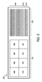
[0049] 図5は、本開示の実施形態による管腔内撮像デバイスの態様を示す概略図である。図500は、撮像素子アレイ302と、マイクロビームフォーマIC304とを含む図1乃至図4の撮像アセンブリ102と一致する。図示されるように、撮像素子アレイ302は、撮像素子サブアレイ420に分割される。例えば撮像素子アレイ302は、8個の撮像素子サブアレイ420に分割される。撮像アセンブリ500はまた、図3及び図4におけるケーブル410及び266と一致し、8本の信号線505、2本の制御線510及び2本の電力線520を含むケーブル530を示す。図示されるように、8個の撮像素子サブアレイ420があり、また、各撮像素子サブアレイ420に対して1つの信号線があり、これにより、各撮像素子サブアレイ420によって受信された信号が、図4の同軸ケーブル410と一致する単独の信号線505を介して制御及び処理システム130に転送されるように、各信号線は1つの撮像素子サブアレイ420と関連付けられる。図示されるように、電力線520/制御線510は、1つ以上の撮像素子サブアレイ420に結合されてよく、1つ以上の撮像素子サブアレイ420に給電する/当該サブアレイ420を制御することができる。
[0049] FIG. 5 is a schematic diagram showing an embodiment of an intraluminal imaging device according to an embodiment of the present disclosure. FIG. 500 corresponds to the
[0050] 幾つかの実施形態では、図4及び図5に示されるように、開口全体が、それぞれ独立してビーム形成される撮像素子サブアレイ420に分割される。撮像素子の2Dアレイ302が示されており、これは3D撮像にも使用することができる。マイクロビームフォーマIC304における重要な要素は、各マイクロチャネル430における遅延素子である。遅延素子は、信号が所望のビーム方向では建設的に増大するが、他の方向では破壊的に増大するように、撮像素子サブアレイ420内の各素子によって受信されたエコーを時間的に整列させるために使用される。遅延素子は、電荷結合素子(CCD)、アナログRAM、タップ付きアナログ遅延線等といった任意の好都合な種類の被制御可変遅延素子であってよい。必要とされる遅延量τは、撮像素子サブアレイ420のサイズ及び最大ステアリング角θに依存する。
τ=dsinθ/v
ここで、dはサブアレイの最大寸法であり、θは最大ビームステアリング角であり、vは撮像される物体内の音速である。幾つかの実施例では、撮像素子サブアレイ420の面積は、その寸法の二乗に比例するので、最大サブアレイ面積Aは、利用可能な遅延の二乗に比例する。
A∝τ2
個々の撮像素子サブアレイ420それぞれの面積が大きいほど、音響アパーチャ全体、即ち、撮像素子アレイ302全体をカバーするのに必要となるサブアレイの数は少なくなる。幾つかの実施例では、各撮像素子サブアレイ420は、素線を通して1本の信号線を供給するので、ケーブルに必要な超音波信号線の数Nは、利用可能な遅延の二乗に反比例する。
N∝1/τ2
[0050] In some embodiments, as shown in FIGS. 4 and 5, the entire aperture is divided into
τ = dsinθ / v
Here, d is the maximum dimension of the sub-array, θ is the maximum beam steering angle, and v is the speed of sound in the object to be imaged. In some embodiments, the area of the
A∝τ 2
The larger the area of each of the individual
N∝1 / τ 2
[0051] 幾つかの実施形態では、使用される遅延素子は、幾つかの連続する素子からなり、これらの素子数が、利用可能である最大遅延を決定する。音響アレイは、マイクロビームフォーマIC304にフリップチップ実装されるので、任意の所与の素子についての遅延を含むすべての処理は、当該1つの素子によって占められる領域にあってよい。幾つかの実施例では、超音波撮像カテーテル2Dアレイは、1000個以上の素子を有するので、必要な超音波信号線の数は、30乃至50本の範囲内であり、15乃至20本の電力線及び制御線も必要とされる。この線数は、同軸線ではなく非シールド素線を使用し、音響素子に個別に取り付けられる既存の1D超音波撮像カテーテルにおいて典型的である。幾つかの実施例では、同軸線ではなく素線を使用すると、ノイズ感受性及び非シールド線間のクロストークのために画質が下がる。幾つかの実施例では、カテーテル先端内にICを使用する場合、接続は、典型的には2.5mmの1つの狭い端部にすることができ、したがって、超音波信号線、電力線及び制御線をすべて含めて最大で約30本に制限される。 [0051] In some embodiments, the delay element used consists of several contiguous elements, the number of these elements determining the maximum delay available. Since the acoustic array is flip-chip mounted on the microbeamformer IC304, all processing, including delays for any given element, may be in the area occupied by that one element. In some embodiments, the ultrasonic imaging catheter 2D array has 1000 or more elements, so the number of ultrasonic signal lines required is in the range of 30 to 50 and 15 to 20 power lines. And control lines are also needed. This number of wires is typical of existing 1D ultrasound imaging catheters that use unshielded strands rather than coaxial and are individually attached to the acoustic element. In some embodiments, using strands rather than coaxial results in poor image quality due to noise sensitivity and crosstalk between unshielded wires. In some embodiments, when using an IC within the tip of the catheter, the connection can typically be one narrow end of 2.5 mm, thus ultrasonic signal lines, power lines and control lines. It is limited to about 30 at the maximum including all.
[0052] 幾つかの実施形態では、撮像信号、例えばトランスデューサ信号について利用可能な遅延量を約2倍にすることができる新しいIC処理機器が現在利用可能である。上記の関係により、超音波信号線の数は、約4倍で、例えば8乃至12本に減らすことができる。この場合、必要とされる線の総数は、マイクロビームフォーマIC304に接続することができる範囲内にある20乃至30本の範囲内にあり、また、同軸ケーブルの使用を可能にする。幾つかの実施例では、少ない線数は、可撓性伸長部材108の先端、例えばカテーテル先端における相互接続部の数が少なくなり、製造コストが削減され、歩留まりが向上し、より大きいサブアレイが時間における受信焦点の深さを追跡できることを含む幾つかの利点を有する。
[0052] In some embodiments, new IC processing devices are currently available that can approximately double the amount of delay available for imaging signals, such as transducer signals. Due to the above relationship, the number of ultrasonic signal lines can be reduced to about 4 times, for example, 8 to 12. In this case, the total number of wires required is in the range of 20 to 30 within the range that can be connected to the
[0053] 幾つかの実施例では、チャネル数を更に減らす可能性があるデジタルの第2のビーム形成段を使用することができる。幾つかの実施例では、オンチップ電力調整を実施し、線の機能を共有し、電力線及び制御線の数を減らすためにプログラム可能な自律型ICコントローラを使用することによって、ケーブル数を更に減らすことができる。 [0053] In some embodiments, a second digital beam forming stage can be used that may further reduce the number of channels. In some embodiments, the number of cables is further reduced by performing on-chip power conditioning, sharing line functions, and using programmable autonomous IC controllers to reduce the number of power lines and control lines. be able to.
[0054] 図6は、血管の管腔内撮像方法600を示すフロー図を提供する。図示されるように、方法600は、幾つかの列挙されたステップを含むが、方法600の実施形態は、列挙されたステップの前、後及び間に追加のステップを含んでよい。幾つかの実施形態では、列挙されたステップのうちの1つ以上が省略されても、異なる順序で行われても又は同時に行われてもよい。方法600は、図1、図2、図3及び図4を参照して行うことができる。ステップ602において、超音波信号が、撮像素子アレイ、例えば撮像素子アレイ302で受信される。撮像素子アレイ302は、管腔内撮像デバイス110の遠位部104内に配置することができる。幾つかの実施例では、マイクロビームフォーマIC304が、撮像素子アレイ302に直接結合され、撮像信号、例えば超音波信号を送受信する。
[0054] FIG. 6 provides a flow chart showing an
[0055] 方法600のステップ604において、撮像素子アレイ302の第1のサブアレイによって受信された超音波信号がビーム形成される。ビーム形成は、図3及び図4を参照して行うことができる。幾つかの実施形態では、マイクロビームフォーマIC304は、例えば下から撮像素子アレイ302に結合される。マイクロビームフォーマIC304は、撮像素子アレイ302に命令し、信号、例えば超音波信号を送受信することができる。幾つかの実施例では、撮像素子アレイ302は、第1のサブアレイを含む複数の撮像素子サブアレイ420に分割される。マイクロビームフォーマIC304はまた、複数のマイクロチャネル遅延線430を含むことができる。マイクロビームフォーマIC304は、マイクロチャネル遅延線430のうちの1つからビーム形成に必要な遅延を第1のサブアレイに供給して、第1のサブアレイのビーム形成を提供する。したがって、ビーム形成は、第1のサブアレイの複数の撮像素子それぞれの信号に必要な遅延を印加することによって提供される。幾つかの実施例では、ビーム形成は送信及び受信の両方の間に行われる。幾つかの他の実施例では、ビーム形成は受信の間に行われる。幾つかの実施例では、撮像素子アレイの第1のサブアレイの複数の撮像素子によって受信された超音波信号は、必要な遅延が印加されることによってビーム形成され、第1のビーム形成信号が作成される。
[0055] In
[0056] 方法600のステップ606において、撮像素子アレイ302の第2のサブアレイによって受信された超音波信号がビーム形成される。ビーム形成は、図3及び図4を参照して行うことができる。マイクロビームフォーマIC304は、マイクロチャネル遅延線430のうちの1つからビーム形成に必要な遅延を第2のサブアレイに供給して、第2のサブアレイのビーム形成を提供する。したがって、ビーム形成は、第2のサブアレイの複数の撮像素子それぞれの信号に必要な遅延を印加することによって提供される。幾つかの実施例では、撮像素子アレイの第2のサブアレイの複数の撮像素子によって受信された超音波信号は、必要な遅延が印加されることによってビーム形成され、第2のビーム形成信号が作成される。
[0056] In
[0057] 方法600のステップ608において、第1のビーム形成信号は、管腔内撮像デバイスのケーブルの第1の信号線を介して送信される。このステップは、図4を参照して行うことができる。ビーム形成信号は、マイクロビームフォーマIC304のマイクロチャネル遅延線430によって提供される必要なビーム形成遅延を、第1の撮像素子サブアレイ420の受信信号に印加した後、第1の撮像素子サブアレイ420の受信及び遅延された信号の集合を、例えば同軸ケーブル410であるケーブルを介して制御及び処理システム130に送信することによって作成される。
[0057] In
[0058] 方法600のステップ610において、第2のビーム形成信号は、管腔内撮像デバイスのケーブルの第2の信号線を介して送信される。同様に、このステップも図4を参照して行うことができる。ビーム形成信号は、マイクロビームフォーマIC304のマイクロチャネル遅延線430によって提供される必要なビーム形成遅延を、第2の撮像素子サブアレイ420の受信信号に印加した後、第2のサブアレイ420の受信及び遅延された信号の集合を、例えば同軸ケーブルであるケーブルを介して制御及び処理システム130に送信することによって作成される。幾つかの実施例では、制御及び処理システム130は、複数のサブアレイから複数のビーム形成信号を受信し、2D画像及び3D画像を作成する。
[0058] In
[0059] 幾つかの実施形態では、典型的なマイクロビームフォーマIC304への最大数の接続は、マイクロビーム形成された受信信号を撮像システムまで戻し、場合によっては、システム100からマイクロビームフォーマICに信号を送信するアナログチャネル線である。幾つかの実施形態では、既存のマイクロビームフォーマ技術と比較してアナログチャネル線の数を低減するために、マイクロビームフォーマIC304上に大きいマイクロビーム形成遅延が生成され、これにより、マイクロビームフォーマIC304への接続数、及び、撮像アセンブリ102を制御及び処理システム130に接続するのに必要な線数が低減される。少ない線数は、材料及び組み立てコスト削減、製造コスト削減、歩留まり増加、信号伝達のための同軸ケーブルの使用、これによって、画質を低下させうるチャネル間のノイズ及びクロストークに対する感受性の低下、線数が少ないことにより大きい線サイズが使用可能であること、それによる信頼性の増加、3D撮像能力の提供、ケーブルとマイクロビームフォーマICとの相互接続の単純化及び相互接続工程の自動化の可能性の提供を含む幾つかの利点を有する。
[0059] In some embodiments, the maximum number of connections to a typical microbeamformer IC304 returns the microbeam-formed received signal to the imaging system and, in some cases, from the
[0060] 当業者であれば、上記装置、システム及び方法が様々な態様で修正可能であることを認識するであろう。したがって、当業者であれば、本開示に包含される実施形態が、上記特定の例示的な実施形態に限定されないことを理解するであろう。この点に関して、例示的な実施形態が示され説明されたが、前述の開示では広範囲の修正、変更及び置換が考えられる。本開示の範囲から逸脱することなく、そのような変形が前述に対してなされうることが理解される。したがって、添付の特許請求の範囲は、広くそして本開示と一致する態様で解釈されることが適切である。
Those skilled in the art will recognize that the devices, systems and methods described above can be modified in various ways. Accordingly, one of ordinary skill in the art will appreciate that the embodiments included in the present disclosure are not limited to the particular exemplary embodiments described above. In this regard, exemplary embodiments have been presented and described, but the aforementioned disclosures may be extensively modified, modified and replaced. It is understood that such modifications can be made to the above without departing from the scope of the present disclosure. Therefore, it is appropriate that the appended claims be broadly construed in a manner consistent with the present disclosure.
Claims (14)
前記管腔内撮像デバイスの遠位部に配置され、複数のサブアレイに配列される複数の撮像素子を含む撮像アレイと、
前記管腔内撮像デバイスの前記遠位部に配置され、前記複数のサブアレイのうちの少なくとも2つのサブアレイの撮像素子から受信される信号を個別にビーム形成する複数のマイクロチャネルを含み、前記撮像アレイが取り付けられたマイクロビームフォーマ集積回路と、
前記マイクロビームフォーマ集積回路に結合される2本以上の信号線と、
を含み、
各信号線は、前記少なくとも2つのサブアレイのうちの1つのサブアレイに対応して、対応する前記サブアレイに特有のビーム形成信号を受信し、
前記複数のマイクロチャネルそれぞれは、前記サブアレイの前記撮像素子から受信される前記信号の整列のための、前記サブアレイのサイズ及び最大ビームステアリング角に依存した最大遅延量を実現する被制御可変遅延素子を含む、撮像アセンブリ。 An imaging assembly for intraluminal imaging devices
An image pickup array including a plurality of image pickup elements arranged in a plurality of subarrays arranged at the distal portion of the intraluminal image pickup device.
The imaging array comprises a plurality of microchannels located at the distal portion of the intraluminal imaging device and individually beaming signals received from imaging elements of at least two of the plurality of subarrays. Microbeamformer integrated circuit with
Two or more signal lines coupled to the microbeam former integrated circuit,
Including
Each signal line corresponds to one of the at least two subarrays and receives a beam forming signal specific to the corresponding subarray.
Each of the plurality of microchannels is a controlled variable delay element that realizes a maximum delay amount depending on the size of the subarray and the maximum beam steering angle for alignment of the signal received from the image sensor of the subarray. Including , imaging assembly.
複数のサブアレイに配列される複数の撮像素子と、
ビームフォーマと、
を含み、
前記複数の撮像素子及び前記ビームフォーマは、前記管腔内撮像システムのカテーテルの遠位部に配置され、
前記複数の撮像素子は、前記ビームフォーマに取り付けられ、
前記ビームフォーマは、
被制御可変遅延素子をそれぞれ含む複数のマイクロチャネルと、
信号線と、
を含み、
前記複数のマイクロチャネルそれぞれの前記被制御可変遅延素子は、前記サブアレイのサイズ及び最大ビームステアリング角に依存した最大遅延量を実現して、前記サブアレイの前記撮像素子からの信号を整列させ、
前記信号線は、整列された前記信号を受信し、前記管腔内撮像システムに送信する、トランスデューサアレイ。
Transducer array of intraluminal imaging system
Multiple image sensors arranged in multiple sub-arrays and
Beam former and
Including
The plurality of image pickup devices and the beam former are arranged at the distal portion of the catheter of the intraluminal imaging system.
The plurality of image pickup devices are attached to the beam former, and the plurality of image pickup elements are attached to the beam former.
The beam former is
Multiple microchannels, each containing a controlled variable delay element,
Signal line and
Including
The controlled variable delay element of each of the plurality of microchannels realizes a maximum delay amount depending on the size of the subarray and the maximum beam steering angle, and aligns the signals from the image pickup element of the subarray.
The signal line is a transducer array that receives the aligned signal and sends it to the intraluminal imaging system.
Applications Claiming Priority (5)
| Application Number | Priority Date | Filing Date | Title |
|---|---|---|---|
| US201662403311P | 2016-10-03 | 2016-10-03 | |
| US62/403,311 | 2016-10-03 | ||
| US201662437778P | 2016-12-22 | 2016-12-22 | |
| US62/437,778 | 2016-12-22 | ||
| PCT/EP2017/074278 WO2018065254A1 (en) | 2016-10-03 | 2017-09-26 | Intraluminal imaging devices with a reduced number of signal channels |
Publications (3)
| Publication Number | Publication Date |
|---|---|
| JP2019528975A JP2019528975A (en) | 2019-10-17 |
| JP2019528975A5 JP2019528975A5 (en) | 2020-11-12 |
| JP7096237B2 true JP7096237B2 (en) | 2022-07-05 |
Family
ID=59974424
Family Applications (1)
| Application Number | Title | Priority Date | Filing Date |
|---|---|---|---|
| JP2019517397A Active JP7096237B2 (en) | 2016-10-03 | 2017-09-26 | Intraluminal imaging device with a small number of signal channels |
Country Status (4)
| Country | Link |
|---|---|
| US (1) | US11911217B2 (en) |
| EP (1) | EP3518774B1 (en) |
| JP (1) | JP7096237B2 (en) |
| WO (1) | WO2018065254A1 (en) |
Families Citing this family (1)
| Publication number | Priority date | Publication date | Assignee | Title |
|---|---|---|---|---|
| CA3110612A1 (en) | 2018-08-31 | 2020-03-05 | The College Of The Holy & Undivided Trinity Of Queen Elizabeth | Ultrasound based three-dimensional lesion verification within a vasculature |
Citations (5)
| Publication number | Priority date | Publication date | Assignee | Title |
|---|---|---|---|---|
| US20050131299A1 (en) | 2003-12-10 | 2005-06-16 | Brent Robinson | Differential partial beamforming |
| JP2008514335A (en) | 2004-09-30 | 2008-05-08 | コーニンクレッカ フィリップス エレクトロニクス エヌ ヴィ | Transducer structure for microbeam formation |
| US20130245450A1 (en) | 2012-03-09 | 2013-09-19 | Oldelft B.V. | Method of manufacturing an ultrasound transducer and devices including an ultrasound transducer |
| WO2015150385A2 (en) | 2014-03-31 | 2015-10-08 | Koninklijke Philips N.V. | Ic die, ultrasound probe, ultrasonic diagnostic system and method |
| WO2016097959A1 (en) | 2014-12-15 | 2016-06-23 | Koninklijke Philips N.V. | Compact ultrasound transducer with direct coax attachment |
Family Cites Families (25)
| Publication number | Priority date | Publication date | Assignee | Title |
|---|---|---|---|---|
| US8241217B2 (en) * | 1995-06-29 | 2012-08-14 | Teratech Corporation | Portable ultrasound imaging data |
| US6669633B2 (en) * | 1999-06-22 | 2003-12-30 | Teratech Corporation | Unitary operator control for ultrasonic imaging graphical user interface |
| US6468216B1 (en) | 2000-08-24 | 2002-10-22 | Kininklijke Philips Electronics N.V. | Ultrasonic diagnostic imaging of the coronary arteries |
| US20050131302A1 (en) * | 2003-12-16 | 2005-06-16 | Poland Mckee D. | Ultrasonic probe having a selector switch |
| US20050203410A1 (en) * | 2004-02-27 | 2005-09-15 | Ep Medsystems, Inc. | Methods and systems for ultrasound imaging of the heart from the pericardium |
| EP1737348A1 (en) * | 2004-04-14 | 2007-01-03 | Koninklijke Philips Electronics N.V. | Ultrasound imaging probe featuring wide field of view |
| WO2005120359A1 (en) * | 2004-06-11 | 2005-12-22 | Olympus Corporation | Ultrasonic probe and ultrasonographic device |
| JP2007068918A (en) * | 2005-09-09 | 2007-03-22 | Fujifilm Corp | Ultrasonic probe and ultrasonic diagnosis apparatus |
| EP1952175B1 (en) * | 2005-11-02 | 2013-01-09 | Visualsonics, Inc. | Digital transmit beamformer for an arrayed ultrasound transducer system |
| US20100168583A1 (en) * | 2006-11-03 | 2010-07-01 | Research Triangle Institute | Enhanced ultrasound imaging probes using flexure mode piezoelectric transducers |
| US20080146940A1 (en) * | 2006-12-14 | 2008-06-19 | Ep Medsystems, Inc. | External and Internal Ultrasound Imaging System |
| US8052607B2 (en) * | 2008-04-22 | 2011-11-08 | St. Jude Medical, Atrial Fibrillation Division, Inc. | Ultrasound imaging catheter with pivoting head |
| JP5433429B2 (en) * | 2010-01-12 | 2014-03-05 | 株式会社東芝 | Ultrasonic probe |
| JP5452319B2 (en) * | 2010-03-31 | 2014-03-26 | 富士フイルム株式会社 | Ultrasonic diagnostic equipment |
| US20120095348A1 (en) * | 2010-10-19 | 2012-04-19 | Sonavation, Inc. | Three Dimensional Imaging Intra Cardiac Echocardiography (ICE) Catheter |
| CA2819644A1 (en) * | 2010-12-03 | 2012-06-07 | Research Triangle Institute | Ultrasound device, and associated cable assembly |
| KR101303626B1 (en) * | 2011-01-06 | 2013-09-11 | 서강대학교산학협력단 | Diagnosis system for diagnosing subject, medical image system for providing diagnosis image of subject and method for displaying diagnosis image of subject |
| WO2014080312A1 (en) * | 2012-11-20 | 2014-05-30 | Koninklijke Philips N.V. | Frameless ultrasound probes with heat dissipation |
| US20140180120A1 (en) * | 2012-12-21 | 2014-06-26 | Volcano Corporation | Ultrasound Imaging Catheters with Reciprocating Phased Array Transducers |
| WO2014105586A1 (en) * | 2012-12-31 | 2014-07-03 | Volcano Corporation | Stepped banded connector for intravascular ultrasound devices |
| EP3013486A2 (en) | 2013-06-26 | 2016-05-04 | Koninklijke Philips N.V. | Integrated circuit arrangement for an ultrasound transducer array |
| WO2015048321A1 (en) * | 2013-09-25 | 2015-04-02 | Georgia Tech Research Corporation | Mri compatible 3-d intracardiac echography catheter and system |
| KR20150118750A (en) * | 2014-04-15 | 2015-10-23 | 삼성전자주식회사 | Ultrasonic imaging apparatus |
| US10537309B2 (en) * | 2014-11-13 | 2020-01-21 | Duke University | Systems and methods for ultrasound motion display and analysis |
| US20180064415A1 (en) * | 2016-09-07 | 2018-03-08 | Siemens Medical Solutions Usa, Inc. | Acoustic ablation assisted intra-cardiac echocardiography catheter |
-
2017
- 2017-09-26 WO PCT/EP2017/074278 patent/WO2018065254A1/en active Application Filing
- 2017-09-26 US US16/338,855 patent/US11911217B2/en active Active
- 2017-09-26 JP JP2019517397A patent/JP7096237B2/en active Active
- 2017-09-26 EP EP17777002.1A patent/EP3518774B1/en active Active
Patent Citations (7)
| Publication number | Priority date | Publication date | Assignee | Title |
|---|---|---|---|---|
| US20050131299A1 (en) | 2003-12-10 | 2005-06-16 | Brent Robinson | Differential partial beamforming |
| JP2008514335A (en) | 2004-09-30 | 2008-05-08 | コーニンクレッカ フィリップス エレクトロニクス エヌ ヴィ | Transducer structure for microbeam formation |
| US20080262351A1 (en) | 2004-09-30 | 2008-10-23 | Koninklijke Philips Electronics, N.V. | Microbeamforming Transducer Architecture |
| US20130245450A1 (en) | 2012-03-09 | 2013-09-19 | Oldelft B.V. | Method of manufacturing an ultrasound transducer and devices including an ultrasound transducer |
| JP2013184064A (en) | 2012-03-09 | 2013-09-19 | Oldelft Bv | Method of manufacturing ultrasound transducer for use in ultrasound imaging device, and ultrasound transducer and ultrasound probe manufactured according to the method |
| WO2015150385A2 (en) | 2014-03-31 | 2015-10-08 | Koninklijke Philips N.V. | Ic die, ultrasound probe, ultrasonic diagnostic system and method |
| WO2016097959A1 (en) | 2014-12-15 | 2016-06-23 | Koninklijke Philips N.V. | Compact ultrasound transducer with direct coax attachment |
Also Published As
| Publication number | Publication date |
|---|---|
| US20200214670A1 (en) | 2020-07-09 |
| WO2018065254A1 (en) | 2018-04-12 |
| EP3518774B1 (en) | 2021-09-01 |
| EP3518774A1 (en) | 2019-08-07 |
| JP2019528975A (en) | 2019-10-17 |
| US11911217B2 (en) | 2024-02-27 |
Similar Documents
| Publication | Publication Date | Title |
|---|---|---|
| US20080025145A1 (en) | Ultrasound Imaging Probe Featuring Wide Field of View | |
| US20050085731A1 (en) | Ultrasound transducer finger probe | |
| JP2019535382A (en) | Wireless intraluminal imaging device and system | |
| US20220409171A1 (en) | Intra-cardiac echocardiography inteposer | |
| US20230397904A1 (en) | Ultrasound imaging device with thermally conductive plate | |
| JP2020513950A (en) | Intraluminal imaging device including wire interconnect for imaging assembly | |
| JP2023078378A (en) | Imaging plane control and display for intraluminal ultrasound, and associated devices, systems, and methods | |
| JP6998373B2 (en) | Inner members for intravascular imaging devices and related devices, systems and methods | |
| JP6980774B2 (en) | Flexible imaging assemblies for intraluminal imaging and related devices, systems and methods | |
| EP3600699B1 (en) | Annular integrated circuit controller for intraluminal ultrasound imaging device | |
| JP7096237B2 (en) | Intraluminal imaging device with a small number of signal channels | |
| US20200275909A1 (en) | Connectors for patient interface module and ultrasound imaging device | |
| JP7167011B2 (en) | X-plane and 3D imaging for asymmetric apertures | |
| JP2019530505A (en) | Flexible phased array transducer for intravascular imaging devices and related devices, systems and methods |
Legal Events
| Date | Code | Title | Description |
|---|---|---|---|
| A521 | Request for written amendment filed |
Free format text: JAPANESE INTERMEDIATE CODE: A523 Effective date: 20200924 |
|
| A621 | Written request for application examination |
Free format text: JAPANESE INTERMEDIATE CODE: A621 Effective date: 20200924 |
|
| A521 | Request for written amendment filed |
Free format text: JAPANESE INTERMEDIATE CODE: A523 Effective date: 20201016 |
|
| A521 | Request for written amendment filed |
Free format text: JAPANESE INTERMEDIATE CODE: A821 Effective date: 20201016 |
|
| A521 | Request for written amendment filed |
Free format text: JAPANESE INTERMEDIATE CODE: A523 Effective date: 20201016 |
|
| A977 | Report on retrieval |
Free format text: JAPANESE INTERMEDIATE CODE: A971007 Effective date: 20210831 |
|
| A131 | Notification of reasons for refusal |
Free format text: JAPANESE INTERMEDIATE CODE: A131 Effective date: 20210928 |
|
| A601 | Written request for extension of time |
Free format text: JAPANESE INTERMEDIATE CODE: A601 Effective date: 20211221 |
|
| A521 | Request for written amendment filed |
Free format text: JAPANESE INTERMEDIATE CODE: A523 Effective date: 20220323 |
|
| TRDD | Decision of grant or rejection written | ||
| A01 | Written decision to grant a patent or to grant a registration (utility model) |
Free format text: JAPANESE INTERMEDIATE CODE: A01 Effective date: 20220530 |
|
| A61 | First payment of annual fees (during grant procedure) |
Free format text: JAPANESE INTERMEDIATE CODE: A61 Effective date: 20220623 |
|
| R150 | Certificate of patent or registration of utility model |
Ref document number: 7096237 Country of ref document: JP Free format text: JAPANESE INTERMEDIATE CODE: R150 |