JP7096122B2 - sash - Google Patents

sash Download PDF

Info

Publication number
JP7096122B2
JP7096122B2 JP2018184003A JP2018184003A JP7096122B2 JP 7096122 B2 JP7096122 B2 JP 7096122B2 JP 2018184003 A JP2018184003 A JP 2018184003A JP 2018184003 A JP2018184003 A JP 2018184003A JP 7096122 B2 JP7096122 B2 JP 7096122B2
Authority
JP
Japan
Prior art keywords
vertical frame
groove
sash
vertical
frame member
Prior art date
Legal status (The legal status is an assumption and is not a legal conclusion. Google has not performed a legal analysis and makes no representation as to the accuracy of the status listed.)
Active
Application number
JP2018184003A
Other languages
Japanese (ja)
Other versions
JP2020051196A (en
Inventor
功 阿部
Original Assignee
昭和フロント株式会社
Priority date (The priority date is an assumption and is not a legal conclusion. Google has not performed a legal analysis and makes no representation as to the accuracy of the date listed.)
Filing date
Publication date
Application filed by 昭和フロント株式会社 filed Critical 昭和フロント株式会社
Priority to JP2018184003A priority Critical patent/JP7096122B2/en
Publication of JP2020051196A publication Critical patent/JP2020051196A/en
Priority to JP2022100869A priority patent/JP7270100B2/en
Application granted granted Critical
Publication of JP7096122B2 publication Critical patent/JP7096122B2/en
Active legal-status Critical Current
Anticipated expiration legal-status Critical

Links

Images

Landscapes

  • Door And Window Frames Mounted To Openings (AREA)

Description

特許法第30条第2項適用 ▲1▼開催日:平成30年7月20日、開催場所:大和リース株式会社 関西工場 ▲2▼メール送信日:平成30年9月12日、メール送信相手先:ナブコシステム株式会社Application of Article 30, Paragraph 2 of the Patent Law ▲ 1 ▼ Date: July 20, 2018, Venue: Daiwa Lease Co., Ltd. Kansai Factory ▲ 2 ▼ Email transmission date: September 12, 2018, email recipient Destination: Nabco System Co., Ltd.

本発明は、左右一対の支柱間に落とし込んで組み付けられるサッシに関するものである。 The present invention relates to a sash that is dropped and assembled between a pair of left and right columns.

一般に、組立ハウスや店舗等に用いられるサッシのなかには、相対向する開口溝を有した左右一対の支柱間に落とし込んで組み付けられるサッシがある。このようなサッシにおいて、サッシ枠内にガラス板や樹脂板等のパネル体を嵌め殺し状に組み込んでFIX部とする場合に、サッシの左右の縦枠を、支柱の開口溝に嵌入して上下方向スライド移動自在に支持されるスライド部を有する第一の縦枠部材と、パネル体の左右縦縁部が嵌合するパネル嵌合溝を有した第二の縦枠部材とを用いて構成したものが知られている(例えば、特許文献1の図6参照)。 Generally, among sashes used in assembly houses and stores, there is a sash that is dropped and assembled between a pair of left and right columns having facing opening grooves. In such a sash, when a panel body such as a glass plate or a resin plate is fitted into the sash frame to form a FIX portion, the left and right vertical frames of the sash are fitted into the opening grooves of the columns to move up and down. It is configured by using a first vertical frame member having a slide portion supported so as to be slidable in a direction, and a second vertical frame member having a panel fitting groove into which the left and right vertical edges of the panel body are fitted. Is known (see, for example, FIG. 6 of Patent Document 1).

登録実用新案第3031673号公報Registered Utility Model No. 3031673

しかしながら、前記特許文献1のものでは、スライド部が支柱の開口溝に支持されている状態で、パネル嵌合溝の溝底部が、支柱の左右外方側に位置するように設けられている。このため、パネル嵌合溝全体が支柱の左右外方側に位置することになって、支柱の開口溝から左右外方に突出する部分の縦枠の見付け寸法が大きくなり、その分パネル体の実質的な左右幅(縦枠で覆蓋される部分を除いたパネル体の左右幅)が短くなって、パネル体としての有効面積が減少してしまうという問題がある。例えば、パネル体として透光性のあるガラス板が用いられている場合、ガラス板の左右幅が短くなった分だけ透光面積が狭くなって、その分採光性が損なわれることになる。
さらに特許文献1のものでは、スライド部が形成される第一の縦枠部材(特許文献1におけるアタッチメント1)と、パネル嵌合溝が形成される第二の縦枠部材(特許文献1におけるサッシユニット3の縦枠材)とを取付ねじを用いて固定する構成になっているが、この場合に、第一、第二縦枠部材の見付け面部同士(特許文献1におけるアタッチメント1のフランジ部1dとサッシユニット3の側縁3a)を支柱の開口溝外で重ね合わせ、該重ね合わせた部分を見付け面部の前後外方側から螺入される取付ねじ5で止着するようになっているから、取付ねじが外部から視認されることになって意匠性に劣るという問題もあり、これらに本発明の解決すべき課題がある。
However, in the case of Patent Document 1, the groove bottom portion of the panel fitting groove is provided so as to be located on the left and right outer sides of the column while the slide portion is supported by the opening groove of the column. For this reason, the entire panel fitting groove is located on the left and right outer sides of the column, and the finding dimension of the vertical frame of the portion protruding from the opening groove of the column to the left and right is increased by that amount. There is a problem that the substantial left-right width (the left-right width of the panel body excluding the portion covered by the vertical frame) becomes short, and the effective area of the panel body decreases. For example, when a translucent glass plate is used as the panel body, the translucent area is narrowed by the shorter the left-right width of the glass plate, and the daylighting property is impaired by that amount.
Further, in the case of Patent Document 1, a first vertical frame member (attachment 1 in Patent Document 1) on which a slide portion is formed and a second vertical frame member (sash in Patent Document 1) in which a panel fitting groove is formed are formed. The vertical frame material of the unit 3) is fixed to each other by using mounting screws. In this case, the found surface portions of the first and second vertical frame members (flange portion 1d of the attachment 1 in Patent Document 1) are fixed to each other. And the side edge 3a) of the sash unit 3 are overlapped outside the opening groove of the column, and the overlapped portion is found and fastened with the mounting screw 5 screwed from the front and rear outer sides of the surface portion. There is also a problem that the mounting screw is visually recognized from the outside and the design is inferior, and these are problems to be solved by the present invention.

本発明は、上記の如き実情に鑑みこれらの課題を解決することを目的として創作されたものであって、請求項1の発明は、相対向する開口溝を有した左右一対の支柱間に落とし込んで組み付けられるサッシであって、該サッシは、前記一対の支柱開口溝に支持される左右の縦枠と、これら左右の縦枠間に組み込まれるパネル体とを備え、前記縦枠は、支柱の開口溝に嵌入して上下方向スライド移動自在に支持されるスライド部を有した第一縦枠部材と、パネル体の左右縦縁部が嵌合されるパネル嵌合溝を有した第二縦枠部材とを組み付けて構成されるとともに、前記第一縦枠部材のスライド部は、支柱の見付け方向を向き、支柱開口溝に嵌入して上下スライド移動自在に支持される前後一対のスライド面部と、これら前後一対のスライド面部同士を支柱開口溝内で連結する連結部とを備える一方、第二縦枠部材のパネル嵌合溝は、溝底部が支柱開口溝内に入り込んで連結部に止着されることを特徴とするサッシである。
請求項2の発明は、請求項1において、第一、第二縦枠部材同士は、支柱の開口溝外で係合する係合部を有し、該係合部にシール材を配したことを特徴とするサッシである。
請求項3の発明は、請求項1または2において、縦枠の前後の見付け面部は、支柱の前後の見込み面部と面一状になっていることを特徴とするサッシである。
The present invention has been created for the purpose of solving these problems in view of the above circumstances, and the invention of claim 1 is inserted between a pair of left and right columns having facing open grooves. The sash is provided with a left and right vertical frame supported by the pair of support column opening grooves and a panel body incorporated between the left and right vertical frames, and the vertical frame is a support column. A first vertical frame member having a slide portion that is fitted into an opening groove and supported so as to be slidable in the vertical direction, and a second vertical frame having a panel fitting groove into which the left and right vertical edges of the panel body are fitted. The slide portion of the first vertical frame member is configured by assembling the members, and has a pair of front and rear slide surface portions that face the strut finding direction, are fitted into the strut opening groove, and are supported so as to be vertically slidable. The panel fitting groove of the second vertical frame member is provided with a connecting portion for connecting the pair of front and rear slide surface portions in the strut opening groove, while the groove bottom portion enters the strut opening groove and is fastened to the connecting portion. It is a sash characterized by that.
According to the first aspect of the present invention, the first and second vertical frame members have an engaging portion that engages with each other outside the opening groove of the column, and a sealing material is arranged in the engaging portion. It is a sash characterized by.
The invention of claim 3 is a sash according to claim 1 or 2, wherein the front and rear finding surface portions of the vertical frame are flush with the prospective surface portions before and after the support column.

請求項1の発明とすることにより、支柱の開口溝から左右外方に突出する部分の縦枠の見付け寸法を小さく設定でき、その分、縦枠に覆蓋されない部分のパネル体の左右幅を広くできる。しかも、パネル嵌合溝の溝底部を連結部に止着するための止着部材は、バネル嵌合溝にパネル体が嵌合された後では外部から視認されることなく、意匠性に優れる。
請求項2の発明とすることにより、支柱の開口溝外における第一、第二縦枠部材の係合部間のシール性を確保することができる。
請求項3の発明とすることにより、支柱と縦枠との見付け面部同士が段差のない連続した状態として視認されることになって、意匠性に優れる。
According to the first aspect of the present invention, the apparent dimension of the vertical frame of the portion protruding outward from the opening groove of the column can be set small, and the lateral width of the panel body of the portion not covered by the vertical frame can be widened accordingly. can. Moreover, the fastening member for fastening the groove bottom portion of the panel fitting groove to the connecting portion is excellent in design without being visually recognized from the outside after the panel body is fitted in the panel fitting groove.
According to the second aspect of the present invention, it is possible to secure the sealing property between the engaging portions of the first and second vertical frame members outside the opening groove of the column.
According to the third aspect of the present invention, the finding surface portions of the support column and the vertical frame are visually recognized as a continuous state without a step, and the design is excellent.

サッシの設置状態を示す正面図である。It is a front view which shows the installation state of a sash. 図1の一部省略X-X断面図である。FIG. 1 is a cross-sectional view taken along the line XX in which a part of FIG. 1 is omitted. 図1の一部省略Y-Y断面図である。FIG. 1 is a partially omitted YY cross-sectional view of FIG. 図1の一部省略V-V断面図である。FIG. 1 is a partially omitted VV cross-sectional view of FIG. 図1の一部省略W-W断面図である。FIG. 1 is a partially omitted WW sectional view of FIG. 縦枠の分解図である。It is an exploded view of a vertical frame. 他例を示す要部断面図である。It is sectional drawing of the main part which shows another example.

以下、本発明の実施の形態について、図面に基づいて説明する。図において、1は建物の開口部に基礎部材2を介して立設される支柱であって、該支柱1は、左右に間隔を存する状態で複数配設されている。各支柱1は、本実施の形態では、前後の見付け面部1aと、これら前後の見付け面部1aの左右方向中間部同士を連結するウエブ1bと、前後の見付け面部1aの左右外方側端部から前後内方側に延びる前後のリップ片1cとを備え、これら前後のリップ片1c間にリップ溝状の開口溝1dが形成された左右対称状の溝形鋼であって、左右に隣接する一対の支柱1の開口溝1d同士が相対向する状態となるように配置されている。 Hereinafter, embodiments of the present invention will be described with reference to the drawings. In the figure, reference numeral 1 denotes a support column which is erected at an opening of a building via a foundation member 2, and a plurality of columns 1 are arranged so as to have a space between the left and right sides. In the present embodiment, each column 1 is provided from the front and rear finding surface portions 1a, the web 1b connecting the front and rear finding surface portions 1a in the left-right direction intermediate portions, and the left and right outer side ends of the front and rear finding surface portions 1a. A pair of left-right symmetrical channel steels having front and rear lip pieces 1c extending inward in the front-rear direction and having lip groove-shaped opening grooves 1d formed between the front and rear lip pieces 1c. The opening grooves 1d of the support columns 1 are arranged so as to face each other.

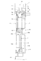
一方、3、4は前記左右に隣接する一対の支柱1間に落とし込んで組み付けられるサッシであって、図1において左側に位置するサッシ3は、上枠5、下枠6および左右の縦枠7により形成されるサッシ枠内に、ガラス板や樹脂板等のパネル体8が組み込まれてFIX部を形成するようになっている。 On the other hand, 3 and 4 are sashes that are dropped and assembled between the pair of columns 1 adjacent to the left and right, and the sash 3 located on the left side in FIG. 1 is an upper frame 5, a lower frame 6, and left and right vertical frames 7. A panel body 8 such as a glass plate or a resin plate is incorporated in the sash frame formed by the above to form a FIX portion.

前記左右の縦枠7は、前記支柱1の開口溝1dに嵌入して上下方向スライド移動自在に支持されるスライド部9を有する第一縦枠部材10と、前記パネル体8の左右縦縁部が嵌合されるパネル嵌合溝11を有する第二縦枠部材12とを組み付けて構成されている。 The left and right vertical frames 7 are a first vertical frame member 10 having a slide portion 9 that is fitted into the opening groove 1d of the support column 1 and is supported so as to be slidable in the vertical direction, and left and right vertical edge portions of the panel body 8. It is configured by assembling a second vertical frame member 12 having a panel fitting groove 11 to which the panel fitting groove 11 is fitted.

前記第一縦枠部材10のスライド部9は、該スライド部9が支柱1の開口溝1dに支持された状態で、支柱1の見付け方向を向き、支柱1の開口溝1dに嵌入して前後のリップ片1cの先端部に上下スライド移動自在に支持される前後一対のスライド面部9aと、これら前後一対のスライド面部9a同士を開口溝1d内で連結する連結部9bとを備えて構成されている。さらに、第一縦枠部材10は、スライド部9が支柱1の開口溝1dに支持された状態で支柱1の左右外方側において前後のリップ片1cに僅かな間隙を存して対向して第一縦枠部材10の左右方向の移動規制をする前後の見込み面部10aと、該見込み面部10aの前後外方側端部から見付け方向に延びる前後の見付け面部10bと、該前後の見付け面部10bの先端部から前後内方側に延びる前後の見込み片10cと、前後の見込み面部10aの前後方向中間部から見付け方向に突出する前後の突片10dと、見込み片10cの先端部と突片10dの先端部との間に形成される前後の係合孔(本発明の第一縦枠部材の係合部に相当する)10eとを備えている。前記第一縦枠部材10の前後の見付け面部10bは、第一縦枠部材10と第二縦枠部材12とにより縦枠7が形成された状態で、該縦枠7の見付け面部7aを構成するとともに、縦枠7のスライド部9が支柱開口溝1dに支持された状態で、支柱1の前後の見付け面部1aと面一状となるように設計されている。 The slide portion 9 of the first vertical frame member 10 faces the finding direction of the support column 1 with the slide portion 9 supported by the opening groove 1d of the support column 1, and is fitted into the opening groove 1d of the support column 1 in the front-rear direction. A pair of front and rear slide surface portions 9a that are supported by the tip of the lip piece 1c so as to be slidable up and down, and a connecting portion 9b that connects the pair of front and rear slide surface portions 9a to each other in the opening groove 1d. There is. Further, the first vertical frame member 10 faces the front and rear lip pieces 1c with a slight gap on the left and right outer sides of the support column 1 in a state where the slide portion 9 is supported by the opening groove 1d of the support column 1. The front and rear prospective surface portions 10a for restricting the movement of the first vertical frame member 10 in the left-right direction, the front and rear finding surface portions 10b extending in the finding direction from the front and rear outer side ends of the prospective surface portion 10a, and the front and rear finding surface portions 10b. Front and rear prospective pieces 10c extending inwardly from the tip of the front and rear, front and rear projectiles 10d protruding in the finding direction from the anterior-posterior intermediate portion of the anterior and posterior prospective surface portions 10a, and the tip and projectile 10d of the prospective piece 10c. It is provided with front and rear engaging holes (corresponding to the engaging portion of the first vertical frame member of the present invention) 10e formed between the tip and the tip of the above. The front and rear finding surface portions 10b of the first vertical frame member 10 form the finding surface portion 7a of the vertical frame 7 in a state where the vertical frame 7 is formed by the first vertical frame member 10 and the second vertical frame member 12. At the same time, the slide portion 9 of the vertical frame 7 is designed to be flush with the finding surface portions 1a before and after the support column 1 in a state of being supported by the support column opening groove 1d.

一方、第二縦枠部材12は、パネル体8の左右縦縁部が嵌合するパネル嵌合溝11と、該パネル嵌合溝11の溝開口側縁部から見込み方向に延びる前後の見込み面部12aと、これら前後の見込み面部12aの先端部(前後外方側端部)に形成され、前記第一縦枠部材10の前後の係合孔10eにそれぞれ係合する前後の係合フック部(本発明の第二縦枠部材の係合部に相当する)12bとを備えて構成されている。 On the other hand, the second vertical frame member 12 has a panel fitting groove 11 into which the left and right vertical edges of the panel body 8 are fitted, and front and rear prospective surface portions extending in a prospective direction from the groove opening side edge of the panel fitting groove 11. Front and rear engaging hook portions (front and rear engaging hook portions) formed at the tip portions (front and rear outer side end portions) of the front and rear prospective surface portions 12a and engaged with the front and rear engaging holes 10e of the first vertical frame member 10, respectively. It is configured to include (corresponding to the engaging portion of the second vertical frame member of the present invention) 12b.

そして、前記第一縦枠部材10と第二縦枠部材12とを固定する場合には、第二縦枠部材12のパネル嵌合溝11を溝底部11a側から第一縦枠部材10の前後のスライド面部9a間に嵌入して溝底部11aを連結部9bに当接させる。この状態で、第一縦枠部材10の前後の見込み片10cと第二縦枠部材12の前後の見込み面部12aとは面一状になるとともに、第一縦枠部材10の係合孔10eに第二縦枠部材12の係合フック部12bが係合するようになっている。そして、前記当接させたパネル嵌合溝11の溝底部11aと連結部9bとを、溝底部11a側から連結部9bに螺入される螺子13で止着することで、第一縦枠部材10と第二縦枠部材12とは固定された状態で組み付けられて縦枠7を形成するようになっている。さらに、前記係合孔10eと係合フック部12bとの係合部にはシール材14が配されており、これにより第一、第二縦枠部材10、12の係合部間のシール性が確保されている。 When fixing the first vertical frame member 10 and the second vertical frame member 12, the panel fitting groove 11 of the second vertical frame member 12 is placed in front of and behind the first vertical frame member 10 from the groove bottom portion 11a side. The groove bottom portion 11a is brought into contact with the connecting portion 9b by being fitted between the slide surface portions 9a of the above. In this state, the prospective pieces 10c before and after the first vertical frame member 10 and the prospective surface portions 12a before and after the second vertical frame member 12 are flush with each other and are formed in the engagement holes 10e of the first vertical frame member 10. The engaging hook portion 12b of the second vertical frame member 12 is adapted to engage. Then, the groove bottom portion 11a and the connecting portion 9b of the panel fitting groove 11 that have been brought into contact with each other are fastened to each other by a screw 13 screwed into the connecting portion 9b from the groove bottom portion 11a side, whereby the first vertical frame member. The 10 and the second vertical frame member 12 are assembled in a fixed state to form the vertical frame 7. Further, a sealing material 14 is arranged at the engaging portion between the engaging hole 10e and the engaging hook portion 12b, whereby the sealing property between the engaging portions of the first and second vertical frame members 10 and 12 is provided. Is secured.

また、前記サッシ3の上枠5は、パネル体8の上縁部が嵌合されるパネル嵌合溝5aと、該パネル嵌合溝5aの溝開口側縁部から見込み方向に延びる前後の見込み面部5bとを有しており、前記左右の第二縦枠部材12の上端部間に、第二縦枠部材12の見込み面部12a側から螺入されて上枠5に形成のビスポケット5cに螺入される螺子15を介して組み付けられるようになっている。また、サッシ3の下枠6は、下枠本体部6aと押縁部材6bを用いて構成されており、これら下枠本体部6aと押縁部材6bとによってパネル体8の下縁部が嵌合するパネル嵌合溝6cが形成されているとともに、左右の第二縦枠部材12の下端部間に、第二縦枠部材12の見込み面部12a側から螺入されて下枠6(下枠本体部6a)に形成のビスポケット6dに螺入される螺子15を介して組み付けられるようになっている。そして、これら上枠5および下枠6(下枠本体部6a)は、前述した第一縦枠部材10と第二縦枠部材12とが固定される前の段階で、左右の第二縦枠部材12に前記螺子15を介して組み付けられる。つまり、左右の第二縦枠部材12に上枠5および下枠6を組み付けて枠組み形成した状態で、左右の第二縦枠部材12に第一縦枠部材10を固定して縦枠7を形成し、このようにして上枠5、下枠6、左右の縦枠7からなるサッシ枠が形成されるようになっている。 Further, the upper frame 5 of the sash 3 is expected to extend in the prospective direction from the panel fitting groove 5a into which the upper edge portion of the panel body 8 is fitted and the groove opening side edge portion of the panel fitting groove 5a. It has a surface portion 5b, and is screwed from the prospective surface portion 12a side of the second vertical frame member 12 between the upper ends of the left and right second vertical frame members 12 into a screw pocket 5c formed in the upper frame 5. It can be assembled via the screw 15 to be screwed in. Further, the lower frame 6 of the sash 3 is configured by using the lower frame main body portion 6a and the ridge member 6b, and the lower edge portion of the panel body 8 is fitted by the lower frame main body portion 6a and the ridge member 6b. The panel fitting groove 6c is formed, and the lower frame 6 (lower frame main body portion) is screwed from the prospective surface portion 12a side of the second vertical frame member 12 between the lower ends of the left and right second vertical frame members 12. It can be assembled via a screw 15 screwed into the screw pocket 6d formed in 6a). The upper frame 5 and the lower frame 6 (lower frame main body portion 6a) are formed in the left and right second vertical frames before the first vertical frame member 10 and the second vertical frame member 12 are fixed. It is assembled to the member 12 via the screw 15. That is, in a state where the upper frame 5 and the lower frame 6 are assembled to the left and right second vertical frame members 12 to form a framework, the first vertical frame member 10 is fixed to the left and right second vertical frame members 12 to form the vertical frame 7. The sash frame is formed, and thus the sash frame including the upper frame 5, the lower frame 6, and the left and right vertical frames 7 is formed.

そして、前述したようにして形成されたサッシ枠は、左右に隣接する支柱1間に落とし込んで組み付けられるが、この場合に、相対向する支柱1の開口溝1dに上方から左右の縦枠7のスライド部9を嵌入し、そのまま下方にスライド移動させて、予め左右の支柱1の下端部間に配設されたベースパネル16上に載置する。この状態で、スライド部9の前後のスライド面部9aは、支柱1の開口溝1dに嵌入して前後のリップ片1cの先端部に上下方向スライド移動自在に支持されるとともに、これら前後のスライド面部9a同士を連結する連結部9bは、開口溝1d内に位置している。そしてこの開口溝1d内に位置している連結部9bには、パネル嵌合溝11の溝底部11aが止着されており、これにより、パネル嵌合溝11の溝底部11aは支柱1の開口溝1d内に入り込む状態となっている。そして、このようにパネル嵌合溝11の溝底部11aを支柱1の開口溝1d内に入り込ませることで、支柱1から左右外方側に突出する部分の縦枠7の見付け寸法Lを小さく設定できるようになっている。 Then, the sash frame formed as described above is dropped between the adjacent columns 1 on the left and right and assembled. In this case, the vertical frames 7 on the left and right are placed in the opening grooves 1d of the opposing columns 1 from above. The slide portion 9 is fitted, slid downward as it is, and placed on the base panel 16 previously arranged between the lower ends of the left and right columns 1. In this state, the front and rear slide surface portions 9a of the slide portion 9 are fitted into the opening groove 1d of the support column 1 and supported by the tip portions of the front and rear lip pieces 1c so as to be vertically slidable, and the front and rear slide surface portions are supported. The connecting portion 9b that connects the 9a to each other is located in the opening groove 1d. The groove bottom portion 11a of the panel fitting groove 11 is fixed to the connecting portion 9b located in the opening groove 1d, whereby the groove bottom portion 11a of the panel fitting groove 11 is opened to the support column 1. It is in a state of entering the groove 1d. Then, by inserting the groove bottom portion 11a of the panel fitting groove 11 into the opening groove 1d of the support column 1 in this way, the finding dimension L of the vertical frame 7 of the portion protruding from the support column 1 to the left and right outward side is set small. You can do it.

ここで、パネル体8は、前述したようにしてサッシ枠が形成された後、支柱1間に落とし込まれる前(あるいは支柱1間に落とし込まれた後)に、上枠5、下枠本体部6aおよび第二縦枠部材12に形成のパネル嵌合溝5a、6c、11に図示しないビードやシーリング材等を介して嵌合支持されるが、この場合に、第二縦枠部材10を第一縦枠部材10に固定するための螺子13は、前述したようにパネル嵌合溝11の溝底部11a側から螺入される構成になっているから、パネル体8がパネル嵌合溝11に嵌合された状態では該パネル体8(およびパネル体8を支持するためのビードやシーリング材等)によって覆われた状態となって外部から視認されないようになっている。尚、下枠6の押縁部材6bは、パネル体8がパネル嵌合溝5a、6c、11に嵌合されてから下枠本体部6aに組み付けられる。 Here, the panel body 8 has the upper frame 5 and the lower frame main body after the sash frame is formed as described above and before being dropped between the columns 1 (or after being dropped between the columns 1). The panel fitting grooves 5a, 6c, 11 formed in the portion 6a and the second vertical frame member 12 are fitted and supported by a bead, a sealing material, or the like (not shown). In this case, the second vertical frame member 10 is provided. Since the screw 13 for fixing to the first vertical frame member 10 is screwed in from the groove bottom portion 11a side of the panel fitting groove 11 as described above, the panel body 8 is the panel fitting groove 11. In the state of being fitted to the panel body 8, it is covered with the panel body 8 (and a bead, a sealing material, etc. for supporting the panel body 8) so that it cannot be visually recognized from the outside. The ridge member 6b of the lower frame 6 is assembled to the lower frame main body portion 6a after the panel body 8 is fitted into the panel fitting grooves 5a, 6c, and 11.

一方、図1において右側に位置するサッシ4は、上枠5、下枠6、左右の縦枠7、および中間枠20によって上下に区画されたサッシ枠が形成されており、上側のサッシ枠内には後述するように排煙窓21が組み込まれ、また、下側のサッシ枠内には、前述した左側のサッシ3と同様にパネル体8が組み込まれてFIX部を形成するようになっている。 On the other hand, in the sash 4 located on the right side in FIG. 1, a sash frame vertically divided by an upper frame 5, a lower frame 6, left and right vertical frames 7, and an intermediate frame 20 is formed, and the inside of the upper sash frame. As will be described later, a smoke exhaust window 21 is incorporated in the sash frame, and a panel body 8 is incorporated in the lower sash frame in the same manner as the sash 3 on the left side to form a FIX portion. There is.

前記右側のサッシ4の上枠5は、前述した左側のサッシ3の上枠5と同形状のものが用いられていて、パネル嵌合溝5aや、該パネル嵌合溝5aの溝開口側縁部から見込み方向に延びる前後の見込み面部5b等を有しているが、右側のサッシ4の上枠5のパネル嵌合溝5aは、溝開口側が上枠5の見込み面部5bと面一状となる蓋体22によって覆蓋されている。 The upper frame 5 of the right sash 4 has the same shape as the upper frame 5 of the left sash 3 described above, and has the same shape as the panel fitting groove 5a and the groove opening side edge of the panel fitting groove 5a. It has front and rear prospective surface portions 5b extending in the prospective direction from the portion, but the panel fitting groove 5a of the upper frame 5 of the sash 4 on the right side is flush with the prospective surface portion 5b of the upper frame 5 on the groove opening side. It is covered with a lid 22.

また、右側のサッシ4の左右の縦枠7は、前述した左側のサッシ3の左右の縦枠7と同様に、支柱1の開口溝1dに嵌入して上下方向スライド移動自在に支持されるスライド部9を有する第一縦枠部材10と、パネル嵌合溝11を有する第二縦枠部材12とを組み付けて構成されているが、これら第一、第二縦枠部材10、12は左側のサッシ3の第一、第二縦枠部材10、12と同形状のものが用いられているとともに、スライド部9を支柱1の開口溝1dに支持せしめた状態で、パネル嵌合溝11の溝底部11aが支柱1の開口溝1d内に入り込んでスライド部9の連結部9bに螺子13を介して止着されている。そして、下側のサッシ枠を構成する部分のパネル嵌合溝11にはパネル体8が組み込まれる一方、上側のサッシ枠を構成する部分のパネル嵌合溝11は、溝開口側が第二縦枠部材12の見込み面部12aと面一状となる蓋体23によって覆蓋されている。 Further, the left and right vertical frames 7 of the right sash 4 are slidably supported by being fitted into the opening groove 1d of the support column 1 and slid vertically in the same manner as the left and right vertical frames 7 of the left sash 3 described above. The first vertical frame member 10 having the portion 9 and the second vertical frame member 12 having the panel fitting groove 11 are assembled, and the first and second vertical frame members 10 and 12 are on the left side. The sash 3 has the same shape as the first and second vertical frame members 10 and 12, and the slide portion 9 is supported by the opening groove 1d of the support column 1, and the groove of the panel fitting groove 11 is used. The bottom portion 11a enters the opening groove 1d of the support column 1 and is fastened to the connecting portion 9b of the slide portion 9 via the screw 13. The panel body 8 is incorporated in the panel fitting groove 11 of the portion constituting the lower sash frame, while the panel fitting groove 11 of the portion constituting the upper sash frame has a second vertical frame on the groove opening side. It is covered with a lid 23 that is flush with the prospective surface portion 12a of the member 12.

また、右側のサッシ4の中間枠20は、下側のサッシ枠内に組み付けられるバネル体8の上縁部が嵌合されるパネル嵌合溝20aと、上側のサッシ枠内に組み付けられる排煙窓21が丁番24を介して開閉揺動自在に支持される排煙窓支持部20bとを備えて構成されている。尚、右側のサッシ4の下枠6は、左側のサッシ3の下枠6と同様のものであるため説明を省略する。 Further, the intermediate frame 20 of the sash 4 on the right side has a panel fitting groove 20a into which the upper edge portion of the panel 8 assembled in the lower sash frame is fitted, and smoke exhaust gas assembled in the upper sash frame. The window 21 is configured to include a smoke exhaust window support portion 20b that is supported by a hinge 24 so as to be openable and closable. Since the lower frame 6 of the sash 4 on the right side is the same as the lower frame 6 of the sash 3 on the left side, the description thereof will be omitted.

一方、前記排煙窓21は、換気等のために開閉自在に設けられるものであって、本実施の形態では、窓枠25内にガラス板等のパネル体26を組み込んで形成されている。そして該排煙窓21は、前述したように、右側のサッシ4において上枠5、左右の縦枠7、中間枠20によって区画される上側のサッシ枠内に組み込まれるとともに、中間枠20の排煙窓支持部20bに丁番24を介して開閉自在に支持されるが、このように上側のサッシ枠内に排煙窓21が組み込まれるとともに、下側のサッシ枠内にパネル体8が組み込まれる場合においても、これら上側および下側のサッシ枠に亘って、支柱1の開口溝1dに嵌入して上下方向スライド移動自在に支持されるスライド部9を有する第一縦枠部材10と、パネル嵌合溝11を有する第二縦枠部材12とを組み付けて構成される縦枠7を用いることができて、部材の兼用化、意匠の統一化が図れる。そして、このように排煙窓21が組み込まれるサッシ枠の縦枠として、パネル体8が組み込まれるサッシ枠と同様にパネル嵌合溝11を有する縦枠7を用いても、該パネル嵌合溝11の溝底部11aは支柱1の開口溝1d内に入り込む状態となっていて、支柱1の左右外方に突出する部分の縦枠の見付け寸法Lを小さく設定できるため、その分排煙窓21の左右幅を大きく設計できる。尚、本実施の形態では上側のサッシ枠内に排煙窓が組み付けられている場合を例示したが、下側のサッシ枠や、上下中間位置に設けられるサッシ枠に排煙窓が設けられている場合、あるいは排煙窓に限らず、サッシ枠内に引違い式の開閉窓等が組み付けられる場合であっても、同様に、本発明の左右の縦枠を用いることができる。 On the other hand, the smoke exhaust window 21 is provided so as to be openable and closable for ventilation and the like, and in the present embodiment, the smoke exhaust window 21 is formed by incorporating a panel body 26 such as a glass plate into the window frame 25. Then, as described above, the smoke exhaust window 21 is incorporated in the upper sash frame partitioned by the upper frame 5, the left and right vertical frames 7, and the intermediate frame 20 in the right sash 4, and the intermediate frame 20 is exhausted. It is supported by the smoke window support portion 20b via the chord 24 so as to be openable and closable. In this way, the smoke exhaust window 21 is incorporated in the upper sash frame, and the panel body 8 is incorporated in the lower sash frame. Even in this case, the first vertical frame member 10 having a slide portion 9 that is fitted into the opening groove 1d of the support column 1 and is supported so as to be slidable in the vertical direction over the upper and lower sash frames, and the panel. A vertical frame 7 configured by assembling a second vertical frame member 12 having a fitting groove 11 can be used, and the members can be shared and the design can be unified. Then, even if the vertical frame 7 having the panel fitting groove 11 is used as the vertical frame of the sash frame into which the smoke exhaust window 21 is incorporated as in the sash frame into which the panel body 8 is incorporated, the panel fitting groove is also used. The groove bottom portion 11a of 11 is in a state of being inserted into the opening groove 1d of the support column 1, and the finding dimension L of the vertical frame of the portion protruding to the left and right of the support column 1 can be set small, so that the smoke exhaust window 21 The left and right width of can be designed large. In this embodiment, the case where the smoke exhaust window is assembled in the upper sash frame is illustrated, but the smoke exhaust window is provided in the lower sash frame and the sash frame provided at the upper and lower intermediate positions. Similarly, the left and right vertical frames of the present invention can be used even when a sliding type opening / closing window or the like is assembled in the sash frame, not limited to the smoke exhaust window.

叙述の如く構成された本発明の実施の形態において、サッシ3、4は、相対向する開口溝1dを有した左右一対の支柱1間に落とし込んで組み付けられるものであって、一対の支柱1の開口溝1dに支持される左右の縦枠7と、これら左右の縦枠7間に組み込まれるパネル体8とを備えて構成されるとともに、前記左右の縦枠7は、支柱1の開口溝1dに嵌入して上下方向スライド移動自在に支持されるスライド部9を有した第一縦枠部材10と、パネル体8の左右縦縁部が嵌合されるパネル嵌合溝11を有した第二縦枠部材12とを組み付けて構成されている。このものにおいて、前記第一縦枠部材10のスライド部9は、該スライド部9を支柱1の開口溝1dに支持せしめた状態で、支柱1の見付け方向を向き、支柱1の開口溝1dに嵌入して上下スライド移動自在に支持される前後一対のスライド面部9aと、これら前後一対のスライド面部9a同士を支柱1の開口溝1d内で連結する連結部9bとを備える一方、第二縦枠部材12のパネル嵌合溝11は、溝底部11aが支柱1の開口溝1d内に入り込んで連結部9bに止着されていることになる。 In the embodiment of the present invention configured as described above, the sashes 3 and 4 are assembled by being dropped between a pair of left and right columns 1 having facing opening grooves 1d, and the pair of columns 1 are assembled. The left and right vertical frames 7 supported by the opening groove 1d and the panel body 8 incorporated between the left and right vertical frames 7 are provided, and the left and right vertical frames 7 are the opening grooves 1d of the support column 1. A first vertical frame member 10 having a slide portion 9 that is fitted into the panel and supported so as to be slidable in the vertical direction, and a second panel fitting groove 11 into which the left and right vertical edge portions of the panel body 8 are fitted. It is configured by assembling the vertical frame member 12. In this product, the slide portion 9 of the first vertical frame member 10 faces the finding direction of the support column 1 in a state where the slide portion 9 is supported by the opening groove 1d of the support column 1, and forms the opening groove 1d of the support column 1. It is provided with a pair of front and rear slide surface portions 9a that are fitted and supported so as to be slidable up and down, and a connecting portion 9b that connects the pair of front and rear slide surface portions 9a within the opening groove 1d of the support column 1, while the second vertical frame. In the panel fitting groove 11 of the member 12, the groove bottom portion 11a enters the opening groove 1d of the support column 1 and is fastened to the connecting portion 9b.

而して、左右一対の支柱1間に落とし込んで組み付けられるサッシ3、4の左右の縦枠7は、支柱1の開口溝1dに嵌入して上下方向スライド移動自在に支持されるスライド部9と、パネル体8の左右縦縁部が嵌合されるパネル嵌合溝11とを備えて構成されるが、該パネル嵌合溝11は、溝底部11aが支柱1の開口溝1d内に入り込んだ状態で設けられることになる。この結果、支柱1の開口溝1dから左右外方に突出する部分の縦枠7の見付け寸法Lを小さく設定でき、その分、縦枠7に覆蓋されない部分のパネル体8の左右幅を大きく採ることができることになって、パネル体としての有効面積を広く使えることになる。例えば、パネル体8として透光性のあるガラス板を用いた場合、該ガラス板の左右幅を広くできることで、サッシの採光性向上に貢献できることになる。 Thus, the left and right vertical frames 7 of the sashes 3 and 4 that are dropped and assembled between the pair of left and right columns 1 are fitted into the opening groove 1d of the columns 1 and are supported by the slide portion 9 that is slidably movable in the vertical direction. The panel fitting groove 11 is provided with a panel fitting groove 11 into which the left and right vertical edges of the panel body 8 are fitted. In the panel fitting groove 11, the groove bottom portion 11a has entered the opening groove 1d of the support column 1. It will be provided in a state. As a result, the finding dimension L of the vertical frame 7 in the portion protruding outward from the opening groove 1d of the support column 1 can be set small, and the left-right width of the panel body 8 in the portion not covered by the vertical frame 7 is increased by that amount. It will be possible to use a wide effective area as a panel body. For example, when a translucent glass plate is used as the panel body 8, the left-right width of the glass plate can be widened, which can contribute to the improvement of the daylighting property of the sash.

しかも、前記パネル嵌合溝11の溝底部11aがスライド部9の連結部9bに止着されることで、スライド部9が設けられる第一縦枠部材10とパネル嵌合溝11が設けられる第二縦枠部材12とが組み付けられることになるが、パネル嵌合溝11の溝底部11aを止着するための止着部材(本実施の形態では螺子13)は、パネル嵌合溝11にパネル体8の左右縦縁部が嵌合された後では該パネル体8によって覆われた状態となって外部から視認されることがないから、意匠性にも優れることになる。さらに、パネル嵌合溝11の溝底部11aが止着されることで、スライド面部9a同士を連結する連結部9bの強度アップも図れる。 Moreover, the groove bottom portion 11a of the panel fitting groove 11 is fastened to the connecting portion 9b of the slide portion 9, so that the first vertical frame member 10 on which the slide portion 9 is provided and the panel fitting groove 11 are provided. (2) The vertical frame member 12 is to be assembled, but the fastening member (screw 13 in the present embodiment) for fastening the groove bottom portion 11a of the panel fitting groove 11 is a panel in the panel fitting groove 11. After the left and right vertical edges of the body 8 are fitted, the panel body 8 covers the body 8 and is not visible from the outside, so that the design is excellent. Further, by fastening the groove bottom portion 11a of the panel fitting groove 11, the strength of the connecting portion 9b that connects the slide surface portions 9a to each other can be increased.

さらにこのものにおいて、第一、第二縦枠部材10、12同士は、支柱1の開口溝1d外で係合する係合部(本実施の形態では、第一縦枠部材10の係合孔10eおよび第二縦枠部材12の係合部12b)を有しているが、該係合部間にはシール材14が配されており、これにより、支柱1の開口溝1d外における第一、第二縦枠部材10、12の係合部間のシール性を確保することができる。 Further, in this product, the first and second vertical frame members 10 and 12 are engaged with each other outside the opening groove 1d of the support column 1 (in the present embodiment, the engagement hole of the first vertical frame member 10). It has an engaging portion 12b) of the 10e and the second vertical frame member 12, and a sealing material 14 is arranged between the engaging portions, whereby the first support column 1 outside the opening groove 1d is arranged. , It is possible to secure the sealing property between the engaging portions of the second vertical frame members 10 and 12.

また、前記縦枠7の前後の見付け面部7a(本実施の形態では、第一縦枠部材10の見付け面部10b)は、支柱1の前後の見込み面部1aと面一状になっているから、支柱1と縦枠7との見付け面部1a、7a同士が段差のない連続した状態で視認されることになって、意匠性に優れる。 Further, since the finding surface portions 7a (in the present embodiment, the finding surface portion 10b of the first vertical frame member 10) before and after the vertical frame 7 are flush with the prospective surface portions 1a before and after the support column 1. The finding surface portions 1a and 7a of the support column 1 and the vertical frame 7 are visually recognized in a continuous state without a step, and the design is excellent.

次に、図7に基づいて、他例を説明する。該他例のサッシ30は、前述した実施の形態のサッシ3、4と同様に、相対向する開口溝1dを有した左右一対の支柱1間に落とし込んで組み付けられるものであって、一対の支柱1の開口溝1dに支持される左右の縦枠31と、これら左右の縦枠31間に組み込まれるパネル体8とを備えて構成されているとともに、左右の縦枠31は、支柱1の開口溝1dに嵌入して上下方向スライド移動自在に支持されるスライド部31aと、パネル体8の左右縦縁部が嵌合されるパネル嵌合溝31bとを備えているが、他例の左右の縦枠31は、前記実施の形態のようにスライド部9を有する第一縦枠部材10とパネル嵌合溝11を有する第二縦枠部材12とを組み付けて形成されるものではなく、スライド部31aとパネル嵌合溝31bとが一体形成された一部材で形成されている。そしてこのようにスライド部31aとパネル嵌合溝31bとが一体形成された他例においても、スライド部31aが支柱1の開口溝1dに支持された状態で、パネル嵌合溝31bは、溝底部31dが支柱1の開口溝1d内に入り込む構成となっている。尚、他例の説明および図7において、縦枠31以外については前記実施の形態と同様であるため、同一の符号を付すとともに説明を省略する。 Next, another example will be described with reference to FIG. 7. The sash 30 of the other example is the same as the sashes 3 and 4 of the above-described embodiment, and is assembled by dropping it between a pair of left and right columns 1 having facing opening grooves 1d. The left and right vertical frames 31 supported by the opening groove 1d of 1 and the panel body 8 incorporated between the left and right vertical frames 31 are provided, and the left and right vertical frames 31 are the openings of the columns 1. It is provided with a slide portion 31a that is fitted into the groove 1d and is supported so as to be slidable in the vertical direction, and a panel fitting groove 31b into which the left and right vertical edges of the panel body 8 are fitted. The vertical frame 31 is not formed by assembling the first vertical frame member 10 having the slide portion 9 and the second vertical frame member 12 having the panel fitting groove 11 as in the above embodiment, but is formed by the slide portion. The 31a and the panel fitting groove 31b are integrally formed of one member. In another example in which the slide portion 31a and the panel fitting groove 31b are integrally formed in this way, the panel fitting groove 31b is the groove bottom portion in a state where the slide portion 31a is supported by the opening groove 1d of the support column 1. The structure is such that 31d enters the opening groove 1d of the support column 1. In addition, in the description of other examples and FIG. 7, since the parts other than the vertical frame 31 are the same as those in the above-described embodiment, the same reference numerals are given and the description thereof will be omitted.

前記他例の左右の縦枠31について詳細に説明すると、該縦枠31は、パネル体8の左右縦縁部が嵌合するパネル嵌合溝31bと、該パネル嵌合溝31bの開口側縁部から見込み方向に延びる前後の見込み面部31cと、該見込み面部31cの見込み方向中間部から見付け方向に延びる前後のスライド部31aとが一体形成されている。そして、該前後のスライド部31aは、支柱1の開口溝1dに嵌入して前後のリップ片1cの先端部に上下スライド移動自在に支持されるように構成されているとともに、該スライド部31aが支柱1の開口溝1dに支持された状態で、前後の見込み面部31cの見込み方向外側半部は、支柱1の左右外方側において前後のリップ片1cに僅かな間隙を存して対向して縦枠31の左右方向の移動規制をするようになっている。さらに、前後のスライド部31aが支柱1の開口溝1dに支持された状態で、パネル嵌合溝31bは、溝底部31dが支柱1の開口溝1d内に入り込むように構成されている。尚、この他例においても、前述した実施の形態と同様に、左右の縦枠31と上枠5および下枠6とは、縦枠31の見込み面部31cから螺入される螺子15により組み付けられる。 The left and right vertical frames 31 of the other example will be described in detail. The vertical frame 31 includes a panel fitting groove 31b into which the left and right vertical edges of the panel body 8 are fitted, and an opening side edge of the panel fitting groove 31b. The front and rear prospective surface portions 31c extending in the prospective direction from the portions and the front and rear slide portions 31a extending in the finding direction from the prospective surface portion 31c in the prospective direction are integrally formed. The front and rear slide portions 31a are configured to be fitted into the opening groove 1d of the support column 1 and supported by the tip portions of the front and rear lip pieces 1c so as to be vertically slidable, and the slide portions 31a are supported. While supported by the opening groove 1d of the support column 1, the front and rear prospective surface portions 31c face the front and rear lip pieces 1c on the left and right outer sides of the support column 1 with a slight gap. The movement of the vertical frame 31 in the left-right direction is restricted. Further, the panel fitting groove 31b is configured such that the groove bottom portion 31d enters the opening groove 1d of the support column 1 in a state where the front and rear slide portions 31a are supported by the opening groove 1d of the support column 1. In this other example as well, the left and right vertical frames 31, the upper frame 5, and the lower frame 6 are assembled by the screws 15 screwed from the prospective surface portion 31c of the vertical frame 31, as in the above-described embodiment. ..

この様に、他例の縦枠31は、スライド部31aとパネル嵌合溝31bとが一体形成されたものであるが、このものにおいても、パネル嵌合溝31bは、溝底部31dが支柱1の開口溝1d内に入り込むように構成されているから、前述した実施の形態と同様に、支柱1の開口溝1dから左右外方に突出する部分の縦枠31の見付け寸法Lを小さく設定でき、その分、縦枠31に覆蓋されない部分のパネル体8の左右幅を大きく採ることができるという作用効果を奏することになる。 As described above, in the vertical frame 31 of another example, the slide portion 31a and the panel fitting groove 31b are integrally formed. In this case as well, the panel fitting groove 31b has the groove bottom portion 31d as the support column 1. Since it is configured to enter into the opening groove 1d of the above, the finding dimension L of the vertical frame 31 of the portion protruding from the opening groove 1d of the support column 1 to the left and right can be set small, as in the above-described embodiment. Therefore, the left-right width of the panel body 8 in the portion not covered by the vertical frame 31 can be increased by that amount.

本発明は、左右一対の支柱間に落とし込んで組み付けられるサッシの縦枠に利用することができる。 The present invention can be used for a vertical frame of a sash that is dropped and assembled between a pair of left and right columns.

1 支柱
1a見付け面部
1d 開口溝
3 サッシ
4 サッシ
7 左右の縦枠
7a 見付け面部
8 パネル体
9 スライド部
9a スライド面部
9b 連結部
10 第一縦枠部材
10b 見付け面部
10e 係合孔
11 パネル嵌合溝
11a 溝底部
12 第二縦枠部材
12b 係合部
13 螺子
14 シール材
1 Support 1a Finding surface 1d Opening groove 3 Sash 4 Sash 7 Left and right vertical frames 7a Finding surface 8 Panel body 9 Sliding part 9a Sliding surface part 9b Connecting part 10 First vertical frame member 10b Finding surface part 10e Engagement hole 11 Panel fitting groove 11a Groove bottom 12 Second vertical frame member 12b Engagement part 13 Screw 14 Sealing material

Claims (3)

相対向する開口溝を有した左右一対の支柱間に落とし込んで組み付けられるサッシであって、該サッシは、前記一対の支柱開口溝に支持される左右の縦枠と、これら左右の縦枠間に組み込まれるパネル体とを備え、前記縦枠は、支柱の開口溝に嵌入して上下方向スライド移動自在に支持されるスライド部を有した第一縦枠部材と、パネル体の左右縦縁部が嵌合されるパネル嵌合溝を有した第二縦枠部材とを組み付けて構成されるとともに、前記第一縦枠部材のスライド部は、支柱の見付け方向を向き、支柱開口溝に嵌入して上下スライド移動自在に支持される前後一対のスライド面部と、これら前後一対のスライド面部同士を支柱開口溝内で連結する連結部とを備える一方、第二縦枠部材のパネル嵌合溝は、溝底部が支柱開口溝内に入り込んで連結部に止着されることを特徴とするサッシ。 It is a sash that is dropped and assembled between a pair of left and right columns having facing opening grooves, and the sash is between the left and right vertical frames supported by the pair of column opening grooves and the left and right vertical frames. The vertical frame includes a panel body to be incorporated, and the vertical frame includes a first vertical frame member having a slide portion that is fitted into an opening groove of a column and is supported so as to be slidable in the vertical direction, and left and right vertical edges of the panel body. It is configured by assembling a second vertical frame member having a panel fitting groove to be fitted, and the slide portion of the first vertical frame member faces the finding direction of the support column and is fitted into the support column opening groove. A pair of front and rear slide surface portions that are supported so as to be vertically slidable and a connecting portion that connects the pair of front and rear slide surface portions within a column opening groove are provided, while the panel fitting groove of the second vertical frame member is a groove. A sash characterized in that the bottom part enters the strut opening groove and is fastened to the connecting part. 請求項1において、第一、第二縦枠部材同士は、支柱の開口溝外で係合する係合部を有し、該係合部にシール材を配したことを特徴とするサッシ。 The sash according to claim 1, wherein the first and second vertical frame members have an engaging portion that engages with each other outside the opening groove of the column, and a sealing material is arranged in the engaging portion. 請求項1または2において、縦枠の前後の見付け面部は、支柱の前後の見込み面部と面一状になっていることを特徴とするサッシ。 The sash according to claim 1 or 2, wherein the front and rear finding surface portions of the vertical frame are flush with the prospective surface portions before and after the support column.
JP2018184003A 2018-09-28 2018-09-28 sash Active JP7096122B2 (en)

Priority Applications (2)

Application Number Priority Date Filing Date Title
JP2018184003A JP7096122B2 (en) 2018-09-28 2018-09-28 sash
JP2022100869A JP7270100B2 (en) 2018-09-28 2022-06-23 sash

Applications Claiming Priority (1)

Application Number Priority Date Filing Date Title
JP2018184003A JP7096122B2 (en) 2018-09-28 2018-09-28 sash

Related Child Applications (1)

Application Number Title Priority Date Filing Date
JP2022100869A Division JP7270100B2 (en) 2018-09-28 2022-06-23 sash

Publications (2)

Publication Number Publication Date
JP2020051196A JP2020051196A (en) 2020-04-02
JP7096122B2 true JP7096122B2 (en) 2022-07-05

Family

ID=69996211

Family Applications (1)

Application Number Title Priority Date Filing Date
JP2018184003A Active JP7096122B2 (en) 2018-09-28 2018-09-28 sash

Country Status (1)

Country Link
JP (1) JP7096122B2 (en)

Citations (3)

* Cited by examiner, † Cited by third party
Publication number Priority date Publication date Assignee Title
JP3031673U (en) 1996-05-27 1996-11-29 株式会社信田屋 Attachment for mounting sash unit, sash unit including it, and sash unit mounting structure
JP2003003758A (en) 2001-06-26 2003-01-08 Shin Nikkei Co Ltd Continuously installed shoji-screen structure and execution method therefor
JP2003148053A (en) 2001-11-16 2003-05-21 Nobutaya:Kk Sash frame for assembly house

Family Cites Families (1)

* Cited by examiner, † Cited by third party
Publication number Priority date Publication date Assignee Title
JPS5391240U (en) * 1976-12-25 1978-07-26

Patent Citations (3)

* Cited by examiner, † Cited by third party
Publication number Priority date Publication date Assignee Title
JP3031673U (en) 1996-05-27 1996-11-29 株式会社信田屋 Attachment for mounting sash unit, sash unit including it, and sash unit mounting structure
JP2003003758A (en) 2001-06-26 2003-01-08 Shin Nikkei Co Ltd Continuously installed shoji-screen structure and execution method therefor
JP2003148053A (en) 2001-11-16 2003-05-21 Nobutaya:Kk Sash frame for assembly house

Also Published As

Publication number Publication date
JP2020051196A (en) 2020-04-02

Similar Documents

Publication Publication Date Title
KR20130024758A (en) Folding door
KR101202186B1 (en) Multi-function crime prevention windows and doors
JP7096122B2 (en) sash
JP4863293B2 (en) Curtain wall panel unit
JP7270100B2 (en) sash
JP6120719B2 (en) Panel structure for toilet booth
JP4981583B2 (en) Partition panel
JP6978297B2 (en) Joinery
JP6386617B2 (en) Panel structure for toilet booth
JP2021001470A (en) Sash and fitting
JP5036503B2 (en) Shoji
JP4850779B2 (en) Sliding door and construction method
JP6506594B2 (en) Joiner
JP2019127741A (en) Fixture
JP2009121155A (en) Fitting structure
KR102202734B1 (en) Connective structure of breadth frame and door plate of door
JP6951238B2 (en) Mullion
KR102025185B1 (en) Door vertical frame for interlocking doors
EP1335097B1 (en) Assembly of elements for a sectional door
KR200368455Y1 (en) A sliding door system for a balcony
JP2017046787A (en) cabinet
JPH0247195Y2 (en)
JPH07640Y2 (en) Saddle with built-in blind
KR101001299B1 (en) Door frame assembling structure for partition
JP2015105501A (en) Sash support structure

Legal Events

Date Code Title Description
A80 Written request to apply exceptions to lack of novelty of invention

Free format text: JAPANESE INTERMEDIATE CODE: A80

Effective date: 20181022

A621 Written request for application examination

Free format text: JAPANESE INTERMEDIATE CODE: A621

Effective date: 20210802

A977 Report on retrieval

Free format text: JAPANESE INTERMEDIATE CODE: A971007

Effective date: 20220517

TRDD Decision of grant or rejection written
A01 Written decision to grant a patent or to grant a registration (utility model)

Free format text: JAPANESE INTERMEDIATE CODE: A01

Effective date: 20220526

A61 First payment of annual fees (during grant procedure)

Free format text: JAPANESE INTERMEDIATE CODE: A61

Effective date: 20220623

R150 Certificate of patent or registration of utility model

Ref document number: 7096122

Country of ref document: JP

Free format text: JAPANESE INTERMEDIATE CODE: R150