[第1実施形態]
次に、本発明の第1実施形態を図面に基づき説明する。なお、遊技機としては、一般的なパチンコ機を例にして説明する。また、以下の説明において、「左」「右」「上」「下」は、遊技機を正面(遊技者側)から見た状態のことをいうものとする。また、「前」「後」は、遊技者に対向する側を「前」とし、遊技者から遠い側を「後」というものとする。
[First Embodiment]
Next, the first embodiment of the present invention will be described with reference to the drawings. As the gaming machine, a general pachinko machine will be described as an example. Further, in the following description, "left", "right", "top", and "bottom" refer to a state in which the gaming machine is viewed from the front (player side). Further, for "front" and "rear", the side facing the player is referred to as "front", and the side far from the player is referred to as "rear".
<パチンコ機>
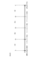
図1に示すように、第1実施形態に係る遊技機10(以下、パチンコ機10)は、外殻を形成する矩形状の外枠11と、この外枠11に対して前方に回転可能に取り付けられた遊技機本体12とを備える。
<Pachinko machine>
As shown in FIG. 1, the gaming machine 10 (hereinafter referred to as a pachinko machine 10) according to the first embodiment has a rectangular outer frame 11 forming an outer shell and is rotatable forward with respect to the outer frame 11. It is provided with the attached gaming machine main body 12.
外枠11は、前後に開口する矩形枠状に形成されて遊技店の設置枠台(不図示)に縦置き姿勢で設置される固定枠である。遊技機本体12は、外枠11に前方側(遊技者側)へ回転可能に支持される内枠(不図示)と、内枠に前方側(遊技者側)へ回転可能に支持される前扉枠13と、内枠に後方側(遊技者とは反対側)へ回転可能に支持される裏パックユニット(不図示)と、施錠装置14とを備える。なお、外枠11の左側には、プリペイドカード式の球貸装置(CRユニット)(不図示)が設けられている。
The outer frame 11 is a fixed frame formed in a rectangular frame shape that opens in the front-rear direction and is installed in a vertical position on an installation frame stand (not shown) of a game store. The gaming machine main body 12 has an inner frame (not shown) rotatably supported by the outer frame 11 toward the front side (player side) and before being rotatably supported by the inner frame toward the front side (player side). The door frame 13 is provided with a back pack unit (not shown) rotatably supported on the inner frame to the rear side (the side opposite to the player), and a locking device 14. A prepaid card type ball lending device (CR unit) (not shown) is provided on the left side of the outer frame 11.
内枠(不図示)は、右側部又は左側部の一方を支持側として外枠11の右側部又は左側部の一方に支持されている。前扉枠13は、右側部又は左側部の一方を支持側として、内枠の右側部又は左側部の一方に支持されている。裏パックユニットは、右側部又は左側部の一方を支持側として、内枠の右側部又は左側部の一方に支持されている。施錠装置14は、遊技機本体12の右側部又は左側部の下部に設けられ(図1では右側下部)、遊技機本体12を外枠に対して開放不能とする機能および前扉枠を内枠に対して開放不能とする機能を有する。第1実施形態に係るパチンコ機10では、施錠装置14は、シリンダー錠である。第1実施形態では、キーを差し込んだのち右回転させると、遊技機本体12を外枠に対して開放不能とする機能が解除され、左回転させると、前扉枠13を内枠に対して開放不能とする機能が解除される。
The inner frame (not shown) is supported by one of the right side portion or the left side portion of the outer frame 11 with one of the right side portion and the left side portion as the support side. The front door frame 13 is supported by one of the right side portion and the left side portion of the inner frame with one of the right side portion and the left side portion as the support side. The back pack unit is supported by one of the right side portion and the left side portion of the inner frame with one of the right side portion and the left side portion as the support side. The locking device 14 is provided at the lower part of the right side or the left side of the gaming machine main body 12 (lower right side in FIG. 1), and has a function of making the gaming machine main body 12 unable to open with respect to the outer frame and an inner frame of the front door frame. It has a function to make it impossible to open. In the pachinko machine 10 according to the first embodiment, the locking device 14 is a cylinder lock. In the first embodiment, when the key is inserted and then rotated to the right, the function of disabling the gaming machine main body 12 to the outer frame is released, and when the key is rotated to the left, the front door frame 13 is moved to the inner frame. The function that makes it impossible to open is canceled.
前扉枠13は、内枠の前面側を覆うようにして設けられ、厚み方向に開口する楕円形状の窓部21と、この窓部21にはめ込まれる透視可能なガラス板や合成樹脂材等により形成された窓パネル22とを有する。
The front door frame 13 is provided so as to cover the front side of the inner frame, and is made of an elliptical window portion 21 that opens in the thickness direction, a transparent glass plate fitted into the window portion 21, a synthetic resin material, or the like. It has a window panel 22 formed.
また、前扉枠13には、窓部21の上部に配設される発光手段としての表示ランプ装置23と、遊技機本体12の上部左側及び右側と、下部左側とに配設される音声出力手段およびナビゲーション手段としてのスピーカ部24とを有する。表示ランプ装置23は、LED(発光ダイオード)やフィラメント、放電素子などの発光素子をガラスの球殻に封入した電球等の発光体(不図示)を有する。また、スピーカ部24は、音声や効果音等を出力できる。そして、後述する図柄表示装置51での図柄変動演出に合わせて表示ランプ装置23を点灯・点滅したり(発光演出)、スピーカ部24から音声や効果音を出力する(音声演出)ことで、表示ランプ装置23やスピーカ部24が演出実行手段として機能するよう構成されている。
Further, the front door frame 13 has an indicator lamp device 23 as a light emitting means arranged on the upper part of the window portion 21, and audio outputs arranged on the upper left and right sides and the lower left side of the gaming machine main body 12. It has a speaker unit 24 as a means and a navigation means. The indicator lamp device 23 has a light emitting body (not shown) such as a light bulb in which a light emitting element such as an LED (light emitting diode), a filament, or a discharge element is enclosed in a glass spherical shell. Further, the speaker unit 24 can output voice, sound effects, and the like. Then, the display lamp device 23 is turned on / blinks in accordance with the symbol variation effect of the symbol display device 51, which will be described later (light emission effect), or the sound or sound effect is output from the speaker unit 24 (voice effect). The lamp device 23 and the speaker unit 24 are configured to function as an effect executing means.
また、前扉枠13は、窓部21の下側に、前方側(遊技者側)へと膨出する上側膨出部25および下側膨出部26とを有する。上側膨出部25および下側膨出部26は、上下方向に並設されている。上側膨出部25は、上向きに開口するようにして内部に設けられ、遊技球を貯留する受け皿となる上受皿251を有している。また、下側膨出部26は、上向きに開口するようにして内部に設けられ、遊技球を貯留する受け皿となる下受皿261を有している。上受皿251は、底面が左側から右側からに向かって緩やかに傾斜するとともに右側部において先細りとなるように構成されており、貯留されている遊技球を一球ずつ整列させながら遊技球発射機構81へと導く機能を有する。
Further, the front door frame 13 has an upper bulging portion 25 and a lower bulging portion 26 that bulge toward the front side (player side) on the lower side of the window portion 21. The upper bulging portion 25 and the lower bulging portion 26 are arranged side by side in the vertical direction. The upper bulging portion 25 is provided inside so as to open upward, and has an upper saucer 251 that serves as a saucer for storing game balls. Further, the lower bulging portion 26 has a lower saucer 261 which is provided inside so as to open upward and serves as a saucer for storing the game ball. The upper saucer 251 is configured such that the bottom surface is gently inclined from the left side to the right side and is tapered on the right side portion, and the game ball launching mechanism 81 is arranged while storing the stored game balls one by one. It has a function to lead to.
上受皿251にて遊技球が余剰となると、遊技球は下受皿261に排出される。つまり、下受皿261は、上受皿251にて余剰となった遊技球を貯留する機能を有する。また、下側膨出部26には、左右方向にスライド動作可能なレバーが設けられており、遊技者がレバーをスライド動作させることで下受皿261に貯留された遊技球が下受皿261の下部から排出されるように構成されている。なお、第1実施形態では、上側膨出部25および下側膨出部26は、前扉枠13の下部位置に前扉枠13と一体的に成型されており、前扉枠13の開閉に合わせて上側膨出部25および下側膨出部26も開閉するよう構成される。
When the game ball becomes surplus in the upper tray 251 the game ball is discharged to the lower tray 261. That is, the lower saucer 261 has a function of storing the game balls surplus in the upper saucer 251. Further, the lower bulging portion 26 is provided with a lever that can slide in the left-right direction, and the game ball stored in the lower tray 261 is moved to the lower portion of the lower tray 261 by the player sliding the lever. It is configured to be discharged from. In the first embodiment, the upper bulging portion 25 and the lower bulging portion 26 are integrally molded with the front door frame 13 at the lower position of the front door frame 13 to open and close the front door frame 13. At the same time, the upper bulging portion 25 and the lower bulging portion 26 are also configured to open and close.
また、パチンコ機10は、遊技機本体12の右下方位置に発射手段としての発射ハンドル27を備える。発射ハンドル27は、反時計回り(左回り)に付勢されており、遊技者が発射ハンドル27を時計回り(右回り)するよう回転操作することで遊技球発射機構81が作動されて、上受皿251に貯留された遊技球が遊技盤31の遊技領域31R(図2参照)に向けて1球ずつ発射される。第1実施形態では、遊技球発射機構81による遊技球の発射動作は、所定の周期(例えば、0.6sec)で行われる。また、第1実施形態では、遊技球発射機構81による遊技球の発射数が1分間に100球を超えないよう制御される。
Further, the pachinko machine 10 is provided with a firing handle 27 as a launching means at a lower right position of the gaming machine main body 12. The launch handle 27 is urged counterclockwise (counterclockwise), and the game ball launch mechanism 81 is activated by the player rotating the launch handle 27 clockwise (clockwise) to move up. The game balls stored in the saucer 251 are fired one by one toward the game area 31R (see FIG. 2) of the game board 31. In the first embodiment, the game ball launching operation by the game ball launching mechanism 81 is performed in a predetermined cycle (for example, 0.6 sec). Further, in the first embodiment, the number of game balls launched by the game ball launch mechanism 81 is controlled so as not to exceed 100 balls per minute.
発射ハンドル27は、その回転量に応じて遊技球発射機構81による遊技球の打球力が変化するように構成されており、遊技者が発射ハンドル27を時計回り(右回り)に回転させるにしたがって遊技球発射機構81による遊技球の打球力が漸増し、遊技者が発射ハンドル27を反時計回り(左回り)に回転させるにしたがって遊技球発射機構81による遊技球の打球力が漸減するように構成されている。すなわち、遊技者が発射ハンドル27を時計回り(右回り)に回転させるに従い、遊技球発射機構81により打ち出される遊技球の遊技盤31における到達位置が左側から右側へと移っていくこととなる。
The launch handle 27 is configured so that the hitting force of the game ball by the game ball launch mechanism 81 changes according to the amount of rotation thereof, and as the player rotates the launch handle 27 clockwise (clockwise). The hitting force of the game ball by the game ball launching mechanism 81 gradually increases, and the hitting force of the game ball by the game ball launching mechanism 81 gradually decreases as the player rotates the firing handle 27 counterclockwise (counterclockwise). It is configured. That is, as the player rotates the launch handle 27 clockwise (clockwise), the arrival position of the game ball launched by the game ball launch mechanism 81 on the game board 31 shifts from the left side to the right side.
また、図8に示すように、発射ハンドル27には、遊技者がハンドルに触れていることを検知する接触センサ271や遊技球の発射を一時的に停止する発射停止スイッチ272が設けられている。遊技球発射機構81による遊技球の発射は、発射ハンドル27が回転操作されて接触センサ271がオンで、かつ発射停止スイッチ272がオフのときに行われ、接触センサ271がオフまたは発射停止スイッチ272がオンの場合には遊技球は発射されない。
Further, as shown in FIG. 8, the launch handle 27 is provided with a contact sensor 271 for detecting that the player is touching the handle and a launch stop switch 272 for temporarily stopping the launch of the game ball. .. The launch of the game ball by the game ball launch mechanism 81 is performed when the launch handle 27 is rotated and the contact sensor 271 is on and the launch stop switch 272 is off, and the contact sensor 271 is off or the launch stop switch 272 is off. If is on, the game ball will not be fired.
また、上側膨出部25の上面には、操作手段としての操作ボタン28が設けられている。操作ボタン28は、演出種類(演出種別)の選択等に際にして用いられ、遊技者は、操作ボタン28を操作することで、演出種類を選択・確定することができる。操作ボタン28は、図9に示すように、中央に配置された決定ボタン281と、決定ボタン281の左側に配置された左方向ボタン282と、決定ボタン281の右側に配置された右方向ボタン283とを備えている。遊技者は、演出種類の選択時において、左方向ボタン282、右方向ボタン283を押下操作して演出種類を選択し、中央に配置された決定ボタン281を押下操作することで演出種類を決定(確定)することができる。
Further, an operation button 28 as an operation means is provided on the upper surface of the upper bulge portion 25. The operation button 28 is used when selecting an effect type (effect type), and the player can select and confirm the effect type by operating the operation button 28. As shown in FIG. 9, the operation buttons 28 include a decision button 281 arranged in the center, a left direction button 282 arranged on the left side of the decision button 281, and a right direction button 283 arranged on the right side of the decision button 281. And have. When selecting the effect type, the player presses the left direction button 282 and the right direction button 283 to select the effect type, and presses the decision button 281 arranged in the center to determine the effect type (the effect type is determined. Can be confirmed).
また、操作ボタン28は、例えば、図柄表示装置51で表示される演出のステージを変更したり、スーパーリーチの演出内容を変更したりする場合などに、遊技者により操作される。ここでステージとは、図柄表示装置51に表示される各種演出に統一性を持たせた演出モードのことであり、図2に示す第1始動口36又は第2始動口37への入球(始動始動入賞)に伴って行われる変動演出やリーチ演出などの各種演出は、それぞれのステージに与えられたテーマに合わせて行われるように設計されている。例えば、海岸をモチーフにした「海岸ステージ」、人物をモチーフにした「人物ステージ」、海中をモチーフにした「海中ステージ」等が、ステージとして用意される。ステージの変更は、変動演出が行われていない期間や高速変動中に遊技者によって操作ボタン28が操作された場合に行われる。
また、上側膨出部25の上面には、CRユニットに挿入されたカードの価値残高(有価残高)の範囲内で遊技球の貸し出しを指示するための球貸ボタン(不図示)およびCRユニットに挿入されているカードの返却を指示するための返却ボタン(不図示)が配設されている。
Further, the operation button 28 is operated by the player, for example, when changing the stage of the effect displayed on the symbol display device 51 or changing the effect content of the super reach. Here, the stage is an effect mode in which various effects displayed on the symbol display device 51 are unified, and the ball enters the first start port 36 or the second start port 37 shown in FIG. Various effects such as variable effects and reach effects that accompany the start-up start prize) are designed to be performed according to the theme given to each stage. For example, a "coastal stage" with a coastal motif, a "personal stage" with a human motif, an "underwater stage" with an underwater motif, and the like are prepared as stages. The stage change is performed when the operation button 28 is operated by the player during a period during which the fluctuation effect is not performed or during high-speed fluctuation.
Further, on the upper surface of the upper bulging portion 25, a ball lending button (not shown) for instructing lending of a game ball within the range of the value balance (valuable balance) of the card inserted in the CR unit and a CR unit are provided. A return button (not shown) is provided to instruct the return of the inserted card.
<遊技盤31>
遊技盤31は、ベニヤ材や合成樹脂材により形成された略矩形状の板部材である。遊技盤31は、図2に示すように、正面(遊技者側)に設けられた略円形状に湾曲形成した2本のレール(内レール32および外レール33)からなるガイド部34(以下、誘導レールともいう)を有する。誘導レール34は、遊技球発射機構81により打ち出される遊技球を遊技盤31の左上部へと案内する機能を有する。遊技者は、発射ハンドル27を操作して、該誘導レール34により画成される略円形の遊技領域31Rへと遊技球を打ち出すことで遊技を行う。また、誘導レール34の端部には、遊技領域31Rへと打ち出された遊技球が誘導レール34内へと戻らないように返し部31aが設けられている。なお、遊技領域31R内に打ち込まれた遊技球は、裏パックユニット(不図示)に設けられた打込球検知センサ(不図示)により検知され、該打込球検知センサの球検出信号がホールコンピュータ(不図示)に出力されるよう構成されている。第1実施形態では、打込球検知センサを裏パックユニットに設けているが、他の場所、例えば、遊技盤31に設けるようにしてもよい。
<Game board 31>
The game board 31 is a substantially rectangular plate member made of a veneer material or a synthetic resin material. As shown in FIG. 2, the game board 31 has a guide portion 34 (hereinafter referred to as a guide portion 34) composed of two rails (inner rail 32 and outer rail 33) provided on the front surface (player side) and curved in a substantially circular shape. It also has a guide rail). The guide rail 34 has a function of guiding the game ball launched by the game ball launch mechanism 81 to the upper left portion of the game board 31. The player operates the launch handle 27 to launch the game ball into the substantially circular game area 31R defined by the guide rail 34, thereby playing the game. Further, at the end of the guide rail 34, a return portion 31a is provided so that the game ball launched into the game area 31R does not return to the inside of the guide rail 34. The game ball driven into the game area 31R is detected by a driving ball detection sensor (not shown) provided in the back pack unit (not shown), and the ball detection signal of the driving ball detection sensor is a hole. It is configured to be output to a computer (not shown). In the first embodiment, the driving ball detection sensor is provided in the back pack unit, but it may be provided in another place, for example, the game board 31.
また、遊技盤31は、ルータ加工が施されることによって、板厚方向に貫通する大小複数の開口部(不図示)が適宜位置に形成されている。また、遊技盤31の各開口部には、第1始動口36、第2始動口37、可変入賞装置38およびアウト口39が設けられている。なお、遊技盤31の遊技領域31Rに形成される開口部の位置及び数は、必要に応じて適宜変更できる。遊技盤31には、中央部左側および中央部右側にスルーゲート41が設けられている。遊技盤31の遊技者が視認できる位置には、主表示装置42が設けられている。遊技盤31の中央部には、可変表示ユニット43が設けられている。遊技盤31には、遊技領域31R内に多数の遊技釘44が設けられている。
Further, the game board 31 is subjected to router processing, so that a plurality of large and small openings (not shown) penetrating in the plate thickness direction are formed at appropriate positions. Further, each opening of the game board 31 is provided with a first starting port 36, a second starting port 37, a variable winning device 38, and an out port 39. The position and number of openings formed in the game area 31R of the game board 31 can be appropriately changed as needed. The game board 31 is provided with through gates 41 on the left side of the central portion and the right side of the central portion. A main display device 42 is provided at a position of the game board 31 that can be visually recognized by the player. A variable display unit 43 is provided at the center of the game board 31. The game board 31 is provided with a large number of game nails 44 in the game area 31R.
なお、第1実施形態では、入球とは、開口部を遊技球が通過することをいい、開口部を通過した後に遊技領域31Rから排出される態様だけでなく、開口部を通過した後に遊技領域31Rから排出されずに遊技領域31Rの流下を継続する態様も含む。また、アウト口39への遊技球の入球と明確に区別するために、各種入賞口への遊技球の入球のことを入賞ともいう。また、スルーゲート41への入球とは、遊技領域31Rに設けられたゲートを通過した後に遊技領域から排出されずに遊技領域の流下を継続することをいう。このスルーゲート41への入球についても各種入賞口への入球と同様に入賞ともいう。
In the first embodiment, the entry ball means that the game ball passes through the opening, and not only the mode in which the game ball is discharged from the game area 31R after passing through the opening but also the game after passing through the opening. It also includes an embodiment in which the flow of the game area 31R is continued without being discharged from the area 31R. Further, in order to clearly distinguish it from the entry of the game ball into the out opening 39, the entry of the game ball into various winning openings is also referred to as a winning. Further, entering the through gate 41 means that after passing through the gate provided in the game area 31R, the ball continues to flow down the game area without being discharged from the game area. The entry into the through gate 41 is also referred to as a entry in the same manner as the entry into various winning openings.
<始動入賞口>
図2に示すように、第1始動口36および第2始動口37は、上下の位置関係、すなわち上下方向に並設されている。ここで、上側に位置する第1始動口36は、遊技領域31R内で常に上方へ開口する常時開放タイプの入賞口である。また、下側に位置する第2始動口37を挟む左右両側には、第2始動口37を開閉可能に構成された一対の開閉部材371からなる電動役物(いわゆる電動チューリップ(電チュー))が設けられている。一対の開閉部材371には、駆動手段としての電動役物駆動部372が連結されており、電動役物駆動部372の駆動に伴って一対の開閉部材371が第2始動口37を閉鎖する閉鎖位置と開放する開放位置とに変位するよう構成されている。第1実施形態では、第2始動口37を開閉する一対の開閉部材371が第2始動口37を挟む左右側部に配置されて、電動役物駆動部372の駆動に伴い一対の開閉部材371の相互位置が近接および離間するよう駆動される。
<Starting winning opening>
As shown in FIG. 2, the first starting port 36 and the second starting port 37 are arranged in a vertical positional relationship, that is, in the vertical direction. Here, the first starting port 36 located on the upper side is a constantly open type winning opening that always opens upward in the game area 31R. Further, on both the left and right sides of the second starting port 37 located on the lower side, an electric accessory (so-called electric tulip (electric tulip)) composed of a pair of opening / closing members 371 configured to open / close the second starting port 37. Is provided. An electric accessory driving unit 372 as a driving means is connected to the pair of opening / closing members 371, and the pair of opening / closing members 371 closes the second starting port 37 as the electric accessory driving unit 372 is driven. It is configured to be displaced between the position and the open position. In the first embodiment, a pair of opening / closing members 371 for opening / closing the second starting port 37 are arranged on the left and right side portions sandwiching the second starting port 37, and the pair of opening / closing members 371 are driven by the electric accessory driving unit 372. Are driven so that their mutual positions are close to each other and separated from each other.
すなわち、第1実施形態において第1始動口36は、遊技領域31Rを流下する遊技球が常時一定の確率で入賞可能に構成され、第2始動口37は、電動役物駆動部372を駆動することで遊技球の入賞確率が可変するよう構成されている。ここで、第2始動口37を挟む左右両側に設けられた開閉部材371が閉鎖位置に変位した状態(以下、電役閉鎖状態)では、第2始動口37への遊技球の入賞が阻止されて、第1始動口36へ遊技球が入賞する確率よりも第2始動口37へ遊技球が入賞する確率が低くなる。また、開閉部材371が開放位置に変位した状態(以下、電役開放状態)では、開閉部材371で受止められた遊技球が第2始動口37に案内されて、第1始動口36へ遊技球が入賞する確率よりも第2始動口37へ遊技球が入賞する確率が高くなる。
That is, in the first embodiment, the first starting port 36 is configured so that the game ball flowing down the game area 31R can always win a prize with a certain probability, and the second starting port 37 drives the electric accessory driving unit 372. By doing so, the winning probability of the game ball is configured to be variable. Here, in a state where the opening / closing members 371 provided on both the left and right sides sandwiching the second starting port 37 are displaced to the closed position (hereinafter, the electric service closed state), the winning of the game ball to the second starting port 37 is prevented. Therefore, the probability that the game ball will win the second starting port 37 is lower than the probability that the game ball will win the first starting port 36. Further, in the state where the opening / closing member 371 is displaced to the open position (hereinafter, the electric service open state), the game ball received by the opening / closing member 371 is guided to the second starting port 37 and the game is played to the first starting port 36. The probability that the game ball will win the second starting port 37 is higher than the probability that the ball will win.
なお、電動役物は、前述した電役閉鎖状態および電役開放状態に代えて、第2始動口37に遊技球が入賞しにくい状態(電役閉鎖状態とは異なり遊技球の入球は可能な状態)と、第2始動口37に遊技球が入賞しやすい状態とを切り換える構成としてもよい。
In addition, in the electric accessory, instead of the above-mentioned electric service closed state and electric service open state, it is difficult for the game ball to win a prize in the second starting port 37 (unlike the electric service closed state, the game ball can be entered. It may be configured to switch between a state in which the game ball is likely to win a prize in the second starting port 37.
<可変入賞装置>
図2に示すように、可変入賞装置38は、遊技領域31Rに開口する特別入賞手段としての特別入賞口381(以下、大入賞口)を開閉自在に閉成する矩形板状に形成された開閉扉(開閉部材,開閉手段)382を備えており、駆動手段としての可変入賞駆動部383の駆動に伴って開閉扉382が閉鎖する閉鎖状態と開放する開放状態に変位するよう構成されている。なお、第1実施形態では、開閉扉382が前後方向へ揺動することで特別入賞口を開閉するよう構成されており、図2では、該開閉扉382により大入賞口381が閉鎖された状態を示している。
<Variable winning device>
As shown in FIG. 2, the variable winning device 38 opens and closes in a rectangular plate shape that allows the special winning opening 381 (hereinafter referred to as the large winning opening) as a special winning means to open in the game area 31R to be opened and closed. A door (opening / closing member, opening / closing means) 382 is provided, and the opening / closing door 382 is configured to be displaced between a closed state and an open state when the variable winning drive unit 383 as a driving means is driven. In the first embodiment, the opening / closing door 382 swings in the front-rear direction to open / close the special winning opening. In FIG. 2, the opening / closing door 382 closes the large winning opening 381. Is shown.
第1実施形態では、開閉扉382は、通常状態では、遊技球が入賞できない閉鎖状態に設定されている。そして、内部抽選において開閉実行モードへの移行に当選し、開閉実行モードに移行した場合、開閉扉382は、遊技球が入賞できる開放状態に設定される。なお、開閉実行モード(特定制御状態)とは、開閉扉382を開放状態に設定し、大入賞口381に遊技球を入球可能とするモードをいう。また、第1実施形態では、開閉実行モードにおいて、開閉扉382を開放状態に設定した後、再び閉鎖状態に設定するまでを1回のラウンド遊技としているが、1回のラウンド遊技における開閉扉382の開閉回数は任意である。例えば、1回のラウンド遊技における開閉扉382の開閉回数を複数回(2回以上)としてもよく、この場合、1回のラウンド遊技において開閉扉382の開放状態と閉鎖状態が複数回設定されることとなる。
In the first embodiment, the opening / closing door 382 is set to a closed state in which the game ball cannot win a prize in the normal state. Then, when the shift to the open / close execution mode is won in the internal lottery and the shift to the open / close execution mode is performed, the open / close door 382 is set to the open state in which the game ball can win a prize. The open / close execution mode (specific control state) is a mode in which the open / close door 382 is set to the open state and the game ball can be inserted into the large winning opening 381. Further, in the first embodiment, in the opening / closing execution mode, the opening / closing door 382 in one round game is set from the opening / closing door 382 to the closed state again. The number of times of opening and closing is arbitrary. For example, the opening / closing door 382 may be opened / closed a plurality of times (twice or more) in one round game, and in this case, the opening / closing state and the closing state of the opening / closing door 382 are set a plurality of times in one round game. It will be.
遊技者は、発射ハンドル27の回転操作量を最大とし、遊技領域の上部における遊技球の到達位置を誘導レール34の出口部分が形成された側部の側からその反対側の側部の側へとシフトさせる(いわゆる右打ちする)ことによって、可変表示ユニット43等を避けて可変入賞装置38に遊技球を導くことができる。
The player maximizes the amount of rotation of the launch handle 27, and moves the arrival position of the game ball in the upper part of the game area from the side of the side where the exit portion of the guide rail 34 is formed to the side of the opposite side. By shifting (so-called right-handed), the game ball can be guided to the variable winning device 38 while avoiding the variable display unit 43 and the like.
<検知センサ>
遊技盤31は、設けられた第1始動口36、第2始動口37および可変入賞装置38の大入賞口381の各種入賞口の近傍に、遊技球の入球を検知する検知センサ502~504を備える(図8参照)。また、これら検知センサ502~504は、遊技盤31の背面側に配設され、検知センサ502は第1始動口36への遊技球の入球を検知し、検知センサ503は第2始動口37への遊技球の入球を検知し、検知センサ504は可変入賞装置38の大入賞口381への遊技球の入球を検知する。検知センサ502~504は、パチンコ機10の裏側に配設された主制御基板61に配線接続されており、各検知センサ502~504による遊技球の検出(第1始動口36、第2始動口37および可変入賞装置38の大入賞口381の各種入賞口への遊技球の入賞)を契機として所定数の賞球(入賞により得る遊技球のこと)が払い出されるよう構成されている。
<Detection sensor>
The game board 31 has detection sensors 502 to 504 that detect the entry of a game ball in the vicinity of various winning openings of the first starting opening 36, the second starting opening 37, and the large winning opening 381 of the variable winning device 38. (See FIG. 8). Further, these detection sensors 502 to 504 are arranged on the back side of the game board 31, the detection sensor 502 detects the entry of the game ball into the first start port 36, and the detection sensor 503 detects the entry of the game ball into the second start port 37. The detection sensor 504 detects the entry of the game ball into the large winning opening 381 of the variable winning device 38. The detection sensors 502 to 504 are wired and connected to the main control board 61 arranged on the back side of the pachinko machine 10, and the detection sensors 502 to 504 detect the game ball (first start port 36, second start port). A predetermined number of prize balls (game balls obtained by winning) are paid out in the wake of the winning of the game balls to the various winning openings of the large winning openings 381 of the variable winning apparatus 38 and the variable winning apparatus 38.
第1実施形態では、パチンコ機10は、検知センサ502により第1始動口36への入球が検知された場合、3個の賞球を払い出し、検知センサ503により第2始動口37への入球が検知された場合、2個の賞球を払い出し、検知センサ504により可変入賞装置38の大入賞口381への入球が検知された場合、13個の賞球を払い出す。なお、各種入賞口への遊技球の入賞による賞球の払い出し数は、これらに限られるものではなく、適宜、変更できる。例えば、第1始動口36への遊技球の入賞により払い出される賞球の数と、第2始動口37への遊技球の入賞により払い出される賞球の数とを同数としてもよい。また、遊技盤31の遊技領域31Rに複数(2以上)の可変入賞装置38を設け、これら複数の可変入賞装置38の大入賞口381への入賞ごとに払い出される賞球の数を異ならせてもよく、例えば、可変入賞装置38を2つ設けた場合、それぞれの可変入賞装置38の大入賞口381への入賞により払い出される賞球数をそれぞれ13と14としてもよい。
In the first embodiment, when the detection sensor 502 detects that the pachinko machine 10 has entered the first starting port 36, the pachinko machine 10 pays out three prize balls and the detection sensor 503 enters the second starting port 37. When a ball is detected, two prize balls are paid out, and when the detection sensor 504 detects that the variable winning device 38 has entered the large winning opening 381, 13 prize balls are paid out. The number of prize balls paid out by winning a game ball to various winning openings is not limited to these, and can be changed as appropriate. For example, the number of prize balls paid out by winning the game ball to the first starting port 36 may be the same as the number of prize balls paid out by winning the game ball to the second starting port 37. Further, a plurality of (two or more) variable winning devices 38 are provided in the game area 31R of the game board 31, and the number of prize balls to be paid out is different for each winning to the large winning opening 381 of the plurality of variable winning devices 38. Also, for example, when two variable winning devices 38 are provided, the number of prize balls paid out by winning a prize in the large winning opening 381 of each variable winning device 38 may be 13 and 14, respectively.
アウト口39は、遊技盤31の遊技領域31Rの最下部に設けられており、各種入賞口等に入球しなかった遊技球は、このアウト口39を通って遊技領域31Rから排出される。アウト口39は、遊技盤31の背面側に配設され、遊技球の入球を検知する検知センサ505を備える(図8参照)。
The out port 39 is provided at the lowermost portion of the game area 31R of the game board 31, and the game balls that have not entered the various winning openings and the like are discharged from the game area 31R through the out port 39. The out port 39 is arranged on the back side of the game board 31 and includes a detection sensor 505 that detects the entry of the game ball (see FIG. 8).
また、各スルーゲート41は、遊技盤31の背面側に配設され、遊技球の入球を検知する検知センサ506を備える(図8参照)。検知センサ505および506は、パチンコ機10の裏側に配設された主制御基板61に配線接続されているが、パチンコ機10は、各種入賞口への入球が発生した場合と異なり、アウト口39および各スルーゲート41への入球が発生した場合、賞球の払い出しは行わない。
Further, each through gate 41 is arranged on the back side of the game board 31 and includes a detection sensor 506 for detecting the entry of the game ball (see FIG. 8). The detection sensors 505 and 506 are wired and connected to the main control board 61 arranged on the back side of the pachinko machine 10, but the pachinko machine 10 has an out port unlike the case where a ball enters various winning openings. If a ball enters 39 and each through gate 41, the prize ball will not be paid out.
なお、各検知センサ502~506は、各種入賞口への遊技球の入球を個別に検知することができればよく、例えば、電磁誘導センサや透過型フォトセンサ等を使用することができる。
It should be noted that each detection sensor 502 to 506 may be capable of individually detecting the entry of a game ball into various winning openings, and for example, an electromagnetic induction sensor, a transmissive photo sensor, or the like can be used.
<図柄表示>
主表示装置42は、メイン表示部46と、役物用表示部47と、ラウンド表示部48とを有し、複数のセグメント発光部を所定の態様で配列したセグメント表示器や、ドット表示器などの複数の表示装置を配置して構成されている。主表示装置42は、その前面側に設けられた窓パネル22に向かって膨出するようにして遊技盤31に設けられており、窓パネル22を介してパチンコ機10の前方から視認可能となっている。また、主表示装置42と、窓パネル22との間の距離(隙間)は、遊技球の外径よりも狭くなっている。このため、主表示装置42と、窓パネル22との隙間、すなわち主表示装置42の前方を遊技球が流下するのが防止されている。
<Design display>
The main display device 42 has a main display unit 46, a display unit 47 for accessories, and a round display unit 48, and has a segment display unit in which a plurality of segment light emitting units are arranged in a predetermined manner, a dot display unit, and the like. It is configured by arranging multiple display devices. The main display device 42 is provided on the game board 31 so as to bulge toward the window panel 22 provided on the front side thereof, and can be visually recognized from the front of the pachinko machine 10 via the window panel 22. ing. Further, the distance (gap) between the main display device 42 and the window panel 22 is narrower than the outer diameter of the game ball. Therefore, it is prevented that the game ball flows down in the gap between the main display device 42 and the window panel 22, that is, in front of the main display device 42.
<メイン表示部46>
メイン表示部46は、第1始動口36への入賞に基づいて行われた内部抽選の結果を表示するための第1結果表示部461と、第2始動口37への入賞に基づいて行われた内部抽選の結果を表示するための第2結果表示部462とを備える(図8参照)。
<Main display unit 46>
The main display unit 46 is performed based on the first result display unit 461 for displaying the result of the internal lottery performed based on the winning of the first starting port 36 and the winning of the second starting port 37. A second result display unit 462 for displaying the result of the internal lottery is provided (see FIG. 8).
<第1結果表示部461>
第1結果表示部461は、第1始動口36への入賞をトリガとして図柄の変動表示を実行するとともに、その変動表示の停止結果として、第1始動口36への入賞に基づいて行われた内部抽選の結果を表示する。具体的には、第1始動口36への遊技球の入賞を契機として、第1結果表示部461が順次点灯・消灯する点滅変動する変動表示が行われ、最終的に第1結果表示部461が確定的に点灯した点灯位置(停止結果)により複数種類(種別)の特別図柄を表示するようになっている。この内部抽選の結果が開閉実行モードへの移行に対応した結果であった場合、第1結果表示部461は、所定の停止結果を表示し、その後、パチンコ機10は、開閉実行モードへ移行する。
<First result display unit 461>
The first result display unit 461 executes the variation display of the symbol triggered by the winning of the first starting port 36, and is performed based on the winning of the first starting port 36 as the stop result of the variation display. Display the result of the internal lottery. Specifically, with the winning of the game ball to the first starting port 36, the first result display unit 461 is sequentially turned on and off, and the fluctuating variable display is performed, and finally the first result display unit 461. Multiple types (types) of special symbols are displayed depending on the lighting position (stop result) that is definitively lit. When the result of this internal lottery corresponds to the shift to the open / close execution mode, the first result display unit 461 displays a predetermined stop result, and then the pachinko machine 10 shifts to the open / close execution mode. ..
<第2結果表示部462>
第2結果表示部462は、第2始動口37への入賞をトリガとして図柄の変動表示を実行するとともに、その変動表示の停止結果として、第2始動口37への入賞に基づいて行われた内部抽選の結果を表示する。具体的には、第2始動口37への遊技球の入賞を契機として、第2結果表示部462が順次点灯・消灯する点滅変動する変動表示が行われ、最終的に第2結果表示部462が確定的に点灯した点灯位置(停止結果)により複数種類(種別)の特別図柄(以下、特図ともいう)を表示するようになっている。この内部抽選の結果が開閉実行モードへの移行に対応した結果であった場合、第2結果表示部462は、所定の停止結果を表示し、その後、パチンコ機10は、開閉実行モードへ移行する。
<Second result display unit 462>
The second result display unit 462 executes the variation display of the symbol triggered by the winning of the second starting port 37, and is performed based on the winning of the second starting port 37 as the stop result of the variation display. Display the result of the internal lottery. Specifically, with the winning of the game ball to the second starting port 37, the second result display unit 462 is sequentially turned on and off, and the fluctuating variable display is performed, and finally the second result display unit 462 is performed. Multiple types (types) of special symbols (hereinafter, also referred to as special symbols) are displayed depending on the lighting position (stop result) in which is definitively lit. When the result of this internal lottery corresponds to the shift to the open / close execution mode, the second result display unit 462 displays a predetermined stop result, and then the pachinko machine 10 shifts to the open / close execution mode. ..
ここで、特図は、大当たり(特定遊技)か否かなどの内部抽選の結果を示す報知用の図柄であり、第1結果表示部461および第2結果表示部462では、LED等の点灯位置により複数種類の特図を表示し得るようになっている。具体的には、第1結果表示部461および第2結果表示部462において表示し得る特図としては、大当たりを認識し得る大当たり表示結果としての複数種類の特図と、外れを認識し得る外れ表示結果としての1種類の特図とが設定されている。そして、特図当たり抽選の結果に応じて1つの特図が決定され、変動表示の停止結果として、先に決定された特図が第1結果表示部461または第2結果表示部462に停止表示される。
Here, the special figure is a symbol for notifying indicating the result of an internal lottery such as whether or not it is a big hit (specific game), and in the first result display unit 461 and the second result display unit 462, the lighting position of the LED or the like. It is possible to display multiple types of special figures. Specifically, the special figures that can be displayed on the first result display unit 461 and the second result display unit 462 include a plurality of types of special figures as a jackpot display result that can recognize a jackpot, and a deviation that can recognize a deviation. One type of special figure as a display result is set. Then, one special map is determined according to the result of the lottery per special map, and as a stop result of the variable display, the previously determined special map is stopped and displayed on the first result display unit 461 or the second result display unit 462. Will be done.
なお、以下の説明では、第1結果表示部461で行われる変動表示を「特図1変動表示」といい、該特図1変動表示の結果、第1結果表示部461に確定停止表示される特図を特図1ともいう。また同様に、第2結果表示部462で行われる変動表示を「第2特図変動表示」といい、第2特図変動表示の結果、第2結果表示部462に確定停止表示される特図を特図2ともいう。
In the following description, the variation display performed by the first result display unit 461 is referred to as "special figure 1 variation display", and as a result of the special figure 1 variation display, a fixed stop display is displayed on the first result display unit 461. The special figure is also called special figure 1. Similarly, the variation display performed by the second result display unit 462 is referred to as "second special figure variation display", and as a result of the second special map variation display, the special figure displayed on the second result display unit 462 as a definite stop display. Is also referred to as special figure 2.
<役物用表示部47>
役物用表示部47は、各スルーゲート41への入賞をトリガとして図柄の変動表示を実行するとともに、その変動表示の停止結果として、各スルーゲート41への入賞に基づいて行われた内部抽選の結果を表示する。具体的には、各スルーゲート41への遊技球の入賞を契機として、役物用表示部47が順次点灯・消灯する点滅変動する変動表示が行われ、最終的に役物用表示部47が確定的に点灯した点灯位置(停止結果)により複数種類の普通図柄(以下、普図ともいう)を表示するようになっている。役物用表示部47は、内部抽選の結果が電役開放状態への移行に対応した結果であった場合、所定の停止結果を表示し、その後、パチンコ機10は、電役開放状態へ移行する。この電役開放状態では、第2始動口37に設けられた電動役物の開閉部材371は開放状態となる。
<Display unit 47 for accessories>
The accessory display unit 47 executes the variable display of the symbol triggered by the winning of each through gate 41, and as a result of stopping the variable display, the internal lottery is performed based on the winning of each through gate 41. Display the result of. Specifically, when the game ball wins a prize in each through gate 41, the accessory display unit 47 is sequentially turned on and off, and the blinking and fluctuating variable display is performed, and finally the accessory display unit 47 is displayed. A plurality of types of normal symbols (hereinafter, also referred to as normal symbols) are displayed depending on the lighting position (stop result) that is definitively lit. When the result of the internal lottery corresponds to the transition to the electric service open state, the accessory display unit 47 displays a predetermined stop result, and then the pachinko machine 10 shifts to the electric service open state. do. In this electric service open state, the opening / closing member 371 of the electric accessory provided in the second starting port 37 is in the open state.
<ラウンド表示部48>
また、第1実施形態のパチンコ機10では、大当たり判定に当選した場合に、後述する複数種類の大当たり遊技(特定遊技)の中から1つの大当たり遊技が決定される。この大当たり遊技には、ラウンド回数が異なる複数種類のものが設定されており、当選した大当たり遊技のラウンド数がラウンド表示部48により報知される。第1実施形態では、大当たり遊技のラウンド数として、「15回」および「2回」の2種類が設定されており、ラウンド表示部48が備えるLEDの点灯パターンによりラウンド数が報知される。第1実施形態では、ラウンド表示部48は、左右に配列された2つのLEDを備え、左側のLEDが点灯することで、ラウンド数が「15回」の大当たり遊技であることが報知され、右側のLEDが点灯することで、ラウンド数が「2回」の大当たり遊技であることが報知される。
<Round display unit 48>
Further, in the pachinko machine 10 of the first embodiment, when the jackpot determination is won, one jackpot game is determined from a plurality of types of jackpot games (specific games) described later. A plurality of types of jackpot games having different numbers of rounds are set, and the number of rounds of the winning jackpot game is notified by the round display unit 48. In the first embodiment, two types of "15 times" and "2 times" are set as the number of rounds of the jackpot game, and the number of rounds is notified by the lighting pattern of the LED provided in the round display unit 48. In the first embodiment, the round display unit 48 includes two LEDs arranged on the left and right, and by turning on the LED on the left side, it is notified that the number of rounds is "15 times", and the right side. By turning on the LED, it is notified that the number of rounds is "twice".
なお、第1実施形態では、メイン表示部46および役物用表示部47は、セグメント表示器や、ドット表示器などの複数の表示装置を配置して構成されているが、これに限定されることはなく、液晶表示装置、有機EL表示装置、CRT、ドットマトリックス等の他のタイプの表示装置によって構成されていてもよい。また、メイン表示部46および役物用表示部47に変動表示させる図柄としては、複数種の文字を変動表示させる構成、複数種の記号を変動表示させる構成、複数種のキャラクタを変動表示させる構成、または複数種の色を切り換えて表示させる構成などを採用できる。また、第1実施形態では、ラウンド表示部48は、LEDを用いた発光表示によりラウンド遊技の回数を報知しているが、これに限定されることはなく、液晶表示装置、有機EL表示装置、CRT、ドットマトリックス等の他のタイプの表示装置によってラウンド遊技の回数を報知するようにしてもよい。なお、メイン表示部46、役物用表示部47およびラウンド表示部48の表示領域は、後述する図柄表示装置51で実行される後述の報知演出等の表示領域に比較して極めて小さく設定されており、図柄表示装置51で実行されている各種演出に注目している遊技者にとっては、メイン表示部46、役物用表示部47、ラウンド表示部48での点灯状態で各情報を簡単には認識し難くなっている。
In the first embodiment, the main display unit 46 and the accessory display unit 47 are configured by arranging a plurality of display devices such as a segment display and a dot display, but the present invention is limited to this. It may be composed of other types of display devices such as a liquid crystal display device, an organic EL display device, a CRT, and a dot matrix. Further, as the symbols to be variablely displayed on the main display unit 46 and the accessory display unit 47, a configuration in which a plurality of types of characters are variablely displayed, a configuration in which a plurality of types of symbols are variablely displayed, and a configuration in which a plurality of types of characters are variablely displayed. , Or a configuration in which multiple types of colors are switched and displayed can be adopted. Further, in the first embodiment, the round display unit 48 notifies the number of round games by a light emitting display using an LED, but the number of round games is not limited to this, and the liquid crystal display device, the organic EL display device, and the like. Other types of display devices such as CRTs and dot matrices may be used to notify the number of round games. The display areas of the main display unit 46, the accessory display unit 47, and the round display unit 48 are set to be extremely smaller than the display areas such as the notification effect described later, which are executed by the symbol display device 51 described later. For a player who is paying attention to various effects performed by the symbol display device 51, each information can be easily displayed in the lighting state of the main display unit 46, the accessory display unit 47, and the round display unit 48. It's hard to recognize.
また、可変表示ユニット43は、図柄の一種である図柄を変動表示(可変表示または切換表示)する図柄表示装置51を備える。また、可変表示ユニット43は、図柄表示装置51を囲むようにして配設されたセンターフレーム52を備える。このセンターフレーム52の上部は、その前面側に設けられた窓パネル22に向かって膨出するようにして設けられている。これによって、パチンコ機10は、図柄表示装置51の表示画面Gの前方を遊技球が落下していくのを防止し、遊技球の落下によって表示画面Gの視認性が低下するといった不都合を生じない構成となっている。更に、可変表示ユニット43には、予告演出用の可動役物である第1役物310が設けられている。
Further, the variable display unit 43 includes a symbol display device 51 that variablely displays (variable display or switching display) a symbol that is a kind of symbol. Further, the variable display unit 43 includes a center frame 52 arranged so as to surround the symbol display device 51. The upper portion of the center frame 52 is provided so as to bulge toward the window panel 22 provided on the front surface side thereof. As a result, the pachinko machine 10 prevents the game ball from falling in front of the display screen G of the symbol display device 51, and does not cause the inconvenience that the visibility of the display screen G is lowered due to the fall of the game ball. It is composed. Further, the variable display unit 43 is provided with a first accessory 310, which is a movable accessory for the advance notice effect.
<図柄表示装置51>
図柄表示装置51は、液晶ディスプレイを備えた液晶表示装置として構成され、図柄表示装置51の表示画面Gが遊技盤31の前面側(遊技者側)に臨むようにして該遊技盤31に着脱可能に組み付けられている。この図柄表示装置51は、所定条件の成立(第1始動口36または第2始動口37への遊技球の入賞)を契機として演出用の装飾図柄(以下、飾図ともいう)の変動表示を開始する。すなわち、図柄表示装置51は、メイン表示部46の第1結果表示部461にて変動表示を実行する場合およびメイン表示部46の第2結果表示部462にて変動表示を実行する場合、それに合わせて変動表示を実行する。なお、図柄表示装置51は、液晶表示装置であることに限定されることはなく、プラズマディスプレイ装置、有機EL表示装置、CRT等の他、ドラム式の図柄表示装置やドットマトリックス式の図柄表示装置等の各種図柄を停止および変動表示可能な従来公知の各種の表示装置を採用し得る。
<Design display device 51>
The symbol display device 51 is configured as a liquid crystal display device provided with a liquid crystal display, and is detachably attached to the game board 31 so that the display screen G of the symbol display device 51 faces the front side (player side) of the game board 31. Has been done. The symbol display device 51 displays a variable display of a decorative symbol (hereinafter, also referred to as a decorative diagram) for staging when a predetermined condition is satisfied (a game ball is won in the first starting port 36 or the second starting port 37). Start. That is, when the symbol display device 51 executes variable display on the first result display unit 461 of the main display unit 46 and when the variable display is executed on the second result display unit 462 of the main display unit 46, the symbol display device 51 is adjusted accordingly. And execute the variable display. The symbol display device 51 is not limited to a liquid crystal display device, and is not limited to a liquid crystal display device, such as a plasma display device, an organic EL display device, a CRT, etc., as well as a drum type symbol display device and a dot matrix type symbol display device. Various conventionally known display devices capable of stopping and variable display of various symbols such as the above can be adopted.
第1実施形態に係る図柄表示装置51には、図3に示すように、飾図を変動表示可能な図柄表示列Z1,Z2,Z3が複数列設定されており、第1始動口36または第2始動口37への入賞を契機として、各図柄表示列Z1,Z2,Z3において飾図が変動開始されるようになっている。また、各図柄表示列Z1,Z2,Z3には、飾図の有効停止位置が夫々設定されており、図柄変動演出により、各図柄表示列Z1,Z2,Z3の有効停止位置を組み合わせた停止図柄有効ラインLに停止表示される飾図の図柄組み合わせを導出するようになっている。なお、第1実施形態の図柄表示装置51には、3列の図柄表示列Z1,Z2,Z3が左右横並び状に設定されると共に、各図柄表示列Z1,Z2,Z3毎に飾図の有効停止位置が1箇所ずつ定められており、3列の飾図からなる図柄変動演出が行われるようになっている。すなわち、第1実施形態の図柄表示装置51には、1つの停止図柄有効ラインLが設定されている。以下の説明では、左側から順に図柄表示列Z1、図柄表示列Z2、図柄表示列Z3という場合がある。
As shown in FIG. 3, the symbol display device 51 according to the first embodiment is set with a plurality of symbol display columns Z1, Z2, Z3 capable of variablely displaying decorative drawings, and the first start port 36 or the first start port 36 or the first. With the winning of the 2 starting port 37 as an opportunity, the decorative drawing starts to change in each symbol display row Z1, Z2, Z3. Further, the effective stop positions of the decorative figures are set in each of the symbol display columns Z1, Z2, Z3, respectively, and the stop symbols that combine the effective stop positions of the respective symbol display columns Z1, Z2, Z3 by the symbol variation effect are set. The symbol combination of the decorative drawing that is stopped and displayed on the effective line L is derived. In the symbol display device 51 of the first embodiment, three rows of symbol display columns Z1, Z2, and Z3 are set side by side, and a decorative figure is effective for each symbol display column Z1, Z2, Z3. The stop positions are set one by one, and a symbol variation effect consisting of three rows of decorative drawings is performed. That is, one stop symbol effective line L is set in the symbol display device 51 of the first embodiment. In the following description, the symbol display column Z1, the symbol display column Z2, and the symbol display column Z3 may be referred to in order from the left side.
また、図柄表示装置51の各図柄表示列Z1,Z2,Z3における飾図の表示領域は、第1結果表示部461および第2結果表示部462に比較して大きな領域で構成されており、特図に比較して飾図が遥かに大きく表示されるようになっている。このため、遊技者は、図柄表示装置51の停止図柄有効ラインLに停止表示された図柄組み合わせから大当たりであるか、外れであるかを視認できる。
Further, the display area of the decorative figure in each of the symbol display columns Z1, Z2, Z3 of the symbol display device 51 is composed of a larger area than the first result display unit 461 and the second result display unit 462. The decorative drawing is displayed much larger than the figure. Therefore, the player can visually recognize whether it is a big hit or a miss from the symbol combination stopped and displayed on the stop symbol effective line L of the symbol display device 51.
図柄表示装置51は、図柄変動演出の開始と共に予め定めた変動方向(第1実施形態では上から下の縦方向)に沿って飾図が移動するようにして変動表示が行うように構成されており、変動表示されている飾図が各図柄表示列Z1,Z2,Z3の有効停止位置に予め定められた停止順序で停止表示されるようになっている。また、図柄表示装置51は、図柄変動演出が終了する前に各図柄表示列Z1,Z2,Z3の有効停止位置に飾図を一時的に仮停止表示し、各図柄表示列Z1,Z2,Z3の飾図を停止表示することで1回の図柄変動演出が終了する。すなわち、図柄変動演出(特図1変動表示および第2特図変動表示)は、1つの始動保留情報に基づいて行われる飾図(特図1および特図2)の変動開始から確定停止までを1回として実行されるようになっている。
The symbol display device 51 is configured to perform variation display so that the decorative figure moves along a predetermined variation direction (vertical direction from top to bottom in the first embodiment) at the start of the symbol variation effect. Therefore, the decorative drawings that are displayed in a variable manner are stopped and displayed at the effective stop positions of the symbol display columns Z1, Z2, and Z3 in a predetermined stop order. Further, the symbol display device 51 temporarily temporarily stops and displays the decorative figure at the effective stop position of each symbol display column Z1, Z2, Z3 before the symbol variation effect is completed, and each symbol display column Z1, Z2, Z3. By stopping and displaying the decorative drawing of, one symbol variation effect is completed. That is, the symbol variation effect (special figure 1 variation display and second special figure variation display) is performed from the start of variation to the final stop of the decorative drawing (special figure 1 and special figure 2) performed based on one start hold information. It is designed to be executed once.
ここで、「変動表示」とは、各図柄表示列Z1,Z2,Z3において、有効停止位置に表示される飾図が所定順序で変化している状態のことである。また、飾図の「確定停止」とは、各図柄表示列Z1,Z2,Z3において有効停止位置に飾図が所定の特図変動インターバル時間(例えば、600ms(ミリ秒))の間、継続して停止表示された状態のことである。また、飾図の「仮停止」とは、各図柄表示列Z1,Z2,Z3において有効停止位置に留まるよう表示された飾図が特図変動インターバル時間の間、継続して停止していない状態である。すなわち、飾図の仮停止には、有効停止位置において飾図がゆれ変動状態で表示されている状態や、特図変動インターバル時間より短い時間で停止表示されている状態が含まれる。
Here, the "variable display" is a state in which the decorative drawings displayed at the effective stop positions in the symbol display columns Z1, Z2, and Z3 are changed in a predetermined order. Further, the "fixed stop" of the decorative drawing means that the decorative drawing continues at the effective stop position in each symbol display column Z1, Z2, Z3 for a predetermined special figure fluctuation interval time (for example, 600 ms (milliseconds)). It is the state where the stop is displayed. Further, the "temporary stop" of the decorative drawing is a state in which the decorative drawing displayed so as to stay at the effective stop position in each symbol display column Z1, Z2, Z3 is not continuously stopped during the special figure fluctuation interval time. Is. That is, the temporary stop of the decorative drawing includes a state in which the decorative drawing is displayed in a fluctuating state at the effective stop position and a state in which the decorative drawing is stopped and displayed in a time shorter than the special drawing fluctuation interval time.
また、第1結果表示部461と図柄表示装置51では、特図1変動表示と該特図1変動表示に関する図柄変動演出が開始され、特図1と飾図とが確定停止表示される。同様に、第2結果表示部462と図柄表示装置51では、第2特図変動表示と該第2特図変動表示に関する図柄変動演出が開始され、特図2と飾図とが確定停止表示される。なお、第1結果表示部461および第2結果表示部462は、特図変動表示が同時に行われることはなく、第1結果表示部461または第2結果表示部462のどちらか一方で特図変動表示が行われている場合、他方の特図変動表示は行われない。
Further, in the first result display unit 461 and the symbol display device 51, the symbol variation effect related to the special figure 1 variation display and the special figure 1 variation display is started, and the special figure 1 and the decorative drawing are fixedly stopped and displayed. Similarly, in the second result display unit 462 and the symbol display device 51, the second special figure variation display and the symbol variation effect related to the second special figure variation display are started, and the special figure 2 and the decorative figure are fixedly stopped and displayed. To. In addition, the first result display unit 461 and the second result display unit 462 do not simultaneously perform the special figure variation display, and the special figure variation is performed on either the first result display unit 461 or the second result display unit 462. When the display is performed, the other special figure variation display is not performed.
ここで、第1実施形態に係る図柄表示装置51には、各図柄表示列Z1,Z2,Z3に「0」~「9」の10種類の数字が基本の飾図として設定されており、該飾図が各図柄表示列Z1,Z2,Z3で順番に変動表示されるようになっている。なお、図柄表示装置51における図柄の変動表示の態様は、これに限定されることはなく任意である。例えば、図柄列の列数、各図柄列のスクロールの方向、各図柄列の図柄数などは適宜変更可能である。また、各図柄列の図柄は、数字のみの態様に代えて、絵と数字とを組み合わせた態様としてもよく、絵のみの態様としてもよい。また、飾図には、大当たり遊技の終了後に確変状態(後述)を付与することを確定的に遊技者が認識可能な第1の識別図柄と、大当たり遊技終了後に確変状態を付与される可能性のあることを非確定的に認識可能な第2の識別図柄に分類されている。
Here, in the symbol display device 51 according to the first embodiment, ten kinds of numbers "0" to "9" are set as basic decorative figures in each symbol display column Z1, Z2, Z3. The decorative drawings are displayed in a variable manner in order in each symbol display column Z1, Z2, Z3. The mode of variable display of the symbol in the symbol display device 51 is not limited to this, and is arbitrary. For example, the number of columns of the symbol string, the scroll direction of each symbol column, the number of symbols of each symbol string, and the like can be appropriately changed. Further, the symbol of each symbol row may be a mode in which a picture and a number are combined, or may be a mode of only a picture, instead of the mode of only numbers. In addition, the decorative drawing may be given a first identification symbol that the player can definitely recognize that the probability change state (described later) is given after the jackpot game ends, and a probability change state after the jackpot game ends. It is classified as a second identification symbol that can be uncertainly recognized as having.
ここで、第1の識別図柄としては、基本となる飾図の中から適宜に設定しても、基本となる飾図以外に定めた特別な飾図を用いることもできる。例えば、「1」、「3」、「5」、「7」、「9」の奇数図柄や「0」、「2」、「4」、「6」、「8」の偶数図柄を第1の識別図柄とし、「0」、「2」、「4」、「6」、「8」の偶数図柄を第2の識別図柄とすることもできる。このように、遊技者は、図柄表示装置51における各図柄表示列Z1,Z2,Z3の有効停止位置(停止図柄有効ラインL)に確定停止表示された各図柄表示列Z1,Z2,Z3の飾図によって当たり遊技が付与されるか否かを把握し得るようになっている。第1実施形態では、当たりの図柄組み合わせとして、各図柄表示列の有効停止位置に同じ飾図が確定停止表示される図柄組み合わせ(例えば、「1・1・1」、「2・2・2」等)が設定されている。
Here, as the first identification symbol, a special decorative drawing other than the basic decorative drawing may be used even if it is appropriately set from the basic decorative drawings. For example, the odd-numbered symbols of "1", "3", "5", "7", and "9" and the even-numbered symbols of "0", "2", "4", "6", and "8" are the first. The identification symbol of "0", "2", "4", "6", and "8" can be used as the second identification symbol. In this way, the player can decorate each of the symbol display columns Z1, Z2, Z3 which is fixedly stopped and displayed at the effective stop position (stop symbol effective line L) of each symbol display column Z1, Z2, Z3 in the symbol display device 51. It is possible to grasp whether or not the winning game is given by the figure. In the first embodiment, as a winning symbol combination, a symbol combination (for example, "1 ・ 1 ・ 1", "2 ・ 2 ・ 2") in which the same decorative figure is fixedly stopped and displayed at the effective stop position of each symbol display column is displayed. Etc.) are set.
この大当たりを認識できる飾図の図柄組み合わせが、当たり表示結果となり、図柄変動演出の終了後に遊技者に有利な大当たり遊技が付与される。一方で、図柄表示装置51の有効停止位置に確定停止表示された全列の図柄が1つでも異なる種類の場合、その図柄組み合わせから、原則的には大当たり遊技が付与されない「外れ」であることを認識できる。この外れを認識できる飾図の図柄組み合わせが、外れ表示結果となる。
The symbol combination of the decorative figure that can recognize this jackpot becomes the hit display result, and the jackpot game that is advantageous to the player is given after the symbol variation effect is completed. On the other hand, if even one of the symbols in all the rows displayed at the effective stop position of the symbol display device 51 is different, the symbol combination is, in principle, "off" in which the jackpot game is not given. Can be recognized. The pattern combination of the decorative drawing that can recognize this deviation is the deviation display result.
また、図柄表示装置51には、第1結果表示部461および第2結果表示部462での特図変動表示の結果、表示される特図に応じた飾図の図柄組み合わせが表示される。すなわち、第1結果表示部461および第2結果表示部462に表示される特図と、図柄表示装置51に表示される飾図の図柄組み合わせとが夫々対応しており、図柄変動演出が終了すると、第1結果表示部461および第2結果表示部462に特図が確定停止されると共に、図柄表示装置51の各図柄表示列Z1,Z2,Z3に飾図が確定停止表示されるようになっている。なお、必ずしも特別図柄に対する飾図の図柄組み合わせを一対一とする必要はなく、1つの特別図柄に対して複数の飾図による図柄組み合わせを対応させるようにしてもよい。
Further, the symbol display device 51 displays a symbol combination of decorative drawings according to the displayed special map as a result of the special map variation display on the first result display unit 461 and the second result display unit 462. That is, the special figure displayed on the first result display unit 461 and the second result display unit 462 and the symbol combination of the decorative figure displayed on the symbol display device 51 correspond to each other, and when the symbol variation effect is completed. , The special figure is fixedly stopped in the first result display unit 461 and the second result display unit 462, and the decorative figure is fixedly stopped and displayed in each symbol display column Z1, Z2, Z3 of the symbol display device 51. ing. It should be noted that it is not always necessary to make one-to-one combination of decorative symbols for special symbols, and one special symbol may be associated with a plurality of decorative symbol combinations.
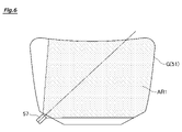
センターフレーム52は、図柄表示装置51の左下側の領域に設けられた第1保留ランプ部53と、図柄表示装置51の中央下側の領域に設けられた第2保留ランプ部54と、図柄表示装置51の右下側の領域に設けられた第3保留ランプ部55と、図柄表示装置51の左下の領域に設けられたタッチセンサ57とを備えている。
The center frame 52 includes a first holding lamp unit 53 provided in the lower left area of the symbol display device 51, a second holding lamp unit 54 provided in the lower center area of the symbol display device 51, and a symbol display. It includes a third holding lamp unit 55 provided in the lower right area of the device 51, and a touch sensor 57 provided in the lower left area of the symbol display device 51.
<保留ランプ>
第1保留ランプ部53は、第1始動口36に入賞した遊技球の保留個数を表示するLEDを備え、遊技球の保留個数と同じ数だけLEDが点灯する。第1実施形態のパチンコ機10は、遊技球を最大4個まで保留することができる。このため、第1保留ランプ部53が備えるLEDの数も、遊技球の最大保留個数と同じ4つとなっている。また、第1保留ランプ部53は、第1結果表示部461および図柄表示装置51の変動表示に対応している。つまり、第1保留ランプ部53で表示される保留数は、第1始動口36へ遊技球が入賞することで1加算され、第1結果表示部461の変動表示が行われる毎に1減算される。
<Hold lamp>
The first holding lamp unit 53 includes an LED that displays the number of holdings of the winning game balls in the first starting port 36, and the LEDs are lit by the same number as the number of holdings of the game balls. The pachinko machine 10 of the first embodiment can hold up to four gaming balls. Therefore, the number of LEDs included in the first holding lamp unit 53 is four, which is the same as the maximum number of holding balls. Further, the first hold lamp unit 53 corresponds to the variable display of the first result display unit 461 and the symbol display device 51. That is, the number of holdings displayed by the first holding lamp unit 53 is added by 1 when the game ball wins the first starting port 36, and is subtracted by 1 each time the variation display of the first result display unit 461 is performed. To.
第2保留ランプ部54は、第2始動口37に入賞した遊技球の保留個数を表示するLEDを備え、遊技球の保留個数と同じ数だけLEDが点灯する。第1実施形態のパチンコ機10は、遊技球を最大4個まで保留することができる。このため、第2保留ランプ部54が備えるLEDの数も、遊技球の最大保留個数と同じ4つとなっている。また、第2保留ランプ部54は、第2結果表示部462および図柄表示装置51の変動表示に対応している。つまり、第2保留ランプ部54で表示される保留数は、第2始動口37へ遊技球が入賞することで1加算され、第2結果表示部462の変動表示が行われる毎に1減算される。
The second holding lamp unit 54 includes an LED that displays the number of holdings of the winning game balls in the second starting port 37, and the LEDs are lit by the same number as the number of holdings of the game balls. The pachinko machine 10 of the first embodiment can hold up to four gaming balls. Therefore, the number of LEDs included in the second holding lamp unit 54 is four, which is the same as the maximum number of holding balls. Further, the second hold lamp unit 54 corresponds to the variable display of the second result display unit 462 and the symbol display device 51. That is, the number of holdings displayed by the second holding lamp unit 54 is added by 1 when the game ball wins the second starting port 37, and is subtracted by 1 each time the variation display of the second result display unit 462 is performed. To.
第3保留ランプ部55は、各スルーゲート41に入賞した遊技球の保留個数を表示するLEDを備え、遊技球の保留個数に応じてLEDが点灯する。この第3保留ランプ部55は、第1実施形態のパチンコ機10は、遊技球を最大4個まで保留することができる。このため、第3保留ランプ部55が備えるLEDの数も、遊技球の最大保留個数と同じ4つとなっている。また、第2保留ランプ部54は、役物用表示部47の変動表示に対応している。つまり、第3保留ランプ部55で表示される保留数は、各スルーゲート41へ遊技球が入賞することで1加算され、役物用表示部47の変動表示が行われる毎に1減算される。
The third holding lamp unit 55 includes an LED that displays the number of holdings of the winning game balls in each through gate 41, and the LED lights up according to the number of holdings of the game balls. The third holding lamp unit 55 can hold up to four gaming balls in the pachinko machine 10 of the first embodiment. Therefore, the number of LEDs included in the third holding lamp unit 55 is four, which is the same as the maximum number of holding balls. Further, the second holding lamp unit 54 corresponds to the variable display of the accessory display unit 47. That is, the number of holdings displayed by the third holding lamp unit 55 is added by 1 when the game ball wins a prize in each through gate 41, and is subtracted by 1 each time the variable display of the accessory display unit 47 is performed. ..
なお、第1実施形態のパチンコ機10は、各保留ランプ部53~55のLEDを点灯させることにより、遊技球の保留数を報知するように構成されているが、図柄表示装置51に画像として、第1始動口36、第2始動口37および各スルーゲート41に入賞した遊技球の保留数を報知する等の他の構成であってもよい。また、第1実施形態のパチンコ機10は、各保留ランプ部53~55が各々備えるLED数は、最大保留数4に対応して4つとしているが、例えば、2つのLEDを並設し、保留数が「1」~「2」の場合LEDを左または右から順に「点灯」し、保留数が「3」~「4」の場合左または右から順に「点滅」することで、保留数を遊技者へ報知するようにしてもよい。
The pachinko machine 10 of the first embodiment is configured to notify the number of reserved game balls by turning on the LEDs of the holding lamp units 53 to 55, but the symbol display device 51 is used as an image. , The first starting port 36, the second starting port 37, and each through gate 41 may have other configurations such as notifying the reserved number of winning game balls. Further, in the pachinko machine 10 of the first embodiment, the number of LEDs provided in each of the holding lamp units 53 to 55 is four corresponding to the maximum holding number 4, but for example, two LEDs are arranged side by side. When the number of holds is "1" to "2", the LED is "lit" in order from the left or right, and when the number of holds is "3" to "4", the number of holds is "blinking" in order from the left or right. May be notified to the player.
図4は、第1役物310が図柄表示装置51の表示画面Gの上側の一部を覆うようにして下降した状態を示している。第1役物310は、例えば、現在行われている変動演出において大当たりとなる期待度を示唆する演出に用いられる役物であり、第1役物310の動作態様によって、大当たりとなる期待度が遊技者に認識できるように構成されている。本実施形態では、この予告演出の一態様(一発告知)として、第1役物310を動作・発光させながら、この第1役物310の動きや発光を強調する画像を表示画面Gに表示することで、大当たりとなることを遊技者に通知する態様が用意されている。また、本実施形態では、第1役物310の動作・発光に連動もしくは独立して、表示画面Gに魚群や泡を表示させるように設定し、当否結果が「大当たり当選」でないと判定した場合には、表示画面Gに魚群や泡を表示させないように設定することによって予告表示の結果を決定する態様も用意されている。遊技者は、変動演出中に実行される予告演出を見ることによって、大当たりとなる期待感を高めることができる。
FIG. 4 shows a state in which the first accessory 310 is lowered so as to cover a part of the upper side of the display screen G of the symbol display device 51. The first accessory 310 is, for example, an accessory used for an effect suggesting an expectation to be a big hit in a variable effect currently being performed, and the expectation to be a big hit depends on the operation mode of the first accessory 310. It is configured to be recognizable to the player. In the present embodiment, as one aspect (one notification) of this advance notice effect, an image that emphasizes the movement and light emission of the first accessory 310 is displayed on the display screen G while operating and emitting light of the first accessory 310. By doing so, there is an aspect of notifying the player that the game will be a big hit. Further, in the present embodiment, when the display screen G is set to display a school of fish or bubbles in conjunction with or independently of the operation / light emission of the first accessory 310, and it is determined that the winning / failing result is not "big hit winning". Also provides an embodiment in which the result of the notice display is determined by setting the display screen G so that the school of fish and bubbles are not displayed. The player can raise the expectation of a big hit by seeing the advance notice effect performed during the variable effect.
パチンコ機10では、変動時間の短い変動演出から変動時間の長い変動演出までが用意されており、通常、変動時間が長いほど大当たりとなる確率が高い。このため、遊技者に大当たりへの期待感を持たせるために変動時間の長い変動演出ほど予告演出が多く実行されるように構成されている。また、変動演出の変動時間が長いと、停止表示されるまで遊技者が退屈してしまう虞があるが、予告演出を数多く実行することで、このような遊技者が退屈してしまう虞を低減することができる。よって、遊技者に対して、遊技への興趣を高めることができ、遊技を継続して行わせることができる。
In the pachinko machine 10, a variation effect with a short variation time to a variation effect with a long variation time are prepared. Normally, the longer the variation time, the higher the probability of a big hit. For this reason, in order to give the player a sense of expectation for a big hit, the variable effect with a longer variation time is configured so that the advance notice effect is executed more often. In addition, if the fluctuation time of the fluctuation effect is long, the player may be bored until the stop display is displayed. However, by executing a large number of advance notice effects, the risk of such a player being bored is reduced. can do. Therefore, it is possible to enhance the interest of the player in the game and to make the player continue to play the game.
第1役物310は、遊技領域31Rの正面視において円盤状の可動役物であり、予告演出(例えば、一発告知)に用いられるものである。第1役物310は、通常時において初期位置として原点位置にあり、遊技領域31Rを正面視した場合のセンターフレーム52の上側に格納されている。そして、例えば、図柄表示装置51にて行われている装飾図柄の変動演出が大当たりとなる場合に、その変動演出が行われている間の任意のタイミングで、第1役物310をセンターフレーム52から下降させる。そして、第1役物310を最大点位置まで下降させた位置付近で、第1役物310を遊技領域31Rの時計回り(右回り)に回転動作させることで、遊技者に回転動作した第1役物310を視認させ、その変動演出において大当たりとなることを予告する予告演出(一発告知演出)が行われる。なお、本実施形態では、第1役物310を遊技領域31Rの時計回り(右回り)に回転動作させるが、第1役物310を一方向に回転動作させたのち反対方向に回転動作させるようにしてもよいし、この動作を繰り返すようにしてもよい。
The first accessory 310 is a disk-shaped movable accessory in the front view of the game area 31R, and is used for a notice effect (for example, one notification). The first accessory 310 is at the origin position as an initial position in a normal state, and is stored above the center frame 52 when the game area 31R is viewed from the front. Then, for example, when the variation effect of the decorative symbol performed by the symbol display device 51 becomes a big hit, the first accessory 310 is placed in the center frame 52 at an arbitrary timing while the variation effect is being performed. Down from. Then, by rotating the first accessory 310 clockwise (clockwise) in the game area 31R near the position where the first accessory 310 is lowered to the maximum point position, the player rotates the first accessory 310. A notice effect (one-shot notification effect) is performed in which the character 310 is visually recognized and a notice is given that the variable effect will be a big hit. In the present embodiment, the first accessory 310 is rotated clockwise (clockwise) in the game area 31R, but the first accessory 310 is rotated in one direction and then in the opposite direction. Alternatively, this operation may be repeated.
また、第1役物310の回転中心付近には、LED(図示せず)が内蔵されており、第1役物310の動作と合わせて、LEDを点灯または点滅させることにより予告演出がより強調される構成となっている。更に、第1役物310の動作に合わせて、第1役物310の周囲の明度が高くなるように、図柄表示装置51の表示画面Gの表示が制御される。これにより、第1役物310による予告演出が更に強調される。また、1の変動演出において、第1役物310による一発告知演出が行われる前に、遊技者によるタッチセンサ57の操作に応じて第1役物310を上下動させながら、一発告知演出が行われることへの期待感を遊技者に付与する一発告知チャンス演出もこの第1役物310によって行われる。
In addition, an LED (not shown) is built in the vicinity of the rotation center of the first accessory 310, and the advance notice effect is further emphasized by turning on or blinking the LED in conjunction with the operation of the first accessory 310. It is configured to be. Further, the display of the display screen G of the symbol display device 51 is controlled so that the brightness around the first accessory 310 becomes higher in accordance with the operation of the first accessory 310. As a result, the advance notice effect by the first accessory 310 is further emphasized. Further, in the variable effect of 1, before the one-shot notification effect by the first accessory 310 is performed, the one-shot notification effect is performed while the first accessory 310 is moved up and down according to the operation of the touch sensor 57 by the player. The first character 310 also performs a one-shot notification chance production that gives the player a sense of expectation that the above will be performed.
一発告知チャンス演出は、変動演出中に内部抽選によりランダムに発生し、発生するタイミングもランダムである。一発告知チャンス演出が行われる変動演出において外れとなる場合は、第1役物310は、初期位置(センターフレーム52の上側内部に格納された位置(原点位置ともいう))から所定位置(最大点位置よりも原点位置側に設定された位置)までの間を上下動し、所定時間経過後に、一発告知チャンスを終了して、第1役物310は、初期位置(原点位置)まで戻る。
The one-shot notification chance effect is randomly generated by an internal lottery during the variable effect, and the timing of occurrence is also random. If the first accessory 310 is out of alignment in the variable effect in which the one-shot notification chance effect is performed, the first accessory 310 is placed at a predetermined position (maximum) from the initial position (the position stored inside the upper side of the center frame 52 (also referred to as the origin position)). It moves up and down from the point position to the position set on the origin position side), and after a predetermined time elapses, the one notification chance ends, and the first accessory 310 returns to the initial position (origin position). ..
一方、一発告知チャンス演出が行われる変動演出において大当たりとなる場合は、予め抽選によって決められた所定回数(例えば、1~5回のいずれか)だけ、第1役物310が所定位置に到達すると、その第1役物310は、最大点位置まで下降し、一発告知演出を実行する。
これにより、第1役物310が上下動することによって、大当たりが確約される一発告知演出が行われることへの期待感を高めることができ、遊技者の遊技に対する興趣を向上させることができる。また、一発告知チャンス演出は、遊技者によるタッチセンサ57の操作状況に応じて第1役物310を上下動させて行われるものであるので遊技者の遊技に対する参加意欲を高めることができ、遊技者に飽きさせることなく遊技を継続させることができる。
On the other hand, in the case of a big hit in the variable production in which the one-shot notification chance production is performed, the first character 310 reaches the predetermined position only a predetermined number of times (for example, 1 to 5 times) determined in advance by lottery. Then, the first accessory 310 descends to the maximum point position and executes a one-shot notification effect.
As a result, by moving the first accessory 310 up and down, it is possible to raise the expectation that a one-shot notification effect that promises a big hit will be performed, and it is possible to improve the player's interest in the game. .. Further, since the one-shot notification chance production is performed by moving the first accessory 310 up and down according to the operation status of the touch sensor 57 by the player, it is possible to increase the player's motivation to participate in the game. The game can be continued without making the player bored.
なお、第1役物310を用いて予告演出(一発告知演出や一発告知チャンス演出等)を行うか否かは、図柄表示装置51の表示を制御する後述の表示制御装置100が決定する。これは、予告演出を含めて図柄表示装置51で実行される変動演出の詳細な実行態様(変動パターン)を、表示制御装置100で決定しているためである。換言すれば、表示制御装置100にて決定した詳細な変動パターンに応じて、第1役物310を用いた予告演出を行うか否かが決まる。
It should be noted that the display control device 100 described later, which controls the display of the symbol display device 51, determines whether or not to perform the advance notice effect (one-shot notification effect, one-shot notification chance effect, etc.) using the first accessory 310. .. This is because the display control device 100 determines the detailed execution mode (variation pattern) of the variation effect executed by the symbol display device 51 including the advance notice effect. In other words, it is determined whether or not to perform the advance notice effect using the first accessory 310 according to the detailed fluctuation pattern determined by the display control device 100.
表示制御装置100において、第1役物310を用いた予告演出を行うことが決定された場合、その予告演出で用いられることが決定された第1役物310の動作態様を含めて、その旨が役物動作開始コマンドとして、表示制御装置100から音声発光制御装置90に対して通知される。
When the display control device 100 decides to perform the advance notice effect using the first accessory 310, the operation mode of the first accessory 310 determined to be used in the advance notice effect is included to that effect. Is notified from the display control device 100 to the voice emission control device 90 as a command to start the operation of the accessory.
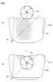
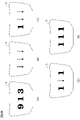
次に、図5(a)を参照して、第1役物310の構成について説明する。第1役物310は、第1役物310を上下動させるための構成として、ラック・アンド・オピニオン方式を採用し、第1役物上下動用モータ310aと、歯車である駆動ギア310b及び従動ギア310cと、スライドギア310dとを有している。また、図示はしていないが、第1役物310を回転動作させるための第1役物回転用モータ(不図示)も設けられている。第1役物回転用モータが駆動されると、第1役物310が、遊技領域31Rの時計回り(右回り)に回転動作する。
Next, the configuration of the first accessory 310 will be described with reference to FIG. 5A. The first accessory 310 adopts a rack-and-opinion method as a configuration for moving the first accessory 310 up and down, and has a first accessory vertical movement motor 310a, a drive gear 310b which is a gear, and a driven gear. It has a 310c and a slide gear 310d. Further, although not shown, a first accessory rotation motor (not shown) for rotating the first accessory 310 is also provided. When the motor for rotating the first accessory is driven, the first accessory 310 rotates clockwise (clockwise) in the game area 31R.
第1役物上下動用モータ310aは、例えば、ステッピングモータであり、図示しないドライバから印加されるパルス信号により駆動され、所定のステップ角度で駆動ギア310bを駆動回転させる。従動ギア310cは、駆動ギア310bに歯合連結し、駆動ギア310bの回転力によって従動回転する。なお、ステッピングモータに変えて回転量を検出するエンコーダ付きのDCモータ等を用いるようにしてもよい。ステッピングモータに比して安価に第1役物310の駆動機構を構成することができる。
The first accessory vertical movement motor 310a is, for example, a stepping motor, which is driven by a pulse signal applied from a driver (not shown) to drive and rotate the drive gear 310b at a predetermined step angle. The driven gear 310c is meshed with the drive gear 310b and is driven to rotate by the rotational force of the drive gear 310b. In addition, a DC motor with an encoder that detects the amount of rotation may be used instead of the stepping motor. The drive mechanism of the first accessory 310 can be configured at a lower cost than the stepping motor.
スライドギア310dは、平板状の棒に歯切りをしたものであり、従動ギア310cに歯合連結し、従動ギア310cの回転に伴って、上下方向に往復移動が可能になっている。このスライドギア310dの下端に第1役物310が接続されている。このため、第1役物上下動用モータ310aにより、駆動ギア310bをステップ単位で駆動回転させることによって、従動ギア310cを介して、スライドギア310dがステップ単位で上下方向に移動し、これに伴って、第1役物310を原点位置から最大点位置までの範囲で上下動させることができる。パチンコ機10では、第1役物310が原点位置にある場合に、その第1役物310が下降する方向に100ステップだけ第1役物上下動用モータ310aを駆動すると第1役物310が最大点位置に到達する。
The slide gear 310d is a flat plate-shaped rod with teeth cut, and is tooth-engaged to the driven gear 310c so that it can reciprocate in the vertical direction as the driven gear 310c rotates. The first accessory 310 is connected to the lower end of the slide gear 310d. Therefore, by driving and rotating the drive gear 310b in step units by the first accessory vertical movement motor 310a, the slide gear 310d moves in the vertical direction in step units via the driven gear 310c. , The first accessory 310 can be moved up and down in the range from the origin position to the maximum point position. In the pachinko machine 10, when the first accessory 310 is at the origin position, the first accessory 310 is maximized when the first accessory vertical movement motor 310a is driven by 100 steps in the direction in which the first accessory 310 descends. Reach the point position.
第1役物上下動用モータ310a及び第1役物回転用モータ(不図示)の駆動制御は、音声発光制御装置90によって行われる。なお、第1役物上下動用モータ310a及び第1役物回転用モータの駆動制御の詳細については後述する。
The drive control of the first accessory vertical movement motor 310a and the first accessory rotation motor (not shown) is performed by the voice emission control device 90. The details of the drive control of the first accessory vertical movement motor 310a and the first accessory rotation motor will be described later.
スライドギア310dの上端には、突起310fが設けられている。また、第1役物310が原点位置にあるときのスライドギア310dの突起310fの位置に、原点検出センサ311が設けられている。また、第1役物310が最大点位置にあるときのスライドギア310dの突起310fの位置に最大点検出センサ312が設けられている。
A protrusion 310f is provided at the upper end of the slide gear 310d. Further, the origin detection sensor 311 is provided at the position of the protrusion 310f of the slide gear 310d when the first accessory 310 is at the origin position. Further, the maximum point detection sensor 312 is provided at the position of the protrusion 310f of the slide gear 310d when the first accessory 310 is at the maximum point position.
次に、図5(b)を参照して、原点検出センサ311の構成について説明する。図5(b)は、原点検出センサ311の概略構成を示した図である。なお、最大点検出センサ312は、原点検出センサ311と同一の構成であるので、説明を省略する。
Next, the configuration of the origin detection sensor 311 will be described with reference to FIG. 5 (b). FIG. 5B is a diagram showing a schematic configuration of the origin detection sensor 311. Since the maximum point detection sensor 312 has the same configuration as the origin detection sensor 311, the description thereof will be omitted.
原点検出センサ311は、発光素子(図示せず)が取り付けられた発光素子取付部311aと、受光素子(図示せず)が取り付けられた受光素子取付部311bと、発光素子取付部311aの一端と受光素子取付部311bの一端とを、発光素子と受光素子とが所定距離だけ離れて対向配置されるように連結する連結部311cとによって構成されたコの字形状のセンサであり、発光素子取付部311aと受光素子取付部311bと連結部311cとによって検出溝311dを形成している。
The origin detection sensor 311 includes a light emitting element mounting portion 311a to which a light emitting element (not shown) is attached, a light receiving element mounting portion 311b to which a light receiving element (not shown) is attached, and one end of the light emitting element mounting portion 311a. It is a U-shaped sensor composed of a connecting portion 311c that connects one end of the light receiving element mounting portion 311b so that the light emitting element and the light receiving element are arranged so as to face each other at a distance of a predetermined distance. The detection groove 311d is formed by the portion 311a, the light receiving element mounting portion 311b, and the connecting portion 311c.
検出溝311dに何ら挿入物がない場合、発光素子取付部311aに取り付けられた発光素子から照射された光は、そのまま受光素子取付部311bに取り付けられた受光素子によって受光される。一方、検出溝311dに挿入物が挿入された場合、発光素子取付部311aに取り付けられた発光素子から照射された光が遮断され、該光を受光素子取付部311bに取り付けられた受光素子が受光できない。原点検出センサ311は、該受光素子において光を受光した場合にオフ信号、受光しなかった場合にオン信号を出力することにより、その信号を受信した音声発光制御装置90において、検出溝311dに何らかの挿入物(突起310f)が挿入されたか否かを判断できる。
When there is no insert in the detection groove 311d, the light emitted from the light emitting element attached to the light emitting element mounting portion 311a is directly received by the light receiving element attached to the light receiving element mounting portion 311b. On the other hand, when an insert is inserted into the detection groove 311d, the light emitted from the light emitting element attached to the light emitting element mounting portion 311a is blocked, and the light is received by the light receiving element mounted on the light receiving element mounting portion 311b. Can not. The origin detection sensor 311 outputs an off signal when light is received by the light receiving element and an on signal when it does not receive light, so that in the voice emission control device 90 that receives the signal, something is sent to the detection groove 311d. It can be determined whether or not the insert (projection 310f) has been inserted.
この原点検出センサ311は、発光素子取付部311aが正面視前面側、受光素子取付部311bが正面視後面側、連結部311cが正面視左側に配置され、第1役物310が原点位置にあり、スライドギア310dの突起310fが検出溝311d内部に挿入されることにより、発光素子から受光素子へ照射される光が遮断されるように、取り付けられている。よって、原点検出センサ311において、発光素子から受光素子へ照射される光が遮断されたことが検出された場合に、原点検出センサ311からオン信号を出力することによって、音声発光制御装置90は、第1役物310が原点位置に到達していることを判断できる。
In this origin detection sensor 311, the light emitting element mounting portion 311a is arranged on the front side in front view, the light receiving element mounting portion 311b is arranged on the rear surface side in front view, the connecting portion 311c is arranged on the left side in front view, and the first accessory 310 is at the origin position. The protrusion 310f of the slide gear 310d is inserted into the detection groove 311d so that the light emitted from the light emitting element to the light receiving element is blocked. Therefore, when the origin detection sensor 311 detects that the light emitted from the light emitting element to the light receiving element is blocked, the origin detection sensor 311 outputs an on signal so that the voice emission control device 90 can be used. It can be determined that the first accessory 310 has reached the origin position.
また、最大点検出センサ312は、原点検出センサ311と同じ向きに配置され、第1役物310が最大点位置にあり、スライドギア310dの突起310fが、最大点検出センサ312の検出溝内部に挿入されることにより、発光素子から受光素子へ照射される光が遮断されるように取り付けられている。このため、最大点検出センサ312において、発光素子から受光素子へ照射される光が遮断されたことが検出された場合に、最大点検出センサ312からオン信号を出力することによって、音声発光制御装置90は、第1役物310が最大点位置に到達していることを判断できる。
Further, the maximum point detection sensor 312 is arranged in the same direction as the origin detection sensor 311, the first accessory 310 is at the maximum point position, and the protrusion 310f of the slide gear 310d is inside the detection groove of the maximum point detection sensor 312. When inserted, it is attached so as to block the light emitted from the light emitting element to the light receiving element. Therefore, when the maximum point detection sensor 312 detects that the light emitted from the light emitting element to the light receiving element is blocked, the maximum point detection sensor 312 outputs an on signal to control the voice emission control device. 90 can determine that the first accessory 310 has reached the maximum point position.
図6は、タッチセンサ57の検出範囲を示す図である。タッチセンサ57は、遊技者に操作されることによって、入力を受け付ける操作手段であり、図6に示すように、図柄表示装置51の中央領域を検出範囲AR1としている。具体的には、タッチセンサ57は、図6に示すように、図柄表示装置51の下の領域から右上の領域に向かって幅広となるように設定された検出範囲AR1を有している。このように図柄表示装置51の対角線と、タッチセンサ57の検出範囲AR1の中央線(軸線)とが一致するようにタッチセンサ57を設けることにより、1つのタッチセンサで図柄表示装置51のより広い範囲をカバーすることができる。そして、タッチセンサ57は、この検出範囲AR1内に遊技者が手をかざした場合に、この遊技者の手(オブジェクト)を検出することができる。ここで、タッチセンサ57は、光学方式を採用しており、その検出範囲AR1内に遊技者が手をかざす行為を窓パネル22越しに検出することができる。
FIG. 6 is a diagram showing a detection range of the touch sensor 57. The touch sensor 57 is an operation means for receiving an input by being operated by the player, and as shown in FIG. 6, the central region of the symbol display device 51 is set as the detection range AR1. Specifically, as shown in FIG. 6, the touch sensor 57 has a detection range AR1 set to widen from the area below the symbol display device 51 toward the area on the upper right. By providing the touch sensor 57 so that the diagonal line of the symbol display device 51 and the center line (axis line) of the detection range AR1 of the touch sensor 57 coincide with each other in this way, one touch sensor is wider than the symbol display device 51. The range can be covered. Then, the touch sensor 57 can detect the player's hand (object) when the player holds his / her hand within the detection range AR1. Here, the touch sensor 57 employs an optical method, and the action of the player holding his / her hand within the detection range AR1 can be detected through the window panel 22.
図7は、タッチセンサ57の検出範囲と第1役物310との位置関係を示す図である。図7(a)は、原点位置にある第1役物310とタッチセンサ57の検出範囲AR1との位置関係を示す図である。図7(a)に示す例では、第1役物310とタッチセンサ57の検出範囲AR1とは平面視にて重なっていない状態となっている。換言すると、第1役物310の位置は、タッチセンサ57により検出されない位置となっている。
また、図7(b)は、最大点位置にある第1役物310とタッチセンサ57の検出範囲AR1との位置関係を示す図である。図7(b)に示す例では、第1役物310とタッチセンサ57の検出範囲AR1とは平面視にて重なった状態となっている。換言すると、第1役物310の位置は、タッチセンサ57により検出される位置となっている。
なお、以下の説明では、図7(a)に示すように第1役物310とタッチセンサ57の検出範囲AR1とが平面視にて重なっておらず、第1役物310がタッチセンサ57により検出されない位置にある状態のことを第1状態ともいう。また、図7(b)に示すように第1役物310とタッチセンサ57の検出範囲AR1とが平面視にて重なっており、第1役物310がタッチセンサ57により検出される位置にある状態のことを第2状態ともいう。なお、図7(b)に示す状態以外にも、第1役物310とタッチセンサ57の検出範囲AR1とが平面視にて重なっている場合には、第1役物310がタッチセンサ57により検出される位置(第2状態)にあるため、第1役物310はタッチセンサ57により検出される。
FIG. 7 is a diagram showing the positional relationship between the detection range of the touch sensor 57 and the first accessory 310. FIG. 7A is a diagram showing the positional relationship between the first accessory 310 at the origin position and the detection range AR1 of the touch sensor 57. In the example shown in FIG. 7A, the first accessory 310 and the detection range AR1 of the touch sensor 57 do not overlap in a plan view. In other words, the position of the first accessory 310 is a position that is not detected by the touch sensor 57.
Further, FIG. 7B is a diagram showing the positional relationship between the first accessory 310 at the maximum point position and the detection range AR1 of the touch sensor 57. In the example shown in FIG. 7B, the first accessory 310 and the detection range AR1 of the touch sensor 57 overlap each other in a plan view. In other words, the position of the first accessory 310 is the position detected by the touch sensor 57.
In the following description, as shown in FIG. 7A, the first accessory 310 and the detection range AR1 of the touch sensor 57 do not overlap in a plan view, and the first accessory 310 is connected by the touch sensor 57. The state in which it is not detected is also called the first state. Further, as shown in FIG. 7B, the first accessory 310 and the detection range AR1 of the touch sensor 57 overlap each other in a plan view, and the first accessory 310 is at a position where the touch sensor 57 detects the first accessory 310. The state is also called the second state. In addition to the state shown in FIG. 7B, when the first accessory 310 and the detection range AR1 of the touch sensor 57 overlap in a plan view, the first accessory 310 is moved by the touch sensor 57. Since it is in the detected position (second state), the first accessory 310 is detected by the touch sensor 57.
<電気的構成>
図8は、パチンコ機10の電気的構成を示すブロック図である。
パチンコ機10は、図8に示すように、主制御装置60と、音声発光制御装置90と、表示制御装置100とを備える。これらの装置は、内枠の背面側に搭載されている。また、パチンコ機10は、前述した払出装置71に遊技球の払い出しをさせる払出制御を実行する払出制御装置70、パチンコ機10へ必要な電力を供給するとともに、遊技球発射機構81を制御する電源・発射制御装置80とを備え、これらの装置は、裏パックユニットに搭載されている。
<Electrical configuration>
FIG. 8 is a block diagram showing an electrical configuration of the pachinko machine 10.
As shown in FIG. 8, the pachinko machine 10 includes a main control device 60, a voice emission control device 90, and a display control device 100. These devices are mounted on the back side of the inner frame. Further, the pachinko machine 10 supplies necessary electric power to the payout control device 70 and the pachinko machine 10 for executing the payout control for causing the above-mentioned payout device 71 to pay out the game ball, and also supplies a power source for controlling the game ball launch mechanism 81. -The launch control device 80 is provided, and these devices are mounted on the back pack unit.
主制御装置60は、パチンコ機10の主な制御(主制御)を司る主制御基板61と、電源を監視する停電監視基板65とを備えている。なお、主制御装置60は、主制御基板61などを収容する基板ボックスを備えている。この基板ボックスは、その開放に際して痕跡を残す痕跡構造を備えていてもよい。具体的には、痕跡手段としては、複数のケース体を結合することによって基板ボックスを構成し、各ケース体の分離に際して所定部位の破壊を要する結合部(カシメ部)を設ける構成や、引き剥がしに際して粘着層が接着対象に残ることで剥がされたことの痕跡を残す封印シールを複数のケース体間の境界を跨ぐようにして貼り付ける構成などを採用することができる。また、痕跡構造としては、これらのケース体間の境界に対して接着剤を塗布する構成などを採用することができる。
The main control device 60 includes a main control board 61 that controls the main control (main control) of the pachinko machine 10, and a power failure monitoring board 65 that monitors the power supply. The main control device 60 includes a board box for accommodating the main control board 61 and the like. The substrate box may have a trace structure that leaves a trace when opened. Specifically, as a trace means, a substrate box is formed by connecting a plurality of case bodies, and a connecting portion (caulking portion) that requires destruction of a predetermined portion when separating each case body is provided or peeled off. At this time, it is possible to adopt a configuration in which a sealing sticker that leaves a trace of peeling due to the adhesive layer remaining on the bonding target is attached so as to straddle the boundary between a plurality of case bodies. Further, as the trace structure, a configuration in which an adhesive is applied to the boundary between these case bodies can be adopted.
主制御基板61は、主制御基板61に実装されたMPU(Micro-Processing Unit)62と、このMPU62を構成しているROM(Read Only Memory)63およびRAM(Random Access Memory)64とを備えている。MPU62は、ROM63およびRAM64の他、CPU、割込回路、タイマ回路、データ入出力回路、および乱数発生器としてのカウンタ回路などを1チップ化した半導体素子であり、いわゆるワンチップマイコンと呼ばれるものである。なお、第1実施形態では、ROM63およびRAM64は、MPU62に対して1チップ化されているが、ROM63、RAM64が個別にチップ化された構成としてもよい。また、ROM63とRAM64とは、物理的に分離された個別のメモリとしているが、物理的に分離していない一つのメモリとし、論理アドレスによりROM63の領域とRAM64の領域を設けるようにしてもよい。この場合、例えば、RAM内の特定領域を書き込み禁止としてROMの機能を持たせるようにしてもよい。主制御装置60以外の他の制御装置のMPUについても同様である。
The main control board 61 includes an MPU (Micro-Processing Unit) 62 mounted on the main control board 61, and a ROM (Read Only Memory) 63 and a RAM (Random Access Memory) 64 constituting the MPU 62. There is. The MPU 62 is a semiconductor element in which a CPU, an interrupt circuit, a timer circuit, a data input / output circuit, a counter circuit as a random number generator, and the like are integrated into one chip in addition to the ROM 63 and the RAM 64, and is a so-called one-chip microcomputer. be. In the first embodiment, the ROM 63 and the RAM 64 are integrated into one chip with respect to the MPU 62, but the ROM 63 and the RAM 64 may be individually chipped. Further, although the ROM 63 and the RAM 64 are physically separated separate memories, they may be one memory that is not physically separated, and the ROM 63 area and the RAM 64 area may be provided by a logical address. .. In this case, for example, a specific area in the RAM may be write-protected so that the ROM function may be provided. The same applies to the MPUs of other control devices other than the main control device 60.
ROM63は、各種の制御プログラムや固定値データを記憶するためのメモリであり、MPU62の主記憶装置として利用される。ROM63は、記憶している情報(データ)の保持に際して外部からの電力供給を必要としない不揮発性メモリであり、書き込みを行うことができない半導体素子である。このROM63は、論理アドレスにより論理的に分離された複数のエリア(領域)を有しており、例えば、当否テーブル記憶エリア631や、振分テーブル記憶エリア632や、リーチ用テーブル記憶エリア633、変動用テーブル記憶エリア634などの各種エリアを有している。これらのエリアについては後に詳細に説明する。
The ROM 63 is a memory for storing various control programs and fixed value data, and is used as the main storage device of the MPU 62. The ROM 63 is a non-volatile memory that does not require external power supply for holding stored information (data), and is a semiconductor element that cannot be written. This ROM 63 has a plurality of areas (areas) logically separated by logical addresses, for example, a pass / fail table storage area 631, a distribution table storage area 632, a reach table storage area 633, and variations. It has various areas such as a table storage area 634. These areas will be described in detail later.
RAM64は、任意に情報の書き込みおよび消去が可能な半導体メモリである。RAM64は、ROM63に記憶された制御プログラムを読み出して実行する際に、各種のデータ等を一時的に記憶するためのメモリであり、記憶している情報の保持に際して外部からの電力供給を必要とする揮発性メモリである。このRAM64は、論理アドレスにより論理的に分離された複数のエリア(領域)を有しており、例えば、各種カウンタエリア641や、保留球格納エリア642や、電役保留エリア643や、停止結果格納エリア644などの各種エリアを有している。これらのエリアについては後に詳細に説明する。なお、第1実施形態では、RAM64として、DRAM(Dynamic Random Access Memory)やSRAM(Static Random Access Memory)等の揮発性メモリを用いているが、RAM64としてMRAM(Magnetoresistive Random Access Memory)等の不揮発性メモリを用いるようにしてもよい。
The RAM 64 is a semiconductor memory capable of arbitrarily writing and erasing information. The RAM 64 is a memory for temporarily storing various data and the like when reading and executing a control program stored in the ROM 63, and requires an external power supply to retain the stored information. It is a volatile memory. This RAM 64 has a plurality of areas (areas) logically separated by logical addresses, and for example, various counter areas 641, a hold ball storage area 642, an electric service hold area 643, and a stop result storage. It has various areas such as area 644. These areas will be described in detail later. In the first embodiment, a volatile memory such as DRAM (Dynamic Random Access Memory) or SRAM (Static Random Access Memory) is used as the RAM 64, but the RAM 64 is non-volatile such as MRAM (Magnetoresistive Random Access Memory). Memory may be used.
MPU62は、入力ポート(不図示)および出力ポート(不図示)を備えている。MPU62の入力ポートは、主制御装置60に設けられた停電監視基板65と、複数の検知センサ502~506とに接続されている。MPU62の出力ポートは、停電監視基板65と、払出制御装置70と、音声発光制御装置90とに接続されている。この音声発光制御装置90と、音声発光制御装置90に接続される表示制御装置100については後に詳細に説明する。また、MPU62の出力ポートは、第2始動口37の開閉部材371を開閉動作させる電動役物駆動部372と、可変入賞装置38の開閉扉382を開閉動作させる可変入賞駆動部383と、メイン表示部46と、役物用表示部47とに接続されている。
The MPU 62 includes an input port (not shown) and an output port (not shown). The input port of the MPU 62 is connected to a power failure monitoring board 65 provided in the main control device 60 and a plurality of detection sensors 502 to 506. The output port of the MPU 62 is connected to the power failure monitoring board 65, the payout control device 70, and the voice emission control device 90. The voice emission control device 90 and the display control device 100 connected to the voice emission control device 90 will be described in detail later. Further, the output port of the MPU 62 includes an electric accessory drive unit 372 that opens and closes the opening / closing member 371 of the second starting port 37, a variable winning drive unit 383 that opens / closes the opening / closing door 382 of the variable winning device 38, and a main display. It is connected to the unit 46 and the accessory display unit 47.
ここで、主制御基板61は、ドライバ回路(不図示)を有しており、MPU62は、このドライバ回路を通じて各種駆動部などの駆動制御を実行する。具体的には、電役開放状態では、MPU62は、電動役物駆動部372の駆動制御を実行して開閉部材371を開閉させる。また、開閉実行モードでは、MPU62は、可変入賞駆動部383の駆動制御を実行して可変入賞装置38の開閉扉382を開閉させる。また、各遊技回では、MPU62は、メイン表示部46の表示制御を実行して各始動口36,37への入賞に基づいて行われた内部抽選の結果を表示する。さらに、MPU62は、役物用表示部47の表示制御を実行して各スルーゲート41への入賞に基づいて行われた内部抽選の結果を表示する。
Here, the main control board 61 has a driver circuit (not shown), and the MPU 62 executes drive control of various drive units and the like through this driver circuit. Specifically, in the electric service open state, the MPU 62 executes drive control of the electric accessory drive unit 372 to open / close the opening / closing member 371. Further, in the open / close execution mode, the MPU 62 executes drive control of the variable winning drive unit 383 to open / close the opening / closing door 382 of the variable winning device 38. Further, in each game round, the MPU 62 executes the display control of the main display unit 46 and displays the result of the internal lottery performed based on the winning of the starting ports 36 and 37. Further, the MPU 62 executes display control of the accessory display unit 47 and displays the result of the internal lottery performed based on the winning of each through gate 41.
停電監視基板65は、主制御基板61と、動作電力を供給する機能を有する電源・発射制御装置80とを中継し、電源・発射制御装置80から出力される直流安定24ボルトの電圧を監視する。MPU62は、停電監視基板65を介して電力(DC24V)を受給する。また、MPU62は、検知センサ502~506の検知結果に基づいて、各種入賞口や、アウト口39や、各スルーゲート41への入賞判定(入球判定)を行っている。MPU62は、第1始動口36または第2始動口37への入賞判定に基づいて、内部抽選を実行する。
The power failure monitoring board 65 relays the main control board 61 and the power supply / emission control device 80 having a function of supplying operating power, and monitors the voltage of DC stable 24 volts output from the power supply / emission control device 80. .. The MPU 62 receives electric power (DC24V) via the power failure monitoring board 65. Further, the MPU 62 makes a winning determination (ball entry determination) for various winning openings, out openings 39, and each through gate 41 based on the detection results of the detection sensors 502 to 506. The MPU 62 executes an internal lottery based on the winning determination to the first starting port 36 or the second starting port 37.
払出制御装置70は、主制御装置60から送信されるコマンド(制御命令)に基づいて、払出装置71に賞球(入賞により得る遊技球のこと)や貸し球(遊技者に貸し出される遊技球)の払い出しをさせる払出制御を実行する。
The payout control device 70 is a prize ball (a game ball obtained by winning a prize) or a rental ball (a game ball lent to a player) to the payout device 71 based on a command (control command) transmitted from the main control device 60. Executes the payout control to make the payout.
電源・発射制御装置80は、例えば、遊技場等における商用電源(外部電源)に接続されている。電源・発射制御装置80は、その商用電源から供給される外部電力に基づいて主制御基板61や払出制御装置70等に対して各々に必要な動作電力を生成するAC-DCコンバータを備え、その生成した動作電力を各装置へ供給する。なお、電源・発射制御装置80は、バックアップ用コンデンサなどの電断時用電源部を備えている。この電断時用電源部は、パチンコ機10への電力供給が遮断された電断時において、主制御装置60のRAM64に記憶保持用の電力を供給する。
The power supply / launch control device 80 is connected to, for example, a commercial power supply (external power supply) in a game hall or the like. The power supply / emission control device 80 includes an AC-DC converter that generates operating power required for each of the main control board 61, the payout control device 70, and the like based on the external power supplied from the commercial power supply. The generated operating power is supplied to each device. The power supply / emission control device 80 includes a power supply unit for power failure such as a backup capacitor. The power supply unit for power failure supplies power for storage and holding to the RAM 64 of the main control device 60 when the power supply to the pachinko machine 10 is cut off.
電源・発射制御装置80は、遊技球発射機構81に遊技球を発射させる発射制御を実行する。ここで、遊技球発射機構81は、遊技盤31の誘導レール34に向けて延びる発射レールと、上受皿251に貯留されている遊技球を発射レール上に供給する球送り装置と、発射レール上に供給された遊技球を誘導レール34に向けて発射させる電動アクチュエータであるソレノイドとを備えている。電源・発射制御装置80は、所定の発射条件(発射ハンドル27が回転操作されており、接触センサ271がオンで、かつ発射停止スイッチ272がオフのとき)が整っている場合に、このソレノイドに対して駆動信号(発射許可信号)を供給し、遊技球を発射させる。
The power supply / launch control device 80 executes launch control for launching the game ball to the game ball launch mechanism 81. Here, the game ball launch mechanism 81 has a launch rail extending toward the guide rail 34 of the game board 31, a ball feeding device for supplying the game balls stored in the upper tray 251 onto the launch rail, and a launch rail. It is equipped with a solenoid, which is an electric actuator that launches the game ball supplied to the guide rail 34 toward the guide rail 34. When the predetermined firing conditions (when the firing handle 27 is rotated, the contact sensor 271 is on, and the firing stop switch 272 is off) are satisfied, the power supply / firing control device 80 is set to this solenoid. A drive signal (launch permission signal) is supplied to the vehicle to launch the game ball.
なお、第1実施形態では、パチンコ機10の遊技球発射機構81は、プランジャー型ソレノイドの直線的な伸縮動作によって遊技球を打ち出す方式を採用しているが、ロータリーソレノイドの回転軸に直結された打球槌が動作して遊技球を打ち出す形式であってもよいし、モータの回転に対して、別位置に支持された打球槌が動作して遊技球を打ち出す形式であってもよい。具体的には、モータにより遊技球を打ち出す方式では、モータと打球槌は別位置で支持されており、モータに接続されたカムが回転することで打球槌を動作させる。モータ(カム)によって動作した打球槌は、接続されたスプリング等の弾性によって逆方向に動作することで遊技球を打球して遊技盤31の遊技領域31Rへと打ち出す。また、ロータリーソレノイドにより遊技球を打ち出す方式では、電源・発射制御装置80からのパルスに応答して回転軸を回転させることによって遊技球を打球し、遊技盤31の遊技領域31Rへと遊技球が発射される。ロータリーソレノイドの回転軸に直結された打球槌は、遊技球の支持位置まで回転することで発射レール上の遊技球を打球し、遊技球が発射される。打球後はロータリーソレノイドのトルクが消失し、打球槌はストッパーに衝突した反動と、自重によって逆方向に回転し、ストッパー によって動作前の位置で停止する。また、プランジャー型ソレノイドにより遊技球を打ち出す方式では、プランジャー型ソレノイドの可動鉄芯に、直接打球槌を接続し、これの直線往復動作によって遊技球を打球し、遊技盤31の遊技領域31Rへと遊技球が発射される。また、プランジャー型ソレノイドは、ソレノイドへの通電によって打球槌を打ち出すタイプと、通電によって打球槌を後退させることでスプリングを圧縮し、スプリングの弾性によって打球槌を前進させ、遊技球を打球するもののどちらを用いるようにしてもよい。
In the first embodiment, the game ball launching mechanism 81 of the pachinko machine 10 adopts a method of launching a game ball by a linear expansion / contraction operation of a plunger type solenoid, but it is directly connected to the rotation axis of the rotary solenoid. It may be a form in which a hitting ball is operated to launch a game ball, or a form in which a hitting mallet supported at a different position operates with respect to the rotation of a motor to launch a game ball. Specifically, in the method of launching a game ball by a motor, the motor and the hitting mallet are supported at different positions, and the hitting mallet is operated by rotating the cam connected to the motor. The hitting mallet operated by the motor (cam) hits the game ball by operating in the opposite direction due to the elasticity of the connected spring or the like, and launches it into the game area 31R of the game board 31. Further, in the method of launching the game ball by the rotary solenoid, the game ball is hit by rotating the rotation axis in response to the pulse from the power supply / launch control device 80, and the game ball is moved to the game area 31R of the game board 31. Be fired. The hitting mallet directly connected to the rotation axis of the rotary solenoid hits the game ball on the launch rail by rotating to the support position of the game ball, and the game ball is launched. After hitting the ball, the torque of the rotary solenoid disappears, and the hitting mallet rotates in the opposite direction due to the reaction of the collision with the stopper and its own weight, and the stopper stops the ball at the position before the operation. Further, in the method of launching the game ball by the plunger type solenoid, the ball hammer is directly connected to the movable iron core of the plunger type solenoid, and the game ball is hit by the linear reciprocating operation of the mallet, and the game area 31R of the game board 31 is hit. A game ball is fired. In addition, the plunger type solenoid is a type that launches a hitting mallet by energizing the solenoid, and a type that compresses the spring by retracting the hitting mallet by energizing, and advances the hitting mallet by the elasticity of the spring to hit the game ball. Either may be used.
また、遊技球発射機構81の球送り装置は、メカ式またはマグネット式のどちらあっても構わない。メカ式の場合、打球槌を駆動するモータの動力を使用して球送り装置を動作させる。メカ式の場合、打球槌と球送り装置の駆動源が同一となっているため、簡易な構造で、打球のタイミングに応じて発射レールへと1球ずつ遊技球を発射レール上に供給することが可能である。また、マグネット式の場合、打球槌の動作とは別に、独立したソレノイドによって球送りを動作させ、1球ずつ球技球を発射レール上へと供給する。マグネット式は、遊技球発射機構81がロータリーソレノイドやプランジャー型ソレノイドを用いて遊技球を発射する場合に採用することが好ましい。
Further, the ball feeding device of the game ball launching mechanism 81 may be either a mechanical type or a magnet type. In the case of the mechanical type, the ball feeding device is operated by using the power of the motor that drives the hitting mallet. In the case of the mechanical type, since the driving source of the hitting mallet and the ball feeding device is the same, the game ball is supplied to the launching rail one by one according to the timing of the hitting ball with a simple structure. Is possible. Further, in the case of the magnet type, the ball feed is operated by an independent solenoid separately from the operation of the hammer, and the ball game balls are supplied one by one onto the launch rail. The magnet type is preferably adopted when the game ball launching mechanism 81 launches a game ball using a rotary solenoid or a plunger type solenoid.
<内部抽選>
図10は、内部抽選に用いられる各カウンタの内容を示す図である。「内部抽選」とは、遊技盤に設けた始動入賞口への遊技球の入賞を契機に遊技者に有利な特定遊技状態(大当たり遊技状態)に移行させるか否かの抽選のことである。MPU62は、図10に示すように、各カウンタC1~C3,CINI,CS,C4の値(情報)を用いることによって内部抽選などを実行する。具体的には、MPU62は、大当たり発生の抽選に大当たり乱数カウンタC1を使用し、大当たり発生に際し、その大当たりの種別の抽選に大当たり種別カウンタC2を使用し、リーチ表示を発生させるか否かの抽選にリーチ乱数カウンタC3を使用する。また、MPU62は、大当たり乱数カウンタC1の初期値設定に乱数初期値カウンタCINIを使用し、メイン表示部46および図柄表示装置51における表示継続時間の決定に変動種別カウンタCSを使用する。さらに、MPU62は、第2始動口37の開閉部材371を開放状態とするか否かの抽選に電動役物開放カウンタC4を使用する。なお、各カウンタC1~C3,CINI,CS,C4は、RAM64の各種カウンタエリア641(図10参照)に設けられている。
<Internal lottery>
FIG. 10 is a diagram showing the contents of each counter used for the internal lottery. The "internal lottery" is a lottery for whether or not to shift to a specific game state (big hit game state) that is advantageous to the player when the game ball is won in the start winning opening provided on the game board. As shown in FIG. 10, the MPU 62 executes an internal lottery or the like by using the values (information) of the counters C1 to C3, CINI, CS, and C4. Specifically, the MPU 62 uses the jackpot random number counter C1 for the lottery for the occurrence of the jackpot, and uses the jackpot type counter C2 for the lottery for the type of the jackpot when the jackpot occurs, and draws whether or not to generate the reach display. The reach random number counter C3 is used for. Further, the MPU 62 uses the random number initial value counter CINI for setting the initial value of the jackpot random number counter C1, and uses the variable type counter CS for determining the display duration in the main display unit 46 and the symbol display device 51. Further, the MPU 62 uses the electric accessory opening counter C4 for a lottery as to whether or not to open the opening / closing member 371 of the second starting port 37. The counters C1 to C3, CINI, CS, and C4 are provided in various counter areas 641 (see FIG. 10) of the RAM 64.
各カウンタC1~C3,CINI,CS,C4は、更新の都度、前回値に1が加算(インクリメント)され、所定の最大値に達した後、0に戻るループカウンタとなっている。各カウンタは、定期的(例えば、4msec毎)に更新される。更新された値は、RAM64の所定領域に設定された抽選カウンタ用バッファに格納される。抽選カウンタ用バッファに格納された値のうち、大当たり乱数カウンタC1、大当たり種別カウンタC2、およびリーチ乱数カウンタC3の各値は、第1始動口36または第2始動口37に遊技球が入賞したタイミングでRAM64に取得情報記憶手段として設けられた保留球格納エリア642(図10参照)に格納される。また、抽選カウンタ用バッファに格納された値のうち、電動役物開放カウンタC4の値は、各スルーゲート41に遊技球が入賞したタイミングでRAM64の電役保留エリア643(図10参照)に格納される。
Each of the counters C1 to C3, CINI, CS, and C4 is a loop counter in which 1 is added (incremented) to the previous value each time it is updated, and after reaching a predetermined maximum value, it returns to 0. Each counter is updated periodically (eg, every 4 msec). The updated value is stored in the lottery counter buffer set in the predetermined area of the RAM 64. Among the values stored in the lottery counter buffer, each value of the jackpot random number counter C1, the jackpot type counter C2, and the reach random number counter C3 is the timing at which the game ball wins the first start port 36 or the second start port 37. It is stored in the reserved ball storage area 642 (see FIG. 10) provided in the RAM 64 as the acquisition information storage means. Further, among the values stored in the lottery counter buffer, the value of the electric accessory opening counter C4 is stored in the electric service holding area 643 (see FIG. 10) of the RAM 64 at the timing when the game ball wins in each through gate 41. Will be done.
保留球格納エリア642は、第1結果表示部用保留エリアRaと、第2結果表示部用保留エリアRbと、実行エリアAEとを備えている。
The holding ball storage area 642 includes a holding area Ra for the first result display unit, a holding area Rb for the second result display unit, and an execution area AE.
第1取得情報記憶手段として設けられた第1結果表示部用保留エリアRaは、第1エリアRa1~第4エリアRa4の4つの記憶エリアを備えている。各エリアRa1~Ra4は、大当たり乱数カウンタC1、大当たり種別カウンタC2、およびリーチ乱数カウンタC3の各値の組をそれぞれ1組ずつ格納可能な記憶容量に設定されている。MPU62は、大当たり乱数カウンタC1、大当たり種別カウンタC2、およびリーチ乱数カウンタC3の各値の組を保留情報として第1始動口36への遊技球の入賞に合わせて各エリアRa1~Ra4に時系列的、すなわち先に取得した値から各エリアRa1~Ra4に順次に格納していく。具体的には、MPU62は、第1始動口36への入賞が複数回連続して発生した場合に、第1エリアRa1→第2エリアRa2→第3エリアRa3→第4エリアRa4の順に保留情報を格納する。
The first result display unit holding area Ra provided as the first acquired information storage means includes four storage areas of the first area Ra1 to the fourth area Ra4. Each area Ra1 to Ra4 is set to a storage capacity capable of storing one set of each value of the jackpot random number counter C1, the jackpot type counter C2, and the reach random number counter C3. The MPU 62 uses the set of the values of the jackpot random number counter C1, the jackpot type counter C2, and the reach random number counter C3 as hold information in chronological order in each area Ra1 to Ra4 according to the winning of the game ball to the first starting port 36. That is, the values acquired earlier are sequentially stored in each area Ra1 to Ra4. Specifically, the MPU 62 holds information in the order of 1st area Ra1 → 2nd area Ra2 → 3rd area Ra3 → 4th area Ra4 when winning the first starting port 36 occurs a plurality of times in succession. To store.
第1実施形態では、第1結果表示部用保留エリアRaは、4つの記憶エリアを備えているので、第1始動口36への遊技球の入賞は、最大4個まで保留されるようになっている。また、第1結果表示部用保留エリアRaは、保留されている大当たり乱数カウンタC1、大当たり種別カウンタC2、およびリーチ乱数カウンタC3の各値の組の数である保留個数を書き込むための記憶エリアが設けられている。なお、第1始動口36に係る保留個数は、4個に限定されることはなく任意であり、例えば、1~3個のいずれか、または5個以上であってもよい。
In the first embodiment, since the holding area Ra for the first result display unit has four storage areas, up to four winning balls to the first starting port 36 are held. ing. Further, the hold area Ra for the first result display unit has a storage area for writing the number of holds, which is the number of sets of each value of the hold random number counter C1, the big hit type counter C2, and the reach random number counter C3. It is provided. The number of reserved pieces related to the first starting port 36 is not limited to four and is arbitrary, and may be, for example, any one of one to three or five or more.
第2取得情報記憶手段として設けられた第2結果表示部用保留エリアRbは、第1エリアRb1~第4エリアRb4の4つの記憶エリアを備えている。各エリアRb1~Rb4は、大当たり乱数カウンタC1、大当たり種別カウンタC2、およびリーチ乱数カウンタC3の各値の組をそれぞれ1組ずつ格納可能な記憶容量に設定されている。MPU62は、大当たり乱数カウンタC1、大当たり種別カウンタC2、およびリーチ乱数カウンタC3の各値の組を保留情報として第2始動口37への遊技球の入賞に合わせて各エリアRb1~Rb4に時系列的、すなわち先に取得した値から各エリアRb1~Rb4に順次に格納していく。具体的には、MPU62は、第2始動口37への入賞が複数回連続して発生した場合に、第1エリアRb1→第2エリアRb2→第3エリアRb3→第4エリアRb4の順に保留情報を時系列的に格納していく。
The second result display unit holding area Rb provided as the second acquired information storage means includes four storage areas of the first area Rb1 to the fourth area Rb4. Each area Rb1 to Rb4 is set to a storage capacity capable of storing one set of each value of the jackpot random number counter C1, the jackpot type counter C2, and the reach random number counter C3. The MPU 62 uses the set of the values of the jackpot random number counter C1, the jackpot type counter C2, and the reach random number counter C3 as hold information in chronological order in each area Rb1 to Rb4 according to the winning of the game ball to the second starting port 37. That is, the values acquired earlier are sequentially stored in each area Rb1 to Rb4. Specifically, the MPU 62 holds information in the order of first area Rb1 → second area Rb2 → third area Rb3 → fourth area Rb4 when winning the second starting port 37 occurs a plurality of times in succession. Is stored in chronological order.
第1実施形態では、第2結果表示部用保留エリアRbは、4つの記憶エリアを備えているので、第2始動口37への遊技球の入賞は、最大4個まで保留されるようになっている。また、第2結果表示部用保留エリアRbは、保留されている大当たり乱数カウンタC1、大当たり種別カウンタC2、およびリーチ乱数カウンタC3の各値の組の数である保留個数を書き込むための記憶エリアが設けられている。なお、第2始動口37に係る保留個数は、4個に限定されることはなく任意であり、例えば、1~3個のいずれか、または5個以上であってもよい。
In the first embodiment, since the holding area Rb for the second result display unit has four storage areas, up to four winning balls to the second starting port 37 are held. ing. Further, the holding area Rb for the second result display unit has a storage area for writing the number of holdings, which is the number of sets of each value of the holding jackpot random number counter C1, the jackpot type counter C2, and the reach random number counter C3. It is provided. The number of reserved pieces related to the second starting port 37 is not limited to four, and may be arbitrary, for example, any one of one to three, or five or more.
実行エリアAEは、各結果表示部461,462の変動表示を開始する際に、第1結果表示部用保留エリアRaまたは第2結果表示部用保留エリアRbの記憶エリアに格納された保留情報を移動させるためのエリアである。
When the execution area AE starts the variable display of the result display units 461 and 462, the execution area AE stores the hold information stored in the storage area of the hold area Ra for the first result display unit or the hold area Rb for the second result display unit. It is an area for moving.
電役保留エリア643は、4つの記憶エリアを備えているので、各スルーゲート41への遊技球の入賞は、最大4個まで保留されるようになっている。なお、第1実施形態に係るパチンコ機10は、2つのスルーゲート41を備えているが、どちらのスルーゲート41に入賞したかに関係なく、一方のスルーゲート41に入賞すれば電役保留エリア643にスルーゲート41への遊技球の入賞が保留される。なお、第2始動口37に係る保留個数は、4個に限定されることはなく任意であり、例えば、1~3個のいずれか、または5個以上であってもよい。
Since the electric service holding area 643 has four storage areas, up to four game balls can be held for winning in each through gate 41. The pachinko machine 10 according to the first embodiment includes two through gates 41. However, regardless of which through gate 41 is awarded, if one of the through gates 41 is awarded, the electric service holding area is provided. At 643, the winning of the game ball to the through gate 41 is suspended. The number of reserved pieces related to the second starting port 37 is not limited to four, and may be arbitrary, for example, any one of one to three, or five or more.
<各カウンタの説明>
次に、各カウンタの詳細について説明する。
<Explanation of each counter>
Next, the details of each counter will be described.
<電動役物開放カウンタC4>
初めに、電動役物開放カウンタC4について説明する。電動役物開放カウンタC4は、例えば、その更新の都度、前回値に1が加算され、最大値250に達した後、0に戻ることによって、0~250の範囲内でループするループカウンタとなっている。電動役物開放カウンタC4は、定期的(例えば、4msec毎)に更新され、その更新された値は、各スルーゲート41に遊技球が入賞したタイミングで抽選カウンタ用バッファを介してRAM64の電役保留エリア643に格納される。MPU62は、電役保留エリア643に格納された電動役物開放カウンタC4の値に基づいて、第2始動口37の開閉部材371を開放状態とするか否かの抽選(電動役物開放抽選)を実行する。
<Electric accessory release counter C4>
First, the electric accessory opening counter C4 will be described. The electric accessory release counter C4 becomes a loop counter that loops in the range of 0 to 250 by adding 1 to the previous value each time it is updated, reaching the maximum value of 250, and then returning to 0. ing. The electric accessory opening counter C4 is updated periodically (for example, every 4 msec), and the updated value is used as the electric function of the RAM 64 via the lottery counter buffer at the timing when the game ball wins a prize in each through gate 41. It is stored in the hold area 643. The MPU 62 is a lottery for whether or not to open the opening / closing member 371 of the second starting port 37 based on the value of the electric accessory opening counter C4 stored in the electric service holding area 643 (electric accessory opening lottery). To execute.
<サポートモード>
ここで、パチンコ機10は、第2始動口37への遊技球の入賞が可能となる開閉部材371の開放状態となる頻度が互いに異なる複数のモード(以下、サポートモード)を有している。具体的には、パチンコ機10は、開閉部材371を開放状態に設定する頻度が相対的に低い低頻度サポートモードと、開閉部材371を開放状態に設定する頻度が相対的に高い高頻度サポートモードとを有している。
<Support mode>
Here, the pachinko machine 10 has a plurality of modes (hereinafter referred to as support modes) in which the frequency with which the opening / closing member 371 that allows the game ball to win a prize in the second starting port 37 is opened is different from each other. Specifically, the pachinko machine 10 has a low-frequency support mode in which the frequency of setting the opening / closing member 371 in the open state is relatively low, and a high-frequency support mode in which the frequency of setting the opening / closing member 371 in the open state is relatively high. And have.
低頻度サポートモードおよび高頻度サポートモードは、電動役物開放抽選において、電役開放状態に当選する確率は同一(例えば、共に4/5)であるが、高頻度サポートモードは、低頻度サポートモードと比較して、電役開放状態に当選した際に、開閉部材371を開放状態に設定する回数が多く、開閉部材371を開放状態に設定する1回あたりの開放時間も長くなっている。また、高頻度サポートモードでは、1回の電役開放状態における各回の開放の間に、開閉部材371を閉鎖状態に設定する閉鎖時間は、1回あたりの開放時間よりも短くなっている。さらに、高頻度サポートモードは、低頻度サポートモードと比較して、電動役物開放抽選を終えてから次回の電動役物開放抽選を行うまでに待機する時間として最低限確保される確保時間(役物用表示部47における1回の変動表示の継続時間)が短くなっている。
The low-frequency support mode and the high-frequency support mode have the same probability of winning the electric role open state in the electric accessory opening lottery (for example, both are 4/5), but the high-frequency support mode is the low-frequency support mode. As compared with the above, when the electric service open state is won, the opening / closing member 371 is set to the open state more often, and the opening time for setting the opening / closing member 371 to the open state is also longer. Further, in the high-frequency support mode, the closing time for setting the opening / closing member 371 to the closed state during each opening in the one-time electric service opening state is shorter than the opening time per opening time. Furthermore, compared to the low-frequency support mode, the high-frequency support mode is the minimum secured time (role) that is secured as the waiting time from the end of the electric accessory opening lottery to the next electric accessory opening lottery. The duration of one variable display on the object display unit 47) is shortened.
高頻度サポートモードでは、低頻度サポートモードと比較して、遊技球は、第2始動口37に入賞しやすい状態となる。つまり、低頻度サポートモードでは、遊技球は、第2始動口37よりも第1始動口36に入賞する確率が高く、高頻度サポートモードでは、遊技球は、第1始動口36よりも第2始動口37に入賞する確率が高い状態となる。また、第2始動口37への入賞が検知センサ503により検知された場合、所定数(例えば、2個)の賞球の払い出しが実行されるので、高頻度サポートモードでは、遊技者は、遊技球をほとんど減らさずに遊技することができる。
In the high-frequency support mode, the game ball is in a state in which it is easier to win a prize in the second starting port 37 as compared with the low-frequency support mode. That is, in the low frequency support mode, the game ball has a higher probability of winning the first start port 36 than the second start port 37, and in the high frequency support mode, the game ball has a second higher probability than the first start port 36. The probability of winning a prize in the starting port 37 is high. Further, when the winning of the second starting port 37 is detected by the detection sensor 503, a predetermined number (for example, two) of prize balls are paid out. Therefore, in the high frequency support mode, the player can play the game. You can play with almost no reduction in the number of balls.
なお、低頻度サポートモードおよび高頻度サポートモードは、上記に限定されることはない。例えば、高頻度サポートモードは、電動役物開放抽選にて電役開放状態に当選する確率を低頻度サポートモードと比較して高くするように構成してもよい。また、例えば、複数種類の確保時間を用意し、高頻度サポートモードは、低頻度サポートモードと比較して、短い確保時間を選択し易いように構成してもよく、選択される確保時間の平均を短くするように構成してもよい。さらに、開閉部材371を開放状態に設定する回数、開放時間、および確保時間の各条件を組み合わせることによって、高頻度サポートモードは、開閉部材371を開放状態に設定する頻度を低頻度サポートモードと比較して相対的に高くするように構成してもよい。また、サポートモードの種類は、2種類に限定されることはなく任意であり、例えば、3種類以上であってもよい。
The low frequency support mode and the high frequency support mode are not limited to the above. For example, the high-frequency support mode may be configured to increase the probability of winning the electric combination open state in the electric accessory opening lottery as compared with the low-frequency support mode. Further, for example, a plurality of types of reservation times may be prepared, and the high frequency support mode may be configured so that a shorter reservation time can be easily selected as compared with the low frequency support mode, and the average of the selection time is selected. May be configured to be shorter. Further, by combining the conditions of the number of times the opening / closing member 371 is set to the open state, the opening time, and the securing time, the high frequency support mode compares the frequency of setting the opening / closing member 371 to the open state with the low frequency support mode. It may be configured to be relatively high. Further, the types of support modes are not limited to two types, and may be arbitrary, and may be, for example, three or more types.
<大当たり用乱数カウンタ>
次に、大当たり乱数カウンタC1について説明する。大当たり乱数カウンタC1は、例えば、その更新の都度、前回値に1が加算され、最大値599に達した後、0に戻ることによって、0~599の範囲内でループするループカウンタとなっている。また、大当たり乱数カウンタC1は、1周ループするごとに、その時点の乱数初期値カウンタCINIの値を初期値として読み込む。なお、乱数初期値カウンタCINIは、大当たり乱数カウンタC1と同様に0~599の範囲内でループするループカウンタである。
<Random number counter for big hits>
Next, the jackpot random number counter C1 will be described. The jackpot random number counter C1 is, for example, a loop counter that loops within the range of 0 to 599 by adding 1 to the previous value each time it is updated, reaching the maximum value of 599, and then returning to 0. .. Further, the jackpot random number counter C1 reads the value of the random number initial value counter CINI at that time as an initial value every time it loops once. The random number initial value counter CINI is a loop counter that loops within the range of 0 to 599, like the jackpot random number counter C1.
つまり、第1実施形態のパチンコ機10は、大当たり乱数カウンタC1と乱数初期値カウンタCINIとを用いることにより、乱数の数列の最終値が発現したときの次の値(初期値)を偶発性のある値によって定めるプラス方式により大当たり抽選を行う。具体的には、大当たり乱数カウンタC1は、電源投入によって初期値である0から乱数が進行していき、最大値である599までカウントが進行すると、次の値が0とはならず、乱数初期値カウンタCINIから取得された値が初期値となる。ここで初期値として100が乱数初期値カウンタCINIから取得されたとすると、大当たり乱数カウンタC1は、100,101,102とカウントを進行していき599までカウントすると0に戻って99までカウントを進行すると、初期値を再度乱数初期値カウンタCINIランダムから取得する。つまり、この方式では、大当たり乱数カウンタC1が1周する毎に初期値が変更されることから、特定の乱数が出現するタイミングに周期性は表れないこととなる。
That is, in the pachinko machine 10 of the first embodiment, by using the jackpot random number counter C1 and the random number initial value counter CINI, the next value (initial value) when the final value of the sequence of random numbers is expressed is accidental. A big hit lottery is performed by a plus method determined by a certain value. Specifically, in the jackpot random number counter C1, the random number progresses from the initial value 0 when the power is turned on, and when the count progresses to the maximum value 599, the next value does not become 0 and the random number initial. The value acquired from the value counter CINI is the initial value. Here, assuming that 100 is acquired from the random number initial value counter CINI as the initial value, the jackpot random number counter C1 advances counting to 100, 101, 102, and when counting to 599, returns to 0 and advances counting to 99. , The initial value is acquired again from the random number initial value counter CINI random. That is, in this method, since the initial value is changed every time the jackpot random number counter C1 makes one round, the periodicity does not appear at the timing when a specific random number appears.
大当たり乱数カウンタC1は、定期的(例えば、4msec毎)に更新され、その更新された値は、第1始動口36または第2始動口37に遊技球が入賞したタイミングで抽選カウンタ用バッファを介してRAM64の保留球格納エリア642に格納される。具体的には、大当たり乱数カウンタC1の値は、第1始動口36に遊技球が入賞したタイミングでRAM64の第1結果表示部用保留エリアRaに格納され、第2始動口37に遊技球が入賞したタイミングでRAM64の第2結果表示部用保留エリアRbに格納される。そして、MPU62は、保留球格納エリア642に格納された大当たり乱数カウンタC1の値に基づいて、大当たり発生の抽選(当否抽選)を実行する。
The jackpot random number counter C1 is updated periodically (for example, every 4 msec), and the updated value is passed through the lottery counter buffer at the timing when the game ball wins the first starting port 36 or the second starting port 37. It is stored in the reserved ball storage area 642 of the RAM 64. Specifically, the value of the jackpot random number counter C1 is stored in the holding area Ra for the first result display unit of the RAM 64 at the timing when the game ball wins in the first start port 36, and the game ball is stored in the second start port 37. It is stored in the holding area Rb for the second result display unit of the RAM 64 at the timing of winning. Then, the MPU 62 executes a lottery (win / fail lottery) for generating a big hit based on the value of the big hit random number counter C1 stored in the reserved ball storage area 642.
図11は、大当たり発生に当選する乱数の値を示す図である。大当たり乱数カウンタC1の値のうち、大当たり発生に当選する乱数の値は、図11に示すように、当否情報群記憶手段として設けられたROM63の当否テーブル記憶エリア631に当否テーブル(当否情報群)として記憶されている。
FIG. 11 is a diagram showing the values of random numbers that win the jackpot generation. Among the values of the jackpot random number counter C1, the value of the random number that wins the jackpot occurrence is, as shown in FIG. 11, a hit / miss table (hit / miss information group) in the hit / miss table storage area 631 of the ROM 63 provided as the hit / miss information group storage means. Is remembered as.
ここで、パチンコ機10は、大当たり発生に当選しにくい低確率モード(低確率状態)と、大当たり発生に当選しやすい高確率モード(高確率状態)との2つの当否抽選モードを有している。また、当否テーブルは、図11(a)に示す低確率モード用の当否テーブル(低確率用当否情報群)と、図11(b)に示す高確率モード用の当否テーブル(高確率用当否情報群)とを備えている。MPU62は、これらの当否テーブルと、保留球格納エリア642に格納された大当たり乱数カウンタC1の値とを比較することによって、大当たり発生の抽選を実行する。
Here, the pachinko machine 10 has two winning / failing lottery modes: a low-probability mode (low-probability state) in which it is difficult to win a big hit, and a high-probability mode (high-probability state) in which a big hit is easy to win. .. The hit / fail tables are the hit / miss table for the low probability mode (low probability hit / miss information group) shown in FIG. 11A and the hit / miss table for the high probability mode shown in FIG. 11B (high probability hit / miss information). Group) and. The MPU 62 executes a lottery for generating a jackpot by comparing these hit / miss tables with the value of the jackpot random number counter C1 stored in the reserved ball storage area 642.
これらの当否テーブルは、「大当たり当選」、「特別外れ結果」、および「通常外れ結果」の複数の大当たり発生の抽選の結果(当否結果)を有している。具体的には、大当たり発生の抽選に際して低確率モード用の当否テーブルを参照することになる遊技状態(低確率状態)下では、図11(a)に示すように、「大当たり当選」となる乱数の値は2個である。また、大当たり発生の抽選に際して高確率モード用の当否テーブルを参照することになる遊技状態(高確率状態)下では、図11(b)に示すように、「大当たり当選」となる乱数の値は21個である。ここで、低確率モード用の当否テーブルに記憶された大当たり当選となる乱数の値は、高確率モード用の当否テーブルに記憶された「大当たり当選」となる乱数の値に含まれている。
These win / fail tables have the results (win / fail results) of a plurality of jackpot occurrences of "big hit win", "special miss result", and "normal miss result". Specifically, under the gaming state (low probability state) in which the winning / failing table for the low probability mode is referred to in the lottery for the occurrence of a big hit, as shown in FIG. 11A, a random number that becomes a “big hit winning”. The value of is two. Further, under the gaming state (high probability state) in which the winning / failing table for the high probability mode is referred to in the lottery for the occurrence of a big hit, as shown in FIG. 11B, the value of the random number that becomes the "big hit winning" is There are 21 pieces. Here, the value of the random number that becomes the jackpot winning stored in the winning / failing table for the low probability mode is included in the value of the random number that becomes the "big hit winning" stored in the winning / failing table for the high probability mode.
なお、各当否テーブルに記憶される乱数の値や個数は任意であり、高確率モードは、低確率モードと比較して「大当たり当選」となる確率が高ければよい。また、高確率モード用の当否テーブルに記憶された「大当たり当選」となる乱数の値は、低確率モード用の当否テーブルに記憶された「大当たり当選」となる乱数の値を含んでいなくてもよく、低確率モード用の当否テーブルに記憶された「大当たり当選」となる乱数の値の一部を含んでいてもよい。
The value and number of random numbers stored in each winning / failing table are arbitrary, and it is sufficient that the high probability mode has a higher probability of becoming a "big hit win" than the low probability mode. In addition, the value of the random number that becomes the "big hit win" stored in the win / fail table for the high probability mode does not include the value of the random number that becomes the "big hit win" stored in the win / fail table for the low probability mode. It may also include a part of the value of the random number that becomes the "big hit win" stored in the win / fail table for the low probability mode.
また、各当否抽選モードにおいて、「大当たり当選」となる乱数の値以外は、大当たり発生に当選せずに外れ結果となる。ここで、パチンコ機10は、前述したように、「特別外れ結果(小当たり結果)」と、「通常外れ結果」との2種類の外れ結果を有している。これらの外れ結果は、いずれも当否抽選モードや、サポートモードの移行契機とはならない点で共通している。しかしながら、「特別外れ結果」は、開閉実行モードへの移行契機となるのに対して、「通常外れ結果」は、開閉実行モードへの移行契機とはならない点で異なっている。
In addition, in each winning / losing lottery mode, other than the value of the random number that is the "big hit winning", the big hit is not won and the result is lost. Here, as described above, the pachinko machine 10 has two types of deviation results, a "special deviation result (small hit result)" and a "normal deviation result". All of these deviation results are common in that they do not trigger the transition to the win / fail lottery mode or the support mode. However, the "special deviation result" is different in that it does not trigger the transition to the open / close execution mode, whereas the "normal deviation result" does not trigger the transition to the open / close execution mode.
次に、大当たり種別カウンタC2について説明する。大当たり種別カウンタC2は、例えば、その更新の都度、前回値に1が加算され、最大値29に達した後、0に戻ることによって、0~29の範囲内でループするループカウンタとなっている。大当たり種別カウンタC2は、定期的(例えば、4msec毎)に更新され、その更新された値は、第1始動口36または第2始動口37に遊技球が入賞したタイミングで抽選カウンタ用バッファを介してRAM64の保留球格納エリア642に格納される。具体的には、大当たり種別カウンタC2の値は、第1始動口36に遊技球が入賞したタイミングでRAM64の第1結果表示部用保留エリアRaに格納され、第2始動口37に遊技球が入賞したタイミングでRAM64の第2結果表示部用保留エリアRbに格納される。そして、MPU62は、保留球格納エリア642に格納された大当たり種別カウンタC2の値に基づいて、大当たり発生に際し、その大当たりの種別の抽選(振分抽選)を実行する。
Next, the jackpot type counter C2 will be described. The jackpot type counter C2 is, for example, a loop counter that loops within the range of 0 to 29 by adding 1 to the previous value each time it is updated, reaching the maximum value of 29, and then returning to 0. .. The jackpot type counter C2 is updated periodically (for example, every 4 msec), and the updated value is passed through the lottery counter buffer at the timing when the game ball wins in the first starting port 36 or the second starting port 37. It is stored in the reserved ball storage area 642 of the RAM 64. Specifically, the value of the jackpot type counter C2 is stored in the holding area Ra for the first result display unit of the RAM 64 at the timing when the game ball wins in the first start port 36, and the game ball is stored in the second start port 37. It is stored in the holding area Rb for the second result display unit of the RAM 64 at the timing of winning. Then, the MPU 62 executes a lottery (sorting lottery) of the jackpot type when a jackpot occurs, based on the value of the jackpot type counter C2 stored in the reserved ball storage area 642.
図12は、大当たりの種別の振分先に係る乱数の値を示す図である。大当たりの種別の振分先に係る乱数の値は、図12に示すように、振分情報群記憶手段として設けられたROM63の振分テーブル記憶エリア632(図8参照)に振分テーブル(振分情報群)として記憶されている。振分テーブルは、図12(a)に示す第1振分テーブル(第1振分情報群)と、図12(b)に示す第2振分テーブル(第2振分情報群)とを備えている。
MPU62は、これらの振分テーブルと、保留球格納エリア642に格納された大当たり種別カウンタC2の値とを比較することによって、大当たりの種別の抽選を実行する。
FIG. 12 is a diagram showing the value of a random number related to the distribution destination of the jackpot type. As shown in FIG. 12, the value of the random number related to the distribution destination of the jackpot type is distributed in the distribution table storage area 632 (see FIG. 8) of the ROM 63 provided as the distribution information group storage means. It is stored as a minute information group). The distribution table includes a first distribution table (first distribution information group) shown in FIG. 12 (a) and a second distribution table (second distribution information group) shown in FIG. 12 (b). ing.
The MPU 62 executes a lottery of the jackpot type by comparing these distribution tables with the value of the jackpot type counter C2 stored in the reserved ball storage area 642.
第1振分テーブルは、第1結果表示部用保留エリアRaから実行エリアAEにシフトされた大当たり種別カウンタC2の値、すなわち第1始動口36への入賞に基づく大当たり種別カウンタC2の値に対して大当たりの種別の抽選を行う場合に参照されるテーブルである。第1振分テーブルは、図12(a)に示すように、「低確結果(低確率対応の特別振分結果)」、「非明示少ラウンド高確結果(少ラウンド対応の潜伏高確率結果)」、「明示少ラウンド高確結果(少ラウンド対応の高確率結果)」、および「最有利結果(高確率対応の特別振分結果)」の複数の振分結果を振分先としている。具体的には、第1振分テーブルでは、大当たり種別カウンタC2の値「0~29」のうち、「0~9」(確率1/3)を「低確結果」に振り分け、「10~14」(確率1/6)を「非明示少ラウンド高確結果」に振り分け、「15~19」(確率1/6)を「明示少ラウンド高確結果」に振り分け、「20~29」(確率1/3)を「最有利結果」に振り分けている。
The first distribution table is for the value of the jackpot type counter C2 shifted from the hold area Ra for the first result display unit to the execution area AE, that is, the value of the jackpot type counter C2 based on the winning of the first starting port 36. This is a table that is referred to when a lottery of the type of jackpot is performed. As shown in FIG. 12A, the first distribution table includes "low probability result (special distribution result corresponding to low probability)" and "unspecified small round high probability result (latent high probability result corresponding to small round)". ) ”,“ Explicit small round high probability result (high probability result corresponding to small round) ”, and“ Most advantageous result (special distribution result corresponding to high probability) ”are set as the distribution destinations. Specifically, in the first distribution table, among the values "0 to 29" of the jackpot type counter C2, "0 to 9" (probability 1/3) is distributed to "low probability results", and "10 to 14". (Probability 1/6) is assigned to "Unspecified low round high probability result", "15-19" (Probability 1/6) is assigned to "Explicit small round high probability result", and "20 to 29" (Probability). 1/3) is assigned to the "most advantageous result".
第2振分テーブルは、第2結果表示部用保留エリアRbから実行エリアAEにシフトされた大当たり種別カウンタC2の値、すなわち第2始動口37への入賞に基づく大当たり種別カウンタC2の値に対して大当たりの種別の抽選を行う場合に参照されるテーブルである。第2振分テーブルは、図12(b)に示すように、「低確結果」および「最有利結果」の2つの振分結果を振分先としている。具体的には、第2振分テーブルでは、大当たり種別カウンタC2の値「0~29」のうち、「0~9」(確率1/3)を「低確結果」に振り分け、「10~29」(確率2/3)を「最有利結果」に振り分けている。
The second distribution table is for the value of the jackpot type counter C2 shifted from the hold area Rb for the second result display unit to the execution area AE, that is, the value of the jackpot type counter C2 based on the winning of the second starting port 37. This is a table that is referred to when a lottery of the type of jackpot is performed. As shown in FIG. 12B, the second distribution table has two distribution results, "low probability result" and "most advantageous result", as distribution destinations. Specifically, in the second distribution table, among the values "0 to 29" of the jackpot type counter C2, "0 to 9" (probability 1/3) is distributed to "low probability results" and "10 to 29". "(Probability 2/3) is assigned to the" most advantageous result ".
各振分結果は、以下の(1)~(3)の条件の少なくともいずれかに差異を有している。
(1)開閉実行モード終了後の当否抽選モード
(2)開閉実行モード終了後のサポートモード
(3)開閉実行モードにおける可変入賞装置38の開閉制御の態様
Each distribution result has a difference in at least one of the following conditions (1) to (3).
(1) Win / fail lottery mode after the end of the open / close execution mode (2) Support mode after the end of the open / close execution mode (3) Mode of open / close control of the variable winning device 38 in the open / close execution mode
まず、(1)の当否抽選モードの相違について説明する。「低確結果」は、開閉実行モード終了前の当否抽選モードに関わらず開閉実行モード終了後に当否抽選モードが低確率モードに設定される振分結果である。この低確率モードは、少なくとも当否抽選において「大当たり当選」となるまで継続する。「非明示少ラウンド高確結果」、「明示少ラウンド高確結果」、および「最有利結果」は、開閉実行モード終了前の当否抽選モードに関わらず開閉実行モード終了後に当否抽選モードが高確率モードに設定される振分結果である。この高確率モードは、少なくとも当否抽選において「大当たり当選」となるまで継続する。
First, the difference in the winning / failing lottery mode of (1) will be described. The "low probability result" is a distribution result in which the winning / failing lottery mode is set to the low probability mode after the opening / closing execution mode ends regardless of the winning / failing lottery mode before the opening / closing execution mode ends. This low-probability mode continues until at least a "big hit win" in the win / loss lottery. "Unspecified small round high probability result", "Explicit small round high probability result", and "Most advantageous result" have a high probability of winning / failing lottery mode after the opening / closing execution mode ends regardless of the winning / failing lottery mode before the opening / closing execution mode ends. This is the distribution result set in the mode. This high-probability mode continues until at least a "big win" is achieved in the winning or losing lottery.
次に、(2)のサポートモードの相違について説明する。「低確結果」は、開閉実行モード終了前のサポートモードに関わらず開閉実行モード終了後にサポートモードが高頻度サポートモードに設定される振分結果である。この高頻度サポートモードは、遊技回が終了基準回数(具体的には、100回)に達した場合、低頻度サポートモードに移行する。
Next, the difference in the support mode of (2) will be described. The "low probability result" is a distribution result in which the support mode is set to the high frequency support mode after the end of the open / close execution mode regardless of the support mode before the end of the open / close execution mode. This high-frequency support mode shifts to the low-frequency support mode when the number of game rounds reaches the end reference number of times (specifically, 100 times).
「非明示少ラウンド高確結果」は、開閉実行モード終了前のサポートモードをそのまま維持する振分結果である。ここで、開閉実行モード終了前のサポートモードが高頻度サポートモードであった場合、高頻度サポートモードは、少なくとも当否抽選において「大当たり当選」となるまで継続する。「明示少ラウンド高確結果」および「最有利結果」は、開閉実行モード終了前のサポートモードに関わらず開閉実行モード終了後にサポートモードが高頻度サポートモードに設定される振分結果である。この高頻度サポートモードは、少なくとも当否抽選において「大当たり当選」となるまで継続する。
The "unspecified small round high accuracy result" is a distribution result in which the support mode before the end of the open / close execution mode is maintained as it is. Here, if the support mode before the end of the open / close execution mode is the high-frequency support mode, the high-frequency support mode continues at least until a "big hit win" is obtained in the winning / failing lottery. The "explicit small round high accuracy result" and the "most advantageous result" are distribution results in which the support mode is set to the high frequency support mode after the end of the open / close execution mode regardless of the support mode before the end of the open / close execution mode. This high-frequency support mode continues until at least a "big win" is obtained in the winning / losing lottery.
なお、(3)の開閉実行モードにおける可変入賞装置38の開閉制御の態様の相違については後に詳細に説明する。
The difference in the mode of opening / closing control of the variable winning device 38 in the opening / closing execution mode of (3) will be described in detail later.
<リーチ乱数カウンタ>
次に、リーチ乱数カウンタC3について説明する。リーチ乱数カウンタC3は、例えば、その更新の都度、前回値に1が加算され、最大値238に達した後、0に戻ることによって、0~238の範囲内でループするループカウンタとなっている。リーチ乱数カウンタC3は、定期的(例えば、4msec毎)に更新され、その更新された値は、第1始動口36または第2始動口37に遊技球が入賞したタイミングで抽選カウンタ用バッファを介してRAM64の保留球格納エリア642に格納される。具体的には、リーチ乱数カウンタC3の値は、第1始動口36に遊技球が入賞したタイミングでRAM64の第1結果表示部用保留エリアRaに格納され、第2始動口37に遊技球が入賞したタイミングでRAM64の第2結果表示部用保留エリアRbに格納される。そして、MPU62は、保留球格納エリア642に格納されたリーチ乱数カウンタC3の値に基づいて、リーチ表示を発生させるか否かの抽選(リーチ発生抽選)を実行する。
<Reach random number counter>
Next, the reach random number counter C3 will be described. The reach random number counter C3 is, for example, a loop counter that loops within the range of 0 to 238 by adding 1 to the previous value each time it is updated, reaching the maximum value 238, and then returning to 0. .. The reach random number counter C3 is updated periodically (for example, every 4 msec), and the updated value is passed through the lottery counter buffer at the timing when the game ball wins the first starting port 36 or the second starting port 37. It is stored in the reserved ball storage area 642 of the RAM 64. Specifically, the value of the reach random number counter C3 is stored in the holding area Ra for the first result display unit of the RAM 64 at the timing when the game ball wins in the first start port 36, and the game ball is stored in the second start port 37. It is stored in the holding area Rb for the second result display unit of the RAM 64 at the timing of winning. Then, the MPU 62 executes a lottery (reach generation lottery) as to whether or not to generate the reach display based on the value of the reach random number counter C3 stored in the reserved ball storage area 642.
MPU62は、当否抽選において「大当たり当選」となることなく「通常外れ結果」となった場合に、リーチ用テーブルと、保留球格納エリア642に格納されたリーチ乱数カウンタC3の値とを比較することによって、リーチ表示を発生させるか否かの抽選を実行し、この抽選においてリーチ表示を発生させるとなった場合にリーチ表示を発生させる。なお、リーチ用テーブルは、リーチ表示の発生に係る乱数の値の情報であり、ROM63のリーチ用テーブル記憶エリア633(図8参照)に記憶されている。
The MPU 62 compares the value of the reach random number counter C3 stored in the reserved ball storage area 642 with the reach table when the result is a "normal loss result" without being a "big hit win" in the win / fail lottery. The lottery for whether or not to generate the reach display is executed, and when the reach display is generated in this lottery, the reach display is generated. The reach table is information on the value of a random number related to the occurrence of the reach display, and is stored in the reach table storage area 633 (see FIG. 8) of the ROM 63.
ここで、当否抽選において「大当たり当選」となって、振分抽選において「最有利結果」に振り分けられた場合、図柄表示装置51は、停止結果として、同一の奇数の数字または同一の偶数の数字を有する図柄の組み合わせを停止図柄有効ラインL上に停止表示する。また、当否抽選において「大当たり当選」となって、振分抽選において「低確結果」に振り分けられた場合、図柄表示装置51は、停止結果として、同一の偶数の数字を有する図柄の組み合わせを停止図柄有効ラインL上に停止表示する。さらに、当否抽選において「大当たり当選」となって、振分抽選において「非明示少ラウンド高確結果」または「明示少ラウンド高確結果」に振り分けられた場合や、当否抽選において「大当たり当選」となることなく「特別外れ結果」となった場合、図柄表示装置51は、停止結果として、同一の数字を有する図柄の組み合わせではなく、当否抽選において「通常外れ結果」となった場合に選択されることのない互いに異なる数字を有する特別な図柄の組み合わせを停止図柄有効ラインL上に停止表示する。
Here, when the winning / fail lottery results in a "big win" and the distribution lottery is distributed to the "most advantageous result", the symbol display device 51 stops the same odd number or the same even number. The combination of symbols having is stopped and displayed on the stop symbol effective line L. In addition, when the result is a "big hit" in the winning / failing lottery and the result is sorted into a "low probability result" in the sorting lottery, the symbol display device 51 stops the combination of symbols having the same even number as a stop result. Stop display on the symbol valid line L. Furthermore, if the winning / fail lottery is a "big win" and the lottery is divided into "unspecified small round high probability result" or "explicit small round high probability result", or if the winning / fail lottery is "big hit winning". If the result is a "special deviation result", the symbol display device 51 is selected when the stop result is not a combination of symbols having the same number but a "normal deviation result" in the winning / failing lottery. A combination of special symbols having different numbers that do not exist is stopped and displayed on the stop symbol effective line L.
リーチ表示は、同一の数字を有する図柄の組み合わせを最終的に停止表示させる場合(当否抽選において「大当たり当選」となって、振分抽選において「最有利結果」または「低確結果」に振り分けられた場合)には、リーチ乱数カウンタC3の値に関わらず発生する。また、リーチ表示は、特別な図柄の組み合わせを最終的に停止表示させる場合(当否抽選において「大当たり当選」となって、振分抽選において「非明示少ラウンド高確結果」または「明示少ラウンド高確結果」に振り分けられた場合や、当否抽選において「大当たり当選」となることなく「特別外れ結果」となった場合)には、リーチ乱数カウンタC3の値に関わらず発生しない。
Reach display is when the combination of symbols with the same number is finally stopped and displayed (it becomes a "big hit win" in the winning / failing lottery, and it is divided into "most advantageous result" or "low probability result" in the distribution lottery. In the case of), it occurs regardless of the value of the reach random number counter C3. In addition, the reach display is when the combination of special symbols is finally stopped and displayed (“Big hit win” in the winning / failing lottery, and “Unspecified small round high probability result” or “Explicit small round high” in the distribution lottery. It does not occur regardless of the value of the reach random number counter C3 in the case of being sorted into "probability result" or in the case of "special loss result" without being "big hit winning" in the winning / losing lottery.
リーチ表示の態様は、図柄表示装置51の表示画面Gに表示される複数の図柄表示列Z1~Z3のうち、特定の図柄表示列(第1実施形態では、図柄表示列Z1および図柄表示列Z3)の停止図柄有効ラインL上に停止表示させ、かつ残りの図柄表示列(第1実施形態では、図柄表示列Z2)が変動表示された表示(リーチ表示)となることで、リーチ状態(リーチ)が生起されたことを遊技者が認識し得るよう構成されている。具体的には、リーチ表示は、図柄表示列Z1および図柄表示列Z3に同じ飾図が停止表示された図柄組み合わせ、例えば、「1・↓・1」、「2・↓・2」(「↓」は変動中であることを表している)等となる。また、リーチ表示を形成する特定の図柄表示列(図柄表示列Z1および図柄表示列Z3)の図柄は、仮停止表示の状態とされ、残りの図柄表示列(図柄表示列Z2)に飾図が停止表示(仮停止表示)された後に、全ての図柄表示列の飾図が確定停止表示される。
The mode of reach display is a specific symbol display column (in the first embodiment, the symbol display column Z1 and the symbol display column Z3) among a plurality of symbol display columns Z1 to Z3 displayed on the display screen G of the symbol display device 51. ) Is stopped and displayed on the effective line L of the symbol, and the remaining symbol display column (in the first embodiment, the symbol display column Z2) is displayed in a variable manner (reach display), so that the reach state (reach) is reached. ) Is configured so that the player can recognize that it has occurred. Specifically, the reach display is a combination of symbols in which the same decorative figure is stopped and displayed in the symbol display column Z1 and the symbol display column Z3, for example, "1 ・ ↓ ・ 1", "2 ・ ↓ ・ 2" ("↓"). "" Means that it is changing). Further, the symbols of the specific symbol display columns (symbol display column Z1 and symbol display column Z3) forming the reach display are in the state of temporary stop display, and the remaining symbol display columns (symbol display column Z2) have decorative symbols. After the stop display (temporary stop display) is displayed, the decorative figures in all the symbol display columns are fixedly stopped and displayed.
パチンコ機10は、リーチ表示を発生させることによって、図柄表示装置51にて変動表示が開始された後、所定の停止結果を表示する前に、当否抽選において「大当たり当選」となって、振分抽選において「低確結果」または「最有利結果」に振り分けられたのではないかと遊技者に期待させることができる。なお、リーチ表示の態様は、これに限定されることはなく、一部の図柄列を停止表示させた上で残りの図柄列を変動表示させるとともに、所定のキャラクタなどを動画として背景に表示してもよく、各図柄列を縮小表示または非表示にした上で所定のキャラクタなどを動画として表示画面Gの略全体に表示してもよい。
The pachinko machine 10 generates a reach display, and after the variable display is started on the symbol display device 51, before displaying a predetermined stop result, the pachinko machine 10 becomes a "big hit win" in the winning / losing lottery and sorts. It is possible to expect the player to be assigned to the "low probability result" or the "most advantageous result" in the lottery. The mode of reach display is not limited to this, and after stopping and displaying a part of the symbol strings, the remaining symbol columns are displayed in a variable manner, and a predetermined character or the like is displayed as a moving image in the background. Alternatively, each symbol string may be reduced or hidden, and then a predetermined character or the like may be displayed as a moving image on substantially the entire display screen G.
なお、第1実施形態では、主制御装置60の主制御基板61がリーチ乱数カウンタC3を備え、MPU62が、ROM63のリーチ用テーブル記憶エリア633に記憶されているリーチ用テーブルと、保留球格納エリア642に格納されたリーチ乱数カウンタC3の値とを比較することによって、リーチ表示を発生させるか否かの抽選を実行している。すなわち、第1実施形態では、リーチ表示を発生させるか否かの抽選は、主制御装置60にて実行されているが、このリーチ表示を発生させるか否かの抽選を、音声発光制御装置90にて実行されるように構成してもよい。
In the first embodiment, the main control board 61 of the main control device 60 includes the reach random number counter C3, and the MPU 62 has a reach table stored in the reach table storage area 633 of the ROM 63 and a holding ball storage area. By comparing with the value of the reach random number counter C3 stored in 642, a lottery for whether or not to generate the reach display is executed. That is, in the first embodiment, the lottery for whether or not to generate the reach display is executed by the main control device 60, but the lottery for whether or not to generate the reach display is performed by the voice emission control device 90. It may be configured to be executed by.
<期待演出>
なお、パチンコ機10は、図柄表示装置51の変動表示の一種として期待演出を有している。期待演出とは、図柄表示装置51にて変動表示が開始された後、所定の停止結果を表示する前に、当否抽選において「大当たり当選」となったのではないかと遊技者に期待させるような演出をいう。前述したリーチ表示も、当否抽選において「大当たり当選」となることなく「通常外れ結果」となった場合に発生する期待演出であり、パチンコ機10は、前述したリーチ表示と、予告表示との2種類の期待演出を有している。リーチ表示については、すでに説明したため、以下、予告表示について説明する。
<Expected production>
The pachinko machine 10 has an expected effect as a kind of variable display of the symbol display device 51. The expected effect is to make the player expect that the winning / failing lottery will be a "big hit" after the variable display is started on the symbol display device 51 and before the predetermined stop result is displayed. Refers to directing. The above-mentioned reach display is also an expected effect that occurs when the result is a “normal loss result” without being a “big hit” in the winning / failing lottery. It has a kind of expected production. Since the reach display has already been described, the notice display will be described below.
<予告表示>
予告表示は、当否抽選において「大当たり当選」となった場合や、当否抽選において「大当たり当選」となることなく「特別外れ結果」となった場合に、当否抽選において「大当たり当選」となることなく「通常外れ結果」となった場合よりも演出を発生しやすくする期待演出である。この予告表示は、演出を発生しやすくする代わりに、出現率の低い演出を選択しやすくするようにしてもよく、これらを組み合わせるようにしてもよい。なお、第1実施形態では、リーチ表示を発生させるか否かの抽選は、主制御装置60にて実行されるのに対し、予告表示を発生させるか否かの抽選は、音声発光制御装置90にて実行される。
<Notice display>
The notice display will not be a "big hit win" in the win / loss lottery if it becomes a "big hit win" in the win / fail lottery, or if it becomes a "special loss result" without becoming a "big hit win" in the win / loss lottery. This is an expected effect that makes it easier to generate an effect than when the result is "normally out of order". This notice display may make it easier to select an effect having a low appearance rate instead of making it easier to generate an effect, or may combine these. In the first embodiment, the lottery for whether or not to generate the reach display is executed by the main control device 60, while the lottery for whether or not to generate the notice display is performed by the voice emission control device 90. Is executed at.
予告表示の態様は、図柄表示装置51の表示画面Gに表示される複数の図柄表示列Z1~Z3のうち、全ての図柄表示列Z1~Z3を変動表示させている、または一部の図柄列(例えば、図柄表示列Z1)を停止図柄有効ラインL上に停止表示させた上で複数の図柄列(例えば、図柄表示列Z2,Z3)を変動表示させている状況において、所定のキャラクタなどを動画として表示画面Gに表示する。この予告表示は、リーチ表示を発生させる場合およびリーチ表示を発生させない場合のいずれの場合においても発生するが、リーチ表示を発生させない場合よりもリーチ表示を発生させる場合に発生しやすくなるように設定されている。なお、予告表示は、これに限定されることはなく、例えば、背景を変更して表示してもよく、図柄表示列Z1~Z3の形態を変更して表示してもよい。
In the mode of the advance notice display, among the plurality of symbol display columns Z1 to Z3 displayed on the display screen G of the symbol display device 51, all the symbol display columns Z1 to Z3 are variablely displayed, or some of the symbol columns are displayed in a variable manner. In a situation where (for example, the symbol display column Z1) is stopped and displayed on the stop symbol effective line L and a plurality of symbol columns (for example, the symbol display columns Z2 and Z3) are variablely displayed, a predetermined character or the like is displayed. It is displayed on the display screen G as a moving image. This notice display occurs in both the case where the reach display is generated and the case where the reach display is not generated, but it is set so that it is more likely to occur when the reach display is generated than when the reach display is not generated. Has been done. The notice display is not limited to this, and for example, the background may be changed and the notice display may be displayed by changing the form of the symbol display columns Z1 to Z3.
最後に、変動種別カウンタCSについて説明する。変動種別カウンタCSは、例えば、その更新の都度、前回値に1が加算され、最大値198に達した後、0に戻ることによって、0~198の範囲内でループするループカウンタとなっている。変動種別カウンタCSは、後述する通常処理の実行ごとに少なくとも1回更新され、その更新の都度、抽選カウンタ用バッファに格納される。そして、MPU62は、変動用テーブルと、抽選カウンタ用バッファに格納された変動種別カウンタCSの値との比較に基づいて、メイン表示部46における図柄の表示継続時間と、図柄表示装置51における図柄の表示継続時間とを決定する。変動用テーブルは、表示継続時間に係る乱数の値の情報であり、前述したようにROM63の変動用テーブル記憶エリア634(図8参照)に記憶されている。
Finally, the variable type counter CS will be described. The variation type counter CS is, for example, a loop counter that loops within the range of 0 to 198 by adding 1 to the previous value each time it is updated, reaching the maximum value of 198, and then returning to 0. .. The variation type counter CS is updated at least once for each execution of the normal processing described later, and is stored in the lottery counter buffer each time the update is performed. Then, the MPU 62 determines the display duration of the symbol on the main display unit 46 and the symbol on the symbol display device 51 based on the comparison between the variation table and the value of the variation type counter CS stored in the lottery counter buffer. Determine the display duration. The variable table is information on the value of a random number related to the display duration, and is stored in the variable table storage area 634 (see FIG. 8) of the ROM 63 as described above.
本実施形態のリーチについてより詳細説明すると、リーチを発生させるか否かの抽選において当選となった場合(リーチを発生させる場合)、MPU62は、変動種別カウンタCSと、ROM63に格納された変動用テーブルとによって、いわゆるノーマルリーチ、スーパーリーチ、スペシャルリーチ等の変動パターンを決定する。変動パターンの決定は、具体的には、図柄変動の変動時間の決定である。音声発光制御装置90および表示制御装置100は、変動種別カウンタCSおよび変動用テーブルに基づいて決定された変動パターン(変動時間)に基づいて、図柄表示装置51で表示される装飾図柄のリーチ種別や詳細な図柄変動態様を決定する。なお、上述したように、本実施形態では、図柄表示装置51でリーチ表示を行うか否かは、リーチ乱数カウンタC3の値に基づいて決定される。
To explain the reach of the present embodiment in more detail, when the lottery for whether or not to generate the reach is won (when the reach is generated), the MPU 62 is the variation type counter CS and the variation stored in the ROM 63. The fluctuation pattern such as so-called normal reach, super reach, special reach, etc. is determined by the table. The determination of the fluctuation pattern is specifically the determination of the fluctuation time of the symbol variation. The voice emission control device 90 and the display control device 100 determine the reach type of the decorative symbol displayed on the symbol display device 51 based on the variation pattern (variation time) determined based on the variation type counter CS and the variation table. Determine the detailed pattern variation mode. As described above, in the present embodiment, whether or not to perform reach display on the symbol display device 51 is determined based on the value of the reach random number counter C3.
図13に示すように、本パチンコ機10では、変動パターンテーブルとして、大当たり時に用いられる大当たり用変動パターンテーブルと、外れ時に用いられる外れ用変動パターンテーブルとが用意されている。また、外れ用変動パターンテーブルとして、遊技状態が時短中を除く通常中の低確率状態か、もしくは、時短中または確変中であるかに応じて、外れ用(通常)変動パターンテーブルおよび外れ用(確変)変動パターンテーブルが用意されている。
As shown in FIG. 13, in the pachinko machine 10, as the fluctuation pattern table, a jackpot fluctuation pattern table used at the time of a jackpot and a deviation fluctuation pattern table used at the time of a miss are prepared. In addition, as the variation pattern table for deviation, the variation pattern table for deviation and the variation pattern table for deviation (normal) depending on whether the gaming state is a low probability state during normal except during time reduction, or during time reduction or probabilistic change (normal). Probability change) A fluctuation pattern table is prepared.
ここで、保留球格納内の1の保留エリアに格納された大当たり乱数カウンタC1の値が大当たりとなる乱数であれば、同じ保留エリアに格納された変動種別カウンタCSの値に対応する変動パターンが、大当たり用変動パターンテーブルから決定される。
Here, if the value of the jackpot random number counter C1 stored in the holding area of 1 in the holding ball storage is a random number that becomes a jackpot, the fluctuation pattern corresponding to the value of the variation type counter CS stored in the same holding area is , Determined from the jackpot variation pattern table.
また、保留球格納エリア642内の1の保留エリアに格納された大当たり乱数カウンタC1の値が大当たりとなる乱数でなければ、即ち、外れとなる乱数であれば、遊技状態が時短中を除く通常中の低確率状態にあるときは、大当たり乱数カウンタC1と同じ保留エリアに格納された変動種別カウンタCSの値に対応する停止パターンが、外れ用(通常)変動パターンテーブルから決定され、遊技状態が時短中または確変中にあるときは、大当たり乱数カウンタC1と同じ保留エリアに格納された変動種別カウンタCSの値に対応する停止パターンが、外れ用(確変)変動パターンテーブルから決定される。
Further, if the value of the jackpot random number counter C1 stored in the hold area of 1 in the hold ball storage area 642 is not a random number that is a jackpot, that is, if it is a random number that is out of order, the game state is normal except during the time reduction. When in the low probability state, the stop pattern corresponding to the value of the fluctuation type counter CS stored in the same holding area as the jackpot random number counter C1 is determined from the off (normal) fluctuation pattern table, and the gaming state is changed. When the time is shortened or the probability change is in progress, the stop pattern corresponding to the value of the variation type counter CS stored in the same holding area as the jackpot random number counter C1 is determined from the deviation (probability variation) variation pattern table.
図13(a)は、ROM63に記憶される大当たり用変動パターンテーブルの一例を模式的に示した図である。大当たりの場合に選択される変動パターンには、ノーマルリーチ各種と、スーパーリーチ各種と、スペシャルリーチ各種とがあり、これらの変動パターンの中から、変動種別カウンタCSの値に応じて変動パターン(変動時間)が選択される。
FIG. 13A is a diagram schematically showing an example of a jackpot variation pattern table stored in the ROM 63. The fluctuation patterns selected in the case of a big hit include various normal reach, various super reach, and various special reach, and among these fluctuation patterns, the fluctuation pattern (variation time) according to the value of the fluctuation type counter CS. ) Is selected.
ここで、ノーマルリーチ各種とは、変動時間が15秒と短い変動パターンであり、短いリーチの後に第1図柄(又は装飾図柄)が揃う(いわゆるビタ止まりで図柄が揃う)変動パターンである。スーパーリーチ各種とは、変動時間が27~60秒とノーマルリーチ各種よりも長い変動パターンであり、比較的長く行われるリーチ(例えば、ロングリーチやノーマルリーチから発展するリーチなど)後に第1図柄(又は装飾図柄)が揃う変動パターンである。スペシャルリーチ各種とは、変動時間が90~127秒とスーパーリーチ各種より更に長い変動パターンであり、最も長い時間行われるリーチ(例えば、スーパーリーチ後に更に発展するリーチやノーマルリーチからの発展先がスーパーリーチとは異なる特殊なリーチなど)後に第1図柄(又は装飾図柄)が揃う変動パターンである。
Here, various types of normal reach are fluctuation patterns in which the fluctuation time is as short as 15 seconds, and the first symbol (or decorative symbol) is aligned after the short reach (the symbols are aligned at the so-called bitter stop). Various super reach is a fluctuation pattern with a fluctuation time of 27 to 60 seconds, which is longer than that of normal reach, and is the first symbol (or decoration) after a relatively long reach (for example, a reach that develops from a long reach or a normal reach). It is a fluctuation pattern in which the symbols) are aligned. The various special reach is a fluctuation pattern with a fluctuation time of 90 to 127 seconds, which is longer than that of the various super reach, and the reach that takes place for the longest time (for example, the reach that further develops after the super reach or the destination from the normal reach is the super reach. It is a variable pattern in which the first symbol (or decorative symbol) is aligned after a special reach different from that of the above.
なお、「リーチ各種」とは、各リーチにおいても演出内容が異なるものが多数あることを意味しており、例えば、スーパーリーチには、背面画像を速く変化させて表示するリーチや、あるキャラクタを突然表示するリーチ等があり、そのほか変動開始前の予告演出が付加されるもの、再変動で大当たりとなる演出が付加されるものなど、演出内容が異なる複数のリーチが含まれている。
In addition, "various reach" means that there are many different effects in each reach. For example, in super reach, a reach that displays a rear image by changing it quickly or a certain character is used. There is a reach that is displayed suddenly, and in addition, there are multiple reach with different production contents, such as one with a notice effect before the start of fluctuation and one with a effect that becomes a big hit due to re-variation.
図13(a)に示すように、大当たり用変動パターンテーブルにおいて、外れ用変動パターンテーブル(図13(b),(c)参照)と同様に、遊技状態が通常中と、時短中または確変中とで、変動種別カウンタCSの値に対応付けられた変動パターン(変動時間)を異ならせている。
As shown in FIG. 13 (a), in the jackpot variation pattern table, the gaming state is normal, time saving, or probable change, as in the case of the deviation pattern table (see FIGS. 13 (b) and 13 (c)). The fluctuation pattern (variation time) associated with the value of the fluctuation type counter CS is different.
具体的には、遊技状態が通常中である場合の変動種別カウンタCSの値と各変動パターン(変動時間)との対応付けは、変動種別カウンタCSが0~50に対してノーマルリーチ各種の変動時間15秒が対応付けられ、変動種別カウンタCSが51~179に対してスーパーリーチ各種の取り得る変動時間27~60秒のいずれかが対応付けられ、変動種別カウンタCSが180~198に対してスペシャルリーチ各種の取り得る変動時間90~127秒のいずれかが対応付けられている。一方、遊技状態が時短中または確変中である場合の変動種別カウンタCSの値と各変動パターン(変動時間)との対応付けは、変動種別カウンタCSが0~149に対してノーマルリーチ各種の変動時間15秒が対応付けられ、変動種別カウンタCSが150~198に対してスーパーリーチ各種が取り得る変動時間27~60秒のいずれかが対応付けられている。
Specifically, the correspondence between the value of the variation type counter CS and each variation pattern (variation time) when the game state is normal is such that the variation type counter CS has 0 to 50 and the variation time of various normal reach. 15 seconds are associated, the variation type counter CS is associated with any of the various possible fluctuation times 27 to 60 seconds for 51 to 179, and the variation type counter CS is special for 180 to 198. Each of the various possible variation times of 90 to 127 seconds is associated with the reach. On the other hand, the correspondence between the value of the fluctuation type counter CS and each fluctuation pattern (variation time) when the game state is during the time reduction or the probability change is that the fluctuation type counter CS has various fluctuation times of normal reach with respect to 0 to 149. 15 seconds are associated with each other, and any of the fluctuation times 27 to 60 seconds that can be taken by various super reach is associated with the variation type counter CS of 150 to 198.
図13(a)に示した大当たり用変動パターンテーブルでは、遊技状態が通常中である場合において、変動時間の長いスーパーリーチ各種やスペシャルリーチ各種が、変動パターンとして選択されやすくなっているのに対し、遊技状態が時短中または確変中である場合は、変動時間の短いノーマルリーチ各種が、変動パターンとして選択されやすくなっている。
In the jackpot variation pattern table shown in FIG. 13 (a), when the gaming state is normal, various super reach and special reach with a long variation time are easily selected as variation patterns. , When the game state is during the time reduction or the probability change, various normal reach with a short fluctuation time are easily selected as the fluctuation pattern.
通常中は、大当たりとなる確率が低いため、変動時間の長いスーパーリーチ各種やスペシャルリーチ各種が変動パターンとして多く選択されることにより、スーパーリーチ各種やスペシャルリーチ各種による変動演出が行われている間、遊技者に大当たりとなる期待感を与えることができる。一方、時短中や確変中は、第2始動口37において始動入賞が発生しやすくなる。よって、時短中や確変中において変動時間の長い変動パターンを多く選択すると、次の変動演出の開始まで時間がかかり、遊技者が待ちの状態となるため、遊技者に不快感を与える可能性がある。また、ホール経営者(遊技場経営者)側としてもパチンコ機10(遊技機)の稼働率が低下してしまうため経営上好ましくない。そこで、遊技状態が時短中または確変中にあるときは、通常中の場合よりも変動時間の短いノーマルリーチ各種が選択され易いように構成し、次の変動表示の開始を早期に行うことで、遊技者に不快感を与える可能性を低下できる。また、稼働率が極端に低下することも抑制できる。
During normal times, the probability of a big hit is low, so various super reach and special reach with long fluctuation times are often selected as fluctuation patterns, so that while various super reach and special reach are being used for variable production. , Can give the player a sense of expectation that will be a big hit. On the other hand, during the time reduction or the probability change, the start winning prize is likely to occur at the second starting port 37. Therefore, if many fluctuation patterns with long fluctuation times are selected during the time reduction or probabilistic change, it takes time until the start of the next fluctuation effect, and the player is in a waiting state, which may cause discomfort to the player. be. Further, the hall manager (game hall manager) is also unfavorable in terms of management because the operating rate of the pachinko machine 10 (game machine) is lowered. Therefore, when the game state is during the time reduction or the probability change, it is configured so that various normal reach with a shorter fluctuation time than the normal time can be easily selected, and the next fluctuation display is started at an early stage. The possibility of causing discomfort to a person can be reduced. In addition, it is possible to suppress an extremely low operating rate.
また、図13(a)に示した大当たり用変動パターンテーブルでは、遊技状態が時短中または確変中の場合は、スペシャルリーチ各種が選択されないようになっている。詳細は後述するが、スペシャルリーチ各種は、外れの場合には選択されない。即ち、スペシャルリーチによって変動演出が行われた場合、それは100%大当たりとなることを意味する。ここで、確変中は、遊技者からすれば必ず大当たりとなる遊技状態であるので、仮に確変中にスペシャルリーチによって変動演出が行われた場合、大当たりとなった喜びよりも、早く変動演出が終了して特別遊技状態(大当たり状態)へ移行して欲しい、との不満感を強く持たせることとなる。本パチンコ機10では、時短中または確変中において、スペシャルリーチによる変動演出が行われないので、このような遊技者の不満感を回避することができる。
Further, in the jackpot variation pattern table shown in FIG. 13A, various special reach types are not selected when the game state is during the time reduction or the probability change. Details will be described later, but various special reach will not be selected in case of deviation. That is, when the variable effect is performed by the special reach, it means that it is a 100% big hit. Here, during the probabilistic change, the game state is always a big hit for the player, so if the variable effect is performed by the special reach during the probable change, the variable effect ends earlier than the joy of the big hit. Then, the dissatisfaction that I want you to shift to the special game state (big hit state) will be strongly felt. In the pachinko machine 10, the variable effect by the special reach is not performed during the time reduction or the probable change, so that such dissatisfaction of the player can be avoided.
なお、本パチンコ機10では、遊技状態が時短中と確変中とで、各変動パターンと変動種別カウンタCSの値との対応付けを同じものとしたが、時短中と確変中とでも、各変動パターンと変動種別カウンタCSの値との対応付けが異なるようにしてもよい。例えば、時短中においては、変動パターンとしてスペシャルリーチ各種が選択されるように、大当たり用変動パターンテーブルを規定してもよい。時短中は、必ずしも大当たりとなることが確約されている訳ではないので、スペシャルリーチによる変動演出が行われることによって、大当たりとなる期待感を遊技者に持たせることができる。
In the pachinko machine 10, the correspondence between each fluctuation pattern and the value of the fluctuation type counter CS is the same depending on whether the gaming state is during the time reduction or during the probability change. The correspondence between the pattern and the value of the variation type counter CS may be different. For example, a jackpot variation pattern table may be specified so that various special reach types are selected as variation patterns during the time reduction. Since it is not always guaranteed that the game will be a big hit during the time saving, it is possible to give the player a sense of expectation that the game will be a big hit by performing a variable effect by special reach.
また、大当たり時の変動パターンは、変動種別カウンタCSのみを使用して決定するものとしたが、他の複数の変動種別カウンタを使用して決定するように構成しても良い。例えば、大当たりやリーチ演出の開始を予告する予告演出を変動開始前や変動演出中に付加するか否かが、他の変動種別カウンタにより決定されても良いし、リーチが成立した場合に、最後に停止する第1図柄(又は装飾図柄)を何図柄ずらして停止させる(例えば、1図柄ずれた前後外れ等)かを他の変動種別カウンタにより決定されてるようにしても良い。
Further, although the fluctuation pattern at the time of a big hit is determined by using only the fluctuation type counter CS, it may be configured to be determined by using a plurality of other fluctuation type counters. For example, whether or not to add a notice effect for notifying the start of a big hit or a reach effect before the start of the change or during the change effect may be determined by another fluctuation type counter, or when the reach is established, the last. The number of symbols to be shifted and stopped (for example, one symbol is displaced from the front and back, etc.) may be determined by another variable type counter.
図13(b)は、ROM63に記憶される外れ用(通常)変動パターンテーブルの一例を模式的に示した図である。図13(b)に示すように、外れ用(通常)変動パターンテーブルは、外れ時の停止種別として完全外れが決定された場合に参照される完全外れ専用、及び、前後外れリーチ及び前後外れ以外リーチが決定された場合に参照されるリーチ共通と、外れ時の停止種別に基づいてグループ(群)に区分けされており、その区分けされたグループに対してそれぞれ変動種別カウンタCSの値が対応付けされている。保留球格納エリア642内の1の保留エリアに格納された大当たり乱数カウンタC1の値が大当たりとなる乱数でなければ、即ち、外れとなる乱数であれば、遊技状態が時短中を除く通常中の低確率状態にあるときは、その保留エリアに格納された変動種別カウンタCSの値に対応する変動パターンが、外れ用(通常)変動パターンテーブルから決定される。
FIG. 13B is a diagram schematically showing an example of a deviation pattern table for deviation (normal) stored in the ROM 63. As shown in FIG. 13 (b), the disengagement (normal) fluctuation pattern table is exclusively for complete disengagement, which is referred to when complete disengagement is determined as the stop type at the time of disengagement, and other than front / rear disengagement reach and front / rear disengagement. It is divided into groups (groups) based on the common reach that is referred to when the reach is determined and the stop type at the time of disconnection, and the value of the variable type counter CS is associated with each of the divided groups. Has been done. If the value of the jackpot random number counter C1 stored in the hold area of 1 in the hold ball storage area 642 is not a random number that is a jackpot, that is, if it is a random number that is out of order, the game state is normal except during the time reduction. When in the low probability state, the fluctuation pattern corresponding to the value of the fluctuation type counter CS stored in the holding area is determined from the deviation (normal) fluctuation pattern table.
完全外れ専用には、短時間(7秒)で変動が終了してリーチも成立しない短外れと、その短外れより長い変動時間(10秒)となるがリーチが成立しない長外れとがある。変動種別カウンタCSの値とこれらの変動時間との対応付けは、変動種別カウンタCSが0~98に対して短外れの変動時間7秒が対応付けられ、変動種別カウンタCSが99~198に対して長外れの変動時間10秒が対応付けられている。また、リーチ共通には、リーチは成立するが変動時間が15秒と短いノーマルリーチ各種と、そのノーマルリーチ各種より変動時間が27~60秒と長いスーパーリーチ各種と、そのスーパーリーチ各種より変動時間が90~127秒と長いスペシャルリーチ各種とがある。そして、変動種別カウンタCSの値とこれらの変動時間との対応付けは、変動種別カウンタCSが0~149に対してノーマルリーチ各種の変動時間15秒が対応付けられ、変動種別カウンタCSが150~189に対してスーパーリーチ各種の取り得る変動時間27~60秒のいずれかが対応付けられ、変動種別カウンタCSが190~198に対してスペシャルリーチ各種の取り得る変動時間90~127秒のいずれかが対応付けられている。
For complete deviation only, there are a short deviation in which the fluctuation is completed in a short time (7 seconds) and the reach is not established, and a long deviation in which the fluctuation time is longer than the short deviation (10 seconds) but the reach is not established. As for the correspondence between the value of the variation type counter CS and these fluctuation times, the variation type counter CS is associated with a short deviation time of 7 seconds for 0 to 98, and the variation type counter CS is associated with 99 to 198. A variation time of 10 seconds is associated with the long deviation. Also, in common with reach, various normal reach with a short fluctuation time of 15 seconds, various super reach with a fluctuation time of 27 to 60 seconds longer than the normal reach, and 90 fluctuation time with the super reach. There are various special reach with a long time of ~ 127 seconds. As for the correspondence between the value of the fluctuation type counter CS and these fluctuation times, the fluctuation type counter CS is associated with the fluctuation time of various normal reach of 15 seconds with respect to 0 to 149, and the fluctuation type counter CS is 150 to 189. Any of the various possible fluctuation times of 27 to 60 seconds is associated with the super reach, and any of the various possible fluctuation times of 90 to 127 seconds of the special reach is associated with the variation type counter CS of 190 to 198. It is associated.
図13(c)は、ROM63に記憶される外れ用(確変)変動パターンテーブルの一例を模式的に示した図である。図13(c)に示すように、外れ用(確変)変動パターンテーブルは、外れ用(通常)変動パターンテーブルと同様に、外れ時の停止種別として完全外れが決定された場合に参照され、短外れと長外れとがある完全外れ専用、及び、前後外れリーチ及び前後外れ以外リーチが決定された場合に参照され、ノーマルリーチ各種とスーパーリーチ各種とがあるリーチ共通というように、外れ時の停止種別に基づいてグループ(群)に区分けされており、その区分けされたグループに対してそれぞれ変動種別カウンタCSの値が対応付けされている。
FIG. 13 (c) is a diagram schematically showing an example of a variation pattern table for deviation (probability variation) stored in the ROM 63. As shown in FIG. 13 (c), the disengagement (probability variation) fluctuation pattern table is referred to when complete disengagement is determined as the stop type at the time of disengagement, as in the case of the disengagement (normal) fluctuation pattern table. It is referred to when the reach is determined for complete detachment with detachment and long detachment, and reach other than front and rear detachment reach and front and rear detachment, and there are various types of normal reach and various types of super reach. It is divided into groups (groups) based on the above, and the value of the variable type counter CS is associated with each of the divided groups.
保留球格納エリア642内の1の保留エリアに格納された大当たり乱数カウンタC1の値が大当たりとなる乱数でなければ、即ち、外れとなる乱数であれば、遊技状態が時短状態または確変時の高確率状態にあるときは、その保留エリアに格納された変動種別カウンタCSの値に対応する変動パターンが、外れ用(確変)変動パターンテーブルから決定される。
If the value of the jackpot random number counter C1 stored in the hold area of 1 in the hold ball storage area 642 is not a random number that is a jackpot, that is, if it is a random number that is out of order, the game state is a time saving state or a high at the time of probability change. When in the stochastic state, the variation pattern corresponding to the value of the variation type counter CS stored in the holding area is determined from the deviation (probability variation) variation pattern table.
完全外れ専用における変動種別カウンタCSの値と変動時間との対応付けは、変動種別カウンタCSが0~190に対して短外れの変動時間7秒が対応付けられ、変動種別カウンタCSが191~198に対して長外れの変動時間10秒が対応付けられている。また、リーチ共通における変動種別カウンタCSの値と変動時間との対応付けは、変動種別カウンタCSが0~190に対してノーマルリーチ各種の変動時間15秒が対応付けられ、変動種別カウンタCSが191~198に対してスーパーリーチ各種の取り得る変動時間27~60秒のいずれかが対応付けられている。
As for the correspondence between the value of the variation type counter CS and the fluctuation time exclusively for complete deviation, the variation type counter CS is associated with the variation time of 7 seconds with a short deviation from 0 to 190, and the variation type counter CS is associated with 191 to 198. A variation time of 10 seconds is associated with this. Further, as for the correspondence between the value of the fluctuation type counter CS and the fluctuation time in common to the reach, the fluctuation type counter CS is associated with the fluctuation type counter CS from 0 to 190 with the fluctuation time of various normal reach of 15 seconds, and the fluctuation type counter CS is from 191 to 191. Each of the various possible fluctuation times of 27 to 60 seconds of the super reach is associated with 198.
外れ用(確変)変動パターンテーブルは、遊技状態が時短中または確変中にあるときに参照されるテーブルであるので、第2始動口37において始動入賞が発生しやすい状態となる。よって、時短中または確変中にあるときに、長外れが多く行われると、次の変動表示の開始まで時間がかかり、遊技者に待ちの状態を与えてしまい、遊技者に不快感を与える可能性がある。また、ホールとしても稼働率が低下して好ましくない。そこで、遊技状態が時短状態または確変時の高確率状態にあるときは、それ以外の場合よりも短外れが選択され易いように構成し、次の変動表示の開始を早期に行うことで、遊技者に不快感を与える可能性を低下できる。また、稼働率が極端に低下することも抑制できる。
Since the disengagement (probability variation) variation pattern table is a table that is referred to when the gaming state is during the time reduction or the probability variation, the start winning prize is likely to occur at the second starting port 37. Therefore, if there are many long deviations during the time reduction or probabilistic change, it takes time to start the next fluctuation display, which gives the player a waiting state and may cause discomfort to the player. There is sex. In addition, the operating rate of the hall is lowered, which is not preferable. Therefore, when the game state is in the time saving state or the high probability state at the time of probability change, the short deviation is configured to be easier to select than in other cases, and the next variation display is started at an early stage. It can reduce the possibility of causing discomfort to a person. In addition, it is possible to suppress an extremely low operating rate.
また、外れの場合に参照される外れ用(通常)変動パターンテーブル及び外れ用(確変)変動パターンテーブルでは、大当たりの場合に変動パターンとして選択され得るスペシャルリーチ各種が選択されない。これにより、スペシャルリーチによる変動演出が行われた場合は、100%大当たりとなる。また、大当たりの場合であっても、変動パターンとしてスペシャルリーチが選択されるのは、遊技状態が通常中の場合だけであり、その選択される確率も低い。よって、スペシャルリーチは特別な変動演出として遊技者に感じさせることができ、スペシャルリーチによる変動演出が行われた場合に遊技者に大きな喜びを与えることができる。
Further, in the deviation (normal) variation pattern table and the deviation (probability variation) variation pattern table referred to in the case of deviation, various special reach that can be selected as the variation pattern in the case of a big hit are not selected. As a result, if a variable effect is performed by special reach, it will be a 100% jackpot. Further, even in the case of a big hit, the special reach is selected as the fluctuation pattern only when the gaming state is normal, and the probability of being selected is low. Therefore, the special reach can be made to feel to the player as a special variation effect, and the player can be greatly delighted when the variation effect by the special reach is performed.
なお、外れ時の変動パターンは、変動種別カウンタCSのみを使用して選択するものとしたが、複数の変動種別カウンタを併用して選択(予告表示の有無等を選択)しても良い。また、外れ種別の選択を、外れ用(通常)変動パターンテーブルと外れ用(確変)変動パターンテーブルとに分けるように構成したが、遊技状態が通常中であっても、保留球が複数(例えば、最大4個であれば3個以上)の場合は、早期に変動表示を終了しても良いので、外れ用(確変)変動パターンテーブルを参照して選択するものとしても良いし、保留球数に対応した通常用または確変用の変動パターンテーブルを用意するように構成しても良い。
The fluctuation pattern at the time of deviation is selected by using only the fluctuation type counter CS, but it may be selected by using a plurality of fluctuation type counters in combination (selecting whether or not to display a notice, etc.). Further, the selection of the deviation type is divided into the deviation (normal) fluctuation pattern table and the deviation (probability variation) fluctuation pattern table, but even if the game state is normal, there are a plurality of reserved balls (for example). In the case of 3 or more if the maximum number is 4, the fluctuation display may be terminated early, so it may be selected by referring to the deviation (probability variation) fluctuation pattern table, or the number of reserved balls. It may be configured to prepare a fluctuation pattern table for normal use or probability variation corresponding to the above.
さらに、図13(b)及び図13(c)に示す各外れ用の変動パターンテーブルで、短外れ及び長外れを単に外れとし、その外れが選択された場合に、他のテーブルを参照して、短外れと長外れとを所定の確率で選択するように構成しても良い。勿論、この場合も、保留球数に対応したテーブルをそれぞれ用意しても良い。
Further, in the variation pattern tables for deviations shown in FIGS. 13 (b) and 13 (c), short deviations and long deviations are simply regarded as deviations, and when the deviations are selected, the other tables are referred to. , Short deviation and long deviation may be selected with a predetermined probability. Of course, in this case as well, a table corresponding to the number of reserved balls may be prepared.
なお、第1実施形態のパチンコ機10では、乱数の生成を乱数生成用ICであるカウンタ回路(カウンタC1~C3,CINI,CS,C4)により行っているが、ソフトウェアによるプログラム制御(いわゆるソフト乱数)と比較して極めて高速にカウントすることが可能となる。また、ソフト乱数の場合、遊技機のプログラム制御の一部として処理されるため、限られたメモリスペースの下ではソフト上の負担となるが、ハード乱数の場合は、ハードウェアで乱数を生成することによって、ソフト上の負担をかけずにソフト乱数の数倍のカウント値を持った乱数を生成することができる。
In the pachinko machine 10 of the first embodiment, random numbers are generated by a counter circuit (counters C1 to C3, CINI, CS, C4) which is a random number generation IC, but program control by software (so-called soft random numbers) is performed. ), It is possible to count at extremely high speed. Also, in the case of soft random numbers, it is processed as part of the program control of the game machine, so it is a burden on the software under the limited memory space, but in the case of hard random numbers, the random numbers are generated by the hardware. As a result, it is possible to generate a random number having a count value several times that of the soft random number without imposing a burden on the software.
<主制御装置60にて実行される各種処理について>
主制御装置60のMPU62は、遊技を進行させるタイマ割込み処理および通常処理や、電源投入に伴って起動するメイン処理を実行する。以下、タイマ割込み処理、通常処理、およびメイン処理について順に説明する。なお、MPU62は、タイマ割込み処理、通常処理、およびメイン処理の他、NMI端子(ノンマスカブル端子)への停電信号の入力によって起動するNMI割込み処理を実行するが、この処理についての説明は省略する。
<About various processes executed by the main controller 60>
The MPU 62 of the main control device 60 executes timer interrupt processing and normal processing for advancing the game, and main processing that is activated when the power is turned on. Hereinafter, timer interrupt processing, normal processing, and main processing will be described in order. The MPU 62 executes NMI interrupt processing that is activated by inputting a power failure signal to the NMI terminal (non-maskable terminal) in addition to timer interrupt processing, normal processing, and main processing, but the description of this processing will be omitted.
<タイマ割込み処理>
図14は、タイマ割込み処理のフローチャートを示す図である。タイマ割込み処理では、MPU62は、図14に示すように、ステップS101~S105を定期的(例えば、2msec周期)に実行する。
<Timer interrupt processing>
FIG. 14 is a diagram showing a flowchart of timer interrupt processing. In the timer interrupt process, the MPU 62 periodically (for example, a 2 msec cycle) executes steps S101 to S105, as shown in FIG.
ステップS101では、MPU62は、複数の検知センサ502~506の状態(検知状態)を読み込み、その状態を判定して入賞検知情報としてRAM64に記憶する。MPU62は、第1始動口36、第2始動口37および大入賞口381の各種入賞口に設けられた検知センサ502~504が遊技球の入賞を検知していると判定した場合、賞球の払い出しを指示する賞球コマンドを設定し、この設定したコマンドを払出制御装置70に送信する。例えば、MPU62は、可変入賞装置38に対応した検知センサ504が遊技球の入賞を検知していると判定した場合、13個の賞球の払い出しを指示する賞球コマンドを払出制御装置70に送信する。
In step S101, the MPU 62 reads the states (detection states) of the plurality of detection sensors 502 to 506, determines the states, and stores them in the RAM 64 as winning detection information. When the MPU 62 determines that the detection sensors 502 to 504 provided in the various winning openings of the first starting opening 36, the second starting opening 37, and the large winning opening 381 detect the winning of the game ball, the prize ball A prize ball command for instructing payout is set, and this set command is transmitted to the payout control device 70. For example, when the MPU 62 determines that the detection sensor 504 corresponding to the variable winning device 38 has detected the winning of a game ball, the MPU 62 transmits a prize ball command instructing the payout of 13 prize balls to the payout control device 70. do.
ステップS102では、MPU62は、乱数初期値カウンタCINIを更新する。具体的には、MPU62は、乱数初期値カウンタCINIの前回値に1を加算して更新するとともに、更新後の値をRAM64の所定領域に設定された抽選カウンタ用バッファに記憶する。なお、MPU62は、乱数初期値カウンタCINIの前回値に1を加算する際に最大値に達していた場合、乱数初期値カウンタCINIの値を0に戻す。
In step S102, the MPU 62 updates the random number initial value counter CINI. Specifically, the MPU 62 updates by adding 1 to the previous value of the random number initial value counter CINI, and stores the updated value in the lottery counter buffer set in the predetermined area of the RAM 64. If the MPU 62 has reached the maximum value when 1 is added to the previous value of the random number initial value counter CINI, the value of the random number initial value counter CINI is returned to 0.
ステップS103では、MPU62は、大当たり乱数カウンタC1、大当たり種別カウンタC2、リーチ乱数カウンタC3、および電動役物開放カウンタC4を更新する。具体的には、MPU62は、前述したように、大当たり乱数カウンタC1、大当たり種別カウンタC2、リーチ乱数カウンタC3、および電動役物開放カウンタC4の前回値にそれぞれ1を加算して更新するとともに、更新後の値をRAM64の所定領域に設定された抽選カウンタ用バッファに格納する。なお、MPU62は、各カウンタC1~C4の前回値にそれぞれ1を加算する際に最大値に達していた場合、各カウンタC1~C4の値を0に戻す。また、大当たり乱数カウンタC1は、1周ループするごとに、その時点の乱数初期値カウンタCINIの値を初期値として読み込む。
In step S103, the MPU 62 updates the jackpot random number counter C1, the jackpot type counter C2, the reach random number counter C3, and the electric accessory release counter C4. Specifically, as described above, the MPU 62 is updated by adding 1 to the previous values of the jackpot random number counter C1, the jackpot type counter C2, the reach random number counter C3, and the electric accessory release counter C4, respectively. The latter value is stored in the lottery counter buffer set in the predetermined area of the RAM 64. If the MPU 62 has reached the maximum value when 1 is added to the previous values of the counters C1 to C4, the MPU 62 returns the values of the counters C1 to C4 to 0. Further, the jackpot random number counter C1 reads the value of the random number initial value counter CINI at that time as an initial value every time it loops once.
ステップS104では、MPU62は、スルー用の入賞処理を実行する。具体的には、MPU62は、各スルーゲート41に設けられた検知センサ506が遊技球の入賞を検知していると判定した場合、ステップS103にて更新した電動役物開放カウンタC4の値を電役保留エリア643に格納する。また、MPU62は、役物用表示部47の図柄の変動表示を実行するコマンドを設定し、各スルーゲート41への入賞に基づいて行われた内部抽選の結果を役物用表示部47に表示させる。役物用表示部47では、MPU62でのコマンド指示に基づいて、順次点灯・消灯する点滅変動する変動表示が行われ、最終的に役物用表示部47が確定的に点灯した点灯位置(停止結果)により普図が表示される。また、MPU62は、第3保留ランプ部55の点灯を指示するコマンドを設定し、この設定したコマンドを音声発光制御装置90に送信する。なお、音声発光制御装置90は、MPU62から送信されるコマンドに基づいて、第3保留ランプ部55を点灯させる。スルーゲート41に入賞した遊技球の保留個数は、最大4個であり、第3保留ランプ部55は、保留個数と同数点灯する。
In step S104, the MPU 62 executes a winning process for thru. Specifically, when the MPU 62 determines that the detection sensor 506 provided in each through gate 41 has detected the winning of the game ball, the MPU 62 electrifies the value of the electric accessory opening counter C4 updated in step S103. It is stored in the combination holding area 643. Further, the MPU 62 sets a command for executing variable display of the symbol of the character display unit 47, and displays the result of the internal lottery performed based on the winning of each through gate 41 on the character display unit 47. Let me. Based on the command instruction in the MPU 62, the accessory display unit 47 performs a blinking and fluctuating variable display that turns on and off in sequence, and finally the lighting position (stop) in which the accessory display unit 47 is definitively lit. The command is displayed by (result). Further, the MPU 62 sets a command for instructing the lighting of the third hold lamp unit 55, and transmits this set command to the voice emission control device 90. The voice emission control device 90 turns on the third hold lamp unit 55 based on the command transmitted from the MPU 62. The maximum number of game balls that have won a prize in the through gate 41 is four, and the third hold lamp unit 55 lights up in the same number as the number of hold balls.
ステップS105では、MPU62は、始動口用の入賞処理を実行する。以下、始動口用の入賞処理について詳細に説明する。
In step S105, the MPU 62 executes a winning process for the starting port. Hereinafter, the winning process for the starting port will be described in detail.
<始動口用の入賞処理>
図15は、始動口用の入賞処理のフローチャートを示す図である。始動口用の入賞処理では、MPU62は、図15に示すように、ステップS201~S207を実行する。
<Prize processing for starting port>
FIG. 15 is a diagram showing a flowchart of a winning process for a starting port. In the winning process for the starting port, the MPU 62 executes steps S201 to S207 as shown in FIG.
ステップS201では、MPU62は、第1始動口36に設けられた検知センサ502が遊技球の入球を検知したかどうかに基づいて、第1始動口36に遊技球が入賞(始動入賞)したか否かを判定する。MPU62は、ステップS201にて第1始動口36に遊技球が入賞したと判定した場合(YES)、ステップS202において、第1結果表示部用保留エリアRaに記憶されている保留個数を把握し、その保留個数を第1始動保留記憶数RaNとして第1結果表示部用保留エリアRaにおける所定の記憶エリアにセットする。その後、MPU62は、ステップS205以降のステップを処理する。
In step S201, the MPU 62 determines whether the game ball has won a prize (starting prize) in the first starting port 36 based on whether the detection sensor 502 provided in the first starting port 36 has detected the entry of the game ball. Judge whether or not. When the MPU 62 determines in step S201 that the game ball has won a prize in the first starting port 36 (YES), the MPU 62 grasps the number of holdings stored in the holding area Ra for the first result display unit in step S202. The reserved number is set as the first start reserved storage number RaN in a predetermined storage area in the reserved area Ra for the first result display unit. After that, the MPU 62 processes the steps after step S205.
MPU62は、ステップS201にて第1始動口36に遊技球が入賞していないと判定した場合(NO)、MPU62は、ステップS203において、第2始動口37に設けられた検知センサ503が遊技球の入球を検知したかどうかに基づいて、第2始動口37に遊技球が入賞(始動入賞)したか否かを判定する。MPU62は、ステップS203にて第2始動口37に遊技球が入賞していないと判定した場合(NO)、始動口用の入賞処理を終了する。また、MPU62は、ステップS203にて第2始動口37に遊技球が入賞したと判定した場合(YES)、ステップS204において、第2結果表示部用保留エリアRbに記憶されている保留個数を把握し、その保留個数を第2始動保留記憶数RbNとして第2結果表示部用保留エリアRbにおける所定の記憶エリアにセットする。その後、MPU62は、ステップS205以降のステップを処理する。
When the MPU 62 determines in step S201 that the game ball has not won in the first starting port 36 (NO), in the MPU 62, the detection sensor 503 provided in the second starting port 37 in step S203 is the game ball. Based on whether or not the ball has been detected, it is determined whether or not the game ball has won a prize (starting prize) in the second starting port 37. When it is determined in step S203 that the game ball has not won a prize in the second starting opening 37 (NO), the MPU 62 ends the winning process for the starting opening. Further, when it is determined in step S203 that the game ball has won a prize in the second starting port 37 (YES), the MPU 62 grasps the number of holdings stored in the holding area Rb for the second result display unit in step S204. Then, the reserved number is set as the second start reserved storage number RbN in a predetermined storage area in the reserved area Rb for the second result display unit. After that, the MPU 62 processes the steps after step S205.
ステップS202またはステップS204の処理を実行した後、MPU62は、ステップS205において、ステップS202またはステップS204にてセットした始動保留記憶数N(RaNまたはRbN)が上限値(第1実施形態では、4)未満であるか否かを判定する。MPU62は、ステップS205にて始動保留記憶数Nが上限値未満でないと判定した場合(NO)、始動口用の入賞処理を終了する。また、MPU62は、ステップS205にて始動保留記憶数Nが上限値未満であると判定した場合(YES)、ステップS206において、始動保留記憶数N(RaNまたはRbN)の値に1を加算して更新する。
After executing the process of step S202 or step S204, in step S205, the start hold storage number N (RaN or RbN) set in step S202 or step S204 is the upper limit value (4 in the first embodiment). Determine if it is less than. When the MPU 62 determines in step S205 that the start hold storage number N is not less than the upper limit value (NO), the MPU 62 ends the winning process for the start port. Further, when the MPU 62 determines in step S205 that the start hold storage number N is less than the upper limit value (YES), the MPU 62 adds 1 to the value of the start hold storage number N (RaN or RbN) in step S206. Update.
ステップS207では、MPU62は、タイマ割込み処理のステップS103にて更新した大当たり乱数カウンタC1、大当たり種別カウンタC2、およびリーチ乱数カウンタC3の各値の組を結果表示部用保留エリアの空き記憶エリアのうち最初の記憶エリア、すなわちステップS206にて更新した始動保留記憶数Nと対応する記憶エリアに保留情報として格納する。
In step S207, the MPU 62 sets each value set of the jackpot random number counter C1, the jackpot type counter C2, and the reach random number counter C3 updated in step S103 of the timer interrupt process in the free storage area of the hold area for the result display unit. It is stored as hold information in the first storage area, that is, the storage area corresponding to the start hold storage number N updated in step S206.
例えば、MPU62は、ステップS202にて第1始動保留記憶数RaNをセットした場合、タイマ割込み処理のステップS103にて更新した大当たり乱数カウンタC1、大当たり種別カウンタC2、およびリーチ乱数カウンタC3の各値の組を第1結果表示部用保留エリアRaの空き記憶エリアのうち最初の記憶エリア、すなわちステップS206にて更新した第1始動保留記憶数RaNと対応する記憶エリアに保留情報として格納する。例えば、MPU62は、ステップS202にて第1始動保留記憶数RaNに「3」をセットした場合、ステップS206にて更新した第1始動保留記憶数RaNの「4」と対応する記憶エリアである第4エリアRa4に保留情報を格納する。
For example, when the first start hold storage number RaN is set in step S202, the MPU 62 has the values of the jackpot random number counter C1, the jackpot type counter C2, and the reach random number counter C3 updated in step S103 of the timer interrupt process. The set is stored as hold information in the first storage area in the free storage area of the hold area Ra for the first result display unit, that is, the storage area corresponding to the first start hold storage number RaN updated in step S206. For example, the MPU 62 is a storage area corresponding to “4” of the first start hold storage number RaN updated in step S206 when “3” is set in the first start hold storage number RaN in step S202. 4 Hold information is stored in the area Ra4.
また、例えば、MPU62は、ステップS204にて第2始動保留記憶数RbNをセットした場合、タイマ割込み処理のステップS103にて更新した大当たり乱数カウンタC1、大当たり種別カウンタC2、およびリーチ乱数カウンタC3の各値の組を第2結果表示部用保留エリアRbの空き記憶エリアのうち最初の記憶エリア、すなわちステップS206にて更新した第2始動保留記憶数RbNと対応する記憶エリアに保留情報として格納する。例えば、MPU62は、ステップS204にて第2始動保留記憶数RbNに「3」をセットした場合、ステップS206にて更新した第2始動保留記憶数RbNの「4」と対応する記憶エリアである第4エリアRb4に保留情報を格納する。
Further, for example, when the second start hold storage number RbN is set in step S204, the MPU 62 has each of the jackpot random number counter C1, the jackpot type counter C2, and the reach random number counter C3 updated in step S103 of the timer interrupt process. The set of values is stored as hold information in the first storage area of the free storage area of the hold area Rb for the second result display unit, that is, the storage area corresponding to the second start hold storage number RbN updated in step S206. For example, the MPU 62 is a storage area corresponding to “4” of the second start hold storage number RbN updated in step S206 when “3” is set in the second start hold storage number RbN in step S204. 4 Hold information is stored in the area Rb4.
また、ステップS207では、MPU62は、第1保留ランプ部53または第2保留ランプ部54の点灯を指示するコマンドを設定し、この設定したコマンドを音声発光制御装置90に送信する。その後、MPU62は、始動口用の入賞処理を終了する。なお、音声発光制御装置90は、MPU62から送信されるコマンドに基づいて、第1保留ランプ部53または第2保留ランプ部54を点灯させる。また、第1実施形態では、第1始動口36または第2始動口37に入賞した遊技球の保留個数は、最大4個である。また、第1保留ランプ部53または第2保留ランプ部54は、保留個数と同じ(対応する)数だけ点灯する。
Further, in step S207, the MPU 62 sets a command for instructing the lighting of the first holding lamp unit 53 or the second holding lamp unit 54, and transmits this set command to the voice emission control device 90. After that, the MPU 62 ends the winning process for the starting port. The voice emission control device 90 turns on the first hold lamp unit 53 or the second hold lamp unit 54 based on the command transmitted from the MPU 62. Further, in the first embodiment, the maximum number of game balls that have won a prize in the first starting port 36 or the second starting port 37 is four. Further, the first holding lamp unit 53 or the second holding lamp unit 54 is lit by the same number (corresponding) as the number of holding lamps.
<通常処理>
図16は、通常処理のフローチャートを示す図である。通常処理は、遊技を進行させるための主要な処理である。通常処理では、MPU62は、図16に示すように、ステップS301~S314を実行する。具体的には、MPU62は、ステップS301~S309を4msec周期で定期的に実行し、残余時間が発生した場合にステップS308~S311を繰り返し実行し、ステップS308の判定結果に応じてステップS312以降を実行する。なお、「残余時間」とは、周期時間(4msec)からステップS301~S309の処理にかかった時間を減算した残り時間のことである。
<Normal processing>
FIG. 16 is a diagram showing a flowchart of normal processing. The normal process is the main process for advancing the game. In normal processing, the MPU 62 executes steps S301 to S314 as shown in FIG. Specifically, the MPU 62 periodically executes steps S301 to S309 in a cycle of 4 msec, repeatedly executes steps S308 to S311 when the remaining time occurs, and steps S312 and subsequent steps according to the determination result of step S308. Run. The "residual time" is the remaining time obtained by subtracting the time required for the processing of steps S301 to S309 from the cycle time (4 msec).
ステップS301では、MPU62は、タイマ割込み処理または前回の通常処理で設定したコマンドをサブ側の各制御装置に送信する外部出力処理を実行する。具体的には、MPU62は、賞球コマンドが設定されているか否かを判定し、賞球コマンドが設定されていると判定した場合、その賞球コマンドを払出制御装置70に送信する。また、第1実施形態では、MPU62は、遊技回用の演出に対応したコマンドや、開閉実行モード用の演出に対応したコマンドなどの演出用のコマンドが設定されているか否かを判定し、演出用のコマンドが設定されていると判定した場合、その演出用のコマンドを音声発光制御装置90に送信する。
In step S301, the MPU 62 executes an external output process of transmitting the command set in the timer interrupt process or the previous normal process to each control device on the sub side. Specifically, the MPU 62 determines whether or not the prize ball command is set, and if it is determined that the prize ball command is set, the MPU 62 transmits the prize ball command to the payout control device 70. Further, in the first embodiment, the MPU 62 determines whether or not a command for the effect such as a command corresponding to the effect for the game round and a command corresponding to the effect for the open / close execution mode is set, and the effect is produced. If it is determined that the command for the effect is set, the command for the effect is transmitted to the voice emission control device 90.
ステップS302では、MPU62は、変動種別カウンタCSの更新を実行する。具体的には、MPU62は、変動種別カウンタCSの前回値に1を加算して更新するとともに、更新後の値をRAM64の所定領域に設定された抽選カウンタ用バッファに格納する。なお、MPU62は、変動種別カウンタCSの前回値に1を加算する際に最大値に達していた場合、変動種別カウンタCSの値を0に戻す。
In step S302, the MPU 62 updates the variation type counter CS. Specifically, the MPU 62 updates by adding 1 to the previous value of the variation type counter CS, and stores the updated value in the lottery counter buffer set in the predetermined area of the RAM 64. If the MPU 62 has reached the maximum value when 1 is added to the previous value of the variation type counter CS, the MPU 62 returns the value of the variation type counter CS to 0.
ステップS303では、MPU62は、遊技回を進行させるための遊技回制御処理を実行する。具体的には、MPU62は、当否抽選および振分抽選を実行するとともに、図柄表示装置51に最終的に停止表示させる図柄に係る情報の決定およびメイン表示部46に最終的に停止表示させる図柄に係る情報の決定などを実行する。
In step S303, the MPU 62 executes a game turn control process for advancing the game turn. Specifically, the MPU 62 executes a win / fail lottery and a distribution lottery, determines information related to a symbol to be finally stopped and displayed on the symbol display device 51, and finally causes the main display unit 46 to stop and display the symbol. Make decisions about such information.
ステップS304では、MPU62は、遊技状態を移行させるための遊技状態移行処理を実行する。具体的には、MPU62は、開閉実行モード、高確率モード、および高頻度サポートモードなどの各遊技状態への移行処理を実行する。なお、ステップS303の遊技回制御処理およびステップS304の遊技状態移行処理については後に詳細に説明する。
In step S304, the MPU 62 executes a game state transition process for shifting the game state. Specifically, the MPU 62 executes a transition process to each gaming state such as an open / close execution mode, a high probability mode, and a high frequency support mode. The game turn control process in step S303 and the game state transition process in step S304 will be described in detail later.
ステップS305では、MPU62は、デモ表示実行判定処理を実行する。具体的には、MPU62は、遊技回の終了後に新たな遊技回が開始されることなく予め定められたデモ開始用の開始待ち期間(例えば、3sec)を経過したか否かを判定し、開始待ち期間を経過していると判定した場合、デモ表示を開始させるためのデモコマンドを音声発光制御装置90に送信する。なお、音声発光制御装置90は、MPU62から送信されるデモコマンドに基づいて、デモ表示実行処理を開始する。
In step S305, the MPU 62 executes the demo display execution determination process. Specifically, the MPU 62 determines whether or not a predetermined start waiting period (for example, 3 sec) for starting a demo has elapsed without starting a new game round after the end of the game round, and starts the game. If it is determined that the waiting period has elapsed, a demo command for starting the demo display is transmitted to the voice emission control device 90. The voice emission control device 90 starts the demo display execution process based on the demo command transmitted from the MPU 62.
ここで、MPU62は、ステップS305の処理の実行回数をカウントすることによって開始待ち期間が経過したか否かを判定する。例えば、開始待ち期間を3secとし、ステップS305の処理を繰り返し実行する間隔が0.1msecである場合、MPU62は、ステップS305の処理の実行回数をカウントして3000回に達したときに開始待ち期間を経過したと判定する。なお、開始待ち期間を測定する構成は任意であり、例えば、リアルタイムクロック(RTC)を用いて開始待ち期間を測定してもよい。また、MPU62は、ステップS305の処理の実行回数をカウントしているときに新たな遊技回を開始した場合、そのカウントの値をリセットする。
Here, the MPU 62 determines whether or not the start waiting period has elapsed by counting the number of times the process of step S305 is executed. For example, if the start waiting period is 3 sec and the interval for repeatedly executing the process of step S305 is 0.1 msec, the MPU 62 counts the number of times the process of step S305 is executed and reaches 3000 times, the start waiting period. Is determined to have passed. The configuration for measuring the start waiting period is arbitrary, and for example, the start waiting period may be measured using a real-time clock (RTC). Further, if the MPU 62 starts a new game round while counting the number of executions of the process in step S305, the MPU 62 resets the value of the count.
ステップS306では、MPU62は、第2始動口37に設けられた開閉部材371の開閉制御を実行する処理(以下、電役サポート用処理)を実行する。具体的には、MPU62は、RAM64の電役保留エリア643に格納された電動役物開放カウンタC4の値に基づいて、電動役物開放抽選を実行するとともに、電動役物開放抽選に当選した場合、開閉部材371の開閉処理を実行する。また、MPU62は、電動役物開放抽選の結果を表示するように、役物用表示部47の表示制御を実行する。
In step S306, the MPU 62 executes a process of executing opening / closing control of the opening / closing member 371 provided in the second starting port 37 (hereinafter referred to as an electric service support process). Specifically, when the MPU 62 executes the electric bonus opening lottery based on the value of the electric bonus opening counter C4 stored in the electric service holding area 643 of the RAM 64 and wins the electric bonus opening lottery. , The opening / closing process of the opening / closing member 371 is executed. Further, the MPU 62 executes display control of the accessory display unit 47 so as to display the result of the electric accessory opening lottery.
ステップS307では、MPU62は、遊技球発射制御処理を実行する。具体的には、MPU62は、遊技者が発射ハンドル27を時計回り(右回り)するよう遊技者が回転操作したことに基づいて、電源・発射制御装置80に遊技球を発射させる発射制御を実行させる。より具体的には、電源・発射制御装置80は、所定の周期(例えば、0.6sec)で遊技球発射機構81のソレノイドを励磁して、遊技球発射機構81に遊技球を発射させる。なお、ソレノイドは、発射ハンドル27の回転操作量に応じた発射強度で遊技球を発射するように励磁される。具体的には、発射ハンドル27の回転操作量が多いほど、強く励磁されるため、遊技球の発射強度が強くなる。電源・発射制御装置80は、所定の発射条件(発射ハンドル27が回転操作されており、接触センサ271がオンで、かつ発射停止スイッチ272がオフのとき)が整っている場合に、遊技球発射機構81のソレノイドに対して駆動信号を出力して遊技球を発射させる。
In step S307, the MPU 62 executes the game ball launch control process. Specifically, the MPU 62 executes launch control for causing the power supply / launch control device 80 to launch a game ball based on the player's rotational operation so that the player rotates the launch handle 27 clockwise (clockwise). Let me. More specifically, the power supply / launch control device 80 excites the solenoid of the game ball launch mechanism 81 in a predetermined cycle (for example, 0.6 sec) to cause the game ball launch mechanism 81 to launch the game ball. The solenoid is excited to launch the game ball with a firing intensity corresponding to the amount of rotation of the firing handle 27. Specifically, the larger the amount of rotation of the firing handle 27, the stronger the excitation, so that the firing strength of the game ball becomes stronger. The power supply / launch control device 80 launches a game ball when predetermined launch conditions (when the launch handle 27 is rotated, the contact sensor 271 is on, and the launch stop switch 272 is off) are met. A drive signal is output to the solenoid of the mechanism 81 to launch the game ball.
ステップS308では、MPU62は、RAM64の停電フラグ格納エリア(図示略)に停電フラグがセットされているか否かを判定する。停電フラグは、MPU62のNMI端子に対して停電監視基板65から停電信号が入力されることによってRAM64にセットされる。停電監視基板65は、停電の発生を確認した場合に、この停電信号を出力する。なお、この停電フラグは、次回のメイン処理の実行時にクリアされる。
In step S308, the MPU 62 determines whether or not the power failure flag is set in the power failure flag storage area (not shown) of the RAM 64. The power failure flag is set in the RAM 64 by inputting a power failure signal from the power failure monitoring board 65 to the NMI terminal of the MPU 62. When the power failure monitoring board 65 confirms the occurrence of a power failure, the power failure monitoring board 65 outputs this power failure signal. The power failure flag is cleared when the next main process is executed.
ここで、パチンコ機10は、RAM64等の所定のエリアに1を代入することによって各種のフラグをセットし、0を代入することによって各種のフラグをクリアする。例えば、パチンコ機10は、RAM64の停電フラグ格納エリアに1を代入することによって停電フラグをセットし、RAM64の停電フラグ格納エリアに0を代入することによって停電フラグをクリアする。
Here, the pachinko machine 10 sets various flags by substituting 1 into a predetermined area such as the RAM 64, and clears various flags by substituting 0. For example, the pachinko machine 10 sets the power failure flag by substituting 1 in the power failure flag storage area of the RAM 64, and clears the power failure flag by substituting 0 in the power failure flag storage area of the RAM 64.
MPU62は、ステップS308にて停電フラグがセットされていると判定した場合(YES)、ステップS309以降の処理を実行することなく、ステップS312以降の電断時処理を実行する。具体的には、ステップS312では、MPU62は、タイマ割込み処理の発生を禁止する。ステップS313では、MPU62は、RAM判定値(RAM64のチェックサム)を算出して記憶する。ステップS314では、MPU62は、RAM64へのアクセスを禁止する。その後、MPU62は、電源が完全に遮断して処理が実行できなくなるまで無限ループを継続する。
When the MPU 62 determines in step S308 that the power failure flag is set (YES), the MPU 62 executes the power failure processing after step S312 without executing the processing after step S309. Specifically, in step S312, the MPU 62 prohibits the occurrence of timer interrupt processing. In step S313, the MPU 62 calculates and stores the RAM determination value (checksum of the RAM 64). In step S314, the MPU 62 prohibits access to the RAM 64. After that, the MPU 62 continues an infinite loop until the power supply is completely cut off and the process cannot be executed.
MPU62は、ステップS308にて停電フラグがセットされていないと判定した場合(NO)、ステップS309において、次回の通常処理を実行するタイミングに至ったか否か、すなわち現在の通常処理を開始したときから所定時間(例えば、4msec)が経過したか否かを判定する。MPU62は、ステップS309にて次回の通常処理を実行するタイミングに至っていないと判定した場合(NO)、すなわち周期時間である4msecが経過しておらず残余時間が発生している場合、ステップS310において、乱数初期値カウンタCINIの更新を実行し、ステップS311において、変動種別カウンタCSの更新を実行する。なお、MPU62は、ステップS309にて次回の通常処理を実行するタイミングに至った(周期時間である4msecが経過した)と判定するまでステップS308~S311の処理を繰り返し実行する。
When the MPU 62 determines in step S308 that the power failure flag is not set (NO), whether or not the timing for executing the next normal processing has been reached in step S309, that is, from the time when the current normal processing is started. It is determined whether or not a predetermined time (for example, 4 msec) has elapsed. When the MPU 62 determines in step S309 that the timing for executing the next normal process has not been reached (NO), that is, when the cycle time of 4 msec has not elapsed and the remaining time has occurred, in step S310. , The random number initial value counter CINI is updated, and in step S311, the variation type counter CS is updated. The MPU 62 repeatedly executes the processes of steps S308 to S311 until it is determined in step S309 that the timing for executing the next normal process has been reached (4 msec, which is the cycle time, has elapsed).
MPU62は、ステップS309にて次回の通常処理を実行するタイミングに至ったと判定した場合(YES)、すなわち周期時間である4msecが経過しており残余時間が発生していない場合、ステップS301を再び実行することによって、次回の通常処理を開始する。
When the MPU 62 determines in step S309 that the timing for executing the next normal process has been reached (YES), that is, when the cycle time of 4 msec has elapsed and the remaining time has not occurred, the MPU 62 executes step S301 again. By doing so, the next normal processing is started.
<メイン処理>
図17は、メイン処理のフローチャートを示す図である。
メイン処理では、MPU62は、図17に示すように、ステップS401~S412を実行する。ステップS401では、MPU62は、電源投入に伴って立ち上げ処理を実行する。この立ち上げ処理には、サブ側の制御基板(音声発光制御装置90の制御基板等)が動作可能な状態になるのを待つための待時間が設けられている。具体的には、MPU62は、電源投入後、所定の時間(例えば、500msec程度)が経過するまで待機する。
<Main processing>
FIG. 17 is a diagram showing a flowchart of the main process.
In the main process, the MPU 62 executes steps S401 to S412 as shown in FIG. In step S401, the MPU 62 executes a start-up process when the power is turned on. In this start-up process, a waiting time is provided for waiting for the control board on the sub side (control board of the voice emission control device 90, etc.) to be in an operable state. Specifically, the MPU 62 waits until a predetermined time (for example, about 500 msec) elapses after the power is turned on.
ステップS402では、MPU62は、RAM64へのアクセスを禁止する期間(以下、許可禁止用期間)である1secが経過したか否かを判定する。MPU62は、ステップS402にて1secが経過したと判定するまでステップS402の処理を繰り返し実行する。すなわち、MPU62は、ステップS402にて1secが経過したと判定しない場合、ステップS402の処理を繰り返し実行し、ステップS402にて1secが経過したと判定した場合、ステップS403以降の処理を実行する。
In step S402, the MPU 62 determines whether or not 1 sec, which is a period for prohibiting access to the RAM 64 (hereinafter referred to as a permission prohibition period), has elapsed. The MPU 62 repeatedly executes the process of step S402 until it is determined in step S402 that 1 sec has elapsed. That is, if it is not determined in step S402 that 1 sec has elapsed, the MPU 62 repeatedly executes the process of step S402, and if it determines in step S402 that 1 sec has elapsed, it executes the process of step S403 and subsequent steps.
第1実施形態では、MPU62は、ステップS402の処理の実行回数をカウントすることによって1secが経過したか否かを判定する。例えば、ステップS402の処理を繰り返し実行する間隔が0.1msecである場合、MPU62は、ステップS402の処理の実行回数をカウントして10000回に達したときに1secが経過したと判定する。なお、許可禁止用期間を測定する構成は任意であり、例えば、リアルタイムクロック(RTC)を用いて許可禁止用期間を測定してもよい。
In the first embodiment, the MPU 62 determines whether or not 1 sec has elapsed by counting the number of times the process of step S402 is executed. For example, when the interval for repeatedly executing the process of step S402 is 0.1 msec, the MPU 62 counts the number of times the process of step S402 is executed and determines that 1 sec has elapsed when it reaches 10,000 times. The configuration for measuring the permission prohibition period is arbitrary, and for example, the permission prohibition period may be measured using a real-time clock (RTC).
ステップS403では、MPU62は、RAM64へのアクセスを許可する。ステップS404では、MPU62は、電源・発射制御装置80に設けられたRAM消去スイッチ(図示略)がオンになっているか否かを判定する。MPU62は、ステップS404にてRAM消去スイッチがオンになっていると判定した場合(YES)、ステップS409以降の処理を実行する。また、MPU62は、ステップS404にてRAM消去スイッチがオンになっていないと判定した場合(NO)、ステップS405において、RAM64の停電フラグ格納エリアに停電フラグがセットされているか否かを判定する。
In step S403, the MPU 62 permits access to the RAM 64. In step S404, the MPU 62 determines whether or not the RAM erasing switch (not shown) provided in the power supply / emission control device 80 is turned on. When the MPU 62 determines in step S404 that the RAM erase switch is turned on (YES), the MPU 62 executes the processes after step S409. Further, when it is determined in step S404 that the RAM erase switch is not turned on (NO), the MPU 62 determines whether or not the power failure flag is set in the power failure flag storage area of the RAM 64 in step S405.
MPU62は、ステップS405にて停電フラグがセットされていないと判定した場合(NO)、ステップS409以降の処理を実行する。また、MPU62は、ステップS405にて停電フラグがセットされていると判定した場合(YES)、ステップS406において、RAM判定値(チェックサム)を算出する。ステップS407では、MPU62は、ステップS406にて算出したRAM判定値が正常であるか否かを判定することによって、RAM64に記憶されたデータの有効性を確認する。具体的には、MPU62は、ステップS406にて算出したRAM判定値(チェックサム)と、通常処理のステップS313(電断時処理)にて記憶されたRAM判定値(チェックサム)とを比較し、これらが一致した場合、RAM判定値は正常であると判定し、一致しない場合、RAM判定値は異常であると判定する。
When the MPU 62 determines in step S405 that the power failure flag is not set (NO), the MPU 62 executes the processes after step S409. Further, when it is determined in step S405 that the power failure flag is set (YES), the MPU 62 calculates the RAM determination value (checksum) in step S406. In step S407, the MPU 62 confirms the validity of the data stored in the RAM 64 by determining whether or not the RAM determination value calculated in step S406 is normal. Specifically, the MPU 62 compares the RAM determination value (checksum) calculated in step S406 with the RAM determination value (checksum) stored in step S313 (processing at the time of power interruption) of normal processing. If they match, it is determined that the RAM determination value is normal, and if they do not match, it is determined that the RAM determination value is abnormal.
MPU62は、ステップS407にてRAM判定値が正常でないと判定した場合(NO)、すなわちチェックサムの値が一致しないと判定した場合、ステップS409以降の処理を実行する。また、MPU62は、ステップS407にてRAM判定値が正常であると判定した場合(YES)、すなわちチェックサムの値が一致すると判定した場合、ステップS408において、RAM64の停電フラグ格納エリアに格納されている停電フラグをクリアする。
When the MPU 62 determines in step S407 that the RAM determination value is not normal (NO), that is, when it is determined that the checksum values do not match, the MPU 62 executes the processes after step S409. Further, the MPU 62 is stored in the power failure flag storage area of the RAM 64 in step S408 when it is determined in step S407 that the RAM determination value is normal (YES), that is, when it is determined that the checksum values match. Clear the power failure flag.
第1実施形態では、チェックサムを利用して、RAM64に記憶されたデータの有効性を確認しているが、RAM64に記憶されたデータの有効性は、チェックサムの値の整合性を確認する方法とは異なる方法によって判定してもよい。例えば、電断時処理にてRAM64の所定のエリアにキーワードを書き込み、このキーワードが正常に書き込まれているか否かをメイン処理にて判定することによって、RAM64に記憶されたデータの有効性を確認してもよい。また、CRC(巡回冗長検査)やMD5(ハッシュ関数)のハッシュ値を、RAM64に記憶されたデータの有効性を確認するために利用するようにしてもよい。なお、チェックサムの算出方法は非常に簡単であり、例えば、ワード列の個々のワードの総計の下位1ワードをそのまま符号値としてもよい。このため、チェックサムによるデータ確認の有効性は、他の誤り検出符号と比べて信頼性は低いが、アルゴリズムが非常に簡易であるため、限られたメモリスペースの下でもMPU62へ負担をかけずに算出することができる。
In the first embodiment, the validity of the data stored in the RAM 64 is confirmed by using the checksum, but the validity of the data stored in the RAM 64 confirms the consistency of the checksum values. The determination may be made by a method different from the method. For example, the validity of the data stored in the RAM 64 is confirmed by writing a keyword in a predetermined area of the RAM 64 in the power failure processing and determining whether or not this keyword is normally written in the main processing. You may. Further, the hash value of CRC (Cyclic Redundancy Check) or MD5 (Hash Function) may be used to confirm the validity of the data stored in the RAM 64. The checksum calculation method is very simple. For example, the lower 1 word of the total of each word in the word string may be used as the code value as it is. Therefore, the effectiveness of data confirmation by checksum is lower than that of other error detection codes, but the algorithm is very simple, so it does not burden the MPU 62 even under limited memory space. Can be calculated.
MPU62は、ステップS404にてRAM消去スイッチがオンになっていると判定した場合(YES)、ステップS405にて停電フラグがセットされていないと判定した場合(NO)、またはステップS407にてRAM判定値が正常でないと判定した場合(NO)、ステップS409以降の処理を実行する。具体的には、MPU62は、ステップS409において、RAM64の作業領域をクリアし、ステップS410において、RAM64の初期化を実行する。
The MPU 62 determines in step S404 that the RAM erase switch is on (YES), in step S405 that the power failure flag is not set (NO), or in step S407 that the RAM is determined. If it is determined that the value is not normal (NO), the processing after step S409 is executed. Specifically, the MPU 62 clears the work area of the RAM 64 in step S409, and initializes the RAM 64 in step S410.
したがって、例えば、遊技場の管理者は、遊技場の営業開始時にRAM消去スイッチを押下しながらパチンコ機10の電源を投入することによって、RAM64に記憶されたデータを初期化することができる。また、パチンコ機10は、停電監視基板65にて停電の発生を確認していない場合や、RAM判定値が異常であった場合にも、RAM64に記憶されたデータを初期化する。
Therefore, for example, the manager of the game hall can initialize the data stored in the RAM 64 by turning on the power of the pachinko machine 10 while pressing the RAM erasing switch at the start of business of the game hall. Further, the pachinko machine 10 initializes the data stored in the RAM 64 even when the occurrence of the power failure is not confirmed on the power failure monitoring board 65 or the RAM determination value is abnormal.
ステップS408またはステップS410の処理を実行した後、MPU62は、ステップS411において、サブ側の制御基板(音声発光制御装置90の制御基板等)に対して初期化コマンドを送信する。また、MPU62は、ステップS412において、タイマ割込み処理の発生を許可する。その後、MPU62は、図16を参照して説明した通常処理に移行する。なお、サブ側の制御基板は、ステップS411にて送信された初期化コマンドを受信することによって、主制御基板61との通信が正常に行われていることを認識するとともに自己を初期化する。
After executing the process of step S408 or step S410, the MPU 62 transmits an initialization command to the control board on the sub side (control board of the voice emission control device 90, etc.) in step S411. Further, the MPU 62 permits the occurrence of timer interrupt processing in step S412. After that, the MPU 62 shifts to the normal processing described with reference to FIG. By receiving the initialization command transmitted in step S411, the control board on the sub side recognizes that communication with the main control board 61 is normally performed and initializes itself.
<遊技回制御処理>
図18は、遊技回制御処理のフローチャートを示す図である。遊技回制御処理では、MPU62は、図18に示すように、ステップS501~S509を実行する。ステップS501では、MPU62は、開閉実行モード中であるか否かを判定する。MPU62は、ステップS501にて開閉実行モード中であると判定した場合(YES)、ステップS502以降の処理を実行することなく、遊技回制御処理を終了する。つまり、開閉実行モード中であると判定した場合、MPU62は、各始動口36,37への遊技球の入賞を検知しているか否かに関わらず遊技回の進行を開始しない。
<Game times control process>
FIG. 18 is a diagram showing a flowchart of the game rotation control process. In the game times control process, the MPU 62 executes steps S501 to S509 as shown in FIG. In step S501, the MPU 62 determines whether or not it is in the open / close execution mode. When the MPU 62 determines in step S501 that the open / close execution mode is in progress (YES), the MPU 62 ends the game round control process without executing the processes after step S502. That is, when it is determined that the opening / closing execution mode is in progress, the MPU 62 does not start the progress of the game round regardless of whether or not the winning of the game ball to each of the starting ports 36 and 37 is detected.
ここで、MPU62は、RAM64に記憶されている開閉実行モード中フラグを参照することによって、開閉実行モード中であるか否かを判定する。以下の各ステップにおいても同様である。また、MPU62は、開閉実行モードへの移行時に開閉実行モード中フラグをセットし、開閉実行モードの終了時に開閉実行モード中フラグをクリアする。
Here, the MPU 62 determines whether or not the open / close execution mode is in progress by referring to the open / close execution mode flag stored in the RAM 64. The same applies to each of the following steps. Further, the MPU 62 sets the open / close execution mode flag at the time of transition to the open / close execution mode, and clears the open / close execution mode flag at the end of the open / close execution mode.
MPU62は、ステップS501にて開閉実行モード中でないと判定した場合(NO)、ステップS502において、メイン表示部46が変動表示中であるか否か、すなわち遊技回を進行中であるか否かを判定する。MPU62は、ステップS502にてメイン表示部46が変動表示中でないと判定した場合(NO)、ステップS503~S505の遊技回開始用処理を実行する。また、MPU62は、ステップS502にてメイン表示部46が変動表示中であると判定した場合(YES)、ステップS506~S509の遊技回進行用処理を実行する。
When the MPU 62 determines in step S501 that the open / close execution mode is not in progress (NO), in step S502, whether or not the main display unit 46 is in the variable display, that is, whether or not the game is in progress. judge. When the MPU 62 determines in step S502 that the main display unit 46 is not in the variable display (NO), the MPU 62 executes the game round start processing of steps S503 to S505. Further, when the MPU 62 determines in step S502 that the main display unit 46 is in the variable display (YES), the MPU 62 executes the game round progress processing of steps S506 to S509.
ステップS503では、MPU62は、第1結果表示部用保留エリアRaに記憶されている保留個数と、第2結果表示部用保留エリアRbに記憶されている保留個数とを認識し、これらの保留個数の合計数CRNが「0」以下であるか否かを判定する。MPU62は、ステップS503にて合計数CRNが「0」以下であると判定した場合(YES)、遊技回制御処理を終了する。
In step S503, the MPU 62 recognizes the number of holdings stored in the holding area Ra for the first result display unit and the number of holdings stored in the holding area Rb for the second result display unit, and these holding numbers. It is determined whether or not the total number CRN of is "0" or less. When the MPU 62 determines in step S503 that the total number CRN is "0" or less (YES), the MPU 62 ends the game times control process.
また、MPU62は、ステップS503にて合計数CRNが「0」以下でないと判定した場合(NO)、ステップS504において、第1結果表示部用保留エリアRaまたは第2結果表示部用保留エリアRbに記憶されている保留情報を遊技回の消化用に設定するためのデータ設定処理を実行する。その後、MPU62は、ステップS505において、メイン表示部46および図柄表示装置51に変動表示を開始させて遊技回を消化するための変動開始処理を実行し、遊技回制御処理を終了する。なお、ステップS504のデータ設定処理については図19を、ステップS505の変動開始処理について図20を、それぞれ参照して後述する。
Further, when the MPU 62 determines in step S503 that the total number CRN is not "0" or less (NO), in step S504, the hold area Ra for the first result display unit or the hold area Rb for the second result display unit is used. Executes the data setting process for setting the stored hold information for the digestion of the game times. After that, in step S505, the MPU 62 causes the main display unit 46 and the symbol display device 51 to start the variation display to execute the variation start process for digesting the game times, and ends the game times control process. The data setting process in step S504 will be described later with reference to FIG. 19, and the fluctuation start process in step S505 will be described later with reference to FIG. 20.
MPU62は、ステップS502において、メイン表示部46が変動表示中であるか否かを判定し、メイン表示部46が変動表示中であると判定した場合(YES)、ステップS506~S509の遊技回進行用処理を実行する。
The MPU 62 determines in step S502 whether or not the main display unit 46 is in the variable display, and if it is determined that the main display unit 46 is in the variable display (YES), the game round progress in steps S506 to S509. Execute the processing.
ステップS506では、MPU62は、後述する変動開始処理(図20参照)のステップS716にてセットした表示継続時間が経過したか否かを判定する。具体的には、MPU62は、RAM64の表示継続時間カウンタにセットされた値が「0」以下になったか否かを判定する。なお、この表示継続時間カウンタの値は、タイマ割込み処理の実行の都度、前回値に1を減算して更新される。
In step S506, the MPU 62 determines whether or not the display duration set in step S716 of the fluctuation start processing (see FIG. 20) described later has elapsed. Specifically, the MPU 62 determines whether or not the value set in the display duration counter of the RAM 64 is "0" or less. The value of this display duration counter is updated by subtracting 1 from the previous value each time the timer interrupt process is executed.
MPU62は、ステップS506にて表示継続時間が経過していないと判定した場合(NO)、ステップS507において、変動表示用処理を実行する。この変動表示用処理では、MPU62は、変動表示中のメイン表示部46の表示を更新する。その後、MPU62は、遊技回制御処理を終了する。
When the MPU 62 determines in step S506 that the display duration has not elapsed (NO), the MPU 62 executes the variable display process in step S507. In this variation display process, the MPU 62 updates the display of the main display unit 46 during the variation display. After that, the MPU 62 ends the game times control process.
また、MPU62は、ステップS506にて表示継続時間が経過していると判定した場合(YES)、ステップS508において、変動終了処理を実行する。この変動終了処理では、MPU62は、後述する変動開始処理(図20参照)のステップS710、ステップS713、およびステップS715のいずれかの処理においてRAM64に記憶した情報(メイン表示部46に最終的に停止表示させる図柄に係る情報)を特定する。そして、MPU62は、遊技回の終了に際し、この特定した情報に対応した図柄を変動表示中のメイン表示部46に表示させるようにメイン表示部46の表示制御を実行する。
Further, when the MPU 62 determines in step S506 that the display duration has elapsed (YES), the MPU 62 executes the variation end process in step S508. In this variation end process, the MPU 62 finally stops the information (finally stopped at the main display unit 46) stored in the RAM 64 in any of the processes of step S710, step S713, and step S715 of the variation start process (see FIG. 20) described later. Specify the information related to the symbol to be displayed). Then, at the end of the game round, the MPU 62 executes the display control of the main display unit 46 so that the symbol corresponding to the specified information is displayed on the main display unit 46 during the variable display.
ここで、メイン表示部46に最終的に停止表示させる図柄は、遊技結果の種類ごとに異なっている。したがって、遊技場の管理者などは、遊技回の終了に際してメイン表示部46を目視することによって、遊技結果を確認することができる。これによれば、遊技場の管理者などは、例えば、大当たり発生の抽選に当選した場合と同様の挙動をパチンコ機10に行わせようとする不正行為が行われているか否かの確認を簡易的に行うことができる。
Here, the symbol that is finally stopped and displayed on the main display unit 46 is different for each type of game result. Therefore, the manager of the game field or the like can confirm the game result by visually observing the main display unit 46 at the end of the game round. According to this, for example, the manager of the amusement park can easily confirm whether or not the pachinko machine 10 is performing a fraudulent act similar to the case where the lottery for the occurrence of a big hit is won. Can be done.
メイン表示部46は、図柄表示装置51の表示画面Gと比較して表示領域が狭く、メイン表示部46に停止表示させる図柄は、図柄表示装置51の表示画面Gに停止表示させる図柄表示列Z1~Z3と比較して遊技者にとって認識しにくいものとなっている。したがって、遊技者は、遊技回の終了に際し、メイン表示部46ではなく図柄表示装置51の表示画面Gを確認することによって、大当たり発生に当選したか否か等を判断することになるので、表示画面Gへの注目度が高まる。
The display area of the main display unit 46 is narrower than that of the display screen G of the symbol display device 51, and the symbol to be stopped and displayed on the main display unit 46 is the symbol display column Z1 to be stopped and displayed on the display screen G of the symbol display device 51. Compared to Z3, it is difficult for the player to recognize. Therefore, at the end of the game round, the player determines whether or not the jackpot has been won by checking the display screen G of the symbol display device 51 instead of the main display unit 46. The degree of attention to the screen G increases.
ステップS509では、MPU62は、変動終了コマンドを設定する。MPU62は、通常処理のステップS301において、ステップS509にて設定した変動終了コマンドを音声発光制御装置90に送信する。その後、MPU62は、遊技回制御処理を終了する。なお、音声発光制御装置90は、MPU62から送信される変動終了コマンドに基づいて、その遊技回の演出を終了させるための処理を実行する。ここで、音声発光制御装置90は、変動終了コマンドの受信を必要とすることなく、独自に遊技回の演出を終了するように構成されていてもよい。
In step S509, the MPU 62 sets a variable end command. The MPU 62 transmits the variation end command set in step S509 to the voice emission control device 90 in step S301 of the normal process. After that, the MPU 62 ends the game times control process. The voice emission control device 90 executes a process for ending the effect of the game round based on the variable end command transmitted from the MPU 62. Here, the voice emission control device 90 may be configured to independently end the effect of the game round without requiring the reception of the variable end command.
<データ設定処理>
次に、図18のステップS504のデータ設定処理について詳細に説明する。図19は、データ設定処理のフローチャートを示す図である。データ設定処理では、MPU62は、図19に示すように、ステップS601~S611を実行する。ステップS601では、MPU62は、前述した始動口用の入賞処理(図15参照)のステップS204にてセットされた第2結果表示部用保留エリアRbの第2始動保留記憶数RbNが「0」以下であるか否かを判定する。MPU62は、ステップS601にて第2始動保留記憶数RbNが「0」以下であると判定した場合(YES)、ステップS602~S606の第1結果表示部用(第1始動口36用)のデータ設定処理を実行し、ステップS601にて第2始動保留記憶数RbNが「0」以下でないと判定した場合(NO)、ステップS607~S611の第2結果表示部用(第2始動口37用)のデータ設定処理を実行する。
<Data setting process>
Next, the data setting process in step S504 of FIG. 18 will be described in detail. FIG. 19 is a diagram showing a flowchart of data setting processing. In the data setting process, the MPU 62 executes steps S601 to S611 as shown in FIG. In step S601, the MPU 62 has a second start hold storage number RbN of "0" or less in the hold area Rb for the second result display unit set in step S204 of the winning process for the start port (see FIG. 15) described above. It is determined whether or not it is. When the MPU 62 determines in step S601 that the second start hold storage number RbN is "0" or less (YES), the data for the first result display unit (for the first start port 36) of steps S602 to S606. When the setting process is executed and it is determined in step S601 that the second start hold storage number RbN is not "0" or less (NO), it is for the second result display unit of steps S607 to S611 (for the second start port 37). Executes the data setting process of.
初めに、ステップS602~S606の第1結果表示部用のデータ設定処理について説明する。ステップS602では、MPU62は、第1結果表示部用保留エリアRaの第1始動保留記憶数RaNの値から1を減算し、第1結果表示部用保留エリアRaに記憶されている第1始動保留記憶数RaNの値を更新する。ステップS603では、MPU62は、第1結果表示部用保留エリアRaの第1エリアRa1に格納された保留情報を実行エリアAEに移動する。
First, the data setting process for the first result display unit in steps S602 to S606 will be described. In step S602, the MPU 62 subtracts 1 from the value of the first start hold storage number RaN of the hold area Ra for the first result display unit, and the first start hold stored in the hold area Ra for the first result display unit. The value of the storage number RaN is updated. In step S603, the MPU 62 moves the hold information stored in the first area Ra1 of the hold area Ra for the first result display unit to the execution area AE.
ステップS604では、MPU62は、第1結果表示部用保留エリアRaの記憶エリアに格納された保留情報をシフトするデータシフト処理を実行する。このデータシフト処理は、各エリアRa1~Ra4に格納されている保留情報を第1エリアRa1側に順にシフトする処理である。具体的には、MPU62は、第2エリアRa2の保留情報を第1エリアRa1にシフトし、第3エリアRa3の保留情報を第2エリアRa2にシフトし、第4エリアRa4の保留情報を第3エリアRa3にシフトする。つまり、ステップS603およびS604では、FIFO(First In, First Out)方式により第1結果表示部用保留エリアRaに記憶されているデータのシフト処理が実行される。
In step S604, the MPU 62 executes a data shift process for shifting the hold information stored in the storage area of the hold area Ra for the first result display unit. This data shift process is a process of sequentially shifting the reserved information stored in each area Ra1 to Ra4 to the first area Ra1 side. Specifically, the MPU 62 shifts the hold information of the second area Ra2 to the first area Ra1, shifts the hold information of the third area Ra3 to the second area Ra2, and shifts the hold information of the fourth area Ra4 to the third area Ra2. Shift to area Ra3. That is, in steps S603 and S604, the shift processing of the data stored in the hold area Ra for the first result display unit is executed by the FIFO (First In, First Out) method.
ステップS605では、MPU62は、RAM64に記憶された第2結果表示部フラグをクリアする。この第2結果表示部フラグは、遊技回の消化に際して第1結果表示部461および第2結果表示部462のうち、どちらのメイン表示部46に変動表示を開始させているかを特定するためのフラグである。このステップS605では、MPU62は、第2結果表示部フラグをクリアしているので、遊技回の消化に際し、第1始動口36への遊技球の入賞に基づいて、第1結果表示部461に変動表示を開始させることを示している。
In step S605, the MPU 62 clears the second result display unit flag stored in the RAM 64. This second result display unit flag is a flag for specifying which of the first result display unit 461 and the second result display unit 462, which of the main display unit 46, has started the variable display at the time of digesting the game times. Is. In this step S605, since the MPU 62 has cleared the second result display unit flag, it changes to the first result display unit 461 based on the winning of the game ball to the first start port 36 at the time of digesting the game times. Indicates that the display should be started.
ステップS606では、MPU62は、保留情報のシフトを実行したことを認識させるためのシフト時コマンドを設定し、この設定したシフト時コマンドを音声発光制御装置90に送信し、データ設定処理を終了する。このシフト時コマンドは、第1始動口36への遊技球の入賞に基づいて第1結果表示部用保留エリアRaに記憶された保留情報を対象として保留情報のシフトを実行したことを音声発光制御装置90に認識させるための情報を含んでいる。
In step S606, the MPU 62 sets a shift command for recognizing that the shift of the reserved information has been executed, transmits the set shift command to the voice emission control device 90, and ends the data setting process. This shift command indicates that the shift of the hold information is executed for the hold information stored in the hold area Ra for the first result display unit based on the winning of the game ball to the first start port 36. It contains information for the device 90 to recognize.
なお、音声発光制御装置90は、MPU62から送信されるシフト時コマンドに基づいて、第1保留ランプ部53の点灯状態を変更する。具体的には、音声発光制御装置90は、第1始動口36に入賞した遊技球の保留個数の減少、すなわち、第1結果表示部用保留エリアRaに記憶されている第1始動保留記憶数RaNの減少に伴い、第1保留ランプ部53の点灯個数を減少させる。
The voice emission control device 90 changes the lighting state of the first hold lamp unit 53 based on the shift command transmitted from the MPU 62. Specifically, the voice emission control device 90 reduces the number of game balls that have won a prize in the first start port 36, that is, the number of first start hold storages stored in the hold area Ra for the first result display unit. As RaN decreases, the number of lights of the first holding lamp unit 53 is reduced.
次に、ステップS607~S611の第2結果表示部用のデータ設定処理について説明する。ステップS607では、MPU62は、第2結果表示部用保留エリアRbの第2始動保留記憶数RbNの値から1を減算し、第2結果表示部用保留エリアRbに記憶されている第2始動保留記憶数RbNの値を更新する。ステップS608では、MPU62は、第2結果表示部用保留エリアRbの第2エリアRb2に格納された保留情報を実行エリアAEに移動する。
Next, the data setting process for the second result display unit in steps S607 to S611 will be described. In step S607, the MPU 62 subtracts 1 from the value of the second start hold storage number RbN of the hold area Rb for the second result display unit, and the second start hold stored in the hold area Rb for the second result display unit. The value of the storage number RbN is updated. In step S608, the MPU 62 moves the hold information stored in the second area Rb2 of the hold area Rb for the second result display unit to the execution area AE.
ステップS609では、MPU62は、第2結果表示部用保留エリアRbの記憶エリアに格納された保留情報をシフトするデータシフト処理を実行する。このデータシフト処理は、各エリアRb1~Rb4に格納されている保留情報を第1エリアRb1側に順にシフトする処理である。具体的には、MPU62は、第2エリアRb2の保留情報を第1エリアRb1にシフトし、第3エリアRb3の保留情報を第2エリアRb2にシフトし、第4エリアRb4の保留情報を第3エリアRb3にシフトする。つまり、ステップS608およびS609では、FIFO(First In First Out, FIFO)方式により第2結果表示部用保留エリアRbに記憶されているデータのシフト処理が実行される。
In step S609, the MPU 62 executes a data shift process for shifting the hold information stored in the storage area of the hold area Rb for the second result display unit. This data shift process is a process of sequentially shifting the reserved information stored in each area Rb1 to Rb4 to the first area Rb1 side. Specifically, the MPU 62 shifts the hold information of the second area Rb2 to the first area Rb1, shifts the hold information of the third area Rb3 to the second area Rb2, and shifts the hold information of the fourth area Rb4 to the third area Rb2. Shift to area Rb3. That is, in steps S608 and S609, the shift processing of the data stored in the hold area Rb for the second result display unit is executed by the FIFO (First In First Out, FIFO) method.
ステップS610では、MPU62は、RAM64に第2結果表示部フラグをセットする。このステップS610では、MPU62は、第2結果表示部フラグをセットしているので、遊技回の消化に際し、第2始動口37への遊技球の入賞に基づいて、第2結果表示部462に変動表示を開始させることを示している。
In step S610, the MPU 62 sets the second result display unit flag in the RAM 64. In this step S610, since the MPU 62 sets the second result display unit flag, it changes to the second result display unit 462 based on the winning of the game ball to the second start port 37 at the time of digesting the game times. Indicates that the display should be started.
ステップS611では、MPU62は、保留情報のシフトを実行したことを認識させるためのシフト時コマンドを設定し、この設定したシフト時コマンドを音声発光制御装置90に送信し、データ設定処理を終了する。このシフト時コマンドは、第2始動口37への遊技球の入賞に基づいて第2結果表示部用保留エリアRbに記憶された保留情報を対象として保留情報のシフトを実行したことを音声発光制御装置90に認識させるための情報を含んでいる。なお、音声発光制御装置90は、MPU62から送信されるシフト時コマンドに基づいて、第2保留ランプ部54の点灯状態を変更する。具体的には、音声発光制御装置90は、第2始動口37に入賞した遊技球の保留個数の減少、すなわち第2結果表示部用保留エリアRbに記憶されている第2始動保留記憶数RbNの減少に伴って、第2保留ランプ部54の点灯個数を減少させる。
In step S611, the MPU 62 sets a shift command for recognizing that the shift of the reserved information has been executed, transmits the set shift command to the voice emission control device 90, and ends the data setting process. This shift command indicates that the shift of the hold information is executed for the hold information stored in the hold area Rb for the second result display unit based on the winning of the game ball to the second start port 37. It contains information for the device 90 to recognize. The voice emission control device 90 changes the lighting state of the second hold lamp unit 54 based on the shift command transmitted from the MPU 62. Specifically, the voice emission control device 90 reduces the number of reserved game balls winning in the second starting port 37, that is, the second starting reserved storage number RbN stored in the holding area Rb for the second result display unit. As the number of lights decreases, the number of lights of the second holding lamp unit 54 is reduced.
以上のように、図19におけるデータ設定処理では、第1結果表示部用保留エリアRaに記憶された保留情報を遊技回の消化用に設定する第1結果表示部用(第1始動口36用)のデータ設定処理(S602~S606)と、第2結果表示部用保留エリアRbに記憶された保留情報を遊技回の消化用に設定する第2結果表示部用(第2始動口37用)のデータ設定処理(S607~S611)とを有している。MPU62は、ステップS601にて第2始動保留記憶数RbNが「0」以下でないと判定した場合、第1結果表示部用のデータ設定処理を実行することなく、第2結果表示部用のデータ設定処理を実行する。MPU62は、第2始動口37への遊技球の入賞に基づいて第2結果表示部用保留エリアRbに記憶された保留情報があると判定した場合、第1始動口36への遊技球の入賞に基づいて第1結果表示部用保留エリアRaに記憶された保留情報があるか否かに関わらず第2結果表示部用保留エリアRbに記憶された保留情報を優先的に遊技回の消化用に設定する。
As described above, in the data setting process in FIG. 19, for the first result display unit (for the first start port 36) in which the hold information stored in the hold area Ra for the first result display unit is set for digestion of the game times. ) Data setting processing (S602 to S606) and the second result display unit (for the second start port 37) that sets the hold information stored in the second result display unit reservation area Rb for digestion of game times. It has the data setting processing (S607 to S611) of. When the MPU 62 determines in step S601 that the second start hold storage number RbN is not "0" or less, the MPU 62 sets the data for the second result display unit without executing the data setting process for the first result display unit. Execute the process. When the MPU 62 determines that there is hold information stored in the hold area Rb for the second result display unit based on the prize of the game ball to the second start port 37, the MPU 62 wins the game ball to the first start port 36. Regardless of whether or not there is hold information stored in the hold area Ra for the first result display unit based on, the hold information stored in the hold area Rb for the second result display unit is preferentially used for digesting the game. Set to.
<変動開示処理>
次に、図18のステップS505の変動開始処理について詳細に説明する。図20は、変動開始処理のフローチャートを示す図である。変動開始処理では、MPU62は、図20に示すように、ステップS701~S718を実行する。
<Variation disclosure processing>
Next, the fluctuation start processing in step S505 of FIG. 18 will be described in detail. FIG. 20 is a diagram showing a flowchart of the fluctuation start process. In the variation start process, the MPU 62 executes steps S701 to S718 as shown in FIG.
ステップS701では、MPU62は、当否抽選モードが高確率モードであるか否かを判定する。MPU62は、ステップS701にて当否抽選モードが高確率モードでないと判定した場合(NO)、ステップS702において、低確率モード用の当否テーブル(図11(a)参照)をROM63の当否テーブル記憶エリア631から読み出す。また、MPU62は、ステップS701にて当否抽選モードが高確率モードであると判定した場合(YES)、ステップS703において、高確率モード用の当否テーブル(図11(b)参照)をROM63の当否テーブル記憶エリア631から読み出す。
In step S701, the MPU 62 determines whether or not the winning / failing lottery mode is the high probability mode. When the MPU 62 determines in step S701 that the winning / failing lottery mode is not the high probability mode (NO), in step S702, the winning / failing table for the low probability mode (see FIG. 11A) is stored in the winning / failing table storage area 631 of the ROM 63. Read from. Further, when the MPU 62 determines in step S701 that the winning / failing lottery mode is the high probability mode (YES), in step S703, the winning / failing table for the high probability mode (see FIG. 11B) is used as the winning / failing table of the ROM 63. Read from the storage area 631.
ステップS702またはステップS703の処理を実行した後、MPU62は、ステップS704において、当否判定処理を実行する。具体的には、MPU62は、実行エリアAEに格納された大当たり乱数カウンタC1の値と、ステップS702で読みだした低確率モード用の当否テーブルまたはステップS703にて読み出した高確率モード用の当否テーブルとの比較により、当否抽選の結果(当否結果)を判定する。なお、当否結果は、「大当たり当選」、「特別外れ結果」、および「通常外れ結果」のいずれかであり、低確率モードであっても高確率モードであっても当否結果は、「大当たり当選」、「特別外れ結果」、および「通常外れ結果」のいずれかとなる。
After executing the process of step S702 or step S703, the MPU 62 executes the pass / fail determination process in step S704. Specifically, the MPU 62 has the value of the jackpot random number counter C1 stored in the execution area AE and the hit / miss table for the low probability mode read in step S702 or the hit / miss table for the high probability mode read in step S703. The result of the winning / failing lottery (winning / failing result) is determined by comparison with. The winning / failing result is either "big hit winning", "special losing result", or "normal losing result", and the winning / failing result is "big hit winning" regardless of whether the mode is low probability mode or high probability mode. , "Special off result", and "Normal off result".
ステップS705では、MPU62は、ステップS704にて判定した当否結果が「大当たり当選」であるか否かを判定する。MPU62は、ステップS705にて当否結果が「大当たり当選」であると判定した場合(YES)、ステップS706以降の処理を実行し、ステップS705にて当否結果が「大当たり当選」でないと判定した場合(NO)、ステップS712以降の処理を実行する。
In step S705, the MPU 62 determines whether or not the winning / failing result determined in step S704 is a “big hit winning”. When the MPU 62 determines in step S705 that the winning / failing result is "big hit winning" (YES), the process after step S706 is executed, and when it is determined in step S705 that the winning / failing result is not "big hit winning" (YES). NO), the processing after step S712 is executed.
MPU62は、ステップS705にて当否結果が「大当たり当選」であると判定した場合(YES)、ステップS706において、RAM64に第2結果表示部フラグがセットされているか否かを判定する。
When the MPU 62 determines in step S705 that the winning / failing result is "big hit winning" (YES), the MPU 62 determines in step S706 whether or not the second result display unit flag is set in the RAM 64.
ここで、RAM64に第2結果表示部フラグがセットされていない場合、第1始動口36への遊技球の入賞に基づく第1結果表示部461に変動表示を開始させることを示している。このため、MPU62は、ステップS706にてRAM64に第2結果表示部フラグがセットされていないと判定した場合(NO)、ステップS707において、第1振分テーブル(図12(a)参照)をROM63の振分テーブル記憶エリア632から読み出す。
Here, when the second result display unit flag is not set in the RAM 64, it is shown that the first result display unit 461 based on the winning of the game ball to the first start port 36 starts the variable display. Therefore, when the MPU 62 determines in step S706 that the second result display unit flag is not set in the RAM 64 (NO), in step S707, the first distribution table (see FIG. 12 (a)) is ROM 63. Is read from the distribution table storage area 632.
また、RAM64に第2結果表示部フラグがセットされている場合、第2始動口37への遊技球の入賞に基づく第2結果表示部462に変動表示を開始させることを示している。このため、MPU62は、ステップS706にてRAM64に第2結果表示部フラグがセットされていると判定した場合(YES)、ステップS708において、第2振分テーブル(図12(b)参照)をROM63の振分テーブル記憶エリア632から読み出す。
Further, when the second result display unit flag is set in the RAM 64, it is shown that the second result display unit 462 based on the winning of the game ball to the second start port 37 starts the variable display. Therefore, when the MPU 62 determines in step S706 that the second result display unit flag is set in the RAM 64 (YES), in step S708, the second distribution table (see FIG. 12B) is ROM 63. Is read from the distribution table storage area 632.
ステップS707またはステップS708の処理を実行した後、MPU62は、ステップS709において、振分判定処理を実行する。この振分判定処理では、MPU62は、実行エリアAEに格納された大当たり種別カウンタC2の値と、ステップS707またはステップS708にて読み出した振分テーブルとを比較することによって、振分抽選の結果(振分結果)を判定する。
After executing the process of step S707 or step S708, the MPU 62 executes the distribution determination process in step S709. In this distribution determination process, the MPU 62 compares the value of the jackpot type counter C2 stored in the execution area AE with the distribution table read out in step S707 or step S708 to obtain the result of the distribution lottery ( Sorting result) is judged.
ステップS710では、MPU62は、大当たり結果用の停止結果設定処理を実行する。この大当たり結果用の停止結果設定処理では、MPU62は、メイン表示部46の第1結果表示部461または第2結果表示部462に最終的に停止表示させる図柄に係る情報を決定し、決定した情報、すなわち停止表示させる図柄に係る情報をRAM64に記憶させる。ここで、MPU62は、ステップS709にて判定した振分結果と、ROM63に予め記憶された大当たり結果用の停止結果テーブルとの比較によって、メイン表示部46に最終的に停止表示させる図柄に係る情報を決定する。この大当たり結果用の停止結果テーブルは、メイン表示部46に停止表示させる図柄の態様を振分結果ごとに相違させて規定している。
In step S710, the MPU 62 executes a stop result setting process for the jackpot result. In the stop result setting process for the jackpot result, the MPU 62 determines the information related to the symbol to be finally stopped and displayed on the first result display unit 461 or the second result display unit 462 of the main display unit 46, and the determined information. That is, the information related to the symbol to be stopped and displayed is stored in the RAM 64. Here, the MPU 62 is information related to a symbol to be finally stopped and displayed on the main display unit 46 by comparing the distribution result determined in step S709 with the stop result table for the jackpot result stored in advance in the ROM 63. To determine. The stop result table for the jackpot result defines the mode of the symbol to be stopped and displayed on the main display unit 46 differently for each distribution result.
ステップS711では、MPU62は、ステップS709にて判定した振分結果に応じたフラグをRAM64にセットする。具体的には、MPU62は、振分結果が「低確結果」であることを特定した場合、低確結果フラグをセットし、「非明示少ラウンド高確結果」であることを特定した場合、非明示少ラウンド高確結果フラグをセットし、「明示少ラウンド高確結果」であることを特定した場合、明示少ラウンド高確結果フラグをセットし、「最有利結果」であることを特定した場合、最有利結果フラグをセットする。その後、MPU62は、ステップS716以降の処理を実行する。なお、以下の各ステップの処理において、MPU62は、RAM64にセットされたフラグの有無を参照して振分結果を判定する。
In step S711, the MPU 62 sets a flag in the RAM 64 according to the distribution result determined in step S709. Specifically, when the MPU 62 specifies that the distribution result is a "low probability result", the low probability result flag is set, and when it is specified that the distribution result is an "unspecified small round high probability result", When the unspecified small round high probability result flag is set and it is specified that it is the "explicit small round high probability result", the explicit small round high probability result flag is set and it is specified that it is the "most advantageous result". If so, set the most favorable result flag. After that, the MPU 62 executes the processes after step S716. In the processing of each of the following steps, the MPU 62 determines the distribution result with reference to the presence / absence of the flag set in the RAM 64.
MPU62は、ステップS705にて当否結果が「大当たり当選」でないと判定した場合(NO)、ステップS712において、ステップS704にて判定した当否結果が「特別外れ結果」であるか否かを判定する。MPU62は、ステップS712にて当否結果が「特別外れ結果」であると判定した場合(YES)、ステップS713以降の処理を実行し、ステップS712にて当否結果が「特別外れ結果」でないと判定した場合(NO)、ステップS715以降の処理を実行する。
When the MPU 62 determines in step S705 that the winning / failing result is not a “big hit winning” (NO), the MPU 62 determines in step S712 whether or not the winning / failing result determined in step S704 is a “special missed result”. When the MPU 62 determines in step S712 that the pass / fail result is a "special miss result" (YES), the process after step S713 is executed, and in step S712 it is determined that the pass / fail result is not a "special miss result". If (NO), the processing after step S715 is executed.
ステップS713では、MPU62は、特別外れ結果用の停止結果設定処理を実行する。この特別外れ結果用の停止結果設定処理では、MPU62は、メイン表示部46の第1結果表示部461または第2結果表示部462に最終的に停止表示させる図柄に係る情報を決定し、決定した情報、すなわち停止表示させる図柄に係る情報をRAM64に記憶させる。ここで、MPU62は、ROM63に予め記憶された特別外れ結果用の停止結果テーブルを参照することによって、メイン表示部46に最終的に停止表示させる図柄に係る情報を決定する。この特別外れ結果用の停止結果テーブルに設定された図柄の態様は、大当たり結果用の停止結果テーブルに設定された図柄の態様とは異なっている。ステップS714では、MPU62は、特別外れフラグをRAM64にセットする。なお、以下の各処理において、MPU62は、RAM64にセットされた特別外れフラグの有無を参照して、当否結果が「特別外れ結果」であるか否かを判定する。
In step S713, the MPU 62 executes a stop result setting process for the special deviation result. In the stop result setting process for the special deviation result, the MPU 62 determines and determines the information related to the symbol to be finally stopped and displayed on the first result display unit 461 or the second result display unit 462 of the main display unit 46. Information, that is, information related to a symbol to be stopped and displayed is stored in the RAM 64. Here, the MPU 62 determines the information related to the symbol to be finally stopped and displayed on the main display unit 46 by referring to the stop result table for the special deviation result stored in advance in the ROM 63. The aspect of the symbol set in the stop result table for the special deviation result is different from the aspect of the symbol set in the stop result table for the jackpot result. In step S714, the MPU 62 sets the special off flag in the RAM 64. In each of the following processes, the MPU 62 determines whether or not the hit / fail result is a "special miss result" by referring to the presence / absence of the special miss flag set in the RAM 64.
ステップS715では、MPU62は、通常外れ結果用の停止結果設定処理を実行する。この通常外れ結果用の停止結果設定処理では、MPU62は、メイン表示部46の第1結果表示部461または第2結果表示部462に最終的に停止表示させる図柄に係る情報を決定し、その決定した情報をRAM64に記憶させる。ここで、MPU62は、ROM63に予め記憶された通常外れ結果用の停止結果テーブルを参照することによって、メイン表示部46に最終的に停止表示させる図柄に係る情報を決定する。なお、通常外れ結果用の停止結果テーブルに設定された図柄の態様は、大当たり結果用の停止結果テーブルおよび特別外れ結果用の停止結果テーブルに設定された図柄の態様とは異なる。
In step S715, the MPU 62 normally executes a stop result setting process for the off-result. In this stop result setting process for the normal deviation result, the MPU 62 determines the information related to the symbol to be finally stopped and displayed on the first result display unit 461 or the second result display unit 462 of the main display unit 46, and the determination is made. The information is stored in the RAM 64. Here, the MPU 62 determines the information related to the symbol to be finally stopped and displayed on the main display unit 46 by referring to the stop result table for the normal deviation result stored in advance in the ROM 63. It should be noted that the aspect of the symbol set in the stop result table for the normal deviation result is different from the aspect of the symbol set in the stop result table for the jackpot result and the stop result table for the special deviation result.
ステップS711、ステップS714、およびステップS715のいずれかの処理を実行した後、MPU62は、ステップS716において、表示継続時間(表示継続期間)の設定処理を実行する。なお、表示継続時間(表示継続期間)の設定処理については後に詳細に説明する。
After executing any of the processes of step S711, step S714, and step S715, the MPU 62 executes the display continuation time (display continuation period) setting process in step S716. The process of setting the display duration (display duration) will be described in detail later.
ステップS717では、MPU62は、変動用コマンドおよび種別コマンドを設定する。MPU62は、前述した通常処理(図16参照)のステップS301において、ステップS717にて設定した変動用コマンドおよび種別コマンドを音声発光制御装置90に送信する。音声発光制御装置90は、MPU62から送信される変動用コマンドおよび種別コマンドに基づいて所定の処理を実行するが、該処理については後に詳細に説明する。
In step S717, the MPU 62 sets a variable command and a type command. The MPU 62 transmits the variation command and the type command set in step S717 in step S301 of the above-mentioned normal processing (see FIG. 16) to the voice emission control device 90. The voice emission control device 90 executes a predetermined process based on the variable command and the type command transmitted from the MPU 62, and the process will be described in detail later.
なお、変動用コマンドには、表示継続時間に係る情報が含まれているが、リーチ表示が発生するか否かの情報は含まれていない。また、種別コマンドには、当否結果に係る情報および振分結果に係る情報が含まれている。より詳細には、種別コマンドには、当否結果に係る情報として、「大当たり当選」、「特別外れ結果」、および「通常外れ結果」に係る各情報が含まれている。また、種別コマンドには、振分結果に係る情報として、「低確結果」、「非明示少ラウンド高確結果」、「明示少ラウンド高確結果」、および「最有利結果」に係る各情報が含まれている。なお、以下の説明では、当否結果および振分結果を総称して遊技結果ともいう。すなわち、種別コマンドには、遊技結果に係る情報が含まれることとなる。
The variable command includes information related to the display duration, but does not include information on whether or not reach display occurs. In addition, the type command includes information related to the result of success or failure and information related to the result of distribution. More specifically, the type command includes each information related to the "big hit winning", the "special loss result", and the "normal loss result" as the information related to the winning / failing result. In addition, in the type command, as information related to the distribution result, each information related to "low probability result", "unspecified small round high probability result", "explicit small round high probability result", and "most advantageous result". It is included. In the following description, the result of success or failure and the result of distribution are also collectively referred to as a game result. That is, the type command includes information related to the game result.
ステップS718では、MPU62は、RAM64に第2結果表示部フラグがセットされているか否かを判定し、その判定結果に基づいてメイン表示部46に変動表示を開始させる。ここで、RAM64に第2結果表示部フラグがセットされていない場合、遊技回の消化に際し、第1始動口36への遊技球の入賞に基づいて、第1結果表示部461に変動表示を開始させることを示している。
In step S718, the MPU 62 determines whether or not the second result display unit flag is set in the RAM 64, and causes the main display unit 46 to start variable display based on the determination result. Here, when the second result display unit flag is not set in the RAM 64, variable display is started in the first result display unit 461 based on the winning of the game ball to the first start port 36 at the time of digesting the game times. It shows that it is made to do.
このため、MPU62は、ステップS718にてRAM64に第2結果表示部フラグがセットされていないと判定した場合、ステップS719において、第1結果表示部461に変動表示を開始させる。また、RAM64に第2結果表示部フラグがセットされている場合、遊技回の消化に際し、第2始動口37への遊技球の入賞に基づいて、第2結果表示部462に変動表示を開始させることを示している。このため、MPU62は、RAM64に第2結果表示部フラグがセットされていると判定した場合、MPU62は、ステップS718において、第2結果表示部462に変動表示を開始させる。
Therefore, when the MPU 62 determines in step S718 that the second result display unit flag is not set in the RAM 64, the MPU 62 causes the first result display unit 461 to start variable display in step S719. Further, when the second result display unit flag is set in the RAM 64, the second result display unit 462 starts variable display based on the winning of the game ball to the second start port 37 at the time of digesting the game times. It is shown that. Therefore, when the MPU 62 determines that the second result display unit flag is set in the RAM 64, the MPU 62 causes the second result display unit 462 to start variable display in step S718.
<表示継続時間の設定処理>
図21は、表示継続時間の設定処理のフローチャートを示す図である。表示継続時間の設定処理では、MPU62は、図21に示すように、ステップS801~S808を実行する。ステップS801では、MPU62は、RAM64の抽選カウンタ用バッファの変動種別用カウンタ用バッファに格納された変動種別カウンタCSの値を取得する。また、MPU62は、図柄表示装置51にてリーチ表示が発生するか否かを判定する。具体的には、MPU62は、ステップS802において、ステップS709にて判定した振分結果が「低確結果」または「最有利結果」であるかを判定する。
<Display duration setting process>
FIG. 21 is a diagram showing a flowchart of the display duration setting process. In the display duration setting process, the MPU 62 executes steps S801 to S808 as shown in FIG. In step S801, the MPU 62 acquires the value of the variation type counter CS stored in the variation type counter buffer of the lottery counter buffer of the RAM 64. Further, the MPU 62 determines whether or not the reach display is generated by the symbol display device 51. Specifically, the MPU 62 determines in step S802 whether the distribution result determined in step S709 is a "low probability result" or a "most advantageous result".
ステップS802では、MPU62は、振分結果が「低確結果」または「最有利結果」である場合(YES)、ステップS803において、図20のステップS704にて判定した当否結果が「通常外れ結果」であるかを判定する。MPU62は、ステップS803にて当否結果が「通常外れ結果」であると判定した場合(YES)、ステップS804において、ROM63に予め記憶されたリーチ用テーブルと、保留球格納エリア642に格納されたリーチ乱数カウンタC3の値との比較により、リーチ発生抽選を実行する。
In step S802, when the distribution result is a "low probability result" or a "most advantageous result" (YES), the pass / fail result determined in step S704 of FIG. 20 in step S803 is a "normal deviation result". Is determined. When the MPU 62 determines in step S803 that the result of success or failure is a "normal result" (YES), in step S804, the reach table stored in advance in the ROM 63 and the reach stored in the reserved ball storage area 642. The reach generation lottery is executed by comparing with the value of the random number counter C3.
ステップS805では、MPU62は、ステップS804でのリーチ発生抽選でリーチ表示が発生するか否かを判定する。MPU62は、ステップS805にてリーチ表示が発生すると判定した場合(YES)、ステップS806において、ROM63に記憶されたリーチ発生用表示継続時間テーブルを参照する。また、MPU62は、ステップS802にて振分結果が「低確結果」または「最有利結果」でないと判定した場合(NO)、ステップS803にて当否結果が「通常外れ結果」でないと判定した場合(NO)、またはステップS805にてリーチ表示が発生しないと判定した場合(NO)、ステップS807において、ROM63に記憶されたリーチ非発生用表示継続時間テーブルを参照する。
In step S805, the MPU 62 determines whether or not the reach display is generated in the reach generation lottery in step S804. When the MPU 62 determines in step S805 that the reach display is generated (YES), the MPU 62 refers to the reach generation display duration table stored in the ROM 63 in the step S806. Further, when the MPU 62 determines in step S802 that the distribution result is not a "low probability result" or a "most advantageous result" (NO), and in step S803, it determines that the pass / fail result is not a "normal deviation result". (NO), or when it is determined in step S805 that the reach display does not occur (NO), the reach non-generation display duration table stored in the ROM 63 is referred to in step S807.
ステップS808では、MPU62は、ステップS806またはステップS807の処理を実行した後、表示継続時間を決定する。具体的には、MPU62は、ステップS806で参照したリーチ発生用表示継続時間テーブルまたはステップS807で参照したリーチ非発生用表示継続時間テーブルに基づいて、動種別カウンタ用バッファから取得した変動種別カウンタCSの値に対応した表示継続時間を決定する。また、MPU62は、ステップS807で決定した表示継続時間をRAM64の各種カウンタエリア641に設けられた表示継続時間カウンタにセットする。
In step S808, the MPU 62 determines the display duration after executing the process of step S806 or step S807. Specifically, the MPU 62 is a variation type counter CS acquired from the movement type counter buffer based on the reach generation display duration table referred to in step S806 or the reach non-generation display duration table referred to in step S807. Determines the display duration corresponding to the value of. Further, the MPU 62 sets the display duration determined in step S807 in the display duration counters provided in the various counter areas 641 of the RAM 64.
第1実施形態では、図21のステップS804~S808を参照して説明したように、MPU62が、ROM63のリーチ用テーブル記憶エリア633に記憶されているリーチ用テーブルと、保留球格納エリア642に格納されたリーチ乱数カウンタC3の値とを比較することによって、リーチ表示を発生させるか否かの抽選を実行しているが、このリーチ表示を発生させるか否かの抽選を音声発光制御装置90で実行するように構成してもよい。
In the first embodiment, as described with reference to steps S804 to S808 of FIG. 21, the MPU 62 is stored in the reach table stored in the reach table storage area 633 of the ROM 63 and the hold ball storage area 642. A lottery for whether or not to generate the reach display is executed by comparing with the value of the reach random number counter C3, and the lottery for whether or not to generate the reach display is performed by the voice emission control device 90. It may be configured to run.
ここで、第1実施形態では、リーチ非発生用表示継続時間テーブルは、保留個数が多くなるほど表示継続時間を短くするように設定されている。つまり、第1始動口36に係る保留情報を消化する際の表示継続時間は、第1始動口36に係る保留個数が多くなるほど短くなるように設定されている。また、第2始動口37に係る保留情報を消化する際の表示継続時間は、第2始動口37に係る保留個数が多くなるほど短くなるように設定されている。保留個数の最大値(4個)を超えて第1始動口36又は第2始動口37に入賞した場合、賞球の払い出しは受けることはできるが大当たりの抽選は受けることができない。しかし、本実施形態のように、保留個数が多くなるほど表示継続時間を短くし、遊技回の消化を早くすることで、保留個数の最大値を超えて入賞する状態(賞球の払い出しは受けることはできるが大当たりの抽選は受けることができない状態)が生じるのを抑制でき、遊技者にとって有利な遊技状態を提供することができる。
Here, in the first embodiment, the display duration table for non-reach generation is set so that the display duration becomes shorter as the number of reserved pieces increases. That is, the display duration when digesting the hold information related to the first start port 36 is set so as to become shorter as the number of hold items related to the first start port 36 increases. Further, the display duration when digesting the hold information related to the second start port 37 is set so as to become shorter as the number of hold items related to the second start port 37 increases. If the prize is won in the first starting port 36 or the second starting port 37 in excess of the maximum number of reserved pieces (4 pieces), the prize balls can be paid out, but the big hit lottery cannot be received. However, as in the present embodiment, as the number of holdings increases, the display duration is shortened and the game times are digested faster, so that the maximum value of the number of holdings is exceeded and a prize is won (the prize ball is paid out). However, it is possible to suppress the occurrence of a state in which a lottery for a big hit cannot be received), and it is possible to provide a game state that is advantageous to the player.
また、リーチ非発生用表示継続時間テーブルは、サポートモードが高頻度サポートモードである場合、低頻度サポートモードである場合と比較して、表示継続時間が短く設定されている。すなわち、保留個数が同じである場合、高頻度サポートモードの表示継続時間は、低頻度サポートモードの表示継続時間よりも短く設定されている。さらに、リーチ発生用表示継続時間テーブルとリーチ非発生用表示継続時間テーブルとでは、表示継続時間が互いに異なるように設定されている。
Further, in the display duration table for non-reach occurrence, the display duration is set shorter when the support mode is the high frequency support mode and as compared with the case where the support mode is the low frequency support mode. That is, when the number of holdings is the same, the display duration of the high frequency support mode is set shorter than the display duration of the low frequency support mode. Further, the display duration table for reach generation and the display duration table for non-reach generation are set so that the display durations are different from each other.
このように、第1実施形態では、リーチ発生用表示継続時間テーブルを参照することによって決定される表示継続時間と、リーチ非発生用表示継続時間テーブルを参照することによって決定される表示継続時間とは互いに異なっている。したがって、リーチ表示が発生するか否かの情報が変動用コマンドに含まれていない場合でも、表示継続時間に係る情報に基づいて、サブ側の制御装置である音声発光制御装置90にてリーチ表示が発生するか否かを判定することができる。この意味では、変動用コマンドは、リーチ表示が発生するか否かの情報を間接的に含んでいるとも言える。なお、変動用コマンドは、リーチ表示が発生するか否かの情報を直接的に含んでいてもよい。
As described above, in the first embodiment, the display duration determined by referring to the reach generation display duration table and the display duration determined by referring to the reach non-generation display duration table. Are different from each other. Therefore, even if the information on whether or not the reach display occurs is not included in the variable command, the reach display is performed by the voice emission control device 90, which is the control device on the sub side, based on the information related to the display duration. Can be determined. In this sense, it can be said that the variable command indirectly includes information on whether or not a reach display occurs. The variable command may directly include information on whether or not reach display occurs.
なお、第1実施形態では、リーチ非発生用表示継続時間テーブルは、保留個数が多くなるほど表示継続時間が短くなっているが、保留個数が多くなるほど表示継続時間が長くなる等のように第1実施形態とは逆の関係に設定されていてもよく、保留個数やサポートモードに応じて表示継続時間が変動(変化)しないよう構成されていてもよい。また、リーチ発生用表示継続時間テーブルおよびリーチ非発生用表示継続時間テーブルを同一としてもよい。この場合、リーチ発生の有無にかかわらず、同一の表示継続時間テーブルを参照して、動種別カウンタ用バッファから取得した変動種別カウンタCSの値に対応した表示継続時間を決定し、RAM64の各種カウンタエリア641に設けられた表示継続時間カウンタにセットすればよい。さらに、当否結果および振分結果のそれぞれに対して個別に表示継続時間テーブルを設定してもよい。
In the first embodiment, the display duration table for non-reach generation has a shorter display duration as the number of holds increases, but the display duration becomes longer as the number of holds increases. It may be set in the opposite relationship to that of the embodiment, and may be configured so that the display duration does not change (change) depending on the number of holdings and the support mode. Further, the display duration table for reach generation and the display duration table for non-reach generation may be the same. In this case, regardless of whether reach occurs or not, the same display duration table is referred to to determine the display duration corresponding to the value of the variation type counter CS acquired from the motion type counter buffer, and various counters of the RAM 64 are used. It may be set in the display duration counter provided in the area 641. Further, the display duration table may be set individually for each of the pass / fail result and the distribution result.
<遊技状態移行処理>
図22は、遊技状態移行処理のフローチャートを示す図である。遊技状態移行処理では、MPU62は、図22に示すように、ステップS901~S914を実行する。ステップS901では、MPU62は、開閉実行モード中であるか否かを判定する。MPU62は、ステップS901にて開閉実行モード中でないと判定した場合(NO)、ステップS902~S910の処理を実行する。また、MPU62は、ステップS901にて開閉実行モード中であると判定した場合(YES)、ステップS911~S914の処理を実行する。
<Game state transition process>
FIG. 22 is a diagram showing a flowchart of the game state transition process. In the game state transition process, the MPU 62 executes steps S901 to S914 as shown in FIG. 22. In step S901, the MPU 62 determines whether or not it is in the open / close execution mode. When the MPU 62 determines in step S901 that the open / close execution mode is not in progress (NO), the MPU 62 executes the processes of steps S902 to S910. Further, when the MPU 62 determines in step S901 that the open / close execution mode is in progress (YES), the MPU 62 executes the processes of steps S911 to S914.
MPU62は、ステップS901にて開閉実行モード中でないと判定した場合(NO)、ステップS902において、メイン表示部46の変動表示が終了したか否かを判定する。MPU62は、ステップS902にてメイン表示部46の変動表示が終了していないと判定した場合(NO)、遊技状態移行処理を終了する。また、MPU62は、ステップS902にてメイン表示部46の変動表示が終了したと判定した場合(YES)、ステップS903において、当否結果が開閉実行モードへの移行に対応したものであるか否かを判定する。具体的には、MPU62は、当否結果が「大当たり当選」または「特別外れ結果」であるか否かを判定する。
When the MPU 62 determines in step S901 that the open / close execution mode is not in progress (NO), the MPU 62 determines in step S902 whether or not the variation display of the main display unit 46 has been completed. When it is determined in step S902 that the variation display of the main display unit 46 has not been completed (NO), the MPU 62 ends the game state transition process. Further, when the MPU 62 determines in step S902 that the variation display of the main display unit 46 is completed (YES), in step S903, whether or not the result of success or failure corresponds to the transition to the open / close execution mode. judge. Specifically, the MPU 62 determines whether or not the winning / failing result is a "big hit winning" or a "special losing result".
MPU62は、ステップS903にて当否結果が開閉実行モードへの移行に対応したものでないと判定した場合(NO)、すなわち当否結果が「通常外れ結果」であると判定した場合、遊技状態移行処理を終了する。また、MPU62は、ステップS903にて当否結果が開閉実行モードへの移行に対応したものであると判定した場合(YES)、RAM64に開閉実行モード中フラグをセットした後、ステップS904において、当否結果が「特別外れ結果」であるか否かを判定する。
When the MPU 62 determines in step S903 that the pass / fail result does not correspond to the transition to the open / close execution mode (NO), that is, when it determines that the pass / fail result is the "normal deviation result", the game state transition process is performed. finish. Further, when the MPU 62 determines in step S903 that the pass / fail result corresponds to the transition to the open / close execution mode (YES), the MPU 62 sets the open / close execution mode flag in the RAM 64, and then in step S904, the pass / fail result. Is a "special deviation result" or not.
MPU62は、ステップS904にて当否結果が「特別外れ結果」であると判定した場合(YES)、ステップS905において、RAM64の各種カウンタエリア641に設けられた開閉カウンタSOCに「2」をセットする。この開閉カウンタSOCは、開閉実行モードへの移行に際して可変入賞装置38の大入賞口381を開閉する総回数をMPU62にて特定するためのカウンタである。また、MPU62は、ステップS904にて当否結果が「特別外れ結果」でないと判定した場合(NO)、すなわち当否結果が「大当たり当選」であると判定した場合、ステップS906において、振分結果が少ラウンド高確結果(「非明示少ラウンド高確結果」または「明示少ラウンド高確結果」)であるか否かを判定する。
When the MPU 62 determines in step S904 that the result of success or failure is a "special deviation result" (YES), the MPU 62 sets "2" in the open / close counter SOC provided in the various counter areas 641 of the RAM 64 in step S905. This open / close counter SOC is a counter for specifying the total number of times the large winning opening 381 of the variable winning device 38 is opened / closed by the MPU 62 when shifting to the open / close execution mode. Further, when the MPU 62 determines in step S904 that the winning / failing result is not a "special missed result" (NO), that is, when it is determined that the winning / failing result is a "big hit winning", the distribution result is small in step S906. It is determined whether or not the round high accuracy result (“unspecified small round high accuracy result” or “explicit small round high accuracy result”).
MPU62は、ステップS906にて振分結果が少ラウンド高確結果であると判定した場合(YES)、ステップS907において、RAM64の各種カウンタエリア641に設けられたラウンドカウンタRCに「2」をセットする。また、MPU62は、ステップS906にて振分結果が少ラウンド高確結果でないと判定した場合(NO)、すなわち振分結果が「低確結果」または「最有利結果」であると判定した場合、ステップS908において、ラウンドカウンタRCに「15」をセットする。このラウンドカウンタRCは、開閉実行モードへの移行に際してラウンド遊技の回数をMPU62にて特定するためのカウンタである。
When the MPU 62 determines in step S906 that the distribution result is a small round high accuracy result (YES), in step S907, "2" is set in the round counter RC provided in various counter areas 641 of the RAM 64. .. Further, when the MPU 62 determines in step S906 that the distribution result is not a small round high accuracy result (NO), that is, when the distribution result is determined to be a "low accuracy result" or a "most advantageous result". In step S908, "15" is set in the round counter RC. This round counter RC is a counter for specifying the number of round games by the MPU 62 when shifting to the open / close execution mode.
第1実施形態では、パチンコ機10は、終了条件が互いに異なる複数の開閉実行モードを有している。具体的には、パチンコ機10は、開閉実行モードとして、当否結果が「大当たり当選」である場合に移行するラウンド数規定モードと、当否結果が「特別外れ結果」である場合に移行する開閉数規定モードとを有している。
In the first embodiment, the pachinko machine 10 has a plurality of open / close execution modes in which the termination conditions are different from each other. Specifically, as the opening / closing execution mode, the pachinko machine 10 has a round number regulation mode that shifts when the winning / failing result is "big hit winning" and an opening / closing number that shifts when the winning / failing result is "special loss result". It has a specified mode.
ラウンド数規定モードは、予め定められた回数のラウンド遊技を実行したことを条件として終了する。ここで、ラウンド遊技の回数は、ラウンドカウンタRCにセットした値に対応している。開閉数規定モードは、予め定められた総回数の大入賞口381の開閉を実行したこと、または予め定められた個数の遊技球が大入賞口381に入賞したことを条件として終了する。ここで、大入賞口381の開閉の総回数は、開閉カウンタSOCにセットした値に対応している。この開閉数規定モードは、ラウンド遊技の実行回数を条件として終了することはない。
The round number regulation mode ends on condition that a predetermined number of round games have been executed. Here, the number of round games corresponds to the value set in the round counter RC. The opening / closing number regulation mode ends on condition that the opening / closing of the large winning opening 381 is executed a predetermined total number of times, or that a predetermined number of game balls have won a prize in the large winning opening 381. Here, the total number of times of opening and closing of the large winning opening 381 corresponds to the value set in the opening / closing counter SOC. This open / close number regulation mode does not end on the condition that the number of round games is executed.
なお、第1実施形態では、パチンコ機10は、1回のラウンド遊技につき、1回の大入賞口381の開閉を実行する。また、1回のラウンド遊技は、以下の2つの条件(1)、条件(2)のうち、一方の条件を満たすまで継続する。すなわち、第1実施形態では、パチンコ機10は、開閉扉382を開放状態に設定した後、以下の2つの条件(1)、条件(2)のうち、一方の条件を満たすことによって、開閉扉382を再び閉鎖状態に設定する。
(1)予め定められた上限継続時間(上限継続期間)が経過すること
(2)大入賞口381への遊技球の総入賞個数が予め定められた上限個数に達すること
In the first embodiment, the pachinko machine 10 opens and closes the large winning opening 381 once for each round game. Further, one round game is continued until one of the following two conditions (1) and (2) is satisfied. That is, in the first embodiment, after setting the opening / closing door 382 to the open state, the pachinko machine 10 satisfies the opening / closing door by satisfying one of the following two conditions (1) and (2). Set 382 to the closed state again.
(1) The predetermined upper limit duration (upper limit duration) has elapsed. (2) The total number of winning balls to the large winning opening 381 reaches the predetermined upper limit.
MPU62は、ステップS905、ステップS907、およびステップS908のいずれかの処理を実行した後、ステップS909において、RAM64の各種カウンタエリア641に設けられたタイマカウンタTにオープニング用の待機時間(待機期間)として「1000」をセットする。このタイマカウンタTにセットされた値は、タイマ割込み処理の実行の都度、前回値に1を減算して更新される。ここで、タイマ割込み処理は2msec周期で行われる。したがって、オープニング用の待機時間は2secとなる。なお、オープニング用の待機時間は、これに限定されることはなく遊技状態と当たり図柄(特図)の組み合わせに応じて任意に決定できる。
After executing any of the processes of step S905, step S907, and step S908, the MPU 62 sets the timer counter T provided in various counter areas 641 of the RAM 64 as a waiting time (waiting period) for opening in step S909. Set "1000". The value set in the timer counter T is updated by subtracting 1 from the previous value each time the timer interrupt process is executed. Here, the timer interrupt process is performed in a cycle of 2 msec. Therefore, the waiting time for the opening is 2 sec. The waiting time for the opening is not limited to this, and can be arbitrarily determined according to the combination of the gaming state and the winning symbol (special symbol).
このように、MPU62は、ステップS903にて当否結果が開閉実行モードへの移行に対応したものであると判定した場合、遊技結果の種類に関わらずタイマカウンタTにオープニング用の待機時間をセットする。換言すれば、オープニング用の待機時間は、遊技結果の種類に関わらず同一である。なお、オープニング用の待機時間は、これに限定されることはなく、例えば、遊技者には同様と認識される程度に遊技結果の種類に応じて微妙に相違させる構成としてもよい。また、例えば、オープニング用の待機時間は、「低確結果」または「最有利結果」の遊技結果である場合と、これら以外の遊技結果である場合とで大きく相違する等のように、遊技結果の種類に応じて大きく相違させる構成としてもよい。
As described above, when the MPU 62 determines in step S903 that the hit / fail result corresponds to the transition to the open / close execution mode, the MPU 62 sets the waiting time for the opening in the timer counter T regardless of the type of the game result. .. In other words, the waiting time for the opening is the same regardless of the type of game result. The waiting time for the opening is not limited to this, and may be slightly different depending on the type of the game result to the extent that the player recognizes the same. Further, for example, the waiting time for the opening differs greatly between the case where the game result is "low probability result" or "most advantageous result" and the case where the game result is other than these. It may be configured to be greatly different depending on the type of.
ステップS910では、MPU62は、オープニングコマンドを設定する。その後、MPU62は、遊技状態移行処理を終了する。ここで、オープニングコマンドは、開閉実行モードへの移行の契機となった遊技結果の情報を含んでおり、MPU62は、前述した通常処理(図16参照)のステップS301において、ステップS910にて設定したオープニングコマンドを音声発光制御装置90に送信する。なお、音声発光制御装置90は、MPU62から送信されるオープニングコマンドに基づいて、開閉実行モードへの移行を認識し、所定の処理を実行する。この処理については、後に詳細に説明する。
In step S910, the MPU 62 sets the opening command. After that, the MPU 62 ends the game state transition process. Here, the opening command includes information on the game result that triggered the transition to the open / close execution mode, and the MPU 62 is set in step S910 in step S301 of the above-mentioned normal process (see FIG. 16). The opening command is transmitted to the voice emission control device 90. The voice emission control device 90 recognizes the transition to the open / close execution mode based on the opening command transmitted from the MPU 62, and executes a predetermined process. This process will be described in detail later.
また、MPU62は、ステップS901にて開閉実行モード中であると判定した場合(YES)、ステップS911において、大入賞口開閉処理を実行する。なお、ステップS911の大入賞口開閉処理については、後に詳細に説明する。
Further, when the MPU 62 determines in step S901 that the opening / closing execution mode is in progress (YES), the MPU 62 executes the large winning opening opening / closing process in step S911. The process of opening and closing the large winning opening in step S911 will be described in detail later.
ステップS912では、MPU62は、ステップS911の大入賞口開閉処理を実行した後、開閉カウンタSOCの値が「0」以下であり、かつラウンドカウンタRCの値が「0」以下であるか否かを判定する。
In step S912, the MPU 62 determines whether or not the value of the open / close counter SOC is "0" or less and the value of the round counter RC is "0" or less after executing the large winning opening opening / closing process of step S911. judge.
MPU62は、ステップS912にて開閉カウンタSOCの値およびラウンドカウンタRCの値の少なくともいずれか一方が「0」以下ではないと判定した場合(NO)、遊技状態移行処理を終了する。また、MPU62は、ステップS912にて開閉カウンタSOCの値およびラウンドカウンタRCの値の双方が「0」以下であると判定した場合(YES)、ステップS913において、タイマカウンタTの値が「0」以下であるか否かを判定する。
When it is determined in step S912 that at least one of the value of the open / close counter SOC and the value of the round counter RC is not "0" or less (NO), the MPU 62 ends the game state transition process. Further, when the MPU 62 determines in step S912 that both the value of the open / close counter SOC and the value of the round counter RC are "0" or less (YES), the value of the timer counter T is "0" in step S913. It is determined whether or not it is as follows.
MPU62は、ステップS913にてタイマカウンタTの値が「0」以下でないと判定した場合(NO)、遊技状態移行処理を終了する。また、MPU62は、ステップS913にてタイマカウンタTの値が「0」以下であると判定した場合(YES)、ステップS914において、RAM64に記憶された開閉実行モード中フラグをクリアした後、開閉実行モード終了時の移行処理を実行する。その後、MPU62は、遊技状態移行処理を終了する。
When it is determined in step S913 that the value of the timer counter T is not "0" or less (NO), the MPU 62 ends the game state transition process. Further, when the MPU 62 determines in step S913 that the value of the timer counter T is "0" or less (YES), the MPU 62 clears the open / close execution mode flag stored in the RAM 64 in step S914, and then opens / close execution. Executes the transition process at the end of the mode. After that, the MPU 62 ends the game state transition process.
次に、図22のステップS911の大入賞口開閉処理について詳細に説明する。
図23は、大入賞口開閉処理のフローチャートを示す図である。大入賞口開閉処理では、MPU62は、図23に示すように、ステップS1001~S1019を実行する。ステップS1001では、MPU62は、大入賞口381が開放中であるか否かを判定する。MPU62は、ステップS1001にて大入賞口381が開放中でないと判定した場合(NO)、ステップS1002以降の処理を実行する。また、MPU62は、ステップS1001にて大入賞口381が開放中であると判定した場合(YES)、ステップS1006以降の処理を実行する。
Next, the large winning opening opening / closing process of step S911 in FIG. 22 will be described in detail.
FIG. 23 is a diagram showing a flowchart of the large winning opening opening / closing process. In the large winning opening opening / closing process, the MPU 62 executes steps S1001 to S1019 as shown in FIG. 23. In step S1001, the MPU 62 determines whether or not the large winning opening 381 is open. When the MPU 62 determines in step S1001 that the large winning opening 381 is not open (NO), the MPU 62 executes the processes after step S1002. Further, when the MPU 62 determines in step S1001 that the large winning opening 381 is open (YES), the MPU 62 executes the processes after step S1006.
MPU62は、ステップS1001にて大入賞口381が開放中でないと判定した場合(NO)、ステップS1002において、開閉カウンタSOCの値が「0」以下であり、かつラウンドカウンタRCの値が「0」以下であるか否かを判定する。MPU62は、ステップS1002にて開閉カウンタSOCの値およびラウンドカウンタRCの値の双方が「0」以下であると判定した場合(YES)、大入賞口開閉処理を終了する。
When the MPU 62 determines in step S1001 that the large winning opening 381 is not open (NO), the value of the open / close counter SOC is "0" or less and the value of the round counter RC is "0" in step S1002. It is determined whether or not it is as follows. When it is determined in step S1002 that both the value of the open / close counter SOC and the value of the round counter RC are “0” or less (YES), the MPU 62 ends the large winning opening opening / closing process.
また、MPU62は、ステップS1002にて開閉カウンタSOCの値およびラウンドカウンタRCの値の少なくとも一方が「0」以下ではないと判定した場合(NO)、ステップS1003において、タイマカウンタTの値が「0」以下であるか否かを判定する。MPU62は、ステップS1003にてタイマカウンタTの値が「0」以下ではないと判定した場合(NO)、大入賞口開閉処理を終了する。
Further, when the MPU 62 determines in step S1002 that at least one of the value of the open / close counter SOC and the value of the round counter RC is not "0" or less (NO), the value of the timer counter T is "0" in step S1003. It is determined whether or not it is less than or equal to. When the MPU 62 determines in step S1003 that the value of the timer counter T is not "0" or less (NO), the MPU 62 ends the large winning opening opening / closing process.
また、MPU62は、ステップS1003にてタイマカウンタTの値が「0」以下であると判定した場合(YES)、ステップS1004において、大入賞口開放処理を実行する。なお、大入賞口開放処理については、後に図24を参照して詳述する。
Further, when the MPU 62 determines in step S1003 that the value of the timer counter T is "0" or less (YES), the MPU 62 executes the large winning opening opening process in step S1004. The process of opening the large winning opening will be described in detail later with reference to FIG. 24.
ステップS1005では、MPU62は、開放コマンドを設定する。また、MPU62は、前述した通常処理(図16参照)のステップS301において、ステップS1005にて設定した開放コマンドを音声発光制御装置90に送信する。その後、MPU62は、大入賞口開閉処理を終了する。なお、音声発光制御装置90は、MPU62から送信される開放コマンドに基づいて、開閉扉382を開放状態に設定したことを認識し、所定の処理を実行する。
In step S1005, the MPU 62 sets an open command. Further, the MPU 62 transmits the release command set in step S1005 to the voice emission control device 90 in step S301 of the above-mentioned normal processing (see FIG. 16). After that, the MPU 62 ends the large winning opening opening / closing process. The voice emission control device 90 recognizes that the open / close door 382 has been set to the open state based on the open command transmitted from the MPU 62, and executes a predetermined process.
MPU62は、ステップS1001において、大入賞口381が開放中であると判定した場合(YES)、ステップS1006において、タイマカウンタTの値が「0」以下であるか否か、すなわち、大入賞口開放処理のステップS1003またはステップS1006にてタイマカウンタTにセットされた上限継続時間が経過したか否かを判定する。
When the MPU 62 determines in step S1001 that the large winning opening 381 is being opened (YES), whether or not the value of the timer counter T is "0" or less in step S1006, that is, opening the large winning opening. It is determined whether or not the upper limit duration set in the timer counter T has elapsed in step S1003 or step S1006 of the process.
MPU62は、ステップS1006において、タイマカウンタTの値が「0」以下でないと判定した場合(NO)、ステップS1007において、大入賞口381への入賞が発生したか否かを判定する。なお、大入賞口381への入賞が発生したか否かの判定は、大入賞口381に対応した検知センサ504の検知結果に基づいて実行される。
When it is determined in step S1006 that the value of the timer counter T is not "0" or less (NO), the MPU 62 determines in step S1007 whether or not a prize has occurred in the large winning opening 381. The determination as to whether or not a prize has been generated in the large winning opening 381 is executed based on the detection result of the detection sensor 504 corresponding to the large winning opening 381.
MPU62は、ステップS1007にて大入賞口381への入賞が発生していないと判定した場合(NO)、大入賞口開閉処理を終了する。また、MPU62は、ステップS1007にて大入賞口381への入賞が発生したと判定した場合(YES)、ステップS1008において、入賞カウンタPCの値から1を減算して更新する。
When it is determined in step S1007 that no prize has been awarded to the large winning opening 381 (NO), the MPU 62 ends the large winning opening opening / closing process. Further, when it is determined in step S1007 that a prize has been awarded to the large winning opening 381 (YES), the MPU 62 updates by subtracting 1 from the value of the winning counter PC in step S1008.
ステップS1009では、MPU62は、入賞カウンタPCの値が「0」以下であるか否かを判定する。MPU62は、ステップS1009にて入賞カウンタPCの値が「0」以下でないと判定した場合(NO)、大入賞口開閉処理を終了する。また、MPU62は、ステップS1009にて入賞カウンタPCの値が「0」以下であると判定した場合(YES)、ステップS1010において、閉鎖実行処理を実行する。この閉鎖実行処理では、MPU62は、可変入賞駆動部383の駆動制御を実行することによって、開閉扉382を閉鎖状態に設定する。
In step S1009, the MPU 62 determines whether or not the value of the winning counter PC is "0" or less. When it is determined in step S1009 that the value of the winning counter PC is not "0" or less (NO), the MPU 62 ends the large winning opening opening / closing process. Further, when the MPU 62 determines in step S1009 that the value of the winning counter PC is "0" or less (YES), the MPU 62 executes the closing execution process in step S1010. In this closing execution process, the MPU 62 sets the opening / closing door 382 to the closed state by executing the drive control of the variable winning drive unit 383.
ステップS1011では、MPU62は、閉鎖コマンドを設定する。MPU62は、前述した通常処理(図16参照)のステップS301において、ステップS1011にて設定した閉鎖コマンドを音声発光制御装置90に送信する。なお、音声発光制御装置90は、MPU62から送信される閉鎖コマンドに基づいて、開閉扉382を閉鎖状態に設定したことを認識し、所定の処理を実行する。
In step S1011 the MPU 62 sets the closure command. The MPU 62 transmits the closing command set in step S1011 to the voice emission control device 90 in step S301 of the above-mentioned normal processing (see FIG. 16). The voice emission control device 90 recognizes that the opening / closing door 382 has been set to the closed state based on the closing command transmitted from the MPU 62, and executes a predetermined process.
ステップS1012では、MPU62は、当否結果が「特別外れ結果」であるか否かを判定する。MPU62は、ステップS1012にて当否結果が「特別外れ結果」であると判定した場合(YES)、後述するステップS1018以降の処理を実行する。
In step S1012, the MPU 62 determines whether or not the hit / fail result is a “special miss result”. When the MPU 62 determines in step S1012 that the result of success or failure is a "special deviation result" (YES), the MPU 62 executes the processes after step S1018, which will be described later.
また、MPU62は、ステップS1012にて当否結果が「特別外れ結果」でないと判定した場合(NO)、ステップS1013以降の処理を実行する。ステップS1013では、MPU62は、ラウンドカウンタRCの値から1を減算して更新する。また、ステップS1014では、MPU62は、ラウンドカウンタRCの値が「0」以下であるか否かを判定する。MPU62は、ステップS1014にてラウンドカウンタRCの値が「0」以下でないと判定した場合(NO)、ステップS1015において、タイマカウンタTの値に「500」をセットする。その後、MPU62は、大入賞口開閉処理を終了する。
Further, when the MPU 62 determines in step S1012 that the pass / fail result is not a "special deviation result" (NO), the MPU 62 executes the processes after step S1013. In step S1013, the MPU 62 is updated by subtracting 1 from the value of the round counter RC. Further, in step S1014, the MPU 62 determines whether or not the value of the round counter RC is “0” or less. When the MPU 62 determines in step S1014 that the value of the round counter RC is not "0" or less (NO), the MPU 62 sets the value of the timer counter T to "500" in step S1015. After that, the MPU 62 ends the large winning opening opening / closing process.
ここで、ステップS1015にてタイマカウンタTにセットされた値は、開閉扉382を開放状態に設定した後、再び閉鎖状態に設定してから再び開閉扉382を開放状態に設定するまでの開放待機時間を規定している。第1実施形態では、開放待機時間を1secに設定しているが、開閉実行モードの種類や進行状況に関わらず開放待機時間は同一である。
Here, the value set in the timer counter T in step S1015 is an open standby until the open / close door 382 is set to the open state, the open / close door 382 is set to the closed state again, and then the open / close door 382 is set to the open state again. It defines the time. In the first embodiment, the open waiting time is set to 1 sec, but the open waiting time is the same regardless of the type and progress of the open / close execution mode.
また、MPU62は、ステップS1014にてラウンドカウンタRCの値が「0」以下であると判定した場合(YES)、ステップS1016以降の処理を実行する。ステップS1016では、MPU62は、タイマカウンタTにエンディング用の待機時間(待機期間)として「2000」をセットする。このタイマカウンタTにセットされた値は、タイマ割込み処理の実行の都度、前回値から1を減算して更新される。ここで、タイマ割込み処理は2msec周期で行われる。したがって、エンディング用の待機時間は4secとなる。なお、エンディング用の待機時間は、これに限定されることはなく遊技状態と当たり図柄(特図)の組み合わせに応じて任意に決定できる。
Further, when the MPU 62 determines in step S1014 that the value of the round counter RC is "0" or less (YES), the MPU 62 executes the processes after step S1016. In step S1016, the MPU 62 sets the timer counter T to "2000" as the waiting time (waiting period) for the ending. The value set in the timer counter T is updated by subtracting 1 from the previous value each time the timer interrupt process is executed. Here, the timer interrupt process is performed in a cycle of 2 msec. Therefore, the waiting time for the ending is 4 sec. The waiting time for the ending is not limited to this, and can be arbitrarily determined according to the combination of the gaming state and the winning symbol (special symbol).
エンディング用の待機時間は、オープニング用の待機時間と同様に、遊技結果の種類に関わらず同一である。すなわち、このエンディング用の待機時間は、開閉実行モードの種類に関わらず同一である。なお、エンディング用の待機時間は、これに限定されることはなく、例えば、遊技者には同様と認識される程度に遊技結果の種類に応じて微妙に相違させる構成としてもよい。また、例えば、エンディング用の待機時間は、「低確結果」または「最有利結果」の遊技結果である場合と、これら以外の遊技結果である場合とで大きく相違する等のように、遊技結果の種類に応じて大きく相違させる構成としてもよい。
The waiting time for the ending is the same as the waiting time for the opening regardless of the type of the game result. That is, the waiting time for this ending is the same regardless of the type of open / close execution mode. The waiting time for the ending is not limited to this, and may be slightly different depending on the type of the game result to the extent that the player recognizes the same. Further, for example, the waiting time for the ending is significantly different between the case where the game result is "low probability result" or "most advantageous result" and the case where the game result is other than these. It may be configured to be greatly different depending on the type of.
ステップS1017では、MPU62は、エンディングコマンドを設定する。MPU62は、前述した通常処理(図16参照)のステップS301において、ステップS1017にて設定したエンディングコマンドを音声発光制御装置90に送信する。その後、MPU62は、大入賞口開閉処理を終了する。なお、音声発光制御装置90は、MPU62から送信されるエンディングコマンドに基づいて、開閉実行モードの終了を認識し、所定の処理を実行する。
In step S1017, the MPU 62 sets the ending command. The MPU 62 transmits the ending command set in step S1017 to the voice emission control device 90 in step S301 of the above-mentioned normal processing (see FIG. 16). After that, the MPU 62 ends the large winning opening opening / closing process. The voice emission control device 90 recognizes the end of the open / close execution mode based on the ending command transmitted from the MPU 62, and executes a predetermined process.
また、MPU62は、ステップS1006にてタイマカウンタTの値が「0」以下であると判定した場合(YES)、前述したステップS1010以降の処理を実行する。また、MPU62は、ステップS1012にて当否結果が「特別外れ結果」であると判定した場合(YES)、ステップS1018において、開閉カウンタSOCの値から1を減算して更新する。
Further, when the MPU 62 determines in step S1006 that the value of the timer counter T is "0" or less (YES), the MPU 62 executes the process after step S1010 described above. Further, when the MPU 62 determines in step S1012 that the pass / fail result is a "special deviation result" (YES), the MPU 62 updates by subtracting 1 from the value of the open / close counter SOC in step S1018.
ステップS1019では、MPU62は、開閉カウンタSOCの値が「0」以下であるか否かを判定する。MPU62は、ステップS1019にて開閉カウンタSOCの値が「0」以下でないと判定した場合(NO)、前述したステップS1015以降の処理を実行する。また、MPU62は、ステップS1019において、開閉カウンタSOCの値が「0」以下であると判定した場合(YES)、前述したS1016以降の処理を実行する。
In step S1019, the MPU 62 determines whether or not the value of the open / close counter SOC is "0" or less. When the MPU 62 determines in step S1019 that the value of the open / close counter SOC is not "0" or less (NO), the MPU 62 executes the process after step S1015 described above. Further, when the MPU 62 determines in step S1019 that the value of the open / close counter SOC is "0" or less (YES), the MPU 62 executes the above-mentioned processing after S1016.
次に、図23のステップS1004の大入賞口開放処理について詳細に説明する。
図24は、大入賞口開放処理のフローチャートを示す図である。大入賞口開放処理では、MPU62は、図24に示すように、ステップS1101~S1106を実行する。ステップS1101では、MPU62は、RAM64の各種カウンタエリア641に設けられた入賞カウンタPCに「8」をセットする。ステップS1102では、MPU62は、当否結果が「特別外れ結果」であるか否かを判定する。MPU62は、ステップS1102にて当否結果が「特別外れ結果」であると判定した場合(YES)、ステップS1103において、タイマカウンタTに「85」をセットする。前述したように、MPU62は、タイマ割込み処理の実行の都度、前回値から1を減算してタイマカウンタTを更新する。ここで、タイマ割込み処理は、2msec周期で実行される。したがって、タイマカウンタTにセットされた時間は0.17secとなる。
Next, the large winning opening opening process in step S1004 of FIG. 23 will be described in detail.
FIG. 24 is a diagram showing a flowchart of the large winning opening opening process. In the large winning opening opening process, the MPU 62 executes steps S1101 to S1106 as shown in FIG. 24. In step S1101, the MPU 62 sets “8” in the winning counter PC provided in various counter areas 641 of the RAM 64. In step S1102, the MPU 62 determines whether or not the hit / fail result is a “special miss result”. When the MPU 62 determines in step S1102 that the hit / fail result is a "special miss result" (YES), the timer counter T is set to "85" in step S1103. As described above, the MPU 62 updates the timer counter T by subtracting 1 from the previous value each time the timer interrupt process is executed. Here, the timer interrupt process is executed in a cycle of 2 msec. Therefore, the time set in the timer counter T is 0.17 sec.
また、MPU62は、ステップS1102にて当否結果が「特別外れ結果」でないと判定した場合(NO)、ステップS1104において、振分結果が少ラウンド高確結果(「非明示少ラウンド高確結果」または「明示少ラウンド高確結果」)であるか否かを判定する。
Further, when the MPU 62 determines in step S1102 that the hit / fail result is not a "special deviation result" (NO), the distribution result is a small round high probability result ("unspecified small round high probability result" or in step S1104. It is determined whether or not the result is "explicit small round high accuracy result").
MPU62は、ステップS1104にて振分結果が少ラウンド高確結果であると判定した場合(YES)、前述したステップS1103において、タイマカウンタTに「85」をセットする。前述したように、MPU62は、タイマ割込み処理の実行の都度、前回値から1を減算してタイマカウンタTを更新する。ここで、タイマ割込み処理は、2msec周期で実行される。したがって、タイマカウンタTにセットされた時間は0.17secとなる。
When the MPU 62 determines in step S1104 that the distribution result is a small round high accuracy result (YES), the timer counter T is set to "85" in step S1103 described above. As described above, the MPU 62 updates the timer counter T by subtracting 1 from the previous value each time the timer interrupt process is executed. Here, the timer interrupt process is executed in a cycle of 2 msec. Therefore, the time set in the timer counter T is 0.17 sec.
また、MPU62は、ステップS1104にて振分結果が少ラウンド高確結果でないと判定した場合(NO)、ステップS1105において、タイマカウンタTに「15000」をセットする。前述したように、タイマカウンタTは、タイマ割込み処理の実行の都度、前回値から1を減算して更新される。ここで、タイマ割込み処理は、2msec周期で実行される。したがって、タイマカウンタTにセットされた時間は30secとなる。
Further, when the MPU 62 determines in step S1104 that the distribution result is not a small round high accuracy result (NO), the timer counter T is set to "15000" in step S1105. As described above, the timer counter T is updated by subtracting 1 from the previous value each time the timer interrupt process is executed. Here, the timer interrupt process is executed in a cycle of 2 msec. Therefore, the time set in the timer counter T is 30 sec.
MPU62は、ステップS1103またはステップS1105の処理を実行した後、ステップS1106において、大入賞口381の開放実行処理を実行する。この開放実行処理では、MPU62は、可変入賞駆動部383の駆動制御を実行することによって、開閉扉382を開放状態に設定する。その後、MPU62は、大入賞口開放処理を終了する。
After executing the process of step S1103 or step S1105, the MPU 62 executes the opening execution process of the large winning opening 381 in step S1106. In this open execution process, the MPU 62 sets the open / close door 382 to the open state by executing the drive control of the variable winning drive unit 383. After that, the MPU 62 ends the large winning opening opening process.
なお、ステップS1101にて入賞カウンタPCにセットされた値は、大入賞口381への遊技球の総入賞個数の上限を規定している。また、ステップS1103またはステップS1105にてタイマカウンタTにセットされた値は、開閉扉382を開放状態に設定した後、再び閉鎖状態に設定するまでの上限継続時間を規定している。したがって、MPU62は、前述したように、タイマカウンタTに「85」または「15000」をセットすることによって、長さの異なる2種類の上限継続時間を設定している。具体的には、MPU62は、上限継続時間を30secに設定した長時間態様と、上限継続時間を長時間態様のそれよりも短い0.17secに設定した短時間態様とを設定している。
The value set in the winning counter PC in step S1101 defines the upper limit of the total number of winning balls to the large winning opening 381. Further, the value set in the timer counter T in step S1103 or step S1105 defines the upper limit duration from setting the open / close door 382 to the open state to setting it to the closed state again. Therefore, as described above, the MPU 62 sets two types of upper limit durations having different lengths by setting the timer counter T to "85" or "15000". Specifically, the MPU 62 sets a long-time mode in which the upper limit duration is set to 30 sec and a short-time mode in which the upper limit duration is set to 0.17 sec, which is shorter than that of the long-time mode.
第1実施形態では、パチンコ機10は、0.6secの周期で遊技球発射機構81のソレノイドを励磁することによって、遊技球発射機構81に遊技球を発射させる。また、MPU62は、入賞カウンタPCに「8」をセットすることによって、大入賞口381への遊技球の総入賞個数の上限を8個に設定している。したがって、長時間態様の上限継続時間(30sec)は、大入賞口381への遊技球の総入賞個数の上限と、遊技球の発射周期との積よりも十分に長いので、上限である8個の遊技球を大入賞口381に入賞させることは容易である。これに対し、短時間態様の上限継続時間(0.17sec)は、遊技球の発射周期よりも短いので、遊技球を大入賞口381に入賞させることは困難である。なお、タイミングによっては1個程度の遊技球を大入賞口381に入賞させることは可能である。
In the first embodiment, the pachinko machine 10 causes the gaming ball launching mechanism 81 to launch the gaming ball by exciting the solenoid of the gaming ball launching mechanism 81 in a cycle of 0.6 sec. Further, the MPU 62 sets the upper limit of the total number of winning balls to the large winning opening 381 to 8 by setting "8" in the winning counter PC. Therefore, the upper limit duration (30 sec) of the long-time mode is sufficiently longer than the product of the upper limit of the total number of winning balls to the large winning opening 381 and the firing cycle of the game balls, and thus is the upper limit of eight. It is easy to get the game ball of No. 3 to win the big prize opening 381. On the other hand, since the upper limit duration (0.17 sec) of the short-time mode is shorter than the firing cycle of the game ball, it is difficult to make the game ball win the big winning opening 381. Depending on the timing, it is possible to make about one game ball win in the large winning opening 381.
次に、図22のステップS914の開閉実行モード終了時の移行処理について詳細に説明する。
図25は、開閉実行モード終了時の移行処理のフローチャートを示す図である。開閉実行モード終了時の移行処理では、MPU62は、図25に示すように、ステップS1201~S1212を実行する。
Next, the transition process at the end of the open / close execution mode in step S914 of FIG. 22 will be described in detail.
FIG. 25 is a diagram showing a flowchart of the transition process at the end of the open / close execution mode. In the transition process at the end of the open / close execution mode, the MPU 62 executes steps S1201 to S1212 as shown in FIG. 25.
ステップS1201では、MPU62は、振分結果が「最有利結果」または「明示少ラウンド高確結果」であるか否かを判定する。MPU62は、ステップS1201にて振分結果が「最有利結果」または「明示少ラウンド高確結果」であると判定した場合(YES)、ステップS1202において、高頻度サポートフラグをRAM64にセットする。MPU62は、RAM64に既に高頻度サポートフラグがセットされている場合、これを維持する。これによって、MPU62は、サポートモードを高頻度サポートモードに設定または維持する。
In step S1201, the MPU 62 determines whether the distribution result is a "most advantageous result" or an "explicit small round high probability result". When the MPU 62 determines in step S1201 that the distribution result is the "most advantageous result" or the "explicit small round high probability result" (YES), the high frequency support flag is set in the RAM 64 in step S1202. The MPU 62 maintains the high frequency support flag if it is already set in the RAM 64. Thereby, the MPU 62 sets or maintains the support mode to the high frequency support mode.
ステップS1203では、MPU62は、RAM64に記憶された回数制限フラグをクリアする。
ここで、高頻度サポートモードは、RAM64に高頻度サポートフラグがセットされているとともに、回数制限フラグがセットされていない場合、少なくとも当否抽選において「大当たり当選」となるまで継続される。
In step S1203, the MPU 62 clears the number-of-times limit flag stored in the RAM 64.
Here, the high-frequency support mode is continued until the high-frequency support flag is set in the RAM 64 and the number-of-times limit flag is not set, at least until a "big hit win" is obtained in the win / fail lottery.
ステップS1204では、MPU62は、高確率モードフラグをRAM64にセットする。MPU62は、RAM64に既に高確率モードフラグがセットされている場合、これを維持する。これによって、MPU62は、当否抽選モードを高確率モードに設定または維持する。この高確率モードは、少なくとも当否抽選において「大当たり当選」となるまで継続される。その後、MPU62は、開閉実行モード終了時の移行処理を終了する。
In step S1204, the MPU 62 sets the high probability mode flag in the RAM 64. The MPU 62 maintains the high probability mode flag if it is already set in the RAM 64. As a result, the MPU 62 sets or maintains the winning / failing lottery mode as the high probability mode. This high-probability mode is continued until at least a "big win" is obtained in the winning / losing lottery. After that, the MPU 62 ends the transition process at the end of the open / close execution mode.
なお、開閉実行モード終了時の移行処理を終了する際には、MPU62は、振分結果に応じてRAM64にセットしたフラグ(低確結果フラグ、非明示少ラウンド高確結果フラグ、明示少ラウンド高確結果フラグ、および最有利結果フラグ)や、特別外れフラグをクリアする。また、前述した変動開始処理(図20参照)のステップS701では、MPU62は、RAM64に高確率モードフラグがセットされているか否かを判定することによって、当否抽選モードが高確率モードであるか否かを判定している。
At the end of the transition process at the end of the open / close execution mode, the MPU 62 sets a flag (low probability result flag, unspecified small round high probability result flag, explicit small round height) set in the RAM 64 according to the distribution result. Clear the probability result flag and the most advantageous result flag) and the special off flag. Further, in step S701 of the above-mentioned fluctuation start processing (see FIG. 20), the MPU 62 determines whether or not the high probability mode flag is set in the RAM 64, thereby determining whether or not the winning / failing lottery mode is the high probability mode. Is determined.
また、MPU62は、ステップS1201にて振分結果が「最有利結果」または「明示少ラウンド高確結果」でないと判定した場合(NO)、ステップS1205において、振分結果が「非明示少ラウンド高確結果」であるか否かを判定する。MPU62は、ステップS1205にて振分結果が「非明示少ラウンド高確結果」であると判定した場合(YES)、ステップS1206において、RAM64に高頻度サポートフラグがセットされているか否かを判定する。
Further, when the MPU 62 determines in step S1201 that the distribution result is not the "most advantageous result" or the "explicit small round high probability result" (NO), the distribution result is "unspecified small round high" in step S1205. It is determined whether or not the result is "certain result". When the MPU 62 determines in step S1205 that the distribution result is an "unspecified low round high accuracy result" (YES), the MPU 62 determines in step S1206 whether or not the high frequency support flag is set in the RAM 64. ..
MPU62は、ステップS1206にてRAM64に高頻度サポートフラグがセットされていると判定した場合(YES)、前述したステップS1203以降の処理を実行する。また、MPU62は、ステップS1206にてRAM64に高頻度サポートフラグがセットされていないと判定した場合(NO)、ステップS1207において、高確率モードフラグをRAM64にセットする。MPU62は、RAM64に既に高確率モードフラグがセットされている場合、これを維持する。これによって、MPU62は、当否抽選モードを高確率モードに設定または維持する。この高確率モードは、少なくとも当否抽選において「大当たり当選」となるまで継続される。その後、MPU62は、開閉実行モード終了時の移行処理を終了する。
When the MPU 62 determines in step S1206 that the high frequency support flag is set in the RAM 64 (YES), the MPU 62 executes the processes after step S1203 described above. Further, when the MPU 62 determines in step S1206 that the high frequency support flag is not set in the RAM 64 (NO), the MPU 62 sets the high probability mode flag in the RAM 64 in the step S1207. The MPU 62 maintains the high probability mode flag if it is already set in the RAM 64. As a result, the MPU 62 sets or maintains the winning / failing lottery mode as the high probability mode. This high-probability mode is continued until at least a "big win" is obtained in the winning / losing lottery. After that, the MPU 62 ends the transition process at the end of the open / close execution mode.
MPU62は、ステップS1205にて振分結果が「非明示少ラウンド高確結果」でないと判定した場合(NO)、ステップS1208において、振分結果が「低確結果」であるか否かを判定する。
When the MPU 62 determines in step S1205 that the distribution result is not an "unspecified small round high accuracy result" (NO), the MPU 62 determines in step S1208 whether or not the distribution result is a "low accuracy result". ..
MPU62は、ステップS1208にて振分結果が「低確結果」でないと判定した場合(NO)、すなわち、当否結果が「特別外れ結果」であると判定した場合、開閉実行モード終了時の移行処理を終了する。
また、MPU62は、ステップS1208にて振分結果が「低確結果」であると判定した場合(YES)、ステップS1209において、高確率モードフラグをクリアする。これによって、MPU62は、当否抽選モードを低確率モードに設定する。この低確率モードは、少なくとも当否抽選において「大当たり当選」となって、振分結果が「低確結果」以外になるまで継続される。
When the MPU 62 determines in step S1208 that the distribution result is not a "low probability result" (NO), that is, when it is determined that the hit / fail result is a "special deviation result", the transition process at the end of the open / close execution mode is performed. To finish.
Further, when the MPU 62 determines in step S1208 that the distribution result is a "low probability result" (YES), the MPU 62 clears the high probability mode flag in step S1209. As a result, the MPU 62 sets the winning / failing lottery mode to the low probability mode. This low-probability mode is continued until at least the winning / losing lottery becomes a "big win" and the distribution result is other than the "low probability result".
ステップS1210では、MPU62は、高頻度サポートフラグをRAM64にセットする。MPU62は、RAM64に既に高頻度サポートフラグがセットされている場合、これを維持する。これによって、MPU62は、サポートモードを高頻度サポートモードに設定または維持する。ステップS1211では、MPU62は、RAM64の各種カウンタエリア641に設けられた遊技回数カウンタの値に「100」をセットする。ステップS1212では、MPU62は、回数制限フラグをRAM64にセットする。MPU62は、RAM64に既に回数制限フラグがセットされている場合、これを維持する。その後、MPU62は、開閉実行モード終了時の移行処理を終了する。
In step S1210, the MPU 62 sets the high frequency support flag in the RAM 64. The MPU 62 maintains the high frequency support flag if it is already set in the RAM 64. Thereby, the MPU 62 sets or maintains the support mode to the high frequency support mode. In step S1211, the MPU 62 sets "100" to the value of the game count counter provided in various counter areas 641 of the RAM 64. In step S1212, the MPU 62 sets the number-of-times limit flag to the RAM 64. The MPU 62 maintains the number-of-times limit flag if it has already been set in the RAM 64. After that, the MPU 62 ends the transition process at the end of the open / close execution mode.
ここで、高頻度サポートモードは、RAM64に高頻度サポートフラグがセットされているとともに、回数制限フラグがセットされている場合、遊技回数カウンタにセットされた終了基準回数である100回の遊技回を消化するまで継続する。MPU62は、100回の遊技回を消化した場合、高頻度サポートフラグおよび回数制限フラグをクリアする。これによって、MPU62は、サポートモードを低頻度サポートモードに設定する。なお、MPU62は、これらの処理を前述した通常処理(図16参照)のステップS306において、電役サポート用処理として実行するが、詳細な説明は省略する。
Here, in the high-frequency support mode, when the high-frequency support flag is set in the RAM 64 and the number-of-times limit flag is set, 100 game times, which is the end reference number set in the game number counter, are set. Continue until digested. The MPU 62 clears the high-frequency support flag and the number-of-times limit flag when 100 game rounds have been digested. As a result, the MPU 62 sets the support mode to the low frequency support mode. The MPU 62 executes these processes as the electric service support process in step S306 of the above-mentioned normal process (see FIG. 16), but detailed description thereof will be omitted.
このように、当否抽選において「大当たり当選」となって、振分抽選において振分結果が「最有利結果」または「明示少ラウンド高確結果」となった場合、遊技状態は、現在の遊技状態に関わらず開閉実行モード(すなわち、ラウンド数規定モード)の終了後に、高確率モードに移行するとともに、高頻度サポートモードに移行する。高確率モードおよび高頻度サポートモードは、少なくとも当否抽選において「大当たり当選」となるまで継続する。
In this way, when the winning / fail lottery results in a "big win" and the distribution result becomes the "most advantageous result" or the "explicit small round high probability result" in the distribution lottery, the gaming state is the current gaming state. Regardless of the end of the open / close execution mode (that is, the round number specified mode), the mode shifts to the high probability mode and the high frequency support mode. The high-probability mode and the high-frequency support mode continue until at least a "big win" is obtained in the winning / losing lottery.
また、現在のサポートモードが高頻度サポートモードであるときに当否抽選において「大当たり当選」となって、振分抽選において振分結果が「非明示少ラウンド高確結果」となった場合、遊技状態は、開閉実行モード(すなわち、ラウンド数規定モード)の終了後に、高確率モードに移行するとともに、高頻度サポートモードに移行する。高確率モードおよび高頻度サポートモードは、少なくとも当否抽選において「大当たり当選」となるまで継続する。
In addition, when the current support mode is the high frequency support mode, if the winning / fail lottery becomes a "big hit win" and the distribution result becomes an "unspecified small round high probability result" in the distribution lottery, the game state. After the end of the open / close execution mode (that is, the round number specified mode), shifts to the high probability mode and shifts to the high frequency support mode. The high-probability mode and the high-frequency support mode continue until at least a "big win" is obtained in the winning / losing lottery.
これに対して、現在のサポートモードが低頻度サポートモードであるときに当否抽選において「大当たり当選」となって、振分抽選において振分結果が「非明示少ラウンド高確結果」となった場合、遊技状態は、開閉実行モード(すなわち、ラウンド数規定モード)の終了後に、高確率モードに移行するとともに、低頻度サポートモードに移行する。高確率モードおよび低頻度サポートモードは、少なくとも当否抽選において「大当たり当選」となるまで継続する。
On the other hand, when the current support mode is the low frequency support mode, the winning / fail lottery results in a "big win" and the distribution result becomes an "unspecified small round high probability result" in the distribution lottery. , The gaming state shifts to the high probability mode and the low frequency support mode after the end of the open / close execution mode (that is, the round number regulation mode). The high-probability mode and the low-frequency support mode continue until at least a "big win" is obtained in the winning / losing lottery.
また、当否抽選において「大当たり当選」となって、振分抽選において振分結果が「低確結果」となった場合、遊技状態は、現在の遊技状態に関わらず開閉実行モード(すなわち、ラウンド数規定モード)の終了後に、低確率モードに移行するとともに、高頻度サポートモードに移行する。低確率モードは、少なくとも当否抽選において「大当たり当選」となるまで継続し、高頻度サポートモードは、当否抽選において「大当たり当選」となることなく、100回の遊技回を消化した場合、低頻度サポートモードに移行する。
In addition, when the winning / fail lottery results in a "big hit" and the distribution result becomes a "low probability result" in the distribution lottery, the game state is the open / close execution mode (that is, the number of rounds) regardless of the current game state. After the end of the specified mode), the mode shifts to the low probability mode and the high frequency support mode. The low-probability mode continues until at least a "big hit" is won in the winning / losing lottery, and the high-frequency support mode is a low-frequency support when 100 game times are completed without becoming a "big hit winning" in the winning / losing lottery. Move to mode.
また、当否抽選において「大当たり当選」とならなかった場合、すなわち当否抽選において当否結果が「特別外れ結果」または「通常外れ結果」となった場合、遊技状態は移行しない。
In addition, if the winning / failing lottery does not result in a "big win", that is, if the winning / failing result becomes a "special loss result" or a "normal loss result" in the win / loss lottery, the gaming state does not change.
<音声発光制御装置90および表示制御装置100の電気的構成>
図26は、音声発光制御装置および表示制御装置の電気的構成を示すブロック図である。音声発光制御装置90は、図26に示すように、音声発光制御基板91と、この音声発光制御基板91に実装されたMPU92と、このMPU92を構成しているROM93およびRAM94とを備えている。ここで、MPU92は、ROM93およびRAM94の他、CPU、割込回路、タイマ回路(RTC)、およびデータ入出力回路などを複合的にチップ化した素子である。
<Electrical configuration of voice emission control device 90 and display control device 100>
FIG. 26 is a block diagram showing an electrical configuration of the voice emission control device and the display control device. As shown in FIG. 26, the voice emission control device 90 includes a voice emission control board 91, an MPU 92 mounted on the voice emission control board 91, and a ROM 93 and a RAM 94 constituting the MPU 92. Here, the MPU 92 is an element in which a CPU, an interrupt circuit, a timer circuit (RTC), a data input / output circuit, and the like are combined into a chip in addition to the ROM 93 and the RAM 94.
ROM93は、NOR型フラッシュメモリやNAND型フラッシュメモリなどの記憶保持に外部からの電力供給が不要なメモリ(すなわち、不揮発性記憶手段)を、読み出し専用として利用するように構成されている。ROM93は、論理アドレスにより論理的に分離された複数のエリア(領域)を有しており、各エリアに各種の制御プログラムやそのプログラムに応じた処理の実行に際して利用される固定値データを記憶している。MPU92は、ROM93に記憶されている制御プログラムに従って処理を実行することで、主制御装置60からの指示に基づく演出の実行を制御する。ROM93は、CPUとチップ化されて内部バスにより接続されているため、そのデータ容量を増大化することが比較的困難であり、具体的にはそのデータ容量は2Mバイトとなっている。
The ROM 93 is configured to use a memory (that is, a non-volatile storage means) such as a NOR type flash memory or a NAND type flash memory that does not require external power supply for storage retention as read-only. The ROM 93 has a plurality of areas (areas) logically separated by logical addresses, and stores various control programs and fixed value data used for executing processing according to the programs in each area. ing. The MPU 92 controls the execution of the effect based on the instruction from the main control device 60 by executing the process according to the control program stored in the ROM 93. Since the ROM 93 is chipped with the CPU and connected by an internal bus, it is relatively difficult to increase the data capacity thereof, and specifically, the data capacity is 2 Mbytes.
RAM94は、SRAMやDRAMなどの記憶保持に外部からの電力供給が必要なメモリ(すなわち、揮発性記憶手段)を読み書き両用として利用するように構成されており、ランダムアクセスが可能であるとともに、同一のデータ容量で比較した場合にROM93よりも読み出しに要する時間が早いものとなっている。RAM94は、論理アドレスにより論理的に分離された複数のエリア(領域)を有しており、例えば、各種カウンタエリアや、各種フラグ格納エリアなどの各種エリアを有している。RAM94は、ROM93内に記憶されている制御プログラムの実行に際して各種のデータ等を一時的に記憶する。なお、MPU92に対してROM93及びRAM94が1チップ化されていることは必須の構成ではなく、それぞれが個別にチップ化された構成としてもよい。
The RAM 94 is configured to use a memory (that is, a volatile storage means) that requires external power supply for storage retention such as SRAM and DRAM for both reading and writing, and is capable of random access and is the same. When compared with the data capacity of, the time required for reading is faster than that of ROM 93. The RAM 94 has a plurality of areas (areas) logically separated by logical addresses, and has various areas such as various counter areas and various flag storage areas, for example. The RAM 94 temporarily stores various data and the like when the control program stored in the ROM 93 is executed. It is not essential that the ROM 93 and the RAM 94 are integrated into one chip with respect to the MPU 92, and each may be individually chipped.
MPU92は、入力ポート(不図示)および出力ポート(不図示)を備えている。MPU92の入力ポートは、主制御装置60に接続されている。また、MPU92の入力ポートは、操作ボタン28およびタッチセンサ57に接続されている。MPU92の出力ポートは、表示ランプ装置23や第1~第3保留ランプ部53~55、スピーカ部24、発光素子駆動部29、表示制御装置100等に接続されている。MPU92は、主制御装置60から送信されるコマンドに基づいて、表示ランプ装置23や第1~第3保留ランプ部53~55、スピーカ部24などの駆動制御を実行する。また、MPU92は、主制御装置60から送信されるコマンドを解析して所定期間における演出の内容を決定し、その決定した演出の内容に応じたコマンドを表示制御装置100に送信する。このコマンド送信には、MPU92とMPU102とを接続するように設けられた信号経路が利用される。なお、音声発光制御装置90は、信号線の両端にコネクタが設けられたハーネスなどのコネクタユニット(接続ユニット)を介して表示制御装置100と電気的に接続されている。
The MPU 92 includes an input port (not shown) and an output port (not shown). The input port of the MPU 92 is connected to the main controller 60. Further, the input port of the MPU 92 is connected to the operation button 28 and the touch sensor 57. The output port of the MPU 92 is connected to the display lamp device 23, the first to third hold lamp units 53 to 55, the speaker unit 24, the light emitting element drive unit 29, the display control device 100, and the like. The MPU 92 executes drive control of the indicator lamp device 23, the first to third hold lamp units 53 to 55, the speaker unit 24, and the like based on the command transmitted from the main control device 60. Further, the MPU 92 analyzes the command transmitted from the main control device 60 to determine the content of the effect in a predetermined period, and transmits the command according to the content of the determined effect to the display control device 100. A signal path provided to connect the MPU 92 and the MPU 102 is used for this command transmission. The voice emission control device 90 is electrically connected to the display control device 100 via a connector unit (connection unit) such as a harness provided with connectors at both ends of the signal line.
MPU92は、所定期間における演出の内容を決定した場合、表示制御装置100だけでなく表示ランプ装置23の発光制御を実行する。この場合、図26では、音声発光制御基板91と表示ランプ装置23とが直接接続されているように記載されているが、これに限定されることはなく、音声発光制御基板91と表示ランプ装置23との間に中継基板が介在していてもよい。
When the MPU 92 determines the content of the effect in a predetermined period, the MPU 92 executes light emission control of not only the display control device 100 but also the display lamp device 23. In this case, although it is described in FIG. 26 that the voice emission control board 91 and the indicator lamp device 23 are directly connected, the present invention is not limited to this, and the voice emission control board 91 and the indicator lamp device are not limited to this. A relay board may be interposed between the 23 and the relay board.
MPU92は、所定期間における演出の内容を決定した場合、スピーカ部24の駆動制御を実行する。スピーカ部24の駆動制御に際しては、音出力LSI95及び共通用ROM96が利用される。
The MPU 92 executes drive control of the speaker unit 24 when the content of the effect in the predetermined period is determined. A sound output LSI 95 and a common ROM 96 are used for drive control of the speaker unit 24.
共通用ROM96は、NOR型フラッシュメモリやNAND型フラッシュメモリなどの記憶保持に外部からの電力供給が不要なメモリ(すなわち、不揮発性記憶手段)を、読み出し専用として利用するように構成されている。当該共通用ROM96は、MPU92に直接接続されているのではなく、音出力LSI95に対して外付けされていることに起因して、そのデータ容量を増大化することはROM93に比べて容易であり、具体的にはそのデータ容量は1Gバイトとなっている。但し、このデータ容量は任意であり、500Mバイトや、4Gバイトであってもよい。
The common ROM 96 is configured to use a memory (that is, a non-volatile storage means) such as a NOR type flash memory or a NAND type flash memory that does not require external power supply for storage retention as read-only. The common ROM 96 is not directly connected to the MPU 92, but is externally attached to the sound output LSI 95, so that it is easier to increase the data capacity than the ROM 93. Specifically, the data capacity is 1 Gbyte. However, this data capacity is arbitrary and may be 500 Mbytes or 4 Gbytes.
音出力LSI95は、I/F951と、レジスタ952と、音データ処理部953と、DAC954と、データ転送部955と、を備えている。音出力LSI95は、MPU92から送信されるデータに従ってスピーカ部24から音を出力するための制御を実行する。
The sound output LSI 95 includes an I / F 951, a register 952, a sound data processing unit 953, a DAC 954, and a data transfer unit 955. The sound output LSI 95 executes control for outputting sound from the speaker unit 24 according to the data transmitted from the MPU 92.
I/F951は、双方向通信用の信号経路群として設けられたバスB1を介してMPU92との間で音出力LSI95が通信を行うためのインターフェースである。このI/F951に接続されたバスB1は8本の信号経路から構成されており、各信号経路を介して、MPU92と音出力LSI95との間でデータの送受信が行われる。
The I / F 951 is an interface for the sound output LSI 95 to communicate with the MPU 92 via a bus B1 provided as a signal path group for bidirectional communication. The bus B1 connected to the I / F 951 is composed of eight signal paths, and data is transmitted / received between the MPU 92 and the sound output LSI 95 via each signal path.
レジスタ952は、音出力LSI95にて利用される各種データを一時的に記憶するための記憶手段としての機能を有しており、記憶保持に外部からの電力供給が必要なメモリを読み書き両用として利用するように構成されている。また、ランダムアクセスが可能であるとともに、同一のデータ容量で比較した場合に、ROM93及び共通用ROM96よりも読み出しに要する時間が早いものとなっている。
The register 952 has a function as a storage means for temporarily storing various data used in the sound output LSI 95, and uses a memory that requires external power supply for storage retention for both reading and writing. It is configured to do. In addition, random access is possible, and when compared with the same data capacity, the time required for reading is faster than that of the ROM 93 and the common ROM 96.
当該レジスタ952は、複数のデータを同時に記憶保持可能なように、多数バイトのデータ容量を有しており、キロバイト又はメガバイトの単位のデータ容量を有している。具体的には、10キロバイト程度のデータ容量を有している。
The register 952 has a data capacity of a large number of bytes so that a plurality of data can be stored and held at the same time, and has a data capacity of a unit of kilobytes or megabytes. Specifically, it has a data capacity of about 10 kilobytes.
音データ処理部953は、MPU92から送信されレジスタ952に記憶されているシーケンスデータ及びパラメータデータを音の出力を行う上で利用可能なように変換するとともに、その変換結果の内容と共通用ROM96から読み出された音データとを利用してデジタル楽音データを作成する機能を有する。シーケンスデータには、一連の音の出力開始タイミングや出力順序を示す時間データが含まれており、パラメータデータには、所定のタイミングにおける音の音高、音量及び音色などを定めるデータが含まれている。
The sound data processing unit 953 converts the sequence data and parameter data transmitted from the MPU 92 and stored in the register 952 so that they can be used for sound output, and from the contents of the conversion result and the common ROM 96. It has a function to create digital music sound data by using the read sound data. The sequence data includes time data indicating the output start timing and output order of a series of sounds, and the parameter data includes data that determines the pitch, volume, timbre, etc. of the sound at a predetermined timing. There is.
また、音データ処理部953は、同時に複数の異なる音を出力可能とするように複数の発音チャンネルの機能を有しており、発音チャンネル毎に作成したデジタル楽音データを合成してデジタル合成楽音データを作成する機能を有する。なお、複数の発音チャンネルとして、16チャンネル分の機能を有しているが、このチャンネル数は任意である。また、仮想トラックを利用することにより、実際の発音チャンネル数よりも多い数のトラック(例えば64トラック)を利用可能となっているが、仮想トラックを利用しない構成としてもよい。
Further, the sound data processing unit 953 has a function of a plurality of sounding channels so as to be able to output a plurality of different sounds at the same time, and the digital musical sound data created for each sounding channel is synthesized to obtain digitally synthesized musical sound data. Has the function of creating. It should be noted that the plurality of sounding channels have the functions of 16 channels, but the number of channels is arbitrary. Further, by using the virtual track, a number of tracks (for example, 64 tracks) larger than the actual number of sounding channels can be used, but the virtual track may not be used.
DAC954は、デジタル/アナログコンバータであり、アナログ信号の増幅回路を備える。DAC954では、音データ処理部953にて作成されたデジタル楽音データ又はデジタル合成楽音データをアナログ信号に変換したアナログ音声信号を増幅後にスピーカ部24へ出力する機能を有している。
The DAC954 is a digital / analog converter and includes an amplifier circuit for analog signals. The DAC 954 has a function of amplifying an analog audio signal obtained by converting digital music data or digital synthetic music data created by the sound data processing unit 953 into an analog signal and then outputting it to the speaker unit 24.
データ転送部955は、双方向通信用の信号経路群として設けられたバスB2を介して共通用ROM96と接続されており、当該共通用ROM96から読み出したデータをレジスタ952に転送する機能を有している。このデータ転送部955と共通用ROM96との間に設けられたバスB2は16本の信号経路から構成されており、その信号経路の数はMPU92とI/F951との間のバスB1よりも多い数となっている。そして、データ転送部955と共通用ROM96との間のデータの通信速度は、MPU92とI/F951との間のデータの通信速度よりも速いものとなっている。データ転送部955では、音データ処理部953においてシーケンスデータ及びパラメータデータから変換されたデータに基づき、音の出力に必要な音データを共通用ROM96から読み出し、レジスタ952に記憶させる。
The data transfer unit 955 is connected to the common ROM 96 via a bus B2 provided as a signal path group for bidirectional communication, and has a function of transferring the data read from the common ROM 96 to the register 952. ing. The bus B2 provided between the data transfer unit 955 and the common ROM 96 is composed of 16 signal paths, and the number of the signal paths is larger than that of the bus B1 between the MPU 92 and the I / F 951. It is a number. The data communication speed between the data transfer unit 955 and the common ROM 96 is faster than the data communication speed between the MPU 92 and the I / F 951. The data transfer unit 955 reads the sound data necessary for sound output from the common ROM 96 based on the data converted from the sequence data and the parameter data in the sound data processing unit 953, and stores it in the register 952.
ここで、データ転送部955は、音データ処理部953において必要な音データをレジスタ952に転送する機能だけでなく、MPU92において必要なデータを共通用ROM96から読み出してレジスタ952に記憶させるとともに、そのレジスタ952に記憶させたデータをMPU92に転送する機能を有している。データ転送に係る構成について以下に説明する。
Here, the data transfer unit 955 not only has a function of transferring the sound data required by the sound data processing unit 953 to the register 952, but also reads the data required by the MPU 92 from the common ROM 96 and stores it in the register 952. It has a function of transferring the data stored in the register 952 to the MPU 92. The configuration related to data transfer will be described below.
<ROM93及び共通用ROM96のデータ構成>
先ず、ROM93及び共通用ROM96のデータ構成について、図27を参照しながら説明する。図27(a)はROM93のデータ構成を説明するための説明図であり、図27(b)は共通用ROM96のデータ構成を説明するための説明図である。
<Data structure of ROM 93 and common ROM 96>
First, the data configurations of the ROM 93 and the common ROM 96 will be described with reference to FIG. 27. 27 (a) is an explanatory diagram for explaining the data structure of the ROM 93, and FIG. 27 (b) is an explanatory diagram for explaining the data structure of the common ROM 96.
図27(a)に示すように、ROM93には、MPU92にて演出制御用の処理を実行するためのプログラム及び処理用データ(1),プログラム及び処理用データ(2),・・・,プログラム及び処理用データ(P)が予め記憶されている。これらプログラム及び処理用データには、各演出を実行するために利用されるデータテーブルや、音出力LSI95に提供するためのシーケンスデータ及びパラメータデータを含む。当該MPU92にて演出制御用の処理を実行するために必要なプログラム及び処理用データは、ROM93に全て記憶されている。
As shown in FIG. 27 (a), the ROM 93 contains a program and processing data (1), a program and processing data (2), ..., A program for executing a process for effect control by the MPU 92. And the processing data (P) are stored in advance. These programs and processing data include a data table used to execute each effect, sequence data and parameter data to be provided to the sound output LSI 95. All the programs and processing data necessary for executing the processing for effect control in the MPU 92 are stored in the ROM 93.
ROM93には、プログラム及び処理用データ(1),プログラム及び処理用データ(2),・・・,プログラム及び処理用データ(P)だけでなく、表示ランプ装置23の発光制御を行うために利用される発光データ(1),発光データ(2),・・・,発光データ(Q)が予め記憶されている。これら各発光データには、所定の演出の期間において、表示ランプ装置23のうち点灯対象となる発光部の種類、点灯期間、及び点灯順序の情報が設定されており、これらの発光パターンの内容が各発光データの種類に応じて異なっている。ROM93に記憶されている各発光データは、対象となる発光制御の期間が相違しているとともに、発光パターンの内容が異なっている。
The ROM 93 is used not only for program and processing data (1), program and processing data (2), ..., Program and processing data (P), but also for controlling light emission of the indicator lamp device 23. The light emission data (1), the light emission data (2), ..., The light emission data (Q) to be generated are stored in advance. In each of these light emission data, information on the type of light emitting unit to be lit, the lighting period, and the lighting order of the display lamp device 23 is set in the predetermined effect period, and the contents of these light emission patterns are set. It differs depending on the type of each emission data. Each of the light emission data stored in the ROM 93 has a different light emission control period, and the content of the light emission pattern is different.
一方、図27(b)に示すように、共通用ROM96には、スピーカ部24から所定の音を出力するために利用される音データ(1),音データ(2),・・・,音データ(S)が予め記憶されている。これら各音データは、各種の音色に対応する楽器によって実際に発音させたメロディや音をサンプリングして得られた波形データを含むとともに、歌詞付きのメロディについては各種の音色に対応する楽器によって発音させたメロディの他に、音声をサンプリングして得られた波形データを含む。音データは、共通用ROM96に全て記憶されている。なお、共通用ROM96に記憶されている音データには、後述する図31の演出A~Dで使用される音楽(BGM)および音声に対応する音データ(音楽データおよび音声データ)、図42の第1モードM1~第5モードM5の演出で使用される音楽および音声に対応する音データ(音楽データおよび音声データ)、図48の第4モードの演出MA~MCで使用される音楽および音声に対応する音データ(音楽データおよび音声データ)等が含まれている。
On the other hand, as shown in FIG. 27 (b), the common ROM 96 has sound data (1), sound data (2), ..., Sound used for outputting a predetermined sound from the speaker unit 24. The data (S) is stored in advance. Each of these sound data includes melody actually sounded by a musical instrument corresponding to various tones and waveform data obtained by sampling a sound, and a melody with lyrics is sounded by a musical instrument corresponding to various tones. In addition to the melody that has been made, the waveform data obtained by sampling the voice is included. All the sound data is stored in the common ROM 96. The sound data stored in the common ROM 96 includes music (BGM) used in the effects A to D of FIG. 31, which will be described later, sound data corresponding to the sound (music data and sound data), and FIG. 42. Sound data (music data and voice data) corresponding to the music and voice used in the production of the first mode M1 to the fifth mode M5, and the music and voice used in the production MA to MC of the fourth mode of FIG. Corresponding sound data (music data and voice data) and the like are included.
音データは、アナログ信号を、パルス符号変調(PCM)により、所定のサンプリング周波数及び所定の量子化信号数でパルス列に変換されたデジタル信号のデータである。具体的には、サンプリング周波数は44.1kHzであるとともに、量子化信号数は16bitである。したがって、1sec間のアナログ信号からなる音の波形データは、1×44.1k×16bitのデータ量となる。ちなみに、この場合のサンプリング周期T1は、22.7μsecとなる。
The sound data is digital signal data obtained by converting an analog signal into a pulse train at a predetermined sampling frequency and a predetermined number of quantization signals by pulse code modulation (PCM). Specifically, the sampling frequency is 44.1 kHz and the number of quantization signals is 16 bits. Therefore, the waveform data of the sound composed of the analog signal for 1 sec has a data amount of 1 × 44.1 k × 16 bits. Incidentally, the sampling period T1 in this case is 22.7 μsec.
音データは、パルス符号変調された1パルス分のデータ、すなわち1サンプル分のデータ毎に共通用ROM96から読み出し可能に設定されている。つまり、1サンプル分のデータ毎にアドレス設定がなされており、音出力LSI95のデータ転送部955は1サンプル分のデータ単位で共通用ROM96からのデータ転送を行うことができるようになっている。
The sound data is set so as to be readable from the common ROM 96 for each pulse code-modulated data for one pulse, that is, data for one sample. That is, the address is set for each sample of data, and the data transfer unit 955 of the sound output LSI 95 can transfer data from the common ROM 96 in units of data for one sample.
なお、サンプリング周波数は、良好な標本化を実現できるのであれば、44.1kHzに限定されることはなく、例えば32kHz、48kHz又は96kHzであってもよい。また、量子化信号数も16bitに限定されることはなく、良好な量子化を実現できるのであれば、16bit以外のビット数であってもよい。
The sampling frequency is not limited to 44.1 kHz as long as good sampling can be achieved, and may be, for example, 32 kHz, 48 kHz, or 96 kHz. Further, the number of quantization signals is not limited to 16 bits, and may be any number of bits other than 16 bits as long as good quantization can be realized.
図27(b)の説明に戻り、共通用ROM96には、音データ(1),音データ(2),・・・音データ(S)だけでなく、発光データ(Q+1),発光データ(Q+2),・・・,発光データ(R)が予め記憶されている。これら各発光データは、対象となる発光制御の期間が相違しているとともに、発光パターンの内容が異なっている。
Returning to the description of FIG. 27 (b), the common ROM 96 contains not only sound data (1), sound data (2), ... sound data (S), but also light emission data (Q + 1) and light emission data (Q + 2). ), ..., The light emission data (R) is stored in advance. Each of these light emission data has a different period of target light emission control and a different light emission pattern.
上記のようにMPU92にて利用される発光データは、当該MPU92のMPU92に対してバスを介して直接接続されたROM93だけではなく、音出力LSI95に接続された共通用ROM96にも記憶されている。換言すれば、発光データは、ROM93と、共通用ROM96とに分配して記憶されている。
As described above, the light emission data used in the MPU 92 is stored not only in the ROM 93 directly connected to the MPU 92 of the MPU 92 via the bus, but also in the common ROM 96 connected to the sound output LSI 95. .. In other words, the light emission data is distributed and stored in the ROM 93 and the common ROM 96.
このように共通用ROM96に対して発光データを記憶させておくことで、ROM93の記憶容量を増加させなくても、発光データのデータ容量を増加させることが可能となる。特に、ROM93は、既に説明したとおり、MPU92内の内部バスを介して接続されていることに起因して、そのデータ容量を増大化することが比較的困難であり、データ容量を増大化しようとするとその内部バス幅の拡張を要することとなり、それへの対応は容易なものではない。これに対して、共通用ROM96は、既に説明したとおり、MPU92に直接接続されているのではなく、音出力LSI95に対して外付けされていることに起因して、そのデータ容量を増大化することは比較的容易である。そして、当該共通用ROM96に発光データを記憶させることで、発光データのデータ容量の増大化に良好に対処することが可能となる。
By storing the light emission data in the common ROM 96 in this way, it is possible to increase the data capacity of the light emission data without increasing the storage capacity of the ROM 93. In particular, as described above, the ROM 93 is relatively difficult to increase its data capacity due to being connected via the internal bus in the MPU 92, and attempts to increase the data capacity are attempted. Then, it becomes necessary to expand the internal bus width, and it is not easy to deal with it. On the other hand, as described above, the common ROM 96 is not directly connected to the MPU 92, but is externally attached to the sound output LSI 95, thereby increasing its data capacity. That is relatively easy. Then, by storing the light emission data in the common ROM 96, it is possible to cope well with the increase in the data capacity of the light emission data.
また、基本的にROMへのデータ設定に際しては、全データ容量の数%程度(例えば2%程度)がブランク(未使用の領域)となっている。この場合に、例えば共通用ROM96のデータ容量が1Gバイトであると仮定した場合、ブランクは20Mバイトとなる。このデータ容量は、ROM93のデータ容量である2Mバイトに比べて大きなデータ容量である。本構成によれば、このようなブランクを利用して発光データを分配して保存しておくことが可能となる。
Further, basically, when setting data in the ROM, about several% (for example, about 2%) of the total data capacity is blank (unused area). In this case, for example, assuming that the data capacity of the common ROM 96 is 1 Gbyte, the blank is 20 Mbytes. This data capacity is larger than the data capacity of the ROM 93, which is 2 Mbytes. According to this configuration, it is possible to distribute and store the light emission data by using such a blank.
さらにまた、音データは所定期間分のメロディや音声に対応したものであるため、一連の出力を行うためのデータ容量は比較的大きなものとなる。そうすると、音データはデータ容量の融通がききづらいものとなり、この点からも共通用ROM96にブランクが生じ易くなる。そして、本構成によれば、このようなブランクを利用して発光データを分配して保存しておくことが可能となる。
Furthermore, since the sound data corresponds to the melody and voice for a predetermined period, the data capacity for performing a series of outputs is relatively large. Then, it becomes difficult to accommodate the data capacity of the sound data, and from this point as well, a blank is likely to occur in the common ROM 96. Then, according to this configuration, it is possible to distribute and store the light emission data by using such a blank.
共通用ROM96に記憶されている発光データは、MPU92にて利用されるものであり、当該MPU92にて利用する必要が生じた際に、MPU92からの転送指示に応じて音出力LSI95にて共通用ROM96からの発光データの読み出しが行われ、その読み出された発光データがMPU92に転送される。そして、この転送に際しては、MPU92と音出力LSI95とを接続するバスB1が利用される。つまり、MPU92から音出力LSI95、又は音出力LSI95からMPU92へデータ転送を行うための信号経路を利用して、共通用ROM96に分配して記憶されている発光データがMPU92に転送される。これにより、例えばROM93とは別のROMをMPU92に対して外付けし、且つそのROMに余剰となる発光データを記憶させる構成に比べて、信号経路の数を増加させることなく余剰となる発光データを記憶しておくことが可能となる。
The light emission data stored in the common ROM 96 is used in the MPU 92, and when it becomes necessary to use it in the MPU 92, it is commonly used in the sound output LSI 95 in response to a transfer instruction from the MPU 92. The light emission data from the ROM 96 is read out, and the read light emission data is transferred to the MPU 92. Then, in this transfer, the bus B1 connecting the MPU 92 and the sound output LSI 95 is used. That is, the light emission data distributed and stored in the common ROM 96 is transferred to the MPU 92 by using the signal path for transferring data from the MPU 92 to the sound output LSI 95 or from the sound output LSI 95 to the MPU 92. As a result, for example, compared to a configuration in which a ROM different from the ROM 93 is externally attached to the MPU 92 and the surplus light emission data is stored in the ROM, the surplus light emission data is obtained without increasing the number of signal paths. Can be memorized.
MPU92にて利用されるプログラム及び処理用データと、発光データとのうち、プログラム及び処理用データはその全てをROM93に記憶させておき、発光データの一部を共通用ROM96に記憶させておく構成とすることにより、データの配分を良好に行うことが可能となる。つまり、プログラム及び処理用データを共通用ROM96へ配分してしまうと、そのプログラム及び処理用データをMPU92のRAM94に転送してくるためのプログラム及び処理用データが別途必要になりプログラムの設計が煩雑なものとなる。これに対して、発光データは、元々、その発光データが記憶されているアドレスを把握して、そのアドレスに基づき発光データを読み出して転送させ、それを利用可能なように展開するという方式であるため、発光データを配分したとしてもプログラムの設計が煩雑なものとなりにくい。
Of the program and processing data used in the MPU 92 and the light emission data, all of the program and processing data are stored in the ROM 93, and a part of the light emission data is stored in the common ROM 96. By doing so, it becomes possible to satisfactorily distribute the data. That is, if the program and processing data are distributed to the common ROM 96, the program and processing data for transferring the program and processing data to the RAM 94 of the MPU 92 are separately required, and the program design becomes complicated. It will be something like that. On the other hand, the light emission data is a method in which the address where the light emission data is originally stored is grasped, the light emission data is read out and transferred based on the address, and the light emission data is expanded so that it can be used. Therefore, even if the light emission data is distributed, the program design is less likely to be complicated.
また、MPU92は、主制御装置60から演出系のコマンドが送信された場合、先ずプログラムを利用してそのコマンドに対応した所定の処理を実行し、その所定の処理の実行過程で発光データを利用して表示ランプ装置23を制御する。つまり、プログラムは主制御装置60からのコマンドの受信に対して突発的に読み出す必要があり読み出されるタイミングの任意性が高いのに対して、発光データは所定の処理の実行過程で利用されるため読み出されるタイミングの任意性が低い。また、プログラムを利用した所定の処理の実行を前提として発光データが利用されるため、読み出しの優先度はプログラムの方が高く、プログラムの読み出しが遅延されてしまうと処理待ち状態となってしまう。このような事情において、プログラムはROM93に記憶されており、発光データの少なくとも一部が共通用ROM96に記憶されていることで、プログラムは音出力LSI95の状態に関係なくMPU92にて独自に読み出すことができるようにしながら、プログラムに比べてデータ量が大きくなり易い発光データについてデータ量の増大化を良好に実現することが可能となる。
Further, when the effect system command is transmitted from the main control device 60, the MPU 92 first uses a program to execute a predetermined process corresponding to the command, and uses the light emission data in the execution process of the predetermined process. And controls the indicator lamp device 23. That is, the program needs to be read suddenly in response to the reception of a command from the main control device 60, and the timing of reading is highly arbitrary, whereas the light emission data is used in the execution process of a predetermined process. The timing of reading is low. Further, since the light emission data is used on the premise of executing a predetermined process using the program, the priority of reading is higher in the program, and if the read of the program is delayed, the process waits. Under such circumstances, the program is stored in the ROM 93, and at least a part of the light emission data is stored in the common ROM 96, so that the program can be independently read by the MPU 92 regardless of the state of the sound output LSI 95. It is possible to satisfactorily increase the amount of data for luminescence data, which tends to have a larger amount of data than the program.
さらにまた、発光データの全てを共通用ROM96に記憶させるのではなく、発光データの一部をROM93に記憶させるとともに、残りを共通用ROM96に記憶させる構成であるため、共通用ROM96のデータ容量を極端に増加させることを抑制しながら、既に説明したような優れた効果を奏することができる。
Furthermore, instead of storing all of the light emission data in the common ROM 96, a part of the light emission data is stored in the ROM 93 and the rest is stored in the common ROM 96, so that the data capacity of the common ROM 96 can be increased. It is possible to achieve the excellent effect as described above while suppressing the excessive increase.
<音出力LSI95のレジスタ952の構成>
次に、MPU92から音出力LSI95に音の出力指示を行うとともに、共通用ROM96に記憶された音データを音出力LSI95からMPU92に転送するために利用されるレジスタ952の構成について、図28を参照しながら説明する。図28は、レジスタ952の構成を説明するための概念図である。
<Structure of register 952 of sound output LSI95>
Next, refer to FIG. 28 for the configuration of the register 952 used for instructing the sound output LSI 95 from the MPU 92 to output the sound and transferring the sound data stored in the common ROM 96 from the sound output LSI 95 to the MPU 92. I will explain while doing. FIG. 28 is a conceptual diagram for explaining the configuration of the register 952.
図28に示すように、音出力LSI95のレジスタ952には、MPU92による音出力LSI95への音の出力指示を行う際にデータ設定が行われるエリア9523a~9523eと、MPU92からのデータ転送指示に基づき共通用ROM96から読み出したデータを一時的に記憶保持しておくためのバッファ9524a~9524eと、音出力LSI95に対してデータ転送指示を行う際にデータ設定が行われる転送指示用エリア9525と、音出力LSI95の内部状態をMPU92において認識するためのフラグ用エリア9526と、がそれぞれ別に設けられている。
As shown in FIG. 28, the register 952 of the sound output LSI 95 is based on the areas 9523a to 9523e where data is set when the MPU 92 gives an instruction to output sound to the sound output LSI 95, and the data transfer instruction from the MPU 92. Buffers 9524a to 9524e for temporarily storing and holding the data read from the common ROM 96, a transfer instruction area 9525 for setting data when instructing the sound output LSI 95 to transfer data, and sound. A flag area 9526 for recognizing the internal state of the output LSI 95 in the MPU 92 is provided separately.
上記各エリア9523a~9526について詳細には、音の出力指示を行う際にデータ設定が行われるエリアとして、第1パラメータ用のエリア9523a、第2パラメータ用のエリア9523b、第3パラメータ用のエリア9523c及び第4パラメータ用のエリア9523dといったパラメータ用のエリア9523a~9523dを複数備えている。また、その他に、シーケンスデータ用のエリア9523eを備えている。
In detail, each of the above areas 9523a to 9526 is an area for setting data when instructing sound output to be an area 9523a for the first parameter, an area 9523b for the second parameter, and an area 9523c for the third parameter. It also has a plurality of parameters 9523a to 9523d such as the area 9523d for the fourth parameter. In addition, an area 9523e for sequence data is provided.
各パラメータ用のエリア9523a~9523dには、メロディや効果音の出力を行う上で必要なパラメータデータが格納されるとともに、音声の出力を行う上で必要なパラメータデータが格納される。このようにパラメータ用のエリア9523a~9523dが複数設けられていることにより、複数の音を同時発音可能となっている。また、シーケンスデータ用のエリア9523eには、既に説明したシーケンスデータが格納される。
In the areas 9523a to 9523d for each parameter, the parameter data necessary for outputting the melody and the sound effect are stored, and the parameter data necessary for outputting the voice are stored. By providing a plurality of parameter areas 9523a to 9523d in this way, it is possible to simultaneously pronounce a plurality of sounds. Further, the sequence data already described is stored in the sequence data area 9523e.
ちなみに、音出力LSI95は、16チャンネル分の機能を有しているため、1のパラメータ用のエリアには複数(具体的には4個)のチャンネル分のパラメータデータが格納される。また、仮想トラックを利用する構成においては、1のパラメータ用のエリアにより多くの数のパラメータが格納されるようにしてもよい。
Incidentally, since the sound output LSI 95 has a function for 16 channels, parameter data for a plurality of (specifically, 4) channels are stored in the area for one parameter. Further, in the configuration using the virtual track, a larger number of parameters may be stored in the area for one parameter.
MPU92から音出力LSI95へのデータ転送指示を行う際にデータ設定が行われるエリアとして、転送指示用エリア9525が設けられている。転送指示用エリア9525には、MPU92において必要な発光データのアドレスデータが格納されるとともに、共通用ROM96から音出力LSI95に読み出された発光データのMPU92への転送指示を与えるデータが格納される。
A transfer instruction area 9525 is provided as an area where data is set when a data transfer instruction is given from the MPU 92 to the sound output LSI 95. In the transfer instruction area 9525, the address data of the light emission data required for the MPU 92 is stored, and the data for giving the transfer instruction of the light emission data read from the common ROM 96 to the sound output LSI 95 to the MPU 92 is stored. ..
MPU92からのデータ転送指示に基づき共通用ROM96から読み出したデータを一時的に記憶保持しておくためのエリアとして、外部読み出し用のバッファ9524a~9524eが複数設けられている。MPU92において必要な発光データは、外部読み出し用のバッファ9524a~9524eに一旦格納され、所定の読み出しタイミングとなった際にMPU92に転送される。
A plurality of external read buffers 9524a to 9524e are provided as areas for temporarily storing and holding the data read from the common ROM 96 based on the data transfer instruction from the MPU 92. The light emission data required for the MPU 92 is temporarily stored in the buffers 9524a to 9524e for external reading, and is transferred to the MPU 92 when a predetermined reading timing is reached.
音出力LSI95の内部状態をMPU92において認識するためのエリアとして、フラグ用エリア9526が設けられている。フラグ用エリア9526としては、例えば読み出し完了フラグが設けられており、MPU92からのデータ転送指示に対して、対応するデータの共通用ROM96から外部読み出し用のバッファ9524a~9524eへの転送が完了した場合に、当該読み出し完了フラグに「1」が格納され、その事実がMPU92において把握される。
A flag area 9526 is provided as an area for recognizing the internal state of the sound output LSI 95 in the MPU 92. As the flag area 9526, for example, a read completion flag is provided, and when the transfer of the corresponding data from the common ROM 96 to the external read buffers 9524a to 9524e is completed in response to the data transfer instruction from the MPU 92. , "1" is stored in the read completion flag, and the fact is grasped in the MPU 92.
上記各エリア9523a~9523e,9525~9526及び各バッファ9524a~9524eはいずれもMPU92からアクセス可能なエリアであるが、それら各エリア9523a~9523e,9525~9526やバッファ9524a~9524eに同時にアクセスされるのではなく、アクセス可能な対象が切り換えられる構成となっている。つまり、MPU92において同時にアクセス可能なエリアの数は、MPU92と音出力LSI95との間のバスB1を構成する第1信号経路~第8信号経路(本実施形態では8本)の数に対応している。
The areas 9523a to 9523e, 9525 to 9526 and the buffers 9524a to 9524e are all accessible areas from the MPU 92, but the areas 9523a to 9523e, 9525 to 9526 and the buffers 9524a to 9524e are simultaneously accessed. Instead, the accessible target can be switched. That is, the number of areas that can be accessed simultaneously in the MPU 92 corresponds to the number of the first signal path to the eighth signal path (eight in the present embodiment) constituting the bus B1 between the MPU 92 and the sound output LSI 95. There is.
具体的には、バスB1を構成する第1信号経路に対応する第1エリア9521aとして、第1パラメータ用のエリア9523a及び1の外部読み出し用のバッファ9524aが割り当てられており、バスB1を構成する第2信号経路に対応する第2エリア9521bとして、第2パラメータ用のエリア9523b及び1の外部読み出し用のバッファ9524bが割り当てられており、バスB1を構成する第3信号経路に対応する第3エリア9521cとして、第3パラメータ用のエリア9523c及び1の外部読み出し用のバッファ9524cが割り当てられており、バスB1を構成する第4信号経路に対応する第4エリア9521dとして、第4パラメータ用のエリア9523d及び1の外部読み出し用のバッファ9524dが割り当てられている。また、バスB1を構成する第5信号経路に対応する第5エリア9521eとして、シーケンスデータ用のエリア9523e及び1の外部読み出し用のバッファ9524eが割り当てられている。
Specifically, as the first area 9521a corresponding to the first signal path constituting the bus B1, the area 9523a for the first parameter and the buffer 9524a for external reading of 1 are allocated to form the bus B1. As the second area 9521b corresponding to the second signal path, the area 9523b for the second parameter and the buffer 9524b for external reading of 1 are assigned, and the third area corresponding to the third signal path constituting the bus B1 is assigned. The area 9523c for the third parameter and the buffer 9524c for external reading of 1 are assigned as the 9521c, and the area 9523d for the fourth parameter is assigned as the fourth area 9521d corresponding to the fourth signal path constituting the bus B1. And 1 external read buffer 9524d is allocated. Further, as the fifth area 9521e corresponding to the fifth signal path constituting the bus B1, the area 9523e for sequence data and the buffer 9524e for external reading of 1 are allocated.
バスB1を構成する第6信号経路に対応するエリアとして、転送指示用エリア9525が割り当てられており、バスB1を構成する第7信号経路に対応するエリアとして、フラグ用エリア9526が割り当てられている。
A transfer instruction area 9525 is assigned as an area corresponding to the sixth signal path constituting the bus B1, and a flag area 9526 is assigned as an area corresponding to the seventh signal path constituting the bus B1. ..
レジスタ952に対しては、第1エリア9521a~第5エリア9521eのそれぞれに対応させてセレクタ9522a~9522eが設けられており、当該セレクタ9522a~9522eにより第1エリア9521a~第5エリア9521eとしてMPU92がアクセス可能なエリアが切り換えられるようになっている。そして、この切り換えは、バスB1を構成する第8信号経路に対応させてレジスタ952に設けられたセレクタ用エリア9527への二値の切り換えを通じて行われる。
Selectors 9522a to 9522e are provided for the registers 952 corresponding to the first area 9521a to the fifth area 9521e, and the selectors 9522a to 9522e use the MPU 92 as the first area 9521a to the fifth area 9521e. The accessible area can be switched. Then, this switching is performed through binary switching to the selector area 9527 provided in the register 952 corresponding to the eighth signal path constituting the bus B1.
詳細には、セレクタ用エリア9527の情報が初期値である「0」である場合には、セレクタ9522a~9522eによるアクセス対象のエリアの設定により、第1エリア9521a~第5エリア9521eは音出力制御用のエリア9523a~9523eに対応したものとなる。つまり、セレクタ用エリア9527の情報が初期値である場合には、MPU92は、各パラメータ用のエリア9523a~9523dと、シーケンスデータ用のエリア9523eとにアクセス可能であり、音出力LSI95に対して音の出力指示を行うことが可能な状態となる。すなわち、音出力LSI95はMPU92に対して第1の干渉状態となる。
Specifically, when the information of the selector area 9527 is "0" which is the initial value, the sound output control of the first area 9521a to the fifth area 9521e is performed by setting the access target area by the selectors 9522a to 9522e. It corresponds to the areas 9523a to 9523e. That is, when the information in the selector area 9527 is the initial value, the MPU 92 can access the areas 9523a to 9523d for each parameter and the area 9523e for the sequence data, and sounds to the sound output LSI 95. It is in a state where it is possible to give an output instruction. That is, the sound output LSI 95 is in the first interference state with respect to the MPU 92.
セレクタ用エリア9527の情報が切換実行値である「1」である場合には、セレクタ9522a~9522eによるアクセス対象のエリアの設定により、第1エリア9521a~第5エリア9521eは外部読み出し用のバッファ9524a~9524eに対応したものとなる。つまり、セレクタ用エリア9527の情報が切換実行値である場合には、MPU92は、外部読み出し用のバッファ9524a~9524eにアクセス可能であり、転送指示を行ったデータの読み出しを行うことが可能な状態となる。すなわち、音出力LSI95はMPU92に対して第2の干渉状態となる。
When the information in the selector area 9527 is "1", which is the switching execution value, the first area 9521a to the fifth area 9521e are buffers 9524a for external reading due to the setting of the access target area by the selectors 9522a to 9522e. It corresponds to ~ 9524e. That is, when the information in the selector area 9527 is the switching execution value, the MPU 92 can access the buffers 9524a to 9524e for external reading, and can read the data for which the transfer instruction has been given. It becomes. That is, the sound output LSI 95 is in a second interference state with the MPU 92.
一方、転送指示用エリア9525、フラグ用エリア9526及びセレクタ用エリア9527は、セレクタ9522a~9522eによる切換対象となっていない。したがって、音出力LSI95がいずれの干渉状態であっても、MPU92は転送指示用エリア9525、フラグ用エリア9526及びセレクタ用エリア9527にアクセス可能となっている。
On the other hand, the transfer instruction area 9525, the flag area 9526, and the selector area 9527 are not subject to switching by the selectors 9522a to 9522e. Therefore, the MPU 92 can access the transfer instruction area 9525, the flag area 9526, and the selector area 9527 regardless of the interference state of the sound output LSI 95.
表示制御装置100は、表示制御基板101と、MPU102と、このMPU102を構成しているプログラムROM103およびワークRAM104と、ビデオディスプレイプロセッサ(VDP)105と、キャラクタROM106と、ビデオRAM107とを備えている。ここで、MPU102は、プログラムROM103およびワークRAM104の他、CPU、割込回路、タイマ回路、およびデータ入出力回路などを複合的にチップ化した素子である。なお、MPU102、VDP105、キャラクタROM106、およびビデオRAM107は、表示制御基板101に実装されている。
The display control device 100 includes a display control board 101, an MPU 102, a program ROM 103 and a work RAM 104 constituting the MPU 102, a video display processor (VDP) 105, a character ROM 106, and a video RAM 107. Here, the MPU 102 is an element in which a CPU, an interrupt circuit, a timer circuit, a data input / output circuit, and the like are combined into chips in addition to the program ROM 103 and the work RAM 104. The MPU 102, VDP 105, character ROM 106, and video RAM 107 are mounted on the display control board 101.
MPU102は、音声発光制御装置90から送信されるコマンドに基づいてVDP105を制御する。具体的には、MPU102は、音声発光制御装置90から送信されるコマンドを解析し、この解析結果に基づいてVDP105に対するコマンドを生成することでVDP105を制御する。
The MPU 102 controls the VDP 105 based on a command transmitted from the voice emission control device 90. Specifically, the MPU 102 controls the VDP 105 by analyzing a command transmitted from the voice emission control device 90 and generating a command for the VDP 105 based on the analysis result.
プログラムROM103は、各種の制御プログラムや固定値データを記憶するためのメモリであり、記憶している情報の保持に際して外部からの電力供給を必要としない不揮発性メモリであり、書き込みを行うことができない半導体素子である。このプログラムROM103は、演出用データ記憶エリア1031、演出データ記憶エリア1032、各種テーブルデータ記憶エリア1033などの各種エリアを有している。これらのエリアについては後に詳細に説明する。
The program ROM 103 is a memory for storing various control programs and fixed value data, is a non-volatile memory that does not require external power supply for holding the stored information, and cannot be written. It is a semiconductor element. This program ROM 103 has various areas such as an effect data storage area 1031, an effect data storage area 1032, and various table data storage areas 1033. These areas will be described in detail later.
ワークRAM104は、プログラムROM103に記憶された制御プログラムの実行に際して各種のデータ等を一時的に記憶するためのメモリであり、記憶している情報の保持に際して外部からの電力供給を必要とする揮発性メモリである。このワークRAM104は、各種カウンタエリア1041や、各種フラグ格納エリア1042などの各種エリアを有している。これらのエリアについては後に詳細に説明する。なお、第1実施形態では、ワークRAM104として、DRAMやSRAM等の揮発性メモリを用いているが、MRAM等の不揮発性メモリを用いるようにしてもよい。
The work RAM 104 is a memory for temporarily storing various data and the like when executing a control program stored in the program ROM 103, and is volatile and requires an external power supply for holding the stored information. It is a memory. The work RAM 104 has various areas such as various counter areas 1041 and various flag storage areas 1042. These areas will be described in detail later. In the first embodiment, a volatile memory such as DRAM or SRAM is used as the work RAM 104, but a non-volatile memory such as MRAM may be used.
VDP105は、図柄表示装置51に組み込まれた液晶表示部ドライバとしての画像処理デバイスを直接操作する描画回路の一種である。VDP105は、ICチップ化されているため、「描画チップ」とも呼ばれ、その実体は、描画処理専用のファームウェアを内蔵したマイコンチップとでも言うべきものである。このVDP105は、MPU102にて生成されたコマンドの内容に基づいて、キャラクタROM106から画像データを読み出し、この画像データをビデオRAM107に記憶させる。
The VDP 105 is a kind of drawing circuit that directly operates an image processing device as a liquid crystal display unit driver incorporated in the symbol display device 51. Since the VDP 105 is made into an IC chip, it is also called a "drawing chip", and its substance can be said to be a microcomputer chip having a built-in firmware dedicated to drawing processing. The VDP 105 reads image data from the character ROM 106 based on the content of the command generated by the MPU 102, and stores the image data in the video RAM 107.
キャラクタROM106は、図柄表示装置51に表示される図柄やキャラクタなどのスプライトデータ、背景データ、及び動画像データなどを含む各種画像データ(画像用情報)を予め記憶し、画像データライブラリとして機能する。このキャラクタROM106は、各種図柄のビットマップ形式画像データや、ビットマップ画像の各ドットでの表現色を決定する際に参照する色パレットテーブル等を保持している。ビデオRAM107は、図柄表示装置51に表示させる表示データを記憶するためのメモリであり、図柄表示装置51の表示内容は、このビデオRAM107の内容を書き替えることによって変更される。
The character ROM 106 stores in advance various image data (image information) including sprite data such as symbols and characters displayed on the symbol display device 51, background data, and moving image data, and functions as an image data library. The character ROM 106 holds bitmap format image data of various symbols, a color palette table to be referred to when determining an expression color at each dot of the bitmap image, and the like. The video RAM 107 is a memory for storing display data to be displayed on the symbol display device 51, and the display content of the symbol display device 51 is changed by rewriting the content of the video RAM 107.
音声発光制御装置90の説明に戻り、MPU92は、主制御装置60から送信された変動用コマンドを受信することで、遊技回用の演出を開始させる必要があることを認識し、遊技回用演出開始処理を実行する。また、主制御装置60から送信される終了コマンドを受信することで、遊技回用の演出を終了させる必要があることを認識し、遊技回用演出終了処理を実行する。また、主制御装置60から送信される大当たり演出用の各種コマンドを受信することで、大当たり演出を開始させる必要があること又は進行させる必要があることを認識し、大当たり演出用処理を実行する。また、主制御装置60から送信されるデモ表示用のコマンドを受信することで、デモ表示を開始させる必要があることを認識し、デモ表示用処理を実行する。なお、MPU92において主制御装置60からのコマンド受信には、主制御装置60からコマンドを直接受信する構成に限定されることはなく、中継基板で中継されたコマンドを受信する構成であってもよい。
Returning to the explanation of the voice emission control device 90, the MPU 92 recognizes that it is necessary to start the effect for the game round by receiving the variable command transmitted from the main control device 60, and the effect for the game round. Execute the start process. Further, by receiving the end command transmitted from the main control device 60, it is recognized that it is necessary to end the effect for the game round, and the game round effect end process is executed. Further, by receiving various commands for the jackpot effect transmitted from the main control device 60, it is recognized that the jackpot effect needs to be started or progressed, and the jackpot effect process is executed. Further, by receiving the demo display command transmitted from the main control device 60, it is recognized that the demo display needs to be started, and the demo display process is executed. The command reception from the main control device 60 in the MPU 92 is not limited to the configuration in which the command is directly received from the main control device 60, and may be a configuration in which the command relayed by the relay board is received. ..
遊技回用演出開始処理では、変動用コマンド及び種別コマンドの両コマンドに基づいて、該当遊技回の変動表示時間(表示継続期間)を把握する変動表示時間の把握処理と、リーチ表示の有無を把握するリーチ表示把握処理と、大当たり結果の有無を把握する大当たり結果発生の把握処理と、大当たり結果が発生する場合における大当たり種別を把握する大当たり種別の把握処理と、を実行する。また、リーチ表示把握処理、大当たり結果発生の把握処理及び大当たり種別の把握処理における把握結果に基づいて、本遊技回において図柄表示装置51の表示画面Gにて行う表示演出の種類を決定する表示演出把握処理を実行するとともに、本遊技回において図柄表示装置51の表示画面Gに最終停止表示させる図柄の種類を決定する図柄種別把握処理を実行する。そして、これら各把握処理の結果に基づいて、変動表示時間の情報及び表示演出の種類の情報を含む変動パターンコマンドと、最終停止表示させる図柄の種類の情報を含む図柄指定コマンドを表示制御装置100に送信する。
In the game rounding effect start processing, based on both the variable command and the type command, the variable display time grasping process for grasping the variable display time (display continuation period) of the corresponding game round and the presence / absence of reach display are grasped. The reach display grasping process, the jackpot result occurrence grasping process for grasping the presence or absence of the jackpot result, and the jackpot type grasping process for grasping the jackpot type when the jackpot result occurs are executed. Further, based on the grasp results in the reach display grasping process, the jackpot result occurrence grasping process, and the jackpot type grasping process, the display effect for determining the type of display effect to be performed on the display screen G of the symbol display device 51 in this game round. In addition to executing the grasping process, the symbol type grasping process for determining the type of the symbol to be finally stopped and displayed on the display screen G of the symbol display device 51 is executed in this game round. Then, based on the result of each of these grasping processes, the display control device 100 displays a variation pattern command including information on the variation display time and information on the type of display effect, and a symbol designation command including information on the type of symbol to be finally stopped and displayed. Send to.
また、遊技回用演出開始処理では、上記各把握処理の他に、予告表示を行うか否かの予告表示抽選処理を実行する。この場合、当該抽選処理では、予告表示の種別抽選についても実行される。そして、予告表示の発生当選である場合には、予告表示の種別の情報を含む予告コマンドを、表示制御装置100に送信する。また、遊技回用演出開始処理では、上記各処理の処理結果に基づいて、遊技回用の発光データ(シーケンスデータおよびパラメータデータを含む)と遊技回用の音データ(シーケンスデータおよびパラメータデータとを含む)とをROM93および共通用ROM96から読み出し、表示ランプ装置23による発光態様やスピーカ部24からの出力態様を規定する。
Further, in the game rounding effect start process, in addition to the above-mentioned grasping processes, a notice display lottery process for whether or not to display a notice is executed. In this case, in the lottery process, the type lottery of the notice display is also executed. Then, if the notice display is won, a notice command including information on the type of the notice display is transmitted to the display control device 100. Further, in the game rounding effect start processing, the light emitting data (including the sequence data and the parameter data) for the game round and the sound data (sequence data and the parameter data) for the game round are input based on the processing result of each of the above processes. (Including) is read from the ROM 93 and the common ROM 96, and the light emitting mode by the indicator lamp device 23 and the output mode from the speaker unit 24 are defined.
遊技回用演出終了処理では、現状の遊技回における表示ランプ装置23の発光制御及びスピーカ部24の音声出力制御を終了する。また、当該遊技回用演出終了処理では、遊技回用演出を終了させるべき情報を含む終了コマンドを、表示制御装置100に送信する。大当たり演出用処理では、受信している大当たり演出用の各種コマンドに基づいて、オープニング時、各ラウンド時、各ラウンド間及びエンディング時などの演出態様を把握し、その把握結果に対応した大当たり演出用のコマンドを表示制御装置100に送信する。また、当該把握結果に基づいて、大当たり演出用の表示データと大当たり演出用のシーケンスデータ、パラメータデータおよび音データ、発光データをROM93および共通用ROM96から読み出し、大当たり演出中における表示ランプ装置23の発光態様やスピーカ部24からの音声の出力態様を規定する。
In the game round production end process, the light emission control of the indicator lamp device 23 and the voice output control of the speaker unit 24 in the current game round are terminated. Further, in the game rounding effect end process, an end command including information for ending the game rounding effect is transmitted to the display control device 100. In the jackpot effect processing, based on the various commands for the jackpot effect received, the effect mode such as opening, each round, between each round, and the ending is grasped, and the jackpot effect corresponding to the grasped result is grasped. Command is transmitted to the display control device 100. Further, based on the grasped result, the display data for the jackpot effect, the sequence data for the jackpot effect, the parameter data and the sound data, and the light emission data are read from the ROM 93 and the common ROM 96, and the light emission of the display lamp device 23 during the jackpot effect. The mode and the mode of outputting the sound from the speaker unit 24 are defined.
デモ表示用処理では、受信しているデモ表示用のコマンドに基づいて、デモ表示の演出態様を把握し、その把握結果に対応したデモ表示用のコマンドを表示制御装置100に送信する。また、当該把握結果に基づいて、デモ表示用の発光データ(シーケンスデータおよびパラメータデータを含む)とデモ表示用の音データ(シーケンスデータおよびパラメータデータを含む)とをROM93および共通用ROM96から読み出し、デモ表示中における発光素子駆動部29による表示ランプ装置23の発光態様やスピーカ部24からの音声の出力態様を規定する。なお、主制御装置60から送信されたコマンドに基づいてMPU92にて実行される処理は、上記処理以外にも、各種ランプ部53~55を発光制御するための処理が含まれる。
In the demo display process, the demo display effect mode is grasped based on the received demo display command, and the demo display command corresponding to the grasped result is transmitted to the display control device 100. Further, based on the grasped result, the light emission data for demo display (including sequence data and parameter data) and the sound data for demo display (including sequence data and parameter data) are read from the ROM 93 and the common ROM 96. It defines the light emitting mode of the display lamp device 23 by the light emitting element driving unit 29 and the output mode of the sound from the speaker unit 24 during the demo display. The process executed by the MPU 92 based on the command transmitted from the main control device 60 includes a process for controlling light emission of various lamp units 53 to 55 in addition to the above process.
また、MPU92では、操作ボタン28の操作部が操作されたことに基づき当該操作ボタン28から送信される操作信号を受信することで、操作ボタン28が操作されたことを認識し、操作対応処理を実行する。また、操作されている状態が解除された場合にも操作信号の立下りによってそれを認識し、操作対応処理を実行する。操作対応処理では、操作信号の種類に応じて操作態様を特定し、操作ボタン28が操作されたことの情報及びその操作態様の情報を含む操作発生コマンドを表示制御装置100に送信する。また、操作対応処理では、操作部の操作が解除(キャンセル)された場合に、操作解除コマンドを表示制御装置100に送信する。また、操作対応処理では、上記コマンドの送信以外にも、発光素子駆動部29による発光態様やスピーカ部24からの音声の出力態様を操作ボタン28の操作に対応したものとなるように規定する。
Further, the MPU 92 recognizes that the operation button 28 has been operated by receiving an operation signal transmitted from the operation button 28 based on the operation of the operation unit of the operation button 28, and performs an operation correspondence process. Run. In addition, even when the operated state is canceled, it is recognized by the falling edge of the operation signal, and the operation correspondence process is executed. In the operation correspondence process, the operation mode is specified according to the type of the operation signal, and the operation generation command including the information that the operation button 28 is operated and the information of the operation mode is transmitted to the display control device 100. Further, in the operation correspondence process, when the operation of the operation unit is canceled (cancelled), the operation cancellation command is transmitted to the display control device 100. Further, in the operation corresponding process, in addition to the transmission of the above command, the light emitting mode by the light emitting element driving unit 29 and the output mode of the sound from the speaker unit 24 are defined to correspond to the operation of the operation button 28.
表示制御装置100は、図柄表示装置51に表示させる変動パターンに応じて、第1役物310を用いた予告演出を行うかを決定する。そして、表示制御装置100において、第1役物310を用いた予告演出を行うことが決定された場合、その予告演出で用いられることが決定された第1役物310の動作態様を含めて、その旨が、役物動作開始コマンドとして、表示制御装置100から音声発光制御装置90に対して通知される。音声発光制御装置90は、この役物動作開始コマンドによって示される第1役物310を、その役物動作開始コマンドによって示される動作態様で動作するように、各可動役物に設けられたソレノイドやモータを駆動する。この表示制御装置100の詳細は後述する。
The display control device 100 determines whether to perform the advance notice effect using the first accessory 310 according to the fluctuation pattern displayed on the symbol display device 51. Then, when the display control device 100 decides to perform the advance notice effect using the first accessory 310, the operation mode of the first accessory 310 determined to be used in the advance notice effect is included. The display control device 100 notifies the voice emission control device 90 to that effect as a command to start the operation of the accessory. The voice emission control device 90 has a solenoid or a solenoid provided in each movable accessory so that the first accessory 310 indicated by the accessory operation start command operates in the operation mode indicated by the accessory operation start command. Drive the motor. Details of the display control device 100 will be described later.
例えば、一発告知抽選カウンタは、第1役物310を動作させ、一発告知を行うか否か、一発告知を行う場合はどのタイミングで行うかを抽選するためのカウンタである。この一発告知抽選カウンタは、0~255の範囲で更新されるループカウンタとして構成される。一発告知抽選カウンタの更新は、20ミリ秒毎にMPU102によって実行されるV割込処理の中で行われ、更新毎に1ずつ一発告知抽選カウンタの値が増加する。そして、一発告知抽選カウンタの値が255の場合に更新が行われる場合は、その値は0に戻される。
For example, the one-shot notification lottery counter is a counter for operating the first accessory 310 to draw a lottery as to whether or not to perform one-shot notification, and when to perform one-shot notification, at what timing. This one-announcement lottery counter is configured as a loop counter updated in the range of 0 to 255. The update of the one-announcement lottery counter is performed in the V interrupt process executed by the MPU 102 every 20 milliseconds, and the value of the one-announcement lottery counter increases by one for each update. Then, when the value of the one-shot notification lottery counter is 255 and the update is performed, the value is returned to 0.
一発告知の抽選は、音声発光制御装置90から表示用停止種別コマンドを受信した場合に行われる。具体的には、表示用停止種別コマンドで示される停止種別情報に基づいて、停止図柄が大当たり図柄となる場合に、その停止図柄に対応する変動演出において一発告知を行うか否か、一発告知を行う場合にはどのタイミングで一発告知を行うかを、一発告知抽選カウンタの値に基づいて決定する。
The lottery for one notification is performed when a display stop type command is received from the voice emission control device 90. Specifically, based on the stop type information indicated by the stop type command for display, when the stop symbol becomes a big hit symbol, whether or not to make one notification in the variation effect corresponding to the stop symbol is one shot. When making a notification, the timing at which one notification is made is determined based on the value of the one-shot notification lottery counter.
一発告知フラグは、一発告知を行うことを示すフラグであり、オンの場合に、一発告知を行うことを示し、オフの場合に、一発告知を行わないことを示す。一発告知フラグは、電源投入後に実行される初期設定処理において、オフに初期化される。そして、一発告知の抽選の結果、一発告知を行うことが決定した場合に、一発告知フラグはオンに設定される。そして、一発告知が行われる。
The one-shot notification flag is a flag indicating that one-shot notification is to be performed, and when it is on, it indicates that one-shot notification is to be performed, and when it is off, it indicates that one-shot notification is not performed. The one notification flag is initialized to off in the initial setting process executed after the power is turned on. Then, when it is decided to perform one notification as a result of the lottery for one notification, the one notification flag is set to ON. Then, one announcement is made.
既に説明したとおり、本パチンコ機10では、音声発光制御基板91のMPU92と表示制御基板101のMPU102との間でコマンドが双方向通信でやり取りされる。そして、双方向通信でコマンドがやり取りされることで、MPU92においては、各種発光部の発光制御、スピーカ部24の音出力制御、並びに可動役物である第1役物310を含む各種可動物の駆動制御が実行され、MPU102においては、図柄表示装置51の表示制御が実行される。以下、これら各種制御を実行するための具体的な処理内容について説明する。
As described above, in the pachinko machine 10, commands are exchanged by bidirectional communication between the MPU 92 of the voice emission control board 91 and the MPU 102 of the display control board 101. Then, by exchanging commands by bidirectional communication, in the MPU 92, light emission control of various light emitting units, sound output control of the speaker unit 24, and various movable objects including the first accessory 310 which is a movable accessory Drive control is executed, and in MPU 102, display control of the symbol display device 51 is executed. Hereinafter, specific processing contents for executing these various controls will be described.
<音声発光制御装置90にて実行されるタイマ割込み処理について>
図29は、音声発光制御装置にて実行されるタイマ割込み処理のフローチャートを示す図である。音声発光制御装置90のMPU92は、遊技を進行させるタイマ割込み処理を実行する。このタイマ割込み処理では、MPU92は、図29に示すように、ステップS1301~S1307を定期的(例えば、2msec周期)に実行する。
<Timer interrupt processing executed by the voice emission control device 90>
FIG. 29 is a diagram showing a flowchart of timer interrupt processing executed by the voice emission control device. The MPU 92 of the voice emission control device 90 executes a timer interrupt process for advancing the game. In this timer interrupt process, the MPU 92 periodically (for example, a 2 msec cycle) executes steps S1301 to S1307, as shown in FIG. 29.
ステップS1301では、MPU92は、コマンド格納処理を実行する。このコマンド格納処理では、MPU92は、MPU62からコマンドを受信した場合、この受信したコマンドをRAM94に格納する。具体的には、RAM94は、MPU62から受信したコマンドの格納および読み出しをするためのリングバッファを有し、MPU92は、MPU62から受信した順序にしたがってコマンドをリングバッファに格納していく。なお、MPU92は、リングバッファに格納した順序にしたがってリングバッファからコマンドを読み出す。
In step S1301, the MPU 92 executes the command storage process. In this command storage process, when the MPU 92 receives a command from the MPU 62, the MPU 92 stores the received command in the RAM 94. Specifically, the RAM 94 has a ring buffer for storing and reading commands received from the MPU 62, and the MPU 92 stores the commands in the ring buffer in the order received from the MPU 62. The MPU 92 reads commands from the ring buffer in the order stored in the ring buffer.
ステップS1302では、MPU92は、主制御装置60のMPU62から受信したコマンドに基づいて演出決定処理を実行する。演出決定処理では、MPU92は、遊技回用の演出や、開閉実行モード用の演出などを実行する。ステップS1303では、MPU92は、MPU62から受信したコマンドに基づいてデモ表示実行処理を実行する。デモ表示実行処理では、MPU92は、遊技回の終了後に新たな遊技回が開始されることなく予め定められたデモ開始用の開始待ち期間(例えば、3sec)を経過した場合にデモ表示を実行する。なお、ステップS1302の演出決定処理およびステップS1303のデモ表示実行処理については後に詳細に説明する。
In step S1302, the MPU 92 executes the effect determination process based on the command received from the MPU 62 of the main control device 60. In the effect determination process, the MPU 92 executes the effect for the game round, the effect for the open / close execution mode, and the like. In step S1303, the MPU 92 executes the demo display execution process based on the command received from the MPU 62. In the demo display execution process, the MPU 92 executes the demo display when a predetermined start waiting period (for example, 3 sec) for starting the demo has elapsed without starting a new game round after the end of the game round. .. The effect determination process in step S1302 and the demo display execution process in step S1303 will be described in detail later.
ステップS1304では、MPU92は、操作受付処理を実行する。具体的には、MPU92は、演出効果を高めるために遊技者に操作されるタッチセンサ57が操作されたか否かの入力を監視し、タッチセンサ57の操作が確認された場合に対応した演出を行うよう設定する。このステップでは、タッチセンサ57の遊技者による操作が検出されると、表示制御装置100に対してタッチセンサ57が操作されたことを通知するタッチセンサ操作コマンドを設定する。
In step S1304, the MPU 92 executes the operation acceptance process. Specifically, the MPU 92 monitors the input of whether or not the touch sensor 57 operated by the player is operated in order to enhance the effect of the effect, and produces an effect corresponding to the case where the operation of the touch sensor 57 is confirmed. Set to do. In this step, when the operation of the touch sensor 57 by the player is detected, a touch sensor operation command for notifying the display control device 100 that the touch sensor 57 has been operated is set.
また、ステップS1304では、MPU92は、操作ボタン28が操作されたか否かの入力を監視する。変動演出が未実行の期間や、高速変動期間中に操作ボタン28が操作された場合は、ステージを変更する処理を行い、表示制御装置100に対する背面画像変更コマンドを設定する。この背面画像変更コマンドに、変更後のステージ(例えば、「海岸ステージ」、「人物ステージ」、「海中ステージ」等に対応する背面画像の種別に関する情報を含めることにより、表示制御装置100において、図柄表示装置51に表示される背面画像をステージに応じた画像に変更する処理が行われる。
Further, in step S1304, the MPU 92 monitors the input of whether or not the operation button 28 has been operated. When the operation button 28 is operated during the period when the variation effect is not executed or during the high-speed variation period, the stage is changed and the rear image change command for the display control device 100 is set. By including information on the type of the rear image corresponding to the changed stage (for example, "coastal stage", "personal stage", "underwater stage", etc., in this rear image change command, the display control device 100 has a design. A process of changing the rear image displayed on the display device 51 to an image corresponding to the stage is performed.
また、MPU92は、演出種類選択の期間中に操作ボタン28が操作された場合は、エンディング後の演出種類を変更する処理を行い、表示制御装置100に対する演出種類変更コマンドを設定する。この演出種類変更コマンドに、変更後の演出等に対応する種別に関する情報を含めることにより、表示制御装置100において、図柄表示装置51に表示される画像を選択された演出に応じた画像に変更する処理が行われるとともに、スピーカ部24から出力される音楽(BGM)が選択された演出に応じた音楽となる。
Further, when the operation button 28 is operated during the period of selecting the effect type, the MPU 92 performs a process of changing the effect type after the ending, and sets an effect type change command for the display control device 100. By including information on the type corresponding to the changed effect and the like in this effect type change command, the display control device 100 changes the image displayed on the symbol display device 51 to the image corresponding to the selected effect. The processing is performed, and the music (BGM) output from the speaker unit 24 becomes music according to the selected effect.
なお、操作ボタン28は、その他、変動表示開始時に予告キャラが出現した場合に操作ボタン28を押すことで今回の変動による大当たりの期待値を表示したり、リーチ演出中に操作ボタン28を押すことで大当たりへの期待感を持てる演出に変更したり、操作ボタン28を複数のリーチ演出のうち1のリーチ演出を選択するための決定ボタンとしてもよい。なお、本実施形態では、変動演出が未実行の期間や、高速変動期間中にステージを変更する処理と、エンディング後の演出種類を変更する処理とを、操作ボタン28の操作に基づいて行うが、ステージを変更する処理と、エンディング後の演出種類を変更する処理とを、異なる操作ボタンによる操作に基づいて行うようにしてもよい。
In addition, the operation button 28 may display the expected value of the jackpot due to this fluctuation by pressing the operation button 28 when the notice character appears at the start of the fluctuation display, or press the operation button 28 during the reach production. The operation button 28 may be changed to an effect that gives a feeling of expectation for a big hit, or the operation button 28 may be used as a decision button for selecting one reach effect from a plurality of reach effects. In this embodiment, the process of changing the stage during the period in which the variation effect is not executed or the high-speed variation period and the process of changing the effect type after the ending are performed based on the operation of the operation button 28. , The process of changing the stage and the process of changing the effect type after the ending may be performed based on the operations by different operation buttons.
ステップS1305では、MPU92は、ステップS1302の演出決定処理~ステップS1304の操作受付処理の内容に基づいて、表示ランプ装置23、第1~第3保留ランプ部53~55を発光制御するための発光制御処理を実行する。ステップS1306では、MPU92は、ステップS1302の演出決定処理~ステップS1304の操作受付処理の内容に基づいて、スピーカ部24を制御するための音声制御処理を実行する。
In step S1305, the MPU 92 controls light emission to control the light emission of the indicator lamp device 23 and the first to third hold lamp units 53 to 55 based on the contents of the effect determination process of step S1302 to the operation reception process of step S1304. Execute the process. In step S1306, the MPU 92 executes a voice control process for controlling the speaker unit 24 based on the contents of the effect determination process of step S1302 to the operation reception process of step S1304.
ステップS1307では、MPU92は、可動役物である第1役物310の第1役物上下動用モータ310aや第1役物回転用モータ等を駆動して、第1役物310を動作させる役物駆動処理を実行する。なお、この役物駆動処理には、第1役物310の中央に内蔵されたLEDの発光・点滅動作も含まれる。この役物駆動処理の詳細は後述する。その後、MPU92は、タイマ割込み処理を終了する。
In step S1307, the MPU 92 drives the first accessory vertical movement motor 310a, the first accessory rotation motor, and the like of the first accessory 310, which is a movable accessory, to operate the first accessory 310. Execute drive processing. It should be noted that this accessory drive process also includes the light emitting / blinking operation of the LED built in the center of the first accessory 310. The details of this accessory drive process will be described later. After that, the MPU 92 ends the timer interrupt processing.
<音声発光制御装置90にて実行される演出決定処理について>
図30は、演出決定処理のフローチャートを示す図である。音声発光制御装置90のMPU92は、遊技回用の演出や、開閉実行モード用の演出などを実行するために演出決定処理を実行する。この演出決定処理では、MPU92は、図30に示すように、ステップS1401~S1414を実行する。
<Regarding the effect determination process executed by the voice emission control device 90>
FIG. 30 is a diagram showing a flowchart of the effect determination process. The MPU 92 of the voice emission control device 90 executes the effect determination process in order to execute the effect for the game round, the effect for the open / close execution mode, and the like. In this effect determination process, the MPU 92 executes steps S1401 to S1414 as shown in FIG.
ステップS1401では、MPU92は、MPU62から送信された変動用コマンドおよび種別コマンドを受信しているか否かを判定する。MPU92は、ステップS1401にて各コマンドを受信していないと判定した場合(NO)、ステップS1409以降の処理を実行する。また、MPU92は、ステップS1401にて各コマンドを受信していると判定した場合(YES)、ステップS1402において、種別コマンドの内容に基づいて、遊技結果が「最有利結果」または「低確結果」であるか否かを判定する。
In step S1401, the MPU 92 determines whether or not the variation command and the type command transmitted from the MPU 62 have been received. When it is determined in step S1401 that the MPU 92 has not received each command (NO), the MPU 92 executes the processes after step S1409. Further, when the MPU 92 determines that each command has been received in step S1401 (YES), the game result is "most advantageous result" or "low probability result" based on the content of the type command in step S1402. It is determined whether or not it is.
MPU92は、ステップS1402にて遊技結果が「最有利結果」または「低確結果」であると判定した場合(YES)、ステップS1403において、遊技結果の種類に対応した図柄決定処理を実行する。この図柄決定処理では、MPU92は、遊技結果が「最有利結果」であると判定した場合、停止図柄有効ラインL上に最終的に停止表示させる停止結果として同一の奇数の数字または同一の偶数の数字を有する図柄(例えば「1・1・1」または「2・2・2」)の組み合わせに係る情報を決定し、遊技結果が「低確結果」であると判定した場合、停止図柄有効ラインL上に最終的に停止表示させる停止結果として同一の偶数の数字を有する図柄(例えば「2・2・2」)の組み合わせに係る情報を決定する。なお、奇数および偶数の数字は、抽選などによってランダムに決定される。
When the MPU 92 determines in step S1402 that the game result is the "most advantageous result" or the "low probability result" (YES), the MPU 92 executes the symbol determination process corresponding to the type of the game result in step S1403. In this symbol determination process, when the MPU 92 determines that the game result is the "most advantageous result", the same odd number or the same even number is used as the stop result to finally display the stop on the stop symbol effective line L. When the information related to the combination of symbols having numbers (for example, "1 ・ 1 ・ 1" or "2 ・ 2 ・ 2") is determined and it is determined that the game result is a "low probability result", the stop symbol valid line The information related to the combination of symbols (for example, "2.2.2") having the same even number as the stop result to be finally stopped and displayed on L is determined. The odd and even numbers are randomly determined by lottery or the like.
また、MPU92は、ステップS1402にて遊技結果が「最有利結果」または「低確結果」でないと判定した場合(NO)、ステップS1404において、種別コマンドの内容に基づいて、遊技結果が「通常外れ結果」であるか否かを判定する。MPU92は、ステップS1404にて遊技結果が「通常外れ結果」でないと判定した場合(NO)、すなわち遊技結果が「特別外れ結果」、「非明示少ラウンド高確結果」、および「明示少ラウンド高確結果」のいずれかであると判定した場合、ステップS1405において、共通用の図柄決定処理を実行する。この共通用の図柄決定処理では、MPU92は、停止図柄有効ラインL上に最終的に停止表示させる停止結果として特別な図柄の組み合わせに係る情報を決定する。具体的には、MPU92は、同一の数字を有する図柄の組み合わせではなく、当否抽選において「通常外れ結果」となった場合に選択されることのない互いに異なる数字を有する特別な図柄の組み合わせ(例えば「3・4・1」)を決定する。なお、この特別な図柄の組み合わせは、遊技結果の種類に関わらず同一である。
Further, when the MPU 92 determines in step S1402 that the game result is not the "most advantageous result" or the "low probability result" (NO), in step S1404, the game result is "normally out of order" based on the content of the type command. It is determined whether or not it is a "result". When the MPU 92 determines in step S1404 that the game result is not a "normal deviation result" (NO), that is, the game result is a "special deviation result", an "unspecified small round high probability result", and an "explicit small round high". If it is determined to be one of the "probability results", the common symbol determination process is executed in step S1405. In this common symbol determination process, the MPU 92 determines information related to a special symbol combination as a stop result to be finally stopped and displayed on the stop symbol effective line L. Specifically, the MPU 92 is not a combination of symbols having the same number, but a special combination of symbols having different numbers that are not selected in the case of a "normally out-of-order result" in the winning / failing lottery (for example). "3.4.1") is decided. The combination of these special symbols is the same regardless of the type of game result.
また、MPU92は、ステップS1404にて遊技結果が「通常外れ結果」であると判定した場合(YES)、ステップS1406において、通常外れ用の図柄決定処理を実行する。この通常外れ用の図柄決定処理では、MPU92は、変動用コマンドの内容に基づいて、リーチ表示が発生するか否かを判定する。
Further, when the MPU 92 determines in step S1404 that the game result is a "normal deviation result" (YES), the MPU 92 executes a symbol determination process for normal deviation in step S1406. In this symbol determination process for normal deviation, the MPU 92 determines whether or not reach display occurs based on the content of the variable command.
MPU92は、リーチ表示が発生すると判定した場合、停止図柄有効ラインL上に最終的に停止表示させる停止結果としてリーチ表示の図柄の組み合わせに係る情報を決定する。なお、リーチ表示の図柄の組み合わせは、抽選などによってランダムに決定される。また、MPU92は、リーチ表示が発生しないと判定した場合、停止図柄有効ラインL上に最終的に停止表示させる停止結果として前述した各図柄の組み合わせとは異なる図柄の組み合わせに係る情報を決定する。具体的には、MPU92は、同一の数字を有する図柄の組み合わせ、特別な図柄の組み合わせ、およびリーチ表示の図柄の組み合わせのいずれとも異なる組み合わせの図柄を抽選などによってランダムに決定する。
When the MPU 92 determines that the reach display occurs, the MPU 92 determines the information related to the combination of the reach display symbols as the stop display finally stopped and displayed on the stop symbol effective line L. In addition, the combination of the symbols of the reach display is randomly determined by lottery or the like. Further, when it is determined that the reach display does not occur, the MPU 92 determines the information related to the combination of symbols different from the combination of the above-mentioned symbols as the stop display finally displayed on the stop symbol effective line L. Specifically, the MPU 92 randomly determines a combination of symbols having the same number, a combination of special symbols, and a combination of symbols different from any of the combinations of reach display symbols by lottery or the like.
ステップS1403、ステップS1405、およびステップS1406のいずれかの処理を実行した後、MPU92は、ステップS1407において、演出パターンの決定処理を実行する。この演出パターンの決定処理では、MPU92は、ROM93に予め記憶されたデータを参照することによって、変動用コマンドおよび種別コマンドに対応する演出パターンを選択する。具体的には、MPU92は、演出パターンとして、演出継続時間(演出継続期間)および演出の内容を選択する。また、MPU92は、選択した演出パターンに基づいて、表示ランプ装置23の発光制御を実行するとともに、スピーカ部24の音声制御を実行する。
After executing any of the processes of step S1403, step S1405, and step S1406, the MPU 92 executes the effect pattern determination process in step S1407. In this effect pattern determination process, the MPU 92 selects an effect pattern corresponding to the variation command and the type command by referring to the data stored in advance in the ROM 93. Specifically, the MPU 92 selects the effect duration (effect continuation period) and the content of the effect as the effect pattern. Further, the MPU 92 executes the light emission control of the indicator lamp device 23 and the voice control of the speaker unit 24 based on the selected effect pattern.
ステップS1408では、MPU92は、ステップS1403、ステップS1405、およびステップS1406のいずれかの処理にて決定した停止結果に係る情報を含む停止結果コマンドと、ステップS1407にて選択した演出パターンを含むパターンコマンドとを表示制御装置100に送信する。表示制御装置100のMPU102は、MPU92から送信された停止結果コマンドおよびパターンコマンドに基づいて、遊技回用の演出を図柄表示装置51にて実行するためのデータテーブルをプログラムROM103の演出用データ記憶エリア1031から読み出す。そして、MPU102は、予め定められた画像更新タイミング(例えば、20msec周期)となる度に、このデータテーブルに基づいてVDP105に対してコマンドを出力する。これによって、図柄表示装置51は、音声発光制御装置90のMPU92にて選択された演出パターンに基づく遊技回用の演出を実行するとともに、MPU92にて決定された停止結果を停止図柄有効ラインL上に最終的に停止表示させる。
In step S1408, the MPU 92 includes a stop result command including information related to the stop result determined in any of the processes of step S1403, step S1405, and step S1406, and a pattern command including the effect pattern selected in step S1407. Is transmitted to the display control device 100. The MPU 102 of the display control device 100 provides a data table for executing the effect for the game round on the symbol display device 51 based on the stop result command and the pattern command transmitted from the MPU 92 in the effect data storage area of the program ROM 103. Read from 1031. Then, the MPU 102 outputs a command to the VDP 105 based on this data table every time the predetermined image update timing (for example, 20 msec cycle) is reached. As a result, the symbol display device 51 executes the effect for the game round based on the effect pattern selected by the MPU 92 of the voice emission control device 90, and the stop result determined by the MPU 92 is displayed on the stop symbol effective line L. Finally stop display.
MPU92は、ステップS1408の処理を実行した後、またはステップS1401にて変動用コマンドおよび種別コマンドを受信していないと判定した場合(NO)、ステップS1409以降の処理を実行する。ステップS1409では、MPU92は、オープニングコマンドを受信しているか否かを判定する。
After executing the process of step S1408, or when it is determined in step S1401 that the variable command and the type command have not been received (NO), the MPU 92 executes the processes of step S1409 and subsequent steps. In step S1409, the MPU 92 determines whether or not the opening command has been received.
MPU92は、ステップS1409にてオープニングコマンドを受信していないと判定した場合(NO)、ステップS1413以降の処理を実行する。また、MPU92は、ステップS1409にてオープニングコマンドを受信していると判定した場合(YES)、ステップS1410において、オープニングコマンドの内容に基づいて、遊技結果の種類を判定する。
When the MPU 92 determines in step S1409 that the opening command has not been received (NO), the MPU 92 executes the processes after step S1413. Further, when it is determined in step S1409 that the opening command has been received (YES), the MPU 92 determines the type of the game result based on the content of the opening command in step S1410.
ステップS1411では、MPU92は、ステップS1410にて判定した遊技結果の種類に対応する開閉実行モード用の演出の決定処理を実行する。開閉実行モード用の演出の決定処理では、MPU92は、ステップS1410にて遊技結果が「特別外れ結果」または「非明示少ラウンド高確結果」であると判定した場合、開閉実行モード用の演出として演出Aを選択する。
In step S1411, the MPU 92 executes the effect determination process for the open / close execution mode corresponding to the type of the game result determined in step S1410. In the process of determining the effect for the open / close execution mode, when the MPU 92 determines in step S1410 that the game result is a "special deviation result" or a "unspecified small round high accuracy result", the MPU 92 is used as an effect for the open / close execution mode. Select the effect A.
また、MPU92は、遊技結果が「明示少ラウンド高確結果」であると判定した場合、開閉実行モード用の演出として演出Bを選択する。また、MPU92は、遊技結果が「最有利結果」であると判定した場合、開閉実行モード用の演出として演出Cを選択する。また、MPU92は、遊技結果が「低確結果」であると判定した場合、開閉実行モード用の演出として演出Dを選択する。なお、演出Aおよび演出Bの継続時間は、開閉実行モードに際して大入賞口381の開閉を短時間態様で2回実行する場合の時間と対応している。また、演出Cおよび演出Dの継続時間は、開閉実行モードに際して大入賞口381の開閉を長時間態様で15回実行する場合の時間と対応している。
Further, when the MPU 92 determines that the game result is an "explicit small round high probability result", the MPU 92 selects the effect B as the effect for the open / close execution mode. Further, when the MPU 92 determines that the game result is the "most advantageous result", the MPU 92 selects the effect C as the effect for the open / close execution mode. Further, when the MPU 92 determines that the game result is a "low probability result", the MPU 92 selects the effect D as the effect for the open / close execution mode. The duration of the effect A and the effect B corresponds to the time when the opening / closing of the large winning opening 381 is executed twice in a short time mode in the opening / closing execution mode. Further, the duration of the effect C and the effect D corresponds to the time when the opening / closing of the large winning opening 381 is executed 15 times in the long-time mode in the opening / closing execution mode.
また、ステップS1411では、MPU92は、演出A~演出Dの選択結果に基づいて、表示ランプ装置23の発光制御を実行するとともにスピーカ部24の音声制御を実行する。
Further, in step S1411, the MPU 92 executes light emission control of the indicator lamp device 23 and voice control of the speaker unit 24 based on the selection results of the effects A to D.
ステップS1412では、MPU92は、ステップS1411にて選択した開閉実行モード用の演出に係る情報を含む開閉実行モード用コマンドを表示制御装置100に送信する。表示制御装置100のMPU102は、MPU92から送信された開閉実行モード用コマンドに基づいて、開閉実行モード用の演出を図柄表示装置51にて実行するためのデータテーブルをプログラムROM103から読み出す。そして、MPU102は、予め定められた画像更新タイミング(例えば、20msec周期)となる度に、このデータテーブルに基づいてVDP105に対してコマンドを出力する。これによって、図柄表示装置51は、音声発光制御装置90のMPU92にて選択された開閉実行モード用の演出を実行する。
In step S1412, the MPU 92 transmits a command for opening / closing execution mode including information related to the effect for opening / closing execution mode selected in step S1411 to the display control device 100. The MPU 102 of the display control device 100 reads from the program ROM 103 a data table for executing the effect for the open / close execution mode on the symbol display device 51 based on the open / close execution mode command transmitted from the MPU 92. Then, the MPU 102 outputs a command to the VDP 105 based on this data table every time the predetermined image update timing (for example, 20 msec cycle) is reached. As a result, the symbol display device 51 executes the effect for the open / close execution mode selected by the MPU 92 of the voice emission control device 90.
MPU92は、ステップS1412の処理を実行した後、またはステップS1409にてオープニングコマンドを受信していないと判定した場合(NO)、ステップS1413において、大当たり遊技終了後のモード演出を遊技者に選択させる演出種類選択処理を発生させるか否かを判定し、判定結果に応じて演出種類選択処理を実行する。この演出種類選択処理については後に詳細に説明する。
When the MPU 92 determines that the opening command has not been received after executing the process of step S1412 or in step S1409 (NO), the effect of causing the player to select the mode effect after the jackpot game ends in step S1413. It is determined whether or not to generate the type selection process, and the effect type selection process is executed according to the determination result. This effect type selection process will be described in detail later.
ステップS1414では、MPU92は、その他の処理を実行する。その他の処理では、MPU92は、例えば、演出移行処理を実行する。演出移行処理では、MPU92は、遊技者により選択された演出MA~MCに基づいて、大当たり遊技からRUSHモードへの遊技モードの移行の処理を実行する。また、ステップS1414では、MPU92は、MPU62から送信された開放コマンド、閉鎖コマンドおよびエンディングコマンドに基づいて、開閉実行モード用の演出および開閉実行モード終了後の演出を進行させるための処理を実行する。その後、MPU92は、演出決定処理を終了する。
In step S1414, the MPU 92 performs other processing. In other processes, the MPU 92 executes, for example, an effect transition process. In the effect transition process, the MPU 92 executes the process of transferring the game mode from the jackpot game to the RUSH mode based on the effects MA to MC selected by the player. Further, in step S1414, the MPU 92 executes a process for advancing the effect for the open / close execution mode and the effect after the end of the open / close execution mode based on the open command, the close command, and the ending command transmitted from the MPU 62. After that, the MPU 92 ends the effect determination process.
<遊技結果と遊技状態等との関係について>
以下、遊技結果と、各種処理の実行に基づく遊技状態等との関係について説明する。図31は、遊技結果と、遊技状態等との関係を示す図である。具体的には、図31は、「通常外れ結果」を除く遊技結果と、遊技状態等との関係を示す図であり、遊技結果を列方向に並べ、遊技状態等を行方向に並べている。パチンコ機10は、図31に示すように、「通常外れ結果」を除く遊技結果として、「大当たり当選」および「特別外れ結果」の当否結果と、「非明示少ラウンド高確結果」、「明示少ラウンド高確結果」、「最有利結果」、および「低確結果」の振分結果とを有している。
<Relationship between game results and game status>
Hereinafter, the relationship between the game result and the game state based on the execution of various processes will be described. FIG. 31 is a diagram showing the relationship between the game result and the game state and the like. Specifically, FIG. 31 is a diagram showing the relationship between the game result excluding the “normal deviation result” and the game state, and the game results are arranged in the column direction and the game state and the like are arranged in the row direction. As shown in FIG. 31, the pachinko machine 10 has "big hit winning" and "special losing result" winning / failing results, "unspecified small round high probability result", and "explicit" as game results excluding "normal loss result". It has "small round high probability result", "most advantageous result", and "low probability result" distribution result.
ここで、「特別外れ結果」は、図31の表2列目に示すように、当否抽選において「大当たり当選」とならなかった場合(図中記号×)に選択される遊技結果である。また、振分結果は、当否抽選において「大当たり当選」となった場合(図中記号○)に選択される遊技結果である。以下、「通常外れ結果」を除く遊技結果と、遊技状態等との関係について説明する。なお、第1実施形態では、パチンコ機10は、遊技結果と、遊技状態等との関係を以下のように設定しているが、遊技結果と、遊技状態等との組み合わせ、遊技結果の内容、および遊技状態等の内容については任意である。
Here, as shown in the second column of the table in FIG. 31, the “special missed result” is a game result selected when the “big hit winning” is not obtained in the winning / losing lottery (symbol × in the figure). In addition, the distribution result is a game result selected when a "big hit win" is obtained in the winning / losing lottery (symbol ○ in the figure). Hereinafter, the relationship between the game result excluding the “normal deviation result” and the game state and the like will be described. In the first embodiment, the pachinko machine 10 sets the relationship between the game result and the game state as follows, but the combination of the game result and the game state, the content of the game result, and the like. And the contents such as the game state are arbitrary.
「特別外れ結果」では、開閉実行モードは、ラウンド数規定モードではなく、開閉数規定モードに移行し、大入賞口381の開閉は、短時間態様で2回実行される。また、「特別外れ結果」では、当否抽選モードに移行しない。「非明示少ラウンド高確結果」では、開閉実行モードは、2回を上限回数としてラウンド遊技が行われるラウンド数規定モードに移行し、大入賞口381の開閉は、短時間態様で2回実行される。また、「非明示少ラウンド高確結果」では、当否抽選モードは、高確率モードに移行する。このように、「特別外れ結果」および「非明示少ラウンド高確結果」は、開閉実行モードの種類は異なるが、大入賞口381の開閉が短時間態様で2回実行される点においては共通している。
In the "special deviation result", the opening / closing execution mode shifts to the opening / closing number specified mode instead of the round number specified mode, and the opening / closing of the large winning opening 381 is executed twice in a short time mode. In addition, the "special loss result" does not shift to the winning / failing lottery mode. In the "unspecified small round high probability result", the opening / closing execution mode shifts to the round number regulation mode in which the round game is performed up to 2 times, and the opening / closing of the large winning opening 381 is executed twice in a short time mode. Will be done. In addition, in the "unspecified small round high probability result", the winning / failing lottery mode shifts to the high probability mode. In this way, the "special off result" and the "unspecified small round high accuracy result" are different in the type of opening / closing execution mode, but are common in that the opening / closing of the large winning opening 381 is executed twice in a short time mode. is doing.
また、「特別外れ結果」および「非明示少ラウンド高確結果」では、停止結果は、特別な図柄の組み合わせとなるとともに開閉実行モード用の演出は演出Aとなる。この演出Aには、開閉実行モードのオープニング用の演出と、開閉実行モードの可変入賞装置を開放および閉鎖させている状況の演出と、開閉実行モードのエンディング中の演出とが含まれており、一連の演出として構成されている。また、「特別外れ結果」および「非明示少ラウンド高確結果」では、サポートモードは移行しない。また、開閉実行モード終了後の遊技回では、図柄表示装置51は、高確率モードであることを明示する画像を表示画面Gに表示しない。
Further, in the "special deviation result" and the "unspecified small round high accuracy result", the stop result is a combination of special symbols, and the effect for the open / close execution mode is the effect A. This effect A includes an effect for opening the open / close execution mode, an effect of opening and closing the variable winning device in the open / close execution mode, and an effect during the ending of the open / close execution mode. It is composed as a series of productions. In addition, the support mode does not shift in the "special off result" and "unspecified small round high accuracy result". Further, in the game round after the opening / closing execution mode ends, the symbol display device 51 does not display an image clearly indicating that the mode is in the high probability mode on the display screen G.
したがって、遊技者は、停止結果や、演出Aを確認することによって、遊技結果が「特別外れ結果」および「非明示少ラウンド高確結果」のいずれであるかを把握することはできない。換言すれば、振分抽選において「非明示少ラウンド高確結果」となって高確率モードに移行した場合であっても、図柄表示装置51は、開閉実行モード終了後の遊技回では、当否抽選モードは移行していないかのごとく偽装を施す。このため、遊技者は、当否抽選モードが高確率モードに移行したか否かの予測を楽しみながら遊技を行うことができる。
Therefore, the player cannot grasp whether the game result is a "special deviation result" or an "unspecified small round high probability result" by checking the stop result and the effect A. In other words, even if the distribution lottery results in an "unspecified small round high probability result" and the mode shifts to the high probability mode, the symbol display device 51 will draw a winning / failing lottery in the game round after the opening / closing execution mode ends. The mode is disguised as if it has not changed. Therefore, the player can play the game while enjoying the prediction of whether or not the winning / failing lottery mode has shifted to the high probability mode.
「明示少ラウンド高確結果」では、開閉実行モードは、2回を上限回数としてラウンド遊技が行われるラウンド数規定モードに移行し、大入賞口381の開閉は、短時間態様で2回実行される。また、「明示少ラウンド高確結果」では、当否抽選モードは、高確率モードに移行する。また、「明示少ラウンド高確結果」では、停止結果は、特別な図柄の組み合わせとなるとともに開閉実行モード用の演出は演出Bとなる。この演出Bには、開閉実行モードのオープニング用の演出と、可変入賞装置を開放および閉鎖させている状況の演出と、開閉実行モードのエンディング中の演出とが含まれており、一連の演出として構成されている。また、「明示少ラウンド高確結果」では、サポートモードは、高頻度サポートモードに移行する。さらに、開閉実行モード終了後の遊技回では、図柄表示装置51は、高確率モードであることを明示する画像を表示画面Gに表示する。したがって、遊技者は、停止結果や、開閉実行モード用の演出を確認することによって、遊技結果が「明示少ラウンド高確結果」であることを把握することができる。
In the "explicit small round high accuracy result", the opening / closing execution mode shifts to the round number regulation mode in which the round game is performed up to two times, and the opening / closing of the large winning opening 381 is executed twice in a short time mode. To. In addition, in the "explicit small round high probability result", the winning / failing lottery mode shifts to the high probability mode. Further, in the "explicit small round high accuracy result", the stop result is a combination of special symbols, and the effect for the open / close execution mode is the effect B. This effect B includes an effect for the opening of the open / close execution mode, an effect of opening and closing the variable winning device, and an effect during the ending of the open / close execution mode, as a series of effects. It is configured. In addition, in the "explicit small round high accuracy result", the support mode shifts to the high frequency support mode. Further, in the game round after the opening / closing execution mode ends, the symbol display device 51 displays an image clearly indicating that the mode is in the high probability mode on the display screen G. Therefore, the player can grasp that the game result is the "explicit small round high probability result" by confirming the stop result and the effect for the open / close execution mode.
「最有利結果」および「低確結果」では、開閉実行モードは、15回を上限回数としてラウンド遊技が行われるラウンド数規定モードに移行し、大入賞口381の開閉は、長時間態様で15回実行される。ここで、「最有利結果」では、停止結果は、同一の奇数の数字または同一の偶数の数字を有する図柄の組み合わせとなるとともに、当否抽選モードは、高確率モードに移行し、開閉実行モード用の演出は、演出Cとなる。この演出Cには、開閉実行モードのオープニング用の演出と、可変入賞装置を開放および閉鎖させている状況の演出と、開閉実行モードのエンディング中の演出とが含まれており、一連の演出として構成されている。
In the "most advantageous result" and "low probability result", the opening / closing execution mode shifts to the round number regulation mode in which the round game is performed up to 15 times, and the opening / closing of the large winning opening 381 is 15 in a long time mode. It is executed once. Here, in the "most advantageous result", the stop result is a combination of symbols having the same odd number or the same even number, and the winning / failing lottery mode shifts to the high probability mode for the open / close execution mode. The production of is production C. This effect C includes an effect for the opening of the open / close execution mode, an effect of opening and closing the variable winning device, and an effect during the ending of the open / close execution mode. It is configured.
また、「低確結果」では、停止結果は、同一の偶数の数字を有する図柄の組み合わせとなるとともに、当否抽選モードは、低確率モードに移行し、開閉実行モード用の演出は、演出Dとなる。さらに、「最有利結果」および「低確結果」では、サポートモードは、高頻度サポートモードに移行する。この演出Dには、開閉実行モードのオープニング用の演出と、可変入賞装置を開放および閉鎖させている状況の演出と、開閉実行モードのエンディング中の演出とが含まれており、一連の演出として構成されている。
Further, in the "low probability result", the stop result is a combination of symbols having the same even number, the winning / fail lottery mode shifts to the low probability mode, and the effect for the open / close execution mode is the effect D. Become. Further, in the "best result" and "low probability result", the support mode shifts to the high frequency support mode. This effect D includes an effect for the opening of the open / close execution mode, an effect of opening and closing the variable winning device, and an effect during the ending of the open / close execution mode, as a series of effects. It is configured.
なお、第1実施形態では、各オープニング演出の演出時間は同一である。また、第1実施形態では、各エンディング演出の演出時間は同一である。しかし、オープニング演出の演出時間及びエンディング演出の演出時間をどの程度の時間行うかは任意であり、オープニング演出の演出時間とエンディング演出の演出とが異なる時間であってもよい。また、遊技結果ごと、すなわちオープニング演出ごとに演出時間が頃なっていてもよいし、一部のオープニング演出のみ演出時間が異なっていてもよい。さらに、遊技結果ごと、すなわちエンディング演出ごとに演出時間が頃なっていてもよいし、一部のエンディング演出のみ演出時間が異なっていてもよい。
In the first embodiment, the production time of each opening effect is the same. Further, in the first embodiment, the production time of each ending effect is the same. However, the production time of the opening effect and the production time of the ending effect are arbitrary, and the production time of the opening effect and the production of the ending effect may be different. Further, the production time may be different for each game result, that is, for each opening production, or the production time may be different only for a part of the opening production. Further, the production time may be different for each game result, that is, for each ending production, or the production time may be different only for a part of the ending production.
<演出パターンの決定処理>
図32は、演出パターンの決定処理のフローチャートを示す図である。
音声発光制御装置90のMPU92は、前述したように、図30の演出決定処理のステップS1407において演出パターンの決定処理を実行する。この演出パターンの決定処理では、MPU92は、予告表示を発生させるか否かの抽選を実行するとともに、その予告表示の内容(報知の有無および結果を含む)と、その予告表示を発生させるタイミングとを設定する。なお、本実施形態のパチンコ機10は、後述する操作予告パートを実行して図柄表示装置51の表示画面Gの中央位置に手をかざすことを遊技者に示唆する形態、換言すると予告表示を実行することの報知を行う形態(以下、報知有予告表示ともいう)と、後述する操作予告パートを実行して図柄表示装置51の表示画面Gの中央位置に手をかざすことを遊技者に示唆しない形態、換言すると予告表示を実行することの報知を行わない形態(以下、報知無予告表示ともいう)とを有する。
<Determining the production pattern>
FIG. 32 is a diagram showing a flowchart of the effect pattern determination process.
As described above, the MPU 92 of the voice emission control device 90 executes the effect pattern determination process in step S1407 of the effect determination process of FIG. In the process of determining the effect pattern, the MPU 92 executes a lottery as to whether or not to generate a notice display, and also determines the content of the notice display (including the presence / absence and result of the notification) and the timing at which the notice display is generated. To set. The pachinko machine 10 of the present embodiment executes the operation notice part described later to suggest to the player that the player holds his / her hand over the center position of the display screen G of the symbol display device 51, in other words, the notice display is executed. It does not suggest to the player that the form of notifying the player to do so (hereinafter, also referred to as the notification display with notification) and the operation notice part described later are executed and the player holds his / her hand over the center position of the display screen G of the symbol display device 51. It has a form, in other words, a form in which notification of executing the notice display is not performed (hereinafter, also referred to as a notice-less notice display).
以下の説明では、演出パターンの決定処理にて抽選を実行する予告表示のうち、タッチセンサ57に関連した予告表示についてのみ説明し、その他の予告表示についての説明を省略する。なお、本実施形態では、MPU92は、タッチセンサ57に関連した予告表示を発生させるか否かの抽選と、その他の予告表示を発生させるか否かの抽選とを実行しているが、タッチセンサ57に関連した予告表示を発生させるか否かの抽選のみを実行してもよい。
In the following description, among the notice displays for executing the lottery in the effect pattern determination process, only the notice display related to the touch sensor 57 will be described, and the description of the other notice displays will be omitted. In the present embodiment, the MPU 92 executes a lottery for whether or not to generate a notice display related to the touch sensor 57 and a lottery for whether or not to generate another notice display. However, the touch sensor Only the lottery for whether or not to generate the notice display related to 57 may be executed.
ステップS1501では、MPU92は、予告表示抽選処理を実行する。この予告表示抽選処理では、MPU92は、予告表示を発生させるか否かの抽選を実行する。
MPU92は、予告表示抽選カウンタの値を用いることによって、予告表示を発生させるか否かの抽選を実行する。なお、予告表示抽選カウンタは、RAM94の各種カウンタエリアに設けられている。
In step S1501, the MPU 92 executes the notice display lottery process. In this notice display lottery process, the MPU 92 executes a lottery as to whether or not to generate a notice display.
The MPU 92 executes a lottery for whether or not to generate a notice display by using the value of the notice display lottery counter. The notice display lottery counter is provided in various counter areas of the RAM 94.
予告表示抽選カウンタは、その更新の都度、前回値に1が加算され、最大値に達した後、0に戻るループカウンタとなっている。予告表示抽選カウンタは、定期的に更新され、その更新された値は、RAM94の所定領域に設定された予告表示抽選カウンタ用バッファに適宜格納される。
MPU92は、予告表示抽選カウンタ用バッファに格納された予告表示抽選カウンタの値に基づいて、予告表示を発生させるか否かの抽選(予告表示抽選)を実行する。具体的には、MPU92は、予告表示抽選カウンタ用バッファに格納された予告表示抽選カウンタの値を取得するとともに、この値を予告表示用テーブルと比較することによって、予告表示を発生させるか否かの抽選を実行する。なお、予告表示用テーブルは、予告表示の発生に係る乱数の値を記憶したテーブルであり、ROM93の予告テーブル記憶エリアに記憶されている。
The notice display lottery counter is a loop counter in which 1 is added to the previous value each time it is updated, and after reaching the maximum value, it returns to 0. The notice display lottery counter is periodically updated, and the updated value is appropriately stored in the notice display lottery counter buffer set in a predetermined area of the RAM 94.
The MPU 92 executes a lottery (notice display lottery) as to whether or not to generate a notice display based on the value of the notice display lottery counter stored in the buffer for the notice display lottery counter. Specifically, whether or not the MPU 92 generates the notice display by acquiring the value of the notice display lottery counter stored in the notice display lottery counter buffer and comparing this value with the notice display table. Execute the lottery. The notice display table is a table that stores the value of a random number related to the occurrence of the notice display, and is stored in the notice table storage area of the ROM 93.
具体的には、予告表示用テーブルは、予告表示抽選カウンタの値に対して予告表示の有無の抽選を行う場合に参照されるテーブルである。予告表示用テーブルは、「予告無結果」、「報知有予告有結果」、「報知無予告有結果」の複数の振分結果を振分先としている。例えば、予告表示用テーブルは、予告表示抽選カウンタの値「0~19」のうち、「0~9」(確率1/2)を「予告無結果」に振り分け、「10~14」(確率1/4)を「報知有予告有結果」に振り分け、「15~19」(確率1/4)を「報知無予告有結果」に振り分ける。
Specifically, the notice display table is a table referred to when a lottery for the presence / absence of a notice display is performed with respect to the value of the notice display lottery counter. The notice display table has a plurality of distribution results of "notified no result", "notified noticed result", and "notified no noticed result" as distribution destinations. For example, in the notice display table, among the values "0 to 19" of the notice display lottery counter, "0 to 9" (probability 1/2) is assigned to "no notice result", and "10 to 14" (probability 1). / 4) is assigned to "Notified result with notice", and "15-19" (probability 1/4) is assigned to "Result without notice".
ステップS1502では、MPU92は、ステップS1501にて予告表示抽選に当選したか否かを判定する。MPU92は、ステップS1502にて予告表示を発生させないと判定した場合(NO)には、ステップS1503以降の処理を実行することなく、演出パターンの決定処理を終了する。
In step S1502, the MPU 92 determines whether or not the notice display lottery has been won in step S1501. When the MPU 92 determines in step S1502 that the advance notice display is not generated (NO), the MPU 92 ends the effect pattern determination process without executing the processes after step S1503.
これに対して、MPU92は、ステップS1502にて予告表示を発生させると判定した場合(YES)には、ステップS1503において、後述する操作予告パートを実行して図柄表示装置51の表示画面Gの中央位置に手をかざすことを遊技者に示唆するか否か、換言すると予告表示を実行することの報知を行うか否かを判定する。MPU92は、ステップS1503にて報知を行うと判定した場合(YES)には、ステップS1504の報知有予告表示設定処理を実行する。この報知有予告表示設定処理では、MPU92は、その報知の有無(報知有り)、予告表示の結果および、その予告表示を発生させるタイミングを設定する。
On the other hand, when the MPU 92 determines in step S1502 that the notice display is to be generated (YES), in step S1503, the operation notice part described later is executed and the center of the display screen G of the symbol display device 51. It is determined whether or not to suggest to the player to hold the hand over the position, in other words, whether or not to notify that the notice display is executed. When the MPU 92 determines in step S1503 that the notification is to be performed (YES), the MPU 92 executes the notification presence notice display setting process in step S1504. In this notification display setting process, the MPU 92 sets the presence / absence of the notification (with notification), the result of the notification display, and the timing at which the notification display is generated.
具体的には、MPU92は、当否結果に係る情報に基づいて予告表示の結果を設定する。例えば、MPU92は、当否結果が「大当たり当選」であると判定した場合には、第1役物310を駆動させるように設定し、当否結果が「大当たり当選」でないと判定した場合には、第1役物310を駆動させないように設定することによって予告表示の結果を決定する。
また、MPU92は、当否結果が「大当たり当選」であると判定した場合には、表示画面Gに魚群や泡を表示させるように設定し、当否結果が「大当たり当選」でないと判定した場合には、表示画面Gに魚群や泡を表示させないように設定することによって予告表示の結果を決定するようにしてもよい。
Specifically, the MPU 92 sets the result of the advance notice display based on the information related to the result of success or failure. For example, the MPU 92 is set to drive the first accessory 310 when it is determined that the winning / failing result is "big hit winning", and when it is determined that the winning / failing result is not "big hit winning", it is the first. 1 The result of the notice display is determined by setting not to drive the accessory 310.
Further, the MPU 92 is set to display a school of fish or bubbles on the display screen G when it is determined that the winning / failing result is "big hit winning", and when it is determined that the winning / failing result is not "big hit winning". , The result of the notice display may be determined by setting so that the school of fish and bubbles are not displayed on the display screen G.
また、MPU92は、ステップS1504において、RAM94の各種カウンタエリアに設けられたタイミングカウンタTMBに報知有予告表示発生タイミング用の待機時間(待機期間)として予告表示を発生させるタイミングに対応した値をセットする。具体的には、MPU92は、図柄表示装置51にて図柄の変動表示を開始した後、タイミングTM1に至るまでの時間に対応する値として「500」をセットする。このタイミングカウンタTMBにセットされた値は、タイマ割込み処理の実行の都度、前回値に1を減算して更新される。このタイマ割込み処理では、MPU92は、定期的に(例えば、2msec周期で)所定の処理を実行するので、報知有予告表示発生タイミング用の待機時間は1secとなる。なお、報知有予告表示発生タイミング用の待機時間は、これに限定されることはなく任意である。
Further, in step S1504, the MPU 92 sets a value corresponding to the timing at which the notice display is generated as the waiting time (waiting period) for the notification presence notice display generation timing in the timing counter TMB provided in various counter areas of the RAM 94. .. Specifically, the MPU 92 sets "500" as a value corresponding to the time from the start of the variable display of the symbol on the symbol display device 51 to the timing TM1. The value set in the timing counter TMB is updated by subtracting 1 from the previous value each time the timer interrupt process is executed. In this timer interrupt process, the MPU 92 periodically (for example, at a cycle of 2 msec) executes a predetermined process, so that the waiting time for the notification display occurrence timing is 1 sec. The waiting time for the timing of occurrence of the notice display is not limited to this, and is arbitrary.
また、MPU92は、ステップS1503にて報知を行わないと判定した場合(NO)には、ステップS1505の報知無予告表示設定処理を実行する。この報知無予告表示設定処理では、MPU92は、報知の有無(報知無し)、予告表示の結果および、その予告表示を発生させるタイミングを設定する。
Further, when the MPU 92 determines in step S1503 that the notification is not performed (NO), the MPU 92 executes the notification non-notification display setting process in step S1505. In this notification non-notification display setting process, the MPU 92 sets the presence / absence of notification (no notification), the result of the notification display, and the timing at which the notification display is generated.
具体的には、MPU92は、当否結果に係る情報に基づいて予告表示の結果を設定する。例えば、MPU92は、当否結果が「大当たり当選」であると判定した場合には、第1役物310を駆動させるように設定し、当否結果が「大当たり当選」でないと判定した場合には、第1役物310を駆動させないように設定することによって予告表示の結果を決定する。また、MPU92は、当否結果に係る情報に基づいて、表示画面Gに魚群や泡を表示させるように設定することによって予告表示の結果を決定するようにしてもよい。
Specifically, the MPU 92 sets the result of the advance notice display based on the information related to the result of success or failure. For example, the MPU 92 is set to drive the first accessory 310 when it is determined that the winning / failing result is "big hit winning", and when it is determined that the winning / failing result is not "big hit winning", it is the first. 1 The result of the notice display is determined by setting not to drive the accessory 310. Further, the MPU 92 may determine the result of the advance notice display by setting the display screen G to display a school of fish or bubbles based on the information related to the result of success or failure.
また、MPU92は、ステップS1505において、RAM94の各種カウンタエリアに設けられたタイミングカウンタTMBに報知無予告表示発生タイミング用の待機時間(待機期間)として予告表示を発生させるタイミングに対応した値をセットする。具体的には、MPU92は、図柄表示装置51にて図柄の変動表示を開始した後、タイミングTM1に至るまでの時間に対応する値として「500」をセットする。このタイミングカウンタTMBにセットされた値は、タイマ割込み処理の実行の都度、前回値に1を減算して更新される。このタイマ割込み処理では、MPU92は、定期的に(例えば、2msec周期で)所定の処理を実行するので、報知無予告表示発生タイミング用の待機時間は1secとなる。なお、報知無予告表示発生タイミング用の待機時間は、これに限定されることはなく任意である。
Further, in step S1505, the MPU 92 sets a value corresponding to the timing at which the notice display is generated as the wait time (standby period) for the notification / no notice display occurrence timing in the timing counter TMB provided in various counter areas of the RAM 94. .. Specifically, the MPU 92 sets "500" as a value corresponding to the time from the start of the variable display of the symbol on the symbol display device 51 to the timing TM1. The value set in the timing counter TMB is updated by subtracting 1 from the previous value each time the timer interrupt process is executed. In this timer interrupt process, the MPU 92 periodically (for example, at a cycle of 2 msec) executes a predetermined process, so that the waiting time for the notification non-notification display occurrence timing is 1 sec. The waiting time for the timing of occurrence of the notification no notice display is not limited to this and is arbitrary.
なお、本実施形態では、MPU92は、当否結果が「大当たり当選」であると判定した場合には、第1役物310を駆動させるように設定し、当否結果が「大当たり当選」でないと判定した場合には、第1役物310を駆動させないように設定することによって予告表示の結果を設定している。
これに対して、例えば、MPU92は、当否結果が「大当たり当選」であると判定した場合には、第1役物310を駆動させるように設定する確率を高くし、当否結果が「大当たり当選」でないと判定した場合には、第1役物310を駆動させるように設定する確率を低くし、この確率に基づいて抽選することによって予告表示の結果を決定してもよい。
また、MPU92は、当否結果が「大当たり当選」であると判定した場合には、表示画面Gに魚群や泡を表示させるように設定する確率を高くし、当否結果が「大当たり当選」でないと判定した場合には、表示画面Gに魚群や泡を表示させるように設定する確率を低くし、この確率に基づいて抽選することによって予告表示の結果を決定してもよい。
In the present embodiment, the MPU 92 is set to drive the first accessory 310 when it is determined that the winning / failing result is "big hit winning", and it is determined that the winning / failing result is not "big hit winning". In this case, the result of the notice display is set by setting not to drive the first accessory 310.
On the other hand, for example, when the MPU 92 determines that the winning / failing result is "big hit winning", the probability of setting the first accessory 310 to be driven is increased, and the winning / failing result is "big hit winning". If it is determined that this is not the case, the probability of setting the first accessory 310 to be driven may be lowered, and the result of the advance notice display may be determined by drawing lots based on this probability.
Further, when the MPU 92 determines that the winning / failing result is "big hit winning", it increases the probability of setting the display screen G to display the school of fish or bubbles, and determines that the winning / failing result is not "big hit winning". If this is the case, the probability of setting the display screen G to display a school of fish or bubbles may be lowered, and the result of the advance notice display may be determined by drawing lots based on this probability.
ステップS1506では、MPU92は、RAM94の各種フラグ格納エリアに設けられた予告当選フラグを示すエリアに1を代入することによって、予告当選フラグをセットする。
ここで、予告当選フラグは、予告表示を発生させることを特定するためのフラグである。換言すれば、MPU92は、RAM94の各種フラグ格納エリアに設けられた予告当選フラグを示すエリアを参照することによって、予告表示を発生させるか否かを判定する。そして、MPU92は、予告表示の結果を報知したときに、RAM94の各種フラグ格納エリアに設けられた予告当選フラグを示すエリアに0を代入することによって、予告当選フラグをクリアする。
In step S1506, the MPU 92 sets the advance notice winning flag by substituting 1 into the area indicating the advance notice winning flag provided in the various flag storage areas of the RAM 94.
Here, the notice winning flag is a flag for specifying that the notice display is generated. In other words, the MPU 92 determines whether or not to generate the advance notice display by referring to the area indicating the advance notice winning flag provided in the various flag storage areas of the RAM 94. Then, when the result of the advance notice display is notified, the MPU 92 clears the advance notice winning flag by substituting 0 into the area indicating the advance notice winning flag provided in the various flag storage areas of the RAM 94.
なお、上記説明では、ステップS1502にて予告表示を発生させると判定した場合(YES)に、ステップS1503において、図柄表示装置51の表示画面Gの中央位置に手をかざすことを遊技者に示唆するか否か、換言すると予告表示を実行することの報知を行うか否かを振分抽選により決定している。換言すると、同一のタイミングで行う予告を報知有とするか報知無とするかを振分抽選により決定している。
しかしながら、図柄表示装置51の表示画面Gに手をかざすことを遊技者に示唆する「報知有」の予告表示と、図柄表示装置51の表示画面Gに手をかざすことを遊技者に示唆しない「報知無」の予告表示とを各々独立して行うようにしてもよい。
この場合、表示画面Gに手をかざすことを遊技者に示唆する「報知有」の予告を行うか否かの抽選と、図柄表示装置51の表示画面Gに手をかざすことを遊技者に示唆しない「報知無」の予告を行うか否かの抽選を各々独立して行い、
抽選結果が予告表示を行うとなった場合、「報知無」の予告表示については、変動パターン(変動時間)ごとに決まったタイミングで「報知無」予告表示を発生させ、「報知有」の予告表示については、変動パターン(変動時間)のどのタイミングで発生させるかをカウンタおよび振分テーブルを用いた抽選により決定するようにしてもよい。
In the above description, when it is determined in step S1502 that the notice display is to be generated (YES), the player is suggested to hold his / her hand over the center position of the display screen G of the symbol display device 51 in step S1503. Whether or not, in other words, whether or not to notify that the notice display is executed is determined by a distribution lottery. In other words, it is decided by a distribution lottery whether the notice given at the same timing is notified or not.
However, the notice display of "notification available" suggesting to the player to hold his hand over the display screen G of the symbol display device 51 and the "notifying" not suggesting to the player to hold his hand over the display screen G of the symbol display device 51. The notice display of "no notification" may be displayed independently.
In this case, a lottery as to whether or not to give a notice of "notification available" suggesting to the player to hold his / her hand over the display screen G, and suggesting to the player to hold his / her hand over the display screen G of the symbol display device 51. Do not Independently draw lots on whether or not to give a notice of "no notification"
When the lottery result is to display a notice, for the notice display of "no notification", a "no notification" notice display is generated at a timing determined for each fluctuation pattern (variation time), and a "notification yes" notice is displayed. Regarding the display, the timing of the fluctuation pattern (variation time) may be determined by lottery using a counter and a distribution table.
図33は、予告表示の操作予告パートを示す図である。本実施形態の予告表示は、操作予告パートにおいて、図柄表示装置51の表示画面Gの中央位置に手をかざすことを遊技者に示唆し、予告結果報知パートにおいて、予告表示の結果を遊技者に報知する。以下、図33を参照して本実施形態の予告表示について説明する。なお、操作予告パートは、報知有予告表示の場合にのみ実行され、報知無予告表示の場合には実行されない。
FIG. 33 is a diagram showing an operation notice part of the notice display. The notice display of the present embodiment suggests to the player that the player holds his / her hand over the center position of the display screen G of the symbol display device 51 in the operation notice part, and the result of the notice display is given to the player in the notice result notification part. Notify. Hereinafter, the advance notice display of the present embodiment will be described with reference to FIG. 33. It should be noted that the operation notice part is executed only in the case of the notification display with notification, and is not executed in the case of the notification without notification display.
予告表示は、操作予告パートにおいて、図33(a)に示すように、図柄表示装置51の表示画面Gの中央位置に手をかざすことを示す画像GB1Aと、操作予告パートの継続時間を示すタイマゲージGB2Aとを表示し、この画像GB1Aの下側に「タッチして!」の文字を表示する。そして、予告表示は、タッチセンサ57に遊技者が手をかざしたときに予告結果報知パートに移行し、予告結果報知パートにおいて、大当たり発生に当選している場合には、図33(b)に示すように、第1役物310を駆動して最大点位置まで下降させた位置付近で、第1役物310を遊技領域31Rの時計回り(右回り)に回転動作させることで、遊技者に回転動作した第1役物310を視認させて、その変動演出において大当たりとなることを予告する予告演出(一発告知チャンス演出)が行われる。この際、第1役物310の回転中心付近に内蔵されたLED(図示せず)を第1役物310の動作と合わせて発光させることに予告演出がより強調される。また、第1役物310の動作に合わせて、第1役物310の周囲の明度が高くなるように、図柄表示装置51の表示画面Gの表示が制御される。これにより、第1役物310による予告演出が更に強調される。
As shown in FIG. 33A, the advance notice display includes an image GB1A indicating that a hand is held over the center position of the display screen G of the symbol display device 51, and a timer indicating the duration of the operation advance notice part. The gauge GB2A is displayed, and the characters "touch!" Are displayed on the lower side of this image GB1A. Then, the notice display shifts to the notice result notification part when the player holds his / her hand over the touch sensor 57, and when the big hit occurrence is won in the notice result notification part, FIG. 33 (b) shows. As shown, the player can rotate the first accessory 310 clockwise (clockwise) in the game area 31R near the position where the first accessory 310 is driven and lowered to the maximum point position. A notice effect (one-shot notification chance effect) is performed in which the first accessory 310 that has been rotated is made to be visually recognized and a notice that a big hit will be made in the fluctuation effect. At this time, the advance notice effect is further emphasized by making the LED (not shown) built in the vicinity of the rotation center of the first accessory 310 emit light in combination with the operation of the first accessory 310. Further, the display of the display screen G of the symbol display device 51 is controlled so that the brightness around the first accessory 310 becomes higher in accordance with the operation of the first accessory 310. As a result, the advance notice effect by the first accessory 310 is further emphasized.
また、予告表示は、予告結果報知パートにおいて、大当たり発生に当選していない場合には、図33(c)に示すように、第1役物310を駆動させないことによって、予告表示の結果を遊技者に報知する。
Further, in the notice display, if the jackpot occurrence is not won in the notice result notification part, as shown in FIG. 33 (c), the result of the notice display is played by not driving the first accessory 310. Notify the person.
なお、本実施形態では、予告表示は、予告結果報知パートにおいて、第1役物310を駆動させるか否かによって、予告表示の結果を遊技者に報知しているが、予告表示は、予告結果報知パートにおいて、大当たり発生に当選している場合に表示画面Gに魚群や泡を表示させるように設定することによって、予告表示の結果を遊技者に報知し、大当たり発生に当選していない場合に、表示画面Gに魚群や泡を表示させないように設定することによって予告表示の結果を決定するようにしてもよい。
In the present embodiment, the notice display notifies the player of the result of the notice display depending on whether or not the first accessory 310 is driven in the notice result notification part, but the notice display is the notice result. In the notification part, by setting the display screen G to display a school of fish or bubbles when a big hit has been won, the result of the notice display is notified to the player, and when the big hit has not been won. , The result of the notice display may be determined by setting so that the school of fish and bubbles are not displayed on the display screen G.
図34は、予告表示を発生させるタイミングを示す図である。
本実施形態では、予告表示は、図34に示すように、遊技回の開始から終了までの多様なタイミングで発生する。例えば、報知有予告表示は、図柄表示装置51にて図柄の変動表示を開始した後、通常のリーチ表示(ノーマルリーチ)を発生させるまでのタイミングTM1や、図柄表示装置51にてリーチ表示を発生させた後、通常のリーチ表示よりも長い表示継続時間のリーチ表示(スーパーリーチ)を発生させるまでのタイミングTM2や、スーパーリーチ表示よりも長い表示継続時間のリーチ表示(スペシャルリーチ)を発生させるまでのタイミングTM3や、図柄表示装置51にてスペシャルリーチを発生させた後、図柄の変動表示を停止させるまでのタイミングTM4などの多様なタイミングで発生する。
FIG. 34 is a diagram showing the timing at which the notice display is generated.
In the present embodiment, as shown in FIG. 34, the notice display occurs at various timings from the start to the end of the game round. For example, in the notification display with notification, the timing TM1 from the start of the variable display of the symbol on the symbol display device 51 until the normal reach display (normal reach) is generated, or the reach display is generated on the symbol display device 51. After that, the timing until the reach display (super reach) of the display duration longer than the normal reach display is generated, and the reach display (special reach) of the display duration longer than the super reach display is generated. It occurs at various timings such as the timing TM3 and the timing TM4 from the generation of the special reach by the symbol display device 51 to the stop of the variable display of the symbol.
また、本実施形態では、報知無予告表示は、図34に示す、図柄表示装置51にてリーチ表示を発生させた後、通常のリーチ表示(ノーマルリーチ)よりも長い表示継続時間のリーチ表示(スーパーリーチ)を発生させるまでのタイミングTM2のタイミングで発生するが、報知無しの予告表示と同様に、遊技回の開始から終了までの多様なタイミングで発生するようにしてもよい。また、本実施形態では、報知無予告表示の受付時間(後述するタイマカウンタTBにより規定される時間)は、報知有予告表示よりも長い時間(例えば10秒)となっている。
Further, in the present embodiment, the notification no notice display is a reach display (super) having a longer display duration than the normal reach display (normal reach) after the reach display is generated by the symbol display device 51 shown in FIG. 34. Timing until the reach) is generated Although it occurs at the timing of TM2, it may be generated at various timings from the start to the end of the game round, as in the case of the advance notice display without notification. Further, in the present embodiment, the reception time of the notification non-notification display (time specified by the timer counter TB described later) is longer than the notification presence notification display (for example, 10 seconds).
なお、本実施形態では、タイミングTM1において、予告表示が発生する場合についてのみ説明し、その他のタイミングにおいて予告表示が発生する場合についての説明を省略する。
また、本実施形態では、MPU92は、タイミングTM1~TM4のいずれかのタイミングにおいて、予告表示を1回だけ発生させるが、各タイミングTM1~TM4において、複数回にわたって予告表示を発生させるようにしてもよい。
In this embodiment, only the case where the notice display occurs in the timing TM1 will be described, and the description about the case where the notice display occurs at other timings will be omitted.
Further, in the present embodiment, the MPU 92 generates the notice display only once at any of the timings TM1 to TM4, but the notice display may be generated a plurality of times at each timing TM1 to TM4. good.
<音声発光制御装置90にて実行される音声発光側予告表示実行処理について>
図35は、音声発光側予告表示実行処理のフローチャートを示す図である。
音声発光制御装置90のMPU92は、演出パターンの決定処理にて決定された予告表示を実行するために音声発光側予告表示実行処理を実行する。この音声発光側予告表示実行処理では、MPU92は、図35に示す処理を定期的に(例えば、2msec周期で)実行する。
<Regarding the audio emission side notice display execution process executed by the audio emission control device 90>
FIG. 35 is a diagram showing a flowchart of the voice emitting side notice display execution process.
The MPU 92 of the voice emission control device 90 executes the voice emission side notice display execution process in order to execute the notice display determined in the effect pattern determination process. In this voice light emitting side notice display execution process, the MPU 92 periodically (for example, at a cycle of 2 msec) executes the process shown in FIG. 35.
ステップS1601では、MPU92は、RAM94の各種フラグ格納エリアに設けられた予告当選フラグを示すエリアを参照することによって、予告表示を発生させるか否かを判定する。
MPU92は、ステップS1601にて予告表示を発生させないと判定した場合(NO)には、ステップS1602以降の処理を実行することなく、音声発光側予告表示実行処理を終了する。
In step S1601, the MPU 92 determines whether or not to generate the advance notice display by referring to the area indicating the advance notice winning flag provided in the various flag storage areas of the RAM 94.
When the MPU 92 determines in step S1601 that the notice display is not generated (NO), the MPU 92 ends the voice emitting side notice display execution process without executing the processes after step S1602.
これに対して、MPU92は、ステップS1601にて予告表示を発生させると判定した場合(YES)には、ステップS1602において、予告表示発生中であるか否かを判定する。
なお、MPU92は、RAM94の各種フラグ格納エリアに設けられた予告表示発生中フラグを示すエリアを参照することによって、予告表示発生中であるか否かを判定する。MPU92は、予告表示を発生させる時にRAM94の各種フラグ格納エリアに設けられた予告表示発生中フラグを示すエリアに1を代入することによって、予告表示発生中フラグをセットし、予告表示の結果を報知した時にRAM94の各種フラグ格納エリアに設けられた予告表示発生中フラグを示すエリアに0を代入することによって、予告表示発生中フラグをクリアする。
On the other hand, when the MPU 92 determines in step S1601 that the advance notice display is generated (YES), the MPU 92 determines in step S1602 whether or not the advance notice display is being generated.
The MPU 92 determines whether or not the advance notice display is being generated by referring to the area indicating the advance notice display generating flag provided in the various flag storage areas of the RAM 94. The MPU 92 sets the notice display generation flag by substituting 1 for the area indicating the notice display generation flag provided in the various flag storage areas of the RAM 94 when the notice display is generated, and notifies the result of the notice display. At this time, the warning display generation flag is cleared by substituting 0 into the area indicating the notice display generation flag provided in the various flag storage areas of the RAM 94.
MPU92は、ステップS1602にて予告表示発生中であると判定した場合(YES)には、ステップS1605以降の処理を実行する。
これに対して、MPU92は、ステップS1602にて予告表示発生中でないと判定した場合(NO)には、ステップS1603において、図32のステップS1504またはステップS1505にて設定した予告表示を発生させるタイミング、すなわちタイミングTM1に至ったか否かを判定する。
When the MPU 92 determines in step S1602 that the notice display is being generated (YES), the MPU 92 executes the processes after step S1605.
On the other hand, when the MPU 92 determines in step S1602 that the notice display is not occurring (NO), the timing for generating the notice display set in step S1504 or step S1505 of FIG. 32 in step S1603, That is, it is determined whether or not the timing TM1 has been reached.
ここで、MPU92は、図32のステップS1504またはステップS1505にてRAM94の各種カウンタエリアにセットしたタイミングカウンタTMBの値が「0」以下であると判定した場合には、タイミングTM1に至ったと判定し、タイミングカウンタTMBの値が「0」以下でないと判定した場合には、タイミングTM1に至っていないと判定する。
換言すれば、MPU92は、図柄表示装置51にて図柄の変動表示を開始した後、予告表示発生タイミング用の待機時間(本実施形態では1sec)を経過したと判定した場合には、タイミングTM1に至ったと判定し、予告表示発生タイミング用の待機時間を経過していないと判定した場合には、タイミングTM1に至っていないと判定する。
Here, when the MPU 92 determines that the value of the timing counter TMB set in the various counter areas of the RAM 94 in step S1504 or step S1505 of FIG. 32 is "0" or less, it is determined that the timing TM1 has been reached. If it is determined that the value of the timing counter TMB is not "0" or less, it is determined that the timing TM1 has not been reached.
In other words, when the MPU 92 determines that the waiting time for the advance notice display occurrence timing (1 sec in the present embodiment) has elapsed after starting the variable display of the symbol on the symbol display device 51, the timing TM1 is set. When it is determined that the timing has been reached and the waiting time for the advance notice display occurrence timing has not elapsed, it is determined that the timing TM1 has not been reached.
MPU92は、ステップS1603において、図32のステップS1504またはステップS1505にて設定した予告表示を発生させるタイミングTM1に至っていないと判定した場合(NO)には、ステップS1604以降の処理を実行することなく、音声発光側予告表示実行処理を終了する。これに対して、MPU92は、図32のステップS1504またはステップS1505にて設定した予告表示を発生させるタイミングTM1に至ったと判定した場合(YES)には、ステップS1604において、予告表示発生処理を実行する。なお、ステップS1604の予告表示発生処理の詳細は後述する。
When the MPU 92 determines in step S1603 that the timing TM1 for generating the notice display set in step S1504 or step S1505 of FIG. 32 has not been reached (NO), the MPU 92 does not execute the processing after step S1604. The sound emitting side notice display execution process is terminated. On the other hand, when the MPU 92 determines that the timing TM1 for generating the notice display set in step S1504 or step S1505 of FIG. 32 has been reached (YES), the MPU 92 executes the notice display generation process in step S1604. .. The details of the notice display generation process in step S1604 will be described later.
MPU92は、ステップS1604の予告表示発生処理を実行した後、またはステップS1602にて予告表示発生中であると判定した場合(YES)には、ステップS1605以降の処理を実行する。
ステップS1605では、MPU92は、RAM94の各種カウンタエリアのタイマカウンタTBにセットされた値が「0」以下になったか否かを判定する。換言すれば、MPU92は、予告表示を発生させた後、タッチセンサ用の待機時間である5secが経過したか否かを判定する。ここで、タッチセンサ用の待機時間は、報知有予告表示と報知無予告表示とで異ならせてもよく、この場合、報知無予告表示では画面をタッチすることが報知されないためタッチセンサ用の待機時間は、報知有予告表示に比べて長いことが好ましく、例えば、10sec程度とすることが好ましい。
After executing the notice display generation process in step S1604, or when it is determined in step S1602 that the notice display is being generated (YES), the MPU 92 executes the processes after step S1605.
In step S1605, the MPU 92 determines whether or not the value set in the timer counter TB of the various counter areas of the RAM 94 is "0" or less. In other words, the MPU 92 determines whether or not 5 sec, which is the standby time for the touch sensor, has elapsed after the warning display is generated. Here, the standby time for the touch sensor may be different between the notification display with notification and the notification without notification display. In this case, the standby for the touch sensor is not notified in the notification / no notification display. The time is preferably longer than that of the notice display with notification, and is preferably about 10 sec, for example.
MPU92は、ステップS1605において、RAM94の各種カウンタエリアのタイマカウンタTBにセットされた値が「0」以下になっていないと判定した場合(NO)には、ステップS1606以降の処理を実行する。
これに対して、MPU92は、RAM94の各種カウンタエリアのタイマカウンタTBにセットされた値が「0」以下になったと判定した場合(YES)には、ステップS1609以降の処理を実行する。
If it is determined in step S1605 that the value set in the timer counter TB of the various counter areas of the RAM 94 is not "0" or less (NO), the MPU 92 executes the processes after step S1606.
On the other hand, when the MPU 92 determines that the value set in the timer counter TB of the various counter areas of the RAM 94 is "0" or less (YES), the MPU 92 executes the processing after step S1609.
まず、ステップS1605において、MPU92にてRAM94の各種カウンタエリアのタイマカウンタTBにセットされた値が「0」以下になっていないと判定された場合の処理(ステップS1606以降の処理)について説明する。
ステップS1606では、MPU92は、タッチセンサ57に遊技者が手をかざしたか否かを判定する。
First, in step S1605, a process (process after step S1606) when it is determined by the MPU 92 that the value set in the timer counter TB of various counter areas of the RAM 94 is not "0" or less will be described.
In step S1606, the MPU 92 determines whether or not the player holds his hand over the touch sensor 57.
MPU92は、ステップS1606にてタッチセンサ57に遊技者が手をかざしていないと判定した場合(NO)には、ステップS1607以降の処理を実行することなく、音声発光側予告表示実行処理を終了する。
これに対して、MPU92は、ステップS1606にてタッチセンサ57に遊技者が手をかざしたと判定した場合(YES)には、ステップS1607において、予告結果報知処理を実行する。この予告結果報知処理では、MPU92は、ステップS1604にて発生させた予告表示の結果を遊技者に報知する。具体的には、MPU92は、予告表示の結果を遊技者に報知するために、第1役物310の駆動制御を実行するとともに表示画面Gにおける表示制御およびスピーカ部24の音声制御を実行する。また、MPU92は、予告結果報知処理を実行したことを認識させるための予告結果報知コマンドを表示制御装置100に送信する。
なお、表示制御装置100は、MPU92から送信された予告結果報知コマンドに基づいて、所定の処理を実行する。この処理については後に詳細に説明する。
If it is determined in step S1606 that the player is not holding his hand over the touch sensor 57 (NO), the MPU 92 ends the voice emitting side notice display execution process without executing the processes after step S1607. ..
On the other hand, when it is determined in step S1606 that the player holds his hand over the touch sensor 57 (YES), the MPU 92 executes the advance notice result notification process in step S1607. In this notice result notification process, the MPU 92 notifies the player of the result of the notice display generated in step S1604. Specifically, the MPU 92 executes drive control of the first accessory 310, display control on the display screen G, and voice control of the speaker unit 24 in order to notify the player of the result of the notice display. Further, the MPU 92 transmits a notice result notification command to the display control device 100 to recognize that the notice result notification process has been executed.
The display control device 100 executes a predetermined process based on the advance notice result notification command transmitted from the MPU 92. This process will be described in detail later.
ステップS1608では、MPU92は、RAM94の各種フラグ格納エリアにセットされた予告表示発生中フラグをクリアする。具体的には、MPU92は、RAM94の各種フラグ格納エリアに設けられた予告表示発生中フラグを示すエリアに0を代入することによって、予告表示発生中フラグをクリアする。その後、MPU92は、音声発光側予告表示実行処理を終了する。
In step S1608, the MPU 92 clears the warning display generating flag set in the various flag storage areas of the RAM 94. Specifically, the MPU 92 clears the notice display occurrence flag by substituting 0 into the area indicating the notice display occurrence flag provided in the various flag storage areas of the RAM 94. After that, the MPU 92 ends the sound emitting side notice display execution process.
次に、ステップS1605において、MPU92にてRAM94の各種カウンタエリアのタイマカウンタTBにセットされた値が「0」以下になったと判定された場合の処理(ステップS1609以降の処理)について説明する。
ステップS1609では、MPU92は、予告失敗報知処理を実行する。この予告失敗報知処理では、MPU92は、予告表示の結果を報知することができなかったことを遊技者に報知する。その後、MPU92は、前述したステップS1608以降の処理を実行する。
Next, in step S1605, a process (process after step S1609) when it is determined by the MPU 92 that the value set in the timer counter TB of various counter areas of the RAM 94 is "0" or less will be described.
In step S1609, the MPU 92 executes the advance notice failure notification process. In this advance notice failure notification process, the MPU 92 notifies the player that the result of the advance notice display could not be notified. After that, the MPU 92 executes the processes after step S1608 described above.
具体的には、MPU92は、予告表示の結果を報知することができなかったことを遊技者に報知するために、表示ランプ装置23の発光制御を実行するとともに、スピーカ部24の音声制御を実行する。また、MPU92は、予告失敗報知処理を実行したことを認識させるための予告失敗報知コマンドを表示制御装置100に送信する。
なお、表示制御装置100は、MPU92から送信された予告失敗報知コマンドに基づいて、所定の処理を実行する。この処理については後に詳細に説明する。
Specifically, the MPU 92 executes light emission control of the display lamp device 23 and voice control of the speaker unit 24 in order to notify the player that the result of the notice display could not be notified. do. Further, the MPU 92 transmits a notice failure notification command to the display control device 100 to recognize that the notice failure notification process has been executed.
The display control device 100 executes a predetermined process based on the advance notice failure notification command transmitted from the MPU 92. This process will be described in detail later.
なお、上記説明では、ステップS1605において、MPU92にてRAM94の各種カウンタエリアのタイマカウンタTBにセットされた値が「0」以下になったと判定された場合(YES)、ステップS1609では、MPU92は、予告表示の結果を報知することができなかったことを遊技者に報知する予告失敗報知処理を実行しているが、MPU92にてRAM94の各種カウンタエリアのタイマカウンタTBにセットされた値が「0」以下になったと判定された場合(YES)、MPU92は、予告表示の結果を報知することができなかったことを遊技者に報知することなくステップS1608の処理を実行するようにしてもよい。
In the above description, when it is determined in step S1605 that the value set in the timer counter TB of the various counter areas of the RAM 94 is "0" or less in MPU 92 (YES), the MPU 92 is determined in step S1609. The notice failure notification process for notifying the player that the result of the notice display could not be notified is being executed, but the value set in the timer counter TB of the various counter areas of the RAM 94 in the MPU 92 is "0". If it is determined that the result is less than or equal to (YES), the MPU 92 may execute the process of step S1608 without notifying the player that the result of the notice display could not be notified.
図36は、予告表示発生処理のフローチャートを示す図である。
予告表示発生処理では、MPU92は、RAM94の各種フラグ格納エリアにセットされた予告当選フラグに基づいて予告表示を発生させるとともに、RAM94の各種フラグ格納エリアに前述した予告表示発生中フラグをセットする。なお、予告当選フラグには、報知の有無についての情報も含まれている。
FIG. 36 is a diagram showing a flowchart of the notice display generation process.
In the notice display generation process, the MPU 92 generates a notice display based on the notice winning flags set in the various flag storage areas of the RAM 94, and sets the above-mentioned notice display generation flag in the various flag storage areas of the RAM 94. The advance notice winning flag also includes information on the presence or absence of notification.
ステップS1701では、MPU92は、RAM94の各種フラグ格納エリアにセットされている予告当選フラグに基づいて予告表示発生処理を実行する。
予告表示発生処理では、MPU92は、例えば、第1役物310の駆動を実行するとともに、表示ランプ装置23の発光制御を実行したり、スピーカ部24の音声制御を実行する。
In step S1701, the MPU 92 executes the advance notice display generation process based on the advance notice winning flags set in the various flag storage areas of the RAM 94.
In the warning display generation process, the MPU 92, for example, drives the first accessory 310, controls the light emission of the display lamp device 23, and controls the voice of the speaker unit 24.
ステップS1702では、MPU92は、RAM94の各種フラグ格納エリアに前述した予告表示発生中フラグをセットする。
また、ステップS1702では、MPU92は、RAM94の各種カウンタエリアに設けられたタイマカウンタTBにタッチセンサ用の待機時間(待機期間)として「1000」をセットする。このタッチセンサ用の待機時間は、予告表示を発生させた後、操作予告パートを終了するまでの操作予告パートの継続時間(継続期間)を規定している。このタイマカウンタTBにセットされた値は、タイマ割込み処理の実行の都度、前回値に1を減算して更新される。このタイマ割込み処理では、MPU92は、定期的に(例えば、2msec周期で)所定の処理を実行するので、タッチセンサ用の待機時間は5secとなる。なお、タッチセンサ用の待機時間は、これに限定されることはなく任意である。また、本実施形態では、タッチセンサ用の待機時間は、報知有予告表示と報知無予告表示とで同一に設定しているが、報知有予告表示と報知無予告表示とで異なっていてもよい。この場合、報知無予告表示では画面をタッチすることが報知されないためタッチセンサ用の待機時間は、報知有予告表示に比べて長いことが好ましく、例えば、10sec程度とすることが好ましい。
In step S1702, the MPU 92 sets the above-mentioned notice display generating flag in the various flag storage areas of the RAM 94.
Further, in step S1702, the MPU 92 sets "1000" as the standby time (standby period) for the touch sensor in the timer counter TB provided in various counter areas of the RAM 94. The standby time for the touch sensor defines the duration (duration) of the operation notice part from the generation of the notice display to the end of the operation notice part. The value set in the timer counter TB is updated by subtracting 1 from the previous value each time the timer interrupt process is executed. In this timer interrupt process, the MPU 92 periodically (for example, at a cycle of 2 msec) executes a predetermined process, so that the standby time for the touch sensor is 5 sec. The standby time for the touch sensor is not limited to this and is arbitrary. Further, in the present embodiment, the standby time for the touch sensor is set to be the same for the notification with notification display and the notification without notification display, but the notification with notification display and the notification without notification display may be different. .. In this case, since it is not notified that the screen is touched in the notification / non-notification display, the standby time for the touch sensor is preferably longer than that in the notification / notification display, and is preferably about 10 sec, for example.
さらに、ステップS1702では、MPU92は、予告表示発生処理を実行したことを認識させるための予告表示発生コマンドを表示制御装置100に送信する。予告表示発生コマンドは、この予告表示発生処理にて発生させた予告表示の内容および結果に係る情報を含んでいる。また、予告表示発生コマンドは、タイマカウンタTBに係る情報を含んでいる。
なお、表示制御装置100は、MPU92から送信された予告表示発生コマンドに基づいて、所定の処理を実行する。この処理については後に詳細に説明する。
Further, in step S1702, the MPU 92 transmits a notice display generation command to the display control device 100 to recognize that the notice display generation process has been executed. The notice display generation command includes information related to the content and result of the notice display generated in this notice display generation process. Further, the warning display generation command includes information related to the timer counter TB.
The display control device 100 executes a predetermined process based on the notice display generation command transmitted from the MPU 92. This process will be described in detail later.
<表示制御装置100にて実行される表示側予告表示実行処理について>
図37は、表示側予告表示実行処理のフローチャートを示す図である。
表示制御装置100のMPU102は、音声発光制御装置90の演出パターンの決定処理にて決定された予告表示を実行するために表示側予告表示実行処理を実行する。この表示側予告表示実行処理では、MPU102は、図37に示すように、ステップS1801~S1808を定期的に(例えば、2msec周期で)実行する。
<Regarding the display side notice display execution process executed by the display control device 100>
FIG. 37 is a diagram showing a flowchart of the display side notice display execution process.
The MPU 102 of the display control device 100 executes the display side notice display execution process in order to execute the notice display determined in the effect pattern determination process of the voice emission control device 90. In this display-side notice display execution process, as shown in FIG. 37, the MPU 102 periodically (for example, at a cycle of 2 msec) executes steps S1801 to S1808.
ステップS1801では、MPU102は、MPU92から送信された予告表示発生コマンドを受信しているか否かを判定する。
MPU102は、ステップS1801にて予告表示発生コマンドを受信していないと判定した場合(NO)には、ステップS1803以降の処理を実行する。
これに対して、MPU102は、ステップS1801にて予告表示発生コマンドを受信していると判定した場合(YES)には、ステップS1802において、予告表示発生処理を実行する。
In step S1801, the MPU 102 determines whether or not the advance notice display generation command transmitted from the MPU 92 has been received.
When the MPU 102 determines in step S1801 that the warning display generation command has not been received (NO), the MPU 102 executes the processes after step S1803.
On the other hand, when the MPU 102 determines in step S1801 that the notice display generation command has been received (YES), the MPU 102 executes the notice display generation process in step S1802.
この予告表示発生処理では、MPU102は、予告表示発生コマンドの内容に基づいて、予告表示の内容および結果を特定し、前述したRAM94の各種カウンタエリアに設けられたタイマカウンタTBと対応するように、ワークRAM104の各種カウンタエリア1041に設けられたタイマカウンタTBにタッチセンサ用の待機時間(待機期間)をセットする。
In this notice display generation process, the MPU 102 identifies the content and result of the notice display based on the content of the notice display generation command, and corresponds to the timer counter TB provided in the various counter areas of the RAM 94 described above. The standby time (standby period) for the touch sensor is set in the timer counter TB provided in the various counter areas 1041 of the work RAM 104.
また、MPU102は、ステップS1802の予告表示発生処理において、ワークRAM104の各種フラグ格納エリア1042に格納された予告当選フラグを示すエリアを参照することによって、予告表示を発生させるか否かを判定する。そして、MPU102は、予告表示を発生させると判定した場合(YES)には、予告表示を発生させるとともに、ワークRAM104の各種フラグ格納エリア1042に設けられた予告表示発生中フラグを示すエリアに1を代入することによって、予告表示発生中フラグをセットする。
なお、MPU102は、ワークRAM104の各種フラグ格納エリア1042に設けられた予告表示発生中フラグを示すエリアを参照することによって、予告表示発生中であるか否かを判定している。MPU102は、予告表示の結果を報知した時にワークRAM104の各種フラグ格納エリア1042に設けられた予告表示発生中フラグを示すエリアに0を代入することによって、予告表示発生中フラグをクリアする。
Further, in the advance notice display generation process of step S1802, the MPU 102 determines whether or not to generate the advance notice display by referring to the area indicating the advance notice winning flag stored in the various flag storage areas 1042 of the work RAM 104. When the MPU 102 determines that the notice display is to be generated (YES), the MPU 102 generates the notice display and sets 1 in the area indicating the notice display generating flag provided in the various flag storage areas 1042 of the work RAM 104. By substituting, the flag indicating that the notice is being displayed is set.
The MPU 102 determines whether or not the advance notice display is being generated by referring to the area indicating the advance notice display generating flag provided in the various flag storage areas 1042 of the work RAM 104. The MPU 102 clears the notice display occurrence flag by substituting 0 into the area indicating the notice display occurrence flag provided in the various flag storage areas 1042 of the work RAM 104 when the result of the notice display is notified.
次いで、MPU102は、予告表示の発生や、タッチセンサ57を遊技者に操作させるため、換言すれば図柄表示装置に遊技者の手をかざさせるようにするための示唆を図柄表示装置51にて実行するためのデータテーブルをプログラムROM103の各種データ記憶エリア1032から読み出す。そして、MPU102は、予め定められた画像更新タイミング(例えば、20msec周期)となる度に、このデータテーブルに基づいてVDP105に対してコマンドを出力する。これによって、図柄表示装置51は、予告表示の発生や、タッチセンサ57を遊技者に操作させるための示唆を実行する。
Next, the MPU 102 executes a suggestion for generating a notice display and for the player to operate the touch sensor 57, in other words, for holding the player's hand over the symbol display device 51. The data table for this purpose is read from various data storage areas 1032 of the program ROM 103. Then, the MPU 102 outputs a command to the VDP 105 based on this data table every time the predetermined image update timing (for example, 20 msec cycle) is reached. As a result, the symbol display device 51 generates a notice display and makes a suggestion for the player to operate the touch sensor 57.
具体的には、MPU102は、中央操作位置の予告表示を発生させる場合(ワークRAM104の各種フラグ格納エリア1042に中央操作位置フラグをセットした場合)には、操作予告パートにおいて、図33(a)に示すように、図柄表示装置51の表示画面Gに手をかざすことを遊技者に示唆し、予告結果報知パートにおいて、図33(b)に示すように、第1役物310を駆動させるか否かによって、予告表示の結果を遊技者に報知する。
Specifically, when the MPU 102 generates a notice display of the central operation position (when the central operation position flag is set in the various flag storage areas 1042 of the work RAM 104), FIG. 33 (a) is shown in the operation notice part. As shown in FIG. 33 (b), the player is suggested to hold his / her hand over the display screen G of the symbol display device 51, and in the notice result notification part, the first accessory 310 is driven as shown in FIG. 33 (b). Depending on whether or not, the result of the notice display is notified to the player.
MPU102は、ステップS1802の予告表示発生処理を実行した後、またはステップS1801にて予告表示発生コマンドを受信していないと判定した場合(NO)には、ステップS1803以降の処理を実行する。
After executing the notice display generation process in step S1802, or when it is determined in step S1801 that the notice display generation command has not been received (NO), the MPU 102 executes the processes after step S1803.
ステップS1803では、MPU102は、予告表示発生中であるか否かを判定する。ここで、MPU102は、ワークRAM104の各種フラグ格納エリア1042に設けられた予告表示発生中フラグを示すエリアを参照することによって、予告表示発生中であるか否かを判定している。
In step S1803, the MPU 102 determines whether or not the advance notice display is being generated. Here, the MPU 102 determines whether or not the advance notice display is being generated by referring to the area indicating the advance notice display occurrence flag provided in the various flag storage areas 1042 of the work RAM 104.
MPU102は、ステップS1803にて予告表示発生中でないと判定した場合(NO)には、ステップS1804以降の処理を実行することなく、表示側予告表示実行処理を終了する。
これに対して、MPU102は、ステップS1803にて予告表示発生中であると判定した場合(YES)には、ステップS1804において、MPU92から送信された予告失敗報知コマンドを受信しているか否かを判定する。
When the MPU 102 determines in step S1803 that the notice display is not occurring (NO), the MPU 102 ends the display side notice display execution process without executing the processes after step S1804.
On the other hand, when it is determined in step S1803 that the advance notice display is being generated (YES), the MPU 102 determines whether or not the advance notice failure notification command transmitted from the MPU 92 is received in step S1804. do.
MPU102は、ステップS1804にてMPU92から送信された予告失敗報知コマンドを受信していると判定した場合(YES)には、ステップS1805において、予告失敗報知処理を実行する。この予告失敗報知処理では、MPU102は、MPU92から送信された予告失敗報知コマンドの内容に基づいて、予告表示の結果を報知することができなかったことを遊技者に報知するための演出を図柄表示装置51にて実行するためのデータテーブルをプログラムROM103の各種データ記憶エリア1032から読み出す。そして、MPU102は、予め定められた画像更新タイミング(例えば、20msec周期)となる度に、このデータテーブルに基づいてVDP105に対してコマンドを出力する。これによって、図柄表示装置51は、予告表示の結果を報知することができなかったことを遊技者に報知する。
If it is determined in step S1804 that the MPU 102 has received the advance notice failure notification command transmitted from the MPU 92 (YES), the MPU 102 executes the advance notice failure notification process in step S1805. In this advance notice failure notification process, the MPU 102 displays a symbol for notifying the player that the result of the advance notice display could not be notified based on the content of the advance notice failure notification command transmitted from the MPU 92. The data table to be executed by the device 51 is read from various data storage areas 1032 of the program ROM 103. Then, the MPU 102 outputs a command to the VDP 105 based on this data table every time the predetermined image update timing (for example, 20 msec cycle) is reached. As a result, the symbol display device 51 notifies the player that the result of the notice display could not be notified.
ステップS1806では、MPU102は、ワークRAM104の各種フラグ格納エリア1042にセットされた各種フラグをクリアする。具体的には、MPU102は、ワークRAM104の各種フラグ格納エリア1042に設けられた各操作位置フラグおよび予告表示発生中フラグを示すエリアに0を代入することによって、各種フラグをクリアする。その後、MPU102は、表示側予告表示実行処理を終了する。
In step S1806, the MPU 102 clears various flags set in the various flag storage areas 1042 of the work RAM 104. Specifically, the MPU 102 clears various flags by substituting 0 into the area indicating each operation position flag and the advance notice display generating flag provided in the various flag storage areas 1042 of the work RAM 104. After that, the MPU 102 ends the display side notice display execution process.
これに対して、MPU102は、ステップS1804にてMPU92から送信された予告失敗報知コマンドを受信していないと判定した場合(NO)には、ステップS1807において、MPU92から送信された予告結果報知コマンドを受信しているか否かを判定する。
On the other hand, when the MPU 102 determines in step S1804 that the advance notice failure notification command transmitted from the MPU 92 has not been received (NO), the MPU 102 issues the advance notice result notification command transmitted from the MPU 92 in step S1807. Determine if it is being received.
MPU102は、ステップS1807にてMPU92から送信された予告結果報知コマンドを受信していないと判定した場合(NO)には、ステップS1808以降の処理を実行することなく、表示側予告表示実行処理を終了する。
これに対して、MPU102は、ステップS1807にてMPU92から送信された予告結果報知コマンドを受信していると判定した場合(YES)には、ステップS1808において、予告結果報知処理を実行する。
When the MPU 102 determines in step S1807 that the notice result notification command transmitted from the MPU 92 has not been received (NO), the display side notice display execution process is terminated without executing the processes after step S1808. do.
On the other hand, if the MPU 102 determines in step S1807 that the advance notice result notification command transmitted from the MPU 92 has been received (YES), the MPU 102 executes the advance notice result notification process in step S1808.
予告結果報知処理では、MPU102は、MPU92から送信された予告結果報知コマンドの内容に基づいて、予告表示の結果を遊技者に報知するための演出を図柄表示装置51にて実行するためのデータテーブルをプログラムROM103の各種データ記憶エリア1032から読み出す。そして、MPU102は、予め定められた画像更新タイミング(例えば、20msec周期)となる度に、このデータテーブルに基づいてVDP105に対してコマンドを出力する。これによって、図柄表示装置51は、予告表示の結果を遊技者に報知する。その後、MPU102は、前述したステップS1806以降の処理を実行する。
In the notice result notification process, the MPU 102 is a data table for executing an effect for notifying the player of the result of the notice display to the player based on the content of the notice result notification command transmitted from the MPU 92 on the symbol display device 51. Is read from various data storage areas 1032 of the program ROM 103. Then, the MPU 102 outputs a command to the VDP 105 based on this data table every time the predetermined image update timing (for example, 20 msec cycle) is reached. As a result, the symbol display device 51 notifies the player of the result of the notice display. After that, the MPU 102 executes the processes after step S1806 described above.
<表示側役物駆動処理>
図38は、表示側役物駆動処理のフローチャートを示す図である。
上述したように役物駆動処理では、表示制御装置100のMPU102は、図柄表示装置51に表示させる変動パターンに応じて、第1役物310を用いた予告演出を行うかを決定する。そして、表示制御装置100において、第1役物310を用いた予告演出を行うことが決定された場合、その予告演出で用いられることが決定された第1役物310の動作態様を含めて、その旨が、役物動作開始コマンドとして、表示制御装置100から音声発光制御装置90に対して通知される。なお以下の説明では、一発告知における第1役物310の駆動態様を例に第1役物310の駆動態様について説明する。
<Display side accessory drive processing>
FIG. 38 is a diagram showing a flowchart of the display side accessory drive process.
As described above, in the accessory drive process, the MPU 102 of the display control device 100 determines whether to perform the advance notice effect using the first accessory 310 according to the fluctuation pattern displayed on the symbol display device 51. Then, when the display control device 100 decides to perform the advance notice effect using the first accessory 310, the operation mode of the first accessory 310 determined to be used in the advance notice effect is included. The display control device 100 notifies the voice emission control device 90 to that effect as a command to start the operation of the accessory. In the following description, the driving mode of the first accessory 310 will be described by taking as an example the driving mode of the first accessory 310 in one notification.
ステップS1901では、MPU102は、主制御装置60から送信された変動用コマンドおよび種別コマンドを受信しているか否かを判定する。MPU102は、ステップS1901にて各コマンドを受信していないと判定した場合(NO)、表示側役物駆動処理の実行を終了する。
また、ステップS1901において変動用コマンドおよび種別コマンドを受信している場合(YES)、MPU102は、ステップS1902にて、ステップS1901にて受信した種別コマンドが大当りまたは特別外れ結果である否かを判定する。
ステップS1902において大当りまたは特別外れ結果でない場合(NO)、MPU102は、表示側役物駆動処理の実行を終了する。
また、ステップS1902において大当りまたは特別外れ結果である場合(YES)、ステップS1903において、MPU102は、一発告知を行うか否かの抽選を行う。ステップS1903では、MPU102は、一発告知抽選カウンタの値に基づいて、一発告知を行うか否か、一発告知を行う場合はどのタイミングで行うかを決定する。
In step S1901, the MPU 102 determines whether or not the variation command and the type command transmitted from the main control unit 60 have been received. When it is determined in step S1901 that the MPU 102 has not received each command (NO), the MPU 102 ends the execution of the display-side accessory drive process.
Further, when the variation command and the type command are received in step S1901 (YES), the MPU 102 determines in step S1902 whether the type command received in step S1901 is a big hit or a special miss result. ..
If there is no big hit or special deviation result in step S1902 (NO), the MPU 102 ends the execution of the display-side accessory drive process.
Further, if the result is a big hit or a special miss in step S1902 (YES), in step S1903, the MPU 102 draws a lottery as to whether or not to make one notification. In step S1903, the MPU 102 determines whether or not to perform one notification, and when to perform one notification, at what timing based on the value of the one-shot notification lottery counter.
一発告知抽選カウンタは、その更新の都度、前回値に1が加算され、最大値に達した後、0に戻るループカウンタとなっている。一発告知抽選カウンタは、定期的に更新され、その更新された値は、ワークRAM104の所定領域に設定された一発告知抽選カウンタ用バッファに適宜格納される。
MPU102は、一発告知抽選カウンタ用バッファに格納された一発告知抽選カウンタの値に基づいて、一発告知を行うか、どのタイミングで第1役物310を駆動して一発告知を行うか、およびその動作態様を抽選する。具体的には、MPU102は、一発告知抽選カウンタ用バッファに格納された一発告知抽選カウンタの値を取得するとともに、この値を一発告知用当否テーブルと比較することによって、一発告知を行うか、どのタイミングで第1役物310を駆動して一発告知を行うか、およびその動作態様(駆動パターン)を抽選する。この一発告知用当否テーブルを用いて第1役物310の駆動パターンを抽選し決定することを「第1役物駆動パターン決定処理」ともいう。
なお、一発告知用当否テーブルは、一発告知の抽選に係る乱数の値を記憶したテーブルであり、プログラムROM103の各種テーブルデータ記憶エリア1033に記憶されている。
The one-announcement lottery counter is a loop counter in which 1 is added to the previous value each time it is updated, and after reaching the maximum value, it returns to 0. The one-announcement lottery counter is periodically updated, and the updated value is appropriately stored in the one-announcement lottery counter buffer set in a predetermined area of the work RAM 104.
Whether the MPU 102 makes one announcement based on the value of the one-announcement lottery counter stored in the buffer for the one-announcement lottery counter, and at what timing the first accessory 310 is driven to perform one announcement. , And its operation mode are drawn by lottery. Specifically, the MPU 102 obtains the value of the one-announcement lottery counter stored in the buffer for the one-announcement lottery counter, and compares this value with the one-announcement winning / failing table to make one announcement. Whether to perform the operation, at what timing the first accessory 310 is driven to perform one notification, and the operation mode (driving pattern) thereof are drawn by lottery. Using this one-announcement hit / fail table to draw and determine the drive pattern of the first accessory 310 is also referred to as "first accessory drive pattern determination process".
The one-issue notification pass / fail table is a table that stores the values of random numbers related to the one-issue notification lottery, and is stored in various table data storage areas 1033 of the program ROM 103.
ステップS1904では、MPU102は、一発告知に当選したか否かを判定する。ステップS1904で一発告知に当選していない場合(NO)、MPU102は、表示側役物駆動処理の実行を終了する。
これに対して、ステップS1904で一発告知に当選している場合(YES)、MPU102は、ステップS1905にて、役物動作開始コマンドを音声発光制御装置90へ送信する。この役物動作開始コマンドには、一発告知を行うタイミングおよび第1役物310の動作態様が含まれており、音声発光制御装置90のMPU92は、役物動作開始コマンドに含まれる情報により、一発告知を行うタイミングおよび第1役物310の動作態様を認識することが可能に構成されている。なお、音声発光制御装置90のMPU92は、役物動作開始コマンドを受信すると、音声発光制御装置90のRAM94の各種フラグ格納エリアに役物動作開始フラグを設定する。
In step S1904, the MPU 102 determines whether or not one notification has been won. If the one notification is not won in step S1904 (NO), the MPU 102 ends the execution of the display-side accessory drive process.
On the other hand, when the one notification is won in step S1904 (YES), the MPU 102 transmits the accessory operation start command to the voice emission control device 90 in step S1905. This accessory operation start command includes a timing for performing one notification and an operation mode of the first accessory 310, and the MPU 92 of the voice emission control device 90 is based on the information included in the accessory operation start command. It is configured so that it is possible to recognize the timing of one notification and the operation mode of the first accessory 310. When the MPU 92 of the voice emission control device 90 receives the accessory operation start command, the accessory operation start flag is set in various flag storage areas of the RAM 94 of the voice emission control device 90.
<一発告知用当否テーブル>
図39は、一発告知用当否テーブルを示す図である。
主制御装置60のMPU62は、図39に示す一発告知用当否テーブルと、一発告知抽選カウンタ用バッファに格納された一発告知抽選カウンタの値とを比較することによって、一発告知を行うか否か、行う場合はどのタイミングで第1役物310を駆動して一発告知を行うか、およびその動作態様の抽選を実行する。
<One-off notification pass / fail table>
FIG. 39 is a diagram showing a pass / fail table for one notification.
The MPU 62 of the main control device 60 makes one notification by comparing the one-shot notification pass / fail table shown in FIG. 39 with the value of the one-shot notification lottery counter stored in the buffer for the one-shot notification lottery counter. Whether or not, and if so, at what timing the first accessory 310 is driven to perform one notification, and a lottery of the operation mode is executed.
一発告知用当否テーブルは、「外れ」、「当選」の一発告知発生の抽選の結果(当否結果)と、「当選」の場合には、どのタイミングで一発告知を発生させるか、換言するとどのタイミングで第1役物310を駆動するか、およびその動作態様とを有している。なお、一発告知用当否テーブルに記憶される乱数の値や個数は任意であり、一発告知に当選する確率は任意である。
In the one-shot notification pass / fail table, the result of the lottery for the occurrence of one notification of "missing" and "winning" (win / fail result), and in the case of "winning", at what timing the one notification is generated, in other words. Then, it has a timing for driving the first accessory 310 and an operation mode thereof. The value and number of random numbers stored in the one-shot notification hit / fail table are arbitrary, and the probability of winning one-shot notification is arbitrary.
<音声発光制御装置90にて実行される音声発光側役物駆動実行処理について>
図40は、音声発光側役物駆動実行処理のフローチャートを示す図である。
音声発光制御装置90のMPU92は、役物駆動処理にて決定された第1役物310を駆動するために音声発光側役物駆動実行処理を実行する。この音声発光側役物駆動実行処理では、MPU92は、図40に示す処理を定期的に(例えば、2msec周期で)実行する。
<About the voice light emitting side accessory drive execution process executed by the voice light emitting control device 90>
FIG. 40 is a diagram showing a flowchart of the voice light emitting side accessory drive execution process.
The MPU 92 of the voice emission control device 90 executes the voice light emitting side accessory drive execution process in order to drive the first accessory 310 determined by the accessory drive process. In this voice light emitting side accessory drive execution process, the MPU 92 periodically (for example, at a cycle of 2 msec) executes the process shown in FIG. 40.
ステップS2001では、MPU92は、RAM94の各種フラグ格納エリアに設けられた役物動作開始フラグを示すエリアを参照することによって、第1役物310を駆動させるか否かを判定する。
MPU92は、ステップS2001にて役物動作開始フラグの値が0であり、第1役物310を駆動させないと判定した場合(NO)には、ステップS2002以降の処理を実行することなく、音声発光側役物駆動実行処理を終了する。
In step S2001, the MPU 92 determines whether or not to drive the first accessory 310 by referring to the area indicating the accessory operation start flag provided in the various flag storage areas of the RAM 94.
When the MPU 92 determines in step S2001 that the value of the accessory operation start flag is 0 and does not drive the first accessory 310 (NO), the MPU 92 emits sound without executing the processing after step S2002. The side accessory drive execution process is terminated.
これに対して、MPU92は、ステップS2001にて役物動作開始フラグの値が1であり、第1役物310を駆動させると判定した場合(YES)には、ステップS2002において、予告表示発生中であるか否かを判定する。具体的には、MPU92は、RAM94の各種フラグ格納エリアに設けられた予告表示発生中フラグを示すエリアを参照することによって、予告表示発生中であるか否かを判定する。
On the other hand, when the MPU 92 determines in step S2001 that the value of the accessory operation start flag is 1 and drives the first accessory 310 (YES), a notice display is being generated in step S2002. It is determined whether or not it is. Specifically, the MPU 92 determines whether or not the advance notice display is being generated by referring to the area indicating the advance notice display generating flag provided in the various flag storage areas of the RAM 94.
MPU92は、ステップS2002にて予告表示発生中であると判定した場合(YES)には、ステップS2003以降の処理を実行することなく、音声発光側役物駆動実行処理を終了する。
これに対して、MPU92は、ステップS2002にて、ステップS2002にて予告表示発生中でないと判定した場合(NO)には、ステップS2003において、第1役物310が駆動中であるか否かを判定する。
なお、MPU92は、RAM94の各種フラグ格納エリアに設けられた役物駆動中フラグを示すエリアを参照することによって、第1役物駆動中であるか否かを判定している。MPU92は、第1役物310を駆動させる時にRAM94の各種フラグ格納エリアに設けられた役物駆動中フラグを示すエリアに1を代入することによって、役物駆動中フラグをセットし、第1役物310を駆動した後にRAM94の各種フラグ格納エリアに設けられた役物駆動中フラグを示すエリアに0を代入することによって、役物駆動中フラグをクリアする。
If it is determined in step S2002 that the advance notice display is being generated (YES), the MPU 92 ends the voice light emitting side accessory drive execution process without executing the process after step S2003.
On the other hand, when the MPU 92 determines in step S2002 that the advance notice display is not occurring in step S2002 (NO), it determines whether or not the first accessory 310 is being driven in step S2003. judge.
The MPU 92 determines whether or not the first accessory is being driven by referring to the area indicating the accessory driving flag provided in the various flag storage areas of the RAM 94. The MPU 92 sets the accessory driving flag by substituting 1 into the area indicating the accessory driving flag provided in the various flag storage areas of the RAM 94 when driving the first accessory 310, and sets the first accessory. After driving the object 310, the accessory driving flag is cleared by substituting 0 into the area indicating the accessory driving flag provided in the various flag storage areas of the RAM 94.
MPU92は、ステップS2003にて第1役物駆動中であると判定した場合(YES)には、ステップS2004以降の処理を実行することなく、音声発光側役物駆動実行処理を終了する。
When the MPU 92 determines in step S2003 that the first accessory is being driven (YES), the MPU 92 ends the voice light emitting side accessory drive execution process without executing the processes after step S2004.
これに対して、MPU92は、ステップS2003にて第1役物駆動中でないと判定した場合(NO)には、ステップS2004において、第1役物310を駆動させるタイミングであるか否かを判定する。具体的には、MPU92は、役物動作開始コマンドに含まれる一発告知の発生タイミングの情報に基づいてRAM94の各種カウンタエリアに設定されたタイミングカウンタTMCの値が0であるか否かを判定する。RAM94の各種カウンタエリアに設けられたタイミングカウンタTMCの値が0でない場合、MPU92は、第1役物310を駆動させるタイミングでないと判定し、RAM94の各種カウンタエリアに設けられたタイミングカウンタTMCの値が0である場合、MPU92は、第1役物310を駆動させるタイミングであると判定する。
On the other hand, when the MPU 92 determines in step S2003 that the first accessory is not being driven (NO), the MPU 92 determines in step S2004 whether or not it is the timing to drive the first accessory 310. .. Specifically, the MPU 92 determines whether or not the value of the timing counter TMC set in the various counter areas of the RAM 94 is 0 based on the information on the occurrence timing of the one-shot notification included in the accessory operation start command. do. When the value of the timing counter TMC provided in the various counter areas of the RAM 94 is not 0, the MPU 92 determines that it is not the timing to drive the first accessory 310, and the value of the timing counter TMC provided in the various counter areas of the RAM 94. When is 0, the MPU 92 determines that it is the timing to drive the first accessory 310.
MPU92は、ステップS2004にて第1役物310を駆動させるタイミングでないと判定した場合(NO)、換言すると、RAM94の各種カウンタエリアに設けられたタイミングカウンタTMCの値が0でない場合には、ステップS2005以降の処理を実行することなく、音声発光側役物駆動実行処理を終了する。
When the MPU 92 determines in step S2004 that it is not the timing to drive the first accessory 310 (NO), in other words, when the value of the timing counter TMC provided in various counter areas of the RAM 94 is not 0, the step The voice light emitting side accessory drive execution process is terminated without executing the process after S2005.
これに対して、MPU92は、ステップS2004にて第1役物310を駆動させるタイミングであると判定した場合(YES)、換言すると、RAM94の各種カウンタエリアに設けられたタイミングカウンタTMCの値が0である場合には、ステップS2005において、役物駆動実行処理を実行する。具体的には、MPU92は、図38の処理で決定された第1役物310の動作態様に基づく動作パターンに基づいて、第1役物上下動用モータ310aおよび第1役物回転用モータを制御して、第1役物310の駆動を実行する。
On the other hand, when the MPU 92 determines in step S2004 that it is the timing to drive the first accessory 310 (YES), in other words, the value of the timing counter TMC provided in various counter areas of the RAM 94 is 0. If this is the case, the accessory-driven execution process is executed in step S2005. Specifically, the MPU 92 controls the first accessory vertical movement motor 310a and the first accessory rotation motor based on the operation pattern based on the operation mode of the first accessory 310 determined in the process of FIG. 38. Then, the driving of the first accessory 310 is executed.
ステップS2006では、第1役物310の駆動完了後にRAM94の各種フラグ格納エリアに設けられた役物動作開始フラグを示すエリアに0を代入することによって、役物動作開始フラグをクリアする。
In step S2006, the bonus operation start flag is cleared by substituting 0 into the area indicating the bonus operation start flag provided in the various flag storage areas of the RAM 94 after the drive of the first bonus 310 is completed.
図41は、役物駆動実行処理のフローチャートを示す図である。
役物駆動実行処理のステップS2101では、MPU92は、抽選により決定された動作パターンをRAM94のデータテーブルから読み出す。ステップS2102では、MPU92は、第1役物310が原点位置にあるか、換言すると原点検出センサ311がONとなっているか否かを判定する。
FIG. 41 is a diagram showing a flowchart of the accessory drive execution process.
In step S2101 of the accessory drive execution process, the MPU 92 reads the operation pattern determined by the lottery from the data table of the RAM 94. In step S2102, the MPU 92 determines whether the first accessory 310 is at the origin position, in other words, whether the origin detection sensor 311 is ON.
ステップS2102で原点検出センサ311がONとなっていない場合(NO)、MPU92は、ステップS2103において、原点復帰処理を実行する。この原点復帰処理では、MPU92は、第1役物上下動用モータ310aのドライバを制御して、原点検出センサ311がONとなるまで、駆動ギア310bを回転駆動して第1役物310を上昇させる。
If the origin detection sensor 311 is not turned on in step S2102 (NO), the MPU 92 executes the origin return process in step S2103. In this origin return process, the MPU 92 controls the driver of the first accessory vertical movement motor 310a and rotationally drives the drive gear 310b until the origin detection sensor 311 is turned on to raise the first accessory 310. ..
ステップS2102において、第1役物310が原点位置にある場合(YES)、もしくはステップS2103において原点復帰が完了した場合、MPU92は、ステップS2104において、動作パターンに基づいて第1役物を駆動させる。具体的には、MPU92は、ステップS2104において、第1役物上下動用モータ310a、第1役物回転用モータ、第1役物310に内蔵されているLEDを駆動するドライバを制御して、図38の表示側役物駆動処理により決定された駆動パターンに基づいて第1役物310を動作させる。
In step S2102, when the first accessory 310 is in the origin position (YES), or when the origin return is completed in step S2103, the MPU 92 drives the first accessory in step S2104 based on the operation pattern. Specifically, in step S2104, the MPU 92 controls a driver for driving the LED built in the first accessory vertical movement motor 310a, the first accessory rotation motor, and the first accessory 310, and the figure shows the figure. The first accessory 310 is operated based on the drive pattern determined by the display side accessory drive process of 38.
ステップS2105では、MPU92は、RAM94の各種フラグ格納エリアにセットされた役物駆動中フラグをクリアする。具体的には、MPU92は、RAM94の各種フラグ格納エリアに設けられた役物駆動中フラグを示すエリアに0を代入することによって、役物駆動中フラグをクリアする。その後、MPU92は、役物駆動実行処理を終了する。
In step S2105, the MPU 92 clears the accessory driving flag set in the various flag storage areas of the RAM 94. Specifically, the MPU 92 clears the accessory driving flag by substituting 0 into the area indicating the accessory driving flag provided in the various flag storage areas of the RAM 94. After that, the MPU 92 ends the accessory drive execution process.
上記のように、本実施形態では、図40のステップS2002において、予告表示発生中であるか否かを判定し、ステップS2002にて予告表示発生中であると判定した場合(YES)には、ステップS2003以降の処理を実行することなく、音声発光側役物駆動実行処理を終了することで、タッチセンサ57の検出を好適に行うことができる。換言すると、タッチセンサ57が可動役物である第1役物310を検出し、遊技者が意図しない制御が行われることを防止することができる。
通常、遊技者によってタッチセンサ57の操作位置は異なるため、タッチセンサ57の検出範囲は広いことが好ましいが、近年の遊技機は、図柄表示装置51の周辺に複数の可動役物である第1役物310を配置している。このため、遊技者が操作していないにも関わらず、タッチセンサ57の操作受付中に第1役物310が動作することで、タッチセンサ57が第1役物310に反応して、遊技者が意図しない制御、例えば、予告演出や一発告知等の演出が実行されることによる不満を感じる虞があるが、本実施形態の発明によれば、このようなことがなく、楽しく遊技をすることができるため、遊技者の満足度を向上することができる。
As described above, in the present embodiment, in step S2002 of FIG. 40, it is determined whether or not the advance notice display is occurring, and when it is determined in step S2002 that the advance notice display is occurring (YES), By terminating the voice light emitting side accessory drive execution process without executing the process after step S2003, the touch sensor 57 can be suitably detected. In other words, the touch sensor 57 can detect the first accessory 310, which is a movable accessory, and prevent the player from performing unintended control.
Normally, since the operation position of the touch sensor 57 differs depending on the player, it is preferable that the detection range of the touch sensor 57 is wide. The accessory 310 is arranged. Therefore, even though the player is not operating, the first accessory 310 operates while the touch sensor 57 is being operated, so that the touch sensor 57 reacts to the first accessory 310 and the player However, according to the invention of the present embodiment, there is a risk of dissatisfaction due to the execution of unintended control, for example, an effect such as a notice effect or a one-shot announcement. Therefore, the satisfaction level of the player can be improved.
<ゲームフロー>
図42は、パチンコ機10において展開されるゲームフローについて説明する図である。パチンコ機10で遊技を開始する場合、第1モードM1から遊技が開始される。「第1モード」(通常モード)は、当否抽選モードが低確率モード、かつ、サポートモードがない遊技状態となるモードである。第1モードM1では、第1始動口36に遊技球を入球させることにより、特図1が変動を開始して遊技が進行していく。
<Game flow>
FIG. 42 is a diagram illustrating a game flow developed in the pachinko machine 10. When the game is started by the pachinko machine 10, the game is started from the first mode M1. The "first mode" (normal mode) is a mode in which the winning / failing lottery mode is a low-probability mode and there is no support mode in the gaming state. In the first mode M1, by inserting the game ball into the first starting port 36, the special figure 1 starts to fluctuate and the game progresses.
第1モードM1にて、「非明示少ラウンド高確結果」に当選すると、第2モードM2(離陸モード)に移行する。「第2モード」は、当否抽選モードが高確率モード、かつ、サポートモードがない遊技状態となるモードである。第2モードM2は、次回大当たりが確約されたモードであり、次回大当たりまで高確率モードが継続する。
If the "unspecified small round high accuracy result" is won in the first mode M1, the mode shifts to the second mode M2 (takeoff mode). The "second mode" is a mode in which the winning / failing lottery mode is a high-probability mode and there is no support mode in the gaming state. The second mode M2 is a mode in which the next big hit is promised, and the high probability mode continues until the next big hit.
また、第1モードM1にて、「明示少ラウンド高確結果」に当選すると、第3モードM3(飛行モード)に移行する。「第3モード」は、当否抽選モードが高確率モード、かつ、サポートモードが回数制限なしの遊技状態となるモードである。第3モードM3は、次回大当たりが確約されたモードであり、次回大当たりまで高確率モードおよびサポートモードが継続する。
In addition, if the "explicit small round high accuracy result" is won in the first mode M1, the mode shifts to the third mode M3 (flight mode). The "third mode" is a mode in which the winning / failing lottery mode is a high-probability mode and the support mode is a gaming state with no limit on the number of times. The third mode M3 is a mode in which the next big hit is promised, and the high probability mode and the support mode continue until the next big hit.
また、第1モードM1にて、「最有利結果」に当選すると第4モードM4(RUSHモード)に移行する。「第4モード」は、当否抽選モードが高確率モード、かつ、サポートモードが回数制限なしの遊技状態となるモードである。第4モードM4は、次回大当たりが確約されたモードであり、次回大当たりまで高確率モードおよびサポートモードが継続する。第1実施形態では、パチンコ機10は、第4モードM4(RUSHモード)の演出として、演出内容の異なる複数種類の演出MA~MC(第1実施形態では3種類)を有している。
Further, if the "most advantageous result" is won in the first mode M1, the mode shifts to the fourth mode M4 (RUSH mode). The "fourth mode" is a mode in which the winning / failing lottery mode is a high-probability mode and the support mode is a gaming state with no limit on the number of times. The fourth mode M4 is a mode in which the next big hit is promised, and the high probability mode and the support mode continue until the next big hit. In the first embodiment, the pachinko machine 10 has a plurality of types of effects MA to MC (three types in the first embodiment) having different effects as the effects of the fourth mode M4 (RUSH mode).
第1実施形態では、「最有利結果」の開閉実行モードの演出中、より具体的にはラウンド遊技中に、第4モードM4での演出種類を選択する演出種類選択演出が実行され、第4モードM4の演出を選択するための画像が表示画面Gに表示される。遊技者が操作ボタン28を操作して、表示画面Gに表示された演出MA~MCの中から好みの演出を選択すると「最有利結果」の遊技後に移行する第4モードM4での演出が選択された演出となる。なお、第4モードM4では、次回大当たりが確約されているため、次回大当たりとなるまで第4モードM4が継続する。
In the first embodiment, during the production of the opening / closing execution mode of the "most advantageous result", more specifically, during the round game, the effect type selection effect of selecting the effect type in the fourth mode M4 is executed, and the fourth mode. An image for selecting the effect of the mode M4 is displayed on the display screen G. When the player operates the operation button 28 and selects a favorite effect from the effects MA to MC displayed on the display screen G, the effect in the fourth mode M4 that shifts after the game of "most advantageous result" is selected. It will be a directed production. Since the next big hit is promised in the fourth mode M4, the fourth mode M4 continues until the next big hit.
また、第1モードM1にて、「低確結果」に当選すると、第5モードM5(リベンジモード)に移行する。「第5モード」は、当否抽選モードが低確率モード、かつ、サポートモードが回数制限100回までの高頻度サポートモードとなる遊技状態のモードである。第5モードM5では、次回大当たりが確約されておらず、サポートモードが回数制限である100回までに再度大当たりに当選すれば、リベンジ成功となるが、サポートモードが回数制限である100回までに再度大当たりに当選しない場合、リベンジ失敗となり、高頻度サポートが終了して、当否抽選モードが低確率モード、かつ、サポートモードがない第1モードM1に移行する。
Further, if the "low probability result" is won in the first mode M1, the mode shifts to the fifth mode M5 (revenge mode). The "fifth mode" is a game state mode in which the winning / failing lottery mode is a low probability mode and the support mode is a high frequency support mode up to a limit of 100 times. In the 5th mode M5, the next big hit is not guaranteed, and if the support mode wins the big hit again by the limit of 100 times, the revenge will be successful, but the support mode will be up to the limit of 100 times. If the jackpot is not won again, the revenge fails, the high frequency support ends, and the winning / losing lottery mode shifts to the low probability mode and the first mode M1 having no support mode.
なお、図42に示すゲームフローは、代表的なゲームフローの一例を示したものであり、第1実施形態に係るパチンコ機10の遊技の流れをすべて網羅しているものではない。例えば、第1実施形態では、特別外れ結果(小当たり)についてはモード移行を行っていないが、前述したように、パチンコ機10は、「特別外れ結果(小当たり結果)」を有しており、「特別外れ結果」は、当否抽選モードやサポートモードの移行契機とはならないが開閉実行モードへの移行契機となる。このため「特別外れ結果」に当選した場合にモード移行するように構成してもよい。
The game flow shown in FIG. 42 shows an example of a typical game flow, and does not cover all the game flows of the pachinko machine 10 according to the first embodiment. For example, in the first embodiment, the mode transition is not performed for the special deviation result (small hit result), but as described above, the pachinko machine 10 has the “special deviation result (small hit result)”. , "Special off result" does not trigger the transition to the win / fail lottery mode or the support mode, but it does trigger the transition to the open / close execution mode. Therefore, it may be configured to shift to the mode when the "special out-of-order result" is won.
<演出画像の例>
次に、パチンコ機10の図柄表示装置51の表示画面Gに表示される演出画像について、例を挙げて説明する。パチンコ機10において大当たりの内部抽選が行われると、主制御装置60のMPU62により変動パターン(変動時間)が決定され、メイン表示部46において変動表示が行われるが、前述したようにメイン表示部46の表示領域は、極めて小さく設定されており、図柄表示装置51で実行されている各種演出に注目している遊技者にとっては、点灯状態で各情報を簡単には認識し難くなっている。そこでパチンコ機10では、図3を参照して説明したように、図柄表示装置51の表示画面Gにおいて演出図柄である飾図を用いた変動表示演出が行われる。なお、この図43では背景画像の図示を省略している。
<Example of staging image>
Next, the effect image displayed on the display screen G of the symbol display device 51 of the pachinko machine 10 will be described with an example. When the jackpot internal lottery is performed in the pachinko machine 10, the fluctuation pattern (variation time) is determined by the MPU 62 of the main control device 60, and the fluctuation display is performed in the main display unit 46. As described above, the main display unit 46 The display area of is set to be extremely small, and it is difficult for a player who is paying attention to various effects performed by the symbol display device 51 to easily recognize each information in the lit state. Therefore, in the pachinko machine 10, as described with reference to FIG. 3, a variable display effect using a decorative figure as an effect symbol is performed on the display screen G of the symbol display device 51. Note that the background image is not shown in FIG. 43.
<変動表示前>
図43(A):特図1が変動を開始する前の状態(デモ演出中でない状態)で表示画面Gの画面内には演出図柄である飾図の列が大きく表示されている。このとき特図1又は特図2の停止表示に合わせて、図柄表示列Z1~Z3の飾図も停止図柄有効ラインL上に停止表示された状態にある。
<Before fluctuation display>
FIG. 43 (A): In the state before the special figure 1 starts to fluctuate (a state in which the demonstration effect is not in progress), a large column of decorative figures, which is an effect pattern, is displayed in the screen of the display screen G. At this time, in accordance with the stop display of the special figure 1 or the special figure 2, the decorative drawings of the symbol display columns Z1 to Z3 are also in a state of being stopped and displayed on the stop symbol effective line L.
<変動表示演出開始>
図43(B):特図1の変動開始に同期して、表示画面Gの表示画面上で図柄表示列Z1~Z3がスクロール変動することで変動表示演出が開始される。すなわち、特図1または特図2の変動開始に同期して、表示画面Gの表示画面内で図柄表示列Z1~Z3の各飾図が縦方向にスクロールする(流れる)ようにして変動表示演出が開始される。なお、図43中、各図柄表示列Z1~Z3の変動表示は下向きの矢印で示されている。また、変動表示中、個々の演出図柄が透けた状態で表示(透過表示)されることにより、このとき表示画面内には演出図柄の背景となる画像(背景画像)が視認しやすい状態で表示される。
<Start of variable display production>
FIG. 43 (B): The fluctuation display effect is started by scrolling the symbol display columns Z1 to Z3 on the display screen of the display screen G in synchronization with the start of the fluctuation of the special figure 1. That is, in synchronization with the start of the fluctuation of the special figure 1 or the special figure 2, each decorative figure of the symbol display columns Z1 to Z3 scrolls (flows) in the vertical direction in the display screen of the display screen G to produce a variable display effect. Is started. In FIG. 43, the variable display of each symbol display column Z1 to Z3 is indicated by a downward arrow. In addition, during the variable display, the individual staging symbols are displayed in a transparent state (transparent display), so that the image (background image) that is the background of the staging symbols is displayed in an easily visible state on the display screen at this time. Will be done.
この場合の背景画像は、例えば、町中、海、山等の風景を表現したものである。このような背景画像は、演出上での滞在モードが、例えば「第1モード」であることを表現している。第1実施形態のパチンコ機10において、「第1モード」は、前述したように、当否抽選モードが低確率モード、かつ、サポートモードがない遊技状態(通常モード)である。パチンコ機10は、この他にも各種の演出モードが設けられており、演出モードごとに異なる背景画像が用意されている。これらモードの違いは、内部的な「当否抽選モード」や「サポートモード」の違いに対応するものである。図43では特に図示はしていないが、この後、例えば表示画面内に特定のキャラクタやアイテム等の画像を表示させることで予告演出が行われる態様であってもよい。
The background image in this case represents, for example, a landscape such as a town, the sea, or a mountain. Such a background image expresses that the stay mode in the staging is, for example, the "first mode". In the pachinko machine 10 of the first embodiment, as described above, the "first mode" is a gaming state (normal mode) in which the winning / failing lottery mode is a low probability mode and there is no support mode. In addition to this, the pachinko machine 10 is provided with various effect modes, and different background images are prepared for each effect mode. The difference between these modes corresponds to the internal difference between the "win / fail lottery mode" and the "support mode". Although not particularly shown in FIG. 43, the advance notice effect may be performed by displaying an image of a specific character, item, or the like on the display screen, for example.
<図柄表示列Z1の停止表示>
図43(C):所定時間(例えば、変動時間の半分程度)が経過すると、最初に図柄表示列Z1が変動表示を停止する。この例では、停止図柄有効ラインLに数字の「8」を表す飾図が停止表示されたことを表している。
<Stop display of symbol display column Z1>
FIG. 43 (C): When a predetermined time (for example, about half of the fluctuation time) elapses, the symbol display column Z1 first stops the fluctuation display. In this example, it means that the decorative figure representing the number "8" is stopped and displayed on the stop symbol effective line L.
<図柄表示列Z3の停止表示>
図43(D):図柄表示列Z1に続いて、その後に図柄表示列Z3が変動表示を停止する。この例では、停止図柄有効ラインLに数字の「3」を表す飾図が停止表示されたことを表している。この時点で既にリーチ状態が発生しないことは確定しているので、今回の変動が非リーチ(通常)変動であるということが見た目上でほとんど明らかとなっている。なお、ここではすべりパターン等によるリーチ変動を除くものとする。「すべりパターン」とは、例えば一旦は数字の「7」を表す飾図が仮停止表示された後、図柄表示列が1図柄分すべって数字の「8」を表す飾図が停止表示され、それによってリーチに発展するというものである。あるいは、一旦は数字の「9」を表す飾図が仮停止表示された後、飾図が逆向きに1図柄分すべって数字の「8」を表す飾図が停止表示され、それによってリーチに発展するパターンも考えられる。また、その他にも例えば「5」等の全くかけ離れた数字を表す演出図柄が仮停止表示された後、画面上にキャラクタが出現して図柄表示列Z3の変動表示を再開させると、数字の「8」を表す飾図が停止表示されてリーチに発展するといったパターンも考えられる。
<Stop display of symbol display column Z3>
FIG. 43 (D): Following the symbol display column Z1, the symbol display column Z3 stops the variable display. In this example, it means that the decorative figure representing the number "3" is stopped and displayed on the stop symbol effective line L. Since it has already been confirmed that the reach state does not occur at this point, it is almost clear in appearance that this fluctuation is a non-reach (normal) fluctuation. Here, reach fluctuations due to slip patterns, etc. are excluded. The "sliding pattern" is, for example, once a decorative figure representing the number "7" is temporarily stopped and displayed, and then the symbol display column slides by one symbol and the decorative figure representing the number "8" is stopped and displayed. By doing so, it develops into reach. Alternatively, once the decorative drawing representing the number "9" is temporarily stopped and displayed, the decorative drawing slides in the opposite direction by one symbol and the decorative drawing representing the number "8" is stopped and displayed, thereby reaching the reach. A pattern that develops is also conceivable. In addition, after a temporary stop display of an effect symbol representing a completely distant number such as "5" is displayed, a character appears on the screen and the variable display of the symbol display column Z3 is restarted. A pattern in which the decorative figure representing "8" is stopped and displayed and develops into reach is also conceivable.
<停止表示演出>
図43(E):特図1または特図2の停止表示に同期して、最後の図柄表示列Z2が変動表示を停止する。今回の内部抽選の結果が非当選であって、特図1が非当選(はずれ)の態様で停止表示される場合、飾図も同様に非当選(はずれ)の組み合わせが停止表示される。すなわち、図43(E)に示す例では、停止図柄有効ラインLに数字の「1」を表す飾図が停止表示されたことを表しており、この場合、飾図の組み合わせは「8・1・3」のはずれ目となるため、今回の変動では通常の「はずれ」に該当したことが演出上で表現されている。
<Stop display effect>
FIG. 43 (E): The last symbol display column Z2 stops the variable display in synchronization with the stop display of the special figure 1 or the special figure 2. When the result of the internal lottery this time is non-winning and the special figure 1 is stopped and displayed in the mode of non-winning (missing), the combination of non-winning (missing) is also stopped and displayed in the decorative drawing. That is, in the example shown in FIG. 43 (E), it is shown that the decorative drawing representing the number "1" is stopped and displayed on the stop symbol effective line L, and in this case, the combination of the decorative drawings is "8.1".・ Because it is a misalignment of "3", it is expressed in the production that it corresponds to the normal "missing" in this fluctuation.
以上、図43を参照して、1回の変動ごとに飾図を用いて行われる変動表示と停止表示(非当選時)の一例について説明した。このような図柄表示装置51の表示画面Gに表示される演出を通じて、遊技者に対して大当たりの当否に対する期待感を抱かせるとともに、最終的に内部抽選の結果を演出上で明確に教示することができる。
As described above, with reference to FIG. 43, an example of the variation display and the stop display (at the time of non-winning) performed by using the decorative drawing for each variation has been described. Through the effect displayed on the display screen G of the symbol display device 51, the player is expected to win or miss the big hit, and finally the result of the internal lottery is clearly taught in the effect. Can be done.
<変動表示の演出例>
図44および図45は、第1モードM1(当否抽選モードが低確率モード、かつ、サポートモードがない遊技状態)において、当否抽選において大当たりに当選し、「最有利結果」に振分けられた場合(いわゆる初当たりした場合)に実行される演出Cの演出例を示す連続図である。なお、以下の説明では、前述した演出例と共通する事項については説明を省略する。なお、この図44および図45では背景画像の図示を省略している。
<Example of variable display effect>
44 and 45 show the case where the big hit is won in the winning / losing lottery in the first mode M1 (the winning / losing lottery mode is the low probability mode and there is no support mode), and the result is sorted to the “most advantageous result” ( It is a continuous figure which shows the production example of the production C executed in the so-called first hit). In the following description, the description of matters common to the above-mentioned production example will be omitted. Note that the background image is not shown in FIGS. 44 and 45.
<変動表示演出開始前>
図44(A):表示画面Gには図柄表示列Z1~Z3が大きく表示されている。各図柄表示列Z1~Z3には、数字の「9・1・3」を表す飾図の組み合わせが停止表示されている。
<Before the start of variable display production>
FIG. 44 (A): The symbol display columns Z1 to Z3 are displayed in large size on the display screen G. In each of the symbol display columns Z1 to Z3, the combination of decorative figures representing the numbers "9, 1, 3" is stopped and displayed.
<変動表示演出開始>
図44(B):表示画面Gにて図柄表示列Z1~Z3がスクロール変動することで変動表示演出が開始される。
<Start of variable display production>
FIG. 44 (B): The variable display effect is started by scrolling the symbol display columns Z1 to Z3 on the display screen G.
<図柄表示列Z1の停止表示>
図44(C):表示画面Gにて図柄表示列Z1が停止表示される。図44(C)では、数字の「1」を表す飾図が停止表示されている。
<Stop display of symbol display column Z1>
FIG. 44 (C): The symbol display column Z1 is stopped and displayed on the display screen G. In FIG. 44 (C), the decorative drawing representing the number "1" is stopped and displayed.
<図柄表示列Z3の停止表示>
図44(D):表示画面Gにて図柄表示列Z3が停止表示される。図44(D)では、数字の「1」を表す飾図が停止表示されている。
<Stop display of symbol display column Z3>
FIG. 44 (D): The symbol display column Z3 is stopped and displayed on the display screen G. In FIG. 44 (D), the decorative drawing representing the number "1" is stopped and displayed.
<停止表示演出>
図44(E):特図1または特図2の停止表示に同期して、図柄表示列Z2が停止表示される。通常、特別図柄がはずれ図柄で停止表示されていれば、表示画面Gに表示される演出図柄である飾図も同様にはずれの態様で停止表示が行われる。ただし、図44(E)では「最有利結果」の態様で特別図柄が停止表示されており、図柄表示列Z2には、数字の「1」を表す飾図が停止表示されている。
<Stop display effect>
FIG. 44 (E): The symbol display column Z2 is stopped and displayed in synchronization with the stop display of the special figure 1 or the special figure 2. Normally, if the special symbol is stopped and displayed as a missed symbol, the decorative figure, which is an effect symbol displayed on the display screen G, is also stopped and displayed in the same manner. However, in FIG. 44 (E), the special symbol is stopped and displayed in the mode of "most advantageous result", and the decorative figure representing the number "1" is stopped and displayed in the symbol display column Z2.
<開閉実行モード時の演出>
表示画面Gに大当たりの飾図の組み合わせが停止表示された場合、その後、開閉実行モードとなり、大当たりの抽選結果に応じた開閉実行モードの演出が表示画面G上で実行される。具体的には、内部抽選の結果である「最有利結果」の開閉実行モードの演出として演出Cが実行される。
<Direction in open / close execution mode>
When the combination of the jackpot decorations is stopped and displayed on the display screen G, the open / close execution mode is set, and the effect of the open / close execution mode according to the lottery result of the jackpot is executed on the display screen G. Specifically, the effect C is executed as an effect of the opening / closing execution mode of the "most advantageous result" which is the result of the internal lottery.
図45(F):開閉実行モードに移行するとオープニング演出が実行される。このオープニング演出では、例えば、表示画面Gに表示される背景画像を大きく変更して、「BONUS!」等の文字画像G1が表示画面G上に大きく表示され、遊技者に大当たりに当選したことが報知される。なお、大当たりに当選したことを遊技者に報知できれば、他の態様(例えば、音声の出力)により報知するようにしてもよい。
FIG. 45 (F): The opening effect is executed when the mode shifts to the open / close execution mode. In this opening effect, for example, the background image displayed on the display screen G is greatly changed, and the character image G1 such as "BONUS!" Is displayed on the display screen G in a large size, and the player wins the jackpot. Be notified. If the player can be notified that the jackpot has been won, the player may be notified by another mode (for example, voice output).
図45(G):次に、右打ちによる遊技を行うことを遊技者に報知するために、例えば「右打ちだ!」の文字画像G2と、右向きの矢印が表示画面G上に大きく表示される。このとき右打ち遊技を行うことが強調されるように、右向きの矢印が「右打ちだ!」の文字画像G3の右隣に表示される。また、表示画面G上への右打ち遊技の報知に合わせて、スピーカ部24からは、例えば、「右打ちだ!」の音声が出力される。パチンコ機10では、図2に示すように可変入賞装置38が遊技盤31の右側に設けられており、可変入賞装置38の大入賞口381へ遊技球を入賞させるためには、発射ハンドル27の回転操作量を最大とし、遊技領域31Rの上部における遊技球の到達位置を誘導レール34の出口部分が形成された側部の側からその反対側の側部の側へとシフトさせる(いわゆる右打ちする)ことが必要となるため、図45(G)に示すように、右打ち遊技を行うことが遊技者に報知される。なお、右向きの矢印および「右打ちだ!」の文字画像G3が画面左側から画面右側へと流れるように表示されるようにしてもよい。これにより、日本語を理解できない遊技者であっても直感的に右打ち遊技を行うことを理解することができる。また、以下の説明では、大当たり遊技状態での右打ち遊技の示唆である右打ちナビを大当たり遊技用右打ちナビともいう。
FIG. 45 (G): Next, in order to notify the player that the game is to be performed by right-handed, for example, a character image G2 of "Right-handed!" And a right-pointing arrow are displayed large on the display screen G. The arrow. At this time, a right-pointing arrow is displayed on the right side of the character image G3 of "Right-handed!" So that the right-handed game is emphasized. Further, in accordance with the notification of the right-handed game on the display screen G, for example, the voice of "Right-handed!" Is output from the speaker unit 24. In the pachinko machine 10, as shown in FIG. 2, a variable winning device 38 is provided on the right side of the game board 31, and in order to make the game ball win in the large winning opening 381 of the variable winning device 38, the firing handle 27 The rotation operation amount is maximized, and the arrival position of the game ball in the upper part of the game area 31R is shifted from the side of the side where the exit portion of the guide rail 34 is formed to the side of the opposite side (so-called right-handed strike). As shown in FIG. 45 (G), the player is notified that the right-handed game is to be performed. The right-pointing arrow and the character image G3 of "Right-handed!" May be displayed so as to flow from the left side of the screen to the right side of the screen. As a result, even a player who cannot understand Japanese can intuitively understand that he / she plays a right-handed game. Further, in the following description, the right-handed navigation which is a suggestion of the right-handed game in the big hit game state is also referred to as a right-handed navigation for the big hit game.
図45(H):オープニング演出に次いで、可変入賞装置を開放および閉鎖させている状況の演出が実行される。この演出では、例えば、バトル演出が行われる。このバトル演出は、遊技者側のキャラクタと敵キャラクタとがバトルを行い、バトルに勝利することで大当たり遊技後に高確率モードへ移行することを遊技者に報知する目的で行われる。また、表示画面Gの上端側には、右打ち遊技を継続することを示すために、「右打ち」の文字および右向きの矢印「→」が複数表示される。また、「右打ち」の文字および右向きの矢印「→」が表示画面Gの左端から右端に向かって流れるように表示される演出を行うようにしてもよい。
FIG. 45 (H): Following the opening effect, an effect of a situation in which the variable winning device is opened and closed is executed. In this production, for example, a battle production is performed. This battle effect is performed for the purpose of notifying the player that the character on the player side and the enemy character battle and win the battle to shift to the high probability mode after the big hit game. Further, on the upper end side of the display screen G, a plurality of characters "right-handed" and a plurality of right-pointing arrows "→" are displayed to indicate that the right-handed game is to be continued. Further, the character "right-handed" and the right-pointing arrow "→" may be displayed so as to flow from the left end to the right end of the display screen G.
図45(I):また、可変入賞装置を開放および閉鎖させている状況の演出中には、図30のステップS1413で説明した、開閉実行モード終了後の演出モードを遊技者に選択させる演出種類選択演出が実行される。この演出種類選択演出では、遊技者は、操作ボタン28の左方向ボタン282および/または右方向ボタン283を押下げ操作して、表示画面Gに表示された演出種類を示す画像GA~GCから好みの演出種類を示す画像を選択する。図45(I)に示す例では、画像GAは演出MAを表す画像であり、画像GBは演出MBを表す画像であり、画像GCは演出MCを表す画像である。遊技者が操作ボタン28を押下げ操作して画像GA~GCのいずれかを選択すると、選択された画像が他の選択されていない画像よりも大きく表示画面G上に表示され、選択されたことが明示されるように構成されている。遊技者が、好みの演出を選択したのち、操作ボタン28の決定ボタン281を押下げ操作すると選択されている画像に対応する演出が第4モードM4の演出として確定する。
FIG. 45 (I): Further, during the effect of opening and closing the variable winning device, the effect type for allowing the player to select the effect mode after the end of the open / close execution mode described in step S1413 of FIG. 30. The selection effect is executed. In this effect type selection effect, the player presses down the left direction button 282 and / or the right direction button 283 of the operation button 28, and prefers from the images GA to GC indicating the effect type displayed on the display screen G. Select an image that shows the type of effect. In the example shown in FIG. 45 (I), the image GA is an image representing the effect MA, the image GB is an image representing the effect MB, and the image GC is an image representing the effect MC. When the player presses down the operation button 28 to select one of the images GA to GC, the selected image is displayed on the display screen G larger than the other unselected images and is selected. Is configured to be explicitly stated. When the player selects a desired effect and then presses down the decision button 281 of the operation button 28, the effect corresponding to the selected image is confirmed as the effect of the fourth mode M4.
なお、第1実施形態では、遊技者が所定の時間内、具体的には、最終ラウンドである第15ラウンドまでに好みの演出を選択・確定しない場合、初期設定により予め決められた演出(第1実施形態では、演出MA)が第4モードM4における演出として自動的に確定される。なお、遊技者が所定の時間内に演出モードを選択・確定しない場合、所定の時間経過時に表示画面Gで選択中の画像に対応する演出が第4モードM4における演出として自動的に確定されるようにしてもよい。図45に示す例では、選択されている画像GB(表示画面G上に他の画像よりも大きく表示されている画像GB)に対応する演出MBが第4モードM4における演出として自動的に確定される。
In the first embodiment, if the player does not select and determine the desired effect within a predetermined time, specifically, by the final round, the 15th round, the effect determined in advance by the initial setting (the first). In one embodiment, the effect MA) is automatically determined as the effect in the fourth mode M4. If the player does not select and confirm the effect mode within a predetermined time, the effect corresponding to the image selected on the display screen G after the predetermined time has elapsed is automatically determined as the effect in the fourth mode M4. You may do so. In the example shown in FIG. 45, the effect MB corresponding to the selected image GB (the image GB displayed larger than the other images on the display screen G) is automatically determined as the effect in the fourth mode M4. To.
また、図45(I)に示す例では、選択されている画像が他の画像よりも大きく表示画面Gに表示される形態であったが、遊技者が、操作ボタン28の左方向ボタン282および/または右方向ボタン283を押下げ操作すると、演出MA~MCに各々対応する画像GA~GCが表示画面Gの中央に移動する形態としてもよい。図45(J)に示す例では、演出MBに対応する画像GBが選択されているため、画像GBが表示画面Gの中央に配置されている。なお、図45(J)に示す例では、遊技者に対して、選択されている画像を明確に示すために選択中の画像GBが表示画面Gを中央に配置するとともに、他の選択されていない画像GAおよびGC上に重ねて(重畳して)表示することで画像GBを最表面に表示し、画像GBが選択されていることを明示している。なお、遊技者に対して、選択されている画像をより明確に示すために選択中の画像GBを他の選択されていない画像GAおよびGCよりも大きく表示するようにしてもよい。
Further, in the example shown in FIG. 45 (I), the selected image is displayed on the display screen G larger than the other images, but the player can use the left direction button 282 of the operation button 28 and the left direction button 282. / Or when the right direction button 283 is pressed down, the images GA to GC corresponding to the effects MA to MC may be moved to the center of the display screen G. In the example shown in FIG. 45 (J), since the image GB corresponding to the effect MB is selected, the image GB is arranged in the center of the display screen G. In the example shown in FIG. 45 (J), the image GB being selected is arranged in the center of the display screen G in order to clearly show the selected image to the player, and other images are selected. The image GB is displayed on the outermost surface by displaying (superimposing) on the non-image GA and GC, and it is clearly shown that the image GB is selected. In addition, in order to show the selected image more clearly to the player, the selected image GB may be displayed larger than the other unselected images GA and GC.
また、図45(J)に示すように、演出MA~MCの選択が可能な時間をゲージ表示するようにしてもよい。例えば、演出MA~MCの選択が可能な時間を示すゲージ画像G4を画像GBの下側に表示し、演出MA~MCの選択が可能な残時間を赤色で示し、時間の経過と共にゲージ画像G4の赤色領域G4a(図45(J)の網掛部分)が減少する構成、具体的には、赤色領域G4a(網掛部分)と白色領域G4b(白抜部分)との境界線L1が時間の経過と共に表示画面Gに向かって左側へと移動する構成としてもよい。また、時間の経過と共にゲージ画像G4の赤色領域G4a(図45(J)の網掛部分)が増加する構成、具体的には、赤色領域G4a(網掛部分)と白色領域G4b(白抜部分)との境界線L1が時間の経過と共に表示画面Gに向かって右側へと移動する構成としてもよい。さらに、選択中の演出の詳細、例えば、選択されている演出がどのような演出であるかの説明、が表示画面Gに表示されるようにしてもよい。この場合、各演出内容が記載された属性情報(メタデータ)をROM93等に記憶させておき、MPU92は、操作ボタン28の操作信号に基づいて選択中の演出の属性情報(メタデータ)をROM93から読み出し、この読み出した属性情報を表示画面Gに表示させるように表示制御装置100に指示するコマンドを送信する。また、上記演出の属性情報をプログラムROM103の演出用データ記憶エリア1031に記憶しておき、音声発光制御装置90のMPU92が、操作ボタン28の操作信号に基づいて選択中の演出の属性情報(メタデータ)をプログラムROM103の演出用データ記憶エリア1031から読み出して表示画面Gに表示させるように表示制御装置100に指示するコマンドを送信してもよい。また、選択中の演出で使用される音楽をスピーカ部24から出力するようにしてもよい。この際、現状の演出で出力されている音楽を一旦ストップして、選択中の演出で使用される音楽をスピーカ部24から出力する。このように、選択中の演出の詳細を遊技者に提示することで、遊技者は、自分の好みに合う演出を選択しやすくなり興趣性が高まる。
Further, as shown in FIG. 45 (J), the time during which the effects MA to MC can be selected may be displayed as a gauge. For example, a gauge image G4 showing the time during which the effects MA to MC can be selected is displayed below the image GB, the remaining time during which the effects MA to MC can be selected is shown in red, and the gauge image G4 is shown with the passage of time. The red region G4a (shaded portion in FIG. 45 (J)) is reduced, specifically, the boundary line L1 between the red region G4a (shaded portion) and the white region G4b (white portion) becomes with the passage of time. It may be configured to move to the left side toward the display screen G. Further, the red region G4a (shaded portion in FIG. 45 (J)) of the gauge image G4 increases with the passage of time, specifically, the red region G4a (shaded portion) and the white region G4b (white portion). The boundary line L1 of the above may be configured to move to the right side toward the display screen G with the passage of time. Further, details of the selected effect, for example, an explanation of what kind of effect the selected effect is, may be displayed on the display screen G. In this case, the attribute information (metadata) in which each effect content is described is stored in the ROM 93 or the like, and the MPU 92 stores the attribute information (meta data) of the selected effect based on the operation signal of the operation button 28 in the ROM 93. Read from, and send a command instructing the display control device 100 to display the read attribute information on the display screen G. Further, the attribute information of the effect is stored in the effect data storage area 1031 of the program ROM 103, and the attribute information (meta) of the effect being selected by the MPU 92 of the voice emission control device 90 based on the operation signal of the operation button 28. You may send a command instructing the display control device 100 to read the data) from the effect data storage area 1031 of the program ROM 103 and display it on the display screen G. Further, the music used in the selected effect may be output from the speaker unit 24. At this time, the music output in the current production is temporarily stopped, and the music used in the selected production is output from the speaker unit 24. In this way, by presenting the details of the selected effect to the player, the player can easily select the effect that suits his / her taste, and the interest is enhanced.
<演出種類(種別)選択処理>
図46は、演出種類(種別)選択処理のフローチャートを示す図である。音声発光制御装置90のMPU92は、前述したように、図30の演出決定処理のステップS1413において、演出種類選択処理を実行する。この演出種類選択処理では、MPU92は、図46に示すように、ステップS2201~S2208を実行することによって、遊技者に第4モードM4で実行する演出種類を選択させる。
<Production type (type) selection process>
FIG. 46 is a diagram showing a flowchart of the effect type (type) selection process. As described above, the MPU 92 of the voice emission control device 90 executes the effect type selection process in step S1413 of the effect determination process of FIG. 30. In this effect type selection process, as shown in FIG. 46, the MPU 92 causes the player to select the effect type to be executed in the fourth mode M4 by executing steps S2201 to S2208.
ステップS2201では、MPU92は、図30のステップS1401で受信した種別コマンドの内容に基づいて、遊技結果が「最有利結果」であるか否かを判定する。MPU92は、ステップS2201にて遊技結果が「最有利結果」でないと判定した場合(NO)、演出種類選択処理を終了する。
In step S2201, the MPU 92 determines whether or not the game result is the "most advantageous result" based on the content of the type command received in step S1401 of FIG. When the MPU 92 determines in step S2201 that the game result is not the "most advantageous result" (NO), the MPU 92 ends the effect type selection process.
MPU92は、ステップS2201にて遊技結果が「最有利結果」であると判定した場合(YES)、ステップS2202において、オープニングコマンドの受信から所定時間が経過しているか否かを判定する。なお、MPU92は、ステップS2202の処理の実行回数をカウントすることによって所定時間が経過したか否かを判定する。例えば、所定時間が10secであり、ステップS2202の処理を繰り返し実行する間隔が2msecである場合、MPU92は、ステップS2202の処理の実行回数をカウントして5000回に達したときに10secが経過したと判定する。なお、許可禁止用期間を測定する構成は任意であり、例えば、リアルタイムクロック(RTC)を用いて許可禁止用期間を測定してもよい。MPU92は、ステップS2202にてオープニングコマンドの受信から所定時間が経過していないと判定した場合(NO)、演出種類選択処理を終了する。
When the MPU 92 determines in step S2201 that the game result is the "most advantageous result" (YES), the MPU 92 determines in step S2202 whether or not a predetermined time has elapsed from the reception of the opening command. The MPU 92 determines whether or not a predetermined time has elapsed by counting the number of times the process of step S2202 is executed. For example, when the predetermined time is 10 sec and the interval for repeatedly executing the process of step S2202 is 2 msec, the MPU 92 counts the number of times the process of step S2202 is executed and reaches 5000 times, when 10 sec has elapsed. judge. The configuration for measuring the permission prohibition period is arbitrary, and for example, the permission prohibition period may be measured using a real-time clock (RTC). When it is determined in step S2202 that the predetermined time has not elapsed since the reception of the opening command (NO), the MPU 92 ends the effect type selection process.
また、MPU92は、ステップS2202にて所定時間が経過している場合(YES)、ステップS2203において、演出種類選択用演出を開始するよう表示制御装置100を制御する。表示制御装置100では、MPU92からの指示に基づいて、表示制御装置100のMPU102がVDP105を制御して演出種類選択用演出の画像を表示画面Gに表示する。前述したように、演出種類選択用演出は、遊技者に、当否抽選において大当たりに当選し、「最有利結果」に振り分けられた際に移行する第4モードM4の演出を、種類が異なる3つの演出種類モードMA、MB、MCから選択・確定させるものである。遊技者は、この演出種類選択用演出において操作ボタン28を操作して好みの演出モードの選択・確定を行うこととなる。
Further, when the predetermined time has elapsed in step S2202 (YES), the MPU 92 controls the display control device 100 so as to start the effect type selection effect in step S2203. In the display control device 100, the MPU 102 of the display control device 100 controls the VDP 105 based on the instruction from the MPU 92, and displays the image of the effect for selecting the effect type on the display screen G. As described above, there are three different types of staging for selecting the staging type, which is the fourth mode M4 staging that shifts to the player when the player wins a big hit in the winning / failing lottery and is assigned to the "most advantageous result". The effect type mode is selected and confirmed from MA, MB, and MC. The player operates the operation button 28 in this effect type selection effect to select and confirm the desired effect mode.
ステップS2204では、MPU92は、遊技者による操作ボタン28による演出種類モードMA、MB、MCの選択を受付ける。遊技者は、操作ボタン28の左方向ボタン282および/または右方向ボタン283を押下げ操作し、表示画面Gに表示された画像GA~GCから好みの演出MA~MCに対応する画像を選択する。このステップS2204では、MPU92は、遊技者が操作ボタン28を操作して画像GAを選択した場合、選択されている画像GAを他の画像GBおよびGCよりも大きく表示するよう表示制御装置100を制御する。表示制御装置100では、MPU92からの指示に基づいて、表示制御装置100のMPU102がVDP105を制御して選択されている画像GAを他の画像GBおよびGCよりも大きく表示させる。
In step S2204, the MPU 92 accepts the selection of the effect type modes MA, MB, and MC by the operation button 28 by the player. The player presses down the left-direction button 282 and / or the right-direction button 283 of the operation button 28, and selects an image corresponding to the desired effect MA to MC from the images GA to GC displayed on the display screen G. .. In step S2204, the MPU 92 controls the display control device 100 so that when the player operates the operation button 28 to select the image GA, the selected image GA is displayed larger than the other image GBs and GCs. do. In the display control device 100, based on the instruction from the MPU 92, the MPU 102 of the display control device 100 controls the VDP 105 to display the selected image GA larger than the other image GBs and GCs.
また、MPU92は、遊技者が操作ボタン28を操作して画像GBを選択した場合、選択されている画像GBを他の画像GAおよびGCよりも大きく表示するよう表示制御装置100を制御する。表示制御装置100では、MPU92からの指示に基づいて、表示制御装置100のMPU102がVDP105を制御して選択されている画像GBを他の画像GAおよびGCよりも大きく表示させる。また、MPU92は、遊技者が操作ボタン28を操作して画像GCを選択した場合、選択されている画像GCを他の画像GAおよびGBよりも大きく表示するよう表示制御装置100を制御する。表示制御装置100では、MPU92からの指示に基づいて、表示制御装置100のMPU102がVDP105を制御して選択されている画像GCを他の画像GAおよびGBよりも大きく表示させる。
Further, the MPU 92 controls the display control device 100 so that when the player operates the operation button 28 to select the image GB, the selected image GB is displayed larger than the other image GAs and GCs. In the display control device 100, based on the instruction from the MPU 92, the MPU 102 of the display control device 100 controls the VDP 105 to display the selected image GB larger than the other image GAs and GCs. Further, the MPU 92 controls the display control device 100 so that when the player operates the operation button 28 to select the image GC, the selected image GC is displayed larger than the other image GAs and GBs. In the display control device 100, based on the instruction from the MPU 92, the MPU 102 of the display control device 100 controls the VDP 105 to display the selected image GC larger than the other image GAs and GBs.
ステップS2205では、MPU92は、遊技者が操作ボタン28を操作して演出を確定したか、すなわち、決定ボタン281の押下操作が受付けられたか否かを判定する。MPU92は、ステップS2205において、決定ボタン281の押下操作が受付けられたと判定される場合(YES)、MPU92は、選択されている画像に対応する演出を第4モードM4の演出として設定する。具体的には、ステップS2205において、MPU92は、画像GAが選択された状態で確定操作が受付けられた場合、MPU92は、ステップS2206において、演出MAを第1モードM1後に移行する第4モードM4の演出として設定する。具体的には、MPU92は、RAM94の各種設定フラグ格納エリアに第4モードM4の演出として演出MAのフラグを設定する。
In step S2205, the MPU 92 determines whether or not the player operates the operation button 28 to confirm the effect, that is, whether or not the pressing operation of the decision button 281 is accepted. When the MPU 92 determines in step S2205 that the pressing operation of the decision button 281 has been accepted (YES), the MPU 92 sets the effect corresponding to the selected image as the effect of the fourth mode M4. Specifically, in step S2205, when the confirmation operation is accepted in the state where the image GA is selected, the MPU 92 shifts the effect MA after the first mode M1 in the step S2206 of the fourth mode M4. Set as a production. Specifically, the MPU 92 sets the flag of the effect MA in the various setting flag storage areas of the RAM 94 as an effect of the fourth mode M4.
また、ステップS2205において、MPU92は、画像GBが選択された状態で確定操作が受付けられた場合、MPU92は、ステップS2206において、演出MBを第1モードM1後に移行する第4モードM4の演出として設定する。具体的には、MPU92は、RAM94の各種設定フラグ格納エリアに第4モードM4の演出として演出MBのフラグを設定する。また、ステップS2205において、MPU92は、画像GCが選択された状態で確定操作が受付けられた場合、MPU92は、ステップS2206において、演出MCを第1モードM1後に移行する第4モードM4の演出として設定する。具体的には、MPU92は、RAM94の各種設定フラグ格納エリアに第4モードM4の演出として演出MCのフラグを設定する。
Further, in step S2205, when the confirmation operation is accepted with the image GB selected, the MPU 92 sets the effect MB as the effect of the fourth mode M4 that shifts the effect MB after the first mode M1 in step S2206. do. Specifically, the MPU 92 sets the flag of the effect MB in the various setting flag storage areas of the RAM 94 as the effect of the fourth mode M4. Further, in step S2205, when the confirmation operation is accepted with the image GC selected, the MPU 92 sets the effect MC as the effect of the fourth mode M4 that shifts the effect MC after the first mode M1 in step S2206. do. Specifically, the MPU 92 sets the flag of the effect MC as the effect of the fourth mode M4 in the various setting flag storage areas of the RAM 94.
また、ステップS2205において、決定ボタン281の押下操作が受付けられていないと判定される場合(NO)、MPU92は、ステップS2207において、所定時間が経過しているかを判定する。なお、MPU92は、ステップS2207の処理の実行回数をカウントすることによって所定時間が経過したか否かを判定する。例えば、所定時間が10secであり、ステップS2207の処理を繰り返し実行する間隔が2msecである場合、MPU92は、ステップS2207の処理の実行回数をカウントして5000回に達したときに10secが経過したと判定する。また、許可禁止用期間を測定する構成は任意であり、例えば、リアルタイムクロック(RTC)を用いて許可禁止用期間を測定してもよい。
Further, when it is determined in step S2205 that the pressing operation of the decision button 281 is not accepted (NO), the MPU 92 determines in step S2207 whether the predetermined time has elapsed. The MPU 92 determines whether or not a predetermined time has elapsed by counting the number of times the process of step S2207 is executed. For example, when the predetermined time is 10 sec and the interval for repeatedly executing the process of step S2207 is 2 msec, the MPU 92 counts the number of times the process of step S2207 is executed and reaches 5000 times, and 10 sec has elapsed. judge. Further, the configuration for measuring the permission prohibition period is arbitrary, and for example, the permission prohibition period may be measured using a real-time clock (RTC).
ステップS2207において、所定時間が経過している場合(YES)、MPU92は、ステップS2208において、初期設定により予め決められた演出(第1実施形態では、演出MA)を第4モードM4での演出として設定する。具体的には、MPU92は、RAM94の各種設定フラグ格納エリアに第4モードM4の演出として演出MAのフラグを設定する。なお、前述したように、ステップS2207において、所定時間が経過している場合、表示画面Gで選択中の画像に対応する演出が第4モードM4における演出として自動的に決定されるようにしてもよい。
When the predetermined time has elapsed in step S2207 (YES), the MPU 92 uses the effect (in the first embodiment, the effect MA) predetermined by the initial setting as the effect in the fourth mode M4 in step S2208. Set. Specifically, the MPU 92 sets the flag of the effect MA in the various setting flag storage areas of the RAM 94 as an effect of the fourth mode M4. As described above, in step S2207, when the predetermined time has elapsed, the effect corresponding to the image selected on the display screen G may be automatically determined as the effect in the fourth mode M4. good.
また、ステップS2207において、所定時間が経過していない場合(NO)、MPU92は、演出種類選択処理を終了する。
If the predetermined time has not elapsed in step S2207 (NO), the MPU 92 ends the effect type selection process.
<演出種類選択処理の他の例>
なお、図46のステップS2202およびステップS2207で所定時間を計測する代わりに、大当たり遊技のラウンド数に基づいて、S2202およびステップS2207の判定処理を行うようにしてもよい。例えば、図23のステップS1005の開放コマンドやラウンド開始コマンド(以下、開放コマンド等ともいう)の受信数に基づいて大当たり遊技のラウンド数をカウントすることができる。この場合、ステップS2202において、MPU92は、開放コマンド等の受信数が3(3ラウンド目)であるかどうかを判定し、開放コマンド等の受信数が3であれば、ステップS2203の演出種類選択演出を開始し、ステップS2207において、MPU92は、開放コマンド等の受信数が15(最終ラウンドである15ラウンド目)であるかどうかを判定し、開放コマンド等の受信数が15であれば、ステップS2208の初期設定の演出をセットするようにしてもよい。
<Other examples of staging type selection processing>
Instead of measuring the predetermined time in steps S2202 and S2207 of FIG. 46, the determination process of S2202 and step S2207 may be performed based on the number of rounds of the jackpot game. For example, the number of rounds of the jackpot game can be counted based on the number of received open commands and round start commands (hereinafter, also referred to as open commands) in step S1005 in FIG. 23. In this case, in step S2202, the MPU 92 determines whether or not the number of received open commands and the like is 3 (third round), and if the number of received open commands and the like is 3, the effect type selection effect of step S2203 is performed. In step S2207, the MPU 92 determines whether or not the number of received open commands and the like is 15 (the 15th round, which is the final round), and if the number of received open commands and the like is 15, step S2208. You may set the effect of the initial setting of.
図47は、演出種類選択処理の他の例におけるフローチャートを示す図である。音声発光制御装置90のMPU92は、前述したように、図30の演出決定処理のステップS1413において、演出種類選択処理を実行する。この演出種類選択処理では、MPU92は、図47に示すように、ステップS2301~S2315を実行することによって、遊技者に第4モードM4で実行する演出種類を選択させる。
FIG. 47 is a diagram showing a flowchart in another example of the effect type selection process. As described above, the MPU 92 of the voice emission control device 90 executes the effect type selection process in step S1413 of the effect determination process of FIG. 30. In this effect type selection process, as shown in FIG. 47, the MPU 92 causes the player to select the effect type to be executed in the fourth mode M4 by executing steps S2301 to S2315.
ステップS2301では、MPU92は、図30のステップS1401で受信した種別コマンドの内容に基づいて、遊技結果が「最有利結果」であるか否かを判定する。MPU92は、ステップS2301にて遊技結果が「最有利結果」でないと判定した場合(NO)、演出種類選択処理を終了する。
In step S2301, the MPU 92 determines whether or not the game result is the "most advantageous result" based on the content of the type command received in step S1401 of FIG. When the MPU 92 determines in step S2301 that the game result is not the "most advantageous result" (NO), the MPU 92 ends the effect type selection process.
MPU92は、ステップS2301にて遊技結果が「最有利結果」であると判定した場合(YES)、ステップS2302において、オープニングコマンドの受信後に受信する開放コマンド等の数を計測するためにカウンタをセットする。
When the MPU 92 determines in step S2301 that the game result is the "most advantageous result" (YES), the MPU 92 sets a counter in step S2302 to measure the number of open commands and the like received after receiving the opening command. ..
ステップS2302では、MPU92は、遊技状態が大当たり遊技の3ラウンド目であるかどうかを判定する。具体的には、MPU92は、オープニングコマンドの受信後、開放コマンド等の受信を受信する度にカウンタをインクリメントし、開放コマンド等の受信数が3(3ラウンド目)となったかどうかを判定する。MPU92は、ステップS2303にて、開放コマンド等の受信数が3以上でないと判定した場合(NO)、演出種類選択処理を終了する。
In step S2302, the MPU 92 determines whether or not the gaming state is the third round of the jackpot game. Specifically, after receiving the opening command, the MPU 92 increments the counter each time the opening command or the like is received, and determines whether or not the number of receiving the opening command or the like is 3 (third round). When it is determined in step S2303 that the number of received open commands or the like is not 3 or more (NO), the MPU 92 ends the effect type selection process.
また、MPU92は、ステップS2303にて開放コマンド等の受信数が3以上である場合(YES)、ステップS2304において、演出種類選択用演出を開始するよう表示制御装置100を制御する。表示制御装置100では、MPU92からの指示に基づいて、表示制御装置100のMPU102がVDP105を制御して演出種類選択用演出の画像、具体的には図45(I)に示す画像を表示画面Gに表示する。
Further, when the number of received open commands and the like is 3 or more in step S2303 (YES), the MPU 92 controls the display control device 100 so as to start the effect type selection effect in step S2304. In the display control device 100, the MPU 102 of the display control device 100 controls the VDP 105 based on the instruction from the MPU 92 to display an image of the effect for selecting the effect type, specifically, the image shown in FIG. 45 (I) on the display screen G. Display on.
ステップS2305では、MPU92は、遊技者による操作ボタン28による演出種類モードMA、MB、MCの選択を受付ける。遊技者は、操作ボタン28の左方向ボタン282および/または右方向ボタン283を押下げ操作し、表示画面Gに表示された画像GA~GCから好みの演出MA~MCに対応する画像を選択する。このステップS2305では、MPU92は、遊技者が操作ボタン28を操作して画像GAを選択した場合、選択されている画像GAを他の画像GBおよびGCよりも大きく表示するよう表示制御装置100を制御する。表示制御装置100では、MPU92からの指示に基づいて、表示制御装置100のMPU102がVDP105を制御して選択されている画像GAを他の画像GBおよびGCよりも大きく表示させる。
In step S2305, the MPU 92 accepts the selection of the effect type modes MA, MB, and MC by the operation button 28 by the player. The player presses down the left-direction button 282 and / or the right-direction button 283 of the operation button 28, and selects an image corresponding to the desired effect MA to MC from the images GA to GC displayed on the display screen G. .. In step S2305, the MPU 92 controls the display control device 100 so that when the player operates the operation button 28 to select the image GA, the selected image GA is displayed larger than the other image GBs and GCs. do. In the display control device 100, based on the instruction from the MPU 92, the MPU 102 of the display control device 100 controls the VDP 105 to display the selected image GA larger than the other image GBs and GCs.
また、MPU92は、遊技者が操作ボタン28を操作して画像GBを選択した場合、選択されている画像GBを他の画像GAおよびGCよりも大きく表示するよう表示制御装置100を制御する。表示制御装置100では、MPU92からの指示に基づいて、表示制御装置100のMPU102がVDP105を制御して選択されている画像GBを他の画像GAおよびGCよりも大きく表示させる。また、MPU92は、遊技者が操作ボタン28を操作して画像GCを選択した場合、選択されている画像GCを他の画像GAおよびGBよりも大きく表示するよう表示制御装置100を制御する。表示制御装置100では、MPU92からの指示に基づいて、表示制御装置100のMPU102がVDP105を制御して選択されている画像GCを他の画像GAおよびGBよりも大きく表示させる。
Further, the MPU 92 controls the display control device 100 so that when the player operates the operation button 28 to select the image GB, the selected image GB is displayed larger than the other image GAs and GCs. In the display control device 100, based on the instruction from the MPU 92, the MPU 102 of the display control device 100 controls the VDP 105 to display the selected image GB larger than the other image GAs and GCs. Further, the MPU 92 controls the display control device 100 so that when the player operates the operation button 28 to select the image GC, the selected image GC is displayed larger than the other image GAs and GBs. In the display control device 100, based on the instruction from the MPU 92, the MPU 102 of the display control device 100 controls the VDP 105 to display the selected image GC larger than the other image GAs and GBs.
ステップS2306では、MPU92は、遊技者が操作ボタン28を操作して演出を確定したか、すなわち、決定ボタン281の押下操作が受付けられたか否かを判定する。MPU92は、ステップS2306において、決定ボタン281の押下操作が受付けられたと判定される場合(YES)、MPU92は、選択されている画像に対応する演出を第4モードM4の演出として設定する。つまり、ステップS2306において、MPU92は、画像GAが選択された状態で確定操作が受付けられた場合、MPU92は、ステップS2307において、演出MAを第1モードM1後に移行する第4モードM4の演出として設定する。具体的には、MPU92は、RAM94の各種設定フラグ格納エリアに第4モードM4の演出として演出MAのフラグを設定する。
In step S2306, the MPU 92 determines whether the player operates the operation button 28 to confirm the effect, that is, whether the pressing operation of the decision button 281 is accepted. When the MPU 92 determines in step S2306 that the pressing operation of the decision button 281 has been accepted (YES), the MPU 92 sets the effect corresponding to the selected image as the effect of the fourth mode M4. That is, in step S2306, when the confirmation operation is accepted with the image GA selected, the MPU 92 sets the effect MA as the effect of the fourth mode M4 that shifts the effect MA after the first mode M1 in step S2307. do. Specifically, the MPU 92 sets the flag of the effect MA in the various setting flag storage areas of the RAM 94 as an effect of the fourth mode M4.
また、ステップS2306において、MPU92は、画像GBが選択された状態で確定操作が受付けられた場合、MPU92は、ステップS2307において、演出MBを第1モードM1後に移行する第4モードM4の演出として設定する。具体的には、MPU92は、RAM94の各種設定フラグ格納エリアに第4モードM4の演出として演出MBのフラグを設定する。また、ステップS2306において、MPU92は、画像GCが選択された状態で確定操作が受付けられた場合、MPU92は、ステップS2307において、演出MCを第1モードM1後に移行する第4モードM4の演出として設定する。具体的には、MPU92は、RAM94の各種設定フラグ格納エリアに第4モードM4の演出として演出MCのフラグを設定する。
Further, in step S2306, when the confirmation operation is accepted with the image GB selected, the MPU 92 sets the effect MB as the effect of the fourth mode M4 that shifts the effect MB after the first mode M1 in step S2307. do. Specifically, the MPU 92 sets the flag of the effect MB in the various setting flag storage areas of the RAM 94 as the effect of the fourth mode M4. Further, in step S2306, when the confirmation operation is accepted with the image GC selected, the MPU 92 sets the effect MC as the effect of the fourth mode M4 that shifts the effect MC after the first mode M1 in step S2307. do. Specifically, the MPU 92 sets the flag of the effect MC as the effect of the fourth mode M4 in the various setting flag storage areas of the RAM 94.
MPU92は、ステップS2308において、開放コマンド等を受信したか否かを判定する。ステップS2308において、開放コマンド等を受信していないと判定される場合(NO)、MPU92は、演出種類選択処理を終了する。また、ステップS2308において、開放コマンド等を受信したと判定される場合(YES)、MPU92は、ステップS2309において、遊技状態が大当たり遊技の最終ラウンド、すなわち15ラウンド目であるかどうかを判定する。具体的には、MPU92は、オープニングコマンドの受信後、開放コマンド等の受信を受信する度にカウンタをインクリメントし、開放コマンド等の受信数が最終ラウンドである15以上(15ラウンド目)となったかどうかを判定する。
The MPU 92 determines in step S2308 whether or not a release command or the like has been received. If it is determined in step S2308 that the release command or the like has not been received (NO), the MPU 92 ends the effect type selection process. If it is determined in step S2308 that the release command or the like has been received (YES), the MPU 92 determines in step S2309 whether or not the gaming state is the final round of the jackpot game, that is, the 15th round. Specifically, after receiving the opening command, the MPU 92 increments the counter each time it receives a release command or the like, and has the number of received open commands or the like reached 15 or more (15th round), which is the final round? Judge whether or not.
ステップS2309において、開放コマンド等の受信数が最終ラウンドである15以上(15ラウンド目)でないと判定される場合(NO)、MPU92は、ステップS2310において、遊技者に対して確定した演出をキャンセルするかを確認する報知を行うよう指示する。具体的には、MPU92は、表示画面Gに「演出をキャンセルしますか?」等の確定した演出をキャンセルするかを確認する文字画像を表示するように表示制御装置100を制御する。表示制御装置100では、MPU92からの指示に基づいて、表示制御装置100のMPU102がVDP105を制御して表示画面Gに「演出をキャンセルしますか?」等の文字画像を表示する。また、MPU92は、「演出をキャンセルしますか?」の音声がスピーカ部24から出力されるように制御する。具体的には、MPU92は、ROM93の共通用ROM96に記憶されている「演出をキャンセルしますか?」の音声に対応するシーケンスデータ、パラメータデータおよび音データを読み出して音出力LSI95のレジスタ952に設定し、スピーカ部24から「演出をキャンセルしますか?」の音声が出力されるように音出力LSI95を制御する。また、ステップS2309において、開放コマンド等の受信数が最終ラウンドである15以上(15ラウンド目)であると判定される場合(YES)、MPU92は、演出種類選択用演出処理を終了する。
If it is determined in step S2309 that the number of received open commands and the like is not 15 or more (15th round), which is the final round (NO), the MPU 92 cancels the determined effect for the player in step S2310. Instruct to give a notification to confirm. Specifically, the MPU 92 controls the display control device 100 so as to display a character image confirming whether to cancel the confirmed effect such as "Do you want to cancel the effect?" On the display screen G. In the display control device 100, the MPU 102 of the display control device 100 controls the VDP 105 based on the instruction from the MPU 92, and displays a character image such as "Do you want to cancel the effect?" On the display screen G. Further, the MPU 92 controls so that the voice of "Do you want to cancel the effect?" Is output from the speaker unit 24. Specifically, the MPU 92 reads out the sequence data, the parameter data, and the sound data corresponding to the voice of "Cancel the effect?" Stored in the common ROM 96 of the ROM 93, and puts it in the register 952 of the sound output LSI 95. Set and control the sound output LSI 95 so that the sound of "Do you want to cancel the effect?" Is output from the speaker unit 24. If it is determined in step S2309 that the number of received open commands and the like is 15 or more (15th round), which is the final round (YES), the MPU 92 ends the effect type selection effect process.
ステップS2311では、MPU92は、ステップS2306で確定した演出がキャンセルされたか否かを判定する。具体的には、MPU92は、遊技者の操作ボタン28の操作に基づいて演出がキャンセルされたか否かを判定する。ステップS2311において、演出がキャンセルされたと判定される場合(YES)、MPU92は、ステップS2305の動作へ戻る。また、ステップS2311において、演出がキャンセルされていないと判定される場合(NO)、MPU92は、演出種類選択用演出処理を終了する。
In step S2311, the MPU 92 determines whether or not the effect determined in step S2306 has been cancelled. Specifically, the MPU 92 determines whether or not the effect has been canceled based on the operation of the player's operation button 28. If it is determined in step S2311 that the effect has been canceled (YES), the MPU 92 returns to the operation of step S2305. If it is determined in step S2311 that the effect has not been canceled (NO), the MPU 92 ends the effect type selection effect process.
また、ステップS2306において、決定ボタン281の押下操作が受付けられていないと判定される場合(NO)、MPU92は、ステップS2312において、開放コマンド等を受信したか否かを判定する。ステップS2312において、開放コマンド等を受信していないと判定される場合(NO)、MPU92は、演出種類選択処理を終了する。また、ステップS2312において、開放コマンド等を受信したと判定される場合(YES)、MPU92は、ステップS2313において、遊技状態が大当たり遊技の最終ラウンド、すなわち15ラウンド目であるかどうかを判定する。具体的には、MPU92は、オープニングコマンドの受信後、開放コマンド等の受信を受信する度にカウンタをインクリメントし、開放コマンド等の受信数が最終ラウンドである15以上(15ラウンド目)となったかどうかを判定する。
Further, when it is determined in step S2306 that the pressing operation of the decision button 281 is not accepted (NO), the MPU 92 determines whether or not the release command or the like has been received in step S2312. If it is determined in step S2312 that the release command or the like has not been received (NO), the MPU 92 ends the effect type selection process. If it is determined in step S2312 that the release command or the like has been received (YES), the MPU 92 determines in step S2313 whether the gaming state is the final round of the jackpot game, that is, the 15th round. Specifically, after receiving the opening command, the MPU 92 increments the counter each time it receives a release command or the like, and has the number of received open commands or the like reached 15 or more (15th round), which is the final round? Judge whether or not.
ステップS2313において、15ラウンド目であると判定される場合(YES)、MPU92は、ステップS2314において、初期設定により予め決められた演出(第1実施形態では、演出MA)を第4モードM4での演出として設定する。具体的には、MPU92は、RAM94の各種設定フラグ格納エリアに第4モードM4の演出として演出MAのフラグを設定する。なお、ステップS2313において、最終ラウンド(15ラウンド目)であると判定される場合(YES)、表示画面Gで選択中の画像に対応する演出が第4モードM4における演出として自動的に決定されるようにしてもよい。なお、MPU92は、ステップS2314において演出を設定すると演出種類選択用演出処理を終了する。
If it is determined in step S2313 that it is the 15th round (YES), the MPU 92 performs the effect (in the first embodiment, the effect MA) predetermined by the initial setting in the fourth mode M4 in step S2314. Set as a production. Specifically, the MPU 92 sets the flag of the effect MA in the various setting flag storage areas of the RAM 94 as an effect of the fourth mode M4. If it is determined in step S2313 that it is the final round (15th round) (YES), the effect corresponding to the image selected on the display screen G is automatically determined as the effect in the fourth mode M4. You may do so. When the effect is set in step S2314, the MPU 92 ends the effect type selection effect process.
また、ステップS2313において、最終ラウンド(15ラウンド目)であると判定されない場合(NO)、MPU92は、ステップS2315において、遊技者に対して演出の選択・確定を促す報知を行うよう指示する。具体的には、MPU92は、表示画面Gに「演出を決定しろ!」、「演出を決定してね!」等の演出の選択・確定を促す文字画像を表示するように表示制御装置100を制御する。表示制御装置100では、MPU92からの指示に基づいて、表示制御装置100のMPU102がVDP105を制御して表示画面Gに「演出を決定しろ!」、「演出を決定してね!」等の演出の選択・確定を促す文字画像を表示する。また、MPU92は、「演出を決定しろ!」、「演出を決定してね!」等の音声がスピーカ部24から出力されるように制御する。具体的には、MPU92は、ROM93の共通用ROM96に記憶されている「演出を決定しろ!」、「演出を決定してね!」等の音声に対応するシーケンスデータ、パラメータデータおよび音データを読み出して音出力LSI95のレジスタ952に設定し、スピーカ部24から「演出を決定しろ!」、「演出を決定してね!」等の音声が出力されるように音出力LSI95を制御する。
If it is not determined in step S2313 that it is the final round (15th round) (NO), the MPU 92 instructs the player to notify the player to select and confirm the effect in step S2315. Specifically, the MPU 92 sets the display control device 100 so as to display a character image prompting the selection / confirmation of the effect such as "determine the effect!" Or "determine the effect!" On the display screen G. Control. In the display control device 100, the MPU 102 of the display control device 100 controls the VDP 105 based on the instruction from the MPU 92, and the display screen G displays "determine the effect!", "Determine the effect!", Etc. Display a character image that prompts you to select and confirm. Further, the MPU 92 controls so that sounds such as "determine the effect!" And "determine the effect!" Are output from the speaker unit 24. Specifically, the MPU 92 obtains sequence data, parameter data, and sound data corresponding to voices such as "determine the effect!" And "determine the effect!" Stored in the common ROM 96 of the ROM 93. It is read out and set in the register 952 of the sound output LSI 95, and the sound output LSI 95 is controlled so that voices such as "determine the effect!" And "determine the effect!" Are output from the speaker unit 24.
なお、どのタイミングで演出種類選択演出を開始するかは任意であり、例えば、開放コマンド等の受信数が1(1ラウンド目)以上15以下(15ラウンド目)であればよい。また、演出種類選択演出を開始するラウンド数をRAM94に格納されているカウンタを用いてランダムに決定するようにしてもよい。また、上記説明では、大当たり遊技のラウンド数に応じて演出のキャンセルが可能(具体的には、14ラウンド目まで演出のキャンセルが可能)な構成としているが、所定時間や所定ラウンド数が経過するまで演出のキャンセルが可能な構成としてもよい。
It should be noted that the timing at which the effect type selection effect is started is arbitrary, and for example, the number of received open commands and the like may be 1 (1st round) or more and 15 or less (15th round). Further, the number of rounds for starting the effect type selection effect may be randomly determined using a counter stored in the RAM 94. Further, in the above explanation, the effect can be canceled according to the number of rounds of the jackpot game (specifically, the effect can be canceled up to the 14th round), but the predetermined time and the predetermined number of rounds elapse. It may be configured so that the production can be canceled.
<演出の移行処理>
次に、当否抽選において大当たりに当選し、振分結果が「最有利結果」となった場合の第4モードM4(RUSHモード)への移行処理について説明する。通常であれば、当否抽選において大当たりに当選した場合、振分結果に応じた開閉実行モードの演出が実行されてエンディング期間が終了した後、次のモードの演出が開始される。しかしながら、第1実施形態のパチンコ機では、当否抽選において大当たりに当選し、振分結果が「最有利結果」となった場合、最有利結果に応じた開閉実行モードの演出Cが実行される。そして、この演出Cのエンディング期間中に第4モードM4の演出が開始される。
<Direction transition process>
Next, the process of shifting to the fourth mode M4 (RUSH mode) when a big hit is won in the winning / losing lottery and the distribution result becomes the "most advantageous result" will be described. Normally, when a big hit is won in the winning / failing lottery, the effect of the opening / closing execution mode according to the distribution result is executed, and after the ending period ends, the effect of the next mode is started. However, in the pachinko machine of the first embodiment, when a big hit is won in the winning / losing lottery and the distribution result becomes the "most advantageous result", the effect C of the opening / closing execution mode according to the most advantageous result is executed. Then, the production of the fourth mode M4 is started during the ending period of the production C.
具体的には、最有利結果に対応する演出Cのエンディング期間中に第4モードM4の演出で使用される音楽の出力が開始されるように制御される。第1実施形態では、図46の演出種類選択処理のステップS2206またはS2208で設定された演出種類に応じて、スピーカ部24から音楽および音声の出力を開始するタイミングが変化する。なお、以下の説明では、第4モードM4の演出において、音楽の演出を音楽演出、表示画面Gに表示する映像の演出を映像演出ともいう。
Specifically, it is controlled so that the output of the music used in the production of the fourth mode M4 is started during the ending period of the production C corresponding to the most advantageous result. In the first embodiment, the timing for starting the output of music and sound from the speaker unit 24 changes according to the effect type set in step S2206 or S2208 of the effect type selection process of FIG. 46. In the following description, in the production of the fourth mode M4, the music production is referred to as a music production, and the video production displayed on the display screen G is also referred to as a video production.
以下、図48を参照して、第4モードM4への移行処理について詳細に説明する。なお、第1実施形態では、第4モードM4の演出が演出MA~MCの3種類あり、演出MA~MCごとに移行処理が異なる。以下では、各演出MA~MCの移行処理の詳細について説明する。なお、以下の説明では、第4モード(RUSHモード)移行時における右打ち遊技の示唆である右打ちナビをRUSH用右打ちナビともいう。
Hereinafter, the transition process to the fourth mode M4 will be described in detail with reference to FIG. 48. In the first embodiment, there are three types of staging of the fourth mode M4, the staging MA to MC, and the transition process is different for each staging MA to MC. Hereinafter, the details of the transition process of each effect MA to MC will be described. In the following description, the right-handed navigation that suggests a right-handed game at the time of transition to the fourth mode (RUSH mode) is also referred to as a right-handed navigation for RUSH.
<演出MAへの移行処理>
初めに、第4モードM4の演出として演出MAが設定されている場合について説明する。演出MAへの移行処理では、「最有利結果」に対応する演出Cのエンディング期間の開始時T1から、スピーカ部24から第4モードM4の演出MAで使用される音楽のイントロ部分の出力が開始されるよう制御される。ここで、演出MAでは、演出Cのエンディング期間と、第4モードM4の演出MAで使用される音楽のイントロ部分の期間とが同じ長さ(時間)となっている。このため、エンディング期間の終了時T2にイントロ部分の出力が終了する。また、スピーカ部24からは、音楽のイントロ部分の出力終了後にイントロ部分に続くAメロ部分が続けて出力されるよう制御される。
<Transition process to staging MA>
First, a case where the effect MA is set as the effect of the fourth mode M4 will be described. In the transition process to the staging MA, the output of the intro part of the music used in the staging MA of the fourth mode M4 starts from the speaker unit 24 from T1 at the start of the ending period of the staging C corresponding to the "most advantageous result". It is controlled to be. Here, in the staging MA, the ending period of the staging C and the period of the intro portion of the music used in the staging MA of the fourth mode M4 have the same length (time). Therefore, the output of the intro portion ends at T2 at the end of the ending period. Further, the speaker unit 24 is controlled so that the A melody portion following the intro portion is continuously output after the output of the intro portion of the music is completed.
また、演出MAへの移行処理では、イントロ部分の出力期間中にスピーカ部24から「A RUSH突入」の音声が出力されるよう制御される。具体的には、「A RUSH突入」の音声の出力は、エンディング期間の開始時T1から音声開始時間TW1後に開始され、イントロ部分の出力終了と同時もしくは略同時に「A RUSH突入」の音声の出力が終了するよう制御される。ここで、音声開始時間TW1は、エンディング期間もしくはイントロ部分の出力期間から「A RUSH突入」の音声の出力時間を引いた時間となる。例えば、エンディング期間もしくはイントロ部分の出力期間が10secで、「A RUSH突入」の音声の出力時間が2secである場合、音声開始時間TW1は、8secとなる。この場合、エンディング期間の開始時T1から8sec後に「A RUSH突入」の音声の出力が開始されるよう制御される。
Further, in the transition process to the staging MA, the speaker unit 24 is controlled to output the sound of “ARUSH rush” during the output period of the intro portion. Specifically, the audio output of "A RUSH rush" is started from T1 at the start of the ending period after the audio start time TW1, and the audio output of "A RUSH rush" is output at the same time as or substantially at the same time as the output end of the intro part. Is controlled to end. Here, the voice start time TW1 is the time obtained by subtracting the voice output time of "ARUSH rush" from the ending period or the output period of the intro portion. For example, if the ending period or the output period of the intro portion is 10 sec and the output time of the voice of "ARUSH rush" is 2 sec, the voice start time TW1 is 8 sec. In this case, it is controlled so that the output of the voice of "ARUSH rush" is started 8 seconds after T1 at the start of the ending period.
なお、エンディング期間の終了時T2には、右打ち遊技を示唆するための「右打ちだ」の音声が出力され、RUSH用右打ちナビがスタートするよう制御される。すなわち、「右打ちだ」の音声の出力は、エンディング期間の終了時、換言すると、第4モードM4(RUSHモード)の開始時に開始されるよう制御される。また、エンディング期間の終了時T2には、演出MAの映像演出が開始されるよう制御される。なお、エンディング期間の終了時T2に、右打ち遊技を示唆するための「右打ちしてください」等の文字が表示画面Gに表示されるように制御してもよい。この場合、「右打ちだ」の音声出力に加えて「右打ちしてください」等の文字が、エンディング期間の終了時、換言すると、第4モードM4(RUSHモード)の開始時に表示されるよう制御される。
At the end of the ending period, the voice of "right-handed" for suggesting a right-handed game is output at T2, and the right-handed navigation for RUSH is controlled to start. That is, the output of the “right-handed” voice is controlled to start at the end of the ending period, in other words, at the start of the fourth mode M4 (RUSH mode). Further, at the end of the ending period, T2, the video effect of the effect MA is controlled to start. At the end of the ending period, T2 may be controlled so that characters such as "Please hit right" for suggesting a right-handed game are displayed on the display screen G. In this case, in addition to the voice output of "right-handed", characters such as "right-handed" are displayed at the end of the ending period, in other words, at the start of the fourth mode M4 (RUSH mode). Be controlled.
<演出MBへの移行処理>
次に、第4モードM4の演出として演出MBが設定されている場合について説明する。演出MBへの移行処理では、「最有利結果」に対応する演出Cのエンディング期間の開始時T1から、スピーカ部24から第4モードM4の演出MBで使用される音楽のイントロ部分の出力が開始されるよう制御される。ここで、演出MBでは、演出Cのエンディング期間よりも第4モードM4の演出MBで使用される音楽のイントロ部分の期間が長くなっている。このため、エンディング期間の終了時T2以降もイントロ部分の出力が継続する。また、スピーカ部24からは、音楽のイントロ部分の出力終了後に、イントロ部分に続くAメロ部分が続けて出力されるよう制御される。
<Transition process to staging MB>
Next, a case where the effect MB is set as the effect of the fourth mode M4 will be described. In the transition process to the staging MB, the output of the intro part of the music used in the staging MB of the fourth mode M4 starts from the speaker unit 24 from T1 at the start of the ending period of the staging C corresponding to the “most advantageous result”. It is controlled to be. Here, in the staging MB, the period of the intro part of the music used in the staging MB of the fourth mode M4 is longer than the ending period of the staging C. Therefore, the output of the intro portion continues even after T2 at the end of the ending period. Further, the speaker unit 24 is controlled so that the A melody portion following the intro portion is continuously output after the output of the intro portion of the music is completed.
また、演出MBへの移行処理では、イントロ部分の出力期間中にスピーカ部24から「B RUSH突入」の音声が出力されるよう制御される。具体的には、「B RUSH突入」の音声の出力は、エンディング期間の開始時T1から音声開始時間TW2後に開始され、イントロ部分の出力終了と同時もしくは略同時に「B RUSH突入」の音声の出力が終了するよう制御される。ここで、音声開始時間TW2は、イントロ部分の出力期間から「B RUSH突入」の音声の出力時間を引いた時間となる。例えば、イントロ部分の出力期間が11secで、「B RUSH突入」の音声の出力時間が2secである場合、音声開始時間TW2は、9secとなる。この場合、エンディング期間の開始時T1から9sec後に「B RUSH突入」の音声の出力が開始されるよう制御される。
Further, in the transition process to the staging MB, the speaker unit 24 is controlled to output the sound of “BRUSH rush” during the output period of the intro portion. Specifically, the audio output of "B RUSH rush" is started from T1 at the start of the ending period after the audio start time TW2, and the audio output of "B RUSH rush" is output at the same time as or substantially at the same time as the output end of the intro part. Is controlled to end. Here, the voice start time TW2 is the time obtained by subtracting the voice output time of "BRUSH rush" from the output period of the intro portion. For example, when the output period of the intro portion is 11 sec and the output time of the voice of "BRUSH rush" is 2 sec, the voice start time TW2 is 9 sec. In this case, it is controlled so that the output of the voice of "BRUSH rush" is started 9 seconds after T1 at the start of the ending period.
ここで、この演出MBへの移行処理では、エンディング期間の終了時T2にまたがって「B RUSH突入」の音声のスピーカ部24から出力される。このため、エンディング期間の終了時T2に右打ち遊技を示唆するための「右打ちだ」の音声が出力されると、「B RUSH突入」の音声と「右打ちだ」の音声が重なって出力される。そこで、この演出MBへの移行処理では、「右打ちだ」の音声を出力せずに、エンディング期間の終了時T2に、右打ち遊技を示唆するための「右打ちしてください」等の文字が表示画面Gに表示され、RUSH用右打ちナビがスタートするよう制御される。すなわち、「右打ちしてください」等の文字の表示画面Gへの表示は、エンディング期間の終了時、換言すると、第4モードM4(RUSHモード)の開始時に開始されるよう制御される。また、エンディング期間の終了時T2には、演出MBの映像演出が開始されるよう制御される。
Here, in this transition process to the effect MB, the sound of "BRUSH rush" is output from the speaker unit 24 over T2 at the end of the ending period. Therefore, when the voice of "right-handed" for suggesting a right-handed game is output at the end of the ending period, the voice of "BRUSH rush" and the voice of "right-handed" are output in an overlapping manner. Will be done. Therefore, in this transition process to the staging MB, characters such as "Please hit right" to suggest a right-handed game are displayed at T2 at the end of the ending period without outputting the voice of "Right-handed". Is displayed on the display screen G, and is controlled so that the right-handed navigation for RUSH starts. That is, the display of characters such as "Please hit right" on the display screen G is controlled to start at the end of the ending period, in other words, at the start of the fourth mode M4 (RUSH mode). Further, at the end of the ending period, T2, the video effect of the effect MB is controlled to be started.
<演出MCへの移行処理>
次に、第4モードM4の演出として演出MCが設定されている場合について説明する。演出MCへの移行処理では、「最有利結果」に対応する演出Cのエンディング期間の開始時T1から、スピーカ部24から第4モードM4の演出MCで使用される音楽のイントロ部分の出力が開始されるよう制御される。ここで、演出MCでは、演出Cのエンディング期間よりも第4モードM4の演出MCで使用される音楽のイントロ部分の期間が短くなっている。このため、エンディング期間の終了時T2よりも前にイントロ部分の出力が終了する。また、スピーカ部24からは、音楽のイントロ部分の出力終了後に、イントロ部分に続くAメロ部分が続けて出力されるよう制御される。
<Transition process to staging MC>
Next, a case where the effect MC is set as the effect of the fourth mode M4 will be described. In the transition process to the staging MC, the output of the intro part of the music used in the staging MC of the fourth mode M4 starts from the speaker unit 24 from T1 at the start of the ending period of the staging C corresponding to the "most advantageous result". It is controlled to be. Here, in the staging MC, the period of the intro part of the music used in the staging MC of the fourth mode M4 is shorter than the ending period of the staging C. Therefore, the output of the intro portion ends before T2 at the end of the ending period. Further, the speaker unit 24 is controlled so that the A melody portion following the intro portion is continuously output after the output of the intro portion of the music is completed.
また、演出MCへの移行処理では、イントロ部分の出力期間中にスピーカ部24から「C RUSH突入」の音声が出力されるよう制御される。具体的には、「C RUSH突入」の音声の出力は、エンディング期間の開始時T1から音声開始時間TW3後に開始され、イントロ部分の出力終了と同時もしくは略同時に「C RUSH突入」の音声の出力が終了するよう制御される。ここで、音声開始時間TW3は、イントロ部分の出力期間から「C RUSH突入」の音声の出力時間を引いた時間となる。例えば、イントロ部分の出力期間が6secで、「C RUSH突入」の音声の出力時間が2secである場合、音声開始時間TW3は、4secとなる。この場合、エンディング期間の開始時T1から4sec後に「C RUSH突入」の音声の出力が開始されるよう制御される。
Further, in the transition process to the staging MC, the sound of "CRUSH rush" is controlled to be output from the speaker unit 24 during the output period of the intro portion. Specifically, the audio output of "C RUSH rush" is started from T1 at the start of the ending period after the audio start time TW3, and the audio output of "C RUSH rush" is output at the same time as or substantially at the same time as the output end of the intro part. Is controlled to end. Here, the voice start time TW3 is the time obtained by subtracting the voice output time of "CRUSH rush" from the output period of the intro portion. For example, when the output period of the intro portion is 6 sec and the output time of the voice of "CRUSH rush" is 2 sec, the voice start time TW3 is 4 sec. In this case, it is controlled so that the output of the voice of "CRUSH rush" is started 4 seconds after T1 at the start of the ending period.
また、演出MCでは、「C RUSH突入」の音声の出力に続けて、右打ち遊技を示唆するための「右打ちして下さい」の音声が出力され、エンディング期間の終了時T2と同時もしくは略同時に「右打ちして下さい」の音声の出力が終了するように制御される。つまり、「右打ちして下さい」の音声の出力時間は、エンディング期間からイントロ部分の出力期間を引いた時間となる。また、演出MCへの移行処理では、エンディング期間の終了時、換言すると第4モードM4の開始時に、右打ち遊技を示唆するための「右打ちしてください」等の文字が表示画面Gに表示され、RUSH用右打ちナビがスタートするよう制御される。
In addition, in the staging MC, following the output of the voice of "CRUSH rush", the voice of "Please hit right" to suggest a right-handed game is output, and at the same time as T2 at the end of the ending period or omitted. At the same time, the output of the "Please hit right" voice is controlled to end. In other words, the voice output time of "Please hit right" is the time obtained by subtracting the output period of the intro part from the ending period. Further, in the transition process to the staging MC, at the end of the ending period, in other words, at the start of the fourth mode M4, characters such as "Please hit right" to suggest a right-handed game are displayed on the display screen G. It is controlled so that the right-handed navigation for RUSH starts.
<演出データ>
次に、第4モードM4の演出への移行処理に用いられるデータについて説明する。第4モードM4の各演出MA~MCで使用される音楽データおよび音声データは、図28で説明したようにシーケンスデータ、パラメータデータおよび音データとして音声発光制御装置90のROM93および共通用ROM96に各々格納されている。具体的には、ROM93には、演出MA~MCで各々使用される音楽データA~Cに対応するシーケンスデータおよびパラメータデータが格納されており、共通用ROM96には、演出MA~MCで各々使用される音楽データA~Cに対応する音データが格納されている。そして、MPU92は、必要に応じて音楽データA~Cに対応するシーケンスデータおよびパラメータデータをROM93から、音データを共通用ROM96から読み出してスピーカ部24から出力するよう音出力LSI95を制御する。より具体的には、読み出した音楽データA~Cに対応するシーケンスデータ、パラメータデータ、音データを音出力LSI95のレジスタ952に設定し、音楽データA~Cがスピーカ部24から出力(再生)されるよう音出力LSI95を制御する。
<Production data>
Next, the data used for the process of shifting to the effect of the fourth mode M4 will be described. The music data and the voice data used in each of the effects MA to MC of the fourth mode M4 are stored in the ROM 93 and the common ROM 96 of the voice emission control device 90 as sequence data, parameter data and sound data as described with reference to FIG. 28, respectively. It is stored. Specifically, the ROM 93 stores sequence data and parameter data corresponding to the music data A to C used in the staging MA to MC, and the common ROM 96 is used in the staging MA to MC, respectively. Sound data corresponding to the music data A to C to be performed is stored. Then, the MPU 92 controls the sound output LSI 95 so as to read the sequence data and the parameter data corresponding to the music data A to C from the ROM 93 and the sound data from the common ROM 96 and output the sound data from the speaker unit 24 as needed. More specifically, the sequence data, parameter data, and sound data corresponding to the read music data A to C are set in the register 952 of the sound output LSI95, and the music data A to C are output (reproduced) from the speaker unit 24. The sound output LSI 95 is controlled so as to be.
ここで、ROM93に格納されたデータテーブルにより音楽データAは演出MAに対応づけられており、音楽データBは演出MBに対応づけられており、音楽データCは演出MCに対応づけられている。このため、MPU92は、図46の演出種類選択処理のステップS2206またはS2208で設定された演出種類が演出MAである場合には、音楽データAに対応するシーケンスデータ、パラメータデータおよび音データをROM93および共通用ROM96から読み出して音出力LSI95のレジスタ952に設定し、音楽データAがスピーカ部24から出力(再生)されるよう音出力LSI95を制御する。また、MPU92は、図46の演出種類選択処理のステップS2206またはS2208で設定された演出種類が演出MBである場合には、音楽データBに対応するシーケンスデータ、パラメータデータおよび音データをROM93および共通用ROM96から読み出して音出力LSI95のレジスタ952に設定し、音楽データBがスピーカ部24から出力(再生)されるよう音出力LSI95を制御する。また、MPU92は、図46の演出種類選択処理のステップS2206またはS2208で設定された演出種類が演出MCである場合には、音楽データCに対応するシーケンスデータ、パラメータデータおよび音データをROM93および共通用ROM96から読み出して音出力LSI95のレジスタ952に設定し、音楽データCがスピーカ部24から出力(再生)されるよう音出力LSI95を制御する。
Here, the music data A is associated with the effect MA, the music data B is associated with the effect MB, and the music data C is associated with the effect MC by the data table stored in the ROM 93. Therefore, when the effect type set in step S2206 or S2208 of the effect type selection process of FIG. 46 is the effect MA, the MPU 92 outputs the sequence data, parameter data, and sound data corresponding to the music data A to the ROM 93 and It is read from the common ROM 96 and set in the register 952 of the sound output LSI 95, and the sound output LSI 95 is controlled so that the music data A is output (reproduced) from the speaker unit 24. Further, when the effect type set in step S2206 or S2208 of the effect type selection process of FIG. 46 is the effect MB, the MPU 92 shares the sequence data, parameter data, and sound data corresponding to the music data B with the ROM 93. It is read from the ROM 96 and set in the register 952 of the sound output LSI 95, and the sound output LSI 95 is controlled so that the music data B is output (reproduced) from the speaker unit 24. Further, when the effect type set in step S2206 or S2208 of the effect type selection process of FIG. 46 is the effect MC, the MPU 92 shares the sequence data, parameter data, and sound data corresponding to the music data C with the ROM 93. It is read from the ROM 96 and set in the register 952 of the sound output LSI 95, and the sound output LSI 95 is controlled so that the music data C is output (reproduced) from the speaker unit 24.
また、音楽データA~Cは、それぞれイントロ部分(前奏)、Aメロ部分(曲の最初のメロディ)、Bメロ部分(Aメロの次に来るメロディ)、サビ部分(コーラス)、間奏、アウト口(後奏)など複数の節から構成されている。一般的な音楽構成の例を以下に示す。なお、以下の例Aおよび例Bは、あくまで一例であり、第1実施形態で使用される音楽の構成は、下記に示す例に限られない。
例A)イントロ→Aメロ→Bメロ→サビ→間奏→Aメロ→Bメロ→サビ→間奏→Cメロ→サビ→アウトロ例B)イントロ→Aメロ→Bメロ→サビ→間奏→Bメロ→サビ→Cメロ→アウトロ
In addition, the music data A to C have an intro part (prelude), an A melody part (the first melody of the song), a B melody part (the melody that comes after the A melody), a chorus part (chorus), an interlude, and an out mouth, respectively. It is composed of multiple sections such as (sequel). An example of a general music composition is shown below. The following Examples A and B are merely examples, and the composition of the music used in the first embodiment is not limited to the examples shown below.
Example A) Intro → A melody → B melody → chorus → interlude → A melody → B melody → chorus → interlude → C melody → chorus → outro Example B) Intro → A melody → B melody → chorus → interlude → B melody → chorus → C melody → outro
また、共通用ROM96およびROM93には、各々音声データA~Eおよび図48を参照して説明した音声開始時間TW1~TW3が格納されている。ここで、音声データA~Cと音声開始時間TW1~TW3とは互いに対応づけられている。MPU92は、必要に応じて共通用ROM96に格納されている音声データ読み出してスピーカ部24から出力するよう音出力LSI95を制御するが、ここで音声データAは「A RUSH突入」、音声データBは「B RUSH突入」、音声データCは「C RUSH突入」、音声データDは「右打ちだ」、音声データEは「右打ちしてください」の音声を音声データとしたものである。
Further, the common ROM 96 and the ROM 93 store the voice data A to E and the voice start times TW1 to TW3 described with reference to FIG. 48, respectively. Here, the voice data A to C and the voice start times TW1 to TW3 are associated with each other. The MPU 92 controls the sound output LSI 95 so as to read the voice data stored in the common ROM 96 and output it from the speaker unit 24 as needed. Here, the voice data A is "A RUSH rush" and the voice data B is. "B RUSH rush", voice data C is "C RUSH rush", voice data D is "right-handed", and voice data E is "right-handed" as voice data.
また、ROM93には、図48を参照して説明したエンディング期間に対応する時間TEが格納されている。MPU92は、エンディング期間が終了したか否かを判定する際に、このROM93に格納されているエンディング期間に対応する時間TEを参照する。
Further, the ROM 93 stores the time TE corresponding to the ending period described with reference to FIG. 48. The MPU 92 refers to the time TE corresponding to the ending period stored in the ROM 93 when determining whether or not the ending period has ended.
また、ROM93に格納されたデータテーブルにより、音声データAは演出MAに対応づけられており、音声データBは演出MBに対応づけられており、音声データCは演出MCに対応づけられている。また、音声データDは演出MAに対応づけられており、音声データEは演出MCに対応づけられている。このため、MPU92は、図46の演出種類選択処理のステップS2206またはS2208で設定された演出種類が演出MAである場合には、音声データAおよび音声データDを読み出してスピーカ部24から出力するよう音出力LSI95を制御する。より具体的には、音声データAおよび音声データDに対応するシーケンスデータ、パラメータデータおよび音データをROM93および共通用ROM96から読み出して音出力LSI95のレジスタ952に設定し、音声データAおよび音声データDがスピーカ部24から出力(再生)されるよう音出力LSI95を制御する。
また、MPU92は、図46の演出種類選択処理のステップS2206またはS2208で設定された演出種類が演出MBである場合には、音声データBを読み出してスピーカ部24から出力するよう音出力LSI95を制御する。より具体的には、音声データBに対応するシーケンスデータ、パラメータデータおよび音データをROM93および共通用ROM96から読み出して音出力LSI95のレジスタ952に設定し、音声データBがスピーカ部24から出力(再生)されるよう音出力LSI95を制御する。
また、MPU92は、図46の演出種類選択処理のステップS2206またはS2208で設定された演出種類が演出MCである場合には、音声データCおよび音声データEを読み出してスピーカ部24から出力するよう音出力LSI95を制御する。より具体的には、音声データCおよび音声データEに対応するシーケンスデータ、パラメータデータおよび音データをROM93および共通用ROM96から読み出して音出力LSI95のレジスタ952に設定し、音声データCおよび音声データEがスピーカ部24から出力(再生)されるよう音出力LSI95を制御する。
Further, according to the data table stored in the ROM 93, the audio data A is associated with the effect MA, the audio data B is associated with the effect MB, and the audio data C is associated with the effect MC. Further, the audio data D is associated with the effect MA, and the audio data E is associated with the effect MC. Therefore, when the effect type set in step S2206 or S2208 of the effect type selection process of FIG. 46 is the effect MA, the MPU 92 reads out the audio data A and the audio data D and outputs them from the speaker unit 24. Controls the sound output LSI 95. More specifically, the sequence data, parameter data and sound data corresponding to the voice data A and the voice data D are read from the ROM 93 and the common ROM 96 and set in the register 952 of the sound output LSI 95, and the voice data A and the voice data D are set. Controls the sound output LSI 95 so that is output (reproduced) from the speaker unit 24.
Further, the MPU 92 controls the sound output LSI 95 so as to read the audio data B and output it from the speaker unit 24 when the effect type set in step S2206 or S2208 of the effect type selection process of FIG. 46 is the effect MB. do. More specifically, the sequence data, parameter data and sound data corresponding to the voice data B are read from the ROM 93 and the common ROM 96 and set in the register 952 of the sound output LSI 95, and the voice data B is output (reproduced) from the speaker unit 24. ) Is controlled by the sound output LSI 95.
Further, when the effect type set in step S2206 or S2208 of the effect type selection process of FIG. 46 is the effect MC, the MPU 92 sounds to read out the voice data C and the voice data E and output them from the speaker unit 24. Controls the output LSI 95. More specifically, the sequence data, parameter data and sound data corresponding to the voice data C and the voice data E are read from the ROM 93 and the common ROM 96 and set in the register 952 of the sound output LSI 95, and the voice data C and the voice data E are set. Controls the sound output LSI 95 so that is output (reproduced) from the speaker unit 24.
なお、MPU92は、音声開始時間TW1~TW3に基づいて、音声データA~Cに対応する音データを共通用ROM96から読み出してスピーカ部24から出力するよう音出力LSI95を制御する。具体的には、MPU92は、音声データAを出力する際は、エンディング期間の開始時T1から音声開始時間TW1経過後(図48参照)に音声データAに対応するシーケンスデータ、パラメータデータおよび音データをROM93および共通用ROM96から読み出してスピーカ部24から出力するよう音出力LSI95を制御する。また、MPU92は、音声データBを出力する際は、エンディング期間の開始時T1から音声開始時間TW2経過後(図48参照)に音声データBに対応するシーケンスデータ、パラメータデータおよび音データをROM93および共通用ROM96からから読み出してスピーカ部24から出力するよう音出力LSI95を制御する。さらに、MPU92は、音声データCを出力する際は、エンディング期間の開始時T1から音声開始時間TW3経過後(図48参照)に音声データCに対応するシーケンスデータ、パラメータデータおよび音データをROM93および共通用ROM96から読み出してスピーカ部24から出力するよう音出力LSI95を制御する。
The MPU 92 controls the sound output LSI 95 so as to read the sound data corresponding to the voice data A to C from the common ROM 96 and output the sound data from the speaker unit 24 based on the voice start times TW1 to TW3. Specifically, when the MPU 92 outputs the voice data A, the sequence data, the parameter data, and the sound data corresponding to the voice data A after the voice start time TW1 elapses from the start time T1 of the ending period (see FIG. 48). Is read from the ROM 93 and the common ROM 96, and the sound output LSI 95 is controlled so as to output the data from the speaker unit 24. Further, when the MPU 92 outputs the voice data B, the sequence data, the parameter data, and the sound data corresponding to the voice data B are stored in the ROM 93 and the sound data after the voice start time TW2 elapses from the start time T1 of the ending period (see FIG. 48). The sound output LSI 95 is controlled so as to read data from the common ROM 96 and output data from the speaker unit 24. Further, when the MPU 92 outputs the voice data C, the sequence data, the parameter data, and the sound data corresponding to the voice data C are stored in the ROM 93 and after the voice start time TW3 elapses from the start time T1 of the ending period (see FIG. 48). The sound output LSI 95 is controlled so as to read data from the common ROM 96 and output data from the speaker unit 24.
また、第4モードM4の各演出で使用される映像データは、表示制御装置100のMPU102が有するプログラムROM103の演出用データ記憶エリア1031に格納されている。具体的には、演出用データ記憶エリア1031には、映像データA~Dが格納されている。MPU102は、MPU92からの指示に従い、演出用データ記憶エリア1031に格納されている映像データ読み出してVDP52に表示画面Gに表示するよう指示する。
Further, the video data used in each effect of the fourth mode M4 is stored in the effect data storage area 1031 of the program ROM 103 included in the MPU 102 of the display control device 100. Specifically, the video data A to D are stored in the effect data storage area 1031. The MPU 102 instructs the VDP 52 to read out the video data stored in the effect data storage area 1031 and display it on the display screen G in accordance with the instruction from the MPU 92.
ここで、データテーブルにより映像データAは演出MAに対応づけられており、映像データBは演出MBに対応づけられており、映像データCは演出MCに対応づけられている。このため、MPU102は、図46の演出種類選択処理のステップS2206またはS2208で設定された演出種類が演出MAである場合には、映像データAを読み出してVDP52に表示画面Gに表示するよう指示する。また、MPU102は、図46の演出種類選択処理のステップS2206またはS2208で設定された演出種類が演出MBである場合には、映像データBを読み出してVDP52に表示画面Gに表示するよう指示する。また、MPU102は、図46の演出種類選択処理のステップS2206またはS2208で設定された演出種類が演出MCである場合には、映像データCを読み出してVDP52に表示画面Gに表示するよう指示する。
Here, the video data A is associated with the staging MA, the video data B is associated with the staging MB, and the video data C is associated with the staging MC by the data table. Therefore, when the effect type set in step S2206 or S2208 of the effect type selection process of FIG. 46 is the effect MA, the MPU 102 instructs the VDP 52 to read the video data A and display it on the display screen G. .. Further, when the effect type set in step S2206 or S2208 of the effect type selection process of FIG. 46 is the effect MB, the MPU 102 instructs the VDP 52 to read the video data B and display it on the display screen G. Further, when the effect type set in step S2206 or S2208 of the effect type selection process of FIG. 46 is the effect MC, the MPU 102 instructs the VDP 52 to read the video data C and display it on the display screen G.
また、映像データDは、RUSH用右打ちナビ用の画像データである。MPU102は、RUSH用右打ちナビを行う際に、演出用データ記憶エリア1031から映像データDを読み出してVDP52に表示画面Gに表示するよう指示する。なお、このRUSH用右打ちナビ用の映像データDをキャラクタROM106に格納し、RUSH用右打ちナビを行う際に、MPU102は、キャラクタROM106から映像データDを読み出して表示画面Gに表示するようVDP52に指示してもよい。
Further, the video data D is image data for right-handed navigation for RUSH. The MPU 102 instructs the VDP 52 to read the video data D from the effect data storage area 1031 and display it on the display screen G when performing the right-handed navigation for RUSH. When the video data D for right-handed navigation for RUSH is stored in the character ROM 106 and the right-handed navigation for RUSH is performed, the MPU 102 reads the video data D from the character ROM 106 and displays it on the display screen G. You may instruct.
<第4モード(RUSHモード)への移行処理>
次に、第4モードM4への移行処理について、図49~図52を参照して詳細に説明する。図49は、第4モード(RUSHモード)への移行処理のフローチャートを示す図である。ここでは、図48を参照して説明した第4モード(RUSHモード)への移行処理の音声発光制御装置90の動作について説明する。この演出モードの移行処理では、MPU92は、図49に示すように、ステップS2401~S2406を実行する。
<Transition process to the 4th mode (RUSH mode)>
Next, the transition process to the fourth mode M4 will be described in detail with reference to FIGS. 49 to 52. FIG. 49 is a diagram showing a flowchart of the transition process to the fourth mode (RUSH mode). Here, the operation of the voice emission control device 90 for the transition process to the fourth mode (RUSH mode) described with reference to FIG. 48 will be described. In this effect mode transition process, the MPU 92 executes steps S2401 to S2406 as shown in FIG. 49.
ステップS2401では、MPU92は、エンディングコマンドを受信したか否かを判定する。該判定では、MPU92は、各種フラグ格納エリアにエンディングコマンドが格納されているかを確認する。ステップS2401において、MPU92は、エンディングコマンドを受信したと判定した場合(YES)、ステップS2402で、第4モードM4の演出種類を判別する。具体的には、MPU92は、図46のステップS2206またはステップS2208で各種設定フラグ格納エリアに設定されたフラグの種類に基づいて、第4モードM4の演出種類を判別する。また、ステップS2401において、MPU92は、エンディングコマンドを受信していないと判定した場合(NO)、演出種類選択処理を終了する。
In step S2401, the MPU 92 determines whether or not the ending command has been received. In the determination, the MPU 92 confirms whether the ending command is stored in the various flag storage areas. If it is determined in step S2401 that the ending command has been received (YES), the MPU 92 determines the effect type of the fourth mode M4 in step S2402. Specifically, the MPU 92 determines the effect type of the fourth mode M4 based on the type of the flag set in the various setting flag storage areas in step S2206 or step S2208 of FIG. Further, in step S2401, when it is determined that the ending command has not been received (NO), the MPU 92 ends the effect type selection process.
ステップS2402の判別結果が演出MAである場合、MPU92は、ステップS2403において演出MAへの移行処理を実行する。なお、ステップS2403の演出MAへの移行処理については、図50を参照して説明する。また、ステップS2402の判別結果が演出MBである場合、MPU92は、ステップS2404において演出MBへの移行処理を実行する。なお、ステップS2404の演出MBへの移行処理については、図51を参照して説明する。さらに、ステップS2402の判別結果が演出MCである場合、MPU92は、ステップS2405において演出MCへの移行処理を実行する。なお、ステップS2405の演出MCへの移行処理については、図52を参照して説明する。
When the determination result of step S2402 is the effect MA, the MPU 92 executes the transition process to the effect MA in step S2403. The process of shifting to the staging MA in step S2403 will be described with reference to FIG. 50. Further, when the determination result of step S2402 is the effect MB, the MPU 92 executes the transition process to the effect MB in step S2404. The process of shifting to the effect MB in step S2404 will be described with reference to FIG. 51. Further, when the determination result in step S2402 is the staging MC, the MPU 92 executes the transition process to the staging MC in step S2405. The process of shifting to the staging MC in step S2405 will be described with reference to FIG. 52.
ステップS2406では、MPU92は、図46のステップS2206またはステップS2208で各種設定フラグ格納エリアに設定されたフラグをクリアする。
In step S2406, the MPU 92 clears the flags set in the various setting flag storage areas in step S2206 or step S2208 of FIG.
<演出MAへの移行処理>
次に、図49のステップS2403の演出MAへの移行処理について、図50を参照して詳細に説明する。図50は、演出MA設定時の移行処理のフローチャートを示す図である。この演出MAへの移行処理では、MPU92は、図50に示すように、ステップS2501~S2508を実行する。
<Transition process to staging MA>
Next, the process of shifting to the effect MA in step S2403 of FIG. 49 will be described in detail with reference to FIG. 50. FIG. 50 is a diagram showing a flowchart of the transition process when the effect MA is set. In the transition process to the effect MA, the MPU 92 executes steps S2501 to S2508 as shown in FIG.
ステップS2501では、MPU92は、後述するステップS2504の時間を計測するためにRAM94の各種カウンタエリアに設けられたタイマカウンタをセットする。具体的には、ROM93を参照し、音声開始時間TW1に対応する値を計測時間としてセットする。例えば、タイマ割込み処理の周期が2msecであり、TW1に「2sec」を設定する場合、MPU92は、タイマカウンタにTW1用の待機時間(待機期間)として「1000」をセットする。このタイマカウンタにセットされた値は、タイマ割込み処理の実行の都度、前回値に1を減算して更新される。
In step S2501, the MPU 92 sets timer counters provided in various counter areas of the RAM 94 in order to measure the time in step S2504 described later. Specifically, the ROM 93 is referred to, and the value corresponding to the voice start time TW1 is set as the measurement time. For example, when the timer interrupt processing cycle is 2 msec and "2 sec" is set for TW1, the MPU 92 sets the timer counter to "1000" as the standby time (standby period) for TW1. The value set in this timer counter is updated by subtracting 1 from the previous value each time the timer interrupt process is executed.
ステップS2502では、MPU92は、後述するステップS2506の時間を計測するためにRAM94の各種カウンタエリアに設けられたタイマカウンタをセットする。具体的には、ROM93を参照し、エンディング期間TEに対応する値をセットする。このタイマカウンタにセットされた値は、タイマ割込み処理の実行の都度、前回値に1を減算して更新される。
In step S2502, the MPU 92 sets timer counters provided in various counter areas of the RAM 94 in order to measure the time in step S2506, which will be described later. Specifically, the ROM 93 is referred to, and the value corresponding to the ending period TE is set. The value set in this timer counter is updated by subtracting 1 from the previous value each time the timer interrupt process is executed.
ステップS2503では、MPU92は、演出MA用の音楽(BGM)の出力を開始する。具体的には、MPU92は、演出MA用の音楽データAに対応するシーケンスデータ、パラメータデータおよび音データをROM93および共通用ROM96から読み出して音出力LSI95のレジスタ952に設定し、音楽データAがスピーカ部24から出力されるよう音出力LSI95を制御する。これにより、スピーカ部24から音楽データAのイントロ部分の出力(再生)が開始される。
In step S2503, the MPU 92 starts outputting music (BGM) for the staging MA. Specifically, the MPU 92 reads sequence data, parameter data, and sound data corresponding to the music data A for the effect MA from the ROM 93 and the common ROM 96 and sets them in the register 952 of the sound output LSI 95, and the music data A is the speaker. The sound output LSI 95 is controlled so as to be output from the unit 24. As a result, the output (reproduction) of the intro portion of the music data A is started from the speaker unit 24.
ステップS2504では、MPU92は、ステップS2501でセットしたタイマカウンタの値に基づいてエンディングコマンドを受信してから音声開始時間TW1が経過したか否かを判定する。MPU92は、音声開始時間TW1が経過したと判定した場合(YES)、ステップS2505にて演出MA用の音声の出力を開始する。具体的には、MPU92は、演出MA用の音声データA「A RUSH突入」に対応するシーケンスデータ、パラメータデータおよび音データをROM93および共通用ROM96から読み出して音出力LSI95のレジスタ952に設定し、音声データAがスピーカ部24から出力されるよう音出力LSI95を制御する。これにより、スピーカ部24から音声データA「A RUSH突入」の出力(再生)が開始される。また、MPU92は、ステップS2504にて音声開始時間TW1が経過していないと判定した場合(NO)、演出MAへの移行処理を終了する。
In step S2504, the MPU 92 determines whether or not the voice start time TW1 has elapsed since the ending command was received based on the value of the timer counter set in step S2501. When the MPU 92 determines that the sound start time TW1 has elapsed (YES), the MPU 92 starts outputting the sound for the effect MA in step S2505. Specifically, the MPU 92 reads sequence data, parameter data, and sound data corresponding to the audio data A “A RUSH rush” for the effect MA from the ROM 93 and the common ROM 96, and sets them in the register 952 of the sound output LSI 95. The sound output LSI 95 is controlled so that the voice data A is output from the speaker unit 24. As a result, the output (reproduction) of the voice data A "A RUSH rush" is started from the speaker unit 24. Further, when it is determined in step S2504 that the voice start time TW1 has not elapsed (NO), the MPU 92 ends the transition process to the effect MA.
ステップS2506では、MPU92は、ステップS2502でセットしたタイマカウンタの値に基づいてエンディング期間が終了したか否かを判定する。MPU92は、エンディング期間が終了したと判定した場合(YES)、ステップS2507にてRUSH用右打ち方ナビを開始する。具体的には、MPU92は、演出MA用の音声データD「右打ちだ」に対応するシーケンスデータ、パラメータデータおよび音データをROM93および共通用ROM96から読み出して音出力LSI95のレジスタ952に設定し、音声データDがスピーカ部24から出力されるよう音出力LSI95を制御する。これにより、スピーカ部24から音声データD「右打ちだ」の出力(再生)が開始され、RUSH用右打ちナビが開始される。また、MPU92は、ステップS2506にてエンディング期間が経過していないと判定した場合(NO)、演出MAへの移行処理を終了する。
In step S2506, the MPU 92 determines whether or not the ending period has ended based on the value of the timer counter set in step S2502. When the MPU 92 determines that the ending period has ended (YES), the MPU 92 starts the right-handed navigation for RUSH in step S2507. Specifically, the MPU 92 reads sequence data, parameter data, and sound data corresponding to the sound data D “right-handed” for the effect MA from the ROM 93 and the common ROM 96, and sets them in the register 952 of the sound output LSI 95. The sound output LSI 95 is controlled so that the audio data D is output from the speaker unit 24. As a result, the output (reproduction) of the voice data D "right-handed" is started from the speaker unit 24, and the right-handed navigation for RUSH is started. Further, when it is determined in step S2506 that the ending period has not elapsed (NO), the MPU 92 ends the transition process to the staging MA.
ステップS2508では、MPU92は、表示制御装置100に演出MAの映像演出を開始するよう指示する。具体的には、MPU92は、表示制御装置100のMPU102に、演出用データ記憶エリア1031に格納されている映像データAを読み出して再生するよう指示する。表示制御装置100のMPU102は、MPU92からの指示に基づいて、演出用データ記憶エリア1031から映像データAを読み出してVDP105に表示画面Gに表示させるよう制御する。
In step S2508, the MPU 92 instructs the display control device 100 to start the video effect of the effect MA. Specifically, the MPU 92 instructs the MPU 102 of the display control device 100 to read and reproduce the video data A stored in the effect data storage area 1031. Based on the instruction from the MPU 92, the MPU 102 of the display control device 100 controls to read the video data A from the effect data storage area 1031 and display it on the display screen G on the VDP 105.
なお、ステップS2504およびステップS2506の時間を計測する構成は任意であり、例えば、リアルタイムクロック(RTC)を用いて測定してもよい。
The configuration for measuring the time of step S2504 and step S2506 is arbitrary, and may be measured using, for example, a real-time clock (RTC).
<演出MBへの移行処理>
次に、図49のステップS2404の演出MBへの移行処理について、図51を参照して詳細に説明する。図51は、演出MB設定時の移行処理のフローチャートを示す図である。この演出MBへの移行処理では、MPU92は、図51に示すように、ステップS2601~S2608を実行する。
<Transition process to staging MB>
Next, the process of shifting to the effect MB in step S2404 of FIG. 49 will be described in detail with reference to FIG. 51. FIG. 51 is a diagram showing a flowchart of the transition process when the effect MB is set. In the transition process to the effect MB, the MPU 92 executes steps S2601 to S2608 as shown in FIG. 51.
ステップS2601では、MPU92は、後述するステップS2604の時間を計測するためにRAM94の各種カウンタエリアに設けられたタイマカウンタをセットする。具体的には、ROM93を参照し、音声開始時間TW2に対応する値を計測時間としてセットする。例えば、タイマ割込み処理の周期が2msecであり、TW2に「3sec」を設定する場合、MPU92は、タイマカウンタにTW2用の待機時間(待機期間)として「1500」をセットする。このタイマカウンタにセットされた値は、タイマ割込み処理の実行の都度、前回値に1を減算して更新される。
In step S2601, the MPU 92 sets timer counters provided in various counter areas of the RAM 94 in order to measure the time in step S2604 described later. Specifically, the ROM 93 is referred to, and the value corresponding to the voice start time TW2 is set as the measurement time. For example, when the timer interrupt processing cycle is 2 msec and "3 sec" is set for TW2, the MPU 92 sets "1500" as the standby time (standby period) for TW2 in the timer counter. The value set in this timer counter is updated by subtracting 1 from the previous value each time the timer interrupt process is executed.
ステップS2602では、MPU92は、後述するステップS2606の時間を計測するためにRAM94の各種カウンタエリアに設けられたタイマカウンタをセットする。具体的には、ROM93を参照し、エンディング期間TEに対応する値をセットする。このタイマカウンタにセットされた値は、タイマ割込み処理の実行の都度、前回値に1を減算して更新される。
In step S2602, the MPU 92 sets timer counters provided in various counter areas of the RAM 94 in order to measure the time in step S2606 described later. Specifically, the ROM 93 is referred to, and the value corresponding to the ending period TE is set. The value set in this timer counter is updated by subtracting 1 from the previous value each time the timer interrupt process is executed.
ステップS2603では、MPU92は、演出MB用の音楽(BGM)の出力を開始する。具体的には、MPU92は、演出MB用の音楽データBに対応するシーケンスデータ、パラメータデータおよび音データをROM93および共通用ROM96から読み出して音出力LSI95のレジスタ952に設定し、音楽データBがスピーカ部24から出力されるよう音出力LSI95を制御する。これにより、スピーカ部24から音楽データBのイントロ部分の出力(再生)が開始される。
In step S2603, the MPU 92 starts outputting music (BGM) for the staging MB. Specifically, the MPU 92 reads sequence data, parameter data, and sound data corresponding to the music data B for the production MB from the ROM 93 and the common ROM 96 and sets them in the register 952 of the sound output LSI 95, and the music data B is the speaker. The sound output LSI 95 is controlled so as to be output from the unit 24. As a result, the output (reproduction) of the intro portion of the music data B is started from the speaker unit 24.
ステップS2604では、MPU92は、ステップS2601でセットしたタイマカウンタの値に基づいてエンディングコマンドを受信してから音声開始時間TW2が経過したか否かを判定する。MPU92は、音声開始時間TW2が経過したと判定した場合(YES)、ステップS2605にて演出MB用の音声の出力を開始する。具体的には、MPU92は、演出MB用の音声データB「B RUSH突入」に対応するシーケンスデータ、パラメータデータおよび音データをROM93および共通用ROM96から読み出して音出力LSI95のレジスタ952に設定し、音声データBがスピーカ部24から出力されるよう音出力LSI95を制御する。これにより、スピーカ部24から音声データB「B RUSH突入」の出力(再生)が開始される。また、MPU92は、ステップS2604にて音声開始時間TW2が経過していないと判定した場合(NO)、演出MBへの移行処理を終了する。
In step S2604, the MPU 92 determines whether or not the voice start time TW2 has elapsed since the ending command was received based on the value of the timer counter set in step S2601. When the MPU 92 determines that the sound start time TW2 has elapsed (YES), the MPU 92 starts outputting the sound for the effect MB in step S2605. Specifically, the MPU 92 reads sequence data, parameter data, and sound data corresponding to the audio data B “B RUSH rush” for the effect MB from the ROM 93 and the common ROM 96, and sets them in the register 952 of the sound output LSI 95. The sound output LSI 95 is controlled so that the voice data B is output from the speaker unit 24. As a result, the output (reproduction) of the voice data B “B RUSH rush” is started from the speaker unit 24. Further, when it is determined in step S2604 that the voice start time TW2 has not elapsed (NO), the MPU 92 ends the transition process to the effect MB.
ステップS2606では、MPU92は、ステップS2602でセットしたタイマカウンタの値に基づいてエンディング期間が終了したか否かを判定する。MPU92は、エンディング期間が終了したと判定した場合(YES)、ステップS2607にて打ち方ナビを開始する。具体的には、MPU92は、表示制御装置100のMPU102に演出用データ記憶エリア1031に格納されている映像データDを読み出して再生するよう指示する。表示制御装置100のMPU102は、MPU92からの指示に基づいて、演出用データ記憶エリア1031から映像データDを読み出してVDP105に表示画面Gに表示させるよう制御し、RUSH用右打ちナビが開始される。また、MPU92は、ステップS2606にてエンディング期間が経過していないと判定した場合(NO)、演出MBへの移行処理を終了する。
In step S2606, the MPU 92 determines whether or not the ending period has ended based on the value of the timer counter set in step S2602. When the MPU 92 determines that the ending period has ended (YES), the MPU 92 starts the striking navigation in step S2607. Specifically, the MPU 92 instructs the MPU 102 of the display control device 100 to read and reproduce the video data D stored in the effect data storage area 1031. Based on the instruction from the MPU 92, the MPU 102 of the display control device 100 controls to read the video data D from the effect data storage area 1031 and display it on the display screen G on the VDP 105, and the right-handed navigation for RUSH is started. .. Further, when it is determined in step S2606 that the ending period has not elapsed (NO), the MPU 92 ends the transition process to the staging MB.
ステップS2608では、MPU92は、表示制御装置100に演出MBの映像演出を開始するよう指示する。具体的には、MPU92は、表示制御装置100のMPU102に、演出用データ記憶エリア1031に格納されている映像データBを読み出して再生するよう指示する。表示制御装置100のMPU102は、MPU92からの指示に基づいて、演出用データ記憶エリア1031から映像データBを読み出してVDP105に表示画面Gに表示させるよう制御する。
In step S2608, the MPU 92 instructs the display control device 100 to start the video effect of the effect MB. Specifically, the MPU 92 instructs the MPU 102 of the display control device 100 to read and reproduce the video data B stored in the effect data storage area 1031. Based on the instruction from the MPU 92, the MPU 102 of the display control device 100 controls to read the video data B from the effect data storage area 1031 and display it on the display screen G on the VDP 105.
なお、ステップS2604およびステップS2606の時間を計測する構成は任意であり、例えば、リアルタイムクロック(RTC)を用いて測定してもよい。
The configuration for measuring the time of step S2604 and step S2606 is arbitrary, and may be measured using, for example, a real-time clock (RTC).
<演出MCへの移行処理>
次に、図49のステップS2405の演出MCへの移行処理について、図52を参照して詳細に説明する。図52は、演出MC設定時の移行処理のフローチャートを示す図である。この演出MCへの移行処理では、MPU92は、図52に示すように、ステップS2701~S2708を実行する。
<Transition process to staging MC>
Next, the process of shifting to the staging MC in step S2405 of FIG. 49 will be described in detail with reference to FIG. 52. FIG. 52 is a diagram showing a flowchart of the transition process when the effect MC is set. In this transition process to the staging MC, the MPU 92 executes steps S2701 to S2708 as shown in FIG. 52.
ステップS2701では、MPU92は、後述するステップS2704の時間を計測するためにRAM94の各種カウンタエリアに設けられたタイマカウンタをセットする。具体的には、ROM93を参照し、音声開始時間TW3に対応する値を計測時間としてセットする。例えば、タイマ割込み処理の周期が2msecであり、TW3に「1sec」を設定する場合、MPU92は、タイマカウンタにTW3用の待機時間(待機期間)として「500」をセットする。このタイマカウンタにセットされた値は、タイマ割込み処理の実行の都度、前回値に1を減算して更新される。
In step S2701, the MPU 92 sets timer counters provided in various counter areas of the RAM 94 in order to measure the time in step S2704 described later. Specifically, the ROM 93 is referred to, and the value corresponding to the voice start time TW3 is set as the measurement time. For example, when the timer interrupt processing cycle is 2 msec and "1 sec" is set for TW3, the MPU 92 sets "500" as the standby time (standby period) for TW3 in the timer counter. The value set in this timer counter is updated by subtracting 1 from the previous value each time the timer interrupt process is executed.
ステップS2702では、MPU92は、後述するステップS2706の時間を計測するためにRAM94の各種カウンタエリアに設けられたタイマカウンタをセットする。具体的には、ROM93を参照し、エンディング期間TEに対応する値をセットする。このタイマカウンタにセットされた値は、タイマ割込み処理の実行の都度、前回値に1を減算して更新される。
In step S2702, the MPU 92 sets timer counters provided in various counter areas of the RAM 94 in order to measure the time in step S2706, which will be described later. Specifically, the ROM 93 is referred to, and the value corresponding to the ending period TE is set. The value set in this timer counter is updated by subtracting 1 from the previous value each time the timer interrupt process is executed.
ステップS2703では、MPU92は、演出MC用の音楽(BGM)の出力を開始する。具体的には、MPU92は、演出MC用の音楽データCに対応するシーケンスデータ、パラメータデータおよび音データをROM93および共通用ROM96から読み出して音出力LSI95のレジスタ952に設定し、音楽データCがスピーカ部24から出力されるよう音出力LSI95を制御する。これにより、スピーカ部24から音楽データCのイントロ部分の出力(再生)が開始される。
In step S2703, the MPU 92 starts outputting music (BGM) for the staging MC. Specifically, the MPU 92 reads sequence data, parameter data, and sound data corresponding to the music data C for the production MC from the ROM 93 and the common ROM 96 and sets them in the register 952 of the sound output LSI 95, and the music data C is the speaker. The sound output LSI 95 is controlled so as to be output from the unit 24. As a result, the output (reproduction) of the intro portion of the music data C is started from the speaker unit 24.
ステップS2704では、MPU92は、ステップS2701でセットしたタイマカウンタの値に基づいてエンディングコマンドを受信してから音声開始時間TW3が経過したか否かを判定する。MPU92は、音声開始時間TW3が経過したと判定した場合(YES)、ステップS2705にて演出MC用の音声の出力を開始する。具体的には、MPU92は、演出MC用の音声データC「C RUSH突入」に対応するシーケンスデータ、パラメータデータおよび音データをROM93および共通用ROM96から読み出して音出力LSI95のレジスタ952に設定し、音声データCがスピーカ部24から出力されるよう音出力LSI95を制御する。これにより、スピーカ部24から音声データC「C RUSH突入」の出力(再生)が開始される。
In step S2704, the MPU 92 determines whether or not the voice start time TW3 has elapsed since the ending command was received based on the value of the timer counter set in step S2701. When the MPU 92 determines that the sound start time TW3 has elapsed (YES), the MPU 92 starts outputting the sound for the effect MC in step S2705. Specifically, the MPU 92 reads sequence data, parameter data, and sound data corresponding to the audio data C “CRUSH rush” for the effect MC from the ROM 93 and the common ROM 96 and sets them in the register 952 of the sound output LSI 95. The sound output LSI 95 is controlled so that the voice data C is output from the speaker unit 24. As a result, the output (reproduction) of the voice data C “CRUSH rush” is started from the speaker unit 24.
また、ステップS2705では、演出MC用の音声データC「C RUSH突入」の出力後、MPU92は、音声データE「右打ちしてください」に対応するシーケンスデータ、パラメータデータおよび音データをROM93および共通用ROM96から読み出して音出力LSI95のレジスタ952に設定し、音声データEがスピーカ部24から出力されるよう音出力LSI95を制御する。これにより、スピーカ部24から音声データE「右打ちしてください」の出力(再生)が開始される。なお、MPU92は、音声データC「C RUSH突入」の出力後、続けて音声データE「右打ちしてください」の出力されるよう音出力LSI95を制御する。このため、スピーカ部24からは、「C RUSH突入」の音声が出力された後、続けて「右打ちしてください」の音声が出力される。また、MPU92は、ステップS2704にて音声開始時間TW3が経過していないと判定した場合(NO)、演出MCへの移行処理を終了する。
Further, in step S2705, after the output of the audio data C “CRUSH rush” for the effect MC, the MPU 92 shares the sequence data, parameter data, and sound data corresponding to the audio data E “Please hit right” with the ROM 93. It is read from the ROM 96 and set in the register 952 of the sound output LSI 95, and the sound output LSI 95 is controlled so that the sound data E is output from the speaker unit 24. As a result, the output (reproduction) of the voice data E "Please hit right" is started from the speaker unit 24. The MPU 92 controls the sound output LSI 95 so that the voice data C "C RUSH rush" is output and then the voice data E "Please hit right" is output. Therefore, from the speaker unit 24, after the voice of "CRUSH rush" is output, the voice of "Please hit right" is continuously output. Further, when it is determined in step S2704 that the voice start time TW3 has not elapsed (NO), the MPU 92 ends the transition process to the staging MC.
ステップS2706では、MPU92は、ステップS2702でセットしたタイマカウンタの値に基づいてエンディング期間が終了したか否かを判定する。MPU92は、エンディング期間が終了したと判定した場合(YES)、ステップS2707にて打ち方ナビを開始する。具体的には、MPU92は、表示制御装置100のMPU102に演出用データ記憶エリア1031に格納されている映像データDを読み出して再生するよう指示する。表示制御装置100のMPU102は、MPU92からの指示に基づいて、演出用データ記憶エリア1031から映像データDを読み出してVDP105に表示画面Gに表示させるよう制御し、RUSH用右打ちナビが開始される。また、MPU92は、ステップS2706にてエンディング期間が経過していないと判定した場合(NO)、演出MCへの移行処理を終了する。
In step S2706, the MPU 92 determines whether or not the ending period has ended based on the value of the timer counter set in step S2702. When the MPU 92 determines that the ending period has ended (YES), the MPU 92 starts the striking navigation in step S2707. Specifically, the MPU 92 instructs the MPU 102 of the display control device 100 to read and reproduce the video data D stored in the effect data storage area 1031. Based on the instruction from the MPU 92, the MPU 102 of the display control device 100 controls to read the video data D from the effect data storage area 1031 and display it on the display screen G on the VDP 105, and the right-handed navigation for RUSH is started. .. Further, when it is determined in step S2706 that the ending period has not elapsed (NO), the MPU 92 ends the transition process to the staging MC.
ステップS2708では、MPU92は、表示制御装置100に演出MBの映像演出を開始するよう指示する。具体的には、MPU92は、表示制御装置100のMPU102に、演出用データ記憶エリア1031に格納されている映像データCを読み出して再生するよう指示する。表示制御装置100のMPU102は、MPU92からの指示に基づいて、演出用データ記憶エリア1031から映像データCを読み出してVDP105に表示画面Gに表示させるよう制御する。
In step S2708, the MPU 92 instructs the display control device 100 to start the video effect of the effect MB. Specifically, the MPU 92 instructs the MPU 102 of the display control device 100 to read and reproduce the video data C stored in the effect data storage area 1031. Based on the instruction from the MPU 92, the MPU 102 of the display control device 100 controls to read the video data C from the effect data storage area 1031 and display it on the display screen G on the VDP 105.
なお、ステップS2704およびステップS2706の時間を計測する構成は任意であり、例えば、リアルタイムクロック(RTC)を用いて測定してもよい。
The configuration for measuring the time of step S2704 and step S2706 is arbitrary, and may be measured using, for example, a real-time clock (RTC).
なお、第1実施形態では、第4モードM4(RUSHモード)の演出種類が演出MA、MB、MCの3種類であるとして各演出MA~MCへの移行処理について説明したが、第4モードM4の演出種類は上記3種類に限られず、任意であり、2種類、もしくは4種類以上であっても構わない。
In the first embodiment, the transition process to each effect MA to MC has been described assuming that the effect types of the fourth mode M4 (RUSH mode) are the effect MA, MB, and MC, but the fourth mode M4 The type of effect is not limited to the above three types, and may be arbitrary, and may be two types or four or more types.
このような本実施形態によれば、以下の作用・効果を奏することができる。
(1)第1実施形態のパチンコ機10は、第1範囲AR1内におけるオブジェクト(例えば、遊技者の手や腕)の有無を検出することにより遊技者の操作を受け付ける操作受付手段(タッチセンサ57、音声発光制御装置90)と、操作受付手段での受付結果に応じて特別演出を実行する特別演出実行手段(音声発光制御装置90、表示制御装置100)と、第1役物310の動作を制御する可動役物制御手段(音声発光制御装置90)とを備え、可動役物制御手段は、遊技者の操作受付期間中、第1役物310の動作を停止させることを特徴とする。
According to such an embodiment, the following actions / effects can be obtained.
(1) The pachinko machine 10 of the first embodiment is an operation receiving means (touch sensor 57) that accepts a player's operation by detecting the presence or absence of an object (for example, a player's hand or arm) in the first range AR1. , Voice emission control device 90), special effect execution means (voice emission control device 90, display control device 100) that executes a special effect according to the reception result of the operation reception means, and the operation of the first accessory 310. A movable accessory control means (voice emission control device 90) for controlling is provided, and the movable accessory control means is characterized in that the operation of the first accessory 310 is stopped during the operation acceptance period of the player.
上記構成によれば、操作受付手段による遊技者の操作受付中に可動役物を動作させないことで、可動役物による誤動作を防止し、遊技者の意図しない制御が行われることを抑制することができる。従って遊技者が、望まない制御、例えば、演出が実行されることによる不満を感じることがなく、楽しく遊技をすることができ、遊技者の満足度が向上する。
According to the above configuration, by not operating the movable accessory during the operation reception of the player by the operation reception means, it is possible to prevent the malfunction due to the movable accessory and suppress the player's unintended control. can. Therefore, the player can enjoy playing the game without feeling dissatisfied with the undesired control, for example, the execution of the effect, and the satisfaction of the player is improved.
(2)第1実施形態のパチンコ機10の操作受付手段は、遊技者の操作を受け付ける際に、遊技者の操作受付期間中であることを示す情報を操作受付状態記憶部(各種フラグ格納エリア)に記憶し、可動役物制御手段は、操作受付状態記憶部を参照して、遊技者の操作受付期間中、可動役物の動作を停止させることを特徴とする。
(2) When the operation reception means of the pachinko machine 10 of the first embodiment accepts the operation of the player, the operation reception status storage unit (various flag storage areas) displays information indicating that the operation reception period of the player is in progress. ), The movable accessory control means is characterized in that the operation of the movable accessory is stopped during the operation acceptance period of the player with reference to the operation reception state storage unit.
上記構成によれば、操作受付手段は、遊技者の操作受付期間中であることを示す情報を操作受付状態記憶部に記憶し、可動役物制御手段は、操作受付状態記憶部を参照して、遊技者の操作受付期間中であるかを判定するので、フラグの有無を確認するだけの簡単な構成で、可動役物による誤動作を防止し、遊技者の意図しない制御が行われることを抑制することができる。また、遊技者の操作受付期間中であるかを判定するための機構を新たに設ける必要がないためコストを増大させることなく可動役物による操作受付手段の誤動作を防止する機能を実装することができる。
According to the above configuration, the operation reception means stores information indicating that the player is in the operation reception period in the operation reception state storage unit, and the movable accessory control means refers to the operation reception state storage unit. Since it is determined whether the player is in the operation acceptance period, a simple configuration that only confirms the presence or absence of the flag prevents malfunctions due to movable accessories and suppresses unintended control by the player. can do. In addition, since it is not necessary to newly provide a mechanism for determining whether the player is in the operation acceptance period, it is possible to implement a function to prevent the operation acceptance means from malfunctioning due to the movable accessory without increasing the cost. can.
(3)第1実施形態のパチンコ機10の操作受付手段は、遊技者の操作受付期間が終了すると、操作受付状態記憶部に記憶した遊技者の操作受付期間中であることを示す情報をクリアすることを特徴とする。
(3) When the operation reception period of the pachinko machine 10 of the first embodiment ends, the operation reception means clears the information indicating that the operation reception period of the player stored in the operation reception status storage unit is in progress. It is characterized by doing.
上記構成によれば、操作受付手段は、遊技者の操作受付期間が終了すると、操作受付状態記憶部に記憶した遊技者の操作受付期間中であることを示す情報をクリアするため、遊技者の操作受付期間終了後は可動役物を動作させて演出を行うことができる。このため遊技者は可動役物による演出を楽しむことができ向趣性が向上する。
According to the above configuration, when the operation reception period of the player ends, the operation reception means clears the information indicating that the operation reception period of the player is being stored in the operation reception status storage unit, so that the player can use the operation reception means. After the operation acceptance period is over, the movable accessory can be operated to produce the effect. For this reason, the player can enjoy the production by the movable character, and the taste is improved.
[第2実施形態]
第1実施形態のパチンコ機10は、タッチセンサ57の操作を受け付けている期間(操作受付期間)中は、可動役物である第1役物310の動作を禁止することで、可動役物によるタッチセンサ57の誤作動を防止している。この第2実施形態のパチンコ機10は、可動役物である第1役物310が動作している間、予告表示抽選を行わないこと、換言するとタッチセンサ57の操作による特別演出を実行しないことで、可動役物によるタッチセンサ57の誤作動を防止する。なお以降の説明では、第2実施形態に係るパチンコ機10について説明するが、第1実施形態で説明した構成と同一の構成には同一の符号を付して重複する説明を省略する。
[Second Embodiment]
The pachinko machine 10 of the first embodiment depends on the movable accessory by prohibiting the operation of the first accessory 310, which is a movable accessory, during the period (operation acceptance period) in which the operation of the touch sensor 57 is accepted. It prevents the touch sensor 57 from malfunctioning. The pachinko machine 10 of the second embodiment does not perform a notice display lottery while the first accessory 310, which is a movable accessory, is operating, in other words, does not execute a special effect by operating the touch sensor 57. This prevents the touch sensor 57 from malfunctioning due to a movable accessory. In the following description, the pachinko machine 10 according to the second embodiment will be described, but the same components as those described in the first embodiment are designated by the same reference numerals and duplicated description will be omitted.
<演出パターンの決定処理>
図53は、第2実施形態の演出パターンの決定処理のフローチャートを示す図である。
音声発光制御装置90のMPU92は、前述したように、図30の演出決定処理のステップS1407において演出パターンの決定処理を実行する。この演出パターンの決定処理では、MPU92は、予告表示を発生させるか否かの抽選を実行するとともに、その予告表示の内容(報知の有無および結果を含む)と、その予告表示を発生させるタイミングとを設定する。なお、本実施形態のパチンコ機10は、後述する操作予告パートを実行して図柄表示装置51の表示画面Gの中央位置に手をかざすことを遊技者に示唆する形態、換言すると予告表示を実行することの報知を行う形態(以下、報知有予告表示ともいう)と、後述する操作予告パートを実行して図柄表示装置51の表示画面Gの中央位置に手をかざすことを遊技者に示唆しない形態、換言すると予告表示を実行することの報知を行わない形態(以下、報知無予告表示ともいう)とを有する。
<Determining the production pattern>
FIG. 53 is a diagram showing a flowchart of the effect pattern determination process of the second embodiment.
As described above, the MPU 92 of the voice emission control device 90 executes the effect pattern determination process in step S1407 of the effect determination process of FIG. In the process of determining the effect pattern, the MPU 92 executes a lottery as to whether or not to generate a notice display, and also determines the content of the notice display (including the presence / absence and result of the notification) and the timing at which the notice display is generated. To set. The pachinko machine 10 of the present embodiment executes the operation notice part described later to suggest to the player that the player holds his / her hand over the center position of the display screen G of the symbol display device 51, in other words, the notice display is executed. It does not suggest to the player that the form of notifying the player to do so (hereinafter, also referred to as the notification display with notification) and the operation notice part described later are executed and the player holds his / her hand over the center position of the display screen G of the symbol display device 51. It has a form, in other words, a form in which notification of executing the notice display is not performed (hereinafter, also referred to as a notice-less notice display).
また、以下説明では、演出パターンの決定処理にて抽選を実行する予告表示のうち、タッチセンサ57に関連した予告表示についてのみ説明し、その他の予告表示についての説明を省略する。なお、本実施形態では、MPU92は、タッチセンサ57に関連した予告表示を発生させるか否かの抽選と、その他の予告表示を発生させるか否かの抽選とを実行しているが、タッチセンサ57に関連した予告表示を発生させるか否かの抽選のみを実行してもよい。
Further, in the following description, among the notice displays for executing the lottery in the effect pattern determination process, only the notice display related to the touch sensor 57 will be described, and the description of the other notice displays will be omitted. In the present embodiment, the MPU 92 executes a lottery for whether or not to generate a notice display related to the touch sensor 57 and a lottery for whether or not to generate another notice display. However, the touch sensor Only the lottery for whether or not to generate the notice display related to 57 may be executed.
ステップS2801では、MPU92は、第1役物310の駆動中であるか否かを判定する。具体的には、MPU92は、RAM94の各種フラグ格納エリアに設けられた役物駆動中フラグを示すエリアを参照することによって、第1役物310が駆動中であるか否かを判定する。ステップS2801において、第1役物310が駆動中である場合(YES)、MPU92は、演出パターンの決定処理を終了する。
In step S2801, the MPU 92 determines whether or not the first accessory 310 is being driven. Specifically, the MPU 92 determines whether or not the first accessory 310 is being driven by referring to the area indicating the accessory driving flag provided in the various flag storage areas of the RAM 94. In step S2801, when the first accessory 310 is being driven (YES), the MPU 92 ends the process of determining the effect pattern.
これに対して、ステップS2801において、第1役物310が駆動中でない場合(NO)、ステップS2802では、MPU92は、予告表示抽選処理を実行する。この予告表示抽選処理では、MPU92は、予告表示を発生させるか否かの抽選を実行する。MPU92は、予告表示抽選カウンタの値を用いることによって、予告表示を発生させるか否かの抽選を実行する。なお、予告表示抽選カウンタは、RAM94の各種カウンタエリアに設けられている。
On the other hand, in step S2801, when the first accessory 310 is not being driven (NO), in step S2802, the MPU 92 executes the notice display lottery process. In this notice display lottery process, the MPU 92 executes a lottery as to whether or not to generate a notice display. The MPU 92 executes a lottery for whether or not to generate a notice display by using the value of the notice display lottery counter. The notice display lottery counter is provided in various counter areas of the RAM 94.
予告表示抽選カウンタは、その更新の都度、前回値に1が加算され、最大値に達した後、0に戻るループカウンタとなっている。予告表示抽選カウンタは、定期的に更新され、その更新された値は、RAM94の所定領域に設定された予告表示抽選カウンタ用バッファに適宜格納される。
MPU92は、予告表示抽選カウンタ用バッファに格納された予告表示抽選カウンタの値に基づいて、予告表示を発生させるか否かの抽選(予告表示抽選)を実行する。具体的には、MPU92は、予告表示抽選カウンタ用バッファに格納された予告表示抽選カウンタの値を取得するとともに、この値を予告表示用テーブルと比較することによって、予告表示を発生させるか否かの抽選を実行する。なお、予告表示用テーブルは、予告表示の発生に係る乱数の値を記憶したテーブルであり、ROM93の予告テーブル記憶エリアに記憶されている。
The notice display lottery counter is a loop counter in which 1 is added to the previous value each time it is updated, and after reaching the maximum value, it returns to 0. The notice display lottery counter is periodically updated, and the updated value is appropriately stored in the notice display lottery counter buffer set in a predetermined area of the RAM 94.
The MPU 92 executes a lottery (notice display lottery) as to whether or not to generate a notice display based on the value of the notice display lottery counter stored in the buffer for the notice display lottery counter. Specifically, whether or not the MPU 92 generates the notice display by acquiring the value of the notice display lottery counter stored in the notice display lottery counter buffer and comparing this value with the notice display table. Execute the lottery. The notice display table is a table that stores the value of a random number related to the occurrence of the notice display, and is stored in the notice table storage area of the ROM 93.
具体的には、予告表示用テーブルは、予告表示抽選カウンタの値に対して予告表示の有無の抽選を行う場合に参照されるテーブルである。予告表示用テーブルは、「予告無結果」、「報知有予告有結果」、「報知無予告有結果」の複数の振分結果を振分先としている。例えば、予告表示用テーブルは、予告表示抽選カウンタの値「0~19」のうち、「0~9」(確率1/2)を「予告無結果」に振り分け、「10~14」(確率1/4)を「報知有予告有結果」に振り分け、「15~19」(確率1/4)を「報知無予告有結果」に振り分ける。
Specifically, the notice display table is a table referred to when a lottery for the presence / absence of a notice display is performed with respect to the value of the notice display lottery counter. The notice display table has a plurality of distribution results of "notified no result", "notified noticed result", and "notified no noticed result" as distribution destinations. For example, in the notice display table, among the values "0 to 19" of the notice display lottery counter, "0 to 9" (probability 1/2) is assigned to "no notice result", and "10 to 14" (probability 1). / 4) is assigned to "Notified result with notice", and "15-19" (probability 1/4) is assigned to "Result without notice".
ステップS2803では、MPU92は、ステップS2802にて予告表示抽選に当選したか否かを判定する。MPU92は、ステップS2803にて予告表示を発生させないと判定した場合(NO)には、ステップS2804以降の処理を実行することなく、演出パターンの決定処理を終了する。
In step S2803, the MPU 92 determines whether or not the notice display lottery has been won in step S2802. When the MPU 92 determines in step S2803 that the notice display is not generated (NO), the MPU 92 ends the effect pattern determination process without executing the processes after step S2804.
これに対して、MPU92は、ステップS2803にて予告表示を発生させると判定した場合(YES)には、ステップS2804において、後述する操作予告パートを実行して図柄表示装置51の表示画面Gの中央位置に手をかざすことを遊技者に示唆するか否か、換言すると予告表示を実行することの報知を行うか否かを判定する。MPU92は、ステップS2804にて報知を行うと判定した場合(YES)には、ステップS2805の報知有予告表示設定処理を実行する。この報知有予告表示設定処理では、MPU92は、その報知の有無(報知有り)、予告表示の結果および、その予告表示を発生させるタイミングを設定する。
On the other hand, when the MPU 92 determines in step S2803 that the notice display is generated (YES), in step S2804, the operation notice part described later is executed and the center of the display screen G of the symbol display device 51. It is determined whether or not to suggest to the player to hold the hand over the position, in other words, whether or not to notify that the notice display is executed. If the MPU 92 determines in step S2804 that the notification is to be performed (YES), the MPU 92 executes the notification presence notice display setting process in step S2805. In this notification display setting process, the MPU 92 sets the presence / absence of the notification (with notification), the result of the notification display, and the timing at which the notification display is generated.
具体的には、MPU92は、当否結果に係る情報に基づいて予告表示の結果を設定する。例えば、MPU92は、当否結果が「大当たり当選」であると判定した場合には、第1役物310を駆動させるように設定し、当否結果が「大当たり当選」でないと判定した場合には、第1役物310を駆動させないように設定することによって予告表示の結果を決定する。また、MPU92は、当否結果が「大当たり当選」であると判定した場合には、表示画面Gに魚群や泡を表示させるように設定し、当否結果が「大当たり当選」でないと判定した場合には、表示画面Gに魚群や泡を表示させないように設定することによって予告表示の結果を決定するようにしてもよい。
Specifically, the MPU 92 sets the result of the advance notice display based on the information related to the result of success or failure. For example, the MPU 92 is set to drive the first accessory 310 when it is determined that the winning / failing result is "big hit winning", and when it is determined that the winning / failing result is not "big hit winning", it is the first. 1 The result of the notice display is determined by setting not to drive the accessory 310. Further, the MPU 92 is set to display a school of fish or bubbles on the display screen G when it is determined that the winning / failing result is "big hit winning", and when it is determined that the winning / failing result is not "big hit winning". , The result of the notice display may be determined by setting so that the school of fish and bubbles are not displayed on the display screen G.
また、MPU92は、ステップS2805において、RAM94の各種カウンタエリアに設けられたタイミングカウンタTMBに報知有予告表示発生タイミング用の待機時間(待機期間)として予告表示を発生させるタイミングに対応した値をセットする。具体的には、MPU92は、図柄表示装置51にて図柄の変動表示を開始した後、タイミングTM1に至るまでの時間に対応する値として「500」をセットする。このタイミングカウンタTMBにセットされた値は、タイマ割込み処理の実行の都度、前回値に1を減算して更新される。このタイマ割込み処理では、MPU92は、定期的に(例えば、2msec周期で)所定の処理を実行するので、報知有予告表示発生タイミング用の待機時間は1secとなる。なお、報知有予告表示発生タイミング用の待機時間は、これに限定されることはなく任意である。
Further, in step S2805, the MPU 92 sets a value corresponding to the timing at which the notice display is generated as the waiting time (waiting period) for the notification presence notice display generation timing in the timing counter TMB provided in various counter areas of the RAM 94. .. Specifically, the MPU 92 sets "500" as a value corresponding to the time from the start of the variable display of the symbol on the symbol display device 51 to the timing TM1. The value set in the timing counter TMB is updated by subtracting 1 from the previous value each time the timer interrupt process is executed. In this timer interrupt process, the MPU 92 periodically (for example, at a cycle of 2 msec) executes a predetermined process, so that the waiting time for the notification display occurrence timing is 1 sec. The waiting time for the timing of occurrence of the notice display is not limited to this, and is arbitrary.
また、MPU92は、ステップS2804にて報知を行わないと判定した場合(NO)には、ステップS2806の報知無予告表示設定処理を実行する。この報知無予告表示設定処理では、MPU92は、報知の有無(報知無し)、予告表示の結果および、その予告表示を発生させるタイミングを設定する。
Further, when the MPU 92 determines in step S2804 that the notification is not performed (NO), the MPU 92 executes the notification non-notification display setting process in step S2806. In this notification non-notification display setting process, the MPU 92 sets the presence / absence of notification (no notification), the result of the notification display, and the timing at which the notification display is generated.
具体的には、MPU92は、当否結果に係る情報に基づいて予告表示の結果を設定する。例えば、MPU92は、当否結果が「大当たり当選」であると判定した場合には、第1役物310を駆動させるように設定し、当否結果が「大当たり当選」でないと判定した場合には、第1役物310を駆動させないように設定することによって予告表示の結果を決定する。また、MPU92は、当否結果が「大当たり当選」であると判定した場合には、表示画面Gに魚群や泡を表示させるように設定し、当否結果が「大当たり当選」でないと判定した場合には、表示画面Gに魚群や泡を表示させないように設定することによって予告表示の結果を決定するようにしてもよい。
Specifically, the MPU 92 sets the result of the advance notice display based on the information related to the result of success or failure. For example, the MPU 92 is set to drive the first accessory 310 when it is determined that the winning / failing result is "big hit winning", and when it is determined that the winning / failing result is not "big hit winning", it is the first. 1 The result of the notice display is determined by setting not to drive the accessory 310. Further, the MPU 92 is set to display a school of fish or bubbles on the display screen G when it is determined that the winning / failing result is "big hit winning", and when it is determined that the winning / failing result is not "big hit winning". , The result of the notice display may be determined by setting so that the school of fish and bubbles are not displayed on the display screen G.
また、MPU92は、ステップS2806において、RAM94の各種カウンタエリアに設けられたタイミングカウンタTMBに報知無予告表示発生タイミング用の待機時間(待機期間)として予告表示を発生させるタイミングに対応した値をセットする。具体的には、MPU92は、図柄表示装置51にて図柄の変動表示を開始した後、タイミングTM1に至るまでの時間に対応する値として「500」をセットする。このタイミングカウンタTMBにセットされた値は、タイマ割込み処理の実行の都度、前回値に1を減算して更新される。このタイマ割込み処理では、MPU92は、定期的に(例えば、2msec周期で)所定の処理を実行するので、予告表示発生タイミング用の待機時間は1secとなる。なお、報知無予告表示発生タイミング用の待機時間は、これに限定されることはなく任意である。
Further, in step S2806, the MPU 92 sets a value corresponding to the timing at which the notice display is generated as the standby time (standby period) for the timing for generating the notification no notice display in the timing counter TMB provided in various counter areas of the RAM 94. .. Specifically, the MPU 92 sets "500" as a value corresponding to the time from the start of the variable display of the symbol on the symbol display device 51 to the timing TM1. The value set in the timing counter TMB is updated by subtracting 1 from the previous value each time the timer interrupt process is executed. In this timer interrupt process, the MPU 92 periodically (for example, at a cycle of 2 msec) executes a predetermined process, so that the waiting time for the advance notice display occurrence timing is 1 sec. The waiting time for the timing of occurrence of the notification no notice display is not limited to this and is arbitrary.
なお、本実施形態では、MPU92は、当否結果が「大当たり当選」であると判定した場合には、第1役物310を駆動させるように設定し、当否結果が「大当たり当選」でないと判定した場合には、第1役物310を駆動させないように設定することによって予告表示の結果を設定している。
これに対して、例えば、MPU92は、当否結果が「大当たり当選」であると判定した場合には、第1役物310を駆動させるように設定する確率を高くし、当否結果が「大当たり当選」でないと判定した場合には、第1役物310を駆動させるように設定する確率を低くし、この確率に基づいて抽選することによって予告表示の結果を決定してもよい。
また、MPU92は、当否結果が「大当たり当選」であると判定した場合には、表示画面Gに魚群や泡を表示させるように設定する確率を高くし、当否結果が「大当たり当選」でないと判定した場合には、表示画面Gに魚群や泡を表示させるように設定する確率を低くし、この確率に基づいて抽選することによって予告表示の結果を決定してもよい。
In the present embodiment, the MPU 92 is set to drive the first accessory 310 when it is determined that the winning / failing result is "big hit winning", and it is determined that the winning / failing result is not "big hit winning". In this case, the result of the notice display is set by setting not to drive the first accessory 310.
On the other hand, for example, when the MPU 92 determines that the winning / failing result is "big hit winning", the probability of setting the first accessory 310 to be driven is increased, and the winning / failing result is "big hit winning". If it is determined that this is not the case, the probability of setting the first accessory 310 to be driven may be lowered, and the result of the advance notice display may be determined by drawing lots based on this probability.
Further, when the MPU 92 determines that the winning / failing result is "big hit winning", it increases the probability of setting the display screen G to display the school of fish or bubbles, and determines that the winning / failing result is not "big hit winning". If this is the case, the probability of setting the display screen G to display a school of fish or bubbles may be lowered, and the result of the advance notice display may be determined by drawing lots based on this probability.
ステップS2807では、MPU92は、RAM94の各種フラグ格納エリアに設けられた予告当選フラグを示すエリアに1を代入することによって、予告当選フラグをセットする。
ここで、予告当選フラグは、予告表示を発生させることを特定するためのフラグである。換言すれば、MPU92は、RAM94の各種フラグ格納エリアに設けられた予告当選フラグを示すエリアを参照することによって、予告表示を発生させるか否かを判定する。そして、MPU92は、予告表示の結果を報知したときに、RAM94の各種フラグ格納エリアに設けられた予告当選フラグを示すエリアに0を代入することによって、予告当選フラグをクリアする。
In step S2807, the MPU 92 sets the advance notice winning flag by substituting 1 into the area indicating the advance notice winning flag provided in the various flag storage areas of the RAM 94.
Here, the notice winning flag is a flag for specifying that the notice display is generated. In other words, the MPU 92 determines whether or not to generate the advance notice display by referring to the area indicating the advance notice winning flag provided in the various flag storage areas of the RAM 94. Then, when the result of the advance notice display is notified, the MPU 92 clears the advance notice winning flag by substituting 0 into the area indicating the advance notice winning flag provided in the various flag storage areas of the RAM 94.
なお上記説明では、ステップS2801において、役物駆動中フラグがあるか否かを判定し、役物駆動中フラグがある場合、ステップS2802以降の処理を行うことなく、MPU92は、演出パターンの決定処理を終了する。しかし、ステップS2802の予告表示抽選に当選していれば予告表示処理が行われるが、予告表示処理に外れていれば予告表示処理が行われない。このため、ステップS2803の予告表示当選の判定において、抽選処理に当選している場合に役物駆動中フラグがあるか否かを判定し、役物駆動中フラグがある場合、ステップS2804以降の処理を行うことなく、MPU92は、演出パターンの決定処理を終了するようにしてもよい。
In the above description, in step S2801, it is determined whether or not there is an accessory driving flag, and if there is an accessory driving flag, the MPU 92 determines the effect pattern without performing the processing after step S2802. To finish. However, if the notice display lottery in step S2802 is won, the notice display process is performed, but if the notice display process is not performed, the notice display process is not performed. Therefore, in the determination of winning the notice display in step S2803, it is determined whether or not there is an accessory driving flag when the lottery process is won, and when there is an accessory driving flag, the processing after step S2804. The MPU 92 may end the process of determining the effect pattern without performing the above.
また、上記説明では、ステップS2803にて予告表示を発生させると判定した場合(YES)に、ステップS2804において、後述する操作予告パートを実行して図柄表示装置51の表示画面Gの中央位置に手をかざすことを遊技者に示唆するか否か、換言すると予告表示を実行することの報知を行うか否かを振分抽選により決定している。換言すると、同一のタイミングで行う予告を報知有とするか報知無とするかを振分抽選により決定している。
しかしながら、後述する操作予告パートを実行して図柄表示装置51の表示画面Gに手をかざすことを遊技者に示唆する「報知有」の予告と、図柄表示装置51の表示画面Gに手をかざすことを遊技者に示唆しない「報知無」の予告とを各々異なるタイミングで行うようにしてもよい。
この場合、表示画面Gに手をかざすことを遊技者に示唆する「報知有」の予告を行うか否かの抽選と、図柄表示装置51の表示画面Gに手をかざすことを遊技者に示唆しない「報知無」の予告を行うか否かの抽選を各々のタイミングで行うこととなる。
Further, in the above description, when it is determined in step S2803 that the notice display is to be generated (YES), the operation notice part described later is executed in step S2804 to move the hand to the center position of the display screen G of the symbol display device 51. It is decided by a distribution lottery whether or not to suggest to the player to hold the player, in other words, whether or not to notify the player to execute the notice display. In other words, it is decided by a distribution lottery whether the notice given at the same timing is notified or not.
However, the notice of "notification" that suggests to the player that the player is to hold his / her hand over the display screen G of the symbol display device 51 by executing the operation notice part described later, and the hand is held over the display screen G of the symbol display device 51. It is also possible to give a notice of "no notification" that does not suggest this to the player at different timings.
In this case, a lottery as to whether or not to give a notice of "notification available" suggesting to the player to hold his / her hand over the display screen G, and suggesting to the player to hold his / her hand over the display screen G of the symbol display device 51. A lottery will be held at each timing as to whether or not to give a notice of "no notification".
上記のように、本実施形態では、図53のステップS2801において、第1役物310の駆動中であるか否かを判定し、第1役物310が駆動中である場合(YES)には、ステップS2801以降の処理を実行することなく、演出パターンの決定処理を終了することで、タッチセンサ57の検出を好適に行うことができる。換言すると、タッチセンサ57が可動役物である第1役物310を検出し、遊技者が意図しない制御が行われることを防止することができる。
通常、遊技者によってタッチセンサ57の操作位置は異なるため、タッチセンサ57の検出範囲は広いことが好ましいが、近年の遊技機は、図柄表示装置51の周辺に複数の可動役物である第1役物310を配置している。このため、遊技者が操作していないにも関わらず、タッチセンサ57の操作受付中に第1役物310が動作することで、タッチセンサ57が第1役物310に反応して、遊技者が意図しない制御、例えば、予告演出や一発告知等の演出が実行されることによる不満を感じる虞があるが、本実施形態の発明によれば、このようなことがなく、楽しく遊技をすることができるため、遊技者の満足度を向上することができる。
As described above, in the present embodiment, in step S2801 of FIG. 53, it is determined whether or not the first accessory 310 is being driven, and if the first accessory 310 is being driven (YES). By ending the effect pattern determination process without executing the process after step S2801, the touch sensor 57 can be suitably detected. In other words, the touch sensor 57 can detect the first accessory 310, which is a movable accessory, and prevent the player from performing unintended control.
Normally, since the operation position of the touch sensor 57 differs depending on the player, it is preferable that the detection range of the touch sensor 57 is wide. The accessory 310 is arranged. Therefore, even though the player is not operating, the first accessory 310 operates while the touch sensor 57 is being operated, so that the touch sensor 57 reacts to the first accessory 310 and the player However, according to the invention of the present embodiment, there is a risk of dissatisfaction due to the execution of unintended control, for example, an effect such as a notice effect or a one-shot announcement. Therefore, the satisfaction level of the player can be improved.
<音声発光制御装置90にて実行される音声発光側役物駆動実行処理について>
図54は、第2実施形態の音声発光側役物駆動実行処理のフローチャートを示す図である。第1実施形態では、タッチセンサ57の操作を受け付けている期間(操作受付期間)中は、可動役物である第1役物310の動作を禁止することで、可動役物によるタッチセンサ57の誤作動を防止しているが、この第2実施形態では、可動役物である第1役物310が動作している間、予告表示抽選を行わないこと、換言するとタッチセンサ57の操作による特別演出を実行しないことで、可動役物によるタッチセンサ57の誤作動を防止する。このため、第1役物310を駆動する際に、予告表示が発生することがなく、予告表示が発生中であるか否かを確認する必要がない。以下、図54を参照して、第2実施形態における音声発光側役物駆動実行処理について説明する。
<About the voice light emitting side accessory drive execution process executed by the voice light emitting control device 90>
FIG. 54 is a diagram showing a flowchart of the voice light emitting side accessory drive execution process of the second embodiment. In the first embodiment, during the period in which the operation of the touch sensor 57 is accepted (operation acceptance period), the operation of the first accessory 310, which is a movable accessory, is prohibited, so that the touch sensor 57 by the movable accessory is prohibited. Although malfunction is prevented, in this second embodiment, the advance notice display lottery is not performed while the first accessory 310, which is a movable accessory, is operating, in other words, it is special by operating the touch sensor 57. By not executing the effect, the touch sensor 57 is prevented from malfunctioning due to a movable accessory. Therefore, when driving the first accessory 310, the notice display does not occur, and it is not necessary to confirm whether or not the notice display is occurring. Hereinafter, the voice light emitting side accessory drive execution process in the second embodiment will be described with reference to FIG. 54.
音声発光制御装置90のMPU92は、役物駆動処理にて決定された第1役物310を駆動するために音声発光側役物駆動実行処理を実行する。この音声発光側役物駆動実行処理では、MPU92は、図54に示す処理を定期的に(例えば、2msec周期で)実行する。
The MPU 92 of the voice emission control device 90 executes the voice light emitting side accessory drive execution process in order to drive the first accessory 310 determined by the accessory drive process. In this voice light emitting side accessory drive execution process, the MPU 92 periodically (for example, at a cycle of 2 msec) executes the process shown in FIG. 54.
ステップS2901では、MPU92は、RAM94の各種フラグ格納エリアに設けられた第1役物駆動フラグを示すエリアを参照することによって、第1役物310を駆動させるか否かを判定する。
MPU92は、ステップS2901にて第1役物310を駆動させないと判定した場合(NO)には、ステップS2902以降の処理を実行することなく、音声発光側役物駆動実行処理を終了する。
In step S2901, the MPU 92 determines whether or not to drive the first accessory 310 by referring to the area indicating the first accessory drive flag provided in the various flag storage areas of the RAM 94.
When the MPU 92 determines in step S2901 that the first accessory 310 is not driven (NO), the MPU 92 ends the voice light emitting side accessory drive execution process without executing the processes after step S2902.
これに対して、MPU92は、ステップS2901にて第1役物310を駆動させると判定した場合(YES)には、ステップS2902において、第1役物310が駆動中であるか否かを判定する。
なお、MPU92は、RAM94の各種フラグ格納エリアに設けられた役物駆動中フラグを示すエリアを参照することによって、第1役物310が駆動中であるか否かを判定している。MPU92は、第1役物310を駆動させる時にRAM94の各種フラグ格納エリアに設けられた役物駆動中フラグを示すエリアに1を代入することによって、役物駆動中フラグをセットし、第1役物310を駆動した後にRAM94の各種フラグ格納エリアに設けられた役物駆動中フラグを示すエリアに0を代入することによって、役物駆動中フラグをクリアする。
On the other hand, when the MPU 92 determines in step S2901 that the first accessory 310 is driven (YES), the MPU 92 determines in step S2902 whether or not the first accessory 310 is being driven. ..
The MPU 92 determines whether or not the first accessory 310 is being driven by referring to the area indicating the accessory driving flag provided in the various flag storage areas of the RAM 94. The MPU 92 sets the accessory driving flag by substituting 1 into the area indicating the accessory driving flag provided in the various flag storage areas of the RAM 94 when driving the first accessory 310, and sets the first accessory. After driving the object 310, the accessory driving flag is cleared by substituting 0 into the area indicating the accessory driving flag provided in the various flag storage areas of the RAM 94.
MPU92は、ステップS2902にて第1役物310が駆動中であると判定した場合(YES)には、ステップS2903以降の処理を実行することなく、音声発光側役物駆動実行処理を終了する。
When the MPU 92 determines in step S2902 that the first accessory 310 is being driven (YES), the MPU 92 ends the voice light emitting side accessory drive execution process without executing the processes after step S2903.
これに対して、MPU92は、ステップS2902にて第1役物駆動中でないと判定した場合(NO)には、ステップS2903において、第1役物310を駆動させるタイミングであるか否かを判定する。具体的には、MPU92は、RAM94の各種カウンタエリアに設けられたタイミングカウンタTMCの値が0であるか否かを判定する。RAM94の各種カウンタエリアに設けられたタイミングカウンタTMCの値が0でない場合、MPU92は、第1役物310を駆動させるタイミングでないと判定し、RAM94の各種カウンタエリアに設けられたタイミングカウンタTMCの値が0である場合、MPU92は、第1役物310を駆動させるタイミングであると判定する。
On the other hand, when the MPU 92 determines in step S2902 that the first accessory is not being driven (NO), the MPU 92 determines in step S2903 whether or not it is the timing to drive the first accessory 310. .. Specifically, the MPU 92 determines whether or not the value of the timing counter TMC provided in various counter areas of the RAM 94 is 0. When the value of the timing counter TMC provided in the various counter areas of the RAM 94 is not 0, the MPU 92 determines that it is not the timing to drive the first accessory 310, and the value of the timing counter TMC provided in the various counter areas of the RAM 94. When is 0, the MPU 92 determines that it is the timing to drive the first accessory 310.
MPU92は、ステップS2903にて第1役物310を駆動させるタイミングでないと判定した場合(NO)、換言すると、RAM94の各種カウンタエリアに設けられたタイミングカウンタTMCの値が0でない場合には、ステップS2904以降の処理を実行することなく、音声発光側役物駆動実行処理を終了する。
When the MPU 92 determines in step S2903 that it is not the timing to drive the first accessory 310 (NO), in other words, when the value of the timing counter TMC provided in various counter areas of the RAM 94 is not 0, the step The voice light emitting side accessory drive execution process is terminated without executing the process after S2904.
これに対して、MPU92は、ステップS2903にて第1役物310を駆動させるタイミングであると判定した場合(YES)、換言すると、RAM94の各種カウンタエリアに設けられたタイミングカウンタTMCの値が0である場合には、ステップS2904において、役物駆動実行処理を実行する。具体的には、MPU92は、図38の表示側役物駆動処理により決定された駆動パターンに基づいて、第1役物上下動用モータ310aおよび第1役物回転用モータを制御して、第1役物310の駆動を実行する。
On the other hand, when the MPU 92 determines in step S2903 that it is the timing to drive the first accessory 310 (YES), in other words, the value of the timing counter TMC provided in various counter areas of the RAM 94 is 0. If this is the case, the accessory-driven execution process is executed in step S2904. Specifically, the MPU 92 controls the first accessory vertical movement motor 310a and the first accessory rotation motor based on the drive pattern determined by the display-side accessory drive process of FIG. 38, and the first The accessory 310 is driven.
ステップS2905では、第1役物310の駆動完了後にRAM94の各種フラグ格納エリアに設けられた役物動作開始フラグを示すエリアに0を代入することによって、役物動作開始フラグをクリアする。なお、ステップS2904の役物駆動実行処理は、図41を参照して説明した第1実施形態の役物駆動実行処理同じであるため重複する説明を省略する。
In step S2905, the bonus operation start flag is cleared by substituting 0 into the area indicating the bonus operation start flag provided in the various flag storage areas of the RAM 94 after the drive of the first bonus 310 is completed. Since the accessory-driven execution process in step S2904 is the same as the accessory-driven execution process of the first embodiment described with reference to FIG. 41, overlapping description will be omitted.
このような本実施形態によれば、以下の作用・効果を奏することができる。
(1)第2実施形態のパチンコ機10は、第1範囲AR1内におけるオブジェクト(例えば、遊技者の手や腕)の有無を検出することにより遊技者の操作を受け付ける操作受付手段(タッチセンサ57、音声発光制御装置90)と、操作受付手段での受付結果に応じて特別演出を実行する特別演出実行手段(音声発光制御装置90、表示制御装置100)と、第1役物310の動作を制御する可動役物制御手段(表示制御装置100)とを備える。そして特別演出実行手段は、可動役物制御手段が第1役物310を動作させている間、特別演出を実行しないことを特徴とする。
According to such an embodiment, the following actions / effects can be obtained.
(1) The pachinko machine 10 of the second embodiment is an operation receiving means (touch sensor 57) that accepts a player's operation by detecting the presence or absence of an object (for example, a player's hand or arm) in the first range AR1. , The operation of the voice emission control device 90), the special effect execution means (voice emission control device 90, display control device 100) that executes the special effect according to the reception result of the operation reception means, and the operation of the first accessory 310. It is provided with a movable accessory control means (display control device 100) to be controlled. The special effect executing means is characterized in that the special effect is not executed while the movable accessory control means is operating the first accessory 310.
上記構成によれば、可動役物の動作期間中に特別演出を実行しないことで、可動役物による誤動作を防止し、遊技者の意図しない制御が行われることを抑制することができる。従って遊技者が、望まない制御、例えば、演出が実行されることによる不満を感じることがなく、楽しく遊技をすることができ、遊技者の満足度が向上する。
According to the above configuration, by not executing the special effect during the operation period of the movable accessory, it is possible to prevent a malfunction due to the movable accessory and prevent the player from performing unintended control. Therefore, the player can enjoy playing the game without feeling dissatisfied with the undesired control, for example, the execution of the effect, and the satisfaction of the player is improved.
(2)第2実施形態のパチンコ機10の可動役物制御手段は、可動役物を動作させる際に、可動役物が動作中であることを示す情報を動作状態記憶部(各種フラグ格納エリア)に記憶し、特別演出実行手段は、動作状態記憶部を参照して、可動役物が動作中である場合には特別演出を実行しないことを特徴とする。
(2) The movable accessory control means of the pachinko machine 10 of the second embodiment stores information indicating that the movable accessory is in operation when the movable accessory is operated (various flag storage areas). ), The special effect executing means refers to the operation state storage unit, and is characterized in that the special effect is not executed when the movable accessory is in operation.
上記構成によれば、可動役物制御手段は、可動役物が動作中であることを示す情報を動作状態記憶部に記憶し、特別演出実行手段は、動作状態記憶部を参照して、可動役物が動作中であるかを判定するので、フラグの有無を確認するだけの簡単な構成で、可動役物による誤動作を防止し、遊技者の意図しない制御が行われることを抑制することができる。また、可動役物が動作中であるかを判定するための機構を新たに設ける必要がないためコストを増大させることなく可動役物による操作受付手段の誤動作を防止する機能を実装することができる。
According to the above configuration, the movable accessory control means stores information indicating that the movable accessory is in operation in the operating state storage unit, and the special effect executing means is movable with reference to the operating state storage unit. Since it is determined whether or not the accessory is in operation, it is possible to prevent malfunction due to a movable accessory and suppress unintended control by the player with a simple configuration that only confirms the presence or absence of a flag. can. Further, since it is not necessary to newly provide a mechanism for determining whether the movable accessory is in operation, it is possible to implement a function of preventing the operation receiving means from malfunctioning due to the movable accessory without increasing the cost. ..
(3)第2実施形態のパチンコ機10の可動役物制御手段は、可動役物の動作が終了すると、動作状態記憶部に記憶した可動役物が動作中であることを示す情報をクリアすることを特徴とする。
(3) When the operation of the movable accessory of the pachinko machine 10 of the second embodiment is completed, the movable accessory control means clears the information indicating that the movable accessory stored in the operation state storage unit is in operation. It is characterized by that.
可動役物制御手段は、可動役物の動作が終了すると、動作状態記憶部に記憶した可動役物が動作中であることを示す情報をクリアするため、可動役物の動作終了後は特別演出を実行することができる。このため遊技者は特別演出を楽しむことができ向趣性が向上する。
When the operation of the movable accessory is completed, the movable accessory control means clears the information indicating that the movable accessory stored in the operation state storage unit is in operation, so that a special effect is produced after the operation of the movable accessory is completed. Can be executed. For this reason, the player can enjoy the special production and the taste is improved.
[第3実施形態]
第2実施形態のパチンコ機10は、可動役物である第1役物310が動作している間、タッチセンサ57の操作による特別演出を実行しないことで、可動役物によるタッチセンサ57の誤作動を防止している。この第3実施形態のパチンコ機10は、可動役物が動作している間、遊技者による操作を受け付けない、換言するとタッチセンサ57の入力を見ないことで、可動役物によるタッチセンサ57の誤作動を防止する。以下、第3実施形態に係るパチンコ機10について説明するが、第1,第2実施形態で説明した構成と同一の構成には同一の符号を付して重複する説明を省略する。
[Third Embodiment]
The pachinko machine 10 of the second embodiment does not perform a special effect by operating the touch sensor 57 while the first accessory 310, which is a movable accessory, is operating, so that the touch sensor 57 is erroneously operated by the movable accessory. The operation is prevented. The pachinko machine 10 of the third embodiment does not accept the operation by the player while the movable accessory is operating, in other words, the touch sensor 57 by the movable accessory does not see the input of the touch sensor 57. Prevent malfunctions. Hereinafter, the pachinko machine 10 according to the third embodiment will be described, but the same components as those described in the first and second embodiments are designated by the same reference numerals and duplicated description will be omitted.
<音声発光制御装置90にて実行される音声発光側予告表示実行処理について>
図55は、音声発光側予告表示実行処理のフローチャートを示す図である。
音声発光制御装置90のMPU92は、演出パターンの決定処理にて決定された予告表示を実行するために音声発光側予告表示実行処理を実行する。この音声発光側予告表示実行処理では、MPU92は、図55に示す処理を定期的に(例えば、2msec周期で)実行する。
<Regarding the audio emission side notice display execution process executed by the audio emission control device 90>
FIG. 55 is a diagram showing a flowchart of the voice emitting side notice display execution process.
The MPU 92 of the voice emission control device 90 executes the voice emission side notice display execution process in order to execute the notice display determined in the effect pattern determination process. In this voice light emitting side notice display execution process, the MPU 92 periodically (for example, at a cycle of 2 msec) executes the process shown in FIG. 55.
ステップS3001では、MPU92は、RAM94の各種フラグ格納エリアに設けられた予告当選フラグを示すエリアを参照することによって、予告表示を発生させるか否かを判定する。
MPU92は、ステップS3001にて予告表示を発生させないと判定した場合(NO)には、ステップS3002以降の処理を実行することなく、音声発光側予告表示実行処理を終了する。
In step S3001, the MPU 92 determines whether or not to generate the advance notice display by referring to the area indicating the advance notice winning flag provided in the various flag storage areas of the RAM 94.
When the MPU 92 determines in step S3001 that the notice display is not generated (NO), the MPU 92 ends the voice emitting side notice display execution process without executing the processes after step S3002.
これに対して、MPU92は、ステップS3001にて予告表示を発生させると判定した場合(YES)には、ステップS3002において、予告表示発生中であるか否かを判定する。
なお、MPU92は、RAM94の各種フラグ格納エリアに設けられた予告表示発生中フラグを示すエリアを参照することによって、予告表示発生中であるか否かを判定する。MPU92は、予告表示を発生させる時にRAM94の各種フラグ格納エリアに設けられた予告表示発生中フラグを示すエリアに1を代入することによって、予告表示発生中フラグをセットし、予告表示の結果を報知した時にRAM94の各種フラグ格納エリアに設けられた予告表示発生中フラグを示すエリアに0を代入することによって、予告表示発生中フラグをクリアする。
On the other hand, when the MPU 92 determines in step S3001 that the advance notice display is generated (YES), the MPU 92 determines in step S3002 whether or not the advance notice display is being generated.
The MPU 92 determines whether or not the advance notice display is being generated by referring to the area indicating the advance notice display generating flag provided in the various flag storage areas of the RAM 94. The MPU 92 sets the notice display generation flag by substituting 1 for the area indicating the notice display generation flag provided in the various flag storage areas of the RAM 94 when the notice display is generated, and notifies the result of the notice display. At this time, the warning display generation flag is cleared by substituting 0 into the area indicating the notice display generation flag provided in the various flag storage areas of the RAM 94.
MPU92は、ステップS3002にて予告表示発生中であると判定した場合(YES)には、ステップS3005以降の処理を実行する。
これに対して、MPU92は、ステップS3002にて予告表示発生中でないと判定した場合(NO)には、ステップS3003において、予告表示を発生させるタイミング、すなわちタイミングTM1に至ったか否かを判定する。
When the MPU 92 determines in step S3002 that the notice display is being generated (YES), the MPU 92 executes the processes after step S3005.
On the other hand, when the MPU 92 determines in step S3002 that the advance notice display is not occurring (NO), the MPU 92 determines in step S3003 whether or not the timing for generating the advance notice display, that is, the timing TM1 has been reached.
ここで、MPU92は、ステップS3003にてRAM94の各種カウンタエリアにセットしたタイミングカウンタTMBの値が「0」以下であると判定した場合には、タイミングTM1に至ったと判定し、タイミングカウンタTMBの値が「0」以下でないと判定した場合には、タイミングTM1に至っていないと判定する。
換言すれば、MPU92は、図柄表示装置51にて図柄の変動表示を開始した後、予告表示発生タイミング用の待機時間(本実施形態では1sec)を経過したと判定した場合には、タイミングTM1に至ったと判定し、予告表示発生タイミング用の待機時間を経過していないと判定した場合には、タイミングTM1に至っていないと判定する。
Here, when the MPU 92 determines that the value of the timing counter TMB set in the various counter areas of the RAM 94 is "0" or less in step S3003, it determines that the timing TM1 has been reached and the value of the timing counter TMB. If it is determined that is not "0" or less, it is determined that the timing TM1 has not been reached.
In other words, when the MPU 92 determines that the waiting time for the advance notice display occurrence timing (1 sec in the present embodiment) has elapsed after starting the variable display of the symbol on the symbol display device 51, the timing TM1 is set. When it is determined that the timing has been reached and the waiting time for the advance notice display occurrence timing has not elapsed, it is determined that the timing TM1 has not been reached.
MPU92は、ステップS3003にて設定した予告表示を発生させるタイミングTM1に至っていないと判定した場合(NO)には、ステップS3004以降の処理を実行することなく、音声発光側予告表示実行処理を終了する。これに対して、MPU92は、ステップS3003にて設定した予告表示を発生させるタイミングTM1に至ったと判定した場合(YES)には、ステップS3004において、予告表示発生処理を実行する。なお、ステップS3004の予告表示発生処理の詳細については第1実施形態にて説明したため重複する説明は省略する。
If the MPU 92 determines that the timing TM1 for generating the advance notice set in step S3003 has not been reached (NO), the MPU 92 ends the voice emitting side advance notice display execution process without executing the processes after step S3004. .. On the other hand, when the MPU 92 determines that the timing TM1 for generating the notice display set in step S3003 has been reached (YES), the MPU 92 executes the notice display generation process in step S3004. Since the details of the notice display generation process in step S3004 have been described in the first embodiment, duplicated description will be omitted.
MPU92は、ステップS3004の予告表示発生処理を実行した後、またはステップS3002にて予告表示発生中であると判定した場合(YES)には、ステップS3005以降の処理を実行する。
ステップS3005では、MPU92は、RAM94の各種カウンタエリアのタイマカウンタTBにセットされた値が「0」以下になったか否かを判定する。換言すれば、MPU92は、予告表示を発生させた後、タッチセンサ用の待機時間である5secが経過したか否かを判定する。
After executing the notice display generation process in step S3004, or when it is determined in step S3002 that the notice display is being generated (YES), the MPU 92 executes the processes after step S3005.
In step S3005, the MPU 92 determines whether or not the value set in the timer counter TB of the various counter areas of the RAM 94 is "0" or less. In other words, the MPU 92 determines whether or not 5 sec, which is the standby time for the touch sensor, has elapsed after the warning display is generated.
MPU92は、RAM94の各種カウンタエリアのタイマカウンタTBにセットされた値が「0」以下になっていないと判定した場合(NO)には、ステップS3006以降の処理を実行する。
これに対して、MPU92は、RAM94の各種カウンタエリアのタイマカウンタTBにセットされた値が「0」以下になったと判定した場合(YES)には、ステップS3009以降の処理を実行する。
When the MPU 92 determines that the value set in the timer counter TB of the various counter areas of the RAM 94 is not "0" or less (NO), the MPU 92 executes the processes after step S3006.
On the other hand, when the MPU 92 determines that the value set in the timer counter TB of the various counter areas of the RAM 94 is "0" or less (YES), the MPU 92 executes the processes after step S3009.
まず、ステップS3005において、MPU92にてRAM94の各種カウンタエリアのタイマカウンタTBにセットされた値が「0」以下になっていないと判定された場合の処理(ステップS3006以降の処理)について説明する。
First, in step S3005, a process (process after step S3006) when it is determined by the MPU 92 that the value set in the timer counter TB of various counter areas of the RAM 94 is not "0" or less will be described.
ステップS3006では、MPU92は、第1役物310の駆動中であるか否かを判定する。具体的には、MPU92は、RAM94の各種フラグ格納エリアに設けられた役物駆動中フラグを示すエリアを参照することによって、第1役物310が駆動中であるか否かを判定する。ステップS3006において、第1役物310が駆動中である場合(YES)、MPU92は、ステップS3007以降の処理を実行することなく、音声発光側予告表示実行処理を終了する。
これに対して、ステップS3006において、第1役物310が駆動中でない場合(NO)、MPU92は、ステップS3007では、MPU92は、タッチセンサ57に遊技者が手をかざしたか否かを判定する。
In step S3006, the MPU 92 determines whether or not the first accessory 310 is being driven. Specifically, the MPU 92 determines whether or not the first accessory 310 is being driven by referring to the area indicating the accessory driving flag provided in the various flag storage areas of the RAM 94. In step S3006, when the first accessory 310 is being driven (YES), the MPU 92 ends the voice emitting side notice display execution process without executing the processes after step S3007.
On the other hand, in step S3006, when the first accessory 310 is not being driven (NO), the MPU 92 determines in step S3007 whether or not the player holds his / her hand over the touch sensor 57.
MPU92は、ステップS3007にてタッチセンサ57に遊技者が手をかざしていないと判定した場合(NO)には、ステップS3008以降の処理を実行することなく、音声発光側予告表示実行処理を終了する。
これに対して、MPU92は、ステップS3007にてタッチセンサ57に遊技者が手をかざしたと判定した場合(YES)には、ステップS3008において、予告結果報知処理を実行する。この予告結果報知処理では、MPU92は、ステップS3004にて発生させた予告表示の結果を遊技者に報知する。具体的には、MPU92は、予告表示の結果を遊技者に報知するために、第1役物310の駆動制御を実行するとともに表示画面Gにおける表示制御およびスピーカ部24の音声制御を実行する。また、MPU92は、予告結果報知処理を実行したことを認識させるための予告結果報知コマンドを表示制御装置100に送信する。
なお、表示制御装置100は、MPU92から送信された予告結果報知コマンドに基づいて、所定の処理を実行するが、この処理については第1実施形態で説明したので重複する説明を省略する。
When the MPU 92 determines in step S3007 that the player is not holding his / her hand over the touch sensor 57 (NO), the MPU 92 ends the voice emitting side notice display execution process without executing the processes after step S3008. ..
On the other hand, when it is determined in step S3007 that the player holds his / her hand over the touch sensor 57 (YES), the MPU 92 executes the advance notice result notification process in step S3008. In this notice result notification process, the MPU 92 notifies the player of the result of the notice display generated in step S3004. Specifically, the MPU 92 executes drive control of the first accessory 310, display control on the display screen G, and voice control of the speaker unit 24 in order to notify the player of the result of the notice display. Further, the MPU 92 transmits a notice result notification command to the display control device 100 to recognize that the notice result notification process has been executed.
The display control device 100 executes a predetermined process based on the advance notice result notification command transmitted from the MPU 92, but since this process has been described in the first embodiment, duplicated description will be omitted.
ステップS3010では、MPU92は、RAM94の各種フラグ格納エリアにセットされた予告表示発生中フラグをクリアする。具体的には、MPU92は、RAM94の各種フラグ格納エリアに設けられた予告表示発生中フラグを示すエリアに0を代入することによって、予告表示発生中フラグをクリアする。その後、MPU92は、音声発光側予告表示実行処理を終了する。
In step S3010, the MPU 92 clears the warning display generating flag set in the various flag storage areas of the RAM 94. Specifically, the MPU 92 clears the notice display occurrence flag by substituting 0 into the area indicating the notice display occurrence flag provided in the various flag storage areas of the RAM 94. After that, the MPU 92 ends the sound emitting side notice display execution process.
次に、ステップS3005において、MPU92にてRAM94の各種カウンタエリアのタイマカウンタTBにセットされた値が「0」以下になったと判定された場合(YES)の処理(ステップS3009以降の処理)について説明する。
ステップS3009では、MPU92は、予告失敗報知処理を実行する。この予告失敗報知処理では、MPU92は、予告表示の結果を報知することができなかったことを遊技者に報知する。その後、MPU92は、前述したステップS3008以降の処理を実行する。
Next, in step S3005, a process (processing after step S3009) when it is determined by the MPU 92 that the value set in the timer counter TB of the various counter areas of the RAM 94 is "0" or less will be described. do.
In step S3009, the MPU 92 executes the advance notice failure notification process. In this advance notice failure notification process, the MPU 92 notifies the player that the result of the advance notice display could not be notified. After that, the MPU 92 executes the processes after step S3008 described above.
具体的には、MPU92は、予告表示の結果を報知することができなかったことを遊技者に報知するために、表示ランプ装置23の発光制御を実行するとともに、スピーカ部24の音声制御を実行する。また、MPU92は、予告失敗報知処理を実行したことを認識させるための予告失敗報知コマンドを表示制御装置100に送信する。
なお、表示制御装置100は、MPU92から送信された予告失敗報知コマンドに基づいて、所定の処理を実行する。
Specifically, the MPU 92 executes light emission control of the display lamp device 23 and voice control of the speaker unit 24 in order to notify the player that the result of the notice display could not be notified. do. Further, the MPU 92 transmits a notice failure notification command to the display control device 100 to recognize that the notice failure notification process has been executed.
The display control device 100 executes a predetermined process based on the advance notice failure notification command transmitted from the MPU 92.
なお、上記説明では、ステップS3005において、MPU92にてRAM94の各種カウンタエリアのタイマカウンタTBにセットされた値が「0」以下になったと判定された場合(YES)、ステップS3009では、MPU92は、予告表示の結果を報知することができなかったことを遊技者に報知する予告失敗報知処理を実行しているが、MPU92にてRAM94の各種カウンタエリアのタイマカウンタTBにセットされた値が「0」以下になったと判定された場合(YES)、MPU92は、予告表示の結果を報知することができなかったことを遊技者に報知することなくステップS3010の処理を実行するようにしてもよい。
In the above description, when it is determined in step S3005 that the value set in the timer counter TB of the various counter areas of the RAM 94 is "0" or less in the MPU 92 (YES), the MPU 92 is determined in the step S3009. The notice failure notification process for notifying the player that the result of the notice display could not be notified is being executed, but the value set in the timer counter TB of the various counter areas of the RAM 94 in the MPU 92 is "0". If it is determined that the result is less than or equal to (YES), the MPU 92 may execute the process of step S3010 without notifying the player that the result of the notice display could not be notified.
上記のように、本実施形態では、図55のステップS3006において、第1役物310の駆動中であるか否かを判定し、第1役物310が駆動中である場合(YES)には、ステップS3007以降の処理を実行することなく、音声発光側予告表示実行処理を終了することで、換言すると、ステップS3006において、第1役物310の駆動中であるか否かを判定し、第1役物310が駆動中である場合(YES)には、ステップS3007のタッチセンサの検知を行わないことで、タッチセンサ57の検出を好適に行うことができる。換言すると、タッチセンサ57が可動役物である第1役物310を検出し、遊技者が意図しない制御が行われることを防止することができる。
通常、遊技者によってタッチセンサ57の操作位置は異なるため、タッチセンサ57の検出範囲は広いことが好ましいが、近年の遊技機は、図柄表示装置51の周辺に複数の可動役物である第1役物310を配置している。このため、遊技者が操作していないにも関わらず、タッチセンサ57の操作受付中に第1役物310が動作することで、タッチセンサ57が第1役物310に反応して、遊技者が意図しない制御、例えば、予告演出や一発告知等の演出が実行されることによる不満を感じる虞があるが、本実施形態の発明によればこのようなことがなく、楽しく遊技をすることができるため、遊技者の満足度を向上することができる。
As described above, in the present embodiment, in step S3006 of FIG. 55, it is determined whether or not the first accessory 310 is being driven, and if the first accessory 310 is being driven (YES). By ending the sound emitting side notice display execution process without executing the process after step S3007, in other words, in step S3006, it is determined whether or not the first accessory 310 is being driven, and the first step is When 1 accessory 310 is being driven (YES), the touch sensor 57 can be suitably detected by not detecting the touch sensor in step S3007. In other words, the touch sensor 57 can detect the first accessory 310, which is a movable accessory, and prevent the player from performing unintended control.
Normally, since the operation position of the touch sensor 57 differs depending on the player, it is preferable that the detection range of the touch sensor 57 is wide. The accessory 310 is arranged. Therefore, even though the player is not operating the touch sensor 57, the first accessory 310 operates while the touch sensor 57 is being operated, so that the touch sensor 57 reacts to the first accessory 310 and the player However, according to the invention of the present embodiment, there is a risk of dissatisfaction due to the execution of unintended control, for example, an effect such as a notice effect or a one-shot announcement. Therefore, the satisfaction level of the player can be improved.
<音声発光制御装置90にて実行される音声発光側役物駆動実行処理について>
図56は、第3実施形態の音声発光側役物駆動実行処理のフローチャートを示す図である。第1実施形態では、タッチセンサ57の操作を受け付けている期間(操作受付期間)中は、可動役物である第1役物310の動作を禁止することで、可動役物によるタッチセンサ57の誤作動を防止しているが、この第3実施形態では、可動役物である第1役物310が動作している間、タッチセンサ57の操作(入力)を受け付けないことで、可動役物によるタッチセンサ57の誤作動を防止する。このため、第1役物310が駆動する際に、予告表示が発生中であるか否かを確認する必要がない。以下、図56を参照して、第3実施形態における音声発光側役物駆動実行処理について説明する。
<About the voice light emitting side accessory drive execution process executed by the voice light emitting control device 90>
FIG. 56 is a diagram showing a flowchart of the voice light emitting side accessory drive execution process of the third embodiment. In the first embodiment, during the period in which the operation of the touch sensor 57 is accepted (operation acceptance period), the operation of the first accessory 310, which is a movable accessory, is prohibited, so that the touch sensor 57 by the movable accessory is prohibited. Although malfunction is prevented, in the third embodiment, the movable accessory is not received from the operation (input) of the touch sensor 57 while the first accessory 310, which is a movable accessory, is operating. Prevents malfunction of the touch sensor 57 due to the above. Therefore, it is not necessary to confirm whether or not the notice display is being generated when the first accessory 310 is driven. Hereinafter, the voice light emitting side accessory drive execution process in the third embodiment will be described with reference to FIG. 56.
音声発光制御装置90のMPU92は、役物駆動処理にて決定された第1役物310を駆動するために音声発光側役物駆動実行処理を実行する。この音声発光側役物駆動実行処理では、MPU92は、図56に示す処理を定期的に(例えば、2msec周期で)実行する。
The MPU 92 of the voice emission control device 90 executes the voice light emitting side accessory drive execution process in order to drive the first accessory 310 determined by the accessory drive process. In this voice light emitting side accessory drive execution process, the MPU 92 periodically executes the process shown in FIG. 56 (for example, at a cycle of 2 msec).
ステップS3101では、MPU92は、RAM94の各種フラグ格納エリアに設けられた第1役物駆動フラグを示すエリアを参照することによって、第1役物310を駆動させるか否かを判定する。
MPU92は、ステップS3101にて第1役物310を駆動させないと判定した場合(NO)には、ステップS3102以降の処理を実行することなく、音声発光側役物駆動実行処理を終了する。
In step S3101, the MPU 92 determines whether or not to drive the first accessory 310 by referring to the area indicating the first accessory drive flag provided in the various flag storage areas of the RAM 94.
When the MPU 92 determines in step S3101 that the first accessory 310 is not driven (NO), the MPU 92 ends the voice light emitting side accessory drive execution process without executing the processes after step S3102.
これに対して、MPU92は、ステップS3101にて第1役物310を駆動させると判定した場合(YES)には、ステップS3102において、第1役物310が駆動中であるか否かを判定する。
なお、MPU92は、RAM94の各種フラグ格納エリアに設けられた役物駆動中フラグを示すエリアを参照することによって、第1役物駆動中であるか否かを判定している。MPU92は、第1役物310を駆動させる時にRAM94の各種フラグ格納エリアに設けられた役物駆動中フラグを示すエリアに1を代入することによって、役物駆動中フラグをセットし、第1役物310を駆動した後にRAM94の各種フラグ格納エリアに設けられた役物駆動中フラグを示すエリアに0を代入することによって、役物駆動中フラグをクリアする。
On the other hand, when the MPU 92 determines in step S3101 that the first accessory 310 is to be driven (YES), the MPU 92 determines in step S3102 whether or not the first accessory 310 is being driven. ..
The MPU 92 determines whether or not the first accessory is being driven by referring to the area indicating the accessory driving flag provided in the various flag storage areas of the RAM 94. The MPU 92 sets the accessory driving flag by substituting 1 in the area indicating the accessory driving flag provided in the various flag storage areas of the RAM 94 when driving the first accessory 310, and sets the first accessory. After driving the object 310, the accessory driving flag is cleared by substituting 0 into the area indicating the accessory driving flag provided in the various flag storage areas of the RAM 94.
MPU92は、ステップS3102にて第1役物駆動中であると判定した場合(YES)には、ステップS3103以降の処理を実行することなく、音声発光側役物駆動実行処理を終了する。
When the MPU 92 determines in step S3102 that the first accessory is being driven (YES), the MPU 92 ends the voice light emitting side accessory drive execution process without executing the processes after step S3103.
これに対して、MPU92は、ステップS3102にて第1役物駆動中でないと判定した場合(NO)には、ステップS3103において、第1役物310を駆動させるタイミングであるか否かを判定する。具体的には、MPU92は、RAM94の各種カウンタエリアに設けられたタイミングカウンタTMCの値が0であるか否かを判定する。RAM94の各種カウンタエリアに設けられたタイミングカウンタTMCの値が0でない場合、MPU92は、第1役物310を駆動させるタイミングでないと判定し、RAM94の各種カウンタエリアに設けられたタイミングカウンタTMCの値が0である場合、MPU92は、第1役物310を駆動させるタイミングであると判定する。
On the other hand, when the MPU 92 determines in step S3102 that the first accessory is not being driven (NO), the MPU 92 determines in step S3103 whether or not it is the timing to drive the first accessory 310. .. Specifically, the MPU 92 determines whether or not the value of the timing counter TMC provided in various counter areas of the RAM 94 is 0. When the value of the timing counter TMC provided in the various counter areas of the RAM 94 is not 0, the MPU 92 determines that it is not the timing to drive the first accessory 310, and the value of the timing counter TMC provided in the various counter areas of the RAM 94. When is 0, the MPU 92 determines that it is the timing to drive the first accessory 310.
MPU92は、ステップS3103にて第1役物310を駆動させるタイミングでないと判定した場合(NO)、換言すると、RAM94の各種カウンタエリアに設けられたタイミングカウンタTMCの値が0でない場合には、ステップS3104以降の処理を実行することなく、音声発光側役物駆動実行処理を終了する。
When the MPU 92 determines in step S3103 that it is not the timing to drive the first accessory 310 (NO), in other words, when the value of the timing counter TMC provided in various counter areas of the RAM 94 is not 0, the step The voice light emitting side accessory drive execution process is terminated without executing the process after S3104.
これに対して、MPU92は、ステップS3103にて第1役物310を駆動させるタイミングであると判定した場合(YES)、換言すると、RAM94の各種カウンタエリアに設けられたタイミングカウンタTMCの値が0である場合には、ステップS3104において、役物駆動実行処理を実行する。具体的には、MPU92は、図38の第1役物駆動パターン決定処理により決定された駆動パターンに基づいて、第1役物上下動用モータ310aおよび第1役物回転用モータを制御して、第1役物310の駆動を実行する。なお、ステップS3104の役物駆動実行処理の詳細については、第1実施形態に置いて説明したため重複する説明を省略する。
On the other hand, when the MPU 92 determines in step S3103 that it is the timing to drive the first accessory 310 (YES), in other words, the value of the timing counter TMC provided in various counter areas of the RAM 94 is 0. If this is the case, the accessory-driven execution process is executed in step S3104. Specifically, the MPU 92 controls the first accessory vertical movement motor 310a and the first accessory rotation motor based on the drive pattern determined by the first accessory drive pattern determination process in FIG. 38. The driving of the first accessory 310 is executed. Since the details of the accessory drive execution process in step S3104 have been described in the first embodiment, duplicate explanations will be omitted.
ステップS3105では、第1役物310の駆動完了後にRAM94の各種フラグ格納エリアに設けられた役物動作開始フラグを示すエリアに0を代入することによって、役物動作開始フラグをクリアする。
In step S3105, the bonus operation start flag is cleared by substituting 0 into the area indicating the bonus operation start flag provided in the various flag storage areas of the RAM 94 after the drive of the first bonus 310 is completed.
このような本実施形態によれば、以下の作用・効果を奏することができる。
(1)第3実施形態のパチンコ機10は、遊技者の操作を受け付ける操作受付手段(タッチセンサ57、音声発光制御装置90)と、操作受付手段での受付結果に応じて特別演出を実行する特別演出実行手段(音声発光制御装置90および表示制御装置100)と、可動役物(第1役物310)の動作を制御する可動役物制御手段(音声発光制御装置90および表示制御装置100)とを備え、操作受付手段は、可動役物制御手段が可動役物を動作させている間、遊技者による操作を受け付けないことを特徴とする。
According to such an embodiment, the following actions / effects can be obtained.
(1) The pachinko machine 10 of the third embodiment executes a special effect according to the operation reception means (touch sensor 57, voice emission control device 90) that receives the operation of the player and the reception result of the operation reception means. The special effect executing means (voice emission control device 90 and display control device 100) and the movable accessory control means (voice emission control device 90 and display control device 100) that control the operation of the movable accessory (first accessory 310). The operation receiving means is characterized in that the operation by the player is not accepted while the movable accessory control means is operating the movable accessory.
上記構成によれば、可動役物の動作期間中に遊技者による操作を受け付けないことで、可動役物による誤動作を防止し、遊技者の意図しない制御が行われることを抑制することができる。従って遊技者が、望まない制御、例えば、演出が実行されることによる不満を感じることがなく、楽しく遊技をすることができ、遊技者の満足度が向上する。
According to the above configuration, by not accepting the operation by the player during the operation period of the movable accessory, it is possible to prevent the malfunction due to the movable accessory and prevent the player from performing unintended control. Therefore, the player can enjoy playing the game without feeling dissatisfied with the undesired control, for example, the execution of the effect, and the satisfaction of the player is improved.
(2)第3実施形態のパチンコ機10の操作受付手段は、遊技者の操作を検知する検出器を備え、可動役物制御手段が可動役物を動作させている間、検出器から出力される検出結果を無視することを特徴とする。
(2) The operation receiving means of the pachinko machine 10 of the third embodiment includes a detector that detects the operation of the player, and is output from the detector while the movable accessory control means is operating the movable accessory. It is characterized by ignoring the detection result.
上記構成によれば、操作受付手段は、可動役物の動作中、遊技者の操作を検知する検出器から出力される検出結果を無視するため、可動役物による誤動作を防止し、遊技者の意図しない制御が行われることを抑制することができる。従って遊技者が、望まない制御、例えば、演出が実行されることによる不満を感じることがなく、楽しく遊技をすることができ、遊技者の満足度が向上する。
According to the above configuration, the operation receiving means ignores the detection result output from the detector that detects the operation of the player during the operation of the movable accessory, so that the malfunction due to the movable accessory is prevented and the player's operation is prevented. It is possible to suppress unintended control. Therefore, the player can enjoy playing the game without feeling dissatisfied with the undesired control, for example, the execution of the effect, and the satisfaction of the player is improved.
(3)第3実施形態のパチンコ機10の可動役物制御手段は、可動役物を動作させる際に、可動役物が動作中であることを示す情報を動作状態記憶部(各種フラグ格納エリア)に記憶し、操作受付手段は、動作状態記憶部を参照して、可動役物が動作中である場合に検出器からの検出結果を無視することを特徴とする。
(3) The movable accessory control means of the pachinko machine 10 of the third embodiment stores information indicating that the movable accessory is in operation when the movable accessory is operated (various flag storage areas). ), The operation receiving means refers to the operation state storage unit and ignores the detection result from the detector when the movable accessory is in operation.
可動役物が動作中であることを示す情報を動作状態記憶部に記憶し、特別演出実行手段は、動作状態記憶部を参照して、可動役物が動作中であるかを判定するので、フラグの有無を確認するだけの簡単な構成で、可動役物による誤動作を防止し、遊技者の意図しない制御が行われることを抑制することができる。また、可動役物が動作中であるかを判定するための機構を新たに設ける必要がないためコストを増大させることなく可動役物による操作受付手段の誤動作を防止する機能を実装することができる。
Information indicating that the movable accessory is in operation is stored in the operation state storage unit, and the special effect executing means refers to the operation state storage unit to determine whether the movable accessory is in operation. With a simple configuration that only confirms the presence or absence of a flag, it is possible to prevent malfunction due to a movable accessory and suppress unintended control by the player. Further, since it is not necessary to newly provide a mechanism for determining whether the movable accessory is in operation, it is possible to implement a function of preventing the operation receiving means from malfunctioning due to the movable accessory without increasing the cost. ..
[第1~第3実施形態の変形例]
上記第1~第3実施形態では、第1役物310の駆動中に予告表示が発生しないように構成されている。換言すると、第1役物駆動フラグがセットされてから第1役物駆動フラグがクリアされるまでの間に予告表示が発生した場合、この予告表示はキャンセルされる構成となっている。しかしながら、予告表示が図柄表示装置51の表示画面Gに表示されてから遊技者がタッチ操作を行うまでに、通常1~数sec程度の時間(タイムラグ)がある。遊技者がタッチ操作を行う場合には、予告表示が表示画面Gに表示されたことを遊技者が認識して、さらに腕を窓パネル22へ伸ばしてタッチ操作を行うという一連の動作が必要となる。このため、予告表示が表示画面Gに表示された後、遊技者がタッチ操作を行うまでには、上述のように1~数sec程度の時間がかかる。
[Varied Examples of First to Third Embodiments]
In the first to third embodiments, the notice display is not generated while the first accessory 310 is being driven. In other words, if the notice display occurs between the time when the first accessory drive flag is set and the time when the first accessory drive flag is cleared, this notice display is canceled. However, there is usually a time (time lag) of about 1 to several sec from the time when the notice display is displayed on the display screen G of the symbol display device 51 until the player performs the touch operation. When the player performs a touch operation, it is necessary for the player to recognize that the notice display is displayed on the display screen G and further extend his arm to the window panel 22 to perform the touch operation. Become. Therefore, after the notice display is displayed on the display screen G, it takes about 1 to several seconds for the player to perform the touch operation as described above.
このため、第1役物310が駆動中であっても、第1役物310の駆動が所定時間(例えば、1sec)内に終了する場合には、予告表示の発生をキャンセルせずに第1役物310の駆動が終了するまで遅らせるようにしてもよい。以下、実施形態の変形例について図57を参照して説明する。
Therefore, even if the first accessory 310 is being driven, if the drive of the first accessory 310 is completed within a predetermined time (for example, 1 sec), the first advance notice display is not canceled without canceling the first operation. It may be delayed until the driving of the accessory 310 is completed. Hereinafter, a modified example of the embodiment will be described with reference to FIG. 57.
<演出パターンの決定処理>
図57は、第1~第3実施形態の変形例の演出パターンの決定処理のフローチャートを示す図である。
音声発光制御装置90のMPU92は、前述したように、図30の演出決定処理のステップS1407において演出パターンの決定処理を実行する。この演出パターンの決定処理では、MPU92は、予告表示を発生させるか否かの抽選を実行するとともに、予告表示に当選した場合、第1役物310が駆動中であるか否か、換言すると第1役物駆動フラグがONである否かを判定し、第1役物310が駆動中である場合には、第1役物310の駆動時間の残時間が所定時間内であれば、予告表示の発生をキャンセルせずに第1役物310の駆動が終了するまで遅らせる制御を行う。
<Determining the production pattern>
FIG. 57 is a diagram showing a flowchart of the effect pattern determination process of the modified examples of the first to third embodiments.
As described above, the MPU 92 of the voice emission control device 90 executes the effect pattern determination process in step S1407 of the effect determination process of FIG. In this effect pattern determination process, the MPU 92 executes a lottery as to whether or not to generate a notice display, and when the notice display is won, whether or not the first accessory 310 is being driven, in other words, is the first. 1 It is determined whether or not the accessory drive flag is ON, and if the first accessory 310 is being driven, a notice is displayed if the remaining drive time of the first accessory 310 is within a predetermined time. Control is performed to delay until the driving of the first accessory 310 is completed without canceling the generation of the first accessory 310.
ステップS3201では、MPU92は、予告表示抽選処理を実行する。この予告表示抽選処理では、MPU92は、予告表示を発生させるか否かの抽選を実行する。
MPU92は、予告表示抽選カウンタの値を用いることによって、予告表示を発生させるか否かの抽選を実行する。なお、予告表示抽選カウンタは、RAM94の各種カウンタエリアに設けられている。
In step S3201, the MPU 92 executes the notice display lottery process. In this notice display lottery process, the MPU 92 executes a lottery as to whether or not to generate a notice display.
The MPU 92 executes a lottery for whether or not to generate a notice display by using the value of the notice display lottery counter. The notice display lottery counter is provided in various counter areas of the RAM 94.
予告表示抽選カウンタは、その更新の都度、前回値に1が加算され、最大値に達した後、0に戻るループカウンタとなっている。予告表示抽選カウンタは、定期的に更新され、その更新された値は、RAM94の所定領域に設定された予告表示抽選カウンタ用バッファに適宜格納される。
MPU92は、予告表示抽選カウンタ用バッファに格納された予告表示抽選カウンタの値に基づいて、予告表示を発生させるか否かの抽選(予告表示抽選)を実行する。具体的には、MPU92は、予告表示抽選カウンタ用バッファに格納された予告表示抽選カウンタの値を取得するとともに、この値を予告表示用テーブルと比較することによって、予告表示を発生させるか否かの抽選を実行する。なお、予告表示用テーブルは、予告表示の発生に係る乱数の値を記憶したテーブルであり、ROM93の予告テーブル記憶エリアに記憶されている。なお、予告表示用テーブルについては説明済みであるため重複する説明を省略する。
The notice display lottery counter is a loop counter in which 1 is added to the previous value each time it is updated, and after reaching the maximum value, it returns to 0. The notice display lottery counter is periodically updated, and the updated value is appropriately stored in the notice display lottery counter buffer set in a predetermined area of the RAM 94.
The MPU 92 executes a lottery (notice display lottery) as to whether or not to generate a notice display based on the value of the notice display lottery counter stored in the buffer for the notice display lottery counter. Specifically, whether or not the MPU 92 generates the notice display by acquiring the value of the notice display lottery counter stored in the notice display lottery counter buffer and comparing this value with the notice display table. Execute the lottery. The notice display table is a table that stores the value of a random number related to the occurrence of the notice display, and is stored in the notice table storage area of the ROM 93. Since the notice display table has already been explained, duplicate explanations will be omitted.
ステップS3202では、MPU92は、ステップS3201にて予告表示抽選に当選したか否かを判定する。MPU92は、ステップS3202にて予告表示を発生させないと判定した場合(NO)には、ステップS3203以降の処理を実行することなく、演出パターンの決定処理を終了する。
In step S3202, the MPU 92 determines whether or not the notice display lottery has been won in step S3201. When the MPU 92 determines in step S3202 that the notice display is not generated (NO), the MPU 92 ends the effect pattern determination process without executing the processes after step S3203.
これに対して、MPU92は、ステップS3202にて予告表示を発生させると判定した場合(YES)には、ステップS3203において、第1役物310の駆動中であるか否かを判定する。具体的には、MPU92は、RAM94の各種フラグ格納エリアに設けられた第1役物駆動フラグを示すエリアを参照することによって、第1役物310が駆動中であるか否かを判定する。
On the other hand, when it is determined in step S3202 that the notice display is generated (YES), the MPU 92 determines in step S3203 whether or not the first accessory 310 is being driven. Specifically, the MPU 92 determines whether or not the first accessory 310 is being driven by referring to the area indicating the first accessory drive flag provided in the various flag storage areas of the RAM 94.
ステップS3203において、第1役物310が駆動中である場合(YES)、ステップS3204では、MPU92は、第1役物310の駆動時間の残時間を算出する。具体的には、MPU92は、図39で説明した駆動パターンにおける第1役物310の駆動時間から第1役物310がステップS3203までに駆動した時間を減算して第1役物310の駆動時間の残時間を算出する。この場合、例えば、図41のステップS2101において読み出した駆動パターンから第1役物310の駆動時間を認識し、ステップS2104にて第1役物310を駆動する際にタイマカウンタを動作させ、ステップS3203までのタイマカウンタの値に基づいて、ステップS3203までの駆動時間を算出する。そして、駆動パターンから認識した第1役物310の駆動時間から上記タイマカウンタに基づいて算出された第1役物310がステップS3203までに駆動した時間を減算して第1役物310の駆動時間の残時間を算出する。
In step S3203, when the first accessory 310 is being driven (YES), in step S3204, the MPU 92 calculates the remaining driving time of the first accessory 310. Specifically, the MPU 92 subtracts the time driven by the first accessory 310 up to step S3203 from the drive time of the first accessory 310 in the drive pattern described with reference to FIG. 39 to drive the first accessory 310. Calculate the remaining time of. In this case, for example, the drive time of the first accessory 310 is recognized from the drive pattern read in step S2101 of FIG. 41, and the timer counter is operated when driving the first accessory 310 in step S2104, and step S3203 The drive time up to step S3203 is calculated based on the values of the timer counters up to. Then, the drive time of the first accessory 310 is calculated by subtracting the time driven by the first accessory 310 by step S3203 calculated based on the timer counter from the drive time of the first accessory 310 recognized from the drive pattern. Calculate the remaining time of.
ステップ3205では、MPU92は、ステップS3204で算出した残時間が所定時間(例えば、1sec)以下であるか否かを判定する。
ステップ3205において、残時間が所定時間以下でない場合(NO)、MPU92はステップS3206以降の処理を実行することなく演出パターン決定処理を終了する(すなわち予告表示はキャンセルされる)。
ステップ3205において、残時間が所定時間以下である場合(YES)、ステップS3206では、MPU92は、予告表示設定処理を実行する。この予告表示設定処理では、操作予告パートを実行して図柄表示装置51の表示画面Gの中央位置に手をかざすことを遊技者に示唆するか否か、換言すると予告表示を実行することの報知を行うか否かを判定する。MPU92は、報知を行うと判定した場合(YES)には報知有予告表示設定処理を実行する。この報知有予告表示設定処理では、MPU92は、報知の有無(報知有り)、予告表示の結果および、その予告表示を発生させるタイミングを設定する。
In step 3205, the MPU 92 determines whether or not the remaining time calculated in step S3204 is the predetermined time (for example, 1 sec) or less.
If the remaining time is not less than or equal to the predetermined time in step 3205 (NO), the MPU 92 ends the effect pattern determination process without executing the process after step S3206 (that is, the notice display is canceled).
If the remaining time is less than or equal to the predetermined time in step 3205 (YES), in step S3206, the MPU 92 executes the notice display setting process. In this notice display setting process, whether or not to indicate to the player that the operation notice part is executed and the player holds his / her hand over the center position of the display screen G of the symbol display device 51, in other words, the notification that the notice display is executed. Judge whether or not to perform. When the MPU 92 determines that the notification is to be performed (YES), the MPU 92 executes the notification presence notice display setting process. In this notification display setting process, the MPU 92 sets the presence / absence of notification (with notification), the result of the notification display, and the timing at which the notification display is generated.
具体的には、MPU92は、当否結果に係る情報に基づいて予告表示の結果を設定する。例えば、MPU92は、当否結果が「大当たり当選」であると判定した場合には、第1役物310を駆動させるように設定し、当否結果が「大当たり当選」でないと判定した場合には、第1役物310を駆動させないように設定することによって予告表示の結果を決定する。また、MPU92は、当否結果が「大当たり当選」であると判定した場合には、表示画面Gに魚群や泡を表示させるように設定し、当否結果が「大当たり当選」でないと判定した場合には、表示画面Gに魚群や泡を表示させないように設定することによって予告表示の結果を決定するようにしてもよい。
Specifically, the MPU 92 sets the result of the advance notice display based on the information related to the result of success or failure. For example, the MPU 92 is set to drive the first accessory 310 when it is determined that the winning / failing result is "big hit winning", and when it is determined that the winning / failing result is not "big hit winning", it is the first. 1 The result of the notice display is determined by setting not to drive the accessory 310. Further, the MPU 92 is set to display a school of fish or bubbles on the display screen G when it is determined that the winning / failing result is "big hit winning", and when it is determined that the winning / failing result is not "big hit winning". , The result of the notice display may be determined by setting so that the school of fish and bubbles are not displayed on the display screen G.
また、MPU92は、ステップS3206において、RAM94の各種カウンタエリアに設けられたタイミングカウンタTMBに報知有予告表示発生タイミング用の待機時間(待機期間)として予告表示を発生させるタイミングにステップS3204で算出した残時間を加算した時間に対応した値をセットする。このタイミングカウンタTMBにセットされた値は、タイマ割込み処理の実行の都度、前回値に1を減算して更新される。このタイマ割込み処理では、MPU92は、定期的に(例えば、2msec周期で)所定の処理を実行するので、例えばタイミングカウンタTMBに1000をセットした場合、報知有予告表示発生タイミング用の待機時間は2secとなる。なお、報知有予告表示発生タイミング用の待機時間は、これに限定されることはなく任意である。
Further, in step S3206, the MPU 92 is the balance calculated in step S3204 at the timing at which the notice display is generated as the standby time (standby period) for the timing for generating the notice display on the timing counter TMB provided in various counter areas of the RAM 94. Set the value corresponding to the time obtained by adding the time. The value set in the timing counter TMB is updated by subtracting 1 from the previous value each time the timer interrupt process is executed. In this timer interrupt process, the MPU 92 periodically (for example, at a cycle of 2 msec) executes a predetermined process. Therefore, when 1000 is set in the timing counter TMB, for example, the waiting time for the notification display occurrence timing is 2 sec. It becomes. The waiting time for the timing of occurrence of the notice display is not limited to this, and is arbitrary.
また、MPU92は、報知を行わないと判定した場合(NO)には報知無予告表示設定処理を実行する。この報知無予告表示設定処理では、MPU92は、報知の有無(報知無し)、予告表示の結果および、その予告表示を発生させるタイミングを設定する。
具体的には、MPU92は、当否結果に係る情報に基づいて予告表示の結果を設定する。例えば、MPU92は、当否結果が「大当たり当選」であると判定した場合には、第1役物310を駆動させるように設定し、当否結果が「大当たり当選」でないと判定した場合には、第1役物310を駆動させないように設定することによって予告表示の結果を決定する。また、MPU92は、当否結果が「大当たり当選」であると判定した場合には、表示画面Gに魚群や泡を表示させるように設定し、当否結果が「大当たり当選」でないと判定した場合には、表示画面Gに魚群や泡を表示させないように設定することによって予告表示の結果を決定するようにしてもよい。
Further, when it is determined that the notification is not performed (NO), the MPU 92 executes the notification non-notification display setting process. In this notification non-notification display setting process, the MPU 92 sets the presence / absence of notification (no notification), the result of the notification display, and the timing at which the notification display is generated.
Specifically, the MPU 92 sets the result of the advance notice display based on the information related to the result of success or failure. For example, the MPU 92 is set to drive the first accessory 310 when it is determined that the winning / failing result is "big hit winning", and when it is determined that the winning / failing result is not "big hit winning", it is the first. 1 The result of the notice display is determined by setting not to drive the accessory 310. Further, the MPU 92 is set to display a school of fish or bubbles on the display screen G when it is determined that the winning / failing result is "big hit winning", and when it is determined that the winning / failing result is not "big hit winning". , The result of the notice display may be determined by setting so that the school of fish and bubbles are not displayed on the display screen G.
また、MPU92は、ステップS3206において、RAM94の各種カウンタエリアに設けられたタイミングカウンタTMBに報知無予告表示発生タイミング用の待機時間(待機期間)として予告表示を発生させるタイミングにステップS3204で算出した残時間を加算した時間に対応した値をセットする。このタイミングカウンタTMBにセットされた値は、タイマ割込み処理の実行の都度、前回値に1を減算して更新される。このタイマ割込み処理では、MPU92は、定期的に(例えば、2msec周期で)所定の処理を実行するので、例えばタイミングカウンタTMBに1500をセットした場合、予告表示発生タイミング用の待機時間は3secとなる。なお、報知無予告表示発生タイミング用の待機時間は、これに限定されることはなく任意である。
Further, in step S3206, the MPU 92 is the balance calculated in step S3204 at the timing at which the notice display is generated as the standby time (standby period) for the timing of the notification non-notification display occurrence timing in the timing counter TMB provided in various counter areas of the RAM 94. Set the value corresponding to the time obtained by adding the time. The value set in the timing counter TMB is updated by subtracting 1 from the previous value each time the timer interrupt process is executed. In this timer interrupt process, the MPU 92 periodically (for example, at a cycle of 2 msec) executes a predetermined process. Therefore, when 1500 is set in the timing counter TMB, for example, the waiting time for the advance notice display occurrence timing is 3 sec. .. The waiting time for the timing of occurrence of the notification no notice display is not limited to this and is arbitrary.
ステップS3203に戻り、ステップS3203において、第1役物310が駆動中でない場合(NO)、ステップS3207では、MPU92は、通常の予告表示設定処理を実行する。MPU92は、報知を行うと判定した場合(YES)には報知有予告表示設定処理を実行する。この報知有予告表示設定処理では、MPU92は、その報知の有無(報知有り)、予告表示の結果および、その予告表示を発生させるタイミングを設定する。
Returning to step S3203, when the first accessory 310 is not being driven (NO) in step S3203, in step S3207, the MPU 92 executes a normal notice display setting process. When the MPU 92 determines that the notification is to be performed (YES), the MPU 92 executes the notification presence notice display setting process. In this notification display setting process, the MPU 92 sets the presence / absence of the notification (with notification), the result of the notification display, and the timing at which the notification display is generated.
具体的には、MPU92は、当否結果に係る情報に基づいて予告表示の結果を設定する。例えば、MPU92は、当否結果が「大当たり当選」であると判定した場合には、第1役物310を駆動させるように設定し、当否結果が「大当たり当選」でないと判定した場合には、第1役物310を駆動させないように設定することによって予告表示の結果を決定する。
また、MPU92は、当否結果が「大当たり当選」であると判定した場合には、表示画面Gに魚群や泡を表示させるように設定し、当否結果が「大当たり当選」でないと判定した場合には、表示画面Gに魚群や泡を表示させないように設定することによって予告表示の結果を決定するようにしてもよい。
Specifically, the MPU 92 sets the result of the advance notice display based on the information related to the result of success or failure. For example, the MPU 92 is set to drive the first accessory 310 when it is determined that the winning / failing result is "big hit winning", and when it is determined that the winning / failing result is not "big hit winning", it is the first. 1 The result of the notice display is determined by setting not to drive the accessory 310.
Further, the MPU 92 is set to display a school of fish or bubbles on the display screen G when it is determined that the winning / failing result is "big hit winning", and when it is determined that the winning / failing result is not "big hit winning". , The result of the notice display may be determined by setting so that the school of fish and bubbles are not displayed on the display screen G.
また、MPU92は、ステップS3207において、RAM94の各種カウンタエリアに設けられたタイミングカウンタTMBに報知有予告表示発生タイミング用の待機時間(待機期間)として予告表示を発生させるタイミングに対応した値をセットする。具体的には、MPU92は、図柄表示装置51にて図柄の変動表示を開始した後、タイミングTM1に至るまでの時間に対応する値として「500」をセットする。このタイミングカウンタTMBにセットされた値は、タイマ割込み処理の実行の都度、前回値に1を減算して更新される。このタイマ割込み処理では、MPU92は、定期的に(例えば、2msec周期で)所定の処理を実行するので、報知有予告表示発生タイミング用の待機時間は1secとなる。なお、報知有予告表示発生タイミング用の待機時間は、これに限定されることはなく任意である。
Further, in step S3207, the MPU 92 sets a value corresponding to the timing at which the notice display is generated as the waiting time (waiting period) for the notification presence notice display generation timing in the timing counter TMB provided in various counter areas of the RAM 94. .. Specifically, the MPU 92 sets "500" as a value corresponding to the time from the start of the variable display of the symbol on the symbol display device 51 to the timing TM1. The value set in the timing counter TMB is updated by subtracting 1 from the previous value each time the timer interrupt process is executed. In this timer interrupt process, the MPU 92 periodically (for example, at a cycle of 2 msec) executes a predetermined process, so that the waiting time for the notification display occurrence timing is 1 sec. The waiting time for the timing of occurrence of the notice display is not limited to this, and is arbitrary.
また、MPU92は、報知を行わないと判定した場合(NO)には報知無予告表示設定処理を実行する。この報知無予告表示設定処理では、MPU92は、報知の有無(報知無し)、予告表示の結果および、その予告表示を発生させるタイミングを設定する。
Further, when it is determined that the notification is not performed (NO), the MPU 92 executes the notification non-notification display setting process. In this notification non-notification display setting process, the MPU 92 sets the presence / absence of notification (no notification), the result of the notification display, and the timing at which the notification display is generated.
具体的には、MPU92は、当否結果に係る情報に基づいて予告表示の結果を設定する。例えば、MPU92は、当否結果が「大当たり当選」であると判定した場合には、第1役物310を駆動させるように設定し、当否結果が「大当たり当選」でないと判定した場合には、第1役物310を駆動させないように設定することによって予告表示の結果を決定する。また、MPU92は、当否結果に係る情報に基づいて、表示画面Gに魚群や泡を表示させるように設定することによって予告表示の結果を決定するようにしてもよい。
Specifically, the MPU 92 sets the result of the advance notice display based on the information related to the result of success or failure. For example, the MPU 92 is set to drive the first accessory 310 when it is determined that the winning / failing result is "big hit winning", and when it is determined that the winning / failing result is not "big hit winning", it is the first. 1 The result of the notice display is determined by setting not to drive the accessory 310. Further, the MPU 92 may determine the result of the advance notice display by setting the display screen G to display a school of fish or bubbles based on the information related to the result of success or failure.
また、MPU92は、ステップS3207において、RAM94の各種カウンタエリアに設けられたタイミングカウンタTMBに報知無予告表示発生タイミング用の待機時間(待機期間)として予告表示を発生させるタイミングに対応した値をセットする。具体的には、MPU92は、図柄表示装置51にて図柄の変動表示を開始した後、タイミングTM1に至るまでの時間に対応する値として「500」をセットする。このタイミングカウンタTMBにセットされた値は、タイマ割込み処理の実行の都度、前回値に1を減算して更新される。このタイマ割込み処理では、MPU92は、定期的に(例えば、2msec周期で)所定の処理を実行するので、報知無予告表示発生タイミング用の待機時間は1secとなる。なお、報知無予告表示発生タイミング用の待機時間は、これに限定されることはなく任意である。
Further, in step S3207, the MPU 92 sets a value corresponding to the timing at which the advance notice display is generated as the standby time (standby period) for the timing of occurrence of the notification no advance notice display in the timing counter TMB provided in various counter areas of the RAM 94. .. Specifically, the MPU 92 sets "500" as a value corresponding to the time from the start of the variable display of the symbol on the symbol display device 51 to the timing TM1. The value set in the timing counter TMB is updated by subtracting 1 from the previous value each time the timer interrupt process is executed. In this timer interrupt process, the MPU 92 periodically (for example, at a cycle of 2 msec) executes a predetermined process, so that the waiting time for the notification non-notification display occurrence timing is 1 sec. The waiting time for the timing of occurrence of the notification no notice display is not limited to this and is arbitrary.
なお、本実施形態の変形例では、MPU92は、当否結果が「大当たり当選」であると判定した場合には、第1役物310を駆動させるように設定し、当否結果が「大当たり当選」でないと判定した場合には、第1役物310を駆動させないように設定することによって予告表示の結果を設定している。
これに対して、例えば、MPU92は、当否結果が「大当たり当選」であると判定した場合には、第1役物310を駆動させるように設定する確率を高くし、当否結果が「大当たり当選」でないと判定した場合には、第1役物310を駆動させるように設定する確率を低くし、この確率に基づいて抽選することによって予告表示の結果を決定してもよい。
また、MPU92は、当否結果が「大当たり当選」であると判定した場合には、表示画面Gに魚群や泡を表示させるように設定する確率を高くし、当否結果が「大当たり当選」でないと判定した場合には、表示画面Gに魚群や泡を表示させるように設定する確率を低くし、この確率に基づいて抽選することによって予告表示の結果を決定してもよい。
In the modified example of the present embodiment, the MPU 92 is set to drive the first accessory 310 when it is determined that the winning / failing result is "big hit winning", and the winning / failing result is not "big hit winning". When it is determined that the first accessory 310 is not driven, the result of the advance notice display is set.
On the other hand, for example, when the MPU 92 determines that the winning / failing result is "big hit winning", the probability of setting the first accessory 310 to be driven is increased, and the winning / failing result is "big hit winning". If it is determined that this is not the case, the probability of setting the first accessory 310 to be driven may be lowered, and the result of the advance notice display may be determined by drawing lots based on this probability.
Further, when the MPU 92 determines that the winning / failing result is "big hit winning", it increases the probability of setting the display screen G to display the school of fish or bubbles, and determines that the winning / failing result is not "big hit winning". If this is the case, the probability of setting the display screen G to display a school of fish or bubbles may be lowered, and the result of the advance notice display may be determined by drawing lots based on this probability.
ステップS3208では、MPU92は、RAM94の各種フラグ格納エリアに設けられた予告表示当選フラグを示すエリアに1を代入することによって、予告当選フラグをセットする。
ここで、予告当選フラグは、予告表示を発生させることを特定するためのフラグである。換言すれば、MPU92は、RAM94の各種フラグ格納エリアに設けられた予告当選フラグを示すエリアを参照することによって、予告表示を発生させるか否かを判定する。そして、MPU92は、予告表示の結果を報知したときに、RAM94の各種フラグ格納エリアに設けられた予告当選フラグを示すエリアに0を代入することによって、予告当選フラグをクリアする。
In step S3208, the MPU 92 sets the notice winning flag by substituting 1 for the area indicating the notice display winning flag provided in the various flag storage areas of the RAM 94.
Here, the notice winning flag is a flag for specifying that the notice display is generated. In other words, the MPU 92 determines whether or not to generate the advance notice display by referring to the area indicating the advance notice winning flag provided in the various flag storage areas of the RAM 94. Then, when the result of the advance notice display is notified, the MPU 92 clears the advance notice winning flag by substituting 0 into the area indicating the advance notice winning flag provided in the various flag storage areas of the RAM 94.
以上のように、予告表示が図柄表示装置51の表示画面Gに表示されてから遊技者がタッチ操作を行うまでに、通常1~数sec程度の時間(タイムラグ)があるが、本実施形態の変形例のように、第1役物310が駆動中であっても、第1役物310の駆動が所定時間(例えば、1sec)内に終了する場合には、予告表示の発生をキャンセルせずに第1役物310の駆動が終了するまで遅らせるようにすることで、予告表示の発生がキャンセルされる回数を減らして、予告表示を可能な限り多く行うことができる。このため、遊技者が退屈してしまう虞を低減して遊技への興趣を高めることができ、遊技を継続して行わせることができる。
As described above, there is usually a time (time lag) of about 1 to several sec from the time when the notice display is displayed on the display screen G of the symbol display device 51 until the player performs the touch operation. Even if the first accessory 310 is being driven as in the modified example, if the drive of the first accessory 310 is completed within a predetermined time (for example, 1 sec), the occurrence of the notice display is not canceled. By delaying until the driving of the first accessory 310 is completed, the number of times the occurrence of the notice display is canceled can be reduced, and the notice display can be performed as many times as possible. For this reason, it is possible to reduce the risk that the player will be bored and to enhance the interest in the game, and it is possible to continue the game.
なお、図57の説明では、第1役物310の駆動が所定時間(例えば、1sec)内に終了する場合には、予告表示の発生をキャンセルせずに第1役物310の駆動が終了するまで遅らせるようにしているが、上記手法に限られず、他の手法により予告表示の発生をキャンセルせずに第1役物310の駆動が終了するまで遅らせるようにしてもよい。
例えば、第1役物310を上下に駆動している第1役物上下用モータのステップ数に基づいて、第1役物310の駆動が所定時間(例えば、1sec)内に終了するか否かを判定するようにしてもよい。この場合、例えば、原点位置のステップ数と、現在位置のステップ数との差分から第1役物310が原点位置に戻るのに必要なステップ数を認識し、この認識したステップ数をパルス速度(周波数)で除算することで第1役物310が原点位置に戻るまでに必要な時間を算出することができ、第1役物310の駆動が所定時間(例えば、1sec)内に終了するか否かを判定することができる。
なお、ステッピングモータは、モータの停止時に回転速度を漸減させながら停止させる(いわゆるスロープ)制御を行うが、この時間は非常に短いため本判定においては概ね無視できる範囲のものである。
In the description of FIG. 57, when the driving of the first accessory 310 is completed within a predetermined time (for example, 1 sec), the driving of the first accessory 310 is completed without canceling the occurrence of the notice display. However, the method is not limited to the above method, and other methods may be used to delay until the driving of the first accessory 310 is completed without canceling the occurrence of the notice display.
For example, whether or not the driving of the first accessory 310 is completed within a predetermined time (for example, 1 sec) based on the number of steps of the first accessory up / down motor driving the first accessory 310 up and down. May be determined. In this case, for example, the number of steps required for the first accessory 310 to return to the origin position is recognized from the difference between the number of steps at the origin position and the number of steps at the current position, and the recognized number of steps is used as the pulse velocity ( By dividing by (frequency), the time required for the first accessory 310 to return to the origin position can be calculated, and whether or not the drive of the first accessory 310 is completed within a predetermined time (for example, 1 sec). Can be determined.
The stepping motor performs a stop control (so-called slope) while gradually reducing the rotation speed when the motor is stopped, but since this time is very short, it is generally negligible in this determination.
[第4実施形態]
前述した第3実施形態のパチンコ機10は、可動役物が動作している間、遊技者による操作を受け付けないことで、可動役物によるタッチセンサ57の誤作動を防止している。本実施形態では、可動役物である第1役物310が動作した際にタッチセンサ57に検出されないようにタッチセンサ57の検出範囲を変化(移動)させることで、第1役物310によるタッチセンサ57の誤作動を防止する。以下、第4実施形態に係るパチンコ機10について説明するが、第1~第3実施形態で説明した構成と同一の構成には同一の符号を付して重複する説明を省略する。
[Fourth Embodiment]
The pachinko machine 10 of the third embodiment described above does not accept the operation by the player while the movable accessory is operating, thereby preventing the touch sensor 57 from malfunctioning due to the movable accessory. In the present embodiment, the touch by the first accessory 310 is touched by changing (moving) the detection range of the touch sensor 57 so that the touch sensor 57 does not detect when the first accessory 310, which is a movable accessory, operates. Prevents malfunction of the sensor 57. Hereinafter, the pachinko machine 10 according to the fourth embodiment will be described, but the same configurations as those described in the first to third embodiments are designated by the same reference numerals, and duplicate description will be omitted.
図58は、第4実施形態の遊技盤の正面図である。図59は、第4実施形態の音声発光制御装置および表示制御装置の電気的構成を示すブロック図である。図58および図59に示すように、第4実施形態に係るパチンコ機10のタッチセンサ57は、遊技盤31と直交する軸回りに回転自在となるようにタッチセンサ57を回転駆動するタッチセンサ駆動部57aを備える。
FIG. 58 is a front view of the game board of the fourth embodiment. FIG. 59 is a block diagram showing an electrical configuration of the voice emission control device and the display control device according to the fourth embodiment. As shown in FIGS. 58 and 59, the touch sensor 57 of the pachinko machine 10 according to the fourth embodiment is a touch sensor drive that rotationally drives the touch sensor 57 so as to be rotatable about an axis orthogonal to the game board 31. A portion 57a is provided.
図60は、第4実施形態の第1役物310が最大点位置まで下降した状態の遊技盤の正面図である。図60に示すように、第4実施形態のパチンコ機10では、タッチセンサ57が、タッチセンサ駆動部57aにて駆動されることによって、図柄表示装置51の中央の領域を検出範囲AR1とする中央検出状態(図60(a)参照)と、図柄表示装置51の左上の領域を検出範囲AR2とする左上検出状態(図60(b)参照)と、図柄表示装置51の右下の領域を検出範囲AR3とする右下検出状態(図60(c)参照)とを段階的に変更することができるように構成されている。
FIG. 60 is a front view of the game board in a state where the first accessory 310 of the fourth embodiment is lowered to the maximum point position. As shown in FIG. 60, in the pachinko machine 10 of the fourth embodiment, the touch sensor 57 is driven by the touch sensor driving unit 57a, so that the central region of the symbol display device 51 is set as the detection range AR1. The detection state (see FIG. 60 (a)), the upper left detection state (see FIG. 60 (b)) in which the upper left area of the symbol display device 51 is the detection range AR2, and the lower right area of the symbol display device 51 are detected. It is configured so that the lower right detection state (see FIG. 60 (c)) in the range AR3 can be changed stepwise.
具体的には、タッチセンサ57は、中央検出状態では、図60(a)に示すように、図柄表示装置51の左下の領域から右上の領域に向かって幅広となるように設定された検出範囲AR1を有している。そして、タッチセンサ57は、中央検出状態では、この検出範囲AR1内に遊技者が手をかざした場合に、これを検出することができる。また、中央検出状態では、第1役物310が最大点位置に向かって下降するとタッチセンサ57の検出範囲AR1内となるため、タッチセンサ57は、第1役物310を検出する。換言すると、中央検出状態では、タッチセンサ57は、第1役物310が最大点位置に向かって下降すると、第1役物310を検出してしまう。
Specifically, in the central detection state, the touch sensor 57 has a detection range set to widen from the lower left region to the upper right region of the symbol display device 51 as shown in FIG. 60 (a). Has AR1. Then, in the central detection state, the touch sensor 57 can detect when the player holds his / her hand within the detection range AR1. Further, in the central detection state, when the first accessory 310 descends toward the maximum point position, the touch sensor 57 is within the detection range AR1 of the touch sensor 57, so that the touch sensor 57 detects the first accessory 310. In other words, in the central detection state, the touch sensor 57 detects the first accessory 310 when the first accessory 310 descends toward the maximum point position.
また、タッチセンサ57は、左上検出状態では、図60(b)に示すように、図柄表示装置51の左下の領域から左上の領域に向かって幅広となるように設定された検出範囲AR2を有している。そして、タッチセンサ57は、左上検出状態では、この検出範囲AR2内に遊技者が手をかざした場合に、これを検出することができる。また、左上検出状態では、第1役物310が最大点位置に向かって下降してもタッチセンサ57の検出範囲AR2外となるため、タッチセンサ57は、第1役物310を検出することはない。換言すると、左上検出状態では、タッチセンサ57は、第1役物310が最大点位置に向かって下降しても第1役物310を検出することがない。ここで、タッチセンサ57は、タッチセンサ駆動部57aにて駆動されることによって、反時計回りに回転し、中央検出状態から左上検出状態へと変更することができる。
Further, in the upper left detection state, the touch sensor 57 has a detection range AR2 set to widen from the lower left region of the symbol display device 51 toward the upper left region, as shown in FIG. 60 (b). is doing. Then, in the upper left detection state, the touch sensor 57 can detect when the player holds his / her hand within the detection range AR2. Further, in the upper left detection state, even if the first accessory 310 descends toward the maximum point position, it is outside the detection range AR2 of the touch sensor 57, so that the touch sensor 57 cannot detect the first accessory 310. do not have. In other words, in the upper left detection state, the touch sensor 57 does not detect the first accessory 310 even if the first accessory 310 descends toward the maximum point position. Here, the touch sensor 57 can be rotated counterclockwise by being driven by the touch sensor driving unit 57a, and can be changed from the center detection state to the upper left detection state.
さらに、タッチセンサ57は、右下検出状態では、図60(c)に示すように、図柄表示装置51の左下の領域から右下の領域に向かって幅広となるように設定された検出範囲AR3を有している。そして、タッチセンサ57は、右下検出状態では、この検出範囲AR3内に遊技者が手をかざした場合に、これを検出することができる。また、右下検出状態では、第1役物310が最大点位置に向かって下降してもタッチセンサ57の検出範囲AR3外となるため、タッチセンサ57は、第1役物310を検出することはない。換言すると、右下検出状態では、タッチセンサ57は、第1役物310が最大点位置に向かって下降しても第1役物310を検出することがない。ここで、タッチセンサ57は、タッチセンサ駆動部57aにて駆動されることによって、時計回りに回転し、中央検出状態から右下検出状態へと変更することができる。
Further, in the lower right detection state, the touch sensor 57 is set to widen from the lower left region to the lower right region of the symbol display device 51 as shown in FIG. 60 (c). have. Then, in the lower right detection state, the touch sensor 57 can detect when the player holds his / her hand within the detection range AR3. Further, in the lower right detection state, even if the first accessory 310 descends toward the maximum point position, it is outside the detection range AR3 of the touch sensor 57, so that the touch sensor 57 detects the first accessory 310. There is no. In other words, in the lower right detection state, the touch sensor 57 does not detect the first accessory 310 even if the first accessory 310 descends toward the maximum point position. Here, the touch sensor 57 can be rotated clockwise by being driven by the touch sensor driving unit 57a, and can be changed from the center detection state to the lower right detection state.
タッチセンサ57は、光学方式を採用しているので、その検出範囲AR1~AR3内に遊技者が手をかざす行為を窓パネル22越しに検出することができる。しかし、第1役物310がタッチセンサ57の検出範囲に入った場合にも、これを検出してしまうため対策が必要となる。そこで本実施形態に係るパチンコ機10は、第1役物310が最大点位置に向かって下降する際に、タッチセンサ駆動部57aによりタッチセンサ57を駆動することでタッチセンサ57の検出範囲を変更し、タッチセンサ57が第1役物310を検出することがないようにしている。
Since the touch sensor 57 employs an optical method, it is possible to detect the action of the player holding his / her hand within the detection ranges AR1 to AR3 through the window panel 22. However, even when the first accessory 310 enters the detection range of the touch sensor 57, it is detected, so countermeasures are required. Therefore, the pachinko machine 10 according to the present embodiment changes the detection range of the touch sensor 57 by driving the touch sensor 57 by the touch sensor drive unit 57a when the first accessory 310 descends toward the maximum point position. However, the touch sensor 57 does not detect the first accessory 310.
ここで、タッチセンサ57に関連した予告表示は、タッチセンサ57の操作位置を遊技者に示唆する操作予告パートと、操作予告パートにて示唆したタッチセンサ57の操作位置に応じてタッチセンサ57が操作されたときに予告表示の結果を遊技者に報知する予告結果報知パートとの2つのパートで構成されている。
ここで、本実施形態の操作予告パートは、図柄表示装置51の表示画面Gに手をかざすことを遊技者に示唆する報知有予告表示と、図柄表示装置51の表示画面Gに手をかざすことを遊技者に示唆しない報知無予告表示とを有する。
Here, in the notice display related to the touch sensor 57, the touch sensor 57 has an operation notice part that suggests the operation position of the touch sensor 57 to the player and a touch sensor 57 according to the operation position of the touch sensor 57 suggested in the operation notice part. It is composed of two parts, a notice result notification part that notifies the player of the result of the notice display when operated.
Here, in the operation notice part of the present embodiment, the notification notice display suggesting to the player to hold the hand over the display screen G of the symbol display device 51 and the hand over the display screen G of the symbol display device 51 are held. It has a notification and no notice display that does not suggest to the player.
図柄表示装置51の表示画面Gに手をかざすことを遊技者に示唆する報知有予告表示では、MPU92は、操作予告パートにおいて、タッチセンサ駆動部57aの駆動制御を実行することによって、図柄表示装置51の中央の領域を検出範囲AR1とする中央検出状態(図61(a)参照)と、図柄表示装置51の左上の領域を検出範囲AR2とする左上検出状態(図61(b)参照)と、図柄表示装置51の右下の領域を検出範囲AR3とする右下検出状態(図61(c)参照)とを段階的に変更するとともに、各検出状態に対応したタッチセンサ57の操作位置に手をかざすことを遊技者に示唆し、予告結果報知パートにおいて、予告表示の結果を遊技者に報知する。
In the notification display that suggests to the player that the player holds his / her hand over the display screen G of the symbol display device 51, the MPU 92 executes the drive control of the touch sensor drive unit 57a in the operation advance notice part, thereby displaying the symbol display device. The central detection state (see FIG. 61 (a)) in which the central region of 51 is the detection range AR1 and the upper left detection state (see FIG. 61 (b)) in which the upper left region of the symbol display device 51 is the detection range AR2. , The lower right detection state (see FIG. 61 (c)) in which the lower right area of the symbol display device 51 is set as the detection range AR3 is gradually changed, and the operation position of the touch sensor 57 corresponding to each detection state is changed. It suggests to the player to hold his hand, and in the notice result notification part, the result of the notice display is notified to the player.
図柄表示装置51の表示画面Gに手をかざすことを遊技者に示唆しない報知無予告表示では、MPU92は、操作予告パートにおいて、タッチセンサ駆動部57aの駆動制御を実行することによって、図柄表示装置51の中央の領域を検出範囲AR1とする中央検出状態(図61(a)参照)と、図柄表示装置51の左上の領域を検出範囲AR2とする左上検出状態(図61(b)参照)と、図柄表示装置51の右下の領域を検出範囲AR3とする右下検出状態(図61(c)参照)とを段階的に変更する。なお、この報知無予告表示では、各検出状態に対応したタッチセンサ57の操作位置に手をかざすことを遊技者に示唆はせず、予告結果報知パートにおいて、予告表示の結果を遊技者に報知する。
なお、MPU92は、タッチセンサ57の操作位置に応じて異なる内容の予告表示を実行するようにしてもよい。
In the notification-less notice display that does not suggest to the player that the player holds his / her hand over the display screen G of the symbol display device 51, the MPU 92 executes the drive control of the touch sensor drive unit 57a in the operation notice part to display the symbol. The central detection state (see FIG. 61 (a)) in which the central region of 51 is the detection range AR1 and the upper left detection state (see FIG. 61 (b)) in which the upper left region of the symbol display device 51 is the detection range AR2. , The lower right detection state (see FIG. 61 (c)) in which the lower right region of the symbol display device 51 is set as the detection range AR3 is changed stepwise. It should be noted that this notification non-notification display does not suggest to the player that the player holds his / her hand over the operation position of the touch sensor 57 corresponding to each detection state, and the notification result notification part notifies the player of the result of the notification display. do.
The MPU 92 may execute a notice display having different contents depending on the operation position of the touch sensor 57.
図61は、各操作位置の予告表示の操作予告パートを示す図である。上述のように、本実施形態のパチンコ機10は、操作予告パートにおいて、図柄表示装置51の表示画面Gに手をかざすことを遊技者に示唆する報知有予告表示と、図柄表示装置51の表示画面Gに手をかざすことを遊技者に示唆しない報知無予告表示とを有する。図61は、このうち図柄表示装置51の表示画面Gに手をかざすことを遊技者に示唆する報知有予告表示についての説明図である。
FIG. 61 is a diagram showing an operation notice part of the notice display of each operation position. As described above, in the operation notice part, the pachinko machine 10 of the present embodiment has a notification notice display suggesting to the player that the player holds his / her hand over the display screen G of the symbol display device 51, and a display of the symbol display device 51. It has an unannounced notification display that does not suggest to the player that the player holds his / her hand over the screen G. FIG. 61 is an explanatory diagram of a notification display that suggests to the player that the player holds his / her hand over the display screen G of the symbol display device 51.
中央操作位置の報知有予告表示は、操作予告パートにおいて、タッチセンサ駆動部57aの駆動制御を実行することによって、図61(a)に示すように、タッチセンサ57を回転させて図柄表示装置51の中央の領域を検出範囲AR1とする中央検出状態に変更するとともに、図柄表示装置51の表示画面Gの中央位置に手をかざすことを示す画像GB1Aと、操作予告パートの継続時間を示すタイマゲージGB2Aとを表示し、この画像GB1Aの下側に「タッチして!」の文字を表示する。
また、中央操作位置の報知無予告表示は、操作予告パートにおいて、タッチセンサ駆動部57aの駆動制御を実行することによって、タッチセンサ57を回転させて図柄表示装置51の中央の領域を検出範囲AR1とする中央検出状態に変更するが、図柄表示装置51の表示画面Gの中央位置に手をかざすことを遊技者に示唆する画像を表示することはない。
As shown in FIG. 61A, the notification display of the central operation position is displayed by rotating the touch sensor 57 by executing the drive control of the touch sensor drive unit 57a in the operation notice part. The image GB1A showing that the central area of the above is changed to the central detection state with the detection range AR1 and the hand is held over the center position of the display screen G of the symbol display device 51, and the timer gauge showing the duration of the operation notice part. GB2A is displayed, and the characters "touch!" Are displayed on the lower side of this image GB1A.
Further, in the notification non-notification display of the central operation position, the touch sensor 57 is rotated by executing the drive control of the touch sensor drive unit 57a in the operation notice part, and the central region of the symbol display device 51 is detected in the detection range AR1. However, the image suggesting to the player that the player holds his / her hand over the center position of the display screen G of the symbol display device 51 is not displayed.
そして、中央操作位置の予告表示は、タッチセンサ57に遊技者が手をかざしたときに予告結果報知パートに移行し、予告結果報知パートにおいて、大当たり発生に当選している場合、または大当たり発生に当選することなく特別外れ結果となっている場合には、第1役物310を駆動する等して予告表示の結果を遊技者に報知する。
また、中央操作位置の予告表示は、予告結果報知パートにおいて、大当たり発生に当選することなく通常外れ結果となっている場合には、第1役物310を駆動しないことにより予告表示の結果を遊技者に報知する。
Then, the notice display of the central operation position shifts to the notice result notification part when the player holds his / her hand over the touch sensor 57, and in the notice result notification part, if the big hit is won or the big hit occurs. If the result is a special loss without winning, the player is notified of the result of the notice display by driving the first accessory 310 or the like.
In addition, in the notice result notification part of the notice result notification part, if the result is normally out of order without winning the big hit, the notice display result is played by not driving the first accessory 310. Notify the person.
左上操作位置の報知有予告表示は、操作予告パートにおいて、タッチセンサ駆動部57aの駆動制御を実行することによって図61(b)に示すように、タッチセンサ57を回転させて図柄表示装置51の左上の領域を検出範囲AR2とする左上検出状態に変更するとともに、図柄表示装置51の表示画面Gの左上位置に手をかざすことを示す画像GB1Bと、操作予告パートの継続時間を示すタイマゲージGB2Bとを表示し、この画像GB1Bの下側に「タッチして!」の文字を表示する。
また、左上操作位置の報知無予告表示は、操作予告パートにおいて、タッチセンサ駆動部57aの駆動制御を実行することによって、タッチセンサ57を回転させて図柄表示装置51の左上の領域を検出範囲AR2とする左上検出状態に変更するが、図柄表示装置51の表示画面Gの左上位置に手をかざすことを遊技者に示唆する画像を表示することはない。
As shown in FIG. 61B, the notice display of the upper left operation position is displayed by rotating the touch sensor 57 by executing the drive control of the touch sensor drive unit 57a in the operation notice part of the symbol display device 51. The image GB1B showing that the upper left area is changed to the upper left detection state with the detection range AR2 and the hand is held over the upper left position of the display screen G of the symbol display device 51, and the timer gauge GB2B showing the duration of the operation notice part. Is displayed, and the characters "touch!" Are displayed on the lower side of this image GB1B.
Further, in the notification non-notification display of the upper left operation position, the touch sensor 57 is rotated by executing the drive control of the touch sensor drive unit 57a in the operation notice part, and the upper left region of the symbol display device 51 is detected in the detection range AR2. However, the image suggesting to the player that the player holds his / her hand over the upper left position of the display screen G of the symbol display device 51 is not displayed.
そして、左上操作位置の予告表示は、タッチセンサ57に遊技者が手をかざしたときに予告結果報知パートに移行し、予告結果報知パートにおいて、大当たり発生に当選している場合、または大当たり発生に当選することなく特別外れ結果となっている場合には、第1役物310を駆動させる等して予告表示の結果を遊技者に報知する。
また、左上操作位置の予告表示は、予告結果報知パートにおいて、大当たり発生に当選することなく通常外れ結果となっている場合には、第1役物310を駆動させないことにより予告表示の結果を遊技者に報知する。
Then, the notice display of the upper left operation position shifts to the notice result notification part when the player holds his / her hand over the touch sensor 57, and in the notice result notification part, if the big hit is won or the big hit occurs. If the result is a special loss without winning, the player is notified of the result of the notice display by driving the first accessory 310 or the like.
In addition, in the notice result notification part of the upper left operation position, if the result is normally out of order without winning the big hit, the result of the notice display is played by not driving the first accessory 310. Notify the person.
右下操作位置の報知有予告表示は、操作予告パートにおいて、タッチセンサ駆動部57aの駆動制御を実行することによって、図61(c)に示すように、タッチセンサ57を回転させて図柄表示装置51の右下の領域を検出範囲AR3とする右下検出状態に変更するとともに、図柄表示装置51の表示画面Gの右下位置に手をかざすことを示す画像GB1Cと、操作予告パートの継続時間を示すタイマゲージGB2Cとを表示し、この画像GB1Cの下側に「タッチして!」の文字を表示する。
また、右下操作位置の報知無予告表示は、操作予告パートにおいて、タッチセンサ駆動部57aの駆動制御を実行することによって、タッチセンサ57を回転させて図柄表示装置51の右下の領域を検出範囲AR3とする右下検出状態に変更するが、図柄表示装置51の表示画面Gの右下位置に手をかざすことを遊技者に示唆する画像を表示することはない。
In the operation warning part, the notification display of the lower right operation position is a symbol display device by rotating the touch sensor 57 by executing the drive control of the touch sensor drive unit 57a, as shown in FIG. 61 (c). The image GB1C showing that the lower right area of 51 is changed to the lower right detection state in which the detection range AR3 is set, and the hand is held over the lower right position of the display screen G of the symbol display device 51, and the duration of the operation notice part. The timer gauge GB2C indicating the above is displayed, and the characters "touch!" Are displayed on the lower side of this image GB1C.
Further, in the notification non-notification display of the lower right operation position, the touch sensor 57 is rotated to detect the lower right area of the symbol display device 51 by executing the drive control of the touch sensor drive unit 57a in the operation notice part. The lower right detection state is changed to the range AR3, but the image suggesting to the player to hold his / her hand over the lower right position of the display screen G of the symbol display device 51 is not displayed.
そして、右下操作位置の予告表示は、タッチセンサ57に遊技者が手をかざしたときに予告結果報知パートに移行し、予告結果報知パートにおいて、大当たり発生に当選している場合、または大当たり発生に当選することなく特別外れ結果となっている場合には、第1役物310を駆動させる等して予告表示の結果を遊技者に報知する。
また、右下操作位置の予告表示は、予告結果報知パートにおいて、大当たり発生に当選することなく通常外れ結果となっている場合には、第1役物310を駆動させないことにより予告表示の結果を遊技者に報知する。
Then, the notice display of the lower right operation position shifts to the notice result notification part when the player holds his / her hand over the touch sensor 57, and when the notice result notification part wins the jackpot occurrence or the jackpot occurs. If the result is a special loss without winning, the player is notified of the result of the notice display by driving the first accessory 310 or the like.
Further, in the notice display of the lower right operation position, in the notice result notification part, if the result is normally out of order without winning the jackpot occurrence, the result of the notice display is displayed by not driving the first accessory 310. Notify the player.
なお、第1実施形態と同様に本実施形態では、予告表示は、予告結果報知パートにおいて、第1役物310を駆動させるか否かによって、予告表示の結果を遊技者に報知しているが、予告表示は、予告結果報知パートにおいて、大当たり発生に当選している場合に表示画面Gに魚群や泡を表示させることによって、予告表示の結果を遊技者に報知し、大当たり発生に当選していない場合に表示画面Gに魚群や泡を表示させないことによって、予告表示の結果を遊技者に報知してもよい。
As in the first embodiment, in the present embodiment, the notice display notifies the player of the result of the notice display depending on whether or not the first accessory 310 is driven in the notice result notification part. In the notice result notification part, the notice display result is notified to the player by displaying a school of fish and bubbles on the display screen G when the big hit occurrence is won, and the big hit occurrence is won. If not, the result of the notice display may be notified to the player by not displaying the school of fish or bubbles on the display screen G.
<演出パターンの決定処理>
図62は、演出パターンの決定処理のフローチャートを示す図である。
音声発光制御装置90のMPU92は、図30の演出決定処理のステップS1407において、演出パターンの決定処理を実行する。この演出パターンの決定処理では、MPU92は、予告表示を発生させるか否かの抽選を実行するとともに、その予告表示の内容および結果と、その予告表示を発生させるタイミングとを設定する。
<Determining the production pattern>
FIG. 62 is a diagram showing a flowchart of the effect pattern determination process.
The MPU 92 of the voice emission control device 90 executes the effect pattern determination process in step S1407 of the effect determination process of FIG. In the process of determining the effect pattern, the MPU 92 executes a lottery for whether or not to generate the notice display, and sets the content and result of the notice display and the timing for generating the notice display.
本実施形態では、演出パターンの決定処理にて抽選を実行する予告表示のうち、タッチセンサ57に関連した予告表示についてのみ説明し、その他の予告表示についての説明を省略する。
なお、本実施形態では、MPU92は、タッチセンサ57に関連した予告表示を発生させるか否かの抽選と、その他の予告表示を発生させるか否かの抽選とを実行しているが、タッチセンサ57に関連した予告表示を発生させるか否かの抽選のみを実行してもよい。
In the present embodiment, among the notice displays for executing the lottery in the effect pattern determination process, only the notice display related to the touch sensor 57 will be described, and the description of the other notice displays will be omitted.
In the present embodiment, the MPU 92 executes a lottery for whether or not to generate a notice display related to the touch sensor 57 and a lottery for whether or not to generate another notice display. However, the touch sensor Only the lottery for whether or not to generate the notice display related to 57 may be executed.
ステップS3301では、MPU92は、予告表示抽選処理を実行する。この予告表示抽選処理では、MPU92は、予告表示を発生させるか否かの抽選を実行する。
MPU92は、予告表示抽選カウンタの値を用いることによって、予告表示を発生させるか否かの抽選を実行する。なお、予告表示抽選カウンタは、RAM94の各種カウンタエリアに設けられている。
In step S3301, the MPU 92 executes the notice display lottery process. In this notice display lottery process, the MPU 92 executes a lottery as to whether or not to generate a notice display.
The MPU 92 executes a lottery for whether or not to generate a notice display by using the value of the notice display lottery counter. The notice display lottery counter is provided in various counter areas of the RAM 94.
予告表示抽選カウンタは、その更新の都度、前回値に1が加算され、最大値に達した後、0に戻るループカウンタとなっている。予告表示抽選カウンタは、定期的に更新され、その更新された値は、RAM94の所定領域に設定された予告表示抽選カウンタ用バッファに適宜格納される。
そして、MPU92は、予告表示抽選カウンタ用バッファに格納された予告表示抽選カウンタの値に基づいて、予告表示を発生させるか否かの抽選(予告表示抽選)を実行する。具体的には、MPU92は、予告表示抽選カウンタ用バッファに格納された予告表示抽選カウンタの値を取得するとともに、この値を予告表示用テーブルと比較することによって、各操作位置の予告表示を発生させるか否かの抽選を実行する。なお、予告表示用テーブルは、各操作位置の予告表示の発生に係る乱数の値を記憶したテーブルであり、ROM93の予告テーブル記憶エリアに記憶されている。
The notice display lottery counter is a loop counter in which 1 is added to the previous value each time it is updated, and after reaching the maximum value, it returns to 0. The notice display lottery counter is periodically updated, and the updated value is appropriately stored in the notice display lottery counter buffer set in a predetermined area of the RAM 94.
Then, the MPU 92 executes a lottery (notice display lottery) as to whether or not to generate the notice display based on the value of the notice display lottery counter stored in the buffer for the notice display lottery counter. Specifically, the MPU 92 acquires the value of the notice display lottery counter stored in the notice display lottery counter buffer, and compares this value with the notice display table to generate a notice display of each operation position. Execute a lottery to decide whether or not to let it. The notice display table is a table that stores the value of a random number related to the occurrence of the notice display at each operation position, and is stored in the notice table storage area of the ROM 93.
ステップS3302では、MPU92は、ステップS3301にて予告表示抽選に当選したか否かを判定する。
MPU92は、ステップS3302にて予告表示を発生させないと判定した場合(NO)には、ステップS3303以降の処理を実行することなく、演出パターンの決定処理を終了する。
In step S3302, the MPU 92 determines whether or not the notice display lottery has been won in step S3301.
When the MPU 92 determines in step S3302 that the advance notice display is not generated (NO), the MPU 92 ends the effect pattern determination process without executing the processes after step S3303.
これに対して、MPU92は、ステップS3302にて予告表示を発生させると判定した場合(YES)には、ステップS3303~S3308の予告表示設定処理を実行する。この予告表示設定処理では、第1役物310が可動中であるか否かに応じて、タッチセンサ57を回転させて検出範囲を変更する。
具合的には、MPU92は、第1役物310が可動中であるか否かに応じて、異なるテーブルデータを読み出し、タッチセンサ駆動部57aの駆動制御を実行することによって、タッチセンサ57を回転させて、図60に示すように、図柄表示装置51の中央の領域を検出範囲AR1とする中央検出状態、図柄表示装置51の左上の領域を検出範囲AR2とする左上検出状態、図柄表示装置51の右下の領域を検出範囲AR3とする右下検出状態、のいずれかの状態とする。
On the other hand, when the MPU 92 determines in step S3302 that the notice display is to be generated (YES), the MPU 92 executes the notice display setting process of steps S3303 to S3308. In this notice display setting process, the touch sensor 57 is rotated to change the detection range depending on whether or not the first accessory 310 is moving.
Specifically, the MPU 92 rotates the touch sensor 57 by reading out different table data depending on whether or not the first accessory 310 is moving and executing the drive control of the touch sensor drive unit 57a. As shown in FIG. 60, the central detection state in which the central area of the symbol display device 51 is the detection range AR1, the upper left detection state in which the upper left region of the symbol display device 51 is the detection range AR2, and the symbol display device 51. The lower right region of the above is set to the detection range AR3, and the lower right detection state is set.
ステップS3302にて予告表示を発生させると判定した場合(YES)には、MPU92は、ステップS3303にて、第1役物310が可動中であるか否かを判定する。
具体的には、MPU92は、RAM94の各種フラグ格納エリアに設けられた役物駆動中フラグを示すエリアを参照することによって、第1役物310が駆動中であるか否かを判定する。
ステップS3303において、第1役物310が駆動中である場合(YES)、MPU92は、ROM93の各種テーブルデータエリアに格納されている第1操作位置抽選用テーブルデータを参照する。
これに対して、ステップS3303において、第1役物310が駆動中でない場合(NO)、MPU92は、ROM93の各種テーブルデータエリアに格納されている第2操作位置抽選用テーブルデータを参照する。
If it is determined in step S3302 that the notice display is to be generated (YES), the MPU 92 determines in step S3303 whether or not the first accessory 310 is moving.
Specifically, the MPU 92 determines whether or not the first accessory 310 is being driven by referring to the area indicating the accessory driving flag provided in the various flag storage areas of the RAM 94.
In step S3303, when the first accessory 310 is being driven (YES), the MPU 92 refers to the first operation position lottery table data stored in various table data areas of the ROM 93.
On the other hand, in step S3303, when the first accessory 310 is not being driven (NO), the MPU 92 refers to the second operation position lottery table data stored in various table data areas of the ROM 93.
ここで、第1,第2操作位置抽選用テーブルデータは、タッチセンサ57の操作位置の振分先を規定するためのテーブルデータである。
第1操作位置抽選用テーブルデータは、第1役物310が可動している状態であるため、タッチセンサ57が第1役物310により反応しないようにするため、その振分が図柄表示装置51の左上の領域を検出範囲AR2とする左上検出状態、図柄表示装置51の右下の領域を検出範囲AR3とする右下検出状態、のいずれかとなっている。
第2操作位置抽選用テーブルデータは、第1役物310が可動していない状態であるため、その振分が図柄表示装置51の中央の領域を検出範囲AR1とする中央検出状態、図柄表示装置51の左上の領域を検出範囲AR2とする左上検出状態、図柄表示装置51の右下の領域を検出範囲AR3とする右下検出状態、のいずれかとなっている。
Here, the first and second operation position lottery table data are table data for defining the distribution destination of the operation position of the touch sensor 57.
In the table data for the first operation position lottery, since the first accessory 310 is in a movable state, the distribution is distributed to the symbol display device 51 so that the touch sensor 57 does not react to the first accessory 310. The upper left region of the above is the detection range AR2, and the lower right region of the symbol display device 51 is the detection range AR3.
Since the first accessory 310 is not movable in the second operation position lottery table data, the central detection state and the symbol display device whose distribution sets the central region of the symbol display device 51 as the detection range AR1. One of the upper left detection state in which the upper left region of 51 is the detection range AR2 and the lower right detection state in which the lower right region of the symbol display device 51 is the detection range AR3.
ステップS3306では、MPU92は、操作位置抽選処理を実行する。この操作位置抽選処理では、MPU92は、操作位置の抽選を実行する。具体的には、MPU92は、ステップS3304またはS3305で読み出した第1,第2操作位置抽選用テーブルデータと、操作位置カウンタの値とを比較することによって、タッチセンサ57による操作位置の抽選を実行する。
In step S3306, the MPU 92 executes the operation position lottery process. In this operation position lottery process, the MPU 92 executes the operation position lottery. Specifically, the MPU 92 executes the lottery of the operation position by the touch sensor 57 by comparing the first and second operation position lottery table data read in step S3304 or S3305 with the value of the operation position counter. do.
操作位置カウンタは、その更新の都度、前回値に1が加算され、最大値に達した後、0に戻るループカウンタとなっている。操作位置カウンタは、定期的に更新され、その更新された値は、RAM94の所定領域に設定された操作位置カウンタ用バッファに適宜格納される。
そして、MPU92は、操作位置カウンタ用バッファに格納された操作位置カウンタの値に基づいて、タッチセンサ57による操作位置の抽選(操作位置抽選)を実行する。具体的には、MPU92は、操作位置カウンタ用バッファに格納された操作位置カウンタの値を取得するとともに、この値を第1,第2操作位置抽選用テーブルデータと比較することによって、タッチセンサ57の操作位置の抽選を実行する。なお、第1,第2操作位置抽選用テーブルデータは、タッチセンサ57の操作位置に係る乱数の値を記憶したテーブルであり、ROM93の予告テーブル記憶エリアに記憶されている。
The operation position counter is a loop counter in which 1 is added to the previous value each time it is updated, and after reaching the maximum value, it returns to 0. The operation position counter is periodically updated, and the updated value is appropriately stored in the operation position counter buffer set in the predetermined area of the RAM 94.
Then, the MPU 92 executes the operation position lottery (operation position lottery) by the touch sensor 57 based on the value of the operation position counter stored in the operation position counter buffer. Specifically, the MPU 92 acquires the value of the operation position counter stored in the buffer for the operation position counter, and compares this value with the table data for the first and second operation position lottery to touch the touch sensor 57. Execute a lottery for the operation position of. The first and second operation position lottery table data is a table that stores the value of the random number related to the operation position of the touch sensor 57, and is stored in the notice table storage area of the ROM 93.
また、ステップS3306では、MPU92は、操作位置フラグを設定する。操作位置フラグは、予告表示の操作位置と、予告表示の結果とを特定するためのフラグである。各操作位置フラグは、中央操作位置フラグ、左上操作位置フラグ、および右下操作位置フラグの3つのフラグを有している。換言すれば、MPU92は、RAM94の各種フラグ格納エリアに設けられた各操作位置フラグを示す3つのエリアを参照することによって、予告表示の操作位置と、その予告表示の結果とを特定することができる。
なお、本実施形態では、MPU92は、各操作位置フラグのうち、いずれか1つのフラグのみをセットするが、複数のフラグをセットするようにしてもよい。
Further, in step S3306, the MPU 92 sets the operation position flag. The operation position flag is a flag for specifying the operation position of the notice display and the result of the notice display. Each operation position flag has three flags, a center operation position flag, an upper left operation position flag, and a lower right operation position flag. In other words, the MPU 92 can specify the operation position of the notice display and the result of the notice display by referring to three areas indicating each operation position flag provided in the various flag storage areas of the RAM 94. can.
In the present embodiment, the MPU 92 sets only one of the operation position flags, but a plurality of flags may be set.
そして、MPU92は、中央操作位置の予告表示を発生させる場合には、RAM94の各種フラグ格納エリアに設けられた中央操作位置フラグを示すエリアに1を代入することによって、中央操作位置フラグをセットする。また、MPU92は、左上操作位置の予告表示を発生させる場合には、RAM94の各種フラグ格納エリアに設けられた左上操作位置フラグを示すエリアに1を代入することによって、左上操作位置フラグをセットする。また、MPU92は、右下操作位置の予告表示を発生させる場合には、RAM94の各種フラグ格納エリアに設けられた右下操作位置フラグを示すエリアに1を代入することによって、右下操作位置フラグをセットする。
Then, when the MPU 92 generates a notice display of the central operation position, the MPU 92 sets the central operation position flag by substituting 1 for the area indicating the central operation position flag provided in the various flag storage areas of the RAM 94. .. Further, when the MPU 92 generates a notice display of the upper left operation position, the MPU 92 sets the upper left operation position flag by substituting 1 for the area indicating the upper left operation position flag provided in the various flag storage areas of the RAM 94. .. Further, when the MPU 92 generates a notice display of the lower right operation position, the MPU 92 substitutes 1 for the area indicating the lower right operation position flag provided in the various flag storage areas of the RAM 94, thereby causing the lower right operation position flag. To set.
ステップS3307では、MPU92は、各操作位置に応じた予告表示の設定処理を実行する。具体的には、MPU92は、RAM94の各種フラグ格納エリアに中央操作位置フラグがセットされているか否かを判定する。
MPU92は、ステップS3307にてRAM94の各種フラグ格納エリアに中央操作位置フラグがセットされていると判定した場合には、ステップS3307において、中央操作位置の予告表示の設定処理を実行する。
In step S3307, the MPU 92 executes a notice display setting process according to each operation position. Specifically, the MPU 92 determines whether or not the central operation position flag is set in the various flag storage areas of the RAM 94.
When the MPU 92 determines in step S3307 that the central operation position flag is set in the various flag storage areas of the RAM 94, the MPU 92 executes the setting process of the advance notice display of the central operation position in step S3307.
中央操作位置の予告表示の設定処理では、MPU92は、当否抽選の結果と関連性を有するように中央操作位置の予告表示の結果を設定する。具体的には、MPU92は、MPU62から送信された変動用コマンドおよび種別コマンドの内容に基づいて、表示継続時間や、当否結果に係る情報を特定する。そして、MPU92は、これらの特定した情報と、ROM93の予告データ記憶エリアに記憶された情報とに基づいて、中央操作位置の予告表示の結果を設定する。
In the process of setting the notice display of the central operation position, the MPU 92 sets the result of the notice display of the central operation position so as to have a relation with the result of the winning / failing lottery. Specifically, the MPU 92 specifies the display duration and the information related to the pass / fail result based on the contents of the variable command and the type command transmitted from the MPU 62. Then, the MPU 92 sets the result of the notice display of the central operation position based on the specified information and the information stored in the notice data storage area of the ROM 93.
具体的には、MPU92は、当否結果に係る情報に基づいて、当否結果が「大当たり当選」であると判定した場合には、第1役物310を駆動させるように設定し、当否結果が「大当たり当選」でないと判定した場合には、第1役物310を駆動させないように設定することによって中央操作位置の予告表示の結果を設定する。
Specifically, the MPU 92 is set to drive the first accessory 310 when it is determined that the winning / failing result is "big hit winning" based on the information related to the winning / failing result, and the winning / failing result is ". If it is determined that the "big hit is not won", the result of the notice display of the central operation position is set by setting not to drive the first accessory 310.
MPU92は、ステップS3307にてRAM94の各種フラグ格納エリアに左上操作位置フラグがセットされていると判定した場合には、ステップS3307において、左上操作位置の予告表示の設定処理を実行する。
When the MPU 92 determines in step S3307 that the upper left operation position flag is set in the various flag storage areas of the RAM 94, the MPU 92 executes the setting process of the advance notice display of the upper left operation position in step S3307.
左上操作位置の予告表示の設定処理では、MPU92は、当否抽選の結果と関連性を有するように左上操作位置の予告表示の結果を設定する。具体的には、MPU92は、MPU62から送信された変動用コマンドおよび種別コマンドの内容に基づいて、表示継続時間や、当否結果に係る情報を特定する。そして、MPU92は、これらの特定した情報と、ROM93の予告データ記憶エリアに記憶された情報とに基づいて、左上操作位置の予告表示の結果を設定する。
In the process of setting the notice display of the upper left operation position, the MPU 92 sets the result of the notice display of the upper left operation position so as to have a relation with the result of the winning / failing lottery. Specifically, the MPU 92 specifies the display duration and the information related to the pass / fail result based on the contents of the variable command and the type command transmitted from the MPU 62. Then, the MPU 92 sets the result of the notice display of the upper left operation position based on the specified information and the information stored in the notice data storage area of the ROM 93.
具体的には、MPU92は、当否結果に係る情報に基づいて、当否結果が「大当たり当選」であると判定した場合には、第1役物310を駆動させるように設定し、当否結果が「大当たり当選」でないと判定した場合には、第1役物310を駆動させないように設定することによって左上操作位置の予告表示の結果を設定する。
Specifically, the MPU 92 is set to drive the first accessory 310 when it is determined that the winning / failing result is "big hit winning" based on the information related to the winning / failing result, and the winning / failing result is ". If it is determined that the "big hit is not won", the result of the advance notice display of the upper left operation position is set by setting not to drive the first accessory 310.
MPU92は、ステップS3307にてRAM94の各種フラグ格納エリアに右下操作位置フラグがセットされていると判定した場合には、ステップS3307において、右下操作位置の予告表示の設定処理を実行する。
When the MPU 92 determines in step S3307 that the lower right operation position flag is set in the various flag storage areas of the RAM 94, the MPU 92 executes the setting process of the advance notice display of the lower right operation position in step S3307.
右下操作位置の予告表示の設定処理では、MPU92は、当否抽選の結果と関連性を有するように右下操作位置の予告表示の結果を設定する。具体的には、MPU92は、MPU62から送信された変動用コマンドおよび種別コマンドの内容に基づいて、表示継続時間や、当否結果に係る情報を特定する。そして、MPU92は、これらの特定した情報と、ROM93の予告データ記憶エリアに記憶された情報とに基づいて、右下操作位置の予告表示の結果を設定する。
In the process of setting the notice display of the lower right operation position, the MPU 92 sets the result of the notice display of the lower right operation position so as to have a relation with the result of the winning / failing lottery. Specifically, the MPU 92 specifies the display duration and the information related to the pass / fail result based on the contents of the variable command and the type command transmitted from the MPU 62. Then, the MPU 92 sets the result of the notice display of the lower right operation position based on the specified information and the information stored in the notice data storage area of the ROM 93.
具体的には、MPU92は、当否結果に係る情報に基づいて、当否結果が「大当たり当選」であると判定した場合には、第1役物310を駆動させるように設定し、当否結果が「大当たり当選」でないと判定した場合には、第1役物310を駆動させないように設定することによって右下操作位置の予告表示の結果を設定する。
Specifically, the MPU 92 is set to drive the first accessory 310 when it is determined that the winning / failing result is "big hit winning" based on the information related to the winning / failing result, and the winning / failing result is ". If it is determined that the "big hit is not won", the result of the advance notice display of the lower right operation position is set by setting not to drive the first accessory 310.
ステップS3308では、MPU92は、RAM94の各種フラグ格納エリアに設けられた予告表示当選フラグを示すエリアに1を代入することによって、予告当選フラグをセットする。
ここで、予告当選フラグは、各操作位置の予告表示を発生させることを特定するためのフラグである。換言すれば、MPU92は、RAM94の各種フラグ格納エリアに設けられた予告当選フラグを示すエリアを参照することによって、各操作位置の予告表示を発生させるか否かを判定する。そして、MPU92は、各操作位置の予告表示の結果を報知したときに、RAM94の各種フラグ格納エリアに設けられた予告当選フラグを示すエリアに0を代入することによって、予告当選フラグをクリアする。
In step S3308, the MPU 92 sets the notice winning flag by substituting 1 for the area indicating the notice display winning flag provided in the various flag storage areas of the RAM 94.
Here, the advance notice winning flag is a flag for specifying that the advance notice display of each operation position is generated. In other words, the MPU 92 determines whether or not to generate the advance notice display of each operation position by referring to the area indicating the advance notice winning flag provided in the various flag storage areas of the RAM 94. Then, when the MPU 92 notifies the result of the advance notice display of each operation position, the advance notice winning flag is cleared by substituting 0 into the area indicating the advance notice winning flag provided in the various flag storage areas of the RAM 94.
なお、本実施形態では、MPU92は、当否結果が「大当たり当選」または「特別外れ結果」であると判定した場合には、第1役物310を駆動させるように設定し、当否結果が「大当たり当選」または「特別外れ結果」でないと判定した場合には、第1役物310を駆動させないように設定している。
これに対して、例えば、MPU92は、当否結果が「大当たり当選」または「特別外れ結果」であると判定した場合には、第1役物310を駆動させるように設定する確率を高くし、当否結果が「大当たり当選」または「特別外れ結果」でないと判定した場合には、第1役物310を駆動させるように設定する確率を低くし、この確率に基づいて抽選することによって各操作位置の予告表示の結果を決定してもよい。
In the present embodiment, the MPU 92 is set to drive the first accessory 310 when it is determined that the winning / failing result is a "big hit winning" or a "special losing result", and the winning / failing result is a "big hit". If it is determined that the result is not "winning" or "special loss result", the first accessory 310 is set not to be driven.
On the other hand, for example, when the MPU 92 determines that the winning / failing result is a "big hit winning" or a "special losing result", the probability of setting the first accessory 310 to be driven is increased, and the winning / failing result is increased. If it is determined that the result is not a "big hit win" or a "special miss result", the probability of setting the first accessory 310 to be driven is lowered, and a lottery is performed based on this probability to determine each operation position. The result of the notice display may be determined.
なお、本実施形態では、MPU92は、当否結果に係る情報と、ROM93の予告データ記憶エリアに記憶された情報とに基づいて、各操作位置の予告表示の結果を設定していた。これに対して、MPU92は、表示継続時間などの他の情報に基づいて、各操作位置の予告表示の結果を設定してもよい。要するに、MPU92は、当否抽選の結果と関連性を有するように各操作位置の予告表示の結果を設定すればよい。
In the present embodiment, the MPU 92 sets the result of the notice display of each operation position based on the information related to the result of success or failure and the information stored in the notice data storage area of the ROM 93. On the other hand, the MPU 92 may set the result of the advance notice display of each operation position based on other information such as the display duration. In short, the MPU 92 may set the result of the advance notice display of each operation position so as to have a relation with the result of the winning / failing lottery.
具体的には、中央操作位置の予告表示では、MPU92は、表示継続時間に係る情報に基づいて、リーチ表示が発生するとともに、当否抽選において「大当たり当選」となったのではないかと遊技者に期待させる程度に表示継続時間が長いと判定した場合(例えば、スーパーリーチが発生する場合)には、表示ランプ装置23を発光させるように設定し、長くないと判定した場合には、表示ランプ装置23を発光させないように設定してもよい。
Specifically, in the notice display of the central operation position, the MPU 92 has a reach display based on the information related to the display duration, and the player is told that the winning / losing lottery may have been a "big hit". If it is determined that the display duration is long enough to be expected (for example, when super reach occurs), the indicator lamp device 23 is set to emit light, and if it is determined that the display duration is not long, the indicator lamp device 23 is set to emit light. 23 may be set not to emit light.
上記のように、本実施形態では、図57のステップS3203において、第1役物310が可動中であるか否かを判定し、第1役物310が駆動中である場合(YES)には、ROM93の各種テーブルデータエリアに格納されている第1操作位置抽選用テーブルデータを参照する。
ここで、第1操作位置抽選用テーブルデータは、タッチセンサ57が第1役物310により反応しないようにするため、その振分が図柄表示装置51の左上の領域を検出範囲AR2とする左上検出状態、図柄表示装置51の右下の領域を検出範囲AR3とする右下検出状態、のいずれかとなっている。
すなわち、第1役物310の駆動中には、タッチセンサ57が第1役物310により反応する図柄表示装置51の中央の領域を検出範囲AR1とする中央検出状態には振分されないように構成されているため、タッチセンサ57の検出を好適に行うことができる。換言すると、タッチセンサ57が可動役物である第1役物310を検出し、遊技者が意図しない制御が行われることを防止することができる。
通常、遊技者によってタッチセンサ57の操作位置は異なるため、タッチセンサ57の検出範囲は広いことが好ましいが、近年の遊技機は、図柄表示装置51の周辺に複数の可動役物である第1役物310を配置している。このため、遊技者が操作していないにも関わらず、タッチセンサ57の操作受付中に第1役物310が動作することで、タッチセンサ57が第1役物310に反応して、遊技者が意図しない制御、例えば、予告演出や一発告知等の演出が実行されることによる不満を感じる虞があるが、本実施形態の発明によれば、このようなことがなく、楽しく遊技をすることができるため、遊技者の満足度を向上することができる。
As described above, in the present embodiment, in step S3203 of FIG. 57, it is determined whether or not the first accessory 310 is moving, and if the first accessory 310 is being driven (YES). , Refer to the first operation position lottery table data stored in various table data areas of the ROM 93.
Here, in the table data for the first operation position lottery, in order to prevent the touch sensor 57 from reacting by the first accessory 310, the upper left detection in which the distribution sets the upper left region of the symbol display device 51 as the detection range AR2. It is either a state or a lower right detection state in which the lower right area of the symbol display device 51 is the detection range AR3.
That is, while the first accessory 310 is being driven, the touch sensor 57 is configured not to be distributed to the central detection state in which the central region of the symbol display device 51 that reacts with the first accessory 310 is set as the detection range AR1. Therefore, the touch sensor 57 can be suitably detected. In other words, the touch sensor 57 can detect the first accessory 310, which is a movable accessory, and prevent the player from performing unintended control.
Normally, since the operation position of the touch sensor 57 differs depending on the player, it is preferable that the detection range of the touch sensor 57 is wide. The accessory 310 is arranged. Therefore, even though the player is not operating, the first accessory 310 operates while the touch sensor 57 is being operated, so that the touch sensor 57 reacts to the first accessory 310 and the player However, according to the invention of the present embodiment, there is a risk of dissatisfaction due to the execution of unintended control, for example, an effect such as a notice effect or a one-shot announcement. Therefore, the satisfaction level of the player can be improved.
<音声発光制御装置90にて実行される音声発光側役物駆動実行処理について>
図63は、第4実施形態の音声発光側役物駆動実行処理のフローチャートを示す図である。第1実施形態では、タッチセンサ57の操作を受け付けている期間(操作受付期間)中は、可動役物である第1役物310の動作を禁止することで、可動役物によるタッチセンサ57の誤作動を防止しているが、この第4実施形態では、可動役物である第1役物310が動作している間、タッチセンサ57の検出範囲を変化させることで、可動役物によるタッチセンサ57の誤作動を防止する。このため、第1役物310を駆動する際に、予告表示が発生中であるか否かを確認する必要がない。以下、図63を参照して、第4実施形態における音声発光側役物駆動実行処理について説明する。
<About the voice light emitting side accessory drive execution process executed by the voice light emitting control device 90>
FIG. 63 is a diagram showing a flowchart of the voice light emitting side accessory drive execution process of the fourth embodiment. In the first embodiment, during the period during which the operation of the touch sensor 57 is accepted (operation acceptance period), the operation of the first accessory 310, which is a movable accessory, is prohibited, so that the touch sensor 57 by the movable accessory is prohibited. Although malfunction is prevented, in the fourth embodiment, the touch by the movable accessory is touched by changing the detection range of the touch sensor 57 while the first accessory 310, which is a movable accessory, is operating. Prevents malfunction of the sensor 57. Therefore, when driving the first accessory 310, it is not necessary to confirm whether or not the notice display is being generated. Hereinafter, the voice light emitting side accessory drive execution process in the fourth embodiment will be described with reference to FIG. 63.
音声発光制御装置90のMPU92は、役物駆動処理にて決定された第1役物310を駆動するために音声発光側役物駆動実行処理を実行する。この音声発光側役物駆動実行処理では、MPU92は、図63に示す処理を定期的に(例えば、2msec周期で)実行する。
The MPU 92 of the voice emission control device 90 executes the voice light emitting side accessory drive execution process in order to drive the first accessory 310 determined by the accessory drive process. In this voice light emitting side accessory drive execution process, the MPU 92 periodically (for example, at a cycle of 2 msec) executes the process shown in FIG. 63.
ステップS3401では、MPU92は、RAM94の各種フラグ格納エリアに設けられた第1役物駆動フラグを示すエリアを参照することによって、第1役物310を駆動させるか否かを判定する。
MPU92は、ステップS3401にて第1役物310を駆動させないと判定した場合(NO)には、ステップS3402以降の処理を実行することなく、音声発光側役物駆動実行処理を終了する。
In step S3401, the MPU 92 determines whether or not to drive the first accessory 310 by referring to the area indicating the first accessory drive flag provided in the various flag storage areas of the RAM 94.
When the MPU 92 determines in step S3401 that the first accessory 310 is not driven (NO), the MPU 92 ends the voice emitting side accessory drive execution process without executing the processes after step S3402.
これに対して、MPU92はステップS3401にて第1役物310を駆動させる判定した場合(YES)には、ステップS3402において、第1役物310が駆動中であるか否かを判定する。
なお、MPU92は、RAM94の各種フラグ格納エリアに設けられた役物駆動中フラグを示すエリアを参照することによって、第1役物駆動中であるか否かを判定している。MPU92は、第1役物310を駆動させる時にRAM94の各種フラグ格納エリアに設けられた役物駆動中フラグを示すエリアに1を代入することによって、役物駆動中フラグをセットし、第1役物310を駆動した後にRAM94の各種フラグ格納エリアに設けられた役物駆動中フラグを示すエリアに0を代入することによって、役物駆動中フラグをクリアする。
On the other hand, when the MPU 92 determines in step S3401 to drive the first accessory 310 (YES), it determines in step S3402 whether or not the first accessory 310 is being driven.
The MPU 92 determines whether or not the first accessory is being driven by referring to the area indicating the accessory driving flag provided in the various flag storage areas of the RAM 94. The MPU 92 sets the accessory driving flag by substituting 1 into the area indicating the accessory driving flag provided in the various flag storage areas of the RAM 94 when driving the first accessory 310, and sets the first accessory. After driving the object 310, the accessory driving flag is cleared by substituting 0 into the area indicating the accessory driving flag provided in the various flag storage areas of the RAM 94.
MPU92は、ステップS3402にて第1役物駆動中であると判定した場合(YES)には、ステップS3403以降の処理を実行することなく、音声発光側役物駆動実行処理を終了する。
When the MPU 92 determines in step S3402 that the first accessory is being driven (YES), the MPU 92 ends the voice light emitting side accessory drive execution process without executing the processes after step S3403.
これに対して、MPU92は、ステップS3402にて第1役物駆動中でないと判定した場合(NO)には、ステップS3403において、第1役物310を駆動させるタイミングであるか否かを判定する。具体的には、MPU92は、RAM94の各種カウンタエリアに設けられたタイミングカウンタTMCの値が0であるか否かを判定する。RAM94の各種カウンタエリアに設けられたタイミングカウンタTMCの値が0でない場合、MPU92は、第1役物310を駆動させるタイミングでないと判定し、RAM94の各種カウンタエリアに設けられたタイミングカウンタTMCの値が0である場合、MPU92は、第1役物310を駆動させるタイミングであると判定する。
On the other hand, when the MPU 92 determines in step S3402 that the first accessory is not being driven (NO), the MPU 92 determines in step S3403 whether or not it is the timing to drive the first accessory 310. .. Specifically, the MPU 92 determines whether or not the value of the timing counter TMC provided in various counter areas of the RAM 94 is 0. When the value of the timing counter TMC provided in the various counter areas of the RAM 94 is not 0, the MPU 92 determines that it is not the timing to drive the first accessory 310, and the value of the timing counter TMC provided in the various counter areas of the RAM 94. When is 0, the MPU 92 determines that it is the timing to drive the first accessory 310.
MPU92は、ステップS3403にて第1役物310を駆動させるタイミングでないと判定した場合(NO)、換言すると、RAM94の各種カウンタエリアに設けられたタイミングカウンタTMCの値が0でない場合には、ステップS3404以降の処理を実行することなく、音声発光側役物駆動実行処理を終了する。
When the MPU 92 determines in step S3403 that it is not the timing to drive the first accessory 310 (NO), in other words, when the value of the timing counter TMC provided in various counter areas of the RAM 94 is not 0, the step The voice light emitting side accessory drive execution process is terminated without executing the processes after S3404.
これに対して、MPU92は、ステップS3403にて第1役物310を駆動させるタイミングであると判定した場合(YES)、換言すると、RAM94の各種カウンタエリアに設けられたタイミングカウンタTMCの値が0である場合には、ステップS3404において、役物駆動実行処理を実行する。具体的には、MPU92は、図38の第1役物駆動パターン決定処理により決定された駆動パターンに基づいて、第1役物上下動用モータ310aおよび第1役物回転用モータを制御して、第1役物310の駆動を実行する。なお、ステップS3404の役物駆動実行処理の詳細は第1実施形態で説明したため重複する説明を省略する。
On the other hand, when the MPU 92 determines in step S3403 that it is the timing to drive the first accessory 310 (YES), in other words, the value of the timing counter TMC provided in various counter areas of the RAM 94 is 0. If this is the case, the accessory-driven execution process is executed in step S3404. Specifically, the MPU 92 controls the first accessory vertical movement motor 310a and the first accessory rotation motor based on the drive pattern determined by the first accessory drive pattern determination process in FIG. 38. The driving of the first accessory 310 is executed. Since the details of the accessory drive execution process in step S3404 have been described in the first embodiment, duplicate description will be omitted.
ステップS3405では、第1役物310の駆動完了後にRAM94の各種フラグ格納エリアに設けられた役物動作開始フラグを示すエリアに0を代入することによって、役物動作開始フラグをクリアする。
In step S3405, the bonus operation start flag is cleared by substituting 0 into the area indicating the bonus operation start flag provided in the various flag storage areas of the RAM 94 after the drive of the first bonus 310 is completed.
[第4実施形態の変形例]
上記説明では、タッチセンサ57の検出範囲を変更するために、遊技盤31と直交する軸回りに回転自在となるようにタッチセンサ57を回転駆動するタッチセンサ駆動部57aを備えている。
この第4実施形態の変形例のパチンコ機10は、タッチセンサ57を回転駆動するのではなく、センターフレーム52の上辺に沿って配置されたガイドレールに沿ってタッチセンサ57を駆動させることで、可動役物である第1役物310が動作している間、遊技者の操作を検出するタッチセンサ57の検出範囲を変化(移動)させ、第1役物310によるタッチセンサ57の誤作動を防止する。以下、第4実施形態の変形例に係るパチンコ機10について説明するが、第1~第4実施形態で説明した構成と同一の構成には同一の符号を付して重複する説明を省略する。
[Modified example of the fourth embodiment]
In the above description, in order to change the detection range of the touch sensor 57, a touch sensor drive unit 57a for rotationally driving the touch sensor 57 so as to be rotatable about an axis orthogonal to the game board 31 is provided.
The pachinko machine 10 of the modified example of the fourth embodiment does not drive the touch sensor 57 in rotation, but drives the touch sensor 57 along a guide rail arranged along the upper side of the center frame 52. While the first accessory 310, which is a movable accessory, is operating, the detection range of the touch sensor 57 that detects the operation of the player is changed (moved), and the touch sensor 57 malfunctions due to the first accessory 310. To prevent. Hereinafter, the pachinko machine 10 according to the modified example of the fourth embodiment will be described, but the same components as those described in the first to fourth embodiments are designated by the same reference numerals and duplicated description will be omitted.
図64は、第4実施形態の第1役物310が最大点位置まで下降した状態の遊技盤の正面図である。図64に示すように、第4実施形態の変形例のパチンコ機10は、タッチセンサ駆動部57a(図示せず)にて駆動されることによって、図柄表示装置51の中央の領域を検出範囲AR1とする中央検出状態(図64(a)参照)と、図柄表示装置51の左側領域を検出範囲AR2とする左側検出状態(図64(b)参照)と、図柄表示装置51の右側の領域を検出範囲AR3とする右側検出状態(図64(c)参照)とを段階的に変更することができるように構成されている。
FIG. 64 is a front view of the game board in a state where the first accessory 310 of the fourth embodiment is lowered to the maximum point position. As shown in FIG. 64, the pachinko machine 10 of the modified example of the fourth embodiment is driven by the touch sensor driving unit 57a (not shown) to detect the central region of the symbol display device 51 in the detection range AR1. The central detection state (see FIG. 64 (a)), the left side detection state (see FIG. 64 (b)) in which the left side area of the symbol display device 51 is the detection range AR2, and the right side area of the symbol display device 51. It is configured so that the detection range AR3 on the right side (see FIG. 64 (c)) can be changed stepwise.
具体的には、タッチセンサ57は、中央検出状態では、図64(a)に示すように、図柄表示装置51の中央上部の領域から中央下部の領域に向かって幅広となるように設定された検出範囲AR1を有している。そして、タッチセンサ57は、中央検出状態では、この検出範囲AR1内に遊技者が手をかざした場合に、これを検出することができる。また、中央検出状態では、第1役物310が最大点位置に向かって下降するとタッチセンサ57の検出範囲AR1内となるため、タッチセンサ57は、第1役物310を検出する。換言すると、中央検出状態では、タッチセンサ57は、第1役物310が最大点位置に向かって下降すると、第1役物310を検出してしまう。
Specifically, in the central detection state, the touch sensor 57 is set to widen from the region of the upper center to the region of the lower center of the symbol display device 51 as shown in FIG. 64 (a). It has a detection range AR1. Then, in the central detection state, the touch sensor 57 can detect when the player holds his / her hand within the detection range AR1. Further, in the central detection state, when the first accessory 310 descends toward the maximum point position, the touch sensor 57 is within the detection range AR1 of the touch sensor 57, so that the touch sensor 57 detects the first accessory 310. In other words, in the central detection state, the touch sensor 57 detects the first accessory 310 when the first accessory 310 descends toward the maximum point position.
また、タッチセンサ57は、左側検出状態では、図64(b)に示すように、図柄表示装置51の左側上部領域から左側下部の領域に向かって幅広となるように設定された検出範囲AR2を有している。そして、タッチセンサ57は、左側検出状態では、この検出範囲AR2内に遊技者が手をかざした場合に、これを検出することができる。また、左側検出状態では、第1役物310が最大点位置に向かって下降してもタッチセンサ57の検出範囲AR2外となるため、タッチセンサ57は、第1役物310を検出することはない。換言すると、左側検出状態では、タッチセンサ57は、第1役物310が最大点位置に向かって下降しても第1役物310を検出することがない。ここで、タッチセンサ57は、タッチセンサ駆動部57aにて駆動されることによって、センターフレーム上部左側へと位置を変更されることで中央検出状態から左側検出状態へと変更することができる。
Further, in the left side detection state, the touch sensor 57 has a detection range AR2 set to widen from the left upper region to the left lower region of the symbol display device 51 as shown in FIG. 64 (b). Have. Then, in the left side detection state, the touch sensor 57 can detect when the player holds his / her hand within the detection range AR2. Further, in the left side detection state, even if the first accessory 310 descends toward the maximum point position, it is outside the detection range AR2 of the touch sensor 57, so that the touch sensor 57 cannot detect the first accessory 310. do not have. In other words, in the left side detection state, the touch sensor 57 does not detect the first accessory 310 even if the first accessory 310 descends toward the maximum point position. Here, the touch sensor 57 can be changed from the central detection state to the left side detection state by being driven by the touch sensor drive unit 57a and changing the position to the upper left side of the center frame.
さらに、タッチセンサ57は、右側検出状態では、図64(c)に示すように、図柄表示装置51の右側上部の領域から右側下部の領域に向かって幅広となるように設定された検出範囲AR3を有している。そして、タッチセンサ57は、右側検出状態では、この検出範囲AR3内に遊技者が手をかざした場合に、これを検出することができる。また、右側検出状態では、第1役物310が最大点位置に向かって下降してもタッチセンサ57の検出範囲AR3外となるため、タッチセンサ57は、第1役物310を検出することはない。換言すると、右側検出状態では、タッチセンサ57は、第1役物310が最大点位置に向かって下降しても第1役物310を検出することがない。ここで、タッチセンサ57は、タッチセンサ駆動部57aにて駆動されることによって、センターフレーム上部左側へと位置を変更されることで中央検出状態から右側検出状態へと変更することができる。
Further, in the right side detection state, the touch sensor 57 has a detection range AR3 set to widen from the upper right area to the lower right area of the symbol display device 51 as shown in FIG. 64 (c). have. Then, in the right side detection state, the touch sensor 57 can detect when the player holds his / her hand within the detection range AR3. Further, in the right side detection state, even if the first accessory 310 descends toward the maximum point position, it is outside the detection range AR3 of the touch sensor 57, so that the touch sensor 57 cannot detect the first accessory 310. do not have. In other words, in the right side detection state, the touch sensor 57 does not detect the first accessory 310 even if the first accessory 310 descends toward the maximum point position. Here, the touch sensor 57 can be changed from the center detection state to the right side detection state by being driven by the touch sensor drive unit 57a and changing the position to the upper left side of the center frame.
タッチセンサ57は、光学方式を採用しているので、その検出範囲AR1~AR3内に遊技者が手をかざす行為を窓パネル22越しに検出することができる。しかし、第1役物310がタッチセンサ57の検出範囲に入った場合にも、これを検出してしまうため対策が必要となる。そこで本実施形態に係るパチンコ機10は、第1役物310が最大点位置に向かって下降する際に、タッチセンサ駆動部57aによりタッチセンサ57を駆動することでタッチセンサ57の検出範囲を変更し、タッチセンサ57が第1役物310を検出することがないようにしている。
Since the touch sensor 57 employs an optical method, it is possible to detect the action of the player holding his / her hand within the detection ranges AR1 to AR3 through the window panel 22. However, even when the first accessory 310 enters the detection range of the touch sensor 57, it is detected, so countermeasures are required. Therefore, the pachinko machine 10 according to the present embodiment changes the detection range of the touch sensor 57 by driving the touch sensor 57 by the touch sensor drive unit 57a when the first accessory 310 descends toward the maximum point position. However, the touch sensor 57 does not detect the first accessory 310.
ここで、タッチセンサ57に関連した予告表示は、タッチセンサ57の操作位置を遊技者に示唆する操作予告パートと、操作予告パートにて示唆したタッチセンサ57の操作位置に応じてタッチセンサ57が操作されたときに予告表示の結果を遊技者に報知する予告結果報知パートとの2つのパートで構成されている。
ここで、本実施形態の操作予告パートは、図柄表示装置51の表示画面Gに手をかざすことを遊技者に示唆する報知有予告表示と、図柄表示装置51の表示画面Gに手をかざすことを遊技者に示唆しない報知無予告表示とを有する。
Here, in the notice display related to the touch sensor 57, the touch sensor 57 has an operation notice part that suggests the operation position of the touch sensor 57 to the player and a touch sensor 57 according to the operation position of the touch sensor 57 suggested in the operation notice part. It is composed of two parts, a notice result notification part that notifies the player of the result of the notice display when operated.
Here, the operation notice part of the present embodiment includes a notification notice display suggesting to the player that the player holds his / her hand over the display screen G of the symbol display device 51, and holding his / her hand over the display screen G of the symbol display device 51. It has a notification and no notice display that does not suggest to the player.
図柄表示装置51の表示画面Gに手をかざすことを遊技者に示唆する報知有予告表示では、MPU92は、操作予告パートにおいて、タッチセンサ駆動部57aの駆動制御を実行することによって、図柄表示装置51の中央の領域を検出範囲AR1とする中央検出状態(図65(a)参照)と、図柄表示装置51の左側の領域を検出範囲AR2とする左側検出状態(図65(b)参照)と、図柄表示装置51の右側の領域を検出範囲AR3とする右側検出状態(図65(c)参照)とを段階的に変更するとともに、各検出状態に対応したタッチセンサ57の操作位置に手をかざすことを遊技者に示唆し、予告結果報知パートにおいて、予告表示の結果を遊技者に報知する。
In the notification display that suggests to the player that the player holds his / her hand over the display screen G of the symbol display device 51, the MPU 92 executes the drive control of the touch sensor drive unit 57a in the operation advance notice part, thereby displaying the symbol display device. The central detection state (see FIG. 65 (a)) in which the central region of 51 is the detection range AR1 and the left side detection state (see FIG. 65 (b)) in which the region on the left side of the symbol display device 51 is the detection range AR2. , The right side detection state (see FIG. 65 (c)) in which the area on the right side of the symbol display device 51 is set to the detection range AR3 is gradually changed, and the operation position of the touch sensor 57 corresponding to each detection state is moved. It suggests to the player to hold it over, and in the notice result notification part, the result of the notice display is notified to the player.
図柄表示装置51の表示画面Gに手をかざすことを遊技者に示唆しない報知無予告表示では、MPU92は、操作予告パートにおいて、タッチセンサ駆動部57aの駆動制御を実行することによって、図柄表示装置51の中央の領域を検出範囲AR1とする中央検出状態(図65(a)参照)と、図柄表示装置51の左側の領域を検出範囲AR2とする左側検出状態(図65(b)参照)と、図柄表示装置51の右側の領域を検出範囲AR3とする右側検出状態(図65(c)参照)とを段階的に変更する。なお、この報知無予告表示では、各検出状態に対応したタッチセンサ57の操作位置に手をかざすことを遊技者に示唆はせず、予告結果報知パートにおいて、予告表示の結果を遊技者に報知する。
なお、MPU92は、タッチセンサ57の操作位置に応じて異なる内容の予告表示を実行するようにしてもよい。
In the notification-less notice display that does not suggest to the player that the player holds his / her hand over the display screen G of the symbol display device 51, the MPU 92 executes the drive control of the touch sensor drive unit 57a in the operation notice part to display the symbol. A central detection state (see FIG. 65 (a)) in which the central region of 51 is set as the detection range AR1 and a left side detection state (see FIG. 65 (b)) in which the region on the left side of the symbol display device 51 is set as the detection range AR2. , The right side detection state (see FIG. 65 (c)) in which the area on the right side of the symbol display device 51 is set to the detection range AR3 is changed stepwise. It should be noted that this notification non-notification display does not suggest to the player that the player holds his / her hand over the operation position of the touch sensor 57 corresponding to each detection state, and the notification result notification part notifies the player of the result of the notification display. do.
The MPU 92 may execute a notice display having different contents depending on the operation position of the touch sensor 57.
図65は、各操作位置の予告表示の操作予告パートを示す図である。本実施形態のパチンコ機10は、操作予告パートにおいて、図柄表示装置51の表示画面Gに手をかざすことを遊技者に示唆する報知有予告表示と、図柄表示装置51の表示画面Gに手をかざすことを遊技者に示唆しない報知無予告表示とを有する。図65は、このうち図柄表示装置51の表示画面Gに手をかざすことを遊技者に示唆する報知有予告表示についての説明図である。
FIG. 65 is a diagram showing an operation notice part of the notice display of each operation position. In the operation notice part, the pachinko machine 10 of the present embodiment has a notification display that suggests to the player that the player holds his / her hand over the display screen G of the symbol display device 51, and a hand on the display screen G of the symbol display device 51. It has a notification and no notice display that does not suggest to the player to hold it over. FIG. 65 is an explanatory diagram of a notification display that suggests to the player that the player holds his / her hand over the display screen G of the symbol display device 51.
中央操作位置の報知有予告表示は、操作予告パートにおいて、図65(a)に示すように、タッチセンサ駆動部57aの駆動制御を実行することによって、タッチセンサ57をセンターフレーム52の上辺に沿って移動させて図柄表示装置51の中央の領域を検出範囲AR1とする中央検出状態に変更するとともに、図柄表示装置51の表示画面Gの中央位置に手をかざすことを示す画像GB1Aと、操作予告パートの継続時間を示すタイマゲージGB2Aとを表示し、この画像GB1Aの下側に「タッチして!」の文字を表示する。
また、中央操作位置の報知無予告表示は、操作予告パートにおいて、タッチセンサ駆動部57aの駆動制御を実行することによって、タッチセンサ57をセンターフレーム52の上辺に沿って移動させて図柄表示装置51の中央の領域を検出範囲AR1とする中央検出状態に変更するが、図柄表示装置51の表示画面Gの中央位置に手をかざすことを遊技者に示唆する画像を表示することはない。
As shown in FIG. 65A, the notification display with notification of the central operation position displays the touch sensor 57 along the upper side of the center frame 52 by executing the drive control of the touch sensor drive unit 57a as shown in FIG. 65 (a). The image GB1A showing that the central area of the symbol display device 51 is changed to the central detection state in which the detection range AR1 is set, and the hand is held over the center position of the display screen G of the symbol display device 51, and the operation notice. A timer gauge GB2A indicating the duration of the part is displayed, and the characters "touch!" Are displayed below the image GB1A.
Further, in the notification non-notification display of the central operation position, the touch sensor 57 is moved along the upper side of the center frame 52 by executing the drive control of the touch sensor drive unit 57a in the operation notice part, and the symbol display device 51. The central region of the above is changed to the central detection state with the detection range AR1, but the image suggesting to the player to hold his / her hand over the center position of the display screen G of the symbol display device 51 is not displayed.
そして、中央操作位置の予告表示は、タッチセンサ57に遊技者が手をかざしたときに予告結果報知パートに移行し、予告結果報知パートにおいて、大当たり発生に当選している場合、または大当たり発生に当選することなく特別外れ結果となっている場合には、第1役物310を駆動する等して予告表示の結果を遊技者に報知する。
また、中央操作位置の予告表示は、予告結果報知パートにおいて、大当たり発生に当選することなく通常外れ結果となっている場合には、第1役物310を駆動しないことにより予告表示の結果を遊技者に報知する。
Then, the notice display of the central operation position shifts to the notice result notification part when the player holds his / her hand over the touch sensor 57, and in the notice result notification part, if the big hit is won or the big hit occurs. If the result is a special loss without winning, the player is notified of the result of the notice display by driving the first accessory 310 or the like.
In addition, in the notice result notification part of the notice result notification part, if the result is normally out of order without winning the big hit, the notice display result is played by not driving the first accessory 310. Notify the person.
左側操作位置の報知有予告表示は、操作予告パートにおいて、図65(b)に示すように、タッチセンサ駆動部57aの駆動制御を実行することによって、タッチセンサ57をセンターフレーム52の上辺に沿って移動させて図柄表示装置51の左側の領域を検出範囲AR2とする左側検出状態に変更するとともに、図柄表示装置51の表示画面Gの左側位置に手をかざすことを示す画像GB1Bと、操作予告パートの継続時間を示すタイマゲージGB2Bとを表示し、この画像GB1Bの下側に「タッチして!」の文字を表示する。
また、左側操作位置の報知無予告表示は、操作予告パートにおいて、タッチセンサ駆動部57aの駆動制御を実行することによって、タッチセンサ57をセンターフレーム52の上辺に沿って移動させて図柄表示装置51の左側の領域を検出範囲AR2とする左側検出状態に変更するが、図柄表示装置51の表示画面Gの左側位置に手をかざすことを遊技者に示唆する画像を表示することはない。
As shown in FIG. 65B, in the operation notice part, the notice display of the left operation position causes the touch sensor 57 to be along the upper side of the center frame 52 by executing the drive control of the touch sensor drive unit 57a. The image GB1B showing that the area on the left side of the symbol display device 51 is changed to the left side detection state in which the detection range AR2 is set, and the hand is held over the left side position of the display screen G of the symbol display device 51, and an operation notice. A timer gauge GB2B indicating the duration of the part is displayed, and the characters "touch!" Are displayed below the image GB1B.
Further, in the notification non-notification display of the left operation position, the touch sensor 57 is moved along the upper side of the center frame 52 by executing the drive control of the touch sensor drive unit 57a in the operation notice part, and the symbol display device 51. The area on the left side of is changed to the left side detection state in which the detection range AR2 is set, but the image suggesting to the player to hold his / her hand over the left side position of the display screen G of the symbol display device 51 is not displayed.
そして、左側操作位置の予告表示は、タッチセンサ57に遊技者が手をかざしたときに予告結果報知パートに移行し、予告結果報知パートにおいて、大当たり発生に当選している場合、または大当たり発生に当選することなく特別外れ結果となっている場合には、第1役物310を駆動させる等して予告表示の結果を遊技者に報知する。
また、左側操作位置の予告表示は、予告結果報知パートにおいて、大当たり発生に当選することなく通常外れ結果となっている場合には、第1役物310を駆動させないことにより予告表示の結果を遊技者に報知する。
Then, the notice display of the left operation position shifts to the notice result notification part when the player holds his / her hand over the touch sensor 57, and in the notice result notification part, if the big hit is won or the big hit occurs. If the result is a special loss without winning, the player is notified of the result of the notice display by driving the first accessory 310 or the like.
In addition, in the notice result notification part of the left side operation position, if the result is normally out of order without winning the big hit, the result of the notice display is played by not driving the first accessory 310. Notify the person.
右側操作位置の報知有予告表示は、操作予告パートにおいて、図65(c)に示すように、タッチセンサ駆動部57aの駆動制御を実行することによって、タッチセンサ57をセンターフレーム52の上辺に沿って移動させて図柄表示装置51の右側の領域を検出範囲AR3とする右側検出状態に変更するとともに、図柄表示装置51の表示画面Gの右側位置に手をかざすことを示す画像GB1Cと、操作予告パートの継続時間を示すタイマゲージGB2Cとを表示し、この画像GB1Cの下側に「タッチして!」の文字を表示する。
また、右側操作位置の報知無予告表示は、操作予告パートにおいて、タッチセンサ駆動部57aの駆動制御を実行することによって、タッチセンサ57をセンターフレーム52の上辺に沿って移動させて図柄表示装置51の右側の領域を検出範囲AR3とする右側検出状態に変更するが、図柄表示装置51の表示画面Gの右側位置に手をかざすことを遊技者に示唆する画像を表示することはない。
As shown in FIG. 65 (c), in the operation notice part, the notification display of the right operation position causes the touch sensor 57 to be along the upper side of the center frame 52 by executing the drive control of the touch sensor drive unit 57a. The area on the right side of the symbol display device 51 is changed to the right side detection state with the detection range AR3, and the image GB1C showing that the hand is held over the right position of the display screen G of the symbol display device 51 and the operation notice are displayed. A timer gauge GB2C indicating the duration of the part is displayed, and the characters "touch!" Are displayed below the image GB1C.
Further, in the notification non-notification display of the right operation position, the touch sensor 57 is moved along the upper side of the center frame 52 by executing the drive control of the touch sensor drive unit 57a in the operation notice part, and the symbol display device 51. The area on the right side of is changed to the right side detection state in which the detection range AR3 is set, but the image suggesting to the player to hold his / her hand over the right side position of the display screen G of the symbol display device 51 is not displayed.
そして、右側操作位置の予告表示は、タッチセンサ57に遊技者が手をかざしたときに予告結果報知パートに移行し、予告結果報知パートにおいて、大当たり発生に当選している場合、または大当たり発生に当選することなく特別外れ結果となっている場合には、第1役物310を駆動させる等して予告表示の結果を遊技者に報知する。
また、右側操作位置の予告表示は、予告結果報知パートにおいて、大当たり発生に当選することなく通常外れ結果となっている場合には、第1役物310を駆動させないことにより予告表示の結果を遊技者に報知する。
Then, the notice display of the right operation position shifts to the notice result notification part when the player holds his / her hand over the touch sensor 57, and in the notice result notification part, if the big hit is won or the big hit occurs. If the result is a special loss without winning, the player is notified of the result of the notice display by driving the first accessory 310 or the like.
In addition, in the notice result notification part of the right side operation position, if the result is normally out of order without winning the big hit, the result of the notice display is played by not driving the first accessory 310. Notify the person.
なお、第1実施形態と同様に本実施形態では、予告表示は、予告結果報知パートにおいて、第1役物310を駆動させるか否かによって、予告表示の結果を遊技者に報知しているが、予告表示は、予告結果報知パートにおいて、大当たり発生に当選している場合に表示画面Gに魚群や泡を表示させることによって、予告表示の結果を遊技者に報知し、大当たり発生に当選していない場合に表示画面Gに魚群や泡を表示させないことによって、予告表示の結果を遊技者に報知してもよい。
As in the first embodiment, in the present embodiment, the notice display notifies the player of the result of the notice display depending on whether or not the first accessory 310 is driven in the notice result notification part. In the notice result notification part, the notice display result is notified to the player by displaying a school of fish and bubbles on the display screen G when the big hit occurrence is won, and the big hit occurrence is won. If not, the result of the notice display may be notified to the player by not displaying the school of fish or bubbles on the display screen G.
<演出パターンの決定処理>
図66は、演出パターンの決定処理のフローチャートを示す図である。
音声発光制御装置90のMPU92は、図30の演出決定処理のステップS1407において、演出パターンの決定処理を実行する。この演出パターンの決定処理では、MPU92は、予告表示を発生させるか否かの抽選を実行するとともに、その予告表示の内容および結果と、その予告表示を発生させるタイミングとを設定する。
<Determining the production pattern>
FIG. 66 is a diagram showing a flowchart of the effect pattern determination process.
The MPU 92 of the voice emission control device 90 executes the effect pattern determination process in step S1407 of the effect determination process of FIG. In the process of determining the effect pattern, the MPU 92 executes a lottery for whether or not to generate the notice display, and sets the content and result of the notice display and the timing for generating the notice display.
本実施形態では、演出パターンの決定処理にて抽選を実行する予告表示のうち、タッチセンサ57に関連した予告表示についてのみ説明し、その他の予告表示についての説明を省略する。
なお、本実施形態では、MPU92は、タッチセンサ57に関連した予告表示を発生させるか否かの抽選と、その他の予告表示を発生させるか否かの抽選とを実行しているが、タッチセンサ57に関連した予告表示を発生させるか否かの抽選のみを実行してもよい。
In the present embodiment, among the notice displays for executing the lottery in the effect pattern determination process, only the notice display related to the touch sensor 57 will be described, and the description of the other notice displays will be omitted.
In the present embodiment, the MPU 92 executes a lottery for whether or not to generate a notice display related to the touch sensor 57 and a lottery for whether or not to generate another notice display. However, the touch sensor Only the lottery for whether or not to generate the notice display related to 57 may be executed.
ステップS3501では、MPU92は、予告表示抽選処理を実行する。この予告表示抽選処理では、MPU92は、予告表示を発生させるか否かの抽選を実行する。
MPU92は、予告表示抽選カウンタの値を用いることによって、予告表示を発生させるか否かの抽選を実行する。なお、予告表示抽選カウンタは、RAM94の各種カウンタエリアに設けられている。
In step S3501, the MPU 92 executes the notice display lottery process. In this notice display lottery process, the MPU 92 executes a lottery as to whether or not to generate a notice display.
The MPU 92 executes a lottery for whether or not to generate a notice display by using the value of the notice display lottery counter. The notice display lottery counter is provided in various counter areas of the RAM 94.
予告表示抽選カウンタは、その更新の都度、前回値に1が加算され、最大値に達した後、0に戻るループカウンタとなっている。予告表示抽選カウンタは、定期的に更新され、その更新された値は、RAM94の所定領域に設定された予告表示抽選カウンタ用バッファに適宜格納される。
そして、MPU92は、予告表示抽選カウンタ用バッファに格納された予告表示抽選カウンタの値に基づいて、予告表示を発生させるか否かの抽選(予告表示抽選)を実行する。具体的には、MPU92は、予告表示抽選カウンタ用バッファに格納された予告表示抽選カウンタの値を取得するとともに、この値を予告表示用テーブルと比較することによって、各操作位置の予告表示を発生させるか否かの抽選を実行する。なお、予告表示用テーブルは、各操作位置の予告表示の発生に係る乱数の値を記憶したテーブルであり、ROM93の予告テーブル記憶エリアに記憶されている。
The notice display lottery counter is a loop counter in which 1 is added to the previous value each time it is updated, and after reaching the maximum value, it returns to 0. The notice display lottery counter is periodically updated, and the updated value is appropriately stored in the notice display lottery counter buffer set in a predetermined area of the RAM 94.
Then, the MPU 92 executes a lottery (notice display lottery) as to whether or not to generate the notice display based on the value of the notice display lottery counter stored in the buffer for the notice display lottery counter. Specifically, the MPU 92 acquires the value of the notice display lottery counter stored in the notice display lottery counter buffer, and compares this value with the notice display table to generate a notice display of each operation position. Execute a lottery to decide whether or not to let it. The notice display table is a table that stores the value of a random number related to the occurrence of the notice display at each operation position, and is stored in the notice table storage area of the ROM 93.
ステップS3502では、MPU92は、ステップS3501にて予告表示抽選に当選したか否かを判定する。
MPU92は、ステップS3502にて予告表示を発生させないと判定した場合(NO)には、ステップS3503以降の処理を実行することなく、演出パターンの決定処理を終了する。
In step S3502, the MPU 92 determines whether or not the notice display lottery has been won in step S3501.
When the MPU 92 determines in step S3502 that the advance notice display is not generated (NO), the MPU 92 ends the effect pattern determination process without executing the processes after step S3503.
これに対して、MPU92は、ステップS3502にて予告表示を発生させると判定した場合(YES)には、ステップS3503~S3508の予告表示設定処理を実行する。この予告表示設定処理では、第1役物310が可動中であるか否かに応じて、タッチセンサ57を移動させて検出範囲を変更する。
具合的には、MPU92は、第1役物310が可動中であるか否かに応じて、異なるテーブルデータを読み出し、タッチセンサ駆動部57aの駆動制御を実行することによって、タッチセンサ57を移動させて、図64に示すように、図柄表示装置51の中央の領域を検出範囲AR1とする中央検出状態、図柄表示装置51の左側の領域を検出範囲AR2とする左側検出状態、図柄表示装置51の右側の領域を検出範囲AR3とする右側検出状態、のいずれかの状態とする。
On the other hand, when the MPU 92 determines in step S3502 that the notice display is to be generated (YES), the MPU 92 executes the notice display setting process of steps S3503 to S3508. In this notice display setting process, the touch sensor 57 is moved to change the detection range depending on whether or not the first accessory 310 is moving.
Specifically, the MPU 92 moves the touch sensor 57 by reading out different table data and executing the drive control of the touch sensor drive unit 57a depending on whether or not the first accessory 310 is moving. As shown in FIG. 64, the central detection state in which the central area of the symbol display device 51 is the detection range AR1, the left side detection state in which the area on the left side of the symbol display device 51 is the detection range AR2, and the symbol display device 51. The area on the right side of is set to the detection range AR3, and the detection state on the right side is set to one of the states.
ステップS3502にて予告表示を発生させると判定した場合(YES)には、MPU92は、ステップS3503にて、第1役物310が可動中であるか否かを判定する。
具体的には、MPU92は、RAM94の各種フラグ格納エリアに設けられた役物駆動中フラグを示すエリアを参照することによって、第1役物310が駆動中であるか否かを判定する。
ステップS3503において、第1役物310が駆動中である場合(YES)、ステップS3504では、MPU92は、ROM93の各種テーブルデータエリアに格納されている第1操作位置抽選用テーブルデータを参照する。
これに対して、ステップS3503において、第1役物310が駆動中でない場合(NO)、ステップS3505では、MPU92は、ROM93の各種テーブルデータエリアに格納されている第2操作位置抽選用テーブルデータを参照する。
If it is determined in step S3502 that the notice display is to be generated (YES), the MPU 92 determines in step S3503 whether or not the first accessory 310 is moving.
Specifically, the MPU 92 determines whether or not the first accessory 310 is being driven by referring to the area indicating the accessory driving flag provided in the various flag storage areas of the RAM 94.
In step S3503, when the first accessory 310 is being driven (YES), in step S3504, the MPU 92 refers to the first operation position lottery table data stored in various table data areas of the ROM 93.
On the other hand, in step S3503, when the first accessory 310 is not being driven (NO), in step S3505, the MPU 92 uses the second operation position lottery table data stored in various table data areas of the ROM 93. refer.
ここで、第1,第2操作位置抽選用テーブルデータは、タッチセンサ57の操作位置の振分先を規定するためのテーブルデータである。
第1操作位置抽選用テーブルデータは、第1役物310が可動している状態であるため、タッチセンサ57が第1役物310により反応しないようにするため、その振分が図柄表示装置51の左側の領域を検出範囲AR2とする左側検出状態、図柄表示装置51の右側の領域を検出範囲AR3とする右側検出状態、のいずれかとなっている。
第2操作位置抽選用テーブルデータは、第1役物310が可動していない状態であるため、その振分が図柄表示装置51の中央の領域を検出範囲AR1とする中央検出状態、図柄表示装置51の左側の領域を検出範囲AR2とする左側検出状態、図柄表示装置51の右側の領域を検出範囲AR3とする右側検出状態、のいずれかとなっている。
Here, the first and second operation position lottery table data are table data for defining the distribution destination of the operation position of the touch sensor 57.
In the table data for the first operation position lottery, since the first accessory 310 is in a movable state, the distribution is distributed to the symbol display device 51 so that the touch sensor 57 does not react to the first accessory 310. The left area of the symbol display device 51 is set to the detection range AR2, and the area on the right side of the symbol display device 51 is set to the detection range AR3.
Since the first accessory 310 is not movable in the second operation position lottery table data, the central detection state and the symbol display device whose distribution sets the central region of the symbol display device 51 as the detection range AR1. It is either a left side detection state in which the area on the left side of 51 is the detection range AR2 or a right side detection state in which the area on the right side of the symbol display device 51 is the detection range AR3.
ステップS3506では、MPU92は、操作位置抽選処理を実行する。この操作位置抽選処理では、MPU92は、操作位置の抽選を実行する。具体的には、MPU92は、ステップS3504またはS3505で読み出した第1,第2操作位置抽選用テーブルデータと、操作位置カウンタの値とを比較することによって、タッチセンサ57による操作位置の抽選を実行する。
In step S3506, the MPU 92 executes the operation position lottery process. In this operation position lottery process, the MPU 92 executes the operation position lottery. Specifically, the MPU 92 executes the lottery of the operation position by the touch sensor 57 by comparing the first and second operation position lottery table data read in step S3504 or S3505 with the value of the operation position counter. do.
操作位置カウンタは、その更新の都度、前回値に1が加算され、最大値に達した後、0に戻るループカウンタとなっている。予告表示抽選カウンタは、定期的に更新され、その更新された値は、RAM94の所定領域に設定された操作位置カウンタ用バッファに適宜格納される。
そして、MPU92は、操作位置カウンタ用バッファに格納された操作位置カウンタの値に基づいて、タッチセンサ57による操作位置の抽選(操作位置抽選)を実行する。具体的には、MPU92は、操作位置カウンタ用バッファに格納された操作位置カウンタの値を取得するとともに、この値を第1,第2操作位置抽選用テーブルデータと比較することによって、タッチセンサ57の操作位置の抽選を実行する。なお、第1,第2操作位置抽選用テーブルデータは、タッチセンサ57の操作位置に係る乱数の値を記憶したテーブルであり、ROM93の予告テーブル記憶エリアに記憶されている。
The operation position counter is a loop counter in which 1 is added to the previous value each time it is updated, and after reaching the maximum value, it returns to 0. The notice display lottery counter is periodically updated, and the updated value is appropriately stored in the operation position counter buffer set in the predetermined area of the RAM 94.
Then, the MPU 92 executes the operation position lottery (operation position lottery) by the touch sensor 57 based on the value of the operation position counter stored in the operation position counter buffer. Specifically, the MPU 92 acquires the value of the operation position counter stored in the buffer for the operation position counter, and compares this value with the table data for the first and second operation position lottery to touch the touch sensor 57. Execute a lottery for the operation position of. The first and second operation position lottery table data is a table that stores the value of the random number related to the operation position of the touch sensor 57, and is stored in the notice table storage area of the ROM 93.
また、ステップS3506では、MPU92は、操作位置フラグを設定する。操作位置フラグは、予告表示の操作位置と、予告表示の結果とを特定するためのフラグである。各操作位置フラグは、中央操作位置フラグ、左側操作位置フラグ、および右側操作位置フラグの3つのフラグを有している。換言すれば、MPU92は、RAM94の各種フラグ格納エリアに設けられた各操作位置フラグを示す3つのエリアを参照することによって、予告表示の操作位置と、その予告表示の結果とを特定することができる。
なお、本実施形態では、MPU92は、各操作位置フラグのうち、いずれか1つのフラグのみをセットするが、複数のフラグをセットするようにしてもよい。
Further, in step S3506, the MPU 92 sets the operation position flag. The operation position flag is a flag for specifying the operation position of the notice display and the result of the notice display. Each operation position flag has three flags, a center operation position flag, a left operation position flag, and a right operation position flag. In other words, the MPU 92 can specify the operation position of the notice display and the result of the notice display by referring to three areas indicating each operation position flag provided in the various flag storage areas of the RAM 94. can.
In the present embodiment, the MPU 92 sets only one of the operation position flags, but a plurality of flags may be set.
そして、MPU92は、中央操作位置の予告表示を発生させる場合には、RAM94の各種フラグ格納エリアに設けられた中央操作位置フラグを示すエリアに1を代入することによって、中央操作位置フラグをセットする。また、MPU92は、左側操作位置の予告表示を発生させる場合には、RAM94の各種フラグ格納エリアに設けられた左側操作位置フラグを示すエリアに1を代入することによって、左側操作位置フラグをセットする。また、MPU92は、右側操作位置の予告表示を発生させる場合には、RAM94の各種フラグ格納エリアに設けられた右側操作位置フラグを示すエリアに1を代入することによって、右側操作位置フラグをセットする。
Then, when the MPU 92 generates a notice display of the central operation position, the MPU 92 sets the central operation position flag by substituting 1 for the area indicating the central operation position flag provided in the various flag storage areas of the RAM 94. .. Further, when the MPU 92 generates a notice display of the left operation position, the MPU 92 sets the left operation position flag by substituting 1 in the area indicating the left operation position flag provided in the various flag storage areas of the RAM 94. .. Further, when the MPU 92 generates a notice display of the right operation position, the MPU 92 sets the right operation position flag by substituting 1 for the area indicating the right operation position flag provided in the various flag storage areas of the RAM 94. ..
ステップS3507では、MPU92は、各操作位置に応じた予告表示の設定処理を実行する。具体的には、MPU92は、RAM94の各種フラグ格納エリアに中央操作位置フラグがセットされているか否かを判定する。
MPU92は、ステップS3507にてRAM94の各種フラグ格納エリアに中央操作位置フラグがセットされていると判定した場合には、ステップS3507において、中央操作位置の予告表示の設定処理を実行する。
In step S3507, the MPU 92 executes a notice display setting process according to each operation position. Specifically, the MPU 92 determines whether or not the central operation position flag is set in the various flag storage areas of the RAM 94.
When the MPU 92 determines in step S3507 that the central operation position flag is set in the various flag storage areas of the RAM 94, the MPU 92 executes the setting process of the advance notice display of the central operation position in step S3507.
中央操作位置の予告表示の設定処理では、MPU92は、当否抽選の結果と関連性を有するように中央操作位置の予告表示の結果を設定する。具体的には、MPU92は、MPU62から送信された変動用コマンドおよび種別コマンドの内容に基づいて、表示継続時間や、当否結果に係る情報を特定する。そして、MPU92は、これらの特定した情報と、ROM93の予告データ記憶エリアに記憶された情報とに基づいて、中央操作位置の予告表示の結果を設定する。
In the process of setting the notice display of the central operation position, the MPU 92 sets the result of the notice display of the central operation position so as to have a relation with the result of the winning / failing lottery. Specifically, the MPU 92 specifies the display duration and the information related to the pass / fail result based on the contents of the variable command and the type command transmitted from the MPU 62. Then, the MPU 92 sets the result of the notice display of the central operation position based on the specified information and the information stored in the notice data storage area of the ROM 93.
具体的には、MPU92は、当否結果に係る情報に基づいて、当否結果が「大当たり当選」であると判定した場合には、第1役物310を駆動させるように設定し、当否結果が「大当たり当選」でないと判定した場合には、第1役物310を駆動させないように設定することによって中央操作位置の予告表示の結果を設定する。
Specifically, the MPU 92 is set to drive the first accessory 310 when it is determined that the winning / failing result is "big hit winning" based on the information related to the winning / failing result, and the winning / failing result is ". If it is determined that the "big hit is not won", the result of the notice display of the central operation position is set by setting not to drive the first accessory 310.
MPU92は、ステップS3507にてRAM94の各種フラグ格納エリアに左側操作位置フラグがセットされていると判定した場合には、ステップS3507において、左側操作位置の予告表示の設定処理を実行する。
When the MPU 92 determines in step S3507 that the left operation position flag is set in the various flag storage areas of the RAM 94, the MPU 92 executes the setting process of the notice display of the left operation position in step S3507.
左側操作位置の予告表示の設定処理では、MPU92は、当否抽選の結果と関連性を有するように左側操作位置の予告表示の結果を設定する。具体的には、MPU92は、MPU62から送信された変動用コマンドおよび種別コマンドの内容に基づいて、表示継続時間や、当否結果に係る情報を特定する。そして、MPU92は、これらの特定した情報と、ROM93の予告データ記憶エリアに記憶された情報とに基づいて、左側操作位置の予告表示の結果を設定する。
In the process of setting the notice display of the left operation position, the MPU 92 sets the result of the notice display of the left operation position so as to have a relation with the result of the winning / failing lottery. Specifically, the MPU 92 specifies the display duration and the information related to the pass / fail result based on the contents of the variable command and the type command transmitted from the MPU 62. Then, the MPU 92 sets the result of the notice display of the left operation position based on the specified information and the information stored in the notice data storage area of the ROM 93.
具体的には、MPU92は、当否結果に係る情報に基づいて、当否結果が「大当たり当選」であると判定した場合には、第1役物310を駆動させるように設定し、当否結果が「大当たり当選」でないと判定した場合には、第1役物310を駆動させないように設定することによって左側操作位置の予告表示の結果を設定する。
Specifically, the MPU 92 is set to drive the first accessory 310 when it is determined that the winning / failing result is "big hit winning" based on the information related to the winning / failing result, and the winning / failing result is ". If it is determined that the "big hit is not won", the result of the notice display of the left operation position is set by setting not to drive the first accessory 310.
MPU92は、ステップS3507にてRAM94の各種フラグ格納エリアに右側操作位置フラグがセットされていると判定した場合には、ステップS3507において、右側操作位置の予告表示の設定処理を実行する。
When the MPU 92 determines in step S3507 that the right operation position flag is set in the various flag storage areas of the RAM 94, the MPU 92 executes the setting process of the notice display of the right operation position in step S3507.
右側操作位置の予告表示の設定処理では、MPU92は、当否抽選の結果と関連性を有するように右側操作位置の予告表示の結果を設定する。具体的には、MPU92は、MPU62から送信された変動用コマンドおよび種別コマンドの内容に基づいて、表示継続時間や、当否結果に係る情報を特定する。そして、MPU92は、これらの特定した情報と、ROM93の予告データ記憶エリアに記憶された情報とに基づいて、右側操作位置の予告表示の結果を設定する。
In the process of setting the notice display of the right operation position, the MPU 92 sets the result of the notice display of the right operation position so as to have a relation with the result of the winning / failing lottery. Specifically, the MPU 92 specifies the display duration and the information related to the pass / fail result based on the contents of the variable command and the type command transmitted from the MPU 62. Then, the MPU 92 sets the result of the notice display of the right operation position based on the specified information and the information stored in the notice data storage area of the ROM 93.
具体的には、MPU92は、当否結果に係る情報に基づいて、当否結果が「大当たり当選」であると判定した場合には、第1役物310を駆動させるように設定し、当否結果が「大当たり当選」でないと判定した場合には、第1役物310を駆動させないように設定することによって右側操作位置の予告表示の結果を設定する。
Specifically, the MPU 92 is set to drive the first accessory 310 when it is determined that the winning / failing result is "big hit winning" based on the information related to the winning / failing result, and the winning / failing result is ". If it is determined that the game is not a big hit, the result of the notice display of the right operation position is set by setting not to drive the first accessory 310.
ステップS3508では、MPU92は、RAM94の各種フラグ格納エリアに設けられた予告当選フラグを示すエリアに1を代入することによって、予告当選フラグをセットする。
ここで、予告当選フラグは、各操作位置の予告表示を発生させることを特定するためのフラグである。換言すれば、MPU92は、RAM94の各種フラグ格納エリアに設けられた予告当選フラグを示すエリアを参照することによって、各操作位置の予告表示を発生させるか否かを判定する。そして、MPU92は、各操作位置の予告表示の結果を報知したときに、RAM94の各種フラグ格納エリアに設けられた予告当選フラグを示すエリアに0を代入することによって、予告当選フラグをクリアする。
In step S3508, the MPU 92 sets the advance notice winning flag by substituting 1 into the area indicating the advance notice winning flag provided in the various flag storage areas of the RAM 94.
Here, the advance notice winning flag is a flag for specifying that the advance notice display of each operation position is generated. In other words, the MPU 92 determines whether or not to generate the advance notice display of each operation position by referring to the area indicating the advance notice winning flag provided in the various flag storage areas of the RAM 94. Then, when the MPU 92 notifies the result of the advance notice display of each operation position, the advance notice winning flag is cleared by substituting 0 into the area indicating the advance notice winning flag provided in the various flag storage areas of the RAM 94.
なお、本実施形態では、MPU92は、当否結果が「大当たり当選」または「特別外れ結果」であると判定した場合には、第1役物310を駆動させるように設定し、当否結果が「大当たり当選」または「特別外れ結果」でないと判定した場合には、第1役物310を駆動させないように設定している。
これに対して、例えば、MPU92は、当否結果が「大当たり当選」または「特別外れ結果」であると判定した場合には、第1役物310を駆動させるように設定する確率を高くし、当否結果が「大当たり当選」または「特別外れ結果」でないと判定した場合には、第1役物310を駆動させるように設定する確率を低くし、この確率に基づいて抽選することによって各操作位置の予告表示の結果を決定してもよい。
In the present embodiment, the MPU 92 is set to drive the first accessory 310 when it is determined that the winning / failing result is a "big hit winning" or a "special losing result", and the winning / failing result is a "big hit". If it is determined that the result is not "winning" or "special loss result", the first accessory 310 is set not to be driven.
On the other hand, for example, when the MPU 92 determines that the winning / failing result is a "big hit winning" or a "special losing result", the probability of setting the first accessory 310 to be driven is increased, and the winning / failing result is increased. If it is determined that the result is not a "big hit win" or a "special miss result", the probability of setting the first accessory 310 to be driven is lowered, and a lottery is performed based on this probability to determine each operation position. The result of the notice display may be determined.
なお、本実施形態では、MPU92は、当否結果に係る情報と、ROM93の予告データ記憶エリアに記憶された情報とに基づいて、各操作位置の予告表示の結果を設定していた。これに対して、MPU92は、表示継続時間などの他の情報に基づいて、各操作位置の予告表示の結果を設定してもよい。要するに、MPU92は、当否抽選の結果と関連性を有するように各操作位置の予告表示の結果を設定すればよい。
In the present embodiment, the MPU 92 sets the result of the notice display of each operation position based on the information related to the result of success or failure and the information stored in the notice data storage area of the ROM 93. On the other hand, the MPU 92 may set the result of the advance notice display of each operation position based on other information such as the display duration. In short, the MPU 92 may set the result of the advance notice display of each operation position so as to have a relation with the result of the winning / failing lottery.
具体的には、中央操作位置の予告表示では、MPU92は、表示継続時間に係る情報に基づいて、リーチ表示が発生するとともに、当否抽選において「大当たり当選」となったのではないかと遊技者に期待させる程度に表示継続時間が長いと判定した場合(例えば、スーパーリーチが発生する場合)には、表示ランプ装置23を発光させるように設定し、長くないと判定した場合には、表示ランプ装置23を発光させないように設定してもよい。
Specifically, in the notice display of the central operation position, the MPU 92 has a reach display based on the information related to the display duration, and the player is told that the winning / losing lottery may have been a "big hit". If it is determined that the display duration is long enough to be expected (for example, when super reach occurs), the indicator lamp device 23 is set to emit light, and if it is determined that the display duration is not long, the indicator lamp device 23 is set to emit light. 23 may be set not to emit light.
なお、この第4実施形態の変形例では、可動役物である第1役物310が動作している間、タッチセンサ57をセンターフレーム52の上辺に沿って移動して検出範囲を変化させることで、可動役物によるタッチセンサ57の誤作動を防止する。このため、第4実施形態と同様に、第1役物310を駆動する際に、予告表示が発生中であるか否かを確認する必要がない、なお、音声発光側役物駆動実行処理については、第4実施形態に係る音声発光側役物駆動実行処理と同じであるため重複する説明を省略する。
In the modified example of the fourth embodiment, the touch sensor 57 is moved along the upper side of the center frame 52 to change the detection range while the first accessory 310, which is a movable accessory, is operating. This prevents the touch sensor 57 from malfunctioning due to a movable accessory. Therefore, as in the fourth embodiment, when driving the first accessory 310, it is not necessary to confirm whether or not the advance notice display is being generated. Regarding the voice light emitting side accessory drive execution process. Is the same as the voice light emitting side accessory drive execution process according to the fourth embodiment, and therefore the duplicate description will be omitted.
上記のように、本実施形態では、図66のステップS3503において、第1役物310が可動中であるか否かを判定し、第1役物310が駆動中である場合(YES)には、ROM93の各種テーブルデータエリアに格納されている第1操作位置抽選用テーブルデータを参照する。
ここで、第1操作位置抽選用テーブルデータは、タッチセンサ57が第1役物310により反応しないようにするため、その振分が図柄表示装置51の左側の領域を検出範囲AR2とする左側検出状態、図柄表示装置51の右側の領域を検出範囲AR3とする右側検出状態、のいずれかとなっている。
すなわち、第1役物310の駆動中には、タッチセンサ57が第1役物310により反応する図柄表示装置51の中央の領域を検出範囲AR1とする中央検出状態に振分されないように構成されているため、タッチセンサ57の検出を好適に行うことができる。換言すると、タッチセンサ57が可動役物である第1役物310を検出し、遊技者が意図しない制御が行われることを防止することができる。
通常、遊技者によってタッチセンサ57の操作位置は異なるため、タッチセンサ57の検出範囲は広いことが好ましいが、近年の遊技機は、図柄表示装置51の周辺に複数の可動役物である第1役物310を配置している。このため、遊技者が操作していないにも関わらず、タッチセンサ57の操作受付中に第1役物310が動作することで、タッチセンサ57が第1役物310に反応して、遊技者が意図しない制御、例えば、予告演出や一発告知等の演出が実行されることによる不満を感じることがなく、楽しく遊技をすることができるため、遊技者の満足度を向上することができる。
As described above, in the present embodiment, in step S3503 of FIG. 66, it is determined whether or not the first accessory 310 is moving, and if the first accessory 310 is being driven (YES). , Refer to the first operation position lottery table data stored in various table data areas of the ROM 93.
Here, in the table data for the first operation position lottery, in order to prevent the touch sensor 57 from reacting by the first accessory 310, the left side detection in which the distribution thereof sets the area on the left side of the symbol display device 51 as the detection range AR2. It is either a state or a right side detection state in which the area on the right side of the symbol display device 51 is set as the detection range AR3.
That is, while the first accessory 310 is being driven, the touch sensor 57 is configured so as not to be distributed to the central detection state in which the central region of the symbol display device 51 that reacts with the first accessory 310 is set as the detection range AR1. Therefore, the touch sensor 57 can be suitably detected. In other words, the touch sensor 57 can detect the first accessory 310, which is a movable accessory, and prevent the player from performing unintended control.
Normally, since the operation position of the touch sensor 57 differs depending on the player, it is preferable that the detection range of the touch sensor 57 is wide. The accessory 310 is arranged. Therefore, even though the player does not operate the touch sensor 57, the first accessory 310 operates while the touch sensor 57 is being operated, so that the touch sensor 57 reacts to the first accessory 310 and the player However, the player's satisfaction can be improved because he / she can enjoy playing the game without feeling dissatisfied by performing an unintended control, for example, a notice effect or an effect such as a one-shot announcement.
このような本実施形態によれば、以下の作用・効果を奏することができる。
(1)第4実施形態のパチンコ機10は、遊技者の操作を受け付ける操作受付手段(タッチセンサ57、音声発光制御装置90)と、操作受付手段での受付結果に応じて特別演出を実行する特別演出実行手段(音声発光制御装置90および表示制御装置100)と、可動役物(第1役物310)の動作を制御する可動役物制御手段(音声発光制御装置90および表示制御装置100)とを備え、操作受付手段は、可動役物制御手段が可動役物を動作させている間、可動役物が操作受付手段の操作内にとならないように遊技者の操作の検出範囲を変化させることを特徴とする。
According to such an embodiment, the following actions / effects can be obtained.
(1) The pachinko machine 10 of the fourth embodiment executes a special effect according to the operation reception means (touch sensor 57, voice emission control device 90) that receives the operation of the player and the reception result of the operation reception means. The special effect executing means (voice emission control device 90 and display control device 100) and the movable accessory control means (voice emission control device 90 and display control device 100) that control the operation of the movable accessory (first accessory 310). The operation reception means changes the detection range of the player's operation so that the movable accessory is not within the operation of the operation reception means while the movable accessory control means is operating the movable accessory. It is characterized by that.
上記構成によれば、可動役物が動作している間、タッチセンサの検出範囲を変化させることで可動役物によるタッチセンサの誤動作を防止する。このため、遊技者が意図しない演出が実行されることで遊技者の向趣性が低減することを抑制できる。従って遊技者が、望まない制御、例えば、演出が実行されることによる不満を感じることがなく、楽しく遊技をすることができ、遊技者の満足度が向上する。
According to the above configuration, while the movable accessory is operating, the detection range of the touch sensor is changed to prevent the touch sensor from malfunctioning due to the movable accessory. Therefore, it is possible to prevent the player's preference from being reduced due to the execution of the effect not intended by the player. Therefore, the player can enjoy playing the game without feeling dissatisfied with the undesired control, for example, the execution of the effect, and the satisfaction of the player is improved.
(2)第4実施形態のパチンコ機10の操作受付手段は、遊技者の操作を検出する検出範囲が可動役物の動作範囲と重ならない第1の検出範囲と、遊技者の操作を検出する検出範囲が可動役物の動作範囲と重なる第2の検出範囲とを有し、可動役物制御手段が可動役物を動作させている間、第2の検出範囲内の遊技者の操作の検出を行わないことを特徴とする。
(2) The operation receiving means of the pachinko machine 10 of the fourth embodiment detects the first detection range in which the detection range for detecting the operation of the player does not overlap with the operation range of the movable accessory, and the operation of the player. The detection range has a second detection range that overlaps with the movement range of the movable accessory, and while the movable accessory control means is operating the movable accessory, the operation of the player within the second detection range is detected. It is characterized by not doing.
上記構成によれば、可動役物を動作させている間、遊技者の操作を検出する検出範囲が可動役物の動作範囲と重なる第2の検出範囲内の遊技者の操作の検出を行わないので、可動役物によるタッチセンサの誤動作を防止する。このため、遊技者が意図しない演出が実行されることで遊技者の向趣性が低減することを抑制できる。従って遊技者が、望まない制御、例えば、演出が実行されることによる不満を感じることがなく、楽しく遊技をすることができ、遊技者の満足度が向上する。
According to the above configuration, while the movable accessory is being operated, the operation of the player within the second detection range in which the detection range for detecting the operation of the player overlaps with the operation range of the movable accessory is not detected. Therefore, the malfunction of the touch sensor due to the movable accessory is prevented. Therefore, it is possible to prevent the player's preference from being reduced due to the execution of the effect not intended by the player. Therefore, the player can enjoy playing the game without feeling dissatisfied with the undesired control, for example, the execution of the effect, and the satisfaction of the player is improved.
(3)第4実施形態のパチンコ機10は、操作受付手段の位置または向きを変化させることにより、第1,第2の検出範囲を切り替える検出範囲切替手段を備える特徴とする。
(3) The pachinko machine 10 of the fourth embodiment is characterized by including a detection range switching means for switching the first and second detection ranges by changing the position or direction of the operation receiving means.
上記構成によれば、操作受付手段の位置または向きを変化させることにより、検出範囲を切り替えるので、一つの操作受付手段で検出範囲を切り替えることができる。
According to the above configuration, the detection range is switched by changing the position or orientation of the operation reception means, so that the detection range can be switched by one operation reception means.
〔第5実施形態〕
第4実施形態では、センターフレーム52は、タッチセンサ57を備え、タッチセンサ57は、タッチセンサ駆動部57aにて駆動されることによって、時計回り、または反時計回りに回転して遊技者の操作を検出するタッチセンサ57の検出範囲を変化(移動)させ、可動役物である第1役物310が動作している間、第1役物310によるタッチセンサ57の誤作動を防止している。
また、第4実施形態の変形例では、タッチセンサ57は、タッチセンサ駆動部57aにて駆動されることによって、センターフレーム52の上辺に沿って配置されたガイドレールに沿って移動することで遊技者の操作を検出するタッチセンサ57の検出範囲を変化(移動)させ、可動役物である第1役物310が動作している間、第1役物310によるタッチセンサ57の誤作動を防止している。
これに対して、本実施形態では、複数のタッチセンサ57A~57Dを備え、第1役物310の動作の有無に応じて遊技者のタッチ操作を検出するタッチセンサ57A~57Dを切り替えることで、可動役物である第1役物310が動作している間、第1役物310によるタッチセンサ57の誤作動を防止する。
以下、図を参照して本実施形態について説明するが、第1~第4実施形態で説明した構成と同一の構成については同一の符号を付して重複する説明を省略する。
[Fifth Embodiment]
In the fourth embodiment, the center frame 52 includes a touch sensor 57, and the touch sensor 57 is driven by the touch sensor drive unit 57a to rotate clockwise or counterclockwise to operate the player. The detection range of the touch sensor 57 for detecting the above is changed (moved) to prevent the touch sensor 57 from malfunctioning due to the first accessory 310 while the first accessory 310, which is a movable accessory, is operating. ..
Further, in the modified example of the fourth embodiment, the touch sensor 57 is driven by the touch sensor drive unit 57a and moves along the guide rail arranged along the upper side of the center frame 52, thereby playing a game. The detection range of the touch sensor 57 that detects the operation of a person is changed (moved) to prevent the touch sensor 57 from malfunctioning due to the first accessory 310 while the first accessory 310, which is a movable accessory, is operating. is doing.
On the other hand, in the present embodiment, a plurality of touch sensors 57A to 57D are provided, and the touch sensors 57A to 57D for detecting the player's touch operation according to the presence or absence of the operation of the first accessory 310 are switched. While the first accessory 310, which is a movable accessory, is operating, the touch sensor 57 is prevented from malfunctioning due to the first accessory 310.
Hereinafter, the present embodiment will be described with reference to the drawings, but the same configurations as those described in the first to fourth embodiments are designated by the same reference numerals and duplicated description will be omitted.
図67は、第5実施形態の遊技盤の正面図である。図68は、第5実施形態の音声発光制御装置および表示制御装置の電気的構成を示すブロック図である。
本実施形態では、センターフレーム52は、図67に示すように、4つのタッチセンサ57A~57Dを備え、各タッチセンサ57A~57Dは、タッチセンサ駆動部を有さず、動作しないように固定されている。
具体的には、タッチセンサ57Aは、図柄表示装置51の左下の領域に固定されている。また、タッチセンサ57Bは、図柄表示装置51の右側中央の領域に固定されている。また、タッチセンサ57Cは、図柄表示装置51の左下の領域に固定されている。さらに、タッチセンサ57Dは、図柄表示装置51の右下の領域に固定されている。
FIG. 67 is a front view of the game board of the fifth embodiment. FIG. 68 is a block diagram showing an electrical configuration of the voice emission control device and the display control device according to the fifth embodiment.
In the present embodiment, as shown in FIG. 67, the center frame 52 includes four touch sensors 57A to 57D, and each touch sensor 57A to 57D does not have a touch sensor drive unit and is fixed so as not to operate. ing.
Specifically, the touch sensor 57A is fixed to the lower left region of the symbol display device 51. Further, the touch sensor 57B is fixed in the central region on the right side of the symbol display device 51. Further, the touch sensor 57C is fixed to the lower left region of the symbol display device 51. Further, the touch sensor 57D is fixed in the lower right region of the symbol display device 51.
図69は、本実施形態のタッチセンサの検出範囲と第1役物との位置関係を示す図であり、(a)は第1役物が原点位置にある場合を示し、(b)は第1役物が最大点位置にある場合を示している。
図69に示すように、タッチセンサ57Aは、図柄表示装置51の左下の領域から右上の領域に向かって幅広となるように設定された検出範囲AR1を有している。そして、タッチセンサ57Aは、この検出範囲AR1内に遊技者が手をかざした場合に、これを検出することができる。
また、タッチセンサ57Bは、図柄表示装置51の右側中央の領域から左側中央の領域に向かって幅広となるように設定された検出範囲AR2を有している。そして、タッチセンサ57Bは、この検出範囲AR2内に遊技者が手をかざした場合に、これを検出することができる。
FIG. 69 is a diagram showing the positional relationship between the detection range of the touch sensor of the present embodiment and the first accessory, (a) shows the case where the first accessory is at the origin position, and (b) is the first. 1 The case where the accessory is at the maximum point position is shown.
As shown in FIG. 69, the touch sensor 57A has a detection range AR1 set to widen from the lower left region of the symbol display device 51 toward the upper right region. Then, the touch sensor 57A can detect when the player holds his / her hand within the detection range AR1.
Further, the touch sensor 57B has a detection range AR2 set to widen from the right central region of the symbol display device 51 toward the left central region. Then, the touch sensor 57B can detect when the player holds his / her hand within the detection range AR2.
また、タッチセンサ57A,57Bは、図柄表示装置51の中央の領域に設定された検出範囲AR12を有している。具体的には、この検出範囲AR12は、検出範囲AR1,AR2の重畳部位である。換言すれば、この検出範囲AR12内に遊技者が手をかざした場合、タッチセンサ57A,57Bのそれぞれが、これを検出することができる。
ここで、タッチセンサ57A,57Bは、光学方式を採用しているので、その検出範囲AR1~AR2内に遊技者が手をかざす行為を窓パネル22越しに検出することができる。
Further, the touch sensors 57A and 57B have a detection range AR12 set in the central region of the symbol display device 51. Specifically, the detection range AR12 is a superposition site of the detection ranges AR1 and AR2. In other words, when the player holds his / her hand within the detection range AR12, each of the touch sensors 57A and 57B can detect this.
Here, since the touch sensors 57A and 57B employ an optical method, the action of the player holding his / her hand within the detection ranges AR1 to AR2 can be detected through the window panel 22.
本実施形態では、タッチセンサ57A,57Bが1組の検出センサとして動作し、タッチセンサ57A,57Bの双方が遊技者の操作を検出した場合に、遊技者が手をかざす操作を行ったと判定する。換言すると、遊技者が検出範囲AR12内に手をかざし、タッチセンサ57A,57Bのそれぞれがこれを検出した場合に遊技者が手をかざす操作を行ったと判定し、遊技者が検出範囲AR12以外の領域に手をかざし、タッチセンサ57A,57Bの一方のみがこれを検出した場合、または、タッチセンサ57A,57Bの双方がこれを検出しない場合は、遊技者が手をかざす操作を行っていないと判定する。
このようにタッチセンサ57A,57Bの双方が遊技者の操作を検出した場合にのみ遊技者が手をかざす操作を行ったと判定することで、ノイズ等による誤検出を防止することができる。
In the present embodiment, when the touch sensors 57A and 57B operate as a set of detection sensors and both the touch sensors 57A and 57B detect the player's operation, it is determined that the player has performed the operation of holding the hand. .. In other words, when the player holds his / her hand within the detection range AR12 and each of the touch sensors 57A and 57B detects this, it is determined that the player has performed the operation of holding his / her hand, and the player has an operation other than the detection range AR12. If the player holds his hand over the area and only one of the touch sensors 57A and 57B detects this, or if both the touch sensors 57A and 57B do not detect this, the player has not held his hand. judge.
By determining that the player has performed the operation of holding the hand only when both the touch sensors 57A and 57B have detected the operation of the player in this way, it is possible to prevent erroneous detection due to noise or the like.
また、タッチセンサ57Cは、図柄表示装置51の左下の領域から右下の領域に向かって幅広となるように設定された検出範囲AR3を有している。そして、タッチセンサ57Cは、この検出範囲AR3内に遊技者が手をかざした場合に、これを検出することができる。
また、タッチセンサ57Dは、図柄表示装置51の右下の領域から左下の領域に向かって幅広となるように設定された検出範囲AR4を有している。そして、タッチセンサ57Dは、この検出範囲AR4内に遊技者が手をかざした場合に、これを検出することができる。
Further, the touch sensor 57C has a detection range AR3 set to widen from the lower left region to the lower right region of the symbol display device 51. Then, the touch sensor 57C can detect when the player holds his / her hand within the detection range AR3.
Further, the touch sensor 57D has a detection range AR4 set to widen from the lower right region to the lower left region of the symbol display device 51. Then, the touch sensor 57D can detect when the player holds his / her hand within the detection range AR4.
また、タッチセンサ57C,57Dは、図柄表示装置51の中央下側の領域に設定された検出範囲AR34を有している。具体的には、この検出範囲AR34は、検出範囲AR3,AR4の重畳部位である。換言すれば、この検出範囲AR34内に遊技者が手をかざした場合、タッチセンサ57C,57Dのそれぞれが、これを検出することができる。
ここで、タッチセンサ57C,57Dは、光学方式を採用しているので、その検出範囲AR3~AR4内に遊技者が手をかざす行為を窓パネル22越しに検出することができる。
Further, the touch sensors 57C and 57D have a detection range AR34 set in a region on the lower center side of the symbol display device 51. Specifically, this detection range AR34 is a superposition site of the detection ranges AR3 and AR4. In other words, when the player holds his / her hand within the detection range AR34, each of the touch sensors 57C and 57D can detect this.
Here, since the touch sensors 57C and 57D employ an optical method, the action of the player holding his / her hand within the detection ranges AR3 to AR4 can be detected through the window panel 22.
本実施形態では、タッチセンサ57C,57Dが1組の検出センサとして動作し、タッチセンサ57C,57Dの双方が遊技者の操作を検出した場合に、遊技者が手をかざす操作を行ったと判定する。換言すると、遊技者が検出範囲AR34内に手をかざし、タッチセンサ57C,57Dのそれぞれがこれを検出した場合に遊技者が手をかざす操作を行ったと判定し、遊技者が検出範囲AR34以外の領域に手をかざし、タッチセンサ57C,57Dの一方のみがこれを検出した場合、または、タッチセンサ57C,57Dの双方がこれを検出しない場合は、遊技者が手をかざす操作を行っていないと判定する。
このようにタッチセンサ57C,57Dの双方が遊技者の操作を検出した場合にのみ遊技者が手をかざす操作を行ったと判定することで、ノイズ等による誤検出を防止することができる。
In the present embodiment, when the touch sensors 57C and 57D operate as a set of detection sensors and both the touch sensors 57C and 57D detect the player's operation, it is determined that the player has performed the operation of holding the hand. .. In other words, when the player holds his / her hand within the detection range AR34 and each of the touch sensors 57C and 57D detects this, it is determined that the player has performed the operation of holding his / her hand, and the player has an operation other than the detection range AR34. If the player holds his hand over the area and only one of the touch sensors 57C and 57D detects this, or if both the touch sensors 57C and 57D do not detect this, the player has not held his hand. judge.
By determining that the player has performed the operation of holding the hand only when both the touch sensors 57C and 57D have detected the operation of the player in this way, it is possible to prevent erroneous detection due to noise or the like.
ここで、タッチセンサ57A~57Dの誤検出には、遊技者が操作するつもりがなかったにも関わらず、はずみで図柄表示装置51の表示画面Gの周辺部を触ってしまった場合や、窓パネル22の外部からの光の反射等によりタッチセンサ57A~57Dが誤検出した場合等が含まれる。特に近年では、遊技者の興趣性向上のためパチンコ機10の筐体の側面から遊技者側に向かって延出して設けられた操作パネルや役物(いわゆるギミック)を有する機種があり、この操作パルや役物を操作する際に、タッチセンサ57A~57Dが誤検出をすることが考えられるが、タッチセンサ57A,57Bを一組のセンサとしてタッチセンサ57A,57Bの双方が遊技者の操作を検出した場合、もしくは、タッチセンサ57C,57Dを一組のセンサとしてタッチセンサ57C,57Dの双方が遊技者の操作を検出した場合に遊技者が手をかざす操作を行ったと判定することで上記のような誤検出を防ぐことができる。
Here, in the case of false detection of the touch sensors 57A to 57D, when the player touches the peripheral portion of the display screen G of the symbol display device 51 with a momentum even though the player did not intend to operate it, or the window. This includes the case where the touch sensors 57A to 57D erroneously detect due to the reflection of light from the outside of the panel 22. In particular, in recent years, there have been models having an operation panel and an accessory (so-called gimmick) provided extending from the side surface of the housing of the pachinko machine 10 toward the player side in order to improve the interest of the player. It is conceivable that the touch sensors 57A to 57D will make an erroneous detection when operating the pal or the accessory, but both the touch sensors 57A and 57B operate the player by using the touch sensors 57A and 57B as a set of sensors. If it is detected, or if both the touch sensors 57C and 57D detect the player's operation with the touch sensors 57C and 57D as a set of sensors, it is determined that the player has performed the operation of holding the hand. It is possible to prevent such false detection.
次に、図69を参照して第1役物310とタッチセンサ57A,57Bの各検出範囲AR1,AR2の重畳部位である検出範囲AR12との位置関係について説明する。
図69(a)は、原点位置にある第1役物310とタッチセンサ57A~57Dの検出範囲AR1~AR4との位置関係を示す図である。図69(a)に示す例では、第1役物310とタッチセンサ57A,57Bの重畳する検出範囲AR12とは平面視にて重なっていない状態となっている。換言すると、原点位置は、第1役物310がタッチセンサ57A,57Bとで構成される検出センサにより検出されない位置となっている。
また、図69(a)に示す例では、第1役物310とタッチセンサ57C,57Dの重畳する検出範囲AR34とは平面視にて重なっていない状態となっている。換言すると、原点位置は、第1役物310がタッチセンサ57C,57Dとで構成される検出センサにより検出されない位置となっている。
Next, with reference to FIG. 69, the positional relationship between the first accessory 310 and the detection range AR12 which is the overlapping portion of the detection ranges AR1 and AR2 of the touch sensors 57A and 57B will be described.
FIG. 69A is a diagram showing the positional relationship between the first accessory 310 at the origin position and the detection ranges AR1 to AR4 of the touch sensors 57A to 57D. In the example shown in FIG. 69A, the first accessory 310 and the overlapping detection ranges AR12 of the touch sensors 57A and 57B are not overlapped in a plan view. In other words, the origin position is a position where the first accessory 310 is not detected by the detection sensor composed of the touch sensors 57A and 57B.
Further, in the example shown in FIG. 69A, the first accessory 310 and the overlapping detection ranges AR34 of the touch sensors 57C and 57D are not overlapped in a plan view. In other words, the origin position is a position where the first accessory 310 is not detected by the detection sensor composed of the touch sensors 57C and 57D.
図69(b)は、最大点位置にある第1役物310とタッチセンサ57A~57Dの検出範囲AR1~AR4との位置関係を示す図である。図69(b)に示す例では、第1役物310とタッチセンサ57A,57Bの重畳する検出範囲AR12とは平面視にて重なった状態となっている。換言すると、最大点位置は、第1役物310がタッチセンサ57A,57Bとで構成される検出センサにより検出される位置となっている。
また、図69(b)に示す例では、第1役物310とタッチセンサ57C,57Dの重畳する検出範囲AR34とは平面視にて重なっていない状態となっている。換言すると、最大点位置は、第1役物310がタッチセンサ57C,57Dとで構成される検出センサにより検出されない位置となっている。
FIG. 69B is a diagram showing the positional relationship between the first accessory 310 at the maximum point position and the detection ranges AR1 to AR4 of the touch sensors 57A to 57D. In the example shown in FIG. 69B, the first accessory 310 and the overlapping detection ranges AR12 of the touch sensors 57A and 57B are in a state of overlapping in a plan view. In other words, the maximum point position is the position where the first accessory 310 is detected by the detection sensor including the touch sensors 57A and 57B.
Further, in the example shown in FIG. 69B, the first accessory 310 and the overlapping detection ranges AR34 of the touch sensors 57C and 57D are not overlapped in a plan view. In other words, the maximum point position is a position where the first accessory 310 is not detected by the detection sensor composed of the touch sensors 57C and 57D.
なお以下の説明では、タッチセンサ57Aの検出範囲AR1とタッチセンサ57Bの検出範囲AR2との重畳部位(検出範囲AR12)を検出範囲とする状態を中央検出状態といい、タッチセンサ57Cの検出範囲AR3とタッチセンサ57Dの検出範囲AR4との重畳部位(検出範囲AR34)を検出範囲とする状態を中央下側検出状態という。
In the following description, the state in which the detection range is the overlapping portion (detection range AR12) between the detection range AR1 of the touch sensor 57A and the detection range AR2 of the touch sensor 57B is referred to as a central detection state, and the detection range AR3 of the touch sensor 57C. The state in which the detection range is the overlapped portion (detection range AR34) with the detection range AR4 of the touch sensor 57D is referred to as the lower center detection state.
ここで、本実施形態では、タッチセンサ57は、光学方式を採用しているので、その検出範囲AR12に遊技者が手をかざす行為を窓パネル22越しに検出することができる。このため、タッチセンサ57Aの検出範囲AR1とタッチセンサ57Bの検出範囲AR2との重畳部位(検出範囲AR12)を検出範囲とする中央検出状態では、第1役物310が検出されてしまうため対策が必要となる。本実施形態に係るパチンコ機10では、第1役物310の動作中には、検出範囲が第1役物310の動作範囲と重なるタッチセンサ57A,57Bによる遊技者の操作検出を行わず、検出範囲が第1役物310の動作範囲と重ならないタッチセンサ57C,57Dにより遊技者の操作検出を行う。
このように、本実施形態では、複数のタッチセンサ57A~57Dを備え、第1役物310の動作の有無に応じて中央検出状態と中央下側検出状態とを切り替えて第1役物310によるタッチセンサ57の誤作動を防止している。
Here, in the present embodiment, since the touch sensor 57 employs an optical method, the action of the player holding his / her hand over the detection range AR 12 can be detected through the window panel 22. Therefore, in the central detection state where the detection range is the overlapping portion (detection range AR12) between the detection range AR1 of the touch sensor 57A and the detection range AR2 of the touch sensor 57B, the first accessory 310 is detected. You will need it. In the pachinko machine 10 according to the present embodiment, during the operation of the first accessory 310, the operation detection of the player is not performed by the touch sensors 57A and 57B whose detection range overlaps with the operation range of the first accessory 310, and the detection is performed. The player's operation is detected by the touch sensors 57C and 57D whose range does not overlap with the operating range of the first accessory 310.
As described above, in the present embodiment, the plurality of touch sensors 57A to 57D are provided, and the central detection state and the central lower detection state are switched according to the presence or absence of the operation of the first accessory 310, and the first accessory 310 is used. It prevents the touch sensor 57 from malfunctioning.
なお、本実施形態では、タッチセンサ57A~57Dは、遊技者の操作を検出する検出範囲の異なる2つの操作位置(図柄表示装置51の中央を操作位置とする中央検出状態および図柄表示装置51の中央下側を操作位置とする中央下側検出状態)を備えているが、3つ以上の操作位置を備えていてもよい。つまり、操作手段は、遊技者の操作を検出する検出範囲の異なる複数の操作位置を備えていればよい。
また、本実施形態では、遊技者によるタッチ操作の操作位置は、タッチセンサ57Aの検出範囲AR1とタッチセンサ57Bの検出範囲AR2との重畳部位(検出範囲AR12)と、タッチセンサ57Cの検出範囲AR3とタッチセンサ57Dの検出範囲AR4との重畳部位(検出範囲AR34)となっている。しかし、タッチセンサの性能が良く誤検出が問題の無いレベルであれば、重畳部位以外の検出範囲をタッチ操作の検出範囲としても良い。
In the present embodiment, the touch sensors 57A to 57D have two operation positions having different detection ranges for detecting the player's operation (a central detection state having the center of the symbol display device 51 as the operation position and the symbol display device 51). The lower center detection state) with the lower center as the operation position) is provided, but three or more operation positions may be provided. That is, the operating means may include a plurality of operating positions having different detection ranges for detecting the player's operation.
Further, in the present embodiment, the operation position of the touch operation by the player is the overlapping portion (detection range AR12) between the detection range AR1 of the touch sensor 57A and the detection range AR2 of the touch sensor 57B, and the detection range AR3 of the touch sensor 57C. And the detection range AR4 of the touch sensor 57D are overlapped with each other (detection range AR34). However, if the performance of the touch sensor is good and the false detection is at a level where there is no problem, the detection range other than the superimposed portion may be set as the detection range of the touch operation.
本実施形態では、タッチセンサ57A~57Dに関連した予告表示は、タッチセンサ57A~57Dの操作位置を遊技者に示唆する操作予告パートと、タッチセンサ57A~57Dの操作位置に応じてタッチセンサ57A~57Dが操作されたときに予告表示の結果を遊技者に報知する予告結果報知パートとの2つのパートで構成されている。
本実施形態の操作予告パートは、図柄表示装置51の表示画面Gに手をかざすことを遊技者に示唆する報知有予告表示と、図柄表示装置51の表示画面Gに手をかざすことを遊技者に示唆しない報知無予告表示とを有する。
In the present embodiment, the notice display related to the touch sensors 57A to 57D is an operation notice part that suggests the operation position of the touch sensors 57A to 57D to the player, and the touch sensor 57A according to the operation position of the touch sensors 57A to 57D. It is composed of two parts, a notice result notification part that notifies the player of the result of the notice display when ~ 57D is operated.
The operation notice part of the present embodiment is a notification display that suggests to the player that the player holds his / her hand over the display screen G of the symbol display device 51, and a player that holds his / her hand over the display screen G of the symbol display device 51. It has a noticeless display that does not suggest to.
本実施形態では、上述したように、図柄表示装置51の中央の領域を検出範囲AR12とする中央検出状態(図70(a)参照)と、図柄表示装置51の中央下側の領域を検出範囲AR34とする中央下側検出状態(図70(b)参照)とを有する。
報知有予告表示では、MPU92は、各検出状態に対応したタッチセンサ57A~57Dの操作位置に手をかざすことを遊技者に示唆し、予告結果報知パートにおいて、予告表示の結果を遊技者に報知する。
また、報知無予告表示では、各検出状態に対応した操作位置に手をかざすことを遊技者に示唆はせず、予告結果報知パートにおいて、予告表示の結果を遊技者に報知する。
なお、MPU92は、タッチセンサ57A~57Dの操作位置に応じて異なる内容の予告表示を実行するようにしてもよい。
In the present embodiment, as described above, the central detection state (see FIG. 70A) in which the central region of the symbol display device 51 is the detection range AR12 and the detection range in the region below the center of the symbol display device 51. It has a lower center detection state (see FIG. 70 (b)) as AR34.
In the notification display, the MPU 92 suggests to the player that he / she holds his / her hand over the operation positions of the touch sensors 57A to 57D corresponding to each detection state, and notifies the player of the result of the notification display in the notification result notification part. do.
Further, in the notification no notice display, the player is not suggested to hold his / her hand over the operation position corresponding to each detection state, and the result of the notice display is notified to the player in the notice result notification part.
The MPU 92 may execute a notice display having different contents depending on the operation positions of the touch sensors 57A to 57D.
上述のように、本実施形態のパチンコ機10は、操作予告パートにおいて、図柄表示装置51の表示画面Gに手をかざすことを遊技者に示唆する報知有予告表示と、図柄表示装置51の表示画面Gに手をかざすことを遊技者に示唆しない報知無予告表示とを有する。図70は、このうち図柄表示装置51の表示画面Gに手をかざすことを遊技者に示唆する報知有予告表示についての説明図である。
As described above, in the operation notice part, the pachinko machine 10 of the present embodiment has a notification notice display suggesting to the player that the player holds his / her hand over the display screen G of the symbol display device 51, and a display of the symbol display device 51. It has an unannounced notification display that does not suggest to the player that the player holds his / her hand over the screen G. FIG. 70 is an explanatory diagram of a notification display that suggests to the player that the player holds his / her hand over the display screen G of the symbol display device 51.
図70は、各操作位置の予告表示の操作予告パートを示す図である。中央操作位置の報知有予告表示は、操作予告パートにおいて、図70(a)に示すように、図柄表示装置51の表示画面Gの中央位置に手をかざすことを示す画像GB1Aと、操作予告パートの継続時間を示すタイマゲージGB2Aとを表示し、この画像GB1Aの下側に「タッチして!」の文字を表示する。
また、中央操作位置の報知無予告表示は、操作予告パートにおいて、図柄表示装置51の表示画面Gの中央位置に手をかざすことを遊技者に示唆する画像を表示することはない。
FIG. 70 is a diagram showing an operation notice part of the notice display of each operation position. As shown in FIG. 70A, the notification display of the central operation position includes the image GB1A indicating that the hand is held over the center position of the display screen G of the symbol display device 51 and the operation notice part. A timer gauge GB2A indicating the duration of the image GB2A is displayed, and the characters "touch!" Are displayed below the image GB1A.
Further, the notification non-notification display of the central operation position does not display an image suggesting to the player that the player holds his / her hand over the center position of the display screen G of the symbol display device 51 in the operation notification part.
そして、中央操作位置の予告表示は、タッチセンサ57A,57Bの重畳する検出範囲に遊技者が手をかざしたときに予告結果報知パートに移行し、予告結果報知パートにおいて、大当たり発生に当選している場合、または大当たり発生に当選することなく特別外れ結果となっている場合には、第1役物310を駆動する等して予告表示の結果を遊技者に報知する。
また、中央操作位置の予告表示は、予告結果報知パートにおいて、大当たり発生に当選することなく通常外れ結果となっている場合には、第1役物310を駆動しないことにより予告表示の結果を遊技者に報知する。
Then, the notice display of the central operation position shifts to the notice result notification part when the player holds his / her hand over the overlapping detection range of the touch sensors 57A and 57B, and the big hit occurrence is won in the notice result notification part. If there is a special hit, or if the result is a special loss without winning the jackpot, the player is notified of the result of the notice display by driving the first accessory 310 or the like.
In addition, in the notice result notification part of the notice result notification part, if the result is normally out of order without winning the big hit, the notice display result is played by not driving the first accessory 310. Notify the person.
中央下側操作位置の報知有予告表示は、操作予告パートにおいて、図70(b)に示すように、図柄表示装置51の表示画面Gの中央下側位置に手をかざすことを示す画像GB1Bと、操作予告パートの継続時間を示すタイマゲージGB2Bとを表示し、この画像GB1Bの下側に「タッチして!」の文字を表示する。
また、中央下側操作位置の報知無予告表示は、操作予告パートにおいて、図柄表示装置51の表示画面Gの中央下側位置に手をかざすことを遊技者に示唆する画像を表示することはない。
As shown in FIG. 70 (b), the notification display with notification of the lower center operation position is the image GB1B indicating that the hand is held over the lower center position of the display screen G of the symbol display device 51 in the operation notice part. , The timer gauge GB2B indicating the duration of the operation notice part is displayed, and the character "touch!" Is displayed on the lower side of this image GB1B.
Further, the notification non-notification display of the lower center operation position does not display an image suggesting to the player that the player holds his / her hand over the lower center position of the display screen G of the symbol display device 51 in the operation notice part. ..
そして、中央下側操作位置の予告表示は、タッチセンサ57C,57Dの重畳する検出範囲に遊技者が手をかざしたときに予告結果報知パートに移行し、予告結果報知パートにおいて、大当たり発生に当選している場合、または大当たり発生に当選することなく特別外れ結果となっている場合には、第1役物310を駆動させる等して予告表示の結果を遊技者に報知する。
また、中央下側操作位置の予告表示は、予告結果報知パートにおいて、大当たり発生に当選することなく通常外れ結果となっている場合には、第1役物310を駆動させないことにより予告表示の結果を遊技者に報知する。
Then, the notice display of the lower center operation position shifts to the notice result notification part when the player holds his / her hand over the overlapping detection range of the touch sensors 57C and 57D, and the big hit is won in the notice result notification part. If the result is a special loss without winning the jackpot, the player is notified of the result of the notice display by driving the first accessory 310 or the like.
In addition, the notice display of the lower center operation position is the result of the notice display by not driving the first accessory 310 when the result is normally out of order without winning the jackpot occurrence in the notice result notification part. Is notified to the player.
なお、第1実施形態と同様に本実施形態では、予告表示は、予告結果報知パートにおいて、第1役物310を駆動させるか否かによって、予告表示の結果を遊技者に報知しているが、予告表示は、予告結果報知パートにおいて、大当たり発生に当選している場合に表示画面Gに魚群や泡を表示させることによって、予告表示の結果を遊技者に報知し、大当たり発生に当選していない場合に表示画面Gに魚群や泡を表示させないことによって、予告表示の結果を遊技者に報知してもよい。
As in the first embodiment, in the present embodiment, the notice display notifies the player of the result of the notice display depending on whether or not the first accessory 310 is driven in the notice result notification part. In the notice result notification part, the notice display result is notified to the player by displaying a school of fish and bubbles on the display screen G when the big hit occurrence is won, and the big hit occurrence is won. If not, the result of the notice display may be notified to the player by not displaying the school of fish or bubbles on the display screen G.
<演出パターンの決定処理>
図71は、演出パターンの決定処理のフローチャートを示す図である。
音声発光制御装置90のMPU92は、図30の演出決定処理のステップS1407において、演出パターンの決定処理を実行する。この演出パターンの決定処理では、MPU92は、予告表示を発生させるか否かの抽選を実行するとともに、その予告表示の内容および結果と、その予告表示を発生させるタイミングとを設定する。
<Determining the production pattern>
FIG. 71 is a diagram showing a flowchart of the effect pattern determination process.
The MPU 92 of the voice emission control device 90 executes the effect pattern determination process in step S1407 of the effect determination process of FIG. In the process of determining the effect pattern, the MPU 92 executes a lottery for whether or not to generate the notice display, and sets the content and result of the notice display and the timing for generating the notice display.
本実施形態では、演出パターンの決定処理にて抽選を実行する予告表示のうち、タッチセンサ57A~57Dに関連した予告表示についてのみ説明し、その他の予告表示についての説明を省略する。
なお、本実施形態では、MPU92は、タッチセンサ57A~57Dに関連した予告表示を発生させるか否かの抽選と、その他の予告表示を発生させるか否かの抽選とを実行しているが、タッチセンサ57A~57Dに関連した予告表示を発生させるか否かの抽選のみを実行してもよい。
In the present embodiment, among the notice displays for executing the lottery in the effect pattern determination process, only the notice displays related to the touch sensors 57A to 57D will be described, and the description of the other notice displays will be omitted.
In the present embodiment, the MPU 92 executes a lottery for whether or not to generate a notice display related to the touch sensors 57A to 57D and a lottery for whether or not to generate another notice display. Only the lottery for whether or not to generate the notice display related to the touch sensors 57A to 57D may be executed.
ステップS3601では、MPU92は、予告表示抽選処理を実行する。この予告表示抽選処理では、MPU92は、予告表示を発生させるか否かの抽選を実行する。
MPU92は、予告表示抽選カウンタの値を用いることによって、予告表示を発生させるか否かの抽選を実行する。なお、予告表示抽選カウンタは、RAM94の各種カウンタエリアに設けられている。
In step S3601, the MPU 92 executes the notice display lottery process. In this notice display lottery process, the MPU 92 executes a lottery as to whether or not to generate a notice display.
The MPU 92 executes a lottery for whether or not to generate a notice display by using the value of the notice display lottery counter. The notice display lottery counter is provided in various counter areas of the RAM 94.
予告表示抽選カウンタは、その更新の都度、前回値に1が加算され、最大値に達した後、0に戻るループカウンタとなっている。予告表示抽選カウンタは、定期的に更新され、その更新された値は、RAM94の所定領域に設定された予告表示抽選カウンタ用バッファに適宜格納される。
そして、MPU92は、予告表示抽選カウンタ用バッファに格納された予告表示抽選カウンタの値に基づいて、予告表示を発生させるか否かの抽選(予告表示抽選)を実行する。具体的には、MPU92は、予告表示抽選カウンタ用バッファに格納された予告表示抽選カウンタの値を取得するとともに、この値を予告表示用テーブルと比較することによって、各操作位置の予告表示を発生させるか否かの抽選を実行する。なお、予告表示用テーブルは、各操作位置の予告表示の発生に係る乱数の値を記憶したテーブルであり、ROM93の予告テーブル記憶エリアに記憶されている。
The notice display lottery counter is a loop counter in which 1 is added to the previous value each time it is updated, and after reaching the maximum value, it returns to 0. The notice display lottery counter is periodically updated, and the updated value is appropriately stored in the notice display lottery counter buffer set in a predetermined area of the RAM 94.
Then, the MPU 92 executes a lottery (notice display lottery) as to whether or not to generate the notice display based on the value of the notice display lottery counter stored in the buffer for the notice display lottery counter. Specifically, the MPU 92 acquires the value of the notice display lottery counter stored in the notice display lottery counter buffer, and compares this value with the notice display table to generate a notice display of each operation position. Execute a lottery to decide whether or not to let it. The notice display table is a table that stores the value of a random number related to the occurrence of the notice display at each operation position, and is stored in the notice table storage area of the ROM 93.
ステップS3602では、MPU92は、ステップS3601にて予告表示抽選に当選したか否かを判定する。
MPU92は、ステップS3602にて予告表示を発生させないと判定した場合(NO)には、ステップS3603以降の処理を実行することなく、演出パターンの決定処理を終了する。
In step S3602, the MPU 92 determines whether or not the notice display lottery has been won in step S3601.
When the MPU 92 determines in step S3602 that the notice display is not generated (NO), the MPU 92 ends the effect pattern determination process without executing the processes after step S3603.
これに対して、MPU92は、ステップS3602にて予告表示を発生させると判定した場合(YES)には、ステップS3603~S3608の予告表示設定処理を実行する。この予告表示設定処理では、第1役物310が可動中であるか否かに応じて、タッチセンサ57A~57Dのうちいずれのタッチセンサを用いてタッチ操作を検出するかに基づいて検出範囲を変更する。
具合的には、MPU92は、第1役物310が動作中であるか否かに応じて、異なるテーブルデータを読み出し、第1役物310が動作中でない場合には、タッチセンサ57C~57Dでタッチ操作を検出し、第1役物310が動作中である場合には、タッチセンサ57C,57Dのみでタッチ操作を検出するようにする。より具体的には、図70に示すように、MPU92は、第1役物310が動作中であるか否かに応じて、図柄表示装置51の中央の領域を検出範囲(検出範囲AR12)とする中央検出状態と、図柄表示装置51の中央下側の領域を検出範囲(検出範囲AR34)とする中央下側検出状態とを切り替えていずれかの状態とする。
On the other hand, when the MPU 92 determines in step S3602 that the notice display is to be generated (YES), the MPU 92 executes the notice display setting process of steps S3603 to S3608. In this notice display setting process, the detection range is set based on which of the touch sensors 57A to 57D is used to detect the touch operation, depending on whether or not the first accessory 310 is moving. change.
Specifically, the MPU 92 reads different table data depending on whether or not the first accessory 310 is operating, and when the first accessory 310 is not operating, the touch sensors 57C to 57D are used. The touch operation is detected, and when the first accessory 310 is in operation, the touch operation is detected only by the touch sensors 57C and 57D. More specifically, as shown in FIG. 70, the MPU 92 sets the central region of the symbol display device 51 as the detection range (detection range AR12) depending on whether or not the first accessory 310 is in operation. The central detection state is switched between the central detection state in which the area below the center of the symbol display device 51 is set as the detection range (detection range AR34) and the lower center detection state is set to either state.
ステップS3602にて予告表示を発生させると判定した場合(YES)には、MPU92は、ステップS3603にて、第1役物310が可動中であるか否かを判定する。
具体的には、MPU92は、RAM94の各種フラグ格納エリアに設けられた役物駆動中フラグを示すエリアを参照することによって、第1役物310が駆動中であるか否かを判定する。
ステップS3603において、第1役物310が駆動中でない場合(NO)には、MPU92は、ROM93の各種テーブルデータエリアに格納されている第1操作位置抽選用テーブルデータを参照する。
これに対して、ステップS3603において、第1役物310が駆動中である場合(YES)には、MPU92は、ROM93の各種テーブルデータエリアに格納されている第2操作位置抽選用テーブルデータを参照する。
If it is determined in step S3602 that the notice display is to be generated (YES), the MPU 92 determines in step S3603 whether or not the first accessory 310 is moving.
Specifically, the MPU 92 determines whether or not the first accessory 310 is being driven by referring to the area indicating the accessory driving flag provided in the various flag storage areas of the RAM 94.
In step S3603, when the first accessory 310 is not being driven (NO), the MPU 92 refers to the first operation position lottery table data stored in various table data areas of the ROM 93.
On the other hand, in step S3603, when the first accessory 310 is being driven (YES), the MPU 92 refers to the second operation position lottery table data stored in various table data areas of the ROM 93. do.
ここで、第1,第2操作位置抽選用テーブルデータは、タッチセンサ57の操作位置の振分先を規定するためのテーブルデータである。
第1操作位置抽選用テーブルデータは、第1役物310が可動していない状態であり、タッチセンサ57A~57Dが第1役物310により反応しないようにする必要がなく、その振分が図柄表示装置51の中央の領域を検出範囲AR12とする中央検出状態、図柄表示装置51の中央下側の領域を検出範囲AR34とする中央下側検出状態、のいずれかとなっている。
第2操作位置抽選用テーブルデータは、第1役物310が可動している状態であり、タッチセンサ57A,57Bが第1役物310により反応しないようにするため、その振分が図柄表示装置51の中央下側の領域を検出範囲AR34とする中央下側検出状態のみとなっている。
Here, the first and second operation position lottery table data are table data for defining the distribution destination of the operation position of the touch sensor 57.
The table data for the first operation position lottery is a state in which the first accessory 310 is not movable, and it is not necessary to prevent the touch sensors 57A to 57D from reacting with the first accessory 310, and the distribution thereof is a symbol. It is either a central detection state in which the central area of the display device 51 is the detection range AR12, or a central lower detection state in which the area below the center of the symbol display device 51 is the detection range AR34.
The second operation position lottery table data is in a state where the first accessory 310 is movable, and the distribution is set in the symbol display device so that the touch sensors 57A and 57B do not react to the first accessory 310. Only the lower center detection state has the detection range AR34 in the lower center region of 51.
ステップS3606では、MPU92は、操作位置抽選処理を実行する。この操作位置抽選処理では、MPU92は、操作位置の抽選を実行する。具体的には、MPU92は、ステップS3604またはS3605で読み出した第1,第2操作位置抽選用テーブルデータと、操作位置カウンタの値とを比較することによって、タッチセンサ57A~57Dによる操作位置の抽選を実行する。
In step S3606, the MPU 92 executes the operation position lottery process. In this operation position lottery process, the MPU 92 executes the operation position lottery. Specifically, the MPU 92 draws the operation position by the touch sensors 57A to 57D by comparing the first and second operation position lottery table data read in step S3604 or S3605 with the value of the operation position counter. To execute.
操作位置カウンタは、その更新の都度、前回値に1が加算され、最大値に達した後、0に戻るループカウンタとなっている。予告表示抽選カウンタは、定期的に更新され、その更新された値は、RAM94の所定領域に設定された操作位置カウンタ用バッファに適宜格納される。
そして、MPU92は、操作位置カウンタ用バッファに格納された操作位置カウンタの値に基づいて、タッチセンサ57A~57Dによる操作位置の抽選(操作位置抽選)を実行する。具体的には、MPU92は、操作位置カウンタ用バッファに格納された操作位置カウンタの値を取得するとともに、この値を第1操作位置抽選用テーブルデータと比較することによって、タッチセンサ57A~57Dの操作位置の抽選を実行する。なお、第1,第2操作位置抽選用テーブルデータは、タッチセンサ57A~57Dの操作位置に係る乱数の値を記憶したテーブルであり、ROM93の予告テーブル記憶エリアに記憶されている。
The operation position counter is a loop counter in which 1 is added to the previous value each time it is updated, and after reaching the maximum value, it returns to 0. The notice display lottery counter is periodically updated, and the updated value is appropriately stored in the operation position counter buffer set in the predetermined area of the RAM 94.
Then, the MPU 92 executes the operation position lottery (operation position lottery) by the touch sensors 57A to 57D based on the value of the operation position counter stored in the operation position counter buffer. Specifically, the MPU 92 obtains the value of the operation position counter stored in the buffer for the operation position counter, and compares this value with the table data for the first operation position lottery to obtain the touch sensors 57A to 57D. Execute a lottery for operating positions. The first and second operation position lottery table data is a table that stores the values of random numbers related to the operation positions of the touch sensors 57A to 57D, and is stored in the notice table storage area of the ROM 93.
また、ステップS3606では、MPU92は、操作位置フラグを設定する。操作位置フラグは、予告表示の操作位置と、予告表示の結果とを特定するためのフラグである。各操作位置フラグは、中央操作位置フラグおよび中央下側操作位置フラグの2つのフラグを有している。換言すれば、MPU92は、RAM94の各種フラグ格納エリアに設けられた各操作位置フラグを示す2つのエリアを参照することによって、予告表示の操作位置と、その予告表示の結果とを特定することができる。
なお、本実施形態では、MPU92は、各操作位置フラグのうち、いずれか1つのフラグのみをセットするが、複数のフラグをセットするようにしてもよい。
Further, in step S3606, the MPU 92 sets the operation position flag. The operation position flag is a flag for specifying the operation position of the notice display and the result of the notice display. Each operation position flag has two flags, a center operation position flag and a center lower operation position flag. In other words, the MPU 92 can specify the operation position of the notice display and the result of the notice display by referring to two areas indicating each operation position flag provided in the various flag storage areas of the RAM 94. can.
In the present embodiment, the MPU 92 sets only one of the operation position flags, but a plurality of flags may be set.
そして、MPU92は、中央操作位置の予告表示を発生させる場合には、RAM94の各種フラグ格納エリアに設けられた中央操作位置フラグを示すエリアに1を代入することによって、中央操作位置フラグをセットする。また、MPU92は、中央下側操作位置の予告表示を発生させる場合には、RAM94の各種フラグ格納エリアに設けられた中央下側操作位置フラグを示すエリアに1を代入することによって、中央下側操作位置フラグをセットする。
Then, when the MPU 92 generates a notice display of the central operation position, the MPU 92 sets the central operation position flag by substituting 1 for the area indicating the central operation position flag provided in the various flag storage areas of the RAM 94. .. Further, when the MPU 92 generates a notice display of the lower center operation position, the MPU 92 substitutes 1 for the area indicating the lower center operation position flag provided in the various flag storage areas of the RAM 94, thereby causing the lower center side. Set the operation position flag.
ステップS3607では、MPU92は、各操作位置に応じた予告表示の設定処理を実行する。具体的には、MPU92は、RAM94の各種フラグ格納エリアに中央操作位置フラグがセットされているか否かを判定する。
MPU92は、ステップS3607にてRAM94の各種フラグ格納エリアに中央操作位置フラグがセットされていると判定した場合には、ステップS3607において、中央操作位置の予告表示の設定処理を実行する。
In step S3607, the MPU 92 executes a notice display setting process according to each operation position. Specifically, the MPU 92 determines whether or not the central operation position flag is set in the various flag storage areas of the RAM 94.
When the MPU 92 determines in step S3607 that the central operation position flag is set in the various flag storage areas of the RAM 94, the MPU 92 executes the setting process of the advance notice display of the central operation position in step S3607.
中央操作位置の予告表示の設定処理では、MPU92は、当否抽選の結果と関連性を有するように中央操作位置の予告表示の結果を設定する。具体的には、MPU92は、MPU62から送信された変動用コマンドおよび種別コマンドの内容に基づいて、表示継続時間や、当否結果に係る情報を特定する。そして、MPU92は、これらの特定した情報と、ROM93の予告データ記憶エリアに記憶された情報とに基づいて、中央操作位置の予告表示の結果を設定する。
In the process of setting the notice display of the central operation position, the MPU 92 sets the result of the notice display of the central operation position so as to have a relation with the result of the winning / failing lottery. Specifically, the MPU 92 specifies the display duration and the information related to the pass / fail result based on the contents of the variable command and the type command transmitted from the MPU 62. Then, the MPU 92 sets the result of the notice display of the central operation position based on the specified information and the information stored in the notice data storage area of the ROM 93.
具体的には、MPU92は、当否結果に係る情報に基づいて、当否結果が「大当たり当選」であると判定した場合には、第1役物310を駆動させるように設定し、当否結果が「大当たり当選」でないと判定した場合には、第1役物310を駆動させないように設定することによって中央操作位置の予告表示の結果を設定する。
Specifically, the MPU 92 is set to drive the first accessory 310 when it is determined that the winning / failing result is "big hit winning" based on the information related to the winning / failing result, and the winning / failing result is ". If it is determined that the "big hit is not won", the result of the notice display of the central operation position is set by setting not to drive the first accessory 310.
MPU92は、ステップS3607にてRAM94の各種フラグ格納エリアに中央下側操作位置フラグがセットされていると判定した場合には、ステップS3607において、中央下側操作位置の予告表示の設定処理を実行する。
When the MPU 92 determines in step S3607 that the center lower operation position flag is set in the various flag storage areas of the RAM 94, the MPU 92 executes the setting process of the advance notice display of the center lower operation position in step S3607. ..
中央下側操作位置の予告表示の設定処理では、MPU92は、当否抽選の結果と関連性を有するように中央下側操作位置の予告表示の結果を設定する。具体的には、MPU92は、MPU62から送信された変動用コマンドおよび種別コマンドの内容に基づいて、表示継続時間や、当否結果に係る情報を特定する。そして、MPU92は、これらの特定した情報と、ROM93の予告データ記憶エリアに記憶された情報とに基づいて、中央下側操作位置の予告表示の結果を設定する。
In the process of setting the notice display of the lower center operation position, the MPU 92 sets the result of the notice display of the lower center operation position so as to be related to the result of the winning / failing lottery. Specifically, the MPU 92 specifies the display duration and the information related to the pass / fail result based on the contents of the variable command and the type command transmitted from the MPU 62. Then, the MPU 92 sets the result of the notice display of the lower center operation position based on the specified information and the information stored in the notice data storage area of the ROM 93.
具体的には、MPU92は、当否結果に係る情報に基づいて、当否結果が「大当たり当選」であると判定した場合には、第1役物310を駆動させるように設定し、当否結果が「大当たり当選」でないと判定した場合には、第1役物310を駆動させないように設定することによって中央下側操作位置の予告表示の結果を設定する。
Specifically, the MPU 92 is set to drive the first accessory 310 when it is determined that the winning / failing result is "big hit winning" based on the information related to the winning / failing result, and the winning / failing result is ". If it is determined that the "big hit is not won", the result of the advance notice display of the lower center operation position is set by setting not to drive the first accessory 310.
ステップS3608では、MPU92は、RAM94の各種フラグ格納エリアに設けられた予告当選フラグを示すエリアに1を代入することによって、予告当選フラグをセットする。
ここで、予告当選フラグは、各操作位置の予告表示を発生させることを特定するためのフラグである。換言すれば、MPU92は、RAM94の各種フラグ格納エリアに設けられた予告当選フラグを示すエリアを参照することによって、各操作位置の予告表示を発生させるか否かを判定する。そして、MPU92は、各操作位置の予告表示の結果を報知したときに、RAM94の各種フラグ格納エリアに設けられた予告当選フラグを示すエリアに0を代入することによって、予告当選フラグをクリアする。
In step S3608, the MPU 92 sets the advance notice winning flag by substituting 1 into the area indicating the advance notice winning flag provided in the various flag storage areas of the RAM 94.
Here, the advance notice winning flag is a flag for specifying that the advance notice display of each operation position is generated. In other words, the MPU 92 determines whether or not to generate the advance notice display of each operation position by referring to the area indicating the advance notice winning flag provided in the various flag storage areas of the RAM 94. Then, when the MPU 92 notifies the result of the advance notice display of each operation position, the advance notice winning flag is cleared by substituting 0 into the area indicating the advance notice winning flag provided in the various flag storage areas of the RAM 94.
なお、本実施形態では、MPU92は、当否結果が「大当たり当選」または「特別外れ結果」であると判定した場合には、第1役物310を駆動させるように設定し、当否結果が「大当たり当選」または「特別外れ結果」でないと判定した場合には、第1役物310を駆動させないように設定している。
これに対して、例えば、MPU92は、当否結果が「大当たり当選」または「特別外れ結果」であると判定した場合には、第1役物310を駆動させるように設定する確率を高くし、当否結果が「大当たり当選」または「特別外れ結果」でないと判定した場合には、第1役物310を駆動させるように設定する確率を低くし、この確率に基づいて抽選することによって各操作位置の予告表示の結果を決定してもよい。
In the present embodiment, the MPU 92 is set to drive the first accessory 310 when it is determined that the winning / failing result is a "big hit winning" or a "special losing result", and the winning / failing result is a "big hit". If it is determined that the result is not "winning" or "special loss result", the first accessory 310 is set not to be driven.
On the other hand, for example, when the MPU 92 determines that the winning / failing result is a "big hit winning" or a "special losing result", the probability of setting the first accessory 310 to be driven is increased, and the winning / failing result is increased. If it is determined that the result is not a "big hit win" or a "special miss result", the probability of setting the first accessory 310 to be driven is lowered, and a lottery is performed based on this probability to determine each operation position. The result of the notice display may be determined.
なお、本実施形態では、MPU92は、当否結果に係る情報と、ROM93の予告データ記憶エリアに記憶された情報とに基づいて、各操作位置の予告表示の結果を設定していた。これに対して、MPU92は、表示継続時間などの他の情報に基づいて、各操作位置の予告表示の結果を設定してもよい。要するに、MPU92は、当否抽選の結果と関連性を有するように各操作位置の予告表示の結果を設定すればよい。
In the present embodiment, the MPU 92 sets the result of the notice display of each operation position based on the information related to the result of success or failure and the information stored in the notice data storage area of the ROM 93. On the other hand, the MPU 92 may set the result of the advance notice display of each operation position based on other information such as the display duration. In short, the MPU 92 may set the result of the advance notice display of each operation position so as to have a relation with the result of the winning / failing lottery.
具体的には、中央操作位置の予告表示では、MPU92は、表示継続時間に係る情報に基づいて、リーチ表示が発生するとともに、当否抽選において「大当たり当選」となったのではないかと遊技者に期待させる程度に表示継続時間が長いと判定した場合(例えば、スーパーリーチが発生する場合)には、表示ランプ装置23を発光させるように設定し、長くないと判定した場合には、表示ランプ装置23を発光させないように設定してもよい。
Specifically, in the notice display of the central operation position, the MPU 92 has a reach display based on the information related to the display duration, and the player is told that the winning / losing lottery may have been a "big hit". If it is determined that the display duration is long enough to be expected (for example, when super reach occurs), the indicator lamp device 23 is set to emit light, and if it is determined that the display duration is not long, the indicator lamp device 23 is set to emit light. 23 may be set not to emit light.
<音声発光制御装置90にて実行される音声発光側予告表示実行処理について>
図72は、音声発光側予告表示実行処理のフローチャートを示す図である。
音声発光制御装置90のMPU92は、演出パターンの決定処理にて決定された予告表示を実行するために音声発光側予告表示実行処理を実行する。この音声発光側予告表示実行処理では、MPU92は、図72に示す処理を定期的に(例えば、2msec周期で)実行する。
<Regarding the audio emission side notice display execution process executed by the audio emission control device 90>
FIG. 72 is a diagram showing a flowchart of the voice emitting side notice display execution process.
The MPU 92 of the voice emission control device 90 executes the voice emission side notice display execution process in order to execute the notice display determined in the effect pattern determination process. In this voice light emitting side notice display execution process, the MPU 92 periodically (for example, at a cycle of 2 msec) executes the process shown in FIG. 72.
ステップS3701では、MPU92は、RAM94の各種フラグ格納エリアに設けられた予告表示当選フラグを示すエリアを参照することによって、予告表示を発生させるか否かを判定する。
MPU92は、ステップS3701にて予告表示を発生させないと判定した場合(NO)には、ステップS3702以降の処理を実行することなく、音声発光側予告表示実行処理を終了する。
In step S3701, the MPU 92 determines whether or not to generate the notice display by referring to the area indicating the notice display winning flag provided in the various flag storage areas of the RAM 94.
When the MPU 92 determines in step S3701 that the notice display is not generated (NO), the MPU 92 ends the voice emitting side notice display execution process without executing the processes after step S3702.
これに対して、MPU92は、ステップS3701にて予告表示を発生させると判定した場合(YES)には、ステップS3702において、予告表示発生中であるか否かを判定する。
なお、MPU92は、RAM94の各種フラグ格納エリアに設けられた予告表示発生中フラグを示すエリアを参照することによって、予告表示発生中であるか否かを判定する。MPU92は、予告表示を発生させる時にRAM94の各種フラグ格納エリアに設けられた予告表示発生中フラグを示すエリアに1を代入することによって、予告表示発生中フラグをセットし、予告表示の結果を報知した時にRAM94の各種フラグ格納エリアに設けられた予告表示発生中フラグを示すエリアに0を代入することによって、予告表示発生中フラグをクリアする。
On the other hand, when the MPU 92 determines in step S3701 that the advance notice display is generated (YES), the MPU 92 determines in step S3702 whether or not the advance notice display is being generated.
The MPU 92 determines whether or not the advance notice display is being generated by referring to the area indicating the advance notice display generating flag provided in the various flag storage areas of the RAM 94. The MPU 92 sets the notice display generation flag by substituting 1 for the area indicating the notice display generation flag provided in the various flag storage areas of the RAM 94 when the notice display is generated, and notifies the result of the notice display. At this time, the warning display generation flag is cleared by substituting 0 into the area indicating the notice display generation flag provided in the various flag storage areas of the RAM 94.
MPU92は、ステップS3702にて予告表示発生中であると判定した場合(YES)には、ステップS3705以降の処理を実行する。
これに対して、MPU92は、ステップS3702にて予告表示発生中でないと判定した場合(NO)には、ステップS3703において、予告表示を発生させるタイミング、すなわちタイミングTM1に至ったか否かを判定する。
If it is determined in step S3702 that the notice display is being generated (YES), the MPU 92 executes the processes after step S3705.
On the other hand, when it is determined in step S3702 that the advance notice display is not occurring (NO), the MPU 92 determines in step S3703 whether or not the timing for generating the advance notice display, that is, the timing TM1 has been reached.
ここで、MPU92は、図72のステップS3703にてRAM94の各種カウンタエリアにセットしたタイミングカウンタTMBの値が「0」以下であると判定した場合には、タイミングTM1に至ったと判定し、タイミングカウンタTMBの値が「0」以下でないと判定した場合には、タイミングTM1に至っていないと判定する。
換言すれば、MPU92は、図柄表示装置51にて図柄の変動表示を開始した後、予告表示発生タイミング用の待機時間(本実施形態では1sec)を経過したと判定した場合には、タイミングTM1に至ったと判定し、予告表示発生タイミング用の待機時間を経過していないと判定した場合には、タイミングTM1に至っていないと判定する。
Here, when the MPU 92 determines that the value of the timing counter TMB set in the various counter areas of the RAM 94 is “0” or less in step S3703 of FIG. 72, it determines that the timing TM1 has been reached and the timing counter. When it is determined that the TMB value is not "0" or less, it is determined that the timing TM1 has not been reached.
In other words, when the MPU 92 determines that the waiting time for the advance notice display occurrence timing (1 sec in the present embodiment) has elapsed after starting the variable display of the symbol on the symbol display device 51, the timing TM1 is set. When it is determined that the timing has been reached and the waiting time for the advance notice display occurrence timing has not elapsed, it is determined that the timing TM1 has not been reached.
MPU92は、図72のステップS3703にて設定した予告表示を発生させるタイミングTM1に至っていないと判定した場合(NO)には、ステップS3704以降の処理を実行することなく、音声発光側予告表示実行処理を終了する。これに対して、MPU92は、図72のステップS3703にて設定した予告表示を発生させるタイミングTM1に至ったと判定した場合(YES)には、ステップS3704において、予告表示発生処理を実行する。なお、ステップS3704の予告表示発生処理の詳細については第1実施形態にて説明したため重複する説明は省略する。
When the MPU 92 determines that the timing TM1 for generating the notice display set in step S3703 of FIG. 72 has not been reached (NO), the voice emitting side notice display execution process is performed without executing the processes after step S3704. To finish. On the other hand, when the MPU 92 determines that the timing TM1 for generating the notice display set in step S3703 of FIG. 72 has been reached (YES), the MPU 92 executes the notice display generation process in step S3704. Since the details of the notice display generation process in step S3704 have been described in the first embodiment, duplicated description will be omitted.
MPU92は、ステップS3704の予告表示発生処理を実行した後、またはステップS3702にて予告表示発生中であると判定した場合(YES)には、ステップS3705以降の処理を実行する。
ステップS3705では、MPU92は、RAM94の各種カウンタエリアのタイマカウンタTBにセットされた値が「0」以下になったか否かを判定する。換言すれば、MPU92は、予告表示を発生させた後、タッチセンサ用の待機時間である5secが経過したか否かを判定する。
After executing the notice display generation process in step S3704, or when it is determined in step S3702 that the notice display is being generated (YES), the MPU 92 executes the processes after step S3705.
In step S3705, the MPU 92 determines whether or not the value set in the timer counter TB of the various counter areas of the RAM 94 is "0" or less. In other words, the MPU 92 determines whether or not 5 sec, which is the standby time for the touch sensor, has elapsed after the warning display is generated.
MPU92は、RAM94の各種カウンタエリアのタイマカウンタTBにセットされた値が「0」以下になっていないと判定した場合(NO)には、ステップS3706以降の処理を実行する。
これに対して、MPU92は、RAM94の各種カウンタエリアのタイマカウンタTBにセットされた値が「0」以下になったと判定した場合(YES)には、ステップS3708以降の処理を実行する。
When the MPU 92 determines that the value set in the timer counter TB of the various counter areas of the RAM 94 is not "0" or less (NO), the MPU 92 executes the processes of step S3706 and subsequent steps.
On the other hand, when the MPU 92 determines that the value set in the timer counter TB of the various counter areas of the RAM 94 is "0" or less (YES), the MPU 92 executes the processes after step S3708.
まず、ステップS3705において、MPU92にてRAM94の各種カウンタエリアのタイマカウンタTBにセットされた値が「0」以下になっていないと判定された場合の処理(ステップS3706以降の処理)について説明する。
First, in step S3705, a process (process after step S3706) when it is determined by the MPU 92 that the value set in the timer counter TB of various counter areas of the RAM 94 is not "0" or less will be described.
ステップS3706では、MPU92は、第1役物310の駆動中であるか否かに応じてタッチセンサ検出処理を実行する。なお、ステップS3707のタッチセンサ検出処理の詳細は図73を参照して後述する。
In step S3706, the MPU 92 executes the touch sensor detection process depending on whether or not the first accessory 310 is being driven. The details of the touch sensor detection process in step S3707 will be described later with reference to FIG. 73.
ステップS3707では、MPU92は、予告結果報知処理を実行する。この予告結果報知処理では、MPU92は、ステップS3704にて発生させた予告表示の結果を遊技者に報知する。具体的には、MPU92は、予告表示の結果を遊技者に報知するために、第1役物310の駆動制御を実行するとともに表示画面Gにおける表示制御およびスピーカ部24の音声制御を実行する。また、MPU92は、予告結果報知処理を実行したことを認識させるための予告結果報知コマンドを表示制御装置100に送信する。
なお、表示制御装置100は、MPU92から送信された予告結果報知コマンドに基づいて、所定の処理を実行するが、この処理については第1実施形態で説明したので重複する説明を省略する。
In step S3707, the MPU 92 executes the advance notice result notification process. In this notice result notification process, the MPU 92 notifies the player of the result of the notice display generated in step S3704. Specifically, the MPU 92 executes drive control of the first accessory 310, display control on the display screen G, and voice control of the speaker unit 24 in order to notify the player of the result of the notice display. Further, the MPU 92 transmits a notice result notification command to the display control device 100 to recognize that the notice result notification process has been executed.
The display control device 100 executes a predetermined process based on the advance notice result notification command transmitted from the MPU 92, but since this process has been described in the first embodiment, duplicated description will be omitted.
ステップS3709では、MPU92は、RAM94の各種フラグ格納エリアにセットされた予告表示発生中フラグをクリアする。具体的には、MPU92は、RAM94の各種フラグ格納エリアに設けられた予告表示発生中フラグを示すエリアに0を代入することによって、予告表示発生中フラグをクリアする。その後、MPU92は、音声発光側予告表示実行処理を終了する。
In step S3709, the MPU 92 clears the warning display generating flag set in the various flag storage areas of the RAM 94. Specifically, the MPU 92 clears the notice display occurrence flag by substituting 0 into the area indicating the notice display occurrence flag provided in the various flag storage areas of the RAM 94. After that, the MPU 92 ends the sound emitting side notice display execution process.
次に、ステップS3705において、MPU92にてRAM94の各種カウンタエリアのタイマカウンタTBにセットされた値が「0」以下になったと判定された場合(YES)の処理(ステップS3708以降の処理)について説明する。
ステップS3708では、MPU92は、予告失敗報知処理を実行する。この予告失敗報知処理では、MPU92は、予告表示の結果を報知することができなかったことを遊技者に報知する。その後、MPU92は、前述したステップS3709以降の処理を実行する。
Next, in step S3705, a process (processing after step S3708) when it is determined by the MPU 92 that the value set in the timer counter TB of various counter areas of the RAM 94 is "0" or less will be described. do.
In step S3708, the MPU 92 executes the advance notice failure notification process. In this advance notice failure notification process, the MPU 92 notifies the player that the result of the advance notice display could not be notified. After that, the MPU 92 executes the processes after step S3709 described above.
具体的には、MPU92は、予告表示の結果を報知することができなかったことを遊技者に報知するために、表示ランプ装置23の発光制御を実行するとともに、スピーカ部24の音声制御を実行する。また、MPU92は、予告失敗報知処理を実行したことを認識させるための予告失敗報知コマンドを表示制御装置100に送信する。
なお、表示制御装置100は、MPU92から送信された予告失敗報知コマンドに基づいて、所定の処理を実行する。
Specifically, the MPU 92 executes light emission control of the display lamp device 23 and voice control of the speaker unit 24 in order to notify the player that the result of the notice display could not be notified. do. Further, the MPU 92 transmits a notice failure notification command to the display control device 100 to recognize that the notice failure notification process has been executed.
The display control device 100 executes a predetermined process based on the advance notice failure notification command transmitted from the MPU 92.
なお、上記説明では、ステップS3705において、MPU92にてRAM94の各種カウンタエリアのタイマカウンタTBにセットされた値が「0」以下になったと判定された場合(YES)、ステップS3708では、MPU92は、予告表示の結果を報知することができなかったことを遊技者に報知する予告失敗報知処理を実行しているが、MPU92にてRAM94の各種カウンタエリアのタイマカウンタTBにセットされた値が「0」以下になったと判定された場合(YES)、MPU92は、予告表示の結果を報知することができなかったことを遊技者に報知することなくステップS3709の処理を実行するようにしてもよい。
In the above description, when it is determined in step S3705 that the value set in the timer counter TB of the various counter areas of the RAM 94 is "0" or less in the MPU 92 (YES), the MPU 92 is determined in the step S3708. The notice failure notification process for notifying the player that the result of the notice display could not be notified is being executed, but the value set in the timer counter TB of the various counter areas of the RAM 94 in the MPU 92 is "0". If it is determined that the result is less than or equal to (YES), the MPU 92 may execute the process of step S3709 without notifying the player that the result of the notice display could not be notified.
<音声発光制御装置90にて実行されるタッチセンサ検知処理について>
図73は、第5実施形態のタッチセンサ検出処理のフローチャートを示す図である。
ここでは、図72のステップS3706で実行されるタッチセンサ検出処理について図73を参照して説明する。
<About the touch sensor detection process executed by the voice emission control device 90>
FIG. 73 is a diagram showing a flowchart of the touch sensor detection process of the fifth embodiment.
Here, the touch sensor detection process executed in step S3706 of FIG. 72 will be described with reference to FIG. 73.
ステップS3801では、MPU92は、第1役物310の駆動中であるか否かを判定する。具体的には、MPU92は、RAM94の各種フラグ格納エリアに設けられた役物駆動中フラグを示すエリアを参照することによって、第1役物310が駆動中であるか否かを判定する。ステップS3801において、第1役物310が駆動中でない場合(NO)、ステップS3802では、MPU92は、タッチセンサ57A,57Bおよびタッチセンサ57C,57Dによるタッチ操作の検出を行う。換言すると、タッチセンサ57A,57Bの重畳する検出範囲AR12およびタッチセンサ57C,57Dの重畳する検出範囲AR34の少なくとも一方においてタッチ操作が行われたか否かを判定する。
また、ステップS3801において、第1役物310が駆動中である場合(YES)、ステップS3803では、MPU92は、タッチセンサ57C,57Dによるタッチ操作の検出のみを行う。換言すると、タッチセンサ57A,57Bの重畳する検出範囲AR12においてタッチ操作が行われたかは検出せずに、タッチセンサ57C,57Dの重畳する検出範囲AR34においてタッチ操作が行われたか否かを判定する。
In step S3801, the MPU 92 determines whether or not the first accessory 310 is being driven. Specifically, the MPU 92 determines whether or not the first accessory 310 is being driven by referring to the area indicating the accessory driving flag provided in the various flag storage areas of the RAM 94. In step S3801, when the first accessory 310 is not being driven (NO), in step S3802, the MPU 92 detects the touch operation by the touch sensors 57A and 57B and the touch sensors 57C and 57D. In other words, it is determined whether or not the touch operation is performed in at least one of the overlapping detection range AR12 of the touch sensors 57A and 57B and the overlapping detection range AR34 of the touch sensors 57C and 57D.
Further, in step S3801 when the first accessory 310 is being driven (YES), in step S3803, the MPU 92 only detects the touch operation by the touch sensors 57C and 57D. In other words, it is determined whether or not the touch operation is performed in the overlapping detection range AR34 of the touch sensors 57C and 57D without detecting whether or not the touch operation is performed in the overlapping detection range AR12 of the touch sensors 57A and 57B. ..
ステップS3802でタッチセンサ57A,57Bの重畳する検出範囲AR12およびタッチセンサ57C,57Dの重畳する検出範囲AR34の少なくとも一方においてタッチ操作が行われた場合(YES)、もしくはステップS3803でタッチセンサ57C,57Dの重畳する検出範囲AR34においてタッチ操作が行われた場合(YES)、MPU92は、図72のステップS3707の処理を行う。
また、ステップS3802でタッチセンサ57A,57Bの重畳する検出範囲AR12およびタッチセンサ57C,57Dの重畳する検出範囲AR34の少なくとも一方においてタッチ操作が行われていない場合(NO)、もしくはステップS3803でタッチセンサ57C,57Dの重畳する検出範囲AR34においてタッチ操作が行われていない場合(NO)、MPU92は、図72のステップS3709の処理を行う。
When a touch operation is performed in at least one of the overlapping detection range AR12 of the touch sensors 57A and 57B and the overlapping detection range AR34 of the touch sensors 57C and 57D in step S3802 (YES), or the touch sensors 57C and 57D in step S3803. When the touch operation is performed in the superimposed detection range AR34 (YES), the MPU 92 performs the process of step S3707 in FIG. 72.
Further, when the touch operation is not performed in at least one of the overlapping detection range AR12 of the touch sensors 57A and 57B and the overlapping detection range AR34 of the touch sensors 57C and 57D in step S3802 (NO), or the touch sensor in step S3803. When the touch operation is not performed in the overlapping detection range AR34 of 57C and 57D (NO), the MPU 92 performs the process of step S3709 of FIG. 72.
上記のように、本実施形態では、図72のステップS3706のタッチセンサ検出処理において、第1役物310が動作中であるか否かを判定し、第1役物310が動作中であると判定した場合(YES)には、検出範囲が第1役物310の動作範囲と重なるタッチセンサ57A,57Bによる遊技者の操作検出を行わず、検出範囲が第1役物310の動作範囲と重ならないタッチセンサ57C,57Dにより遊技者の操作検出を行う。換言すると遊技者のタッチ操作の検出範囲を、第1役物310の動作範囲と重ならない検出範囲AR34に切り替える。これにより、タッチセンサ57A~57Dによる遊技者のタッチ操作の検出を好適に行うことができる。換言すると、タッチセンサ57A~57Dが可動役物である第1役物310を検出し、遊技者が意図しない制御が行われることを防止することができる。
通常、遊技者によってタッチセンサ57A~57Dの操作位置は異なるため、タッチセンサ57A~57Dの検出範囲は広いことが好ましいが、近年の遊技機は、図柄表示装置51の周辺に複数の可動役物である第1役物310を配置している。このため、遊技者が操作していないにも関わらず、タッチセンサ57A~57Dの操作受付中に第1役物310が動作することで、タッチセンサ57A~57Dが第1役物310に反応して、遊技者が意図しない制御、例えば、予告演出や一発告知等の演出が実行されることによる不満を感じる虞があるが、本実施形態の発明ではこのようなことがなく、楽しく遊技をすることができるため、遊技者の満足度を向上することができる。
As described above, in the present embodiment, in the touch sensor detection process of step S3706 of FIG. 72, it is determined whether or not the first accessory 310 is in operation, and the first accessory 310 is in operation. When the determination is made (YES), the player's operation is not detected by the touch sensors 57A and 57B whose detection range overlaps with the operating range of the first accessory 310, and the detection range overlaps with the operating range of the first accessory 310. The player's operation is detected by the touch sensors 57C and 57D. In other words, the detection range of the player's touch operation is switched to the detection range AR34 that does not overlap with the operation range of the first accessory 310. This makes it possible to suitably detect the player's touch operation by the touch sensors 57A to 57D. In other words, the touch sensors 57A to 57D can detect the first accessory 310, which is a movable accessory, and prevent the player from performing unintended control.
Normally, since the operation positions of the touch sensors 57A to 57D differ depending on the player, it is preferable that the detection range of the touch sensors 57A to 57D is wide. The first accessory 310 is arranged. Therefore, even though the player is not operating, the first accessory 310 operates while the touch sensors 57A to 57D are being operated, so that the touch sensors 57A to 57D react to the first accessory 310. Therefore, there is a risk that the player may feel dissatisfied with the execution of unintended control, for example, a notice effect or an effect such as a one-shot notification. Therefore, the satisfaction level of the player can be improved.
<音声発光制御装置90にて実行される音声発光側役物駆動実行処理について>
図74は、第5実施形態の音声発光側役物駆動実行処理のフローチャートを示す図である。第1実施形態では、タッチセンサ57の操作を受け付けている期間(操作受付期間)中は、可動役物である第1役物310の動作を禁止することで、可動役物によるタッチセンサ57の誤作動を防止しているが、この第5実施形態では、可動役物である第1役物310が動作している間、遊技者のタッチ操作を検出するタッチセンサ57A~57Dの組を切り替えることで、可動役物によるタッチセンサ57A~57Dの誤作動を防止する。このため、第1役物310が駆動する際に、予告表示が発生中であるか否かを確認する必要がない。以下、図74を参照して、第5実施形態における音声発光側役物駆動実行処理について説明する。
<About the voice light emitting side accessory drive execution process executed by the voice light emitting control device 90>
FIG. 74 is a diagram showing a flowchart of the voice light emitting side accessory drive execution process of the fifth embodiment. In the first embodiment, during the period in which the operation of the touch sensor 57 is accepted (operation acceptance period), the operation of the first accessory 310, which is a movable accessory, is prohibited, so that the touch sensor 57 by the movable accessory is prohibited. Although malfunction is prevented, in the fifth embodiment, the set of the touch sensors 57A to 57D for detecting the touch operation of the player is switched while the first accessory 310, which is a movable accessory, is operating. This prevents the touch sensors 57A to 57D from malfunctioning due to the movable accessory. Therefore, it is not necessary to confirm whether or not the notice display is being generated when the first accessory 310 is driven. Hereinafter, the voice light emitting side accessory drive execution process in the fifth embodiment will be described with reference to FIG. 74.
音声発光制御装置90のMPU92は、役物駆動処理にて決定された第1役物310を駆動するために音声発光側役物駆動実行処理を実行する。この音声発光側役物駆動実行処理では、MPU92は、図74に示す処理を定期的に(例えば、2msec周期で)実行する。
The MPU 92 of the voice emission control device 90 executes the voice light emitting side accessory drive execution process in order to drive the first accessory 310 determined by the accessory drive process. In this voice light emitting side accessory drive execution process, the MPU 92 periodically (for example, at a cycle of 2 msec) executes the process shown in FIG. 74.
ステップS3901では、MPU92は、RAM94の各種フラグ格納エリアに設けられた第1役物駆動フラグを示すエリアを参照することによって、第1役物310を駆動させるか否かを判定する。
MPU92は、ステップS3901にて第1役物310を駆動させないと判定した場合(NO)には、ステップS3902以降の処理を実行することなく、音声発光側役物駆動実行処理を終了する。
In step S3901, the MPU 92 determines whether or not to drive the first accessory 310 by referring to the area indicating the first accessory drive flag provided in the various flag storage areas of the RAM 94.
When the MPU 92 determines in step S3901 that the first accessory 310 is not driven (NO), the MPU 92 ends the voice light emitting side accessory drive execution process without executing the processes after step S3902.
これに対して、MPU92は、ステップS3901にて第1役物310を駆動させると判定した場合(YES)には、ステップS3902において、第1役物310が駆動中であるか否かを判定する。
なお、MPU92は、RAM94の各種フラグ格納エリアに設けられた役物駆動中フラグを示すエリアを参照することによって、第1役物駆動中であるか否かを判定している。MPU92は、第1役物310を駆動させる時にRAM94の各種フラグ格納エリアに設けられた役物駆動中フラグを示すエリアに1を代入することによって、役物駆動中フラグをセットし、第1役物310を駆動した後にRAM94の各種フラグ格納エリアに設けられた役物駆動中フラグを示すエリアに0を代入することによって、役物駆動中フラグをクリアする。
On the other hand, when the MPU 92 determines in step S3901 that the first accessory 310 is driven (YES), the MPU 92 determines in step S3902 whether or not the first accessory 310 is being driven. ..
The MPU 92 determines whether or not the first accessory is being driven by referring to the area indicating the accessory driving flag provided in the various flag storage areas of the RAM 94. The MPU 92 sets the accessory driving flag by substituting 1 into the area indicating the accessory driving flag provided in the various flag storage areas of the RAM 94 when driving the first accessory 310, and sets the first accessory. After driving the object 310, the accessory driving flag is cleared by substituting 0 into the area indicating the accessory driving flag provided in the various flag storage areas of the RAM 94.
MPU92は、ステップS3902にて第1役物駆動中であると判定した場合(YES)には、ステップS3903以降の処理を実行することなく、音声発光側役物駆動実行処理を終了する。
When the MPU 92 determines in step S3902 that the first accessory is being driven (YES), the MPU 92 ends the voice light emitting side accessory drive execution process without executing the processes after step S3903.
これに対して、MPU92は、ステップS3902にて第1役物駆動中でないと判定した場合(NO)には、ステップS3903において、第1役物310を駆動させるタイミングであるか否かを判定する。具体的には、MPU92は、RAM94の各種カウンタエリアに設けられたタイミングカウンタTMCの値が0であるか否かを判定する。RAM94の各種カウンタエリアに設けられたタイミングカウンタTMCの値が0でない場合、MPU92は、第1役物310を駆動させるタイミングでないと判定し、RAM94の各種カウンタエリアに設けられたタイミングカウンタTMCの値が0である場合、MPU92は、第1役物310を駆動させるタイミングであると判定する。
On the other hand, when the MPU 92 determines in step S3902 that the first accessory is not being driven (NO), the MPU 92 determines in step S3903 whether or not it is the timing to drive the first accessory 310. .. Specifically, the MPU 92 determines whether or not the value of the timing counter TMC provided in various counter areas of the RAM 94 is 0. When the value of the timing counter TMC provided in the various counter areas of the RAM 94 is not 0, the MPU 92 determines that it is not the timing to drive the first accessory 310, and the value of the timing counter TMC provided in the various counter areas of the RAM 94. When is 0, the MPU 92 determines that it is the timing to drive the first accessory 310.
MPU92は、ステップS3903にて第1役物310を駆動させるタイミングでないと判定した場合(NO)、換言すると、RAM94の各種カウンタエリアに設けられたタイミングカウンタTMCの値が0でない場合には、ステップS3904以降の処理を実行することなく、音声発光側役物駆動実行処理を終了する。
When the MPU 92 determines in step S3903 that it is not the timing to drive the first accessory 310 (NO), in other words, when the value of the timing counter TMC provided in various counter areas of the RAM 94 is not 0, the step The voice light emitting side accessory drive execution process is terminated without executing the process after S3904.
これに対して、MPU92は、ステップS3903にて第1役物310を駆動させるタイミングであると判定した場合(YES)、換言すると、RAM94の各種カウンタエリアに設けられたタイミングカウンタTMCの値が0である場合には、ステップS3904において、役物駆動実行処理を実行する。具体的には、MPU92は、図38の第1役物駆動パターン決定処理により決定された駆動パターンに基づいて、第1役物上下動用モータ310aおよび第1役物回転用モータを制御して、第1役物310の駆動を実行する。なお、ステップS3904の役物駆動実行処理の詳細については、第1実施形態に置いて説明したため重複する説明を省略する。
On the other hand, when the MPU 92 determines in step S3903 that it is the timing to drive the first accessory 310 (YES), in other words, the value of the timing counter TMC provided in various counter areas of the RAM 94 is 0. If this is the case, the accessory-driven execution process is executed in step S3904. Specifically, the MPU 92 controls the first accessory vertical movement motor 310a and the first accessory rotation motor based on the drive pattern determined by the first accessory drive pattern determination process in FIG. 38. The driving of the first accessory 310 is executed. Since the details of the accessory drive execution process in step S3904 have been described in the first embodiment, duplicate explanations will be omitted.
ステップS3905では、第1役物310の駆動完了後にRAM94の各種フラグ格納エリアに設けられた役物動作開始フラグを示すエリアに0を代入することによって、役物動作開始フラグをクリアする。
In step S3905, the bonus operation start flag is cleared by substituting 0 into the area indicating the bonus operation start flag provided in the various flag storage areas of the RAM 94 after the drive of the first bonus 310 is completed.
[第5実施形態の変形例]
図75は、第5実施形態の変形例のタッチセンサの検出範囲を示す図である。上記第5実施形態では、ノイズを防止する観点からタッチセンサ57A,57Bおよびタッチセンサ57C,57Dをそれぞれ一組としてタッチ操作の検出を行うようにしているが、この方式だとタッチセンサが4つ必要となるが図75に示すように3つのタッチセンサ57A~57Cを備える形態とすることもできる。以下、図75を参照して第5実施形態の変形例について説明するが第5実施形態で説明した構成と同一の構成には同一の符号を付して重複する説明を省略する。
[Variation example of the fifth embodiment]
FIG. 75 is a diagram showing a detection range of the touch sensor of the modified example of the fifth embodiment. In the fifth embodiment, the touch sensors 57A and 57B and the touch sensors 57C and 57D are set as a set to detect the touch operation from the viewpoint of preventing noise. However, in this method, there are four touch sensors. Although it is necessary, as shown in FIG. 75, it is also possible to provide a form including three touch sensors 57A to 57C. Hereinafter, a modified example of the fifth embodiment will be described with reference to FIG. 75, but the same components as those described in the fifth embodiment are designated by the same reference numerals and duplicated description will be omitted.
本実施形態の変形例のパチンコ機10は、図柄表示装置51の左下の領域から右上の領域に向かって幅広となるように設定された検出範囲AR1を有するタッチセンサ57A、図柄表示装置51の左上側の領域から右上側の領域に向かって幅広となるように設定された検出範囲AR2を有するタッチセンサ57B、図柄表示装置51の左下側の領域から右下側の領域に向かって幅広となるように設定された検出範囲AR3を有するタッチセンサ57Cを備えるようにしてもよい。
The pachinko machine 10 of the modification of the present embodiment is a touch sensor 57A having a detection range AR1 set to widen from the lower left region of the symbol display device 51 toward the upper right region, and the upper left of the symbol display device 51. The touch sensor 57B having a detection range AR2 set to widen from the side area toward the upper right side area, widen from the lower left area to the lower right area of the symbol display device 51. A touch sensor 57C having a detection range AR3 set in may be provided.
タッチセンサ57Aは、検出範囲AR1内に遊技者が手をかざした場合に、これを検出することができる。
タッチセンサ57Bは、検出範囲AR2内に遊技者が手をかざした場合に、これを検出することができる。
タッチセンサ57Cは、検出範囲AR3内に遊技者が手をかざした場合に、これを検出することができる。
The touch sensor 57A can detect when the player holds his / her hand within the detection range AR1.
The touch sensor 57B can detect when the player holds his / her hand within the detection range AR2.
The touch sensor 57C can detect when the player holds his / her hand within the detection range AR3.
また、タッチセンサ57A,57Bは、図柄表示装置51の中央上側の領域に設定された検出範囲AR21を有している。具体的には、この検出範囲AR21は、検出範囲AR1,AR2の重畳部位である。換言すれば、この検出範囲AR21内に遊技者が手をかざした場合、タッチセンサ57A,57Bのそれぞれが、これを検出することができる。
ここで、タッチセンサ57A,57Bは、光学方式を採用しているので、その検出範囲AR1,AR2内に遊技者が手をかざす行為を窓パネル22越しに検出することができる。
Further, the touch sensors 57A and 57B have a detection range AR21 set in the area on the upper center of the symbol display device 51. Specifically, the detection range AR21 is a superposition site of the detection ranges AR1 and AR2. In other words, when the player holds his / her hand within the detection range AR21, each of the touch sensors 57A and 57B can detect this.
Here, since the touch sensors 57A and 57B employ an optical method, the action of the player holding his / her hand within the detection ranges AR1 and AR2 can be detected through the window panel 22.
本実施形態の変形例では、タッチセンサ57A,57Bが1組の検出センサとして動作し、タッチセンサ57A,57Bの双方が遊技者の操作を検出した場合に、遊技者が手をかざす操作を行ったと判定する。換言すると、遊技者が検出範囲AR21内に手をかざし、タッチセンサ57A,57Bのそれぞれがこれを検出した場合に遊技者が手をかざす操作を行ったと判定し、遊技者が検出範囲AR21以外の領域に手をかざし、タッチセンサ57A,57Bの一方のみがこれを検出した場合、または、タッチセンサ57A,57Bの双方がこれを検出しない場合は、遊技者が手をかざす操作を行っていないと判定する。
このようにタッチセンサ57A,57Bの双方が遊技者の操作を検出した場合にのみ遊技者が手をかざす操作を行ったと判定することで、ノイズ等による誤検出を防止することができる。
In the modification of the present embodiment, when the touch sensors 57A and 57B operate as a set of detection sensors and both the touch sensors 57A and 57B detect the player's operation, the player holds his hand over the operation. Judged as In other words, when the player holds his / her hand within the detection range AR21 and each of the touch sensors 57A and 57B detects this, it is determined that the player has performed the operation of holding his / her hand, and the player has an operation other than the detection range AR21. If the player holds his hand over the area and only one of the touch sensors 57A and 57B detects this, or if both the touch sensors 57A and 57B do not detect this, the player has not held his hand. judge.
As described above, by determining that the player has performed the operation of holding the hand only when both the touch sensors 57A and 57B detect the operation of the player, it is possible to prevent erroneous detection due to noise or the like.
また、タッチセンサ57A,57Cは、図柄表示装置51の左下側の領域に設定された検出範囲AR13を有している。具体的には、この検出範囲AR13は、検出範囲AR1,AR3の重畳部位である。換言すれば、この検出範囲AR13内に遊技者が手をかざした場合、タッチセンサ57A,57Cのそれぞれが、これを検出することができる。
ここで、タッチセンサ57A,57Cは、光学方式を採用しているので、その検出範囲AR1,AR3内に遊技者が手をかざす行為を窓パネル22越しに検出することができる。
Further, the touch sensors 57A and 57C have a detection range AR13 set in the lower left region of the symbol display device 51. Specifically, the detection range AR13 is a superposition site of the detection ranges AR1 and AR3. In other words, when the player holds his / her hand within the detection range AR13, each of the touch sensors 57A and 57C can detect this.
Here, since the touch sensors 57A and 57C employ an optical method, the action of the player holding his / her hand within the detection ranges AR1 and AR3 can be detected through the window panel 22.
本実施形態の変形例では、タッチセンサ57A,57Cが1組の検出センサとして動作し、タッチセンサ57A,57Cの双方が遊技者の操作を検出した場合に、遊技者が手をかざす操作を行ったと判定する。換言すると、遊技者が検出範囲AR13内に手をかざし、タッチセンサ57A,57Cのそれぞれがこれを検出した場合に遊技者が手をかざす操作を行ったと判定し、遊技者が検出範囲AR13以外の領域に手をかざし、タッチセンサ57A,57Cの一方のみがこれを検出した場合、または、タッチセンサ57A,57Cの双方がこれを検出しない場合は、遊技者が手をかざす操作を行っていないと判定する。
このようにタッチセンサ57A,57Cの双方が遊技者の操作を検出した場合にのみ遊技者が手をかざす操作を行ったと判定することで、ノイズ等による誤検出を防止することができる。
In the modification of the present embodiment, when the touch sensors 57A and 57C operate as a set of detection sensors and both the touch sensors 57A and 57C detect the player's operation, the player holds his hand over the operation. Judged as In other words, when the player holds his / her hand within the detection range AR13 and each of the touch sensors 57A and 57C detects this, it is determined that the player has performed the operation of holding his / her hand, and the player has an operation other than the detection range AR13. If the player holds his hand over the area and only one of the touch sensors 57A and 57C detects this, or if both the touch sensors 57A and 57C do not detect this, the player has not held his hand. judge.
By determining that the player has performed the operation of holding the hand only when both the touch sensors 57A and 57C have detected the operation of the player in this way, it is possible to prevent erroneous detection due to noise or the like.
次に、第1役物310とタッチセンサ57A,57Bの各検出範囲AR1,AR2の重畳部位である検出範囲AR21との位置関係について説明する。
図75(a)は、原点位置にある第1役物310とタッチセンサ57A~57Cの検出範囲AR1~AR3との位置関係を示す図である。図75(a)に示す例では、第1役物310とタッチセンサ57A,57Bの重畳する検出範囲AR21とは平面視にて重なっていない状態となっている。換言すると、原点位置は、第1役物310がタッチセンサ57A,57Bとで構成される検出センサにより検出されない位置となっている。
また、図75(a)に示す例では、第1役物310とタッチセンサ57A,57Cの重畳する検出範囲AR13とは平面視にて重なっていない状態となっている。換言すると、原点位置は、第1役物310がタッチセンサ57A,57Cとで構成される検出センサにより検出されない位置となっている。
Next, the positional relationship between the first accessory 310 and the detection range AR21 which is the overlapping portion of the detection ranges AR1 and AR2 of the touch sensors 57A and 57B will be described.
FIG. 75A is a diagram showing the positional relationship between the first accessory 310 at the origin position and the detection ranges AR1 to AR3 of the touch sensors 57A to 57C. In the example shown in FIG. 75A, the first accessory 310 and the overlapping detection ranges AR21 of the touch sensors 57A and 57B are not overlapped in a plan view. In other words, the origin position is a position where the first accessory 310 is not detected by the detection sensor composed of the touch sensors 57A and 57B.
Further, in the example shown in FIG. 75A, the first accessory 310 and the overlapping detection ranges AR13 of the touch sensors 57A and 57C are not overlapped in a plan view. In other words, the origin position is a position where the first accessory 310 is not detected by the detection sensor composed of the touch sensors 57A and 57C.
図75(b)は、最大点位置にある第1役物310とタッチセンサ57A~57Cの検出範囲AR1~AR3との位置関係を示す図である。図75(b)に示す例では、第1役物310とタッチセンサ57A,57Bの重畳する検出範囲AR21とは平面視にて重なった状態となっている。換言すると、最大点位置は、第1役物310がタッチセンサ57A,57Bとで構成される検出センサにより検出される位置となっている。
また、図75(b)に示す例では、第1役物310とタッチセンサ57A,57Cの重畳する検出範囲AR13とは平面視にて重なっていない状態となっている。換言すると、最大点位置は、第1役物310がタッチセンサ57A,57Cとで構成される検出センサにより検出されない位置となっている。
FIG. 75B is a diagram showing the positional relationship between the first accessory 310 at the maximum point position and the detection ranges AR1 to AR3 of the touch sensors 57A to 57C. In the example shown in FIG. 75 (b), the first accessory 310 and the overlapping detection ranges AR21 of the touch sensors 57A and 57B are in a state of overlapping in a plan view. In other words, the maximum point position is the position where the first accessory 310 is detected by the detection sensor including the touch sensors 57A and 57B.
Further, in the example shown in FIG. 75B, the first accessory 310 and the overlapping detection ranges AR13 of the touch sensors 57A and 57C are not overlapped in a plan view. In other words, the maximum point position is a position where the first accessory 310 is not detected by the detection sensor composed of the touch sensors 57A and 57C.
ここで、本実施形態では、タッチセンサ57は、光学方式を採用しているので、その検出範囲AR21に遊技者が手をかざす行為を窓パネル22越しに検出することができる。このため、タッチセンサ57Aの検出範囲AR1とタッチセンサ57Bの検出範囲AR2との重畳部位(検出範囲AR21)を検出範囲とする状態では、第1役物310が検出されてしまうため対策が必要となる。そこで本実施形態の変形例に係るパチンコ機10では、第1役物310の動作中には、第1役物310の動作範囲と重なるタッチセンサ57A,57Bによる検出範囲AR21での遊技者の操作検出を行わず、第1役物310の動作範囲と重ならないタッチセンサ57A,57Cにより検出範囲AR13での遊技者の操作検出を行う。
このように、本実施形態の変形例のように、複数のタッチセンサ57A~57Cを備え、第1役物310の動作の有無に応じてタッチセンサ57A,57Bによる検出状態とタッチセンサ57A,57Cによる検出状態とを切り替えて第1役物310によるタッチセンサ57の誤作動を防止するようにしてもよい。このように構成することで、ノイズによる誤検出を防止しつつタッチセンサの数を減らすことができ、遊技機10の製造コストを低減することができる。
Here, in the present embodiment, since the touch sensor 57 employs an optical method, the action of the player holding his / her hand over the detection range AR 21 can be detected through the window panel 22. Therefore, in a state where the detection range is the overlapping portion (detection range AR21) between the detection range AR1 of the touch sensor 57A and the detection range AR2 of the touch sensor 57B, the first accessory 310 is detected, so countermeasures are required. Become. Therefore, in the pachinko machine 10 according to the modified example of the present embodiment, during the operation of the first accessory 310, the player operates in the detection range AR21 by the touch sensors 57A and 57B that overlap with the operation range of the first accessory 310. The operation of the player in the detection range AR13 is detected by the touch sensors 57A and 57C that do not detect and do not overlap with the operating range of the first accessory 310.
As described above, as in the modified example of the present embodiment, a plurality of touch sensors 57A to 57C are provided, and the detection state by the touch sensors 57A and 57B and the touch sensors 57A and 57C depending on the presence or absence of the operation of the first accessory 310. The detection state may be switched to prevent the touch sensor 57 from malfunctioning due to the first accessory 310. With such a configuration, it is possible to reduce the number of touch sensors while preventing erroneous detection due to noise, and it is possible to reduce the manufacturing cost of the gaming machine 10.
このような本実施形態によれば、以下の作用・効果を奏することができる。
(1)第5実施形態のパチンコ機10は、遊技者の操作を受け付ける検出範囲の異なる複数の検出器(タッチセンサ57A~57D)有する操作受付手段(音声発光制御装置90)と、操作受付手段での受付結果に応じて特別演出を実行する特別演出実行手段(音声発光制御装置90、表示制御装置100)と、可動役物(第1役物310)の動作を制御する可動役物制御手段(音声発光制御装置90、表示制御装置100)とを備える。そして操作受付手段は、可動役物制御手段が可動役物を動作させている間、可動役物が操作受付手段の操作範囲内にとならないように遊技者の操作を検出する検出器を切り替えることを特徴とする。
According to such an embodiment, the following actions / effects can be obtained.
(1) The pachinko machine 10 of the fifth embodiment has an operation receiving means (voice emission control device 90) having a plurality of detectors (touch sensors 57A to 57D) having different detection ranges for receiving the operation of the player, and an operation receiving means. A special effect executing means (voice emission control device 90, display control device 100) that executes a special effect according to the reception result in, and a movable accessory control means that controls the operation of the movable accessory (first accessory 310). (Voice emission control device 90, display control device 100). Then, the operation receiving means switches a detector that detects the player's operation so that the movable accessory does not fall within the operation range of the operation receiving means while the movable accessory controlling means is operating the movable accessory. It is characterized by.
上記構成によれば、タッチセンサの検出を好適に行うことができる。具体的には、可動役物が動作している間、遊技者の操作を検出するタッチセンサを切り替えることで可動役物によるタッチセンサの誤動作を防止する。このため、遊技者が意図しない演出が実行されることで遊技者の向趣性が低減することを抑制できる。従って遊技者が、望まない制御、例えば、演出が実行されることによる不満を感じることがなく、楽しく遊技をすることができ、遊技者の満足度が向上する。
According to the above configuration, the touch sensor can be suitably detected. Specifically, while the movable accessory is operating, the touch sensor that detects the player's operation is switched to prevent the touch sensor from malfunctioning due to the movable accessory. Therefore, it is possible to prevent the player's preference from being reduced due to the execution of the effect not intended by the player. Therefore, the player can enjoy playing the game without feeling dissatisfied with the undesired control, for example, the execution of the effect, and the satisfaction of the player is improved.
(2)第5実施形態のパチンコ機10の操作受付手段は、少なくとも第1,第2の検出器を有し、第1の検出器(タッチセンサ57C,57D)は、遊技者の操作を検出する検出範囲が可動役物の動作範囲と重ならない第1の検出範囲を有し、第2の検出器(タッチセンサ57A,57B)は、遊技者の操作を検出する検出範囲が可動役物の動作範囲と重なる第2の検出範囲を有し、操作受付手段は、可動役物制御手段が可動役物を動作させている間、第2の検出器での前記遊技者の操作の検出を行わないことを特徴とする。
(2) The operation receiving means of the pachinko machine 10 of the fifth embodiment has at least the first and second detectors, and the first detectors (touch sensors 57C and 57D) detect the operation of the player. The second detector (touch sensors 57A, 57B) has a first detection range in which the detection range to be detected does not overlap with the operation range of the movable accessory, and the detection range for detecting the operation of the player is the movable accessory. It has a second detection range that overlaps with the operation range, and the operation receiving means detects the operation of the player by the second detector while the movable accessory control means is operating the movable accessory. It is characterized by the absence.
上記構成によれば、可動役物を動作させている間、第2の検出器による遊技者の操作の検出を行わないので、可動役物によるタッチセンサの誤動作を防止する。このため、遊技者が意図しない演出が実行されることで遊技者の向趣性が低減することを抑制できる。従って遊技者が、望まない制御、例えば、演出が実行されることによる不満を感じることがなく、楽しく遊技をすることができ、遊技者の満足度が向上する。
According to the above configuration, since the operation of the player is not detected by the second detector while the movable accessory is being operated, the touch sensor is prevented from malfunctioning due to the movable accessory. Therefore, it is possible to prevent the player's preference from being reduced due to the execution of the effect not intended by the player. Therefore, the player can enjoy playing the game without feeling dissatisfied with the undesired control, for example, the execution of the effect, and the satisfaction of the player is improved.
(3)第5実施形態のパチンコ機10の第1,第2の検出器の少なくとも一方は、1組のタッチセンサで構成され、操作受付手段は、第1,第2の検出器の少なくとも一方が備える1組のタッチセンサにおいて遊技者の操作が検出された場合に、遊技者による操作が行われたと認識することを特徴とする。
(3) At least one of the first and second detectors of the pachinko machine 10 of the fifth embodiment is composed of a set of touch sensors, and the operation receiving means is at least one of the first and second detectors. When a player's operation is detected by a set of touch sensors provided in the above, it is recognized that the player's operation has been performed.
上記構成によれば、第1,第2の検出器が備える1組のタッチセンサが遊技者の操作を検出した場合にのみ遊技者が手をかざす操作を行ったと判定することで、ノイズ等による誤検出を防止することができる。より具体的には、遊技者が操作するつもりがなかったにも関わらず、はずみで図柄表示装置51の表示画面Gの周辺部を触ってしまった場合や、窓パネル22の外部からの光の反射等による誤検出を防止することができる。
According to the above configuration, it is determined that the player has performed the operation of holding the hand only when the set of touch sensors included in the first and second detectors detects the operation of the player, which is caused by noise or the like. False detection can be prevented. More specifically, when the player touches the peripheral part of the display screen G of the symbol display device 51 with a momentum even though the player did not intend to operate it, or when the light from the outside of the window panel 22 is emitted. False detection due to reflection or the like can be prevented.
[第6実施形態]
第1実施形態では、第4モードM4(RUSHモード)の音楽データ(BGM)と音声データとを個別に音声発光制御装置90の共通用ROM96に格納し、演出MA~MCで使用される音楽データ(BGM)A~Cとは別に「A RUSH突入」、「B RUSH突入」、「C RUSH突入」の音声データA~Cを読み出して各々出力している。しかしながら、図48を参照して説明したように、演出MA~MCで使用される音楽のイントロ部分の出力中に、「A RUSH突入」、「B RUSH突入」、「C RUSH突入」の音声が各々出力される。このため、音楽データA~Cのイントロ部分に、各々「A RUSH突入」、「B RUSH突入」、「C RUSH突入」の音声を含ませておいてもよい。この第6実施形態では、音楽データA~Cのイントロ部分に、各々「A RUSH突入」、「B RUSH突入」、「C RUSH突入」の音声を含ませた実施形態について説明する。以下、本実施形態に係るパチンコ機10について説明するが、第1~第6実施形態に係るパチンコ機10と同一の構成には同一の符号を付して重複する説明を省略する。
[Sixth Embodiment]
In the first embodiment, the music data (BGM) and the voice data of the fourth mode M4 (RUSH mode) are individually stored in the common ROM 96 of the voice emission control device 90, and the music data used in the production MA to MC. (BGM) Separately from A to C, the voice data A to C of "A RUSH rush", "B RUSH rush", and "C RUSH rush" are read out and output respectively. However, as described with reference to FIG. 48, the sounds of "A RUSH rush", "B RUSH rush", and "C RUSH rush" are heard during the output of the intro part of the music used in the staging MA to MC. Each is output. Therefore, the intro portion of the music data A to C may include the voices of "A RUSH rush", "B RUSH rush", and "C RUSH rush", respectively. In the sixth embodiment, an embodiment in which the intro portion of the music data A to C includes the voices of "A RUSH rush", "B RUSH rush", and "C RUSH rush" will be described. Hereinafter, the pachinko machine 10 according to the present embodiment will be described, but the same components as those of the pachinko machine 10 according to the first to sixth embodiments are designated by the same reference numerals, and duplicate description will be omitted.
<演出データ>
図76は、共通用ROM96に格納されている音楽データを示す図である。本実施形態では、上述したように、各音楽データA~Cのイントロ部分に、各々「A RUSH突入」、「B RUSH突入」、「C RUSH突入」の音声データが含まれている。音楽のイントロ部分に「右打ちしてください」等の音声を含めた場合、音楽の再生が終了して初めに戻って音楽の出力を再開する、いわゆるループ処理を行う場合、「右打ちしてください」等の音声がループ時(2回目以降の再生時)にも出力されてしまう。このため、本実施形態では、イントロ部分については、ループ処理に含めないことが好ましい。
<Production data>
FIG. 76 is a diagram showing music data stored in the common ROM 96. In the present embodiment, as described above, the intro portion of each music data A to C includes voice data of "A RUSH rush", "B RUSH rush", and "C RUSH rush", respectively. If you include a voice such as "Please hit right" in the intro part of the music, if you want to perform so-called loop processing, which is to return to the beginning and restart the output of the music after the music playback ends, "Right hit" A voice such as "Please" is output even during a loop (during the second and subsequent playbacks). Therefore, in the present embodiment, it is preferable not to include the intro portion in the loop processing.
そこで、この本実施形態では、図76に示すように、各演出MA~MCで使用される音楽データに対応するシーケンスデータ、パラメータデータおよび音データがイントロ部分とその他のループ部分とに分割してROM93および共通用ROM96に格納されている。より具体的には、音楽データA~Cは、各々「右打ちしてください」等の音声データを含むイントロ部分のみの音楽データに対応するシーケンスデータ、パラメータデータおよび音データと、イントロ部分を除いたAメロ部分以降の音楽データに対応するシーケンスデータ、パラメータデータおよび音データとに分割してROM93および共通用ROM96に格納されている。
Therefore, in this embodiment, as shown in FIG. 76, the sequence data, the parameter data, and the sound data corresponding to the music data used in each of the staging MA to MC are divided into an intro part and other loop parts. It is stored in the ROM 93 and the common ROM 96. More specifically, the music data A to C exclude the sequence data, parameter data and sound data corresponding to the music data of only the intro part including the voice data such as "Please hit right", and the intro part. The sequence data, parameter data, and sound data corresponding to the music data after the A-melody portion are divided and stored in the ROM 93 and the common ROM 96.
そして、MPU92は、例えば、演出MAで使用される音楽データAをループさせる場合、初回の音楽の出力時には、イントロ部分の音楽データを再生した後、続けてループ部分の音楽データを再生し、ループ部分の音楽データが終了したら、ループ部分の音楽データを再度出力する処理(以下、ループ処理とも記載する)を行う。なお、演出MB、MCで使用される音楽データB、Cについても上記と同様の処理を行うことで、ループ処理時に、「右打ちしてください」等の音声が2回目以降の再生時(ループ処理時)にも出力されることが防止される。
Then, for example, when the music data A used in the production MA is looped, the MPU 92 reproduces the music data of the intro portion and then continuously reproduces the music data of the loop portion at the time of outputting the music for the first time, and loops. When the music data of the part is completed, a process of outputting the music data of the loop part again (hereinafter, also referred to as a loop process) is performed. By performing the same processing as above for the music data B and C used in the staging MB and MC, the voice such as "Please hit right" is played for the second time or later (loop) during the loop processing. It is prevented from being output even during processing).
なお、音楽データAのイントロ部分に含まれる「A RUSH突入」の音声は、音楽データAのイントロ部分の出力終了と同時もしくは略同時に「A RUSH突入」の音声の出力が終了するように設定されている。また、音楽データBのイントロ部分に含まれる「B RUSH突入」の音声は、音楽データBのイントロ部分の出力終了と同時もしくは略同時に「B RUSH突入」の音声の出力が終了するように設定されている。さらに、音楽データCのイントロ部分に含まれる「C RUSH突入」の音声は、音楽データCのイントロ部分の出力終了と同時もしくは略同時に「C RUSH突入」の音声の出力が終了するように設定されている。
The voice of "A RUSH rush" included in the intro part of the music data A is set so that the output of the voice of "A RUSH rush" ends at the same time as or substantially at the same time as the output of the intro part of the music data A ends. ing. Further, the voice of "B RUSH rush" included in the intro part of the music data B is set so that the output of the voice of "B RUSH rush" ends at the same time as or substantially at the same time as the output of the intro part of the music data B ends. ing. Further, the voice of "C RUSH rush" included in the intro part of the music data C is set so that the output of the voice of "C RUSH rush" ends at the same time as or substantially at the same time as the output end of the intro part of the music data C. ing.
また、ROM93に格納されたデータテーブルにより、音楽データAは演出MAに対応づけられており、音楽データBは演出MBに対応づけられており、音楽データCは演出MCに対応づけられている。このため、MPU92は、図46の演出種類選択処理のステップS2206またはS2208で設定された演出種類が演出MAである場合には、音楽データAを読み出してスピーカ部24から出力するよう音出力LSI95を制御する。また、MPU92は、図46の演出種類選択処理のステップS2206またはS2208で設定された演出種類が演出MBである場合には、音楽データBを読み出してスピーカ部24から出力するよう音出力LSI95を制御する。また、MPU92は、図46の演出種類選択処理のステップS2206またはS2208で設定された演出種類が演出MCである場合には、音楽データCを読み出してスピーカ部24から出力するよう音出力LSI95を制御する。より具体的には、MPU92は、ROM93に格納されているプログラムおよび処理用データに基づいて、ROM93および共通用ROM96からシーケンスデータ、パラメータデータおよび音データを読み出して音出力LSI95のレジスタ952に設定する。音出力LSI95は、レジスタ952に設定されたデータに基づいて音楽データA~Cをスピーカ部24から出力(再生)する。
Further, according to the data table stored in the ROM 93, the music data A is associated with the effect MA, the music data B is associated with the effect MB, and the music data C is associated with the effect MC. Therefore, when the effect type set in step S2206 or S2208 of the effect type selection process of FIG. 46 is the effect MA, the MPU 92 sets the sound output LSI 95 so as to read the music data A and output it from the speaker unit 24. Control. Further, the MPU 92 controls the sound output LSI 95 so as to read the music data B and output it from the speaker unit 24 when the effect type set in step S2206 or S2208 of the effect type selection process of FIG. 46 is the effect MB. do. Further, the MPU 92 controls the sound output LSI 95 so as to read the music data C and output it from the speaker unit 24 when the effect type set in step S2206 or S2208 of the effect type selection process of FIG. 46 is the effect MC. do. More specifically, the MPU 92 reads sequence data, parameter data, and sound data from the ROM 93 and the common ROM 96 based on the program and processing data stored in the ROM 93, and sets them in the register 952 of the sound output LSI 95. .. The sound output LSI 95 outputs (reproduces) music data A to C from the speaker unit 24 based on the data set in the register 952.
さらに、ROM93および共通用ROM96には、音声データDおよびEに対応するシーケンスデータ、パラメータデータおよび音データが格納されている。MPU92は、必要に応じてROM93および共通用ROM96に格納されている音声データに対応するシーケンスデータ、パラメータデータおよび音データを読み出して音出力LSI95のレジスタ952に設定し、音声データDおよびEがスピーカ部24から出力(再生)されるよう音出力LSI95を制御する。ここで、音声データDは「右打ちだ」、音声データEは「右打ちしてください」の音声をデータ化したものである。ここで、音声データDは演出MAに対応づけられており、音声データEは演出MCに対応づけられている。このため、MPU92は、図46の演出種類選択処理のステップS2206またはS2208で設定された演出種類が演出MAである場合には、音声データDを読み出してスピーカ部24から出力するよう音出力LSI95を制御する。また、MPU92は、図46の演出種類選択処理のステップS2206またはS2208で設定された演出種類が演出MCである場合には、音声データEを読み出してスピーカ部24から出力するよう音出力LSI95を制御する。
Further, the ROM 93 and the common ROM 96 store sequence data, parameter data, and sound data corresponding to the voice data D and E. The MPU 92 reads sequence data, parameter data, and sound data corresponding to the voice data stored in the ROM 93 and the common ROM 96 as necessary and sets them in the register 952 of the sound output LSI 95, and the voice data D and E are speakers. The sound output LSI 95 is controlled so as to be output (reproduced) from the unit 24. Here, the voice data D is the voice of "right-handed" and the voice data E is the voice of "please right-handed". Here, the audio data D is associated with the staging MA, and the audio data E is associated with the staging MC. Therefore, when the effect type set in step S2206 or S2208 of the effect type selection process of FIG. 46 is the effect MA, the MPU 92 sets the sound output LSI 95 so as to read the audio data D and output it from the speaker unit 24. Control. Further, the MPU 92 controls the sound output LSI 95 so as to read the audio data E and output it from the speaker unit 24 when the effect type set in step S2206 or S2208 of the effect type selection process of FIG. 46 is the effect MC. do.
<演出MAへの移行処理>
次に、本実施形態における演出MAへの移行処理について、図77を参照して詳細に説明する。図77は、本実施形態の演出MAへの移行処理のフローチャートを示す図である。この演出MAへの移行処理では、MPU92は、図77に示すように、ステップS4001~S4006を実行する。
<Transition process to staging MA>
Next, the transition process to the staging MA in the present embodiment will be described in detail with reference to FIG. 77. FIG. 77 is a diagram showing a flowchart of the transition process to the staging MA of the present embodiment. In the transition process to the effect MA, the MPU 92 executes steps S4001 to S4006 as shown in FIG. 77.
ステップS4001では、MPU92は、後述するステップS4003の時間を計測するためにRAM94の各種カウンタエリアに設けられたタイマカウンタをセットする。具体的には、ROM93を参照し、エンディング期間TEに対応する値を計測時間としてセットする。例えば、タイマ割込み処理の周期が2msecであり、エンディング期間TEとして「10sec」を設定する場合、MPU92は、タイマカウンタにエンディング期間TEの待機時間(待機期間)として「5000」をセットする。このタイマカウンタにセットされた値は、タイマ割込み処理の実行の都度、前回値に1を減算して更新される。
In step S4001, the MPU 92 sets timer counters provided in various counter areas of the RAM 94 in order to measure the time in step S4003 described later. Specifically, the ROM 93 is referred to, and the value corresponding to the ending period TE is set as the measurement time. For example, when the timer interrupt processing cycle is 2 msec and the ending period TE is set to "10 sec", the MPU 92 sets the timer counter to "5000" as the waiting time (waiting period) of the ending period TE. The value set in this timer counter is updated by subtracting 1 from the previous value each time the timer interrupt process is executed.
ステップS4002では、MPU92は、音楽データAに対応するシーケンスデータ、パラメータデータおよび音データをROM93および共通用ROM96から読み出して音出力LSI95のレジスタ952に設定し、音楽データAがスピーカ部24から出力されるよう音出力LSI95を制御する。これにより、スピーカ部24から音楽データAのイントロ部分の出力(再生)が開始される。また、音楽データAのイントロ部分には、「A RUSH突入」の音声データが含まれている。このため、音楽データAのイントロ部分の出力開始から所定時間(TW1)経過後にスピーカ部24から音楽データAのイントロ部分に合わせて音声「A RUSH突入」が出力(再生)される。
In step S4002, the MPU 92 reads sequence data, parameter data, and sound data corresponding to the music data A from the ROM 93 and the common ROM 96, sets them in the register 952 of the sound output LSI 95, and outputs the music data A from the speaker unit 24. The sound output LSI 95 is controlled so as to be. As a result, the output (reproduction) of the intro portion of the music data A is started from the speaker unit 24. Further, the intro part of the music data A includes the voice data of "A RUSH rush". Therefore, after a predetermined time (TW1) has elapsed from the start of output of the intro portion of the music data A, the voice "ARUSH rush" is output (reproduced) from the speaker unit 24 in accordance with the intro portion of the music data A.
ステップS4003では、MPU92は、ステップS4001でセットしたタイマカウンタの値に基づいて、エンディング期間が終了したか否かを判定する。MPU92は、エンディング期間が終了したと判定した場合(YES)、ステップS4004にてRUSH用右打ち方ナビを開始する。具体的には、MPU92は、音声データD「右打ちだ」に対応するシーケンスデータ、パラメータデータおよび音データをROM93および共通用ROM96から読み出して音出力LSI95のレジスタ952に設定し、音声データDがスピーカ部24から出力されるよう音出力LSI95を制御する。これにより、スピーカ部24から音声データD「右打ちだ」の出力(再生)が開始される。
In step S4003, the MPU 92 determines whether or not the ending period has ended based on the value of the timer counter set in step S4001. When the MPU 92 determines that the ending period has ended (YES), the MPU 92 starts the right-handed navigation for RUSH in step S4004. Specifically, the MPU 92 reads sequence data, parameter data, and sound data corresponding to the voice data D “right-handed” from the ROM 93 and the common ROM 96 and sets them in the register 952 of the sound output LSI 95, and the voice data D is set. The sound output LSI 95 is controlled so as to be output from the speaker unit 24. As a result, the output (reproduction) of the voice data D "right-handed" is started from the speaker unit 24.
ステップS4005では、MPU92は、表示制御装置100に演出MAの映像演出を開始するよう指示する。具体的には、MPU92は、表示制御装置100のMPU102に、演出用データ記憶エリア1031に格納されている映像データAを読み出して再生するよう指示する。表示制御装置100のMPU102は、MPU92からの指示に基づいて、演出用データ記憶エリア1031から映像データAを読み出してVDP105に表示画面Gに表示させるよう制御する。
In step S4005, the MPU 92 instructs the display control device 100 to start the video effect of the effect MA. Specifically, the MPU 92 instructs the MPU 102 of the display control device 100 to read and reproduce the video data A stored in the effect data storage area 1031. Based on the instruction from the MPU 92, the MPU 102 of the display control device 100 controls to read the video data A from the effect data storage area 1031 and display it on the display screen G on the VDP 105.
ステップS4006では、MPU92は、ループ処理を行う。具体的には、MPU92は、音楽データAの出力が終了したか否かを判定し、音楽データAの出力が終了している場合、音楽データAのうち(イントロ部分を除く)ループ部分に対応するシーケンスデータ、パラメータデータおよび音データをROM93および共通用ROM96から読み出して音出力LSI95のレジスタ952に設定し、音楽データAのループ部分がスピーカ部24から出力(再生)されるように音出力LSI95を制御する。また、MPU92は、音楽データAの出力が終了していない場合、音楽データAのループ部分の読み出しを行わない。
In step S4006, the MPU 92 performs loop processing. Specifically, the MPU 92 determines whether or not the output of the music data A has ended, and if the output of the music data A has ended, the MPU 92 corresponds to the loop portion (excluding the intro portion) of the music data A. The sequence data, parameter data and sound data to be output are read from the ROM 93 and the common ROM 96 and set in the register 952 of the sound output LSI 95, and the loop portion of the music data A is output (reproduced) from the speaker unit 24 so that the sound output LSI 95 To control. Further, the MPU 92 does not read the loop portion of the music data A when the output of the music data A is not completed.
なお、ステップS4003の時間を計測する構成は任意であり、例えば、リアルタイムクロック(RTC)を用いて測定してもよい。
The configuration for measuring the time in step S4003 is arbitrary, and may be measured using, for example, a real-time clock (RTC).
<演出MBへの移行処理>
次に、本実施形態における演出MBへの移行処理について、図78を参照して詳細に説明する。図78は、本実施形態の演出MBへの移行処理のフローチャートを示す図である。この演出MBへの移行処理では、MPU92は、図78に示すように、ステップS4101~S4106を実行する。
<Transition process to staging MB>
Next, the transition process to the staging MB in the present embodiment will be described in detail with reference to FIG. 78. FIG. 78 is a diagram showing a flowchart of the transition process to the staging MB of the present embodiment. In the transition process to the effect MB, the MPU 92 executes steps S4101 to S4106 as shown in FIG. 78.
ステップS4101では、MPU92は、後述するステップS4103の時間を計測するためにRAM94の各種カウンタエリアに設けられたタイマカウンタをセットする。具体的には、ROM93を参照し、エンディング期間TEに対応する値を計測時間としてセットする。例えば、タイマ割込み処理の周期が2msecであり、エンディング期間TEとして「10sec」を設定する場合、MPU92は、タイマカウンタにエンディング期間TEの待機時間(待機期間)として「5000」をセットする。このタイマカウンタにセットされた値は、タイマ割込み処理の実行の都度、前回値に1を減算して更新される。
In step S4101, the MPU 92 sets timer counters provided in various counter areas of the RAM 94 in order to measure the time in step S4103, which will be described later. Specifically, the ROM 93 is referred to, and the value corresponding to the ending period TE is set as the measurement time. For example, when the timer interrupt processing cycle is 2 msec and the ending period TE is set to "10 sec", the MPU 92 sets the timer counter to "5000" as the waiting time (waiting period) of the ending period TE. The value set in this timer counter is updated by subtracting 1 from the previous value each time the timer interrupt process is executed.
ステップS4102では、MPU92は、音楽データBに対応するシーケンスデータ、パラメータデータおよび音データをROM93および共通用ROM96から読み出して音出力LSI95のレジスタ952に設定し、音楽データBがスピーカ部24から出力されるよう音出力LSI95を制御する。これにより、スピーカ部24から音楽データBのイントロ部分の出力(再生)が開始される。また、音楽データBのイントロ部分には、「B RUSH突入」の音声データが含まれている。このため、音楽データBのイントロ部分の出力開始から所定時間(TW2)経過後にスピーカ部24から音楽データBのイントロ部分に合わせて音声「B RUSH突入」が出力(再生)される。
In step S4102, the MPU 92 reads sequence data, parameter data, and sound data corresponding to the music data B from the ROM 93 and the common ROM 96 and sets them in the register 952 of the sound output LSI 95, and the music data B is output from the speaker unit 24. The sound output LSI 95 is controlled so as to be. As a result, the output (reproduction) of the intro portion of the music data B is started from the speaker unit 24. Further, the intro part of the music data B includes the voice data of "BRUSH rush". Therefore, after a predetermined time (TW2) has elapsed from the start of output of the intro portion of the music data B, the voice "BRUSH rush" is output (reproduced) from the speaker unit 24 in accordance with the intro portion of the music data B.
ステップS4103では、MPU92は、ステップS4101でセットしたタイマカウンタの値に基づいて、エンディング期間が終了したか否かを判定する。MPU92は、エンディング期間が終了したと判定した場合(YES)、ステップS4104にてRUSH用右打ち方ナビを開始する。具体的には、MPU92は、表示制御装置100のMPU102に演出用データ記憶エリア1031に格納されている映像データDを読み出して再生するよう指示する。表示制御装置100のMPU102は、MPU92からの指示に基づいて、演出用データ記憶エリア1031から映像データDを読み出してVDP105に表示画面Gに表示させるよう制御し、RUSH用右打ちナビが開始される。
In step S4103, the MPU 92 determines whether or not the ending period has ended based on the value of the timer counter set in step S4101. When the MPU 92 determines that the ending period has ended (YES), the MPU 92 starts the right-handed navigation for RUSH in step S4104. Specifically, the MPU 92 instructs the MPU 102 of the display control device 100 to read and reproduce the video data D stored in the effect data storage area 1031. Based on the instruction from the MPU 92, the MPU 102 of the display control device 100 controls to read the video data D from the effect data storage area 1031 and display it on the display screen G on the VDP 105, and the right-handed navigation for RUSH is started. ..
ステップS4105では、MPU92は、表示制御装置100に演出MBの映像演出を開始するよう指示する。具体的には、MPU92は、表示制御装置100のMPU102に、演出用データ記憶エリア1031に格納されている映像データBを読み出して再生するよう指示する。表示制御装置100のMPU102は、MPU92からの指示に基づいて、演出用データ記憶エリア1031から映像データBを読み出してVDP105に表示画面Gに表示させるよう制御する。
In step S4105, the MPU 92 instructs the display control device 100 to start the video effect of the effect MB. Specifically, the MPU 92 instructs the MPU 102 of the display control device 100 to read and reproduce the video data B stored in the effect data storage area 1031. Based on the instruction from the MPU 92, the MPU 102 of the display control device 100 controls to read the video data B from the effect data storage area 1031 and display it on the display screen G on the VDP 105.
ステップS4106では、MPU92は、ループ処理を行う。具体的には、MPU92は、音楽データBの出力が終了したか否かを判定し、音楽データBの出力が終了している場合、音楽データBのうち(イントロ部分を除く)ループ部分に対応するシーケンスデータ、パラメータデータおよび音データをROM93および共通用ROM96から読み出して音出力LSI95のレジスタ952に設定し、音楽データBのループ部分がスピーカ部24から出力(再生)されるように音出力LSI95を制御する。また、MPU92は、音楽データBの出力が終了していない場合、音楽データBのループ部分の読み出しを行わない。
In step S4106, the MPU 92 performs loop processing. Specifically, the MPU 92 determines whether or not the output of the music data B has been completed, and if the output of the music data B has been completed, the MPU 92 corresponds to the loop portion of the music data B (excluding the intro portion). The sequence data, parameter data and sound data to be output are read from the ROM 93 and the common ROM 96 and set in the register 952 of the sound output LSI 95, and the loop portion of the music data B is output (reproduced) from the speaker unit 24 so that the sound output LSI 95 To control. Further, the MPU 92 does not read the loop portion of the music data B when the output of the music data B is not completed.
なお、ステップS4103の時間を計測する構成は任意であり、例えば、リアルタイムクロック(RTC)を用いて測定してもよい。
The configuration for measuring the time in step S4103 is arbitrary, and may be measured using, for example, a real-time clock (RTC).
<演出MCへの移行処理>
次に、本実施形態における演出MCへの移行処理について、図79を参照して詳細に説明する。図79は、本実施形態の演出MCへの移行処理のフローチャートを示す図である。この演出MBへの移行処理では、MPU92は、図79に示すように、ステップS4201~S4206を実行する。
<Transition process to staging MC>
Next, the transition process to the staging MC in the present embodiment will be described in detail with reference to FIG. 79. FIG. 79 is a diagram showing a flowchart of the transition process to the staging MC of the present embodiment. In the transition process to the effect MB, the MPU 92 executes steps S4201 to S4206 as shown in FIG. 79.
ステップS4201では、MPU92は、後述するステップS4203の時間を計測するためにRAM94の各種カウンタエリアに設けられたタイマカウンタをセットする。具体的には、ROM93を参照し、エンディング期間TEに対応する値を計測時間としてセットする。例えば、タイマ割込み処理の周期が2msecであり、エンディング期間TEに「10sec」を設定する場合、MPU92は、タイマカウンタにエンディング期間TEの待機時間(待機期間)として「5000」をセットする。このタイマカウンタにセットされた値は、タイマ割込み処理の実行の都度、前回値に1を減算して更新される。
In step S4201, the MPU 92 sets timer counters provided in various counter areas of the RAM 94 in order to measure the time in step S4203, which will be described later. Specifically, the ROM 93 is referred to, and the value corresponding to the ending period TE is set as the measurement time. For example, when the timer interrupt processing cycle is 2 msec and the ending period TE is set to "10 sec", the MPU 92 sets the timer counter to "5000" as the waiting time (waiting period) of the ending period TE. The value set in this timer counter is updated by subtracting 1 from the previous value each time the timer interrupt process is executed.
ステップS4202では、MPU92は、音楽データCに対応するシーケンスデータ、パラメータデータおよび音データをROM93および共通用ROM96から読み出して音出力LSI95のレジスタ952に設定し、音楽データCがスピーカ部24から出力されるよう音出力LSI95を制御する。これにより、スピーカ部24から音楽データCのイントロ部分の出力(再生)が開始される。また、音楽データCのイントロ部分には、「C RUSH突入」および「右打ちしてください」の音声データが含まれている。このため、音楽データCのイントロ部分の出力開始から所定時間(TW3)経過後にスピーカ部24から音楽データCのイントロ部分に合わせて音声「C RUSH突入」が出力され、音声「C RUSH突入」の出力後、続けて、「右打ちしてください」の音声が出力(再生)される。
In step S4202, the MPU 92 reads sequence data, parameter data, and sound data corresponding to the music data C from the ROM 93 and the common ROM 96 and sets them in the register 952 of the sound output LSI 95, and the music data C is output from the speaker unit 24. The sound output LSI 95 is controlled so as to be. As a result, the output (reproduction) of the intro portion of the music data C is started from the speaker unit 24. Further, the intro part of the music data C includes the voice data of "C RUSH rush" and "Please hit right". Therefore, after a predetermined time (TW3) has elapsed from the start of output of the intro portion of the music data C, the voice "C RUSH rush" is output from the speaker unit 24 in accordance with the intro portion of the music data C, and the voice "C RUSH rush" is output. After the output, the voice of "Please hit right" is output (played).
ステップS4203では、MPU92は、ステップS4201でセットしたタイマカウンタの値に基づいて、エンディング期間が終了したか否かを判定する。MPU92は、エンディング期間が終了したと判定した場合(YES)、ステップS4204にて打ち方ナビを開始する。具体的には、MPU92は、表示制御装置100のMPU102に演出用データ記憶エリア1031に格納されている映像データDを読み出して再生するよう指示する。表示制御装置100のMPU102は、MPU92からの指示に基づいて、演出用データ記憶エリア1031から映像データDを読み出してVDP105に表示画面Gに表示させるよう制御し、RUSH用右打ちナビが開始される。
In step S4203, the MPU 92 determines whether or not the ending period has ended based on the value of the timer counter set in step S4201. When the MPU 92 determines that the ending period has ended (YES), the MPU 92 starts the striking navigation in step S4204. Specifically, the MPU 92 instructs the MPU 102 of the display control device 100 to read and reproduce the video data D stored in the effect data storage area 1031. Based on the instruction from the MPU 92, the MPU 102 of the display control device 100 controls to read the video data D from the effect data storage area 1031 and display it on the display screen G on the VDP 105, and the right-handed navigation for RUSH is started. ..
ステップS4205では、MPU92は、表示制御装置100に演出MCの映像演出を開始するよう指示する。具体的には、MPU92は、表示制御装置100のMPU102に、演出用データ記憶エリア1031に格納されている映像データCを読み出して再生するよう指示する。表示制御装置100のMPU102は、MPU92からの指示に基づいて、演出用データ記憶エリア1031から映像データCを読み出してVDP105に表示画面Gに表示させるよう制御する。
In step S4205, the MPU 92 instructs the display control device 100 to start the video effect of the effect MC. Specifically, the MPU 92 instructs the MPU 102 of the display control device 100 to read and reproduce the video data C stored in the effect data storage area 1031. Based on the instruction from the MPU 92, the MPU 102 of the display control device 100 controls to read the video data C from the effect data storage area 1031 and display it on the display screen G on the VDP 105.
ステップS4206では、MPU92は、ループ処理を行う。具体的には、MPU92は、音楽データCの出力が終了したか否かを判定し、音楽データCの出力が終了している場合、音楽データCのうち(イントロ部分を除く)ループ部分に対応するシーケンスデータ、パラメータデータおよび音データをROM93および共通用ROM96から読み出して音出力LSI95のレジスタ952に設定し、音楽データCのループ部分がスピーカ部24から出力(再生)されるよう音出力LSI95を制御する。また、MPU92は、音楽データCの出力が終了していない場合、音楽データCのループ部分の読み出しを行わない。
In step S4206, the MPU 92 performs loop processing. Specifically, the MPU 92 determines whether or not the output of the music data C has ended, and if the output of the music data C has ended, the MPU 92 corresponds to the loop portion (excluding the intro portion) of the music data C. The sequence data, parameter data, and sound data to be output are read from the ROM 93 and the common ROM 96, set in the register 952 of the sound output LSI 95, and the sound output LSI 95 is output (reproduced) so that the loop portion of the music data C is output (reproduced) from the speaker unit 24. Control. Further, the MPU 92 does not read the loop portion of the music data C when the output of the music data C is not completed.
なお、ステップS4203の時間を計測する構成は任意であり、例えば、リアルタイムクロック(RTC)を用いて測定してもよい。
The configuration for measuring the time in step S4203 is arbitrary, and may be measured using, for example, a real-time clock (RTC).
このような本実施形態によれば、以下の作用・効果を奏することができる。
(1)本実施形態のパチンコ機10は、音楽データ(BGM)A~Cのイントロ部分に、各々「A RUSH突入」、「B RUSH突入」、「C RUSH突入」の音声を含ませている。このため、第4モードM4(RUSHモード)の音楽データと音声データとを記憶手段(ROM93および共通用ROM96)に個別に格納する必要がなく、また、「A RUSH突入」、「B RUSH突入」、「C RUSH突入」の音声を出力するタイミングをとるために時間を計測する必要もない。このため、記憶手段(ROM93および共通用ROM96)の記憶容量を節約することができる。また、MPU92の演算処理を軽減することができる。また、第1データに含まれる「A RUSH突入」、「B RUSH突入」、「C RUSH突入」の音声により、遊技者は、遊技状態を認識することができる。このため、遊技者の遊技への注目度を向上させることができ、遊技への期待感を向上させることができる。また、「A RUSH突入」、「B RUSH突入」、「C RUSH突入」の音声データが含まれているイントロ部分のデータは繰り返して再生せず、イントロ部分を除くAメロ以降のデータを繰り返して再生するため、「A RUSH突入」、「B RUSH突入」、「C RUSH突入」の音声が繰り返し再生されて遊技者が煩わしく感じることもない。そのほかの効果は、第1実施形態に係るパチンコ機10と同じである。
According to such an embodiment, the following actions / effects can be obtained.
(1) In the pachinko machine 10 of the present embodiment, the intro portion of the music data (BGM) A to C includes the voices of "A RUSH rush", "B RUSH rush", and "C RUSH rush", respectively. .. Therefore, it is not necessary to separately store the music data and the voice data of the fourth mode M4 (RUSH mode) in the storage means (ROM93 and the common ROM96), and also "A RUSH rush" and "B RUSH rush". , It is not necessary to measure the time in order to take the timing to output the voice of "CRUSH rush". Therefore, the storage capacity of the storage means (ROM93 and the common ROM96) can be saved. In addition, the arithmetic processing of the MPU 92 can be reduced. Further, the player can recognize the gaming state by the voices of "A RUSH rush", "B RUSH rush", and "C RUSH rush" included in the first data. Therefore, the player's attention to the game can be improved, and the expectation for the game can be improved. In addition, the data in the intro part that includes the audio data of "A RUSH rush", "B RUSH rush", and "C RUSH rush" is not played repeatedly, and the data after the verse excluding the intro part is repeated. Since the data is reproduced, the voices of "A RUSH rush", "B RUSH rush", and "C RUSH rush" are repeatedly played back, and the player does not feel annoyed. Other effects are the same as those of the pachinko machine 10 according to the first embodiment.
なお、上記実施形態では、第4モードM4(RUSHモード)の演出種類が演出MA、MB、MCの3種類であるとして各演出MA~MCへの移行処理について説明したが、第4モードM4の演出種類は上記3種類に限られず、任意であり、2種類、もしくは4種類以上であっても構わない。
In the above embodiment, the transition process to each effect MA to MC has been described assuming that the effect types of the fourth mode M4 (RUSH mode) are the effect MA, MB, and MC, but the fourth mode M4 The type of effect is not limited to the above three types, and may be arbitrary, and may be two types or four or more types.
また、上記実施形態では、第4モードM4(RUSHモード)への移行時に音楽のイントロ部分を再生する実施形態について説明しているが、本発明の適用は、第4モードM4への移行時に限られず、音楽の変化を伴うモード移行のすべてに適用することができる。
Further, in the above embodiment, the embodiment in which the intro portion of the music is reproduced at the time of transition to the fourth mode M4 (RUSH mode) is described, but the application of the present invention is limited to the transition to the fourth mode M4. It can be applied to all mode transitions with music changes.
[第7実施形態]
上記実施形態では、音声発光制御装置90の音声発光制御基板91にMPU92と音出力LSI95と、共通用ROM96とを搭載している実施形態である。第1,第6実施形態では、MPU92は、主制御装置60から受信するコマンドに基づいて、所定期間分の演出の内容を決定し、その内容に従った発光制御を各種ランプ部に対して行う機能を有している。また、MPU92は、決定した演出の内容に即して、音出力LSI95に対して音出力指示を行い、当該音出力LSI95にスピーカ部24からの音の出力制御を行わせている。
[7th Embodiment]
In the above embodiment, the MPU 92, the sound output LSI 95, and the common ROM 96 are mounted on the voice emission control board 91 of the voice emission control device 90. In the first and sixth embodiments, the MPU 92 determines the content of the effect for a predetermined period based on the command received from the main control device 60, and performs light emission control to the various lamp units according to the content. It has a function. Further, the MPU 92 gives a sound output instruction to the sound output LSI 95 according to the content of the determined effect, and causes the sound output LSI 95 to control the sound output from the speaker unit 24.
本実施形態では、図80に示すように、音声発光制御基板91に、音光用SOC(System On a Chip)97及び音光用ROM98が設けられてた構成となっている。音光用SOC97には、主制御装置から受信したコマンドに従って演出の実行内容を決定するとともにその決定した演出内容に従って表示ランプ装置23の発光制御を行う制御コア971と、当該制御コア971が決定した演出内容に従ってスピーカ部24の音出力制御を行う音出力コア972と、制御コア971のデータ転送部(DMA:Direct Memory Access)972cから送信されたアドレスデータ及び音出力コア972のデータ転送部971cから送信されたアドレスデータに従って音光用ROM98からのデータの読み出しを実行するメモリコントローラ974とが内蔵されている。この場合に、音出力コア972の方が制御コア971よりもデータの読み出しに際して優先される。
In the present embodiment, as shown in FIG. 80, the sound emission control board 91 is provided with a sound light SOC (System On a Chip) 97 and a sound light ROM 98. For the sound / light SOC 97, a control core 971 that determines the execution content of the effect according to the command received from the main control device and controls the light emission of the indicator lamp device 23 according to the determined effect content, and the control core 971 are determined. From the sound output core 972 that controls the sound output of the speaker unit 24 according to the content of the effect, and the data transfer unit 971c of the address data and sound output core 972 transmitted from the data transfer unit (DMA: Direct Memory Access) 972c of the control core 971. It has a built-in memory controller 974 that reads data from the sound / light ROM 98 according to the transmitted address data. In this case, the sound output core 972 has priority over the control core 971 when reading data.
<演出の実行制御に係る電気的構成>
以下、本実施形態に係るパチンコ機10の演出の実行制御を行うための電気的構成について、図80のブロック図を参照しながら説明する。なお、上記実施形態に係るパチンコ機10と同一の構成には同一の符号を付して重複する説明を省略する。
<Electrical configuration related to production execution control>
Hereinafter, an electrical configuration for controlling the execution of the effect of the pachinko machine 10 according to the present embodiment will be described with reference to the block diagram of FIG. 80. The same components as those of the pachinko machine 10 according to the above embodiment are designated by the same reference numerals, and duplicate description will be omitted.
主制御装置60からの指示に基づき演出の実行を制御するための制御装置として、音声発光制御装置90を備えている。音声発光制御装置90は、図80に示すように、音光用SOC97、音光用ROM98及び増幅回路99が搭載された音声発光制御基板91を備えている。音光用SOC97は制御コア971、音出力コア972、音データ処理部973及びメモリコントローラ974を備えており、これら各素子が1チップ化されることで音光用SOC97が構成されている。
A voice emission control device 90 is provided as a control device for controlling the execution of the effect based on the instruction from the main control device 60. As shown in FIG. 80, the voice emission control device 90 includes a voice emission control board 91 on which a SOC 97 for sound light, a ROM 98 for sound light, and an amplifier circuit 99 are mounted. The sound / light SOC 97 includes a control core 971, a sound output core 972, a sound data processing unit 973, and a memory controller 974, and the sound / light SOC 97 is configured by integrating each of these elements into one chip.
制御コア971は、主制御装置60から受信したコマンドに基づき演出の具体的な内容を決定するとともにその決定した内容に従って表示ランプ装置23の発光制御を実行する。また、制御コア971は、その決定した演出の内容に応じたデータ設定を音出力コア972に設けられたレジスタ972aに対して行うとともに、その決定した演出の内容に応じたコマンドを表示制御装置100に送信する。これにより、音出力コア972は制御コア971から指示された内容に従った態様で音出力制御を実行するとともに、表示制御装置100は制御コア971から指示された内容に従った態様で表示制御を実行する。ちなみに、制御コア971による音出力コア972のレジスタ972aに対するデータ設定は、音光用SOC97において制御コア971と音出力コア972とを電気的に接続するデータバスSLを通じて行われる。なお、当該データバスSLを通じて制御コア971と音出力コア972とは双方向通信可能となっており、制御コア971から音出力コア972に対しては上記のとおりデータ設定が行われ、音出力コア972から制御コア971に対しては音出力を行っている状態であることを示す信号が送信される。
The control core 971 determines the specific content of the effect based on the command received from the main control device 60, and executes the light emission control of the indicator lamp device 23 according to the determined content. Further, the control core 971 sets data according to the content of the determined effect to the register 972a provided in the sound output core 972, and issues a command according to the content of the determined effect to the display control device 100. Send to. As a result, the sound output core 972 executes sound output control in a manner in accordance with the contents instructed by the control core 971, and the display control device 100 performs display control in a manner in accordance with the contents instructed by the control core 971. Run. Incidentally, the data setting for the register 972a of the sound output core 972 by the control core 971 is performed through the data bus SL that electrically connects the control core 971 and the sound output core 972 in the sound light SOC 97. The control core 971 and the sound output core 972 can be bidirectionally communicated with each other through the data bus SL, and the data is set from the control core 971 to the sound output core 972 as described above, and the sound output core is set. A signal indicating that sound output is being performed is transmitted from 972 to the control core 971.
制御コア971には、制御部及び演算部を含む中央演算処理装置であるCPU971aの他に、音光用ROM98に予め記憶されたプログラム用データ及び制御用データの読み出しに際して利用されるとともにプログラムの実行に際して必要なデータを一時記憶するためのRAM971bが内蔵されている。RAM971bは、SRAMやDRAMなどの記憶保持に外部からの電力供給が必要なメモリ(すなわち、揮発性記憶手段)を読み書き両用として利用するように構成されており、ランダムアクセスが可能であるとともに、同一のデータ容量で比較した場合に音光用ROM98よりも読み出しに要する時間が早いものとなっている。RAM971bのデータ容量は、複数のデータを同時に記憶保持可能なように、多数バイトのデータ容量を有しており、キロバイト又はメガバイトの単位のデータ容量を有している。具体的には、4メガバイト程度のデータ容量を有している。データ容量は、音光用ROM98のデータ容量よりも小さいものとなっている。但し、RAM971bのデータ容量はこれに限定されることはなく、制御コア971において好適に制御を実行することが可能であれば任意である。
The control core 971 is used for reading program data and control data stored in advance in the sound / light ROM 98 in addition to the CPU 971a, which is a central processing unit including a control unit and a calculation unit, and executes a program. A RAM 971b for temporarily storing necessary data is built in. The RAM 971b is configured to use a memory (that is, a volatile storage means) that requires external power supply for storage retention such as SRAM and DRAM for both reading and writing, and is capable of random access and is the same. When compared with the data capacity of, the time required for reading is faster than that of the sound / light ROM 98. The data capacity of the RAM 971b has a data capacity of a large number of bytes so that a plurality of data can be stored and held at the same time, and has a data capacity of a unit of kilobytes or megabytes. Specifically, it has a data capacity of about 4 megabytes. The data capacity is smaller than the data capacity of the sound / light ROM 98. However, the data capacity of the RAM 971b is not limited to this, and is arbitrary as long as it can be suitably controlled by the control core 971.
また、制御コア971には、CPU971aからの指示に基づき、音光用ROM98からのデータ読み出し指示をメモリコントローラ974に対して行うデータ転送部971cも内蔵されている。データ転送部971cは、データ読み出し指示に対応したデータがCPU971aによりデータ転送部971cの内部レジスタに書き込まれた場合、その読み出し指示に対応したデータの全てがRAM971bに読み出されるまで、メモリコントローラ974に対してデータ読み出し指示用のアドレスデータを送信する。このアドレスデータの送信は、データ転送部971cに内蔵されたクロック回路から定期的に送信されるクロック信号に同期して行われる(例えば4MHz)。
Further, the control core 971 also has a built-in data transfer unit 971c that gives an instruction to read data from the sound / light ROM 98 to the memory controller 974 based on the instruction from the CPU 971a. When the data corresponding to the data read instruction is written to the internal register of the data transfer unit 971c by the CPU 971a, the data transfer unit 971c informs the memory controller 974 until all the data corresponding to the read instruction is read to the RAM 971b. And sends the address data for data read instruction. The transmission of this address data is performed in synchronization with the clock signal periodically transmitted from the clock circuit built in the data transfer unit 971c (for example, 4 MHz).
音出力コア972は、制御コア971において決定された演出の内容に従ってスピーカ部24の音出力制御を実行する。音出力コア972には、レジスタ972a、HWD972b、SCM972d及びデータ転送部972cが内蔵されている。
The sound output core 972 executes the sound output control of the speaker unit 24 according to the content of the effect determined by the control core 971. The sound output core 972 contains a register 972a, an HWD972b, an SCM972d, and a data transfer unit 972c.
レジスタ972aは、音出力コア972にて利用される各種データを一時的に記憶するための記憶手段としての機能を有しており、記憶保持に外部からの電力供給が必要なメモリを読み書き両用として利用するように構成されている。また、ランダムアクセスが可能であるとともに、同一のデータ容量で比較した場合に、音光用ROM98よりも読み出しに要する時間が早いものとなっている。レジスタ972aは、複数のデータを同時に記憶保持可能なように、多数バイトのデータ容量を有しており、キロバイト又はメガバイトの単位のデータ容量を有している。具体的には、2メガバイト程度のデータ容量を有している。データ容量は、音光用ROM98のデータ容量よりも小さいものとなっているとともに制御コア971のRAM971bのデータ容量よりも小さいものとなっている。但し、レジスタ972aのデータ容量はこれに限定されることはなく、音出力コア972において好適に制御を実行することが可能であれば任意である。
The register 972a has a function as a storage means for temporarily storing various data used in the sound output core 972, and can be used for both reading and writing a memory that requires external power supply for storage retention. It is configured to be used. In addition, random access is possible, and when compared with the same data capacity, the time required for reading is faster than that of the sound / light ROM 98. The register 972a has a data capacity of a large number of bytes so that a plurality of data can be stored and held at the same time, and has a data capacity of a unit of kilobytes or megabytes. Specifically, it has a data capacity of about 2 megabytes. The data capacity is smaller than the data capacity of the sound / light ROM 98 and smaller than the data capacity of the RAM 971b of the control core 971. However, the data capacity of the register 972a is not limited to this, and is arbitrary as long as the sound output core 972 can be suitably controlled.
HWD972b及びSCM972dは、制御コア971から送信されレジスタ972aに記憶されているシーケンスデータ及びパラメータデータに従って音光用ROM98から読み出された音データを利用してデジタル楽音データを作成する機能を有する。シーケンスデータには、一連の音の出力開始タイミングや出力順序を示す時間データが含まれており、パラメータデータには、所定のタイミングにおける音の音高、音量及び音色などを定めるデータが含まれている。これらシーケンスデータ及びパラメータデータは相互に対応する1組のデータとして設定されており、これら1組のシーケンスデータ及びパラメータデータを利用することで一連の音出力を可能とする。また、1組のシーケンスデータ及びパラメータデータによって定められる音出力の期間は、シーケンスデータ及びパラメータデータの種類に関係なく特定時間で一定となっており、例えば1回の遊技回分や1回の開閉実行モード分よりも短い2.1secとなっている。但し、これに限定されることはなく、2.1secよりも短くてもよく長くてもよい。また、一連のメロディ分である構成としてもよく、この場合、シーケンスデータ及びパラメータデータによって定められる音出力の期間は、それらデータの種類に応じて変動することとなる。
The HWD 972b and SCM972d have a function of creating digital musical tone data by using the sound data transmitted from the control core 971 and stored in the register 972a and read from the sound / light ROM 98 according to the sequence data and the parameter data. The sequence data includes time data indicating the output start timing and output order of a series of sounds, and the parameter data includes data that determines the pitch, volume, timbre, etc. of the sound at a predetermined timing. There is. These sequence data and parameter data are set as a pair of data corresponding to each other, and a series of sound output is possible by using these pair of sequence data and parameter data. Further, the period of sound output defined by one set of sequence data and parameter data is constant at a specific time regardless of the type of sequence data and parameter data, for example, one game round or one open / close execution. It is 2.1 sec, which is shorter than the mode. However, the present invention is not limited to this, and may be shorter or longer than 2.1 sec. Further, the configuration may be a series of melody components, and in this case, the period of sound output determined by the sequence data and the parameter data varies depending on the type of the data.
HWD972bは、事前にサンプリングされた録音データを再生するためにデジタル楽音データを作成するものであり、音光用ROM98に予め記憶されたHWD用の録音データを用いて正弦波データを作成することで、録音データの再生を可能とする。なお、当該録音データとしてはMP3などの圧縮データであってもよく非圧縮データであってもよい。SCM972dは、所定の時間分の録音データからデジタル楽音データを作成するのではなく、音光用ROM98に予め記憶された矩形波データを時系列で組み合わせることでデジタル楽音データを作成し、これにより電子音(いわゆるピコピコ音)の再生を可能とする。
The HWD972b creates digital music sound data in order to reproduce pre-sampled recording data, and by creating sinusoidal data using the HWD recording data stored in advance in the sound / light ROM 98. , Enables playback of recorded data. The recorded data may be compressed data such as MP3 or uncompressed data. The SCM972d does not create digital music data from recorded data for a predetermined time, but creates digital music data by combining square wave data stored in advance in the sound light ROM 98 in chronological order, thereby creating electronic music data. It enables reproduction of sound (so-called pico-pico sound).
ここで、HWD972b及びSCM972dにおいてデジタル楽音データを作成するために利用されるレジスタ972aの構成について図81の説明図を参照しながら説明する。レジスタ972aには、シーケンス用エリア111と、パラメータ用エリア112と、HWD用エリア113と、SCM用エリア114とが設けられている。シーケンス用エリア111には既に説明したシーケンスデータが書き込まれ、パラメータ用エリア112には既に説明したパラメータデータが書き込まれる。
Here, the configuration of the register 972a used for creating digital musical tone data in the HWD 972b and the SCM 972d will be described with reference to the explanatory diagram of FIG. 81. The register 972a is provided with a sequence area 111, a parameter area 112, an HWD area 113, and an SCM area 114. The sequence data already described is written in the sequence area 111, and the parameter data already described is written in the parameter area 112.
HWD972bは、シーケンス用エリア111に書き込まれたシーケンスデータ及びパラメータ用エリア112に書き込まれたパラメータデータを参照することで、音光用ROM98に記憶された録音データをHWD用エリア113に読み出し、その録音データからデジタル楽音データを作成することで録音された音の出力を可能とする。HWD用エリア113には、第1CH用エリア113a~第16CH用エリア113pが設けられており、それぞれのCH用エリア113a~143pにおいて異なる録音データに基づくデジタル楽音データの作成が可能である。これにより、複数の異なる録音データに対応した音を同時に出力可能となっている。
The HWD 972b reads the recording data stored in the sound / light ROM 98 into the HWD area 113 by referring to the sequence data written in the sequence area 111 and the parameter data written in the parameter area 112, and records the recording data. By creating digital music sound data from the data, it is possible to output the recorded sound. The HWD area 113 is provided with the first CH area 113a to the 16th CH area 113p, and it is possible to create digital musical tone data based on different recording data in each CH area 113a to 143p. This makes it possible to simultaneously output sounds corresponding to a plurality of different recording data.
SCM972dはシーケンス用エリア111に書き込まれたシーケンスデータ及びパラメータ用エリア112に書き込まれたパラメータデータを参照することで、音光用ROM98に記憶された矩形波データをSCM用エリア114に読み出し、その矩形波データからデジタル楽音データを作成することで電子音の出力を可能とする。SCM用エリア114には、第1CH用エリア114a~第16CH用エリア114pが設けられており、それぞれのCH用エリア114a~144pにおいて異なるデジタル楽音データの作成が可能である。これにより、複数の異なる電子音を同時に出力可能となっている。
The SCM972d reads the square wave data stored in the sound / light ROM 98 into the SCM area 114 by referring to the sequence data written in the sequence area 111 and the parameter data written in the parameter area 112, and the square wave data thereof. Electronic sound can be output by creating digital music sound data from wave data. The SCM area 114 is provided with the first CH area 114a to the 16th CH area 114p, and different digital musical tone data can be created in each CH area 114a to 144p. This makes it possible to output a plurality of different electronic sounds at the same time.
HWD用エリア113の第1CH用エリア113a~第16CH用エリア113p及びSCM用エリア114の第1CH用エリア114a~第16CH用エリア114pはそれぞれ、作成済みのデジタル楽音データを2個記憶可能なエリアを備えており、一方の記憶可能なエリアに作成されたデジタル楽音データを利用して音出力制御を行っている最中において、当該音出力制御の実行期間に対して次の実行期間に対応したデジタル楽音データが他方の記憶可能なエリアに作成される。これにより、音の出力を行いながら、次の音出力制御の実行期間において必要なデジタル楽音データの作成を並行して行うことが可能となり、音の出力を連続的に行うことが可能となる。
The 1st CH area 113a to 16th CH area 113p of the HWD area 113 and the 1st CH area 114a to 16th CH area 114p of the SCM area 114 each have an area that can store two created digital musical tone data. It is provided, and while sound output control is being performed using digital musical tone data created in one of the memorable areas, digital corresponding to the next execution period with respect to the execution period of the sound output control. Musical tone data is created in the other memorable area. As a result, it is possible to continuously create the digital musical tone data required for the next sound output control execution period while outputting the sound, and it is possible to continuously output the sound.
図80の説明に戻り、音光用SOC97の音データ処理部973は、デジタル/アナログコンバータとしての機能を有しており、レジスタ972aのHWD用エリア113に作成されたデジタル楽音データ及びSCM用エリア114に作成されたデジタル楽音データをアナログ音信号に変換し、表示制御基板101に形成された増幅回路99に出力する。増幅回路99は、そのアナログ音信号の出力レベルをボリュームで設定されている音量に応じたレベルに増幅し、その増幅した結果の音信号をスピーカ部24に出力する。これにより、スピーカ部24から所定の音が出力される。また、音データ処理部973は、HWD用エリア113における複数のCH用エリア113a~143pに同時にデジタル楽音データが作成されている場合にはそれらデジタル楽音データの合成を行うとともに、SCM用エリア114における複数のCH用エリア114a~144pに同時にデジタル楽音データが作成されている場合にはそれらデジタル楽音データの合成を行う。また、HWD用エリア113及びSCM用エリア114のそれぞれにデジタル楽音データが作成されている場合には、それらデジタル楽音データの合成を行う。このように合成が行われた場合、その合成後のデジタル合成楽音データがアナログ音信号に変換され、既に説明したとおり増幅回路99にて増幅された後にスピーカ部24に出力される。これにより、複数の異なる音をスピーカ部24から同時に出力することが可能となる。
Returning to the description of FIG. 80, the sound data processing unit 973 of the SOC97 for sound and light has a function as a digital / analog converter, and the digital music data and the SCM area created in the HWD area 113 of the register 972a. The digital music sound data created in 114 is converted into an analog sound signal and output to the amplifier circuit 99 formed on the display control board 101. The amplifier circuit 99 amplifies the output level of the analog sound signal to a level corresponding to the volume set by the volume, and outputs the amplified sound signal to the speaker unit 24. As a result, a predetermined sound is output from the speaker unit 24. Further, when digital music data is simultaneously created in a plurality of CH areas 113a to 143p in the HWD area 113, the sound data processing unit 973 synthesizes the digital music data and also in the SCM area 114. When digital music sound data is simultaneously created in a plurality of CH areas 114a to 144p, the digital music sound data is combined. When digital musical tone data is created in each of the HWD area 113 and the SCM area 114, the digital musical tone data are combined. When the synthesis is performed in this way, the digitally synthesized musical tone data after the synthesis is converted into an analog sound signal, amplified by the amplifier circuit 99 as described above, and then output to the speaker unit 24. This makes it possible to simultaneously output a plurality of different sounds from the speaker unit 24.
上記のとおり音の出力に際しては録音データ及び矩形波データのいずれかである音データが音光用ROM98からレジスタ972aに読み出されることとなるが、音データの読み出しはレジスタ972aのシーケンス用エリア111に記憶されたシーケンスデータに基づき音出力コア972のデータ転送部972cにより行われる。
As described above, when the sound is output, the sound data, which is either the recorded data or the rectangular wave data, is read from the sound / light ROM 98 to the register 972a, but the sound data is read out to the sequence area 111 of the register 972a. It is performed by the data transfer unit 972c of the sound output core 972 based on the stored sequence data.
シーケンスデータの一例を示す図82の説明図を利用して具体的に説明すると、当該シーケンスデータSDには、音出力コア972の処理タイミングに対応させて設定されたポインタデータが定められているとともに、各ポインタデータに対応させて音出力の内容データ及びデータ転送の内容データが定められている。音出力コア972の処理タイミングは、当該音出力コア972に内蔵された図示しないクロック回路から定期的に送信されるクロック信号に同期して発生する。この場合、当該クロック信号の周期はデータ転送部972cのクロック信号の周期よりも短くなっており、具体的には10MHzとなっている。音出力コア972の処理タイミングとなった場合、HWD972b、SCM972d及びデータ転送部972cのそれぞれがシーケンスデータ及びパラメータデータに対応した動作を行う。
More specifically, the sequence data SD is defined with pointer data set in accordance with the processing timing of the sound output core 972, which is specifically described by using the explanatory diagram of FIG. 82 showing an example of the sequence data. , The content data of the sound output and the content data of the data transfer are defined corresponding to each pointer data. The processing timing of the sound output core 972 is generated in synchronization with a clock signal periodically transmitted from a clock circuit (not shown) built in the sound output core 972. In this case, the period of the clock signal is shorter than the period of the clock signal of the data transfer unit 972c, specifically, it is 10 MHz. When the processing timing of the sound output core 972 comes, each of the HWD 972b, the SCM 972d, and the data transfer unit 972c performs an operation corresponding to the sequence data and the parameter data.
シーケンスデータSDにおける音出力の内容データは、HWD972b及びSCM972dにおいてチャンネル毎にデジタル楽音データを作成するために利用される。この場合、音出力の内容データはポインタデータに対応させて設定されており、各ポインタデータに対応させて設定された音出力の内容データに基づくデジタル楽音データの作成は、レジスタ972aに事前に転送された音データを利用して行われる。
The content data of the sound output in the sequence data SD is used in HWD972b and SCM972d to create digital musical tone data for each channel. In this case, the content data of the sound output is set corresponding to the pointer data, and the creation of the digital music sound data based on the content data of the sound output set corresponding to each pointer data is transferred to the register 972a in advance. It is performed using the sound data that has been created.
シーケンスデータSDにおけるデータ転送の内容データは、データ転送部972cにおいて音光用ROM98からのデータ読み出しタイミングを特定するために利用されるとともに、読み出すべきデータが記憶されている音光用ROM98のエリアのアドレスデータを特定するために利用される。データ転送の内容データには、1のチャンネルに対応した音データの読み出しタイミングと次のチャンネルに対応した音データの読み出しタイミングとの間に予め定められた複数個のポインタデータが存在するようにデータ読み出し指示のデータが設定されている。1のデータ読み出し指示のデータには、所定時間分の音の出力を可能とするデータ量の音データを読み出すためのデータが設定されており、当該音データはHWD972b及びSCM972dのいずれかについての1個のチャンネルに対応している。したがって、複数のデジタル楽音データを合成して音の出力が行われる場合には、それらデジタル楽音データの数分のデータ読み出し指示が行われる。また、1のデータ読み出し指示に基づき読み出される音データは、対応するチャンネルにおいて上記所定時間として700μsecに亘る音出力を可能とするデータに対応している。この場合に、HWD972b及びSCM972dはそれぞれ16チャンネルを有しており、これら各16チャンネルの全てについて700μsec分の音データを読み出すために必要な時間は、700μsecよりも短い。これにより、所定時間分の音の出力を行いながら、当該所定時間に対して連続する次の所定時間分の音の出力を可能とするためのデジタル楽音データを作成することが可能となる。
The content data of the data transfer in the sequence data SD is used in the data transfer unit 972c to specify the data read timing from the sound / light ROM 98, and is in the area of the sound / light ROM 98 in which the data to be read is stored. Used to identify address data. Data of data transfer Data so that there are a plurality of predetermined pointer data between the read timing of the sound data corresponding to one channel and the read timing of the sound data corresponding to the next channel. Read instruction data is set. In the data of the data read instruction of 1, data for reading the sound data of the data amount capable of outputting the sound for a predetermined time is set, and the sound data is 1 for any of HWD972b and SCM972d. It supports individual channels. Therefore, when a plurality of digital musical tone data are combined and the sound is output, data reading instructions for the number of the digital musical tone data are given. Further, the sound data read based on the data read instruction of 1 corresponds to the data that enables sound output over 700 μsec as the predetermined time in the corresponding channel. In this case, HWD972b and SCM972d each have 16 channels, and the time required to read 700 μsec of sound data for all of these 16 channels is shorter than 700 μsec. This makes it possible to create digital musical tone data that enables continuous output of sound for the next predetermined time for the predetermined time while outputting sound for the predetermined time.
制御コア971のデータ転送部971c及び音出力コア972のデータ転送部972cのそれぞれにて、共通の音光用ROM98からデータの読み出しが行われる。音光用ROM98は、記憶保持に外部からの電力供給が不要なメモリ(すなわち、不揮発性記憶手段)を読み出し専用として利用するように構成されている。具体的には、音光用ROM98としてNOR型フラッシュメモリが用いられているが、NAND型フラッシュメモリを用いてもよい。音光用ROM98は、各種の制御プログラム及びそのプログラムに応じた処理の実行に際して利用される固定値データを記憶している。
Data is read from the common sound / light ROM 98 by each of the data transfer unit 971c of the control core 971 and the data transfer unit 972c of the sound output core 972. The sound and light ROM 98 is configured to use a memory (that is, a non-volatile storage means) that does not require external power supply for storage retention as read-only. Specifically, although the NOR type flash memory is used as the sound / light ROM 98, a NAND type flash memory may be used. The sound and light ROM 98 stores various control programs and fixed value data used when executing processing according to the programs.
音光用ROM98のデータ構成について図83を参照しながら詳細に説明する。音光用ROM98には、制御コア971のCPU971aにて演出制御用の処理を実行するためのプログラム用データ(1)、プログラム用データ(2)、・・・、プログラム用データ(L)が予め記憶されている。これらプログラム用データを利用することにより、CPU971aにおいて後述するメイン処理やタイマ割込み処理などが実行される。また、音光用ROM98には、処理用データ(1)、処理用データ(2)、・・・、処理用データ(M)が予め記憶されている。これら処理用データには、各演出を実行するために利用されるデータテーブルや、音出力コア972に提供するためのシーケンスデータ及びパラメータデータが含まれる。また、音光用ROM98には、コマンドデータ(1)、コマンドデータ(2)、・・・、コマンドデータ(N)が予め記憶されている。これらコマンドデータは、制御コア971のCPU971aにおいて表示制御装置100に演出内容を指示するために利用される。
The data structure of the sound and light ROM 98 will be described in detail with reference to FIG. 83. In the sound / light ROM 98, program data (1), program data (2), ..., Program data (L) for executing a process for effect control by the CPU 971a of the control core 971 are stored in advance. It is remembered. By using these program data, the CPU 971a executes main processing, timer interrupt processing, and the like, which will be described later. Further, the processing data (1), the processing data (2), ..., And the processing data (M) are stored in advance in the sound / light ROM 98. These processing data include a data table used to execute each effect, sequence data and parameter data to be provided to the sound output core 972. Further, the command data (1), the command data (2), ..., And the command data (N) are stored in advance in the sound / light ROM 98. These command data are used in the CPU 971a of the control core 971 to instruct the display control device 100 of the effect content.
音光用ROM98には、上記のように制御コア971のCPU971aにて処理を実行するために利用されるデータ以外にも、発光データ(1)、発光データ(2)、・・・、発光データ(P)が記憶されているとともに、音データ(1)、音データ(2)、・・・、音データ(Q)が記憶されている。各発光データには、所定の演出の期間において、表示ランプ装置23の点灯対象となる発光部の種類、点灯期間、及び点灯順序の情報が設定されており、これらの発光パターンの内容が各発光データの種類に応じて異なっている。音光用ROM98に記憶されている各発光データは、対象となる発光制御の期間が相違しているとともに、発光パターンの内容が異なっている。また、各音データは、正弦波からなる録音データを含むとともに、電子音を出力するために利用される矩形波データを含む。
図80に示すように、音光用ROM98は、アドレスバスSL1及びデータバスSL2を介して音光用SOC97のメモリコントローラ974と電気的に接続されている。メモリコントローラ974は、アドレスバスSL3及びデータバスSL4を介して制御コア971と電気的に接続されているとともに、アドレスバスSL5及びデータバスSL6を介して音出力コア972と電気的に接続されている。
In the sound / light ROM 98, in addition to the data used for executing the processing by the CPU 971a of the control core 971 as described above, the light emission data (1), the light emission data (2), ..., The light emission data (P) is stored, and sound data (1), sound data (2), ..., Sound data (Q) are stored. Information on the type of light emitting unit to be lit by the indicator lamp device 23, the lighting period, and the lighting order is set in each light emission data during a predetermined effect period, and the contents of these light emission patterns are each light emission. It depends on the type of data. Each light emission data stored in the sound light ROM 98 has a different light emission control period, and the content of the light emission pattern is different. Further, each sound data includes a recorded data composed of a sine wave, and also includes a square wave data used for outputting an electronic sound.
As shown in FIG. 80, the sound / light ROM 98 is electrically connected to the memory controller 974 of the sound / light SOC 97 via the address bus SL1 and the data bus SL2. The memory controller 974 is electrically connected to the control core 971 via the address bus SL3 and the data bus SL4, and is also electrically connected to the sound output core 972 via the address bus SL5 and the data bus SL6. ..
メモリコントローラ974には、制御コア971のデータ転送部971cからアドレスバスSL3を介して読み出し指示対象のアドレスデータが送信される。メモリコントローラ974は、データ転送部971cから受信したアドレスデータを格納するために制御側アドレスバッファ974aを備えており、未処理のアドレスデータが格納されていない状況でデータ転送部971cから新たにアドレスデータを受信した場合、そのアドレスデータが制御側アドレスバッファ974aに格納される。この際、アドレスデータが正常に受け付けられたことを示す正常受付信号がデータバスSL4を介して、メモリコントローラ974からデータ転送部971cに送信され、これによりデータ転送部971cにおいてアドレスデータが正常に受け付けられたことが特定される。一方、未処理のアドレスデータが制御側アドレスバッファ974aに格納されている状況でデータ転送部971cから新たにアドレスデータを受信した場合、そのアドレスデータは制御側アドレスバッファ974aに格納されない。この場合、正常受付信号がデータ転送部971cに送信されないため、データ転送部971cにおいては同一のアドレスデータを再度送信する必要があることが特定される。
The address data of the read instruction target is transmitted to the memory controller 974 from the data transfer unit 971c of the control core 971 via the address bus SL3. The memory controller 974 includes a control side address buffer 974a for storing the address data received from the data transfer unit 971c, and newly addresses data from the data transfer unit 971c in a situation where the unprocessed address data is not stored. Is received, the address data is stored in the control side address buffer 974a. At this time, a normal reception signal indicating that the address data has been normally received is transmitted from the memory controller 974 to the data transfer unit 971c via the data bus SL4, whereby the data transfer unit 971c normally receives the address data. It is identified that it was done. On the other hand, when the unprocessed address data is newly received from the data transfer unit 971c in the situation where the unprocessed address data is stored in the control side address buffer 974a, the address data is not stored in the control side address buffer 974a. In this case, since the normal reception signal is not transmitted to the data transfer unit 971c, it is specified that the data transfer unit 971c needs to transmit the same address data again.
データ転送部971cから送信されたアドレスデータに対応する場合、メモリコントローラ974はアドレスバスSL1を介してのアドレスデータを音光用ROM98に送信し、データバスSL2を介してそのアドレスデータに対応したデータを音光用ROM98から受信する。そして、データバスSL4を介してその受信したデータを制御コア971のRAM971b又はCPU971aの内部レジスタに送信する。
When corresponding to the address data transmitted from the data transfer unit 971c, the memory controller 974 transmits the address data via the address bus SL1 to the sound / optical ROM 98, and the data corresponding to the address data via the data bus SL2. Is received from the sound / light ROM 98. Then, the received data is transmitted to the internal register of the RAM 971b of the control core 971 or the CPU 971a via the data bus SL4.
メモリコントローラ974には、音出力コア972のデータ転送部972cからアドレスバスSL5を介して読み出し指示対象のアドレスデータが送信される。メモリコントローラ974は、データ転送部972cから受信したアドレスデータを格納するために音出力側アドレスバッファ974bを備えており、未処理のアドレスデータが格納されていない状況でデータ転送部972cから新たにアドレスデータを受信した場合、そのアドレスデータが音出力側アドレスバッファ974bに格納される。この際、アドレスデータが正常に受け付けられたことを示す正常受付信号がデータバスSL6を介して、メモリコントローラ974からデータ転送部972cに送信され、これによりデータ転送部972cにおいてアドレスデータが正常に受け付けられたことが特定される。一方、未処理のアドレスデータが音出力側アドレスバッファ974bに格納されている状況でデータ転送部972cから新たにアドレスデータを受信した場合、そのアドレスデータは音出力側アドレスバッファ974bに格納されない。この場合、正常受付信号がデータ転送部972cに送信されないため、データ転送部972cにおいては同一のアドレスデータを再度送信する必要があることが特定される。
The address data to be read is transmitted from the data transfer unit 972c of the sound output core 972 to the memory controller 974 via the address bus SL5. The memory controller 974 includes a sound output side address buffer 974b for storing the address data received from the data transfer unit 972c, and is newly addressed from the data transfer unit 972c in a situation where the unprocessed address data is not stored. When the data is received, the address data is stored in the sound output side address buffer 974b. At this time, a normal reception signal indicating that the address data has been normally received is transmitted from the memory controller 974 to the data transfer unit 972c via the data bus SL6, whereby the data transfer unit 972c normally receives the address data. It is identified that it was done. On the other hand, when the unprocessed address data is newly received from the data transfer unit 972c in the situation where the unprocessed address data is stored in the sound output side address buffer 974b, the address data is not stored in the sound output side address buffer 974b. In this case, since the normal reception signal is not transmitted to the data transfer unit 972c, it is specified that the data transfer unit 972c needs to transmit the same address data again.
データ転送部972cから送信されたアドレスデータに対応する場合、メモリコントローラ974はアドレスバスSL1を介してそのアドレスデータを音光用ROM98に送信し、データバスSL2を介してそのアドレスデータに対応したデータを音光用ROM98から受信する。そして、データバスSL6を介してその受信したデータを音出力コア972のレジスタ972aに送信する。
When corresponding to the address data transmitted from the data transfer unit 972c, the memory controller 974 transmits the address data to the sound / optical ROM 98 via the address bus SL1, and the data corresponding to the address data via the data bus SL2. Is received from the sound / light ROM 98. Then, the received data is transmitted to the register 972a of the sound output core 972 via the data bus SL6.
メモリコントローラ974にはクロック回路が内蔵されており、メモリコントローラ974における処理は当該クロック回路から定期的に送信されるクロック信号に同期して行われる。この場合、当該クロック信号の周期はデータ転送部972cのクロック信号の周期及び音出力コア972のクロック信号の周期よりも短くなっており、具体的には15MHzとなっている。
A clock circuit is built in the memory controller 974, and the processing in the memory controller 974 is performed in synchronization with the clock signal periodically transmitted from the clock circuit. In this case, the cycle of the clock signal is shorter than the cycle of the clock signal of the data transfer unit 972c and the cycle of the clock signal of the sound output core 972, specifically 15 MHz.
[各実施形態から抽出される発明群]
以下、前記各実施形態から抽出される発明の特徴を説明する。なお、本発明群の特徴のうち、前記各実施形態において対応する構成を括弧書きで示すが、本発明群の特徴は、前記各実施形態に限定されるものではなく、本発明群の特徴の目的を達成できる範囲での変形、改良等、各特徴の組み合わせは本発明群の特徴に含まれるものである。
[Invention group extracted from each embodiment]
Hereinafter, the features of the invention extracted from each of the above embodiments will be described. Among the features of the present invention group, the configurations corresponding to each of the above-described embodiments are shown in parentheses, but the features of the present invention group are not limited to the above-mentioned embodiments, and the features of the present invention group are characterized. The combination of each feature, such as deformation and improvement within the range in which the object can be achieved, is included in the features of the present invention group.
<特徴A群>
特徴A1.
遊技者の操作を受け付ける操作受付手段(タッチセンサ57、音声発光制御装置90)と、
前記操作受付手段での受付結果に応じて特別演出を実行する特別演出実行手段(音声発光制御装置90、表示制御装置100)と、
可動役物(第1役物310)の動作を制御する可動役物制御手段(音声発光制御装置90、表示制御装置100)とを備え、
前記可動役物制御手段は、前記遊技者の操作受付期間中、前記可動役物の動作を停止させることを特徴とする遊技機。
<Characteristic A group>
Features A1.
An operation receiving means (touch sensor 57, voice emission control device 90) that accepts the player's operation, and
A special effect executing means (voice emission control device 90, display control device 100) that executes a special effect according to the reception result of the operation reception means, and
A movable accessory control means (voice emission control device 90, display control device 100) for controlling the operation of the movable accessory (first accessory 310) is provided.
The movable accessory control means is a gaming machine characterized in that the operation of the movable accessory is stopped during the operation acceptance period of the player.
本発明群の特徴A1によれば、
タッチセンサの検出を好適に行うことができる。具体的には、操作受付手段による遊技者の操作受付中に可動役物を動作させないことで、可動役物による誤動作を防止し、遊技者の意図しない制御が行われることを抑制することができる。従って遊技者が、望まない制御、例えば、演出が実行されることによる不満を感じることがなく、楽しく遊技をすることができ、遊技者の満足度が向上する。
According to the feature A1 of the present invention group
It is possible to suitably detect the touch sensor. Specifically, by not operating the movable accessory while the player's operation is being accepted by the operation reception means, it is possible to prevent a malfunction due to the movable accessory and prevent the player from performing unintended control. .. Therefore, the player can enjoy playing the game without feeling dissatisfied with the undesired control, for example, the execution of the effect, and the satisfaction of the player is improved.
特徴A2.
本発明群の特徴A1に記載された遊技機において、
前記操作受付手段は、
前記遊技者の操作を受け付ける際に、前記遊技者の操作受付期間中であることを示す情報を操作受付状態記憶部(各種フラグ格納エリア)に記憶し、
前記可動役物制御手段は、
前記操作受付状態記憶部を参照して、前記遊技者の操作受付期間中、前記可動役物の動作を停止させることを特徴とする遊技機。
Feature A2.
In the gaming machine described in the feature A1 of the present invention group,
The operation receiving means is
When accepting the operation of the player, information indicating that the operation acceptance period of the player is in progress is stored in the operation reception status storage unit (various flag storage areas).
The movable accessory control means is
A gaming machine characterized in that the operation of the movable accessory is stopped during the operation acceptance period of the player with reference to the operation reception state storage unit.
本発明群の特徴A2によれば、
操作受付手段は、遊技者の操作受付期間中であることを示す情報を操作受付状態記憶部に記憶し、可動役物制御手段は、操作受付状態記憶部を参照して、遊技者の操作受付期間中であるかを判定するので、フラグの有無を確認するだけの簡単な構成で、可動役物による誤動作を防止し、遊技者の意図しない制御が行われることを抑制することができる。また、遊技者の操作受付期間中であるかを判定するための機構を新たに設ける必要がないためコストを増大させることなく可動役物による操作受付手段の誤動作を防止する機能を実装することができる。
According to the feature A2 of the present invention group
The operation reception means stores information indicating that the player is in the operation reception period in the operation reception status storage unit, and the movable accessory control means refers to the operation reception status storage unit to receive the operation of the player. Since it is determined whether or not it is during the period, it is possible to prevent a malfunction due to a movable accessory and suppress unintended control by the player with a simple configuration of only confirming the presence or absence of a flag. In addition, since it is not necessary to newly provide a mechanism for determining whether the player is in the operation acceptance period, it is possible to implement a function to prevent the operation acceptance means from malfunctioning due to the movable accessory without increasing the cost. can.
特徴A3.
本発明群の特徴A2に記載された遊技機において、
前記操作受付手段は、
前記遊技者の操作受付期間が終了すると、前記操作受付状態記憶部に記憶した前記遊技者の操作受付期間中であることを示す情報をクリアすることを特徴とする遊技機。
Feature A3.
In the gaming machine described in the feature A2 of the present invention group,
The operation receiving means is
A gaming machine characterized in that when the operation acceptance period of the player ends, the information indicating that the operation acceptance period of the player is being stored stored in the operation acceptance state storage unit is cleared.
本発明群の特徴A3によれば、
操作受付手段は、遊技者の操作受付期間が終了すると、操作受付状態記憶部に記憶した遊技者の操作受付期間中であることを示す情報をクリアするため、遊技者の操作受付期間終了後は可動役物を動作させて演出を行うことができる。このため遊技者は可動役物による演出を楽しむことができ向趣性が向上する。
According to the feature A3 of the present invention group
When the operation reception period of the player ends, the operation reception means clears the information indicating that the operation reception period of the player is being stored stored in the operation reception status storage unit, so that after the operation reception period of the player ends, the operation reception means clears the information. A movable accessory can be operated to produce an effect. For this reason, the player can enjoy the production by the movable character, and the taste is improved.
特徴A4.
本発明群の特徴A1乃至特徴A3のいずれかに記載された遊技機において、
前記操作受付手段による前記遊技者の操作の受付をしている旨を報知する操作受付報知手段(音声発光制御装置90、表示制御装置100)を備えることを特徴とする遊技機。
Feature A4.
In the gaming machine described in any of the features A1 to A3 of the present invention group.
A gaming machine comprising: an operation reception notification means (voice emission control device 90, display control device 100) for notifying that the player's operation is being received by the operation reception means.
本発明群の特徴A4によれば、
遊技者の操作の受付をしている旨を報知するので、遊技者は、特別演出のための操作を受け付けていることを確実に認識することができる。このため遊技者は、操作を行うことで特別演出を楽しむことができ、遊技者の向趣性が向上する。
According to the feature A4 of the present invention group
Since the player is notified that the operation of the player is being accepted, the player can surely recognize that the operation for the special effect is being accepted. Therefore, the player can enjoy the special effect by performing the operation, and the player's preference is improved.
特徴A5.
本発明群の特徴A4に記載された遊技機において、
操作受付報知手段は、前記操作受付手段による前記遊技者の操作の受付をしている旨を報知するか否かをランダムに決定することを特徴とする遊技機。
Feature A5.
In the gaming machine described in the feature A4 of the present invention group,
The operation reception notification means is a gaming machine characterized in that it randomly determines whether or not to notify that the operation reception means is receiving the operation of the player.
本発明群の特徴A5によれば、
遊技者の操作の受付をしている旨をランダムに報知するので、報知がない場合でも特別演出が行われるかもしれないという期待感を遊技者に与えることができる。また、報知がない場合でも特別演出が行われるかもしれないという期待感があるため、遊技者の遊技への注目度を向上させることができる。
According to the feature A5 of the present invention group
Since the player is randomly notified that the operation of the player is being accepted, it is possible to give the player a sense of expectation that a special effect may be performed even if there is no notification. In addition, since there is an expectation that a special effect may be performed even when there is no notification, it is possible to improve the player's attention to the game.
特徴A6.
本発明群の特徴A1乃至特徴A5のいずれかに記載された遊技機において、
前記特別演出実行手段は、前記操作受付手段が前記遊技者の操作を受け付けると、前記遊技者にとって有利な特定制御状態に遊技状態を移行するのではないかと遊技者に期待させるような期待演出(予告演出)を実行することを特徴とする遊技機。
Feature A6.
In the gaming machine described in any of the features A1 to A5 of the present invention group.
The special effect executing means is an expected effect that makes the player expect that when the operation receiving means receives the operation of the player, the gaming state will shift to a specific control state that is advantageous to the player. A gaming machine characterized by executing a notice production).
本発明群の特徴A6によれば、
特別演出実行手段は、操作受付手段が遊技者の操作を受け付けると、遊技者にとって有利な特定制御状態に遊技状態を移行するのではないかと遊技者に期待させるような期待演出(予告演出)を実行するので、遊技者の遊技への注目度をさらに向上させることができる。
According to the feature A6 of the present invention group
The special effect executing means provides an expected effect (notice effect) that makes the player expect that the game state will shift to a specific control state that is advantageous to the player when the operation receiving means accepts the player's operation. Since it is executed, the player's attention to the game can be further improved.
特徴A7.
本発明群の特徴A1乃至特徴A6のいずれかに記載された遊技機において、
前記可動役物制御手段による前記可動役物の動作が所定時間内に終了するか否かを判定する判定手段(MPU92)を備え、
前記特別演出実行手段は、
前記可動役物の動作が所定時間以内に終了する場合、前記特別演出の実行をキャンセルせずに、前記可動役物の動作終了後に前記特別演出を実行することを特徴とする。
Feature A7.
In the gaming machine described in any of the features A1 to A6 of the present invention group.
A determination means (MPU92) for determining whether or not the operation of the movable accessory by the movable accessory control means is completed within a predetermined time is provided.
The special effect execution means is
When the operation of the movable accessory is completed within a predetermined time, the special effect is executed after the operation of the movable accessory is completed without canceling the execution of the special effect.
本発明群の特徴A7によれば、
予告表示が図柄表示装置51の表示画面Gに表示されてから遊技者がタッチ操作を行うまでに、通常1~数sec程度の時間(タイムラグ)があるが、本発明群の特徴A7のように、可動役物制御手段による可動役物の動作が所定時間内に終了するか否かを判定し、可動役物の動作が所定時間以内に終了する場合、特別演出の実行をキャンセルせずに、可動役物の動作終了後に特別演出を実行することで、特別演出の発生がキャンセルされる回数を減らして、特別演出を可能な限り多く行うことができる。このため、遊技者が退屈してしまう虞を低減して遊技への興趣を高めることができ、遊技を継続して行わせることができる。
According to the feature A7 of the present invention group
There is usually a time (time lag) of about 1 to several sec from the time when the notice display is displayed on the display screen G of the symbol display device 51 until the player performs the touch operation, but as in the feature A7 of the present invention group. , It is determined whether or not the operation of the movable accessory by the movable accessory control means is completed within the predetermined time, and if the operation of the movable accessory is completed within the predetermined time, the execution of the special effect is not canceled. By executing the special effect after the operation of the movable accessory is completed, the number of times the occurrence of the special effect is canceled can be reduced, and the special effect can be performed as many times as possible. For this reason, it is possible to reduce the risk that the player will be bored and to enhance the interest in the game, and it is possible to continue the game.
このような本発明の特徴A群によれば、作受付手段による遊技者の操作受付中に可動役物を動作させないことで、可動役物による誤動作を防止し、遊技者の意図しない制御が行われることを抑制することができるので、次のような課題を解決することができる。
According to such a feature A group of the present invention, by not operating the movable accessory during the reception of the player's operation by the work reception means, the malfunction due to the movable accessory is prevented, and the player's unintended control is performed. Since it is possible to suppress the problem, the following problems can be solved.
遊技者に操作されることによって、入力を受け付けるタッチセンサ等の操作手段を備えた遊技機が知られている。例えば、従来の遊技機には、図柄表示装置に遊技者の手をかざさせるように示唆し、これをタッチセンサにて検出することによって、遊技者にとって有利な特定制御状態(大量の遊技球を払い出す状態)に遊技状態を移行するのではないかと遊技者に期待させるような期待演出を実行するものがある。
A gaming machine provided with an operating means such as a touch sensor that receives an input by being operated by a player is known. For example, a conventional gaming machine is suggested to hold the player's hand over the symbol display device, and by detecting this with a touch sensor, a specific control state (a large number of gaming balls) advantageous to the player is achieved. There is something that performs an expected effect that makes the player expect that the gaming state will shift to the payout state).
しかしながら、近年の遊技機は、図柄表示装置の周辺に可動役物を配置しており、可動役物の可動タイミングおよび可動範囲によっては、タッチセンサが可動役物に反応し、遊技者が意図しない演出や制御が行われる虞がある。
However, in recent gaming machines, a movable accessory is arranged around the symbol display device, and the touch sensor reacts to the movable accessory depending on the movable timing and movable range of the movable accessory, which is not intended by the player. There is a risk that production and control will be performed.
<特徴B群>
特徴B1.
遊技者の操作を受け付ける操作受付手段(タッチセンサ57、音声発光制御装置90)と、
前記操作受付手段での受付結果に応じて特別演出を実行する特別演出実行手段(音声発光制御装置90、表示制御装置100)と、
可動役物(第1役物310)の動作を制御する可動役物制御手段(音声発光制御装置90、表示制御装置100)とを備え、
前記特別演出実行手段は、前記可動役物制御手段が前記可動役物を動作させている間、前記特別演出を実行しないことを特徴とする遊技機。
<Characteristic B group>
Feature B1.
An operation receiving means (touch sensor 57, voice emission control device 90) that accepts the player's operation, and
A special effect executing means (voice emission control device 90, display control device 100) that executes a special effect according to the reception result of the operation reception means, and
A movable accessory control means (voice emission control device 90, display control device 100) for controlling the operation of the movable accessory (first accessory 310) is provided.
The special effect executing means is a gaming machine characterized in that the special effect is not executed while the movable accessory control means is operating the movable accessory.
本発明群の特徴B1によれば、
タッチセンサの検出を好適に行うことができる。具体的には、可動役物の動作期間中に特別演出を実行しないことで、可動役物による誤動作を防止し、遊技者の意図しない制御が行われることを抑制することができる。従って遊技者が、望まない制御、例えば、演出が実行されることによる不満を感じることがなく、楽しく遊技をすることができ、遊技者の満足度が向上する。
According to the feature B1 of the present invention group
It is possible to suitably detect the touch sensor. Specifically, by not executing the special effect during the operation period of the movable accessory, it is possible to prevent a malfunction due to the movable accessory and prevent the player from performing unintended control. Therefore, the player can enjoy playing the game without feeling dissatisfied with the undesired control, for example, the execution of the effect, and the satisfaction of the player is improved.
特徴B2.
本発明群の特徴B1に記載された遊技機において、
前記可動役物制御手段は、
前記可動役物を動作させる際に、前記可動役物が動作中であることを示す情報を動作状態記憶部(各種フラグ格納エリア)に記憶し、
前記特別演出実行手段は、
前記動作状態記憶部を参照して、前記可動役物が動作中である場合には前記特別演出を実行しないことを特徴とする遊技機。
Feature B2.
In the gaming machine described in the feature B1 of the present invention group,
The movable accessory control means is
When operating the movable accessory, information indicating that the movable accessory is in operation is stored in the operation state storage unit (various flag storage areas).
The special effect execution means is
A gaming machine characterized in that the special effect is not executed when the movable accessory is in operation with reference to the operation state storage unit.
本発明群の特徴B2によれば、
可動役物制御手段は、可動役物が動作中であることを示す情報を動作状態記憶部に記憶し、特別演出実行手段は、動作状態記憶部を参照して、可動役物が動作中であるかを判定するので、フラグの有無を確認するだけの簡単な構成で、可動役物による誤動作を防止し、遊技者の意図しない制御が行われることを抑制することができる。また、可動役物が動作中であるかを判定するための機構を新たに設ける必要がないためコストを増大させることなく可動役物による操作受付手段の誤動作を防止する機能を実装することができる。
According to the feature B2 of the present invention group
The movable accessory control means stores information indicating that the movable accessory is in operation in the operation state storage unit, and the special effect executing means refers to the operation state storage unit and the movable accessory is in operation. Since it is determined whether or not there is a flag, it is possible to prevent a malfunction due to a movable accessory and suppress unintended control by the player with a simple configuration of only confirming the presence or absence of a flag. Further, since it is not necessary to newly provide a mechanism for determining whether the movable accessory is in operation, it is possible to implement a function of preventing the operation receiving means from malfunctioning due to the movable accessory without increasing the cost. ..
特徴B3.
本発明群の特徴B2に記載された遊技機において、
前記可動役物制御手段は、
前記可動役物の動作が終了すると、前記動作状態記憶部に記憶した前記可動役物が動作中であることを示す情報をクリアすることを特徴とする遊技機。
Feature B3.
In the gaming machine described in the feature B2 of the present invention group,
The movable accessory control means is
A gaming machine characterized in that when the operation of the movable accessory is completed, the information indicating that the movable accessory stored in the operation state storage unit is in operation is cleared.
本発明群の特徴B3によれば、
可動役物制御手段は、可動役物の動作が終了すると、動作状態記憶部に記憶した可動役物が動作中であることを示す情報をクリアするため、可動役物の動作終了後は特別演出を実行することができる。このため遊技者は特別演出を楽しむことができ向趣性が向上する。
According to the feature B3 of the present invention group
When the operation of the movable accessory is completed, the movable accessory control means clears the information indicating that the movable accessory stored in the operation state storage unit is in operation, so that a special effect is produced after the operation of the movable accessory is completed. Can be executed. For this reason, the player can enjoy the special production and the taste is improved.
特徴B4.
本発明群の特徴B1乃至特徴B3のいずれかに記載された遊技機において、
前記操作受付手段による前記遊技者の操作の受付をしている旨を報知する操作受付報知手段(音声発光制御装置90、表示制御装置100)を備えることを特徴とする遊技機。
Feature B4.
In the gaming machine described in any of the features B1 to B3 of the present invention group.
A gaming machine comprising: an operation reception notification means (voice emission control device 90, display control device 100) for notifying that the player's operation is being received by the operation reception means.
本発明群の特徴B4によれば、
遊技者の操作の受付をしている旨を報知するので、遊技者は、特別演出のための操作を受け付けていることを確実に認識することができる。このため遊技者は、操作を行うことで特別演出を楽しむことができ、遊技者の向趣性が向上する。
According to the feature B4 of the present invention group
Since the player is notified that the operation of the player is being accepted, the player can surely recognize that the operation for the special effect is being accepted. Therefore, the player can enjoy the special effect by performing the operation, and the player's preference is improved.
特徴B5.
本発明群の特徴B4に記載された遊技機において、
操作受付報知手段は、前記操作受付手段による前記遊技者の操作の受付をしている旨を報知するか否かをランダムに決定することを特徴とする遊技機。
Feature B5.
In the gaming machine described in the feature B4 of the present invention group,
The operation reception notification means is a gaming machine characterized in that it randomly determines whether or not to notify that the operation reception means is receiving the operation of the player.
本発明群の特徴B5によれば、
遊技者の操作の受付をしている旨をランダムに報知するので、報知がない場合でも特別演出が行われるかもしれないという期待感を遊技者に与えることができる。また、報知がない場合でも特別演出が行われるかもしれないという期待感があるため、遊技者の遊技への注目度を向上させることができる。
According to the feature B5 of the present invention group
Since the player is randomly notified that the operation of the player is being accepted, it is possible to give the player a sense of expectation that a special effect may be performed even if there is no notification. In addition, since there is an expectation that a special effect may be performed even when there is no notification, it is possible to improve the player's attention to the game.
特徴B6.
本発明群の特徴B1乃至特徴B5のいずれかに記載された遊技機において、
前記特別演出実行手段は、前記操作受付手段が前記遊技者の操作を受け付けると、前記遊技者にとって有利な特定制御状態に遊技状態を移行するのではないかと遊技者に期待させるような期待演出(予告演出)を実行することを特徴とする遊技機。
Feature B6.
In the gaming machine described in any of the features B1 to B5 of the present invention group.
The special effect executing means is an expected effect that makes the player expect that when the operation receiving means receives the operation of the player, the gaming state will shift to a specific control state that is advantageous to the player. A gaming machine characterized by executing a notice production).
本発明群の特徴B6によれば、
特別演出実行手段は、操作受付手段が遊技者の操作を受け付けると、遊技者にとって有利な特定制御状態に遊技状態を移行するのではないかと遊技者に期待させるような期待演出(予告演出)を実行するので、遊技者の遊技への注目度をさらに向上させることができる。
According to the feature B6 of the present invention group
The special effect executing means provides an expected effect (notice effect) that makes the player expect that the game state will shift to a specific control state that is advantageous to the player when the operation receiving means accepts the player's operation. Since it is executed, the player's attention to the game can be further improved.
特徴B7.
本発明群の特徴B6に記載された遊技機において、
前記特別演出実行手段は、前記可動役物が動作中である場合には、前記期待演出を行うか否かの抽選を行わないことを特徴とする遊技機。
Feature B7.
In the gaming machine described in the feature B6 of the present invention group,
The special effect executing means is a gaming machine characterized in that when the movable accessory is in operation, a lottery for whether or not to perform the expected effect is not performed.
本発明群の特徴B7によれば、
特別演出実行手段は、可動役物が動作中である場合には、期待演出を行うか否かの抽選を行わないので、特別演出実行手段のリソースを他の用途に割くことができ、MPUの利用効率が向上する。
According to the feature B7 of the present invention group
Since the special effect executing means does not draw a lottery as to whether or not to perform the expected effect when the movable accessory is in operation, the resources of the special effect executing means can be allocated to other uses, and the MPU can be used. Utilization efficiency is improved.
特徴B8.
本発明群の特徴B1乃至特徴B7のいずれかに記載された遊技機において、
前記可動役物制御手段による前記可動役物の動作が所定時間内に終了するか否かを判定する判定手段(MPU92)を備え、
前記特別演出実行手段は、
前記前記可動役物の動作が所定時間以内に終了する場合、前記特別演出の実行をキャンセルせずに、前記可動役物の動作終了後に前記特別演出を実行することを特徴とする。
Feature B8.
In the gaming machine described in any of the features B1 to B7 of the present invention group.
A determination means (MPU92) for determining whether or not the operation of the movable accessory by the movable accessory control means is completed within a predetermined time is provided.
The special effect execution means is
When the operation of the movable accessory is completed within a predetermined time, the special effect is executed after the operation of the movable accessory is completed without canceling the execution of the special effect.
本発明群の特徴B8によれば、
予告表示が図柄表示装置51の表示画面Gに表示されてから遊技者がタッチ操作を行うまでに、通常1~数sec程度の時間(タイムラグ)があるが、本発明群の特徴B8のように、可動役物制御手段による可動役物の動作が所定時間内に終了するか否かを判定し、可動役物の動作が所定時間以内に終了する場合、特別演出の実行をキャンセルせずに、可動役物の動作終了後に特別演出を実行することで、特別演出の発生がキャンセルされる回数を減らして、特別演出を可能な限り多く行うことができる。このため、遊技者が退屈してしまう虞を低減して遊技への興趣を高めることができ、遊技を継続して行わせることができる。
According to the feature B8 of the present invention group
There is usually a time (time lag) of about 1 to several sec from the time when the notice display is displayed on the display screen G of the symbol display device 51 until the player performs the touch operation, but as in the feature B8 of the present invention group. , It is determined whether or not the operation of the movable accessory by the movable accessory control means is completed within the predetermined time, and if the operation of the movable accessory is completed within the predetermined time, the execution of the special effect is not canceled. By executing the special effect after the operation of the movable accessory is completed, the number of times the occurrence of the special effect is canceled can be reduced, and the special effect can be performed as many times as possible. For this reason, it is possible to reduce the risk that the player will be bored and to enhance the interest in the game, and it is possible to continue the game.
このような本発明の特徴B群によれば、可動役物の動作期間中に特別演出を実行しないことで、可動役物による誤動作を防止し、遊技者の意図しない制御が行われることを抑制することができるので、次のような課題を解決することができる。
According to the feature B group of the present invention, by not executing the special effect during the operation period of the movable accessory, the malfunction due to the movable accessory is prevented and the player's unintended control is suppressed. Therefore, the following problems can be solved.
遊技者に操作されることによって、入力を受け付けるタッチセンサ等の操作手段を備えた遊技機が知られている。例えば、従来の遊技機には、図柄表示装置に遊技者の手をかざさせるように示唆し、これをタッチセンサにて検出することによって、遊技者にとって有利な特定制御状態(大量の遊技球を払い出す状態)に遊技状態を移行するのではないかと遊技者に期待させるような期待演出を実行するものがある。
A gaming machine provided with an operating means such as a touch sensor that receives an input by being operated by a player is known. For example, a conventional gaming machine is suggested to hold the player's hand over the symbol display device, and by detecting this with a touch sensor, a specific control state (a large number of gaming balls) advantageous to the player is achieved. There is something that performs an expected effect that makes the player expect that the gaming state will shift to the payout state).
しかしながら、近年の遊技機は、図柄表示装置の周辺に可動役物を配置しており、可動役物の可動タイミングおよび可動範囲によっては、タッチセンサが可動役物に反応し、遊技者が意図しない演出や制御が行われる虞があり、このような場合に、遊技者が望まない制御、例えば、演出が実行されることによる不満が生じる。
However, in recent gaming machines, a movable accessory is arranged around the symbol display device, and the touch sensor reacts to the movable accessory depending on the movable timing and movable range of the movable accessory, which is not intended by the player. There is a possibility that the effect or control may be performed, and in such a case, dissatisfaction arises due to the execution of the control that the player does not want, for example, the effect.
<特徴C群>
特徴C1.
遊技者の操作を受け付ける操作受付手段(タッチセンサ57、音声発光制御装置90)と、
前記操作受付手段での受付結果に応じて特別演出を実行する特別演出実行手段(音声発光制御装置90、表示制御装置100)と、
可動役物(第1役物310)の動作を制御する可動役物制御手段(音声発光制御装置90、表示制御装置100)とを備え、
前記操作受付手段は、前記可動役物制御手段が前記可動役物を動作させている間、遊技者による操作を受け付けないことを特徴とする遊技機。
<Characteristic C group>
Features C1.
An operation receiving means (touch sensor 57, voice emission control device 90) that accepts the player's operation, and
A special effect executing means (voice emission control device 90, display control device 100) that executes a special effect according to the reception result of the operation reception means, and
A movable accessory control means (voice emission control device 90, display control device 100) for controlling the operation of the movable accessory (first accessory 310) is provided.
The operation receiving means is a gaming machine characterized in that it does not accept an operation by a player while the movable accessory controlling means is operating the movable accessory.
本発明群の特徴C1によれば、
タッチセンサの検出を好適に行うことができる。具体的には、可動役物の動作期間中に遊技者による操作を受け付けないことで、可動役物による誤動作を防止し、遊技者の意図しない制御が行われることを抑制することができる。従って遊技者が、望まない制御、例えば、演出が実行されることによる不満を感じることがなく、楽しく遊技をすることができ、遊技者の満足度が向上する。
According to the feature C1 of the present invention group
It is possible to suitably detect the touch sensor. Specifically, by not accepting the operation by the player during the operation period of the movable accessory, it is possible to prevent the malfunction due to the movable accessory and prevent the player from performing unintended control. Therefore, the player can enjoy playing the game without feeling dissatisfied with the undesired control, for example, the execution of the effect, and the satisfaction of the player is improved.
特徴C2.
本発明群の特徴C1に記載された遊技機において、
前記操作受付手段は、
前記遊技者の操作を検知する検出器(タッチセンサ57)を備え、
前記可動役物制御手段が前記可動役物を動作させている間、前記検出器から出力される検出結果を無視することを特徴とする遊技機。
Feature C2.
In the gaming machine described in the feature C1 of the present invention group,
The operation receiving means is
A detector (touch sensor 57) for detecting the operation of the player is provided.
A gaming machine characterized in that the detection result output from the detector is ignored while the movable accessory control means operates the movable accessory.
本発明群の特徴C2によれば、
操作受付手段は、可動役物の動作中、遊技者の操作を検知する検出器から出力される検出結果を無視するため、可動役物による誤動作を防止し、遊技者の意図しない制御が行われることを抑制することができる。従って遊技者が、望まない制御、例えば、演出が実行されることによる不満を感じることがなく、楽しく遊技をすることができ、遊技者の満足度が向上する。
According to the feature C2 of the present invention group
Since the operation receiving means ignores the detection result output from the detector that detects the operation of the player during the operation of the movable accessory, the malfunction due to the movable accessory is prevented and the player's unintended control is performed. It can be suppressed. Therefore, the player can enjoy playing the game without feeling dissatisfied with the undesired control, for example, the execution of the effect, and the satisfaction of the player is improved.
特徴C3.
本発明群の特徴C2に記載された遊技機において、
前記可動役物制御手段は、
前記可動役物を動作させる際に、前記可動役物が動作中であることを示す情報を動作状態記憶部(各種フラグ格納エリア)に記憶し、
前記操作受付手段は、
前記動作状態記憶部を参照して、前記可動役物が動作中である場合に前記検出器からの検出結果を無視することを特徴とする遊技機。
Feature C3.
In the gaming machine described in the feature C2 of the present invention group,
The movable accessory control means is
When operating the movable accessory, information indicating that the movable accessory is in operation is stored in the operation state storage unit (various flag storage areas).
The operation receiving means is
A gaming machine characterized in that the detection result from the detector is ignored when the movable accessory is in operation with reference to the operation state storage unit.
本発明群の特徴C3によれば、
可動役物が動作中であることを示す情報を動作状態記憶部に記憶し、特別演出実行手段は、動作状態記憶部を参照して、可動役物が動作中であるかを判定するので、フラグの有無を確認するだけの簡単な構成で、可動役物による誤動作を防止し、遊技者の意図しない制御が行われることを抑制することができる。また、可動役物が動作中であるかを判定するための機構を新たに設ける必要がないためコストを増大させることなく可動役物による操作受付手段の誤動作を防止する機能を実装することができる。
According to the feature C3 of the present invention group
Information indicating that the movable accessory is in operation is stored in the operation state storage unit, and the special effect executing means refers to the operation state storage unit to determine whether the movable accessory is in operation. With a simple configuration that only confirms the presence or absence of a flag, it is possible to prevent malfunction due to a movable accessory and suppress unintended control by the player. Further, since it is not necessary to newly provide a mechanism for determining whether the movable accessory is in operation, it is possible to implement a function of preventing the operation receiving means from malfunctioning due to the movable accessory without increasing the cost. ..
特徴C4.
本発明群の特徴C3に記載された遊技機において、
前記可動役物制御手段は、
前記可動役物の動作が終了すると、前記動作状態記憶部に記憶した前記可動役物が動作中であることを示す情報をクリアすることを特徴とする遊技機。
Feature C4.
In the gaming machine described in the feature C3 of the present invention group,
The movable accessory control means is
A gaming machine characterized in that when the operation of the movable accessory is completed, the information indicating that the movable accessory stored in the operation state storage unit is in operation is cleared.
本発明群の特徴C4によれば、
可動役物制御手段は、可動役物の動作が終了すると、動作状態記憶部に記憶した可動役物が動作中であることを示す情報をクリアするため、可動役物の動作終了後は遊技者の操作を受け付けて特別演出を実行することができる。このため遊技者は特別演出を楽しむことができ向趣性が向上する。
According to the feature C4 of the present invention group
When the operation of the movable accessory is completed, the movable accessory control means clears the information indicating that the movable accessory stored in the operation state storage unit is in operation. Therefore, after the operation of the movable accessory is completed, the player It is possible to accept the operation of and execute a special effect. For this reason, the player can enjoy the special production and the taste is improved.
特徴C5.
本発明群の特徴C1乃至特徴C4のいずれかに記載された遊技機において、
前記操作受付手段による前記遊技者の操作の受付をしている旨を報知する操作受付報知手段(音声発光制御装置90、表示制御装置100)を備えることを特徴とする遊技機。
Feature C5.
In the gaming machine described in any of the features C1 to C4 of the present invention group.
A gaming machine comprising: an operation reception notification means (voice emission control device 90, display control device 100) for notifying that the player's operation is being received by the operation reception means.
本発明群の特徴C5によれば、
遊技者の操作の受付をしている旨を報知するので、遊技者は、特別演出のための操作を受け付けていることを確実に認識することができる。このため遊技者は、操作を行うことで特別演出を楽しむことができ、遊技者の向趣性が向上する。
According to the feature C5 of the present invention group
Since the player is notified that the operation of the player is being accepted, the player can surely recognize that the operation for the special effect is being accepted. Therefore, the player can enjoy the special effect by performing the operation, and the player's preference is improved.
特徴C6.
本発明群の特徴C5に記載された遊技機において、
操作受付報知手段は、前記操作受付手段による前記遊技者の操作の受付をしている旨を報知するか否かをランダムに決定することを特徴とする遊技機。
Feature C6.
In the gaming machine described in the feature C5 of the present invention group,
The operation reception notification means is a gaming machine characterized in that it randomly determines whether or not to notify that the operation reception means is receiving the operation of the player.
本発明群の特徴C6によれば、
遊技者の操作の受付をしている旨をランダムに報知するので、報知がない場合でも特別演出が行われるかもしれないという期待感を遊技者に与えることができる。また、報知がない場合でも特別演出が行われるかもしれないという期待感があるため、遊技者の遊技への注目度を向上させることができる。
According to the feature C6 of the present invention group
Since the player is randomly notified that the operation of the player is being accepted, it is possible to give the player a sense of expectation that a special effect may be performed even if there is no notification. In addition, since there is an expectation that a special effect may be performed even when there is no notification, it is possible to improve the player's attention to the game.
特徴C7.
本発明群の特徴C1乃至特徴C6のいずれかに記載された遊技機において、
前記特別演出実行手段は、前記操作受付手段が前記遊技者の操作を受け付けると、前記遊技者にとって有利な特定制御状態に遊技状態を移行するのではないかと遊技者に期待させるような期待演出(予告演出)を実行することを特徴とする遊技機。
Feature C7.
In the gaming machine described in any of the features C1 to C6 of the present invention group.
The special effect executing means is an expected effect that makes the player expect that when the operation receiving means receives the operation of the player, the gaming state will shift to a specific control state that is advantageous to the player. A gaming machine characterized by executing a notice production).
本発明群の特徴C7によれば、
特別演出実行手段は、操作受付手段が遊技者の操作を受け付けると、遊技者にとって有利な特定制御状態に遊技状態を移行するのではないかと遊技者に期待させるような期待演出(予告演出)を実行するので、遊技者の遊技への注目度をさらに向上させることができる。
According to the feature C7 of the present invention group
The special effect executing means provides an expected effect (notice effect) that makes the player expect that the game state will shift to a specific control state that is advantageous to the player when the operation receiving means accepts the player's operation. Since it is executed, the player's attention to the game can be further improved.
特徴C8.
本発明群の特徴C1乃至特徴C7のいずれかに記載された遊技機において、
前記可動役物制御手段による前記可動役物の動作が所定時間内に終了するか否かを判定する判定手段(MPU92)を備え、
前記特別演出実行手段は、
前記前記可動役物の動作が所定時間以内に終了する場合、前記特別演出の実行をキャンセルせずに、前記可動役物の動作終了後に前記特別演出を実行することを特徴とする。
Feature C8.
In the gaming machine described in any of the features C1 to C7 of the present invention group.
A determination means (MPU92) for determining whether or not the operation of the movable accessory by the movable accessory control means is completed within a predetermined time is provided.
The special effect execution means is
When the operation of the movable accessory is completed within a predetermined time, the special effect is executed after the operation of the movable accessory is completed without canceling the execution of the special effect.
本発明群の特徴C8によれば、
予告表示が図柄表示装置51の表示画面Gに表示されてから遊技者がタッチ操作を行うまでに、通常1~数sec程度の時間(タイムラグ)があるが、本発明群の特徴C8のように、可動役物制御手段による可動役物の動作が所定時間内に終了するか否かを判定し、可動役物の動作が所定時間以内に終了する場合、特別演出の実行をキャンセルせずに、可動役物の動作終了後に特別演出を実行することで、特別演出の発生がキャンセルされる回数を減らして、特別演出を可能な限り多く行うことができる。このため、遊技者が退屈してしまう虞を低減して遊技への興趣を高めることができ、遊技を継続して行わせることができる。
According to the feature C8 of the present invention group
There is usually a time (time lag) of about 1 to several sec from the time when the notice display is displayed on the display screen G of the symbol display device 51 until the player performs the touch operation, but as in the feature C8 of the present invention group. , It is determined whether or not the operation of the movable accessory by the movable accessory control means is completed within the predetermined time, and if the operation of the movable accessory is completed within the predetermined time, the execution of the special effect is not canceled. By executing the special effect after the operation of the movable accessory is completed, the number of times the occurrence of the special effect is canceled can be reduced, and the special effect can be performed as many times as possible. For this reason, it is possible to reduce the risk that the player will be bored and to enhance the interest in the game, and it is possible to continue the game.
このような本発明の特徴C群によれば、可動役物の動作期間中に遊技者による操作を受け付けないことで、可動役物による誤動作を防止し、遊技者の意図しない制御が行われることを抑制することができるので、次のような課題を解決することができる。
According to the feature C group of the present invention, by not accepting the operation by the player during the operation period of the movable accessory, the malfunction due to the movable accessory is prevented and the control unintentional by the player is performed. Can be suppressed, so the following problems can be solved.
遊技者に操作されることによって、入力を受け付けるタッチセンサ等の操作手段を備えた遊技機が知られている。例えば、従来の遊技機には、図柄表示装置に遊技者の手をかざさせるように示唆し、これをタッチセンサにて検出することによって、遊技者にとって有利な特定制御状態(大量の遊技球を払い出す状態)に遊技状態を移行するのではないかと遊技者に期待させるような期待演出を実行するものがある。
A gaming machine provided with an operating means such as a touch sensor that receives an input by being operated by a player is known. For example, a conventional gaming machine is suggested to hold the player's hand over the symbol display device, and by detecting this with a touch sensor, a specific control state (a large number of gaming balls) advantageous to the player is achieved. There is something that performs an expected effect that makes the player expect that the gaming state will shift to the payout state).
しかしながら、近年の遊技機は、図柄表示装置の周辺に可動役物を配置しており、可動役物の可動タイミングおよび可動範囲によっては、タッチセンサが可動役物に反応し、遊技者が意図しない演出や制御が行われる虞があり、このような場合に、遊技者が望まない制御、例えば、演出が実行されることによる不満が生じる。
However, in recent gaming machines, a movable accessory is arranged around the symbol display device, and the touch sensor reacts to the movable accessory depending on the movable timing and movable range of the movable accessory, which is not intended by the player. There is a possibility that the effect or control may be performed, and in such a case, dissatisfaction arises due to the execution of the control that the player does not want, for example, the effect.
<特徴D群>
特徴D1.
遊技者の操作を受け付ける操作受付手段(タッチセンサ57、音声発光制御装置90)と、
前記操作受付手段での受付結果に応じて特別演出を実行する特別演出実行手段(音声発光制御装置90、表示制御装置100)と、
可動役物(第1役物310)の動作を制御する可動役物制御手段(音声発光制御装置90、表示制御装置100)とを備え、
前記操作受付手段は、
前記可動役物制御手段が前記可動役物を動作させている間、前記可動役物が前記操作受付手段の操作内にとならないように前記遊技者の操作の検出範囲を変化させることを特徴とする遊技機。
<Characteristic D group>
Feature D1.
An operation receiving means (touch sensor 57, voice emission control device 90) that accepts the player's operation, and
A special effect executing means (voice emission control device 90, display control device 100) that executes a special effect according to the reception result of the operation reception means, and
A movable accessory control means (voice emission control device 90, display control device 100) for controlling the operation of the movable accessory (first accessory 310) is provided.
The operation receiving means is
While the movable accessory control means is operating the movable accessory, the detection range of the player's operation is changed so that the movable accessory is not within the operation of the operation receiving means. Pachinko machine.
本発明群の特徴D1によれば、
タッチセンサの検出を好適に行うことができる。具体的には、可動役物が動作している間、タッチセンサの検出範囲を変化させることで可動役物によるタッチセンサの誤動作を防止する。このため、遊技者が意図しない演出が実行されることで遊技者の向趣性が低減することを抑制できる。従って遊技者が、望まない制御、例えば、演出が実行されることによる不満を感じることがなく、楽しく遊技をすることができ、遊技者の満足度が向上する。
According to the feature D1 of the present invention group
It is possible to suitably detect the touch sensor. Specifically, while the movable accessory is operating, the detection range of the touch sensor is changed to prevent the touch sensor from malfunctioning due to the movable accessory. Therefore, it is possible to prevent the player's preference from being reduced due to the execution of the effect not intended by the player. Therefore, the player can enjoy playing the game without feeling dissatisfied with the undesired control, for example, the execution of the effect, and the satisfaction of the player is improved.
特徴D2.
本発明群の特徴D1に記載された遊技機において、
前記操作受付手段は、
前記遊技者の操作を検出する検出範囲が前記可動役物の動作範囲と重ならない第1の検出範囲と、前記遊技者の操作を検出する検出範囲が前記可動役物の動作範囲と重なる第2の検出範囲とを有し、前記可動役物制御手段が前記可動役物を動作させている間、前記第2の検出範囲内の前記遊技者の操作の検出を行わないことを特徴とする遊技機。
Feature D2.
In the gaming machine described in the feature D1 of the present invention group,
The operation receiving means is
A first detection range in which the detection range for detecting the operation of the player does not overlap with the operation range of the movable accessory, and a second detection range in which the detection range for detecting the operation of the player overlaps with the operation range of the movable accessory. The game is characterized in that the operation of the player within the second detection range is not detected while the movable accessory control means is operating the movable accessory. Machine.
本発明群の特徴D2によれば、
可動役物を動作させている間、遊技者の操作を検出する検出範囲が可動役物の動作範囲と重なる第2の検出範囲内の遊技者の操作の検出を行わないので、可動役物によるタッチセンサの誤動作を防止する。このため、遊技者が意図しない演出が実行されることで遊技者の向趣性が低減することを抑制できる。従って遊技者が、望まない制御、例えば、演出が実行されることによる不満を感じることがなく、楽しく遊技をすることができ、遊技者の満足度が向上する。
According to the feature D2 of the present invention group
While the movable accessory is being operated, the operation of the player within the second detection range where the detection range for detecting the player's operation overlaps with the operation range of the movable accessory is not detected, so that the movable accessory is used. Prevent malfunction of the touch sensor. Therefore, it is possible to prevent the player's preference from being reduced due to the execution of the effect not intended by the player. Therefore, the player can enjoy playing the game without feeling dissatisfied with the undesired control, for example, the execution of the effect, and the satisfaction of the player is improved.
特徴D3.
本発明群の特徴D2に記載された遊技機において、
前記操作受付手段の位置または向きを変化させることにより、前記第1,第2の検出範囲を切り替える検出範囲切替手段を備える特徴とする遊技機。
Feature D3.
In the gaming machine described in the feature D2 of the present invention group,
A gaming machine comprising a detection range switching means for switching the first and second detection ranges by changing the position or orientation of the operation receiving means.
本発明群の特徴D3によれば、
操作受付手段の位置または向きを変化させることにより、検出範囲を切り替えるので、一つの操作受付手段で検出範囲を切り替えることができる。
According to the feature D3 of the present invention group
Since the detection range is switched by changing the position or orientation of the operation reception means, the detection range can be switched by one operation reception means.
特徴D4.
本発明群の特徴D3に記載された遊技機において、
前記操作受付手段は、
操作受付手段を回転動作させることにより、前記第1,第2の検出範囲を切り替える検出範囲切替手段を備える特徴とする遊技機。
Feature D4.
In the gaming machine described in the feature D3 of the present invention group,
The operation receiving means is
A gaming machine characterized by comprising a detection range switching means for switching the first and second detection ranges by rotating an operation receiving means.
本発明群の特徴D4によれば、
操作受付手段を回転動作させることにより、操作手段の位置を移動させることなく、検出範囲を切り替えるので、操作受付手段を設置するスペースを小さくすることできる。
According to the feature D4 of the present invention group
By rotating the operation receiving means, the detection range is switched without moving the position of the operating means, so that the space for installing the operation receiving means can be reduced.
特徴D5.
本発明群の特徴D2乃至特徴D4のいずれかに記載された遊技機において、
前記特別演出実行手段は、前記第1,第2の検出範囲のいずれかで前記遊技者の操作を受け付けたかに応じて異なる特別演出を実行することを特徴とする遊技機。
Feature D5.
In the gaming machine described in any of the features D2 to D4 of the present invention group.
The special effect executing means is a gaming machine characterized in that different special effects are executed depending on whether or not the player's operation is accepted in any of the first and second detection ranges.
本発明群の特徴D5によれば、
いずれの検出範囲で遊技者の操作を受け付けたかに応じて異なる特別演出を実行するので、遊技者は、異なる期待演出を楽しむことができる。このため、遊技者の遊技への注目度を向上させることができる。
According to the feature D5 of the present invention group
Since different special effects are executed depending on which detection range the player's operation is accepted, the player can enjoy different expected effects. Therefore, it is possible to improve the player's attention to the game.
特徴D6.
本発明群の特徴D1乃至特徴D5のいずれかに記載された遊技機において、
前記操作受付手段による前記遊技者の操作の検出範囲を示唆する操作位置示唆手段(音声発光制御装置90および表示制御装置100)を備えることを特徴とする遊技機。
Feature D6.
In the gaming machine described in any of the features D1 to D5 of the present invention group.
A gaming machine including an operation position suggestion means (voice emission control device 90 and display control device 100) that suggests a detection range of the player's operation by the operation reception means.
本発明群の特徴D6によれば、
操作受付手段による遊技者の操作の検出範囲を示唆するので、操作受付手段の検出範囲を遊技者に認識させることができ、遊技者の遊技への注目度を向上させることができる。
According to the feature D6 of the present invention group
Since the detection range of the player's operation by the operation reception means is suggested, the player can be made to recognize the detection range of the operation reception means, and the player's attention to the game can be improved.
特徴D7.
本発明群の特徴D1乃至特徴D6のいずれかに記載された遊技機において、
前記遊技者に対して操作の受付をしている旨を報知する操作受付報知手段(音声発光制御装置90、表示制御装置100)を備えることを特徴とする遊技機。
Feature D7.
In the gaming machine described in any of the features D1 to D6 of the present invention group.
A gaming machine including an operation reception notification means (voice emission control device 90, display control device 100) for notifying the player that an operation is being received.
本発明群の特徴D7によれば、
遊技者の操作の受付をしている旨を報知するので、遊技者は、特別演出のための操作を受け付けていることを確実に認識することができる。このため遊技者は、操作を行うことで特別演出を楽しむことができ、遊技者の向趣性が向上する。
According to the feature D7 of the present invention group
Since the player is notified that the operation of the player is being accepted, the player can surely recognize that the operation for the special effect is being accepted. Therefore, the player can enjoy the special effect by performing the operation, and the player's preference is improved.
特徴D8.
本発明群の特徴D7に記載された遊技機において、
操作受付報知手段は、前記操作受付手段による前記遊技者の操作の受付をしている旨を報知するか否かをランダムに決定することを特徴とする遊技機。
Feature D8.
In the gaming machine described in the feature D7 of the present invention group,
The operation reception notification means is a gaming machine characterized in that it randomly determines whether or not to notify that the operation reception means is receiving the operation of the player.
本発明群の特徴D8によれば、
遊技者の操作の受付をしている旨をランダムに報知するので、報知がない場合でも特別演出が行われるかもしれないという期待感を遊技者に与えることができる。また、報知がない場合でも特別演出が行われるかもしれないという期待感があるため、遊技者の遊技への注目度を向上させることができる。
According to the feature D8 of the present invention group
Since the player is randomly notified that the operation of the player is being accepted, it is possible to give the player a sense of expectation that a special effect may be performed even if there is no notification. In addition, since there is an expectation that a special effect may be performed even when there is no notification, it is possible to improve the player's attention to the game.
特徴D9.
本発明群の特徴D1乃至特徴D8のいずれかに記載された遊技機において、
前記特別演出実行手段は、前記操作受付手段が前記遊技者の操作を受け付けると、前記遊技者にとって有利な特定制御状態に遊技状態を移行するのではないかと遊技者に期待させるような期待演出(予告演出)を実行することを特徴とする遊技機。
Feature D9.
In the gaming machine described in any of the features D1 to D8 of the present invention group.
The special effect executing means is an expected effect that makes the player expect that when the operation receiving means receives the operation of the player, the gaming state will shift to a specific control state that is advantageous to the player. A gaming machine characterized by executing a notice production).
本発明群の特徴D9によれば、
特別演出実行手段は、操作受付手段が遊技者の操作を受け付けると、遊技者にとって有利な特定制御状態に遊技状態を移行するのではないかと遊技者に期待させるような期待演出(予告演出)を実行するので、遊技者の遊技への注目度をさらに向上させることができる。
According to the feature D9 of the present invention group
The special effect executing means provides an expected effect (notice effect) that makes the player expect that the game state will shift to a specific control state that is advantageous to the player when the operation receiving means accepts the player's operation. Since it is executed, the player's attention to the game can be further improved.
このような本発明の特徴D群によれば、可動役物が動作している間、タッチセンサの検出範囲を変化させることで可動役物によるタッチセンサの誤動作を防止し、遊技者の意図しない制御が行われることを抑制することができるので、次のような課題を解決することができる。
According to the feature D group of the present invention, the detection range of the touch sensor is changed while the movable accessory is operating to prevent the touch sensor from malfunctioning due to the movable accessory, which is not intended by the player. Since it is possible to suppress the control from being performed, the following problems can be solved.
遊技者に操作されることによって、入力を受け付けるタッチセンサ等の操作手段を備えた遊技機が知られている。例えば、従来の遊技機には、図柄表示装置に遊技者の手をかざさせるように示唆し、これをタッチセンサにて検出することによって、遊技者にとって有利な特定制御状態(大量の遊技球を払い出す状態)に遊技状態を移行するのではないかと遊技者に期待させるような期待演出を実行するものがある。
A gaming machine provided with an operating means such as a touch sensor that receives an input by being operated by a player is known. For example, a conventional gaming machine is suggested to hold the player's hand over the symbol display device, and by detecting this with a touch sensor, a specific control state (a large number of gaming balls) advantageous to the player is achieved. There is something that performs an expected effect that makes the player expect that the gaming state will shift to the payout state).
しかしながら、近年の遊技機は、図柄表示装置の周辺に可動役物を配置しており、可動役物の可動タイミングおよび可動範囲によっては、タッチセンサが可動役物に反応し、遊技者が意図しない演出や制御が行われる虞があり、このような場合に、遊技者が望まない制御、例えば、演出が実行されることによる不満が生じる。
However, in recent gaming machines, a movable accessory is arranged around the symbol display device, and the touch sensor reacts to the movable accessory depending on the movable timing and movable range of the movable accessory, which is not intended by the player. There is a possibility that the effect or control may be performed, and in such a case, dissatisfaction arises due to the execution of the control that the player does not want, for example, the effect.
<特徴E群>
特徴E1.
遊技者の操作を受け付ける検出範囲の異なる複数の検出器(タッチセンサ57A~57D)有する操作受付手段(音声発光制御装置90)と、
前記操作受付手段での受付結果に応じて特別演出を実行する特別演出実行手段(音声発光制御装置90、表示制御装置100)と、
可動役物(第1役物310)の動作を制御する可動役物制御手段(音声発光制御装置90、表示制御装置100)とを備え、
前記操作受付手段は、
前記可動役物制御手段が前記可動役物を動作させている間、前記可動役物が前記操作受付手段の操作範囲内にとならないように前記遊技者の操作を検出する検出器を切り替えることを特徴とする遊技機。
<Characteristic E group>
Features E1.
An operation receiving means (voice emission control device 90) having a plurality of detectors (touch sensors 57A to 57D) having different detection ranges for receiving the operation of the player, and
A special effect executing means (voice emission control device 90, display control device 100) that executes a special effect according to the reception result of the operation reception means, and
A movable accessory control means (voice emission control device 90, display control device 100) for controlling the operation of the movable accessory (first accessory 310) is provided.
The operation receiving means is
While the movable accessory control means is operating the movable accessory, the detector that detects the player's operation is switched so that the movable accessory does not fall within the operation range of the operation reception means. A featured gaming machine.
本発明群の特徴E1によれば、
タッチセンサの検出を好適に行うことができる。具体的には、可動役物が動作している間、遊技者の操作を検出するタッチセンサを切り替えることで可動役物によるタッチセンサの誤動作を防止する。このため、遊技者が意図しない演出が実行されることで遊技者の向趣性が低減することを抑制できる。従って遊技者が、望まない制御、例えば、演出が実行されることによる不満を感じることがなく、楽しく遊技をすることができ、遊技者の満足度が向上する。
According to the feature E1 of the present invention group
It is possible to suitably detect the touch sensor. Specifically, while the movable accessory is operating, the touch sensor that detects the player's operation is switched to prevent the touch sensor from malfunctioning due to the movable accessory. Therefore, it is possible to prevent the player's preference from being reduced due to the execution of the effect not intended by the player. Therefore, the player can enjoy playing the game without feeling dissatisfied with the undesired control, for example, the execution of the effect, and the satisfaction of the player is improved.
特徴E2.
本発明群の特徴E1に記載された遊技機において、
前記操作受付手段は、
少なくとも第1,第2の検出器を有し、
前記第1の検出器(タッチセンサ57C,57D)は、前記遊技者の操作を検出する検出範囲が前記可動役物の動作範囲と重ならない第1の検出範囲を有し、
前記第2の検出器(タッチセンサ57A,57B)は、前記遊技者の操作を検出する検出範囲が前記可動役物の動作範囲と重なる第2の検出範囲を有し、
前記操作受付手段は、
前記可動役物制御手段が前記可動役物を動作させている間、前記第2の検出器での前記遊技者の操作の検出を行わないことを特徴とする遊技機。
Feature E2.
In the gaming machine described in the feature E1 of the present invention group,
The operation receiving means is
It has at least the first and second detectors and
The first detector (touch sensors 57C, 57D) has a first detection range in which the detection range for detecting the operation of the player does not overlap with the operation range of the movable accessory.
The second detector (touch sensors 57A, 57B) has a second detection range in which the detection range for detecting the operation of the player overlaps with the operation range of the movable accessory.
The operation receiving means is
A gaming machine characterized in that the operation of the player is not detected by the second detector while the movable accessory control means is operating the movable accessory.
本発明群の特徴E2によれば、
可動役物を動作させている間、第2の検出器による遊技者の操作の検出を行わないので、可動役物によるタッチセンサの誤動作を防止する。このため、遊技者が意図しない演出が実行されることで遊技者の向趣性が低減することを抑制できる。従って遊技者が、望まない制御、例えば、演出が実行されることによる不満を感じることがなく、楽しく遊技をすることができ、遊技者の満足度が向上する。
According to the feature E2 of the present invention group
Since the operation of the player is not detected by the second detector while the movable accessory is being operated, the touch sensor is prevented from malfunctioning due to the movable accessory. Therefore, it is possible to prevent the player's preference from being reduced due to the execution of the effect not intended by the player. Therefore, the player can enjoy playing the game without feeling dissatisfied with the undesired control, for example, the execution of the effect, and the satisfaction of the player is improved.
特徴E3.
本発明群の特徴E2に記載された遊技機において、
前記第1,第2の検出器の少なくとも一方は、1組のタッチセンサで構成され、
前記操作受付手段は、
前記第1,第2の検出器の少なくとも一方が備える前記1組のタッチセンサにおいて前記遊技者の操作が検出された場合に、前記遊技者による操作が行われたと認識することを特徴とする遊技機。
Feature E3.
In the gaming machine described in the feature E2 of the present invention group,
At least one of the first and second detectors is composed of a set of touch sensors.
The operation receiving means is
A game characterized in that when an operation of the player is detected by the set of touch sensors included in at least one of the first and second detectors, it is recognized that the operation by the player has been performed. Machine.
本発明群の特徴E3によれば、
第1,第2の検出器の少なくとも一方が備える1組のタッチセンサが遊技者の操作を検出した場合にのみ遊技者が手をかざす操作を行ったと判定することで、ノイズ等による誤検出を防止することができる。より具体的には、遊技者が操作するつもりがなかったにも関わらず、はずみで図柄表示装置51の表示画面Gの周辺部を触ってしまった場合や、窓パネル22の外部からの光の反射等による誤検出を防止することができる。
According to the feature E3 of the present invention group
False detection due to noise or the like is detected by determining that the player has performed an operation of holding his / her hand only when a set of touch sensors provided in at least one of the first and second detectors detects the player's operation. Can be prevented. More specifically, when the player touches the peripheral part of the display screen G of the symbol display device 51 with a momentum even though the player did not intend to operate it, or when the light from the outside of the window panel 22 is emitted. False detection due to reflection or the like can be prevented.
特徴E4.
本発明群の特徴E3に記載された遊技機において、
前記第1,第2の検出器は、それぞれ1組のタッチセンサで構成され、
前記第1,第2の検出器をそれぞれ構成する前記1組のタッチセンサのうち1のタッチセンサは前記第1,第2の検出器において共通して使用されることを特徴とする遊技機。
Feature E4.
In the gaming machine described in the feature E3 of the present invention group,
The first and second detectors are each composed of a set of touch sensors.
A gaming machine characterized in that one of the set of touch sensors constituting the first and second detectors is commonly used in the first and second detectors.
本発明群の特徴E4によれば、
第1,第2の検出器を構成する複数のタッチセンサのうち1のタッチセンサを共通して使用するため、ノイズによる誤検出を防止しつつタッチセンサの数を減らすことができ、遊技機10の製造コストを低減することができる。
According to the feature E4 of the present invention group
Since one of the plurality of touch sensors constituting the first and second detectors is commonly used, the number of touch sensors can be reduced while preventing erroneous detection due to noise, and the game machine 10 Manufacturing cost can be reduced.
特徴E5.
本発明群の特徴E2乃至特徴E4のいずれかに記載された遊技機において、
前記特別演出実行手段は、前記第1,第2の検出範囲のいずれで前記遊技者の操作を受け付けたかに応じて異なる特別演出を実行することを特徴とする遊技機。
Feature E5.
In the gaming machine described in any of the features E2 to E4 of the present invention group.
The special effect executing means is a gaming machine characterized in that different special effects are executed depending on which of the first and second detection ranges the player's operation is accepted.
本発明群の特徴E5によれば、
いずれの検出範囲で遊技者の操作を受け付けたかに応じて異なる特別演出を実行するので、遊技者は、異なる期待演出を楽しむことができる。このため、遊技者の遊技への注目度を向上させることができる。
According to the feature E5 of the present invention group
Since different special effects are executed depending on which detection range the player's operation is accepted, the player can enjoy different expected effects. Therefore, it is possible to improve the player's attention to the game.
特徴E6.
本発明群の特徴E1乃至特徴E5のいずれかに記載された遊技機において、
前記操作受付手段による前記遊技者の操作の検出範囲を示唆する操作位置示唆手段(音声発光制御装置90および表示制御装置100)を備えることを特徴とする遊技機。
Feature E6.
In the gaming machine described in any of the features E1 to E5 of the present invention group.
A gaming machine including an operation position suggestion means (voice emission control device 90 and display control device 100) that suggests a detection range of the player's operation by the operation reception means.
本発明群の特徴E6によれば、
操作受付手段による遊技者の操作の検出範囲を示唆するので、操作受付手段の検出範囲を遊技者に認識させることができ、遊技者の遊技への注目度を向上させることができる。
According to the feature E6 of the present invention group
Since the detection range of the player's operation by the operation reception means is suggested, the player can be made to recognize the detection range of the operation reception means, and the player's attention to the game can be improved.
特徴E7.
本発明群の特徴E1乃至特徴E6のいずれかに記載された遊技機において、
前記遊技者に対して操作の受付をしている旨を報知する操作受付報知手段(音声発光制御装置90、表示制御装置100)を備えることを特徴とする遊技機。
Feature E7.
In the gaming machine described in any of the features E1 to E6 of the present invention group.
A gaming machine including an operation reception notification means (voice emission control device 90, display control device 100) for notifying the player that an operation is being received.
本発明群の特徴E7によれば、
遊技者の操作の受付をしている旨を報知するので、遊技者は、特別演出のための操作を受け付けていることを確実に認識することができる。このため遊技者は、操作を行うことで特別演出を楽しむことができ、遊技者の向趣性が向上する。
According to the feature E7 of the present invention group
Since the player is notified that the operation of the player is being accepted, the player can surely recognize that the operation for the special effect is being accepted. Therefore, the player can enjoy the special effect by performing the operation, and the player's preference is improved.
特徴E8.
本発明群の特徴E7に記載された遊技機において、
操作受付報知手段は、前記操作受付手段による前記遊技者の操作の受付をしている旨を報知するか否かをランダムに決定することを特徴とする遊技機。
Feature E8.
In the gaming machine described in the feature E7 of the present invention group,
The operation reception notification means is a gaming machine characterized in that it randomly determines whether or not to notify that the operation reception means is receiving the operation of the player.
本発明群の特徴E8によれば、
遊技者の操作の受付をしている旨をランダムに報知するので、報知がない場合でも特別演出が行われるかもしれないという期待感を遊技者に与えることができる。また、報知がない場合でも特別演出が行われるかもしれないという期待感があるため、遊技者の遊技への注目度を向上させることができる。
According to the feature E8 of the present invention group
Since the player is randomly notified that the operation of the player is being accepted, it is possible to give the player a sense of expectation that a special effect may be performed even if there is no notification. In addition, since there is an expectation that a special effect may be performed even when there is no notification, it is possible to improve the player's attention to the game.
特徴E9.
本発明群の特徴E1乃至特徴E8のいずれかに記載された遊技機において、
前記特別演出実行手段は、前記操作受付手段が前記遊技者の操作を受け付けると、前記遊技者にとって有利な特定制御状態に遊技状態を移行するのではないかと遊技者に期待させるような期待演出(予告演出)を実行することを特徴とする遊技機。
Feature E9.
In the gaming machine described in any of the features E1 to E8 of the present invention group.
The special effect executing means is an expected effect that makes the player expect that when the operation receiving means receives the operation of the player, the gaming state will shift to a specific control state that is advantageous to the player. A gaming machine characterized by executing a notice production).
本発明群の特徴E9によれば、
特別演出実行手段は、操作受付手段が遊技者の操作を受け付けると、遊技者にとって有利な特定制御状態に遊技状態を移行するのではないかと遊技者に期待させるような期待演出(予告演出)を実行するので、遊技者の遊技への注目度をさらに向上させることができる。
According to the feature E9 of the present invention group
The special effect executing means provides an expected effect (notice effect) that makes the player expect that the game state will shift to a specific control state that is advantageous to the player when the operation receiving means accepts the player's operation. Since it is executed, the player's attention to the game can be further improved.
このような本発明の特徴E群によれば、可動役物が動作している間、遊技者の操作を検出するタッチセンサを切り替えることで可動役物によるタッチセンサの誤動作を防止し、遊技者の意図しない制御が行われることを抑制することができるので、次のような課題を解決することができる。
According to the feature E group of the present invention as described above, while the movable accessory is operating, the touch sensor that detects the operation of the player is switched to prevent the touch sensor from malfunctioning due to the movable accessory, and the player. Since it is possible to suppress the unintended control of the above, the following problems can be solved.
遊技者に操作されることによって、入力を受け付けるタッチセンサ等の操作手段を備えた遊技機が知られている。例えば、従来の遊技機には、図柄表示装置に遊技者の手をかざさせるように示唆し、これをタッチセンサにて検出することによって、遊技者にとって有利な特定制御状態(大量の遊技球を払い出す状態)に遊技状態を移行するのではないかと遊技者に期待させるような期待演出を実行するものがある。
A gaming machine provided with an operating means such as a touch sensor that receives an input by being operated by a player is known. For example, a conventional gaming machine is suggested to hold the player's hand over the symbol display device, and by detecting this with a touch sensor, a specific control state (a large number of gaming balls) advantageous to the player is achieved. There is something that performs an expected effect that makes the player expect that the gaming state will shift to the payout state).
しかしながら、近年の遊技機は、図柄表示装置の周辺に可動役物を配置しており、可動役物の可動タイミングおよび可動範囲によっては、タッチセンサが可動役物に反応し、遊技者が意図しない演出や制御が行われる虞があり、このような場合に、遊技者が望まない制御、例えば、演出が実行されることによる不満が生じる。
However, in recent gaming machines, a movable accessory is arranged around the symbol display device, and the touch sensor reacts to the movable accessory depending on the movable timing and movable range of the movable accessory, which is not intended by the player. There is a possibility that the effect or control may be performed, and in such a case, dissatisfaction arises due to the execution of the control that the player does not want, for example, the effect.