JP7094507B2 - Drip bag - Google Patents
Drip bag Download PDFInfo
- Publication number
- JP7094507B2 JP7094507B2 JP2018081517A JP2018081517A JP7094507B2 JP 7094507 B2 JP7094507 B2 JP 7094507B2 JP 2018081517 A JP2018081517 A JP 2018081517A JP 2018081517 A JP2018081517 A JP 2018081517A JP 7094507 B2 JP7094507 B2 JP 7094507B2
- Authority
- JP
- Japan
- Prior art keywords
- bag
- bag body
- drip
- hooking
- drip bag
- Prior art date
- Legal status (The legal status is an assumption and is not a legal conclusion. Google has not performed a legal analysis and makes no representation as to the accuracy of the status listed.)
- Active
Links
Images


Description
本発明は、カップ等の容器の上部に掛止することにより、容易にドリップ式でコーヒー、紅茶、緑茶、漢方薬等の抽出液を得られるようにするドリップバッグに関する。 The present invention relates to a drip bag that can be easily drip-type to obtain an extract of coffee, black tea, green tea, Chinese herbal medicine, etc. by hooking it on the upper part of a container such as a cup.
従来、手軽に本格的なコーヒーを楽しむことを可能とするコーヒーの入れ方として、ペーパードリップ方式が広く普及している。このペーパードリップ方式では、通常、数杯分のコーヒーが一度に抽出される。 Conventionally, the paper drip method has been widely used as a method of making coffee that makes it possible to easily enjoy authentic coffee. With this paper drip method, several cups of coffee are usually extracted at one time.
一方、近年、一人暮らしをする者が多くなり、また、核家族化や出生率の低下等により一家族の構成人数も少なくなっている。そのため、従来の数杯分のコーヒーを抽出することが基本とされているペーパードリップ方式に代えて、一杯分のコーヒーの抽出を手軽に行えるようにすることを目的とした、使い捨てのドリップバッグが種々の製品形態で市場に出回っている。 On the other hand, in recent years, the number of people living alone has increased, and the number of members of one family has decreased due to the nuclear family and the decline in the birth rate. Therefore, instead of the conventional paper drip method that is based on extracting several cups of coffee, a disposable drip bag aimed at making it easy to extract a cup of coffee is available. It is on the market in various product forms.
例えば、上縁部が開口する袋本体の表裏に、薄板状材料からなる掛止部が、袋本体から引き起こし可能に設けられているドリップバッグにおいて、袋本体の表裏の掛止部を互いに反対方向に引っ張ることにより、掛止部の引き起こし作業と袋本体の上縁部の開口作業とを同時に行えるようにするため、袋本体の上縁部を剥離容易に接合し、掛止部の上縁部を袋本体に固着すること(特許文献1)、また、引き起こし可能な掛止部がその下部で袋本体に接合され、上端部は袋本体から離れる部分となる場合に、掛止部の上端部と袋本体とを剥離可能に接合することが提案されている(特許文献2)。これらのドリップバッグによれば、袋本体の表裏の掛止部の下端部を互いに反対方向に引っ張ると、その力が袋本体の開口に使用され、袋本体を開口できるとされている。 For example, in a drip bag in which a bag body made of a thin plate-like material is provided on the front and back surfaces of the bag body having an open upper edge so that the bag body can be raised from the bag body, the front and back hook portions of the bag body are opposed to each other. In order to be able to simultaneously raise the hook and open the upper edge of the bag body by pulling it to, the upper edge of the bag body is easily peeled off and joined, and the upper edge of the bag body is joined. (Patent Document 1), and when a sackable portion is joined to the bag body at the lower portion and the upper end portion is a portion separated from the bag body, the upper end portion of the hang portion. It has been proposed that the bag body and the bag body are detachably joined (Patent Document 2). According to these drip bags, when the lower ends of the front and back hooks of the bag body are pulled in opposite directions, the force is used to open the bag body, and the bag body can be opened.
しかしながら、従来のドリップバッグでは、袋本体の表裏の掛止部を互いに反対方向に引っ張るだけで袋本体の上縁部を開口させることは容易ではない。袋本体の表裏の掛止部を互いに反対方向に強く引っ張ることで袋本体の上縁部を開口させることができても、開口時に袋本体の内容物が飛び散ってしまう場合もある。 However, in the conventional drip bag, it is not easy to open the upper edge portion of the bag body only by pulling the hooking portions on the front and back sides of the bag body in opposite directions. Even if the upper edge of the bag body can be opened by pulling the hooks on the front and back of the bag body strongly in opposite directions, the contents of the bag body may be scattered at the time of opening.
袋本体の表裏の掛止部を互いに反対方向に引っ張ることで袋本体の上縁部が容易に開口するようにするためには、袋本体の上縁部の接合を過度に弱めなくてはならない。しかしながら、袋本体の上縁部の接合を過度に弱めると袋本体が不用意に開口し、内容物が袋本体から漏れ出てしまうという問題が生じる。 In order to easily open the upper edge of the bag by pulling the hooks on the front and back of the bag in opposite directions, the joint of the upper edge of the bag must be weakened excessively. .. However, if the upper edge of the bag body is excessively weakened, the bag body may be inadvertently opened and the contents may leak from the bag body.
これに対し、本発明は、袋本体から引き起こし可能な掛止部を有する掛止部材が、袋本体を挟んで対向して取り付けられているドリップバッグにおいて、袋本体から内容物が不用意に漏れ出ないようにし、かつ、袋本体を挟んで対向する掛止部材を反対方向に引っ張ることにより袋本体が容易に開口し、袋本体の開口作業と掛止部の引き起こし作業を同時に行えるようにすることを課題とする。 On the other hand, in the present invention, in a drip bag in which a bag member having a bag that can be raised from the bag body is attached facing the bag body, the contents leak from the bag body carelessly. The bag body can be easily opened by pulling the hooking members facing each other across the bag body so that they do not come out, and the opening work of the bag body and the raising work of the bag body can be performed at the same time. That is the issue.
本発明者は、袋本体の上縁部に易開裂線を形成すると共に、袋本体を挟んで対向して設ける掛止部材に、袋本体から引き起こし可能な掛止部を形成しておき、その対向する掛止部を互いに反対方向に引っ張ることにより袋本体を開口させるドリップバッグにおいて、掛止部材に、該掛止部材の幅方向中央部の易開裂線に隣接する部分から下方に伸びた上部中央貼着域を形成し、その上部中央貼着域を左右から挟む突出部分を掛止部に設けると、掛止部を引っ張る力が袋本体の上縁部の幅方向中央部に集中的に作用し、この突出部分が無い場合に比して、弱い引っ張り力で袋本体を開口できることを想到し、本発明を完成させた。 The present inventor forms an easy-opening line on the upper edge of the bag body, and forms a hooking portion that can be raised from the bag body on a hooking member provided so as to face each other across the bag body. In a drip bag that opens the bag body by pulling the facing hooking portions in opposite directions, the upper portion of the hooking member extends downward from the portion adjacent to the easy-opening line at the center of the width direction of the hooking member. When a central attachment area is formed and a protruding portion that sandwiches the upper central attachment area from the left and right is provided in the bag, the force that pulls the bag is concentrated in the center of the upper edge of the bag body in the width direction. The present invention was completed with the idea that the bag body can be opened with a weak pulling force as compared with the case where there is no protruding portion.
即ち、本発明は、通水濾過性シートから形成された袋本体、袋本体の対向する2面の外表面に設けられた薄板状材料からなる掛止部材、及び袋本体に充填されている抽出材料からなるドリップバッグであって、
袋本体は、上縁部に易開裂線を有し、
掛止部材は、袋本体との貼着域として該掛止部材の幅方向中央部の易開裂線に隣接する部分から下方に伸びた上部中央貼着域を有すると共に、上部中央貼着域と連続し、袋本体から引き起こし可能に形成された掛止部を有し、
掛止部は、上部中央貼着域の左右両側を挟むように上方に突出した突出部分を有するドリップバッグを提供する。
That is, in the present invention, a bag body formed of a water-permeable filterable sheet, a bag member made of a thin plate-like material provided on the outer surfaces of two facing surfaces of the bag body, and an extraction filled in the bag body. A drip bag made of materials
The bag body has an easy split line on the upper edge,
The hooking member has an upper center sticking area extending downward from a portion adjacent to the easy-opening line at the center of the width direction of the bag body as a sticking area to the bag body, and also has an upper center sticking area. It has a hook that is continuous and can be raised from the bag body and is formed.
The hook provides a drip bag having a protruding portion that protrudes upward so as to sandwich the left and right sides of the upper central attachment area.
本発明のドリップバッグによれば、袋本体の対向する2面の外表面に設けられた掛止部材の掛止部を互いに反対方向に引っ張ると、その引っ張り力が上部中央貼着域を介して袋本体の上縁部の幅方向中央部に集中的に作用するので、上部中央貼着域及び該上部中央貼着域を挟むように形成された突出部分が無い場合に比して、袋本体の開口に要する引っ張り力を著しく低減させることができる。したがって、袋本体の表裏の掛止部を反対方向に引っ張ると、容易に袋本体の易開裂線を開口させることができ、袋本体の開口時に袋本体から内容物が飛び散ることもない。また、袋本体の開口時に開裂させる易開裂線を、過度に開裂容易に形成することが不要となり、袋本体が不用意に開口し、内容物が漏れ出てしまうという問題を解消できる。 According to the drip bag of the present invention, when the hooking portions of the hooking members provided on the outer surfaces of the two opposing surfaces of the bag body are pulled in opposite directions, the pulling force is applied through the upper center sticking area. Since it acts intensively on the central portion of the upper edge of the bag body in the width direction, the bag body has no protrusion formed so as to sandwich the upper center attachment area and the upper center attachment area. The pulling force required for the opening of the can be significantly reduced. Therefore, by pulling the hooking portions on the front and back sides of the bag body in the opposite direction, the easy opening line of the bag body can be easily opened, and the contents do not scatter from the bag body when the bag body is opened. Further, it is not necessary to form an easy-to-open line that is easily opened when the bag body is opened, and it is possible to solve the problem that the bag body is inadvertently opened and the contents leak out.
さらに、本発明のドリップバッグによれば、袋本体を挟んで対向する掛止部材の引き起こし可能な掛止部を摘まみ上げ、そのまま互いに反対方向に引っ張ることにより袋本体を開口させ、引き続いて掛止部をカップの側壁に掛けることができるので、袋本体を開口させる操作から袋本体が開口したドリップバッグをカップに掛ける操作までを、ドリップバッグを持ち替えること無く、一続きの操作で行うことができる。したがって、ドリップバッグの使い勝手が向上する。 Further, according to the drip bag of the present invention, the bag body is opened by picking up the provocative hooking portions of the facing members across the bag body and pulling them in the opposite directions as they are, and subsequently hooking. Since the stop can be hung on the side wall of the cup, the operation from opening the bag body to hanging the drip bag with the bag body open on the cup can be performed in a continuous operation without changing the drip bag. can. Therefore, the usability of the drip bag is improved.
以下、図面を参照しつつ本発明を具体的に説明する。なお、各図中、同一符号は同一又は同等の構成要素を表している。
(ドリップバッグの全体構造)
Hereinafter, the present invention will be specifically described with reference to the drawings. In each figure, the same reference numerals represent the same or equivalent components.
(Overall structure of drip bag)
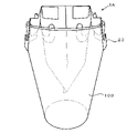
図1Aは、本発明の一実施例のドリップバッグ1Aの未開封状態の平面図であり、図1B~図1Eはこのドリップバッグ1Aの袋本体10の開口方法の説明図である。また、図2Aは、袋本体10が開口したドリップバッグ1Aをカップ100に掛止させた状態の斜視図であり、図2Bはその側面図である。このドリップバッグ1Aは、袋本体10と袋本体10の対向する2面の外表面、即ち、袋本体10の表裏に設けられた一対の掛止部材20で形成されている。
1A is a plan view of an unopened drip bag 1A according to an embodiment of the present invention, and FIGS. 1B to 1E are explanatory views of an opening method of a
(袋本体)
袋本体10は、通水濾過性シートから形成され、その内部には抽出材料50としてコーヒー粉が充填されている。
(Bag body)
The
袋本体10を形成する通水濾過性シートとしては、所定量のコーヒー粉を充填し、注湯した場合にコーヒーの浸出が可能であるものを種々使用することができる。一般に、浸出用シートとしては、例えば、ポリエステル、ナイロン、ポリエチレン、ポリプロピレン、ビニロン等の合成繊維、レーヨン等の半合成繊維、コウゾ、ミツマタ等の天然繊維の単独又は複合繊維からなる織布あるいは不織布、マニラ麻、木材パルプ、ポリプロピレン繊維等からなる混抄紙等、ティーバッグ原紙等の紙類が知られており、本発明においてもこれらを使用することができるが、ドリップバッグの使用後の廃棄性の点から、通水濾過性シート材料には生分解性繊維を含有させることが好ましい。生分解性繊維としては、ポリ乳酸、ポリブチレンサクシネート、ポリエチレンサクシネート等をあげることができる。また、ドリップ時にコーヒー粉に適度な蒸らし効果も付与できるようにするため、これらの繊維材料から通水濾過性シートを製造するに際しては、繊維層の空隙率を調整することによりコーヒー粉に直接接することとなる層を「疎」とし、直接には接しない層を「密」とする疎密の複層構造とし、かつコーヒー粉に直接接することとなる層では疎水性繊維の含有率を高め、コーヒー粉に直接接しない層では疎水性繊維の含有率を下げることが好ましい(特許第3674486号)。
As the water-permeable filterable sheet forming the
袋本体10は、上辺11aが通水濾過性シートの折山で輪になっており、下辺11b及び左右の側辺11c、11dがシールされた矩形の平袋であって、対向する2面を有している。袋本体10の上辺11aには、その全幅にわたり易開裂線として開封用ミシン目12が設けられている。開封用ミシン目12としては、ミシン目の開封を容易にする点から、マイクロミシン目を形成することが好ましい。
The
なお、本発明においては、上辺11aを折山とせず、対向する通水濾過性シートの縁辺を重ね合わせ、袋本体の上縁部となる部分を弱いシール強度でシールしてもよい。この袋本体10の上縁部の弱シール13は、開口操作以外で不用に剥離することはないが、袋本体10の他の辺のシールに比してシール強度を弱くすることが好ましい(図7)。また、本発明において、袋本体10の底部や側部には必要に応じてマチを設けても良い。
In the present invention, the
袋本体10の正味の平面寸法は、ドリップバッグを掛止するカップ又は容器の大きさに応じて適宜設定することができる。例えば、市販のコーヒーカップで使用できる大きさにすればよい。
The net planar dimensions of the
(掛止部材)
掛止部材20は、板紙、プラスチックシート等の薄板状材料の打ち抜きにより形成することができる。薄板状材料も、ドリップバッグ1Aの使用後の廃棄性の点から、ポリ乳酸、ポリブチレンサクシネート、ポリエチレンサクシネート等の生分解性材料から形成したものが好ましい。
(Hooking member)
The hooking
図1Aに示した実施例のドリップバッグ1Aでは、掛止部材20は、図1に斜線で塗りつぶした領域で袋本体10と貼着している。即ち、掛止部材20は、袋本体10との貼着域として上部中央貼着域S1を有している。この上部中央貼着域S1は、掛止部材20の幅方向中央部で易開裂線12に隣接する部分から下方に伸びている。ここで、袋本体10との貼着域とは、掛止部材20のうち、袋本体10と貼着している正味の部分をいい、貼着方法に制限はなく、熱溶着、超音波溶着、接着剤等を含む。また、上部中央貼着域S1の上端は、掛止部材20の上辺20aに重なっていてもよく、上辺20aの近傍にあってもよい。後述するように、袋本体10の表裏の掛止部23を互いに反対方向に引っ張って袋本体10の上縁部を開口するときに、その引っ張り力をより効果的に袋本体10の上縁部の中央部に集中的に作用させる点から、上部中央貼着域S1の上端と袋本体10の上辺11aとの距離L2(袋本体の上縁部に弱シール13が形成されている場合(図7)には、弱シール13との距離)は0~2mmとすることが好ましい。
In the drip bag 1A of the embodiment shown in FIG. 1A, the hooking
上部中央貼着域S1の左右両側には、掛止部材20と袋本体10との貼着域である上部側方貼着域S2が、上部中央貼着域S1から離間し、袋本体10の上縁部に沿って形成されている。また、上部中央貼着域S1の左右両側には、上部側方貼着域S2を含むことにより袋本体10から引き起こし不能の上部帯状部21が形成されている。上部帯状部21は袋本体10の上辺11aに沿って形成されている。上部側方貼着域S2や上部帯状部21は、袋本体10の上辺11aを開口し、ドリップバッグ1Aをカップに掛止させた状態で袋本体10の開口形状を維持する点から、設けることが好ましい。
On the left and right sides of the upper center attachment area S1, the upper side attachment area S2, which is the attachment area between the hooking
上部中央貼着域S1の下方の、掛止部材20の幅方向中央部には中央部25が形成されている。中央部25は中央部中央貼着域S3と中央部側方貼着域S4によって袋本体10から引き起こし不能となっている。なお、中央部中央貼着域S3と中央部側方貼着域S4を連続した貼着域としてもよい。また、本発明においては、貼着域によって袋本体に固定されている中央部25を省略することもできるが、ドリップバッグ1Aをカップに掛止させた状態での袋本体10の開口形状を安定させる点から中央部25を設けることが好ましい。
A
上部側方貼着域S2の下方には、袋本体10から引き起こし可能な掛止部23が、中央部25を囲むように形成されている。掛止部23は、上部中央貼着域S1の左右両側を挟むように上方に突出した突出部分24を有する。突出部分24は本発明のドリップバッグに特徴的な構成であり、この突出部分24を掛止部材20に設けることにより、袋本体10の表裏の掛止部23を互いに反対方向に引っ張ったときの引っ張り力を、上部中央貼着域S1の上端に隣接する袋本体の易開裂線12に集中的に作用させ、突出部分24が無い場合に比して袋本体10の開口に必要な引っ張り力を著しく低減させることが可能となる。
Below the upper lateral attachment area S2, a hooking
掛止部材20の上下方向の突出部分24の長さL5(即ち、突出部分24の上端24aと掛止部23の側辺の上端との掛止部材の上下方向の距離)は、上述の引っ張り力を袋本体10の開口により効果的に作用させる点から、掛止部材20の上端と突出部分24の基部24bとの掛止部材20の上下方向の距離(又は掛止部材20の上端と掛止部23の側辺の上端との掛止部材20の上下方向の距離)の30~100%が好ましい(図1A)。
The length L5 of the vertically protruding
掛止部23と上部中央貼着域S1とは薄板状材料が連続しており、突出部分24の引き起こされる部分と上部中央貼着域S1との間に、概略上下方向の一対の折れ線B3が形成されている。袋本体10の開口時に袋本体10の表裏の掛止部23を互いに反対方向に引っ張った場合に、折れ線B3が形成されていると掛止部材は折れ線B3で屈曲して掛止部23が起立し、その引っ張り力が上部中央貼着域S1に集中的に作用しやすくなり、上述の突出部分24の形成と相まって袋本体の開口が容易となる。引っ張り力を上部中央貼着域S1に集中させる作用は、折れ線B3の形成に加えて、後述する折れ線B4、B6の形成により、又は折れ線B5、B6の形成により、さらに効果的となる。なお、本発明において折れ線は、ミシン目、ハーフカット、筋押し等により形成することができる。
A thin plate-like material is continuous between the hooking
上部中央貼着域S1の左右両側の一対の折れ線B3の形成方向は、より詳細には、図4(a)に示すように、一対の折れ線B3の掛止部材幅方向の間隔が、上部から下部に向かって狭くなっており、該折れ線B3の下端における間隔L4bが上端における間隔L4tよりも狭く、一対の折れ線B3が逆ハ字型に形成されている。このように上部中央貼着域S1の両側の一対の折れ線B3を逆ハ字型とすることにより、袋本体10を開口し、ドリップバッグ1Aをカップ100に掛けた場合に、図4(b)に示すように、掛止部23でカップ100の側壁をしっかりと押さえることができるので好ましい。これに対し、図5(a)に示すドリップバッグ1A'のように、一対の折れ線B3が平行に掛止部材の上下方向に形成されていると、袋本体10を開口し、ドリップバッグ1A'をカップ100に掛け、開口部から袋本体10内に注湯し、袋本体10内が重くなると、カップ100の開口径や側壁の厚さなどによっては図5(b)に示すように掛止部23がカップ100の側壁から矢印方向にずり上がりやすくなる。さらに、図6(a)に示すドリップバッグ1A''のように、一対の折れ線B3の間隔が、該折れ線Bの上端よりも下端で広いハ字型になると、図6(b)に示すようにドリップバッグ1A''の掛止部23はカップ100の側壁から矢印方向にさらにずり上がりやすくなり、掛止部23がカップ100の側壁から外れる場合がある。
More specifically, as shown in FIG. 4A, the formation direction of the pair of polygonal lines B3 on the left and right sides of the upper center attachment area S1 is such that the distance between the pair of polygonal lines B3 in the width direction of the hooking member is from the upper part. The distance L4b at the lower end of the polygonal line B3 is narrower than the interval L4t at the upper end, and the pair of polygonal lines B3 are formed in an inverted C shape. When the
掛止部23は、該掛止部23の上部の左右両側に逆L字型部分23aを有し、その下部に、左右の逆L字型部分23aと連続するU字型部分23bを有する(図1A)。逆L字型部分23aがあることにより、掛止部23をカップ100の側壁に掛止することが容易となり、また、左右の逆L字型部分23aを繋ぐU字型部分23bがあることにより、掛止部23をカップ100の側壁に掛止した形態を安定させることができる。
The hooking
掛止部23の上部の左右両側の逆L字型部分23aには、それぞれ掛止部23の側辺に沿う折れ線B4がある。また、U字型部分23bには、掛止部23の下部中央部に一対の縦折れ線B6がある。これらの折れ線B4、B6や上述の折れ線B3があることにより、袋本体10を開口させるために、袋本体10の表裏の一対の掛止部23を引き起こし、互いに反対方向に引っ張った場合に、図1Cに示すように上部中央貼着域S1の両側で折れ線B3が屈曲し、上部中央貼着域S1の表面に対し、掛止部23のうち上部中央貼着域S1に隣接した部分が起立するので、引っ張り力が上部中央貼着域S1を介して袋本体10の上縁部の袋本体幅方向の中央部に集中しやすくなると共に、掛止部23内の折れ線B4、B6が屈曲し、掛止部23がよじれにくくなる。その結果、掛止部23を引っ張る力が袋本体10の易開裂線(ミシン目12)の袋本体幅方向の中央部に確実に作用し、袋本体10が容易に開口する。
The inverted L-shaped portions 23a on the left and right sides of the upper part of the hooking
なお、本発明においては、折れ線B4に代えて、図8に示したドリップバッグ1Cのように掛止部23の下部の両側部に一対の折れ線B5を形成してもよい。この折れ線B5の形成によっても、折れ線B4の形成と同様の効果を得ることができる。
In the present invention, instead of the polygonal line B4, a pair of polygonal lines B5 may be formed on both sides of the lower portion of the hooking
一方、ドリップバッグ1Aには掛止部材20の中央部25にも掛止部材20の上下方向に一対の折れ線B7が形成されている。折れ線B7が形成されていると、袋本体10の開口後に袋本体10が柱状の開口形状を維持しやすくなる。
On the other hand, in the drip bag 1A, a pair of polygonal lines B7 are formed in the
なお、本発明において折れ線B3、B4、B5、B6、B7は、掛止部材20を構成する薄板状材料のコシ、原紙強度等により必要に応じて設けられる。
In the present invention, the polygonal lines B3, B4, B5, B6, and B7 are provided as necessary depending on the stiffness of the thin plate-shaped material constituting the hooking
(ドリップバッグの使用方法)
ドリップバッグ1Aの使用方法としては、まず、袋本体10の表裏の掛止部材20にそれぞれ設けられている掛止部23のU字型部分23bの中央部23cを両手で摘まみ、互いに反対方向に引っ張る(図1B)。さらに引っ張ると折れ線B3で掛止部23が上部中央貼着域S1に対して起立するように掛止部材20が屈曲し、折れ線B4、B6も屈曲し(図1C)、さらに引っ張ると、袋本体10の表裏の掛止部材20の上辺11aの中央部が互いに離れ始め(図1D)、袋本体10の上辺11aの中央部で開封用ミシン目12が破断することにより袋本体10の開口が始まり、以降は速やかに袋本体10の上辺11aがその全幅にわたって開口する(図1E)。なお、図1Eにおいて符号50は、袋本体10内に充填されていた抽出材料50を表している。
(How to use the drip bag)
As a method of using the drip bag 1A, first, the central portion 23c of the
次に、袋本体10が開口したドリップバッグ1AのU字型部分23bの中央部23cを両手で摘まんだまま、そのドリップバッグ1Aをカップ100上に移動させ、掛止部23をカップ100の側壁に掛止させる(図2A、図2B)。そこで、袋本体10の開口部14から注湯し、カップ100内にコーヒー抽出液を得る。
Next, while holding the central portion 23c of the
袋本体10の開口方法としては、図3に示すように、袋本体10の表裏の掛止部材20の掛止部23を、掛止部23の左右の側辺23d同士が重なり合うように折りたたみ、その重ね合わせた部分を互いに反対方向に引っ張ってもよい。このように掛止部23を引っ張ることによっても、袋本体10の上辺11aの中央部からミシン目の破断が始まり、その破断が袋本体10の開口部の全幅に広がり、袋本田10を全幅で開口させることが可能となる。
As a method of opening the
ただし、このドリップバッグ1Aは、図2A、図2Bに示したように、カップ100に掛止させるときには、掛止部23が折り畳まれていない状態でU字型部分23bがカップ100の側壁を押さえつけるようにするので、図3に示したように掛止部23を折り畳んでドリップバッグ1Aを開口した場合には、折りたたんだ掛止部23を広げてカップに掛止させることが必要となる。そのため、袋本体10の開口からカップ100への掛止までを連続的な操作で行うことができなくなる。
However, as shown in FIGS. 2A and 2B, when the drip bag 1A is hooked on the
(ドリップバッグの製造方法)
ドリップバッグ1Aの製造方法としては、図15に示すように、長尺の通水濾過性シート41に掛止部材20を所定間隔で並べて貼着したドリップバッグ製造用シート40Aを用意する。尚、同図において、隣り合う二点鎖線で挟まれた領域が、ドリップバッグ1個
分の製造に使用される領域となる。
(Manufacturing method of drip bag)
As a method for manufacturing the drip bag 1A, as shown in FIG. 15, a drip
このドリップバッグ製造用シート40Aの製造に際しては、ドリップバッグ1Aの開封用ミシン目12となる長尺のミシン目42を、予め長尺の通水濾過性シート41に形成しておくことが好ましい。
In manufacturing the drip
次に、掛止部材20と通水濾過性シート41とを合わせ、図1Aに斜線で塗りつぶした貼着域で掛止部材20と通水濾過性シート41とを貼着する。図15中一番上の掛止部材20にこの斜線で塗りつぶした貼着域を示す。
Next, the hooking
掛止部材20と通水濾過性シート41との貼着を、通水濾過性シート41側から加熱ヘッドをあて、通水濾過性シート41と掛止部材20とを熱溶着させることにより行う場合、本来の貼着域と共に、袋本体10の開封開始部となる部分にも加熱ヘッドをあて、通水濾過性シート41に脆弱化部分を形成することが好ましい。この脆弱化部分の形成により袋本体10の開封に必要とされる力を特に低減させることができるので好ましい。
When the hooking
ドリップバッグ1Aは、ドリップバッグ製造用シート40Aを充填包装機で用いることにより連続的に製造することができる。この場合、図16に示すように、ドリップバッグ製造用シート40Aの長手方向の両側辺を重ね合わせるように二つ折りにし、その長手方向の側辺同士を溶着(縦シール)ことにより筒状体を形成し、ドリップバッグ1Aの袋本体の下辺11bを形成する。次に、筒状体の短手方向の溶着(横シール)と袋本体10内への内容物の充填を交互に繰り返すことによりドリップバッグ1Aの袋本体10の側辺11c、11dが上下に繋がったドリップバッグを製造し、これを個々のドリップバッグ1Aに切り離して個々のドリップバッグ1Aを得る。あるいは、袋本体10の側辺11c、11dの溶着時に溶断も同時に行い、個々に切り離されたドリップバッグ1Aを連続的に製造する。
The drip bag 1A can be continuously manufactured by using the drip
なお、袋本体10の上辺11aを折山とせず、図7に示したように、袋本体10の上縁bに弱シール13を形成し、袋本体10の下辺11bを折山とする場合には、図17に示すように、長尺の通水濾過性シート41の両側辺に掛止部材20の上部帯状部21が沿うように掛止部材20を貼着したドリップバッグ製造用シート40Bを使用することができる。
When the
この場合、ドリップバッグ製造用シート40Bに形成する縦シールが、ドリップバッグ1Aの袋本体10の上縁部となるから、縦シールは横シールよりも弱くするが、不用意にシール部分が開裂し、内容物がこぼれない程度に形成することが好ましい。
In this case, since the vertical seal formed on the drip
(変形態様)
本発明のドリップバッグは、上述のドリップバッグ1A、1B、1Cの他にも種々の態様をとることができる。
例えば、掛止部23の形状としては、図9に示したドリップバッグ1Dのように、掛止部23の左右両側に逆L字型部分23aを有するが、それらの下部を繋ぐU字型部分23bを省略した形状としてもよい。このドリップバッグ1Dでは、図3に示したように、掛止部23を折りたたんで引っ張り、袋本体10を開口した後、掛止部23を持ち替えることなく、カップに掛止させることができる。
(Deformation mode)
The drip bag of the present invention can take various aspects other than the above-mentioned
For example, the shape of the hooking
図10に示したドリップバッグ1Eのように、掛止部23の突出部分24が掛止部材20の上辺20aに達しておらず、上部帯状部21を掛止部材20の全幅にわたって連続させてもよい。この場合、上部中央貼着域S1と上部側方貼着域S2を連続させてもよい。上部帯状部21を掛止部材20の全幅にわたって連続させることにより、袋本体10を開口し、ドリップバッグ1Eをカップに掛止させた場合に、カップの開口径が大きいために袋本体の上部中央部が掛止部23によって強く引っ張られても、ドリップバッグの開口形状が扁平化することを抑えることができる。
Even if the protruding
上部帯状部21を掛止部材20の全幅にわたって連続的に形成する場合に、図11に示したドリップバッグ1Fのように、上部側方貼着域S2を断続的に形成してもよい。
When the upper band-shaped
図12に示したドリップバッグ1Gのように、袋本体10の表裏の掛止部材の上部帯状部21を連続させてもよい。このドリップバッグ1Gは、図18に示したドリップバッグ製造用シート40Cを用いて製造することができる。このドリップバッグ製造用シート40Cによれば、袋本体の表裏の掛止部材20が連続しているので、ドリップバッグ製造用シート40Cの製造時に掛止部材20の位置ずれが起こりにくくなるので好ましい。また、ドリップバッグ製造用シート40Cを用いてドリップバッグ1Gを製造する際には、縦シールによりドリップバッグ製造用シート40Cの筒状体を形成し、次に筒状体の横シールと内容物の充填を交互に繰り返すが、1回の横シールで製造されるドリップバッグ1Gの袋本体の上縁部は弱シールとし、底部は強シール13とすることが好ましい。このようなシールは、例えば、特開2017-19513号公報に記載の超音波溶着溶断装置を用いて行うことができる。
Like the
掛止部23の突出部分24の形状としては、図13に示したドリップバッグ1Hのように突出部分24の上端24aを掛止部材20の上辺20aに達しさせると共に、突出部分24の基部24bを掛止部23の側辺の上端とし、突出部分24の上端24aと基部24bとの間の突出部分24の輪郭を直線状に形成し、突出部分24と袋本体10の上辺11aとの間隙をうめるように、上部帯状部21を三角形状に形成してもよい。あるいは、図14に示したドリップバッグ1Iのように上部帯状部21を極限まで小さくし、上部帯状部21が上部側方貼着域S2と一致するようにしてもよい。また、袋本体10を形成する通水濾過性シートとして剛性の高いものを使用した場合などには、上部側方貼着域S2を省略しても、袋本体10の開口後に、開口部が広く開いた開口形状を維持することができる。
As for the shape of the protruding
上述したドリップバッグの変形部分は適宜組み合わせることができる。 The deformed portions of the drip bag described above can be combined as appropriate.
以上、袋本体10にコーヒー粉を充填したドリップバッグについて、説明したが、本発明のドリップバッグの袋本体10に充填する抽出材料50はコーヒー粉に限らない。紅茶、緑茶等の茶葉、漢方薬等を充填してもよい。
The drip bag in which the
以下、実施例に基づいて本発明を具体的に説明する。
実施例1、2、比較例1
(1)ドリップバッグの作製
実施例1として、図1Aに示したドリップバッグ1Aを作製した。この場合、袋本体10を形成する通水濾過性シートとしては、ポリエステルを主体とする短繊維からなる湿式不織布とポリプロピレン製のメルトブロー不織布とを部分熱圧着により一体化した不織布(大紀商事株式会社製)を使用し、袋本体10の上辺の折山部分には開封用ミシン目12が位置するようにした。袋本体10は、幅W1が80mm、高さH1が100mmの平袋とした。
Hereinafter, the present invention will be specifically described based on examples.
Examples 1 and 2, Comparative Example 1
(1) Preparation of drip bag As Example 1, the drip bag 1A shown in FIG. 1A was prepared. In this case, as the water-permeable filterable sheet forming the
掛止部材20は、カップ原紙にポリプロピレンをラミネートした板紙から次の寸法に形成した。
掛止部材の高さH2:42mm、
掛止部材の幅W2:62mm、
掛止部材上下方向の突出部分の長さL5:14mm、
一対の折れ線B3の上端同士の間隔L4t:10mm、
一対の折れ線B3の下端同士の間隔L4b:4mm
The hooking
Height of hooking member H2: 42 mm,
Width of hook member W2: 62 mm,
Length of protruding part in the vertical direction of the hooking member L5: 14 mm,
Spacing between the upper ends of the pair of polygonal lines B3 L4t: 10 mm,
Spacing between the lower ends of the pair of polygonal lines B3 L4b: 4 mm
実施例2として、突出部分24の長さL5を5mmとする以外は、実施例1と同様のドリップバッグ1Eを作製した(図10)。
As Example 2, a
比較例1として、突出部分を形成しない以外は実施例1と同様のドリップバッグ1Xを作製した(図19)。
As Comparative Example 1, a
(2)引っ張り試験
図20に示すように、各実施例及び比較例のドリップバッグの袋本体の表裏の掛止部23のU字型部分の中央部23cにそれぞれ粘着テープを貼り付けて持ち手30とし、持ち手30を引っ張り試験機の治具で挟持して互いに反対方向に引っ張り、掴み間隔L10の伸び量と引張強度を測定した。この引っ張り試験では、当初伸び量の増加に応じて引張強度が増加するが、袋本体の開封用ミシン目12が開裂すると急激に引張強度がゼロになる。そこで、この開裂直前の引張強度を開裂時の引張強度とした。引っ張り試験は各実施例及び比較例について5回繰り返し、開封用ミシン目12の開裂時の引張強度の平均を求めた。結果を以下に示す。
(2) Pull test As shown in FIG. 20, an adhesive tape is attached to the central portion 23c of the U-shaped portion of the front and back hooking
実施例1:引張強度1.85N
実施例2:引張強度3.61N
比較例1:引張強度5.11N
Example 1: Tensile strength 1.85N
Example 2: Tensile strength 3.61N
Comparative Example 1: Tensile strength 5.11N
この結果から、掛止部に突出部分を形成することが、袋本体の開口に要する引張強度を低下させることが確認できた。 From this result, it was confirmed that forming the protruding portion in the hooking portion reduces the tensile strength required for the opening of the bag body.
1A、1A'、1A''、1B、1C、1D、1E、1F、1G,1H、1I ドリップバッグ
10 袋本体
11a 上辺
11b 下辺
11c 側辺
11d 側辺
12 開封用ミシン目、易開裂線
13 弱シール
14 開口部
20 掛止部材
20a 掛止部材の上辺
21 上部帯状部
23 掛止部
23a 逆L字型部分
23b U字型部分
23c U字型部分の中央部
23d 掛止部の側辺
24 突出部分
24a 突出部分の上端
24b 突出部分の基部
25 中央部
30 持ち手
40A、40B、40C ドリップバッグ製造用シート
41 長尺の通水濾過性シート
42 ミシン目
50 抽出材料
100 カップ
B3 上部中央貼着域と掛止部との間の折れ線
B4、B5、B6 掛止部の折れ線
B7 中央部の折れ線
L2 上部中央貼着域の上端部と袋本体の上辺との距離
L4t 一対の折れ線B3の上端同士の間隔
L4b 一対の折れ線B3の下端同士の間隔
L5 掛止部材の上下方向の突出部分の長さ
L10 掴み間隔
S1 上部中央貼着域
S2 上部側方貼着域
S3 中央部中央貼着域
S4 中央部側方貼着域
W1 袋本体の幅
W2 掛止部材の幅
H1 袋本体の高さ
H2 掛止部材の高さ
1A, 1A', 1A'', 1B, 1C, 1D, 1E, 1F, 1G, 1H, 1I Drip bag 10 Bag body 11a Upper side 11b Lower side 11c Side side 11d Side side 12 Opening perforation, easy opening line 13 Weak Seal 14 Opening 20 Hanging member 20a Upper side of hanging member 21 Upper band-shaped part 23 Hanging part 23a Inverted L-shaped part 23b U-shaped part 23c Central part of U-shaped part 23d Side side of hooking part 24 Projection Part 24a Upper end of protruding part 24b Base of protruding part 25 Central part 30 Handle 40A, 40B, 40C Sheet for manufacturing drip bag 41 Long water-permeable filterable sheet 42 Perforation 50 Extraction material 100 Cup B3 Upper center attachment area Bag line between the bag and the bag B4, B5, B6 Bag line B7 Center bag line L2 Distance between the upper end of the upper center attachment area and the upper side of the bag body L4t Between the upper ends of the pair of bag lines B3 Spacing L4b Spacing between the lower ends of the pair of bent lines B3 L5 Length of the protruding portion in the vertical direction of the hooking member L10 Gripping spacing S1 Upper center sticking area S2 Upper side sticking area S3 Central part Central sticking area S4 Central part Side attachment area W1 Width of bag body W2 Width of bag member H1 Height of bag body H2 Height of bag member
Claims (8)
袋本体は、その上縁部に易開裂線を有し、
掛止部材は、袋本体との貼着域として該掛止部材の幅方向中央部の易開裂線に隣接する部分から下方に伸びた上部中央貼着域を有すると共に、上部中央貼着域と連続し、袋本体から引き起こし可能に形成された掛止部を有し、
掛止部は、上部中央貼着域の左右両側を挟むように上方に突出した、袋本体から引き起こし可能な突出部分を有するドリップバッグ。 A bag body made of a water-permeable filterable sheet, a bag made of a thin plate-like material provided on the outer surfaces of two facing surfaces of the bag body, and a drip bag made of an extract material filled in the bag body. There,
The bag body has an easy split line on its upper edge,
The hooking member has an upper center sticking area extending downward from a portion adjacent to the easy-opening line at the center of the width direction of the bag body as a sticking area to the bag body, and also has an upper center sticking area. It has a hook that is continuous and can be raised from the bag body and is formed.
The hook is a drip bag that has a protruding part that can be raised from the bag body and protrudes upward so as to sandwich the left and right sides of the upper center sticking area.
Priority Applications (1)
| Application Number | Priority Date | Filing Date | Title |
|---|---|---|---|
| JP2018081517A JP7094507B2 (en) | 2018-04-20 | 2018-04-20 | Drip bag |
Applications Claiming Priority (1)
| Application Number | Priority Date | Filing Date | Title |
|---|---|---|---|
| JP2018081517A JP7094507B2 (en) | 2018-04-20 | 2018-04-20 | Drip bag |
Publications (3)
| Publication Number | Publication Date |
|---|---|
| JP2019187631A JP2019187631A (en) | 2019-10-31 |
| JP2019187631A5 JP2019187631A5 (en) | 2020-12-24 |
| JP7094507B2 true JP7094507B2 (en) | 2022-07-04 |
Family
ID=68388008
Family Applications (1)
| Application Number | Title | Priority Date | Filing Date |
|---|---|---|---|
| JP2018081517A Active JP7094507B2 (en) | 2018-04-20 | 2018-04-20 | Drip bag |
Country Status (1)
| Country | Link |
|---|---|
| JP (1) | JP7094507B2 (en) |
Families Citing this family (2)
| Publication number | Priority date | Publication date | Assignee | Title |
|---|---|---|---|---|
| CN110840253A (en) * | 2019-12-10 | 2020-02-28 | 谢成豪 | Coffee cup |
| US11643270B2 (en) * | 2020-03-11 | 2023-05-09 | Ohki Co., Ltd. | Extraction bag |
Citations (4)
| Publication number | Priority date | Publication date | Assignee | Title |
|---|---|---|---|---|
| JP2007230649A (en) | 2006-01-31 | 2007-09-13 | Naoki Sugiyama | Hooking member of drip bag |
| JP2008050021A (en) | 2006-08-23 | 2008-03-06 | Key Coffee Inc | Drip bag |
| JP2014094255A (en) | 2012-11-07 | 2014-05-22 | Keiichi Kikuchi | Simple dripper |
| JP2015205055A (en) | 2014-04-21 | 2015-11-19 | 片岡物産株式会社 | Simple type filter |
-
2018
- 2018-04-20 JP JP2018081517A patent/JP7094507B2/en active Active
Patent Citations (4)
| Publication number | Priority date | Publication date | Assignee | Title |
|---|---|---|---|---|
| JP2007230649A (en) | 2006-01-31 | 2007-09-13 | Naoki Sugiyama | Hooking member of drip bag |
| JP2008050021A (en) | 2006-08-23 | 2008-03-06 | Key Coffee Inc | Drip bag |
| JP2014094255A (en) | 2012-11-07 | 2014-05-22 | Keiichi Kikuchi | Simple dripper |
| JP2015205055A (en) | 2014-04-21 | 2015-11-19 | 片岡物産株式会社 | Simple type filter |
Also Published As
| Publication number | Publication date |
|---|---|
| JP2019187631A (en) | 2019-10-31 |
Similar Documents
| Publication | Publication Date | Title |
|---|---|---|
| TWI557044B (en) | Filter bag | |
| JP5593989B2 (en) | Drip bag seat | |
| WO2014091567A1 (en) | Drip bag | |
| JP7094507B2 (en) | Drip bag | |
| JP6750662B2 (en) | Drip bag | |
| JP7148907B2 (en) | drip bag | |
| JP5071640B2 (en) | Drip bag | |
| JP5640754B2 (en) | Drip bag | |
| JP7357405B2 (en) | extraction bag | |
| JP7129081B2 (en) | drip bag | |
| JP7249644B2 (en) | drip bag | |
| WO2021171655A1 (en) | Drip bag | |
| JP6657624B2 (en) | Ultrasonic welding and fusing device and package | |
| JP6710385B1 (en) | Extraction bag | |
| JP5858172B2 (en) | Drip bag | |
| WO2021214957A1 (en) | Extraction bag | |
| JP2020025855A (en) | Drip bag | |
| JP7452859B2 (en) | drip bag | |
| JP5892262B2 (en) | Drip bag | |
| WO2021181555A1 (en) | Extraction bag | |
| JP2024033613A (en) | drip bag | |
| JP2023055568A (en) | drip bag | |
| TW202140346A (en) | Extraction bag being capable of obtaining an extraction liquid by dipping the bag body into hot water |
Legal Events
| Date | Code | Title | Description |
|---|---|---|---|
| RD01 | Notification of change of attorney |
Free format text: JAPANESE INTERMEDIATE CODE: A7426 Effective date: 20180521 |
|
| A521 | Request for written amendment filed |
Free format text: JAPANESE INTERMEDIATE CODE: A821 Effective date: 20180521 |
|
| A521 | Request for written amendment filed |
Free format text: JAPANESE INTERMEDIATE CODE: A523 Effective date: 20201112 |
|
| A621 | Written request for application examination |
Free format text: JAPANESE INTERMEDIATE CODE: A621 Effective date: 20201112 |
|
| A977 | Report on retrieval |
Free format text: JAPANESE INTERMEDIATE CODE: A971007 Effective date: 20211021 |
|
| A131 | Notification of reasons for refusal |
Free format text: JAPANESE INTERMEDIATE CODE: A131 Effective date: 20211102 |
|
| A521 | Request for written amendment filed |
Free format text: JAPANESE INTERMEDIATE CODE: A523 Effective date: 20211227 |
|
| TRDD | Decision of grant or rejection written | ||
| A01 | Written decision to grant a patent or to grant a registration (utility model) |
Free format text: JAPANESE INTERMEDIATE CODE: A01 Effective date: 20220517 |
|
| A61 | First payment of annual fees (during grant procedure) |
Free format text: JAPANESE INTERMEDIATE CODE: A61 Effective date: 20220610 |
|
| R150 | Certificate of patent or registration of utility model |
Ref document number: 7094507 Country of ref document: JP Free format text: JAPANESE INTERMEDIATE CODE: R150 |