JP7093182B2 - Devices for diagnosing patient ventilation effectiveness and methods for determining patient ventilation effectiveness - Google Patents
Devices for diagnosing patient ventilation effectiveness and methods for determining patient ventilation effectiveness Download PDFInfo
- Publication number
- JP7093182B2 JP7093182B2 JP2017564354A JP2017564354A JP7093182B2 JP 7093182 B2 JP7093182 B2 JP 7093182B2 JP 2017564354 A JP2017564354 A JP 2017564354A JP 2017564354 A JP2017564354 A JP 2017564354A JP 7093182 B2 JP7093182 B2 JP 7093182B2
- Authority
- JP
- Japan
- Prior art keywords
- ventilation
- patient
- parameters
- volume
- sensor
- Prior art date
- Legal status (The legal status is an assumption and is not a legal conclusion. Google has not performed a legal analysis and makes no representation as to the accuracy of the status listed.)
- Active
Links
- 238000009423 ventilation Methods 0.000 title claims description 208
- 238000000034 method Methods 0.000 title claims description 37
- 230000000241 respiratory effect Effects 0.000 claims description 23
- 210000004072 lung Anatomy 0.000 claims description 18
- 230000008569 process Effects 0.000 claims description 12
- 230000002457 bidirectional effect Effects 0.000 claims description 7
- 238000012986 modification Methods 0.000 claims description 7
- 230000004048 modification Effects 0.000 claims description 7
- 108700025647 major vault Proteins 0.000 claims description 6
- 238000012937 correction Methods 0.000 claims description 4
- 230000035479 physiological effects, processes and functions Effects 0.000 claims description 2
- 230000029058 respiratory gaseous exchange Effects 0.000 description 11
- 238000004364 calculation method Methods 0.000 description 8
- 238000005259 measurement Methods 0.000 description 8
- 230000003434 inspiratory effect Effects 0.000 description 7
- 238000004458 analytical method Methods 0.000 description 4
- 238000001514 detection method Methods 0.000 description 4
- 230000036541 health Effects 0.000 description 4
- 239000012530 fluid Substances 0.000 description 3
- 208000010496 Heart Arrest Diseases 0.000 description 2
- QVGXLLKOCUKJST-UHFFFAOYSA-N atomic oxygen Chemical compound [O] QVGXLLKOCUKJST-UHFFFAOYSA-N 0.000 description 2
- 238000011161 development Methods 0.000 description 2
- 230000003287 optical effect Effects 0.000 description 2
- 239000001301 oxygen Substances 0.000 description 2
- 229910052760 oxygen Inorganic materials 0.000 description 2
- 230000036412 respiratory physiology Effects 0.000 description 2
- 230000002269 spontaneous effect Effects 0.000 description 2
- 208000008203 tachypnea Diseases 0.000 description 2
- 206010043089 tachypnoea Diseases 0.000 description 2
- 238000011144 upstream manufacturing Methods 0.000 description 2
- 206010002091 Anaesthesia Diseases 0.000 description 1
- 208000000059 Dyspnea Diseases 0.000 description 1
- 206010013975 Dyspnoeas Diseases 0.000 description 1
- 238000004566 IR spectroscopy Methods 0.000 description 1
- 206010038687 Respiratory distress Diseases 0.000 description 1
- 230000037005 anaesthesia Effects 0.000 description 1
- 230000008901 benefit Effects 0.000 description 1
- 230000035565 breathing frequency Effects 0.000 description 1
- 238000002680 cardiopulmonary resuscitation Methods 0.000 description 1
- 210000000748 cardiovascular system Anatomy 0.000 description 1
- 230000008859 change Effects 0.000 description 1
- 239000003086 colorant Substances 0.000 description 1
- 230000006835 compression Effects 0.000 description 1
- 238000007906 compression Methods 0.000 description 1
- 238000003745 diagnosis Methods 0.000 description 1
- 238000010586 diagram Methods 0.000 description 1
- 239000006185 dispersion Substances 0.000 description 1
- 238000001914 filtration Methods 0.000 description 1
- 239000007789 gas Substances 0.000 description 1
- 230000005484 gravity Effects 0.000 description 1
- 230000003993 interaction Effects 0.000 description 1
- 238000001361 intraarterial administration Methods 0.000 description 1
- 238000007726 management method Methods 0.000 description 1
- 239000000203 mixture Substances 0.000 description 1
- 238000012544 monitoring process Methods 0.000 description 1
- 230000007170 pathology Effects 0.000 description 1
- 238000012545 processing Methods 0.000 description 1
- 230000009467 reduction Effects 0.000 description 1
- 238000011160 research Methods 0.000 description 1
- 230000004202 respiratory function Effects 0.000 description 1
- 210000002345 respiratory system Anatomy 0.000 description 1
- 230000004044 response Effects 0.000 description 1
- 230000003797 telogen phase Effects 0.000 description 1
- 238000012549 training Methods 0.000 description 1
- 230000003519 ventilatory effect Effects 0.000 description 1
- 230000000007 visual effect Effects 0.000 description 1
Images


Classifications
-
- A—HUMAN NECESSITIES
- A61—MEDICAL OR VETERINARY SCIENCE; HYGIENE
- A61B—DIAGNOSIS; SURGERY; IDENTIFICATION
- A61B5/00—Measuring for diagnostic purposes; Identification of persons
- A61B5/48—Other medical applications
- A61B5/4836—Diagnosis combined with treatment in closed-loop systems or methods
-
- A—HUMAN NECESSITIES
- A61—MEDICAL OR VETERINARY SCIENCE; HYGIENE
- A61B—DIAGNOSIS; SURGERY; IDENTIFICATION
- A61B5/00—Measuring for diagnostic purposes; Identification of persons
- A61B5/48—Other medical applications
- A61B5/4848—Monitoring or testing the effects of treatment, e.g. of medication
-
- A—HUMAN NECESSITIES
- A61—MEDICAL OR VETERINARY SCIENCE; HYGIENE
- A61B—DIAGNOSIS; SURGERY; IDENTIFICATION
- A61B5/00—Measuring for diagnostic purposes; Identification of persons
- A61B5/08—Detecting, measuring or recording devices for evaluating the respiratory organs
- A61B5/087—Measuring breath flow
- A61B5/0878—Measuring breath flow using temperature sensing means
-
- A—HUMAN NECESSITIES
- A61—MEDICAL OR VETERINARY SCIENCE; HYGIENE
- A61B—DIAGNOSIS; SURGERY; IDENTIFICATION
- A61B5/00—Measuring for diagnostic purposes; Identification of persons
- A61B5/74—Details of notification to user or communication with user or patient ; user input means
- A61B5/746—Alarms related to a physiological condition, e.g. details of setting alarm thresholds or avoiding false alarms
-
- A—HUMAN NECESSITIES
- A61—MEDICAL OR VETERINARY SCIENCE; HYGIENE
- A61M—DEVICES FOR INTRODUCING MEDIA INTO, OR ONTO, THE BODY; DEVICES FOR TRANSDUCING BODY MEDIA OR FOR TAKING MEDIA FROM THE BODY; DEVICES FOR PRODUCING OR ENDING SLEEP OR STUPOR
- A61M16/00—Devices for influencing the respiratory system of patients by gas treatment, e.g. mouth-to-mouth respiration; Tracheal tubes
- A61M16/0051—Devices for influencing the respiratory system of patients by gas treatment, e.g. mouth-to-mouth respiration; Tracheal tubes with alarm devices
-
- A—HUMAN NECESSITIES
- A61—MEDICAL OR VETERINARY SCIENCE; HYGIENE
- A61M—DEVICES FOR INTRODUCING MEDIA INTO, OR ONTO, THE BODY; DEVICES FOR TRANSDUCING BODY MEDIA OR FOR TAKING MEDIA FROM THE BODY; DEVICES FOR PRODUCING OR ENDING SLEEP OR STUPOR
- A61M16/00—Devices for influencing the respiratory system of patients by gas treatment, e.g. mouth-to-mouth respiration; Tracheal tubes
- A61M16/0057—Pumps therefor
- A61M16/0078—Breathing bags
-
- A—HUMAN NECESSITIES
- A61—MEDICAL OR VETERINARY SCIENCE; HYGIENE
- A61M—DEVICES FOR INTRODUCING MEDIA INTO, OR ONTO, THE BODY; DEVICES FOR TRANSDUCING BODY MEDIA OR FOR TAKING MEDIA FROM THE BODY; DEVICES FOR PRODUCING OR ENDING SLEEP OR STUPOR
- A61M16/00—Devices for influencing the respiratory system of patients by gas treatment, e.g. mouth-to-mouth respiration; Tracheal tubes
- A61M16/0057—Pumps therefor
- A61M16/0084—Pumps therefor self-reinflatable by elasticity, e.g. resuscitation squeeze bags
-
- A—HUMAN NECESSITIES
- A61—MEDICAL OR VETERINARY SCIENCE; HYGIENE
- A61M—DEVICES FOR INTRODUCING MEDIA INTO, OR ONTO, THE BODY; DEVICES FOR TRANSDUCING BODY MEDIA OR FOR TAKING MEDIA FROM THE BODY; DEVICES FOR PRODUCING OR ENDING SLEEP OR STUPOR
- A61M16/00—Devices for influencing the respiratory system of patients by gas treatment, e.g. mouth-to-mouth respiration; Tracheal tubes
- A61M16/021—Devices for influencing the respiratory system of patients by gas treatment, e.g. mouth-to-mouth respiration; Tracheal tubes operated by electrical means
- A61M16/022—Control means therefor
- A61M16/024—Control means therefor including calculation means, e.g. using a processor
-
- A—HUMAN NECESSITIES
- A61—MEDICAL OR VETERINARY SCIENCE; HYGIENE
- A61B—DIAGNOSIS; SURGERY; IDENTIFICATION
- A61B2560/00—Constructional details of operational features of apparatus; Accessories for medical measuring apparatus
- A61B2560/04—Constructional details of apparatus
- A61B2560/0443—Modular apparatus
- A61B2560/045—Modular apparatus with a separable interface unit, e.g. for communication
-
- A—HUMAN NECESSITIES
- A61—MEDICAL OR VETERINARY SCIENCE; HYGIENE
- A61B—DIAGNOSIS; SURGERY; IDENTIFICATION
- A61B5/00—Measuring for diagnostic purposes; Identification of persons
- A61B5/68—Arrangements of detecting, measuring or recording means, e.g. sensors, in relation to patient
- A61B5/6801—Arrangements of detecting, measuring or recording means, e.g. sensors, in relation to patient specially adapted to be attached to or worn on the body surface
- A61B5/6802—Sensor mounted on worn items
- A61B5/6803—Head-worn items, e.g. helmets, masks, headphones or goggles
-
- A—HUMAN NECESSITIES
- A61—MEDICAL OR VETERINARY SCIENCE; HYGIENE
- A61M—DEVICES FOR INTRODUCING MEDIA INTO, OR ONTO, THE BODY; DEVICES FOR TRANSDUCING BODY MEDIA OR FOR TAKING MEDIA FROM THE BODY; DEVICES FOR PRODUCING OR ENDING SLEEP OR STUPOR
- A61M16/00—Devices for influencing the respiratory system of patients by gas treatment, e.g. mouth-to-mouth respiration; Tracheal tubes
- A61M16/0003—Accessories therefor, e.g. sensors, vibrators, negative pressure
- A61M2016/0027—Accessories therefor, e.g. sensors, vibrators, negative pressure pressure meter
-
- A—HUMAN NECESSITIES
- A61—MEDICAL OR VETERINARY SCIENCE; HYGIENE
- A61M—DEVICES FOR INTRODUCING MEDIA INTO, OR ONTO, THE BODY; DEVICES FOR TRANSDUCING BODY MEDIA OR FOR TAKING MEDIA FROM THE BODY; DEVICES FOR PRODUCING OR ENDING SLEEP OR STUPOR
- A61M16/00—Devices for influencing the respiratory system of patients by gas treatment, e.g. mouth-to-mouth respiration; Tracheal tubes
- A61M16/0003—Accessories therefor, e.g. sensors, vibrators, negative pressure
- A61M2016/003—Accessories therefor, e.g. sensors, vibrators, negative pressure with a flowmeter
- A61M2016/0033—Accessories therefor, e.g. sensors, vibrators, negative pressure with a flowmeter electrical
- A61M2016/0036—Accessories therefor, e.g. sensors, vibrators, negative pressure with a flowmeter electrical in the breathing tube and used in both inspiratory and expiratory phase
-
- A—HUMAN NECESSITIES
- A61—MEDICAL OR VETERINARY SCIENCE; HYGIENE
- A61M—DEVICES FOR INTRODUCING MEDIA INTO, OR ONTO, THE BODY; DEVICES FOR TRANSDUCING BODY MEDIA OR FOR TAKING MEDIA FROM THE BODY; DEVICES FOR PRODUCING OR ENDING SLEEP OR STUPOR
- A61M2205/00—General characteristics of the apparatus
- A61M2205/15—Detection of leaks
-
- A—HUMAN NECESSITIES
- A61—MEDICAL OR VETERINARY SCIENCE; HYGIENE
- A61M—DEVICES FOR INTRODUCING MEDIA INTO, OR ONTO, THE BODY; DEVICES FOR TRANSDUCING BODY MEDIA OR FOR TAKING MEDIA FROM THE BODY; DEVICES FOR PRODUCING OR ENDING SLEEP OR STUPOR
- A61M2205/00—General characteristics of the apparatus
- A61M2205/18—General characteristics of the apparatus with alarm
-
- A—HUMAN NECESSITIES
- A61—MEDICAL OR VETERINARY SCIENCE; HYGIENE
- A61M—DEVICES FOR INTRODUCING MEDIA INTO, OR ONTO, THE BODY; DEVICES FOR TRANSDUCING BODY MEDIA OR FOR TAKING MEDIA FROM THE BODY; DEVICES FOR PRODUCING OR ENDING SLEEP OR STUPOR
- A61M2205/00—General characteristics of the apparatus
- A61M2205/27—General characteristics of the apparatus preventing use
- A61M2205/273—General characteristics of the apparatus preventing use preventing reuse, e.g. of disposables
-
- A—HUMAN NECESSITIES
- A61—MEDICAL OR VETERINARY SCIENCE; HYGIENE
- A61M—DEVICES FOR INTRODUCING MEDIA INTO, OR ONTO, THE BODY; DEVICES FOR TRANSDUCING BODY MEDIA OR FOR TAKING MEDIA FROM THE BODY; DEVICES FOR PRODUCING OR ENDING SLEEP OR STUPOR
- A61M2205/00—General characteristics of the apparatus
- A61M2205/33—Controlling, regulating or measuring
- A61M2205/3331—Pressure; Flow
- A61M2205/3334—Measuring or controlling the flow rate
-
- A—HUMAN NECESSITIES
- A61—MEDICAL OR VETERINARY SCIENCE; HYGIENE
- A61M—DEVICES FOR INTRODUCING MEDIA INTO, OR ONTO, THE BODY; DEVICES FOR TRANSDUCING BODY MEDIA OR FOR TAKING MEDIA FROM THE BODY; DEVICES FOR PRODUCING OR ENDING SLEEP OR STUPOR
- A61M2205/00—General characteristics of the apparatus
- A61M2205/50—General characteristics of the apparatus with microprocessors or computers
- A61M2205/502—User interfaces, e.g. screens or keyboards
-
- A—HUMAN NECESSITIES
- A61—MEDICAL OR VETERINARY SCIENCE; HYGIENE
- A61M—DEVICES FOR INTRODUCING MEDIA INTO, OR ONTO, THE BODY; DEVICES FOR TRANSDUCING BODY MEDIA OR FOR TAKING MEDIA FROM THE BODY; DEVICES FOR PRODUCING OR ENDING SLEEP OR STUPOR
- A61M2205/00—General characteristics of the apparatus
- A61M2205/58—Means for facilitating use, e.g. by people with impaired vision
- A61M2205/583—Means for facilitating use, e.g. by people with impaired vision by visual feedback
- A61M2205/584—Means for facilitating use, e.g. by people with impaired vision by visual feedback having a color code
-
- A—HUMAN NECESSITIES
- A61—MEDICAL OR VETERINARY SCIENCE; HYGIENE
- A61M—DEVICES FOR INTRODUCING MEDIA INTO, OR ONTO, THE BODY; DEVICES FOR TRANSDUCING BODY MEDIA OR FOR TAKING MEDIA FROM THE BODY; DEVICES FOR PRODUCING OR ENDING SLEEP OR STUPOR
- A61M2230/00—Measuring parameters of the user
- A61M2230/40—Respiratory characteristics
- A61M2230/43—Composition of exhalation
- A61M2230/432—Composition of exhalation partial CO2 pressure (P-CO2)
Description
本発明は、呼吸補助下にある患者の換気有効性を診断するための装置に関する。本発明はまた、そのような装置を含む患者への呼吸補助を提供するための換気システム、およびそのような換気システムを用いて患者の換気有効性を決定するための方法に関する。 The present invention relates to a device for diagnosing the ventilatory effectiveness of a patient under respiratory assistance. The present invention also relates to a ventilation system for providing respiratory assistance to a patient, including such a device, and a method for determining the ventilation effectiveness of a patient using such a ventilation system.
換気システムは、第1対応者および医療従事者および緊急時に対応する救急医療従事者によって、病院または他の健康センターの内外における麻酔および蘇生において用いられる。 Ventilation systems are used in anesthesia and resuscitation both inside and outside hospitals or other health centers by first responders and health care workers and emergency care workers who respond to emergencies.
手動式換気の有効性を改善するために、最近数年間にわたり複数の研究プロジェクトが実施され、複数の装置が開発されてきた。 Over the last few years, several research projects have been carried out and multiple devices have been developed to improve the effectiveness of manual ventilation.
米国特許出願(US2013/0180527)は、換気のために用いられるバッグの形状の最適化に関しており、1のかつ唯一の圧縮方法が用いられることを保証するためにバッグは指の位置を含んでおり、それによって患者へ分配される空気量の変動を軽減する。この装置は、500~600mlの間の一定量を分配するように設計された。 A US patent application (US2013 / 0180527) relates to optimizing the shape of the bag used for ventilation, and the bag contains finger positions to ensure that one and only compression method is used. , Thereby reducing fluctuations in the amount of air distributed to the patient. The device was designed to dispense a fixed amount between 500 and 600 ml.
米国特許出願(US2008/0236585)は、送気バルブで空気流量およびピーク圧を測定し、第1対応者へ理想的な換気の頻度を発光レート信号によって指示し、そして各換気サイクルにおける送気量を表示する。 A US patent application (US2008 / 0236585) measures air flow rate and peak pressure with an insufflation valve, indicates the ideal ventilation frequency to the first responder by means of an emission rate signal, and the amount of insufflation in each ventilation cycle. Is displayed.
国際特許出願公開(WO2014/078840)は、患者の蘇生および呼吸機能を制御するためのシステムおよび方法を記載する。圧力センサが、空気圧を検出し、第1検出信号を生成する。流速センサが、空気流速を測定し、第2信号を生成する。プロセッサが上記第1および第2検出信号を受信し、換気頻度、肺圧、および患者へ分配された空気の量を同定するために、アルゴリズムを用いて処理する。これら同定された値により分析報告書が実時間で生成される。 Publication of International Patent Application (WO2014 / 078840) describes systems and methods for controlling resuscitation and respiratory function in patients. The pressure sensor detects the air pressure and generates the first detection signal. The flow velocity sensor measures the air flow velocity and generates a second signal. The processor receives the first and second detection signals and processes them using an algorithm to identify ventilation frequency, lung pressure, and the amount of air distributed to the patient. These identified values produce an analysis report in real time.
市販の装置のうちで、Weinmann社のMedumat Easy CPRは、機械式可搬型換気装置に比べて高価でない代替品である。この装置は、手動で起動される人工換気を陽圧で遂行し、そして第1対応者が例えば国際救急医療勧告に記載された最適換気頻度を順守することを可能にするレート機能を有している。この装置は、いくつかの研究において評価され、換気パラメータ、例えば換気頻度および送気量における分散を先験的に減少させる。しかし、その使用は、圧搾された酸素の供給源を要する。さらに第1対応者は、患者の病態に応じて換気パラメータを調整しうるために呼吸生理学および気管支管理の知識があることを要求される。 Among the commercially available equipment, Weinmann's Medimat Easy CPR is a less expensive alternative to mechanical portable ventilation equipment. This device has a rate function that allows manually activated artificial ventilation to be performed under positive pressure and allows the first responder to adhere to, for example, the optimal ventilation frequency described in the International Emergency Medical Recommendations. There is. This device has been evaluated in several studies and a priori reduces dispersion in ventilation parameters such as ventilation frequency and volume. However, its use requires a source of squeezed oxygen. In addition, the first responder is required to have knowledge of respiratory physiology and bronchial management in order to be able to adjust ventilation parameters according to the patient's condition.
他の公知の装置(Galemed Corporationによって商標Exhalometer(商標)の下に市販されている)は、患者へ与えられる送気量、毎分拍出量、および換気頻度を測定することを意図されている。この装置は、バッグの呼気用弁を通過する空気量を測定する。それは実際の呼吸量から有意に異なりうる。特に、多くの研究は、マスク換気の間に多量の漏洩、即ち25~40%の間の漏洩を示し、Exhalometer(商標)を通過する呼気量は、マスクと患者の顔との間の送気および呼気の間に生じる漏洩によって減らされる。 Other known devices (commercially available under the Trademark Exhalometer ™ by Galemed Corporation) are intended to measure the amount of air delivered to the patient, the volume per minute, and the frequency of ventilation. .. This device measures the amount of air passing through the exhalation valve of the bag. It can differ significantly from the actual breathing volume. In particular, many studies have shown a large amount of leakage during mask ventilation, ie between 25-40%, and the amount of exhaled air passing through Exhalometer ™ is the insufflation between the mask and the patient's face. And reduced by leaks that occur during exhalation.
これら2つの装置は、患者の病態を考慮した換気の有効性を評価することを可能にせず、かつ過度の換気を減少させること、または第1対応者へ警告メッセージを届けることを可能にする機能を有しない。 These two devices do not make it possible to assess the effectiveness of ventilation in consideration of the patient's condition, and also allow the reduction of excessive ventilation or the delivery of a warning message to the first responder. Does not have.
このようにして患者の病態を考慮する換気システムを提供する必要性がある。 In this way, there is a need to provide a ventilation system that takes into account the patient's condition.
また、高度な事前訓練なしで、任意の第1対応者および医療従事者またはヘルスセンター内外における救急医療従事者によって使用可能な換気システムを提供する必要性がある。 There is also a need to provide a ventilation system that can be used by any first responder and health care worker or emergency care worker inside or outside the health center without a high degree of prior training.
最後に、貧弱な換気の急速な是正を可能にする換気システムを提供する必要性がある。 Finally, there is a need to provide a ventilation system that allows for the rapid correction of poor ventilation.
上述の必要性の全て又はいくつかを満たすために、本発明は、患者を換気するためのシステムと相互作用することを意図された、呼吸補助下の該患者の換気の有効性を診断するための装置であって、
‐ 送気および呼気での空気流速を実時間において測定しうる二方向熱質量センサと、
‐ 該センサにより測定された該空気流速に関するデータを受け取りかつ処理するように構成された、上記センサへ接続された電子ユニットと、
を含む該装置を提供する。
To meet all or some of the above needs, the invention is intended to diagnose the effectiveness of a patient's ventilation under respiratory assistance intended to interact with a system for ventilating the patient. It ’s a device of
-A two-way thermal mass sensor that can measure the air flow velocity in insufflation and exhalation in real time.
-With an electronic unit connected to the sensor configured to receive and process data about the air flow velocity measured by the sensor.
The device including the above is provided.
該二方向性熱質量センサの存在のおかげで、そこを通って流れる気体状流体の量に相関付けられるところの温度勾配の測定によって送気および呼気の空気流速を測定することが可能である。このセンサは、空気流(これが吸気か呼気かに関わらず)に対して有意な抵抗を示さず、そして、温度、圧力、および該流体の組成(空気、O2、N2)に依存する測定の較正を許容し、重力または装置の配向に敏感ではない。今日の機械的ベンチレータにおいて用いられる圧力勾配フローメータとは反対に、この技術は、患者に対する送気または呼気の妨害物に対する抵抗に対抗することなく共により正確であるという有利な点を持っている。 Thanks to the presence of the bidirectional thermal mass sensor, it is possible to measure the air flow velocity of insufflation and exhalation by measuring the temperature gradient where it correlates with the amount of gaseous fluid flowing through it. This sensor shows no significant resistance to air flow (whether it is inspiratory or expiratory) and is a measurement that depends on temperature, pressure and composition of the fluid (air, O 2 , N 2 ). Allows calibration and is not sensitive to gravity or device orientation. Contrary to the pressure gradient flow meters used in today's mechanical ventilators, this technique has the advantage of being more accurate together without competing with resistance to insufflation or exhalation obstructions to the patient. ..
該センサは、好ましくは使い捨てである。センサはオートクレーブ処理可能でありうる。そのような使い捨てまたはオートクレーブ処理可能の二方向熱質量センサの使用は、フィルタの使用を避けることを可能にする。該フィルタは、そのかさと空気流に対するその抵抗の故に、換気および換気パラメータの測定に対する実質的な障害物である。 The sensor is preferably disposable. The sensor can be autoclaved. The use of such disposable or autoclaved two-way thermal mass sensors makes it possible to avoid the use of filters. The filter is a substantial obstacle to the measurement of ventilation and ventilation parameters due to its bulk and its resistance to airflow.
「呼吸補助」または「換気補助」によって意味されるものは、任意のタイプの呼吸補助(部分的または全体的であるに関わらず)であり、全呼吸補助はまた呼吸置換と呼ばれる。 What is meant by "respiratory assistance" or "ventilation assistance" is any type of respiratory assistance (whether partial or total), and total respiratory assistance is also referred to as respiratory replacement.
診断装置は、患者の換気のための、および換気の必要性の任意のタイプのための任意の装置と、および侵襲性または非侵襲性インタフェースの任意のタイプと提携させられうる。 The diagnostic device can be associated with any device for ventilation of the patient and for any type of ventilation need, and with any type of invasive or non-invasive interface.
本発明によって、換気の有効性を診断するための装置が提供され、該装置はコンパクトで軽く、そして、患者の呼吸パラメータを測定するために、マスク又はチューブの患者の上流の出来るだけ近くに置かれる。そのコンパクト性は、さらにより小型のケーシングが用いられることを可能にする。その小さい重量はその操作性およびその使用を改良する。 The present invention provides a device for diagnosing the effectiveness of ventilation, which is compact, light and placed as close as possible upstream of the patient in a mask or tube to measure the patient's respiratory parameters. Be taken. Its compactness allows even smaller casings to be used. Its small weight improves its maneuverability and its use.
該装置は好ましくは、該センサと該電子ユニットとの間の切断可能な接続部を含んでいる。 The device preferably comprises a disconnectable connection between the sensor and the electronic unit.
該センサおよび該電子ユニットは、電子機械接続部を介して、道具または特別なノウハウ無しに容易に接続されうる。 The sensor and the electronic unit can be easily connected via an electromechanical connection without tools or special know-how.
変更実施形態として、該センサと該電子ユニットとの間のリンクは無線である。該電子ユニットは、
‐ 表示装置、例えばスクリーン、およびデータを入力するための手段を備えるユーザインタフェースと、
‐ データ処理センターと、
‐ 電力を供給するための手段、例えば少なくとも1つのバッテリーと、
を含む。
As a modification, the link between the sensor and the electronic unit is wireless. The electronic unit is
-With a display device, such as a screen, and a user interface with means for entering data,
-Data processing center and
-Means for supplying power, such as at least one battery,
including.
1以上のバッテリーが存在するとき、該装置を電源線にプラグでつなぐ必要性はなく、このことは診断装置がどこででも用いられることを可能にする。 When one or more batteries are present, there is no need to plug the device into the power line, which allows the diagnostic device to be used anywhere.
該データ処理センターは例えば、データを獲得、処理、かつ表示し、換気の有効性を実時間に分析し、且つ警告、(特に以下に記載されたような)を管理するようにプログラムされたアルゴリズムに従って動作する。 The data processing center is, for example, an algorithm programmed to acquire, process, and display data, analyze ventilation effectiveness in real time, and manage warnings (especially as described below). It works according to.
該電子ユニットは、該二方向性熱質量センサと、任意的に有線リンクによって、接続されたマイクロプロセッサの形態を取りうる。該ユーザインタフェースおよび該データ処理センターおよび該電子ユニットの別の構成要素は、1の同一装置内に置かれ得、または互に分離され又は遠隔に置かれうる。 The electronic unit may take the form of a microprocessor connected to the bidirectional thermal mass sensor, optionally by a wired link. The user interface and other components of the data processing center and the electronic unit may be located in one identical device, or separated from each other or remotely.
該診断装置は、以下のセンサ:圧力センサ、および空気中のCO2濃度のセンサから選択された、少なくとも1つの別のセンサさえも含みうる。そのようなセンサは、患者の肺の特徴および病状の特徴を測定することを可能にすることができ、これらの特徴はその後、該装置の電子ユニットのデータ処理センターによって分析されるであろう。1以上の他のセンサは、それらが存在するとき、診断装置と一体化されうる。変更実施態様として、それらは、該診断装置がそれと相互作用するところの換気システム内に存在しうる。 The diagnostic device may even include at least one other sensor selected from the following sensors: pressure sensors, and sensors of CO 2 concentration in the air. Such sensors may be able to measure the characteristics of the patient's lungs and pathology, which will then be analyzed by the data processing center of the electronic unit of the device. One or more other sensors may be integrated with the diagnostic device when they are present. As a modification, they may be in the ventilation system where the diagnostic device interacts with it.
該診断装置は、実際の1回の呼吸量を評価することを可能にし、気体交換に参加する空気の実際の量についての制御と情報が与えられることを可能にする。それは、患者の生理的な特徴に関する換気の有効性の特注の分析を実時間で実行する。該装置は、あらゆる環境において適切な換気が維持されるように、第1対応者へ警告および助言メッセージを届ける。診断装置は、特に光信号及び/又は聴覚信号を介して第1対応者へ正しい換気頻度に関する情報を与え、および患者に分配しなければならない実際の呼吸量を表示するために、患者の生理的特徴を考慮に入れる。 The diagnostic device makes it possible to assess the actual single breathing volume and to be given control and information about the actual volume of air participating in the gas exchange. It performs a bespoke analysis of the effectiveness of ventilation with respect to the patient's physiological characteristics in real time. The device delivers warning and advisory messages to first responders to ensure proper ventilation is maintained in all environments. The diagnostic device informs the first responder about the correct ventilation frequency, especially via optical and / or auditory signals, and the patient's physiology to display the actual respiratory volume that must be distributed to the patient. Take into account the features.
呼吸補助下の患者の換気の有効性を診断するための装置は、患者の推奨された必要性または患者の病状の進展と矛盾しない、患者に適用された換気パラメータの実時間での調整を許容する。 A device for diagnosing the effectiveness of ventilation in a patient under respiratory assistance allows real-time adjustment of ventilation parameters applied to the patient, consistent with the patient's recommended needs or the development of the patient's condition. do.
「患者の生理的特徴」または「患者の生理的パラメータ」によって意味されるものは、呼吸システムの機械的特性(とりわけ例えば、肺容量、肺コンプライアンス、肺抵抗、呼吸時定数)の水準、または患者の換気と他の生理的システム、特に心臓血管システム(とりわけ例えば呼気中のCO2濃度、動脈内酸素飽和度)との間の相互作用に起因する変数の水準の両方に関する、患者の固有の特性を特徴付けるところの任意の物理量である。 What is meant by "patient's physiological characteristics" or "patient's physiological parameters" is the level of mechanical properties of the respiratory system (especially lung capacity, lung compliance, lung resistance, respiratory time constant), or the patient. Patient's unique characteristics regarding both the level of variables due to the interaction between the ventilation of the patient and other physiological systems, especially the cardiovascular system (especially CO 2 concentration in the exhaled breath, intra-arterial oxygen saturation). Is any physical quantity that characterizes.
「換気パラメータ」によって意味されるものは、患者の呼吸補助の実装に対応する測定されたパラメータである。 What is meant by "ventilation parameters" are the measured parameters that correspond to the patient's implementation of respiratory assistance.
本発明の別の局面による別の主体は、上記との組み合わせにおいて、上で規定されたような患者の換気の有効性を診断するための装置、および可撓性のバッグ、自己膨張バッグ、および機械的ベンチレータから成るグループから選択された換気装置を有している、患者への呼吸補助を提供する換気システムである。 Another subject according to another aspect of the invention is a device for diagnosing the effectiveness of patient ventilation as defined above, and flexible bags, self-inflating bags, and in combination with the above. A ventilation system that provides respiratory assistance to a patient, having a ventilation system selected from a group consisting of mechanical ventilators.
該換気システムは好ましくは、呼吸の悩みを抱える患者の連続的換気、無呼吸患者のための呼吸置換、患者の自発的換気、および心停止の患者の不連続的な換気、から成るグループから選択される使用に適しうる。 The ventilation system is preferably selected from a group consisting of continuous ventilation of patients with respiratory distress, respiratory replacement for breathing patients, spontaneous ventilation of patients, and discontinuous ventilation of patients with cardiac arrest. May be suitable for use.
該換気システムは有利的に、気管切開又は気管チューブを介する侵襲的換気、およびマスクを介する非侵襲的換気、から成るグループから選択された換気インタフェースを含む。 The ventilation system advantageously comprises a ventilation interface selected from the group consisting of invasive ventilation through a tracheostomy or tracheal tube, and non-invasive ventilation through a mask.
本発明の別の局面による別の主体は、上記とは独立にまたは上記との組み合わせにおいて、少なくとも換気装置、換気インタフェース、および空気流速、圧力、及び/又は空気中のCO2濃度の1以上のセンサ、および関連するマイクロプロセッサを備える換気システム(特に例えば上で規定されたような、または何らかの別の適切な換気システム)を用いる、患者の換気有効性を決定するための方法であり、この方法は、以下の工程:
a)該患者の身体的及び/又は生理的特徴を電子ユニットに入力すること、及び/又は換気に関する、特に換気のタイプ、換気装置のタイプ、及び/又は換気インタフェースのタイプに関する特徴を入力することを可能にすること;
b)該センサを用いて該患者の該生理的パラメータを測定すること;
c)工程a)において入力された該特徴と、工程b)において測定されたパラメータとを分析すること;
d)それらから、上記患者の最適な換気のために理想的な換気パラメータ、および各換気パラメータについての最小閾値及び/又は最大閾値を実時間で演繹すること;
e)該患者の該換気パラメータを実時間で測定すること;
f)該測定された換気パラメータを上記閾値と夫々比較すること;
g)各換気パラメータに対して、測定された換気パラメータの値が対応する最大閾値よりも大きい及び/又は対応する最小閾値よりも小さい場合に、警告及び/又は変更されるべき1つ又は2以上のパラメータ、または最適換気を達成するように実行されるべき修正に関する情報を生成すること:
h)該患者に提供された換気補助の期間中、特に各換気サイクルにおいて、工程b)から工程g)を繰り返すこと;
を包含することを特徴とする。
Another subject according to another aspect of the invention is at least one or more of the ventilator, ventilation interface, and air flow velocity, pressure, and / or CO 2 concentration in the air, either independently of the above or in combination with the above. A method for determining the ventilation effectiveness of a patient using a ventilation system with sensors and associated microprocessors (especially, for example, as specified above, or some other suitable ventilation system). Is the following process:
a) Entering the physical and / or physiological characteristics of the patient into the electronic unit and / or inputting characteristics relating to ventilation, especially regarding the type of ventilation, the type of ventilator, and / or the type of ventilation interface. To enable;
b) Using the sensor to measure the physiological parameters of the patient;
c) Analyzing the features input in step a) and the parameters measured in step b);
d) From them, deduce the ideal ventilation parameters for optimal ventilation of the patient, and the minimum and / or maximum thresholds for each ventilation parameter in real time;
e) Measuring the ventilation parameters of the patient in real time;
f) Compare the measured ventilation parameters with the above thresholds, respectively;
g) For each ventilation parameter, one or two or more to be warned and / or changed if the measured ventilation parameter value is greater than the corresponding maximum threshold and / or less than the corresponding minimum threshold. To generate information about the parameters of, or the modifications that should be made to achieve optimal ventilation:
h) Repeat steps b) to g) during the period of ventilation assistance provided to the patient, especially in each ventilation cycle;
It is characterized by including.
本発明に従う該方法によって、特に工程c)およびd)において、呼吸補助下に置かれた患者の生理的特徴の診断を遂行すること、および該患者の推奨された必要性または該患者の病状の進展と矛盾しない、該患者に適用された換気パラメータを実時間において調整すること、およびそれに従って警告閾値を調製することを可能にする。 By the method according to the invention, in particular in steps c) and d), the diagnosis of the physiological characteristics of a patient placed under respiratory assistance is carried out, and the recommended need of the patient or the medical condition of the patient. It makes it possible to adjust the ventilation parameters applied to the patient in real time, consistent with the progress, and to adjust the warning threshold accordingly.
本発明に従う該方法は、呼吸曲線の連続的且つ自動的な解釈を実行することを包含している。警告メッセージを管理するためのシステムは、危険な換気の場合に該第1対応者が警告されること、および適切な換気に戻す最も効果的な仕方を指示することを可能にする。目的は、換気の有効性について負のインパクトを有するパラメータを検出すること、および有効性の満足なレベルを出切る限り速く簡単に回復するために該第1対応者へ特定のメッセージを表示することである。複数の問題が、換気が不充分または過剰である場合に生起しえて、そしてこの鍵の機能の役割は、したがって有効な換気を保証するために、これらのパラメータの内のどれが優先的に修正されうるかを示すことである。 The method according to the invention comprises performing a continuous and automatic interpretation of the respiratory curve. The system for managing warning messages allows the first responder to be warned in the event of dangerous ventilation and to indicate the most effective way to return to proper ventilation. The purpose is to detect parameters that have a negative impact on the effectiveness of ventilation, and to display a specific message to the first responder to recover as quickly and easily as possible beyond a satisfactory level of effectiveness. be. Multiple problems can occur when ventilation is inadequate or excessive, and the role of this key function is therefore preferentially modified by any of these parameters to ensure effective ventilation. It is to show whether it can be done.
該患者の身体的及び/又は生理的特徴およびパラメータは、以下の特徴またはパラメータ:該患者のサイズ、該患者の肺容量、該患者の肺コンプライアンス、該患者の肺抵抗、該患者の呼気時定数、該患者の終末呼気陽圧、該患者の呼気中のCO2濃度、から少なくとも2つを有利に包含している。 The patient's physical and / or physiological characteristics and parameters include the following characteristics or parameters: the patient's size, the patient's lung volume, the patient's lung compliance, the patient's lung resistance, the patient's exhalation time constant. , At least two from the patient's terminal expiratory positive pressure, the CO 2 concentration in the patient's exhaled breath, are advantageously included.
該換気パラメータは例えば、以下のパラメータ:送気量、呼気量、呼吸量(Vt)、漏洩量、換気頻度(Fr)、および送気圧、からの少なくとも2つを包含している。 The ventilation parameters include, for example, at least two from the following parameters: air volume, expiratory volume, respiratory volume (Vt), leak volume, ventilation frequency (Fr), and air pressure.
さらに、本発明のおかげで、変更されるべきパラメータまたは値の許容可能な範囲へ回帰するために為される修正が、該第1対応者のために決定され、それにより彼が、必要な場合に、問題の1以上のパラメータを指示された仕方で変更するように実時間で行動することを可能にする。このことは、該第1対応者の側に特別の知識が必要とせずに、換気パラメータが最適であることを保証すること、ひいては該患者に提供された換気補助が成功であることを保証することを可能にする。 Further, thanks to the present invention, modifications made to return to an acceptable range of parameters or values to be changed are determined for the first counterpart, thereby allowing him if necessary. It allows you to act in real time to change one or more parameters of the problem in the indicated way. This ensures that the ventilation parameters are optimal, without the need for special knowledge on the part of the first responder, and thus that the ventilation assistance provided to the patient is successful. Make it possible.
変更されるべきパラメータまたは為されるべき修正は、ユーザ、即ち第1対応者へ、表示装置、例えばスクリーン、及び/又は可視の及び/又は聴覚の及び/又は触覚の指示器によって伝達されうる。 The parameters to be changed or the modifications to be made may be communicated to the user, i.e. the first responder, by display devices such as screens and / or visible and / or auditory and / or tactile indicators.
本発明に従う患者を換気するための方法は、該患者の病状及び該患者の生理的特徴を実時間で考慮に入れることを可能にする。これは、呼吸補助の期間中患者の病状に対応して該患者を最適に換気することを可能にする。 The method for ventilating a patient according to the present invention makes it possible to take into account the patient's medical condition and the patient's physiological characteristics in real time. This makes it possible to optimally ventilate the patient in response to the patient's medical condition during the period of respiratory assistance.
該方法を実装するために用いられる、患者を換気するための該システムの該換気装置および該換気インタフェースは、例えば上で規定されたようなものでありうる。該1つの又は2以上のセンサは、例えば上で規定されたようなものである。変更された実施形態として、該二方向性熱質量センサの代わりに、該換気システムは、空気流速の適切なセンサの何らかの別のタイプを備えうる。該マイクロプロセッサは任意的に、1以上の有線によって1以上のセンサへ接続されうる。該マイクロプロセッサは、該電子ユニット(例えば上で規定されたような)に類似でありえ、1以上のセンサから受信された情報とユーザによって入力された情報とを処理するように、および本方法に従って該ユーザへ情報を配信するように配設されている。 The ventilator and ventilator interface of the system for ventilating a patient used to implement the method can be, for example, as defined above. The one or more sensors are, for example, as defined above. As a modified embodiment, instead of the bidirectional thermal mass sensor, the ventilation system may include some other type of appropriate sensor for air flow velocity. The microprocessor may optionally be connected to one or more sensors by one or more wires. The microprocessor can be similar to the electronic unit (eg, as defined above) so as to process information received from one or more sensors with information input by the user, and according to the method. It is arranged to deliver information to the user.
本発明は、これら実装のこれらに限定する意図のない実施例の以下の詳細な記載を読むことおよび添付された図面を検討することによって、より良く理解されよう。 The present invention will be better understood by reading the following detailed description of the unintended embodiments of these implementations and reviewing the accompanying drawings.
図1は、患者の換気の有効性を分析するための装置10(以下に記載される)を含む、患者に対する呼吸補助を提供するための換気システム1を示している。
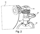
FIG. 1 shows a
換気システム1は、本例において自己膨張バッグを形成する換気装置11を含んでいる。本発明の範囲は、例え換気装置が異なっても、例えば機械式ベンチレータまたはとりわけ可撓性バッグから成る場合に、逸脱されない。
The
換気システム1は、使用、例えば呼吸困難な患者の連続的換気、無呼吸患者のための呼吸代替、患者の自発的換気、または心臓停止の患者の不連続な換気、または別の使用に対して適しうる。
換気システム1はさらに、図示された例においてマスクを介する非侵襲性の換気から成る、該換気システム1を患者に接続するよう働く換気インタフェース12を含む。マスクは、患者の口と鼻とにつけることが意図されている。本発明の範囲は、換気インタフェース12が気管チューブ又は上部喉頭部(supralaryngeal)装置を介する侵襲性換気で構成される場合に、逸脱されない。
換気システム1はさらに、換気装置11由来の空気を換気インタフェース12の方へ向かわせ、且つ患者によって吐き出された空気を大気へ逃すために、換気装置11と換気インタフェース12との間に置かれた一方向性呼気弁13を含んでいる。
The
この例おいて、換気装置11は、開放空気に開いており且つ大気から換気装置11内へ空気が流れることを可能にするところのチェック弁14を備えている。
In this example, the
換気システム1はさらに、患者が空気を供給されることを可能にするところの一方向性送気弁15を含んでいる。
The
診断装置10、換気装置11、換気インタフェース12、呼気弁13、および送気弁15は、例えば、それ自体公知の仕方で図1に概略的に示されたように係合を介して、一緒に可逆的に組み立てられる。
The
換気の有効性を診断するための装置10は、呼気および送気の空気流速を実時間で測定できる二方向熱質量センサ20、および電気的及び機械的接続を確保する切断可能な接続手段22によって上記センサ20へ接続された電子ユニット21を含んでいる。二方向熱質量センサ20(熱質量流速計とも呼ばれる)は、一回使用またはオートクレーブ処理可能でありうる。それは、図1および2で分るように、一方で、換気装置11の送気弁15と呼気弁13との間に差し込まれ、他方で換気インタフェース12に差し込まれることを意図されている。該センサ20は、流体の比熱容量を測定することによって、および各換気サイクル毎にそこを通過する空気の量を拡張することによって、吸われ及び吐かれた空気の流速および体積を測定することを可能にする。電子ユニット21は、センサ20によって測定された空気流速に関するデータを受信し処理するように構成されている。
The
図示された実施例においては、診断装置10は他の如何なるセンサも含んでいないが、本発明の範囲を逸脱しない限り、他のセンサ、例えば圧力センサ及び/又は空気中のCO2濃度のセンサを含みうる。
In the illustrated embodiment, the
診断装置10の電子ユニット21は、ハードウェア部分とソフトウェア部分を含むデータ処理センター、表示装置およびデータを入力する手段を備える制御インタフェース又はユーザインタフェース、および電力を供給するための手段、例えば1以上のバッテリーを含んでいる。電子ユニット21は、換気カーブが解釈されることを可能にし、および換気の有効性に関する重要な情報と様々な警告メッセージが第1対応者へ表示されることを可能にする。換気の有効性が患者に対して不適切であり又は危険であると考えられた場合に、診断装置10は、有効性のこの欠如の主原因が同定されること、および特定の警告メッセージが第1対応者へ送られることを可能にする。
The
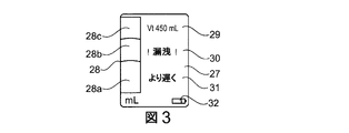
電子ユニット21は、この実施例において、図1において分るように、可視アラームが表示されることを可能にする発光ダイオード25即ちLED、およびリセットボタン26、及び電子ユニット21によって実行された有効性の分析に基づいて、様々なタイプの警告およびメッセージが表示されることを可能にする表示装置27(図3に示される)を含んでいる。
The
電子ユニット21は、変形として、特定のアプリケーションを実行するラップトップの、スマートフォンの、タブレットのコンピュータを含み又は構成され、必要な場合には、うる。1以上のセンサおよびシステムの他の要素とインタフェースするためのハードウェアインタフェースを有しうる。
As a variant, the
情報は、1以上の有線及び/又は無線を介して処理センターと1以上のセンサ及びシステムの他の要素との間で交換されうる。 Information can be exchanged between the processing center and one or more sensors and other elements of the system via one or more wired and / or wireless.
図3に示された本実施例において、1回の呼吸量Vt29(これは各呼吸において肺に到達する空気の体積であり、mlで表示される)は、各換気サイクル毎に表示装置27上に表示される。この実施例において、測定された1回の呼吸量Vtが450mlと読み取られうる。
In this example shown in FIG. 3, a single breath volume Vt29 (which is the volume of air reaching the lungs in each breath, expressed in ml) is on the
吸い込み及び吐き出した量はまた、本実施例において3つの部分に分割されて、色28a、28b、28cの3つの帯域を形成する棒状グラフ28の形状においてスクリーン上に表示され、これは、患者の生理学的特性に基づいて、量が不十分(28a)、有効(28b)、または過剰(28c)であるか否かを夫々に示す。
The amount of inhalation and exhalation is also divided into three parts in this embodiment and displayed on the screen in the form of a
データ処理センターによって決定された最適換気頻度は、第1対応者が用いる正しい頻度を知らせるために発光信号及び/又は音響信号及び/又は触覚信号を介して、該対応者へ伝達される。図3の実施例においては、換気頻度を減少させる必要があることを示す警告メッセージ31が現れる。
The optimum ventilation frequency determined by the data processing center is transmitted to the responder via an emission signal and / or an acoustic signal and / or a tactile signal to inform the correct frequency used by the first responder. In the embodiment of FIG. 3, a
図3の実施例において、「漏洩」を示す警告メッセージ30が現れて、第1対応者へ漏洩を(例えば患者のマスクの位置を直すことにより)減らす必要があることを知らせる。具体的には、漏洩は、各換気サイクルにおける吸われた体積と吐き出された体積との間の相違を測定することにより、及び/又は流速の増加を同時に伴っている送気圧における低下を観測することにより検出され計算される。
In the embodiment of FIG. 3, a
最後に、再び図3において可視の指示32は、1又は2以上のバッテリーの充電のレベルを見ることを可能にする。
Finally, again in FIG. 3, the
この診断装置10によって、電子ユニット21によって配信された、主要な換気パラメータの値、患者の生理的及び身体的特徴とILCOR(International Liaison Committee On Resuscitation:国際蘇生法連絡委員会)の勧告との一致に関する情報が、換気サイクル毎に第1対応者へフィードバックされる。具体的には、換気インタフェース12の上流に置かれたセンサ20によって得られた呼気量と送気量との測定は、電子ユニット21のデータ処理センターによって処理された後、1回の換気量、即ち患者の肺へ実際に供給された空気の量、および各換気サイクルにおける漏洩が評価され表示されることを可能にする。流速の測定はまた、特定のトリガーにより換気サイクルの様々なフェーズの検出を可能にする。特定のトリガーは特に、呼気の終わる前に第1対応者が患者に再送気を行なうときに生じるところの患者の過剰換気を防止するために、患者の呼気フェーズの終わりを検出することを可能にする。過剰に高い呼気漏洩の故に呼気フェーズの終わりの検出が可能でないとき、それは患者の呼気時定数の測定によって評価されうる。
Consistency between the values of key ventilation parameters, the physiological and physical characteristics of the patient and the recommendations of the International Liaison Committee On Resuscitation (ILCOR) delivered by the
図4~7は、本発明に従う換気システム1を用いて患者に換気をおこなうための方法の工程を示している。
FIGS. 4-7 show the steps of a method for ventilating a patient using the
図4を参照して、換気システム1を用いて患者に換気をおこなうための方法は、患者の身体的及び/又は心理的特性(特に患者のサイズ)を選択する又は電子ユニット21へ指示するためにユーザインタフェース(特に入力手段)を第1対応者が用いる工程1を包含している。この特徴を受け取るデータ処理センターは、すると患者の肺容量および正しい1回の呼吸量(Vt)の範囲、例えば1回の呼吸量の最小閾値および最大閾値を自動的に規定するように構成されている。
With reference to FIG. 4, a method for ventilating a patient using the
工程2において、第1対応者は、換気(特に換気のタイプ)に関する特徴を選択または指示することができ、該特徴は、例えば心肺蘇生(CPR)または換気のみから選択される。データ処理センターは次に、流速のフィルタリングのレベル、および呼気フェーズと送気のフェーズの検出のために用いられるトリガー値を自動的に規定する。 In step 2, the first responder can select or direct features relating to ventilation (particularly the type of ventilation), which features are selected, for example, from cardiopulmonary resuscitation (CPR) or ventilation alone. The data processing center then automatically defines the level of flow velocity filtering and the trigger values used to detect the expiratory and insufflation phases.
工程3において、第1対応者は、換気の別の特徴、例えば侵襲的または非侵襲的換気から選らばれた換気モードを選択しうる。データ処理センターは次に、漏洩量許容範囲、即ち最大漏洩量閾値を自動的に規定する。
In
工程4において、表示装置27の主スクリーンはスイッチを入れられ、データ処理センターのメインプログラムは始動する。
In step 4, the main screen of the
各サイクルにおいて、分析が実行される。 Analysis is performed in each cycle.
工程5において、休止フェーズ6、吸気フェーズ7、呼気フェーズ8を検出し且つ計算フェーズ9を実行するためにセンサ20を用いて流速が測定される。具体的には、休止フェーズ6と吸気フェーズ7との間で、クロックリセットを生成する陽流速を検出することから成る工程6bisが存在し、これは吸気フェーズの途中であることの検出を可能にする。さらに、吸気フェーズ7と呼気フェーズ8との間、工程7bisにおいて、陰流速が検出され、これは呼気フェーズの途中であることを告げることを可能にする。呼気フェーズ8の後、流速(工程8bisにおいて検出される)はゼロであり、これは計算フェーズ9が起動されることを可能にする。
In
陽流速の検出から換気サイクルの終わりまで、サイクル時間(Tcycle)と換気頻度(Fr)は、工程10において測定される。
From the detection of the positive flow rate to the end of the ventilation cycle, the cycle time (Tcycle) and ventilation frequency (Fr) are measured in
換気サイクルを監視しながら、計算フェーズ9において得られた結果に依存して、以下に説明するように、情報が表示され及び/又は警告が視覚の及び/又は聴覚の及び/又は接触の表示の形で起動される。 Depending on the results obtained in calculation phase 9, information is displayed and / or warnings are displayed for visual and / or auditory and / or contact, as described below, while monitoring the ventilation cycle. It is started in the form.
吸気フェーズ7の間の方法の詳細は、図5に示されている。この吸気フェーズ7は、呼気時間Ti 71の測定を含む。吸気時間Tiがプリセット期間、例えば4秒よりも長い場合に、「呼気がない」とのメッセージ72が送られる。吸気は一般に0.5~2秒の間続くことが指摘されよう。このようにして、プリセット期間の後に2秒間よりも長く、例えば送気開始後に4秒間より長く呼気が検出されなかった場合に、メッセージ72が表示される。
Details of the method during
並行して、工程73において流速が測定され、そして流速は送気時間Tiに亘って積分され、それにより、工程74において送気された又は吸気量Viを計算すること、そして工程75において吸気量Viが表示されること、そして棒状グラフ28が立ち上げられることを可能にする。
In parallel, the flow velocity is measured in step 73, and the flow velocity is integrated over the insufflation time Ti, thereby calculating the insufflation or intake amount Vi in
並行して、工程76において、送気圧が測定され、工程77において最大圧Ppeakが測定され、そして工程78においてこの最大圧Ppeakが表示される。
In parallel, in step 76, the air pressure is measured, in step 77 the maximum pressure P peak is measured, and in
呼気フェーズ8における方法が、図6に詳細に示されている。呼気フェーズ8において、工程81において呼気時間Teが測定される。
The method in
並行して、工程82において、流速が測定され、そして理論的な呼気時間TeThが計算される。TeThの計算は、患者の呼気時定数(これは5*R*Cに等しい、ここでRは肺抵抗、Cは肺コンプライアンスである)を評価することによって遂行される。TeThはまた、呼気流速カーブの指数関数的回帰によって予測される。次に、流速は、工程84において、呼気量Veの計算を減らすために、呼気時間Teに亘り積分される。換気モードが非侵襲性であるとき、棒状グラフ28は、工程85において、期間TeThに亘り徐々に下げられる。換気モードが侵襲性であるとき、棒状グラフ28は、工程86において、Veに直接比例して下げられる。
In parallel, in step 82, the flow rate is measured and the theoretical expiratory time TeTh is calculated. The calculation of TeTh is performed by assessing the patient's expiratory time constant, which is equal to 5 * R * C, where R is lung resistance and C is lung compliance. TeTh is also predicted by exponential regression of the exponential flow rate curve. The flow rate is then integrated over the expiratory time Te in step 84 to reduce the calculation of the expiratory volume Ve. When the ventilation mode is non-invasive, the
並行して、工程87において、例えばセンサ20とインタフェース12との間に置かれた任意的なセンサによって実行された測定を用いて、CO2濃度が測定され、そして呼気のCO2の量EtCO2が表示される。そのようなセンサは、例えば赤外線分光法による測定を可能にするNDIR(NonDispersive InfraRed:非分散性赤外線)センサである。
In parallel, in
並行して、工程88において、終末呼気陽圧(PEEP:positive end-expiratory pressure)が測定され且つ表示される。 In parallel, in step 88, the positive end-expiratory pressure (PEEP) is measured and displayed.
最後に、計算フェーズ9において、図7に詳細に示されたように、漏洩量Vleaksが工程91において計算され、次いで1回の呼吸量Vtが工程92において計算され、そして1回の換気量Vtは工程93において表示される。工程94において、肺コンプライアンスCが、式C=Vt/(Ppeak-PEEP)を用いて計算される。工程95において、肺抵抗Rが、式R=Te/5*Cを用いて計算される。
Finally, in calculation phase 9, as shown in detail in FIG. 7, leakage V leaks are calculated in step 91, then one breathing volume Vt is calculated in
休止時間Tpはまた、工程96において計算され、そして換気頻度Frの測定、患者のサイズ、換気のタイプ、および換気モードを用いて、計算は、工程94及び95において実行され、特に工程97において肺モデルおよび有効性閾値および換気パラメータが規定され、そして換気の有効性が分析される。
The rest time Tp is also calculated in step 96, and using the measurement of ventilation frequency Fr, patient size, type of ventilation, and ventilation mode, the calculation is performed in
漏洩量Vleaksが最大プリセット閾値よりも大きい場合に、工程98において、警告メッセージ「漏洩」30が表示される。漏洩量Vleaksが上記プリセット最大閾値よりも小さい場合に、工程99において、警告メッセージ30は消される。
When the leakage amount V leaks is larger than the maximum preset threshold value, the warning message “leakage” 30 is displayed in the step 98. When the leakage amount V leaks is smaller than the preset maximum threshold value, the
並行して、換気頻度Frが所定の最大閾値よりも多い場合に、すると工程910において、警告メッセージ「高換気頻度」または「高Fr」が表示される。しかし、換気頻度がプリセット最大閾値よりも少ない場合に、工程911において、警告メッセージは消される。換気頻度Frがプリセット最小閾値よりも少ない場合に、工程912において、警告メッセージ「低換気頻度」または「低Fr」が表示され、しかし換気頻度Frが上記プリセット最小閾値よりも多い場合に、工程913において、警告メッセージは消される。
In parallel, if the ventilation frequency Fr is greater than a predetermined maximum threshold, then in
並行して、1回の呼吸量Vtがプリセット最大閾値より多い場合、工程914において、警告メッセージ「多呼吸量」または「多Vt」が表示される。しかし、1回の呼吸量Vtがこのプリセット最大閾値より少ない場合、工程915において、警告メッセージは消される。1回の呼吸量Vtがプリセット最小閾値より少ない場合、工程916において、警告メッセージ「少呼吸量」または「少Vt」が表示される。呼吸量Vtがプリセット最小閾値より多い場合、工程917において、警告メッセージは消される。
In parallel, if the single breathing volume Vt is greater than the preset maximum threshold, the warning message "tachypnea" or "tachypnea" is displayed in step 914. However, if the breathing volume Vt at one time is less than this preset maximum threshold, the warning message is erased in step 915. If the single breathing volume Vt is less than the preset minimum threshold, the warning message "low breathing volume" or "low Vt" is displayed in
図4に示された工程11において、サイクル時間が値のプリセット範囲内(例えば5~7秒の間)にある定数よりも長く且つ呼気フェーズの終わりが検出されるか又はサイクル時間がプリセット閾値(例えば7秒)を越えるとき、緑色の発光ダイオード25が点灯され且つ音響信号が発せられる。この光信号および音響信号は、第1対応者へ呼吸の正しい時間を表示することを可能にする。送り込まれた量Viが正しい範囲に達するか又は呼気フェーズの開始が検出されるとき、次いで工程12において、可視の表示、例えば赤色の発光ダイオード25が、第1対応者へ警告するために点灯される。送気量Viの正しい範囲は、工程1および97において決定される。漏洩がない場合、量Viは正しい。そうでない場合、正しい量は漏洩に応じて正しくされる。最適サイクル時間は、患者の肺特性、例えば彼の肺コンプライアンスおよび肺抵抗に基づく。
In
漏洩量はまた、送気量の百分率で表され、かつプリセット最大閾値(例えば、送気量の約20%~40%の間にある)を有している。呼吸頻度Frの最大閾値は、例えば1分間当り約12~20回の間であり、そして換気頻度の最小閾値は、例えば1分間当り約8~12回の間である。1回の呼吸量Vtに関して、プリセット最大閾値は、例えば約500ml~700mlの間にあり、そしてプリセット最小閾値は、例えば約300ml~500mlの間にある。 The leak amount is also expressed as a percentage of the insufflation amount and has a preset maximum threshold (eg, between about 20% and 40% of the insufflation amount). The maximum threshold for breathing frequency Fr is, for example, between about 12 and 20 times per minute, and the minimum threshold for ventilation frequency is, for example, between about 8 and 12 times per minute. For a single breath volume Vt, the preset maximum threshold is, for example, between about 500 ml and 700 ml, and the preset minimum threshold is, for example, between about 300 ml and 500 ml.
本発明によって、第1対応者は、漏洩量、換気頻度Fr、1回の呼吸量Vtに関する情報に直ぐにアクセスでき、そして必要ならば患者のために最適な換気を再構成するために、正されるべき1以上のパラメータに非常に素早く影響を与えうる。患者の各換気サイクルにおける方法の工程の繰り返しは、換気システム又は呼吸生理学の深い知識を有さなくても、第1対応者が患者の臨床状態の進展に連続的に適応すること、および表示装置27に示されたパラメータを修正することを可能にする。 INDUSTRIAL APPLICABILITY According to the present invention, the first responder has immediate access to information on leakage volume, ventilation frequency Fr, and single breath volume Vt, and is corrected to reconstruct the optimal ventilation for the patient if necessary. It can affect one or more parameters that should be very quickly. Repeating the steps of the method in each ventilation cycle of the patient allows the first responder to continuously adapt to the development of the patient's clinical condition, and the display device, without in-depth knowledge of the ventilation system or respiratory physiology. It is possible to modify the parameters shown in 27.
本発明は、勿論、ここの記載された実施例に限定されるものではない。 The present invention is, of course, not limited to the examples described herein.
特にシステムは、小児科または新生児用の使用に適応させられることができ、上で記載された閾値はそれに従って変更されうる。 In particular the system can be adapted for pediatric or neonatal use and the thresholds described above can be modified accordingly.
本記載を通して、表現「1の~を含む」は、表現「少なくとも1の~を備えている」と同義であるとして理解されなければならない。 Throughout this description, the expression "including 1" must be understood as synonymous with the expression "having at least 1".
値の範囲は、別の指示がない限り、端の値が含まれると理解される。 The range of values is understood to include the values at the ends, unless otherwise indicated.
1 換気システム
6 休止フェーズ
7 吸気フェーズ
8 呼気フェーズ
9 計算フェーズ
10 診断装置
11 換気装置
12 換気インタフェース
13 呼気弁
14 チェック弁
15 一方向性送気弁
20 二方向熱質量センサ
21 電子ユニット
22 接続手段
25 発光ダイオード
26 リセットボタン
27 表示装置
28 棒状グラフ
30 警告メッセージ
32 可視の指示
1
Claims (14)
‐ 送気および呼気での空気流速を実時間において測定しうる二方向熱質量センサ(20)と、
‐ 前記二方向熱質量センサ(20)により測定された該空気流速に関するデータを受け取りかつ処理するように構成された、切断可能な電子機械接続部を介し、道具なしに前記二方向熱質量センサ(20)へ接続された電子ユニット(21)と、
を備え、
該電子ユニット(21)は、
i.表示装置(27)およびデータを入力するための手段を備えるユーザインタフェースと、
ii.データ処理センターと、ここで、該データ処理センターは、データを受け取り処理しかつ表示し、換気の有効性を実時間において分析しかつ警報を管理するようにプログラムされたアルゴリズムに従って動作する、
iii.電力を供給するための手段と、
を備えており、
該データ処理センターは、上記患者の最適な換気のために理想的な換気パラメータ、および各換気パラメータについての最小閾値及び/又は最大閾値を実時間で演繹し、該換気パラメータの値が対応する最大閾値よりも大きい及び/又は対応する最小閾値よりも小さい場合に、警報を出すように構成されており、
該装置(10)は、換気インタフェース(12)と上記可撓性のバッグまたは自己膨張バッグの間で、上記患者を換気するためのシステム(1)に継がれることを意図される、
上記装置(10)。 A device for diagnosing the effectiveness of ventilation of a patient under respiratory assistance, which has a flexible bag or a self-inflating bag and is intended to interact with the system for ventilating the patient (1). 10), and the device (10) is
-A two-way thermal mass sensor (20) that can measure the air flow velocity in insufflation and exhalation in real time.
-The bidirectional thermal mass sensor (20) without tools via a cuttable electromechanical connection configured to receive and process data about the air flow velocity measured by the bidirectional thermal mass sensor (20). The electronic unit (21) connected to 20) and
Equipped with
The electronic unit (21) is
i. A user interface with a display device (27) and means for inputting data,
ii. A data processing center and, where it operates, according to an algorithm programmed to receive, process and display data, analyze ventilation effectiveness in real time and manage alarms.
iii. Means for supplying power and
Equipped with
The data processing center demonstrates the ideal ventilation parameters for optimal ventilation of the patient, and the minimum and / or maximum thresholds for each ventilation parameter in real time, and the value of the ventilation parameter corresponds to the maximum. It is configured to issue an alarm if it is greater than the threshold and / or less than the corresponding minimum threshold.
The device (10) is intended to be connected to the system (1) for ventilating the patient between the ventilation interface (12) and the flexible bag or self-inflating bag.
The device (10).
上記換気システム。 The device (10) for diagnosing the effectiveness of ventilation of the patient according to any one of claims 1 to 9 , which is a ventilation system (1) for providing respiratory assistance to the patient. It is equipped with a ventilator (11) selected from the group consisting of a flexible bag and a self-inflating bag, the ventilation system (1) via a tracheal incision tube or an invasive ventilation through a tracheal tube and a mask. A ventilation interface (12) selected from the group consisting of non-invasive ventilation is provided, and a two-way thermal mass sensor (20) is placed between the ventilation device (11) and the ventilation interface (12). ,
The above ventilation system.
a)患者の身体的及び/又は生理的特徴、及び/又は換気に関する特徴を該電子ユニット(21)内へ入力することを可能にすること、該換気に関する特徴は、換気のタイプ、換気装置(11)のタイプ及び/又は換気インタフェース(12)のタイプに関する特徴である;
b)該二方向熱質量センサ(20)を用いて該患者の生理的パラメータを測定すること;
c)工程a)において入力された該特徴と、工程b)において測定された該パラメータとを分析すること;
d)それらから、前記患者の最適な換気のために理想的な換気パラメータ、および各換気パラメータについての最小閾値及び/又は最大閾値を実時間で演繹すること;
e)該患者の該換気パラメータを実時間で測定すること;
f)該測定された換気パラメータを前記閾値と夫々比較すること;
g)各換気パラメータに対して、測定された換気パラメータの値が対応する最大閾値よりも大きい場合及び/又は対応する最小閾値よりも小さい場合に、警告及び/又は、変更されるべき1つ又は2以上のパラメータまたは最適換気を達成するように実行されるべき修正に関する情報を生成すること:
h)該患者に提供された換気補助の期間中、工程b)から工程g)を繰り返すこと;
を包含することを特徴とする、
上記方法。 A method for determining the effectiveness of a patient's ventilation using the ventilation system according to claim 10 , wherein the following steps:
a) Allowing the patient's physical and / or physiological characteristics and / or ventilation characteristics to be input into the electronic unit (21), the ventilation characteristics being the type of ventilation, the ventilation device. Features relating to the type of (11) and / or the type of ventilation interface (12);
b) Measuring the patient's physiological parameters using the bidirectional thermal mass sensor (20);
c) Analyzing the features input in step a) and the parameters measured in step b);
d) From them, deduce the ideal ventilation parameters for optimal ventilation of the patient, and the minimum and / or maximum thresholds for each ventilation parameter in real time;
e) Measuring the ventilation parameters of the patient in real time;
f) Compare the measured ventilation parameters with the thresholds, respectively;
g) For each ventilation parameter, a warning and / or one that should be changed if the value of the measured ventilation parameter is greater than the corresponding maximum threshold and / or less than the corresponding minimum threshold. Generating information about two or more parameters or modifications to be made to achieve optimal ventilation:
h) Repeat steps b) to g) during the period of ventilation assistance provided to the patient;
Characterized by including
The above method.
Priority Applications (1)
| Application Number | Priority Date | Filing Date | Title |
|---|---|---|---|
| JP2022001334A JP2022058525A (en) | 2015-06-08 | 2022-01-06 | Device for diagnosing ventilatory efficacy of patient and method for determining ventilatory efficacy of patient |
Applications Claiming Priority (3)
| Application Number | Priority Date | Filing Date | Title |
|---|---|---|---|
| FR1555220 | 2015-06-08 | ||
| FR1555220A FR3036944B1 (en) | 2015-06-08 | 2015-06-08 | DEVICE FOR DIAGNOSING THE EFFICIENCY OF THE VENTILATION OF A PATIENT AND METHOD OF VENTILATION OF A PATIENT |
| PCT/EP2016/062162 WO2016198275A1 (en) | 2015-06-08 | 2016-05-30 | Device for diagnosing the efficacy of ventilation of a patient and method for determining the ventilatory efficacy of a patient |
Related Child Applications (1)
| Application Number | Title | Priority Date | Filing Date |
|---|---|---|---|
| JP2022001334A Division JP2022058525A (en) | 2015-06-08 | 2022-01-06 | Device for diagnosing ventilatory efficacy of patient and method for determining ventilatory efficacy of patient |
Publications (3)
| Publication Number | Publication Date |
|---|---|
| JP2018524064A JP2018524064A (en) | 2018-08-30 |
| JP2018524064A5 JP2018524064A5 (en) | 2019-06-27 |
| JP7093182B2 true JP7093182B2 (en) | 2022-06-29 |
Family
ID=54478104
Family Applications (2)
| Application Number | Title | Priority Date | Filing Date |
|---|---|---|---|
| JP2017564354A Active JP7093182B2 (en) | 2015-06-08 | 2016-05-30 | Devices for diagnosing patient ventilation effectiveness and methods for determining patient ventilation effectiveness |
| JP2022001334A Pending JP2022058525A (en) | 2015-06-08 | 2022-01-06 | Device for diagnosing ventilatory efficacy of patient and method for determining ventilatory efficacy of patient |
Family Applications After (1)
| Application Number | Title | Priority Date | Filing Date |
|---|---|---|---|
| JP2022001334A Pending JP2022058525A (en) | 2015-06-08 | 2022-01-06 | Device for diagnosing ventilatory efficacy of patient and method for determining ventilatory efficacy of patient |
Country Status (5)
| Country | Link |
|---|---|
| US (1) | US20180160970A1 (en) |
| EP (1) | EP3302235A1 (en) |
| JP (2) | JP7093182B2 (en) |
| FR (1) | FR3036944B1 (en) |
| WO (1) | WO2016198275A1 (en) |
Families Citing this family (9)
| Publication number | Priority date | Publication date | Assignee | Title |
|---|---|---|---|---|
| US11433211B2 (en) * | 2016-03-17 | 2022-09-06 | Zoll Medical Corporation | Flow sensor for ventilation |
| US11433202B2 (en) * | 2017-12-18 | 2022-09-06 | Koninklijke Philips N.V. | Interactive guidance related to a subject's expiratory flow limitation results |
| WO2019213591A1 (en) | 2018-05-03 | 2019-11-07 | Umbulizer LLC | Ventilation apparatus |
| FR3088187A1 (en) | 2018-11-09 | 2020-05-15 | Archeon | ASSISTANCE APPARATUS FOR CARRYING OUT AN EMERGENCY CARE PROCEDURE, SYNCHRONIZED CARDIOPULMONARY RESUSCITATION ASSISTANCE SYSTEM AND ASSOCIATED METHOD |
| WO2020118138A1 (en) * | 2018-12-07 | 2020-06-11 | University Of Cincinnati | Rescue breathing device |
| JP7449066B2 (en) * | 2019-10-11 | 2024-03-13 | 日本光電工業株式会社 | Biological information processing system, light emitting device and biological information processing device |
| WO2021167870A1 (en) * | 2020-02-18 | 2021-08-26 | Rush University Medical Center | Device to monitor and alarm manual ventilation parameters during cardiopulmonary resuscitation |
| FR3118694A1 (en) | 2021-01-08 | 2022-07-15 | Air Liquide Medical Systems | Autonomous box for monitoring ventilation delivered during cardiopulmonary resuscitation |
| US20220395653A1 (en) | 2021-06-15 | 2022-12-15 | Stryker Corporation | Systems and methods for airway management |
Citations (2)
| Publication number | Priority date | Publication date | Assignee | Title |
|---|---|---|---|---|
| JP2010527737A (en) | 2007-05-30 | 2010-08-19 | ジャコブス クイパース,ギルバート | Electrically operated improved resuscitation device |
| JP2014518725A (en) | 2011-05-23 | 2014-08-07 | ゾール メディカル コーポレイション | Medical ventilation system with ventilation quality feedback unit |
Family Cites Families (13)
| Publication number | Priority date | Publication date | Assignee | Title |
|---|---|---|---|---|
| US6463930B2 (en) * | 1995-12-08 | 2002-10-15 | James W. Biondi | System for automatically weaning a patient from a ventilator, and method thereof |
| US6158432A (en) * | 1995-12-08 | 2000-12-12 | Cardiopulmonary Corporation | Ventilator control system and method |
| JP4602539B2 (en) * | 2000-12-06 | 2010-12-22 | 帝人株式会社 | Respiratory measurement device |
| GB0509371D0 (en) * | 2005-05-07 | 2005-06-15 | Smiths Group Plc | Resuscitators |
| US8394040B2 (en) * | 2006-12-15 | 2013-03-12 | Laerdal Medical As | Signal processing device for providing feedback on chest compression in CPR |
| US20080236585A1 (en) | 2007-03-29 | 2008-10-02 | Caldyne Inc. | Indicating device for a ventilator |
| US8656913B2 (en) * | 2007-06-05 | 2014-02-25 | Allied Healthcare Products, Inc. | Ventilator apparatus |
| CA2739435A1 (en) * | 2008-10-01 | 2010-04-08 | Breathe Technologies, Inc. | Ventilator with biofeedback monitoring and control for improving patient activity and health |
| WO2011089491A1 (en) * | 2010-01-22 | 2011-07-28 | Koninklijke Philips Electronics N.V. | Automatically controlled ventilation system |
| US8607791B2 (en) * | 2010-06-30 | 2013-12-17 | Covidien Lp | Ventilator-initiated prompt regarding auto-PEEP detection during pressure ventilation |
| KR101287171B1 (en) | 2010-09-27 | 2013-07-17 | 김도희 | Bag valve mask for ventilating of optimal air |
| US11129950B2 (en) | 2012-11-19 | 2021-09-28 | The General Hospital Corporation | System and method for monitoring resuscitation or respiratory mechanics of a patient |
| US9446211B2 (en) * | 2013-03-14 | 2016-09-20 | Carefusion 2200, Inc. | Resuscitation device with onboard processor |
-
2015
- 2015-06-08 FR FR1555220A patent/FR3036944B1/en active Active
-
2016
- 2016-05-30 US US15/580,526 patent/US20180160970A1/en not_active Abandoned
- 2016-05-30 WO PCT/EP2016/062162 patent/WO2016198275A1/en active Application Filing
- 2016-05-30 JP JP2017564354A patent/JP7093182B2/en active Active
- 2016-05-30 EP EP16729808.2A patent/EP3302235A1/en active Pending
-
2022
- 2022-01-06 JP JP2022001334A patent/JP2022058525A/en active Pending
Patent Citations (2)
| Publication number | Priority date | Publication date | Assignee | Title |
|---|---|---|---|---|
| JP2010527737A (en) | 2007-05-30 | 2010-08-19 | ジャコブス クイパース,ギルバート | Electrically operated improved resuscitation device |
| JP2014518725A (en) | 2011-05-23 | 2014-08-07 | ゾール メディカル コーポレイション | Medical ventilation system with ventilation quality feedback unit |
Also Published As
| Publication number | Publication date |
|---|---|
| JP2018524064A (en) | 2018-08-30 |
| JP2022058525A (en) | 2022-04-12 |
| US20180160970A1 (en) | 2018-06-14 |
| WO2016198275A1 (en) | 2016-12-15 |
| FR3036944A1 (en) | 2016-12-09 |
| EP3302235A1 (en) | 2018-04-11 |
| FR3036944B1 (en) | 2021-01-22 |
Similar Documents
| Publication | Publication Date | Title |
|---|---|---|
| JP7093182B2 (en) | Devices for diagnosing patient ventilation effectiveness and methods for determining patient ventilation effectiveness | |
| US20200383606A1 (en) | Exhaled gas measurement compensation during high flow respiratory therapy | |
| JP7258461B2 (en) | Respiratory therapy device and method | |
| US11247009B2 (en) | Anomaly detection device and method for respiratory mechanics parameter estimation | |
| US20200046922A1 (en) | Manual ventilation feedback sensor for use in clinical and training settings | |
| US20080236585A1 (en) | Indicating device for a ventilator | |
| JP2015506189A (en) | Method and apparatus for monitoring and controlling pressure assist devices | |
| JP6961530B2 (en) | Patient treatment system and monitoring device | |
| JP2018524064A5 (en) | ||
| JP7190351B2 (en) | Apparatus, system and method for determining respiratory characteristics of a subject based on respiratory gases | |
| KR20230051487A (en) | Improvements related to breathing assistance | |
| KR101856869B1 (en) | Electronic Manual Resucitator equipped with air flow controller functions | |
| WO2015104669A1 (en) | Patient-ventilator asynchrony detection | |
| US20220111167A1 (en) | Device for diagnosing the efficacy of ventilation of a patient and method for determining the ventilatory efficacy of a patient | |
| US10821246B2 (en) | Medical device and method for determining operating situations in a medical device | |
| EP2378966B1 (en) | Determining the functional residual capacity of a subject | |
| JP2011030990A (en) | Lifesaving navigation device of portable respirator | |
| EP3606423A1 (en) | Flow therapy system and method | |
| CN107635613A (en) | The equipment for artificial ventilation with monitoring chest compressions missing | |
| EP4272788A1 (en) | Respiratory support device and control method therefor, and storage medium | |
| JP7174128B2 (en) | Patient care system and monitoring device | |
| TWM481734U (en) | Respiratory auxiliary device capable of displaying breathing conditions | |
| US11298491B1 (en) | System, device, and arrangement for a manual ventilation assistant | |
| JP2014511716A (en) | System and method for diagnosis of central apnea | |
| US20230201516A1 (en) | Breath detection apparatus and method for breath detection |
Legal Events
| Date | Code | Title | Description |
|---|---|---|---|
| A711 | Notification of change in applicant |
Free format text: JAPANESE INTERMEDIATE CODE: A711 Effective date: 20190214 |
|
| A521 | Request for written amendment filed |
Free format text: JAPANESE INTERMEDIATE CODE: A821 Effective date: 20190214 |
|
| A521 | Request for written amendment filed |
Free format text: JAPANESE INTERMEDIATE CODE: A523 Effective date: 20190322 |
|
| A521 | Request for written amendment filed |
Free format text: JAPANESE INTERMEDIATE CODE: A523 Effective date: 20190520 |
|
| A621 | Written request for application examination |
Free format text: JAPANESE INTERMEDIATE CODE: A621 Effective date: 20190520 |
|
| A977 | Report on retrieval |
Free format text: JAPANESE INTERMEDIATE CODE: A971007 Effective date: 20200311 |
|
| A131 | Notification of reasons for refusal |
Free format text: JAPANESE INTERMEDIATE CODE: A131 Effective date: 20200420 |
|
| A521 | Request for written amendment filed |
Free format text: JAPANESE INTERMEDIATE CODE: A523 Effective date: 20200716 |
|
| A131 | Notification of reasons for refusal |
Free format text: JAPANESE INTERMEDIATE CODE: A131 Effective date: 20210104 |
|
| A521 | Request for written amendment filed |
Free format text: JAPANESE INTERMEDIATE CODE: A523 Effective date: 20210402 |
|
| A02 | Decision of refusal |
Free format text: JAPANESE INTERMEDIATE CODE: A02 Effective date: 20210907 |
|
| A521 | Request for written amendment filed |
Free format text: JAPANESE INTERMEDIATE CODE: A523 Effective date: 20220106 |
|
| C60 | Trial request (containing other claim documents, opposition documents) |
Free format text: JAPANESE INTERMEDIATE CODE: C60 Effective date: 20220106 |
|
| C11 | Written invitation by the commissioner to file amendments |
Free format text: JAPANESE INTERMEDIATE CODE: C11 Effective date: 20220118 |
|
| A911 | Transfer to examiner for re-examination before appeal (zenchi) |
Free format text: JAPANESE INTERMEDIATE CODE: A911 Effective date: 20220309 |
|
| C21 | Notice of transfer of a case for reconsideration by examiners before appeal proceedings |
Free format text: JAPANESE INTERMEDIATE CODE: C21 Effective date: 20220317 |
|
| TRDD | Decision of grant or rejection written | ||
| A01 | Written decision to grant a patent or to grant a registration (utility model) |
Free format text: JAPANESE INTERMEDIATE CODE: A01 Effective date: 20220519 |
|
| A61 | First payment of annual fees (during grant procedure) |
Free format text: JAPANESE INTERMEDIATE CODE: A61 Effective date: 20220617 |
|
| R150 | Certificate of patent or registration of utility model |
Ref document number: 7093182 Country of ref document: JP Free format text: JAPANESE INTERMEDIATE CODE: R150 |