JP7091923B2 - Transfer device, transfer method and program - Google Patents
Transfer device, transfer method and program Download PDFInfo
- Publication number
- JP7091923B2 JP7091923B2 JP2018148897A JP2018148897A JP7091923B2 JP 7091923 B2 JP7091923 B2 JP 7091923B2 JP 2018148897 A JP2018148897 A JP 2018148897A JP 2018148897 A JP2018148897 A JP 2018148897A JP 7091923 B2 JP7091923 B2 JP 7091923B2
- Authority
- JP
- Japan
- Prior art keywords
- route
- transfer
- cluster
- packet
- switch cluster
- Prior art date
- Legal status (The legal status is an assumption and is not a legal conclusion. Google has not performed a legal analysis and makes no representation as to the accuracy of the status listed.)
- Active
Links
Images


Classifications
-
- H—ELECTRICITY
- H04—ELECTRIC COMMUNICATION TECHNIQUE
- H04L—TRANSMISSION OF DIGITAL INFORMATION, e.g. TELEGRAPHIC COMMUNICATION
- H04L49/00—Packet switching elements
- H04L49/25—Routing or path finding in a switch fabric
- H04L49/253—Routing or path finding in a switch fabric using establishment or release of connections between ports
- H04L49/254—Centralised controller, i.e. arbitration or scheduling
-
- H—ELECTRICITY
- H04—ELECTRIC COMMUNICATION TECHNIQUE
- H04L—TRANSMISSION OF DIGITAL INFORMATION, e.g. TELEGRAPHIC COMMUNICATION
- H04L49/00—Packet switching elements
- H04L49/55—Prevention, detection or correction of errors
- H04L49/557—Error correction, e.g. fault recovery or fault tolerance
-
- H—ELECTRICITY
- H04—ELECTRIC COMMUNICATION TECHNIQUE
- H04L—TRANSMISSION OF DIGITAL INFORMATION, e.g. TELEGRAPHIC COMMUNICATION
- H04L12/00—Data switching networks
- H04L12/28—Data switching networks characterised by path configuration, e.g. LAN [Local Area Networks] or WAN [Wide Area Networks]
-
- H—ELECTRICITY
- H04—ELECTRIC COMMUNICATION TECHNIQUE
- H04L—TRANSMISSION OF DIGITAL INFORMATION, e.g. TELEGRAPHIC COMMUNICATION
- H04L49/00—Packet switching elements
- H04L49/65—Re-configuration of fast packet switches
-
- H—ELECTRICITY
- H04—ELECTRIC COMMUNICATION TECHNIQUE
- H04L—TRANSMISSION OF DIGITAL INFORMATION, e.g. TELEGRAPHIC COMMUNICATION
- H04L49/00—Packet switching elements
- H04L49/15—Interconnection of switching modules
- H04L49/1507—Distribute and route fabrics, e.g. sorting-routing or Batcher-Banyan
Description
本発明は、通信ネットワークを構成する転送装置群(スイッチクラスタ)の通信経路の拡張制御、並びに、通信経路における障害発生時の自動経路切替制御を行う転送装置、転送方法及びプログラムに関する。 The present invention relates to a transfer device , a transfer method, and a program that perform extended control of a communication path of a transfer device group (switch cluster) constituting a communication network, and automatic route switching control when a failure occurs in the communication path.
近年、OTT(Over The Top)の発展に伴い、汎用的な転送機能に特化したデータセンタ向けの汎用スイッチ市場が盛んになっている。通信キャリアとしても従来から用いられてきた転送装置として、キャリア向け専用開発装置を分離して汎用装置群とする検討が進められている(特許文献1)。 In recent years, with the development of OTT (Over The Top), the general-purpose switch market for data centers specializing in general-purpose transfer functions has become active. As a transfer device that has been conventionally used as a communication carrier, studies are underway to separate a dedicated development device for carriers into a general-purpose device group (Patent Document 1).
例えば、図10に従来の転送装置の構成を示す。この転送装置10は、転送装置10の制御を行うマネージメント機能10aと、他の転送装置と接続する経路を制御するルーティング機能10bと、パケットを転送するパケット転送機能10cの3つの機能を1パッケージに収容して構成されている。
For example, FIG. 10 shows the configuration of a conventional transfer device. The
転送装置10の内部には、図11に示すように、NOS(Network Operating System)12で制御されるファブリックカード13a,13bと、ラインカード14a,14b,14cとが組み込まれている。ファブリックカード13a,13bと、ラインカード14a,14b,14cという2種類の装置コンポーネント間はClos型トポロジ15で接続されている。
As shown in FIG. 11, a
また、図12に示す従来の転送システムは、外部のサーバ11に切り離して収容したマネージメント機能10aと、このマネージメント機能10aにより制御される転送装置11a,11b,11c,11d,11e群とで構成される。この際、各転送装置11a~11eはパケット転送機能10cを備える。更に、各転送装置11a~11e及びサーバ11の何れか一方でルーティング機能10bを備える。
Further, the conventional transfer system shown in FIG. 12 is composed of a management function 10a separately housed in an
図12に示す伝送システムの各転送装置11a~11eには、図13に示す構成要素が次のように収容されている。転送装置11aはスパインSW(Switch)17aであり、転送装置11bはスパインSW17b、転送装置11cはリーフSW18a、転送装置11dはリーフSW18b、転送装置11eはリーフSW18eである。
The components shown in FIG. 13 are housed in the
図13に示す転送システムは、サーバ16に搭載されたCTL(Controller)16aで制御されるスパインSW17a,17bと、リーフSW18a,18b,18cという2種類の装置コンポーネント間が、Clos型トポロジ19で接続されて構成されている。Clos型トポロジ19で接続されたスパインSW17a,17b及びリーフSW18a~18cは、スイッチクラスタ20を構成している。この構成により大容量転送を実現している(非特許文献1)。
In the transfer system shown in FIG. 13, the spine SW17a, 17b controlled by the CTL (Controller) 16a mounted on the
図13に示すような、従来の転送装置と同様の転送容量を担保するために将来期待される通信ネットワーク構成においては、複数の転送装置を組み合わせてトラフィックを処理する構成が検討されている。 In the communication network configuration expected in the future in order to secure the same transfer capacity as the conventional transfer device as shown in FIG. 13, a configuration in which a plurality of transfer devices are combined to process traffic is being studied.
また、複数の汎用の転送装置群を制御する既存のアーキテクチャとして、自律分散型(非特許文献2)と、集中制御型(非特許文献3,4)がある。図14に自律分散型転送システム21を示し、図15に集中制御型転送システム31を示す。 Further, as an existing architecture for controlling a plurality of general-purpose transfer devices, there are an autonomous decentralized type (Non-Patent Document 2) and a centralized control type (Non-Patent Documents 3 and 4). FIG. 14 shows the autonomous distributed transfer system 21, and FIG. 15 shows the centralized control type transfer system 31.
図14に示す自律分散型転送システム21は、コントロール機能としてのNOSCTL22aが搭載された外部のサーバ22と、NOS CTL22aによりマネージメントSW23を介して制御される転送装置24a~24e群とで構成されている。各転送装置24a~24eは、ルーティング機能とパケット転送機能を実現するNOSを備える。このように、各転送装置24a~24eに自律的な経路解決機能としてのNOSを配備することで、NOSCTL22aとの接続が切断された場合においても,各転送装置24a~24e上のNOS自身で自律的に経路構築できるため、従来同様の通信ネットワークの信頼性が維持できる利点がある。
The autonomous distributed transfer system 21 shown in FIG. 14 is composed of an
しかし、物理的な転送装置24a~24eの台数の増加に伴い経路情報も増加し、通信ネットワーク全体に影響が生じる。既存のネットワークで用いられている専用の転送装置24a~24eは、図14に示すシステム21で置き換えを想定すると,装置台数の増加に伴う経路情報の増加により、ネットワーク全体に影響が生じるため、周囲に影響を与えずに置き換えることは困難である。そこで、下記集中制御型の転送システムが実現されている。
However, as the number of
図15に示す集中制御型転送システム31は、R/F(Routing/Forwarding)制御を行うコントローラであるR/FCTL32aが搭載された外部のサーバ32と、転送装置34a~34e群とを備えて構成されている。R/F CTL32aは、ルーティング機能とフォワーディング制御機能とを有する。転送装置34a~34e群は、パケット転送機能を備え、R/F CTL32aによりマネージメントSW33を介して制御される。
The centralized control type forwarding system 31 shown in FIG. 15 includes an
このような集中制御型の転送システム31は、複数の転送装置34a~34eに対して、外部に切り離したR/FCTL32aで一元的に経路構築を行うため、経路情報交換時に物理的な転送装置の台数を意識せずに、転送装置を論理的なノードとして制御できる利点がある。
In such a centralized control type transfer system 31, a route is centrally constructed for a plurality of
非特許文献5における転送システムの実装例を図16に示す。ここで、上述の図15に示した集中制御型転送システム31では、R/FCTL32aから各転送装置34a~34eに破線で示す1本の制御線しか接続できず冗長性に欠けていた。しかし、図16の集中制御型の転送システム41では、データ転送用の線43も用いて、上記図15の1本の制御線のみに依存しない構成が実現されている。
FIG. 16 shows an implementation example of the transfer system in Non-Patent Document 5. Here, in the centralized control type transfer system 31 shown in FIG. 15 above, only one control line shown by a broken line can be connected from the R /
図16では、CTL45から、D-plane(主信号)と同様の経路も用いて集中制御するために、追加機能47をマネージメントポート48を介して各転送装置42a,42bに接続している。また、各外部サーバ43a,43bと各転送装置42a,42bとは、マネージメントポート48で接続されている。更に、各転送装置42a,42bにD-plane用ポート46経由で外部装置44a,44bが接続されている。
In FIG. 16, an
上述した非特許文献3~5では、通信ネットワークを構成する複数の転送装置を、1台の集中制御装置(CTL)で集中制御して管理する集中制御技術(Openflow)が用いられている。しかし、集中制御技術に対応した転送装置は、集中制御装置と接続するためのマネージメントポートを1つしか持たないものが多い。そこで、集中制御装置と複数の転送装置との接続には、マネージメントスイッチ(図15のマネージメントSW23,33参照)で集約して接続するため、この集約接続部分が単一障害点となってしまう問題があった。更に、集中制御装置と転送装置とのトラフィックが特定経路に集中してしまう問題があった。 In the above-mentioned non-patent documents 3 to 5, a centralized control technique (Openflow) is used in which a plurality of transfer devices constituting a communication network are centrally controlled and managed by one centralized control device (CTL). However, many transfer devices compatible with centralized control technology have only one management port for connecting to the centralized control device. Therefore, since the centralized control device and the plurality of transfer devices are collectively connected by the management switch (see management SW23 and 33 in FIG. 15), this centralized connection portion becomes a single point of failure. was there. Further, there is a problem that the traffic between the centralized control device and the transfer device is concentrated on a specific route.
この他、図16に一例を示したように、外部サーバ等に搭載した集中制御装置(CTL45)から各転送装置を制御するための通信をD-plane(主信号)と同様の経路で行う技術も提案されている。しかし、スイッチクラスタ内のデータ転送は転送先ポートを静的(固定的)に指定して行っている。このため、スイッチクラスタ内の障害(例えば、図16に×印で示す経路障害)が発生すると、迂回経路の選択機能が無いため、集中制御装置との通信が途切れてしまう。 In addition, as shown in FIG. 16, a technique for performing communication for controlling each transfer device from a centralized control device (CTL45) mounted on an external server or the like by a route similar to that of a D-plane (main signal). Has also been proposed. However, data transfer within the switch cluster is performed by statically (fixed) the transfer destination port. Therefore, when a failure in the switch cluster (for example, a route failure indicated by a cross in FIG. 16) occurs, communication with the centralized control device is interrupted because there is no detour route selection function.
つまり、図17に示すように、図示せぬ外部サーバ内に配備されて集中制御を行うCTL51が、矢印Y2~Y5で示すように、各転送装置52a~52dとD-plane(主信号)と同様の経路により通信を行っている場合に次のように通信が行えなくなる。即ち、図17に×印で示すように、転送装置52aと転送装置52d間の経路に断線等の障害が発生したとすると、迂回経路の選択機能が無いので、CTL51は、転送装置52b及び52dと矢印Y2,Y3で示す通信が行えなくなる問題が生じる。
That is, as shown in FIG. 17, the
本発明は、このような事情に鑑みてなされたものであり、集中制御装置と転送装置群との接続における単一障害点を回避できると共にトラフィックを複数経路に分散でき、スイッチクラスタ内の障害時に迂回経路を選択できる転送装置、転送方法及びプログラムを提供することを課題とする。 The present invention has been made in view of such circumstances, and can avoid a single point of failure in the connection between the centralized control device and the transfer device group, can distribute traffic to a plurality of routes, and can handle a failure in a switch cluster. An object of the present invention is to provide a transfer device , a transfer method, and a program capable of selecting a detour route.
上記課題を解決するための手段として、請求項1に係る発明は、通信の経路で接続された転送装置群によるスイッチクラスタに外部から集中制御を行う集中制御装置と、主信号経路を介して経路制御の通信を行う当該スイッチクラスタの転送装置であって、前記主信号経路を伝送する、前記スイッチクラスタの内部用パケットと、当該スイッチクラスタの外部の経路制御を行う外部用パケットとを分離する分離部と、前記スイッチクラスタの内部の複数経路を自在に辿る経路を求める経路制御を行う内部経路制御部とを備え、前記分離部は前記スイッチクラスタの内部向けの経路制御パケットを分離し、前記内部経路制御部は、当該分離された内部向けの経路制御パケットの不通時に当該不通の経路を迂回する経路を生成する経路制御を行うことを特徴とする転送装置である。 As a means for solving the above problems, the invention according to claim 1 has a centralized control device that centrally controls a switch cluster by a group of transfer devices connected by a communication path from the outside, and a path via a main signal path. Separation of the internal packet of the switch cluster that transmits the main signal path and the external packet that controls the external route of the switch cluster, which is the transfer device of the switch cluster that performs control communication. A unit and an internal route control unit that performs route control for finding a route that freely follows a plurality of routes inside the switch cluster are provided, and the separation unit separates route control packets for the inside of the switch cluster and separates the route control packet into the inside. The route control unit is a transfer device characterized by performing route control to generate a route that bypasses the route when the separated internal route control packet is interrupted .
請求項6に係る発明は、通信の経路で接続された転送装置群によるスイッチクラスタに外部から集中制御を行う集中制御装置と、主信号経路を介して経路制御の通信を行う当該スイッチクラスタの転送装置による転送方法であって、前記転送装置は、前記主信号経路を伝送する、前記スイッチクラスタの内部用パケットと、当該スイッチクラスタの外部用パケットとを分離するステップと、前記スイッチクラスタ内部の複数経路を自在に辿る経路を求める経路制御を行うステップと、前記分離において前記スイッチクラスタの内部向けの経路制御パケットを分離し、当該分離された内部向けの経路制御パケットの不通時に当該不通の経路を迂回する経路を生成する経路制御を行うステップとを実行することを特徴とする転送方法である。 The invention according to claim 6 is a transfer of a centralized control device that performs centralized control from the outside to a switch cluster by a group of transfer devices connected by a communication path, and the switch cluster that performs route control communication via a main signal path. A transfer method using a device, wherein the transfer device has a step of separating an internal packet of the switch cluster and an external packet of the switch cluster that transmit the main signal path, and a plurality of packets inside the switch cluster. In the separation, the route control packet for the inside of the switch cluster is separated from the step of performing the route control for finding the route that freely follows the route, and when the separated route control packet for the inside is interrupted, the route of the interruption is set. It is a transfer method characterized by executing a step of performing route control to generate a detour route.
請求項7に係る発明は、通信の経路で接続された転送装置群によるスイッチクラスタに外部から集中制御を行う集中制御装置と、主信号経路を介して経路制御の通信を行う当該スイッチクラスタの転送装置としてのコンピュータを、前記主信号経路を伝送する、前記スイッチクラスタの内部用パケットと、当該スイッチクラスタの外部用パケットとを分離する手段、前記スイッチクラスタ内部の複数経路を自在に辿る経路を求める経路制御を行う手段、前記分離において前記スイッチクラスタの内部向けの経路制御パケットを分離し、当該分離された内部向けの経路制御パケットの不通時に当該不通の経路を迂回する経路を生成する経路制御を行う手段、前記スイッチクラスタ内部の経路情報及び前記スイッチクラスタ外部の経路情報を、パケット転送機能が用いる経路情報として通知する手段として機能させるためのプログラムである。
The invention according to
請求項1の構成と請求項6の方法と請求項7のプログラムによれば、スイッチクラスタ(クラスタともいう)の内部用パケットと、クラスタの外部用パケットとを分離できるので、クラスタ内部では、クラスタ外部の経路と独立に動的な経路制御が可能となる。このため、クラスタと、クラスタ外部の集中制御装置との単一障害点が回避可能となると共に、クラスタ内の転送装置の故障や経路の故障においても、この故障経路を迂回する経路(迂回経路)を生成できるので、故障前の通信を継続できる。
According to the configuration of claim 1, the method of claim 6 , and the program of
請求項2に係る発明は、前記内部経路制御部が、前記スイッチクラスタの内部に転送装置群の接続経路が複数ある場合、前記主信号経路に係る通信を複数経路に分散することも可能な経路制御を行うことを特徴とする請求項1に記載の転送装置である。 According to the second aspect of the present invention, when the internal route control unit has a plurality of connection routes of the transfer device group inside the switch cluster, the communication related to the main signal route can be distributed to a plurality of routes. The transfer device according to claim 1, wherein the transfer device is controlled.
この構成によれば、クラスタ内部に経路が複数ある場合は、集中制御装置との通信を複数経路に分散できる。これによって、クラスタと、クラスタ外部の集中制御装置との単一障害点が回避可能となる。 According to this configuration, when there are a plurality of routes in the cluster, the communication with the centralized control device can be distributed to the plurality of routes. This makes it possible to avoid a single point of failure between the cluster and the centralized controller outside the cluster.
請求項3に係る発明は、前記内部経路制御部が、前記スイッチクラスタの内部経路を、当該スイッチクラスタの外部経路と独立して経路制御することを特徴とする請求項1又は2に記載の転送装置である。 The transfer according to claim 1, wherein the internal route control unit controls the route of the internal route of the switch cluster independently of the external route of the switch cluster. It is a device.
この構成によれば、クラスタの内部経路は、外部経路と独立して制御されるので、クラスタ内部の故障を検知した際に迂回経路を生成し、故障前の通信を継続できる。 According to this configuration, since the internal route of the cluster is controlled independently of the external route, a detour route can be generated when a failure inside the cluster is detected, and communication before the failure can be continued.
請求項4に係る発明は、前記分離部で分離された前記スイッチクラスタの外部向けの経路制御パケットを、前記集中制御装置へ転送する外部ルートエージェントを更に備えることを特徴とする請求項1~3の何れか1項に記載の転送装置である。 The invention according to claim 4 is further provided with an external route agent that transfers a route control packet for the outside of the switch cluster separated by the separation unit to the centralized control device. The transfer device according to any one of the above items.
この構成によれば、クラスタの外部向けの経路制御パケットを、内部向けの経路制御パケットと独立して集中制御装置へ転送できるので、集中制御装置がクラスタ外部の経路制御を容易に行うことができる。 According to this configuration, the route control packet for the outside of the cluster can be transferred to the centralized control device independently of the route control packet for the inside, so that the centralized control device can easily perform the route control outside the cluster. ..
請求項5に係る発明は、前記内部経路制御部が、前記集中制御装置と前記スイッチクラスタの内部の転送装置との通信を、当該スイッチクラスタの内部経路を介して行うように制御することを特徴とする請求項1~4の何れか1項に記載の転送装置である。 The invention according to claim 5 is characterized in that the internal route control unit controls communication between the centralized control device and the transfer device inside the switch cluster so as to be performed via the internal route of the switch cluster. The transfer device according to any one of claims 1 to 4.
この構成によれば、集中制御装置がクラスタ内部の転送装置と通信する際に、内部経路制御部が生成した迂回経路等を介して行うことができる。 According to this configuration, when the centralized control device communicates with the transfer device inside the cluster, it can be performed via a detour route generated by the internal route control unit or the like.
本発明によれば、集中制御装置と転送装置群との接続における単一障害点を回避できると共にトラフィックを複数経路に分散でき、スイッチクラスタ内の障害時に迂回経路を選択できる転送装置、転送システム、転送方法及びプログラムを提供することができる。 According to the present invention, a transfer device, a transfer system, which can avoid a single point of failure in the connection between a centralized control device and a group of transfer devices, can distribute traffic to a plurality of routes, and can select a detour route in the event of a failure in a switch cluster. A transfer method and program can be provided.
以下、本発明の実施形態を、図面を参照して説明する。但し、本明細書の全図において機能の対応する構成部分には同一符号を付し、その説明を適宜省略する。
<実施形態の構成>
図1は、本発明の実施形態に係る転送装置を用いた転送システムの構成を示すブロック図である。
Hereinafter, embodiments of the present invention will be described with reference to the drawings. However, the same reference numerals are given to the components corresponding to the functions in all the drawings of the present specification, and the description thereof will be omitted as appropriate.
<Structure of Embodiment>
FIG. 1 is a block diagram showing a configuration of a transfer system using the transfer device according to the embodiment of the present invention.
図1に示す転送システム60は、複数の転送装置61a,61b,61c,61dと、この転送装置61a~61d群によるスイッチクラスタ(クラスタ)61に接続された複数のサーバ62a,62bとを備えて構成されている。クラスタ61の外部には、外部ルータ63が接続されている。これら構成要素は、光ファイバや導電線等の経路65a~65gで接続されている。
The
本実施形態の特徴は、各転送装置61a~61dに、クラスタ61の内部(クラスタ内部という)からのD-plane(主信号)と同様の経路による経路制御パケットと、クラスタ61の外部(クラスタ外部という)からのD-plane(主信号)と同様の経路による経路制御パケットとを分離する機能(図4のパケットフローコントローラ87)を備える。この分離機能で、クラスタ内部の経路制御パケットと、クラスタ外部の経路制御パケットとを分離し、クラスタ内部の経路制御パケットに応じてクラスタ内部向けの経路制御エンジン(図4の内部ルートエンジン85)が経路制御を行う。また、外部ルートエージェント84(図4)がクラスタ外部の経路制御パケットをサーバ62a,62bに搭載される集中制御装置(図4の集中制御装置73)に転送するようにした。
The features of this embodiment are that each
これによって、クラスタ内では、クラスタ外部の経路と独立に動的な経路制御が可能となるため、クラスタ61とこの外部の集中制御装置73(図4)との単一障害点が回避可能となると共に、クラスタ内の障害においても迂回経路を生成して障害を回避可能とした。更に、クラスタ内部に経路が複数ある場合は、集中制御装置73との通信を複数経路に分散可能とした。
This enables dynamic route control within the cluster independently of the route outside the cluster, so that a single point of failure between the
図2に示すように、各転送装置61a~61dに、上記分離されたクラスタ内の経路制御パケットから自律的な経路切替制御処理を行う自律分散制御機能85(図4の内部ルートエンジン85に対応)を備える。つまり、クラスタ外部の経路とは独立してクラスタ内部経路の制御が行われる。
As shown in FIG. 2, each
自律分散制御機能85は、D-plane(主信号)と同様の経路上で、転送装置61a~61dの故障(装置故障という)や、クラスタ内の経路65c~65fの故障(経路故障という)を契機に、自動で集中制御装置73との通信(集中制御用通信)の経路65a~65fを、自律的に故障を回避できる経路に切り替えて通信を継続する機能を有する。また、自律分散制御機能85は、転送装置61a~61d、クラスタ内の経路の増減設においても、自律的に経路を切り替えて通信を継続する機能を有する。
The autonomous distributed
但し、集中制御用通信をD-plane(主信号)と同様の経路上で流通させるために、集中制御用通信に用いるIP(Internet Protocol address)アドレスの経路交換を、各転送装置61a~61d上のクラスタ内部向けの自律分散制御機能85がD-plane(主信号)と同様の経路上で行っている。
However, in order to distribute the centralized control communication on the same route as the D-plane (main signal), the route exchange of the IP (Internet Protocol address) address used for the centralized control communication is performed on each
また、自律分散制御機能85は、クラスタ内の経路65c~65fの状態を監視し、経路障害時に経路を選択するルーティング機能を有する。ルーティング機能は、クラスタ内の経路65c~65fの故障解決に用いるルーティングプロトコル(プロトコル)を有する。また、ルーティング機能は、前述した自律分散型転送システム21(図14)による自律分散型の転送と同様に、各転送装置61a~61dと集中制御装置73と間の転送による疎通性を自律的に解決する処理を行う。つまり、クラスタ内部に経路が複数ある場合は、各転送装置61a~61dと集中制御装置73との通信を複数経路に分散する処理も可能である。
Further, the autonomous distributed
クラスタ内部において、上記プロトコルは、OSPF(Open Shortest Path First)やIS-IS(Intermediate System to Intermediate System)等の動的に経路状態を取得し、自律的に経路計算を行うプロトコルであればどれでもよい。一方、クラスタの外部からくる経路情報においても同プロトコルを用いる場合があるが、その経路情報は、集中制御装置73で処理される。
Inside the cluster, the above protocol is any protocol that dynamically acquires the route state and calculates the route autonomously, such as OSPF (Open Shortest Path First) and IS-IS (Intermediate System to Intermediate System). good. On the other hand, the same protocol may be used for route information coming from outside the cluster, but the route information is processed by the
集中制御装置73から各転送装置61a~61dへのパケットの転送は、図3に示すように、転送装置61a~61dに外部ルートエージェント84を備え、この外部ルートエージェント84が集中制御装置73からの転送を仲介する。この仲介は、集中制御装置73において、特定の転送装置61aからのパケットの出力を命令する場合は、一度、集中制御装置73から外部ルートエージェント84にそのパケット出力指示を出し、この外部ルートエージェント84から出力されたパケットが転送装置61aから他の転送装置61bへ出力される様にすることをいう。
For the transfer of packets from the
また、転送装置61a~61d上の外部ルートエージェント84は、集中制御装置73より集中制御により経路指示を受けるが,その経路としてはマネージメントポート(図4のマネージメントポート81)経由か、D-plane通信用ポート経由の何れか一方又は両方でもよい。クラスタ61の外部からの通信は、外部からの経路制御パケットを受信した集中制御装置73が集中制御をクラスタ61に行う。この集中制御の指示を、外部ルートエージェント84が受ける。
Further, the
また、上述したクラスタ61の外部からの通信は、図3に示すように、転送システム60の外部に存在する外部ルータ63の外部ルーティング機能74が外部の経路制御パケットを、直接接続するクラスタ61内の転送装置61a~61dとこの装置上の外部ルートエージェント84を経由して集中制御装置73に転送する。
Further, as shown in FIG. 3, the communication from the outside of the
この構成により、クラスタ内の装置故障や経路故障時に、各転送装置61a~61dが自律的にクラスタ内の経路接続を解決する処理を行い、クラスタ61とマネージメントポート(図4のマネージメントポート81)及びD-plane通信用ポートの何れか一方又は両方を介した集中制御装置73間の通信を維持可能としている。また、ルーティング機能がルーティングプロトコルに応じて、クラスタ内の経路65c~65fを複数経路同時に利用可能とし、これにより効率的な帯域利用を可能としている。
With this configuration, in the event of a device failure or route failure in the cluster, each
また、クラスタ内部の経路故障解決のための通信(内部通信)と、クラスタ外部からの通信(外部通信)とは、各転送装置61a~61dに配備される上述した分離機能により区別される。しかし、区別するための条件は、MAC(Media Access Control)アドレス、IPアドレス、VLAN(Virtual Local Area Network)番号等の固有情報を用いて行われている。なお、各固有情報を組み合わせて用いてもよい。
Further, communication for resolving a route failure inside the cluster (internal communication) and communication from outside the cluster (external communication) are distinguished by the above-mentioned separation function provided in each of the
上記の内部通信と外部通信との分離機構により、内部で自律分散的に解決した経路の影響をクラスタ外部の転送装置へ与えることが無いため、クラスタ外部からはクラスタ61の転送装置61a~61d群を論理的な単一ノードと見做すことが可能となる。また、クラスタ内部では複数の転送装置61a~61dの自律分散的な連携を実現可能としている。
Due to the above-mentioned separation mechanism between internal communication and external communication, the influence of the route solved autonomously and decentralized internally does not affect the transfer device outside the cluster. Therefore, from the outside of the cluster, the
次に、図4は同一構成の転送装置61a~61dの内、転送装置61aの構成を代表して示すブロック図である。
Next, FIG. 4 is a block diagram showing the configuration of the
図4に示す転送装置61aは、マネージメントポート81と、ASICによる高速・大容量のハードウェア転送を実現する転送機能部83と、CPUによるソフトウェア処理が行われる計算処理部で構成されている。計算処理部にはハードウエアOS82があり、このOS82上で、外部ルートエージェント84と、内部ルートエンジン85と、パケット制御エージェント86と、パケットフローコントローラ87と、転送機能ドライバ(ドライバともいう)88とが動作している。
The
転送機能部83は、ASIC(Application Specific Integrated Circuit)等の半導体集積回路で形成されており、これにより高速で大容量の転送が可能となっている。また、転送機能部83は、転送先のポートを備え、当該ポートを使用して書き込まれたフォワーディングルールに従ってパケットを転送可能となっている。
The
なお、内部ルートエンジン85は、上述した自律分散制御機能であり、請求項記載の内部経路制御部を構成する。パケットフローコントローラ87は、請求項記載の分離部を構成する。
The
マネージメントポート81は、集中制御指示のパケットや、集中制御装置73で処理されるべきクラスタ外部からの経路情報パケットを、集中制御装置73があるサーバへ接続することができる。なお、集中制御指示のパケットや、集中制御装置73で処理されるべきクラスタ外部からの経路情報パケットは、転送機能部83経由で集中制御装置73があるサーバへ接続することもできる。
The
外部ルートエージェント84は、内部ルートエンジン85が後述のように生成した内部経路の情報を用いてマネージメントポート81や転送機能部83を介して集中制御装置73に接続し、集中制御装置73に経路制御を問い合わせる処理を行う。また、外部ルートエージェント84は、集中制御装置73が処理したクラスタ外部からの経路情報を外部ルートエージェント84内の記憶部(図示せず)に記憶する。パケットフローコントローラ87は、その外部ルートエージェント84に記憶された経路情報をドライバ88を介して転送機能部83にコピーする。更に、外部ルートエージェント84は、内部ルートエンジン85及び転送機能部83を介して、他のサーバ62cの集中制御装置73に接続することも可能である。即ち、外部ルートエージェント84は、クラスタ外部からの経路情報を受け取り、集中制御装置73へ転送することで集中制御されるためのエージェントであり、集中制御装置73間との通信により、クラスタ内部のトポロジ解決用通信パケットと、外部からの経路情報パケットを集中制御装置73まで転送する。
The
内部ルートエンジン85は、外部ルートエージェント84と集中制御装置73の間の通信経路を解決するための、内部経路情報を処理する。この内部ルートエンジン85は、ルーティングプロトコルに応じて内部経路の解決を次のように行う。即ち、パケット制御エージェント86に、転送機能部83の各ポートを模擬した仮想IF(Interface)を用意する。次に、パケットフローコントローラ87がパケット制御エージェント86に用意された各ポートの中から転送先に対応するポートへブリッジして、転送機能部83の内部経路に係るパケットを内部ルートエンジン85へ転送する。この転送されたパケットを内部ルートエンジン85が処理する。
The
また、内部ルートエンジン85は、クラスタ内の各転送装置61a~61dに配備された内部ルートエンジン85同士で経路交換を行い、転送装置61a~61dの故障や経路故障時に自動で迂回経路を生成する等の経路再計算を行う。この経路再計算により内部経路の自動切り替えが可能となる。
Further, the
パケット制御エージェント86は、転送機能部83からパケットフローコントローラ87により引き上げられたパケットを内部ルートエンジン85や外部ルートエージェント84に受け渡す。
The
転送機能ドライバ88は、転送機能部83の制御を可能とするものであり、経路情報の転送機能部83への書き込みと、パケット制御エージェント86に入ってきたパケットを、パケットフローコントローラ87経由で転送機能部83のポートから転送させる機能と、転送機能部83のポートに入ってきたパケットの内、自装置宛となるパケットをパケットフローコントローラ87経由でパケット制御エージェント86まで転送することを可能とする機能を担っている。
The
パケットフローコントローラ87は、後述のパケット分離と転送機能部の制御とを行う。即ち、パケット分離は、転送機能部83からパケットを取得し、内部ルートエンジン85と外部ルートエージェント84とに分離して出力する制御を行う処理である。転送機能部83の制御は、内部ルートエンジン85と外部ルートエージェント84に保存された経路情報をドライバ88を介して転送機能部83にコピーするものである。
The
転送機能部83に経路情報をコピーしない場合、パケットが入力された際に経路情報が無いためパケットの転送が不可能となる。転送機能部83は、経路情報があれば自転送機能部83自体でパケットの転送先を判断できる。
If the route information is not copied to the
また、経路故障や装置故障の障害発生時の迅速な切り替えを実現するため、パケットフローコントローラ87は、転送機能部83の各ポートの経路ダウンを検知した際に、内部ルートエンジン85に接続される仮想IFの内の対応するポートをダウンさせる。この機能により、ルーティングプロトコルのタイマ待ちによる経路再計算を行う場合と比較して高速な切り替えが可能となっている。
Further, in order to realize quick switching in the event of a route failure or a device failure failure, the
<実施形態の動作>
次に、本実施形態に係る転送システム60の経路故障時の動作を、図5~図7を参照して説明する。
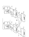
図5は2台のサーバ62a,62bと、4台の転送装置61a~61dで構成されるスイッチクラスタとの構成を示すブロック図である。図5の矢印Y11~Y14は、集中制御装置73a,73bと各転送装置61a~61d間で集中制御を行うための通信を示す。矢印Y15は、2つある集中制御装置73a,73b同士で情報を同期するための通信を示す。
<Operation of the embodiment>
Next, the operation of the
FIG. 5 is a block diagram showing a configuration of two
この通信時に、図6に×印で示すように経路65dに断線等の通信を不通とする故障が発生したとする。この場合、転送装置61d,61b間では、経路65dを経由していたクラスタ内で処理されるパケットやクラスタ外からのパケットが不通となる。つまり、矢印Y14で示す転送装置61dと集中制御装置73b間の通信と、矢印Y15で示す転送装置61a,61d,61bを介した集中制御装置73a,73b間の通信とが不通となる。この際、故障経路65dの両側の転送装置61d,61bの内部ルートエンジン85(図4)が、経路65dの故障を検知する。
During this communication, it is assumed that a failure such as disconnection occurs in the
この経路故障検知後、クラスタ内の各転送装置61a~61dの内部ルートエンジン85は、内部ルートエンジン85同士で経路交換を行い、ルーティングプロトコルに応じて自律的に故障経路65dを経由しない迂回経路を生成する経路再計算を行う。
After detecting this route failure, the
この経路再計算により図7に矢印Y17で示す迂回経路(新経路Y17)と、矢印Y18で示す迂回経路(新経路Y18)とが生成される。新経路Y17は、転送装置61dが転送装置61aを介して集中制御装置73aと繋がる経路である。新経路Y18は、集中制御装置73a,73b同士が転送装置61a,61c,61bを介して繋がる経路である。
By this route recalculation, the detour route (new route Y17) indicated by the arrow Y17 and the detour route (new route Y18) indicated by the arrow Y18 are generated in FIG. 7. The new route Y17 is a route in which the
また、矢印Y17で示す経路上の転送装置61d,61aの外部ルートエージェント84が新経路Y17を介して集中制御装置73aに接続する。この結果、集中制御装置73はクラスタ内部の経路構成変更を認識した上で、継続してクラスタを集中制御することが可能となる。
Further, the
更に、矢印Y18で示す経路上の転送装置61a,61c,61bの外部ルートエージェント84が新経路Y18を介して集中制御装置73a,73bに接続し新経路Y18の経路情報を転送する。これにより集中制御装置73a,73bに新経路Y18の経路情報が記憶され、集中制御装置73a,73b間で新経路Y18を経由した通信が可能となる。この後、集中制御装置73a,73baによる外部経路の処理が行われ、外部ルートエージェント84(図4)経由で新たな経路情報を転送機能部83(図4)が認識する。
Further, the
新経路Y17やY18経由で外部ルートエージェント84や内部ルートエンジン85に蓄積された経路情報を、各転送装置61a~61d上のパケットフローコントローラ87が各転送装置61a~61dの転送機能部83に更新する。
The
次に、図5に示した通信時に、図8に×印で示すように転送装置61dに部品故障等の通信不能となる故障が発生したとする。この場合、故障した転送装置61dに繋がる経路65e、65dが故障状態となるため、矢印Y14で示す転送装置61dと転送装置61bを介した集中制御装置73b間の通信が不通となり、矢印Y15で示す転送装置61dを介した集中制御装置73a,73b間の通信が不通となる。この際、故障した転送装置61dに繋がる転送装置61a,61bの内部ルートエンジン85が、経路65e,65dの故障を検知する。
Next, it is assumed that during the communication shown in FIG. 5, a failure such as a component failure occurs in the
この経路故障検知後、正常な経路65c,65fで繋がる転送装置61a~61cは、内部ルートエンジン85同士で経路交換を行い、次の経路再計算を行う。即ち、自律的なプロトコルに応じて故障経路65e,65dを経由しない迂回経路を生成する経路再計算を行う。この経路再計算により図9に矢印Y19で示す迂回経路(新経路Y19)が生成されたとする。新経路Y19は、集中制御装置73a,73b同士が、正常な経路65c,65fで繋がる転送装置61a,61c,61bを介して繋がる経路である。
After the route failure is detected, the
その正常な転送装置61a,61c,61bの外部ルートエージェント84経由で新たな経路情報を転送機能部83が認識する。
The
また、集中制御装置73a,73b間は,各転送装置上の内部ルートエンジン85が構築した新経路Y19の経路を用いて接続することが可能となる。その後、集中制御装置73a、73bは故障前と同様に、クラスタ外部からの新たな経路情報の処理が継続可能となる。
Further, the
但し、経路故障を各転送装置61a,61c,61b上のソフトウェアで認識できていない場合は、内部ルートエンジン85での経路故障検知による内部経路の再計算はできない。しかし、ルーティングプロトコルの応答も無くなるため、無応答のプロトコルに通常設定されているタイマのタイムアップを契機に、内部ルートエンジン85が別経路での再計算を行う。これにより経路の疎通が回復する。
However, if the route failure cannot be recognized by the software on the
このようなパケット転送不能だが、各転送装置61a,61c,61b上のソフトウェアで経路が未故障状態と認識されている場合に、高速な経路切替を実現するために、プロトコルのタイマを最小化することや、BFD(Bidirectional Forwarding Detection)等の障害検知技術を併用してもよい。この機能により、経路故障又は、プロトコルの応答が無くなる場合の経路故障及び装置故障が発生した場合においても、集中制御装置73a,73bによる論理ノードとしての転送装置61a~61dの制御を維持するための、従来のプロトコルタイマよりも高速な経路自動切替が実現可能となる。
Although such packet transfer is not possible, when the software on each
<実施形態の効果>
本実施形態に係る転送装置61a~61dの効果について説明する。転送装置61a~61dは、転送装置61a~61d群によるクラスタ61に外部から集中制御を行う集中制御装置73と、主信号経路であるD-plane(主信号)と同様の経路を介して経路制御の通信を行う。
<Effect of embodiment>
The effects of the
(1)転送装置61a~61dは、D-plane(主信号)と同様の経路を伝送する、クラスタ61の内部用パケットと、当該クラスタ61の外部用パケットとを分離する分離部としてのパケットフローコントローラ87と、クラスタ61の内部の複数経路を自在に辿る経路を求める経路制御を行う内部ルートエンジン85とを備える。パケットフローコントローラ87は、クラスタ61の内部向けの経路制御パケットを分離し、内部ルートエンジン85は、当該分離された内部向けの経路制御パケットの不通時に当該不通の経路を迂回する経路を生成する経路制御を行う構成とした。
(1) The
但し、内部用パケットは、クラスタ61のみで転送され、クラスタ61の集中制御を維持するために通信されるパケットである。具体的には、D-plane(主信号)と同様の経路を介した集中制御通信用パケットと、内部ルートエンジン85がクラスタ61内部の経路情報を交換するためにD-plane(主信号)と同様の経路を介する通信パケットの2つである。また、外部用パケットは、クラスタ61外より送られてくるクラスタ61外部の経路情報等のパケット{ルーティングプロトコルのパケットや、ARP(Address Resolution Protocolペケット)等}である。
However, the internal packet is a packet that is forwarded only by the
この構成によれば、クラスタ61の内部用パケットと、クラスタ61の外部用パケットとを分離できるので、クラスタ内部では、クラスタ外部の経路と独立に動的な経路制御が可能となる。このため、クラスタ61と、クラスタ外部の集中制御装置73との単一障害点が回避可能となると共に、クラスタ内部の転送装置の故障や経路の故障においても、この故障経路を迂回する経路(迂回経路)を生成できるので、故障前の通信を継続できる。
According to this configuration, the internal packet of the
(2)内部ルートエンジン85は、クラスタ61の内部に各転送装置61a~61dと集中制御装置73との間に接続経路が複数ある場合、それらの集中制御用通信を複数経路に分散することを可能とする経路制御を行う構成とした。
(2) When the
この構成によれば、クラスタ内部に経路が複数ある場合は、集中制御装置73との通信を複数経路に分散できる。これによって、クラスタ61と、クラスタ外部の集中制御装置73との単一障害点が回避可能となる。
According to this configuration, when there are a plurality of routes in the cluster, the communication with the
(3)内部ルートエンジン85は、クラスタ61の内部経路65c~65fを、当該クラスタ61の外部経路と独立して経路制御する構成とした。
(3) The
この構成によれば、クラスタの内部経路65c~65fは、外部経路と独立して制御されるので、クラスタ内部の故障を検知した際に迂回経路を生成し、故障前の通信を継続できる。
According to this configuration, since the
(4)転送装置61a~61dは、パケットフローコントローラ87で分離されたクラスタ61の外部向けの経路制御パケットを、集中制御装置73へ転送する外部ルートエージェント84を更に備える構成とした。
(4) The
この構成によれば、クラスタの外部向けの経路制御パケットを、内部向けの経路制御パケットと独立して集中制御装置73へ転送できるので、集中制御装置73がクラスタ外部の経路制御を容易に行うことができる。
According to this configuration, the route control packet for the outside of the cluster can be transferred to the
(5)内部ルートエンジン85は、集中制御装置73とクラスタ61の内部の転送装置との通信を、当該クラスタ61の内部経路65a~65fを介して行うように制御する構成とした。
(5) The
この構成によれば、集中制御装置73がクラスタ内部の転送装置と通信する際に、内部ルートエンジン85が生成した迂回経路等を介して行うことができる。
According to this configuration, when the
また、本実施形態の転送システムは、通信の経路で接続された転送装置群によるクラスタ61と、当該クラスタ61の外部から集中制御を行う集中制御装置73とを有し、集中制御装置73で主信号経路を介してクラスタ61の経路制御の通信を行う。集中制御装置73は、クラスタ61の外部向けの経路制御パケットに応じて、クラスタ61の外部から当該クラスタ61が単一ノードと見做せるように、当該外部との経路制御を行う構成とした。
Further, the transfer system of the present embodiment has a
この構成によれば、クラスタの外部から、クラスタ内の転送装置61a~61d群を単一ノードと見做して通信を行うことができる。このため、転送装置61a~61d群への通信を単純化できる。つまり、纏めて1つのノードとして見せることで、クラスタ外部に対して経路情報が増加するのを抑圧できる。
According to this configuration, it is possible to communicate from the outside of the cluster by regarding the
また、本実施形態のコンピュータで実行されるプログラムについて説明する。コンピュータは、経路接続された転送装置61a~61d群によるクラスタ61に外部から集中制御を行う集中制御装置73に対して、D-plane(主信号)と同様の経路を介して経路制御の通信を行う当該クラスタ61の転送装置であるとする。このコンピュータは請求項に記載されており、転送装置内のCPU、又はCPU及びASIC等の半導体チップの両方を備えるものである。
Further, a program executed by the computer of the present embodiment will be described. The computer transmits route control communication to the
このプログラムは、上記コンピュータを、D-plane(主信号)と同様の経路又は主信号と同様の経路を伝送する、クラスタ61の内部用パケットと、当該クラスタ61の外部用パケットとを分離する手段、クラスタ61内部の複数経路を自在に辿る経路を求める経路制御を行う手段、分離においてクラスタ61の内部向けの経路制御パケットを分離し、当該分離された内部向けの経路制御パケットの不通時に当該不通の経路を迂回する経路を生成する経路制御を行う手段、クラスタ61内部の経路情報及びクラスタ61外部の経路情報を、パケット転送機能(転送機能部83)が用いる経路情報として通知する手段として機能させる。
This program is a means for separating the internal packet of the
このプログラムによれば、上述した転送装置61a~61dと同様な効果を得ることができる。
According to this program, the same effect as that of the
その他、具体的な構成について、本発明の主旨を逸脱しない範囲で適宜変更が可能である。 In addition, the specific configuration can be appropriately changed without departing from the gist of the present invention.
60 転送システム
61a~61d 転送装置
62a,62b サーバ
63 外部ルータ
65a~65g 経路
74 外部ルーティング機能
81 マネージメントポート
82 ハードウエアOS
83 転送機能部
84 外部ルートエージェント
85 内部ルートエンジン又は自律分散制御機能(内部経路制御部)
86 パケット制御エージェント(分離部)
87 パケットフローコントローラ(分離部)
88 転送機能ドライバ
60
83
86 Packet control agent (separator)
87 Packet flow controller (separator)
88 Transfer function driver
Claims (7)
前記主信号経路を伝送する、前記スイッチクラスタの内部用パケットと、当該スイッチクラスタの外部の経路制御を行う外部用パケットとを分離する分離部と、
前記スイッチクラスタの内部の複数経路を自在に辿る経路を求める経路制御を行う内部経路制御部と
を備え、
前記分離部は前記スイッチクラスタの内部向けの経路制御パケットを分離し、前記内部経路制御部は、当該分離された内部向けの経路制御パケットの不通時に当該不通の経路を迂回する経路を生成する経路制御を行う
ことを特徴とする転送装置。 A centralized control device that centrally controls the switch cluster by a group of transfer devices connected by a communication path from the outside, and a transfer device of the switch cluster that performs route control communication via the main signal path.
A separation unit that separates the internal packet of the switch cluster that transmits the main signal path and the external packet that controls the external route of the switch cluster.
It is equipped with an internal route control unit that performs route control to find a route that freely follows a plurality of routes inside the switch cluster.
The separation unit separates the route control packet for the inside of the switch cluster, and the internal route control unit generates a route that bypasses the route when the separated route control packet for the inside is interrupted. Take control
A transfer device characterized by that.
前記スイッチクラスタの内部に転送装置群の接続経路が複数ある場合、前記主信号経路に係る通信を複数経路に分散することも可能な経路制御を行う
ことを特徴とする請求項1に記載の転送装置。 The internal route control unit is
The transfer according to claim 1, wherein when there are a plurality of connection routes of the transfer device group inside the switch cluster, route control capable of distributing the communication related to the main signal route to the plurality of routes is performed. Device.
前記スイッチクラスタの内部経路を、当該スイッチクラスタの外部経路と独立して経路制御する
ことを特徴とする請求項1又は2に記載の転送装置。 The internal route control unit is
The transfer device according to claim 1 or 2, wherein the internal route of the switch cluster is controlled independently of the external route of the switch cluster.
ことを特徴とする請求項1~3の何れか1項に記載の転送装置。 The invention according to any one of claims 1 to 3, further comprising an external route agent that forwards the route control packet for the outside of the switch cluster separated by the separation unit to the centralized control device. Transfer device.
前記集中制御装置と前記スイッチクラスタの内部の転送装置との通信を、当該スイッチクラスタの内部経路を介して行うように制御する
ことを特徴とする請求項1~4の何れか1項に記載の転送装置。 The internal route control unit is
The invention according to any one of claims 1 to 4, wherein the communication between the centralized control device and the transfer device inside the switch cluster is controlled so as to be performed via the internal route of the switch cluster. Transfer device.
前記転送装置は、
前記主信号経路を伝送する、前記スイッチクラスタの内部用パケットと、当該スイッチクラスタの外部用パケットとを分離するステップと、
前記スイッチクラスタ内部の複数経路を自在に辿る経路を求める経路制御を行うステップと、
前記分離において前記スイッチクラスタの内部向けの経路制御パケットを分離し、当該分離された内部向けの経路制御パケットの不通時に当該不通の経路を迂回する経路を生成する経路制御を行うステップと
を実行することを特徴とする転送方法。 It is a transfer method by a centralized control device that centrally controls the switch cluster by a group of transfer devices connected by a communication path from the outside and a transfer device of the switch cluster that performs route control communication via the main signal path.
The transfer device is
A step of separating an internal packet of the switch cluster and an external packet of the switch cluster that transmit the main signal path.
The step of performing route control for finding a route that freely follows a plurality of routes inside the switch cluster, and
In the separation, the steps of separating the route control packet for the inside of the switch cluster and performing route control to generate a route that bypasses the route when the separated route control packet for the inside is interrupted are executed. A transfer method characterized by that.
前記主信号経路を伝送する、前記スイッチクラスタの内部用パケットと、当該スイッチクラスタの外部用パケットとを分離する手段、
前記スイッチクラスタ内部の複数経路を自在に辿る経路を求める経路制御を行う手段、
前記分離において前記スイッチクラスタの内部向けの経路制御パケットを分離し、当該分離された内部向けの経路制御パケットの不通時に当該不通の経路を迂回する経路を生成する経路制御を行う手段、
前記スイッチクラスタ内部の経路情報及び前記スイッチクラスタ外部の経路情報を、パケット転送機能が用いる経路情報として通知する手段
として機能させるためのプログラム。 A centralized control device that centrally controls the switch cluster by a group of transfer devices connected by a communication path from the outside, and a computer as a transfer device of the switch cluster that performs route control communication via the main signal path.
A means for separating an internal packet of the switch cluster and an external packet of the switch cluster that transmit the main signal path.
A means for performing route control for finding a route that freely follows a plurality of routes inside the switch cluster.
A means for performing route control that separates the route control packet for the inside of the switch cluster in the separation and generates a route that bypasses the route when the separated route control packet for the inside is interrupted.
A program for functioning as a means for notifying route information inside the switch cluster and route information outside the switch cluster as route information used by the packet transfer function.
Priority Applications (3)
| Application Number | Priority Date | Filing Date | Title |
|---|---|---|---|
| JP2018148897A JP7091923B2 (en) | 2018-08-07 | 2018-08-07 | Transfer device, transfer method and program |
| PCT/JP2019/028883 WO2020031687A1 (en) | 2018-08-07 | 2019-07-23 | Transfer device, transfer system, transfer method, and program |
| US17/264,890 US11799801B2 (en) | 2018-08-07 | 2019-07-23 | Transfer device, transfer system, transfer method, and program |
Applications Claiming Priority (1)
| Application Number | Priority Date | Filing Date | Title |
|---|---|---|---|
| JP2018148897A JP7091923B2 (en) | 2018-08-07 | 2018-08-07 | Transfer device, transfer method and program |
Publications (2)
| Publication Number | Publication Date |
|---|---|
| JP2020025201A JP2020025201A (en) | 2020-02-13 |
| JP7091923B2 true JP7091923B2 (en) | 2022-06-28 |
Family
ID=69413489
Family Applications (1)
| Application Number | Title | Priority Date | Filing Date |
|---|---|---|---|
| JP2018148897A Active JP7091923B2 (en) | 2018-08-07 | 2018-08-07 | Transfer device, transfer method and program |
Country Status (3)
| Country | Link |
|---|---|
| US (1) | US11799801B2 (en) |
| JP (1) | JP7091923B2 (en) |
| WO (1) | WO2020031687A1 (en) |
Families Citing this family (10)
| Publication number | Priority date | Publication date | Assignee | Title |
|---|---|---|---|---|
| US10942788B2 (en) | 2018-06-15 | 2021-03-09 | Vmware, Inc. | Policy constraint framework for an sddc |
| US10812337B2 (en) | 2018-06-15 | 2020-10-20 | Vmware, Inc. | Hierarchical API for a SDDC |
| US10833973B1 (en) * | 2019-02-15 | 2020-11-10 | Juniper Networks, Inc. | Enabling selection of a bypass path from available paths in an open shortest path first (OSPF) domain and an intermediate system to intermediate system (ISIS) domain |
| WO2021196080A1 (en) | 2020-04-01 | 2021-10-07 | Vmware Information Technology (China) Co., Ltd. | Auto deploying network elements for heterogeneous compute elements |
| US11803408B2 (en) | 2020-07-29 | 2023-10-31 | Vmware, Inc. | Distributed network plugin agents for container networking |
| US11863352B2 (en) | 2020-07-30 | 2024-01-02 | Vmware, Inc. | Hierarchical networking for nested container clusters |
| ES2946957T3 (en) * | 2020-08-24 | 2023-07-28 | Deutsche Telekom Ag | Procedure for the operation of a broadband access network of a telecommunications network comprising a plurality of central office delivery points, broadband access networks or telecommunications networks, clusters of central office delivery points, systems , programs and computer-readable media |
| US20230231741A1 (en) | 2022-01-14 | 2023-07-20 | Vmware, Inc. | Per-namespace ip address management method for container networks |
| US11848910B1 (en) | 2022-11-11 | 2023-12-19 | Vmware, Inc. | Assigning stateful pods fixed IP addresses depending on unique pod identity |
| US11831511B1 (en) | 2023-01-17 | 2023-11-28 | Vmware, Inc. | Enforcing network policies in heterogeneous systems |
Citations (1)
| Publication number | Priority date | Publication date | Assignee | Title |
|---|---|---|---|---|
| JP2017228935A (en) | 2016-06-22 | 2017-12-28 | 日本電信電話株式会社 | Device, method and program for packet transfer control |
Family Cites Families (23)
| Publication number | Priority date | Publication date | Assignee | Title |
|---|---|---|---|---|
| US5544163A (en) * | 1994-03-08 | 1996-08-06 | Excel, Inc. | Expandable telecommunications system |
| US6473608B1 (en) * | 1999-01-12 | 2002-10-29 | Powerdsine Ltd. | Structure cabling system |
| US8144574B1 (en) * | 2007-10-31 | 2012-03-27 | World Wide Packets, Inc. | Distributed control packet processing |
| US7940753B2 (en) * | 2007-11-29 | 2011-05-10 | Alcatel Lucent | Enhancing routing optimality in IP networks requiring path establishment |
| US8775674B2 (en) * | 2009-02-27 | 2014-07-08 | Telecom Recovery | Systems and methods for seamless communications recovery and backup using networked communication devices |
| WO2011083785A1 (en) * | 2010-01-05 | 2011-07-14 | 日本電気株式会社 | Network system and network redundancy method |
| US9525647B2 (en) * | 2010-07-06 | 2016-12-20 | Nicira, Inc. | Network control apparatus and method for creating and modifying logical switching elements |
| RU2595963C2 (en) * | 2010-10-15 | 2016-08-27 | Нек Корпорейшн | Switching system and method for transferring data |
| US9178833B2 (en) * | 2011-10-25 | 2015-11-03 | Nicira, Inc. | Chassis controller |
| JP5965335B2 (en) * | 2013-02-19 | 2016-08-03 | 日本電信電話株式会社 | COMMUNICATION SYSTEM AND ROUTE CONTROL METHOD |
| US9426060B2 (en) * | 2013-08-07 | 2016-08-23 | International Business Machines Corporation | Software defined network (SDN) switch clusters having layer-3 distributed router functionality |
| JP6311265B2 (en) * | 2013-10-17 | 2018-04-18 | 日本電気株式会社 | Communication relay device, communication relay system, relay definition information update method, and update program |
| US9614726B2 (en) * | 2014-01-21 | 2017-04-04 | Telefonaktiebolaget L M Ericsson (Publ) | Method and system for deploying maximally redundant trees in a data network |
| US20150319081A1 (en) * | 2014-03-14 | 2015-11-05 | Avni Networks Inc. | Method and apparatus for optimized network and service processing |
| US10356011B2 (en) * | 2014-05-12 | 2019-07-16 | Futurewei Technologies, Inc. | Partial software defined network switch replacement in IP networks |
| US9800522B2 (en) * | 2014-10-13 | 2017-10-24 | Ciena Corporation | Make-before-break systems and methods decoupling a control plane from a data plane |
| WO2016105330A1 (en) * | 2014-12-22 | 2016-06-30 | Hewlett Packard Enterprise Development Lp | Response to an inoperative network device managed by a controller |
| US9699116B2 (en) * | 2015-01-26 | 2017-07-04 | Telefonaktiebolaget L M Ericsson (Publ) | SDN based interdomain and intradomain traffic engineering |
| US9756121B2 (en) * | 2015-06-24 | 2017-09-05 | International Business Machines Corporation | Optimizing routing and load balancing in an SDN-enabled cloud during enterprise data center migration |
| JP6471066B2 (en) | 2015-08-10 | 2019-02-13 | 日本電信電話株式会社 | Network management apparatus and address setting method |
| US20170195253A1 (en) * | 2015-12-31 | 2017-07-06 | Fortinet, Inc. | Flexible pipeline architecture for multi-table flow processing |
| WO2017122847A1 (en) * | 2016-01-12 | 2017-07-20 | 쿨클라우드(주) | Method for sdn-based network system supporting multi-tenants and system for same |
| CN114980221A (en) * | 2016-12-30 | 2022-08-30 | 英特尔公司 | Method and apparatus for radio communication |
-
2018
- 2018-08-07 JP JP2018148897A patent/JP7091923B2/en active Active
-
2019
- 2019-07-23 WO PCT/JP2019/028883 patent/WO2020031687A1/en active Application Filing
- 2019-07-23 US US17/264,890 patent/US11799801B2/en active Active
Patent Citations (1)
| Publication number | Priority date | Publication date | Assignee | Title |
|---|---|---|---|---|
| JP2017228935A (en) | 2016-06-22 | 2017-12-28 | 日本電信電話株式会社 | Device, method and program for packet transfer control |
Non-Patent Citations (1)
| Title |
|---|
| 平澤 崇佳 他,分散連携型Openflowコントローラにおける連携通信帯域の考察,電子情報通信学会2017年通信ソサイエティ大会講演論文集2,日本,電子情報通信学会,2017年08月29日,p.19(B-6-1),「2.ネットワーク装置の提案装置制御手法」, Fig.1 |
Also Published As
| Publication number | Publication date |
|---|---|
| WO2020031687A9 (en) | 2021-02-11 |
| US11799801B2 (en) | 2023-10-24 |
| JP2020025201A (en) | 2020-02-13 |
| US20210306285A1 (en) | 2021-09-30 |
| WO2020031687A1 (en) | 2020-02-13 |
Similar Documents
| Publication | Publication Date | Title |
|---|---|---|
| JP7091923B2 (en) | Transfer device, transfer method and program | |
| US10868757B2 (en) | Efficient routing in software defined networks | |
| US6751191B1 (en) | Load sharing and redundancy scheme | |
| JP5867211B2 (en) | RELAY DEVICE, RELAY DEVICE CONTROL METHOD, AND RELAY SYSTEM | |
| US8576721B1 (en) | Local forwarding bias in a multi-chassis router | |
| US8842518B2 (en) | System and method for supporting management network interface card port failover in a middleware machine environment | |
| JP4688765B2 (en) | Network redundancy method and intermediate switch device | |
| JP5416596B2 (en) | Network relay device, network system, and control method thereof | |
| EP3484074B1 (en) | Data center optical transport failure protection | |
| JP6008801B2 (en) | Transmission system, transmission method, and transmission apparatus | |
| US20160248669A1 (en) | Systems and methods of inter data center out-bound traffic management | |
| EP3820089A1 (en) | Controller provided protection paths | |
| CN104754025A (en) | Programmable Distributed Networking | |
| WO2010069382A1 (en) | Method and apparatus for transferring data packets between a first network and a second network | |
| WO2014133585A1 (en) | System and method for traffic polarization during failures | |
| JP2013026829A (en) | Transmission system and control method of transmission system | |
| US8625407B2 (en) | Highly available virtual packet network device | |
| JP6527488B2 (en) | Packet transfer control device, packet transfer control method, and packet transfer control program | |
| JP2008311715A (en) | Overlay node, overlay network provided with the overlay node, overlay routing method, and program therefor | |
| US8732335B2 (en) | Device communications over unnumbered interfaces | |
| JP2006019867A (en) | Path calculation system | |
| JP3887301B2 (en) | Frame forwarding network | |
| JP5519549B2 (en) | COMMUNICATION SYSTEM, COMMUNICATION CONTROL METHOD, AND COMMUNICATION DEVICE | |
| JP2004153706A (en) | Communication equipment and network interface device |
Legal Events
| Date | Code | Title | Description |
|---|---|---|---|
| A621 | Written request for application examination |
Free format text: JAPANESE INTERMEDIATE CODE: A621 Effective date: 20201204 |
|
| A131 | Notification of reasons for refusal |
Free format text: JAPANESE INTERMEDIATE CODE: A131 Effective date: 20211130 |
|
| A521 | Request for written amendment filed |
Free format text: JAPANESE INTERMEDIATE CODE: A523 Effective date: 20220121 |
|
| TRDD | Decision of grant or rejection written | ||
| A01 | Written decision to grant a patent or to grant a registration (utility model) |
Free format text: JAPANESE INTERMEDIATE CODE: A01 Effective date: 20220517 |
|
| A61 | First payment of annual fees (during grant procedure) |
Free format text: JAPANESE INTERMEDIATE CODE: A61 Effective date: 20220530 |
|
| R150 | Certificate of patent or registration of utility model |
Ref document number: 7091923 Country of ref document: JP Free format text: JAPANESE INTERMEDIATE CODE: R150 |