JP7089854B2 - Terminal devices, communication systems, and communication control methods - Google Patents
Terminal devices, communication systems, and communication control methods Download PDFInfo
- Publication number
- JP7089854B2 JP7089854B2 JP2017178218A JP2017178218A JP7089854B2 JP 7089854 B2 JP7089854 B2 JP 7089854B2 JP 2017178218 A JP2017178218 A JP 2017178218A JP 2017178218 A JP2017178218 A JP 2017178218A JP 7089854 B2 JP7089854 B2 JP 7089854B2
- Authority
- JP
- Japan
- Prior art keywords
- connection destination
- communication
- current consumption
- terminal
- terminal device
- Prior art date
- Legal status (The legal status is an assumption and is not a legal conclusion. Google has not performed a legal analysis and makes no representation as to the accuracy of the status listed.)
- Active
Links
- 238000004891 communication Methods 0.000 title claims description 384
- 238000000034 method Methods 0.000 title claims description 151
- 238000005259 measurement Methods 0.000 claims description 170
- 239000000284 extract Substances 0.000 claims description 27
- 238000011156 evaluation Methods 0.000 claims description 5
- 238000000605 extraction Methods 0.000 description 71
- 210000000678 band cell Anatomy 0.000 description 46
- 210000004027 cell Anatomy 0.000 description 40
- 238000010586 diagram Methods 0.000 description 35
- 238000012545 processing Methods 0.000 description 22
- 230000000694 effects Effects 0.000 description 10
- 230000005540 biological transmission Effects 0.000 description 4
- 238000007792 addition Methods 0.000 description 2
- 230000010267 cellular communication Effects 0.000 description 2
- 238000007796 conventional method Methods 0.000 description 2
- 238000010295 mobile communication Methods 0.000 description 2
- 230000007704 transition Effects 0.000 description 2
- 230000001174 ascending effect Effects 0.000 description 1
- 238000012937 correction Methods 0.000 description 1
- 230000001186 cumulative effect Effects 0.000 description 1
- 230000007423 decrease Effects 0.000 description 1
- 230000007774 longterm Effects 0.000 description 1
- 238000004088 simulation Methods 0.000 description 1
- 238000000060 site-specific infrared dichroism spectroscopy Methods 0.000 description 1
- 230000008685 targeting Effects 0.000 description 1
Images


Classifications
-
- H—ELECTRICITY
- H04—ELECTRIC COMMUNICATION TECHNIQUE
- H04W—WIRELESS COMMUNICATION NETWORKS
- H04W36/00—Hand-off or reselection arrangements
- H04W36/0005—Control or signalling for completing the hand-off
- H04W36/0083—Determination of parameters used for hand-off, e.g. generation or modification of neighbour cell lists
- H04W36/00835—Determination of neighbour cell lists
-
- H—ELECTRICITY
- H04—ELECTRIC COMMUNICATION TECHNIQUE
- H04W—WIRELESS COMMUNICATION NETWORKS
- H04W36/00—Hand-off or reselection arrangements
- H04W36/24—Reselection being triggered by specific parameters
- H04W36/30—Reselection being triggered by specific parameters by measured or perceived connection quality data
-
- H—ELECTRICITY
- H04—ELECTRIC COMMUNICATION TECHNIQUE
- H04W—WIRELESS COMMUNICATION NETWORKS
- H04W24/00—Supervisory, monitoring or testing arrangements
- H04W24/08—Testing, supervising or monitoring using real traffic
-
- H—ELECTRICITY
- H04—ELECTRIC COMMUNICATION TECHNIQUE
- H04W—WIRELESS COMMUNICATION NETWORKS
- H04W4/00—Services specially adapted for wireless communication networks; Facilities therefor
- H04W4/02—Services making use of location information
- H04W4/029—Location-based management or tracking services
-
- H—ELECTRICITY
- H04—ELECTRIC COMMUNICATION TECHNIQUE
- H04W—WIRELESS COMMUNICATION NETWORKS
- H04W64/00—Locating users or terminals or network equipment for network management purposes, e.g. mobility management
-
- H—ELECTRICITY
- H04—ELECTRIC COMMUNICATION TECHNIQUE
- H04W—WIRELESS COMMUNICATION NETWORKS
- H04W36/00—Hand-off or reselection arrangements
- H04W36/0005—Control or signalling for completing the hand-off
- H04W36/0083—Determination of parameters used for hand-off, e.g. generation or modification of neighbour cell lists
- H04W36/0085—Hand-off measurements
-
- H—ELECTRICITY
- H04—ELECTRIC COMMUNICATION TECHNIQUE
- H04W—WIRELESS COMMUNICATION NETWORKS
- H04W36/00—Hand-off or reselection arrangements
- H04W36/24—Reselection being triggered by specific parameters
- H04W36/30—Reselection being triggered by specific parameters by measured or perceived connection quality data
- H04W36/302—Reselection being triggered by specific parameters by measured or perceived connection quality data due to low signal strength
-
- H—ELECTRICITY
- H04—ELECTRIC COMMUNICATION TECHNIQUE
- H04W—WIRELESS COMMUNICATION NETWORKS
- H04W36/00—Hand-off or reselection arrangements
- H04W36/24—Reselection being triggered by specific parameters
- H04W36/32—Reselection being triggered by specific parameters by location or mobility data, e.g. speed data
- H04W36/322—Reselection being triggered by specific parameters by location or mobility data, e.g. speed data by location data
-
- H—ELECTRICITY
- H04—ELECTRIC COMMUNICATION TECHNIQUE
- H04W—WIRELESS COMMUNICATION NETWORKS
- H04W4/00—Services specially adapted for wireless communication networks; Facilities therefor
- H04W4/02—Services making use of location information
Description
本発明は、基地局装置と無線通信を行う端末装置、端末装置と無線通信を行う基地局装置、端末装置と基地局装置とを備えた通信システム、および基地局装置と無線通信を行う端末装置で行われる通信制御方法に関するものである。 The present invention relates to a terminal device that performs wireless communication with a base station device, a base station device that performs wireless communication with a terminal device, a communication system including a terminal device and a base station device, and a terminal device that performs wireless communication with the base station device. It is related to the communication control method performed in.
近年、LTE(Long Term Evolution)などのセルラー通信や無線LANなどの様々な無線通信方式が普及しており、今後は5G(次世代移動通信システム)が加わることで、端末での接続先の選択肢がさらに広がる。特に、5G(第5世代移動通信システム)では、高SHF(Super High Frequency)帯、EHF(Extremely High Frequency)帯などを利用したスモールセルが多数存在するため、接続先を選択する際に必要な制御が多く、接続先の選択に時間を要することから、多数の接続先の中から最適な接続先を効率よく選択することが求められる。 In recent years, various wireless communication methods such as cellular communication such as LTE (Long Term Evolution) and wireless LAN have become widespread, and with the addition of 5G (next-generation mobile communication system) in the future, options for connection destinations at terminals will be available. Spreads further. In particular, in 5G (5th generation mobile communication system), there are many small cells that use the high SHF (Super High Frequency) band, EHF (Extremely High Frequency) band, etc., so it is necessary when selecting a connection destination. Since there is a lot of control and it takes time to select the connection destination, it is required to efficiently select the optimum connection destination from a large number of connection destinations.
このように接続先の選択を効率よく行うことに関する技術として、従来、端末が接続可能な接続先に関する接続先候補リストを、基地局から端末に送信し、端末において、基地局から取得した接続先候補リストに基づいて、基地局から提示された接続先の中から、通信品質の測定対象とする接続先を選択するとともに、その接続先に優先順位を付与して、その優先順位にしたがって通信品質を測定して、通信品質の測定結果を含む測定報告を基地局に送信する技術が知られている(特許文献1参照)。 As a technique for efficiently selecting a connection destination in this way, conventionally, a connection destination candidate list regarding a connection destination to which a terminal can connect is transmitted from a base station to the terminal, and the connection destination acquired from the base station in the terminal. Based on the candidate list, select the connection destination to be measured for communication quality from the connection destinations presented by the base station, give priority to the connection destination, and communicate quality according to the priority. Is known, and a technique of transmitting a measurement report including a measurement result of communication quality to a base station is known (see Patent Document 1).
さて、端末において最適な接続先を探し出す接続先探索(セルサーチ)の処理では、接続先の通信品質を測定するが、この測定時間を短縮するために測定対象を絞り込むようにすると、ユーザデータの通信時間が相対的に増大するため、システム容量を増大させる上で大きな効果が期待される。また、測定対象を絞り込むことで、不要な測定を回避して、端末の消費電力を低減することができる。 By the way, in the connection destination search (cell search) process for finding the optimum connection destination in the terminal, the communication quality of the connection destination is measured, but if the measurement target is narrowed down in order to shorten this measurement time, the user data Since the communication time increases relatively, a great effect is expected in increasing the system capacity. Further, by narrowing down the measurement target, unnecessary measurement can be avoided and the power consumption of the terminal can be reduced.
一方、前記従来の技術では、通信品質の測定対象とする接続先を選択する処理で、測定対象を絞り込むようにすれば、前記のシステム容量の向上などの効果が期待できる。しかしながら、前記従来の技術では、基地局から提供される選択補助情報に基づいて、端末が、通信品質の測定対象とする接続先を選択することから、基地局の負担が大きくなるという不都合があり、基地局の負担を大きくすることなく、端末において、通信品質の測定対象を絞り込んで、適切な接続先を効率よく探し出すことができる技術が望まれる。 On the other hand, in the conventional technique, if the measurement target is narrowed down by the process of selecting the connection destination for which the communication quality is to be measured, the effect of improving the system capacity can be expected. However, in the above-mentioned conventional technique, there is an inconvenience that the burden on the base station is increased because the terminal selects the connection destination for which the communication quality is to be measured based on the selection auxiliary information provided from the base station. It is desired to have a technique that can efficiently find an appropriate connection destination by narrowing down the communication quality measurement target in the terminal without increasing the burden on the base station.
特に、5Gでは、小さなセルが多数存在するため、不要なハンドオーバが頻発する場合があり、これに応じて、ハンドオーバの際に発生する通信の瞬断も頻発する。このため、システム容量を十分に改善することができないという問題があった。また、不要な測定報告のための通信も増加するため、端末の消費電力が増大するとともに、ネットワークの負荷が増大するという問題があった。また、通信距離が長い接続先への不要なハンドオーバが発生することで、端末の消費電力が増大するという問題があった。 In particular, in 5G, since there are many small cells, unnecessary handover may occur frequently, and in response to this, momentary interruption of communication that occurs at the time of handover also occurs frequently. Therefore, there is a problem that the system capacity cannot be sufficiently improved. In addition, since communication for unnecessary measurement reports also increases, there is a problem that the power consumption of the terminal increases and the load on the network increases. Further, there is a problem that the power consumption of the terminal increases due to the occurrence of unnecessary handover to the connection destination having a long communication distance.
そこで、本発明は、基地局の負担を大きくすることなく、端末において、通信品質の測定対象を絞り込んで、適切な接続先を効率よく探し出すことができ、さらに、不要なハンドオーバを抑制して、システム容量の向上などを図ることができる端末装置、通信システム、および通信制御方法を提供することを主な目的とする。 Therefore, the present invention can narrow down the communication quality measurement target in the terminal without increasing the burden on the base station, efficiently find an appropriate connection destination, and further suppress unnecessary handover. The main purpose is to provide a terminal device, a communication system, and a communication control method capable of improving the system capacity.
本発明の端末装置は、基地局装置と無線通信を行う端末装置であって、自装置の位置情報を取得する位置情報取得部と、各位置での少なくとも通信時間および移動速度を含む過去の通信状況に関する履歴情報を蓄積する記憶部と、前記位置情報に基づいて、自装置の現在位置に関する前記履歴情報を前記記憶部から取得して、接続先ごとの前記通信時間および前記移動速度に基づいて、当該端末装置が接続可能な接続先としての前記基地局装置の中から、通信品質の測定対象となる接続先を抽出して、抽出された接続先に関する通信品質を測定する制御部と、を備える構成とする。 The terminal device of the present invention is a terminal device that wirelessly communicates with a base station device, and communicates with a position information acquisition unit that acquires position information of its own device in the past including at least communication time and movement speed at each position. A storage unit that stores history information regarding the situation, and based on the location information, the history information regarding the current position of the own device is acquired from the storage unit, and based on the communication time and the movement speed for each connection destination. A control unit that extracts a connection destination whose communication quality is to be measured from the base station equipment as a connection destination to which the terminal device can be connected and measures the communication quality of the extracted connection destination. It shall be configured to be prepared.
また、本発明の通信システムは、端末装置と、この端末装置と無線通信を行う基地局装置と、を備えた通信システムであって、前記端末装置は、自装置の位置情報を取得する位置情報取得部と、各位置での少なくとも通信時間および移動速度を含む過去の通信状況に関する履歴情報を蓄積する記憶部と、前記位置情報に基づいて、自装置の現在位置に関する前記履歴情報を前記記憶部から取得して、接続先ごとの前記通信時間および前記移動速度に基づいて、当該端末装置が接続可能な接続先としての前記基地局装置の中から、通信品質の測定対象となる接続先を抽出して、抽出された接続先に関する通信品質を測定する制御部と、を備える構成とする。 Further, the communication system of the present invention is a communication system including a terminal device and a base station device that performs wireless communication with the terminal device, and the terminal device obtains position information of its own device. The acquisition unit, a storage unit that stores history information about the past communication status including at least the communication time and the movement speed at each position, and the storage unit that stores the history information about the current position of the own device based on the position information. Based on the communication time and the movement speed of each connection destination, the connection destination to be measured for communication quality is extracted from the base station equipment as the connection destination to which the terminal device can be connected. Then, the configuration is provided with a control unit for measuring the communication quality of the extracted connection destination.
また、本発明の通信制御方法は、基地局装置と無線通信を行う端末装置で行われる通信制御方法であって、自装置の位置情報を取得し、各位置での少なくとも通信時間および移動速度を含む過去の通信状況を記憶する履歴情報の中から、自装置の現在位置に関する履歴情報を取得し、取得した前記履歴情報の接続先ごとの前記通信時間および前記移動速度に基づいて、当該端末装置が接続可能な接続先としての前記基地局装置の中から、通信品質の測定対象となる接続先を抽出し、抽出された接続先に関する通信品質を測定する構成とする。 Further, the communication control method of the present invention is a communication control method performed by a terminal device that performs wireless communication with a base station device, obtains position information of the own device, and obtains at least communication time and movement speed at each position. From the history information that stores the past communication status including the past communication status, the history information about the current position of the own device is acquired, and the terminal device is based on the communication time and the movement speed of each connection destination of the acquired history information. The connection destination to be measured for communication quality is extracted from the base station apparatus as a connection destination to which the user can connect, and the communication quality of the extracted connection destination is measured.
本発明によれば、端末装置に蓄積された履歴情報に基づいて、通信品質の測定対象を絞り込むため、基地局の負担を大きくすることなく、適切な接続先を効率よく探し出すことができる。 According to the present invention, since the measurement target of the communication quality is narrowed down based on the history information stored in the terminal device, it is possible to efficiently find an appropriate connection destination without increasing the burden on the base station.
前記課題を解決するためになされた第1の発明は、基地局装置と無線通信を行う端末装置であって、自装置の位置情報を取得する位置情報取得部と、各位置での少なくとも通信時間および移動速度を含む過去の通信状況に関する履歴情報を蓄積する記憶部と、前記位置情報に基づいて、自装置の現在位置に関する前記履歴情報を前記記憶部から取得して、接続先ごとの前記通信時間および前記移動速度に基づいて、当該端末装置が接続可能な接続先としての前記基地局装置の中から、通信品質の測定対象となる接続先を抽出して、抽出された接続先に関する通信品質を測定する制御部と、を備える構成とする。 The first invention made to solve the above-mentioned problems is a terminal device that performs wireless communication with a base station device, and has a position information acquisition unit that acquires position information of the own device and at least a communication time at each position. And a storage unit that stores history information about the past communication status including the movement speed , and based on the position information, the history information about the current position of the own device is acquired from the storage unit, and the communication for each connection destination. Based on the time and the moving speed , the connection destination whose communication quality is to be measured is extracted from the base station equipment as the connection destination to which the terminal device can be connected, and the communication quality related to the extracted connection destination is extracted. It is configured to include a control unit for measuring.
これによると、端末装置に蓄積された履歴情報に基づいて、通信品質の測定対象を絞り込むため、基地局の負担を大きくすることなく、適切な接続先を効率よく探し出すことができる。特に、過去の通信時間に加えて、過去の移動速度を考慮して、通信品質の測定対象を絞り込むため、測定対象を適切に絞り込むことができる。また、過去の通信時間が長い接続先に絞り込むようにすると、ハンドオーバによる瞬断を低減することができる。 According to this, since the measurement target of the communication quality is narrowed down based on the history information stored in the terminal device, it is possible to efficiently find an appropriate connection destination without increasing the burden on the base station. In particular, since the measurement target of the communication quality is narrowed down in consideration of the past movement speed in addition to the past communication time, the measurement target can be appropriately narrowed down. Further, by narrowing down to the connection destinations having a long past communication time, it is possible to reduce the momentary interruption due to the handover.
また、第2の発明は、前記制御部は、前記位置情報に基づき推定した自装置の移動状態に基づいて、自装置の移動先エリアを予測して、その移動先エリアに関する接続先ごとの前記通信時間に基づいて、通信品質の測定対象となる接続先を抽出する構成とする。 Further, in the second invention, the control unit predicts the movement destination area of the own device based on the movement state of the own device estimated based on the position information, and the above-mentioned for each connection destination regarding the movement destination area. Based on the communication time, the connection destination to be measured for communication quality is extracted.
これによると、移動先エリアに関する通信時間に基づいて、通信品質の測定対象を絞り込むため、最適な接続先を効率よく探し出すことができる。 According to this, since the measurement target of the communication quality is narrowed down based on the communication time related to the movement destination area, it is possible to efficiently find the optimum connection destination.
また、第3の発明は、前記記憶部は、アプリケーションごとの必要通信時間に関する通信時間テーブルを記憶し、前記制御部は、接続先ごとの前記通信時間および移動速度と、ハンドオーバが必要か否かに応じて設定されたハンドオーバコストとに基づいて、接続先ごとの期待通信時間を取得するとともに、前記通信時間テーブルに基づいて、現在通信中のアプリケーションの必要通信時間を取得して、前記期待通信時間が前記必要通信時間以上となる接続先を測定対象に選定する構成とする。 Further, in the third invention, the storage unit stores a communication time table relating to the required communication time for each application, and the control unit stores the communication time and the moving speed for each connection destination, and whether or not handover is necessary. Based on the handover cost set according to, the expected communication time for each connection destination is acquired, and the required communication time of the application currently being communicated is acquired based on the communication time table, and the expected communication is performed. The connection destination whose time is longer than the required communication time is selected as the measurement target .
これによると、不要なハンドオーバを抑止することができる。また、現在通信中のアプリケーションを考慮して、通信品質の測定対象を絞り込むため、ユーザの体感品質を向上させることができる。 According to this, unnecessary handover can be suppressed. In addition, since the measurement target of the communication quality is narrowed down in consideration of the application currently being communicated, the user's perceived quality can be improved .
また、第4の発明は、基地局装置と無線通信を行う端末装置であって、自装置の位置情報を取得する位置情報取得部と、各位置での少なくとも通信時間を含む過去の通信状況に関する履歴情報を蓄積する記憶部と、前記位置情報に基づいて、自装置の現在位置に関する前記履歴情報を前記記憶部から取得して、接続先ごとの前記通信時間に基づいて、当該端末装置が接続可能な接続先としての前記基地局装置の中から、通信品質の測定対象となる接続先を抽出して、抽出された接続先に関する通信品質を測定する制御部と、を備え前記制御部は、ハンドオーバが必要となる接続先の評価が低くなるように、接続先ごとの前記通信時間を補正して、補正された通信時間に基づいて、通信品質の測定対象となる接続先を抽出する構成とする。 Further, the fourth invention relates to a terminal device that performs wireless communication with a base station device, and relates to a position information acquisition unit that acquires position information of its own device, and a past communication status including at least communication time at each position. The storage unit that stores the history information and the history information about the current position of the own device are acquired from the storage unit based on the position information, and the terminal device is connected based on the communication time for each connection destination. The control unit includes a control unit that extracts a connection destination to be measured for communication quality from the base station apparatus as a possible connection destination and measures the communication quality of the extracted connection destination. The communication time for each connection destination is corrected so that the evaluation of the connection destination that requires handover is low, and the connection destination whose communication quality is to be measured is extracted based on the corrected communication time. do.
これによると、不要なハンドオーバを抑止して、ハンドオーバ時に発生する瞬断を低減することで、システム容量を向上させることができる。また、不要な測定報告を抑止して、端末装置の消費電力を低減するとともに、ネットワークの負荷を軽減することができる。 According to this, it is possible to improve the system capacity by suppressing unnecessary handover and reducing the momentary interruption that occurs at the time of handover. In addition, unnecessary measurement reports can be suppressed, the power consumption of the terminal device can be reduced, and the load on the network can be reduced .
また、第5の発明は、基地局装置と無線通信を行う端末装置であって、自装置の位置情報を取得する位置情報取得部と、各位置での少なくとも消費電流を含む過去の通信状況に関する履歴情報を蓄積する記憶部と、前記位置情報に基づいて、自装置の現在位置に関する前記履歴情報を前記記憶部から取得して、接続先ごとの前記消費電流に基づいて、当該端末装置が接続可能な接続先としての前記基地局装置の中から、通信品質の測定対象となる接続先を抽出して、抽出された接続先に関する通信品質を測定する制御部と、を備える構成とする。 Further, the fifth invention relates to a terminal device that performs wireless communication with a base station device, and relates to a position information acquisition unit that acquires position information of the own device, and a past communication status including at least current consumption at each position. The storage unit that stores the history information and the history information about the current position of the own device are acquired from the storage unit based on the position information, and the terminal device is connected based on the current consumption for each connection destination. The configuration includes a control unit that extracts a connection destination whose communication quality is to be measured from the base station apparatus as a possible connection destination and measures the communication quality of the extracted connection destination.
これによると、第1の発明と同様に、端末装置に蓄積された履歴情報に基づいて、通信品質の測定対象を絞り込むため、基地局の負担を大きくすることなく、適切な接続先を効率よく探し出すことができる。特に、過去の消費電流を考慮して、通信品質の測定対象を絞り込むため、測定対象を適切に絞り込むことができる。また、過去の消費電流が小さい接続先に絞り込むようにすると、消費電力を低減することができる。 According to this, as in the first invention, since the measurement target of the communication quality is narrowed down based on the history information stored in the terminal device, the appropriate connection destination can be efficiently selected without increasing the burden on the base station. You can find out. In particular, since the measurement target of communication quality is narrowed down in consideration of the past current consumption, the measurement target can be appropriately narrowed down. In addition, power consumption can be reduced by narrowing down to connection destinations that consume less current in the past.
また、第6の発明は、前記記憶部は、アプリケーションごとの必要消費電流に関する消費電流テーブルを記憶し、前記制御部は、接続先ごとの前記消費電流と、ハンドオーバが必要か否かに応じて設定されたハンドオーバコストとに基づいて、接続先ごとの期待消費電流を取得するとともに、前記消費電流テーブルに基づいて、現在通信中のアプリケーションの必要消費電流を取得して、前記期待消費電流が前記必要消費電流以上となる接続先を測定対象に選定する構成とする。 Further, in the sixth invention, the storage unit stores a current consumption table relating to the required current consumption for each application, and the control unit determines the current consumption for each connection destination and whether or not handover is necessary. Based on the set handover cost, the expected current consumption for each connection destination is acquired, and the required current consumption of the application currently being communicated is acquired based on the current consumption table, and the expected current consumption is the said. The configuration is such that the connection destination that exceeds the required current consumption is selected as the measurement target.
これによると、不要なハンドオーバを抑止することができる。また、現在通信中のアプリケーションを考慮して、通信品質の測定対象を絞り込むため、ユーザの体感品質を向上させることができる。 According to this, unnecessary handover can be suppressed. In addition, since the measurement target of the communication quality is narrowed down in consideration of the application currently being communicated, the user's perceived quality can be improved.
また、第7の発明は、前記記憶部は、さらに通信中のアプリケーションの識別情報を蓄積し、前記制御部は、接続先ごとの前記消費電流および前記通信中のアプリケーションの識別情報に基づいて、通信品質の測定対象となる接続先を抽出する構成とする。 Further, in the seventh invention, the storage unit further stores the identification information of the application being communicated, and the control unit is based on the current consumption for each connection destination and the identification information of the application being communicated. The configuration is such that the connection destination to be measured for communication quality is extracted.
これによると、過去の消費電流に加えて、過去の通信中のアプリケーションを考慮して、通信品質の測定対象を絞り込むため、測定対象を適切に絞り込むことができる。 According to this, in addition to the past current consumption, the measurement target of the communication quality is narrowed down in consideration of the application in the past communication, so that the measurement target can be appropriately narrowed down.
また、第8の発明は、前記記憶部は、アプリケーションごとの必要消費電流に関する消費電流テーブルを記憶し、前記制御部は、接続先ごとの前記消費電流および前記通信中のアプリケーションの識別情報と、ハンドオーバが必要か否かに応じて設定されたハンドオーバコストとに基づいて、接続先ごとの期待消費電流を取得するとともに、前記消費電流テーブルに基づいて、現在通信中のアプリケーションの必要消費電流を取得して、前記期待消費電流が前記必要消費電流以上となる接続先を測定対象に選定する構成とする。 Further, in the eighth aspect of the present invention, the storage unit stores a current consumption table relating to the required current consumption for each application, and the control unit stores the current consumption for each connection destination and the identification information of the application during communication. The expected current consumption for each connection destination is acquired based on the handover cost set according to whether or not handover is necessary, and the required current consumption of the application currently being communicated is acquired based on the current consumption table. Then, the connection destination whose expected current consumption is equal to or higher than the required current consumption is selected as the measurement target.
これによると、不要なハンドオーバを抑止することができる。また、現在通信中のアプリケーションを考慮して、通信品質の測定対象を絞り込むため、ユーザの体感品質を向上させることができる。 According to this, unnecessary handover can be suppressed. In addition, since the measurement target of the communication quality is narrowed down in consideration of the application currently being communicated, the user's perceived quality can be improved.
また、第9の発明は、端末装置と、この端末装置と無線通信を行う基地局装置と、を備えた通信システムであって、前記端末装置は、自装置の位置情報を取得する位置情報取得部と、各位置での少なくとも通信時間および移動速度を含む過去の通信状況に関する履歴情報を蓄積する記憶部と、前記位置情報に基づいて、自装置の現在位置に関する前記履歴情報を前記記憶部から取得して、接続先ごとの前記通信時間および前記移動速度に基づいて、当該端末装置が接続可能な接続先としての前記基地局装置の中から、通信品質の測定対象となる接続先を抽出して、抽出された接続先に関する通信品質を測定する制御部と、を備える構成とする。 The ninth invention is a communication system including a terminal device and a base station device that performs wireless communication with the terminal device, wherein the terminal device acquires position information to acquire position information of its own device. A unit, a storage unit that stores history information regarding past communication status including at least communication time and movement speed at each position, and a storage unit that stores the history information regarding the current position of the own device based on the position information. Based on the communication time and the movement speed for each connection destination, the connection destination to be measured for communication quality is extracted from the base station equipment as the connection destination to which the terminal device can be connected. The configuration is provided with a control unit for measuring the communication quality of the extracted connection destination.
これによると、第1の発明と同様に、基地局の負担を大きくすることなく、端末において、通信品質の測定対象を絞り込んで、適切な接続先を効率よく探し出すことができる。特に、過去の通信時間に加えて、過去の移動速度を考慮して、通信品質の測定対象を絞り込むため、測定対象を適切に絞り込むことができる。 According to this, as in the first invention, it is possible to narrow down the measurement target of the communication quality in the terminal and efficiently search for an appropriate connection destination without increasing the burden on the base station. In particular, since the measurement target of the communication quality is narrowed down in consideration of the past movement speed in addition to the past communication time, the measurement target can be appropriately narrowed down.
また、第10の発明は、端末装置と、この端末装置と無線通信を行う基地局装置と、を備えた通信システムであって、前記端末装置は、自装置の位置情報を取得する位置情報取得部と、各位置での少なくとも消費電流を含む過去の通信状況に関する履歴情報を蓄積する記憶部と、前記位置情報に基づいて、自装置の現在位置に関する前記履歴情報を前記記憶部から取得して、接続先ごとの前記消費電流に基づいて、当該端末装置が接続可能な接続先としての前記基地局装置の中から、通信品質の測定対象となる接続先を抽出して、抽出された接続先に関する通信品質を測定する制御部と、を備える構成とする。 The tenth aspect of the present invention is a communication system including a terminal device and a base station device that performs wireless communication with the terminal device, wherein the terminal device acquires position information of its own device. A unit, a storage unit that stores history information about the past communication status including at least the current consumption at each position, and a storage unit that acquires the history information about the current position of the own device based on the position information. , Based on the current consumption of each connection destination, the connection destination to be measured for communication quality is extracted from the base station equipment as the connection destination to which the terminal device can be connected, and the extracted connection destination is extracted. It is configured to include a control unit for measuring communication quality related to the above.
これによると、第7の発明と同様に、基地局の負担を大きくすることなく、端末において、通信品質の測定対象を絞り込んで、適切な接続先を効率よく探し出すことができる。特に、過去の消費電流を考慮して、通信品質の測定対象を絞り込むため、測定対象を適切に絞り込むことができる。 According to this, as in the seventh invention, it is possible to narrow down the measurement target of the communication quality in the terminal and efficiently search for an appropriate connection destination without increasing the burden on the base station. In particular, since the measurement target of communication quality is narrowed down in consideration of the past current consumption, the measurement target can be appropriately narrowed down.
また、第11の発明は、基地局装置と無線通信を行う端末装置で行われる通信制御方法であって、自装置の位置情報を取得し、各位置での少なくとも通信時間および移動速度を含む過去の通信状況を記憶する履歴情報の中から、自装置の現在位置に関する履歴情報を取得し、取得した前記履歴情報の接続先ごとの前記通信時間および前記移動速度に基づいて、当該端末装置が接続可能な接続先としての前記基地局装置の中から、通信品質の測定対象となる接続先を抽出し、抽出された接続先に関する通信品質を測定する構成とする。 The eleventh invention is a communication control method performed by a terminal device that performs wireless communication with a base station device, in which the position information of the own device is acquired and at least the communication time and the moving speed at each position are included in the past. From the history information that stores the communication status of, the history information about the current position of the own device is acquired, and the terminal device is connected based on the communication time and the movement speed of each connection destination of the acquired history information. From the base station apparatus as a possible connection destination, a connection destination whose communication quality is to be measured is extracted, and the communication quality of the extracted connection destination is measured.
これによると、第1の発明と同様に、基地局の負担を大きくすることなく、端末において、通信品質の測定対象を絞り込んで、適切な接続先を効率よく探し出すことができる。特に、過去の通信時間に加えて、過去の移動速度を考慮して、通信品質の測定対象を絞り込むため、測定対象を適切に絞り込むことができる。 According to this, as in the first invention, it is possible to narrow down the measurement target of the communication quality in the terminal and efficiently search for an appropriate connection destination without increasing the burden on the base station. In particular, since the measurement target of the communication quality is narrowed down in consideration of the past movement speed in addition to the past communication time, the measurement target can be appropriately narrowed down.
また、第12の発明は、基地局装置と無線通信を行う端末装置で行われる通信制御方法であって、自装置の位置情報を取得し、各位置での少なくとも消費電流を含む過去の通信状況を記憶する履歴情報の中から、自装置の現在位置に関する履歴情報を取得し、取得した前記履歴情報の接続先ごとの前記消費電流に基づいて、当該端末装置が接続可能な接続先としての前記基地局装置の中から、通信品質の測定対象となる接続先を抽出し、抽出された接続先に関する通信品質を測定する構成とする。 Further, the twelfth invention is a communication control method performed by a terminal device that performs wireless communication with a base station device, in which the position information of the own device is acquired and the past communication status including at least the current consumption at each position is included. From the history information that stores The connection destination to be measured for communication quality is extracted from the base station equipment, and the communication quality of the extracted connection destination is measured.
これによると、第7の発明と同様に、基地局の負担を大きくすることなく、端末において、通信品質の測定対象を絞り込んで、適切な接続先を効率よく探し出すことができる。特に、過去の消費電流を考慮して、通信品質の測定対象を絞り込むため、測定対象を適切に絞り込むことができる。 According to this, as in the seventh invention, it is possible to narrow down the measurement target of the communication quality in the terminal and efficiently search for an appropriate connection destination without increasing the burden on the base station. In particular, since the measurement target of communication quality is narrowed down in consideration of the past current consumption, the measurement target can be appropriately narrowed down.
以下、本発明の実施の形態を、図面を参照しながら説明する。 Hereinafter, embodiments of the present invention will be described with reference to the drawings.
(第1実施形態)
図1は、第1実施形態に係る通信システムの全体構成図である。
(First Embodiment)
FIG. 1 is an overall configuration diagram of a communication system according to the first embodiment.
この通信システムは、端末1(端末装置、図面ではUE1と記載)と、マクロセルの基地局2(基地局装置)と、低SHF帯セルの基地局3(基地局装置)と、高SHF帯セルの基地局4(基地局装置)と、無線LANの基地局5(アクセスポイント、基地局装置)と、を備えている。マクロセル、低SHF帯セル、高SHF帯セル、および無線LANの通信エリアは重畳して配置される。 This communication system includes a terminal 1 (terminal device, described as UE1 in the drawing), a macro cell base station 2 (base station device), a low SHF band cell base station 3 (base station device), and a high SHF band cell. The base station 4 (base station device) and the wireless LAN base station 5 (access point, base station device) are provided. The communication areas of the macro cell, the low SHF band cell, the high SHF band cell, and the wireless LAN are arranged so as to be superimposed.
端末1は、スマートフォンやタブレット端末などである。この端末1は、マクロセルの基地局2、低SHF帯セルの基地局3、高SHF帯セルの基地局4、および無線LANの基地局5の全てと通信を行うことができる。
The
マクロセルの基地局2は、UHF帯(周波数:300MHz~3GHz)を利用した無線通信を行うものである。低SHF帯セルの基地局3は、低SHF帯(周波数:3GHz~6GHz)を利用した無線通信を行うものである。高SHF帯セルの基地局4は、高SHF帯(周波数:6GHz~30GHz帯)を利用した無線通信を行うものである。無線LANの基地局5は、Wi-Fi(登録商標)やWiGig(登録商標)などの無線LAN通信を行うものである。
The
本実施形態では、マクロセル、低SHF帯セル、高SHF帯セル、および無線LANの通信エリアの全てを含むエリアを対象にして、所定の形状(例えば正方形、円、楕円)の均一な大きさのメッシュが設定され、端末1において、各メッシュでの過去の通信状況に関する履歴情報を蓄積した履歴データベースが構築される。なお、端末1は、各メッシュの位置情報を記憶しており、自端末がどのメッシュ内にいるかを把握している。
In the present embodiment, an area including all of a macro cell, a low SHF band cell, a high SHF band cell, and a communication area of a wireless LAN is targeted, and a predetermined shape (for example, a square, a circle, an ellipse) has a uniform size. A mesh is set, and a history database accumulating history information regarding the past communication status in each mesh is constructed in the
次に、端末1およびマクロセルの基地局2の動作について説明する。図2は、端末1およびマクロセルの基地局2の動作の概要を示すシーケンス図である。
Next, the operation of the
マクロセルの基地局2では、まず、対象となる端末1と接続可能な基地局2~5を接続先候補としてリストアップした接続先候補リストを生成する。そして、その接続先候補リストを含む測定制御のメッセージ(Measurement Configuration)を端末1に送信する。
The
端末1では、マクロセルの基地局2から送信される測定制御のメッセージ(Measurement Configuration)を受信すると、履歴データベースを使用して測定対象を抽出する処理が行われる。この処理では、端末1が現在位置するメッシュを特定して、そのメッシュの履歴情報に基づいて、測定制御のメッセージに含まれる接続先候補リストに提示された接続先の中から、通信品質の測定対象とする接続先を抽出する。
When the
ついで、測定対象として抽出した接続先に関する通信品質(例えばSINR)を測定する。そして、通信品質の測定結果が測定報告の条件を満たす場合には、通信品質の測定結果を含む測定報告のメッセージ(Measurement Report)をマクロセルの基地局2に送信する。
Then, the communication quality (for example, SINR) of the connection destination extracted as the measurement target is measured. Then, when the measurement result of the communication quality satisfies the condition of the measurement report, a measurement report message (Measurement Report) including the measurement result of the communication quality is transmitted to the
マクロセルの基地局2では、端末1から送信される測定報告のメッセージ(Measurement Report)を受信すると、ハンドオーバ制御に進み、測定報告のメッセージに基づいて、対象となる端末1の接続先を決定する。そして、接続先として決定された基地局2~5に関する接続先情報を端末1に送信する。
When the
なお、端末1において、通信品質の測定結果が測定報告の条件を満たさない場合には、測定報告のメッセージはマクロセルの基地局2に送信されず、ハンドオーバ制御は行われない。
If the measurement result of the communication quality does not satisfy the condition of the measurement report in the
次に、第1実施形態に係る端末1の概略構成について説明する。図3は、端末1の概略構成を示すブロック図である。
Next, a schematic configuration of the
端末1は、通信部11と、位置情報取得部12と、制御部13と、記憶部14と、を備えている。
The
通信部11は、マクロセルの基地局2、低SHF帯セルの基地局3、高SHF帯セルの基地局4、および無線LANの基地局5(アクセスポイント)との間で通信を行う。
The
位置情報取得部12は、GPS(Global Positioning System)などの衛星測位システムにより端末1の位置情報を取得する。
The position
記憶部14は、制御部13で管理される履歴データベースの登録情報や、制御部13で用いられる通信時間テーブルの登録情報や、制御部13を構成するプロセッサで実行されるプログラムなどを記憶する。
The
制御部13は、接続先探索部21と、履歴登録部22と、を備えている。この制御部13はプロセッサで構成され、制御部13の各部は、記憶部14に記憶されたプログラムをプロセッサで実行することで実現される。
The
接続先探索部21は、最適な接続先を探索するものであり、測定対象抽出部23と、通信品質測定部24と、を備えている。
The connection
測定対象抽出部23は、端末1が現在位置するメッシュの履歴情報を、記憶部14の履歴データベースから取得して、その履歴情報に基づいて、通信品質の測定対象とする接続先を抽出する。
The measurement
通信品質測定部24は、測定対象抽出部23で測定対象として抽出された接続先に関する通信品質を測定する。本実施形態では、通信品質として、SINR(信号対干渉雑音比:Signal to Interference plus Noise power Ratio)を測定する。
The communication
履歴登録部22は、1つのメッシュに端末1が位置するタイミングで、その時点での通信状況に関する情報(接続先情報および通信品質情報)を取得して、その情報を当該メッシュの履歴情報として履歴データベースに登録する。この履歴登録処理を周期的に行うことで、端末1が通過した全てのメッシュの履歴情報を履歴データベースに登録することができる。
The
次に、第1実施形態に係る測定対象抽出部23で参照される履歴データベースについて説明する。図4は、履歴データベースの登録内容の一例を示す説明図である。
Next, the history database referred to by the measurement
本実施形態では、測定対象抽出部23において、記憶部14の履歴データベースから、端末1が現在位置するメッシュの履歴情報を取得して、そのメッシュの履歴情報に基づいて、測定対象となる接続先を抽出する。
In the present embodiment, the measurement
履歴データベースには、履歴情報として、例えば1秒間隔の各時刻(Time)におけるメッシュID、接続先情報および通信品質情報が登録されている。メッシュIDは、当該時刻において端末が位置したメッシュを表す。接続先情報は、当該時刻における接続先に関する情報であり、接続先識別子、周波数および通信方式が登録されている。通信品質情報は、当該時刻における通信品質の測定結果であり、受信電力、スループットおよび通信データ量が登録されている。 As history information, for example, a mesh ID, connection destination information, and communication quality information at each time (Time) at 1-second intervals are registered in the history database. The mesh ID represents the mesh in which the terminal is located at that time. The connection destination information is information about the connection destination at the time, and the connection destination identifier, frequency, and communication method are registered. The communication quality information is the measurement result of the communication quality at the time, and the received power, the throughput and the amount of communication data are registered.
なお、メッシュIDは、メッシュに付与された識別番号である。また、接続先識別子は、接続先の基地局2~5の識別情報であり、セルラー通信ではセルIDなどであり、無線LANではSSIDなどである。
The mesh ID is an identification number assigned to the mesh. Further, the connection destination identifier is identification information of the connection
また、履歴データベースに、端末1の位置情報(緯度、経度および高度)も登録するようにしてもよい。また、通信品質情報は、受信電力、スループットおよび通信データ量に限定されるものではなく、干渉量、切断率、誤り率、接続率などを登録するようにしてもよい。
Further, the position information (latitude, longitude and altitude) of the
また、時間帯ごとに履歴情報を履歴データベースに登録するようにしてもよい。これにより、時間帯に応じて最適な接続先が異なる場合に、最適な接続先に接続することが可能となる。 Further, the history information may be registered in the history database for each time zone. This makes it possible to connect to the optimum connection destination when the optimum connection destination differs depending on the time zone.
また、端末1が過去に通過したことがない区域では通信の実績がないため、このような区域のメッシュには履歴情報が登録されていない。この場合、履歴情報が登録されていないメッシュの周辺に位置するメッシュの履歴情報を用いて履歴情報の補間を行うようにしてもよい。
Further, since there is no communication record in the area where the
また、履歴データベースを他の端末1と共有するようにしてもよい。例えば、各端末1の履歴情報をサーバにアップロードして、サーバにおいて、各端末1の履歴情報を統合して、その統合された履歴情報を各端末1に配信する。これにより、端末1が過去に通過したことがない区域に位置するメッシュの履歴情報を利用することができる。また、履歴がない区域では、従来動作(接続先候補を全て測定)し、履歴情報を蓄積するようにしてもよい。
Further, the history database may be shared with another
次に、第1実施形態に係る測定対象抽出部23で行われる処理について説明する。図5は、測定対象抽出部23で行われる処理の概要を示す説明図である。
Next, the process performed by the measurement
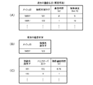
端末1は、自端末が現在位置しているメッシュ(メッシュID)を把握している。そこで、測定対象抽出部23では、履歴データベース(図4参照)のメッシュIDから、端末1が現在位置するメッシュの履歴情報を抽出して、その履歴情報に基づいて、図5(A)に示すように、接続先ごとの通信時間(在圏時間)、すなわち、各接続先に接続して連続して通信していた時間を取得する。
The
図5に示す例では、図5(B)に示すように、現在の接続先が、接続先識別子が「123」となるセルである。一方、図5(A)に示すように、端末1が現在位置するメッシュ(メッシュID:16097)の履歴情報では、2つの接続先(接続先識別子:101,123)がある。ここで、履歴データベース(図4参照)では、各時刻(Time)を1秒間隔としており、接続先(接続先識別子:101)では、通信時間が2秒となり、接続先(接続先識別子:123)では、通信時間が1秒となる。
In the example shown in FIG. 5, as shown in FIG. 5B, the current connection destination is a cell whose connection destination identifier is “123”. On the other hand, as shown in FIG. 5A, there are two connection destinations (connection destination identifiers: 101, 123) in the history information of the mesh (mesh ID: 16097) in which the
また、測定対象抽出部23では、接続先ごとの通信時間から、図5(C)に示すように、接続先ごとの期待通信時間を算出する。
Further, the measurement
このとき、現在通信中の接続先ではない、すなわち、その接続先と接続するにはハンドオーバを行うことが必要となる接続先である場合には、ハンドオーバに関するパラメータとして、ハンドオーバ時の端末1や基地局2の負荷に相当するハンドオーバコストを接続先ごとに設定して、この接続先ごとのハンドオーバコストと、端末1が現在位置するメッシュの履歴情報から取得した接続先ごとの通信時間とに基づいて、接続先ごとの期待通信時間を算出する。すなわち、通信時間をハンドオーバコストで補正することで、期待通信時間を算出する。
At this time, if the connection destination is not the connection destination currently being communicated with, that is, the connection destination requires a handover to connect to the connection destination, the
具体的には、次式のように、履歴情報から取得した接続先ごとの通信時間から、接続先ごとのハンドオーバコストを減算して、接続先ごとの期待通信時間を算出する。なお、現在通信中の接続先では、ハンドオーバコストは「0」となる。
期待通信時間=通信時間-ハンドオーバコスト
Specifically, as shown in the following equation, the expected communication time for each connection destination is calculated by subtracting the handover cost for each connection destination from the communication time for each connection destination acquired from the history information. The handover cost is "0" at the connection destination currently being communicated.
Expected communication time = communication time-handover cost
図5(C)に示す例では、現在通信中の接続先ではない場合のハンドオーバコストを0.5sに設定しており、現在の接続先(接続先識別子:123)では、期待通信時間は、1s-0s=1sとなる。一方、現在の接続先と異なる接続先(接続先識別子:101)では、期待通信時間は、2s-0.5s=1.5sとなる。 In the example shown in FIG. 5C, the handover cost when the connection destination is not currently being communicated is set to 0.5s, and the expected communication time is set at the current connection destination (connection destination identifier: 123). 1s-0s = 1s. On the other hand, at a connection destination different from the current connection destination (connection destination identifier: 101), the expected communication time is 2s-0.5s = 1.5s.
これにより、接続先が、現在通信中の接続先でない、すなわち、その接続先と接続するにはハンドオーバが必要となる場合には、期待通信時間が短くなり、ハンドオーバが発生する接続先の評価が低くなる。 As a result, when the connection destination is not the connection destination currently being communicated, that is, when a handover is required to connect to the connection destination, the expected communication time is shortened, and the evaluation of the connection destination where the handover occurs is evaluated. It gets lower.
次に、第1実施形態に係る測定対象抽出部23で参照される通信時間テーブルについて説明する。図6は、通信時間テーブルの一例を示す説明図である。
Next, the communication time table referred to by the measurement
測定対象抽出部23では、記憶部14の通信時間テーブルに基づいて、現在通信中のアプリケーションの必要通信時間を取得する。
The measurement
この通信時間テーブルには、アプリケーションごとの必要通信時間(連続通信時間)が登録されている。図6に示す例では、VoLTE通話、映像配信、トーク(チャット)、VoIP通話、地図配信、経路案内、ゲームの各アプリケーションの必要通信時間が登録されている。ここでは、アプリケーションの種類ごとに、必要通信時間を登録する例を示しているが、個別のアプリケーションごとに一意に設定されるスライスIDなどの識別情報を用いて、アプリケーション個々に必要通信時間を登録するようにしてもよい。 The required communication time (continuous communication time) for each application is registered in this communication time table. In the example shown in FIG. 6, the required communication time of each application of VoLTE call, video distribution, talk (chat), VoIP call, map distribution, route guidance, and game is registered. Here, an example of registering the required communication time for each application type is shown, but the required communication time is registered for each application using identification information such as a slice ID uniquely set for each application. You may try to do it.
なお、アプリケーションごとの必要通信時間は、ユーザの使用状況に応じて大きく変わるため、ユーザの使用状況に応じて通信時間テーブルを更新するようにしてもよい。 Since the required communication time for each application varies greatly depending on the usage status of the user, the communication time table may be updated according to the usage status of the user.
次に、第1実施形態に係る接続先探索部21で行われる処理の手順について説明する。図7は、接続先探索部21で行われる処理の手順を示すフロー図である。なお、この手順は、データ受信(ダウンロード)時およびデータ送信(アップロード)時の両方に適用される。
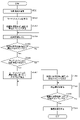
Next, the procedure of the process performed by the connection
接続先探索部21では、まず、位置情報取得部12から取得した端末1の現在の位置情報に基づいて、端末1が現在位置するメッシュIDを取得する(ST101)。次に、通信時間を考慮した制御を行うか否かを判定する(ST102)。なお、通信時間を考慮した制御を行うか否かは、予めユーザが設定しておくようにするとよい。または、電池残量が閾値以下になった場合に通信時間を考慮した制御を行う設定としてもよい。
First, the connection
ここで、通信時間を考慮した制御を行う場合には(ST102でYes)、次に、履歴データベースから、端末1が現在位置するメッシュIDの履歴情報を抽出して、その履歴情報に基づいて、接続先ごとの通信時間(在圏時間)を取得する(ST103)。次に、接続先ごとの通信時間およびハンドオーバコストに基づいて、接続先ごとの期待通信時間を算出する(ST104)。
Here, when performing control in consideration of the communication time (Yes in ST102), next, the history information of the mesh ID in which the
また、記憶部14の通信時間テーブルに基づいて、現在通信中のアプリケーションの必要通信時間を取得する(ST105)。 Further, the required communication time of the application currently being communicated is acquired based on the communication time table of the storage unit 14 (ST105).
次に、接続先番号jおよび選定済み接続先nを初期化する(ST106)。そして、期待通信時間が長い順に接続先を並べるソートを行い、順に接続先に接続先番号jを割り振る(ST107)。 Next, the connection destination number j and the selected connection destination n are initialized (ST106). Then, sorting is performed in which the connection destinations are arranged in descending order of the expected communication time, and the connection destination number j is assigned to the connection destinations in order (ST107).
次に、既に測定対象に選定された接続先の数(選定済み接続先数n)が、測定対象とする上限の接続先の数(測定対象抽出数N)より小さいか否かを判定する(ST108)。なお、測定対象抽出数Nは、予め端末1に設定されていてもよい。あるいは、端末の電池残量に応じて可変に設定されてもよく、電池残量が少なければ、測定対象抽出数Nが小さくなるように設定する。ここで、選定済み接続先数nが測定対象抽出数Nより小さい場合には(ST107でYes)、次に、接続先番号jの接続先(最初は期待通信時間が最も長い接続先)を対象にして、期待通信時間が必要通信時間以上か否かを判定する(ST109)。
Next, it is determined whether or not the number of connection destinations already selected as the measurement target (number of selected connection destinations n) is smaller than the number of upper limit connection destinations to be measured (measurement target extraction number N) ( ST108). The measurement target extraction number N may be set in the
ここで、期待通信時間が必要通信時間以上である場合には(ST109でYes)、その接続先を測定対象に選定して、選定済み接続先nを1増分する(ST110)。そして、接続先番号jを1増分して(ST111)、ST108に戻り、次順位の接続先を対象にして判定を行う。なお、ここでは図示していないが、増分された接続先番号jが、期待通信時間が長い順にソートされた接続先の数に達した場合は、選定済み接続先数nが測定対象抽出数Nに達しなくても、ST112に遷移するものとする。 Here, when the expected communication time is longer than the required communication time (Yes in ST109), the connection destination is selected as the measurement target, and the selected connection destination n is incremented by 1 (ST110). Then, the connection destination number j is incremented by 1 (ST111), returned to ST108, and a determination is made for the connection destination of the next order. Although not shown here, when the incremented connection destination number j reaches the number of connection destinations sorted in descending order of expected communication time, the number of selected connection destinations n is the number of extractions to be measured N. Even if it does not reach, it is assumed that the transition to ST112 is made.
一方、期待通信時間が必要通信時間以上でない場合には(ST109でNo)、接続先番号jの接続先を測定対象に選定することなく、接続先番号jを1増分して(ST111)、ST108に戻り、次順位の接続先を対象にして判定を行う。 On the other hand, if the expected communication time is not longer than the required communication time (No in ST109), the connection destination number j is incremented by 1 (ST111) without selecting the connection destination of the connection destination number j as the measurement target, and ST108. Return to, and make a judgment targeting the next-ranked connection destination.
そして、選定済み接続先数nが測定対象抽出数Nに達すると(ST108でNo)、測定対象に選定された接続先を対象にしてSINRを測定する(ST112)。 Then, when the number of selected connection destinations n reaches the number of extractions to be measured N (No in ST108), SINR is measured for the connection destinations selected as the measurement target (ST112).
一方、通信時間を考慮した制御を行わない場合には(ST102でNo)、履歴データベースから、端末1が現在位置するメッシュIDの履歴情報を抽出して、その履歴情報に基づいて、接続先ごとの通信品質を取得する(ST113)。次に、通信品質が高い順に接続先を並べるソートを行い、通信品質が上位から所定数(測定対象抽出数N)の接続先を測定対象として選定する(ST114)。そして、測定対象に選定された接続先を対象にしてSINRを測定する(ST112)。
On the other hand, when the control in consideration of the communication time is not performed (No in ST102), the history information of the mesh ID in which the
このように本実施形態では、通信時間が長い接続先から順に測定対象に選定することから、通信時間が長い接続先に絞り込むことができるため、ハンドオーバによる瞬断を低減することができる。 As described above, in the present embodiment, since the connection destinations having the longest communication time are selected in order from the connection destinations, the connection destinations having the long communication time can be narrowed down, so that the momentary interruption due to the handover can be reduced.
なお、本実施形態では、履歴情報から接続先ごとの通信時間を求めて、その通信時間をハンドオーバコストで補正することで期待通信時間を取得して、その期待通信時間が、使用中のアプリケーションの必要通信時間以上となる場合に、測定対象に選定するようにしたが、ハンドオーバコストによる補正を省略するようにしてもよい。さらに、使用中のアプリケーションの必要通信時間との比較を省略して、通信時間が長いものから所定数(測定対象抽出数N)の接続先を測定対象として選定するようにしてもよい。 In this embodiment, the communication time for each connection destination is obtained from the history information, and the expected communication time is obtained by correcting the communication time with the handover cost, and the expected communication time is the expected communication time of the application in use. When the required communication time is exceeded, it is selected as the measurement target, but the correction due to the handover cost may be omitted. Further, the comparison with the required communication time of the application in use may be omitted, and a predetermined number of connection destinations (measurement target extraction number N) may be selected as the measurement target from the one having the long communication time.
また、本実施形態では、履歴情報から接続先ごとの通信時間を取得して、その通信時間に基づいて、測定対象とする接続先を抽出するようにしたが、履歴情報から接続先ごとの通信時間および通信品質(例えば受信電力)を取得して、その通信時間および通信品質の両方に基づいて、測定対象とする接続先を抽出するようにしてもよい。 Further, in the present embodiment, the communication time for each connection destination is acquired from the history information, and the connection destination to be measured is extracted based on the communication time. However, the communication for each connection destination is extracted from the history information. The time and communication quality (for example, received power) may be acquired, and the connection destination to be measured may be extracted based on both the communication time and the communication quality.
次に、第1実施形態に係る接続先探索処理の効果について説明する。図8は、接続先探索処理の効果の一例を示す説明図である。 Next, the effect of the connection destination search process according to the first embodiment will be described. FIG. 8 is an explanatory diagram showing an example of the effect of the connection destination search process.
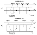
本例では、図8(A)に示すように、5GのNR(New Radio)となる高SHF帯またはEHF帯(ミリ波帯)を利用した無線通信を行う2つのセルA,Bが隣接しており、端末1が移動するのに応じて、2つのセルA,Bのいずれかが接続先に選択される。
In this example, as shown in FIG. 8A, two cells A and B that perform wireless communication using a high SHF band or an EHF band (millimeter wave band) having a 5G NR (New Radio) are adjacent to each other. Therefore, one of the two cells A and B is selected as the connection destination according to the movement of the
ここで、図8(B)に示すように、履歴情報の通信品質が良好な接続先が、セルA、セルB、セルA、セルBと変化する場合、図8(C-1)に示すように、本実施形態による制御を行わない場合、すなわち、履歴情報の通信品質に基づいて測定対象を抽出した場合には、ハンドオーバによる瞬断が頻発する。 Here, as shown in FIG. 8 (B), when the connection destination with good communication quality of the history information changes to cell A, cell B, cell A, and cell B, it is shown in FIG. 8 (C-1). As described above, when the control according to the present embodiment is not performed, that is, when the measurement target is extracted based on the communication quality of the history information, the momentary interruption due to the handover occurs frequently.
一方、図8(C-2)に示すように、本実施形態による制御を行うと、ハンドオーバが抑制され、接続先をセルAとした状態が継続し、ハンドオーバによる瞬断を抑制することができる。 On the other hand, as shown in FIG. 8 (C-2), when the control according to the present embodiment is performed, the handover is suppressed, the state where the connection destination is the cell A continues, and the momentary interruption due to the handover can be suppressed. ..
また、図8(D)に示すように、本実施形態による制御を行うと、ハンドオーバによる瞬断が抑制されるため、本実施形態による制御を行わない場合より累積通信容量を増やすことができる。 Further, as shown in FIG. 8D, when the control according to the present embodiment is performed, the momentary interruption due to the handover is suppressed, so that the cumulative communication capacity can be increased as compared with the case where the control according to the present embodiment is not performed.
なお、本実施形態では、履歴情報の通信時間を考慮して、測定対象となる接続先を抽出するようにしたが、通信時間に加えて、履歴情報の通信品質を考慮して、測定対象となる接続先を抽出するようにしてもよい。 In this embodiment, the connection destination to be measured is extracted in consideration of the communication time of the history information. However, in addition to the communication time, the communication quality of the history information is considered as the measurement target. The connection destination may be extracted.
(第2実施形態)
次に、第2実施形態について説明する。なお、ここで特に言及しない点は前記の実施形態と同様である。
(Second Embodiment)
Next, the second embodiment will be described. It should be noted that the points not particularly mentioned here are the same as those in the above-described embodiment.
第1実施形態では、履歴情報に含まれる通信時間(在圏時間)を考慮して、測定対象となる接続先を抽出するようにしたが、本実施形態では、通信時間の他に端末1の移動速度を考慮して、測定対象となる接続先を抽出する。
In the first embodiment, the connection destination to be measured is extracted in consideration of the communication time (occupied time) included in the history information, but in the present embodiment, in addition to the communication time, the
次に、第2実施形態に係る測定対象抽出部23で参照される履歴データベースについて説明する。図9は、履歴データベースの登録内容の一例を示す説明図である。
Next, the history database referred to by the measurement
本実施形態では、履歴データベースに、履歴情報として、例えば1秒間隔の各時刻(Time)におけるメッシュID、移動速度、接続先情報および通信品質情報が登録されている。メッシュID、接続先情報および通信品質情報は、第1実施形態(図4参照)と同様である。移動速度は、当該時刻における端末1の移動速度である。なお、移動速度は、位置情報取得部12で取得した位置情報の推移状況から算出すればよい。
In the present embodiment, as history information, for example, a mesh ID, a movement speed, connection destination information, and communication quality information at each time (Time) at 1-second intervals are registered in the history database. The mesh ID, connection destination information, and communication quality information are the same as those in the first embodiment (see FIG. 4). The moving speed is the moving speed of the
次に、第2実施形態に係る測定対象抽出部23で行われる処理について説明する。図10は、測定対象抽出部23で行われる処理の概要を示す説明図である。
Next, the process performed by the measurement
第1実施形態(図5参照)と同様に、図10に示す例では、図10(B)に示すように、現在の接続先が、接続先識別子が「123」となるセルである。一方、図10(A)に示すように、端末1が現在位置するメッシュ(メッシュID:16097)の履歴情報では、2つの接続先(接続先識別子:101,123)がある。ここで、履歴データベース(図9参照)では、各時刻(Time)を1秒間隔としており、接続先(接続先識別子:101)では、通信時間が2秒となり、接続先(接続先識別子:123)では、通信時間が1秒となる。
Similar to the first embodiment (see FIG. 5), in the example shown in FIG. 10, as shown in FIG. 10B, the current connection destination is a cell whose connection destination identifier is “123”. On the other hand, as shown in FIG. 10A, there are two connection destinations (connection destination identifiers: 101, 123) in the history information of the mesh (mesh ID: 16097) in which the
本実施形態では、履歴データベースから、接続先ごとの通信時間の他に、接続先ごとの移動速度も取得する。そして、接続先ごとの通信時間および移動速度から、図10(C)に示すように、接続先ごとの期待通信時間を算出する。なお、同じ接続先の履歴情報として異なる移動速度が複数ある場合は、平均値を取得するようにしてもよいし、直近の履歴情報の移動速度を取得するようにしてもよいし、現在の端末1の移動速度に最も近い移動速度を取得するようにしてもよい。 In the present embodiment, in addition to the communication time for each connection destination, the movement speed for each connection destination is also acquired from the history database. Then, as shown in FIG. 10C, the expected communication time for each connection destination is calculated from the communication time and the moving speed for each connection destination. If there are multiple different movement speeds as the history information of the same connection destination, the average value may be acquired, the movement speed of the latest history information may be acquired, or the current terminal may be acquired. The movement speed closest to the movement speed of 1 may be acquired.
ここで、端末1の移動速度が速くなるのに応じて通信品質が低下することから、履歴情報の接続先に対応する移動速度より、現在の移動速度の方が速い状況にあった場合は、その接続先を低く評価する必要がある。
Here, since the communication quality deteriorates as the moving speed of the
そこで、本実施形態では、現在通信中でない接続先では、履歴情報から取得した過去の移動速度と現在の移動速度との比率(過去の移動速度/現在の移動速度)である速度係数を求めて、次式のように、通信時間からハンドオーバコストを減算した値に速度係数を乗じて、期待通信時間を算出する。なお、本実施形態でも、現在通信中の接続先では、ハンドオーバコストは「0」、現在通信中ではない接続先では、ハンドオーバコストは「0.5」に設定している。また、現在通信中の接続先では、過去の移動速度と現在の移動速度は同じなので、速度係数は「1」となる。
期待通信時間=(通信時間-ハンドオーバコスト)×速度係数
Therefore, in the present embodiment, at the connection destination that is not currently communicating, a speed coefficient that is a ratio (past movement speed / current movement speed) between the past movement speed and the current movement speed acquired from the history information is obtained. , The expected communication time is calculated by multiplying the value obtained by subtracting the handover cost from the communication time by the speed coefficient as shown in the following equation. Also in this embodiment, the handover cost is set to "0" at the connection destination currently being communicated, and the handover cost is set to "0.5" at the connection destination not currently communicating. Further, at the connection destination currently being communicated, the past movement speed and the current movement speed are the same, so the speed coefficient is "1".
Expected communication time = (communication time-handover cost) x speed coefficient
図10(A)に示す例では、現在の接続先(接続先識別子:123)での移動速度が10km/hとなり、別の接続先(接続先識別子:101)での移動速度が5km/hとなっている。したがって、図10に示すように、現在の接続先(接続先識別子:123)では、期待通信時間は、(1s-0s)×(10/10)=1sとなる。一方、現在の接続先と異なる接続先(接続先識別子:101)では、期待通信時間は、(2s-0.5s)×(5/10)=0.75sとなる。 In the example shown in FIG. 10A, the moving speed at the current connection destination (connection destination identifier: 123) is 10 km / h, and the movement speed at another connection destination (connection destination identifier: 101) is 5 km / h. It has become. Therefore, as shown in FIG. 10, at the current connection destination (connection destination identifier: 123), the expected communication time is (1s-0s) × (10/10) = 1s. On the other hand, at a connection destination different from the current connection destination (connection destination identifier: 101), the expected communication time is (2s-0.5s) × (5/10) = 0.75s.
これにより、過去の移動速度が現在の移動速度より遅い場合には、期待通信時間が短くなり、現在の移動速度より移動速度が遅い状況にあった接続先の評価が低くなる。 As a result, when the past movement speed is slower than the current movement speed, the expected communication time becomes shorter, and the evaluation of the connection destination in the situation where the movement speed is slower than the current movement speed becomes low.
次に、第2実施形態に係る接続先探索部21で行われる処理の手順について説明する。図11は、接続先探索部21で行われる処理の手順を示すフロー図である。なお、この手順は、データ受信(ダウンロード)時およびデータ送信(アップロード)時の両方に適用される。
Next, the procedure of the process performed by the connection
接続先探索部21では、まず、位置情報取得部12から取得した端末1の現在の位置情報に基づいて、端末1が現在位置するメッシュIDを取得する(ST101)。次に、通信時間および移動速度を考慮した制御を行うか否かを判定する(ST121)。
First, the connection
ここで、通信時間および移動速度を考慮した制御を行う場合には(ST121でYes)、次に、履歴データベースから、端末1が現在位置するメッシュIDの履歴情報を抽出して、その履歴情報に基づいて、接続先ごとの通信時間(在圏時間)および移動速度を取得する(ST122)。次に、接続先ごとの通信時間、ハンドオーバコストおよび移動速度に基づいて、接続先ごとの期待通信時間を算出する(ST123)。
Here, when performing control in consideration of the communication time and the moving speed (Yes in ST121), next, the history information of the mesh ID in which the
以降は、第1実施形態(図7参照)と同様である。 After that, it is the same as the first embodiment (see FIG. 7).
(第3実施形態)
次に、第3実施形態について説明する。なお、ここで特に言及しない点は前記の実施形態と同様である。
(Third Embodiment)
Next, the third embodiment will be described. It should be noted that the points not particularly mentioned here are the same as those in the above-described embodiment.
第1実施形態では、履歴情報に含まれる通信時間を考慮して、測定対象となる接続先を抽出するようにしたが、本実施形態では、通信時の消費電流を考慮して、測定対象となる接続先を抽出する。 In the first embodiment, the connection destination to be measured is extracted in consideration of the communication time included in the history information, but in the present embodiment, the measurement target is in consideration of the current consumption during communication. Extract the connection destination.
次に、第3実施形態に係る端末1の概略構成について説明する。図12は、端末1の概略構成を示すブロック図である。
Next, a schematic configuration of the
端末1の構成は、第1実施形態(図3参照)と略同様であるが、本実施形態では、消費電流測定部31が設けられている。この消費電流測定部31は、通信時に電池32から通信部11に給電する電流を測定する。
The configuration of the
なお、本実施形態では、電池32から通信部11に給電する電流を測定するようにしたが、電池32の残量の変化で消費電流を測定するようにしてもよい。また、消費電流ではなく、消費電力を測定するようにしてもよい。
In the present embodiment, the current supplied from the
次に、第3実施形態に係る測定対象抽出部23で参照される履歴データベースについて説明する。図13は、履歴データベースの登録内容の一例を示す説明図である。
Next, the history database referred to by the measurement
本実施形態では、履歴データベースに、履歴情報として、例えば1秒間隔の各時刻(Time)におけるメッシュID、消費電流、接続先情報および通信品質情報が登録されている。メッシュID、接続先情報および通信品質情報は、第1実施形態(図4参照)と同様である。消費電流は、当該時刻において消費電流測定部31で測定された消費電流である。
In the present embodiment, as history information, for example, a mesh ID, current consumption, connection destination information, and communication quality information at each time (Time) at 1-second intervals are registered in the history database. The mesh ID, connection destination information, and communication quality information are the same as those in the first embodiment (see FIG. 4). The current consumption is the current consumption measured by the current
次に、第3実施形態に係る測定対象抽出部23で行われる処理について説明する。図14は、測定対象抽出部23で行われる処理の概要を示す説明図である。
Next, the process performed by the measurement
前記実施形態と同様に、図14に示す例では、図14(B)に示すように、現在の接続先が、接続先識別子が「123」となるセルである。一方、図14(A)に示すように、端末1が現在位置するメッシュ(メッシュID:16097)の履歴情報では、2つの接続先(接続先識別子:101,123)がある。ここで、履歴データベース(図13参照)では、接続先(接続先識別子:101)に該当する消費電流は「500」と「400」の2つがあり、接続先(接続先識別子:123)に該当する消費電流は、「200」の1つである。
Similar to the above embodiment, in the example shown in FIG. 14, as shown in FIG. 14B, the current connection destination is a cell whose connection destination identifier is “123”. On the other hand, as shown in FIG. 14A, there are two connection destinations (connection destination identifiers: 101, 123) in the history information of the mesh (mesh ID: 16097) in which the
本実施形態では、測定対象抽出部23において、履歴データベースから、端末1が現在位置するメッシュの履歴情報を抽出して、その履歴情報に基づいて、図14(A)に示すように、接続先ごとの自端末の消費電流を取得する。このとき、同じ接続先において複数の消費電流がある場合は、その平均値を当該接続先の消費電流とするとよい。ここでは、接続先(接続先識別子:101)に該当する消費電流は「500」と「400」の2つがあるので、その平均である「450」とする。そして、接続先ごとの消費電流に基づいて、図14(C)に示すように、接続先ごとの期待消費電流(その接続先に接続した場合に予想される自端末の消費電流)を算出する。
In the present embodiment, the measurement
具体的には、次式のように、履歴情報から取得した接続先ごとの消費電流から、接続先ごとのハンドオーバコストに定数を乗じたものを減算して、接続先ごとの期待消費電流を算出する。なお、本実施形態でも、現在通信中の接続先では、ハンドオーバコストは「0」、現在通信中ではない接続先では、ハンドオーバコストは「0.5」に設定しているが、シミュレーションにより消費電流の場合に最適なハンドオーバコストを決定してもよい。
期待消費電流=消費電流+(定数×ハンドオーバコスト)
Specifically, as shown in the following equation, the expected current consumption for each connection destination is calculated by subtracting the handover cost for each connection destination multiplied by a constant from the current consumption for each connection destination acquired from the history information. do. Also in this embodiment, the handover cost is set to "0" at the connection destination currently in communication, and the handover cost is set to "0.5" at the connection destination not currently communicating. In this case, the optimum handover cost may be determined.
Expected current consumption = current consumption + (constant x handover cost)
図14(C)に示す例では、ハンドオーバコストに乗じる定数を「100」に設定しており、現在の接続先(接続先識別子:123)では、期待消費電流は、200+(100×0)=200mAとなる。したがって、現在の接続先の期待消費電流は、履歴情報の消費電流に等しくなる。一方、現在の接続先と異なる接続先(接続先識別子:101)では、期待消費電流は、450+(100×0.5)=500mAとなる。したがって、接続するにはハンドオーバが発生する接続先の期待消費電流は、履歴情報の消費電流よりも大きくなる。 In the example shown in FIG. 14C, the constant to be multiplied by the handover cost is set to "100", and at the current connection destination (connection destination identifier: 123), the expected current consumption is 200+ (100 × 0) =. It will be 200mA. Therefore, the expected current consumption of the current connection destination is equal to the current consumption of the historical information. On the other hand, at a connection destination different from the current connection destination (connection destination identifier: 101), the expected current consumption is 450 + (100 × 0.5) = 500 mA. Therefore, the expected current consumption of the connection destination where the handover occurs for connection is larger than the current consumption of the history information.
これにより、接続先が、現在通信中の接続先でない、すなわち、ハンドオーバが必要となる場合には、期待消費電流が大きくなり、ハンドオーバが必要となる接続先の評価が低くなる。 As a result, when the connection destination is not the connection destination currently being communicated, that is, when handover is required, the expected current consumption becomes large, and the evaluation of the connection destination requiring handover becomes low.
次に、第3実施形態に係る測定対象抽出部23で参照される消費電流テーブルについて説明する。図15は、消費電流テーブルの一例を示す説明図である。
Next, the current consumption table referred to by the measurement
本実施形態では、測定対象抽出部23において、記憶部14の消費電流テーブルに基づいて、現在通信中のアプリケーションが動作するのに必要とする必要消費電流を取得する。
In the present embodiment, the measurement
この消費電流テーブルには、アプリケーションごとの必要消費電流(単位時間当たりの平均消費電流)が登録されている。図15に示す例では、VoLTE通話、映像配信、トーク(チャット)、VoIP通話、地図配信、経路案内、ゲームの各アプリケーションの必要通信時間が登録されている。ここでは、アプリケーションの種類ごとに、必要消費電流を登録する例を示しているが、個別のアプリケーションごとに一意に設定されるスライスIDなどの識別情報を用いて、アプリケーション個々に必要消費電流を登録するようにしてもよい。 In this current consumption table, the required current consumption (average current consumption per unit time) for each application is registered. In the example shown in FIG. 15, the required communication time of each application of VoLTE call, video distribution, talk (chat), VoIP call, map distribution, route guidance, and game is registered. Here, an example of registering the required current consumption for each application type is shown, but the required current consumption is registered for each application using identification information such as a slice ID uniquely set for each application. You may try to do it.
なお、アプリケーションごとの必要消費電流は、ユーザの使用状況に応じて大きく変わるため、ユーザの使用状況に応じて消費電流テーブルを更新するようにしてもよい。 Since the required current consumption for each application varies greatly depending on the usage status of the user, the current consumption table may be updated according to the usage status of the user.
次に、第3実施形態に係る接続先探索部21で行われる処理の手順について説明する。図16は、接続先探索部21で行われる処理の手順を示すフロー図である。なお、この手順は、データ送信(アップロード)時に適用される。
Next, the procedure of the process performed by the connection
接続先探索部21では、まず、位置情報取得部12から取得した端末1の現在の位置情報に基づいて、端末1が現在位置するメッシュIDを取得する(ST101)。次に、消費電流を考慮した制御を行うか否かを判定する(ST131)。
First, the connection
ここで、消費電流を考慮した制御を行う場合には(ST131でYes)、次に、履歴データベースから、端末1が現在位置するメッシュIDの履歴情報を抽出して、その履歴情報に基づいて、接続先ごとの消費電流を取得する(ST132)。次に、接続先ごとの消費電流およびハンドオーバコストに基づいて、接続先ごとの期待消費電流を算出する(ST133)。
Here, when performing control in consideration of the current consumption (Yes in ST131), next, the history information of the mesh ID in which the
また、記憶部14の消費電流テーブルに基づいて、現在通信中のアプリケーションの必要消費電流を取得する(ST134)。 Further, the required current consumption of the application currently being communicated is acquired based on the current consumption table of the storage unit 14 (ST134).
次に、接続先番号jおよび選定済み接続先数nを初期化する(ST106)。そして、端末1の消費電流が小さい接続先を優先するため、期待消費電流が小さい順に接続先を並べるソートを行い、順に接続先に接続先番号jを割り振る(ST135)。
Next, the connection destination number j and the number of selected connection destinations n are initialized (ST106). Then, in order to give priority to the connection destination having the smaller current consumption of the
次に、選定済み接続先数nが測定対象抽出数Nより小さいか否かを判定する(ST108)。ここで、選定済み接続先数nが測定対象抽出数Nより小さい場合には(ST108でYes)、次に、接続先番号jの接続先(最初は期待消費電流が最も小さい接続先)を対象にして、期待消費電流が必要消費電流以上か否かを判定する(ST136)。 Next, it is determined whether or not the selected connection destination number n is smaller than the measurement target extraction number N (ST108). Here, when the number of selected connection destinations n is smaller than the number of extractions to be measured N (Yes in ST108), then the connection destination of the connection destination number j (initially, the connection destination with the smallest expected current consumption) is targeted. Then, it is determined whether or not the expected current consumption is equal to or higher than the required current consumption (ST136).
ここで、期待消費電流が必要消費電流以上である場合には(ST136でYes)、その接続先を測定対象に選定して、選定済み接続先nを1増分する(ST110)。そして、接続先番号jを1増分して(ST111)、ST108に戻り、次順位の接続先を対象にして判定を行う。 Here, when the expected current consumption is equal to or greater than the required current consumption (Yes in ST136), the connection destination is selected as the measurement target, and the selected connection destination n is incremented by 1 (ST110). Then, the connection destination number j is incremented by 1 (ST111), returned to ST108, and a determination is made for the connection destination of the next order.
一方、期待消費電流が必要消費電流以上でない場合には(ST136でNo)、接続先を測定対象に選定することなく、接続先番号jを1増分して(ST101)、ST108に戻り、次順位の接続先を対象にして判定を行う。 On the other hand, if the expected current consumption is not equal to or higher than the required current consumption (No in ST136), the connection destination number j is incremented by 1 (ST101) without selecting the connection destination as the measurement target, and the process returns to ST108, and the order is next. Judgment is made for the connection destination of.
以降は、第1実施形態(図7参照)と同様である。 After that, it is the same as the first embodiment (see FIG. 7).
このように本実施形態では、端末1の消費電流が小さい接続先から順に測定対象に選定することから、測定対象を消費電流が小さい接続先に絞り込むことができるため、端末1の消費電力を低減することができる。
As described above, in the present embodiment, since the connection destinations having the lowest current consumption of the
なお、本実施形態では、履歴情報から接続先ごとの消費電流を取得して、その消費電流に基づいて、測定対象とする接続先を抽出するようにしたが、履歴情報から接続先ごとの消費電流および通信品質(例えば受信電力)を取得して、その消費電流および通信品質の両方に基づいて、測定対象とする接続先を抽出するようにしてもよい。 In this embodiment, the current consumption for each connection destination is acquired from the history information, and the connection destination to be measured is extracted based on the current consumption. However, the consumption for each connection destination is extracted from the history information. The current and communication quality (for example, received power) may be acquired, and the connection destination to be measured may be extracted based on both the current consumption and the communication quality.
(第4実施形態)
次に、第4実施形態について説明する。なお、ここで特に言及しない点は前記の実施形態と同様である。
(Fourth Embodiment)
Next, the fourth embodiment will be described. It should be noted that the points not particularly mentioned here are the same as those in the above-described embodiment.
第3実施形態では、履歴情報に含まれる消費電流を考慮して、測定対象となる接続先を抽出するようにしたが、本実施形態では、消費電流の他に、履歴情報に含まれる通信中アプリケーションを考慮して、測定対象となる接続先を抽出する。 In the third embodiment, the connection destination to be measured is extracted in consideration of the current consumption included in the history information, but in the present embodiment, in addition to the current consumption, during communication included in the history information. Extract the connection destination to be measured in consideration of the application.
次に、第4実施形態に係る測定対象抽出部23で参照される履歴データベースについて説明する。図17は、履歴データベースの登録内容の一例を示す説明図である。
Next, the history database referred to by the measurement
本実施形態では、履歴データベースに、履歴情報として、例えば1秒間隔の各時刻(Time)におけるメッシュID、通信中アプリケーション、消費電流、接続先情報および通信品質情報が登録されている。メッシュID、消費電流、接続先情報および通信品質情報は、第3実施形態(図13参照)と同様である。通信中アプリケーションは、当該時刻において通信部11を使用して通信を行っていたアプリケーションの識別情報である。このアプリケーションの識別情報は、アプリケーションの種類ごとの識別情報であっても、あるいは、個別のアプリケーションごとに一意に設定されるスライスIDなどの識別情報であってもよい。
In the present embodiment, as history information, for example, a mesh ID at each time (Time) at 1-second intervals, a communication application, current consumption, connection destination information, and communication quality information are registered in the history database. The mesh ID, current consumption, connection destination information, and communication quality information are the same as those in the third embodiment (see FIG. 13). The communicating application is identification information of the application that was communicating using the
次に、第4実施形態に係る測定対象抽出部23で行われる処理について説明する。図18は、測定対象抽出部23で行われる処理の概要を示す説明図である。
Next, the process performed by the measurement
前記実施形態と同様に、図18に示す例では、図18(B)に示すように、現在の接続先が、接続先識別子が「123」となるセルである。一方、図18(A)に示すように、端末1が現在位置するメッシュ(メッシュID:16097)の履歴情報では、2つの接続先(接続先識別子:101,123)がある。ここで、履歴データベース(図17参照)では、接続先(接続先識別子:101)に該当する履歴情報は2つあるが、いずれも通信中アプリケーションの識別情報は「A」であり、接続先(接続先識別子:123)に該当する通信中アプリケーションの識別情報は「B」である。また、接続先(接続先識別子:101)に該当する消費電流は「500」と「400」の2つがあり、接続先(接続先識別子:123)に該当する消費電流は、「200」の1つである。
Similar to the above embodiment, in the example shown in FIG. 18, as shown in FIG. 18B, the current connection destination is a cell whose connection destination identifier is “123”. On the other hand, as shown in FIG. 18A, there are two connection destinations (connection destination identifiers: 101, 123) in the history information of the mesh (mesh ID: 16097) in which the
本実施形態では、測定対象抽出部23において、履歴データベースから、端末1が現在位置するメッシュの履歴情報を抽出して、その履歴情報に基づいて、図18(A)に示すように、接続先ごとの通信中アプリケーションおよび消費電流を取得する。このとき、同じ接続先において複数の消費電流がある場合は、その平均値を当該接続先の消費電流とするとよい。ここでは、接続先(接続先識別子:101)に該当する消費電流は「500」と「400」の2つがあるので、その平均である「450」とする。なお、直近の消費電流を取得するようにしてもよい。そして、接続先ごとの通信中アプリケーションおよび消費電流に基づいて、図18(C)に示すように、接続先ごとの期待消費電流を算出する。
In the present embodiment, the measurement
また、本実施形態では、履歴情報から取得した過去の通信中アプリケーションの消費電流と現在の通信中アプリケーションの消費電流との比率(過去の通信中アプリケーションの消費電流/現在の通信中アプリケーションの消費電流)であるアプリケーション係数を求めて、次式のように、通信時間からハンドオーバコストを減算した値にアプリケーション係数を乗じて、期待消費電流を算出する。 Further, in the present embodiment, the ratio of the current consumption of the past communication application acquired from the history information to the current consumption of the current communication application (current consumption of the past communication application / current consumption of the current communication application). ) Is obtained, and the expected current consumption is calculated by multiplying the value obtained by subtracting the handover cost from the communication time by the application coefficient as shown in the following equation.
図17に示す例では、現在通信中の接続先(接続先識別子:123)の場合は、「過去の通信中アプリケーションの消費電流」と「現在の通信中アプリケーションの消費電流」のいずれも、「200」であり、現在通信中ではない接続先(接続先識別子:101)の場合は、「過去の通信中アプリケーションの消費電流」は平均値の「450」、「現在の通信中アプリケーションの消費電流」は「200」である。また、本実施形態でも、現在通信中の接続先では、ハンドオーバコストは「0」、現在通信中ではない接続先では、ハンドオーバコストは「0.5」に設定している。また、ハンドオーバコストに乗じる定数を「100」に設定している。また、現在通信中の接続先では、上述のようにアプリケーション係数は「1」となる。
期待消費電流=過去の消費電流+(定数×ハンドオーバコスト)×アプリケーション係数
In the example shown in FIG. 17, in the case of the connection destination currently being communicated (connection destination identifier: 123), both the "current consumption of the past communication application" and the "current consumption of the current communication application" are ". In the case of a connection destination (connection destination identifier: 101) that is "200" and is not currently communicating, the "current consumption of the past communication application" is the average value "450", and the "current consumption of the current communication application". Is "200". Further, also in this embodiment, the handover cost is set to "0" at the connection destination currently being communicated, and the handover cost is set to "0.5" at the connection destination not currently communicating. Further, the constant to be multiplied by the handover cost is set to "100". Further, at the connection destination currently being communicated, the application coefficient is "1" as described above.
Expected current consumption = past current consumption + (constant x handover cost) x application coefficient
図18に示す例では、図18(B)に示すように、現在の接続先が、接続先識別子が「123」となるセルであり、アプリケーションBが通信中である。一方、図18(A)に示すように、端末1が現在位置するメッシュ(メッシュID:16097)の履歴情報では、一方の接続先(接続先識別子:101)では、過去に、アプリケーションAが通信中だったことがあり、他方の接続先(接続先識別子:123)では、アプリケーションBが現在、通信中である。
In the example shown in FIG. 18, as shown in FIG. 18B, the current connection destination is the cell whose connection destination identifier is “123”, and the application B is communicating. On the other hand, as shown in FIG. 18A, in the history information of the mesh (mesh ID: 16097) in which the
ここで、現在の通信中アプリケーションBの消費電流が200mAとし、アプリケーションAの消費電流が平均値の450mAとすると、図18(C)に示すように、現在の接続先(接続先識別子:123)では、期待消費電流は、200+(100×0)×(200/200)=200mAとなる。したがって、現在の接続先の期待消費電流は、履歴情報の消費電流に等しくなる。一方、現在の接続先と異なる接続先(接続先識別子:101)では、期待消費電流は、450+(100×0.5)×(400/200)=550mAとなる。したがって、接続するにはハンドオーバが発生する接続先の期待消費電流は、履歴情報の消費電流よりも大きくなる。 Here, assuming that the current consumption of the application B currently being communicated is 200 mA and the current consumption of the application A is an average value of 450 mA, as shown in FIG. 18C, the current connection destination (connection destination identifier: 123). Then, the expected current consumption is 200+ (100 × 0) × (200/200) = 200 mA. Therefore, the expected current consumption of the current connection destination is equal to the current consumption of the historical information. On the other hand, at a connection destination different from the current connection destination (connection destination identifier: 101), the expected current consumption is 450 + (100 × 0.5) × (400/200) = 550 mA. Therefore, the expected current consumption of the connection destination where the handover occurs for connection is larger than the current consumption of the history information.
次に、第4実施形態に係る接続先探索部21で行われる処理の手順について説明する。図19は、接続先探索部21で行われる処理の手順を示すフロー図である。なお、この手順は、データ送信(アップロード)時に適用される。
Next, the procedure of the process performed by the connection
接続先探索部21では、まず、位置情報取得部12から取得した端末1の現在の位置情報に基づいて、端末1が現在位置するメッシュIDを取得する(ST101)。次に、消費電流および通信中アプリケーションを考慮した制御を行うか否かを判定する(ST141)。
First, the connection
ここで、消費電流および通信中アプリケーションを考慮した制御を行う場合には(ST141でYes)、次に、履歴データベースから、端末1が現在位置するメッシュIDの履歴情報を抽出して、その履歴情報に基づいて、接続先ごとの消費電流および通信中アプリケーションを取得する(ST142)。次に、接続先ごとの消費電流、ハンドオーバコストおよび通信中アプリケーションに基づいて、接続先ごとの期待消費電流を算出する(ST143)。
Here, when performing control in consideration of the current consumption and the application during communication (Yes in ST141), next, the history information of the mesh ID in which the
以降は、第1実施形態(図7参照)と同様である。 After that, it is the same as the first embodiment (see FIG. 7).
このように本実施形態では、端末1の使用アプリケーションの消費電流が小さい接続先から順に測定対象に選定することから、測定対象を消費電流が小さい接続先に絞り込むことができるため、端末1の消費電力を低減することができる。
As described above, in the present embodiment, since the measurement target is selected in order from the connection destination where the current consumption of the application used by the
(第5実施形態)
次に、第5実施形態について説明する。なお、ここで特に言及しない点は前記の実施形態と同様である。
(Fifth Embodiment)
Next, the fifth embodiment will be described. It should be noted that the points not particularly mentioned here are the same as those in the above-described embodiment.
本実施形態では、前記の実施形態と同様に、接続先探索処理として、履歴データベースにメッシュごとに登録された履歴情報を参照して、通信品質の測定対象とする接続先を抽出して、その接続先に関する通信品質を測定するが、前記の実施形態のように、端末1が現在位置するメッシュの履歴情報を参照するようにすると、通信品質の測定が完了する前に、参照元のメッシュを端末1が通り過ぎてしまうことで、接続先探索の処理が無駄になる場合がある。
In the present embodiment, as in the above embodiment, as the connection destination search process, the connection destination to be measured for communication quality is extracted by referring to the history information registered for each mesh in the history database, and the connection destination is extracted. The communication quality of the connection destination is measured, but if the
そこで、本実施形態では、端末1の位置情報に基づいて、端末1の移動状態(移動速度や移動方向)を推定して、その移動状態に基づいて、端末1の移動先となるメッシュ(移動先エリア)を予測して、その移動先となるメッシュの履歴情報に基づいて、通信品質の測定対象とする移動先を抽出して、その接続先に関する通信品質を測定する。
Therefore, in the present embodiment, the moving state (moving speed and moving direction) of the
これにより、接続先探索の処理が無駄になることがなく、最適な接続先を効率よく探し出すことができる。また、高速大容量なセルとの接続時間を増大することができるため、システム容量を向上させることができる。 As a result, the process of searching for a connection destination is not wasted, and the optimum connection destination can be efficiently searched for. Further, since the connection time with a high-speed and large-capacity cell can be increased, the system capacity can be improved.
次に、第5実施形態に係る端末1の概略構成について説明する。図20は、端末1の概略構成を示すブロック図である。
Next, a schematic configuration of the
端末1の構成は、第1実施形態(図3参照)と略同様であるが、制御部13が、接続先探索部21および履歴登録部22の他に、移動状態推定部25と、移動先予測部26と、タイミング制御部27と、を備えている。
The configuration of the
移動状態推定部25は、位置情報取得部12から現在の位置情報を取得し、また、記憶部14から過去の位置情報を取得して、現在の位置情報および過去の位置情報に基づいて、端末1の現在の移動状態として、移動速度および移動方向を推定する。なお、この移動状態の推定では、位置情報としての緯度、経度および高度から空間的な移動状態を取得するようにするとよいが、緯度および経度のみから水平面上の移動状態を取得するようにしてもよい。また、セル切り替え回数やセル再選択回数を計数して、その回数に基づいて移動状態を推定するようにしてもよい。
The moving
移動先予測部26は、移動状態推定部25で取得した端末1の移動状態(移動速度および移動方向)に基づいて、端末1の将来の移動先であるターゲットメッシュ(移動先エリア)を予測する。
The movement
測定対象抽出部23は、移動先予測部26で取得したターゲットメッシュの履歴情報を、記憶部14の履歴データベースから取得して、そのターゲットメッシュの履歴情報に基づいて、通信品質の測定対象とする接続先を抽出する。
The measurement
タイミング制御部27は、移動状態推定部25で取得した端末1の移動状態(移動速度および移動方向)、および現在の接続先と測定対象となる接続先とで周波数が異なるか否かに基づいて、接続先探索処理、すなわち、測定対象抽出部で行われる測定対象抽出、および通信品質測定部24で行われる通信品質測定の処理を開始するタイミング(位置)を決定し、接続先探索処理を開始するタイミングになると、測定対象抽出部23に測定対象抽出の処理を実施させ、続いて通信品質測定部24に通信品質測定の処理を実施させる。
The
次に、第5実施形態に係る移動先予測部26で行われる処理について説明する。図21は、移動先予測部26で行われる処理の概要を示す説明図である。
Next, the process performed by the move
本実施形態では、移動先予測部26において、端末1の移動状況に基づいて端末1の将来の移動先であるターゲットメッシュを予測し、そのターゲットメッシュの履歴情報を参照して、通信品質の測定対象とする接続先を抽出して、その接続先に関する通信品質を測定する。
In the present embodiment, the movement
本実施形態では、移動状態推定部25で取得した端末1の移動速度および移動方向に基づいて、ターゲットメッシュを決定する。
In the present embodiment, the target mesh is determined based on the moving speed and the moving direction of the
ここで、端末1の移動速度が遅い場合には、端末1が現在位置するメッシュに隣接するメッシュをターゲットメッシュとして選択する。
Here, when the moving speed of the
図21(A)に示す例は、端末1の移動速度が遅く、かつ、端末1がメッシュを平行方向(縦横に配列されたメッシュの配列方向に対して平行な方向)に移動する場合である。この場合、端末1が現在位置するメッシュに対して端末1の進行方向に隣接する1つのメッシュをターゲットメッシュとして選択し、ターゲットメッシュの数は1となる。なお、ここではメッシュの形状を正方形として例示するが、円や楕円であってもよい。
The example shown in FIG. 21 (A) is a case where the moving speed of the
また、図21(B)に示す例は、端末1の移動速度が遅く、かつ、端末1がメッシュを対角(斜め)方向(縦横に配列されたメッシュの配列方向に対して平行でない方向)に移動する場合である。この場合、端末1が現在位置するメッシュに対して端末1の進行方向に隣接する3つのメッシュをターゲットメッシュとして選択し、ターゲットメッシュの数は3となる。
Further, in the example shown in FIG. 21B, the moving speed of the
一方、端末1の移動速度が速いと、端末1が位置するメッシュに隣接するメッシュのみをターゲットメッシュとすると、接続先探索処理が完了する前にターゲットメッシュを端末1が通り過ぎてしまう場合がある。このため、端末1が位置するメッシュに隣接するメッシュの他に、進行方向の先にあるメッシュもターゲットメッシュとして選択する。
On the other hand, if the moving speed of the
図21(C)に示す例は、端末1の移動速度が速く、かつ、端末1がメッシュを平行方向(縦横に配列されたメッシュの配列方向に対して平行な方向)に移動する場合である。この場合、端末1の進行方向に並んだ3つのメッシュをターゲットメッシュとして選択し、ターゲットメッシュの数は3となる。
The example shown in FIG. 21C is a case where the moving speed of the
また、図21(D)に示す例は、端末1の移動速度が速く、かつ、端末1がメッシュを対角(斜め)方向(縦横に配列されたメッシュの配列方向に対して平行でない方向)に移動する場合である。この場合、端末1の進行方向に並んだ6つのメッシュをターゲットメッシュとして選択し、ターゲットメッシュの数は6となる。
Further, in the example shown in FIG. 21D, the moving speed of the
なお、図21(C),(D)に示す高速移動時の例は、図21(A),(B)に示す低速移動時の速度V1の3倍の速度V2で移動している場合を想定している。 The example of high-speed movement shown in FIGS. 21 (C) and 21 (D) is a case where the vehicle is moving at a speed V2 that is three times the speed V1 of the low-speed movement shown in FIGS. 21 (A) and 21 (B). I'm assuming.
このように本実施形態では、端末1の移動速度および移動方向に基づいて、端末1が将来進入するメッシュをターゲットメッシュとして選択して、そのターゲットメッシュの履歴情報を参照して、通信品質の測定対象とする接続先を抽出する。
As described above, in the present embodiment, the mesh that the
特に、端末1の移動速度が速い場合には、移動速度が遅い場合より、移動先エリアを大きく設定する。すなわち、移動先エリアとなるターゲットメッシュを多く設定する。これにより、移動速度が速い場合に、接続先探索処理(測定対象抽出および通信品質測定)を早期に開始することができ、接続先探索の処理が完了する前に、端末1がターゲットメッシュを通り過ぎてしまうことで、接続先探索の処理が無駄になる不都合を避けることができる。
In particular, when the moving speed of the
なお、端末1の移動速度が速い場合には、移動速度が遅い場合より、メッシュを大きく設定するようにしてもよい。このメッシュの大きさを移動速度に応じて変更することは、履歴登録部22で行われる(図29参照)。
When the moving speed of the
また、本実施形態では、図21(B),(D)に示すように、端末1がメッシュを対角(斜め)方向(縦横に配列されたメッシュの配列方向に対して平行でない方向)に移動する場合には、端末1がメッシュを平行方向(縦横に配列されたメッシュの配列方向に対して平行な方向)に移動する場合より、移動先エリアとなるターゲットメッシュを多く設定する。これにより、ターゲットメッシュの漏れをなくして、接続先探索の処理を適切に行うことができる。
Further, in the present embodiment, as shown in FIGS. 21 (B) and 21 (D), the
測定対象抽出部23では、この履歴データベースから、移動先予測部26で取得したターゲットメッシュの履歴情報を取得して、このターゲットメッシュの履歴情報に基づいて、測定対象となる接続先を抽出する。
The measurement
このとき、端末1の移動速度が速い場合には、図21(C),(D)に示したように、移動速度が遅い場合より、多数のターゲットメッシュを設定して、ターゲットメッシュの履歴情報の参照による測定対象の抽出を短い間隔で行う。また、図21(B),(D)に示したように、端末1がメッシュを対角(斜め)方向(縦横に配列されたメッシュの配列方向に対して平行でない方向)に移動する場合にも、端末1がメッシュを平行方向(縦横に配列されたメッシュの配列方向に対して平行な方向)に移動する場合より、多数のターゲットメッシュを設定して、ターゲットメッシュの履歴情報の参照による測定対象の抽出を短い間隔で行う。これにより、各ターゲットメッシュの履歴情報の参照による測定対象の抽出を適切に行うことができる。
At this time, when the moving speed of the
また、履歴データベースを参照して測定対象を抽出する際に、ターゲットメッシュに2つ以上の接続先の通信履歴がある場合には、測定時間を短縮するために、測定対象を1つに絞り込むことが望ましい。この場合、前記実施形態により接続先を抽出すればよい。このとき、期待されるスループットの高さ、受信電力の大きさ、通信データ量などの通信品質情報も合わせて考慮するようにしてもよい。 Also, when extracting the measurement target by referring to the history database, if the target mesh has communication history of two or more connection destinations, narrow down the measurement target to one in order to shorten the measurement time. Is desirable. In this case, the connection destination may be extracted according to the above embodiment. At this time, communication quality information such as the expected high throughput, the magnitude of the received power, and the amount of communication data may also be taken into consideration.
また、ターゲットメッシュの履歴情報に複数の接続先がある場合において、移動速度が速い場合には、測定対象の抽出数を、移動速度が遅い場合より増やすようにするとよい。また、端末1がメッシュを対角(斜め)方向(縦横に配列されたメッシュの配列方向に対して平行でない方向)に移動する場合には、測定対象の抽出数を、端末1がメッシュを平行方向(縦横に配列されたメッシュの配列方向に対して平行な方向)に移動する場合より増やすようにするとよい。これにより、測定対象の再抽出を避けて、接続先探索の処理を効率よく行うことができる。
Further, when there are a plurality of connection destinations in the history information of the target mesh and the moving speed is high, it is preferable to increase the number of extractions of the measurement target as compared with the case where the moving speed is slow. Further, when the
また、ターゲットメッシュの履歴情報に複数の接続先がある場合には、測定対象の抽出数を増やすことで、測定対象の再抽出を避けることができるが、測定対象が増えると、接続先探索遅延時間が長くなり、また、端末1の移動速度が速いと、接続先探索遅延時間での移動距離が大きくなり、接続先探索が完了する前にターゲットメッシュを通り過ぎてしまい、最適な接続先に接続できなくなる。このように、ターゲットメッシュの履歴情報にある接続先の数や端末1の移動速度から単純に測定対象の最適な抽出数を求めることができない面がある。そこで、端末1の移動速度と、ターゲットメッシュの履歴情報にある接続先の数と、測定対象の抽出数と、1接続先当たりの探索遅延時間との最適な組み合わせをシミュレーションで決定して、その結果に基づいて測定対象の抽出を行うようにしてもよい。
Also, if there are multiple connection destinations in the history information of the target mesh, re-extraction of the measurement target can be avoided by increasing the number of extractions of the measurement target, but if the number of measurement targets increases, the connection destination search delay If the time is long and the movement speed of the
次に、第5実施形態に係るタイミング制御部27で行われる処理について説明する。図22は、端末1の移動速度に応じた接続先探索遅延時間における端末1の移動距離を示す説明図である。図23は、端末1において接続先探索処理を開始するタイミングの一例を示す説明図である。
Next, the process performed by the
本実施形態では、端末1において、履歴データベースからターゲットメッシュの履歴情報を取得して、このターゲットメッシュの履歴情報を参照して、測定対象となる接続先を抽出して、その接続先を対象として通信品質の測定を行う。
In the present embodiment, in the
このとき、本実施形態では、ターゲットメッシュに進入する前に、接続先探索処理(測定対象抽出および通信品質測定の処理)を開始して、ターゲットメッシュに進入するまでに接続先探索処理を完了させて、ターゲットメッシュに進入したところで即座に最適な接続先に接続することができるようにする。これには、接続先探索遅延時間(接続先探索処理に要する時間)における端末1の移動距離を考慮して、接続先探索処理を開始するタイミング(位置)を決定すればよい。すなわち、ターゲットメッシュまでの距離が、接続先探索遅延時間における端末1の移動距離に一致するタイミング(位置)で接続先探索処理を開始すればよい。
At this time, in the present embodiment, the connection destination search process (measurement target extraction and communication quality measurement process) is started before entering the target mesh, and the connection destination search process is completed by the time the target mesh is entered. Then, when the target mesh is entered, it is possible to immediately connect to the optimum connection destination. For this purpose, the timing (position) for starting the connection destination search process may be determined in consideration of the moving distance of the
ここで、図22に示すように、端末1の移動速度が速いと、接続先探索遅延時間における端末1の移動距離が大きくなる。
Here, as shown in FIG. 22, when the moving speed of the
また、現在接続中の接続先と測定対象となる接続先とで周波数が異なる場合(以下、「異周波数」と呼称する)の接続先探索遅延時間は、現在接続中の接続先と測定対象となる接続先とで周波数が同じ場合(以下、「同周波数」と呼称する)の接続先探索遅延時間より長くなる。図22に示す例では、同周波数の接続先探索遅延時間を1秒とし、異周波数の接続先探索遅延時間を3.84秒としている。なお、ここでは、測定対象の周波数が1つである場合を想定している。 In addition, when the frequency is different between the connection destination currently connected and the connection destination to be measured (hereinafter referred to as "different frequency"), the connection destination search delay time is the connection destination currently connected and the measurement target. When the frequency is the same as that of the connection destination (hereinafter referred to as "same frequency"), the connection destination search delay time is longer. In the example shown in FIG. 22, the connection destination search delay time of the same frequency is set to 1 second, and the connection destination search delay time of different frequencies is set to 3.84 seconds. Here, it is assumed that the frequency to be measured is one.
このように、端末1の移動速度に応じて接続先探索遅延時間における移動距離が変化し、また。同周波数の場合と異周波数の場合とで接続先探索遅延時間が異なる。そこで、本実施形態では、端末1の移動速度と、同周波数および異周波数のいずれであるかに応じて、接続先探索処理を開始するタイミング(位置)を決定する。すなわち、同周波数の場合は、同周波数の接続先探索遅延時間と移動速度とによる移動距離を考慮したタイミング(位置)で接続先探索処理を開始し、異周波数の場合は、異周波数の接続先探索遅延時間と移動速度による移動距離を考慮したタイミング(位置)で接続先探索処理を開始する。
In this way, the moving distance in the connection destination search delay time changes according to the moving speed of the
図23(A-1),(A-2)に示す例は、端末1の移動速度を3km/h(0.8m/s)とした場合であり、図23(B-1),(B-2)に示す例は、端末1の移動速度を10km/h(2.8m/s)とした場合である。なお、メッシュサイズ(一辺の長さ)を10mとしている。
The example shown in FIGS. 23 (A-1) and 23 (A-2) is a case where the moving speed of the
図23(A-1)に示すように、移動速度が3km/hで同周波数の場合には、ターゲットメッシュまでの距離が0.8mとなる位置で、接続先探索処理(測定)を開始する。また、図23(A-2)に示すように、移動速度を3km/hで異周波数の場合には、ターゲットメッシュまでの距離が3.2mとなる位置で接続先探索処理(抽出・測定)を開始する。 As shown in FIG. 23 (A-1), when the moving speed is 3 km / h and the frequency is the same, the connection destination search process (measurement) is started at the position where the distance to the target mesh is 0.8 m. .. Further, as shown in FIG. 23 (A-2), when the moving speed is 3 km / h and the frequency is different, the connection destination search process (extraction / measurement) is performed at the position where the distance to the target mesh is 3.2 m. To start.
一方、図23(B-1)に示すように、移動速度が10km/hで同周波数の場合には、ターゲットメッシュまでの距離が2.8mとなる位置で接続先探索処理(測定)を開始する。また、図23(B-2)に示すように、移動速度が10km/hで異周波数の場合には、ターゲットメッシュまでの距離が10.7mとなる位置で接続先探索処理(抽出・測定)を開始する。この場合、2つ手前のメッシュに端末1が位置するタイミングで接続先探索処理を開始する。
On the other hand, as shown in FIG. 23 (B-1), when the moving speed is 10 km / h and the frequency is the same, the connection destination search process (measurement) is started at the position where the distance to the target mesh is 2.8 m. do. Further, as shown in FIG. 23 (B-2), when the moving speed is 10 km / h and the frequency is different, the connection destination search process (extraction / measurement) is performed at the position where the distance to the target mesh is 10.7 m. To start. In this case, the connection destination search process is started at the timing when the
ここで、測定対象として複数の接続先を抽出することで、測定する周波数が複数になる場合がある。この場合、測定する周波数の数に応じて、接続先探索処理(抽出・測定)を開始するタイミングを制御する。例えば、抽出・測定する周波数が2つある場合には、ターゲットメッシュまでの距離が、抽出・測定する周波数が1つだけの場合の2倍となるタイミング(位置)で、接続先探索処理(抽出・測定)を開始する。例えば、図23(A-2)に示す例と同様に、端末1の移動速度が3km/hの場合では、ターゲットメッシュまでの距離が6.4mとなるタイミングで接続先探索処理(抽出・測定)を開始する。
Here, by extracting a plurality of connection destinations as measurement targets, the frequency to be measured may be a plurality. In this case, the timing for starting the connection destination search process (extraction / measurement) is controlled according to the number of frequencies to be measured. For example, when there are two frequencies to be extracted / measured, the connection destination search process (extraction) is performed at a timing (position) where the distance to the target mesh is twice that when there is only one frequency to be extracted / measured.・ Start measurement). For example, as in the example shown in FIG. 23 (A-2), when the moving speed of the
次に、第5実施形態に係る端末1で行われる処理の手順について説明する。図24は、端末1で行われる処理の手順を示すフロー図である。
Next, the procedure of the processing performed by the
端末1では、まず、移動状態推定部25において、位置情報取得部12から現在の位置情報を取得し、また、記憶部14から過去の位置情報を取得して、現在の位置情報および過去の位置情報に基づいて、端末1の移動状態(移動速度および移動方向)を推定する(ST201)。次に、移動先予測部26において、端末1の移動状態に基づいて、移動先となるターゲットメッシュを予測する(ST202)。次に、タイミング制御部27において、接続先探索処理(抽出)を開始するタイミング(位置)を決定する(ST203)。
In the
次に、位置情報取得部12から現在の位置情報を取得して(ST204)、その現在の位置情報に基づいて、接続先探索処理(抽出)を開始するタイミングか否かを判定する(ST205)。 Next, the current position information is acquired from the position information acquisition unit 12 (ST204), and based on the current position information, it is determined whether or not it is the timing to start the connection destination search process (extraction) (ST205). ..
ここで、接続先探索処理(抽出)を開始するタイミングである場合には(ST205でYes)、次に、履歴データベースにターゲットメッシュの履歴情報があるか否かを判定する(ST206)。ここで、履歴データベースにターゲットメッシュの履歴情報がある場合には(ST206でYes)、測定対象抽出部23において、ターゲットメッシュの履歴情報を参照して、測定対象となる接続先(測定周波数)を抽出する(ST207)。
Here, when it is the timing to start the connection destination search process (extraction) (Yes in ST205), then it is determined whether or not the history database has the history information of the target mesh (ST206). Here, if the history database has the history information of the target mesh (Yes in ST206), the measurement
このとき、第1実施形態に示したように、過去の通信時間に基づいて測定対象となる接続先を抽出し、また、第2実施形態に示したように、過去の通信時間および移動速度に基づいて測定対象となる接続先を抽出し、また、第3実施形態に示したように、過去の消費電流に基づいて測定対象となる接続先を抽出し、また、第4実施形態に示したように、過去の消費電流および通信中アプリケーションに基づいて測定対象となる接続先を抽出すればよい。 At this time, as shown in the first embodiment, the connection destination to be measured is extracted based on the past communication time, and as shown in the second embodiment, the past communication time and the moving speed are used. The connection destination to be measured was extracted based on the above, and the connection destination to be measured was extracted based on the past current consumption as shown in the third embodiment, and also shown in the fourth embodiment. As described above, the connection destination to be measured may be extracted based on the past current consumption and the application during communication.
次に、タイミング制御部27において、接続先探索処理(測定)を開始するタイミング(位置)を決定する(ST208)。そして、位置情報取得部12から現在の位置情報を取得して(ST209)、その現在の位置情報に基づいて、接続先探索処理(測定)を開始するタイミングか否かを判定する(ST210)。ここで、接続先探索処理(測定)を開始するタイミングである場合には(ST210でYes)、通信品質測定部24において、抽出された接続先に関する通信品質を測定する(ST211)。
Next, the
一方、接続先探索処理を開始するタイミングでない場合には(ST205でNo)、接続先探索処理を開始するタイミングになるまで、位置情報の取得(ST204)を繰り返す。また、ターゲットメッシュの履歴情報がない場合には(ST206でNo)、履歴情報に基づく測定対象の抽出(ST207)は行わない。この場合、マクロセルの基地局2から取得した接続先候補リストから測定対象を選択する。
On the other hand, if it is not the timing to start the connection destination search process (No in ST205), the acquisition of the position information (ST204) is repeated until the timing to start the connection destination search process. If there is no history information of the target mesh (No in ST206), the measurement target is not extracted based on the history information (ST207). In this case, the measurement target is selected from the connection destination candidate list acquired from the
ここで、通信品質の測定(ST211)において、通信品質が所定の基準を満たさない場合には、測定対象抽出部23において、測定対象となる接続先の抽出をやり直す。すなわち、ターゲットメッシュの履歴情報にある別の接続先を測定対象として抽出する。ターゲットメッシュの履歴情報にある全ての接続先で所定の基準を満たさない場合には、マクロセルの基地局2から取得した接続先候補リストから別の接続先を選択し、接続先候補リストの全ての接続先で所定の基準を満たさない場合には、接続不能であることを表す報告情報をマクロセルの基地局2に送信する。
Here, in the measurement of communication quality (ST211), if the communication quality does not satisfy a predetermined standard, the measurement
次に、第5実施形態に係る接続先探索処理の効果について説明する。図25および図26は、接続先探索処理の効果の一例を示す説明図である。 Next, the effect of the connection destination search process according to the fifth embodiment will be described. 25 and 26 are explanatory views showing an example of the effect of the connection destination search process.
図25(A),(B)に示す例では、マクロセルと高SHF帯セルと低SHF帯セルとが重畳されており、高SHF帯セルの境界とメッシュの境界とが一致しており、端末1が現在位置するメッシュおよびターゲットメッシュの一方が高SHF帯セルの外側にあり、他方が高SHF帯セルの内側にある。 In the examples shown in FIGS. 25 (A) and 25 (B), the macro cell, the high SHF band cell, and the low SHF band cell are superimposed, and the boundary of the high SHF band cell and the boundary of the mesh match, and the terminal. One of the mesh in which 1 is currently located and the target mesh is outside the high SHF band cell, and the other is inside the high SHF band cell.
図25(A)に示すように、端末1が高SHF帯セルに進入する場合、高SHF帯セルに位置するターゲットメッシュの履歴情報では、抽出の優先順位の1位が高SHF帯セルとなり、2位が低SHF帯セルとなり、高SHF帯セルが測定対象候補として抽出されるが、現在、端末1は低SHF帯セルにのみ在圏し、高SHF帯セルに在圏していないため、高SHF帯セルに関する通信品質の測定ができず、接続先探索処理を早期に完了させることができない。
As shown in FIG. 25 (A), when the
一方、図25(B)に示すように、端末1が高SHF帯セルから退出する場合、現在端末1が位置するメッシュの履歴情報では、抽出の優先順位の1位が高SHF帯セルとなり、2位が低SHF帯セルとなり、ターゲットメッシュの履歴情報では、抽出の優先順位の1位が低SHF帯セルとなり、2位がマクロセルとなるが、現在、端末1はマクロセル、低SHF帯セルおよび高SHF帯セルのいずれにも在圏しているため、端末1の位置し、高SHF帯セルに接続しているメッシュの位置において低SHF帯セルに関する通信品質の測定が可能であり、接続先探索処理を現在端末1が位置するメッシュから開始し、早期に完了させることができ、高SHF帯セルの圏外に出た直後に低SHF帯に接続することができる。
On the other hand, as shown in FIG. 25B, when the
図26(A)、図26(B)に示す例では、図25(A)、図25(B)に示す例と同様に、マクロセルと高SHF帯セルと低SHF帯セルとが重畳されているが、高SHF帯セルの境界とメッシュの境界とが一致せず、現在端末1が位置するメッシュが高SHF帯セルと低SHF帯セルとに跨がる状態となっている。また、図26(A)、図26(B)に示す例は、図25(A)に示す例と同様に、端末1が高SHF帯セルに進入する場合である。
In the example shown in FIGS. 26 (A) and 26 (B), the macro cell, the high SHF band cell, and the low SHF band cell are superimposed as in the example shown in FIGS. 25 (A) and 25 (B). However, the boundary of the high SHF band cell and the boundary of the mesh do not match, and the mesh in which the
この場合、図26(A)では、ターゲットメッシュの履歴情報では、抽出の優先度1位が低SHF帯、抽出の優先度2位が高SHF帯セルで、抽出数が1の場合は測定対象候補として低SHF帯のみが抽出されるが、抽出数が2の場合は、測定対象候補として低SHF帯と高SHF帯が抽出される。または、次のターゲットメッシュを抽出対象にふくめた場合も、測定対象候補として低SHF帯と高SHF帯が抽出される。図26(B)では、現在端末1が位置するメッシュは高SHF帯セルと低SHF帯セルとに跨がるため、図26(A)の説明のように高SHF帯を含めて測定対象を抽出でき、現在端末1が位置するメッシュ内で高SHF帯セルに関する通信品質の測定を開始することができるため、接続先探索処理を早期に完了させることができる。
In this case, in FIG. 26A, in the history information of the target mesh, when the extraction priority 1st place is the low SHF band, the extraction priority 2nd place is the high SHF band cell, and the number of extractions is 1, the measurement target. Only the low SHF band is extracted as a candidate, but when the number of extractions is 2, the low SHF band and the high SHF band are extracted as measurement target candidates. Alternatively, when the following target mesh is included in the extraction target, the low SHF band and the high SHF band are extracted as measurement target candidates. In FIG. 26 (B), since the mesh in which the
次に、第5実施形態に係る履歴登録部22で行われる処理について説明する。図27は、履歴登録部22で行われる処理の概要を示す説明図である。
Next, the process performed by the
履歴登録部22では、1つのメッシュに端末1が位置するタイミングで、その時点での通信状況に関する情報(接続先情報および通信品質情報)を取得して、その情報を当該メッシュの履歴情報として履歴データベースに登録する。この履歴登録処理を周期的に行うことで、端末1が移動した区域に設定されたメッシュごとの履歴情報を履歴データベースに登録することができる。
The
ここで、履歴登録処理を行う周期は、メッシュサイズ、接続先探索遅延時間、および端末1の移動速度に応じて設定すればよい。
Here, the cycle for performing the history registration process may be set according to the mesh size, the connection destination search delay time, and the movement speed of the
図27に示す例では、履歴登録処理を行う周期を移動速度に応じて設定している。図27(A)に示すように、移動速度が速い場合には、履歴登録処理の周期を短く設定し、図27(B)に示すように、移動速度が遅い場合には、履歴登録処理の周期を長く設定する。これにより、移動速度に関係なく、メッシュサイズを統一することができる。 In the example shown in FIG. 27, the cycle for performing the history registration process is set according to the moving speed. As shown in FIG. 27 (A), when the movement speed is fast, the cycle of the history registration process is set short, and as shown in FIG. 27 (B), when the movement speed is slow, the history registration process is performed. Set a long cycle. This makes it possible to unify the mesh size regardless of the moving speed.
例えば、メッシュサイズを11.2mとし、接続先探索遅延時間を1sとした場合、端末1の移動速度が10km/h(2.8m/s)の場合には、履歴登録処理の周期を4sとし、端末1の移動速度が20km/h(5.6m/s)の場合には、履歴登録処理の周期を2sとする。これにより、11.2m間隔で履歴登録処理が実施され、11.2mのメッシュに履歴情報を1つずつ登録することができる。
For example, when the mesh size is 11.2 m and the connection destination search delay time is 1 s, and the moving speed of the
このように履歴登録処理の周期を移動速度に応じて変更して、メッシュサイズを統一するようにすると、メッシュごとに一定数の(図27では1つ)履歴情報を登録することができるため、履歴データベースのための記憶容量を削減することができる。 By changing the cycle of the history registration process according to the movement speed in this way to unify the mesh size, a certain number of history information (one in FIG. 27) can be registered for each mesh. The storage capacity for the history database can be reduced.
次に、第5実施形態に係る履歴登録部22で行われる処理の手順について説明する。図28は、履歴登録部22で行われる処理の手順を示すフロー図である。
Next, the procedure of the process performed by the
まず、移動状態推定部25において、位置情報取得部12から現在の位置情報を取得し、また、記憶部14から過去の位置情報を取得して、現在の位置情報および過去の位置情報に基づいて、端末1の移動状態(移動速度および移動方向)を推定する(ST301)。次に、履歴登録部22において、端末1の移動状態に基づいて、履歴登録処理の周期を設定する(ST302)。
First, in the moving
次に、カウンタの計数値が、履歴登録処理の周期に対応する目標値に達したか否かにより、履歴登録処理を実施するタイミングか否かを判定する(ST303)。ここで、履歴登録処理を実施するタイミングでない場合には(ST303でNo)、カウンタを1増分する(ST304)。 Next, it is determined whether or not it is the timing to execute the history registration process depending on whether or not the count value of the counter reaches the target value corresponding to the cycle of the history registration process (ST303). Here, if it is not the timing to execute the history registration process (No in ST303), the counter is incremented by 1 (ST304).
一方、履歴登録処理を実施するタイミングである場合には(ST303でYes)、カウンタをリセットする(ST305)。次に、位置情報取得部12から現在の位置情報を取得する(ST306)。次に、現在の位置情報から、端末1が位置するメッシュを判定し、現在の通信状況に関する情報(接続先情報および通信品質情報)を取得して、その情報と移動速度を、該当するメッシュの履歴情報として履歴データベースに登録する(ST307)。
On the other hand, when it is time to execute the history registration process (Yes in ST303), the counter is reset (ST305). Next, the current position information is acquired from the position information acquisition unit 12 (ST306). Next, the mesh in which the
次に、第5実施形態に係る履歴登録部22で行われる処理の別例について説明する。図29は、履歴登録部22で行われる処理の別例の概要を示す説明図である。
Next, another example of the process performed by the
図27に示した例では、端末1の移動速度に応じて、履歴登録処理を実施する周期を変更するようにしたが、履歴登録処理を一定の周期で実施するようにしてもよい。この場合、図29に示すように、端末1の移動速度に応じてメッシュサイズが変化し、高速移動時にはメッシュサイズが大きくなり、低速移動時にはメッシュサイズが小さくなる。
In the example shown in FIG. 27, the cycle for executing the history registration process is changed according to the moving speed of the
図29に示す例では、図29(A)に示す高速移動時の移動速度が、図29(B)に示す低速移動時の移動速度の2倍としている。例えば、履歴登録処理を実施する周期を1秒とすると、移動速度が10km/h(2.8m/s)の場合には、2.8mの間隔で履歴登録処理が実施され、メッシュサイズが2.8mとなる。移動速度が20km/h(5.6m/s)の場合には、5.6mの間隔で履歴登録処理が実施され、メッシュサイズが5.6mとなる。 In the example shown in FIG. 29, the moving speed during high-speed movement shown in FIG. 29 (A) is twice the moving speed during low-speed movement shown in FIG. 29 (B). For example, assuming that the cycle for executing the history registration process is 1 second, when the moving speed is 10 km / h (2.8 m / s), the history registration process is executed at intervals of 2.8 m and the mesh size is 2. It will be 8.8m. When the moving speed is 20 km / h (5.6 m / s), the history registration process is performed at intervals of 5.6 m, and the mesh size becomes 5.6 m.
このように、移動速度が速い場合には、メッシュサイズが大きくなるため、履歴データベースの容量を削減することができる。また、メッシュサイズが大きくなることで、接続先探索処理が過度な頻度で実施されなくなるため、端末1の省電力化を図ることができる。なお、メッシュサイズが大きくなると、接続先探索処理が実施される間隔も大きくなるが、移動速度が速い場合には、1つのメッシュに滞在する時間が短くなるため、メッシュサイズを大きくしても、実用上の支障はない。
As described above, when the moving speed is high, the mesh size becomes large, so that the capacity of the history database can be reduced. Further, as the mesh size becomes large, the connection destination search process is not executed at an excessive frequency, so that the power saving of the
ここで、履歴登録処理を実施する周期を一定とすると、端末1の移動速度に応じて、履歴登録処理が実施される間隔が異なる、すなわち、メッシュサイズが異なる。このため、同一の区域で端末1の移動速度が異なる場合があると、端末1の移動速度ごとに履歴データベースを作成する必要がある。
Here, assuming that the cycle for executing the history registration process is constant, the interval at which the history registration process is executed differs depending on the moving speed of the
ただし、ユーザの行動パターンに応じて、位置に応じた移動速度は概ね一定と想定される。すなわち、ユーザが徒歩で移動する区域や車両で移動する区域は決まっており、ユーザが徒歩で移動する区域では端末1の移動速度が遅く、ユーザが車両で移動する区域では端末1の移動速度が速くなる。このため、1つの履歴データベースにおいて、ユーザが徒歩で移動する区域のメッシュサイズは小さくなり、ユーザが車両で移動する区域のメッシュサイズは大きくなる。
However, it is assumed that the moving speed according to the position is generally constant according to the behavior pattern of the user. That is, the area where the user moves on foot and the area where the user moves by vehicle are fixed, the moving speed of the
このため、一定の周期で登録処理を実施するようにしても、移動速度に応じたメッシュサイズでメッシュごとの履歴情報を1つの履歴データベースに登録することができ、履歴データベースの記憶容量を最適化することができる。 Therefore, even if the registration process is performed at regular intervals, the history information for each mesh can be registered in one history database with the mesh size according to the moving speed, and the storage capacity of the history database is optimized. can do.
次に、第5実施形態に係る履歴登録部22で行われる処理の別例の手順について説明する。図30は、履歴登録部22で行われる処理の別例の手順を示すフロー図である。
Next, another procedure of the process performed by the
まず、履歴登録部22において、カウンタの計数値が、予め設定された履歴登録処理の周期に対応する目標値に達したか否かにより、履歴登録処理を実施するタイミングか否かを判定する(ST401)。ここで、履歴登録処理を実施するタイミングでない場合には(ST401でNo)、カウンタを1増分する(ST402)。
First, in the
一方、履歴登録処理を実施するタイミングである場合には(ST401でYes)、カウンタをリセットする(ST403)。次に、位置情報取得部12から現在の位置情報を取得し、また、記憶部14から過去の位置情報を取得する(ST404)。次に、現在の位置情報および過去の位置情報に基づいて、端末1の移動状態(移動速度)を推定する(ST405)。次に、現在の通信状況に関する情報(接続先情報および通信品質情報)を取得して、その情報と移動速度を、該当するメッシュの履歴情報として履歴データベースに登録する(ST406)。
On the other hand, when it is time to execute the history registration process (Yes in ST401), the counter is reset (ST403). Next, the current position information is acquired from the position
なお、本実施形態における履歴登録部22の処理は、前記の第1~第3実施形態にも適用することができる。
The process of the
以上のように、本出願において開示する技術の例示として、実施形態を説明した。しかしながら、本開示における技術は、これに限定されず、変更、置き換え、付加、省略などを行った実施形態にも適用できる。また、上記の実施形態で説明した各構成要素を組み合わせて、新たな実施形態とすることも可能である。 As described above, embodiments have been described as an example of the techniques disclosed in this application. However, the technique in the present disclosure is not limited to this, and can be applied to embodiments in which changes, replacements, additions, omissions, etc. have been made. It is also possible to combine the components described in the above embodiment to form a new embodiment.
本発明に係る端末装置、通信システム、および通信制御方法は、端末において、通信品質の測定対象を絞り込んで、適切な接続先を効率よく探し出すことができ、さらに、不要なハンドオーバを抑制して、システム容量の向上などを図ることができる効果を有し、基地局装置と無線通信を行う端末装置、端末装置と無線通信を行う基地局装置、端末装置と基地局装置とを備えた通信システム、および基地局装置と無線通信を行う端末装置で行われる通信制御方法などとして有用である。 The terminal device, the communication system, and the communication control method according to the present invention can narrow down the measurement target of the communication quality in the terminal, efficiently find an appropriate connection destination, and further suppress unnecessary handover. A terminal device that has the effect of improving the system capacity and wirelessly communicates with the base station device, a base station device that performs wireless communication with the terminal device, and a communication system including the terminal device and the base station device. It is also useful as a communication control method performed by a terminal device that performs wireless communication with a base station device.
1 端末(端末装置)
2 マクロセルの基地局(基地局装置)
3 低SHF帯セルの基地局(基地局装置)
4 高SHF帯セルの基地局(基地局装置)
5 無線LANの基地局(基地局装置)
11 通信部
12 位置情報取得部
13 制御部
14 記憶部
1 Terminal (terminal device)
2 Macrocell base station (base station equipment)
3 Base station of low SHF band cell (base station equipment)
4 Base station of high SHF band cell (base station equipment)
5 Wireless LAN base station (base station equipment)
11
Claims (12)
自装置の位置情報を取得する位置情報取得部と、
各位置での少なくとも通信時間および移動速度を含む過去の通信状況に関する履歴情報を蓄積する記憶部と、
前記位置情報に基づいて、自装置の現在位置に関する前記履歴情報を前記記憶部から取得して、接続先ごとの前記通信時間および前記移動速度に基づいて、当該端末装置が接続可能な接続先としての前記基地局装置の中から、通信品質の測定対象となる接続先を抽出して、抽出された接続先に関する通信品質を測定する制御部と、
を備えることを特徴とする端末装置。 A terminal device that performs wireless communication with a base station device.
The location information acquisition unit that acquires the location information of the own device,
A storage unit that stores historical information about past communication status, including at least communication time and movement speed at each position.
Based on the position information, the history information about the current position of the own device is acquired from the storage unit, and the connection destination to which the terminal device can be connected is based on the communication time and the movement speed of each connection destination. A control unit that extracts a connection destination whose communication quality is to be measured from the above-mentioned base station equipment and measures the communication quality of the extracted connection destination.
A terminal device characterized by being provided with.
前記制御部は、接続先ごとの前記通信時間および移動速度と、ハンドオーバが必要か否かに応じて設定されたハンドオーバコストとに基づいて、接続先ごとの期待通信時間を取得するとともに、前記通信時間テーブルに基づいて、現在通信中のアプリケーションの必要通信時間を取得して、前記期待通信時間が前記必要通信時間以上となる接続先を測定対象に選定することを特徴とする請求項1に記載の端末装置。 The storage unit stores a communication time table relating to the required communication time for each application.
The control unit acquires the expected communication time for each connection destination based on the communication time and movement speed for each connection destination and the handover cost set according to whether or not handover is necessary, and the communication. The first aspect of claim 1 , wherein the required communication time of the application currently being communicated is acquired based on the time table, and a connection destination having the expected communication time equal to or longer than the required communication time is selected as the measurement target. Terminal device.
自装置の位置情報を取得する位置情報取得部と、
各位置での少なくとも通信時間を含む過去の通信状況に関する履歴情報を蓄積する記憶部と、
前記位置情報に基づいて、自装置の現在位置に関する前記履歴情報を前記記憶部から取得して、接続先ごとの前記通信時間に基づいて、当該端末装置が接続可能な接続先としての前記基地局装置の中から、通信品質の測定対象となる接続先を抽出して、抽出された接続先に関する通信品質を測定する制御部と、
を備え
前記制御部は、ハンドオーバが必要となる接続先の評価が低くなるように、接続先ごとの前記通信時間を補正して、補正された通信時間に基づいて、通信品質の測定対象となる接続先を抽出することを特徴とする端末装置。 A terminal device that performs wireless communication with a base station device.
The location information acquisition unit that acquires the location information of the own device,
A storage unit that stores historical information about past communication status, including at least communication time at each position,
Based on the position information, the history information about the current position of the own device is acquired from the storage unit, and based on the communication time for each connection destination, the base station as a connection destination to which the terminal device can be connected. A control unit that extracts the connection destination to be measured for communication quality from the device and measures the communication quality related to the extracted connection destination.
The control unit corrects the communication time for each connection destination so that the evaluation of the connection destination that requires handover is low, and the communication quality is measured based on the corrected communication time. A terminal device characterized by extracting a connection destination.
自装置の位置情報を取得する位置情報取得部と、
各位置での少なくとも消費電流を含む過去の通信状況に関する履歴情報を蓄積する記憶部と、
前記位置情報に基づいて、自装置の現在位置に関する前記履歴情報を前記記憶部から取得して、接続先ごとの前記消費電流に基づいて、当該端末装置が接続可能な接続先としての前記基地局装置の中から、通信品質の測定対象となる接続先を抽出して、抽出された接続先に関する通信品質を測定する制御部と、
を備えることを特徴とする端末装置。 A terminal device that performs wireless communication with a base station device.
The location information acquisition unit that acquires the location information of the own device,
A storage unit that stores historical information about past communication status, including at least current consumption at each position,
Based on the position information, the history information about the current position of the own device is acquired from the storage unit, and based on the current consumption for each connection destination, the base station as a connection destination to which the terminal device can be connected. A control unit that extracts the connection destination to be measured for communication quality from the device and measures the communication quality related to the extracted connection destination.
A terminal device characterized by being provided with.
前記制御部は、接続先ごとの前記消費電流と、ハンドオーバが必要か否かに応じて設定されたハンドオーバコストとに基づいて、接続先ごとの期待消費電流を取得するとともに、前記消費電流テーブルに基づいて、現在通信中のアプリケーションの必要消費電流を取得して、前記期待消費電流が前記必要消費電流以上となる接続先を測定対象に選定することを特徴とする請求項5に記載の端末装置。 The storage unit stores a current consumption table relating to the required current consumption for each application.
The control unit acquires the expected current consumption for each connection destination based on the current consumption for each connection destination and the handover cost set according to whether or not handover is necessary, and sets the current consumption table in the current consumption table. The terminal device according to claim 5 , wherein the required current consumption of the application currently being communicated is acquired based on the above, and a connection destination whose expected current consumption is equal to or higher than the required current consumption is selected as a measurement target. ..
前記制御部は、接続先ごとの前記消費電流および前記通信中のアプリケーションの識別情報に基づいて、通信品質の測定対象となる接続先を抽出することを特徴とする請求項5に記載の端末装置。 The storage unit further stores the identification information of the application being communicated with.
The fifth aspect of claim 5 , wherein the control unit extracts a connection destination whose communication quality is to be measured based on the current consumption of each connection destination and the identification information of the application being communicated. Terminal device.
前記制御部は、接続先ごとの前記消費電流および前記通信中のアプリケーションの識別情報と、ハンドオーバが必要か否かに応じて設定されたハンドオーバコストとに基づいて、接続先ごとの期待消費電流を取得するとともに、前記消費電流テーブルに基づいて、現在通信中のアプリケーションの必要消費電流を取得して、前記期待消費電流が前記必要消費電流以上となる接続先を測定対象に選定することを特徴とする請求項7に記載の端末装置。 The storage unit stores a current consumption table relating to the required current consumption for each application.
The control unit determines the expected current consumption for each connection destination based on the current consumption for each connection destination, the identification information of the application being communicated, and the handover cost set according to whether or not handover is necessary. The feature is that the required current consumption of the application currently being communicated is acquired based on the current consumption table, and the connection destination whose expected current consumption is equal to or higher than the required current consumption is selected as the measurement target. The terminal device according to claim 7 .
前記端末装置は、
自装置の位置情報を取得する位置情報取得部と、
各位置での少なくとも通信時間および移動速度を含む過去の通信状況に関する履歴情報を蓄積する記憶部と、
前記位置情報に基づいて、自装置の現在位置に関する前記履歴情報を前記記憶部から取得して、接続先ごとの前記通信時間および前記移動速度に基づいて、当該端末装置が接続可能な接続先としての前記基地局装置の中から、通信品質の測定対象となる接続先を抽出して、抽出された接続先に関する通信品質を測定する制御部と、
を備えることを特徴とする通信システム。 A communication system including a terminal device and a base station device that performs wireless communication with the terminal device.
The terminal device is
The location information acquisition unit that acquires the location information of the own device,
A storage unit that stores historical information about past communication status, including at least communication time and movement speed at each position.
Based on the position information, the history information about the current position of the own device is acquired from the storage unit, and the connection destination to which the terminal device can be connected is based on the communication time and the movement speed of each connection destination. A control unit that extracts a connection destination whose communication quality is to be measured from the above-mentioned base station equipment and measures the communication quality of the extracted connection destination.
A communication system characterized by being provided with.
前記端末装置は、
自装置の位置情報を取得する位置情報取得部と、
各位置での少なくとも消費電流を含む過去の通信状況に関する履歴情報を蓄積する記憶部と、
前記位置情報に基づいて、自装置の現在位置に関する前記履歴情報を前記記憶部から取得して、接続先ごとの前記消費電流に基づいて、当該端末装置が接続可能な接続先としての前記基地局装置の中から、通信品質の測定対象となる接続先を抽出して、抽出された接続先に関する通信品質を測定する制御部と、
を備えることを特徴とする通信システム。 A communication system including a terminal device and a base station device that performs wireless communication with the terminal device.
The terminal device is
The location information acquisition unit that acquires the location information of the own device,
A storage unit that stores historical information about past communication status, including at least current consumption at each position,
Based on the position information, the history information about the current position of the own device is acquired from the storage unit, and based on the current consumption for each connection destination, the base station as a connection destination to which the terminal device can be connected. A control unit that extracts the connection destination to be measured for communication quality from the device and measures the communication quality related to the extracted connection destination.
A communication system characterized by being provided with.
自装置の位置情報を取得し、
各位置での少なくとも通信時間および移動速度を含む過去の通信状況を記憶する履歴情報の中から、自装置の現在位置に関する履歴情報を取得し、
取得した前記履歴情報の接続先ごとの前記通信時間および前記移動速度に基づいて、当該端末装置が接続可能な接続先としての前記基地局装置の中から、通信品質の測定対象となる接続先を抽出し、
抽出された接続先に関する通信品質を測定することを特徴とする通信制御方法。 It is a communication control method performed by a terminal device that performs wireless communication with a base station device.
Acquires the position information of the own device and
From the history information that stores the past communication status including at least the communication time and the movement speed at each position, the history information about the current position of the own device is acquired, and the history information is acquired.
Based on the communication time and the moving speed of each connection destination of the acquired history information, the connection destination whose communication quality is to be measured is selected from the base station devices as the connection destinations to which the terminal device can be connected. Extract and
A communication control method characterized by measuring the communication quality of the extracted connection destination.
自装置の位置情報を取得し、
各位置での少なくとも消費電流を含む過去の通信状況を記憶する履歴情報の中から、自装置の現在位置に関する履歴情報を取得し、
取得した前記履歴情報の接続先ごとの前記消費電流に基づいて、当該端末装置が接続可能な接続先としての前記基地局装置の中から、通信品質の測定対象となる接続先を抽出し、
抽出された接続先に関する通信品質を測定することを特徴とする通信制御方法。 It is a communication control method performed by a terminal device that performs wireless communication with a base station device.
Acquires the position information of the own device and
From the history information that stores the past communication status including at least the current consumption at each position, the history information about the current position of the own device is acquired, and the history information is acquired.
Based on the current consumption of each connection destination of the acquired history information, the connection destination to be measured for communication quality is extracted from the base station equipment as the connection destination to which the terminal device can be connected.
A communication control method characterized by measuring the communication quality of the extracted connection destination.
Priority Applications (3)
| Application Number | Priority Date | Filing Date | Title |
|---|---|---|---|
| JP2017178218A JP7089854B2 (en) | 2017-09-15 | 2017-09-15 | Terminal devices, communication systems, and communication control methods |
| PCT/JP2018/021765 WO2019053970A1 (en) | 2017-09-15 | 2018-06-06 | Terminal device, communication system, and communication control method |
| US16/646,810 US10986553B2 (en) | 2017-09-15 | 2018-06-06 | Terminal device, communication system, and communication control method |
Applications Claiming Priority (1)
| Application Number | Priority Date | Filing Date | Title |
|---|---|---|---|
| JP2017178218A JP7089854B2 (en) | 2017-09-15 | 2017-09-15 | Terminal devices, communication systems, and communication control methods |
Publications (2)
| Publication Number | Publication Date |
|---|---|
| JP2019054457A JP2019054457A (en) | 2019-04-04 |
| JP7089854B2 true JP7089854B2 (en) | 2022-06-23 |
Family
ID=65722609
Family Applications (1)
| Application Number | Title | Priority Date | Filing Date |
|---|---|---|---|
| JP2017178218A Active JP7089854B2 (en) | 2017-09-15 | 2017-09-15 | Terminal devices, communication systems, and communication control methods |
Country Status (3)
| Country | Link |
|---|---|
| US (1) | US10986553B2 (en) |
| JP (1) | JP7089854B2 (en) |
| WO (1) | WO2019053970A1 (en) |
Families Citing this family (4)
| Publication number | Priority date | Publication date | Assignee | Title |
|---|---|---|---|---|
| JP6969922B2 (en) * | 2017-07-18 | 2021-11-24 | パナソニック株式会社 | Communication device, communication system, and connection destination control method |
| WO2020244739A1 (en) * | 2019-06-04 | 2020-12-10 | Telefonaktiebolaget Lm Ericsson (Publ) | Transmitting a communication on a first channel or a second channel |
| KR20220103335A (en) * | 2021-01-15 | 2022-07-22 | 삼성전자주식회사 | A UE performing measument operation for handover, communication system including same, and operation method thereof |
| CN115913323A (en) * | 2022-10-14 | 2023-04-04 | 西安空间无线电技术研究所 | Low-orbit access selection method based on space-time grid and storage medium |
Citations (2)
| Publication number | Priority date | Publication date | Assignee | Title |
|---|---|---|---|---|
| JP2016201729A (en) | 2015-04-13 | 2016-12-01 | パナソニックIpマネジメント株式会社 | Communication device and cell selection method |
| JP2016208371A (en) | 2015-04-24 | 2016-12-08 | パナソニックIpマネジメント株式会社 | Wireless communication terminal and base station allocation method |
Family Cites Families (12)
| Publication number | Priority date | Publication date | Assignee | Title |
|---|---|---|---|---|
| JP2001014285A (en) * | 1999-04-28 | 2001-01-19 | Fujitsu Ltd | Data transfer managing system, data transfer system, transfer history collector, and recording medium |
| JP2004201001A (en) * | 2002-12-18 | 2004-07-15 | Matsushita Electric Ind Co Ltd | Mobile communication system and mobile communication control method |
| US7489901B2 (en) * | 2004-09-30 | 2009-02-10 | Alcatel-Lucent Usa Inc. | Method for dynamically estimating noise floor and rise over thermal (ROT) |
| JP5637219B2 (en) * | 2010-12-21 | 2014-12-10 | 富士通株式会社 | Wireless communication system, wireless communication method, and wireless base station |
| JP5844991B2 (en) * | 2011-04-14 | 2016-01-20 | キヤノン株式会社 | Source node and its transmission method |
| JP2013090203A (en) * | 2011-10-19 | 2013-05-13 | Hitachi Ltd | Radio communication system, handover control method, and base station |
| US9942823B2 (en) * | 2013-12-06 | 2018-04-10 | Nec Corporation | Communication terminal, communication method, and communication program |
| US9668165B2 (en) * | 2014-04-02 | 2017-05-30 | Softbank Corp. | Measuring communication quality via a mobile communication network |
| JP6247616B2 (en) * | 2014-08-25 | 2017-12-13 | 日立建機株式会社 | Wireless system and operation management server |
| JP6575860B2 (en) | 2015-09-09 | 2019-09-18 | パナソニックIpマネジメント株式会社 | Terminal apparatus, base station apparatus, communication system, and communication quality measurement method |
| JP6746426B2 (en) * | 2016-08-05 | 2020-08-26 | キヤノン株式会社 | Information processing apparatus, control method of information processing apparatus, and program |
| JP6343316B2 (en) * | 2016-09-16 | 2018-06-13 | パナソニック株式会社 | Terminal device, communication system, and communication control method |
-
2017
- 2017-09-15 JP JP2017178218A patent/JP7089854B2/en active Active
-
2018
- 2018-06-06 WO PCT/JP2018/021765 patent/WO2019053970A1/en active Application Filing
- 2018-06-06 US US16/646,810 patent/US10986553B2/en active Active
Patent Citations (2)
| Publication number | Priority date | Publication date | Assignee | Title |
|---|---|---|---|---|
| JP2016201729A (en) | 2015-04-13 | 2016-12-01 | パナソニックIpマネジメント株式会社 | Communication device and cell selection method |
| JP2016208371A (en) | 2015-04-24 | 2016-12-08 | パナソニックIpマネジメント株式会社 | Wireless communication terminal and base station allocation method |
Also Published As
| Publication number | Publication date |
|---|---|
| WO2019053970A1 (en) | 2019-03-21 |
| US20200305052A1 (en) | 2020-09-24 |
| JP2019054457A (en) | 2019-04-04 |
| US10986553B2 (en) | 2021-04-20 |
Similar Documents
| Publication | Publication Date | Title |
|---|---|---|
| JP7089854B2 (en) | Terminal devices, communication systems, and communication control methods | |
| JP6343316B2 (en) | Terminal device, communication system, and communication control method | |
| US10257762B2 (en) | System and method for wireless network access map and applications | |
| US20110244859A1 (en) | Communication control apparatus, communication control method, program, terminal equipment and wireless communication system | |
| CN109302720A (en) | A kind of method and apparatus selecting wave beam | |
| US8625538B2 (en) | Method and apparatus for association control in mobile wireless networks | |
| JP4074795B2 (en) | Mobile terminal device, control device, communication system, and communication method | |
| US9572195B2 (en) | Link sharing within a communication system | |
| CN105682163A (en) | Base station switching control method, base station switching control device and terminal | |
| KR20180125947A (en) | Method and apparatus for determining transmission resources of device-to-device communication | |
| US7940725B2 (en) | Mobile station and method of performing handover based on information of movement between cells | |
| CN111866964A (en) | Cell selection method, network equipment and terminal | |
| CN113170388A (en) | Selecting a wireless network connection | |
| US20150341848A1 (en) | Method and apparatus for discovering radio network | |
| JP2004297482A (en) | Communication control method, base station information generation device and mobile machine | |
| CN110463279A (en) | Wireless communication system and wireless communication control method | |
| US10524195B2 (en) | Access point availability prediction | |
| JP6287618B2 (en) | Wireless communication apparatus, wireless communication method, program | |
| US8606278B2 (en) | Mobile communication system, cell selection method, base station apparatus, and mobile station apparatus | |
| US20160142972A1 (en) | Method and Apparatus for Efficiently Reducing Number of Access Points in a Radio Map | |
| JP2014187499A (en) | Mobile communication terminal and mobile communication system | |
| KR20210071067A (en) | Choose a greedy terminal data transmission network | |
| US10075909B2 (en) | Method to select a candidate cell during cell selection | |
| JP2010219755A (en) | Wireless communication terminal | |
| JP2009027227A (en) | Method for handover to radio access transmission line including a plurality of radio links, radio terminal, and radio system |
Legal Events
| Date | Code | Title | Description |
|---|---|---|---|
| A621 | Written request for application examination |
Free format text: JAPANESE INTERMEDIATE CODE: A621 Effective date: 20200825 |
|
| A131 | Notification of reasons for refusal |
Free format text: JAPANESE INTERMEDIATE CODE: A131 Effective date: 20211102 |
|
| A521 | Request for written amendment filed |
Free format text: JAPANESE INTERMEDIATE CODE: A523 Effective date: 20211227 |
|
| TRDD | Decision of grant or rejection written | ||
| A01 | Written decision to grant a patent or to grant a registration (utility model) |
Free format text: JAPANESE INTERMEDIATE CODE: A01 Effective date: 20220517 |
|
| A61 | First payment of annual fees (during grant procedure) |
Free format text: JAPANESE INTERMEDIATE CODE: A61 Effective date: 20220613 |
|
| R151 | Written notification of patent or utility model registration |
Ref document number: 7089854 Country of ref document: JP Free format text: JAPANESE INTERMEDIATE CODE: R151 |