JP7089674B2 - Wires with terminals and connectors - Google Patents
Wires with terminals and connectors Download PDFInfo
- Publication number
- JP7089674B2 JP7089674B2 JP2018247608A JP2018247608A JP7089674B2 JP 7089674 B2 JP7089674 B2 JP 7089674B2 JP 2018247608 A JP2018247608 A JP 2018247608A JP 2018247608 A JP2018247608 A JP 2018247608A JP 7089674 B2 JP7089674 B2 JP 7089674B2
- Authority
- JP
- Japan
- Prior art keywords
- electric wire
- conductor
- recessed
- terminal
- barrel
- Prior art date
- Legal status (The legal status is an assumption and is not a legal conclusion. Google has not performed a legal analysis and makes no representation as to the accuracy of the status listed.)
- Active
Links
Images


Classifications
-
- H—ELECTRICITY
- H01—ELECTRIC ELEMENTS
- H01R—ELECTRICALLY-CONDUCTIVE CONNECTIONS; STRUCTURAL ASSOCIATIONS OF A PLURALITY OF MUTUALLY-INSULATED ELECTRICAL CONNECTING ELEMENTS; COUPLING DEVICES; CURRENT COLLECTORS
- H01R13/00—Details of coupling devices of the kinds covered by groups H01R12/70 or H01R24/00 - H01R33/00
- H01R13/648—Protective earth or shield arrangements on coupling devices, e.g. anti-static shielding
- H01R13/658—High frequency shielding arrangements, e.g. against EMI [Electro-Magnetic Interference] or EMP [Electro-Magnetic Pulse]
- H01R13/6591—Specific features or arrangements of connection of shield to conductive members
- H01R13/6592—Specific features or arrangements of connection of shield to conductive members the conductive member being a shielded cable
- H01R13/6593—Specific features or arrangements of connection of shield to conductive members the conductive member being a shielded cable the shield being composed of different pieces
-
- H—ELECTRICITY
- H01—ELECTRIC ELEMENTS
- H01R—ELECTRICALLY-CONDUCTIVE CONNECTIONS; STRUCTURAL ASSOCIATIONS OF A PLURALITY OF MUTUALLY-INSULATED ELECTRICAL CONNECTING ELEMENTS; COUPLING DEVICES; CURRENT COLLECTORS
- H01R13/00—Details of coupling devices of the kinds covered by groups H01R12/70 or H01R24/00 - H01R33/00
- H01R13/648—Protective earth or shield arrangements on coupling devices, e.g. anti-static shielding
- H01R13/658—High frequency shielding arrangements, e.g. against EMI [Electro-Magnetic Interference] or EMP [Electro-Magnetic Pulse]
- H01R13/6591—Specific features or arrangements of connection of shield to conductive members
- H01R13/65912—Specific features or arrangements of connection of shield to conductive members for shielded multiconductor cable
-
- H—ELECTRICITY
- H01—ELECTRIC ELEMENTS
- H01R—ELECTRICALLY-CONDUCTIVE CONNECTIONS; STRUCTURAL ASSOCIATIONS OF A PLURALITY OF MUTUALLY-INSULATED ELECTRICAL CONNECTING ELEMENTS; COUPLING DEVICES; CURRENT COLLECTORS
- H01R13/00—Details of coupling devices of the kinds covered by groups H01R12/70 or H01R24/00 - H01R33/00
- H01R13/648—Protective earth or shield arrangements on coupling devices, e.g. anti-static shielding
- H01R13/658—High frequency shielding arrangements, e.g. against EMI [Electro-Magnetic Interference] or EMP [Electro-Magnetic Pulse]
- H01R13/6581—Shield structure
-
- H—ELECTRICITY
- H01—ELECTRIC ELEMENTS
- H01R—ELECTRICALLY-CONDUCTIVE CONNECTIONS; STRUCTURAL ASSOCIATIONS OF A PLURALITY OF MUTUALLY-INSULATED ELECTRICAL CONNECTING ELEMENTS; COUPLING DEVICES; CURRENT COLLECTORS
- H01R4/00—Electrically-conductive connections between two or more conductive members in direct contact, i.e. touching one another; Means for effecting or maintaining such contact; Electrically-conductive connections having two or more spaced connecting locations for conductors and using contact members penetrating insulation
- H01R4/10—Electrically-conductive connections between two or more conductive members in direct contact, i.e. touching one another; Means for effecting or maintaining such contact; Electrically-conductive connections having two or more spaced connecting locations for conductors and using contact members penetrating insulation effected solely by twisting, wrapping, bending, crimping, or other permanent deformation
- H01R4/18—Electrically-conductive connections between two or more conductive members in direct contact, i.e. touching one another; Means for effecting or maintaining such contact; Electrically-conductive connections having two or more spaced connecting locations for conductors and using contact members penetrating insulation effected solely by twisting, wrapping, bending, crimping, or other permanent deformation by crimping
- H01R4/183—Electrically-conductive connections between two or more conductive members in direct contact, i.e. touching one another; Means for effecting or maintaining such contact; Electrically-conductive connections having two or more spaced connecting locations for conductors and using contact members penetrating insulation effected solely by twisting, wrapping, bending, crimping, or other permanent deformation by crimping for cylindrical elongated bodies, e.g. cables having circular cross-section
- H01R4/184—Electrically-conductive connections between two or more conductive members in direct contact, i.e. touching one another; Means for effecting or maintaining such contact; Electrically-conductive connections having two or more spaced connecting locations for conductors and using contact members penetrating insulation effected solely by twisting, wrapping, bending, crimping, or other permanent deformation by crimping for cylindrical elongated bodies, e.g. cables having circular cross-section comprising a U-shaped wire-receiving portion
-
- H—ELECTRICITY
- H01—ELECTRIC ELEMENTS
- H01R—ELECTRICALLY-CONDUCTIVE CONNECTIONS; STRUCTURAL ASSOCIATIONS OF A PLURALITY OF MUTUALLY-INSULATED ELECTRICAL CONNECTING ELEMENTS; COUPLING DEVICES; CURRENT COLLECTORS
- H01R9/00—Structural associations of a plurality of mutually-insulated electrical connecting elements, e.g. terminal strips or terminal blocks; Terminals or binding posts mounted upon a base or in a case; Bases therefor
- H01R9/03—Connectors arranged to contact a plurality of the conductors of a multiconductor cable, e.g. tapping connections
- H01R9/05—Connectors arranged to contact a plurality of the conductors of a multiconductor cable, e.g. tapping connections for coaxial cables
- H01R9/0518—Connection to outer conductor by crimping or by crimping ferrule
-
- H—ELECTRICITY
- H01—ELECTRIC ELEMENTS
- H01R—ELECTRICALLY-CONDUCTIVE CONNECTIONS; STRUCTURAL ASSOCIATIONS OF A PLURALITY OF MUTUALLY-INSULATED ELECTRICAL CONNECTING ELEMENTS; COUPLING DEVICES; CURRENT COLLECTORS
- H01R13/00—Details of coupling devices of the kinds covered by groups H01R12/70 or H01R24/00 - H01R33/00
- H01R13/648—Protective earth or shield arrangements on coupling devices, e.g. anti-static shielding
- H01R13/658—High frequency shielding arrangements, e.g. against EMI [Electro-Magnetic Interference] or EMP [Electro-Magnetic Pulse]
- H01R13/6591—Specific features or arrangements of connection of shield to conductive members
- H01R13/6592—Specific features or arrangements of connection of shield to conductive members the conductive member being a shielded cable
-
- H—ELECTRICITY
- H01—ELECTRIC ELEMENTS
- H01R—ELECTRICALLY-CONDUCTIVE CONNECTIONS; STRUCTURAL ASSOCIATIONS OF A PLURALITY OF MUTUALLY-INSULATED ELECTRICAL CONNECTING ELEMENTS; COUPLING DEVICES; CURRENT COLLECTORS
- H01R4/00—Electrically-conductive connections between two or more conductive members in direct contact, i.e. touching one another; Means for effecting or maintaining such contact; Electrically-conductive connections having two or more spaced connecting locations for conductors and using contact members penetrating insulation
- H01R4/10—Electrically-conductive connections between two or more conductive members in direct contact, i.e. touching one another; Means for effecting or maintaining such contact; Electrically-conductive connections having two or more spaced connecting locations for conductors and using contact members penetrating insulation effected solely by twisting, wrapping, bending, crimping, or other permanent deformation
- H01R4/18—Electrically-conductive connections between two or more conductive members in direct contact, i.e. touching one another; Means for effecting or maintaining such contact; Electrically-conductive connections having two or more spaced connecting locations for conductors and using contact members penetrating insulation effected solely by twisting, wrapping, bending, crimping, or other permanent deformation by crimping
- H01R4/183—Electrically-conductive connections between two or more conductive members in direct contact, i.e. touching one another; Means for effecting or maintaining such contact; Electrically-conductive connections having two or more spaced connecting locations for conductors and using contact members penetrating insulation effected solely by twisting, wrapping, bending, crimping, or other permanent deformation by crimping for cylindrical elongated bodies, e.g. cables having circular cross-section
- H01R4/186—Electrically-conductive connections between two or more conductive members in direct contact, i.e. touching one another; Means for effecting or maintaining such contact; Electrically-conductive connections having two or more spaced connecting locations for conductors and using contact members penetrating insulation effected solely by twisting, wrapping, bending, crimping, or other permanent deformation by crimping for cylindrical elongated bodies, e.g. cables having circular cross-section using a body comprising a plurality of cable-accommodating recesses or bores
-
- H—ELECTRICITY
- H01—ELECTRIC ELEMENTS
- H01R—ELECTRICALLY-CONDUCTIVE CONNECTIONS; STRUCTURAL ASSOCIATIONS OF A PLURALITY OF MUTUALLY-INSULATED ELECTRICAL CONNECTING ELEMENTS; COUPLING DEVICES; CURRENT COLLECTORS
- H01R9/00—Structural associations of a plurality of mutually-insulated electrical connecting elements, e.g. terminal strips or terminal blocks; Terminals or binding posts mounted upon a base or in a case; Bases therefor
- H01R9/03—Connectors arranged to contact a plurality of the conductors of a multiconductor cable, e.g. tapping connections
- H01R9/05—Connectors arranged to contact a plurality of the conductors of a multiconductor cable, e.g. tapping connections for coaxial cables
Description
本明細書によって開示される技術は、端子付き電線およびコネクタに関する。 The techniques disclosed herein relate to electric wires with terminals and connectors.
例えば、通信用の信号が伝送されるシールド電線の端末に接続されたシールドコネクタとして、特開2013-229255号公報(下記特許文献1)に記載のものが知られている。このシールドコネクタは、シールド電線のシールド箔とシース部とを皮剥ぎして露出させたシールド線に接続されるオス端子と、オス端子を収容するインナハウジングと、インナハウジングを覆う筒状部を有し、シールド電線のシールド箔に接続されるシールドシェルと、シールドシェルを覆うシールドシェルカバーとを備えている。 For example, a shield connector described in Japanese Patent Application Laid-Open No. 2013-229255 (Patent Document 1 below) is known as a shield connector connected to a terminal of a shielded electric wire to which a signal for communication is transmitted. This shielded connector has a male terminal connected to a shielded wire that is exposed by peeling off the shielded foil and sheath of the shielded wire, an inner housing that houses the male terminal, and a tubular part that covers the inner housing. It also has a shielded shell that is connected to the shielded foil of the shielded wire and a shielded shell cover that covers the shielded shell.
シールドシェルカバーは、シールドシェルの両側の側板部に設けられた係止用爪と、シールドシェルカバーの両側部に形成した係止穴とを係止させることによりシールドシェルに固定される。 The shield shell cover is fixed to the shield shell by locking the locking claws provided on the side plates on both sides of the shield shell and the locking holes formed on both sides of the shield shell cover.
ところで、シールドシェルに相当する金属製の第1導体に対してシールドシェルカバーに相当する金属製の第2導体を固定する手段として、第2導体に延出して形成された延出片を第1導体の外周面に巻き付けるように圧着することにより、第1導体に係止用爪を形成したり、第2導体に係止孔を形成したりするなど外導体の構造を複雑にせずに、第1導体に対して第2導体を固定することができる。 By the way, as a means for fixing the metal second conductor corresponding to the shield shell cover to the metal first conductor corresponding to the shield shell, the extension piece formed by extending to the second conductor is first. By crimping so as to wind around the outer peripheral surface of the conductor, the structure of the outer conductor is not complicated, such as forming a locking claw on the first conductor or forming a locking hole on the second conductor. The second conductor can be fixed to one conductor .
ところが、第2導体の延出片を第1導体の外周面に巻き付けるように圧着すると、圧着により変形した延出片が若干もとに戻ろうとする、いわゆるスプリングバックによって第1導体の外面から延出片が浮き上がった状態となる不具合が生じることが懸念される。 However, when the extension piece of the second conductor is crimped so as to be wound around the outer peripheral surface of the first conductor, the extension piece deformed by the crimping tends to return to its original state, that is, it extends from the outer surface of the first conductor by so-called springback. There is a concern that there will be a problem that the pieces will be in a raised state.
本明細書では、導体におけるスプリングバックの発生を抑制する技術を開示する。 This specification discloses a technique for suppressing the occurrence of springback in a conductor.
本明細書によって開示される技術は、少なくとも1本の被覆電線の外周を覆う導電性のシールド部と、前記シールド部の外周を覆うシース部と、を有するシールド電線と、筒状の接続部を有し、前記シールド部に接続される金属製の第1導体と、前記接続部の外面に沿うように周方向に巻き付けて圧着される少なくとも1つの板状のバレルを有する第2導体と、を備えた端子付き電線であって、前記接続部には、前記バレルと径方向に対向するように内側に配置され、前記バレルを正規の圧着位置よりも過剰に変形させて圧着させることを許容する窪み部を有している構成とした。 The technique disclosed herein comprises a shielded wire having a conductive shield that covers the outer circumference of at least one covered wire, a sheath that covers the outer circumference of the shield, and a tubular connection. A first metal conductor having and connected to the shield portion, and a second conductor having at least one plate-shaped barrel that is wound around the outer surface of the connection portion in the circumferential direction and crimped. An electric wire with a terminal provided, which is arranged inside the connection portion so as to face the barrel in the radial direction, and allows the barrel to be excessively deformed and crimped from the normal crimping position. It has a structure with a recess.
また、本明細書によって開示される技術は、コネクタであって、前記端子付き電線と、前記端子付き電線を収容するハウジングとを備えている。 Further, the technique disclosed in the present specification is a connector, which includes the electric wire with a terminal and a housing for accommodating the electric wire with the terminal.
このような構成の端子付き電線によると、第1導体の接続部に対して第2導体のバレルを周方向に巻き付けて圧着する際に、バレルを窪み部内に進入させるようにして接続部に対して過剰に変形させて圧着させることができる。 According to the electric wire with a terminal having such a configuration, when the barrel of the second conductor is wound around the connection portion of the first conductor in the circumferential direction and crimped, the barrel is inserted into the recessed portion with respect to the connection portion. It can be excessively deformed and crimped.
つまり、窪み部内に進入させて過剰に変形させたバレルがスプリングバックによって若干もとに戻り、正規の圧着位置に配置される。これにより、バレルが接続部から浮き上がった不正規の圧着位置に配置されることを抑制することができる。 That is, the barrel that has entered the recess and is excessively deformed is slightly returned to its original position by the springback, and is placed in the regular crimping position. As a result, it is possible to prevent the barrel from being placed in an irregular crimping position raised from the connection portion.
本明細書によって開示される端子付き電線は、以下の構成としてもよい。 The electric wire with a terminal disclosed by the present specification may have the following configuration.
前記窪み部は、前記接続部の外面よりも凹んだ有底の凹部とされており、前記接続部は、前記窪み部において貫通しない構成となっている構成としてもよい。 The recessed portion is a bottomed recess recessed from the outer surface of the connecting portion, and the connecting portion may be configured so as not to penetrate in the recessed portion.
このような構成によると、接続部の窪み部においてバレルを過剰に変形させることによってバレルが不正規の圧着位置に配置されることを抑制することができると共に、接続部に貫通孔が形成されることを防ぐことで接続部におけるシールド性能が低下することを抑制することができる。 According to such a configuration, it is possible to prevent the barrel from being placed in an irregular crimping position by excessively deforming the barrel in the recessed portion of the connecting portion, and a through hole is formed in the connecting portion. By preventing this, it is possible to suppress the deterioration of the shielding performance at the connection portion.
前記窪み部は、前記バレルの先端部と径方向に対向する位置に形成されている構成としてもよい。 The recessed portion may be formed at a position radially opposed to the tip end portion of the barrel.
一般に、板状の金属片を巻き付けるように圧着する場合、金属片の先端部においてスプリングバックによる浮き上がりが大きくなる傾向にある。ところが、このような構成によると、窪み部がバレルの先端部と径方向に対向する位置に形成されているから、スプリングバックによる浮き上がりの影響が大きいバレルの先端部が不正規の圧着位置に配置されることを抑制することができる。 Generally, when a plate-shaped metal piece is crimped so as to be wound around it, the lift due to the springback tends to be large at the tip of the metal piece. However, according to such a configuration, since the recess is formed at a position that faces the tip of the barrel in the radial direction, the tip of the barrel, which is greatly affected by the lifting due to the springback, is placed at the irregular crimping position. It can be suppressed from being done.
前記第2導体は、複数の前記バレルを有しており、前記窪み部は、前記複数のバレルの先端部が一括して進入可能な大きさに形成されている構成としてもよい。 The second conductor may have a plurality of the barrels, and the recessed portion may be formed in a size such that the tip portions of the plurality of barrels can enter at once.
このような構成によると、複数のバレルを圧着する際に、複数のバレルの先端部を1つの窪み部に一括して進入させることができるから、例えば、複数のバレルの先端部が個別に進入可能な窪み部を複数形成する場合に比べて、接続部、ひいては第1導体の形状が複雑になることを抑制することができる。 According to such a configuration, when crimping a plurality of barrels, the tips of the plurality of barrels can be collectively entered into one recess, so that, for example, the tips of the plurality of barrels individually enter. Compared with the case where a plurality of possible recessed portions are formed, it is possible to prevent the shape of the connecting portion and the first conductor from becoming complicated.
前記シールド電線は、複数の前記被覆電線を含み、前記被覆電線に接続される端子を並べて収容した状態で前記接続部内に収容される端子収容部材をさらに備え、前記端子収容部材には、前記窪み部に沿って凹んで形成され、前記端子の並び方向について前記端子が配置された領域とは異なる領域を底部とする凹み部が設けられている構成としてもよい。 The shielded electric wire includes a plurality of the coated electric wires, and further includes a terminal accommodating member accommodated in the connection portion in a state where terminals connected to the coated electric wire are arranged side by side, and the terminal accommodating member has the recess. The configuration may be such that a recessed portion is formed so as to be recessed along the portion and whose bottom is a region different from the region where the terminals are arranged in the arrangement direction of the terminals.
このような構成によると、端子収容部材に凹み部を形成することにより、端子を収容する部分を構成する壁部の板厚が薄くなることを抑制することができる。 According to such a configuration, by forming the recessed portion in the terminal accommodating member, it is possible to prevent the plate thickness of the wall portion constituting the portion accommodating the terminal from becoming thin.
本明細書によって開示される技術によれば、導体におけるスプリングバックの発生を抑制することができる。 According to the technique disclosed herein, the occurrence of springback in a conductor can be suppressed.
<実施形態1>
本明細書に開示された技術における実施形態1について図1から図22を参照して説明する。
<Embodiment 1>
The first embodiment of the technique disclosed herein will be described with reference to FIGS. 1 to 22.
本実施形態は、例えば電気自動車やハイブリット自動車等の車両に搭載され、例えば車両内における車載電装品(カーナビゲーションシステム、ETC、モニタ等)と外部機器(カメラ等)との間や、車載電装品間の有線の通信経路に配される通信用のコネクタ10を例示している。
This embodiment is mounted on a vehicle such as an electric vehicle or a hybrid vehicle, for example, between an in-vehicle electrical component (car navigation system, ETC, monitor, etc.) and an external device (camera, etc.) in the vehicle, or an in-vehicle electrical component. An example is a
コネクタ10は、図示しない相手方コネクタと嵌合可能とされており、図1から図4に示すように、ハウジング70と、ハウジング70に収容される端子モジュール(「端子付き電線」の一例)68とを備えて構成されている。なお、図1から図4においては、端子モジュール68は、上下反転させた状態でハウジング70に収容されている。
The
ハウジング70は、合成樹脂製であって、図3に示すように、端子モジュール68を収容するモジュール収容部72を有している。
The
モジュール収容部72は、図1から図4に示すように、前後方向に貫通する略角筒状に形成されており、モジュール収容部72内には、端子モジュール68の後述する外導体50に設けられたランス孔61Aの縁部と係止可能なランス73が設けられている。ランス73は、端子モジュール68がモジュール収容部72の正規収容位置に収容されると、図3に示すように、ランス孔61Aに嵌まり込み、ランス73とランス孔61Aの縁部とが係止することで端子モジュール68がハウジング70内に保持されるようになっている。
As shown in FIGS. 1 to 4, the
端子モジュール68は、シールド電線11と、シールド電線11の前側の端末に接続される複数の内導体20と、複数の内導体20を収容する端子収容部材30と、端子収容部材30の外周を覆った状態でシールド電線11に接続される外導体50と、外導体50を収容するハウジング70とを備えて構成されている。
The
シールド電線11は、複数の被覆電線12と、複数の被覆電線12の外周を一括して覆う編組線からなるシールド部15と、シールド部15のさらに外周を覆う絶縁性の被覆からなるシース部16とを備えて構成されている。本実施形態のシールド電線11は、2本の被覆電線12がシールド部15に一括して覆われている。
The shielded
各被覆電線12は、導電性を有する芯線13を絶縁性の絶縁被覆14によって覆った形態とされている。被覆電線12は、シールド部15に覆われた状態では、2本の被覆電線12が捻って撚り合わせた状態となっており、シールド電線11の端末である前端部では、シース部16が皮剥ぎされて、撚りが解かれた状態の2本の被覆電線12とシールド部15とが露出している。
Each covered
シールド部15は、複数の導電性を有する金属細線を筒状に編んで形成されている。シース部16の端末から露出したシールド部15は、シース部16の端部上に折り返されてシース部16の端部の外周を覆っており、このシールド部15が折り返された部分は、折り返し部15Aとされている。
The
折り返し部15Aから前方に引き出された各被覆電線12の前端部は、絶縁被覆14がさらに皮剥ぎされることによって芯線13が露出しており、露出した芯線13には内導体20が電気的に接続されている。
At the front end of each covered
内導体20は、相手方コネクタに設けられた図示しない相手方内導体のピン型の相手方接続部が挿入されて接続される角筒状の接続筒部22を有しており、接続筒部22の後方に芯線13および絶縁被覆14の端末に圧着して接続される電線接続部24が連なって形成されている。
The
被覆電線12において内導体20とシールド部15における折り返し部15Aとの間に被覆電線12はシールド部15から露出した露出部17とされており、露出部17には、露出部17におけるインピーダンスを調整するための調整部材80が装着されている。
In the coated
調整部材80は、導電性を有する金属板材をプレスなどによって加工することによって形成されている。調整部材80は、被覆電線12における露出部17の外周にそれぞれ装着される2つの調整部本体82と、2つの調整部本体82を連結する連結部85とを備えて構成されている。
The adjusting
それぞれの調整部本体82は、露出部17の外周面を周方向に覆う略円筒状に形成されている。調整部本体82は、露出部17の前後方向略中央部に装着されており、調整部本体82の前後方向の長さ寸法は、露出部17の前後方向の長さ寸法よりもやや短くなっている。
Each adjusting portion
連結部85は、上方に向かって膨らむように湾曲した形態とされており、2つの調整部本体82を左右方向に連結している。また、連結部85は、図12に示すように、後部に比べて前部が左右方向に幅広に形成されている。したがって、調整部材80は、後部よりも前部が左右方向に幅広となっている。
The connecting
端子収容部材30は、合成樹脂製であって、図6に示すように、前後方向に長い直方体状に形成されている。
The
端子収容部材30の前後方向中央部よりも前側には、図9に示すように、前後方向に延びるキャビティ32が左右方向に2つ並んで形成されている。各キャビティ32内には、被覆電線12に接続された内導体20が収容されている。
As shown in FIG. 9, two
端子収容部材30の後部は、2つの内導体20から後方に引き出された露出部17が調整部材80を装着した状態で収容される大収容部33とされている。
The rear portion of the
また、端子収容部材30は、図4から図6に示すように、上部に配置されるアッパ部材35と、下部に配されるロア部材40とを上下方向に組み合わせることで構成されている。
Further, as shown in FIGS. 4 to 6, the
アッパ部材35は、図4、図5および図18に示すように、端子収容部材30の上壁31Uを構成する天井壁35Uと、天井壁35Uの両側縁に設けられた一対の係止片36とを備えて構成されている。天井壁35Uは、前後方向に長い略矩形の板状に形成されており、天井壁35Uは2つの内導体20を上方から覆うようにロア部材40に組み付けられるようになっている。
As shown in FIGS. 4, 5 and 18, the
一対の係止片36は、天井壁35Uの前後方向略中央部において下方に延出されて形成されており、各係止片36は、左右方向に貫通する略矩形状の係止孔36Aを有している。
The pair of locking
ロア部材40は、図4および図5に示すように、端子収容部材30の下壁31D
を構成する底壁40Dと、底壁40Dの前端部に設けられた前壁42と、底壁40Dの左右方向両側の側縁にそれぞれ設けられた側壁44とを備えて構成されている。
As shown in FIGS. 4 and 5, the
40D, a
底壁40Dは、前後方向に長い略矩形の平板状に形成されており、2つの内導体20が載置可能とされている。底壁40Dの左右方向略中央部には、底壁40Dから上方に向けて延出する隔壁45が形成されている。隔壁45は、ロア部材40とアッパ部材35とが組み付けられると、アッパ部材35の天井壁35Uと上下方向に対向するように近接して配され、図9に示すように、端子収容部材30内に内導体20が収容される2つのキャビティ32を構成する。
The
前壁42は、図6に示すように、底壁40Dの前端縁から上方に延びる板状に形成されており、前壁42には、雄端子が挿入される挿入口42Aが設けられている。
As shown in FIG. 6, the
一対の側壁44は、それぞれが底壁40Dから上方に延出した形態とされており、前壁42の左右方向両側の側縁にそれぞれ連なって形成されている。
Each of the pair of
各側壁44の前後方向略中央部には、ロア部材40とアッパ部材35とが組み付けられた際に、アッパ部材35の係止片36が嵌合される嵌合凹部44Aが形成されている。嵌合凹部44Aは、側壁44の側面から内側に向かって凹んだ形態をなしており、嵌合凹部44Aの内側に位置する底壁44Dには、左右方向外方にむかって突出する係止突起46が形成されている。
A
係止突起46は、ロア部材40とアッパ部材35とが組み付けられて嵌合凹部44A内にアッパ部材35の係止片36が嵌合された際に、図6に示すように、係止片36の係止孔36Aに嵌まり込んでロア部材40とアッパ部材35とを組み付けた状態に保持するようになっている。
The locking
外導体50は、相手方コネクタに設けられた図示しない相手方外導体と嵌合接続可能とされており、図11から図17に示すように、端子収容部材30の外周を覆う第1外導体(「第1導体」の一例)51と、第1外導体51およびシールド電線11の折り返し部15Aの外周を覆うように第1外導体51に組み付けられる第2外導体(「第2導体」の一例)60とによって構成されている。
The
第1外導体51は、導電性を有する金属板材をプレスなどによって加工することによって形成されている。第1外導体51は、図6から図9に示すように、端子収容部材30を収容する筒状部(「接続部」の一例)52と、筒状部52の上側後端縁に設けられたシールド接続部53とを備えている。
The first
筒状部52は、図19および図20に示すように、正面視略矩形の角筒状に形成されており、筒状部52の外側には、図示しない相手方外導体が嵌合可能とされている。筒状部52における左右方向の内寸法は、端子収容部材30の左右方向の幅寸法よりも僅かに大きく形成されており、図3に示すように、筒状部52内に端子収容部材30が後方から適合して収容されるようになっている。
As shown in FIGS. 19 and 20, the
シールド接続部53は、図6および図7に示すように、筒状部52の上側後端縁から斜め上後方に向かって延びる繋ぎ片54と、繋ぎ片54の後端縁から後方に向かって延びる略矩形の板状の舌片55とを備えている。
As shown in FIGS. 6 and 7, the
繋ぎ片54は、図6に示すように、筒状部52の上側後端縁から後方に向かうほど左右方向の幅寸法が小さくなるように形成されている。
As shown in FIG. 6, the connecting
舌片55は、繋ぎ片54の後端縁に連なるように形成されており、筒状部52内に端子収容部材30が収容されると、図10に示すように、シールド電線11における折り返し部15Aの上方に配置されるようになっている。
The
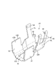
第2外導体60は、導電性を有する金属板材をプレスなどによって加工することによって形成されている。第2外導体60は、図11に示すように、筒状部52からシールド電線11の折り返し部15Aの位置まで延びる覆い部61と、覆い部61の前縁に設けられた一対の固定バレル(「バレル」の一例)62と、覆い部61の後縁に設けられた一対の接続バレル63とを備えて構成されている。
The second
覆い部61は、筒状部52の後部から折り返し部15Aまでの領域を下方から覆う大きさに形成されており、覆い部61の前部には、図3および図21に示すように、上下方向に貫通するランス孔61Aが設けられている。
The covering
固定バレル62は、図21および図22に示すように、それぞれが略矩形状の板状に形成されており、覆い部61の前部における左右方向両側の側縁にそれぞれ設けられている。一対の固定バレル62は、第2外導体60が第1外導体51に組み付けられる前の状態では、図21に示すように、覆い部61の左右方向両側の側縁から互いに離れるように斜め上方に向かって真っ直ぐ延出されており、第2外導体60が第1外導体51に組み付けられると、図15から図17に示すように、一対の固定バレル62が、左右方向の両側から筒状部52の後部の外面52Aに沿うように周方向に巻き付くように圧着される。
As shown in FIGS. 21 and 22, the fixed
また、一対の固定バレル62が筒状部52に圧着され、一対の固定バレル62の先端部62Aが天井板52Uに沿って水平に突き合わされた正規の圧着位置に配されると、一対の固定バレル62における互いの先端部62Aが筒状部52の左右方向略中央部において左右方向に突き合わせるように配置される。
Further, when the pair of
一対の接続バレル63は、図21および図22に示すように、一対の固定バレル62の後方に連なるように覆い部61の後部における左右方向両側の側縁に設けられている。一対の接続バレル63のうちの一方の接続バレル63は、折り返し部15Aの左右方向の一方の側部に沿って配置される側板64と、側板64の上端に設けられた1つの固定片65とを有しており、他方の接続バレル63は、折り返し部15Aの左右方向の他方の側部に沿って配置される側板64と、側板64の上端に設けられた2つの固定片65とを有している。
As shown in FIGS. 21 and 22, the pair of connecting
また、一対の接続バレル63は、第2外導体60が第1外導体51に組み付けられる前の状態では、図21に示すように、覆い部61の左右方向両側の側縁から互いに離れるように斜め上方に向かって真っ直ぐ延出されており、第2外導体60が第1外導体51に組み付けられると、図15から図17に示すように、折り返し部15Aの上方に配置された第1外導体51の舌片55と共に折り返し部15Aの下部に巻き付くように圧着固定されるようになっている。
Further, in the state before the second
また、それぞれの固定片65の先端部には、図21に示すように、内側に向かって折り返したフック部66が形成されている。
フック部66は、図15に示すように、それぞれの固定片65が圧着されると舌片55の左右方向両側の側縁のいずれか一方に引っ掛かり、それぞれの固定片65がシールド部15から外れないように固定されるようになっている。これにより、第1外導体51と第2外導体60とによって構成される外導体50がシールド電線11のシールド部15に電気的に接続固定されるようになっている。
Further, as shown in FIG. 21, a
As shown in FIG. 15, the
さて、第1外導体51における筒状部52の天井板52Uには、図6から図17に示すように、一対の固定バレル62の過剰圧着を許容する窪み部57が形成されている。
As shown in FIGS. 6 to 17, the
窪み部57は、図8および図19に示すように、前後方向に長い略矩形状の上端開口58を有する有底の凹部とされており、上端開口58の左右方向両側の側方開口縁58Wから左右方向略中央部に向かうほど下方に向かって傾斜して互いに左右方向に連なる一対の傾斜面57Wと、一対の傾斜面57Wの前側縁59Fと上端開口58の前側開口縁58Fとに連なる前側傾斜面57Fと、一対の傾斜面57Wの後側縁59Bと上端開口58の後側開口縁58Bとに連なる後側傾斜面57Bとによって形成されている。したがって、筒状部52の天井板52Uは、図9および図10に示すように、窪み部57において上下方向に貫通しない構成となっている。
As shown in FIGS. 8 and 19, the
窪み部57は、図17に示すように、一対の固定バレル62の先端部62Aが窪み部57の左右方向略中央部上に配置されるように一対の固定バレル62の先端部62Aの内側に径方向に対向して配置されている。また、窪み部57は、一対の固定バレル62を筒状部52に対して圧着させる際に、図13に示すように、一対の固定バレル62の両先端部62Aを一括して進入させることができる大きさに形成されている。つまり、窪み部57は、一対の固定バレル62の先端部62Aが天井板52Uに沿って水平に突き合わされた正規の圧着位置よりも径方向内側に向けて過剰に圧着されることを許容することができるようになっている。
As shown in FIG. 17, the recessed
また、窪み部57において一対の傾斜面57Wが互いに連なる部分は、図14に示すように、窪み部57において最も下方に位置する導体底部57Dとされており、一対の固定バレル62の先端部62Aを過剰に屈曲変形させて圧着させた際に、それぞれの先端部62Aがそれぞれの傾斜面57W上に沿って配されると共に、先端部62Aの先端62Bが窪み部57の導体底部57D上に配されるようになっている。
Further, as shown in FIG. 14, the portion of the recessed
一方、端子収容部材30の上壁31Uには、図9、図14および図17に示すように、第1外導体51の筒状部52に端子収容部材30が収容された際に、筒状部52の窪み部57における一対の傾斜面57Wが沿って配される凹み部37が設けられている。
On the other hand, as shown in FIGS. 9, 14 and 17, the
凹み部37は、図6に示すように、下方に向かって凹んだ形態とされており、上壁31Uの前後方向の全長に亘って形成されている。また、凹み部37は、上壁31Uの左右方向略中央部が最も低くなる底部38を有しており、凹み部37は、上壁31Uの上面を左右方向両側の側縁から底部38に向かうほど下方に傾斜させることによって形成されている。
As shown in FIG. 6, the recessed
また、凹み部37は、図9、図14および図17に示すように、内導体20の並び方向である左右方向について内導体20が収容されるキャビティ32が配置された領域とは異なる左右方向中央部の領域に底部38が配置されており、端子収容部材30の上壁31Uに凹み部37を形成することにより、キャビティ32を構成する壁部の板厚が薄くなることを抑制することができるようになっている。
Further, as shown in FIGS. 9, 14 and 17, the recessed
本実施形態は、以上のような構成であって、次に、通信用のコネクタ10の組み立て手順の一例を簡単に説明すると共に、コネクタ10の作用および効果について説明する。
This embodiment has the above-mentioned configuration, and next, an example of the procedure for assembling the
まず、シールド電線11のシース部16を皮剥ぎして、2本の被覆電線12の端末とシールド部15を露出させ、シールド部15をシース部16の外面に折り返して折り返し部15Aを形成する。また、2本の被覆電線12の前端部の絶縁被覆14を皮剥ぎして芯線13を露出させ、露出した芯線13に電線接続部24を圧着して内導体20を接続する。
First, the
次に、シールド電線11の2本の被覆電線12の露出部17に調整部材80を装着する。ここで、調整部材80は、露出部17に装着する前の展開状態では、図4に示すように、調整部本体82を構成する上側の部分が上方に開いた状態となっている。調整部本体82が開いた状態の調整部材80上に被覆電線12の露出部17を配置し、露出部17に巻き付けるようにして調整部本体82を圧着することにより露出部17に調整部材80が固定される。
Next, the adjusting
次に、図5に示すように、ロア部材40の底壁40D上に2つの内導体20を組み付け、ロア部材40に対してアッパ部材35を上方から組み付ける。これにより、図6に示すように、内導体20が端子収容部材30に収容される。
Next, as shown in FIG. 5, two
次に、図7から図10に示すように、外導体50の第1外導体51における筒状部52に後方から端子収容部材30を挿入する。すると、端子収容部材30の凹み部37上に、筒状部52の窪み部57における一対の傾斜面57Wが沿って配される。
Next, as shown in FIGS. 7 to 10, the
次に、図11に示すように、第1外導体51に対して第2外導体60を組み付ける。第2外導体60の組み付けは、第2外導体60の覆い部61上に第1外導体51およびシールド電線11の折り返し部15Aを載置し、図12から図17に示すように、固定バレル62を筒状部52に巻き付けるようにして圧着すると共に、接続バレル63のそれぞれの固定片65を舌片55およびシールド部15に巻き付けるようにして圧着する。
Next, as shown in FIG. 11, the second
ここで、それぞれの固定片65は、舌片55およびシールド部15に圧着されると、図12に示すように、固定片65のフック部66が舌片55の側縁に引っ掛かることで固定片65が舌片55およびシールド部15から外れないように固定される。
Here, when each fixing
ところが、一対の固定バレル62には、筒状部52に対して引っ掛ける構成になっていない。また、固定バレル62は、筒状部52の外周面に巻き付けるように圧着すると、圧着により変形するものの、若干もとに戻ろうとする、いわゆるスプリングバックによって筒状部52の外面52Aから固定バレル62が浮き上がった状態になってしまうことが懸念される。
However, the pair of
そこで、一対の固定バレル62を筒状部52に対して圧着する際には、図12から図14に示すように、一対の固定バレル62の先端部62Aを窪み部57内に進入させるようことで、一対の固定バレル62の先端部62Aが正規の圧着位置よりも径方向内側に向けて過剰に圧着されることが許容され、筒状部52に一対の固定バレル62が圧着される。また、一対の固定バレル62の先端部62Aが筒状部52に対して過剰に屈曲変形されて圧着されると、図14に示すように、それぞれの先端部62Aがそれぞれの傾斜面57W上に沿って配されると共に、先端部62Aの先端62Bが窪み部57の導体底部57D上に配される。
Therefore, when the pair of
そして、固定バレル62の圧着作業が終了すると、固定バレル62の先端部62Aがスプリングバックによって窪み部57の傾斜面57W上から固定バレル62の先端部62Aが浮き上がり、図15および図17に示すように、正規の圧着位置に配置される。これにより、図15から図17に示す端子モジュール68が完成する。
Then, when the crimping work of the fixed
最後に、端子モジュール68をハウジング70のモジュール収容部72に後方から挿入し、端子モジュール68が正規の収容位置に至ると、図3に示すように、ランス73が外導体50のランス孔61Aに嵌まり込み、端子モジュール68がハウジング70内に抜け止めされて保持される。これにより、通信用のコネクタ10が完成する。
Finally, when the
以上のように、本実施形態のコネクタ10における端子モジュール68は、少なくとも1本の被覆電線12の外周を覆う導電性のシールド部15と、シールド部15の外周を覆うシース部16と、を有するシールド電線11と、角筒状の筒状部(接続部)52を有し、シールド部15に接続される金属製の第1外導体51と、筒状部52の外面52Aに沿うように周方向に巻き付けて圧着される少なくとも1つの板状の固定バレル(バレル)62を有する第2外導体60と、を備え、筒状部52には、図15および図17に示すように、固定バレル62と径方向に対向するように内側に配置され、固定バレル62を正規の圧着位置よりも過剰に変形させて圧着させることを許容する窪み部57を有している。
As described above, the
すなわち、本実施形態によると、第1外導体51の筒状部52に対して第2外導体60の固定バレル62を周方向に巻き付けて圧着する際に、固定バレル62を窪み部57内に進入させるようにして筒状部52に対して固定バレル62を過剰に変形させて圧着させることができる。
That is, according to the present embodiment, when the fixed
つまり、窪み部57内に進入させて過剰に変形させた固定バレル62がスプリングバックによって若干もとに戻り、正規の圧着位置に配置される。これにより、固定バレル62が筒状部52の外面52Aから浮き上がった不正規の圧着位置に配置されることを抑制することができる。
That is, the fixed
また、窪み部57は、図9および図10に示すように、筒状部52の外面52Aよりも凹んだ有底の凹部とされており、筒状部52は、窪み部57において貫通しない構成となっている。このような構成によると、筒状部52の窪み部57において固定バレル62を過剰に変形させることにより、固定バレル62が不正規の圧着位置に配置されることを抑制することができると共に、筒状部52に貫通孔が形成されることを防ぐことで、筒状部52におけるシールド性能が低下することを抑制することができる。
Further, as shown in FIGS. 9 and 10, the recessed
ところで、一般に、板状の金属片を巻き付けるように圧着する場合、金属片の先端部においてスプリングバックによる浮き上がりが大きくなる傾向にある。ところが、本実施形態によると、窪み部57は、固定バレル62の先端部62Aと径方向に対向する位置に形成されているから、スプリングバックによる浮き上がりの影響が大きい固定バレル62の先端部62Aが不正規の圧着位置に配置されることを抑制することができる。
By the way, in general, when a plate-shaped metal piece is crimped so as to be wound around it, the lift due to the springback tends to be large at the tip of the metal piece. However, according to the present embodiment, since the recessed
また、本実施形態の第2外導体60は、一対(複数)の固定バレル62を有しており、窪み部57は、一対の固定バレル62の先端部62Aが一括して進入可能な大きさに形成されている。このような構成によると、図12から図14に示すように、一対の固定バレル62を圧着する際に、一対の固定バレル62の先端部62Aを1つの窪み部57に一括して進入させることができるから、例えば、筒状部52に複数の窪み部57を形成する場合に比べて、筒状部52、ひいては第1外導体51の形状が複雑になることを抑制することができる。
Further, the second
さらに、本実施形態は、シールド電線11が2本(複数)の被覆電線12を含み、被覆電線12に接続される内導体20を並べて収容した状態で筒状部52内に収容される端子収容部材30をさらに備え、端子収容部材30には、図9、図14および図17に示すように、窪み部57に沿って凹んで形成され、内導体(端子)20の並び方向について内導体20が配置された領域とは異なる左右方向中央部の領域を底部38とする凹み部37が設けられている。つまり、端子収容部材30に凹み部37を形成することにより、内導体20を収容する部分における壁部の板厚が薄くなることを抑制することができるようになっている。
Further, in the present embodiment, the shielded
<実施形態2>
次に、実施形態2について図23を参照して説明する。
実施形態2の端子モジュール168は、実施形態1における一対の固定バレル62の形状を変更したものであって、実施形態1と共通する構成、作用、および効果については重複するため、その説明を省略する。また、実施形態1と同じ構成については同一の符号を用いるものとする。
<Embodiment 2>
Next, the second embodiment will be described with reference to FIG. 23.
The
実施形態2の一対の固定バレル162のうち、一方の固定バレル162の先端部162Aには、先端縁162Bから突出する嵌合突部167が形成され、他方の固定バレル162の先端部162Aには、嵌合突部167と嵌合可能な嵌合溝部169が形成されている。
Of the pair of
嵌合溝部169は、先端縁162Bから奥部に向かうほど前後方向の長さ寸法が大きくなるあり溝状に形成されている。
嵌合突部167は、先端縁162Bから突出するほど前後方向の長さ寸法が大きくなるあり状に形成されている。
The
The
嵌合突部167と嵌合溝部169とは、一対の固定バレル162の先端部162Aが筒状部52に対して過剰に屈曲変形され、先端部162Aがスプリングバックによって窪み部57の傾斜面57W上から浮き上がって正規の圧着位置に配置された際に嵌合するようになっている。
In the
すなわち、一対の固定バレル162は、それぞれの先端部162Aが正規の圧着位置に配置において嵌合突部167と嵌合溝部169とが嵌合した状態となるから、一対の固定バレル62が筒状部52の外面52Aから浮き上がることをさらに抑制することができる。
That is, in the pair of
<他の実施形態>
本明細書で開示される技術は上記記述及び図面によって説明した実施形態に限定されるものではなく、例えば次のような種々の態様も含まれる。
(1)上記実施形態では、端子収容部材30を収容する筒状部52を備えた第1外導体51を第1導体として構成した。しかしながら、これに限らず、第1導体を、雄型端子が内部に挿入される筒状部を有する雌型端子として構成してもよい。
<Other embodiments>
The techniques disclosed herein are not limited to the embodiments described above and in the drawings, and include, for example, various embodiments such as:
(1) In the above embodiment, the first
(2)上記実施形態では、シールド電線11が2本の被覆電線12を有し、端子収容部材30が2つの内導体20を収容する構成とした。しかしながら、これに限らず、シールド電線が3本以上の被覆電線を有し、端子収容部材が3つ以上の内導体を収容する構成としてもよい。
(2) In the above embodiment, the shielded
(3)上記実施形態では、内導体20を雄側端子として構成した。しかしながら、これに限らず、内導体を雌型端子として構成してもよい。
(3) In the above embodiment, the
10:コネクタ
11:シールド電線
12:被覆電線
15:シールド部
16:シース部
30:端子収容部材
37:窪み部
38:底部
51:第1外導体(「第1導体」の一例)
52:筒状部(「接続部」の一例)
57:窪み部
60:第2外導体(「第2導体」の一例)
62:固定バレル(「バレル」の一例)
62A:固定バレルの先端部
68:端子モジュール(「端子付き電線」の一例)
70:ハウジング
10: Connector 11: Shielded wire 12: Covered wire 15: Shielded part 16: Sheath part 30: Terminal accommodating member 37: Recessed part 38: Bottom 51: First outer conductor (an example of "first conductor")
52: Cylindrical part (an example of "connection part")
57: Recessed portion 60: Second outer conductor (an example of "second conductor")
62: Fixed barrel (an example of "barrel")
62A: Tip of fixed barrel 68: Terminal module (an example of "electric wire with terminal")
70: Housing
Claims (5)
筒状の接続部を有し、前記シールド部に接続される金属製の第1導体と、
前記接続部の外面に沿うように周方向に巻き付けて圧着される少なくとも1つの板状のバレルを有する第2導体と、を備えた端子付き電線であって、
前記接続部には、前記バレルと径方向に対向するように内側に配置され、前記バレルを正規の圧着位置よりも過剰に変形させて圧着させることを許容する窪み部を有しており、
前記シールド電線は、複数の前記被覆電線を含み、
前記被覆電線に接続される端子を並べて収容した状態で前記接続部内に収容される端子収容部材をさらに備え、
前記端子収容部材には、前記窪み部に沿って凹んで形成され、前記端子の並び方向について前記端子が配置された領域とは異なる領域を底部とする凹み部が設けられている端子付き電線。 A shielded electric wire having a conductive shield portion that covers the outer circumference of at least one covered electric wire and a sheath portion that covers the outer circumference of the shielded portion.
A first metal conductor that has a cylindrical connection and is connected to the shield.
An electric wire with a terminal comprising a second conductor having at least one plate-shaped barrel that is wound and crimped in the circumferential direction along the outer surface of the connection portion.
The connection portion has a recess portion that is arranged inside so as to face the barrel in the radial direction and allows the barrel to be excessively deformed and crimped from the normal crimping position .
The shielded wire includes a plurality of the coated wires.
Further, a terminal accommodating member accommodated in the connection portion in a state where the terminals connected to the coated electric wire are accommodated side by side is provided.
The terminal accommodating member is formed by being recessed along the recessed portion, and is provided with a recessed portion having a recessed portion as a bottom in a region different from the region in which the terminals are arranged in the arrangement direction of the terminals .
前記接続部は、前記窪み部において貫通しない構成となっている請求項1に記載の端子付き電線。 The recess is a bottomed recess recessed from the outer surface of the connection.
The electric wire with a terminal according to claim 1, wherein the connecting portion is configured so as not to penetrate in the recessed portion.
前記窪み部は、前記複数のバレルの先端部が一括して進入可能な大きさに形成されている請求項3に記載の端子付き電線。 The second conductor has a plurality of the barrels.
The electric wire with a terminal according to claim 3, wherein the recessed portion is formed in a size such that the tip portions of the plurality of barrels can enter at once.
前記端子付き電線を収容するハウジングとを備えたコネクタ。 The electric wire with a terminal according to any one of claims 1 to 4 ,
A connector with a housing for accommodating the terminald wire.
Priority Applications (4)
| Application Number | Priority Date | Filing Date | Title |
|---|---|---|---|
| JP2018247608A JP7089674B2 (en) | 2018-12-28 | 2018-12-28 | Wires with terminals and connectors |
| PCT/JP2019/050525 WO2020138037A1 (en) | 2018-12-28 | 2019-12-24 | Electrical wire with attached terminal, and connector |
| CN201980085937.4A CN113228429B (en) | 2018-12-28 | 2019-12-24 | Wire with terminal and connector |
| US17/418,461 US11848524B2 (en) | 2018-12-28 | 2019-12-24 | Cable with connector including conductor connected to the cable |
Applications Claiming Priority (1)
| Application Number | Priority Date | Filing Date | Title |
|---|---|---|---|
| JP2018247608A JP7089674B2 (en) | 2018-12-28 | 2018-12-28 | Wires with terminals and connectors |
Publications (3)
| Publication Number | Publication Date |
|---|---|
| JP2020107569A JP2020107569A (en) | 2020-07-09 |
| JP2020107569A5 JP2020107569A5 (en) | 2021-07-26 |
| JP7089674B2 true JP7089674B2 (en) | 2022-06-23 |
Family
ID=71129389
Family Applications (1)
| Application Number | Title | Priority Date | Filing Date |
|---|---|---|---|
| JP2018247608A Active JP7089674B2 (en) | 2018-12-28 | 2018-12-28 | Wires with terminals and connectors |
Country Status (4)
| Country | Link |
|---|---|
| US (1) | US11848524B2 (en) |
| JP (1) | JP7089674B2 (en) |
| CN (1) | CN113228429B (en) |
| WO (1) | WO2020138037A1 (en) |
Citations (3)
| Publication number | Priority date | Publication date | Assignee | Title |
|---|---|---|---|---|
| JP2000012165A (en) | 1998-06-25 | 2000-01-14 | Sumitomo Wiring Syst Ltd | Shield connector |
| JP2013229254A (en) | 2012-04-26 | 2013-11-07 | Yazaki Corp | Shield connector |
| JP2017174576A (en) | 2016-03-23 | 2017-09-28 | 株式会社オートネットワーク技術研究所 | Terminal metal fitting |
Family Cites Families (8)
| Publication number | Priority date | Publication date | Assignee | Title |
|---|---|---|---|---|
| US5199903A (en) * | 1991-02-28 | 1993-04-06 | Amp General Patent Counsel | Ferruleless back shell |
| US5518421A (en) | 1993-01-26 | 1996-05-21 | The Whitaker Corporation | Two piece shell for a connector |
| JP3405961B2 (en) * | 2000-05-24 | 2003-05-12 | 日本圧着端子製造株式会社 | Receptacle type relay connector |
| JP5757426B2 (en) * | 2012-03-28 | 2015-07-29 | 住友電装株式会社 | connector |
| JP5934568B2 (en) * | 2012-04-26 | 2016-06-15 | 矢崎総業株式会社 | Shield connector |
| JP6244332B2 (en) * | 2015-06-12 | 2017-12-06 | 矢崎総業株式会社 | Connector and connector manufacturing method |
| JP2018113176A (en) * | 2017-01-12 | 2018-07-19 | 住友電装株式会社 | Shield conductive path |
| DE102017105682A1 (en) * | 2017-03-16 | 2018-09-20 | Te Connectivity Germany Gmbh | Contact carrier, electrical contact device and method for producing a ready-made cable |
-
2018
- 2018-12-28 JP JP2018247608A patent/JP7089674B2/en active Active
-
2019
- 2019-12-24 CN CN201980085937.4A patent/CN113228429B/en active Active
- 2019-12-24 US US17/418,461 patent/US11848524B2/en active Active
- 2019-12-24 WO PCT/JP2019/050525 patent/WO2020138037A1/en active Application Filing
Patent Citations (3)
| Publication number | Priority date | Publication date | Assignee | Title |
|---|---|---|---|---|
| JP2000012165A (en) | 1998-06-25 | 2000-01-14 | Sumitomo Wiring Syst Ltd | Shield connector |
| JP2013229254A (en) | 2012-04-26 | 2013-11-07 | Yazaki Corp | Shield connector |
| JP2017174576A (en) | 2016-03-23 | 2017-09-28 | 株式会社オートネットワーク技術研究所 | Terminal metal fitting |
Also Published As
| Publication number | Publication date |
|---|---|
| CN113228429A (en) | 2021-08-06 |
| JP2020107569A (en) | 2020-07-09 |
| US20220149570A1 (en) | 2022-05-12 |
| CN113228429B (en) | 2023-09-05 |
| WO2020138037A1 (en) | 2020-07-02 |
| US11848524B2 (en) | 2023-12-19 |
Similar Documents
| Publication | Publication Date | Title |
|---|---|---|
| EP3621158B1 (en) | Connector and wire harness | |
| US10511116B2 (en) | Connector | |
| US10381785B2 (en) | Shield connector and shielded cable with connector | |
| JP2017507461A (en) | Electrical connector assembly | |
| US10008809B2 (en) | Shield connector | |
| JP6997954B2 (en) | Terminal modules and connectors | |
| JP7089674B2 (en) | Wires with terminals and connectors | |
| JP6927447B2 (en) | Terminal modules and connectors | |
| CN113196580B (en) | Terminal module and connector | |
| JP7169525B2 (en) | connector | |
| JP7388264B2 (en) | Connectors and cables with connectors | |
| JP6958589B2 (en) | Electrical connector | |
| WO2022054455A1 (en) | Shield connector | |
| JP2023018170A (en) | shield connector |
Legal Events
| Date | Code | Title | Description |
|---|---|---|---|
| A621 | Written request for application examination |
Free format text: JAPANESE INTERMEDIATE CODE: A621 Effective date: 20210330 |
|
| A521 | Request for written amendment filed |
Free format text: JAPANESE INTERMEDIATE CODE: A523 Effective date: 20210610 |
|
| A131 | Notification of reasons for refusal |
Free format text: JAPANESE INTERMEDIATE CODE: A131 Effective date: 20220208 |
|
| A521 | Request for written amendment filed |
Free format text: JAPANESE INTERMEDIATE CODE: A523 Effective date: 20220407 |
|
| TRDD | Decision of grant or rejection written | ||
| A01 | Written decision to grant a patent or to grant a registration (utility model) |
Free format text: JAPANESE INTERMEDIATE CODE: A01 Effective date: 20220512 |
|
| A61 | First payment of annual fees (during grant procedure) |
Free format text: JAPANESE INTERMEDIATE CODE: A61 Effective date: 20220525 |
|
| R150 | Certificate of patent or registration of utility model |
Ref document number: 7089674 Country of ref document: JP Free format text: JAPANESE INTERMEDIATE CODE: R150 |