JP7088556B2 - Intermittent printing machine - Google Patents
Intermittent printing machine Download PDFInfo
- Publication number
- JP7088556B2 JP7088556B2 JP2019047015A JP2019047015A JP7088556B2 JP 7088556 B2 JP7088556 B2 JP 7088556B2 JP 2019047015 A JP2019047015 A JP 2019047015A JP 2019047015 A JP2019047015 A JP 2019047015A JP 7088556 B2 JP7088556 B2 JP 7088556B2
- Authority
- JP
- Japan
- Prior art keywords
- printed
- impression cylinder
- substrate
- roller
- paper
- Prior art date
- Legal status (The legal status is an assumption and is not a legal conclusion. Google has not performed a legal analysis and makes no representation as to the accuracy of the status listed.)
- Active
Links
Images


Classifications
-
- B—PERFORMING OPERATIONS; TRANSPORTING
- B41—PRINTING; LINING MACHINES; TYPEWRITERS; STAMPS
- B41F—PRINTING MACHINES OR PRESSES
- B41F33/00—Indicating, counting, warning, control or safety devices
- B41F33/04—Tripping devices or stop-motions
- B41F33/06—Tripping devices or stop-motions for starting or stopping operation of sheet or web feed
-
- B—PERFORMING OPERATIONS; TRANSPORTING
- B41—PRINTING; LINING MACHINES; TYPEWRITERS; STAMPS
- B41F—PRINTING MACHINES OR PRESSES
- B41F21/00—Devices for conveying sheets through printing apparatus or machines
-
- B—PERFORMING OPERATIONS; TRANSPORTING
- B41—PRINTING; LINING MACHINES; TYPEWRITERS; STAMPS
- B41F—PRINTING MACHINES OR PRESSES
- B41F13/00—Common details of rotary presses or machines
- B41F13/02—Conveying or guiding webs through presses or machines
- B41F13/025—Registering devices
-
- B—PERFORMING OPERATIONS; TRANSPORTING
- B41—PRINTING; LINING MACHINES; TYPEWRITERS; STAMPS
- B41F—PRINTING MACHINES OR PRESSES
- B41F13/00—Common details of rotary presses or machines
- B41F13/02—Conveying or guiding webs through presses or machines
- B41F13/04—Conveying or guiding webs through presses or machines intermittently
-
- B—PERFORMING OPERATIONS; TRANSPORTING
- B41—PRINTING; LINING MACHINES; TYPEWRITERS; STAMPS
- B41F—PRINTING MACHINES OR PRESSES
- B41F13/00—Common details of rotary presses or machines
- B41F13/08—Cylinders
- B41F13/24—Cylinder-tripping devices; Cylinder-impression adjustments
- B41F13/34—Cylinder lifting or adjusting devices
- B41F13/36—Cams, eccentrics, wedges, or the like
-
- B—PERFORMING OPERATIONS; TRANSPORTING
- B41—PRINTING; LINING MACHINES; TYPEWRITERS; STAMPS
- B41F—PRINTING MACHINES OR PRESSES
- B41F23/00—Devices for treating the surfaces of sheets, webs, or other articles in connection with printing
- B41F23/04—Devices for treating the surfaces of sheets, webs, or other articles in connection with printing by heat drying, by cooling, by applying powders
- B41F23/0403—Drying webs
- B41F23/0406—Drying webs by radiation
-
- B—PERFORMING OPERATIONS; TRANSPORTING
- B41—PRINTING; LINING MACHINES; TYPEWRITERS; STAMPS
- B41F—PRINTING MACHINES OR PRESSES
- B41F23/00—Devices for treating the surfaces of sheets, webs, or other articles in connection with printing
- B41F23/04—Devices for treating the surfaces of sheets, webs, or other articles in connection with printing by heat drying, by cooling, by applying powders
- B41F23/044—Drying sheets, e.g. between two printing stations
-
- B—PERFORMING OPERATIONS; TRANSPORTING
- B41—PRINTING; LINING MACHINES; TYPEWRITERS; STAMPS
- B41F—PRINTING MACHINES OR PRESSES
- B41F23/00—Devices for treating the surfaces of sheets, webs, or other articles in connection with printing
- B41F23/04—Devices for treating the surfaces of sheets, webs, or other articles in connection with printing by heat drying, by cooling, by applying powders
- B41F23/0476—Cooling
-
- B—PERFORMING OPERATIONS; TRANSPORTING
- B41—PRINTING; LINING MACHINES; TYPEWRITERS; STAMPS
- B41F—PRINTING MACHINES OR PRESSES
- B41F23/00—Devices for treating the surfaces of sheets, webs, or other articles in connection with printing
- B41F23/04—Devices for treating the surfaces of sheets, webs, or other articles in connection with printing by heat drying, by cooling, by applying powders
- B41F23/0483—Drying combined with cooling
-
- B—PERFORMING OPERATIONS; TRANSPORTING
- B41—PRINTING; LINING MACHINES; TYPEWRITERS; STAMPS
- B41M—PRINTING, DUPLICATING, MARKING, OR COPYING PROCESSES; COLOUR PRINTING
- B41M1/00—Inking and printing with a printer's forme
- B41M1/26—Printing on other surfaces than ordinary paper
- B41M1/30—Printing on other surfaces than ordinary paper on organic plastics, horn or similar materials
Description
本発明は、間欠印刷機に関するものである。 The present invention relates to an intermittent printing machine.
間欠印刷機は、被印刷基材を正方向に走行しながら画像を印刷し、印刷した後、被印刷基材を、画像を印刷せずに逆方向に走行し、再び正方向に走行して印刷することを繰り返し、被印刷基材に画像を、天地方向の隙間を小さくして印刷するようにしたものである。
例えば、特許文献1に間欠印刷機が開示されている。
この間欠印刷機は、正回転駆動と逆回転駆動される2つの送りローラの間に、複数の印刷ユニットが設けられ、印刷ユニットは、版胴とブランケット胴と圧胴を有している。ブランケット胴の周面は、圧胴の周面と圧接する大径部と、圧胴の周面と離隔する小径部を有している。
The intermittent printing machine prints an image while traveling in the forward direction on the substrate to be printed, prints, then travels on the substrate to be printed in the reverse direction without printing the image, and then travels in the forward direction again. Printing is repeated, and the image is printed on the substrate to be printed with a small gap in the vertical direction.
For example,
In this intermittent printing machine, a plurality of printing units are provided between two feed rollers driven in a forward rotation drive and a reverse rotation drive, and the printing unit has a plate cylinder, a blanket cylinder, and an impression cylinder. The peripheral surface of the blanket cylinder has a large-diameter portion that is in pressure contact with the peripheral surface of the impression cylinder and a small-diameter portion that is separated from the peripheral surface of the impression cylinder.
そして、2つの送りローラを正回転駆動して被印刷基材を正方向に走行する時に、ブランケット胴の大径部と圧胴の周面が圧接して被印刷基材に画像を印刷する。画像を印刷した後に、2つの送りローラを逆回転駆動して被印刷基材を逆方向に走行する。被印刷基材が逆方向に走行する時は、被印刷基材がブランケット胴の小径部と圧胴の周面との間の隙間を通過するので、画像が印刷されない。
この動作を繰り返すことで、被印刷基材に画像を、天地方向の隙間を小さくして印刷する。
この間欠印刷機は、被印刷基材が逆方向に走行する時にブランケット胴の小径部と圧胴の周面との間の隙間を通るので、被印刷基材は圧胴とブランケット胴で挟持されずに、動きが規制されていない状態である。
Then, when the two feed rollers are driven in a forward rotation to travel in the positive direction on the substrate to be printed, the large diameter portion of the blanket cylinder and the peripheral surface of the impression cylinder are in pressure contact with each other to print an image on the substrate to be printed. After printing the image, the two feed rollers are driven in reverse rotation to travel in the opposite direction on the substrate to be printed. When the substrate to be printed travels in the opposite direction, the image is not printed because the substrate to be printed passes through the gap between the small diameter portion of the blanket cylinder and the peripheral surface of the impression cylinder.
By repeating this operation, an image is printed on the substrate to be printed with a small gap in the vertical direction.
Since this intermittent printing machine passes through the gap between the small diameter portion of the blanket cylinder and the peripheral surface of the impression cylinder when the substrate to be printed travels in the opposite direction, the substrate to be printed is sandwiched between the impression cylinder and the blanket cylinder. The movement is not regulated.
このために、被印刷基材が逆方向に走行する時に、被印刷基材にバラツキ、たるみが発生しやすい。被印刷基材にバラツキ、たるみが発生すると、ブランケット胴、圧胴に被印刷基材が接触することによる被印刷基材の損傷、印刷汚れなどが生じる。
このことを解消する間欠印刷機が特許文献2に開示されている。
この間欠印刷機は、2つのガイドローラを設けることで、被印刷基材を圧胴の周面に、所定の巻き角で巻き掛け、圧胴を2つの送りローラと同期して正回転駆動、逆回転駆動するようにしている。
この間欠印刷機によれば、被印刷基材が圧胴の周面に巻き掛けてあることで、被印刷基材が逆方向に走行する時に、被印刷基材の動きが規制される。したがって、被印刷基材が逆方向に走行する時に、被印刷基材にバラツキ、たるみが発生することがない。
For this reason, when the substrate to be printed travels in the opposite direction, the substrate to be printed tends to vary and sag. When the substrate to be printed varies or sags, the substrate to be printed is damaged due to the contact of the substrate to be printed with the blanket cylinder or the impression cylinder, and printing stains occur.
In this intermittent printing machine, by providing two guide rollers, the substrate to be printed is wound around the peripheral surface of the impression cylinder at a predetermined winding angle, and the impression cylinder is driven in a forward rotation in synchronization with the two feed rollers. It is driven in reverse rotation.
According to this intermittent printing machine, the substrate to be printed is wound around the peripheral surface of the impression cylinder, so that the movement of the substrate to be printed is restricted when the substrate to be printed travels in the opposite direction. Therefore, when the substrate to be printed travels in the opposite direction, the substrate to be printed does not vary or sag.
特許文献2に開示されたように、被印刷基材が圧胴の周面に巻き掛けられ、圧胴を正回転駆動、逆回転駆動する間欠印刷機で印刷したところ、印刷見当のバラツキが発生することがあった。特に、表面の平滑性が高い被印刷基材、被印刷基材としてフィルムを用いて印刷した場合に印刷見当のバラツキが著しく発生した。
本発明者等は、印刷見当のバラツキが発生する原因を調査した結果、次のことを見出し、本発明に至った。
被印刷基材が圧胴の周面に巻き掛けてあるために、被印刷基材を圧胴の周面に滑らせて走行させることは困難であるから、圧胴を送りローラと同期して正回転駆動、逆回転駆動することで、圧胴の回転により被印刷基材を正方向、逆方向に走行させている。
As disclosed in
As a result of investigating the cause of the variation in the printing register, the present inventors have found the following, and have arrived at the present invention.
Since the substrate to be printed is wound around the peripheral surface of the impression cylinder, it is difficult to slide the substrate to be printed on the peripheral surface of the impression cylinder to run. By driving in the forward rotation and the reverse rotation, the substrate to be printed is driven in the forward and reverse directions by the rotation of the impression cylinder.
このために、被印刷基材が逆方向に走行する時や方向転換時には、圧胴の周面とブランケット胴の小径部が離れており、被印刷基材がブランケット胴の小径部に対して非接触で、圧胴の周面と被印刷基材との間に生じる摩擦力のみで被印刷基材が走行するので、摩擦力が小さい場合に、圧胴の周面と被印刷基材との間でスリップが生じることがある。
圧胴の周面と被印刷基材との間にスリップが生じると、被印刷基材を正方向に走行させて画像を印刷開始する時に、ブランケット胴の大径部の回転方向の先端が被印刷基材に接触開始する位置が天地方向にずれるので、印刷見当がずれる。
そして、スリップする長さは一定ではなく、バラツキがあるので、印刷見当のバラツキが発生する。
表面の平滑性が高い被印刷基材を用いて印刷する場合は、その被印刷基材と圧胴の周面との間にスリップが発生しやすいので、印刷見当のバラツキが著しく発生する。
For this reason, when the substrate to be printed travels in the opposite direction or when the direction is changed, the peripheral surface of the impression cylinder and the small diameter portion of the blanket cylinder are separated from each other, and the substrate to be printed is not the small diameter portion of the blanket cylinder. Since the substrate to be printed travels only by the frictional force generated between the peripheral surface of the impression cylinder and the substrate to be printed by contact, when the frictional force is small, the peripheral surface of the impression cylinder and the substrate to be printed Slip may occur between them.
When a slip occurs between the peripheral surface of the impression cylinder and the substrate to be printed, the tip of the large diameter portion of the blanket cylinder in the rotational direction is covered when the substrate to be printed is moved in the positive direction to start printing an image. Since the position where the contact with the printing substrate starts is shifted in the vertical direction, the printing register is shifted.
Since the slip length is not constant and varies, the print register varies.
When printing is performed using a substrate to be printed having a high surface smoothness, slippage is likely to occur between the substrate to be printed and the peripheral surface of the impression cylinder, so that the printing register varies significantly.
被印刷基材としてフィルムを用いた場合は、フィルムの密度が高く空気が通らないので、フィルムを圧胴の周面に巻き掛けた状態で、圧胴の周面とフィルムとの間に残存する空気がフィルムを通してフィルムの表面から逃げることができない。
さらには、圧胴の回転速度(被印刷基材の走行速度)が上昇すると、圧胴の周面とフィルムとの間に空気が引き込まれて空気層を形成することがある。
これらのことから、フィルムを被印刷基材として用いた場合は、圧胴の周面とフィルムとの間の摩擦力が小さく、スリップが発生しやすいので、印刷見当のバラツキが著しく発生する。
When a film is used as the substrate to be printed, the density of the film is high and air does not pass through it. Therefore, the film remains between the peripheral surface of the impression cylinder and the film in a state of being wound around the peripheral surface of the impression cylinder. Air cannot escape from the surface of the film through the film.
Further, when the rotational speed of the impression cylinder (running speed of the substrate to be printed) increases, air may be drawn between the peripheral surface of the impression cylinder and the film to form an air layer.
From these facts, when the film is used as the substrate to be printed, the frictional force between the peripheral surface of the impression cylinder and the film is small, and slip is likely to occur, so that the printing register varies remarkably.
本発明は、上記の課題を解決するために為されたもので、その目的は、被印刷基材を走行する時に、圧胴の周面と被印刷基材との間でスリップが生じることがなく、印刷見当のバラツキが発生しない間欠印刷機を提供することである。 The present invention has been made to solve the above-mentioned problems, and an object thereof is that slip occurs between the peripheral surface of the impression cylinder and the substrate to be printed when traveling on the substrate to be printed. It is to provide an intermittent printing machine in which the printing register does not vary.
本発明の間欠印刷機は、被印刷基材を送り出す入紙部と、前記入紙部から送り出された被印刷基材に画像を印刷する複数の印刷ユニットを有する印刷部と、画像が印刷された被印刷基材を排出する排紙部を備え、
前記入紙部は、被印刷基材をループ状に蓄える入紙側の緩衝装置と、被印刷基材を正方向に走行する正回転駆動及び、被印刷基材を逆方向に走行する逆回転駆動される入紙側のステップバックローラとを有し、
前記印刷ユニットは、圧胴と、前記圧胴の周面と接する画像範囲と、前記圧胴の周面と接しない非画像範囲を有するブランケット胴とを有し、
前記排紙部は、被印刷基材を正方向に走行する正回転駆動及び、被印刷基材を逆方向に走行する逆回転駆動される排紙側のステップバックローラと、画像が印刷された被印刷基材をループ状に蓄える排紙側の緩衝装置とを有し、
前記入紙側のステップバックローラと前記排紙側のステップバックローラを、同期して正回転駆動することで、被印刷基材を正方向に走行して、前記圧胴の周面と、前記ブランケット胴の画像範囲とで、被印刷基材に画像を印刷し、前記入紙側のステップバックローラと前記排紙側のステップバックローラを、同期して逆回転駆動することで、被印刷基材を、前記圧胴の周面と前記ブランケット胴の非画像範囲との間の隙間を通して、逆方向に走行するようにした間欠印刷機において、
前記圧胴の周面と前記ブランケット胴の間を通る被印刷基材を、前記圧胴の周面に、所定の巻き角で巻き掛ける入紙側のガイドローラと、排紙側のガイドローラを設け、
前記圧胴の周面に巻き掛けられた被印刷基材を、前記圧胴の周面に押しつける圧胴用のニップローラを設け、
被印刷基材を正方向に走行する時には、前記圧胴を、前記入紙側のステップバックローラ及び前記排紙側のステップバックローラと、同期して正回転駆動し、被印刷基材を逆方向に走行する時には、前記圧胴を、前記入紙側のステップバックローラ及び前記排紙側のステップバックローラと、同期して逆回転駆動するようにし、
前記圧胴の周面に巻き掛けられた被印刷基材を乾燥する乾燥装置と、前記圧胴を冷却する圧胴の冷却装置を備え、
前記乾燥装置は、前記圧胴用のニップローラよりも圧胴正回転方向の上流側に位置していることを特徴とする間欠印刷機である。
The intermittent printing machine of the present invention has a paper receiving unit that feeds out a substrate to be printed, a printing unit having a plurality of printing units for printing an image on the substrate to be printed sent from the paper receiving unit, and an image is printed. Equipped with a paper ejection section that discharges the printed substrate
The paper-entry portion includes a shock absorber on the paper-entry side that stores the substrate to be printed in a loop, a forward rotation drive that travels the substrate to be printed in the forward direction, and a reverse rotation that travels the substrate to be printed in the reverse direction. It has a step back roller on the paper entry side that is driven,
The printing unit has an impression cylinder, an image range in contact with the peripheral surface of the impression cylinder, and a blanket cylinder having a non-image range not in contact with the peripheral surface of the impression cylinder.
The paper ejection unit is printed with a forward rotation drive that travels in the positive direction of the substrate to be printed and a step back roller on the output side that is driven in the reverse rotation that travels in the reverse direction of the substrate to be printed. It has a shock absorber on the discharge side that stores the substrate to be printed in a loop shape.
By synchronously driving the step back roller on the paper entry side and the step back roller on the paper discharge side in a forward rotation, the substrate to be printed is driven in the positive direction, and the peripheral surface of the impression cylinder and the above are described. An image is printed on the substrate to be printed in the image range of the blanket body, and the step back roller on the paper entry side and the step back roller on the paper discharge side are synchronously driven in reverse rotation to drive the print base. In an intermittent printing machine in which the material is run in the opposite direction through a gap between the peripheral surface of the impression cylinder and the non-image range of the blanket cylinder.
A guide roller on the paper entry side and a guide roller on the paper discharge side are used to wind the substrate to be printed, which passes between the peripheral surface of the impression cylinder and the blanket cylinder, around the peripheral surface of the impression cylinder at a predetermined winding angle. Provide,
A nip roller for the impression cylinder is provided to press the substrate to be printed wound around the peripheral surface of the impression cylinder against the peripheral surface of the impression cylinder.
When traveling in the forward direction on the substrate to be printed, the impression cylinder is driven in a forward rotation in synchronization with the step back roller on the paper entry side and the step back roller on the paper discharge side, and the substrate to be printed is reversed. When traveling in the direction, the impression cylinder is driven in reverse rotation in synchronization with the step back roller on the paper entry side and the step back roller on the paper discharge side.
A drying device for drying the substrate to be printed wrapped around the peripheral surface of the impression cylinder and a cooling device for the impression cylinder for cooling the impression cylinder are provided.
The drying device is an intermittent printing machine characterized in that it is located on the upstream side in the forward rotation direction of the impression cylinder with respect to the nip roller for the impression cylinder.
本発明の間欠印刷機においては、前記入紙側のガイドローラと前記排紙側のガイドローラは、前記入紙側のガイドローラと前記圧胴との間の入紙側の走行路の延長線と、前記排紙側のガイドローラと前記圧胴との間の排紙側の走行路の延長線とが交差するように設けてある間欠印刷機とすることができる。
この間欠印刷機によれば、圧胴の周面に巻き掛けた被印刷基材の巻き角を、180度以上とすることができ、圧胴の周面と被印刷基材の間の摩擦力が大きく、スリップが生じることを確実に防止できる。
In the intermittent printing machine of the present invention, the guide roller on the paper entry side and the guide roller on the paper ejection side are extension lines of the traveling path on the paper entry side between the guide roller on the paper entry side and the impression cylinder. And the intermittent printing machine provided so that the extension line of the traveling path on the paper ejection side between the guide roller on the paper ejection side and the impression cylinder intersect.
According to this intermittent printing machine, the winding angle of the substrate to be printed wound around the peripheral surface of the impression cylinder can be 180 degrees or more, and the frictional force between the peripheral surface of the impression cylinder and the substrate to be printed can be set. Is large, and slippage can be reliably prevented.
本発明の間欠印刷機においては、前記圧胴は、前記ブランケット胴が印刷開始位置から画像範囲回転して被印刷基材に画像を印刷する時に、前記ブランケット胴と同一の一定速度で正回転駆動し、前記圧胴は、前記ブランケット胴が印刷終了位置から非画像範囲回転する時に、前記一定速度から減速正回転駆動して回転停止し、回転停止後に、所定の逆回転駆動速度まで加速逆回転駆動し、前記所定の逆回転駆動速度から減速逆回転駆動して回転停止し、回転停止後に、前記一定速度まで加速正回転駆動して、被印刷基材に印刷した印刷画像の後端と前記ブランケット胴の印刷範囲の先端が接するようにした間欠印刷機とすることができる。
この間欠印刷機によれば、圧胴は、徐々に回転停止し、徐々に回転開始するので、被印刷基材と圧胴の周面との間のスリップの発生を防止するとともに、圧胴の駆動系に故障などが発生することがない。
In the intermittent printing machine of the present invention, the impression cylinder is driven in a forward rotation at the same constant speed as the blanket cylinder when the blanket cylinder rotates in the image range from the printing start position and prints an image on the substrate to be printed. Then, when the blanket cylinder rotates in a non-image range from the printing end position, the impression cylinder is decelerated from the constant speed to a forward rotation drive to stop rotating, and after the rotation is stopped, the impression cylinder accelerates to a predetermined reverse rotation drive speed and reverse rotation. The rear end of the printed image printed on the substrate to be printed and the said It can be an intermittent printing machine in which the tip of the printing range of the blanket body is in contact with the printing range.
According to this intermittent printing machine, the impression cylinder gradually stops rotating and gradually starts rotating, so that slip occurrence between the substrate to be printed and the peripheral surface of the impression cylinder is prevented, and the impression cylinder There is no failure in the drive system.
本発明の間欠印刷機においては、前記圧胴の前記減速正回転駆動の回転駆動速度比変化と、前記加速正回転駆動の回転駆動速度比変化は線対称で、前記圧胴の前記加速逆回転駆動の回転駆動速度比変化と、前記減速逆回転駆動の回転駆動速度比変化は線対称で、前記圧胴の前記一定速度から前記所定の逆回転駆動速度までの回転駆動速度比変化と、前記所定の逆回転駆動速度から前記一定速度までの回転駆動速度比変化が、略U字形状の曲線に沿って滑らかに変化するようにした間欠印刷機とすることができる。
この間欠印刷機によれば、圧胴は滑らかに速度変化し、被印刷基材はスムーズに逆方向と正方向に向きを変えて走行するので、被印刷基材と圧胴の周面との間のスリップの発生を防止して、被印刷基材に正確に印刷することができる。
In the intermittent printing machine of the present invention, the change in the rotation drive speed ratio of the deceleration forward rotation drive of the impression cylinder and the change of the rotation drive speed ratio of the acceleration forward rotation drive are line-symmetrical, and the acceleration reverse rotation of the impression cylinder. The change in the rotation drive speed ratio of the drive and the change in the rotation drive speed ratio of the deceleration reverse rotation drive are line-symmetrical, and the change in the rotation drive speed ratio from the constant speed of the impression cylinder to the predetermined reverse rotation drive speed and the above. It is possible to use an intermittent printing machine in which the rotation drive speed ratio change from a predetermined reverse rotation drive speed to the constant speed changes smoothly along a substantially U-shaped curve.
According to this intermittent printing machine, the impression cylinder smoothly changes in speed, and the substrate to be printed smoothly turns in the opposite direction and the forward direction to travel. It is possible to prevent the occurrence of slip between them and to print accurately on the substrate to be printed.
本発明の間欠印刷機においては、前記各印刷ユニット間に、見当調整装置がそれぞれ設けられ、前記見当調整装置は、前記印刷ユニット間の被印刷基材の走行路の長さを変えて印刷見当を調整する構成である間欠印刷機とすることができる。
この間欠印刷機によれば、印刷ユニット間の走行路の長さを変えて印刷前の印刷見当を調整するので、圧胴の周面に被印刷基材が巻き掛けてある状態で印刷見当を調整できる。
In the intermittent printing machine of the present invention, a register adjusting device is provided between the printing units, and the register adjusting device changes the length of the path of the substrate to be printed between the printing units to print a register. It can be an intermittent printing machine having a configuration for adjusting.
According to this intermittent printing machine, the printing register before printing is adjusted by changing the length of the traveling path between the printing units, so that the printing register is printed with the substrate to be printed wrapped around the peripheral surface of the impression cylinder. Can be adjusted.
本発明の間欠印刷機においては、前記見当調整装置は、入紙側のプルローラと、排紙側のプルローラと、可動ローラとを有し、前記可動ローラを移動することで、前記入紙側のプルローラと前記排紙側のプルローラとの間の走行路の長さが変わる構成で、前記両方のプルローラは、前記入紙側のステップバックローラ及び前記排紙側のステップバックローラと同期して、被印刷基材を正方向に走行する正回転駆動及び、被印刷基材を逆方向に走行する逆回転駆動され、前記両方のプルローラの周面に巻き掛けられた被印刷基材を、前記両方のプルローラの周面に押しつけるプルローラ用ニップローラがそれぞれ設けてある間欠印刷機とすることができる。
この間欠印刷機によれば、入紙側のプルローラの周面と被印刷基材との間にスリップが生じることがなく、排紙側のプルローラの周面と被印刷基材との間にもスリップが生じないので、見当調整装置のために印刷見当のバラツキが発生することがない。
In the intermittent printing machine of the present invention, the register adjusting device has a pull roller on the paper entry side, a pull roller on the paper ejection side, and a movable roller, and by moving the movable roller, the paper entry side In a configuration in which the length of the traveling path between the pull roller and the pull roller on the paper ejection side is changed, both the pull rollers are synchronized with the step back roller on the paper entry side and the step back roller on the paper ejection side. Both of the printed base materials, which are driven in the forward rotation to travel in the forward direction on the substrate to be printed and in the reverse rotation to travel in the reverse direction on the substrate to be printed, are wound around the peripheral surfaces of both of the pull rollers. It can be an intermittent printing machine provided with nip rollers for pull rollers that are pressed against the peripheral surface of the pull rollers.
According to this intermittent printing machine, slip does not occur between the peripheral surface of the pull roller on the paper entry side and the substrate to be printed, and also between the peripheral surface of the pull roller on the paper ejection side and the substrate to be printed. Since no slip occurs, there is no variation in the print register due to the register adjustment device.
本発明の間欠印刷機においては、前記入紙側のステップバックローラの回転速度と、前記排紙側のステップバックローラの回転速度と、前記各印刷ユニットの圧胴の回転速度と、前記各見当調整装置の入紙側のプルローラの回転速度、排紙側のプルローラの回転速度を、それぞれ別々に制御可能とした間欠印刷機とすることができる。
この間欠印刷機によれば、印刷ユニット毎に被印刷基材の張力を調整することができる。
In the intermittent printing machine of the present invention, the rotation speed of the step back roller on the paper entry side, the rotation speed of the step back roller on the paper discharge side, the rotation speed of the impression cylinder of each printing unit, and each register. It is possible to use an intermittent printing machine in which the rotation speed of the pull roller on the paper entry side and the rotation speed of the pull roller on the paper discharge side of the adjusting device can be controlled separately.
According to this intermittent printing machine, the tension of the substrate to be printed can be adjusted for each printing unit.
本発明の間欠印刷機においては、前記印刷ユニット間の被印刷基材の走行路に、前記被印刷基材が巻き掛けられたプルローラを少なくとも2つ設け、前記プルローラは、前記入紙側のステップバックローラ及び前記排紙側のステップバックローラと同期して、前記被印刷基材を正方向に走行する正回転駆動及び、前記被印刷基材を逆方向に走行する逆回転駆動され、前記各プルローラの周面に巻き掛けられた前記被印刷基材を、前記各プルローラの周面に押しつけるプルローラ用ニップローラが設けてある間欠印刷機とすることができる。
この間欠印刷機によれば、印刷ユニット間の走行路を走行する被印刷基材にバラツキ、たるみが発生することがない。
しかも、プルローラの周面と被印刷基材との間の摩擦力がそれぞれ大きくなり、両者の間でスリップが生じることがなく、プルローラを設けたことにより印刷見当のバラツキが発生することはない。
In the intermittent printing machine of the present invention, at least two pull rollers around which the substrate to be printed is wound are provided on the path of the substrate to be printed between the printing units, and the pull rollers are the steps on the paper entry side. Synchronized with the back roller and the step back roller on the paper ejection side, a forward rotation drive for traveling the substrate to be printed in the forward direction and a reverse rotation drive for traveling the substrate to be printed in the reverse direction are performed. The printing substrate wound around the peripheral surface of the pull roller can be used as an intermittent printing machine provided with a nip roller for the pull roller that presses the substrate to be printed against the peripheral surface of each pull roller.
According to this intermittent printing machine, there is no variation or slack in the substrate to be printed running on the running path between the printing units.
Moreover, the frictional force between the peripheral surface of the pull roller and the substrate to be printed becomes large, slip does not occur between the two, and the print register does not vary due to the provision of the pull roller.
本発明の間欠印刷機において、被印刷基材はフィルムである間欠印刷機とすることができる。
この間欠印刷機によれば、フィルムに画像を、印刷見当のバラツキが発生することなく印刷できる。
In the intermittent printing machine of the present invention, the substrate to be printed can be an intermittent printing machine which is a film.
According to this intermittent printing machine, an image can be printed on a film without any variation in printing register.
本発明の間欠印刷機によれば、被印刷基材を走行する時に、圧胴の周面と被印刷基材との間でスリップが生じないので、印刷見当のバラツキが発生することがない。
被印刷基材に印刷された画像のインキが、乾燥装置で定着、乾燥されるので、圧胴用のニップローラの接触等による画像の乱れがないとともに、圧胴用のニップローラにインキが付着して汚れることがない。
圧胴を冷却装置で冷却しているから、圧胴や被印刷基材が高い温度となることがない。
入紙側の緩衝装置と排紙側の緩衝装置とで、被印刷基材をループ状に蓄えることができ、被印刷基材を正方向、逆方向にスムーズに走行することができる。
According to the intermittent printing machine of the present invention, when traveling on the substrate to be printed, slip does not occur between the peripheral surface of the impression cylinder and the substrate to be printed, so that the printing register does not vary.
Since the ink of the image printed on the substrate to be printed is fixed and dried by the drying device, the image is not disturbed due to contact with the nip roller for the impression cylinder, and the ink adheres to the nip roller for the impression cylinder. It does not get dirty.
Since the impression cylinder is cooled by the cooling device, the impression cylinder and the substrate to be printed do not reach a high temperature.
The shock absorber on the paper entry side and the shock absorber on the paper discharge side can store the substrate to be printed in a loop shape, and can smoothly run the substrate to be printed in the forward direction and the reverse direction.
本発明の間欠印刷機の全体の基本構成を図1に基づいて説明する。図1は、本発明の実施の形態に係る間欠印刷機の全体正面図である。
間欠印刷機100は、被印刷基材Wを給紙する給紙部1Aと、給紙部1Aから給紙された被印刷基材Wを送り出す入紙部1Bと、入紙部1Bから送り出された被印刷基材Wに画像を印刷する印刷部2と、画像が印刷された印刷済みの被印刷基材W(以下単に被印刷基材Wという)を排出する排紙部3Aと、被印刷基材Wを後処理する後処理部3Bとを備えている。
この実施の形態の間欠印刷機100で使用する被印刷基材Wは、表面の平滑性が高く柔軟性のあるフィルムである。例えば、軟包装の素材が使用される。
The overall basic configuration of the intermittent printing machine of the present invention will be described with reference to FIG. FIG. 1 is an overall front view of an intermittent printing machine according to an embodiment of the present invention.
The
The substrate W to be printed used in the
一般に、軟包装とは、柔軟性に富む材料で構成されている包装材を意味するもので、ポリプロピレン(PP)やポリエチレン(PE)などの薄い柔軟性のある素材を、単体あるいは貼り合わせて使用した包装の総称である。
これらはフィルム素材である為、紙に比べて高い表面の平滑性と柔軟性を有している。他に同様な被印刷基材Wとしてフィルム法合成紙なども使用される。
In general, flexible packaging means a packaging material composed of highly flexible materials, and thin and flexible materials such as polypropylene (PP) and polyethylene (PE) are used alone or in combination. It is a general term for packaging that has been made.
Since these are film materials, they have higher surface smoothness and flexibility than paper. In addition, a film method synthetic paper or the like is also used as a similar substrate W to be printed.
本発明の実施の形態において給紙部1Aは、被印刷基材Wを給紙する詳細は後述する給紙装置4である。
入紙部1Bは、給紙装置4から給紙された被印刷基材Wをループ状に蓄える入紙側の緩衝装置5と、入紙側の緩衝装置5で蓄えられた被印刷基材Wを走行させる入紙側のステップバックローラ6を有する。
印刷部2は、複数の印刷ユニットを有している。例えば、ブラック(K)の色のインキを使用して印刷する第1印刷ユニット2aと、シアン(C)の色のインキを使用して印刷する第2印刷ユニット2bと、マゼンタ(M)の色のインキを使用して印刷する第3印刷ユニット2cと、イエロー(Y)の色のインキを使用して印刷する第4印刷ユニット2dと、白色のベタ印刷を行う第5印刷ユニット2e、第6印刷ユニット2fの6基の印刷ユニットを有している。
In the embodiment of the present invention, the
The
The
そして、第1から第4印刷ユニット2a~2dで、それぞれ異なる一色のカラー印刷が被印刷基材Wに対して行われる。
このカラー印刷後、第5、第6印刷ユニット2e、2fで白色のベタ印刷を被印刷基材Wに行う。
カラー印刷は、印刷面側とは反対側で、被印刷基材Wを介した側から視認される。白色ベタは、カラー印刷の視認性を向上するための背景色として使用される。
このように、印刷部2は、6基の印刷ユニット2a、2b、2c、2d、2e、2fを有しているので、特許文献2に示す印刷部のように、4基の印刷ユニットを有する間欠印刷機と比べて、ステップバックローラ間の被印刷基材Wの走行路の長さ(入紙側のステップバックローラ6から後述する排紙側のステップバックローラ10までの距離)が長く、印刷見当のバラツキが発生しやすい。
Then, in the first to
After this color printing, solid white printing is performed on the substrate W to be printed by the fifth and
Color printing is visible from the side opposite to the printing surface side and through the printed substrate W. The solid white color is used as a background color for improving the visibility of color printing.
As described above, since the
6基の印刷ユニット2a、2b、2c、2d、2e、2fの構造は同一で、版胴7、ブランケット胴8、圧胴9の3胴を有している。
排紙部3Aは、被印刷基材Wを走行させる排紙側のステップバックローラ10と、排紙側のステップバックローラ10で走行された被印刷基材Wをループ状に蓄える排紙側の緩衝装置11と、後述する自動見当装置38と、監視装置39を有している。
本発明の実施の形態において後処理部3Bは、排紙側の緩衝装置11に蓄えられた被印刷基材Wを巻き取りする巻取装置12である。
The six
The
In the embodiment of the present invention, the
この間欠印刷機の基本印刷動作は次のとおりである。
入紙側の緩衝装置5と排紙側の緩衝装置11とで被印刷基材Wをループ状にそれぞれ蓄えた状態で、入紙側のステップバックローラ6と排紙側のステップバックローラ10を、同期して正回転駆動し、被印刷基材Wを正方向(入紙部1Bから排紙部3Aに向かう方向)に走行しながら画像を印刷する。
印刷した後、入紙側のステップバックローラ6と排紙側のステップバックローラ10を、同期して逆回転駆動し、被印刷基材Wを逆方向(排紙部3Aから入紙部1Bに向かう方向)に走行し、印刷した画像の後端が次の印刷開始位置になるように天地方向の位置を調整したら、入紙側のステップバックローラ6と排紙側のステップバックローラ10を正回転駆動して被印刷基材Wを正方向に走行しながら画像を印刷する。この動作を繰り返して被印刷基材Wに、画像を天地方向の隙間を小さくして印刷する。つまり、基本印刷動作は従来の間欠印刷機と同様である。
The basic printing operation of this intermittent printing machine is as follows.
The step back
After printing, the step back
給紙装置4は、図2に示すように、ロール状に巻いた被印刷基材Wが取り付けられる給紙軸20と、給紙軸20に取り付けられた被印刷基材Wを繰り出して送り出す送りローラ21と、詳細は後述するがコロナ処理装置24と、張力検出装置25と、蛇行防止装置26を有している。即ち、給紙軸20から送りローラ21までが給紙装置4である。
給紙軸20には、図示しないパウダーブレーキが連結され、給紙軸20に回転抵抗を付与できるようにしてある。
送りローラ21の周面に、給紙軸20から繰り出しされた被印刷基材Wが巻き付けられる。送りローラ21には図示しない駆動モータが連結され、その駆動モータで送りローラ21を、被印刷基材Wを送り出す方向(図2で時計方向)にのみ回転駆動する。
As shown in FIG. 2, the
A powder brake (not shown) is connected to the
The substrate W to be printed, which is fed out from the
送りローラ21は、送り出し方向と反対方向(図2で反時計方向)には回転駆動しない。
送りローラ21の周面には、少なくとも1つのニップローラ22が圧接している。このニップローラ22と送りローラ21とで被印刷基材Wを挟持し、駆動モータで送りローラ21を回転駆動することで被印刷基材Wを引っ張り、給紙軸20を回転してロール状の被印刷基材Wを繰り出し、入紙側の緩衝装置5に向けて確実に送り出しできるようにしてある。ニップローラ22は、送りローラ21の周面における被印刷基材Wが巻き付けられる範囲内に圧接している。
被印刷基材Wが繰り出されると給紙軸20は回転するが、給紙軸20にはパウダーブレーキで回転抵抗が付与されているので、被印刷基材Wには、その回転抵抗の大きさ(ブレーキ力)に見合う値の張力(テンション)が生じる。
The
At least one nip
The
給紙軸20から送りローラ21に至る被印刷基材Wの走行路23には、コロナ処理装置24、張力検出装置25、蛇行防止装置26が設けられている。
コロナ処理装置24は、被印刷基材Wの表面に対してコロナ処理を行う。コロナ処理が施されることで、被印刷基材Wの表面が改質され、インキの被印刷基材Wへの定着性が向上する。この実施の形態で使用する被印刷基材Wは、フィルムなどの軟包装の素材であり、紙と比較してインキの定着性が悪いので、コロナ処理することが好ましい。
張力検出装置25は、給紙軸20から繰り出しされた被印刷基材Wの張力を検出する。検出した張力値は、図示しない制御部で設定張力値と比較される。制御部は、検出張力値と設定張力値とが一致するようにパウダーブレーキのブレーキ力を調整し、被印刷基材Wを常に設定張力値で繰り出しできるようにしている。
A
The
The
蛇行防止装置26は、被印刷基材Wの幅方向の位置を検出し、所定の位置とずれている場合は被印刷基材Wを幅方向に移動して所定の幅方向の位置とする。これで、被印刷基材Wの幅方向の位置ずれを防止する。被印刷基材Wの幅方向とは、繰り出し方向と直角な方向である。
入紙側の緩衝装置5は、図2に示すように、上部が開口した箱のような上向き凹陥部5aと、上向き凹陥部5a内の空気を吸引する吸引装置(図示せず)を有し、その吸引装置で上向き凹陥部5a内の空気を吸引することで、被印刷基材Wを上向き凹陥部5a内に吸収してループ状に蓄える。吸引装置の吸引力は、上向き凹陥部5a内に蓄えられている被印刷基材Wが蛇行しない張力となるように制御される。
また、上向き凹陥部5a内に蓄えられている被印刷基材Wの長さが所定の範囲に収まるように緩衝装置5に取り付けられたセンサ(図示せず)の出力に応じて、送りローラ21の回転速度を制御する。
The
As shown in FIG. 2, the
Further, the
入紙側のステップバックローラ6は、図2に示すように、図示しない駆動モータで正回転駆動、逆回転駆動される2つの駆動ローラ27と、各駆動ローラ27の周面に圧接した少なくとも2つのニップローラ28を有している。2つの駆動ローラ27は上下方向に離隔して設けてある。
被印刷基材Wは、2つの駆動ローラ27に亘って逆S字形状となるように巻きつけて走行するようにしてあり、被印刷基材Wは各駆動ローラ27とニップローラ28とでそれぞれ挟持されている。2つのニップローラ28は、駆動ローラ27の周面における被印刷基材Wが巻きつく範囲内で回転方向に離隔した位置に圧接している。
したがって、駆動ローラ27を正回転駆動、逆回転駆動することで被印刷基材Wを確実に正方向、逆方向に走行することができる。
As shown in FIG. 2, the step back
The substrate W to be printed is wound around two
Therefore, by driving the
この実施の形態では、給紙部1A(給紙装置4)と入紙部1B(入紙側の緩衝装置5、入紙側のステップバックローラ6)を1つのユニットとしてあるが、これに限ることはない。
例えば、給紙部1A(給紙装置4)を1つのユニットとし、入紙部1B(入紙側の緩衝装置5と入紙側のステップバックローラ6)を別の1つのユニットとしてもよい。この場合には、入紙側の緩衝装置5の給紙側に送りローラを設けることが好ましい。つまり、図2に示す給紙部1Aと入紙部1Bでは、給紙装置4の送りローラ21が入紙側の緩衝装置5の送りローラを兼用している。
In this embodiment, the
For example, the
排紙側のステップバックローラ10は、図3に示すように、図示しない駆動モータで正回転駆動、逆回転駆動される2つの駆動ローラ30と、各駆動ローラ30の周面に圧接した少なくとも2つのニップローラ31を有している。2つの駆動ローラ30は上下方向に離隔して設けてある。
被印刷基材Wは、2つの駆動ローラ30に亘ってS字形状となるように巻きつけて走行するようにしてあり、被印刷基材Wは各駆動ローラ30とニップローラ31とでそれぞれ挟持されている。2つのニップローラ31は、駆動ローラ30の周面における被印刷基材Wが巻きつく範囲内で回転方向に離隔した位置に圧接している。
したがって、駆動ローラ30を正回転駆動、逆回転駆動することで被印刷基材Wを確実に正方向、逆方向に走行することができる。
排紙側のステップバックローラ10(駆動ローラ30)と入紙側のステップバックローラ6(駆動ローラ27)は、同期して正回転駆動、逆回転駆動される。
As shown in FIG. 3, the step back
The substrate W to be printed is wound around two
Therefore, by driving the
The step back roller 10 (drive roller 30) on the paper ejection side and the step back roller 6 (drive roller 27) on the paper entry side are synchronously driven in the forward rotation and the reverse rotation.
排紙側の緩衝装置11は、上部が開口した箱のような上向き凹陥部11aと、上向き凹陥部11a内の空気を吸引する吸引装置(図示せず)と、被印刷基材Wを後処理部3Bに向けて送る送りローラ33を有し、その吸引装置で上向き凹陥部11a内の空気を吸引することで、被印刷基材Wを上向き凹陥部11a内に吸収してループ状に蓄える。
吸引装置の吸引力は、上向き凹陥部11a内に蓄えられている被印刷基材Wが蛇行しない張力になるように制御される。
そして、上向き凹陥部11a内に蓄えられている被印刷基材Wの長さが所定の範囲に収まるように緩衝装置11に取り付けられたセンサ(図示せず)の出力に応じて、送りローラ33の回転速度を制御する。
The
The suction force of the suction device is controlled so that the substrate W to be printed stored in the upward
Then, the
送りローラ33の周面に、排紙側の緩衝装置11から繰り出された被印刷基材Wが巻き付けられる。送りローラ33には図示しない駆動モータが連結され、その駆動モータで被印刷基材Wを後処理部3Bに向けて送る方向(図3で時計方向)にのみ回転駆動され、後処理部3Bの反対に向けて送る方向(図3で反時計方向)には回転しない。
送りローラ33の周面には、少なくとも2つのニップローラ34が圧接している。このニップローラ34と送りローラ33とで被印刷基材Wを挟持し、駆動モータで送りローラ33を回転駆動することで被印刷基材Wを引っ張り、後処理部3Bに向けて確実に送ることができるようにしてある。
2つのニップローラ34は、送りローラ33の周面における被印刷基材Wが巻き付けられる範囲の回転方向に離隔した位置に圧接している。
The substrate W to be printed, which is unwound from the
At least two nip
The two nip
排紙側のステップバックローラ10と印刷部2(第6印刷ユニット2f)との間の被印刷基材Wの走行路37には、印刷見当のバラツキを検出するための自動見当装置38と、監視装置39が設けてある。自動見当装置38が印刷部2側に位置し、監視装置39が排紙側のステップバックローラ10側に位置している。
自動見当装置38は、各印刷ユニット2a~2fで被印刷基材Wに印刷されたドットを読み取り、ドット間のピッチを測定することで各印刷ユニット2a~2fの印刷見当のずれを見つけ、印刷見当の微調整を印刷動作中に行う。自動見当装置38による印刷見当の微調整は、予め設定された印刷機の情報に基づいて、自動で各印刷ユニット2a~2fを制御することで行われる。
On the
The
監視装置39は、被印刷基材Wに印刷された画像を撮影するカメラユニット39aと、撮影した画像を映像として表示する図示しないモニターとを有している。
各印刷ユニット2a~2fで被印刷基材Wに印刷された各色の見当マークをカメラユニット39aで撮影し、モニターに映像として表示する。モニターの映像を操作者が見ることで、どの印刷ユニットの天地方向の印刷見当、幅方向の印刷見当がずれているかを知ることができるから、操作者は天地方向の印刷見当のずれの補正、幅方向の印刷見当のずれの補正を手動で行うことが可能である。
The
The register marks of each color printed on the substrate W to be printed by the
天地方向の印刷見当、幅方向の印刷見当は、図1に示す版胴7及びブランケット胴8を回転駆動する1つの駆動モータ(図示せず)と、版胴7を幅方向に移動する駆動モータ(図示せず)を駆動することで調整するように構成してある。
したがって、自動見当装置38により各駆動モータを自動制御すること及び、監視装置39の結果により操作者が各駆動モータを制御操作することで、天地方向の印刷見当、幅方向の印刷見当を調整できる。
The printing register in the top-bottom direction and the printing register in the width direction are one drive motor (not shown) that rotationally drives the
Therefore, the print register in the top-bottom direction and the print register in the width direction can be adjusted by automatically controlling each drive motor by the
巻取装置12は、図3に示すように、被印刷基材Wを巻取する巻取軸32と、後述する張力検出装置36を有している。
巻取軸32の一端には、図示しない駆動モータが連結され、その駆動モータで被印刷基材Wを巻き取る方向(図3で時計方向)にのみ回転駆動され、巻き取り方向と反対の方向(図3で反時計方向)には回転しないようにしてある。
送りローラ33から巻取軸32に至る被印刷基材Wの走行路35には、その走行路35を走行する被印刷基材Wの張力を検出する張力検出装置36が設けられている。
張力検出装置36で検出した張力値を、図示しない制御部で設定した張力値と比較し、検出した張力値が設定した張力値となるように巻取軸32と送りローラ33の回転速度を制御する。
As shown in FIG. 3, the winding
A drive motor (not shown) is connected to one end of the take-up
The traveling
The tension value detected by the
つまり、送りローラ33の回転速度よりも巻取軸32の回転速度を速くすることで走行路35を走行する被印刷基材Wに張力が生じ、その張力の大きさは、送りローラ33と巻取軸32の回転速度差で決まるので、その回転速度差を変えて検出した張力値を設定張力値と一致させる。
後処理部3Bは、巻取装置12に限ることはない。
例えば、被印刷基材Wを加工する加工装置、被印刷基材Wを下流側へ設けた別の装置へ搬送するユニット、デリバリユニットなどを後処理部3Bとすることができる。
That is, by making the rotation speed of the take-up
The
For example, a processing device for processing the base material W to be printed, a unit for transporting the base material W to be printed to another device provided on the downstream side, a delivery unit, and the like can be used as the
印刷ユニット2a~2fを図4に基づき説明する。図4は、図1に示す間欠印刷機の2つの印刷ユニット2a、2b部分を拡大した正面図である。
版胴7とブランケット胴8と圧胴9及び後に説明する各部材は、印刷ユニットの機枠2A内にそれぞれ設けてあるが、理解を容易とするために各胴と各部材を実線で図示してある。
版胴7とブランケット胴8は、図示しない1つの駆動モータで同期して反対方向(図4の矢印方向)に回転駆動される。
圧胴9は、後に説明する圧胴用駆動モータで入紙側のステップバックローラ6、排紙側のステップバックローラ10と同期して正回転駆動、逆回転駆動される。
The
The
The
The
版胴7とブランケット胴8と圧胴9の構成を図5に基づいて説明する。
図5に示すように、版胴7の周面には、版胴7の全周長(周面の周方向の長さ)より短い刷版7aが取り付けてある。版胴7の刷版7aには、この版胴7に隣接して設けてある図示しないインキ供給装置からインキが供給される。
ブランケット胴8の周面には、ブランケット胴8の全周長より短いブランケット8aが取り付けてある。
版胴7とブランケット胴8は、図5(a)に示すように、刷版7aとブランケット8aが接触して刷版7aの画像がブランケット8aに転写される。版胴7の刷版7aが取り付けてない周面部分と、ブランケット胴8のブランケット8aは接触しない。
The configuration of the
As shown in FIG. 5, a
A
As shown in FIG. 5A, the
ブランケット胴8と圧胴9は、図5(b)に示すように、ブランケット8aと圧胴9の周面が被印刷基材Wを介して接触してブランケット8aの画像が被印刷基材Wに印刷される。つまり、ブランケット8aがブランケット胴8の画像範囲である。
図5(c)に示すように、ブランケット胴8のブランケット8aが取り付けてない周面部分は圧胴9の周面と接触しない。つまり、ブランケット胴8のブランケット8aが取り付けてない周面部分が、ブランケット胴8の非画像範囲である。
As shown in FIG. 5B, in the
As shown in FIG. 5C, the peripheral surface portion of the
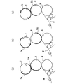
本発明の実施の形態に係る間欠印刷機100の間欠印刷動作を図6と図7と図8に基づいて説明する。
実施の形態では、版胴7の円周の長さと、ブランケット胴8の円周の長さと、圧胴9の円周の長さは同一である。
版胴7とブランケット胴8は、間欠印刷動作中に実線矢印で示すように相互に反対方向(版胴7は時計回り方向、ブランケット胴8は反時計回り方向)に同一の速度で連続して回転駆動される。
圧胴9は、実線矢印で示すように時計回り方向に回転、つまり、正回転駆動することで、被印刷基材Wを実線矢印で示すように正方向に走行し、点線矢印で示すように反時計回り方向に回転、つまり、逆回転駆動することで、被印刷基材Wを点線矢印で示すように逆方向に走行する。この時、図6と図7と図8には図示していない入紙側のステップバックローラ6及び排紙側のステップバックローラ10を、圧胴9と同期して正回転駆動、逆回転駆動する。
The intermittent printing operation of the
In the embodiment, the circumference of the
The
The
最初に印刷する(1ページ目の印刷)時の印刷開始から印刷終了までの動作を図6に基づき説明する。
図6は、最初の印刷開始から印刷終了までのブランケット胴8と圧胴9の回転角度の変化を時系列順に示している。
図6(a)に示すように、圧胴9が正回転駆動することで被印刷基材Wが正方向に走行し、ブランケット8aの先端8a-1が、圧胴9の周面に接している被印刷基材Wに接触開始することで被印刷基材Wにブランケット8aの画像を印刷開始する。ブランケット8aの先端8a-1とは、ブランケット8aの回転方向の下流側の端である。
The operation from the start of printing to the end of printing at the time of first printing (printing of the first page) will be described with reference to FIG.
FIG. 6 shows changes in the rotation angles of the
As shown in FIG. 6A, the printing substrate W travels in the positive direction by driving the
この状態から、圧胴9は、ブランケット胴8の速度と同じ一定速度で正回転駆動され、ブランケット胴8と圧胴9が回転駆動されていることで、図6(b)に示すようにブランケット8aから被印刷基材Wに最初の画像が順次印刷される。図6(c)に示すように、ブランケット8aの後端8a-2が圧胴9の周面に接している被印刷基材Wに接触することで最初の印刷が終了する。
ブランケット8aの後端8a-2とは、ブランケット8aの回転方向の上流側の端である。
つまり、入紙側のステップバックローラ6と排紙側のステップバックローラ10と圧胴9を、同期して一定速度で正回転駆動して被印刷基材Wを、正方向に一定速度で走行しながらブランケット8aを、被印刷基材Wに接触することで、ブランケット8aの画像を被印刷基材Wに最初に印刷する。
ブランケット胴8の回転角度αは、ブランケット胴8の回転中心8bと圧胴9の回転中心9cを結ぶ直線bとブランケット8aの後端8a-2の成す角度であり、印刷終了時の直線bの位置を0度として正転方向を正とする。圧胴9の回転角度βは、直線bと被印刷基材Wに印刷した印刷画像Gの後端G-1との成す角度であり、印刷終了時の直線bの位置を0度として正転方向を正とする。すなわち、図6(c)の印刷終了時がα=0かつβ=0であり、印刷終了の状態からブランケット胴8および圧胴9が正回転駆動することでαとβはそれぞれ増加する。
From this state, the
The
That is, the step back
The rotation angle α of the
被印刷基材Wに最初に印刷された印刷画像Gの長さ(印刷画像Gの後端G-1から先端G-2までの距離)、つまり、1ページ分の印刷範囲は、ブランケット8aのサイズ(ブランケット8aの先端8a-1から後端8a-2までの距離)と一致する。印刷画像Gの後端G-1とは、圧胴9の正回転方向の上流側の端である。印刷画像Gの先端G-2とは、圧胴9の正回転方向の下流側の端である。
印刷終了時のブランケット胴8の直線bからブランケット8aの先端8a-1までの回転角度は、第1ブランケット胴回転角度α-1で、圧胴9の直線bから印刷画像Gの先端G-2までの回転角度は、第1圧胴回転角度β-1である。ブランケット胴8と圧胴9の回転駆動速度は同一で、ブランケット8aのサイズと印刷画像Gの長さが同一であるので、α-1とβ-1は同一角度である。
なお、印刷画像Gは被印刷基材Wの表面に印刷されるが、理解を容易とするために、図6では圧胴9の周面の内側に図示してある。後述する図7、図8においても印刷画像を圧胴9の周面の内側に図示してある。
The length of the printed image G first printed on the substrate W to be printed (distance from the rear end G-1 to the tip G-2 of the printed image G), that is, the print range for one page is the
The rotation angle from the straight line b of the
The printed image G is printed on the surface of the substrate W to be printed, but is shown inside the peripheral surface of the
図6(c)に示す印刷終了時に圧胴9は一定速度で正回転駆動しているので、印刷終了後に圧胴9を減速正回転駆動し、圧胴9を徐々に回転停止させ、被印刷基材Wと圧胴9の周面との間のスリップの発生を防止するとともに、圧胴9の駆動系などに故障が発生することがないようにする。つまり、一定速度で正回転駆動している圧胴9を急に回転停止すると、被印刷基材Wと圧胴9の周面との間のスリップの原因になるとともに、圧胴9の駆動系などに無理な力が働き故障の原因となる。
圧胴9は、印刷終了後に徐々に回転停止するために、圧胴9は図6(d)に示すように、図6(c)で示す印刷終了時の位置から所定の回転角度正回転した位置で回転停止する。つまり、圧胴9の回転停止位置での回転角度βは、第2圧胴回転角度β-2である。
Since the
Since the
圧胴9が回転停止した状態では、図6(d)に示すように、ブランケット胴8の回転角度αは第2ブランケット胴回転角度α-2である。
第2ブランケット胴回転角度α-2は、第2圧胴回転角度β-2より大きい。つまり、ブランケット胴8は印刷終了後も一定の速度で回転駆動しているが、圧胴9は印刷終了後に減速正回転駆動しているので、α-2>β-2となる。
圧胴9が印刷終了時の位置(β=0)から第2圧胴回転角度β-2だけ減速正回転駆動する時には、被印刷基材Wとブランケット8aが離れ、被印刷基材Wは圧胴9とブランケット胴8とで挟持されないので、圧胴9の周面と被印刷基材Wとの間でスリップが発生しやすい。
When the
The second blanket cylinder rotation angle α-2 is larger than the second impression cylinder rotation angle β-2. That is, the
When the
最初の印刷終了から二番目の印刷(2ページ目の印刷)を開始するまでの動作を図7に基づいて説明する。
図7は、圧胴9が回転停止してから二番目の印刷を開始するまでのブランケット胴8と圧胴9の回転角度の変化を時系列順に示している。
図7(a)に示すように、最初の印刷動作が終了して回転停止している圧胴9を、点線矢印で示すように加速逆回転駆動し、被印刷基材Wを点線矢印で示すように逆方向に走行する。
図7(b)に示すように、圧胴9が第2圧胴回転角度β-2だけ逆回転駆動し、被印刷基材Wに最初に印刷した印刷画像Gの後端G-1が印刷終了時の位置(β=0)に移動した時に、圧胴9が所定の逆回転駆動速度になるようにする。所定の逆回転駆動速度とは、最も早い逆回転駆動速度で、印刷中の一定速度より遅い速度である。
The operation from the end of the first printing to the start of the second printing (printing of the second page) will be described with reference to FIG. 7.
FIG. 7 shows changes in the rotation angles of the
As shown in FIG. 7A, the
As shown in FIG. 7B, the
図7(b)に示す状態のブランケット胴8の回転角度αは、第3ブランケット胴回転角度α-3である。α-3>α-2である。
この後、圧胴9を減速逆回転駆動して圧胴9を徐々に回転停止する。圧胴9が回転停止した状態では図7(c)に示すように、圧胴9の回転角度βは印刷終了時の位置(β=0)より入紙側に第3圧胴回転角度β-3ずれた位置となる。
この第3圧胴回転角度β-3の大きさは、第2圧胴回転角度β-2と同一である。β-3=β-2である。
ブランケット胴8の回転角度αは、第4ブランケット胴回転角度α-4(α-4>α-3)まで回転し、ブランケット8aの先端8a-1は圧胴9の印刷開始位置に接近している。ブランケット8aの先端8a-1と直線bの成す角度は第5ブランケット胴回転角度α-5である。α-5=360度-(α-1+α-4)で、α-5>β-3である。
圧胴9が徐々に回転停止するので、被印刷基材Wと圧胴9の周面との間のスリップの発生を防止するとともに、圧胴9の駆動系に故障などが発生することがない。
The rotation angle α of the
After that, the
The size of the third impression cylinder rotation angle β-3 is the same as that of the second impression cylinder rotation angle β-2. β-3 = β-2.
The rotation angle α of the
Since the
なお、入紙側のステップバックローラ6と排紙側のステップバックローラ10を圧胴9と同様に回転駆動する。
被印刷基材Wは、図7(a)から図7(c)に示すように、ブランケット胴8のブランケット8aが取り付けてない周面部分と、圧胴9の周面との間の隙間を通り、入紙部1B側に向けて走行(逆方向に走行)するので、被印刷基材Wは、圧胴9とブランケット胴8とで挟持されないので、逆方向に走行する時に圧胴9の周面と被印刷基材Wとの間でスリップが発生しやすい。
The step back
As shown in FIGS. 7 (a) to 7 (c), the substrate W to be printed has a gap between the peripheral surface portion of the
図7(c)に示すように、圧胴9が回転停止した状態から、圧胴9を、加速正回転駆動することで、圧胴9を徐々に正回転駆動し、被印刷基材Wを正方向に走行する。
そして、圧胴9の回転角度βが第3圧胴回転角度β-3だけ正回転駆動すると、図7(d)に示すように、印刷画像Gの後端G-1にブランケット8aの先端8a-1が接触する(β=0)。
この状態で、圧胴9をブランケット胴と同じ一定速度で正回転駆動するようにして二番目の印刷を開始する。なお、入紙側のステップバックローラ6と排紙側のステップバックローラ10を圧胴9と同様に回転駆動する。
圧胴9は、徐々に回転開始するので、被印刷基材Wと圧胴9の周面との間のスリップの発生を防止するとともに、圧胴9の駆動系に故障などが発生することがない。
したがって、最初の印刷をする時にブランケット胴8は1回転(360度)する。ブランケット胴8が1回転する間に圧胴9は、印刷中に回転するブランケット8aのサイズ(画像範囲)だけ正方向に回転する。
As shown in FIG. 7 (c), the
Then, when the rotation angle β of the
In this state, the
Since the
Therefore, the
図7(c)に示すように、減速逆回転駆動して圧胴9が回転停止してから再び圧胴9が加速正回転駆動して、図7(d)に示すように印刷開始まで正回転駆動するまでの間は、被印刷基材Wとブランケット8aが離れ、被印刷基材Wは圧胴9とブランケット胴8で挟持されないので、圧胴9の周面と被印刷基材Wとの間でスリップが発生しやすい。
つまり、最初の印刷が終了した後に二番目の印刷を開始するまでの動作は、最初の印刷が終了して圧胴9が回転停止した後に、入紙側のステップバックローラ6と排紙側のステップバックローラ10と圧胴9を、同期して加速逆回転駆動、減速逆回転駆動、加速正回転駆動することで、被印刷基材Wを、印刷画像Gの後端G-1が二番目の印刷開始位置となるように逆方向及び正方向に走行する。
As shown in FIG. 7 (c), the
That is, the operation from the end of the first printing to the start of the second printing is that after the first printing is completed and the
二番目の印刷をする(2ページ目の印刷)時の印刷開始から印刷終了までの動作を図8に基づき説明する。
図8は、二番目の印刷開始から二番目の印刷が終了までのブランケット胴8と圧胴9の回転角度の変化を時系列順に示している。
図8(a)の示すように、最初に印刷した印刷画像Gの後端G-1とブランケット8aの先端8a-1が接触した状態で、圧胴9をブランケット胴8と同じ一定速度で正回転駆動して二番目の印刷を開始する。図8(b)に示すように、二番目の印刷画像Hの先端H-2は最初に印刷した印刷画像Gの後端G-1と連続する。
圧胴9が第1圧胴回転角度β-1正回転駆動すると、図8(c)に示すように、二番目の印刷画像Hの後端H-1とブランケット8aの後端8a-2が一致し、二番目の印刷が終了する。
The operation from the start of printing to the end of printing at the time of performing the second printing (printing of the second page) will be described with reference to FIG.
FIG. 8 shows changes in the rotation angles of the
As shown in FIG. 8A, the
When the
この状態から、圧胴9を減速正回転駆動することで、図8(d)に示すように、圧胴9を第2圧胴回転角度β-2回転して回転停止する。つまり、二番目の印刷は最初の印刷と同様に行う。
三番目以降の印刷は、二番目の印刷と同様に行う。
From this state, by driving the
The third and subsequent prints are performed in the same manner as the second print.
図9に基づいて、印刷終了から印刷開始して再び印刷終了するまでの間、つまり一回の印刷動作を行う時のブランケット胴8の回転角度に対する圧胴9の回転角度および回転駆動速度比を説明する。
図9は、ブランケット胴8の回転角度に対する圧胴9の回転角度および回転駆動速度比を示す図表(グラフ)で、横軸がブランケット胴8の回転角度で、一回の印刷動作を示すために、0度から360度で示される。すなわち、横軸は回転角度αである。縦軸は圧胴9の回転角度、圧胴9の回転駆動速度比を示し、印刷終了時および印刷開始時の圧胴9の回転角度を0度とし、正回転駆動している時の回転角度をプラスで表し、逆回転駆動している時の回転角度をマイナスで表している。すなわち、縦軸の圧胴9の回転角度は回転角度βである。回転駆動速度比は印刷中の速度を100%とし、圧胴9が回転停止している時を0%としている。
Based on FIG. 9, the rotation angle and rotation drive speed ratio of the
FIG. 9 is a chart (graph) showing the rotation angle and rotation drive speed ratio of the
圧胴9の回転駆動速度比の変化を実線Xで示し、圧胴9の回転角度を実線Yで示している。
図9の区間1は、図6(c)、図8(c)の印刷終了から図6(d)、図8(d)の圧胴9が回転停止するまでを示している。
区間1では、圧胴9の回転駆動速度比が実線Xで示すように、印刷中の一定速度(100%)から圧胴9が回転停止する0%まで滑らかに変化している。圧胴9の回転角度は、実線Yで示すように、0度から第2圧胴回転角度β-2まで滑らかに変化する。
ブランケット胴8の回転角度は0度から第2ブランケット胴回転角度α-2まで変化する。
The change in the rotation drive speed ratio of the
In
The rotation angle of the
図9の区間2は、図7(a)、(b)の圧胴9を加速逆回転駆動して所定の逆回転駆動速度になるまでを示している。
区間2では、圧胴9の回転駆動速度比が実線Xで示すように、0%から所定の逆回転駆動速度となる回転駆動速度比まで滑らかに変化している。圧胴9の回転角度は実線Yで示すように、第2圧胴回転角度β-2から0度まで滑らかに変化している。
ブランケット胴8の回転角度は、第2ブランケット胴回転角度α-2から第3ブランケット胴回転角度α-3まで変化している。
ブランケット胴8の回転角度の変化の大きさは、区間1よりも区間2が大きくなっているが、これは、圧胴の回転駆動速度比の変化が、区間1よりも区間2が緩やかなためである。
In the
The rotation angle of the
The magnitude of the change in the rotation angle of the
図9の区間3は、図7(b)、(c)の圧胴9を減速逆回転駆動して回転停止するまでを示している。
区間3では、圧胴9の回転駆動速度比は実線Xで示すように、所定の逆回転駆動速度となる回転駆動速度比から0%まで滑らかに変化している。圧胴9の回転角度は実線Yで示すように、0度から第3圧胴回転角度β-3まで滑らかに変化している。
ブランケット胴8の回転角度は、第4ブランケット胴回転角度α-4まで変化している。
図9の区間4は、図7(c)、(d)の圧胴9を加速正回転駆動して一定の印刷速度で印刷開始位置となるまでを示している。
In the
The rotation angle of the
区間4では、圧胴9の回転駆動速度比は実線Xで示すように、0%から印刷中の一定の正回転駆動速度となる100%まで滑らかに変化している。圧胴9の回転角度は実線Yで示すように、第3圧胴回転角度β-3から0度まで滑らかに変化している。
ブランケット胴8の回転角度は、第4ブランケット胴回転角度α-4と第5ブランケット胴回転角度α-5の和まで変化している。
ブランケット胴8の回転角度の変化の大きさは、区間4よりも区間3が大きくなっているが、これは、圧胴の回転駆動速度比の変化が、区間4よりも区間3が緩やかなためである。区間1から区間4が、非印刷範囲である。
図9の区間5は、印刷中を示し、圧胴9の回転駆動速度比は実線Xで示すように、100%で、圧胴9の回転角度は実線Yで示すように、0度から第1圧胴回転角度β-1まで直線的に変化している。区間5が印刷範囲である。
In the
The rotation angle of the
The magnitude of the change in the rotation angle of the
区間1における圧胴9の減速正回転駆動の回転駆動速度比変化と、区間4における圧胴9の加速正回転駆動の回転駆動速度比変化は線対称である。
区間2における圧胴9の加速逆回転駆動の回転駆動速度比の変化と、区間3における圧胴9の減速逆回転駆動の回転駆動速度比の変化は線対称である。
そして、圧胴9の一定速度から所定の逆回転駆動速度までの回転駆動速度比変化と、所定の逆回転駆動速度から一定速度までの回転駆動速度比変化が、略U字形状の曲線に沿って滑らかに変化する。
The change in the rotation drive speed ratio of the deceleration forward rotation drive of the
The change in the rotation drive speed ratio of the acceleration reverse rotation drive of the
Then, the rotation drive speed ratio change from the constant speed of the
図10は、圧胴の回転駆動速度変化を示す図表であり、ブランケット胴8の回転角度に対する圧胴9の回転駆動速度の異なる2つの印刷速度の場合を示している。印刷速度によらず、圧胴9の印刷中の一定速度から所定の逆回転駆動速度までの速度変化と、所定の逆回転駆動速度から印刷中の一定速度までの速度変化が、略U字形状の曲線に沿って滑らかに変化するので、圧胴9は滑らかに速度変化し、被印刷基材Wはスムーズに逆方向と正方向に向きを変えて走行するので、被印刷基材Wと圧胴9の周面との間のスリップの発生を防止して、被印刷基材Wに正確に印刷することができる。
FIG. 10 is a chart showing changes in the rotational drive speed of the impression cylinder, and shows the case of two printing speeds in which the rotational drive speed of the
図11に示すように、ブランケット胴8にサイズが小さいブランケット8aを取り付け、圧胴9を先の実施の形態のように回転駆動して印刷すると、印刷終了後に圧胴9が加速逆回転駆動、減速逆回転駆動して圧胴9が回転停止した時に、ブランケット8aの先端8a-1と直線bが成す第5ブランケット胴回転角度α-5が、図7(c)に示す角度より大きくなる。
したがって、圧胴9を加速正回転駆動して印刷開始する時に、印刷画像Gの後端G-1とブランケット8aの先端8a-1が接触せずに、正しく印刷できない。
As shown in FIG. 11, when a small-
Therefore, when the
つまり、図12では、図9と同様に、圧胴9の回転駆動速度比の変化を実線Xで示し、圧胴9の回転角度を実線Yで示しているが、ブランケット8aのサイズが小さいからブランケット胴8が区間5の印刷中に回転する回転角度が小さく、圧胴9が印刷終了してから印刷開始するまでのブランケット胴8の回転角度が大きいので、先の実施の形態のように圧胴を回転駆動したのでは正しく印刷できない。
そこで、図12に示すように区間1の圧胴9の減速正回転駆動の回転駆動速度比変化、区間2の圧胴9の加速逆回転駆動の回転駆動速度比変化、区間3の圧胴9の減速逆回転駆動の回転駆動速度比変化、区間4の圧胴9の加速正回転駆動の回転駆動速度比変化をそれぞれ変えて、印刷開始位置で印刷画像Gの後端G-1とブランケット8aの先端8a-1が接触するようにする。すなわち、小さいブランケット8aの場合には第5ブランケット胴回転角度α-5が大きくなることに応じて、第2圧胴回転角度β-2、第3圧胴回転角度β-3を大きくしている。
That is, in FIG. 12, as in FIG. 9, the change in the rotation drive speed ratio of the
Therefore, as shown in FIG. 12, the change in the rotation drive speed ratio of the deceleration forward rotation drive of the
図13に示すように、ブランケット胴8にサイズが大きいブランケット8aを取り付け、圧胴9を先の実施の形態のように回転駆動して印刷すると、印刷終了後に圧胴9が加速逆回転駆動、減速逆回転駆動して圧胴9が回転停止した時に、圧胴8aの先端8a-1と直線bが成す第5ブランケット胴回転角度α-5が、図7(c)に示す角度より小さくなる。
したがって、圧胴9を加速正回転駆動して印刷開始する時に、印刷画像Gの後端G-1とブランケット8aの先端8a-1が接触せずに、正しく印刷できない。
As shown in FIG. 13, when a large-
Therefore, when the
つまり、図14では、図9と同様に、圧胴9の回転駆動速度比の変化を実線Xで示し、圧胴9の回転角度を実線Yで示しているが、ブランケット8aのサイズが大きいからブランケット胴8が区間5の印刷中に回転する回転角度が大きく、圧胴9が印刷終了してから印刷開始するまでのブランケット胴8の回転角度が小さいので、先の実施の形態のように圧胴を回転駆動したのでは正しく印刷できない。
そこで、図14に示すように、区間1の圧胴9の減速正回転駆動の回転駆動速度比変化、区間2の圧胴9の加速逆回転駆動の回転駆動速度比変化、区間3の圧胴9の減速逆回転駆動の回転駆動速度比変化、区間4の圧胴9の加速正回転駆動の回転駆動速度比変化をそれぞれ変えて、印刷開始位置で印刷画像Gの後端G-1とブランケット8aの先端8a-1が接触するようにする。すなわち、大きいブランケット8aの場合には第5ブランケット胴回転角度α-5が小さくなることに応じて、第2圧胴回転角度β-2、第3圧胴回転角度β-3を小さくしている。
That is, in FIG. 14, as in FIG. 9, the change in the rotation drive speed ratio of the
Therefore, as shown in FIG. 14, the change in the rotation drive speed ratio of the deceleration forward rotation drive of the
印刷速度を変えて単位時間当たりの印刷ページ数を変更する場合は、圧胴9が一定速度から減速開始する時及び、一定速度となる時のブランケット胴8の回転角度は変えずに、圧胴9の正逆回転駆動の加速度を変化すればよい。
例えば、図10に示すように、点線で示した印刷速度を、実線で示した印刷速度より遅くする場合には、圧胴9が一定速度から減速開始する時のブランケット胴8の回転角度及び、圧胴9が一定速度になる時のブランケット胴8の回転角度を変えずに、圧胴9を正逆回転駆動する時の加速度を小さくする。
When changing the number of printed pages per unit time by changing the printing speed, the rotation angle of the
For example, as shown in FIG. 10, when the printing speed shown by the dotted line is slower than the printing speed shown by the solid line, the rotation angle of the
次に、被印刷基材Wを圧胴9の周面に巻き掛ける構成を説明する。
図4に示すように、被印刷基材Wは、入紙側の走行路15aから圧胴9の周面に巻き付き、排紙側の走行路15bに至る。
入紙側の走行路15aは、被印刷基材Wが正方向に走行する時の走行方向上流側の走行路で、被印刷基材Wが逆方向に走行する時には走行方向下流側の走行路である。
排紙側の走行路15bは、被印刷基材Wが正方向に走行する時の走行方向下流側の走行路で、被印刷基材Wが逆方向に走行する時には走行方向上流側の走行路である。
ブランケット胴8と圧胴9の間を走行する被印刷基材Wは、入紙側のガイドローラ40と排紙側のガイドローラ41とで圧胴9の周面に所定の巻き角で巻き掛けられる。
Next, a configuration in which the substrate W to be printed is wound around the peripheral surface of the
As shown in FIG. 4, the substrate W to be printed wraps around the peripheral surface of the
The
The traveling
The base material W to be printed running between the
入紙側のガイドローラ40は入紙側の走行路15aに設けてある。
排紙側のガイドローラ41は排紙側の走行路15bに設けてある。
入紙側のガイドローラ40と排紙側のガイドローラ41の少なくとも一方の位置を変えることで、被印刷基材Wの圧胴9周面への巻き角が変化する。
入紙側のガイドローラ40と排紙側のガイドローラ41はフリー回転するローラで、駆動モータなどで回転駆動されない。
The
The
By changing the positions of at least one of the
The
図15に示すように、入紙側のガイドローラ40は、圧胴9よりも入紙部1B寄りの位置に設けてある。
入紙側のガイドローラ40の周面と被印刷基材Wが接する位置40aは、圧胴9の周面におけるブランケット胴8のブランケット8aと接触する位置(以下印刷位置という)9aよりも下に位置し、入紙側の走行路15aを走行する被印刷基材Wは、入紙側のガイドローラ40の周面下部と圧胴9の周面上部との間を、入紙側のガイドローラ40と接触する位置40aが低く、圧胴9の周面と接触開始する位置が高くなるように斜めに走行する。
したがって、入紙側の走行路15aを走行する被印刷基材Wが、圧胴9の周面に巻き掛け開始する入紙側の巻き掛け開始位置(圧胴9の周面と接触開始する入紙側の位置)16aは、圧胴9の印刷位置9aよりも入紙側で、印刷位置9aよりも低い位置である。
As shown in FIG. 15, the
The
Therefore, the printing base material W traveling on the paper entry
排紙側のガイドローラ41は、圧胴9よりも入紙部1B寄りで、かつ入紙側の走行路15aに接近した位置に設けてある。排紙側のガイドローラ41の周面と被印刷基材Wが接触開始する圧胴9側の位置41aは、圧胴9の周面における下部位置9bよりも上に位置し、排紙側の走行路15bにおける排紙側のガイドローラ41よりも圧胴9側を走行する被印刷基材Wは、圧胴9の周面下部と排紙側のガイドローラ41の周面上部との間を、圧胴9の周面と接触開始する位置が低く、排紙側のガイドローラ41と接触開始する位置41aが高くなるように斜めに走行する。圧胴9の周面の下部位置9bとは、印刷位置9aと圧胴9の中心9cを通る直線aと圧胴9の周面下部との交点である。
したがって、排紙側の走行路15bを走行する被印刷基材Wが、圧胴9の周面に巻き掛け開始する排紙側の巻き掛け開始位置(圧胴9の周面に接触開始する排紙側の位置)16bは、圧胴9の周面の下部位置9bよりも入紙側で、下部位置9bより高い位置である。
The
Therefore, the printing base material W traveling on the traveling
つまり、入紙側のガイドローラ40の周面における被印刷基材Wが接する位置40aと、圧胴9の周面における入紙側の巻き掛け開始位置16aを結ぶ直線(入紙側のガイドローラ40と圧胴9との間の入紙側の走行路15aの延長線)と、排紙側のガイドローラ41の周面における被印刷基材Wが接する位置41aと圧胴9の周面における排紙側の巻き掛け開始位置16bを結ぶ直線(排紙側のガイドローラ41と圧胴9との間の排紙側の走行路15bの延長線)は交差する。
したがって、被印刷基材Wが圧胴9の周面に巻き掛けられる巻き角θは、180度より大きい角度、図15では270度であり、被印刷基材Wと圧胴9の周面との接触面積が広く、両者の間に生じる摩擦力は大きい値である。
That is, a straight line connecting the
Therefore, the winding angle θ around which the substrate W to be printed is wound around the peripheral surface of the
摩擦力が大きい値である理由は次の通りである。
被印刷基材Wが圧胴9の周面に巻き掛けられていることで、巻き掛けられている範囲において、被印刷基材Wから圧胴9に対して圧胴9の中心9c方向に向かう力が発生する。
この力の反作用として、被印刷基材Wには圧胴9の周面に巻き掛けられている範囲に垂直抗力が発生する。
被印刷基材Wに働く摩擦力は、被印刷基材Wが圧胴9の周面に巻き掛けられている範囲全体に対する垂直抗力に比例するため、被印刷基材Wが圧胴9の周面に巻き掛けられている範囲が広いほど摩擦力が大きくなる。
The reason why the frictional force is a large value is as follows.
Since the substrate W to be printed is wound around the peripheral surface of the
As a reaction of this force, a normal force is generated in the range around the peripheral surface of the
Since the frictional force acting on the substrate W to be printed is proportional to the normal force with respect to the entire range in which the substrate W to be printed is wound around the peripheral surface of the
したがって、被印刷基材Wが圧胴9の周面に巻き掛けられている巻き角θが大きい角度であれば、被印刷基材Wと圧胴9の周面の間に生じる摩擦力が大きい値となる。
被印刷基材Wと圧胴9の周面の間に生じる摩擦力が大きい値であれば、圧胴9を逆回転駆動して被印刷基材Wを逆方向に走行する時に、圧胴9の周面と被印刷基材Wとの間に生じるスリップを抑制することができる。
Therefore, if the winding angle θ around which the substrate W to be printed is wound around the peripheral surface of the
If the frictional force generated between the printing substrate W and the peripheral surface of the
図4に示すように、圧胴9の周面における被印刷基材Wが巻き掛けられる部分(図15に示す入紙側の巻き掛け開始位置16aと排紙側の巻き掛け開始位置16bとの間の周面部分)と対向して圧胴用のニップローラ42と乾燥装置43が設けてある。
圧胴用のニップローラ42は圧胴9の周面に圧接して設けてあり、被印刷基材Wは、圧胴用のニップローラ42と圧胴9の周面によって常に挟持されながら走行する。つまり、圧胴用のニップローラ42は、被印刷基材Wを圧胴9の周面に押しつけるものである。
圧胴用のニップローラ42を設けたことによって、圧胴用のニップローラ42で押しつけられる部分において、被印刷基材Wと圧胴9の周面との間に生じる摩擦力が増大し、摩擦力は大きな値となる。
As shown in FIG. 4, a portion of the peripheral surface of the
The
By providing the
また、圧胴9を逆回転駆動して被印刷基材Wを逆方向に走行している時には、圧胴9の周面とブランケット胴8の周面が離れており、被印刷基材Wがブランケット胴8に対して非接触であるので、逆方向に走行する被印刷基材Wは、圧胴用のニップローラ42で圧胴9の周面に押しつけられている箇所(図15のニップ位置42a)よりも走行方向下流側が、走行方向に引っ張られる。
被印刷基材Wが走行方向に引っ張られることで、被印刷基材Wから圧胴9の周面に対して圧胴9の中心9c方向に向かう力が生じる。この力によって、圧胴9の周面と被印刷基材Wとの間に残存する空気が逃げ、空気層の形成を抑制するので、圧胴9の周面と被印刷基材Wとの間の摩擦力が空気層により低下することが少なくなる。
Further, when the
When the substrate W to be printed is pulled in the traveling direction, a force is generated from the substrate W to be printed with respect to the peripheral surface of the
また、被印刷基材Wから圧胴9の周面に対して圧胴の9の中心方向に向かう力により、圧胴9の周面と被印刷基材Wとの間の摩擦力が大きくなる。
これらのことが相俟って、圧胴9と入紙側のステップバックローラ6と排紙側のステップバックローラ10を逆回転駆動して、被印刷基材Wを逆方向に走行する時及び、圧胴9が印刷開始位置から回転停止するまで被印刷基材Wが正方向に走行する時並びに、逆方向に走行した被印刷基材Wを印刷開始位置まで正方向に走行する時(つまり、被印刷基材Wがブランケット8aと離れ、被印刷基材Wが圧胴9とブランケット胴8とで挟持されない状態で走行する時)に、被印刷基材Wと圧胴9の周面との間にスリップが生じることがない。
したがって、印刷見当のバラツキの発生を防止できる。
Further, the frictional force between the peripheral surface of the
In combination with these factors, when the
Therefore, it is possible to prevent the occurrence of variation in the print register.
先に述べた、空気層の形成を抑制して、圧胴9の周面と被印刷基材Wとの間の摩擦力を大きくすることは、引っ張られる被印刷基材Wの圧胴9の周面に接触している部分の長さ(図15に示す入紙側の巻き掛け開始位置16aから排紙側の巻き掛け開始位置16bまでの長さ)が長いほど効果がある。
そこで、図15に示すように、圧胴用のニップローラ42は、その圧胴9の周面に圧接するニップ位置42aが、圧胴の印刷位置9aよりも排紙側のガイドローラ41寄りとなるように設けてある。
つまり、圧胴用のニップローラ42の圧胴9の周面に圧接するニップ位置42aは、被印刷基材Wが逆方向に走行する時に、圧胴9の印刷位置9aよりも被印刷基材Wの走行方向上流側(逆回転方向の上流側)である。
Suppressing the formation of the air layer and increasing the frictional force between the peripheral surface of the
Therefore, as shown in FIG. 15, in the impression cylinder nip
That is, the nip position 42a that is in pressure contact with the peripheral surface of the
そして、そのニップ位置42aは、排紙側の巻き掛け開始位置16bを越えない最も排紙側のガイドローラ41に近い位置が望ましい。
ニップ位置42aが排紙側の巻き掛け開始位置16bを越えると、後に説明するように、圧胴用のニップローラ42を圧胴9の周面から離隔した時に、被印刷基材Wの圧胴9の周面への巻き角が変化するとともに、走行路の長さが変化するので、印刷見当がずれてしまう。
圧胴用のニップローラ42は、圧胴9の周面に圧接する位置と離隔する位置とに亘って移動可能としてある。
It is desirable that the nip position 42a is the position closest to the
When the nip position 42a exceeds the winding start position 16b on the paper ejection side, as will be described later, when the
The
圧胴用のニップローラ42の取り付け構成を図16と図17に基づき説明する。
印刷ユニットの機枠2Aは被印刷基材Wの走行方向と直角方向一方の操作側のフレーム2A-1と、他方の駆動側のフレーム2A-2とを備えている。
排紙側のガイドローラ41の支持軸50は、操作側のフレーム2A-1と駆動側のフレーム2A-2とに亘って軸方向に位置決めされるとともに回転可能に取り付けられ、その支持軸50に排紙側のガイドローラ41が回転可能に取り付けしてある。また、その支持軸50の長さ方向の一端は操作側のフレーム2A-1から外部に突きだしている。
支持軸50の長さ方向に離隔した2つの位置に、支持アーム51の基端部が回動しないように固定してそれぞれ取り付けてある。この2つの支持アーム51の先端部間に跨ってニップローラ軸52が回転しないように固定して取り付けてあり、そのニップローラ軸52に圧胴用のニップローラ42が回転可能に取り付けてある。
The mounting configuration of the
The
The
The base end portion of the
印刷ユニットの機枠2Aの操作側のフレーム2A-1の外側面(表面)に、ニップローラ移動用のシリンダ53が回動可能に取り付けてあり、そのニップローラ移動用のシリンダ53のピストンロッド53aにレバー54の基端部が回動可能に取り付けてある。そのレバー54の先端部に支持軸50が回転しないように固定して取り付けてある。
そして、ニップローラ移動用のシリンダ53のピストンロッド53aを伸長することで、レバー54が図16で反時計方向に回動し、支持軸50が反時計方向に所定の回転角度回転して支持アーム51が圧胴9の周面に向けて回動し、圧胴用のニップローラ42が圧胴9の周面に圧接する位置に移動する。
A
Then, by extending the
ニップローラ移動用のシリンダ53のピストンロッド53aを縮小することで、レバー54が図16で時計方向に回動し、支持軸50が時計方向に所定の回転角度回転して支持アーム51が圧胴9の周面と離れる方向に回動し、圧胴用のニップローラ42が圧胴9の周面と離隔する位置に移動する。
したがって、印刷動作時には圧胴用のニップローラ42を圧胴9の周面に圧接する位置に移動してスリップの発生を防止し、保守点検作業時にはニップローラ42を圧胴9の周面から離隔した位置に移動することで、保守点検作業等が容易となる。
By reducing the
Therefore, during the printing operation, the
そして、被印刷基材Wに画像を印刷する時は、圧胴9の周面とブランケット胴8のブランケット8aが被印刷基材Wを介して接触しているので、圧胴用のニップローラ42がなくとも圧胴9の周面と被印刷基材Wとの間にスリップが発生することがない(図6参照)。しかも、圧胴用のニップローラ42を圧胴9の周面と離隔しても排紙側のガイドローラ41の周面における被印刷基材Wが接触開始する圧胴9側の位置41aと圧胴9の周面における排紙側の巻き掛け開始位置16bを結ぶ直線の間の排紙側の走行路15bの長さが変わらない。したがって、圧胴用のニップローラ42を圧胴9の周面から離隔しても印刷見当のバラツキが発生することがない(図15参照)。
When printing an image on the substrate W to be printed, the peripheral surface of the
図4に示すように、乾燥装置43は被印刷基材Wに印刷された画像のインキの定着、乾燥を行う。この実施の形態では紫外線硬化型インキを使用して印刷するので、紫外線を照射して乾燥する乾燥装置を用いている。紫外線の光源としては、水銀ランプ、メタハラランプ、LEDランプなど適宜選択可能であるが、被印刷基材Wへの熱の影響を軽減するためにLEDランプが適している。
乾燥装置43は、圧胴9の印刷位置9aと圧胴用のニップローラ42との間に設けてある。つまり、乾燥装置43は圧胴用のニップローラ42よりも圧胴正回転方向の上流側に設けてある。
したがって、印刷した画像のインキが定着、乾燥された後に圧胴用のニップローラ42が接触するので、圧胴用のニップローラ42が接触することによって画像が乱されることがない。
As shown in FIG. 4, the drying
The drying
Therefore, since the
乾燥装置43で発生する熱で圧胴9や被印刷基材Wが高い温度となり、被印刷基材Wが熱による悪い影響を受けることがある。特に被印刷基材Wとしてフィルム等の軟包装の素材を用いた場合は、熱による悪い影響を受けやすい。熱による悪い影響としては、熱により被印刷基材Wが伸びて印刷見当がずれること等がある。
そこで、圧胴9に冷却装置72を設け、圧胴9を冷却することで、圧胴9や被印刷基材Wが熱による悪い影響を受ける高い温度にならないようにしている。
The heat generated by the drying
Therefore, a
図18と図19に基づいて圧胴9の冷却装置72を説明する。
圧胴9は、筒体60と、筒体60の一方の開口部を閉じる一方の端面板61と、筒体60の他方の開口部を閉じる他方の端面板62とで中空部を有する筒形状である。
一方の端面板61に一方の支持軸63が設けてあり、一方の支持軸63は偏心軸受64により操作側のフレーム2A-1に回転可能に支持されている。
他方の端面板62に他方の支持軸65が設けてあり、他方の支持軸65は偏心軸受64により駆動側のフレーム2A-2に回転可能に支持されている。また、他方の偏心軸受64には圧胴用の駆動モータ68を固定するためのモータ固定用偏心部品64aが取り付けられている。
The
The
One
The other end face
駆動側のフレーム2A-2にステー66を介してモータ支持フレーム67が取り付けてあり、そのモータ支持フレーム67に、モータ固定用偏心部品64aが回転可能に取り付けてあり、圧胴用の駆動モータ68はモータ固定用偏心部品64aに取り付けてある。
圧胴用の駆動モータ68の図示しない回転軸と他方の支持軸65が図示しないカップリングで連結されている。
圧胴9は、圧胴用の駆動モータ68で正回転駆動、逆回転駆動される。
圧胴用の駆動モータ68は、版胴7及びブランケット胴8の駆動モータ(図示せず)と独立して、入紙側のステップバックローラ6の駆動モータ及び、排紙側のステップバックローラ10の駆動モータと同期制御される。
A
A rotation shaft (not shown) of the
The
The
したがって、圧胴9は、入紙側のステップバックローラ6及び、排紙側のステップバックローラ10と同期して正回転駆動、逆回転駆動される。
圧胴9の中空部内には図示しない冷却水流通用のパイプが設けてある。そのパイプは一方の端面板61、一方の支持軸63を貫通して操作側のフレーム2A-1から外部に突き出し、ロータリージョイント69を経て冷却水の供給配管70と冷却水の排出配管71に接続している。冷却水の供給配管70は冷却水の供給ポンプの吐出側に接続してあり、冷却水の排出配管71は冷却水のタンクに接続してある。
Therefore, the
A pipe for cooling water flow (not shown) is provided in the hollow portion of the
そして、冷却水の供給配管70から冷却水がパイプに流入し、その冷却水はパイプ内を流れて冷却水の排出配管71から流出する。
このように、パイプ内を冷却水が流れることで圧胴9が冷却され、圧胴の冷却装置72を構成している。
各偏心軸受64及びモータ固定用偏心部品64aの回転中心と支持軸63、65の回転中心は偏心しており、各偏心軸受64を回転機構73で所定の回転角度回転することで、圧胴9及び圧胴用の駆動モータ68は、所定の回転角度偏心回転する。
圧胴9が偏心回転することで、圧胴9のブランケット胴8に対する位置が変化し、圧胴9の周面とブランケット胴8のブランケット8aとの接触圧(印圧)を調整できる。
Then, the cooling water flows into the pipe from the cooling
In this way, the
The center of rotation of each
When the
回転機構73を説明する。
操作側のフレーム2A-1と駆動側のフレーム2A-2に亘って回転軸74が回転可能に取り付けてある。この回転軸74に取り付けてあるウォーム歯車75が、軸76に取り付けたウォーム77と噛合している。軸76に固定したハンドル76aを回転することで回転軸74が回転する。
各偏心軸受64には扇形の歯車78がそれぞれ取り付けてあり、この各歯車78が回転軸74の長さ方向の両側にそれぞれ取り付けある歯車79にそれぞれ噛合っている。
したがって、ハンドル76aで軸76を回転することで各偏心軸受64が、所定の回転角度回転する。
The
A
Fan-shaped
Therefore, by rotating the
図1に示すように、印刷部2の各印刷ユニット間に見当調整装置80がそれぞれ設けてある。具体的には、第1印刷ユニット2aと第2印刷ユニット2bとの間、第2印刷ユニット2bと第3印刷ユニット2cとの間、第3印刷ユニット2cと第4印刷ユニット2dとの間、第4印刷ユニット2dと第5印刷ユニット2eとの間、第5印刷ユニット2eと第6印刷ユニット2fとの間に、見当調整装置80がそれぞれ設けてある。
見当調整装置80は、印刷を開始する前に、印刷する画像の天地方向の長さに応じて印刷見当を調整するものである。
As shown in FIG. 1, a
The
従来の特許文献1に開示された間欠印刷機では、圧胴を回転停止した状態で、印刷ユニットを移動して印刷ユニット間の距離を変えることで印刷見当を調整しているが、このような印刷見当の調整の仕方を本発明の間欠印刷機に適用することはできない。
その理由は、本発明の間欠印刷機では、圧胴9の周面に被印刷基材Wが巻き掛けてあるので、印刷ユニット2a~2fを移動すると圧胴9も移動し、圧胴9の移動により被印刷基材Wが引っ張られて切断したり、弛んだりすることがあるためである。
本発明の見当調整装置80は、印刷ユニット間の被印刷基材Wの走行路の長さ(紙パスの長さ)を変えることで、印刷見当を調整するものである。
したがって、圧胴9の周面に被印刷基材Wが巻き掛けてあっても印刷見当を調整できる。
In the conventional intermittent printing machine disclosed in
The reason is that in the intermittent printing machine of the present invention, the substrate W to be printed is wound around the peripheral surface of the
The
Therefore, the print register can be adjusted even if the substrate W to be printed is wrapped around the peripheral surface of the
見当調整装置80は、図4に示すように、入紙側のプルローラ81と、入紙側のプルローラ81よりも下方に設けられた排紙側のプルローラ82と、入紙側のプルローラ81と排紙側のプルローラ82との間に設けられ、水平方向に移動する可動ローラ83と、排紙側のプルローラ82よりも排紙側に設けたガイドローラ84を有する。
被印刷基材Wは、入紙側のプルローラ81から可動ローラ83、可動ローラ83から排紙側のプルローラ82、排紙側のプルローラ82からガイドローラ84と順次巻き付いて走行する。
つまり、被印刷基材Wが正方向(実線矢印方向)に走行する時には、入紙側の印刷ユニット(第1印刷ユニット2a)から入紙側のプルローラ81を経て可動ローラ83に巻き付いて走行方向を変え、排紙側のプルローラ82に巻き付いて再び走行方向を変えて、ガイドローラ84を経て排紙側の印刷ユニット(第2印刷ユニット2b)へと走行する。
As shown in FIG. 4, the
The substrate W to be printed travels by sequentially winding from the
That is, when the substrate W to be printed travels in the positive direction (solid line arrow direction), it winds around the
被印刷基材Wが逆方向(点線矢印方向)に走行する時には、排紙側の印刷ユニット(第2印刷ユニット2b)からガイドローラ84を経て排紙側のプルローラ82に巻き付いて走行方向を変え、可動ローラ83に巻き付いて再び走行方向を変えて、入紙側のプルローラ81を経て入紙側の印刷ユニット(第1印刷ユニット2a)へと走行する。
可動ローラ83は、入紙側の位置83aと排紙側の位置83bとの間を移動することができる。可動ローラ83が移動することで入紙側のプルローラ81と排紙側のプルローラ82との間の被印刷基材Wの走行路85aの長さが変化する。つまり、入紙側のプルローラ81と排紙側のプルローラ82との間の走行路85aは、可動ローラ83で折り返すループ状となっているので、可動ローラ83が移動することで、走行路85aの長さが変化する。
したがって、入紙側のプルローラ81と排紙側のプルローラ82との間の走行路85aの長さが変化することにより、第1印刷ユニット2aの印刷位置9aと第2印刷ユニット2bの印刷位置9aの間の被印刷基材Wの走行路85(以下印刷ユニット間の被印刷基材Wの走行路85という)の長さが変化する。
When the substrate W to be printed travels in the opposite direction (dotted line arrow direction), it winds around the
The
Therefore, the length of the traveling
可動ローラ83が入紙側の位置83aであると印刷ユニット間の被印刷基材Wの走行路85の長さが最も短い。可動ローラ83が排紙側の位置83bであると印刷ユニット間の被印刷基材Wの走行路85の長さが最も長い。
したがって、可動ローラ83が入紙側の位置83aと排紙側の位置83bとの間を移動することで、印刷ユニット間の被印刷基材Wの走行路85の長さが変わるので、印刷前に印刷見当を調整できる。例えば、印刷ユニット間の被印刷基材Wの走行路85の長さを、印刷する画像の天地方向の長さの整数倍とする。
各ローラ81、82、83、84は、見当調整装置80の枠体80A内に設けてあるが、理解を容易とするために、各ローラ81、82、83、84を実線で図示してある。
When the
Therefore, when the
The
入紙側のプルローラ81と排紙側のプルローラ82は、図示しない別々の駆動モータで回転駆動制御される。そして、入紙側のプルローラ81と排紙側のプルローラ82は入紙側のステップバックローラ6及び、排紙側のステップバックローラ10と同期して正回転駆動、逆回転駆動される。
可動ローラ83は、枠体80A内に移動可能に設けた図示しない移動体に回転可能に取り付けてある。移動体を図示しない移動機構で移動することで可動ローラ83を移動する。
移動機構としては、モータで送りねじを回転し、その送りねじを移動体のねじ孔にねじ合したもの、ラックとピニオンを用いるもの、シリンダを用いるものなどである。
The
The
As the moving mechanism, a feed screw is rotated by a motor and the lead screw is screwed into a screw hole of a moving body, a rack and a pinion are used, a cylinder is used, and the like.
被印刷基材Wは可動ローラ83の周面の180度の範囲に巻き付いているので、可動ローラ83が移動しても常に180度の範囲に巻き付き、巻き角が変化しないので、可動ローラ83の移動距離の2倍の長さだけ印刷ユニット間の被印刷基材Wの走行路85の長さを正確に変えることができる。しかしながら、180度の範囲に巻き付いているために、被印刷基材Wと可動ローラ83の周面との接する面積が広く、被印刷基材Wの走行抵抗が大きくなる。このために、被印刷基材Wが正方向に走行する時には、排紙側のプルローラ82の周面と被印刷基材Wとの間でスリップが生じやすく、被印刷基材Wが逆方向に走行する時には、入紙側のプルローラ81の周面と被印刷基材Wとの間でスリップが生じやすい。
そこで、入紙側のプルローラ81の周面に圧接する入紙側のプルローラ用ニップローラ86と、排紙側のプルローラ82に圧接する排紙側のプルローラ用ニップローラ87をそれぞれ設けてある。
Since the substrate W to be printed is wound in a range of 180 degrees on the peripheral surface of the
Therefore, a pull roller nip
そして、入紙側のプルローラ81の周面と入紙側のプルローラ用ニップローラ86とで被印刷基材Wを挟持し、排紙側のプルローラ82の周面と排紙側のプルローラ用ニップローラ87とで被印刷基材Wを挟持している。
したがって、入紙側のプルローラ81の周面と被印刷基材Wとの間の摩擦力が大きくなり、両者の間でスリップが生じることがなく、排紙側のプルローラ82の周面と被印刷基材Wとの間の摩擦力が大きくなり、両者の間にスリップが生じることがないので、見当調整装置80を設けたことにより印刷見当のバラツキが発生することはない。
入紙側のプルローラ用ニップローラ86は、入紙側のプルローラ81の周面に圧接する位置と、離隔する位置とに亘って移動可能としてある。
排紙側のプルローラ用ニップローラ87は、排紙側のプルローラ82の周面に圧接する位置と、離隔する位置とに亘って移動可能としてある。
Then, the substrate W to be printed is sandwiched between the peripheral surface of the
Therefore, the frictional force between the peripheral surface of the
The pull roller nip
The pull roller nip
入紙側のプルローラ用ニップローラ86の取り付け構成を図20と図21に基づき説明する。枠体80Aは被印刷基材Wの走行方向と直角方向一方の操作側のフレーム80A-1と、他方の駆動側のフレーム80A-2とを備えている。
枠体80Aの操作側のフレーム80A-1と駆動側のフレーム80A-2とに亘って支持軸90が、軸方向に位置決めされるとともに回転可能に取り付けてあり、その支持軸90の長さ方向の一端は操作側のフレーム80A-1から外部に突きだしている。支持軸90の長さ方向に離隔した2つの位置に、支持アーム91の基端部が、回動しないように固定してそれぞれ取り付けてある。この2つの支持アーム91の先端部間に跨ってニップローラ軸92が回転しないように固定して取り付けてあり、そのニップローラ軸92に入紙側のプルローラ用ニップローラ86が回転可能に取り付けてある。
The mounting configuration of the pull roller nip
The
枠体80Aの操作側のフレーム80A-1の外側面(表面)に、ニップローラ移動用のシリンダ93が回動可能に取り付けてあり、そのニップローラ移動用のシリンダ93のピストンロッド93aにレバー94の基端部が回動可能に取り付けてある。そのレバー94の先端部に支持軸90が回転しないように固定して取り付けてある。
そして、ニップローラ移動用のシリンダ93のピストンロッド93aを伸長することで、レバー94が図20で時計方向に回動し、支持軸90が時計方向に所定の回転角度回転して支持アーム91が入紙側のプルローラ81の周面に向けて回動し、入紙側のプルローラ用ニップローラ86は、入紙側のプルローラ81の周面に圧接する位置に移動する。
ニップローラ移動用のシリンダ93のピストンロッド93aを縮小することで、レバー94が図20で反時計方向に回動し、支持軸90が反時計方向に所定の回転角度回転して支持アーム91が入紙側のプルローラ81の周面と離れる方向に回動し、入紙側のプルローラ用ニップローラ86は、入紙側のプルローラ81の周面と離隔する位置に移動する。
なお、排紙側のプルローラ用ニップローラ87も同様に取り付けしてあるので、同じ部材に同じ符号を付けて説明を省略する。
A
Then, by extending the
By reducing the
Since the pull roller nip
また、入紙側のプルローラ用ニップローラ86と排紙側のプルローラ用ニップローラ87を離隔位置に移動することで、印刷開始前に、見当調整装置80内に被印刷基材Wを通す作業(紙通し作業)や、ローラの保守点検作業がやり易くなる。
可動ローラ83を移動する時には、圧胴用のニップローラ42、入紙側のプルローラ用ニップローラ86、排紙側のプルローラ用ニップローラ87、その他のニップローラをそれぞれ離隔位置に移動して、可動ローラ83の移動により被印刷基材Wが各ローラに沿って滑りながら移動するようにしている。
Further, by moving the pull roller nip
When moving the
本発明の間欠印刷機は、各印刷ユニット2a~2fの圧胴9の周面に被印刷基材Wが巻き掛けてあり、各圧胴9の周面には圧胴用のニップローラ42が圧接している。各見当調整装置80の入紙側のプルローラ81の周面には、入紙側のプルローラ用ニップローラ86が圧接し、排紙側のプルローラ82の周面には、排紙側のプルローラ用ニップローラ87が圧接している。
このために、入紙側のステップバックローラ6の回転速度と排紙側のステップバックローラ10の回転速度を制御しても、各印刷ユニット2a~2f、各見当調整装置80を走行する被印刷基材Wの張力が均一にならないので、入紙側のステップバックローラ6と排紙側のステップバックローラ10の回転速度を制御することで、各印刷ユニット2a~2f、各見当調整装置80を走行する被印刷基材Wの張力を所定の値とすることができない。
In the intermittent printing machine of the present invention, the substrate W to be printed is wound around the peripheral surface of the
For this reason, even if the rotation speed of the step back
そこで、本発明の間欠印刷機では、入紙側のステップバックローラ6、各印刷ユニット2a~2fの圧胴9、各見当調整装置80の入紙側のプルローラ81、排紙側のプルローラ82、排紙側のステップバックローラ10を、それぞれ単独で回転駆動し、各ローラの回転速度を単独で制御することで、各印刷ユニット2a~2f、各見当調整装置80を走行する被印刷基材Wの張力を所定の値としている。この張力の調整操作は、第1印刷ユニット2aから第6印刷ユニット2fに向けて印刷ユニットごとに順次行う。
Therefore, in the intermittent printing machine of the present invention, the step back
例えば、図22に示すように、入紙側のステップバックローラ6と第1印刷ユニット2aの圧胴9との間の区間17aを走行する被印刷基材Wの張力、第1印刷ユニット2aの圧胴9と入紙側のプルローラ81との間の区間17bを走行する被印刷基材Wの張力、入紙側のプルローラ81と排紙側のプルローラ82との間の区間17cを走行する被印刷基材Wの張力、排紙側のプルローラ82と第2印刷ユニット2bの圧胴9との間の区間17dを走行する被印刷基材Wの張力、第2印刷ユニット2bの圧胴9と入紙側のプルローラ81との間の区間17eを走行する被印刷基材Wの張力、入紙側のプルローラ81と排紙側のプルローラ82との間の区間17fを走行する被印刷基材Wの張力、排紙側のプルローラ82と第3印刷ユニット2cの圧胴9との間の区間17gを走行する被印刷基材Wの張力、第3印刷ユニット2cの圧胴9と入紙側のプルローラ81との間の区間17hを走行する被印刷基材Wの張力、入紙側のプルローラ81と排紙側のプルローラ82との間の区間17iを走行する被印刷基材Wの張力をそれぞれ制御する。
For example, as shown in FIG. 22, the tension of the substrate W to be printed traveling in the
さらに、排紙側のプルローラ82と第4印刷ユニット2dの圧胴9との間の区間17jを走行する被印刷基材Wの張力、第4印刷ユニット2dの圧胴9と入紙側のプルローラ81との間の区間17kを走行する被印刷基材Wの張力、入紙側のプルローラ81と排紙側のプルローラ82との間の区間17lを走行する被印刷基材Wの張力、排紙側のプルローラ82と第5印刷ユニット2eの圧胴9との間の区間17mを走行する被印刷基材Wの張力、第5印刷ユニット2eの圧胴9と入紙側のプルローラ81との間の区間17nを走行する被印刷基材Wの張力、入紙側のプルローラ81と排紙側のプルローラ82との間の区間17oを走行する被印刷基材Wの張力、排紙側のプルローラ82と第6印刷ユニット2fの圧胴9との間の区間17pを走行する被印刷基材Wの張力、第6印刷ユニット2fの圧胴9と排紙側のステップバックローラ10との間の区間17qを走行する被印刷基材Wの張力を、それぞれ制御するようにしている。
Further, the tension of the substrate W to be printed traveling in the section 17j between the
各区間を走行する被印刷基材Wの張力制御は、被印刷基材Wの走行方向の下流側のローラの回転速度を、走行方向の上流側のローラの回転速度よりも速くして、下流側のローラによる被印刷基材Wの送り出し量を、上流側のローラの被印刷基材Wの送り出し量よりも多くする。
例えば、被印刷基材Wを正方向に走行する場合は、第6印刷ユニット2fの圧胴9と排紙側のステップバックローラ10との間の区間17qを走行する被印刷基材Wの張力を、入紙側のステップバックローラ6と第1印刷ユニット2aの圧胴9との間の区間17aを走行する被印刷基材Wの張力よりも大きくし、他の区間を走行する被印刷基材Wの張力は、入紙側のステップバックローラ6と第1印刷ユニット2aの圧胴9との間の区間17aを走行する被印刷基材Wの張力と同一とする。
The tension control of the substrate W to be printed traveling in each section makes the rotation speed of the roller on the downstream side in the traveling direction of the substrate W to be printed faster than the rotation speed of the roller on the upstream side in the traveling direction, and is downstream. The amount of the base material W to be printed by the roller on the side is set to be larger than the amount of the base material W to be printed by the roller on the upstream side.
For example, when traveling in the positive direction of the substrate W to be printed, the tension of the substrate W to be printed traveling in the
被印刷基材Wを逆方向に走行する場合は、入紙側のステップバックローラ6と第1印刷ユニット2aの圧胴9との間の区間17aを走行する被印刷基材Wの張力を、第6印刷ユニット2fの圧胴9と排紙側のステップバックローラ10との間の区間17qを走行する被印刷基材Wの張力よりも大きくし、他の区間を走行する被印刷基材の張力は、第6印刷ユニット2fの圧胴9と排紙側のステップバックローラ10との間の区間17qを走行する被印刷基材Wの張力と同一とする。
When traveling in the reverse direction of the substrate W to be printed, the tension of the substrate W to be printed traveling in the
本発明の間欠印刷機において、3つの異なる状態で被印刷基材Wに画像を印刷し、状態毎に天地方向の印刷見当のバラツキを測定した。印刷見当のバラツキは、自動見当装置38、監視装置39で測定した。
第1の状態は、圧胴用のニップローラ42が圧胴9の周面から離隔し、入紙側のプルローラ81は回転駆動せずに自由回転可能で、かつ入紙側のプルローラ用ニップローラ86が入紙側のプルローラ81の周面と離隔して入紙側のプルローラ81をガイドローラと同様とし、排紙側のプルローラ82は回転駆動せずに自由回転可能で、かつ排紙側のプルローラ用ニップローラ87が排紙側のプルローラ82の周面と離隔して排紙側のプルローラ82をガイドローラと同様とした状態で、圧胴9を入紙側のステップバックローラ6及び排紙側のステップバックローラ10と同期して正回転駆動、逆回転駆動する。
第2の状態は、第1の状態において、圧胴用のニップローラ42を圧胴9の周面に圧接した状態で、圧胴9を入紙側のステップバックローラ6及び排紙側のステップバックローラ10と同期して正回転駆動、逆回転駆動する。
In the intermittent printing machine of the present invention, images were printed on the substrate W to be printed in three different states, and the variation in the printing register in the top-bottom direction was measured for each state. The variation in the print register was measured by the
In the first state, the
In the second state, in the first state, the
第3の状態は、圧胴用のニップローラ42を圧胴9の周面に圧接し、入紙側のプルローラ用ニップローラ86を入紙側のプルローラ81の周面に圧接し、排紙側のプルローラ用ニップローラ87を排紙側のプルローラ82の周面に圧接した状態で、(各ニップローラ42、86、87を圧接位置に移動した状態)で、圧胴9と、入紙側のステップバックローラ6と、排紙側のステップバックローラ10と、入紙側のプルローラ81と、排紙側のプルローラ82とを同期して正回転駆動、逆回転駆動する。
その結果、印刷見当のバラツキの発生は、第1の状態で印刷した場合が最も多く、第2の状態で印刷した場合が次に多く、第3の状態で印刷した場合が最も少なかった。
このことから、圧胴用のニップローラ42、プルローラ用ニップローラ86、87(プルローラ81、82)を設けることが、印刷見当のバラツキを防止する上で効果的であることが判る。
In the third state, the
As a result, the occurrence of variation in the print register was the most in the case of printing in the first state, the second most in the case of printing in the second state, and the least in the case of printing in the third state.
From this, it can be seen that providing the
この実施の形態では、印刷ユニット間に見当調整装置80を設けてあるが、その見当調整装置80を設けなくてもよい。その場合には、印刷ユニット間の被印刷基材Wの走行路85に、プルローラを設けて被印刷基材Wにバラツキ、たるみが発生しないようにする。
例えば、図23に示すように、印刷ユニット間の被印刷基材Wの走行路85における入紙側寄りと排紙側寄りにプルローラ110をそれぞれ設け、被印刷基材Wは各プルローラ110の周面に巻き掛けられている。各プルローラ110は、印刷ユニット間の枠体120内に回転可能に設けてある。各プルローラ110は、図示しない別々の駆動モータで、入紙側のステップバックローラ6及び、排紙側のステップバックローラ10と同期してそれぞれ正回転駆動、逆回転駆動される。
In this embodiment, the
For example, as shown in FIG. 23, pull
したがって、印刷ユニット間の走行路85を走行する被印刷基材Wにバラツキ、たるみが発生しない。
さらに、各プルローラ110の周面に巻き付けられている被印刷基材Wを、プルローラ110の周面に押しつけるプルローラ用ニップローラ111がそれぞれ設けてあり、各プルローラ110の周面とプルローラ用ニップローラ111とで被印刷基材Wをそれぞれ挟持している。
したがって、各プルローラ110の周面と被印刷基材Wとの間の摩擦力がそれぞれ大きくなり、両者の間でスリップが生じることがなく、プルローラ110を設けたことにより印刷見当のバラツキが発生することはない。
各プルローラ用ニップローラ111は、各プルローラ110の周面に圧接する位置と、離隔する位置とに亘ってそれぞれ移動可能としてある。
Therefore, the printed substrate W traveling on the traveling
Further, a pull roller nip
Therefore, the frictional force between the peripheral surface of each
The
例えば、枠体120に回転可能に取り付けた支持軸112に一対の支持アーム113を固定し、一対の支持アーム113間に亘り軸114を固定する。軸114にプルローラ用ニップローラ111を回転可能に取り付ける。
シリンダ115で回動されるレバー116を支持軸112に固定し、レバー116が回動することで支持軸112が所定の回転角度回転し、支持アーム113が回動してプルローラ用ニップローラ111がプルローラ110の圧接する位置と離隔する位置に移動するようにする。この構成は、見当調整装置80のプルローラ用ニップローラを移動する構成と同様である。
For example, the pair of
The
なお、プルローラ110は3つ以上設けてもよい。つまり、プルローラ110は少なくとも2つ設ければよい。
また、被印刷基材Wの走行路85における2つのプルローラ110の間、プルローラ110と印刷ユニットとの間のいずれか一方、または両方に、可動ローラを設けて走行路の長さを変更できるようにしてもよい。
In addition, three or
Further, a movable roller may be provided between the two
1A…給紙部、1B…入紙部、2…印刷部、2a…第1印刷ユニット、2b…第2印刷ユニット、2c…第3印刷ユニット、2d…第4印刷ユニット、2e…第5印刷ユニット、2f…第6印刷ユニット、2A…機枠、2A-1…操作側のフレーム、2A-2…駆動側のフレーム、3A…排紙部、3B…後処理部、4…給紙装置、5…入紙側の緩衝装置、6…入紙側のステップバックローラ、7…版胴、7a…刷版、8…ブランケット胴、8a…ブランケット、9…圧胴、9a…印刷位置、10…排紙側のステップバックローラ、11…排紙側の緩衝装置、12…巻取装置、15a…入紙側の走行路、15b…排紙側の走行路、16a…入紙側の巻き掛け開始位置、16b…排紙側の巻き掛け開始位置、40…入紙側のガイドローラ、41…排紙側のガイドローラ、42…圧胴用のニップローラ、43…乾燥装置、72…冷却装置、80…見当調整装置、81…入紙側のプルローラ、82…排紙側のプルローラ、83…可動ローラ、85…印刷ユニット間の被印刷基材の走行路、86…入紙側のプルローラ用ニップローラ、87…排紙側のプルローラ用ニップローラ、110…プルローラ、111…プルローラ用ニップローラ。 1A ... Paper feeding unit, 1B ... Paper receiving unit, 2 ... Printing unit, 2a ... First printing unit, 2b ... Second printing unit, 2c ... Third printing unit, 2d ... Fourth printing unit, 2e ... Fifth printing Unit, 2f ... 6th printing unit, 2A ... machine frame, 2A-1 ... operation side frame, 2A-2 ... drive side frame, 3A ... paper ejection unit, 3B ... post-processing unit, 4 ... paper feed device, 5 ... Shock absorber on the paper entry side, 6 ... Step back roller on the paper entry side, 7 ... Plate cylinder, 7a ... Printing plate, 8 ... Blanket cylinder, 8a ... Blanket, 9 ... Impression cylinder, 9a ... Printing position, 10 ... Step back roller on the paper ejection side, 11 ... Shock absorber on the paper ejection side, 12 ... Winding device, 15a ... Paper entry side running path, 15b ... Paper ejection side running path, 16a ... Paper entry side winding start Position, 16b ... Paper ejection side winding start position, 40 ... Paper entry side guide roller, 41 ... Paper ejection side guide roller, 42 ... Paper ejection nip roller, 43 ... Drying device, 72 ... Cooling device, 80 ... Register adjustment device, 81 ... Pull roller on the paper entry side, 82 ... Pull roller on the paper ejection side, 83 ... Movable roller, 85 ... Running path of the substrate to be printed between printing units, 86 ... Nip roller for the pull roller on the paper entry side, 87 ... Nip roller for pull roller on the paper ejection side, 110 ... Pull roller, 111 ... Nip roller for pull roller.
Claims (9)
前記入紙部は、被印刷基材をループ状に蓄える入紙側の緩衝装置と、被印刷基材を正方向に走行する正回転駆動及び、被印刷基材を逆方向に走行する逆回転駆動される入紙側のステップバックローラとを有し、
前記印刷ユニットは、圧胴と、前記圧胴の周面と接する画像範囲と、前記圧胴の周面と接しない非画像範囲を有するブランケット胴とを有し、
前記排紙部は、被印刷基材を正方向に走行する正回転駆動及び、被印刷基材を逆方向に走行する逆回転駆動される排紙側のステップバックローラと、画像が印刷された被印刷基材をループ状に蓄える排紙側の緩衝装置とを有し、
前記入紙側のステップバックローラと前記排紙側のステップバックローラを、同期して正回転駆動することで、被印刷基材を正方向に走行して、前記圧胴の周面と、前記ブランケット胴の画像範囲とで、被印刷基材に画像を印刷し、前記入紙側のステップバックローラと前記排紙側のステップバックローラを、同期して逆回転駆動することで、被印刷基材を、前記圧胴の周面と前記ブランケット胴の非画像範囲との間の隙間を通して、逆方向に走行するようにした間欠印刷機において、
前記圧胴の周面と前記ブランケット胴の間を通る被印刷基材を、前記圧胴の周面に、所定の巻き角で巻き掛ける入紙側のガイドローラと、排紙側のガイドローラを設け、
前記圧胴の周面に巻き掛けられた被印刷基材を、前記圧胴の周面に押しつける圧胴用のニップローラを設け、
被印刷基材を正方向に走行する時には、前記圧胴を、前記入紙側のステップバックローラ及び前記排紙側のステップバックローラと、同期して正回転駆動し、被印刷基材を逆方向に走行する時には、前記圧胴を、前記入紙側のステップバックローラ及び前記排紙側のステップバックローラと、同期して逆回転駆動するようにし、
前記圧胴の周面に巻き掛けられた被印刷基材を乾燥する乾燥装置と、前記圧胴を冷却する圧胴の冷却装置を備え、
前記乾燥装置は、前記圧胴用のニップローラよりも圧胴正回転方向の上流側に位置していることを特徴とする間欠印刷機。 A paper receiving section for feeding out the substrate to be printed, a printing section having a plurality of printing units for printing an image on the printing substrate sent out from the paper receiving section, and a printing substrate on which an image is printed are discharged. Equipped with a paper ejection section
The paper-entry portion includes a shock absorber on the paper-entry side that stores the substrate to be printed in a loop, a forward rotation drive that travels the substrate to be printed in the forward direction, and a reverse rotation that travels the substrate to be printed in the reverse direction. It has a step back roller on the paper entry side that is driven,
The printing unit has an impression cylinder, an image range in contact with the peripheral surface of the impression cylinder, and a blanket cylinder having a non-image range not in contact with the peripheral surface of the impression cylinder.
The paper ejection unit is printed with a forward rotation drive that travels in the positive direction of the substrate to be printed and a step back roller on the output side that is driven in the reverse rotation that travels in the reverse direction of the substrate to be printed. It has a shock absorber on the discharge side that stores the substrate to be printed in a loop shape.
By synchronously driving the step back roller on the paper entry side and the step back roller on the paper discharge side in a forward rotation, the substrate to be printed is driven in the positive direction, and the peripheral surface of the impression cylinder and the above are described. An image is printed on the substrate to be printed in the image range of the blanket body, and the step back roller on the paper entry side and the step back roller on the paper discharge side are synchronously driven in reverse rotation to drive the print base. In an intermittent printing machine in which the material is run in the opposite direction through a gap between the peripheral surface of the impression cylinder and the non-image range of the blanket cylinder.
A guide roller on the paper entry side and a guide roller on the paper discharge side are used to wind the substrate to be printed, which passes between the peripheral surface of the impression cylinder and the blanket cylinder, around the peripheral surface of the impression cylinder at a predetermined winding angle. Provide,
A nip roller for the impression cylinder is provided to press the substrate to be printed wound around the peripheral surface of the impression cylinder against the peripheral surface of the impression cylinder.
When traveling in the forward direction on the substrate to be printed, the impression cylinder is driven in a forward rotation in synchronization with the step back roller on the paper entry side and the step back roller on the paper discharge side, and the substrate to be printed is reversed. When traveling in the direction, the impression cylinder is driven in reverse rotation in synchronization with the step back roller on the paper entry side and the step back roller on the paper discharge side.
A drying device for drying the substrate to be printed wrapped around the peripheral surface of the impression cylinder and a cooling device for the impression cylinder for cooling the impression cylinder are provided.
The drying device is an intermittent printing machine characterized in that it is located on the upstream side in the forward rotation direction of the impression cylinder with respect to the nip roller for the impression cylinder.
前記入紙側のガイドローラと前記排紙側のガイドローラは、前記入紙側のガイドローラと前記圧胴との間の入紙側の走行路の延長線と、前記排紙側のガイドローラと前記圧胴との間の排紙側の走行路の延長線とが交差するように設けてある間欠印刷機。 In the intermittent printing machine according to claim 1,
The guide roller on the paper entry side and the guide roller on the paper discharge side are an extension line of the traveling path on the paper entry side between the guide roller on the paper entry side and the impression cylinder, and the guide roller on the paper discharge side. An intermittent printing machine provided so as to intersect the extension line of the traveling path on the paper ejection side between the impression cylinder and the impression cylinder.
前記圧胴は、前記ブランケット胴が印刷開始位置から画像範囲回転して被印刷基材に画像を印刷する時に、前記ブランケット胴と同一の一定速度で正回転駆動し、
前記圧胴は、前記ブランケット胴が印刷終了位置から非画像範囲回転する時に、前記一定速度から減速正回転駆動して回転停止し、回転停止後に、所定の逆回転駆動速度まで加速逆回転駆動し、前記所定の逆回転駆動速度から減速逆回転駆動して回転停止し、回転停止後に、前記一定速度まで加速正回転駆動して、被印刷基材に印刷した印刷画像の後端と前記ブランケット胴の印刷範囲の先端が接するようにした間欠印刷機。 In the intermittent printing machine according to claim 1 or 2.
The impression cylinder is driven in a positive rotation at the same constant speed as the blanket cylinder when the blanket cylinder rotates in the image range from the printing start position and prints an image on the substrate to be printed.
When the blanket cylinder rotates in a non-image range from the printing end position, the impression cylinder is decelerated forward rotation driven from the constant speed to stop rotation, and after the rotation stop, acceleration reverse rotation drive is performed to a predetermined reverse rotation drive speed. , The deceleration reverse rotation drive is performed from the predetermined reverse rotation drive speed to stop the rotation, and after the rotation stop, the acceleration forward rotation drive is performed to the constant speed to accelerate the forward rotation drive to the rear end of the printed image printed on the substrate to be printed and the blanket cylinder. Intermittent printing machine with the tip of the printing range in contact.
前記圧胴の前記減速正回転駆動の回転駆動速度比変化と、前記加速正回転駆動の回転駆動速度比変化は線対称で、
前記圧胴の前記加速逆回転駆動の回転駆動速度比変化と、前記減速逆回転駆動の回転駆動速度比変化は線対称で、
前記圧胴の前記一定速度から前記所定の逆回転駆動速度までの回転駆動速度比変化と、前記所定の逆回転駆動速度から前記一定速度までの回転駆動速度比変化が、略U字形状の曲線に沿って滑らかに変化するようにした間欠印刷機。 In the intermittent printing machine according to claim 3.
The change in the rotation drive speed ratio of the deceleration forward rotation drive of the impression cylinder and the change in the rotation drive speed ratio of the acceleration forward rotation drive are line-symmetrical.
The change in the rotation drive speed ratio of the acceleration reverse rotation drive of the impression cylinder and the change in the rotation drive speed ratio of the deceleration reverse rotation drive are line-symmetrical.
The change in the rotation drive speed ratio from the constant speed of the impression cylinder to the predetermined reverse rotation drive speed and the change in the rotation drive speed ratio from the predetermined reverse rotation drive speed to the constant speed are substantially U-shaped curves. Intermittent printing machine that changes smoothly along the line.
前記各印刷ユニット間に、見当調整装置がそれぞれ設けられ、前記見当調整装置は、前記印刷ユニット間の被印刷基材の走行路の長さを変えて印刷見当を調整する構成である間欠印刷機。 In the intermittent printing machine according to any one of claims 1 to 4.
A register adjusting device is provided between the printing units, and the register adjusting device is an intermittent printing machine having a configuration in which the length of the path of the substrate to be printed between the printing units is changed to adjust the printing register. ..
前記見当調整装置は、入紙側のプルローラと、排紙側のプルローラと、可動ローラとを有し、前記可動ローラを移動することで、前記入紙側のプルローラと前記排紙側のプルローラとの間の走行路の長さが変わる構成で、
前記両方のプルローラは、前記入紙側のステップバックローラ及び前記排紙側のステップバックローラと同期して、被印刷基材を正方向に走行する正回転駆動及び、被印刷基材を逆方向に走行する逆回転駆動され、前記両方のプルローラの周面に巻き掛けられた被印刷基材を、前記両方のプルローラの周面に押しつけるプルローラ用ニップローラがそれぞれ設けてある間欠印刷機。 In the intermittent printing machine according to claim 5.
The register adjusting device has a pull roller on the paper entry side, a pull roller on the paper discharge side, and a movable roller, and by moving the movable roller, the pull roller on the paper entry side and the pull roller on the paper discharge side can be obtained. With a configuration that changes the length of the running path between
Both of the pull rollers are driven in a forward rotation to travel in the forward direction of the substrate to be printed and in the reverse direction of the substrate to be printed in synchronization with the step back roller on the paper entry side and the step back roller on the paper discharge side. An intermittent printing machine provided with nip rollers for pull rollers, which are driven in reverse rotation and are wound around the peripheral surfaces of both pull rollers and press the substrate to be printed against the peripheral surfaces of both pull rollers.
前記入紙側のステップバックローラの回転速度と、前記排紙側のステップバックローラの回転速度と、前記各印刷ユニットの圧胴の回転速度と、前記各見当調整装置の入紙側のプルローラの回転速度、排紙側のプルローラの回転速度を、それぞれ別々に制御可能とした間欠印刷機。 In the intermittent printing machine according to claim 6.
The rotation speed of the step back roller on the paper entry side, the rotation speed of the step back roller on the paper discharge side, the rotation speed of the impression cylinder of each printing unit, and the pull roller on the paper entry side of each register adjusting device. An intermittent printing machine that can control the rotation speed and the rotation speed of the pull roller on the paper ejection side separately.
前記印刷ユニット間の被印刷基材の走行路に、前記被印刷基材が巻き掛けられたプルローラを少なくとも2つ設け、前記プルローラは、前記入紙側のステップバックローラ及び前記排紙側のステップバックローラと同期して、前記被印刷基材を正方向に走行する正回転駆動及び、前記被印刷基材を逆方向に走行する逆回転駆動され、前記各プルローラの周面に巻き掛けられた前記被印刷基材を、前記各プルローラの周面に押しつけるプルローラ用ニップローラが設けてある間欠印刷機。 In the intermittent printing machine according to any one of claims 1 to 4.
At least two pull rollers around which the substrate to be printed is wound are provided on the path of the substrate to be printed between the printing units, and the pull rollers are a step back roller on the paper entry side and a step on the paper discharge side. Synchronized with the back roller, a forward rotation drive for traveling the substrate to be printed in the forward direction and a reverse rotation drive for traveling in the reverse direction on the substrate to be printed were driven and wound around the peripheral surface of each pull roller. An intermittent printing machine provided with a nip roller for a pull roller that presses the substrate to be printed against the peripheral surface of each pull roller.
Priority Applications (5)
| Application Number | Priority Date | Filing Date | Title |
|---|---|---|---|
| JP2019047015A JP7088556B2 (en) | 2019-03-14 | 2019-03-14 | Intermittent printing machine |
| KR1020200016428A KR20200110171A (en) | 2019-03-14 | 2020-02-11 | Intermittent printing apparatus |
| AU2020201139A AU2020201139A1 (en) | 2019-03-14 | 2020-02-18 | Intermittent Printing Apparatus |
| EP20162510.0A EP3711952B1 (en) | 2019-03-14 | 2020-03-11 | Intermittent printing apparatus |
| CN202010168715.3A CN111688352B (en) | 2019-03-14 | 2020-03-12 | Intermittent printing machine |
Applications Claiming Priority (1)
| Application Number | Priority Date | Filing Date | Title |
|---|---|---|---|
| JP2019047015A JP7088556B2 (en) | 2019-03-14 | 2019-03-14 | Intermittent printing machine |
Publications (3)
| Publication Number | Publication Date |
|---|---|
| JP2020146941A JP2020146941A (en) | 2020-09-17 |
| JP2020146941A5 JP2020146941A5 (en) | 2021-09-02 |
| JP7088556B2 true JP7088556B2 (en) | 2022-06-21 |
Family
ID=69804718
Family Applications (1)
| Application Number | Title | Priority Date | Filing Date |
|---|---|---|---|
| JP2019047015A Active JP7088556B2 (en) | 2019-03-14 | 2019-03-14 | Intermittent printing machine |
Country Status (5)
| Country | Link |
|---|---|
| EP (1) | EP3711952B1 (en) |
| JP (1) | JP7088556B2 (en) |
| KR (1) | KR20200110171A (en) |
| CN (1) | CN111688352B (en) |
| AU (1) | AU2020201139A1 (en) |
Families Citing this family (2)
| Publication number | Priority date | Publication date | Assignee | Title |
|---|---|---|---|---|
| CN112644165A (en) * | 2020-12-21 | 2021-04-13 | 镇江恒华彩印包装有限责任公司 | Full-automatic intelligent printing production line and printing process thereof |
| DE102021105926A1 (en) | 2021-03-11 | 2022-09-15 | Koenig & Bauer Ag | Transport cylinder, drying unit with this transport cylinder and sheet-fed printing machine with this drying unit |
Citations (5)
| Publication number | Priority date | Publication date | Assignee | Title |
|---|---|---|---|---|
| US1653199A (en) | 1925-10-26 | 1927-12-20 | Bemis Bro Bag Co | Feeding attachment for printing presses |
| JP2004276616A (en) | 2003-03-14 | 2004-10-07 | Werner Kammann Mas Fab Gmbh | Method and apparatus for printing web material |
| JP2006247869A (en) | 2005-03-08 | 2006-09-21 | Miyakoshi Printing Machinery Co Ltd | Variable printing machine |
| EP2251196A2 (en) | 2009-05-15 | 2010-11-17 | Edelmann Graphics GmbH | Printing press |
| US20110242167A1 (en) | 2010-04-06 | 2011-10-06 | Ward Kraft, Inc. | Method And Apparatus For High-Speed Multicolor Inkjet Printing |
Family Cites Families (6)
| Publication number | Priority date | Publication date | Assignee | Title |
|---|---|---|---|---|
| JPH0275561A (en) | 1988-09-13 | 1990-03-15 | Sanjiyou Kikai Seisakusho:Kk | Feeding device for beltlike printed matter |
| DE9420707U1 (en) * | 1994-12-24 | 1995-02-16 | Steuer Armin | Embossing rotary machine |
| JP4960035B2 (en) * | 2006-08-01 | 2012-06-27 | 株式会社ミヤコシ | Variable printing machine |
| CN102161254B (en) * | 2011-03-25 | 2012-08-15 | 南京信息工程大学 | Printing cylinder of drum offset printer |
| JP5808125B2 (en) * | 2011-03-25 | 2015-11-10 | 株式会社ミヤコシ | Digital printing method and apparatus |
| JP5999752B2 (en) * | 2012-02-21 | 2016-09-28 | 株式会社ミヤコシ | Variable printing machine |
-
2019
- 2019-03-14 JP JP2019047015A patent/JP7088556B2/en active Active
-
2020
- 2020-02-11 KR KR1020200016428A patent/KR20200110171A/en unknown
- 2020-02-18 AU AU2020201139A patent/AU2020201139A1/en active Pending
- 2020-03-11 EP EP20162510.0A patent/EP3711952B1/en active Active
- 2020-03-12 CN CN202010168715.3A patent/CN111688352B/en active Active
Patent Citations (5)
| Publication number | Priority date | Publication date | Assignee | Title |
|---|---|---|---|---|
| US1653199A (en) | 1925-10-26 | 1927-12-20 | Bemis Bro Bag Co | Feeding attachment for printing presses |
| JP2004276616A (en) | 2003-03-14 | 2004-10-07 | Werner Kammann Mas Fab Gmbh | Method and apparatus for printing web material |
| JP2006247869A (en) | 2005-03-08 | 2006-09-21 | Miyakoshi Printing Machinery Co Ltd | Variable printing machine |
| EP2251196A2 (en) | 2009-05-15 | 2010-11-17 | Edelmann Graphics GmbH | Printing press |
| US20110242167A1 (en) | 2010-04-06 | 2011-10-06 | Ward Kraft, Inc. | Method And Apparatus For High-Speed Multicolor Inkjet Printing |
Also Published As
| Publication number | Publication date |
|---|---|
| KR20200110171A (en) | 2020-09-23 |
| CN111688352A (en) | 2020-09-22 |
| EP3711952B1 (en) | 2021-11-17 |
| JP2020146941A (en) | 2020-09-17 |
| CN111688352B (en) | 2022-08-16 |
| EP3711952A1 (en) | 2020-09-23 |
| AU2020201139A1 (en) | 2020-10-29 |
Similar Documents
| Publication | Publication Date | Title |
|---|---|---|
| JP5746009B2 (en) | Digital printing method and apparatus | |
| JP7088556B2 (en) | Intermittent printing machine | |
| FR2505734A1 (en) | ROTARY PRESS WITH COILS | |
| US6877427B2 (en) | Quality control device | |
| EP1884361A2 (en) | Variable printing machine | |
| JP2008023751A (en) | Rotary press and operating method thereof | |
| JPH0366151B2 (en) | ||
| JP2006247869A (en) | Variable printing machine | |
| US20100083854A1 (en) | Method for starting up a web-fed rotary printing press | |
| US6557468B2 (en) | Delivery for a sheet processing machine, particularly for a sheet-fed printing machine | |
| JP2009527434A (en) | Feeding system for image forming machine | |
| JPS5922753A (en) | Web offset rotary press | |
| JP3771611B2 (en) | Multi-color printing press width register correction device | |
| JPS6371058A (en) | Intermittent feed device for continuous sheet | |
| JP3008589B2 (en) | Web sheet processing equipment | |
| JP4301233B2 (en) | Variable printing machine | |
| JP6732058B2 (en) | Thermal printer | |
| JP2001260323A (en) | Letterpress printing machine | |
| JP2022102803A (en) | Intermittent printer and manufacturing method of printed matter using the intermittent printer | |
| EP3581382B1 (en) | Controlling longitudinal positioning of a foil web as used in a printing process | |
| JPS63159055A (en) | Color-to-color registering apparatus in flexographic rotary press | |
| US673475A (en) | Printing-machine. | |
| JP2011520738A (en) | Apparatus and method for feeding ribbon to a former | |
| US567776A (en) | Web-printing press | |
| JPS61221033A (en) | Intermittent feeder of continuous sheet |
Legal Events
| Date | Code | Title | Description |
|---|---|---|---|
| A521 | Request for written amendment filed |
Free format text: JAPANESE INTERMEDIATE CODE: A523 Effective date: 20210726 |
|
| A621 | Written request for application examination |
Free format text: JAPANESE INTERMEDIATE CODE: A621 Effective date: 20210726 |
|
| TRDD | Decision of grant or rejection written | ||
| A01 | Written decision to grant a patent or to grant a registration (utility model) |
Free format text: JAPANESE INTERMEDIATE CODE: A01 Effective date: 20220531 |
|
| A977 | Report on retrieval |
Free format text: JAPANESE INTERMEDIATE CODE: A971007 Effective date: 20220531 |
|
| A61 | First payment of annual fees (during grant procedure) |
Free format text: JAPANESE INTERMEDIATE CODE: A61 Effective date: 20220602 |
|
| R150 | Certificate of patent or registration of utility model |
Ref document number: 7088556 Country of ref document: JP Free format text: JAPANESE INTERMEDIATE CODE: R150 |