JP7086943B2 - Improved PRACH and / or SRS switching - Google Patents
Improved PRACH and / or SRS switching Download PDFInfo
- Publication number
- JP7086943B2 JP7086943B2 JP2019516576A JP2019516576A JP7086943B2 JP 7086943 B2 JP7086943 B2 JP 7086943B2 JP 2019516576 A JP2019516576 A JP 2019516576A JP 2019516576 A JP2019516576 A JP 2019516576A JP 7086943 B2 JP7086943 B2 JP 7086943B2
- Authority
- JP
- Japan
- Prior art keywords
- prach
- transmission
- srs
- ccs
- pdcch
- Prior art date
- Legal status (The legal status is an assumption and is not a legal conclusion. Google has not performed a legal analysis and makes no representation as to the accuracy of the status listed.)
- Active
Links
Images


Classifications
-
- H—ELECTRICITY
- H04—ELECTRIC COMMUNICATION TECHNIQUE
- H04W—WIRELESS COMMUNICATION NETWORKS
- H04W52/00—Power management, e.g. TPC [Transmission Power Control], power saving or power classes
- H04W52/04—TPC
- H04W52/30—TPC using constraints in the total amount of available transmission power
- H04W52/34—TPC management, i.e. sharing limited amount of power among users or channels or data types, e.g. cell loading
- H04W52/346—TPC management, i.e. sharing limited amount of power among users or channels or data types, e.g. cell loading distributing total power among users or channels
-
- H—ELECTRICITY
- H04—ELECTRIC COMMUNICATION TECHNIQUE
- H04L—TRANSMISSION OF DIGITAL INFORMATION, e.g. TELEGRAPHIC COMMUNICATION
- H04L5/00—Arrangements affording multiple use of the transmission path
- H04L5/0001—Arrangements for dividing the transmission path
- H04L5/0003—Two-dimensional division
- H04L5/0005—Time-frequency
- H04L5/0007—Time-frequency the frequencies being orthogonal, e.g. OFDM(A), DMT
- H04L5/001—Time-frequency the frequencies being orthogonal, e.g. OFDM(A), DMT the frequencies being arranged in component carriers
-
- H—ELECTRICITY
- H04—ELECTRIC COMMUNICATION TECHNIQUE
- H04L—TRANSMISSION OF DIGITAL INFORMATION, e.g. TELEGRAPHIC COMMUNICATION
- H04L5/00—Arrangements affording multiple use of the transmission path
- H04L5/003—Arrangements for allocating sub-channels of the transmission path
- H04L5/0048—Allocation of pilot signals, i.e. of signals known to the receiver
- H04L5/0051—Allocation of pilot signals, i.e. of signals known to the receiver of dedicated pilots, i.e. pilots destined for a single user or terminal
-
- H—ELECTRICITY
- H04—ELECTRIC COMMUNICATION TECHNIQUE
- H04L—TRANSMISSION OF DIGITAL INFORMATION, e.g. TELEGRAPHIC COMMUNICATION
- H04L5/00—Arrangements affording multiple use of the transmission path
- H04L5/003—Arrangements for allocating sub-channels of the transmission path
- H04L5/0053—Allocation of signaling, i.e. of overhead other than pilot signals
-
- H—ELECTRICITY
- H04—ELECTRIC COMMUNICATION TECHNIQUE
- H04L—TRANSMISSION OF DIGITAL INFORMATION, e.g. TELEGRAPHIC COMMUNICATION
- H04L5/00—Arrangements affording multiple use of the transmission path
- H04L5/0091—Signaling for the administration of the divided path
- H04L5/0092—Indication of how the channel is divided
-
- H—ELECTRICITY
- H04—ELECTRIC COMMUNICATION TECHNIQUE
- H04L—TRANSMISSION OF DIGITAL INFORMATION, e.g. TELEGRAPHIC COMMUNICATION
- H04L5/00—Arrangements affording multiple use of the transmission path
- H04L5/0091—Signaling for the administration of the divided path
- H04L5/0096—Indication of changes in allocation
-
- H—ELECTRICITY
- H04—ELECTRIC COMMUNICATION TECHNIQUE
- H04W—WIRELESS COMMUNICATION NETWORKS
- H04W52/00—Power management, e.g. TPC [Transmission Power Control], power saving or power classes
- H04W52/04—TPC
- H04W52/06—TPC algorithms
- H04W52/08—Closed loop power control
-
- H—ELECTRICITY
- H04—ELECTRIC COMMUNICATION TECHNIQUE
- H04W—WIRELESS COMMUNICATION NETWORKS
- H04W52/00—Power management, e.g. TPC [Transmission Power Control], power saving or power classes
- H04W52/04—TPC
- H04W52/30—TPC using constraints in the total amount of available transmission power
- H04W52/32—TPC of broadcast or control channels
- H04W52/325—Power control of control or pilot channels
-
- H—ELECTRICITY
- H04—ELECTRIC COMMUNICATION TECHNIQUE
- H04W—WIRELESS COMMUNICATION NETWORKS
- H04W52/00—Power management, e.g. TPC [Transmission Power Control], power saving or power classes
- H04W52/04—TPC
- H04W52/30—TPC using constraints in the total amount of available transmission power
- H04W52/34—TPC management, i.e. sharing limited amount of power among users or channels or data types, e.g. cell loading
-
- H—ELECTRICITY
- H04—ELECTRIC COMMUNICATION TECHNIQUE
- H04W—WIRELESS COMMUNICATION NETWORKS
- H04W52/00—Power management, e.g. TPC [Transmission Power Control], power saving or power classes
- H04W52/04—TPC
- H04W52/30—TPC using constraints in the total amount of available transmission power
- H04W52/36—TPC using constraints in the total amount of available transmission power with a discrete range or set of values, e.g. step size, ramping or offsets
- H04W52/367—Power values between minimum and maximum limits, e.g. dynamic range
-
- H—ELECTRICITY
- H04—ELECTRIC COMMUNICATION TECHNIQUE
- H04W—WIRELESS COMMUNICATION NETWORKS
- H04W52/00—Power management, e.g. TPC [Transmission Power Control], power saving or power classes
- H04W52/04—TPC
- H04W52/38—TPC being performed in particular situations
- H04W52/50—TPC being performed in particular situations at the moment of starting communication in a multiple access environment
-
- H—ELECTRICITY
- H04—ELECTRIC COMMUNICATION TECHNIQUE
- H04W—WIRELESS COMMUNICATION NETWORKS
- H04W72/00—Local resource management
- H04W72/04—Wireless resource allocation
- H04W72/044—Wireless resource allocation based on the type of the allocated resource
- H04W72/0453—Resources in frequency domain, e.g. a carrier in FDMA
-
- H—ELECTRICITY
- H04—ELECTRIC COMMUNICATION TECHNIQUE
- H04W—WIRELESS COMMUNICATION NETWORKS
- H04W72/00—Local resource management
- H04W72/20—Control channels or signalling for resource management
- H04W72/23—Control channels or signalling for resource management in the downlink direction of a wireless link, i.e. towards a terminal
-
- H—ELECTRICITY
- H04—ELECTRIC COMMUNICATION TECHNIQUE
- H04W—WIRELESS COMMUNICATION NETWORKS
- H04W74/00—Wireless channel access, e.g. scheduled or random access
- H04W74/08—Non-scheduled or contention based access, e.g. random access, ALOHA, CSMA [Carrier Sense Multiple Access]
- H04W74/0833—Non-scheduled or contention based access, e.g. random access, ALOHA, CSMA [Carrier Sense Multiple Access] using a random access procedure
Landscapes
- Engineering & Computer Science (AREA)
- Signal Processing (AREA)
- Computer Networks & Wireless Communication (AREA)
- Mobile Radio Communication Systems (AREA)
- Transmitters (AREA)
- Oscillators With Electromechanical Resonators (AREA)
- Preparation Of Compounds By Using Micro-Organisms (AREA)
- Electrotherapy Devices (AREA)
Description
本出願は、本出願の譲受人に譲渡され、参照により本明細書に明確に組み込まれる、2016年9月30日に出願された米国仮特許出願第62/402,915号の利益を主張する、2017年6月9日に出願された米国出願第15/619,063号の優先権を主張する。 This application claims the benefit of U.S. Provisional Patent Application No. 62 / 402,915 filed September 30, 2016, which is assigned to the assignee of this application and is expressly incorporated herein by reference. Claim the priority of US Application No. 15 / 619,063 filed on June 9, 2014.
本開示の態様は、一般に、ワイヤレス通信システムに関し、より詳細には、物理ランダムアクセスチャネル(PRACH)および/またはサウンディング基準信号(SRS)切替えの向上のための方法および装置、たとえば、コンポーネントキャリア間のSRS切替えのためにPRACHを送信するための方法および装置に関する。 Aspects of the present disclosure generally relate to wireless communication systems, and more particularly to methods and devices for improving physical random access channel (PRACH) and / or sounding reference signal (SRS) switching, eg, between component carriers. It relates to a method and a device for transmitting PRACH for SRS switching.
ワイヤレス通信システムは、電話、ビデオ、データ、メッセージング、およびブロードキャストなどの、様々な電気通信サービスを提供するために広く展開されている。一般のワイヤレス通信システムは、利用可能なシステムリソース(たとえば、帯域幅、送信電力)を共有することによって複数のユーザとの通信をサポートすることが可能な多元接続技術を採用し得る。そのような多元接続技術の例は、ロングタームエボリューション(LTE)システム、符号分割多元接続(CDMA)システム、時分割多元接続(TDMA)システム、周波数分割多元接続(FDMA)システム、直交周波数分割多元接続(OFDMA)システム、シングルキャリア周波数分割多元接続(SC-FDMA)システム、および時分割同期符号分割多元接続(TD-SCDMA)システムを含む。 Wireless communication systems are widely deployed to provide a variety of telecommunications services such as telephone, video, data, messaging, and broadcast. A typical wireless communication system may employ multiple access techniques that can support communication with multiple users by sharing available system resources (eg, bandwidth, transmit power). Examples of such multiple access technologies are long term evolution (LTE) systems, code division multiple access (CDMA) systems, time division multiple access (TDMA) systems, frequency division multiple access (FDMA) systems, and frequency division multiple access (orthogonal frequency division multiple access). Includes (OFDMA) systems, single carrier frequency division multiple access (SC-FDMA) systems, and time division synchronous code division multiple access (TD-SCDMA) systems.
ワイヤレス通信ネットワークは、いくつかのユーザ機器(UE)のための通信をサポートできるいくつかの基地局(BS)を含み得る。UEは、ダウンリンクおよびアップリンクを介してBSと通信し得る。ダウンリンク(または、順方向リンク)は、BSからUEへの通信リンクを指し、アップリンク(または、逆方向リンク)は、UEからBSへの通信リンクを指す。本明細書でより詳細に説明するように、BSは、ノードB、eNB、gNB、アクセスポイント(AP)、無線ヘッド、送信受信ポイント(TRP)、ニューラジオ(NR:new radio)BS、5GノードBなどと呼ばれることがある。 A wireless communication network may include several base stations (BS) that can support communication for some user equipment (UE). The UE may communicate with the BS via downlinks and uplinks. A downlink (or forward link) refers to a communication link from BS to UE, and an uplink (or reverse link) refers to a communication link from UE to BS. As described in more detail herein, BS is a node B, eNB, gNB, access point (AP), radio head, transmit / receive point (TRP), new radio (NR) BS, 5G node. Sometimes called B etc.
これらの多元接続技術は、異なるワイヤレスデバイスが都市、国家、地域、さらには地球規模で通信することを可能にする共通プロトコルを提供するために、様々な電気通信規格において採用されている。新生の電気通信規格の一例は、ニューラジオ(NR)、たとえば、5G無線アクセスである。NRは、第3世代パートナーシッププロジェクト(3GPP)によって公表されたLTEモバイル規格に対する拡張のセットである。それは、スペクトル効率を改善し、コストを削減し、サービスを改善し、新しいスペクトルを利用し、またダウンリンク(DL)およびアップリンク(UL)上でOFDMAをサイクリックプレフィックス(CP)とともに使用する他のオープン規格とよりうまく統合することによって、モバイルブロードバンドインターネットアクセスをよりうまくサポートし、ならびにビームフォーミング、多入力多出力(MIMO)アンテナ技術、およびキャリアアグリゲーションをサポートするように設計されている。しかしながら、モバイルブロードバンドアクセスに対する需要が増大し続けるにつれて、NR技術におけるさらなる改善が必要である。好ましくは、これらの改善は、他の多元接続技術、およびこれらの技術を用いる電気通信規格に適用可能であるべきである。 These multiple access technologies have been adopted in various telecommunications standards to provide common protocols that allow different wireless devices to communicate in cities, nations, regions, and even globally. An example of a new telecommunications standard is New Radio (NR), for example 5G wireless access. NR is a set of extensions to the LTE mobile standard published by the 3rd Generation Partnership Project (3GPP). It improves spectral efficiency, reduces costs, improves service, takes advantage of new spectra, and uses OFDMA with cyclic prefixes (CPs) on downlinks (DLs) and uplinks (ULs). It is designed to better support mobile broadband Internet access, as well as beamforming, multi-input, multi-output (MIMO) antenna technology, and carrier aggregation by better integrating with the open standards of. However, as the demand for mobile broadband access continues to grow, further improvements in NR technology are needed. Preferably, these improvements should be applicable to other multiple access techniques and telecommunications standards using these techniques.
一部のネットワーク(たとえば、LTE)では、UEが、キャリアアグリゲーションのために複数のコンポーネントキャリア(CC)で構成され得る。各CCは、アップリンクだけの送信、ダウンリンクだけの送信、またはアップリンクとダウンリンクの両方の送信ために構成され得る。アップリンクとダウンリンクの両方をサポートするCCの場合、(たとえば、SRSを用いる)送信ダイバーシティベースのフィードバックは、フィードバックに基づいてダウンリンクリンクチャネルを推定するために(たとえば、BSによって)チャネルの相反性が使用され得るので、有益であり得る。だが、UEは、アップリンクCCよりも多い数のダウンリンクCCをアグリゲートすることが可能であり得る。結果として、UEが、構成されたアップリンクCCにおいてSRSを送信することを制限される場合、SRSを用いるアップリンク送信を有しないことがあるUEのためのダウンリンク送信を有するいくつかのCCがあることがあり、そのため、アップリンクとダウンリンクとの間のチャネルの相反性に基づくこれらのキャリアのための送信ダイバーシティベースのフィードバックが利用可能ではないことがある。 In some networks (eg LTE), the UE may consist of multiple component carriers (CCs) for carrier aggregation. Each CC may be configured for uplink-only transmission, downlink-only transmission, or both uplink and downlink transmission. For CCs that support both uplinks and downlinks, transmit diversity-based feedback (using SRS, for example) is a channel conflict (for example, by BS) to estimate the downlink link channel based on the feedback. It can be beneficial as sex can be used. However, the UE may be able to aggregate a larger number of downlink CCs than the uplink CCs. As a result, some CCs with downlink transmissions for UEs may not have uplink transmissions with SRS if the UE is restricted from transmitting SRS in the configured uplink CCs. There may be, and therefore, transmit diversity-based feedback for these carriers based on channel reciprocity between the uplink and downlink may not be available.
そのような状況では、一部のネットワークは、チャネルの相反性を活用するために、UEが構成されたダウンリンク(たとえば、構成されたアップリンクではない)CC上でSRSを送信することができるように、CCへの、またCC間のSRS切替えをサポートし得る。SRS切替えは、一般に、CC上での通信を中断すること、SRSを送信するために異なるCCに切り替える/再チューニングすること、およびSRSを送信した後にCCに切り替え/再チューニング復帰することを伴い得る。 In such situations, some networks may send SRS over a UE-configured downlink (eg, not a configured uplink) CC to take advantage of channel reciprocity. As such, it may support SRS switching to and between CCs. SRS switching can generally involve interrupting communication on the CC, switching / retuning to a different CC to send the SRS, and switching / retuning to the CC after sending the SRS. ..
加えて、UEは、ダウンリンクCC上でのSRS送信に関する有効なタイミングアドバンス(TA)を有しないことがある(たとえば、ダウンリンクCCは、UEのために構成された他のCCのTAグループ(TAG)とは異なるTAGに属することがある)。そのような場合、UEは、SRSの送信に関する初期TA推定値を取得するために、ダウンリンクCC上でPRACHを送信することを試行し得る。だが、ダウンリンクCC上でのPRACHの送信は、(たとえば、SRSの送信と同様に)別のCC上での通信を中断することもある。PRACH送信に起因するこのさらなる中断は、他のCCにおけるスループットおよび通信に著しい影響を及ぼし得る。したがって、たとえば、SRS切替えのために、ランダムアクセス手順を改善するための技法が望まれ得る。 In addition, the UE may not have a valid Timing Advance (TA) for SRS transmission over the downlink CC (for example, the downlink CC is a TA group of other CCs configured for the UE (for example). It may belong to a different TAG than TAG)). In such cases, the UE may attempt to send a PRACH over the downlink CC to get an initial TA estimate for the SRS transmission. However, the transmission of PRACH on a downlink CC may interrupt communication on another CC (similar to the transmission of SRS, for example). This further interruption due to PRACH transmission can have a significant impact on throughput and communication in other CCs. Therefore, for example, for SRS switching, a technique for improving the random access procedure may be desired.
さらに、一般に、UEは、周期的または非周期的にSRSを送信するようトリガされ得る。だが、そのような従来のトリガリング機構は、一般に、SRS送信を一緒にトリガすること、およびSRS送信のために電力制御を実行することが可能ではない。したがって、SRS送信を一緒にトリガし、SRS送信のために電力制御を実行するための技法が望まれ得る。 Moreover, in general, the UE can be triggered to send SRS periodically or aperiodically. However, such conventional triggering mechanisms are generally not capable of triggering SRS transmissions together and performing power control for SRS transmissions. Therefore, techniques for triggering SRS transmissions together and performing power control for SRS transmissions may be desired.
本開示のシステム、方法、およびデバイスはそれぞれ、いくつかの態様を有し、それらのうちの単一の態様だけが、その望ましい属性を担うわけではない。以下の特許請求の範囲によって表される本開示の範囲を限定することなく、いくつかの特徴についてここで簡潔に説明する。この説明を考慮した後、また特に「発明を実施するための形態」と題するセクションを読んだ後、本開示の特徴が、ワイヤレスネットワークにおけるアクセスポイントと局との間の改善された通信を含む利点をどのようにもたらすかが理解されよう。 The systems, methods, and devices of the present disclosure each have several aspects, of which only a single aspect is not responsible for its desired attributes. Some features are briefly described here without limiting the scope of the disclosure represented by the claims below. After considering this description, and especially after reading the section entitled "Modes for Carrying Out the Invention," the features of this disclosure include the advantages of improved communication between access points and stations in wireless networks. Will be understood how to bring about.
本開示のいくつかの態様は、一般に、ワイヤレスネットワークにおけるPRACHおよび/またはSRS切替えのための1つまたは複数の向上に関する。 Some aspects of the disclosure generally relate to one or more improvements for PRACH and / or SRS switching in wireless networks.
いくつかの態様では、本明細書で提示する技法は、UEが特殊サブフレームのアップリンクパイロットタイムスロット(UpPTS)の開始(または最初の)シンボルにおいてPRACHを送信できるようにすることによって、SRS切替えのためにランダムアクセス手順を改善することができる。たとえば、一部のネットワークでは、UpPTSは、最大で6つのシンボルに使用されてよく、BSがTA推定値を決定できるようにするためには、2~4シンボルPRACHで十分であり得る。UEは、BSからの構成または指示に基づいて、UpPTSのどのシンボルをPRACH送信に使用するかを決定し得る。一態様では、BSは、UpPTSの最初のシンボル(たとえば、少なくとも最初の2つのシンボル)においてPRACHを送信するようにUEを構成することができる。一態様では、BSは、UpPTSの最後のシンボル(たとえば、最後の2つのシンボル)のうちの1つまたは複数を除くUpPTSの1つまたは複数のシンボルにおいてPRACHを送信するようにUEを構成することができる。 In some embodiments, the techniques presented herein are SRS switching by allowing the UE to send a PRACH at the start (or first) symbol of the uplink pilot time slot (UpPTS) of a special subframe. Random access procedures can be improved for. For example, in some networks UpPTS may be used for up to 6 symbols, and 2-4 symbols PRACH may be sufficient to allow the BS to determine TA estimates. The UE may decide which symbol of UpPTS to use for PRACH transmission based on the configuration or instructions from the BS. In one aspect, the BS can be configured to send a PRACH at the first symbol of UpPTS (eg, at least the first two symbols). In one aspect, the BS configures the UE to send PRACH on one or more symbols of UpPTS except one or more of the last symbols of UpPTS (eg, the last two symbols). Can be done.
UEは、第1のCCから第2のCCに切り替えるために第1のCC上での通信を中断し得る。第2のCCに切り替えた後、UEは、BSから受信された構成(または指示)に基づいて、UpPTSにおいてPRACHを送信し得る。UpPTSの最初のシンボルにおいてPRACHを送信するようにUEを構成することによって、本明細書で提示する態様は、SRSのための別の(たとえば、第2のダウンリンク専用)CC上でのPRACH送信に起因する(たとえば、第1の)CCに対する切替え/中断の影響を低減することができる。 The UE may interrupt communication on the first CC in order to switch from the first CC to the second CC. After switching to the second CC, the UE may send a PRACH in UpPTS based on the configuration (or instructions) received from the BS. By configuring the UE to transmit PRACH at the first symbol of UpPTS, the embodiment presented herein is PRACH transmission on another (eg, second downlink only) CC for SRS. The effect of switching / interruption on the (eg, first) CC due to can be reduced.
本開示のいくつかの態様は、たとえば、ユーザ機器(UE)によって実行され得るワイヤレス通信のための方法を提供する。本方法は、一般に、1つまたは複数の条件に基づいて、基地局(BS)へのPRACHの送信にアップリンクパイロットタイムスロット(UpPTS)の1つまたは複数のシンボルを使用するかどうかを決定するステップを含む。本方法はまた、第1のコンポーネントキャリア(CC)から第2のCCに切り替えるために第1のCC上での通信を中断するステップを含む。本方法は、第2のCCに切り替えた後に、決定に基づいてUpPTSにおいてPRACHを送信するステップをさらに含む。 Some aspects of the disclosure provide, for example, methods for wireless communication that can be performed by a user device (UE). The method generally determines whether to use one or more symbols of the Uplink Pilot Time Slot (UpPTS) to send PRACH to a base station (BS) based on one or more conditions. Including steps. The method also comprises interrupting communication on the first CC in order to switch from the first component carrier (CC) to the second CC. The method further comprises the step of transmitting a PRACH in UpPTS based on the decision after switching to the second CC.
本開示のいくつかの態様は、UEなど、ワイヤレス通信のための装置を提供する。本装置は、一般に、1つまたは複数の条件に基づいて、BSへのPRACHの送信にUpPTSの1つまたは複数のシンボルを使用するかどうかを決定するための手段を含む。本装置はまた、第1のCCから第2のCCに切り替えるために第1のCC上での通信を中断するための手段を含む。本装置は、第2のCCに切り替えた後に、決定に基づいてUpPTSにおいてPRACHを送信するための手段をさらに含む。 Some aspects of the present disclosure provide a device for wireless communication, such as a UE. The appliance generally includes means for deciding whether to use one or more symbols of UpPTS to transmit PRACH to the BS based on one or more conditions. The device also includes means for interrupting communication on the first CC in order to switch from the first CC to the second CC. The device further includes means for transmitting PRACH in UpPTS based on the decision after switching to the second CC.
本開示のいくつかの態様は、UEなど、ワイヤレス通信のための装置を提供する。本装置は、一般に、少なくとも1つのプロセッサと、少なくとも1つのプロセッサに結合されたメモリとを含む。少なくとも1つのプロセッサは、1つまたは複数の条件に基づいて、BSへのPRACHの送信にUpPTSの1つまたは複数のシンボルを使用するかどうかを決定するように構成される。少なくとも1つのプロセッサはまた、第1のコンポーネントキャリア(CC)から第2のCCに切り替えるために第1のCC上での通信を中断するように構成される。少なくとも1つのプロセッサは、第2のCCに切り替えた後に、決定に基づいてUpPTSにおいてPRACHを送信するようにさらに構成される。 Some aspects of the present disclosure provide a device for wireless communication, such as a UE. The apparatus generally includes at least one processor and memory coupled to at least one processor. At least one processor is configured to determine whether to use one or more symbols of UpPTS to send PRACH to the BS based on one or more conditions. At least one processor is also configured to interrupt communication on the first CC in order to switch from the first component carrier (CC) to the second CC. At least one processor is further configured to send PRACH in UpPTS based on the decision after switching to the second CC.
本開示のいくつかの態様は、たとえば、UEによって実行され得るワイヤレス通信のためのコンピュータ実行可能コードが記憶されたコンピュータ可読媒体を提供する。コンピュータ実行可能コードは、一般に、1つまたは複数の条件に基づいて、BSへのPRACHの送信にUpPTSの1つまたは複数のシンボルを使用するかどうかを決定するためのコードと、第1のCCから第2のCCに切り替えるために第1のCC上での通信を中断するためのコードと、第2のCCに切り替えた後に、決定に基づいてUpPTSにおいてPRACHを送信するためのコードとを含む。 Some aspects of the present disclosure provide, for example, a computer-readable medium in which computer executable code for wireless communication that can be performed by the UE is stored. Computer executable code is generally a code for deciding whether to use one or more symbols of UpPTS to send a PRACH to a BS based on one or more conditions, and a first CC. Includes a code to interrupt communication on the first CC to switch from to the second CC, and a code to send a PRACH in UpPTS based on the decision after switching to the second CC. ..
本開示のいくつかの態様は、たとえば、基地局(BS)によって実行され得るワイヤレス通信のための方法を提供する。本方法は、一般に、1つまたは複数の条件に基づいて、BSへのPRACHの送信にUpPTSの1つまたは複数のシンボルを使用するようにUEを構成するどうかを決定するステップを含む。本方法はまた、UEに決定の指示を送信するステップを含む。本方法は、UpPTSにおいてPRACHをUEから受信するステップをさらに含む。 Some aspects of the disclosure provide, for example, methods for wireless communication that can be performed by a base station (BS). The method generally involves determining whether the UE is configured to use one or more symbols of UpPTS to send PRACH to the BS based on one or more conditions. The method also includes sending a decision instruction to the UE. The method further comprises the step of receiving PRACH from the UE in UpPTS.
本開示のいくつかの態様は、BSなど、ワイヤレス通信のための装置を提供する。本装置は、一般に、1つまたは複数の条件に基づいて、装置へのPRACHの送信にUpPTSの1つまたは複数のシンボルを使用するようにUEを構成するどうかを決定するための手段を含む。本装置はまた、UEに決定の指示を送信するための手段を含む。本装置は、UpPTSにおいてPRACHをUEから受信するための手段をさらに含む。 Some aspects of the present disclosure provide a device for wireless communication, such as BS. The appliance generally includes means for determining whether the UE is configured to use one or more symbols of UpPTS to transmit PRACH to the appliance based on one or more conditions. The device also includes means for sending a decision instruction to the UE. The device further includes means for receiving PRACH from the UE in UpPTS.
本開示のいくつかの態様は、BSなど、ワイヤレス通信のための装置を提供する。本装置は、一般に、少なくとも1つのプロセッサと、少なくとも1つのプロセッサに結合されたメモリとを含む。少なくとも1つのプロセッサは、1つまたは複数の条件に基づいて、装置へのPRACHの送信にUpPTSの1つまたは複数のシンボルを使用するようにUEを構成するかどうかを決定するように構成される。少なくとも1つのプロセッサはまた、UEに決定の指示を送信するように構成される。少なくとも1つのプロセッサは、UpPTSにおいてPRACHをUEから受信するようにさらに構成される。 Some aspects of the present disclosure provide a device for wireless communication, such as BS. The apparatus generally includes at least one processor and memory coupled to at least one processor. At least one processor is configured to determine whether the UE is configured to use one or more symbols of UpPTS to send PRACH to the device based on one or more conditions. .. At least one processor is also configured to send a decision instruction to the UE. At least one processor is further configured to receive PRACH from the UE in UpPTS.
本開示のいくつかの態様は、たとえば、BSによって実行され得るワイヤレス通信のためのコンピュータ実行可能コードが記憶されたコンピュータ可読媒体を提供する。コンピュータ実行可能コードは、一般に、1つまたは複数の条件に基づいて、BSへのPRACHの送信にUpPTSの1つまたは複数のシンボルを使用するようにUEを構成するかどうかを決定するためのコードと、UEに決定の指示を送信するためのコードと、UpPTSにおいてPRACHをUEから受信するためのコードとを含む。 Some aspects of the present disclosure provide, for example, a computer-readable medium in which computer executable code for wireless communication that can be performed by BS is stored. Computer executable code is generally code for deciding whether to configure the UE to use one or more symbols of UpPTS to send PRACH to the BS based on one or more conditions. And a code for sending a decision instruction to the UE and a code for receiving PRACH from the UE in UpPTS.
いくつかの態様では、本明細書で提示する技法は、別の(たとえば、第2のダウンリンク専用)CC上でのPRACH送信に起因する(たとえば、第1の)CCに対する切替え/中断の影響を低減するために、従来のランダムアクセス手順を修正し得る。たとえば、UEは、PRACH送信のためのBSからの物理ダウンリンク制御チャネル(PDCCH)命令がないか監視し得る。PDCCH命令は、PRACH送信のためのリソース割振り情報を含み得る。UEがPRACHを送信した後、UEは、BSからのランダムアクセス応答(RAR)がないか監視し得る。RARが検出されない(PRACH試行が不成功であった可能性を示す)場合、UEは、別のPRACHを送信する前にBSから確認を受信するのを待ち得る。すなわち、RARがUEによって検出されない場合、UEは、従来のランダムアクセス手順の場合のようにPRACH送信を自動的に繰り返すのとは対照的に、次のPRACHを送信する前に別のPDCCH命令がないか監視し得る。UEに、連続するPRACHを送信する前に別のPDCCH命令がないか監視させることによって、本明細書で提示する態様は、SRSのための別の(たとえば、第2のダウンリンク専用)CC上での連続するPRACH送信に起因する(たとえば、第1の)CCに対する繰り返される切替え/中断の影響を低減することができる。 In some embodiments, the techniques presented herein are the effect of switching / interruption on a (eg, first) CC due to PRACH transmission on another (eg, second downlink only) CC. Traditional random access procedures can be modified to reduce. For example, the UE may monitor for physical downlink control channel (PDCCH) instructions from the BS for PRACH transmission. The PDCCH instruction may include resource allocation information for PRACH transmission. After the UE sends a PRACH, the UE may monitor for a random access response (RAR) from the BS. If no RAR is detected (indicating that the PRACH attempt may have been unsuccessful), the UE may wait to receive a confirmation from the BS before sending another PRACH. That is, if the RAR is not detected by the UE, the UE will automatically repeat the PRACH transmission as in the traditional random access procedure, but another PDCCH instruction will be issued before the next PRACH is transmitted. You can monitor for it. By having the UE monitor for another PDCCH instruction before sending a series of PRACHs, the embodiments presented herein are on another (eg, second downlink only) CC for SRS. The effect of repeated switching / interruption on CC (eg, first) due to continuous PRACH transmissions in.
本開示のいくつかの態様は、たとえば、UEによって実行され得るワイヤレス通信のための方法を提供する。本方法は、一般に、第1のPRACH送信のための第1のPDCCH命令がないか監視するステップを含む。本方法はまた、第1のPDCCH命令において受信されたインジケータまたは第1のPRACH送信の再送信インデックスに基づいて、第1のPRACH送信のための送信電力を決定するステップを含む。本方法は、決定された送信電力で第1のPRACHを送信するステップをさらに含む。本方法はまた、第1のPRACHを送信した後、第2のPRACHを送信する前に第2のPDCCH命令がないか監視するステップをさらに含む。 Some aspects of the disclosure provide, for example, methods for wireless communication that can be performed by the UE. The method generally includes the step of monitoring for a first PDCCH instruction for a first PRACH transmission. The method also includes determining the transmit power for the first PRACH transmission based on the indicator received in the first PDCCH instruction or the retransmission index of the first PRACH transmission. The method further comprises transmitting the first PRACH with the determined transmit power. The method further comprises the step of monitoring for a second PDCCH instruction after transmitting the first PRACH and before transmitting the second PRACH.
本開示のいくつかの態様は、UEなど、ワイヤレス通信のための装置を提供する。本装置は、一般に、第1のPRACH送信のための第1のPDCCH命令がないか監視するための手段と、第1のPDCCH命令において受信されたインジケータまたは第1のPRACH送信の再送信インデックスに基づいて、第1のPRACH送信のための送信電力を決定するための手段とを含む。本装置はまた、決定された送信電力で第1のPRACHを送信するための手段を含む。本装置はまた、第1のPRACHを送信した後、第2のPRACHを送信する前に第2のPDCCH命令がないか監視するための手段をさらに含む。 Some aspects of the present disclosure provide a device for wireless communication, such as a UE. The device is generally used as a means for monitoring for the first PDCCH instruction for the first PRACH transmission and for the indicator received in the first PDCCH instruction or the retransmission index of the first PRACH transmission. Based on this, it includes means for determining the transmission power for the first PRACH transmission. The apparatus also includes means for transmitting the first PRACH with the determined transmission power. The apparatus also includes means for monitoring for a second PDCCH instruction after transmitting the first PRACH and before transmitting the second PRACH.
本開示のいくつかの態様は、UEなど、ワイヤレス通信のための装置を提供する。本装置は、一般に、少なくとも1つのプロセッサと、少なくとも1つのプロセッサに結合されたメモリとを含む。少なくとも1つのプロセッサは、第1のPRACH送信のための第1のPDCCH命令がないか監視し、第1のPDCCH命令において受信されたインジケータまたは第1のPRACH送信の再送信インデックスに基づいて、第1のPRACH送信のための送信電力を決定するように構成される。少なくとも1つのプロセッサはまた、決定された送信電力で第1のPRACHを送信するように構成される。少なくとも1つのプロセッサは、第1のPRACHを送信した後、第2のPRACHを送信する前に第2のPDCCH命令がないか監視するようにさらに構成される。 Some aspects of the present disclosure provide a device for wireless communication, such as a UE. The apparatus generally includes at least one processor and memory coupled to at least one processor. At least one processor monitors for the first PDCCH instruction for the first PRACH transmission and is based on the indicator received in the first PDCCH instruction or the retransmission index of the first PRACH transmission. It is configured to determine the transmit power for one PRACH transmission. At least one processor is also configured to transmit the first PRACH with the determined transmit power. At least one processor is further configured to monitor for a second PDCCH instruction after transmitting the first PRACH and before transmitting the second PRACH.
本開示のいくつかの態様は、たとえば、UEによって実行され得るワイヤレス通信のためのコンピュータ実行可能コードが記憶されたコンピュータ可読媒体を提供する。コンピュータ実行可能コードは、一般に、第1のPRACH送信のための第1のPDCCH命令がないか監視するためのコードと、第1のPDCCH命令において受信されたインジケータまたはPRACH送信の再送信インデックスに基づいて、第1のPRACH送信のための送信電力を決定するためのコードと、決定された送信電力で第1のPRACHを送信するためのコードと、第1のPRACHを送信した後、第2のPRACHを送信する前に第2のPDCCH命令がないか監視するためのコードとを含む。 Some aspects of the present disclosure provide, for example, a computer-readable medium in which computer executable code for wireless communication that can be performed by the UE is stored. Computer executable code is generally based on the code for monitoring for the first PDCCH instruction for the first PRACH transmission and the indicator or retransmission index for the PRACH transmission received in the first PDCCH instruction. The code for determining the transmission power for the first PRACH transmission, the code for transmitting the first PRACH with the determined transmission power, and the second after transmitting the first PRACH. Includes code to monitor for a second PDCCH instruction before sending a PRACH.
本開示のいくつかの態様は、SRS送信を一緒にトリガし、SRS送信のために電力制御を実行するための改善された技法を提供する。BSは、UEにとってBSへのSRS送信に使用することが可能である複数のCCを識別し得る。BSは、UEがSRS送信に使用する複数のCCのうちの1つまたは複数をそれぞれ含むSRSトリガグループのセットを構成し得る。BSは、UEに構成の指示をシグナリングし得る。したがって、本明細書で説明する技法を使用して、BSは、複数のUEからのSRS送信をトリガし、同時に同じUEからの複数のCCからのSRS送信をトリガし、かつ/またはUEのために構成された各CCからのSRS送信のために別個に電力制御を実行し得る。したがって、これらの技法は、従来のSRSトリガリング機構と比較して、UEのために(電力制御により)SRS送信を構成するための柔軟性の向上およびオーバーヘッドの低減をもたらすことができる。 Some aspects of the present disclosure provide improved techniques for triggering SRS transmissions together and performing power control for SRS transmissions. The BS may identify multiple CCs that the UE can use to send SRS to the BS. The BS may constitute a set of SRS trigger groups, each containing one or more of the CCs used by the UE for SRS transmission. The BS may signal the UE for configuration instructions. Therefore, using the techniques described herein, the BS triggers SRS transmissions from multiple UEs, simultaneously triggers SRS transmissions from multiple CCs from the same UE, and / or for the UE. Power control may be performed separately for SRS transmission from each CC configured in. Therefore, these techniques can provide increased flexibility and reduced overhead for configuring SRS transmission (by power control) for the UE compared to traditional SRS triggering mechanisms.
本開示のいくつかの態様は、たとえば、BSによって実行され得るワイヤレス通信のための方法を提供する。本方法は、一般に、少なくとも1つのUEにとってBSへのSRS送信に使用可能な複数のCCを識別するステップを含む。本方法はまた、少なくとも1つのUEがSRS送信に使用する複数のCCからの1つまたは複数のCCを指定する構成を決定するステップを含む。本方法は、少なくとも1つのUEに構成の指示をシグナリングするステップをさらに含む。 Some aspects of the disclosure provide, for example, methods for wireless communication that can be performed by BS. The method generally involves identifying multiple CCs available for SRS transmission to the BS for at least one UE. The method also includes determining a configuration that specifies one or more CCs from multiple CCs that at least one UE uses for SRS transmission. The method further comprises signaling configuration instructions to at least one UE.
本開示のいくつかの態様は、BSなど、ワイヤレス通信のための装置を提供する。本装置は、一般に、少なくとも1つのUEにとって装置へのSRS送信に使用可能な複数のCCを識別するための手段を含む。本装置はまた、少なくとも1つのUEがSRS送信に使用する複数のCCからの1つまたは複数のCCを指定する構成を決定するための手段を含む。本装置は、少なくとも1つのUEに構成の指示をシグナリングするための手段をさらに含む。 Some aspects of the present disclosure provide a device for wireless communication, such as BS. The appliance generally includes means for at least one UE to identify multiple CCs available for SRS transmission to the appliance. The appliance also includes means for determining a configuration that specifies one or more CCs from multiple CCs that at least one UE uses for SRS transmission. The apparatus further includes means for signaling configuration instructions to at least one UE.
本開示のいくつかの態様は、BSなど、ワイヤレス通信のための装置を提供する。本装置は、一般に、少なくとも1つのプロセッサと、少なくとも1つのプロセッサに結合されたメモリとを含む。少なくとも1つのプロセッサは、少なくとも1つのUEにとって装置へのSRS送信に使用可能な複数のCCを識別するように構成される。少なくとも1つのプロセッサはまた、少なくとも1つのUEがSRS送信に使用する複数のCCからの1つまたは複数のCCを指定する構成を決定するように構成される。少なくとも1つのプロセッサは、少なくとも1つのUEに構成の指示をシグナリングするようにさらに構成される。 Some aspects of the present disclosure provide a device for wireless communication, such as BS. The apparatus generally includes at least one processor and memory coupled to at least one processor. At least one processor is configured to identify multiple CCs available for SRS transmission to the device for at least one UE. The at least one processor is also configured to determine the configuration in which at least one UE specifies one or more CCs from multiple CCs used for SRS transmission. At least one processor is further configured to signal configuration instructions to at least one UE.
本開示のいくつかの態様は、たとえば、BSによって実行され得るワイヤレス通信のためのコンピュータ実行可能コードが記憶されたコンピュータ可読媒体を提供する。コンピュータ実行可能コードは、一般に、少なくとも1つのUEにとってBSへのSRS送信に使用可能な複数のCCを識別するためのコードと、少なくとも1つのUEがSRS送信に使用する複数のCCからの1つまたは複数のCCを指定する構成を決定するためのコードと、少なくとも1つのUEに構成の指示をシグナリングするためのコードとを含む。 Some aspects of the present disclosure provide, for example, a computer-readable medium in which computer executable code for wireless communication that can be performed by BS is stored. The computer executable code is generally one from the code to identify the multiple CCs available for SRS transmission to the BS for at least one UE and the multiple CCs used by at least one UE for SRS transmission. Or it contains a code for determining a configuration that specifies multiple CCs and a code for signaling configuration instructions to at least one UE.
本開示のいくつかの態様は、たとえば、UEによって実行され得るワイヤレス通信のための方法を提供する。本方法は、一般に、1つまたは複数の対応するBSに1つまたは複数のCCからなるグループの各CC上でSRSを送信するトリガを受信するステップを含む。本方法はまた、トリガに応答してBSにSRSを送信するステップを含む。 Some aspects of the disclosure provide, for example, methods for wireless communication that can be performed by the UE. The method generally includes the step of receiving a trigger to send an SRS on each CC in a group consisting of one or more CCs to one or more corresponding BSs. The method also includes sending an SRS to the BS in response to a trigger.
本開示のいくつかの態様は、UEなど、ワイヤレス通信のための装置を提供する。本装置は、一般に、1つまたは複数の対応するBSに1つまたは複数のCCからなるグループの各CC上でSRSを送信するトリガを受信するための手段を含む。本装置はまた、トリガに応答してBSにSRSを送信するための手段を含む。 Some aspects of the present disclosure provide a device for wireless communication, such as a UE. The appliance generally includes means for receiving a trigger to send an SRS on each CC in a group consisting of one or more CCs to one or more corresponding BSs. The appliance also includes means for sending SRS to the BS in response to a trigger.
本開示のいくつかの態様は、UEなど、ワイヤレス通信のための装置を提供する。本装置は、一般に、少なくとも1つのプロセッサと、少なくとも1つのプロセッサに結合されたメモリとを含む。少なくとも1つのプロセッサは、1つまたは複数の対応するBSに1つまたは複数のCCからなるグループの各CC上でSRSを送信するトリガを受信するように構成される。少なくとも1つのプロセッサはまた、トリガに応答してBSにSRSを送信するように構成される。 Some aspects of the present disclosure provide a device for wireless communication, such as a UE. The apparatus generally includes at least one processor and memory coupled to at least one processor. At least one processor is configured to receive a trigger to send an SRS on each CC in a group of CCs to one or more corresponding BSs. At least one processor is also configured to send an SRS to the BS in response to a trigger.
本開示のいくつかの態様は、たとえば、UEによって実行され得るワイヤレス通信のためのコンピュータ実行可能コードが記憶されたコンピュータ可読媒体を提供する。コンピュータ実行可能コードは、一般に、1つまたは複数の対応するBSに1つまたは複数のCCからなるグループの各CC上でSRSを送信するトリガを受信するためのコードと、トリガに応答してBSにSRSを送信するためのコードとを含む。 Some aspects of the present disclosure provide, for example, a computer-readable medium in which computer executable code for wireless communication that can be performed by the UE is stored. Computer executable code is typically the code for receiving a trigger to send an SRS on each CC in a group of CCs to one or more corresponding BSs, and the BS in response to the trigger. Includes a code for sending SRS to.
上記の目的および関係する目的を達成するために、1つまたは複数の態様は、以下で十分に説明され、特に特許請求の範囲で指摘される特徴を含む。以下の説明および添付の図面は、1つまたは複数の態様のいくつかの例示的な特徴を詳細に記載する。しかしながら、これらの特徴は、様々な態様の原理が利用され得る様々な方法のほんのいくつかを示すものであり、この説明は、すべてのそのような態様およびそれらの均等物を含むものである。 In order to achieve the above and related objectives, one or more aspects are fully described below and include features specifically pointed out in the claims. The following description and accompanying drawings detail some exemplary features of one or more embodiments. However, these features represent just a few of the various methods in which the principles of the various embodiments can be utilized, and this description includes all such embodiments and their equivalents.
本開示の上記の特徴が詳細に理解され得るように、上記で簡単に要約したより具体的な説明が、態様を参照することによって行われることがあり、態様のうちのいくつかは添付の図面に示される。しかしながら、本説明は他の等しく効果的な態様に通じ得るので、添付の図面が、本開示のいくつかの典型的な態様のみを示し、したがって、本開示の範囲を限定するものと見なされるべきではないことに留意されたい。 More specific description briefly summarized above may be made by reference to embodiments so that the above features of the present disclosure can be understood in detail, some of which are in the accompanying drawings. Shown in. However, as this description may lead to other equally effective embodiments, the accompanying drawings should be considered to show only some typical embodiments of the present disclosure and thus limit the scope of the present disclosure. Please note that it is not.
理解を容易にするために、可能な場合、図に共通する同一の要素を示すために、同一の参照番号が使用されている。特定の具陳なしに、一態様において開示する要素が他の態様において有利に利用され得ることが企図される。 For ease of understanding, where possible, the same reference numbers are used to indicate the same elements that are common to the figures. It is contemplated that the elements disclosed in one embodiment may be advantageously utilized in another embodiment without specific indication.
本開示の態様は、SRS切替え状況でPRACH送信を向上させるための技法および装置を提供する。 Aspects of the present disclosure provide techniques and devices for improving PRACH transmission in SRS switching situations.
一般に、UEが1つまたは複数のダウンリンク専用CCなどで構成される場合、UEは、ダウンリンクCC上で(たとえば、非アクティブなULサブフレームにおいて)SRSを送信するために、ダウンリンクCCへの、またはダウンリンクCC間のSRS切替えを実行し得る。SRS送信は、SRSに基づいてダウンリンクチャネル品質を推定するときに、BSがアップリンクとダウンリンクとの間のチャネルの相反性を活用することを可能にし得る。だが、多くの場合、UEは、限られた数の送信チェーンを有することがあり(たとえば、UEは、単一の送信チェーンを有することがあり)、そのため、SRS切替えは、UEが1つの(たとえば、第1の)CC上での送信から異なる(たとえば、ダウンリンク専用)CC上でのSRS送信に切り替え、次いで第1のCCに切り替え復帰することを伴い得る。この切替えは、第1のCC上での通信に影響を及ぼす(たとえば、かかる通信を中断する)ことがある。 In general, if the UE consists of one or more downlink-only CCs, the UE goes to the downlink CC to send an SRS over the downlink CC (for example, in an inactive UL subframe). Or SRS switching between downlink CCs can be performed. SRS transmission may allow BS to take advantage of the channel reciprocity between the uplink and downlink when estimating downlink channel quality based on SRS. However, in many cases, a UE may have a limited number of transmit chains (for example, a UE may have a single transmit chain), so SRS switching is one UE (for example). For example, it may involve switching from transmission on the first) CC to SRS transmission on a different (eg, downlink only) CC, and then switching back to the first CC. This switch may affect communication on the first CC (eg, interrupt such communication).
加えて、UEが所与のCC上でSRSを送信することを試行する前に、UEは、そのCCに関する有効なタイミングアドバンス(TA)を必要とし得る。だが、ダウンリンク専用CCが、アップリンクのために構成された別のCCと同じタイミングアドバンスグループ(TAG)に属さない場合、UEは、ダウンリンク専用CCに関する初期TAを有しないことがある。そのような場合、UEは、ダウンリンク専用CC上でのSRS送信に使用するダウンリンク専用CCに関するTAを取得するために、ランダムアクセス手順を実行することを試行し得る。だが、UEが限られた数の送信チェーンを有する場合、UEは、(たとえば、SRS切替えと同様に)ダウンリンク専用CC上でPRACHを送信するために、(たとえば、第1の)CC上での通信を中断しなければならないこともがある。PRACH送信に起因する(たとえば、第1の)CCに対するそのような中断は、第1のCCにおけるスループット、通信などに著しい影響を及ぼし得る。たとえば、PRACH送信に起因する中断は、第1のCCにおける以前および/または後続のサブフレームにおけるさらなる中断をもたらし得る。 In addition, the UE may require a valid Timing Advance (TA) for that CC before the UE attempts to send an SRS over a given CC. However, if the downlink-only CC does not belong to the same Timing Advance Group (TAG) as another CC configured for the uplink, the UE may not have an initial TA for the downlink-only CC. In such cases, the UE may attempt to perform a random access procedure to obtain a TA for the downlink-only CC used for SRS transmission on the downlink-only CC. However, if the UE has a limited number of transmit chains, the UE will send the PRACH on the downlink-only CC (eg, as with SRS switching) on the (eg, first) CC. Communication may have to be interrupted. Such interruptions to the (eg, first) CC due to PRACH transmission can have a significant impact on throughput, communications, etc. in the first CC. For example, interruptions resulting from PRACH transmission can result in further interruptions in previous and / or subsequent subframes in the first CC.
さらに、場合によっては、レガシー(または従来の)ランダムアクセス手順に基づいてダウンリンク専用CC上でランダムアクセス手順を開始することは、非効率的で、第1のCCにおける多数の中断をもたらすことがある。たとえば、レガシーランダムアクセス手順を使用するUEは、(たとえば、以前のPRACHが成功しなかったとUEが判断した場合に)PRACH送信を繰り返すことを自動的に試行することがある。だが、UEは、各PRACHを送信するために第2のCCに切り替えなければならないことがあり、これらの繰り返されるPRACH送信は、第1のCC上での通信に対する著しい中断および妨害をもたらし、それにより、第1のCC上のスループットが低下することがある。 In addition, in some cases, initiating a random access procedure on a downlink-only CC based on a legacy (or traditional) random access procedure can be inefficient and result in numerous interruptions in the first CC. be. For example, a UE using a legacy random access procedure may automatically attempt to repeat PRACH transmissions (for example, if the UE determines that the previous PRACH was unsuccessful). However, the UE may have to switch to a second CC to send each PRACH, and these repeated PRACH transmissions result in significant interruptions and disruptions to communication over the first CC, which May reduce the throughput on the first CC.
したがって、SRS切替え状況で実行され得るランダムアクセス手順のさらなる改善が必要である。 Therefore, further improvements in the random access procedures that can be performed in SRS switching situations are needed.
本明細書で提示する態様は、UEが、SRS切替え状況でPRACHを送信するために特殊サブフレームのUpPTSの開始部分(たとえば、最初のシンボル)を使用することを可能にし得る。たとえば、UEは、1つまたは複数の条件に基づいて、PRACH送信にUpPTSの1つまたは複数の開始シンボルを使用するかどうかを決定し得る。1つまたは複数の条件は、UpPTSの開始シンボルを使用するための構成、UpPTSの開始シンボルを使用するための指示、またはPRACH送信にUpPTSの開始シンボルを使用するUEの能力のうちの少なくとも1つを含み得る。第1のCCから第2のCCに切り替えるために第1のCC上での通信を中断した後、UEは、決定に基づいて第2のCC上でPRACHを送信し得る。第2のCCは、ダウンリンク送信だけのために構成されたCC(たとえば、少なくともPUSCH/PUCCH送信のために構成されていないCC)であり得る。このようにして、UEは、第2のCC上でのPRACH送信に起因して第1のCC上で通信が中断される時間量を低減し得る。 The embodiments presented herein may allow the UE to use the starting part of the UpPTS (eg, the first symbol) of a special subframe to send a PRACH in an SRS switching situation. For example, the UE may decide whether to use one or more start symbols of UpPTS for PRACH transmission based on one or more conditions. One or more conditions are at least one of the configuration to use the UpPTS start symbol, the instruction to use the UpPTS start symbol, or the UE's ability to use the UpPTS start symbol for PRACH transmission. May include. After interrupting communication on the first CC to switch from the first CC to the second CC, the UE may send a PRACH on the second CC based on the decision. The second CC can be a CC configured for downlink transmission only (eg, at least a CC not configured for PUSCH / PUCCH transmission). In this way, the UE can reduce the amount of time communication is interrupted on the first CC due to PRACH transmission on the second CC.
追加または代替として、本明細書で提示する態様は、第1のCCに対する切替え/中断の影響を低減するために、ダウンリンク送信だけのために構成されたCCにUEが使用することができる修正ランダムアクセス手順を提供する。いくつかの態様では、UEが(たとえば、初期PDCCH命令に基づいて)PRACHを送信した後、UEは、第2のCC上で別のPRACHを送信する(たとえば、PRACH送信を繰り返す)前に別のPDCCH命令がないか監視し得る。第2のCCは、たとえば、ダウンリンク送信だけのために構成されたCCであり得る。このようにして、UEは、(通常はレガシーランダムアクセス手順に関連する)第2のCC上での繰り返されるPRACH送信に起因して第1のCCに対する多数の中断をもたらすことを回避することができる。 As an addition or alternative, the embodiments presented herein are modifications that can be used by the UE for CCs configured for downlink transmission only to reduce the impact of switching / interruption on the first CC. Provide random access procedures. In some embodiments, after the UE sends a PRACH (eg, based on the initial PDCCH instruction), the UE sends another PRACH on the second CC (eg, repeating the PRACH transmission). Can monitor for PDCCH instructions. The second CC can be, for example, a CC configured for downlink transmission only. In this way, the UE can avoid causing numerous interruptions to the first CC due to repeated PRACH transmissions on the second CC (usually related to legacy random access procedures). can.
本開示の態様はまた、SRSの送信をトリガし管理するための1つまたは複数の向上を実現する。SRS送信をトリガするための従来の機構は、SRSの送信を一緒にトリガすること、およびSRS送信のために電力制御を行うことが一般に不可能である。本明細書で提示する技法は、BSが(たとえば、グループダウンリンク制御情報(DCI)を介して)1つもしくは複数のUEからのSRS送信を一緒にトリガすること、同じUEからの複数のCCからのSRS送信をトリガすること、および/または各CCのために別個に電力制御を実行することなどを可能にする柔軟で効率的な機構を提供する。多数の他の態様が提供される。 Aspects of the present disclosure also provide one or more improvements for triggering and managing the transmission of SRS. Traditional mechanisms for triggering SRS transmissions are generally not possible to trigger SRS transmissions together and to provide power control for SRS transmissions. The technique presented herein is that the BS triggers SRS transmissions from one or more UEs together (eg, via Group Downlink Control Information (DCI)), multiple CCs from the same UE. It provides a flexible and efficient mechanism that allows to trigger SRS transmissions from and / or perform power control separately for each CC. Many other aspects are provided.
本開示の様々な態様は、添付の図面を参照しながら以下でより十分に説明される。しかしながら、本開示は、多くの異なる形態で具現化されてよく、本開示全体にわたって提示される任意の特定の構造または機能に限定されるものと解釈されるべきではない。むしろ、これらの態様は、本開示が周到で完全になり、本開示の範囲を当業者に十分に伝えるように提示される。本明細書の教示に基づいて、本開示の範囲は、本開示の任意の他の態様とは無関係に実装されるにせよ、本開示の任意の他の態様と組み合わせて実装されるにせよ、本明細書で開示する本開示の任意の態様を包含するものであることを、当業者は諒解されたい。たとえば、本明細書に記載される任意の数の態様を使用して、装置が実装されてよく、または方法が実践されてよい。加えて、本開示の範囲は、本明細書に記載された本開示の様々な態様に加えて、またはそれらの態様以外に、他の構造、機能、または構造および機能を使用して実践されるそのような装置または方法を包含するものとする。本明細書で開示する本開示のいずれの態様も、請求項の1つまたは複数の要素によって具現化され得ることを理解されたい。 Various aspects of the present disclosure will be more fully described below with reference to the accompanying drawings. However, this disclosure may be embodied in many different forms and should not be construed as being limited to any particular structure or function presented throughout this disclosure. Rather, these aspects are presented to ensure that the present disclosure is meticulous and complete and that the scope of the present disclosure is fully communicated to those of skill in the art. Based on the teachings of this specification, the scope of the present disclosure may be implemented independently of any other aspect of the present disclosure or in combination with any other aspect of the present disclosure. Those skilled in the art will appreciate that it embraces any aspect of the present disclosure disclosed herein. For example, the device may be implemented or the method may be practiced using any number of aspects described herein. In addition, the scope of this disclosure is practiced in addition to, or in addition to, the various aspects of the present disclosure described herein, using other structures, functions, or structures and functions. It shall include such devices or methods. It should be understood that any aspect of the disclosure disclosed herein may be embodied by one or more elements of the claims.
「例示的」という語は、本明細書では「例、事例、または例示として機能すること」を意味するために使用される。本明細書で「例示的」であるものとして説明されるいずれの態様も、必ずしも他の態様よりも好ましいまたは有利であると解釈されるべきではない。 The term "exemplary" is used herein to mean "to act as an example, case, or example." Any aspect described herein as "exemplary" should not necessarily be construed as preferred or advantageous over other aspects.
特定の態様が本明細書で説明されるが、これらの態様の多くの変形および置換が、本開示の範囲内に入る。好ましい態様のいくつかの利益および利点が述べられるが、本開示の範囲は特定の利益、使用、または目的に限定されるように意図されない。むしろ、本開示の態様は、異なるワイヤレス技術、システム構成、ネットワーク、および伝送プロトコルに広く適用可能であるものとし、そのうちのいくつかが例として図および好ましい態様の以下の説明において示される。発明を実施するための形態および図面は、限定的なものではなく、本開示を説明するものにすぎず、本開示の範囲は、添付の特許請求の範囲およびその均等物によって規定されている。 Although specific embodiments are described herein, many variations and substitutions of these embodiments fall within the scope of the present disclosure. Although some benefits and advantages of preferred embodiments are mentioned, the scope of this disclosure is not intended to be limited to a particular benefit, use, or purpose. Rather, embodiments of the present disclosure are broadly applicable to different wireless technologies, system configurations, networks, and transmission protocols, some of which are illustrated in the figures and the following description of preferred embodiments as examples. The embodiments and drawings for carrying out the invention are not limiting, but merely explain the present disclosure, and the scope of the present disclosure is defined by the appended claims and their equivalents.
本明細書で説明する技法は、LTE、CDMA、TDMA、FDMA、OFDMA、SC-FDMA、および他のネットワークなどの、様々なワイヤレス通信ネットワークに使用され得る。「ネットワーク」および「システム」という用語は、しばしば、互換的に使用される。CDMAネットワークは、ユニバーサル地上無線アクセス(UTRA)、cdma2000などの無線技術を実装し得る。UTRAは、広帯域CDMA(WCDMA(登録商標))、およびCDMAの他の変形を含む。cdma2000は、IS-2000規格、IS-95規格、およびIS-856規格を対象とする。TDMAネットワークは、モバイル通信用グローバルシステム(GSM(登録商標))などの無線技術を実装し得る。OFDMAネットワークは、NR(たとえば、5G RA)、発展型UTRA(E-UTRA)、ウルトラモバイルブロードバンド(UMB)、IEEE 802.11(Wi-Fi)、IEEE 802.16(WiMAX)、IEEE 802.20、Flash-OFDMAなどの無線技術を実装し得る。UTRAおよびE-UTRAは、ユニバーサルモバイルテレコミュニケーションシステム(UMTS)の一部である。NRは、5G技術フォーラム(5GTF)とともに開発中の新しく出現したワイヤレス通信技術である。3GPPロングタームエボリューション(LTE)およびLTEアドバンスト(LTE-A)は、E-UTRAを使用するUMTSのリリースである。UTRA、E-UTRA、UMTS、LTE、LTE-AおよびGSM(登録商標)は、「第3世代パートナーシッププロジェクト」(3GPP)と称する団体による文書に記載されている。cdma2000およびUMBは、「第3世代パートナーシッププロジェクト2」(3GPP2)と称する団体の文書に記載されている。本明細書で説明する技法は、上述のワイヤレスネットワークおよび無線技術、ならびに他のワイヤレスネットワークおよび無線技術に使用され得る。明確にするために、本明細書では一般に3Gおよび/または4Gワイヤレス技術に関連する用語を使用して態様が説明されることがあるが、本開示の態様は、NR技術を含めて、5G以降のものなどの他の世代ベースの通信システムにおいて適用され得る。
The techniques described herein can be used for various wireless communication networks such as LTE, CDMA, TDMA, FDMA, OFDMA, SC-FDMA, and other networks. The terms "network" and "system" are often used interchangeably. CDMA networks may implement wireless technologies such as Universal Terrestrial Radio Access (UTRA), cdma2000. UTRA includes wideband CDMA (WCDMA®), and other variants of CDMA. cdma2000 covers the IS-2000, IS-95, and IS-856 standards. The TDMA network may implement wireless technologies such as the Global System for Mobile Communications (GSM®). OFDMA networks include NR (eg 5G RA), Evolved UTRA (E-UTRA), Ultra Mobile Broadband (UMB), IEEE 802.11 (Wi-Fi), IEEE 802.16 (WiMAX), IEEE 802.11, Flash-OFDMA, etc. Wireless technology can be implemented. UTRA and E-UTRA are part of the Universal Mobile Telecommunications System (UMTS). NR is a newly emerging wireless communication technology under development with the 5G Technology Forum (5GTF). 3GPP Long Term Evolution (LTE) and LTE Advanced (LTE-A) are UMTS releases that use E-UTRA. UTRA, E-UTRA, UMTS, LTE, LTE-A and GSM® are described in a document by an organization called the "Third Generation Partnership Project" (3GPP). cdma2000 and UMB are described in a document from an organization called "3rd
例示的なワイヤレス通信システム
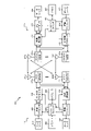
図1は、本開示の態様が実行され得る例示的なワイヤレスネットワーク100を示す。たとえば、ワイヤレスネットワーク100は、ニューラジオまたは5Gネットワークであり得る。基地局(BS)110は、eNB、gNB、送信受信ポイント(TRP)、ノードB(NB)、5G NB、アクセスポイント(AP)、ニューラジオ(NR)BSなどを含み得る。
Illustrative Wireless Communication System Figure 1 shows an
態様では、レガシーランダムアクセス手順に従ってダウンリンク専用CC上でPRACHを送信するのとは対照的に、UE120は、SRSのための別のCC上でのPRACH送信に起因するCCに対する中断の影響を低減する修正ランダムアクセス手順を使用し得る。修正ランダムアクセス手順は、連続するPRACHを送信する前にBSからの確認を待つことを伴い得る。たとえば、UE120は、PRACH送信のためのBS110からのPDCCH命令がないか監視し得る。UE120は、PDCCH命令における情報(たとえば、リソース割振り情報、PRACHを送信する試行の数、送信電力など)に基づいてBS110にPRACHを送信し得る。
In an aspect, the
PRACHを送信するために、UE120は、第1のCCから第2のCCに切り替えるために第1のCC上での通信を中断し、第2のCC上でPRACHを送信することができる。第2のCCは、ダウンリンク送信のために構成された(たとえば、少なくともPUSCH/PUCCH送信のために構成されていない)CCであり得る。PRACHを送信した後、UE120は、BS110からのランダムアクセス応答(RAR)がないか監視し得る。RARが検出されない場合、UE120は、PRACH送信を繰り返す前に、BS110からの別のPDCCH命令がないか監視し得る。このようにして、UE120は、本来であればレガシーランダムアクセス手順に基づいて実行される自動的な繰り返されるPRACH試行によってもたらされる第1のCCに対する影響(たとえば、中断)を低減することができる。
To transmit the PRACH, the
追加または代替として、態様は、UE120が第2のCC上でのPRACH送信にUpPTSの開始シンボルを使用することを可能にすることによって、PRACH送信のために第2のCCに切り替えることに起因する第1のCCに対する影響を低減することができる。たとえば、UE120は、第2のCC上でのPRACH送信にUpPTSの開始シンボルを使用するかどうかを決定し得る。決定は、UpPTSの開始シンボルを使用するための構成、UpPTSの開始シンボルを使用するための指示、またはPRACH送信にUpPTSの開始シンボルを使用するUEの能力のうちの少なくとも1つに基づき得る。第1のCCから第2のCCに切り替えた後、UE120は、決定に基づいて第2のCC上でPRACHを送信し得る。このようにして、UE120は、第2のCC上でのPRACH送信に起因して第1のCC上で通信が中断される時間量を低減することができる。
As an addition or alternative, the embodiment results from switching to a second CC for PRACH transmission by allowing the
追加または代替として、本明細書で提示する態様は、BS110が(たとえば、グループDCIを介して)1つもしくは複数のUE120からのSRS送信を一緒にトリガすること、同じUE120からの複数のCCからのSRS送信をトリガすること、および/または各CCのために別個に電力制御を実行することなどを可能にする。SRS送信を一緒にトリガすること、および/または電力制御を実行することで、(従来のSRSトリガリング機構に対して)UEのためにSRS送信を構成することに関連する柔軟性を高め、かつ/またはオーバーヘッドを低減することができる。 As an addition or alternative, the embodiments presented herein are such that the BS110 together triggers an SRS transmission from one or more UE120s (eg, via group DCI), from multiple CCs from the same UE120. Allows you to trigger SRS transmissions and / or perform power control separately for each CC. By triggering SRS transmissions together and / or performing power control, the flexibility associated with configuring SRS transmissions for the UE (as opposed to traditional SRS triggering mechanisms) is increased, and / Or the overhead can be reduced.
図1に示すように、ワイヤレスネットワーク100は、いくつかのBS110と他のネットワークエンティティとを含み得る。BSは、UEと通信する局であり得る。各BS110は、特定の地理的エリアに通信カバレージを提供し得る。3GPPでは、「セル」という用語は、この用語が使用される状況に応じて、このカバレージエリアにサービスしているノードBおよび/またはノードBサブシステムのカバレージエリアを指すことがある。NRシステムでは、「セル」およびeNB、gNB、ノードB、5G NB、AP、NR BS、またはTRPなどの用語は交換可能であり得る。いくつかの例では、セルは、必ずしも静止しているとは限らないことがあり、セルの地理的エリアは、モバイル基地局のロケーションに従って移動し得る。いくつかの例では、基地局は、任意の適切なトランスポートネットワークを使用して、直接物理接続、仮想ネットワークなど、様々なタイプのバックホールインターフェースを通じて、ワイヤレスネットワーク100内で互いに、および/または1つもしくは複数の他の基地局もしくはネットワークノード(図示せず)に相互接続され得る。
As shown in FIG. 1, the
一般に、任意の数のワイヤレスネットワークが、所与の地理的エリアにおいて展開されてよい。各ワイヤレスネットワークは、特定の無線アクセス技術(RAT)をサポートしてよく、1つまたは複数の周波数で動作してよい。RATは、無線技術、エアインターフェースなどと呼ばれることもある。周波数は、キャリア、周波数チャネルなどと呼ばれることもある。各周波数は、異なるRATのワイヤレスネットワーク間の干渉を回避するために、所与の地理的エリアにおいて単一のRATをサポートしてよい。場合によっては、NR RATネットワークまたは5G RATネットワークが展開されてよい。 In general, any number of wireless networks may be deployed in a given geographic area. Each wireless network may support a particular radio access technology (RAT) and may operate at one or more frequencies. RAT is sometimes called wireless technology, air interface, etc. Frequency is sometimes referred to as carrier, frequency channel, and the like. Each frequency may support a single RAT in a given geographic area to avoid interference between wireless networks of different RATs. In some cases, an NR RAT network or a 5G RAT network may be deployed.
BSは、マクロセル、ピコセル、フェムトセル、および/または他のタイプのセルのための通信カバレージを提供し得る。マクロセルは、比較的大きい地理的エリア(たとえば、半径数キロメートル)をカバーすることができ、サービスに加入しているUEによる無制限アクセスを可能にしてよい。ピコセルは、比較的小さい地理的エリアをカバーすることができ、サービスに加入しているUEによる無制限アクセスを可能にしてよい。フェムトセルは、比較的小さい地理的エリア(たとえば、自宅)をカバーすることができ、フェムトセルとの関連を有するUE(たとえば、限定加入者グループ(CSG)内のUE、自宅内のユーザのためのUEなど)による制限付きアクセスを可能にしてよい。マクロセルのためのBSは、マクロBSと呼ばれることがある。ピコセルのためのBSは、ピコBSと呼ばれることがある。フェムトセルのためのBSは、フェムトBSまたはホームBSと呼ばれることがある。図1に示す例では、BS110a、110bおよび110cは、それぞれ、マクロセル102a、102bおよび102cのためのマクロBSであり得る。BS110xは、ピコセル102xのためのピコBSであり得る。BS110yおよび110zは、それぞれ、フェムトセル102yおよび102zのためのフェムトBSであり得る。BSは1つまたは複数(たとえば、3つ)のセルをサポートしてよい。
BS may provide communication coverage for macrocells, picocells, femtocells, and / or other types of cells. Macrocells can cover relatively large geographic areas (eg, a few kilometers in radius) and may allow unlimited access by UEs subscribing to the service. The picocell can cover a relatively small geographic area and may allow unlimited access by the UEs subscribed to the service. A femtocell can cover a relatively small geographic area (eg, home) and is associated with a femtocell UE (eg, a UE in a limited subscriber group (CSG), for users in the home). It may allow restricted access by UE etc.). BS for macro cells is sometimes called macro BS. BS for picocell is sometimes called picoBS. The BS for a femtocell is sometimes referred to as a femto BS or home BS. In the example shown in FIG. 1, BS110a, 110b and 110c can be macro BSs for macrocells 102a, 102b and 102c, respectively. BS110x can be a pico BS for
ワイヤレスネットワーク100は、中継局も含んでもよい。中継局は、アップストリーム局(たとえばBSまたはUE)からデータおよび/または他の情報の送信を受信し、ダウンストリーム局(たとえば、UEまたBS)にデータおよび/または他の情報の送信を送る局である。また、中継局は、他のUEのための送信を中継するUEであってもよい。図1に示す例では、中継局110rは、BS110aとUE120rとの間の通信を容易にするために、BS110aおよびUE120rと通信することができる。中継局はまた、リレーBS、リレーなどと呼ばれることもある。
The
ワイヤレスネットワーク100は、異なるタイプのBS、たとえば、マクロBS、ピコBS、フェムトBS、リレーなどを含む異種ネットワークとすることができる。これらの異なるタイプのBSは、異なる送信電力レベル、異なるカバレージエリア、およびワイヤレスネットワーク100中の干渉に対する異なる影響を有してよい。たとえば、マクロBSは高い送信電力レベル(たとえば、20ワット)を有することがあり、一方で、ピコBS、フェムトBS、およびリレーはより低い送信電力レベル(たとえば、1ワット)を有することがある。
The
ワイヤレスネットワーク100は、同期動作または非同期動作をサポートしてよい。同期動作の場合、BSは、同様のフレームタイミングを有することができ、異なるBSからの送信は、時間的にほぼ整合し得る。非同期動作の場合、BSは、異なるフレームタイミングを有する場合があり、異なるBSからの送信は、時間的に整合していない場合がある。本明細書で説明する技法は、同期動作と非同期動作の両方に使用されてよい。
The
ネットワークコントローラ130は、BSのセットに結合し、これらのBSのための調整および制御を行い得る。ネットワークコントローラ130は、バックホールを介してBS110と通信し得る。BS110はまた、たとえば、直接、または間接的にワイヤレスバックホールもしくは有線バックホールを介して、互いに通信し得る。
The
UE120(たとえば、120x、120yなど)は、ワイヤレスネットワーク100の全体にわたって分散されてよく、各UEは静止であってよく、またはモバイルであってよい。UEは、移動局、端末、アクセス端末、加入者ユニット、局、顧客構内設備(CPE:Customer Premises Equipment)、セルラーフォン、スマートフォン、携帯情報端末(PDA)、ワイヤレスモデム、ワイヤレス通信デバイス、ハンドヘルドデバイス、ラップトップコンピュータ、コードレスフォン、ワイヤレスローカルループ(WLL)局、タブレット、カメラ、ゲームデバイス、ネットブック、スマートブック、ウルトラブック、医療デバイスもしくは医療機器、生体センサー/デバイス、スマートウォッチ、スマート衣料、スマートグラス、スマートリストバンド、スマートジュエリー(たとえば、スマートリング、スマートブレスレットなど)などのウェアラブルデバイス、娯楽デバイス(たとえば、音楽デバイス、ビデオデバイス、衛星無線など)、車両コンポーネントもしくは車両センサー、スマートメータ/センサー、工業生産機器、全地球測位システムデバイス、またはワイヤレス媒体もしくはワイヤード媒体を介して通信するように構成された任意の他の適切なデバイスと呼ばれる場合もある。一部のUEは、発展型デバイスもしくはマシンタイプ通信(MTC)デバイスまたは発展型MTC(eMTC)デバイスと見なされる場合がある。MTC UEおよびeMTC UEは、BS、別のデバイス(たとえば、リモートデバイス)、または何らかの他のエンティティと通信することができる、たとえば、ロボット、ドローン、リモートデバイス、センサー、メータ、モニタ、ロケーションタグなどを含む。ワイヤレスノードは、たとえば、ワイヤード通信リンクまたはワイヤレス通信リンクを介して、ネットワーク(たとえば、インターネットもしくはセルラーネットワークなどのワイドエリアネットワーク)のための、またはネットワークへの接続性を提供し得る。一部のUEは、モノのインターネット(IoT)デバイスと見なされ得る。
UE120s (eg, 120x, 120y, etc.) may be distributed throughout the
図1において、両矢印を有する実線は、UEとサービングBSとの間の所望の送信を示し、サービングBSは、ダウンリンクおよび/またはアップリンク上でUEにサービスするように指定されたBSである。両矢印を有する破線は、UEとBSとの間の干渉する送信を示す。 In FIG. 1, a solid line with a double-headed arrow indicates the desired transmission between the UE and the serving BS, which is the BS designated to serve the UE on the downlink and / or the uplink. .. A dashed line with both arrows indicates an interfering transmission between the UE and BS.
特定のワイヤレスネットワーク(たとえば、LTE)は、ダウンリンク上で直交周波数分割多重化(OFDM)を利用し、かつアップリンク上でシングルキャリア周波数分割多重化(SC-FDM)を利用する。OFDMおよびSC-FDMは、システム帯域幅を、一般に、トーン、ビンなどとも呼ばれる、複数の(K個の)直交サブキャリアに区分する。各サブキャリアは、データで変調され得る。一般に、変調シンボルは、OFDMでは周波数領域において送られ、SC-FDMでは時間領域において送られる。隣接するサブキャリア間の間隔は固定される場合があり、サブキャリアの総数(K)は、システム帯域幅に依存する場合がある。たとえば、サブキャリアの間隔は15kHzであってよく、最小のリソース割振り(「リソースブロック」と呼ばれる)は12個のサブキャリア(または180kHz)であってよい。その結果、公称FFTサイズは、1.25、2.5、5、10または20メガヘルツ(MHz)のシステム帯域幅に対して、それぞれ、128、256、512、1024または2048に等しくなり得る。システム帯域幅はまた、サブバンドに区分され得る。たとえば、サブバンドは、1.08MHz(すなわち、6個のリソースブロック)をカバーすることができ、1.25、2.5、5、10または20MHzのシステム帯域幅に対して、それぞれ、1、2、4、8または16個のサブバンドが存在し得る。 Certain wireless networks (eg LTE) utilize Orthogonal Frequency Division Multiplexing (OFDM) on the downlink and Single Carrier Frequency Division Multiplexing (SC-FDM) on the uplink. OFDM and SC-FDM divide system bandwidth into multiple (K) orthogonal subcarriers, also commonly referred to as tones, bins, and so on. Each subcarrier can be modulated with data. In general, modulation symbols are sent in the frequency domain in OFDM and in the time domain in SC-FDM. The spacing between adjacent subcarriers may be fixed and the total number of subcarriers (K) may depend on system bandwidth. For example, the interval between subcarriers may be 15 kHz and the minimum resource allocation (called a "resource block") may be 12 subcarriers (or 180 kHz). As a result, the nominal FFT size can be equal to 128, 256, 512, 1024 or 2048, respectively, for a system bandwidth of 1.25, 2.5, 5, 10 or 20 MHz (MHz). System bandwidth can also be subdivided into subbands. For example, a subband can cover 1.08MHz (ie, 6 resource blocks) and for a system bandwidth of 1.25, 2.5, 5, 10 or 20MHz, 1, 2, 4, 8 respectively. Or there can be 16 subbands.
本明細書で説明する例の態様はLTE技術に関連付けられ得るが、本開示の態様は、NRなど、他のワイヤレス通信システムに適用可能であり得る。NRは、アップリンクおよびダウンリンク上でCPを用いてOFDMを利用し、TDDを使用する半二重動作に対するサポートを含み得る。100MHzの単一のコンポーネントキャリア帯域幅がサポートされ得る。NRリソースブロックは、0.1msの持続時間にわたって、サブキャリア帯域幅が75kHzの12個のサブキャリアにまたがり得る。各無線フレームは、10msの長さを有する50個のサブフレームで構成され得る。結果として、各サブフレームは0.2msの長さを有することができる。各サブフレームは、データ送信用のリンク方向(すなわち、DLまたはUL)を示してよく、サブフレームごとのリンク方向は、動的に切り替えられてよい。各サブフレームは、DL/ULデータならびにDL/UL制御データを含み得る。ビームフォーミングがサポートされ得、ビーム方向が動的に構成され得る。プリコーディングを用いたMIMO送信もサポートされ得る。DLにおけるMIMO構成は、最大で8個のストリームおよびUEごとに最大で2個のストリームを用いたマルチレイヤDL送信で最大で8個の送信アンテナをサポートし得る。UEごとに最大で2個のストリームを用いたマルチレイヤ送信がサポートされ得る。最大で8個のサービングセルを用いて複数のセルのアグリゲーションがサポートされ得る。代替として、NRは、OFDMベース以外の異なるエアインターフェースをサポートし得る。NRネットワークは、集約ユニットまたは分散ユニットなどのエンティティを含み得る。 Although aspects of the examples described herein may be associated with LTE technology, aspects of the present disclosure may be applicable to other wireless communication systems, such as NR. NR may utilize OFDM with CP on uplinks and downlinks and may include support for half-duplex operation using TDD. A single component carrier bandwidth of 100MHz may be supported. The NR resource block can span 12 subcarriers with a subcarrier bandwidth of 75 kHz over a duration of 0.1 ms. Each radio frame may consist of 50 subframes with a length of 10 ms. As a result, each subframe can have a length of 0.2ms. Each subframe may indicate a link direction for data transmission (ie, DL or UL), and the link direction for each subframe may be dynamically switched. Each subframe may contain DL / UL data as well as DL / UL control data. Beamforming can be supported and beam directions can be dynamically configured. MIMO transmission using precoding may also be supported. MIMO configurations in DL may support up to 8 transmit antennas for multilayer DL transmission with up to 8 streams and up to 2 streams per UE. Multi-layer transmission with up to two streams per UE may be supported. Aggregation of multiple cells can be supported with up to 8 serving cells. Alternatively, the NR may support different air interfaces other than OFDM-based. The NR network can include entities such as aggregate units or distributed units.
いくつかの例では、エアインターフェースへのアクセスがスケジュールされてよく、スケジューリングエンティティ(たとえば、基地局)は、そのサービスエリアまたはセル内のいくつかのまたはすべてのデバイスおよび機器の間で通信のためのリソースを割り振る。本開示内では、以下でさらに説明するように、スケジューリングエンティティは、1つまたは複数の従属エンティティ用のリソースをスケジュールすること、割り当てること、再構成すること、および解放することを担当し得る。すなわち、スケジュールされた通信に対して、従属エンティティは、スケジューリングエンティティによって割り振られたリソースを利用する。 In some examples, access to an air interface may be scheduled, and a scheduling entity (eg, a base station) is for communication between some or all devices and devices within its service area or cell. Allocate resources. Within this disclosure, a scheduling entity may be responsible for scheduling, allocating, reconfiguring, and releasing resources for one or more dependent entities, as described further below. That is, for scheduled communication, the dependent entity utilizes the resources allocated by the scheduling entity.
基地局は、スケジューリングエンティティとして機能し得る唯一のエンティティではない。すなわち、いくつかの例では、UEが、1つまたは複数の従属エンティティ(たとえば、1つまたは複数の他のUE)のためのリソースをスケジュールする、スケジューリングエンティティとして機能し得る。この例では、UEは、スケジューリングエンティティとして機能しており、他のUEは、ワイヤレス通信のためにUEによってスケジュールされたリソースを利用する。UEは、ピアツーピア(P2P)ネットワーク中および/またはメッシュネットワーク中でスケジューリングエンティティとして機能し得る。メッシュネットワーク例では、UEは、スケジューリングエンティティと通信することに加えて、場合によっては互いに直接通信し得る。 The base station is not the only entity that can act as a scheduling entity. That is, in some examples, a UE may act as a scheduling entity that schedules resources for one or more dependent entities (eg, one or more other UEs). In this example, the UE is acting as a scheduling entity, and the other UEs utilize the resources scheduled by the UE for wireless communication. The UE can act as a scheduling entity in peer-to-peer (P2P) networks and / or in mesh networks. In the mesh network example, the UEs may communicate directly with each other in addition to communicating with the scheduling entity.
したがって、時間-周波数リソースへのスケジュールされたアクセスを伴い、セルラー構成、P2P構成、およびメッシュ構成を有するワイヤレス通信ネットワークでは、スケジューリングエンティティおよび1つまたは複数の従属エンティティは、スケジュールされたリソースを利用して通信し得る。 Therefore, in a wireless communication network with a cellular, P2P, and mesh configuration with scheduled access to time-frequency resources, the scheduling entity and one or more dependent entities utilize the scheduled resource. Can communicate with.
図2は、電気通信システム(たとえば、LTE)において使用されるダウンリンク(DL)フレーム構造を示す。ダウンリンクのための送信タイムラインは、無線フレームのユニットに区分され得る。各無線フレームは、事前に決定された持続時間(たとえば10ミリ秒(ms))を有することができ、0から9のインデックスを用いる10個のサブフレームに区分され得る。各サブフレームは、2個のスロットを含むことができる。各無線フレームは、したがって、0から19のインデックスを用いる20個のスロットを含むことができる。各スロットは、L個のシンボル期間を含んでよく、たとえば、(図2に示すように)通常サイクリックプレフィックスに対して7個のシンボル期間を含んでよく、または拡張サイクリックプレフィックスに対して14個のシンボル期間を含んでよい。各サブフレームの2L個のシンボル期間は、0から2L-1のインデックスを割り当てられ得る。利用可能な時間周波数リソースは、リソースブロックに区分され得る。各リソースブロックは、1つのスロットにおいてN個のサブキャリア(たとえば、12個のサブキャリア)をカバーし得る。 FIG. 2 shows a downlink (DL) frame structure used in a telecommunications system (eg LTE). The transmission timeline for the downlink may be divided into units of radio frames. Each radio frame can have a predetermined duration (eg, 10 milliseconds (ms)) and can be divided into 10 subframes with an index of 0-9. Each subframe can contain two slots. Each radio frame can therefore contain 20 slots with indexes from 0 to 19. Each slot may contain L symbol periods, for example, 7 symbol periods for a normal cyclic prefix (as shown in Figure 2), or 14 for an extended cyclic prefix. It may contain a number of symbol periods. The 2L symbol period in each subframe can be assigned an index from 0 to 2L-1. Available time frequency resources can be divided into resource blocks. Each resource block may cover N subcarriers (eg, 12 subcarriers) in one slot.
いくつかのシステム(たとえば、LTE)では、BSは、BS中の各セルのための1次同期信号(PSS)および2次同期信号(SSS)を送り得る。1次同期信号および2次同期信号は、図2に示すように、通常サイクリックプレフィックスを有する各無線フレームのサブフレーム0および5の各々において、それぞれ、シンボル期間6および5において送られ得る。同期信号は、セルの検出および獲得のためにUEによって使用され得る。BSは、サブフレーム0のスロット1において、シンボル期間0から3において物理ブロードキャストチャネル(PBCH)を送ることができる。PBCHは、特定のシステム情報を搬送してよい。
In some systems (eg LTE), the BS may send a primary sync signal (PSS) and a secondary sync signal (SSS) for each cell in the BS. The primary sync signal and the secondary sync signal can be sent in
図2では第1のシンボル期間全体に描かれているが、BSは、各サブフレームの第1のシンボル期間の一部のみにおいて物理制御フォーマットインジケータチャネル(PCFICH)を送ることができる。PCFICHは、制御チャネルに使用されるシンボル期間(M)の数を伝えることができ、Mは1、2、または3に等しいことがあり、サブフレームごとに変化することがある。Mは、たとえば、リソースブロックが10個未満である、小さいシステム帯域幅では4に等しい場合もある。図2に示す例では、M=3である。BSは、各サブフレームの最初のM個のシンボル期間内で(図2ではM=3)、物理HARQインジケータチャネル(PHICH)と物理ダウンリンク制御チャネル(PDCCH)とを送ることができる。PHICHは、ハイブリッド自動再送信(HARQ)をサポートするための情報を搬送することができる。PDCCHは、UEに対するアップリンクおよびダウンリンクでのリソース割振りについての情報と、アップリンクチャネルに対する電力制御情報とを搬送することができる。図2では第1のシンボル期間に示されないが、PDCCHおよびPHICHも第1のシンボル期間に含まれることが、理解されよう。同様に、図2ではそのように示されないが、PHICHおよびPDCCHも、第2のシンボル期間と第3のシンボル期間の両方にある。BSは、各サブフレームの残りのシンボル期間において、物理ダウンリンク共有チャネル(PDSCH)を送ることができる。PDSCHは、ダウンリンク上でのデータ送信のためにスケジュールされたUEに対するデータを搬送することができる。LTEにおける様々な信号およびチャネルは、公開されている「Evolved Universal Terrestrial Radio Access (E-UTRA); Physical Channels and Modulation」と題する3GPP TS 36.211に記載されている。 Although depicted throughout the first symbol period in Figure 2, the BS can send the Physical Control Format Indicator Channel (PCFICH) only during a portion of the first symbol period of each subframe. PCFICH can convey the number of symbol periods (M) used for the control channel, where M can be equal to 1, 2, or 3 and can vary from subframe to subframe. M can be equal to 4, for example, with less than 10 resource blocks and a small system bandwidth. In the example shown in FIG. 2, M = 3. The BS can send the physical HARQ indicator channel (PHICH) and the physical downlink control channel (PDCCH) within the first M symbol period of each subframe (M = 3 in Figure 2). PHICH can carry information to support hybrid automatic retransmission (HARQ). The PDCCH can carry information about uplink and downlink resource allocation to the UE and power control information to the uplink channel. Although not shown in the first symbol period in Figure 2, it will be appreciated that PDCCH and PHICH are also included in the first symbol period. Similarly, PHICH and PDCCH, which are not shown as such in FIG. 2, are also in both the second and third symbol periods. The BS may send a physical downlink shared channel (PDSCH) for the remaining symbolic period of each subframe. The PDSCH can carry data to the UE scheduled for data transmission over the downlink. The various signals and channels in LTE are described in the publicly available 3GPP TS 36.211 entitled "Evolved Universal Terrestrial Radio Access (E-UTRA); Physical Channels and Modulation".
BSは、ノードBによって使用されるシステム帯域幅の中央の1.08MHzにおいてPSS、SSSおよびPBCHを送り得る。BSは、これらのチャネルが送られる各シンボル期間においてシステム帯域幅全体でPCFICHおよびPHICHを送り得る。BSは、システム帯域幅の特定の部分においてPDCCHをUEのグループに送り得る。BSは、システム帯域幅の特定の部分においてPDSCHを特定のUEに送り得る。BSは、PSS、SSS、PBCH、PCFICHおよびPHICHをブロードキャスト方式ですべてのUEに送ることができ、PDCCHをユニキャスト方式で特定のUEに送ることができ、またPDSCHをユニキャスト方式で特定のUEに送ることができる。 BS may send PSS, SSS and PBCH at 1.08MHz in the middle of the system bandwidth used by node B. The BS may send PCFICH and PHICH over the entire system bandwidth during each symbol period in which these channels are sent. BS may send PDCCH to a group of UEs at certain parts of the system bandwidth. The BS may send the PDSCH to a particular UE at a particular portion of the system bandwidth. BS can send PSS, SSS, PBCH, PCFICH and PHICH to all UEs by broadcast method, PDCCH can be sent to a specific UE by unicast method, and PDSCH can be sent to a specific UE by unicast method. Can be sent to.
いくつかのリソース要素は、各シンボル期間において利用可能であり得る。各リソース要素は、1つのシンボル期間において1つのサブキャリアをカバーすることができ、実数値または複素数値であり得る1つの変調シンボルを送るために使用され得る。各シンボル期間において基準信号に使用されないリソース要素は、リソース要素グループ(REG)に配列され得る。各REGは、1つのシンボル期間において4つのリソース要素を含み得る。PCFICHは、4つのREGを占有してよく、4つのREGは、シンボル期間0において、周波数にわたってほぼ等しく離間され得る。PHICHは、3つのREGを占有してよく、3つのREGは、1つまたは複数の構成可能なシンボル期間において、周波数にわたって分散され得る。たとえば、PHICHのための3つのREGは、シンボル期間0にすべて属し得るか、またはシンボル期間0、1および2に分散され得る。PDCCHは、最初のM個のシンボル期間において、利用可能なREGから選択され得る、たとえば、9、18、36または72個のREGを占有し得る。REGのいくつかの組合せのみがPDCCHに対して許可されてよい。
Several resource elements may be available during each symbol period. Each resource element can cover one subcarrier in one symbol period and can be used to send one modulated symbol, which can be real or complex. Resource elements that are not used in the reference signal during each symbol period may be arranged in a resource element group (REG). Each REG can contain four resource elements in one symbol period. The PCFICH may occupy four REGs, which may be spaced approximately equally over frequency at
UEは、PHICHおよびPCFICHに使用される特定のREGを認識していることがある。UEは、PDCCHのためのREGの異なる組合せを探索し得る。探索すべき組合せの数は通常、PDCCHに対して許可される組合せの数よりも少ない。BSは、UEが探索する組合せのいずれかにおいてPDCCHをUEに送り得る。 The UE may be aware of the specific REG used for PHICH and PCFICH. The UE can explore different combinations of REGs for PDCCH. The number of combinations to be searched is usually less than the number of combinations allowed for PDCCH. The BS may send the PDCCH to the UE in any of the combinations that the UE seeks.
UEは、複数のBSのカバレージ内にあり得る。これらのBSのうちの1つが、UEにサービスするために選択され得る。サービングBSは、受信電力、経路損失、信号対雑音比(SNR)などの、様々な基準に基づいて選択され得る。 The UE can be in the coverage of multiple BSs. One of these BSs may be selected to serve the UE. Serving BS can be selected based on various criteria such as received power, path loss, signal-to-noise ratio (SNR), and so on.
(たとえば、NRシステムまたは5Gシステムなどの)いくつかのシステムでは、BSは、サブフレームのこれらのロケーションまたは異なるロケーションにおいて、これらまたは他の信号を送信し得る。 On some systems (eg, NR systems or 5G systems), the BS may send these or other signals at these or different locations in the subframe.
図3は、ワイヤレス電気通信システム(たとえば、LTE)におけるアップリンク(UL)フレーム構造の一例を示す図300である。ULに利用可能なリソースブロックは、データセクションおよび制御セクションに区分され得る。制御セクションは、システム帯域幅の2つのエッジに形成される場合があり、構成可能なサイズを有する場合がある。制御セクションの中のリソースブロックは、制御情報の送信のためにUEに割り当てられ得る。データセクションは、制御セクションに含まれないすべてのリソースブロックを含む場合がある。このULフレーム構造により、データセクションは連続するサブキャリアを含むことになり、これにより、単一のUEに、データセクション内の連続するサブキャリアのすべてを割り当てることが可能になり得る。 FIG. 3 is FIG. 300 showing an example of an uplink (UL) frame structure in a wireless telecommunications system (eg LTE). The resource blocks available to UL can be divided into data and control sections. The control section may be formed at the two edges of the system bandwidth and may have a configurable size. Resource blocks within the control section can be assigned to the UE for transmission of control information. The data section may contain all resource blocks not included in the control section. This UL frame structure allows the data section to contain contiguous subcarriers, which may allow a single UE to be assigned all of the contiguous subcarriers within the data section.
UEは、制御情報をBSに送信するために、制御セクション内のリソースブロック310a、310bを割り当てられてよい。UEはまた、データをBSに送信するために、データセクション内のリソースブロック320a、320bを割り当てられてよい。UEは、制御セクション内の割り当てられたリソースブロック上の物理UL制御チャネル(PUCCH)において、制御情報を送信し得る。UEは、データセクション内の割り当てられたリソースブロック上の物理UL共有チャネル(PUSCH)において、データのみ、またはデータと制御情報の両方を送信し得る。UL送信は、サブフレームの両方のスロットにまたがる場合があり、周波数にわたってホップする場合がある。
The UE may be assigned
リソースブロックのセットは、初期システムアクセスを実行し、物理ランダムアクセスチャネル(PRACH)330におけるUL同期を達成するために使用され得る。PRACH330は、ランダムシーケンスを搬送し、いかなるULデータ/シグナリングも搬送できない。各ランダムアクセスプリアンブルは、連続する6個のリソースブロックに対応する帯域幅を占有し得る。開始周波数は、ネットワークによって指定される。すなわち、ランダムアクセスプリアンブルの送信は、いくつかの時間リソースおよび周波数リソースに限定され得る。PRACHに対しては、周波数ホッピングは存在しないことがある。PRACHの試行は、単一のサブフレーム(1ms)内で、または少数の連続するサブフレームのシーケンス内で搬送されてよく、UEは、フレーム(10ms)ごとに単一のPRACHの試行を行うことができる。態様では、本明細書で説明するように、PRACHおよび/またはSRSは、追加のかつ/または異なる時間および/または周波数リソースに位置し得る。 A set of resource blocks can be used to perform initial system access and achieve UL synchronization on Physical Random Access Channel (PRACH) 330. PRACH330 carries a random sequence and cannot carry any UL data / signaling. Each random access preamble can occupy bandwidth corresponding to six consecutive resource blocks. The starting frequency is specified by the network. That is, the transmission of random access preambles may be limited to some time and frequency resources. For PRACH, frequency hopping may not exist. PRACH trials may be carried within a single subframe (1ms) or within a sequence of a few consecutive subframes, and the UE shall make a single PRACH trial every frame (10ms). Can be done. In aspects, as described herein, PRACH and / or SRS may be located in additional and / or different time and / or frequency resources.
(たとえば、NRシステムまたは5Gシステムなどの)いくつかのシステムでは、BSは、サブフレームのこれらのロケーションまたは異なるロケーションにおいて、これらまたは他の信号を送信し得る。 On some systems (eg, NR systems or 5G systems), the BS may send these or other signals at these or different locations in the subframe.
図4は、本開示の態様を実施するために使用され得る、図1に示すワイヤレスネットワーク100のBS110およびUE120の例示的な構成要素を示す。BS110およびUE120の1つまたは複数の構成要素は、本開示の態様を実践するために使用され得る。たとえば、UE120のアンテナ452、Tx/Rx222、プロセッサ466、458、464、および/もしくはコントローラ/プロセッサ480は、本明細書で説明し、図15、図17および図19を参照しながら示す動作を実行するために使用され得、かつ/またはBS110のアンテナ434、プロセッサ430、420、438、および/もしくはコントローラ/プロセッサ440は、本明細書で説明し、図16および図18を参照しながら示す動作を実行するために使用され得る。
FIG. 4 shows exemplary components of BS110 and UE120 of the
図4は、図1におけるBSのうちの1つおよびUEのうちの1つであってよい、BS110およびUE120の設計のブロック図を示す。制限された接続シナリオの場合、BS110は図1のマクロBS110cであってよく、UE120はUE120yであってよい。BS110はまた、何らかの他のタイプの基地局であり得る。BS110は、アンテナ434a~434tを備えることができ、UE120は、アンテナ452a~452rを備えることができる。
FIG. 4 shows a block diagram of the BS110 and UE120 designs, which may be one of the BSs and one of the UEs in FIG. For restricted connection scenarios, BS110 may be macro BS110c of FIG. 1 and UE120 may be UE120y. BS110 can also be some other type of base station. The BS110 can be equipped with
BS110において、送信プロセッサ420は、データソース412からデータを受信し、コントローラ/プロセッサ440から制御情報を受信し得る。制御情報は、PBCH、PCFICH、PHICH、PDCCHなどに関するものであってよい。データは、PDSCHなどに関するものであってよい。プロセッサ420は、データおよび制御情報を処理(たとえば、符号化およびシンボルマッピング)して、それぞれデータシンボルおよび制御シンボルを取得することができる。プロセッサ420はまた、たとえば、PSS、SSS、およびセル固有基準信号に関する基準シンボルを生成することもできる。送信(TX)多入力多出力(MIMO)プロセッサ430は、適用可能な場合には、データシンボル、制御シンボル、および/または基準シンボルに対して空間処理(たとえば、プリコーディング)を実行することができ、出力シンボルストリームを変調器(MOD)432a~432tに提供することができる。各変調器432は、(たとえば、OFDMなどのための)それぞれの出力シンボルストリームを処理して、出力サンプルストリームを取得することができる。各変調器432は、出力サンプルストリームをさらに処理(たとえば、アナログに変換、増幅、フィルタリング、およびアップコンバート)して、ダウンリンク信号を取得することができる。変調器432a~432tからのダウンリンク信号を、それぞれアンテナ434a~434tを介して送信してよい。
In BS110, the transmit
UE120において、アンテナ452a~452rは、BS110からダウンリンク信号を受信することができ、受信信号をそれぞれ復調器(DEMOD)454a~454rに提供することができる。各復調器454は、それぞれの受信信号を調整(たとえば、フィルタリング、増幅、ダウンコンバート、およびデジタル化)して、入力サンプルを取得することができる。各復調器454は、(たとえば、OFDMなどのための)入力サンプルをさらに処理して、受信シンボルを取得することができる。MIMO検出器456は、すべての復調器454a~454rから受信シンボルを取得し、適用可能な場合、受信シンボルに対してMIMO検出を実行し、検出されたシンボルを提供することができる。受信プロセッサ458は、検出されたシンボルを処理(たとえば、復調、デインターリーブ、および復号)し、UE120のための復号されたデータをデータシンク460に提供し、復号された制御情報をコントローラ/プロセッサ480に提供することができる。
In UE120, the
アップリンクでは、UE120において、送信プロセッサ464が、データソース462からの(たとえば、PUSCHについての)データ、およびコントローラ/プロセッサ480からの(たとえば、PUCCHについての)制御情報を受信し、処理してよい。送信プロセッサ464はまた、基準信号のための基準シンボルを生成し得る。送信プロセッサ464からのシンボルは、適用可能な場合には、TX MIMOプロセッサ466によってプリコーディングされ、(たとえばSC-FDMなどのために)復調器454a~454rによってさらに処理され、BS110に送信されてよい。BS110において、UE120からのアップリンク信号は、アンテナ434によって受信され、変調器432によって処理され、適用可能な場合には、MIMO検出器436によって検出され、受信プロセッサ438によってさらに処理されて、UE120によって送られた復号データおよび制御情報を取得し得る。受信プロセッサ438は、データシンク439に復号されたデータを提供し、コントローラ/プロセッサ440に復号された制御情報を提供してよい。
On the uplink, in
コントローラ/プロセッサ440および480は、それぞれBS110およびUE120における動作を指示し得る。BS110におけるプロセッサ440ならびに/または他のプロセッサおよびモジュールは、たとえば、図16、図18に示す機能的ブロックの実施および/または本明細書で説明する技法に対する他のプロセスを実行または指示し得る。UE120におけるプロセッサ480ならびに/または他のプロセッサおよびモジュールは、たとえば、図15、図17、図19に示す機能的ブロックの実施および/または本明細書で説明する技法に対する他のプロセスを実行または指示し得る。メモリ442および482は、それぞれBS110およびUE120のためのデータおよびプログラムコードを記憶し得る。スケジューラ444は、ダウンリンクおよび/またはアップリンク上でのデータおよび/または制御送信のために1つまたは複数UEをスケジューリングし得る。
Controllers /
図5は、いくつかのシステム(たとえば、LTE)におけるユーザプレーン用および制御プレーン用の無線プロトコルアーキテクチャの一例を示す図500である。UEおよびBSのための無線プロトコルアーキテクチャは、レイヤ1、レイヤ2、およびレイヤ3という3つのレイヤで示される。レイヤ1(L1レイヤ)は最下位レイヤであり、様々な物理レイヤ信号処理機能を実装する。L1レイヤは、本明細書では物理レイヤ506と呼ばれる。レイヤ2(L2レイヤ)508は、物理レイヤ506の上にあり、物理レイヤ506を介したUEとBSとの間のリンクを担う。
FIG. 5 is FIG. 500 showing an example of a radio protocol architecture for the user plane and control plane in some systems (eg LTE). The radio protocol architecture for UE and BS is shown in three layers:
ユーザプレーンでは、L2レイヤ508は、たとえば、媒体アクセス制御(MAC)サブレイヤ510、無線リンク制御(RLC)サブレイヤ512、およびパケットデータコンバージェンスプロトコル(PDCP)サブレイヤ514を含み、それらはネットワーク側のBSにおいて終端される。示されていないが、UEは、L2レイヤ508の上にいくつかの上位レイヤを有することがあり、それらは、ネットワーク側のPDNゲートウェイ118において終端されるネットワークレイヤ(たとえば、IPレイヤ)、および接続の他端(たとえば、遠端UE、サーバなど)において終端されるアプリケーションレイヤを含む。
In the user plane,
PDCPサブレイヤ514は、様々な無線ベアラと論理チャネルとの間の多重化を行う。PDCPサブレイヤ514はまた、無線送信オーバーヘッドを低減するための上位レイヤデータパケットのヘッダ圧縮、データパケットを暗号化することによるセキュリティ、およびBS間のUEのハンドオーバーサポートを実現する。RLCサブレイヤ512は、上位レイヤデータパケットのセグメント化および再アセンブリ、紛失したデータパケットの再送、ならびに、ハイブリッド自動再送要求(HARQ)に起因して順序の狂った受信を補償するためのデータパケットの並べ替えを行う。MACサブレイヤ510は、論理チャネルとトランスポートチャネルとの間の多重化を行う。MACサブレイヤ510はまた、1つのセル中の様々な無線リソース(たとえば、リソースブロック)をUEの間で割り振ることを担う。MACサブレイヤ510はまた、HARQ動作を担う。
制御プレーンでは、制御プレーンのためのヘッダ圧縮機能がないことを除いて、UEおよびBSの無線プロトコルアーキテクチャは、物理レイヤ506およびL2レイヤ508について実質的に同じである。制御プレーンは、レイヤ3(L3レイヤ)の中に無線リソース制御(RRC)サブレイヤ516も含む。RRCサブレイヤ516は、無線リソース(すなわち、無線ベアラ)を取得すること、およびノードBとUEとの間のRRCシグナリングを使用して下位レイヤを構成することを担う。
In the control plane, the UE and BS radio protocol architectures are substantially the same for
図6は、通常サイクリックプレフィックスを有するダウンリンクの場合の2つの例示的なサブフレームフォーマット610および620を示す。ダウンリンクに利用可能な時間周波数リソースは、リソースブロックに区分され得る。各リソースブロックは、1つのスロットにおいて12個のサブキャリアをカバーすることができ、いくつかのリソース要素を含み得る。各リソース要素は、1つのシンボル期間において1つのサブキャリアをカバーすることができ、実数値または複素数値であり得る1つの変調シンボルを送るために使用され得る。 FIG. 6 shows two exemplary subframe formats 610 and 620 for downlinks, which usually have cyclic prefixes. The time frequency resources available for the downlink can be divided into resource blocks. Each resource block can cover 12 subcarriers in one slot and may contain several resource elements. Each resource element can cover one subcarrier in one symbol period and can be used to send one modulated symbol, which can be real or complex.
サブフレームフォーマット610は、2つのアンテナを備えたBSに使用され得る。CRSは、シンボル期間0、4、7、および11においてアンテナ0および1から送信され得る。基準信号は、送信機および受信機によってアプリオリに知られる信号であり、パイロットと呼ばれることもある。CRSは、たとえば、セル識別情報(ID)に基づいて生成される、セルに固有の基準信号である。図6では、ラベルRaを有する所与のリソース要素について、アンテナaからそのリソース要素上で変調シンボルが送信されることがあり、他のアンテナからそのリソース要素上で変調シンボルが送信されないことがある。サブフレームフォーマット620は、4つのアンテナを備えたBSに使用され得る。CRSは、シンボル期間0、4、7、および11においてアンテナ0および1から、またシンボル期間1および8においてアンテナ2および3から送信され得る。サブフレームフォーマット610と620の両方に対して、CRSは、セルIDに基づいて決定され得る均等に離間したサブキャリア上で送信され得る。異なるBSは、それらのCRSを、それらのセルIDに応じて、同じまたは異なるサブキャリア上で送信し得る。サブフレームフォーマット610と620の両方の場合、CRSに使用されないリソース要素は、データ(たとえば、トラフィックデータ、制御データ、および/または他のデータ)を送信するために使用され得る。
Subframe format 610 can be used for BSs with two antennas. CRS can be transmitted from
LTEにおけるPSS、SSS、CRSおよびPBCHは、公開されている「Evolved Universal Terrestrial Radio Access(E-UTRA); Physical Channels and Modulation」と題する3GPP TS 36.211に記載されている。 PSS, SSS, CRS and PBCH in LTE are described in the published 3GPP TS 36.211 entitled "Evolved Universal Terrestrial Radio Access (E-UTRA); Physical Channels and Modulation".
(たとえば、LTEにおける)FDD用のダウンリンクおよびアップリンクの各々にインターレース構造が使用され得る。たとえば、0~Q-1というインデックスを有するQ個のインターレースが規定されてよく、ここで、Qは、4、6、8、10、または何らかかの他の値に等しくてよい。各インターレースは、Q個のフレームだけ離間しているサブフレームを含み得る。詳細には、インターレースqは、サブフレームq、q+Q、q+2Qなどを含んでよく、ここで、q∈{0,...,Q-1}である。 Interlaced structures can be used for each of the downlinks and uplinks for FDD (eg in LTE). For example, Q interlaces with an index of 0 to Q-1 may be specified, where Q may be equal to 4, 6, 8, 10, or some other value. Each interlace may contain subframes separated by Q frames. In particular, the interlaced q may include subframes q, q + Q, q + 2Q, etc., where q ∈ {0, ..., Q-1}.
ワイヤレスネットワークは、ダウンリンクおよびアップリンク上でのデータ送信のためにハイブリッド自動再送信(HARQ)をサポートし得る。HARQの場合、送信機(たとえばBS)は、パケットが受信機(たとえば、UE)によって正しく復号されるか、またはいくつかの他の終了条件に遭遇するまで、パケットの1つまたは複数の送信を送ってよい。たとえば、同期HARQの場合、パケットのすべての送信は、単一インターレースのサブフレームにおいて送られ得る。たとえば、非同期HARQの場合、パケットの各送信は、任意のサブフレームにおいて送られ得る。 Wireless networks may support hybrid automatic retransmission (HARQ) for downlink and uplink data transmission. For HARQ, the transmitter (eg BS) sends one or more packets until the packet is correctly decoded by the receiver (eg UE) or encounters some other termination condition. You may send it. For example, in the case of synchronous HARQ, all transmissions of a packet may be sent in a single interlaced subframe. For example, in the case of asynchronous HARQ, each transmission of a packet can be sent in any subframe.
本明細書で説明する例の態様はLTE技術に関連付けられ得るが、本開示の態様は、NRまたは5G技術など、他のワイヤレス通信システムに適用可能であり得る。 Although aspects of the examples described herein may be associated with LTE technology, aspects of the present disclosure may be applicable to other wireless communication systems, such as NR or 5G technology.
ニューラジオ(NR)は、(たとえば、直交周波数分割多元接続(OFDMA)ベースのエアインターフェース以外の)新たなエアインターフェースまたは(たとえば、インターネットプロトコル(IP)以外の)固定トランスポートレイヤに従って動作するように構成された無線を指すことがある。NRは、アップリンクおよびダウンリンク上でCPを用いてOFDMを利用し、TDDを使用する半二重動作に対するサポートを含み得る。NRは、拡張モバイルブロードバンド(eMBB:Enhanced Mobile Broadband)サービスターゲットの広い帯域幅(たとえば、80MHzを越える)、ミリ波(mmW:millimeter wave)ターゲットの高いキャリア周波数(たとえば、60GHz)、マッシブMTC(mMTC:massive MTC)ターゲットの後方互換性のないMTC技法、および/またはミッションクリティカルターゲットの超高信頼低レイテンシ通信(URLLC:ultra reliable low latency communications)サービスを含み得る。 New Radio (NR) now operates according to a new air interface (for example, other than Orthogonal Frequency Division Multiple Access (OFDMA) based air interface) or a fixed transport layer (for example, other than Internet Protocol (IP)). May refer to a configured radio. NR may utilize OFDM with CP on uplinks and downlinks and may include support for half-duplex operation using TDD. NR is a wide bandwidth for Enhanced Mobile Broadband (eMBB) service targets (eg, over 80MHz), high carrier frequencies for millimeter wave (mmW) targets (eg, 60GHz), Massive MTC (mMTC). : massive MTC) May include backward incompatible MTC techniques for targets and / or ultra reliable low latency communications (URLLC) services for mission-critical targets.
100MHzの単一のコンポーネントキャリア帯域幅がサポートされ得る。NRリソースブロックは、0.1msの持続時間にわたって、サブキャリア帯域幅が75kHzの12個のサブキャリアにまたがり得る。各無線フレームは、10msの長さを有する50個のサブフレームで構成され得る。結果として、各サブフレームは0.2msの長さを有することができる。各サブフレームは、データ送信用のリンク方向(すなわち、DLまたはUL)を示してよく、サブフレームごとのリンク方向は、動的に切り替えられてよい。各サブフレームは、DL/ULデータならびにDL/UL制御データを含み得る。NRに関するULサブフレームおよびDLサブフレームについては、図9および図10に関して以下でより詳細に説明され得る。 A single component carrier bandwidth of 100MHz may be supported. The NR resource block can span 12 subcarriers with a subcarrier bandwidth of 75 kHz over a duration of 0.1 ms. Each radio frame may consist of 50 subframes with a length of 10 ms. As a result, each subframe can have a length of 0.2ms. Each subframe may indicate a link direction for data transmission (ie, DL or UL), and the link direction for each subframe may be dynamically switched. Each subframe may contain DL / UL data as well as DL / UL control data. UL and DL subframes for NR can be described in more detail below with respect to FIGS. 9 and 10.
ビームフォーミングがサポートされ得、ビーム方向が動的に構成され得る。プリコーディングを用いたMIMO送信もサポートされ得る。DLにおけるMIMO構成は、最大で8個のストリームおよびUEごとに最大で2個のストリームを用いたマルチレイヤDL送信で最大で8個の送信アンテナをサポートし得る。UEごとに最大で2個のストリームを用いたマルチレイヤ送信がサポートされ得る。最大で8個のサービングセルを用いて複数のセルのアグリゲーションがサポートされ得る。代替として、NRは、OFDMベースのインターフェース以外の異なるエアインターフェースをサポートし得る。NRネットワークは、集約ユニットまたは分散ユニットなどのエンティティを含み得る。 Beamforming can be supported and beam directions can be dynamically configured. MIMO transmission using precoding may also be supported. MIMO configurations in DL may support up to 8 transmit antennas for multilayer DL transmission with up to 8 streams and up to 2 streams per UE. Multi-layer transmission with up to two streams per UE may be supported. Aggregation of multiple cells can be supported with up to 8 serving cells. Alternatively, the NR may support different air interfaces other than OFDM-based interfaces. The NR network can include entities such as aggregate units or distributed units.
RANは、集約ユニット(CU)および分散ユニット(DU)を含み得る。NR BS(たとえば、gNB、5GノードB、ノードB、送信受信ポイント(TRP)、アクセスポイント(AP))は、1つまたは複数のBSに対応し得る。NRセルは、アクセスセル(ACell)またはデータオンリーセル(DCell)として構成され得る。たとえば、RAN(たとえば、集約ユニットまたは分散ユニット)は、セルを構成することができる。DCellは、キャリアアグリゲーションまたは二重接続性に使用されるが、初期アクセス、セル選択/再選択、またはハンドオーバに使用されないセルであり得る。場合によっては、DCellは同期信号を送信しないことがあり、場合によっては、DCellはSSを送信することがある。NR BSは、セルタイプを示すダウンリンク信号をUEに送信し得る。セルタイプ指示に基づいて、UEはNR BSと通信し得る。たとえば、UEは、示されたセルタイプに基づいて、セル選択用、アクセス用、ハンドオーバ用、および/または測定用と見なすべきNR BSを決定し得る。 The RAN may include an aggregate unit (CU) and a distributed unit (DU). An NR BS (eg, gNB, 5G node B, node B, transmit / receive point (TRP), access point (AP)) can accommodate one or more BSs. The NR cell can be configured as an access cell (ACell) or a data-only cell (DCell). For example, a RAN (for example, an aggregate unit or a distributed unit) can constitute a cell. DCell can be a cell that is used for carrier aggregation or dual connectivity but not for initial access, cell selection / reselection, or handover. In some cases, the DCell may not send a sync signal, and in some cases, the DCell may send an SS. The NR BS may send a downlink signal indicating the cell type to the UE. Based on the cell type indication, the UE may communicate with the NR BS. For example, the UE may determine the NR BS to be considered for cell selection, access, handover, and / or measurement based on the cell type indicated.
図7は、本開示の態様による、分散型RAN700の例示的な論理アーキテクチャを示す。5Gアクセスノード706は、アクセスノードコントローラ(ANC)702を含み得る。ANCは、分散型RAN700の集約ユニット(CU)であってよい。次世代コアネットワーク(NG-CN:next generation core network)704へのバックホールインターフェースは、ANCにおいて終端し得る。近隣次世代アクセスノード(NG-AN)へのバックホールインターフェースは、ANCにおいて終端し得る。ANCは、1つまたは複数のTRP708(BS、NR BS、ノードB、5G NB、AP、または何らかの他の用語で呼ばれることもある)を含み得る。上記で説明したように、TRPは「セル」と交換可能に使用され得る。
FIG. 7 shows an exemplary logical architecture of a distributed RAN700 according to aspects of the present disclosure. The
TRP708は、分散ユニット(DU)であってよい。TRPは、1つのANC(ANC702)に接続されてよく、または2つ以上のANC(図示せず)に接続されてよい。たとえば、RAN共有、サービスとしての無線(RaaS:radio as a service)、およびサービス固有ANC配置に対して、TRPは2つ以上のANCに接続され得る。TRPは、1つまたは複数のアンテナポートを含み得る。TRPは、UEへのトラフィックを個別に(たとえば、動的選択)または一緒に(たとえば、共同送信)サービスするように構成され得る。 The TRP708 may be a distributed unit (DU). The TRP may be connected to one ANC (ANC702) or to two or more ANCs (not shown). For example, for RAN sharing, radio as a service (RaaS), and service-specific ANC deployments, the TRP can be connected to more than one ANC. The TRP may include one or more antenna ports. The TRP can be configured to service traffic to the UE individually (eg, dynamic selection) or together (eg, co-sending).
ローカルアーキテクチャ700は、フロントホール定義を示すために使用され得る。異なる展開タイプにわたるフロントホール(fronthauling)解決策をサポートするアーキテクチャが定義され得る。たとえば、アーキテクチャは、送信ネットワーク能力(たとえば、帯域幅、レイテンシ、および/またはジッタ)に基づき得る。
アーキテクチャは、特徴および/または構成要素をLTEと共有し得る。態様によれば、次世代AN(NG-AN)710は、NRとの二重接続性をサポートし得る。NG-ANは、LTEおよびNRに対して共通フロントホールを共有し得る。 The architecture may share features and / or components with LTE. According to aspects, the next generation AN (NG-AN) 710 may support dual connectivity with NR. NG-AN may share a common front hole for LTE and NR.
アーキテクチャは、TRP708間の協働を可能にし得る。たとえば、協働は、TRP内にプリセットされてよく、かつ/またはANC702を経由してTRPにわたってプリセットされてよい。態様によれば、TRP間インターフェースが必要とされない/存在しない場合がある。 The architecture may allow collaboration between TRP708s. For example, collaboration may be preset within the TRP and / or across the TRP via ANC702. Depending on the embodiment, the TRP-to-TRP interface may not be required / exist.
態様によれば、アーキテクチャ700内に、分割された論理機能の動的構成が存在する場合がある。PDCP、RLC、MACプロトコルは、ANCまたはTRPに適用可能に配置され得る。
According to the embodiment, there may be a dynamic configuration of divided logical functions within the
いくつかの態様によれば、BSは、集約ユニット(CU)(たとえば、ANC702)および/または1つもしくは複数の分散ユニット(たとえば、1つもしくは複数のTRP708)を含んでよい。 According to some embodiments, the BS may include an aggregate unit (CU) (eg, ANC702) and / or one or more distributed units (eg, one or more TRP708).
図8は、本開示のいくつかの態様による、分散型RAN800の例示的な物理アーキテクチャを示す。集中型コアネットワークユニット(C-CU)802が、コアネットワーク機能をホストし得る。C-CUは、中央に配置されてよい。C-CU機能は、ピーク容量に対処しようとして、(たとえば、アドバンストワイヤレスサービス(AWS)に)オフロードされ得る。 FIG. 8 illustrates an exemplary physical architecture of a distributed RAN800, according to some aspects of the present disclosure. Centralized core network unit (C-CU) 802 can host core network functions. The C-CU may be centrally located. C-CU functionality can be offloaded (for example, to Advanced Wireless Services (AWS)) in an attempt to deal with peak capacity.
集中型RANユニット(C-RU)804が、1つまたは複数のANC機能をホストし得る。場合によっては、C-RUは、コアネットワーク機能を局所的にホストし得る。C-RUは分散配置を有してよい。C-RUは、ネットワークエッジのより近くにあってよい。 A centralized RAN unit (C-RU) 804 may host one or more ANC functions. In some cases, the C-RU may locally host core network functions. The C-RU may have a distributed arrangement. The C-RU may be closer to the network edge.
分散ユニット(DU)806は、1つまたは複数のTRPをホストし得る。DUは、無線周波数(RF)機能を備えたネットワークのエッジに位置し得る。 Distributed Unit (DU) 806 may host one or more TRPs. The DU can be located at the edge of a network with radio frequency (RF) capabilities.
図9は、DL中心サブフレームの一例を示す図900である。DL中心サブフレームは、制御部分902を含み得る。制御部分902は、DL中心サブフレームの最初の部分または開始部分に存在し得る。制御部分902は、DL中心サブフレームの様々な部分に対応する様々なスケジューリング情報および/または制御情報を含み得る。いくつかの構成では、制御部分902は、図9に示すように、物理DL制御チャネル(PDCCH)であってよい。DL中心サブフレームは、DLデータ部分904も含み得る。DLデータ部分904は時々、DL中心サブフレームのペイロードと呼ばれ得る。DLデータ部分904は、スケジューリングエンティティ(たとえば、UEまたはBS)から従属エンティティ(たとえば、UE)にDLデータを通信するために利用される通信リソースを含み得る。いくつかの構成では、DLデータ部分904は、PDSCHであってよい。
FIG. 9 is FIG. 900 showing an example of the DL center subframe. The DL center subframe may include
DL中心サブフレームは、共通UL部分906も含み得る。共通UL部分906は時々、ULバースト、共通ULバースト、および/または様々な他の適切な用語で呼ばれ得る。共通UL部分906は、DL中心サブフレームの様々な他の部分に対応するフィードバック情報を含み得る。たとえば、共通UL部分906は、制御部分902に対応するフィードバック情報を含み得る。フィードバック情報の非限定的な例は、ACK信号、NACK信号、HARQインジケータ、および/または様々な他の適切なタイプの情報を含み得る。共通UL部分906は、ランダムアクセスチャネル(RACH)手順、スケジューリング要求(SR)に関する情報、および様々な他の適切なタイプの情報などの、追加のまたは代替の情報を含み得る。図9に示すように、DLデータ部分904の終わりは、共通UL部分906の始まりから時間的に分離され得る。この時間の分離は時々、ギャップ、ガード期間、ガードインターバル、および/または様々な他の適切な用語で呼ばれ得る。この分離は、DL通信(たとえば、従属エンティティ(たとえば、UE)による受信動作)からUL通信(たとえば、従属エンティティ(たとえば、UE)による送信)への切替えのための時間を与える。上記はDL中心サブフレームの一例にすぎず、同様の特徴を有する代替構造が、必ずしも本明細書で説明する態様から逸脱することなく存在し得ることを、当業者は理解されよう。
The DL center subframe may also include the
図10は、UL中心サブフレームの一例を示す図1000である。UL中心サブフレームは、制御部分1002を含み得る。制御部分1002は、UL中心サブフレームの最初の部分または開始部分に存在し得る。図10における制御部分1002は、図9を参照しながら上記で説明した制御部分902と同様であってよい。UL中心サブフレームは、ULデータ部分1004も含み得る。ULデータ部分1004は時々、UL中心サブフレームのペイロードと呼ばれ得る。UL部分は、従属エンティティ(たとえば、UE)からスケジューリングエンティティ(たとえば、UEまたはBS)にULデータを通信するために利用される通信リソースを指すことがある。いくつかの構成では、制御部分1002は、物理DL制御チャネル(PDCCH)であってよい。
FIG. 10 is FIG. 1000 showing an example of a UL center subframe. The UL center subframe may include
図10に示すように、制御部分1002の終わりは、ULデータ部分1004の始まりから時間的に分離され得る。この時間の分離は時々、ギャップ、ガード期間、ガードインターバル、および/または様々な他の適切な用語で呼ばれ得る。この分離は、DL通信(たとえば、スケジューリングエンティティによる受信動作)からUL通信(たとえば、スケジューリングエンティティによる送信)への切替えのための時間を与える。UL中心サブフレームは、共通UL部分1006も含み得る。図10における共通UL部分1006は、図9を参照しながら上記で説明した共通UL部分906と同様であってよい。共通UL部分1006は、追加または代替として、チャネル品質インジケータ(CQI)、サウンディング基準信号(SRS)に関する情報、および様々な他の適切なタイプの情報を含み得る。上記はUL中心サブフレームの一例にすぎず、同様の特徴を有する代替構造が、必ずしも本明細書で説明する態様から逸脱することなく存在し得ることを、当業者は理解されよう。
As shown in FIG. 10, the end of the
いくつかの状況では、2つ以上の従属エンティティ(たとえば、UE)はサイドリンク信号を使用して互いに通信することができる。そのようなサイドリンク通信の現実世界の適用例は、公共安全、近接サービス、UEからネットワークへの中継、車両間(V2V)通信、インターネットオブエブリシング(IoE:Internet of Everything)通信、IoT通信、ミッションクリティカルメッシュ、および/または様々な他の適切な適用例を含み得る。一般に、サイドリンク信号は、スケジューリングおよび/または制御のためにスケジューリングエンティティが利用され得るにもかかわらず、スケジューリングエンティティ(たとえば、UEまたはBS)を通じてその通信を中継せずに、ある従属エンティティ(たとえば、UE1)から別の従属エンティティ(たとえば、UE2)に通信される信号を指す場合がある。いくつかの例では、サイドリンク信号は、(通常は無認可スペクトルを使用するワイヤレスローカルエリアネットワークとは異なり)認可スペクトルを使用して通信されてよい。 In some situations, two or more dependent entities (eg, UE) can use sidelink signals to communicate with each other. Real-world applications of such side-link communications include public safety, proximity services, UE-to-network relay, vehicle-to-vehicle (V2V) communications, Internet of Everything (IoE) communications, IoT communications, and missions. It may include critical meshes and / or various other suitable applications. In general, a sidelink signal is a dependent entity (eg, UE or BS) that does not relay its communication through the scheduling entity (eg, UE or BS), even though the scheduling entity may be utilized for scheduling and / or control. It may refer to a signal transmitted from UE1) to another dependent entity (eg UE2). In some examples, sidelink signals may be communicated using a licensed spectrum (unlike wireless local area networks, which typically use an unlicensed spectrum).
LTE-アドバンストUEは、各方向の送信に使用される最大で全体が100MHz(5個のコンポーネントキャリア(CC))のキャリアアグリゲーションで割り振られる、最大で20MHzの帯域幅のスペクトルを使用し得る。LTEアドバンストモバイルシステムについて、図11および図12にそれぞれ示されている、連続CAおよび非連続CAという2つのタイプのキャリアアグリゲーション(CA)方法が提案されている。複数の利用可能なコンポーネントキャリアが相互に隣接しているとき、連続CAが発生する(図11)。他方では、複数の利用可能なコンポーネントキャリアが周波数帯域に沿って分離されているとき、非連続CAが発生する(図12)。非連続CAと連続CAの両方が、複数のLTE/コンポーネントキャリアをアグリゲートして、LTEアドバンストUEの単一のユニットにサービスする。様々な実施形態によれば、マルチキャリアシステム(キャリアアグリゲーションとも呼ばれる)で動作するUEは、「1次キャリア」と呼ばれることもある同じキャリア上で、複数のキャリアの特定の機能、たとえば、制御およびフィードバックの機能をアグリゲートするように構成される。サポートを1次キャリアに依存する残りのキャリアは、関連する2次キャリアと呼ばれる。たとえば、UEは、オプションの専用チャネル(DCH)、スケジューリングされない許可、物理アップリンク制御チャネル(PUCCH)、および/または物理ダウンリンク制御チャネル(PDCCH)によって提供される機能などの、制御機能をアグリゲートすることができる。 LTE-advanced UEs may use a spectrum with a bandwidth of up to 20 MHz, allocated with carrier aggregation of up to 100 MHz (5 component carriers (CC)) used for transmission in each direction. Two types of carrier aggregation (CA) methods have been proposed for LTE advanced mobile systems, continuous CA and discontinuous CA, as shown in FIGS. 11 and 12, respectively. Continuous CA occurs when multiple available component carriers are adjacent to each other (Figure 11). On the other hand, discontinuous CA occurs when multiple available component carriers are separated along the frequency band (Figure 12). Both discontinuous and continuous CAs aggregate multiple LTE / component carriers to serve a single unit in the LTE Advanced UE. According to various embodiments, UEs operating in a multi-carrier system (also called carrier aggregation) are on the same carrier, sometimes referred to as "primary carriers," with specific functions of multiple carriers, such as control and control. It is configured to aggregate the function of feedback. The remaining carriers that rely on the primary carrier for support are referred to as the associated secondary carriers. For example, the UE aggregates control functions such as optional dedicated channel (DCH), unscheduled permissions, physical uplink control channel (PUCCH), and / or functionality provided by the physical downlink control channel (PDCCH). can do.
いくつかのシステム(たとえば、ワイヤレス規格のリリース13以降に従って動作するLTEシステム)では、UEは、たとえば、CAのために最大で32個のCCで構成され得る。各CCは、サイズが最大で20MHzであり得る(たとえば、後方互換性があり得る)。したがって、最大で640MHzの帯域幅が、UEのために構成され得る(たとえば、32個のCC×CCごとに20MHz)。
On some systems (eg LTE systems operating according to
CAにおけるCCは、すべて周波数分割複信(FDD)CCとして、すべて時分割複信(TDD)CCとして構成され得るか、またはFDD CCとTDD CCとの混合として構成され得る。異なるTDD CCは、同じまたは異なるダウンリンクアップリンク(DL/UL)構成を有し得る。空間サブフレームも、異なるTDD CCに対して異なるように構成され得る。 All CCs in CA can be configured as Frequency Division Duplex (FDD) CCs, all as Time Division Duplex (TDD) CCs, or as a mixture of FDD CCs and TDD CCs. Different TDD CCs can have the same or different downlink uplink (DL / UL) configurations. Spatial subframes can also be configured differently for different TDD CCs.
例示的なCA構成では、あるCCは、UEのための1次CC(たとえば、PcellまたはPCCと呼ばれる)として構成されてよく、多くとも1つの他のCCは、1次2次CC(たとえば、pScellと呼ばれる)として構成されてよい。PcellおよびpScellのみが、物理アップリンク制御チャネル(PUCCH)を搬送することができる。UEは、Pcell上でのみ共通探索空間を監視することができる。すべての他のCCは2次CC(SCC)と呼ばれ得る。CCは、アップリンクだけ、ダウンリンクだけ、またはアップリンクとダウンリンクの両方のために構成され得る。 In an exemplary CA configuration, one CC may be configured as a primary CC for the UE (eg, called Pcell or PCC), and at most one other CC may be a primary secondary CC (eg, for example). It may be configured as (called pScell). Only Pcell and pScell can carry the physical uplink control channel (PUCCH). The UE can monitor the common search space only on the Pcell. All other CCs can be called secondary CCs (SCCs). CCs can be configured for uplinks only, downlinks only, or both uplinks and downlinks.
SRSは、アップリンク方向にUEによって送信される基準信号である。SRSは、より広い帯域幅にわたってアップリンクチャネル品質を推定するためにBSによって使用されることがある。TDDの場合、SRSは、(たとえば、チャネルの相反性に起因して)ダウンリンクチャネルを推定するためにもBSによって使用されることもある。BSは、ダウンリンクとアップリンクの両方のためのアップリンク周波数選択スケジューリングのために、この情報を使用し得る。だが、ダウンリンクだけのために構成された(たとえば、少なくともPUSCH/PUCCH送信のために構成されていない)1つまたは複数のアグリゲートされたCCでUEが構成される場合、UEがダウンリンク専用キャリア上でSRSを送信することを許容されない場合にチャネルの相反性を活用することが可能ではないことがある。 The SRS is a reference signal transmitted by the UE in the uplink direction. SRS may be used by BS to estimate uplink channel quality over a wider bandwidth. In the case of TDD, SRS may also be used by BS to estimate downlink channels (eg, due to channel reciprocity). BS may use this information for uplink frequency selection scheduling for both downlink and uplink. However, if the UE is configured with one or more aggregated CCs configured for downlink only (for example, not configured for at least PUSCH / PUCCH transmission), the UE is dedicated to downlink. It may not be possible to take advantage of channel reciprocity if the carrier is not allowed to send SRS.
したがって、いくつかのシステム(たとえば、リリース14 LTEシステム以降)は、CCへの、またCC間のSRS切替えをサポートし得る。SRS切替えは、UEが(たとえば、PDSCHのキャリアアグリゲーションに利用可能なCCの数と比較して)PUSCHのキャリアアグリゲーションに利用可能なより少ないCCを有する場合にサポートされ得る。これらの場合、SRS送信に利用可能なCCは、PDSCHのキャリアアグリゲーションに利用可能なCC(たとえば、アグリゲートされたダウンリンク専用CC)に対応し得る。たとえば、UEが5つのアグリゲートされたCC(CC1、CC2、CC3、CC4およびCC5)で構成され、CC1がPCCであり、ダウンリンク/アップリンク送信のために構成され、CC2~CC5がSCCであり、ダウンリンクだけの送信のために構成されると仮定する。この例では、(SRS切替えの際に)SRS送信に利用可能なCCは、SCC CC2~CC5である。 Therefore, some systems (eg, release 14 LTE systems and later) may support SRS switching to and between CCs. SRS switching may be supported if the UE has fewer CCs available for PUSCH carrier aggregation (eg, compared to the number of CCs available for PDSCH carrier aggregation). In these cases, the CC available for SRS transmission may correspond to the CC available for carrier aggregation of PDSCH (eg, an aggregated downlink-only CC). For example, a UE consists of 5 aggregated CCs (CC1, CC2, CC3, CC4 and CC5), CC1 is a PCC, is configured for downlink / uplink transmission, and CC2 to CC5 are SCCs. Yes, and assume that it is configured for downlink-only transmission. In this example, the CCs available for SRS transmission (during SRS switching) are SCC CC2 to CC5.
SRS切替えは、UE(たとえば、が単一の送信チェーンを有するUE)が1つの(たとえば、第1の)CC上での送信から異なる(たとえば、ダウンリンク専用)CC上でのSRS送信に切り替え、次いで第1のCCに切り替え復帰することを伴い得る。上記の例を続けると、UEは、SCC CC2~CC5のうちの1つまたは複数への、PCC CC1からの、またはSCC CC2~CC5のうちの別の1つからのSRS切替えを実行し得る。SRS切替えは、第1のCC上での送信から他方のCC上でのSRSの送信に切り替え、第1のCCに切り替え復帰するための切替え時間を伴い得る。切替えは、異なるTDD CC、異なるFDD CC、TDD CCおよびFDD CCなどの間で行われ得る。UEが切り替える特定のCCならびにUEの能力が、SRS切替えに関与する切替え時間に影響し得る。 SRS switching switches from sending on one (eg, first) CC to SRS sending on a different (eg, downlink-only) CC where the UE (eg, UE with a single transmit chain) , Then may be accompanied by switching back to the first CC. Continuing the above example, the UE may perform an SRS switch to one or more of SCC CC2-CC5, from PCC CC1, or from another one of SCC CC2-CC5. SRS switching may be accompanied by a switching time for switching from transmission on the first CC to transmission of SRS on the other CC and switching back to the first CC. Switching can be done between different TDD CCs, different FDD CCs, TDD CCs and FDD CCs and so on. The specific CCs that the UE switches and the capabilities of the UE can affect the switching time involved in the SRS switching.
図13は、本開示のいくつかの態様による、2つのCCのための例示的なアップリンクおよびダウンリンクサブフレームを示すブロック図である。図13に示すように、UEは、少なくともTDD CC1(たとえば、PCC)およびTDD CC2で構成され得る。CC2はDLのためにだけ構成されるTDDキャリアであり得る。すなわち、一例では、CC2は、PUSCH/PUCCH送信のために構成されないことがある。たとえば、図13に示すように、TDD CC2では、サブフレーム0、4、5、9がダウンリンクサブフレームとして構成され、サブフレーム1および6が特殊サブフレームとして構成され、サブフレーム2、3、7、8が非アクティブなアップリンクサブフレームである(たとえば、CC1では、サブフレーム2、3、7、8はアクティブなアップリンクサブフレームである)。しかしながら、上記で説明したように、上記のリソースのうちの1つまたは複数は、異なる方式で割り振られ、かつ/または利用され得る。たとえば、態様では、CC2のためのSRSは、CC2上で(たとえば、チャネルの相反性を利用するために)非アクティブなアップリンクサブフレームにおいて(たとえば、図13に示す例ではサブフレーム7において)送信され得る。
FIG. 13 is a block diagram showing exemplary uplink and downlink subframes for two CCs, according to some aspects of the disclosure. As shown in FIG. 13, the UE can be composed of at least TDD CC1 (eg PCC) and TDD CC2. CC2 can be a TDD carrier configured only for DL. That is, in one example, CC2 may not be configured for PUSCH / PUCCH transmission. For example, as shown in Figure 13, in TDD CC2,
場合によっては、CC2上でのSRS送信は、CC1上でのPUSCHまたはPUCCHなどの他の送信と同時であり得る。そのような場合、CC2におけるSRS送信は、CC1における送信を中断し得る。代替または追加として、CC2におけるSRS送信はドロップされ得る。図14は、本開示のいくつかの態様による、干渉を伴う例示的なSRS切り替えを示すブロック図である。図14に示す例では、CC2上でのSRS送信は、UE120に、CC1上でPUSCHまたはPUCCHの1つまたは複数のシンボルを無視させること、削除させること、パンクチャさせること、ドロップさせること、および/または処理させないことがある。たとえば、図14に示すように、UE120が2シンボルの切替え時間(再チューニング時間を含む)を有する場合、全体で5個のシンボルが、CC2上でSRSを送信するためにCC1とCC2との間で切り替えるためのCC1上でのUEによる通信の中断により、CC1上で無視されること、削除されること、パンクチャされること、ドロップされること、および/または処理されないことがある。 In some cases, the SRS transmission on CC2 can coincide with other transmissions such as PUSCH or PUCCH on CC1. In such a case, the SRS transmission in CC2 may interrupt the transmission in CC1. As an alternative or addition, SRS transmissions in CC2 can be dropped. FIG. 14 is a block diagram illustrating exemplary SRS switching with interference, according to some aspects of the present disclosure. In the example shown in Figure 14, SRS transmission on CC2 causes UE120 to ignore, delete, puncture, drop, and / or one or more symbols of PUSCH or PUCCH on CC1. Or it may not be processed. For example, as shown in Figure 14, if the UE120 has a switchover time of 2 symbols (including retuning time), a total of 5 symbols will be between CC1 and CC2 to send SRS over CC2. Interruption of communication by the UE on CC1 to switch on may be ignored, deleted, punctured, dropped, and / or not processed on CC1.
例示的なPRACHおよび/またはSRS切替えの向上
一般に、ネットワークにおけるUEからのSRS送信は、ネットワークにおける他のUEからのSRS送信に直交すべきである。ネットワークにおける直交性を維持するために、UEからネットワークにおける特定のBSへのSRS送信は、同時に(またはCP長の中で)BSに到着すべきである。したがって、UEは、SRSの送信に関する初期タイミングアドバンス(TA)推定値を取得するために、PRACHを送信することを試行し得る。
Improved exemplary PRACH and / or SRS switching In general, SRS transmissions from a UE in a network should be orthogonal to SRS transmissions from other UEs in the network. To maintain orthogonality in the network, SRS transmissions from the UE to a particular BS in the network should arrive at the BS at the same time (or within the CP length). Therefore, the UE may attempt to send a PRACH in order to obtain an initial timing advance (TA) estimate for the transmission of the SRS.
だが、UEがPCCおよび1つまたは複数のダウンリンク専用SCCによりCAモードでSRS切替えを実行するように構成されるとき、UEは、(たとえば、ダウンリンク専用SCC上でSRSを送信する場合と同様に)ダウンリンク専用SCC上でPRACHを送信しなければならないことがある。UEは、たとえば、pCellに関するPCCおよびsCellに関するSCCが異なるタイミングアドバンスグループ(TAG)に属し、そのため異なるTA値を有する(たとえば、PCCに関連するpCellがSCCに関連するsCellとコロケートされていないことに起因する)場合に、そうすることがある。そのような場合、BSは(たとえば、sCellに関するTAを確立するために)、UEに(たとえば、pCell上で)PDCCH命令を送信することによってsCell上でPRACHを送信するようUEをトリガし得る。 However, when the UE is configured to perform SRS switching in CA mode with the PCC and one or more downlink-only SCCs, the UE will (for example, send SRS over the downlink-only SCC). It may be necessary to send a PRACH on a downlink-only SCC. UEs, for example, that PCCs for pCells and SCCs for sCells belong to different Timing Advance Groups (TAGs) and therefore have different TA values (for example, PCC-related pCells are not collated with SCC-related sCells). In some cases). In such cases, the BS may trigger the UE to send a PRACH on the sCell by sending a PDCCH instruction (for example, on the pCell) to the UE (for example, to establish a TA for the sCell).
だが、UEが限られた数の送信チェーンを有する(たとえば、UEが1つの送信チェーンを有し得る)場合、sCell上でのPRACHの送信は、(たとえば、図14に示すように、sCell上でのSRS送信がpCell上での通信を中断する場合と同様に)pCell上での通信を中断し得る。PRACHの構成および位置(たとえば、サブフレーム内のシンボルロケーション)に応じて、この中断は、pCellにおけるスループットに著しい影響を及ぼし得る。たとえば、PRACH送信に起因する中断は、pCell上での以前および/または後続のサブフレームにおけるさらなる中断をもたらし得る。 However, if the UE has a limited number of transmit chains (eg, the UE can have one transmit chain), then the transmission of PRACH on the sCell will be on the sCell (eg, as shown in Figure 14). Communication on pCell can be interrupted (as if SRS transmission on) interrupts communication on pCell. Depending on the configuration and location of the PRACH (eg, the symbol location within the subframe), this interruption can have a significant impact on the throughput in the pCell. For example, interruptions resulting from PRACH transmission can result in further interruptions in previous and / or subsequent subframes on the pCell.
本明細書で提示する態様は、たとえば、PRACHおよび/またはSRS送信に起因する切替えの影響を低減するための技法を提供する。 The embodiments presented herein provide techniques for reducing the effects of switching due to, for example, PRACH and / or SRS transmission.
一態様では、本明細書で提示する技法は、アップリンクパイロットタイムスロット(UpPTS)におけるPRACH送信を改善するために使用され得る。 In one aspect, the techniques presented herein can be used to improve PRACH transmission in the uplink pilot time slot (UpPTS).
たとえば、LTEなど、いくつかのシステムでは、サブフレームフォーマットがUpPTSを含み得る。参照例として10msの無線フレームを使用すると、10msの無線フレームは、等しい長さ(たとえば、5ms)の2つのハーフフレームを含むことができ、各ハーフフレームは、10個のスロットまたは8個のスロットと3つの特殊フィールド、すなわち、特殊サブフレームにおけるDwPTS(ダウンリンクパイロットタイムスロット)、GP(ガード期間)、およびUpPTSとからなる。この例では、各スロットは、長さが0.5msであり得、2つの連続するスロットが1サブフレームを形成し得る。(UpPTSを含む)特殊サブフレームは、たとえば、TDD動作においてアップリンクおよびダウンリンクサブフレームの間で切り替えるために使用され得る。 On some systems, for example LTE, the subframe format may include UpPTS. Using a 10ms radio frame as a reference example, a 10ms radio frame can contain two half frames of equal length (eg 5ms), where each half frame has 10 slots or 8 slots. And three special fields: DwPTS (Downlink Pilot Time Slot), GP (Guard Period), and UpPTS in special subframes. In this example, each slot can be 0.5 ms long and two consecutive slots can form one subframe. Special subframes (including UpPTS) can be used, for example, to switch between uplink and downlink subframes in TDD operation.
LTE Rel-13では、UpPTSは、最大で6つのシンボル(たとえば、SC-FDMAシンボル)に使用され得る。態様では、UEは、PRACH、SRS、および/またはPUSCHなどを送信するためにUpPTSを使用し得る。場合によっては、BSがTA推定値を決定することを可能にするためには、2~4シンボルPRACHで十分であり得る。したがって、本明細書で提示する態様は、PRACHを送信するときに別のCCに切り替えることに起因するCC(たとえば、PCCまたはSCC)に対する影響を低減するために、(たとえば、UpPTSの最後のシンボルのうちの1つまたは複数を除く)UpPTSの最初のシンボルにおけるPRACHの送信を可能にし得る。 In LTE Rel-13, UpPTS can be used for up to 6 symbols (eg SC-FDMA symbols). In aspects, the UE may use UpPTS to transmit PRACH, SRS, and / or PUSCH and the like. In some cases, 2-4 symbols PRACH may be sufficient to allow BS to determine TA estimates. Therefore, the embodiments presented herein are to reduce the impact on CC (eg PCC or SCC) resulting from switching to another CC when transmitting PRACH (eg, the last symbol of UpPTS). (Except for one or more of them) May enable the transmission of PRACH at the first symbol of UpPTS.
図15は、本開示のいくつかの態様による、ワイヤレス通信のための例示的な動作1500を示すフローチャートである。動作1500は、たとえば、UE(たとえば、UE120)によって実行され得る。(たとえば、1504、1506、1508、1510および1516において)破線のボックスで説明されるステップは、動作1500の一部として実行され得る随意のステップに対応することに留意されたい。
FIG. 15 is a flow chart illustrating an
動作1500は1502において始まることができ、UEは、1つまたは複数の条件に基づいて、BS(たとえば、BS110)へのPRACHの送信にUpPTSの1つまたは複数のシンボルを使用するかどうかを決定する。たとえば、UEは、PRACH送信にUpPTSの最大で6つのシンボルを使用し得る。加えて、BSがSCCに関するアップリンクTAを決定することを可能にするにするためには、2~4シンボルPRACHで十分であり得る。いくつかの態様では、UEは、(たとえば、UpPTSの最後のシンボルとは対照的に)SCC上でのPRACH送信にUpPTSの最初の(開始)シンボルを使用するかどうかを決定し得る。たとえば、PRACHに2つのシンボルが使用されると仮定すると、UEは、UpPTSの最初の2つのシンボルまたは(UpPTSの最後の1つもしくは2つのシンボルを除く)UpPTSの任意の2つのシンボルを使用するかどうかを決定し得る。参照例として本明細書で2シンボルPRACHが使用されるが、本明細書で提示する技法は3または4シンボルPRACHに適用されてもよいことに留意されたい。
1504において、UEは、BSへのPRACHの送信にUpPTSの1つまたは複数のシンボルを使用する能力の指示をシグナリングし得る。たとえば、UEは、UpPTSの最初の(たとえば、少なくとも2つの)シンボルまたは最後の(たとえば、最後の2つの)シンボルのうちの1つもしくは複数を除くシンボルにおいてPRACHを送信する能力をUEが有する(たとえば、UEがRel-14以降をサポートし得る)と判断し得る。UEは、UpPTSの1つまたは複数のシンボル(たとえば、最初のシンボル)においてPRACHを送信するUEの能力をBSに知らせる(たとえば、かかる能力の指示をシグナリングする)ことができる。一態様では、(たとえば、1502における)1つまたは複数の条件は、PRACH送信にUpPTSの1つまたは複数のシンボルを使用する能力をUEが有するかどうかに部分的に基づき得る。 At 1504, the UE may signal an indication of the ability to use one or more symbols of UpPTS to send PRACH to the BS. For example, the UE has the ability to send PRACH on symbols other than one or more of the first (eg, at least two) symbols or the last (eg, last two) symbols of UpPTS (for example). For example, the UE may support Rel-14 and above). The UE can inform the BS of the UE's ability to send PRACH at one or more symbols of UpPTS (eg, the first symbol) (eg, signal instructions for such ability). In one aspect, one or more conditions (eg, in 1502) may be based in part on whether the UE has the ability to use one or more symbols of UpPTS for PRACH transmission.
1506において、UEは、UpPTSの1つまたは複数の(たとえば、最初の)シンボルにおいてPRACHを送信するための指示または構成をBSから受信し得る。UEは、たとえば、PRACH送信にUpPTSの最初のシンボルを使用する能力をUEが有することを示す(たとえば、1504における)シグナリングに応答した指示または構成を受信し得る。一態様では、(たとえば、1502における)1つまたは複数の条件は、PRACH送信にUpPTSの1つまたは複数のシンボルを使用するためのBSからの指示または構成をUEが受信するかどうかに部分的に基づき得る。一態様では、UEは、RRCシグナリングを介して指示または構成を受信し得る。指示または構成は、ブロードキャスト方式とは対照的にユニキャスト方式で送られ得る。 In 1506, the UE may receive instructions or configurations from the BS to send a PRACH at one or more (eg, first) symbols of the UpPTS. The UE may receive, for example, an instruction or configuration in response to signaling (eg, in 1504) indicating that the UE has the ability to use the first symbol of UpPTS for PRACH transmission. In one aspect, one or more conditions (eg, in 1502) are partial to whether the UE receives instructions or configurations from the BS to use one or more symbols of UpPTS for PRACH transmission. Obtained based on. In one aspect, the UE may receive instructions or configurations via RRC signaling. Instructions or configurations can be sent in a unicast manner as opposed to a broadcast scheme.
1508において、UEは、PRACH送信のための(たとえば、BSからの)PDCCH命令がないか監視し得る。PDCCH命令は、PRACHを送信することによってBSとのランダムアクセス手順を開始するようUEをトリガし得る。PDCCH命令は、たとえば、UEがBSと同期外れである状況、UEがBSへのアップリンク送信に使用する初期(または更新された)TAを必要とする状況などにおいて送信され得る。PDCCH命令は、1つまたは複数の所定のDCIフォーマットのうちの1つを使用して送られ得る。そしてUEは、BSにPRACHを送信する前にPDCCH命令のための1つまたは複数のDCIフォーマットがないか監視し得る。 In 1508, the UE may monitor for PDCCH instructions (eg, from BS) for PRACH transmission. The PDCCH instruction may trigger the UE to initiate a random access procedure with the BS by sending a PRACH. PDCCH instructions can be sent, for example, in situations where the UE is out of sync with the BS, or where the UE requires an initial (or updated) TA to use for uplink transmission to the BS. PDCCH instructions may be sent using one or more of a given DCI format. The UE may then monitor for one or more DCI formats for the PDCCH instruction before sending the PRACH to the BS.
1510において、UEは、PDCCH命令に基づいて、PRACHを送信するためのリソース割振り情報を決定し得る。たとえば、PDCCH命令は、PRACHのためのリソース割振りの少なくとも一部を含み得る。リソース割振り情報は、PRACH送信に関する時間位置(たとえば、2シンボルPRACHを仮定すると、UpPTSの最初の2つのシンボル、中間の2つのシンボル、最後の2つのシンボル)、PRACH送信に関する周波数位置(たとえば、システム帯域幅内の6つの物理リソースブロックのセット)、および/またはPRACH送信に関する電力制御情報のうちの少なくとも1つを示し得る。一態様では、電力制御情報は、PRACHを送信する試行の数またはその数の試行の各々に使用する送信電力の量のうちの少なくとも1つを示し得る。 At 1510, the UE may determine the resource allocation information for transmitting the PRACH based on the PDCCH instruction. For example, the PDCCH instruction may include at least part of the resource allocation for PRACH. The resource allocation information is the time position for PRACH transmission (for example, assuming two symbols PRACH, the first two symbols of UpPTS, the middle two symbols, and the last two symbols), and the frequency position for PRACH transmission (for example, the system). A set of 6 physical resource blocks within the bandwidth), and / or at least one of the power control information for PRACH transmission. In one aspect, the power control information may indicate the number of trials to transmit PRACH or at least one of the amount of transmitted power used for each of that number of trials.
1512において、UEは、第1のCCから第2のCCに切り替えるために第1のCC上での通信を中断する。たとえば、UEは、限られた数の送信チェーン(たとえば、単一の送信チェーン)を有し得る。そのような場合、UEは、第2のCC上でPRACHを送信するために、その送信チェーンを第2のCCに再チューニングするために、第1のCC上での通信を中断しなければならないことがある。第2のCCが、(たとえば、UEがSCC上での後続のSRS送信に使用するために)確立されたアップリンクTAを有しないダウンリンク専用CCである場合に、UEは、第2のCC上でPRACHを送信し得る。 At 1512, the UE interrupts communication on the first CC to switch from the first CC to the second CC. For example, a UE may have a limited number of transmit chains (eg, a single transmit chain). In such a case, the UE must interrupt communication on the first CC in order to retune its transmission chain to the second CC in order to transmit PRACH on the second CC. Sometimes. If the second CC is a downlink-only CC that does not have an established uplink TA (for example, for the UE to use for subsequent SRS transmissions over the SCC), the UE will be the second CC. PRACH can be sent above.
1514において、第2のCCに切り替えた後、UEは、決定に基づいてUpPTSにおいてPRACHを送信する。たとえば、PRACH送信にUpPTSの最初のシンボルを使用するための構成または指示をUEが受信した場合、UEは、UpPTSの指示された最初のシンボルにおいてPRACHを送信し得る。UEはまた、(たとえば、1510において)PDCCH命令を介して受信されたリソース割振り情報に従ってPRACHを送信し得る。第2のCC上でUpPTSの最初のシンボルにおいてPRACHを送信することで、第1のCCに対する中断の量を低減し得る。 At 1514, after switching to the second CC, the UE sends a PRACH in UpPTS based on the decision. For example, if the UE receives a configuration or instruction to use the first symbol of UpPTS for PRACH transmission, the UE may transmit PRACH at the first symbol of UpPTS indicated. The UE may also send PRACH according to the resource allocation information received via the PDCCH instruction (eg at 1510). By transmitting PRACH at the first symbol of UpPTS on the second CC, the amount of interruption to the first CC can be reduced.
1516において、PRACHを送信した後、UEは、PRACH送信を繰り返す前に(BSからの)別のPDCCH命令がないか監視し得る。たとえば、第2のCC上でPRACHを送信した後、UEは、BSからのRARがないか監視するために、第1のCC(たとえば、PCC)または別のSCCにチューニング復帰し得る。RARが検出されない場合、UEは、(初期PDCCH命令から決定された許容されるPRACH試行の数に従って)PRACHを自動的に再送信するために第2のCCに切り替え復帰するのとは対照的に、別のPDCCH命令がないか監視するために第1のCC上にとどまり得る。このようにして、UEはさらに、複数のPRACH試行のために第2のCCに繰り返し切り替えることに関連付けられ得る第1のCCに対する中断の量を低減することができる。 At 1516, after transmitting the PRACH, the UE may monitor for another PDCCH instruction (from the BS) before repeating the PRACH transmission. For example, after sending a PRACH on the second CC, the UE may tune back to the first CC (eg PCC) or another SCC to monitor for RAR from the BS. If no RAR is detected, the UE switches back to the second CC to automatically retransmit the PRACH (according to the number of permissible PRACH attempts determined from the initial PDCCH instruction). , Can stay on the first CC to monitor for another PDCCH instruction. In this way, the UE can further reduce the amount of interruption to the first CC that can be associated with repeatedly switching to the second CC for multiple PRACH attempts.
図16は、本開示のいくつかの態様による、ワイヤレス通信のための例示的な動作1600を示すフローチャートである。動作1600は、たとえば、BS(たとえば、BS110)によって実行され得る。(たとえば、1604および1608において)破線のボックスで説明されるステップは、動作1600の一部として実行され得る随意のステップに対応することに留意されたい。
FIG. 16 is a flow chart illustrating an
動作1600は1602において始まることができ、BSは、1つまたは複数の条件に基づいて、BSへのPRACHの送信にUpPTSの1つまたは複数のシンボルを使用するようにUEを構成するかどうかを決定する。たとえば、場合によっては、BSがSCCに関するアップリンクTAを決定することを可能にするにするためには、2~4シンボルPRACHで十分であり得る。BSは、(たとえば、UpPTSの最後のシンボルのうちの1つまたは複数とは対照的に)SCC上でのPRACH送信に6シンボルUpPTSの最初の(開始)シンボルを使用するようにUEを構成するかどうかを決定することができる。
1604において、BSは、PRACHの送信にUpPTSの1つまたは複数のシンボル(たとえば、最初のシンボル)を使用するUEの能力の指示を受信し得る。UEは、UpPTSの1つまたは複数のシンボル(たとえば、最初のシンボル)においてPRACHを送信するUEの能力をBSに知らせる(たとえば、かかる能力の指示をシグナリングする)ことができる。一態様では、(たとえば、1602における)1つまたは複数の条件は、BSがUEの能力の指示を受信するかどうかに部分的に基づき得る。一態様では、(たとえば、1602における)1つまたは複数の条件は、PRACH送信にUpPTSの1つまたは複数のシンボルを使用する能力をUEが有するかどうかに部分的に基づき得る。 In 1604, the BS may receive an indication of the UE's ability to use one or more symbols of UpPTS (eg, the first symbol) in the transmission of PRACH. The UE can inform the BS of the UE's ability to send PRACH at one or more symbols of UpPTS (eg, the first symbol) (eg, signal instructions for such ability). In one aspect, one or more conditions (eg, in 1602) may be based in part on whether the BS receives instructions for the UE's capabilities. In one aspect, one or more conditions (eg, in 1602) may be based in part on whether the UE has the ability to use one or more symbols of UpPTS for PRACH transmission.
1606において、BSは、UEに決定の指示を送信する。一態様では、BSは、PRACH送信にUpPTSの1つまたは複数のシンボルを使用する能力をUEが有することを示す(たとえば、1604における)指示を受信した後、UpPTSの最初のシンボルにおいてPRACHを送信するための指示を送信するか、またはPRACHを送信するようにUEを構成し得る。だが、いくつかの態様では、BSがUEの能力の指示を受信しない場合でも、BSは、UpPTSの1つまたは複数のシンボル(たとえば、最初のシンボル)においてPRACHを送信するようにUEを構成し得る。BSは、RRCシグナリングを介してUpPTSの最初のシンボルにおいてPRACHを送信するようにUEを構成し得る。BSは、PRACHを送信するように(たとえば、ブロードキャスト方式とは対照的に)ユニキャスト方式でUEを構成し得る。 At 1606, the BS sends a decision instruction to the UE. In one aspect, the BS sends a PRACH at the first symbol of UpPTS after receiving an instruction (eg, in 1604) indicating that the UE has the ability to use one or more symbols of UpPTS for PRACH transmission. The UE may be configured to send instructions to or to send PRACH. However, in some embodiments, the BS configures the UE to send a PRACH at one or more symbols of the UpPTS (eg, the first symbol) even if the BS does not receive instructions for the UE's capabilities. obtain. The BS may configure the UE to send a PRACH at the first symbol of UpPTS via RRC signaling. The BS may configure the UE in a unicast fashion to send PRACH (eg, as opposed to a broadcast scheme).
1608において、BSは、UEにPRACH送信のためのPDCCH命令を送信し得る。PDCCH命令は、PRACHを送信することによってBSとのランダムアクセス手順を開始するようUEをトリガし得る。BSは、UEが同期外れである、UEがSCCに関する初期(または更新された)TAを必要とする、などとBSが判断する状況などにおいてPDCCH命令を送信し得る。PDCCH命令は、1つまたは複数の所定のDCIフォーマットのうちの1つを使用して送られ得る。いくつかの態様では、PDCCH命令は、PRACHのためのリソース割振りの少なくとも一部を含み得る。たとえば、リソース割振りは、PRACH送信に関する時間位置、PRACH送信に関する周波数位置、またはPRACH送信に関する電力制御情報のうちの少なくとも1つを示し得る。電力制御情報は、許容されるPRACCH試行の数および/または各PRACCH試行に使用する送信電力の量を示し得る。 In 1608, the BS may send a PDCCH instruction for PRACH transmission to the UE. The PDCCH instruction may trigger the UE to initiate a random access procedure with the BS by sending a PRACH. The BS may send PDCCH instructions in situations where the BS determines that the UE is out of sync, the UE needs an initial (or updated) TA for SCC, and so on. PDCCH instructions may be sent using one or more of a given DCI format. In some embodiments, the PDCCH instruction may include at least part of the resource allocation for PRACH. For example, a resource allocation may indicate at least one of a time position for PRACH transmission, a frequency position for PRACH transmission, or power control information for PRACH transmission. The power control information may indicate the number of PRACCH trials allowed and / or the amount of transmit power used for each PRACCH trial.
1610において、BSは、UpPTSにおいて送信されたPRACHをUEから受信する。一態様では、BSは、ダウンリンク送信だけのために構成されたUEに関連するSCCを介してUpPTSにおいてPRACHを受信し得る。PRACHは、(たとえば、1608において)UEに送信されたPDCCH命令からのリソース割振り情報に従って送信され得る。PRACHは、UEがダウンリンク専用SCC上での後続のSRS送信に使用するTAをBSが決定することを可能にし得る。 At 1610, the BS receives the PRACH transmitted in the UpPTS from the UE. In one aspect, the BS may receive PRACH in the UpPTS via the UE-related SCC configured for downlink transmission only. PRACH may be transmitted according to the resource allocation information from the PDCCH instruction transmitted to the UE (eg in 1608). PRACH may allow the BS to determine the TA that the UE will use for subsequent SRS transmissions on the downlink-only SCC.
本明細書で提示する態様はまた、たとえば、SRS切替えのためにランダムアクセス(RA)手順を改善するための技法を提供する。 The embodiments presented herein also provide techniques for improving random access (RA) procedures, for example for SRS switching.
たとえば、(たとえば、PDCCH命令、コンテンションフリーのための)従来のランダムアクセス手順は、一般に、以下のステップを伴う。(1)UEは、BSからのPDCCH命令がないか監視する、(2)PDCCH命令が検出された場合、UEは、BSにPRACHを送信する、(3)UEは、BSからのランダムアクセス応答(RAR)がないか監視する、(4)RARが(たとえば、UEのための対応するランダムアクセスプリアンブル識別子(RAPID)フィールドとともに)検出された場合、RA手順は完了する、(5)そうではなく、RARが検出されない場合、UEは、電力ランピングを実行する(たとえば、PRACH送信電力レベルを引き上げ、PDCCH命令(たとえば、ステップ2)からの許容されるPRACH試行の数に従ってPRACH送信を繰り返す)。 For example, traditional random access procedures (eg, for PDCCH instructions, contention-free) generally involve the following steps: (1) UE monitors for PDCCH instructions from BS, (2) UE sends PRACH to BS when PDCCH instructions are detected, (3) UE sends random access response from BS Monitor for (RAR), (4) If a RAR is found (for example, with a corresponding random access preamble identifier (RAPID) field for the UE), the RA procedure is complete, (5) otherwise If no RAR is detected, the UE performs power ramping (eg, raises the PRACH transmit power level and repeats the PRACH transmission according to the number of PRACH attempts allowed from the PDCCH instruction (eg, step 2)).
だが、場合によっては、UEは、PRACHを送信した後にBSからのRARを検出しないことがある。たとえば、UEおよびBSが同期外れである場合、RARは送信されていることがあるが、UEはRARを復号することが可能ではないことがある。別の例では、BSは、PRACHを検出しないことがあり、そのため、UEにRARを送信しないことがある。だが、上記の手順により、UEがBSからのRARを検出しない場合、UEは、BSに別のPRACHを送信することを自律的に決定することができる。UEがPRACHを送信することを決定するたびに、UEは、PRACHを送信するためにSCCに切り替えるためにPCCを中断しなければならないことがある。結果として、繰り返されるPRACH送信は、一般に、PCCまたはソースキャリアにおける著しい中断をもたらし得るので、上記の手順を使用することは、SRS切替えの状況では非常に非効率的であることがある。したがって、たとえば、SRS切替えのために、ランダムアクセス手順を改善することが望まれ得る。 However, in some cases, the UE may not detect the RAR from the BS after sending the PRACH. For example, if the UE and BS are out of sync, the RAR may have been sent, but the UE may not be able to decrypt the RAR. In another example, the BS may not detect the PRACH and therefore may not send the RAR to the UE. However, by the above procedure, if the UE does not detect the RAR from the BS, the UE can autonomously decide to send another PRACH to the BS. Each time the UE decides to send a PRACH, the UE may have to interrupt the PCC to switch to the SCC to send the PRACH. As a result, repeated PRACH transmissions can generally result in significant interruptions in the PCC or source carrier, so using the above procedure can be very inefficient in SRS switching situations. Therefore, it may be desirable to improve the random access procedure, for example for SRS switching.
図17は、本開示のいくつかの態様による、ワイヤレス通信のための例示的な動作1700を示すフローチャートである。動作1700は、たとえば、UE(たとえば、UE120)によって実行され得る。(たとえば、1708において)破線のボックスで説明されるステップは、動作1700の一部として実行され得る随意のステップに対応することに留意されたい。
FIG. 17 is a flow chart illustrating an
動作1700は1702において始まることができ。UEは、第1のPRACH送信のための第1のPDCCH命令がないか監視する。第1のPDCCH命令は、第1のPRACHを送信するようUEをトリガし得る。UEは、第1のPDCCH命令のための1つまたは複数の所定のDCIフォーマットがないか監視し得る。PDCCH命令は、少なくとも、PRACH送信のためのリソース割振り情報を含み得る。
1704において、UEは、第1のPRACH送信のための送信電力を決定し得る。一態様では、UEは、第1のPDCCH命令において受信されたインジケータに基づいて送信電力を決定し得る。たとえば、(第1のPDCCH命令の)リソース割振り情報は、少なくとも、PRACH送信に関する電力制御情報を含み得る。電力制御情報は、PRACHを送信する/繰り返す許容される試行の数(たとえば、preambleTransMax)または各PRACH試行に使用する送信電力の量のうちの少なくとも1つを示し得る。(第1のPDCCH命令における)電力制御インジケータは、絶対電力制御値または1つもしくは複数の以前のPRACH送信に関する1つもしくは複数の電力制御値に対する電力制御値を示し得る。一態様では、UEは、第1のPRACH送信の再送信インデックスに基づいて送信電力を決定し得る。たとえば、UEは、PRACHの再送信インデックスに部分的に基づく電力ランプに従って、各PRACH試行のための送信電力を増大させ得る。 In 1704, the UE may determine the transmit power for the first PRACH transmission. In one aspect, the UE may determine the transmit power based on the indicator received in the first PDCCH instruction. For example, the resource allocation information (of the first PDCCH instruction) may include at least power control information regarding PRACH transmission. The power control information can indicate at least one of the number of trials allowed to transmit / repeat PRACH (eg, preambleTransMax) or the amount of transmitted power used for each PRACH trial. The power control indicator (in the first PDCCH instruction) may indicate an absolute power control value or a power control value for one or more power control values for one or more previous PRACH transmissions. In one aspect, the UE may determine the transmit power based on the retransmission index of the first PRACH transmit. For example, the UE may increase the transmit power for each PRACH attempt according to a power ramp that is partially based on the PRACH retransmission index.
1706において、UEは、決定された送信電力で第1のPRACHを送信する。たとえば、PRACHを送信するために、UEは、第1のCC(たとえば、PCCまたはSCC)から第2のCCに切り替えるために第1のCC上での通信を中断し得る。第2のCCに切り替えた後、UEは、第2のCC上でPRACHを送信し得る。第2のCCは、ダウンリンク送信だけのために構成されたCC(たとえば、少なくともPUSCH/PUCCH送信のために構成されていないCC)であり得る。 In 1706, the UE transmits the first PRACH with the determined transmit power. For example, to send a PRACH, the UE may interrupt communication on the first CC to switch from the first CC (eg PCC or SCC) to the second CC. After switching to the second CC, the UE may send a PRACH on the second CC. The second CC can be a CC configured for downlink transmission only (eg, at least a CC not configured for PUSCH / PUCCH transmission).
1708において、UEは、第1のPRACHを送信した後にRARがないか監視し得る。たとえば、いくつかの態様では、UEは、BSからのRARがないか監視するために、第1のCCまたは別のSCCに切り替え復帰し得る。RARが検出された場合、ランダムアクセス手順は完了し得る。たとえば、RARは、UEが(たとえば、SRSなどの)アップリンク送信に関するUEのアップリンクタイミングを調整するために使用するTA値を含み得る。RARが検出されない場合、UEは、送信電力を増大させ、(UEが許容される再送信試行の最大数を下回ると仮定して)別のPRACH送信を試行し得る。 At 1708, the UE may monitor for RAR after sending the first PRACH. For example, in some embodiments, the UE may switch back to the first CC or another SCC to monitor for RAR from the BS. If RAR is detected, the random access procedure may be completed. For example, the RAR may include a TA value that the UE uses to adjust the UE's uplink timing for uplink transmissions (eg, SRS). If no RAR is detected, the UE may increase transmit power and attempt another PRACH transmission (assuming the UE is below the maximum number of retransmission attempts allowed).
1710において、第1のPRACHを送信した後、UEは、第2のPRACHを送信する前に第2のPDCCH命令がないか監視する。たとえば、いくつかの態様では、UEは、上記で説明したレガシーランダムアクセス手順を使用し得るが、(たとえば、RARを検出していないことに応答して)次のPRACHを自動的に送信する代わりに、UEは、次のPRACHを送信する前にBSからの別のPDCCH命令がないか監視し得る。すなわち、UEは、第1のPRACHを送信した後にRARがないか監視し、RARが検出されない場合に、第1のPDCCH命令における試行の数に従ってPRACH送信を自動的に繰り返す代わりに別の(たとえば、第2の)PDCCH命令がないか監視し得る。第2のPDCCH命令が受信されると、UEは、(第2のPDCCH命令から決定された)増大した電力により(たとえば、第2のPDCCH命令に関連する)第2のPRACHを送信し得る。場合によっては、UEは、(たとえば、以前の第1のPRACH送信に対して電力を増大させる)電力ランプステップに従って決定された増大した電力により第2のPRACHを送信し得る。言い換えれば、参照例として上記のレガシー手順を使用すると、UEは、ステップ5の後にステップ2の代わりに、ステップ5の後にステップ1を実行し得る。
In 1710, after transmitting the first PRACH, the UE monitors for a second PDCCH instruction before transmitting the second PRACH. For example, in some embodiments, the UE may use the legacy random access procedure described above, but instead of automatically sending the next PRACH (for example, in response to not detecting RAR). In addition, the UE may monitor for another PDCCH instruction from the BS before sending the next PRACH. That is, the UE monitors for RAR after sending the first PRACH, and if no RAR is detected, instead of automatically repeating the PRACH transmission according to the number of trials in the first PDCCH instruction, another (eg, for example). , Second) PDCCH instructions can be monitored. Upon receipt of the second PDCCH instruction, the UE may transmit a second PRACH (eg, associated with the second PDCCH instruction) with increased power (determined from the second PDCCH instruction). In some cases, the UE may transmit a second PRACH with increased power determined according to the power ramp step (eg, increasing power relative to the previous first PRACH transmission). In other words, using the legacy procedure above as a reference example, the UE may perform
いくつかの態様によれば、(たとえば、1706において)UEは、電力を引き上げることなく単一のPRACH送信を送るように構成され得る。たとえば、(たとえば、1702において)UEは、1に設定されたpreambleTransMaxなどのプリアンブル送信しきい値に関連するパラメータで(第1のPDCCH命令を介して)構成され得る。 According to some embodiments, the UE (eg, in 1706) may be configured to send a single PRACH transmission without boosting power. For example, the UE (for example, in 1702) may be configured (via the first PDCCH instruction) with parameters related to the preamble transmission threshold, such as preambleTransMax set to 1.
いくつかの態様では、単一のPRACH送信を送るように構成されることに加えて、UEは、単一のPRACH送信のための送信電力を(たとえば、1704において)決定し得る。たとえば、ある場合には、BSは、単一のPRACH送信のための初期送信電力に関連するP_0または同様のパラメータの新しい値でUEをRRC再構成し得る。ある場合には、BSは、単一のPRACH送信に関する送信電力値を示すために(たとえば、第1のPDCCH命令において受信されるインジケータを介して)UEに電力制御インジケータを送り得る。電力制御インジケータは、絶対電力制御値または相対(たとえば、増分)電力制御値を示し得る。 In some embodiments, in addition to being configured to send a single PRACH transmission, the UE may determine the transmit power for a single PRACH transmission (eg, in the 1704). For example, in some cases, the BS may RRC reconfigure the UE with a new value of P_0 or a similar parameter associated with the initial transmit power for a single PRACH transmit. In some cases, the BS may send a power control indicator to the UE (eg, via the indicator received in the first PDCCH instruction) to indicate the transmit power value for a single PRACH transmission. The power control indicator can indicate an absolute power control value or a relative (eg, incremental) power control value.
いくつかの態様によれば、UEは、許容可能なPRACH試行の数および/または各PRACH試行に使用する電力制御値のBSからの明示的指示を(たとえば、1702において)受信し得る。明示的指示は、たとえば、PUSCH/PUCCH送信のために構成されていないCC上で送信するようにUEが構成される場合に、受信され得る。UEは、試行の数を示すダウンリンク制御情報(DCI)内の命令(たとえば、PDCCH命令)または許可を(たとえば、1702において)受信し得る。場合によっては、試行の数は、1に固定され得る。追加または代替として、一態様では、DCI内の命令または許可は、各PRACH送信に使用する電力制御値(たとえば、送信電力の量)を含み得る。そのような電力制御値は、絶対電力制御値(たとえば、開ループ電力制御値に対する10dBなどの電力制御値)または相対電力制御値(たとえば、1つもしくは複数の以前のPRACH送信に関する1つもしくは複数の電力制御値に対する値)(たとえば、異なるトリガにわたる累積)であり得る。場合によっては、電力制御インジケータは、より大きい電力制御調整を可能にするのに十分な数のビット(たとえば、3~4ビット)を有し得る。 According to some embodiments, the UE may receive an explicit indication (eg, at 1702) from the BS of the number of acceptable PRACH trials and / or the power control value used for each PRACH trial. Explicit instructions may be received, for example, if the UE is configured to send on a CC that is not configured for PUSCH / PUCCH transmission. The UE may receive an instruction (eg, a PDCCH instruction) or permission (eg, at 1702) in the downlink control information (DCI) that indicates the number of attempts. In some cases, the number of trials can be fixed at 1. As an addition or alternative, in one aspect, the instruction or authorization within the DCI may include a power control value (eg, the amount of transmit power) used for each PRACH transmission. Such a power control value may be an absolute power control value (eg, a power control value such as 10 dB relative to an open-loop power control value) or a relative power control value (eg, one or more for one or more previous PRACH transmissions). Can be a value for a power control value of (eg, cumulative over different triggers). In some cases, the power control indicator may have a sufficient number of bits (eg, 3-4 bits) to allow for larger power control adjustments.
SRSトリガリングのための例示的なグループDCI
いくつかのネットワーク(たとえば、LTE)の場合、態様では、グループDCIがSRS送信を一緒にトリガし、かつ/またはSRS送信の電力制御を実行し得る。
Illustrative group DCI for SRS triggering
For some networks (eg LTE), in aspects, group DCIs may trigger SRS transmissions together and / or perform power control of SRS transmissions.
一般に、SRS送信に関してどのCCがトリガされるかを示すDCI許可中のフィールドがあり得る。ある場合には、UEは、どのCCがトリガされるかを示す(たとえば、CCごとに1ビットを有する)ビットマップを受信し得る。UEが4つのCCで構成され、ビットマップ「0101」を受信すると仮定すると、UEは、SRS送信に関してCC2およびCC4がトリガされると判断し得る。ある場合には、UEは、一度に1つのキャリアに関するトリガを受信し得る。したがって、UEが8つのCCで構成されると仮定すると、UEは、8つのCCのうちのどれがトリガされるかを示すDCI許可内の3ビットフィールドを受信し得る。 In general, there may be a DCI-authorized field that indicates which CC will be triggered for the SRS transmission. In some cases, the UE may receive a bitmap indicating which CC is triggered (eg, having 1 bit per CC). Assuming that the UE consists of four CCs and receives the bitmap "0101", the UE can determine that CC2 and CC4 are triggered for SRS transmission. In some cases, the UE may receive triggers for one carrier at a time. Therefore, assuming the UE consists of eight CCs, the UE may receive a 3-bit field in the DCI permission indicating which of the eight CCs will be triggered.
だが、このようにしてSRS送信をトリガすることは、非効率的であり得る。たとえば、ビットマップが使用される場合、多数のCCで構成されるUEの場合に、ビットマップフィールドは多数のビット(たとえば、32個のCCで構成されたUEの場合に32ビット)を有し得る。他方では、一度に単一のCCからのSRS送信をトリガすると、柔軟性が低下し得る。 However, triggering SRS transmissions in this way can be inefficient. For example, if a bitmap is used, the bitmap field will have many bits (for example, 32 bits for a UE composed of 32 CCs) for a UE composed of many CCs. obtain. On the other hand, triggering an SRS transmission from a single CC at a time can reduce flexibility.
したがって、SRS送信をトリガし、かつ/またはSRS送信のために電力制御を実行するための改善された技法を提供することが望まれ得る。下記のように、本明細書で説明する技法は、BSが、複数のUEからのSRS送信をトリガし、同時に同じUEからの複数のCCからのSRS送信をトリガし、かつ/またはUEのために構成された各CCのために別個に電力制御を実行することを可能にする。 Therefore, it may be desirable to provide improved techniques for triggering SRS transmissions and / or performing power control for SRS transmissions. As described herein, the techniques described herein are for the BS to trigger SRS transmissions from multiple UEs and at the same time trigger SRS transmissions from multiple CCs from the same UE and / or for the UE. Allows you to perform power control separately for each CC configured in.
図18は、本開示のいくつかの態様による、ワイヤレス通信のための例示的な動作1800を示すフローチャートである。動作1800は、たとえば、BS(たとえば、BS110)によって実行され得る。(たとえば、1806、1810、1812、1814および1816において)破線のボックスで説明されるステップは、動作1800の一部として実行され得る随意のステップに対応することに留意されたい。
FIG. 18 is a flow chart illustrating an
動作1800は1802において始まることができ、BSは、少なくとも1つのUEにとってBSへのSRS送信に使用可能な複数のCCを識別する。UEは、複数のアグリゲートされたCCで構成され得る。CCの各々は、ダウンリンク送信だけ、アップリンク送信だけ、またはダウンリンクとアップリンクの両方の送信のために構成され得る。UEは、ダウンリンク専用CC、アップリンク専用CC、またはダウンリンク/アップリンク両方の送信をサポートするCC上でSRS送信を送ることが可能であり得る。BSは、CCのうちのどれでUEがSRS送信を送ることが可能であるかを構成から識別し得る。
1804において、BSは、少なくとも1つのUEがSRS送信に使用する複数のCCからの1つまたは複数のCCを指定する構成を決定する。一態様では、構成は、単一のUEがSRS送信に使用する1つまたは複数のCCを指定し得る。一態様では、構成は、複数のUEがSRS送信に使用する1つまたは複数のCCを指定し得る。一態様では、構成は、UEのそれぞれの異なるグループがSRS送信に使用する異なる1つまたは複数のCCを指定し得る。 In 1804, BS determines the configuration that specifies one or more CCs from multiple CCs that at least one UE uses for SRS transmission. In one aspect, the configuration may specify one or more CCs used by a single UE for SRS transmission. In one aspect, the configuration may specify one or more CCs used by multiple UEs for SRS transmission. In one aspect, the configuration may specify different CCs used by each different group of UEs for SRS transmission.
1806において、BSは、構成のための1つまたは複数のSRSトリガグループを決定し得る。各SRSグループは、少なくとも1つのUEがSRS送信に使用する、(たとえば、1802において)BSによって識別される、複数のCCからの1つまたは複数のCCを含み得る。場合によっては、各SRSグループは、複数のCCからの異なる1つまたは複数のCCを含み得る。各SRSグループは、グループ中のCCからの複数のSRS送信を有することができ、CCの順序が示され得る。各SRSグループ中の1つまたは複数のCCは、ダウンリンク送信だけのために構成されたCCであり得る。1つの参照例では、UEは、SRSグループ1: {CC1, CC3, CC4}、SRSグループ2: {CC4, CC2}、SRSグループ3: {CC1}、およびグループ4: {CC4, CC5, CC6}で構成され得る。4つのSRSグループの例は参照例として提供されており、UEは任意の数のSRSグループで構成されてよいことに留意されたい。 In 1806, the BS may determine one or more SRS trigger groups for the configuration. Each SRS group may contain one or more CCs from multiple CCs identified by the BS (eg, at 1802) that at least one UE uses for SRS transmission. In some cases, each SRS group may contain different CCs from multiple CCs. Each SRS group can have multiple SRS transmissions from the CCs in the group, and the order of the CCs may be indicated. One or more CCs in each SRS group can be CCs configured for downlink transmission only. In one reference example, the UEs are SRS Group 1: {CC1, CC3, CC4}, SRS Group 2: {CC4, CC2}, SRS Group 3: {CC1}, and Group 4: {CC4, CC5, CC6}. Can consist of. Note that the four SRS group examples are provided as reference examples, and the UE may consist of any number of SRS groups.
1808において、BSは、少なくとも1つのUEに構成の指示をシグナリングし得る。一態様では、BSは、RRCシグナルリングを介して(たとえば、1806における)SRSトリガグループのセットでUEを構成し得る。 In 1808, the BS may signal at least one UE a configuration instruction. In one aspect, the BS may constitute a UE with a set of SRS trigger groups (eg, in 1806) via the RRC signal ring.
1810において、BSは、SRSグループのうちの1つにおける1つまたは複数のCCを介したUEからのSRS送信をトリガし得る。4つのSRSトリガグループの上記の例を続けると、BSは、4つのSRSグループのうちの1つにおけるSRS送信をトリガするために、グループDCI中の2ビットフィールドを使用し得る。2ビットフィールドが「11」を含むと仮定すると、UEは、(たとえば、SRSグループ4中の)CC4、CC5およびCC6を介してSRS送信を送信するようトリガされ得る。だが、一般に、フィールドのサイズは、(たとえば、RRCシグナルリングを介して)UEのために構成されたSRSグループの数に基づき得る。たとえば、グループDCI中の(たとえば、ビットでの)フィールドのサイズは、ceil(log2(Ngroups))に等しくなり得る。 In 1810, the BS may trigger an SRS transmission from the UE via one or more CCs in one of the SRS groups. Continuing the above example of four SRS trigger groups, the BS may use a 2-bit field in the group DCI to trigger an SRS transmission in one of the four SRS groups. Assuming the 2-bit field contains "11", the UE can be triggered to send SRS transmissions via CC4, CC5 and CC6 (eg in SRS group 4). But in general, the size of the field can be based on the number of SRS groups configured for the UE (eg, via the RRC signal ring). For example, the size of a field in a group DCI (for example, in bits) can be equal to ceil (log2 (Ngroups)).
加えて、1812において、BSは、(たとえば、1810において)SRS送信に関してトリガされたグループ中の1つまたは複数のCCのために電力制御を実行し得る。たとえば、BSは、グループDCIを介して、SRSグループのうちのトリガされたものにおけるCCのうちの少なくとも1つのための電力コマンドを提供することができ、グループDCI中の電力制御コマンドのためのフィールドの数は、SRSグループのうちのどれが最大数のCCを有するかに部分的に基づき得る。4つのSRSトリガグループの上記の例を続けると、4つのグループの間で最大数のCCは、3つのCCであるので、BSは、トリガされたグループ中のCCのために電力制御を実現するために、グループDCI内の3つのフィールドを使用し得る。トリガされたグループ中のCCの数がグループDCI中のフィールドの数よりも少ない場合(たとえば、上記のグループ3がトリガされた場合)、BSは、トリガされたグループ中のCCのための電力制御コマンドを提供するために、より少ない数の割振りフィールドを使用し得る(たとえば、BSは、グループ3中のCC1のために(DCI中の3つのフィールドのうちの)単一のフィールドに電力制御コマンドを含め得る)。場合によっては、電力制御コマンドのためのフィールドの数は、トリガされたSRSグループ中のCCの数に等しくなり得る。場合によっては、電力制御コマンドのためのフィールドの数は、ダウンリンク送信だけのために構成されたトリガされたSRSグループ中のCCの数に等しくなり得る。
In addition, in 1812, the BS may perform power control for one or more CCs in the group triggered for SRS transmission (eg, in 1810). For example, the BS can provide power commands for at least one of the CCs in the triggered one of the SRS groups via the group DCI, a field for power control commands in the group DCI. The number of can be based in part on which of the SRS groups has the maximum number of CCs. Continuing the above example of four SRS trigger groups, the maximum number of CCs among the four groups is three CCs, so the BS provides power control for the CCs in the triggered group. For this, three fields in the group DCI can be used. If the number of CCs in the triggered group is less than the number of fields in the group DCI (for example, if
1814において、BSは代替的に、(たとえば、1810における)トリガされたSRSグループ中のCCのうちの1つのための単一の送信電力コマンドを提供し得る。一態様では、たとえば、BSは、どのCCが送信電力コマンドによって影響されるかを(たとえば、RRCシグナリングを介して)示し得る。一態様では、どのCCが影響されるかの判断は、暗示的であり得る(たとえば、既定のルールまたは構成により得る)。たとえば、UEは、SRSグループ中の第1のCCにTPCを使用することを暗示的に決定し得る。一態様では、送信電力コマンドの数およびそれらが適用される対応するCCは、RRCによって構成され得る。 In 1814, the BS may instead provide a single transmit power command for one of the CCs in the triggered SRS group (eg, in 1810). In one aspect, for example, the BS may indicate which CC is affected by the transmit power command (eg, via RRC signaling). In one aspect, the determination of which CC is affected can be implicit (eg, obtained by default rules or configurations). For example, the UE may implicitly decide to use TPC for the first CC in the SRS group. In one aspect, the number of transmit power commands and the corresponding CC to which they apply may be configured by RRC.
いくつかの態様によれば、1816において、BSは、少なくとも1つのUEのために構成された複数のCCのうちの複数のCCからのSRS送信を同時にトリガし得る。一態様では、(たとえば、1804における)構成は、少なくとも1つのUEのために構成された複数のCCのうちの複数のCCを示すことができ、構成の(たとえば、1808における)指示は、複数のCCからの少なくとも1つのUEからのSRS送信を同時にトリガし得る。たとえば、BSは、グループDCI中のフィールドの1つまたは複数のグループを介して、複数のCCからのSRS送信をトリガし得る。たとえば、BSが同時に2つのCCをトリガしたいと仮定すると、BSは、グループDCIにフィールドの2つのグループを含めることができ、各グループは、どのCCがトリガされるかを示すフィールド、およびトリガされたCCのためのTPCコマンドを示すフィールドを含む。たとえば、UEが8つのCC(CC1~CC8)で構成される場合、BSは、CC4を示す3ビットフィールドおよびCC4のためのTPCコマンドを示す1つまたは複数のビットを有する別のフィールドを含む第1のグループを介してCC4からSRSを送信するようUEをトリガし、CC5を示す3ビットフィールドおよびCC5のためのTPCコマンドを示す1つまたは複数のビットを有する別のフィールドを含む第2のグループを介してCC5からSRSを送信するようUEをトリガし得る。2つのCCからの同時送信の例は参照例として提供されており、BSは、本明細書で提示する技法を使用して、任意の数のCCからSRSを同時に送信するようUEをトリガすることができることに留意されたい。 According to some embodiments, in 1816, the BS may simultaneously trigger SRS transmissions from multiple CCs out of multiple CCs configured for at least one UE. In one aspect, a configuration (eg, in 1804) can indicate multiple CCs out of a plurality of CCs configured for at least one UE, and configuration instructions (eg, in 1808) are plural. Can trigger SRS transmissions from at least one UE from the CC at the same time. For example, the BS may trigger SRS transmissions from multiple CCs through one or more groups of fields in the group DCI. For example, if BS wants to trigger two CCs at the same time, the BS can contain two groups of fields in the group DCI, where each group has a field that indicates which CC is triggered, and is triggered. Contains a field indicating the TPC command for CC. For example, if the UE consists of eight CCs (CC1 to CC8), the BS may contain a 3-bit field indicating CC4 and another field with one or more bits indicating the TPC command for CC4. A second group that triggers the UE to send SRS from CC4 through one group and contains a 3-bit field indicating CC5 and another field with one or more bits indicating a TPC command for CC5. The UE can be triggered to send SRS from CC5 via. An example of simultaneous transmission from two CCs is provided as a reference example, and BS uses the techniques presented herein to trigger the UE to transmit SRS simultaneously from any number of CCs. Please note that you can.
いくつかの態様によれば、(たとえば、1804における)構成は、少なくとも1つのUEのために構成された1つまたは複数のグループ無線ネットワーク一時識別子(G-RNTI)に関連付けられ得る。たとえば、UEは、異なるG-RNTI DCIにおいて異なるCCおよび/またはCCのグループがトリガされ得るように、2つ以上のG-RNTIで構成されるか、またはかかるG-RNTIに関連付けられ得る。したがって、UEが2つのG-RNTIで構成されると仮定すると、UEは、G-RNTI_1に関連するグループDCIに基づく(SRSトリガグループの第1のセットを有する)第1の構成、およびG-RNTI_2に関連するグループDCIに基づく(SRSトリガグループの第2のセットを有する)第2の構成がないか監視し得る。いくつかの態様では、UEは、(たとえば、1806の場合のような)SRSトリガグループのセットでUEを構成するG-RNTI DCIがないか監視し、(たとえば、1816の場合のような)複数のCCのうちの複数のCCを介したUEからのSRS送信を同時にトリガする別のG-RNTI DCIがないか監視し得る。 According to some embodiments, the configuration (eg, in 1804) may be associated with one or more Group Radio Network Temporary Identifiers (G-RNTIs) configured for at least one UE. For example, a UE may consist of or be associated with two or more G-RNTIs such that different CCs and / or groups of CCs can be triggered in different G-RNTI DCIs. Therefore, assuming that the UE consists of two G-RNTIs, the UE has a first configuration (with a first set of SRS trigger groups) based on the group DCI associated with G-RNTI_1, and G- A second configuration (with a second set of SRS trigger groups) based on the group DCI associated with RNTI_2 can be monitored. In some embodiments, the UE monitors for G-RNTI DCIs that make up the UE with a set of SRS trigger groups (for example, in the case of 1806) and multiples (for example, in the case of 1816). It is possible to monitor for another G-RNTI DCI that simultaneously triggers SRS transmission from the UE via multiple CCs of the CC.
いくつかの態様によれば、(たとえば、1804における)構成および/またはG-RNTI構成は、少なくとも1つのUEのためのサブフレーム構成に関連付けられ得る。すなわち、G-RNTIおよび/またはCCのセットを構成するとき、構成は、サブフレーム依存またはサブフレーム関連であり得る。1つの参照例では、BSは、第1のサブフレームにおいてCCの第1のセットをトリガし、第2のサブフレームおいてCCの第2のセットをトリガすることができる。一例では、BSは、第1のサブフレームにおいてCC1のためのTPCコマンドを提供し、第2のサブフレームおいてCC2のためのTPCコマンドを提供し得る。場合によっては、ビットの総数におけるUE/CCの位置(たとえば、UE/CC情報)も、サブフレーム依存またはサブフレーム関連であり得る。追加または代替として、グループDCIに存在するCCおよびUEのセットは、サブフレーム依存またはサブフレーム関連であり得る。 According to some embodiments, the configuration (eg, in 1804) and / or the G-RNTI configuration can be associated with a subframe configuration for at least one UE. That is, when constructing a set of G-RNTI and / or CC, the configuration can be subframe-dependent or subframe-related. In one reference example, the BS can trigger the first set of CCs in the first subframe and the second set of CCs in the second subframe. In one example, the BS may provide a TPC command for CC1 in the first subframe and a TPC command for CC2 in the second subframe. In some cases, the UE / CC position in the total number of bits (eg, UE / CC information) can also be subframe-dependent or subframe-related. As an addition or alternative, the set of CCs and UEs present in group DCI can be subframe dependent or subframe related.
いくつかの態様によれば、UEは、レガシーDCI(たとえば、TPCコマンドのみのためのDCIフォーマット3/3A)に加えてSRSトリガ/TPCコマンドのための新しいグループDCIがないか監視することができる。たとえば、UEは、所与のCCに関する電力制御情報が新しいグループDCIにあるか、DCI3/3Aにあるか、それとも両方にあるかを示す(たとえば、1808におけるBSを介した)RRC構成シグナリングを受信し得る。加えて、BSは、SRSのためのDL許可に追加の2ビットTPCコマンドを含め得る。
According to some aspects, the UE can monitor for new group DCIs for SRS triggers / TPC commands in addition to legacy DCIs (eg
いくつかの態様によれば、グループDCIに関して、異なるUEは、それらのRRC構成に依存する異なるビット幅を有し得る。たとえば、UE1が2つのCCを有し、UE2が4つのCCを有する場合、UE2のビット幅は、UE1の場合の約2倍のサイズであり得る。 According to some embodiments, different UEs may have different bit widths depending on their RRC configuration with respect to group DCI. For example, if UE1 has two CCs and UE2 has four CCs, the bit width of UE2 can be about twice the size of UE1.
図19は、本開示のいくつかの態様による、ワイヤレス通信のための例示的な動作1900を示すフローチャートである。動作1900は、たとえば、UE(たとえば、UE120)によって実行され得る。(たとえば、1904、1906および1908において)破線のボックスで説明されるステップは、動作1900の一部として実行され得る随意のステップに対応することに留意されたい。
FIG. 19 is a flow chart illustrating an
動作1900は1902において始まることができ、UEは、1つまたは複数の対応するBS(たとえば、1つまたは複数のBS110)に1つまたは複数のCCからなるグループの各CC上でSRSを送信するトリガを受信する。一態様では、UEは、UEのために構成された複数のSRSグループのうちの1つにおける1つまたは複数のCCからSRSを送信するようUEをトリガするグループDCIを受信し得る。たとえば、UEは、1つまたは複数のCCからなる特定のグループをトリガするグループDCI中の2ビットフィールドを受信し得る。トリガされたグループ中の各CCは、ダウンリンク送信だけ、アップリンク送信だけ、またはダウンリンクとアップリンクの両方の送信のために構成されたCCであり得る。
1904において、UEは、1つまたは複数のCCからなる複数のグループを示す構成を受信し得る。たとえば、UEは、RRCシグナリングを介して、SRSトリガグループのセットを受信し得る。各SRSトリガグループは、SRS送信のために構成された複数のCCからの(たとえば、異なる)1つまたは複数のCCを含み得る。一態様では、(たとえば、1902における)トリガは、複数のグループからのCCのグループ(たとえば、SRSトリガグループ)の指示を含み得る。すなわち、(たとえば、1902における)グループDCIは、受信された構成において示されたSRSグループのうちの1つをトリガし得る。 In 1904, the UE may receive a configuration indicating multiple groups of one or more CCs. For example, the UE may receive a set of SRS trigger groups via RRC signaling. Each SRS trigger group may contain one or more CCs (eg, different) from multiple CCs configured for SRS transmission. In one aspect, the trigger (eg, in 1902) may include instructions for a group of CCs (eg, an SRS trigger group) from multiple groups. That is, the group DCI (eg, in 1902) can trigger one of the SRS groups shown in the received configuration.
1906において、1つまたは複数のCCからなるグループ中のCCのうちの少なくとも1つのための1つまたは複数の電力制御コマンドを受信し得る。UEは、DCI(たとえば、グループDCI)中の命令または許可を介して(たとえば、1902における)トリガおよび電力制御コマンドを受信し得る。たとえば、UEは、グループDCIを介して、トリガされたSRSグループ中のCCのうちの少なくとも1つのための電力コマンドを受信することができ、グループDCI中の電力制御コマンドのためのフィールドの数は、UEのために構成されたSRSグループのうちのどれが最大数のCCを有するかに部分的に基づき得る。いくつかの態様では、電力制御コマンドのためのフィールドの数は、トリガされたSRSグループ中のCCの数に等しくなり得る。いくつかの態様では、電力制御コマンドのためのフィールドの数は、ダウンリンク送信だけのために構成されたトリガされたSRSグループ中のCCの数に等しくなり得る。 In 1906, one or more power control commands may be received for at least one of the CCs in a group of one or more CCs. The UE may receive trigger and power control commands (eg, in 1902) via instructions or permissions in DCI (eg, group DCI). For example, the UE can receive power commands for at least one of the CCs in a triggered SRS group via group DCI, and the number of fields for power control commands in group DCI is. , Which of the SRS groups configured for the UE may have the maximum number of CCs, in part. In some embodiments, the number of fields for a power control command can be equal to the number of CCs in the triggered SRS group. In some embodiments, the number of fields for a power control command can be equal to the number of CCs in a triggered SRS group configured for downlink transmission only.
1908において、UEは、複数のCCからのSRSの送信を同時にトリガする指示を受信し得る。一態様では、UEは、グループDCI中のフィールドの1つまたは複数のグループを受信することができ、フィールドの各グループは、SRS送信のためにトリガされた特定のCCに対応する。たとえば、グループDCI中の各グループは、どのCCがトリガされるかを示すフィールド、およびトリガされたCCのためのTPCコマンドを示すフィールドを含み得る。 In 1908, the UE may receive instructions to trigger the transmission of SRS from multiple CCs at the same time. In one aspect, the UE may receive one or more groups of fields in the group DCI, and each group of fields corresponds to a particular CC triggered for SRS transmission. For example, each group in a group DCI may contain a field indicating which CC is triggered and a TPC command for the triggered CC.
1910において、UEは、トリガに応答してBSにSRSを送信する。各SRSを送信するために、UEは、第1のCC上での送信を中断し、トリガされたCCに切り替え、トリガされたCC上でSRSを送信し得る。トリガされたCCは、ダウンリンク送信だけのために構成されたCCであり得る。 In 1910, the UE sends an SRS to the BS in response to the trigger. To transmit each SRS, the UE may suspend transmission on the first CC, switch to the triggered CC, and transmit the SRS on the triggered CC. The triggered CC can be a CC configured for downlink transmission only.
開示したプロセスにおけるステップの特定の順序または階層が例示的な手法の例示であることが理解されよう。設計選好に基づいて、プロセスにおけるステップの特定の順序または階層が再構成されてよいことが理解されよう。さらに、いくつかのステップは、組み合わせられてよく、または省略されてよい。添付の方法クレームは、様々なステップの要素を例示的な順序で提示し、提示された特定の順序または階層に限定されることは意図されない。 It will be appreciated that the particular order or hierarchy of steps in the disclosed process is an example of an exemplary approach. It will be appreciated that a particular order or hierarchy of steps in a process may be reconstructed based on design preferences. In addition, some steps may be combined or omitted. The attached method claims present the elements of the various steps in an exemplary order and are not intended to be limited to the particular order or hierarchy presented.
本明細書で使用する場合、項目の列挙「のうちの少なくとも1つ」を指す句は、単一のメンバーを含むそれらの項目の任意の組合せを指す。例として、「a、b、またはcのうちの少なくとも1つ」は、a、b、c、a-b、a-c、b-c、およびa-b-c、ならびに複数の同じ要素を有する任意の組合せ(たとえば、a-a、a-a-a、a-a-b、a-a-c、a-b-b、a-c-c、b-b、b-b-b、b-b-c、c-c、およびc-c-c、または任意の他の順序のa、b、およびc)を包含するものとする。さらに、「または」という用語は、排他的な「または」ではなく、包含的な「または」を意味するものとする。すなわち、別段に規定されていない限り、または文脈から明らかでない限り、「XはAまたはBを使用する」という句は、自然包括的並べ替えのいずれかを意味するものとする。すなわち、「XはAまたはBを使用する」という句は、以下の場合のいずれかによって満たされる。XはAを使用する。XはBを使用する。XはAとBの両方を使用する。加えて、本出願および添付の特許請求の範囲で使用する冠詞「a」および「an」は、別段に規定されていない限り、または単数形を対象とすることが文脈から明らかでない限り、概して「1つまたは複数の」を意味するものと解釈されるべきである。 As used herein, the phrase "at least one of" an enumeration of items refers to any combination of those items, including a single member. As an example, "at least one of a, b, or c" is a, b, c, a-b, a-c, b-c, and a-b-c, as well as any combination with multiple identical elements (eg, a-a, a-a-a). , A-a-b, a-a-c, a-b-b, a-c-c, b-b, b-b-b, b-b-c, c-c, and c-c-c, or any other sequence of a, b, and c). Further, the term "or" shall mean an inclusive "or" rather than an exclusive "or". That is, unless otherwise specified or clear from the context, the phrase "X uses A or B" shall mean either a natural inclusive sort. That is, the phrase "X uses A or B" is satisfied by one of the following cases: X uses A. X uses B. X uses both A and B. In addition, the articles "a" and "an" used in this application and the appended claims are generally "unless otherwise specified, or unless it is clear from the context that they are in the singular." It should be construed to mean "one or more".
本明細書で開示する方法は、説明した方法を実現するための1つまたは複数のステップまたはアクションを含む。方法ステップおよび/またはアクションは、特許請求の範囲の範囲から逸脱することなく互いに入れ替えられ得る。言い換えれば、ステップまたはアクションの特定の順序が指定されない限り、特定のステップおよび/またはアクションの順序および/または使用は、特許請求の範囲の範囲から逸脱することなく修正され得る。 The methods disclosed herein include one or more steps or actions to achieve the methods described. Method steps and / or actions can be interchanged with each other without departing from the claims. In other words, unless a specific order of steps or actions is specified, the order and / or use of specific steps and / or actions may be modified without departing from the scope of the claims.
本明細書で使用する「決定すること」という用語は、幅広い様々なアクションを包含する。たとえば、「決定すること」は、算出すること、計算すること、処理すること、導出すること、調査すること、ルックアップすること(たとえば、テーブル、データベースまたは別のデータ構造においてルックアップすること)、確認することなどを含んでよい。また、「決定すること」は、受信すること(たとえば、情報を受信すること)、アクセスすること(たとえば、メモリ内のデータにアクセスすること)などを含み得る。また、「決定すること」は、解決すること、選択すること、選出すること、確立することなどを含み得る。 The term "determining" as used herein includes a wide variety of actions. For example, "deciding" means calculating, calculating, processing, deriving, investigating, and looking up (for example, looking up in a table, database, or another data structure). , Confirmation, etc. may be included. Also, "determining" may include receiving (eg, receiving information), accessing (eg, accessing data in memory), and the like. Also, "deciding" may include solving, selecting, selecting, establishing, and the like.
前述の説明は、いかなる当業者も、本明細書で説明した様々な態様を実践することが可能になるように提供される。これらの態様の様々な変更が、当業者には容易に明らかになり、本明細書において規定される一般原理は、他の態様に適用される場合がある。したがって、特許請求の範囲は、本明細書に示した態様に限定されるものではなく、クレーム文言と一致するすべての範囲を与えられるべきであり、単数形での要素への言及は、そのように明記されていない限り、「唯一無二の」ではなく、「1つまたは複数の」を意味するものとする。別段に明記されていない限り、「いくつかの」という用語は、1つまたは複数を指す。当業者に知られているか、または後で知られることになる、本開示全体にわたって説明した様々な態様の要素に対するすべての構造的および機能的均等物は、参照により本明細書に明確に組み込まれ、特許請求の範囲によって包含されることが意図される。その上、本明細書で開示したものは、そのような開示が特許請求の範囲に明示的に記載されているかどうかにかかわらず、公に供されるものではない。請求項の要素は、要素が「のための手段」という句を使用して明確に列挙されていない限り、または方法クレームの場合、要素が「のためのステップ」という句を使用して列挙されていない限り、米国特許法112条第6段落の規定に基づいて解釈されるべきではない。
The above description is provided to allow any person skilled in the art to practice the various aspects described herein. Various modifications of these embodiments will be readily apparent to those of skill in the art, and the general principles set forth herein may apply to other embodiments. Therefore, the scope of claims is not limited to the embodiments shown herein, but should be given the full scope consistent with the wording of the claim, and references to elements in the singular form are such. Unless otherwise stated in, it shall mean "one or more" rather than "unique". Unless otherwise stated, the term "several" refers to one or more. All structural and functional equivalents to the elements of the various aspects described throughout this disclosure, which will be known to those of skill in the art or will be known later, are expressly incorporated herein by reference. , It is intended to be included by the scope of claims. Moreover, what is disclosed herein is not publicly available, whether or not such disclosure is expressly stated in the claims. Claim elements are listed using the phrase "steps for" unless the elements are explicitly listed using the phrase "means for" or, in the case of method claims, the elements are listed using the phrase "steps for". Unless otherwise stated, it should not be construed under the provisions of Article 112,
上記で説明した方法の様々な動作は、対応する機能を実行することが可能な任意の適切な手段によって実行され得る。手段は、限定はしないが、回路、特定用途向け集積回路(ASIC)、またはプロセッサを含む、様々なハードウェアおよび/またはソフトウェア構成要素および/またはモジュールを含み得る。一般に、図に示す動作がある場合、それらの動作は、同様の番号を付された対応する同等のミーンズプラスファンクション構成要素を有し得る。 The various actions of the methods described above can be performed by any suitable means capable of performing the corresponding function. Means may include various hardware and / or software components and / or modules, including, but not limited to, circuits, application specific integrated circuits (ASICs), or processors. In general, if there are the actions shown in the figure, those actions may have the corresponding equivalent Means Plus function components with similar numbers.
たとえば、送信するための手段、シグナリングするための手段、構成するための手段、通信するための手段、提供するための手段、繰り返すための手段、送るための手段、増大させるための手段、および/または示すための手段は、図4に示す基地局110の送信プロセッサ420、TX MIMOプロセッサ430、および/もしくはアンテナ434、ならびに/または図4に示すユーザ機器120の送信プロセッサ464、TX MIMOプロセッサ466、および/もしくはアンテナ452を含み得る。監視するための手段、受信するための手段、通信するための手段、および/または検出するための手段は、図4に示す基地局110の受信プロセッサ438および/もしくはアンテナ434、ならびに/または図4に示すユーザ機器120の受信プロセッサ458および/もしくはアンテナ452を含み得る。監視するための手段、決定するための手段、送信するための手段、検出するための手段、控えるための手段、中断するための手段、通信するための手段、切り替えるための手段、受信するための手段、シグナリングするための手段、繰り返すための手段、識別するための手段、トリガするための手段、示すための手段、提供するための手段、構成するための手段、送るための手段、増大させるための手段、および/または交換するための手段は、図4に示すユーザ機器120のコントローラ/プロセッサ480、および/または図4に示す基地局110のコントローラ/プロセッサ440など、1つまたは複数のプロセッサまたは他の要素を含み得る。
For example, means for transmitting, means for signaling, means for configuring, means for communicating, means for providing, means for repeating, means for sending, means for augmenting, and /. Or means to indicate: transmit
本開示に関連して説明する様々な例示的な論理ブロック、モジュール、および回路は、汎用プロセッサ、デジタル信号プロセッサ(DSP)、特定用途向け集積回路(ASIC)、フィールドプログラマブルゲートアレイ(FPGA)もしくは他のプログラマブル論理デバイス(PLD)、ディスクリートゲートもしくはトランジスタ論理、ディスクリートハードウェア構成要素、または本明細書で説明する機能を実行するように設計されたそれらの任意の組合せを用いて実装または実行され得る。汎用プロセッサは、マイクロプロセッサであってよいが、代替として、プロセッサは、任意の市販のプロセッサ、コントローラ、マイクロコントローラ、または状態機械であってよい。プロセッサはまた、コンピューティングデバイスの組合せ、たとえば、DSPとマイクロプロセッサとの組合せ、複数のマイクロプロセッサ、DSPコアと連携した1つもしくは複数のマイクロプロセッサ、または任意の他のそのような構成として実装されてもよい。 The various exemplary logic blocks, modules, and circuits described in connection with this disclosure include general purpose processors, digital signal processors (DSPs), application-specific integrated circuits (ASICs), field programmable gate arrays (FPGAs), or others. It can be implemented or implemented using a programmable logic device (PLD), discrete gate or transistor logic, discrete hardware components, or any combination thereof designed to perform the functions described herein. The general purpose processor may be a microprocessor, but in the alternative, the processor may be any commercially available processor, controller, microcontroller, or state machine. Processors are also implemented as a combination of computing devices, such as a DSP and microprocessor combination, multiple microprocessors, one or more microprocessors associated with a DSP core, or any other such configuration. You may.
ハードウェアにおいて実装される場合、例示的なハードウェア構成は、ワイヤレスノード内の処理システムを含み得る。処理システムは、バスアーキテクチャを用いて実装され得る。バスは、処理システムの特定の適用例および全体的な設計制約に応じて、任意の数の相互接続バスおよびブリッジを含んでよい。バスは、プロセッサ、機械可読媒体、およびバスインターフェースを含む様々な回路を互いにリンクさせ得る。バスインターフェースは、バスを介して、とりわけ、処理システムにネットワークアダプタを接続するために使用され得る。ネットワークアダプタは、PHYレイヤの信号処理機能を実装するために使用され得る。ユーザ端末120(図1参照)の場合、ユーザインターフェース(たとえば、キーパッド、ディスプレイ、マウス、ジョイスティックなど)がバスに接続されてもよい。バスは、タイミングソース、周辺装置、電圧調整器、電力管理回路などの様々な他の回路をリンクさせる場合があるが、これらの回路は当技術分野でよく知られており、したがって、これ以上は説明しない。プロセッサは、1つまたは複数の汎用プロセッサおよび/または専用プロセッサを用いて実装されてよい。例には、マイクロプロセッサ、マイクロコントローラ、DSPプロセッサ、およびソフトウェアを実行できる他の回路が含まれる。当業者は、特定の適用例とシステム全体に課せられた全体的な設計制約とに応じて処理システムに関する上述の機能を最も適切に実装するにはどうすべきかを認識するであろう。 When implemented in hardware, an exemplary hardware configuration may include a processing system within a wireless node. The processing system can be implemented using a bus architecture. The bus may include any number of interconnect buses and bridges, depending on the particular application of the processing system and the overall design constraints. Buses can link various circuits, including processors, machine-readable media, and bus interfaces, to each other. The bus interface can be used over the bus, among other things, to connect network adapters to the processing system. Network adapters can be used to implement the signal processing capabilities of the PHY layer. For user terminal 120 (see Figure 1), a user interface (eg, keypad, display, mouse, joystick, etc.) may be connected to the bus. Buses may link various other circuits such as timing sources, peripherals, voltage regulators, power management circuits, etc., which are well known in the art and therefore no more. I will not explain. The processor may be implemented using one or more general purpose processors and / or dedicated processors. Examples include microprocessors, microcontrollers, DSP processors, and other circuits that can run software. One of ordinary skill in the art will recognize how to best implement the above-mentioned functionality for a processing system, depending on the particular application and the overall design constraints imposed on the entire system.
ソフトウェアにおいて実装される場合、機能は、1つまたは複数の命令またはコードとしてコンピュータ可読媒体上に記憶されるか、またはコンピュータ可読媒体を介して送信され得る。ソフトウェアは、ソフトウェア、ファームウェア、ミドルウェア、マイクロコード、ハードウェア記述言語と呼ばれるか、または他の名称で呼ばれるかどうかにかかわらず、命令、データ、またはそれらの任意の組合せを意味するように広く解釈されるべきである。コンピュータ可読媒体は、コンピュータ記憶媒体と、ある場所から別の場所へのコンピュータプログラムの伝達を容易にする任意の媒体を含む通信媒体の両方を含む。プロセッサは、機械可読記憶媒体に記憶されたソフトウェアモジュールの実行を含む、バスおよび一般的な処理を管理することを担い得る。コンピュータ可読記憶媒体は、プロセッサがその記憶媒体から情報を読み取ることができ、かつその記憶媒体に情報を書き込むことができるようにプロセッサに結合されてよい。代替として、記憶媒体は、プロセッサと一体であってよい。例として、機械可読媒体は、送信線路、データによって変調された搬送波、および/またはワイヤレスノードとは別個の命令が記憶されたコンピュータ可読記憶媒体を含んでよく、これらはすべて、バスインターフェースを介してプロセッサによってアクセスされる場合がある。代替としてまたは追加として、機械可読媒体またはその任意の部分は、キャッシュおよび/または汎用レジスタファイルと同様にプロセッサに統合されてよい。機械可読記憶媒体の例は、例として挙げると、RAM(ランダムアクセスメモリ)、フラッシュメモリ、ROM(読取り専用メモリ)、PROM(プログラマブル読取り専用メモリ)、EPROM(消去可能プログラマブル読取り専用メモリ)、EEPROM(電気的消去可能プログラマブル読取り専用メモリ)、レジスタ、磁気ディスク、光ディスク、ハードドライブ、もしくは任意の他の適切な記憶媒体、またはそれらの任意の組合せがあり得る。機械可読媒体はコンピュータプログラム製品内で具現化されてよい。 When implemented in software, a function may be stored on or transmitted via a computer-readable medium as one or more instructions or codes. Software is broadly interpreted to mean instructions, data, or any combination thereof, whether referred to as software, firmware, middleware, microcode, hardware description language, or other names. Should be. Computer-readable media include both computer storage media and communication media, including any medium that facilitates the transmission of computer programs from one location to another. The processor may be responsible for managing buses and general processing, including execution of software modules stored on machine-readable storage media. The computer-readable storage medium may be coupled to the processor so that the processor can read information from the storage medium and write information to the storage medium. Alternatively, the storage medium may be integrated with the processor. As an example, a machine-readable medium may include a transmission line, a carrier wave modulated by data, and / or a computer-readable storage medium in which instructions separate from the wireless node are stored, all via the bus interface. May be accessed by the processor. Alternatively or additionally, the machine-readable medium or any portion thereof may be integrated into the processor as well as the cache and / or general purpose register file. Examples of machine-readable storage media are RAM (random access memory), flash memory, ROM (read-only memory), PROM (programmable read-only memory), EPROM (erasable programmable read-only memory), and EEPROM (Erasable programmable read-only memory). There can be electrically erasable programmable read-only memory), registers, magnetic disks, optical disks, hard drives, or any other suitable storage medium, or any combination thereof. Machine-readable media may be embodied within computer program products.
ソフトウェアモジュールは、単一の命令または多くの命令を含み得、いくつかの異なるコードセグメントにわたって、異なるプログラム間で、また複数の記憶媒体にわたって、分散され得る。コンピュータ可読媒体は、いくつかのソフトウェアモジュールを含んでよい。ソフトウェアモジュールは、プロセッサなどの装置によって実行されると、処理システムに様々な機能を実行させる命令を含む。ソフトウェアモジュールは、送信モジュールと受信モジュールとを含んでよい。各ソフトウェアモジュールは、単一の記憶デバイス内に存在しても、または複数の記憶デバイスにわたって分散されてよい。例として、トリガイベントが発生したときに、ソフトウェアモジュールは、ハードドライブからRAMにロードされてよい。ソフトウェアモジュールの実行中、プロセッサは、アクセス速度を高めるために、命令のうちのいくつかをキャッシュにロードしてよい。1つまたは複数のキャッシュラインが、次いで、プロセッサによって実行されるように汎用レジスタファイルにロードされてよい。以下でソフトウェアモジュールの機能に言及する場合、そのような機能は、そのソフトウェアモジュールからの命令を実行するときにプロセッサによって実装されることが理解されよう。 A software module may contain a single instruction or many instructions and may be distributed across several different code segments, between different programs, and across multiple storage media. The computer readable medium may include several software modules. A software module contains instructions that cause a processing system to perform various functions when executed by a device such as a processor. The software module may include a transmit module and a receive module. Each software module may reside within a single storage device or may be distributed across multiple storage devices. As an example, the software module may be loaded from the hard drive into RAM when a trigger event occurs. While the software module is running, the processor may load some of the instructions into the cache to speed up access. One or more cache lines may then be loaded into the general purpose register file for execution by the processor. When referring to the functionality of a software module below, it will be understood that such functionality is implemented by the processor when executing instructions from that software module.
また、任意の接続が、適切にコンピュータ可読媒体と呼ばれる。たとえば、ソフトウェアが、同軸ケーブル、光ファイバーケーブル、ツイストペア、デジタル加入者回線(DSL)、または赤外線(IR)、無線、およびマイクロ波などのワイヤレス技術を使用して、ウェブサイト、サーバ、または他のリモートソースから送信される場合、同軸ケーブル、光ファイバーケーブル、ツイストペア、DSL、または赤外線、無線、およびマイクロ波などのワイヤレス技術は、媒体の定義に含まれる。本明細書で使用するディスク(disk)およびディスク(disc)は、コンパクトディスク(disc)(CD)、レーザディスク(disc)、光ディスク(disc)、デジタル多用途ディスク(disc)(DVD)、フロッピーディスク(disk)、およびBlu-ray(登録商標)ディスク(disc)を含み、ディスク(disk)は、通常、データを磁気的に再生し、ディスク(disc)は、レーザを用いてデータを光学的に再生する。したがって、いくつかの態様では、コンピュータ可読媒体は、非一時的コンピュータ可読媒体(たとえば、有形媒体)を含んでよい。加えて、他の態様の場合、コンピュータ可読媒体は、一時的コンピュータ可読媒体(たとえば、信号)を含んでよい。上記の組合せもコンピュータ可読媒体の範囲に含まれるべきである。 Also, any connection is properly referred to as a computer-readable medium. For example, the software uses coaxial cables, fiber optic cables, twist pairs, digital subscriber lines (DSL), or wireless technologies such as infrared (IR), wireless, and microwave to websites, servers, or other remotes. When transmitted from a source, wireless technologies such as coaxial cable, fiber optic cable, twist pair, DSL, or infrared, wireless, and microwave are included in the definition of medium. The discs and discs used herein are compact discs (CDs), laser discs, optical discs, digital versatile discs (DVDs), floppy discs. Including (disk) and Blu-ray® discs, a disc usually reproduces data magnetically, and a disc optically reproduces data using a laser. Reproduce. Therefore, in some embodiments, the computer-readable medium may include a non-temporary computer-readable medium (eg, a tangible medium). In addition, in other embodiments, the computer-readable medium may include a temporary computer-readable medium (eg, a signal). The above combinations should also be included in the scope of computer readable media.
したがって、いくつかの態様は、本明細書で提示した動作を実行するためのコンピュータプログラム製品を含んでよい。たとえば、そのようなコンピュータプログラム製品は、本明細書で説明した動作を実行するように1つまたは複数のプロセッサによって実行可能である命令が記憶された(および/または符号化された)コンピュータ可読媒体を含んでよい。たとえば、UEの最大利用可能送信電力を決定するための命令、第1の基地局へのアップリンク送信に利用可能な第1の最低保証電力および第2の基地局へのアップリンク送信に利用可能な第2の最低保証電力を半静的に構成するための命令、ならびにUEの最大利用可能送信電力、第1の最低保証電力および第2の最低保証電力に少なくとも部分的に基づいて、第1の基地局へのアップリンク送信に利用可能な第1の最大送信電力および第2の基地局へのアップリンク送信に利用可能な第2の最大送信電力を動的に決定するための命令。 Accordingly, some embodiments may include computer program products for performing the operations presented herein. For example, such computer program products are computer-readable media in which instructions that can be executed by one or more processors to perform the operations described herein are stored (and / or encoded). May include. For example, an instruction to determine the maximum available transmit power of the UE, the first minimum guaranteed power available for uplink transmission to the first base station, and available for uplink transmission to the second base station. First, based on the instructions for semi-statically configuring the second minimum guaranteed power, as well as the UE's maximum available transmit power, first minimum guaranteed power, and second minimum guaranteed power. An instruction to dynamically determine the first maximum transmission power available for uplink transmission to a base station and the second maximum transmission power available for uplink transmission to a second base station.
さらに、本明細書で説明する方法および技法を実行するためのモジュールおよび/または他の適切な手段は、適用可能な場合、ユーザ端末および/または基地局によってダウンロードおよび/または別の方法で取得されてよいことを理解されたい。たとえば、そのようなデバイスは、本明細書で説明する方法を実行するための手段の転送を容易にするためにサーバに結合されてよい。代替的に、本明細書で説明する様々な方法は、ユーザ端末および/または基地局が記憶手段(たとえば、RAM、ROM、コンパクトディスク(CD)またはフロッピーディスクなどの物理的記憶媒体など)をデバイスに結合または提供すると様々な方法を取得することができるように、記憶手段を介して提供されてよい。さらに、本明細書で説明する方法および技法をデバイスに提供するための任意の他の適切な技法が利用されてよい。 In addition, modules and / or other suitable means for performing the methods and techniques described herein are, where applicable, downloaded and / or otherwise obtained by the user terminal and / or base station. Please understand that it is good. For example, such devices may be coupled to a server to facilitate the transfer of means for performing the methods described herein. Alternatively, in the various methods described herein, user terminals and / or base stations use storage means (eg, RAM, ROM, physical storage media such as compact discs (CDs) or floppy disks) as devices. It may be provided via storage means so that various methods can be obtained when combined or provided with. In addition, any other suitable technique may be utilized to provide the device with the methods and techniques described herein.
特許請求の範囲が上記で示した厳密な構成および構成要素に限定されないことを理解されたい。特許請求の範囲の範囲から逸脱することなく、上記で説明した方法および装置の構成、動作、および詳細において、様々な修正、変更、および変形が加えられてよい。 It should be understood that the claims are not limited to the exact components and components shown above. Various modifications, changes, and modifications may be made in the configurations, operations, and details of the methods and devices described above without departing from the scope of the claims.
100 ワイヤレスネットワーク
102a マクロセル
102b マクロセル
102c マクロセル
102x ピコセル
102y フェムトセル
102z フェムトセル
110 基地局(BS)
110a BS
110b BS
110c BS、マクロBS
110r 中継局
110x BS
110y BS
110z BS
118 PDNゲートウェイ
120 UE
120r UE
120y UE
130 ネットワークコントローラ
222 Tx/Rx
300 図
310a リソースブロック
310b リソースブロック
320a リソースブロック
320b リソースブロック
330 物理ランダムアクセスチャネル(PRACH)
412 データソース
420 プロセッサ、送信プロセッサ
430 プロセッサ、送信(TX)多入力多出力(MIMO)プロセッサ
432 変調器
432a~432t 変調器(MOD)
434 アンテナ
434a~434t アンテナ
436 MIMO検出器
438 プロセッサ、受信プロセッサ
439 データシンク
440 コントローラ/プロセッサ、プロセッサ
442 メモリ
444 スケジューラ
452 アンテナ
452a~452r アンテナ
454 復調器
454a~454r 復調器(DEMOD)
456 MIMO検出器
458 プロセッサ、受信プロセッサ
460 データシンク
462 データソース
464 プロセッサ、送信プロセッサ
466 プロセッサ、TX MIMOプロセッサ
480 コントローラ/プロセッサ
482 メモリ
500 図
506 物理レイヤ
508 レイヤ2(L2レイヤ)
510 媒体アクセス制御(MAC)サブレイヤ
512 無線リンク制御(RLC)サブレイヤ
514 パケットデータコンバージェンスプロトコル(PDCP)サブレイヤ
516 無線リソース制御(RRC)サブレイヤ
610 サブフレームフォーマット
620 サブフレームフォーマット
700 分散型RAN、ローカルアーキテクチャ、アーキテクチャ
702 アクセスノードコントローラ(ANC)
704 次世代コアネットワーク(NG-CN)
706 5Gアクセスノード
708 TRP
710 次世代AN(NG-AN)
800 分散型RAN
802 集中型コアネットワークユニット(C-CU)
804 集中型RANユニット(C-RU)
806 分散ユニット(DU)
900 図
902 制御部分
904 DLデータ部分
906 共通UL部分
1000 図
1002 制御部分
1004 ULデータ部分
1006 共通UL部分
1500 動作
1600 動作
1700 動作
1800 動作
1900 動作
100 wireless network
102a macro cell
102b macro cell
102c macro cell
102x picocell
102y femtocell
102z femtocell
110 Base Station (BS)
110a BS
110b BS
110c BS, macro BS
110r relay station
110x BS
110y BS
110z BS
118 PDN gateway
120 UE
120r UE
120y UE
130 network controller
222 Tx / Rx
300 Figure
310a resource block
310b resource block
320a resource block
320b resource block
330 Physical Random Access Channel (PRACH)
412 data source
420 processor, transmit processor
430 processor, transmit (TX) multi-input multi-output (MIMO) processor
432 Modulator
432a-432t modulator (MOD)
434 antenna
434a-434t antenna
436 MIMO detector
438 processor, receive processor
439 Data sync
440 controller / processor, processor
442 memory
444 Scheduler
452 antenna
452a-452r antenna
454 demodulator
454a-454r Demodulator (DEMOD)
456 MIMO detector
458 processor, receive processor
460 data sync
462 data source
464 processor, transmit processor
466 processor, TX MIMO processor
480 controller / processor
482 memory
Figure 500
506 Physical layer
508 Layer 2 (L2 layer)
510 Medium Access Control (MAC) Sublayer
512 Wireless Link Control (RLC) Sublayer
514 Packet Data Convergence Protocol (PDCP) Sublayer
516 Radio Resource Control (RRC) sublayer
610 subframe format
620 subframe format
700 distributed RAN, local architecture, architecture
702 Access Node Controller (ANC)
704 Next Generation Core Network (NG-CN)
706 5G access node
708 TRP
710 Next Generation AN (NG-AN)
800 distributed RAN
802 Centralized Core Network Unit (C-CU)
804 Centralized RAN unit (C-RU)
806 Distributed Unit (DU)
900 Figure
902 Control part
904 DL data part
906 Common UL part
1000 Figure
1002 control part
1004 UL data part
1006 Common UL part
1500 operation
1600 operation
1700 operation
1800 operation
1900 operation
Claims (9)
第1の物理ランダムアクセスチャネル(PRACH)送信のための第1の物理ダウンリンク制御チャネル(PDCCH)命令がないか監視するステップであって、PDCCH命令は、PRACH送信のためのリソース割振り情報を含む、ステップと、
前記第1のPRACH送信の再送信インデックスに基づいて、前記第1のPRACH送信のための送信電力を決定するステップと、
前記決定された送信電力で前記第1のPRACHを送信するステップと、
前記第1のPRACHを送信した後、第2のPRACHを送信する前に第2のPDCCH命令がないか監視するステップと
を含む方法。 A method for wireless communication by a user device (UE)
A step of monitoring for a first physical downlink control channel (PDCCH) instruction for a first physical random access channel (PRACH) transmission, the PDCCH instruction containing resource allocation information for PRACH transmission. , Steps and
A step of determining the transmission power for the first PRACH transmission based on the retransmission index of the first PRACH transmission, and
The step of transmitting the first PRACH with the determined transmission power, and
A method comprising the step of monitoring for a second PDCCH instruction after the first PRACH is transmitted and before the second PRACH is transmitted.
第1のコンポーネントキャリア(CC)から第2のCCに切り替えるために前記第1のCC上での通信を中断するステップと、
前記第2のCCに切り替えた後に、前記第2のCC上で前記第1のPRACHを送信するステップと
を含む、請求項1に記載の方法。 The step of transmitting the first PRACH is
The step of interrupting communication on the first CC in order to switch from the first component carrier (CC) to the second CC,
The method of claim 1, comprising the step of transmitting the first PRACH on the second CC after switching to the second CC.
第1の物理ランダムアクセスチャネル(PRACH)送信のための第1の物理ダウンリンク制御チャネル(PDCCH)命令がないか監視するための手段であって、PDCCH命令は、PRACH送信のためのリソース割振り情報を含む、手段と、
前記第1のPRACH送信の再送信インデックスに基づいて、前記第1のPRACH送信のための送信電力を決定するための手段と、
前記決定された送信電力で前記第1のPRACHを送信するための手段と、
前記第1のPRACHを送信した後、第2のPRACHを送信する前に第2のPDCCH命令がないか監視するための手段と
を含む装置。 A device for wireless communication
The PDCCH instruction is a means for monitoring the presence of the first physical downlink control channel (PDCCH) instruction for the first physical random access channel (PRACH) transmission, and the PDCCH instruction is the resource allocation information for the PRACH transmission. Including means and
A means for determining the transmission power for the first PRACH transmission and a means for determining the transmission power for the first PRACH transmission based on the retransmission index of the first PRACH transmission.
The means for transmitting the first PRACH with the determined transmission power, and
A device comprising a means for monitoring for a second PDCCH instruction after transmitting the first PRACH and before transmitting the second PRACH.
第1のコンポーネントキャリア(CC)から第2のCCに切り替えるために前記第1のCC上での通信を中断するための手段と、
前記第2のCCに切り替えた後に、前記第2のCC上で前記第1のPRACHを送信するための手段と
を含む、請求項5に記載の装置。 The means for transmitting the first PRACH is
A means for interrupting communication on the first CC in order to switch from the first component carrier (CC) to the second CC.
5. The apparatus of claim 5 , comprising means for transmitting the first PRACH on the second CC after switching to the second CC.
Applications Claiming Priority (5)
| Application Number | Priority Date | Filing Date | Title |
|---|---|---|---|
| US201662402915P | 2016-09-30 | 2016-09-30 | |
| US62/402,915 | 2016-09-30 | ||
| US15/619,063 | 2017-06-09 | ||
| US15/619,063 US11032850B2 (en) | 2016-09-30 | 2017-06-09 | PRACH and/or SRS switching enhancements |
| PCT/US2017/053962 WO2018064304A1 (en) | 2016-09-30 | 2017-09-28 | Prach and/or srs switching enhancements |
Publications (3)
| Publication Number | Publication Date |
|---|---|
| JP2019535183A JP2019535183A (en) | 2019-12-05 |
| JP2019535183A5 JP2019535183A5 (en) | 2020-10-22 |
| JP7086943B2 true JP7086943B2 (en) | 2022-06-20 |
Family
ID=61759211
Family Applications (2)
| Application Number | Title | Priority Date | Filing Date |
|---|---|---|---|
| JP2019516576A Active JP7086943B2 (en) | 2016-09-30 | 2017-09-28 | Improved PRACH and / or SRS switching |
| JP2019516595A Active JP7202291B2 (en) | 2016-09-30 | 2017-09-28 | Improved PRACH and/or SRS switching |
Family Applications After (1)
| Application Number | Title | Priority Date | Filing Date |
|---|---|---|---|
| JP2019516595A Active JP7202291B2 (en) | 2016-09-30 | 2017-09-28 | Improved PRACH and/or SRS switching |
Country Status (10)
| Country | Link |
|---|---|
| US (2) | US11032850B2 (en) |
| EP (4) | EP3520295B1 (en) |
| JP (2) | JP7086943B2 (en) |
| KR (2) | KR102586314B1 (en) |
| CN (3) | CN109804590B (en) |
| AU (3) | AU2017336670B2 (en) |
| BR (2) | BR112019006639A2 (en) |
| ES (2) | ES2875786T3 (en) |
| TW (2) | TWI750229B (en) |
| WO (2) | WO2018064304A1 (en) |
Families Citing this family (26)
| Publication number | Priority date | Publication date | Assignee | Title |
|---|---|---|---|---|
| US10547426B2 (en) * | 2016-03-14 | 2020-01-28 | Samsung Electronics Co., Ltd. | Transmission of sounding reference signals in communication systems with carrier aggregation |
| US20190165906A1 (en) | 2016-04-08 | 2019-05-30 | Idac Holdings, Inc. | Phy layer multiplexing of different types of traffic in 5g systems |
| JP6911296B2 (en) * | 2016-08-08 | 2021-07-28 | ソニーグループ株式会社 | Communication equipment, communication methods, and programs |
| US10601565B2 (en) * | 2016-09-22 | 2020-03-24 | Qualcomm Incorporated | Flexible data and/or reference signal scheduling in one or more uplink pilot time slots in a wireless network |
| US11032850B2 (en) | 2016-09-30 | 2021-06-08 | Qualcomm Incorporated | PRACH and/or SRS switching enhancements |
| CN115052350A (en) * | 2016-11-02 | 2022-09-13 | Idac控股公司 | Shared data channel design |
| JPWO2018084207A1 (en) * | 2016-11-02 | 2019-09-26 | 株式会社Nttドコモ | User terminal and wireless communication method |
| US10778288B2 (en) * | 2017-05-12 | 2020-09-15 | Mediatek Inc. | Apparatuses and methods for a physical random access channel (PRACH) retransmission |
| CN109474400B (en) * | 2017-09-08 | 2021-07-20 | 华为技术有限公司 | Communication method, network equipment and terminal equipment |
| WO2019074436A1 (en) * | 2017-10-10 | 2019-04-18 | Telefonaktiebolaget Lm Ericsson (Publ) | Mobile-terminated early data transmission |
| CN115396076A (en) * | 2017-10-23 | 2022-11-25 | 华为技术有限公司 | Signal configuration method and related equipment |
| US11284396B2 (en) | 2018-03-19 | 2022-03-22 | Qualcomm Incorporated | Techniques for determining beams for beamforming wireless communications |
| CN110784914B (en) * | 2018-07-27 | 2023-07-18 | 华硕电脑股份有限公司 | Method and apparatus for power saving with respect to physical downlink shared channel reception |
| JPWO2020054642A1 (en) * | 2018-09-14 | 2021-08-30 | 三菱電機株式会社 | Communication systems, communication terminals and base stations |
| CN111132332A (en) * | 2018-10-31 | 2020-05-08 | 华硕电脑股份有限公司 | Method and apparatus for transmitting using preconfigured uplink resources |
| US11570646B2 (en) * | 2019-02-12 | 2023-01-31 | Qualcomm Incorporated | Reduced monitoring state |
| US10912030B2 (en) * | 2019-03-06 | 2021-02-02 | Corning Research & Development Corporation | Selectively controlling transmit power from a radio access network (RAN) cell to user equipment (UE) in closed-loop power control for uplink control channel based on variation in measured uplink signal quality |
| US11751249B2 (en) | 2019-06-05 | 2023-09-05 | Qualcomm Incorporated | Random access diversity |
| KR102564421B1 (en) * | 2019-11-27 | 2023-08-07 | 한국전자통신연구원 | Method and apparatus for generating baseband transmission signal in mobile communication system supporting multiple component carriers |
| US11876635B2 (en) * | 2019-12-20 | 2024-01-16 | Qualcomm Incorporated | Selective processing of multicast and broadcast retransmissions |
| WO2021142561A1 (en) * | 2020-01-13 | 2021-07-22 | Qualcomm Incorporated | Methods and apparatus for aperiodic srs triggering |
| CN111447620B (en) * | 2020-03-19 | 2022-05-17 | 重庆邮电大学 | Millimeter wave heterogeneous network resource allocation joint optimization method |
| US20220304012A1 (en) * | 2020-08-05 | 2022-09-22 | Apple Inc. | Scheduling a User Equipment as Part of a Group |
| CN116830683A (en) | 2020-12-15 | 2023-09-29 | 欧芬诺有限责任公司 | Path loss reference signal determination in uplink channel repetition |
| CN112737750B (en) * | 2020-12-18 | 2023-04-07 | 中国信息通信研究院 | Uplink SRS pilot frequency transmission method and device |
| WO2023204494A1 (en) * | 2022-04-22 | 2023-10-26 | 엘지전자 주식회사 | Method for transmitting/receiving uplink signal and apparatus for same |
Citations (2)
| Publication number | Priority date | Publication date | Assignee | Title |
|---|---|---|---|---|
| JP2013005130A (en) | 2011-06-15 | 2013-01-07 | Sharp Corp | Mobile station device, base station device, communication system, communication method, and integrated circuit |
| JP2017505033A (en) | 2013-12-20 | 2017-02-09 | クゥアルコム・インコーポレイテッドQualcomm Incorporated | PUSCH and PUCCH power control under coverage extension in LTE |
Family Cites Families (38)
| Publication number | Priority date | Publication date | Assignee | Title |
|---|---|---|---|---|
| CN101414902B (en) | 2007-10-16 | 2010-05-12 | 大唐移动通信设备有限公司 | Transmission method and apparatus for long term evolution TDD system |
| CN102349329A (en) * | 2009-03-12 | 2012-02-08 | 交互数字专利控股公司 | Method and apparatus for performing component carrier-specific reconfiguration |
| AU2010238671B2 (en) * | 2009-04-23 | 2014-06-12 | Interdigital Patent Holdings, Inc. | Method and apparatus for random access in multicarrier wireless communications |
| CN101594683B (en) | 2009-06-19 | 2014-03-19 | 中兴通讯股份有限公司南京分公司 | Signal transmission method and system under carrier aggregation |
| US9763197B2 (en) | 2009-10-05 | 2017-09-12 | Qualcomm Incorporated | Component carrier power control in multi-carrier wireless network |
| CN101778462B (en) * | 2010-01-08 | 2015-05-20 | 中兴通讯股份有限公司 | Method and device for sending uplink transmission power control information |
| CN102714807B (en) * | 2010-02-11 | 2016-03-16 | 上海贝尔股份有限公司 | Based on the method and apparatus detecting random access failure in carrier aggregation communication system |
| JP5440248B2 (en) * | 2010-02-25 | 2014-03-12 | ソニー株式会社 | Method for controlling handover, terminal device, base station, and radio communication system |
| TW201145953A (en) | 2010-04-08 | 2011-12-16 | Htc Corp | Method of handling sounding reference signal transmission and related communication device |
| WO2011142608A2 (en) | 2010-05-12 | 2011-11-17 | 엘지전자 주식회사 | Method for transmitting an srs-triggering-based srs in a wireless communication system |
| US8976751B2 (en) | 2010-07-16 | 2015-03-10 | Lg Electronics Inc. | Method for transmitting control information and apparatus for same |
| CN101958772B (en) | 2010-09-29 | 2016-03-02 | 中兴通讯股份有限公司 | For across the Physical Downlink Control Channel sending method of carrier dispatching and base station |
| US9350506B2 (en) | 2010-09-30 | 2016-05-24 | Qualcomm Incorporated | Aperiodic SRS for carrier aggregation |
| US20120235799A1 (en) | 2011-03-15 | 2012-09-20 | Omron Corporation | Rfid reader/writer, rfid system, and communication method |
| WO2012163423A1 (en) | 2011-06-01 | 2012-12-06 | Nokia Siemens Networks Oy | Signalling arrangement for inter-site carrier aggregation having only single component carrier available in uplink direction |
| US8885616B2 (en) | 2011-07-13 | 2014-11-11 | Qualcomm Incorporated | Enhancing sounding reference signals (SRS) |
| US10405306B2 (en) * | 2011-09-29 | 2019-09-03 | Qualcomm Incorporated | Half-duplex operation for low cost wireless devices |
| US9237537B2 (en) | 2012-01-25 | 2016-01-12 | Ofinno Technologies, Llc | Random access process in a multicarrier base station and wireless device |
| KR102065082B1 (en) | 2012-02-29 | 2020-01-10 | 삼성전자 주식회사 | Method and apparatus for transceiving channel related to terminal that supports half duplex transmission in mobile communication system |
| KR20130126427A (en) * | 2012-05-11 | 2013-11-20 | 주식회사 팬택 | Apparatus and method of transmitting user equipment capability information in multiple component carrier system |
| KR101589911B1 (en) * | 2012-08-03 | 2016-02-18 | 주식회사 케이티 | Methods and apparatuses for power control of random access |
| CN103929803B (en) * | 2013-01-10 | 2018-03-23 | 电信科学技术研究院 | A kind of uplink power control commands transmission method and device |
| US10201005B2 (en) | 2013-03-13 | 2019-02-05 | Lg Electronics Inc. | Method for transmitting and receiving control channel and device therefor |
| US9451639B2 (en) * | 2013-07-10 | 2016-09-20 | Samsung Electronics Co., Ltd. | Method and apparatus for coverage enhancement for a random access process |
| EP3621330B1 (en) | 2013-07-26 | 2022-02-09 | LG Electronics Inc. | Method for transmitting signal for mtc and apparatus for same |
| CN104348603B (en) | 2013-07-30 | 2020-06-12 | 北京三星通信技术研究有限公司 | Method and device for configuring uplink transmission timing |
| WO2015105353A1 (en) * | 2014-01-08 | 2015-07-16 | Lg Electronics Inc. | A method and an apparatus of wireless communication |
| CN105723781A (en) | 2014-01-24 | 2016-06-29 | Lg电子株式会社 | Method for controlling transmission power of sounding reference signal on special subframe in TDD-type wireless communication system and device therefor |
| RU2699233C2 (en) | 2014-09-12 | 2019-09-04 | Телефонактиеболагет Лм Эрикссон (Пабл) | Radio communication unit, wireless device and methods thereof |
| WO2016085310A1 (en) * | 2014-11-28 | 2016-06-02 | 엘지전자 주식회사 | Wireless signal transmission and reception method and device in wireless communication system |
| US10440670B2 (en) * | 2014-12-29 | 2019-10-08 | Lg Electronics Inc. | Method for performance device-to-device communication in wireless communication system and apparatus therefor |
| US20180115965A1 (en) * | 2015-04-09 | 2018-04-26 | Ntt Docomo, Inc. | User terminal, radio base station, radio communication system and radio communication method |
| PT3351047T (en) * | 2015-09-18 | 2021-03-08 | Ericsson Telefon Ab L M | Random access procedure for latency reduction |
| US10547426B2 (en) | 2016-03-14 | 2020-01-28 | Samsung Electronics Co., Ltd. | Transmission of sounding reference signals in communication systems with carrier aggregation |
| ES2914649T3 (en) * | 2016-04-01 | 2022-06-15 | Huawei Tech Co Ltd | System and method of switching, transmission and SRS improvements |
| CN112688769A (en) * | 2016-05-13 | 2021-04-20 | 华为技术有限公司 | Uplink reference signal sending method, uplink reference signal receiving method and device |
| WO2018031869A1 (en) * | 2016-08-11 | 2018-02-15 | Docomo Innovations, Inc. | Method for uplink transmission |
| US11032850B2 (en) | 2016-09-30 | 2021-06-08 | Qualcomm Incorporated | PRACH and/or SRS switching enhancements |
-
2017
- 2017-06-09 US US15/619,063 patent/US11032850B2/en active Active
- 2017-06-09 US US15/619,094 patent/US11140714B2/en active Active
- 2017-09-28 ES ES17784133T patent/ES2875786T3/en active Active
- 2017-09-28 CN CN201780059998.4A patent/CN109804590B/en active Active
- 2017-09-28 AU AU2017336670A patent/AU2017336670B2/en active Active
- 2017-09-28 ES ES19205372T patent/ES2909187T3/en active Active
- 2017-09-28 CN CN202110563021.4A patent/CN113286356A/en active Pending
- 2017-09-28 KR KR1020197008909A patent/KR102586314B1/en active IP Right Grant
- 2017-09-28 BR BR112019006639A patent/BR112019006639A2/en unknown
- 2017-09-28 AU AU2017335894A patent/AU2017335894B2/en active Active
- 2017-09-28 WO PCT/US2017/053962 patent/WO2018064304A1/en unknown
- 2017-09-28 EP EP17784128.5A patent/EP3520295B1/en active Active
- 2017-09-28 TW TW106133334A patent/TWI750229B/en active
- 2017-09-28 KR KR1020197008908A patent/KR102544305B1/en active IP Right Grant
- 2017-09-28 CN CN201780059999.9A patent/CN109792352B/en active Active
- 2017-09-28 JP JP2019516576A patent/JP7086943B2/en active Active
- 2017-09-28 EP EP17784133.5A patent/EP3520296B1/en active Active
- 2017-09-28 EP EP21152662.9A patent/EP3829100B1/en active Active
- 2017-09-28 EP EP19205372.6A patent/EP3621239B1/en active Active
- 2017-09-28 JP JP2019516595A patent/JP7202291B2/en active Active
- 2017-09-28 WO PCT/US2017/054091 patent/WO2018064376A1/en unknown
- 2017-09-28 BR BR112019006631A patent/BR112019006631A2/en unknown
- 2017-09-28 TW TW106133328A patent/TWI770064B/en active
-
2022
- 2022-01-05 AU AU2022200032A patent/AU2022200032B2/en active Active
Patent Citations (2)
| Publication number | Priority date | Publication date | Assignee | Title |
|---|---|---|---|---|
| JP2013005130A (en) | 2011-06-15 | 2013-01-07 | Sharp Corp | Mobile station device, base station device, communication system, communication method, and integrated circuit |
| JP2017505033A (en) | 2013-12-20 | 2017-02-09 | クゥアルコム・インコーポレイテッドQualcomm Incorporated | PUSCH and PUCCH power control under coverage extension in LTE |
Non-Patent Citations (1)
| Title |
|---|
| Qualcomm Incorporated,Collision handling[online],3GPP TSG-RAN WG1#85 R1-164446,インターネット<URL:http://www.3gpp.org/ftp/tsg_ran/WG1_RL1/TSGR1_564/Docs/R1-164446.zip>,2016年05月23日 |
Also Published As
Similar Documents
| Publication | Publication Date | Title |
|---|---|---|
| JP7086943B2 (en) | Improved PRACH and / or SRS switching | |
| JP6959397B2 (en) | Handling of interruptions due to carrier switching and instructions for carrier switching capability | |
| US20230180240A1 (en) | Resource allocation patterns for scheduling services in a wireless network | |
| EP3602917B1 (en) | Coexistence of control resource sets with different waveforms | |
| JP7164593B2 (en) | Method and Apparatus for SRS Antenna Switching in Carrier Aggregation |
Legal Events
| Date | Code | Title | Description |
|---|---|---|---|
| A521 | Request for written amendment filed |
Free format text: JAPANESE INTERMEDIATE CODE: A523 Effective date: 20200911 |
|
| A621 | Written request for application examination |
Free format text: JAPANESE INTERMEDIATE CODE: A621 Effective date: 20200911 |
|
| A977 | Report on retrieval |
Free format text: JAPANESE INTERMEDIATE CODE: A971007 Effective date: 20210726 |
|
| A131 | Notification of reasons for refusal |
Free format text: JAPANESE INTERMEDIATE CODE: A131 Effective date: 20210913 |
|
| A521 | Request for written amendment filed |
Free format text: JAPANESE INTERMEDIATE CODE: A523 Effective date: 20211210 |
|
| TRDD | Decision of grant or rejection written | ||
| A01 | Written decision to grant a patent or to grant a registration (utility model) |
Free format text: JAPANESE INTERMEDIATE CODE: A01 Effective date: 20220516 |
|
| A61 | First payment of annual fees (during grant procedure) |
Free format text: JAPANESE INTERMEDIATE CODE: A61 Effective date: 20220608 |
|
| R150 | Certificate of patent or registration of utility model |
Ref document number: 7086943 Country of ref document: JP Free format text: JAPANESE INTERMEDIATE CODE: R150 |