JP7086860B2 - Optical fiber core wire - Google Patents
Optical fiber core wire Download PDFInfo
- Publication number
- JP7086860B2 JP7086860B2 JP2018559001A JP2018559001A JP7086860B2 JP 7086860 B2 JP7086860 B2 JP 7086860B2 JP 2018559001 A JP2018559001 A JP 2018559001A JP 2018559001 A JP2018559001 A JP 2018559001A JP 7086860 B2 JP7086860 B2 JP 7086860B2
- Authority
- JP
- Japan
- Prior art keywords
- optical fiber
- buffer layer
- core wire
- fiber core
- hardness
- Prior art date
- Legal status (The legal status is an assumption and is not a legal conclusion. Google has not performed a legal analysis and makes no representation as to the accuracy of the status listed.)
- Active
Links
Images


Classifications
-
- G—PHYSICS
- G02—OPTICS
- G02B—OPTICAL ELEMENTS, SYSTEMS OR APPARATUS
- G02B6/00—Light guides; Structural details of arrangements comprising light guides and other optical elements, e.g. couplings
- G02B6/44—Mechanical structures for providing tensile strength and external protection for fibres, e.g. optical transmission cables
- G02B6/4439—Auxiliary devices
- G02B6/4471—Terminating devices ; Cable clamps
- G02B6/4478—Bending relief means
-
- A—HUMAN NECESSITIES
- A61—MEDICAL OR VETERINARY SCIENCE; HYGIENE
- A61B—DIAGNOSIS; SURGERY; IDENTIFICATION
- A61B18/00—Surgical instruments, devices or methods for transferring non-mechanical forms of energy to or from the body
- A61B18/18—Surgical instruments, devices or methods for transferring non-mechanical forms of energy to or from the body by applying electromagnetic radiation, e.g. microwaves
- A61B18/20—Surgical instruments, devices or methods for transferring non-mechanical forms of energy to or from the body by applying electromagnetic radiation, e.g. microwaves using laser
- A61B18/22—Surgical instruments, devices or methods for transferring non-mechanical forms of energy to or from the body by applying electromagnetic radiation, e.g. microwaves using laser the beam being directed along or through a flexible conduit, e.g. an optical fibre; Couplings or hand-pieces therefor
-
- G—PHYSICS
- G02—OPTICS
- G02B—OPTICAL ELEMENTS, SYSTEMS OR APPARATUS
- G02B6/00—Light guides; Structural details of arrangements comprising light guides and other optical elements, e.g. couplings
- G02B6/02—Optical fibres with cladding with or without a coating
- G02B6/02395—Glass optical fibre with a protective coating, e.g. two layer polymer coating deposited directly on a silica cladding surface during fibre manufacture
-
- A—HUMAN NECESSITIES
- A61—MEDICAL OR VETERINARY SCIENCE; HYGIENE
- A61B—DIAGNOSIS; SURGERY; IDENTIFICATION
- A61B1/00—Instruments for performing medical examinations of the interior of cavities or tubes of the body by visual or photographical inspection, e.g. endoscopes; Illuminating arrangements therefor
- A61B1/00163—Optical arrangements
- A61B1/00165—Optical arrangements with light-conductive means, e.g. fibre optics
- A61B1/0017—Details of single optical fibres, e.g. material or cladding
-
- A—HUMAN NECESSITIES
- A61—MEDICAL OR VETERINARY SCIENCE; HYGIENE
- A61B—DIAGNOSIS; SURGERY; IDENTIFICATION
- A61B18/00—Surgical instruments, devices or methods for transferring non-mechanical forms of energy to or from the body
- A61B18/18—Surgical instruments, devices or methods for transferring non-mechanical forms of energy to or from the body by applying electromagnetic radiation, e.g. microwaves
- A61B18/20—Surgical instruments, devices or methods for transferring non-mechanical forms of energy to or from the body by applying electromagnetic radiation, e.g. microwaves using laser
- A61B18/22—Surgical instruments, devices or methods for transferring non-mechanical forms of energy to or from the body by applying electromagnetic radiation, e.g. microwaves using laser the beam being directed along or through a flexible conduit, e.g. an optical fibre; Couplings or hand-pieces therefor
- A61B18/26—Surgical instruments, devices or methods for transferring non-mechanical forms of energy to or from the body by applying electromagnetic radiation, e.g. microwaves using laser the beam being directed along or through a flexible conduit, e.g. an optical fibre; Couplings or hand-pieces therefor for producing a shock wave, e.g. laser lithotripsy
-
- A—HUMAN NECESSITIES
- A61—MEDICAL OR VETERINARY SCIENCE; HYGIENE
- A61B—DIAGNOSIS; SURGERY; IDENTIFICATION
- A61B18/00—Surgical instruments, devices or methods for transferring non-mechanical forms of energy to or from the body
- A61B18/18—Surgical instruments, devices or methods for transferring non-mechanical forms of energy to or from the body by applying electromagnetic radiation, e.g. microwaves
- A61B18/20—Surgical instruments, devices or methods for transferring non-mechanical forms of energy to or from the body by applying electromagnetic radiation, e.g. microwaves using laser
- A61B18/22—Surgical instruments, devices or methods for transferring non-mechanical forms of energy to or from the body by applying electromagnetic radiation, e.g. microwaves using laser the beam being directed along or through a flexible conduit, e.g. an optical fibre; Couplings or hand-pieces therefor
- A61B2018/2205—Characteristics of fibres
- A61B2018/2222—Fibre material or composition
-
- A—HUMAN NECESSITIES
- A61—MEDICAL OR VETERINARY SCIENCE; HYGIENE
- A61B—DIAGNOSIS; SURGERY; IDENTIFICATION
- A61B18/00—Surgical instruments, devices or methods for transferring non-mechanical forms of energy to or from the body
- A61B18/18—Surgical instruments, devices or methods for transferring non-mechanical forms of energy to or from the body by applying electromagnetic radiation, e.g. microwaves
- A61B18/20—Surgical instruments, devices or methods for transferring non-mechanical forms of energy to or from the body by applying electromagnetic radiation, e.g. microwaves using laser
- A61B18/22—Surgical instruments, devices or methods for transferring non-mechanical forms of energy to or from the body by applying electromagnetic radiation, e.g. microwaves using laser the beam being directed along or through a flexible conduit, e.g. an optical fibre; Couplings or hand-pieces therefor
- A61B2018/2244—Features of optical fibre cables, e.g. claddings
Landscapes
- Physics & Mathematics (AREA)
- Health & Medical Sciences (AREA)
- Optics & Photonics (AREA)
- Life Sciences & Earth Sciences (AREA)
- Surgery (AREA)
- Heart & Thoracic Surgery (AREA)
- Molecular Biology (AREA)
- Veterinary Medicine (AREA)
- Public Health (AREA)
- General Health & Medical Sciences (AREA)
- Engineering & Computer Science (AREA)
- Biomedical Technology (AREA)
- Animal Behavior & Ethology (AREA)
- Medical Informatics (AREA)
- Nuclear Medicine, Radiotherapy & Molecular Imaging (AREA)
- General Physics & Mathematics (AREA)
- Electromagnetism (AREA)
- Otolaryngology (AREA)
- Biophysics (AREA)
- Radiology & Medical Imaging (AREA)
- Pathology (AREA)
- Optical Fibers, Optical Fiber Cores, And Optical Fiber Bundles (AREA)
- Addition Polymer Or Copolymer, Post-Treatments, Or Chemical Modifications (AREA)
- Endoscopes (AREA)
Description
本発明は、光ファイバ心線に関する。 The present invention relates to an optical fiber core wire.
光ファイバが複数の樹脂層で被覆された光ファイバ心線が知られている。例えば、特許文献1には、石英製の光ファイバが低硬度のウレタンアクリレート樹脂で形成された内側の第1被覆層及び高硬度のウレタンアクリレート樹脂で形成された外側の第2被覆層で被覆された光ファイバ心線が開示されている。特許文献2には、ポリマークラッド光ファイバがパーフルオロエーテルポリマー構造を有する熱硬化型シリコーン樹脂組成物で形成された内側の第1被覆層及び熱硬化型シリコーン樹脂組成物で形成された内側の第1被覆層で被覆された光ファイバ心線が開示されている。 An optical fiber core wire in which an optical fiber is coated with a plurality of resin layers is known. For example, in Patent Document 1, an optical fiber made of quartz is coated with an inner first coating layer formed of a low-hardness urethane acrylate resin and an outer second coating layer formed of a high-hardness urethane acrylate resin. The optical fiber core wire is disclosed. In Patent Document 2, the polymer-clad optical fiber has an inner first coating layer formed of a thermosetting silicone resin composition having a perfluoroether polymer structure and an inner first coating layer formed of the thermosetting silicone resin composition. 1 An optical fiber core wire coated with a coating layer is disclosed.
本発明は、コアと、前記コアを被覆するように設けられた前記コアよりも屈折率が低いクラッドとを有する光ファイバと、前記光ファイバを被覆するように設けられた前記クラッドよりも屈折率が低く且つショアD硬さがD/20.0/1以上である第1バッファ層と、前記第1バッファ層を被覆するように設けられた前記第1バッファ層よりもショアD硬さが高く且つ前記ショアD硬さがD/40.0/1以上である第2バッファ層と、前記第2バッファ層を被覆するように設けられた前記第2バッファ層よりもショアD硬さが高く且つ前記ショアD硬さがD/50.0/1以上D/110/1以下であるジャケットとを備え、前記第2バッファ層のショアD硬さと前記第1バッファ層のショアD硬さとの差が10.0以上50.0以下であり、且つ前記ジャケットのショアD硬さと前記第2バッファ層のショアD硬さとの差が3.00以上30.0以下である光ファイバ心線である。 The present invention has an optical fiber having a core, a clad having a lower refractive index than the core provided so as to cover the core, and a more refractive index than the clad provided so as to cover the optical fiber. The shore D hardness is higher than that of the first buffer layer having a low shore D hardness of D / 20.0/1 or more and the first buffer layer provided so as to cover the first buffer layer. Moreover, the shore D hardness is higher than that of the second buffer layer having a shore D hardness of D / 40.0 / 1 or more and the second buffer layer provided so as to cover the second buffer layer. A jacket having a shore D hardness of D / 50.0 / 1 or more and D / 110/1 or less is provided, and the shore D hardness of the second buffer layer and the shore D hardness of the first buffer layer are An optical fiber core wire having a difference of 10.0 or more and 50.0 or less, and a difference between the shore D hardness of the jacket and the shore D hardness of the second buffer layer of 3.00 or more and 30.0 or less. ..
以下、実施形態について詳細に説明する。 Hereinafter, embodiments will be described in detail.
図1は実施形態に係る光ファイバ心線10を示す。実施形態に係る光ファイバ心線10は、例えば尿路結石や腎臓結石にレーザ光を照射して破砕する治療用の内視鏡装置に用いられるものである。
FIG. 1 shows an optical
実施形態に係る光ファイバ心線10は、光ファイバ11、第1及び第2バッファ層121,122、並びにジャケット13を備える。また、光ファイバ11は、コア111及びクラッド112を有する。実施形態に係る光ファイバ心線10は、これらの光ファイバ11のコア111及びクラッド112、第1及び第2バッファ層121,122、並びにジャケット13が同心状に設けられ、以下に記載する構成を有することにより曲げ直径の小さな曲げが加えられたときの曲げ損失が低く、且つジャケット13の剥離性が優れるものである。光ファイバ心線10の外径は例えば0.25mm以上1.5mm以下であり、光ファイバ11の外径は例えば0.15mm以上1.0mm以下である。
The optical
光ファイバ11のコア111は、ファイバ中心に設けられている。コア111は石英で形成されていることが好ましい。コア111は、純粋石英で形成されていてもよく、また、ゲルマニウム等の屈折率を高くするドーパントがドープされた石英で形成されていてもよい。
The
コア111の横断面形状は一般的には円形であり、その直径は例えば130μm以上950μm以下である。コア111の屈折率は、後述のクラッド112よりも高く、例えば1.458以上1.502以下である。ここで、屈折率は、温度25℃において、波長589nm(d線)の光を用いて測定されるものである(以下、同様)。
The cross-sectional shape of the
光ファイバ11のクラッド112は、コア111の直上にコア111を被覆するように層状に一体に設けられている。クラッド112は、コア111が純粋石英で形成されている場合、フッ素等の屈折率を低くするドーパントがドープされた石英で形成されていることが好ましい。クラッド112は、コア111が純粋石英よりも高屈折率の場合、純粋石英で形成されていてもよい。
The
クラッド112の厚さは例えば5.0μm以上50μm以下である。クラッド112の屈折率は、コア111よりも低く、例えば1.430以上1.458以下である。コア111とクラッド112との比屈折率差は例えば0.70%以上4.0%以下である。ここで、この比屈折率差は、コア111の屈折率からクラッド112の屈折率を引いた差をコア111の屈折率で除して100倍した百分率で求められる。
The thickness of the
第1バッファ層121は、光ファイバ11の直上に光ファイバ11を被覆するように層状に設けられている。第1バッファ層121は、熱可塑性樹脂、熱硬化性樹脂、紫外線硬化性樹脂などの光硬化性樹脂等の樹脂材料で形成されていることが好ましく、加工性が優れるという観点から、光硬化性樹脂で形成されていることがより好ましく、紫外線硬化性樹脂で形成されていることが更に好ましい。第1バッファ層121は、フッ化アクリレート樹脂のような分子中にフッ素を含むフッ素含有ポリマー樹脂で形成されていることが好ましい。
The
第1バッファ層121の厚さは、屈曲性を損なわずに曲げ直径の小さな曲げが加えられたときの曲げ損失を低くする観点から、好ましくは5.0μm以上40μm以下、より好ましくは10μm以上30μm以下である。
The thickness of the
第1バッファ層121の屈折率(測定波長λ:852nm及び測定温度:25℃)は、曲げ直径の小さな曲げが加えられたときの曲げ損失を低くする観点から、光ファイバ11のクラッド112の屈折率よりも更に低く、好ましくは1.370以下、より好ましくは1.360以下である。測定波長λ:852nm及び測定温度:25℃としたときの光ファイバ11のコア111と第1バッファ層121との比屈折率差は、好ましくは、5.5%以上、より好ましくは6.0%以上、更に好ましくは6.7%以上である。ここで、この比屈折率差は、光ファイバ11のコア111の屈折率から第1バッファ層121の屈折率を引いた差をコア111の屈折率で除して100倍した百分率で求められる。
The refractive index of the first buffer layer 121 (measurement wavelength λ: 852 nm and measurement temperature: 25 ° C.) is the refraction of the
第1バッファ層121のショアD硬さはD/20.0/1以上である。第1バッファ層121のショアD硬さは、屈曲性を損なわずに優れたジャケット13の剥離性を得る観点から、好ましくはD/20.0/1以上D/100/1以下、好ましくはD/30.0/1以上D/80.0/1以下である。ここで、このショアD硬さは、ASTMD2240に基づいて、測定温度を23±2℃及び測定時間を1秒として測定されるものである(以下、同様)。
The shore D hardness of the
第2バッファ層122は、第1バッファ層121の直上に第1バッファ層121を被覆するように層状に設けられている。第2バッファ層122は、熱可塑性樹脂、熱硬化性樹脂、紫外線硬化性樹脂などの光硬化性樹脂等の樹脂材料で形成されていることが好ましく、加工性が優れるという観点から、光硬化性樹脂で形成されていることがより好ましく、紫外線硬化性樹脂で形成されていることが更に好ましい。第1バッファ層121は、フッ化アクリレート樹脂のような分子中にフッ素を含むフッ素含有ポリマー樹脂で形成されていることが好ましい。
The
第2バッファ層122の厚さは、屈曲性を損なわずに優れたジャケット13の剥離性を得る観点から、好ましくは10μm以上50μm以下、より好ましくは15μm以上40μm以下である。第1及び第2バッファ層122の厚さは、同一であってもよく、また、異なっていてもよい。
The thickness of the
第2バッファ層122の屈折率(測定波長λ:589nm及び測定温度:25℃)は、好ましくは1.450以下、より好ましくは1.420以下である。 The refractive index of the second buffer layer 122 (measurement wavelength λ: 589 nm and measurement temperature: 25 ° C.) is preferably 1.450 or less, more preferably 1.420 or less.
第2バッファ層122のショアD硬さは、屈曲性を損なわずに優れたジャケット13の剥離性を得る観点から、好ましくはD/40.0/1以上D/100/1以下、好ましくはD/50.0/1以上D/80.0/1以下である。第2バッファ層122のショアD硬さは、第1バッファ層121のショアD硬さよりも高く、その差は、優れたジャケット13の剥離性を得る観点から、好ましくは10.0以上70.0以下、好ましくは20.0以上50.0以下である。第1バッファ層121のショアD硬さに対する第2バッファ層122のショアD硬さの比(第2バッファ層122のショアD硬さ/第1バッファ層121のショアD硬さ)は、優れたジャケット13の剥離性を得る観点から、好ましくは1.25以上2.70以下、好ましくは1.50以上2.40以下である。
The shore D hardness of the
ジャケット13は、第2バッファ層122の直上に第2バッファ層122を被覆するように層状に設けられている。ジャケット13は、熱可塑性樹脂や熱硬化性樹脂の樹脂材料で形成されていることが好ましい。ジャケット13は、優れた剥離性を得る観点から、分子中にフッ素を含む熱可塑性樹脂のフッ素系樹脂で形成されていることが好ましい。かかるフッ素系樹脂としては、例えば、ポリテトラフルオロエチレン樹脂(PTFE)、エチレンテトラフルオロエチレン共重合体樹脂(ETFE)、ポリクロロトリフルオロエチレン樹脂(PCTFE)、ポリフッ化ビニリデン樹脂(PVDF)、ポリフッ化ビニル樹脂(PVF)等が挙げられる。これらのうちエチレンテトラフルオロエチレン共重合体樹脂(ETFE)が好ましい。
The
ジャケット13の厚さは、屈曲性を損なわずに優れたジャケット13の剥離性を得る観点から、好ましくは0.030mm以上0.30mm以下、より好ましくは0.040mm以上0.20mm以下である。
The thickness of the
ジャケット13のショアD硬さは、屈曲性を損なわずに優れたジャケット13の剥離性を得る観点から、好ましくはD/50.0/1以上D/110/1以下、好ましくはD/65.0/1以上D/90.0/1以下である。ジャケット13のショアD硬さは、第2バッファ層122のショアD硬さよりも若干高いことが好ましく、その差は、優れたジャケット13の剥離性を得る観点から、好ましくは3.00以上30.0以下、好ましくは5.00以上10.0以下である。第2バッファ層122のショアD硬さに対するジャケット13のショアD硬さの比(ジャケット13のショアD硬さ/第2バッファ層122のショアD硬さ)は、優れたジャケット13の剥離性を得る観点から、好ましくは1.04以上1.75以下、好ましくは1.07以上1.40以下である。
The shore D hardness of the
ところで、尿路結石や腎臓結石にレーザ光を照射して破砕する治療に用いられる光ファイバ心線では、体内で曲げ直径の小さな曲げが加えられると大きな曲げ損失が生じるため、その状態でレーザ光の照射を継続すると漏れ光によって光ファイバを被覆する樹脂製のジャケットが焼損する虞がある。また、光ファイバ心線には、光ファイバとジャケットとの間に樹脂製のバッファ層が設けられた構造を有するものがあり、かかる構造の光ファイバ心線では、光コネクタ等への組み付けのための端部の加工容易性の観点から、端部においてバッファ層を残したままジャケットだけを剥離できることが好ましい。 By the way, in the optical fiber core wire used for the treatment of crushing urinary tract stones and kidney stones by irradiating them with laser light, a large bending loss occurs when a bending with a small bending diameter is applied in the body. If the irradiation is continued, the resin jacket that covers the optical fiber may be burnt due to the leaked light. In addition, some optical fiber core wires have a structure in which a resin buffer layer is provided between the optical fiber and the jacket, and the optical fiber core wire having such a structure is used for assembly to an optical connector or the like. From the viewpoint of ease of processing of the end portion, it is preferable that only the jacket can be peeled off while leaving the buffer layer at the end portion.
しかしながら、以上の構成の実施形態に係る光ファイバ心線10によれば、光ファイバ11とジャケット13との間に内側の第1バッファ層121及び外側の第2バッファ層122が設けられており、第1バッファ層121が光ファイバ11のクラッド112よりも屈折率が低いので、曲げ直径の小さな曲げが加えられたときにコア111から光は漏洩するものの、第1バッファ層121が光ファイバ11のクラッド112よりも屈折率が低いため、この第1バッファ層121の内側にコア111から漏洩した光を閉じ込めながら出力端まで伝送することで実質的に曲げ損失を抑えることができ、また、第1バッファ層121のショアD硬さがD/20/1以上であると共に第2バッファ層122が第1バッファ層121よりもショアD硬さが高いので、ジャケット13の剥離性が優れ、第1及び第2バッファ層122を残したままジャケット13だけを容易に剥離することができる。
However, according to the optical
実施形態に係る光ファイバ心線10は、例えば、石英製の母材から光ファイバ11を線引きするのに続いて、その外周面に紫外線硬化性樹脂を付着させて紫外線を照射することにより硬化させて第1及び第2バッファ層121,122を連続して形成したものを一旦巻き取り、次に、それを押出機に通してジャケット13を形成することにより製造することができる。
The optical
(フッ化アクリレート樹脂)
以下の樹脂1~樹脂4の4種のフッ化アクリレート樹脂を準備した。それぞれの構成を表1に示す。(Fluoride acrylate resin)
The following four types of fluoroacrylate resins 1 to 4 were prepared. Each configuration is shown in Table 1.
<樹脂1>
硬化後の屈折率(測定波長λ:852nm及び測定温度:25℃)が1.340及びショアD硬さがD/12.5/1の紫外線硬化性のフッ化アクリレート樹脂を樹脂1とした。<Resin 1>
Resin 1 was an ultraviolet curable fluorinated acrylate resin having a refractive index (measurement wavelength λ: 852 nm and measurement temperature: 25 ° C.) after curing of 1.340 and a shore D hardness of D / 12.5 / 1.
<樹脂2>
硬化後の屈折率(測定波長λ:852nm及び測定温度:25℃)が1.349及びショアD硬さがD/37.5/1の紫外線硬化性のフッ化アクリレート樹脂を樹脂2とした。<Resin 2>
Resin 2 was an ultraviolet curable fluorinated acrylate resin having a refractive index (measurement wavelength λ: 852 nm and measurement temperature: 25 ° C.) after curing of 1.349 and a shore D hardness of D / 37.5 / 1.
<樹脂3>
硬化後の屈折率(測定波長λ:852nm及び測定温度:25℃)が1.363及びショアD硬さがD/40.0/1の紫外線硬化性のフッ化アクリレート樹脂を樹脂3とした。<Resin 3>
Resin 3 was an ultraviolet curable fluorinated acrylate resin having a refractive index (measurement wavelength λ: 852 nm and measurement temperature: 25 ° C.) after curing of 1.363 and a shore D hardness of D / 40.0/1.
<樹脂4>
硬化後の屈折率(測定波長λ:589nm及び測定温度:25℃)が1.402及びショアD硬さがD/64.0/1の紫外線硬化性のフッ化アクリレート樹脂を樹脂4とした。<Resin 4>
Resin 4 was an ultraviolet curable fluorinated acrylate resin having a refractive index (measurement wavelength λ: 589 nm and measurement temperature: 25 ° C.) after curing of 1.402 and a shore D hardness of D / 64.0 / 1.

(光ファイバ心線)
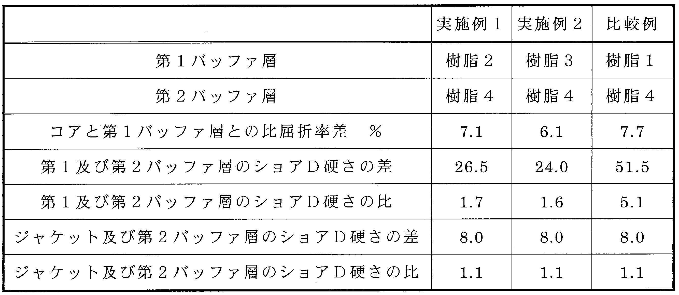
以下の実施例1及び2並びに比較例の光ファイバ心線を作製した。それぞれの構成を表2に示す。(Optical fiber core wire)
The following optical fiber core wires of Examples 1 and 2 and Comparative Example were produced. Each configuration is shown in Table 2.
<実施例1>
実施形態と同様の構成であって、樹脂2を用いて第1バッファ層を形成すると共に、樹脂4を用いて第2バッファ層を形成した光ファイバ心線を作製し、それを実施例1とした。<Example 1>
An optical fiber core wire having the same configuration as that of the embodiment, in which the resin 2 is used to form the first buffer layer and the resin 4 is used to form the second buffer layer, is referred to as Example 1. did.
光ファイバ心線の外径は0.43mmであり、光ファイバの外径は0.28mmであった。光ファイバは、純粋石英で形成された横断面における直径が240μmコアと、フッ素がドープされた石英で形成された厚さが20μmのクラッドとを有し、測定波長λ:589nm及び測定温度:25℃でのコアの屈折率が1.458及びクラッドの屈折率が1.441であった。従って、このときのコアとクラッドとの比屈折率差は1.2%である。 The outer diameter of the optical fiber core wire was 0.43 mm, and the outer diameter of the optical fiber was 0.28 mm. The optical fiber has a core having a diameter of 240 μm in a cross section made of pure quartz and a clad having a thickness of 20 μm made of quartz doped with fluorine, and has a measurement wavelength λ: 589 nm and a measurement temperature: 25. The refractive index of the core at ° C was 1.458 and the refractive index of the cladding was 1.441. Therefore, the difference in the specific refractive index between the core and the clad at this time is 1.2%.
また、図2に示す純粋石英の25℃における測定波長λと屈折率との関係によれば、測定波長λ:852nmでのコアの屈折率は1.452である。このことから、測定波長λ:852nm及び測定温度:25℃としたときのコアと第1バッファ層との比屈折率差は(1.452-1.349)/1.452≒7.1%である。 Further, according to the relationship between the measured wavelength λ and the refractive index of pure quartz at 25 ° C. shown in FIG. 2, the refractive index of the core at the measured wavelength λ: 852 nm is 1.452. From this, the difference in the specific refractive index between the core and the first buffer layer when the measurement wavelength λ: 852 nm and the measurement temperature: 25 ° C. is (1.452-1.349) /1.452≈7.1%. Is.
第1バッファ層の厚さは20μmであった。第2バッファ層の厚さは15μmであった。ジャケットは、エチレンテトラフルオロエチレン共重合体樹脂(ETFE)で形成した。ジャケットの厚さは40μmであった。ジャケットのショアD硬さはD/72.0/1であった。 The thickness of the first buffer layer was 20 μm. The thickness of the second buffer layer was 15 μm. The jacket was made of ethylene tetrafluoroethylene copolymer resin (ETFE). The thickness of the jacket was 40 μm. The shore D hardness of the jacket was D / 72.0 / 1.
<実施例2>
樹脂3を用いて第1バッファ層を形成したことを除いて実施例1と同様にして光ファイバ心線を作製し、それを実施例2とした。<Example 2>
An optical fiber core wire was produced in the same manner as in Example 1 except that the first buffer layer was formed using the resin 3, and this was designated as Example 2.
<比較例>
樹脂1を用いて第1バッファ層を形成したことを除いて実施例1と同様にして光ファイバ心線を作製し、それを比較例とした。<Comparison example>
An optical fiber core wire was produced in the same manner as in Example 1 except that the first buffer layer was formed using the resin 1, and this was used as a comparative example.
(試験方法)
<焼損率>
実施例1及び2並びに比較例のそれぞれの光ファイバ心線について、図3に示すように、光ファイバ心線10の一端をHo:YAGレーザLに接続し且つ他端部を水Wに浸漬して曲げ直径が1.5cmとなるようにU字状に曲げた状態で、Ho:YAGレーザLから1パルス当たりのエネルギーが1.5Jである波長2.1μmのパルスレーザー光を周波数30Hzで1分間出力し(平均出力45W)、そのときの光ファイバの断線等の損傷の有無を確認した。この試行を20回行い、損傷が確認された試行の回数の割合を焼損率として評価した。また、曲げ直径が1.0cmとなるようにU字状に曲げた場合についても同様の試験を行った。(Test method)
<Burning rate>
As shown in FIG. 3, for each of the optical fiber core wires of Examples 1 and 2 and the comparative example, one end of the optical
<ジャケット剥離性>
実施例1及び2並びに比較例のそれぞれの光ファイバ心線について、ジャケット剥離具(マイクロエレクトロニクス社製)を用いて心線端から5cmの長さのジャケットを剥離し、露出した第2バッファ層の損傷の有無を確認した。そして、損傷がない場合をA及びある場合をBと評価した。<Jacket peelability>
For each of the optical fiber core wires of Examples 1 and 2 and Comparative Example, a jacket having a length of 5 cm from the end of the core wire was peeled off using a jacket peeling tool (manufactured by Microelectronics), and the exposed second buffer layer was obtained. It was confirmed whether there was any damage. Then, the case where there was no damage was evaluated as A, and the case where there was damage was evaluated as B.
(試験結果)
試験結果を表3に示す。(Test results)
The test results are shown in Table 3.
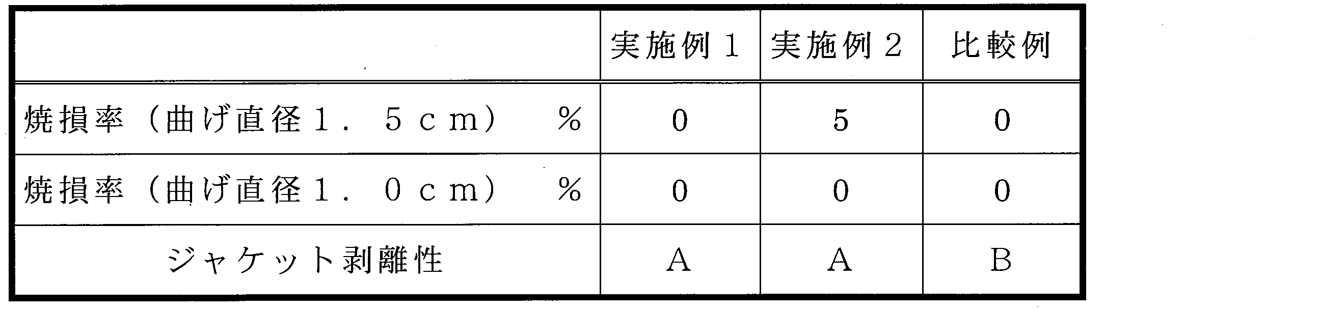
表3によれば、第1バッファ層がクラッドよりも屈折率が低く、第1バッファ層のショアD硬さがD/20/1以上であり、且つ第2バッファ層が第1バッファ層よりもショアD硬さが高い実施例1及び2では、焼損率が低く、また、ジャケット剥離性が優れることが分かる。 According to Table 3, the first buffer layer has a lower refractive index than the clad, the shore D hardness of the first buffer layer is D / 20/1 or more, and the second buffer layer is higher than the first buffer layer. It can be seen that in Examples 1 and 2 in which the shore D hardness is high, the burnout rate is low and the jacket peelability is excellent.
一方、第1バッファ層がクラッドよりも屈折率が低く、且つ第2バッファ層が第1バッファ層よりもショアD硬さが高いものの、第1バッファ層のショアD硬さがD/20/1よりも低い比較例では、焼損率は低いが、ジャケット剥離性が劣ることが分かる。 On the other hand, although the first buffer layer has a lower refractive index than the clad and the second buffer layer has a higher shore D hardness than the first buffer layer, the shore D hardness of the first buffer layer is D / 20/1. In the comparative example lower than, it can be seen that the burnout rate is low, but the jacket peelability is inferior.
本発明は、光ファイバ心線の技術分野について有用である。 The present invention is useful in the technical field of optical fiber cores.
10 光ファイバ心線
11 光ファイバ
111 コア
112 クラッド
121 第1バッファ層
122 第2バッファ層
13 ジャケット10 Optical
Claims (10)
前記光ファイバを被覆するように設けられた前記クラッドよりも屈折率が低く且つショアD硬さがD/20.0/1以上である第1バッファ層と、
前記第1バッファ層を被覆するように設けられた前記第1バッファ層よりもショアD硬さが高く且つ前記ショアD硬さがD/40.0/1以上である第2バッファ層と、
前記第2バッファ層を被覆するように設けられた前記第2バッファ層よりもショアD硬さが高く且つ前記ショアD硬さがD/50.0/1以上D/110/1以下であるジャケットと、
を備え、
前記第2バッファ層のショアD硬さと前記第1バッファ層のショアD硬さとの差が10.0以上50.0以下であり、且つ前記ジャケットのショアD硬さと前記第2バッファ層のショアD硬さとの差が3.00以上30.0以下である光ファイバ心線。 An optical fiber having a core and a clad having a lower refractive index than the core provided so as to cover the core.
A first buffer layer having a lower refractive index and a shore D hardness of D / 20.0/1 or more than the clad provided so as to cover the optical fiber.
A second buffer layer having a higher shore D hardness than the first buffer layer provided so as to cover the first buffer layer and having a shore D hardness of D / 40.0 / 1 or more .
A jacket having a higher shore D hardness than the second buffer layer provided so as to cover the second buffer layer and having a shore D hardness of D / 50.0 / 1 or more and D / 110/1 or less. When,
Equipped with
The difference between the shore D hardness of the second buffer layer and the shore D hardness of the first buffer layer is 10.0 or more and 50.0 or less, and the shore D hardness of the jacket and the shore D of the second buffer layer. An optical fiber core wire having a difference from hardness of 3.00 or more and 30.0 or less .
前記コアと前記第1バッファ層との比屈折率差が5.5%以上である光ファイバ心線。 In the optical fiber core wire according to claim 1,
An optical fiber core wire having a specific refractive index difference of 5.5% or more between the core and the first buffer layer.
前記コアと前記第1バッファ層との比屈折率差が6.0%以上である光ファイバ心線。 In the optical fiber core wire according to claim 2,
An optical fiber core wire having a specific refractive index difference of 6.0% or more between the core and the first buffer layer.
前記第1バッファ層の屈折率が前記クラッドの屈折率よりも低い光ファイバ心線。 In the optical fiber core wire according to any one of claims 1 to 3.
An optical fiber core wire having a refractive index of the first buffer layer lower than that of the clad.
前記第1バッファ層がフッ素含有ポリマー樹脂で形成されている光ファイバ心線。 In the optical fiber core wire according to any one of claims 1 to 4.
An optical fiber core wire in which the first buffer layer is made of a fluorine-containing polymer resin.
前記第2バッファ層がフッ素含有ポリマー樹脂で形成されている光ファイバ心線。 In the optical fiber core wire according to any one of claims 1 to 5 .
An optical fiber core wire in which the second buffer layer is made of a fluorine-containing polymer resin.
前記ジャケットがフッ素系樹脂で形成されている光ファイバ心線。 In the optical fiber core wire according to any one of claims 1 to 6 .
An optical fiber core wire whose jacket is made of a fluororesin.
内視鏡装置に用いられる光ファイバ心線。 In the optical fiber core wire according to any one of claims 1 to 7 .
An optical fiber core wire used in an endoscope device.
前記光ファイバ心線の全長に渡って、前記第2バッファ層が前記第1バッファ層を被覆するように設けられている光ファイバ心線。 In the optical fiber core wire according to any one of claims 1 to 8 .
An optical fiber core wire provided so that the second buffer layer covers the first buffer layer over the entire length of the optical fiber core wire.
前記ジャケットが前記第2バッファ層の直上に設けられている光ファイバ心線。 In the optical fiber core wire according to any one of claims 1 to 9 .
An optical fiber core wire in which the jacket is provided directly above the second buffer layer.
Applications Claiming Priority (3)
| Application Number | Priority Date | Filing Date | Title |
|---|---|---|---|
| JP2016252795 | 2016-12-27 | ||
| JP2016252795 | 2016-12-27 | ||
| PCT/JP2017/044495 WO2018123556A1 (en) | 2016-12-27 | 2017-12-12 | Optical fiber core wire |
Publications (2)
| Publication Number | Publication Date |
|---|---|
| JPWO2018123556A1 JPWO2018123556A1 (en) | 2019-10-31 |
| JP7086860B2 true JP7086860B2 (en) | 2022-06-20 |
Family
ID=62707361
Family Applications (1)
| Application Number | Title | Priority Date | Filing Date |
|---|---|---|---|
| JP2018559001A Active JP7086860B2 (en) | 2016-12-27 | 2017-12-12 | Optical fiber core wire |
Country Status (3)
| Country | Link |
|---|---|
| US (1) | US11385431B2 (en) |
| JP (1) | JP7086860B2 (en) |
| WO (1) | WO2018123556A1 (en) |
Families Citing this family (5)
| Publication number | Priority date | Publication date | Assignee | Title |
|---|---|---|---|---|
| DE102018107523A1 (en) | 2018-03-29 | 2019-10-02 | Schott Ag | Light or image guide components for disposable endoscopes |
| DE102019133042A1 (en) | 2019-12-04 | 2021-06-10 | Schott Ag | Endoscope, single-use endoscope system and light source for endoscope |
| WO2021122491A1 (en) * | 2019-12-20 | 2021-06-24 | Koninklijke Philips N.V. | Catheter sheath for acoustically amplifying laser-induced pressure waves |
| EP4090636A1 (en) * | 2020-01-17 | 2022-11-23 | Corning Incorporated | Reduced coating diameter chlorine-doped silica optical fibers with low loss and microbend sensitivity |
| DE102020106915A1 (en) * | 2020-03-13 | 2021-09-16 | Schott Ag | Endoscope and single-use endoscope system |
Citations (3)
| Publication number | Priority date | Publication date | Assignee | Title |
|---|---|---|---|---|
| JP2000510609A (en) | 1997-03-21 | 2000-08-15 | エスディーエル,インコーポレイテッド | Coated optical fiber |
| JP2005505013A (en) | 2001-10-09 | 2005-02-17 | スリーエム イノベイティブ プロパティズ カンパニー | Small diameter high-strength optical fiber |
| US20110085772A1 (en) | 2009-10-13 | 2011-04-14 | Seldon David Benjamin | Buffered Large Core Fiber |
Family Cites Families (11)
| Publication number | Priority date | Publication date | Assignee | Title |
|---|---|---|---|---|
| JPH0466905A (en) * | 1990-07-04 | 1992-03-03 | Mitsubishi Rayon Co Ltd | Optical fiber |
| US5182785A (en) * | 1991-10-10 | 1993-01-26 | W. L. Gore & Associates, Inc. | High-flex optical fiber coil cable |
| KR960706094A (en) * | 1994-09-16 | 1996-11-08 | 마에다 가츠노스케 | Broadband Fiber Optics, Fiber Optic Cores, and Fiber Optic Cords |
| JP3487314B2 (en) * | 1995-01-19 | 2004-01-19 | 住友電気工業株式会社 | Manufacturing method of coated optical fiber |
| JPH09243877A (en) * | 1996-03-12 | 1997-09-19 | Nippon Telegr & Teleph Corp <Ntt> | Coated optical fiber |
| JPH09325221A (en) * | 1996-04-04 | 1997-12-16 | Hitachi Cable Ltd | Lighting device |
| US7463807B2 (en) * | 2006-07-06 | 2008-12-09 | Peter Dragic | Waveguide configuration |
| US20090087154A1 (en) * | 2007-09-28 | 2009-04-02 | Bradley Kelvin B | Optical fiber cables |
| EP2502107A4 (en) * | 2009-11-20 | 2017-12-20 | ADC Telecommunications, INC. | Fiber optic cable |
| JP6140676B2 (en) | 2014-12-10 | 2017-05-31 | 株式会社フジクラ | Manufacturing method of polymer clad optical fiber |
| CN104536085B (en) * | 2015-01-07 | 2017-06-20 | 烽火通信科技股份有限公司 | A kind of thin footpath polarization maintaining optical fibre |
-
2017
- 2017-12-12 WO PCT/JP2017/044495 patent/WO2018123556A1/en active Application Filing
- 2017-12-12 US US16/474,504 patent/US11385431B2/en active Active
- 2017-12-12 JP JP2018559001A patent/JP7086860B2/en active Active
Patent Citations (3)
| Publication number | Priority date | Publication date | Assignee | Title |
|---|---|---|---|---|
| JP2000510609A (en) | 1997-03-21 | 2000-08-15 | エスディーエル,インコーポレイテッド | Coated optical fiber |
| JP2005505013A (en) | 2001-10-09 | 2005-02-17 | スリーエム イノベイティブ プロパティズ カンパニー | Small diameter high-strength optical fiber |
| US20110085772A1 (en) | 2009-10-13 | 2011-04-14 | Seldon David Benjamin | Buffered Large Core Fiber |
Also Published As
| Publication number | Publication date |
|---|---|
| JPWO2018123556A1 (en) | 2019-10-31 |
| US20190346649A1 (en) | 2019-11-14 |
| WO2018123556A1 (en) | 2018-07-05 |
| US11385431B2 (en) | 2022-07-12 |
Similar Documents
| Publication | Publication Date | Title |
|---|---|---|
| JP7086860B2 (en) | Optical fiber core wire | |
| US10492864B2 (en) | Methods and apparatus related to a distal end portion of an optical fiber having a substantially spherical shape | |
| JP6275379B2 (en) | Optical fiber structure and manufacturing method thereof | |
| JPH07265449A (en) | Light scattering apparatus and its manufacture | |
| JP2009168914A (en) | Optical fiber and method for manufacturing the same | |
| JP6841837B2 (en) | Optical fiber ribbon manufacturing method and optical fiber cable manufacturing method | |
| JP5227038B2 (en) | Optical fiber | |
| JP2012053121A (en) | Coated optical fiber and photoelectric composite cable using the same | |
| JP6881510B2 (en) | Optical fiber, optical fiber cable and communication equipment | |
| JP5521480B2 (en) | Plastic clad optical fiber core and optical fiber cable | |
| JP2012088356A (en) | Coated optical fiber and optical-electrical composite cable provided with the same | |
| JP6623674B2 (en) | Optical fiber, optical fiber cable, communication equipment and lighting equipment | |
| WO2016063829A1 (en) | Optical fiber, method for manufacturing optical fiber, optical fiber cable, and sensor | |
| KR101688827B1 (en) | Optic fiber for optical treatment and method for manufacturing thereof | |
| TW201219873A (en) | Plastic optical fiber unit and plastic optical fiber cable using same | |
| JP4680715B2 (en) | Manufacturing method of plastic optical fiber cable | |
| JP7228429B2 (en) | Optical fiber for laser light transmission | |
| JP2008111762A (en) | Impact detecting optical fiber sensor | |
| JP2002245821A (en) | Optical fiber illuminator | |
| JP6800826B2 (en) | Optical connector structure | |
| FR2632076A1 (en) | COUPLER FOR OPTICAL FIBER GROUPS, AND METHOD FOR MANUFACTURING THE SAME | |
| JP2000214342A (en) | Plastic clad optical fiber and its production | |
| KR101653800B1 (en) | solar light combiner | |
| JP6496695B2 (en) | Polymer clad fiber and method for producing polymer clad fiber | |
| JP2006145847A (en) | Secondary coated optical fiber |
Legal Events
| Date | Code | Title | Description |
|---|---|---|---|
| A621 | Written request for application examination |
Free format text: JAPANESE INTERMEDIATE CODE: A621 Effective date: 20200622 |
|
| A131 | Notification of reasons for refusal |
Free format text: JAPANESE INTERMEDIATE CODE: A131 Effective date: 20210713 |
|
| A521 | Request for written amendment filed |
Free format text: JAPANESE INTERMEDIATE CODE: A523 Effective date: 20210907 |
|
| A02 | Decision of refusal |
Free format text: JAPANESE INTERMEDIATE CODE: A02 Effective date: 20220301 |
|
| A521 | Request for written amendment filed |
Free format text: JAPANESE INTERMEDIATE CODE: A523 Effective date: 20220425 |
|
| C60 | Trial request (containing other claim documents, opposition documents) |
Free format text: JAPANESE INTERMEDIATE CODE: C60 Effective date: 20220425 |
|
| A911 | Transfer to examiner for re-examination before appeal (zenchi) |
Free format text: JAPANESE INTERMEDIATE CODE: A911 Effective date: 20220509 |
|
| C21 | Notice of transfer of a case for reconsideration by examiners before appeal proceedings |
Free format text: JAPANESE INTERMEDIATE CODE: C21 Effective date: 20220510 |
|
| TRDD | Decision of grant or rejection written | ||
| A01 | Written decision to grant a patent or to grant a registration (utility model) |
Free format text: JAPANESE INTERMEDIATE CODE: A01 Effective date: 20220531 |
|
| A61 | First payment of annual fees (during grant procedure) |
Free format text: JAPANESE INTERMEDIATE CODE: A61 Effective date: 20220608 |
|
| R150 | Certificate of patent or registration of utility model |
Ref document number: 7086860 Country of ref document: JP Free format text: JAPANESE INTERMEDIATE CODE: R150 |