JP7086543B2 - Posture holder - Google Patents
Posture holder Download PDFInfo
- Publication number
- JP7086543B2 JP7086543B2 JP2017159124A JP2017159124A JP7086543B2 JP 7086543 B2 JP7086543 B2 JP 7086543B2 JP 2017159124 A JP2017159124 A JP 2017159124A JP 2017159124 A JP2017159124 A JP 2017159124A JP 7086543 B2 JP7086543 B2 JP 7086543B2
- Authority
- JP
- Japan
- Prior art keywords
- support
- backrest
- plate portion
- seat
- seated person
- Prior art date
- Legal status (The legal status is an assumption and is not a legal conclusion. Google has not performed a legal analysis and makes no representation as to the accuracy of the status listed.)
- Active
Links
- 239000000470 constituent Substances 0.000 claims description 37
- 210000000115 thoracic cavity Anatomy 0.000 claims description 12
- 230000007423 decrease Effects 0.000 claims description 5
- 210000004705 lumbosacral region Anatomy 0.000 claims description 4
- 210000001217 buttock Anatomy 0.000 description 9
- 239000000463 material Substances 0.000 description 6
- 230000005489 elastic deformation Effects 0.000 description 5
- 230000002093 peripheral effect Effects 0.000 description 5
- 238000006073 displacement reaction Methods 0.000 description 3
- 230000000630 rising effect Effects 0.000 description 2
- 230000003068 static effect Effects 0.000 description 2
- JOYRKODLDBILNP-UHFFFAOYSA-N Ethyl urethane Chemical compound CCOC(N)=O JOYRKODLDBILNP-UHFFFAOYSA-N 0.000 description 1
- 125000002066 L-histidyl group Chemical group [H]N1C([H])=NC(C([H])([H])[C@](C(=O)[*])([H])N([H])[H])=C1[H] 0.000 description 1
- 238000005452 bending Methods 0.000 description 1
- 230000002146 bilateral effect Effects 0.000 description 1
- 230000037237 body shape Effects 0.000 description 1
- 210000000038 chest Anatomy 0.000 description 1
- 230000006866 deterioration Effects 0.000 description 1
- 239000004744 fabric Substances 0.000 description 1
- 239000006260 foam Substances 0.000 description 1
- 230000014759 maintenance of location Effects 0.000 description 1
- 239000000203 mixture Substances 0.000 description 1
- 230000003014 reinforcing effect Effects 0.000 description 1
- 210000001991 scapula Anatomy 0.000 description 1
- 229920003002 synthetic resin Polymers 0.000 description 1
- 239000000057 synthetic resin Substances 0.000 description 1
- 210000000689 upper leg Anatomy 0.000 description 1
Images


Classifications
-
- A—HUMAN NECESSITIES
- A47—FURNITURE; DOMESTIC ARTICLES OR APPLIANCES; COFFEE MILLS; SPICE MILLS; SUCTION CLEANERS IN GENERAL
- A47C—CHAIRS; SOFAS; BEDS
- A47C9/00—Stools for specified purposes
-
- A—HUMAN NECESSITIES
- A47—FURNITURE; DOMESTIC ARTICLES OR APPLIANCES; COFFEE MILLS; SPICE MILLS; SUCTION CLEANERS IN GENERAL
- A47C—CHAIRS; SOFAS; BEDS
- A47C7/00—Parts, details, or accessories of chairs or stools
- A47C7/36—Support for the head or the back
- A47C7/40—Support for the head or the back for the back
- A47C7/46—Support for the head or the back for the back with special, e.g. adjustable, lumbar region support profile; "Ackerblom" profile chairs
Description
本発明は、姿勢保持具に関するものである。 The present invention relates to a posture holder.
特許文献1には、着座者の姿勢を正しい状態に保持する姿勢保持具が開示されている。この姿勢保持具は、着座者の臀部を下から支える臀部支持部と、臀部支持部の後縁から立ち上がった腰部支持部とを備えている。腰部支持部は、着座者の腰と背中の下端部とを支えることが可能な高さを有しており、全体として略方形の厚板状をなしている。 Patent Document 1 discloses a posture holder that keeps the seated posture in a correct state. This posture holder includes a buttocks support portion that supports the buttocks of the seated person from below, and a lumbar support portion that rises from the trailing edge of the buttocks support portion. The lumbar support portion has a height capable of supporting the waist of the seated person and the lower end portion of the back, and has a substantially rectangular plate shape as a whole.
上記の姿勢保持具は、腰部支持部の前面(腰と背中が当たる面)が全体として概ね平面状をなしているので、着座者は、上半身を左右に傾ける動作や上半身を左右に捻る動作を行い易い。しかしながら、この姿勢保持具は、着座者の上半身を正しい姿勢で安定させることができないため、着座者が、上半身を左右に傾けた姿勢や上半身を左右に捻った姿勢のままで長時間を過ごしてしまうことが懸念される。 In the above posture holder, the front surface of the lumbar support (the surface where the waist and back touch) is generally flat, so the seated person can tilt the upper body to the left or right or twist the upper body to the left or right. Easy to do. However, since this posture holder cannot stabilize the upper body of the seated person in the correct posture, the seated person spends a long time with the upper body tilted to the left and right or the upper body twisted to the left and right. There is concern that it will end up.
本発明は上記のような事情に基づいて完成されたものであって、着座者の上半身を正しい姿勢に保持することを目的とする。 The present invention has been completed based on the above circumstances, and an object of the present invention is to hold the upper body of the seated person in a correct posture.
本発明の姿勢保持具は、
座部と、
前記座部の後端部から立ち上がった形態の背凭れ部と、
前記背凭れ部を構成し、着座者の背中の左右方向中央部を当接させる第1支持部と、
前記背凭れ部を構成し、前記第1支持部の左右両側縁から延出することによって前記第1支持部の左右両側方に配されて、着座者の背中の左右両側部を当接させる一対の第2支持部とを備え、
前記第1支持部の上縁部における最下端部が、前記第2支持部の上縁部における最上端部より低い位置に配され、
前記第1支持部は、着座者の背中のうち腰椎の上部から胸椎の下部に亘る範囲の全体又は一部を支え、
前記第2支持部は、着座者の背中における肋骨背部のうち胸椎の下部から胸椎の中程高さに亘って対応する部位の全体又は一部を支え、
前記第1支持部の上端部が、斜め上後方へ反るように湾曲していることを特徴とする。
The posture holder of the present invention is
With the seat
The backrest, which stands up from the rear end of the seat,
A first support portion that constitutes the backrest portion and abuts the central portion of the seater's back in the left-right direction, and a first support portion.
A pair that constitutes the backrest and is arranged on both the left and right sides of the first support portion by extending from the left and right side edges of the first support portion, and abuts the left and right side portions of the back of the seated person. Equipped with a second support part of
The lowermost end portion of the upper edge portion of the first support portion is arranged at a position lower than the uppermost end portion of the upper edge portion of the second support portion.
The first support portion supports the entire or part of the seated person's back from the upper part of the lumbar spine to the lower part of the thoracic spine.
The second support portion supports all or part of the corresponding portion of the back of the ribs on the back of the occupant from the lower part of the thoracic vertebra to the middle height of the thoracic vertebra.
The upper end portion of the first support portion is curved so as to warp diagonally upward and backward.
着座者は、背中の中央部における比較的低い部位を第1支持部に当て、背中の左右両側部における比較的高い部位を第2支持部に当てた状態で着座する。本願発明の姿勢保持具は、着座者の背中を3つの支持部で支えるので、着座者の上半身が左右に傾けた姿勢や左右に捻った姿勢になることを抑制し、着座者の上半身を正しい姿勢に保持することができる。 The seated person sits with a relatively low portion in the central part of the back against the first support portion and a relatively high portion in both the left and right sides of the back against the second support portion. Since the posture holder of the present invention supports the back of the occupant with three support portions, it suppresses the occupant's upper body from being tilted to the left or right or twisted to the left or right, and the occupant's upper body is correct. Can be held in posture.
本発明は、前記第2支持部の上端部が、上方に向かうほど斜め後方へ反るように湾曲していてもよい。
この構成によれば、着座者の上半身を背凭れ部に深くもたせかけたときに第2支持部の上端縁が着座者の身体に食い込む虞がない。
In the present invention, the upper end portion of the second support portion may be curved so as to warp diagonally backward toward the upper side.
According to this configuration, there is no possibility that the upper end edge of the second support portion will bite into the seated person's body when the upper body of the seated person is leaned deeply against the backrest portion.
本発明は、前記座部を構成する座部構成板部と前記背凭れ部を構成する背凭れ部構成板部が、前記背凭れ部構成板部の下端部を略支点として弾性的に相対変位し得るように連なり、前記背凭れ部構成板部は、前記第1支持部を構成する第1支持板部と、前記第1支持板部の左右両側縁から斜め前方へ突出して前記第2支持部を構成する第2支持板部とからなり、前記第2支持板部の下端側領域における前記第1支持板部からの突出寸法は、下方に向かって次第に小さくなっていてもよい。
この構成によれば、着座者が上半身を背凭れ部に押し付けると、背凭れ部がその下端縁を略支点として後方へ弾性変位する。第2支持板部の下端側領域における第1支持板部からの突出寸法は、下方に向かって次第に小さくなるので、背凭れ部構成板部の下端側領域も弾性変形する。これにより、背凭れ部構成板部の下端縁への応力集中を防止できる。
In the present invention, the seat portion constituent plate portion constituting the seat portion and the backrest portion constituent plate portion constituting the backrest portion are elastically displaced relative to each other with the lower end portion of the backrest portion constituent plate portion as a substantially fulcrum. The backrest portion constituting plate portion is connected so as to be possible, and the backrest portion constituting plate portion protrudes diagonally forward from the first support plate portion constituting the first support portion and the left and right side edges of the first support plate portion to support the second support portion. It is composed of a second support plate portion constituting the portion, and the protrusion dimension from the first support plate portion in the lower end side region of the second support plate portion may be gradually reduced downward.
According to this configuration, when the seated person presses the upper body against the backrest, the backrest is elastically displaced backward with the lower end edge as a substantially fulcrum. Since the protrusion dimension from the first support plate portion in the lower end side region of the second support plate portion gradually decreases downward, the lower end side region of the backrest portion constituent plate portion is also elastically deformed. This makes it possible to prevent stress concentration on the lower end edge of the backrest portion constituent plate portion.
本発明は、前記第1支持部のうち背中と対向する第1支持面と、前記第2支持部のうち背中と対向する第2支持面とが、左右一対の繋ぎ面を介して連なっており、平面視において前記第1支持面の曲率と前記第2支持面の曲率が前記繋ぎ面の曲率より小さくてもよい。
この構成によれば、曲率の大きい繋ぎ面には背中が当たることはないので、第1支持面と左右一対の第2支持面との3箇所において着座者の上半身を安定して支えることができる。
In the present invention, the first support surface of the first support portion facing the back and the second support surface of the second support portion facing the back are connected via a pair of left and right connecting surfaces. In a plan view, the curvature of the first support surface and the curvature of the second support surface may be smaller than the curvature of the connecting surface.
According to this configuration, since the back does not hit the connecting surface having a large curvature, the upper body of the seated person can be stably supported at three points of the first support surface and the pair of left and right second support surfaces. ..
<実施例1>
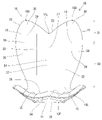
以下、本発明を具体化した実施例1を図1~図12を参照して説明する。尚、以下の説明において、前後の方向については、図4~6,12における左方、図3,7~10における下方を前方と定義する。上下の方向については、図1,2,4~6,11,12にあらわれる向きを、そのまま上方、下方と定義する。左右の方向については、図2,3,7~11にあらわれる向きを、そのまま左方、右方と定義する。
<Example 1>
Hereinafter, Example 1 embodying the present invention will be described with reference to FIGS. 1 to 12. In the following description, the front-back direction is defined as the left side in FIGS. 4 to 6 and 12 and the lower side in FIGS. 3 and 7 to 10 as the front direction. As for the vertical direction, the directions appearing in FIGS. 1, 2, 4 to 6, 11 and 12 are defined as upward and downward as they are. Regarding the left-right direction, the directions appearing in FIGS. 2, 3, 7 to 11 are defined as left and right as they are.
本実施例1の姿勢保持具10は、形状的及び機能的には、着座者50の臀部51を下から支える座部11と、着座者50の背中52を後方から支える背凭れ部16とから構成され、左右対称な形状である。座部11と背凭れ部16は一体をなしている。尚、本実施例1において「着座者50の背中52」とは、着座者50の背部及び腰部(上半身のうち体幹の背面側及び側面側)と定義する。
The
座部11の平面視形状について説明する。図3に示すように、前後方向において、座部11の後端から前方概ね2/3に亘る後端側支持領域12Rは、前方に向かって次第に拡幅した略台形をなす。後端側支持領域12Rでは座部11の幅寸法(左右方向の寸法)が最大となる。座部11のうち後端側支持領域12Rより前方の前端側支持領域12Fの外周縁は、左右対称な一対の前側湾曲縁部13と、前縁抉り部14とから構成されている。前側湾曲縁部13は、後端側支持領域12Rの左右両側縁に連なり、座部11の前縁部を構成する。前縁抉り部14は、座部11の左右方向中央部において鈍角状に凹んだ形状であり、左右両前側湾曲縁部13を繋いでいる。
The plan view shape of the
座部11の正面視形状について説明する。図2,11に示すように、と、座部11は、上面側が凹むように湾曲した左右対称な一対の支承部15から構成されている。座部11は、左右方向中央部と左右両端部が高くなっているので、着座者50の臀部51と太腿の付け根部分とを安定して支えることができる。
The front view shape of the
図1,4に示すように、背凭れ部16は、座部11の後端部から上方へ立ち上がった形態である。背凭れ部16は、背凭れ部16の左右方向中央部を構成する第1支持部17と、背凭れ部16の左右両側縁部を構成する左右対称な一対の第2支持部18とから構成されている。左右両第2支持部18は、第1支持部17の左右両側縁から斜め前方へ片持ち状に延出した形態である。左右両第2支持部18の延出方向は、平面視において、両第2支持部18の左右方向の間隔が前方に向かって次第に拡がるような向きである。
As shown in FIGS. 1 and 4, the
背凭れ部16の前面は、着座者50の背中52と接触又は対向する支持面19となっている。支持面19(背凭れ部16)の正面視形状について説明する。図2,11に示すように、上下方向(高さ方向)において、背凭れ部16の下端から上方概ね2/3に亘る下端側支持領域20は、上方に向かって次第に拡幅した略台形をなす。背凭れ部16のうち下端側支持領域20より上方の上端側支持領域21の外周縁は、左右対称な一対の上側湾曲縁部22と、上縁抉り部23とから構成されている。上側湾曲縁部22は、下端側支持領域20の左右両側縁に連なり、背凭れ部16の上縁部を構成する。上側抉り部は、背凭れ部16の左右方向中央部において鈍角状に凹んだ形状であり、左右両上側湾曲縁部22を繋いでいる。
The front surface of the
上側湾曲縁部22は第2支持部18の外周縁のみに形成されている。上縁抉り部23は、第1支持部17の上縁部の全領域と第2支持部18の上縁部の一部を構成する。背凭れ部16の上縁部の高さ寸法は、上側湾曲縁部22の上端において最大であり、上縁抉り部23の最下端(背凭れ部16の左右方向中央)において最小である。換言すると、第1支持部17の上縁部における最下端部17Lは、第2支持部18の上縁部における最上端部18Uより低い位置に配されている。第1支持部17の上縁部における最下端部17Lは、上側湾曲縁部22(上端側支持領域21)の下端(背凭れ部16が最大幅となる高さ)よりも高い位置にある。上側湾曲縁部22の下端は、背凭れ部16が最大幅となる高さである。
The upper
図2に示すように、背凭れ部16の幅寸法は、下端側支持領域20の上端(上側湾曲縁部22の下端)において最大となっている。背凭れ部16の最大幅寸法は、座部11の最大幅寸法より少し小さく設定されている。背凭れ部16の幅寸法は、背凭れ部16(下端側支持領域20)の下端部16L(即ち、座部11の後端部)において最小となっている。左右両上側湾曲縁部22の上端間の間隔(幅寸法)は、背凭れ部16の最大幅寸法より小さい。背凭れ部16の高さ寸法は座部11の前後寸法よりも大きく設定されている。
As shown in FIG. 2, the width dimension of the
図2,3に示すように、支持面19は、第1支持部17を構成する第1支持面24と、第2支持部18を構成する左右対称な一対の第2支持面28とによって構成されている。第1支持面24は、支持面19における左右方向中央部に配されており、全体として縦長の略方形をなす。図4に示すように、第1支持面24の上端部は、斜め上前方へ膨らんで斜め上後方へ反るように湾曲した第1上部湾曲面25となっている。
As shown in FIGS. 2 and 3, the
図4に示すように、第1支持面24の下端部24Lは、後方に向かって上り勾配となるように湾曲した座部11の後端部と滑らかに連なっている。第1支持面24のうち第1上部湾曲面25より下方の領域は、概ね平面状をなす第1受け面27となっている。第1受け面27は、姿勢保持具10を使用している状態で概ね鉛直方向に沿う向きとなる。第1受け面27の上下寸法は、第1支持面24の全高寸法の概ね1/2の寸法である。
As shown in FIG. 4, the
左右一対の第2支持面28は、支持面19のうち第1支持面24の左右両側方に配されている。第2支持面28は、第1支持面24の左右両側縁部から斜め前方へ延出した形状である。第2支持面28の前縁部は、前方に向かって膨らむように湾曲した形状である。即ち、第2支持面28の前後方向の寸法(第1支持面24の側縁部からの延出寸法)は、第2支持面28のうち上端側支持領域21においては上方に向かうほど大きくなり、第2支持面28のうち下端側支持領域20では下方に向かうほど小さくなる。
The pair of left and right second support surfaces 28 are arranged on both the left and right sides of the
第2支持面28のうち左右方向において第1支持面24に近い領域は、第2受け面29となっている。第2受け面29は、第2支持部18の延出方向と略平行な概ね平面状をなしている。第2支持面28のうち第2受け面29を上方、前方及び下方から包囲する周縁部は、斜め前方内向きに膨らんで斜め後方へ反るように湾曲している。
The region of the
第2支持面28の上端部は、斜め上前方へ膨らんで斜め上後方へ反るように湾曲した第2上部湾曲面30となっている。左右両第2上部湾曲面30は第1上部湾曲面25の左右両側部と滑らかに連なっている。第2支持面28の下端部は、斜め下前方へ膨らむように湾曲した第2下部湾曲面31となっている。
The upper end of the
図3,11に示すように、平面視において、支持面19のうち第1支持面24の左右両側縁部と、第2支持面28の第2受け面29とを左右一対の繋ぐ領域は、弧状に凹んだ繋ぎ面32となっている。一対の繋ぎ面32は、左右対称であり、上下方向に細長く延びている。平面視において、第1支持面24(第1受け面27)の曲率と第2支持面28(第2受け面29)の曲率は殆どゼロに近い小さい値であるのに対し、繋ぎ面32の曲率は大きい。背凭れ部16の前方には、第1支持面24と左右両第2支持面28と左右両繋ぎ面32とで区画されることにより、前方へ開放された概ね台形状の保持空間33が構成されている。
As shown in FIGS. The connecting
第1支持部17の第1受け面27は、第1支持面24のうち着座時に着座者50の背中52の左右方向中央部が当たり得る領域である。第2支持部18の第2受け面29は、第2支持面28のうち着座時に着座者50の背中52の左右両側部が当たり得る領域である。第1受け面27の最上端位置は第2受け面29の最上端位置よりも低い位置に設定されている。第1受け面27は左右方向において一対の第2受け面29の間に挟まれるように位置する。したがって、姿勢保持具10は、1つの第1受け面27と左右一対の第2受け面29とにより着座者50の背中52を3箇所で支えることができる。この3箇所の受け面27,29は、高低差があり、左右に間隔を空け、且つ前後に間隔を空けた位置関係にある。
The
図12に示すように、姿勢保持具10は、部品構成的には、外殻部材34とクッション材39と外装シート40とから構成されている。外殻部材34は、硬質の合成樹脂からなり、厚さが全領域に亘って一定の板状をなす単一部材である。外殻部材34は、側面視形状が概ねL字形をなすように湾曲した形状に成形されている。外殻部材34は、座部11を構成する座部構成板部35と、背凭れ部16を構成する背凭れ部構成板部36とからなる。座部構成板部35は、上述した座部11の形状と略同一の形状であり、曲率の異なるように湾曲した複数の曲面状板部によって構成されている。背凭れ部構成板部36は、座部構成板部35の後端部から上方へ立ち上がった形態であり、第1支持部17を構成する第1支持板部37と、第2支持部18を構成する左右対称な一対の第2支持板部38とから構成されている。
As shown in FIG. 12, the
第1支持板部37の形状は、上述した第1支持部17及び第1支持面24と略同一の形状である。第1支持板部37のうち第1受け面27と対応する高さ領域は、側面視形状が全体として前方へ膨らむように湾曲した形状であり、姿勢保持具10を水平面に載置した状態で鉛直方向よりも少し前方へ傾いた向きとなる。また、第1支持板部37のうち第1上部湾曲面25と対応する領域は、斜め上後方へ反るように湾曲している。第1支持板部37のうち第1下部湾曲部26と対応する領域は、下方に向かって下り勾配となるように、且つ斜め下後方へ膨らむように湾曲した形状である。
The shape of the first
一対の第2支持板部38は、第1支持板部37の概ね直線状をなす左右両側縁から斜め前方へ且つ互いの左右間隔が前方に向かって拡がるように片持ち状に延出した形態である。第2支持板部38の形状は、上述した第2支持部18及び第2支持面28と略同一の形状である。第2支持板部38のうち第2受け面29と対応する領域は、概ね平板状をなし、第2支持板部38の周縁部は、斜め後方へ反るように湾曲した形状である。
The pair of second
図4に示すように、背凭れ部構成板部36の下端部36Lは座部構成板部35の後端部に連なっているのであるが、背凭れ部構成板部36の下端部36Lを構成するのは第1支持板部37だけである。つまり、第1支持板部37は座部構成板部35に対して直接的に連なっているが、第2支持板部38は、座部構成板部35に対して直接的には連なっておらず、第1支持板部37を介すことによって座部構成板部35に連なっている。
As shown in FIG. 4, the
外殻部材34は、姿勢保持具10の全体形状を保つものであり、着座者50の姿勢を安定して保持し得る剛性(形状保持性)を有する。但し、着座者50の体重に起因する静的な荷重や、着座者50の着座姿勢変更に起因する動的な荷重等を受けたときには、着座姿勢に影響を与えない程度に弾性変形し得るようになっている。具体的には、第2支持板部38が、第1支持板部37に対し、第1支持板部37の左右両側縁部を略支点として左右方向へ拡開するように弾性的に相対変位し得るようになっている。
The
また、上記の静的荷重や動的荷重を受けたときには、背凭れ部構成板部36(背凭れ部16)が、座部構成板部35(座部11)に対し、背凭れ部構成板部36の下端部36L(座部構成板部35の後端部)を略支点として前後方向へ姿勢を傾けるように弾性的に相対変位し得るようになっている。このとき、背凭れ部構成板部36の弾性変形量(背凭れ部構成板部36に生じる応力)は、弾性変位の略支点となる下端部36Lにおいて最大となるが、第1支持板部37の少なくとも下端側支持領域20も弾性変形する。第1支持板部37の下端側支持領域20が弾性変形することは、背凭れ部構成板部36の下端部36Lにおける応力集中を回避する手段として好ましい。
Further, when the above-mentioned static load or dynamic load is received, the backrest portion constituent plate portion 36 (backrest portion 16) has a backrest portion constituent plate with respect to the seat portion configuration plate portion 35 (seat portion 11). With the
しかし、第1支持板部37の左右両側縁から突出する第2支持板部38は、第1支持板部37の弾性変形に抗する補強リブとして機能する。そこで、図8~10に示すように、第2支持板部38の下端側領域における第1支持板部37からの突出寸法を、下方に向かって次第に小さくなるように設定した。これにより、背凭れ部構成板部36が座部構成板部35に対して前後方向へ弾性変位するときに、第1支持板部37の下端側領域も弾性的に湾曲変形するようになっている。尚、本実施例1において、第2支持板部38の下端側領域とは、第2支持板部38の下端部38Lから少なくとも1/3程度の高さに亘る領域と定義する。
However, the second
クッション材39は、外殻部材34のうち着座者50と対向する面(座部11を構成する部分の上面と、背凭れ部16を構成する部分の前面)に対し積層するように取り付けられている。クッション材39は、例えばウレタンフォーム等からなり、着座者50の臀部51や背中52が硬い外殻部材34に当たることに起因する不快感を回避するための部材である。クッション材39のうち第1受け面27と対応する部分の厚さは、上下方向において一定寸法ではなく、下方に向かって次第に厚肉となるように厚さ寸法が変化している。これにより、姿勢保持具10を水平面に載置したときに、第1支持面24の第1受け面27が概ね鉛直に立ち上がる向きとなる。
The
外装シート40は、布製であり、外殻部材34の外面(座部11を構成する部分の下面と、背凭れ部16を構成する部分の後面)と、クッション材39のうち着座者50と対向する面(座部11を構成する部分の上面と、背凭れ部16を構成する部分の前面)の全体を覆っている。クッション材39と外装シート40は、外殻部材34が弾性変形すると、追従して柔軟に変形する。
The
姿勢保持具10は、床面(図示省略)に直接置いた状態や椅子53に載せた状態で使用することができる。図12には、椅子に載せて使用している状態を示す。着座者50が姿勢保持具10に着座すると、臀部51が座部11によって下から支えられ、上半身の体幹部が保持空間33内に収容されて背中52が背凭れ部16により後方から支えられる。このとき、背中52の左右方向中央部位のうち胸椎下部と対応する部位が第1支持面24に当接するとともに、背中52の左右両側部位が左右の第2支持面28に当接する。
The
このとき、第2支持面28への当接部位は、第1支持面24への当接部位よりも高い位置であり、且つ第1支持面24への当接部位よりも前方の位置である。つまり、背中52は、三次元方向において位置の異なる複数部位を支えられることになる。また、着座者50が平均的体型の成人である場合、第2支持面28への当接位置は、肋骨の背面側であり、且つ肩甲骨より低い高さである。
At this time, the contact portion with the
本実施例1の姿勢保持具10は、着座者50の臀部51を下から支える座部11と、座部11の後端部から立ち上がった形態であって着座者50の上半身を背中52側から支える背凭れ部16とを備えている。背凭れ部16は、着座者50の背中52の左右方向中央部を当接させる第1支持部17と、第1支持部17の左右両側方に配されて着座者50の背中52の左右両側部を当接させる一対の第2支持部18とを備えて構成されている。
The
第1支持部17は、着座者50の背中52の中央部における比較的低い部位を後方から支え、左右一対の第2支持部18は背中52の左右両側部のうち第1支持部17より高い部位を斜め後方から挟むように支える。したがって、着座者50は、背中52の中央部における比較的低い部位を第1支持部17に当て、背中52の左右両側部における比較的高い部位を第2支持部18に当てた状態で着座する。着座者50は、3つの支持部17,18により左右に間隔を空け、且つ高低差のある3箇所で背中52を支えられるので、上半身を左右に傾けた姿勢や上半身を左右に捻った姿勢になることを抑制される。したがって、本実施例1の姿勢保持具10は、着座者50の上半身を正しい姿勢に保持することができる。
The
また、第1支持部17は着座者50の背中52のうち比較的低い部位(腰椎の上部から胸椎の下部に亘る範囲の全体又は一部)を支え、第2支持部18は背中52の比較的高い部位(肋骨背部のうち胸椎の下部から胸椎の中程高さに亘って対応する部位の全体又は一部)を支えるので、着座者50が背凭れ部16に体重を預けたときに、高低差のある複数箇所で背中52が支えられる。これにより、着座者50の上半身は、側面視において脊椎が適正なカーブを描くような正しい姿勢に保たれる。ここで、正しい姿勢とは、胸椎が後方へ膨らむように湾曲し、腰椎が前方へ膨らむように湾曲し、仙骨から尾骨に亘って後方へ膨らむように湾曲した姿勢である。
Further, the
また、第1支持部17の上端の高さを第2支持部18の上端と同じ高さに揃えた場合、背中52のうち後方へ膨らむように湾曲している胸椎部分が第1支持部17の上端に当たり、脊椎が適正なカーブを描き難くなる虞がある。その対策として、本実施例1の姿勢保持具10は、背凭れ部16の上端縁に上縁抉り部23を形成し、第1支持部17の上端の高さを第2支持部18の上端より低くしているのであるが、上縁抉り部23を形成すると、第1支持部17の上方直近(即ち、左右両第2支持部18の上端部の間)が空間となるので、第1支持部17の上方直近では背中52を支えることができなくなる。そのため、着座者50の上半身のうち第1支持部17(背中52の比較的低い部位)より上方の部分が後方へ反ってしまうことが懸念されるのであるが、着座者50の上半身は、第1支持部17より上方の左右両側方において第2支持部18で支えられるので、着座者50は、適度に胸が開きリラックスした状態で着座することができる。
Further, when the height of the upper end of the
また、着座状態では着座者50の上半身からの押圧力を受けて第2支持部18が斜め後方へ弾性変位するので、第2支持部18(第2支持板部38)の弾性復元力により、背中52の中央部よりも左右両側において圧力を強く感得する。そのため、着座者50の上半身が左右に傾いた姿勢や左右に捻られた姿勢になることを抑制できる。
Further, in the seated state, the
また、第2支持部18の上端部には、上方に向かうほど斜め後方へ反るように湾曲した第2上部湾曲面30が形成されているので、着座者50の上半身を背凭れ部16に深くもたせかけたときに第2支持部18の上端縁が着座者50の身体に食い込むことがなく、着座者50は座部11に深く腰掛けることができる。また、深く腰掛けることで、背中52の左右両側部が第2支持部18にしっかりと押し付けられるので、上半身が左右に捻られることを確実に防止できる。さらに、第2支持部18の上端部が着座者50の身体に食い込まないことで、背中52の上部を適度に後方へ反らせることが可能となるので、着座者50を正しい姿勢に保持することができる。
Further, since the second upper
また、姿勢保持具10は、その形状を保つための外殻部材34を備えている。外殻部材34は、座部11を構成する座部構成板部35と、背凭れ部16を構成する背凭れ部構成板部36とを備えている。背凭れ部構成板部36は、座部構成板部35に対し、背凭れ部構成板部36の下端部36Lを略支点として弾性的に相対変位し得るように連なっている。そのため、着座者50が上半身を背凭れ部16に強く押し付けると、背凭れ部16が、その下端部36Lを略支点として座部11に対して後方へ弾性的に相対変位する。
Further, the
このとき、相対的弾性変位の支点となる背凭れ部構成板部36の下端部36Lに応力が集中すると、応力集中が繰り返しされることによって劣化が進み、耐久性が低下することが懸念される。背凭れ部構成板部36の下端部36Lに応力が集中することを回避する手段としては、背凭れ部構成板部36の下端部36Lだけでなく、背凭れ部構成板部36の少なくとも下端側領域も一緒に弾性変形させることが好ましい。
At this time, if stress is concentrated on the
ところが、背凭れ部構成板部36は、第1支持部17を構成する第1支持板部37と、第1支持板部37の左右両側縁から斜め前方へ突出して第2支持部18を構成する左右一対の第2支持板部38とからなるため、変形し難い。そこで、第2支持板部38の下端側領域における第1支持板部37からの突出寸法を、下方に向かって次第に小さくなるようにした。これにより、背凭れ部構成板部36は、その下端部36Lだけでなく下端側領域も弾性変形するので、背凭れ部構成板部36の下端部36Lに応力が集中することを防止できる。尚、背凭れ部構成板部36の上端側領域は、下端側領域に比べて撓み剛性が高く弾性変形し難いので、着座者50の上半身を安定して保持することができる。
However, the backrest portion
また、第1支持部17のうち背中52と対向する第1支持面24と、第2支持部18のうち背中52と対向する第2支持面28とが、左右一対の繋ぎ面32を介して連なっており、平面視において第1支持面24の曲率と第2支持面28の曲率が繋ぎ面32の曲率より小さく設定されている。この構成によれば、曲率の大きい繋ぎ面32には背中52が当たることはないので、第1支持面24と左右一対の第2支持面28との3箇所において着座者50の上半身を安定して支えることができる。
Further, the
<他の実施例>
本発明は上記記述及び図面によって説明した実施例に限定されるものではなく、例えば次のような実施例も本発明の技術的範囲に含まれる。
(1)上記実施例の姿勢保持具は、座部と背凭れ部が一体に形成されたものであるが、姿勢保持具は、別体部材の座部と背凭れ部とを組み付けて構成されるものであってもよい。
(2)上記実施例では、第2支持部の上端部が、上方に向かうほど斜め後方へ反るように湾曲した形状であるが、第2支持部の上端部は、湾曲しない形状であってもよい。
(3)上記実施例の背凭れ部構成板部は、第1支持板部と第2支持板部とを一体に形成したものであるが、背凭れ部構成板部は、別体部材の第1支持板部と第2支持板部とを組み付けて構成されていてもよい。
(4)上記実施例では、第2支持板部の下端側領域における第1支持板部からの突出寸法が、下方に向かって次第に小さくなっているが、第2支持板部の下端側領域における第1支持板部からの突出寸法は、上下方向において概ね一定であってもよい。
(5)上記実施例では、座部と背凭れ部が弾性的に相対変位するようにしたが、座部と背凭れ部は相対変位しないようになっていてもよい。
(6)上記実施例では、第1支持面と第2支持面が曲率の大きい繋ぎ面を介して連なっていて、着座者の背中を左右に間隔を空けた3ヶ所で支えるようにたが、これに限らず、繋ぎ面の曲率を実施例1より小さくし、左側の第2支持面から右側の第2支持面に亘って左右方向に連続した領域で背中を支えるようにしてもよい。この場合でも、着座者の上半身が左右に傾けた姿勢や左右に捻った姿勢になることを抑制することができる。
(7)上記実施例では、第1支持部の上縁部に上縁抉り部を形成し、第1支持部の上方近傍(左右両第2支持部の上端部の間)に空間が空くようにしたが、上縁抉り部を形成せず、第1支持部の上端の高さと第2支持部の上端の高さを概ね同じ高さに揃えてもよい。このような背凭れ部の上縁部が広範囲に亘って一定の高さであっても、背凭れ部の上縁部のうち第1支持部の上端部と対応する領域の後傾の程度を第2支持部の上端部より深くすれば、背中を後方へ反らせたときに、背中の左右方向中央部が背凭れ部の上縁部に強く当たることを回避することができる。
<Other Examples>
The present invention is not limited to the examples described in the above description and drawings, and for example, the following examples are also included in the technical scope of the present invention.
(1) The posture holder of the above embodiment has a seat portion and a backrest portion integrally formed, but the posture holder is configured by assembling a seat portion and a backrest portion of a separate member. It may be one.
(2) In the above embodiment, the upper end portion of the second support portion is curved so as to warp diagonally backward toward the upward direction, but the upper end portion of the second support portion is not curved. May be good.
(3) The backrest portion constituent plate portion of the above embodiment is formed by integrally forming the first support plate portion and the second support plate portion, but the backrest portion constituent plate portion is a separate member. 1 The support plate portion and the second support plate portion may be assembled and configured.
(4) In the above embodiment, the protrusion dimension from the first support plate portion in the lower end side region of the second support plate portion gradually decreases downward, but in the lower end side region of the second support plate portion. The protruding dimension from the first support plate portion may be substantially constant in the vertical direction.
(5) In the above embodiment, the seat portion and the backrest portion are elastically displaced relative to each other, but the seat portion and the backrest portion may not be displaced relative to each other.
(6) In the above embodiment, the first support surface and the second support surface are connected to each other via a connecting surface having a large curvature, and the back of the seated person is supported at three places with a space between the left and right sides. Not limited to this, the curvature of the connecting surface may be made smaller than that of the first embodiment, and the back may be supported in a region continuous in the left-right direction from the second support surface on the left side to the second support surface on the right side. Even in this case, it is possible to prevent the upper body of the seated person from being tilted to the left or right or twisted to the left or right.
(7) In the above embodiment, an upper edge scooping portion is formed on the upper edge portion of the first support portion so that a space is provided in the upper vicinity of the first support portion (between the upper ends of both the left and right second support portions). However, the height of the upper end of the first support portion and the height of the upper end of the second support portion may be made substantially the same without forming the upper edge cutting portion. Even if the upper edge of the backrest has a constant height over a wide area, the degree of backward tilting of the region corresponding to the upper end of the first support portion of the upper edge of the backrest is determined. By making it deeper than the upper end portion of the second support portion, it is possible to prevent the central portion of the back in the left-right direction from strongly hitting the upper edge portion of the backrest portion when the back is bent backward.
10…姿勢保持具
11…座部
16…背凭れ部
17…第1支持部
18…第2支持部
17L…第1支持部の上縁部における最下端部
18U…第2支持部の上縁部における最上端部
24…第1支持面
28…第2支持面
32…繋ぎ面
35…座部構成板部
36…背凭れ部構成板部
36L…背凭れ部構成板部の下端部
37…第1支持板部
38…第2支持板部
50…着座者
51…臀部
52…背中
10 ...
Claims (4)
前記座部の後端部から立ち上がった形態の背凭れ部と、
前記背凭れ部を構成し、着座者の背中の左右方向中央部を当接させる第1支持部と、
前記背凭れ部を構成し、前記第1支持部の左右両側縁から延出することによって前記第1支持部の左右両側方に配されて、着座者の背中の左右両側部を当接させる一対の第2支持部とを備え、
前記第1支持部の上縁部における最下端部が、前記第2支持部の上縁部における最上端部より低い位置に配され、
前記第1支持部は、着座者の背中のうち腰椎の上部から胸椎の下部に亘る範囲の全体又は一部を支え、
前記第2支持部は、着座者の背中における肋骨背部のうち胸椎の下部から胸椎の中程高さに亘って対応する部位の全体又は一部を支え、
前記第1支持部の上端部が、斜め上後方へ反るように湾曲していることを特徴とする姿勢保持具。 With the seat
The backrest, which stands up from the rear end of the seat,
A first support portion that constitutes the backrest portion and abuts the central portion of the seater's back in the left-right direction, and a first support portion.
A pair that constitutes the backrest and is arranged on both the left and right sides of the first support portion by extending from the left and right side edges of the first support portion, and abuts the left and right side portions of the back of the seated person. Equipped with a second support part of
The lowermost end portion of the upper edge portion of the first support portion is arranged at a position lower than the uppermost end portion of the upper edge portion of the second support portion.
The first support portion supports the entire or part of the seated person's back from the upper part of the lumbar spine to the lower part of the thoracic spine.
The second support portion supports all or part of the corresponding portion of the back of the ribs on the back of the occupant from the lower part of the thoracic vertebra to the middle height of the thoracic vertebra.
A posture holder characterized in that the upper end portion of the first support portion is curved so as to warp diagonally upward and backward.
前記背凭れ部構成板部は、前記第1支持部を構成する第1支持板部と、前記第1支持板部の左右両側縁から斜め前方へ突出して前記第2支持部を構成する第2支持板部とからなり、
前記第2支持板部の下端側領域における前記第1支持板部からの突出寸法が、下方に向かって次第に小さくなっていることを特徴とする請求項1又は請求項2記載の姿勢保持具。 The seat portion constituent plate portion constituting the seat portion and the backrest portion constituent plate portion constituting the backrest portion can be elastically displaced relative to each other with the lower end portion of the backrest portion constituent plate portion as a substantially fulcrum. In a row,
The backrest portion constituting plate portion includes a first supporting plate portion constituting the first supporting portion and a second supporting portion constituting the second supporting portion so as to project diagonally forward from the left and right both left and right edges of the first supporting plate portion. It consists of a support plate and
The posture holder according to claim 1 or 2, wherein the protrusion dimension from the first support plate portion in the lower end side region of the second support plate portion gradually decreases downward.
平面視において前記第1支持面の曲率と前記第2支持面の曲率が前記繋ぎ面の曲率より小さいことを特徴とする請求項1ないし請求項3のいずれか1項に記載の姿勢保持具。 The first support surface of the first support portion facing the back and the second support surface of the second support portion facing the back are connected via a pair of left and right connecting surfaces.
The posture holder according to any one of claims 1 to 3, wherein the curvature of the first support surface and the curvature of the second support surface are smaller than the curvature of the connecting surface in a plan view.
Priority Applications (4)
| Application Number | Priority Date | Filing Date | Title |
|---|---|---|---|
| JP2017159124A JP7086543B2 (en) | 2017-08-22 | 2017-08-22 | Posture holder |
| CN201710879424.3A CN109419205B (en) | 2017-08-22 | 2017-09-26 | Posture holder |
| CN202311529909.1A CN117322739A (en) | 2017-08-22 | 2017-09-26 | Posture holder |
| JP2022092658A JP2022111251A (en) | 2017-08-22 | 2022-06-08 | posture holder |
Applications Claiming Priority (1)
| Application Number | Priority Date | Filing Date | Title |
|---|---|---|---|
| JP2017159124A JP7086543B2 (en) | 2017-08-22 | 2017-08-22 | Posture holder |
Related Child Applications (1)
| Application Number | Title | Priority Date | Filing Date |
|---|---|---|---|
| JP2022092658A Division JP2022111251A (en) | 2017-08-22 | 2022-06-08 | posture holder |
Publications (2)
| Publication Number | Publication Date |
|---|---|
| JP2019037272A JP2019037272A (en) | 2019-03-14 |
| JP7086543B2 true JP7086543B2 (en) | 2022-06-20 |
Family
ID=65513558
Family Applications (2)
| Application Number | Title | Priority Date | Filing Date |
|---|---|---|---|
| JP2017159124A Active JP7086543B2 (en) | 2017-08-22 | 2017-08-22 | Posture holder |
| JP2022092658A Pending JP2022111251A (en) | 2017-08-22 | 2022-06-08 | posture holder |
Family Applications After (1)
| Application Number | Title | Priority Date | Filing Date |
|---|---|---|---|
| JP2022092658A Pending JP2022111251A (en) | 2017-08-22 | 2022-06-08 | posture holder |
Country Status (2)
| Country | Link |
|---|---|
| JP (2) | JP7086543B2 (en) |
| CN (2) | CN109419205B (en) |
Families Citing this family (3)
| Publication number | Priority date | Publication date | Assignee | Title |
|---|---|---|---|---|
| US20210022512A1 (en) * | 2018-03-30 | 2021-01-28 | Backjoy Orthotics, Llc | Posture seat |
| KR102104458B1 (en) * | 2019-12-11 | 2020-04-24 | (주) 파트라 | Stacking chairs |
| KR102163201B1 (en) * | 2020-02-06 | 2020-10-08 | 주식회사 디에스앤 | Functional chair |
Citations (5)
| Publication number | Priority date | Publication date | Assignee | Title |
|---|---|---|---|---|
| KR200314746Y1 (en) | 2003-03-13 | 2003-05-27 | 안현섭 | a chair |
| JP3196468U (en) | 2014-12-26 | 2015-03-12 | 信豪健康器材股▲ふん▼有限公司 | Sitting posture assist device |
| WO2015080231A1 (en) | 2013-11-29 | 2015-06-04 | 株式会社 Mtg | Posture holder |
| JP2016043062A (en) | 2014-08-22 | 2016-04-04 | 有限会社スギウラクラフト | Seat cushion |
| JP2017086375A (en) | 2015-11-09 | 2017-05-25 | 株式会社イトーキ | Body support medium of chair |
Family Cites Families (7)
| Publication number | Priority date | Publication date | Assignee | Title |
|---|---|---|---|---|
| US4047757A (en) * | 1976-05-03 | 1977-09-13 | Eames Loren W | Seating structures with flexible backs |
| BR9905555A (en) * | 1999-12-01 | 2001-07-24 | Milton Janke | Lumbar dorsal massager and washer |
| US7290836B2 (en) * | 2003-08-28 | 2007-11-06 | A-Dec, Inc. | Patient chair |
| CA2714851C (en) * | 2007-03-13 | 2015-10-27 | Hni Technologies Inc. | Dynamic chair back lumbar support system |
| JP2009160175A (en) * | 2007-12-28 | 2009-07-23 | Panasonic Electric Works Co Ltd | Massage machine |
| US9155393B2 (en) * | 2011-11-04 | 2015-10-13 | Okamura Corporation | Chair |
| JP3178256U (en) * | 2012-06-26 | 2012-09-06 | 株式会社アビーロード | Children's chair |
-
2017
- 2017-08-22 JP JP2017159124A patent/JP7086543B2/en active Active
- 2017-09-26 CN CN201710879424.3A patent/CN109419205B/en active Active
- 2017-09-26 CN CN202311529909.1A patent/CN117322739A/en active Pending
-
2022
- 2022-06-08 JP JP2022092658A patent/JP2022111251A/en active Pending
Patent Citations (5)
| Publication number | Priority date | Publication date | Assignee | Title |
|---|---|---|---|---|
| KR200314746Y1 (en) | 2003-03-13 | 2003-05-27 | 안현섭 | a chair |
| WO2015080231A1 (en) | 2013-11-29 | 2015-06-04 | 株式会社 Mtg | Posture holder |
| JP2016043062A (en) | 2014-08-22 | 2016-04-04 | 有限会社スギウラクラフト | Seat cushion |
| JP3196468U (en) | 2014-12-26 | 2015-03-12 | 信豪健康器材股▲ふん▼有限公司 | Sitting posture assist device |
| JP2017086375A (en) | 2015-11-09 | 2017-05-25 | 株式会社イトーキ | Body support medium of chair |
Also Published As
| Publication number | Publication date |
|---|---|
| JP2019037272A (en) | 2019-03-14 |
| CN117322739A (en) | 2024-01-02 |
| JP2022111251A (en) | 2022-07-29 |
| CN109419205B (en) | 2023-12-08 |
| CN109419205A (en) | 2019-03-05 |
Similar Documents
| Publication | Publication Date | Title |
|---|---|---|
| JP4442876B2 (en) | Vehicle seat | |
| JP6475278B2 (en) | Vehicle seat | |
| JP2022111251A (en) | posture holder | |
| US9050919B2 (en) | Vehicle seat cushion | |
| EP2926691B1 (en) | Chair | |
| JP2022111251A5 (en) | ||
| JP5524578B2 (en) | Chair backrest device | |
| JP5396808B2 (en) | Seating structure of stacking chair | |
| JP7240024B2 (en) | chair | |
| JP2004290605A (en) | Backrest seat for vehicle seat | |
| JP6373226B2 (en) | Posture holder | |
| JP6789366B2 (en) | Posture holder | |
| JP6549370B2 (en) | Load support member for chair and chair | |
| JP7377710B2 (en) | vehicle seating device | |
| JP5931395B2 (en) | Chair seat, chair back and chair | |
| JPH07100031A (en) | Shell of chair | |
| JP5600151B2 (en) | Chair backrest device | |
| JP6584206B2 (en) | Toilet device | |
| JP7212918B2 (en) | Seating cushions and chair seats | |
| JP5534754B2 (en) | Chair support structure | |
| JP4272031B2 (en) | Chair | |
| JP7330857B2 (en) | Chair | |
| JP5592171B2 (en) | Body support member and chair | |
| KR200385449Y1 (en) | Backplate for chair | |
| JP6379377B2 (en) | Chair |
Legal Events
| Date | Code | Title | Description |
|---|---|---|---|
| A621 | Written request for application examination |
Free format text: JAPANESE INTERMEDIATE CODE: A621 Effective date: 20200601 |
|
| A977 | Report on retrieval |
Free format text: JAPANESE INTERMEDIATE CODE: A971007 Effective date: 20210318 |
|
| A131 | Notification of reasons for refusal |
Free format text: JAPANESE INTERMEDIATE CODE: A131 Effective date: 20210330 |
|
| A521 | Request for written amendment filed |
Free format text: JAPANESE INTERMEDIATE CODE: A523 Effective date: 20210531 |
|
| A131 | Notification of reasons for refusal |
Free format text: JAPANESE INTERMEDIATE CODE: A131 Effective date: 20211125 |
|
| A521 | Request for written amendment filed |
Free format text: JAPANESE INTERMEDIATE CODE: A523 Effective date: 20220117 |
|
| TRDD | Decision of grant or rejection written | ||
| A01 | Written decision to grant a patent or to grant a registration (utility model) |
Free format text: JAPANESE INTERMEDIATE CODE: A01 Effective date: 20220510 |
|
| A61 | First payment of annual fees (during grant procedure) |
Free format text: JAPANESE INTERMEDIATE CODE: A61 Effective date: 20220608 |
|
| R150 | Certificate of patent or registration of utility model |
Ref document number: 7086543 Country of ref document: JP Free format text: JAPANESE INTERMEDIATE CODE: R150 |