[1.パチンコ機の全体構造]
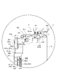
本発明の一実施形態であるパチンコ機1について、図面を参照して詳細に説明する。まず、図1~図13を参照して本実施形態のパチンコ機1の全体構成について説明する。図1は本発明の一実施形態であるパチンコ機の正面図である。図2はパチンコ機の右側面図であり、図3はパチンコ機の左側面図であり、図4はパチンコ機の背面図である。図5はパチンコ機を右前から見た斜視図であり、図6はパチンコ機を左前から見た斜視図であり、図7はパチンコ機を後ろから見た斜視図である。図8は演出操作ユニットの押圧操作部が上昇位置の時のパチンコ機の正面図であり、図9は演出操作ユニットの押圧操作部が上昇位置の時のパチンコ機を右前から見た斜視図である。また、図10、図11は、本体枠から扉枠を開放させると共に、外枠から本体枠を開放させた状態で前から見たパチンコ機の斜視図である。図12はパチンコ機を扉枠、遊技盤、本体枠、及び外枠に分解して前から見た分解斜視図であり、図13はパチンコ機を扉枠、遊技盤、本体枠、及び外枠に分解して後ろから見た分解斜視図である。
[1. Overall structure of pachinko machine]
The pachinko machine 1 according to the embodiment of the present invention will be described in detail with reference to the drawings. First, the overall configuration of the pachinko machine 1 of the present embodiment will be described with reference to FIGS. 1 to 13. FIG. 1 is a front view of a pachinko machine according to an embodiment of the present invention. FIG. 2 is a right side view of the pachinko machine, FIG. 3 is a left side view of the pachinko machine, and FIG. 4 is a rear view of the pachinko machine. FIG. 5 is a perspective view of the pachinko machine viewed from the front right, FIG. 6 is a perspective view of the pachinko machine viewed from the front left, and FIG. 7 is a perspective view of the pachinko machine viewed from the back. FIG. 8 is a front view of the pachinko machine when the pressing operation unit of the staging operation unit is in the raised position, and FIG. 9 is a perspective view of the pachinko machine when the pressing operation unit of the staging operation unit is in the raised position. be. 10 and 11 are perspective views of the pachinko machine viewed from the front with the door frame opened from the main body frame and the main body frame opened from the outer frame. FIG. 12 is an exploded perspective view of the pachinko machine disassembled into a door frame, a game board, a main body frame, and an outer frame, and FIG. 13 is an exploded perspective view of the pachinko machine as a door frame, a game board, a main body frame, and an outer frame. It is an exploded perspective view seen from the back after being disassembled into.
本実施形態のパチンコ機1は、遊技ホールの島設備(図示しない)に設置される枠状の外枠2と、外枠2の前面を開閉可能に閉鎖する扉枠3と、扉枠3を開閉可能に支持していると共に外枠2に開閉可能に取付けられている本体枠4と、本体枠4に前側から着脱可能に取付けられると共に扉枠3を通して遊技者側から視認可能とされ遊技者によって遊技球B(図106を参照)が打込まれる遊技領域5aを有した遊技盤5と、を備えている。
The pachinko machine 1 of the present embodiment includes a frame-shaped outer frame 2 installed in an island facility (not shown) of a game hall, a door frame 3 for opening and closing the front surface of the outer frame 2, and a door frame 3. The main body frame 4 which is openable and closable and is attached to the outer frame 2 so as to be openable and closable, and the main body frame 4 which is detachably attached from the front side and is visible from the player side through the door frame 3. It includes a game board 5 having a game area 5a into which a game ball B (see FIG. 106) is hit.
外枠2は、正面視の形状が上下に延びた四角形の枠に形成されている。外枠2は、左右に離間しており上下に延びている外枠左組立体10及び外枠右組立体20と、外枠左組立体10及び外枠右組立体20の上端同士を連結している外枠上部材30と、外枠左組立体10及び外枠右組立体20の下端同士を連結している外枠下組立体40と、外枠上部材30の上面左端に取付けられている外枠上ヒンジ組立体50と、外枠左組立体10の右側面下部と外枠下組立体40の上面左端に取付けられている外枠下ヒンジ部材60と、を備えている。
The outer frame 2 is formed in a quadrangular frame having a front view extending vertically. The outer frame 2 connects the outer frame left assembly 10 and the outer frame right assembly 20 which are separated from each other to the left and right and extend vertically, and the upper ends of the outer frame left assembly 10 and the outer frame right assembly 20. The outer frame upper member 30 is attached to the outer frame lower assembly 40 connecting the lower ends of the outer frame left assembly 10 and the outer frame right assembly 20, and the upper left end of the outer frame upper member 30. The outer frame upper hinge assembly 50 and the outer frame lower hinge member 60 attached to the lower right side of the outer frame left assembly 10 and the upper left end of the outer frame lower assembly 40 are provided.
外枠2は、パチンコ機1が設置される遊技ホールの島設備に取付けられ、外枠上ヒンジ組立体50と外枠下ヒンジ部材60とによって、本体枠4の本体枠上ヒンジ部材510と本体枠下ヒンジ組立体520とを同軸上で回転可能に支持して、本体枠4を正面視左側を中心にして前方へ開閉可能に取付けるためのものである。
The outer frame 2 is attached to the island equipment of the game hall where the pachinko machine 1 is installed, and the hinge member 510 on the main body frame of the main body frame 4 and the main body are formed by the hinge assembly 50 on the outer frame and the hinge member 60 below the outer frame. The hinge under-frame hinge assembly 520 is rotatably supported on the same axis, and the main body frame 4 is mounted so as to be openable and closable forward with the left side of the front view as the center.
また、扉枠3は、本体枠4を閉じた時に、外枠下組立体40が、本体枠4における基板ユニット620のスピーカユニット620aと協働して、本体枠スピーカ622のエンクロージャ624の一部を形成し、本体枠スピーカ622の後方へ出力されたサウンドを、位相反転させて前方へ放射することで、より重低音のサウンドを遊技者に聴かせることができるものである。
Further, in the door frame 3, when the main body frame 4 is closed, the outer frame lower assembly 40 cooperates with the speaker unit 620a of the board unit 620 in the main body frame 4 to be a part of the enclosure 624 of the main body frame speaker 622. Is formed, and the sound output to the rear of the main body frame speaker 622 is phase-inverted and radiated to the front, so that the player can hear a deeper bass sound.
扉枠3は、遊技球Bが打込まれる遊技盤5の遊技領域5aを前側から視認可能に閉鎖し、遊技領域5a内に打込むための遊技球Bを貯留すると共に、貯留している遊技球Bを遊技領域5a内へ打込むために遊技者が操作するハンドル182を備えているものである。また、扉枠3は、パチンコ機1の前面全体を装飾するものである。
The door frame 3 visibly closes the game area 5a of the game board 5 into which the game ball B is driven, stores the game ball B for driving into the game area 5a, and stores the stored game. It is provided with a handle 182 operated by a player to drive the ball B into the game area 5a. Further, the door frame 3 decorates the entire front surface of the pachinko machine 1.
また、扉枠3は、ハンドル182とは別に遊技者が操作可能な演出操作部301を備えており、遊技者参加型演出が実行された際に、遊技者が演出操作部301を操作することで遊技者が演出に参加できるようになり、遊技球Bによる遊技に加えて、演出操作部301の操作によっても遊技者を楽しませることができるようにしている。
Further, the door frame 3 is provided with an effect operation unit 301 that can be operated by the player separately from the handle 182, and the player operates the effect operation unit 301 when the player participation type effect is executed. The player can participate in the production, and the player can be entertained by operating the production operation unit 301 in addition to the game by the game ball B.
本体枠4は、後部が外枠2の枠内に挿入可能とされると共に遊技盤5の外周を支持可能とされた枠状の本体枠ベースユニット500と、本体枠4を外枠2に対して開閉可能に取付けると共に扉枠3を開閉可能に取付けるための本体枠上ヒンジ部材510及び本体枠下ヒンジ組立体520と、本体枠ベースユニット500を補強している金属製の本体枠補強フレーム530と、遊技盤5の遊技領域5a内に遊技球Bを打込むための球発射装置540と、遊技ホールの島設備から供給される遊技球Bを受取る払出ベースユニット550と、払出ベースユニット550で受取った遊技球Bを遊技者側へ払出すための払出ユニット560と、電源基板630や払出制御基板633を有している基板ユニット620と、本体枠ベース501に取付けられた遊技盤5の後側を覆う裏カバー640と、外枠2と本体枠4、及び扉枠3と本体枠4の間を施錠する施錠ユニット650と、を備えている。
The main body frame 4 has a frame-shaped main body frame base unit 500 having a rear portion that can be inserted into the frame of the outer frame 2 and can support the outer periphery of the game board 5, and the main body frame 4 with respect to the outer frame 2. The main body frame upper hinge member 510 and the main body frame lower hinge assembly 520 for opening and closing the door frame 3 and the metal main body frame reinforcement frame 530 that reinforces the main body frame base unit 500. A ball launching device 540 for driving the game ball B into the game area 5a of the game board 5, a payout base unit 550 for receiving the game ball B supplied from the island equipment of the game hall, and a payout base unit 550. After the payout unit 560 for paying out the received game ball B to the player side, the board unit 620 having the power supply board 630 and the payout control board 633, and the game board 5 attached to the main body frame base 501. It includes a back cover 640 that covers the side, an outer frame 2 and a main body frame 4, and a locking unit 650 that locks between the door frame 3 and the main body frame 4.
本体枠4は、遊技球Bを打込むことで遊技が行われる遊技領域5aを有した遊技盤5を保持すると共に、遊技球Bを遊技者側へ払出したり、遊技に使用された遊技球Bをパチンコ機1の後方(遊技ホールの島設備側)へ排出したり、するためのものである。本体枠4は、前方が開放された箱状に形成されており、内部に前方から遊技盤5が着脱可能に収容される。また、本体枠4は、正面左辺側前端の上下において、遊技ホールの島設備に取付けられる枠状の外枠2に開閉可能に取付けられると共に、開放された前面側が閉鎖されるように扉枠3が開閉可能に取付けられる。
The main body frame 4 holds a game board 5 having a game area 5a in which a game is played by hitting the game ball B, and at the same time, pays out the game ball B to the player side or uses the game ball B for the game. Is for discharging to the rear of the pachinko machine 1 (on the island equipment side of the game hall). The main body frame 4 is formed in a box shape with an open front, and the game board 5 is detachably housed inside from the front. Further, the main body frame 4 is openably attached to the frame-shaped outer frame 2 attached to the island equipment of the game hall above and below the front end on the left side of the front side, and the door frame 3 is closed so that the opened front side is closed. Can be installed so that it can be opened and closed.
遊技盤5は、遊技者の操作によって遊技球Bが行われる遊技領域5aと、遊技領域5aの外周を区画し外形が正面視略四角形状とされた前構成部材1000と、前構成部材1000の後側に取付けられており遊技領域5aの後端を区画する板状の遊技パネル1100と、遊技パネル1100の後側下部に取付けられている基板ホルダ1200と、基板ホルダ1200の後面に取付けられており主制御基板1310を有している主制御ユニット1300と、主制御基板1310からの制御信号に基づいて遊技状況を表示する機能表示ユニット1400と、正面視において遊技領域5aの中央に配置されており所定の演出画像を表示可能な演出表示装置1600と、遊技パネル1100の後側であって演出表示装置1600の裏面側に配置されている透明基板ボックスとして構成される周辺制御ユニット1500と、遊技パネル1100の前面に取付けられる表ユニット2000と、遊技パネル1100の後面に取付けられる裏ユニット3000と、を備えている。裏ユニット3000には、遊技状態に応じて可動演出や発光演出を行うことが可能な各種の演出ユニットを備えている。
The game board 5 includes a game area 5a in which a game ball B is played by a player's operation, a front component 1000 that divides the outer periphery of the game area 5a and has a substantially square shape in front view, and a front component 1000. A plate-shaped game panel 1100 that is attached to the rear side and divides the rear end of the game area 5a, a board holder 1200 that is attached to the lower part of the rear side of the game panel 1100, and a board holder 1200 that is attached to the rear surface of the board holder 1200. The main control unit 1300 having the cage main control board 1310, the function display unit 1400 that displays the game status based on the control signal from the main control board 1310, and the function display unit 1400 arranged in the center of the game area 5a in the front view. A staging display device 1600 capable of displaying a predetermined staging image, a peripheral control unit 1500 configured as a transparent board box arranged on the rear side of the game panel 1100 and on the back side of the staging display device 1600, and a game. It includes a front unit 2000 attached to the front surface of the panel 1100 and a back unit 3000 attached to the rear surface of the game panel 1100. The back unit 3000 is provided with various effect units capable of performing a movable effect and a light emitting effect according to the game state.
遊技盤5の遊技領域5a内には、遊技球Bと当接し所定のゲージ配列で植設されている複数の障害釘と、遊技球Bの受入れ又は通過により遊技者に対して所定の特典(例えば、所定数の遊技球Bの払出し)を付与する一般入賞口2001、第一始動口2002、ゲート部2003、第二始動口2004、第一大入賞口2005及び第二大入賞口2006と、を備えている。障害釘は、遊技パネル1100の前面に植設されている。一般入賞口2001、第一始動口2002、ゲート部2003、第二始動口2004、第一大入賞口2005及び第二大入賞口2006は、表ユニット2000に備えられている。
In the game area 5a of the game board 5, a plurality of obstacle nails that are in contact with the game ball B and are planted in a predetermined gauge arrangement, and a predetermined privilege for the player by accepting or passing the game ball B ( For example, a general winning opening 2001, a first starting opening 2002, a gate portion 2003, a second starting opening 2004, a first major winning opening 2005, and a second major winning opening 2006, which give out a predetermined number of game balls B). It is equipped with. Obstacle nails are planted in front of the game panel 1100. The general winning opening 2001, the first starting opening 2002, the gate portion 2003, the second starting opening 2004, the first large winning opening 2005, and the second large winning opening 2006 are provided in the table unit 2000.
遊技盤5の遊技領域5a内には、遊技者がハンドルユニット180のハンドル182を操作することで、遊技球Bを打込むことができる。これにより、遊技球Bが、遊技領域5a内の一般入賞口2001、第一始動口2002、ゲート部2003、第二始動口2004、第一大入賞口2005及び第二大入賞口2006等に、受入れられたり通過したりするように、遊技者に対してハンドル182の打込操作を楽しませることができる。
A player can drive the game ball B into the game area 5a of the game board 5 by operating the handle 182 of the handle unit 180. As a result, the game ball B is placed in the general winning opening 2001, the first starting opening 2002, the gate portion 2003, the second starting opening 2004, the first major winning opening 2005, the second major winning opening 2006, etc. in the game area 5a. It is possible to entertain the player with the driving operation of the handle 182 so as to be accepted or passed.
また、遊技盤5は、遊技領域5a内に遊技球Bを打込むことで変化する遊技状態に応じて、演出表示装置1600に所定の演出画像を表示させたり、表演出ユニット2600、下部可動演出ユニット3100、上部後可動演出ユニット3200、及び上部前可動演出ユニット3300等により可動演出や発光演出を行わせたりして、遊技者を楽しませることができる。
Further, the game board 5 displays a predetermined effect image on the effect display device 1600, or displays a predetermined effect image on the effect display device 1600, or displays the table effect unit 2600 and the lower movable effect according to the game state that changes by driving the game ball B into the game area 5a. The player can be entertained by performing a movable effect or a light emitting effect by the unit 3100, the upper rear movable effect unit 3200, the upper front movable effect unit 3300, or the like.
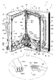
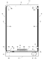
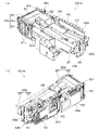
[2.外枠の全体構成]
パチンコ機1の外枠2について、図14~図19を参照して説明する。図14はパチンコ機における外枠の正面図であり、図15は外枠の背面図であり、図15は外枠の右側面図である。また、図17は外枠を前から見た斜視図であり、図18は外枠を後ろから見た斜視図である。図19は、外枠を主な部材毎に分解して前から見た分解斜視図である。外枠2は、遊技ホール等のパチンコ機1が設置される島設備(図示は省略)に取付けられるものである。外枠2は、正面視の形状が上下に延びた四角形の枠に形成されている。
[2. Overall composition of the outer frame]
The outer frame 2 of the pachinko machine 1 will be described with reference to FIGS. 14 to 19. 14 is a front view of the outer frame of the pachinko machine, FIG. 15 is a rear view of the outer frame, and FIG. 15 is a right side view of the outer frame. Further, FIG. 17 is a perspective view of the outer frame viewed from the front, and FIG. 18 is a perspective view of the outer frame viewed from the back. FIG. 19 is an exploded perspective view of the outer frame disassembled for each main member and viewed from the front. The outer frame 2 is attached to an island facility (not shown) in which a pachinko machine 1 such as a game hall is installed. The outer frame 2 is formed in a quadrangular frame having a front view extending vertically.
外枠2は、図示するように、左右に離間しており上下に延びている外枠左組立体10及び外枠右組立体20と、外枠左組立体10及び外枠右組立体20の上端同士を連結している外枠上部材30と、外枠左組立体10及び外枠右組立体20の下端同士を連結している外枠下組立体40と、外枠上部材30の上面左端に取付けられている外枠上ヒンジ組立体50と、外枠左組立体10の右側面下部と外枠下組立体40の上面左端に取付けられている外枠下ヒンジ部材60と、を備えている。
As shown in the figure, the outer frame 2 includes an outer frame left assembly 10 and an outer frame right assembly 20 which are separated from each other to the left and right and extend vertically, and an outer frame left assembly 10 and an outer frame right assembly 20. The outer frame upper member 30 connecting the upper ends, the outer frame lower assembly 40 connecting the lower ends of the outer frame left assembly 10 and the outer frame right assembly 20, and the upper surface of the outer frame upper member 30. The outer frame upper hinge assembly 50 attached to the left end, and the outer frame lower hinge member 60 attached to the lower right side of the outer frame left assembly 10 and the upper left end of the outer frame lower assembly 40 are provided. ing.
外枠2は、本体枠4を閉じた時に、外枠下組立体40が、本体枠4における基板ユニット620のスピーカユニット620aと協働して、本体枠スピーカ622のエンクロージャ624の一部を形成していると共に、本体枠スピーカ622の後方へ出力されたサウンドを、位相反転させて前方へ放射することができるものである。
In the outer frame 2, when the main body frame 4 is closed, the outer frame lower assembly 40 cooperates with the speaker unit 620a of the board unit 620 in the main body frame 4 to form a part of the enclosure 624 of the main body frame speaker 622. At the same time, the sound output to the rear of the main body frame speaker 622 can be phase-inverted and radiated to the front.
外枠2は、外枠上ヒンジ組立体50が、本体枠4の本体枠上ヒンジ部材510を着脱可能に支持することができる。外枠2は、外枠上ヒンジ組立体50と外枠下ヒンジ部材60とによって、本体枠4の本体枠上ヒンジ部材510と本体枠下ヒンジ組立体520とを同軸上で回転可能に支持することができ、本体枠4を正面視左側を中心にして前方へ開閉可能に取付けることができる。
In the outer frame 2, the hinge assembly 50 on the outer frame can detachably support the hinge member 510 on the main body frame of the main body frame 4. The outer frame 2 coaxially and rotatably supports the main body frame upper hinge member 510 and the main body frame lower hinge assembly 520 of the main body frame 4 by the outer frame upper hinge assembly 50 and the outer frame lower hinge member 60. The main body frame 4 can be attached so as to be openable and closable forward with the left side of the front view as the center.
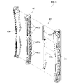
[2-1.外枠左組立体及び外枠右組立体]
外枠2の外枠左組立体10及び外枠右組立体20について、主に図20を参照して詳細に説明する。図20は、外枠の外枠左組立体及び外枠右組立体をそれぞれ分解して前から見た分解斜視図である。外枠2の外枠左組立体10及び外枠右組立体20は、それぞれが上下に延びており、互いに左右に離間して配置されている。外枠左組立体10及び外枠右組立体20は、本体枠4の本体枠上ヒンジ部材510及び本体枠下ヒンジ組立体520を同軸上で回転可能に支持して、外枠2に対して本体枠4を開閉可能に取付けるためのものである。
[2-1. Outer frame left assembly and outer frame right assembly]
The outer frame left assembly 10 and the outer frame right assembly 20 of the outer frame 2 will be described in detail mainly with reference to FIG. FIG. 20 is an exploded perspective view of the outer frame left assembly and the outer frame right assembly of the outer frame disassembled and viewed from the front. The outer frame left assembly 10 and the outer frame right assembly 20 of the outer frame 2 extend vertically, and are arranged so as to be separated from each other on the left and right sides. The outer frame left assembly 10 and the outer frame right assembly 20 coaxially and rotatably support the main body frame upper hinge member 510 and the main body frame lower hinge assembly 520 of the main body frame 4 with respect to the outer frame 2. This is for mounting the main body frame 4 so that it can be opened and closed.
まず、外枠左組立体10は、前後方向が一定の幅(奥行)で上下に延びている外枠左部材11と、外枠左部材11の右側面上端に取付けられている左上連結部材12と、外枠左部材11の右側面下端に取付けられている左下連結部材13と、を備えている。
First, in the outer frame left assembly 10, the outer frame left member 11 extending vertically with a constant width (depth) in the front-rear direction and the upper left connecting member 12 attached to the upper end of the right side surface of the outer frame left member 11 And a lower left connecting member 13 attached to the lower end of the right side surface of the outer frame left member 11.
外枠左部材11は、一定の断面形状で上下に延びており、アルミ合金の押出型材によって形成されている。外枠左部材11は、左側面における前後方向を三等分したうちの後側の部位において平坦状に右方へ窪んでいる凹部11aと、右側面における凹部11aとは反対側の部位から右方へ膨出している膨出部11bと、膨出部11bを上下に貫通している空洞部11cと、を備えている。外枠左部材11は、凹部11aや膨出部11bによって、強度・剛性が高められていると共に、空洞部11cによって、重量が軽減されている。
The outer frame left member 11 extends vertically with a constant cross-sectional shape, and is formed of an aluminum alloy extruded mold material. The outer frame left member 11 has a concave portion 11a that is flatly recessed to the right in the rear portion of the left side surface divided into three equal parts in the front-rear direction, and a portion on the right side surface that is opposite to the concave portion 11a to the right. It includes a bulging portion 11b that bulges toward the direction and a hollow portion 11c that vertically penetrates the bulging portion 11b. The strength and rigidity of the outer frame left member 11 is increased by the concave portion 11a and the bulging portion 11b, and the weight is reduced by the hollow portion 11c.
また、外枠左部材11は、左右両側面において、上下に延びた複数の溝が形成されている。左側面の複数の溝は、V字状に形成されており、右側面の複数の溝は、半円形状に形成されている。外枠左部材11は、後述する外枠右組立体20の外枠右部材21と左右対称形状に形成されている。
Further, the outer frame left member 11 is formed with a plurality of grooves extending vertically on both the left and right sides. The plurality of grooves on the left side surface are formed in a V shape, and the plurality of grooves on the right side surface are formed in a semicircular shape. The outer frame left member 11 is formed in a symmetrical shape with the outer frame right member 21 of the outer frame right assembly 20 described later.
左上連結部材12は、外枠左部材11の上端と外枠上部材30の左端とを連結するためのものである。左上連結部材12は、水平に延びた平板状の水平固定部12aと、水平固定部12aの左辺における前後方向の中間から上方へ延出している平板状の上横固定部12bと、水平固定部12aの左辺における上横固定部12bの前後両側から下方へ延出している平板状の一対の下横固定部12cと、を備えている。左上連結部材12は、平板状の金属板を屈曲させて形成されている。
The upper left connecting member 12 is for connecting the upper end of the outer frame left member 11 and the left end of the outer frame upper member 30. The upper left connecting member 12 includes a horizontally extending flat plate-shaped horizontal fixing portion 12a, a flat plate-shaped upper-horizontal fixing portion 12b extending upward from the middle in the front-rear direction on the left side of the horizontal fixing portion 12a, and a horizontal fixing portion. It is provided with a pair of flat plate-shaped lower horizontal fixing portions 12c extending downward from both front and rear sides of the upper horizontal fixing portion 12b on the left side of 12a. The upper left connecting member 12 is formed by bending a flat metal plate.
左上連結部材12は、後側の下横固定部12cを外枠左部材11の空洞部11c内に挿入させると共に、水平固定部12aを外枠左部材11の上端に当接させ、更に、前側及び後側の下横固定部12cを外枠左部材11の右側面に当接させた状態で、外枠左部材11の左側面の外側から下横固定部12cにビスを捩じ込むことで、外枠左部材11に取付けられる。また、左上連結部材12は、水平固定部12aを外枠上部材30の左端側の下面に当接させると共に、上横固定部12bを外枠上部材30の左側面の切欠部30a内に挿入させた状態で、水平固定部12a及び上横固定部12bを通して外枠上部材30にビスを捩じ込むことで、外枠上部材30に取付けられる。
In the upper left connecting member 12, the lower horizontal fixing portion 12c on the rear side is inserted into the cavity portion 11c of the outer frame left member 11, the horizontal fixing portion 12a is brought into contact with the upper end of the outer frame left member 11, and further, the front side is further formed. In a state where the lower horizontal fixing portion 12c on the rear side is in contact with the right side surface of the outer frame left member 11, a screw is screwed into the lower horizontal fixing portion 12c from the outside of the left side surface of the outer frame left member 11. , Attached to the outer frame left member 11. Further, in the upper left connecting member 12, the horizontal fixing portion 12a is brought into contact with the lower surface on the left end side of the outer frame upper member 30, and the upper horizontal fixing portion 12b is inserted into the notch 30a on the left side surface of the outer frame upper member 30. In this state, it is attached to the outer frame upper member 30 by screwing a screw into the outer frame upper member 30 through the horizontal fixing portion 12a and the upper horizontal fixing portion 12b.
左下連結部材13は、外枠左部材11の下端と外枠下組立体40(外枠下部材41)の左端とを連結するためのものである。左下連結部材13は、水平に延びた平板状の水平固定部13aと、水平固定部13aの左辺から上方へ延出していると共に水平固定部13aよりも後方へ延出している平板状の上横固定部13bと、上横固定部13bの下辺における水平固定部よりも後側の部位から下方へ延出している平板状の下横固定部13cと、上横固定部13bの後辺から右方へ短く延出している平板状の当接部13dと、を備えている。左下連結部材13は、平板状の金属板を屈曲させて形成されている。
The lower left connecting member 13 is for connecting the lower end of the outer frame left member 11 and the left end of the outer frame lower assembly 40 (outer frame lower member 41). The lower left connecting member 13 has a horizontally extending flat plate-shaped horizontal fixing portion 13a and a flat plate-shaped upper side extending upward from the left side of the horizontal fixing portion 13a and extending rearward from the horizontal fixing portion 13a. The fixed portion 13b, the flat plate-shaped lower lateral fixing portion 13c extending downward from the portion posterior to the horizontal fixing portion on the lower side of the upper lateral fixing portion 13b, and the upper lateral fixing portion 13b to the right from the rear side. It is provided with a flat plate-shaped contact portion 13d extending shortly to. The lower left connecting member 13 is formed by bending a flat metal plate.
左下連結部材13は、当接部13dの後面を外枠左部材11の膨出部11bの前面に当接させると共に、上横固定部13bの左側面を外枠左部材11の右側面に当接させ、水平固定部13aの下面を外枠左部材11の下端と一致させた状態で、外枠左部材11の左側面の外側から上横固定部13bにビスを捩じ込むことで、外枠左部材11に取付けられる。また、左下連結部材13は、水平固定部13aを外枠下部材41の左端側の上面に当接させると共に、下横固定部13cを外枠下部材41の左側面の切欠部41aに挿入させた状態で、水平固定部13a及び下横固定部13cを通して外枠下部材にビスを捩じ込むことで、外枠下部材41に取付けられる。
In the lower left connecting member 13, the rear surface of the contact portion 13d is brought into contact with the front surface of the bulging portion 11b of the outer frame left member 11, and the left surface of the upper horizontal fixing portion 13b is in contact with the right surface of the outer frame left member 11. With the lower surface of the horizontal fixing portion 13a in contact with the lower end of the outer frame left member 11, a screw is screwed into the upper horizontal fixing portion 13b from the outside of the left side surface of the outer frame left member 11 to the outside. It is attached to the frame left member 11. Further, in the lower left connecting member 13, the horizontal fixing portion 13a is brought into contact with the upper surface on the left end side of the outer frame lower member 41, and the lower horizontal fixing portion 13c is inserted into the notch portion 41a on the left side surface of the outer frame lower member 41. In this state, it is attached to the outer frame lower member 41 by screwing a screw into the outer frame lower member through the horizontal fixing portion 13a and the lower horizontal fixing portion 13c.
次に、外枠右組立体20は、前後方向が一定の幅(奥行)で上下に延びている外枠右部材21と、外枠右部材21の左側面上端に取付けられている右上連結部材22と、外枠右部材21の左側面下端に取付けられている右下連結部材23と、外枠右部材21の左側面上部に取付けられている上鉤掛部材24と、外枠右部材21の左側面下部に取付けられている下鉤掛部材25と、を備えている。
Next, in the outer frame right assembly 20, the outer frame right member 21 extending vertically with a certain width (depth) in the front-rear direction and the upper right connecting member attached to the upper end of the left side surface of the outer frame right member 21. 22, the lower right connecting member 23 attached to the lower end of the left side surface of the outer frame right member 21, the upper hooking member 24 attached to the upper part of the left side surface of the outer frame right member 21, and the outer frame right member 21. It is provided with a lower hook member 25 attached to the lower part of the left side surface.
外枠右部材21は、一定の断面形状で上下に延びており、アルミ合金の押出型材によって形成されている。外枠右部材21は、右側面における前後方向を三等分したうちの後側の部位において平坦状に左方へ窪んでいる凹部21aと、左側面における凹部21aとは反対側の部位から左方へ膨出している膨出部21bと、膨出部21bを上下に貫通している空洞部21cと、を備えている。外枠右部材21は、凹部21aや膨出部21bによって、強度・剛性が高められていると共に、空洞部21cによって、重量が軽減されている。
The outer frame right member 21 extends vertically with a constant cross-sectional shape, and is formed of an aluminum alloy extruded mold material. The outer frame right member 21 has a concave portion 21a that is flatly recessed to the left in the rear portion of the right side surface divided into three equal parts in the front-rear direction, and a portion on the left side surface that is opposite to the concave portion 21a to the left. It includes a bulging portion 21b that bulges toward the direction and a hollow portion 21c that vertically penetrates the bulging portion 21b. The strength and rigidity of the outer frame right member 21 is increased by the concave portion 21a and the bulging portion 21b, and the weight is reduced by the hollow portion 21c.
また、外枠右部材21は、左右両側面において、上下に延びた複数の溝が形成されている。右側面の複数の溝は、V字状に形成されており、左側面の複数の溝は、半円形状に形成されている。外枠右部材21は、外枠左組立体10の外枠左部材11と左右対称形状に形成されている。
Further, the outer frame right member 21 is formed with a plurality of grooves extending vertically on both the left and right sides. The plurality of grooves on the right side surface are formed in a V shape, and the plurality of grooves on the left side surface are formed in a semicircular shape. The outer frame right member 21 is formed in a symmetrical shape with the outer frame left member 11 of the outer frame left assembly 10.
右上連結部材22は、外枠右部材21の上端と外枠上部材30の右端とを連結するためのものである。右上連結部材22は、水平に延びた平板状の水平固定部22aと、水平固定部22aの右辺における前後方向の中間から上方へ延出している平板状の上横固定部22bと、水平固定部22aの右辺における上横固定部22bの前後両側から下方へ延出している平板状の一対の下横固定部22cと、を備えている。右上連結部材22は、平板状の金属板を屈曲させて形成されている。
The upper right connecting member 22 is for connecting the upper end of the outer frame right member 21 and the right end of the outer frame upper member 30. The upper right connecting member 22 includes a horizontally extending flat plate-shaped horizontal fixing portion 22a, a flat plate-shaped upper-horizontal fixing portion 22b extending upward from the middle in the front-rear direction on the right side of the horizontal fixing portion 22a, and a horizontal fixing portion. It is provided with a pair of flat plate-shaped lower horizontal fixing portions 22c extending downward from both front and rear sides of the upper horizontal fixing portion 22b on the right side of 22a. The upper right connecting member 22 is formed by bending a flat metal plate.
右上連結部材22は、後側の下横固定部22cを外枠右部材21の空洞部21c内に挿入させると共に、水平固定部22aを外枠右部材21の上端に当接させ、更に、前側及び後側の下横固定部22cを外枠右部材21の左側面に当接させた状態で、外枠右部材21の右側面の外側から下横固定部22cにビスを捩じ込むことで、外枠右部材21に取付けられる。また、右上連結部材22は、水平固定部22aを外枠上部材30の右端側の下面に当接させると共に、上横固定部22bを外枠上部材30の右側面の切欠部30a内に挿入させた状態で、水平固定部22a及び上横固定部22bを通して外枠上部材30にビスを捩じ込むことで、外枠上部材30に取付けられる。
In the upper right connecting member 22, the lower horizontal fixing portion 22c on the rear side is inserted into the hollow portion 21c of the outer frame right member 21, the horizontal fixing portion 22a is brought into contact with the upper end of the outer frame right member 21, and further, the front side. In a state where the lower horizontal fixing portion 22c on the rear side is in contact with the left side surface of the outer frame right member 21, a screw is screwed into the lower horizontal fixing portion 22c from the outside of the right side surface of the outer frame right member 21. , Attached to the outer frame right member 21. Further, in the upper right connecting member 22, the horizontal fixing portion 22a is brought into contact with the lower surface on the right end side of the outer frame upper member 30, and the upper horizontal fixing portion 22b is inserted into the notch 30a on the right side surface of the outer frame upper member 30. In this state, it is attached to the outer frame upper member 30 by screwing a screw into the outer frame upper member 30 through the horizontal fixing portion 22a and the upper horizontal fixing portion 22b.
右下連結部材23は、外枠右部材21の下端と外枠下組立体40(外枠下部材41)の右端とを連結するためのものである。右下連結部材23は、水平に延びた平板状の水平固定部23aと、水平固定部23aの右辺から上方へ延出していると共に水平固定部23aよりも後方へ延出している平板状の上横固定部23bと、上横固定部23bの下辺における水平固定部よりも後側の部位から下方へ延出している平板状の下横固定部23cと、上横固定部23bの後辺から左方へ短く延出している平板状の当接部23dと、を備えている。右下連結部材23は、平板状の金属板を屈曲させて形成されている。
The lower right connecting member 23 is for connecting the lower end of the outer frame right member 21 and the right end of the outer frame lower assembly 40 (outer frame lower member 41). The lower right connecting member 23 has a horizontally extending flat plate-shaped horizontal fixing portion 23a and a flat plate-shaped upper portion extending upward from the right side of the horizontal fixing portion 23a and extending rearward from the horizontal fixing portion 23a. The horizontal fixing portion 23b, the flat plate-shaped lower horizontal fixing portion 23c extending downward from the portion posterior to the horizontal fixing portion on the lower side of the upper horizontal fixing portion 23b, and the left from the rear side of the upper horizontal fixing portion 23b. It is provided with a flat plate-shaped contact portion 23d that extends shortly toward the direction. The lower right connecting member 23 is formed by bending a flat metal plate.
右下連結部材23は、当接部23dの後面を外枠右部材21の膨出部21bの前面に当接させると共に、上横固定部23bの右側面を外枠右部材21の左側面に当接させ、水平固定部23aの下面を外枠右部材21の下端と一致させた状態で、外枠右部材21の右側面の外側から上横固定部23bにビスを捩じ込むことで、外枠右部材21に取付けられる。また、右下連結部材23は、水平固定部23aを外枠下部材41の右端側の上面に当接させると共に、下横固定部23cを外枠下部材41の右側面の切欠部41aに挿入させた状態で、水平固定部23a及び下横固定部23cを通して外枠下部材にビスを捩じ込むことで、外枠下部材41に取付けられる。
In the lower right connecting member 23, the rear surface of the contact portion 23d is brought into contact with the front surface of the bulging portion 21b of the outer frame right member 21, and the right surface of the upper horizontal fixing portion 23b is attached to the left surface of the outer frame right member 21. By abutting and in a state where the lower surface of the horizontal fixing portion 23a is aligned with the lower end of the outer frame right member 21, a screw is screwed into the upper horizontal fixing portion 23b from the outside of the right side surface of the outer frame right member 21. It is attached to the outer frame right member 21. Further, in the lower right connecting member 23, the horizontal fixing portion 23a is brought into contact with the upper surface on the right end side of the outer frame lower member 41, and the lower horizontal fixing portion 23c is inserted into the notch portion 41a on the right side surface of the outer frame lower member 41. In this state, it is attached to the outer frame lower member 41 by screwing a screw into the outer frame lower member through the horizontal fixing portion 23a and the lower horizontal fixing portion 23c.
上鉤掛部材24及び下鉤掛部材25は、後述する本体枠4における施錠ユニット650の外枠用鉤653が掛止されるものである。上鉤掛部材24は、前後方向に一定の幅で上下に延びており外枠右部材21の左側面に取付けられる平板状の取付部24aと、取付部24aの前辺から左方へ延出しており上側の外枠用鉤653が掛止される平板状の掛止片部24bと、を備えている。
The upper hook hook member 24 and the lower hook hook member 25 are for hooking the outer frame hook 653 of the locking unit 650 in the main body frame 4, which will be described later. The upper hook member 24 extends vertically with a certain width in the front-rear direction, and extends to the left from the front side of the flat plate-shaped mounting portion 24a mounted on the left side surface of the outer frame right member 21 and the mounting portion 24a. It is provided with a flat plate-shaped hook piece portion 24b on which the hook 653 for the outer frame on the upper side of the cage is hooked.
下鉤掛部材25は、前後方向に一定の幅で上下に延びており外枠右部材21の左側面に取付けられる平板状の取付部25aと、取付部25aの前辺から左方へ延出しており下側の外枠用鉤653が掛止される平板状の掛止片部25bと、掛止片部25bを前後に貫通しており下側の外枠用鉤653が挿通可能な挿通口25cと、を備えている。
The lower hook member 25 extends vertically with a certain width in the front-rear direction, and has a flat plate-shaped mounting portion 25a mounted on the left side surface of the outer frame right member 21 and a flat plate-shaped mounting portion 25a extending from the front side of the mounting portion 25a to the left. A flat plate-shaped hook piece portion 25b on which the lower outer frame hook 653 is hooked and an insertion through which the lower outer frame hook 653 can be inserted through the hook piece portion 25b in the front-rear direction. It has a mouth 25c and.
[2-2.外枠上部材]
外枠2の外枠上部材30について、主に図19を参照して詳細に説明する。外枠上部材30は、左右に離間している外枠左組立体10及び外枠右組立体20の上端同士を連結するためのものである。外枠上部材30は、前後方向の幅が、外枠左部材11及び外枠右部材21の前後方向と略同じ幅で、上下方向の厚さが一定で、左右方向に延びており、木材によって形成されている。外枠上部材30は、左右方向の長さが、後述する外枠下組立体40の外枠下部材41の左右方向の長さと同じに形成されている。
[2-2. Outer frame upper member]
The outer frame upper member 30 of the outer frame 2 will be described in detail mainly with reference to FIG. The outer frame upper member 30 is for connecting the upper ends of the outer frame left assembly 10 and the outer frame right assembly 20 that are separated from each other to the left and right. The width of the outer frame upper member 30 in the front-rear direction is substantially the same as the width in the front-rear direction of the outer frame left member 11 and the outer frame right member 21, the thickness in the vertical direction is constant, and the width extends in the left-right direction. Is formed by. The outer frame upper member 30 is formed so that the length in the left-right direction is the same as the length in the left-right direction of the outer frame lower member 41 of the outer frame lower assembly 40 described later.
外枠上部材30は、左右両側面における前後方向の中央において、上下に貫通した状態で左右方向中央側へそれぞれ窪んでいる切欠部30aを備えている。これら左右両端の切欠部30aには、左上連結部材12の上横固定部12b及び右上連結部材22の上横固定部22bがそれぞれ挿入された状態で取付けられる。
The outer frame upper member 30 is provided with a notch 30a that is recessed toward the center in the left-right direction while penetrating vertically at the center in the front-rear direction on both the left and right sides. The upper lateral fixing portion 12b of the upper left connecting member 12 and the upper lateral fixing portion 22b of the upper right connecting member 22 are attached to the cutout portions 30a at both left and right ends in a state of being inserted.
また、外枠上部材30は、左側端部において、上面と前面が一般面よりも窪んだ取付段部30bを備えている。この取付段部30bには、後述する外枠上ヒンジ組立体50が取付けられる。
Further, the outer frame upper member 30 includes a mounting step portion 30b whose upper surface and front surface are recessed from the general surface at the left end portion. A hinge assembly 50 on an outer frame, which will be described later, is mounted on the mounting step portion 30b.
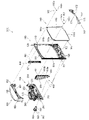
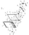
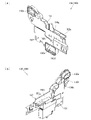
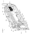
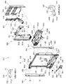
[2-3.外枠下組立体]
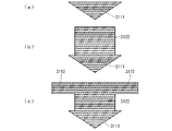
外枠2の外枠下組立体40について、主に図21を参照して詳細に説明する。図21は、外枠の外枠下組立体を分解して前から見た分解斜視図である。外枠下組立体40は、左右に離間している外枠左組立体10及び外枠右組立体20の下端同士を連結すると共に、パチンコ機1において扉枠3よりも下側を閉鎖して装飾するためのものである。
[2-3. Assembly under the outer frame]
The outer frame lower assembly 40 of the outer frame 2 will be described in detail mainly with reference to FIG. 21. FIG. 21 is an exploded perspective view of the outer frame lower assembly of the outer frame as viewed from the front by disassembling it. The outer frame lower assembly 40 connects the lower ends of the outer frame left assembly 10 and the outer frame right assembly 20 that are separated from each other to the left and right, and closes the lower side of the pachinko machine 1 below the door frame 3. It is for decoration.
外枠下組立体40は、左右に離間している外枠左組立体10及び外枠右組立体20の下端同士を連結しており左右に延びている外枠下部材41と、外枠下部材41の前方に配置されており外枠下部材41に沿って左右に延びていると共に後方が開放されている箱状の幕板前部材42と、幕板前部材42の後側に取付けられていると共に外枠下部材41の上面に取付けられており前方が開放されている左右に延びた箱状の幕板後部材43と、幕板後部材43の上面における左端に形成されている球噛防止機構44と、を備えている。
The outer frame lower assembly 40 has an outer frame lower member 41 that connects the lower ends of the outer frame left assembly 10 and the outer frame right assembly 20 that are separated to the left and right and extends to the left and right, and the outer frame lower assembly 40. A box-shaped front curtain plate member 42 that is arranged in front of the member 41 and extends to the left and right along the outer frame lower member 41 and is open at the rear, and is attached to the rear side of the front curtain plate member 42. A box-shaped rear curtain plate member 43 that is attached to the upper surface of the outer frame lower member 41 and has an open front, and a ball bite prevention formed on the left end of the upper surface of the curtain plate rear member 43. It is equipped with a mechanism 44.
外枠下部材41は、前後方向の幅が、外枠左部材11及び外枠右部材21の前後方向と略同じ幅で、上下方向の厚さが一定で、左右方向に延びており、木材によって形成されている。外枠下部材41は、左右方向の長さが、外枠上部材30の左右方向の長さと同じに形成されている。
The width of the outer frame lower member 41 in the front-rear direction is substantially the same as the width in the front-rear direction of the outer frame left member 11 and the outer frame right member 21, the thickness in the vertical direction is constant, and the width extends in the left-right direction. Is formed by. The outer frame lower member 41 is formed so that the length in the left-right direction is the same as the length in the left-right direction of the outer frame upper member 30.
外枠下部材41は、左右両側面における前後方向の中央において、上下に貫通した状態で左右方向中央側へそれぞれ窪んでいる切欠部41aを備えている。これら左右両端の切欠部41aには、左下連結部材13の下横固定部13c及び右下連結部材23の下横固定部23cがそれぞれ挿入された状態で取付けられる。これにより、外枠左部材11及び外枠右部材21の下端同士を連結することができる。
The outer frame lower member 41 is provided with a notch 41a that is recessed toward the center in the left-right direction while penetrating vertically at the center in the front-rear direction on both the left and right sides. The lower lateral fixing portion 13c of the lower left connecting member 13 and the lower lateral fixing portion 23c of the lower right connecting member 23 are attached to the cutout portions 41a at both left and right ends in a state of being inserted. Thereby, the lower ends of the outer frame left member 11 and the outer frame right member 21 can be connected to each other.
また、外枠下部材41は、上面から凹んでおり、幕板後部材43の下部が挿入される凹部41bを備えている。凹部41bは、左右に延びていると共に、前後方向中央の後ろ寄りの位置から前端側へ抜けている。この凹部41bにより、幕板前部材42及び幕板後部材43により形成される幕板内部空間40aの容積を可及的に広くしている。
Further, the outer frame lower member 41 is recessed from the upper surface, and has a recess 41b into which the lower portion of the curtain plate rear member 43 is inserted. The concave portion 41b extends to the left and right, and is removed from the position toward the rear in the center in the front-rear direction toward the front end side. The recess 41b makes the volume of the curtain plate internal space 40a formed by the curtain plate front member 42 and the curtain plate rear member 43 as wide as possible.
幕板前部材42は、左右方向の長さが外枠下部材41と同じ長さに延びており、高さに対して前後方向の奥行が短い横長の直方体状の箱状に形成されており、後側の全面が開放されている。幕板前部材42は、開放されている後側を、幕板後部材43によって閉鎖することで、幕板後部材43と協働して本体枠スピーカ622のエンクロージャ624の一部となる幕板内部空間40aを形成する。幕板前部材42は、右端付近の前面において、前後に貫通していると共に左右に延びている長孔状の開口部42aを備えている。
The curtain plate front member 42 has a length in the left-right direction extending to the same length as the outer frame lower member 41, and is formed in a horizontally long rectangular parallelepiped box shape having a short depth in the front-rear direction with respect to the height. The entire rear side is open. The curtain plate front member 42 is closed on the open rear side by the curtain plate rear member 43, so that the curtain plate front member 42 cooperates with the curtain plate rear member 43 to become a part of the enclosure 624 of the main body frame speaker 622. It forms a space 40a. The curtain plate front member 42 has an elongated hole-shaped opening 42a that penetrates back and forth and extends left and right on the front surface near the right end.
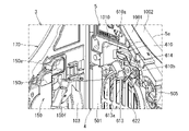
幕板後部材43は、左右方向の長さが外枠下部材41よりも若干短く延びており、前方が開放された箱状に形成されている。幕板後部材43は、前面に幕板前部材42を取付けることで、幕板前部材42と協働して本体枠スピーカ622のエンクロージャ624の一部となる幕板内部空間40aを形成する。幕板後部材43は、上面における左右方向中央部において、左右に延びていると共に上方へ突出しており幕板内部空間40aと連通している筒状の接続筒部43aを有している。接続筒部43aは、上端が、幕板後部材43の一般的な上面と一致している前端側から後方へ向かうほど上方へ位置するように傾斜している。本実施形態では、接続筒部43aの上端は、45度の角度で傾斜している。
The curtain plate rear member 43 has a length in the left-right direction slightly shorter than that of the outer frame lower member 41, and is formed in a box shape with an open front. By attaching the curtain plate front member 42 to the front surface of the curtain plate rear member 43, the curtain plate front member 42 cooperates with the curtain plate front member 42 to form a curtain plate internal space 40a that becomes a part of the enclosure 624 of the main body frame speaker 622. The curtain plate rear member 43 has a tubular connecting cylinder portion 43a that extends left and right and projects upward at the central portion in the left-right direction on the upper surface and communicates with the curtain plate internal space 40a. The upper end of the connecting cylinder portion 43a is inclined so as to be positioned upward from the front end side, which coincides with the general upper surface of the curtain plate rear member 43, toward the rear. In the present embodiment, the upper end of the connecting cylinder portion 43a is inclined at an angle of 45 degrees.
この接続筒部43aは、左右方向の長さが、幕板後部材43全体の約1/3の長さに形成されていると共に、前後方向の奥行が、幕板後部材43全体の奥行よりも若干短く形成されている。接続筒部43a内には、前端側と後端側とを結ぶ複数のリブ43bが備えられている。この接続筒部43aの上端には、外枠2に対して本体枠4を閉じた時に、本体枠4における基板ユニット620のスピーカユニット620aにおけるスピーカカバー621の接続部621cが接続されて、スピーカユニット620aの内部空間と連通した状態となり、エンクロージャ624を形成する。
The length of the connecting cylinder portion 43a in the left-right direction is formed to be about 1/3 of the length of the entire curtain plate rear member 43, and the depth in the front-rear direction is greater than the depth of the entire curtain plate rear member 43. Is also formed slightly shorter. A plurality of ribs 43b connecting the front end side and the rear end side are provided in the connection cylinder portion 43a. When the main body frame 4 is closed with respect to the outer frame 2, the connection portion 621c of the speaker cover 621 in the speaker unit 620a of the board unit 620 in the main body frame 4 is connected to the upper end of the connection cylinder portion 43a. It communicates with the internal space of the 620a and forms the enclosure 624.
球噛防止機構44は、幕板後部材43の上面における左端において、外枠下ヒンジ部材60の部位に遊技球Bが滞留することで、外枠2と本体枠4との間に遊技球Bが挟まれるのを防止するためのものである。
In the ball biting prevention mechanism 44, the game ball B stays at the portion of the outer frame lower hinge member 60 at the left end on the upper surface of the curtain plate rear member 43, so that the game ball B is between the outer frame 2 and the main body frame 4. Is to prevent being pinched.
球噛防止機構44は、幕板後部材43の上面における左端に形成されており、後述する外枠下ヒンジ部材60が際されるように平坦に形成された載置部44aと、載置部44aの左端において上方へ向かって開口している第一排出口44bと、載置部44aにおける第一排出口44bよりも右方で上方へ向かって開口している第二排出口44cと、載置部44aの後辺及び右辺から上方へ延出している立壁部44dと、立壁部44dの上端から前方へ突出していると共に上面が後方へ向かうに従って上方に位置するように傾斜している上端突出部44eと、を備えている。
The ball biting prevention mechanism 44 is formed at the left end on the upper surface of the curtain plate rear member 43, and is a mounting portion 44a formed flat so that the hinge member 60 under the outer frame, which will be described later, is highlighted, and a mounting portion. The first discharge port 44b that opens upward at the left end of 44a and the second discharge port 44c that opens upward to the right of the first discharge port 44b in the mounting portion 44a are mounted. A vertical wall portion 44d extending upward from the rear side and the right side of the placement portion 44a, and an upper end protrusion protruding forward from the upper end of the vertical wall portion 44d and inclined so that the upper surface is positioned upward as the upper surface moves backward. It is provided with a portion 44e.
第一排出口44bは、後述する外枠下ヒンジ部材60の排出孔60dと一致する位置に形成されている。第一排出口44b及び第二排出口44cは、遊技球Bが通過可能な大きさに形成されている。第一排出口44b及び第二排出口44cは、幕板内部空間40aとは連通しておらず、幕板後部材43の後面に開口している。したがって、第一排出口44b及び第二排出口44cに進入した遊技球Bを、幕板後部材43の後方へ排出することができる。
The first discharge port 44b is formed at a position corresponding to the discharge hole 60d of the outer frame lower hinge member 60, which will be described later. The first discharge port 44b and the second discharge port 44c are formed in a size that allows the game ball B to pass through. The first discharge port 44b and the second discharge port 44c do not communicate with the curtain plate internal space 40a and are open to the rear surface of the curtain plate rear member 43. Therefore, the game ball B that has entered the first discharge port 44b and the second discharge port 44c can be discharged to the rear of the curtain plate rear member 43.
この球噛防止機構44は、球噛防止機構44は、外枠下ヒンジ部材60と後述する本体枠下ヒンジ組立体520との間の隙間を通して、ピアノ線等の不正な工具が挿入された場合、載置部44aの後端から立上っている立壁部44dにより、不正な工具の侵入を阻止することができる。仮に、不正な工具の先端が立壁部44dに当接することで、上方へ曲がったとしても、立壁部44dの上端に備えられている前方へ突出した上端突出部44eに当接し、これ以上の侵入を阻止することができる。したがって、外枠下ヒンジ部材60の部位を介して、不正行為が行われるのを防止することができる。
The ball biting prevention mechanism 44 is a case where an illegal tool such as a piano wire is inserted through the gap between the outer frame lower hinge member 60 and the main body frame lower hinge assembly 520 described later. The standing wall portion 44d rising from the rear end of the mounting portion 44a can prevent an unauthorized tool from entering. Even if the tip of an illegal tool comes into contact with the standing wall portion 44d and bends upward, it comes into contact with the forward protruding upper end protruding portion 44e provided at the upper end of the standing wall portion 44d and further invades. Can be blocked. Therefore, it is possible to prevent fraudulent acts from being performed through the portion of the hinge member 60 under the outer frame.
ところで、載置部44aの後端に立壁部44dを備えた場合、外枠2に対して本体枠4を開けた時に、何らかの理由により載置部44a上に落下した遊技球Bが、立壁部44dによって外枠2の後方への移動が阻止されるため、載置部44a上に遊技球Bが滞留し易くなる。そして、載置部44a上に遊技球Bが滞留していると、外枠2に対して本体枠4を閉じる際に、外枠2と本体枠4との間に遊技球Bが挟み込まれてしまい、本体枠4を閉じることができなくなる問題が発生する。
By the way, when the standing wall portion 44d is provided at the rear end of the mounting portion 44a, the game ball B that has fallen on the mounting portion 44a for some reason when the main body frame 4 is opened with respect to the outer frame 2 is the standing wall portion. Since the movement of the outer frame 2 to the rear is prevented by the 44d, the game ball B is likely to stay on the mounting portion 44a. When the game ball B stays on the mounting portion 44a, the game ball B is sandwiched between the outer frame 2 and the main body frame 4 when the main body frame 4 is closed with respect to the outer frame 2. This causes a problem that the main body frame 4 cannot be closed.
これに対して、本実施形態の球噛防止機構44では、外枠下ヒンジ部材60上や載置部44a上に落下した遊技球Bを、外枠下ヒンジ部材60の排出孔60dと第一排出口44bを通して、又は、第二排出口44cを通して、遊技球Bを幕板後部材43の後方(外枠2の後方)へ排出することができ、外枠2と本体枠4との間に遊技球Bが挟まれるのを防止することができる。
On the other hand, in the ball biting prevention mechanism 44 of the present embodiment, the game ball B that has fallen on the outer frame lower hinge member 60 or on the mounting portion 44a is first referred to as the discharge hole 60d of the outer frame lower hinge member 60. The game ball B can be discharged to the rear of the curtain plate rear member 43 (behind the outer frame 2) through the discharge port 44b or the second discharge port 44c, and is between the outer frame 2 and the main body frame 4. It is possible to prevent the game ball B from being pinched.
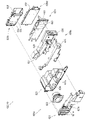
外枠下組立体40は、幕板前部材42及び幕板後部材43の上面に左右に離間して配置されている一対の案内部材45と、幕板前部材42の開口部42aを後側から閉鎖している平板状のグリル部材46と、グリル部材46を挟んで開口部42aを閉鎖するように幕板前部材42の内部に取付けられており前後に延びた二つの円筒を有したポート部材47と、幕板後部材43の接続筒部43aの上端に配置される枠状のシール部材48と、を備えている。
The outer frame lower assembly 40 closes a pair of guide members 45 arranged apart from each other on the upper surfaces of the curtain plate front member 42 and the curtain plate rear member 43, and the opening 42a of the curtain plate front member 42 from the rear side. A flat plate-shaped grill member 46 and a port member 47 having two cylinders that are attached to the inside of the curtain plate front member 42 so as to close the opening 42a across the grill member 46 and extend back and forth. A frame-shaped seal member 48 arranged at the upper end of the connection cylinder portion 43a of the curtain plate rear member 43 is provided.
一対の案内部材45は、外枠2に対して本体枠4を閉じた時に、扉枠3の下端が当接するものである。案内部材45は、摩擦抵抗の低い低摩擦材料によって形成されており、本体枠4の下端を滑り易くして、開閉を容易にしている。
The pair of guide members 45 are such that the lower end of the door frame 3 comes into contact with the outer frame 2 when the main body frame 4 is closed. The guide member 45 is made of a low-friction material having low frictional resistance, and makes the lower end of the main body frame 4 slippery to facilitate opening and closing.
グリル部材46は、無数の小穴を有したパンチングメタルにより形成されている。ポート部材47は、二つの円筒により、グリル部材46を介して幕板内部空間40a(エンクロージャ624)と外枠2の前方とを連通させている。ポート部材47は、二つの円筒が、所定の内径で所定の長さに形成されており、ヘルムホルツ共鳴の原理により本体枠スピーカ622から後方(エンクロージャ624内)へ発せられた低音を共振・増幅させて、豊かな低音を外枠2の前方(遊技者側)へ放射することができる。つまり、本実施形態では、本体枠スピーカ622のエンクロージャ624がバスレフ型とされており、遊技者に対して重低音を聞かせることができる。
The grill member 46 is formed of a punching metal having innumerable small holes. The port member 47 communicates the curtain plate internal space 40a (enclosure 624) with the front of the outer frame 2 via the grill member 46 by two cylinders. The port member 47 has two cylinders formed with a predetermined inner diameter and a predetermined length, and resonates and amplifies the bass emitted from the main body frame speaker 622 to the rear (inside the enclosure 624) by the principle of Helmholtz resonance. Therefore, rich bass can be radiated to the front (player side) of the outer frame 2. That is, in the present embodiment, the enclosure 624 of the main body frame speaker 622 is a bass reflex type, and the player can hear the deep bass.
シール部材48は、外枠2に対して本体枠4を閉じた時に、接続筒部43aの上端と本体枠4におけるスピーカカバー621の接続部621cの下端との間に挟まれて圧縮されるものであり、接続筒部43aと接続部621cとの間からスピーカのエンクロージャ内の音が漏れるのを防止するものである。
The seal member 48 is sandwiched and compressed between the upper end of the connection cylinder portion 43a and the lower end of the connection portion 621c of the speaker cover 621 in the main body frame 4 when the main body frame 4 is closed with respect to the outer frame 2. This is to prevent the sound in the speaker enclosure from leaking from between the connection cylinder portion 43a and the connection portion 621c.
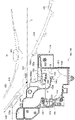
[2-4.外枠上ヒンジ組立体]
外枠2の外枠上ヒンジ組立体50について、主に図22を参照して詳細に説明する。図22(a)は外枠2の外枠上ヒンジ組立体を分解して前上から見た分解斜視図であり、(b)は(a)を前下から見た分解斜視図である。外枠上ヒンジ組立体50は、外枠左組立体10の上端と外枠上部材30の左端に取付けられるものであり、外枠2に対して本体枠4をヒンジ回転可能に取付けるためのものである。外枠上ヒンジ組立体50は、外枠左部材11の凹部11aの上端と外枠上部材30の取付段部30bとに取付けられる外枠上ヒンジ部材51と、外枠上ヒンジ部材51に取付けられているロック部材52と、ロック部材52を外枠上ヒンジ部材51に取付けている取付ビス53と、を備えている。
[2-4. Hinge assembly on outer frame]
The hinge assembly 50 on the outer frame of the outer frame 2 will be described in detail mainly with reference to FIG. 22. 22 (a) is an exploded perspective view of the outer frame upper hinge assembly of the outer frame 2 disassembled and viewed from the front upper side, and FIG. 22 (b) is an exploded perspective view of (a) viewed from the front lower surface. The outer frame upper hinge assembly 50 is attached to the upper end of the outer frame left assembly 10 and the left end of the outer frame upper member 30, and is for attaching the main body frame 4 to the outer frame 2 so that the hinge can be rotated. Is. The outer frame upper hinge assembly 50 is attached to the outer frame upper hinge member 51 attached to the upper end of the recess 11a of the outer frame left member 11 and the mounting step portion 30b of the outer frame upper member 30, and to the outer frame upper hinge member 51. The lock member 52 is provided with a locking member 52 and a mounting screw 53 for attaching the lock member 52 to the hinge member 51 on the outer frame.
外枠上ヒンジ部材51は、水平に延びた平板状で外枠上部材30の取付段部30bの上面に取付けられる上固定部51aと、上固定部51aの前辺から前方へ延出している平板状の前方延出部51bと、前方延出部51bの右辺の途中から前方へ向かうに従って前方延出部51bの左右中央へ延びており上下に貫通している軸受溝51cと、上固定部51aの左辺から下方へ延びている平板状の横固定部51dと、前方延出部51bの左辺から前辺を周って軸受溝51cが開口している部位までの端縁から下方へ延びており横固定部51dと連続している平板状の端縁壁部51eと、を備えている。外枠上ヒンジ部材51は、金属板をプレス成型により打抜き・屈曲させて形成されている。外枠上ヒンジ部材51は、軸受溝51c内において、本体枠上ヒンジ部材510の後述する本体枠上ヒンジピン512を回転可能に支持することができる。
The outer frame upper hinge member 51 has an upper fixing portion 51a that is horizontally extended and is attached to the upper surface of the mounting step portion 30b of the outer frame upper member 30, and extends forward from the front side of the upper fixing portion 51a. A flat plate-shaped front extending portion 51b, a bearing groove 51c extending vertically from the middle of the right side of the front extending portion 51b to the left and right center of the front extending portion 51b and penetrating vertically, and an upper fixing portion. The flat plate-shaped horizontal fixing portion 51d extending downward from the left side of the 51a and the end edge extending downward from the left side of the front extending portion 51b to the portion where the bearing groove 51c is opened around the front side. It is provided with a flat plate-shaped edge wall portion 51e that is continuous with the cage horizontal fixing portion 51d. The hinge member 51 on the outer frame is formed by punching and bending a metal plate by press molding. The outer frame upper hinge member 51 can rotatably support the main body frame upper hinge pin 512 described later of the main body frame upper hinge member 510 in the bearing groove 51c.
ロック部材52は、前後に延びている帯板状のロック本体52aと、ロック本体52aの後端から右方へ突出している操作片52bと、ロック本体52aの後端から左方へ延びた後に斜め左前方へ延びている弾性変形可能な棒状の弾性部52cと、ロック本体52aの後端付近で上下に貫通している取付孔52dと、を備えている。ロック部材52は、合成樹脂によって形成されている。ロック部材52は、取付ビス53によって、外枠上ヒンジ部材51における前方延出部51bの下面で、軸受溝51cよりも後側の部位に回動可能に取付けられる。
The lock member 52 has a strip-shaped lock body 52a extending back and forth, an operation piece 52b protruding to the right from the rear end of the lock body 52a, and after extending to the left from the rear end of the lock body 52a. It is provided with an elastically deformable rod-shaped elastic portion 52c extending diagonally to the left front and a mounting hole 52d penetrating vertically near the rear end of the lock body 52a. The lock member 52 is made of synthetic resin. The lock member 52 is rotatably attached to a portion of the outer frame upper hinge member 51 on the lower surface of the front extending portion 51b behind the bearing groove 51c by the mounting screw 53.
ロック部材52は、外枠上ヒンジ部材51に取付けた状態で、ロック本体52aが、平面視で軸受溝51cを遮ることができると共に、前端付近の右側面が、外枠上ヒンジ部材51の端縁壁部51eにおける軸受溝51cの開口まで延びている部位と当接可能となるように前方へ延びている。また、ロック本体52aの後端から左方へ延びている弾性部52cの先端は、外枠上ヒンジ部材51における端縁壁部51eの内周面に当接している。このロック部材52は、弾性部52cの付勢力によって取付孔52dを中心に、前端が左方へ回動する方向に付勢されている。したがって、通常の状態では、ロック部材52のロック本体52aの前端付近の右側面が、端縁壁部51eに当接している。この状態では、軸受溝51cにおけるロック本体52aよりも前側の部位に、本体枠上ヒンジ部材510の本体枠上ヒンジピン512を収容可能な空間が形成される。
When the lock member 52 is attached to the hinge member 51 on the outer frame, the lock body 52a can block the bearing groove 51c in a plan view, and the right side surface near the front end is the end of the hinge member 51 on the outer frame. It extends forward so that it can come into contact with a portion of the edge wall portion 51e that extends to the opening of the bearing groove 51c. Further, the tip of the elastic portion 52c extending to the left from the rear end of the lock main body 52a is in contact with the inner peripheral surface of the end edge wall portion 51e of the hinge member 51 on the outer frame. The lock member 52 is urged by the urging force of the elastic portion 52c in a direction in which the front end rotates to the left around the mounting hole 52d. Therefore, under normal conditions, the right side surface of the lock member 52 near the front end of the lock body 52a is in contact with the edge wall portion 51e. In this state, a space that can accommodate the hinge pin 512 on the main body frame of the hinge member 510 on the main body frame is formed in a portion of the bearing groove 51c on the front side of the lock main body 52a.
このロック部材52は、操作片52bを操作することで、弾性部52cの付勢力に抗してロック本体52aを回動させることができる。そして、操作片52bの操作によって、ロック本体52aを、その前端が左方へ移動する方向へ回動させることで、平面視において軸受溝51cからロック本体52aを後退させることができ、軸受溝51cが全通している状態とすることができる。これにより、軸受溝51c内に本体枠上ヒンジピン512を挿入したり、軸受溝51c内から本体枠上ヒンジピン512を外したりすることができる。
By operating the operation piece 52b, the lock member 52 can rotate the lock body 52a against the urging force of the elastic portion 52c. Then, by operating the operation piece 52b, the lock body 52a is rotated in the direction in which the front end thereof moves to the left, so that the lock body 52a can be retracted from the bearing groove 51c in a plan view, and the bearing groove 51c can be retracted. Can be in a state of being fully passed. As a result, the hinge pin 512 on the main body frame can be inserted into the bearing groove 51c, and the hinge pin 512 on the main body frame can be removed from the inside of the bearing groove 51c.
[2-5.外枠下ヒンジ部材]
外枠2の外枠下ヒンジ部材60について、主に図19を参照して詳細に説明する。外枠下ヒンジ部材60は、水平に延びた平板状の水平部60aと、水平部60aの左辺において前後方向中央よりも後側の部位から上方へ立上っている平板状の立上部60bと、水平部60aの前端付近から上方へ突出している外枠下ヒンジピン60cと、水平部60aを上下に貫通しており遊技球Bが一つのみ通過可能な大きさの排出孔60dと、を備えている。この外枠下ヒンジ部材60は、金属板をプレス成型により打抜き・屈曲させて形成されている。
[2-5. Hinge member under the outer frame]
The hinge member 60 below the outer frame of the outer frame 2 will be described in detail mainly with reference to FIG. The outer frame lower hinge member 60 includes a horizontally extending flat plate-shaped horizontal portion 60a and a flat plate-shaped rising portion 60b rising upward from a portion posterior to the center in the front-rear direction on the left side of the horizontal portion 60a. It is provided with a hinge pin 60c under the outer frame protruding upward from the vicinity of the front end of the horizontal portion 60a, and a discharge hole 60d having a size that allows only one game ball B to pass through the horizontal portion 60a up and down. ing. The outer frame lower hinge member 60 is formed by punching and bending a metal plate by press molding.
外枠下ヒンジ部材60の水平部60aは、平面視において、左辺を底辺とした台形に形成されている。外枠下ヒンジピン60cは、円柱状で、上下方向中央よりも上部が、上端が窄まった円錐台状に形成されている。この外枠下ヒンジピン60cは、水平部60aの前端付近における左寄りの位置に取付けられている。排出孔60dは、水平部60aにおいて、立上部60bの前後方向中央の部位と接し、水平部60aの左辺から右方へ逆U字状に延びるように形成されている。この排出孔60dは、外枠下組立体40における球噛防止機構44の第一排出口44bと、略同じ大きさに形成されている。
The horizontal portion 60a of the outer frame lower hinge member 60 is formed in a trapezoidal shape with the left side as the base in a plan view. The lower hinge pin 60c of the outer frame is columnar and is formed in a conical stand shape in which the upper end is narrowed above the center in the vertical direction. The lower hinge pin 60c of the outer frame is attached to a position on the left side near the front end of the horizontal portion 60a. The discharge hole 60d is formed in the horizontal portion 60a so as to be in contact with the central portion in the front-rear direction of the rising portion 60b and extend from the left side of the horizontal portion 60a to the right in an inverted U shape. The discharge hole 60d is formed to have substantially the same size as the first discharge port 44b of the ball biting prevention mechanism 44 in the outer frame lower assembly 40.
外枠下ヒンジ部材60は、外枠2に組立てた状態で、水平部60aの後部が、外枠下組立体40における幕板後部材43の載置部44a上に載置され、図示しないビスによって幕板後部材43に固定されている。また、立上部60bが、外枠左部材11の右側面における膨出部11bよりも前側の部位に、図示しないビスによって取付けられている。この外枠下ヒンジ部材60は、外枠下ヒンジピン60cを、本体枠4の本体枠下ヒンジ組立体520における外枠用下ヒンジ孔521aに挿通させることで、外枠上ヒンジ部材51と協働して本体枠4を開閉可能に取付けることができる。
In the state where the outer frame lower hinge member 60 is assembled on the outer frame 2, the rear portion of the horizontal portion 60a is mounted on the mounting portion 44a of the curtain plate rear member 43 in the outer frame lower assembly 40, and a screw (not shown) is provided. It is fixed to the member 43 behind the curtain plate. Further, the rising portion 60b is attached to a portion on the right side surface of the outer frame left member 11 on the front side of the bulging portion 11b by a screw (not shown). The outer frame lower hinge member 60 cooperates with the outer frame upper hinge member 51 by inserting the outer frame lower hinge pin 60c into the outer frame lower hinge hole 521a in the main body frame lower hinge assembly 520 of the main body frame 4. Then, the main body frame 4 can be attached so as to be openable and closable.
また、外枠2を組立てた状態では、排出孔60dが、外枠下組立体40における球噛防止機構44の第一排出口44bと一致している。これにより、水平部60a上の遊技球Bを、排出孔60d及び第一排出口44bを通して、外枠2の後方へ落下(排出)させることができる。詳述すると、外枠2に対して本体枠4を閉じる時に、外枠2と本体枠4との間に落下した遊技球Bが、本体枠4が閉じられるのに従って、外枠2と本体枠4との間が徐々に狭くなることから、間隔が広い後方側へ転動とすることとなり、排出孔60dから排出させることができる。この際に、排出孔60dが、パチンコ機1に組立てた状態で、外枠2に対して本体枠4を閉じた時に、本体枠4の後端と略同じとなる位置に形成されているため、外枠2と本体枠4との間に落下した遊技球Bを、排出孔60dから排出させることで本体枠4よりも後側へ転動するのを阻止し易くすることができ、外枠下ヒンジ部材60の部位に遊技球Bが留まり難くすることができる。
Further, in the state where the outer frame 2 is assembled, the discharge hole 60d coincides with the first discharge port 44b of the ball biting prevention mechanism 44 in the outer frame lower assembly 40. As a result, the game ball B on the horizontal portion 60a can be dropped (discharged) to the rear of the outer frame 2 through the discharge hole 60d and the first discharge port 44b. More specifically, when the main body frame 4 is closed with respect to the outer frame 2, the game ball B that has fallen between the outer frame 2 and the main body frame 4 is closed, and the outer frame 2 and the main body frame 4 are closed. Since the space between the cloaca and the cloaca is gradually narrowed, the cloaca is rolled to the rear side where the distance is wide, and the cloaca can be discharged from the discharge hole 60d. At this time, since the discharge hole 60d is formed at a position substantially the same as the rear end of the main body frame 4 when the main body frame 4 is closed with respect to the outer frame 2 in the state of being assembled in the pachinko machine 1. By discharging the game ball B that has fallen between the outer frame 2 and the main body frame 4 from the discharge hole 60d, it is possible to easily prevent the game ball B from rolling to the rear side of the main body frame 4, and the outer frame can be easily prevented from rolling. The game ball B can be made difficult to stay at the portion of the lower hinge member 60.
[3.扉枠の全体構成]
パチンコ機1の扉枠3について、主に図23~図31を参照して詳細に説明する。図23はパチンコ機における扉枠の表面図であり、図24は扉枠の背面図であり、図25は扉枠の左側面図であり、図26は扉枠の右側面図である。図27は扉枠を右前から見た斜視図であり、図28は扉枠を左前から見た斜視図であり、図29は扉枠を後ろから見た斜視図である。図30は扉枠を主な部材毎に分解して前から見た分解斜視図であり、図31は扉枠を主な部材毎に分解して後ろから見た分解斜視図である。
[3. Overall configuration of door frame]
The door frame 3 of the pachinko machine 1 will be described in detail mainly with reference to FIGS. 23 to 31. 23 is a front view of the door frame in the pachinko machine, FIG. 24 is a rear view of the door frame, FIG. 25 is a left side view of the door frame, and FIG. 26 is a right side view of the door frame. 27 is a perspective view of the door frame viewed from the front right, FIG. 28 is a perspective view of the door frame viewed from the front left, and FIG. 29 is a perspective view of the door frame viewed from the rear. FIG. 30 is an exploded perspective view of the door frame disassembled for each main member and viewed from the front, and FIG. 31 is an exploded perspective view of the door frame disassembled for each main member and viewed from the rear.
扉枠3は、外枠2の枠内と略同じ大きさで正面視において上下に延びた四角形に形成されており、本体枠4を介して外枠2の枠内を前側から開閉可能に取付けられている。扉枠3は、遊技球Bが打込まれる遊技盤5の遊技領域5aを前側から視認可能に閉鎖し、遊技領域5a内に打込むための遊技球Bを貯留すると共に、貯留している遊技球Bを遊技領域5a内へ打込むために遊技者が操作するハンドル182を備えているものである。また、扉枠3は、パチンコ機1の前面全体を装飾するものである。
The door frame 3 has substantially the same size as the inside of the outer frame 2 and is formed in a quadrangle extending vertically in front view, and the inside of the outer frame 2 can be opened and closed from the front side via the main body frame 4. Has been done. The door frame 3 visibly closes the game area 5a of the game board 5 into which the game ball B is driven, stores the game ball B for driving into the game area 5a, and stores the stored game. It is provided with a handle 182 operated by a player to drive the ball B into the game area 5a. Further, the door frame 3 decorates the entire front surface of the pachinko machine 1.
扉枠3は、正面視の外形が上下に延びた四角形で枠状の扉枠ベースユニット100と、扉枠ベースユニット100に着脱可能に取付けられており本体枠4に取付けられた遊技盤5の遊技領域5aを前方から視認可能に閉鎖しているガラスユニット160と、ガラスユニット160の下部を後側から覆うように扉枠ベースユニット100に取付けられている防犯カバー170と、扉枠ベースユニット100の前面右下隅に取付けられているハンドルユニット180と、扉枠ベースユニット100の前面下部に取付けられている皿ユニット200と、皿ユニット200の上側で扉枠ベースユニット100の前面左部に取付けられている扉枠左サイドユニット400と、皿ユニットの上側で扉枠ベースユニット100の前面右部に取付けられている扉枠右サイドユニット410と、扉枠左サイドユニット400及び扉枠右サイドユニット410の上側で扉枠ベースユニット100の前面上部に取付けられている扉枠トップユニット450と、を備えている。
The door frame 3 is a square and frame-shaped door frame base unit 100 having a front view extending vertically, and a game board 5 detachably attached to the door frame base unit 100 and attached to the main body frame 4. A glass unit 160 that visibly closes the game area 5a from the front, a security cover 170 that is attached to the door frame base unit 100 so as to cover the lower part of the glass unit 160 from the rear side, and a door frame base unit 100. The handle unit 180 attached to the lower right corner of the front surface of the door frame, the dish unit 200 attached to the lower part of the front surface of the door frame base unit 100, and the upper side of the dish unit 200 attached to the front left portion of the door frame base unit 100. The door frame left side unit 400, the door frame right side unit 410 attached to the front right part of the door frame base unit 100 on the upper side of the dish unit, the door frame left side unit 400, and the door frame right side unit 410. The door frame top unit 450, which is attached to the upper part of the front surface of the door frame base unit 100 on the upper side of the door frame, is provided.
扉枠ベースユニット100は、正面視の外形が上下に延びた四角形(長方形)に形成されており前後に貫通している扉窓101aを有した扉枠ベース101と、扉枠ベース101の前面右下に取付けられているハンドル取付部材102と、扉枠ベース101の後側で背面視右下隅に取付けられているスピーカダクト103と、扉枠ベース101の後側の下部における背面視右端付近に取付けられている扉枠主中継基板104と、扉枠主中継基板104の背面視左方に取付けられている扉枠副中継基板105と、扉枠副中継基板105の背面視左方に取付けられているハンドル後中継基板106と、扉枠主中継基板104と扉枠副中継基板105の一部とを後側から被覆する扉枠中継基板カバー107と、ハンドル後中継基板106を後側から被覆するハンドル後中継基板カバー108と、配線ケーブルを被覆するケーブルカバー109と、を備えている。
The door frame base unit 100 has a door frame base 101 having a door window 101a that is formed in a square shape (rectangular shape) whose outer shape extends vertically and penetrates back and forth, and a front right side of the door frame base 101. The handle mounting member 102 mounted below, the speaker duct 103 mounted in the lower right corner of the rear view on the rear side of the door frame base 101, and the speaker duct 103 mounted in the lower part of the rear side of the door frame base 101 near the right end of the rear view. The door frame main relay board 104, the door frame sub-relay board 105 attached to the left side of the door frame main relay board 104, and the door frame sub-relay board 105 attached to the left side of the rear view. Covers the rear relay board 106 after the handle, the door frame relay board cover 107 that covers the door frame main relay board 104 and a part of the door frame sub relay board 105 from the rear side, and the door frame rear relay board 106 from the rear side. It includes a relay board cover 108 after the handle and a cable cover 109 that covers the wiring cable.
また、扉枠ベースユニット100は、扉枠ベース101の後側に取付けられている枠状の扉枠補強ユニット110と、扉枠補強ユニット110に取付けられている扉枠上ヒンジ組立体120及び扉枠下ヒンジ部材125と、扉枠補強ユニット110に取付けられている開閉用のシリンダ錠130と、扉枠ベース101の後側でハンドル後中継基板106の上方に取付けられている球送給ユニット140と、扉枠ベース101の後側の下部における背面視右側に取付けられているファールカバーユニット150と、を備えている。
Further, the door frame base unit 100 includes a frame-shaped door frame reinforcing unit 110 attached to the rear side of the door frame base 101, a hinge assembly 120 on the door frame attached to the door frame reinforcing unit 110, and a door. The hinge member 125 under the frame, the cylinder lock 130 for opening and closing attached to the door frame reinforcing unit 110, and the ball feeding unit 140 attached above the relay board 106 after the handle on the rear side of the door frame base 101. And a foul cover unit 150 attached to the right side of the rear view at the lower part of the rear side of the door frame base 101.
扉枠補強ユニット110は、扉枠ベース101の後側に取付けられることで、扉枠ベース101を補強して剛性を付与するものである。扉枠上ヒンジ組立体120及び扉枠下ヒンジ部材125は、扉枠3を本体枠4に対して開閉可能に取付けるためのものである。シリンダ錠130は、本体枠4の施錠ユニット650と協働して、扉枠3と本体枠4との開閉、及び、外枠2と本体枠4との開閉施錠に使用されるものである。
The door frame reinforcing unit 110 is attached to the rear side of the door frame base 101 to reinforce the door frame base 101 and impart rigidity. The door frame upper hinge assembly 120 and the door frame lower hinge member 125 are for attaching the door frame 3 to the main body frame 4 so as to be openable and closable. The cylinder lock 130 is used in cooperation with the locking unit 650 of the main body frame 4 to open and close the door frame 3 and the main body frame 4, and to open and close the outer frame 2 and the main body frame 4.
また、球送給ユニット140は、上皿201内の遊技球Bを一つずつ本体枠4の球発射装置540へ供給するためのものである。ファールカバーユニット150は、球発射装置540により発射されて遊技盤5の遊技領域5a内に到達しなかった遊技球B(ファール球)を、下皿202に誘導すると共に、払出装置580から払出された遊技球Bを、上皿201又は下皿202に誘導するためのものである。
Further, the ball feeding unit 140 is for supplying the game balls B in the upper plate 201 one by one to the ball launching device 540 of the main body frame 4. The foul cover unit 150 guides the game ball B (foul ball), which is launched by the ball launcher 540 and does not reach the game area 5a of the game board 5, to the lower plate 202 and is discharged from the payout device 580. This is for guiding the game ball B to the upper plate 201 or the lower plate 202.
ガラスユニット160は、透明なガラス板162を有しており扉枠ベース101の扉窓101aを閉鎖している。防犯カバー170は、ガラスユニット160の下部を後方から覆うように扉枠ベース101に取付けられている。ハンドルユニット180は、遊技者が回転操作可能なハンドル182を備えており、ハンドル182を操作することで、上皿201内の遊技球Bを、球発射装置540によって遊技盤5の遊技領域5a内に打込む遊技を行うためのものである。
The glass unit 160 has a transparent glass plate 162 and closes the door window 101a of the door frame base 101. The security cover 170 is attached to the door frame base 101 so as to cover the lower portion of the glass unit 160 from the rear. The handle unit 180 includes a handle 182 that can be rotated by a player, and by operating the handle 182, the game ball B in the upper plate 201 is moved into the game area 5a of the game board 5 by the ball launcher 540. It is for playing a game to be driven into.
[3-1.扉枠ベースユニットの全体構成]
扉枠3の扉枠ベースユニット100について、主に図32~図34を参照して詳細に説明する。図32(a)は扉枠の扉枠ベースユニットを前から見た斜視図であり、(b)は扉枠ベースユニットを後ろから見た斜視図である。図33は扉枠ベースユニットを主な部材毎に分解して前から見た分解斜視図であり、図34は扉枠ベースユニットを主な部材毎に分解して後ろから見た分解斜視図である。
[3-1. Overall configuration of door frame base unit]
The door frame base unit 100 of the door frame 3 will be described in detail mainly with reference to FIGS. 32 to 34. 32 (a) is a perspective view of the door frame base unit of the door frame as viewed from the front, and FIG. 32 (b) is a perspective view of the door frame base unit as viewed from the rear. FIG. 33 is an exploded perspective view of the door frame base unit disassembled for each main member and viewed from the front, and FIG. 34 is an exploded perspective view of the door frame base unit disassembled for each main member and viewed from the rear. be.
扉枠ベースユニット100は、正面視左辺側が本体枠4に対してヒンジ回転可能に取付けられ、本体枠4の前面を開閉可能に閉鎖していると共に、本体枠4に取付けられている遊技盤の遊技領域を前方から視認可能としている。扉枠ベースユニット100は、外形が上下に延びた四角形で平板状の扉枠ベース101と、扉枠ベース101の前面右下に取付けられておりハンドルユニット180を取付けるためのハンドル取付部材102と、扉枠ベース101の後側で背面視右下隅に取付けられているスピーカダクト103と、を備えている。
The door frame base unit 100 is attached so that the left side side of the front view can be hinged with respect to the main body frame 4 so that the front surface of the main body frame 4 can be opened and closed, and the game board attached to the main body frame 4 is closed. The game area is visible from the front. The door frame base unit 100 includes a rectangular flat plate-shaped door frame base 101 whose outer shape extends vertically, a handle mounting member 102 mounted on the lower right front of the door frame base 101 for mounting the handle unit 180, and a handle mounting member 102. It is provided with a speaker duct 103 attached to the lower right corner of the rear view on the rear side of the door frame base 101.
また、扉枠ベースユニット100は、扉枠ベース101の後側の下部における背面視右端付近に取付けられている扉枠主中継基板104と、扉枠ベース101の後側の下部における扉枠主中継基板104の背面視左方に取付けられている扉枠副中継基板105と、扉枠ベース101の後側の下部における扉枠副中継基板105の背面視左方に取付けられているハンドル後中継基板106と、扉枠ベース101の後側に取付けられており扉枠主中継基板104と扉枠副中継基板105の一部とを後側から被覆する扉枠中継基板カバー107と、扉枠ベース101の後側に取付けられておりハンドル後中継基板106を後側から被覆するハンドル後中継基板カバー108と、扉枠ベース101の後側に取付けられており配線ケーブルを被覆するケーブルカバー109と、を備えている。
Further, the door frame base unit 100 includes a door frame main relay board 104 attached near the right end of the rear view at the lower rear side of the door frame base 101 and a door frame main relay at the lower rear side of the door frame base 101. The door frame sub-relay board 105 mounted on the left side of the rear view of the board 104, and the rear handle relay board mounted on the left side of the rear view of the door frame sub-relay board 105 at the lower rear side of the door frame base 101. The door frame relay board cover 107, which is attached to the rear side of the door frame base 101 and covers a part of the door frame main relay board 104 and the door frame sub relay board 105 from the rear side, and the door frame base 101. The rear relay board cover 108, which is attached to the rear side and covers the rear relay board 106 from the rear side, and the cable cover 109, which is attached to the rear side of the door frame base 101 and covers the wiring cable, are attached. I have.
更に、扉枠ベースユニット100は、扉枠ベース101の後側に取付けられている枠状の扉枠補強ユニット110と、扉枠補強ユニット110に取付けられている扉枠上ヒンジ組立体120及び扉枠下ヒンジ部材125と、扉枠補強ユニット110に取付けられている開閉用のシリンダ錠130と、扉枠ベース101の後側でハンドル後中継基板106の上方に取付けられている球送給ユニット140と、扉枠ベース101の後側の下部における背面視右側に取付けられているファールカバーユニット150と、を備えている。
Further, the door frame base unit 100 includes a frame-shaped door frame reinforcing unit 110 attached to the rear side of the door frame base 101, a hinge assembly 120 on the door frame attached to the door frame reinforcing unit 110, and a door. The hinge member 125 under the frame, the cylinder lock 130 for opening and closing attached to the door frame reinforcing unit 110, and the ball feeding unit 140 attached above the relay board 106 after the handle on the rear side of the door frame base 101. And a foul cover unit 150 attached to the right side of the rear view at the lower part of the rear side of the door frame base 101.
この扉枠ベースユニット100には、前面下隅にハンドルユニット180が、扉窓101aの下側前面に皿ユニット200が、扉窓101aの左外側前面に扉枠左サイドユニット400が、扉窓101aの右外側前面に扉枠右サイドユニット410が、扉窓101aの上外側前面に扉枠トップユニット450が、それぞれ取付けられるものである。
The door frame base unit 100 has a handle unit 180 in the lower front corner, a dish unit 200 in the lower front surface of the door window 101a, a door frame left side unit 400 in the left outer front surface of the door window 101a, and a door window 101a. The door frame right side unit 410 is attached to the right outer front surface, and the door frame top unit 450 is attached to the upper outer front surface of the door window 101a.
また、扉枠ベースユニット100には、扉窓101aを後方から閉鎖するようにガラスユニット160が取付けられると共に、ガラスユニット160の下部を後方から覆うように透明な防犯カバー170が取付けられるものである。
Further, a glass unit 160 is attached to the door frame base unit 100 so as to close the door window 101a from the rear, and a transparent security cover 170 is attached so as to cover the lower portion of the glass unit 160 from the rear. ..
[3-1-1.扉枠ベース]
扉枠3における扉枠ベースユニット100の扉枠ベース101について、主に図32~図34を参照して詳細に説明する。扉枠ベース101は、正面視の外形が上下に延びた四角形(長方形)に形成されている。扉枠ベース101は、前後に貫通しており、正面視における内周形状が上下に延びた略四角形に形成された扉窓101aを備えている。扉窓101aは、内周を形成している上辺及び左右両辺が、扉枠ベース101の外周辺にそれぞれ接近しており、内周を形成している下辺が、扉枠ベース101の下端から上下方向の約1/3の高さに位置している。このように、扉枠ベース101は、前後に貫通している扉窓101aにより全体が枠状に形成されている。この扉枠ベース101は、合成樹脂により一体成形されている。
[3-1-1. Door frame base]
The door frame base 101 of the door frame base unit 100 in the door frame 3 will be described in detail mainly with reference to FIGS. 32 to 34. The door frame base 101 is formed in a quadrangle (rectangle) whose outer shape in front view extends vertically. The door frame base 101 penetrates back and forth, and includes a door window 101a formed in a substantially quadrangular shape having an inner peripheral shape extending vertically in a front view. In the door window 101a, the upper side and the left and right sides forming the inner circumference are close to the outer periphery of the door frame base 101, respectively, and the lower side forming the inner circumference is up and down from the lower end of the door frame base 101. It is located at a height of about 1/3 in the direction. As described above, the door frame base 101 is entirely formed in a frame shape by the door windows 101a penetrating the front and rear. The door frame base 101 is integrally molded with a synthetic resin.
扉枠ベース101は、前面における正面視右下隅に形成されており左端側が右端側よりも前方へやや突出するように傾斜しているハンドル取付座面101bと、ハンドル取付座面101bと扉窓101aとの間で正面視右端付近に後面から前方へ向かって窪み、扉枠補強ユニット110のシリンダ取付フレーム115が挿入される挿入凹部101cと、挿入凹部101cにおいて前後に貫通しておりシリンダ錠130のシリンダ本体131が挿通されるシリンダ挿通孔101dと、シリンダ挿通孔101d及びハンドル取付座面101bの正面視左側で前後に貫通しており球送給ユニット140の進入口141a及び球抜口141bを前方に臨ませるための球送給開口101eと、を備えている。
The door frame base 101 is formed in the lower right corner of the front view and is inclined so that the left end side slightly protrudes forward from the right end side, the handle mounting seat surface 101b, the handle mounting seat surface 101b, and the door window 101a. The cylinder lock 130 is recessed from the rear surface to the front near the right end of the front view, and penetrates back and forth between the insertion recess 101c into which the cylinder mounting frame 115 of the door frame reinforcing unit 110 is inserted and the insertion recess 101c. The cylinder insertion hole 101d through which the cylinder body 131 is inserted, the cylinder insertion hole 101d, and the handle mounting seat surface 101b penetrate the front and rear on the left side of the front view, and the entry entrance 141a and the ball outlet 141b of the ball feeding unit 140 are forward. It is equipped with a ball feeding opening 101e for facing the cylinder.
また、扉枠ベース101は、左右方向中央より左寄りで且つハンドル取付座面101bと略同じ高さで前後に貫通しておりファールカバーユニット150の球放出口150dを前方に臨ませる下皿用球通過口101fと、正面視左端付近で扉窓101aの下辺に隣接するように前後に貫通しておりファールカバーユニット150の貫通球通路150aを前方に臨ませる上皿用球通過口101gと、扉窓101aの内周に沿って後面から前方へ向かって窪み、ガラスユニット160のガラス枠161が挿入されるガラスユニット取付部101hと、を備えている。
Further, the door frame base 101 is to the left of the center in the left-right direction and penetrates back and forth at substantially the same height as the handle mounting seat surface 101b, so that the ball discharge port 150d of the foul cover unit 150 faces forward. The passage port 101f, the ball passage port 101g for the upper plate that penetrates back and forth so as to be adjacent to the lower side of the door window 101a near the left end of the front view and faces the through ball passage 150a of the foul cover unit 150 to the front, and the door. It is provided with a glass unit mounting portion 101h that is recessed from the rear surface to the front along the inner circumference of the window 101a and into which the glass frame 161 of the glass unit 160 is inserted.
また、扉枠ベース101は、正面視左下隅(上皿用球通過口101gの下方)に形成されており前後に貫通した縦長の複数のスリット101iを、備えている。複数のスリット101iの後側にスピーカダクト103が取付けられる。また、複数のスリット101iは、パチンコ機1を組立てた状態で、前方に皿ユニット200における皿ユニットベース211のスピーカ口211bが位置していると共に、後方に本体枠4のスピーカユニット620aにおける本体枠スピーカ622が位置しており、本体枠スピーカ622からの音を前方へ放射することができる。
Further, the door frame base 101 is formed in the lower left corner of the front view (below the upper plate ball passage port 101 g), and is provided with a plurality of vertically long slits 101i that penetrate the front and rear. The speaker duct 103 is attached to the rear side of the plurality of slits 101i. Further, in the plurality of slits 101i, in the state where the pachinko machine 1 is assembled, the speaker port 211b of the dish unit base 211 in the dish unit 200 is located in front, and the main body frame in the speaker unit 620a of the main body frame 4 is rearward. The speaker 622 is located, and the sound from the main body frame speaker 622 can be radiated forward.
更に、扉枠ベース101は、扉窓101aの下方でハンドル取付座面101bの上方において、前後に貫通している貫通孔101jを備えている。この貫通孔101jは、扉枠ベースユニット100側と皿ユニット200側とを接続する配線ケーブル(図示は省略)が挿通されるものであり、後述する扉枠補強ユニット110における中間補強フレーム114の貫通部114bと一致するように形成されている。
Further, the door frame base 101 is provided with a through hole 101j penetrating back and forth below the door window 101a and above the handle mounting seat surface 101b. A wiring cable (not shown) connecting the door frame base unit 100 side and the dish unit 200 side is inserted through the through hole 101j, and the intermediate reinforcing frame 114 in the door frame reinforcing unit 110 described later is penetrated. It is formed so as to coincide with the portion 114b.
[3-1-2.ハンドル取付部材]
扉枠ベースユニット100のハンドル取付部材102について、主に図32~図34を参照して詳細に説明する。ハンドル取付部材102は、扉枠ベース101の前面にハンドルユニットを取付けるためのものであり、扉枠ベース101の前面のハンドル取付座面101bに取付けられる。
[3-1-2. Handle mounting member]
The handle mounting member 102 of the door frame base unit 100 will be described in detail mainly with reference to FIGS. 32 to 34. The handle mounting member 102 is for mounting the handle unit on the front surface of the door frame base 101, and is mounted on the handle mounting seat surface 101b on the front surface of the door frame base 101.
ハンドル取付部材102は、前後方向へ延びた円筒状の筒部102aと、筒部102aの後端から筒部102aの軸に対して直角方向外方へ延びた円環状のフランジ部102bと、筒部102a内に突出していると共に筒部102aの軸方向全長に亘って延びており筒部102aの周方向に対して不等間隔に配置された複数(本例では三つ)の突条102cと、筒部102aの外周面とフランジ部102bの前面とを繋ぎ、筒部102aの周方向に対して複数配置された補強リブ102dと、を備えている。
The handle mounting member 102 includes a cylindrical tubular portion 102a extending in the front-rear direction, an annular flange portion 102b extending outward in a direction perpendicular to the axis of the tubular portion 102a from the rear end of the tubular portion 102a, and a cylinder. With a plurality of (three in this example) ridges 102c that protrude into the portion 102a and extend over the entire axial length of the cylinder portion 102a and are arranged at irregular intervals in the circumferential direction of the cylinder portion 102a. The outer peripheral surface of the tubular portion 102a and the front surface of the flange portion 102b are connected to each other, and a plurality of reinforcing ribs 102d arranged in the circumferential direction of the tubular portion 102a are provided.
ハンドル取付部材102は、フランジ部102bの後面を、扉枠ベース101におけるハンドル取付座面101bの前面に当接させた状態で、ビスによってハンドル取付座面101bに取付けられる。
The handle mounting member 102 is mounted on the handle mounting seat surface 101b with screws in a state where the rear surface of the flange portion 102b is in contact with the front surface of the handle mounting seat surface 101b of the door frame base 101.
筒部102aは、内径がハンドルユニット180におけるハンドルベース181の基部181aの外径よりも若干大きく形成されている。三つの突条102cは、一つが筒部102aの上部に備えられており、残り二つが筒部102aの下部に備えられている。これら三つの突条102cは、ハンドルベース181における三つの溝部181cと対応する位置に形成されている。したがって、ハンドル取付部材102は、三つの突条102cと、ハンドルベース181の三つの溝部181cとを一致させた状態でのみ、筒部102a内にハンドルベース181の基部181aを挿入させることができ、扉枠ベース101に対してハンドルベース181(ハンドルユニット180)の回転位置を規制することができる。
The inner diameter of the tubular portion 102a is formed to be slightly larger than the outer diameter of the base portion 181a of the handle base 181 in the handle unit 180. One of the three ridges 102c is provided on the upper portion of the tubular portion 102a, and the other two are provided on the lower portion of the tubular portion 102a. These three ridges 102c are formed at positions corresponding to the three groove portions 181c in the handle base 181. Therefore, the handle mounting member 102 can insert the base portion 181a of the handle base 181 into the tubular portion 102a only when the three protrusions 102c and the three groove portions 181c of the handle base 181 are aligned with each other. The rotation position of the handle base 181 (handle unit 180) can be restricted with respect to the door frame base 101.
なお、ハンドル取付部材102は、フランジ部102bの後面に対して、筒部102aの軸線が垂直に延びていることから、扉枠ベース101の傾斜しているハンドル取付座面101bに取付けることで、筒部102aの軸線が右前方へ延びるように傾いた状態となり、ハンドルユニット180を同様に傾いた状態で扉枠ベース101に取付けることができる。
Since the axis of the tubular portion 102a extends perpendicularly to the rear surface of the flange portion 102b, the handle mounting member 102 can be attached to the inclined handle mounting seat surface 101b of the door frame base 101. The axis of the tubular portion 102a is tilted so as to extend to the front right, and the handle unit 180 can be attached to the door frame base 101 in the same tilted state.
[3-1-3.スピーカダクト]
扉枠ベースユニット100のスピーカダクト103について、主に図32~図34を参照して詳細に説明する。このスピーカダクト103は、筒状に形成されており、扉枠ベース101の後側において複数のスリット101iが形成されている部位に取付けられる。スピーカダクト103は、パチンコ機1を組立てた状態で、筒状の部位の後端が、本体枠4の本体枠スピーカ622の前方に位置している。これにより、本体枠4の本体枠スピーカ622から放射(出力)された音(サウンド)を、拡散させることなく前方へ誘導することができ、扉枠ベース101の複数のスリット101i及び皿ユニット200の皿ユニットベース211におけるスピーカ口211bを通して、パチンコ機1の前方(遊技者側)へ良好に誘導することができる。
[3-1-3. Speaker duct]
The speaker duct 103 of the door frame base unit 100 will be described in detail mainly with reference to FIGS. 32 to 34. The speaker duct 103 is formed in a cylindrical shape, and is attached to a portion where a plurality of slits 101i are formed on the rear side of the door frame base 101. In the speaker duct 103, when the pachinko machine 1 is assembled, the rear end of the cylindrical portion is located in front of the main body frame speaker 622 of the main body frame 4. As a result, the sound (sound) radiated (output) from the main body frame speaker 622 of the main body frame 4 can be guided forward without being diffused, and the plurality of slits 101i of the door frame base 101 and the dish unit 200 can be guided. It can be satisfactorily guided to the front (player side) of the pachinko machine 1 through the speaker port 211b in the dish unit base 211.
また、スピーカダクト103は、筒状の部位の下方の後面に、接続ケーブル503を保持するケーブルホルダ103aを備えている。ケーブルホルダ103aは、扉枠中継基板カバー107よりも正面視左方に配置されており、扉枠主中継基板104及び扉枠副中継基板105に接続されている接続ケーブル503を、扉枠3の左端側へ延びるように保持している。
Further, the speaker duct 103 is provided with a cable holder 103a for holding the connection cable 503 on the lower rear surface of the cylindrical portion. The cable holder 103a is arranged on the left side of the door frame relay board cover 107 when viewed from the front, and the connection cable 503 connected to the door frame main relay board 104 and the door frame sub-relay board 105 is connected to the door frame 3. It is held so as to extend to the left end side.
[3-1-4.扉枠主中継基板・扉枠副中継基板・ハンドル後中継基板]
扉枠ベースユニット100の扉枠主中継基板104、扉枠副中継基板105、ハンドル後中継基板106について、主に図33及び図34等を参照して説明する。扉枠主中継基板104は、外形が上下に延びた四角形に形成されており、扉枠ベース101の後側の下部における背面視右下隅に取付けられる。扉枠主中継基板104は、ハンドル後中継基板106と本体枠4の基板ユニット620におけるインターフェイス基板635との接続を中継するためのものであり、本体枠4から延びている接続ケーブル503(図99及び図100を参照)の一部が接続される。
[3-1-4. Door frame main relay board, door frame sub relay board, rear relay board after handle]
The door frame main relay board 104, the door frame sub-relay board 105, and the rear-handle relay board 106 of the door frame base unit 100 will be described mainly with reference to FIGS. 33 and 34. The door frame main relay board 104 is formed in a quadrangle whose outer shape extends vertically, and is attached to the lower right corner of the rear side of the door frame base 101 in the lower right corner of the rear view. The door frame main relay board 104 is for relaying the connection between the relay board 106 after the handle and the interface board 635 in the board unit 620 of the main body frame 4, and the connection cable 503 extending from the main body frame 4 (FIG. 99). And a part of (see FIG. 100) are connected.
扉枠副中継基板105は、外形が、上下に延びた四角形の上部の正面視右側に左右に延びた四角形が組み合された逆L字状に形成されており、上下に延びているが扉枠主中継基板104の背面視左方に隣接するように、扉枠ベース101の後側に取付けられている。扉枠副中継基板105は、ハンドルユニット180のハンドル装飾基板184、皿ユニット200の皿ユニット中継基板214、扉枠左サイドユニット400の扉枠左サイド装飾基板402、扉枠右サイドユニット410のサイド窓内装飾部装飾基板413及び扉枠右サイド装飾基板418、扉枠トップユニット450の扉枠トップ中継基板467等と、本体枠4のインターフェイス基板635との接続を中継するためのものであり、本体枠4から延びている接続ケーブル503の残りが接続される。
The door frame sub-relay board 105 is formed in an inverted L shape in which the quadrangles extending to the left and right are combined on the right side of the front view of the upper part of the quadrangles extending vertically, and the outer shape is formed in an inverted L shape. It is attached to the rear side of the door frame base 101 so as to be adjacent to the left side of the frame main relay board 104 when viewed from the rear. The door frame sub-relay board 105 is the handle decorative board 184 of the handle unit 180, the dish unit relay board 214 of the dish unit 200, the door frame left side decorative board 402 of the door frame left side unit 400, and the side of the door frame right side unit 410. The purpose is to relay the connection between the decorative board 413 of the decorative portion in the window, the decorative board 418 on the right side of the door frame, the door frame top relay board 467 of the door frame top unit 450, and the interface board 635 of the main body frame 4. The rest of the connection cable 503 extending from the main body frame 4 is connected.
扉枠主中継基板104及び扉枠副中継基板105は、接続端子が後方へ向かって突出するように、扉枠ベース101に取付けられる。扉枠主中継基板104及び扉枠副中継基板105は、扉枠ベースユニット100を組立てた状態で、扉枠主中継基板104と扉枠副中継基板105の上下に延びている部位とが、扉枠中継基板カバー107によって後側が被覆された状態となり、扉枠副中継基板105の残りの部位が、ファールカバーユニット150によって後側が被覆された状態となる。
The door frame main relay board 104 and the door frame sub-relay board 105 are attached to the door frame base 101 so that the connection terminals project rearward. In the door frame main relay board 104 and the door frame sub-relay board 105, the door frame main relay board 104 and the parts extending vertically of the door frame sub-relay board 105 are doors in a state where the door frame base unit 100 is assembled. The rear side is covered by the frame relay board cover 107, and the remaining portion of the door frame sub-relay board 105 is covered by the foul cover unit 150.
ハンドル後中継基板106は、外形が左右に延びた四角形に形成されており、扉枠ベース101の後側における球送給開口101eの下方でハンドル取付座面101bの後側に取付けられる。ハンドル後中継基板106は、扉枠主中継基板104とハンドルユニット180のハンドル回転検知センサ189、ハンドルタッチセンサ192、単発ボタン操作センサ194、及び球送給ユニット140の球送給ソレノイド145との接続を中継するためのものである。ハンドル後中継基板106は、扉枠ベースユニット100を組立てた状態で、ハンドル後中継基板カバー108によって後側が被覆された状態となる。
The rear handle relay board 106 is formed in a quadrangle whose outer shape extends to the left and right, and is mounted on the rear side of the handle mounting seat surface 101b below the ball feeding opening 101e on the rear side of the door frame base 101. The rear-handle relay board 106 is connected to the door frame main relay board 104, the handle rotation detection sensor 189 of the handle unit 180, the handle touch sensor 192, the single-shot button operation sensor 194, and the ball feed solenoid 145 of the ball feed unit 140. Is for relaying. The rear side of the handle rear relay board 106 is covered with the handle rear relay board cover 108 in a state where the door frame base unit 100 is assembled.
[3-1-5.扉枠中継基板カバー・ハンドル後中継基板カバー・ケーブルカバー]
扉枠ベースユニット100の扉枠中継基板カバー107、ハンドル後中継基板カバー108、及びケーブルカバー109について、主に図32~図34を参照して説明する。扉枠中継基板カバー107は、扉枠ベース101の後側に取付けることで、扉枠主中継基板104と扉枠副中継基板の一部(逆L字状の上下に延びている部位)の後側を被覆するものである。扉枠中継基板カバー107は、前方及び正面視左方が開放された箱状に形成されている。扉枠ベースユニット100に組立てた状態では、後側を被覆している扉枠主中継基板104及び扉枠副中継基板105の接続端子が扉枠中継基板カバー107の内部に露出しており、開放されている左側から接続ケーブル503を内部に挿入して、それら端子に接続することができる。
[3-1-5. Door frame relay board cover / rear relay board cover / cable cover]
The door frame relay board cover 107, the rear relay board cover 108 after the handle, and the cable cover 109 of the door frame base unit 100 will be described mainly with reference to FIGS. 32 to 34. By attaching the door frame relay board cover 107 to the rear side of the door frame base 101, the door frame main relay board 104 and a part of the door frame sub-relay board (a portion extending up and down in an inverted L shape) are rear. It covers the side. The door frame relay board cover 107 is formed in a box shape with the front side and the left side when viewed from the front open. In the state of being assembled to the door frame base unit 100, the connection terminals of the door frame main relay board 104 and the door frame sub relay board 105 covering the rear side are exposed inside the door frame relay board cover 107 and are open. The connection cable 503 can be inserted inside from the left side and connected to those terminals.
ハンドル後中継基板カバー108は、ハンドル後中継基板106の後側を被覆するように扉枠ベース101の後側に取付けられるものである。ケーブルカバー109は、扉枠補強ユニット110における中間補強フレーム114の後側に取付けられ、扉枠主中継基板104と皿ユニット200の球貸操作ユニット220とを接続する配線ケーブル(図示は省略)を被覆するためのものである。ケーブルカバー109は、左右に延びた箱状に形成されており、前面の左端付近と下面の左右方向中央に、配線ケーブルを通すための開口が形成されている。
The rear-handle relay board cover 108 is attached to the rear side of the door frame base 101 so as to cover the rear side of the rear-handle relay board 106. The cable cover 109 is attached to the rear side of the intermediate reinforcing frame 114 in the door frame reinforcing unit 110, and has a wiring cable (not shown) connecting the door frame main relay board 104 and the ball rental operation unit 220 of the dish unit 200. It is for covering. The cable cover 109 is formed in a box shape extending to the left and right, and openings for passing wiring cables are formed near the left end of the front surface and in the center of the lower surface in the left-right direction.
[3-1-6.扉枠補強ユニット]
扉枠ベースユニット100の扉枠補強ユニット110について、主に図32~図34を参照して詳細に説明する。扉枠補強ユニット110は、扉枠ベース101の後側に取付けられることで、平板状の扉枠ベース101を補強して、扉枠ベースユニット100に剛性を付与している。扉枠補強ユニット110は、左右に離間して配置されている上下に延びた左補強フレーム111及び右補強フレーム112と、左補強フレーム111及び右補強フレーム112の上端同士を連結している左右に延びた上補強フレーム113と、左補強フレーム111の下端から上寄りの位置に左端側が取付けられており右補強フレーム112付近まで右方へ延びた中間補強フレーム114と、中間補強フレーム114の右端と右補強フレーム112とを連結しているシリンダ取付フレーム115と、右補強フレーム112の後側に上下に離間して複数取付けられており本体枠4の施錠ユニット650の扉枠用鉤652が掛止される鉤掛部材116と、を備えている。
[3-1-6. Door frame reinforcement unit]
The door frame reinforcing unit 110 of the door frame base unit 100 will be described in detail mainly with reference to FIGS. 32 to 34. The door frame reinforcing unit 110 is attached to the rear side of the door frame base 101 to reinforce the flat plate-shaped door frame base 101 and impart rigidity to the door frame base unit 100. The door frame reinforcing unit 110 is provided on the left and right sides connecting the vertically extending left reinforcing frame 111 and the right reinforcing frame 112, which are arranged apart from each other on the left and right, and the upper ends of the left reinforcing frame 111 and the right reinforcing frame 112. The extended upper reinforcing frame 113, the intermediate reinforcing frame 114 extending to the right to the vicinity of the right reinforcing frame 112 with the left end side attached at a position upward from the lower end of the left reinforcing frame 111, and the right end of the intermediate reinforcing frame 114. A cylinder mounting frame 115 connecting the right reinforcing frame 112 and a plurality of mounted cylinder mounting frames 115 vertically separated from each other on the rear side of the right reinforcing frame 112, and hooks 652 for the door frame of the locking unit 650 of the main body frame 4 are hooked. The hooking member 116 and the hooking member 116 are provided.
左補強フレーム111及び右補強フレーム112は、左右方向が一定の幅で、扉枠ベース101の上下の高さと略同じ長さで上下に延びている。右補強フレーム112には、上下方向に離間しており、前後方向に貫通している複数の挿通孔が形成されている。これら挿通孔は、本体枠4に対して扉枠3を閉めた時に、施錠ユニット650の扉枠用鉤652の先端が挿通される。上補強フレーム113は、上下方向が一定の幅で、扉枠ベース101の左右の幅と略同じ長さで左右に延びている。
The left reinforcing frame 111 and the right reinforcing frame 112 have a constant width in the left-right direction, and extend vertically at substantially the same length as the vertical height of the door frame base 101. The right reinforcing frame 112 is formed with a plurality of insertion holes that are separated in the vertical direction and penetrate in the front-rear direction. The tip of the door frame hook 652 of the locking unit 650 is inserted into these insertion holes when the door frame 3 is closed with respect to the main body frame 4. The upper reinforcing frame 113 has a constant width in the vertical direction, and extends to the left and right with substantially the same length as the left and right width of the door frame base 101.
中間補強フレーム114は、上下方向が上補強フレーム113の上下の幅よりも広い幅で左右に延びている。中間補強フレーム114は、左端付近において上端から下方へ四角く切欠かれた切欠部114aと、右端付近において前後に貫通している貫通部114bと、を有している。切欠部114aは、扉枠ベース101の上皿用球通過口101gと、貫通部114bは、扉枠ベース101の貫通孔101jと、それぞれ一致する位置に形成されている。
The intermediate reinforcing frame 114 extends to the left and right in the vertical direction with a width wider than the vertical width of the upper reinforcing frame 113. The intermediate reinforcing frame 114 has a notch 114a which is notched downward from the upper end in the vicinity of the left end, and a penetrating portion 114b which penetrates back and forth in the vicinity of the right end. The notch 114a is formed at a position corresponding to the upper plate ball passage port 101g of the door frame base 101, and the penetrating portion 114b is formed at a position corresponding to the through hole 101j of the door frame base 101.
シリンダ取付フレーム115は、左右に離間して配置されており正面視において上下に延びた四角形の平板状に形成されている一対の後片部と、一対の後片部の対面しているそれぞれの辺から前方へ平板状に延出している一対の側片部と、一対の前方延出部の前端の辺同士を連結している平板状の前片部と、を備えている。このシリンダ取付フレーム115は、平面視の形状が前方へ突出した凸形状に形成されている。シリンダ取付フレーム115は、左側の後片部が中間補強フレーム114の右端に取付けられ、右側の後片部が右補強フレーム112に取付けられる。このシリンダ取付フレーム115は、前片部にシリンダ錠130が取付けられる。
The cylinder mounting frame 115 is arranged so as to be separated from each other on the left and right sides, and has a pair of rear piece portions formed in a rectangular flat plate shape extending vertically when viewed from the front, and a pair of rear piece portions facing each other. It includes a pair of side pieces extending in a flat plate shape from the side to the front, and a flat plate-shaped front piece portion connecting the front end sides of the pair of front extending portions. The cylinder mounting frame 115 is formed in a convex shape in which the shape in a plan view protrudes forward. The cylinder mounting frame 115 has a rear piece on the left side mounted on the right end of the intermediate reinforcing frame 114 and a rear piece on the right side mounted on the right reinforcing frame 112. A cylinder lock 130 is attached to the front piece of the cylinder mounting frame 115.
鉤掛部材116は、右補強フレーム112の後側において、前後に貫通している挿通孔の部位に取付けられている。これら鉤掛部材116は、施錠ユニット650の扉枠用鉤652が掛止される。
The hook member 116 is attached to the portion of the insertion hole penetrating the front and rear on the rear side of the right reinforcing frame 112. The hook 652 for the door frame of the locking unit 650 is hooked on these hook members 116.
扉枠補強ユニット110を構成している左補強フレーム111、右補強フレーム112、上補強フレーム113、中間補強フレーム114、シリンダ取付フレーム115、及び鉤掛部材116は、金属板をプレス成型によって打抜き・屈曲することで形成されている。これらは、リベットによって組立てられている。
The left reinforcing frame 111, the right reinforcing frame 112, the upper reinforcing frame 113, the intermediate reinforcing frame 114, the cylinder mounting frame 115, and the hooking member 116 constituting the door frame reinforcing unit 110 are punched out metal plates by press molding. It is formed by bending. These are assembled by rivets.
扉枠補強ユニット110は、左補強フレーム111、右補強フレーム112、及び上補強フレーム113が、扉枠ベース101の左辺、右辺、及び上辺に沿うように組立てられていると共に、中間補強フレーム114が、扉枠ベース101の扉窓101aの下方に位置するように組立てられている。
In the door frame reinforcing unit 110, the left reinforcing frame 111, the right reinforcing frame 112, and the upper reinforcing frame 113 are assembled so as to be along the left side, the right side, and the upper side of the door frame base 101, and the intermediate reinforcing frame 114 is provided. , Is assembled so as to be located below the door window 101a of the door frame base 101.
扉枠補強ユニット110は、図示しない複数のビスにより扉枠ベース101の後側に取付けられる。この扉枠補強ユニット110は、扉枠ベース101に取付けた状態で、中間補強フレーム114の切欠部114a及び貫通部114bが、扉枠ベース101の上皿用球通過口101g及び貫通孔101jと一致した状態となると共に、シリンダ取付フレーム115が、扉枠ベース101の挿入凹部101c内に挿入された状態となる。
The door frame reinforcing unit 110 is attached to the rear side of the door frame base 101 by a plurality of screws (not shown). When the door frame reinforcing unit 110 is attached to the door frame base 101, the notch 114a and the penetrating portion 114b of the intermediate reinforcing frame 114 coincide with the upper plate ball passage port 101g and the through hole 101j of the door frame base 101. The cylinder mounting frame 115 is inserted into the insertion recess 101c of the door frame base 101.
[3-1-7.扉枠上ヒンジ組立体]
扉枠ベースユニット100の扉枠上ヒンジ組立体120について、主に図32~図34を参照して説明する。扉枠上ヒンジ組立体120は、扉枠補強ユニット110の正面視左上隅に取付けられる。扉枠上ヒンジ組立体120は、扉枠3を、扉枠下ヒンジ部材125と協働して本体枠4に対してヒンジ回転可能に取付けるためのものである。扉枠上ヒンジ組立体120は、扉枠補強ユニット110に取付けられるヒンジブラケット121と、ヒンジブラケット121に上下方向へ移動可能に取付けられる扉枠上ヒンジピン122と、扉枠上ヒンジピン122に取付けられる鍔部材123と、扉枠上ヒンジピン122を上方へ移動するように付勢しているロックバネ124と、を備えている。
[3-1-7. Hinge assembly on door frame]
The hinge assembly 120 on the door frame of the door frame base unit 100 will be described mainly with reference to FIGS. 32 to 34. The hinge assembly 120 on the door frame is attached to the upper left corner of the door frame reinforcing unit 110 when viewed from the front. The door frame upper hinge assembly 120 is for attaching the door frame 3 to the main body frame 4 in cooperation with the door frame lower hinge member 125 so that the hinge can be rotated. The door frame upper hinge assembly 120 includes a hinge bracket 121 attached to the door frame reinforcing unit 110, a door frame upper hinge pin 122 attached to the hinge bracket 121 so as to be movable in the vertical direction, and a flange attached to the door frame upper hinge pin 122. It includes a member 123 and a lock spring 124 that urges the hinge pin 122 on the door frame to move upward.
ヒンジブラケット121は、正面視四角形の平板状の取付片121aと、取付片121aの上辺及び下辺から前方へ延出している平板状の突出片121bと、を備えている。ヒンジブラケット121は、取付片121aが扉枠補強ユニット110に取付けられる。ヒンジブラケット121は、金属板を屈曲させて形成されている。
The hinge bracket 121 includes a flat plate-shaped mounting piece 121a having a rectangular front view, and a flat plate-shaped protruding piece 121b extending forward from the upper and lower sides of the mounting piece 121a. In the hinge bracket 121, the mounting piece 121a is mounted on the door frame reinforcing unit 110. The hinge bracket 121 is formed by bending a metal plate.
扉枠上ヒンジピン122は、円柱状の金属棒をL字状に屈曲させたものである。扉枠上ヒンジピン122は、扉枠上ヒンジ組立体120に組立てた状態で、上下に延びている部位が、ヒンジブラケット121における一対の突出片121bの前端付近において下方から貫通し、上端が上側の突出片121bよりも上方へ延び出していると共に、水平に延びている部位が下側の突出片121bの下面に当接している。扉枠上ヒンジピン122は、上端が本体枠4の本体枠上ヒンジ部材510における上ヒンジ本体511の扉枠用上ヒンジ孔511aに回転可能に挿通される。
The hinge pin 122 on the door frame is a columnar metal rod bent into an L shape. In the state where the hinge pin 122 on the door frame is assembled to the hinge assembly 120 on the door frame, a portion extending vertically penetrates from below near the front end of the pair of projecting pieces 121b in the hinge bracket 121, and the upper end is on the upper side. A portion extending upward from the protruding piece 121b and extending horizontally is in contact with the lower surface of the lower protruding piece 121b. The upper end of the door frame upper hinge pin 122 is rotatably inserted into the door frame upper hinge hole 511a of the upper hinge main body 511 in the main body frame upper hinge member 510 of the main body frame 4.
鍔部材123は、Eリングとされており、扉枠上ヒンジピン122における一対の突出片121bの間となる部位に取付けられている。ロックバネ124は、コイル状に形成されており、鍔部材123とヒンジブラケット121における下側の突出片121bとの間において扉枠上ヒンジピン122の上下に延びている部位の周りに被せられている。このロックバネ124により、鍔部材123を介して扉枠上ヒンジピン122が上方へ付勢されている。
The flange member 123 is an E-ring, and is attached to a portion of the hinge pin 122 on the door frame between the pair of projecting pieces 121b. The lock spring 124 is formed in a coil shape and is placed around a portion extending vertically on the hinge pin 122 on the door frame between the flange member 123 and the lower protruding piece 121b of the hinge bracket 121. The lock spring 124 urges the hinge pin 122 on the door frame upward via the flange member 123.
扉枠上ヒンジ組立体120は、扉枠上ヒンジピン122がロックバネ124により上方へ付勢された状態となっており、扉枠上ヒンジピン122における下端の水平に延びている部位が下側の突出片121bの下面に当接することで、これ以上の上方への移動が規制されている。この状態では、扉枠上ヒンジピン122の上端が、上側の突出片121bの上面よりも所定量上方に突出している。
In the door frame upper hinge assembly 120, the door frame upper hinge pin 122 is in a state of being urged upward by the lock spring 124, and the horizontally extending portion of the lower end of the door frame upper hinge pin 122 is a lower protruding piece. Further upward movement is restricted by abutting on the lower surface of 121b. In this state, the upper end of the hinge pin 122 on the door frame protrudes above the upper surface of the upper protruding piece 121b by a predetermined amount.
扉枠上ヒンジ組立体120は、扉枠上ヒンジピン122における下端の水平に延びている部位を、ロックバネ124の付勢力に抗してその部位を下方へ移動させると、扉枠上ヒンジピン122を全体的に下方へ移動させることができ、扉枠上ヒンジピン122の上端を、上側の突出片121bの上面よりも下方へ没入させることができる。したがって、扉枠上ヒンジ組立体120は、扉枠上ヒンジピン122の上端を、本体枠上ヒンジ部材510の扉枠用上ヒンジ孔511aに対して下方から挿入させたり、下方へ抜いたりすることができる。これにより、扉枠上ヒンジピン122の上端を、本体枠上ヒンジ部材510の扉枠用上ヒンジ孔511aに挿入させることで、扉枠3の正面視上部左端を、本体枠4に対してヒンジ回転可能に支持させることができる。
When the horizontally extending portion of the lower end of the door frame upper hinge pin 122 is moved downward against the urging force of the lock spring 124, the door frame upper hinge assembly 120 moves the door frame upper hinge pin 122 as a whole. The upper end of the hinge pin 122 on the door frame can be immersed below the upper surface of the upper protruding piece 121b. Therefore, in the door frame upper hinge assembly 120, the upper end of the door frame upper hinge pin 122 may be inserted from below into the door frame upper hinge hole 511a of the main body frame upper hinge member 510, or may be pulled out downward. can. As a result, the upper end of the door frame upper hinge pin 122 is inserted into the door frame upper hinge hole 511a of the main body frame upper hinge member 510, so that the upper left end of the door frame 3 in front view is hinged with respect to the main body frame 4. It can be supported as much as possible.
また、扉枠上ヒンジ組立体120は、扉枠上ヒンジピン122における上下に延びている部位が、後述する扉枠下ヒンジ部材125の扉枠下ヒンジピン126と同軸上に位置している。これにより、扉枠上ヒンジピン122と扉枠下ヒンジピン126とによって、扉枠3を本体枠4に対して良好な状態でヒンジ回転させることができる。
Further, in the door frame upper hinge assembly 120, the vertically extending portion of the door frame upper hinge pin 122 is located coaxially with the door frame lower hinge pin 126 of the door frame lower hinge member 125 described later. As a result, the door frame 3 can be hinged and rotated with respect to the main body frame 4 by the door frame upper hinge pin 122 and the door frame lower hinge pin 126.
[3-1-8.扉枠下ヒンジ部材]
扉枠ベースユニット100の扉枠下ヒンジ部材125について、主に図32~図34を参照して説明する。扉枠下ヒンジ部材125は、扉枠補強ユニット110の正面視左下隅に取付けられる。扉枠下ヒンジ部材125は、扉枠3を、扉枠上ヒンジ組立体120と協働して本体枠4に対してヒンジ回転可能に取付けるためのものである。
[3-1-8. Hinge member under the door frame]
The hinge member 125 under the door frame of the door frame base unit 100 will be described mainly with reference to FIGS. 32 to 34. The door frame lower hinge member 125 is attached to the front left lower corner of the door frame reinforcing unit 110. The door frame lower hinge member 125 is for attaching the door frame 3 to the main body frame 4 in cooperation with the door frame upper hinge assembly 120 so that the hinge can be rotated.
扉枠下ヒンジ部材125は、扉枠補強ユニット110に取付けられ正面視四角形で平板状の取付片125aと、取付片125aの下辺から前方へ延出している平板状の突出片125bと、突出片125bの前端付近の下面から下方へ突出している扉枠下ヒンジピン126(図23等を参照)と、を備えている。
The door frame lower hinge member 125 is attached to the door frame reinforcing unit 110 and has a square flat plate-shaped mounting piece 125a, a flat plate-shaped projecting piece 125b extending forward from the lower side of the mounting piece 125a, and a projecting piece. The door frame lower hinge pin 126 (see FIG. 23 and the like) projecting downward from the lower surface near the front end of 125b is provided.
扉枠下ヒンジ部材125の取付片125a及び突出片125bは、金属板を屈曲させて形成されている。扉枠下ヒンジピン126は、円柱状の金属棒で、下端部の外周にテーパ状の面取りが施されている。この扉枠下ヒンジピン126は、扉枠ベースユニット100に組立てた状態で、突出片125bにおける扉枠上ヒンジ組立体120の扉枠上ヒンジピン122の上下に延びている部位と同軸上となる部位に取付けられている。
The mounting piece 125a and the protruding piece 125b of the hinge member 125 under the door frame are formed by bending a metal plate. The hinge pin 126 under the door frame is a columnar metal rod having a tapered chamfer on the outer periphery of the lower end portion. The door frame lower hinge pin 126 is located coaxially with the portion extending vertically of the door frame upper hinge pin 122 of the door frame upper hinge assembly 120 in the protruding piece 125b in a state of being assembled to the door frame base unit 100. It is installed.
この扉枠下ヒンジ部材125は、扉枠下ヒンジピン126を本体枠側下ヒンジ部材の扉枠用ヒンジ孔に挿入することで、扉枠3を本体枠4に対してヒンジ回転可能に支持することができる。
The door frame lower hinge member 125 supports the door frame 3 with respect to the main body frame 4 so as to be rotatable by inserting the door frame lower hinge pin 126 into the door frame hinge hole of the main body frame side lower hinge member. Can be done.
[3-1-9.シリンダ錠]
扉枠ベースユニット100のシリンダ錠130について、主に図32~図34を参照して詳細に説明する。シリンダ錠130は、扉枠補強ユニット110のシリンダ取付フレーム115に取付けられ、後述する施錠ユニット650と協働して、扉枠3と本体枠4との開閉、及び、外枠2と本体枠4との開閉施錠に使用されるものである。シリンダ錠130は、前後に延びた円柱状のシリンダ本体131と、シリンダ本体131の前端面に形成されている鍵穴132と、シリンダ本体131の後側に取付けられており鍵穴132に挿入され正規の鍵を回転させると一緒に回転する回転伝達部材133と、を備えている。
[3-1-9. Cylinder lock]
The cylinder lock 130 of the door frame base unit 100 will be described in detail mainly with reference to FIGS. 32 to 34. The cylinder lock 130 is attached to the cylinder mounting frame 115 of the door frame reinforcing unit 110, and cooperates with the locking unit 650 described later to open and close the door frame 3 and the main body frame 4, and the outer frame 2 and the main body frame 4. It is used for opening and closing locks. The cylinder lock 130 is a regular columnar cylinder body 131 extending back and forth, a keyhole 132 formed on the front end surface of the cylinder body 131, and a keyhole 132 attached to the rear side of the cylinder body 131 and inserted into the keyhole 132. It includes a rotation transmission member 133 that rotates with the rotation of the key.
シリンダ錠130のシリンダ本体131は、シリンダ取付フレーム115の前片部を後方から貫通して後端が前片部に取付けられている。回転伝達部材133は、後方が開放された円筒状(詳しくは、後方へ向かうに従って直径が大きくなる円錐筒状)に形成されており、中心軸を挟んで対向した位置に後端から前方へ向かって切欠かれた一対の切欠部を有している。回転伝達部材133は、本体枠4における施錠ユニット650の伝達シリンダ654が後方から挿入されるように形成されており、伝達シリンダ654の一対の突起が一対の切欠部内に挿入されることで、回転伝達部材133(鍵穴132に挿入された鍵)の回転を、伝達シリンダ654に伝達させて回転させることができる。
The cylinder body 131 of the cylinder lock 130 penetrates the front piece of the cylinder mounting frame 115 from the rear, and the rear end is attached to the front piece. The rotation transmission member 133 is formed in a cylindrical shape with an open rear (specifically, a conical cylinder whose diameter increases toward the rear), and faces forward from the rear end to positions facing each other across the central axis. It has a pair of notches that are notched. The rotation transmission member 133 is formed so that the transmission cylinder 654 of the locking unit 650 in the main body frame 4 is inserted from the rear, and the pair of protrusions of the transmission cylinder 654 is inserted into the pair of notches to rotate. The rotation of the transmission member 133 (the key inserted in the keyhole 132) can be transmitted to the transmission cylinder 654 to be rotated.
シリンダ錠130は、扉枠3に組立てた状態で、シリンダ本体131の前端が皿ユニット200における皿ユニット本体252のシリンダ挿通口252hの前端と略一致した状態となる(図23等を参照)。
When the cylinder lock 130 is assembled to the door frame 3, the front end of the cylinder body 131 is in a state of substantially coincident with the front end of the cylinder insertion port 252h of the dish unit main body 252 in the dish unit 200 (see FIG. 23 and the like).
[3-1-10.球送給ユニット]
扉枠ベースユニット100の球送給ユニット140について、主に図35及び図36を参照して詳細に説明する。図35(a)は扉枠ベースユニットの球送給ユニットを前から見た斜視図であり、(b)は球送給ユニットを後ろから見た斜視図である。図36(a)は球送給ユニットを分解して前から見た分解斜視図であり、(b)は球送給ユニットの後ケースと不正防止部材を外して後から見た分解斜視図である。球送給ユニット140は、皿ユニット200の上皿201から供給される遊技球Bを一つずつ本体枠4の球発射装置540へ供給することができると共に、上皿201内に貯留された遊技球Bを、上皿球抜ボタン222の操作によって下皿202へ抜くことができるものである。
[3-1-10. Ball feeding unit]
The ball feeding unit 140 of the door frame base unit 100 will be described in detail mainly with reference to FIGS. 35 and 36. FIG. 35A is a perspective view of the ball feeding unit of the door frame base unit as viewed from the front, and FIG. 35B is a perspective view of the ball feeding unit as viewed from the rear. FIG. 36A is an exploded perspective view of the ball feeding unit disassembled and viewed from the front, and FIG. 36B is an exploded perspective view of the ball feeding unit after removing the rear case and the fraud prevention member. be. The ball feeding unit 140 can supply the game balls B supplied from the upper plate 201 of the plate unit 200 one by one to the ball launching device 540 of the main body frame 4, and the game stored in the upper plate 201. The ball B can be pulled out to the lower plate 202 by operating the upper plate ball removal button 222.
球送給ユニット140は、皿ユニット200の上皿201から遊技球Bが供給され前後方向に貫通している進入口141a、及び進入口141aの下側に開口する球抜口141bを有し後方が開放された箱状の前カバー141と、前カバー141の後端を閉鎖すると共に前方が開放された箱状で、前後方向に貫通している前カバー141の進入口141aから進入した遊技球Bを球発射装置540へ供給するための打球供給口142aを有した後カバー142と、後カバー142及び前カバー141の間で前後方向へ延びた軸周りに回動可能に軸支され前カバー141の後側で進入口141aと球抜口141bとの間を仕切る仕切部143aを有した球抜部材143と、球抜部材143の仕切部143a上の遊技球Bを一つずつ後カバー142の打球供給口142aへ送り、前カバー141と後カバー142との間で上下方向へ延びた軸周りに回動可能に支持された球送給部材144と、球送給部材144を回動させる球送給ソレノイド145と、を備えている。
The ball feeding unit 140 has an entrance 141a through which the game ball B is supplied from the upper plate 201 of the plate unit 200 and penetrates in the front-rear direction, and a ball outlet 141b that opens below the entrance 141a. A game ball that has entered from the entrance 141a of the box-shaped front cover 141 that is open and the front cover 141 that is open in the front and rear while closing the rear end of the front cover 141. The front cover is rotatably supported around an axis extending in the front-rear direction between the rear cover 142 having a hitting ball supply port 142a for supplying B to the ball launching device 540, the rear cover 142, and the front cover 141. A ball pulling member 143 having a partition portion 143a for partitioning between the entrance 141a and the ball pulling port 141b on the rear side of 141, and a game ball B on the partition portion 143a of the ball pulling member 143 are rear-covered 142 one by one. The ball feeding member 144, which is rotatably supported around an axis extending in the vertical direction between the front cover 141 and the rear cover 142, and the ball feeding member 144 are rotated. It is equipped with a ball feeding solenoid 145.
この球送給ユニット140は、図示するように、正面視で、球送給部材144が進入口141aの右側に配置されており、球送給部材144の左側に球抜部材143が、球送給部材144の右側に球送給ソレノイド145がそれぞれ配置されている。
As shown in the figure, in the ball feeding unit 140, the ball feeding member 144 is arranged on the right side of the entrance 141a in the front view, and the ball feeding member 143 is ball feeding on the left side of the ball feeding member 144. Ball feeding solenoids 145 are arranged on the right side of the feeding member 144, respectively.
球送給ユニット140の前カバー141は、正面視で球抜口141bの左側に、球抜部材143の回転中心に対して同心円状に形成された円弧状のスリット141cを備えており、このスリット141cから後述する球抜部材143の作動棹143cが前方へ延びだすようになっている。また、前カバー141は、進入口141aの上縁から上側が上方へ延びだしており、扉枠3を組立てた際に、上皿球抜後ユニット240における後ベース241の球送給誘導路241b及び球抜誘導路241cの上流端側の後方へ開放されている部位を後側から閉鎖するように形成されている。
The front cover 141 of the ball feeding unit 140 is provided with an arcuate slit 141c formed concentrically with respect to the rotation center of the ball pulling member 143 on the left side of the ball pulling port 141b when viewed from the front. From 141c, the operating rod 143c of the ball pulling member 143, which will be described later, extends forward. Further, the front cover 141 extends upward from the upper edge of the entrance 141a, and when the door frame 3 is assembled, the ball feeding guide path 241b of the rear base 241 in the upper plate ball removing rear unit 240 And the portion of the ball ejection taxiway 241c that is open to the rear on the upstream end side is closed from the rear side.
球抜部材143は、進入口141aよりも下側で進入口141aと球抜口141bとの間を仕切り上面が球送給部材144の方向へ向かって低くなる仕切部143aと、仕切部143aの球送給部材144とは反対側の端部から下方へ延出すると共に上下方向の中間付近から球抜口141bの下側中央へ向かってく字状に屈曲し下端が前後方向へ延びた軸周りに回動可能に支持される回動棹部143bと、回動棹部143bの上端から前方へ向かって突出する棒状の作動棹143cと、作動棹143cよりも下側で回動棹部143bの側面から仕切部143aとは反対側へ突出した錘部143dと、を備えている。球抜部材143の作動棹143cは、前カバー141に形成された円弧状のスリット141cを通して前方へ突出するように形成されている(図35(a)を参照)。作動棹143cは、扉枠ベース101の球送給開口101eを介して皿ユニット200の上皿球抜ボタン222の押圧操作によって下方へ移動する上皿球抜スライダ242の作動伝達部242bの上端(上面)と当接する。
The ball pulling member 143 has a partition portion 143a and a partition portion 143a whose upper surface is lowered toward the ball feeding member 144, which is below the entrance 141a and between the entrance 141a and the ball ejection port 141b. Around the axis that extends downward from the end opposite to the ball feeding member 144 and bends in a dogleg shape from the vicinity of the middle in the vertical direction toward the lower center of the ball ejection port 141b and the lower end extends in the front-rear direction. A rotating rod portion 143b that is rotatably supported, a rod-shaped operating rod 143c that protrudes forward from the upper end of the rotating rod portion 143b, and a rotating rod portion 143b that is below the operating rod 143c. It is provided with a weight portion 143d protruding from the side surface to the side opposite to the partition portion 143a. The actuating rod 143c of the ball pulling member 143 is formed so as to project forward through the arcuate slit 141c formed in the front cover 141 (see FIG. 35 (a)). The actuating rod 143c is the upper end of the operation transmission portion 242b of the upper plate ball removal slider 242 that moves downward by the pressing operation of the upper plate ball removal button 222 of the plate unit 200 through the ball feeding opening 101e of the door frame base 101. Contact with the upper surface).
球送給部材144は、進入口141a及び球抜部材143の仕切部143aの方を向き上下方向へ延びた回転軸芯を中心とした平面視が扇状の遮断部144aと、遮断部144aの後端から回転軸芯側へ円弧状に窪んだ球保持部144bと、球保持部144bの後端から下方へ延出する棒状の棹部144cと、を備えている。球送給部材144における遮断部144aと球保持部144bは、それぞれ回転軸芯を中心とした約180゜の角度範囲内に隣接して形成されている。また、球送給部材144の球保持部144bは、一つの遊技球Bを保持可能な大きさとされている。球送給部材144は、球送給ソレノイド145の駆動によって回転軸芯と偏芯した位置に配置された棹部144cが左右方向へ移動させられることで、回転軸芯周りに回動する。
The ball feeding member 144 is after the blocking portion 144a and the blocking portion 144a having a fan-shaped plan view centered on the rotation axis extending in the vertical direction toward the partition portion 143a of the entrance entrance 141a and the ball pulling member 143. It is provided with a ball holding portion 144b recessed in an arc shape from the end toward the center of rotation axis, and a rod-shaped rod-shaped rod portion 144c extending downward from the rear end of the ball holding portion 144b. The blocking portion 144a and the ball holding portion 144b of the ball feeding member 144 are formed adjacent to each other within an angle range of about 180 ° about the center of rotation axis. Further, the ball holding portion 144b of the ball feeding member 144 has a size capable of holding one game ball B. The ball feeding member 144 rotates around the rotating shaft core by driving the ball feeding solenoid 145 to move the rod portion 144c arranged at a position eccentric to the rotating shaft core in the left-right direction.
この球送給部材144は、遮断部144aが仕切部143aの方向を向くと同時に球保持部144bが打球供給口142aと連通した方向を向いた供給位置と、球保持部144bが仕切部143aの方向へ向いた保持位置との間で回動するようになっている。球送給部材144が供給位置の時には、球保持部144bに保持された遊技球Bが、打球供給口142aから球発射装置540へ供給されると共に、進入口141aから仕切部143a上に進入した遊技球Bが、遮断部144aによって球保持部144b(打球供給口142a)側への移動が遮断されて仕切部143a上に留まった状態(待機位置に留まった状態)となる。一方、球送給部材144が保持位置へ回動すると、球保持部144bが仕切部143aの方向を向くと共に、球保持部144bの棹部144c側の端部が打球供給口142aを閉鎖した状態となり、待機位置である仕切部143a上の遊技球Bが一つだけ球保持部144b内に保持される。
The ball feeding member 144 has a supply position in which the blocking portion 144a faces the direction of the partition portion 143a and at the same time the ball holding portion 144b faces the direction in which the ball holding portion 144b communicates with the hit ball supply port 142a, and the ball holding portion 144b faces the partition portion 143a. It is designed to rotate between the holding position and the holding position facing in the direction. When the ball feeding member 144 is in the supply position, the game ball B held by the ball holding portion 144b is supplied to the ball launching device 540 from the hitting ball supply port 142a and enters the partition portion 143a from the entrance 141a. The game ball B is in a state of being blocked from moving toward the ball holding portion 144b (striking ball supply port 142a) by the blocking portion 144a and staying on the partition portion 143a (a state of staying in the standby position). On the other hand, when the ball feeding member 144 rotates to the holding position, the ball holding portion 144b faces the direction of the partition portion 143a, and the end portion of the ball holding portion 144b on the rod portion 144c side closes the ball hitting supply port 142a. Therefore, only one game ball B on the partition portion 143a, which is the standby position, is held in the ball holding portion 144b.
また、球送給ユニット140は、球送給ソレノイド145の駆動(通電)によって先端が上下方向へ揺動する球送給作動棹146と、球送給作動棹146における上下方向へ揺動する先端の動きによって前後方向へ延びた軸周りに回動すると共に、球送給部材144を上下方向へ延びた軸周りに回動させる球送給クランク147と、を備えている。
Further, the ball feeding unit 140 has a ball feeding operating rod 146 whose tip swings in the vertical direction by driving (energization) of the ball feeding solenoid 145 and a tip swinging in the vertical direction in the ball feeding operating rod 146. It is provided with a ball feeding crank 147 that rotates around an axis extending in the front-rear direction and rotates a ball feeding member 144 around an axis extending in the vertical direction.
球送給作動棹146は、球送給ソレノイド145の下方の部位に鉄板146aを備えている。球送給作動棹146は、左右に延びており、球送給クランク147とは反対側の端部(右端部)が前後に延びた軸周りに回転可能に前カバー141及び後カバー142に取付けられている。球送給作動棹146は、球送給ソレノイド145が駆動されると、発生する磁力によって鉄板146aが球送給ソレノイド145の方(上方)へ引寄せられ、右端部を中心にして球送給クランク147に近い左端部側が上方へ移動するように回動する。その後、球送給ソレノイド145の駆動が解除されると、磁力が消滅することによって鉄板146aの自重が作用して、右端部を中心にして球送給クランク147に近い左端部側が下方へ移動するように回動して初めの状態に復帰する。これにより、球送給作動棹146は、球送給ソレノイド145によって、球送給クランク147に近い左端部(先端)が上下方向に揺動することとなる。
The ball feeding operation rod 146 is provided with an iron plate 146a at a portion below the ball feeding solenoid 145. The ball feeding operation rod 146 extends to the left and right, and the end (right end) opposite to the ball feeding crank 147 is rotatably attached to the front cover 141 and the rear cover 142 around the axis extending back and forth. Has been done. When the ball feeding solenoid 145 is driven, the iron plate 146a is attracted to the ball feeding solenoid 145 (upward) by the generated magnetic force, and the ball feeding operation rod 146 is centered on the right end portion. The left end side near the crank 147 rotates so as to move upward. After that, when the drive of the ball feeding solenoid 145 is released, the magnetic force disappears and the weight of the iron plate 146a acts, and the left end side close to the ball feeding crank 147 moves downward around the right end. It rotates in this way and returns to the initial state. As a result, in the ball feeding operation rod 146, the left end portion (tip) near the ball feeding crank 147 swings in the vertical direction by the ball feeding solenoid 145.
球送給クランク147は、球送給作動棹146の上下動する先端と係合可能とされ左右方向へ延びた係合部147aと、係合部147aの球送給作動棹146と係合する側とは反対側に配置され前カバー141と後カバー142との間で前後方向へ延びた軸周りに回動可能に軸支される軸部147bと、軸部147bから上方へ延出しており、球送給部材144における回動中心に対して偏芯した位置から下方へ突出する棒状の棹部144c(図36(b)を参照)と係合する伝達部147cと、を備えている。
The ball feeding crank 147 engages with the engaging portion 147a extending in the left-right direction so as to be able to engage with the vertically moving tip of the ball feeding operating rod 146, and the ball feeding operating rod 146 of the engaging portion 147a. A shaft portion 147b that is arranged on the opposite side to the side and is rotatably supported around an axis extending in the front-rear direction between the front cover 141 and the rear cover 142, and extends upward from the shaft portion 147b. The ball feeding member 144 includes a transmission portion 147c that engages with a rod-shaped rod-shaped rod portion 144c (see FIG. 36 (b)) that protrudes downward from a position eccentric with respect to the center of rotation.
この球送給ユニット140は、球送給ソレノイド145の駆動により球送給作動棹146の先端(左端)を上方へ移動させることで、球送給作動棹146を介して球送給クランク147を前後に延びた軸周りに回動させることができる。
The ball feeding unit 140 moves the tip (left end) of the ball feeding operating rod 146 upward by driving the ball feeding operating solenoid 145, thereby moving the ball feeding crank 147 via the ball feeding operating rod 146. It can be rotated around an axis that extends back and forth.
球送給ユニット140は、球送給ソレノイド145の非駆動時(通常時)では、球送給作動棹146が球送給ソレノイド145の下端から離れて先端が下方へ位置した状態となり、この状態では球送給部材144が供給位置に位置した状態となる。また、球送給ソレノイド145の駆動時では、球送給作動棹146が球送給ソレノイド145の下端に吸引されて先端(左端)が上方へ位置した状態となり、球送給部材144が保持位置へ回動する。つまり、球送給ソレノイド145が駆動される(ONの状態)と、球送給部材144が待機位置にある遊技球Bを一つ受入れ、球送給ソレノイド145の駆動が解除される(OFFの状態)と、球送給部材144が受入れた遊技球Bを球発射装置540側へ送る(供給する)ことができる。この球送給ユニット140における球送給ソレノイド145の駆動は、払出制御基板633の発射制御部633b(図153を参照)により発射ソレノイド542の駆動制御と同期して制御される。
When the ball feeding solenoid 145 is not driven (normal time), the ball feeding unit 140 is in a state where the ball feeding operating rod 146 is separated from the lower end of the ball feeding solenoid 145 and the tip is positioned downward. Then, the ball feeding member 144 is in a state of being positioned at the supply position. Further, when the ball feeding solenoid 145 is driven, the ball feeding operating rod 146 is sucked by the lower end of the ball feeding solenoid 145 and the tip (left end) is positioned upward, and the ball feeding member 144 is in the holding position. Rotate to. That is, when the ball feeding solenoid 145 is driven (ON state), the ball feeding member 144 receives one game ball B in the standby position, and the driving of the ball feeding solenoid 145 is released (OFF). The state) and the game ball B received by the ball feeding member 144 can be sent (supplied) to the ball launching device 540 side. The drive of the ball feed solenoid 145 in the ball feed unit 140 is controlled by the launch control unit 633b (see FIG. 153) of the payout control board 633 in synchronization with the drive control of the launch solenoid 542.
また、球送給ユニット140は、回動可能に軸支されている球抜部材143か、錘部143dによって正面視反時計周りの方向へ回転するようなモーメントがかかるようになっている。しかしながら、球抜部材143の前方へ突出している作動棹143cが、皿ユニット200の上皿球抜ボタン222の押圧操作によって動作する上皿球抜スライダ242の作動伝達部242bの上端と当接することで、その回動が規制されているため、通常の状態では、球抜部材143の仕切部143aが進入口141aと球抜口141bとの間に位置して仕切っており、球抜口141b側へ遊技球Bが侵入することはない。
Further, the ball feeding unit 140 is adapted to apply a moment such that it rotates in a counterclockwise direction when viewed from the front by a ball pulling member 143 rotatably supported by the shaft or a weight portion 143d. However, the operating rod 143c projecting forward of the ball removing member 143 comes into contact with the upper end of the operation transmitting portion 242b of the upper plate ball removing slider 242 operated by the pressing operation of the upper plate ball removing button 222 of the plate unit 200. Since the rotation is restricted, the partition portion 143a of the ball pulling member 143 is positioned and partitioned between the entrance 141a and the ball pulling port 141b under the normal state, and is on the ball pulling port 141b side. The game ball B does not invade.
そして、遊技者が、皿ユニットの上皿球抜ボタンを下方へ押圧操作すると、上皿球抜スライダが作動伝達部と共に下方へスライドし、作動伝達部の下方への移動に伴って作動棹143cも相対的に下方へ移動することとなる。作動伝達部と共に作動棹143cが下方へ移動すると、球抜部材143が正面視反時計周りの方向へ回動し、仕切部143aが進入口141aと球抜口141bとの間から移動して仕切りが解除される。これにより、進入口141aから進入した遊技球Bが、球抜口141b側へ落下し、球抜口141bから皿ユニット200における上皿球抜後ユニット240の球抜誘導路241cへと排出され、下皿球供給口211cを介して下皿202へ排出(供給)させることができる。
Then, when the player presses the upper plate ball removal button of the plate unit downward, the upper plate ball removal slider slides downward together with the operation transmission unit, and the operation rod 143c is moved downward with the operation transmission unit. Will move relatively downward. When the operating rod 143c moves downward together with the operation transmitting portion, the ball pulling member 143 rotates in the counterclockwise direction when viewed from the front, and the partition portion 143a moves from between the entrance 141a and the ball pulling port 141b to partition. Is released. As a result, the game ball B that has entered from the entrance 141a falls to the ball extraction port 141b side, and is discharged from the ball extraction port 141b to the ball extraction guide path 241c of the upper plate ball extraction unit 240 in the plate unit 200. It can be discharged (supplied) to the lower plate 202 via the lower plate ball supply port 211c.
なお、球抜部材143の作動棹143cが当接する作動伝達部242bが形成されている上皿球抜スライダ242は、バネ243によって上方へ付勢されているので、仕切部143a上に遊技球Bが勢い良く供給されても、その衝撃を、作動棹143cを介してバネ243によって吸収させることができ、球抜部材143等が破損するのを防止することができると共に、遊技球Bが仕切部143aで跳ね返るのを防止することができる。
Since the upper plate ball pulling slider 242 on which the working transmission portion 242b with which the working rod 143c of the ball pulling member 143 abuts is formed is urged upward by the spring 243, the game ball B is placed on the partition portion 143a. Even if the plate is vigorously supplied, the impact can be absorbed by the spring 243 via the operating rod 143c, the ball pulling member 143 and the like can be prevented from being damaged, and the game ball B is a partition portion. It is possible to prevent it from bouncing off at 143a.
また、球送給ユニット140は、後カバー142における打球供給口142aの背面視で右上に前方へ窪んだ矩形状の取付凹部142b(図36(b)等を参照)が形成されていると共に、その取付凹部142b内に第1の不正防止手段たる操作線無効化部材700が収容されるように取付けられている。球送給ユニット140の操作線無効化部材700は、工具鋼やステンレス等の硬質の金属板により形成されており、後カバー142の取付凹部142b内に対して後側から脱着可能に取付けられている。なお、ここで、操作線の無効化とは、操作線を切断又は挟止(挟んで止める)又は絡める(巻き取る)又はホットメルト等で接着する等して不正球の操作が正常に行えない状態にすることをいう。
Further, the ball feeding unit 140 is formed with a rectangular mounting recess 142b (see FIG. 36 (b) and the like) recessed forward in the upper right corner of the ball feeding port 142a in the rear cover 142 when viewed from the rear. The operation line invalidating member 700, which is the first fraud prevention means, is mounted in the mounting recess 142b so as to be accommodated. The operation line invalidation member 700 of the ball feeding unit 140 is formed of a hard metal plate such as tool steel or stainless steel, and is detachably attached to the inside of the mounting recess 142b of the rear cover 142 from the rear side. There is. Here, disabling the operation line means that the operation line cannot be normally operated by cutting or pinching (pinching and stopping), entwining (winding), or adhering with hot melt or the like. It means to put it in a state.
操作線無効化部材700は、正面視の外形が左右に延びた長方形状に形成されており、右辺から左方へ所定距離の間において、上下方向略中央で上下に分離している第一片部701及び第二片部702と、第一片部701及び第二片部702の互いに対向している辺の先端側(正面視右端側)でC面取り状にそれぞれ形成されている傾斜部703と、を備えている。操作線無効化部材700の第一片部701は、操作線無効化部材700の平板面に対して、図36(a)において正面視右端が後方へ突出するように屈曲させられている。一方、第二片部702は、操作線無効化部材700の平板面と同一面上に延びている。これにより、平面視において、第一片部701と第二片部702とによって、右方に向かうに従ってV字状に広がる剪断部700vを形成している。
The operation line invalidation member 700 is formed in a rectangular shape with the outer shape of the front view extending to the left and right, and is separated vertically at a substantially center in the vertical direction within a predetermined distance from the right side to the left. Inclined portions 703 formed in a C chamfer shape on the tip end side (right end side when viewed from the front) of the portions 701 and the second piece portion 702 and the sides of the first piece portion 701 and the second piece portion 702 facing each other. And have. The first piece 701 of the operation line invalidation member 700 is bent so that the right end of the front view projects rearward with respect to the flat plate surface of the operation line invalidation member 700 in FIG. 36 (a). On the other hand, the second piece portion 702 extends on the same plane as the flat plate surface of the operation line invalidation member 700. As a result, in a plan view, the first piece portion 701 and the second piece portion 702 form a shearing portion 700v that spreads in a V shape toward the right.
操作線無効化部材700は、後カバー142の取付凹部142bに取付けられることで、第一片部701と第二片部702とで形成されるV字状の剪断部700vが打球供給口142a内と連通した状態となる。
When the operation line invalidation member 700 is attached to the mounting recess 142b of the rear cover 142, a V-shaped shearing portion 700v formed by the first piece portion 701 and the second piece portion 702 is formed in the ball striking supply port 142a. It will be in a state of communication with.
この操作線無効化部材700によれば、柔軟な紐状の操作線(糸、ピアノ線、ワイヤーあるいはカテーテル等の線状部材)を取付けた不正球(遊技球か又はそれとほぼ同径の金属球又はそれとほぼ同径の合成樹脂球)を、上皿201から球送給ユニット140を介して球発射装置540により遊技領域5a内に打込み、不正球に取付けられた上皿201側に出ている操作線を操作して、不正球を用いて不正な球流路を形成したり、不正球を第一始動口2002等に出し入れさせるような不正行為が行われる際に、球発射装置540により遊技領域5aに到達可能な強さで発射(打球)された不正球の勢いによって、不正球に取付けられた操作線を、第一片部701と第二片部702との間に挿入させた上で、第一片部701と第二片部702とによって形成された剪断部700vの狭くなった部位によりハサミのごとくに切断させることができ、そうして操作線を無効化して不正球を用いた不正行為が行われるのを抑止することができる。
According to the operation line invalidation member 700, an illegal ball (a game ball or a metal ball having almost the same diameter as the game ball) to which a flexible string-shaped operation line (a linear member such as a thread, a piano wire, a wire or a catheter) is attached. Or a synthetic resin ball having almost the same diameter as that) is driven into the game area 5a from the upper plate 201 via the ball feeding unit 140 by the ball launching device 540, and is exposed to the upper plate 201 side attached to the illegal ball. When the operation line is operated to form an illegal ball flow path using an illegal ball, or when an illegal act such as causing an illegal ball to be taken in and out of the first starting port 2002 or the like is performed, a game is performed by the ball launcher 540. The operation line attached to the illegal ball is inserted between the first piece part 701 and the second piece part 702 by the momentum of the illegal ball launched (struck) with a strength that can reach the region 5a. Then, the narrowed portion of the sheared portion 700v formed by the first piece portion 701 and the second piece portion 702 can be cut like scissors, thereby invalidating the operation line and using an illegal ball. It is possible to deter the fraudulent activity that was being carried out.
なお、球送給ユニット140に設けられる第1の不正防止手段としては、上記した形態のものに限らず、他の形態であってもよい。例えば、不正球に取付けられた操作線を切断或は狭止して、不正行為を抑止する構成であれば、金属板を上述と異なる形態に屈曲させたり、折り曲げた操作線無効化部材700を設ける構成としてもよいし、不正球に取付けられた操作線を切断或は狭止し得る形状を有した樹脂成型部材を、金属板に代えて設ける構成としてもよい。
The first fraud prevention means provided in the ball feeding unit 140 is not limited to the above-mentioned form, but may be another form. For example, if the operation line attached to the fraudulent ball is cut or narrowed to prevent fraudulent activity, the metal plate may be bent into a form different from the above, or the bent operation line nullifying member 700 may be used. It may be provided, or a resin molded member having a shape capable of cutting or narrowing the operation line attached to the illegal ball may be provided in place of the metal plate.
また、不正球がアクリル等の合成樹脂製である場合には、球送給ユニット140の上述した待機位置(上述した仕切部143a上)にある金属製の遊技球を非接触タイプ(例えば近接スイッチ)のセンサーで検知し、その検知信号を電動送給手段たる球送給ソレノイド145の駆動条件に加えることで不正球の発射自体を防止することができる。非接触タイプのセンサーでは合成樹脂製の不正球が検知されず、球送給ソレノイド145が球送給用の駆動を行わないためである。
When the illegal ball is made of a synthetic resin such as acrylic, the metal game ball at the above-mentioned standby position (on the above-mentioned partition portion 143a) of the ball feeding unit 140 is a non-contact type (for example, a proximity switch). ) Is detected, and the detection signal is added to the driving conditions of the ball feeding solenoid 145, which is an electric feeding means, to prevent the firing of an illegal ball itself. This is because the non-contact type sensor does not detect an illegal ball made of synthetic resin, and the ball feeding solenoid 145 does not drive the ball feeding.
[3-1-11.ファールカバーユニット]
扉枠ベースユニット100のファールカバーユニット150について、主に図37及び図38を参照して詳細に説明する。図37(a)は扉枠ベースユニットのファールカバーユニットを前から見た斜視図であり、(b)はファールカバーユニットを後ろから見た斜視図である。また、図38(a)はファールカバーユニットを蓋部材を外して前から見た分解斜視図であり、(b)はファールカバーユニットを蓋部材を外して後ろから見た分解斜視図である。
[3-1-11. Foul cover unit]
The foul cover unit 150 of the door frame base unit 100 will be described in detail mainly with reference to FIGS. 37 and 38. FIG. 37 (a) is a perspective view of the foul cover unit of the door frame base unit as viewed from the front, and FIG. 37 (b) is a perspective view of the foul cover unit as viewed from the rear. Further, FIG. 38 (a) is an exploded perspective view of the foul cover unit viewed from the front with the lid member removed, and FIG. 38 (b) is an exploded perspective view of the foul cover unit viewed from the rear with the lid member removed.
ファールカバーユニット150は、扉枠ベース101の後側の下部における背面視右側に取付けられている。ファールカバーユニット150は、球発射装置540により所定の力(遊技領域5aに到達可能な発射力)より弱い力(遊技領域5aに到達不能な発射力)で発射されて遊技盤5の遊技領域5a内に到達しなかった遊技球B(ファール球)を、下皿202に誘導すると共に、払出装置580から払出された遊技球Bを、上皿201又は下皿202に誘導するためのものである。
The foul cover unit 150 is attached to the right side of the rear view of the lower part of the rear side of the door frame base 101. The foul cover unit 150 is launched by the ball launcher 540 with a force weaker than a predetermined force (launch force that can reach the game area 5a) (launch force that cannot reach the game area 5a), and the game area 5a of the game board 5 is launched. The purpose is to guide the game ball B (foul ball) that has not reached the inside to the lower plate 202, and to guide the game ball B discharged from the payout device 580 to the upper plate 201 or the lower plate 202. ..
ファールカバーユニット150は、図示するように、扉枠ベース101の後側に取付けられ前側が開放された浅い箱状のユニット本体151と、ユニット本体151の前面に取付けられている平板状の蓋部材152と、を備えている。
As shown in the figure, the foul cover unit 150 includes a shallow box-shaped unit main body 151 attached to the rear side of the door frame base 101 and the front side open, and a flat plate-shaped lid member attached to the front surface of the unit main body 151. It is equipped with 152.
ファールカバーユニット150は、正面視左上隅において前後に貫通しており本体枠4の下部満タン球経路ユニット610の下部通常払出通路610aと皿ユニット200の球用開口である上皿球供給口211aとを連通させる貫通球通路150aと、貫通球通路150aの正面視右下側で後方へ向かって開口しており本体枠4の下部満タン球経路ユニット610の下部満タン払出通路610bと連通可能な満タン球受口150bと、を備えている。
The foul cover unit 150 penetrates back and forth in the upper left corner of the front view, and the lower normal payout passage 610a of the lower full tank path unit 610 of the main body frame 4 and the upper dish ball supply port 211a which is an opening for the ball of the dish unit 200. It is possible to communicate with the penetrating ball passage 150a that communicates with the penetrating ball passage 150a and the lower full tank payout passage 610b of the lower full ball path unit 610 of the main body frame 4 that opens toward the rear on the lower right side of the front view of the penetrating ball passage 150a. It is equipped with a full tank ball receiving port 150b.
また、ファールカバーユニット150は、満タン球受口150bの正面視右側で上方へ向かって開口しており本体枠4の球発射装置540で発射レール544から発射されたにも関わらず勢い不足で遊技領域5a内へ到達することなく発射レール544と外レール1001との間に形成されたファール球落下口1013に落下した遊技球B(ファール球)を受けるファール球受部150cと、正面視右下隅付近で前方へ向かって開口しており満タン球受口150b及びファール球受部150cに受入れられた遊技球Bを前方へ放出すると共に皿ユニット200の球用開口たる下皿球供給口211cと連通する球放出口150dと、球放出口150d(厳密には後述する貯留通路150e)とファール球受部150cとをつなぐ連絡通路150hと、を備えている。この連絡通路150hは、ファール球受部150cの底壁150gの下側に底壁150gとは逆の勾配にして配設された上部通路壁150iと、上部通路壁150iから遊技球ほぼ1球分の間隔を離して平行に配設された下部通路壁150jとからなり、始端部がファール球受部150cの底壁150gの下傾端部に上向きに開口し、終端部が貯留通路150eに対して下向きに開口する。
Further, the foul cover unit 150 opens upward on the right side of the front view of the full tank ball receiving port 150b, and although it is launched from the launch rail 544 by the ball launching device 540 of the main body frame 4, the momentum is insufficient. A foul ball receiving portion 150c that receives a foul ball B (foul ball) that has fallen into a foul ball falling port 1013 formed between the launch rail 544 and the outer rail 1001 without reaching the game area 5a, and a front view right. The game ball B, which is open toward the front near the lower corner and is received by the full tank ball receiving port 150b and the foul ball receiving portion 150c, is discharged forward and the lower dish ball supply port 211c which is an opening for the ball of the dish unit 200. It is provided with a ball discharge port 150d communicating with the ball discharge port 150d, and a communication passage 150h connecting the ball discharge port 150d (strictly speaking, the storage passage 150e described later) and the foul ball receiving portion 150c. The connecting passage 150h has an upper passage wall 150i arranged below the bottom wall 150g of the foul ball receiving portion 150c with a slope opposite to that of the bottom wall 150g, and approximately one game ball from the upper passage wall 150i. It consists of a lower passage wall 150j arranged in parallel at intervals of, the starting end opens upward to the downwardly inclined end portion of the bottom wall 150g of the foul ball receiving portion 150c, and the ending portion opens with respect to the storage passage 150e. Open downwards.
なお、発射レール544と外レール1001の間に開設されたファール球落下口1013からファール球受部150cと連絡通路150hと貯留通路150eを通って球放出口150dに至る一連の通路がファール球返却通路であり、これら一連の要素によって返却通路部1014が形成される。
A series of passages from the foul ball drop port 1013 established between the launch rail 544 and the outer rail 1001 to the ball discharge port 150d through the foul ball receiving portion 150c, the connecting passage 150h and the storage passage 150e are returned. It is a passage, and the return passage portion 1014 is formed by these series of elements.
更に、ファールカバーユニット150は、ユニット本体151及び蓋部材152によって、満タン球受口150b及びファール球受部150cと球放出口150dとの間に形成されており所定量の遊技球Bを貯留可能な広さを有している貯留通路150eを、備えている。
Further, the foul cover unit 150 is formed by the unit body 151 and the lid member 152 between the full tank ball receiving port 150b, the foul ball receiving portion 150c, and the ball discharging port 150d, and stores a predetermined amount of the game ball B. It is provided with a storage passage 150e having a possible size.
貫通球通路150aは、ユニット本体151と蓋部材152の両方に跨って形成されている。満タン球受口150b及びファール球受部150cは、ユニット本体151に形成されている。球放出口150dは、蓋部材152に形成されている。貯留通路150eは、ユニット本体151と蓋部材152とで形成されている。
The penetrating ball passage 150a is formed so as to straddle both the unit main body 151 and the lid member 152. The full tank ball receiving port 150b and the foul ball receiving portion 150c are formed in the unit main body 151. The ball discharge port 150d is formed on the lid member 152. The storage passage 150e is formed by the unit main body 151 and the lid member 152.
また、ファールカバーユニット150は、貯留通路150eの内壁の一部を構成しており下端が回動可能にユニット本体151及び蓋部材152に取付けられている平板状の可動片153と、可動片153の貯留通路150eから遠ざかる方向への回動を検知する満タン検知センサ154と、可動片153を貯留通路150e側へ付勢しているバネ155と、を備えている。
Further, the foul cover unit 150 constitutes a part of the inner wall of the storage passage 150e, and has a flat plate-shaped movable piece 153 and a movable piece 153 whose lower ends are rotatably attached to the unit main body 151 and the lid member 152. It is provided with a full tank detection sensor 154 that detects rotation in a direction away from the storage passage 150e, and a spring 155 that urges the movable piece 153 toward the storage passage 150e.
このファールカバーユニット150は、皿ユニット200の下皿202内が遊技球Bで一杯になって、球放出口150dから遊技球Bが下皿202側へ放出されなくなると、貯留通路150e内にある程度の数の遊技球Bを貯留することができる。そして、貯留通路150e内にある程度の数の遊技球Bが貯留されると、遊技球Bの重さによって可動片153の上端がバネ155の付勢力に抗して貯留通路150eから遠ざかる方向へ移動するように可動片153が回動し、その回動が満タン検知センサ154によって検知される。これにより、下皿202が遊技球Bで満タンになっていると判断することができるため、満タン検知センサ154により満タンが検知されると、これ以上の遊技球Bの払出しを停止させると共に、その旨を遊技者や遊技ホールの係員等に報知して、下皿202の満タンを解消させるように促すことができる。
In this foul cover unit 150, when the lower plate 202 of the plate unit 200 is filled with the game ball B and the game ball B is not discharged from the ball discharge port 150d to the lower plate 202 side, the storage passage 150e is filled to some extent. The number of game balls B can be stored. Then, when a certain number of game balls B are stored in the storage passage 150e, the upper end of the movable piece 153 moves in a direction away from the storage passage 150e against the urging force of the spring 155 due to the weight of the game balls B. The movable piece 153 rotates so as to do so, and the rotation is detected by the full tank detection sensor 154. As a result, it can be determined that the lower plate 202 is full with the game ball B. Therefore, when the full tank detection sensor 154 detects that the lower plate 202 is full, the payout of the game ball B is stopped. At the same time, it is possible to notify the player, the person in charge of the game hall, or the like to that effect, and urge the player to eliminate the full tank of the lower plate 202.
また、ファールカバーユニット150は、ユニット本体151の後側で貫通球通路150aの下側に取付けられており、本体枠4の後述する払出ユニット560における下部満タン球経路ユニット610の払出通路開閉扉613の作動突部613aが当接可能な扉開閉当接部150fを備えている(図109を参照)。扉開閉当接部150fは、後面が下方へ向かうに従って前方へ移動するように傾斜している。この扉開閉当接部150fに払出通路開閉扉613の作動突部613aが当接することで、払出通路開閉扉613を回動させて下部通常払出通路610a及び下部満タン払出通路610bの下流端(前側開口)を開放させることができる。
Further, the foul cover unit 150 is attached to the lower side of the penetrating ball passage 150a on the rear side of the unit main body 151, and the payout passage opening / closing door of the lower full tank path unit 610 in the payout unit 560 described later in the main body frame 4. The actuating protrusion 613a of the 613 is provided with a door opening / closing contact portion 150f that can be contacted (see FIG. 109). The door opening / closing contact portion 150f is inclined so as to move forward as the rear surface moves downward. When the actuating protrusion 613a of the payout passage opening / closing door 613 comes into contact with the door opening / closing contact portion 150f, the payout passage opening / closing door 613 is rotated to rotate the downstream end of the lower normal payout passage 610a and the lower full tank payout passage 610b. The front opening) can be opened.
また、ファールカバーユニット150には、操作線Lを取付けた不正球Qによる不正を抑止するための第2の不正防止手段たる操作線無効化部材7000が設けられ、同じく発射レール544と外レール1001の間に開設されたファール球落下口1013には第3の不正防止手段たる操作線無効化部材7000H,7000Sが設けられている。
Further, the foul cover unit 150 is provided with an operation line invalidating member 7000 as a second fraud prevention means for suppressing fraud by the fraudulent ball Q to which the operation line L is attached, and also has a launch rail 544 and an outer rail 1001. The foul ball drop port 1013 opened between the two is provided with operation line invalidating members 7000H and 7000S, which are third fraud prevention means.
ファールカバーユニット150に設けられた第2の操作線無効化部材7000は、連絡通路150hの上部通路壁150iとファール球受部150cの底壁150gとの間の内部空間であって、図40拡大図に示したようにユニット本体151の取付孔151h及び蓋部材152の取付孔152hに両横の凸部7001が嵌合支持され且つ上部通路壁150iの上面に固着(接着)して取り付けられ、さらに、安全上の配慮から従業員や遊技機組立作業員等の手が接触困難なように、ユニット本体151及び蓋部材152によって外部からカバーして収容されている。
The second operation line invalidating member 7000 provided in the foul cover unit 150 is an internal space between the upper passage wall 150i of the connecting passage 150h and the bottom wall 150g of the foul ball receiving portion 150c, which is enlarged in FIG. 40. As shown in the figure, the convex portions 7001 on both sides are fitted and supported in the mounting holes 151h of the unit main body 151 and the mounting holes 152h of the lid member 152, and are attached (adhered) to the upper surface of the upper passage wall 150i. Further, for safety reasons, the unit body 151 and the lid member 152 cover and accommodate the unit body 151 and the lid member 152 so that the hands of employees, game machine assembly workers, and the like are difficult to contact.
具体的な操作線無効化部材7000は、球送給ユニット140に設けられた操作線無効化部材700と同等の構成要素を備えており、図36の屈曲した第一片部701に相当する第一片部7010と、真っ直ぐな第二片部702に相当する凸部7001から延設された第二片部7020とによって、連絡通路150hの球の流下方向と対向する向きに開口するV字状の剪断部7000vが形成されている。
The specific operation line invalidation member 7000 includes the same components as the operation line invalidation member 700 provided in the ball feeding unit 140, and corresponds to the bent first piece portion 701 in FIG. 36. A V-shape that opens in the direction facing the flow direction of the ball in the connecting passage 150h by the one piece 7010 and the second piece 7020 extending from the convex portion 7001 corresponding to the straight second piece 702. The sheared portion 7000v is formed.
なお、実施形態のファールカバーユニット150は、図40拡大図に示したように、操作線無効化部材7000のV字状の剪断部7000vの中心が、ファールカバーユニット150を構成する蓋部材152の内面とほぼ面一になるように配設されると共にファール球受部150cの底壁150gと連絡通路150hの上部通路壁150iとの折り返し部分に操作線無効化部材7000の剪断部7000vに向けて操作線Lを誘導し得るテーパ状の誘導部150kが設けられている。具体的にはファール球受部150cの底壁150gは、その上面を遊技球が流下するに必要な面幅を有しつつ、上部通路壁150iとの折り返し部分に、蓋部材152側に向けて操作線無効化部材7000側に下る第一の傾斜部150kaと、その第一の傾斜部150kaに連続するように蓋部材152沿いに操作線無効化部材7000の剪断部7000vに向かって幅が狭くなる先窄み形状(操作線Lを捕獲し得る形状)の第二の傾斜部150kbと、からなるテーパ状の誘導部150kを有している。そして、この誘導部150kに不正球Qの転がりや外部からの引張りで張力を受けた操作線Lが巻回状に摺接すると、操作線Lに加わる張力によって第一の傾斜部150kaから第二の傾斜部150kbを滑るようにして操作線Lが操作線無効化部材7000に誘導される。これにより、操作線Lを操作線無効化部材7000で確実に捉えることができる。このようにして正常なファール球の円滑な流下と、不正球Qに取り付けられた操作線Lの誘導を担っている。なお、操作線Lをより捕獲しやすくするために、誘導部150kの第一の傾斜部150kaと第二の傾斜部150kbの角部を湾曲状に形成しておくようにしてもよい。
In the foul cover unit 150 of the embodiment, as shown in the enlarged view of FIG. 40, the center of the V-shaped shearing portion 7000v of the operation line invalidation member 7000 is the lid member 152 constituting the foul cover unit 150. It is arranged so as to be substantially flush with the inner surface, and at the folded portion between the bottom wall 150 g of the foul ball receiving portion 150c and the upper passage wall 150i of the connecting passage 150h, toward the sheared portion 7000v of the operation line invalidating member 7000. A tapered guide portion 150k capable of guiding the operation line L is provided. Specifically, the bottom wall 150g of the foul ball receiving portion 150c has a surface width required for the game ball to flow down on the upper surface thereof, and is directed toward the lid member 152 side at the folded portion with the upper passage wall 150i. The width is narrowed toward the sheared portion 7000v of the operation line invalidating member 7000 along the lid member 152 so as to be continuous with the first inclined portion 150ka descending to the operation line invalidating member 7000 side and the first inclined portion 150ka. It has a second inclined portion 150 kb having a squeezed tip shape (a shape capable of capturing the operation line L) and a tapered guide portion 150 kb. Then, when the operation line L tensioned by the rolling of the illegal ball Q or the tension from the outside slides into the guide portion 150k in a winding shape, the tension applied to the operation line L causes the first inclined portion 150ka to the second. The operation line L is guided to the operation line invalidation member 7000 by sliding the inclined portion 150 kb of the above. As a result, the operation line L can be reliably captured by the operation line invalidation member 7000. In this way, it is responsible for the smooth flow of the normal foul ball and the guidance of the operation line L attached to the illegal ball Q. In addition, in order to make it easier to capture the operation line L, the corner portions of the first inclined portion 150 ka and the second inclined portion 150 kb of the guide portion 150 k may be formed in a curved shape.
ファールカバーユニット150に設けられた第2の操作線無効化部材7000は以上のように構成されているため、下皿球供給口211cから遊技領域5aに連通する空間を用いて、操作線Lを取付けた不正球Qを遊技領域5aに侵入させるとともに、下皿球供給口211c側に出ている操作線Lを操作して、不正球Qを用いて不正な球流路を形成したり、不正球Qを第一始動口等に出し入れさせるような不正行為を抑止することができる。
Since the second operation line nullification member 7000 provided in the foul cover unit 150 is configured as described above, the operation line L is provided by using the space communicating from the lower plate ball supply port 211c to the game area 5a. In addition to invading the attached illegal ball Q into the game area 5a, the operation line L protruding from the lower plate ball supply port 211c side is operated to form an illegal ball flow path using the illegal ball Q, or an illegal ball flow path is formed. It is possible to deter fraudulent acts such as moving the ball Q in and out of the first starting port or the like.
例えば、下皿球供給口211cからセル板等の専用工具を使って不正球Qを返却通路部1014に押し込んで逆流させて球発射装置540の発射位置に送り込むような不正行為(以下「不正行為A」という。)が行われた場合、不正球Qが連絡通路150hの上部通路壁150iとファール球受部150cの底壁150gとの折り返し部分を越えて発射レール544の発射位置に向かうと、それに引っ張られて(張力が負荷されて)操作線Lが同折り返し部分に沿ってUターン状に回り込む。そうすると、操作線Lが、誘導部150kのテーパに沿って操作線無効化部材7000に案内され、第一片部7010と第二片部7020によるV字状の剪断部7000vに入り込んで最終的に切断され、結果的に操作線Lが操作できなくなるから不正球Qを用いた不正行為を抑止することが可能となる。
For example, a fraudulent act such as pushing the fraudulent ball Q into the return passage portion 1014 from the lower plate ball supply port 211c using a special tool such as a cell plate, causing it to flow backward and sending it to the launch position of the ball launcher 540 (hereinafter, “illegal act”). When "A") is performed, when the illegal ball Q goes over the folded portion between the upper passage wall 150i of the connecting passage 150h and the bottom wall 150g of the foul ball receiving portion 150c and heads for the launch position of the launch rail 544, Pulled by it (tension is applied), the operation line L wraps around the folded portion in a U-turn shape. Then, the operation line L is guided to the operation line invalidation member 7000 along the taper of the guide portion 150k, enters the V-shaped shearing portion 7000v by the first piece portion 7010 and the second piece portion 7020, and finally. Since the operation line L cannot be operated as a result of being disconnected, it is possible to suppress fraudulent acts using the fraudulent ball Q.
また、操作線Lに複数の不正球Qをつなげてそのうちの1つを打球供給口142aから発射位置に送り込み、それを意図的にファール球にして、球用開口である下皿球供給口211cからファール球となった不正球に繋げられた操作線Lを掴んで後続の不正球Qを遊技領域5aに発射する不正行為(以下「不正行為B」という。)が行われた場合にも、連絡通路150hの上部通路壁150iとファール球受部150cの底壁150gとの折り返し部分に存在する操作線Lが、後続の不正球Qの発射により引っ張られて(張力が負荷されて)操作線Lが同折り返し部分に押し付けられ、上記と同様に操作線Lが剪断部7000vに入り込んで切断され、結果的に操作線Lが操作できなくなるから不正球Qを用いた不正行為を抑止することが可能となる。なお、図39、図40は、不正行為Bが行われた場合を想定した説明図である。また、上述した不正行為Bに対しては、第1の不正防止手段たる操作線無効化部材700等がファール球となる不正球Qに十分に効果を発揮できない可能性(例えば、ファール球となる程度の強さで不正球Qが発射されても操作線Lが第1の不正防止手段で無効化されない可能性)もあるため、本実施形態は、第1の不正防止手段による不正対策を補強する効果も有している。このため、不正行為Bを対象にする場合には、第1、第2の不正防止手段たる操作線無効化部材700,7000、さらには後述する第3の不正防止手段たる操作線無効化部材7000H,7000Sを適宜併用することが好ましく、第1の操作線無効化部材700と、それとは別の第2の操作線無効化部材7000或は第3の操作線無効化部材7000H,7000Sを一台のパチンコ機1に一緒に設けるとよい。この場合、第1の操作線無効化部材700と第2の操作線無効化部材7000は、扉枠3側に一緒に且つ外部に露出しない状態に設けられているため目立ちにくく、従って球詰まり等のトラブルで扉枠3を開いても不正対策情報が漏れにくい。また、操作線無効化部材700,7000は、切れ味の低下等が防犯性能を左右するため、扉枠3と一緒に交換されるようにすれば防犯性能を維持することが容易である。
Further, a plurality of illegal balls Q are connected to the operation line L, one of them is sent from the hit ball supply port 142a to the launch position, and the foul ball is intentionally made into a foul ball, which is a lower plate ball supply port 211c which is an opening for a ball. Even when a fraudulent act (hereinafter referred to as "cheating act B") is performed in which the operation line L connected to the fraudulent ball that has become a foul ball is grabbed and the subsequent fraudulent ball Q is launched into the game area 5a. The operation line L existing at the folded portion between the upper passage wall 150i of the connecting passage 150h and the bottom wall 150g of the foul ball receiving portion 150c is pulled (tension is applied) by the subsequent firing of the illegal ball Q. L is pressed against the folded portion, and the operation line L enters the sheared portion 7000v and is cut in the same manner as described above, and as a result, the operation line L cannot be operated. It will be possible. Note that FIGS. 39 and 40 are explanatory diagrams assuming a case where fraudulent activity B is performed. Further, for the above-mentioned fraudulent act B, there is a possibility that the operation line invalidating member 700 or the like, which is the first fraud prevention means, cannot sufficiently exert an effect on the fraudulent ball Q which is a foul ball (for example, it becomes a foul ball). There is a possibility that the operation line L will not be invalidated by the first fraud prevention means even if the fraud ball Q is fired with a certain degree of strength), so this embodiment reinforces the fraud countermeasures by the first fraud prevention means. It also has the effect of Therefore, when targeting fraudulent activity B, the operation line invalidating member 700, 7000 as the first and second fraud prevention means, and further, the operation line invalidating member 7000H as the third fraud prevention means described later. , 7000S is preferably used in combination as appropriate, and one unit of the first operation line invalidation member 700 and another second operation line invalidation member 7000 or the third operation line invalidation member 7000H, 7000S. It is recommended to install it together with the pachinko machine 1. In this case, the first operation line invalidation member 700 and the second operation line invalidation member 7000 are provided together on the door frame 3 side and in a state where they are not exposed to the outside, so that they are inconspicuous. Even if the door frame 3 is opened due to the trouble of, it is difficult for fraud countermeasure information to be leaked. Further, since the operation line invalidation members 700 and 7000 have a decrease in sharpness and the like affect the crime prevention performance, it is easy to maintain the crime prevention performance if they are replaced together with the door frame 3.
ところで上述した第1、第2の不正防止手段たる操作線無効化部材700,7000は、剪断部700v,7000vによって操作線Lを切断して無効化するものであるが、操作線Lを挟止させる、つまり操作線Lを例えば二枚の金属板7011,7022間に挟み込んで柔軟な操作線Lを押し引き不能又は押し引き困難な状態にして操作線Lに繋がる不正球Qを容易に操作できないように無効化するようにしてもよい。
By the way, the operation line invalidating members 700 and 7000, which are the first and second fraud prevention means described above, cut the operation line L by the shearing portions 700v and 7000v to invalidate the operation line L, but sandwich the operation line L. That is, the operation line L is sandwiched between, for example, two metal plates 7011 and 7022, and the flexible operation line L cannot be easily pushed or pulled or the illegal ball Q connected to the operation line L cannot be easily operated. It may be invalidated as follows.
具体的には、例えば図41、図42に示したように操作線無効化部材7000を図41拡大図の斜線部で接合した二枚の金属板7011,7022で形成し、金属板7011,7022の先端の非接合部前半をV字状に拡開させて導入案内部7033とし、非接合部後半を挟止部7044とする。このような操作線無効化部材7000は、蓋部材152の内面に固着して取り付けられ、さらに、安全上の配慮から従業員や遊技機組立者等の手に接触困難なように、ユニット本体151及び蓋部材152によって外部からカバーして収容されている。
Specifically, for example, as shown in FIGS. 41 and 42, the operation line invalidation member 7000 is formed of two metal plates 7011 and 7022 joined by the shaded portion in the enlarged view of FIG. 41, and the metal plates 7011 and 7022 are formed. The first half of the non-joined portion of the tip is expanded in a V shape to form an introduction guide portion 7033, and the latter half of the non-joined portion is used as a pinching portion 7044. Such an operation line invalidation member 7000 is fixedly attached to the inner surface of the lid member 152, and further, for safety reasons, the unit main body 151 is made so as to be difficult to contact with the hands of employees, game machine assemblers, or the like. And it is covered and accommodated from the outside by the lid member 152.
かかる操作線無効化部材7000によれば、図42拡大図に示したように操作線Lが、不正球Qに引っ張られて連絡通路150hの上部通路壁150iとファール球受部150cの底壁150gとの折り返し部分をUターン状に回り込むとき、同折り返し部分の誘導部150kのテーパに沿って操作線無効化部材7000に案内され、金属板7011と金属板7022の非接合部後半の挟止部7044によってピンセットのごとくに挟まれて挟止される。
According to the operation line invalidation member 7000, as shown in the enlarged view of FIG. 42, the operation line L is pulled by the illegal ball Q and the upper passage wall 150i of the connecting passage 150h and the bottom wall 150g of the foul ball receiving portion 150c. When wrapping around the folded portion in a U-turn shape, the metal plate 7011 and the metal plate 7022 are guided by the operation line invalidating member 7000 along the taper of the guide portion 150k of the folded portion, and the holding portion of the latter half of the non-joint portion of the metal plate 7011 and the metal plate 7022. It is pinched and pinched by 7044 like tweezers.
これにより、上述した不正行為Aにより下皿球供給口211cから逆流した不正球Qが発射レール544の発射位置に到達すること、或は、不正行為Bにより意図的にファール球にした不正球Qが球用開口である下皿球供給口211cに到達することを抑制することが可能になると共に、仮にそこまで到達したとしても、操作線Lが操作線無効化部材7000に挟まれた状態にあるため、下皿球供給口211cから柔軟な操作線Lをいくら押し入れようとしてもそこで弛むのみであって結果的に操作線Lの繰り出し量が調整できない(遊技領域5aにぶら下がった不正球Qの高さが調整できない)ようになるから不正球Qを用いた不正行為を抑止することが可能となる。
As a result, the fraudulent ball Q that has flowed back from the lower plate ball supply port 211c due to the above-mentioned fraudulent act A reaches the launch position of the launch rail 544, or the fraudulent ball Q that is intentionally made into a foul ball by the fraudulent act B. It becomes possible to suppress the arrival of the lower plate ball supply port 211c, which is the opening for the ball, and even if it reaches there, the operation line L is sandwiched between the operation line invalidation member 7000. Therefore, no matter how much the flexible operation line L is pushed in from the lower plate ball supply port 211c, it only loosens there, and as a result, the extension amount of the operation line L cannot be adjusted (the illegal ball Q hanging in the game area 5a). Since the height cannot be adjusted), it is possible to deter fraudulent acts using the fraudulent ball Q.
なお、上述した実施形態では、二枚の金属板7011,7022の先端の非接合部前半をV字状に拡開させて導入案内部7033とし、非接合部後半を挟止部7044とする構成としたが、これに代えて、一枚の金属板を板面を重ねるように折り曲げて、折り曲がった一方の板面の先端部分をV字状に拡開させて導入案内部7033(誘導部)とし、両板面の挟幅部分を挟止部7044とする構成としてもよい。これにより、上述の不正抑止効果と同様の効果を奏しつつ、金属板の部品点数を減らすことによる組付作業効率を向上させることができる。
In the above-described embodiment, the first half of the non-joining portion at the tips of the two metal plates 7011 and 7022 is expanded in a V shape to form an introduction guide portion 7033, and the latter half of the non-joining portion is used as a pinching portion 7044. However, instead of this, one metal plate is bent so as to overlap the plate surfaces, and the tip portion of one of the bent plate surfaces is expanded in a V shape to expand the introduction guide portion 7033 (guidance portion). ), And the sandwiching width portion of both plate surfaces may be a sandwiching portion 7044. As a result, it is possible to improve the assembly work efficiency by reducing the number of parts of the metal plate while achieving the same effect as the above-mentioned fraud deterrent effect.
また、操作線Lを挟止させる操作線無効化部材7000は、図示しないが図42の第二の傾斜部150kbの隙間に両面テープを設置するか或は硬化しない性質の粘着剤を充填するなどして粘着部を形成し、そうして第二の傾斜部150kbに誘導された操作線Lがこの粘着部に接着されて動けなくなるようにしてもよい。
Further, although not shown, the operation line invalidation member 7000 that sandwiches the operation line L is provided with a double-sided tape in the gap of the second inclined portion 150 kb in FIG. 42, or is filled with an adhesive having a non-curable property. The adhesive portion may be formed, and the operation line L guided to the second inclined portion 150 kb may be adhered to the adhesive portion to be immobile.
また、操作線Lを挟止させる操作線無効化部材7000は、二枚の金属板7011,7022からなる上記のものを、図43に示したようにコイルスプリングに変更し、このコイルスプリングを、誘導部150kの第二の傾斜部150kbの誘導方向と自己の中心軸線とが略直交するように設置して形成してもよい。かかるコイルスプリングの隣合うコイル同士の間に第二の傾斜部150kbで案内された操作線Lが嵌り込んで挟止される。
Further, in the operation line invalidation member 7000 for sandwiching the operation line L, the above-mentioned one composed of two metal plates 7011 and 7022 is changed to a coil spring as shown in FIG. 43, and this coil spring is replaced with a coil spring. It may be installed and formed so that the guiding direction of the second inclined portion 150kb of the guiding portion 150k and its own central axis are substantially orthogonal to each other. The operation line L guided by the second inclined portion 150 kb is fitted between the adjacent coils of the coil spring and is sandwiched.
なお、コイルスプリングは、引張りコイルスプリングや捩りコイルスプリングのような無荷重時に隣合うコイル同士が当接している構造のものが、圧縮コイルスプリングのように圧縮状態にして設置する必要があるものに比べて設置作業上有利である。
In addition, coil springs that have a structure in which adjacent coils are in contact with each other when no load is applied, such as tension coil springs and torsion coil springs, need to be installed in a compressed state, such as compression coil springs. Compared to this, it is advantageous in terms of installation work.
また、コイルスプリングは、無荷重時の真っ直ぐな状態で設置してももちろんよいが、図43に示したように操作線Lの進入側のコイル同士が若干拡開する向きに湾曲させて設置する方が、操作線Lの進入が円滑になるため好ましい。このように、操作線無効化部材7000をコイルスプリングで形成した場合には、安価に製造できるため低コストにすることができる。
Further, the coil spring may be installed in a straight state when no load is applied, but as shown in FIG. 43, the coil spring is installed by being curved in a direction in which the coils on the approach side of the operation line L are slightly expanded. This is preferable because the entry of the operation line L becomes smooth. As described above, when the operation line invalidation member 7000 is formed by the coil spring, it can be manufactured at low cost and therefore low in cost.
また、上述した操作線無効化部材7000に対し、球用開口(下皿球供給口211c)からセル板等の異物を差し込んでこのセル板で操作線無効化部材7000への誘導部150kを塞ごうとするさらなる不正工作が考えられるが、これに対応すべく上述した実施形態では、ファール球の返却通路部1014の進路変更部分(本実施形態では下皿球供給口211c直上に対応する部分)に、かかるセル板(異物)が入り込むスリット1015を形成している(図39参照)。これにより、球用開口(下皿球供給口211c)から異物を差し込んで誘導部150kを塞ごうとするさらなる不正工作も抑止することができる。なお、球用開口(下皿球供給口211c)からセル板等の異物を差し込んで誘導部150kを塞ごうとする不正工作の対応としては、上述のスリット1015のようにセル板等の異物を取り込む取り込み口を形成するものに限らず、図39に二点鎖線で示したように、セル板等の異物を衝突させて誘導部150kまでの到達を阻害する突起状の障害部1016を設ける構成として、さらに高度な不正防止が達成できるようにしてもよい。
Further, a foreign substance such as a cell plate is inserted into the above-mentioned operation line invalidation member 7000 through the opening for a ball (lower plate ball supply port 211c), and the cell plate closes the guide portion 150k to the operation line invalidation member 7000. Further fraudulent work is conceivable, but in the above-described embodiment, the course change portion of the return passage portion 1014 of the foul ball (in this embodiment, the portion corresponding to directly above the lower plate ball supply port 211c). A slit 1015 is formed in the cell plate (foreign matter) into which the cell plate (foreign matter) enters (see FIG. 39). As a result, it is possible to prevent further illicit work in which a foreign object is inserted through the ball opening (lower plate ball supply port 211c) to close the guide portion 150k. As a countermeasure against illegal work in which a foreign substance such as a cell plate is inserted from the ball opening (lower plate ball supply port 211c) to close the guide portion 150k, a foreign substance such as a cell plate is inserted as in the slit 1015 described above. Not limited to the one that forms the intake port, as shown by the alternate long and short dash line in FIG. 39, the configuration is provided with a protruding obstacle portion 1016 that collides with a foreign substance such as a cell plate and hinders the arrival of the guide portion 150k. As a result, a higher degree of fraud prevention may be achieved.
また、これまで説明した第1、第2の操作線無効化部材700,7000は、操作線Lの進入を待って無効化する静的構造になっているが、図49、図50、図51、図52、図53に示したように、不正球Qの存在によって操作線Lを積極的に無効化する動的な操作線無効化部材7000Dにしてもよい。
Further, the first and second operation line invalidation members 700 and 7000 described so far have a static structure that waits for the entry of the operation line L and invalidates the members, but FIGS. 49, 50, and 51. As shown in FIGS. 52 and 53, a dynamic operation line invalidation member 7000D that positively invalidates the operation line L due to the presence of the illegal ball Q may be used.
図49、図50、図51は、動的な操作線無効化部材7000Dの一つの具体例を示したものであり、その操作線無効化部材7000Dは、ファール球返却通路(返却通路部1014)の進路変更部(下皿球供給口211c直上に対応する角部)に揺動可能に軸着されている。
49, 50, and 51 show one specific example of the dynamic operation line invalidation member 7000D, and the operation line invalidation member 7000D is a foul ball return passage (return passage portion 1014). It is oscillatedly attached to the course change portion (corner portion corresponding to directly above the lower plate ball supply port 211c).
つまり、操作線無効化部材7000Dは、図49において、水平な板状の球受部2645と、球受部2645の右端に垂直に突設した板状の無効化部2646と、球受部2645と無効化部2646が交わる角部に形成した軸孔2647と、無効化部2646の上縁から右側に突設された軸孔2647を中心とする弧状の球止部2648と、を有し、軸孔2647にファールカバーユニット150に植設された支持軸2649が回転自在に挿通されていて、図50(a)の球受け姿勢から反時計回りに約90゜回転した図50(b)のリリース姿勢に揺動し得る。また、操作線無効化部材7000Dには、球受部2645と無効化部2646の軸孔2647を挟んだ反対側にバランスウェイト2660が設けられており、バランスウェイト2660の付勢によって球受部2645に外力(具体的には遊技球1個分の荷重)が作用しない状態で図50(a)の球受け姿勢が保たれ、一方、球受部2645に遊技球1個分の荷重が作用したとき図50(b)のリリース姿勢に揺動するようになっている。
That is, in FIG. 49, the operation line invalidation member 7000D has a horizontal plate-shaped ball receiving portion 2645, a plate-shaped invalidating portion 2646 projecting vertically to the right end of the ball receiving portion 2645, and a ball receiving portion 2645. It has a shaft hole 2647 formed at a corner where the nullification portion 2646 and the nullification portion 2646 intersect, and an arc-shaped ball stop portion 2648 centered on the shaft hole 2647 projecting to the right from the upper edge of the nullification portion 2646. The support shaft 2649 planted in the foul cover unit 150 is rotatably inserted into the shaft hole 2647, and is rotated by about 90 ° counterclockwise from the ball receiving posture of FIG. 50 (a) in FIG. 50 (b). It can swing to the release posture. Further, the operation line invalidation member 7000D is provided with a balance weight 2660 on the opposite side of the ball receiving portion 2645 and the invalidating portion 2646 sandwiching the shaft hole 2647, and the ball receiving portion 2645 is urged by the balance weight 2660. The ball receiving posture shown in FIG. 50 (a) was maintained in a state where an external force (specifically, a load equivalent to one game ball) did not act on the ball receiving portion 2645, while a load equivalent to one game ball acted on the ball receiving portion 2645. When it swings to the release posture shown in FIG. 50 (b).
また、操作線無効化部材7000Dの無効化部2646の端縁は、軸孔2647を中心に旋回してファール球返却通路(返却通路部1014)を横切る交差辺部2651になっており、操作線無効化部材7000Dが図50(b)のリリース姿勢に揺動したとき交差辺部2651がファール球返却通路の受部2652に嵌まるようになっている。
Further, the end edge of the invalidation portion 2646 of the operation line invalidation member 7000D is an intersection side portion 2651 that turns around the shaft hole 2647 and crosses the foul ball return passage (return passage portion 1014). When the invalidating member 7000D swings to the release posture shown in FIG. 50 (b), the crossing side portion 2651 is fitted into the receiving portion 2652 of the foul ball return passage.
以上の動的な操作線無効化部材7000Dを備えたファールカバーユニット150に通常のファール球が流入した場合は、このファール球が図50(a)のようにファール球返却通路の連絡通路150hを流下し、進路変更部で下向きに進路を変えた直後に球受け姿勢にある操作線無効化部材7000Dの球受部2645に載る。このファール球の荷重により操作線無効化部材7000Dが支持軸2649を中心に反時計回りに回動して図50(b)のリリース姿勢に変わる。そうすると、操作線無効化部材7000Dの球受部2645に載っていたファール球が下流の貯留通路150eに放出されるため、このファール球から解放された操作線無効化部材7000Dがバランスウェイト2660の付勢により元の球受け姿勢に復動する。
When a normal foul ball flows into the foul cover unit 150 provided with the above-mentioned dynamic operation line invalidation member 7000D, the foul ball passes through the connecting passage 150h of the foul ball return passage as shown in FIG. 50 (a). Immediately after flowing down and changing the course downward at the course changing section, the ball is placed on the ball receiving section 2645 of the operation line invalidating member 7000D in the ball receiving posture. Due to the load of the foul ball, the operation line nullification member 7000D rotates counterclockwise around the support shaft 2649 and changes to the release posture shown in FIG. 50 (b). Then, the foul ball mounted on the ball receiving portion 2645 of the operation line invalidation member 7000D is discharged to the downstream storage passage 150e, so that the operation line invalidation member 7000D released from the foul ball is attached with the balance weight 2660. It returns to the original ball receiving posture by the force.
なお、まれに複数のファール球が一度に発生する場合があるが、そうした場合でも先のファール球が操作線無効化部材7000Dで処理される間、後のファール球が図50(b)のように弧状の球止部2648で止められ、操作線無効化部材7000Dが復動してから続けて処理される。したがって、ファール球が複数個同時に発生しても、一個ずつ順番に支障なく処理することができる。
In rare cases, a plurality of foul balls may be generated at one time, but even in such a case, while the previous foul ball is processed by the operation line invalidation member 7000D, the later foul ball is as shown in FIG. 50 (b). It is stopped by the arc-shaped ball stop portion 2648, and is continuously processed after the operation line invalidation member 7000D is relocated. Therefore, even if a plurality of foul balls are generated at the same time, they can be processed one by one without any problem.
次に、動的な操作線無効化部材7000Dを備えたファールカバーユニット150に上述した不正行為B(操作線Lに複数の不正球Qをつなげてそのうちの1つを打球供給口142aから発射位置に送り込み、その不正球を意図的に弱く発射することによりファール球にして球用開口である下皿球供給口211cから取り出し、さらにその不正球に繋げられた操作線Lを掴んで後続の不正球Qを遊技領域5aに発射する不正行為)による不正球Qが流入した場合は、不正球Qが図51(a)のように連絡通路150hを流下し、進路変更部で下向きに進路を変えた直後に球受け姿勢にある操作線無効化部材7000Dの球受部2645に載る。そしてこの不正球Qの荷重により操作線無効化部材7000Dが支持軸2649を中心に反時計回りに回動して図51(b)のリリース姿勢に変わる。このとき操作線無効化部材7000Dの無効化部2646も回動し、その端縁の交差辺部2651がファール球返却通路を横切って通路側の受部2652に嵌まるが、交差辺部2651がファール球返却通路を横切る際、そこを通る操作線Lも当然に横切るため、操作線Lが図51(b)のように交差辺部2651と受部2652の間に挟まって動けない状態(挟止)になる。そうすると、操作線Lに繋がっている不正球Qが落下不能になるため、操作線無効化部材7000Dの球受部2645が不正球Qから解放されずにリリース姿勢を継続することになる。もちろん操作線無効化部材7000Dは、球用開口たる下皿球供給口211cから手を入れても届かない位置にあるため、この位置に止まる不正球Qが外部から取り出されるおそれはない。
Next, the above-mentioned fraudulent act B (a plurality of fraudulent balls Q are connected to the operation line L and one of them is launched from the hit ball supply port 142a) to the foul cover unit 150 provided with the dynamic operation line invalidation member 7000D. By intentionally firing the illegal ball weakly, it is made into a foul ball and taken out from the lower plate ball supply port 211c which is an opening for the ball, and further, the operation line L connected to the illegal ball is grasped and the subsequent illegal ball is performed. When the fraudulent ball Q (a fraudulent act of launching the ball Q into the game area 5a) flows in, the fraudulent ball Q flows down the connecting passage 150h as shown in FIG. Immediately after that, the ball is placed on the ball receiving portion 2645 of the operation line invalidating member 7000D in the ball receiving posture. Then, due to the load of the illegal ball Q, the operation line invalidation member 7000D rotates counterclockwise around the support shaft 2649 and changes to the release posture shown in FIG. 51 (b). At this time, the invalidation portion 2646 of the operation line invalidation member 7000D also rotates, and the intersection side portion 2651 of the end edge crosses the foul ball return passage and fits into the receiving portion 2652 on the passage side, but the intersection side portion 2651 When crossing the foul ball return passage, the operation line L passing through the passage naturally also crosses, so that the operation line L is sandwiched between the intersection side portion 2651 and the receiving portion 2652 as shown in FIG. 51 (b) and cannot move (pinching). Stop). Then, since the illegal ball Q connected to the operation line L cannot fall, the ball receiving portion 2645 of the operation line invalidation member 7000D is not released from the illegal ball Q and continues the release posture. Of course, since the operation line invalidation member 7000D is in a position that cannot be reached even if a hand is put in from the lower plate ball supply port 211c, which is an opening for the ball, there is no possibility that the illegal ball Q that stops at this position is taken out from the outside.
なお、交差辺部2651と受部2652の間で操作線Lを蛇行させるなどして操作線Lの逆進が困難になるようにしておけば、操作線無効化部材7000Dに捕捉された状態の不正球Qを打球供給口142a側に引き戻すことも困難になる。これにより、操作線無効化部材7000Dに残った不正球Qを証拠球として保存・回収することができる。
If the operation line L is meandered between the intersection side portion 2651 and the receiving portion 2652 to make it difficult for the operation line L to move backward, the operation line L is captured by the operation line invalidation member 7000D. It is also difficult to pull the illegal ball Q back to the hit ball supply port 142a side. As a result, the illegal ball Q remaining on the operation line invalidation member 7000D can be stored and recovered as a proof ball.
以上の動的な操作線無効化部材7000Dは、不正球Qの自重を利用したものであるが、操作線無効化部材7000Dを図52に示したように電動駆動手段で作動させるようにしてもよい。
The above-mentioned dynamic operation line invalidation member 7000D utilizes the own weight of the illegal ball Q, but even if the operation line invalidation member 7000D is operated by the electric drive means as shown in FIG. 52. good.
つまり図52の操作線無効化部材7000Dは、上述したバランスウェイト2660を設けた部分に電動駆動手段たるソレノイド2653のプランジャ2654を連結すると共に操作線無効化部材7000Dの無効化部2646に球検出器2655を設けてなり、球受部2645に遊技球が載ってそれが球検出器2655によって検出されるとソレノイド2653のプランジャ2654が上昇して操作線無効化部材7000Dが球受け姿勢からリリース姿勢に変化し、また、球受部2645から遊技球が放出されてそれが球検出器2655によって検出(遊技球有りから無しへの信号の変化)されるとソレノイド2653のプランジャ2654が下降して操作線無効化部材7000Dがリリース姿勢から球受け姿勢に復動するようになっている。
That is, in the operation line invalidation member 7000D of FIG. 52, the plunger 2654 of the solenoid 2653, which is an electric drive means, is connected to the portion provided with the balance weight 2660 described above, and the ball detector is connected to the invalidation unit 2646 of the operation line invalidation member 7000D. 2655 is provided, and when a game ball is placed on the ball receiving portion 2645 and it is detected by the ball detector 2655, the plunger 2654 of the solenoid 2653 rises and the operation line invalidating member 7000D changes from the ball receiving posture to the release posture. When the game ball is released from the ball receiving unit 2645 and detected by the ball detector 2655 (the signal changes from the presence or absence of the game ball), the plunger 2654 of the solenoid 2653 descends and the operation line is changed. The nullification member 7000D is adapted to return from the release posture to the ball receiving posture.
斯かる操作線無効化部材7000Dの球受部2645に正常なファール球が載った場合は、ファール球の発生と放出が球検出器2655の信号の変化によって検出され、それを受けてソレノイド2653が適宜作動するため、自重利用の操作線無効化部材7000Dと同様にファール球が一個ずつ処理される。
When a normal foul ball is placed on the ball receiving portion 2645 of the operation line invalidating member 7000D, the generation and emission of the foul ball is detected by the change of the signal of the ball detector 2655, and the solenoid 2653 receives it. In order to operate appropriately, foul balls are processed one by one in the same manner as the operation line invalidation member 7000D using its own weight.
一方、操作線無効化部材7000Dの球受部2645に不正球Qが載った場合は、不正球Qが球検出器2655で検出されるため、ソレノイド2653のプランジャ2654が上昇して操作線無効化部材7000Dが不正球Qを伴ってリリース姿勢に変化するものの、上述したように、操作線Lが無効化部2646の交差辺部2651と受部2652に挟止されて不正球Qが落下せず、球検出器2655から放出の信号が発せられないため、ソレノイド2653のプランジャ2654が上昇位置に止まる。よって不正球Qが狙った球用開口から取り出せないため、不正を未然に防止することができる。
On the other hand, when the illegal ball Q is placed on the ball receiving portion 2645 of the operation line invalidation member 7000D, the illegal ball Q is detected by the ball detector 2655, so that the plunger 2654 of the solenoid 2653 rises to invalidate the operation line. Although the member 7000D changes to the release posture with the illegal ball Q, as described above, the operation line L is sandwiched between the intersecting side portion 2651 and the receiving portion 2652 of the invalidation portion 2646, and the illegal ball Q does not fall. Since the emission signal is not emitted from the ball detector 2655, the plunger 2654 of the solenoid 2653 stops at the ascending position. Therefore, since the fraudulent ball Q cannot be taken out from the target ball opening, fraudulent ball Q can be prevented.
なお、上述した動的な操作線無効化部材7000Dは、無効化部2646の交差辺部2651及び/又は受部2652に切断刃を設けておくことにより、操作線Lを切断して無効化することができる。また、実施形態の操作線無効化部材7000Dは、球受部2645が返却通路部104を塞いだ状態で球用開口側からの不正球Qの侵入を阻止する機能を有するため、後述する不正球逆進防止手段として利用することもできる。よって、より高い不正防止機能を発揮する。
The above-mentioned dynamic operation line invalidation member 7000D cuts and invalidates the operation line L by providing a cutting blade at the intersecting side portion 2651 and / or the receiving portion 2652 of the invalidation portion 2646. be able to. Further, since the operation line invalidation member 7000D of the embodiment has a function of preventing the illegal ball Q from entering from the opening side for the ball while the ball receiving portion 2645 is blocking the return passage portion 104, the illegal ball described later will be described. It can also be used as a means of preventing reverse movement. Therefore, a higher fraud prevention function is exhibited.
また、動的な操作線無効化部材7000Dは、上述した構成以外にも、例えば無効化部を、直線的に進退して連絡通路150hを開閉するシャッター板構造に形成すると共にそのシャッター板の先端をファール球返却通路を横切る交差辺部となし、また、連絡通路150hの流路の途中であって交差辺部の可動領域より下流に球検出器を設置すると共に交差辺部の可動領域を通過した後の不正球Qをこの球検出器で検出して無効化部を作動させるようになし、そうして連絡通路150hを横切った交差辺部で操作線Lを挟止又は切断させるようにしてもよい。
Further, in the dynamic operation line invalidation member 7000D, in addition to the above-mentioned configuration, for example, the invalidation portion is formed into a shutter plate structure that linearly advances and retreats to open and close the connecting passage 150h, and the tip of the shutter plate is formed. Is a crossing side that crosses the foul ball return passage, and a ball detector is installed downstream of the movable area of the crossing side in the middle of the flow path of the connecting passage 150h and passes through the movable area of the crossing side. The illegal ball Q after this is detected by this ball detector and the invalidation part is activated, so that the operation line L is pinched or cut at the crossing side portion crossing the connecting passage 150h. May be good.
また、上述した動的な操作線無効化部材7000Dは、球送給ユニット140の第1の操作線無効化部材700に適用することもできる。具体的には、球送給ユニット140に設けられている球送給ソレノイド145を操作線無効化部材7000Dのソレノイド2653に置き換え、球送給部材144を操作線無効化部材7000Dに置き換える。この場合、不正球Qが球送給ユニット140内に止まって球発射装置540へ供給されなくなるため、不正抑止効果を確実に高めることができる。
Further, the above-mentioned dynamic operation line invalidation member 7000D can also be applied to the first operation line invalidation member 700 of the ball feeding unit 140. Specifically, the ball feeding solenoid 145 provided in the ball feeding unit 140 is replaced with the solenoid 2653 of the operation line nullifying member 7000D, and the ball feeding member 144 is replaced with the operating line nullifying member 7000D. In this case, since the fraudulent ball Q stops in the ball feeding unit 140 and is not supplied to the ball launching device 540, the fraudulent deterrent effect can be surely enhanced.
また、図53は、動的な操作線無効化部材7000Dであって、操作線Lを巻き取って無効化するものである。
Further, FIG. 53 is a dynamic operation line invalidation member 7000D, which winds up and invalidates the operation line L.
つまり、この操作線無効化部材7000Dは、ファールカバーユニット150の連絡通路150h内にこの通路と直交する向きの回転軸2656を中心に回転し得るように取り付けられた角リング状の無効化部2646と、無効化部2646を回転させる電動駆動手段たるモーター2657と、無効化部2646の連絡通路150hを横切る横棒を交差辺部2651として交差辺部2651の可動(回転)領域より下流に設けられた球検出器2655と、からなり、球検出器2655でファール球が検出される度に無効化部2646を1回転させるようにしたものである。
That is, the operation line nullification member 7000D is mounted in the connecting passage 150h of the foul cover unit 150 so as to be able to rotate about the rotation shaft 2656 in the direction orthogonal to the passage, and is a square ring-shaped nullification portion 2646. The motor 2657, which is an electric drive means for rotating the disabling portion 2646, and the horizontal bar crossing the connecting passage 150h of the disabling portion 2646 are provided as the crossing side portion 2651 downstream from the movable (rotating) region of the crossing side portion 2651. It is composed of a ball detector 2655 and a ball detector 2655, and each time a foul ball is detected by the ball detector 2655, the invalidation unit 2646 is rotated once.
斯かる操作線無効化部材7000Dを備えたファールカバーユニット150に通常のファール球が流入した場合は、このファール球が連絡通路150hに入って無効化部2646を潜り抜け、そのファール球が球検出器2655で検出されることで無効化部2646が1回空回りするが、ファール球はそのまま流下して球用開口から外部に放出される。
When a normal foul ball flows into the foul cover unit 150 provided with such an operation line nullification member 7000D, the foul ball enters the connecting passage 150h and passes through the nullification section 2646, and the foul ball is detected. When detected by the vessel 2655, the invalidation unit 2646 spins once, but the foul ball flows down as it is and is discharged to the outside through the ball opening.
一方、この操作線無効化部材7000Dを備えたファールカバーユニット150に上述した不正行為Bによる不正球Qが流入した場合は、不正球Qが無効化部2646を潜った時点で操作線Lも無効化部2646を通るため、不正球Qが球検出器2655で検出されて無効化部2646が1回転すると操作線Lが無効化部2646に巻き付く。したがって、不正球Qが連絡通路150h内に止まるため、不正者の手に渡るおそれがない。
On the other hand, when the fraudulent ball Q due to the above-mentioned fraudulent act B flows into the foul cover unit 150 provided with the operation line invalidation member 7000D, the operation line L is also invalidated when the fraudulent ball Q goes under the invalidation unit 2646. Since the illegal ball Q is detected by the ball detector 2655 and the invalidation unit 2646 makes one rotation in order to pass through the conversion unit 2646, the operation line L winds around the invalidation unit 2646. Therefore, since the fraudulent ball Q stops in the communication passage 150h, there is no risk of it falling into the hands of the fraudulent person.
なお、不正球Qを検出する球検出器2655は、不正球Qに付された操作線Lの張力を受けて変位するものでもよく、そうした場合は、不正球Qを確実に検出することができるため、上述した操作線Lを巻き取る操作線無効化部材7000Dの無駄な空回しをなくすることができる。
The ball detector 2655 for detecting the illegal ball Q may be displaced by receiving the tension of the operation line L attached to the illegal ball Q, and in such a case, the illegal ball Q can be reliably detected. Therefore, it is possible to eliminate unnecessary idle rotation of the operation line invalidation member 7000D that winds up the operation line L described above.
以上、動的な操作線無効化部材に関する実施形態の説明には、次のような技術的思想が含まれる。
「遊技球で遊技を行う遊技領域と、
遊技球を発射する球発射装置と、
前記球発射装置の発射位置から前記遊技領域に連通する発射球通路を形成する発射通路部と、
前記発射球通路の途中に開設されたファール球落下口と機前の外部に遊技球を放出する球用開口とを結ぶファール球返却通路を形成する返却通路部と、
不正球に付された操作線の機前からの操作を防止し得る不正防止手段と、を備え、
前記不正防止手段は、前記操作線を挟止又は切断又は巻き取って無効化する操作線無効化部材であり、
該操作線無効化部材は、遊技球の前記ファール球返却通路を横切る交差辺部を備えると共に前記不正球が該交差辺部の可動領域を通過した後に該交差辺部を作動させて前記ファール球返却通路を横切らせるようになし、そうして前記交差辺部で前記ファール球返却通路を通る前記操作線を挟止又は切断又は巻き取って無効化するものであることを特徴とする遊技機。」
As described above, the description of the embodiment relating to the dynamic operation line invalidation member includes the following technical ideas.
"A game area where you play games with a game ball,
A ball launcher that launches game balls,
A launch passage portion that forms a launch ball passage that communicates with the game area from the launch position of the ball launcher.
A return passage portion forming a foul ball return passage connecting a foul ball drop opening opened in the middle of the launch ball passage and a ball opening for discharging a game ball to the outside of the machine.
Equipped with fraud prevention means that can prevent the operation of the operation line attached to the fraudulent ball from the front of the machine.
The fraud prevention means is an operation line invalidating member that clamps, cuts, or winds the operation line to invalidate it.
The operation line nullification member includes an intersection side portion that crosses the foul ball return passage of the game ball, and after the illegal ball passes through the movable area of the intersection side portion, the intersection side portion is operated to operate the foul ball. A gaming machine characterized in that it is designed to cross a return passage, thereby pinching, cutting or winding the operation line passing through the foul ball return passage at the intersection, and invalidating the operation line. "
次に、上述したファール球落下口1013に設けられた第3の不正防止手段は、図10、図11、図39、図47、図48に示したように、発射レール544の端部(終端部)に設けられた操作線無効化部材7000Hと外レール1001の端部(具体的には樹脂製のレール基台1001x)に設けられた操作線無効化部材7000Sとからなる。
Next, as shown in FIGS. 10, 11, 39, 47, and 48, the third fraud prevention means provided at the foul ball drop port 1013 described above is the end (termination) of the launch rail 544. The operation line invalidation member 7000H provided on the outer rail 1001 and the operation line invalidation member 7000S provided on the end portion (specifically, the resin rail base 1001x) of the outer rail 1001.
発射レール544の飛び出し側の端部に設けられた操作線無効化部材7000Hは、鋭利な切断刃であり、その刃先に作業者の手が直接触れないように金属製の三角プレートを櫛歯状に並べた安全カバー部1017でカバーしてなる。なお、切断刃は、この安全カバー部1017によって支持されている。
The operation line nullification member 7000H provided at the end of the launch rail 544 on the protruding side is a sharp cutting blade, and a metal triangular plate is comb-shaped so that the operator's hand does not directly touch the cutting edge. It is covered with the safety cover part 1017 arranged in. The cutting blade is supported by the safety cover portion 1017.
したがって、上述したように、下皿球供給口211cからセル板等の専用工具を使って不正球Qを返却通路部1014に押し込んで逆流させ、球発射装置540の発射位置に送り込むような不正行為Aが行われた場合、不正球Qが発射レール544の端部に載って傾斜により転がって発射位置に向かうと、それに引っ張られて(張力が負荷されて)操作線Lが操作線無効化部材7000Hの切断刃に触れて切断される。よって操作線Lが操作できなくなる。
Therefore, as described above, an illegal act such as pushing the illegal ball Q from the lower plate ball supply port 211c into the return passage portion 1014 using a special tool such as a cell plate to cause the illegal ball Q to flow backward and send it to the launch position of the ball launcher 540. When A is performed, when the illegal ball Q is placed on the end of the launch rail 544 and rolls due to the inclination toward the launch position, it is pulled by it (tension is applied) and the operation line L becomes the operation line invalidation member. It is cut by touching the cutting blade of 7000H. Therefore, the operation line L cannot be operated.
また、操作線Lに複数の不正球Qをつなげてそのうちの1つを打球供給口142aから発射位置に送り込み、それを意図的にファール球にして球用開口である下皿球供給口211cから不正球Qに繋げられた操作線Lを掴んで後続の不正球Qを遊技領域5aに発射する不正行為Bが行われた場合にも、不正球Qがファール球となって返却通路部1014を落下する過程で操作線Lが操作線無効化部材7000Hの切断刃に触れるため、その段階で切断される。よって操作線Lが操作できなくなる。
Further, a plurality of illegal balls Q are connected to the operation line L, one of them is sent from the hit ball supply port 142a to the launch position, and the foul ball is intentionally made into a foul ball from the lower plate ball supply port 211c which is an opening for the ball. Even when a fraudulent act B is performed in which the operation line L connected to the fraudulent ball Q is grabbed and the subsequent fraudulent ball Q is launched into the game area 5a, the fraudulent ball Q becomes a foul ball and the return passage portion 1014 is used. Since the operation line L touches the cutting blade of the operation line invalidation member 7000H in the process of falling, it is cut at that stage. Therefore, the operation line L cannot be operated.
一方、外レール1001を構成する樹脂製のレール基台1001xに設けられた操作線無効化部材7000Sは、図10、図39及び図47に示したように硬質樹脂製の線材をブラシ状に多数突設してなる。
On the other hand, the operation line invalidation member 7000S provided on the resin rail base 1001x constituting the outer rail 1001 has a large number of hard resin wires in a brush shape as shown in FIGS. 10, 39 and 47. It's a rush.
かかる操作線無効化部材7000Sによれば、仮に不正球Qが遊技領域5aに到達して操作線Lにつながった状態でぶら下がり、その操作線Lの端を球用開口である下皿球供給口211cを介して不正者が掴んでいるとしても、遊技領域5aの不正球Qを上昇させるべく操作線Lを外部から引っ張ったとき、その張力により操作線Lが操作線無効化部材7000Sの線材同士の間に入り込むため、その後、不正球Qを下降させるべく操作線Lを操る手の力を緩めても、操作線Lが操作線無効化部材7000Sの線材群から受ける抵抗で滑りにくくなっているから緩めた手の動きが不正球Qに伝わらない。つまり遊技領域5aにある不正球Qが下げられないため、結果的に不正球Qを用いた不正行為を抑止することができる。
According to the operation line invalidation member 7000S, the illegal ball Q tentatively hangs in a state where it reaches the game area 5a and is connected to the operation line L, and the end of the operation line L is a lower plate ball supply port which is an opening for a ball. Even if an illegal person is grasping through the 211c, when the operation line L is pulled from the outside in order to raise the illegal ball Q in the game area 5a, the operation line L is caused by the tension between the wires of the operation line invalidation member 7000S. Since it gets in between, even if the force of the hand operating the operation line L is loosened in order to lower the illegal ball Q, the operation line L is not slippery due to the resistance received from the wire group of the operation line invalidation member 7000S. The movement of the loosened hand is not transmitted to the illegal ball Q. That is, since the fraudulent ball Q in the game area 5a cannot be lowered, it is possible to suppress fraudulent acts using the fraudulent ball Q as a result.
このように第3の不正防止手段は、不正行為A、Bの初期段階で発射レール544側の操作線無効化部材7000Hが効果を発揮し、また、仮にそれが破られたとしても外レール1001側の操作線無効化部材7000Sが効果を発揮するため、より高度な不正防止効果が得られる。
As described above, as the third fraud prevention means, the operation line nullification member 7000H on the launch rail 544 side is effective at the initial stage of the fraudulent acts A and B, and even if it is broken, the outer rail 1001 Since the operation line invalidation member 7000S on the side exerts an effect, a higher fraud prevention effect can be obtained.
なお、操作線無効化部材7000H,7000Sの何れか一方を単独で使用することももちろん可能であり、また、操作線無効化部材7000Hと操作線無効化部材7000Sの具体的な無効化部材も実施形態同士で入れ替えたり、同じ無効化部材を採用してもよい。
Of course, it is also possible to use either one of the operation line invalidation member 7000H and 7000S alone, and a specific invalidation member of the operation line invalidation member 7000H and the operation line invalidation member 7000S is also implemented. The forms may be exchanged with each other, or the same invalidation member may be adopted.
また、操作線無効化部材7000H,7000Sを実施形態のように別部品化して発射レール544や外レール1001に取り付ける場合の他、例えば発射レール544を構成する金属板を適宜加工して操作線無効化部材7000Hを一体に形成したり、或は外レール1001を構成する樹脂製のレール基台1001xに線材を一体成形するか、またはレール基台1001xの角部に図8BのようにV溝状の挟止部7000Svを刻設し挟止部7000Svの溝奥に操作線Lを誘引して挟止するようにしてもよい。
Further, in addition to the case where the operation line invalidation members 7000H and 7000S are made into separate parts and attached to the launch rail 544 and the outer rail 1001 as in the embodiment, for example, the metal plate constituting the launch rail 544 is appropriately processed to invalidate the operation line. The metal member 7000H is integrally formed, or the wire is integrally formed on the resin rail base 1001x constituting the outer rail 1001, or the corner of the rail base 1001x has a V-groove shape as shown in FIG. 8B. The pinching portion 7000Sv may be engraved and the operation line L may be attracted to the depth of the groove of the pinching portion 7000Sv to be pinched.
更にまた、外レール1001の操作線無効化部材7000Sを、図48に示したように第2の操作線無効化部材7000と同じ構成、例えば図41、図42で説明した二枚の金属板7011,7022で形成し、外レール1001のレール基台1001xに第一の傾斜部150kaと第二の傾斜部150kbとからなる誘導部150kを設ける構成にしてもよい。
Furthermore, the operation line invalidation member 7000S of the outer rail 1001 has the same configuration as the second operation line invalidation member 7000 as shown in FIG. 48, for example, the two metal plates 7011 described with reference to FIGS. 41 and 42. , 7022 may be formed, and the rail base 1001x of the outer rail 1001 may be provided with a guide portion 150k including a first inclined portion 150 ka and a second inclined portion 150 kb.
以上、不正球Qに取り付けられた操作線Lを無効化する第2の操作線無効化部材7000を返却通路部1014に設ける実施形態について、また、同じく第3の操作線無効化部材7000をファール球落下口1013に設ける実施形態について説明したが、もちろん本発明は上述の実施形態に限定されるものではない。
As described above, regarding the embodiment in which the second operation line invalidation member 7000 for invalidating the operation line L attached to the illegal ball Q is provided in the return passage portion 1014, and also the third operation line invalidation member 7000 is fouled. Although the embodiment provided in the ball drop opening 1013 has been described, the present invention is, of course, not limited to the above-described embodiment.
例えば、上述の実施形態では操作線無効化部材7000をファール球受部150cの底壁150gと連絡通路150hの上部通路壁150iとの折り返し部分、つまり連絡通路150hの入口部分に設けたが、操作線無効化部材7000を連絡通路150hの出口部分(図39矢示z参照)に設けたり、図38(a)の球放出口150dの後面側に設けたり、ファール球落下口1013を構成する外レール1001の始端部と発射レール544の終端部のそれぞれに設ける等、操作線Lが返却通路部1014の一部に当接して屈曲する部位であって操作線Lが不正球Qの重量等と不正者による引張り力とによる張力を受けて真っ直ぐ張ろうとした場合に押圧力を受ける部位であることを条件として、返却通路部1014内のどの位置に設けるようにしてもよい。なお、実施形態の操作線無効化部材7000の設置位置は、球用開口から遊技者が指先を挿入しても触れることができない位置としており、この位置が、遊技者の安全面及び操作線無効化部材7000自体に対する不正工作が困難になる防犯面を考慮すると好ましい。
For example, in the above-described embodiment, the operation line invalidating member 7000 is provided at the folded portion between the bottom wall 150 g of the foul ball receiving portion 150c and the upper passage wall 150i of the connecting passage 150h, that is, at the entrance portion of the connecting passage 150h. The line nullification member 7000 is provided at the exit portion of the connecting passage 150h (see z in FIG. 39), is provided on the rear surface side of the ball discharge port 150d in FIG. 38 (a), or is provided outside the foul ball drop port 1013. The operation line L is a portion where the operation line L abuts on a part of the return passage portion 1014 and bends, such as provided at the start end portion of the rail 1001 and the end portion of the launch rail 544, and the operation line L is the weight of the illegal ball Q or the like. It may be provided at any position in the return passage portion 1014, provided that it is a portion that receives a pressing force when it is pulled straight by a tension caused by a pulling force by an unauthorized person. The operation line invalidation member 7000 of the embodiment is installed at a position where the player cannot touch even if the player inserts a fingertip through the opening for the ball, and this position is the safety aspect of the player and the operation line is invalid. It is preferable in consideration of the crime prevention aspect that makes it difficult to illegally work on the chemical member 7000 itself.
また、実施形態では操作線無効化部材7000を連絡通路150hの一方に片寄せて設けるようにしたが、図44(a),(b)のように通路幅一杯に操作線無効化部材7000として切断刃を配置するようにしてもよい。なお、図44(a),(b)では、ファール球受部150cの底壁150gの終端部分と連絡通路150hの始端部分を櫛歯状の安全カバー部1017にして切断刃の刃先が作業者に触れないようになっている。この場合の操作線無効化部材7000の切断刃は、周知の折れ刃構造又はチップ構造のものを使用し、これを上部通路壁150iの上面の鞘状ホルダー部1018に設置すると共にユニット本体151と蓋部材152のそれぞれに装填口1019と排出口1020を設け、そうして切断刃をところてん式に押し出して新旧交換し得るようにすれば、常にシャープな切れ味を持続させることができる。その他、図44(a),(b)において符合1021は、安全カバー部1017の谷部に切り込んだ操作線L用の挟止割線部であり、挟止割線部1021に操作線Lが食い込み得るようになっている。したがって、もし仮に切断刃の操作線無効化部材7000が操作線Lの切断に失敗したとしても、底壁150g等の挟止割線部1021に操作線Lが食い込み得るため、不正防止の確実性が向上する。
Further, in the embodiment, the operation line invalidation member 7000 is provided so as to be offset to one side of the connecting passage 150h, but as shown in FIGS. 44 (a) and 44 (b), the operation line invalidation member 7000 is provided to fill the passage width. The cutting blade may be arranged. In FIGS. 44 (a) and 44 (b), the end portion of the bottom wall 150 g of the foul ball receiving portion 150c and the start end portion of the connecting passage 150h are made into a comb-shaped safety cover portion 1017, and the cutting edge of the cutting blade is an operator. It is designed not to touch. In this case, the cutting blade of the operation line invalidation member 7000 uses a well-known folding blade structure or a chip structure, which is installed in the sheath-shaped holder portion 1018 on the upper surface of the upper passage wall 150i and with the unit main body 151. If the loading port 1019 and the discharging port 1020 are provided in each of the lid members 152, and the cutting blade is extruded in a sloping manner so that the old and new can be exchanged, sharp sharpness can always be maintained. In addition, in FIGS. 44 (a) and 44 (b), the code 1021 is a pinching split line portion for the operation line L cut into the valley portion of the safety cover portion 1017, and the operation line L may bite into the pinching split line portion 1021. It has become like. Therefore, even if the operation line invalidating member 7000 of the cutting blade fails to cut the operation line L, the operation line L can bite into the pinching split line portion 1021 such as the bottom wall 150 g, so that the certainty of fraud prevention is ensured. improves.
また、上述の実施形態ではファール球が下皿に返却される例を示したが、ファール球が上皿(下皿がない場合を含む)に返却される構造の遊技機もあり、こうした遊技機の場合、上皿球供給口(球用開口)から遊技領域5aに連通する空間を用いて、操作線Lを取付けた不正球Qを遊技領域5aに侵入させる不正行為(上述した不正行為A、Bに類似する不正行為)が行われる虞がある。こうした遊技機の場合には、上皿球供給口から遊技領域5aに連通する空間に位置するファール返却通路の所定部位に、上述した実施例と同様に第2の不正防止手段を設けることが例示できる。
Further, in the above-described embodiment, an example in which the foul ball is returned to the lower plate is shown, but there is also a gaming machine having a structure in which the foul ball is returned to the upper plate (including the case where there is no lower plate). In the case of, the fraudulent act of invading the fraudulent ball Q to which the operation line L is attached into the game area 5a by using the space communicating from the upper plate ball supply port (opening for the ball) to the game area 5a (the above-mentioned fraudulent act A, There is a risk of fraudulent activity similar to B). In the case of such a gaming machine, it is exemplified that a second fraud prevention means is provided at a predetermined portion of the foul return passage located in the space communicating from the upper plate ball supply port to the gaming area 5a, as in the above-described embodiment. can.
また、上述の実施形態では、返却通路部1014を構成するファールカバーユニット150を扉枠3側に設けたが、ファールカバーユニット150は本体枠4側に設けてもよい。
Further, in the above-described embodiment, the foul cover unit 150 constituting the return passage portion 1014 is provided on the door frame 3 side, but the foul cover unit 150 may be provided on the main body frame 4 side.
また、上述の実施形態では、返却通路部1014を構成するファールカバーユニット150に第2の不正防止手段を一つ設けるようにしたが、複数設けるようにしてもよい。例えば、返却通路部1014に上述した実施形態の折り返し部分のような屈曲部が複数形成される通路構成の場合、屈曲部の各々に(折り返し部分の各々に)、上述した実施形態のような第2の不正防止手段を設けるようにしてもよい。これにより、不正球Qを用いた不正行為の抑止効果を一層高めることが可能となる。
Further, in the above-described embodiment, the foul cover unit 150 constituting the return passage portion 1014 is provided with one second fraud prevention means, but a plurality of second fraud prevention means may be provided. For example, in the case of a passage configuration in which a plurality of bent portions such as the folded portions of the above-described embodiment are formed in the return passage portion 1014, each of the bent portions (each of the folded portions) has a second such as the above-described embodiment. The fraud prevention means of 2 may be provided. This makes it possible to further enhance the deterrent effect of fraudulent activity using the fraudulent ball Q.
また、上述の実施形態では、返却通路部1014を構成するファールカバーユニット150に第2の不正防止手段として金属板を設けるようにしたが、金属板でなく同様の構成の樹脂成型物を設けるものとしたり、あるいは、ファールカバーユニット150の成型そのものを特殊な形状として第2の不正防止手段として機能し得るようにしてもよい。例えば、前述した実施形態における第2の不正防止手段である金属板を設けず、代わりに、ファール球受部150cの底壁150gと連絡通路150hの上部通路壁150iとの折り返し部分に設けられるテーパ状の誘導部150kの最も幅が狭い部分(最狭部分)で操作線Lを捕獲し得るように、返却通路部1014を構成する樹脂成型部品にスリット状の捕獲部を形成するようにしておき、この誘導部150kの最狭部分である捕獲部で不正球Qに取り付けられた操作線Lが挟止される構成としてもよい。このような構成でも、上述した実施形態と同等の不正抑止効果を奏することができる。
Further, in the above-described embodiment, the foul cover unit 150 constituting the return passage portion 1014 is provided with a metal plate as a second fraud prevention means, but a resin molded product having the same configuration is provided instead of the metal plate. Alternatively, the molding of the foul cover unit 150 itself may be made into a special shape so as to function as a second fraud prevention means. For example, the metal plate which is the second fraud prevention means in the above-described embodiment is not provided, and instead, a taper provided at the folded portion between the bottom wall 150 g of the foul ball receiving portion 150c and the upper passage wall 150i of the connecting passage 150h. A slit-shaped catching portion is formed in the resin molded part constituting the return passage portion 1014 so that the operation line L can be captured in the narrowest portion (narrowest portion) of the shaped guide portion 150k. The operation line L attached to the fraudulent ball Q may be pinched by the catching portion which is the narrowest portion of the guiding portion 150k. Even with such a configuration, it is possible to obtain the same fraud deterrent effect as that of the above-described embodiment.
また、上述の実施形態では不正球Qに取り付けられた操作線Lを操作線無効化部材7000によって切断又は挟止するようにしたが、上述した不正行為Aの対策に特化したものとして、図45,図46,図49では、正常なファール球の流下に影響を与えることなく、球用開口からの不正球Qの侵入を阻止する(不正球Qの逆進・逆流を阻止する)不正球逆進防止手段を設けることによって、不正球Qによる不正を防止するようにしている。
Further, in the above-described embodiment, the operation line L attached to the fraudulent ball Q is cut or pinched by the operation line invalidation member 7000. In 45, 46, and 49, an illegal ball that prevents the intrusion of the illegal ball Q from the opening for the ball (prevents the reverse and backflow of the illegal ball Q) without affecting the flow of the normal foul ball. By providing a reverse movement prevention means, fraud due to the fraudulent ball Q is prevented.
具体的には、図45のように、返却通路部1014の進路変更部(下皿球供給口211c直上に対応する部分)に、例えば不正球Qを押し込むセル板(異物)のような専用工具だけでなく、不正球Qそのものを別通路に誘引して動きを封じるための誘引部1022を設けることが例示できる(第1の不正球逆進防止手段)。これにより、正常なファール球の流下に影響を与えることなく、上述した不正行為Aのような不正球Qを逆流させる不正行為を抑止できる。加えて、誘引部1022の入口部分に、逆流した不正球Qの誘引部1022への侵入方向にのみ揺動可能な捕獲弁(誘引部1022への侵入を許容し、且つ、誘引部1022からの離脱を不能とする片開き式の弁、図示省略)を設けるようにしてもよく、これにより不正球Qを使用した痕跡、不正行為を行った証拠を残すことができる。
Specifically, as shown in FIG. 45, a special tool such as a cell plate (foreign matter) for pushing an illegal ball Q into the course change part (the part directly above the lower plate ball supply port 211c) of the return passage part 1014. Not only that, it can be exemplified that the attracting portion 1022 for attracting the illegal ball Q itself to another passage and blocking the movement is provided (first illegal ball reverse movement prevention means). As a result, it is possible to deter the fraudulent act of causing the fraudulent ball Q to flow backward, such as the above-mentioned fraudulent act A, without affecting the flow of the normal foul ball. In addition, a capture valve that can swing only in the direction of entry of the illegal ball Q that has flowed back into the attraction section 1022 at the inlet portion of the attraction section 1022 (allows entry into the attraction section 1022 and from the attraction section 1022). A one-sided valve that makes it impossible to withdraw (not shown) may be provided, whereby traces of using the fraudulent ball Q and evidence of fraudulent activity can be left.
また、図46のように、返却通路部1014の所定部位に遊技球の流下方向にのみ揺動可能な逆止弁1023を設けて、不正球Qの逆進(逆流)を阻止することが例示できる(第2の不正球逆進防止手段)。このような構成によっても、正常なファール球の流下に影響を与えることなく、上述した不正行為Aのような不正球Qを逆流させる不正行為を抑止できる。なお、図49の操作線無効化部材7000Dも一種の逆止弁であり、逆止弁1023と同様な効果を発揮する。
Further, as shown in FIG. 46, it is exemplified that a check valve 1023 that can swing only in the flow direction of the game ball is provided at a predetermined portion of the return passage portion 1014 to prevent the backflow (backflow) of the illegal ball Q. Yes (second illegal ball reversal prevention means). Even with such a configuration, it is possible to deter the fraudulent act of causing the fraudulent ball Q to flow backward, such as the above-mentioned fraudulent act A, without affecting the flow of the normal foul ball. The operation line invalidation member 7000D in FIG. 49 is also a kind of check valve, and exhibits the same effect as the check valve 1023.
また、上述した静的な操作線無効化部材と動的な操作線無効化部材は、両方を兼ね備えるようにしてももちろんよい。
Further, it is of course possible that the static operation line invalidation member and the dynamic operation line invalidation member described above have both of them.
また、上述の実施形態では第1の操作線無効化部材700とは別の操作線無効化部材を返却通路部1014に設けるようにしたが、かかる操作線無効化部材を例えばファール球落下口1013と発射位置との間或はファール球落下口1013と内レール1002の上端との間に設けるようにしてもよい。
Further, in the above-described embodiment, an operation line invalidation member different from the first operation line invalidation member 700 is provided in the return passage portion 1014, but such an operation line invalidation member is provided, for example, a foul ball drop port 1013. It may be provided between the launch position and the launch position, or between the foul ball drop port 1013 and the upper end of the inner rail 1002.
また、上述の実施形態では遊技機としてパチンコ機1に適用したものを示したが、これに限定するものではなく、パチスロ機や、パチンコ機とパチスロ機とを融合させてなる遊技機に、適用しても良く、この場合でも、上述した同様の作用効果を奏することができる。
Further, in the above-described embodiment, the one applied to the pachinko machine 1 as a gaming machine is shown, but the present invention is not limited to this, and is applied to a pachislot machine or a gaming machine obtained by fusing a pachinko machine and a pachislot machine. However, even in this case, the same effects as described above can be obtained.
[3-2.ガラスユニット]
扉枠3におけるガラスユニット160について、主に図30及び図31等を参照して詳細に説明する。ガラスユニット160は、扉枠ベースユニット100における扉枠ベース101の扉窓101aを閉鎖するように、後方からガラスユニット取付部101h内に挿入されて着脱可能に取付けられている。このガラスユニット160は、扉枠3を本体枠4に対して閉めた時に、本体枠4に取付けられている遊技盤5の遊技領域5aを遊技者側(前方)から視認可能とすると共に、遊技領域5aの前方を閉鎖するものである。
[3-2. Glass unit]
The glass unit 160 in the door frame 3 will be described in detail mainly with reference to FIGS. 30 and 31 and the like. The glass unit 160 is inserted into the glass unit mounting portion 101h from the rear so as to close the door window 101a of the door frame base 101 in the door frame base unit 100, and is detachably mounted. When the door frame 3 is closed with respect to the main body frame 4, the glass unit 160 makes the game area 5a of the game board 5 attached to the main body frame 4 visible from the player side (front), and also makes the game visible. It closes the front of the region 5a.
ガラスユニット160は、扉枠ベース101の扉窓101aの内周形状よりも大きくガラスユニット取付部101hに取付可能な枠状のガラス枠161と、ガラス枠161の枠内を閉鎖し外周がガラス枠161に取付けられている透明な二つのガラス板162と、扉枠ベースユニット100における扉枠ベース101の後側に回転可能に取付けられガラス枠161を扉枠ベース101に取付けるための一対のガラスユニット取付部材163と、を備えている。
The glass unit 160 has a frame-shaped glass frame 161 that is larger than the inner peripheral shape of the door window 101a of the door frame base 101 and can be attached to the glass unit mounting portion 101h, and the glass frame 161 is closed and the outer periphery is a glass frame. Two transparent glass plates 162 attached to 161 and a pair of glass units rotatably attached to the rear side of the door frame base 101 in the door frame base unit 100 to attach the glass frame 161 to the door frame base 101. It is provided with a mounting member 163.
ガラス枠161は、正面視左右上隅よりも下側の位置から外方へ平板状に延出している一対の取付片161aと、下端から下方へ突出していると共に下辺に沿って延びている帯板状の係止片161bと、を有している。ガラス枠161の取付片161aは、ガラスユニット取付部材163の突出部163bと当接可能とされている。係止片161bは、扉枠ベース101と扉枠補強ユニット110の中間補強フレーム114との間の空間内に挿入可能とされている(図115を参照)。二つのガラス板162は、ガラス枠161の前端側と後端側とにそれぞれ取付けられており、互いの間に空間が形成されるように前後に離間している(図115を参照)。
The glass frame 161 is a pair of mounting pieces 161a extending outward in a flat plate shape from a position below the upper left and right corners in the front view, and a band extending downward from the lower end and extending along the lower side. It has a plate-shaped locking piece 161b and. The mounting piece 161a of the glass frame 161 can be brought into contact with the protruding portion 163b of the glass unit mounting member 163. The locking piece 161b can be inserted into the space between the door frame base 101 and the intermediate reinforcing frame 114 of the door frame reinforcing unit 110 (see FIG. 115). The two glass plates 162 are attached to the front end side and the rear end side of the glass frame 161 respectively, and are separated from each other in the front-rear direction so as to form a space between them (see FIG. 115).
ガラスユニット取付部材163は、扉枠ベース101の後側で前後に延びた軸線周りに対して回転可能に取付けられる円盤状の基部163aと、基部163aから回転軸線に対して直角方向へ棒状に突出している突出部163bと、を有している。ガラスユニット取付部材163は、扉枠ベース101の後面における扉窓101aの四隅のうち上側の二つの隅の外側に、それぞれ回転可能に取付けられる。
The glass unit mounting member 163 has a disk-shaped base 163a that is rotatably mounted around an axis extending back and forth on the rear side of the door frame base 101, and a rod-shaped protrusion from the base 163a in a direction perpendicular to the rotation axis. It has a protruding portion 163b and a protruding portion 163b. The glass unit mounting member 163 is rotatably mounted on the outside of the upper two corners of the four corners of the door window 101a on the rear surface of the door frame base 101.
ガラスユニット160を扉枠ベース101に取付けるには、まず、扉枠ベース101に取付けられているガラスユニット取付部材163を、突出部163bが基部163aよりも上方に位置するように回転させた状態とする。そして、扉枠ベース101の後側から、ガラスユニット160のガラス枠161の係止片161bを、扉枠ベース101と扉枠補強ユニット110の中間補強フレーム114との間の隙間に上方から挿入した上で、ガラス枠161の前端を扉枠ベース101のガラスユニット取付部101hの後面に当接させる。その後、ガラスユニット取付部材163を、突出部163bが基部163aよりも下方に位置するように回転させて、突出部163bをガラス枠161の取付片161aの後面と当接させる。これにより、ガラスユニット160が扉枠ベース101に取付けられる。
To attach the glass unit 160 to the door frame base 101, first, the glass unit attachment member 163 attached to the door frame base 101 is rotated so that the protrusion 163b is located above the base 163a. do. Then, from the rear side of the door frame base 101, the locking piece 161b of the glass frame 161 of the glass unit 160 was inserted from above into the gap between the door frame base 101 and the intermediate reinforcing frame 114 of the door frame reinforcing unit 110. Above, the front end of the glass frame 161 is brought into contact with the rear surface of the glass unit mounting portion 101h of the door frame base 101. After that, the glass unit mounting member 163 is rotated so that the protruding portion 163b is located below the base portion 163a, and the protruding portion 163b is brought into contact with the rear surface of the mounting piece 161a of the glass frame 161. As a result, the glass unit 160 is attached to the door frame base 101.
ガラスユニット160を扉枠ベース101から取外す場合は、上述した手順と逆の手順により、取外すことができる。これにより、ガラスユニット160は、扉枠ベース101(扉枠ベースユニット100)に対して着脱可能となっている。
When the glass unit 160 is removed from the door frame base 101, it can be removed by reversing the procedure described above. As a result, the glass unit 160 can be attached to and detached from the door frame base 101 (door frame base unit 100).
なお、ガラスユニット160では、ガラスユニット取付部材163の突出部163bが、基部163aよりも下方に位置している回転位置の時に、突出部163bによりガラス枠161の後方への移動を規制しているため、ガラスユニット取付部材163に振動等が作用しても、突出部163bが基部163aよりも上方となるように位置へ回転することはない。したがって、ガラス枠161の後方への移動の規制が自然に解除されることはなく、ガラスユニット160が扉枠ベース101から自然に外れることはない。
In the glass unit 160, when the protruding portion 163b of the glass unit mounting member 163 is in the rotational position located below the base portion 163a, the protruding portion 163b restricts the movement of the glass frame 161 to the rear. Therefore, even if vibration or the like acts on the glass unit mounting member 163, the protruding portion 163b does not rotate to a position above the base portion 163a. Therefore, the restriction on the rearward movement of the glass frame 161 is not naturally lifted, and the glass unit 160 does not naturally come off from the door frame base 101.
[3-3.防犯カバー]
扉枠3における防犯カバー170について、主に図30及び図31等を参照して詳細に説明する。防犯カバー170は、ガラスユニット160の後面下部を覆うように扉枠ベースユニット100の後側に取付けられ、透明な合成樹脂により形成されている。防犯カバー170は、外周が所定形状に形成された平板状の本体部171と、本体部171の外周縁に沿って後方へ短く突出した平板状の後方突片172と、左右に離間して配置され本体部171よりも前方に突出し、扉枠ベース101の後側に係止可能とされている一対の係止片173と、を備えている。
[3-3. Security cover]
The security cover 170 in the door frame 3 will be described in detail mainly with reference to FIGS. 30 and 31 and the like. The security cover 170 is attached to the rear side of the door frame base unit 100 so as to cover the lower part of the rear surface of the glass unit 160, and is made of a transparent synthetic resin. The security cover 170 is arranged so as to be separated from each other to the left and right by a flat plate-shaped main body portion 171 having a predetermined outer periphery and a flat plate-shaped rear projecting piece 172 protruding rearward along the outer peripheral edge of the main body portion 171. It is provided with a pair of locking pieces 173 that project forward from the main body portion 171 and can be locked to the rear side of the door frame base 101.
防犯カバー170の本体部171は、扉枠ベースユニット100に取付けた状態で下端がガラスユニット160の下端よりも下方へ突出するように形成されている。また、本体部171は、上端が、パチンコ機1に組立てた状態で、遊技盤5における遊技領域5aの下端に沿った形状に形成されている。詳述すると、本体部171の上端は、後述する前構成部材1000の内レール1002の一部、アウト誘導部1003、右下レール1004の一部、及び右レール1005に沿った形状に形成されており、パチンコ機1に組立てた状態で遊技領域5a内に突出しないように形成されている。
The main body 171 of the security cover 170 is formed so that the lower end thereof protrudes downward from the lower end of the glass unit 160 when attached to the door frame base unit 100. Further, the upper end of the main body 171 is formed in a shape along the lower end of the game area 5a in the game board 5 in a state where the upper end is assembled to the pachinko machine 1. More specifically, the upper end of the main body portion 171 is formed in a shape along a part of the inner rail 1002 of the front component 1000, which will be described later, an out guide portion 1003, a part of the lower right rail 1004, and the right rail 1005. The rails are formed so as not to protrude into the game area 5a in a state of being assembled in the pachinko machine 1.
後方突片172は、本体部171の外周縁の略全周に亘って形成されている。したがって、防犯カバー170は、本体部171と後方突片172とによって、後方へ開放された浅い箱状に形成されており、強度・剛性が高くなっている。また、後方突片172は、本体部171の外周縁とは異なる本体部171の後面の一部からも後方に突出している。この本体部171の後面の一部から後方に突出している後方突片172は、パチンコ機1に組立てた状態で遊技盤5の前構成部材1000における外レール1001の一部と沿うように形成されている。
The rear projecting piece 172 is formed over substantially the entire circumference of the outer peripheral edge of the main body portion 171. Therefore, the crime prevention cover 170 is formed in a shallow box shape that is opened rearward by the main body portion 171 and the rear projecting piece 172, and has high strength and rigidity. Further, the rear projecting piece 172 also protrudes rearward from a part of the rear surface of the main body portion 171 which is different from the outer peripheral edge of the main body portion 171. The rear projecting piece 172 projecting rearward from a part of the rear surface of the main body 171 is formed along a part of the outer rail 1001 in the front component 1000 of the game board 5 in a state of being assembled in the pachinko machine 1. ing.
なお、後方突片172は、パチンコ機1に組立てた状態で、遊技盤5における外レール1001と内レール1002との間に位置する部位には形成されていない。これにより、外レール1001と内レール1002との間を通る遊技球B(球発射装置540により発射された遊技球B)が、防犯カバー170の後方突片172に当接することはなく、遊技領域5a内への遊技球Bの打込みを阻害することはない。
The rear projecting piece 172 is not formed at a portion of the game board 5 located between the outer rail 1001 and the inner rail 1002 in a state of being assembled on the pachinko machine 1. As a result, the game ball B (game ball B launched by the ball launcher 540) passing between the outer rail 1001 and the inner rail 1002 does not come into contact with the rear projecting piece 172 of the security cover 170, and the game area. It does not hinder the driving of the game ball B into 5a.
一対の係止片173は、扉枠ベースユニット100(スピーカダクト103及びケーブルカバー109)の後側に弾性係止される。これにより、防犯カバー170は、扉枠ベースユニット100に対して容易に着脱することができる。
The pair of locking pieces 173 are elastically locked to the rear side of the door frame base unit 100 (speaker duct 103 and cable cover 109). As a result, the security cover 170 can be easily attached to and detached from the door frame base unit 100.
防犯カバー170は、パチンコ機1に組立てた状態で、本体部171の前面がガラスユニット160の後面(ガラス枠161の後端)と当接し、本体部171の下辺から後方へ突出している部位を除いた後方突片172が、前構成部材1000の防犯凹部1009内に挿入された状態となる。また、防犯カバー170は、本体部171の下辺から後方に突出している後方突片172が、前構成部材1000の下面と接するように前構成部材1000の前面よりも後方へ突出している状態となる。これにより、防犯カバー170と遊技盤5(前構成部材1000)との間が、防犯カバー170の後方突片172と前構成部材1000の防犯凹部1009とによって複雑に屈曲した状態となるため、遊技盤5の前面下方より防犯カバー170と前構成部材1000との間を通してピアノ線等の不正な工具を遊技領域5a内に侵入させようとしても、後方突片172や防犯凹部1009に阻まれることとなり、遊技領域5a内への不正な工具の侵入を阻止することができる。
When the security cover 170 is assembled in the pachinko machine 1, the front surface of the main body 171 is in contact with the rear surface of the glass unit 160 (the rear end of the glass frame 161), and the portion protruding rearward from the lower side of the main body 171 is formed. The removed rear projecting piece 172 is in a state of being inserted into the security recess 1009 of the front component 1000. Further, the security cover 170 is in a state in which the rear projecting piece 172 projecting rearward from the lower side of the main body portion 171 projects rearward from the front surface of the front component member 1000 so as to be in contact with the lower surface of the front component member 1000. .. As a result, the space between the security cover 170 and the game board 5 (front component 1000) is complicatedly bent by the rear projecting piece 172 of the security cover 170 and the security recess 1009 of the front component 1000. Even if an unauthorized tool such as a piano wire is attempted to enter the game area 5a from below the front surface of the board 5 through between the security cover 170 and the front component 1000, it will be blocked by the rear projecting piece 172 and the security recess 1009. , It is possible to prevent an unauthorized tool from entering the game area 5a.
[3-4.ハンドルユニット]
扉枠3におけるハンドルユニット180について、主に図54等を参照して詳細に説明する。図54(a)は扉枠におけるハンドルユニットを分解して前から見た分解斜視図であり、(b)はハンドルユニットを分解して後ろから見た分解斜視図である。ハンドルユニット180は、扉枠ベースユニット100のハンドル取付部材102に取付けられ、遊技者が操作することで、上皿201内の遊技球Bを遊技盤5の遊技領域5a内に打込むことができるものである。
[3-4. Handle unit]
The handle unit 180 in the door frame 3 will be described in detail mainly with reference to FIG. 54 and the like. FIG. 54A is an exploded perspective view of the handle unit in the door frame disassembled and viewed from the front, and FIG. 54B is an exploded perspective view of the handle unit disassembled and viewed from the rear. The handle unit 180 is attached to the handle mounting member 102 of the door frame base unit 100, and by being operated by the player, the game ball B in the upper plate 201 can be driven into the game area 5a of the game board 5. It is a thing.
ハンドルユニット180は、扉枠ベースユニット100におけるハンドル取付部材102の筒部102aに取付けられるハンドルベース181と、ハンドルベース181の前端に回転可能に取付けられるハンドル182と、ハンドル182の前端側を覆うようにハンドルベース181に取付けられる円盤状のカバー台座183と、カバー台座183の前側に取付けられており前面に複数のLEDが実装されているハンドル装飾基板184と、ハンドル装飾基板184の前側を覆うようにカバー台座183に取付けられているハンドルカバー185と、を備えている。
The handle unit 180 covers the handle base 181 attached to the tubular portion 102a of the handle mounting member 102 in the door frame base unit 100, the handle 182 rotatably attached to the front end of the handle base 181 and the front end side of the handle 182. Covers the disk-shaped cover pedestal 183 attached to the handle base 181 and the handle decorative board 184 mounted on the front side of the cover pedestal 183 and having multiple LEDs mounted on the front side, and the front side of the handle decorative board 184. The handle cover 185, which is attached to the cover pedestal 183, is provided.
また、ハンドルユニット180は、ハンドル182の後側でハンドルベース181の前面に取付けられるインナーベース186と、前端にハンドル182が取付けられると共にインナーベース186とハンドルベース181とによって回転可能に取付けられ外周に駆動ギア部187aを有している軸部材187と、軸部材187の駆動ギア部187aと噛合している伝達ギア188と、伝達ギア188と一体回転する検知軸189aを有しハンドルベース181とインナーベース186との間に挟持されているハンドル回転検知センサ189と、を備えている。
Further, the handle unit 180 has an inner base 186 attached to the front surface of the handle base 181 on the rear side of the handle 182, and a handle 182 attached to the front end thereof, and is rotatably attached to the outer periphery by the inner base 186 and the handle base 181. The handle base 181 and the inner have a shaft member 187 having a drive gear portion 187a, a transmission gear 188 meshing with the drive gear portion 187a of the shaft member 187, and a detection shaft 189a that rotates integrally with the transmission gear 188. It is equipped with a handle rotation detection sensor 189 sandwiched between the base 186 and the base 186.
更に、ハンドルユニット180は、一端側がハンドルベース181に取付けられると共に他端側がハンドル182に取付けられハンドル182を初期回転位置(正面視で反時計周りの方向への回転端)へ復帰させるように付勢しているハンドル復帰バネ190と、一端側がインナーベース186に取付けられると共に他端側が伝達ギア188に取付けられ伝達ギア188を介してハンドル回転検知センサ189の検知軸189aを正面視で時計回りの方向へ付勢している補助バネ191と、を備えている。
Further, the handle unit 180 is attached so that one end side is attached to the handle base 181 and the other end side is attached to the handle 182 so that the handle 182 is returned to the initial rotation position (rotation end in the counterclockwise direction when viewed from the front). The steering wheel return spring 190 and the other end side are attached to the inner base 186 and the other end side is attached to the transmission gear 188, and the detection shaft 189a of the handle rotation detection sensor 189 is viewed clockwise through the transmission gear 188. It is equipped with an auxiliary spring 191 that is urging in the direction.
また、ハンドルユニット180は、インナーベース186の後方でハンドルベース181に取付けられているハンドルタッチセンサ192と、先端側がハンドルベース181の前端外周面の正面視おける左側から外方に突出していると共に基端側がインナーベース186の後方でハンドルベース181に前後に延びた軸周りに回転可能に取付けられている単発ボタン193と、単発ボタン193の押圧操作を検知しハンドルベース181に取付けられている単発ボタン操作センサ194と、を備えている。
Further, the handle unit 180 has a handle touch sensor 192 attached to the handle base 181 behind the inner base 186, and the tip side of the handle unit 180 protrudes outward from the left side of the front outer peripheral surface of the handle base 181 when viewed from the front. A single-shot button 193 whose end side is rotatably attached to the handle base 181 behind the inner base 186 around an axis extending back and forth, and a single-shot button that detects the pressing operation of the single-shot button 193 and is attached to the handle base 181. It is equipped with an operation sensor 194.
ハンドルユニット180のハンドルベース181は、前後に延びた円筒状の基部181aと、基部181aの前端から半径方向へ突出している円盤状の前端部181bと、円筒状の基部181aの外周面から窪んでいると共に軸方向に延びており周方向へ不等間隔で三つ形成されている溝部181cと、を備えている。ハンドルベース181の基部181aは、外径がハンドル取付部材102の筒部102aの内径よりも若干小さく形成されている。また、三つの溝部181cは、ハンドル取付部材102における筒部102aの三つの突条102cと対応した位置に形成されている。したがって、三つの溝部181cを三つの突条102cと一致させた状態で、基部181aをハンドル取付部材102の筒部102a内に挿入させることができると共に、三つの溝部181c内にそれぞれ突条102cが挿入されることで、ハンドルベース181がハンドル取付部材102に対して相対回転不能な状態となる。
The handle base 181 of the handle unit 180 is recessed from a cylindrical base 181a extending back and forth, a disk-shaped front end 181b protruding radially from the front end of the base 181a, and an outer peripheral surface of the cylindrical base 181a. It also has three groove portions 181c that extend in the axial direction and are formed at irregular intervals in the circumferential direction. The base portion 181a of the handle base 181 is formed so that the outer diameter is slightly smaller than the inner diameter of the tubular portion 102a of the handle mounting member 102. Further, the three groove portions 181c are formed at positions corresponding to the three ridges 102c of the tubular portion 102a in the handle mounting member 102. Therefore, with the three groove portions 181c aligned with the three ridges 102c, the base portion 181a can be inserted into the tubular portion 102a of the handle mounting member 102, and the ridges 102c can be inserted into the three groove portions 181c, respectively. By being inserted, the handle base 181 becomes in a state where it cannot rotate relative to the handle mounting member 102.
ハンドル182は、外周面から周方向に離れて外方へ突出している四つの第一突起182a、第二突起182b、第三突起182c、及び第四突起182dと、回転軸(軸部材187)を中心として円弧状に延びていると共に前後方向に貫通している二つのスリット182eと、スリット182eよりも回転中心に対して内側の位置から後方に突出しておりハンドル復帰バネ190の他端側が係止される係止突部182fと、を備えている。
The handle 182 has four first protrusions 182a, a second protrusion 182b, a third protrusion 182c, and a fourth protrusion 182d protruding outward from the outer peripheral surface in the circumferential direction, and a rotation shaft (shaft member 187). Two slits 182e extending in an arc shape as the center and penetrating in the front-rear direction, and protruding rearward from a position inside the rotation center with respect to the slit 182e, the other end side of the handle return spring 190 is locked. It is provided with a locking protrusion 182f and the like.
四つの第一突起182a、第二突起182b、第三突起182c、及び第四突起182dは、正面視において時計回りの方向に順番に備えられている。詳述すると、第一突起182aは、ハンドル182の一般外周面から最も突出した部位の正面視時計回りの方向の側面が、外側へ膨らむように膨出しており、反対側である反都決周りの方向の側面が、内側へ湾曲するように凹んでいる(抉れている)。第二突起182bは、ハンドル182の一般外周面から最も突出した部位が、第一突起182aの最も突出した部位から時計回りの方向へ約85度の回転角度で離れており、第一突起182aよりはやや低く突出している。この第二突起182bは、最も突出した部位の正面視時計回りの方向の側面が、外側へ膨らむように膨出しており、反対側である反時計周りの方向の側面が、内側へ湾曲するように凹んでおり、第一突起182aと相似した形状に形成されている。
The four first protrusions 182a, the second protrusions 182b, the third protrusions 182c, and the fourth protrusions 182d are sequentially provided in the clockwise direction in the front view. More specifically, the first protrusion 182a has a side surface in the front-view clockwise direction of the portion most protruding from the general outer peripheral surface of the handle 182, which bulges outward so as to bulge outward, and is the opposite side of the anti-city area. The side surface in the direction of is dented (cut) so as to curve inward. In the second protrusion 182b, the most protruding portion from the general outer peripheral surface of the handle 182 is separated from the most protruding portion of the first protrusion 182a in the clockwise direction at a rotation angle of about 85 degrees, and the second protrusion 182b is separated from the first protrusion 182a. It protrudes slightly low. The second protrusion 182b bulges outward so that the side surface in the front-view clockwise direction of the most protruding portion bulges outward, and the side surface in the counterclockwise direction on the opposite side curves inward. It is recessed in the shape of the first protrusion 182a and is formed in a shape similar to that of the first protrusion 182a.
第三突起182cは、ハンドル182の一般外周面から最も突出した部位が、第二突起182bの最も突出した部位から時計回りの方向へ約70度の回転角度で離れており、第一突起182aの約半分の高さで突出している。この第三突起182cは、両側の側面が略直線状に傾斜しており、時計回りの方向の側面が反対側である反時計回りの方向の側面よりもなだらかに傾斜している。第四突起182dは、ハンドル182の一般外周面から最も突出した部位が、第三突起182cの最も突出した部位から時計回りの方向へ約55度の回転角度で離れており、第一突起182aよりもやや高く突出している。この第四突起182dは、両側の側面が略直線状に傾斜しており、略二等辺三角形に形成されている。
In the third protrusion 182c, the portion most protruding from the general outer peripheral surface of the handle 182 is separated from the most protruding portion of the second protrusion 182b in the clockwise direction at a rotation angle of about 70 degrees, and the third protrusion 182a has a rotation angle of about 70 degrees. It protrudes at about half the height. The side surfaces of the third protrusion 182c are inclined substantially linearly on both sides, and the side surface in the clockwise direction is inclined more gently than the side surface in the counterclockwise direction on the opposite side. In the fourth protrusion 182d, the most protruding portion from the general outer peripheral surface of the handle 182 is separated from the most protruding portion of the third protrusion 182c in the clockwise direction at a rotation angle of about 55 degrees, and the fourth protrusion 182d is separated from the first protrusion 182a. It protrudes slightly higher. The fourth protrusion 182d has side surfaces on both sides that are inclined in a substantially straight line, and is formed into a substantially isosceles triangle.
カバー台座183は、円盤状に形成されており、後面から後方へ突出している三つの取付ボス183aを備えている。三つの取付ボス183aは、ハンドル182のスリット182eを前方から貫通してハンドルベース181の前面に取付けられる。ハンドルカバー185の取付ボス183aが、ハンドル182のスリット182eを貫通していることから、取付ボス183aがスリット182eの周方向端部に当接することとなり、ハンドル182の回転角度を規制している。本例では、ハンドル182を、約120度の回転角度の範囲内で回転させることができる。
The cover pedestal 183 is formed in a disk shape and includes three mounting bosses 183a projecting rearward from the rear surface. The three mounting bosses 183a penetrate the slit 182e of the handle 182 from the front and are mounted on the front surface of the handle base 181. Since the mounting boss 183a of the handle cover 185 penetrates the slit 182e of the handle 182, the mounting boss 183a comes into contact with the circumferential end of the slit 182e, which regulates the rotation angle of the handle 182. In this example, the handle 182 can be rotated within a rotation angle of about 120 degrees.
ハンドルカバー185は、前面が前方へ丸く膨出しており、透光性を有している。ハンドルカバー185は、内部に、透明な部材で立体的に形成されたレンズ部材が備えられている。このハンドルカバー185は、ハンドル装飾基板184の前面のLEDを適宜発光させることで、発光装飾させられる。
The front surface of the handle cover 185 is rounded forward and has translucency. The handle cover 185 is provided with a lens member three-dimensionally formed of a transparent member inside. The handle cover 185 is decorated with light emission by appropriately causing the LED on the front surface of the handle decoration substrate 184 to emit light.
このハンドルユニット180は、扉枠ベース101のハンドル取付座面101bに対して、ハンドル取付部材102を介して取付けられる。この扉枠ベース101のハンドル取付座面101bは、平面視において、右端側が左端側よりも後方に位置するように傾斜しており、外側(開放側)を向いているため、ハンドル取付部材102を介して取付けられるハンドルユニット180も平面視で外側に傾斜(換言すると、パチンコ機1の前面に直交する線に対してその先端部がパチンコ機1の外側に向かうように傾斜している。)して扉枠3に取付固定される。これにより、遊技者がハンドルユニット180のハンドル182が握り易く、違和感がなく回動操作を行わせることができる。
The handle unit 180 is attached to the handle mounting seat surface 101b of the door frame base 101 via the handle mounting member 102. The handle mounting seat surface 101b of the door frame base 101 is inclined so that the right end side is located behind the left end side in a plan view and faces the outside (open side). Therefore, the handle mounting member 102 is attached. The handle unit 180 attached via the slingshot unit 180 is also tilted outward in a plan view (in other words, its tip is tilted toward the outside of the pachinko machine 1 with respect to a line orthogonal to the front surface of the pachinko machine 1). It is attached and fixed to the door frame 3. As a result, the player can easily grip the handle 182 of the handle unit 180 and perform the rotation operation without any discomfort.
ハンドルユニット180のハンドル回転検知センサ189は、可変抵抗器とされており、ハンドル182を回転させると、軸部材187及び伝達ギア188を介してハンドル回転検知センサ189の検知軸189aが回転する。この検知軸189aの回転角度に応じてハンドル回転検知センサ189の内部抵抗が変化し、ハンドル回転検知センサ189の内部抵抗に応じて後述する球発射装置540における発射ソレノイド542の駆動力が変化して、ハンドル182の回転角度に応じた強さで遊技球Bが遊技領域5a内へ打込まれる。
The handle rotation detection sensor 189 of the handle unit 180 is a variable resistor, and when the handle 182 is rotated, the detection shaft 189a of the handle rotation detection sensor 189 rotates via the shaft member 187 and the transmission gear 188. The internal resistance of the handle rotation detection sensor 189 changes according to the rotation angle of the detection shaft 189a, and the driving force of the launch solenoid 542 in the ball launcher 540 described later changes according to the internal resistance of the handle rotation detection sensor 189. , The game ball B is driven into the game area 5a with a strength corresponding to the rotation angle of the handle 182.
ハンドルタッチセンサ192は、ハンドルユニット180に作用する静電気を検知するものであり、遊技者がハンドル182等に接触することで、遊技者から作用する静電気を検知し、遊技者のハンドル182等への接触を検出する。そして、ハンドルタッチセンサ192が遊技者の接触を検出している時に、ハンドル182を回動させると、ハンドル回転検知センサ189の検知が受付けられ、ハンドル182の回転角度に応じた強さで発射ソレノイド542の駆動が制御されて、遊技球Bを打込むことができる。つまり、遊技者がハンドル182に触れずに、何らかの方法でハンドル182を回転させて遊技球Bを遊技領域5a内に打込もうとしても、ハンドルタッチセンサ192が遊技者の接触を検知していないことから、発射ソレノイド542は駆動されず、遊技球Bを打込むことができないようになっている。これにより、遊技者が本来とは異なる方法でハンドル182を回転させて遊技が行われるのを防止することができ、パチンコ機1を設置する遊技ホールに係る負荷(負担)を軽減させることができる。
The steering wheel touch sensor 192 detects static electricity acting on the steering wheel unit 180, and when the player comes into contact with the steering wheel 182 or the like, the static electricity acting from the player is detected and the static electricity acting on the steering wheel 182 or the like of the player is detected. Detect contact. Then, when the handle 182 is rotated while the handle touch sensor 192 is detecting the contact of the player, the detection of the handle rotation detection sensor 189 is received, and the firing solenoid has a strength corresponding to the rotation angle of the handle 182. The drive of the 542 is controlled, and the game ball B can be driven. That is, even if the player tries to drive the game ball B into the game area 5a by rotating the handle 182 in some way without touching the handle 182, the handle touch sensor 192 does not detect the player's contact. Therefore, the firing solenoid 542 is not driven, and the game ball B cannot be driven. As a result, it is possible to prevent the player from rotating the handle 182 by a method different from the original method to play the game, and it is possible to reduce the load (burden) on the game hall in which the pachinko machine 1 is installed. ..
また、ハンドルユニット180は、遊技者がハンドル182を回転操作中に、単発ボタン193を押圧すると、単発ボタン操作センサ194が単発ボタン193の操作を検知し、払出制御基板633の発射制御部633bによって発射ソレノイド542の駆動が停止させられる。これにより、ハンドル182の回転操作を戻さなくても、遊技球Bの発射を一時的に停止させることができると共に、単発ボタン193の押圧操作を解除することで、単発ボタン193を操作する前の打込み強さで再び遊技球Bを遊技領域5a内に打込むことができる。
Further, in the handle unit 180, when the player presses the single-shot button 193 while the player is rotating the handle 182, the single-shot button operation sensor 194 detects the operation of the single-shot button 193, and the launch control unit 633b of the payout control board 633 determines. The drive of the firing solenoid 542 is stopped. As a result, the firing of the game ball B can be temporarily stopped without returning the rotation operation of the handle 182, and by releasing the pressing operation of the single-shot button 193, before operating the single-shot button 193. The game ball B can be driven into the game area 5a again with the driving strength.
更に、ハンドルユニット180は、ハンドル182に、四つの第一突起182a、第二突起182b、第三突起182c、及び第四突起182dを備えており、ハンドル182を正面視時計回りの方向へ最も回転させて、遊技球Bを最も強く遊技領域5a内に打込むようにした(所謂、「右打ち」した)時に、第四突起182dが、ハンドル182を回転させていない時の第一突起182aの位置と、略同じ位置となるため、第四突起182dを第一突起182aとしてハンドル182を持ち替えることで、遊技者が楽な状態で「右打ち」の位置でハンドル182を維持させることができ、遊技者の疲労感を軽減させて遊技に対する興趣の低下を抑制させることができる。
Further, the handle unit 180 includes four first protrusions 182a, a second protrusion 182b, a third protrusion 182c, and a fourth protrusion 182d on the handle 182, and rotates the handle 182 most in the front-view clockwise direction. When the game ball B is driven into the game area 5a most strongly (so-called "right-handed"), the fourth protrusion 182d of the first protrusion 182a when the handle 182 is not rotated. Since the position is almost the same as the position, by changing the handle 182 with the fourth protrusion 182d as the first protrusion 182a, the player can maintain the handle 182 in the "right-handed" position in a comfortable state. It is possible to reduce the feeling of fatigue of the player and suppress the decline in the interest in the game.
[3-5.皿ユニットの全体構成]
扉枠3における皿ユニット200について、主に図55~図58を参照して詳細に説明する。図55は扉枠の皿ユニットを見た斜視図であり、図56は皿ユニットを後ろから見た斜視図である。図57は皿ユニットを主な部材毎に分解して前から見た分解斜視図であり、図58は皿ユニットを主な部材毎に分解して後ろから見た分解斜視図である。皿ユニット200は、扉枠ベースユニット100の扉枠ベース101の前面における扉窓101aよりも下側の部位に取付けられる。皿ユニット200は、遊技領域5a内に打込むための遊技球Bを貯留する上皿201と、上皿201の下側に配置されており上皿201やファールカバーユニット150から供給される遊技球Bを貯留可能な下皿202と、を備えている。
[3-5. Overall configuration of the dish unit]
The dish unit 200 in the door frame 3 will be described in detail mainly with reference to FIGS. 55 to 58. FIG. 55 is a perspective view of the plate unit of the door frame, and FIG. 56 is a perspective view of the plate unit as viewed from behind. FIG. 57 is an exploded perspective view of the dish unit disassembled for each main member and viewed from the front, and FIG. 58 is an exploded perspective view of the dish unit disassembled for each main member and viewed from the rear. The dish unit 200 is attached to a portion on the front surface of the door frame base 101 of the door frame base unit 100 below the door window 101a. The plate unit 200 has an upper plate 201 for storing a game ball B for driving into the game area 5a, and a game ball arranged below the upper plate 201 and supplied from the upper plate 201 and the foul cover unit 150. It is provided with a lower plate 202 capable of storing B.
皿ユニット200は、上皿201を有しており扉枠ベースユニット100の扉枠ベース101の前面に取付けられている皿ベースユニット210と、皿ベースユニット210の前面に取付けられており下皿202を有している皿装飾ユニット250と、皿装飾ユニット250及び皿ベースユニット210の前面に取付けられており遊技者が操作可能な演出操作ユニット300と、を備えている。
The plate unit 200 has an upper plate 201, a plate base unit 210 attached to the front surface of the door frame base 101 of the door frame base unit 100, and a lower plate 202 attached to the front surface of the plate base unit 210. It is provided with a plate decoration unit 250 having a plate decoration unit 250, and a production operation unit 300 attached to the front surface of the plate decoration unit 250 and the plate base unit 210 and operated by a player.
皿ベースユニット210は、左右に延びた平板状の皿ユニットベース211と、皿ユニットベース211の前面上部に取付けられ上皿201を有している上皿本体212と、上皿本体212の右方に取付けられており前方へ突出している取付ベース213と、取付ベース213の右方に取付けられている皿ユニット中継基板214と、取付ベース213の上面に取付けられている球貸操作ユニット220と、取付ベース213の下方に取付けられている上皿球抜前ユニット230と、上皿球抜前ユニット230の後方に取付けられている上皿球抜後ユニット240と、を備えている。
The plate base unit 210 includes a flat plate-shaped plate unit base 211 extending to the left and right, an upper plate main body 212 attached to the upper part of the front surface of the plate unit base 211 and having an upper plate 201, and the right side of the upper plate main body 212. The mounting base 213 mounted on the mounting base 213 and protruding forward, the dish unit relay board 214 mounted on the right side of the mounting base 213, and the ball rental operation unit 220 mounted on the upper surface of the mounting base 213. The upper plate ball removal unit 230 mounted below the mounting base 213 and the upper plate ball removal unit 240 mounted behind the upper plate ball removal unit 230 are provided.
皿装飾ユニット250は、皿ユニットベース211の前面下部に取付けられており下皿202を有している下皿本体251と、下皿本体251の外周を覆うように皿ユニットベース211の前面に取付けられる皿ユニット本体252と、下皿本体251の下面に取付けられている下皿球抜ユニット260と、皿ユニット本体252の前面上部に左右に離間してそれぞれ取付けられている皿左上装飾ユニット270及び皿右上装飾ユニット275と、皿左上装飾ユニット270及び皿右上装飾ユニット275のそれぞれの下方に取付けられている皿左下装飾ユニット280及び皿右下装飾ユニット285と、を備えている。
The plate decoration unit 250 is attached to the lower part of the front surface of the plate unit base 211 and is attached to the front surface of the lower plate main body 251 having the lower plate 202 and the lower plate main body 251 so as to cover the outer periphery of the lower plate main body 251. The dish unit main body 252, the lower dish ball pulling unit 260 attached to the lower surface of the lower dish main body 251 and the dish upper left decorative unit 270 attached to the upper part of the front surface of the dish unit main body 252, respectively. It includes a plate upper right decoration unit 275, a plate upper left decoration unit 270, and a plate upper left decoration unit 280 and a plate lower right decoration unit 285 attached below each of the plate upper right decoration unit 275.
演出操作ユニット300は、遊技者が操作可能な演出操作部301として、遊技者が回転操作可能な回転操作部302と、遊技者が押圧操作可能な押圧操作部303と、を備えている。演出操作ユニット300は、皿装飾ユニット250の前面に取付けられる演出操作部カバーユニット310と、演出操作部カバーユニット310に内に収容される操作部ベース320と、操作部ベース320の上面に取付けられており回転操作部302を有している円環状の演出操作リング330と、回転操作部302を回転させる回転駆動ユニット340と、回転駆動ユニット340の回転を回転操作部302に伝達させる操作リング用伝達ギア350と、操作リング用伝達ギア350を回転可能に取付けているギア取付部材351と、を備えている。
The effect operation unit 300 includes a rotation operation unit 302 that can be rotated by the player and a pressing operation unit 303 that can be pressed by the player as the effect operation unit 301 that can be operated by the player. The effect operation unit 300 is attached to the upper surface of the effect operation unit cover unit 310 mounted on the front surface of the dish decoration unit 250, the operation unit base 320 housed in the effect operation unit cover unit 310, and the operation unit base 320. For an annular effect operation ring 330 having a rotation operation unit 302, a rotation drive unit 340 for rotating the rotation operation unit 302, and an operation ring for transmitting the rotation of the rotation drive unit 340 to the rotation operation unit 302. It includes a transmission gear 350 and a gear mounting member 351 that rotatably mounts the transmission gear 350 for an operation ring.
また、演出操作ユニット300は、演出操作リング330を発光装飾させる演出操作リング装飾基板352と、演出操作リング装飾基板352の上側を覆う装飾基板カバー353と、操作部ベース320の下面に取付けられている振動スピーカ354と、演出操作リング330の環内に臨むように操作部ベース320に取付けられている演出操作ボタンユニット360と、操作部ベース320の後面に取付けられている操作部中継基板ユニット390と、を備えている。
Further, the staging operation unit 300 is attached to the staging operation ring decorative substrate 352 that emits and decorates the staging operation ring 330, the decorative substrate cover 353 that covers the upper side of the staging operation ring decorative substrate 352, and the lower surface of the operation unit base 320. The vibration speaker 354, the effect operation button unit 360 attached to the operation unit base 320 so as to face the inside of the ring of the effect operation ring 330, and the operation unit relay board unit 390 attached to the rear surface of the operation unit base 320. And have.
皿ユニット200は、全体が前方へ膨出しており、左右方向中央において演出操作部301の上面が斜め上前方を向くように演出操作ユニット300が配置されており、上面における演出操作ユニット300の左側に上皿201が演出操作ユニット300の右側に球貸操作ユニット220が配置されていると共に、上皿201の下側で演出操作ユニット300の左側に下皿202が配置されている。
The plate unit 200 bulges forward as a whole, and the staging operation unit 300 is arranged so that the upper surface of the staging operation unit 301 faces diagonally upward and forward at the center in the left-right direction, and the left side of the staging operation unit 300 on the upper surface. The upper plate 201 has a ball lending operation unit 220 arranged on the right side of the effect operation unit 300, and the lower plate 202 is arranged on the lower side of the upper plate 201 and on the left side of the effect operation unit 300.
[3-5-1.上皿]
皿ユニット200の上皿201について、主に図55~図58等を参照して詳細に説明する。上皿201は、皿ユニットベース211と上皿本体212とによって形成されており、正面視左右の中央より左側の方が大きく前方へ膨出し、上方へ開放された容器状に形成されている。上皿201(上皿本体212)は、扉枠3の左右方向の幅に対して左端から右方へ約1/3の部位が最も前方に膨出している。上皿201は、最も膨出した部位から正面視右方へ向かうに従って、前端が後方へ後退しており、前後方向の奥行が遊技球Bの外径よりも若干大きい誘導通路部201a(図62を参照)を有している。上皿201は、誘導通路部201aを含む底面の全体が、右端側が低くなるように傾斜しており、誘導通路部201aの正面視右端側が、球貸操作ユニット220の下方へ潜り込んでいる。
[3-5-1. Upper plate]
The upper plate 201 of the plate unit 200 will be described in detail mainly with reference to FIGS. 55 to 58 and the like. The upper plate 201 is formed by the plate unit base 211 and the upper plate main body 212, and is formed in a container shape in which the left side side bulges forward more than the center of the left and right sides of the front view and is opened upward. In the upper plate 201 (upper plate main body 212), a portion of about 1/3 from the left end to the right with respect to the width in the left-right direction of the door frame 3 bulges most forward. The front end of the upper plate 201 recedes backward from the most bulging portion toward the right in the front view, and the depth in the front-rear direction is slightly larger than the outer diameter of the game ball B. Guidance passage portion 201a (FIG. 62). See). The entire bottom surface of the upper plate 201 including the guide passage portion 201a is inclined so that the right end side is lowered, and the front view right end side of the guide passage portion 201a is submerged below the ball lending operation unit 220.
上皿201は、皿ユニット200に組立てた状態で、その底面が、皿ユニットベース211の上皿球供給口211aよりも下側の位置から上皿球送給口211eの上端に対して遊技球Bの外径よりも若干下側の位置へ向かって低くなるように傾斜している。これにより、上皿球供給口211aから前方へ放出された遊技球Bが、上皿201内に受けられて貯留させることができると共に、受けられた遊技球Bを誘導通路部201aの右端側から上皿球送給口211eを通って球送給ユニット140側へ供給させることができる。
When the upper plate 201 is assembled in the plate unit 200, the bottom surface of the upper plate 201 is a game ball from a position lower than the upper plate ball supply port 211a of the plate unit base 211 with respect to the upper end of the upper plate ball feeding port 211e. It is inclined so as to be slightly lower than the outer diameter of B. As a result, the game ball B discharged forward from the upper plate ball supply port 211a can be received and stored in the upper plate 201, and the received game ball B can be received from the right end side of the guide passage portion 201a. It can be supplied to the ball feeding unit 140 side through the upper plate ball feeding port 211e.
なお、誘導通路部201aには、パチンコ機1において電気的に接地(アース)されている金属製のアース金具201bが備えられており、遊技球Bが接触(転動)することで、遊技球Bに帯電した静電気を除去させることができる。
The guide passage portion 201a is provided with a metal ground fitting 201b that is electrically grounded in the pachinko machine 1, and the game ball B comes into contact with (rolls) to the game ball. The static electricity charged in B can be removed.
[3-5-2.下皿]
皿ユニット200の下皿202について、主に図55~図58等を参照して詳細に説明する。下皿202は、上皿201の下方で、正面視おいて皿ユニット200(扉枠3)の左右方向中央よりも左側に配置されている。下皿202は、下皿本体251と皿ユニットベース211とで形成されている。下皿202は、遊技球Bを貯留可能な容器状に形成されており、底壁に上下に貫通し遊技球Bを排出可能とされた下皿球抜孔202aを備えている。下皿202の下皿球抜孔202aは、下皿球抜ユニット260によって開閉可能に閉鎖されている。
[3-5-2. Lower plate]
The lower plate 202 of the plate unit 200 will be described in detail mainly with reference to FIGS. 55 to 58 and the like. The lower plate 202 is arranged below the upper plate 201 and on the left side of the center of the plate unit 200 (door frame 3) in the left-right direction when viewed from the front. The lower plate 202 is formed of a lower plate main body 251 and a plate unit base 211. The lower plate 202 is formed in a container shape capable of storing the game ball B, and is provided with a lower plate ball extraction hole 202a that penetrates vertically through the bottom wall and is capable of discharging the game ball B. The lower plate ball extraction hole 202a of the lower plate 202 is closed so as to be openable and closable by the lower plate ball extraction unit 260.
下皿202は、平面視の形状が左右に延びた略四角形に形成されており、左右方向中央より左側の前端が右側よりも前方へ突出している。下皿202は、上下に貫通している下皿球抜孔202aが、右端付近の前端付近に配置されている。この下皿202は、底面が下皿球抜孔202aへ向かって低くなるように傾斜している。下皿202の下皿球抜孔202aは、皿ユニット200に組立てた状態で、下皿球供給口211cの前方で演出操作ユニット300の下方に位置している。
The lower plate 202 is formed in a substantially quadrangular shape in which the shape in a plan view extends to the left and right, and the front end on the left side from the center in the left-right direction protrudes forward from the right side. In the lower plate 202, a lower plate ball extraction hole 202a penetrating vertically is arranged near the front end near the right end. The bottom surface of the lower plate 202 is inclined so as to be lower toward the lower plate ball extraction hole 202a. The lower plate ball extraction hole 202a of the lower plate 202 is located in front of the lower plate ball supply port 211c and below the staging operation unit 300 in a state of being assembled in the plate unit 200.
下皿202は、下皿球抜孔202aを閉鎖している状態で、下皿球供給口211cから前方へ放出された遊技球Bを貯留することができると共に、下皿球抜孔202aを開放することで貯留されている遊技球Bを皿ユニット200の下方(例えば、ドル箱)へ排出させることができる。また、下皿202の下皿球抜孔202aが開放されている状態では、下皿球抜孔202aが下皿球供給口211cの前方に配置されていることから、下皿球供給口211cから前方へ放出された遊技球Bを、最短距離の移動で速やかに下皿球抜孔202aから下方へ排出させることができる。
The lower plate 202 can store the game ball B discharged forward from the lower plate ball supply port 211c in a state where the lower plate ball extraction hole 202a is closed, and at the same time, the lower plate ball extraction hole 202a is opened. The game ball B stored in the plate unit 200 can be discharged below the plate unit 200 (for example, a dollar box). Further, in the state where the lower plate ball extraction hole 202a of the lower plate 202 is open, since the lower plate ball extraction hole 202a is arranged in front of the lower plate ball supply port 211c, the lower plate ball supply port 211c is forward. The released game ball B can be quickly discharged downward from the lower plate ball extraction hole 202a by moving the shortest distance.
[3-5-3.皿ベースユニット]
皿ユニット200における皿ベースユニット210について、主に図59~図62を参照して詳細に説明する。図59は皿ユニットにおける皿ベースユニットを前から見た斜視図であり、図60は皿ユニットにおける皿ベースユニットを後ろから見た斜視図である。また、図61は皿ベースユニットを主な部材毎に分解して前から見た分解斜視図であり、図62は皿ベースユニットを主な部材毎に分解して後ろから見た分解斜視図である。皿ベースユニット210は、扉枠ベースユニット100の扉枠ベース101の前面における扉窓101aの下方に取付けられると共に、前面に、皿装飾ユニット250及び演出操作ユニット300が取付けられるものである。
[3-5-3. Plate base unit]
The dish base unit 210 in the dish unit 200 will be described in detail mainly with reference to FIGS. 59 to 62. FIG. 59 is a perspective view of the plate base unit in the plate unit as viewed from the front, and FIG. 60 is a perspective view of the plate base unit in the plate unit as viewed from the back. Further, FIG. 61 is an exploded perspective view of the dish base unit disassembled for each main member and viewed from the front, and FIG. 62 is an exploded perspective view of the dish base unit disassembled for each main member and viewed from the rear. be. The plate base unit 210 is attached below the door window 101a on the front surface of the door frame base 101 of the door frame base unit 100, and the plate decoration unit 250 and the staging operation unit 300 are attached to the front surface.
皿ベースユニット210は、扉枠ベースユニット100の前面下部に取付けられ左右に延びた平板状の皿ユニットベース211と、皿ユニットベース211の前面上部に取付けられ上皿201を有している上皿本体212と、皿ユニットベース211の前面上部における上皿本体212の右方に取付けられており前方へ突出している取付ベース213と、皿ユニットベース211の前面で取付ベース213の右方に取付けられている皿ユニット中継基板214と、を備えている。
The plate base unit 210 has a flat plate-shaped plate unit base 211 attached to the lower part of the front surface of the door frame base unit 100 and extending to the left and right, and an upper plate attached to the upper part of the front surface of the plate unit base 211 and having an upper plate 201. The main body 212, the mounting base 213 mounted on the right side of the upper dish main body 212 at the upper front surface of the dish unit base 211 and protruding forward, and the mounting base 213 mounted on the front side of the dish unit base 211 on the right side of the mounting base 213. The dish unit relay board 214 is provided.
また、皿ベースユニット210は、取付ベース213の上面に取付けられている球貸操作ユニット220と、取付ベース213の下方で皿ユニットベース211の前面に取付けられている上皿球抜前ユニット230と、上皿球抜前ユニット230の後方で皿ユニットベース211の後側に取付けられている上皿球抜後ユニット240と、を備えている。
Further, the plate base unit 210 includes a ball lending operation unit 220 mounted on the upper surface of the mounting base 213 and an upper plate ball pulling-out unit 230 mounted on the front surface of the dish unit base 211 below the mounting base 213. The upper plate ball removal unit 240, which is attached to the rear side of the plate unit base 211 behind the upper plate ball removal unit 230, is provided.
[3-5-3a.皿ユニットベース]
皿ベースユニット210の皿ユニットベース211について、主に図61及び図62を参照して詳細に説明する。皿ユニットベース211は、扉枠ベースユニット100の扉枠ベース101の前面における扉窓101aの下方に取付けられ、扉枠ベース101の全幅に亘って左右に延びた平板状(後方が開放された浅い箱状)に形成されている。
[3-5-3a. Dish unit base]
The dish unit base 211 of the dish base unit 210 will be described in detail mainly with reference to FIGS. 61 and 62. The dish unit base 211 is attached below the door window 101a on the front surface of the door frame base 101 of the door frame base unit 100, and has a flat plate shape (shallow with the rear open) extending to the left and right over the entire width of the door frame base 101. It is formed in a box shape).
皿ユニットベース211は、正面視左上隅付近で前後に貫通していると共に後方へ筒状に延びている上皿球供給口211aと、上皿球供給口211aの下方で前後に貫通しており前側にパンチングメタルが取付けられているスピーカ口211bと、正面視左右中央に対して左寄りの下部において前後に貫通していると共に後方へ筒状に延びている下皿球供給口211cと、下皿球供給口211cの後方へ筒状に延びている部位の右側壁において遊技球Bが通過可能な大きさに切欠かれている切欠部211dと、下皿球供給口211cの正面視右上側で前後に貫通していると共に上下に延びており上部が上皿本体212の右端に位置する上皿球送給口211eと、を備えている。
The plate unit base 211 penetrates back and forth near the upper left corner of the front view and also penetrates back and forth below the upper plate ball supply port 211a and the upper plate ball supply port 211a extending rearward in a tubular shape. The speaker port 211b to which the punching metal is attached on the front side, the lower plate ball supply port 211c that penetrates back and forth at the lower part on the left side with respect to the center of the left and right sides of the front view and extends to the rear in a tubular shape, and the lower plate. A notch 211d cut out to a size that allows the game ball B to pass through the right wall of a portion extending in a tubular shape to the rear of the ball supply port 211c, and front and rear on the upper right side of the front view of the lower plate ball supply port 211c. It is provided with an upper plate ball feeding port 211e whose upper portion is located at the right end of the upper plate main body 212.
また、皿ユニットベース211は、上皿球送給口211eの右方で前方へ突出しており取付ベースが載置される載置突部211fと、上皿球送給口211eの左方で上皿本体の下方において前後に貫通しており上皿球抜後ユニット240における上皿球抜スライダ242の作動伝達部242bが挿通されるスライダ挿通口211gと、正面視右下隅で前後に貫通しており扉枠ベースユニット100のハンドル取付部材102の筒部102aが挿通されるハンドル挿通口211hと、正面視右隅付近で前後に貫通しておりシリンダ錠130のシリンダ本体131が挿通されるシリンダ挿通口211iと、を備えている。
Further, the plate unit base 211 protrudes forward on the right side of the upper plate ball feeding port 211e, and is on the left side of the mounting protrusion 211f on which the mounting base is mounted and the upper plate ball feeding port 211e. It penetrates back and forth under the plate body and penetrates back and forth at the slider insertion port 211g through which the operation transmission portion 242b of the upper plate ball removal slider 242 in the upper plate ball removal slider 242 is inserted, and at the lower right corner of the front view. Cylinder insertion through which the cylinder portion 102a of the handle mounting member 102 of the door frame base unit 100 is inserted and the cylinder body 131 of the cylinder lock 130 which penetrates back and forth near the right corner of the front view. It is equipped with a mouth 211i.
皿ユニットベース211の上皿球供給口211aは、扉枠3に組立てた状態で、前端が上皿201の後壁に開口し、筒状の後端が扉枠ベース101の上皿用球通過口101gを前側から貫通してファールカバーユニット150の貫通球通路150aの前端と接続している。これにより、払出ユニット560の払出装置580から払出された遊技球Bが、上皿球供給口211aを通って上皿201内に供給(払出)される。
The upper plate ball supply port 211a of the plate unit base 211 is assembled in the door frame 3, the front end opens to the rear wall of the upper plate 201, and the cylindrical rear end passes through the upper plate ball of the door frame base 101. The mouth 101g is penetrated from the front side and connected to the front end of the penetrating ball passage 150a of the foul cover unit 150. As a result, the game ball B paid out from the payout device 580 of the payout unit 560 is supplied (paid out) into the upper plate 201 through the upper plate ball supply port 211a.
下皿球供給口211cは、扉枠3に組立てた状態で、前端が下皿202の後壁に開口し、筒状の後端が扉枠ベース101の下皿用球通過口101fを前側から貫通してファールカバーユニット150の球放出口150dの前端と接続している。これにより、ファールカバーユニット150の貯留通路150e内を流通する遊技球Bが、下皿球供給口211cを通って下皿202内に供給される。また、下皿球供給口211cの筒状に延びている部位に形成されている切欠部211dには、上皿球抜後ユニット240の後ベース241における球抜誘導路241cの下流端が接続されている。これにより、上皿201に貯留されている遊技球Bが、上皿球抜ボタン222の操作により、上皿球送給口211e、球送給ユニット140の進入口141a及び球抜口141b、上皿球抜後ユニット240の球送給誘導路241b及び球抜誘導路241c、及び切欠部211dを介して、下皿球供給口211cから下皿202内に排出される。
The lower plate ball supply port 211c has a front end opening to the rear wall of the lower plate 202 and a tubular rear end having a lower plate ball passage port 101f of the door frame base 101 from the front side in a state of being assembled to the door frame 3. It penetrates and is connected to the front end of the ball discharge port 150d of the foul cover unit 150. As a result, the game ball B circulating in the storage passage 150e of the foul cover unit 150 is supplied into the lower plate 202 through the lower plate ball supply port 211c. Further, the downstream end of the ball removal guide path 241c in the rear base 241 of the upper plate ball removal unit 240 is connected to the notch portion 211d formed in the cylindrically extending portion of the lower plate ball supply port 211c. ing. As a result, the game ball B stored in the upper plate 201 can be moved to the upper plate ball feeding port 211e, the entrance / entrance 141a and the ball removing port 141b of the ball feeding unit 140 by operating the upper plate ball removing button 222. After the dish ball is pulled out, the dish is discharged from the lower dish ball supply port 211c into the lower dish 202 via the ball feeding guide path 241b and the ball pulling guide path 241c of the unit 240, and the notch 211d.
上皿球送給口211eは、皿ベースユニット210に組立てた状態で、上皿球抜後ユニット240における後ベース241の球受口241aの前方に位置しており、上皿201内の遊技球Bが、上皿球抜後ユニット240の球受口241aから球送給誘導路241bへ供給される。
The upper plate ball feeding port 211e is located in front of the ball receiving port 241a of the rear base 241 in the unit 240 after removing the upper plate ball in a state of being assembled to the plate base unit 210, and is a game ball in the upper plate 201. B is supplied to the ball feeding guide path 241b from the ball receiving port 241a of the unit 240 after the upper plate ball is removed.
[3-5-3b.上皿本体]
皿ベースユニット210の上皿本体212について、主に図61及び図62等を参照して詳細に説明する。上皿本体212は、皿ユニットベース211の前面に取付けられ、皿ユニットベース211と協働して上皿201を形成するものである。上皿本体212は、上方及び後方が開放された容器状(皿状)に形成されている。上皿本体212は、左右に延びており、正面視左右の中央より左側の方が大きく前方へ膨出している。上皿本体212は、最も前方へ膨出した部位から正面視右方へ向かうに従って、前端が後方へ後退しており、前後方向の奥行が遊技球Bの外径よりも若干大きい幅に形成されている。上皿本体212の底面は、右端が最も低くなるように傾斜している。上皿本体212は、右端付近の上方が閉鎖されている。
[3-5-3b. Precision plate body]
The upper plate main body 212 of the plate base unit 210 will be described in detail mainly with reference to FIGS. 61 and 62 and the like. The upper plate main body 212 is attached to the front surface of the plate unit base 211 and cooperates with the plate unit base 211 to form the upper plate 201. The upper plate main body 212 is formed in a container shape (dish shape) with the upper and rear sides open. The upper plate main body 212 extends to the left and right, and the left side is larger and bulges forward than the center of the left and right in the front view. The front end of the upper plate main body 212 is retracted backward from the most forward bulging portion toward the right side of the front view, and the depth in the front-rear direction is formed to be slightly larger than the outer diameter of the game ball B. ing. The bottom surface of the upper plate body 212 is inclined so that the right end is the lowest. The upper plate main body 212 is closed above the right end.
上皿本体212は、皿ユニット200に組立てた状態で、右端付近の上方が閉鎖されている部位が、球貸操作ユニット220の下方に潜り込むように取付けられている。また、上皿本体212は、上部における左右方向の中間部に、演出操作ユニット取付部212aが形成されており、この演出操作ユニット取付部212aに演出操作ユニット300の一部が取付けられる。
In the state of being assembled to the plate unit 200, the upper plate main body 212 is attached so that the portion where the upper part near the right end is closed is recessed below the ball lending operation unit 220. Further, in the upper plate main body 212, a staging operation unit mounting portion 212a is formed in an intermediate portion in the left-right direction at the upper part, and a part of the staging operation unit 300 is mounted on the staging operation unit mounting portion 212a.
[3-5-3c.取付ベース]
皿ベースユニット210の取付ベース213について、主に図61及び図62を参照して詳細に説明する。取付ベース213は、皿ユニットベース211の載置突部211fの上面に載置された状態で皿ユニットベース211の前面に取付けられると共に、上側に球貸操作ユニット220が取付けられるものである。取付ベース213は、上方が開放された浅い箱状に形成されている。取付ベース213は、左端付近において上下に貫通している挿通口213aと、後端右隅において上下に貫通している貫通口213bと、を備えている。
[3-5-3c. Mounting base]
The mounting base 213 of the dish base unit 210 will be described in detail mainly with reference to FIGS. 61 and 62. The mounting base 213 is mounted on the front surface of the dish unit base 211 in a state of being mounted on the upper surface of the mounting protrusion 211f of the dish unit base 211, and the ball lending operation unit 220 is mounted on the upper side. The mounting base 213 is formed in a shallow box shape with an open upper part. The mounting base 213 includes an insertion port 213a that penetrates vertically near the left end and a through opening 213b that penetrates vertically at the right corner of the rear end.
取付ベース213の挿通口213aは、上皿球抜前ユニット230の前スライダ232が挿通されるものである。また、貫通口213bは、球貸操作ユニット220と扉枠主中継基板104とを接続するための配線ケーブルが挿通されるものである。
The front slider 232 of the upper plate ball removal unit 230 is inserted into the insertion port 213a of the mounting base 213. Further, the through port 213b is inserted with a wiring cable for connecting the ball rental operation unit 220 and the door frame main relay board 104.
[3-5-3d.皿ユニット中継基板]
皿ベースユニット210の皿ユニット中継基板214は、扉枠ベースユニット100における扉枠副中継基板105と、皿左下装飾基板283、皿右下装飾基板288、及び操作部中継基板392との接続を中継するためのものである。皿ユニット中継基板214は、皿ユニットベース211の前面における載置突部211fより右側に取付けられる。この皿ユニット中継基板214は、皿ユニットベース211に取付けた状態では、後面が皿ユニットベース211の後側に臨んでいる。
[3-5-3d. Dish unit relay board]
The dish unit relay board 214 of the dish base unit 210 relays the connection between the door frame sub-relay board 105 in the door frame base unit 100, the dish lower left decorative board 283, the dish lower right decorative board 288, and the operation unit relay board 392. It is for doing. The dish unit relay board 214 is attached to the right side of the mounting protrusion 211f on the front surface of the dish unit base 211. When the dish unit relay board 214 is attached to the dish unit base 211, its rear surface faces the rear side of the dish unit base 211.
[3-5-3e.球貸操作ユニット]
皿ベースユニット210の球貸操作ユニット220について、主に図55~図62等を参照して詳細に説明する。球貸操作ユニット220は、取付ベース213を介して皿ユニットベース211の前面に取付けられている。この球貸操作ユニット220は、上皿201に貯留されている遊技球Bを下皿202へ排出したり、パチンコ機1に隣接して設けられた球貸機(図示は省略)に対して現金やプリペイドカードを投入した上で、所定数の遊技球Bを皿ユニット200の上皿201内へ貸出したり、球貸機に投入された現金やプリペイドカードの残量を表示したり、球貸機に投入された現金やプリペイドカードを貸出された遊技球Bの分を差し引いて返却したり、するためのものである。
[3-5-3e. Ball rental operation unit]
The ball lending operation unit 220 of the plate base unit 210 will be described in detail mainly with reference to FIGS. 55 to 62 and the like. The ball lending operation unit 220 is mounted on the front surface of the dish unit base 211 via the mounting base 213. The ball lending operation unit 220 discharges the game ball B stored in the upper plate 201 to the lower plate 202, or cashes the ball lending machine (not shown) provided adjacent to the pachinko machine 1. After inserting a prepaid card or a prepaid card, a predetermined number of game balls B can be rented into the upper plate 201 of the plate unit 200, the remaining amount of cash or prepaid card inserted in the ball lending machine can be displayed, or the ball lending machine can be used. The purpose is to deduct the amount of cash and prepaid cards that were put into the rented game ball B and return them.
球貸操作ユニット220は、取付ベース213の上側に取付けられるベース部221と、ベース部221の上面の左端付近に配置されている上皿球抜ボタン222と、ベース部221の上面における上皿球抜ボタン222の右方に配置されており透光性を有した円盤状の球貸操作ベース223と、球貸操作ベース223の前部左側に配置されている球貸ボタン224と、球貸操作ベース223の前部右側に配置されている返却ボタン225と、球貸操作ベース223の後部下方に配置されている球貸表示部(図示は省略)と、を備えている。
The ball lending operation unit 220 includes a base portion 221 mounted on the upper side of the mounting base 213, an upper plate ball removal button 222 arranged near the left end of the upper surface of the base portion 221 and an upper plate ball on the upper surface of the base portion 221. A disk-shaped ball lending operation base 223 that is arranged on the right side of the pull-out button 222 and has transparency, a ball lending button 224 that is arranged on the front left side of the ball lending operation base 223, and a ball lending operation. It includes a return button 225 arranged on the right side of the front part of the base 223, and a ball lending display unit (not shown) arranged below the rear part of the ball lending operation base 223.
上皿球抜ボタン222は、ベース部221の上面から円柱状に上方へ突出しており、遊技者が押圧操作することで下方へ移動することができる。球貸ボタン224は、円形状に形成されている。返却ボタン225は、三角形状に形成されている。球貸表示部は、三つの7セグメントLEDにより構成されており、発光している状態で透明な球貸操作ベース223を通して視認することができる。
The upper plate ball removal button 222 projects upward in a columnar shape from the upper surface of the base portion 221 and can be moved downward by a pressing operation by the player. The ball lending button 224 is formed in a circular shape. The return button 225 is formed in a triangular shape. The ball lending display unit is composed of three 7-segment LEDs, and can be visually recognized through the transparent ball lending operation base 223 in a light emitting state.
球貸操作ユニット220は、上皿球抜ボタン222を押圧操作することで、上皿201に貯留されている遊技球Bを下皿へ排出することができる。また、球貸機に現金や残金のあるプリペイドカードを投入した上で、球貸ボタン224を押圧操作すると、所定数の遊技球Bが上皿201に供給される。返却ボタン225を押圧操作すると、球貸機に投入されている現金やプリペイドカードに対して、貸出された遊技球Bの分を差し引いて返却する。球貸表示部には、球貸機に投入されている現金やプリペイドカードの残量が表示される。また、球貸表示部には、球貸機が故障した時にエラーコードが表示される。
The ball lending operation unit 220 can discharge the game ball B stored in the upper plate 201 to the lower plate by pressing the upper plate ball removal button 222. Further, when a prepaid card having cash or a balance is inserted into the ball lending machine and then the ball lending button 224 is pressed, a predetermined number of game balls B are supplied to the upper plate 201. When the return button 225 is pressed, the cash or prepaid card inserted in the ball lending machine is returned after deducting the amount of the rented game ball B. The ball lending display unit displays the remaining amount of cash and prepaid cards inserted in the ball lending machine. In addition, an error code is displayed on the ball lending display unit when the ball lending machine breaks down.
[3-5-3f.上皿球抜前ユニット及び上皿球抜後ユニット]
皿ベースユニット210における上皿球抜前ユニット230及び上皿球抜後ユニット240について、主に図61及び図62等を参照して詳細に説明する。上皿球抜前ユニット230及び上皿球抜後ユニット240は、球貸操作ユニット220の上皿球抜ボタン222が押圧操作された時に、球送給ユニット140と協働して、上皿201内に貯留されている遊技球Bを下皿202へ排出させるためのものである。
[3-5-3f. Unit before removing the upper plate ball and unit after removing the upper plate ball]
The unit 230 before removing the upper plate ball and the unit 240 after removing the upper plate ball in the plate base unit 210 will be described in detail mainly with reference to FIGS. 61 and 62. The upper plate ball removal unit 230 and the upper plate ball removal unit 240 cooperate with the ball feeding unit 140 when the upper plate ball removal button 222 of the ball lending operation unit 220 is pressed, and the upper plate 201 This is for discharging the game ball B stored in the lower plate 202 to the lower plate 202.
上皿球抜前ユニット230は、皿ユニットベース211の前面における載置突部211fの左方で球貸操作ユニット220の下方に取付けられる。上皿球抜後ユニット240は、皿ユニットベース211の後面における上皿球抜前ユニット230の後方となる部位に取付けられる。
The upper plate ball removal unit 230 is attached below the ball lending operation unit 220 on the left side of the mounting protrusion 211f on the front surface of the plate unit base 211. The upper plate ball removal unit 240 is attached to a portion on the rear surface of the plate unit base 211 behind the upper plate ball removal unit 230.
上皿球抜前ユニット230は、皿ユニットベース211の前面に取付けられており上下に延びた筒状の前ベース231と、前ベース231の筒内に上下方向へ移動可能に挿入されている前スライダ232と、を備えている。前ベース231は、皿ユニットベース211の前面における上皿球送給口211e及びスライダ挿通口211gの前方付近に取付けられている。前スライダ232は、上下に延びており、上端が上皿球抜ボタン222の下端と当接していると共に、下端が上皿球抜後ユニット240の上皿球抜スライダ242の作動受部242aの上面と当接している。
The upper plate ball extraction unit 230 is attached to the front surface of the plate unit base 211 and has a vertically extending tubular front base 231 and a front that is movably inserted into the cylinder of the front base 231 in the vertical direction. The slider 232 and the like are provided. The front base 231 is attached to the front surface of the dish unit base 211 near the front of the upper dish ball feeding port 211e and the slider insertion port 211g. The front slider 232 extends up and down, and the upper end is in contact with the lower end of the upper plate ball removal button 222, and the lower end is the actuating receiving portion 242a of the upper plate ball removal slider 242 of the unit 240 after the upper plate ball removal. It is in contact with the upper surface.
上皿球抜後ユニット240は、上皿球送給口211e及びスライダ挿通口211gを後方から閉鎖するように皿ユニットベース211の後面に取付けられる後ベース241と、後ベース241の前面に上下方向へスライド可能に取付けられている上皿球抜スライダ242と、上皿球抜スライダ242を上方へ付勢しているバネ243と、後ベース241の後側に取付けられている後カバー244と、を備えている。
The unit 240 after removing the upper plate ball has a rear base 241 attached to the rear surface of the plate unit base 211 so as to close the upper plate ball feeding port 211e and the slider insertion port 211g from the rear, and a vertical direction on the front surface of the rear base 241. An upper plate ball pulling slider 242 mounted slidably to, a spring 243 for urging the upper plate ball pulling slider 242 upward, and a rear cover 244 attached to the rear side of the rear base 241. It is equipped with.
後ベース241は、上皿球抜スライダ242をスライド可能に取付ける部位から上方へ突出していると共に前方へ向かって開口しており遊技球Bが通過可能な球受口241aと、球受口241aに受入れられた遊技球Bを後ベース241の後面において下方へ誘導した後に後方へ誘導する球送給誘導路241bと、後ベース241の後面において球送給誘導路241bよりも下側の位置から遊技球Bを下方へ誘導した後に背面視右方へ誘導する球抜誘導路241cと、を備えている。
The rear base 241 protrudes upward from the portion where the upper plate ball removal slider 242 is slidably attached and is open forward, so that the ball receiving port 241a and the ball receiving port 241a through which the game ball B can pass can be used. A game from a position below the ball feeding taxiway 241b on the rear surface of the rear base 241 and a ball feeding taxiway 241b that guides the received game ball B downward on the rear surface of the rear base 241 and then guides it backward. It is provided with a taxiway 241c for guiding the ball B downward and then to the right in the rear view.
球受口241aは、皿ベースユニット210に組立てた状態で、上皿201の誘導通路部201a下流端(正面視右端)において、皿ユニットベース211の上皿球送給口211eを通して前方へ向かって開口する位置に形成されている。球送給誘導路241bは、扉枠3に組立てた状態で、下部の後方に球送給ユニット140の進入口141aが位置するように形成されている。これにより、上皿201に供給された遊技球Bが、球受口241a及び球送給誘導路241bを通って球送給ユニット140の進入口141aに進入するようになっている。
The ball receiving port 241a is assembled in the plate base unit 210, and at the downstream end (right end in the front view) of the guide passage portion 201a of the upper plate 201, the ball receiving port 241a is directed forward through the upper plate ball feeding port 211e of the plate unit base 211. It is formed at the opening position. The ball feeding guide path 241b is formed so that the entrance / exit 141a of the ball feeding unit 140 is located behind the lower part in a state of being assembled to the door frame 3. As a result, the game ball B supplied to the upper plate 201 enters the entrance 141a of the ball feeding unit 140 through the ball receiving port 241a and the ball feeding guide path 241b.
球抜誘導路241cの左右に延びている部位は、上皿球抜スライダ242をスライド可能に取付けている部位よりも背面視右方へ突出していると共に、背面視右端側が低くなるように傾斜しており、背面視右側面に開口している。球抜誘導路241cの左右に延びている部位は、後側が後カバー244によって閉鎖される。球抜誘導路241cは、扉枠3に組立てた状態で、球送給誘導路241bの下方で上下に延びている部位の上部が、球送給ユニット140の球抜口141bの前方に位置すると共に、左右に延びている部位の背面視右端が皿ユニットベース211における下皿球供給口211cの切欠部211dに接続されるように形成されている。これにより、球送給ユニット140の球抜口141bから排出された遊技球Bは、球抜誘導路241c及び切欠部211dを介して下皿球供給口211cから下皿202内へ放出される。
The portion extending to the left and right of the ball removal taxiway 241c protrudes to the right of the rear view from the portion where the upper plate ball removal slider 242 is slidably attached, and is inclined so that the right end side of the rear view is lower. It is open on the right side of the rear view. The rear side of the portion extending to the left and right of the ball removal taxiway 241c is closed by the rear cover 244. In the state where the ball feeding guide path 241c is assembled to the door frame 3, the upper part of the portion extending vertically below the ball feeding guiding path 241b is located in front of the ball feeding port 141b of the ball feeding unit 140. At the same time, the right end of the portion extending to the left and right is formed so as to be connected to the cutout portion 211d of the lower plate ball supply port 211c in the plate unit base 211. As a result, the game ball B discharged from the ball ejection port 141b of the ball feeding unit 140 is discharged into the lower plate 202 from the lower plate ball supply port 211c via the ball extraction guide path 241c and the notch 211d.
上皿球抜スライダ242は、正面視の形状が四角形に形成されており、左上隅から前方へ突出している作動受部242aと、作動受部242aの後側となる後面から後方へ突出している作動伝達部242bと、を備えている。作動受部242aは、上面が平坦に形成されている。また、作動伝達部242bは、上面が後方へ向かうに従って下方へ位置するように傾斜しており、上面の後端と繋がるように下面が水平に延びている。
The upper plate ball pulling slider 242 has a quadrangular shape in front view, and protrudes rearward from the actuating receiving portion 242a projecting forward from the upper left corner and the rear surface on the rear side of the actuating receiving portion 242a. The operation transmission unit 242b and the like are provided. The upper surface of the actuating receiving portion 242a is formed flat. Further, the operation transmitting portion 242b is inclined so that the upper surface is positioned downward toward the rear, and the lower surface thereof extends horizontally so as to be connected to the rear end of the upper surface.
上皿球抜スライダ242は、扉枠3に組立てた状態で、作動受部242aが、皿ユニットベース211のスライダ挿通口211gを後側から貫通して前方へ突出していると共に、作動受部242aの上面に上皿球抜前ユニット230の前スライダ232の下端が当接している。また、上皿球抜スライダ242は、扉枠3に組立てた状態で、作動伝達部242bが、後ベース241の後方に突出していると共に、上面に球送給ユニット140の球抜部材143における作動棹143cが当接している。
In the state where the upper plate ball removing slider 242 is assembled to the door frame 3, the actuating receiving portion 242a penetrates the slider insertion port 211g of the plate unit base 211 from the rear side and protrudes forward, and the actuating receiving portion 242a. The lower end of the front slider 232 of the upper plate ball extraction unit 230 is in contact with the upper surface of the above. Further, in the state where the upper plate ball pulling slider 242 is assembled on the door frame 3, the operation transmitting portion 242b projects to the rear of the rear base 241 and operates on the ball feeding unit 140 on the upper surface. The door 143c is in contact with the door.
バネ243は、上端が後ベース241に取付けられていると共に、下端が上皿球抜スライダ242に取付けられており、上皿球抜スライダ242を上方へ付勢している。したがって、上皿球抜スライダ242は、バネ243の付勢力により上方への移動端に位置しており、バネ243の付勢力に抗することで下方へ移動することができる。
The upper end of the spring 243 is attached to the rear base 241 and the lower end is attached to the upper plate ball removal slider 242 to urge the upper plate ball removal slider 242 upward. Therefore, the upper plate ball pulling slider 242 is located at the upward moving end by the urging force of the spring 243, and can move downward by resisting the urging force of the spring 243.
上皿球抜前ユニット230及び上皿球抜後ユニット240は、バネ243の付勢力により、上皿球抜スライダ242が上方への移動端に位置させていると共に、上皿球抜スライダ242の作動受部242aの上面に当接している前スライダ232を介して上皿球抜ボタン222を上方へ移動端に位置させている。また、バネ243の付勢力により、上皿球抜スライダ242が上方への移動端に位置させていることから、作動伝達部242bの上面に当接している作動棹143cの下方への移動を阻止しており、球抜部材143の仕切部143aを進入口141aと球抜口141bとの間に位置させて、両者の間を仕切っている。
In the upper plate ball removal unit 230 and the upper plate ball removal unit 240, the upper plate ball removal slider 242 is positioned at the upward moving end by the urging force of the spring 243, and the upper plate ball removal slider 242 The upper plate ball removal button 222 is positioned upward at the moving end via the front slider 232 that is in contact with the upper surface of the actuating receiving portion 242a. Further, since the countersunk ball pulling slider 242 is positioned at the upward moving end by the urging force of the spring 243, the downward movement of the working rod 143c which is in contact with the upper surface of the working transmission portion 242b is prevented. The partition portion 143a of the ball pulling member 143 is positioned between the entrance 141a and the ball pulling port 141b to partition the two.
したがって、上皿球抜ボタン222を押圧していない状態では、球送給ユニット140において進入口141aと球抜口141bとの間が仕切られており、上皿201から球受口241aへ送られた遊技球Bを、進入口141a及び球送給部材144を介して打球供給口142aから球発射装置540側へ送ることができる。
Therefore, when the upper plate ball ejection button 222 is not pressed, the ball feeding unit 140 is partitioned between the entrance entrance 141a and the ball ejection port 141b, and is sent from the upper plate 201 to the ball receiving port 241a. The game ball B can be sent from the hit ball supply port 142a to the ball launcher 540 side via the entrance entrance 141a and the ball feeding member 144.
一方、上皿球抜ボタン222を、バネ243の付勢力に抗して下方へ押圧すると、前スライダ232を介して上皿球抜スライダ242が下方へ移動し、上皿球抜スライダ242の作動伝達部242bの上面に当接している球抜部材143の作動棹143cが下方へ移動できるようになり、球抜部材143の錘部143dの荷重により球抜部材143が回動して仕切部143aが進入口141aと球抜口141bとの間から後退する。これにより、上皿201から球受口241a及び球送給誘導路241bを通って進入口141aに進入した遊技球Bが、進入口141aの下方に開口している球抜口141bから前方へ排出されることとなる。そして、球抜口141bから前方へ排出された遊技球Bは、球抜誘導路241cを通って切欠部211dから下皿球供給口211c内へ誘導された後に、下皿球供給口211cから下皿202内へ放出され、上皿201内の遊技球Bが下皿202内へ排出されることとなる。
On the other hand, when the upper plate ball removal button 222 is pressed downward against the urging force of the spring 243, the upper plate ball removal slider 242 moves downward via the front slider 232, and the upper plate ball removal slider 242 operates. The operating rod 143c of the ball pulling member 143 that is in contact with the upper surface of the transmitting portion 242b can move downward, and the ball pulling member 143 rotates due to the load of the weight portion 143d of the ball pulling member 143 to rotate the partition portion 143a. Retreats from between the entrance 141a and the ball outlet 141b. As a result, the game ball B that has entered the entrance 141a from the upper plate 201 through the ball receiving port 241a and the ball feeding guide path 241b is discharged forward from the ball outlet 141b that is open below the entrance 141a. Will be done. Then, the game ball B discharged forward from the ball ejection port 141b is guided into the lower plate ball supply port 211c from the notch portion 211d through the ball extraction guide path 241c, and then lower from the lower plate ball supply port 211c. It is discharged into the plate 202, and the game ball B in the upper plate 201 is discharged into the lower plate 202.
上皿球抜ボタン222の下方への押圧を解除すると、バネ243の付勢力により上皿球抜スライダ242が上方へ移動し、作動受部242aと当接している前スライダ232を介して上皿球抜ボタン222が上昇すると共に、作動伝達部242bと当接している作動棹143cにより球抜部材143が回動して進入口141aと球抜口141bとの間に仕切部143aが位置して元の状態に復帰することとなる。
When the downward pressure of the upper plate ball removal button 222 is released, the upper plate ball removal slider 242 moves upward due to the urging force of the spring 243, and the upper plate is passed through the front slider 232 that is in contact with the actuating receiving portion 242a. As the ball pulling button 222 rises, the ball pulling member 143 rotates due to the working rod 143c in contact with the working transmission portion 242b, and the partition portion 143a is located between the entrance 141a and the ball pulling port 141b. It will return to the original state.
このように、上皿球抜前ユニット230及び上皿球抜後ユニット240によって、上皿201内の遊技球Bを、球送給ユニット140を介して球発射装置540側へ送給したり、下皿202側へ排出したりすることができる。
In this way, the game ball B in the upper plate 201 can be fed to the ball launching device 540 side via the ball feeding unit 140 by the upper plate ball removal unit 230 and the upper plate ball removal unit 240. It can be discharged to the lower plate 202 side.
[3-5-4.皿装飾ユニット]
皿ユニット200における皿装飾ユニット250について、主に図63~図66等を参照して詳細に説明する。図63は皿ユニットにおける皿装飾ユニットを前から見た斜視図であり、図64は皿装飾ユニットを後ろから見た斜視図である。また、図65は皿装飾ユニットを主な部材毎に分解して前から見た分解斜視図であり、図66は皿装飾ユニットを主な部材毎に分解して後ろから見た分解斜視図である。皿装飾ユニット250は、下皿202を有しており皿ベースユニット210の前面に取付けられると共に、左右方向中央に前方から演出操作ユニット300が取付けられるものである。皿装飾ユニット250は、皿ユニット200の略全体を装飾している。
[3-5-4. Dish decoration unit]
The plate decoration unit 250 in the plate unit 200 will be described in detail mainly with reference to FIGS. 63 to 66 and the like. FIG. 63 is a perspective view of the plate decoration unit in the plate unit as viewed from the front, and FIG. 64 is a perspective view of the plate decoration unit as viewed from the back. Further, FIG. 65 is an exploded perspective view of the dish decoration unit disassembled for each main member and viewed from the front, and FIG. 66 is an exploded perspective view of the dish decoration unit disassembled for each main member and viewed from the rear. be. The plate decoration unit 250 has a lower plate 202 and is attached to the front surface of the plate base unit 210, and the staging operation unit 300 is attached to the center in the left-right direction from the front. The dish decoration unit 250 decorates substantially the entire dish unit 200.
皿装飾ユニット250は、皿ユニットベース211の前面下部に取付けられ皿ユニットベース211と協働して下皿202を形成する下皿本体251と、下皿本体251の外周を覆うように皿ユニットベース211の前面に取付けられる皿ユニット本体252と、下皿本体251の下面に取付けられている下皿球抜ユニット260と、皿ユニット本体252の前面上部に左右に離間してそれぞれ取付けられている皿左上装飾ユニット270及び皿右上装飾ユニット275と、皿ユニット本体252の全面で皿左上装飾ユニット270及び皿右上装飾ユニット275のそれぞれの下方に取付けられている皿左下装飾ユニット280及び皿右下装飾ユニット285と、を備えている。
The plate decoration unit 250 is attached to the lower part of the front surface of the plate unit base 211 to form the lower plate 202 in cooperation with the plate unit base 211, and the plate unit base so as to cover the outer periphery of the lower plate body 251. The plate unit main body 252 attached to the front surface of the 211, the lower plate ball removal unit 260 attached to the lower surface of the lower plate main body 251 and the plates attached to the upper part of the front surface of the plate unit main body 252, respectively. The upper left decoration unit 270 and the upper right decoration unit 275 of the plate, and the lower left decoration unit 280 and the lower right decoration unit of the plate attached below the upper left decoration unit 270 and the upper right decoration unit 275 of the plate on the entire surface of the plate unit main body 252. 285 and.
[3-5-4a.下皿本体]
皿装飾ユニット250における下皿本体251について、主に図63~図66等を参照して詳細に説明する。下皿本体251は、皿ベースユニット210の皿ユニットベース211と協働して下皿202を形成するものである。下皿本体251は、左右に延びていると共に、上方及び後方が開放された容器状(皿状)に形成されている。この下皿本体251は、皿ユニットベース211の前面下部における左右方向中央より左側の部位に、開放されている後方が閉鎖されるように取付けられる。
[3-5-4a. Lower plate body]
The lower plate main body 251 in the plate decoration unit 250 will be described in detail mainly with reference to FIGS. 63 to 66 and the like. The lower plate main body 251 cooperates with the plate unit base 211 of the plate base unit 210 to form the lower plate 202. The lower plate body 251 extends to the left and right, and is formed in a container shape (dish shape) with the upper and rear sides open. The lower plate body 251 is attached to a portion on the left side of the center in the left-right direction in the lower part of the front surface of the plate unit base 211 so that the open rear portion is closed.
下皿本体251は、平面視の形状が左右に延びた略四角形に形成されており、左右方向中央より左側の前端が右側よりも前方へ突出している。下皿本体251には、平面視において、右端の前端付近において、上下に貫通している下皿球抜孔202aが形成されている。下皿本体251は、底面が、下皿球抜孔202aへ向かって低くなるように傾斜している。下皿球抜孔202aは、下皿球抜ユニット260の下皿球抜蓋265によって開閉可能に閉鎖される。
The lower plate main body 251 is formed in a substantially quadrangular shape in which the shape in a plan view extends to the left and right, and the front end on the left side from the center in the left-right direction protrudes forward from the right side. The lower plate main body 251 is formed with a lower plate ball extraction hole 202a penetrating up and down in the vicinity of the front end of the right end in a plan view. The bottom surface of the lower plate main body 251 is inclined so as to be lowered toward the lower plate ball extraction hole 202a. The lower plate ball extraction hole 202a is closed by the lower plate ball extraction lid 265 of the lower plate ball extraction unit 260 so as to be openable and closable.
下皿本体251は、皿装飾ユニット250に組立てた状態で、外周と下面の一部とが皿ユニット本体252に覆われた状態となる。また、下皿本体は、皿ユニット200に組立てた状態で、底面が皿ユニットベース211の下皿球供給口211cよりも下方に位置していると共に、下皿球抜孔202aが下皿球供給口211cの前方に位置している。これにより、下皿球供給口211cから前方へ放出された遊技球Bを、貯留することができる。
The lower plate main body 251 is in a state of being assembled to the plate decoration unit 250, and the outer periphery and a part of the lower surface are covered with the plate unit main body 252. Further, in the state where the lower plate body is assembled to the plate unit 200, the bottom surface is located below the lower plate ball supply port 211c of the plate unit base 211, and the lower plate ball extraction hole 202a is the lower plate ball supply port. It is located in front of 211c. As a result, the game ball B discharged forward from the lower plate ball supply port 211c can be stored.
[3-5-4b.皿ユニット本体]
皿装飾ユニット250における皿ユニット本体252について、主に図63~図66等を参照して詳細に説明する。皿ユニット本体252は、皿ベースユニット210における皿ユニットベース211の前面に取付けられ、皿ユニット200の前面を装飾するものである。皿ユニット本体252は、上部側では左右方向の中央が前方へ突出するように膨出しており、下部側では左右方向の左側が前方へ突出するように膨出している。また、皿ユニット本体252は、上面が、左右方向の中央が最も低くなるように湾曲している。皿ユニット本体252は、後方へ開放された箱状に形成されている。
[3-5-4b. Dish unit body]
The plate unit main body 252 in the plate decoration unit 250 will be described in detail mainly with reference to FIGS. 63 to 66 and the like. The plate unit main body 252 is attached to the front surface of the plate unit base 211 in the plate base unit 210 to decorate the front surface of the plate unit 200. The dish unit main body 252 bulges so that the center in the left-right direction protrudes forward on the upper side, and the left side in the left-right direction protrudes forward on the lower side. Further, the upper surface of the dish unit main body 252 is curved so that the center in the left-right direction is the lowest. The dish unit main body 252 is formed in a box shape that is open to the rear.
皿ユニット本体252は、上部において左右両端から左右方向中央へ向かうに従って前方へ膨出していると共に下方へ延びており左右に離間している上部サイド膨出部252aと、下部において左右方向中央より左側が下皿本体251の外周を被覆するように前方へ膨出している下部前面装飾部252bと、下部前面装飾部252bの下端から後方へ平板状に延びている底板部252cと、を備えている。
The dish unit main body 252 has an upper side bulging portion 252a that bulges forward from both left and right ends toward the center in the left-right direction and extends downward and is separated from the left and right, and a left side from the center in the left-right direction at the lower part. Includes a lower front decorative portion 252b that bulges forward so as to cover the outer periphery of the lower plate main body 251 and a bottom plate portion 252c that extends rearward from the lower end of the lower front decorative portion 252b in a flat plate shape. ..
左右の上部サイド膨出部252aは、後方が開放された箱状に形成されており、それぞれの前面に皿左上装飾ユニット270及び皿左下装飾ユニット280と皿右上装飾ユニット275及び皿右下装飾ユニット285が取付けられる。左側の上部サイド膨出部252aは、下面の右端が下部前面装飾部252bと接続されている。また、右側の上部サイド膨出部252aは、下端が下部前面装飾部252bと接続されている。
The left and right upper side bulging portions 252a are formed in a box shape with the rear open, and the upper left decorative unit 270 and the lower left decorative unit 280 of the plate, the upper right decorative unit 275 of the plate, and the lower right decorative unit of the plate are formed on the front of each. 285 is attached. The right end of the lower surface of the upper side bulging portion 252a on the left side is connected to the lower front decorative portion 252b. Further, the lower end of the upper side bulging portion 252a on the right side is connected to the lower front decorative portion 252b.
皿ユニット本体252は、左側の上部サイド膨出部252aと下部前面装飾部252bとの間で前後に貫通している下皿開口部252dが形成されている。下皿開口部252dは、遊技者の手指が挿入可能な大きさで、左方へ向かうに従って上下が広くなるように形成されている。下皿開口部252dは、下皿本体251と左側の上部サイド膨出部252aの下面とによって、前後に延びた筒状に形成されている。
The plate unit main body 252 is formed with a lower plate opening 252d that penetrates back and forth between the upper side bulging portion 252a on the left side and the lower front decorative portion 252b. The lower plate opening 252d has a size that allows the player's fingers to be inserted, and is formed so as to become wider in the vertical direction toward the left. The lower plate opening 252d is formed in a tubular shape extending back and forth by the lower plate main body 251 and the lower surface of the upper side bulging portion 252a on the left side.
また、皿ユニット本体252は、下部前面装飾部252bにおける下皿本体251の外周を被覆している部位の前面下端から上方へ切欠かれている前面切欠部252eと、底板部252cにおける下皿本体251の下方となる部位において切欠かれている底面切欠部252fと、を備えている。前面切欠部252e及び底面切欠部252fには、下皿球抜ユニット260が挿入される。
Further, the plate unit main body 252 has a front notch portion 252e cut upward from the lower front end of the portion covering the outer periphery of the lower plate main body 251 in the lower front decorative portion 252b, and the lower plate main body 251 in the bottom plate portion 252c. It is provided with a bottom surface notch 252f, which is notched in a portion below the above. The lower plate ball removing unit 260 is inserted into the front notch 252e and the bottom notch 252f.
更に、皿ユニット本体252は、下部前面装飾部252bの右下隅において前後に貫通しておりハンドル取付部材102の筒部102aが挿通されるハンドル挿通口252gと、ハンドル挿通口252gの上方で下部前面装飾部252bを前後に貫通しておりシリンダ錠130のシリンダ本体131が挿通されるシリンダ挿通口252hと、左右方向中央となる一対の上部サイド膨出部252aの間に形成されており演出操作ユニット300が取付けられる演出操作ユニット取付部252iと、を備えている。演出操作ユニット取付部252iは、皿ユニット本体252の左右方向の幅の約1/3の幅に形成されている。
Further, the dish unit main body 252 penetrates back and forth in the lower right corner of the lower front decorative portion 252b, and has a handle insertion port 252 g through which the cylinder portion 102a of the handle mounting member 102 is inserted, and a lower front surface above the handle insertion port 252 g. It is formed between the cylinder insertion port 252h, which penetrates the decorative portion 252b back and forth and into which the cylinder body 131 of the cylinder lock 130 is inserted, and the pair of upper side bulging portions 252a which are centered in the left-right direction. It is provided with a staging operation unit mounting portion 252i to which the 300 is mounted. The staging operation unit mounting portion 252i is formed to have a width of about 1/3 of the width in the left-right direction of the dish unit main body 252.
皿ユニット本体252は、皿ユニット200に組立てた状態で、皿ベースユニット210の前面を全体的に覆うように形成されており、下皿開口部252dを通してスピーカ口211bが前方へ臨んだ状態となる。また、皿装飾ユニット250に組立てた状態では、前面切欠部252eから下皿球抜ユニット260の下皿球抜ボタン263が前方へ臨むと共に、下皿球抜ユニット260の下皿球抜ベース261が底面切欠部252fを閉鎖して下面同士が同一面上の状態となる。
The plate unit main body 252 is formed so as to completely cover the front surface of the plate base unit 210 in a state of being assembled to the plate unit 200, and the speaker port 211b faces forward through the lower plate opening 252d. .. Further, in the state of being assembled to the plate decoration unit 250, the lower plate ball removal button 263 of the lower plate ball removal unit 260 faces forward from the front notch 252e, and the lower plate ball removal base 261 of the lower plate ball removal unit 260 faces forward. The bottom surface notch 252f is closed so that the bottom surfaces are on the same surface.
[3-5-4c.下皿球抜ユニット]
皿装飾ユニット250における下皿球抜ユニット260について、主に図63~図66等を参照して詳細に説明する。下皿球抜ユニット260は、下皿本体251の下面に取付けられ、下皿球抜孔202aを開閉させることで、下皿202に遊技球Bを貯留させたり、下皿202から遊技球Bを排出させたりするためのものである。
[3-5-4c. Lower plate ball removal unit]
The lower plate ball removing unit 260 in the plate decoration unit 250 will be described in detail mainly with reference to FIGS. 63 to 66 and the like. The lower plate ball removing unit 260 is attached to the lower surface of the lower plate main body 251 and opens and closes the lower plate ball removing hole 202a to store the game ball B in the lower plate 202 and discharge the game ball B from the lower plate 202. It is for letting you do it.
下皿球抜ユニット260は、下皿本体251の下面に取付けられており平面視右前隅に上下に貫通している貫通孔を有した平板状の下皿球抜ベース261と、下皿球抜ベース261の上面側において前後へスライド可能に取付けられているスライダ262と、スライダ262の前端に取付けられている下皿球抜ボタン263と、スライダ262を前方へ付勢しているバネ264と、スライダ262の前後方向への移動によって貫通孔を開閉する下皿球抜蓋265と、スライダ262を介して下皿球抜蓋265を開状態に保持する保持機構266と、を備えている。
The lower plate ball removal unit 260 is attached to the lower surface of the lower plate main body 251 and has a flat plate-shaped lower plate ball removal base 261 having a through hole penetrating up and down in the right front corner in a plan view, and a lower plate ball removal unit. A slider 262 that is slidably attached back and forth on the upper surface side of the base 261, a lower plate ball removal button 263 that is attached to the front end of the slider 262, and a spring 264 that urges the slider 262 forward. It is provided with a lower plate ball removing lid 265 that opens and closes a through hole by moving the slider 262 in the front-rear direction, and a holding mechanism 266 that holds the lower plate ball removing lid 265 in an open state via the slider 262.
下皿球抜ベース261は、皿ユニット本体252の底面切欠部252fを閉鎖する大きさに形成されており、下皿202(下皿本体251)の下皿球抜孔202aと一致する位置に上下に貫通している貫通孔が形成されている。下皿球抜ベース261の貫通孔は、下皿球抜孔202aと同じ大きさに形成されている。スライダ262は、前後に延びた平板状に形成されており、下皿球抜ベース261における左右方向中央から左寄りの部位に、前後へスライド可能に取付けられている。スライダ262は、上方へ円柱状に突出している突ピンを備えている。
The lower plate ball removal base 261 is formed in a size that closes the bottom notch 252f of the plate unit main body 252, and is vertically located at a position corresponding to the lower plate ball extraction hole 202a of the lower plate 202 (lower plate main body 251). A through hole is formed through. The through hole of the lower plate ball extraction base 261 is formed to have the same size as the lower plate ball extraction hole 202a. The slider 262 is formed in a flat plate shape extending in the front-rear direction, and is slidably attached to a portion of the lower plate ball removal base 261 to the left from the center in the left-right direction. The slider 262 includes a protruding pin that projects upward in a columnar shape.
下皿球抜蓋265は、左端側が、スライダ262よりも左方の位置で、上下に延びた軸周りに対して回転可能に下皿球抜ベース261に取付けられており、右端側が、スライダ262を越えて右方へ延出しており右端側が貫通孔を閉鎖可能に形成されている。下皿球抜蓋265には、スライダ262の突ピンが摺動可能に挿入される左右に延びたスリットが形成されている。
The lower plate ball removal lid 265 is attached to the lower plate ball removal base 261 so that the left end side can rotate around the axis extending vertically at a position to the left of the slider 262, and the right end side is the slider 262. It extends to the right beyond the above, and the right end side is formed so that the through hole can be closed. The lower plate ball removing lid 265 is formed with a slit extending to the left and right into which the protrusion pin of the slider 262 is slidably inserted.
下皿球抜ユニット260は、皿装飾ユニット250に組立てた状態で、下皿球抜ベース261が皿ユニット本体252の底面切欠部252fを閉鎖していると共に、下皿球抜ベース261の下面が底板部252cの下面と同一面上に位置している。また、下皿球抜ボタン263が、皿ユニット本体252の前面切欠部252eから前方に臨んでいる。下皿球抜ユニット260は、通常の状態では、スライダ262がバネ264の付勢力により前方側の移動端に位置していると共に、下皿球抜蓋265の右端側が貫通孔の直上に位置しており、貫通孔(下皿球抜孔202a)を閉鎖している。
In the state where the lower plate ball removal unit 260 is assembled to the plate decoration unit 250, the lower plate ball removal base 261 closes the bottom notch 252f of the plate unit main body 252, and the lower surface of the lower plate ball removal base 261 is It is located on the same surface as the lower surface of the bottom plate portion 252c. Further, the lower plate ball removal button 263 faces forward from the front notch 252e of the plate unit main body 252. In the lower plate ball removing unit 260, under normal conditions, the slider 262 is located at the moving end on the front side due to the urging force of the spring 264, and the right end side of the lower plate ball removing lid 265 is located directly above the through hole. The through hole (lower plate ball extraction hole 202a) is closed.
この通常の状態では、下皿球抜孔202aが下皿球抜蓋265によって閉鎖されており、下皿202に遊技球Bを貯留させることができる。また、通常の状態では、下皿球抜ボタン263の前面が、下部前面装飾部252bの前面における前面切欠部252eの周囲の前面と略一致している。
In this normal state, the lower plate ball extraction hole 202a is closed by the lower plate ball extraction lid 265, and the game ball B can be stored in the lower plate 202. Further, in a normal state, the front surface of the lower plate ball removal button 263 substantially coincides with the front surface around the front surface notch portion 252e in the front surface of the lower front surface decorative portion 252b.
通常の状態において、下皿球抜ボタン263を後方へ押圧して、バネ264の付勢力に抗して後方へ移動させると、下皿球抜ボタン263と伴にスライダ262が後方へ移動することとなる。このスライダ262が後方へ移動することで、スライダ262の突ピンがスリットを介して下皿球抜蓋265を後方へ押圧し、下皿球抜蓋265が左端側を中心にして右端側が後方へ移動する方向へ回動することとなる。そして、貫通孔の直上に位置していた下皿球抜蓋265の右端側が、貫通孔の位置から後方へ移動することで、貫通孔が開放されて下皿球抜孔202aが開いた状態となり、下皿球抜孔202aを通して下皿202内の遊技球Bを皿ユニット200の下方へ排出させることができる。
In the normal state, when the lower plate ball removal button 263 is pressed backward and moved backward against the urging force of the spring 264, the slider 262 moves backward together with the lower plate ball removal button 263. It becomes. When the slider 262 moves backward, the protruding pin of the slider 262 pushes the lower plate ball removal lid 265 backward through the slit, and the lower plate ball removal lid 265 moves backward with the left end side as the center. It will rotate in the direction of movement. Then, the right end side of the lower plate ball removal lid 265 located directly above the through hole moves rearward from the position of the through hole, so that the through hole is opened and the lower plate ball removal hole 202a is opened. The game ball B in the lower plate 202 can be discharged below the plate unit 200 through the lower plate ball extraction hole 202a.
なお、下皿球抜ボタン263の押圧によりスライダ262を後方へ移動させると、スライダ262の後端が保持機構266によって保持されるようになっており、下皿球抜ボタン263の押圧を解除しても、スライダ262がバネ264の付勢力によって前方へ移動することはない。これにより、下皿球抜蓋265の右端側が後方へ回動したままの状態となり、下皿球抜孔202aが開放されたままの状態で維持され、下皿202内の遊技球Bを連続して下方へ排出させることができる。
When the slider 262 is moved backward by pressing the lower plate ball removal button 263, the rear end of the slider 262 is held by the holding mechanism 266, and the pressing of the lower plate ball removal button 263 is released. However, the slider 262 does not move forward due to the urging force of the spring 264. As a result, the right end side of the lower plate ball removal lid 265 remains rotated backward, the lower plate ball extraction hole 202a is maintained in the open state, and the game balls B in the lower plate 202 are continuously played. It can be discharged downward.
この状態から下皿球抜孔202aを閉鎖するには、下部前面装飾部252bの前面よりも後退している下皿球抜ボタン263を後方へ押圧すると、保持機構266によるスライダ262の保持が解除される。そして、下皿球抜ボタン263の押圧を放すと、スライダ262がバネ264の付勢力により前方へ移動し、下皿球抜ボタン263の前面が下部前面装飾部252bの前面と一致した状態に復帰すると共に、下皿球抜蓋265が回動して右端側が貫通孔の直上に位置し、下皿球抜孔202aが下皿球抜蓋265により閉鎖された状態となる。これにより、下皿202内に遊技球Bを貯留させることができる。
To close the lower plate ball extraction hole 202a from this state, press the lower plate ball extraction button 263, which is recessed from the front surface of the lower front decorative portion 252b, backward, and the holding of the slider 262 by the holding mechanism 266 is released. To. Then, when the pressure of the lower plate ball removal button 263 is released, the slider 262 moves forward by the urging force of the spring 264, and the front surface of the lower plate ball removal button 263 returns to the state of matching the front surface of the lower front decorative portion 252b. At the same time, the lower plate ball removal lid 265 is rotated so that the right end side is located directly above the through hole, and the lower plate ball removal hole 202a is closed by the lower plate ball removal lid 265. As a result, the game ball B can be stored in the lower plate 202.
[3-5-4e.皿左上装飾ユニット及び皿右上装飾ユニット]
皿装飾ユニット250における皿左上装飾ユニット270及び皿右上装飾ユニット275について、主に図63~図66等を参照して詳細に説明する。皿左上装飾ユニット270及び皿右上装飾ユニット275は、皿ユニット本体252の上部サイド膨出部252aにおける前面の上部に取付けられる。皿左上装飾ユニット270及び皿右上装飾ユニット275は、皿ユニット200の上部で演出操作ユニット300の左右両側を装飾するものである。
[3-5-4e. Plate upper left decoration unit and plate upper right decoration unit]
The plate upper left decoration unit 270 and the plate upper right decoration unit 275 in the plate decoration unit 250 will be described in detail mainly with reference to FIGS. 63 to 66 and the like. The dish upper left decorative unit 270 and the dish upper right decorative unit 275 are attached to the upper part of the front surface of the upper side bulging portion 252a of the dish unit main body 252. The plate upper left decoration unit 270 and the plate upper right decoration unit 275 decorate both the left and right sides of the staging operation unit 300 at the upper part of the plate unit 200.
皿左上装飾ユニット270は、半円筒状で左右に延びており透光性を有している皿左上装飾体271と、皿左上装飾体271の後側に取付けられている皿左上リフレクタ272と、皿左上リフレクタ272の後側に取付けられており前面に複数のLEDが実装されている皿左上装飾基板273と、を備えている。
The dish upper left decorative unit 270 has a semi-cylindrical, left-right extending dish upper left decorative body 271 and a dish upper left reflector 272 attached to the rear side of the dish upper left decorative body 271. It is equipped with a dish upper left decorative board 273 which is attached to the rear side of the dish upper left reflector 272 and has a plurality of LEDs mounted on the front surface.
皿左上装飾体271は、左端から右端へ向かうに従って、前方へ移動すると共に下方へ移動するように曲線状に延びており、左側の上部サイド膨出部252aの上部に取付けられる。皿左上装飾体271は、前方へ膨出した半円弧が、左端では中心軸が斜め左上に延びていると共に、右端では中心軸が左右に延びており、半円筒が捩れているような形状に形成されている。この皿左上装飾体271は、乳白色に形成されている。
The dish upper left decorative body 271 extends in a curved shape so as to move forward and downward from the left end to the right end, and is attached to the upper part of the left upper side bulging portion 252a. The dish upper left decorative body 271 has a semi-circular shape that bulges forward, with the central axis extending diagonally to the upper left at the left end and the central axis extending left and right at the right end, forming a twisted semi-cylinder. It is formed. The upper left decorative body 271 of the plate is formed to be milky white.
皿左上リフレクタ272は、皿左上装飾体271の内部に後方から挿入されており、皿左上装飾基板273のLEDと対応している部位に貫通孔が形成されている。皿左上装飾基板273は、皿左上装飾体271に沿うように左右に延びた細長い帯板状に形成されている。皿左上装飾基板273に実装されている複数のLEDは、フルカラーLEDとされており、発光させることで、皿左上装飾体271を発光装飾させることができる。
The dish upper left reflector 272 is inserted from the rear inside the dish upper left decorative body 271, and a through hole is formed in a portion corresponding to the LED of the dish upper left decorative substrate 273. The plate upper left decorative substrate 273 is formed in the shape of an elongated strip extending to the left and right along the plate upper left decorative body 271. The plurality of LEDs mounted on the plate upper left decorative substrate 273 are full-color LEDs, and by emitting light, the plate upper left decorative body 271 can be luminescently decorated.
皿左上装飾ユニット270は、扉枠3に組立てた状態で、左端が扉枠左サイドユニット400の下端と連続し、右端が演出操作ユニット300におけるユニット前カバー312の皿中央上装飾体312aの左端と連続している。皿左上装飾ユニット270は、皿左上装飾体271において長手方向の途中にリブを有していないことから、皿左上装飾基板273の複数のLEDを発光させると、皿左上装飾体271の前面全体を略均一に発光装飾させることができ、蛍光灯が埋め込まれているように見せることができる。
In the state where the plate upper left decorative unit 270 is assembled to the door frame 3, the left end is continuous with the lower end of the door frame left side unit 400, and the right end is the left end of the plate center upper decorative body 312a of the unit front cover 312 in the staging operation unit 300. Is continuous. Since the plate upper left decorative unit 270 does not have a rib in the middle of the plate upper left decorative body 271 in the longitudinal direction, when a plurality of LEDs of the plate upper left decorative substrate 273 are made to emit light, the entire front surface of the plate upper left decorative body 271 is emitted. It can be decorated with light emission almost uniformly, and it can be made to look like a fluorescent lamp is embedded.
皿右上装飾ユニット275は、半円筒状で左右に延びており透光性を有している皿右上装飾体276と、皿右上装飾体276の後側に取付けられている皿右上リフレクタ277と、皿右上リフレクタ277の後側に取付けられており前面に複数のLEDが実装されている皿右上装飾基板278と、を備えている。
The dish upper right decorative unit 275 has a semi-cylindrical, left-right extending dish upper right decorative body 276, a dish upper right decorative body 276 attached to the rear side of the dish upper right decorative body 276, and a dish upper right reflector 277. It is equipped with a dish upper right decorative board 278, which is attached to the rear side of the dish upper right reflector 277 and has a plurality of LEDs mounted on the front surface.
皿右上装飾体276は、右端から左端へ向かうに従って、前方へ移動すると共に下方へ移動するように曲線状に延びており、右側の上部サイド膨出部252aの上部に取付けられる。皿右上装飾体276は、前方へ膨出した半円弧が、右端では中心軸が斜め右上に延びていると共に、左端では中心軸が左右に延びており、半円筒が捩れているような形状に形成されている。この皿右上装飾体276は、乳白色に形成されている。
The dish upper right decorative body 276 extends in a curved shape so as to move forward and downward from the right end to the left end, and is attached to the upper part of the upper side bulging portion 252a on the right side. The dish upper right decorative body 276 has a semi-circular bulging forward, with the central axis extending diagonally to the upper right at the right end and the central axis extending left and right at the left end, forming a twisted semi-cylinder. It is formed. The upper right decorative body 276 of the plate is formed in a milky white color.
皿右上リフレクタ277は、皿右上装飾体276の内部に後方から挿入されており、皿右上装飾基板278のLEDと対応している部位に貫通孔が形成されている。皿右上装飾基板278は、皿右上装飾体276に沿うように左右に延びた細長い帯板状に形成されている。皿右上装飾基板278に実装されている複数のLEDは、フルカラーLEDとされており、発光させることで、皿右上装飾体276を発光装飾させることができる。
The dish upper right reflector 277 is inserted from the rear inside the dish upper right decorative body 276, and a through hole is formed in a portion corresponding to the LED of the dish upper right decorative substrate 278. The plate upper right decorative substrate 278 is formed in the shape of an elongated strip extending to the left and right along the plate upper right decorative body 276. The plurality of LEDs mounted on the plate upper right decorative substrate 278 are full-color LEDs, and by emitting light, the plate upper right decorative body 276 can be light-emitting and decorated.
皿右上装飾ユニット275は、扉枠3に組立てた状態で、右端が扉枠右サイドユニット410の下端と連続し、左端が演出操作ユニット300におけるユニット前カバー312の皿中央上装飾体312aの右端と連続している。皿右上装飾ユニット275は、皿右上装飾体276において長手方向の途中にリブを有していないことから、皿右上装飾基板278の複数のLEDを発光させると、皿右上装飾体276の前面全体を略均一に発光装飾させることができ、蛍光灯が埋め込まれているように見せることができる。
In the state where the plate upper right decorative unit 275 is assembled to the door frame 3, the right end is continuous with the lower end of the door frame right side unit 410, and the left end is the right end of the plate center upper decorative body 312a of the unit front cover 312 in the staging operation unit 300. Is continuous. Since the plate upper right decorative unit 275 does not have a rib in the middle of the longitudinal direction in the plate upper right decorative unit 276, when a plurality of LEDs of the plate upper right decorative substrate 278 are made to emit light, the entire front surface of the plate upper right decorative body 276 is emitted. It can be decorated with light emission almost uniformly, and it can be made to look like a fluorescent lamp is embedded.
[3-5-4f.皿左下装飾ユニット及び皿右下装飾ユニット]
皿装飾ユニット250における皿左下装飾ユニット280及び皿右下装飾ユニット285について、主に図63~図66等を参照して詳細に説明する。皿左下装飾ユニット280及び皿右下装飾ユニット285は、皿左上装飾ユニット270及び皿右上装飾ユニット275にそれぞれ沿って延びるように、皿ユニット本体252の上部サイド膨出部252aにおける前面の下部に取付けられる。皿左下装飾ユニット280及び皿右下装飾ユニット285は、皿左上装飾ユニット270及び皿右上装飾ユニット275と協働して、皿ユニット200の前面と演出操作ユニット300の左右両側を装飾するものである。
[3-5-4f. Lower left decorative unit of the plate and lower right decorative unit of the plate]
The lower left decorative unit 280 and the lower right decorative unit 285 of the dish decoration unit 250 will be described in detail mainly with reference to FIGS. 63 to 66 and the like. The lower left decorative unit 280 and the lower right decorative unit 285 of the plate are attached to the lower part of the front surface of the upper side bulge 252a of the plate unit main body 252 so as to extend along the upper left decorative unit 270 and the upper right decorative unit 275 of the plate, respectively. Be done. The lower left plate decoration unit 280 and the lower right plate decoration unit 285 cooperate with the upper left plate decoration unit 270 and the upper right plate decoration unit 275 to decorate the front surface of the plate unit 200 and the left and right sides of the staging operation unit 300. ..
皿左下装飾ユニット280は、半円筒状で左右に延びており透光性を有している皿左下装飾体281と、皿左下装飾体281の後側に取付けられている皿左下リフレクタ282と、皿左下リフレクタ282の後側に取付けられており前面に複数のLEDが実装されている皿左下装飾基板283と、を備えている。
The lower left dish decorative unit 280 has a semi-cylindrical shape extending to the left and right to have translucency, a lower left dish decorative body 281, and a lower left dish reflector 282 attached to the rear side of the lower left dish decorative body 281. It is equipped with a lower left decorative substrate 283 of the dish, which is attached to the rear side of the lower left reflector 282 of the dish and has a plurality of LEDs mounted on the front surface.
皿左下装飾体281は、左端から右端へ向かうに従って、前方へ移動すると共に下方へ移動するように曲線状に延びていると共に、平面視において後方に中心を有した円弧状に延びており、左側の上部サイド膨出部252aの下部に取付けられる。皿左下装飾体281は、皿左上装飾体271及び皿右上装飾体276よりも小さい半径で前方へ膨出した半円弧が、左端では中心軸がやや斜め左上後方に延びていると共に、右端では中心軸が左右に延びており、半円筒が曲げられているような形状に形成されている。皿左下装飾体281は、左端が球面状に形成されている。皿左下装飾体281は、左端側へ向かうに従って細くなるように半円弧の曲率が変化している。この皿左下装飾体281は、乳白色に形成されている。
The lower left decorative body 281 of the dish extends in a curved shape so as to move forward and downward from the left end to the right end, and also extends in an arc shape having a center in the rear in a plan view, and is on the left side. It is attached to the lower part of the upper side bulging portion 252a of the above. The lower left decorative body 281 of the plate has a semi-circular shape that bulges forward with a radius smaller than that of the upper left decorative body 271 of the plate and the upper right decorative body 276 of the plate. The shaft extends to the left and right, and is formed in a shape in which a semi-cylinder is bent. The left end of the lower left decorative body 281 of the plate is formed in a spherical shape. The curvature of the semi-arc of the lower left decorative body 281 of the plate changes so as to become thinner toward the left end side. The lower left decorative body 281 of the plate is formed in a milky white color.
皿左下リフレクタ282は、皿左下装飾体281の内部に後方から挿入されており、皿左下装飾基板283のLEDと対応している部位に貫通孔が形成されている。皿左下装飾基板283は、皿左下装飾体281に沿うように左右に延びた細長い帯板状に形成されている。皿左下装飾基板283に実装されている複数のLEDは、フルカラーLEDとされており、発光させることで、皿左下装飾体281を発光装飾させることができる。
The lower left dish reflector 282 is inserted into the lower left dish decorative body 281 from the rear, and a through hole is formed in a portion corresponding to the LED of the lower left dish decorative substrate 283. The lower left decorative substrate 283 of the plate is formed in the shape of an elongated strip extending to the left and right along the lower left decorative body 281 of the plate. The plurality of LEDs mounted on the lower left decorative substrate 283 of the plate are full-color LEDs, and the decorative body 281 on the lower left of the plate can be light-emitting and decorated by emitting light.
皿左下装飾ユニット280は、扉枠3に組立てた状態で、左端が皿左上装飾ユニット270の左端の下方に位置し、右端が演出操作ユニット300におけるユニット前カバー312の皿中央下装飾体312bの左端と連続している。皿左下装飾ユニット280は、皿左下装飾体281の左端が球面状に形成されていることから、左端が扉枠3内へ潜り込んでいるように見える。皿左下装飾ユニット280は、皿左下装飾体281において長手方向の途中にリブを有していないことから、皿左下装飾基板283の複数のLEDを発光させると、皿左下装飾体281の前面全体を略均一に発光装飾させることができ、蛍光灯が埋め込まれているように見せることができる。
The left end of the dish lower left decorative unit 280 is located below the left end of the dish upper left decorative unit 270 in the state of being assembled to the door frame 3, and the right end is the dish center lower decorative body 312b of the unit front cover 312 in the staging operation unit 300. It is continuous with the left end. Since the left end of the lower left decorative unit 281 of the plate is formed in a spherical shape, the lower left decorative unit 280 seems to have the left end sunk into the door frame 3. Since the lower left decorative unit 280 of the dish does not have a rib in the middle of the lower left decorative body 281 in the longitudinal direction, when a plurality of LEDs of the lower left decorative substrate 283 of the dish are made to emit light, the entire front surface of the lower left decorative body 281 of the dish is emitted. It can be decorated with light emission almost uniformly, and it can be made to look like a fluorescent lamp is embedded.
皿右下装飾ユニット285は、半円筒状で左右に延びており透光性を有している皿右下装飾体286と、皿右下装飾体286の後側に取付けられている皿右下リフレクタ287と、皿右下リフレクタ287の後側に取付けられており前面に複数のLEDが実装されている皿右下装飾基板288と、を備えている。
The lower right decorative unit 285 of the plate has a semi-cylindrical shape extending to the left and right and has transparency, and the lower right decorative unit 286 of the plate and the lower right of the plate attached to the rear side of the lower right decorative body 286 of the plate. It includes a reflector 287 and a decorative substrate 288 on the lower right side of the plate, which is attached to the rear side of the reflector 287 on the lower right side of the plate and has a plurality of LEDs mounted on the front surface.
皿右下装飾体286は、右端から左端へ向かうに従って、前方へ移動すると共に下方へ移動するように曲線状に延びていると共に、平面視において後方に中心を有した円弧状に延びており、右側の上部サイド膨出部252aの下部に取付けられる。皿右下装飾体286は、皿左上装飾体271及び皿右上装飾体276よりも小さい半径で前方へ膨出した半円弧が、右端では中心軸がやや斜め右上後方に延びていると共に、左端では中心軸が左右に延びており、半円筒が曲げられているような形状に形成されている。皿右下装飾体286は、右端が球面状に形成されている。皿右下装飾体286は、右端側へ向かうに従って細くなるように半円弧の曲率が変化している。この皿右下装飾体286は、乳白色に形成されている。
The lower right decorative body 286 of the dish extends in a curved shape so as to move forward and downward from the right end to the left end, and also extends in an arc shape having a center in the rear in a plan view. It is attached to the lower part of the upper side bulge 252a on the right side. The lower right decorative body 286 of the plate has a semi-circular shape that bulges forward with a radius smaller than that of the upper left decorative body 271 of the plate and the upper right decorative body 276 of the plate. The central axis extends to the left and right, and the shape is such that the semi-cylinder is bent. The right end of the lower right decorative body 286 of the plate is formed in a spherical shape. The curvature of the semi-arc of the lower right decorative body 286 of the plate changes so as to become thinner toward the right end side. The lower right decorative body 286 of the dish is formed in a milky white color.
皿右下リフレクタ287は、皿右下装飾体286の内部に後方から挿入されており、皿右下装飾基板288のLEDと対応している部位に貫通孔が形成されている。皿右下装飾基板288は、皿右下装飾体286に沿うように左右に延びた細長い帯板状に形成されている。皿右下装飾基板288に実装されている複数のLEDは、フルカラーLEDとされており、発光させることで、皿右下装飾体286を発光装飾させることができる。
The lower right reflector 287 of the dish is inserted from the rear inside the lower right decorative body 286 of the dish, and a through hole is formed in a portion corresponding to the LED of the lower right decorative substrate 288 of the dish. The lower right decorative substrate 288 of the plate is formed in the shape of an elongated strip extending to the left and right along the lower right decorative body 286 of the plate. The plurality of LEDs mounted on the lower right decorative substrate 288 of the plate are full-color LEDs, and the decorative body 286 on the lower right of the plate can be light-emitting and decorated by emitting light.
皿右下装飾ユニット285は、扉枠3に組立てた状態で、右端が皿右上装飾ユニット275の右端の下方に位置し、左端が演出操作ユニット300におけるユニット前カバー312の皿中央下装飾体312bの右端と連続している。皿右下装飾ユニット285は、皿右下装飾体286の右端が球面状に形成されていることから、右端が扉枠3内へ潜り込んでいるように見える。皿右下装飾ユニット285は、皿右下装飾体286において長手方向の途中にリブを有していないことから、皿右下装飾基板288の複数のLEDを発光させると、皿右下装飾体286の前面全体を略均一に発光装飾させることができ、蛍光灯が埋め込まれているように見せることができる。
The lower right decorative unit 285 of the plate is assembled on the door frame 3, the right end is located below the right end of the upper right decorative unit 275 of the plate, and the left end is the lower right decorative unit 312b of the unit front cover 312 of the staging operation unit 300. It is continuous with the right end of. Since the right end of the lower right decorative unit 286 of the plate is formed in a spherical shape, the lower right decorative unit 285 seems to have the right end submerged in the door frame 3. Since the lower right decorative unit 285 of the plate does not have a rib in the middle of the longitudinal direction of the lower right decorative unit 286, when a plurality of LEDs of the lower right decorative substrate 288 of the plate are made to emit light, the lower right decorative unit 286 of the plate is emitted. The entire front surface of the plate can be decorated with light emission almost uniformly, and it can be made to appear as if a fluorescent lamp is embedded.
[3-5-5.演出操作ユニットの全体構成]
皿ユニット200における演出操作ユニット300の全体構成について、主に図67~図70等を参照して詳細に説明する。図67は、皿ユニットにおける演出操作ユニットを演出操作ボタンの進退方向から見た平面図である。図68(a)は演出操作ユニットを前から見た斜視図であり、(b)は演出操作ユニットを後ろから見た斜視図である。図69は演出操作ユニットを主な部材毎に分解して前から見た分解斜視図であり、図70は演出操作ユニットを主な部材毎に分解して後ろから見た分解斜視図である。演出操作ユニット300は、皿ユニット200における左右方向中央に備えられており、皿ユニット200を装飾していると共に、遊技者参加型演出が実行された際に遊技者が操作して演出に参加することができるものである。演出操作ユニット300は、皿ベースユニット210と皿装飾ユニット250とに取付けられている。
[3-5-5. Overall configuration of the staging operation unit]
The overall configuration of the staging operation unit 300 in the dish unit 200 will be described in detail mainly with reference to FIGS. 67 to 70 and the like. FIG. 67 is a plan view of the staging operation unit in the dish unit as viewed from the advancing / retreating direction of the staging operation button. FIG. 68A is a perspective view of the staging operation unit as viewed from the front, and FIG. 68B is a perspective view of the staging operation unit as viewed from the back. FIG. 69 is an exploded perspective view of the staging operation unit disassembled for each main member and viewed from the front, and FIG. 70 is an exploded perspective view of the staging operation unit disassembled for each main member and viewed from the rear. The effect operation unit 300 is provided in the center of the plate unit 200 in the left-right direction, decorates the plate unit 200, and is operated by the player to participate in the effect when the player participation type effect is executed. It is something that can be done. The staging operation unit 300 is attached to the plate base unit 210 and the plate decoration unit 250.
演出操作ユニット300は、遊技者が操作可能な演出操作部301を備えている。演出操作部301は、遊技者が回転操作可能な回転操作部302と、遊技者が押圧操作可能な押圧操作部303と、から構成されている。演出操作部301は、回転操作部302が、外径に対して約3/5の大きさの内径を有した円環状に形成されており、その環内に押圧操作部303が配置されている。押圧操作部303は、回転操作部302の中心に配置され、回転操作部302の内径の半分よりも若干大きい直径の中央押圧操作部303aと、中央押圧操作部303aの外周と回転操作部302の内周との間に配置されている円環状の外周押圧操作部303bとで構成されている。
The staging operation unit 300 includes a staging operation unit 301 that can be operated by the player. The effect operation unit 301 includes a rotation operation unit 302 that allows the player to perform a rotation operation, and a pressing operation unit 303 that allows the player to perform a pressing operation. In the staging operation unit 301, the rotation operation unit 302 is formed in an annular shape having an inner diameter of about 3/5 of the outer diameter, and the pressing operation unit 303 is arranged in the ring. .. The pressing operation unit 303 is arranged at the center of the rotation operation unit 302, and has a central pressing operation unit 303a having a diameter slightly larger than half the inner diameter of the rotation operation unit 302, and an outer circumference of the central pressing operation unit 303a and the rotation operation unit 302. It is composed of an annular outer peripheral pressing operation unit 303b arranged between the inner circumference and the inner circumference.
演出操作ユニット300は、皿装飾ユニット250の前面に取付けられる演出操作部カバーユニット310と、演出操作部カバーユニット310に内に収容される操作部ベース320と、操作部ベース320の上面に取付けられており回転操作部302を有している円環状の演出操作リング330と、演出操作リング330の回転操作部302を回転させる回転駆動ユニット340と、回転駆動ユニット340と演出操作リング330の回転操作部302との間で回転を伝達させる操作リング用伝達ギア350と、操作リング用伝達ギア350を回転可能に操作部ベース320に取付けているギア取付部材351と、を備えている。
The effect operation unit 300 is attached to the upper surface of the effect operation unit cover unit 310 mounted on the front surface of the dish decoration unit 250, the operation unit base 320 housed in the effect operation unit cover unit 310, and the operation unit base 320. An annular effect operation ring 330 having a rotation operation unit 302, a rotation drive unit 340 for rotating the rotation operation unit 302 of the effect operation ring 330, and a rotation operation of the rotation drive unit 340 and the effect operation ring 330. It includes a transmission gear 350 for an operation ring that transmits rotation to and from the unit 302, and a gear mounting member 351 that rotatably attaches the transmission gear 350 for the operation ring to the operation unit base 320.
また、演出操作ユニット300は、演出操作リング330の下方で操作部ベース320の上面に取付けられており上面に複数のLEDが実装されている演出操作リング装飾基板352と、演出操作リング装飾基板352の上側を覆うように操作部ベース320に取付けられている装飾基板カバー353と、操作部ベース320の下面に取付けられている振動スピーカ354と、演出操作リング330の環内に臨むように操作部ベース320に取付けられている演出操作ボタンユニット360と、操作部ベース320の後面に取付けられている操作部中継基板ユニット390と、を備えている。
Further, the staging operation unit 300 is attached to the upper surface of the operation unit base 320 below the staging operation ring 330, and the staging operation ring decorative board 352 and the staging operation ring decorative board 352 on which a plurality of LEDs are mounted on the upper surface. The decorative board cover 353 attached to the operation unit base 320 so as to cover the upper side of the operation unit base 320, the vibration speaker 354 attached to the lower surface of the operation unit base 320, and the operation unit so as to face the inside of the ring of the staging operation ring 330. It includes an effect operation button unit 360 attached to the base 320, and an operation unit relay board unit 390 attached to the rear surface of the operation unit base 320.
[3-5-5a.演出操作部カバーユニット]
演出操作ユニット300の演出操作部カバーユニット310について、主に図69及び図70等を参照して詳細に説明する。演出操作部カバーユニット310は、皿装飾ユニット250の皿ユニット本体252の演出操作ユニット取付部252iに取付けられ、皿ユニット200の左右方向中央で演出操作ユニット300の前面を装飾するものである。演出操作部カバーユニット310は、上方及び後方が開放された容器状に形成されている。
[3-5-5a. Production operation unit cover unit]
The staging operation unit cover unit 310 of the staging operation unit 300 will be described in detail mainly with reference to FIGS. 69 and 70. The effect operation unit cover unit 310 is attached to the effect operation unit mounting portion 252i of the plate unit main body 252 of the plate decoration unit 250, and decorates the front surface of the effect operation unit 300 at the center in the left-right direction of the plate unit 200. The staging operation unit cover unit 310 is formed in the shape of a container with the upper and rear sides open.
演出操作部カバーユニット310は、下方へ窪んだ半球状のユニット下カバー311と、ユニット下カバー311の前側上端に取付けられており前方へ膨出した半円環状のユニット前カバー312と、ユニット前カバー312の皿中央上装飾体312a内に後方から取付けられている皿中央上リフレクタ313と、皿中央上リフレクタ313に取付けられており前方へ向かって光を照射可能な複数のLEDが実装されている皿中央上装飾基板314と、ユニット前カバー312の皿中央下装飾体312b内に後方から取付けられている皿中央下リフレクタ315と、皿中央下リフレクタ315に取付けられており前方へ向かって光を照射可能な複数のLEDが実装されている皿中央下装飾基板316と、を備えている。
The effect operation unit cover unit 310 includes a hemispherical unit lower cover 311 that is recessed downward, a semi-annular unit front cover 312 that is attached to the front upper end of the unit lower cover 311 and bulges forward, and the front of the unit. A reflector 313 on the center of the dish mounted from the rear inside the decorative body 312a on the center of the dish of the cover 312, and a plurality of LEDs mounted on the reflector 313 on the center of the dish and capable of irradiating light toward the front are mounted. The dish center upper decorative substrate 314, the dish center lower reflector 315 attached to the dish center lower decorative body 312b of the unit front cover 312 from the rear, and the dish center lower reflector 315 attached to the dish center lower reflector 315 and light toward the front. It is provided with a dish center lower decorative substrate 316 on which a plurality of LEDs capable of illuminating the plate are mounted.
ユニット下カバー311は、ユニット下カバー311は、前後方向中央後寄りから前側が、下方へ膨出した半球面状に形成されており、これより後側が、皿ユニット本体252の演出操作ユニット取付部252iに、上方から載置されるように取付けられる。ユニット下カバー311は、前部の半円弧状に延びている上端縁に形成される仮想の平面に垂直な軸線が、上方へ向かうに従って前方へ位置するように、傾斜した状態で取付けられる。本実施形態では、鉛直線に対して約18度(18.65度)の角度で傾斜している。ユニット下カバー311は、皿ユニット200に組立てた時に、最も低くなる部位に複数の排水孔311aが形成されている。
The unit lower cover 311 is formed in a hemispherical shape in which the front side of the unit lower cover 311 bulges downward from the rear side in the center in the front-rear direction, and the rear side is the staging operation unit mounting portion of the dish unit main body 252. It is attached to the 252i so as to be mounted from above. The unit lower cover 311 is attached in an inclined state so that the axis perpendicular to the virtual plane formed on the upper end edge extending in the shape of a semicircle at the front is positioned forward as it goes upward. In this embodiment, it is tilted at an angle of about 18 degrees (18.65 degrees) with respect to the vertical line. When the lower cover 311 of the unit is assembled to the dish unit 200, a plurality of drain holes 311a are formed at the lowest portion.
ユニット前カバー312は、ユニット前カバー312は、平面視の形状がユニット下カバー311の前端に沿うように前方へ膨出した半円弧状に形成されており、ユニット下カバー311の前部上端に取付けられている。ユニット前カバー312は、前方へ膨出した半円弧がユニット下カバー311の前端に沿うように半円弧状に延びている皿中央上装飾体312aと、皿中央上装飾体312aの下方で前方へ膨出した半円弧がユニット下カバー311の前端に沿うように半円弧状に延びている皿中央下装飾体312bと、を備えている。ユニット前カバー312は、皿中央下装飾体312bの下端がユニット下カバー311に取付けられている。
The unit front cover 312 is formed in a semi-circular shape in which the shape of the unit front cover 312 bulges forward along the front end of the unit lower cover 311 and is formed on the upper end of the front portion of the unit lower cover 311. It is installed. The unit front cover 312 has a semi-circular arc extending forward along the front end of the unit lower cover 311 in a semi-circular shape, and the dish center upper decorative body 312a and the lower plate center upper decorative body 312a forward. It is provided with a dish center lower decorative body 312b in which a bulging semicircle extends in a semicircular shape along the front end of the unit lower cover 311. In the unit front cover 312, the lower end of the dish center lower decorative body 312b is attached to the unit lower cover 311.
ユニット前カバー312の皿中央上装飾体312aと皿中央下装飾体312bは、略同じ太さ(半径)の円筒を、半割にした上で割面を中心側へ向けて半円弧状に延びるように屈曲させた形状に形成されている。皿中央上装飾体312aに対して皿中央下装飾体312bは、大きい曲率で半円弧状に延びていると共に、皿中央上装飾体312aに対して皿中央下装飾体312bは、若干細い太さの半円筒状に形成されている。ユニット前カバー312は、皿ユニット200に組立てた状態で、皿中央上装飾体312aの前端が、皿中央下装飾体312bの前端よりも前方へ突出している。また、皿ユニット200に組立てた状態では、皿中央上装飾体312aの左右両端が、皿左上装飾ユニット270の右端及び皿右上装飾ユニット275の左端とそれぞれ連続していると共に、皿中央下装飾体312bの左右両端が、皿左下装飾ユニット280の右端及び皿右下装飾ユニット285の左端とそれぞれ連続している。ユニット前カバー312は、透光性を有し、乳白色に形成されている。
The dish center upper decorative body 312a and the dish center lower decorative body 312b of the unit front cover 312 are formed by dividing a cylinder having substantially the same thickness (radius) into half and extending the split surface toward the center in a semicircular shape. It is formed in such a bent shape. The dish center lower decoration 312b extends in a semicircular shape with a large curvature with respect to the dish center upper decoration 312a, and the dish center lower decoration 312b has a slightly thinner thickness than the dish center upper decoration 312a. It is formed in the shape of a semi-cylindrical shape. When the unit front cover 312 is assembled in the dish unit 200, the front end of the dish center upper decorative body 312a protrudes forward from the front end of the dish center lower decorative body 312b. Further, in the state of being assembled in the plate unit 200, the left and right ends of the plate center upper decoration unit 312a are continuous with the right end of the plate upper left decoration unit 270 and the left end of the plate upper right decoration unit 275, respectively, and the plate center lower decoration body. The left and right ends of the 312b are continuous with the right end of the lower left decorative unit 280 of the plate and the left end of the lower right decorative unit 285 of the plate, respectively. The unit front cover 312 has translucency and is formed in a milky white color.
また、ユニット前カバー312は、扉枠3に組立てた状態で、その前端が扉枠3の前端となっており、扉枠ベース101の前面からユニット前カバー312の前端までの距離が、扉枠ベース101の左右方向の全幅の約1/2の距離となっている。
Further, the front end of the unit front cover 312 is the front end of the door frame 3 in a state of being assembled to the door frame 3, and the distance from the front surface of the door frame base 101 to the front end of the unit front cover 312 is the door frame. The distance is about 1/2 of the total width of the base 101 in the left-right direction.
皿中央上リフレクタ313は、前方へ膨出した半円弧状に形成されており、ユニット前カバー312の皿中央上装飾体312a内に後方から挿入されて取付けられる。皿中央上リフレクタ313は、皿中央上装飾基板314に実装されているLEDからの光が、後方(内側)へ漏れるのを遮断している。皿中央上装飾基板314は、皿中央上装飾体312aに沿うように半円弧状を有する細長い帯板状に形成されており、上面に前方(外側)へ向かって光を照射可能な複数のLEDが実装されている。皿中央上装飾基板314の複数のLEDは、フルカラーLEDとされており、発光させることで皿中央上装飾体312aを発光装飾させることができる。
The dish center upper reflector 313 is formed in a semicircular shape that bulges forward, and is inserted and attached from the rear into the dish center upper decorative body 312a of the unit front cover 312. The reflector 313 on the center of the plate blocks the light from the LED mounted on the decorative substrate 314 on the center of the plate from leaking to the rear (inside). The decorative substrate 314 on the center of the plate is formed in an elongated strip shape having a semicircular shape along the decorative body 312a on the center of the plate, and a plurality of LEDs capable of irradiating the upper surface with light toward the front (outside). Is implemented. The plurality of LEDs on the decorative substrate 314 on the center of the plate are full-color LEDs, and the decorative body 312a on the center of the plate can be light-emittingly decorated by emitting light.
皿中央下リフレクタ315は、前方へ膨出した半円弧状に形成されており、ユニット前カバー312の皿中央下装飾体312b内に後方から挿入されて取付けられる。皿中央下リフレクタ315は、皿中央下装飾基板316に実装されているLEDからの光が、後方(内側)へ漏れるのを遮断している。皿中央下装飾基板316は、皿中央下装飾体312bに沿うように半円弧状を有する細長い帯板状に形成されており、上面に前方(外側)へ向かって光を照射可能な複数のLEDが実装されている。皿中央下装飾基板316の複数のLEDは、フルカラーLEDとされており、発光させることで皿中央下装飾体312bを発光装飾させることができる。
The dish center lower reflector 315 is formed in a semicircular shape that bulges forward, and is inserted and attached from the rear into the dish center lower decorative body 312b of the unit front cover 312. The dish center lower reflector 315 blocks the light from the LED mounted on the dish center lower decorative substrate 316 from leaking to the rear (inside). The dish center lower decorative substrate 316 is formed in an elongated strip shape having a semicircular arc shape along the dish center lower decorative substrate 312b, and a plurality of LEDs capable of irradiating the upper surface with light toward the front (outside). Is implemented. The plurality of LEDs of the decorative substrate 316 under the center of the plate are full-color LEDs, and the decorative body 312b under the center of the plate can be light-emittingly decorated by emitting light.
演出操作部カバーユニット310は、ユニット前カバー312の皿中央上装飾体312a及び皿中央下装飾体312bにおいて、半円弧状に延びている途中に補強用のリブを有していないことから、皿中央上装飾基板314のLED及び皿中央下装飾基板316のLEDを発光させると、それぞれの全体を略均一に発光装飾させることができ、蛍光灯が埋め込まれているように見せることができる。
Since the effect operation unit cover unit 310 does not have a rib for reinforcement in the middle of extending in a semi-arc shape in the dish center upper decorative body 312a and the dish center lower decorative body 312b of the unit front cover 312, the dish When the LED of the decorative substrate 314 on the upper center and the LED of the decorative substrate 316 below the center of the plate are made to emit light, the whole of each can be light-emitting and decorated substantially uniformly, and it can be made to appear as if a fluorescent lamp is embedded.
演出操作部カバーユニット310は、皿ユニット200に組立てた状態で、前端が、上皿201や下皿202よりも前方へ大きく突出している。また、演出操作部カバーユニット310は、皿中央上装飾体312aが皿左上装飾体271及び皿右上装飾体276と連続していると共に、皿中央下装飾体312bが皿左下装飾体281及び皿右下装飾体286と連続している。これにより、演出操作ユニット300を目立たせていると共に、一体的な装飾により見栄えを良くしている。
The front end of the staging operation unit cover unit 310 is greatly projected forward from the upper plate 201 and the lower plate 202 in a state of being assembled to the plate unit 200. Further, in the effect operation unit cover unit 310, the plate center upper decorative body 312a is continuous with the plate upper left decorative body 271 and the plate upper right decorative body 276, and the plate center lower decorative body 312b is the plate lower left decorative body 281 and the plate right. It is continuous with the lower decoration body 286. As a result, the staging operation unit 300 is made to stand out, and the appearance is improved by the integrated decoration.
[3-5-5b.操作部ベース]
演出操作ユニット300の操作部ベース320について、主に図69及び図70等を参照して詳細に説明する。操作部ベース320は、演出操作部カバーユニット310内に上方から挿入され、下端が演出操作部カバーユニット310に取付けられると共に、上部後端が皿ベースユニット210における上皿本体212の演出操作ユニット取付部212aに取付けられる。操作部ベース320は、上方が開放された容器状に形成されている。
[3-5-5b. Operation unit base]
The operation unit base 320 of the staging operation unit 300 will be described in detail mainly with reference to FIGS. 69 and 70. The operation unit base 320 is inserted into the effect operation unit cover unit 310 from above, the lower end is attached to the effect operation unit cover unit 310, and the upper rear end is the effect operation unit attachment of the upper plate body 212 on the plate base unit 210. It is attached to the portion 212a. The operation unit base 320 is formed in the shape of a container with an open upper part.
操作部ベース320は、外形が略立方体の箱状に形成されており上方が開放されている本体部321と、本体部321の上端から外方へ延出しており外周が円形状に形成されているフランジ部322と、本体部321の底面から下方へ突出している複数(ここでは四つ)の脚部323と、フランジ部322の後端に形成されており皿ベースユニット210に取付けられる上部取付部324と、本体部321の左外側でフランジ部322を貫通して上方に開口しており操作リング用伝達ギア350を回転可能に支持するためのギア軸受部325と、を備えている。
The operation unit base 320 has a main body portion 321 whose outer shape is formed in a substantially cubic box shape and whose upper portion is open, and a main body portion 321 which extends outward from the upper end of the main body portion 321 and has a circular outer circumference. The flange portion 322, the plurality of (four in this case) leg portions 323 protruding downward from the bottom surface of the main body portion 321 and the upper mounting formed at the rear end of the flange portion 322 and attached to the dish base unit 210. It is provided with a portion 324 and a gear bearing portion 325 that rotatably supports the transmission gear 350 for an operation ring, which is open upward through the flange portion 322 on the left outer side of the main body portion 321.
操作部ベース320は、本体部321が、内部に演出操作ボタンユニット360を収容可能な大きさに形成されている。本体部321は、底壁に下側から振動スピーカ354が取付けられると共に、下面における振動スピーカ354が取付けられる部位が平坦面に形成されている。本体部321の底壁は、振動スピーカ354からの振動に対して共振し易く形成されており、振動を増幅させることができると共に、振動を音声や音楽等のサウンドに変換して出力させることができる。
The operation unit base 320 is formed in such a size that the main body unit 321 can accommodate the effect operation button unit 360 inside. The main body portion 321 has a vibration speaker 354 attached to the bottom wall from below, and a portion on the lower surface to which the vibration speaker 354 is attached is formed on a flat surface. The bottom wall of the main body 321 is formed so as to easily resonate with the vibration from the vibration speaker 354, and the vibration can be amplified and the vibration can be converted into a sound such as voice or music and output. can.
本体部321の底壁の上面には、演出操作ボタンユニット360におけるボタンユニットベース361の脚部361bが取付けられる。また、本体部321は、底壁の外周縁において、本体部321内に侵入した液体を排出させる貫通孔が形成されている。本体部321は、左側壁外側に回転駆動ユニット340が取付けられると共に、後側壁外側に操作部中継基板ユニット390が取付けられる。
The leg portion 361b of the button unit base 361 in the staging operation button unit 360 is attached to the upper surface of the bottom wall of the main body portion 321. Further, the main body portion 321 is formed with a through hole on the outer peripheral edge of the bottom wall for discharging the liquid that has entered the main body portion 321. The rotation drive unit 340 is attached to the outside of the left wall of the main body 321 and the operation unit relay board unit 390 is attached to the outside of the rear side wall.
フランジ部322は、外周がユニット前カバー312の皿中央上装飾体312aの内周と略一致する直径に形成されている。フランジ部322の上面には、演出操作リング装飾基板352及び装飾基板カバー353が取付けられると共に、演出操作リング330のリング取付ベース331が取付けられる。複数の脚部323は、下端が演出操作部カバーユニット310におけるユニット下カバー311の上面に取付けられる。
The flange portion 322 has a diameter whose outer circumference substantially coincides with the inner circumference of the decorative body 312a on the center of the dish of the unit front cover 312. The staging operation ring decorative substrate 352 and the decorative substrate cover 353 are attached to the upper surface of the flange portion 322, and the ring mounting base 331 of the staging operation ring 330 is attached. The lower ends of the plurality of legs 323 are attached to the upper surface of the unit lower cover 311 in the staging operation unit cover unit 310.
ギア軸受部325は、ギア取付部材と協働して操作リング用伝達ギアを、左右に延びた軸周りに対して回転可能に取付けることができる。ギア軸受部325に操作リング用伝達ギア350を取付けた状態では、操作リング用伝達ギア350の上部が上方へ突出した状態となると共に、操作リング用伝達ギア350の駆動側ギア部350bがフランジ部322の下方において外側に露出した状態となる。
The gear bearing portion 325 can rotatably mount the transmission gear for the operation ring around the axis extending to the left and right in cooperation with the gear mounting member. When the operation ring transmission gear 350 is attached to the gear bearing portion 325, the upper portion of the operation ring transmission gear 350 protrudes upward, and the drive side gear portion 350b of the operation ring transmission gear 350 is a flange portion. Below 322, it is exposed to the outside.
操作部ベース320は、演出操作ユニット300に組立てた状態で、フランジ部322の上面が、ユニット前カバー312の皿中央上装飾体312aの上面よりも若干下方に位置している。また、演出操作ユニット300に組立てた状態では、本体部321の下面に振動スピーカ354が接した状態で取付けられている。
When the operation unit base 320 is assembled to the staging operation unit 300, the upper surface of the flange portion 322 is located slightly below the upper surface of the dish center upper decorative body 312a of the unit front cover 312. Further, in the state of being assembled to the staging operation unit 300, the vibration speaker 354 is attached to the lower surface of the main body portion 321 in a state of being in contact with the lower surface.
[3-5-5c.演出操作リング]
演出操作ユニット300の演出操作リング330について、主に図71及び図72等を参照して詳細に説明する。図71(a)は演出操作ユニットの演出操作リングを上前から見た斜視図であり、(b)は演出操作リングを下前から見た斜視図である。図72(a)は演出操作リングを分解して上前から見た分解斜視図であり、(b)は演出操作リングを分解して下前から見た分解斜視図である。演出操作リング330は、操作部ベース320におけるフランジ部322の上面に取付けられ、遊技者が回転操作可能な回転操作部302を有している。演出操作リング330(回転操作部302)は、直径(外径)が上皿201の前後方向の寸法の約2倍の大きさとされており、内径が外径の約3/5の大きさの円環状に形成されている。本実施形態では、演出操作リング330の外径が約13cmとされている。
[3-5-5c. Direction operation ring]
The staging operation ring 330 of the staging operation unit 300 will be described in detail mainly with reference to FIGS. 71 and 72. FIG. 71 (a) is a perspective view of the staging operation ring of the staging operation unit as viewed from the top front, and FIG. 71 (b) is a perspective view of the staging operation ring as viewed from the bottom front. FIG. 72 (a) is an exploded perspective view of the staging operation ring disassembled and viewed from above, and FIG. 72 (b) is an exploded perspective view of the staging operation ring disassembled and viewed from below. The effect operation ring 330 is attached to the upper surface of the flange portion 322 of the operation unit base 320, and has a rotation operation unit 302 that can be rotated by the player. The diameter (outer diameter) of the staging operation ring 330 (rotation operation unit 302) is about twice the size of the upper plate 201 in the front-rear direction, and the inner diameter is about 3/5 of the outer diameter. It is formed in an annular shape. In the present embodiment, the outer diameter of the staging operation ring 330 is set to about 13 cm.
演出操作リング330は、操作部ベース320のフランジ部322の上面に取付けられる円環状のリング取付ベース331と、リング取付ベース331に回転可能に載置される円環状の回転ベース332と、回転ベース332の外周面と当接しリング取付ベース331に上下に延びた軸周りに回転可能に取付けられている複数のブッシュ333と、リング取付ベース331に取付けられており回転ベース332の上方への移動を規制しているリング抜止部材334と、を備えている。
The effect operation ring 330 includes an annular ring mounting base 331 mounted on the upper surface of the flange portion 322 of the operating portion base 320, an annular rotation base 332 rotatably mounted on the ring mounting base 331, and a rotation base. A plurality of bushes 333 that are in contact with the outer peripheral surface of the 332 and are rotatably mounted around the axis extending up and down on the ring mounting base 331, and the rotation base 332 that is mounted on the ring mounting base 331 and moves upward. It is provided with a restricting ring retaining member 334.
また、演出操作リング330は、回転ベース332の上面に取付けられており回転操作部302の一部を構成しているリング外上カバー335と、リング外上カバー335の下側に取付けられており回転操作部302の一部を構成しているリング外下カバー336と、リング外上カバー335の内周側で回転ベース332の上面に取付けられており回転操作部302の一部を構成しているリング内カバー337と、を備えている。リング外上カバー335、リング外下カバー336、及びリング内カバー337は、それぞれ透光性を有した円環状に形成されている。
Further, the effect operation ring 330 is attached to the upper surface of the rotation base 332 and is attached to the lower side of the ring outer upper cover 335 and the ring outer upper cover 335 which form a part of the rotation operation unit 302. The ring outer lower cover 336, which constitutes a part of the rotation operation unit 302, and the ring outer upper cover 335, which are attached to the upper surface of the rotation base 332 on the inner peripheral side, form a part of the rotation operation unit 302. It is equipped with a ring inner cover 337 and a cover. The ring outer upper cover 335, the ring outer lower cover 336, and the ring inner cover 337 are each formed in an annular shape having translucency.
リング取付ベース331は、外径が操作部ベース320のフランジ部322の外径よりも若干大きく、内径がフランジ部322の内径と略同じ大きさに形成されている。リング取付ベース331は、内周縁に沿った上面側に回転ベース332が周方向へ摺動可能に載置される載置部331aと、上面における載置部331aよりも外側で周方向へ離間して複数(ここでは四つ)の部位から上方へ円筒状に突出しておりブッシュ333を回転可能に取付けるためのボス部331bと、上面における載置部331aよりも外側で周方向へ間隔をあけて複数の部位において上下に貫通している貫通口331cと、を備えている。複数の貫通口331cは、演出操作リング装飾基板352のLEDと対応する位置に形成されている。
The ring mounting base 331 has an outer diameter slightly larger than the outer diameter of the flange portion 322 of the operation portion base 320, and the inner diameter is formed to be substantially the same as the inner diameter of the flange portion 322. The ring mounting base 331 is separated from the mounting portion 331a on which the rotary base 332 is slidably mounted on the upper surface side along the inner peripheral edge in the circumferential direction outside the mounting portion 331a on the upper surface. The boss portion 331b, which protrudes upward in a cylindrical shape from a plurality of (here, four) parts and for rotatably mounting the bush 333, and the mounting portion 331a on the upper surface are spaced outward from each other in the circumferential direction. It is provided with a through-hole 331c that penetrates up and down in a plurality of parts. The plurality of through holes 331c are formed at positions corresponding to the LEDs of the effect operation ring decorative substrate 352.
回転ベース332は、外径がリング取付ベース331の載置部331aの直径(外径)よりも若干小さく、内径がリング取付ベース331の内径よりも小さく形成されている。回転ベース332は、下面から下方へ突出していると共に周方向へ延びているリングギア332aを備えている。リングギア332aは、回転ベース332の中心側へ向かうに従って下方へ突出するように傘歯車に形成されている。リングギア332aは、リング取付ベース331の内径よりも外径が小さく形成されており、演出操作リング330に組立てた状態では、リング取付ベース331の内周側から下方へ臨んだ状態となる。このリングギア332aは、演出操作ユニット300に組立てた状態で、操作リング用伝達ギア350のリング側ギア部350aと噛合する。
The rotation base 332 is formed so that the outer diameter is slightly smaller than the diameter (outer diameter) of the mounting portion 331a of the ring mounting base 331 and the inner diameter is smaller than the inner diameter of the ring mounting base 331. The rotary base 332 includes a ring gear 332a that projects downward from the lower surface and extends in the circumferential direction. The ring gear 332a is formed on the bevel gear so as to project downward toward the center side of the rotation base 332. The ring gear 332a is formed to have an outer diameter smaller than the inner diameter of the ring mounting base 331, and when assembled to the staging operation ring 330, the ring gear 332a faces downward from the inner peripheral side of the ring mounting base 331. The ring gear 332a meshes with the ring-side gear portion 350a of the operation ring transmission gear 350 in a state of being assembled to the staging operation unit 300.
リング外上カバー335は、円形における外部且つ上部を構成している円弧が円環状に延びている外上表面部335aと、外上表面部335aに立体的に形成されており周方向へ複数配置されている装飾部335bと、外上表面部335aの内周端から下方へ延出した後に中心側へ延出しており周方向へ複数配置されている外上カバー取付部335cと、を備えている。リング外上カバー335の外上表面部335aは、円の1/4の範囲の円弧が円環状に延びた形状に形成されている。装飾部335bは、外形が六角形に形成されている。外上カバー取付部335cは、外上表面部335aの下端よりも若干下方へ延出しており、回転ベース332の上面に取付けられるものである。
The ring outer upper cover 335 is three-dimensionally formed on the outer upper surface portion 335a and the outer upper surface portion 335a in which the arcs constituting the outer and upper parts of the circle extend in an annular shape, and a plurality of rings are arranged in the circumferential direction. It is provided with a decorative portion 335b that is provided, and an outer upper cover mounting portion 335c that extends downward from the inner peripheral end of the outer upper surface portion 335a and then extends toward the center side and is arranged in a plurality of circumferential directions. There is. The outer upper surface portion 335a of the ring outer upper cover 335 is formed in a shape in which an arc in a range of 1/4 of a circle extends in an annular shape. The decorative portion 335b has a hexagonal outer shape. The outer upper cover mounting portion 335c extends slightly downward from the lower end of the outer upper surface portion 335a, and is mounted on the upper surface of the rotation base 332.
リング外下カバー336は、円形における外部且つ下部を構成している円弧が円環状に延びている外下表面部336aと、外下表面部336aの内側から上方且つ中心側へ突出しており周方向へ複数配置されている外下カバー取付部336bと、を備えている。リング外下カバー336の外下表面部336aは、円の1/8の範囲の円弧が円環状に延びた形状に形成されている。外下カバー取付部336bは、リング外上カバー335に取付けられるものである。
The outer lower cover 336 of the ring has an outer lower surface portion 336a in which an arc constituting the outer and lower parts of a circle extends in an annular shape, and the outer lower surface portion 336a projects upward and toward the center from the inside and in the circumferential direction. It is provided with an outer lower cover mounting portion 336b and a plurality of arranged portions. The outer lower surface portion 336a of the outer lower cover 336 of the ring is formed in a shape in which an arc in the range of 1/8 of the circle extends in an annular shape. The outer lower cover mounting portion 336b is attached to the ring outer upper cover 335.
リング内カバー337は、円形における内部且つ上部を構成している円弧が円環状に延びている内表面部337aと、内表面部337aの内側端部から中心軸に平行に下方へ延びている筒状の筒表面部337bと、筒表面部337bの外周に形成されており周方向へ複数配置されている内カバー取付部337cと、を備えている。リング内カバー337の内表面部337aは、円の1/8の範囲の円弧が円環状に延びた形状に形成されている。筒表面部337bは、円筒状の内径が回転ベース332の内径と同じ大きさである。内カバー取付部337cは、回転ベース332の上面に取付けられるものである。
The ring inner cover 337 is a cylinder having an inner surface portion 337a in which an arc constituting the inner and upper parts of a circle extends in an annular shape and a cylinder extending downward in parallel with the central axis from the inner end portion of the inner surface portion 337a. It is provided with a cylindrical surface portion 337b and an inner cover mounting portion 337c formed on the outer periphery of the tubular surface portion 337b and arranged in a plurality in the circumferential direction. The inner surface portion 337a of the ring inner cover 337 is formed in a shape in which an arc in the range of 1/8 of the circle extends in an annular shape. The cylindrical inner diameter of the cylinder surface portion 337b is the same as the inner diameter of the rotary base 332. The inner cover mounting portion 337c is mounted on the upper surface of the rotation base 332.
リング外上カバー335、リング外下カバー336、及びリング内カバー337は、演出操作リング330に組立てた状態で、外上表面部335a、外下表面部336a、及び内表面部337aが、連続するように形成されており、外上表面部335a、外下表面部336a、及び内表面部337aによって、円の1/2以上の範囲の部位を構成し、全体がドーナツ状となる。演出操作リング330は、演出操作リング装飾基板352によって発光装飾可能とされている。
When the ring outer upper cover 335, the ring outer lower cover 336, and the ring inner cover 337 are assembled to the staging operation ring 330, the outer upper surface portion 335a, the outer lower surface portion 336a, and the inner surface portion 337a are continuous. The outer upper surface portion 335a, the outer lower surface portion 336a, and the inner surface portion 337a form a portion in a range of 1/2 or more of the circle, and the whole is donut-shaped. The staging operation ring 330 can be light-emitting decorated by the staging operation ring decorative substrate 352.
[3-5-5d.回転駆動ユニット]
演出操作ユニット300における回転駆動ユニット340について、主に図73~図75等を参照して詳細に説明する。図73(a)は演出操作ユニットの回転駆動ユニットを前から見た斜視図であり、(b)は回転駆動ユニットを後ろから見た斜視図である。図74は回転駆動ユニットを分解して右前から見た分解斜視図であり、図75は回転駆動ユニットを分解して左前から見た分解斜視図である。回転駆動ユニット340は、演出操作リング330の回転操作部302を回転駆動させたり、回転操作部302の回転操作を検知したりするためのものである。回転駆動ユニット340は、操作部ベース320の本体部321における左側面の外側に取付けられる。
[3-5-5d. Rotation drive unit]
The rotation drive unit 340 in the staging operation unit 300 will be described in detail mainly with reference to FIGS. 73 to 75 and the like. FIG. 73 (a) is a perspective view of the rotary drive unit of the staging operation unit as viewed from the front, and FIG. 73 (b) is a perspective view of the rotary drive unit as viewed from the rear. FIG. 74 is an exploded perspective view of the rotary drive unit disassembled and viewed from the front right, and FIG. 75 is an exploded perspective view of the rotary drive unit disassembled and viewed from the front left. The rotation drive unit 340 is for driving the rotation operation unit 302 of the effect operation ring 330 to rotate and detecting the rotation operation of the rotation operation unit 302. The rotation drive unit 340 is attached to the outside of the left side surface of the main body portion 321 of the operation portion base 320.
回転駆動ユニット340は、操作部ベース320の本体部321に取付けられる回転駆動ベース341と、回転駆動ベース341の右側面後部に回転軸が左方へ突出するように取付けられる操作リング駆動モータ342と、操作リング駆動モータ342の回転軸に取付けられる駆動ギア343と、駆動ギア343により回転させられる変速ギア344と、変速ギア344により回転させられると共に操作リング用伝達ギア350を回転させる伝達検知ギア部材345と、変速ギア344及び伝達検知ギア部材345を回転駆動ベースを協働して回転可能に取付けていると共に駆動ギア343、変速ギア344及び伝達検知ギア部材345左方から被覆しているギアカバー346と、を備えている。
The rotation drive unit 340 includes a rotation drive base 341 attached to the main body 321 of the operation unit base 320, and an operation ring drive motor 342 attached to the rear portion of the right side surface of the rotation drive base 341 so that the rotation shaft projects to the left. , A drive gear 343 attached to the rotating shaft of the operation ring drive motor 342, a transmission gear 344 rotated by the drive gear 343, and a transmission detection gear member rotated by the transmission gear 344 and rotating the transmission gear 350 for the operation ring. A gear cover that rotatably mounts the 345, the transmission gear 344, and the transmission detection gear member 345 in cooperation with the rotary drive base, and covers the drive gear 343, the transmission gear 344, and the transmission detection gear member 345 from the left side. It is equipped with 346 and.
また、回転駆動ユニット340は、ギアカバー346に取付けられており伝達検知ギア部材345の回転位置を検知している第一回転検知センサ347及び第二回転検知センサ348と、第一回転検知センサ347及び第二回転検知センサ348を左方から覆うようにギアカバー346に取付けられているセンサカバー349と、を備えている。
Further, the rotation drive unit 340 includes a first rotation detection sensor 347 and a second rotation detection sensor 348, which are attached to the gear cover 346 and detect the rotation position of the transmission detection gear member 345, and a first rotation detection sensor 347. And a sensor cover 349 attached to the gear cover 346 so as to cover the second rotation detection sensor 348 from the left side.
回転駆動ベース341は、左右方向が短く前後方向へ長く延びており左方へ開放されている浅い箱状に形成されている。操作リング駆動モータ342は、ステッピングモータとされている。駆動ギア343は、平歯車とされている。変速ギア344は、駆動ギアと噛合する平歯車状の第一ギア344aと、第一ギア344aと一体回転すると共に大径に形成されている平歯車状の第二ギア344bと、から構成されている。変速ギア344の第二ギア344bは、伝達検知ギア部材345のギア部345aと噛合する。
The rotary drive base 341 is formed in a shallow box shape that is short in the left-right direction and long in the front-rear direction and is open to the left. The operation ring drive motor 342 is a stepping motor. The drive gear 343 is a spur gear. The transmission gear 344 is composed of a spur gear-shaped first gear 344a that meshes with the drive gear and a spur gear-shaped second gear 344b that rotates integrally with the first gear 344a and is formed with a large diameter. There is. The second gear 344b of the transmission gear 344 meshes with the gear portion 345a of the transmission detection gear member 345.
伝達検知ギア部材345は、変速ギア344よりも大径(第二ギア344bの直径の2倍の大きさ)のギア部345aと、ギア部345aの左側面から左方へ突出しており周方向に一定の間隔で列設されている複数の検知片345bと、を備えている。ギア部345aは、変速ギア344の第二ギア344bと噛合すると共に、操作リング用伝達ギア350の駆動側ギア部350bと噛合する。複数の検知片345bは、周方向の長さが周方向へ離間している間隔と同じ長さとされている。本実施形態では、検知片345bは、45度の回転角度の間隔で、周方向に八つ配置されている。これら検知片345bは、第一回転検知センサ347及び第二回転検知センサ348によって検知される。
The transmission detection gear member 345 has a gear portion 345a having a diameter larger than that of the transmission gear 344 (twice the diameter of the second gear 344b) and a gear portion 345a projecting to the left from the left side surface of the gear portion 345a in the circumferential direction. A plurality of detection pieces 345b, which are arranged in a row at regular intervals, are provided. The gear portion 345a meshes with the second gear 344b of the transmission gear 344 and also meshes with the drive side gear portion 350b of the transmission gear 350 for the operation ring. The plurality of detection pieces 345b have the same length as the interval in which the length in the circumferential direction is separated in the circumferential direction. In the present embodiment, eight detection pieces 345b are arranged in the circumferential direction at intervals of a rotation angle of 45 degrees. These detection pieces 345b are detected by the first rotation detection sensor 347 and the second rotation detection sensor 348.
第一回転検知センサ347及び第二回転検知センサ348は、伝達検知ギア部材345の検知片345bを検知するものである。第一回転検知センサ347及び第二回転検知センサ348は、周方向へ列設されている検知片345bの間隔に対して、整数倍とは異なる間隔で周方向へ離間して配置されている。本実施形態では、第一回転検知センサ347及び第二回転検知センサ348は、101.25度の回転角度で離間している。これにより、伝達検知ギア部材345が回転した時に、第一回転検知センサ347及び第二回転検知センサ348が同じタイミングで検知片345bを検知することはなく、一方が先に検知片345bを検知するようになっている。これにより、伝達検知ギア部材345を介して演出操作リング330における回転操作部302の回転方向や回転速度を検知することができる。
The first rotation detection sensor 347 and the second rotation detection sensor 348 detect the detection piece 345b of the transmission detection gear member 345. The first rotation detection sensor 347 and the second rotation detection sensor 348 are arranged apart from each other in the circumferential direction at intervals different from an integral multiple with respect to the spacing between the detection pieces 345b arranged in the circumferential direction. In this embodiment, the first rotation detection sensor 347 and the second rotation detection sensor 348 are separated by a rotation angle of 101.25 degrees. As a result, when the transmission detection gear member 345 rotates, the first rotation detection sensor 347 and the second rotation detection sensor 348 do not detect the detection piece 345b at the same timing, and one of them first detects the detection piece 345b. It has become like. Thereby, the rotation direction and the rotation speed of the rotation operation unit 302 in the effect operation ring 330 can be detected via the transmission detection gear member 345.
回転駆動ユニット340は、組立てた状態で、伝達検知ギア部材345のギア部345aの上部が上方へ露出しており、ギア部345aの露出した部位が操作リング用伝達ギア350の駆動側ギア部350bと噛合する。また、回転駆動ユニット340は、演出操作ユニット300に組立てた状態で、全体が演出操作部カバーユニット310内に位置している。
In the assembled state of the rotary drive unit 340, the upper portion of the gear portion 345a of the transmission detection gear member 345 is exposed upward, and the exposed portion of the gear portion 345a is the drive side gear portion 350b of the transmission gear 350 for the operation ring. To mesh with. Further, the rotation drive unit 340 is entirely located in the staging operation unit cover unit 310 in a state of being assembled in the staging operation unit 300.
回転駆動ユニット340は、操作リング駆動モータ342の駆動により、駆動ギア343、変速ギア344、伝達検知ギア部材345、及び操作リング用伝達ギアを介して、演出操作リング330の回転操作部302を任意の方向へ回転させることができる。また、回転駆動ユニット340は、操作リング駆動モータ342により駆動ギア343を、所定の回転角度の範囲で正転・逆転を繰返させることで、回転操作部302を往復回動させて振動させることができる。
The rotation drive unit 340 arbitrarily drives the rotation operation unit 302 of the effect operation ring 330 via the drive gear 343, the transmission gear 344, the transmission detection gear member 345, and the transmission gear for the operation ring by driving the operation ring drive motor 342. Can be rotated in the direction of. Further, the rotation drive unit 340 can reciprocate and vibrate the rotation operation unit 302 by repeating forward rotation and reverse rotation of the drive gear 343 by the operation ring drive motor 342 within a range of a predetermined rotation angle. can.
また、回転駆動ユニット340は、遊技者により演出操作リング330の回転操作部302が回転させられると、操作リング用伝達ギア350を介して伝達検知ギア部材345が回転し、伝達検知ギア部材345の検知片345bが第一回転検知センサ347及び第二回転検知センサ348によって検知され、回転操作部302の回転操作を検知することができる。したがって、回転操作部302の回転方向に応じて遊技者参加型演出の内容を変化させることができる。
Further, in the rotation drive unit 340, when the rotation operation unit 302 of the effect operation ring 330 is rotated by the player, the transmission detection gear member 345 rotates via the operation ring transmission gear 350, and the transmission detection gear member 345 The detection piece 345b is detected by the first rotation detection sensor 347 and the second rotation detection sensor 348, and can detect the rotation operation of the rotation operation unit 302. Therefore, the content of the player participation type effect can be changed according to the rotation direction of the rotation operation unit 302.
また、回転駆動ユニット340では、第一回転検知センサ347及び第二回転検知センサ348によって回転操作部302の回転操作を検知することができるため、回転操作された回転方向と同じ方向へ操作リング駆動モータ342を駆動させることで、遊技者の回転操作をアシストすることができると共に、回転操作部302の回転方向とは反対の方向へ操作リング駆動モータ342を駆動させることで、遊技者の回転操作に負荷を与えることができる。したがって、これらを適宜組合せることで、回転操作部302に、遊技者参加型演出の内容に応じた操作感を付与したり、クリック感を付与したりすることができる。
Further, in the rotation drive unit 340, since the rotation operation of the rotation operation unit 302 can be detected by the first rotation detection sensor 347 and the second rotation detection sensor 348, the operation ring is driven in the same direction as the rotation operation. By driving the motor 342, the player's rotation operation can be assisted, and by driving the operation ring drive motor 342 in the direction opposite to the rotation direction of the rotation operation unit 302, the player's rotation operation can be performed. Can be loaded. Therefore, by appropriately combining these, it is possible to give the rotation operation unit 302 an operation feeling according to the content of the player participation type staging, or to give a click feeling.
[3-5-5e.操作リング用伝達ギア]
演出操作ユニット300の操作リング用伝達ギア350について、主に図69及び図70等を参照して詳細に説明する。操作リング用伝達ギア350は、回転駆動ユニット340の伝達検知ギア部材345と演出操作リング330の回転操作部302の回転ベース332との間で回転を伝達させるものであり、操作部ベース320のギア軸受部325に回転可能に取付けられるものである。
[3-5-5e. Transmission gear for operation ring]
The operation ring transmission gear 350 of the staging operation unit 300 will be described in detail mainly with reference to FIGS. 69 and 70. The transmission gear 350 for the operation ring transmits rotation between the transmission detection gear member 345 of the rotation drive unit 340 and the rotation base 332 of the rotation operation unit 302 of the effect operation ring 330, and is a gear of the operation unit base 320. It is rotatably attached to the bearing portion 325.
操作リング用伝達ギア350は、演出操作リング330の回転ベース332におけるリングギア332aと噛合する傘歯車状のリング側ギア部350aと、リング側ギア部350aと一体回転し回転駆動ユニット340の伝達検知ギア部材345におけるギア部345aと噛合する平歯車状の駆動側ギア部350bと、を備えている。リング側ギア部350aと駆動側ギア部350bは、ピッチ円が同じ直径に形成されている。傘歯車状のリング側ギア部350aは、回転ベース332の回転軸の方向へ窄まっている。
The transmission gear 350 for the operation ring rotates integrally with the ring-side gear portion 350a in the shape of a bevel gear that meshes with the ring gear 332a in the rotation base 332 of the effect operation ring 330, and the transmission detection of the rotation drive unit 340. A spur gear-shaped drive-side gear portion 350b that meshes with the gear portion 345a of the gear member 345 is provided. The ring-side gear portion 350a and the drive-side gear portion 350b have pitch circles having the same diameter. The bevel gear-shaped ring-side gear portion 350a is narrowed in the direction of the rotation axis of the rotation base 332.
操作リング用伝達ギア350は、回転軸が左右方向へ延びていると共に、演出操作リング330の回転ベース332の回転軸と交わるように、操作部ベース320に取付けられる。操作リング用伝達ギア350は、操作部ベース320のギア軸受部325に上方から挿入された上で、ギア取付部材351が操作部ベース320に取付けられることで、操作部ベース320に回転可能に取付けられる。
The operation ring transmission gear 350 is attached to the operation unit base 320 so that the rotation axis extends in the left-right direction and intersects with the rotation axis of the rotation base 332 of the staging operation ring 330. The transmission gear 350 for the operation ring is rotatably attached to the operation unit base 320 by being inserted into the gear bearing portion 325 of the operation unit base 320 from above and then the gear mounting member 351 is attached to the operation unit base 320. Be done.
操作リング用伝達ギア350は、演出操作ユニット300に組立てられた状態で、リング側ギア部350aが演出操作リング330における回転ベース332のリングギア332aと噛合していると共に、駆動側ギア部350bが回転駆動ユニット340における伝達検知ギア部材345のギア部345aと噛合している。したがって、操作リング用伝達ギア350は、演出操作リング330の回転操作部302の回転操作を回転駆動ユニット340側へ伝達させることができると共に、回転駆動ユニット340の操作リング駆動モータ342の回転駆動を演出操作リング330の回転操作部302に伝達させて回転させることができる。
In the state where the operation ring transmission gear 350 is assembled to the effect operation unit 300, the ring side gear portion 350a meshes with the ring gear 332a of the rotation base 332 in the effect operation ring 330, and the drive side gear portion 350b It meshes with the gear portion 345a of the transmission detection gear member 345 in the rotation drive unit 340. Therefore, the operation ring transmission gear 350 can transmit the rotation operation of the rotation operation unit 302 of the effect operation ring 330 to the rotation drive unit 340 side, and at the same time, the rotation drive of the operation ring drive motor 342 of the rotation drive unit 340. It can be transmitted to the rotation operation unit 302 of the effect operation ring 330 and rotated.
[3-5-5f.演出操作リング装飾基板]
演出操作ユニット300における演出操作リング装飾基板352について、主に図69及び図70等を参照して説明する。演出操作リング装飾基板352は、操作部ベース320におけるフランジ部322の上面に取付けられ、上面に複数のLEDが実装されている。演出操作リング装飾基板352は、演出操作リング330の下方に取付けられており、複数のLEDを適宜発光させることで演出操作リング330(回転操作部302)を発光装飾させることができる。
[3-5-5f. Direction operation ring decorative board]
The staging operation ring decorative substrate 352 in the staging operation unit 300 will be described mainly with reference to FIGS. 69 and 70. The effect operation ring decorative substrate 352 is attached to the upper surface of the flange portion 322 of the operation portion base 320, and a plurality of LEDs are mounted on the upper surface. The staging operation ring decorative substrate 352 is attached below the staging operation ring 330, and the staging operation ring 330 (rotation operation unit 302) can be light-lit and decorated by appropriately emitting light from a plurality of LEDs.
演出操作リング装飾基板352は、円環を前後に分割したような形態に形成されており、前側の半円弧状を有する細長い帯板状に形成される前装飾基板352aと、後側の半円弧状を有する細長い帯板状に形成される後装飾基板352bとで構成されている。前装飾基板352a及び後装飾基板352bの上面のそれぞれに、複数のLEDが外周に沿って列設されている。演出操作リング装飾基板352の複数のLEDは、フルカラーLEDとされている。
The effect operation ring decorative substrate 352 is formed in a form in which the annulus is divided into front and rear parts, and the front decorative substrate 352a formed in the shape of an elongated strip having a semicircular shape on the front side and the semicircle on the rear side. It is composed of a posterior decorative substrate 352b formed in the shape of an elongated strip having an arc shape. A plurality of LEDs are arranged along the outer periphery on each of the upper surfaces of the front decorative substrate 352a and the rear decorative substrate 352b. The plurality of LEDs of the effect operation ring decorative substrate 352 are full-color LEDs.
演出操作リング装飾基板352は、演出操作ユニット300に組立てた状態で、演出操作リング330のリング取付ベース331の下方に位置している。演出操作リング装飾基板352は、上側が透明な装飾基板カバー353によって被覆されている。装飾基板カバー353は、演出操作リング装飾基板352と同様に、前後に分割された形態に形成されており、前装飾基板352aを上側から覆い操作部ベース320のフランジ部322に取付けられる前基板カバー353aと、後装飾基板352bを上側から覆い操作部ベース320のフランジ部322に取付けられる後基板カバー353bと、で構成されている。
The staging operation ring decorative substrate 352 is located below the ring mounting base 331 of the staging operation ring 330 in a state of being assembled to the staging operation unit 300. The effect operation ring decorative substrate 352 is covered with a transparent decorative substrate cover 353 on the upper side. The decorative substrate cover 353 is formed in a front and rear divided form like the staging operation ring decorative substrate 352, and covers the front decorative substrate 352a from above and is attached to the flange portion 322 of the operation portion base 320. It is composed of a rear substrate cover 353b that covers the rear decorative substrate 352b from above and is attached to the flange portion 322 of the operation unit base 320.
演出操作リング装飾基板352は、上面に実装されている複数のLEDを発光させることで、装飾基板カバー353及びリング取付ベース331の貫通口331cを通して、回転操作部302を構成しているリング外上カバー335、リング外下カバー336、及びリング内カバー337を、内部から発光装飾させることができる。したがって、回転操作部302内にLEDが備えられているような発光装飾を遊技者に見せることができる。
The effect operation ring decorative substrate 352 emits light from a plurality of LEDs mounted on the upper surface, thereby passing through the decorative substrate cover 353 and the through hole 331c of the ring mounting base 331, and above the ring constituting the rotation operation unit 302. The cover 335, the ring outer and lower covers 336, and the ring inner cover 337 can be luminescently decorated from the inside. Therefore, it is possible to show the player a light emitting decoration as if an LED is provided in the rotation operation unit 302.
[3-5-5g.振動スピーカ]
演出操作ユニット300における振動スピーカ354について、主に図69及び図70等を参照して詳細に説明する。振動スピーカ354は、操作部ベース320における本体部321の下面に出力方向を上方へ向けて取付けられており、音声や音楽等のサウンドに加えて、多彩な周波数の振動を出力することができるものである。
[3-5-5 g. Vibration speaker]
The vibration speaker 354 in the staging operation unit 300 will be described in detail mainly with reference to FIGS. 69 and 70. The vibration speaker 354 is attached to the lower surface of the main body 321 of the operation unit base 320 with the output direction facing upward, and can output vibrations of various frequencies in addition to sounds such as voice and music. Is.
振動スピーカ354は、操作部ベース320の底壁を振動板として振動させることで、音声、効果音、音楽等のサウンド(音)を出力することができる。また、振動スピーカ354は、操作部ベース320を介して演出操作ユニット300全体を振動させることができる。このとき、遊技者は、演出操作ユニット300が震えたかのような感触を得ることとなる。この振動スピーカ354は、偏芯させた錘をモータで回転させる振動装置と比較して、様々な周波数の振動を発生させることができ、より多彩な演出を遊技者に提供することができる。
The vibration speaker 354 can output sounds such as voice, sound effects, and music by vibrating the bottom wall of the operation unit base 320 as a diaphragm. Further, the vibration speaker 354 can vibrate the entire staging operation unit 300 via the operation unit base 320. At this time, the player feels as if the staging operation unit 300 trembles. This vibration speaker 354 can generate vibrations of various frequencies as compared with a vibration device that rotates an eccentric weight with a motor, and can provide a player with a wider variety of effects.
振動スピーカ354は音情報を与えて、演出操作部301を振動させることを目的としており、共振により振動が得られるように音情報を与えることとなる。ここで、共振させるにあたっては、遊技機に取り付けられる振動スピーカ354の特性、振動スピーカを取り付ける部材の材質、硬さ、取り付け方法に左右されるため、特定の周波数のみの音情報を入力するようにした場合には、特性のバラツキによって共振せずに振動が得られない場合がある。本実施形態では、これらの特性のバラツキを吸収すべく、入力する音情報の周波数を単一の周波数とはせずに、幅を持たせた周波数として入力している。具体的には、40Hz±2Hzの正弦波、38Hzから42Hzを1Hz単位で各1周期、およそ1秒間に8回変化(スイープ)させている。これを断続的に、1秒スイープ入力しては、1秒後再び入力することを繰り返し行っている。
The vibration speaker 354 is intended to give sound information to vibrate the staging operation unit 301, and gives sound information so that vibration can be obtained by resonance. Here, in resonating, since it depends on the characteristics of the vibration speaker 354 attached to the game machine, the material and hardness of the member to which the vibration speaker is attached, and the attachment method, sound information of only a specific frequency should be input. In that case, vibration may not be obtained without resonance due to variations in characteristics. In the present embodiment, in order to absorb the variation of these characteristics, the frequency of the sound information to be input is not a single frequency but is input as a frequency having a width. Specifically, a sine wave of 40 Hz ± 2 Hz and 38 Hz to 42 Hz are changed (sweep) 8 times per second in 1 Hz units for each cycle. This is intermittently input by sweeping for 1 second, and then input again after 1 second, which is repeated.
なお、遊技機の組み立て作業において、出荷時における振動スピーカの検査(動作確認)については、遊技の進行を制御する主制御ユニット1300の主制御基板1310に設けられるRAMクリアスイッチが操作されることに基づいて行うようになっている。具体的には、検査員が遊技機の電源投入時に所定期間内にRAMクリアスイッチを操作すると(又は、検査員がRAMクリアスイッチを操作した状態で遊技機の電源を投入すると)、主制御基板1310がRAMをクリアして初期化する旨のコマンドを後述する周辺制御ユニット1500の周辺制御基板へ送信(出力)する。周辺制御基板は、このコマンドを受信すると、振動スピーカの検査(動作確認)を行う振動スピーカ動作確認処理を行う。検査員は、この振動スピーカ動作確認処理により、振動スピーカ354による音声や音楽等のサウンド(音)を確認することができるほかに、振動スピーカ354による演出操作ユニット300の振動を確認することもできる。
In the assembly work of the gaming machine, the RAM clear switch provided on the main control board 1310 of the main control unit 1300 that controls the progress of the gaming is operated for the inspection (operation check) of the vibration speaker at the time of shipment. It is supposed to be done based on. Specifically, when the inspector operates the RAM clear switch within a predetermined period when the power of the gaming machine is turned on (or when the inspector turns on the power of the gaming machine while operating the RAM clear switch), the main control board The command 1310 clears and initializes the RAM is transmitted (output) to the peripheral control board of the peripheral control unit 1500 described later. Upon receiving this command, the peripheral control board performs a vibration speaker operation confirmation process for inspecting (operation confirmation) the vibration speaker. By this vibration speaker operation confirmation process, the inspector can confirm the sound (sound) such as voice and music by the vibration speaker 354, and can also confirm the vibration of the effect operation unit 300 by the vibration speaker 354. ..
[3-5-5h.演出操作ボタンユニット]
演出操作ユニット300における演出操作ボタンユニット360について、主に図76~図78等を参照して詳細に説明する。図76は演出操作ユニットの演出操作ボタンユニットを分解して前上から見た分解斜視図であり、図77は演出操作ボタンユニットを分解して前下から見た分解斜視図である。図78(a)は押圧操作部が下降位置の時の演出操作ボタンユニットの断面図であり、(b)押圧操作部が上昇位置の時の演出操作ボタンユニットの断面図である。演出操作ボタンユニット360は、演出操作リング330の環内に臨むように操作部ベース320に取付けられており、遊技者が押圧操作可能な押圧操作部303を有している。演出操作ボタンユニット360の押圧操作部303は、円柱状の中央押圧操作部303aと、中央押圧操作部303aの外周を覆うように形成されている円筒状の外周押圧操作部303bと、で構成されている。
[3-5-5h. Direction operation button unit]
The staging operation button unit 360 in the staging operation unit 300 will be described in detail mainly with reference to FIGS. 76 to 78 and the like. FIG. 76 is an exploded perspective view of the staging operation button unit of the staging operation unit disassembled and viewed from the front upper side, and FIG. 77 is an exploded perspective view of the staging operation button unit disassembled and viewed from the front lower side. FIG. 78 (a) is a cross-sectional view of the effect operation button unit when the pressing operation unit is in the descending position, and FIG. 78 (b) is a cross-sectional view of the effect operation button unit when the pressing operation unit is in the ascending position. The effect operation button unit 360 is attached to the operation unit base 320 so as to face the inside of the ring of the effect operation ring 330, and has a pressing operation unit 303 that can be pressed by the player. The pressing operation unit 303 of the staging operation button unit 360 is composed of a cylindrical central pressing operation unit 303a and a cylindrical outer peripheral pressing operation unit 303b formed so as to cover the outer periphery of the central pressing operation unit 303a. ing.
演出操作ボタンユニット360は、外周が略円形状に形成されており操作部ベース320の本体部321内に取付けられるボタンユニットベース361と、ボタンユニットベース361の中心軸を境にして対象に配置されており上方へ円柱状に延出している一対のガイドシャフト362と、一対のガイドシャフト362の上端同士を連結しており外周がボタンユニットベース361よりも小さい円形状に形成されている円盤状の上部ベース363と、上部ベース363とボタンユニットベース361との間において一対のガイドシャフト362によって上下方向へ移動可能に取付けられており外周がボタンユニットベース361と略同じ大きさの円形状に形成されている円盤状の昇降ベース364と、一対のガイドシャフト362がそれぞれ挿通されており昇降ベース364を上方へ付勢している一対の昇降バネ365と、を備えている。
The effect operation button unit 360 has a substantially circular outer circumference and is arranged on the target with the button unit base 361 mounted in the main body 321 of the operation unit base 320 and the central axis of the button unit base 361 as a boundary. A disk-shaped guide shaft 362 that extends upward in a columnar shape and the upper ends of the pair of guide shafts 362 are connected to each other and the outer circumference is formed in a circular shape smaller than the button unit base 361. The upper base 363 is movably attached between the upper base 363 and the button unit base 361 by a pair of guide shafts 362 in the vertical direction, and the outer circumference is formed in a circular shape having substantially the same size as the button unit base 361. It is provided with a disk-shaped elevating base 364 and a pair of elevating springs 365 through which a pair of guide shafts 362 are inserted to urge the elevating base 364 upward.
また、演出操作ボタンユニット360は、ボタンユニットベース361の中心から上方へ円柱状に延出しており上端が上部ベース363に取付けられている中央シャフト366と、ボタンユニットベース361の下面に回転軸が上方へ突出するように取付けられている操作ボタン昇降駆動モータ367と、操作ボタン昇降駆動モータ367の回転軸に取付けられている平歯車状の昇降駆動ギア368と、昇降駆動ギア368と噛合しておりボタンユニットベース361の上側に回転可能に取付けられている平歯車状の従動ギア369と、従動ギア369により回転させられ中央シャフト366が挿通されて回転可能に取付けられている昇降カム駆動ギア部材370と、昇降カム駆動ギア部材370と下端が連結されていると共に中央シャフト366が挿通されて回転可能に取付けられており回転することで昇降ベース364を昇降させる昇降カム部材371と、昇降駆動ギア368、従動ギア369、及び昇降カム駆動ギア部材370を上方から覆うようにボタンユニットベース361の上側に取付けられている円盤状のギアカバー372と、を備えている。
Further, the effect operation button unit 360 has a central shaft 366 extending upward from the center of the button unit base 361 in a columnar shape and having an upper end attached to the upper base 363, and a rotation shaft on the lower surface of the button unit base 361. The operation button elevating drive motor 367 mounted so as to project upward, the spur gear-shaped elevating drive gear 368 attached to the rotating shaft of the operation button elevating drive motor 367, and the elevating drive gear 368 mesh with each other. A spur gear-shaped driven gear 369 rotatably mounted on the upper side of the cage button unit base 361, and an elevating cam drive gear member rotatably mounted by inserting a central shaft 366 rotated by the driven gear 369. The 370, the elevating cam drive gear member 370 and the lower end are connected, and the central shaft 366 is inserted and rotatably attached. It includes a 368, a driven gear 369, and a disk-shaped gear cover 372 attached to the upper side of the button unit base 361 so as to cover the elevating cam drive gear member 370 from above.
更に、演出操作ボタンユニット360は、内径が上部ベースよりも大径で上下に延びた有底筒状に形成されており昇降ベース364より上側で一対のガイドシャフト362によって上下方向へ移動可能に取付けられている中央ボタン本体373と、中央ボタン本体373と昇降ベース364との間に配置されており中央ボタン本体373を上方へ付勢している一対のボタンバネ374と、中央ボタン本体373と略同じ径で上端側が閉鎖された有底筒状に形成されており上部ベース363の上方を覆うように中央ボタン本体373の上端に取付けられている中央ボタンカバー375と、上部ベース363の上面に取付けられており上方へ光を照射可能な複数のLEDが実装されている中央ボタン装飾基板376と、を備えている。演出操作ボタンユニット360は、中央ボタン本体373と中央ボタンカバー375とで中央押圧操作部303aを構成している。
Further, the effect operation button unit 360 is formed in a bottomed cylindrical shape having an inner diameter larger than that of the upper base and extending vertically, and is mounted on the upper side of the elevating base 364 so as to be movable in the vertical direction by a pair of guide shafts 362. The center button body 373, the pair of button springs 374 that are arranged between the center button body 373 and the elevating base 364 and urge the center button body 373 upward, and the center button body 373 are substantially the same. The central button cover 375, which is formed in a bottomed cylinder shape with the upper end side closed by diameter and is attached to the upper end of the central button body 373 so as to cover the upper part of the upper base 363, and is attached to the upper surface of the upper base 363. It is equipped with a central button decorative substrate 376 on which a plurality of LEDs capable of irradiating light upward are mounted. In the staging operation button unit 360, the center button main body 373 and the center button cover 375 constitute a center pressing operation unit 303a.
また、演出操作ボタンユニット360は、昇降ベース364の上面における中央ボタン本体373よりも外側の部位に取付けられており上面に複数のLEDが実装されている円環状の外周ボタン装飾基板377と、外周ボタン装飾基板377の上側を覆うと共に中央ボタン本体373の外周を覆うように昇降ベース364に取付けられている外周基板カバー378と、外周基板カバー378における中央ボタン本体373の外周を覆っている部位の外周側で外周ボタン装飾基板377の上方に配置されており立体的な装飾が施された透光性を有する円筒状の外周装飾レンズ379と、外周装飾レンズ379の外周及び上面を覆うように昇降ベース364に取付けられており中央において中央ボタンカバー375が上方へ臨む透明な外周ボタンカバー380と、を備えている。演出操作ボタンユニット360は、外周基板カバー378と外周装飾レンズ379と外周ボタンカバー380とで、外周押圧操作部303bを構成している。
Further, the effect operation button unit 360 is attached to a portion of the upper surface of the elevating base 364 outside the central button body 373, and has an annular outer peripheral button decorative substrate 377 on which a plurality of LEDs are mounted on the upper surface, and an outer circumference. The outer peripheral board cover 378 attached to the elevating base 364 so as to cover the upper side of the button decorative board 377 and the outer circumference of the central button main body 373, and the portion of the outer peripheral board cover 378 that covers the outer circumference of the central button main body 373. A cylindrical outer peripheral decorative lens 379 that is arranged above the outer peripheral button decorative substrate 377 on the outer peripheral side and has a three-dimensional decoration and has translucency, and is moved up and down so as to cover the outer circumference and the upper surface of the outer peripheral decorative lens 379. It is attached to the base 364 and has a transparent outer peripheral button cover 380 in which the central button cover 375 faces upward in the center. The effect operation button unit 360 includes an outer peripheral substrate cover 378, an outer peripheral decorative lens 379, and an outer peripheral button cover 380, and constitutes an outer peripheral pressing operation unit 303b.
また、演出操作ボタンユニット360は、ボタンユニットベース361に取付けられており押圧操作部303の押圧操作を検知する押圧検知センサ381と、ボタンユニットベース361に取付けられており昇降カム駆動ギア部材370の回転位置を検知することで昇降ベース364の昇降を検知する昇降検知センサ382と、を備えている。
Further, the effect operation button unit 360 is attached to the button unit base 361 and is attached to the press detection sensor 381 to detect the pressing operation of the pressing operation unit 303, and is attached to the button unit base 361 and is attached to the elevating cam drive gear member 370. It is equipped with an elevating detection sensor 382 that detects the elevating of the elevating base 364 by detecting the rotation position.
ボタンユニットベース361は、円盤状に形成されているベース本体361aと、ベース本体361aから下方へ突出している複数の脚部361bと、を備えている。ボタンユニットベース361のベース本体361aは、外径が、操作部ベース320における本体部321の内周径よりも若干小さい大きさに形成されている。このベース本体361aは、上面に、一対のガイドシャフト362、中央シャフト366、従動ギア369、昇降カム駆動ギア部材370、及びギアカバー372が取付けられ、下面に、押圧検知センサ381及び昇降検知センサ382が取付けられる。ボタンユニットベース361は、脚部361bの下端が操作部ベース320における本体部321の底壁に取付けられる。
The button unit base 361 includes a base body 361a formed in a disk shape, and a plurality of legs 361b protruding downward from the base body 361a. The base main body 361a of the button unit base 361 is formed so that the outer diameter is slightly smaller than the inner peripheral diameter of the main body portion 321 of the operation unit base 320. A pair of guide shafts 362, a central shaft 366, a driven gear 369, an elevating cam drive gear member 370, and a gear cover 372 are attached to the upper surface of the base body 361a, and a pressure detection sensor 381 and an elevating detection sensor 382 are attached to the lower surface. Is attached. In the button unit base 361, the lower end of the leg portion 361b is attached to the bottom wall of the main body portion 321 of the operation portion base 320.
一対のガイドシャフト362は、ボタンユニットベース361のベース本体361aの上面において、中心から前方及び後方へ、ベース本体361aの直径の半分の距離の位置にそれぞれ取付けられている。一対のガイドシャフト362及び中央シャフト366は、金属棒によって形成されている。一対のガイドシャフト362は、中央シャフト366よりも太く形成されている。
The pair of guide shafts 362 are attached to the upper surface of the base body 361a of the button unit base 361 from the center to the front and the rear at a distance of half the diameter of the base body 361a, respectively. The pair of guide shafts 362 and the center shaft 366 are formed of metal rods. The pair of guide shafts 362 are formed thicker than the central shaft 366.
上部ベース363は、外径がボタンユニットベース361のベース本体361aの外径の約1/2の大きさに形成されている。一対の昇降バネ365は、コイルスプリングとされており、下端がボタンユニットベース361のベース本体361aに当接していると共に、上端が昇降ベース364に当接している。昇降バネ365は、ボタンバネ374よりも付勢力の強いバネとされている。
The outer diameter of the upper base 363 is formed to be about ½ of the outer diameter of the base body 361a of the button unit base 361. The pair of elevating springs 365 are coil springs, the lower end of which is in contact with the base body 361a of the button unit base 361, and the upper end of which is in contact with the elevating base 364. The elevating spring 365 is a spring having a stronger urging force than the button spring 374.
昇降ベース364は、外径がボタンユニットベース361のベース本体361aの外径と略同じ大きさに形成されている。昇降ベース364は、一対のガイドシャフト362がそれぞれ摺動可能に挿入される一対のガイド孔364aと、中央において昇降カム部材371が通過可能な大きさで上下に貫通している中央孔364bと、中央孔364bの周縁から上方へ円筒状に突出している立壁部364cと、立壁部364cの下端付近において中央孔364bの内へ互いに対向するように突出している一対の案内ピン364dと、を備えている。一対の案内ピン364dは、同一軸芯上で互いに対向していると共に、軸芯周りに回転可能に取付けられている。
The elevating base 364 is formed so that the outer diameter is substantially the same as the outer diameter of the base body 361a of the button unit base 361. The elevating base 364 includes a pair of guide holes 364a into which a pair of guide shafts 362 are slidably inserted, and a central hole 364b in which the elevating cam member 371 is vertically penetrated in a size that allows the elevating cam member 371 to pass through. A vertical wall portion 364c projecting upward from the peripheral edge of the central hole 364b in a cylindrical shape, and a pair of guide pins 364d projecting into the central hole 364b so as to face each other near the lower end of the vertical wall portion 364c. There is. The pair of guide pins 364d face each other on the same axis and are rotatably attached around the axis.
昇降ベース364は、一対のガイド孔364aに一対のガイドシャフト362が挿通されることで、上下方向へ昇降可能に案内される。昇降ベース364は、立壁部364cの上端が上部ベース363に当接することで、上方への移動が規制されると共に、上部ベース363との間に中央ボタン本体373の底部373bが移動可能な空間を形成している。また、昇降ベース364は、一対の案内ピン364dが、昇降カム部材371のカム部371aに案内されることで、上下方向へ移動させられる。
The elevating base 364 is guided so as to be able to move up and down in the vertical direction by inserting the pair of guide shafts 362 into the pair of guide holes 364a. The elevating base 364 has a space in which the upper end of the vertical wall portion 364c abuts on the upper base 363 to restrict upward movement and the bottom portion 373b of the central button body 373 can move between the elevating base 364 and the upper base 363. Is forming. Further, the elevating base 364 is moved in the vertical direction by the pair of guide pins 364d being guided by the cam portion 371a of the elevating cam member 371.
昇降カム駆動ギア部材370は、従動ギア369と噛合する平歯車状のギア部370aと、ギア部370aから上方へ突出しており昇降カム部材371の下端が連結される連結部370bと、ギア部370aから下方へ筒状に突出していると共に対向している二箇所が切欠かれており昇降検知センサ382により検知される昇降検知片370cと、を備えている。昇降カム駆動ギア部材370は、ギア部370aの中心に中央シャフト366が挿入されることで、回転可能に取付けられる。
The elevating cam drive gear member 370 includes a spur gear-shaped gear portion 370a that meshes with the driven gear 369, a connecting portion 370b that protrudes upward from the gear portion 370a and is connected to the lower end of the elevating cam member 371, and a gear portion 370a. It is provided with an elevating detection piece 370c, which protrudes downward from the top in a cylindrical shape and has two notches facing each other and is detected by the elevating detection sensor 382. The elevating cam drive gear member 370 is rotatably attached by inserting the central shaft 366 into the center of the gear portion 370a.
昇降カム部材371は、中心に中央シャフト366が挿通されることで、回転可能に取付けられる。昇降カム部材371は、円柱状の外周面において周方向へ180度離間しており、外方へ突出している一対のカム部371aを備えている。一対のカム部371aは、昇降ベース364の案内ピン364dを案内するものである。
The elevating cam member 371 is rotatably attached by inserting the central shaft 366 in the center. The elevating cam member 371 is provided with a pair of cam portions 371a that are separated by 180 degrees in the circumferential direction on the outer peripheral surface of the columnar column and project outward. The pair of cam portions 371a guide the guide pin 364d of the elevating base 364.
カム部371aは、下端付近において軸芯に対して直角方向へ延びている第一カム371bと、第一カム371bの中間で上方へ窪んでいる係止部371cと、第一カム371bの一方の端部から軸芯と平行に上方へ延びている第二カム371dと、第一カム371bの第二カム371dとは反対側の端部から螺旋状に上方へ延びている第三カム371eと、を備えている(図78を参照)。第二カム371dと第三カム371eは、同じ高さまで上方へ延びており、隣接するカム部371a同士の間では、昇降ベース364の案内ピン364dの直径よりも小さい距離で離間している。
The cam portion 371a is one of a first cam 371b extending in a direction perpendicular to the axis near the lower end, a locking portion 371c recessed upward in the middle of the first cam 371b, and a first cam 371b. The second cam 371d extending upward from the end in parallel with the axis, and the third cam 371e spirally extending upward from the end opposite to the second cam 371d of the first cam 371b. (See FIG. 78). The second cam 371d and the third cam 371e extend upward to the same height, and are separated from each other by a distance smaller than the diameter of the guide pin 364d of the elevating base 364 between the adjacent cam portions 371a.
また、昇降カム部材371は、下端に昇降カム駆動ギア部材370の連結部370bと連結する被連結部371fを備えている。
Further, the elevating cam member 371 is provided with a connected portion 371f connected to the connecting portion 370b of the elevating cam drive gear member 370 at the lower end.
昇降カム部材371は、カム部371aにおいて、第二カム371dが、昇降カム部材371を平面視において反時計回りの方向へ回転させた時に、第一カム371bの後端側から上方へ延出するように形成されている。昇降カム部材371は、回転することで、カム部371aにより昇降ベース364の案内ピン364dを案内して昇降ベース364を昇降させることができる。
The elevating cam member 371 extends upward from the rear end side of the first cam 371b in the cam portion 371a when the second cam 371d rotates the elevating cam member 371 in the counterclockwise direction in a plan view. It is formed like this. By rotating the elevating cam member 371, the elevating base 364 can be moved up and down by guiding the guide pin 364d of the elevating base 364 by the cam portion 371a.
中央ボタン本体373は、中央ボタン本体373は、上下に延びた円筒状の筒部373aと、筒部373aの下端側を閉鎖している底部373bと、底部373bを貫通しており一対のガイドシャフト362が摺動可能に挿入される一対のガイド孔373cと、底部373bの中央において昇降ベース364の立壁部364cの外径よりも大きい径で貫通している中央口373dと、底部373bから下方へ突出しており押圧検知センサ381により検知される押圧検知片373eと、底部373bから後方へ円柱状に突出しておりボタンバネ374に挿通される一対のガイドボス373fと、を備えている。
The center button body 373 has a pair of guide shafts that penetrate the cylindrical cylinder portion 373a extending vertically, the bottom portion 373b that closes the lower end side of the cylinder portion 373a, and the bottom portion 373b. A pair of guide holes 373c into which the 362 is slidably inserted, a central opening 373d penetrating at the center of the bottom 373b with a diameter larger than the outer diameter of the vertical wall portion 364c of the elevating base 364, and downward from the bottom 373b. It includes a pressing detection piece 373e that protrudes and is detected by the pressing detection sensor 381, and a pair of guide bosses 373f that protrudes rearward from the bottom 373b in a cylindrical shape and is inserted through the button spring 374.
中央ボタン本体373は、筒部373aと底部373bとによって、有底筒状に形成されている。中央ボタン本体373は、底部373bが上部ベース363と昇降ベース364との間に配置されると共に、筒部373aの上端が上部ベース363よりも上方へ突出するように形成されている。中央口373dは、下方へ短く延びた円筒状に形成されており、下端が昇降ベース364の上面に当接することで、中央ボタン本体373の下方への移動が規制される。中央ボタン本体373の中央口373dを通って、昇降ベース364の立壁部364cの上端が上部ベース363に当接する。
The central button main body 373 is formed in a bottomed tubular shape by a cylindrical portion 373a and a bottom portion 373b. The central button body 373 is formed so that the bottom portion 373b is arranged between the upper base 363 and the elevating base 364, and the upper end of the tubular portion 373a projects upward from the upper base 363. The central opening 373d is formed in a cylindrical shape that extends downward shortly, and the lower end abuts on the upper surface of the elevating base 364 to restrict the downward movement of the central button body 373. The upper end of the vertical wall portion 364c of the elevating base 364 abuts on the upper base 363 through the central opening 373d of the central button main body 373.
中央ボタン本体373は、一対のガイドボス373fが挿通されている一対のボタンバネ374によって上方へ付勢されている。一対のガイドボス373fは、下端が昇降ベース364を貫通して下方へ延出するように形成されており、下端にワッシャが挿通されたビスが取付けられる。ガイドボス373fの下端に取付けられたワッシャが昇降ベース364の下面に当接することで、中央ボタン本体373の上方への移動が規制される。
The central button body 373 is urged upward by a pair of button springs 374 through which a pair of guide bosses 373f are inserted. The pair of guide bosses 373f are formed so that the lower end penetrates the elevating base 364 and extends downward, and a screw having a washer inserted is attached to the lower end. The washer attached to the lower end of the guide boss 373f abuts on the lower surface of the elevating base 364, thereby restricting the upward movement of the center button body 373.
中央ボタン本体373の押圧検知片373eは、一対のボタンバネ374の付勢力に抗して中央ボタン本体373の底部373b(中央口373dの下端)が昇降ベース364の上面に当接した時に、昇降ベース364を貫通して下方へ突出するように形成されている。この中央ボタン本体373は、不透明に形成されている。一対のボタンバネ374は、昇降バネ365よりも付勢力の弱いコイルバネとされている。
The press detection piece 373e of the central button main body 373 is the elevating base when the bottom portion 373b (lower end of the central opening 373d) of the central button main body 373 abuts on the upper surface of the elevating base 364 against the urging force of the pair of button springs 374. It is formed so as to penetrate 364 and project downward. The center button body 373 is formed opaquely. The pair of button springs 374 are coil springs having a weaker urging force than the elevating spring 365.
中央ボタンカバー375は、中央ボタン本体373の筒部373aと略同じ直径の円盤状の天板部375aと、天板部375aの外周から下方へ延出している筒状の周壁部375bと、を備えており、透光性を有するように形成されている。中央ボタンカバー375は、天板部375aと周壁部375bとによって有底筒状に形成されている。この中央ボタンカバー375は、周壁部375bの下端が中央ボタン本体373における筒部373aの上端に取付けられる。
The central button cover 375 includes a disk-shaped top plate portion 375a having substantially the same diameter as the cylindrical portion 373a of the central button main body 373, and a tubular peripheral wall portion 375b extending downward from the outer periphery of the top plate portion 375a. It is provided and is formed to have translucency. The central button cover 375 is formed in a bottomed cylindrical shape by the top plate portion 375a and the peripheral wall portion 375b. The lower end of the peripheral wall portion 375b of the central button cover 375 is attached to the upper end of the tubular portion 373a of the central button main body 373.
中央ボタン装飾基板376は、上面に実装されている複数のLEDがフルカラーLEDとされている。中央ボタン装飾基板376は、複数のLEDを適宜発光させることで、中央ボタンカバー375を発光装飾させることができる。外周ボタン装飾基板377は、上面に実装されている複数のLEDがフルカラーLEDとされている。外周ボタン装飾基板377は、複数のLEDを適宜発光させることで、外周装飾レンズ379及び外周ボタンカバー380を発光装飾させることができる。
In the central button decorative substrate 376, a plurality of LEDs mounted on the upper surface are full-color LEDs. The central button decoration substrate 376 can make the center button cover 375 emit light by appropriately emitting light from a plurality of LEDs. In the outer peripheral button decorative substrate 377, a plurality of LEDs mounted on the upper surface are full-color LEDs. The outer peripheral button decorative substrate 377 can illuminate and decorate the outer peripheral decorative lens 379 and the outer peripheral button cover 380 by appropriately emitting light from a plurality of LEDs.
外周基板カバー378は、外周ボタン装飾基板377の上側を覆い昇降ベース364に取付けられる円環状の基板部378aと、基板部378aの内周から上方へ筒状に延出しており中央ボタン本体373の外周を覆う円筒部378bと、を備えている。外周基板カバー378は、透明に形成されている。
The outer peripheral board cover 378 has an annular board portion 378a that covers the upper side of the outer peripheral button decorative board 377 and is attached to the elevating base 364, and the outer peripheral board portion 378 that extends upward from the inner circumference of the board portion 378a in a cylindrical shape. It is provided with a cylindrical portion 378b that covers the outer periphery. The outer peripheral substrate cover 378 is formed transparently.
外周装飾レンズ379は、上方へ向かうに従って周方向へ移動するように延びている捩れた部位が、周方向に一定の間隔で列設されている。外周装飾レンズ379は、外周基板カバー378における基板部378aの上側に取付けられている。外周ボタンカバー380は、外周装飾レンズ379の外周を覆う円筒状の筒状部380aと、筒状部380aの上端から中心側へ延出している円環状の環状部380bと、を備えている。外周ボタンカバー380は、筒状部380aの下端が昇降ベース364に取付けられる。環状部380bは、内径が外周基板カバー378の円筒部378bと略同じ大きさに形成されている。
In the outer peripheral decorative lens 379, twisted portions extending so as to move in the circumferential direction toward the upward direction are arranged in a row at regular intervals in the circumferential direction. The outer peripheral decorative lens 379 is attached to the upper side of the substrate portion 378a of the outer peripheral substrate cover 378. The outer peripheral button cover 380 includes a cylindrical tubular portion 380a that covers the outer periphery of the outer peripheral decorative lens 379, and an annular annular portion 380b that extends from the upper end of the tubular portion 380a toward the center. The lower end of the cylindrical portion 380a of the outer peripheral button cover 380 is attached to the elevating base 364. The inner diameter of the annular portion 380b is formed to be substantially the same as that of the cylindrical portion 378b of the outer peripheral substrate cover 378.
演出操作ボタンユニット360は、組立てた状態では、図78(a)に示すように、昇降ベース364が一対の昇降バネ365によって上方へ付勢された状態で、昇降ベース364の案内ピン364dが、昇降カム部材371のカム部371aにおける係止部371cに下方から挿入されている。この状態では、昇降ベース364が下方へ移動した下降位置の状態となっており、一対の昇降バネ365が圧縮されている。また、この状態では、中央ボタン本体373がボタンバネ374の付勢力により上方側への移動端に位置しており、中央ボタンカバー375の上面が、外周ボタンカバー380の上面よりも上方へ突出した状態となっている。
In the assembled state of the effect operation button unit 360, as shown in FIG. 78 (a), the guide pin 364d of the elevating base 364 is in a state where the elevating base 364 is urged upward by the pair of elevating springs 365. It is inserted from below into the locking portion 371c of the cam portion 371a of the elevating cam member 371. In this state, the elevating base 364 is in the descending position moved downward, and the pair of elevating springs 365 are compressed. Further, in this state, the central button main body 373 is located at the upward moving end due to the urging force of the button spring 374, and the upper surface of the central button cover 375 protrudes upward from the upper surface of the outer peripheral button cover 380. It has become.
したがって、演出操作ユニット300に組立てた状態では、外周ボタンカバー380の上面が演出操作リング330の上面よりも僅かに上方へ突出していると共に、中央ボタンカバー375の上面が外周ボタンカバー380の上面よりも上方へ突出している(図79等を参照)。
Therefore, in the state of being assembled to the staging operation unit 300, the upper surface of the outer peripheral button cover 380 protrudes slightly upward from the upper surface of the staging operation ring 330, and the upper surface of the central button cover 375 protrudes from the upper surface of the outer peripheral button cover 380. Also protrudes upward (see FIG. 79 etc.).
この状態(図78(a)の状態)で、中央ボタンカバー375(中央押圧操作部303a)を下方へ押圧して、ボタンバネ374の付勢力に抗して下方へ移動させると、中央ボタン本体373の押圧検知片373eが押圧検知センサ381により検知され、中央押圧操作部303aの押圧操作が検知される。中央押圧操作部303aを押圧操作した状態では、中央ボタンカバー375の上面が、外周ボタンカバー380の上面と略一致した高さとなっている(図81(c)を参照)。
In this state (state of FIG. 78A), when the central button cover 375 (center pressing operation unit 303a) is pressed downward and moved downward against the urging force of the button spring 374, the center button main body 373 is moved downward. The pressing detection piece 373e is detected by the pressing detection sensor 381, and the pressing operation of the central pressing operation unit 303a is detected. In the state where the central pressing operation unit 303a is pressed, the upper surface of the central button cover 375 has a height substantially coincided with the upper surface of the outer peripheral button cover 380 (see FIG. 81 (c)).
また、この状態で、外周ボタンカバー380(外周押圧操作部303b)を下方へ押圧操作しても、外周ボタンカバー380は下方へ移動することはなく、中央ボタン本体373の押圧検知片373eが押圧検知センサ381に検知されることもない。つまり、押圧操作部303の押圧操作が検知されない。
Further, even if the outer peripheral button cover 380 (outer peripheral pressing operation unit 303b) is pressed downward in this state, the outer peripheral button cover 380 does not move downward, and the pressing detection piece 373e of the central button main body 373 presses. It is not detected by the detection sensor 381. That is, the pressing operation of the pressing operation unit 303 is not detected.
この下降位置の状態で、操作ボタン昇降駆動モータ367により昇降駆動ギア368を平面視において反時計回りの方向へ回転させると、昇降駆動ギア368と噛合している従動ギア369を介して昇降カム駆動ギア部材370が平面視反時計回りの方向へ回転し、昇降カム駆動ギア部材370と連結されている昇降カム部材371も同じ方向へ回転することとなる。この昇降カム部材371が反時計回りの方向へ回転すると、図78において正面に見えているカム部371aが右方へ移動することとなり、昇降ベース364の案内ピン364dが、係止部371cから第一カム371bにおける係止部371cの左方の部位へ転動すると共に、案内ピン364dを介して昇降ベース364が昇降バネ365の付勢力に抗して下方へ移動する。
When the elevating drive gear 368 is rotated in the counterclockwise direction in the plan view by the operation button elevating drive motor 367 in this descending position, the elevating cam is driven via the driven gear 369 meshing with the elevating drive gear 368. The gear member 370 rotates in the counterclockwise direction in a plan view, and the elevating cam member 371 connected to the elevating cam drive gear member 370 also rotates in the same direction. When the elevating cam member 371 rotates in the counterclockwise direction, the cam portion 371a seen in the front in FIG. 78 moves to the right, and the guide pin 364d of the elevating base 364 moves from the locking portion 371c to the third. One cam 371b rolls to the left portion of the locking portion 371c, and the elevating base 364 moves downward against the urging force of the elevating spring 365 via the guide pin 364d.
そして、昇降カム部材371の回転に伴って、第一カム371bに沿って相対的に左方へ転動する案内ピン364dが、第一カム371bの左端から第二カム371d側へ位置すると、第二カム371dが第一カム371bに対して垂直に上方へ延びていることから、昇降バネ365の付勢力により案内ピン364dが第二カム371dに沿って上方へ移動することとなり、案内ピン364dと一緒に昇降ベース364が上昇して上昇位置の状態となる。
Then, when the guide pin 364d that rolls relatively to the left along the first cam 371b with the rotation of the elevating cam member 371 is located from the left end of the first cam 371b to the second cam 371d side, the second cam Since the second cam 371d extends vertically upward with respect to the first cam 371b, the guide pin 364d moves upward along the second cam 371d due to the urging force of the elevating spring 365, and the guide pin 364d and the guide pin 364d. At the same time, the elevating base 364 rises and is in the ascending position.
上昇位置の状態では、図78(b)に示すように、昇降ベース364の案内ピン364dが、一方のカム部371aの第二カム371dと残りのカム部371aの第三カム371eとに接した状態となっている。この状態で、操作ボタン昇降駆動モータ367の駆動が一旦停止される。
In the raised position, as shown in FIG. 78 (b), the guide pin 364d of the elevating base 364 is in contact with the second cam 371d of one cam portion 371a and the third cam 371e of the remaining cam portion 371a. It is in a state. In this state, the drive of the operation button elevating drive motor 367 is temporarily stopped.
上昇位置の状態では、昇降ベース364の立壁部364cの上端が上部ベース363の下面に当接しており、昇降ベース364のこれ以上の上方への移動が規制されている。また、上昇位置の状態では、下降位置の時の中央ボタンカバー375(中央押圧操作部303a)と外周ボタンカバー380(外周押圧操作部303b)との位置関係が保持されており、中央ボタンカバー375及び外周ボタンカバー380を含む押圧操作部303全体が上方へ移動していると共に、中央ボタンカバー375の上面が外周ボタンカバー380の上面よりも上方へ突出している。
In the raised position, the upper end of the vertical wall portion 364c of the elevating base 364 is in contact with the lower surface of the upper base 363, and further upward movement of the elevating base 364 is restricted. Further, in the raised position, the positional relationship between the central button cover 375 (center pressing operation unit 303a) and the outer peripheral button cover 380 (outer peripheral pressing operation unit 303b) in the lowered position is maintained, and the central button cover 375 is maintained. The entire pressing operation unit 303 including the outer peripheral button cover 380 is moved upward, and the upper surface of the central button cover 375 projects upward from the upper surface of the outer peripheral button cover 380.
演出操作ユニット300に組立てた状態で、上昇位置へ移動させると、中央ボタンカバー375及び外周ボタンカバー380が、演出操作リング330の上面よりも大きく突出した状態となる(図81(b)等を参照)。
When the center button cover 375 and the outer peripheral button cover 380 are moved to the ascending position in the state of being assembled to the staging operation unit 300, the central button cover 375 and the outer peripheral button cover 380 are in a state of protruding more than the upper surface of the staging operation ring 330 (FIG. 81 (b) and the like). reference).
この上昇位置の状態で、中央ボタンカバー375(中央押圧操作部303a)を、ボタンバネ374の付勢力よりも強い力で下方へ押圧した場合、中央ボタンカバー375及び中央ボタン本体373がボタンバネ374の付勢力に抗して下方へ移動し、中央ボタン本体373が昇降ベース364に当接することとなる。中央ボタン本体373が昇降ベース364に当接している状態では、中央ボタン本体373の押圧検知片373eが昇降ベース364よりも下方へ突出した状態となっているが、昇降ベース364がボタンユニットベース361から離れているため、押圧検知片373eが押圧検知センサ381によって検知されることはない。
When the center button cover 375 (center pressing operation unit 303a) is pressed downward with a force stronger than the urging force of the button spring 374 in this raised position, the center button cover 375 and the center button body 373 are attached with the button spring 374. It moves downward against the force, and the center button body 373 comes into contact with the elevating base 364. In the state where the center button main body 373 is in contact with the elevating base 364, the press detection piece 373e of the central button main body 373 is in a state of protruding downward from the elevating base 364, but the elevating base 364 is the button unit base 361. The press detection piece 373e is not detected by the press detection sensor 381 because it is separated from the press detection piece 373e.
中央ボタンカバー375(中央押圧操作部303a)を、昇降バネ365の付勢力よりも強い力で下方へ押圧した場合、中央ボタンカバー375及び中央ボタン本体373がボタンバネ374の付勢力に抗して、中央ボタン本体373が昇降ベース364に当接した上で、昇降ベース364が、昇降バネ365の付勢力に抗して下方へ移動し、昇降ベース364の下端がボタンユニットベース361に当接することとなる。昇降ベース364がボタンユニットベース361に当接することで、昇降ベース364が下降位置の状態となり、昇降ベース364と共に外周ボタンカバー380(外周押圧操作部303b)も下降位置の状態となる。
When the center button cover 375 (center pressing operation unit 303a) is pressed downward with a force stronger than the urging force of the elevating spring 365, the center button cover 375 and the center button body 373 resist the urging force of the button spring 374. After the center button body 373 abuts on the elevating base 364, the elevating base 364 moves downward against the urging force of the elevating spring 365, and the lower end of the elevating base 364 abuts on the button unit base 361. Become. When the elevating base 364 comes into contact with the button unit base 361, the elevating base 364 is in the lowered position, and the outer peripheral button cover 380 (outer peripheral pressing operation unit 303b) is also in the lowered position together with the elevating base 364.
このように、中央ボタン本体373が昇降ベース364に当接した状態で、昇降ベース364がボタンユニットベース361に当接すると、昇降ベース364から下方へ突出している中央ボタン本体373の押圧検知片373eが、押圧検知センサ381に検知された状態となり、中央ボタンカバー375(中央押圧操作部303a)の押圧が検知される。
In this way, when the elevating base 364 abuts on the button unit base 361 while the center button body 373 abuts on the elevating base 364, the press detection piece 373e of the center button body 373 protruding downward from the elevating base 364e. Is detected by the press detection sensor 381, and the press of the center button cover 375 (center press operation unit 303a) is detected.
一方、上昇位置の状態で、外周ボタンカバー380(外周押圧操作部303b)を、昇降バネ365の付勢力よりも力で下方へ押圧した場合、外周ボタンカバー380を介して昇降ベース364が昇降バネ365の付勢力に抗して下方へ移動し、昇降ベース364の下端がボタンユニットベース361に当接することとなる。この状態では、昇降ベース364と共に外周ボタンカバー380が下降位置の状態となるが、中央ボタンカバー375(中央押圧操作部303a)がボタンバネ374の付勢力により上方へ突出していることから、中央ボタン本体373の押圧検知片373eが昇降ベース364から下方へ突出しておらず、押圧検知片373eが押圧検知センサ381により検知されない。
On the other hand, when the outer peripheral button cover 380 (outer peripheral pressing operation unit 303b) is pressed downward by a force higher than the urging force of the elevating spring 365 in the raised position, the elevating base 364 via the outer peripheral button cover 380 raises and lowers the spring. It moves downward against the urging force of 365, and the lower end of the elevating base 364 comes into contact with the button unit base 361. In this state, the outer peripheral button cover 380 is in the lowered position together with the elevating base 364, but since the center button cover 375 (center pressing operation unit 303a) protrudes upward due to the urging force of the button spring 374, the center button main body The press detection piece 373e of 373 does not protrude downward from the elevating base 364, and the press detection piece 373e is not detected by the press detection sensor 381.
中央ボタンカバー375及び外周ボタンカバー380を(押圧操作部303を)、上昇位置から下降位置へ戻すには、操作ボタン昇降駆動モータ367により、昇降カム部材371を平面視反時計回りの方向へ回転させると、図78(b)において、昇降ベース364の案内ピン364dの左上と当接している第三カム371eが、右方(案内ピン364dの方向)へ移動することとなるため、第三カム371eによって案内ピン364dが下方へ押圧され、案内ピン364dを介して昇降ベース364が昇降バネ365の付勢力に抗して下方へ移動することとなる。
To return the central button cover 375 and the outer peripheral button cover 380 (pressing operation unit 303) from the ascending position to the descending position, the elevating cam member 371 is rotated counterclockwise in a plan view by the operation button elevating drive motor 367. Then, in FIG. 78 (b), the third cam 371e, which is in contact with the upper left of the guide pin 364d of the elevating base 364, moves to the right (direction of the guide pin 364d), so that the third cam The guide pin 364d is pressed downward by the 371e, and the elevating base 364 moves downward against the urging force of the elevating spring 365 via the guide pin 364d.
そして、昇降カム部材371の回転に伴って案内ピン364dが第三カム371eの下端から第一カム371b側へ移動すると、昇降ベース364の下方への移動が停止し、案内ピン364dが第一カム371bに沿って転動する。その後、案内ピン364dが第一カム371bの途中の係止部371cの位置に到達すると、昇降バネ365の付勢力により案内ピン364dが上方へ窪んだ係止部371c内に挿入されると共に、操作ボタン昇降駆動モータ367による昇降カム部材371の回転を停止させることで、元の下降位置の状態となる。
Then, when the guide pin 364d moves from the lower end of the third cam 371e to the first cam 371b side with the rotation of the elevating cam member 371, the downward movement of the elevating base 364 stops and the guide pin 364d moves to the first cam. Roll along 371b. After that, when the guide pin 364d reaches the position of the locking portion 371c in the middle of the first cam 371b, the guide pin 364d is inserted into the locking portion 371c recessed upward by the urging force of the elevating spring 365, and the operation is performed. By stopping the rotation of the elevating cam member 371 by the button elevating drive motor 367, the original descending position is restored.
[3-5-5i.操作部中継基板ユニット]
演出操作ユニット300における操作部中継基板ユニット390について、主に図69及び図70等を参照して詳細に説明する。操作部中継基板ユニット390は、操作部ベース320の後面に取付けられている。操作部中継基板ユニット390は、操作部ベース320における本体部321の後面に取付けられる箱状の基板ボックス391と、基板ボックス391内に取付けられている操作部中継基板392と、を備えている。
[3-5-5i. Operation unit relay board unit]
The operation unit relay board unit 390 in the staging operation unit 300 will be described in detail mainly with reference to FIGS. 69 and 70. The operation unit relay board unit 390 is attached to the rear surface of the operation unit base 320. The operation unit relay board unit 390 includes a box-shaped substrate box 391 attached to the rear surface of the main body portion 321 of the operation unit base 320, and an operation unit relay board 392 installed in the substrate box 391.
基板ボックス391は、演出操作ユニット300に組立てた時に、回転駆動ユニット340の操作リング駆動モータ342を後側から覆うモータカバー部391aを有している。操作部中継基板392は、皿中央上装飾基板314、皿中央下装飾基板316、操作リング駆動モータ342、第一回転検知センサ347、第二回転検知センサ348、演出操作リング装飾基板352、振動スピーカ354、操作ボタン昇降駆動モータ367、中央ボタン装飾基板376、外周ボタン装飾基板377、押圧検知センサ381、及び昇降検知センサ382と、皿ベースユニット210の皿ユニット中継基板214との接続を中継している。
The board box 391 has a motor cover portion 391a that covers the operation ring drive motor 342 of the rotary drive unit 340 from the rear side when assembled to the staging operation unit 300. The operation unit relay board 392 includes a dish center upper decorative board 314, a dish center lower decorative board 316, an operation ring drive motor 342, a first rotation detection sensor 347, a second rotation detection sensor 348, an effect operation ring decorative board 352, and a vibration speaker. 354, operation button elevating drive motor 367, center button decorative board 376, outer peripheral button decorative board 377, press detection sensor 381, and elevating detection sensor 382, relaying the connection between the dish unit relay board 214 of the dish base unit 210. There is.
[3-5-5j.演出操作ユニットの作用]
次に、演出操作ユニット300の作用について、主に図79~図81等を参照して詳細に説明する。図79は、演出操作ユニットの左側面図において演出操作リングと回転駆動ユニットとの関係を示す説明図である。図80は、演出操作ユニットを押圧操作部の押圧方向から見た平面図において演出操作リングと演出操作リング装飾基板との関係を示す説明図である。図81(a)は通常の状態で示す皿ユニットの正面図であり、(b)は押圧操作部が上昇位置の時の皿ユニットの正面図であり、(c)は押圧操作部の中央押圧操作部を押圧した時の皿ユニットの正面図である。
[3-5-5j. Action of staging operation unit]
Next, the operation of the staging operation unit 300 will be described in detail mainly with reference to FIGS. 79 to 81 and the like. FIG. 79 is an explanatory diagram showing the relationship between the effect operation ring and the rotation drive unit in the left side view of the effect operation unit. FIG. 80 is an explanatory diagram showing the relationship between the staging operation ring and the staging operation ring decorative substrate in a plan view of the staging operation unit viewed from the pressing direction of the pressing operation unit. FIG. 81A is a front view of the dish unit shown in a normal state, FIG. 81B is a front view of the dish unit when the pressing operation unit is in the raised position, and FIG. 81C is a central pressing of the pressing operation unit. It is a front view of the dish unit when the operation part is pressed.
演出操作ユニット300は、上面に遊技者が操作可能な演出操作部301を備えている。演出操作部301は、大きな円環状の回転操作部302と、回転操作部302の環内に配置されている押圧操作部303とで構成されている。押圧操作部303は、回転操作部302の中心に位置する円柱状の中央押圧操作部303aと、中央押圧操作部303aと回転操作部302との間に配置されている円環状の外周押圧操作部303bとで構成されている。
The staging operation unit 300 is provided with a staging operation unit 301 on the upper surface thereof, which can be operated by the player. The effect operation unit 301 is composed of a large annular rotation operation unit 302 and a pressing operation unit 303 arranged in the ring of the rotation operation unit 302. The pressing operation unit 303 is a cylindrical central pressing operation unit 303a located at the center of the rotation operation unit 302, and an annular outer peripheral pressing operation unit arranged between the central pressing operation unit 303a and the rotation operation unit 302. It is composed of 303b.
回転操作部302は、演出操作リング330のリング外上カバー335、リング外下カバー336、及びリング内カバー337によって形成されている。中央押圧操作部303aは、演出操作ボタンユニット360の中央ボタンカバー375及び中央ボタン本体373によって形成されており、外周押圧操作部303bは、外周ボタンカバー380及び外周基板カバー378によって形成されている。
The rotation operation unit 302 is formed by a ring outer upper cover 335, a ring outer lower cover 336, and a ring inner cover 337 of the staging operation ring 330. The central pressing operation unit 303a is formed by the central button cover 375 and the central button main body 373 of the staging operation button unit 360, and the outer peripheral pressing operation unit 303b is formed by the outer peripheral button cover 380 and the outer peripheral board cover 378.
演出操作ユニット300は、円環状の回転操作部302(演出操作リング330)の上面によって形成される仮想の平面の前方側が低くなるように傾斜した状態で皿ユニット200に組立てられる。したがって、回転操作部302の環内に配置されている押圧操作部303の押圧方向が、下方へ向かうに従って後方へ移動する(換言すると、上方へ向かうに従って前方へ移動する)ように傾斜している。
The effect operation unit 300 is assembled to the dish unit 200 in a state of being inclined so that the front side of the virtual plane formed by the upper surface of the annular rotation operation unit 302 (effect operation ring 330) is lowered. Therefore, the pressing direction of the pressing operation unit 303 arranged in the ring of the rotation operation unit 302 is inclined so as to move backward as it goes downward (in other words, it moves forward as it goes upward). ..
演出操作ユニット300は、通常の状態では、回転操作部302の上面よりも押圧操作部303が僅かに上方へ突出した状態となっている。詳しくは、演出操作リング330の上面よりも外周ボタンカバー380の上面が僅かに上方へ突出していると共に、外周ボタンカバー380の上面よりも中央ボタンカバー375の上面が上方へ突出した状態となっている(図79等を参照)。
In the normal state, the staging operation unit 300 is in a state in which the pressing operation unit 303 slightly protrudes upward from the upper surface of the rotation operation unit 302. Specifically, the upper surface of the outer peripheral button cover 380 slightly protrudes upward from the upper surface of the staging operation ring 330, and the upper surface of the central button cover 375 protrudes upward from the upper surface of the outer peripheral button cover 380. (See Fig. 79 etc.).
この通常の状態で、回転駆動ユニット340の操作リング駆動モータ342により、伝達検知ギア部材345を左側面視で時計回りの方向へ回転させると、操作リング用伝達ギア350を介して演出操作リング330の回転操作部302が、平面視において時計周りの方向へ回転する。一方、操作リング駆動モータ342により、伝達検知ギア部材345を左側面視で反時計周りの方向へ回転させると、演出操作リング330の回転操作部302が平面視において反時計回りの方向へ回転する。
In this normal state, when the transmission detection gear member 345 is rotated clockwise by the operation ring drive motor 342 of the rotation drive unit 340 in the left side view, the effect operation ring 330 is passed through the transmission gear 350 for the operation ring. The rotation operation unit 302 of the above rotates in the clockwise direction in a plan view. On the other hand, when the transmission detection gear member 345 is rotated in the counterclockwise direction in the left side view by the operation ring drive motor 342, the rotation operation unit 302 of the effect operation ring 330 rotates in the counterclockwise direction in the plan view. ..
操作リング駆動モータ342は、ステッピングモータとされており、所定の回転角度の範囲で正転・逆転を繰返させることで、回転操作部302を往復回動させて振動させることができる。この振動は、振動スピーカ354による振動とは異なり、回転操作部302のみが振動する。
The operation ring drive motor 342 is a stepping motor, and by repeatedly rotating forward and reverse within a predetermined rotation angle range, the rotation operation unit 302 can be reciprocally rotated and vibrated. This vibration is different from the vibration caused by the vibration speaker 354, and only the rotation operation unit 302 vibrates.
演出操作リング330の回転操作部302は、操作リング駆動モータ342により回転させられるだけでなく、遊技者によっても回転させることができる。回転操作部302を平面視において時計回りの方向へ回転させると、操作リング用伝達ギア350を介して回転駆動ユニット340の伝達検知ギア部材345が左側面視において時計回りの方向へ回転し、回転操作部302を平面視において反時計回りの方向へ回転させると、伝達検知ギア部材345が左側面視において反時計回りの方向へ回転する。この伝達検知ギア部材345は、第一回転検知センサ347と第二回転検知センサ348の二つのセンサによって回転を検知している。
The rotation operation unit 302 of the effect operation ring 330 is not only rotated by the operation ring drive motor 342, but can also be rotated by the player. When the rotation operation unit 302 is rotated in the clockwise direction in the plan view, the transmission detection gear member 345 of the rotation drive unit 340 is rotated in the clockwise direction in the left side view via the transmission gear 350 for the operation ring and rotates. When the operation unit 302 is rotated in the counterclockwise direction in the plan view, the transmission detection gear member 345 rotates in the counterclockwise direction in the left side view. The transmission detection gear member 345 detects rotation by two sensors, a first rotation detection sensor 347 and a second rotation detection sensor 348.
伝達検知ギア部材345の回転は、複数の検知片345bを第一回転検知センサ347及び第二回転検知センサ348によって検知することで、回転を検知している。詳述すると、周方向に等間隔で列設されている複数の検知片345bの間隔に対して、周方向に離間している第一回転検知センサ347と第二回転検知センサ348との間隔が、整数倍とならない間隔とされている。これにより、第一回転検知センサ347と第二回転検知センサ348とが、同じタイミングで検知片345bを検知しないように構成されている。
The rotation of the transmission detection gear member 345 is detected by detecting a plurality of detection pieces 345b by the first rotation detection sensor 347 and the second rotation detection sensor 348. More specifically, the distance between the first rotation detection sensor 347 and the second rotation detection sensor 348 separated in the circumferential direction is equal to the distance between the plurality of detection pieces 345b arranged at equal intervals in the circumferential direction. , The interval is not an integral multiple. As a result, the first rotation detection sensor 347 and the second rotation detection sensor 348 are configured so as not to detect the detection piece 345b at the same timing.
本実施形態では、伝達検知ギア部材345が左側面視において時計回りの方向へ回転すると、第二回転検知センサ348が検知片345bを検知してから第一回転検知センサ347が検知片345bを検知する。これに対して、伝達検知ギア部材345が左側面視において反時計回りの方向へ回転すると、第一回転検知センサ347が検知片345bを検知してから第二回転検知センサ348が検知片345bを検知する。したがって、第一回転検知センサ347と第二回転検知センサ348とが、検知片345bを検知する順番によって、伝達検知ギア部材345(回転操作部302)の回転方向を検知することができる。また、第一回転検知センサ347及び第二回転検知センサ348における検知片345bの検知時間によって、伝達検知ギア部材345(回転操作部302)の回転速度を検知することができる。
In the present embodiment, when the transmission detection gear member 345 rotates in the clockwise direction in the left side view, the second rotation detection sensor 348 detects the detection piece 345b, and then the first rotation detection sensor 347 detects the detection piece 345b. do. On the other hand, when the transmission detection gear member 345 rotates in the counterclockwise direction in the left side view, the first rotation detection sensor 347 detects the detection piece 345b, and then the second rotation detection sensor 348 detects the detection piece 345b. Detect. Therefore, the first rotation detection sensor 347 and the second rotation detection sensor 348 can detect the rotation direction of the transmission detection gear member 345 (rotation operation unit 302) in the order of detecting the detection piece 345b. Further, the rotation speed of the transmission detection gear member 345 (rotation operation unit 302) can be detected by the detection time of the detection piece 345b in the first rotation detection sensor 347 and the second rotation detection sensor 348.
このように、回転操作部302の回転操作を検知することができるため、回転操作部302の回転方向に応じて遊技者参加型演出の内容を変化させることができる。また、回転操作部302の回転操作を検知した時に、操作リング駆動モータ342により、回転操作部302を回転操作方向と同じ方向へ回転駆動させることで、回転操作を軽くしてアシストすることができると共に、操作リング駆動モータ342により、回転操作部302を回転操作方向と反対方向へ回転駆動させることで、回転操作を重くしたり、クリック感を付与したりすることができる。
In this way, since the rotation operation of the rotation operation unit 302 can be detected, the content of the player participation type effect can be changed according to the rotation direction of the rotation operation unit 302. Further, when the rotation operation of the rotation operation unit 302 is detected, the rotation operation unit 302 is rotationally driven in the same direction as the rotation operation direction by the operation ring drive motor 342, so that the rotation operation can be lightened and assisted. At the same time, the rotation operation unit 302 is rotationally driven in the direction opposite to the rotation operation direction by the operation ring drive motor 342, so that the rotation operation can be made heavy and a click feeling can be given.
演出操作リング330の回転操作部302は、リング外上カバー335、リング外下カバー336、及びリング内カバー337によって形成されており、円の半分以上の円弧が環状に延びている形状に形成されている。換言すると、回転操作部302がドーナツ状に形成されている。そして、回転操作部302は、図示するように、外周面、上面、及び内周面の一部、が露出した状態で取付けられているため、遊技者の手で掴み易い形状に形成されている。
The rotation operation unit 302 of the effect operation ring 330 is formed by a ring outer upper cover 335, a ring outer lower cover 336, and a ring inner cover 337, and is formed in a shape in which an arc of more than half of a circle extends in an annular shape. ing. In other words, the rotation operation unit 302 is formed in a donut shape. As shown in the figure, the rotation operation unit 302 is attached in a state where the outer peripheral surface, the upper surface, and a part of the inner peripheral surface are exposed, so that the rotation operation unit 302 is formed in a shape that can be easily grasped by the player's hand. ..
これにより、回転操作部302に対して遊技者が様々な方向から触れることができるため、遊技者のやり易い思い思いの仕方で回転操作部302を回転操作させることができ、回転操作部302の操作性が高められている。また、回転操作部302は、押圧操作部303が下降位置又は上昇位置の何れの状態の時でも、回転操作することができる。なお、回転操作部302は、下面側が操作部ベース320に取付けられているため、自動車のハンドルのように握ることはできない。
As a result, the player can touch the rotation operation unit 302 from various directions, so that the rotation operation unit 302 can be rotated and operated in a way that is easy for the player to do, and the rotation operation unit 302 can be operated. The sex is enhanced. Further, the rotation operation unit 302 can be rotated while the pressing operation unit 303 is in either the descending position or the ascending position. Since the lower surface side of the rotation operation unit 302 is attached to the operation unit base 320, the rotation operation unit 302 cannot be gripped like a steering wheel of an automobile.
演出操作ユニット300は、図80に示すように、演出操作リング330の下方に、複数のLEDが円環状に列設されている演出操作リング装飾基板352を備えている。これにより、演出操作リング装飾基板352のLEDを発光させることで、演出操作リング330の回転操作部302を発光装飾させることができる。また、演出操作リング装飾基板352では、複数のLEDを回転操作部302に沿って環状に列設しているため、回転操作部302の回転に合わせて、列設されている複数のLEDを順次発光させることで、回転している回転操作部302の特定の部位のみを発光装飾させることができる。これにより、回転する回転操作部302内に、LED(装飾基板)が備えられているように遊技者を錯覚させることができる。
As shown in FIG. 80, the staging operation unit 300 includes a staging operation ring decorative substrate 352 in which a plurality of LEDs are arranged in an annular shape below the staging operation ring 330. As a result, the rotation operation unit 302 of the effect operation ring 330 can be light-emitting and decorated by causing the LED of the effect operation ring decoration substrate 352 to emit light. Further, in the effect operation ring decorative substrate 352, since a plurality of LEDs are arranged in a ring shape along the rotation operation unit 302, the plurality of LEDs arranged in a row are sequentially arranged according to the rotation of the rotation operation unit 302. By emitting light, it is possible to illuminate and decorate only a specific portion of the rotating rotation operation unit 302. This makes it possible for the player to have the illusion that an LED (decorative substrate) is provided in the rotating rotation operation unit 302.
演出操作ユニット300は、通常の状態では、図81(a)に示すように、回転操作部302の環内に配置されている押圧操作部303が、その上面が回転操作部302の上面よりも僅かに上方に突出した下降位置の状態となっている。この状態では、回転操作部302を回転させることができると共に、押圧操作部303における中央押圧操作部303aを押圧操作することができる。中央押圧操作部303aを下方へ押圧操作すると、中央押圧操作部303a(中央ボタンカバー375)の上面が、外周押圧操作部303b(外周ボタンカバー380)の上面と略同じ高さまで下降し、押圧検知センサ381により押圧が検知される。
In the normal state of the staging operation unit 300, as shown in FIG. 81A, the pressing operation unit 303 arranged in the ring of the rotation operation unit 302 has an upper surface thereof more than the upper surface of the rotation operation unit 302. It is in a descending position that protrudes slightly upward. In this state, the rotation operation unit 302 can be rotated, and the central pressing operation unit 303a in the pressing operation unit 303 can be pressed. When the central pressing operation unit 303a is pressed downward, the upper surface of the central pressing operation unit 303a (center button cover 375) descends to substantially the same height as the upper surface of the outer peripheral pressing operation unit 303b (outer peripheral button cover 380), and the pressing is detected. Pressing is detected by the sensor 381.
この通常(下降位置)の状態では、押圧操作部303における外周押圧操作部303bを下方へ押圧しても、外周押圧操作部303b(外周ボタンカバー380)が下方へ移動することはなく、押圧検知センサ381により押圧が検知されることはない。
In this normal (lowering position) state, even if the outer peripheral pressing operation unit 303b in the pressing operation unit 303 is pressed downward, the outer peripheral pressing operation unit 303b (outer peripheral button cover 380) does not move downward, and the pressing is detected. No pressing is detected by the sensor 381.
通常の状態で、操作ボタン昇降駆動モータ367により、昇降カム部材371を平面視において反時計回りの方向へ回転させると、昇降ベース364の案内ピン364dがカム部371a(第一カム371b)から外れて、一対の昇降バネ365の付勢力により、昇降ベース364と共に押圧操作部303が勢いよく上方へ突出して上昇位置の状態となる(図81(b)を参照)。この上昇位置の状態では、押圧操作部303の上面が回転操作部302の上面よりも大きく上方に位置している。換言すると、中央ボタンカバー375及び外周ボタンカバー380が、演出操作リング330の上面よりも大きく上方へ突出している。
In a normal state, when the elevating cam member 371 is rotated in the counterclockwise direction in a plan view by the operation button elevating drive motor 367, the guide pin 364d of the elevating base 364 is disengaged from the cam portion 371a (first cam 371b). Then, due to the urging force of the pair of elevating springs 365, the pressing operation unit 303 vigorously protrudes upward together with the elevating base 364 to be in the ascending position (see FIG. 81 (b)). In this raised position, the upper surface of the pressing operation unit 303 is located above the upper surface of the rotation operating unit 302. In other words, the central button cover 375 and the outer peripheral button cover 380 project significantly upward from the upper surface of the staging operation ring 330.
押圧操作部303が上昇位置の状態で、中央押圧操作部303aを下方へ押圧すると、まず、ボタンバネ374の付勢力に抗して中央押圧操作部303aが下方へ移動し、中央押圧操作部303aの上面と外周押圧操作部303bの上面とが略同じ高さの状態となる。この状態では、押圧検知センサ381が押圧を検知しない。更に、昇降バネ365の付勢力に抗して中央押圧操作部303aが外周押圧操作部303bと一緒に下方へ移動し、中央押圧操作部303a及び外周押圧操作部303bの上面が回転操作部302の上面と略同じ高さの状態となる(図81(c)を参照)。この状態では、押圧検知センサ381が押圧を検知する。
When the central pressing operation unit 303a is pressed downward while the pressing operation unit 303 is in the raised position, first, the central pressing operation unit 303a moves downward against the urging force of the button spring 374, and the central pressing operation unit 303a The upper surface and the upper surface of the outer peripheral pressing operation unit 303b are in a state of substantially the same height. In this state, the press detection sensor 381 does not detect the press. Further, the central pressing operation unit 303a moves downward together with the outer peripheral pressing operation unit 303b against the urging force of the elevating spring 365, and the upper surfaces of the central pressing operation unit 303a and the outer peripheral pressing operation unit 303b are the rotation operation unit 302. It is in a state of substantially the same height as the upper surface (see FIG. 81 (c)). In this state, the press detection sensor 381 detects the press.
また、押圧操作部303が上昇位置の状態で、外周押圧操作部303bを下方へ押圧すると、中央押圧操作部303aの上面が外周押圧操作部303bの上面よりも上方へ突出している状態のまま、外周押圧操作部303bと中央押圧操作部303aとが下方へ移動し、外周押圧操作部303bの上面が回転操作部302の上面と略同じ高さの状態となる(図81(a)を参照)。この状態では、押圧検知センサ381が押圧を検知しない。
Further, when the outer peripheral pressing operation unit 303b is pressed downward while the pressing operation unit 303 is in the raised position, the upper surface of the central pressing operation unit 303a remains projected upward from the upper surface of the outer peripheral pressing operation unit 303b. The outer peripheral pressing operation unit 303b and the central pressing operation unit 303a move downward, and the upper surface of the outer peripheral pressing operation unit 303b is in a state of substantially the same height as the upper surface of the rotation operation unit 302 (see FIG. 81 (a)). .. In this state, the press detection sensor 381 does not detect the press.
このように、本実施形態の押圧操作部303は、下降位置又は上昇位置に関わらず、中央押圧操作部303aを、下方への移動端まで押圧しないと、押圧検知センサ381により検知されないようになっている。したがって、遊技者に対して、中央押圧操作部303aをしっかりと押圧操作させることを促すことが可能となるため、遊技者参加型演出において演出操作部301の操作に注意を引付けさせることができ、遊技者参加型演出をより楽しませることができる。
As described above, the pressing operation unit 303 of the present embodiment is not detected by the pressing detection sensor 381 unless the central pressing operation unit 303a is pressed to the downward moving end regardless of the descending position or the ascending position. ing. Therefore, since it is possible to urge the player to firmly press the center pressing operation unit 303a, it is possible to draw attention to the operation of the staging operation unit 301 in the player participation type production. , Player participation type production can be more enjoyed.
なお、押圧操作部303が上昇位置の状態でも、回転操作部302を回転させることができる。したがって、押圧操作部303を上昇位置の状態とした時では、遊技者によっては、押圧操作部303を手がかりにして回転操作が楽になったり、押圧操作部303が邪魔になって回転操作がし難くなったりすることから、回転操作部302の操作性を変化させることができ、より多彩な操作を楽しませることができる。
The rotation operation unit 302 can be rotated even when the pressing operation unit 303 is in the raised position. Therefore, when the pressing operation unit 303 is in the raised position, depending on the player, the pressing operation unit 303 may be used as a clue to facilitate the rotation operation, or the pressing operation unit 303 may be an obstacle to the rotation operation. The operability of the rotation operation unit 302 can be changed, and more various operations can be enjoyed.
[3-6.扉枠左サイドユニット]
扉枠3における扉枠左サイドユニット400について、主に図82~図84を参照して詳細に説明する。図82(a)は扉枠の扉枠左サイドユニットを前から見た斜視図であり、(b)は扉枠左サイドユニットを後ろから見た斜視図である。図83は扉枠左サイドユニットを分解して前から見た分解斜視図であり、図84は扉枠左サイドユニットを分解して後ろから見た分解斜視図である。扉枠左サイドユニット400は、皿ユニット200の上側で扉枠ベースユニット100の前面左部に取付けられており、正面視において遊技領域5aの左外側を装飾するものである。
[3-6. Door frame left side unit]
The door frame left side unit 400 in the door frame 3 will be described in detail mainly with reference to FIGS. 82 to 84. FIG. 82A is a perspective view of the door frame left side unit of the door frame as viewed from the front, and FIG. 82B is a perspective view of the door frame left side unit as viewed from the rear. FIG. 83 is an exploded perspective view of the door frame left side unit disassembled and viewed from the front, and FIG. 84 is an exploded perspective view of the door frame left side unit disassembled and viewed from the rear. The door frame left side unit 400 is attached to the front left portion of the door frame base unit 100 on the upper side of the plate unit 200, and decorates the left outer side of the game area 5a in the front view.
扉枠左サイドユニット400は、扉枠ベースユニット100の扉枠ベース101の前面における扉窓101aの左外側に取付けられる扉枠左サイドベース401と、扉枠左サイドベース401の前面に取付けられており前面に複数のLEDが実装されている扉枠左サイド装飾基板402と、扉枠左サイド装飾基板402の前側を覆うように扉枠左サイドベース401に取付けられている左サイドリフレクタ403と、左サイドリフレクタ403の前側を覆うように扉枠左サイドベース401に取付けられている扉枠左サイド装飾体404と、を備えている。
The door frame left side unit 400 is attached to the front surface of the door frame left side base 401 attached to the left outer side of the door window 101a on the front surface of the door frame base 101 of the door frame base unit 100 and the front surface of the door frame left side base 401. The door frame left side decorative board 402 on which multiple LEDs are mounted on the front of the cage, and the left side reflector 403 attached to the door frame left side base 401 so as to cover the front side of the door frame left side decorative board 402. A door frame left side decorative body 404 attached to the door frame left side base 401 so as to cover the front side of the left side reflector 403 is provided.
扉枠左サイドベース401は、上下に延びており前方へ開放された箱状に形成されている。扉枠左サイド装飾基板402は、扉枠左サイド装飾体404に沿うように上下に延びた細長い帯板状に形成されており、左サイド上装飾基板402aと左サイド下装飾基板402bとで構成されている。扉枠左サイド装飾基板402は、前面に実装されている複数のLEDが、フルカラーLEDとされている。扉枠左サイド装飾基板402は、複数のLEDを適宜発光させることで、扉枠左サイド装飾体404を発光装飾させることができる。
The door frame left side base 401 extends vertically and is formed in a box shape that is open to the front. The door frame left side decorative board 402 is formed in the shape of an elongated strip extending vertically along the door frame left side decorative body 404, and is composed of the left side upper decorative board 402a and the left side lower decorative board 402b. Has been done. In the door frame left side decorative board 402, a plurality of LEDs mounted on the front surface are full-color LEDs. The door frame left side decorative substrate 402 can illuminate and decorate the door frame left side decorative body 404 by appropriately causing a plurality of LEDs to emit light.
左サイドリフレクタ403は、扉枠左サイド装飾基板402に実装されているLEDと対応する位置に前後に貫通している貫通孔403aが形成されている。扉枠左サイド装飾体404は、透光性を有した乳白色に形成されている。扉枠左サイド装飾体404は、前方へ膨出した半円弧が上下に延びた形態に形成されている。これにより、扉枠左サイド装飾体404は、後方へ開放された半チューブ状に形成されている。
The left side reflector 403 has a through hole 403a formed in the front and rear at a position corresponding to the LED mounted on the door frame left side decorative substrate 402. The door frame left side decorative body 404 is formed in a milky white color having translucency. The door frame left side decorative body 404 is formed in a form in which a semi-arc bulging forward extends vertically. As a result, the door frame left side decorative body 404 is formed in a semi-tube shape that is open to the rear.
扉枠左サイドユニット400は、下端が皿ユニット200における皿左上装飾ユニット270の皿左上装飾体271の左端と連続するように形成されており、上端が扉枠トップユニット450扉枠トップ装飾体453の左側下端と連続するように形成されている。
The lower end of the door frame left side unit 400 is formed so as to be continuous with the left end of the dish upper left decorative unit 271 of the dish upper left decorative unit 270 in the dish unit 200, and the upper end is formed so as to be continuous with the left end of the dish upper left decorative unit 270. It is formed so as to be continuous with the lower left end of the door.
扉枠左サイドユニット400は、左右方向の幅と前後方向の奥行が、略同じ距離に形成されている。扉枠左サイドユニット400は、扉枠3に組立てた状態で、扉枠ベース101の扉窓101aの左外側を装飾しており、円柱状の蛍光灯が埋め込まれているように見せている。
The door frame left side unit 400 is formed so that the width in the left-right direction and the depth in the front-rear direction are substantially the same distance. The door frame left side unit 400, in a state of being assembled to the door frame 3, decorates the left outer side of the door window 101a of the door frame base 101, and makes it appear that a cylindrical fluorescent lamp is embedded.
[3-7.扉枠右サイドユニット]
扉枠3における扉枠右サイドユニット410について、主に図85~図87を参照して詳細に説明する。図85(a)は扉枠の扉枠右サイドユニットを前から見た斜視図であり、(b)は扉枠右サイドユニットを後ろから見た斜視図である。図86は扉枠右サイドユニットを分解して前から見た分解斜視図であり、図87は扉枠右サイドユニットを分解して後ろから見た分解斜視図である。扉枠右サイドユニット410は、皿ユニット200の上側で扉枠ベースユニット100の前面右部に取付けられており、正面視において遊技領域5aの右外側を装飾するものである。
[3-7. Door frame right side unit]
The door frame right side unit 410 in the door frame 3 will be described in detail mainly with reference to FIGS. 85 to 87. FIG. 85A is a perspective view of the door frame right side unit of the door frame as viewed from the front, and FIG. 85B is a perspective view of the door frame right side unit as viewed from the rear. FIG. 86 is an exploded perspective view of the door frame right side unit disassembled and viewed from the front, and FIG. 87 is an exploded perspective view of the door frame right side unit disassembled and viewed from the rear. The door frame right side unit 410 is attached to the front right portion of the door frame base unit 100 on the upper side of the dish unit 200, and decorates the right outer side of the game area 5a in the front view.
扉枠右サイドユニット410は、扉枠3の右辺から皿ユニット200の上皿201や下皿202と略同じ位置まで前方へ平板状に延出しており、左右方向へ貫通しているサイド窓410aと、サイド窓410a内に複数配置されている発光可能なサイド窓内装飾部410bと、を備えている。この扉枠右サイドユニット410は、パチンコ機1が設置された遊技ホール等において、右側に配置されているパチンコ機の遊技領域内を見え難くしたり、右側のパチンコ機で遊技している遊技者から本パチンコ機1の遊技領域5a内を見え難くしたりすることができ、遊技のプライバシーを保護するような遊技者のパーソナル空間を形成することができる。
The door frame right side unit 410 extends forward in a flat plate shape from the right side of the door frame 3 to substantially the same position as the upper plate 201 and the lower plate 202 of the plate unit 200, and the side window 410a penetrates in the left-right direction. And, a plurality of light emitting side window interior decorative portions 410b arranged in the side window 410a are provided. The door frame right side unit 410 makes it difficult to see the inside of the game area of the pachinko machine arranged on the right side in the game hall or the like where the pachinko machine 1 is installed, or a player playing a game with the pachinko machine on the right side. Therefore, it is possible to make it difficult to see the inside of the game area 5a of the pachinko machine 1, and it is possible to form a personal space for the player that protects the privacy of the game.
扉枠右サイドユニット410は、扉枠ベースユニット100の扉枠ベース101の前面における扉窓101aの右外側に取付けられ上下に延びている扉枠右サイドベース411と、扉枠右サイドベース411の前面に取付けられており前方へ円筒状に延出し上下に列設されている複数のサイド窓内装飾部410bを有するサイド窓内装飾部材412と、前面におけるサイド窓内装飾部材412の複数のサイド窓内装飾部410bと対応する部位に複数のLEDが実装されており扉枠右サイドベース411の前側に取付けられているサイド窓内装飾部装飾基板413と、サイド窓内装飾部材412の複数のサイド窓内装飾部410bの内部にそれぞれ挿入されている内部リフレクタ414と、を備えている。
The door frame right side unit 410 is a door frame right side base 411 attached to the right outside of the door window 101a on the front surface of the door frame base 101 of the door frame base unit 100 and extending vertically, and a door frame right side base 411. A side window decoration member 412 having a plurality of side window interior decoration members 410b mounted on the front surface and extending forward in a cylindrical shape and arranged vertically, and a plurality of sides of the side window interior decoration member 412 on the front surface. A plurality of LEDs are mounted on the portion corresponding to the window decoration portion 410b, and the side window decoration portion decoration substrate 413 mounted on the front side of the door frame right side base 411 and a plurality of side window decoration members 412. It is provided with an internal reflector 414 inserted into each of the side window interior decorative portions 410b.
また、扉枠右サイドユニット410は、サイド窓内装飾部材412の前端よりも前方に配置されており上下に延びている右サイドリフレクタ415と、扉枠右サイドベース411に取付けられており扉枠右サイドベース411と右サイドリフレクタ415の右側面を被覆するように上下方向及び前後方向へ平板状に延びていると共に左右方向へ貫通しサイド窓410aを構成する貫通口416aが形成されている扉枠右サイド外パネル416と、扉枠右サイドベース411及び右サイドリフレクタ415に取付けられており扉枠右サイドベース411と右サイドリフレクタ415の左側面を被覆するように上下方向及び前後方向へ平板状に延びていると共に左右方向へ貫通しサイド窓410aを構成する貫通口417aが形成されている扉枠右サイド内パネルと417と、を備えている。
Further, the door frame right side unit 410 is attached to the right side reflector 415, which is arranged in front of the front end of the side window decorative member 412 and extends vertically, and the door frame right side base 411, and is attached to the door frame. A door that extends in a flat plate shape in the vertical and front-rear directions so as to cover the right side surface of the right side base 411 and the right side reflector 415, and also has a through opening 416a that penetrates in the left-right direction and constitutes a side window 410a. It is attached to the frame right side outer panel 416, the door frame right side base 411 and the right side reflector 415, and is flat plate in the vertical and front-back directions so as to cover the left side surface of the door frame right side base 411 and the right side reflector 415. It is provided with an inner panel on the right side of the door frame and 417, which extend in a shape and penetrate in the left-right direction to form a through opening 417a forming a side window 410a.
更に、扉枠右サイドユニット410は、右サイドリフレクタ415の後面に取付けられており前面に複数のLEDが実装されている扉枠右サイド装飾基板418と、右サイドリフレクタ415の前側を覆うように右サイドリフレクタ415に取付けられている扉枠右サイド装飾体419と、を備えている。
Further, the door frame right side unit 410 is attached to the rear surface of the right side reflector 415 so as to cover the door frame right side decorative board 418 on which a plurality of LEDs are mounted on the front surface and the front side of the right side reflector 415. It is provided with a door frame right side decorative body 419 attached to the right side reflector 415.
扉枠右サイドベース411は、上下に延びており後方へ開放された箱状に形成されている。サイド窓内装飾部材412は、上下方向に列設されている複数(ここでは三つ)のサイド窓内装飾部410bの下端同士を連結している平板状の連結ベース412aを有している。サイド窓内装飾部材412のサイド窓内装飾部410bは、前端側が後端側よりも外径がやや小さくなった円錐台状の円筒に形成されていると共に、円筒の前端が半球状に形成されている。サイド窓内装飾部材412は、サイド窓内装飾部410bの前端が扉枠右サイド外パネル416に取付けられる。サイド窓内装飾部材412は、扉枠右サイドベース411の前面において、上下方向中央に対して下寄りの位置から上側の部位に取付けられる。サイド窓内装飾部材412は、透光性を有した乳白色に形成されている。
The door frame right side base 411 extends vertically and is formed in a box shape that is open to the rear. The side window interior decorative member 412 has a flat plate-shaped connecting base 412a that connects the lower ends of a plurality of (here, three) side window interior decoration members 410b arranged in a vertical direction. The side window interior decoration portion 410b of the side window interior decoration member 412 is formed in a conical trapezoidal cylinder whose outer diameter is slightly smaller than that of the rear end side on the front end side, and the front end of the cylinder is formed in a hemispherical shape. ing. In the side window interior decoration member 412, the front end of the side window interior decoration portion 410b is attached to the door frame right side outer panel 416. The decorative member 412 in the side window is attached to a portion on the front surface of the right side base 411 of the door frame from a position lower to the center in the vertical direction to an upper portion. The decorative member 412 in the side window is formed in a milky white color having translucency.
サイド窓内装飾部装飾基板413は、サイド窓内装飾部材412に沿うように上下に延びた細長い帯板状に形成されており、扉枠右サイドベース411の前面において、サイド窓内装飾部材412の連結ベース412aの後方となる部位に取付けられる。サイド窓内装飾部装飾基板413に備えられている複数のLEDは、フルカラーLEDとされている。サイド窓内装飾部装飾基板413は、複数のサイド窓内装飾部410bのそれぞれの後方となる部位に、四つのLEDがサイド窓内装飾部410bの軸芯を中心として上下左右の十字状に配置されている。
The decorative substrate 413 for the decorative portion in the side window is formed in the shape of an elongated strip extending vertically along the decorative member 412 in the side window, and the decorative member 412 in the side window is formed on the front surface of the right side base 411 of the door frame. It is attached to the portion behind the connection base 412a of. The plurality of LEDs provided on the decorative substrate 413 of the decorative portion in the side window are considered to be full-color LEDs. In the side window decorative portion decorative substrate 413, four LEDs are arranged in a cross shape up, down, left and right around the axis of the side window interior decorative portion 410b at a portion behind each of the plurality of side window interior decorative portions 410b. Has been done.
内部リフレクタ414は、正面視の形状がX状に形成されており、挿入されるサイド窓内装飾部410bの内面に沿うように前後方向に延びている。内部リフレクタ414は、サイド窓内装飾部410bの内部を、上下左右の四つに仕切っている。
The internal reflector 414 has an X-shaped front view, and extends in the front-rear direction along the inner surface of the side window interior decorative portion 410b to be inserted. The internal reflector 414 divides the inside of the side window interior decoration portion 410b into four parts, top, bottom, left, and right.
右サイドリフレクタ415は、扉枠右サイドベース411と同じ高さで上下に延びており、前後方向の形状が、上端から下端へ向かうに従って、前方へ移動した後に後方へ移動するような波状に形成されている。右サイドリフレクタ415は、前後に貫通し、扉枠右サイド装飾基板418のLEDが前方へ臨む複数の貫通孔415aが形成されている。
The right side reflector 415 extends vertically at the same height as the door frame right side base 411, and the shape in the front-rear direction is formed in a wavy shape that moves forward and then backward as it goes from the upper end to the lower end. Has been done. The right side reflector 415 penetrates back and forth, and a plurality of through holes 415a through which the LED of the door frame right side decorative substrate 418 faces forward are formed.
扉枠右サイド外パネル416は、平板状で上下及び前後に延びており、後辺が鉛直に直線状に延びていると共に、前辺が右サイドリフレクタ415に沿って波状に延びている。扉枠右サイド外パネル416は、左右方向へ貫通している貫通口416aが、上下に延びた変楕円形状に形成されていると共に、サイド窓内装飾部材412の連結ベース412aの前側と扉枠右サイド装飾基板418(右サイドリフレクタ415)の後側とを被覆可能に形成されている。扉枠右サイド外パネル416は、不透光性に形成されている。
The door frame right side outer panel 416 is flat and extends vertically and back and forth, and the rear side extends vertically and linearly, and the front side extends in a wavy shape along the right side reflector 415. In the door frame right side outer panel 416, the through hole 416a penetrating in the left-right direction is formed in a variable elliptical shape extending vertically, and the front side of the connecting base 412a of the side window interior decorative member 412 and the door frame. It is formed so as to be able to cover the rear side of the right side decorative substrate 418 (right side reflector 415). The outer panel 416 on the right side of the door frame is formed to be translucent.
扉枠右サイド内パネル417は、平板状で上下及び前後に延びており、後辺が鉛直に直線状に延びていると共に、前辺が右サイドリフレクタ415に沿って波状に延びている。扉枠右サイド内パネル417は、左右方向へ貫通している貫通口417aが、上下に延びた変楕円形状に形成されていると共に、サイド窓内装飾部材412の連結ベース412aの前側と扉枠右サイド装飾基板418(右サイドリフレクタ415)の後側とを被覆可能に形成されている。扉枠右サイド内パネル417は、不透光性に形成されている。
The inner panel 417 on the right side of the door frame is flat and extends vertically and back and forth, and the rear side extends vertically and linearly, and the front side extends in a wavy shape along the right side reflector 415. The inner panel 417 on the right side of the door frame has a through hole 417a penetrating in the left-right direction formed in a variable elliptical shape extending vertically, and the front side of the connecting base 412a of the decorative member 412 in the side window and the door frame. It is formed so as to be able to cover the rear side of the right side decorative substrate 418 (right side reflector 415). The inner panel 417 on the right side of the door frame is formed to be translucent.
扉枠右サイド装飾基板418は、扉枠右サイド装飾体419に沿うように上下に延びた細長い帯板状に形成されており、右サイド上装飾基板418aと右サイド下装飾基板418bとで構成されている。扉枠右サイド装飾基板418は、前面に実装されている複数のLEDが、フルカラーLEDとされている。扉枠右サイド装飾基板418は、複数のLEDを適宜発光させることで、扉枠右サイド装飾体419を発光装飾させることができる。
The door frame right side decorative board 418 is formed in an elongated strip shape extending vertically along the door frame right side decorative body 419, and is composed of a right side upper decorative board 418a and a right side lower decorative board 418b. Has been done. In the door frame right side decorative board 418, a plurality of LEDs mounted on the front surface are full-color LEDs. The door frame right side decorative substrate 418 can illuminate and decorate the door frame right side decorative body 419 by appropriately emitting light from a plurality of LEDs.
扉枠右サイド装飾体419は、透光性を有した乳白色に形成されている。扉枠右サイド装飾体419は、前方へ膨出した半円弧が、右サイドリフレクタ415に沿うように波状に上下に延びた形態に形成されている。これにより、扉枠右サイド装飾体419は、後方へ開放された半チューブ状に形成されている。
The decorative body 419 on the right side of the door frame is formed in a milky white color having translucency. The door frame right side decorative body 419 is formed in a form in which a semi-circular bulging forward extends vertically in a wavy shape along the right side reflector 415. As a result, the door frame right side decorative body 419 is formed in a semi-tube shape that is open to the rear.
扉枠右サイドユニット410は、下端が皿ユニット200における皿右上装飾ユニット275の皿右上装飾体276の右端と連続するように形成されていると共に、上端が扉枠トップユニット450の扉枠トップ装飾体453の右側下端と連続するように形成されている。
The lower end of the door frame right side unit 410 is formed so as to be continuous with the right end of the dish upper right decorative body 276 of the dish upper right decorative unit 275 in the dish unit 200, and the upper end is the door frame top decoration of the door frame top unit 450. It is formed so as to be continuous with the lower right end of the body 453.
扉枠右サイドユニット410は、扉枠3に組立てた状態で、扉枠ベース101の扉窓101aの右外側を装飾しており、扉枠右サイド装飾体419の部位が円柱状の蛍光灯が埋め込まれているように見える。扉枠右サイドユニット410は、上から1/4の部位が最も前方へ突出するように前端(前辺)が波状に前方へ延びており、衝立状に形成されている。扉枠右サイドユニット410は、左右方向へ貫通しているサイド窓410aを有しており、サイド窓410aを通して反対側を視認することができる。
The door frame right side unit 410 decorates the right outside of the door window 101a of the door frame base 101 in a state of being assembled to the door frame 3, and the part of the door frame right side decorative body 419 is a cylindrical fluorescent lamp. Looks like it's embedded. The front end (front side) of the door frame right side unit 410 extends forward in a wavy shape so that the portion 1/4 from the top protrudes most forward, and is formed in a tsuitate shape. The door frame right side unit 410 has a side window 410a penetrating in the left-right direction, and the opposite side can be visually recognized through the side window 410a.
扉枠右サイドユニット410は、サイド窓410a内に、前後に延びた円筒状(円柱状)のサイド窓内装飾部410bを備えており、サイド窓内装飾部装飾基板413のLEDを発光させることで、サイド窓内装飾部410bを発光装飾させることができる。そして、サイド窓内装飾部410bを発光装飾させることで、サイド窓410a内を眩しくすることができ、サイド窓410aを通して反対側を見え難くすることができる。
The door frame right side unit 410 includes a cylindrical (cylindrical) side window interior decoration portion 410b extending in the front-rear direction in the side window 410a, and causes the LED of the side window interior decoration portion decoration substrate 413 to emit light. Therefore, the decorative portion 410b in the side window can be decorated by light emission. Then, by illuminating the decoration portion 410b in the side window, the inside of the side window 410a can be dazzled, and the opposite side can be made difficult to see through the side window 410a.
本実施形態の扉枠右サイドユニット410によれば、通常の状態では、複数のサイド窓内装飾部410bを発光装飾させるサイド窓内装飾部装飾基板413のLEDが消灯しているため、サイド窓410aにおける三つのサイド窓内装飾部410bの間を通して、本パチンコ機1の横(島設備の端)から遊技領域5a内を視認することができる。したがって、遊技をするパチンコ機として本パチンコ機1(本遊技盤5)を探している遊技者が、島設備に沿って本パチンコ機1の前方まで移動しなくても、本パチンコ機1を簡単に見つけることができ、本パチンコ機1での遊技に対する期待感を高めさせて興趣の低下を抑制させることができる。
According to the door frame right side unit 410 of the present embodiment, in a normal state, the LED of the side window interior decoration portion decoration substrate 413 that emits and decorates the plurality of side window interior decoration portions 410b is turned off, so that the side window The inside of the game area 5a can be visually recognized from the side (the end of the island equipment) of the pachinko machine 1 through between the three side window decoration portions 410b in the 410a. Therefore, a player who is looking for the pachinko machine 1 (the game board 5) as a pachinko machine to play a game can easily use the pachinko machine 1 without having to move to the front of the pachinko machine 1 along the island equipment. It can be found in, and it is possible to raise the expectation for the game with this pachinko machine 1 and suppress the deterioration of the interest.
また、扉枠右サイドユニット410にサイド窓410aが貫通していてもサイド窓内装飾部410bを含むその他の部位によって、近隣に位置している遊技者の視線を遮ることができるため、他の遊技者から遊技領域5aの全体を見え辛くすることができ、他の遊技者から見られているような感じを受け難くすることで他の遊技者に気兼ねすることなく遊技を行わせることができる。
Further, even if the side window 410a penetrates the door frame right side unit 410, the line of sight of a player located in the vicinity can be blocked by other parts including the side window interior decoration portion 410b. It is possible to make the entire game area 5a difficult for the player to see, and to make it difficult for the player to feel as if it is being seen by another player, so that the other player can play the game without hesitation. ..
更に、サイド窓内装飾部装飾基板413のLEDにより三つのサイド窓内装飾部410bを発光させると、その光によりサイド窓410a内を眩しくすることができ、サイド窓410aを通した視認性を変化させる。この際に、三つのサイド窓内装飾部410bを、円柱状としていることから、光が帯状且つ放射状に放射されることとなるため、サイド窓内装飾部410bを眩しくさせて間から反対側を視認し難くすることができ、隣等の他の遊技者から遊技領域5a内を覗かれ難くすることができる。このように、遊技領域5a内を覗かれ難くすることができることから、他の遊技者が本パチンコ機1に注目するのを回避させることができるため、注目されることで他の遊技者が気になって遊技に専念できないことから不快感を覚えたり、ミスが誘発されることで損した気分になったりするのを防止することができ、遊技者を遊技に専念させることで遊技をより楽しませて興趣の低下を抑制させることができる。
Further, when the three side window decoration portions 410b are made to emit light by the LED of the side window interior decoration portion decoration substrate 413, the inside of the side window 410a can be dazzled by the light, and the visibility through the side window 410a is changed. Let me. At this time, since the three side window interior decoration portions 410b are columnar, light is radiated in a band-like and radial manner. It is possible to make it difficult to see, and it is possible to make it difficult for other players such as those next to each other to look into the game area 5a. In this way, since it is possible to make it difficult for the inside of the game area 5a to be seen, it is possible to prevent other players from paying attention to the pachinko machine 1, and the attention is paid to other players. It is possible to prevent the player from feeling uncomfortable because he / she cannot concentrate on the game, or feeling lost due to the induction of mistakes, and by devoting the player to the game, he / she can enjoy the game more. However, it is possible to suppress the decline in interest.
[3-8.扉枠トップユニット]
扉枠3における扉枠トップユニット450について、主に図88~図90等を参照して詳細に説明する。図88(a)は扉枠における扉枠トップユニットを前から見た斜視図であり、(b)は扉枠トップユニットを後ろから見た斜視図であり、(c)はトップ下カバーを外した状態で示す扉枠トップユニットの底面図である。図89は扉枠トップユニットを分解して前上から見た分解斜視図であり、図90は扉枠トップユニットを分解して前下から見た分解斜視図である。扉枠トップユニット450は、扉枠左サイドユニット400及び扉枠右サイドユニット410の上側で扉枠ベースユニット100の前面上部に取付けられるものである。
[3-8. Door frame top unit]
The door frame top unit 450 in the door frame 3 will be described in detail mainly with reference to FIGS. 88 to 90 and the like. FIG. 88 (a) is a perspective view of the door frame top unit in the door frame as viewed from the front, FIG. 88 (b) is a perspective view of the door frame top unit as viewed from the back, and FIG. It is the bottom view of the door frame top unit shown in this state. FIG. 89 is an exploded perspective view of the door frame top unit disassembled and viewed from the front upper side, and FIG. 90 is an exploded perspective view of the door frame top unit disassembled and viewed from the front lower side. The door frame top unit 450 is attached to the upper part of the front surface of the door frame base unit 100 above the door frame left side unit 400 and the door frame right side unit 410.
扉枠トップユニット450は、扉枠ベースユニット100の扉枠ベース101の前面における扉窓101aよりも上側に取付けられる扉枠トップベース451と、扉枠トップベース451の左右両側と前面上部を覆うように扉枠トップベース451に取付けられているトップ上カバー452と、トップ上カバー452の前端に取付けられている扉枠トップ装飾体453と、扉枠トップ装飾体453の下端と扉枠トップベース451の下端とを連結している扉枠トップ底板454と、を添えている。
The door frame top unit 450 covers the door frame top base 451 mounted above the door window 101a on the front surface of the door frame base 101 of the door frame base unit 100, and the left and right sides and the front upper portion of the door frame top base 451. The top top cover 452 attached to the door frame top base 451, the door frame top decorative body 453 attached to the front end of the top top cover 452, the lower end of the door frame top decorative body 453, and the door frame top base 451. The door frame top bottom plate 454, which is connected to the lower end of the door frame, is attached.
また、扉枠トップユニット450は、扉枠トップ装飾体453の後方でトップ上カバー452の前面中央に取付けられており前面に複数のLEDが実装されている扉枠トップ中央装飾基板455と、扉枠トップ装飾体453の後方でトップ上カバー452の前面における扉枠トップ中央装飾基板455の左方に取付けられており前面に複数のLEDが実装されている扉枠トップ左装飾基板456と、扉枠トップ装飾体453の後方でトップ上カバー452の前面における扉枠トップ中央装飾基板455の右方に取付けられており前面に複数のLEDが実装されている扉枠トップ右装飾基板457と、を備えている。
Further, the door frame top unit 450 is attached to the center of the front surface of the top top cover 452 behind the door frame top decorative body 453, and has a door frame top central decorative board 455 on which a plurality of LEDs are mounted on the front surface, and a door. Door frame top left decorative board 456 mounted on the left side of the door frame top central decorative board 455 on the front side of the top top cover 452 behind the frame top decorative body 453 and having a plurality of LEDs mounted on the front, and a door. A door frame top right decorative board 457, which is attached to the right side of the door frame top center decorative board 455 on the front side of the top top cover 452 behind the frame top decorative body 453 and has a plurality of LEDs mounted on the front surface. I have.
また、扉枠トップユニット450は、扉枠トップ装飾体453と扉枠トップ中央装飾基板455との間に配置されトップ上カバー452の前面に取付けられているトップ中央リフレクタ458と、扉枠トップ装飾体453と扉枠トップ左装飾基板456との間に配置されトップ上カバー452の前面に取付けられているトップ左リフレクタ459と、扉枠トップ装飾体453と扉枠トップ右装飾基板457との間に配置されトップ上カバー452の前面に取付けられているトップ右リフレクタ460と、を備えている。
Further, the door frame top unit 450 has a top center reflector 458 arranged between the door frame top decorative body 453 and the door frame top central decorative substrate 455 and attached to the front surface of the top top cover 452, and the door frame top decoration. Between the top left reflector 459 arranged between the body 453 and the door frame top left decorative board 456 and attached to the front of the top top cover 452, and between the door frame top decorative body 453 and the door frame top right decorative board 457. It is provided with a top right reflector 460, which is arranged in and attached to the front surface of the top top cover 452.
更に、扉枠トップユニット450は、扉枠トップ底板454の上面中央に取付けられている中央スピーカボックス461と、中央スピーカボックス461に下方へ向けて取付けられている一対のトップ中央スピーカ462と、扉枠トップベース451の前面左右両端付近に取付けられている一対のスピーカブラケット463と、一対のスピーカブラケット463にそれぞれ取付けられている一対のトップサイドスピーカ464と、扉枠トップ底板454を下方から覆うように扉枠トップ底板454に取付けられているトップ下カバー465と、トップ下カバー465の外周縁を下方から押圧するように扉枠トップ底板454に取付けられている下カバー枠466と、扉枠トップベース451の上部右端付近に取付けられている扉枠トップ中継基板467と、扉枠トップベース451の上方を覆うようにトップ上カバー452に取付けられている扉枠トップ天板468と、を備えている。
Further, the door frame top unit 450 includes a central speaker box 461 attached to the center of the upper surface of the door frame top bottom plate 454, a pair of top central speakers 462 attached downward to the central speaker box 461, and a door. To cover the pair of speaker brackets 463 attached to the front left and right ends of the frame top base 451, the pair of top side speakers 464 attached to the pair of speaker brackets 463, and the door frame top bottom plate 454 from below. The top lower cover 465 attached to the door frame top bottom plate 454, the lower cover frame 466 attached to the door frame top bottom plate 454 so as to press the outer peripheral edge of the top lower cover 465 from below, and the door frame top. The door frame top relay board 467 attached near the upper right end of the base 451 and the door frame top top plate 468 attached to the top top cover 452 so as to cover the upper part of the door frame top base 451 are provided. There is.
扉枠トップベース451は、扉枠ベースユニット100の扉枠ベース101の左右方向の幅と同じ長さで左右に延びている平板状の本体部451aと、本体部451aの前面における左右両端付近から前方へ突出している前方突出部451bと、を備えている。本体部451aは、下辺が、扉枠ベース101における扉窓101aの上縁と沿うように、左右方向の中央が上方へ位置するような湾曲状に形成されている。左右の前方突出部451bは、前端が下方へ向かうに従って後方へ移動するように傾斜しており、後方へ開放された箱状に形成されている。正面視右側の前方突出部451bは、上方にも開放されている。
The door frame top base 451 has a flat plate-shaped main body portion 451a extending left and right with the same length as the width in the left-right direction of the door frame base 101 of the door frame base unit 100, and from the vicinity of both left and right ends on the front surface of the main body portion 451a. It is provided with a front protruding portion 451b that protrudes forward. The main body portion 451a is formed in a curved shape so that the lower side thereof is aligned with the upper edge of the door window 101a in the door frame base 101 and the center in the left-right direction is located upward. The left and right front protrusions 451b are inclined so as to move backward as the front ends move downward, and are formed in a box shape that is open to the rear. The front protrusion 451b on the right side of the front view is also open upward.
トップ上カバー452は、正面視の形状が、扉枠トップベース451と略同じ形状に形成されている。トップ上カバー452は、扉枠トップベース451の左右の前方突出部451bのそれぞれの外側を覆うと共に、左右の前方突出部451bの前端上部の間を結ぶような形状に形成されている。トップ上カバー452の前端は、左右方向中央が前方へ最も突出しており、左右方向中央から左右方向両端へ向かうに従って、下方及び後方へ移動するように湾曲状に延びている。また、トップ上カバー452は、上面に後端から前方へ向かって大きく切欠かれた開口部452aを有している。この開口部452aは、扉枠トップ天板468によって閉鎖される。
The top top cover 452 is formed so that the front view shape is substantially the same as that of the door frame top base 451. The top top cover 452 is formed so as to cover the outside of each of the left and right front protrusions 451b of the door frame top base 451 and to connect between the upper front ends of the left and right front protrusions 451b. The front end of the top top cover 452 projects most forward in the center in the left-right direction, and extends in a curved shape so as to move downward and backward from the center in the left-right direction toward both ends in the left-right direction. Further, the top top cover 452 has an opening 452a on the upper surface, which is largely cut out from the rear end toward the front. The opening 452a is closed by the door frame top top plate 468.
扉枠トップ装飾体453は、透光性を有した乳白色に形成されている。扉枠トップ装飾体453は、前方へ膨出した半円弧が、左右両端から左右方向中央へ向かうに従って曲率が小さくなると共に、トップ上カバー452の前端に沿うように、左右方向へ延びた形態に形成されている。これにより、扉枠トップ装飾体453は、後方へ開放された半チューブ状に形成されている。扉枠トップ装飾体453は、左右方向の両端が下方へ延びるように向いており、扉枠左サイド装飾体404及び扉枠右サイド装飾体419の上端とそれぞれ連続するように形成されている。
The door frame top decorative body 453 is formed in a milky white color having translucency. The door frame top decorative body 453 has a shape in which a semi-arc that bulges forward decreases in curvature toward the center in the left-right direction from both left and right ends, and extends in the left-right direction along the front end of the top cover 452. It is formed. As a result, the door frame top decorative body 453 is formed in a semi-tube shape that is open to the rear. The door frame top decorative body 453 is oriented so that both ends in the left-right direction extend downward, and is formed so as to be continuous with the upper ends of the door frame left side decorative body 404 and the door frame right side decorative body 419, respectively.
扉枠トップ底板454は、扉枠トップ装飾体453の下端と扉枠トップベース451の本体部451aの下端同士を連結するように前後方向へ延びていると共に、左右方向中央が上方へ膨出するように左右方向へ延びている。扉枠トップ底板454は、前後方向の中央が下方へ突出するように折れ曲がった形態に形成されている。扉枠トップ底板454は、左右方向へ離間しており前端と後端とを結ぶと共に上方へ平板状に延びている一対の補強リブ454aと、一対の補強リブ454aの間において上下に貫通しておりトップ中央スピーカ462が臨む一対の中央スピーカ口454bと、一対の補強リブ454aのそれぞれの左右方向外側において上下に貫通しておりトップサイドスピーカ464が臨む一対のサイドスピーカ口454cと、を有している。扉枠トップ底板454の上面における一対の補強リブ454aの間に中央スピーカボックス461が取付けられる。
The door frame top bottom plate 454 extends in the front-rear direction so as to connect the lower end of the door frame top decorative body 453 and the lower end of the main body portion 451a of the door frame top base 451, and the center in the left-right direction bulges upward. It extends in the left-right direction. The door frame top bottom plate 454 is formed in a bent shape so that the center in the front-rear direction protrudes downward. The door frame top bottom plate 454 penetrates vertically between the pair of reinforcing ribs 454a, which are separated in the left-right direction, connect the front end and the rear end, and extend upward in a flat plate shape, and the pair of reinforcing ribs 454a. It has a pair of central speaker openings 454b facing the top central speaker 462, and a pair of side speaker openings 454c penetrating vertically on the outside of each of the pair of reinforcing ribs 454a in the left-right direction and facing the top side speaker 464. ing. The central speaker box 461 is mounted between the pair of reinforcing ribs 454a on the upper surface of the door frame top bottom plate 454.
扉枠トップ中央装飾基板455は、左右に延びた細長い帯板状に形成されている。扉枠トップ中央装飾基板455は、前面に実装されている複数のLEDが、フルカラーLEDとされている。この扉枠トップ中央装飾基板455は、複数のLEDを適宜発光させることで、扉枠トップ装飾体453の中央部分を発光装飾させることができる。
The door frame top center decorative substrate 455 is formed in the shape of an elongated strip extending to the left and right. In the door frame top center decorative board 455, a plurality of LEDs mounted on the front surface are full-color LEDs. The door frame top central decorative substrate 455 can illuminate and decorate the central portion of the door frame top decorative body 453 by appropriately emitting light from a plurality of LEDs.
扉枠トップ左装飾基板456は、左右に延びた細長い帯板状に形成されている。扉枠トップ左装飾基板456は、前面に実装されている複数のLEDが、フルカラーLEDとされている。この扉枠トップ左装飾基板456は、複数のLEDを適宜発光させることで、扉枠トップ装飾体453の左部分を発光装飾させることができる。
The door frame top left decorative substrate 456 is formed in the shape of an elongated strip extending to the left and right. In the door frame top left decorative board 456, a plurality of LEDs mounted on the front surface are full-color LEDs. The door frame top left decorative substrate 456 can illuminate and decorate the left portion of the door frame top decorative body 453 by appropriately emitting a plurality of LEDs.
扉枠トップ右装飾基板457は、左右に延びた細長い帯板状に形成されている。扉枠トップ右装飾基板457は、前面に実装されている複数のLEDが、フルカラーLEDとされている。この扉枠トップ右装飾基板457は、複数のLEDを適宜発光させることで、扉枠トップ装飾体453の右部分を発光装飾させることができる。
The door frame top right decorative substrate 457 is formed in the shape of an elongated strip extending to the left and right. In the door frame top right decorative board 457, a plurality of LEDs mounted on the front surface are full-color LEDs. The door frame top right decorative substrate 457 can illuminate and decorate the right portion of the door frame top decorative body 453 by appropriately emitting light from a plurality of LEDs.
トップ中央リフレクタ458、トップ左リフレクタ459、及びトップ右リフレクタ460は、それぞれ左右方向に延びており、扉枠トップ中央装飾基板455、扉枠トップ左装飾基板456、及び扉枠トップ右装飾基板457にそれぞれ実装されているLEDと対応する位置に前後に貫通している貫通孔が形成されている。
The top center reflector 458, the top left reflector 459, and the top right reflector 460 extend in the left-right direction, respectively, on the door frame top center decorative board 455, the door frame top left decorative board 456, and the door frame top right decorative board 457. Through holes penetrating back and forth are formed at positions corresponding to the mounted LEDs.
中央スピーカボックス461は、左右に延びた箱状に形成され、一対のトップ中央スピーカ462が下前を向くように取付けられる。この中央スピーカボックス461は、扉枠トップ底板454の上面における一対の補強リブ454aの間に取付けられる。トップ中央スピーカ462は、フルレンジスピーカとされており、広い周波数帯域で音声や音楽等のサウンドを出力するものである。
The central speaker box 461 is formed in a box shape extending to the left and right, and a pair of top center speakers 462 are attached so as to face downward and forward. The central speaker box 461 is mounted between a pair of reinforcing ribs 454a on the upper surface of the door frame top bottom plate 454. The top center speaker 462 is a full-range speaker, and outputs sounds such as voice and music in a wide frequency band.
スピーカブラケット463は、扉枠トップベース451における左右の前方突出部451bの下面に取付けられる。トップサイドスピーカ464は、ツイータとされており、音声や音楽等のサウンドの高音域を出力するものである。
The speaker bracket 463 is attached to the lower surface of the left and right front protrusions 451b in the door frame top base 451. The top-side speaker 464 is a tweeter and outputs a high frequency range of sounds such as voice and music.
トップ下カバー465は、無数の貫通孔を有した金属板からなるパンチングメタルによって形成されている。トップ下カバー465を通して、トップ中央スピーカ462やトップサイドスピーカ464から出力されたサウンドが、前方且つ下方へ向けて放射される。
The top lower cover 465 is formed of a punching metal made of a metal plate having innumerable through holes. The sound output from the top center speaker 462 and the top side speaker 464 is radiated forward and downward through the top lower cover 465.
扉枠トップ中継基板467は、扉枠トップ中央装飾基板455、扉枠トップ左装飾基板456、扉枠トップ右装飾基板457、トップ中央スピーカ462、及びトップサイドスピーカ464と、扉枠ベースユニット100の扉枠副中継基板105との接続を中継するためのものである。
The door frame top relay board 467 includes a door frame top central decorative board 455, a door frame top left decorative board 456, a door frame top right decorative board 457, a top center speaker 462, a top side speaker 464, and a door frame base unit 100. The purpose is to relay the connection with the door frame sub-relay board 105.
扉枠トップ天板468は、トップ上カバー452の開口部452aを閉鎖するものであり、前端がトップ上カバー452に係止されると共に、後端が扉枠ベースユニット100に取付けられる。
The door frame top top plate 468 closes the opening 452a of the top top cover 452, the front end is locked to the top top cover 452, and the rear end is attached to the door frame base unit 100.
扉枠トップユニット450は、扉枠3に組立てた状態で、扉枠ベース101の扉窓101aの上外側を装飾している。扉枠トップユニット450は、扉枠トップ装飾体453の左右両端が、扉枠左サイド装飾体404及び扉枠右サイド装飾体419の上端とそれぞれ連続しており、一体的な装飾を形成している。また、扉枠トップユニット450は、一対のトップ中央スピーカ462及び一対のトップサイドスピーカ464によって、音声や音楽等のサウンドを遊技者側へ出力することができる。
The door frame top unit 450 is assembled on the door frame 3 and decorates the upper and outer sides of the door window 101a of the door frame base 101. In the door frame top unit 450, the left and right ends of the door frame top decorative body 453 are continuous with the upper ends of the door frame left side decorative body 404 and the door frame right side decorative body 419, respectively, forming an integrated decoration. There is. Further, the door frame top unit 450 can output sounds such as voice and music to the player side by the pair of top center speakers 462 and the pair of top side speakers 464.
[3-9.扉枠の装飾]
扉枠3における装飾について、主に図91等を参照して詳細に説明する。図91は、各装飾基板と共に示す扉枠の正面図である。扉枠3は、図示するように、正面視中央に、ガラスユニット160の透明なガラス板162によって閉鎖されている上下に延びた略四角形の扉窓101aを有している。扉枠3は、皿ユニット200の皿左上装飾体271、皿右上装飾体276、演出操作ユニット300の皿中央上装飾体312a、扉枠左サイドユニット400の扉枠左サイド装飾体404、扉枠右サイドユニット410の扉枠右サイド装飾体419、及び扉枠トップユニット450の扉枠トップ装飾体453によって、扉窓101aの外周が全周に亘って囲まれている。
[3-9. Door frame decoration]
The decoration of the door frame 3 will be described in detail mainly with reference to FIG. 91 and the like. FIG. 91 is a front view of the door frame shown together with each decorative substrate. As shown in the figure, the door frame 3 has a substantially quadrangular door window 101a extending vertically and closed by a transparent glass plate 162 of the glass unit 160 in the center of the front view. The door frame 3 includes a dish upper left decorative body 271 of the dish unit 200, a dish upper right decorative body 276, a dish center upper decorative body 312a of the effect operation unit 300, a door frame left side decorative body 404 of the door frame left side unit 400, and a door frame. The outer periphery of the door window 101a is surrounded by the door frame right side decorative body 419 of the right side unit 410 and the door frame top decorative body 453 of the door frame top unit 450 over the entire circumference.
扉窓101aの外周を囲っている皿左上装飾体271、皿右上装飾体276、皿中央上装飾体312a、扉枠左サイド装飾体404、扉枠右サイド装飾体419、及び扉枠トップ装飾体453は、半チューブ状に形成されているため、扉窓101aの全周が蛍光灯で囲まれているような装飾を遊技者に見せることができる。
Plate upper left decorative body 271, plate upper right decorative body 276, plate center upper decorative body 312a, door frame left side decorative body 404, door frame right side decorative body 419, and door frame top decorative body surrounding the outer periphery of the door window 101a. Since the 453 is formed in a semi-tube shape, it is possible to show the player a decoration in which the entire circumference of the door window 101a is surrounded by a fluorescent lamp.
扉枠3では、扉窓101aの外周を囲っている皿左上装飾体271、皿右上装飾体276、皿中央上装飾体312a、扉枠左サイド装飾体404、扉枠右サイド装飾体419、及び扉枠トップ装飾体453の後方に、皿左上装飾基板273、皿右上装飾基板278、皿中央上装飾基板314、扉枠左サイド装飾基板402、扉枠右サイド装飾基板418、扉枠トップ中央装飾基板455、扉枠トップ左装飾基板456、及び扉枠トップ右装飾基板457が配置されているため、それら装飾基板のLEDを適宜発光させることで、扉窓101aの外周全体を発光装飾させたり、扉窓101aの外周に沿って光が移動するように発光演出を遊技者に見せたり、することができる。
In the door frame 3, the dish upper left decorative body 271 surrounding the outer periphery of the door window 101a, the dish upper right decorative body 276, the dish center upper decorative body 312a, the door frame left side decorative body 404, the door frame right side decorative body 419, and Behind the door frame top decorative body 453, the dish upper left decorative board 273, the dish upper right decorative board 278, the dish center upper decorative board 314, the door frame left side decorative board 402, the door frame right side decorative board 418, the door frame top center decoration Since the substrate 455, the door frame top left decorative substrate 456, and the door frame top right decorative substrate 457 are arranged, the entire outer periphery of the door window 101a can be illuminated and decorated by appropriately emitting the LEDs of the decorative substrate. It is possible to show the player a light emitting effect so that the light moves along the outer periphery of the door window 101a.
扉枠3の皿ユニット200では、上面に、上皿201の前後方向の距離よりも直径が大きい円環状でドーナツ形状の回転操作部302と、回転操作部302の環内に同軸状に配置された円筒状の外周押圧操作部303bと円柱状の中央押圧操作部303aとからなる押圧操作部303とが取付けられていると共に、回転操作部302の下方に回転操作部302と同じような半円弧のドーナツ形状(半円筒状、若しくは、半チューブ状)で直径の大きな二つの皿中央上装飾体312a及び皿中央下装飾体312bが上下に二つ離間して取付けられていると共に、皿中央上装飾体312a及び皿中央下装飾体312bの両端と連続するように同じような形状の扉枠左サイドユニット400の扉枠左サイド装飾体404、扉枠右サイドユニット410の扉枠右サイド装飾体419、及び扉枠トップユニット450の扉枠トップ装飾体453が遊技領域5aの外周を囲むように扉枠ベース101の扉窓101aの外側に取付けられている。
In the plate unit 200 of the door frame 3, an annular and donut-shaped rotation operation unit 302 having a diameter larger than the distance in the front-rear direction of the upper plate 201 is arranged coaxially in the ring of the rotation operation unit 302 on the upper surface. A pressing operation unit 303 consisting of a cylindrical outer peripheral pressing operation unit 303b and a cylindrical central pressing operation unit 303a is attached, and a semi-circular arc similar to the rotation operation unit 302 is attached below the rotation operation unit 302. Two donut-shaped (semi-cylindrical or semi-tube-shaped) large-diameter upper dish center upper decorative body 312a and dish center lower decorative body 312b are attached vertically apart from each other, and above the center of the dish. Door frame left side decorative body 404 of door frame left side unit 400 and door frame right side decorative body of door frame right side unit 410 having the same shape so as to be continuous with both ends of decorative body 312a and dish center lower decorative body 312b. The 419 and the door frame top decorative body 453 of the door frame top unit 450 are attached to the outside of the door window 101a of the door frame base 101 so as to surround the outer periphery of the game area 5a.
これにより、皿ユニット200において、回転操作部302と二つの皿中央上装飾体312a及び皿中央下装飾体312bとで三つのドーナツ形状の部材が上下に並んでいると共に、回転操作部302、外周押圧操作部303b、及び中央押圧操作部303aが同心円状に並んでいるため、見た目のインパクトを高めることができ、回転操作部302や押圧操作部303を目立たせることができる。
As a result, in the plate unit 200, three donut-shaped members are vertically arranged in the rotation operation unit 302, the two plate center upper decorative bodies 312a, and the plate center lower decorative body 312b, and the rotation operation unit 302 and the outer periphery thereof. Since the pressing operation unit 303b and the central pressing operation unit 303a are arranged concentrically, the impact of appearance can be enhanced, and the rotation operation unit 302 and the pressing operation unit 303 can be made conspicuous.
また、皿左上装飾体271、皿右上装飾体276、及び皿中央上装飾体312aの下方に配置されている皿左下装飾体281、皿右下装飾体286及び皿中央下装飾体312bを、半チューブ状のチューブの太さを若干細くしていると共に、皿中央下装飾体312bの下方に半球面状のユニット下カバー311を備えている。これにより、演出操作ユニット300では下端から上方へ向かうほど大きくなっているため、上下方向に対する遠近感を強調することが可能となり、上側に配置されている遊技者が操作可能な回転操作部302や押圧操作部303を大きく見せることができ、遊技者の関心を皿ユニット200の上面の演出操作ユニット300における回転操作部302や押圧操作部303へ強く引付けさせて興趣の低下を抑制させることができる。
Further, the dish upper left decorative body 271, the dish upper right decorative body 276, and the dish lower left decorative body 281, the dish lower right decorative body 286, and the dish center lower decorative body 312b arranged below the dish central upper decorative body 312a are half. The thickness of the tubular tube is slightly reduced, and a hemispherical unit lower cover 311 is provided below the dish center lower decorative body 312b. As a result, since the staging operation unit 300 becomes larger from the lower end toward the upper side, it is possible to emphasize the perspective in the vertical direction, and the rotation operation unit 302 arranged on the upper side can be operated by the player. The pressing operation unit 303 can be made to look large, and the player's interest can be strongly attracted to the rotation operation unit 302 and the pressing operation unit 303 in the effect operation unit 300 on the upper surface of the dish unit 200, and the deterioration of the interest can be suppressed. can.
更に、皿ユニット200の上面に、ドーナツ形状の回転操作部302を上方へ向かうに従って前方へ位置するように延びている軸周りに回転可能に取付けており、回転操作部302の上面が、前端側が低くなるように傾斜した状態となるため、回転操作部302や押圧操作部303の上面が本パチンコ機1の前方に着座した遊技者の頭(顔)の方向を向くこととなり、遊技者から回転操作部302や押圧操作部303の全容を見え易くすることができ、回転操作部302や押圧操作部303を大きく見せることができる。また、上述したように、回転操作部302や押圧操作部303の全容が判り易くなるため、遊技者に対して回転操作部302がドーナツ形状であることを認識させ易くすることができる。したがって、遊技者に対して、ドーナツ形状の回転操作部302が回転操作するものであることを即座に認識させることができるため、遊技者参加型演出が実行された時に、即座に遊技者が回転操作部302を回転操作することができ、回転操作部302の操作により遊技者参加型演出を楽しませて興趣の低下を抑制させることができる。
Further, a donut-shaped rotation operation unit 302 is rotatably attached to the upper surface of the dish unit 200 around an axis extending so as to be positioned forward as it goes upward, and the upper surface of the rotation operation unit 302 has a front end side. Since the rotation operation unit 302 and the pressing operation unit 303 are tilted so as to be lowered, the upper surfaces of the rotation operation unit 302 and the pressing operation unit 303 face the direction of the player's head (face) seated in front of the pachinko machine 1, and the rotation operation unit 302 rotates from the player. The entire operation unit 302 and the pressing operation unit 303 can be easily seen, and the rotation operation unit 302 and the pressing operation unit 303 can be made to look larger. Further, as described above, since it is easy to understand the whole picture of the rotation operation unit 302 and the pressing operation unit 303, it is possible to make it easy for the player to recognize that the rotation operation unit 302 has a donut shape. Therefore, since the player can immediately recognize that the donut-shaped rotation operation unit 302 is to be rotated, the player immediately rotates when the player participation type effect is executed. The operation unit 302 can be rotated, and the operation of the rotation operation unit 302 can entertain the player-participation-type production and suppress the deterioration of the interest.
また、回転操作部302の直径を上皿201の前後方向の距離よりも大きくしていると共に、皿中央上装飾体312a及び皿中央下装飾体312bの直径を回転操作部302よりも大きくしており、パチンコ機1の皿ユニット200において、回転操作部302や皿中央上装飾体312a及び皿中央下装飾体312bの前端側が上皿201よりも前方へ大きく突出した状態となると共に、皿中央上装飾体312a及び皿中央下装飾体312bが回転操作部302の外周を装飾している状態となるため、回転操作部302や皿中央上装飾体312a及び皿中央下装飾体312bを大きく目立たせることができると同時に、皿中央上装飾体312a及び皿中央下装飾体312bによって回転操作部302周りの見栄えを良くすることができる。したがって、遊技者に対して、一見して他のパチンコ機とは異なるパチンコ機1であることを認識させることができ、遊技者の関心を強く引付けさせることができると共に、遊技者に対する訴求力を高めることができ、遊技するパチンコ機として本パチンコ機1を選択させ易くすることができる。
Further, the diameter of the rotation operation unit 302 is made larger than the distance in the front-rear direction of the upper plate 201, and the diameters of the upper plate center upper decorative body 312a and the plate center lower decorative body 312b are made larger than the rotation operation unit 302. In the plate unit 200 of the pachinko machine 1, the front end side of the rotation operation unit 302, the plate center upper decorative body 312a, and the plate center lower decorative body 312b is in a state of protruding forward from the upper plate 201, and is on the plate center. Since the decorative body 312a and the plate center lower decorative body 312b are in a state of decorating the outer periphery of the rotation operation unit 302, the rotation operation unit 302, the plate center upper decorative body 312a, and the plate center lower decorative body 312b should be greatly conspicuous. At the same time, the appearance around the rotation operation unit 302 can be improved by the decorative body 312a on the center of the plate and the decorative body 312b on the lower center of the plate. Therefore, it is possible to make the player recognize that the pachinko machine 1 is different from other pachinko machines at first glance, and it is possible to strongly attract the player's interest and appeal to the player. This makes it easier to select the pachinko machine 1 as the pachinko machine to play.
[4.本体枠の全体構成]
パチンコ機1における本体枠4の全体構成について、主に図92~図98を参照して詳細に説明する。図92はパチンコ機における本体枠の正面図であり、図93はパチンコ機における本体枠の背面図である。図94は本体枠を右前から見た斜視図であり、図95は本体枠を左前から見た斜視図であり、図96は本体枠を後ろから見た斜視図である。図97は本体枠を主な部材毎に分解して前から見た分解斜視図であり、図98は本体枠を主な部材毎に分解して後ろから見た分解斜視図である。
[4. Overall configuration of the main body frame]
The overall configuration of the main body frame 4 in the pachinko machine 1 will be described in detail mainly with reference to FIGS. 92 to 98. FIG. 92 is a front view of the main body frame of the pachinko machine, and FIG. 93 is a rear view of the main body frame of the pachinko machine. FIG. 94 is a perspective view of the main body frame viewed from the front right, FIG. 95 is a perspective view of the main body frame viewed from the front left, and FIG. 96 is a perspective view of the main body frame viewed from the back. FIG. 97 is an exploded perspective view of the main body frame disassembled for each main member and viewed from the front, and FIG. 98 is an exploded perspective view of the main body frame disassembled for each main member and viewed from the rear.
本体枠4は、遊技球Bを打込むことで遊技が行われる遊技領域5aを有した遊技盤5を保持すると共に、遊技球Bを遊技者側へ払出したり、遊技に使用された遊技球Bをパチンコ機1の後方(遊技ホールの島設備側)へ排出したり、するためのものである。本体枠4は、図示するように、前方が開放された箱状に形成されており、内部に前方から遊技盤5が着脱可能に収容される。本体枠4は、正面左辺側前端の上下において、遊技ホールの島設備に取付けられる枠状の外枠2に開閉可能に取付けられると共に、開放された前面側が閉鎖されるように扉枠3が開閉可能に取付けられる。
The main body frame 4 holds a game board 5 having a game area 5a in which a game is played by hitting the game ball B, and at the same time, pays out the game ball B to the player side or uses the game ball B for the game. Is for discharging to the rear of the pachinko machine 1 (on the island equipment side of the game hall). As shown in the figure, the main body frame 4 is formed in a box shape with an open front, and the game board 5 is detachably housed inside from the front. The main body frame 4 is operably attached to a frame-shaped outer frame 2 attached to the island equipment of the game hall above and below the front end on the left side of the front, and the door frame 3 is opened and closed so that the opened front side is closed. Can be installed.
本体枠4は、後部が外枠2の枠内に挿入可能とされると共に遊技盤5の外周を支持可能とされた枠状の本体枠ベースユニット500と、本体枠ベースユニット500の正面視左側の上端に取付けられ外枠2の外枠上ヒンジ組立体50に回転可能に取付けられると共に扉枠3の扉枠上ヒンジ組立体120が回転可能に取付けられる本体枠上ヒンジ部材510と、本体枠ベースユニット500の正面視左側の下端に取付けられ外枠2の外枠下ヒンジ部材60に回転可能に取付けられると共に扉枠3の扉枠下ヒンジ部材125が回転可能に取付けられる本体枠下ヒンジ組立体520と、を備えている。
The main body frame 4 has a frame-shaped main body frame base unit 500 whose rear portion can be inserted into the frame of the outer frame 2 and which can support the outer periphery of the game board 5, and the left side of the main body frame base unit 500 when viewed from the front. The hinge member 510 on the main body frame, which is attached to the upper end of the outer frame 2 and is rotatably attached to the hinge assembly 50 on the outer frame of the outer frame 2, and the hinge assembly 120 on the door frame of the door frame 3 is rotatably attached, and the main body frame. Main body frame lower hinge assembly that is attached to the lower end on the left side of the front view of the base unit 500 and is rotatably attached to the outer frame lower hinge member 60 of the outer frame 2 and the door frame lower hinge member 125 of the door frame 3 is rotatably attached. It is equipped with a three-dimensional 520.
また、本体枠4は、本体枠ベースユニット500の正面視左側面に取付けられる金属製の本体枠補強フレーム530と、本体枠ベースユニット500の前面下部に取付けられており遊技盤5の遊技領域5a内に遊技球Bを打込むための球発射装置540と、本体枠ベースユニット500の後側における正面視上辺及び左辺に沿って取付けられている逆L字状の払出ベースユニット550と、払出ベースユニット550の後側に取付けられており遊技者側へ遊技球Bを払出すための払出ユニット560と、本体枠ベースユニット500の後面下部に取付けられている基板ユニット620と、本体枠ベースユニット500の後側に開閉可能に取付けられ本体枠ベース501に取付けられた遊技盤5の後側を覆う裏カバー640と、本体枠ベースユニット500の正面視右側面に取付けられており外枠2と本体枠4、及び扉枠3と本体枠4の間を施錠する施錠ユニット650と、を備えている。
Further, the main body frame 4 is attached to a metal main body frame reinforcing frame 530 attached to the left side surface of the main body frame base unit 500 when viewed from the front, and a game area 5a of the game board 5 attached to the lower front portion of the main body frame base unit 500. A ball launcher 540 for driving the game ball B inside, an inverted L-shaped payout base unit 550 attached along the upper side and the left side of the front view on the rear side of the main body frame base unit 500, and a payout base. A payout unit 560 attached to the rear side of the unit 550 for paying out the game ball B to the player side, a board unit 620 attached to the lower part of the rear surface of the main body frame base unit 500, and a main body frame base unit 500. The back cover 640 that can be opened and closed on the rear side and covers the rear side of the game board 5 attached to the main body frame base 501, and the outer frame 2 and the main body that are attached to the right side surface of the main body frame base unit 500 when viewed from the front. It includes a frame 4 and a locking unit 650 that locks between the door frame 3 and the main body frame 4.
本体枠ベースユニット500は、正面視の形状が上下に延びた長方形の枠状に形成されている本体枠ベース501と、扉枠3側と接続するための接続ケーブル503を案内する接続ケーブル案内部材502と、遊技盤5を着脱可能に保持するための遊技盤ロック部材505と、を備えている。
The main body frame base unit 500 is a connection cable guide member that guides the main body frame base 501, which is formed in a rectangular frame shape whose front view shape extends vertically, and the connection cable 503 for connecting to the door frame 3 side. It includes a 502 and a game board lock member 505 for holding the game board 5 detachably.
払出ベースユニット550は、本体枠ベースユニット500の本体枠ベース501の後側に取付けられる払出ベース551と、払出ベース551に取付けられており左右に延びた箱状で上方へ開放されている球タンク552と、球タンク552の左側に取付けられており上方へ開放された溝状に左方へ延びている1条の誘導通路を有するタンクレール553と、タンクレール553の上端に取付けられている第一レールカバー554と、第一レールカバー554から正面視左方に離間してタンクレール553の上端に取付けられている第二レールカバー555と、第一レールカバー554と第二レールカバー555の間の位置でタンクレール553の上端に取付けられている球整流部材556と、タンクレール553の下流側端に取付けられている球止部材557と、を備えている。
The payout base unit 550 is a payout base 551 attached to the rear side of the main body frame base 501 of the main body frame base unit 500, and a ball tank attached to the payout base 551 and open upward in a box shape extending to the left and right. A 552, a tank rail 553 attached to the left side of the ball tank 552 and having a single guide passage extending to the left in a groove shape open upward, and a first attached to the upper end of the tank rail 553. Between one rail cover 554, the second rail cover 555 attached to the upper end of the tank rail 555 separated from the first rail cover 554 to the left in the front view, and between the first rail cover 554 and the second rail cover 555. A ball rectifying member 556 attached to the upper end of the tank rail 553 and a ball stopping member 557 attached to the downstream end of the tank rail 553 are provided at the position of.
払出ユニット560は、タンクレール553からの遊技球Bを蛇行状に下方へ誘導する1条の誘導通路を有する球誘導ユニット570と、球誘導ユニット570の1条の誘導通路により誘導された遊技球Bを払出制御基板633からの指示に基づいて一つずつ払出す払出装置580と、払出装置580を通った遊技球Bを下方へ誘導する上部満タン球経路ユニット600と、上部満タン球経路ユニット600を通った遊技球Bを扉枠3側又は基板ユニット620側へ誘導する下部満タン球経路ユニット610と、を備えている。
The payout unit 560 is a ball guiding unit 570 having a single guiding passage for guiding the game ball B from the tank rail 553 downward in a meandering manner, and a gaming ball guided by the one guiding passage of the ball guiding unit 570. A payout device 580 that pays out B one by one based on an instruction from the payout control board 633, an upper full tank path unit 600 that guides the game ball B passing through the payout device 580 downward, and an upper full tank path. It includes a lower full tank path unit 610 that guides the game ball B that has passed through the unit 600 to the door frame 3 side or the board unit 620 side.
基板ユニット620は、本体枠ベースユニット500の本体枠ベース501に取付けられるスピーカユニット620aと、本体枠ベース501の後面に取付けられるベースユニット620bと、ベースユニット620bの後側に取付けられている電源ユニット620cと、電源ユニット620cの後側に取付けられている払出制御ユニット620dと、スピーカユニット620aの後面に取付けられているインターフェイスユニット620eと、を備えている。
The board unit 620 includes a speaker unit 620a attached to the main body frame base 501 of the main body frame base unit 500, a base unit 620b attached to the rear surface of the main body frame base 501, and a power supply unit attached to the rear side of the base unit 620b. It includes a 620c, a payout control unit 620d attached to the rear side of the power supply unit 620c, and an interface unit 620e attached to the rear surface of the speaker unit 620a.
施錠ユニット650は、本体枠ベース501に取付けられるユニットベース651と、ユニットベース651から前方へ突出しており扉枠3と係止可能な複数の扉枠用鉤652と、ユニットベース651から後方へ突出しており外枠2と係止可能な複数の外枠用鉤653と、扉枠用鉤652又は外枠用鉤653を上下方向へ移動させる伝達シリンダ654と、扉枠用鉤652を下方へ付勢していると共に外枠用鉤653を上方へ付勢している錠バネ655と、外枠用鉤653を下方へ移動させる外枠用開錠レバー656と、を備えている。
The locking unit 650 has a unit base 651 attached to the main body frame base 501, a plurality of door frame hooks 652 that project forward from the unit base 651 and can be locked to the door frame 3, and project rearward from the unit base 651. A plurality of outer frame hooks 653 that can be locked to the outer frame 2, a transmission cylinder 654 that moves the door frame hook 652 or the outer frame hook 653 in the vertical direction, and a door frame hook 652 are attached downward. It is equipped with a lock spring 655 that is urging and urging the outer frame hook 653 upward, and an outer frame unlocking lever 656 that moves the outer frame hook 653 downward.
[4-1.本体枠ベースユニット]
本体枠4における本体枠ベースユニット500について、主に図92~図100等を参照して詳細に説明する。図99(a)は本体枠における正面左下隅を示す拡大斜視図であり、(b)は本体枠に対して扉枠を開いた時の本体枠の正面左下隅を示す拡大斜視図である。図100は、本体枠に対する扉枠の開閉時における本体枠の接続ケーブル案内部材の動作を示す説明図である。本体枠ベースユニット500は、前方から後部が外枠2の枠内に挿入されると共に、前方から挿入された遊技盤5の外周を保持するものである。
[4-1. Body frame base unit]
The main body frame base unit 500 in the main body frame 4 will be described in detail mainly with reference to FIGS. 92 to 100 and the like. FIG. 99 (a) is an enlarged perspective view showing a front left lower corner of the main body frame, and FIG. 99 (b) is an enlarged perspective view showing a front left lower corner of the main body frame when the door frame is opened with respect to the main body frame. FIG. 100 is an explanatory diagram showing the operation of the connection cable guide member of the main body frame when the door frame is opened and closed with respect to the main body frame. The main body frame base unit 500 is inserted from the front to the rear into the frame of the outer frame 2, and holds the outer periphery of the game board 5 inserted from the front.
本体枠ベースユニット500は、正面視の形状が上下に延びた長方形の枠状に形成されている本体枠ベース501と、本体枠ベース501の前面における左下隅に取付けられており接続ケーブル503を案内する接続ケーブル案内部材502と、本体枠ベース501の前面下部に前後に延びた軸周りに回転可能に取付けられており遊技盤5を着脱可能に保持するための遊技盤ロック部材505と、を備えている。
The main body frame base unit 500 is attached to the main body frame base 501, which is formed in a rectangular frame shape in which the shape of the front view extends vertically, and the lower left corner on the front surface of the main body frame base 501, and guides the connection cable 503. It is provided with a connection cable guide member 502 to be connected, and a game board lock member 505 that is rotatably attached to the lower part of the front surface of the main body frame base 501 around an axis extending back and forth and for holding the game board 5 detachably. ing.
本体枠ベースユニット500の本体枠ベース501は、正面視の形状が上下に延びた長方形に形成されているベース本体501aと、ベース本体501aの上端よりやや下側の位置から全高の約3/4の高さの範囲で前後に貫通しており遊技盤5が前側から挿入される遊技盤挿入口501bと、遊技盤挿入口501bの下辺を形成しており遊技盤5が載置される遊技盤載置部501cと、遊技盤載置部501cの左右方向中央から上方へ突出しており遊技盤5の下端の左右及び後方への移動を規制する遊技盤規制部501dと、を備えている。
The main body frame base 501 of the main body frame base unit 500 has a base main body 501a whose front view shape is formed in a rectangular shape extending vertically, and about 3/4 of the total height from a position slightly below the upper end of the base main body 501a. A game board that penetrates back and forth within the range of the height of the game board and forms the lower side of the game board insertion port 501b into which the game board 5 is inserted from the front side and the game board insertion port 501b on which the game board 5 is placed. It includes a mounting unit 501c and a game board restricting unit 501d that projects upward from the center of the game board mounting unit 501c in the left-right direction and regulates the movement of the lower end of the game board 5 to the left and right and to the rear.
また、本体枠ベース501は、ベース本体501aの前面における遊技盤載置部501cの正面視右下側で後方へ窪んでおり球発射装置540を取付けるための発射装置取付部501eと、発射装置取付部501eの正面視右側で前後に貫通しており施錠ユニット650の伝達シリンダ654が挿通されるシリンダ挿通口501fと、遊技盤載置部501cの正面視左下側で前後に貫通しており基板ユニット620におけるスピーカユニット620aの本体枠スピーカ622を前方へ臨ませる円形状のスピーカ用開口部501gと、本体枠ベース501は、スピーカ用開口部501gの下方で後方へ窪んでいると共に左右に延びており接続ケーブル案内部材502が取付けられるケーブル取付凹部501hと、ケーブル取付凹部501hの正面視右端上部において前後に貫通しているケーブル挿通口501iと、を備えている。
Further, the main body frame base 501 is recessed rearward on the lower right side of the front view of the game board mounting portion 501c on the front surface of the base main body 501a, and the launcher mounting portion 501e for mounting the ball launcher 540 and the launcher mounting portion 501e. The board unit penetrates back and forth on the right side of the front view of the portion 501e and penetrates back and forth on the lower left side of the front view of the cylinder insertion port 501f through which the transmission cylinder 654 of the locking unit 650 is inserted and the game board mounting portion 501c. The circular speaker opening 501 g for the main body frame speaker 622 of the speaker unit 620a in the 620 and the main body frame base 501 are recessed rearward and extend to the left and right below the speaker opening 501 g. It is provided with a cable mounting recess 501h to which the connection cable guide member 502 is mounted, and a cable insertion port 501i penetrating back and forth at the upper right end of the cable mounting recess 501h when viewed from the front.
更に、本体枠ベース501は、ベース本体501aにおける遊技盤挿入口501bの正面視右辺から後方へ板状に延出しており、右側面に施錠ユニット650が取付けられると共に、後端に裏カバー640が回動可能に取付けられる後方延出部501jと、ベース本体501aの後面における正面視左端の上下両端部付近に形成されており、本体枠上ヒンジ部材510及び本体枠下ヒンジ組立体520を取付けるための上ヒンジ取付部501k及び下ヒンジ取付部501lと、を備えている。
Further, the main body frame base 501 extends from the right side of the game board insertion port 501b in the base main body 501a to the rear in a plate shape, the locking unit 650 is attached to the right side surface, and the back cover 640 is attached to the rear end. A rear extending portion 501j that is rotatably attached and is formed near both upper and lower ends of the left end of the front view on the rear surface of the base main body 501a to attach the hinge member 510 on the main body frame and the hinge assembly 520 below the main body frame. It includes an upper hinge mounting portion 501k and a lower hinge mounting portion 501l.
本体枠ベース501には、前面における遊技盤載置部501cの下方でスピーカ用開口部501gの右方の位置に、遊技盤ロック部材505が前後に延びた軸周りに回転可能に取付けられる。遊技盤ロック部材505は、遊技盤挿入口501bに挿通された遊技盤5の前方への移動を規制可能とすることで、遊技盤挿入口501bに挿入された遊技盤5を着脱可能としている。
The game board lock member 505 is rotatably attached to the main body frame base 501 at a position on the right side of the speaker opening 501 g below the game board mounting portion 501c on the front surface and around an axis extending back and forth. The game board lock member 505 makes it possible to restrict the forward movement of the game board 5 inserted through the game board insertion port 501b, so that the game board 5 inserted into the game board insertion port 501b can be attached and detached.
本体枠ベース501のケーブル取付凹部501hは、下ヒンジ取付部501lの右端側からスピーカ用開口部501gよりも右方で遊技盤ロック部材505が取付けられ部位の下方の位置まで左右方向に延びている。ケーブル取付凹部501hは、接続ケーブル案内部材502を収容可能な大きさに形成されており、接続ケーブル案内部材502の右端側を上下に延びた軸周りに回転可能に取付けることができる。
The cable mounting recess 501h of the main body frame base 501 extends in the left-right direction from the right end side of the lower hinge mounting portion 501l to the right side of the speaker opening 501g to the position below the portion where the game board lock member 505 is mounted. .. The cable mounting recess 501h is formed in a size that can accommodate the connection cable guide member 502, and the right end side of the connection cable guide member 502 can be rotatably mounted around an vertically extending axis.
本体枠ベースユニット500の接続ケーブル案内部材502は、左右に延びた平板状の案内本体502aと、案内本体502aの上下両辺においてそれぞれ前方へ突出していると共に案内本体502aの右端よりも右方へ延出している帯板状の一対の枠片502bと、一対の枠片502bの右端同士を連結している円柱状の取付軸502cと、案内本体502aの上下両端において前後に貫通していると共に左右方向へ列設されている複数の貫通孔502dと、を備えている。
The connection cable guide member 502 of the main body frame base unit 500 protrudes forward on both the upper and lower sides of the flat guide main body 502a extending to the left and right and the guide main body 502a, and extends to the right of the right end of the guide main body 502a. A pair of strip-shaped frame pieces 502b that are exposed, a columnar mounting shaft 502c that connects the right ends of the pair of frame pieces 502b, and the upper and lower ends of the guide body 502a that penetrate back and forth and are left and right. It is provided with a plurality of through holes 502d arranged in a row in the direction.
接続ケーブル案内部材502は、左右方向の長さが、本体枠ベース501のケーブル取付凹部501hの左右方向の長さよりも若干短い長さとされており、ケーブル取付凹部501h内に収容可能な大きさに形成されている。接続ケーブル案内部材502は、取付軸502cが、ケーブル取付凹部501h内における右端付近において上下に延びた軸周りに回転可能に取付けられる。これにより、接続ケーブル案内部材502は、左端側が前方へ突出するように回動(ヒンジ回転)することができる。
The length of the connection cable guide member 502 in the left-right direction is slightly shorter than the length in the left-right direction of the cable mounting recess 501h of the main body frame base 501, and has a size that can be accommodated in the cable mounting recess 501h. It is formed. In the connection cable guide member 502, the mounting shaft 502c is rotatably mounted around a shaft extending vertically near the right end in the cable mounting recess 501h. As a result, the connection cable guide member 502 can be rotated (hinge rotation) so that the left end side projects forward.
この接続ケーブル案内部材502は、接続ケーブル503を案内するためのものである。接続ケーブル503は、複数の配線コードからなり、一方の端部が基板ユニット620のインターフェイス基板635に接続されると共に、反対側の端部が扉枠3の扉枠主中継基板104及び扉枠副中継基板105に接続される。
The connection cable guide member 502 is for guiding the connection cable 503. The connection cable 503 is composed of a plurality of wiring cords, one end of which is connected to the interface board 635 of the board unit 620, and the other end of the door frame 3 is the door frame main relay board 104 and the door frame sub. It is connected to the relay board 105.
続いて、接続ケーブル案内部材502による作用効果について説明する。接続ケーブル案内部材502は、図100等に示すように、本体枠ベース501に対して、左右方向における扉枠3をヒンジ回転可能に取付ける側(左側)とは反対側の端部(右側端部)が、扉枠3のヒンジ軸と平行に延びた軸周りに回転可能に取付けられる。
Subsequently, the action and effect of the connection cable guide member 502 will be described. As shown in FIG. 100 and the like, the connection cable guide member 502 has an end portion (right end portion) opposite to the side (left side) on which the door frame 3 is rotatably attached in the left-right direction with respect to the main body frame base 501. ) Is rotatably attached around an axis extending parallel to the hinge axis of the door frame 3.
そして、本体枠4のインターフェイス基板635と扉枠3の扉枠主中継基板104及び扉枠副中継基板105とを接続する接続ケーブル503は、インターフェイス基板635に接続されている側が、接続ケーブル案内部材502の案内本体502aの右方から左方へ延びるように案内本体502aの前面に当接させた状態で、案内本体502aの上下両端側に形成されている複数の貫通孔502dのうち左右方向が同じ位置の一組の貫通孔502dに挿通した結束バンド504により、案内本体502aと一緒に締付けられることで、案内本体502aに取付けられる。
The connection cable 503 that connects the interface board 635 of the main body frame 4 to the door frame main relay board 104 and the door frame sub-relay board 105 of the door frame 3 has a connection cable guide member on the side connected to the interface board 635. The left and right directions of the plurality of through holes 502d formed on the upper and lower ends of the guide body 502a are in contact with the front surface of the guide body 502a so as to extend from the right side to the left side of the guide body 502a. It is attached to the guide body 502a by being fastened together with the guide body 502a by a binding band 504 inserted through a set of through holes 502d at the same position.
本体枠4の接続ケーブル案内部材502は、パチンコ機1に組立て扉枠3を本体枠4に対して閉じた状態で、扉枠3の扉枠主中継基板104及び扉枠副中継基板105の後方に位置している(図100(a)を参照)。この状態では、接続ケーブル503が、接続ケーブル案内部材502から左方へ延び出した後、下ヒンジ取付部501lの前方で曲げ返されて扉枠3のケーブルホルダ103aを通って扉枠中継基板カバー107内へ延出している。扉枠3のケーブルホルダ103aは、接続ケーブル案内部材502の左端よりも左方に配置されている。
The connection cable guide member 502 of the main body frame 4 is assembled in the pachinko machine 1 and the door frame 3 is closed with respect to the main body frame 4. Behind the door frame main relay board 104 and the door frame sub-relay board 105 of the door frame 3. It is located at (see FIG. 100 (a)). In this state, the connection cable 503 extends to the left from the connection cable guide member 502, is bent back in front of the lower hinge mounting portion 501l, passes through the cable holder 103a of the door frame 3, and covers the door frame relay board. It extends into 107. The cable holder 103a of the door frame 3 is arranged to the left of the left end of the connection cable guide member 502.
この状態で、扉枠3を本体枠4に対して開くようにヒンジ回転させると、接続ケーブル案内部材502の左端側が、接続ケーブル503における扉枠3に取付けられている側によって前方へ引っ張られ、接続ケーブル案内部材502が右端の取付軸502cを中心にして回動することとなる。この際に、本実施形態では、扉枠3の開角度αと、接続ケーブル案内部材502の開角度βとの関係が、 α/2≧β (望ましくは、α/3≧β) を満たすように形成されている(図100(b)を参照)。
In this state, when the door frame 3 is hinged to open with respect to the main body frame 4, the left end side of the connection cable guide member 502 is pulled forward by the side of the connection cable 503 attached to the door frame 3. The connection cable guide member 502 rotates about the mounting shaft 502c at the right end. At this time, in the present embodiment, the relationship between the opening angle α of the door frame 3 and the opening angle β of the connecting cable guide member 502 satisfies α / 2 ≧ β (preferably α / 3 ≧ β). (See FIG. 100 (b)).
接続ケーブル案内部材502の開角度βは、扉枠3が閉じている状態(扉枠3の開角度αが0度の状態)では、0度となっている。接続ケーブル案内部材502の開角度βは、扉枠3を開いて開角度αが大きくなるに従って、大きくなるが、開角度αがある程度(例えば、約90度)よりも大きくなると、増加が停止するように推移する。本実施形態では、開角度βの最大角度が、45度未満とされている。
The opening angle β of the connection cable guide member 502 is 0 degrees when the door frame 3 is closed (the opening angle α of the door frame 3 is 0 degrees). The opening angle β of the connection cable guide member 502 increases as the opening angle α increases when the door frame 3 is opened, but the increase stops when the opening angle α becomes larger than a certain level (for example, about 90 degrees). It changes like this. In the present embodiment, the maximum opening angle β is set to be less than 45 degrees.
このように、扉枠3を開けた時に、接続ケーブル案内部材502の左端側が、本体枠ベース501よりも前方へ移動するように接続ケーブル案内部材502が回動するため、接続ケーブル案内部材502に接続ケーブル503が案内されることで、扉枠3と本体枠4との間で接続ケーブル503が垂れ下がってしまうのを防止することができる。
In this way, when the door frame 3 is opened, the connection cable guide member 502 rotates so that the left end side of the connection cable guide member 502 moves forward from the main body frame base 501, so that the connection cable guide member 502 By guiding the connection cable 503, it is possible to prevent the connection cable 503 from hanging between the door frame 3 and the main body frame 4.
開いた扉枠3を閉める時には、接続ケーブル503における扉枠3に取付けられている部位が相対的に後方へ移動することとなるため、接続ケーブル503によって接続ケーブル案内部材502の左端側が後方へ押圧され、接続ケーブル案内部材502が取付軸502cを中心にして左端側が後方へ移動するように回動することとなる。この際に、接続ケーブル案内部材502が、45度未満の開角度βで開いているため、接続ケーブル案内部材502が扉枠3の閉じる方向への移動を阻害することはなく、扉枠3をスムーズに閉めることができる。また、接続ケーブル503が接続ケーブル案内部材502に案内されているため、扉枠3を閉める際に、接続ケーブル503が扉枠3と本体枠4との間に挟まれることはなく、接続ケーブル503に不具合が生じるのを防止することができる。
When the opened door frame 3 is closed, the portion of the connection cable 503 attached to the door frame 3 moves relatively rearward, so that the left end side of the connection cable guide member 502 is pressed backward by the connection cable 503. Then, the connection cable guide member 502 rotates about the mounting shaft 502c so that the left end side moves rearward. At this time, since the connection cable guide member 502 is opened at an opening angle β of less than 45 degrees, the connection cable guide member 502 does not hinder the movement of the door frame 3 in the closing direction, and the door frame 3 is opened. It can be closed smoothly. Further, since the connection cable 503 is guided by the connection cable guide member 502, the connection cable 503 is not sandwiched between the door frame 3 and the main body frame 4 when the door frame 3 is closed, and the connection cable 503 is not sandwiched between the door frame 3 and the main body frame 4. It is possible to prevent problems from occurring in the door.
また、本体枠4に対して扉枠3を閉じた時に、接続ケーブル案内部材502に案内されている接続ケーブル503を、180度折返していることから、接続ケーブル503の折返している部位に、折り癖を付けることができる。これにより、扉枠3を開くことで、接続ケーブル503の180度折返されている部位が開くように変化した時に、折り癖により接続ケーブル503に対して閉じようとする力が作用することとなるため、扉枠3を閉じる際に、その折り癖により接続ケーブル503(接続ケーブル案内部材502)が開く方向へ移動するのを阻止することができると共に、接続ケーブル503(接続ケーブル案内部材502)を閉じる方向へ誘導させることができ、扉枠3を円滑に閉じさせることができる。
Further, when the door frame 3 is closed with respect to the main body frame 4, the connection cable 503 guided by the connection cable guide member 502 is folded 180 degrees, so that the connection cable 503 is folded at the folded portion. You can make a habit. As a result, when the door frame 3 is opened and the portion of the connection cable 503 folded 180 degrees is changed to open, a force to close the connection cable 503 is exerted due to the folding habit. Therefore, when the door frame 3 is closed, it is possible to prevent the connection cable 503 (connection cable guide member 502) from moving in the opening direction due to the bending habit, and the connection cable 503 (connection cable guide member 502) can be prevented from moving. The door frame 3 can be smoothly closed by being guided in the closing direction.
更に、扉枠3側において、折返されている接続ケーブル503を接続ケーブル案内部材502の先端よりも扉枠上ヒンジピン122及び扉枠下ヒンジピン126の中心軸(軸芯)に近い位置でケーブルホルダ103aによって保持していることから、本体枠4に対して扉枠3を閉じる際に、ケーブルホルダ103aによって保持されている接続ケーブル503により、接続ケーブル案内部材502の先端側を扉枠上ヒンジピン122及び扉枠下ヒンジピン126の中心軸(軸芯)側へ引寄せることができる。
Further, on the door frame 3 side, the folded connection cable 503 is placed closer to the central axis (axis core) of the hinge pin 122 above the door frame and the hinge pin 126 below the door frame than the tip of the connection cable guide member 502. When the door frame 3 is closed with respect to the main body frame 4, the connection cable 503 held by the cable holder 103a causes the tip end side of the connection cable guide member 502 to be held by the hinge pin 122 on the door frame and the hinge pin 122 on the door frame. It can be pulled toward the central axis (axis core) side of the hinge pin 126 under the door frame.
また、本実施形態では、接続ケーブル案内部材502の回転中心を通り、扉枠上ヒンジピン122及び扉枠下ヒンジピン126の中心軸(軸芯)を中心として、スピーカダクト103におけるケーブルホルダ103aよりも扉枠上ヒンジピン122及び扉枠下ヒンジピン126の中心軸(軸芯)側で後方へ突出している部位(押圧部)を通る円に接する接線と、本体枠4の前面と交差する角度が、45度以下となるように構成している。これにより、これにより、本体枠4に対して扉枠3を閉じる時に、押圧部が接続ケーブル503に当接することにより、接続ケーブル503を介して開いている接続ケーブル案内部材502の先端側を閉じる方向へ押圧することができるため、扉枠3の閉方向への移動に伴って接続ケーブル案内部材502をスムーズに閉じさせることができ、扉枠3を確実に閉じることができる。また、扉枠3の開閉に伴って回転(開閉)する接続ケーブル案内部材502の最大開角度βを、45度以下とすることができるため、扉枠3を閉じる際に、接続ケーブル案内部材502を閉じる方向へ確実に回転させることができ、上述と同様の作用効果を奏することができる。
Further, in the present embodiment, the door passes through the rotation center of the connection cable guide member 502, is centered on the central axis (axis core) of the hinge pin 122 above the door frame and the hinge pin 126 below the door frame, and is closer to the door than the cable holder 103a in the speaker duct 103. The angle between the tangent line tangent to the circle passing through the portion (pressing portion) protruding rearward on the central axis (axis core) side of the hinge pin 122 above the frame and the hinge pin 126 below the door frame and the front surface of the main body frame 4 is 45 degrees. It is configured as follows. As a result, when the door frame 3 is closed with respect to the main body frame 4, the pressing portion abuts on the connection cable 503, thereby closing the tip end side of the connection cable guide member 502 that is open via the connection cable 503. Since it can be pressed in the direction, the connection cable guide member 502 can be smoothly closed as the door frame 3 moves in the closing direction, and the door frame 3 can be reliably closed. Further, since the maximum opening angle β of the connection cable guide member 502 that rotates (opens and closes) with the opening and closing of the door frame 3 can be set to 45 degrees or less, the connection cable guide member 502 is used when the door frame 3 is closed. Can be reliably rotated in the closing direction, and the same effects as described above can be obtained.
[4-2.本体枠上ヒンジ部材]
本体枠4における本体枠上ヒンジ部材510について、主に図97及び図98等を参照して詳細に説明する。本体枠上ヒンジ部材510は、本体枠ベースユニット500の本体枠ベース501における上ヒンジ取付部501kに取付けられ、外枠2の外枠上ヒンジ組立体50に回転可能に取付けられると共に、扉枠3の扉枠上ヒンジ組立体120を回転可能に取付けるものである。
[4-2. Hinge member on the main body frame]
The hinge member 510 on the main body frame in the main body frame 4 will be described in detail mainly with reference to FIGS. 97 and 98. The hinge member 510 on the main body frame is attached to the upper hinge mounting portion 501k in the main body frame base 501 of the main body frame base unit 500, and is rotatably attached to the outer frame upper hinge assembly 50 of the outer frame 2 and the door frame 3 is attached. The hinge assembly 120 on the door frame is rotatably attached.
本体枠上ヒンジ部材510は、水平に延びた平板状の板材の後部が下方へL字状に折り曲げられている上ヒンジ本体511と、上ヒンジ本体511の前端から上方へ円柱状に突出しており外枠上ヒンジ組立体50に軸支される本体枠上ヒンジピン512と、を備えている。上ヒンジ本体511は、水平に延びた部位における本体枠上ヒンジピン512の正面視左側で上下方向に貫通しており扉枠上ヒンジ組立体120を軸支するための扉枠用上ヒンジ孔511aを備えている。
The hinge member 510 on the main body frame has an upper hinge main body 511 in which the rear portion of a horizontally extending flat plate is bent downward in an L shape, and the upper hinge main body 511 projects upward in a columnar shape from the front end. The hinge pin 512 on the main body frame, which is pivotally supported by the hinge assembly 50 on the outer frame, is provided. The upper hinge main body 511 penetrates in the vertical direction on the left side of the front view of the main body frame upper hinge pin 512 in a horizontally extended portion, and provides a door frame upper hinge hole 511a for axially supporting the door frame upper hinge assembly 120. I have.
本体枠上ヒンジ部材510は、上ヒンジ本体511における下方へ折り曲げられて上下に延びている部位が、本体枠ベースユニット500の本体枠ベース501における上ヒンジ取付部501kに取付けられる。本体枠上ヒンジ部材510は、本体枠上ヒンジピン512が、外枠上ヒンジ組立体50における外枠上ヒンジ部材51の軸受溝51c内に挿入されて軸支される。上ヒンジ本体511の扉枠用上ヒンジ孔511aには、扉枠3の扉枠上ヒンジ組立体120における扉枠上ヒンジピン122が下方から回転可能に挿入される。
In the main body frame upper hinge member 510, a portion of the upper hinge main body 511 that is bent downward and extends vertically is attached to the upper hinge mounting portion 501k of the main body frame base 501 of the main body frame base unit 500. The main body frame upper hinge member 510 is pivotally supported by the main body frame upper hinge pin 512 inserted into the bearing groove 51c of the outer frame upper hinge member 51 in the outer frame upper hinge assembly 50. The hinge pin 122 on the door frame of the door frame upper hinge assembly 120 of the door frame 3 is rotatably inserted into the door frame upper hinge hole 511a of the upper hinge main body 511 from below.
この本体枠上ヒンジ部材510は、本体枠下ヒンジ組立体520と協働して、本体枠4を外枠2に対してヒンジ回転可能に取付けることができると共に、本体枠4に対して扉枠3をヒンジ回転可能に取付けることができる。
The main body frame upper hinge member 510 can cooperate with the main body frame lower hinge assembly 520 to rotatably attach the main body frame 4 to the outer frame 2 and the door frame to the main body frame 4. 3 can be attached so that the hinge can be rotated.
[4-3.本体枠下ヒンジ組立体]
本体枠4における本体枠下ヒンジ組立体520について、主に図97及び図98等を参照して詳細に説明する。本体枠下ヒンジ組立体520は、本体枠ベースユニット500の本体枠ベース501における下ヒンジ取付部501lに取付けられ、外枠2の外枠下ヒンジ部材60に回転可能に取付けられると共に、扉枠3の扉枠下ヒンジ部材125が回転可能に取付けられる。
[4-3. Hinge assembly under the main body frame]
The hinge assembly 520 under the main body frame in the main body frame 4 will be described in detail mainly with reference to FIGS. 97 and 98. The main body frame lower hinge assembly 520 is attached to the lower hinge mounting portion 501l of the main body frame base 501 of the main body frame base unit 500, and is rotatably attached to the outer frame lower hinge member 60 of the outer frame 2, and the door frame 3 is attached. The hinge member 125 under the door frame is rotatably attached.
本体枠下ヒンジ組立体520は、水平に延びた平板状の板材の後部が上方へL字状に折り曲げられている下ヒンジ第一本体521と、下ヒンジ第一本体521の上側に配置されており水平に延びた平板状の板材の後部が上方へL字状に折り曲げられている下ヒンジ第二本体522と、を備えている。本体枠下ヒンジ組立体520は、下ヒンジ第一本体521の水平に延びている部位から上方へ間隔をあけて下ヒンジ第二本体522の水平に延びている部位が配置されていると共に、下ヒンジ第一本体521の垂直に延びている部位の前面に、下ヒンジ第二本体522の垂直に延びている部位が当接している。
The lower hinge assembly 520 of the main body frame is arranged above the lower hinge first main body 521 and the lower hinge first main body 521 in which the rear portion of a horizontally extending flat plate is bent upward in an L shape. It is provided with a lower hinge second main body 522 in which the rear portion of a flat plate-like plate extending horizontally is bent upward in an L shape. In the lower hinge assembly 520 of the main body frame, the horizontally extending portion of the lower hinge second main body 522 is arranged at an upward interval from the horizontally extending portion of the lower hinge first main body 521, and the lower portion is arranged. The vertically extending portion of the lower hinge second main body 522 is in contact with the front surface of the vertically extending portion of the hinge first main body 521.
下ヒンジ第一本体521は、水平に延びている部位の前端付近で上下に貫通しており外枠2の外枠下ヒンジ部材60における外枠下ヒンジピン60cが下方から挿入される外枠用下ヒンジ孔521aを有している。外枠用下ヒンジ孔521aは、本体枠上ヒンジ部材510の本体枠上ヒンジピン512と同軸上に形成されている。
The lower hinge first main body 521 penetrates up and down near the front end of the horizontally extending portion, and the lower hinge pin 60c for the outer frame of the outer frame lower hinge member 60 of the outer frame 2 is inserted from below. It has a hinge hole 521a. The lower hinge hole 521a for the outer frame is formed coaxially with the hinge pin 512 on the main body frame of the hinge member 510 on the main body frame.
下ヒンジ第二本体522は、水平に延びている部位の前端付近で上下に貫通しており扉枠3の扉枠下ヒンジ部材125の扉枠下ヒンジピン126が上方から挿入される扉枠用下ヒンジ孔522aと、水平に延びている部位の左辺における扉枠用下ヒンジ孔522aよりも後側の位置から上方へ延出しており扉枠3の回動範囲を規制するための規制片522bと、を備えている。扉枠用下ヒンジ孔522aは、本体枠上ヒンジ部材510の上ヒンジ本体511における扉枠用上ヒンジ孔511aと同軸上に形成されている。
The lower hinge second main body 522 penetrates up and down near the front end of the horizontally extending portion, and the lower hinge pin 126 for the door frame lower hinge member 125 of the door frame lower hinge member 125 of the door frame 3 is inserted from above. A hinge hole 522a and a restricting piece 522b extending upward from a position behind the lower hinge hole 522a for the door frame on the left side of the horizontally extending portion to regulate the rotation range of the door frame 3. , Is equipped. The lower hinge hole 522a for the door frame is formed coaxially with the upper hinge hole 511a for the door frame in the upper hinge main body 511 of the upper hinge member 510 of the main body frame.
本体枠下ヒンジ組立体520は、下ヒンジ第一本体521と下ヒンジ第二本体522とにおける垂直に延びている部位が、本体枠ベースユニット500の本体枠ベース501における下ヒンジ取付部501lに取付けられる。本体枠下ヒンジ組立体520は、本体枠上ヒンジ部材510と協働して、本体枠4を外枠2に対してヒンジ回転可能に取付けることができると共に、本体枠4に対して扉枠3をヒンジ回転可能に取付けることができる。
In the main body frame lower hinge assembly 520, the vertically extending portions of the lower hinge first main body 521 and the lower hinge second main body 522 are attached to the lower hinge mounting portion 501l of the main body frame base 501 of the main body frame base unit 500. Be done. The main body frame lower hinge assembly 520 can cooperate with the main body frame upper hinge member 510 to attach the main body frame 4 to the outer frame 2 so that the hinge can be rotated, and the door frame 3 to the main body frame 4. Can be mounted so that the hinge can be rotated.
[4-4.本体枠補強フレーム]
本体枠4における本体枠補強フレーム530について、主に図97及び図98等を参照して詳細に説明する。本体枠補強フレーム530は、本体枠ベースユニット500における本体枠ベース501の左側面に取付けられる。本体枠補強フレーム530は、平面視の断面形状が、右側が開放されたコ字状に形成されており、一定の断面形状で上下に延びている。本実施形態では、本体枠補強フレーム530が、金属の押出型材によって形成されている。
[4-4. Body frame reinforcement frame]
The main body frame reinforcing frame 530 in the main body frame 4 will be described in detail mainly with reference to FIGS. 97 and 98. The main body frame reinforcing frame 530 is attached to the left side surface of the main body frame base 501 in the main body frame base unit 500. The main body frame reinforcing frame 530 has a cross-sectional shape in a plan view formed in a U-shape with the right side open, and extends vertically with a constant cross-sectional shape. In the present embodiment, the main body frame reinforcing frame 530 is formed of an extruded metal material.
本体枠補強フレーム530には、前端から右方へ延びている部位の後側に、本体枠ベース501の遊技盤挿入口501bに挿入された遊技盤5が前方及び上下に移動するのを規制する左位置規制部材531が、上下に離間して二つ取付けられている。
The main body frame reinforcing frame 530 restricts the game board 5 inserted into the game board insertion port 501b of the main body frame base 501 from moving forward and up and down on the rear side of the portion extending to the right from the front end. Two left position restricting members 531 are attached vertically separated from each other.
本体枠補強フレーム530は、本体枠ベースユニット500の本体枠ベース501の左側(ヒンジ側)を補強していると共に、外枠2と本体枠4の間を通した左側からの本体枠4内(遊技盤5)への不正な工具の差し込みを防止している。
The main body frame reinforcing frame 530 reinforces the left side (hinge side) of the main body frame base 501 of the main body frame base unit 500, and also enters the main body frame 4 from the left side passing between the outer frame 2 and the main body frame 4 (the main body frame 4). It prevents unauthorized insertion of tools into the game board 5).
[4-5.球発射装置]
本体枠4における球発射装置540について、主に図101等を参照して詳細に説明する。図101(a)は本体枠における球発射装置を前から見た斜視図であり、(b)は球発射装置を後ろから見た斜視図である。球発射装置540は、本体枠ベースユニット500の前面下部に取付けられており、扉枠3における皿ユニット200の上皿201に貯留されている遊技球Bを、本体枠4に取付けられた遊技盤5の遊技領域5a内に打込むためのものである。球発射装置540は、扉枠3の前面右下隅のハンドルユニット180のハンドル182の回動角度に応じた強さで遊技球Bを打込むことができる。
[4-5. Ball launcher]
The ball launcher 540 in the main body frame 4 will be described in detail mainly with reference to FIG. 101 and the like. FIG. 101 (a) is a perspective view of the ball launching device in the main body frame as viewed from the front, and FIG. 101 (b) is a perspective view of the ball launching device as viewed from the rear. The ball launcher 540 is attached to the lower part of the front surface of the main body frame base unit 500, and the game ball B stored in the upper plate 201 of the plate unit 200 in the door frame 3 is attached to the main body frame 4. It is for driving into the game area 5a of 5. The ball launcher 540 can drive the game ball B with a strength corresponding to the rotation angle of the handle 182 of the handle unit 180 at the lower right corner of the front surface of the door frame 3.
球発射装置540は、本体枠ベースユニット500における本体枠ベース501の発射装置取付部501eに取付けられる平板状の発射ベース541と、発射ベース541の正面視右部の後面に取付けられており回動軸が発射ベース541を貫通して前方へ延出しているロータリーソレノイドからなる発射ソレノイド542と、発射ソレノイド542の回転軸に基端が取付けられている打球槌543と、打球槌543の先端付近から左斜め上方へ延出するように発射ベース541の前面に取付けられており遊技球Bが転動可能な発射レール544と、を備えている。
The ball launcher 540 is attached to the flat plate-shaped launch base 541 attached to the launcher mounting portion 501e of the main body frame base 501 in the main body frame base unit 500, and the rear surface of the right portion of the launch base 541 in front view and rotates. From the launch solenoid 542, which consists of a rotary solenoid whose shaft penetrates the launch base 541 and extends forward, the hitting mallet 543 whose base end is attached to the rotation shaft of the launching solenoid 542, and the vicinity of the tip of the hitting mallet 543. It is equipped with a launch rail 544 that is attached to the front surface of the launch base 541 so as to extend diagonally upward to the left and on which the game ball B can roll.
球発射装置540は、扉枠3の球送給ユニット140から遊技球Bが発射レール544の上面右端に供給されるようになっており、発射レール544の上面右端に遊技球Bが供給されている状態で、ハンドル182を回動操作すると、その回動操作角度に応じた強さで発射ソレノイド542が駆動して、打球槌543により遊技球Bを打球する。そして、打球槌543により打たれた遊技球Bは、発射レール544を通って遊技盤5の外レール1001及び内レール1002に案内されて遊技領域5a内に打込まれる。
In the ball launcher 540, the game ball B is supplied from the ball feeding unit 140 of the door frame 3 to the upper right end of the launch rail 544, and the game ball B is supplied to the upper right end of the launch rail 544. When the handle 182 is rotated in this state, the firing solenoid 542 is driven with a strength corresponding to the rotation operation angle, and the game ball B is hit by the hitting mallet 543. Then, the game ball B hit by the hitting mallet 543 is guided to the outer rail 1001 and the inner rail 1002 of the game board 5 through the launch rail 544 and is driven into the game area 5a.
なお、遊技球Bの打込強さ等の関係で、打球した遊技球Bが遊技領域5a内に到達しなかった場合は、発射レール544と遊技盤5(外レール1001及び内レール1002)との間から、下方のファールカバーユニット150のファール球受口150cへ落下し、ファールカバーユニット150内を通って下皿202に排出される。
If the hit game ball B does not reach the game area 5a due to the driving strength of the game ball B, the launch rail 544 and the game board 5 (outer rail 1001 and inner rail 1002) are used. From between, it falls to the foul ball receiving port 150c of the lower foul cover unit 150, passes through the inside of the foul cover unit 150, and is discharged to the lower plate 202.
[4-6.払出ベースユニット]
本体枠4における払出ベースユニット550について、主に図102等を参照して詳細に説明する。図102(a)は本体枠の払出ベースユニットを前から見た斜視図であり、(b)は払出ベースユニットを後ろから見た斜視図である。払出ベースユニット550は、逆L字状に形成されており、本体枠ベースユニット500の後側に取付けられる。
[4-6. Payout base unit]
The payout base unit 550 in the main body frame 4 will be described in detail mainly with reference to FIG. 102 and the like. FIG. 102 (a) is a perspective view of the payout base unit of the main body frame as viewed from the front, and FIG. 102 (b) is a perspective view of the payout base unit as viewed from the back. The payout base unit 550 is formed in an inverted L shape and is attached to the rear side of the main body frame base unit 500.
払出ベースユニット550は、本体枠ベースユニット500における本体枠ベース501の後側に取付けられる払出ベース551を備えている。払出ベース551は、透明な合成樹脂によって成型され、前後方向が略一定の幅で左右に延びている天板部551aと、天板部551aの正面視左辺から前後方向の幅が天板部と略同じ幅で下方へ長く延びている左側板部551bと、天板部551aの正面視右辺から前後方向の幅が天板部551aと略同じ幅で下方へ短く延びている右側板部551cと、天板部551aの後辺から右側板部551cの下辺と同じ位置まで下方へ延びている背板上部551dと、左側板部551bの後辺よりも前方寄りの位置から右方へ略一定の幅で下端付近まで延びている背板左部551eと、背板左部551eの右辺から後方へ左側板部551bの後辺と同じ位置まで延びている内側板部551fと、左側板部551bの下辺の前部から右方へ背板左部551eの右辺と略同じ位置まで延びている底板部551gと、底板部551gの右辺と内側板部551fの下辺とを連結している連結板部551hと、を備えている。払出ベース551は、正面視において逆L字状に形成されており、前方とL字の内方へ開放された箱状に形成されている。なお、背板上部551dの後面には、その下辺から所定長さ離間した部位に後方へ向かって突出する庇部551daが左右方向に形成されている。
The payout base unit 550 includes a payout base 551 attached to the rear side of the main body frame base 501 in the main body frame base unit 500. The payout base 551 is molded from a transparent synthetic resin and has a top plate portion 551a whose front-rear direction extends to the left and right with a substantially constant width, and a top plate portion whose width in the front-rear direction from the left side of the top plate portion 551a in the front-rear direction is the top plate portion. The left side plate portion 551b having substantially the same width and extending downward long, and the right side plate portion 551c having a width in the front-rear direction from the front view right side of the top plate portion 551a extending downward with substantially the same width as the top plate portion 551a. , The upper part 551d of the back plate extending downward from the rear side of the top plate portion 551a to the same position as the lower side of the right side plate portion 551c, and the position closer to the front than the rear side of the left side plate portion 551b are substantially constant to the right. A back plate left portion 551e extending to the vicinity of the lower end in width, an inner plate portion 551f extending rearward from the right side of the back plate left portion 551e to the same position as the rear side of the left plate portion 551b, and a left plate portion 551b. A connecting plate portion 551h that connects the bottom plate portion 551g extending from the front portion of the lower side to the right to substantially the same position as the right side of the back plate left portion 551e, and the right side of the bottom plate portion 551g and the lower side of the inner plate portion 551f. And have. The payout base 551 is formed in an inverted L shape in front view, and is formed in a box shape open to the front and inward of the L shape. In addition, on the rear surface of the upper part 551d of the back plate, an eaves portion 551da protruding rearward is formed at a portion separated by a predetermined length from the lower side thereof in the left-right direction.
払出ベース551は、天板部551aが本体枠ベース501の遊技盤挿入口501bの左右方向の幅と略同じ長さで左右に延びていると共に、左側板部551bが遊技盤挿入口501bの上下方向の高さと略同じ長さで上下に延びている。払出ベース551は、天板部551a、左側板部551b、及び右側板部551cの前端が本体枠ベース501の後側に取付けられる。
In the payout base 551, the top plate portion 551a extends to the left and right with substantially the same length as the width in the left-right direction of the game board insertion port 501b of the main body frame base 501, and the left side plate portion 551b extends above and below the game board insertion port 501b. It extends up and down with approximately the same length as the height in the direction. In the payout base 551, the front ends of the top plate portion 551a, the left plate portion 551b, and the right side plate portion 551c are attached to the rear side of the main body frame base 501.
また、払出ベース551は、左側板部551b、背板左部551e、及び内側板部551fによって、後方へ開放されており上下に延びている浅い凹部状の部位を備えており、その部位に払出ユニット560が取付けられる。また、払出ベース551は、内側板部551fの正面視右側面の上部において右方へ突出しており、裏カバー640が取付けられる裏カバー取付部551iを有している。
Further, the payout base 551 is provided with a shallow concave portion that is opened rearward and extends vertically by the left plate portion 551b, the back plate left portion 551e, and the inner plate portion 551f, and the payout base 551 is provided at the portion. The unit 560 is mounted. Further, the payout base 551 projects to the right at the upper part of the right side surface of the inner plate portion 551f when viewed from the front, and has a back cover mounting portion 551i to which the back cover 640 is mounted.
払出ベースユニット550は、払出ベース551の天板部551aの上面に取付けられており左右に延びた箱状で上方へ開放されている球タンク552と、払出ベース551の左右に延びている部位の上側における球タンク552の左側に取付けられており上方へ開放された溝状に左方へ延びているタンクレール553と、を備えている。
The payout base unit 550 is a box-shaped ball tank 552 that is attached to the upper surface of the top plate portion 551a of the payout base 551 and is open upward in a box shape that extends to the left and right, and a portion that extends to the left and right of the payout base 551. It is provided with a tank rail 553 attached to the left side of the ball tank 552 on the upper side and extending to the left in a groove shape open upward.
また、払出ベースユニット550は、タンクレール553の上端における左右方向の途中に取付けられている第一レールカバー554と、第一レールカバー554から正面視左方に離間してタンクレール553の上端に取付けられておりタンクレール553の左端まで延びている第二レールカバー555と、第一レールカバー554と第二レールカバー555の間の位置でタンクレール553の上端に取付けられている球整流部材556と、タンクレール553の下端における正面視左端付近に取付けられている球止部材557と、を備えている。
Further, the payout base unit 550 is located at the upper end of the tank rail 553, separated from the first rail cover 554 attached in the middle of the upper end of the tank rail 555 in the left-right direction and leftward in the front view. The second rail cover 555 that is attached and extends to the left end of the tank rail 555, and the ball rectifying member 556 that is attached to the upper end of the tank rail 555 at a position between the first rail cover 554 and the second rail cover 555. And a ball stop member 557 attached near the left end of the front view at the lower end of the tank rail 553.
球タンク552は、ポリカーボネートにカーボンを含有した導電性の樹脂製であり、不透明な黒色に成型され、左右方向が払出ベース551の天板部551aの左右方向の幅の約半分の長さに形成されていると共に、前後方向が天板部551aの前後方向の奥行よりも短い長さに形成されている。球タンク552は、天板部551aの上面において、左右方向の右寄りの位置に取付けられている。球タンク552の底面は、左端側が低くなるように傾斜している。球タンク552は、左端側がタンクレール553と連通している。
The ball tank 552 is made of a conductive resin containing carbon in polycarbonate and is molded in an opaque black color, and the left-right direction is formed to be about half the width of the top plate portion 551a of the payout base 551 in the left-right direction. In addition, the length in the front-rear direction is shorter than the depth in the front-rear direction of the top plate portion 551a. The ball tank 552 is attached to the upper surface of the top plate portion 551a at a position to the right in the left-right direction. The bottom surface of the ball tank 552 is inclined so that the left end side is low. The left end side of the ball tank 552 communicates with the tank rail 553.
タンクレール553は、非導電性の透明な合成樹脂によって成型され、払出ベース551の天板部551aの上面における左右方向中央より左側の後端付近に取付けられている。タンクレール553は、平面視の形状が、球タンク552と連通している右端から左方且つ後方へ斜めで前後方向の奥行が遊技球Bの外径の数倍の奥行から略一つ分の奥行になるように延びた後に、前後方向の奥行が遊技球Bの外径よりも若干大きい奥行で左方へ真直ぐに延びた形状に形成されている。タンクレール553は、左端側が低くなるように底面が傾斜しており、底面の左端が遊技球Bの外径よりも若干大きい大きさで下方へ向かって開口することにより1条の誘導通路が形成されている。タンクレール553の底面の左端の開口が、払出ユニット560の球誘導ユニット570における1条の誘導通路570aの上端開口と連通している。
The tank rail 553 is molded from a non-conductive transparent synthetic resin and is attached to the vicinity of the rear end on the left side of the center in the left-right direction on the upper surface of the top plate portion 551a of the payout base 551. The shape of the tank rail 553 in plan view is diagonally to the left and rearward from the right end communicating with the ball tank 552, and the depth in the front-rear direction is approximately one from the depth several times the outer diameter of the game ball B. After extending to the depth, the depth in the front-rear direction is formed in a shape extending straight to the left with a depth slightly larger than the outer diameter of the game ball B. The bottom surface of the tank rail 553 is inclined so that the left end side is lower, and the left end of the bottom surface is slightly larger than the outer diameter of the game ball B and opens downward to form a single guide passage. Has been done. The opening at the left end of the bottom surface of the tank rail 553 communicates with the upper end opening of the one guiding passage 570a in the ball guiding unit 570 of the payout unit 560.
また、タンクレール553は、左方へ真直ぐに延びている部位の上端が、左端側の高さが遊技球Bの外径よりも若干大きい高さとなるように、底面よりも水平に対して急な角度で左端側が低くなるように傾斜している。タンクレール553は、左方へ真直ぐに延びている部位の後端が、天板部551aの後辺と略一致するように天板部551aの上面に取付けられる。タンクレール553が天板部551aに取付けられると、タンクレール553の下方に天板部551aが配置されると共に、タンクレール553の後面と背板上部551dの後面とが略同一面上に配置されるようになっている。なお、タンクレール553が配置される天板部551aの前後方向の断面形状は、天板部551aの前辺から後辺へ向かう(天板部551aの前方から後方へ向かう)に従って下方へ複数屈曲した階段状に形成されている。また、タンクレール553は、左方へ真直ぐ延びている部位の上端に、第一レールカバー554、第二レールカバー555、球整流部材556、及び球止部材557が取付けられる。
Further, the tank rail 553 is steeper than the bottom surface so that the upper end of the portion extending straight to the left has a height slightly larger than the outer diameter of the game ball B on the left end side. It is tilted so that the left end side is low at an angle. The tank rail 553 is attached to the upper surface of the top plate portion 551a so that the rear end of the portion extending straight to the left substantially coincides with the rear side of the top plate portion 551a. When the tank rail 553 is attached to the top plate portion 551a, the top plate portion 551a is arranged below the tank rail 553, and the rear surface of the tank rail 553 and the rear surface of the back plate upper portion 551d are arranged on substantially the same surface. It has become so. The cross-sectional shape of the top plate portion 551a on which the tank rail 551 is arranged is bent downward from the front side to the rear side of the top plate portion 551a (from the front to the rear of the top plate portion 551a). It is formed in a staircase shape. Further, in the tank rail 555, the first rail cover 554, the second rail cover 555, the ball rectifying member 556, and the ball stopping member 557 are attached to the upper end of the portion extending straight to the left.
第一レールカバー554及び第二レールカバー555は、ポリアミド(ナイロン)の樹脂製であり、不透明な白色に成型されており、タンクレール553における左方へ真直ぐに延びている部位の上端に取付けられる。第一レールカバー554及び第二レールカバー555は、タンクレール553の上端の前後方向の奥行が、タンクレール553内の遊技球Bの圧力によって、広がったり、狭くなったりするのを防止するためのものである。
The first rail cover 554 and the second rail cover 555 are made of polyamide (nylon) resin, are molded in an opaque white color, and are attached to the upper end of a portion of the tank rail 553 that extends straight to the left. .. The first rail cover 554 and the second rail cover 555 are for preventing the depth of the upper end of the tank rail 553 in the front-rear direction from expanding or narrowing due to the pressure of the game ball B in the tank rail 553. It is a thing.
球整流部材556は、ポリアミド(ナイロン)の樹脂製であり、不透明な白色に成型されており、タンクレール553の上端における第一レールカバー554と第二レールカバー555との間に部位において、第一レールカバー554側の端部が前後方向に延びた軸周りに対して回転可能に取付けられている。球整流部材556は、タンクレール553内へ突出し左右方向に延びている整流片556aを備えている(図110を参照)。この整流片556aによって上下二段になって流通している遊技球Bの上段側の遊技球Bの流れを遅らせて、下流側では一段となって流れるように整流することで、タンクレール553内の高さが低くなっても球詰りしないようにしている。
The ball rectifying member 556 is made of a polyamide (nylon) resin and is molded in an opaque white color, and is formed at a position between the first rail cover 554 and the second rail cover 555 at the upper end of the tank rail 555. One end of the rail cover on the 554 side is rotatably attached around an axis extending in the front-rear direction. The ball rectifying member 556 includes a rectifying piece 556a that protrudes into the tank rail 553 and extends in the left-right direction (see FIG. 110). The rectifying piece 556a delays the flow of the game ball B on the upper stage side of the game ball B that is distributed in two upper and lower stages, and rectifies the game ball B so that it flows in one stage on the downstream side. I try not to clog the ball even if the height becomes low.
球止部材557は、ポリアミド(ナイロン)の樹脂製であり、不透明な赤色に成型されており、タンクレール553の下面における正面視左端付近において、左右方向へスライド可能に取付けられており、左方へスライドさせることで、タンクレール553の底面左端の開口を閉鎖して、タンクレール553から下流の払出ユニット側へ遊技球Bが流通しないようにすることができる。
The ball stop member 557 is made of polyamide (nylon) resin, is molded in an opaque red color, and is slidably attached to the left side in the vicinity of the left end of the front view on the lower surface of the tank rail 553. By sliding to, the opening at the left end of the bottom surface of the tank rail 553 can be closed so that the game ball B does not flow from the tank rail 553 to the payout unit side downstream.
タンクレール553が配置される天板部551aの前後方向の断面形状は、上述したように、天板部551aの前辺から後辺へ向かう(天板部551aの前方から後方へ向かう)に従って下方へ複数屈曲した階段状に形成されている。この複数屈曲した階段状に形成される部分のうち、一部の領域が、外部端子板558と枠アース基板559とを取付ける基板収容部551aaとして形成されている。外部端子板558の上側は、透明な合成樹脂によって成型される端子カバー551kにより覆われている。外部端子板558は、その実装面と複数の電線接続端子558a(複数の外部端子(本実施形態では、払出ベースユニット550を後ろから見て左側から右側へ向かって一列に配置される外部端子XCN1~XCN10という10個の外部端子を備えている。))とが露出するように、払出ベース551を正面から見て、その実装面を払出ベース551の後方へ向けて垂直となるように基板収容部551aaに取付けられている。これに対して、枠アース基板559は、複数のアース端子(本実施形態では、アース端子ECN1~ECN5という5個のアース端子を備えている。)が実装される実装面を下方へ向けて水平となるように、払出ベース551を正面から見て、外部端子板558の前方に配置して基板収容部551aaに取付けられて端子カバー551kにより覆われている。このため、枠アース基板559は、基板収容部551aaと端子カバー551kとにより形成される空間に収容された状態となっている。端子カバー551kが透明な合成樹脂によって成型されているため、基板収容部551aaと端子カバー551kとにより形成される空間に収容される枠アース基板559を端子カバー551kの外部から視認することができるようになっている。
As described above, the cross-sectional shape of the top plate portion 551a on which the tank rail 551 is arranged decreases downward from the front side to the rear side of the top plate portion 551a (from the front to the rear of the top plate portion 551a). It is formed in a staircase shape with multiple bends. A part of the plurality of bent stepped portions is formed as a substrate accommodating portion 551aa to which the external terminal plate 558 and the frame grounding substrate 559 are attached. The upper side of the external terminal board 558 is covered with a terminal cover 551k molded from a transparent synthetic resin. The external terminal board 558 has a mounting surface thereof and a plurality of electric wire connection terminals 558a (a plurality of external terminals (in this embodiment, the external terminals XCN1 arranged in a row from the left side to the right side when the payout base unit 550 is viewed from the back). The board is housed so that the payout base 551 is viewed from the front and the mounting surface is perpendicular to the rear of the payout base 551 so that 10 external terminals called XCN10 are exposed.)) It is attached to the portion 551aa. On the other hand, the frame ground board 559 is horizontal with the mounting surface on which a plurality of ground terminals (in this embodiment, five ground terminals ECN1 to ECN5) are mounted facing downward. When the payout base 551 is viewed from the front, the payout base 551 is arranged in front of the external terminal board 558, attached to the substrate accommodating portion 551aa, and covered with the terminal cover 551k. Therefore, the frame ground board 559 is housed in the space formed by the board housing portion 551aa and the terminal cover 551k. Since the terminal cover 551k is molded of a transparent synthetic resin, the frame grounding board 559 housed in the space formed by the board accommodating portion 551aa and the terminal cover 551k can be visually recognized from the outside of the terminal cover 551k. It has become.
なお、アース端子ECN1~ECN5のうち、アース端子ECN2~ECN4の高さは、13.4mm(アース端子ECN2~ECN4に対応するハウジングが挿入されると、実装高さが18.6mmとなる。)であるのに対して、アース端子ECN1,ECN5の高さは、7mm(アース端子ECN1,ECN5に対応するハウジングが挿入されると、実装高さが9.8mmとなる。)である。基板収容部551aaの内部に枠アース基板559が収容されて取付けられると共に、基板収容部551aaの後面に外部端子板558が取付けられる状態においては、パチンコ機1を背面から見ると、枠アース基板559が外部端子板558の存在により隠れて視認困難となるものの、枠アース基板559のアース端子ECN1~ECN5のうち、アース端子ECN2,ECN4のみ、外部端子板558の下辺より飛び出した状態となり、パチンコ機1の背面から視認することができるようになっている(例えば、図93を参照)。アース端子ECN3は、その高さが上述したように13.4mmであり高いものの、パチンコ機1を背面から見ると、球整流部材556の存在により隠れて視認し難くなっている。アース端子ECN1,ECN5は、その高さが上述したように7mmであり低く、外部端子板558の下辺より飛び出すことができず、パチンコ機1を背面から見ると、外部端子板558の存在により隠れて視認困難となっている。枠アース基板559についての詳細な説明を後述する。
Of the ground terminals ECN1 to ECN5, the height of the ground terminals ECN2 to ECN4 is 13.4 mm (when the housing corresponding to the ground terminals ECN2 to ECN4 is inserted, the mounting height becomes 18.6 mm). On the other hand, the height of the ground terminals ECN1 and ECN5 is 7 mm (when the housing corresponding to the ground terminals ECN1 and ECN5 is inserted, the mounting height becomes 9.8 mm). In a state where the frame grounding board 559 is housed and mounted inside the board housing part 551aa and the external terminal board 558 is mounted on the rear surface of the board housing part 551aa, the frame grounding board 559 is viewed from the back of the pachinko machine 1. Is hidden by the presence of the external terminal board 558 and difficult to see, but of the ground terminals ECN1 to ECN5 of the frame ground board 559, only the ground terminals ECN2 and ECN4 are in a state of protruding from the lower side of the external terminal board 558, and the pachinko machine. It can be visually recognized from the back surface of No. 1 (see, for example, FIG. 93). Although the height of the ground terminal ECN3 is as high as 13.4 mm as described above, when the pachinko machine 1 is viewed from the back, it is hidden by the presence of the ball rectifying member 556 and is difficult to see. The heights of the ground terminals ECN1 and ECN5 are as low as 7 mm as described above, and cannot protrude from the lower side of the external terminal board 558. When the pachinko machine 1 is viewed from the back, it is hidden by the presence of the external terminal board 558. It is difficult to see. A detailed description of the frame grounding substrate 559 will be described later.
外部端子板558は、パチンコ機1とパチンコ機1が設置される遊技ホールの島設備との間で電気的な接続を行うためのものである。枠アース基板559は、各所で生じた電磁波ノイズを一旦集約して遊技ホールの島設備に接地(アース)するためのものである。
The external terminal board 558 is for making an electrical connection between the pachinko machine 1 and the island equipment of the game hall where the pachinko machine 1 is installed. The frame grounding board 559 is for temporarily collecting electromagnetic noise generated in various places and grounding it to the island equipment of the game hall.
[4-7.払出ユニットの全体構成]
本体枠4における払出ユニット560の全体構成について、主に図103及び図104等を参照して詳細に説明する。図103(a)は本体枠における払出ユニットを前から見た斜視図であり、(b)は払出ユニットを後ろから見た斜視図である。図104(a)は払出ユニットを主な構成毎に分解して前から見た分解斜視図であり、(b)は払出ユニットを主な構成毎に分解して後ろから見た分解斜視図である。払出ユニット560は、払出ベースユニット550の払出ベース551の背板左部551eの後面に取付けられるものである。
[4-7. Overall configuration of payout unit]
The overall configuration of the payout unit 560 in the main body frame 4 will be described in detail mainly with reference to FIGS. 103 and 104. FIG. 103 (a) is a perspective view of the payout unit in the main body frame as viewed from the front, and FIG. 103 (b) is a perspective view of the payout unit as viewed from the back. FIG. 104 (a) is an exploded perspective view of the payout unit disassembled for each main configuration and viewed from the front, and FIG. 104 (b) is an exploded perspective view of the payout unit disassembled for each main configuration and viewed from behind. be. The payout unit 560 is attached to the rear surface of the back plate left portion 551e of the payout base 551 of the payout base unit 550.
払出ユニット560は、タンクレール553からの遊技球Bを蛇行状に下方へ誘導する球誘導ユニット570と、球誘導ユニット570の下側に配置されており球誘導ユニット570により誘導された遊技球Bを払出制御基板633からの指示に基づいて一つずつ払出す払出装置580と、払出装置580を通った遊技球Bを下方へ誘導する上部満タン球経路ユニット600と、上部満タン球経路ユニット600を通った遊技球Bを扉枠3側又は基板ユニット620側へ誘導する下部満タン球経路ユニット610と、を備えている。
The payout unit 560 has a ball guiding unit 570 that guides the game ball B from the tank rail 553 downward in a meandering manner, and a game ball B that is arranged below the ball guiding unit 570 and is guided by the ball guiding unit 570. A payout device 580 that pays out one by one based on an instruction from the payout control board 633, an upper full tank path unit 600 that guides the game ball B that has passed through the payout device 580 downward, and an upper full tank path unit. It includes a lower full tank path unit 610 that guides the game ball B that has passed through 600 to the door frame 3 side or the board unit 620 side.
球誘導ユニット570は、タンクレール553の1条の誘導通路により一列に整列された遊技球Bを、払出装置580へ供給する。払出装置580は、球誘導ユニット570の1条の誘導通路570aから供給された遊技球Bが流通可能な1条の払出通路580aと、払出通路580aの途中から分岐している1条の球抜通路580bとを有しており、通常の状態では、払出制御基板633からの指示に基づいて払出通路580aから上部満タン球経路ユニット600側へ遊技球Bを放出し、球抜レバー593が操作される球抜通路580bから上部満タン球経路ユニット600側へ遊技球Bを放出するものである。
The ball guidance unit 570 supplies the game balls B arranged in a row by the single guidance passage of the tank rail 553 to the payout device 580. The payout device 580 has one payout passage 580a through which the game ball B supplied from the one guide passage 570a of the ball guidance unit 570 can be distributed, and one payout passage 580a branched from the middle of the payout passage 580a. It has a passage 580b, and in a normal state, the game ball B is discharged from the payout passage 580a to the upper full tank path unit 600 side based on the instruction from the payout control board 633, and the ball ejection lever 593 is operated. The game ball B is discharged from the ball pulling passage 580b to the upper full tank path unit 600 side.
上部満タン球経路ユニット600は、払出装置580の払出通路580aから放出された遊技球Bと、球抜通路580bから放出された遊技球Bとを、分けて下方へ誘導するものである。下部満タン球経路ユニット610は、上部満タン球経路ユニット600を介して、払出装置580の払出通路580aから放出された遊技球Bを扉枠3側へ誘導し、球抜通路580bから放出された遊技球Bを基板ユニット620側へ誘導するものである。
The upper full tank path unit 600 separately guides the game ball B discharged from the payout passage 580a of the payout device 580 and the game ball B discharged from the ball ejection passage 580b downward. The lower full tank path unit 610 guides the game ball B discharged from the payout passage 580a of the payout device 580 to the door frame 3 side via the upper full tank path unit 600, and is discharged from the ball ejection passage 580b. The game ball B is guided to the substrate unit 620 side.
[4-7-1.球誘導ユニット]
払出ユニット560における球誘導ユニット570について、主に図103及び図104等を参照して詳細に説明する。球誘導ユニット570は、払出ベースユニット550における払出ベース551の背板左部551eの後面上部に後方から取付けられ、タンクレール553からの遊技球Bを受取って払出装置580側へ遊技球Bを誘導するためのものである。
[4-7-1. Ball guidance unit]
The ball guidance unit 570 in the payout unit 560 will be described in detail mainly with reference to FIGS. 103 and 104. The ball guidance unit 570 is attached from the rear to the upper part of the rear surface of the left side portion 551e of the back plate of the payout base 551 in the payout base unit 550, receives the game ball B from the tank rail 553, and guides the game ball B to the payout device 580 side. It is for doing.
球誘導ユニット570は、遊技球Bが流通可能な蛇行状に延びた誘導通路570aを有しており前方へ開放されている箱状の誘導ユニットベース571と、誘導ユニットベース571の前側を閉鎖している平板状の誘導通路前蓋572と、誘導通路570a内を流通する遊技球Bにより可動する可動片部材573と、可動片部材573の可動を検知することで誘導通路570a内の遊技球Bの有無を検知する球切検知センサ574と、を備えている(図110を参照)。
The ball guidance unit 570 has a meandering guidance passage 570a through which the game ball B can flow, and closes a box-shaped guidance unit base 571 that is open forward and the front side of the guidance unit base 571. The flat plate-shaped guide passage front lid 572, the movable piece member 573 that is movable by the game ball B circulating in the guide passage 570a, and the game ball B in the guide passage 570a by detecting the movement of the movable piece member 573. It is equipped with a ball-cutting detection sensor 574 that detects the presence or absence of a ball (see FIG. 110).
球誘導ユニット570は、誘導ユニットベース571及び誘導通路前蓋572の正面視の形状が、上下に延びた四角形に形成されている。誘導通路570aは、誘導ユニットベース571の上面の左端付近において上方へ開口しており、上端から誘導ユニットベース571の高さ方向中央付近まで垂直に下方へ延びた後に、右方へ屈曲し、誘導ユニットベース571の左右方向の幅の間で折返しを繰返しながら蛇行状に下方へ延びて、誘導ユニットベース571の下面の左端付近において下方へ開口している。
In the ball guidance unit 570, the shape of the guidance unit base 571 and the guidance passage front lid 572 in front view is formed in a quadrangle extending vertically. The guidance passage 570a opens upward near the left end of the upper surface of the guidance unit base 571, extends vertically downward from the upper end to the vicinity of the center in the height direction of the guidance unit base 571, and then bends to the right to guide. It extends downward in a meandering manner while repeatedly folding back between the widths of the unit base 571 in the left-right direction, and opens downward near the left end of the lower surface of the induction unit base 571.
誘導通路570aは、遊技球Bが流通する流通方向に対して、前後右方の奥行と、左右方向の幅とが、遊技球Bの外径よりも若干大きく形成されており、遊技球Bを一列で誘導することができる。
The guide passage 570a has a depth on the front-back right side and a width in the left-right direction slightly larger than the outer diameter of the game ball B with respect to the distribution direction in which the game ball B is distributed. It can be guided in a row.
球誘導ユニット570は、上部付近において、可動片部材573が誘導通路570a内へ進退可能に取付けられている。詳しくは、可動片部材573は、上部が誘導通路570aの正面視右外側の部位で前後に延びた軸周りに回転可能に取付けられており、自重により下端の一部が誘導通路570a内へ突出するように形成されている。この可動片部材573は、誘導通路570a内へ突出している部位に遊技球Bが当接することで、突出している部位が遊技球Bに押されて誘導通路570a内から後退して突出していない状態となる。
In the ball guidance unit 570, a movable piece member 573 is attached in the vicinity of the upper portion so as to be able to advance and retreat into the guidance passage 570a. Specifically, the movable piece member 573 is rotatably attached around an axis whose upper portion extends back and forth at the right outer portion of the guide passage 570a in front view, and a part of the lower end protrudes into the guide passage 570a due to its own weight. It is formed to do. The movable piece member 573 is in a state in which the game ball B abuts on the portion protruding into the guide passage 570a, so that the protruding portion is pushed by the game ball B and retracts from the inside of the guide passage 570a and does not protrude. It becomes.
球切検知センサ574は、可動片部材573の一部が誘導通路570a内へ突出している時には、可動片部材573を検知せず、可動片部材573の一部が誘導通路570a内から後退して突出していない時には、可動片部材573を検知する。したがって、球切検知センサ574は、誘導通路570a内に遊技球Bが存在している時には検知の状態となり、誘導通路570a内に遊技球Bが存在していない時には非検知の状態となる。
When a part of the movable piece member 573 protrudes into the guide passage 570a, the ball cutting detection sensor 574 does not detect the movable piece member 573, and a part of the movable piece member 573 retracts from the inside of the guide passage 570a. When it is not protruding, the movable piece member 573 is detected. Therefore, the ball cut detection sensor 574 is in the detection state when the game ball B is present in the guidance passage 570a, and is in the non-detection state when the game ball B is not present in the guidance passage 570a.
球誘導ユニット570は、本体枠4に組立てた状態で、誘導通路570aの上流端が、タンクレール553の下流端と連通していると共に、誘導通路570aの下流端が、払出装置580の払出通路580aの上流端と連通している。球誘導ユニット570は、遊技球Bを誘導する誘導通路570aが蛇行状に延びていることから、球誘導ユニット570の全高によりも誘導通路570aが長く延びており、誘導通路570a内に多くの遊技球Bを貯留することができる。また、球誘導ユニット570は、球切検知センサ574によって誘導通路570a内の遊技球Bの有無を検知することができるため、誘導通路570aを介して球タンク552内の遊技球Bの有無を検知することができる。
In the state where the ball guiding unit 570 is assembled in the main body frame 4, the upstream end of the guiding passage 570a communicates with the downstream end of the tank rail 553, and the downstream end of the guiding passage 570a is the payout passage of the payout device 580. It communicates with the upstream end of 580a. In the ball guidance unit 570, since the guidance passage 570a for guiding the game ball B extends in a meandering shape, the guidance passage 570a extends longer than the total height of the ball guidance unit 570, and many games are played in the guidance passage 570a. The sphere B can be stored. Further, since the ball guidance unit 570 can detect the presence / absence of the game ball B in the guidance passage 570a by the ball cut detection sensor 574, the presence / absence of the game ball B in the ball tank 552 is detected via the guidance passage 570a. can do.
[4-7-2.払出装置]
払出ユニット560における払出装置580について、主に図105~図108等を参照して詳細に説明する。図105は、払出ユニットの払出装置を払出羽根の前後方向中央で切断した背面断面図である。図106(a)は球抜可動片が開状態の時に払出装置を払出羽根の前後方向中央で切断した背面断面図であり、(b)は(a)におけるA-A線で切断した断面図である。図107は払出羽根の回転位置を説明するための払出装置の背面図である。図108は球詰まり及び球抜け防止を説明するための払出装置の背面図である。なお、図107は、払出羽根の回転位置を説明するために、払出装置の背面から視認できない払出ギア部材や各種ギアの一部を視認可能に記載していると共に、説明の対象となっている払出羽根589の球収容部589bの底部分に小さな丸印を付している。ここでは、まず払出装置580の構成について説明し、続いて払出羽根の回転位置、球詰まり防止及び球抜け防止について説明する。
[4-7-2. Payout device]
The payout device 580 in the payout unit 560 will be described in detail mainly with reference to FIGS. 105 to 108 and the like. FIG. 105 is a rear sectional view of the payout device of the payout unit cut at the center in the front-rear direction of the payout blade. FIG. 106 (a) is a rear sectional view of the payout device cut at the center in the front-rear direction of the payout blade when the ball-extracting movable piece is in the open state, and FIG. 106 (b) is a cross-sectional view taken along the line AA in (a). Is. FIG. 107 is a rear view of the payout device for explaining the rotation position of the payout blade. FIG. 108 is a rear view of a payout device for explaining prevention of ball jamming and ball dropout. In addition, in FIG. 107, in order to explain the rotation position of the payout blade, a part of the payout gear member and various gears that cannot be visually recognized from the back surface of the payout device are visibly described and is the subject of the explanation. A small circle is marked on the bottom of the ball accommodating portion 589b of the payout blade 589. Here, the configuration of the payout device 580 will be described first, and then the rotation position of the payout blade, the prevention of ball clogging, and the prevention of ball dropout will be described.
[4-7-2a.払出装置の構成]
払出装置580は、払出ベースユニット550の払出ベース551における背板左部551eの後面の球誘導ユニット570の下側に後方から着脱可能に取付けられる。払出装置580は、後方へ開放された箱状で遊技球Bが流通可能な払出通路580a及び払出通路580aの途中から分岐している球抜通路580bを有している払出装置本体581と、払出装置本体581を後側から閉鎖している平板状の払出装置後蓋582と、払出装置本体581の前側に取付けられており後方へ開放された浅い箱状の払出装置前蓋583と、を備えている。なお、払出装置本体581、及び払出装置前蓋583は、ポリカーボネートの樹脂製であり、不透明な黒色に成型されている。払出装置後蓋582は、ポリカーボネートの樹脂製であり、透明に成型されている。このため、払出装置580の払出通路580a及び払出通路580aを流下する遊技球Bを、透明な払出装置後蓋582を通して、払出装置580の背面側から視認することができる。
[4-7-2a. Disposer device configuration]
The payout device 580 is detachably attached from the rear to the lower side of the ball guidance unit 570 on the rear surface of the left side portion 551e of the back plate in the payout base 551 of the payout base unit 550. The payout device 580 includes a payout device main body 581 having a box-shaped payout passage 580a open to the rear and a ball ejection passage 580b branching from the middle of the payout passage 580a through which the game ball B can be distributed, and a payout device main body 581. It is provided with a flat plate-shaped payout device rear lid 582 that closes the device main body 581 from the rear side, and a shallow box-shaped payout device front lid 583 that is attached to the front side of the payout device main body 581 and is open to the rear. ing. The payout device main body 581 and the payout device front lid 583 are made of polycarbonate resin and are molded in an opaque black color. The rear lid 582 of the dispensing device is made of polycarbonate resin and is transparently molded. Therefore, the game ball B flowing down the payout passage 580a and the payout passage 580a of the payout device 580 can be visually recognized from the back side of the payout device 580 through the transparent back cover 582 of the payout device.
また、払出装置580は、払出装置本体581の後面に取付けられており回転軸が払出装置本体581と払出装置前蓋583との間に突出している払出モータ584と、払出モータ584の回転軸に取付けられている平歯車状の駆動ギア585(歯数Z0:9)と、駆動ギア585と噛合しており払出装置本体581と払出装置前蓋583とによって回転可能に取付けられている平歯車状の第一伝達ギア586(歯数Z1:20)と、第一伝達ギア586と噛合しており払出装置本体581と払出装置前蓋583とによって回転可能に取付けられている平歯車状の第二伝達ギア587(歯数Z2:20)と、第二伝達ギア587と噛合している平歯車状の払出ギア588a及び払出ギア588a(歯数Z3:24)よりも外方へ延出している複数の検知片588bを有し払出装置本体581と払出装置前蓋583との間で回転可能に取付けられている払出ギア部材588と、払出装置本体581と払出装置後蓋582との間で払出ギア部材588と一体回転し払出通路580a内に突出している複数の羽根片589aを有した払出羽根589と、払出装置本体581の後側に取付けられており払出ギア部材588の検知片588bを検知する羽根回転検知センサ590と、を備えている。払出モータ584は、払出制御基板633により制御されてステップ駆動される。払出モータ584は、ステップ駆動されると、これに応じて予め定めた角度(本実施形態では、18度)で回転軸をステップ回転する。つまり、払出モータ584は、1ステップ回転でその回転軸を18度回転する。羽根回転検知センサ590からの検出信号は、払出制御基板633に入力されている。なお、駆動ギア585、第一伝達ギア586、第二伝達ギア587、及び払出ギア部材588は、ポリアミド(ナイロン)の樹脂製であり、不透明な黒色に成型されている。払出羽根589は、ポリアミド(ナイロン)の樹脂製であり、不透明な白色に成型されている。
Further, the payout device 580 is attached to the payout motor 584, which is attached to the rear surface of the payout device main body 581 and whose rotary shaft projects between the payout device main body 581 and the payout device front lid 583, and the rotary shaft of the payout motor 584. The spur gear-shaped drive gear 585 (number of teeth Z0: 9) that is attached and the spur gear-shaped that is rotatably attached by the payout device main body 581 and the payout device front lid 583 that mesh with the drive gear 585. A spur gear-shaped second gear that meshes with the first transmission gear 586 (number of teeth Z1: 20) and is rotatably attached by the payout device main body 581 and the payout device front lid 583. Multiple transmission gears 587 (number of teeth Z2: 20) and spur gear-shaped payout gears 588a and payout gears 588a (number of teeth Z3: 24) meshing with the second transmission gear 587. The payout gear member 588 which has the detection piece 588b and is rotatably attached between the payout device main body 581 and the payout device front lid 583, and the payout gear between the payout device main body 581 and the payout device rear lid 582. It detects the payout blade 589 having a plurality of blade pieces 589a that rotate integrally with the member 588 and project into the payout passage 580a, and the detection piece 588b of the payout gear member 588 attached to the rear side of the payout device main body 581. It is equipped with a blade rotation detection sensor 590. The payout motor 584 is controlled by the payout control board 633 and is step-driven. When the payout motor 584 is step-driven, the rotation shaft is step-rotated at a predetermined angle (18 degrees in this embodiment) accordingly. That is, the payout motor 584 rotates its rotation axis by 18 degrees in one step rotation. The detection signal from the blade rotation detection sensor 590 is input to the payout control board 633. The drive gear 585, the first transmission gear 586, the second transmission gear 587, and the payout gear member 588 are made of polyamide (nylon) resin and are molded in an opaque black color. The payout blade 589 is made of a polyamide (nylon) resin and is molded into an opaque white color.
更に、払出装置580は、払出通路580aの下流端において払出装置本体581と払出装置後蓋582とによって取付けられており遊技球Bを検知する払出検知センサ591と、払出装置本体581と払出装置後蓋582とによって払出通路580aから分岐する部位で球抜通路580bを開閉可能に取付けられている球抜可動片592と、球抜可動片592が球抜通路580bを閉鎖している位置で保持可能とされており払出装置本体581と払出装置後蓋582とによって上下方向へスライド可能に取付けられている球抜レバー593と、を備えている。なお、球抜可動片592は、ポリアミド(ナイロン)の樹脂製であり、不透明な白色に成型されている。球抜レバー593は、ポリアミド(ナイロン)の樹脂製であり、不透明な赤色に成型されている。
Further, the payout device 580 is attached by a payout device main body 581 and a payout device rear lid 582 at the downstream end of the payout passage 580a, and has a payout detection sensor 591 for detecting the game ball B, and a payout device main body 581 and after the payout device. A ball-pulling movable piece 592 attached so that the ball-pulling passage 580b can be opened and closed at a portion branched from the payout passage 580a by the lid 582, and a ball-pulling movable piece 592 can be held at a position where the ball-pulling passage 580b is closed. It is provided with a ball pulling lever 593 that is slidably attached in the vertical direction by the payout device main body 581 and the payout device rear lid 582. The ball-extracting movable piece 592 is made of polyamide (nylon) resin and is molded into an opaque white color. The ball pulling lever 593 is made of polyamide (nylon) resin and is molded in an opaque red color.
払出装置580は、平面視の形状が上下に延びた四角形に形成されている。払出装置580は、左右方向の幅が、球誘導ユニット570の左右方向の幅よりも正面視右方へ大きく形成されている。
The payout device 580 is formed in a quadrangle whose plan view shape extends vertically. The payout device 580 is formed so that the width in the left-right direction is larger to the right in the front view than the width in the left-right direction of the ball guidance unit 570.
払出装置580の払出通路580aは、図105に示すように、背面視において、上流端が左右方向の中央から左寄りの位置で上方へ開口しており、下流端が左右方向の右端付近の位置で下方へ開口している。払出通路580aは、上流端から下方へ向かうに従って少しずつ左方へ移動するように上から全高の約1/3の高さほど下方へ斜めに延び、そこから右方やや斜め下へ折れ曲がった後に、左右の幅の約1/3のところで折れ曲がって払出羽根589の中心(回転軸)へ向かうように下方へ略垂直に延びている。そして、払出羽根589の中心よりも上側において、遊技球Bの外径よりも若干大きい幅で背面視右方へ折れ曲がった後に、払出羽根589の外周との間に遊技球Bよりも若干大きい隙間が形成されるように払出羽根589と同心円の円弧状に下方へ延びた上で、払出羽根589の中心よりも背面視右方の位置で下流端まで下方へ垂直に延びている。
As shown in FIG. 105, the payout passage 580a of the payout device 580 has an upstream end opening upward from the center in the left-right direction to the left and a downstream end near the right end in the left-right direction. It opens downward. The payout passage 580a extends diagonally downward from the top to a height of about 1/3 of the total height so as to gradually move to the left from the upstream end, and then bends slightly diagonally downward to the right. It bends at about 1/3 of the width of the left and right and extends substantially vertically downward toward the center (rotation axis) of the payout blade 589. Then, on the upper side of the center of the payout blade 589, after bending to the right in the rear view with a width slightly larger than the outer diameter of the game ball B, a gap slightly larger than the game ball B is formed between the payout blade 589 and the outer circumference. It extends downward in an arc shape concentric with the payout blade 589 so as to form, and then extends vertically downward to the downstream end at a position on the right side of the rear view from the center of the payout blade 589.
払出通路580a内において、払出羽根589よりも下方で下流端の直上に払出検知センサ591が配置されている。払出検知センサ591には、非接触タイプの電磁式の近接スイッチを用いている。
In the payout passage 580a, the payout detection sensor 591 is arranged below the payout blade 589 and directly above the downstream end. A non-contact type electromagnetic proximity switch is used for the payout detection sensor 591.
球抜通路580bは、払出通路580a内における上流端から斜め下方へ延びて右方へ折れ曲がっている部位で分岐して、背面視左辺に沿って下端まで垂直に延びており、底面の背面視における左端付近で下方へ開口している。この分岐する部位には、払出通路580aを形成する通路内壁の一部が所定距離寸法を有して球抜通路580bへ向かってリブ状に球詰まり防止部581rが突設され、球詰まり防止部581rの上面と払出通路580aを形成する通路内壁面とが同一平面状に形成されて背面視右下り傾斜面となっている。この球詰まり防止部581rについての詳細な説明を後述する。
The ball ejection passage 580b branches at a portion of the payout passage 580a that extends diagonally downward from the upstream end and bends to the right, and extends vertically to the lower end along the left side of the rear view, and is seen in the back view of the bottom surface. It opens downward near the left end. At this branching portion, a part of the inner wall of the passage forming the payout passage 580a has a predetermined distance dimension, and a ball clogging prevention portion 581r is projected in a rib shape toward the ball ejection passage 580b, and the ball clogging prevention portion is provided. The upper surface of the 581r and the inner wall surface of the passage forming the payout passage 580a are formed in the same plane to form a downwardly inclined surface in the rear view. A detailed description of the ball clogging prevention unit 581r will be described later.
払出装置本体581及び払出装置後蓋582は、払出通路580aと球抜通路580bとが分岐している部位における球抜可動片592が取付けられている側において、互いに対向し遊技球Bの外径よりも狭い隙間を形成するようにそれぞれから後方及び前方へ突出していると共に、それぞれが払出通路580aと球抜通路580bの背面視における左側壁と連続するように形成されている本体側ガイド壁581a及び後蓋側ガイド壁582aを備えている。本体側ガイド壁581a及び後蓋側ガイド壁582aは、払出通路580aにおける球抜通路580bと分岐して上から約1/3の高さの位置で背面視右方へ延びている部位の背面視左方の位置に形成されている。本体側ガイド壁581a及び後蓋側ガイド壁582aは、背面視において左斜め上へ窪むように湾曲しており、主に球抜通路580bの側壁を構成するように形成されている。本体側ガイド壁581aと後蓋側ガイド壁582aとの間を通って球抜可動片592が回動する。
The payout device main body 581 and the payout device rear lid 582 face each other on the side where the ball pulling movable piece 592 is attached at the portion where the payout passage 580a and the ball pulling passage 580b are branched, and the outer diameter of the game ball B is opposed to each other. The main body side guide wall 581a is formed so as to project rearward and forward from each so as to form a narrower gap, and to be continuous with the left side wall in the rear view of the payout passage 580a and the ball ejection passage 580b, respectively. And a rear lid side guide wall 582a is provided. The guide wall 581a on the main body side and the guide wall 582a on the rear lid side branch from the ball ejection passage 580b in the payout passage 580a and extend to the right in the rear view at a height of about 1/3 from the top. It is formed in the left position. The main body side guide wall 581a and the rear lid side guide wall 582a are curved so as to be recessed diagonally upward to the left in the rear view, and are mainly formed to form the side wall of the ball ejection passage 580b. The ball pulling movable piece 592 rotates between the main body side guide wall 581a and the rear lid side guide wall 582a.
払出モータ584は、払出装置本体581における払出通路580aが上流端から斜め下方へ延びている部位の背面視右方に取付けられている。駆動ギア585、第一伝達ギア586、第二伝達ギア587、及び払出ギア部材588は、払出装置本体581の前方に配置されており、前側が払出装置前蓋583によって被覆されている。払出ギア部材588は、外方へ延出している円弧状を有する平板状の検知片588bが、周方向へ120度の角度の間隔で三つ備えられている。
The payout motor 584 is attached to the right side of the rear view of the portion of the payout device main body 581 where the payout passage 580a extends diagonally downward from the upstream end. The drive gear 585, the first transmission gear 586, the second transmission gear 587, and the payout gear member 588 are arranged in front of the payout device main body 581, and the front side is covered with the payout device front lid 583. The payout gear member 588 is provided with three flat plate-shaped detection pieces 588b having an arc shape extending outward at intervals of 120 degrees in the circumferential direction.
払出羽根589は、払出装置本体581と払出装置後蓋582との間に配置されている。払出羽根589は、その回転軸から同心円状に外方へ平板状に延出している円弧状を有する複数の羽根片589aが、周方向へ120度の角度の間隔で三つ備えられている。羽根片589aは、払出通路580a内における上方から回転軸に向かって延びた後に背面視右方へ延びている部位において、払出通路の側壁との間が遊技球Bの外径よりも狭くなるように、払出通路580a内へ突出している。払出羽根589は、三つの羽根片589aの間に、中心側へ遊技球Bの半径よりも若大きい半径の円弧で窪んだ球収容部589bを備えており、円柱形状の外周部分に円弧で窪んだ球収容部589bが等間隔に形成されることで、山となる羽根片589aと、谷となる球収容部589bと、が交互に三つ形成される形状となっている。この球収容部589bには、遊技球Bを一つのみ収容可能とされている。これにより、払出羽根589は、羽根片589aによって払出通路580a内の遊技球Bが、払出羽根589よりも下流側へ移動するのを規制することができると共に、背面視時計回りの方向へ回転することで球収容部589bに収容された遊技球Bを下流側へ移動させることができる。
The payout blade 589 is arranged between the payout device main body 581 and the payout device rear lid 582. The payout blade 589 is provided with a plurality of blade pieces 589a having an arc shape extending concentrically outward from the rotation axis in a flat plate shape at intervals of 120 degrees in the circumferential direction. The blade piece 589a is narrower than the outer diameter of the game ball B at a portion of the payout passage 580a extending from above toward the rotation axis and then extending to the right in the rear view. In addition, it protrudes into the payout passage 580a. The payout blade 589 is provided with a ball accommodating portion 589b recessed in an arc having a radius younger than the radius of the game ball B toward the center between the three blade pieces 589a, and is recessed in the outer peripheral portion of the cylindrical shape by an arc. By forming the ball accommodating portions 589b at equal intervals, three blade pieces 589a forming a mountain and three ball accommodating portions 589b forming a valley are alternately formed. Only one game ball B can be accommodated in the ball accommodating portion 589b. As a result, the payout blade 589 can be restricted from moving the game ball B in the payout passage 580a to the downstream side of the payout blade 589 by the blade piece 589a, and is rotated in the clockwise direction in the rear view. As a result, the game ball B accommodated in the ball accommodating portion 589b can be moved to the downstream side.
払出ギア部材588と払出羽根589は、払出装置後蓋582と払出装置前蓋583とによって同軸上で一体回転可能に取付けられている。羽根回転検知センサ590は、背面視において、払出ギア部材588の回転軸の背面視左方に配置されている。羽根回転検知センサ590は、払出羽根589と一体回転する払出ギア部材588の検知片588bを検知することで、払出羽根589の回転を検知するためのものである。
The payout gear member 588 and the payout blade 589 are coaxially and integrally rotatably attached by the payout device rear lid 582 and the payout device front lid 583. The blade rotation detection sensor 590 is arranged on the left side of the rotation shaft of the payout gear member 588 in the rear view. The blade rotation detection sensor 590 is for detecting the rotation of the payout blade 589 by detecting the detection piece 588b of the payout gear member 588 that rotates integrally with the payout blade 589.
球抜可動片592は、上端が、本体側ガイド壁581a及び後蓋側ガイド壁582aの上端において前後に延びた軸周りに回転可能に取付けられている。球抜可動片592は、く字状に屈曲しており、窪んでいる側が払出通路580a内を向くように取付けられている。球抜可動片592は、前後方向の奥行が、本体側ガイド壁581aと後蓋側ガイド壁582aとの間の隙間よりも小さく形成されており、本体側ガイド壁581a及び後蓋側ガイド壁582aの間の隙間を通って、球抜通路580b内へ突出したり球抜通路580b外へ後退したりすることができる。
The ball pulling movable piece 592 is rotatably attached around an axis extending back and forth at the upper ends of the main body side guide wall 581a and the rear lid side guide wall 582a. The ball-extracting movable piece 592 is bent in a dogleg shape, and is attached so that the recessed side faces the inside of the payout passage 580a. The ball-extracting movable piece 592 is formed so that the depth in the front-rear direction is smaller than the gap between the main body side guide wall 581a and the rear lid side guide wall 582a, and the main body side guide wall 581a and the rear lid side guide wall 582a are formed. Through the gap between them, it is possible to project into the ball pulling passage 580b or retreat to the outside of the ball pulling passage 580b.
球抜レバー593は、球抜可動片592の上端付近の背面視左方において上下方向へスライド可能に、払出装置本体581及び払出装置後蓋582に取付けられている。球抜レバー593は、一部が払出装置後蓋582を貫通して後方へ突出しており、その突出している部位を操作することで、スライドさせることができる。球抜レバー593は、下降端に位置させることで、下部が球抜可動片592と当接可能となり、球抜可動片592の背面視時計回りの方向への回動を規制することができ、球抜可動片592によって球抜通路580bを閉鎖させることができる。また、球抜レバー593は、上昇端に位置させることで、球抜可動片592を球抜通路580bの外側へ回動できるようにすることができ、球抜通路580bを開くことができる(図106を参照)。このように、球抜レバー593を用いて球抜通路580bを開くことにより球抜きを行うことができるようになっている。
The ball pulling lever 593 is attached to the payout device main body 581 and the payout device rear lid 582 so as to be slidable in the vertical direction on the left side of the rear view near the upper end of the ball pulling movable piece 592. A part of the ball pulling lever 593 penetrates the rear lid 582 of the payout device and protrudes rearward, and can be slid by operating the protruding portion. By locating the ball pulling lever 593 at the descending end, the lower part can come into contact with the ball pulling movable piece 592, and the rotation of the ball pulling movable piece 592 in the clockwise direction of the rear view can be restricted. The ball pulling passage 580b can be closed by the ball pulling movable piece 592. Further, by locating the ball pulling lever 593 at the rising end, the ball pulling movable piece 592 can be rotated to the outside of the ball pulling passage 580b, and the ball pulling passage 580b can be opened (FIG. FIG. See 106). In this way, the ball can be pulled out by opening the ball pulling passage 580b using the ball pulling lever 593.
球抜レバー593を上昇させて球抜可動片592を回動可能な状態とすることにより球抜きを行うと、球抜可動片592の上流側で数珠繋ぎのような状態となっていた遊技球Bが、球抜可動片592を越えて球抜通路580b側へ流下することとなる。この際に、球抜通路580bが払出通路580aの上流側から真直ぐに直線状に延びているため、払出通路580aの上流から流下してきた遊技球Bが、真直ぐに球抜通路580b側へ流下すると共に、球抜通路580bの下流側が島設備側に連通していることから、払出羽根589のように遊技球Bの流れを抑制するようなものがないため、遊技球Bが払出通路580a側よりも早く流下することとなる。
When the ball is pulled out by raising the ball pulling lever 593 to make the ball pulling movable piece 592 rotatable, the game ball B which is in a state like a string of beads on the upstream side of the ball pulling movable piece 592. However, it will flow over the ball-extracting movable piece 592 to the ball-extracting passage 580b side. At this time, since the ball ejection passage 580b extends straight from the upstream side of the payout passage 580a, the game ball B flowing down from the upstream side of the payout passage 580a flows straight down to the ball ejection passage 580b side. At the same time, since the downstream side of the ball ejection passage 580b communicates with the island equipment side, there is no such thing as the payout blade 589 that suppresses the flow of the game ball B, so that the game ball B is from the payout passage 580a side. Will flow down soon.
このように、球抜可動片592を回動可能としている状態では、球抜通路580b内を遊技球Bが早い速度で流下することから、球抜通路580b内に突出している球抜可動片592の下端側に遊技球Bが勢い良く当接することとなるが、球抜可動片592が払出装置本体581の本体側ガイド壁581aと払出装置後蓋582の後蓋側ガイド壁582aとの間を通して球抜通路580bの内面よりも外側へ移動することができることから、その当接の力によって球抜可動片592が球抜通路580bの外側へ移動することとなるため、球抜可動片592が球抜通路580bの壁面と遊技球Bとの間に挟まれることはなく、遊技球Bにより球抜可動片592に強い力が作用しないようにすることができ、遊技球Bの衝突による球抜可動片592の耐久性の低下や破損を抑制させることができる。
In this way, in the state where the ball-extracting movable piece 592 is rotatable, the game ball B flows down in the ball-extracting passage 580b at a high speed, so that the ball-extracting movable piece 592 projecting into the ball-extracting passage 580b. The game ball B vigorously abuts on the lower end side of the ball, but the ball-extracting movable piece 592 passes between the main body side guide wall 581a of the payout device main body 581 and the rear lid side guide wall 582a of the payout device rear lid 582. Since the ball-extracting movable piece 592 can move to the outside of the ball-extracting passage 580b due to the contact force, the ball-extracting movable piece 592 moves to the outside of the ball-extracting passage 580b. It is not sandwiched between the wall surface of the pull-out passage 580b and the game ball B, and the game ball B can prevent a strong force from acting on the ball pull-out movable piece 592, and the ball can be pulled out by the collision of the game ball B. It is possible to suppress a decrease in durability and damage of the piece 592.
このようなことから、球抜可動片592を破損し難くすることができることから、球抜通路580bの下流側の島設備側へより多くの遊技球Bをより早く排出させることができるため、パチンコ機1の交換やメンテナンス等にかかる時間の増加を抑制させることができ、遊技ホール側の負担を軽減させることができる。
For this reason, since the movable ball-extracting piece 592 can be made difficult to be damaged, more game balls B can be discharged to the island equipment side on the downstream side of the ball-extracting passage 580b more quickly, so that the pachinko machine can be used. It is possible to suppress an increase in the time required for replacement and maintenance of the machine 1, and it is possible to reduce the burden on the game hall side.
また、球抜可動片592が回動可能な状態の時に、球抜可動片592が遊技球Bよりも狭い間隔の本体側ガイド壁581aと後蓋側ガイド壁582aとの間を通して球抜通路580bの外側へ移動するため、球抜通路580b内に突出している球抜可動片592に遊技球Bが当接することで球抜可動片592が本体側ガイド壁581aと後蓋側ガイド壁582aとの間を通して外側へ移動する際に、球抜可動片592と一緒に遊技球Bが本体側ガイド壁581aと後蓋側ガイド壁582aとの間側へ移動しても、遊技球Bよりも間隔の狭い本体側ガイド壁581aと後蓋側ガイド壁582aとの間により、遊技球Bのみが外側への移動を阻止することができる。
Further, when the ball pulling movable piece 592 is in a rotatable state, the ball pulling movable piece 592 passes between the main body side guide wall 581a and the rear lid side guide wall 582a at a narrower interval than the game ball B, and the ball pulling passage 580b. In order to move to the outside of the ball pulling passage 580b, the game ball B comes into contact with the ball pulling movable piece 592 protruding into the ball pulling passage 580b, so that the ball pulling movable piece 592 comes into contact with the main body side guide wall 581a and the rear lid side guide wall 582a. Even if the game ball B moves to the side between the main body side guide wall 581a and the rear lid side guide wall 582a together with the ball pulling movable piece 592 when moving outward through the space, the space is larger than that of the game ball B. Only the game ball B can be prevented from moving outward due to the space between the narrow main body side guide wall 581a and the rear lid side guide wall 582a.
そして、本体側ガイド壁581aと後蓋側ガイド壁582aとの間によって遊技球Bの外側への移動が阻止されることで、球抜可動片592から遊技球Bが離れることとなり、その後の球抜可動片592の移動が慣性力によることとなるため、球抜可動片592に対して強い力が作用することはなく、球抜可動片592を破損し難くすることができると共に、本体側ガイド壁581aと後蓋側ガイド壁582aとの間から遊技球Bが球抜通路580bの外側へ飛び出すことはなく、遊技球Bを球抜通路580bの下流側へ確実に流通させることができる。
Then, the movement of the game ball B to the outside is blocked by the space between the main body side guide wall 581a and the rear lid side guide wall 582a, so that the game ball B is separated from the ball pulling movable piece 592, and the subsequent ball. Since the movement of the movable ball-pulling piece 592 is due to the inertial force, a strong force does not act on the movable ball-pulling piece 592, and the movable ball-pulling piece 592 can be made difficult to be damaged, and the guide on the main body side. The game ball B does not jump out of the ball pulling passage 580b from between the wall 581a and the rear lid side guide wall 582a, and the game ball B can be reliably distributed to the downstream side of the ball pulling passage 580b.
[4-7-2b.払出羽根の回転位置]
払出装置580は、上述したように、払出モータ584の回転軸に取付けられる平歯車状の駆動ギア585(歯数Z0:9)、駆動ギア585と噛合する平歯車状の第一伝達ギア586(歯数Z1:20)、第一伝達ギア586と噛合する平歯車状の第二伝達ギア587(歯数Z2:20)、第二伝達ギア587と噛合する平歯車状の払出ギア588a(歯数Z3:24)と複数の検知片588bとを有する払出ギア部材588、払出ギア部材588と一体回転する払出羽根589、払出ギア部材588の検知片588bを検知する羽根回転検知センサ590等を備え、払出モータ584の回転軸が回転駆動すると、その回転が駆動ギア585、第一伝達ギア586、第二伝達ギア587、払出ギア部材588の払出ギア588aを介して払出羽根589を回転するように伝達される。
[4-7-2b. Rotational position of payout blade]
As described above, the payout device 580 includes a spur gear-shaped drive gear 585 (number of teeth Z0: 9) attached to the rotating shaft of the payout motor 584, and a spur gear-shaped first transmission gear 586 that meshes with the drive gear 585. Number of teeth Z1: 20), spur gear-shaped second transmission gear 587 that meshes with the first transmission gear 586 (number of teeth Z2: 20), spur gear-shaped payout gear 588a that meshes with the second transmission gear 587 (number of teeth) It is provided with a payout gear member 588 having Z3: 24) and a plurality of detection pieces 588b, a payout blade 589 that rotates integrally with the payout gear member 588, a blade rotation detection sensor 590 that detects the detection piece 588b of the payout gear member 588, and the like. When the rotation shaft of the payout motor 584 is rotationally driven, the rotation is transmitted so as to rotate the payout blade 589 via the drive gear 585, the first transmission gear 586, the second transmission gear 587, and the payout gear 588a of the payout gear member 588. Will be done.
ここで、払出ギア部材588の回転速度は、駆動ギア585、第一伝達ギア586、第二伝達ギア587、払出ギア部材588の払出ギア588aによって、払出モータ584の回転速度を減速したものとなる。この減速比nは、機構学による計算により、駆動ギア585の歯数Z0(=9)/払出ギア部材588の払出ギア588aの歯数Z3(=24)に設定されている。本実施形態では、払出モータ584は1ステップ回転で18度回転する回転軸を有する2-2相励磁により励磁されるステッピングモータであり(払出モータ584の回転軸が20ステップ回転して360度(=18度×20ステップ)回転する。)、払出ギア部材588と一体回転する払出羽根589は、払出モータ584の回転軸が1ステップ回転すると、6.75度(=18度×減速比n)回転することとなる。これにより、払出モータ584の回転軸が54ステップ回転すると、払出羽根589が364.5度(=6.75度×54ステップ)回転することとなり、一回転(360度回転)すると、4.5度余分に回転することとなる。
Here, the rotational speed of the payout gear member 588 is such that the rotational speed of the payout motor 584 is reduced by the drive gear 585, the first transmission gear 586, the second transmission gear 587, and the payout gear 588a of the payout gear member 588. .. This reduction ratio n is set to the number of teeth Z0 (= 9) of the drive gear 585 / the number of teeth Z3 (= 24) of the payout gear 588a of the payout gear member 588 by calculation by mechanics. In the present embodiment, the payout motor 584 is a stepping motor excited by 2-2 phase excitation having a rotation shaft that rotates 18 degrees in one step rotation (the rotation shaft of the payout motor 584 rotates 20 steps and 360 degrees ( = 18 degrees x 20 steps) The payout blade 589, which rotates integrally with the payout gear member 588, is 6.75 degrees (= 18 degrees x reduction ratio n) when the rotation shaft of the payout motor 584 rotates one step. It will rotate. As a result, when the rotation axis of the payout motor 584 rotates 54 steps, the payout blade 589 rotates 364.5 degrees (= 6.75 degrees x 54 steps), and when it makes one rotation (360 degrees rotation), it rotates 4.5 degrees. It will rotate extra degrees.
このように、本実施形態では、払出モータ584の回転軸を54ステップ回転すると、払出羽根589が364.5度回転することとなるため、払出羽根589が一回転(360度回転)するには払出モータ584の回転軸を53.333・・・(=360度÷6.75度)ステップ回転する必要があり、払出羽根589の一回転(360度回転)に見合う払出モータ584へのステップ駆動の回数であるステップ回数が整数とならないようになっている。
As described above, in the present embodiment, when the rotation axis of the payout motor 584 is rotated by 54 steps, the payout blade 589 is rotated by 364.5 degrees, so that the payout blade 589 is rotated once (360 degrees). It is necessary to rotate the rotation axis of the payout motor 584 in steps of 53.333 ... (= 360 degrees ÷ 6.75 degrees), and step drive to the payout motor 584 corresponding to one rotation (360 degree rotation) of the payout blade 589. The number of steps, which is the number of times of, is not an integer.
つまり、本実施形態では、払出羽根589に球収容部589bが等間隔に3つ形成され、払出モータ584の回転軸がステップ駆動されることに応じて予め定めた角度として18度だけ回転し、駆動ギア585、第一伝達ギア586、第二伝達ギア587、払出ギア部材588の払出ギア588aを介して、払出羽根589が6.75度だけ回転する(つまり、払出モータ584の回転軸が1ステップ回転(18度回転)すると、払出羽根589が6.75度回転する)ようになっているため、払出羽根589が120度の回転ごとに1球の遊技球Bを送り出すことができ、払出羽根589を120度回転させるためには、払出モータ584の回転軸を17.777・・・ステップ回転(=120度÷6.75度)する必要がある。そこで、本実施形態では、この小数点以下を切り上げた整数となる18ステップ回転を、払出羽根589による1球の遊技球の送り出しに見合う払出モータ584へのステップ駆動の回数とすることで、払出羽根589を、120度を超えた回転(実際には、121.5度回転(=18ステップ回転×6.75度))することで、次の遊技球Bを受け入れる位置まで払出羽根589の回転位置を回転することができるようになっている。
That is, in the present embodiment, three ball accommodating portions 589b are formed on the payout blade 589 at equal intervals, and the rotation shaft of the payout motor 584 is step-driven and rotated by 18 degrees as a predetermined angle. The payout blade 589 rotates by 6.75 degrees via the drive gear 585, the first transmission gear 586, the second transmission gear 587, and the payout gear 588a of the payout gear member 588 (that is, the rotation shaft of the payout motor 584 is 1). When the step rotation (rotation by 18 degrees), the payout blade 589 rotates 6.75 degrees), so that the payout blade 589 can send out one game ball B every 120 degree rotation, and pay out. In order to rotate the blade 589 by 120 degrees, it is necessary to rotate the rotation axis of the payout motor 584 in steps of 17.777 ... (= 120 degrees ÷ 6.75 degrees). Therefore, in the present embodiment, the 18-step rotation, which is an integer rounded up after the decimal point, is set as the number of step drives to the payout motor 584 corresponding to the delivery of one game ball by the payout blade 589. By rotating the 589 by more than 120 degrees (actually, by rotating it by 121.5 degrees (= 18-step rotation x 6.75 degrees)), the rotation position of the payout blade 589 to the position where the next game ball B is received. Can be rotated.
払出羽根589は、一回転(360度回転)するごとに、3球の遊技球Bを払い出すことができるものの、1球のみ遊技球Bを払い出す場合もあるし、例えばタバコのヤニや埃などにより払出羽根589の回転位置を羽根回転検知センサ590が誤検出する場合もあるため、1球の遊技球Bを払い出すごとに、払出羽根589の回転位置の原点を設定する処理を行うことが好ましい。本実施形態では、払出羽根589による1球の遊技球の送り出しに見合う払出モータ584へのステップ駆動の回数として、上述したように、小数点以下を切り上げた整数となる18ステップ回転とすることで、払出羽根589を、120度を超えた回転(実際には、121.5度回転(=18ステップ回転×6.75度))とするとともに、1球の遊技球Bを払い出すごとに、払出羽根589の回転位置の原点を設定する処理を行って払出羽根589の回転位置の精度を高めている。
Although the payout blade 589 can pay out three game balls B for each rotation (360 degree rotation), only one ball may be paid out, for example, cigarette tar or dust. Since the blade rotation detection sensor 590 may erroneously detect the rotation position of the payout blade 589 due to such reasons, the origin of the rotation position of the payout blade 589 is set every time one game ball B is paid out. Is preferable. In the present embodiment, as described above, the number of step drives to the payout motor 584 corresponding to the delivery of one game ball by the payout blade 589 is set to 18 step rotation, which is an integer rounded up to the nearest whole number. The payout blade 589 is rotated over 120 degrees (actually, it is rotated by 121.5 degrees (= 18 step rotation x 6.75 degrees)), and it is paid out every time one game ball B is paid out. The process of setting the origin of the rotation position of the blade 589 is performed to improve the accuracy of the rotation position of the payout blade 589.
また、払出羽根589による1球の遊技球Bの送り出しに見合う払出モータ584へのステップ駆動の回数は、上述したように、整数とならないようになっているため、遊技球を1球払い出すごとに誤差が累積しても、払出羽根589の回転角度は、払出羽根589の回転軸と同軸に設けられた払出ギア部材588の複数の検知片588bにて検出することにより、遊技球を1球払い出すごとに、その累積した誤差をリセットすることができるようになっている。これにより、仮にタバコのヤニや埃などの影響を受けて遊技球を1球払い出すごとに誤差が生じても、その累積した誤差を遊技球を1球払い出すごとに確実にリセットすることができるようになっている。したがって、遊技球を受け入れて送り出す払出羽根589の回転位置に誤差が生じ難くすることができる。
Further, as described above, the number of step drives to the payout motor 584 corresponding to the delivery of one game ball B by the payout blade 589 is not an integer, so that every time one game ball is paid out. Even if an error is accumulated, the rotation angle of the payout blade 589 is detected by a plurality of detection pieces 588b of the payout gear member 588 provided coaxially with the rotation axis of the payout blade 589, so that one game ball can be obtained. The accumulated error can be reset each time it is paid out. As a result, even if an error occurs every time one game ball is paid out due to the influence of cigarette tar or dust, the accumulated error can be reliably reset every time one game ball is paid out. You can do it. Therefore, it is possible to make it difficult for an error to occur in the rotational position of the payout blade 589 that receives and sends out the game ball.
また、払出羽根589による1球の遊技球Bの送り出しに見合う払出モータ584へのステップ駆動の回数は、上述したように、整数とならないようになっているため、遊技球を1球払い出すごとに位置決め位置が毎回異なる。これにより、遊技球と払出羽根589との接触位置が毎回異なることによりヤニや埃の付着位置を分散することができる。また当然このような位置決め誤差を生じるような回転伝達部材の減速比に設定すると、誤差が累積するものの、遊技球を1球払い出すごとに誤差が累積しても、払出羽根589の回転角度は、払出羽根589の回転軸と同軸に設けられた、図105の払出ギア部材588の複数の検知片588bにて検出することにより、その累積した誤差がある程度溜まるとリセットされる。これにより、払い出される遊技球の数の正確さは担保される。したがって、パチンコ機1においては、遊技球を受け入れて送り出す球送り回転部の回転位置を、遊技球を払い出すごとに変化させてヤニや埃が付着する位置を分散させることによりヤニや埃などに対して強い払出装置580を持つことができる。なお、払出装置580は、上述したように、1条の払出通路580aを有している。このため、2条の払出通路にそれぞれ払出羽根を有する払出装置と比べると、遊技球の払出速度を同一とする場合、本実施形態における1条の払出通路580aを有する払出装置580の払出羽根589は、2倍速く回転する必要がある。そうすると、本実施形態における1条の払出通路580aを有する払出装置580の払出羽根589は、2条の払出通路にそれぞれ払出羽根を有する払出装置と比べて、遊技球と払出羽根589とが衝突する回数も2倍となるため、払出羽根589に対してタバコのヤニや埃が付着する蓋然性が高くなっている。
Further, as described above, the number of step drives to the payout motor 584 corresponding to the delivery of one game ball B by the payout blade 589 is not an integer, so that every time one game ball is paid out. The positioning position is different every time. As a result, the contact positions between the game ball and the payout blade 589 are different each time, so that the positions where tar and dust adhere can be dispersed. Of course, if the reduction ratio of the rotation transmission member is set so as to cause such a positioning error, the error is accumulated, but even if the error is accumulated every time one game ball is paid out, the rotation angle of the payout blade 589 is set. By detecting with a plurality of detection pieces 588b of the payout gear member 588 provided coaxially with the rotation axis of the payout blade 589, the accumulated error is reset to some extent. As a result, the accuracy of the number of game balls to be paid out is guaranteed. Therefore, in the pachinko machine 1, the rotation position of the ball feed rotating portion that receives and feeds the game ball is changed each time the game ball is discharged to disperse the position where the tar and dust adhere to the slingshot and dust. On the other hand, it is possible to have a strong payout device 580. As described above, the payout device 580 has one payout passage 580a. Therefore, when the payout speed of the game ball is the same as that of the payout device having the payout blades in the payout passages of Article 2, the payout blade 589 of the payout device 580 having the payout passage 580a of Article 1 in the present embodiment. Needs to rotate twice as fast. Then, the payout blade 589 of the payout device 580 having the payout passage 580a of Article 1 in the present embodiment collides with the game ball and the payout blade 589 as compared with the payout device having the payout blades in the payout passages of Article 2. Since the number of times is doubled, there is a high possibility that tobacco tar and dust will adhere to the payout blade 589.
本実施形態では、払出モータ584の回転軸を54ステップ回転すると、上述したように、払出羽根589が1回転を超えるため、払出羽根589の1回転を払出モータ584の回転軸の54ステップ回転とするセットとして定めて管理する制御を行うと、払出モータ584の回転軸が54ステップ回転するごとに払出羽根589の1回転に対して4.5度の角度差が生ずることとなり、例えば、80セットの場合で角度差が最終的に360度(=4.5度×80セット)まで積み上がることとなって、遊技球Bを払い出す球数が3球増加することとなる。
In the present embodiment, when the rotation shaft of the payout motor 584 is rotated by 54 steps, the payout blade 589 exceeds one rotation as described above. If the control is performed to determine and manage the set, an angle difference of 4.5 degrees will occur with respect to one rotation of the payout blade 589 every 54 steps of the rotation axis of the payout motor 584. For example, 80 sets. In the case of, the angle difference is finally accumulated up to 360 degrees (= 4.5 degrees × 80 sets), and the number of balls to be paid out of the game ball B is increased by 3.
払出ギア部材588は、上述したように、外方へ延出している平板状の検知片588bが、周方向へ120度の角度の間隔で3つ備えられている。具体的には、検知片588bが形成されている60度の領域と検知片588bが形成されていない60度の領域とを有する120度の領域を、周方向に沿って3つ配置されている。検知片588bは、上述したように、羽根回転検知センサ590により検知され、羽根回転検知センサ590からの検出信号が払出制御基板633に入力されるようになっている。
As described above, the payout gear member 588 is provided with three flat plate-shaped detection pieces 588b extending outward at intervals of 120 degrees in the circumferential direction. Specifically, three 120-degree regions having a 60-degree region where the detection piece 588b is formed and a 60-degree region where the detection piece 588b is not formed are arranged along the circumferential direction. .. As described above, the detection piece 588b is detected by the blade rotation detection sensor 590, and the detection signal from the blade rotation detection sensor 590 is input to the payout control board 633.
そこで、本実施形態では、上述した角度差が生じないように、払出制御基板633は、羽根回転検知センサ590からの検出信号に基づいて、払出ギア部材588と一体回転する払出羽根589の回転位置として、検知片588bが形成されている60度の領域と検知片588bが形成されていない60度の領域とを有する120度の領域を1つの管理範囲とすることにより、遊技球Bを1球ずつ払い出す動作として管理することができるようになっている。
Therefore, in the present embodiment, the payout control board 633 rotates integrally with the payout gear member 588 based on the detection signal from the blade rotation detection sensor 590 so that the above-mentioned angle difference does not occur. The game ball B is set as one control range by setting a 120-degree region having a 60-degree region where the detection piece 588b is formed and a 60-degree region where the detection piece 588b is not formed as one management range. It can be managed as an operation to pay out one by one.
具体的には、まず、払出ギア部材588の周方向の120度の領域のうち、検知片588bが形成されている60度の領域は羽根回転検知センサ590の光軸を検知片588bが遮断する状態であるため遮光範囲として払出モータ584の回転軸の9ステップ回転(払出ギア部材588と一体回転する払出羽根589の60.75度(=6.75度×9ステップ)回転に相当する。)として管理され、検知片588bが形成されていない60度の領域は羽根回転検知センサ590の光軸を検知片588bが非遮断する状態であるため受光範囲として払出モータ584の回転軸の9ステップ回転(払出ギア部材588と一体回転する払出羽根589の60.75度(=6.75度×9ステップ)回転に相当する。)として管理されている。
Specifically, first, of the 120-degree region of the payout gear member 588 in the circumferential direction, the detection piece 588b blocks the optical axis of the blade rotation detection sensor 590 in the 60-degree region where the detection piece 588b is formed. Since it is in a state, the rotation shaft of the payout motor 584 is rotated in 9 steps (corresponding to 60.75 degrees (= 6.75 degrees x 9 steps) rotation of the payout blade 589 that rotates integrally with the payout gear member 588) as a light-shielding range. Since the detection piece 588b does not block the optical axis of the blade rotation detection sensor 590 in the 60-degree region where the detection piece 588b is not formed, the light receiving range is the 9-step rotation of the rotation shaft of the payout motor 584. (It corresponds to 60.75 degrees (= 6.75 degrees x 9 steps) rotation of the payout blade 589 that rotates integrally with the payout gear member 588.).
つまり、本実施形態では、払出ギア部材588の周方向の120度の領域を、検知片588bが形成されている60度の領域を遮光範囲として払出モータ584の回転軸の9ステップ回転と、検知片588bが形成されていない60度の領域を受光範囲として払出モータ584の回転軸の9ステップ回転と、を合わせた18ステップ回転により管理されており、遊技球Bの1球の払い出しに対して払出モータ584の回転軸が18ステップ回転することにより行われるようになっている。
That is, in the present embodiment, the region of 120 degrees in the circumferential direction of the payout gear member 588 is detected as 9-step rotation of the rotation shaft of the payout motor 584 with the region of 60 degrees where the detection piece 588b is formed as a light shielding range. It is managed by 18-step rotation including 9-step rotation of the rotation axis of the payout motor 584 with the 60-degree region where the piece 588b is not formed as the light receiving range, with respect to the payout of one ball of the game ball B. The rotation of the payout motor 584 is rotated by 18 steps.
なお、払出モータ584の回転軸が9ステップ回転すると、払出ギア部材588と一体回転する払出羽根589が60.75度(=6.75度×9ステップ)回転するため、遮光範囲である60度と受光範囲である60度とに比べて少し大きく払出モータ584の回転軸が回転することができるようになっているため、検知片588bが形成されている60度の領域(遮光範囲)と、検知片588bが形成されていない60度の領域(受光範囲)と、を確実に判別することができる。
When the rotation shaft of the payout motor 584 rotates 9 steps, the payout blade 589, which rotates integrally with the payout gear member 588, rotates 60.75 degrees (= 6.75 degrees x 9 steps), which is a light-shielding range of 60 degrees. Since the rotation axis of the payout motor 584 can rotate slightly larger than the light receiving range of 60 degrees, the 60 degree region (light shielding range) where the detection piece 588b is formed and It is possible to reliably discriminate the region (light receiving range) of 60 degrees in which the detection piece 588b is not formed.
ここで、払出ギア部材588と一体回転する払出羽根589の原点の設定方法について、図107を参照して説明する。払出制御基板633は、図107(a)に示すように、払出ギア部材588の検知片588bが羽根回転検知センサ590の光軸を遮断状態から非遮断状態へ遷移した状態(「第1のエッジ検出状態」という。)を払出羽根589の回転位置をA点として設定する。このA点においては、払出羽根589の羽根片589aによって払出通路580a内の遊技球Bが払出羽根589よりも下流側への移動が規制される状態となる。
Here, a method of setting the origin of the payout blade 589 that rotates integrally with the payout gear member 588 will be described with reference to FIG. 107. As shown in FIG. 107 (a), the payout control board 633 has a state in which the detection piece 588b of the payout gear member 588 transitions the optical axis of the blade rotation detection sensor 590 from the cutoff state to the non-cutoff state (“first edge”). The "detection state") is set with the rotation position of the payout blade 589 as point A. At this point A, the blade piece 589a of the payout blade 589 restricts the movement of the game ball B in the payout passage 580a to the downstream side of the payout blade 589.
払出制御基板633は、このA点から払出モータ584の回転軸を5ステップ回転した払出羽根589の回転位置を、図107(b)に示すように、原点と設定する。この原点においては、払出通路580a内の遊技球Bが一つのみ払出羽根589の球収容部589bに収容される状態となる。この状態では、払出羽根589の球収容部589bに収容された遊技球Bの中心(重心)と、払出羽根589の回転中心軸と、が同一垂直線上に配置される。
The payout control board 633 sets the rotation position of the payout blade 589, which is the rotation axis of the payout motor 584 rotated by 5 steps from the point A, as the origin as shown in FIG. 107 (b). At this origin, only one game ball B in the payout passage 580a is housed in the ball accommodating portion 589b of the payout blade 589. In this state, the center (center of gravity) of the game ball B housed in the ball accommodating portion 589b of the payout blade 589 and the rotation center axis of the payout blade 589 are arranged on the same vertical line.
払出制御基板633は、原点から払出モータ584の回転軸を4ステップ回転した払出羽根589の回転位置をB点として設定する。このB点においては、払出ギア部材588の検知片588bが羽根回転検知センサ590の光軸を非遮断状態から遮断状態へ遷移した状態(「第2のエッジ検出状態」という。)となる。払出ギア部材588と一体回転する払出羽根589の回転位置がA点から原点そしてB点までに亘って回転する領域において、図107(d)に示すように、受光範囲(つまり、上述した払出ギア部材588の周方向の120度の領域のうち、検知片588bが形成されていない60度の領域)となる。
The payout control board 633 sets the rotation position of the payout blade 589, which is obtained by rotating the rotation axis of the payout motor 584 from the origin by 4 steps, as point B. At this point B, the detection piece 588b of the payout gear member 588 is in a state in which the optical axis of the blade rotation detection sensor 590 is transitioned from the non-blocking state to the blocking state (referred to as “second edge detection state”). As shown in FIG. 107 (d), in the region where the rotation position of the payout blade 589 that rotates integrally with the payout gear member 588 rotates from the point A to the origin and the point B, the light receiving range (that is, the above-mentioned payout gear) Of the 120-degree region in the circumferential direction of the member 588, the 60-degree region in which the detection piece 588b is not formed).
払出制御基板633は、B点から払出モータ584の回転軸を9ステップ回転した払出羽根589の回転位置を再び上述したA点として設定する。このとき、原点において払出羽根589の球収容部589bに収容された遊技球Bが払出通路580a内の払出羽根589よりも下流側へ移動される状態となる。払出ギア部材588と一体回転する払出羽根589の回転位置がB点からA点までに亘って回転する領域において、図107(d)に示すように、遮光範囲(つまり、上述した払出ギア部材588の周方向の120度の領域のうち、検知片588bが形成されている60度の領域)となる。
The payout control board 633 sets the rotation position of the payout blade 589, which is obtained by rotating the rotation axis of the payout motor 584 by 9 steps from the point B, as the above-mentioned point A again. At this time, the game ball B housed in the ball accommodating portion 589b of the payout blade 589 at the origin is moved to the downstream side of the payout blade 589 in the payout passage 580a. In the region where the rotation position of the payout blade 589 that rotates integrally with the payout gear member 588 rotates from the point B to the point A, as shown in FIG. 107 (d), a light shielding range (that is, the above-mentioned payout gear member 588). Of the 120-degree region in the circumferential direction of the above, the 60-degree region where the detection piece 588b is formed).
ここで、払出制御基板633による払出装置580の制御について簡単に説明する。払出制御基板633は、パチンコ機1の電源投入時や停電(瞬間的に停電が発生する瞬停)後の電力回復時における復電時において、払出制御側電源投入時処理を実行する。払出制御基板633は、払出制御側電源投入時処理において、初期設定処理、割り込み開始設定を実行すると、定常処理を繰り返し実行する。払出制御基板633は、割り込み開始設定後に、2ミリ秒(ms)ごとに割り込みが発生し、払出制御側2ms割り込み処理を実行する。払出制御基板633は、払出制御側2ms割り込み処理において、払出モータ制御処理、履歴作成処理、原点設定処理等の各種処理を繰り返し行う。
Here, the control of the payout device 580 by the payout control board 633 will be briefly described. The payout control board 633 executes the payout control side power-on time process at the time of power-on of the pachinko machine 1 or at the time of power recovery at the time of power recovery after a power failure (a momentary power failure in which a momentary power failure occurs). When the payout control board 633 executes the initial setting process and the interrupt start setting in the payout control side power-on time process, the payout control board 633 repeatedly executes the steady process. The payout control board 633 generates an interrupt every 2 milliseconds (ms) after the interrupt start setting, and executes the payout control side 2 ms interrupt process. The payout control board 633 repeatedly performs various processes such as payout motor control process, history creation process, origin setting process, etc. in the payout control side 2 ms interrupt process.
払出制御基板633は、払出モータ制御処理を繰り返し実行することにより、パルス幅を4msとする、2-2相励磁により払出モータ584を励磁している。払出制御基板633は、履歴作成処理を繰り返し実行することにより、2msごとに、羽根回転検知センサ590からの検出信号の入力の有無を確認している。払出制御基板633は、2-2相励磁による払出モータ584を励磁切り替えする4msごとに、つまり今回と前回とにそれぞれ確認した羽根回転検知センサ590からの検出信号に基づいて羽根回転検知センサ590の光軸を検知片588bが遮断する状態であるか非遮断する状態であるかのうちいずれか一方の状態であるかを確認した結果を、8ビット幅を有する履歴情報の最下位ビットから最上位ビットへ向かって1つずつビットシフトした後に、今回と前回との確認結果がともに羽根回転検知センサ590の光軸を検知片588bが遮断する状態であったときには値0を最下位ビットにセットする一方、今回と前回との確認結果がともに羽根回転検知センサ590の光軸を検知片588bが非遮断する状態であったとき、又は今回と前回との確認結果が異なるとき(例えば、今回と前回との確認結果の一方が羽根回転検知センサ590の光軸を検知片588bが遮断する状態であったときであって他方が羽根回転検知センサ590の光軸を検知片588bが非遮断する状態であったとき)には値1を最下位ビットにセットする。
The payout control board 633 excites the payout motor 584 by 2-2 phase excitation having a pulse width of 4 ms by repeatedly executing the payout motor control process. The payout control board 633 repeatedly executes the history creation process to confirm whether or not a detection signal is input from the blade rotation detection sensor 590 every 2 ms. The payout control board 633 of the blade rotation detection sensor 590 is based on the detection signals from the blade rotation detection sensor 590 confirmed this time and the previous time, every 4 ms when the payout motor 584 by 2-2 phase excitation is excited and switched. The result of confirming whether the detection piece 588b is in the blocking state or the non-blocking state of the optical axis is checked from the lowest bit to the highest bit of the history information having an 8-bit width. After bit shifting toward the bit one by one, the value 0 is set to the lowest bit when the detection piece 588b blocks the optical axis of the blade rotation detection sensor 590 in both the confirmation results of this time and the previous time. On the other hand, when the confirmation results of this time and the previous time are both in a state where the detection piece 588b does not block the optical axis of the blade rotation detection sensor 590, or when the confirmation results of this time and the previous time are different (for example, this time and the previous time). One of the confirmation results is when the detection piece 588b blocks the optical axis of the blade rotation detection sensor 590, and the other is the state where the detection piece 588b does not block the optical axis of the blade rotation detection sensor 590. If there is), the value 1 is set to the least significant bit.
このように、払出制御基板633は、履歴作成処理において、8ビット幅を有する履歴情報を、2-2相励磁による払出モータ584を励磁切り替えする4msごとに更新作成している。払出制御基板633は、4msごとに更新作成する履歴情報に基づいて、払出羽根589の回転位置を原点に設定する原点設定処理を実行する。払出制御基板633は、払出モータ制御処理を繰り返し実行することにより、払出羽根589の回転位置がA点に位置している状態から払出モータ584の回転軸を5ステップ回転すると、上述したように、払出羽根589の回転位置が原点となるため、上述した検知片588bが形成されていない60度の領域に羽根回転検知センサ590の光軸が位置し、羽根回転検知センサ590の光軸を検知片588bが非遮断する状態となる。
As described above, in the history creation process, the payout control board 633 updates and creates the history information having an 8-bit width every 4 ms when the payout motor 584 by 2-2 phase excitation is excited and switched. The payout control board 633 executes an origin setting process for setting the rotation position of the payout blade 589 to the origin based on the history information updated and created every 4 ms. When the payout control board 633 repeatedly executes the payout motor control process to rotate the rotation axis of the payout motor 584 by 5 steps from the state where the rotation position of the payout blade 589 is located at the point A, as described above. Since the rotation position of the payout blade 589 is the origin, the optical axis of the blade rotation detection sensor 590 is located in the region of 60 degrees where the above-mentioned detection piece 588b is not formed, and the optical axis of the blade rotation detection sensor 590 is detected. 588b is in a non-blocking state.
そうすると、8ビット幅を有する履歴情報に記憶保持される最上位ビットから最下位ビットまでの情報には、払出羽根589の回転位置がA点に位置する直前において検知片588bが羽根回転検知センサ590の光軸を遮断状態から非遮断状態へ遷移した状態(第1のエッジ検出状態)となるため、00000001B(「B」はビット情報であることを示す。以下、同じ。)がセットされている。そして、払出羽根589の回転位置がA点から原点まで進むと、8ビット幅を有する履歴情報に記憶保持される最上位ビットから最下位ビットまでの情報には、00111111Bがセットされているため、払出制御基板633は、原点設定処理において、11110000Bという第1判定値を履歴情報に対して第1マスク処理することにより、履歴情報から8回前から5回前までのデータを演算結果として取り出した後に(ここでは、第1マスク処理により、演算結果が00110000Bとなる。)、この取り出したデータに対して00010000Bという第2判定値をさらに第2マスク処理することにより、履歴情報から5回前のデータを演算結果として取り出し(ここでは、第2マスク処理により、演算結果が00010000Bとなる。)、値0である場合には払出羽根589の現在の回転位置が原点にないと判別して払出羽根589の現在の回転位置を原点として設定しない一方、値0でない場合には払出羽根589の現在の回転位置が原点にあると判別して払出羽根589の現在の回転位置を原点として設定する。
Then, in the information from the most significant bit to the least significant bit stored in the history information having an 8-bit width, the detection piece 588b is the blade rotation detection sensor 590 immediately before the rotation position of the payout blade 589 is located at the point A. Since the optical axis of the above is changed from the blocked state to the non-blocked state (first edge detection state), 000000001B (“B” indicates bit information. The same shall apply hereinafter) is set. .. Then, when the rotation position of the payout blade 589 advances from the point A to the origin, the information from the most significant bit to the least significant bit stored and held in the history information having an 8-bit width is set to 01111111B. In the origin setting process, the payout control board 633 extracts the data from 8 times before to 5 times before as the calculation result by performing the first mask processing on the history information with the first determination value of 11110000B. Later (here, the calculation result becomes 00110,000B by the first mask processing), the second determination value of 00010000B is further processed in the second mask for the extracted data, so that the second mask processing is performed five times before the history information. Data is taken out as a calculation result (here, the calculation result becomes 00010000B by the second mask processing), and when the value is 0, it is determined that the current rotation position of the payout blade 589 is not at the origin, and the payout blade is used. While the current rotation position of the 589 is not set as the origin, if the value is not 0, it is determined that the current rotation position of the payout blade 589 is at the origin and the current rotation position of the payout blade 589 is set as the origin.
なお、払出制御基板633は、原点設定処理において、払出羽根589の回転位置を原点として設定すると、払出羽根589の回転位置が原点に位置している状態から払出モータ584の回転軸を5ステップ回転して払出羽根589の回転位置をB点とし、そして、払出羽根589の回転位置がB点に位置している状態から払出モータ584の回転軸を9ステップ回転して(つまり、遮光範囲を超えて再び受光範囲となる)払出羽根589の回転位置を再びA点とする合計13ステップ回転において、本処理をそのまま終了する。つまり、本実施形態では、払出制御基板633は、原点設定処理において、払出羽根589の回転位置を原点として設定すると、払出モータ584の回転軸を合計13ステップ回転するまでの時間が経過するまで、払出羽根589に対する原点設定を禁止するという原点検出禁止時間が設けられている。
In the payout control board 633, when the rotation position of the payout blade 589 is set as the origin in the origin setting process, the rotation shaft of the payout motor 584 is rotated by 5 steps from the state where the rotation position of the payout blade 589 is located at the origin. Then, the rotation position of the payout blade 589 is set to point B, and the rotation axis of the payout motor 584 is rotated by 9 steps from the state where the rotation position of the payout blade 589 is located at point B (that is, the light-shielding range is exceeded). This process is terminated as it is in a total of 13 steps of rotation in which the rotation position of the payout blade 589 is set to point A again. That is, in the present embodiment, when the payout control board 633 sets the rotation position of the payout blade 589 as the origin in the origin setting process, the time until the rotation axis of the payout motor 584 is rotated by a total of 13 steps elapses. There is an origin detection prohibition time that prohibits the origin setting for the payout blade 589.
払出制御基板633は、払出モータ制御処理を実行することにより、4msごとに2-2相励磁による払出モータ584を励磁切り替えしている。払出制御基板633は、図107に示したように、払出羽根589の回転位置がA点に位置している状態から払出モータ584の回転軸を5ステップ回転して払出羽根589の回転位置を原点とする時間は20ms(=4ms×5ステップ回転)となり、払出羽根589の回転位置が原点に位置している状態から払出モータ584の回転軸を5ステップ回転して払出羽根589の回転位置をB点とする時間は16ms(=4ms×4ステップ回転)となり、払出羽根589の回転位置がB点に位置している状態から払出モータ584の回転軸を9ステップ回転して(つまり、遮光範囲を超えて再び受光範囲となる)払出羽根589の回転位置を再びA点とする時間は36ms(=4ms×9ステップ回転)となる。遊技球Bの1球の払い出しには、上述したように、払出モータ584の回転軸の18ステップ回転により行われるようになっているため、遊技球Bの1球の払い出しにかかる時間は、払出モータ584の回転軸の18ステップ回転により行われることにより、72ms(=4ms×18ステップ回転)となる。
The payout control board 633 excites and switches the payout motor 584 by 2-2 phase excitation every 4 ms by executing the payout motor control process. As shown in FIG. 107, the payout control board 633 rotates the rotation axis of the payout motor 584 by 5 steps from the state where the rotation position of the payout blade 589 is located at the point A, and the rotation position of the payout blade 589 is the origin. The time is 20 ms (= 4 ms × 5 step rotation), and the rotation axis of the payout motor 584 is rotated by 5 steps from the state where the rotation position of the payout blade 589 is located at the origin, and the rotation position of the payout blade 589 is set to B. The time to be a point is 16 ms (= 4 ms × 4 step rotation), and the rotation axis of the payout motor 584 is rotated by 9 steps from the state where the rotation position of the payout blade 589 is located at the point B (that is, the shading range is set. The time for the rotation position of the payout blade 589 to be the point A again is 36 ms (= 4 ms × 9 step rotation). As described above, the payout of one ball of the game ball B is performed by 18-step rotation of the rotation axis of the payout motor 584. Therefore, the time required for paying out one ball of the game ball B is paid out. By performing 18-step rotation of the rotation shaft of the motor 584, 72 ms (= 4 ms × 18-step rotation) is obtained.
因みに、従来より、払出モータが駆動されることにより遊技球を受け入れて送り出す払出回転体の回転量に応じた個数の遊技球を払い出す払出装置を備える遊技機が提案されている(例えば、特開2004-041261号公報(段落[0052]、及び図4))。この文献の遊技機では、払出モータの1ステップの回転時間が18mSに設定され、4ステップ分のデータ駆動データの出力によって払出モータが30度回転して遊技球を1球払い出すように設定されている。パチンコ店に設置されるパチンコ機において遊技球に付着したタバコのヤニや埃などが払出装置の内部に付着することは避けられない。また払出装置を分解して清掃することは行われないため、タバコのヤニや埃などに対して強い払出装置が求められている。ところで、この文献の遊技機では、払出モータの4ステップ分の駆動によって払出モータが30度回転して遊技球を1球払い出すように設定されているため、正確な動作を期待できる半面、遊技球と払出回転体との接触位置が毎回同じであることがわかる。このため、タバコのヤニや埃が付着する位置も固定されてしまい堆積されやすいという問題があった。
Incidentally, conventionally, a gaming machine equipped with a payout device that pays out a number of game balls according to the amount of rotation of a payout rotating body that receives and sends out game balls by driving a payout motor has been proposed (for example, special feature). Kai 2004-041261 (paragraph [0052], and FIG. 4)). In the gaming machine of this document, the rotation time of one step of the payout motor is set to 18 mS, and the payout motor is set to rotate 30 degrees by the output of the data drive data for four steps to pay out one game ball. ing. In pachinko machines installed in pachinko parlors, it is inevitable that cigarette tar and dust adhering to the game balls will adhere to the inside of the payout device. Further, since the dispensing device is not disassembled and cleaned, a dispensing device that is strong against tobacco tar and dust is required. By the way, in the gaming machine of this document, the payout motor is set to rotate 30 degrees by driving four steps of the payout motor to pay out one game ball, so that accurate operation can be expected, but the game is played. It can be seen that the contact position between the ball and the payout rotating body is the same every time. For this reason, there is a problem that the position where tobacco tar and dust adhere is fixed and easily deposited.
[4-7-2c.球詰まり防止及び球抜け防止]
次に、球詰まり防止及び球抜け防止について、図108を参照して説明する。ここでは、まず球抜き時における球詰まり防止について説明し、続いて払出モータ584の非通電状態による球抜け防止について説明する。
[4-7-2c. Ball jam prevention and ball dropout prevention]
Next, prevention of ball clogging and prevention of ball omission will be described with reference to FIG. 108. Here, the prevention of ball clogging at the time of ball removal will be described first, and then the prevention of ball removal due to the non-energized state of the payout motor 584 will be described.
球抜レバー593は、上述したように、上昇端に位置させることで、球抜可動片592を球抜通路580bの外側へ回動できるようにすることができ、球抜通路580bを開くことができるようになっている。球抜きを行う場合には、この球抜レバー593を上昇させて球抜可動片592を回動可能な状態とする。このとき、払出羽根589の回転位置が原点に停止している状態において、図108(a)に示すように、払出羽根589の球収容部589bから、払出通路580aを形成する通路内壁の一部が所定距離寸法を有して球抜通路580bへ向かって突設されたリブ状の球詰まり防止部581rまでに亘って、合計4球の遊技球Bが停留されている状態となっている。この所定距離寸法としては、球詰まり防止部581rの上面に停留する遊技球Bの中心(重心)位置が球詰まり防止部581rの左端辺より右側であって下流側(つまり、払出羽根589が存在する払出通路580aの下流側)に位置する長さとなっている。これにより、払出羽根589の球収容部589bから、払出通路580aを形成する通路内壁の一部が所定距離寸法を有して球抜通路580bへ向かって突設されたリブ状の球詰まり防止部581rまでに亘って複数の遊技球Bが払出通路580aに停留するときには、この停留する最後尾の遊技球Bの一部が球詰まり防止部581rにおいて球抜通路580bへ向かってはみ出す状態となる。つまり、所定距離寸法としては、球詰まり防止部581rの上面に遊技球B(つまり、最後尾の遊技球B)が停留されているときにおいて、球抜通路580bの側壁を構成するように形成されている上述した本体側ガイド壁581a及び後蓋側ガイド壁582aに沿って流下する遊技球Bが球詰まり防止部581rの上面に停留する遊技球B(つまり、最後尾の遊技球B)と衝突しても、球抜通路580b側へ流下することができる長さとなっている。このように、球詰まり防止部581rの上面において遊技球B(つまり、最後尾の遊技球B)の一部が球抜通路580bへ向かってはみ出す状態で停留することにより(換言すると、球詰まり防止部581rの上面に停留する遊技球Bの一部が球抜通路580bへ向かってはみ出す長さにより)、球抜通路580bの幅として1球の遊技球Bが流下することができる幅に規制することができるようになっている。
As described above, the ball pulling lever 593 can be positioned at the rising end so that the ball pulling movable piece 592 can rotate to the outside of the ball pulling passage 580b, and the ball pulling passage 580b can be opened. You can do it. When the ball is pulled out, the ball pulling lever 593 is raised to make the ball pulling movable piece 592 rotatable. At this time, in a state where the rotation position of the payout blade 589 is stopped at the origin, as shown in FIG. 108 (a), a part of the passage inner wall forming the payout passage 580a from the ball accommodating portion 589b of the payout blade 589. A total of four game balls B are parked up to the rib-shaped ball clogging prevention portion 581r, which has a predetermined distance dimension and protrudes toward the ball ejection passage 580b. As for this predetermined distance dimension, the center (center of gravity) position of the game ball B anchored on the upper surface of the ball jam prevention portion 581r is on the right side of the left end side of the ball jam prevention portion 581r and is on the downstream side (that is, the payout blade 589 exists). It has a length located on the downstream side of the payout passage 580a). As a result, a rib-shaped ball clogging prevention portion in which a part of the inner wall of the passage forming the payout passage 580a is projected from the ball accommodating portion 589b of the payout blade 589 toward the ball ejection passage 580b having a predetermined distance dimension. When a plurality of game balls B are stopped in the payout passage 580a up to 581r, a part of the last game ball B to be stopped is in a state of protruding toward the ball removal passage 580b in the ball clogging prevention portion 581r. That is, the predetermined distance dimension is formed so as to form the side wall of the ball ejection passage 580b when the game ball B (that is, the last game ball B) is parked on the upper surface of the ball jam prevention portion 581r. The game ball B flowing down along the main body side guide wall 581a and the rear lid side guide wall 582a described above collides with the game ball B (that is, the last game ball B) staying on the upper surface of the ball jam prevention portion 581r. Even so, the length is such that it can flow down to the ball ejection passage 580b side. In this way, a part of the game ball B (that is, the last game ball B) stays on the upper surface of the ball clogging prevention portion 581r in a state of protruding toward the ball removal passage 580b (in other words, ball clogging prevention). The width of the ball-extracting passage 580b is restricted to the width at which one game ball B can flow down. You can do it.
また、球詰まり防止部581rは、上述したように、その上面と払出通路580aを形成する通路内壁面とが同一平面状に形成されて背面視右下り傾斜面となっている。
Further, as described above, the ball clogging prevention portion 581r is formed so that the upper surface thereof and the inner wall surface of the passage forming the payout passage 580a are formed in the same plane so as to be a downwardly inclined surface in the rear view.
つまり、球詰まり防止部581rの上面に遊技球B(つまり、最後尾の遊技球B)が停留している状態で球抜きを行う場合においては、払出通路580aの上流から流下してきた遊技球Bが、球詰まり防止部581rの上面に停留する遊技球B(つまり、最後尾の遊技球B)と衝突しても、球詰まり防止部581rの上面が背面視右下り傾斜面となっていると共に、球詰まり防止部581rの上面に停留する遊技球B(つまり、最後尾の遊技球B)の中心(重心)位置が球詰まり防止部581rの左端辺より右側であって下流側に位置するように形成されているため、球詰まり防止部581rの上面に停留する遊技球B(つまり、最後尾の遊技球B)が衝突により弾けて球抜通路580bへ向かって流下することを防止することができるようになっている。これにより、球詰まり防止部581rの左端近傍において、払出通路580aの上流から流下してきた遊技球Bが球詰まりを生ずることを防止することができる。
That is, when the ball is pulled out while the game ball B (that is, the last game ball B) is stopped on the upper surface of the ball jam prevention portion 581r, the game ball B that has flowed down from the upstream of the payout passage 580a. However, even if the ball collides with the game ball B (that is, the last game ball B) stopped on the upper surface of the ball jam prevention portion 581r, the upper surface of the ball jam prevention portion 581r is a downwardly inclined surface in the rear view. The center (center of gravity) of the game ball B (that is, the rearmost game ball B) anchored on the upper surface of the ball jam prevention portion 581r is located on the right side of the left end side of the ball jam prevention portion 581r and on the downstream side. Therefore, it is possible to prevent the game ball B (that is, the last game ball B) stopped on the upper surface of the ball jam prevention portion 581r from popping due to a collision and flowing down toward the ball ejection passage 580b. You can do it. As a result, it is possible to prevent the game ball B flowing down from the upstream of the payout passage 580a from causing ball clogging in the vicinity of the left end of the ball clogging prevention portion 581r.
この結果、球詰まり防止部581rの上面に停留する遊技球B(つまり、最後尾の遊技球B)が球抜き経路(本体側ガイド壁581a及び後蓋側ガイド壁582aに沿って球抜通路580b側へ流下する経路)上の遊技球Bの流下経路を図108(a)の一点鎖線のように、球抜通路580bの幅として1球の遊技球Bが流下することができる幅に規制することにより球詰まりを防止することができる。したがって、球抜き時における球詰まりを確実に防止することができる。なお、本実施形態では、球抜通路580bの幅として、払出羽根589の回転位置により変動するものの、最小幅:12mmから最大幅:14mmまでとなるように設定されており、払出羽根589の回転位置が原点に停止している状態において13mmに設定されている。因みに、各種通路の幅を遊技球の直径(11mm)の2倍より広いところから遊技球の直径の2倍より少し狭く(例えば21mm)絞る場所において球詰まりが発生しやすい。
As a result, the game ball B (that is, the last game ball B) staying on the upper surface of the ball jam prevention portion 581r is a ball removal path (the ball removal passage 580b along the main body side guide wall 581a and the rear lid side guide wall 582a). The flow path of the game ball B on the side) is restricted to the width at which one game ball B can flow down as the width of the ball ejection passage 580b as shown by the alternate long and short dash line in FIG. 108 (a). This makes it possible to prevent ball clogging. Therefore, it is possible to reliably prevent ball clogging when the ball is pulled out. In the present embodiment, the width of the ball ejection passage 580b is set to be from the minimum width: 12 mm to the maximum width: 14 mm, although it varies depending on the rotation position of the payout blade 589, and the rotation of the payout blade 589. It is set to 13 mm when the position is stopped at the origin. Incidentally, ball clogging is likely to occur in a place where the width of various passages is narrowed from a place wider than twice the diameter of the game ball (11 mm) to a little narrower than twice the diameter of the game ball (for example, 21 mm).
次に、払出モータ584の非通電状態による球抜け防止について説明する。払出羽根589の回転位置が原点に停止している状態において、図108(a)に示すように、払出羽根589の球収容部589bには払出通路580a内の遊技球Bが一つのみ収容される状態となると共に、この遊技球Bに数珠繋ぎで後続の遊技球Bが当接した状態で払出通路580aに停留される状態となる。この状態では、上述したように、払出羽根589の球収容部589bに収容された遊技球Bの中心(重心)と、払出羽根589の回転中心軸と、が同一垂直線上に配置される。また、払出通路580aは、上述したように、上流端から下方へ向かうに従って少しずつ左方へ移動するように上から全高の約1/3の高さほど下方へ斜めに延び、そこから右方やや斜め下へ折れ曲がった後に、左右の幅の約1/3のところで折れ曲がって払出羽根589の中心(回転軸)へ向かうように下方へ略垂直に延びている。
Next, prevention of ball dropout due to the non-energized state of the payout motor 584 will be described. As shown in FIG. 108 (a), in the state where the rotation position of the payout blade 589 is stopped at the origin, only one game ball B in the payout passage 580a is accommodated in the ball accommodating portion 589b of the payout blade 589. At the same time, the game ball B is connected to the game ball B and the succeeding game ball B is in contact with the game ball B, and the ball is stopped at the payout passage 580a. In this state, as described above, the center (center of gravity) of the game ball B housed in the ball accommodating portion 589b of the payout blade 589 and the rotation center axis of the payout blade 589 are arranged on the same vertical line. Further, as described above, the payout passage 580a extends diagonally downward from the top to a height of about 1/3 of the total height so as to gradually move to the left as it goes downward from the upstream end, and slightly to the right from there. After bending diagonally downward, it bends at about 1/3 of the width of the left and right and extends substantially vertically downward toward the center (rotation axis) of the payout blade 589.
このため、払出羽根589の球収容部589bに収容される遊技球Bと当接する遊技球Bの中心(重心)位置は、払出羽根589の球収容部589bに収容される遊技球Bの中心(重心)位置と比べて少し左側にズレて位置することとなり、払出羽根589の回転位置が原点に停止している状態において、払出羽根589の球収容部589bに収容される遊技球Bには後続する遊技球Bの自重による球圧により払出羽根589の回転中心軸に対して右向きの力(つまり、時計方向へ向かって回転する力)が作用する状態となっている。
Therefore, the center (center of gravity) position of the game ball B in contact with the game ball B accommodated in the ball accommodating portion 589b of the payout blade 589 is the center of the game ball B accommodated in the ball accommodating portion 589b of the payout blade 589 (the center of the game ball B). It will be located slightly to the left of the center of gravity) position, and will follow the game ball B accommodated in the ball accommodating portion 589b of the payout blade 589 in a state where the rotation position of the payout blade 589 is stopped at the origin. Due to the ball pressure due to the weight of the game ball B, a rightward force (that is, a force rotating in the clockwise direction) acts on the rotation center axis of the payout blade 589.
このような状態において、払出モータ584が非通電状態となると、払出羽根589の回転中心軸に対して時計方向へ向かって自然に回転することとなり、払出羽根589の球収容部589bに収容される遊技球Bが払出通路580aの下流側へ流下する(送り出される)こととなり、球抜けが生ずることとなる。
In such a state, when the payout motor 584 is in a non-energized state, it naturally rotates clockwise with respect to the rotation center axis of the payout blade 589, and is accommodated in the ball accommodating portion 589b of the payout blade 589. The game ball B will flow down (delivered) to the downstream side of the payout passage 580a, resulting in ball omission.
そこで、本実施形態では、払出モータ584が非通電状態となると、払出羽根589の回転中心軸に対して時計方向へ向かって自然に回転しても、払出モータ584の回転軸が払出羽根589の原点から6ステップ回転で停止することができるように背面視において払出羽根589の右方の払出通路580aの形状が形成されている。
Therefore, in the present embodiment, when the payout motor 584 is in a non-energized state, the rotation shaft of the payout motor 584 is the payout blade 589 even if it naturally rotates clockwise with respect to the rotation center axis of the payout blade 589. The shape of the payout passage 580a on the right side of the payout blade 589 is formed in the rear view so that it can be stopped by rotating in 6 steps from the origin.
具体的には、図108(b),(c)に示すように、払出モータ584が非通電状態となると、払出モータ584の回転軸が払出羽根589の原点から6ステップ回転して停止した状態において、払出羽根589の球収容部589bに収容された遊技球Bに当接する遊技球Bが、払出通路580aの側壁に当接するS1点と、払出羽根589の円弧状を有する羽根片589aの外周面のうち遊技球Bが収容された球収容部589b側寄り(つまり、遊技球Bが収容された球収容部589bと、この球収容部589bと後続する遊技球Bが収容されていない球収容部589bと、を繋ぐ羽根片589aの外周面のうち、この外周面の中心より遊技球Bが収容された球収容部589b側寄り)に当接するS2点と、にそれぞれもたれかかることにように払出通路580aの形状が形成されている。これにより、払出羽根589の羽根片589aの外周面を押さえつける球圧が生ずることができ、払出モータ584の回転軸が払出羽根589の原点から6ステップ回転して停止することができる。したがって、払出モータ584の非通電状態による球抜けを確実に防止することができる。
Specifically, as shown in FIGS. 108 (b) and 108 (c), when the payout motor 584 is in a non-energized state, the rotation shaft of the payout motor 584 rotates 6 steps from the origin of the payout blade 589 and stops. The outer circumference of the blade piece 589a having an arc shape of the payout blade 589 and the S1 point where the game ball B abutting on the game ball B housed in the ball accommodating portion 589b of the payout blade 589 abuts on the side wall of the payout passage 580a. Of the surface, the ball accommodating portion 589b in which the game ball B is accommodated (that is, the ball accommodating portion 589b in which the game ball B is accommodated, the ball accommodating portion 589b, and the ball accommodating the subsequent game ball B are not accommodated). Of the outer peripheral surface of the blade piece 589a connecting the portion 589b, the S2 point that abuts on the ball accommodating portion 589b side in which the game ball B is accommodated from the center of the outer peripheral surface is leaned against each other. The shape of the payout passage 580a is formed. As a result, a ball pressure that presses the outer peripheral surface of the blade piece 589a of the payout blade 589 can be generated, and the rotation shaft of the payout motor 584 can be stopped by rotating 6 steps from the origin of the payout blade 589. Therefore, it is possible to reliably prevent the ball from coming off due to the non-energized state of the payout motor 584.
なお、払出モータ584の回転軸が払出羽根589の原点から6ステップ回転して停止した状態において、払出制御基板633が払出モータ584を制御開始する場合では、払出羽根589の原点から6ステップ回転して進んでいるため、図107(d)に示した、原点から4ステップ回転して進んだB点を超えて遮光範囲(9ステップ)のうち、2ステップ回転して進んだ状態となっているものの、払出モータ584の回転軸が13ステップ回転(図107(d)に示した、9ステップのうち2ステップ回転して進むため残りの7ステップ回転+A点から5ステップ回転)すると、払出羽根589の回転位置が原点となり、払出羽根589の球収容部589bに収容された遊技球Bが払出通路580aの下流側へ流下し(送り出され)、払出検知センサ591により確実に検知されるようになっている。したがって、払出モータ584の回転軸が払出羽根589の原点からズレて(6ステップ回転して進んで)停止した状態においても、遊技球Bが払い出される球数の過多は発生しない。
When the payout control board 633 starts controlling the payout motor 584 in a state where the rotation shaft of the payout motor 584 rotates 6 steps from the origin of the payout blade 589 and stops, it rotates 6 steps from the origin of the payout blade 589. Therefore, it is in a state of being rotated by 2 steps in the shading range (9 steps) beyond the point B which is rotated by 4 steps from the origin and advanced as shown in FIG. 107 (d). However, when the rotation axis of the payout motor 584 rotates in 13 steps (the remaining 7 steps rotate + 5 steps from point A because it rotates 2 steps out of 9 steps shown in FIG. 107 (d)), the payout blade 589 rotates. The game ball B housed in the ball accommodating portion 589b of the payout blade 589 flows down (delivered) to the downstream side of the payout passage 580a, and is reliably detected by the payout detection sensor 591. ing. Therefore, even when the rotation axis of the payout motor 584 is deviated from the origin of the payout blade 589 (rotates by 6 steps and advances) and stops, the number of balls to be paid out of the game ball B does not become excessive.
また、本実施形態では、払出制御基板633は、上述したように、皿ユニット200における球貸操作ユニット220の球貸ボタン224の押圧操作や、遊技盤5の主制御基板等からの払出コマンドに応じて、払出装置580の払出モータ584を制御して、指示された数の遊技球Bを遊技者側(上皿201又は下皿202)に払出すため、パチンコ機1の電源投入時や停電(瞬間的に停電が発生する瞬停)後の電力回復時における復電時において、まず払出モータ584を制御して払出羽根589の回転位置を原点に戻す動作を行わないようになっている。これは、上述したように、払出モータ584の回転軸が払出羽根589の原点からズレて(6ステップ回転して進んで)停止した状態において、遊技球Bが払い出される球数の過多を発生することを防止するためである。
Further, in the present embodiment, as described above, the payout control board 633 can be used for pressing the ball lending button 224 of the ball lending operation unit 220 in the dish unit 200, or for a payout command from the main control board of the game board 5. Accordingly, the payout motor 584 of the payout device 580 is controlled to pay out the instructed number of game balls B to the player side (upper plate 201 or lower plate 202), so that when the power of the pachinko machine 1 is turned on or a power failure occurs. At the time of power recovery at the time of power recovery after (a momentary power failure occurs), the payout motor 584 is first controlled so as not to return the rotation position of the payout blade 589 to the origin. This causes an excessive number of balls to be paid out by the game ball B in a state where the rotation shaft of the payout motor 584 is displaced from the origin of the payout blade 589 (rotates by 6 steps and advances) and stops. This is to prevent this.
[4-7-3.上部満タン球経路ユニット]
払出ユニット560における上部満タン球経路ユニット600について、主に図103及び図104等を参照して詳細に説明する。上部満タン球経路ユニット600は、払出ベースユニット550における払出ベース551の背板左部551eの後面下部で払出装置580の下側に後方から取付けられる。上部満タン球経路ユニット600は、払出装置580から下方へ放出され遊技球Bを、下部満タン球経路ユニット610へ誘導するためのものである。上部満タン球経路ユニット600は、正面視の形状が上下に延びた四角形に形成されている。
[4-7-3. Upper full tank path unit]
The upper full tank path unit 600 in the payout unit 560 will be described in detail mainly with reference to FIGS. 103 and 104. The upper full tank path unit 600 is attached from the rear to the lower side of the payout device 580 at the lower part of the rear surface of the left side portion 551e of the back plate of the payout base 551 in the payout base unit 550. The upper full tank path unit 600 is for guiding the game ball B downward from the payout device 580 to the lower full tank path unit 610. The upper full tank path unit 600 is formed in a quadrangle whose front view shape extends vertically.
上部満タン球経路ユニット600は、払出ベース551に取付けられ後側が開放された箱状の上部満タンベース601と、上部満タンベース601の後側に取付けられており前側が開放された箱状の上部満タンカバー602と、上部満タンカバー602の上端付近に回転可能に取付けられており払出装置580を上方へ押圧可能な払出装置押圧部材603と、を備えている。上部満タンベース601は、正面視右辺から右方へ突出しており、裏カバーを取付けるための裏カバー取付部601aを備えている。
The upper full tank path unit 600 has a box-shaped upper full tank base 601 attached to the payout base 551 and the rear side is open, and a box shape attached to the rear side of the upper full tank base 601 and the front side is open. The upper full tank cover 602 and the payout device pressing member 603 rotatably attached near the upper end of the upper full tank cover 602 and capable of pressing the payout device 580 upward are provided. The upper full tank base 601 projects to the right from the right side of the front view, and includes a back cover mounting portion 601a for mounting the back cover.
また、上部満タン球経路ユニット600は、上面における正面視左端付近において上方へ開口しており下から全高の約2/3の高さの位置まで左辺に沿って下方へ延出している上部払出球受通路600aと、上部払出球受通路600aと連通しており正面視右方へ全幅の約3/4ほど延びていると共に下から全高の約1/6の高さまで下方へ延出している上部球貯留通路600bと、上部球貯留通路600bの左右方向中央より正面視左側から下方へ延びており下面において下方へ開口している上部通常払出通路600cと、上部通常払出通路600cと隣接し上部球貯留通路600bの左右方向中央より正面視右側から下方へ延びており下面において下方へ開口している上部満タン払出通路600dと、上面における正面視右端付近において上方へ開口して下方へ略垂直に延びた後に下面の右端付近において下方へ開口している上部球抜通路600eと、を備えている(図110を参照)。
Further, the upper full tank path unit 600 is open upward near the left end of the front view on the upper surface, and extends downward along the left side from the bottom to a position at a height of about 2/3 of the total height. It communicates with the ball receiving passage 600a and the upper payout ball receiving passage 600a, and extends to the right of the front view by about 3/4 of the total width and downwards from the bottom to a height of about 1/6 of the total height. The upper sphere storage passage 600b, the upper normal payout passage 600c extending downward from the left side in the front view from the center of the upper sphere storage passage 600b in the left-right direction and opening downward on the lower surface, and the upper normal payout passage 600c adjacent to the upper normal payout passage 600c. The upper full tank payout passage 600d extending downward from the right side of the front view from the center of the ball storage passage 600b in the left-right direction and opening downward on the lower surface, and the upper full tank payout passage 600d opening upward near the right end of the front view on the upper surface and substantially vertical downward. It is provided with an upper ball-extracting passage 600e, which is open downward near the right end of the lower surface after extending to (see FIG. 110).
上部満タン球経路ユニット600は、下面において、正面視左側から、上部通常払出通路600c、上部満タン払出通路600d、及び上部球抜通路600eが、順に並んで下方へ開口している。上部満タン球経路ユニット600は、払出ユニット560に組立てた状態で、上部払出球受通路600aの上流端が、払出装置580における払出通路580aの下流端の直下で開口しており、上部球抜通路600eの上流端が、払出装置580における球抜通路580bの下流端の直下で開口している。これにより、払出装置580の払出通路580aから放出(払出)された遊技球Bは、上部払出球受通路600a及び上部球貯留通路600bを通って、上部通常払出通路600c又は上部満タン払出通路600dの何れかから下方へ放出される。また、払出装置580の球抜通路580bから下方へ放出された遊技球Bは、上部球抜通路600eを通って下方へ放出される。
In the upper full tank path unit 600, the upper normal payout passage 600c, the upper full tank payout passage 600d, and the upper ball removal passage 600e are opened downward in order from the left side of the front view on the lower surface. In the state where the upper full tank path unit 600 is assembled in the payout unit 560, the upstream end of the upper payout ball receiving passage 600a is open just below the downstream end of the payout passage 580a in the payout device 580, and the upper ball is pulled out. The upstream end of the passage 600e is open just below the downstream end of the ball ejection passage 580b in the payout device 580. As a result, the game ball B discharged (paid out) from the payout passage 580a of the payout device 580 passes through the upper payout ball receiving passage 600a and the upper ball storage passage 600b, and passes through the upper normal payout passage 600c or the upper full tank payout passage 600d. It is released downward from any of the above. Further, the game ball B discharged downward from the ball pulling passage 580b of the payout device 580 is discharged downward through the upper ball pulling passage 600e.
[4-7-4.下部満タン球経路ユニット]
払出ユニット560における下部満タン球経路ユニット610について、主に図103及び図104等を参照して詳細に説明する。下部満タン球経路ユニット610は、払出ベースユニット550における払出ベース551の底板部551gに載置されると共に、上部満タン球経路ユニット600の下部に取付けられる。下部満タン球経路ユニット610は、上部満タン球経路ユニット600から下方へ放出された遊技球Bを、扉枠3側へ誘導したり、基板ユニット620側へ誘導したりするものである。下部満タン球経路ユニット610は、前端側が低くなるように前後方向に延びていると共に、後端が上方へ延びている。
[4-7-4. Lower full tank path unit]
The lower full tank path unit 610 in the payout unit 560 will be described in detail mainly with reference to FIGS. 103 and 104. The lower full tank path unit 610 is mounted on the bottom plate portion 551 g of the payout base 551 in the payout base unit 550, and is attached to the lower part of the upper full tank path unit 600. The lower full tank path unit 610 guides the game ball B discharged downward from the upper full tank path unit 600 to the door frame 3 side or to the substrate unit 620 side. The lower full tank path unit 610 extends in the front-rear direction so that the front end side is low, and the rear end extends upward.
下部満タン球経路ユニット610は、下部通常払出通路610a、下部満タン払出通路610b、及び下部球抜通路610cを有しており前後方向に延びていると共に上方へ開放されている下部満タンベース611と、下部満タンベース611の上側に取付けられている下部満タンカバー612と、下部満タンベース611の前端に前後に延びた軸周りに回動可能に取付けられており下部通常払出通路610a及び下部満タン払出通路610bの下流端開口を開閉可能としている払出通路開閉扉613と、下部通常払出通路610a及び下部満タン払出通路610bの下流端開口を閉鎖する方向へ払出通路開閉扉613を付勢している閉鎖バネ614と、を備えている。
The lower full tank path unit 610 has a lower normal payout passage 610a, a lower full tank payout passage 610b, and a lower ball removal passage 610c, and is a lower full tank base that extends in the front-rear direction and is open upward. The 611, the lower full tank cover 612 attached to the upper side of the lower full tank base 611, and the lower normal payout passage 610a and the lower normal payout passage 610a rotatably attached to the front end of the lower full tank base 611 around an axis extending back and forth. A payout passage opening / closing door 613 that can open and close the downstream end opening of the lower full tank payout passage 610b, and a payout passage opening / closing door 613 in the direction of closing the downstream end opening of the lower normal payout passage 610a and the lower full tank payout passage 610b are attached. It is equipped with a closing spring 614, which is in force.
下部満タン球経路ユニット610は、後端の上方へ延びている部位の上面に、正面視左から順に、下部通常払出通路610a、下部満タン払出通路610b、及び下部球抜通路610cが並んだ状態で、それぞれの上流端が上方へ向かって開口している。下部通常払出通路610a及び下部満タン払出通路610bは、左右に並んだ状態で前方へ延びた上で、下部満タン球経路ユニット610の前端において前方へ向かって開口している。下部満タン払出通路610bは、下部通常払出通路610aよりも若干低い状態で前方へ延びている。下部球抜通路610cは、下部満タン払出通路610bの正面視右側面に沿って前方へ延びており、前後方向の途中において右方へ向かって開口している。
In the lower full tank path unit 610, the lower normal payout passage 610a, the lower full tank payout passage 610b, and the lower ball removal passage 610c are arranged in this order from the left when viewed from the front on the upper surface of the portion extending upward from the rear end. In the state, each upstream end opens upward. The lower normal payout passage 610a and the lower full tank payout passage 610b extend forward in a state of being arranged side by side, and then open forward at the front end of the lower full tank ball path unit 610. The lower full tank payout passage 610b extends forward in a state slightly lower than the lower normal payout passage 610a. The lower ball ejection passage 610c extends forward along the front right side surface of the lower full tank payout passage 610b, and opens to the right in the middle of the front-rear direction.
払出通路開閉扉613は、下部通常払出通路610aと下部満タン払出通路610bとのそれぞれの前端開口の間の位置で回動可能に取付けられている。この払出通路開閉扉613は、閉鎖バネ614によって正面視時計回りの方向へ付勢されており、通常の状態では、下部通常払出通路610a及び下部満タン払出通路610bのそれぞれの前端開口(下流端開口)を閉鎖している。払出通路開閉扉613は、前方へ突出している作動突部613aを備えている。作動突部613aは、正面視の形状が、払出通路開閉扉613の回動中心を中心とした短い円弧状に形成されており、前端面が、反時計回りの方向の端部側へ近付くに従って前方へ突出するように傾斜している。この作動突部613aは、本体枠4に対して扉枠3を閉めた時に、扉枠3におけるファールカバーユニット150の扉開閉当接部150fと当接するように形成されている。
The payout passage opening / closing door 613 is rotatably attached at a position between the front end openings of the lower normal payout passage 610a and the lower full tank payout passage 610b. The payout passage opening / closing door 613 is urged in the clockwise direction in the front view by the closing spring 614. Under normal conditions, the front end openings (downstream ends) of the lower normal payout passage 610a and the lower full tank payout passage 610b are provided. The opening) is closed. The payout passage opening / closing door 613 is provided with an actuating protrusion 613a projecting forward. The front view of the actuating protrusion 613a is formed in a short arc shape centered on the rotation center of the payout passage opening / closing door 613, and as the front end surface approaches the end side in the counterclockwise direction. It is tilted so that it protrudes forward. The actuating protrusion 613a is formed so as to come into contact with the door opening / closing contact portion 150f of the foul cover unit 150 in the door frame 3 when the door frame 3 is closed with respect to the main body frame 4.
下部満タン球経路ユニット610は、払出ユニット560に組立てた状態で、後部上端において上方へ開口している下部通常払出通路610a、下部満タン払出通路610b、下部球抜通路610cが、それぞれ上部満タン球経路ユニット600の上部通常払出通路600c、上部満タン払出通路600d、及び上部球抜通路600eの下流端の直下に位置している。これにより、上部通常払出通路600cから下方へ放出された遊技球Bは、下部通常払出通路610aを流通し、上部満タン払出通路600dから下方へ放出された遊技球Bは下部満タン払出通路610bを流通し、上部球抜通路600eから下方へ放出された遊技球Bは下部球抜通路610cを流通することとなる。
In the state where the lower full tank path unit 610 is assembled to the payout unit 560, the lower normal payout passage 610a, the lower full tank payout passage 610b, and the lower ball ejection passage 610c, which are open upward at the upper end of the rear portion, are each upper full. It is located directly below the downstream end of the upper normal payout passage 600c, the upper full tank payout passage 600d, and the upper ball removal passage 600e of the tongue path unit 600. As a result, the game ball B discharged downward from the upper normal payout passage 600c circulates in the lower normal payout passage 610a, and the game ball B discharged downward from the upper full tank payout passage 600d circulates in the lower full tank payout passage 610b. The game ball B discharged downward from the upper ball pulling passage 600e will circulate in the lower ball pulling passage 610c.
また、下部満タン球経路ユニット610は、パチンコ機1に組立てた状態で、下部通常払出通路610a及び下部満タン払出通路610bの前端(下流端)が、扉枠3におけるファールカバーユニット150の貫通球通路150a及び満タン球受口150bの直後で開口している。また、下部球抜通路610cの下流端は、基板ユニット620のベースユニット620bにおける左方へ開口した球抜誘導部627と対向するように開口している。
Further, in the state where the lower full tank ball path unit 610 is assembled in the pachinko machine 1, the front end (downstream end) of the lower normal payout passage 610a and the lower full tank payout passage 610b penetrates the foul cover unit 150 in the door frame 3. It opens immediately after the ball passage 150a and the full ball receiving port 150b. Further, the downstream end of the lower ball pulling passage 610c is opened so as to face the ball pulling guide portion 627 opened to the left in the base unit 620b of the substrate unit 620.
下部満タン球経路ユニット610は、通常の状態(本体枠4に対して扉枠3を閉じている状態)では、払出通路開閉扉613の作動突部613aがファールカバーユニット150の扉開閉当接部150fと当接することで、閉鎖バネ614の付勢力に抗して正面視反時計回りの方向へ回動している。これにより、下部通常払出通路610a及び下部満タン払出通路610bのそれぞれの下流端の開口が開いた状態となっており、ファールカバーユニット150の貫通球通路150a及び満タン球受口150bと連通した状態となっている。
In the lower full tank path unit 610, in a normal state (a state in which the door frame 3 is closed with respect to the main body frame 4), the operating protrusion 613a of the payout passage opening / closing door 613 is in contact with the door opening / closing contact of the foul cover unit 150. By abutting against the portion 150f, it rotates in the counterclockwise direction in the front view against the urging force of the closing spring 614. As a result, the openings at the downstream ends of the lower normal payout passage 610a and the lower full tank payout passage 610b are open, and communicate with the through ball passage 150a and the full tank receiver 150b of the foul cover unit 150. It is in a state.
一方、本体枠4に対して扉枠3を開いた状態とすると、払出通路開閉扉613の作動突部613aがファールカバーユニット150の扉開閉当接部150fから離れることとなり、払出通路開閉扉613が閉鎖バネ614の付勢力によって正面視時計回りの方向へ回動し、下部通常払出通路610a及び下部満タン払出通路610bのそれぞれの下流端の開口が閉じられた状態となる。この状態では、下部通常払出通路610a及び下部満タン払出通路610b内の遊技球Bが、それぞれの前端開口から前方へ移動することができなくなる。これにより、本体枠4に対して扉枠3を開けても、下部通常払出通路610a及び下部満タン払出通路610bから遊技球Bがこぼれることはない。
On the other hand, when the door frame 3 is opened with respect to the main body frame 4, the operating protrusion 613a of the payout passage opening / closing door 613 is separated from the door opening / closing contact portion 150f of the foul cover unit 150, and the payout passage opening / closing door 613 is separated from the door opening / closing contact portion 150f. Is rotated in the clockwise direction in the front view by the urging force of the closing spring 614, and the openings at the downstream ends of the lower normal payout passage 610a and the lower full tank payout passage 610b are closed. In this state, the game balls B in the lower normal payout passage 610a and the lower full tank payout passage 610b cannot move forward from their respective front end openings. As a result, even if the door frame 3 is opened with respect to the main body frame 4, the game ball B does not spill from the lower normal payout passage 610a and the lower full tank payout passage 610b.
[4-7-5.払出ユニットにおける遊技球の流れ]
続いて、払出ユニット560における遊技球Bの流れについて、主に図110を参照して詳細に説明する。払出ユニット560は、本体枠4に組立てた状態では、払出ベース551の後面に取付けられている。通常の状態では、払出装置580の球抜レバー593が下降端に位置しており、払出通路580aから分岐している球抜通路580bを分岐部分において閉鎖している。また、下部満タン球経路ユニット610では、払出通路開閉扉613が開状態となっている。
[4-7-5. Flow of game balls in the payout unit]
Subsequently, the flow of the game ball B in the payout unit 560 will be described in detail mainly with reference to FIG. 110. The payout unit 560 is attached to the rear surface of the payout base 551 when assembled on the main body frame 4. In a normal state, the ball ejection lever 593 of the payout device 580 is located at the descending end, and the ball ejection passage 580b branching from the payout passage 580a is closed at the branch portion. Further, in the lower full tank path unit 610, the payout passage opening / closing door 613 is in an open state.
上方へ開放されている球タンク552には、パチンコ機1を設置している遊技ホールの島設備から、例えば、球誘導ユニット570の球切検知センサ574による球切れの検知に基づいて、所定数の遊技球Bが供給される。球タンク552に供給・貯留された遊技球Bは、タンクレール553によって一列に整列された状態で、球誘導ユニット570の誘導通路570aを通って払出装置580の払出通路580a内へと送られる。払出モータ584が回転していない状態では、遊技球Bが払出羽根589よりも下流側へ移動(流下)することができず、払出羽根589よりも上流側に複数の遊技球Bが滞留した状態となる。
The ball tank 552 opened upward has a predetermined number based on the detection of the ball out by the ball out of ball detection sensor 574 of the ball guidance unit 570, for example, from the island equipment of the game hall where the pachinko machine 1 is installed. Game ball B is supplied. The game balls B supplied and stored in the ball tank 552 are sent to the payout passage 580a of the payout device 580 through the guide passage 570a of the ball guide unit 570 in a state of being arranged in a row by the tank rail 555. When the payout motor 584 is not rotating, the game ball B cannot move (flow down) to the downstream side of the payout blade 589, and a plurality of game balls B stay on the upstream side of the payout blade 589. Will be.
そして、球誘導ユニット570の誘導通路570a内の遊技球Bが可動片部材573を押圧し、球切検知センサ574が可動片部材573を検知することなる。これにより、少なくとも可動片部材573から払出羽根589までの間の通路内に遊技球Bが貯留されていることが判る。
Then, the game ball B in the guiding passage 570a of the ball guiding unit 570 presses the movable piece member 573, and the ball cutting detection sensor 574 detects the movable piece member 573. As a result, it can be seen that the game ball B is stored in the passage between at least the movable piece member 573 and the payout blade 589.
この状態で、払出モータ584により払出羽根589が背面視時計周りの方向へ回転すると、球収容部589bに収容された遊技球Bが背面視時計回りの方向へ移動し、払出通路580aにおける払出羽根589よりも下流側へ放出される。そして、払出羽根589(球収容部589b)から放出された遊技球Bは、払出検知センサ591に検知された後に、上部満タン球経路ユニット600の上部払出球受通路600aへと送られる。
In this state, when the payout blade 589 is rotated in the rear view clockwise direction by the payout motor 584, the game ball B housed in the ball accommodating portion 589b moves in the rear view clockwise direction, and the payout blade 580a in the payout passage 580a moves. It is released to the downstream side of 589. Then, the game ball B released from the payout blade 589 (ball accommodating portion 589b) is sent to the upper payout ball receiving passage 600a of the upper full tank ball path unit 600 after being detected by the payout detection sensor 591.
上部満タン球経路ユニット600の上部払出球受通路600aへ送られた遊技球Bは、通常の状態では、上部球貯留通路600bを通って、上部払出球受通路600aの直下に配置されている上部通常払出通路600cへと流下する。そして、上部通常払出通路600cへと流下した遊技球Bは、下部満タン球経路ユニット610の下部通常払出通路610a、扉枠3のファールカバーユニット150の貫通球通路150aを通って、皿ユニット200における皿ユニットベース211の上皿球供給口211aから上皿201内へ放出される。
The game ball B sent to the upper payout ball receiving passage 600a of the upper full tank ball path unit 600 is normally arranged through the upper ball storage passage 600b and directly below the upper payout ball receiving passage 600a. It flows down to the upper normal payout passage 600c. Then, the game ball B flowing down to the upper normal payout passage 600c passes through the lower normal payout passage 610a of the lower full tank path unit 610 and the through ball passage 150a of the foul cover unit 150 of the door frame 3, and the dish unit 200. It is discharged into the upper plate 201 from the upper plate ball supply port 211a of the plate unit base 211 in the above.
払出装置580から多くの遊技球Bが払出されて、上皿201内が遊技球Bで一杯になると、上皿球供給口211aから前方へ遊技球Bを放出することができなくなるため、払出装置580から払出された遊技球Bが、下部満タン球経路ユニット610の下部通常払出通路610a内に滞留するようになり、更に遊技球Bが払出されると、下部通常払出通路610aと上流側で連通している上部満タン球経路ユニット600の上部通常払出通路600c内にも滞留することとなる。そして、上部通常払出通路600c内が遊技球Bで一杯になった状態で、更に遊技球Bが払出されると、上部通常払出通路600cの上流側で連通している上部球貯留通路600b内に遊技球Bが滞留し始める共に、遊技球Bが上部通常払出通路600cと隣接している上部満タン払出通路600d側へ流下し初める。
When a large number of game balls B are paid out from the payout device 580 and the inside of the upper plate 201 is filled with the game balls B, the game balls B cannot be discharged forward from the upper plate ball supply port 211a, so that the payout device The game ball B paid out from the 580 stays in the lower normal payout passage 610a of the lower full tank path unit 610, and when the game ball B is further paid out, the lower normal payout passage 610a and the upstream side It will also stay in the upper normal payout passage 600c of the upper full tank path unit 600 that communicates. Then, when the game ball B is further discharged while the upper normal payout passage 600c is filled with the game ball B, the upper normal payout passage 600c is communicated with the upper ball storage passage 600b on the upstream side. As the game ball B begins to stay, the game ball B begins to flow down to the upper full tank payout passage 600d adjacent to the upper normal payout passage 600c.
そして、上部満タン払出通路600d側へ流下した遊技球Bは、下部満タン球経路ユニット610の下部満タン払出通路610bを通って、扉枠3のファールカバーユニット150における満タン球受口150bに受けられる。その後、満タン球受口150bに受けられた遊技球Bは、貯留通路150e、球放出口150d、及び皿ユニットベース211の下皿球供給口211cを通って下皿202内へ放出される。これにより、上皿201が遊技球Bで満タンになった状態で、更に遊技球Bが払出された場合、遊技球Bを自動的に下皿202へ払出させることができる。
Then, the game ball B flowing down to the upper full tank payout passage 600d passes through the lower full tank payout passage 610b of the lower full tank path unit 610, and passes through the lower full tank payout passage 610b, and the full tank ball receiving port 150b in the foul cover unit 150 of the door frame 3 Can be received by. After that, the game ball B received by the full tank ball receiving port 150b is discharged into the lower plate 202 through the storage passage 150e, the ball discharging port 150d, and the lower plate ball supply port 211c of the plate unit base 211. As a result, when the upper plate 201 is filled with the game ball B and the game ball B is further paid out, the game ball B can be automatically paid out to the lower plate 202.
なお、下皿202が遊技球Bで一杯になって、下皿球供給口211cから前方へ遊技球Bを放出することができなくなった状態で、更に遊技球Bが払出されると、下皿球供給口211cの上流側のファールカバーユニット150の貯留通路150e内に遊技球Bが滞留して貯留されることとなる。そして、貯留通路150e内にある程度の数の遊技球Bが貯留されると、可動片153が可動して満タン検知センサ154に検知され、上皿201及び下皿202が遊技球Bで満杯(満タン)になっていることを遊技者に案内すると共に、払出装置580の払出モータ584を、満タン検知センサ154が非検知の状態となるまで一時的に停止させる。
When the lower plate 202 is filled with the game ball B and the game ball B cannot be discharged forward from the lower plate ball supply port 211c, the lower plate B is further discharged. The game ball B is retained and stored in the storage passage 150e of the foul cover unit 150 on the upstream side of the ball supply port 211c. When a certain number of game balls B are stored in the storage passage 150e, the movable piece 153 moves and is detected by the full tank detection sensor 154, and the upper plate 201 and the lower plate 202 are filled with the game balls B (the upper plate 201 and the lower plate 202 are full. The player is informed that the tank is full), and the payout motor 584 of the payout device 580 is temporarily stopped until the full tank detection sensor 154 becomes a non-detection state.
パチンコ機1のメンテナンスや交換等の際に、球タンク552内に貯留されている遊技球Bをパチンコ機1から排出する場合は、払出装置580の球抜レバー593を下降端の位置から上方へスライドさせて上昇端の位置の状態とする。その後、球抜可動片592の下端側が遊技球Bに押されて、背面視時計回りの方向へ回動することとなり、球抜可動片592が本体側ガイド壁581aと後蓋側ガイド壁582aとの間を通って、球抜通路580bの外側へ押し出された状態となる。これにより、払出通路580aから分岐している球抜通路580bへ遊技球Bが進入可能となり、上流側の遊技球Bが球抜通路580bを通って下方へ放出される。
When discharging the game ball B stored in the ball tank 552 from the pachinko machine 1 during maintenance or replacement of the pachinko machine 1, move the ball pulling lever 593 of the payout device 580 upward from the position of the lower end. Slide it to the position of the rising end. After that, the lower end side of the ball-extracting movable piece 592 is pushed by the game ball B and rotates in the clockwise direction of the rear view, and the ball-extracting movable piece 592 becomes the main body side guide wall 581a and the rear lid side guide wall 582a. It is in a state of being pushed out to the outside of the ball ejection passage 580b through the space. As a result, the game ball B can enter the ball removal passage 580b branching from the payout passage 580a, and the game ball B on the upstream side is discharged downward through the ball removal passage 580b.
この際に、球抜可動片592の部位では、流下する遊技球Bが、球抜可動片592よりも本体側ガイド壁581a及び後蓋側ガイド壁582aに強く当接するため、球抜可動片592が破損し難くなっている。
At this time, at the portion of the ball-pulling movable piece 592, the flowing game ball B abuts more strongly on the main body side guide wall 581a and the rear lid side guide wall 582a than the ball-pulling movable piece 592, so that the ball-pulling movable piece 592 Is less likely to be damaged.
そして、払出装置580の球抜通路580bから下方へ放出された遊技球Bは、上部満タン球経路ユニット600の上部球抜通路600e、及び下部満タン球経路ユニット610の下部球抜通路610cを通って、下部球抜通路610cの下流端開口から基板ユニット620の球抜誘導部627へ放出された後に、排出球受部628及び球排出口629を通ってパチンコ機1の後方外部(遊技ホールの島設備側)に排出される。
Then, the gaming ball B discharged downward from the ball pulling passage 580b of the payout device 580 passes through the upper ball pulling passage 600e of the upper full tank path unit 600 and the lower ball pulling passage 610c of the lower full tank path unit 610. After being discharged from the downstream end opening of the lower ball ejection passage 610c to the ball ejection guiding portion 627 of the substrate unit 620, it passes through the ejection ball receiving portion 628 and the ball ejection port 629 to the rear outside of the pachinko machine 1 (game hole). It is discharged to the island facility side).
[4-8.基板ユニット]
本体枠4における基板ユニット620について、主に図111~図115等を参照して詳細に説明する。図111(a)は本体枠の基板ユニットを前から見た斜視図であり、(b)は基板ユニットを後ろから見た斜視図である。図112は、基板ユニットを後ろ下から見た斜視図である。図113は基板ユニットを主な構成毎に分解して前から見た分解斜視図であり、図114は基板ユニットを主な構成毎に分解して後ろから見た分解斜視図である。図115は、左右方向中央で切断したパチンコ機の下部を示す拡大側面断面図である。基板ユニット620は、本体枠ベースユニット500の後面下部に取付けられている。
[4-8. Board unit]
The substrate unit 620 in the main body frame 4 will be described in detail mainly with reference to FIGS. 111 to 115 and the like. FIG. 111A is a perspective view of the substrate unit of the main body frame as viewed from the front, and FIG. 111B is a perspective view of the substrate unit as viewed from the rear. FIG. 112 is a perspective view of the substrate unit as viewed from the lower rear. FIG. 113 is an exploded perspective view of the substrate unit disassembled for each main configuration and viewed from the front, and FIG. 114 is an exploded perspective view of the substrate unit disassembled for each main configuration and viewed from the rear. FIG. 115 is an enlarged side sectional view showing the lower part of the pachinko machine cut at the center in the left-right direction. The board unit 620 is attached to the lower part of the rear surface of the main body frame base unit 500.
基板ユニット620は、本体枠ベースユニット500における本体枠ベース501の後面における遊技盤載置部501cよりも下側に取付けられるスピーカユニット620aと、スピーカユニット620aの一部を後方から覆うように本体枠ベース501の後面に取付けられるベースユニット620bと、ベースユニット620bの後側に取付けられている電源ユニット620cと、電源ユニット620cの後側に取付けられている払出制御ユニット620dと、払出制御ユニット620dの一部を後方から覆うようにスピーカユニット620aの後面に取付けられているインターフェイスユニット620eと、を備えている。
The board unit 620 includes a speaker unit 620a mounted below the game board mounting portion 501c on the rear surface of the main body frame base 501 of the main body frame base unit 500, and a main body frame so as to cover a part of the speaker unit 620a from the rear. A base unit 620b mounted on the rear surface of the base 501, a power supply unit 620c mounted on the rear side of the base unit 620b, a payout control unit 620d mounted on the rear side of the power supply unit 620c, and a payout control unit 620d. It includes an interface unit 620e attached to the rear surface of the speaker unit 620a so as to partially cover the speaker unit 620a from the rear.
スピーカユニット620aは、本体枠ベースユニット500における本体枠ベース501の後面における遊技盤載置部501cよりも下側に取付けられるスピーカカバー621と、スピーカカバー621の後面における正面視左端付近において前方へ向けて取付けられている本体枠スピーカ622と、本体枠スピーカ622の後側を覆うようにスピーカカバー621の後側に取付けられており前方へ開放された容器状のスピーカボックス623と、を備えている。
The speaker unit 620a has a speaker cover 621 mounted below the game board mounting portion 501c on the rear surface of the main body frame base 501 of the main body frame base unit 500, and the speaker cover 621 facing forward near the left end of the front view on the rear surface of the speaker cover 621. It is provided with a main body frame speaker 622 attached to the main body frame speaker 622, and a container-shaped speaker box 623 attached to the rear side of the speaker cover 621 so as to cover the rear side of the main body frame speaker 622 and opened forward. ..
スピーカカバー621は、左右方向へ延びており、正面視左端付近において前後に貫通しており上下に延びた複数のスリットにより構成されている円形状のスピーカ取付部621aと、スピーカ取付部621aの正面視右方側で後方から前方へ膨出するように窪んでいる空間用前凹部621bと、空間用前凹部621bの下面から下方へ突出していると共に左右方向へ延びており斜め下後へ向けて開口している接続部621cと、を備えている。
The speaker cover 621 extends in the left-right direction, penetrates back and forth near the left end of the front view, and is composed of a plurality of slits extending vertically, and the front of the speaker mounting portion 621a and the circular speaker mounting portion 621a. The space front recess 621b, which is recessed so as to bulge from the rear to the front on the right side of the view, and the space front recess 621b, which protrudes downward from the lower surface and extends in the left-right direction, diagonally downward and backward. It is provided with an open connection portion 621c.
スピーカカバー621のスピーカ取付部621aに、後側から本体枠スピーカ622が前方へ向けて取付けられる。また、スピーカカバー621の接続部621cは、下端が外枠2の外枠下組立体40における幕板後部材43の接続筒部43aの上端と一致するように45度の角度で傾斜している。本体枠スピーカ622は、主に低音を出力するコーン型スピーカとされている
The main body frame speaker 622 is attached to the speaker mounting portion 621a of the speaker cover 621 from the rear side toward the front. Further, the connection portion 621c of the speaker cover 621 is inclined at an angle of 45 degrees so that the lower end coincides with the upper end of the connection cylinder portion 43a of the curtain plate rear member 43 in the outer frame lower assembly 40 of the outer frame 2. .. The main body frame speaker 622 is a cone type speaker that mainly outputs bass.
スピーカボックス623は、前方へ開放された容器状に形成されており、本体枠スピーカ622の後側となる部位が後方へ最も大きく突出しており、正面視右方へ向かうに従って、階段状に後方への突出が小さくなるように形成されている。これにより、スピーカボックス623の正面視中央より右側の後方の空間を十分に確保することができ、ベースユニット620bや電源ユニット620c等が配置できるようにしている。スピーカボックス623は、スピーカカバー621の接続部621cを除いた後面の全体を被覆する(閉じる)ように形成されている。
The speaker box 623 is formed in a container shape that is open to the front, and the portion on the rear side of the main body frame speaker 622 protrudes most rearward, and as it goes to the right in the front view, it steps backward in a stepped manner. It is formed so that the protrusion of the speaker is small. As a result, a sufficient space behind the center of the front view of the speaker box 623 can be secured, and the base unit 620b, the power supply unit 620c, and the like can be arranged. The speaker box 623 is formed so as to cover (close) the entire rear surface of the speaker cover 621 except for the connection portion 621c.
スピーカユニット620aは、スピーカカバー621とスピーカボックス623とで本体枠スピーカ622から後方へ出力されるサウンドを封じ込めるエンクロージャ624の一部を形成している。このエンクロージャ624は、スピーカカバー621においてスピーカ取付部621aの正面視右方に前方へ膨出した空間用前凹部621bが形成されていることから、スピーカボックス623が右方へ向かうに従って後方への突出量が小さくなるように階段状に形成されていても、本体枠スピーカ622よりも右方の空間を充分に広く確保されている。
The speaker unit 620a forms a part of an enclosure 624 in which the speaker cover 621 and the speaker box 623 contain the sound output rearward from the main body frame speaker 622. Since the enclosure 624 has a front recess 621b for space that bulges forward to the right of the front view of the speaker mounting portion 621 in the speaker cover 621, the speaker box 623 projects rearward as it goes to the right. Even if it is formed in a stepped shape so that the amount is small, the space to the right of the main body frame speaker 622 is sufficiently widened.
スピーカユニット620aは、外枠2に対して本体枠4を閉じた状態とすると、スピーカカバー621の接続部621cがシール部材48を挟むように接続筒部43aに接続され、本体枠スピーカ622の後方の空間と、外枠2の幕板内部空間40aとが連通した状態となる。したがって、本体枠スピーカ622の後側に、スピーカカバー621、スピーカボックス623、幕板前部材42、及び幕板後部材43によって、広い空間のエンクロージャ624を形成することができ、本体枠スピーカ622の後方へ出力されたサウンドを幕板前部材42の開口部42aから前方へ出力(放射)させることができる。
When the main body frame 4 of the speaker unit 620a is closed with respect to the outer frame 2, the connection portion 621c of the speaker cover 621 is connected to the connection cylinder portion 43a so as to sandwich the seal member 48, and is behind the main body frame speaker 622. The space of the above and the space 40a inside the curtain plate of the outer frame 2 are in communication with each other. Therefore, an enclosure 624 in a wide space can be formed by the speaker cover 621, the speaker box 623, the curtain plate front member 42, and the curtain plate rear member 43 on the rear side of the main body frame speaker 622, and behind the main body frame speaker 622. The sound output to can be output (radiated) forward from the opening 42a of the curtain plate front member 42.
詳述すると、上述したように、スピーカユニット620aでは、本体枠スピーカ622の後方の空間(エンクロージャ624の一部)を、比較的広い奥行で正面視右方まで延出させて、接続部621c及び接続筒部43aを介して外枠下組立体40側へ連通させていることから、本体枠スピーカ622から後方へ出力されたサウンドにおいて、特に低音域を減衰させることなく、外枠下組立体40側へ伝達させることができると共に、伝達された低音域を二つのポート部材47を通すことで共振・増幅させて幕板前部材42の開口部42aから前方へ放射することができる。
More specifically, as described above, in the speaker unit 620a, the space behind the main body frame speaker 622 (a part of the enclosure 624) is extended to the right side of the front view with a relatively wide depth, and the connection portion 621c and the connection portion 621c are extended. Since the sound is communicated to the outer frame lower assembly 40 side via the connection cylinder portion 43a, the outer frame lower assembly 40 does not particularly attenuate the bass range in the sound output rearward from the main body frame speaker 622. It can be transmitted to the side, and the transmitted bass range can be resonated and amplified by passing through the two port members 47 and radiated forward from the opening 42a of the curtain plate front member 42.
この際に、幕板前部材42の開口部42aから前方へ放射されるサウンドは、位相が反転された状態で、放射されるようにしているため、本体枠スピーカ622の前面から出力されて皿ユニット200のスピーカ口211bから放射されたサウンドに対して、増幅させるように共振することとなり、本体枠スピーカ622の口径が小さくても重低音が響く大きなサウンドを出力することができる。
At this time, since the sound radiated forward from the opening 42a of the curtain plate front member 42 is radiated in a state where the phase is inverted, it is output from the front surface of the main body frame speaker 622 and is a dish unit. The sound radiated from the speaker port 211b of the 200 is resonated so as to be amplified, and even if the diameter of the main body frame speaker 622 is small, it is possible to output a large sound in which deep bass sounds.
つまり、本実施形態では、本体枠スピーカ622のエンクロージャ624がバスレフ型とされており、遊技者に対して重低音を聞かせることができる。これにより、本体枠スピーカ622の前面から出力されて皿ユニット200のスピーカ口211bから放射されるサウンドと、本体枠スピーカ622の後面から出力されて外枠2のグリル部材46から放射されるサウンドとによって、豊かな低音を有したサウンドを遊技者に聴かせることができる。
That is, in the present embodiment, the enclosure 624 of the main body frame speaker 622 is a bass reflex type, and the player can hear the deep bass. As a result, the sound output from the front surface of the main body frame speaker 622 and radiated from the speaker port 211b of the dish unit 200 and the sound output from the rear surface of the main body frame speaker 622 and radiated from the grill member 46 of the outer frame 2 This makes it possible for the player to hear a sound having rich bass.
また、スピーカユニット620aは、スピーカカバー621に、スピーカ取付部621aの下部と空間用前凹部621bとの間の位置で前後方向に貫通している貫通口621dが形成されていると共に、スピーカボックス623に、貫通口621dと連通して筒状に延びており前後に貫通している貫通筒623aが形成されている。スピーカユニット620aに組立てた状態では、貫通口621dと貫通筒623aが互いに連通し、エンクロージャ624とは独立した状態となる。これら貫通口621d及び貫通筒623aには、接続ケーブル503が挿通される。
Further, the speaker unit 620a is formed with a through hole 621d penetrating in the front-rear direction at a position between the lower portion of the speaker mounting portion 621a and the front recess for space 621b in the speaker cover 621, and the speaker box 623. A through-cylinder 623a that communicates with the through-hole 621d and extends in a tubular shape and penetrates back and forth is formed. In the state of being assembled to the speaker unit 620a, the through port 621d and the through cylinder 623a communicate with each other and become independent from the enclosure 624. A connection cable 503 is inserted through the through port 621d and the through cylinder 623a.
基板ユニット620のベースユニット620bは、スピーカボックス623の一部を後方から覆うように本体枠ベース501の後面に取付けられる前ベース625と、前ベース625の後側に取付けられており後面に電源ユニット620cが取付けられる後ベース626と、を備えている。
The base unit 620b of the board unit 620 has a front base 625 mounted on the rear surface of the main body frame base 501 so as to cover a part of the speaker box 623 from the rear, and a power supply unit mounted on the rear side of the front base 625. It is equipped with a rear base 626 to which the 620c is mounted.
また、ベースユニット620bは、前ベース625と後ベース626とで協働して形成しており、下部満タン球経路ユニット610の下部球抜通路610cから放出された遊技球Bを受取って正面視右方へ誘導する球抜誘導部627と、球抜誘導部627の下流側で正面視右方において上方へ開口しており遊技盤5から下方に排出された遊技球Bを受ける排出球受部628と、球抜誘導部627及び排出球受部628を通った遊技球Bを下方へ排出する球排出口629と、を備えている。
Further, the base unit 620b is formed in cooperation with the front base 625 and the rear base 626, and receives the game ball B released from the lower ball removal passage 610c of the lower full tank path unit 610 and is viewed from the front. A ball ejection guide portion 627 that guides to the right, and a discharge ball receiving portion that is open upward on the right side of the front view on the downstream side of the ball ejection guidance portion 627 and receives the game ball B discharged downward from the game board 5. It is provided with a 628 and a ball discharge port 629 for downwardly discharging the game ball B that has passed through the ball ejection guidance unit 627 and the discharge ball receiving unit 628.
球抜誘導部627は、上流端が正面視において左側面の上部に左方へ向けて開口しており、下流端が排出球受部628の左端側に開口している。球抜誘導部627は、本体枠4に組立てた状態で、上流端の開口が、下部満タン球経路ユニット610の下部球抜通路610cの下流端開口と一致するように対向しており、下部球抜通路610cから放出された遊技球Bを受取って、排出球受部628へ誘導することができる。
The ball ejection guide portion 627 has an upstream end opening to the upper part of the left side surface toward the left in front view, and a downstream end opening to the left end side of the discharge ball receiving portion 628. In the state of being assembled to the main body frame 4, the ball pulling guide portion 627 faces the opening at the upstream end so as to coincide with the opening at the downstream end of the lower ball pulling passage 610c of the lower full tank path unit 610. The game ball B released from the ball removal passage 610c can be received and guided to the discharge ball receiving portion 628.
排出球受部628は、上方へ開放されていると共に、左右に長く延びている。排出球受部628の底面は、正面視左端が球抜誘導部627の底面と連続しており、右方へ向かうに従って低くなるように傾斜している。
The discharge ball receiving portion 628 is open upward and extends long to the left and right. The bottom surface of the discharge ball receiving portion 628 is inclined so that the left end of the front view is continuous with the bottom surface of the ball ejection guiding portion 627 and becomes lower toward the right.
ベースユニット620bは、球タンク552から抜かれた遊技球Bや、遊技盤5から排出された遊技球Bを、球抜誘導部627や排出球受部628によって正面視右方へ誘導した後に、球排出口629から下方へ排出するようにしているため、正面視において左右方向中央より左側の空間を広く確保し易くすることができる。これにより、スピーカユニット620aのエンクロージャ624の空間を広くすることができ、従来のパチンコ機よりも豊かな低音を有したサウンドを遊技者に聴かせることができる。
The base unit 620b guides the game ball B ejected from the ball tank 552 and the game ball B ejected from the game board 5 to the right in the front view by the ball ejection guiding portion 627 and the ejecting ball receiving portion 628, and then the ball. Since the space is discharged downward from the discharge port 629, it is possible to easily secure a large space on the left side of the center in the left-right direction in the front view. As a result, the space of the enclosure 624 of the speaker unit 620a can be widened, and the player can hear the sound having richer bass than the conventional pachinko machine.
基板ユニット620の電源ユニット620cは、ベースユニット620bの後ベース626の後側に取付けられている電源基板630と、電源基板630の後側を覆うように後ベース626に取付けられている電源基板カバー631と、を備えている。なお、遊技ホールの島設備には図示しないトランスがあり、交流100ボルト(AC100V)の商用電源電圧を交流24ボルト(AC24V)の遊技機用電源電圧に降圧している。遊技ホールの島設備において降圧されるAC24Vが図示しない電源コードを介して電源基板630に供給されている。電源基板630は、遊技ホールの島設備から供給されるAC24Vから各種電源(直流+35V、直流+12V、直流+5V等の各種直流電圧)を作成して各種基板へ供給している。
The power supply unit 620c of the board unit 620 has a power supply board 630 attached to the rear side of the rear base 626 of the base unit 620b and a power supply board cover attached to the rear base 626 so as to cover the rear side of the power supply board 630. It is equipped with 631 and. There is a transformer (not shown) in the island facility of the game hall, and the commercial power supply voltage of AC 100 volt (AC100 V) is stepped down to the AC 24 volt (AC24 V) power supply voltage for the game machine. AC24V, which is stepped down in the island equipment of the game hall, is supplied to the power supply board 630 via a power cord (not shown). The power supply board 630 creates various power sources (various DC voltages such as DC + 35V, DC + 12V, and DC + 5V) from AC24V supplied from the island equipment of the game hall and supplies them to various boards.
払出制御ユニット620dは、電源ユニット620cにおける電源基板カバー631の後側に着脱可能に取付けられる箱状の払出制御基板ボックス632と、払出制御基板ボックス632内に収容されている払出制御基板633(図115を参照)と、を備えている。払出制御基板633は、皿ユニット200における球貸操作ユニット220の球貸ボタン224の押圧操作や、遊技盤5の主制御基板等からの払出コマンドに応じて、払出装置580の払出モータ584を制御して、指示された数の遊技球Bを遊技者側(上皿201又は下皿202)に払出すためのものである。
The payout control unit 620d has a box-shaped payout control board box 632 detachably attached to the rear side of the power supply board cover 631 in the power supply unit 620c, and a payout control board 633 housed in the payout control board box 632 (FIG. (See 115) and. The payout control board 633 controls the payout motor 584 of the payout device 580 in response to the pressing operation of the ball lending button 224 of the ball lending operation unit 220 in the dish unit 200 and the payout command from the main control board of the game board 5. Then, the instructed number of game balls B is to be paid out to the player side (upper plate 201 or lower plate 202).
払出制御基板ボックス632は、図示しないカバー体と図示しないベース体とから構成されている。カバー体とベータ体とは、ポリカーボネートの樹脂製であり、透明に成型されている。カバー体とベース体とにより形成される内部空間には、払出制御基板633を収容することができるようになっている。カバー体とベータ体とがポリカーボネートの樹脂製により透明に成型されていることにより、払出制御基板633の表面側や裏面側の状態(不正な改変が行われているか否か、又は不正ICが実装されているか否か)を、払出制御基板ボックス632の外側から確認することができるようになっている。また、払出制御基板ボックス632は、カバー体とベータ体とにそれぞれ対応するように複数の封印機構を備えており、一つの封印機構を用いて払出制御基板ボックス632を閉じると、次に、払出制御基板ボックス632を開けるためにはその封印機構を破壊する必要があり、払出制御基板ボックス632の開閉の痕跡を残すことができる。したがって、開閉の痕跡を見ることで、払出制御基板ボックス632の不正な開閉を発見することができ、払出制御基板ボックス632への不正行為に対する抑止力が高められている。
The payout control board box 632 is composed of a cover body (not shown) and a base body (not shown). The cover body and the beta body are made of polycarbonate resin and are transparently molded. The payout control board 633 can be accommodated in the internal space formed by the cover body and the base body. Since the cover body and the beta body are transparently molded of polycarbonate resin, the state of the front surface side and the back surface side of the payout control board 633 (whether or not unauthorized modification has been performed, or an unauthorized IC is mounted). Whether or not it is done) can be confirmed from the outside of the payout control board box 632. Further, the payout control board box 632 is provided with a plurality of sealing mechanisms corresponding to the cover body and the beta body, respectively, and when the payout control board box 632 is closed by using one sealing mechanism, the payout control board box 632 is then paid out. In order to open the control board box 632, it is necessary to destroy the sealing mechanism, and it is possible to leave a trace of opening and closing of the payout control board box 632. Therefore, by looking at the traces of opening and closing, it is possible to detect unauthorized opening and closing of the payout control board box 632, and the deterrence against fraudulent acts on the payout control board box 632 is enhanced.
インターフェイスユニット620eは、スピーカユニット620aにおけるスピーカボックス623の後側に取付けられている基板ベース634と、基板ベース634の後面に取付けられているインターフェイス基板635と、インターフェイス基板635の後側を覆うように基板ベース634に取付けられているインターフェイス基板カバー636と、を備えている。
The interface unit 620e covers the board base 634 mounted on the rear side of the speaker box 623 in the speaker unit 620a, the interface board 635 mounted on the rear surface of the board base 634, and the rear side of the interface board 635. It includes an interface board cover 636 attached to the board base 634.
基板ベース634は、スピーカボックス623の後面における本体枠スピーカ622の後方となる後方へ最も突出している部位に取付けられている。インターフェイス基板635は、接続ケーブル503の一方(本体枠4側)の端部が接続されている。インターフェイス基板635は、電源基板630、払出制御基板633、主制御基板、周辺制御基板、等が接続されると共に、パチンコ機1の外部に設置されているCRユニットと接続される。インターフェイス基板カバー636は、払出制御ユニット620dの一部を覆うように基板ベース634(インターフェイス基板635)よりも正面視右方へ延出している。
The board base 634 is attached to a portion of the rear surface of the speaker box 623 that protrudes most rearward from the main body frame speaker 622. The interface board 635 is connected to one end of the connection cable 503 (main body frame 4 side). The interface board 635 is connected to a power supply board 630, a payout control board 633, a main control board, a peripheral control board, and the like, and is also connected to a CR unit installed outside the pachinko machine 1. The interface board cover 636 extends to the right of the front view from the board base 634 (interface board 635) so as to cover a part of the payout control unit 620d.
[4-9.裏カバー]
本体枠4における裏カバー640について、主に図92~図98を参照して詳細に説明する。裏カバー640は、本体枠ベースユニット500の本体枠ベース501の遊技盤挿入口501b内に前方から挿入されて取付けられた遊技盤5の後側を覆うものである。裏カバー640は、正面視における右辺が、本体枠ベース501の後方延出部501jの上下に延びている後端に、上下に延びた軸周りに回転可能に取付けられ、左辺が、払出ベース551の裏カバー取付部551iと上部満タン球経路ユニット600の裏カバー取付部601aとに取付けられる。裏カバー640の左辺が払出ベース551の裏カバー取付部551iと上部満タン球経路ユニット600の裏カバー取付部601aとに取付けられた状態では、裏カバー640の上辺に形成される
[4-9. Back cover]
The back cover 640 in the main body frame 4 will be described in detail mainly with reference to FIGS. 92 to 98. The back cover 640 covers the rear side of the game board 5 inserted and attached from the front into the game board insertion port 501b of the main body frame base 501 of the main body frame base unit 500. The back cover 640 is rotatably attached to the rear end where the right side in front view extends up and down the rear extension portion 501j of the main body frame base 501 around the axis extending up and down, and the left side is the payout base 551. It is attached to the back cover mounting portion 551i of the above and the back cover mounting portion 601a of the upper full tank ball path unit 600. When the left side of the back cover 640 is attached to the back cover mounting portion 551i of the payout base 551 and the back cover mounting portion 601a of the upper full tank ball path unit 600, it is formed on the upper side of the back cover 640.
裏カバー640は、上下左右に延びた平板の正面視右辺側が前方へ折り曲げられたような形状に形成されていると共に、上辺側に前方へ一段下がった当接部640aが形成されており、本体枠4に組立てた状態で、後面が払出ベース551の背板上部551dの後面(上述した背板上部551dに形成される庇部551daの後面)と略同一面上に位置するように形成されている。また、裏カバー640が本体枠4に組立てた状態では、当接部640aの前面が払出ベース551の背板上部551dの後面に面接触する当接した状態となると共に、この当接した部分が、背板上部551dに突出して形成される庇部551daによって覆われている。
The back cover 640 is formed in a shape in which the right side of the flat plate extending vertically and horizontally is bent forward, and the contact portion 640a which is lowered one step forward is formed on the upper side. In the state of being assembled to the frame 4, the rear surface is formed so as to be positioned substantially on the same surface as the rear surface of the back plate upper portion 551d of the payout base 551 (the rear surface of the eaves portion 551da formed on the back plate upper portion 551d described above). There is. Further, when the back cover 640 is assembled on the main body frame 4, the front surface of the contact portion 640a is in contact with the rear surface of the back plate upper portion 551d of the payout base 551, and the contacted portion is in contact with the rear surface. , It is covered with an eaves portion 551da formed so as to project from the upper portion 551d of the back plate.
裏カバー640は、当接部640aを除いて、前後に貫通し上下に延びている複数のスリット641が形成されている。本実施形態では、裏カバー640は、透明な合成樹脂によって形成されており、パチンコ機1の後側から本体枠4内を視認することができる。
The back cover 640 is formed with a plurality of slits 641 that penetrate back and forth and extend vertically, except for the contact portion 640a. In the present embodiment, the back cover 640 is made of a transparent synthetic resin, and the inside of the main body frame 4 can be visually recognized from the rear side of the pachinko machine 1.
[4-10.施錠ユニット]
本体枠4における施錠ユニット650について、主に図116を参照して詳細に説明する。図116(a)は本体枠の施錠ユニットを前から見た斜視図であり、(b)は施錠ユニットを後ろから見た斜視図である。施錠ユニット650は、本体枠4の本体枠ベース501に取付けられ、本体枠4と扉枠3、本体枠4と外枠2、との間を施錠するものである。
[4-10. Locking unit]
The locking unit 650 in the main body frame 4 will be described in detail mainly with reference to FIG. 116. FIG. 116 (a) is a perspective view of the locking unit of the main body frame as viewed from the front, and FIG. 116 (b) is a perspective view of the locking unit as viewed from the rear. The locking unit 650 is attached to the main body frame base 501 of the main body frame 4 and locks between the main body frame 4 and the door frame 3, and between the main body frame 4 and the outer frame 2.
施錠ユニット650は、本体枠ベース501の後方延出部501jの右側面に取付けられ上下に延びているユニットベース651と、ユニットベース651から前方へ突出しており扉枠3と係止可能な複数の扉枠用鉤652と、ユニットベース651から後方へ突出しており外枠2と係止可能な複数の外枠用鉤653と、ユニットベース651の前端下部から前方へ突出しており回転方向によって扉枠用鉤652又は外枠用鉤653を上下方向へ移動させる伝達シリンダ654と、を備えている。
The locking unit 650 includes a unit base 651 that is attached to the right side surface of the rear extending portion 501j of the main body frame base 501 and extends vertically, and a plurality of units that project forward from the unit base 651 and can be locked to the door frame 3. Door frame hook 652, multiple outer frame hooks 653 that project rearward from the unit base 651 and can be locked to the outer frame 2, and door frame that protrudes forward from the lower part of the front end of the unit base 651 depending on the direction of rotation. It is provided with a transmission cylinder 654 for moving the hook 652 or the hook 653 for the outer frame in the vertical direction.
また、施錠ユニット650は、扉枠用鉤652を下方へ付勢していると共に外枠用鉤653を上方へ付勢している錠バネ655と、ユニットベース651の前端における伝達シリンダ654よりも上方の位置から前方へ突出しており下方へスライドさせることで、外枠用鉤653を下方へ移動させる外枠用開錠レバー656と、を備えている。
Further, the lock unit 650 is more than the lock spring 655 that urges the door frame hook 652 downward and the outer frame hook 653 upward, and the transmission cylinder 654 at the front end of the unit base 651. It is equipped with an outer frame unlocking lever 656 that projects forward from an upper position and slides downward to move the outer frame hook 653 downward.
施錠ユニット650は、本体枠4に組立てた状態で、複数(三つ)の扉枠用鉤652、伝達シリンダ654、及び外枠用開錠レバー656が、本体枠ベース501の前面よりも前方へ突出している。伝達シリンダ654は、本体枠ベース501のシリンダ挿通口501fを通って前方へ突出し、本体枠4に対して扉枠3を閉じた状態とすることで、前端が扉枠3のシリンダ錠130の回転伝達部材133と係合し、鍵穴132に挿入された鍵の回転が伝達されて回転する。
When the locking unit 650 is assembled on the main body frame 4, a plurality of (three) door frame hooks 652, a transmission cylinder 654, and an outer frame unlocking lever 656 are moved forward from the front surface of the main body frame base 501. It stands out. The transmission cylinder 654 protrudes forward through the cylinder insertion port 501f of the main body frame base 501, and the door frame 3 is closed with respect to the main body frame 4, so that the front end of the cylinder lock 130 of the door frame 3 rotates. Engages with the transmission member 133, and the rotation of the key inserted in the keyhole 132 is transmitted and rotates.
施錠ユニット650は、複数(三つ)の扉枠用鉤652が、扉枠3の扉枠ベースユニット100における扉枠補強ユニット110の鉤掛部材116に係止され、複数(二つ)の外枠用鉤653が、外枠2における外枠右組立体20の上鉤掛部材24と下鉤掛部材25とに係止される。
In the locking unit 650, a plurality of (three) door frame hooks 652 are locked to the hook member 116 of the door frame reinforcing unit 110 in the door frame base unit 100 of the door frame 3, and the outside of the plurality (two). The frame hook 653 is locked to the upper hook member 24 and the lower hook member 25 of the outer frame right assembly 20 in the outer frame 2.
施錠ユニット650は、パチンコ機1に組立てた状態で、シリンダ錠130の鍵穴132に対応している鍵を差し込んで、正面視反時計回りの方向へ回転させると、伝達シリンダ654を介して複数の扉枠用鉤652が上方へ移動し、本体枠4に対して扉枠3が開錠される。一方、鍵を正面視時計回りの方向へ回転させると、伝達シリンダ654を介して複数の外枠用鉤653が下方へ移動し、外枠2に対して本体枠4が開錠される。本体枠4に対して扉枠3を開いた状態では、外枠用開錠レバー656を下方へスライドさせると、複数の外枠用鉤653が下方へ移動し、外枠2に対して本体枠4が開錠される。このようにして、本体枠4と扉枠3との間や、本体枠4と外枠2との間の施錠を、開錠することができる。
When the lock unit 650 is assembled in the pachinko machine 1, the key corresponding to the keyhole 132 of the cylinder lock 130 is inserted and rotated in the counterclockwise direction when viewed from the front, a plurality of lock units 650 are inserted via the transmission cylinder 654. The door frame hook 652 moves upward, and the door frame 3 is unlocked with respect to the main body frame 4. On the other hand, when the key is rotated in the clockwise direction in the front view, a plurality of outer frame hooks 653 move downward via the transmission cylinder 654, and the main body frame 4 is unlocked with respect to the outer frame 2. When the door frame 3 is opened with respect to the main body frame 4, when the outer frame unlocking lever 656 is slid downward, a plurality of outer frame hooks 653 move downward, and the main body frame with respect to the outer frame 2 is moved downward. 4 is unlocked. In this way, the lock between the main body frame 4 and the door frame 3 and between the main body frame 4 and the outer frame 2 can be unlocked.
本体枠4と扉枠3との間や、本体枠4と外枠2との間を施錠する場合は、扉枠用鉤652及び外枠用鉤653の先端側が細くなるように傾斜しているため、本体枠4に対して扉枠3を閉じたり、外枠2に対して本体枠4を閉じたりすると、扉枠用鉤652や外枠用鉤653が、鉤掛部材116や上鉤掛部材24及び下鉤掛部材25を乗り越えるように下方や上方へ移動した後に、錠バネ655の付勢力によって施錠状態となる。
When locking between the main body frame 4 and the door frame 3 or between the main body frame 4 and the outer frame 2, the tip side of the door frame hook 652 and the outer frame hook 653 is inclined so as to be thin. Therefore, when the door frame 3 is closed with respect to the main body frame 4 or the main body frame 4 is closed with respect to the outer frame 2, the hook 652 for the door frame and the hook 653 for the outer frame are replaced with the hook member 116 and the upper hook member. After moving downward or upward so as to get over the 24 and the lower hook member 25, the lock is locked by the urging force of the lock spring 655.
[4-11.本体枠上部の詳細な構成]
次に、本体枠4の上部の詳細な構成について、主に図117乃至図124を参照して詳細に説明する。図117(a)は本体枠の平面図であり、(b)は(a)におけるB-B線で切断した断面図である。図118は、本体枠を後ろから見た斜視図において上部を拡大して示す拡大図である。図119(a)は球タンクにタンクレール等を組立てた状態で前上から見た斜視図であり、(b)は(a)を前下から見た斜視図である。図120は、図119(a)を分解して前から見た分解斜視図である。図121は、本体枠上部における球タンクから溢れた遊技球が流通する領域を示す説明図である。図122は、本体枠上部における球タンクから溢れた遊技球の流れを示す説明図である。図123は、本体枠上部における迂回通路への遊技球の流れを示す説明図である。図124は、本体枠をヒンジ側の後ろから見た斜視図においてタンクレール付近を拡大して示す拡大図である。
[4-11. Detailed configuration of the upper part of the main body frame]
Next, the detailed configuration of the upper part of the main body frame 4 will be described in detail mainly with reference to FIGS. 117 to 124. FIG. 117 (a) is a plan view of the main body frame, and FIG. 117 (b) is a cross-sectional view taken along the line BB in (a). FIG. 118 is an enlarged view showing an enlarged upper part in a perspective view of the main body frame as viewed from behind. FIG. 119 (a) is a perspective view seen from the front upper side with a tank rail or the like assembled on the ball tank, and FIG. 119 (b) is a perspective view seen from the front lower side of (a). FIG. 120 is an exploded perspective view of FIG. 119 (a) as viewed from the front. FIG. 121 is an explanatory diagram showing a region in the upper part of the main body frame where game balls overflowing from the ball tank circulate. FIG. 122 is an explanatory diagram showing the flow of a game ball overflowing from a ball tank at the upper part of the main body frame. FIG. 123 is an explanatory diagram showing the flow of the game ball to the detour passage in the upper part of the main body frame. FIG. 124 is an enlarged view showing the vicinity of the tank rail in an enlarged perspective view of the main body frame as viewed from behind on the hinge side.
本体枠4は、上述したように、後部が外枠2の枠内に挿入可能とされると共に本体枠上ヒンジ部材510及び本体枠下ヒンジ組立体520により外枠2に対して着脱可能且つヒンジ回転可能に取付けられ遊技盤5の外周を支持可能とされた枠状の本体枠ベース501と、本体枠ベース501の後側における正面視上辺及び左辺に沿って取付けられている逆L字状の払出ベース551と、払出ベース551に取付けられており左右に延びた箱状(容器状)で上方へ開放されている球タンク552と、球タンク552の左側に取付けられており上方へ開放された溝状に左方へ延びているタンクレール553と、タンクレール553の上端の一部に取付けられている第一レールカバー554と、第一レールカバー554から正面視左方に離間してタンクレール553の上端に取付けられている第二レールカバー555と、第一レールカバー554と第二レールカバー555の間の位置でタンクレール553の上端に取付けられている球整流部材556と、タンクレール553の下流側端に取付けられている球止部材557と、払出ベース551の後側でタンクレール553の下流側に取付けられており遊技者側へ遊技球Bを払出すための払出装置580と、を備えている。
As described above, the main body frame 4 has a rear portion that can be inserted into the frame of the outer frame 2, and is removable and hinged to the outer frame 2 by the main body frame upper hinge member 510 and the main body frame lower hinge assembly 520. A frame-shaped main frame base 501 that is rotatably attached and can support the outer periphery of the game board 5, and an inverted L-shaped base that is attached along the upper side and the left side of the front view on the rear side of the main body frame base 501. The payout base 551, the ball tank 552 attached to the payout base 551 and open upward in a box shape (container shape) extending to the left and right, and the ball tank 552 attached to the left side of the ball tank 552 and opened upward. The tank rail 553 extending to the left in a groove shape, the first rail cover 554 attached to a part of the upper end of the tank rail 553, and the tank rail separated from the first rail cover 554 to the left in the front view. The second rail cover 555 attached to the upper end of the 555, the ball rectifying member 556 attached to the upper end of the tank rail 555 at the position between the first rail cover 554 and the second rail cover 555, and the tank rail 555. A ball stop member 557 attached to the downstream end of the ball, and a payout device 580 attached to the downstream side of the tank rail 553 on the rear side of the payout base 551 to pay out the game ball B to the player side. It is equipped with.
球タンク552は、平面視の形状が左右方向へ延びた四角形に形成されており正面視において左側が低くなるように傾斜している底壁552aと、底壁552aの前辺及び後辺からそれぞれ上方へ延びている前壁552b及び後壁552cと、底壁552aの左右両辺からそれぞれ上方へ延びている左側壁552d及び右側壁552eと、を有し、上側が開放されている容器状に形成されている。球タンク552には、パチンコ機1が設置される遊技ホール等の島設備から供給される遊技球Bが貯留される。
The ball tank 552 has a bottom wall 552a which is formed in a quadrangle whose plan view shape extends in the left-right direction and is inclined so that the left side is lowered in the front view, and the bottom wall 552a from the front side and the rear side, respectively. It has a front wall 552b and a rear wall 552c extending upward, and a left side wall 552d and a right side wall 552e extending upward from both the left and right sides of the bottom wall 552a, respectively, and is formed in a container shape in which the upper side is open. Has been done. The ball tank 552 stores the game ball B supplied from the island equipment such as the game hall where the pachinko machine 1 is installed.
また、球タンク552は、前壁552bにおいて上方から切欠いて残りの外周上端縁よりも低く形成されている越流部552fを有している。この越流部552fは、前壁552bにおける左側壁552dの端部側から反対側(右側壁552e側)の端部へ向かって、前壁552bの左右方向の長さの約3/4の長さに亘って形成されている。
Further, the ball tank 552 has an overflow portion 552f which is notched from above in the front wall 552b and is formed lower than the remaining outer peripheral upper end edge. This overflow portion 552f has a length of about 3/4 of the lateral length of the front wall 552b from the end side of the left side wall 552d of the front wall 552b toward the end on the opposite side (right side wall 552e side). It is formed over the span.
タンクレール553は、正面視において右端側(上流側)が球タンク552の内部と連通していると共に、球タンク552から遠ざかるように下流側が左右方向の一方側(左方側)へ延びている。タンクレール553は、底部において上流付近から下流端まで延びており遊技球Bの流通方向に直交する幅方向が遊技球Bを一つのみ流通可能に形成されている樋状の主誘導部553aを有している。主誘導部553aは、正面視左方へ向かうほど低くなるように傾斜している。また、主誘導部553aは、平面視において、右端側から左方へ左右方向に延びた軸線に対して平行に右端から左右方向の全長の約1/10の位置まで延びた後に、左方へ向かうに従って後方へ移動するように右端から左右方向の全長の約4/10の位置まで斜めに延び、そこから左右方向に延びた軸線に対して平行に左端まで延びたクランク状に形成されている。
In the front view of the tank rail 553, the right end side (upstream side) communicates with the inside of the ball tank 552, and the downstream side extends to one side (left side) in the left-right direction so as to move away from the ball tank 552. .. The tank rail 553 has a gutter-shaped main guide portion 553a that extends from the vicinity of the upstream to the downstream end at the bottom and is formed so that only one game ball B can be distributed in the width direction orthogonal to the distribution direction of the game ball B. Have. The main guide portion 553a is inclined so as to be lower toward the left side of the front view. Further, in the plan view, the main guide portion 553a extends to the left from the right end to a position of about 1/10 of the total length in the left-right direction in parallel with the axis extending in the left-right direction from the right end side. It is formed in a crank shape that extends diagonally from the right end to a position of about 4/10 of the total length in the left-right direction so as to move backward as it goes toward it, and extends parallel to the axis line extending in the left-right direction to the left end. ..
タンクレール553は、主誘導部553aにおいて、左端から右方へ左右方向に延びた軸線に対して平行に延びている部位が、同じ幅で上端まで延びており、この部位の上端に第一レールカバー554、第二レールカバー555、及び球整流部材556が取付けられることで上側が閉鎖される。また、タンクレール553は、上側が閉鎖される部位において、遊技球Bが流通する流路の高さが下流端(左端)へ向かうに従って低くなるように形成されており、下流端では遊技球Bが一つのみ流通可能な高さ(遊技球Bの外径よりも若干高い高さ)に形成されている。
In the tank rail 553, a portion of the main guide portion 553a extending parallel to the axis extending from the left end to the right in the left-right direction extends to the upper end with the same width, and the first rail extends to the upper end of this portion. The upper side is closed by attaching the cover 554, the second rail cover 555, and the ball rectifying member 556. Further, the tank rail 553 is formed so that the height of the flow path through which the game ball B flows becomes lower toward the downstream end (left end) at the portion where the upper side is closed, and the game ball B is formed at the downstream end. Is formed at a height at which only one can be distributed (a height slightly higher than the outer diameter of the game ball B).
また、タンクレール553は、上側が閉鎖される部位において、樋状の主誘導部553aの底面と正面視において主誘導部553aの後壁とに左右方向に所定長さ(本実施形態では、約30mm)を有する矩形状の切り欠き部553aaが所定間隔(本実施形態では、約10mm)を有して三つ形成されている。矩形状の切り欠き部553aaにより、主誘導部553aの底面には主誘導部553aの後壁から前方へ向かってその後壁の厚み(本実施形態では、約2.5mm)を加えた約7mm、左右方向の長さ約30mmを有する長方形状の穴が形成されると共に、主誘導部553aの後壁には主誘導部553aの底面から上方へ向かってその底面の底板の厚み(本実施形態では、約2.5mm)を加えた高さ約7mm、左右方向の長さ約30mmを有する長方形状の穴が形成され、これらの長方形状の穴が連通して形成されている。
Further, the tank rail 553 has a predetermined length in the left-right direction with respect to the bottom surface of the gutter-shaped main guide portion 553a and the rear wall of the main guide portion 553a in front view at the portion where the upper side is closed (in this embodiment, about Three rectangular notch portions 553aa having (30 mm) are formed with a predetermined interval (about 10 mm in this embodiment). Due to the rectangular notch 553aa, the bottom surface of the main guide portion 553a is added with the thickness of the rear wall (about 2.5 mm in this embodiment) from the rear wall of the main guide portion 553a to the front, and is about 7 mm. A rectangular hole having a length of about 30 mm in the left-right direction is formed, and the thickness of the bottom plate of the main guide portion 553a is formed upward from the bottom surface of the main guide portion 553a on the rear wall of the main guide portion 553a (in the present embodiment). , About 2.5 mm) is added to form a rectangular hole having a height of about 7 mm and a length of about 30 mm in the left-right direction, and these rectangular holes are formed in communication with each other.
球タンク552からタンクレール553へ流入する遊技球Bは、遊技球Bが互いに衝突したり、擦れ合ったり等の摩耗により遊技球Bから金属粉が剥がれて落下する。このため、遊技球Bの摩耗により生じた金属粉が主誘導部553aに付着する状態となると、遊技球Bの下流方向への流れが妨げられることにより、遊技球Bを下流側へ向かってスムーズに供給することが困難となって、払出装置580による遊技球Bの払出しが停止することとなる。
In the game ball B flowing from the ball tank 552 to the tank rail 553, the metal powder is peeled off from the game ball B and falls due to wear such as the game balls B colliding with each other or rubbing against each other. Therefore, when the metal powder generated by the wear of the game ball B adheres to the main guide portion 553a, the flow of the game ball B in the downstream direction is obstructed, so that the game ball B is smoothly moved toward the downstream side. It becomes difficult to supply the game ball B to the payout device 580, and the payout of the game ball B is stopped.
そこで、本実施形態では、主誘導部553aに切り欠き部553aaを複数形成し、遊技球Bの摩耗により生じた金属粉を主誘導部553aから取り除くことができるように構成されている。これにより、例えば、遊技球Bの摩耗により生じた金属粉が切り欠き部553aaを介して主誘導部553aから外部へ自然に落下することで金属粉を主誘導部553aから取り除くことができるし、主誘導部553aを転動する遊技球Bの振動により主誘導部553aに付着している遊技球Bの摩耗により生じた金属粉が切り欠き部553aaを介して主誘導部553aから外部へ落下することで金属粉を主誘導部553aから取り除くことができるし、遊技ホールの店員等の係員により綿棒を切り欠き部553aaに挿入して主誘導部553aに付着している遊技球Bの摩耗により生じた金属粉を取り除く作業を行うことですることで金属粉を主誘導部553aから取り除くことができる。
Therefore, in the present embodiment, a plurality of notched portions 553aa are formed in the main guiding portion 553a so that the metal powder generated by the wear of the game ball B can be removed from the main guiding portion 553a. Thereby, for example, the metal powder generated by the wear of the game ball B naturally falls from the main guide portion 553a to the outside through the notch portion 553aa, so that the metal powder can be removed from the main guide portion 553a. Metal powder generated by the wear of the game ball B adhering to the main guide portion 553a due to the vibration of the game ball B rolling on the main guide portion 553a falls from the main guide portion 553a to the outside through the notch portion 553aa. As a result, the metal powder can be removed from the main guide portion 553a, and a cotton rod is inserted into the cutout portion 553aa by a staff member such as a clerk of the game hall, which is caused by the wear of the game ball B attached to the main guide portion 553a. By performing the work of removing the metal powder, the metal powder can be removed from the main induction portion 553a.
また、タンクレール553は、主誘導部553aよりも上方で上流端から上側が閉鎖される部位まで延びており、遊技球Bの流通方向に直交する幅方向へ遊技球Bが複数並ぶように主誘導部553aの幅よりも広く膨出していると共に上流端から下流側へ向かって幅方向が狭くなって主誘導部553aの幅と一致するように変化している膨出部553bを有している。この膨出部553bによって、上流側では幅方向に広がっていた複数の遊技球Bを、下流側へ向かうに従って、幅方向を遊技球B一つ分の幅となるように整列させることができる。また、膨出部553bは、上端側から下方の主誘導部553aへ向かうに従って幅方向が狭くなるように形成されている。このようなことから、タンクレール553は、膨出部553bを流通している複数の遊技球Bを、下流側及び下方側へ向かうに従って、幅方向が一列となるように整列させることができる。
Further, the tank rail 553 extends above the main guide portion 553a from the upstream end to a portion where the upper side is closed, and the game balls B are mainly arranged in the width direction orthogonal to the distribution direction of the game balls B. It has a bulging portion 553b that bulges wider than the width of the guiding portion 553a and that narrows in the width direction from the upstream end toward the downstream side and changes to match the width of the main guiding portion 553a. There is. With this bulging portion 553b, a plurality of game balls B that have spread in the width direction on the upstream side can be aligned so that the width direction becomes the width of one game ball B toward the downstream side. Further, the bulging portion 553b is formed so that the width direction becomes narrower from the upper end side toward the lower main guiding portion 553a. For this reason, the tank rail 553 can align the plurality of game balls B circulating in the bulging portion 553b so that the width directions become one line toward the downstream side and the downward side.
タンクレール553の膨出部553bは、曲率の中心が内部側に配置されており、三次元的に湾曲した形状に形成されている。膨出部553bは、湾曲している曲率の中心が、主誘導部553aよりも上方に配置されているため、タンクレール553では、主誘導部553aと膨出部553bとの境に、わずかに面取りされた角が形成されている。また、膨出部553bは、上流側よりも下流側の方が、湾曲している曲率が大きく形成されている。このようなことから、三次元的に湾曲している膨出部553bを流通する遊技球Bでは、当接する膨出部553bの位置によって、膨出部553b側からの反力が作用する向きが様々に方向へ変化することとなり、膨出部553b内において球ガミの発生を抑制させることができる。詳述すると、膨出部553bを一定に延びている形状に形成した場合、膨出部553b内を流通する遊技球Bには、膨出部553bの内面から常に一定の方向へ反力が作用することとなり、反力が分散し難くなるため、内部の遊技球Bが常に一定の方向へ押されることで、遊技球Bが逃げ難くなり、球詰り(球ガミ)が発生し易くなる。これに対して、膨出部553bを三次元的な湾曲面としていることから、遊技球Bの位置によって膨出部553bの内面から作用する反力の向きが区々となるため、内部を流通する複数の遊技球Bの押される方向が分散されることで、押された遊技球Bを逃げ易くすることができ、球詰り(球ガミ)を発生し難くすることができる。
The bulging portion 553b of the tank rail 553 has the center of curvature arranged on the inner side, and is formed in a three-dimensionally curved shape. Since the center of the curved curvature of the bulging portion 553b is arranged above the main guiding portion 553a, the tank rail 553 is slightly at the boundary between the main guiding portion 553a and the bulging portion 553b. Chamfered corners are formed. Further, the bulging portion 553b is formed to have a larger curvature on the downstream side than on the upstream side. For this reason, in the game ball B circulating through the three-dimensionally curved bulging portion 553b, the direction in which the reaction force from the bulging portion 553b side acts depends on the position of the bulging portion 553b that abuts. It changes in various directions, and it is possible to suppress the generation of ball shavings in the bulging portion 553b. More specifically, when the bulging portion 553b is formed into a shape that extends constantly, a reaction force always acts in a constant direction from the inner surface of the bulging portion 553b on the game ball B circulating in the bulging portion 553b. Since the reaction force is difficult to disperse, the internal game ball B is always pushed in a certain direction, so that the game ball B is difficult to escape and ball clogging (ball shaving) is likely to occur. On the other hand, since the bulging portion 553b has a three-dimensional curved surface, the direction of the reaction force acting from the inner surface of the bulging portion 553b varies depending on the position of the game ball B, so that the reaction force flows inside. By dispersing the pushed directions of the plurality of game balls B to be pushed, it is possible to make it easier for the pushed game balls B to escape, and it is possible to make it difficult for ball clogging (ball shavings) to occur.
また、タンクレール553は、透明な素材により形成されており、外側から内部を視認することができるように構成されている。これにより、仮に、タンクレール553内において球詰り(球ガミ)が発生しても、外側からタンクレール553内の遊技球Bの状態を見ることができるため、球詰りしている場所を素早く特定することができる。したがって、タンクレール553内での球詰りを、素早く解消させることができるため、球詰りの発生による遊技の中断を可及的に短くすることができ、遊技の中断による遊技者の遊技に対する興趣の低下を抑制させることができる。また、タンクレール553を透明にしていることから、後方からタンクレール553を通して本体枠4に取付けられている遊技盤5の後側(裏ユニット3000)を視認することができるため、遊技盤5の可動演出ユニット等において可動の不具合が発生した時に、遊技盤5を本体枠4に取付けたままの状態で、駆動モータやギアやベルト等の伝達機構の状況を確認することができ、上述した相用効果と同様の作用効果を奏することができる。
Further, the tank rail 553 is made of a transparent material and is configured so that the inside can be visually recognized from the outside. As a result, even if a ball jam (ball gummy) occurs in the tank rail 553, the state of the game ball B in the tank rail 553 can be seen from the outside, so that the location where the ball is jammed can be quickly identified. can do. Therefore, since the ball clogging in the tank rail 553 can be quickly cleared, the interruption of the game due to the occurrence of the ball clogging can be shortened as much as possible, and the player's interest in the game due to the interruption of the game can be achieved. The decrease can be suppressed. Further, since the tank rail 553 is made transparent, the rear side (back unit 3000) of the game board 5 attached to the main body frame 4 can be visually recognized from the rear through the tank rail 553, so that the game board 5 can be visually recognized. When a movable defect occurs in the movable staging unit or the like, the status of the transmission mechanism such as the drive motor, the gear, the belt, etc. can be confirmed with the game board 5 attached to the main body frame 4, and the above-mentioned phase can be confirmed. It can produce the same effect as the effect.
本体枠4は、球タンク552の前側に備えられ、前後方向へ延びていると共に左右方向におけるタンクレール553の下流側と同じ側(正面視において左側)が球タンク552の左側壁552dよりも外方(左方)へ延びており、球タンク552から前方へ溢れた遊技球Bを球タンク552へ戻すために後端側が越流部552fと同じ高さで前端側が高くなるように傾斜している越流面部501mと、越流面部501mの後端における球タンク552の左側壁552dの外側からタンクレール553における上側が開放されている膨出部553bの上方まで後方へ延び、後端側が低くなるように傾斜していると共に、左右方向において球タンク552から遠ざかっている側(左側)が低くなるように傾斜しており、球タンク552から越流面部501mに溢れた遊技球Bの一部を誘導する迂回通路552gと、を備えている。
The main body frame 4 is provided on the front side of the ball tank 552, extends in the front-rear direction, and the same side (left side in the front view) as the downstream side of the tank rail 553 in the left-right direction is outside the left side wall 552d of the ball tank 552. In order to return the game ball B, which extends to the left (left) and overflows forward from the ball tank 552, to the ball tank 552, the rear end side is inclined so that the rear end side is at the same height as the detour portion 552f and the front end side is higher. It extends rearward from the outside of the left side wall 552d of the ball tank 552 at the rear end of the overflow surface portion 501 m and the overflow surface portion 501 m to the upper side of the bulging portion 553b where the upper side of the tank rail 553 is open, and the rear end side is low. A part of the game ball B that overflows from the ball tank 552 to the overflow surface portion 501 m because it is tilted so that the side (left side) away from the ball tank 552 is lowered in the left-right direction. It is equipped with a detour passage 552 g for guiding the vehicle.
また、本体枠4は、迂回通路552gの左右方向両外側のうち球タンク552の左側壁552dとは反対側に備えられており、左右方向の間隔が遊技球の外径よりも広く、底面の高さがタンクレール553における上側が開放されている部位よりも低い排出部551jと、排出部551jを間にして迂回通路552gとは反対側で、越流面部501mよりも低い位置に備えられており、後方から電気配線を接続可能とされている複数の電線接続端子558aを有した外部端子板558と、複数の電線接続端子558a(外部端子板558)の上側を覆い、上面が越流面部501mよりも高い位置で水平に延びている端子カバー551kと、を備えている。
Further, the main body frame 4 is provided on the side opposite to the left side wall 552d of the ball tank 552 on both outer sides of the detour passage 552 g in the left-right direction, and the distance in the left-right direction is wider than the outer diameter of the game ball and the bottom surface. It is provided at a position lower than the overflow surface portion 501 m on the opposite side of the detour passage 552 g with the discharge portion 551j whose height is lower than the portion where the upper side of the tank rail 553 is open and the discharge portion 551j. It covers the upper side of the external terminal plate 558 having a plurality of electric wire connection terminals 558a to which electrical wiring can be connected from the rear and the plurality of electric wire connection terminals 558a (external terminal plate 558), and the upper surface is an overflow surface portion. It is equipped with a terminal cover 551k that extends horizontally at a position higher than 501 m.
越流面部501mは、本体枠ベース501に形成されている。越流面部501mは、正面視の形状が上下に延びた長方形に形成されているベース本体501aの後面における上辺から遊技球Bの外径の2倍~4倍の距離低い位置から後方へ平板状に延出している。越流面部501mは、左右方向の長さが、本体枠ベース501の左右方向の長さの約1/3の長さに形成されており、正面視における左端が、本体枠ベース501の左端から左右方向の全長の1/3よりも右方に位置している。越流面部501mは、前端から後端までの高さが、遊技球Bの外径の約1/2の高さに形成されている。この越流面部501mは、本体枠4を外枠2に対して閉じた状態で、外枠上部材30との間に、遊技球Bの外径の約2倍の距離の隙間が形成される。
The overflow surface portion 501m is formed on the main body frame base 501. The overflow surface portion 501 m has a flat plate shape from a position lower than the outer diameter of the game ball B by a distance of 2 to 4 times from the upper side on the rear surface of the base body 501a, which is formed in a rectangular shape with the shape of the front view extending vertically. It is extended to. The overflow surface portion 501 m is formed so that the length in the left-right direction is about 1/3 of the length in the left-right direction of the main body frame base 501, and the left end in the front view is from the left end of the main body frame base 501. It is located to the right of 1/3 of the total length in the left-right direction. The height of the overflow surface portion 501 m from the front end to the rear end is formed to be about ½ of the outer diameter of the game ball B. In the overflow surface portion 501m, a gap having a distance of about twice the outer diameter of the game ball B is formed between the main body frame 4 and the outer frame upper member 30 in a state where the main body frame 4 is closed with respect to the outer frame 2. ..
本体枠ベース501は、越流面部501mの左右両側に配置されており、越流面部501mの前端と同じ高さで略水平に延びている平板状の左段部501n及び右段部501oと、左段部501n及び右段部501oのそれぞれの左右方向両外側において左段部501n及び右段部501oよりも上端が高く前後方向へ帯板状に延びており、左右方向へ遊技球Bの外径よりも狭い間隔で列設されている複数のリブ501pと、を有している。左段部501nは、前後方向の長さに対して、左右方向の長さが短く形成されている。また、左段部501nは、水平面に対して、正面視において後端右隅が僅かに低くなるように傾斜している。右段部501oは、前後方向の長さに対して、左右方向の長さが長く形成されている。また、右段部501oは、水平面に対して、正面視において後端左隅が僅かに低くなるように傾斜している。
The main body frame base 501 is arranged on both the left and right sides of the overflow surface portion 501 m, and has a flat plate-shaped left step portion 501n and a right step portion 501o extending substantially horizontally at the same height as the front end of the overflow surface portion 501 m. On both outer sides of the left-stage portion 501n and the right-stage portion 501o in the left-right direction, the upper ends are higher than the left-stage portion 501n and the right-stage portion 501o and extend in a strip shape in the front-rear direction, and the outside of the game ball B in the left-right direction. It has a plurality of ribs 501p, which are arranged in rows at intervals narrower than the diameter. The left-stage portion 501n is formed so that the length in the left-right direction is shorter than the length in the front-rear direction. Further, the left step portion 501n is inclined so that the right corner at the rear end is slightly lower than the horizontal plane in the front view. The right-stage portion 501o is formed to have a length in the left-right direction longer than the length in the front-rear direction. Further, the right step portion 501o is inclined so that the left corner at the rear end is slightly lower than the horizontal plane in the front view.
本体枠ベース501の複数のリブ501pは、端子カバー551kの上面よりも高く形成されており、本体枠4を外枠2に対して閉じた状態では、外枠2の外枠上部材30の下面との間の隙間が、遊技球Bの外径よりも狭くなる高さに形成されている。
The plurality of ribs 501p of the main body frame base 501 are formed higher than the upper surface of the terminal cover 551k, and when the main body frame 4 is closed with respect to the outer frame 2, the lower surface of the outer frame upper member 30 of the outer frame 2 is formed. The gap between the ball and the ball B is formed at a height that is narrower than the outer diameter of the game ball B.
本体枠ベース501は、本体枠4に組立てた状態で、正面視において、越流面部501mの右端が球タンク552における越流部552fの右端と左右方向が一致していると共に、越流面部501mの左端が迂回通路552gの左端と左右方向が度一致しており、右段部501oの右端が球タンク552の右側壁552eと左右方向が一致している。
When the main body frame base 501 is assembled to the main body frame 4, the right end of the overflow surface portion 501 m coincides with the right end of the overflow portion 552f in the ball tank 552 in the left-right direction, and the overflow surface portion 501 m. The left end of the detour passage 552g coincides with the left end of the detour passage 552g in the left-right direction, and the right end of the right step portion 501o coincides with the right end wall 552e of the ball tank 552 in the left-right direction.
迂回通路552gは、球タンク552と一体に形成されている。なお、以下では、底壁552a、前壁552b、後壁552c、左側壁552d、及び右側壁552eで囲まれた容器状の領域を、単に球タンク552とも称する。迂回通路552gは、球タンク552の左側壁552dの外側から左方へ平板状に延出しており前端が越流部552fと同じ高さで後端が低くなるように傾斜している通路面552hと、通路面552hにおける左側壁552dとは反対側の端辺から上方へ左側壁552dと同じ高さまで延出している堰部と、を有している。迂回通路552gの通路面552hの後端辺は、正面視において後端辺の左端側(堰部552i側)が、球タンク552の後壁552cと同じ位置まで後方に延びており、その左端側から右端側へ向かうに従って前方へ移動するように斜めに延びている。なお、迂回通路552gの通路面552hは、左右方向の傾斜を水平にしてもよい。
The detour passage 552 g is integrally formed with the ball tank 552. In the following, the container-shaped region surrounded by the bottom wall 552a, the front wall 552b, the rear wall 552c, the left side wall 552d, and the right side wall 552e is also simply referred to as a ball tank 552. The detour passage 552g extends from the outside of the left side wall 552d of the ball tank 552 to the left in a flat plate shape, and the front end is the same height as the overflow portion 552f and the rear end is inclined so as to be low. And a weir portion extending upward from the end side of the passage surface 552h opposite to the left side wall 552d to the same height as the left side wall 552d. As for the rear end side of the passage surface 552h of the detour passage 552g, the left end side (weir portion 552i side) of the rear end side extends rearward to the same position as the rear wall 552c of the ball tank 552 in the front view, and the left end side thereof. It extends diagonally so that it moves forward toward the right end. The passage surface 552h of the detour passage 552g may be inclined in the left-right direction horizontally.
迂回通路552gは、本体枠4に組立てた状態で、後端が、左右方向へクランク状に延びているタンクレール553において、左右方向に対して斜めに延びている部位の前端側と沿うように延びている。つまり、迂回通路552gの後端は、左右方向に対して斜めに延びている。これにより、迂回通路552gにより後方へ誘導された遊技球Bは、斜めになっている後端より、その流通方向が斜めの後端に対して垂直方向となるように変化することとなる。迂回通路552gの斜めに延びている後端は、タンクレール553の斜めに延びている部位と、略平行(タンクレール553内における遊技球Bの流通方向)に延びている。したがって、迂回通路552gの後端からは、タンクレール553の流通方向(幅方向)に対して略垂直な方向へ遊技球Bが放出されるため、タンクレール553で幅の広い部位で迂回通路552gからの遊技球Bを受けることができる。また、迂回通路552gからタンクレール553内へは、遊技球Bの流通方向に対して略垂直方向(直角方向)に遊技球Bが供給されるため、迂回通路552gからの遊技球Bによるタンクレール553内での球詰りを発生し難くすることができる。
The detour passage 552g is assembled on the main body frame 4 so that the rear end of the tank rail 553 extending in a crank shape in the left-right direction is along the front end side of the portion extending diagonally in the left-right direction. It is extended. That is, the rear end of the detour passage 552 g extends diagonally in the left-right direction. As a result, the game ball B guided backward by the detour passage 552 g changes from the slanted rear end so that its distribution direction is perpendicular to the slanted rear end. The diagonally extending rear end of the detour passage 552g extends substantially parallel to the diagonally extending portion of the tank rail 553 (the distribution direction of the game ball B in the tank rail 553). Therefore, since the game ball B is discharged from the rear end of the detour passage 552g in a direction substantially perpendicular to the distribution direction (width direction) of the tank rail 553, the detour passage 552g is discharged at a wide portion of the tank rail 553. You can receive the game ball B from. Further, since the game ball B is supplied from the detour passage 552 g into the tank rail 553 in a direction substantially perpendicular (perpendicular direction) to the distribution direction of the game ball B, the tank rail by the game ball B from the detour passage 552 g. It is possible to make it difficult for ball clogging in 553 to occur.
迂回通路552gは、後端が、タンクレール553の下流側へ向かうに従って後方へ移動するように、左右方向に対して斜めに延びているため、迂回通路552gからタンクレール553側へ遊技球Bが放出される際に、斜めに延びている後端により、遊技球Bを、タンクレール553の幅が狭くなっている下流側よりも幅の広くなっている上流側へ放出することができ、幅の広い部位に放出することでタンクレール553内での球ガミの発生を抑制することができる。
Since the rear end of the detour passage 552g extends diagonally in the left-right direction so as to move backward toward the downstream side of the tank rail 553, the game ball B moves from the detour passage 552g to the tank rail 553 side. When released, the diagonally extending rear end allows the game ball B to be discharged to the upstream side, which is wider than the downstream side, where the width of the tank rail 553 is narrower. By releasing it to a wide area of the tank rail 553, it is possible to suppress the generation of ball shavings in the tank rail 553.
また、迂回通路552gにより遊技球Bを誘導する部位は、タンクレール553において、球タンク552の左側壁552dの後部と後壁552cの正面視左部の外側に該当している。この部位には、球タンク552内から、球タンク552の案内面部552jの下側(開口部552kの天井側)を潜った遊技球Bが流通する。このようなことから、タンクレール553における迂回通路552gの後方となる部位では、上下方向に積み重なった複数の遊技球Bの高さが、開口部552kの天井の高さ(タンクレール553の壁の高さ)を越えることはない。したがって、タンクレール553における球タンク552の下流側、つまり、迂回通路552gの後端側において、上側へ遊技球Bを積み重ねることが可能なスペース(空き)を確保することができるため、迂回通路552gにより後方へ誘導された遊技球Bを、タンクレール553において確実に受取ることができ、タンクレール553から遊技球Bが後方へこぼれることはない。
Further, the portion for guiding the game ball B by the detour passage 552g corresponds to the rear portion of the left side wall 552d of the ball tank 552 and the outside of the front left portion of the rear wall 552c in the tank rail 553. A game ball B that has submerged under the guide surface portion 552j of the ball tank 552 (the ceiling side of the opening 552k) is distributed from inside the ball tank 552 to this portion. For this reason, at the portion of the tank rail 553 behind the detour passage 552 g, the height of the plurality of game balls B stacked in the vertical direction is the height of the ceiling of the opening 552 k (of the wall of the tank rail 553). Height) will not be exceeded. Therefore, on the downstream side of the ball tank 552 in the tank rail 553, that is, on the rear end side of the detour passage 552 g, it is possible to secure a space (vacant space) in which the game balls B can be stacked on the upper side. The game ball B guided to the rear can be reliably received by the tank rail 553, and the game ball B does not spill backward from the tank rail 553.
球タンク552は、前壁552b、後壁552c、及び左側壁552dに囲まれた内側において、左側壁552dにおける越流部552fよりも若干低い位置から右方へ低くなるように延びている平板状の案内面部552jを有している。案内面部552jは、前後方向が前壁552bから後壁552cまで延びている。また、案内面部552jは、正面視において右端辺が、前壁552bにおける左端から前壁552bの左右方向の全長の約1/3の位置から、前壁552bにおける左端から前壁552bの左右方向の全長の約1/9で前壁552bから左側壁552dの前後方向の全長の約1/2付近の位置まで後方へ斜めに延びた後に、左側壁552dと平行に後壁552cの近傍まで延び、そこから後壁552cに平行に前後方向が一定の幅で後壁552cの左端から後壁552cの左右方向の全長の約1/3の位置まで延びた形状に形成されている。
The ball tank 552 has a flat plate shape extending to the right from a position slightly lower than the overflow portion 552f on the left side wall 552d inside surrounded by the front wall 552b, the rear wall 552c, and the left side wall 552d. It has a guide surface portion 552j. The guide surface portion 552j extends from the front wall 552b to the rear wall 552c in the front-rear direction. Further, in the front view, the right end side of the guide surface portion 552j is from the position of about 1/3 of the total length in the left-right direction of the front wall 552b from the left end of the front wall 552b to the left-right end of the front wall 552b in the left-right direction of the front wall 552b. It extends diagonally backward from the front wall 552b to a position near about 1/2 of the total length in the anteroposterior direction of the left side wall 552d at about 1/9 of the total length, and then extends to the vicinity of the rear wall 552c in parallel with the left side wall 552d. From there, it is formed in a shape extending from the left end of the rear wall 552c to a position of about 1/3 of the total length in the left-right direction of the rear wall 552c with a constant width in the front-rear direction parallel to the rear wall 552c.
球タンク552には、平面視において、上述した形状に形成されている案内面部552jの右端辺と、当該右端辺の前壁552b側の端と後壁552c側の端とを結んだ直線とで囲まれた領域が、上下方向に貫通するように形成された開口部552kを有している。また、球タンク552は、右側壁552eの前端側と迂回通路552gの堰部552iの前端側に、それぞれ前壁552bと同一面上で左右方向外方及び上下方向に延びている平板状のフランジ部552lを有している。球タンク552は、前壁552bにおける越流部552fを除いた部位の上端縁と、二つのフランジ部552lの上端縁の高さが、左側壁552dや後壁552cの上端縁(本体枠ベース501の左段部501n及び右段部501oの上面)よりも高く形成されている。
The ball tank 552 has a straight line connecting the right end side of the guide surface portion 552j formed in the above-mentioned shape in a plan view, the end of the right end side on the front wall 552b side, and the end on the rear wall 552c side. The enclosed area has an opening 552k formed so as to penetrate in the vertical direction. Further, the ball tank 552 is a flat plate-shaped flange extending in the lateral direction outward and the vertical direction on the same surface as the front wall 552b on the front end side of the right side wall 552e and the front end side of the weir portion 552i of the detour passage 552g, respectively. It has a portion 552 liters. In the ball tank 552, the height of the upper end edge of the portion of the front wall 552b excluding the overflow portion 552f and the upper end edge of the two flange portions 552l is the upper end edge of the left side wall 552d and the rear wall 552c (main body frame base 501). It is formed higher than the left step portion 501n and the upper surface of the right step portion 501o).
球タンク552とタンクレール553は、互いに組立てた状態では、球タンク552の開口部552kに、タンクレール553の上流端(正面視において右端)が接続されている。また、平面視においてクランク状に左右方向へ延びているタンクレール553の斜めに延びている部位とその左側の左右方向へ真直ぐに延びている部位とは、球タンク552よりも後方に位置(突出)している。そして、球タンク552の左側壁552dの左側の迂回通路552gの後端辺は、クランク状に左右方向へ延びているタンクレール553の斜めに延びている部位の前端に位置している。
When the ball tank 552 and the tank rail 553 are assembled from each other, the upstream end (right end in the front view) of the tank rail 553 is connected to the opening 552k of the ball tank 552. Further, in a plan view, the diagonally extending portion of the tank rail 553 extending in the left-right direction in a crank shape and the portion extending straight in the left-right direction on the left side thereof are located rearward (protruding) from the ball tank 552. )is doing. The rear end side of the detour passage 552g on the left side of the left side wall 552d of the ball tank 552 is located at the front end of the diagonally extending portion of the tank rail 553 extending in the left-right direction in a crank shape.
排出部551jは、払出ベース551の上面に形成されている。排出部551jは、本体枠4に組立てた状態で、迂回通路552gよりも低い高さから球タンク552の底壁552aと同じ高さまで後方へ向かって階段状に低くなるように、球タンク552における正面視左側のフランジ部552lの後側からタンクレール553まで後方へ延びた後に、タンクレール553に沿って左方へタンクレール553の上端よりも高くなる位置(第二レールカバー555の左右方向中央付近の位置)まで延びた上で、後方へ向かって延びている。
The discharge portion 551j is formed on the upper surface of the payout base 551. The discharge portion 551j is in the ball tank 552 so as to be stepped rearward from a height lower than the detour passage 552 g to the same height as the bottom wall 552a of the ball tank 552 in a state of being assembled to the main body frame 4. After extending backward from the rear side of the flange portion 552l on the left side of the front view to the tank rail 553, a position higher than the upper end of the tank rail 553 to the left along the tank rail 553 (center in the left-right direction of the second rail cover 555). It extends to the vicinity) and then extends backward.
外部端子板558は、後面に複数の電線接続端子558aが左右方向へ並んだ状態で取付けられている。この電線接続端子558aは、レバーの操作により把持部が開いて電気配線の先端を把持することができワンタッチターミナルである。外部端子板558は、本体枠4に組立てた状態で、タンクレール553における上側が第一レールカバー554、第二レールカバー555、及び球整流部材556により閉鎖される部位の前方に配置されている。外部端子板558(複数の電線接続端子558a)の上側を覆う端子カバー551kは、払出ベース551の上面に形成されている。端子カバー551kの上面は、球タンク552におけるフランジ部552lの上端と略同じ高さに形成されている。
The external terminal board 558 is attached with a plurality of electric wire connection terminals 558a arranged side by side in the left-right direction on the rear surface. The electric wire connection terminal 558a is a one-touch terminal in which the grip portion can be opened by operating the lever to grip the tip of the electric wiring. The external terminal plate 558 is arranged in front of the portion closed by the first rail cover 554, the second rail cover 555, and the ball rectifying member 556 on the upper side of the tank rail 555 in the state of being assembled on the main body frame 4. .. The terminal cover 551k that covers the upper side of the external terminal board 558 (a plurality of electric wire connection terminals 558a) is formed on the upper surface of the payout base 551. The upper surface of the terminal cover 551k is formed at substantially the same height as the upper end of the flange portion 552l in the ball tank 552.
次に、パチンコ機1における本体枠4の上部の作用効果について説明する。まず、越流面部501m、左段部501n、右段部501o、及び迂回通路552gは、図121において白抜きの矢印で示すように、越流面部501mと迂回通路552gは後端側が低くなるように傾斜しており、左段部501nは後端右隅が、右段部501oは後端左隅が、それぞれ低くなるように傾斜している。また、球タンク552の底壁552a及びタンクレール553(主誘導部553a)は、正面視において、それぞれ左端側が低くなるように傾斜している。また、球タンク552の案内面部552jは、底壁552aとは逆方向の右端側が低くなるように傾斜している。
Next, the action and effect of the upper part of the main body frame 4 in the pachinko machine 1 will be described. First, the overflow surface portion 501m, the left step portion 501n, the right step portion 501o, and the detour passage 552g have the overflow surface portion 501m and the detour passage 552g lower at the rear end side as shown by the white arrows in FIG. 121. The left corner portion 501n is inclined so that the rear end right corner is lowered, and the right stage portion 501o is inclined so that the rear end left corner is lowered. Further, the bottom wall 552a and the tank rail 553 (main guide portion 553a) of the ball tank 552 are inclined so that the left end side thereof is lower in the front view. Further, the guide surface portion 552j of the ball tank 552 is inclined so that the right end side in the direction opposite to the bottom wall 552a is lower.
そして、島設備から供給されることで球タンク552内に貯留されている遊技球Bの量が増えてくると、まず初めに、外周上端縁のうち最も高さの低い越流部552fを越えて球タンク552の外側(前方)へ流出させることができ、球タンク552から溢れた遊技球Bを越流面部501mに逃すことができると共に、球タンク552から前方の越流面部501mへ流出させた遊技球Bを、越流面部501mの傾斜により球タンク552内へ戻すことができる(図122を参照)。したがって、球タンク552内でのこれ以上の遊技球Bの増加を防止することができるため、球タンク552内において遊技球B同士が強く押し合うこと(球圧の増加)を抑制させることができ、球タンク552内において遊技球B同士の噛み合いによる詰り(いわゆる、球ガミ)の発生を防止することができる。
Then, when the amount of the game ball B stored in the ball tank 552 increases due to being supplied from the island equipment, first of all, it exceeds the overflow portion 552f, which is the lowest height among the upper peripheral edges. It can be discharged to the outside (front) of the ball tank 552, and the game ball B overflowing from the ball tank 552 can be released to the overflow surface portion 501 m, and is also discharged from the ball tank 552 to the front overflow surface portion 501 m. The game ball B can be returned to the ball tank 552 by inclining the overflow surface portion 501 m (see FIG. 122). Therefore, since it is possible to prevent the game balls B from further increasing in the ball tank 552, it is possible to suppress the strong pressing of the game balls B against each other (increase in the ball pressure) in the ball tank 552. , It is possible to prevent the occurrence of clogging (so-called ball shaving) due to the engagement between the game balls B in the ball tank 552.
また、迂回通路552gを備えていることから、図123に示すように、球タンク552から越流面部501mに溢れた遊技球Bを、迂回通路552gを介してタンクレール553へ送ることができる。これにより、越流面部501mに溜った遊技球Bにより球タンク552内の遊技球Bに後方への押圧力が強く作用することを回避させることができ、球タンク552内における遊技球Bの詰りを防止することができる。また、迂回通路552gを介して遊技球Bをタンクレール553へ送ることができるため、球タンク552や越流面部501mから溢れた遊技球Bが本体枠4の外側(後側)にこぼれるのを防止することができる。したがって、本体枠4の外側にこぼれた遊技球Bが、外枠2と本体枠4との間に挟まれて本体枠4が開閉できなくなるような不具合の発生を回避させることができる。
Further, since the detour passage 552 g is provided, as shown in FIG. 123, the game ball B overflowing from the ball tank 552 to the overflow surface portion 501 m can be sent to the tank rail 553 via the detour passage 552 g. As a result, it is possible to prevent the game ball B accumulated in the overflow surface portion 501 m from exerting a strong backward pressing force on the game ball B in the ball tank 552, and the game ball B in the ball tank 552 is clogged. Can be prevented. Further, since the game ball B can be sent to the tank rail 553 via the detour passage 552 g, the game ball B overflowing from the ball tank 552 and the overflow surface portion 501 m can be prevented from spilling to the outside (rear side) of the main body frame 4. Can be prevented. Therefore, it is possible to avoid the occurrence of a problem that the game ball B spilled on the outside of the main body frame 4 is sandwiched between the outer frame 2 and the main body frame 4 and the main body frame 4 cannot be opened or closed.
更に、球タンク552から越流面部501mに溢れた遊技球Bの一部を、迂回通路552gによりタンクレール553の下流側へ誘導することができると共に、球タンク552から遠ざかっている左側に沿った一定の位置から遊技球Bをタンクレール553へ送ることができるため、迂回通路552gによってタンクレール553へ送られた遊技球Bによる流れ(圧力)をタンクレール553の下流側へ向けさせることができ、タンクレール553内において遊技球B同士が強く押し合うのを抑制して遊技球Bが詰まるのを防止することができる。
Further, a part of the game ball B overflowing from the ball tank 552 to the overflow surface portion 501 m can be guided to the downstream side of the tank rail 553 by the detour passage 552 g, and along the left side away from the ball tank 552. Since the game ball B can be sent to the tank rail 553 from a fixed position, the flow (pressure) of the game ball B sent to the tank rail 553 by the detour passage 552 g can be directed to the downstream side of the tank rail 553. , It is possible to prevent the game balls B from being clogged by suppressing the strong pressing of the game balls B against each other in the tank rail 553.
また、球タンク552の外周上端縁において、越流部552f以外の残りの上端縁の高さを越流部552fよりも高くしていることから、球タンク552と迂回通路552gとの間の球タンク552における左右方向の一方側の左側壁552dの上端縁が、越流部552f、つまり、越流面部501mの後端よりも高くなっている。これにより、球タンク552から越流部552fを越えて越流面部501mに溢れた上で、越流面部501mから迂回通路552gへ流通している遊技球Bが、球タンク552の一方側の左側壁552dにより遮られることで、迂回通路552gから球タンク552側へ戻ってしまうことを防止することができ、迂回通路552g側の遊技球Bが球タンク552内の遊技球Bを押圧して球タンク552内において遊技球Bの詰りが発生することを防止することができる。
Further, since the height of the remaining upper end edge other than the overflow portion 552f is higher than that of the overflow portion 552f at the outer peripheral upper end edge of the ball tank 552, the ball between the ball tank 552 and the detour passage 552g. The upper end edge of the left side wall 552d on one side in the left-right direction of the tank 552 is higher than the overflow portion 552f, that is, the rear end of the overflow surface portion 501m. As a result, the game ball B, which overflows from the ball tank 552 to the overflow surface portion 501m beyond the overflow portion 552f and is distributed from the overflow surface portion 501m to the detour passage 552g, is on the left side of one side of the ball tank 552. By being blocked by the wall 552d, it is possible to prevent the detour passage 552g from returning to the ball tank 552 side, and the game ball B on the detour passage 552g side presses the game ball B in the ball tank 552. It is possible to prevent the game ball B from being clogged in the tank 552.
更に、上述したように、球タンク552と迂回通路552gとの間の左側壁552dの上端縁が、越流面部501mの後端(迂回通路552gにおける遊技球Bが転動する通路面552h)よりも高くなっているため、越流面部501mを介することなく遊技球Bが球タンク552から迂回通路552gへ溢れてしまうことを防止することができる。これにより、迂回通路552gに対して横(球タンク552)からの遊技球Bの流入を防止することができるため、迂回通路552gにおける遊技球Bの流れを、前端側の越流面部501mから後端側のタンクレール553へ向かう一定の方向の流れとすることができ、迂回通路552gからタンクレール553へ誘導される遊技球Bの圧力を一定方向とすることができる。したがって、タンクレール553内において、遊技球Bにかかる圧力の向きがばらばらとなることで遊技球B同士が押し合って噛み込んでしまうことを防止することができ、遊技球Bの詰りの発生を防止することができる。
Further, as described above, the upper end edge of the left side wall 552d between the ball tank 552 and the detour passage 552g is from the rear end of the overflow surface portion 501m (passage surface 552h in which the game ball B in the detour passage 552g rolls). It is possible to prevent the game ball B from overflowing from the ball tank 552 to the detour passage 552 g without passing through the overflow surface portion 501 m. As a result, the inflow of the game ball B from the side (ball tank 552) to the detour passage 552 g can be prevented, so that the flow of the game ball B in the detour passage 552 g is rearward from the overflow surface portion 501 m on the front end side. The flow can be in a fixed direction toward the tank rail 553 on the end side, and the pressure of the game ball B guided from the detour passage 552 g to the tank rail 553 can be in a fixed direction. Therefore, it is possible to prevent the game balls B from pushing each other and biting each other due to the different directions of the pressure applied to the game balls B in the tank rail 553, and the game balls B are clogged. Can be prevented.
また、タンクレール553の底部に、下流端まで延びている主誘導部553aを備えていることから、タンクレール553内の遊技球Bが主誘導部553aに到達することで、左右方向へ一列に並んだ状態となるため、タンクレール553内の遊技球Bを整列させることができ、遊技球Bを下流側の払出装置580へ確実に誘導することができる。また、タンクレール553における上側が開放されている部位において、複数の遊技球Bが並ぶことが可能な幅の広い膨出部553bを備えているため、迂回通路552gの後端から放出された遊技球Bを確実に受けることができ、上述した作用効果を確実に奏することができる。
Further, since the bottom of the tank rail 553 is provided with a main guide portion 553a extending to the downstream end, the game balls B in the tank rail 553 reach the main guide portion 553a in a row in the left-right direction. Since the game balls B are arranged side by side, the game balls B in the tank rail 553 can be aligned, and the game balls B can be reliably guided to the payout device 580 on the downstream side. Further, since the tank rail 553 is provided with a wide bulging portion 553b in which a plurality of game balls B can be lined up in a portion where the upper side is open, the game released from the rear end of the detour passage 552 g. The sphere B can be reliably received, and the above-mentioned action and effect can be reliably achieved.
また、タンクレール553の膨出部553bを、上流端から上側が閉鎖されている部位まで延びるようにすると共に、上流端から下流側へ向かって幅方向が狭くなって主誘導部553aの幅と一致するように変化させるようにしているため、複数の遊技球Bが膨出部553b内において下流側へ向かうに従って、それらが幅方向に対して一列となるように整列させられることができる。また、タンクレール553における上側が閉鎖されている部位を、遊技球Bが流通する流路の高さが下流端へ向かうに従って低くなるように形成しているため、上流側(球タンク552側)において高さ方向へ複数段に積み重なっていた複数の遊技球Bを、タンクレール553における上側が閉鎖されている部位を通って下流側へ流通させることで、高さ方向の段数を少なくして一列に整列させることができる。したがって、タンクレール553により、複数の遊技球Bを、一列に整列させた状態で下流側(払出装置580側)へ誘導することができる。
Further, the bulging portion 553b of the tank rail 553 is extended from the upstream end to the portion where the upper side is closed, and the width direction is narrowed from the upstream end to the downstream side to match the width of the main guiding portion 553a. Since they are changed to match, the plurality of game balls B can be aligned so as to be in a line with respect to the width direction as the plurality of game balls B are directed toward the downstream side in the bulging portion 553b. Further, since the portion of the tank rail 553 where the upper side is closed is formed so that the height of the flow path through which the game ball B flows decreases toward the downstream end, the upstream side (ball tank 552 side). By distributing a plurality of game balls B stacked in a plurality of stages in the height direction to the downstream side through a portion of the tank rail 553 where the upper side is closed, the number of stages in the height direction is reduced in a row. Can be aligned with. Therefore, the tank rail 553 can guide the plurality of game balls B to the downstream side (the payout device 580 side) in a state of being aligned in a row.
更に、越流面部501m及び迂回通路552gを備えていることから、それらにおいて或る程度の数の遊技球Bを貯留することが可能となると共に、タンクレール553に膨出部553bを備えていることから、タンクレール553内の容積を大きくすることができるため、球タンク552と合わせてより多くの遊技球Bを貯留することができる。
Further, since the overflow surface portion 501 m and the detour passage 552 g are provided, it is possible to store a certain number of game balls B in them, and the tank rail 553 is provided with a bulge portion 553 b. Therefore, since the volume inside the tank rail 553 can be increased, more game balls B can be stored together with the ball tank 552.
また、迂回通路552g及び排出部551jを間にして球タンク552とは反対側に、電気配線が接続される複数の電線接続端子558aを備えた外部端子板558と、複数の電線接続端子558a(外部端子板558)の上側を覆う端子カバー551kとを備えているため、島設備から遊技球Bが供給される球タンク552に対して、電線接続端子558a及び端子カバー551kを遠くすることができるため、島設備から供給された遊技球Bが、球タンク552や越流面部501mにおいて跳ねたり勢いよく供給されたりしても、電線接続端子558a等に到達(当接)し難くすることができ、遊技球Bの当接によりショートしたり電気配線が外れたりするような不具合が発生することはない。
Further, an external terminal board 558 provided with a plurality of electric wire connection terminals 558a to which electrical wiring is connected and a plurality of electric wire connection terminals 558a on the opposite side of the ball tank 552 with the detour passage 552 g and the discharge portion 551j in between. Since the terminal cover 551k that covers the upper side of the external terminal board 558) is provided, the electric wire connection terminal 558a and the terminal cover 551k can be far from the ball tank 552 to which the game ball B is supplied from the island facility. Therefore, even if the game ball B supplied from the island facility bounces or is vigorously supplied in the ball tank 552 or the overflow surface portion 501 m, it can be difficult to reach (contact) the electric wire connection terminal 558a or the like. , There is no problem such as short circuit or disconnection of the electric wiring due to the contact of the game ball B.
また、複数の電線接続端子558aを後方へ向けると共に、端子カバー551kの上面を、越流面部501mよりも高くしているため、島設備から球タンク552に供給された遊技球Bが球タンク552や越流面部501mで跳ねても、端子カバー551kの上面に乗り難くすることができると共に、端子カバー551kの上面に遊技球Bが乗っても、後側から落下し難くすることができ上述したような不具合の発生を回避させ易くすることができる。
Further, since the plurality of electric wire connection terminals 558a are directed to the rear and the upper surface of the terminal cover 551k is higher than the overflow surface portion 501m, the game ball B supplied from the island equipment to the ball tank 552 is the ball tank 552. Even if it bounces on the overflow surface portion 501 m, it can be made difficult to get on the upper surface of the terminal cover 551k, and even if the game ball B gets on the upper surface of the terminal cover 551k, it can be made difficult to fall from the rear side. It is possible to easily avoid the occurrence of such a problem.
更に、越流面部501mから球タンク552の案内面部552jに戻された遊技球Bは、案内面部552jの傾斜により球タンク552の上流側(図122において右方向)へ送られる。これにより、案内面部552j上の遊技球Bが、球タンク552内の遊技球Bに対して下流方向へ押圧することを防止することができ、球タンク552内において遊技球Bの詰りが発生することを防止することができる。
Further, the game ball B returned from the overflow surface portion 501 m to the guide surface portion 552j of the ball tank 552 is sent to the upstream side of the ball tank 552 (to the right in FIG. 122) due to the inclination of the guide surface portion 552j. As a result, it is possible to prevent the game ball B on the guide surface portion 552j from pressing the game ball B in the ball tank 552 in the downstream direction, and the game ball B is clogged in the ball tank 552. Can be prevented.
また、島設備から球タンク552に供給された遊技球Bが、球タンク552や越流面部501mで跳ねて、越流面部501mの左右両側にある左段部501nや右段部501oに乗っても、図122に示すように、それらの傾斜により遊技球Bを越流面部501mや迂回通路552gへ誘導することができ、本体枠4の外側に遊技球Bがこぼれることで不具合が発生するのを防止することができる。
Further, the game ball B supplied from the island equipment to the ball tank 552 bounces on the ball tank 552 and the overflow surface portion 501 m, and rides on the left stage portion 501n and the right stage portion 501o on the left and right sides of the overflow surface portion 501 m. However, as shown in FIG. 122, the game ball B can be guided to the overflow surface portion 501 m and the detour passage 552 g by their inclination, and the game ball B spills on the outside of the main body frame 4, which causes a problem. Can be prevented.
また、球タンク552からタンクレール553側へ遊技球Bが流通する際に、遊技球Bが案内面部552jの下側を通る構成としているため、案内面部552jによりタンクレール553において上側に積み重なる遊技球Bの量(高さ)を、案内面部552jの下面よりも高くならないように規制することができる。したがって、タンクレール553における球タンク552(案内面部552j)の下流側、つまり、迂回通路552gの後端側において、上側へ遊技球Bを積み重ねることが可能なスペース(空き)を確保することができ、迂回通路552gにより誘導された遊技球Bを確実に受取ることができる。
Further, since the game ball B is configured to pass under the guide surface portion 552j when the game ball B is distributed from the ball tank 552 to the tank rail 553 side, the game balls stacked on the upper side of the tank rail 552 by the guide surface portion 552j. The amount (height) of B can be regulated so as not to be higher than the lower surface of the guide surface portion 552j. Therefore, it is possible to secure a space (vacant space) on the downstream side of the ball tank 552 (guide surface portion 552j) in the tank rail 553, that is, on the rear end side of the detour passage 552 g, on which the game balls B can be stacked upward. , The game ball B guided by the detour passage 552 g can be reliably received.
更に、複数の電線接続端子558a及び端子カバー551kを、タンクレール553における上側が閉鎖されている部位の前方に配置しているため、端子カバー551kから後方へ遊技球Bが落下しても、その遊技球Bがタンクレール553に受入られることはなく、当該遊技球Bがタンクレール553内の遊技球Bに影響を与えて不具合が発生することを防止することができる。
Further, since the plurality of electric wire connection terminals 558a and the terminal cover 551k are arranged in front of the portion where the upper side of the tank rail 553 is closed, even if the game ball B falls backward from the terminal cover 551k, the game ball B can be dropped. The game ball B is not accepted by the tank rail 553, and it is possible to prevent the game ball B from affecting the game ball B in the tank rail 553 and causing a problem.
また、球タンク552は導電性の樹脂により成型されるのに対して、タンクレール553と後述する周辺制御ユニット1500の周辺制御基板ボックスとは非導電性の樹脂により成型されている。本実施形態では、タンクレール553と周辺制御基板ボックスとが帯電すると、同じ極性となるようになっているため、タンクレール553に付着した遊技球Bの金属粉は、同じ極性の周辺制御基板ボックスと反発し、周辺制御基板ボックスに引き寄せられないようになっている。
Further, the ball tank 552 is molded of a conductive resin, whereas the tank rail 555 and the peripheral control board box of the peripheral control unit 1500 described later are molded of a non-conductive resin. In the present embodiment, when the tank rail 553 and the peripheral control board box are charged, they have the same polarity. Therefore, the metal powder of the game ball B adhering to the tank rail 553 has the same polarity as the peripheral control board box. It repels and is not drawn to the peripheral control board box.
[4-12.金属粉対策の構成]
次に、タンクレール553の樋状の主誘導部553aに複数形成される切り欠き部553aaを介して主誘導部553aから外部へ落下した遊技球Bの金属粉によって引き起こされる電気的なトラブル(短絡)を回避することができる金属粉対策の構成について、図125を参照して説明する。図125は、図117(a)のC-C線で切断した断面図の一部を拡大した図であり、金属粉対策の構成の概要図である。なお、図125では、遊技盤5の外形を実線により表し、説明上必要な遊技盤5の箇所のみ断面図として表した。
[4-12. Configuration of metal powder measures]
Next, an electrical trouble (short circuit) caused by the metal powder of the game ball B that has fallen to the outside from the main guide portion 553a via a plurality of cutout portions 553a formed in the gutter-shaped main guide portion 553a of the tank rail 553. ) Can be avoided with reference to FIG. 125. FIG. 125 is an enlarged view of a part of the cross-sectional view cut along the line CC of FIG. 117 (a), and is a schematic view of the configuration of measures against metal powder. In FIG. 125, the outer shape of the game board 5 is represented by a solid line, and only the portion of the game board 5 necessary for explanation is shown as a cross-sectional view.
タンクレール553の樋状の主誘導部553aに複数形成される切り欠き部553aaから落下する遊技球Bの金属粉(異物)がタンクレール553の下方に配置される周辺制御ユニット1500に付着すると、電気的なトラブルが生じて周辺制御ユニット1500に不具合が発生したり、誤動作したりする等の原因となる。例えば、周辺制御ユニット1500の周辺制御基板1510には、後述する周辺制御IC、ROM、SDRAM等のICを備え、後述する周辺データROM基板には、周辺データROM等のICを備えている。これらのICのピン間隔が小さくなっていると共に、周辺制御基板1510に備える各種コネクタ、特殊コネクタのピン間隔が狭くなり、周辺制御基板1510にコネクタの数が増大することで各種コネクタの間隔が狭くなり、コネクタと特殊コネクタとの間隔も狭くなっているため、タンクレールからの落下異物による電気的なトラブルの対策を講ずる必要がある。
When the metal powder (foreign matter) of the game ball B falling from the notches 553a formed in the gutter-shaped main guide portion 553a of the tank rail 553 adheres to the peripheral control unit 1500 arranged below the tank rail 553, An electrical trouble may occur and the peripheral control unit 1500 may malfunction or malfunction. For example, the peripheral control board 1510 of the peripheral control unit 1500 is provided with an IC such as a peripheral control IC, ROM, and SDRAM described later, and the peripheral data ROM board described later is provided with an IC such as a peripheral data ROM. As the pin spacing of these ICs becomes smaller, the pin spacing of various connectors and special connectors provided in the peripheral control board 1510 becomes narrower, and the number of connectors on the peripheral control board 1510 increases, so that the spacing of various connectors becomes narrower. As the distance between the connector and the special connector is narrowed, it is necessary to take measures against electrical troubles caused by foreign matter falling from the tank rail.
まず、タンクレール553の樋状の主誘導部553aに複数形成される切り欠き部553aaは、図125に示すように、遊技盤5の遊技パネル1100の後側(裏ユニット3000の裏箱3010の後面に取付けられている演出表示装置1600の後側)に取り付けられる周辺制御ユニット1500のカバー体1501と比べて後方へ向かってズレ(本実施形態では、遊技球Bの直径の約2分の1の距離寸法だけズレ)て配置されている。
First, as shown in FIG. 125, a plurality of cutout portions 553aa formed in the gutter-shaped main guide portion 553a of the tank rail 553 are on the rear side of the game panel 1100 of the game board 5 (the back box 3010 of the back unit 3000). Compared to the cover body 1501 of the peripheral control unit 1500 attached to the rear side of the effect display device 1600 attached to the rear surface, the deviation toward the rear (in this embodiment, about half the diameter of the game ball B). It is arranged so that it is offset by the distance dimension of.
タンクレール553が配置される払出ベース551の天板部551aの前後方向の断面形状は、上述したように、天板部551aの前辺から後辺へ向かう(天板部551aの前方から後方へ向かう)に従って下方へ複数屈曲した階段状に形成されている。この天板部551aの後辺から右側板部551cの下辺と同じ位置まで下方へ背板上部551dが延びている。タンクレール553が天板部551aに取付けられると、タンクレール553の下方に屈曲した天板部551aが配置されると共に、タンクレール553の後面と背板上部551dの後面とが略同一面上に配置されるようになっている。また、裏カバー640が本体枠4に組立てた状態では、上述したように、裏カバー640に形成される当接部640aの前面が払出ベース551の背板上部551dの後面に面接触する当接した状態となっていると共に、この当接した部分が、背板上部551dの後面において後方へ向かって突出して形成される凸部551daによって覆われている。
As described above, the cross-sectional shape of the top plate portion 551a of the payout base 551 on which the tank rail 551 is arranged is from the front side to the rear side of the top plate portion 551a (from the front to the rear of the top plate portion 551a). It is formed in a staircase shape that bends downward in accordance with the direction). The upper back plate 551d extends downward from the rear side of the top plate portion 551a to the same position as the lower side of the right side plate portion 551c. When the tank rail 553 is attached to the top plate portion 551a, the bent top plate portion 551a is arranged below the tank rail 553, and the rear surface of the tank rail 553 and the rear surface of the back plate upper portion 551d are substantially on the same surface. It is designed to be placed. Further, when the back cover 640 is assembled on the main body frame 4, as described above, the front surface of the contact portion 640a formed on the back cover 640 comes into contact with the rear surface of the back plate upper portion 551d of the payout base 551. The contacted portion is covered with a convex portion 551da formed so as to project rearward on the rear surface of the upper portion 551d of the back plate.
これにより、切り欠き部553aaを介して主誘導部553aから外部へ落下した遊技球Bの金属粉は、天板部551aにおいて受けられて付着したり、凸部551daにおいて受けられて付着したりすることができるようになっている。更に、裏カバー640に形成される当接部640aの前面と払出ベース551の背板上部551dの後面とが面接触する当接した部分は、背板上部551dの後面において後方へ向かって突出して形成される凸部551daによって覆われているため、切り欠き部553aaを介して主誘導部553aから外部へ落下した遊技球Bの金属粉がその当接した部分から、遊技盤5の遊技パネル1100の後側(裏ユニット3000の裏箱3010の後面に取付けられている演出表示装置1600の後側)に取り付けられる周辺制御ユニット1500のカバー体1501、及びベース体1502へ向かって落下することできないようになっている。
As a result, the metal powder of the game ball B that has fallen to the outside from the main guide portion 553a via the notch portion 553a may be received and adhered by the top plate portion 551a or received and adhered by the convex portion 551da. You can do it. Further, the contacted portion where the front surface of the contact portion 640a formed on the back cover 640 and the rear surface of the back plate upper portion 551d of the payout base 551 are in surface contact is projected rearward on the rear surface of the back plate upper portion 551d. Since it is covered by the formed convex portion 551da, the metal powder of the game ball B that has fallen to the outside from the main guide portion 553a via the notch portion 553a abuts on the game panel 1100 of the game board 5. To prevent the peripheral control unit 1500 from falling toward the cover body 1501 and the base body 1502 attached to the rear side (the rear side of the effect display device 1600 attached to the rear surface of the back box 3010 of the back unit 3000). It has become.
このように、払出ベース551の天板部551a、及び背板上部551dは、主誘導部553aに複数形成される切り欠き部553aaを介して主誘導部553aから外部へ落下した遊技球Bの金属粉が遊技盤5の遊技パネル1100の後側(裏ユニット3000の裏箱3010の後面に取付けられている演出表示装置1600の後側)に取り付けられる周辺制御ユニット1500へ向かって落下することを防止することができる庇として機能している。したがって、タンクレール553からの遊技球Bの金属粉による電気的なトラブルを防止することができる。
As described above, the top plate portion 551a and the back plate upper portion 551d of the payout base 551 are the metal of the game ball B that has fallen to the outside from the main guide portion 553a via the notch portions 553aa formed in the main guide portion 553a. Prevents powder from falling toward the peripheral control unit 1500 attached to the rear side of the game panel 1100 of the game board 5 (the rear side of the effect display device 1600 attached to the rear surface of the back box 3010 of the back unit 3000). It is functioning as an eaves that can be used. Therefore, it is possible to prevent electrical troubles caused by the metal powder of the game ball B from the tank rail 553.
また、本実施形態では、タンクレール553の樋状の主誘導部553aに複数形成される切り欠き部553aaと、遊技盤5の遊技パネル1100の後側(裏ユニット3000の裏箱3010の後面に取付けられている演出表示装置1600の後側)に取り付けられる周辺制御ユニット1500のカバー体1501と、がズレ(本実施形態では、遊技球Bの直径の約2分の1の距離寸法だけズレ)た配置となっていることにより(つまり、切り欠き部553aaの真下に周辺制御ユニット1500が配置されない構造となっていることにより)、タンクレール553からの遊技球Bの金属粉による電気的なトラブルを防止することができる金属粉対策に効果がある。
Further, in the present embodiment, a plurality of cutout portions 553aa formed in the gutter-shaped main guide portion 553a of the tank rail 553 and the rear side of the game panel 1100 of the game board 5 (on the rear surface of the back box 3010 of the back unit 3000). The cover body 1501 of the peripheral control unit 1500 attached to the attached effect display device 1600 (rear side) is misaligned (in this embodiment, the distance dimension is about half the diameter of the game ball B). Due to the arrangement (that is, the structure is such that the peripheral control unit 1500 is not arranged directly under the notch 553aa), electrical troubles due to the metal powder of the game ball B from the tank rail 553. It is effective as a countermeasure against metal powder that can prevent.
また、カバー体1501に複数形成される通風孔1501azは、カバー体1501の後面(後述するカバー平板)に設けられているのに対して、カバー体1501(後述するカバー平板)の上辺、左辺、下辺、及び右辺にそれぞれ設けられる各カバー側壁に設けられていないため、仮に、カバー体1501の上側壁(後述するカバー平板の上辺に形成されるカバー側壁)に遊技球Bの金属粉が付着してもカバー体1501の内部へ侵入することが困難とすることができるようになっている。
Further, a plurality of ventilation holes 1501az formed in the cover body 1501 are provided on the rear surface (cover flat plate described later) of the cover body 1501, whereas the upper side and the left side of the cover body 1501 (cover flat plate described later). Since it is not provided on each cover side wall provided on the lower side and the right side, the metal powder of the game ball B temporarily adheres to the upper side wall of the cover body 1501 (the cover side wall formed on the upper side of the cover flat plate described later). However, it is possible to make it difficult to invade the inside of the cover body 1501.
また、周辺制御ユニット1500におけるカバー体1501は、その中央側に、空冷ファンFANを取り付けるための正方形状を有する後述するFAN取付凹部が形成されると共に、FAN取付凹部の底面に複数の同心円上に沿って後述する円弧形状のスリット孔が複数それぞれ形成されている。また、カバー体1501は、その下辺側に沿って、カバー体1501の内側に取り付けられる周辺制御基板1510に備える後述する7つのコネクタ、及び音量調整スイッチと対応する位置に、7つのコネクタ穴、及び音量調整穴がそれぞれ形成されていると共に、後述する液晶出力基板に備える2つのコネクタと対応する位置に、2つのコネクタ穴がそれぞれ形成されている。カバー体1501の内側に周辺制御基板1510が取り付けられた状態では、周辺制御基板1510に備える7つのコネクタと、カバー体1501に形成される7つのコネクタ穴と、にすき間が形成されて、これらの7つコネクタ穴から周辺制御基板1510に備える7つのコネクタがそれぞれ露出すると共に、周辺制御基板1510に備える音量調整スイッチと、カバー体1501に形成される音量調整穴と、にすき間が形成されて、この音量調整穴から周辺制御基板1510に備える音量調整スイッチが露出する。また、カバー体1501の内側に後述する液晶出力基板が取り付けられた状態では、液晶出力基板に備える2つのコネクタと、カバー体1501に形成される2つのコネクタ穴と、にすき間が形成されて、これらの2つコネクタ穴から液晶出力基板に備える2つのコネクタがそれぞれ露出する。
Further, the cover body 1501 in the peripheral control unit 1500 is formed with a square-shaped FAN mounting recess described later having a square shape for mounting the air-cooled fan FAN on the center side thereof, and is formed on a plurality of concentric circles on the bottom surface of the FAN mounting recess. A plurality of arc-shaped slit holes, which will be described later, are formed along the line. Further, the cover body 1501 has seven connectors to be described later provided on the peripheral control board 1510 attached to the inside of the cover body 1501 along the lower side thereof, and seven connector holes and seven connector holes at positions corresponding to the volume control switch. A volume adjustment hole is formed, and two connector holes are formed at positions corresponding to the two connectors provided on the liquid crystal output board described later. When the peripheral control board 1510 is attached to the inside of the cover body 1501, a gap is formed between the seven connectors provided in the peripheral control board 1510 and the seven connector holes formed in the cover body 1501. The seven connectors provided on the peripheral control board 1510 are exposed from the seven connector holes, and a gap is formed between the volume control switch provided on the peripheral control board 1510 and the volume control hole formed on the cover body 1501. The volume control switch provided on the peripheral control board 1510 is exposed from this volume control hole. Further, in a state where the liquid crystal output board described later is attached to the inside of the cover body 1501, a gap is formed between the two connectors provided in the liquid crystal output board and the two connector holes formed in the cover body 1501. The two connectors provided on the liquid crystal output board are exposed from these two connector holes.
周辺制御ユニット1500に取り付けられる空冷ファンFANの羽部が回転すると、この回転により羽部を介して、カバー体1501の内側空間の空気を周辺制御ユニット1500の外部へ向かってはき出すことにより、周辺制御ユニット1500の外部から空気を、カバー体1501に複数形成される通風孔1501az、そしてカバー体1501とベース体1502との空間内に収容されるシールド板1540に複数形成される通風孔1540azを介して、取り込むと共に、上述したすき間(周辺制御基板1510に備える7つのコネクタと、カバー体1501に形成される7つのコネクタ穴と、に形成されるすき間、周辺制御基板1510に備える音量調整スイッチと、カバー体1501に形成される音量調整穴と、に形成されるすき間、そして液晶出力基板に備える2つのコネクタと、カバー体1501に形成される2つのコネクタ穴と、に形成されるすき間)を介して、取り込むこととなる。
When the wings of the air-cooled fan FAN attached to the peripheral control unit 1500 rotate, the rotation causes the air in the inner space of the cover body 1501 to be ejected to the outside of the peripheral control unit 1500 to control the peripherals. A plurality of ventilation holes 1501az formed in the cover body 1501 from the outside of the unit 1500, and a plurality of ventilation holes 1540az formed in the shield plate 1540 accommodated in the space between the cover body 1501 and the base body 1502. , The gaps formed in the above-mentioned gaps (seven connectors provided in the peripheral control board 1510 and the seven connector holes formed in the cover body 1501), the volume adjustment switch provided in the peripheral control board 1510, and the cover. Through the volume control hole formed in the body 1501, the gap formed in, and the gap formed in the two connectors provided in the liquid crystal output board and the two connector holes formed in the cover body 1501). , Will be taken in.
カバー体1501のFAN取付凹部の底面に形成される複数の円弧形状のスリット孔におけるそれぞれ面積を加えたもの(総面積)は、カバー体1501に複数形成される通風孔1501azにおける面積と、上述したすき間(周辺制御基板1510に備える7つのコネクタと、カバー体1501に形成される7つのコネクタ穴と、に形成されるすき間、周辺制御基板1510に備える音量調整スイッチと、カバー体1501に形成される音量調整穴と、に形成されるすき間、そして液晶出力基板に備える2つのコネクタと、カバー体1501に形成される2つのコネクタ穴と、に形成されるすき間)における面積と、を加えたものより小さくなっている。このため、周辺制御ユニット1500に取り付けられる空冷ファンFANの羽部が回転すると、この回転により羽部を介して、カバー体1501の内側空間の空気を周辺制御ユニット1500の外部へ向かってはき出すことにより、周辺制御ユニット1500の外部から空気を、カバー体1501に複数形成される通風孔1501az、そしてカバー体1501とベース体1502との空間内に収容されるシールド板1540に複数形成される通風孔1540azを介して、取り込む際に、カバー体1501に複数形成される通風孔1501azのそれぞれに流入する空気の流速を小さく抑えることができる。これにより、遊技球Bの金属粉という重い粉が空気の流れの影響を受けて通風孔1501azを介してカバー体1501の内側空間へ侵入することを防止することができるようになっている。
The area (total area) of the plurality of arc-shaped slit holes formed in the bottom surface of the FAN mounting recess of the cover body 1501 is the area in the ventilation holes 1501az formed in the cover body 1501 and described above. Gap (seven connectors provided in the peripheral control board 1510, seven connector holes formed in the cover body 1501, gap formed in, volume control switch provided in the peripheral control board 1510, and formed in the cover body 1501. From the sum of the volume adjustment hole, the gap formed in, the two connectors provided in the liquid crystal output board, the two connector holes formed in the cover body 1501, and the area in the gap formed in). It's getting smaller. Therefore, when the wing portion of the air-cooled fan FAN attached to the peripheral control unit 1500 rotates, the air in the inner space of the cover body 1501 is ejected to the outside of the peripheral control unit 1500 through the wing portion by this rotation. , A plurality of ventilation holes 1501az formed in the cover body 1501 from the outside of the peripheral control unit 1500, and a plurality of ventilation holes 1540az formed in the shield plate 1540 accommodated in the space between the cover body 1501 and the base body 1502. It is possible to keep the flow velocity of the air flowing into each of the plurality of ventilation holes 1501az formed in the cover body 1501 small when the air is taken in. As a result, it is possible to prevent heavy powder called metal powder of the game ball B from invading the inner space of the cover body 1501 through the ventilation hole 1501az under the influence of the air flow.
因みに、周辺制御ユニット1500の空冷ファンFANの羽部が回転すると、この回転により羽部を介して、周辺制御ユニット1500の外部の空気をカバー体1501の内側空間へ向かって吸い込むときには、空冷ファンFANの羽部の回転による空気の流速が速くなるため、遊技球Bの金属粉という重い粉が空気の流れの影響を受けてカバー体1501の内側空間へ向かって吸い込まれる蓋然性が高くなり、吸い込んだ金属粉による電気的なトラブル(短絡)により、カバー体1501の内側に取り付けられる周辺データROM基板1520、及び液晶出力基板1530等の各種基板に備える各種電子部品等に不具合(故障)が生ずることとなる。
Incidentally, when the wing portion of the air-cooled fan FAN of the peripheral control unit 1500 rotates, this rotation causes the air outside the peripheral control unit 1500 to be sucked toward the inner space of the cover body 1501 through the wing portion. Since the air flow velocity increases due to the rotation of the wings of the game ball B, it is highly probable that heavy powder called metal powder of the game ball B will be sucked into the inner space of the cover body 1501 under the influence of the air flow. Due to electrical troubles (short circuits) caused by metal powder, defects (failures) occur in various electronic components provided in various substrates such as the peripheral data ROM substrate 1520 mounted inside the cover body 1501 and the liquid crystal output substrate 1530. Become.
そこで、このような電気的なトラブル(短絡)を防止するために、周辺制御ユニット1500におけるカバー体1501の上辺に沿って突出部を形成することにより、遊技球Bの金属粉という重い粉が空冷ファンFANに吸い込まれることを防止する庇としての機能を有するように構成することができるし、カバー体1501に形成されるFAN取付凹部の上辺近傍に沿って突出部を形成することにより、遊技球Bの金属粉という重い粉が空冷ファンFANに吸い込まれることを防止する庇としての機能を有するように構成することができるし、空冷ファンFANの奥行き方向の距離寸法(厚み)を薄いタイプのものを選定して(つまり、FAN取付凹部の奥行き方向の距離寸法と比べて、空冷ファンFANの奥行き方向の距離寸法(厚み)が短い距離寸法を有するものを選定して)、カバー体1501に形成されるFAN取付凹部に空冷ファンFANを収容した際にFAN取付凹部の内壁により、遊技球Bの金属粉という重い粉が空冷ファンFANに吸い込まれることを防止する庇としての機能を有するように構成することができる。なお、周辺制御ユニット1500の構成についての詳細な説明を後述する。
Therefore, in order to prevent such an electrical trouble (short circuit), by forming a protruding portion along the upper side of the cover body 1501 in the peripheral control unit 1500, a heavy powder called a metal powder of the game ball B is air-cooled. It can be configured to have a function as an eaves to prevent being sucked into the fan FAN, and by forming a protruding portion along the vicinity of the upper side of the FAN mounting recess formed in the cover body 1501, a game ball. It can be configured to have a function as an eaves to prevent heavy powder called metal powder of B from being sucked into the air-cooled fan FAN, and the air-cooled fan FAN has a thin distance dimension (thickness) in the depth direction. (That is, select one that has a shorter distance dimension (thickness) in the depth direction of the air-cooled fan FAN than the distance dimension in the depth direction of the FAN mounting recess) and form it on the cover body 1501. When the air-cooled fan FAN is housed in the FAN mounting recess, the inner wall of the FAN mounting recess is configured to have a function as an eaves to prevent heavy powder called metal powder of the game ball B from being sucked into the air-cooled fan FAN. can do. A detailed description of the configuration of the peripheral control unit 1500 will be described later.
次に、遊技球Bの金属粉よって引き起こされる電気的なトラブルを回避することができるという金属粉対策が講じられる本発明の他の構成(以下、「第2乃至5実施形態に係る金属粉対策の構成」と記載する。)について、図126乃至図129を参照して説明する。図126は第2実施形態に係る金属粉対策の構成であり、第2実施形態に係る金属粉対策の構成の概要図である。図127は第3実施形態に係る金属粉対策の構成であり、第3実施形態に係る金属粉対策の構成の概要図である。図128は第4実施形態に係る金属粉対策の構成であり、第4実施形態に係る金属粉対策の構成の概要図である。図129は第5実施形態に係る金属粉対策の構成であり、第5実施形態に係る金属粉対策の構成の概要図である。なお、図126乃至図129では、図125に示した実施形態(以下、「第1実施形態に係る金属粉対策の構成」と記載する。)と同じ機能を奏する部材には、同じ符号を付して表すと共に、遊技盤5の外形を実線により表し、説明上必要な遊技盤5の箇所のみ断面図として表した。
Next, another configuration of the present invention (hereinafter, "measures against metal powder according to the second to fifth embodiments") is provided with measures against metal powder that can avoid electrical troubles caused by the metal powder of the game ball B. (Structure) will be described with reference to FIGS. 126 to 129. FIG. 126 is a configuration of the metal powder countermeasure according to the second embodiment, and is a schematic diagram of the configuration of the metal powder countermeasure according to the second embodiment. FIG. 127 is a configuration of the metal powder countermeasure according to the third embodiment, and is a schematic diagram of the configuration of the metal powder countermeasure according to the third embodiment. FIG. 128 is a configuration of the metal powder countermeasure according to the fourth embodiment, and is a schematic diagram of the configuration of the metal powder countermeasure according to the fourth embodiment. FIG. 129 is a configuration of the metal powder countermeasure according to the fifth embodiment, and is a schematic diagram of the configuration of the metal powder countermeasure according to the fifth embodiment. In addition, in FIGS. 126 to 129, the same reference numerals are given to the members having the same functions as those of the embodiment shown in FIG. 125 (hereinafter, referred to as “the configuration of the metal powder countermeasures according to the first embodiment”). The outer shape of the game board 5 is shown by a solid line, and only the part of the game board 5 necessary for explanation is shown as a cross-sectional view.
[第1実施形態に係る金属粉対策の構成と第2実施形態に係る金属粉対策の構成との対比]
第1実施形態に係る金属粉対策の構成では、タンクレール553が配置される天板部551aの前後方向の断面形状は、上述したように、天板部551aの前辺から後辺へ向かう(天板部551aの前方から後方へ向かう)に従って下方へ複数屈曲した階段状に形成され、この天板部551aの後辺から右側板部551cの下辺と同じ位置まで下方へ背板上部551dが延びており、タンクレール553が天板部551aに取付けられると、上述したように、タンクレール553の下方に屈曲した天板部551aが配置されると共に、タンクレール553の後面と背板上部551dの後面とが略同一面上に配置されるようになっている。
[Comparison between the configuration of the metal powder countermeasures according to the first embodiment and the configuration of the metal powder countermeasures according to the second embodiment]
In the configuration of the metal powder countermeasure according to the first embodiment, the cross-sectional shape of the top plate portion 551a on which the tank rail 551 is arranged in the front-rear direction is directed from the front side to the rear side of the top plate portion 551a as described above. (From the front to the rear of the top plate portion 551a), a plurality of downwardly curved steps are formed, and the upper back plate portion 551d extends downward from the rear side of the top plate portion 551a to the same position as the lower side of the right side plate portion 551c. When the tank rail 553 is attached to the top plate portion 551a, the bent top plate portion 551a is arranged below the tank rail 553, and the rear surface of the tank rail 553 and the upper portion of the back plate 551d are arranged. The rear surface is arranged on substantially the same surface.
これに対して、第2実施形態に係る金属粉対策の構成では、図126に示すように、タンクレール553が配置される天板部551aの前後方向の断面形状は、天板部551aの前辺から後辺へ向かう(天板部551aの前方から後方へ向かう)に従って下方へ複数屈曲した階段状に形成されるものの、第1実施形態に係る金属粉対策の構成における上述した背板上部551dが全く設けられず、屈曲した天板部551aの後辺が天板部551aに形成される樋状の主誘導部553aの前壁と平行となると共に、主誘導部553aの底部から上方へ向かって所定距離寸法(本実施形態では、遊技球Bの直径の約2分の1の距離寸法)を有して形成されている。つまり、屈曲した天板部551aの端面が主誘導部553aの底部と比べて上方に配置されている。タンクレール553が天板部551aに取付けられると共に、遊技盤5がパチンコ機1に装着された状態では、タンクレール553の下方に裏ユニット3000における裏箱3010の上壁3010aが配置されると共に、タンクレール553の後面と裏ユニット3000における裏箱3010の後面3010dとが略同一面上に配置されるようになっている。なお、タンクレール553と略同一面上に配置される裏ユニット3000における裏箱3010の後面3010dは、演出表示装置1600を取り付ける部分から枝分かれして後方へ向かって延出されて形成されている。
On the other hand, in the configuration of the metal powder countermeasure according to the second embodiment, as shown in FIG. 126, the cross-sectional shape of the top plate portion 551a on which the tank rail 353 is arranged in the front-rear direction is in front of the top plate portion 551a. Although it is formed in a stepped shape with a plurality of downward bends from the side to the rear side (from the front to the rear of the top plate portion 551a), the upper part of the back plate 551d described above in the configuration of the metal powder countermeasure according to the first embodiment. Is not provided at all, and the rear side of the bent top plate portion 551a is parallel to the front wall of the gutter-shaped main guide portion 553a formed on the top plate portion 551a, and is directed upward from the bottom of the main guide portion 553a. It is formed to have a predetermined distance dimension (in this embodiment, a distance dimension of about half the diameter of the game ball B). That is, the end surface of the bent top plate portion 551a is arranged above the bottom portion of the main guide portion 553a. When the tank rail 553 is attached to the top plate portion 551a and the game board 5 is attached to the pachinko machine 1, the upper wall 3010a of the back box 3010 in the back unit 3000 is arranged below the tank rail 553. The rear surface of the tank rail 553 and the rear surface 3010d of the back box 3010 in the back unit 3000 are arranged on substantially the same surface. The rear surface 3010d of the back box 3010 in the back unit 3000 arranged on substantially the same surface as the tank rail 553 is formed by branching from a portion to which the effect display device 1600 is attached and extending rearward.
また、第1実施形態に係る金属粉対策の構成では、裏カバー640が本体枠4に組立てた状態において、上述したように、裏カバー640に形成される当接部640aの前面が払出ベース551の背板上部551dの後面に面接触する当接した状態となっていると共に、この当接した部分が、背板上部551dの後面において後方へ向かって突出して形成される凸部551daによって覆われている。
Further, in the configuration of the metal powder countermeasure according to the first embodiment, in the state where the back cover 640 is assembled on the main body frame 4, as described above, the front surface of the contact portion 640a formed on the back cover 640 is the payout base 551. The contacted portion is in contact with the rear surface of the back plate upper portion 551d in surface contact, and the contacted portion is covered with the convex portion 551da formed so as to project rearward on the rear surface of the back plate upper portion 551d. ing.
これに対して、第2実施形態に係る金属粉対策の構成では、裏カバー640が本体枠4に組立てた状態において裏カバー640に形成される当接部640aの前面が裏箱3010の後面3010dに形成される取付凹部3010daに面接触する当接した状態となっていると共に、この当接した部分が、取付凹部3010daにより形成される上壁によって覆われている。
On the other hand, in the configuration of the metal powder countermeasure according to the second embodiment, the front surface of the contact portion 640a formed on the back cover 640 in the state where the back cover 640 is assembled on the main body frame 4 is the rear surface 3010d of the back box 3010. It is in a state of contact with the mounting recess 3010da formed in the above surface, and the contacted portion is covered with an upper wall formed by the mounting recess 3010da.
このように、第1実施形態に係る金属粉対策の構成では、タンクレール553が天板部551aに取付けられると、タンクレール553の下方に屈曲した天板部551aが配置されると共に、タンクレール553の後面と背板上部551dの後面とが略同一面上に配置されるのに対して、第2実施形態に係る金属粉対策の構成では、タンクレール553が天板部551aに取付けられると共に、遊技盤5がパチンコ機1に装着された状態において、タンクレール553の下方に裏ユニット3000における裏箱3010の上壁3010aが配置されると共に、タンクレール553の後面と裏ユニット3000における裏箱3010の後面3010dとが略同一面上に配置されるという点で相違している。また、第1実施形態に係る金属粉対策の構成では、裏カバー640が本体枠4に組立てた状態において裏カバー640に形成される当接部640aの前面が払出ベース551の背板上部551dの後面に面接触する当接した状態となっていると共に、この当接した部分が、背板上部551dの後面において後方へ向かって突出して形成される凸部551daによって覆われるのに対して、第2実施形態に係る金属粉対策の構成では、裏カバー640が本体枠4に組立てた状態において裏カバー640に形成される当接部640aの前面が裏箱3010の後面3010dに形成される取付凹部3010daに面接触する当接した状態となっていると共に、この当接した部分が、取付凹部3010daにより形成される上壁によって覆われるという点で相違している。
As described above, in the configuration of the metal powder countermeasure according to the first embodiment, when the tank rail 551 is attached to the top plate portion 551a, the bent top plate portion 551a is arranged below the tank rail 553 and the tank rail is arranged. While the rear surface of the 553 and the rear surface of the upper portion 551d of the back plate are arranged on substantially the same surface, in the configuration of the metal powder countermeasure according to the second embodiment, the tank rail 553 is attached to the top plate portion 551a. In a state where the game board 5 is mounted on the pachinko machine 1, the upper wall 3010a of the back box 3010 in the back unit 3000 is arranged below the tank rail 553, and the rear surface of the tank rail 553 and the back box in the back unit 3000. The difference is that the rear surface 3010d of 3010 is arranged on substantially the same surface. Further, in the configuration of the metal powder countermeasure according to the first embodiment, the front surface of the contact portion 640a formed on the back cover 640 in the state where the back cover 640 is assembled on the main body frame 4 is the upper portion 551d of the back plate of the payout base 551. The contacted portion is in contact with the rear surface, and the contacted portion is covered with the convex portion 551da formed by projecting rearward on the rear surface of the upper portion 551d of the back plate. In the configuration of the metal powder countermeasures according to the second embodiment, the front surface of the contact portion 640a formed on the back cover 640 in the state where the back cover 640 is assembled on the main body frame 4 is formed on the rear surface 3010d of the back box 3010. The difference is that the contact portion is in contact with the surface of 3010 da, and the contact portion is covered by the upper wall formed by the mounting recess 3010 da.
第2実施形態に係る金属粉対策の構成においても、第1実施形態に係る金属粉対策の構成と同様な作用効果を奏することができる。つまり、主誘導部553aに複数形成される切り欠き部553aaを介して主誘導部553aから外部へ落下した遊技球Bの金属粉は、裏ユニット3000における裏箱3010の上壁3010aにおいて受けられて付着することができるようになっている。更に、裏カバー640に形成される当接部640aの前面と裏箱3010の後面3010dに形成される取付凹部3010daとが面接触する当接した部分は、取付凹部3010daにより形成される上壁によって覆われているため、切り欠き部553aaを介して主誘導部553aから外部へ落下した遊技球Bの金属粉がその当接した部分から、遊技盤5の遊技パネル1100の後側(裏ユニット3000の裏箱3010の後面に取付けられている演出表示装置1600の後側)に取り付けられる周辺制御ユニット1500のカバー体1501、及びベース体1502へ向かって落下することできないようになっている。
Also in the configuration of the metal powder countermeasures according to the second embodiment, the same action and effect as the configuration of the metal powder countermeasures according to the first embodiment can be obtained. That is, the metal powder of the game ball B that has fallen to the outside from the main guide portion 553a via the notch portions 553a formed in the main guide portion 553a is received by the upper wall 3010a of the back box 3010 in the back unit 3000. It is designed to be able to adhere. Further, the contact portion where the front surface of the contact portion 640a formed on the back cover 640 and the mounting recess 3010da formed on the rear surface 3010d of the back box 3010 are in surface contact is formed by the upper wall formed by the mounting recess 3010da. Since it is covered, the metal powder of the game ball B that has fallen to the outside from the main guide portion 553a via the notch portion 553a abuts on the rear side of the game panel 1100 of the game board 5 (back unit 3000). The peripheral control unit 1500 attached to the rear side of the effect display device 1600 attached to the rear surface of the back box 3010 cannot fall toward the cover body 1501 and the base body 1502.
このように、裏ユニット3000における裏箱3010の上壁3010a、及び裏箱3010の後面3010dは、主誘導部553aに複数形成される切り欠き部553aaを介して主誘導部553aから外部へ落下した遊技球Bの金属粉が遊技盤5の遊技パネル1100の後側(裏ユニット3000の裏箱3010の後面に取付けられている演出表示装置1600の後側)に取り付けられる周辺制御ユニット1500へ向かって落下することを防止することができる庇として機能している。したがって、タンクレール553からの遊技球Bの金属粉による電気的なトラブルを防止することができる。
As described above, the upper wall 3010a of the back box 3010 and the rear surface 3010d of the back box 3010 in the back unit 3000 fell from the main guide portion 553a to the outside through the notches 553aa formed in the main guide portion 553a. Toward the peripheral control unit 1500 in which the metal powder of the game ball B is attached to the rear side of the game panel 1100 of the game board 5 (the rear side of the effect display device 1600 attached to the rear surface of the back box 3010 of the back unit 3000). It functions as an eave that can prevent it from falling. Therefore, it is possible to prevent electrical troubles caused by the metal powder of the game ball B from the tank rail 553.
[第1実施形態に係る金属粉対策の構成と第3実施形態に係る金属粉対策の構成との対比]
第1実施形態に係る金属粉対策の構成では、タンクレール553が配置される天板部551aの前後方向の断面形状は、上述したように、天板部551aの前辺から後辺へ向かう(天板部551aの前方から後方へ向かう)に従って下方へ複数屈曲した階段状に形成され、この天板部551aの後辺から右側板部551cの下辺と同じ位置まで下方へ背板上部551dが延びており、タンクレール553が天板部551aに取付けられると、上述したように、タンクレール553の下方に屈曲した天板部551aが配置されると共に、タンクレール553の後面と背板上部551dの後面とが略同一面上に配置されるようになっている。
[Comparison between the configuration of the metal powder countermeasures according to the first embodiment and the configuration of the metal powder countermeasures according to the third embodiment]
In the configuration of the metal powder countermeasure according to the first embodiment, the cross-sectional shape of the top plate portion 551a on which the tank rail 551 is arranged in the front-rear direction is directed from the front side to the rear side of the top plate portion 551a as described above. (From the front to the rear of the top plate portion 551a), a plurality of downwardly curved steps are formed, and the upper back plate portion 551d extends downward from the rear side of the top plate portion 551a to the same position as the lower side of the right side plate portion 551c. When the tank rail 553 is attached to the top plate portion 551a, the bent top plate portion 551a is arranged below the tank rail 553, and the rear surface of the tank rail 553 and the upper portion of the back plate 551d are arranged. The rear surface is arranged on substantially the same surface.
これに対して、第3実施形態に係る金属粉対策の構成では、図127に示すように、タンクレール553が配置される天板部551aの前後方向の断面形状は、天板部551aの前辺から後辺へ向かう(天板部551aの前方から後方へ向かう)に従って下方へ複数屈曲した階段状に形成されるものの、第1実施形態に係る金属粉対策の構成における上述した背板上部551dが全く設けられていない。タンクレール553が天板部551aに取付けられると、タンクレール553の下方に屈曲した天板部551aが配置されると共に、この屈曲した天板部551aの端面がタンクレール553の後面寄りであって主誘導部553aに形成される切り欠き部553aaの下方まで突出して配置されるようになっている。
On the other hand, in the configuration of the metal powder countermeasure according to the third embodiment, as shown in FIG. 127, the cross-sectional shape of the top plate portion 551a on which the tank rail 555 is arranged is in front of the top plate portion 551a. Although it is formed in a stepped shape with a plurality of downward bends from the side to the rear side (from the front to the rear of the top plate portion 551a), the upper part of the back plate 551d described above in the configuration of the metal powder countermeasure according to the first embodiment. Is not provided at all. When the tank rail 553 is attached to the top plate portion 551a, the bent top plate portion 551a is arranged below the tank rail 553, and the end surface of the bent top plate portion 551a is closer to the rear surface of the tank rail 553. It is arranged so as to project below the notch portion 553aa formed in the main guide portion 553a.
また、第1実施形態に係る金属粉対策の構成では、裏カバー640が本体枠4に組立てた状態において、上述したように、裏カバー640に形成される当接部640aの前面が払出ベース551の背板上部551dの後面に面接触する当接した状態となっていると共に、この当接した部分が、背板上部551dの後面において後方へ向かって突出して形成される凸部551daによって覆われている。
Further, in the configuration of the metal powder countermeasure according to the first embodiment, in the state where the back cover 640 is assembled on the main body frame 4, as described above, the front surface of the contact portion 640a formed on the back cover 640 is the payout base 551. The contacted portion is in contact with the rear surface of the back plate upper portion 551d in surface contact, and the contacted portion is covered with the convex portion 551da formed so as to project rearward on the rear surface of the back plate upper portion 551d. ing.
これに対して、第3実施形態に係る金属粉対策の構成では、裏カバー640が本体枠4に組立てた状態において裏カバー640に形成される当接部640aの前面が、タンクレール553の下方に配置される屈曲した天板部551aの端面に面接触する当接した状態となっていると共に、タンクレール553の下方に配置される屈曲した天板部551aの上面と当接部640aの上面とが同一面に配置されている。
On the other hand, in the configuration of the metal powder countermeasure according to the third embodiment, the front surface of the contact portion 640a formed on the back cover 640 in the state where the back cover 640 is assembled on the main body frame 4 is below the tank rail 553. The upper surface of the bent top plate portion 551a and the upper surface of the abutting portion 640a arranged below the tank rail 553 are in contact with the end surface of the bent top plate portion 551a arranged in the above. Are arranged on the same surface.
このように、第1実施形態に係る金属粉対策の構成では、タンクレール553が天板部551aに取付けられると、タンクレール553の下方に屈曲した天板部551aが配置されると共に、タンクレール553の後面と背板上部551dの後面とが略同一面上に配置されるのに対して、第3実施形態に係る金属粉対策の構成では、タンクレール553が天板部551aに取付けられると、タンクレール553の下方に屈曲した天板部551aが配置されると共に、タンクレール553の後面と、タンクレール553の下方に配置される屈曲した天板部551aの端面と、が略同一面上に配置されるという点で相違している。また、第1実施形態に係る金属粉対策の構成では、裏カバー640が本体枠4に組立てた状態において裏カバー640に形成される当接部640aの前面が払出ベース551の背板上部551dの後面に面接触する当接した状態となっていると共に、この当接した部分が、背板上部551dの後面において後方へ向かって突出して形成される凸部551daによって覆われるのに対して、第3実施形態に係る金属粉対策の構成では、裏カバー640が本体枠4に組立てた状態において裏カバー640に形成される当接部640aの前面が、タンクレール553の下方に配置される屈曲した天板部551aの端面に面接触する当接した状態となっていると共に、タンクレール553の下方に配置される屈曲した天板部551aの上面と当接部640aの上面とが同一面に配置されるという点で相違している。
As described above, in the configuration of the metal powder countermeasure according to the first embodiment, when the tank rail 551 is attached to the top plate portion 551a, the bent top plate portion 551a is arranged below the tank rail 553 and the tank rail is arranged. While the rear surface of the 553 and the rear surface of the back plate upper portion 551d are arranged on substantially the same surface, in the configuration of the metal powder countermeasure according to the third embodiment, when the tank rail 553 is attached to the top plate portion 551a. , The bent top plate portion 551a is arranged below the tank rail 553, and the rear surface of the tank rail 553 and the end surface of the bent top plate portion 551a arranged below the tank rail 553 are substantially on the same surface. It differs in that it is placed in. Further, in the configuration of the metal powder countermeasure according to the first embodiment, the front surface of the contact portion 640a formed on the back cover 640 in the state where the back cover 640 is assembled on the main body frame 4 is the upper portion 551d of the back plate of the payout base 551. The contacted portion is in contact with the rear surface, and the contacted portion is covered with the convex portion 551da formed by projecting rearward on the rear surface of the upper portion 551d of the back plate. In the configuration of the metal powder countermeasure according to the third embodiment, the front surface of the contact portion 640a formed on the back cover 640 in the state where the back cover 640 is assembled on the main body frame 4 is bent so as to be arranged below the tank rail 553. The top surface of the top plate 551a is in contact with the end surface of the top plate 551a, and the upper surface of the bent top plate 551a and the upper surface of the contact portion 640a arranged below the tank rail 553 are arranged on the same surface. It differs in that it is done.
第3実施形態に係る金属粉対策の構成においても、第1実施形態に係る金属粉対策の構成と同様な作用効果を奏することができる。つまり、主誘導部553aに複数形成される切り欠き部553aaを介して主誘導部553aから外部へ落下した遊技球Bの金属粉は、タンクレール553の下方に配置された屈曲した天板部551aや裏カバー640の当接部640aの上面において受けられて付着することができるようになっている。更に、裏カバー640に形成される当接部640aの前面と、タンクレール553の下方に配置された屈曲した天板部551aの端面と、が面接触する当接した部分は、当接していることにより、すき間が形成されない状態となっているため、切り欠き部553aaを介して主誘導部553aから外部へ落下した遊技球Bの金属粉がその当接した部分から、遊技盤5の遊技パネル1100の後側(裏ユニット3000の裏箱3010の後面に取付けられている演出表示装置1600の後側)に取り付けられる周辺制御ユニット1500のカバー体1501、及びベース体1502へ向かって落下することできないようになっている。
Also in the configuration of the metal powder countermeasure according to the third embodiment, the same action and effect as the configuration of the metal powder countermeasure according to the first embodiment can be obtained. That is, the metal powder of the game ball B that has fallen to the outside from the main guide portion 553a via the notch portions 553a formed in the main guide portion 553a is the bent top plate portion 551a arranged below the tank rail 553. And on the upper surface of the contact portion 640a of the back cover 640, it can be received and adhered. Further, the contacted portion where the front surface of the contact portion 640a formed on the back cover 640 and the end surface of the bent top plate portion 551a arranged below the tank rail 553 are in surface contact with each other is in contact with each other. As a result, no gap is formed, so that the metal powder of the game ball B that has fallen to the outside from the main guide portion 553a via the notch portion 553a abuts on the game panel of the game board 5. It cannot fall toward the cover body 1501 and the base body 1502 of the peripheral control unit 1500 attached to the rear side of the 1100 (the rear side of the effect display device 1600 attached to the rear surface of the back box 3010 of the back unit 3000). It has become like.
このように、タンクレール553の下方に配置された屈曲した天板部551aは、主誘導部553aに複数形成される切り欠き部553aaを介して主誘導部553aから外部へ落下した遊技球Bの金属粉が遊技盤5の遊技パネル1100の後側(裏ユニット3000の裏箱3010の後面に取付けられている演出表示装置1600の後側)に取り付けられる周辺制御ユニット1500へ向かって落下することを防止することができる庇として機能している。したがって、タンクレール553からの遊技球Bの金属粉による電気的なトラブルを防止することができる。
In this way, the bent top plate portion 551a arranged below the tank rail 553 of the game ball B that has fallen to the outside from the main guide portion 553a via a plurality of cutout portions 553aa formed in the main guide portion 553a. Metal powder may fall toward the peripheral control unit 1500 attached to the rear side of the game panel 1100 of the game board 5 (the rear side of the effect display device 1600 attached to the rear surface of the back box 3010 of the back unit 3000). It functions as an eaves that can be prevented. Therefore, it is possible to prevent electrical troubles caused by the metal powder of the game ball B from the tank rail 553.
[第1実施形態に係る金属粉対策の構成と第4実施形態に係る金属粉対策の構成との対比]
第1実施形態に係る金属粉対策の構成では、タンクレール553が配置される天板部551aの前後方向の断面形状は、上述したように、天板部551aの前辺から後辺へ向かう(天板部551aの前方から後方へ向かう)に従って下方へ複数屈曲した階段状に形成され、この天板部551aの後辺から右側板部551cの下辺と同じ位置まで下方へ背板上部551dが延びており、タンクレール553が天板部551aに取付けられると、上述したように、タンクレール553の下方に屈曲した天板部551aが配置されると共に、タンクレール553の後面と背板上部551dの後面とが略同一面上に配置されるようになっている。
[Comparison between the configuration of the metal powder countermeasures according to the first embodiment and the configuration of the metal powder countermeasures according to the fourth embodiment]
In the configuration of the metal powder countermeasure according to the first embodiment, the cross-sectional shape of the top plate portion 551a on which the tank rail 551 is arranged in the front-rear direction is directed from the front side to the rear side of the top plate portion 551a as described above. (From the front to the rear of the top plate portion 551a), a plurality of downwardly curved steps are formed, and the upper back plate portion 551d extends downward from the rear side of the top plate portion 551a to the same position as the lower side of the right side plate portion 551c. When the tank rail 553 is attached to the top plate portion 551a, the bent top plate portion 551a is arranged below the tank rail 553, and the rear surface of the tank rail 553 and the upper portion of the back plate 551d are arranged. The rear surface is arranged on substantially the same surface.
これに対して、第4実施形態に係る金属粉対策の構成では、図128に示すように、タンクレール553が配置される天板部551aの前後方向の断面形状は、天板部551aの前辺から後辺へ向かう(天板部551aの前方から後方へ向かう)に従って下方へ複数屈曲した階段状に形成されるものの、第1実施形態に係る金属粉対策の構成における上述した背板上部551dが全く設けられていない。タンクレール553が天板部551aに取付けられると、タンクレール553の下方に屈曲した天板部551aが配置されると共に、屈曲した天板部551aの端面がタンクレール553の後面から後方へ向かって所定距離寸法(本実施形態では、遊技球Bの直径の約3分の1の距離寸法)だけ突出して配置されるようになっている。
On the other hand, in the configuration of the metal powder countermeasure according to the fourth embodiment, as shown in FIG. 128, the cross-sectional shape of the top plate portion 551a on which the tank rail 353 is arranged in the front-rear direction is in front of the top plate portion 551a. Although it is formed in a stepped shape with a plurality of downward bends from the side to the rear side (from the front to the rear of the top plate portion 551a), the upper part of the back plate 551d described above in the configuration of the metal powder countermeasure according to the first embodiment. Is not provided at all. When the tank rail 553 is attached to the top plate portion 551a, the bent top plate portion 551a is arranged below the tank rail 553, and the end surface of the bent top plate portion 551a is directed from the rear surface of the tank rail 553 to the rear. It is arranged so as to project by a predetermined distance dimension (in the present embodiment, a distance dimension of about one-third of the diameter of the game ball B).
また、第1実施形態に係る金属粉対策の構成では、裏カバー640が本体枠4に組立てた状態において、上述したように、裏カバー640に形成される当接部640aの前面が払出ベース551の背板上部551dの後面に面接触する当接した状態となっていると共に、この当接した部分が、背板上部551dの後面において後方へ向かって突出して形成される凸部551daによって覆われている。
Further, in the configuration of the metal powder countermeasure according to the first embodiment, in the state where the back cover 640 is assembled on the main body frame 4, as described above, the front surface of the contact portion 640a formed on the back cover 640 is the payout base 551. The contacted portion is in contact with the rear surface of the back plate upper portion 551d in surface contact, and the contacted portion is covered with the convex portion 551da formed so as to project rearward on the rear surface of the back plate upper portion 551d. ing.
これに対して、第4実施形態に係る金属粉対策の構成では、裏カバー640が本体枠4に組立てた状態において裏カバー640に形成される当接部640aの前面が、タンクレール553の下方に配置された、屈曲した天板部551aの後面において下方へ向かって突出して形成される凸部551abに面接触する当接した状態となっていると共に、この当接した部分が、タンクレール553の下方に配置された、屈曲した天板部551aの後面によって覆われている。
On the other hand, in the configuration of the metal powder countermeasure according to the fourth embodiment, the front surface of the contact portion 640a formed on the back cover 640 in the state where the back cover 640 is assembled on the main body frame 4 is below the tank rail 553. In the rear surface of the bent top plate portion 551a arranged in the above, the convex portion 551ab formed by projecting downward is in contact with the convex portion 551ab, and the contacted portion is the tank rail 553. It is covered by the rear surface of the bent top plate portion 551a, which is arranged below the top plate portion 551a.
このように、第1実施形態に係る金属粉対策の構成では、タンクレール553が天板部551aに取付けられると、タンクレール553の下方に屈曲した天板部551aが配置されると共に、タンクレール553の後面と背板上部551dの後面とが略同一面上に配置されるのに対して、第4実施形態に係る金属粉対策の構成では、タンクレール553が天板部551aに取付けられると、タンクレール553の下方に屈曲した天板部551aが配置されると共に、屈曲した天板部551aの端面がタンクレール553の後面と比べて後方へ向かって少し突出するように配置されるという点で相違している。また、第1実施形態に係る金属粉対策の構成では、裏カバー640が本体枠4に組立てた状態において裏カバー640に形成される当接部640aの前面が払出ベース551の背板上部551dの後面に面接触する当接した状態となっていると共に、この当接した部分が、背板上部551dの後面において後方へ向かって突出して形成される凸部551daによって覆われるのに対して、第4実施形態に係る金属粉対策の構成では、裏カバー640が本体枠4に組立てた状態において裏カバー640に形成される当接部640aの前面が、タンクレール553の下方に配置された、屈曲した天板部551aの後面において下方へ向かって突出して形成される凸部551abに面接触する当接した状態となっていると共に、この当接した部分が、タンクレール553の下方に配置された、屈曲した天板部551aの後面によって覆われるという点で相違している。
As described above, in the configuration of the metal powder countermeasure according to the first embodiment, when the tank rail 551 is attached to the top plate portion 551a, the bent top plate portion 551a is arranged below the tank rail 553 and the tank rail is arranged. While the rear surface of the 553 and the rear surface of the upper portion 551d of the back plate are arranged on substantially the same surface, in the configuration of the metal powder countermeasure according to the fourth embodiment, when the tank rail 553 is attached to the top plate portion 551a. The bent top plate portion 551a is arranged below the tank rail 553, and the end surface of the bent top plate portion 551a is arranged so as to project slightly rearward from the rear surface of the tank rail 553. Is different. Further, in the configuration of the metal powder countermeasure according to the first embodiment, the front surface of the contact portion 640a formed on the back cover 640 in the state where the back cover 640 is assembled on the main body frame 4 is the upper portion 551d of the back plate of the payout base 551. The contacted portion is in contact with the rear surface, and the contacted portion is covered with the convex portion 551da formed by projecting rearward on the rear surface of the upper portion 551d of the back plate. In the configuration of the metal powder countermeasure according to the fourth embodiment, the front surface of the contact portion 640a formed on the back cover 640 in the state where the back cover 640 is assembled on the main body frame 4 is arranged below the tank rail 553 and is bent. On the rear surface of the top plate portion 551a, the convex portion 551ab formed by projecting downward is in contact with the convex portion 551ab, and the contacted portion is arranged below the tank rail 553. It differs in that it is covered by the rear surface of the bent top plate portion 551a.
第4実施形態に係る金属粉対策の構成においても、第1実施形態に係る金属粉対策の構成と同様な作用効果を奏することができる。つまり、主誘導部553aに複数形成される切り欠き部553aaを介して主誘導部553aから外部へ落下した遊技球Bの金属粉は、タンクレール553の下方に配置された、屈曲した天板部551aにおいて受けられて付着することができるようになっている。更に、裏カバー640に形成される当接部640aの前面と、タンクレール553の下方に配置された、屈曲した天板部551aの後面において下方へ向かって突出して形成される凸部551abと、が面接触する当接した部分は、タンクレール553の下方に配置された、屈曲した天板部551aの後面によって覆われているため、切り欠き部553aaを介して主誘導部553aから外部へ落下した遊技球Bの金属粉がその当接した部分から、遊技盤5の遊技パネル1100の後側(裏ユニット3000の裏箱3010の後面に取付けられている演出表示装置1600の後側)に取り付けられる周辺制御ユニット1500のカバー体1501、及びベース体1502へ向かって落下することできないようになっている。
Also in the configuration of the metal powder countermeasures according to the fourth embodiment, the same action and effect as the configuration of the metal powder countermeasures according to the first embodiment can be obtained. That is, the metal powder of the game ball B that has fallen to the outside from the main guide portion 553a via the plurality of cutout portions 553a formed in the main guide portion 553a is a bent top plate portion arranged below the tank rail 553. It can be received and attached at 551a. Further, the front surface of the contact portion 640a formed on the back cover 640, and the convex portion 551ab formed so as to project downward on the rear surface of the bent top plate portion 551a arranged below the tank rail 553. Since the contacted portion where the metal is in surface contact is covered by the rear surface of the bent top plate portion 551a arranged below the tank rail 553, it falls from the main guide portion 553a to the outside through the notch portion 553aa. Attached to the rear side of the game panel 1100 of the game board 5 (the rear side of the effect display device 1600 attached to the rear surface of the back box 3010 of the back unit 3000) from the portion where the metal powder of the game ball B abuts. It is designed so that it cannot fall toward the cover body 1501 and the base body 1502 of the peripheral control unit 1500.
このように、タンクレール553の下方に配置された、屈曲した天板部551aは、主誘導部553aに複数形成される切り欠き部553aaを介して主誘導部553aから外部へ落下した遊技球Bの金属粉が遊技盤5の遊技パネル1100の後側(裏ユニット3000の裏箱3010の後面に取付けられている演出表示装置1600の後側)に取り付けられる周辺制御ユニット1500へ向かって落下することを防止することができる庇として機能していると共に、遊技球Bの金属粉の受け皿としても機能している。したがって、タンクレール553からの遊技球Bの金属粉による電気的なトラブルを防止することができる。
In this way, the bent top plate portion 551a arranged below the tank rail 553 has the game ball B that has fallen to the outside from the main guide portion 553a via a plurality of notched portions 553aa formed in the main guide portion 553a. Metal powder falls toward the peripheral control unit 1500 attached to the rear side of the game panel 1100 of the game board 5 (the rear side of the effect display device 1600 attached to the rear surface of the back box 3010 of the back unit 3000). It functions as an eaves that can prevent the above, and also functions as a saucer for the metal powder of the game ball B. Therefore, it is possible to prevent electrical troubles caused by the metal powder of the game ball B from the tank rail 553.
なお、第4実施形態に係る金属粉対策の構成においては、タンクレール553の下方に配置される庇として機能する屈曲した天板部551aを、別部材(別の構造部品)として天板部551aに取付けるように構成することもできる。
In the configuration of the metal powder countermeasures according to the fourth embodiment, the bent top plate portion 551a that functions as an eaves arranged below the tank rail 553 is used as a separate member (another structural component) for the top plate portion 551a. It can also be configured to be mounted on.
[第1実施形態に係る金属粉対策の構成と第5実施形態に係る金属粉対策の構成との対比]
第1実施形態に係る金属粉対策の構成では、タンクレール553が配置される天板部551aの前後方向の断面形状は、上述したように、天板部551aの前辺から後辺へ向かう(天板部551aの前方から後方へ向かう)に従って下方へ複数屈曲した階段状に形成され、この天板部551aの後辺から右側板部551cの下辺と同じ位置まで下方へ背板上部551dが延びており、タンクレール553が天板部551aに取付けられると、上述したようにタンクレール553の下方に屈曲した天板部551aが配置されると共に、タンクレール553の後面と背板上部551dの後面とが略同一面上に配置されるようになっている。
[Comparison between the configuration of the metal powder countermeasures according to the first embodiment and the configuration of the metal powder countermeasures according to the fifth embodiment]
In the configuration of the metal powder countermeasure according to the first embodiment, the cross-sectional shape of the top plate portion 551a on which the tank rail 551 is arranged in the front-rear direction is directed from the front side to the rear side of the top plate portion 551a as described above. (From the front to the rear of the top plate portion 551a), a plurality of downwardly curved steps are formed, and the upper back plate portion 551d extends downward from the rear side of the top plate portion 551a to the same position as the lower side of the right side plate portion 551c. When the tank rail 553 is attached to the top plate portion 551a, the bent top plate portion 551a is arranged below the tank rail 553 as described above, and the rear surface of the tank rail 553 and the rear surface of the back plate upper portion 551d are arranged. And are arranged on substantially the same plane.
これに対して、第5実施形態に係る金属粉対策の構成では、図129に示すように、タンクレール553が配置される天板部551aの前後方向の断面形状は、天板部551aの前辺から後辺へ向かう(天板部551aの前方から後方へ向かう)に従って下方へ複数屈曲した階段状に形成されるものの、第1実施形態に係る金属粉対策の構成における上述した背板上部551dが全く設けられず、屈曲した天板部551aの後辺が天板部551aに形成される樋状の主誘導部553aの前壁と平行となると共に、主誘導部553aの底部から下方へ向かって所定距離寸法(本実施形態では、遊技球Bの直径の約2分の1の距離寸法)を有して形成されている。つまり、屈曲した天板部551aの端面が主誘導部553aの底部と比べて下方に突出して配置されるようになっている。
On the other hand, in the configuration of the metal powder countermeasure according to the fifth embodiment, as shown in FIG. 129, the cross-sectional shape in the front-rear direction of the top plate portion 551a on which the tank rail 553 is arranged is in front of the top plate portion 551a. Although it is formed in a stepped shape with a plurality of downward bends from the side to the rear side (from the front to the rear of the top plate portion 551a), the upper part of the back plate 551d described above in the configuration of the metal powder countermeasure according to the first embodiment. Is not provided at all, and the rear side of the bent top plate portion 551a is parallel to the front wall of the gutter-shaped main guide portion 553a formed on the top plate portion 551a, and is directed downward from the bottom of the main guide portion 553a. It is formed to have a predetermined distance dimension (in this embodiment, a distance dimension of about half the diameter of the game ball B). That is, the end surface of the bent top plate portion 551a is arranged so as to project downward with respect to the bottom portion of the main guide portion 553a.
また、第1実施形態に係る金属粉対策の構成では、裏カバー640が本体枠4に組立てた状態において、上述したように、裏カバー640に形成される当接部640aの前面が払出ベース551の背板上部551dの後面に面接触する当接した状態となっていると共に、この当接した部分が、背板上部551dの後面において後方へ向かって突出して形成される凸部551daによって覆われている。
Further, in the configuration of the metal powder countermeasure according to the first embodiment, in the state where the back cover 640 is assembled on the main body frame 4, as described above, the front surface of the contact portion 640a formed on the back cover 640 is the payout base 551. The contacted portion is in contact with the rear surface of the back plate upper portion 551d in surface contact, and the contacted portion is covered with the convex portion 551da formed so as to project rearward on the rear surface of the back plate upper portion 551d. ing.
これに対して、第5実施形態に係る金属粉対策の構成では、裏カバー640が本体枠4に組立てた状態において裏カバー640の上辺側が前方へ向かって大きく折り曲げられて形成される当接部640aの前面が、樋状の主誘導部553aの前壁と平行に配置されると共に、主誘導部553aの底部と比べて下方に突出して配置される天板部551aの後面に面接触する当接した状態となっている。
On the other hand, in the configuration of the metal powder countermeasure according to the fifth embodiment, the contact portion formed by greatly bending the upper side of the back cover 640 forward in the state where the back cover 640 is assembled to the main body frame 4. The front surface of the 640a is arranged in parallel with the front wall of the gutter-shaped main guiding portion 553a, and is in surface contact with the rear surface of the top plate portion 551a arranged so as to project downward from the bottom of the main guiding portion 553a. It is in contact with each other.
また、第1実施形態に係る金属粉対策の構成では、裏カバー640が本体枠4に組立てた状態において、上述したように、裏カバー640に形成される当接部640aの前面が払出ベース551の背板上部551dの後面に面接触する当接した状態となっていると共に、この当接した部分が、背板上部551dの後面において後方へ向かって突出して形成される凸部551daによって覆われている。
Further, in the configuration of the metal powder countermeasure according to the first embodiment, in the state where the back cover 640 is assembled on the main body frame 4, as described above, the front surface of the contact portion 640a formed on the back cover 640 is the payout base 551. The contacted portion is in contact with the rear surface of the back plate upper portion 551d in surface contact, and the contacted portion is covered with the convex portion 551da formed so as to project rearward on the rear surface of the back plate upper portion 551d. ing.
これに対して、第5実施形態に係る金属粉対策の構成では、裏カバー640が本体枠4に組立てた状態において裏カバー640に形成される当接部640aの前面が、樋状の主誘導部553aの前壁と平行に配置されると共に主誘導部553aの底部と比べて下方に突出して配置される天板部551aの後面に面接触する当接した状態となっていると共に、この当接した部分が、主誘導部553aに複数形成される切り欠き部553aaより前方に大きくズレて配置されている。
On the other hand, in the configuration of the metal powder countermeasure according to the fifth embodiment, the front surface of the contact portion 640a formed on the back cover 640 in the state where the back cover 640 is assembled on the main body frame 4 is a gutter-shaped main guide. It is in contact with the rear surface of the top plate portion 551a, which is arranged parallel to the front wall of the portion 553a and is arranged so as to project downward from the bottom portion of the main guide portion 553a, and is in contact with the rear surface of the top plate portion 551a. The contacted portions are arranged so as to be largely displaced forward from the notched portions 553aa formed in the main guiding portion 553a.
このように、第1実施形態に係る金属粉対策の構成では、タンクレール553が天板部551aに取付けられると、タンクレール553の下方に屈曲した天板部551aが配置されると共に、タンクレール553の後面と背板上部551dの後面とが略同一面上に配置されるのに対して、第5実施形態に係る金属粉対策の構成では、タンクレール553が天板部551aに取付けられると、タンクレール553の下方に、屈曲した天板部551aが配置されず、裏カバー640が本体枠4に組立てた状態において裏カバー640の上辺側が前方へ向かって大きく折り曲げられて形成される当接部640aが配置されるという点で相違している。また、第1実施形態に係る金属粉対策の構成では、裏カバー640が本体枠4に組立てた状態において裏カバー640に形成される当接部640aの前面が払出ベース551の背板上部551dの後面に面接触する当接した状態となっていると共に、この当接した部分が、背板上部551dの後面において後方へ向かって突出して形成される凸部551daによって覆われるのに対して、第5実施形態に係る金属粉対策の構成では、裏カバー640が本体枠4に組立てた状態において裏カバー640に形成される当接部640aの前面が、樋状の主誘導部553aの前壁と平行に配置されると共に主誘導部553aの底部と比べて下方に突出して配置される天板部551aの後面に面接触する当接した状態となっていると共に、この当接した部分が、主誘導部553aに複数形成される切り欠き部553aaより前方に大きくズレて配置されるという点で相違している。
As described above, in the configuration of the metal powder countermeasure according to the first embodiment, when the tank rail 551 is attached to the top plate portion 551a, the bent top plate portion 551a is arranged below the tank rail 553 and the tank rail is arranged. While the rear surface of the 553 and the rear surface of the back plate upper portion 551d are arranged on substantially the same surface, in the configuration of the metal powder countermeasure according to the fifth embodiment, when the tank rail 553 is attached to the top plate portion 551a. , The bent top plate portion 551a is not arranged below the tank rail 553, and the upper side of the back cover 640 is largely bent forward in a state where the back cover 640 is assembled to the main body frame 4. The difference is that the portion 640a is arranged. Further, in the configuration of the metal powder countermeasure according to the first embodiment, the front surface of the contact portion 640a formed on the back cover 640 in the state where the back cover 640 is assembled on the main body frame 4 is the upper portion 551d of the back plate of the payout base 551. The contacted portion is in contact with the rear surface, and the contacted portion is covered with the convex portion 551da formed by projecting rearward on the rear surface of the upper portion 551d of the back plate. In the configuration of the metal powder countermeasures according to the fifth embodiment, the front surface of the contact portion 640a formed on the back cover 640 in the state where the back cover 640 is assembled on the main body frame 4 is the front wall of the gutter-shaped main guide portion 553a. It is in a state of contact with the rear surface of the top plate portion 551a which is arranged in parallel and protrudes downward from the bottom of the main guide portion 553a, and this contacted portion is the main. The difference is that they are arranged with a large deviation in front of the notch portions 553aa formed in the guide portion 553a.
第5実施形態に係る金属粉対策の構成においても、第1実施形態に係る金属粉対策の構成と同様な作用効果を奏することができる。つまり、主誘導部553aに複数形成される切り欠き部553aaを介して主誘導部553aから外部へ落下した遊技球Bの金属粉は、タンクレール553の下方に配置された、裏カバー640の上辺側が前方へ向かって大きく折り曲げられて形成される当接部640aの上面において受けられて付着することができるようになっている。更に、裏カバー640に形成される当接部640aの前面と、樋状の主誘導部553aの前壁と平行に配置されると共に主誘導部553aの底部と比べて下方に突出して配置される天板部551aの後面と、が面接触する当接した部分は、主誘導部553aに複数形成される切り欠き部553aaより前方に大きくズレて配置されていると共に、当接しているため、すき間が形成されない状態となっている。このため、切り欠き部553aaを介して主誘導部553aから外部へ落下した遊技球Bの金属粉がその当接した部分から、遊技盤5の遊技パネル1100の後側(裏ユニット3000の裏箱3010の後面に取付けられている演出表示装置1600の後側)に取り付けられる周辺制御ユニット1500のカバー体1501、及びベース体1502へ向かって落下することできないようになっている。
Also in the configuration of the metal powder countermeasure according to the fifth embodiment, the same action and effect as the configuration of the metal powder countermeasure according to the first embodiment can be obtained. That is, the metal powder of the game ball B that has fallen to the outside from the main guide portion 553a via the notch portions 553a formed in the main guide portion 553a is the upper side of the back cover 640 arranged below the tank rail 553. The side can be received and adhered on the upper surface of the contact portion 640a formed by being greatly bent toward the front. Further, it is arranged parallel to the front surface of the contact portion 640a formed on the back cover 640 and the front wall of the gutter-shaped main guide portion 553a, and is arranged so as to project downward with respect to the bottom portion of the main guide portion 553a. The contacted portions that are in surface contact with the rear surface of the top plate portion 551a are arranged so as to be largely displaced forward from the notched portions 553aa formed in the main guiding portion 553a, and are in contact with each other, so that there is a gap. Is not formed. Therefore, from the portion where the metal powder of the game ball B that has fallen to the outside from the main guide portion 553a via the notch portion 553a abuts, the rear side of the game panel 1100 of the game board 5 (the back box of the back unit 3000). The peripheral control unit 1500 attached to the rear side of the effect display device 1600 attached to the rear surface of the 3010 cannot fall toward the cover body 1501 and the base body 1502.
このように、裏カバー640の上辺側が前方へ向かって大きく折り曲げられて形成される当接部640aは、主誘導部553aに複数形成される切り欠き部553aaを介して主誘導部553aから外部へ落下した遊技球Bの金属粉が遊技盤5の遊技パネル1100の後側(裏ユニット3000の裏箱3010の後面に取付けられている演出表示装置1600の後側)に取り付けられる周辺制御ユニット1500へ向かって落下することを防止することができる庇として機能していると共に、遊技球Bの金属粉の受け皿としても機能している。したがって、タンクレール553からの遊技球Bの金属粉による電気的なトラブルを防止することができる。
In this way, the abutting portion 640a formed by the upper side of the back cover 640 being largely bent forward is from the main guiding portion 553a to the outside via a plurality of notched portions 553a formed in the main guiding portion 553a. The dropped metal powder of the game ball B is attached to the peripheral control unit 1500 attached to the rear side of the game panel 1100 of the game board 5 (the rear side of the effect display device 1600 attached to the rear surface of the back box 3010 of the back unit 3000). It functions as an eave that can prevent it from falling toward it, and also functions as a saucer for the metal powder of the game ball B. Therefore, it is possible to prevent electrical troubles caused by the metal powder of the game ball B from the tank rail 553.
因みに、従来より、球タンクからの遊技球を下流側へ導くタンクレールを備える遊技機が提案されている(例えば、特開2013-215440号公報(図2))。このタンクレールには、遊技球によって生ずる異物を排出する孔が設けられていた。ところが、タンクレールに設けられる孔から落下する異物がタンクレールの下方に配置される制御基板に付着すると、電気的なトラブルが生じて制御基板に不具合が発生したり、誤動作したりする等の原因となっていた。最近の制御基板では、制御対象の数が増大することによりコネクタのピン間隔が狭くなり、コネクタの数が増大することでコネクタの間隔が狭くなっていると共に、さらに、ICのピン間隔が小さくなっているため、タンクレールからの落下異物による電気的なトラブルの対策を講ずる必要がある。
Incidentally, conventionally, a gaming machine including a tank rail for guiding a gaming ball from a ball tank to the downstream side has been proposed (for example, Japanese Patent Application Laid-Open No. 2013-215440 (FIG. 2)). The tank rail was provided with a hole for discharging foreign matter generated by the game ball. However, if foreign matter that falls from the holes provided in the tank rail adheres to the control board located below the tank rail, electrical troubles may occur, causing problems with the control board or malfunction. It was. In recent control boards, as the number of controlled objects increases, the connector pin spacing becomes narrower, and as the number of connectors increases, the connector spacing becomes narrower, and the IC pin spacing becomes smaller. Therefore, it is necessary to take measures against electrical troubles caused by foreign matter falling from the tank rail.
[5.遊技盤の全体構成]
パチンコ機1における遊技盤5の全体構成について、主に図130及び図131を参照して詳細に説明する。図130は、パチンコ機における遊技盤の正面図である。図131は、遊技盤における遊技球が流通する遊技領域内を示す正面図である。パチンコ機1の遊技盤5は、遊技者がハンドルユニット180のハンドル182を操作することで遊技球Bが打込まれる遊技領域5aを有している。遊技領域5aには、遊技球Bの受入れ又は通過により遊技者に対して所定の特典(例えば、所定数の遊技球Bの払出し)を付与する一般入賞口2001、第一始動口2002、ゲート部2003、第二始動口2004、第一大入賞口2005、及び第二大入賞口2006が備えられている(図131を参照)。したがって、遊技盤5は、遊技球Bが、遊技領域5a内の一般入賞口2001、第一始動口2002、ゲート部2003、第二始動口2004、第一大入賞口2005、及び第二大入賞口2006等に、受入れられたり通過したりするように、ハンドル182の打込操作と遊技領域5a内での遊技球Bの流通とを楽しませる遊技を行うためのものである。
[5. Overall configuration of the game board]
The overall configuration of the game board 5 in the pachinko machine 1 will be described in detail mainly with reference to FIGS. 130 and 131. FIG. 130 is a front view of a gaming board in a pachinko machine. FIG. 131 is a front view showing the inside of the game area in which the game balls are distributed on the game board. The game board 5 of the pachinko machine 1 has a game area 5a in which the game ball B is driven by the player operating the handle 182 of the handle unit 180. In the game area 5a, a general winning opening 2001, a first starting port 2002, and a gate portion that grant a predetermined privilege (for example, payout of a predetermined number of game balls B) to a player by accepting or passing the game ball B. 2003, a second starting opening 2004, a first major winning opening 2005, and a second major winning opening 2006 are provided (see FIG. 131). Therefore, in the game board 5, the game ball B has a general winning opening 2001, a first starting opening 2002, a gate portion 2003, a second starting opening 2004, a first big winning opening 2005, and a second big winning opening in the game area 5a. The purpose is to entertain the driving operation of the handle 182 and the distribution of the game ball B in the game area 5a so that the handle 182 can be received or passed through the mouth 2006 or the like.
遊技盤5は、遊技領域5aの外周を区画し外形が正面視略四角形状とされた前構成部材1000と、前構成部材1000の後側に取付けられており遊技領域5aの後端を区画する板状の遊技パネル1100と、を備えている。遊技パネル1100の前面における遊技領域5a内となる部位には、遊技球Bと当接する複数の障害釘Nが所定のゲージ配列で植設されている(図131を参照)。また、遊技盤5は、遊技パネル1100の後側下部に取付けられている基板ホルダ1200と、基板ホルダ1200の後面に取付けられており遊技球Bを遊技領域5a内へ打込むことで行われる遊技内容を制御する主制御基板1310(図115及び図153等を参照)を有している主制御ユニット1300と、を備えている。
The game board 5 is attached to the rear side of the front component 1000, which divides the outer periphery of the game area 5a and has a substantially square shape in front view, and divides the rear end of the game area 5a. It is equipped with a plate-shaped game panel 1100. A plurality of obstacle nails N that come into contact with the game ball B are planted in a predetermined gauge arrangement in a portion within the game area 5a on the front surface of the game panel 1100 (see FIG. 131). Further, the game board 5 is a game played by driving the game ball B into the game area 5a, which is attached to the rear surface of the board holder 1200 attached to the lower rear side of the game panel 1100 and the board holder 1200. It comprises a main control unit 1300 having a main control board 1310 (see FIGS. 115, 153, etc.) for controlling the contents.
また、遊技盤5は、主制御基板1310からの制御信号に基づいて遊技状況を表示し前構成部材1000の左上隅に遊技者側へ視認可能に取付けられている機能表示ユニット1400と、遊技パネル1100の後側に配置されている周辺制御ユニット(図示は省略)と、正面視において遊技領域5aの中央に配置されており所定の演出画像を表示可能な演出表示装置1600と、遊技パネル1100の前面に取付けられる表ユニット2000と、遊技パネル1100の後面に取付けられる裏ユニット3000と、を更に備えている。裏ユニット3000の後面に演出表示装置1600が取付けられていると共に、演出表示装置1600の後面に周辺制御ユニットが取付けられている。
Further, the game board 5 displays a game status based on a control signal from the main control board 1310, and has a function display unit 1400 and a game panel visibly attached to the player side in the upper left corner of the front component 1000. A peripheral control unit (not shown) arranged behind the 1100, an effect display device 1600 arranged in the center of the game area 5a in front view and capable of displaying a predetermined effect image, and a game panel 1100. It further includes a front unit 2000 mounted on the front surface and a back unit 3000 mounted on the rear surface of the game panel 1100. The effect display device 1600 is attached to the rear surface of the back unit 3000, and the peripheral control unit is attached to the rear surface of the effect display device 1600.
遊技パネル1100は、外周が枠状の前構成部材1000の内周よりもやや大きく形成されていると共に透明な平板状のパネル板1110と、パネル板1110の外周を保持しており前構成部材1000の後側に取付けられると共に後面に裏ユニット3000が取付けられる枠状のパネルホルダ(図示は省略)と、を備えている。
The game panel 1100 holds a transparent flat plate-shaped panel plate 1110 and a transparent flat plate-shaped panel plate 1110 having an outer periphery slightly larger than the inner circumference of the frame-shaped front constituent member 1000, and holds the outer periphery of the panel plate 1110. It is provided with a frame-shaped panel holder (not shown) to which the back unit 3000 is mounted on the rear side as well as being mounted on the rear side.
演出表示装置1600は、額縁状の金属製フレームと、この金属製フレームの後面全体を塞ぐ金属製裏蓋と、透明な合成樹脂製ボックスと、により構成されている。額縁状の金属製フレームには、液晶パネル、バックライト、駆動回路等が収容されている。この額縁状の金属製フレームの後面全体が金属製裏蓋により塞がれて固定された状態となっており、透明な合成樹脂製ボックスに収容されている。額縁状の金属製フレームに金属製裏蓋が固定されることで電気的に接続されると共に、この額縁状の金属製フレームに収容する駆動回路のグランド(GND)ラインと電気的に接続されるようになっている。
The effect display device 1600 is composed of a frame-shaped metal frame, a metal back cover that closes the entire rear surface of the metal frame, and a transparent synthetic resin box. The frame-shaped metal frame houses a liquid crystal panel, a backlight, a drive circuit, and the like. The entire rear surface of this frame-shaped metal frame is closed and fixed by a metal back cover, and is housed in a transparent synthetic resin box. A metal back cover is fixed to the frame-shaped metal frame to be electrically connected, and it is also electrically connected to the ground (GND) line of the drive circuit housed in the frame-shaped metal frame. It has become like.
演出表示装置1600は、自身の後側に取付けられる周辺制御ユニット1500により制御され、周辺制御ユニット1500に収容される周辺制御基板1510等のグランド(GND)ラインと電気的に接続されることにより同一のグランド(GND)となるようになっている。演出表示装置1600は、液晶パネルの周囲が額縁状の金属製フレームにより囲まれることにより、額縁状の金属製フレームに囲まれる液晶パネルの領域が視認可能な演出表示装置1600の表示領域となる。額縁状の金属製フレームの前面には、両面接着テープが貼られ、額縁状の金属製フレームの前面とその内側領域とを覆うように一枚の透明板(本実施形態では、1mmの板厚を有している。)が取り付けられている(接着されている)。
The staging display device 1600 is controlled by the peripheral control unit 1500 mounted on the rear side of the display device 1600, and is the same by being electrically connected to a ground (GND) line such as a peripheral control board 1510 housed in the peripheral control unit 1500. It is supposed to be the ground (GND) of. The effect display device 1600 has a frame-shaped metal frame around the liquid crystal panel, so that the area of the liquid crystal panel surrounded by the frame-shaped metal frame becomes a visible display area of the effect display device 1600. A double-sided adhesive tape is attached to the front surface of the frame-shaped metal frame, and a single transparent plate (in this embodiment, a plate thickness of 1 mm) is attached so as to cover the front surface of the frame-shaped metal frame and its inner region. Has been attached (glued).
なお、透明な合成樹脂製ボックスの裏面側には、周辺制御ユニット1500を演出表示装置1600の後側に取付けるための取付部が形成されると共に、周辺制御ユニット1500の金属製のシールド板の一部を露出するための貫通口が形成されている。周辺制御ユニット1500が演出表示装置1600の後側に取付けられると、その詳細な説明を後述するが、周辺制御ユニット1500の金属製のシールド板の一部が透明な合成樹脂製ボックスの裏面側に形成される貫通口を通って演出表示装置1600の金属製裏蓋に導電性弾性部材を介して当接した状態となるようになっている。これにより、周辺制御ユニット1500の金属製のシールド板と、演出表示装置1600の金属製裏蓋と、が電気的に接続される状態となる。
A mounting portion for mounting the peripheral control unit 1500 on the rear side of the staging display device 1600 is formed on the back surface side of the transparent synthetic resin box, and one of the metal shield plates of the peripheral control unit 1500. A through hole is formed to expose the portion. When the peripheral control unit 1500 is attached to the rear side of the effect display device 1600, a detailed description thereof will be described later, but a part of the metal shield plate of the peripheral control unit 1500 is on the back side of the transparent synthetic resin box. Through the formed through-hole, the metal back cover of the effect display device 1600 is in contact with the metal back cover via the conductive elastic member. As a result, the metal shield plate of the peripheral control unit 1500 and the metal back cover of the staging display device 1600 are electrically connected.
表ユニット2000は、遊技領域5a内に打込まれた遊技球Bを受入可能に常時開口している複数(ここでは四つ)の一般入賞口2001と、複数の一般入賞口2001とは遊技領域5a内の異なる位置で遊技球Bを受入可能に常時開口している第一始動口2002と、遊技領域5a内の所定位置に取付けられており遊技球Bの通過を検知するゲート部2003と、遊技球Bがゲート部2003を通過することに基づいて主制御ユニット1300の主制御基板1310による抽選される普通抽選結果に応じて遊技球Bの受入れが可能となる第二始動口2004と、第一始動口2002又は第二始動口2004への遊技球Bの受入れに基づいて主制御ユニット1300の主制御基板1310による抽選される第一特別抽選結果又は第二特別抽選結果に応じて何れかにおいて遊技球Bの受入れが可能となる第一大入賞口2005及び第二大入賞口2006と、を備えている。
The table unit 2000 has a plurality of (here, four) general winning openings 2001 that are always open so that the game ball B driven into the game area 5a can be received, and the plurality of general winning openings 2001 are game areas. The first start port 2002, which is always open so that the game ball B can be received at different positions in 5a, and the gate portion 2003, which is attached to a predetermined position in the game area 5a and detects the passage of the game ball B, The second starting port 2004, which enables acceptance of the game ball B according to the result of a normal lottery drawn by the main control board 1310 of the main control unit 1300 based on the game ball B passing through the gate portion 2003, and the first (1) In either the first special lottery result or the second special lottery result drawn by the main control board 1310 of the main control unit 1300 based on the acceptance of the game ball B into the starting port 2002 or the second starting port 2004. It is provided with a first major winning opening 2005 and a second major winning opening 2006 that can accept the game ball B.
また、表ユニット2000は、遊技領域5a内の左右方向中央で遊技領域5aの下端の直上に取付けられており第一始動口2002と一つの一般入賞口2001を有している始動口ユニット2100と、始動口ユニット2100の正面視左方で内レール1002に沿うように取付けられており二つの一般入賞口2001を有しているサイドユニット2200と、遊技領域5a内の正面視右端で上下方向中央に対して下寄りに取付けられておりゲート部2003を有しているゲートユニット2300と、遊技領域5a内の正面視略中央に取付けられており一つの一般入賞口2001、第二始動口2004、第一大入賞口2005、及び第二大入賞口2006を有している枠状のセンター役物2500と、を備えている。
Further, the table unit 2000 is attached to the center of the game area 5a in the left-right direction and directly above the lower end of the game area 5a, and has a first start port 2002 and a start port unit 2100 having one general winning port 2001. The side unit 2200, which is mounted along the inner rail 1002 on the left side of the front view of the start port unit 2100 and has two general winning openings 2001, and the center in the vertical direction at the right end of the front view in the game area 5a. A gate unit 2300 which is attached to the lower side and has a gate portion 2003, and one general winning opening 2001 and a second starting opening 2004 which are attached to the center of the front view in the game area 5a. It is provided with a frame-shaped center accessory 2500 having a first prize opening 2005 and a second prize opening 2006.
裏ユニット3000は、遊技パネル1100(パネルホルダ)の後面に取付けられ前方が開放されている箱状で後壁に後側から演出表示装置1600が着脱可能に取付けられることで閉鎖される四角い開口部を有している裏箱3010と、裏箱3010内に取付けられている下部可動演出ユニット3100、上部後可動演出ユニット3200、及び上部前可動演出ユニット3300と、を備えている。
The back unit 3000 is a box-shaped opening that is attached to the rear surface of the game panel 1100 (panel holder) and has an open front, and is closed by detachably attaching the staging display device 1600 from the rear to the rear wall. The back box 3010 is provided with a lower movable effect unit 3100, an upper rear movable effect unit 3200, and an upper front movable effect unit 3300 installed in the back box 3010.
[5-1.前構成部材]
遊技盤5における前構成部材1000について、主に図130及び図131を参照して詳細に説明する。前構成部材1000は、正面視の外形が略正方形とされ、内形が略円形状に前後方向へ貫通しており、内形の内周によって遊技領域5aの外周を区画している。この前構成部材1000は、正面視で左右方向中央から左寄りの下端から時計回りの周方向へ沿って円弧状に延び正面視左右方向中央上端を通り過ぎて右斜め上部まで延びた外レール1001と、外レール1001に略沿って前構成部材1000の内側に配置され正面視左右方向中央下部から正面視左斜め上部まで円弧状に延びた内レール1002と、内レール1002の下端の正面視右側で遊技領域5aの最も低くなった位置に形成されており後方へ向かって低くなるように傾斜しているアウト誘導部1003と、を備えている。
[5-1. Front component]
The front component 1000 in the game board 5 will be described in detail mainly with reference to FIGS. 130 and 131. The front component 1000 has a substantially square outer shape in front view, and has a substantially circular inner shape penetrating in the front-rear direction, and the inner circumference of the inner shape divides the outer periphery of the game area 5a. The front component 1000 includes an outer rail 1001 extending in an arc shape from the lower end on the left side from the center in the left-right direction in the front view in an arc shape along the circumferential direction in the clockwise direction, passing through the upper end in the center in the left-right direction in the front view, and extending to the upper right diagonally. A game is played on the inner rail 1002, which is arranged inside the front component 1000 substantially along the outer rail 1001 and extends in an arc shape from the lower center in the left-right direction in the front view to the diagonally upper left in the front view, and the right side in the front view of the lower end of the inner rail 1002. It includes an out-guide portion 1003, which is formed at the lowest position of the region 5a and is inclined so as to be lowered toward the rear.
また、前構成部材1000は、アウト誘導部1003の正面視右端から前構成部材1000の右辺付近まで右端側が僅かに高くなるように直線状に傾斜している右下レール1004と、右下レール1004の右端から前構成部材1000の右辺に沿って外レール1001の上端の下側まで延びており上部が前構成部材1000の内側へ湾曲している右レール1005と、右レール1005の上端と外レール1001の上端とを繋いでおり外レール1001に沿って転動して来た遊技球Bが当接する衝止部1006と、を備えている。
Further, the front component 1000 has a lower right rail 1004 and a lower right rail 1004 that are linearly inclined so that the right end side is slightly higher from the right end of the front view of the out guide portion 1003 to the vicinity of the right side of the front component 1000. Right rail 1005 extending from the right end of the front component 1000 to the lower side of the upper end of the outer rail 1001 along the right side of the front component 1000, and the upper end curved inward of the front component 1000, and the upper end and outer rail of the right rail 1005. It is provided with an abutting portion 1006 that is connected to the upper end of the 1001 and is in contact with the game ball B that has rolled along the outer rail 1001.
また、前構成部材1000は、内レール1002の上端に回動可能に軸支され、外レール1001との間を閉鎖するように内レール1002の上端から上方へ延出した閉鎖位置と正面視時計回りの方向へ回動して外レール1001との間を開放した開放位置との間でのみ回動可能とされると共に閉鎖位置側へ復帰するように図示しないバネによって付勢された逆流防止部材1007を、備えている。
Further, the front component 1000 is rotatably supported on the upper end of the inner rail 1002, and has a closing position and a front view clock extending upward from the upper end of the inner rail 1002 so as to close between the front constituent member 1000 and the outer rail 1001. Backflow prevention member urged by a spring (not shown) so that it can rotate only with the open position that rotates in the circumferential direction and opens between the outer rail 1001 and returns to the closed position side. It is equipped with 1007.
更に、前構成部材1000は、枠内における正面視左右方向中央下部で、アウト誘導部1003の後端において前後に貫通しているアウト口1008を備えている。アウト誘導部1003によって後方へ誘導された遊技球Bは、アウト口1008を通って前構成部材1000(遊技パネル1100)の後方へ排出される。
Further, the front component 1000 includes an out port 1008 that penetrates back and forth at the rear end of the out guide portion 1003 at the lower center in the left-right direction in the front view in the frame. The game ball B guided rearward by the out guide unit 1003 is discharged to the rear of the front component 1000 (game panel 1100) through the out port 1008.
また、前構成部材1000は、外レール1001及び内レール1002における下端から略垂直に延びた付近の部位の外側、アウト誘導部1003及び右下レール1004の下側、及び右レール1005の外側、のそれぞれの部位において、前端から後方へ窪んだ防犯凹部1009を備えている。この防犯凹部1009は、遊技盤5を本体枠4に取付けて、本体枠4に対して扉枠3を閉じた状態とすると、扉枠3における防犯カバー170の後方へ突出した後方突片172が挿入された状態となる。これにより、防犯カバー170と遊技盤5(前構成部材1000)との間が、防犯カバー170の後方突片172と前構成部材1000の防犯凹部1009とによって複雑に屈曲した状態となるため、遊技盤5の前面下方より防犯カバー170と前構成部材1000との間を通してピアノ線等の不正な工具を遊技領域5a内に侵入させようとしても、後方突片172や防犯凹部1009に阻まれることとなり、遊技領域5a内への不正な工具の侵入を阻止することができる。
Further, the front component 1000 is formed on the outside of a portion of the outer rail 1001 and the inner rail 1002 that extends substantially vertically from the lower end, the lower side of the out guide portion 1003 and the lower right rail 1004, and the outer side of the right rail 1005. Each portion is provided with a security recess 1009 recessed from the front end to the rear. When the game board 5 is attached to the main body frame 4 and the door frame 3 is closed with respect to the main body frame 4, the security recess 1009 has a rear projection piece 172 protruding rearward of the security cover 170 in the door frame 3. It will be in the inserted state. As a result, the space between the security cover 170 and the game board 5 (front component 1000) is complicatedly bent by the rear projecting piece 172 of the security cover 170 and the security recess 1009 of the front component 1000. Even if an unauthorized tool such as a piano wire is attempted to enter the game area 5a from below the front surface of the board 5 through between the security cover 170 and the front component 1000, it will be blocked by the rear projection piece 172 and the security recess 1009. , It is possible to prevent an unauthorized tool from entering the game area 5a.
また、前構成部材1000は、正面視左下隅において下端から上方へ切欠かれている切欠部1010を備えている。この切欠部1010は、遊技パネル1100における図示しないパネルホルダの切欠部と一致しており、遊技盤5を本体枠4に取付けた時に、切欠部1010及び切欠部を貫通して下部満タン球経路ユニット610の下部通常払出通路610a及び下部満タン払出通路610bの前端開口が前方へ臨むようになっている。
Further, the front component 1000 includes a notch portion 1010 notched upward from the lower end in the lower left corner of the front view. This notch 1010 coincides with the notch of the panel holder (not shown) in the game panel 1100, and when the game board 5 is attached to the main body frame 4, the lower full ball path penetrates the notch 1010 and the notch. The front end openings of the lower normal payout passage 610a and the lower full tank payout passage 610b of the unit 610 face forward.
[5-2.遊技パネル]
遊技盤5における遊技パネル1100について、主に図130及び100を参照して詳細に説明する。遊技パネル1100は、前構成部材1000の後面に取付けられており、表ユニット2000及び裏ユニット3000が取付けられるものである。遊技パネル1100は、外周が枠状の前構成部材1000の内周よりもやや大きく形成されていると共に透明な合成樹脂で形成されている平板状のパネル板1110と、パネル板1110の外周を保持しており前構成部材1000の後側に取付けられると共に後面に裏ユニット3000が取付けられる枠状のパネルホルダ(図示は省略)と、を備えている。
[5-2. Game panel]
The game panel 1100 in the game board 5 will be described in detail mainly with reference to FIGS. 130 and 100. The game panel 1100 is attached to the rear surface of the front component 1000, and the front unit 2000 and the back unit 3000 are attached to the game panel 1100. The game panel 1100 holds a flat plate-shaped panel plate 1110 whose outer circumference is slightly larger than the inner circumference of the frame-shaped front component 1000 and is made of a transparent synthetic resin, and the outer circumference of the panel plate 1110. It is provided with a frame-shaped panel holder (not shown) to which the back unit 3000 is mounted on the rear surface as well as being mounted on the rear side of the front component 1000.
遊技パネル1100のパネル板1110は、アクリル樹脂、ポリカーボネイト樹脂、ポリアリレート樹脂、メタクリル樹脂等の合成樹脂板や、ガラスや金属等の無機質板により形成されている。このパネル板1110の板厚は、パネルホルダよりも薄く、障害釘Nを前面に植設したり表ユニット2000を取付けたりしても十分に保持可能な必要最低限の厚さ(8~10mm)とされている。なお、本実施形態では、透明な合成樹脂板によってパネル板1110が形成されている。
The panel plate 1110 of the game panel 1100 is formed of a synthetic resin plate such as acrylic resin, polycarbonate resin, polyarylate resin, and methacrylic resin, or an inorganic plate such as glass or metal. The plate thickness of this panel plate 1110 is thinner than the panel holder, and is the minimum necessary thickness (8 to 10 mm) that can be sufficiently held even if the obstacle nail N is planted on the front surface or the front unit 2000 is attached. It is said that. In this embodiment, the panel plate 1110 is formed of a transparent synthetic resin plate.
パネル板1110は、図示は省略するが、遊技領域5a内において最も低い位置となり前構成部材1000のアウト口1008と対応した位置に下端から上方へ窪んだアウト凹部1111が形成されている。また、パネル板1110には、前後に貫通しており表ユニット2000を取付けるための開口部が複数形成されている。
Although not shown, the panel plate 1110 has an out recess 1111 which is the lowest position in the game area 5a and is recessed upward from the lower end at a position corresponding to the out port 1008 of the front component 1000. Further, the panel plate 1110 is formed with a plurality of openings for mounting the table unit 2000, which penetrate the panel plate 1110 in the front-rear direction.
遊技パネル1100のパネルホルダは、パネル板1110を包含する大きさで外形が略四角形状とされ、パネル板1110よりも厚く(本例では、約20mm)形成されている。パネルホルダは、合成樹脂(例えば、熱可塑性合成樹脂)により形成されている。このパネルホルダは、パネル板1110を着脱可能に保持し前面側から後方側に向かって凹んだ上で、内側が略遊技領域5aと同等の大きさで前後方向に貫通している貫通口を備えている。
The panel holder of the game panel 1100 has a size including the panel plate 1110 and has a substantially square outer shape, and is formed to be thicker than the panel plate 1110 (about 20 mm in this example). The panel holder is made of a synthetic resin (for example, a thermoplastic synthetic resin). This panel holder is provided with a through-hole that holds the panel plate 1110 detachably, is recessed from the front side to the rear side, and the inside is approximately the same size as the game area 5a and penetrates in the front-rear direction. ing.
また、パネルホルダは、正面視左下隅において下端から上方へ切欠かれている切欠部を備えている。この切欠部は、前構成部材1000の切欠部1010と一致するように形成されており、遊技盤5を本体枠4に取付けた時に、切欠部1010及び切欠部を貫通して貫通して下部満タン球経路ユニット610の下部通常払出通路610a及び下部満タン払出通路610bの前端開口が前方へ臨むようになっている。
Further, the panel holder has a notch portion notched upward from the lower end in the lower left corner of the front view. This notch is formed so as to coincide with the notch 1010 of the front component 1000, and when the game board 5 is attached to the main body frame 4, it penetrates through the notch 1010 and the notch and fills the lower part. The front end openings of the lower normal payout passage 610a and the lower full tank payout passage 610b of the tongue path unit 610 face forward.
[5-3.基板ホルダ]
遊技盤5における基板ホルダ1200について、主に図115を参照して詳細に説明する。基板ホルダ1200は、上方及び前方が開放された横長の箱状に形成されており、底面が左右方向中央へ向かって低くなるように傾斜している。基板ホルダ1200は、底面における左右方向中央において、前端から後方へ向かって切欠かれている排出部1201を有している。この基板ホルダ1200は、遊技盤5に組立てた状態で、遊技パネル1100の後側に取付けられている裏ユニット3000の下部を下側及び後側から覆っていると共に、後面に主制御ユニット1300の主制御基板ボックス1320が取付けられている。
[5-3. Board holder]
The substrate holder 1200 in the game board 5 will be described in detail mainly with reference to FIG. 115. The substrate holder 1200 is formed in a horizontally long box shape with the upper side and the front side open, and the bottom surface is inclined so as to be lowered toward the center in the left-right direction. The substrate holder 1200 has a discharge portion 1201 notched from the front end to the rear at the center in the left-right direction on the bottom surface. The board holder 1200 covers the lower part of the back unit 3000 attached to the rear side of the game panel 1100 from the lower side and the rear side in a state of being assembled on the game board 5, and the main control unit 1300 is on the rear surface. The main control board box 1320 is attached.
基板ホルダ1200は、パチンコ機1に組立てた状態で、排出部1201が、本体枠4の基板ユニット620におけるベースユニット620bの排出球受部628の直上に位置している。これにより、アウト口1008を通って遊技パネル1100の後側へ排出された遊技球B、及び、表ユニット2000及び裏ユニット3000から下方へ排出された遊技球B、を全て受けることができ、底面に形成された排出部1201から下方の排出球受部628へ排出させることができる。
When the board holder 1200 is assembled in the pachinko machine 1, the discharge unit 1201 is located directly above the discharge ball receiving unit 628 of the base unit 620b in the board unit 620 of the main body frame 4. As a result, the game ball B discharged to the rear side of the game panel 1100 through the out port 1008 and the game ball B discharged downward from the front unit 2000 and the back unit 3000 can all be received, and the bottom surface can be received. It can be discharged from the discharge unit 1201 formed in the above to the discharge ball receiving unit 628 below.
[5-4.主制御基板ユニット]
遊技盤5における主制御ユニット1300について、主に図115を参照して詳細に説明する。主制御ユニット1300は、基板ホルダ1200の後面に着脱可能に取付けられている。主制御ユニット1300は、遊技内容及び遊技球Bの払出し等を制御する主制御基板1310(図153を参照)と、主制御基板1310を収容しており基板ホルダ1200に取付けられる主制御基板ボックス1320と、を備えている。
[5-4. Main control board unit]
The main control unit 1300 in the game board 5 will be described in detail mainly with reference to FIG. 115. The main control unit 1300 is detachably attached to the rear surface of the board holder 1200. The main control unit 1300 houses the main control board 1310 (see FIG. 153) that controls the game content, the payout of the game ball B, and the like, and the main control board box 1320 that houses the main control board 1310 and is attached to the board holder 1200. And have.
主制御基板ボックス1320は、図示しないカバー体と図示しないベース体とから構成されている。カバー体とベータ体とは、ポリカーボネートの樹脂製であり、透明に成型されている。カバー体とベース体とにより形成される内部空間には、主制御基板1310を収容することができるようになっている。カバー体とベータ体とがポリカーボネートの樹脂製により透明に成型されていることにより、主制御基板1310の表面側や裏面側の状態(不正な改変が行われているか否か、又は不正ICが実装されているか否か)を、主制御基板ボックス1320の外側から確認することができるようになっている。また、主制御基板ボックス1320は、カバー体とベータ体とにそれぞれ対応するように複数の封印機構を備えており、一つの封印機構を用いて主制御基板ボックス1320を閉じると、次に、主制御基板ボックス1320を開けるためにはその封印機構を破壊する必要があり、主制御基板ボックス1320の開閉の痕跡を残すことができる。したがって、開閉の痕跡を見ることで、主制御基板ボックス1320の不正な開閉を発見することができ、主制御基板1310への不正行為に対する抑止力が高められている。
The main control board box 1320 is composed of a cover body (not shown) and a base body (not shown). The cover body and the beta body are made of polycarbonate resin and are transparently molded. The main control board 1310 can be accommodated in the internal space formed by the cover body and the base body. Since the cover body and the beta body are transparently molded of polycarbonate resin, the state of the front surface side and the back surface side of the main control board 1310 (whether or not unauthorized modification has been performed, or an unauthorized IC is mounted). Whether or not it is done) can be confirmed from the outside of the main control board box 1320. Further, the main control board box 1320 is provided with a plurality of sealing mechanisms so as to correspond to the cover body and the beta body, respectively. When the main control board box 1320 is closed by using one sealing mechanism, the main control board box 1320 is then closed. In order to open the control board box 1320, it is necessary to destroy the sealing mechanism, and it is possible to leave a trace of opening and closing of the main control board box 1320. Therefore, by looking at the traces of opening and closing, it is possible to detect unauthorized opening and closing of the main control board box 1320, and the deterrence against illegal acts on the main control board 1310 is enhanced.
主制御ユニット1300の主制御基板1310は、インターフェイス基板635、及び周辺制御基板1510と、接続されている。また、主制御基板1310は、機能表示ユニット1400、ゲートセンサ2301、第二始動口センサ2511、第一大入賞口センサ2512、第二大入賞口センサ2513、始動口ソレノイド2514、第一アタッカソレノイド2515、第二アタッカソレノイド2516、一般入賞口センサ3001、第一始動口センサ3002、磁気センサ3003、と接続されている。
The main control board 1310 of the main control unit 1300 is connected to the interface board 635 and the peripheral control board 1510. Further, the main control board 1310 includes a function display unit 1400, a gate sensor 2301, a second start port sensor 2511, a first prize opening sensor 2512, a second prize opening sensor 2513, a start port solenoid 2514, and a first attacker solenoid 2515. , The second attacker solenoid 2516, the general winning opening sensor 3001, the first starting opening sensor 3002, and the magnetic sensor 3003.
[5-5.機能表示ユニット]
遊技盤5における機能表示ユニット1400について、主に図130及び図131を参照して詳細に説明する。機能表示ユニット1400は、遊技領域5aの外側で前構成部材1000の左上隅に取付けられている。機能表示ユニット1400は、パチンコ機1に組立てた状態で、扉枠3の扉窓101aを通して前方(遊技者側)から視認することができる。この機能表示ユニット1400は、主制御基板1310からの制御信号に基づき複数のLEDを用いて、遊技状態(遊技状況)や、普通抽選結果や特別抽選結果等を表示するものである。
[5-5. Function display unit]
The function display unit 1400 in the game board 5 will be described in detail mainly with reference to FIGS. 130 and 131. The function display unit 1400 is attached to the upper left corner of the front component 1000 on the outside of the game area 5a. The function display unit 1400 can be visually recognized from the front (player side) through the door window 101a of the door frame 3 in a state of being assembled in the pachinko machine 1. The function display unit 1400 uses a plurality of LEDs based on control signals from the main control board 1310 to display a game state (game status), a normal lottery result, a special lottery result, and the like.
機能表示ユニット1400は、詳細な図示は省略脛が、遊技状態を表示する三つのLEDからなる状態表示器と、ゲート部2003に対する遊技球Bの通過により抽選される普通抽選結果を表示する二つのLEDからなる普通図柄表示器と、ゲート部2003に対する遊技球Bの通過に係る保留数を表示する二つのLEDからなる普通保留表示器と、を備えている。
The function display unit 1400 has a status display consisting of three LEDs for displaying the game status, and two normal lottery results drawn by the passage of the game ball B to the gate portion 2003. It includes a normal symbol display made of LEDs and a normal hold display made of two LEDs that display the number of holds related to the passage of the game ball B to the gate portion 2003.
また、機能表示ユニット1400は、第一始動口2002への遊技球Bの受入れにより抽選された第一特別抽選結果を表示する八つのLEDからなる第一特別図柄表示器と、第一始動口2002への遊技球Bの受入れに係る保留数を表示する二つのLEDからなる第一特別保留数表示器と、第二始動口2004への遊技球Bの受入れにより抽選された第二特別抽選結果を表示する八つのLEDからなる第二特別図柄表示器と、第二始動口2004への遊技球Bの受入れに係る保留数を表示する二つのLEDからなる第二特別保留数表示器と、を備えている。
Further, the function display unit 1400 has a first special symbol display consisting of eight LEDs for displaying the result of the first special lottery drawn by accepting the game ball B into the first starting port 2002, and the first starting port 2002. The first special hold number indicator consisting of two LEDs indicating the number of holds related to the acceptance of the game ball B to the second start port 2004, and the second special lottery result drawn by the acceptance of the game ball B to the second start port 2004. It is equipped with a second special symbol display consisting of eight LEDs to display, and a second special holding number display consisting of two LEDs displaying the number of holdings related to the acceptance of the game ball B into the second starting port 2004. ing.
更に、機能表示ユニット1400は、第一特別抽選結果又は第二特別抽選結果が「大当り」等の時に、第一大入賞口2005又は第二大入賞口2006の少なくとも一方の開閉パターンの繰返し回数(ラウンド数)を表示する五つのLEDからなるラウンド表示器、を備えている。
Further, when the first special lottery result or the second special lottery result is a "big hit" or the like, the function display unit 1400 repeats the opening / closing pattern of at least one of the first big winning opening 2005 and the second big winning opening 2006 ( It is equipped with a round indicator consisting of five LEDs that display the number of rounds).
この機能表示ユニット1400では、備えられているLEDを、適宜、点灯、消灯、及び、点滅、等させることにより、保留数や図柄等を表示することができる。
In this function display unit 1400, the number of holds, the design, etc. can be displayed by appropriately turning on, turning off, blinking, and the like the LED provided.
[5-6.周辺制御ユニット]
遊技盤5における周辺制御ユニットについて説明する。周辺制御ユニット1500は、裏ユニット3000の裏箱3010の後面に取付けられている演出表示装置1600の後側に取付けられている。周辺制御ユニット1500は、主制御基板1310からのコマンドに基づいて遊技者に提供する演出の進行を制御する周辺制御基板1510等を備えている。
[5-6. Peripheral control unit]
The peripheral control unit in the game board 5 will be described. The peripheral control unit 1500 is attached to the rear side of the effect display device 1600 attached to the rear surface of the back box 3010 of the back unit 3000. The peripheral control unit 1500 includes a peripheral control board 1510 and the like that control the progress of the effect provided to the player based on the command from the main control board 1310.
周辺制御ユニットの周辺制御基板1510は、主制御基板1310、演出操作ユニット300、扉枠3側の各種装飾基板、及び他の基板(後述する周辺データROM基板、液晶出力基板)等と接続されている。なお、周辺制御ユニット1500の構成については後述する。
The peripheral control board 1510 of the peripheral control unit is connected to the main control board 1310, the staging operation unit 300, various decorative boards on the door frame 3 side, and other boards (peripheral data ROM board, liquid crystal output board described later) and the like. There is. The configuration of the peripheral control unit 1500 will be described later.
[5-7.演出表示装置]
遊技盤5における演出表示装置1600について説明する。演出表示装置1600は、正面視において遊技領域5aの中央に配置されており、遊技パネル1100の後側に、裏ユニット3000の裏箱3010を介して取付けられている。演出表示装置1600は、裏箱3010の後壁の略中央の後面に対して、着脱可能に取付けられている。演出表示装置1600は、遊技盤5を組立てた状態で、枠状のセンター役物2500の枠内を通して、前側(遊技者側)から視認することができる。演出表示装置1600は、白色LEDをバックライトとした19inchのフルカラーの液晶表示装置である。演出表示装置は、周辺制御ユニット1500に接続されており、所定の静止画像や動画を表示することができる。
[5-7. Production display device]
The staging display device 1600 in the game board 5 will be described. The effect display device 1600 is arranged in the center of the game area 5a in the front view, and is attached to the rear side of the game panel 1100 via the back box 3010 of the back unit 3000. The effect display device 1600 is detachably attached to the rear surface at the substantially center of the rear wall of the back box 3010. The effect display device 1600 can be visually recognized from the front side (player side) through the frame of the frame-shaped center accessory 2500 in a state where the game board 5 is assembled. The staging display device 1600 is a 19-inch full-color liquid crystal display device backed by a white LED. The effect display device is connected to the peripheral control unit 1500, and can display a predetermined still image or moving image.
[5-8.表ユニット]
遊技盤5における表ユニット2000について、主に図130及び図131を参照して詳細に説明する。表ユニット2000は、遊技パネル1100のパネル板1110に、前方から取付けられており、前端がパネル板1110の前面よりも前方へ突出していると共に、後端の一部がパネル板1110の開口部を貫通してパネル板1110の後面よりも後方へ突出している。
[5-8. Table unit]
The table unit 2000 in the game board 5 will be described in detail mainly with reference to FIGS. 130 and 131. The table unit 2000 is attached to the panel plate 1110 of the game panel 1100 from the front, the front end protrudes forward from the front surface of the panel plate 1110, and a part of the rear end has an opening of the panel plate 1110. It penetrates and protrudes rearward from the rear surface of the panel plate 1110.
表ユニット2000は、遊技領域5a内に打込まれた遊技球Bを受入可能としており常時開口している複数(ここでは四つ)の一般入賞口2001と、複数の一般入賞口2001とは遊技領域5a内の異なる位置で遊技球Bを受入可能に常時開口している第一始動口2002と、遊技領域5a内の所定位置に取付けられており遊技球Bの通過を検知するゲート部2003と、遊技球Bがゲート部2003を通過することにより抽選される普通抽選結果に応じて可動片を開閉させて遊技球Bの受入れが可能となる第二始動口2004と、第一始動口2002又は第二始動口2004への遊技球Bの受入れにより抽選される第一特別抽選結果又は第二特別抽選結果に応じて少なくとも一方において遊技球Bの受入れが可能となる第一大入賞口2005及び第二大入賞口2006と、を備えている。第一大入賞口2005は開閉部材を開閉させて遊技球Bの受入れが可能となり、第二大入賞口2006開閉部材を開閉させて遊技球Bの受入れが可能となる。
The table unit 2000 is capable of accepting the game ball B driven into the game area 5a, and the plurality of (here, four) general winning openings 2001 that are always open, and the plurality of general winning openings 2001 are games. A first start port 2002 that is always open so that the game ball B can be received at different positions in the area 5a, and a gate portion 2003 that is attached to a predetermined position in the game area 5a and detects the passage of the game ball B. The second starting port 2004 and the first starting port 2002 or the first starting port 2002, which can open and close the movable piece according to the result of the normal lottery drawn when the game ball B passes through the gate portion 2003, and can accept the game ball B. The first big winning opening 2005 and the first large winning opening 2005 and the first which can accept the game ball B in at least one according to the first special lottery result or the second special lottery result drawn by the acceptance of the game ball B to the second start opening 2004. It is equipped with two major winning openings 2006. The opening and closing member of the first prize opening 2005 can be opened and closed to accept the game ball B, and the opening and closing member of the second prize opening 2006 can be opened and closed to accept the game ball B.
複数(ここでは四つ)の一般入賞口2001は、遊技領域5a内の下部に配置されており、左右方向中央に対して左側に三つ、右側に一つそれぞれ配置されている。第一始動口2002は、遊技領域5a内の左右方向中央で最下端にあるアウト口1008の直上に配置されている。ゲート部2003は、遊技領域5a内における正面視右端付近で上下方向中央の下寄りに配置されている。ゲート部2003の直下に右側の一般入賞口2001が配置されている。第二始動口2004は、ゲート部2003の左下方で右側の一般入賞口2001よりも若干下方の高さに配置されている。第一大入賞口2005は、第二始動口2004の下方で第一始動口2002よりも若干下方の高さに配置されている。第二大入賞口2006は、第一大入賞口2005の左方で若干低い位置に配置されている。
A plurality of (here, four) general winning openings 2001 are arranged at the lower part in the game area 5a, three on the left side and one on the right side with respect to the center in the left-right direction. The first starting port 2002 is arranged directly above the out port 1008 at the lowermost end in the center in the left-right direction in the game area 5a. The gate portion 2003 is arranged below the center in the vertical direction near the right end of the front view in the game area 5a. The general winning opening 2001 on the right side is arranged directly below the gate portion 2003. The second starting port 2004 is arranged at a height slightly lower than the general winning opening 2001 on the right side at the lower left of the gate portion 2003. The first prize-winning opening 2005 is arranged below the second starting opening 2004 and at a height slightly below the first starting opening 2002. The second prize opening 2006 is arranged at a slightly lower position on the left side of the first prize opening 2005.
表ユニット2000は、遊技領域5a内の左右方向中央でアウト口1008の直上に取付けられており一つの一般入賞口2001と第一始動口2002とを有している始動口ユニット2100と、始動口ユニット2100の正面視左方で内レール1002に沿うように取付けられており二つの一般入賞口2001を有しているサイドユニット2200と、遊技領域5a内の正面視右端で上下方向中央に対して下寄りに取付けられておりゲート部2003を有しているゲートユニット2300と、遊技領域5a内の正面視略中央やや上寄りに取付けられており一つの一般入賞口2001、第二始動口2004、第一大入賞口2005、及び第二大入賞口2006を有している枠状のセンター役物2500と、センター役物2500の枠内を閉鎖するように取付けられている透明な表演出ユニット2600と、を備えている。
The table unit 2000 has a starting port unit 2100, which is mounted directly above the out opening 1008 in the center of the game area 5a in the left-right direction and has one general winning opening 2001 and a first starting opening 2002, and a starting opening. The side unit 2200, which is mounted along the inner rail 1002 on the left side of the unit 2100 and has two general winning openings 2001, and the right end of the front view in the game area 5a with respect to the center in the vertical direction. The gate unit 2300, which is attached to the lower side and has the gate portion 2003, and one general winning opening 2001, the second starting opening 2004, which is attached to the slightly upper side in the center of the front view in the game area 5a, The frame-shaped center accessory 2500 having the first major winning opening 2005 and the second major winning opening 2006, and the transparent front effect unit 2600 attached so as to close the inside of the frame of the center accessory 2500. And have.
表ユニット2000のゲートユニット2300は、遊技領域5a内の正面視右端で上下方向中央に対して下寄りに配置されており、遊技パネル1100のパネル板1110の前面に取付けられている。ゲートユニット2300は、上下方向へ遊技球Bが一つずつ常時通過可能に形成されているゲート部2003と、ゲート部2003を通過した遊技球Bを検知するゲートセンサ2301と、を備えている。
The gate unit 2300 of the table unit 2000 is arranged downward with respect to the center in the vertical direction at the right end of the front view in the game area 5a, and is attached to the front surface of the panel plate 1110 of the game panel 1100. The gate unit 2300 includes a gate portion 2003 formed so that the game balls B can always pass one by one in the vertical direction, and a gate sensor 2301 for detecting the game balls B that have passed through the gate portion 2003.
表ユニット2000において、一般入賞口2001に受入れられた遊技球Bは、遊技パネル1100の後側の裏ユニット3000へ送られて一般入賞口センサ3001により検知された上で、下方の基板ホルダ1200へ排出される。また、第一始動口2002に受入れられた遊技球Bは、遊技パネル1100の後側の裏ユニット3000へ送られて第一始動口センサ3002により検知された上で、下方の基板ホルダ1200へ排出される。
In the front unit 2000, the game ball B received in the general winning opening 2001 is sent to the back unit 3000 on the rear side of the game panel 1100, detected by the general winning opening sensor 3001, and then sent to the lower board holder 1200. It is discharged. Further, the game ball B received in the first start port 2002 is sent to the back unit 3000 on the rear side of the game panel 1100, detected by the first start port sensor 3002, and then discharged to the lower board holder 1200. Will be done.
また、第二始動口2004に受入れられた遊技球Bは、第二始動口センサ2511に検知された後に、遊技パネル1100の後側へ送られて、下方の基板ホルダ1200へ排出される。第一大入賞口2005又は第二大入賞口2006に受入れられた遊技球Bは、第一大入賞口センサ2512又は第二大入賞口センサ2513に検知された後に、遊技パネル1100の後側へ送られて、下方の基板ホルダ1200へ排出される。
Further, the game ball B received in the second start port 2004 is sent to the rear side of the game panel 1100 after being detected by the second start port sensor 2511, and is discharged to the lower substrate holder 1200. The game ball B received in the first big winning opening 2005 or the second big winning opening 2006 is detected by the first big winning opening sensor 2512 or the second big winning opening sensor 2513, and then moves to the rear side of the game panel 1100. It is sent and discharged to the lower substrate holder 1200.
[5-8-1.センター役物]
表ユニット2000のセンター役物2500について、主に主に図130~図132を参照して詳細に説明する。図132は、遊技盤の表ユニットにおけるセンター役物と表演出ユニットの正面図である。表ユニット2000のセンター役物2500は、遊技領域5a内の正面視略中央に配置されており、遊技パネル1100のパネル板1110の前面に取付けられている。センター役物2500は、枠状に形成されており、枠内を通して遊技パネル1100の後方に配置された演出表示装置1600や裏ユニット3000に備えられている下部可動演出ユニット3100や上部前可動演出ユニット3300等を前方から視認することができる。枠状のセンター役物2500は、下辺を除いた全周が、遊技パネル1100のパネル板1110の前面よりも前方へ突出しており、遊技領域5a内に打込まれた遊技球Bが、枠内に侵入できないようになっている。
[5-8-1. Center role]
The center accessory 2500 of the table unit 2000 will be described in detail mainly with reference to FIGS. 130 to 132. FIG. 132 is a front view of the center accessory and the table effect unit in the table unit of the game board. The center accessory 2500 of the table unit 2000 is arranged substantially in the center of the front view in the game area 5a, and is attached to the front surface of the panel plate 1110 of the game panel 1100. The center accessory 2500 is formed in a frame shape, and the lower movable effect unit 3100 and the upper front movable effect unit provided in the effect display device 1600 and the back unit 3000 arranged behind the game panel 1100 through the frame. The 3300 and the like can be visually recognized from the front. In the frame-shaped center accessory 2500, the entire circumference excluding the lower side protrudes forward from the front surface of the panel plate 1110 of the game panel 1100, and the game ball B driven into the game area 5a is inside the frame. It is not possible to invade.
センター役物2500は、枠の外周における正面視右下隅に配置されている一つの一般入賞口2001と、一般入賞口2001の左方でやや下方の配置されている第二始動口2004と、第二始動口2004の下方に配置されている第一大入賞口2005と、第一大入賞口2005の左方でやや下方に配置されている第二大入賞口2006と、を有している。また、センター役物2500は、正面視左側の外周面に、遊技領域5a内の遊技球Bが進入可能に開口しているワープ入口2501と、ワープ入口2501に進入した遊技球Bを放出可能とされ枠内に開口しているワープ出口2502と、ワープ出口2502から放出された遊技球Bを左右方向に転動させた後に遊技領域5a内へ放出可能なステージ2503と、を備えている。
The center accessory 2500 has one general winning opening 2001 arranged in the lower right corner of the front view on the outer circumference of the frame, and a second starting opening 2004 arranged slightly below the left side of the general winning opening 2001. (2) It has a first large winning opening 2005 arranged below the starting opening 2004 and a second large winning opening 2006 arranged slightly below the left side of the first large winning opening 2005. Further, the center accessory 2500 can release the warp entrance 2501 in which the game ball B in the game area 5a is open to enter and the game ball B that has entered the warp entrance 2501 on the outer peripheral surface on the left side of the front view. It is provided with a warp outlet 2502 that is open in the frame, and a stage 2503 that can roll the game ball B discharged from the warp outlet 2502 in the left-right direction and then discharge it into the game area 5a.
センター役物2500のステージ2503は、左右方向の中央側が窪んだ湾曲状で、始動口ユニット2100の第一始動口2002の直上と対応した位置、つまり、センター役物2500を遊技パネル1100(パネル板1110)に取付けた状態で左右方向の略中央の位置が、最も低くなるように形成されている。このステージ2503は、左右方向中央の最も低くなっている部位が、前方へ向かって低くなるように傾斜しており、この部位から遊技球Bを遊技領域5a内へ放出させることができる。センター役物2500は、ステージ2503の最も低くなっている部位の高さが、第二始動口2004と略同じ高さとなっている。
The stage 2503 of the center accessory 2500 has a curved shape with a concave center side in the left-right direction, and the position corresponding to directly above the first start port 2002 of the start port unit 2100, that is, the center accessory 2500 is placed on the game panel 1100 (panel plate). It is formed so that the position at the substantially center in the left-right direction is the lowest when it is attached to 1110). The stage 2503 is inclined so that the lowest portion in the center in the left-right direction becomes lower toward the front, and the game ball B can be discharged into the game region 5a from this portion. In the center accessory 2500, the height of the lowest portion of the stage 2503 is substantially the same as the height of the second starting port 2004.
センター役物2500は、遊技盤5に組立てた状態で、ステージ2503の左右方向中央の高くなっている部位(頂部)が、始動口ユニット2100の第一始動口2002の直上に位置している。これにより、ステージ2503の中央から遊技球Bが放出されると、極めて高い確率で第一始動口2002に受入れられる。
When the center accessory 2500 is assembled on the game board 5, the raised portion (top) at the center of the stage 2503 in the left-right direction is located directly above the first starting port 2002 of the starting port unit 2100. As a result, when the game ball B is released from the center of the stage 2503, it is received by the first starting port 2002 with an extremely high probability.
また、センター役物2500は、第二始動口2004に受入れられた遊技球Bを検知する第二始動口センサ2511と、第一大入賞口2005に受入れられた遊技球Bを検知する第一大入賞口センサ2512と、第二大入賞口2006に受入れられた遊技球Bを検知する第二大入賞口センサ2513と、を備えている(図153を参照)。また、センター役物2500は、ゲート部2003の遊技球Bの通過により抽選される普通抽選結果に応じて第二始動口2004を可動片により開閉させる始動口ソレノイド2514と、第一始動口2002又は第二始動口2004への遊技球Bの受入れにより抽選される第一特別抽選結果又は第二特別抽選結果に応じて第一大入賞口2005を開閉部材により開閉させる第一アタッカソレノイド2515と、第一始動口2002又は第二始動口2004への遊技球Bの受入れにより抽選される第一特別抽選結果又は第二特別抽選結果に応じて第二大入賞口2006を開閉部材により開閉させる第二アタッカソレノイド2516と、を備えている。
Further, the center accessory 2500 has a second start port sensor 2511 that detects the game ball B received in the second start port 2004 and a first large game ball B that detects the game ball B received in the first big prize opening 2005. It includes a winning opening sensor 2512 and a second major winning opening sensor 2513 that detects a game ball B received in the second major winning opening 2006 (see FIG. 153). Further, the center accessory 2500 has a start port solenoid 2514 that opens and closes the second start port 2004 by a movable piece according to the result of a normal lottery drawn by passing the game ball B of the gate portion 2003, and the first start port 2002 or The first attacker solenoid 2515 that opens and closes the first special winning opening 2005 by the opening / closing member according to the first special lottery result or the second special lottery result drawn by accepting the game ball B to the second starting port 2004, and the first (1) A second attacker that opens and closes the second major winning opening 2006 by an opening / closing member according to the result of the first special lottery or the result of the second special lottery drawn by accepting the game ball B to the starting port 2002 or the second starting port 2004. It is equipped with a solenoid 2516.
センター役物2500は、遊技盤5に組立てた状態で、正面視において上面の左右方向中央より右側と、右側面の上部とが、遊技領域5aの外周(外レール1001及び右レール1005)との間に、遊技球Bの外径よりも若干大きい隙間を形成している。また、センター役物2500は、遊技盤5に組立てた状態では、正面視右下隅が、一般入賞口2001、第二始動口2004、第一大入賞口2005、及び第二大入賞口2006が配置されている正面視右下隅の部位が、遊技領域5a内の右下隅まで延出しており、右下隅の部位と右側面の上部の部位との間に空間を形成している。その空間に、ゲートユニット2300が配置されている。
When the center accessory 2500 is assembled on the game board 5, the right side of the upper surface in the left-right direction and the upper part of the right side of the upper surface are the outer periphery of the game area 5a (outer rail 1001 and right rail 1005). A gap slightly larger than the outer diameter of the game ball B is formed between them. Further, in the state where the center accessory 2500 is assembled on the game board 5, the general winning opening 2001, the second starting opening 2004, the first major winning opening 2005, and the second major winning opening 2006 are arranged in the lower right corner of the front view. The portion of the lower right corner of the front view extends to the lower right corner in the game area 5a, and forms a space between the portion of the lower right corner and the portion of the upper part of the right side surface. The gate unit 2300 is arranged in the space.
したがって、遊技球Bがセンター役物2500の右側を流通するように遊技領域5a内に打込む(所謂、右打ちする)と、高い確率でゲート部2003に対して遊技球Bを通過させることができると共に、高い確率で開放されている(開いている)第一大入賞口2005や第二大入賞口2006に対して遊技球Bを受入させることができる。
Therefore, when the game ball B is driven into the game area 5a (so-called right-handed) so as to circulate on the right side of the center accessory 2500, the game ball B can be passed through the gate portion 2003 with high probability. At the same time, it is possible to accept the game ball B to the first major winning opening 2005 and the second major winning opening 2006 that are open (open) with high probability.
[5-8-2.表演出ユニット]
表ユニット2000における表演出ユニット2600について、主に図132~図136等を参照して詳細に説明する。図133は、センター役物と共に表演出ユニットを左右方向中央で切断して右から見た側面断面図である。図134は、表演出ユニットにおけるLEDと表導光板の反射凹部との関係を模式的に示す説明図である。図135は、表導光板の発光態様を示す正面図である。図136は、表演出ユニットの表導光板を発光させた状態で示す遊技盤の正面図である。
[5-8-2. Table production unit]
The table effect unit 2600 in the table unit 2000 will be described in detail mainly with reference to FIGS. 132 to 136 and the like. FIG. 133 is a side sectional view of the front effect unit cut at the center in the left-right direction together with the center accessory and viewed from the right. FIG. 134 is an explanatory diagram schematically showing the relationship between the LED in the table effect unit and the reflection recess of the table light guide plate. FIG. 135 is a front view showing a light emitting mode of the front light guide plate. FIG. 136 is a front view of the game board showing a state in which the front light guide plate of the front effect unit is made to emit light.
表ユニット2000の表演出ユニット2600は、枠状のセンター役物2500に、センター役物2500の枠内を閉鎖するように取付けられている。表演出ユニット2600は、センター役物2500の枠内を閉鎖しており透明な平板状の表導光板2610と、表導光板2610の上辺に取付けられているリフレクタ2620と、リフレクタ2620の上面に取付けられており表導光板2610の上面に向かって光を照射する複数のLED2630が実装されている表導光板装飾基板2640と、表導光板装飾基板2640及びリフレクタ2620を前方から覆うようにセンター役物2500に取付けられている前カバー2650と、を備えている。
The front effect unit 2600 of the table unit 2000 is attached to the frame-shaped center accessory 2500 so as to close the inside of the frame of the center accessory 2500. The table effect unit 2600 is attached to the transparent flat plate-shaped front light guide plate 2610, which is closed inside the frame of the center accessory 2500, the reflector 2620 attached to the upper side of the front light guide plate 2610, and the upper surface of the reflector 2620. The center accessory is provided so as to cover the front light guide plate decorative substrate 2640 on which a plurality of LEDs 2630 that irradiate light toward the upper surface of the front light guide plate 2610 are mounted, the front light guide plate decorative substrate 2640, and the reflector 2620 from the front. It is equipped with a front cover 2650 attached to 2500.
表演出ユニット2600の表導光板2610は、透明平板状の導光板本体2611と、導光板本体2611の裏面に形成されており導光板本体2611の上面における複数の特定入光部2612の何れかから入射された光を前方へ反射させる微細な複数の反射凹部2613と、を有している。表導光板2610の複数の特定入光部2612は、第一特定入光部2612a、第二特定入光部2612b、第三特定入光部2612c、第四特定入光部2612d、の四つから構成されている。第一特定入光部2612a、第二特定入光部2612b、第三特定入光部2612c、第四特定入光部2612dは、導光板本体2611の上面を長手方向(左右方向)へ8等分して、左から右へ順番に二巡(第四特定入光部2612dの次は初めに戻って第一特定入光部2612aとなるような順番)して配置されている。
The front light guide plate 2610 of the front effect unit 2600 is formed on the back surface of the transparent flat plate-shaped light guide plate main body 2611 and the light guide plate main body 2611, and is formed from any of a plurality of specific light input portions 2612 on the upper surface of the light guide plate main body 2611. It has a plurality of fine reflection recesses 2613 that reflect the incident light forward. The plurality of specific light input units 2612 of the front light guide plate 2610 are from four of the first specific light input unit 2612a, the second specific light input unit 2612b, the third specific light input unit 2612c, and the fourth specific light input unit 2612d. It is configured. The first specific light input unit 2612a, the second specific light input unit 2612b, the third specific light input unit 2612c, and the fourth specific light input unit 2612d divide the upper surface of the light guide plate main body 2611 into eight equal parts in the longitudinal direction (left-right direction). Then, they are arranged in two rounds in order from left to right (the order in which the fourth specific light input unit 2612d is returned to the beginning and becomes the first specific light input unit 2612a).
反射凹部2613は、対応している特定入光部2612と結んだ直線に対して、直角方向へ延びていると共に導光板本体2611の後面に対して45度傾斜している平面を有している。反射凹部2613は、ペントルーフ状の三角形に凹んでいる。反射凹部2613は、対応している特定入光部2612から入射された光を、導光板本体2611の前面の垂直線に対して略平行な方向へ反射させることができる。また、反射凹部2613は、対応していない特定入光部2612から入射された光を、導光板本体2611の前面の垂直線に対して傾斜している方向へ反射させることができる。
The reflection recess 2613 has a plane that extends in a direction perpendicular to the straight line connected to the corresponding specific light input portion 2612 and is inclined by 45 degrees with respect to the rear surface of the light guide plate main body 2611. .. The reflection recess 2613 is recessed in a pent roof-shaped triangle. The reflection recess 2613 can reflect the light incident from the corresponding specific light input unit 2612 in a direction substantially parallel to the vertical line on the front surface of the light guide plate main body 2611. Further, the reflection recess 2613 can reflect the light incident from the non-corresponding specific light input unit 2612 in a direction inclined with respect to the vertical line on the front surface of the light guide plate main body 2611.
これにより、図134において破線で示すように、対応している特定入光部2612から光が入射されると、反射凹部2613により導光板本体2611の前方正面(紙面に対して垂直方向)へ反射し、パチンコ機1の前方に着座している遊技者からは反射凹部2613が発光して見える。これに対して、図134において一点鎖線で示すように、対応していない特定入光部2612から光が入射されると、反射凹部2613により導光板本体2611の前方正面以外の方向へ反射し、パチンコ機1の前方に着座している遊技者からは反射凹部2613が発光していないように見える。
As a result, as shown by the broken line in FIG. 134, when light is incident from the corresponding specific light input unit 2612, it is reflected by the reflection recess 2613 in the front front surface (perpendicular to the paper surface) of the light guide plate main body 2611. However, the reflective recess 2613 appears to emit light from the player sitting in front of the pachinko machine 1. On the other hand, as shown by the alternate long and short dash line in FIG. 134, when light is incident from the non-corresponding specific light input portion 2612, it is reflected by the reflection recess 2613 in a direction other than the front front of the light guide plate main body 2611. From the player sitting in front of the pachinko machine 1, the reflective recess 2613 does not appear to emit light.
なお、本実施形態では、反射凹部2613として、三角形に凹んだ状態で、対応している特定入光部2612と結んだ直線に対して直角方向へ延びている形態のものを示したが、これに限定するものではなく、対応する特定入光部2612と結んだ直線に対して直角方向へ延びているものであれば良い。
In addition, in this embodiment, the reflection recess 2613 is shown in a state of being recessed in a triangle and extending in a direction perpendicular to a straight line connected to the corresponding specific light input portion 2612. It is not limited to the above, and any one extending in a direction perpendicular to the straight line connected to the corresponding specific light input unit 2612 may be used.
複数の反射凹部2613は、複数の特定入光部2612の何れかに対応しており、第一特定入光部2612aに対応している複数の第一反射凹部2613a、第二特定入光部2612bに対応している複数の第二反射凹部2613b、第三特定入光部2612cに対応している複数の第三反射凹部2613c、第四特定入光部2612dに対応している複数の第四反射凹部2613d、とから構成されている。
The plurality of reflection recesses 2613 correspond to any of the plurality of specific light input units 2612, and the plurality of first reflection recesses 2613a and the second specific light input unit 2612b corresponding to the first specific light input unit 2612a. A plurality of second reflection recesses 2613b corresponding to the above, a plurality of third reflection recesses 2613c corresponding to the third specific light input unit 2612c, and a plurality of fourth reflections corresponding to the fourth specific light input unit 2612d. It is composed of a recess 2613d and.
また、表導光板2610は、複数の反射凹部2613のうちの特定の群の反射凹部2613が前方へ光を反射させることにより、互いな異なる態様に発光表示可能な複数の絵柄2614を有している。複数の絵柄2614は、複数の第一反射凹部2613aのみからなる第一絵柄2614aと、複数の第二反射凹部2613bのみからなる第二絵柄2614bと、複数の第三反射凹部2613cのみからなる第三絵柄2614cと、複数の第四反射凹部2613dのみからなる第四絵柄2614d、とから構成されている。
Further, the front light guide plate 2610 has a plurality of patterns 2614 capable of displaying light emission in different modes from each other by reflecting light forward by the reflection recess 2613 of a specific group among the plurality of reflection recesses 2613. There is. The plurality of patterns 2614 include a first pattern 2614a consisting of only a plurality of first reflection recesses 2613a, a second pattern 2614b consisting of only a plurality of second reflection recesses 2613b, and a third pattern 2614b consisting of only a plurality of third reflection recesses 2613c. It is composed of a picture 2614c and a fourth picture 2614d composed of only a plurality of fourth reflection recesses 2613d.
第一絵柄2614a、第二絵柄2614b、第三絵柄2614c、第四絵柄2614dは、図132及び図135等に示すように、同心円状で外側から中心へ順番に且つ巡回(第四絵柄2614dの次は初めに戻って第一絵柄2614aとなるような順番)するように配置されている。
As shown in FIGS. 132 and 135, the first pattern 2614a, the second pattern 2614b, the third pattern 2614c, and the fourth pattern 2614d are concentric and circulate in order from the outside to the center (next to the fourth pattern 2614d). Are arranged so as to return to the beginning and become the first pattern 2614a).
リフレクタ2620は、表導光板2610の上端が挿入される固定凹部2621を有している。リフレクタ2620は、固定凹部2621内に、表導光板2610を挿入することで、表導光板2610の前面側と裏面側とを挟持することができ、表導光板2610がガタツクことなく位置決めすることができる。固定凹部2621の底面(上面)において、表導光板装飾基板2640に実装されている複数のLED2630と対応している部位に、上下に貫通している貫通孔2622が形成されている。
The reflector 2620 has a fixed recess 2621 into which the upper end of the front light guide plate 2610 is inserted. The reflector 2620 can sandwich the front side and the back side of the front light guide plate 2610 by inserting the front light guide plate 2610 into the fixed recess 2621, and the front light guide plate 2610 can be positioned without rattling. can. On the bottom surface (upper surface) of the fixed recess 2621, through holes 2622 penetrating vertically are formed at a portion corresponding to a plurality of LEDs 2630 mounted on the front light guide plate decorative substrate 2640.
表導光板装飾基板2640は、左右に延びた帯板状で、下面におけるリフレクタ2620の固定凹部2621の直上となる部位に複数のLED2630が実装されている。複数のLED2630は、リフレクタ2620の複数の貫通孔2622と対応する部位にそれぞれ実装され(取付けられ)ている。表導光板装飾基板2640は、リフレクタ2620の上面に取付けることにより、複数のLED2630がそれぞれ貫通孔2622を通して下方へ臨むように形成されている。
The front light guide plate decorative substrate 2640 has a strip-like shape extending to the left and right, and a plurality of LEDs 2630 are mounted on a portion directly above the fixing recess 2621 of the reflector 2620 on the lower surface. The plurality of LEDs 2630 are mounted (attached) to the portions corresponding to the plurality of through holes 2622 of the reflector 2620, respectively. By attaching the front light guide plate decorative substrate 2640 to the upper surface of the reflector 2620, a plurality of LEDs 2630 are formed so as to face downward through the through holes 2622, respectively.
複数のLED2630は、表導光板2610の複数の特定入光部2612と対応するように取付けられている。複数のLED2630は、第一特定入光部2612aと対応している第一LED群2630aと、第二特定入光部2612bと対応している第二LED群2630bと、第三特定入光部2612cと対応している第三LED群2630cと、第四特定入光部2612dと対応している第四LED群2630dと、から構成されている。第一LED群2630a、第二LED群2630b、第三LED群2630c、第四LED群2630dは、左右方向に列設されている複数のLED2630を、左右方向へ8等分して、左から右へ順番に二巡(第四LED群2630dの次は初めに戻って第一LED群2630aとなるような順番)して配置されている。本実施形態では、第一LED群2630a、第二LED群2630b、第三LED群2630c、第四LED群2630dには、それぞれ6個ずつLED2630を有している。
The plurality of LEDs 2630 are attached so as to correspond to the plurality of specific light receiving portions 2612 of the front light guide plate 2610. The plurality of LEDs 2630 include a first LED group 2630a corresponding to the first specific light input unit 2612a, a second LED group 2630b corresponding to the second specific light input unit 2612b, and a third specific light input unit 2612c. It is composed of a third LED group 2630c corresponding to the above, and a fourth LED group 2630d corresponding to the fourth specific light input unit 2612d. The first LED group 2630a, the second LED group 2630b, the third LED group 2630c, and the fourth LED group 2630d divide a plurality of LEDs 2630 arranged in the left-right direction into eight equal parts in the left-right direction, and divide them into eight equal parts from left to right. They are arranged in two rounds in order (the order in which the fourth LED group 2630d is returned to the beginning and becomes the first LED group 2630a). In the present embodiment, the first LED group 2630a, the second LED group 2630b, the third LED group 2630c, and the fourth LED group 2630d each have six LEDs 2630.
次に、本実施形態の表演出ユニット2600による発光演出について、詳細に説明する。表導光板装飾基板2640の第一LED群2630aを発光させると、導光板本体2611内に第一特定入光部2612aから光が入射され、第一反射凹部2613aでは正面へ反射され、残りの第二反射凹部2613b、第三反射凹部2613c、第四反射凹部2613dでは正面以外へ反射されるため、パチンコ機1の正面に着座した遊技者からは第一反射凹部2613aのみが光って見えることとなり、複数の第一反射凹部2613aから構成されている第一絵柄2614aを発光させることができる(図135(a)を参照)。
Next, the light emission effect by the table effect unit 2600 of the present embodiment will be described in detail. When the first LED group 2630a of the front light guide plate decorative substrate 2640 is made to emit light, light is incident from the first specific light input portion 2612a into the light guide plate main body 2611, is reflected to the front by the first reflection recess 2613a, and the remaining first. Since the second reflection recess 2613b, the third reflection recess 2613c, and the fourth reflection recess 2613d are reflected to other than the front surface, only the first reflection recess 2613a can be seen by the player seated in front of the pachinko machine 1. The first pattern 2614a composed of the plurality of first reflection recesses 2613a can emit light (see FIG. 135 (a)).
表導光板装飾基板2640の第二LED群2630bを発光させると、導光板本体2611内に第二特定入光部2612bから光が入射され、第二反射凹部2613bでは正面へ反射され、残りの第一反射凹部2613a、第三反射凹部2613c、第四反射凹部2613dでは正面以外へ反射されるため、パチンコ機1の正面に着座した遊技者からは第二反射凹部2613bのみが光って見えることとなり、複数の第二反射凹部2613bから構成されている第二絵柄2614bを発光させることができる(図135(b)を参照)。
When the second LED group 2630b of the front light guide plate decorative substrate 2640 is made to emit light, light is incident from the second specific light input unit 2612b into the light guide plate main body 2611, reflected to the front in the second reflection recess 2613b, and the remaining second light is reflected. Since the first reflection recess 2613a, the third reflection recess 2613c, and the fourth reflection recess 2613d are reflected to other than the front surface, only the second reflection recess 2613b can be seen by the player sitting in front of the pachinko machine 1. The second pattern 2614b composed of the plurality of second reflection recesses 2613b can emit light (see FIG. 135 (b)).
表導光板装飾基板2640の第三LED群2630cを発光させると、導光板本体2611内に第三特定入光部2612cから光が入射され、第三反射凹部2613cでは正面へ反射され、残りの第一反射凹部2613a、第二反射凹部2613b、第四反射凹部2613dでは正面以外へ反射されるため、パチンコ機1の正面に着座した遊技者からは第三反射凹部2613cのみが光って見えることとなり、複数の第三反射凹部2613cから構成されている第三絵柄2614cを発光させることができる(図135(c)を参照)。
When the third LED group 2630c of the front light guide plate decorative substrate 2640 is made to emit light, light is incident from the third specific light input unit 2612c into the light guide plate main body 2611, and is reflected to the front by the third reflection recess 2613c, and the remaining second light is reflected. Since the first reflection recess 2613a, the second reflection recess 2613b, and the fourth reflection recess 2613d are reflected to other than the front surface, only the third reflection recess 2613c can be seen by the player seated in front of the pachinko machine 1. The third pattern 2614c composed of the plurality of third reflection recesses 2613c can emit light (see FIG. 135 (c)).
表導光板装飾基板2640の第四LED群2630dを発光させると、導光板本体2611内に第四特定入光部2612dから光が入射され、第四反射凹部2613dでは正面へ反射され、残りの第一反射凹部2613a、第二反射凹部2613b、第三反射凹部2613cでは正面以外へ反射されるため、パチンコ機1の正面に着座した遊技者からは第四反射凹部2613dのみが光って見えることとなり、複数の第四反射凹部2613dから構成されている第四絵柄2614dを発光させることができる(図135(d)を参照)。
When the fourth LED group 2630d of the front light guide plate decorative substrate 2640 is made to emit light, light is incident from the fourth specific light input unit 2612d into the light guide plate main body 2611, and is reflected to the front by the fourth reflection recess 2613d, and the remaining first light is reflected. Since the first reflection recess 2613a, the second reflection recess 2613b, and the third reflection recess 2613c are reflected to other than the front surface, only the fourth reflection recess 2613d can be seen by the player sitting in front of the pachinko machine 1. The fourth pattern 2614d, which is composed of a plurality of fourth reflection recesses 2613d, can emit light (see FIG. 135 (d)).
上述したように、同心円状に配置されている複数の絵柄2614をそれぞれ発光させることができるため、複数のLED2630を、第一LED群2630a、第二LED群2630b、第三LED群2630c、第四LED群2630dの順番に発光させると、第一絵柄2614a、第二絵柄2614b、第三絵柄2614c、第四絵柄2614dの順番に発光させることができ、中心から外側へ向かって広がるような動きのあるアニメーションのような発光演出を行うことができる。
As described above, since the plurality of patterns 2614 arranged concentrically can be made to emit light, the plurality of LEDs 2630 are arranged in the first LED group 2630a, the second LED group 2630b, the third LED group 2630c, and the fourth LED 2630. When the LED group 2630d is made to emit light in this order, the first picture 2614a, the second picture 2614b, the third picture 2614c, and the fourth picture 2614d can be made to emit light in this order, and there is a movement that spreads from the center to the outside. It is possible to perform a light emission effect like an animation.
一方、複数のLED2630を、第四LED群2630d、第三LED群2630c、第二LED群2630b、第一LED群2630a、の順番に発光させると、第四絵柄2614d、第三絵柄2614c、第二絵柄2614b、第一絵柄2614aの順番に発光させることができ、外側から中心へ向かって集中するような動きのあるアニメーションのような発光演出を行うことができる。
On the other hand, when a plurality of LEDs 2630 are made to emit light in the order of the fourth LED group 2630d, the third LED group 2630c, the second LED group 2630b, and the first LED group 2630a, the fourth LED group 2614d, the third LED group 2614c, and the second LED group 2630a. The picture 2614b and the first picture 2614a can be made to emit light in this order, and a light emitting effect such as an animation with a movement that concentrates from the outside toward the center can be performed.
このように、表演出ユニット2600によれば、一枚の表導光板2610により、複数(3つ以上)の互いに異なる絵柄2614を発光させることができるため、アニメーション表示等をさせるために絵柄毎に複数の導光板を備える必要がなく、前後方向の厚さを可及的に薄くすることができる。また、表導光板2610をセンター役物2500に取付けているため、表導光板2610を遊技者側へ可及的に近付けた位置とすることができ、表導光板2610の後側に広いスペースを確保し易くすることができる。したがって、表導光板2610の後側に広いスペースを確保することができるため、表導光板2610の後側に、下部可動演出ユニット3100、上部後可動演出ユニット3200、及び上部前可動演出ユニット3300等を配置することができ、それらにより遊技領域5a内の見栄えを良くして遊技者に対する訴求力の高いパチンコ機1とすることができると共に、絵柄2614の発光表示による演出に加えて、下部可動演出ユニット3100、上部後可動演出ユニット3200、及び上部前可動演出ユニット3300等による可動演出を行うことで遊技者に多彩な演出を提供することができ、遊技者を楽しませて興趣の低下を抑制させることができる。
As described above, according to the table effect unit 2600, a plurality of (three or more) different patterns 2614 can be made to emit light by one table light guide plate 2610, so that each pattern can be displayed in an animation. It is not necessary to provide a plurality of light guide plates, and the thickness in the front-rear direction can be made as thin as possible. Further, since the front light guide plate 2610 is attached to the center accessory 2500, the front light guide plate 2610 can be positioned as close as possible to the player side, and a wide space is provided behind the front light guide plate 2610. It can be easily secured. Therefore, since a large space can be secured on the rear side of the front light guide plate 2610, the lower movable effect unit 3100, the upper rear movable effect unit 3200, the upper front movable effect unit 3300, etc. can be secured on the rear side of the front light guide plate 2610. Can be arranged, thereby improving the appearance in the game area 5a and making the pachinko machine 1 highly appealing to the player. By performing movable effects by the unit 3100, the upper rear movable effect unit 3200, the upper front movable effect unit 3300, etc., it is possible to provide a variety of effects to the player, entertaining the player and suppressing the deterioration of the interest. be able to.
また、表導光板2610により、図136に示すように、演出ユニットや装飾体、演出表示装置1600の前方において、複数の反射凹部2613の点状発光による半透明な複数の絵柄2614が浮かびあがってアニメーションのよう動く発光装飾を見せることができるため、従来の導光板を用いた発光演出に見慣れた遊技者に対して強いインパクトを与えることができ、遊技者を驚かせて楽しませることができると共に、遊技者に対して何か良いことがあるのではないかと思わせることができ、遊技者の遊技に対する期待感を高めさせて興趣の低下を抑制させることができる。
Further, as shown in FIG. 136, the front light guide plate 2610 makes a plurality of translucent patterns 2614 emerge in front of the staging unit, the decorative body, and the staging display device 1600 by the point-like emission of the plurality of reflection recesses 2613. Since it is possible to show a light emitting decoration that moves like an animation, it is possible to give a strong impact to the player who is accustomed to the light emitting effect using the conventional light guide plate, and it is possible to surprise and entertain the player. It is possible to make the player think that there is something good, and it is possible to raise the player's expectation for the game and suppress the decline in the interest.
また、パチンコ機1の前方正面に着座している遊技者のみが表導光板2610による絵柄2614の発光表示を良好に見ることができるため、正面から離れている他の遊技者からは絵柄2614の発光表示が見辛くなり、他の遊技者に対して、表導光板2610を用いた演出が行われていることを気付かせ難くすることができ、他の遊技者が注目するのを抑制することができると共に、他の遊技者に気兼ねすことなく遊技を行うことができ、遊技を楽しませて興趣の低下を抑制させることができる。
Further, since only the player sitting in the front front of the pachinko machine 1 can see the light emission display of the pattern 2614 by the front light guide plate 2610 well, other players who are away from the front can see the pattern 2614. The light emission display becomes difficult to see, and it is possible to make it difficult for other players to notice that the effect using the front light guide plate 2610 is being performed, and to suppress the attention of other players. At the same time, it is possible to play the game without worrying about other players, and it is possible to entertain the game and suppress the deterioration of the interest.
また、リフレクタ2620の固定凹部2621により挟むようにして表導光板2610を取付けているため、表導光板2610の上面に対して、表導光板装飾基板2640に取付けられている複数のLED2630を、確実に位置決めすることができる。これにより、表導光板2610の各特定入光部2612に対応した位置に、各LED2630(第一LED群2630a、第二LED群2630b、第三LED群2630c、第四LED群2630d)を配置することができるため、各LED2630からの光を対応する反射凹部2613で前方正面へ反射させることができ、対応する絵柄2614を確実に発光させることができる。
Further, since the front light guide plate 2610 is attached so as to be sandwiched by the fixed recess 2621 of the reflector 2620, the plurality of LEDs 2630 attached to the front light guide plate decorative substrate 2640 are reliably positioned with respect to the upper surface of the front light guide plate 2610. can do. As a result, each LED 2630 (first LED group 2630a, second LED group 2630b, third LED group 2630c, fourth LED group 2630d) is arranged at a position corresponding to each specific light input unit 2612 of the front light guide plate 2610. Therefore, the light from each LED 2630 can be reflected forward and forward by the corresponding reflection recess 2613, and the corresponding pattern 2614 can be reliably emitted.
更に、正面視遊技領域5a内の中央にセンター役物2500を取付けられているセンター役物2500の枠内に表導光板2610を取付けているため、LED2630により絵柄2614を発光表示させても、発光表示されている絵柄2614が遊技領域5a内での遊技の妨げとなることはなく、実際に遊技が行われる領域を遊技者側から良好な状態で視認させることができ、遊技が見え辛くなることで遊技者に不信感を与えてしまうのを防止して良好な状態で遊技を楽しませることができる。
Further, since the front light guide plate 2610 is mounted in the frame of the center bonus 2500 in which the center bonus 2500 is mounted in the center of the front view game area 5a, even if the pattern 2614 is light-emitting by the LED 2630, it emits light. The displayed pattern 2614 does not interfere with the game in the game area 5a, and the area where the game is actually performed can be visually recognized from the player side in good condition, making the game difficult to see. It is possible to prevent the player from giving a feeling of distrust and to enjoy the game in a good condition.
また、リフレクタ2620の固定凹部2621に表導光板2610の導光板本体2611を嵌め込むようにしているため、従来のように二つの部材で取付けるようにした場合と比較して、表導光板2610とリフレクタ2620との間のガタツキを無くすことができ、表導光板2610に対して複数のLED2630を所望の位置に確実に位置決めすることができる。したがって、表導光板2610の特定入光部2612に対してLED2630を確実に位置決めできるため、LED2630からの光を対応する特定入光部2612へ確実に照射させることができ、意図した絵柄2614のみを確実に発光表示させることができる。
Further, since the light guide plate main body 2611 of the front light guide plate 2610 is fitted into the fixed recess 2621 of the reflector 2620, the front light guide plate 2610 and the reflector 2620 are compared with the case where the light guide plate main body 2611 is attached by two members as in the conventional case. It is possible to eliminate the rattling between the and, and the plurality of LEDs 2630 can be reliably positioned at a desired position with respect to the front light guide plate 2610. Therefore, since the LED 2630 can be reliably positioned with respect to the specific light input unit 2612 of the front light guide plate 2610, the light from the LED 2630 can be reliably irradiated to the corresponding specific light input unit 2612, and only the intended pattern 2614 can be displayed. It is possible to reliably display the light emission.
更に、複数の特定入光部2612を導光板本体2611の上辺にのみ配置することで、前カバー2650(リフレクタ2620や複数のLED2630)を導光板本体2611の上辺にのみ配置していることから、前カバー2650(リフレクタ2620や複数のLED2630)によって導光板本体2611の外周が囲まれることなく、導光板本体2611の全周に亘って前カバー(枠体)を備えた場合と比較して、後方に配置されている演出表示装置1600の演出画像や装飾体を仕切ってしまうのを回避させることができるため、遊技者側から演出画像等を見易くすることができ、遊技者に対して演出画像を良好な状態で楽しませて興趣の低下を抑制させることができると共に、正面視において遊技領域5a内に枠状の仕切りがないことで開放感のあるパチンコ機1とすることができ、遊技領域5a内の見栄えを良くして遊技者の関心を強く引付けられる訴求力のあるものとすることができる。
Further, since the plurality of specific light input units 2612 are arranged only on the upper side of the light guide plate main body 2611, the front cover 2650 (reflector 2620 and a plurality of LEDs 2630) are arranged only on the upper side of the light guide plate main body 2611. The front cover 2650 (reflector 2620 and a plurality of LEDs 2630) does not surround the outer periphery of the light guide plate main body 2611, and the front cover (frame body) is provided over the entire circumference of the light guide plate main body 2611. Since it is possible to prevent the effect image and the decorative body of the effect display device 1600 arranged in the above from being partitioned, the effect image and the like can be easily seen from the player side, and the effect image can be displayed to the player. It is possible to entertain in a good state and suppress the deterioration of the interest, and since there is no frame-shaped partition in the game area 5a in the front view, the pachinko machine 1 with a feeling of openness can be obtained, and the game area 5a can be obtained. It can improve the appearance of the inside and make it appealing to the player's attention.
また、枠状のセンター役物2500に表導光板2610を取付けていることから、表導光板2610の周縁とセンター役物2500の枠とを一致させることで、表導光板2610の周縁(リフレクタ2620や複数のLED2630)を遊技者側から見え難くすることができ、遊技者に対して表導光板2610の存在に気付かせ難くすることができるため、絵柄2614を発光表示させた時に、表導光板2610が存在していないと思っていた遊技者に対して強いインパクトを与えて驚かせることができ、表導光板2610による複数の絵柄2614の発光表示を楽しませて興趣の低下を抑制させることができる。
Further, since the front light guide plate 2610 is attached to the frame-shaped center accessory 2500, the peripheral edge of the front light guide plate 2610 (reflector 2620) can be obtained by matching the peripheral edge of the front light guide plate 2610 with the frame of the center accessory 2500. And a plurality of LEDs 2630) can be made difficult to see from the player side, and it can be made difficult for the player to notice the existence of the front light guide plate 2610. It is possible to give a strong impact to the player who thought that the 2610 does not exist and surprise it, and to entertain the light emission display of multiple patterns 2614 by the front light guide plate 2610 and suppress the deterioration of the interest. can.
更に、前カバー2650によって複数のLED2630やリフレクタ2620を遊技者側から見えないようにしていることから、リフレクタ2620等が見えることで遊技領域5a内の見栄えが悪くなるのを防止することができるため、遊技領域5a内の見栄えを良くすることができ、遊技者に対する訴求力を高めさせることができると共に、遊技するパチンコ機として本パチンコ機1を選択させ易くすることができ、本パチンコ機1による遊技を楽しませて興趣の低下を抑制させることができる。
Further, since the front cover 2650 hides the plurality of LEDs 2630 and the reflector 2620 from the player side, it is possible to prevent the reflector 2620 and the like from being seen and the appearance in the game area 5a from being deteriorated. , The appearance in the game area 5a can be improved, the appealing power to the player can be enhanced, and the pachinko machine 1 can be easily selected as the pachinko machine to be played. It is possible to entertain the game and suppress the decline in interest.
また、前カバー2650により複数のLED2630を遊技者側から見えないようにしていることから、遊技者に対して複数のLED2630を用いる表導光板2610の存在に気付かせ難くすることができるため、LED2630により表導光板2610の絵柄2614を発光表示させるで、遊技者が予測していなかった発光表示により遊技者を大いに驚かせることができ、絵柄2614の発光表示を楽しませることができると共に、遊技者に対して何か良いことがあるのではないかと思わせることができ、遊技に対する期待感を高めさせて興趣の低下を抑制させることができる。
Further, since the front cover 2650 hides the plurality of LEDs 2630 from the player side, it is possible to make it difficult for the player to notice the existence of the front light guide plate 2610 using the plurality of LEDs 2630. By making the picture 2614 of the front light guide plate 2610 emit light, the player can be greatly surprised by the light emission display that the player did not anticipate, and the light emission display of the picture 2614 can be enjoyed, and the player can enjoy the light emission display. It is possible to make people think that there is something good about the game, raise expectations for the game, and suppress the decline in interest.
更に、表導光板2610の後方に演出画像を表示可能な演出表示装置1600を備えていることから、表導光板2610による互いに異なる複数の絵柄2614の発光表示と、演出表示装置1600による演出画像とを合わせた演出を遊技者に見せることができるため、それらを適宜組み合わせることで多様な演出を行うことができ、遊技者を飽きさせ難くすることができると共に、表導光板2610と演出表示装置1600とによる演出によって遊技者を楽しませることができ、遊技者の遊技に対する興趣の低下を抑制させることができる。
Further, since the staging display device 1600 capable of displaying the staging image is provided behind the front light guide plate 2610, the light emission display of a plurality of different patterns 2614 by the front light guide plate 2610 and the staging image by the staging display device 1600. Since it is possible to show the player a combination of the effects, various effects can be performed by combining them as appropriate, and the player can be less likely to get bored. At the same time, the front light guide plate 2610 and the effect display device 1600 can be shown. It is possible to entertain the player by the production by the above, and it is possible to suppress the deterioration of the player's interest in the game.
また、表導光板2610の後方に演出表示装置1600を配置していることから、パチンコ機1の前方に着座した遊技者からの表導光板2610までの距離と、演出表示装置1600までの距離とが異なっているため、表導光板2610で発光表示される複数の絵柄2614と関連した演出画像を表示させることで、発光表示されている絵柄2614に奥行き感や立体感を付与させることが可能となり、遊技者の関心を強く引付けさせることが可能な演出(表示演出)を遊技者に見せることができ、遊技者を楽しませて遊技に対する興趣の低下を抑制させることができる。
Further, since the staging display device 1600 is arranged behind the front light guide plate 2610, the distance from the player seated in front of the pachinko machine 1 to the front light guide plate 2610 and the distance to the staging display device 1600. By displaying a staging image related to a plurality of patterns 2614 that are emitted and displayed on the front light guide plate 2610, it is possible to give a sense of depth and a three-dimensional effect to the patterns 2614 that are emitted and displayed. , A staging (display staging) that can strongly attract the player's interest can be shown to the player, and the player can be entertained and the decline in the interest in the game can be suppressed.
なお、上述した実施形態では、反射凹部2613として、断面が三角形で一定に延びているものを示したが、これに限定するものではなく、断面が半円弧状で一定に延びているもの、断面が多角形で一定に延びているもの、断面が曲線状で一定に延びているもの、等としても良い。
In the above-described embodiment, the reflective recess 2613 is shown to have a triangular cross section and a constant extension, but the present invention is not limited to this, and the cross section is a semicircular arc and a constant extension. May be polygonal and have a constant extension, or have a curved cross section and have a constant extension.
また、LED2630は、単色としても良いし、フルカラーとしても良い。また、複数の絵柄2614は、4つ以上としても良く、絵柄2614の数に合わせて、特定入光部、反射凹部、及びLED群の数を適宜選択することができる。
Further, the LED 2630 may be a single color or a full color. Further, the plurality of patterns 2614 may be four or more, and the number of the specific light input portion, the reflection recess, and the LED group can be appropriately selected according to the number of the patterns 2614.
[5-9.裏ユニット]
遊技盤5における裏ユニット3000について、主に図137~図147を参照して説明する。図137は下部可動演出ユニットにおいて下部前中央装飾体を発光させた状態で示す遊技盤の正面図であり、図138は下部可動演出ユニットにおいて下部中央昇降ベースを上昇させて下部前中央装飾体及び下部後中央装飾体を発光させた状態で示す遊技盤の正面図であり、図139は下部可動演出ユニットにおいて下部中央昇降ベース、下部左サイド昇降ベース及び下部右サイド昇降ベースを上昇させて下部前中央装飾体、下部後中央装飾体、下部左サイド装飾体、及び下部右サイド装飾を発光させた状態で示す遊技盤の正面図である。図140は、遊技盤が図139の状態で演出操作ユニットの押圧操作部が上昇位置の時のパチンコ機の正面図である。また、図141は、下部可動演出ユニットにおける四つの回転装飾体、左サイド回転装飾体、左サブサイド回転装飾体、右サイド回転装飾体、右サブサイド回転装飾体をそれぞれ展開して各面の装飾部の装飾を概略で示す説明図である。図142は、下部可動演出ユニットにおいて発光表示される矢印の種類(大きさ)を概略で示す説明図である。
[5-9. Back unit]
The back unit 3000 in the game board 5 will be described mainly with reference to FIGS. 137 to 147. FIG. 137 is a front view of the game board showing a state in which the lower front center decoration is made to emit light in the lower movable effect unit, and FIG. 138 is a lower front center decoration and the lower front center decoration by raising the lower center elevating base in the lower movable effect unit. It is a front view of the game board which shows the state that the lower rear center decorative body is made to emit light, and FIG. It is a front view of the game board which shows the central decoration body, the lower rear center decoration body, the lower left side decoration body, and the lower right side decoration in a state where light is emitted. FIG. 140 is a front view of the pachinko machine when the gaming board is in the state of FIG. 139 and the pressing operation unit of the staging operation unit is in the raised position. Further, FIG. 141 shows the four rotating decorative bodies, the left side rotating decorative body, the left sub-side rotating decorative body, the right side rotating decorative body, and the right sub-side rotating decorative body in the lower movable staging unit, each of which is developed as a decorative portion on each side. It is explanatory drawing which shows the decoration of. FIG. 142 is an explanatory diagram schematically showing the type (size) of the arrow emitted and displayed in the lower movable staging unit.
また、図143は、上部後可動演出ユニットの上部後左装飾体及び上部後右装飾体を下降させた状態で示す遊技盤の正面図である。図144は、上部後可動演出ユニットの駆動機構を正面から概略で示す説明図である。図145は、上部後可動演出ユニットのクラッチ機構の構造を示す説明図である。図146は、上部前可動演出ユニットの上部前可動装飾体を下降させた状態で示す遊技盤の正面図である。図147は、上部前可動演出ユニットの上部前可動装飾体の動きを示す説明図である。
Further, FIG. 143 is a front view of the game board showing the upper rear left decorative body and the upper rear right decorative body in a state where the upper rear left decorative body and the upper rear right decorative body of the upper rear movable effect unit are lowered. FIG. 144 is an explanatory diagram schematically showing the drive mechanism of the upper rear movable staging unit from the front. FIG. 145 is an explanatory diagram showing the structure of the clutch mechanism of the upper rear movable staging unit. FIG. 146 is a front view of the game board showing a state in which the upper front movable decorative body of the upper front movable effect unit is lowered. FIG. 147 is an explanatory diagram showing the movement of the upper front movable decorative body of the upper front movable effect unit.
裏ユニット3000は、遊技パネル1100におけるパネルホルダの後面に演出表示装置1600及び周辺制御ユニットが取付けられている。裏ユニット3000は、表ユニット2000の一般入賞口2001に受入れられた遊技球Bを検知する一般入賞口センサ3001と、第一始動口2002に受入れられた遊技球Bを検知する第一始動口センサ3002と、第一始動口2002付近に作用する磁気を検知する磁気センサ3003と、を備えている(図153を参照)。
In the back unit 3000, the effect display device 1600 and the peripheral control unit are attached to the rear surface of the panel holder in the game panel 1100. The back unit 3000 includes a general winning opening sensor 3001 that detects the game ball B received in the general winning opening 2001 of the front unit 2000, and a first starting port sensor that detects the game ball B received in the first starting port 2002. It includes a 3002 and a magnetic sensor 3003 that detects magnetism acting in the vicinity of the first starting port 2002 (see FIG. 153).
裏ユニット3000は、パネルホルダの後面に取付けられ前方が開放されている箱状で後壁に演出表示装置1600が前方へ臨む四角い開口部を有している裏箱3010と、裏箱3010内の下部に取付けられている下部可動演出ユニット3100と、裏箱3010内の上部に取付けられている上部後可動演出ユニット3200と、裏箱3010内の上部で上部後可動演出ユニット3200の前方に取付けられている上部前可動演出ユニット3300と、を備えている。
The back unit 3000 has a box shape attached to the rear surface of the panel holder and the front is open, and the back box 3010 having a square opening in which the staging display device 1600 faces forward on the rear wall, and the back box 3010. The lower movable effect unit 3100 attached to the lower part, the upper rear movable effect unit 3200 attached to the upper part in the back box 3010, and the upper rear movable effect unit 3200 attached to the upper part in the back box 3010 in front of the upper rear movable effect unit 3200. It is equipped with an upper front movable staging unit 3300.
[5-9-1.下部可動演出ユニット]
裏ユニット3000における下部可動演出ユニット3100について、主に図137~図142等を参照して詳細に説明する。下部可動演出ユニット3100は、裏箱3010内の下部に取付けられており、一部が演出表示装置1600の下部の前方に位置している。下部可動演出ユニット3100は、演出表示装置1600よりも下方で裏箱3010の前端付近に取付けられている下部前中央装飾ユニット3110と、下部前中央装飾ユニット3110の後方に配置されている下部中央演出ユニット3120と、下部中央演出ユニット3120の左右両側にそれぞれ配置されている下部左サイド演出ユニット3150及び下部右サイド演出ユニット3170と、を備えている。
[5-9-1. Lower movable production unit]
The lower movable staging unit 3100 in the back unit 3000 will be described in detail mainly with reference to FIGS. 137 to 142 and the like. The lower movable effect unit 3100 is attached to the lower part in the back box 3010, and a part of the lower movable effect unit 3100 is located in front of the lower part of the effect display device 1600. The lower movable effect unit 3100 is a lower front center decoration unit 3110 attached below the effect display device 1600 near the front end of the back box 3010, and a lower center effect unit 3110 arranged behind the lower front center decoration unit 3110. It includes a unit 3120, a lower left side effect unit 3150 and a lower right side effect unit 3170 arranged on the left and right sides of the lower center effect unit 3120, respectively.
下部前中央装飾ユニット3110は、下方へ窄まった台形状(頂点を平坦にした逆二等辺三角形状)で透光性を有する下部前中央装飾体3111を備えている。下部前中央装飾ユニット3110は、遊技盤5に組立てた状態で、センター役物2500のステージ2503及び始動口ユニット2100の第一始動口2002の後方に位置している。下部前中央装飾体3111は、下部中央演出ユニット3120の下部中央装飾基板によって発光装飾可能とされている。
The lower front center decoration unit 3110 includes a lower front center decoration unit 3111 having a trapezoidal shape (inverted isosceles triangle shape with flat vertices) and translucency. The lower front center decoration unit 3110 is located behind the stage 2503 of the center accessory 2500 and the first start port 2002 of the start port unit 2100 in a state of being assembled on the game board 5. The lower front center decorative body 3111 can be light-emitting decorated by the lower central decorative substrate of the lower central staging unit 3120.
下部中央演出ユニット3120は、下部前中央装飾ユニット3110の後方で裏箱3010内に昇降可能に取付けられている下部中央昇降ベース3121と、下部中央昇降ベース3121の前面に取付けられており透光性を有している下部後中央装飾体3122と、下部後中央装飾体3122の後側に配置されており前方へ向かって光を照射可能な複数のLEDが実装されている下部中央装飾基板(図示は省略)と、下部中央昇降ベース3121の上部に取付けられている中央可動ユニット3125と、を備えている。
The lower center effect unit 3120 is mounted on the front of the lower center elevating base 3121 and the lower center elevating base 3121 which are vertically mounted in the back box 3010 behind the lower front center decoration unit 3110 and is translucent. A lower central decorative substrate 3122 having a lower rear central decorative body 3122 and a lower central decorative substrate (illustrated) on which a plurality of LEDs arranged behind the lower rear central decorative body 3122 and capable of irradiating light toward the front are mounted. Is omitted), and a central movable unit 3125 attached to the upper part of the lower central elevating base 3121.
また、下部中央演出ユニット3120は、図示は省略するが、裏箱3010に取付けられているユニットベースと、ユニットベースに取付けられており下部中央昇降ベースを上下方向へ案内する一対の昇降ガイドと、ユニットベースに基端が前後に延びた軸周りに回転可能に取付けられている棒状のアーム部材と、アーム部材の先端に取付けられ下部中央昇降ベース3121のスリットに挿入される摺動ピンと、アーム部材を回転させる下部中央昇降駆動モータと、を備えている。
Further, although not shown, the lower center effect unit 3120 includes a unit base attached to the back box 3010, a pair of elevating guides attached to the unit base and guiding the lower center elevating base in the vertical direction. A rod-shaped arm member whose base end extends rotatably around an axis extending back and forth on the unit base, a sliding pin attached to the tip of the arm member and inserted into the slit of the lower center elevating base 3121, and an arm member. It is equipped with a lower center lift drive motor that rotates.
下部中央昇降ベース3121は、図示は省略するが、左右に延びたスリットを有しており、このスリット内に、アーム部材の先端に取付けられている摺動ピンが摺動可能に挿入される。下部中央昇降ベース3121は、下部中央昇降駆動モータにより、全体が下部前中央装飾体3111の後方となる下降位置と、全体が下部前中央装飾体3111よりも上方となる上昇位置と、の間で昇降可能に取付けられている。
Although not shown, the lower center elevating base 3121 has a slit extending to the left and right, and a sliding pin attached to the tip of the arm member is slidably inserted into the slit. The lower center elevating base 3121 is located between a lowering position where the whole is behind the lower front central decorative body 3111 and an ascending position where the whole is above the lower front central decorative body 3111 by the lower central elevating drive motor. It is installed so that it can be raised and lowered.
下部後中央装飾体3122は、横長の長方形に形成されていると共に、上下方向へ列設されている複数の発光領域3122aを有している。下部後中央装飾体3122は、下部中央装飾基板のLEDの発光により発光装飾することができる。下部中央装飾基板は、複数のLEDが、下部後中央装飾体3122の各発光領域3122aを、それぞれ独立して発光装飾させることができるように実装されていると共に、下部中央昇降ベース3121が上昇した時に、下方且つ前方となる下部前中央装飾体3111へ向かって光を照射可能に実装されている。
The lower rear center decorative body 3122 is formed in a horizontally long rectangular shape, and has a plurality of light emitting regions 3122a arranged in a row in the vertical direction. The lower rear center decorative body 3122 can be luminescently decorated by the light emitted from the LED of the lower central decorative substrate. The lower center decorative substrate is mounted so that a plurality of LEDs can independently emit and decorate each light emitting region 3122a of the lower rear center decoration body 3122, and the lower center elevating base 3121 is raised. Occasionally, it is mounted so that it can irradiate light toward the lower front center ornament 3111 which is downward and forward.
中央可動ユニット3125は、詳細に図示は省略するが、下部中央昇降ベース3121の上端に左右方向へ間隔をあけて取付けられておりそれぞれが上方へ平板状に延出している複数の取付ベースと、複数の取付ベースに回転軸を左右方向へ向けた状態でそれぞれ取付けられている複数の中央回転駆動モータと、各中央回転駆動モータの回転軸に取付けられており、それぞれの中央回転駆動モータの外周を覆う立方体状の複数の回転装飾体3126と、を備えている。複数の回転装飾体3126は、中央回転駆動モータにより左右に延びた軸周りに回転可能とされており、それぞれが左右方向へ同軸上に配置されている。また、各回転装飾体3126は、周方向の四つの面に互いに異なる装飾部3127が形成されている(図141を参照)。複数の回転装飾体3126は、それぞれの中央回転駆動モータにより、それぞれが独立して回転することができる。
Although not shown in detail, the central movable unit 3125 is attached to the upper end of the lower central elevating base 3121 at intervals in the left-right direction, and each of the central movable unit 3125 extends upward in a flat plate shape. A plurality of central rotation drive motors mounted on a plurality of mounting bases with their rotation shafts oriented in the left-right direction, and an outer circumference of each center rotation drive motor mounted on the rotation shafts of each center rotation drive motor. It is provided with a plurality of cubic rotating decorative bodies 3126, which cover the above. The plurality of rotary ornaments 3126 are rotatable around an axis extending to the left and right by a central rotation drive motor, and each of them is arranged coaxially in the left-right direction. Further, each rotating decorative body 3126 has different decorative portions 3127 formed on four surfaces in the circumferential direction (see FIG. 141). Each of the plurality of rotary ornaments 3126 can be independently rotated by the central rotary drive motor.
また、中央可動ユニット3125は、図示は省略するが、下部中央昇降ベース3121の上面で各回転装飾体3126の下方に取付けられており、各回転装飾体3126へ向かって光を照射可能な複数のLEDが実装されている下部中央上面装飾基板を備えている。下部中央上面装飾基板のLEDを適宜発光させることで、各回転装飾体3126を発光装飾させることができる。
Further, although not shown, the central movable unit 3125 is attached below each rotating decorative body 3126 on the upper surface of the lower central elevating base 3121, and a plurality of pieces capable of irradiating light toward each rotating decorative body 3126. It is equipped with a lower center upper surface decorative substrate on which LEDs are mounted. Each rotating decorative body 3126 can be light-emitting and decorated by appropriately emitting the LED of the lower center upper surface decorative substrate.
下部可動演出ユニット3100の下部左サイド演出ユニット3150は、詳細な図示は省略するが、水平に延びている平板状の下片部、下片部の左端から上方へ延出している平板状の側辺部、及び側辺部の上端から下片部の上方側へ下片部よりも短く右方へ延びている平板状の上辺部を有しており、下部中央演出ユニット3120のユニットベースの正面視左方において裏箱3010内に取付けられている左ユニットベースと、左ユニットベースの側辺部の右側付近で下端と上端がそれぞれ下片部と上片部に取付けられている円柱状のガイドシャフトと、ガイドシャフトと平行に延びるように左ユニットベースの下片部と上片部によって上下に延びた軸周りに回転可能に取付けられており外周に雄ネジが形成されている棒状の雄ネジ部材と、雄ネジ部材に螺合されているナットを有しガイドシャフトに摺動可能に取付けられている下部左サイド昇降ベース3151と、左ユニットベースに取付けられており雄ネジ部材を回転させる下部左サイド昇降駆動モータと、下部左サイド昇降ベース3151の前面に取付けられており透光性を有する下部左サイド装飾体3152と、下部左サイド装飾体3152の右側面側に取付けられており左方へ向かって光を照射可能な複数のLEDが実装されている下部左サイド装飾基板と、を備えている。
Although detailed illustration is omitted, the lower left side effect unit 3150 of the lower movable effect unit 3100 has a horizontally extending flat plate-shaped lower piece portion and a flat plate-shaped side extending upward from the left end of the lower piece portion. It has a flat plate-shaped upper side extending from the upper end of the side part and the side side part to the upper side of the lower piece part shorter than the lower piece part to the right, and has a front surface of the unit base of the lower center effect unit 3120. A columnar guide whose lower and upper ends are attached to the lower and upper pieces, respectively, near the right side of the side side of the left unit base and the left unit base installed in the back box 3010 on the left side of the view. A rod-shaped male screw that is rotatably attached around the axis extending up and down by the lower and upper pieces of the left unit base so as to extend parallel to the shaft and the guide shaft, and has a male screw formed on the outer circumference. The lower left side elevating base 3151 which has a member screwed to the male screw member and is slidably attached to the guide shaft, and the lower part which is attached to the left unit base and rotates the male screw member. The left side elevating drive motor, the lower left side decorative body 3152 attached to the front of the lower left side elevating base 3151 and having translucency, and the lower left side decorative body 3152 attached to the right side of the lower left side decorative body 3152 to the left. It is equipped with a lower left side decorative board on which a plurality of LEDs capable of irradiating light toward are mounted.
下部左サイド装飾体3152は、上下方向へ列設されている複数の発光領域3152aを有しており、下部左サイド装飾基板に実装されている複数のLEDを適宜発光させることで、各発光領域3152aをそれぞれ独立して発光装飾させることができる。
The lower left side decorative body 3152 has a plurality of light emitting regions 3152a arranged in a row in the vertical direction, and each light emitting region is appropriately emitted by a plurality of LEDs mounted on the lower left side decorative substrate. The 3152a can be independently luminescently decorated.
また、下部左サイド演出ユニット3150は、詳細な図示は省略するが、下部左サイド昇降ベース3151の上部に左右方向へスライド可能に取付けられており前後に延びたスリットを有しているスライダと、スライダの下方で回転軸が上方へ延出するように下部左サイド昇降ベース3151の後側に取付けられている下部左スライド駆動モータと、下部左スライド駆動モータの回転軸に基端側が取付けられており基端側から水平方向へ延出している先端側にスライダのスリット内に摺動可能に挿入されている円柱状の摺動ピンを有しているカム部材と、を備えている。
Further, although detailed illustration is omitted, the lower left side effect unit 3150 has a slider that is slidably attached to the upper part of the lower left side elevating base 3151 in the left-right direction and has a slit extending in the front-rear direction. The lower left slide drive motor attached to the rear side of the lower left side elevating base 3151 so that the rotation axis extends upward below the slider, and the base end side attached to the rotation axis of the lower left slide drive motor. A cam member having a columnar sliding pin slidably inserted into the slit of the slider is provided on the tip side extending horizontally from the base end side of the cage.
更に、下部左サイド演出ユニット3150は、詳細な図示は省略するが、スライダに取付けられており上方へ平板状に延出している取付ベースと、取付ベースに回転軸を左右方向へ向けた状態で取付けられている左サイド回転駆動モータと、左サイド回転駆動モータの回転軸に取付けられており、左サイド回転駆動モータの外周を覆う立方体状の左サイド回転装飾体3153と、を備えている。左サイド回転装飾体3153は、周方向の四つの面に互いに異なる装飾部3154が形成されている(図141を参照)。また、左サイド回転装飾体3153は、左サイド回転駆動モータにより、左右に延びた軸周りに回転可能とされている。
Further, although detailed illustration is omitted, the lower left side effect unit 3150 has a mounting base that is mounted on a slider and extends upward in a flat plate shape, and a state in which the rotation axis is oriented in the left-right direction on the mounting base. It includes a left-side rotary drive motor that is mounted, and a cubic left-side rotary decorative body 3153 that is mounted on the rotary shaft of the left-side rotary drive motor and covers the outer periphery of the left-side rotary drive motor. The left side rotating decorative body 3153 has different decorative portions 3154 formed on four surfaces in the circumferential direction (see FIG. 141). Further, the left side rotation decoration body 3153 can be rotated around an axis extending to the left and right by a left side rotation drive motor.
また、下部左サイド演出ユニット3150は、詳細な図示は省略するが、スライダの上面で左サイド回転装飾体3153の下方に取付けられており、左サイド回転装飾体3153へ向かって光を照射可能な複数のLEDが実装されている下部左サイド上面装飾基板を備えている。下部左サイド上面装飾基板のLEDを適宜発光させることで、左サイド回転装飾体3153を発光装飾させることができる。
Further, although detailed illustration is omitted, the lower left side effect unit 3150 is attached below the left side rotation decoration body 3153 on the upper surface of the slider, and can irradiate light toward the left side rotation decoration body 3153. It is equipped with a lower left side upper surface decorative board on which a plurality of LEDs are mounted. By appropriately emitting the LED of the lower left side upper surface decorative substrate, the left side rotating decorative body 3153 can be light-emitting decorated.
更に、下部左サイド演出ユニット3150は、詳細な図示は省略するが、左ユニットベースにおける上片部の上面に取付けられており上方へ平板状に延出しているサブ取付ベースと、サブ取付ベースに回転軸を左右方向へ向けた状態で取付けられている左サブサイド回転駆動モータと、左サブサイド回転駆動モータの回転軸に取付けられており、左サブサイド回転駆動モータの外周を覆う立方体状の左サブサイド回転装飾体3155と、を備えている。左サブサイド回転装飾体3155は、周方向の四つの面に互いに異なる装飾部3156が形成されている(図141を参照)。また、左サブサイド回転装飾体3155は、左サブサイド回転駆動モータにより、左右に延びた軸周りに回転可能とされている。
Further, although detailed illustration is omitted, the lower left side effect unit 3150 is attached to the sub-mounting base which is mounted on the upper surface of the upper piece of the left unit base and extends upward in a flat plate shape, and the sub-mounting base. A cubic left sub-side rotation that is mounted on the rotation shaft of the left sub-side rotation drive motor and the left sub-side rotation drive motor that is mounted with the rotation axis oriented in the left-right direction and covers the outer circumference of the left sub-side rotation drive motor. It is equipped with a decorative body 3155. The left sub-side rotating decorative body 3155 has different decorative portions 3156 formed on four surfaces in the circumferential direction (see FIG. 141). Further, the left sub-side rotation decoration body 3155 is made rotatable around an axis extending to the left and right by a left sub-side rotation drive motor.
また、下部左サイド演出ユニット3150は、詳細な図示は省略するが、左ユニットベースの上片部の上面で左サブサイド回転装飾体3155の下方に取付けられており、左サブサイド回転装飾体3155へ向かって光を照射可能な複数のLEDが実装されている下部左サブサイド上面装飾基板を備えている。下部左サブサイド上面装飾基板のLEDを適宜発光させることで、左サブサイド回転装飾体3155を発光装飾させることができる。
Further, although detailed illustration is omitted, the lower left side effect unit 3150 is attached below the left sub-side rotating decoration body 3155 on the upper surface of the upper piece of the left unit base, and heads toward the left sub-side rotating decoration body 3155. It is equipped with a lower left sub-side upper surface decorative substrate on which a plurality of LEDs capable of irradiating light are mounted. By appropriately emitting the LED of the lower left sub-side upper surface decorative substrate, the left sub-side rotating decorative body 3155 can be illuminated and decorated.
下部左サイド演出ユニット3150は、遊技盤5に組立てた状態で、左ユニットベースに取付けられている左サブサイド回転装飾体3155が、下方に左サイド回転装飾体3153が進入可能な高さで、下部中央演出ユニット3120の下部中央昇降ベース3121を上昇端へ位置(上昇)させた時の複数の回転装飾体3126と略同じ高さに配置されている。また、下部左サイド演出ユニット3150は、左サブサイド回転装飾体3155が、遊技盤5に組立てた時に、下部中央演出ユニット3120の最も左側の回転装飾体3126との間に、左サイド回転装飾体3153が進入可能な間隔が開けられている。
The lower left side staging unit 3150 is at a height at which the left sub-side rotating decoration body 3155 attached to the left unit base can enter the lower left side rotating decoration body 3153 in a state of being assembled on the game board 5. The lower central elevating base 3121 of the central staging unit 3120 is arranged at substantially the same height as the plurality of rotating decorative bodies 3126 when the lower central elevating base 3121 is positioned (raised) to the ascending end. Further, in the lower left side effect unit 3150, when the left sub-side rotation decoration body 3155 is assembled on the game board 5, the left side rotation decoration body 3153 is located between the lower left side rotation decoration unit 3120 and the leftmost rotation decoration body 3126 of the lower center production unit 3120. There is an interval that allows entry.
下部左サイド演出ユニット3150は、下部左サイド昇降駆動モータにより雄ネジ部材を回転させることにより、下部左サイド昇降ベース3151を介してスライダと一緒に左サイド回転装飾体3153を、下部中央演出ユニット3120の下部中央昇降ベース3121が下降位置の回転装飾体3126の高さよりも若干高い下降位置と、左サブサイド回転装飾体3155と同じ高さの上昇位置との間で、昇降させることができる。また、下部左サイド演出ユニット3150は、下部左スライド駆動モータによりカム部材を回転させることにより、スライダを介して左サイド回転装飾体3153を、下部中央演出ユニット3120に接近して隣接する出現位置と、下部中央演出ユニット3120から遠ざかって半分ほどが左サブサイド回転装飾体3155の下方に位置する退避位置と、の間で左右方向へスライドさせることができる。
The lower left side effect unit 3150 rotates the male screw member by the lower left side elevating drive motor, so that the left side rotation decoration body 3153 is rotated together with the slider via the lower left side elevating base 3151, and the lower center effect unit 3120. The lower center elevating base 3121 can be moved up and down between a lowering position slightly higher than the height of the rotating decorative body 3126 in the lowering position and an ascending position at the same height as the left subside rotating decorative body 3155. Further, in the lower left side effect unit 3150, the cam member is rotated by the lower left slide drive motor, so that the left side rotation decoration body 3153 is brought close to the lower center effect unit 3120 via the slider and is adjacent to the appearance position. , It can be slid in the left-right direction between the retracted position, which is located below the left sub-side rotating decoration body 3155, about half away from the lower center effect unit 3120.
下部可動演出ユニット3100の下部右サイド演出ユニット3170は、詳細な図示は省略するが、水平に延びている平板状の下片部、下片部の右端から上方へ延出している平板状の側辺部、及び側辺部の上端から下片部の上方側へ下片部よりも短く左方へ延びている平板状の上辺部を有しており、下部中央演出ユニット3120のユニットベースの正面視右方において裏箱3010内に取付けられている右ユニットベースと、右ユニットベースの側辺部の左側付近で下端と上端がそれぞれ下片部と上片部に取付けられている円柱状のガイドシャフトと、ガイドシャフトと平行に延びるように右ユニットベースの下片部と上片部によって上下に延びた軸周りに回転可能に取付けられており外周に雄ネジが形成されている棒状の雄ネジ部材と、雄ネジ部材に螺合されているナットを有しガイドシャフトに摺動可能に取付けられている下部右サイド昇降ベース3171と、右ユニットベースに取付けられており雄ネジ部材を回転させる下部右サイド昇降駆動モータと、下部右サイド昇降ベース3171の前面に取付けられており透光性を有する下部右サイド装飾体3172と、下部右サイド装飾体3172の右側面側に取付けられており右方へ向かって光を照射可能な複数のLEDが実装されている下部右サイド装飾基板と、を備えている。
Although detailed illustration is omitted, the lower right side effect unit 3170 of the lower movable effect unit 3100 has a horizontally extending flat plate-shaped lower piece portion and a flat plate-shaped side extending upward from the right end of the lower piece portion. It has a flat plate-shaped upper side that extends to the upper side of the lower piece from the upper end of the side part and the side part to the left shorter than the lower piece, and is the front surface of the unit base of the lower center effect unit 3120. A columnar guide whose lower and upper ends are attached to the lower and upper pieces, respectively, near the left side of the side side of the right unit base and the right unit base installed in the back box 3010 on the right side of the view. A rod-shaped male screw that is rotatably attached around the axis extending up and down by the lower and upper pieces of the right unit base so as to extend parallel to the shaft and the guide shaft, and has a male screw formed on the outer circumference. The lower right side elevating base 3171 which has a member screwed to the male screw member and is slidably attached to the guide shaft, and the lower part which is attached to the right unit base and rotates the male screw member. The right side elevating drive motor, the lower right side decorative body 3172 attached to the front of the lower right side elevating base 3171 and having transparency, and the lower right side decorative body 3172 attached to the right side of the lower right side decorative body 3172 to the right. It is equipped with a lower right side decorative board on which a plurality of LEDs capable of irradiating light toward are mounted.
下部右サイド装飾体3172は、上下方向へ列設されている複数の発光領域3172aを有しており、下部右サイド装飾基板に実装されている複数のLEDを適宜発光させることで、各発光領域3172aをそれぞれ独立して発光装飾させることができる。
The lower right side decorative body 3172 has a plurality of light emitting regions 3172a arranged in a row in the vertical direction, and each light emitting region is appropriately emitted by a plurality of LEDs mounted on the lower right side decorative substrate. The 3172a can be independently luminescently decorated.
また、下部右サイド演出ユニット3170は、詳細な図示は省略するが、下部右サイド昇降ベース3171の上部に左右方向へスライド可能に取付けられており前後に延びたスリットを有しているスライダと、スライダの下方で回転軸が上方へ延出するように下部右サイド昇降ベース3171の後側に取付けられている下部右スライド駆動モータと、下部右スライド駆動モータの回転軸に基端側が取付けられており基端側から水平方向へ延出している先端側にスライダのスリット内に摺動可能に挿入されている円柱状の摺動ピンを有しているカム部材と、を備えている。
Further, although detailed illustration is omitted, the lower right side effect unit 3170 has a slider that is slidably attached to the upper part of the lower right side elevating base 3171 in the left-right direction and has a slit extending in the front-rear direction. The lower right slide drive motor attached to the rear side of the lower right side elevating base 3171 so that the rotation axis extends upward below the slider, and the base end side attached to the rotation axis of the lower right slide drive motor. A cam member having a columnar sliding pin slidably inserted into the slit of the slider is provided on the tip side extending horizontally from the base end side of the cage.
更に、下部右サイド演出ユニット3170は、詳細な図示は省略するが、スライダに取付けられており上方へ平板状に延出している取付ベースと、取付ベースに回転軸を左右方向へ向けた状態で取付けられている右サイド回転駆動モータと、右サイド回転駆動モータの回転軸に取付けられており、右サイド回転駆動モータの外周を覆う立方体状の右サイド回転装飾体3173と、を備えている。右サイド回転装飾体3173は、周方向の四つの面に互いに異なる装飾部3174が形成されている(図141を参照)。また、右サイド回転装飾体3173は、右サイド回転駆動モータにより、左右に延びた軸周りに回転可能とされている。
Further, although detailed illustration is omitted, the lower right side effect unit 3170 has a mounting base that is mounted on a slider and extends upward in a flat plate shape, and a state in which the rotation axis is oriented in the left-right direction on the mounting base. It includes a right-side rotary drive motor that is mounted, and a cubic right-side rotary decorative body 3173 that is mounted on the rotary shaft of the right-side rotary drive motor and covers the outer periphery of the right-side rotary drive motor. The right-side rotating decorative body 3173 has different decorative portions 3174 formed on four surfaces in the circumferential direction (see FIG. 141). Further, the right side rotation decoration body 3173 can be rotated around an axis extending to the left and right by a right side rotation drive motor.
また、下部右サイド演出ユニット3170は、詳細な図示は省略するが、スライダの上面で右サイド回転装飾体3173の下方に取付けられており、右サイド回転装飾体3173へ向かって光を照射可能な複数のLEDが実装されている下部右サイド上面装飾基板を備えている。下部右サイド上面装飾基板のLEDを適宜発光させることで、右サイド回転装飾体3173を発光装飾させることができる。
Further, although detailed illustration is omitted, the lower right side effect unit 3170 is attached below the right side rotation decoration body 3173 on the upper surface of the slider, and can irradiate light toward the right side rotation decoration body 3173. It is equipped with a lower right side upper surface decorative board on which a plurality of LEDs are mounted. By appropriately emitting the LED of the lower right side upper surface decorative substrate, the right side rotating decorative body 3173 can be illuminated and decorated.
更に、下部右サイド演出ユニット3170は、詳細な図示は省略するが、右ユニットベースにおける上片部の上面に取付けられており上方へ平板状に延出しているサブ取付ベースと、サブ取付ベースに回転軸を左右方向へ向けた状態で取付けられている右サブサイド回転駆動モータと、右サブサイド回転駆動モータの回転軸に取付けられており、右サブサイド回転駆動モータの外周を覆う立方体状の右サブサイド回転装飾体3175と、を備えている。右サブサイド回転装飾体3175は、周方向の四つの面に互いに異なる装飾部3176が形成されている(図141を参照)。また、右サブサイド回転装飾体3175は、右サブサイド回転駆動モータにより、左右に延びた軸周りに回転可能とされている。
Further, although detailed illustration is omitted, the lower right side effect unit 3170 is attached to the sub-mounting base which is mounted on the upper surface of the upper piece of the right unit base and extends upward in a flat plate shape, and the sub-mounting base. A cubic right sub-side rotation that is mounted on the rotation shaft of the right sub-side rotation drive motor and the right sub-side rotation drive motor that is mounted with the rotation axis oriented in the left-right direction and covers the outer circumference of the right sub-side rotation drive motor. It is equipped with a decorative body 3175. The right sub-side rotating decorative body 3175 has different decorative portions 3176 formed on four surfaces in the circumferential direction (see FIG. 141). Further, the right sub-side rotation decoration body 3175 is made rotatable around an axis extending to the left and right by a right sub-side rotation drive motor.
また、下部右サイド演出ユニット3170は、詳細な図示は省略するが、右ユニットベースの上片部の上面で右サブサイド回転装飾体3175の下方に取付けられており、右サブサイド回転装飾体3175へ向かって光を照射可能な複数のLEDが実装されている下部右サブサイド上面装飾基板を備えている。下部右サブサイド上面装飾基板のLEDを適宜発光させることで、右サブサイド回転装飾体3175を発光装飾させることができる。
Further, although detailed illustration is omitted, the lower right side effect unit 3170 is attached below the right sub-side rotating decoration body 3175 on the upper surface of the upper piece of the right unit base, and heads toward the right sub-side rotating decoration body 3175. It is equipped with a lower right sub-side upper surface decorative substrate on which a plurality of LEDs capable of irradiating light are mounted. By appropriately emitting the LED of the lower right sub-side upper surface decorative substrate, the right sub-side rotating decorative body 3175 can be illuminated and decorated.
下部右サイド演出ユニット3170は、遊技盤5に組立てた状態で、右ユニットベースに取付けられている右サブサイド回転装飾体3175が、下方に右サイド回転装飾体3173が進入可能な高さで、下部中央演出ユニット3120の下部中央昇降ベース3121を上昇端へ位置(上昇)させた時の複数の回転装飾体3126と略同じ高さに配置されている。また、下部右サイド演出ユニット3170は、右サブサイド回転装飾体3175が、遊技盤5に組立てた時に、下部中央演出ユニット3120の最も右側の回転装飾体3126との間に、右サイド回転装飾体3173が進入可能な間隔が開けられている。
The lower right side staging unit 3170 is at a height at which the right sub-side rotating decorative body 3175 attached to the right unit base can enter the lower right side rotating decorative body 3173 in a state of being assembled on the game board 5. The lower central elevating base 3121 of the central staging unit 3120 is arranged at substantially the same height as the plurality of rotating decorative bodies 3126 when the lower central elevating base 3121 is positioned (raised) to the ascending end. Further, in the lower right side effect unit 3170, when the right sub-side rotation decoration body 3175 is assembled on the game board 5, the right side rotation decoration body 3173 is placed between the lower right side rotation decoration unit 3120 and the rightmost rotation decoration body 3126 of the lower center production unit 3120. There is an interval that allows entry.
下部右サイド演出ユニット3170は、下部右サイド昇降駆動モータにより雄ネジ部材を回転させることにより、下部右サイド昇降ベース3171を介してスライダと一緒に右サイド回転装飾体3173を、下部中央演出ユニット3120の下部中央昇降ベース3121が下降位置の回転装飾体3126の高さよりも若干高い下降位置と、右サブサイド回転装飾体3175と同じ高さの上昇位置との間で、昇降させることができる。また、下部右サイド演出ユニット3170は、下部右スライド駆動モータによりカム部材を回転させることにより、スライダを介して右サイド回転装飾体3173を、下部中央演出ユニット3120に接近して隣接する出現位置と、下部中央演出ユニット3120から遠ざかって半分ほどが右サブサイド回転装飾体3175の下方に位置する退避位置と、の間で左右方向へスライドさせることができる。
The lower right side effect unit 3170 rotates the male screw member by the lower right side elevating drive motor, so that the right side rotation decoration 3173 is rotated together with the slider via the lower right side elevating base 3171, and the lower center effect unit 3120. The lower center elevating base 3121 can be moved up and down between a lowering position slightly higher than the height of the rotating decorative body 3126 in the lowering position and an ascending position at the same height as the right subside rotating decorative body 3175. Further, in the lower right side effect unit 3170, by rotating the cam member by the lower right slide drive motor, the right side rotation decoration 3173 is brought close to and adjacent to the lower center effect unit 3120 via the slider. , It can be slid in the left-right direction between the retracted position, which is located below the right sub-side rotating decorative body 3175, about half away from the lower center effect unit 3120.
下部可動演出ユニット3100は、図141に示すように、四つの回転装飾体3126のそれぞれの装飾部3127、左サイド回転装飾体3153の装飾部3154、左サブサイド回転装飾体3155の装飾部3156、右サイド回転装飾体3173の装飾部3174、右サブサイド回転装飾体3175の装飾部3176に、それぞれ異なる装飾が形成されている。四つの回転装飾体3126、左サイド回転装飾体3153、左サブサイド回転装飾体3155、右サイド回転装飾体3173、右サブサイド回転装飾体3175は、それぞれサイコロ状の立方体に形成されており、左右に延びた回転軸周りの第一面~第四面に、互いに異なる装飾が形成されている。
As shown in FIG. 141, the lower movable staging unit 3100 has a decorative portion 3127 of each of the four rotating decorative bodies 3126, a decorative portion 3154 of the left side rotating decorative body 3153, and a decorative portion 3156 of the left sub-side rotating decorative body 3155, right. Different decorations are formed on the decorative portion 3174 of the side rotating decorative body 3173 and the decorative portion 3176 of the right sub-side rotating decorative body 3175. The four rotating ornaments 3126, the left side rotating ornament 3153, the left subside rotating ornament 3155, the right side rotating ornament 3173, and the right subside rotating ornament 3175 are each formed into a dice-shaped cube and extend to the left and right. Different decorations are formed on the first to fourth surfaces around the axis of rotation.
四つの回転装飾体3126、左サイド回転装飾体3153、左サブサイド回転装飾体3155、右サイド回転装飾体3173、右サブサイド回転装飾体3175のそれぞれの第一面を正面へ向けた状態では、左から「凰」「一の目」「一の目」「二の目」「三の目」「四の目」「一の目」「凰」となっている。また、それぞれの第二面を正面へ向けた状態では、左から「星」「超」「チ」「ャ」「ン」「ス」「!」「星」となっている。また、第三面を正面へ向けた状態では、左から「!」「凰」「ゲ」「キ」「ア」「ツ」「凰」「!」となっている。更に、第四面を正面へ向けた状態では、左から「祝」「!」「お」「め」「で」「と」「う」「!!」となっている。
From the left when the front surfaces of each of the four rotating ornaments 3126, the left side rotating ornament 3153, the left subside rotating ornament 3155, the right side rotating ornament 3173, and the right subside rotating ornament 3175 are facing the front. They are "凰", "one eye", "one eye", "second eye", "third eye", "four eyes", "one eye", and "凰". In addition, when the second side of each is facing the front, it is "star", "super", "chi", "ya", "n", "su", "!", And "star" from the left. In addition, when the third side is facing the front, it is "!", "凰", "ge", "ki", "a", "tsu", "凰", "!" From the left. Furthermore, when the fourth side is facing the front, it is "celebration", "!", "O", "me", "de", "to", "u", "!!" from the left.
このように、四つの回転装飾体3126、左サイド回転装飾体3153、左サブサイド回転装飾体3155、右サイド回転装飾体3173、右サブサイド回転装飾体3175を、それぞれ同じ番号の面を正面へ向けることで、所定のメッセージを遊技者に見せることができると共に、メッセージの内容により「大当り」となる期待値を表示することができる。
In this way, the four rotating decorations 3126, the left side rotating decoration 3153, the left subside rotating decoration 3155, the right side rotating decoration 3173, and the right subside rotating decoration 3175 are each facing the front with the same number. Therefore, a predetermined message can be shown to the player, and an expected value that becomes a "big hit" can be displayed depending on the content of the message.
また、下部可動演出ユニット3100は、図142に示すように、下部前中央装飾体3111、下部後中央装飾体3122、下部左サイド装飾体3152、下部右サイド装飾体3172を適宜発光させることで、大きさの異なる「矢印」を発光表示させることができる。具体的には、下部前中央装飾体3111のみを発光させると、二等辺三角形の頂点が下方を向いた三角形の「小矢印」を発光表示させることができる(図137及び図142(a)を参照)。また、下部前中央装飾体3111と上昇させた下部後中央装飾体3122とを発光させると、「小矢印」よりも大きく上方へ延びる棒を有する下方を向いた「中矢印」を発光表示させることができる(図138及び図142(b)を参照)。更に、「中矢印」の状態で、下部左サイド装飾体3152及び下部右サイド装飾体3172を上昇させ、下部前中央装飾体3111、下部後中央装飾体3122、下部左サイド装飾体3152、下部右サイド装飾体3172を全て発光させると、「中矢印」よりも大きく下方を向いた矢印の上端が左右に広がっている「大矢印」を発光表示させることができる(図139及び図142(c)を参照)。
Further, as shown in FIG. 142, the lower movable staging unit 3100 causes the lower front center decorative body 3111, the lower rear center decorative body 3122, the lower left side decorative body 3152, and the lower right side decorative body 3172 to emit light as appropriate. "Arrows" of different sizes can be displayed by light emission. Specifically, when only the lower front center decoration body 3111 is made to emit light, a triangular "small arrow" in which the apex of the isosceles triangle points downward can be made to emit light (FIGS. 137 and 142 (a)). reference). Further, when the lower front center decoration 3111 and the raised lower rear center decoration 3122 are made to emit light, a downwardly pointing "middle arrow" having a rod extending upward larger than the "small arrow" is emitted and displayed. (See FIG. 138 and FIG. 142 (b)). Further, in the state of the "middle arrow", the lower left side decoration 3152 and the lower right side decoration 3172 are raised, and the lower front center decoration 3111, the lower rear center decoration 3122, the lower left side decoration 3152, and the lower right are raised. When all the side decorations 3172 are made to emit light, a "large arrow" in which the upper end of the arrow pointing downward larger than the "middle arrow" extends to the left and right can be emitted (FIG. 139 and FIG. 142 (c)). See).
このように、「小矢印」「中矢印」「大矢印」の三つの大きさの異なった矢印を発光表示させることができるため、「小矢印」「中矢印」「大矢印」の順に「大当り」となる期待値が高いことを発光表示させることができる。
In this way, since it is possible to emit light and display three arrows of different sizes, "small arrow", "medium arrow", and "large arrow", "big arrow", "medium arrow", and "large arrow" are "big hits" in that order. It is possible to display that the expected value is high.
次に、下部可動演出ユニット3100を用いた演出について説明する。下部可動演出ユニット3100は、通常の状態では、図130等に示すように、下部中央演出ユニット3120において、下部中央昇降ベース3121が、下部前中央装飾ユニット3110の後方となり前方から視認不能な下降位置に位置しており、下部中央昇降ベース3121の上端に取付けられている四つの回転装飾体3126が、正面視において下部前中央装飾体3111の上端に接するように位置している。
Next, an effect using the lower movable effect unit 3100 will be described. In the lower center effect unit 3100, as shown in FIG. 130 and the like, the lower center effect unit 3100 has a lower center elevating base 3121 behind the lower front center decoration unit 3110 and is invisible from the front. The four rotary decorative bodies 3126 attached to the upper end of the lower central elevating base 3121 are located so as to be in contact with the upper end of the lower front central decorative body 3111 in the front view.
また、通常の状態では、下部左サイド演出ユニット3150において、下部左サイド昇降ベース3151が下部前中央装飾ユニット3110の上端よりもやや上方で前方から殆ど視認不能な下降位置に位置していると共に、スライダを介して左サイド回転装飾体3153が下部中央演出ユニット3120から左方へ離れ半分ほどが左サブサイド回転装飾体3155の下方となる退避位置に位置しており、左サブサイド回転装飾体3155が遊技領域5a内の上下方向中央から下寄りの左端付近に位置している。
Further, in the normal state, in the lower left side staging unit 3150, the lower left side elevating base 3151 is located at a lower position slightly above the upper end of the lower front center decoration unit 3110 and almost invisible from the front. The left side rotating decoration 3153 is separated from the lower center effect unit 3120 to the left via the slider, and about half of it is located in the retracted position below the left sub side rotating decoration 3155, and the left sub side rotating decoration 3155 is a game. It is located near the left end in the region 5a, which is downward from the center in the vertical direction.
更に、通常の状態では、下部右サイド演出ユニット3170において、下部右サイド昇降ベース3171が下部前中央装飾ユニット3110の上端よりもやや上方で前方から殆ど視認不能な下降位置に位置していると共に、スライダを介して右サイド回転装飾体3173が下部中央演出ユニット3120から右方へ離れ半分ほどが右サブサイド回転装飾体3175の下方となる退避位置に位置しており、右サブサイド回転装飾体3175が遊技領域5a内の上下方向中央から下寄りの右端付近に位置している。
Further, under a normal state, in the lower right side staging unit 3170, the lower right side elevating base 3171 is located at a lower position slightly above the upper end of the lower front center decoration unit 3110 and almost invisible from the front. The right side rotating decoration 3173 is separated to the right from the lower center effect unit 3120 via the slider, and about half of it is located in the retracted position below the right sub side rotating decoration 3175, and the right sub side rotating decoration 3175 is a game. It is located near the right end in the region 5a, which is downward from the center in the vertical direction.
この通常の状態で、遊技者に提供する演出の一つとして、例えば、第一始動口2002や第二始動口2004への遊技球Bの受入れにより抽選された第一特別抽選結果又は第二特別抽選結果に応じて、四つの回転装飾体3126を回転させた上で、それぞれの回転装飾体3126の回転を停止させ、回転停止した各回転装飾体3126において前方を向いている装飾部3127の組合せを遊技者に視認させる。これにより、遊技者が所望の組合せで四つの回転装飾体3126の回転が停止するか否かによって、ハラハラ・ドキドキさせることができ、四つの回転装飾体3126による可動演出を楽しませることができる。
As one of the effects provided to the player in this normal state, for example, the first special lottery result or the second special lottery result drawn by accepting the game ball B to the first starting port 2002 or the second starting port 2004 or the second special According to the lottery result, after rotating the four rotating decorative bodies 3126, the rotation of each rotating decorative body 3126 is stopped, and the combination of the decorative portions 3127 facing forward in each rotating decorative body 3126 that has stopped rotating. To be visually recognized by the player. As a result, the player can be thrilled depending on whether or not the rotation of the four rotating decorative bodies 3126 is stopped in a desired combination, and the movable effect of the four rotating decorative bodies 3126 can be enjoyed.
そして、回転停止した四つの回転装飾体3126のそれぞれの装飾部3127の組合せが、所定の条件を充足した場合、下部中央装飾基板により下部中央昇降ベース3121に取付けられている下部後中央装飾体3122を発光させて、前方に位置している下部前中央装飾ユニット3110の下部前中央装飾体3111を発光装飾させる。
Then, when the combination of the decorative portions 3127 of the four rotating decorative bodies 3126 that have stopped rotating satisfies the predetermined conditions, the lower rear central decorative body 3122 attached to the lower central elevating base 3121 by the lower central decorative substrate. Is emitted to emit light to decorate the lower front central decoration unit 3111 of the lower front center decoration unit 3110 located in front of the unit.
これにより、図137に示すように、下部前中央装飾体3111によって下向きの矢印が発光表示されることとなるため、この下向きの矢印の発光表示により、遊技者の視線を、遊技領域5aの下方に配置されている演出操作部301へ誘導させることができ、遊技者に対して演出操作部301の操作を促すことができると共に、演出操作部301を操作する遊技者参加型演出に参加させ易くすることができ、遊技者に遊技者参加型演出を楽しませて興趣の低下を抑制させることができる。
As a result, as shown in FIG. 137, the lower front central decorative body 3111 emits a downward arrow, and the downward arrow emits light to display the player's line of sight below the game area 5a. It is possible to guide the player to the effect operation unit 301 arranged in, and it is possible to urge the player to operate the effect operation unit 301, and it is easy to participate in the player participation type effect that operates the effect operation unit 301. It is possible to entertain the player with the player participation type production and suppress the deterioration of the interest.
または、通常の状態から、第一始動口2002や第二始動口2004への遊技球Bの受入れにより抽選された第一特別抽選結果又は第二特別抽選結果に応じて、下部中央昇降ベース3121を下降位置から上昇位置へ上昇させる。これにより、下部後中央装飾体3122と四つの回転装飾体3126とが、演出表示装置1600に表示されている演出画像の一部を遮るように正面視遊技領域5aの中央へ移動するため、遊技者を驚かせることができると共に、遊技者に何か良いことがあるのではないかと思わせることができ、遊技に対する期待感を高めさせることができる。その後、四つの回転装飾体3126を回転させた上で、それぞれの回転装飾体3126の回転を停止させ、回転停止した各回転装飾体3126において前方を向いている装飾部3127の組合せを遊技者に視認させる。これにより、遊技者に対して四つの回転装飾体3126が所望の組合せで回転停止すると、「大当り」(遊技者が有利となる有利遊技状態(「大当り遊技状態」と記載する場合もある。)が発生する抽選結果)に違いないと思わせることができ、所望の組合せで四つの回転装飾体3126の回転が停止するか否かによって遊技者をハラハラ・ドキドキさせて、抽選結果に対する期待感を高めさせることができる。そして、回転停止した四つの回転装飾体3126のそれぞれの装飾部3127の組合せが、所定の条件を充足した場合、上昇している下部中央昇降ベース3121に取付けられている下部中央装飾基板の複数のLEDを発光させ、前方に配置されている下部後中央装飾体3122と下方前方に配置されている下部前中央装飾体3111とを発光装飾させる。これにより、図138に示すように、下部後中央装飾体3122と下部前中央装飾体3111とによって下向きの大きな矢印が発光表示されることとなるため、この下向きの大きな矢印の発光表示により、遊技者の視線を、遊技領域5aの下方に配置されている演出操作部301へ誘導させて遊技者に演出操作部301の操作を促すことができると共に、大きな矢印の発光表示により演出操作部301を操作することで「大当り」になると思わせることができ、遊技者に演出操作部301を操作させて遊技者参加型演出を楽しませることができる。
Alternatively, from the normal state, the lower center elevating base 3121 is set according to the result of the first special lottery or the result of the second special lottery drawn by accepting the game ball B to the first start port 2002 or the second start port 2004. Raise from the descending position to the ascending position. As a result, the lower rear center decorative body 3122 and the four rotating decorative bodies 3126 move to the center of the front view game area 5a so as to block a part of the effect image displayed on the effect display device 1600. Not only can the person be surprised, but the player can be made to think that there is something good, and the expectation for the game can be raised. After that, after rotating the four rotating decorative bodies 3126, the rotation of each rotating decorative body 3126 is stopped, and the combination of the decorative portions 3127 facing forward in each rotating decorative body 3126 that has stopped rotating is given to the player. Make it visible. As a result, when the four rotating decorative bodies 3126 stop rotating in a desired combination with respect to the player, a "big hit" (an advantageous gaming state in which the player is advantageous (sometimes referred to as a "big hit gaming state")). It can be made to think that it must be the lottery result), and the player is thrilled and excited by whether or not the rotation of the four rotating ornaments 3126 stops in the desired combination, and the expectation for the lottery result is raised. It can be raised. Then, when the combination of the decorative portions 3127 of the four rotating decorative bodies 3126 that have stopped rotating satisfies the predetermined conditions, a plurality of lower central decorative substrates attached to the rising lower central elevating base 3121. The LED is made to emit light, and the lower rear center decorative body 3122 arranged in the front and the lower front central decorative body 3111 arranged in the lower front are made to emit light. As a result, as shown in FIG. 138, the lower rear center decoration body 3122 and the lower front center decoration body 3111 cause a large downward arrow to be emitted and displayed. The line of sight of the person can be guided to the staging operation unit 301 arranged below the game area 5a to urge the player to operate the staging operation unit 301, and the staging operation unit 301 can be displayed by emitting a large arrow. By operating it, it is possible to make the player think that it is a "big hit", and the player can operate the production operation unit 301 to enjoy the player participation type production.
更には、通常の状態から、第一始動口2002や第二始動口2004への遊技球Bの受入れにより抽選された第一特別抽選結果又は第二特別抽選結果に応じて、下部中央昇降ベース3121を下降位置から上昇位置へ上昇させる。これにより、下部後中央装飾体3122と四つの回転装飾体3126とが、演出表示装置1600に表示されている演出画像の一部を遮るように正面視遊技領域5aの中央へ移動するため、遊技者を驚かせることができると共に、遊技者に何か良いことがあるのではないかと思わせることができ、遊技に対する期待感を高めさせることができる。続いて、左右の左サイド回転装飾体3153及び右サイド回転装飾体3173を、中央側の出現位置へそれぞれスライドさせた上で、それぞれの下部左サイド昇降ベース3151及び下部右サイド昇降ベース3171をそれぞれ上昇位置へ上昇させる(図139を参照)。これにより、左サブサイド回転装飾体3155、左サイド回転装飾体3153、四つの回転装飾体3126、右サイド回転装飾体3173、及び右サブサイド回転装飾体3175が、左右方向へ一直線に並んだ状態となるため、遊技者に対して強いインパクトを与えることができ、抽選結果が「大当り」ではないかと思わせて遊技に対する期待感を高めさせることができる。その後、左サブサイド回転装飾体3155、左サイド回転装飾体3153、四つの回転装飾体3126、右サイド回転装飾体3173、及び右サブサイド回転装飾体3175を回転させた上で、回転停止させて、左サブサイド回転装飾体3155の装飾部3156、左サイド回転装飾体3153の装飾部3154、四つの回転装飾体3126のそれぞれの装飾部3127、右サイド回転装飾体3173の装飾部3174、及び右サブサイド回転装飾体3175の装飾部3176、の組合せを遊技者に視認させる。この際に、複数の装飾部3127には、数字の装飾が施されている装飾部3127が含まれていることから、数字の装飾部3127が前方を向くように回転停止させることで、カウントダウンをしているような演出を行うことができ、カウントダウンの演出により遊技者に対して抽選結果が「大当り」に違いないと思わせて遊技に対する興趣を高めさせることができる。そして、左サブサイド回転装飾体3155、左サイド回転装飾体3153、四つの回転装飾体3126、右サイド回転装飾体3173、及び右サブサイド回転装飾体3175の回転が停止して、カウントダウンが終了した時に、下部前中央装飾体3111、下部後中央装飾体3122、下部左サイド装飾体3152、及び下部右サイド装飾体3172を、発光装飾させる。これにより、図139に示すように、更に大きな下向きの矢印(巨大な矢印)が発光表示されるため、遊技者に対して巨大な矢印の先に配置されている演出操作部301を操作することで抽選結果が「大当り」であると確信させることができ、遊技者に演出操作部301を確実に操作させることができる。この巨大な矢印を発光表示した時に、演出表示装置1600に演出操作部301を解説するメッセージを表示させた上で、演出操作部301の押圧操作部303を上昇させると共に、演出操作部301の回転操作部302を高速で回転させる(図140を参照)。これにより、回転操作部302が高速で回転することで、遊技者の興趣を高めさせることができるため、押圧操作部303を確実に押圧操作させることができ、遊技者を楽しませて興趣の低下を抑制させることができる。
Furthermore, depending on the result of the first special lottery or the result of the second special lottery drawn by accepting the game ball B to the first starting port 2002 or the second starting port 2004 from the normal state, the lower center elevating base 3121 Is raised from the descending position to the ascending position. As a result, the lower rear center decorative body 3122 and the four rotating decorative bodies 3126 move to the center of the front view game area 5a so as to block a part of the effect image displayed on the effect display device 1600. Not only can the person be surprised, but the player can be made to think that there is something good, and the expectation for the game can be raised. Subsequently, after sliding the left and right left side rotating decorations 3153 and the right side rotating decorations 3173 to the appearance positions on the center side, respectively, the lower left side elevating base 3151 and the lower right side elevating base 3171 are respectively. Raise to the ascending position (see Figure 139). As a result, the left sub-side rotating decoration 3155, the left-side rotating decoration 3153, the four rotating decorations 3126, the right-side rotating decoration 3173, and the right sub-side rotating decoration 3175 are arranged in a straight line in the left-right direction. Therefore, it is possible to give a strong impact to the player, and it is possible to raise the expectation for the game by making the lottery result seem to be a "big hit". After that, the left sub-side rotating decoration 3155, the left-side rotating decoration 3153, the four rotating decorations 3126, the right-side rotating decoration 3173, and the right sub-side rotating decoration 3175 are rotated and then stopped to rotate to the left. The decorative part 3156 of the sub-side rotating decorative body 3155, the decorative part 3154 of the left-side rotating decorative body 3153, the decorative part 3127 of each of the four rotating decorative bodies 3126, the decorative part 3174 of the right-side rotating decorative body 3173, and the right sub-side rotating decoration. The player is made to visually recognize the combination of the decorative portion 3176 of the body 3175. At this time, since the plurality of decorative portions 3127 include the decorative portion 3127 on which the numerical decoration is applied, the countdown is started by stopping the rotation of the numerical decorative portion 3127 so as to face forward. It is possible to perform an effect as if it were done, and the countdown effect can make the player think that the lottery result must be a "big hit" and enhance the interest in the game. Then, when the rotation of the left sub-side rotating decoration body 3155, the left side rotating decoration body 3153, the four rotating decoration bodies 3126, the right side rotating decoration body 3173, and the right sub-side rotating decoration body 3175 is stopped and the countdown is completed, the countdown is completed. The lower front center decoration 3111, the lower rear center decoration 3122, the lower left side decoration 3152, and the lower right side decoration 3172 are luminescently decorated. As a result, as shown in FIG. 139, a larger downward arrow (giant arrow) is emitted and displayed, so that the player can operate the staging operation unit 301 arranged at the tip of the huge arrow. It is possible to be convinced that the lottery result is a "big hit", and the player can be sure to operate the staging operation unit 301. When this huge arrow is emitted and displayed, the effect display device 1600 is displayed with a message explaining the effect operation unit 301, the pressing operation unit 303 of the effect operation unit 301 is raised, and the effect operation unit 301 is rotated. The operation unit 302 is rotated at high speed (see FIG. 140). As a result, the rotation operation unit 302 rotates at a high speed, so that the player's interest can be enhanced. Therefore, the pressing operation unit 303 can be reliably pressed, which entertains the player and reduces the interest. Can be suppressed.
下部可動演出ユニット3100を用いた演出として、図140では、演出表示装置1600に「下のボタンの回転が熱い!」の文字を表示して、回転操作部302に遊技者を注目させ、回転操作部302の回転速度が早いほど、「大当り」となる期待値が高いことを遊技者に知らせるようにしている。つまり、回転操作部302の回転速度により期待値を表しており、その期待値を遊技者に知らせる演出画像を演出表示装置1600に表示したものである。
As an effect using the lower movable effect unit 3100, in FIG. 140, the character "The rotation of the lower button is hot!" Is displayed on the effect display device 1600, and the rotation operation unit 302 is focused on the player to perform the rotation operation. The faster the rotation speed of the unit 302, the higher the expected value of "big hit" is to inform the player. That is, the expected value is represented by the rotation speed of the rotation operation unit 302, and the effect image for notifying the player of the expected value is displayed on the effect display device 1600.
一方、図140において、演出表示装置1600に表示される演出画像として、下部可動演出ユニット3100は、図142に示すように、下部前中央装飾体3111、下部後中央装飾体3122、下部左サイド装飾体3152、下部右サイド装飾体3172等により発光表示される「矢印」によって遊技者の操作が促される演出操作部301の操作方法を示唆する演出画像を表示させるようにしても良い。具体的には、「ボタンを押せ!」、「ダイヤルを回せ!」、「ダイヤルを左に回せ!」、「ダイヤルを右に回せ!」、等のような演出画像を表示する。これにより、演出操作部301での操作を的確に行うことができ、演出操作部301を操作する遊技者参加型演出を確実に楽しませることができる。
On the other hand, in FIG. 140, as an effect image displayed on the effect display device 1600, the lower movable effect unit 3100 has a lower front center decorative body 3111, a lower rear center decorative body 3122, and a lower left side decoration as shown in FIG. 142. It is also possible to display an effect image suggesting an operation method of the effect operation unit 301 in which the player's operation is prompted by the "arrow" emitted and displayed by the body 3152, the lower right side decorative body 3172, and the like. Specifically, an effect image such as "press the button!", "Turn the dial!", "Turn the dial to the left!", "Turn the dial to the right!", Etc. is displayed. As a result, the operation of the staging operation unit 301 can be accurately performed, and the player participation type staging that operates the staging operation unit 301 can be surely enjoyed.
そして、遊技者が演出操作部301を操作することで、演出表示装置1600において、所定の演出画像が表示され、その演出画像によって「大当り」となる期待値を表示させるようにしても良いし、それぞれがサイコロ状に形成されている四つの回転装飾体3126、左サイド回転装飾体3153、左サブサイド回転装飾体3155、右サイド回転装飾体3173、右サブサイド回転装飾体3175を用いて、期待値を表示させるようにしても良い。
Then, when the player operates the effect operation unit 301, a predetermined effect image is displayed on the effect display device 1600, and the expected value that becomes a "big hit" may be displayed by the effect image. Expected values are obtained using four rotating decorations 3126, left side rotating decoration 3153, left subside rotating decoration 3155, right side rotating decoration 3173, and right subside rotating decoration 3175, each of which is formed in a dice shape. It may be displayed.
サイコロ状にそれぞれ形成されている四つの回転装飾体3126、左サイド回転装飾体3153、左サブサイド回転装飾体3155、右サイド回転装飾体3173、右サブサイド回転装飾体3175を用いた期待値の表示としては、それぞれの回転&停止により正面を向いた各装飾部3127、装飾部3154、装飾部3156、装飾部3174、装飾部3176、の組合せにより、「大当り」となる期待値を表示する演出を行う。具体的には、中央にある下部中央演出ユニット3120の四つの回転装飾体3126のみを用いる場合、例えば、以下の三つのパターンがある。パターンa1は、四つの回転装飾体3126が回転停止した時にそれぞれ正面を向いている装飾部3127の組合せが、遊技者が意味を読み取ることができないバラバラの組合せの状態で、期待値を表示していないパターン。パターンa2は、それぞれの回転装飾体3126が第二面を正面に向けて回転停止して装飾部3127の組合せが「チ」「ャ」「ン」「ス」の状態で、期待値がある程度高いことを表示しているパターン。パターンa3は、それぞれの回転装飾体3126が第三面を正面に向けて回転停止して装飾部3127の組合せが「ゲ」「キ」「ア」「ツ」の状態で、期待値が極めて高いことを表示しているパターン。このように、四つの回転装飾体3126の回転停止により表示されたパターンにより期待値を表示することができ、パターンa1、パターンa2、パターンa3の順に期待値が高くなる。
As an expected value display using four rotating decorations 3126, left side rotating decorations 3153, left subside rotating decorations 3155, right side rotating decorations 3173, and right subside rotating decorations 3175, which are each formed in a dice shape. Performs an effect of displaying an expected value that becomes a "big hit" by combining each decorative part 3127, decorative part 3154, decorative part 3156, decorative part 3174, and decorative part 3176 facing the front by each rotation & stop. .. Specifically, when only the four rotating decorative bodies 3126 of the lower central staging unit 3120 in the center are used, for example, there are the following three patterns. In the pattern a1, the expected value is displayed in a state in which the combination of the decorative portions 3127 facing the front when the four rotating decorative bodies 3126 stop rotating is a disjointed combination in which the player cannot read the meaning. No pattern. In the pattern a2, the expected value is high to some extent in the state where each rotating decorative body 3126 stops rotating with the second surface facing the front and the combination of the decorative portions 3127 is "chi", "ya", "n", and "su". The pattern displaying that. In the pattern a3, the expected value is extremely high in the state where each rotating decorative body 3126 stops rotating with the third surface facing the front and the combination of the decorative portions 3127 is "ge", "ki", "a", and "tsu". The pattern displaying that. In this way, the expected value can be displayed by the pattern displayed by the rotation stop of the four rotating decorative bodies 3126, and the expected value becomes higher in the order of the pattern a1, the pattern a2, and the pattern a3.
更に、下部可動演出ユニット3100を用いた演出として、四つの回転装飾体3126、左サイド回転装飾体3153、左サブサイド回転装飾体3155、右サイド回転装飾体3173、右サブサイド回転装飾体3175の全て(八つ)のサイコロ状の回転体を用いて、それらの装飾部3127、装飾部3154、装飾部3156、装飾部3174、装飾部3176、の組合せにより「大当り」となる期待値を表示する演出を行うようにしても良い。具体的には、以下の六つのパターンがある。パターンb1は、回転停止した装飾部3127、装飾部3154、装飾部3156、装飾部3174、装飾部3176の組合せがバラバラの組合せ(期待値の表示なし)。パターンb2は、左サブサイド回転装飾体3155が「凰」又は「星」、左サイド回転装飾体3153が「!」又は「凰」、中央の四つの回転装飾体3126が「チ」「ャ」「ン」「ス」、右サイド回転装飾体3173が「!」又は「凰」、右サブサイド回転装飾体3175が「凰」又は「星」の組合せ(チャンス表示)。パターンb3は、左サブサイド回転装飾体3155が「凰」又は「星」、左サイド回転装飾体3153が「!」又は「凰」、中央の四つの回転装飾体3126が「ゲ」「キ」「ア」「ツ」、右サイド回転装飾体3173が「!」又は「凰」、右サブサイド回転装飾体3175が「凰」又は「星」の組合せ(ゲキアツ表示)。パターンb4は、左サブサイド回転装飾体3155が「凰」又は「星」、左サイド回転装飾体3153が「超」、中央の四つの回転装飾体3126が「チ」「ャ」「ン」「ス」、右サイド回転装飾体3173が「!」、右サブサイド回転装飾体3175が「凰」又は「星」の組合せ(超チャンス表示)。パターンb5は、左サブサイド回転装飾体3155が「凰」又は「星」、左サイド回転装飾体3153が「超」、中央の四つの回転装飾体3126が「ゲ」「キ」「ア」「ツ」、右サイド回転装飾体3173が「!」、右サブサイド回転装飾体3175が「凰」又は「星」の組合せ(超ゲキアツ表示)。パターンb6は、左サブサイド回転装飾体3155が「祝」、左サイド回転装飾体3153が「!」、中央の四つの回転装飾体3126が「お」「め」「で」「と」、右サイド回転装飾体3173が「う」、右サブサイド回転装飾体3175が「!!」の組合せ(「大当り」確定)。このように、四つの回転装飾体3126、左サイド回転装飾体3153、左サブサイド回転装飾体3155、右サイド回転装飾体3173、右サブサイド回転装飾体3175、の八つの回転体の回転停止により表示されたパターンにより期待値を表示することができ、パターンb1、パターンb2、パターンb3、パターンb4、パターンb5、パターンb6、の順に期待値が高くなる。
Further, as an effect using the lower movable effect unit 3100, all of the four rotating ornaments 3126, the left side rotating ornament 3153, the left subside rotating ornament 3155, the right side rotating ornament 3173, and the right subside rotating ornament 3175 ( Using the dice-shaped rotating body of eight), the effect of displaying the expected value of "big hit" by combining the decorative part 3127, the decorative part 3154, the decorative part 3156, the decorative part 3174, and the decorative part 3176 is produced. You may do it. Specifically, there are the following six patterns. In the pattern b1, the combinations of the decorative portion 3127, the decorative portion 3154, the decorative portion 3156, the decorative portion 3174, and the decorative portion 3176 that have stopped rotating are different combinations (the expected value is not displayed). In pattern b2, the left sub-side rotating decoration 3155 is "凰" or "star", the left side rotating decoration 3153 is "!" Or "凰", and the four central rotating decorations 3126 are "chi" "ya" " The combination of "n" and "su", the right side rotating decoration 3173 is "!" Or "凰", and the right sub-side rotating decoration 3175 is "凰" or "star" (chance display). In the pattern b3, the left sub-side rotating decoration 3155 is "凰" or "star", the left side rotating decoration 3153 is "!" Or "凰", and the four central rotating decorations 3126 are "ge" "ki" " A "" "tsu", the right side rotating decoration 3173 is a combination of "!" Or "凰", and the right sub-side rotating decoration 3175 is a combination of "凰" or "star" (Gekiatsu display). In pattern b4, the left sub-side rotating decoration 3155 is "凰" or "star", the left side rotating decoration 3153 is "super", and the four central rotating decorations 3126 are "chi" "ya" "n" "su". , The right side rotating decoration 3173 is a combination of "!", And the right sub side rotating decoration 3175 is a combination of "凰" or "star" (super chance display). In pattern b5, the left sub-side rotating decoration 3155 is "凰" or "star", the left side rotating decoration 3153 is "super", and the four central rotating decorations 3126 are "ge" "ki" "a" "tsu". , The right side rotating decoration 3173 is a combination of "!", And the right sub side rotating decoration 3175 is a combination of "凰" or "star" (super gekiatsu display). In pattern b6, the left sub-side rotating decoration 3155 is "celebration", the left side rotating decoration 3153 is "!", The four central rotating decorations 3126 are "o", "me", "de", "to", and the right side. The combination of the rotating decoration 3173 is "U" and the right sub-side rotating decoration 3175 is "!!" ("Big hit" confirmed). In this way, it is displayed by stopping the rotation of eight rotating bodies of four rotating decorative bodies 3126, left side rotating decorative body 3153, left sub-side rotating decorative body 3155, right side rotating decorative body 3173, and right sub-side rotating decorative body 3175. The expected value can be displayed by the pattern, and the expected value increases in the order of pattern b1, pattern b2, pattern b3, pattern b4, pattern b5, and pattern b6.
なお、上述した演出では、演出操作部301の操作が促されてから、一定時間内に遊技者が演出操作部301を操作しなかった場合、上述した期待値を表示する演出は行われず、「矢印」の発光表示も消灯する。一方、演出操作部301の操作が促されてから、一定時間内に遊技者が演出操作部301を操作した場合、残りの演出時間を使って上述した期待値を表示するような演出を行い続け、演出時間が終了すると上述した演出が終了すると共に「矢印」の発光表示も消灯して演出が終了する。
In the above-mentioned effect, if the player does not operate the effect operation unit 301 within a certain period of time after the operation of the effect operation unit 301 is prompted, the effect of displaying the above-mentioned expected value is not performed, and the effect of displaying the above-mentioned expected value is not performed. The light emission display of "arrow" is also turned off. On the other hand, if the player operates the effect operation unit 301 within a certain period of time after the operation of the effect operation unit 301 is prompted, the effect of displaying the above-mentioned expected value is continuously performed using the remaining effect time. When the effect time ends, the above-mentioned effect ends and the light emission display of the "arrow" turns off to end the effect.
このように、下部可動演出ユニット3100によれば、通常の状態で、遊技領域5a内において遊技が行われることで遊技状態が変化すると(第一始動口2002又は第二始動口2004への遊技球Bの受入れにより抽選された第一特別抽選結果又は第二特別抽選結果に応じて)、下部前中央装飾体3111の上側で左右に並んでいる四つの回転装飾体3126が回転したり、下部中央昇降ベース3121により左右に並んでいる四つの回転装飾体3126が下部後中央装飾体3122と一緒に上昇したり、下部中央昇降ベース3121により上昇した四つの回転装飾体3126が回転したり、下部左サイド演出ユニット3150の下部左スライド駆動モータ及び下部右サイド演出ユニット3170の下部右スライド駆動モータ等(スライド機構)により一対の左サイド回転装飾体3153及び右サイド回転装飾体3173が左右方向へスライドしたり、左サイド回転装飾体3153や右サイド回転装飾体3173が回転したり、スライド機構と下部左サイド昇降ベース3151及び下部右サイド昇降ベース3171とにより左サイド回転装飾体3153及び右サイド回転装飾体3173が上昇している四つの回転装飾体3126や左サブサイド回転装飾体3155及び右サブサイド回転装飾体3175と左右方向に並んだり、左サブサイド回転装飾体3155や右サブサイド回転装飾体3175が回転したり、するような可動演出を遊技者に見せることができるため、遊技者を中央可動ユニット3125(四つの回転装飾体3126)、左サイド回転装飾体3153と右サイド回転装飾体3173、及び左サブサイド回転装飾体3155と右サブサイド回転装飾体3175等に注目させることができると共に、それらによる可動演出を楽しませることができる。
As described above, according to the lower movable effect unit 3100, when the game state changes due to the game being performed in the game area 5a under the normal state (the game ball to the first start port 2002 or the second start port 2004). (Depending on the result of the first special lottery or the second special lottery drawn by the acceptance of B), the four rotating decorations 3126 arranged side by side on the upper side of the lower front center decoration 3111 rotate or the lower center. The four rotating ornaments 3126 arranged side by side by the elevating base 3121 rise together with the lower rear central decorative body 3122, and the four rotating decorative bodies 3126 raised by the lower central elevating base 3121 rotate, and the lower left A pair of left side rotating decorations 3153 and right side rotating decorations 3173 slide in the left-right direction by the lower left slide drive motor of the side effect unit 3150 and the lower right slide drive motor of the lower right side effect unit 3170 (slide mechanism). The left side rotating decoration 3153 and the right side rotating decoration 3173 rotate, and the left side rotating decoration 3153 and the right side rotating decoration are provided by the slide mechanism and the lower left side elevating base 3151 and the lower right side elevating base 3171. The four rotating decorations 3126, the left subside rotating decoration 3155, and the right subside rotating decoration 3175, on which 3173 is rising, are lined up in the left-right direction, and the left subside rotating decoration 3155 and the right subside rotating decoration 3175 rotate. Since it is possible to show the player a movable effect such as The decorative body 3155 and the right sub-side rotating decorative body 3175 and the like can be noticed, and the movable effect by them can be enjoyed.
また、下部中央昇降ベース3121が下降端に位置している時に下部後中央装飾体3122を発光させて下部前中央装飾体3111を発光装飾させることにより下向きの矢印を発光表示したり、下部中央昇降ベース3121を上昇させて下部中央装飾基板の複数のLEDにより下部後中央装飾体3122と下部前中央装飾体3111とを発光させることにより大きな下向きの矢印を発光表示させたり、一対の下部左サイド昇降ベース3151及び下部右サイド昇降ベース3171を上昇させてそれぞれの下部左サイド装飾体3152及び下部右サイド装飾体3172を発光させることにより更に大きな下向きの矢印を発光表示させたりすることができるため、発光演出によっても遊技者を楽しませることができると共に、発光表示された下向きの矢印により遊技者の視線を下方の演出操作部301へ誘導させることができ、遊技者に対して演出操作部301の操作を促すことができる。そして、演出操作部301では、回転操作部302が回転したり、遊技者が回転操作部302を回転操作したり、押圧操作部303を押圧操作したり、することにより遊技者参加型演出に参加して楽しませることができる。
Further, when the lower center elevating base 3121 is located at the descending end, the lower rear central decorative body 3122 is made to emit light and the lower front central decorative body 3111 is made to emit light, so that a downward arrow is emitted and the lower center elevating is displayed. By raising the base 3121 and causing the lower rear central decorative body 3122 and the lower front central decorative body 3111 to emit light by a plurality of LEDs on the lower central decorative substrate, a large downward arrow can be displayed by emitting light, or a pair of lower left side elevating and lowering. By raising the base 3151 and the lower right side elevating base 3171 to make the lower left side decorative body 3152 and the lower right side decorative body 3172 emit light, a larger downward arrow can be emitted and displayed. The effect can also entertain the player, and the downward arrow displayed by the light emitting can guide the player's line of sight to the effect operation unit 301 below, so that the player can operate the effect operation unit 301. Can be urged. Then, in the effect operation unit 301, the rotation operation unit 302 rotates, the player rotates the rotation operation unit 302, and presses the pressing operation unit 303 to participate in the player participation type effect. Can be entertained.
したがって、上述したような多様な可動演出、発光演出、遊技者参加型演出を行うことができるため、それらを適宜組合せることにより、遊技者に対して多彩なパターンの演出を提供することができ、遊技者を飽きさせ難くすることができると共に、遊技者に対して演出パターンを予想させ難くすることができるため、予想外の演出が行われることで遊技者を驚かせることができ、遊技者を楽しませて遊技に対する興趣の低下を抑制させることができる。
Therefore, since it is possible to perform various movable effects, light emission effects, and player participation type effects as described above, it is possible to provide a player with various patterns of effects by appropriately combining them. Since it is possible to make it difficult for the player to get bored and to make it difficult for the player to predict the production pattern, it is possible to surprise the player by performing an unexpected production. It is possible to entertain and suppress the decline in the interest in the game.
また、上述したように、下部前中央装飾体3111、下部後中央装飾体3122、下部左サイド装飾体3152、下部右サイド装飾体3172等により下向きの矢印を発光表示させて、遊技者に下方の演出操作部301の操作を促す時に、演出表示装置1600に、演出操作部301の操作を促す演出画像や、演出操作部301の操作を解説する演出画像や、遊技者が有利となる有利遊技状態の発生と演出操作部301との関係を示す演出画像、等を表示させることにより、遊技者に対して演出操作部301を操作する遊技者参加型演出への参加を強く促すことができると共に、演出操作部301を操作させ易くすることができ、遊技者参加型演出を楽しませて興趣の低下を抑制させることができる。
Further, as described above, the lower front center decoration body 3111, the lower rear center decoration body 3122, the lower left side decoration body 3152, the lower right side decoration body 3172, etc. are used to emit a downward arrow to display the downward arrow to the player. When prompting the operation of the effect operation unit 301, the effect display device 1600 is provided with an effect image for prompting the operation of the effect operation unit 301, an effect image explaining the operation of the effect operation unit 301, and an advantageous gaming state in which the player is advantageous. By displaying an effect image showing the relationship between the occurrence of the effect and the effect operation unit 301, etc., it is possible to strongly encourage the player to participate in the player participation type effect of operating the effect operation unit 301. The staging operation unit 301 can be easily operated, and the player-participatory staging can be enjoyed and the deterioration of the interest can be suppressed.
[5-9-2.上部後可動演出ユニット]
裏ユニット3000における上部後可動演出ユニット3200について、主に図143~図145等を参照して詳細に説明する。上部後可動演出ユニット3200は、演出表示装置1600よりも上方で裏箱3010内の上部に取付けられている。上部後可動演出ユニット3200は、裏箱3010内の左上隅に取付けられる上部後左ユニット3210と、裏箱3010内の右上隅に取付けられる上部後右ユニット3230と、を備えている。
[5-9-2. Movable production unit after the upper part]
The upper rear movable staging unit 3200 in the back unit 3000 will be described in detail mainly with reference to FIGS. 143 to 145 and the like. The upper rear movable effect unit 3200 is attached to the upper part in the back box 3010 above the effect display device 1600. The upper rear movable effect unit 3200 includes an upper rear left unit 3210 attached to the upper left corner in the back box 3010 and an upper rear right unit 3230 attached to the upper right corner in the back box 3010.
上部後可動演出ユニット3200の上部後左ユニット3210は、詳細な図示は省略するが、裏箱3010内に取付けられる左ベース3211と、左ベース3211に左上から右下へ向かう斜め方向へスライド可能に取付けられている左スライダ3212と、左スライダ3212に取付けられている直線状のラックギア3213と、左ベース3211に回転軸を前後方向へ向けて取付けられている上部後左駆動モータ3214と、上部後左駆動モータ3214に取付けられており上部後左駆動モータ3214の回転軸が入力側に接続されているクラッチ機構3250と、クラッチ機構3250の出力側に接続されている平歯車状の駆動ギア3215と、駆動ギア3215と噛合しており左ベース3211に回転可能に取付けられている平歯車状の第一伝達ギア3216と、第一伝達ギア3216と噛合しており左ベース3211に回転可能に取付けられている平歯車状の第二伝達ギア3217と、第二伝達ギア3217と噛合しており左ベース3211に回転可能に取付けられている第三伝達ギア3218と、第三伝達ギア3218及びラックギア3213とそれぞれ噛合しており左ベース3211に回転可能に取付けられている平歯車状のピニオンギア3219と、を備えている。
The upper rear left unit 3210 of the upper rear movable production unit 3200 can be slid diagonally from the upper left to the lower right on the left base 3211 mounted in the back box 3010 and the left base 3211, although detailed illustration is omitted. The left slider 3212 attached, the linear rack gear 3213 attached to the left slider 3212, the upper rear left drive motor 3214 attached to the left base 3211 with the rotation axis facing forward and backward, and the upper rear. A clutch mechanism 3250 attached to the left drive motor 3214 and connected to the rotation shaft of the upper rear left drive motor 3214 on the input side, and a spur gear-shaped drive gear 3215 connected to the output side of the clutch mechanism 3250. , A spur gear-shaped first transmission gear 3216 that meshes with the drive gear 3215 and is rotatably attached to the left base 3211, and a spur gear-shaped first transmission gear 3216 that meshes with the first transmission gear 3216 and is rotatably attached to the left base 3211. The spur gear-shaped second transmission gear 3217, the third transmission gear 3218 that meshes with the second transmission gear 3217 and is rotatably attached to the left base 3211, and the third transmission gear 3218 and the rack gear 3213. It is equipped with a spur gear-shaped pinion gear 3219, which is meshed with each other and is rotatably attached to the left base 3211.
また、上部後左ユニット3210は、左スライダ3212の下端に取付けられており左右に延びている平板状の上部後左装飾体3220と、上部後左装飾体3220の後側に取付けられており前面に複数のLEDが実装されている上部後左装飾基板と、を備えている。上部後左装飾体3220は、上部後左装飾基板の複数のLEDを発光させることで発光装飾することができる。
Further, the upper rear left unit 3210 is attached to the lower end of the left slider 3212 and is attached to the rear side of the flat plate-shaped upper rear left decorative body 3220 extending to the left and right and the upper rear left decorative body 3220 to the front surface. It is equipped with an upper rear left decorative board on which a plurality of LEDs are mounted. The upper rear left decorative body 3220 can be luminescently decorated by emitting light from a plurality of LEDs on the upper rear left decorative substrate.
上部後左ユニット3210は、上部後左駆動モータ3214を駆動することでラックギア3213を介して上部後左装飾体3220を昇降させることができる。
The upper rear left unit 3210 can raise and lower the upper rear left decorative body 3220 via the rack gear 3213 by driving the upper rear left drive motor 3214.
上部後可動演出ユニット3200の上部後右ユニット3230は、詳細な図示は省略するが、裏箱3010内に取付けられる右ベース3231と、右ベース3231に右上から左下へ向かう斜め方向へスライド可能に取付けられている右スライダ3232と、右スライダ3232に取付けられている直線状のラックギア3233と、右ベース3231に回転軸を前後方向へ向けて取付けられている上部後右駆動モータ3234と、上部後右駆動モータ3234に取付けられており上部後右駆動モータ3234の回転軸が入力側に接続されているクラッチ機構3250と、クラッチ機構3250の出力側に接続されている平歯車状の駆動ギア3235と、駆動ギア3235と噛合しており右ベース3231に回転可能に取付けられている平歯車状の第一伝達ギア3236と、第一伝達ギア3236と噛合しており右ベース3231に回転可能に取付けられている平歯車状の第二伝達ギア3237と、第二伝達ギア3237と噛合しており右ベース3231に回転可能に取付けられている第三伝達ギア3238と、第三伝達ギア3238及びラックギア3233とそれぞれ噛合しており右ベース3231に回転可能に取付けられている平歯車状のピニオンギア3239と、を備えている。
The upper rear right unit 3230 of the upper rear movable production unit 3200 is attached to the right base 3231 mounted in the back box 3010 and the right base 3231 so as to be slidable diagonally from the upper right to the lower left, although detailed illustration is omitted. The right slider 3232, the linear rack gear 3233 attached to the right slider 3232, the upper rear right drive motor 3234 attached to the right base 3231 with the rotation axis oriented in the front-rear direction, and the upper rear right. A clutch mechanism 3250 attached to the drive motor 3234 and having the rotation shaft of the upper rear right drive motor 3234 connected to the input side, and a spur gear-shaped drive gear 3235 connected to the output side of the clutch mechanism 3250. A spur gear-shaped first transmission gear 3236 that meshes with the drive gear 3235 and is rotatably attached to the right base 3231, and a spur gear-shaped first transmission gear 3236 that meshes with the first transmission gear 3236 and is rotatably attached to the right base 3231. The spur gear-shaped second transmission gear 3237, the third transmission gear 3238 that meshes with the second transmission gear 3237 and is rotatably attached to the right base 3231, and the third transmission gear 3238 and the rack gear 3233, respectively. It is equipped with a spur gear-shaped pinion gear 3239 that is meshed and rotatably attached to the right base 3231.
また、上部後右ユニット3230は、右スライダ3232の下端に取付けられており左右に延びている平板状の上部後右装飾体3240と、上部後右装飾体3240の後側に取付けられており前面に複数のLEDが実装されている上部後右装飾基板と、を備えている。上部後右装飾体3240は、上部後右装飾基板の複数のLEDを発光させることで発光装飾することができる。
Further, the upper rear right unit 3230 is attached to the lower end of the right slider 3232 and is attached to the rear side of the flat plate-shaped upper rear right decorative body 3240 extending to the left and right and the upper rear right decorative body 3240 to the front surface. It is equipped with an upper rear right decorative board on which a plurality of LEDs are mounted. The upper rear right decorative body 3240 can be luminescently decorated by emitting light from a plurality of LEDs on the upper rear right decorative substrate.
上部後右ユニット3230は、上部後右駆動モータ3234を駆動することでラックギア3233を介して上部後右装飾体3240を昇降させることができる。
The upper rear right unit 3230 can raise and lower the upper rear right decorative body 3240 via the rack gear 3233 by driving the upper rear right drive motor 3234.
クラッチ機構3250は、筒状の収容ケース3251と、収容ケース3251内において収容ケース3251の内面付近まで放射状に延出している複数の突出部3252aを有しており、上部後左駆動モータ3214又は上部後右駆動モータ3234の回転軸が取付けられる入力部材3252と、収容ケース3251内において入力部材3252の突出部3252aが周方向へ隙間を有した状態で挿入されている複数の伝達溝3253a、周方向へ入力部材3252の突出部3252aに接近するほど収容ケース3251の内面との間が狭くなるように形成されている複数のカム面3253b、及び収容ケース3251から突出しており駆動ギア3215又は駆動ギア3235が取付けられる出力軸3253c、を有している出力部材3253と、出力部材3253の複数のカム面3253bと収容ケース3251の内面との間に挿入されている複数のローラ3254と、収容ケース3251を外側から締付けている締付バネ3255と、収容ケース3251及び締付バネ3255を収容している収容凹部3256aを有しており、左ベース3211又は右ベース3231に取付けられる本体ハウジング3256と、本体ハウジング3256の収容凹部3256aを閉鎖しており出力部材3253の出力軸3253cが貫通している蓋部材3257と、蓋部材3257に取付けられており出力軸3253cが挿通されているベアリング3258と、を備えている(図145(a)~(c)を参照)。
The clutch mechanism 3250 has a tubular accommodating case 3251 and a plurality of protruding portions 3252a radially extending to the vicinity of the inner surface of the accommodating case 3251 in the accommodating case 3251, and has an upper rear left drive motor 3214 or an upper portion. An input member 3252 to which the rotation shaft of the rear right drive motor 3234 is attached, and a plurality of transmission grooves 3253a inserted in the accommodating case 3251 with a protrusion 3252a of the input member 3252 having a circumferential gap. A plurality of cam surfaces 3253b formed so that the distance from the inner surface of the accommodating case 3251 becomes narrower as it approaches the projecting portion 3252a of the input member 3252, and the drive gear 3215 or the drive gear 3235 projecting from the accommodating case 3251. An output member 3253 having an output shaft 3253c to which the output member 3253 is attached, a plurality of rollers 3254 inserted between a plurality of cam surfaces 3253b of the output member 3253 and an inner surface of the accommodating case 3251, and an accommodating case 3251. It has a tightening spring 3255 that is tightened from the outside, and a storage recess 3256a that houses the storage case 3251 and the tightening spring 3255. It is provided with a lid member 3257 that closes the accommodating recess 3256a of the 3256 and through which the output shaft 3253c of the output member 3253 penetrates, and a bearing 3258 that is attached to the lid member 3257 and through which the output shaft 3253c is inserted. (See FIGS. 145 (a) to 145 (c)).
クラッチ機構3250は、上部後左駆動モータ3214又は上部後右駆動モータ3234により入力部材3252を回転させると、入力部材3252の複数の突出部3252aが出力部材3253の伝達溝3253aの周方向端部に当接し、出力部材3253が回転することとなり、出力部材3253の出力軸3253cに取付けられている駆動ギア3215又は駆動ギア3235が回転することとなる。つまり、クラッチ機構3250は、上部後左駆動モータ3214又は上部後右駆動モータ3234からの回転を、駆動ギア3215又は駆動ギア3235側へそのまま伝達させることができる。
In the clutch mechanism 3250, when the input member 3252 is rotated by the upper rear left drive motor 3214 or the upper rear right drive motor 3234, the plurality of protruding portions 3252a of the input member 3252 become the circumferential ends of the transmission groove 3253a of the output member 3253. The abutment causes the output member 3253 to rotate, and the drive gear 3215 or the drive gear 3235 attached to the output shaft 3253c of the output member 3253 rotates. That is, the clutch mechanism 3250 can directly transmit the rotation from the upper rear left drive motor 3214 or the upper rear right drive motor 3234 to the drive gear 3215 or the drive gear 3235 side.
また、クラッチ機構3250は、駆動ギア3215又は駆動ギア3235側から出力軸3253cを介して出力部材3253を回転させると、出力部材3253のカム面3253bが入力部材3252の突出部3252aの方向へ移動することとなるため、カム面3253bと収容ケース3251の内面との間が狭くなり、その間にローラ3254が噛み込まれる。これにより、出力部材3253の回転が阻止された状態となり、駆動ギア3215又は駆動ギア3235の回転がロックされると共に、駆動ギア3215又は駆動ギア3235側からの回転が入力部材3252を介して上部後左駆動モータ3214又は上部後右駆動モータ3234側へ伝達されることはない。したがって、重力により上部後左装飾体3220や上部後右装飾体3240を下方へ移動させようとする力が作用しても、クラッチ機構3250により出力部材3253を介して駆動ギア3215又は駆動ギア3235の回転をロックしているため、上部後左装飾体3220や上部後右装飾体3240が勝手に下方へ移動することはなく、上部後左駆動モータ3214又は上部後右駆動モータ3234に負荷をかけることなく上部後左装飾体3220や上部後右装飾体3240を任意の位置に停止させたままとの状態とすることができる。
Further, when the clutch mechanism 3250 rotates the output member 3253 from the drive gear 3215 or the drive gear 3235 side via the output shaft 3253c, the cam surface 3253b of the output member 3253 moves in the direction of the protruding portion 3252a of the input member 3252. Therefore, the space between the cam surface 3253b and the inner surface of the storage case 3251 becomes narrow, and the roller 3254 is bitten between them. As a result, the rotation of the output member 3253 is blocked, the rotation of the drive gear 3215 or the drive gear 3235 is locked, and the rotation from the drive gear 3215 or the drive gear 3235 side is rearward via the input member 3252. It is not transmitted to the left drive motor 3214 or the upper rear right drive motor 3234 side. Therefore, even if a force for moving the upper rear left decorative body 3220 or the upper rear right decorative body 3240 acts downward due to gravity, the clutch mechanism 3250 causes the drive gear 3215 or the drive gear 3235 via the output member 3253. Since the rotation is locked, the upper rear left decorative body 3220 and the upper rear right decorative body 3240 do not move downward without permission, and a load is applied to the upper rear left drive motor 3214 or the upper rear right drive motor 3234. The upper rear left decorative body 3220 and the upper rear right decorative body 3240 can be left stopped at an arbitrary position.
本実施形態のクラッチ機構3250では、収容ケース3251を外周側からコイルスプリングからなる締付バネ3255により締付けていると共に、締付バネ3255と収容ケース3251とを本体ハウジング3256の収容凹部3256a内に収容していることから、駆動ギア3215又は駆動ギア3235側から出力軸3253cを介して出力部材3253にかかる回転の負荷(トルク)が、所定以上大きくなると、締付バネ3255の締付力(付勢力)に抗して収容ケース3251が回転し、出力部材3253の伝達溝3253aの周方向端部が入力部材3252の突出部3252aに当接し、入力部材3252に回転が伝達される。これにより、出力側から出力部材3253を強い力で回転させようとすると、収容ケース3251を締付けている締付バネ3255と収容ケース3251との間に滑りが生じて、その回転力を上部後左駆動モータ3214側及び上部後右駆動モータ3234側へ伝達させて逃すことができるため、ローラ3254が強く噛み込んでロックを解除することができなくなったり、出力部材3253や収容ケース3251が破損したりするのを防止することができる。
In the clutch mechanism 3250 of the present embodiment, the accommodating case 3251 is tightened from the outer peripheral side by a tightening spring 3255 made of a coil spring, and the tightening spring 3255 and the accommodating case 3251 are accommodated in the accommodating recess 3256a of the main body housing 3256. Therefore, when the rotational load (torque) applied to the output member 3253 from the drive gear 3215 or the drive gear 3235 side via the output shaft 3253c becomes larger than a predetermined value, the tightening force (urging force) of the tightening spring 3255 is increased. ), The accommodation case 3251 rotates, the circumferential end of the transmission groove 3253a of the output member 3253 abuts on the protruding portion 3252a of the input member 3252, and the rotation is transmitted to the input member 3252. As a result, when the output member 3253 is to be rotated with a strong force from the output side, slippage occurs between the tightening spring 3255 tightening the accommodation case 3251 and the accommodation case 3251, and the rotational force is applied to the upper rear left. Since it can be transmitted to the drive motor 3214 side and the upper rear right drive motor 3234 side and escaped, the roller 3254 may be strongly bitten and the lock cannot be released, or the output member 3253 and the accommodating case 3251 may be damaged. Can be prevented from doing so.
更に、クラッチ機構3250は、図145(d)に示すように、収容ケース3251の内面とカム面3253bとの間で突出部3252a同士の間に二つのローラ3254を挿入すると共に、二つのローラ3254をそれぞれロックバネ3260によりそれぞれに近い突出部3252a側へ付勢するようにした構成としても良い。これにより、上部後左装飾体3220側及び上部後右装飾体3240側から出力部材3253を回転させようとする力が作用した時に、直ちにローラ3254を出力部材3253のカム面3253bと収容ケース3251の内面との間に噛み込ませることができ、上部後左装飾体3220側及び上部後右装飾体3240側からの回転が作用してからロックがかかるまでの出力部材3253の回転(回転角度)を可及的に少なくすることができる。
Further, as shown in FIG. 145 (d), the clutch mechanism 3250 inserts two rollers 3254 between the protrusions 3252a between the inner surface of the accommodating case 3251 and the cam surface 3253b, and also inserts the two rollers 3254. May be configured to urge each of the protrusions 3252a close to each other by a lock spring 3260. As a result, when a force for rotating the output member 3253 is applied from the upper rear left decorative body 3220 side and the upper rear right decorative body 3240 side, the roller 3254 is immediately moved to the cam surface 3253b of the output member 3253 and the accommodation case 3251. It can be engaged between the inner surface and the rotation (rotation angle) of the output member 3253 from the action of rotation from the upper rear left decorative body 3220 side and the upper rear right decorative body 3240 side until the lock is applied. It can be reduced as much as possible.
次に、上部後可動演出ユニット3200を用いた演出について説明する。上部後可動演出ユニット3200は、通常の状態では、図130等に示すように、演出表示装置1600の上方で、上部前可動演出ユニット3300の後方に位置しており、上部後左装飾体3220及び上部後右装飾体3240が遊技者側から視認不能な状態となっている。この通常の状態では、上部後左駆動モータ3214及び上部後右駆動モータ3234がそれぞれ非駆動の状態となっているが、上述したように、上部後左駆動モータ3214及び上部後右駆動モータ3234と、上部後左装飾体3220及び上部後右装飾体3240との間に介装されているクラッチ機構3250により、出力部材3253を介して駆動ギア3215及び駆動ギア3235の回転がロックされており、上部後左装飾体3220及び上部後右装飾体3240が勝手に下方へ移動することはない。
Next, an effect using the upper rear movable effect unit 3200 will be described. Under normal conditions, the upper rear movable effect unit 3200 is located above the effect display device 1600 and behind the upper front movable effect unit 3300, as shown in FIG. 130 and the like. The upper rear right decorative body 3240 is invisible from the player side. In this normal state, the upper rear left drive motor 3214 and the upper rear right drive motor 3234 are not driven, respectively, but as described above, the upper rear left drive motor 3214 and the upper rear right drive motor 3234 , The rotation of the drive gear 3215 and the drive gear 3235 is locked via the output member 3253 by the clutch mechanism 3250 interposed between the upper rear left decorative body 3220 and the upper rear right decorative body 3240, and the upper part The rear left decorative body 3220 and the upper rear right decorative body 3240 do not move downward without permission.
これにより、上部後左装飾体3220及び上部後右装飾体3240の下方への移動を阻止するために、上部後左駆動モータ3214及び上部後右駆動モータ3234を駆動させ続けたり、下方への移動を阻止するための電気的なロック機構を備えたりする必要がなく、パチンコ機1に係る構成を簡略化することができる。また、クラッチ機構3250の存在により上部後左装飾体3220及び上部後右装飾体3240が勝手に移動するのを防止することができるため、遊技盤5を搬送中や遊技ホールの島設備への取付け等の際の振動や加速度が作用しても、上部後左装飾体3220及び上部後右装飾体3240が出荷時の原点の状態のままとなっており、不要な原点調整を行う必要がなく、遊技盤5の設置に係る手間を少なくすることができ、遊技ホール側の負担の増加を抑制させることができる。
As a result, in order to prevent the upper rear left decorative body 3220 and the upper rear right decorative body 3240 from moving downward, the upper rear left drive motor 3214 and the upper rear right drive motor 3234 are continuously driven or moved downward. It is not necessary to provide an electric lock mechanism for preventing the pachinko machine 1, and the configuration of the pachinko machine 1 can be simplified. Further, since the presence of the clutch mechanism 3250 can prevent the upper rear left decorative body 3220 and the upper rear right decorative body 3240 from moving without permission, the game board 5 can be transported or attached to the island equipment of the game hall. Even if vibration or acceleration acts in such a case, the upper rear left decorative body 3220 and the upper rear right decorative body 3240 remain in the state of the origin at the time of shipment, and there is no need to perform unnecessary origin adjustment. It is possible to reduce the time and effort required to install the game board 5, and it is possible to suppress an increase in the burden on the game hall side.
この通常の状態で、第一始動口2002や第二始動口2004への遊技球Bの受入れにより抽選された第一特別抽選結果又は第二特別抽選結果に応じて、上部後左駆動モータ3214及び上部後右駆動モータ3234を駆動させると、それぞれクラッチ機構3250を介して上部後左装飾体3220及び上部後右装飾体3240が中央寄りの斜め下方への移動することとなり、上部後左装飾体3220の右端と、上部後右装飾体3240の左端とが当接して、一つの大きな装飾体を形成する(図143を参照)。これにより、演出表示装置1600の前面上部に、左右に延びた大きな装飾体が出現するため、遊技者を驚かせることができ、遊技者を楽しませて興趣の低下を抑制させることができる。
In this normal state, the upper rear left drive motor 3214 and the upper rear left drive motor 3214 according to the first special lottery result or the second special lottery result drawn by accepting the game ball B to the first starting port 2002 and the second starting port 2004. When the upper rear right drive motor 3234 is driven, the upper rear left decorative body 3220 and the upper rear right decorative body 3240 move diagonally downward toward the center via the clutch mechanism 3250, respectively, and the upper rear left decorative body 3220. The right end of the upper rear right ornament 3240 abuts to form one large ornament (see FIG. 143). As a result, a large decorative body extending to the left and right appears on the upper part of the front surface of the staging display device 1600, so that the player can be surprised, the player can be entertained, and the deterioration of the interest can be suppressed.
このように、本実施形態の上部後可動演出ユニット3200によれば、上部後左駆動モータ3214及び上部後右駆動モータ3234と左スライダ3212及び右スライダ3232(上部後左装飾体3220及び上部後右装飾体3240)との間にそれぞれクラッチ機構3250を備えていることから、遊技者が操作可能な演出操作部301や他の可動装飾体等からの振動や、左スライダ3212及び右スライダ3232や上部後左装飾体3220及び上部後右装飾体3240に作用する重力等により、左スライダ3212及び右スライダ3232が下降しようとすることでクラッチ機構3250の出力側の出力部材3253が回転しようとしても、出力部材3253のカム面3253bによりローラ3254が収容ケース3251の内面へ押圧されて、収容ケース3251の内面とカム面3253bとの間にローラ3254が噛み込まれた状態となり、出力部材3253側(上部後左装飾体3220側及び上部後右装飾体3240側)から上部後左駆動モータ3214側及び上部後右駆動モータ3234側への回転の伝達が遮断されると共に出力部材3253の回転がロックされることとなるため、左スライダ3212及び右スライダ3232が勝手に下降するのを規制することができ、左スライダ3212及び右スライダ3232を介して上部後左装飾体3220及び上部後右装飾体3240が予期しない動き(落下)をするのを防止することができると共に、上部後左装飾体3220及び上部後右装飾体3240が意図しない動きをすることで遊技者に不信感を与えてしまうのを回避させることができ、遊技者に上部後左装飾体3220及び上部後右装飾体3240の動きを楽しませて興趣の低下を抑制させることができる。
As described above, according to the upper rear movable effect unit 3200 of the present embodiment, the upper rear left drive motor 3214, the upper rear right drive motor 3234, the left slider 3212, and the right slider 3232 (upper rear left decorative body 3220 and upper rear right). Since the clutch mechanism 3250 is provided between the decorative body 3240), vibration from the effect operation unit 301 and other movable decorative bodies that can be operated by the player, the left slider 3212, the right slider 3232, and the upper part are provided. Even if the output member 3253 on the output side of the clutch mechanism 3250 tries to rotate due to the left slider 3212 and the right slider 3232 trying to descend due to gravity acting on the rear left decorative body 3220 and the upper rear right decorative body 3240, the output is output. The roller 3254 is pressed against the inner surface of the accommodating case 3251 by the cam surface 3253b of the member 3253, and the roller 3254 is engaged between the inner surface of the accommodating case 3251 and the cam surface 3253b. The transmission of rotation from the left decorative body 3220 side and the upper rear right decorative body 3240 side) to the upper rear left drive motor 3214 side and the upper rear right drive motor 3234 side is cut off and the rotation of the output member 3253 is locked. Therefore, it is possible to restrict the left slider 3212 and the right slider 3232 from descending arbitrarily, and the upper rear left decorative body 3220 and the upper rear right decorative body 3240 are unexpected via the left slider 3212 and the right slider 3232. It is possible to prevent the player from moving (falling), and to prevent the upper rear left decorative body 3220 and the upper rear right decorative body 3240 from giving a distrust to the player due to unintended movement. It is possible to entertain the player with the movements of the upper rear left decorative body 3220 and the upper rear right decorative body 3240 and suppress the deterioration of the interest.
また、上述したように、上部後左装飾体3220側及び上部後右装飾体3240側が下降しようとしてもクラッチ機構3250により出力部材3253の回転を規制してロックすることができることから、左スライダ3212及び右スライダ3232を介して任意の高さの位置に上部後左装飾体3220及び上部後右装飾体3240を停止させることができるため、上部後左装飾体3220及び上部後右装飾体3240が様々な位置で昇降停止する多彩な演出パターンを遊技者に見せることができ、上部後左装飾体3220及び上部後右装飾体3240の可動演出に対して遊技者を飽きさせ難くして興趣の低下を抑制させることができる。
Further, as described above, even if the upper rear left decorative body 3220 side and the upper rear right decorative body 3240 side try to descend, the rotation of the output member 3253 can be restricted and locked by the clutch mechanism 3250. Since the upper rear left decorative body 3220 and the upper rear right decorative body 3240 can be stopped at any height position via the right slider 3232, the upper rear left decorative body 3220 and the upper rear right decorative body 3240 are various. It is possible to show the player a variety of staging patterns that stop ascending and descending at the position, making it difficult for the player to get bored with the movable staging of the upper rear left decorative body 3220 and the upper rear right decorative body 3240, and suppressing the decline in interest. Can be made to.
また、クラッチ機構3250を備えているため、左スライダ3212及び右スライダ3232を介して上下方向の任意の位置に上部後左装飾体3220及び上部後右装飾体3240を停止させても、上部後左駆動モータ3214及び上部後右駆動モータ3234に負荷がかからないようにすることができ、過負荷による上部後左駆動モータ3214及び上部後右駆動モータ3234の早期の破損を防止することができると共に、上部後左駆動モータ3214及び上部後右駆動モータ3234の破損による遊技の中断を回避させて遊技者に不快感を与えてしまうのを防止することができ、遊技者の遊技に対する興趣の低下を抑制させることができる。
Further, since the clutch mechanism 3250 is provided, even if the upper rear left decorative body 3220 and the upper rear right decorative body 3240 are stopped at arbitrary positions in the vertical direction via the left slider 3212 and the right slider 3232, the upper rear left decorative body 3240 is provided. The drive motor 3214 and the upper rear right drive motor 3234 can be prevented from being loaded, and the upper rear left drive motor 3214 and the upper rear right drive motor 3234 can be prevented from being damaged at an early stage due to an overload, and the upper portion can be prevented from being damaged. It is possible to avoid interruption of the game due to damage to the rear left drive motor 3214 and the upper rear right drive motor 3234, prevent the player from being uncomfortable, and suppress the deterioration of the player's interest in the game. be able to.
更に、図145(d)に示すように、収容ケース3251の内面とカム面3253bとの間で突出部3252a同士の間に二つのローラ3254を挿入すると共に、二つのローラ3254をそれぞれロックバネ3260によりそれぞれに近い突出部3252a側へ付勢するようにした場合、上部後左装飾体3220側及び上部後右装飾体3240側から出力部材3253を回転させようとする力が作用した時に、直ちにローラ3254を出力部材3253のカム面3253bと収容ケース3251の内面との間に噛み込ませることができ、上部後左装飾体3220側及び上部後右装飾体3240側からの回転が作用してからロックがかかるまでの出力部材3253の回転を可及的に少なくすることができる。これにより、上部後左駆動モータ3214及び上部後右駆動モータ3234により左スライダ3212及び右スライダ3232を下方へ移動させる時に、左スライダ3212及び右スライダ3232がギクシャクすることなくスムーズに下降することとなるため、遊技者に対して上部後左装飾体3220及び上部後右装飾体3240の動きに違和感を与えることはなく、上部後左装飾体3220及び上部後右装飾体3240による可動演出を楽しませることができ、遊技者の遊技に対する興趣の低下を抑制させることができる。
Further, as shown in FIG. 145 (d), two rollers 3254 are inserted between the protrusions 3252a between the inner surface of the accommodation case 3251 and the cam surface 3253b, and the two rollers 3254 are each connected by the lock spring 3260. When the protrusions 3252a close to each are urged, the rollers 3254 are immediately applied when a force for rotating the output member 3253 is applied from the upper rear left decorative body 3220 side and the upper rear right decorative body 3240 side. Can be engaged between the cam surface 3253b of the output member 3253 and the inner surface of the storage case 3251, and the lock is released after rotation from the upper rear left decorative body 3220 side and the upper rear right decorative body 3240 side acts. The rotation of the output member 3253 up to this point can be reduced as much as possible. As a result, when the left slider 3212 and the right slider 3232 are moved downward by the upper rear left drive motor 3214 and the upper rear right drive motor 3234, the left slider 3212 and the right slider 3232 are smoothly lowered without jerking. Therefore, the player does not feel uncomfortable with the movement of the upper rear left decorative body 3220 and the upper rear right decorative body 3240, and enjoys the movable effect by the upper rear left decorative body 3220 and the upper rear right decorative body 3240. It is possible to suppress the deterioration of the player's interest in the game.
また、上部後左装飾体3220及び上部後右装飾体3240をそれぞれ下方へ移動させて上部後左装飾体3220及び上部後右装飾体3240同士を当接させることで、上部後左装飾体3220及び上部後右装飾体3240同士を合体させて大きな装飾体を形成することができるため、合体して大きな装飾体が出現することで遊技者に対して強いインパクトを与えることができ、遊技者を楽しませることができると共に、大きな装飾体の出現により遊技者に対して遊技者が有利となる有利遊技状態(例えば、「大当り遊技」)が発生するのではないかと思わせることができ、遊技に対する期待感を高めさせて興趣の低下を抑制させることができる。上部後左装飾体3220及び上部後右装飾体3240が互いに当接して合体する際に、互いが当接することで相手側の上部後右装飾体3240又は上部後左装飾体3220を移動させようとする力が作用することとなるが、それぞれにクラッチ機構3250を備えているため、上部後左装飾体3220及び上部後右装飾体3240を移動させようとする力(出力側から回転させようとする力)が作用しても、ローラ3254が出力部材3253のカム面3253bと収容ケース3251の内面との間に噛み込まれて上部後左装飾体3220及び上部後右装飾体3240の移動をロックすることができ、上部後左装飾体3220及び上部後右装飾体3240同士の当接により移動するのを防止することができると共に、当接の反動により上部後左装飾体3220及び上部後右装飾体3240が戻るのも防止することができ、上部後左装飾体3220及び上部後右装飾体3240が当接して合体する可動演出を確実に遊技者に楽しませて興趣の低下を抑制させることができる。
Further, by moving the upper rear left decorative body 3220 and the upper rear right decorative body 3240 downward to bring the upper rear left decorative body 3220 and the upper rear right decorative body 3240 into contact with each other, the upper rear left decorative body 3220 and the upper rear left decorative body 3240 and the upper rear left decorative body 3240 are brought into contact with each other. Since the upper rear right decorative bodies 3240 can be combined to form a large decorative body, the appearance of the large decorative body by combining them can give a strong impact to the player and entertain the player. At the same time, it is possible to make the player think that an advantageous gaming state (for example, "big hit game") in which the player is advantageous to the player due to the appearance of a large decorative body may occur, and the expectation for the game. It is possible to enhance the feeling and suppress the decline in interest. When the upper rear left decorative body 3220 and the upper rear right decorative body 3240 are in contact with each other and united, they try to move the upper rear right decorative body 3240 or the upper rear left decorative body 3220 on the other side by contacting each other. However, since each of them is equipped with a clutch mechanism 3250, a force for moving the upper rear left decorative body 3220 and the upper rear right decorative body 3240 (rotating from the output side). Even if a force) is applied, the roller 3254 is engaged between the cam surface 3253b of the output member 3253 and the inner surface of the storage case 3251 to lock the movement of the upper rear left decorative body 3220 and the upper rear right decorative body 3240. It is possible to prevent the upper rear left decorative body 3220 and the upper rear right decorative body 3240 from moving due to contact with each other, and the upper rear left decorative body 3220 and the upper rear right decorative body due to the reaction of the contact. It is also possible to prevent the 3240 from returning, and it is possible to surely entertain the player with a movable effect in which the upper rear left decorative body 3220 and the upper rear right decorative body 3240 are in contact with each other and unite, and suppress the deterioration of the interest. ..
また、クラッチ機構3250において、収容ケース3251を締付バネ3255で締付けていると共に、締付バネ3255と収容ケース3251を本体ハウジング3256の収容凹部3256a内に収容しているため、出力側から出力部材3253を回転させて、出力部材3253のカム面3253bによりローラ3254を収容ケース3251の内面へ押圧して、収容ケース3251の内面と出力部材3253のカム面3253bとの間にローラ3254を噛み込ませることで、複数のローラ3254を介して収容ケース3251を回転させようとする力が作用した時に、収容ケース3251を回転させようとする力(トルク)が締付バネ3255の締付力による摩擦抵抗よりも大きいと、収容ケース3251と締付バネ3255との間に滑りが生じ、収容ケース3251が回転することとなる。そして、収容ケース3251が回転することで、複数のローラ3254を介して出力部材3253が回転し、出力部材3253の伝達溝3253aの周方向端部が入力部材3252の突出部3252aに当接して、入力部材3252に回転が伝達されることとなる。これにより、出力側から出力部材3253を強い力で回転させようとすると、収容ケース3251を締付けている締付バネ3255と収容ケース3251との間に滑りが生じて、その回転力を上部後左駆動モータ3214側及び上部後右駆動モータ3234側へ伝達させて逃すことができるため、ローラ3254が強く噛み込んでロックを解除することができなくなったり、出力部材3253や収容ケース3251が破損したりするのを防止することができ、上述した作用効果を確実に奏するパチンコ機1を具現化することができる。
Further, in the clutch mechanism 3250, the accommodating case 3251 is tightened by the tightening spring 3255, and the tightening spring 3255 and the accommodating case 3251 are accommodated in the accommodating recess 3256a of the main body housing 3256, so that the output member is output from the output side. The 3253 is rotated and the roller 3254 is pressed against the inner surface of the accommodating case 3251 by the cam surface 3253b of the output member 3253 so that the roller 3254 is engaged between the inner surface of the accommodating case 3251 and the cam surface 3253b of the output member 3253. Therefore, when a force for rotating the accommodation case 3251 acts via a plurality of rollers 3254, the force (torque) for rotating the accommodation case 3251 is the frictional resistance due to the tightening force of the tightening spring 3255. If it is larger than, slippage occurs between the storage case 3251 and the tightening spring 3255, and the storage case 3251 rotates. Then, as the housing case 3251 rotates, the output member 3253 rotates via the plurality of rollers 3254, and the circumferential end portion of the transmission groove 3253a of the output member 3253 comes into contact with the protruding portion 3252a of the input member 3252. The rotation is transmitted to the input member 3252. As a result, when the output member 3253 is to be rotated with a strong force from the output side, slippage occurs between the tightening spring 3255 tightening the accommodation case 3251 and the accommodation case 3251, and the rotational force is applied to the upper rear left. Since it can be transmitted to the drive motor 3214 side and the upper rear right drive motor 3234 side and escaped, the roller 3254 may be strongly bitten and the lock cannot be released, or the output member 3253 and the accommodating case 3251 may be damaged. It is possible to embody the pachinko machine 1 that can prevent the above-mentioned action and effect.
[5-9-3.上部前可動演出ユニット]
裏ユニット3000における上部前可動演出ユニット3300について、主に図146及び図147を参照して詳細に説明する。上部前可動演出ユニット3300は、演出表示装置1600よりも正面視において上方で裏箱3010内の上部における上部後可動演出ユニット3200の前側に取付けられている。上部前可動演出ユニット3300は、裏箱3010内の上部に取付けられる横長のユニットベース3301と、ユニットベース3301に取付けられている上部前駆動モータ3302と、ユニットベース3301に上下方向へ昇降可能に取付けられており上部前駆動モータ3302の駆動により昇降する上部前可動装飾体3350と、を備えている。
[5-9-3. Upper front movable production unit]
The upper front movable staging unit 3300 in the back unit 3000 will be described in detail mainly with reference to FIGS. 146 and 147. The upper front movable effect unit 3300 is attached to the front side of the upper rear movable effect unit 3200 at the upper part in the back box 3010 above the effect display device 1600 in front view. The upper front movable staging unit 3300 is attached to the horizontally long unit base 3301 mounted on the upper part in the back box 3010, the upper front drive motor 3302 mounted on the unit base 3301, and the unit base 3301 so as to be able to move up and down in the vertical direction. It is equipped with an upper front movable decorative body 3350 that moves up and down by being driven by an upper front drive motor 3302.
上部前可動装飾体3350は、ユニットベース3301の左右方向中央で上下方向へ(下方へ)昇降可能に取付けられている円形状の中央装飾体3351と、中央装飾体3351の左右両側に配置されている一対の第一突出装飾部3352a、及び一対の第一突出装飾部3352a同士を連結しており中央装飾体3351の後側に前後方向へ延びた軸周りに回転可能に取付けられている第一連結棒3352bを有している第一突出装飾体3352と、中央装飾体3351の左右両側に配置されている一対の第二突出装飾部3353a、及び一対の第二突出装飾部3353a同士を連結しており第一突出装飾体3352の第一連結棒3352bと同軸上で中央装飾体3351の後側に前後方向へ延びた軸周りに回転可能に取付けられている第二連結棒3353bを有している第二突出装飾体3353と、を備えている。
The upper front movable decorative body 3350 is arranged on both the left and right sides of the circular central decorative body 3351 and the central decorative body 3351 which are attached so as to be vertically (downward) up and down at the center of the unit base 3301 in the horizontal direction. A pair of first protruding decorative portions 3352a and a pair of first protruding decorative portions 3352a are connected to each other and are rotatably attached to the rear side of the central decorative body 3351 around an axis extending in the front-rear direction. The first protruding decorative body 3352 having the connecting rod 3352b, the pair of second protruding decorative portions 3353a arranged on the left and right sides of the central decorative body 3351, and the pair of second protruding decorative portions 3353a are connected to each other. It has a second connecting rod 3353b that is coaxially attached to the rear side of the central decorative body 3351 and rotatably attached around an axis extending in the front-rear direction. The second protruding decorative body 3353 and the like are provided.
第一突出装飾体3352は、一対の第一突出装飾部3352aが、中央装飾体3351側を底辺とする長く突出した二等辺三角形状に形成されている。一対の第一突出装飾部3352aは、中央装飾体3351の右側の第一突出装飾部3352aが、左側の第一突出装飾部3352aよりも前後方向が後方に配置されている。また、第一突出装飾体3352は、右側の第一突出装飾部3352aの先端に、後述する右側の第二リンク棒3304の先端が回転可能に取付けられるリンク取付部3352cを有している。
In the first protruding decorative body 3352, a pair of first protruding decorative portions 3352a are formed in a long protruding isosceles triangle shape with the central decorative body 3351 side as the base. In the pair of first protruding decorative portions 3352a, the first protruding decorative portion 3352a on the right side of the central decorative body 3351 is arranged rearward in the front-rear direction with respect to the first protruding decorative portion 3352a on the left side. Further, the first protruding decorative body 3352 has a link attaching portion 3352c to which the tip of the second link rod 3304 on the right side, which will be described later, is rotatably attached to the tip of the first protruding decorative portion 3352a on the right side.
第二突出装飾体3353は、一対の第二突出装飾部3353aが、中央装飾体3351側を底辺とする長く突出した二等辺三角形状に形成されている。一対の第二突出装飾部3353aは、中央装飾体3351の左側の第二突出装飾部3353aが、右側の第二突出装飾部3353aよりも前後方向が後方に配置されている。また、第二突出装飾体3353は、左側の第二突出装飾部3353aの先端に、後述する左側の第二リンク棒3304の先端が回転可能に取付けられるリンク取付部3353cを有している。
In the second protruding decorative body 3353, a pair of second protruding decorative portions 3353a are formed in a long protruding isosceles triangle shape with the central decorative body 3351 side as the base. In the pair of second protruding decorative portions 3353a, the second protruding decorative portion 3353a on the left side of the central decorative body 3351 is arranged rearward in the front-rear direction with respect to the second protruding decorative portion 3353a on the right side. Further, the second protruding decorative body 3353 has a link mounting portion 3353c to which the tip of the second link rod 3304 on the left side, which will be described later, is rotatably attached to the tip of the second protruding decorative portion 3353a on the left side.
上部前可動装飾体3350は、第一突出装飾体3352の第一突出装飾部3352aと、第二突出装飾体3353の第二突出装飾部3353aとが、互いに同じ形状で同じ大きさに形成されている。上部前可動装飾体3350は、左側の第一突出装飾部3352aの後方に左側の第二突出装飾部3353aが、右側の第二突出装飾部3353aの後方に右側の第一突出装飾部3352aがそれぞれ位置して、第一突出装飾体3352と第二突出装飾体3353とが前後方向に重なるように構成されている。
In the upper front movable decorative body 3350, the first protruding decorative portion 3352a of the first protruding decorative body 3352 and the second protruding decorative portion 3353a of the second protruding decorative body 3353 are formed to have the same shape and the same size. There is. The upper front movable decorative body 3350 has a second protruding decorative portion 3353a on the left side behind the first protruding decorative portion 3352a on the left side and a first protruding decorative portion 3352a on the right side behind the second protruding decorative portion 3353a on the right side. Positionally, the first protruding decorative body 3352 and the second protruding decorative body 3353 are configured to overlap each other in the front-rear direction.
また、上部前可動装飾体3350は、図示は省略するが、中央装飾体3351、一対の第一突出装飾部3352a、及び一対の第二突出装飾部3353aの後側に、それぞれ前面に複数のLEDが実装されている上部前中央装飾基板、第一突出装飾部装飾基板、及び第二突出装飾部装飾基板を有しており、中央装飾体3351、一対の第一突出装飾部3352a、及び一対の第二突出装飾部3353aをそれぞれ独立して発光装飾させることができる。
Although not shown, the upper front movable decorative body 3350 has a plurality of LEDs on the front side of the central decorative body 3351, the pair of first protruding decorative portions 3352a, and the pair of second protruding decorative portions 3353a. Has an upper front center decorative substrate, a first protruding decorative portion decorative substrate, and a second protruding decorative portion decorative substrate, the central decorative body 3351, a pair of first protruding decorative portions 3352a, and a pair. The second protruding decorative portion 3353a can be independently luminescently decorated.
また、上部前可動演出ユニット3300は、ユニットベース3301に前面の左右方向中央を間にして対称となる位置に基端が前後に延びた軸周りに回転可能に取付けられており左右方向外方へ棒状に延出している一対の第一リンク棒3303と、一対の第一リンク棒3303のそれぞれの先端に基端側が前後に延びた軸周りに回転可能に取付けられていると共に先端側が第一突出装飾体3352のリンク取付部3352c及び第二突出装飾体3353のリンク取付部3353cにそれぞれ前後に延びた軸周りに回転可能に取付けられている一対の第二リンク棒3304と、ユニットベース3301の前面から前方へ突出しており第一リンク棒3303の先端側の上方への回転を規制する上ストッパ3305と、第一リンク棒3303の先端側の下方への回転を規制する下ストッパ3306と、を備えている。
Further, the upper front movable effect unit 3300 is rotatably attached to the unit base 3301 around an axis whose base end extends in the front-rear direction at a symmetrical position with the center in the left-right direction of the front surface in between, and outward in the left-right direction. The pair of first link rods 3303 extending in a rod shape and the tip of each of the pair of first link rods 3303 are rotatably attached around an axis whose base end side extends back and forth, and the tip side protrudes first. A pair of second link rods 3304 rotatably attached around an axis extending back and forth to the link mounting portion 3352c of the decorative body 3352 and the link mounting portion 3353c of the second protruding decorative body 3353, and the front surface of the unit base 3301. It is provided with an upper stopper 3305 that projects forward from the front and regulates the upward rotation of the tip side of the first link rod 3303, and a lower stopper 3306 that regulates the downward rotation of the first link rod 3303 on the tip side. ing.
次に、上部前可動演出ユニット3300を用いた演出について説明する。上部前可動演出ユニット3300は、通常の状態では、図130等に示すように、上部前可動装飾体3350が上昇しており、中央装飾体3351が遊技領域5aの左右方向上端付近に位置していると共に、第一突出装飾体3352及び第二突出装飾体3353が水平に延びて互いが前後方向に重なった状態となっている(図147(a)を参照)。この通常の状態では、第一突出装飾体3352と第二突出装飾体3353とが互いに前後方向に重なっているため、遊技者に対して一つの装飾体であると認識させることができる。また、通常の状態では、一対の第一リンク棒3303がそれぞれ上ストッパ3305に当接しており、先端側が上方へ移動する方向へのこれ以上の回転が阻止されている。
Next, an effect using the upper front movable effect unit 3300 will be described. In the upper front movable effect unit 3300, as shown in FIG. 130 and the like, the upper front movable decorative body 3350 is raised, and the central decorative body 3351 is located near the upper end in the left-right direction of the game area 5a. At the same time, the first protruding decorative body 3352 and the second protruding decorative body 3353 extend horizontally and overlap each other in the front-rear direction (see FIG. 147 (a)). In this normal state, since the first protruding decorative body 3352 and the second protruding decorative body 3353 overlap each other in the front-rear direction, the player can be made to recognize that the decorative body is one. Further, in the normal state, the pair of first link rods 3303 are in contact with the upper stopper 3305, respectively, and further rotation in the direction in which the tip side moves upward is prevented.
この通常の状態で、第一始動口2002や第二始動口2004への遊技球Bの受入れにより抽選された第一特別抽選結果又は第二特別抽選結果に応じて、上部前駆動モータ3302を駆動させると、中央装飾体3351が第一突出装飾体3352及び第二突出装飾体3353と一緒に上部前可動装飾体3350の全体が下方へ移動する。この際に、第一突出装飾体3352及び第二突出装飾体3353は、水平に延びた状態のままで下方へ移動する。これら第一突出装飾体3352及び第二突出装飾体3353が下方へ移動することで、右側の第一突出装飾部3352aのリンク取付部3352cに取付けられている右側の第二リンク棒3304と、左側の第二突出装飾部3353aのリンク取付部3353cに取付けられている左側の第二リンク棒3304とが、それぞれ下方へ移動することとなり、それぞれ先端に第二リンク棒3304が取付けられている一対の第一リンク棒3303が、それぞれ先端側が下方へ移動するように回転する。
In this normal state, the upper front drive motor 3302 is driven according to the result of the first special lottery or the result of the second special lottery drawn by accepting the game ball B to the first start port 2002 or the second start port 2004. Then, the central decorative body 3351 moves downward together with the first protruding decorative body 3352 and the second protruding decorative body 3353. At this time, the first protruding decorative body 3352 and the second protruding decorative body 3353 move downward while remaining horizontally extended. By moving the first protruding decorative body 3352 and the second protruding decorative body 3353 downward, the second link rod 3304 on the right side and the second link rod 3304 on the right side attached to the link mounting portion 3352c of the first protruding decorative portion 3352a on the right side and the left side. The second link rod 3304 on the left side attached to the link attachment portion 3353c of the second protruding decorative portion 3353a of the above moves downward, and a pair of second link rods 3304 are attached to their respective tips. The first link rod 3303 rotates so that the tip side of each rotates downward.
そして、上部前可動装飾体3350(中央装飾体3351)の下方への移動に伴って回転する一対の第一リンク棒3303が、それぞれ下ストッパ3306に当接すると、これ以上の回転が阻止された状態となる(図147(b)を参照)。一対の第一リンク棒3303がそれぞれ下ストッパ3306に当接した後に、更に、中央装飾体3351が下方へ移動すると、右側の第一突出装飾部3352aと左側の第二突出装飾部3353aとが、左右の第二リンク棒3304によって下方への移動が規制された状態となるため、第一突出装飾体3352及び第二突出装飾体3353が、第一連結棒3352b及び第二連結棒3353bの中央(中央装飾体3351の中央)を中心にして、それぞれ第二リンク棒3304が取付けられている側と反対側の第一突出装飾部3352a及び第二突出装飾部3353aが下方へ移動する方向へ回転することとなる(図147(c)を参照)。これにより、中央装飾体3351の左右両側に配置されている第一突出装飾部3352aと第二突出装飾部3353aとが、中央装飾体3351を中心にしてハサミが開くようにそれぞれ回動するため、上部前可動装飾体3350の全体を大きくすることができ、遊技者を驚かせて遊技に対する興趣の低下を抑制させることができる。
Then, when the pair of first link rods 3303 rotating with the downward movement of the upper front movable decorative body 3350 (center decorative body 3351) abut on the lower stopper 3306, further rotation was prevented. It becomes a state (see FIG. 147 (b)). After the pair of first link rods 3303 abut on the lower stopper 3306, when the central decorative body 3351 further moves downward, the first protruding decorative portion 3352a on the right side and the second protruding decorative portion 3353a on the left side are moved. Since the downward movement is restricted by the left and right second link rods 3304, the first protruding decorative body 3352 and the second protruding decorative body 3353 are located at the center of the first connecting rod 3352b and the second connecting rod 3353b. Centering on the center of the central decorative body 3351), the first protruding decorative portion 3352a and the second protruding decorative portion 3353a on the opposite side to the side to which the second link rod 3304 is attached rotate downward. (See FIG. 147 (c)). As a result, the first protruding decorative portion 3352a and the second protruding decorative portion 3353a arranged on the left and right sides of the central decorative body 3351 rotate around the central decorative body 3351 so that the scissors open. The entire upper front movable decorative body 3350 can be enlarged, and the player can be surprised and the deterioration of the interest in the game can be suppressed.
このように、上部前可動演出ユニット3300によれば、通常の状態では、上部前可動装飾体3350の第一突出装飾体3352と第二突出装飾体3353とが前後に重なって一つの装飾体のように見せ、上部前可動装飾体3350を下降させると、重なっている第一突出装飾部3352aと第二突出装飾部3353aとが、先端同士が遠ざかるように回転して開いた状態となるため、一つの装飾体と認識していた遊技者を驚かせることができ、上部前可動装飾体3350の動きを楽しませることができる。
As described above, according to the upper front movable effect unit 3300, under the normal state, the first protruding decorative body 3352 and the second protruding decorative body 3353 of the upper front movable decorative body 3350 are overlapped in the front-rear direction to form one decorative body. When the upper front movable decorative body 3350 is lowered, the overlapping first protruding decorative portion 3352a and the second protruding decorative portion 3353a are rotated and opened so that the tips are separated from each other. It is possible to surprise the player who has recognized it as one decorative body, and to entertain the movement of the upper front movable decorative body 3350.
また、第一リンク棒3303及び第二リンク棒3304の作用により、上部前可動装飾体3350を下方へ移動させるだけで、第一突出装飾体3352及び第二突出装飾体3353を、中央装飾体3351を中心に互いに相反する方向へ回転させて開かせることができるため、第一突出装飾体3352及び第二突出装飾体3353を回転させるための駆動モータを別途備える必要がない。
Further, by the action of the first link rod 3303 and the second link rod 3304, the first protruding decorative body 3352 and the second protruding decorative body 3353 can be moved to the central decorative body 3351 by simply moving the upper front movable decorative body 3350 downward. It is not necessary to separately provide a drive motor for rotating the first protruding decorative body 3352 and the second protruding decorative body 3353 because the first protruding decorative body 3352 and the second protruding decorative body 3353 can be rotated and opened in opposite directions to each other.
[6.周辺制御ユニットの構成]
次に、図13に示した遊技盤5に備える遊技パネル1100の後側(裏ユニット3000の裏箱3010の後面に取付けられている演出表示装置1600の後側)に配置される周辺制御ユニット1500の全体構成について、図148~図152を参照して詳細に説明する。図148は周辺制御ユニットの正面分解斜視図であり、図149は周辺制御ユニットの背面分解斜視図であり、図150は周辺制御ユニットの正面図であり、図151は図150のX-X線の断面図であり、図152は図150のA矢視図である。ここでは、パチンコ機1の背面側を周辺制御ユニット1500の正面側として説明する。
[6. Peripheral control unit configuration]
Next, the peripheral control unit 1500 arranged on the rear side of the game panel 1100 provided in the game board 5 shown in FIG. 13 (the rear side of the effect display device 1600 attached to the rear surface of the back box 3010 of the back unit 3000). The overall configuration of the above will be described in detail with reference to FIGS. 148 to 152. 148 is a front exploded perspective view of the peripheral control unit, FIG. 149 is a rear exploded perspective view of the peripheral control unit, FIG. 150 is a front view of the peripheral control unit, and FIG. 151 is an X-ray of FIG. 150. It is a cross-sectional view of FIG. 152, and FIG. 152 is a view taken along the line A of FIG. 150. Here, the back side of the pachinko machine 1 will be described as the front side of the peripheral control unit 1500.
周辺制御ユニット1500は、図148及び図149に示すように、後方が開口されると共に上下方向と比べて左右方向に長いボックス形状を有する透明なカバー体1501と、遊技の進行を制御する主制御ユニット1300の主制御基板1310からのコマンドに基づいて演出の進行を制御することができる周辺制御基板1510と、周辺制御基板1510と電気的に接続される周辺データROM基板1520と、周辺制御基板1510と電気的に接続される液晶出力基板1530と、周辺制御基板1510、周辺データROM基板1520、及び液晶出力基板1530へ侵入する電磁波ノイズを低減(抑制)することができる金属製のシールド板1540と、金属製のシールド板1540の所定箇所に取付けられる(接着される)導電性弾性部材1545と、カバー体1501の開口を塞ぐ透明なベース体1502と、を備えている。カバー体1501の内部空間内には、周辺制御基板1510、周辺データROM基板1520、及び液晶出力基板1530等の各種基板が金属製のシールド板1540と共にそれぞれ所定位置に取り付けられることによりシールド板1540がカバー体1501と各種基板とにより挟持され、カバー体1501の開口をベース体1502により塞ぐことにより、カバー体1501とベース体1502とによる周辺制御基板ボックス1505(封印基板ボックス)が構成されている。
As shown in FIGS. 148 and 149, the peripheral control unit 1500 has a transparent cover body 1501 having a box shape that is open in the rear and longer in the left-right direction than in the up-down direction, and a main control that controls the progress of the game. The peripheral control board 1510 that can control the progress of the effect based on the command from the main control board 1310 of the unit 1300, the peripheral data ROM board 1520 that is electrically connected to the peripheral control board 1510, and the peripheral control board 1510. A liquid crystal output board 1530 electrically connected to the peripheral control board 1510, a peripheral data ROM board 1520, and a metal shield plate 1540 capable of reducing (suppressing) electromagnetic noise invading the liquid crystal output board 1530. , A conductive elastic member 1545 attached (bonded) to a predetermined position of a metal shield plate 1540, and a transparent base body 1502 that closes an opening of the cover body 1501. In the internal space of the cover body 1501, various substrates such as the peripheral control substrate 1510, the peripheral data ROM substrate 1520, and the liquid crystal output substrate 1530 are attached to the shield plate 1540 together with the metal shield plate 1540 at predetermined positions to form the shield plate 1540. A peripheral control board box 1505 (sealed board box) is configured by the cover body 1501 and the base body 1502 by being sandwiched between the cover body 1501 and various substrates and closing the opening of the cover body 1501 with the base body 1502.
[6-1.カバー体]
カバー体1501の内部空間内に取り付けられる各種基板には、周辺制御基板1510のほかに、周辺制御基板1510の制御対象となっている各種の制御情報(周辺データ)を記憶することができる周辺データROM基板1520と、演出表示装置1600に画像を描画するための描画データを出力することができる液晶出力基板1530と、がある。周辺制御基板1510は、カバー体1501を背面から見て、約3分の2の領域を有する横長の長方形状を有し、カバー体1501の左側に詰めて配置されている。周辺データROM基板1520と液晶出力基板1530とは、カバー体1501を背面から見て、残り約3分の1の領域のうち、周辺データROM基板1520が正方形状を有してカバー体1501の右上側に配置されている一方、液晶出力基板1530が周辺データROM基板1520と比べて二回り大きい正方形状を有してカバー体1501の右下側に配置されている。
[6-1. Cover body]
In addition to the peripheral control board 1510, various control information (peripheral data) controlled by the peripheral control board 1510 can be stored in the various boards mounted in the internal space of the cover body 1501. There is a ROM board 1520 and a liquid crystal output board 1530 capable of outputting drawing data for drawing an image on the effect display device 1600. The peripheral control board 1510 has a horizontally long rectangular shape having a region of about two-thirds when the cover body 1501 is viewed from the back surface, and is arranged so as to be packed on the left side of the cover body 1501. The peripheral data ROM board 1520 and the liquid crystal output board 1530 have a square shape in the peripheral data ROM board 1520 in the remaining one-third area when the cover body 1501 is viewed from the back, and the upper right corner of the cover body 1501. On the other hand, the liquid crystal output board 1530 has a square shape that is twice as large as the peripheral data ROM board 1520, and is placed on the lower right side of the cover body 1501.
周辺制御基板1510と周辺データROM基板1520との基板間は、後述する基板間コネクタにより電気的に接続され、周辺制御基板1510と液晶出力基板1530との基板間は、後述する基板間コネクタにより電気的に接続されている。これにより、周辺制御基板1510のグランド(GND)ラインと、周辺データROM基板1520のグランド(GND)ラインと、液晶出力基板1530のグランド(GND)ラインと、が電気的に接続され、同一のグランド(GND)となっている。なお、周辺制御基板1510、周辺データROM基板1520、及び液晶出力基板1530のグランド(GND)ラインは、図113に示した本体枠4の基板ユニット620における電源基板630のグランド(GND)ラインと電気的に接続されている。
The boards of the peripheral control board 1510 and the peripheral data ROM board 1520 are electrically connected by a board-to-board connector described later, and the boards of the peripheral control board 1510 and the liquid crystal output board 1530 are electrically connected by a board-to-board connector described later. Is connected. As a result, the ground (GND) line of the peripheral control board 1510, the ground (GND) line of the peripheral data ROM board 1520, and the ground (GND) line of the liquid crystal output board 1530 are electrically connected and are the same ground. (GND). The ground (GND) lines of the peripheral control board 1510, the peripheral data ROM board 1520, and the liquid crystal output board 1530 are the ground (GND) line of the power supply board 630 in the board unit 620 of the main body frame 4 shown in FIG. 113 and electricity. Is connected.
カバー体1501は、非導電性の樹脂製であり、透明に成型され、その正面から見て、横長の長方形状のカバー平板1501a(板厚:2mm)の上辺、左辺、下辺、及び右辺にカバー側壁1501b~1501eが後方(パチンコ機1の正面側)へ向かってそれぞれ突設されることにより開口を有するボックス形状に形成されている。
The cover body 1501 is made of a non-conductive resin, is transparently molded, and covers the upper, left, lower, and right sides of a horizontally long rectangular cover flat plate 1501a (plate thickness: 2 mm) when viewed from the front. The side walls 1501b to 1501e are respectively projected rearward (front side of the pachinko machine 1) to form a box shape having an opening.
カバー平板1501aは、その正面から見て、その中央やや右上側であって、カバー平板1501aの裏面側に取り付けられる周辺制御基板1510に備える周辺制御IC1510aと対応する位置に、空冷ファンFANを取り付けるための正方形状を有するFAN取付凹部1501aaがカバー体1501の開口側へ向かって突出されて形成されている。FAN取付凹部1501aaの底面には、この底面の上下左右方向の中心を中心点とする複数の同心円上に沿って、円弧形状のスリット孔1501aaaが複数それぞれ形成されている。またFAN取付凹部1501aaの底面の四隅には、正方形状を有する空冷ファンFANの四隅に形成される貫通孔th1~th4と対応する位置に、この貫通孔th1~th4に挿通される円柱形状の所定高さ(空冷ファンFANの奥行き方向の距離寸法より短い距離寸法)を有する案内突出部1501aab1~1501aab4がカバー体1501の開口側と反対側へ向かって突出されてそれぞれ形成されている。なお、円弧形状のスリット孔1501aaaとして形成することにより、周辺制御基板1510に備える各種電子部品等を、周辺制御基板1510から不正に取り出す不正行為を防止することができるようになっている。
The cover flat plate 1501a is for mounting the air cooling fan FAN at a position slightly on the upper right side of the center thereof when viewed from the front and corresponding to the peripheral control IC 1510a provided on the peripheral control board 1510 attached to the back surface side of the cover flat plate 1501a. The FAN mounting recess 1501aa having a square shape is formed so as to project toward the opening side of the cover body 1501. On the bottom surface of the FAN mounting recess 1501aa, a plurality of arc-shaped slit holes 1501aa are formed along a plurality of concentric circles centered on the center in the vertical and horizontal directions of the bottom surface. Further, at the four corners of the bottom surface of the FAN mounting recess 1501aa, a cylindrical shape to be inserted through the through holes th1 to th4 at positions corresponding to the through holes th1 to th4 formed at the four corners of the air-cooled fan FAN having a square shape. Guide protrusions 1501aab1 to 1501ab4 having a height (distance dimension shorter than the distance dimension in the depth direction of the air-cooled fan FAN) are formed so as to project toward the side opposite to the opening side of the cover body 1501. By forming the arc-shaped slit holes 1501aa, it is possible to prevent fraudulent acts of illegally taking out various electronic components and the like provided in the peripheral control board 1510 from the peripheral control board 1510.
またカバー平板1501aには、FAN取付凹部1501aaの近傍であって対角状に一対の取付孔1501aac1,aac2が形成されている。空冷ファンFANをFAN取付凹部1501aaに押し込んで取り付けると、空冷ファンFANの正面側の面と、カバー体1501のカバー平板1501aの正面側の面と、が同一の平面上に配置されるようになっている。この状態において、一対の取付孔1501aac1,aac2にそれぞれカバー平板1501aの正面から後方へ向かって、図示しない金属製の座付きナベねじ(ナベ頭と平ワッシャーとを一体とした形状を有するねじ)をねじ込むことにより、座付きナベねじの座部分である平ワッシャーが空冷ファンFANの正面とカバー体1501のカバー平板1501aの正面とに当接する状態となることによって、空冷ファンFANがFAN取付凹部1501aaから飛び出すことを防止することができるようになっている。
Further, the cover flat plate 1501a is formed with a pair of mounting holes 1501aac1 and aac2 diagonally in the vicinity of the FAN mounting recess 1501aa. When the air-cooled fan FAN is pushed into the FAN mounting recess 1501aa and mounted, the front surface of the air-cooled fan FAN and the front surface of the cover flat plate 1501a of the cover body 1501 are arranged on the same plane. ing. In this state, a metal countersunk head screw (a screw having a shape in which a pan head and a flat washer are integrated), which is not shown, is screwed into the pair of mounting holes 1501aac1 and aac2 from the front to the rear of the cover flat plate 1501a, respectively. As a result, the flat washer, which is the seat portion of the pan head screw with a seat, comes into contact with the front surface of the air-cooled fan FAN and the front surface of the cover flat plate 1501a of the cover body 1501, so that the air-cooled fan FAN pops out from the FAN mounting recess 1501aa. Can be prevented.
カバー平板1501aの裏面側に周辺制御基板1510が固定されると、周辺制御IC1510aの表面(品番や型式が印刷されている面)とFAN取付凹部1501aaの後面とに所定の距離寸法を有する隙間(本実施形態では、2.3mm)が形成される状態となる。
When the peripheral control board 1510 is fixed to the back surface side of the cover flat plate 1501a, a gap having a predetermined distance dimension between the front surface of the peripheral control IC 1510a (the surface on which the product number and model are printed) and the rear surface of the FAN mounting recess 1501aa ( In this embodiment, 2.3 mm) is formed.
なお、カバー平板1501aは、FAN取付凹部1501aaに連通すると共に、FAN取付凹部1501aaの底面と比べて高い位置(カバー平板1501aの正面からFAN取付凹部1501aaの底面までの距離寸法と比べて短い距離寸法を有する位置)に、配線引出凹部1501abがカバー体1501の開口部へ向かって突出されて形成されている。空冷ファンFANがFAN取付凹部1501aaに取り付けられて固定されると、空冷ファンFANからの複数の配線を配線引出凹部1501abから引き出せるようになっている。
The cover flat plate 1501a communicates with the FAN mounting recess 1501aa and is located at a higher position than the bottom surface of the FAN mounting recess 1501aa (a distance dimension shorter than the distance dimension from the front surface of the cover flat plate 1501a to the bottom surface of the FAN mounting recess 1501aa). The wiring drawer recess 1501ab is formed so as to project toward the opening of the cover body 1501. When the air-cooled fan FAN is attached to and fixed to the FAN mounting recess 1501aa, a plurality of wires from the air-cooled fan FAN can be drawn out from the wiring extraction recess 1501ab.
カバー平板1501aは、その正面から見て、その下辺側に沿って、カバー平板1501aの裏面側に取り付けられる、周辺制御基板1510に備えるコネクタCN1~CN7、及び音量調整スイッチ1510dと対応する位置を1つの閉じたほぼ横長の長方形領域(正確には、音量調整スイッチ1510dとコネクタCN1とを上部とすると共に、コネクタCN2~コネクタCN7を下部とする凸状領域)としてコネクタ凹部1501acがFAN取付凹部1501aaの底面と比べて低い位置(カバー平板1501aの正面からFAN取付凹部1501aaの底面までの距離寸法と比べて長い距離寸法を有する位置)に、カバー体1501の開口側へ向かって突出されて形成されている。コネクタ凹部1501acの底面には、周辺制御基板1510に備えるコネクタCN1~CN7、及び音量調整スイッチ1510dと対応する位置に、コネクタ穴1501ac1~1501ac7、及び音量調整穴1501ac8がそれぞれ形成されている。なお、コネクタ凹部1501acの底面は、カバー平板1501aを正面から見て、右下側の領域を概ね占有している。このため、コネクタ凹部1501acの底面の面積が大きくなることによって生ずるカバー体1501(カバー平板1501a)の強度不足及び反りの対策として、コネクタ凹部1501acの底面には、コネクタ穴1501ac1~1501ac7、及び音量調整穴1501ac8と干渉しない位置であって、上下方向に細長い2つの補強リブ1510aci1,1510aci2が所定間隔をあけて前方へ突出して形成されている。
The cover flat plate 1501a has a position corresponding to the connectors CN1 to CN7 provided on the peripheral control board 1510 and the volume control switch 1510d attached to the back surface side of the cover flat plate 1501a along the lower side thereof when viewed from the front. The connector recess 1501ac is the FAN mounting recess 1501aa as two closed, almost horizontally long rectangular regions (to be exact, a convex region having the volume control switch 1510d and the connector CN1 at the top and the connector CN2 to the connector CN7 at the bottom). It is formed so as to project toward the opening side of the cover body 1501 at a position lower than the bottom surface (a position having a long distance dimension compared to the distance dimension from the front surface of the cover flat plate 1501a to the bottom surface of the FAN mounting recess 1501aa). There is. On the bottom surface of the connector recess 1501ac, connector holes 1501ac1 to 1501ac7 and volume adjustment holes 1501ac8 are formed at positions corresponding to the connectors CN1 to CN7 provided in the peripheral control board 1510 and the volume control switch 1510d, respectively. The bottom surface of the connector recess 1501ac generally occupies a region on the lower right side when the cover flat plate 1501a is viewed from the front. Therefore, as a countermeasure against insufficient strength and warpage of the cover body 1501 (cover flat plate 1501a) caused by an increase in the area of the bottom surface of the connector recess 1501ac, the bottom surface of the connector recess 1501ac has connector holes 1501ac1 to 1501ac7 and volume adjustment. Two reinforcing ribs 1510aci1 and 1510aci2 elongated in the vertical direction are formed so as to project forward at predetermined intervals at positions that do not interfere with the holes 1501ac8.
カバー平板1501aの裏面側に周辺制御基板1510が固定されると、周辺制御基板1510に備えるコネクタCN1~CN7、及び音量調整スイッチ1510dは、コネクタ凹部1501acの底面に形成されるコネクタ穴1501ac1~1501ac7、及び音量調整穴1501ac8からそれぞれ露出する状態となる。このとき、コネクタCN1~CN7に対応するプラグが挿入されると、実装高さは、コネクタ凹部1501acの底面からカバー平板1501aの表面までに亘る距離寸法と比べて低くなるようになっている。つまり、コネクタ凹部1501acの底面から見ると、コネクタ凹部1501acの底面の上側がカバー平板1501aという突出する壁により、コネクタCN1~CN7に対応するプラグが挿入されても、プラグが隠れた状態となってカバー平板1501aの表面から突出することができないようになっている。音量調整スイッチ1510dはコネクタCN1~CN7の高さより低く、カバー平板1501aの表面から突出することができない。これにより、カバー平板1501aの上辺に設けられるカバー側壁1501bに付着した塵、何らかの金属性を有する粉等がカバー側壁1501bから落下しても、コネクタCN1~CN7、及び音量調整スイッチ1510dに付着することを防止することができるようになっている。
When the peripheral control board 1510 is fixed to the back surface side of the cover flat plate 1501a, the connectors CN1 to CN7 provided in the peripheral control board 1510 and the volume control switch 1510d have connector holes 1501ac1 to 1501ac7 formed on the bottom surface of the connector recess 1501ac. And the volume adjustment hole 1501ac8 is exposed. At this time, when the plugs corresponding to the connectors CN1 to CN7 are inserted, the mounting height is lower than the distance dimension from the bottom surface of the connector recess 1501ac to the surface of the cover flat plate 1501a. That is, when viewed from the bottom surface of the connector recess 1501ac, the upper side of the bottom surface of the connector recess 1501ac is a protruding wall called the cover flat plate 1501a, so that the plug is hidden even if the plugs corresponding to the connectors CN1 to CN7 are inserted. It is designed so that it cannot protrude from the surface of the cover flat plate 1501a. The volume control switch 1510d is lower than the height of the connectors CN1 to CN7 and cannot protrude from the surface of the cover flat plate 1501a. As a result, even if dust adhering to the cover side wall 1501b provided on the upper side of the cover flat plate 1501a, powder having some metallic property, or the like falls from the cover side wall 1501b, it adheres to the connectors CN1 to CN7 and the volume control switch 1510d. Can be prevented.
カバー平板1501aは、その正面から見て、その下辺側に沿って、カバー平板1501aの裏面側に取り付けられる液晶出力基板1530に備えるコネクタCN8,CN9と対応する位置を1つの閉じた横長の長方形領域としてコネクタ凹部1501adがFAN取付凹部1501aaの底面と比べて低い位置(カバー平板1501aの正面からFAN取付凹部1501aaの底面までの距離寸法と比べて長い距離寸法を有する位置)に、カバー体1501の開口側へ向かって突出されて形成され、コネクタ凹部1501adの底面とコネクタ凹部1501acの底面とが同一の平面上に配置されている。コネクタ凹部1501adの底面には、液晶出力基板1530に備えるコネクタCN8,CN9と対応する位置に、コネクタ穴1501ac9,1501ac10がそれぞれ形成されている。
The cover flat plate 1501a is a horizontally long rectangular region having one closed position corresponding to the connectors CN8 and CN9 provided on the liquid crystal output board 1530 attached to the back surface side of the cover flat plate 1501a along the lower side thereof when viewed from the front surface thereof. The opening of the cover body 1501 at a position where the connector recess 1501ad is lower than the bottom surface of the FAN mounting recess 1501aa (a position having a longer distance dimension than the distance dimension from the front surface of the cover flat plate 1501a to the bottom surface of the FAN mounting recess 1501aa). It is formed so as to project toward the side, and the bottom surface of the connector recess 1501ad and the bottom surface of the connector recess 1501ac are arranged on the same plane. On the bottom surface of the connector recess 1501ad, connector holes 1501ac9 and 1501ac10 are formed at positions corresponding to the connectors CN8 and CN9 provided on the liquid crystal output board 1530, respectively.
カバー平板1501aの裏面側に液晶出力基板1530が固定されると、液晶出力基板1530に備えるコネクタCN8,CN9は、コネクタ凹部1501adの底面に形成されるコネクタ穴1501ac9,1501ac10からそれぞれ露出する状態となる。このとき、コネクタCN8,CN9に対応するプラグが挿入されると、実装高さは、コネクタ凹部1501acの底面からカバー平板1501aの表面までに亘る距離寸法と比べて低くなるようになっている。つまり、コネクタ凹部1501acの底面から見ると、コネクタ凹部1501acの底面の上側がカバー平板1501aという突出する壁により、コネクタCN8,CN9に対応するプラグが挿入されても、プラグが隠れた状態となってカバー平板1501aの表面から突出することができないようになっている。これにより、カバー平板1501aの上辺に設けられるカバー側壁1501bに付着した塵、何らかの金属性を有する粉等がカバー側壁1501bから落下しても、コネクタCN8,CN9に付着することを防止することができるようになっている。
When the liquid crystal output board 1530 is fixed to the back surface side of the cover flat plate 1501a, the connectors CN8 and CN9 provided on the liquid crystal output board 1530 are exposed from the connector holes 1501ac9 and 1501ac10 formed on the bottom surface of the connector recess 1501ad, respectively. .. At this time, when the plugs corresponding to the connectors CN8 and CN9 are inserted, the mounting height is lower than the distance dimension from the bottom surface of the connector recess 1501ac to the surface of the cover flat plate 1501a. That is, when viewed from the bottom surface of the connector recess 1501ac, the upper side of the bottom surface of the connector recess 1501ac is a protruding wall called the cover flat plate 1501a, so that the plug is hidden even if the plug corresponding to the connectors CN8 and CN9 is inserted. It is designed so that it cannot protrude from the surface of the cover flat plate 1501a. As a result, even if dust, powder having some metallic property, or the like attached to the cover side wall 1501b provided on the upper side of the cover flat plate 1501a falls from the cover side wall 1501b, it can be prevented from adhering to the connectors CN8 and CN9. It has become like.
またカバー平板1501aは、その正面から見て、その左辺側に沿って、液晶出力基板1530に備えるCN10と対応する位置に、配線引出開口部1501aeが形成されている。この配線引出開口部1501aeに連通すると共に、配線引出開口部1501aeを塞ぐことができる横長の長方形状を有する配線カバー体1503を取り付けるための取付凹部1501afが上述したFAN取付凹部1501aaの底面と比べて高い位置(カバー平板1501aの正面からFAN取付凹部1501aaの底面までの距離寸法と比べて短い距離寸法を有する位置)に、カバー体1501の開口部へ向かって突出されて形成されている。取付凹部1501afは、配線カバー体1503に形成される貫通穴1503aと対応する位置に、この貫通穴1503aに挿通される円柱形状の所定高さ(配線カバー体1503の奥行き方向の距離寸法より短い距離寸法)を有する突出部1501afaがカバー体1501の開口側と反対側へ向かって突出されて形成されると共に、配線カバー体1503に形成される貫通孔1503b1,1503b2と対応する位置に、取付孔1501afb1,1501afb2がそれぞれ形成されている。
Further, the cover flat plate 1501a has a wiring outlet opening 1501ae formed at a position corresponding to CN10 provided on the liquid crystal output substrate 1530 along the left side of the cover flat plate 1501a. The mounting recess 1501af for mounting the wiring cover body 1503 having a horizontally long rectangular shape that can communicate with the wiring outlet opening 1501ae and close the wiring outlet opening 1501ae is compared with the bottom surface of the FAN mounting recess 1501aa described above. It is formed at a high position (a position having a shorter distance dimension than the distance dimension from the front surface of the cover flat plate 1501a to the bottom surface of the FAN mounting recess 1501a) so as to project toward the opening of the cover body 1501. The mounting recess 1501af has a predetermined height of a cylindrical shape (a distance shorter than the distance dimension in the depth direction of the wiring cover body 1503) inserted into the through hole 1503a at a position corresponding to the through hole 1503a formed in the wiring cover body 1503. The protruding portion 1501afa having a dimension) is formed so as to project toward the side opposite to the opening side of the cover body 1501, and the mounting holes 1501afb1 are formed at positions corresponding to the through holes 1503b1 and 1503b2 formed in the wiring cover body 1503. , 1501afb2 are formed, respectively.
配線カバー体1503を取付凹部1501afに嵌め合わせると、配線カバー体1503の正面側の面と、カバー体1501のカバー平板1501aの正面側の面と、が同一の平面上に配置されるようになっている。この状態において、配線カバー体1503に形成される貫通孔1503b1,1503b2に図示しない金属製のナベねじを挿入して取付孔1501afb1,1501afb2にそれぞれ配線カバー体1503の正面から後方へ向かってねじ込むことにより、配線カバー体1503を取付凹部1501afに固定することができる。
When the wiring cover body 1503 is fitted into the mounting recess 1501af, the front surface of the wiring cover body 1503 and the front surface of the cover flat plate 1501a of the cover body 1501 are arranged on the same plane. ing. In this state, by inserting a metal pan screw (not shown) into the through holes 1503b1 and 1503b2 formed in the wiring cover body 1503 and screwing them into the mounting holes 1501afb1 and 1501afb2 from the front to the rear of the wiring cover body 1503, respectively. , The wiring cover body 1503 can be fixed to the mounting recess 1501af.
配線カバー体1503が取付凹部1501afに固定されると、配線引出開口部1501aeを塞ぐと共に、液晶出力基板1530に備えるコネクタCN10と接続される複数の配線(演出表示装置1600に描画データを伝送するための複数の配線)を触れることができないように保護するカバーとして配線カバー体1503が機能することができるようになっている。配線カバー体1503は、非導電性の樹脂製であり、透明に成型されている。
When the wiring cover body 1503 is fixed to the mounting recess 1501af, the wiring outlet opening 1501ae is closed and a plurality of wirings (to transmit drawing data to the effect display device 1600) connected to the connector CN10 provided on the liquid crystal output board 1530. The wiring cover body 1503 can function as a cover that protects the wiring from being touched. The wiring cover body 1503 is made of a non-conductive resin and is transparently molded.
カバー体1501を正面から見て、左側のカバー側壁1501cのカバー体1501の開口側近傍であって中央所定間隔をあけて上下それぞれ外側へ突出する板状の案内部1501ca,1501cbが形成されていると共に、案内部1501caの上方に配置され外側へ突出するヒンジ掛け部1501ccと、案内部1501cbの下方に配置され外側へ突出するヒンジ掛け部1501cdと、がそれぞれ形成されている。案内部1501ca,1501cbの左端の後面側は面取りが形成されている。これに対して、ヒンジ掛け部1501cc,1501cdの左端の前面側に前方に対して突出するL字状の鉤部1501cca,1501cdaが形成されている。また、右側のカバー側壁1501eのカバー体1501の中央には、外側へ突出するカバー側封印部1501eaが形成されている。
When the cover body 1501 is viewed from the front, plate-shaped guide portions 1501ca and 1501cc are formed in the vicinity of the opening side of the cover body 1501 on the left side cover side wall 1501c and project upward and downward at predetermined intervals in the center. At the same time, a hinge hooking portion 1501cc arranged above the guide portion 1501ca and projecting outward and a hinge hanging portion 1501cd arranged below the guide portion 1501cc and projecting outward are formed. A chamfer is formed on the rear surface side of the left end of the guide portions 1501ca and 1501cc. On the other hand, L-shaped hooks 1501cca and 1501cda protruding forward are formed on the front side of the left end of the hinge hanging portions 1501cc and 1501cd. Further, in the center of the cover body 1501 of the cover side wall 1501e on the right side, a cover-side sealing portion 1501ea protruding outward is formed.
周辺制御基板1510がカバー体1501の背面の左側に詰めて配置されるように、カバー平板1501aは、その背面から見て、周辺制御基板1510に形成される4つの貫通孔1510r1~1510r4と対応する位置に、4つの取付ボス孔1501ag1~1501ag4がカバー平板1501aの裏面からカバー体1501の開口側へ向かって突出されて形成されている。周辺制御基板1510に形成される4つの貫通孔1510r1~1510r4の周囲は、周辺制御基板1510の表面側に円形状を有するハンダ付け用銅箔(いわゆる、「ランド」)1510rf1~1510rf4と、周辺制御基板1510の裏面側に円形状を有するハンダ付け用銅箔(いわゆる、「ランド」)1510rb1~1510rb4と、がそれぞれ形成されると共に、これらのランド1510rf1~1510rf4,1510rb1~1510rb4は、それぞれ周辺制御基板1510のグランド(GND)ラインと電気的に接続されるように配線パターンが周辺制御基板1510に形成されている。
The cover flat plate 1501a corresponds to the four through holes 1510r1 to 1510r4 formed in the peripheral control board 1510 when viewed from the back surface so that the peripheral control board 1510 is arranged so as to be packed on the left side of the back surface of the cover body 1501. At the positions, four mounting boss holes 1501ag1 to 1501ag4 are formed so as to project from the back surface of the cover flat plate 1501a toward the opening side of the cover body 1501. The periphery of the four through holes 1510r1 to 1510r4 formed in the peripheral control board 1510 is a copper foil for soldering (so-called "land") 1510rf1 to 1510rf4 having a circular shape on the surface side of the peripheral control board 1510, and peripheral control. Copper foils for soldering (so-called “lands”) 1510 rb1 to 1510 rb4 having a circular shape on the back surface side of the substrate 1510 are formed, and these lands 1510 rf1 to 1510 rf4 and 1510 rb1 to 1510 rb4 are peripheral control boards, respectively. A wiring pattern is formed on the peripheral control board 1510 so as to be electrically connected to the ground (GND) line of 1510.
周辺制御基板1510をカバー平板1501aの裏面側に取り付けるときには、後述する金属製のシールド板1540のL字状取付片1540c1に形成される貫通孔1540c1aを、カバー平板1501aの裏面側に形成される取付ボス孔1501ag1に合わせるように配置し、後述する金属製のシールド板1540のL字状取付片1540c2に形成される貫通孔1540c2aを、カバー平板1501aの裏面側に形成される取付ボス孔1501ag4に合わせるように配置する。そして、周辺制御基板1510に形成される貫通孔1510r1~1510r4のうち、貫通孔1510r1,1510r4を、シールド板1540のL字状取付片1540c1に形成される貫通孔1540c1a、シールド板1540のL字状取付片1540c1に形成される貫通孔1540c2a、及びカバー平板1501aの裏面側に形成される取付ボス孔1501ag1,1501ag4に合わせるように配置すると共に、周辺制御基板1510に形成される貫通孔1510r2,1510r3を、カバー平板1501aの裏面側に形成される取付ボス孔1501ag2,1501ag3に合わせるように配置する。そして、貫通孔1510r1~1510r4に図示しない金属製のナベねじを挿入して取付ボス孔1501ag1~1501ag4へ向かってねじ込むことにより周辺制御基板1510をカバー平板1501aの裏面側に固定することができる。これにより、金属製のシールド板1540のL字状取付片1540c1,1540c2がカバー体1501と周辺制御基板1510とにより挟持される状態となる。この状態において、周辺制御基板1510の表面側に形成されるランド1510rf1~1510rf4のうち、ランド1510rf1,1510rf4と、金属製のシールド板1540のL字状取付片1540c1,1540c2の裏面と、がそれぞれ当接した状態となると共に、ランド1510rf2,1510rf3と、カバー平板1501aの裏面側に形成される取付ボス孔1501ag2,1501ag3の取付面(ボス面)と、がそれぞれ当接した状態となる。また、周辺制御基板1510の裏面側に形成されるランド1510rb1~1510rb4と、金属製のナベねじの座面と、がそれぞれ当接した状態となる。さらに、金属製のナベねじの軸(ネジ部)がカバー平板1501aの裏面側に形成される取付ボス孔1501ag1~1501ag4にねじ込まれた状態となる。
When the peripheral control board 1510 is mounted on the back surface side of the cover flat plate 1501a, the through hole 1540c1a formed in the L-shaped mounting piece 1540c1 of the metal shield plate 1540 described later is mounted on the back surface side of the cover flat plate 1501a. Arranged so as to match the boss hole 1501ag1, the through hole 1540c2a formed in the L-shaped mounting piece 1540c2 of the metal shield plate 1540 described later is aligned with the mounting boss hole 1501ag4 formed on the back surface side of the cover flat plate 1501a. Arrange like this. Then, among the through holes 1510r1 to 1510r4 formed in the peripheral control board 1510, the through holes 1510r1 and 1510r4 are formed in the L-shaped mounting piece 1540c1 of the shield plate 1540, and the through holes 1540c1a and the shield plate 1540 are L-shaped. The through holes 1510r2 and 1510r3 formed in the peripheral control board 1510 are arranged so as to match the through holes 1540c2a formed in the mounting piece 1540c1 and the mounting boss holes 1501ag1 and 1501ag4 formed on the back surface side of the cover flat plate 1501a. , The cover flat plate 1501a is arranged so as to match the mounting boss holes 1501ag2 and 1501ag3 formed on the back surface side. Then, the peripheral control board 1510 can be fixed to the back surface side of the cover flat plate 1501a by inserting a metal pan head screw (not shown) into the through holes 1510r1 to 1510r4 and screwing it toward the mounting boss holes 1501ag1 to 1501ag4. As a result, the L-shaped mounting pieces 1540c1 and 1540c2 of the metal shield plate 1540 are sandwiched between the cover body 1501 and the peripheral control board 1510. In this state, of the lands 1510rf1 to 1510rf4 formed on the front surface side of the peripheral control board 1510, the lands 1510rf1, 1510rf4 and the back surfaces of the L-shaped mounting pieces 1540c1, 1540c2 of the metal shield plate 1540 correspond to each other. In addition to being in contact with each other, the land 1510rf2 and 1510rf3 and the mounting surface (boss surface) of the mounting boss holes 1501ag2 and 1501ag3 formed on the back surface side of the cover flat plate 1501a are in contact with each other. Further, the lands 1510rb1 to 1510rb4 formed on the back surface side of the peripheral control board 1510 and the bearing surface of the metal pan head screw are in contact with each other. Further, the shaft (screw portion) of the metal pan head screw is screwed into the mounting boss holes 1501ag1 to 1501ag4 formed on the back surface side of the cover flat plate 1501a.
これにより、金属製のシールド板1540のL字状取付片1540c1,1540c2は、周辺制御基板1510に形成されるランド1510rf1,1510rf4とそれぞれ電気的に接続される状態となることで金属製のシールド板1540が周辺制御基板1510のグランド(GND)へ回路アースされることとなる。周辺制御基板1510のグランド(GND)ラインは、上述したように、周辺データROM基板1520のグランド(GND)ラインと、液晶出力基板1530のグランド(GND)ラインと、が電気的に接続され、同一のグランド(GND)となっているため、金属製のシールド板1540は、周辺制御基板1510のグランド(GND)へ回路アースされることにより、周辺データROM基板1520のグランド(GND)と、液晶出力基板1530のグランド(GND)と、へ回路アースされることとなる。また、周辺制御基板1510、周辺データROM基板1520、及び液晶出力基板1530のグランド(GND)ラインは、上述したように、本体枠4の基板ユニット620における電源基板630のグランド(GND)ラインと電気的に接続されているため、金属製のシールド板1540は、周辺制御基板1510のグランド(GND)へ回路アースされることにより、電源基板630のグランド(GND)ラインへ回路アースされることとなる。
As a result, the L-shaped mounting pieces 1540c1 and 1540c2 of the metal shield plate 1540 are electrically connected to the lands 1510rf1 and 1510rf4 formed on the peripheral control board 1510, respectively, so that the metal shield plate is in a state of being electrically connected. The 1540 will be circuit grounded to the ground (GND) of the peripheral control board 1510. As described above, the ground (GND) line of the peripheral control board 1510 is the same as the ground (GND) line of the peripheral data ROM board 1520 and the ground (GND) line of the liquid crystal output board 1530, which are electrically connected to each other. The metal shield plate 1540 is grounded to the ground (GND) of the peripheral control board 1510, so that the ground (GND) of the peripheral data ROM board 1520 and the liquid crystal output are output. The circuit will be grounded to the ground (GND) of the board 1530. Further, as described above, the ground (GND) lines of the peripheral control board 1510, the peripheral data ROM board 1520, and the liquid crystal output board 1530 are the ground (GND) line of the power supply board 630 in the board unit 620 of the main body frame 4 and electricity. The metal shield plate 1540 is circuit grounded to the ground (GND) of the peripheral control board 1510, so that the shield plate 1540 is circuit grounded to the ground (GND) line of the power supply board 630. ..
なお、周辺制御基板1510がカバー平板1501aの裏面側に固定されると、貫通孔1510r1~1510r4に挿入されてねじ込んだ金属製のナベねじの頭部がカバー体1501のカバー側壁1501b~1501eの開口側の端面より内側に(つまり、カバー側壁1501b~1501eの開口側の端面より外側へ飛び出さないように)配置されるようになっている。
When the peripheral control board 1510 is fixed to the back surface side of the cover flat plate 1501a, the head of the metal pan head screw inserted and screwed into the through holes 1510r1 to 1510r4 opens the cover side walls 1501b to 1501e of the cover body 1501. It is arranged inward from the end surface on the side (that is, so as not to protrude outward from the end surface on the opening side of the cover side walls 1501b to 1501e).
周辺データROM基板1520がカバー体1501の背面の右上側に配置されるように、カバー平板1501aは、その背面から見て、周辺データROM基板1520に形成される4つの貫通孔1520r1~1520r4と対応する位置に、一対の取付ボス孔1501ah1,1501ah2と、一対の取付ボス突出部1501ai1,1501ai2と、が対角状に、カバー平板1501aの裏面からカバー体1501の開口側へ向かって突出されて形成されている。周辺データROM基板1520に形成される4つの貫通孔1520r1~1520r4の周囲は、周辺データROM基板1520の表面側に円形状を有するハンダ付け用銅箔(いわゆる、「ランド」)1520rf1~1520rf4と、周辺データROM基板1520の裏面側に円形状を有するハンダ付け用銅箔(いわゆる、「ランド」)1520rb1~1520rb4と、がそれぞれ形成されると共に、これらのランド1520rf1~1520rf4,1520rb1~1520rb4は、それぞれ周辺データROM基板1520のグランド(GND)ラインと電気的に接続されるように配線パターンが周辺データROM基板1520に形成されている。
The cover flat plate 1501a corresponds to the four through holes 1520r1 to 1520r4 formed in the peripheral data ROM board 1520 when viewed from the back surface so that the peripheral data ROM board 1520 is arranged on the upper right side of the back surface of the cover body 1501. A pair of mounting boss holes 1501ah1, 1501ah2 and a pair of mounting boss projecting portions 1501ai1, 1501ai2 are formed diagonally from the back surface of the cover flat plate 1501a toward the opening side of the cover body 1501. Has been done. The periphery of the four through holes 1520r1 to 1520r4 formed in the peripheral data ROM board 1520 is a copper foil for soldering (so-called “land”) 1520rf1 to 1520rf4 having a circular shape on the surface side of the peripheral data ROM board 1520. Copper foils for soldering (so-called “lands”) 1520 rb1 to 1520 rb4 having a circular shape are formed on the back surface side of the peripheral data ROM board 1520, and these lands 1520 rf1 to 1520 rf4 and 1520 rb1 to 1520 rb4 are formed, respectively. A wiring pattern is formed on the peripheral data ROM board 1520 so as to be electrically connected to the ground (GND) line of the peripheral data ROM board 1520.
周辺データROM基板1520をカバー平板1501aの裏面側に取り付けるときには、後述する金属製のシールド板1540のL字状取付片1540b1に形成される貫通孔1540b1aを、カバー平板1501aの裏面側に形成される取付ボス孔1501ah2に合わせるように配置する。そして、周辺データROM基板1520に形成される貫通孔1520r1,1520r3を、カバー平板1501aの裏面側に形成される取付ボス突出部1501ai1,1501ai2に挿入する。そして、周辺データROM基板1520に形成される貫通孔1520r2,1520r4に図示しない金属製のナベねじを挿入してカバー平板1501aの裏面側に形成される取付ボス孔1501ah1,1501ah2へ向かってねじ込むことにより周辺データROM基板1520をカバー平板1501aの裏面側に固定することができる。これにより、金属製のシールド板1540のL字状取付片1540b1がカバー体1501と周辺データROM基板1520とにより挟持される状態となる。この状態において、周辺データROM基板1520の表面側に形成されるランド1520rf1~1520rf4のうち、ランド1520rf4と、金属製のシールド板1540のL字状取付片1540b1の裏面と、が当接した状態となると共に、ランド1520rf1~1520rf3と、カバー平板1501aの裏面側に形成される取付ボス突出部1501ai1,1501ai2の取付面(ボス面)及び取付ボス孔1501ah1の取付面(ボス面)と、がそれぞれ当接した状態となる。また、周辺データROM基板1520の裏面側に形成されるランド1520rb1~1520rb4と、金属製のナベねじの座面と、がそれぞれ当接した状態となる。さらに、金属製のナベねじの軸(ネジ部)がカバー平板1501aの裏面側に形成される取付ボス孔1501ah1,1501ah2にねじ込まれた状態となる。
When the peripheral data ROM board 1520 is attached to the back surface side of the cover flat plate 1501a, a through hole 1540b1a formed in the L-shaped attachment piece 1540b1 of the metal shield plate 1540 described later is formed on the back surface side of the cover flat plate 1501a. Arrange so as to match the mounting boss hole 1501ah2. Then, the through holes 1520r1 and 1520r3 formed in the peripheral data ROM substrate 1520 are inserted into the mounting boss protrusions 1501ai1 and 1501ai2 formed on the back surface side of the cover flat plate 1501a. Then, a metal pan head screw (not shown) is inserted into the through holes 1520r2 and 1520r4 formed in the peripheral data ROM board 1520 and screwed toward the mounting boss holes 1501ah1 and 1501ah2 formed on the back surface side of the cover flat plate 1501a. The peripheral data ROM board 1520 can be fixed to the back surface side of the cover flat plate 1501a. As a result, the L-shaped mounting piece 1540b1 of the metal shield plate 1540 is sandwiched between the cover body 1501 and the peripheral data ROM board 1520. In this state, of the lands 1520rf1 to 1520rf4 formed on the front surface side of the peripheral data ROM substrate 1520, the land 1520rf4 and the back surface of the L-shaped mounting piece 1540b1 of the metal shield plate 1540 are in contact with each other. At the same time, the lands 1520rf1 to 1520rf3, the mounting surface (boss surface) of the mounting boss protrusions 1501ai1 and 1501ai2 formed on the back surface side of the cover flat plate 1501a, and the mounting surface (boss surface) of the mounting boss hole 1501ah1 are in contact with each other. It will be in contact. Further, the lands 1520rb1 to 1520rb4 formed on the back surface side of the peripheral data ROM substrate 1520 and the bearing surface of the metal pan head screw are in contact with each other. Further, the shaft (screw portion) of the metal pan head screw is screwed into the mounting boss holes 1501ah1 and 1501ah2 formed on the back surface side of the cover flat plate 1501a.
これにより、金属製のシールド板1540のL字状取付片1540b1は、周辺データROM基板1520に形成されるランド1520rf4と電気的に接続される状態となることで金属製のシールド板1540が周辺データROM基板1520のグランド(GND)へ回路アースされることとなる。周辺データROM基板1520のグランド(GND)ラインは、上述したように、周辺制御基板1510のグランド(GND)ラインと、液晶出力基板1530のグランド(GND)ラインと、が電気的に接続され、同一のグランド(GND)となっているため、金属製のシールド板1540は、周辺データROM基板1520のグランド(GND)へ回路アースされることにより、周辺制御基板1510のグランド(GND)と、液晶出力基板1530のグランド(GND)と、へ回路アースされることとなる。また、周辺制御基板1510、周辺データROM基板1520、及び液晶出力基板1530のグランド(GND)ラインは、上述したように、本体枠4の基板ユニット620における電源基板630のグランド(GND)ラインと電気的に接続されているため、金属製のシールド板1540は、周辺データROM基板1520のグランド(GND)へ回路アースされることにより、電源基板630のグランド(GND)ラインへ回路アースされることとなる。
As a result, the L-shaped mounting piece 1540b1 of the metal shield plate 1540 is in a state of being electrically connected to the land 1520rf4 formed on the peripheral data ROM board 1520, so that the metal shield plate 1540 is in a state of being electrically connected to the peripheral data. The circuit will be grounded to the ground (GND) of the ROM board 1520. As described above, the ground (GND) line of the peripheral data ROM board 1520 is the same as the ground (GND) line of the peripheral control board 1510 and the ground (GND) line of the liquid crystal output board 1530, which are electrically connected to each other. The metal shield plate 1540 is grounded to the ground (GND) of the peripheral data ROM board 1520, so that the ground (GND) of the peripheral control board 1510 and the liquid crystal output are output. The circuit will be grounded to the ground (GND) of the board 1530. Further, as described above, the ground (GND) lines of the peripheral control board 1510, the peripheral data ROM board 1520, and the liquid crystal output board 1530 are the ground (GND) line of the power supply board 630 in the board unit 620 of the main body frame 4 and electricity. The metal shield plate 1540 is circuit grounded to the ground (ground) line of the power supply board 630 by being circuit grounded to the ground (GND) of the peripheral data ROM board 1520. Become.
なお、周辺データROM基板1520がカバー平板1501aの裏面側に固定されると、貫通孔1520r2,1520r4に挿入されてねじ込んだ金属製のナベねじの頭部がカバー体1501のカバー側壁1501b~1501eの開口側の端面より内側に(つまり、カバー側壁1501b~1501eの開口側の端面より外側へ飛び出さないように)配置されると共に、周辺データROM基板1520の裏面と、カバー平板1501aの裏面側に固定される周辺制御基板1510の裏面と、が同一の平面上に配置されるようになっている。
When the peripheral data ROM board 1520 is fixed to the back surface side of the cover flat plate 1501a, the head of the metal pan screw inserted into the through holes 1520r2 and 1520r4 and screwed into the cover side wall 1501b to 1501e of the cover body 1501. It is arranged inside the end surface on the opening side (that is, so as not to protrude outside from the end surface on the opening side of the cover side walls 1501b to 1501e), and on the back surface side of the peripheral data ROM substrate 1520 and the back surface side of the cover flat plate 1501a. The back surface of the peripheral control board 1510 to be fixed is arranged on the same plane.
液晶出力基板1530がカバー体1501の背面の右下側に配置されるように、カバー平板1501aは、その背面から見て、液晶出力基板1530に形成される4つの貫通孔1530r1~1530r4と対応する位置に、一対の取付ボス孔1501am1,1501am2と、一対の取付ボス突出部1501an1,1501an2と、が対角状に、カバー平板1501aの裏面からカバー体1501の開口側へ向かって突出されて形成されている。液晶出力基板1530に形成される4つの貫通孔1530r1~1530r4の周囲は、液晶出力基板1530の表面側に円形状を有するハンダ付け用銅箔(いわゆる、「ランド」)1530rf1~1530rf4と、液晶出力基板1530の裏面側に円形状を有するハンダ付け用銅箔(いわゆる、「ランド」)1530rb1~1530rb4と、がそれぞれ形成されると共に、これらのランド1530rf1~1530rf4,1530rb1~1530rb4は、それぞれ液晶出力基板1530のグランド(GND)ラインと電気的に接続されるように配線パターンが液晶出力基板1530に形成されている。
The cover flat plate 1501a corresponds to the four through holes 1530r1 to 1530r4 formed in the liquid crystal output board 1530 when viewed from the back surface so that the liquid crystal output board 1530 is arranged on the lower right side of the back surface of the cover body 1501. At the position, a pair of mounting boss holes 1501am1,1501am2 and a pair of mounting boss protrusions 1501an1,1501an2 are formed diagonally so as to project from the back surface of the cover flat plate 1501a toward the opening side of the cover body 1501. ing. The four through holes 1530r1 to 1530r4 formed in the liquid crystal output board 1530 are surrounded by soldering copper foils (so-called "lands") 1530rf1 to 1530rf4 having a circular shape on the surface side of the liquid crystal output board 1530, and liquid crystal output. Copper foils for soldering (so-called “lands”) 1530 rb1 to 1530 rb4 having a circular shape on the back surface side of the substrate 1530 are formed, and these lands 1530 rf1 to 1530 rf4 and 1530 rb1 to 1530 rb4 are liquid crystal output boards, respectively. A wiring pattern is formed on the liquid crystal output board 1530 so as to be electrically connected to the ground (GND) line of 1530.
液晶出力基板1530をカバー平板1501aの裏面側に取り付けるときには、後述する金属製のシールド板1540のL字状取付片1540b2に形成される貫通孔1540b2aを、カバー平板1501aの裏面側に形成される取付ボス孔1501am1に合わせるように配置する。そして、液晶出力基板1530に形成される貫通孔1530r2,1530r4を、カバー平板1501aの裏面側に形成される取付ボス突出部1501an1,1501an2に挿入する。そして、液晶出力基板1530に形成される貫通孔1530r1,1530r3に図示しない金属製のナベねじを挿入してカバー平板1501aの裏面側に形成される取付ボス孔1501am1,1501am2へ向かってねじ込むことにより液晶出力基板1530をカバー平板1501aの裏面側に固定することができる。これにより、金属製のシールド板1540のL字状取付片1540b2がカバー体1501と液晶出力基板1530とにより挟持される状態となる。この状態において、液晶出力基板1530の表面側に形成されるランド1530rf1~1530rf4のうち、ランド1530rf1と、金属製のシールド板1540のL字状取付片1540b2の裏面と、が当接した状態となると共に、ランド1530rf2~1530rf4と、カバー平板1501aの裏面側に形成される取付ボス突出部1501n1,1501n2の取付面(ボス面)及び取付ボス孔1501am2の取付面(ボス面)と、がそれぞれ当接した状態となると共に、液晶出力基板1530の裏面側に形成されるランド1530rb1~1530rb4と、金属製のナベねじの座面と、がそれぞれ当接した状態となる。さらに、金属製のナベねじの軸(ネジ部)がカバー平板1501aの裏面側に形成される取付ボス孔1501am1,1501am2にねじ込まれた状態となる。
When the liquid crystal output substrate 1530 is attached to the back surface side of the cover flat plate 1501a, the through hole 1540b2a formed in the L-shaped attachment piece 1540b2 of the metal shield plate 1540 described later is attached to the back surface side of the cover flat plate 1501a. Arrange so as to match the boss hole 1501 am1. Then, the through holes 1530r2 and 1530r4 formed in the liquid crystal output substrate 1530 are inserted into the mounting boss protrusions 1501an1 and 1501an2 formed on the back surface side of the cover flat plate 1501a. Then, a metal pan head screw (not shown) is inserted into the through holes 1530r1 and 1530r3 formed in the liquid crystal output substrate 1530, and the liquid crystal display is screwed toward the mounting boss holes 1501am1 and 1501am2 formed on the back surface side of the cover flat plate 1501a. The output board 1530 can be fixed to the back surface side of the cover flat plate 1501a. As a result, the L-shaped mounting piece 1540b2 of the metal shield plate 1540 is sandwiched between the cover body 1501 and the liquid crystal output substrate 1530. In this state, of the lands 1530rf1 to 1530rf4 formed on the front surface side of the liquid crystal output substrate 1530, the lands 1530rf1 and the back surface of the L-shaped mounting piece 1540b2 of the metal shield plate 1540 are in contact with each other. At the same time, the lands 1530rf2 to 1530rf4 and the mounting surface (boss surface) of the mounting boss protrusions 1501n1, 1501n2 formed on the back surface side of the cover flat plate 1501a and the mounting surface (boss surface) of the mounting boss hole 1501am2 are in contact with each other. The land 1530rb1 to 1530rb4 formed on the back surface side of the liquid crystal output substrate 1530 and the bearing surface of the metal pan head screw are in contact with each other. Further, the shaft (screw portion) of the metal pan head screw is screwed into the mounting boss holes 1501am1 and 1501am2 formed on the back surface side of the cover flat plate 1501a.
これにより、金属製のシールド板1540のL字状取付片1540b2は、液晶出力基板1530に形成されるランド1530rf1と電気的に接続される状態となることで金属製のシールド板1540が液晶出力基板1530のグランド(GND)へ回路アースされることとなる。液晶出力基板1530のグランド(GND)ラインは、上述したように、周辺制御基板1510のグランド(GND)ラインと、周辺データROM基板1520のグランド(GND)ラインと、が電気的に接続され、同一のグランド(GND)となっているため、金属製のシールド板1540は、液晶出力基板1530のグランド(GND)へ回路アースされることにより、周辺制御基板1510のグランド(GND)と、周辺データROM基板1520のグランド(GND)と、へ回路アースされることとなる。また、周辺制御基板1510、周辺データROM基板1520、及び液晶出力基板1530のグランド(GND)ラインは、上述したように、本体枠4の基板ユニット620における電源基板630のグランド(GND)ラインと電気的に接続されているため、金属製のシールド板1540は、液晶出力基板1530のグランド(GND)へ回路アースされることにより、電源基板630のグランド(GND)ラインへ回路アースされることとなる。
As a result, the L-shaped mounting piece 1540b2 of the metal shield plate 1540 is in a state of being electrically connected to the land 1530rf1 formed on the liquid crystal output board 1530, so that the metal shield plate 1540 is connected to the liquid crystal output board. The circuit will be grounded to the ground (GND) of 1530. As described above, the ground (GND) line of the liquid crystal output board 1530 is the same as the ground (GND) line of the peripheral control board 1510 and the ground (GND) line of the peripheral data ROM board 1520, which are electrically connected to each other. The metal shield plate 1540 is grounded to the ground (GND) of the liquid crystal output board 1530, so that the ground (GND) of the peripheral control board 1510 and the peripheral data ROM are grounded. The circuit will be grounded to the ground (GND) of the board 1520. Further, as described above, the ground (GND) lines of the peripheral control board 1510, the peripheral data ROM board 1520, and the liquid crystal output board 1530 are the ground (GND) line of the power supply board 630 in the board unit 620 of the main body frame 4 and electricity. The metal shield plate 1540 is circuit grounded to the ground (GND) of the liquid crystal output board 1530, so that the circuit is grounded to the ground (GND) line of the power supply board 630. ..
なお、液晶出力基板1530がカバー平板1501aの裏面側に固定されると、貫通孔1530r1,1530r3に挿入されてねじ込んだ金属製のナベねじの頭部がカバー体1501のカバー側壁1501b~1501eの開口側の端面より内側に(つまり、カバー側壁1501b~1501eの開口側の端面より外側へ飛び出さないように)配置されると共に、液晶出力基板1530の裏面と、カバー平板1501aの裏面側に固定される周辺制御基板1510の裏面と、カバー平板1501aの裏面側に固定される周辺データROM基板1520の裏面と、が同一の平面上に配置されるようになっている。
When the liquid crystal output substrate 1530 is fixed to the back surface side of the cover flat plate 1501a, the head of the metal pan screw inserted and screwed into the through holes 1530r1 and 1530r3 opens the cover side walls 1501b to 1501e of the cover body 1501. It is arranged inside the end surface on the side (that is, so as not to protrude outward from the end surface on the opening side of the cover side walls 1501b to 1501e), and is fixed to the back surface of the liquid crystal output substrate 1530 and the back surface side of the cover flat plate 1501a. The back surface of the peripheral control board 1510 and the back surface of the peripheral data ROM board 1520 fixed to the back surface side of the cover flat plate 1501a are arranged on the same plane.
周辺制御基板1510、周辺データROM基板1520、及び液晶出力基板1530等の各種基板が金属製のシールド板1540と共にそれぞれカバー平板1501aの裏面側の所定位置に取り付けられることによりシールド板1540がカバー体1501と各種基板とにより挟持されて固定される状態において、周辺制御IC1510aの表面(品番や型式が印刷されている面)とFAN取付凹部1501aaの後面とには、上述した所定の距離寸法を有する隙間(本実施形態では、2.3mm)が形成される状態となる。
Various substrates such as the peripheral control board 1510, the peripheral data ROM board 1520, and the liquid crystal output board 1530 are attached together with the metal shield plate 1540 at predetermined positions on the back surface side of the cover flat plate 1501a, so that the shield plate 1540 becomes the cover body 1501. A gap having the above-mentioned predetermined distance dimension between the surface of the peripheral control IC 1510a (the surface on which the product number and model are printed) and the rear surface of the FAN mounting recess 1501aa in a state of being sandwiched and fixed by the various substrates. (2.3 mm in this embodiment) is formed.
カバー体1501のカバー平板1501aには、複数の円形状を有する通風孔1501azがFAN取付凹部1501aaの右側、右下側、左下側、及び左側にそれぞれ形成されている。FAN取付凹部1501aaに取り付けられる空冷ファンFANの羽部が回転すると、この回転により羽部を介して、カバー体1501の内側空間の空気を周辺制御ユニット1500の外部へ向かってはき出すことにより、周辺制御ユニット1500の外部から空気を、これらの通風孔1501azを介して、取り込むことでカバー体1501の内側空間(特に、周辺制御IC1510a)を空冷することができる。これらの通風孔1501azは、直径が3mm、左右方向のピッチ幅が6.5mm、上下方向のピッチ幅が6.0mm~6.5mmを有して形成されている。
In the cover flat plate 1501a of the cover body 1501, ventilation holes 1501az having a plurality of circular shapes are formed on the right side, the lower right side, the lower left side, and the left side of the FAN mounting recess 1501aa, respectively. When the wings of the air-cooled fan FAN mounted in the FAN mounting recess 1501aa rotate, the rotation causes the air in the inner space of the cover body 1501 to be blown out toward the outside of the peripheral control unit 1500 to control the peripherals. By taking in air from the outside of the unit 1500 through these ventilation holes 1501az, the inner space of the cover body 1501 (particularly, the peripheral control IC 1510a) can be air-cooled. These ventilation holes 1501az are formed to have a diameter of 3 mm, a pitch width in the left-right direction of 6.5 mm, and a pitch width in the up-down direction of 6.0 mm to 6.5 mm.
なお、カバー平板1501aの裏面側に周辺制御基板1510が固定されると、周辺制御基板1510に備える7つのコネクタCN1~CN7と、カバー体1501に形成される7つのコネクタ穴1501ac1~1501ac7と、にすき間が形成されると共に、周辺制御基板1510に備える音量調整スイッチ1510dと、カバー体1501に形成される音量調整穴1501ac8と、にすき間が形成される。また、カバー平板1501aの裏面側に液晶出力基板1530が固定されると、液晶出力基板1530に備える2つのコネクタCN8,CN9と、カバー体1501に形成される2つのコネクタ穴1501ac9,1501ac10と、にすき間が形成される。このため、FAN取付凹部1501aaに取り付けられる空冷ファンFANの羽部が回転すると、この回転により羽部を介して、カバー体1501の内側空間の空気を周辺制御ユニット1500の外部へ向かってはき出すことにより、周辺制御ユニット1500の外部から空気を、叙述した通風孔1501azを介して、取り込むと共に、上述したすき間(周辺制御基板1510に備える7つのコネクタCN1~CN7と、カバー体1501に形成される7つのコネクタ穴1501ac1~1501ac7と、に形成されるすき間、周辺制御基板1510に備える音量調整スイッチ1510dと、カバー体1501に形成される音量調整穴1501ac8と、に形成されるすき間、そして液晶出力基板1530に備える2つのコネクタCN8,CN9と、カバー体1501に形成される2つのコネクタ穴1501ac9,1501ac10と、に形成されるすき間)を介して、取り込むこととなる。
When the peripheral control board 1510 is fixed to the back surface side of the cover flat plate 1501a, the seven connectors CN1 to CN7 provided in the peripheral control board 1510 and the seven connector holes 1501ac1 to 1501ac7 formed in the cover body 1501 become available. A gap is formed, and a gap is formed between the volume adjusting switch 1510d provided in the peripheral control board 1510 and the volume adjusting hole 1501ac8 formed in the cover body 1501. When the liquid crystal output board 1530 is fixed to the back surface side of the cover flat plate 1501a, the two connectors CN8 and CN9 provided in the liquid crystal output board 1530 and the two connector holes 1501ac9 and 1501ac10 formed in the cover body 1501 become available. A gap is formed. Therefore, when the wings of the air-cooled fan FAN mounted in the FAN mounting recess 1501aa rotate, the rotation causes the air in the inner space of the cover body 1501 to be ejected to the outside of the peripheral control unit 1500 through the wings. , Air is taken in from the outside of the peripheral control unit 1500 through the ventilation holes 1501az described above, and at the same time, the above-mentioned gaps (seven connectors CN1 to CN7 provided in the peripheral control board 1510 and seven formed in the cover body 1501) are taken in. The gaps formed in the connector holes 1501ac1 to 1501ac7, the volume adjustment switch 1510d provided in the peripheral control board 1510, the gaps formed in the volume control holes 1501ac8 formed in the cover body 1501, and the liquid crystal output board 1530. It is taken in through the gaps formed in the two connectors CN8 and CN9 provided and the two connector holes 1501ac9 and 1501ac10 formed in the cover body 1501.
FAN取付凹部1501aaの底面に形成される複数の円弧形状のスリット孔1501aaaにおけるそれぞれ面積を加えたもの(総面積)は、カバー体1501のカバー平板1501aに複数形成される通風孔1501azにおける面積と、上述したすき間(周辺制御基板1510に備える7つのコネクタCN1~CN7と、カバー体1501に形成される7つのコネクタ穴1501ac1~1501ac7と、に形成されるすき間、周辺制御基板1510に備える音量調整スイッチ1510dと、カバー体1501に形成される音量調整穴1501ac8と、に形成されるすき間、そして液晶出力基板1530に備える2つのコネクタCN8,CN9と、カバー体1501に形成される2つのコネクタ穴1501ac9,1501ac10と、に形成されるすき間)における面積と、を加えたものより小さくなっている。このため、FAN取付凹部1501aaに取り付けられる空冷ファンFANの羽部が回転すると、この回転により羽部を介して、カバー体1501の内側空間の空気を周辺制御ユニット1500の外部へ向かってはき出すことにより、周辺制御ユニット1500の外部から空気を、カバー体1501のカバー平板1501aに複数形成される通風孔1501az、そしてカバー体1501とベース体1502との空間内に収容されるシールド板1540に複数形成される通風孔1540azを介して、取り込む際に、カバー体1501のカバー平板1501aに複数形成される通風孔1501azのそれぞれに流入する空気の流速を小さく抑えることができるようになっている。
The sum of the areas (total area) of the plurality of arc-shaped slit holes 1501aa formed on the bottom surface of the FAN mounting recess 1501aa is the area of the ventilation holes 1501az formed in the cover flat plate 1501a of the cover body 1501. The gaps formed in the above-mentioned gaps (seven connectors CN1 to CN7 provided in the peripheral control board 1510 and the seven connector holes 1501ac1 to 1501ac7 formed in the cover body 1501), and the volume control switch 1510d provided in the peripheral control board 1510. , The volume adjustment hole 1501ac8 formed in the cover body 1501, the gap formed in the cover body 1501, the two connectors CN8 and CN9 provided in the liquid crystal output board 1530, and the two connector holes 1501ac9, 1501ac10 formed in the cover body 1501. And the area in the gap formed in) is smaller than the sum. Therefore, when the wings of the air-cooled fan FAN mounted in the FAN mounting recess 1501aa rotate, the rotation causes the air in the inner space of the cover body 1501 to be ejected to the outside of the peripheral control unit 1500 through the wings. , A plurality of air is formed from the outside of the peripheral control unit 1500 in the ventilation holes 1501az formed in the cover flat plate 1501a of the cover body 1501, and in the shield plate 1540 accommodated in the space between the cover body 1501 and the base body 1502. The flow velocity of the air flowing into each of the plurality of ventilation holes 1501az formed in the cover flat plate 1501a of the cover body 1501 can be suppressed to be small when the air is taken in through the ventilation holes 1540az.
[6-2.ベース体]
カバー体1501の開口を塞ぐベース体1502は、非導電性の樹脂製であり、透明に成型され、その正面から見て、横長の長方形状のベース平板1502aの上辺、左辺、下辺、及び右辺にベース側壁1502b~1502eが前方(パチンコ機1の背面側)へ向かってそれぞれ突設されることにより開口を有するボックス形状に形成されている。ベース体1502のベース側壁1502b~1502eにより形成される開口の大きさは、カバー体1501のカバー側壁1501b~1501eにより形成される開口の大きさと比べると、一回り大きく形成されている。これにより、カバー体1501にベース体1502を被せることによりカバー体1501の開口をベース体1502で塞ぐ状態においては、ベース体1502のベース側壁1502b~1502eの内側にカバー体1501のカバー側壁1501b~1501eが嵌まると共に内接(面接触)する状態となる。
[6-2. Base body]
The base body 1502 that closes the opening of the cover body 1501 is made of a non-conductive resin and is transparently molded. The base side walls 1502b to 1502e are respectively projected forward (on the back side of the pachinko machine 1) to form a box shape having an opening. The size of the openings formed by the base side walls 1502b to 1502e of the base body 1502 is one size larger than the size of the openings formed by the cover side walls 1501b to 1501e of the cover body 1501. As a result, in a state where the opening of the cover body 1501 is closed by the base body 1502 by covering the cover body 1501 with the base body 1502, the cover side walls 1501b to 1501e of the cover body 1501 are inside the base side walls 1502b to 1502e of the base body 1502. Is fitted and inscribed (surface contact).
ベース平板1502aは、その正面から見て、下辺側に沿って、所定間隔をあけて、周辺制御基板1510に備えるコネクタCN2~CN7と干渉しない位置に、これらのコネクタCN2~CN7に対して配線を接続するためのコネクタを挿入するときの力により周辺制御基板1510が反って周辺制御基板1510に形成される電気配線パターンが断線するのを防ぐ上下方向に細長い断線防止リブ部1502aa1~1502aa3がそれぞれ形成され、周辺制御基板1510に備えるコネクタCN1及び音量調整スイッチ1510dと干渉しない位置に、コネクタCN1に対して配線を接続するためのコネクタを挿入するときの力や音量調整スイッチ1510dを操作するときの力により周辺制御基板1510が反って周辺制御基板1510に形成される電気配線パターンが断線するのを防ぐ左右方向に細長い断線防止リブ部1502aa4が形成されている。
When viewed from the front of the base flat plate 1502a, wiring is provided to the connectors CN2 to CN7 at positions that do not interfere with the connectors CN2 to CN7 provided on the peripheral control board 1510 at predetermined intervals along the lower side. The peripheral control board 1510 is warped by the force when the connector for connection is inserted, and the vertically elongated disconnection prevention rib portions 1502aa1 to 1502aa3 are formed to prevent the electrical wiring pattern formed on the peripheral control board 1510 from being disconnected. The force for inserting the connector for connecting the wiring to the connector CN1 and the force for operating the volume adjustment switch 1510d at a position that does not interfere with the connector CN1 and the volume adjustment switch 1510d provided on the peripheral control board 1510. As a result, the peripheral control board 1510 is warped, and an elongated disconnection prevention rib portion 1502aa4 is formed in the left-right direction to prevent the electrical wiring pattern formed on the peripheral control board 1510 from being disconnected.
また、ベース平板1502aは、その正面から見て、右側であって、後述する金属製のシールド板1540に屈曲して形成されるL字状回路アース片1540dと対応する位置に、L字状回路アース片1540dの裏面形状より一回り大きい形状となる、上下方向に長い長方形状の貫通口1502abが形成されている。
Further, the base flat plate 1502a is located on the right side when viewed from the front thereof, at a position corresponding to the L-shaped circuit ground piece 1540d formed by bending the metal shield plate 1540 described later. A rectangular through hole 1502ab that is long in the vertical direction is formed, which is one size larger than the shape of the back surface of the ground piece 1540d.
ベース体1502を正面から見て、左側のベース側壁1502cのベース体1502の開口側近傍には、外側へ突出する係合部1502caが形成されている。この係合部1502caには、カバー体1501に形成される板状の案内部1501ca,1501cbと対応する位置に案内受部1502caa,1502cabと、カバー体1501に形成されるヒンジ掛け部1501cc,1501cdと対応する位置にヒンジ受け部1502cac,1502cadと、がそれぞれ形成されている。ヒンジ受け部1502cac,1502cadは、U字溝形状の袋部1502cae,1502cafが形成されている。
When the base body 1502 is viewed from the front, an engaging portion 1502ca protruding outward is formed in the vicinity of the opening side of the base body 1502 of the base side wall 1502c on the left side. The engaging portion 1502ca includes guide receiving portions 1502caa and 1502cab at positions corresponding to the plate-shaped guide portions 1501ca and 1501cc formed on the cover body 1501, and hinge hanging portions 1501cc and 1501cd formed on the cover body 1501. Hinge receiving portions 1502cc and 1502cad are formed at the corresponding positions, respectively. The hinge receiving portions 1502cac and 1502cad are formed with U-shaped groove-shaped bag portions 1502cae and 1502caf.
案内受部1502caa,1502cabに、上述したカバー体1501に形成される板状の案内部1501ca,1501cbを挿入すると共に、ヒンジ受け部1502cac,1502cadのU字溝形状の袋部1502cae,1502cafに、上述したカバー体1501に形成されるヒンジ掛け部1501cc,1501cdのL字状の鉤部1501cca,1501cdaを挿入する。そして、ヒンジ受け部1502cac,1502cadのU字溝形状の袋部1502cae,1502cafに、カバー体1501に形成されるヒンジ掛け部1501cc,1501cdのL字状の鉤部1501cca,1501cdaが当接した状態で回り込ませることによって、ヒンジ受け部1502cac,1502cadのU字溝形状の袋部1502cae,1502cafに、カバー体1501に形成されるヒンジ掛け部1501cc,1501cdのL字状の鉤部1501cca,1501cdaを引っ掛けて係合することができるようになっている。
The plate-shaped guide portions 1501ca and 1501cc formed on the cover body 1501 described above are inserted into the guide receiving portions 1502caa and 1502cab, and the hinge receiving portions 1502cac and 1502cad are inserted into the U-shaped groove-shaped bag portions 1502cae and 1502caf described above. The hinged hooks 1501cc and 1501cd L-shaped hooks 1501cc and 1501cda formed on the cover body 1501 are inserted. Then, with the hinge receiving portions 1502cac and 1502cad U-shaped groove-shaped bag portions 1502cae and 1502caf in contact with the hinge hanging portions 1501cc and 1501cd L-shaped hook portions 1501cca and 1501cda formed on the cover body 1501. By wrapping around, the hinge hanging portions 1501cc and 1501cd L-shaped hook portions 1501cca and 1501cda formed on the cover body 1501 are hooked on the U-shaped groove-shaped bag portions 1502cae and 1502caf of the hinge receiving portions 1502cac and 1502cad. It is designed to be able to engage.
また、右側のベース側壁1502eの中央には、カバー体1501に形成されるカバー側封印部1501eaと対応する位置に外側へ突出するベース側封印部1502eaが形成されている。また右側のベース側壁1502eの上側及び下側には、周辺制御ユニット1500を遊技盤5に備える遊技パネル1100に取り付けるための貫通孔1502eb1,1502eb2がそれぞれ形成されている。
Further, in the center of the base side wall 1502e on the right side, a base-side sealing portion 1502ea is formed so as to project outward at a position corresponding to the cover-side sealing portion 1501ea formed on the cover body 1501. Further, through holes 1502eb1 and 1502eb2 for attaching the peripheral control unit 1500 to the game panel 1100 provided in the game board 5 are formed on the upper side and the lower side of the base side wall 1502e on the right side, respectively.
[6-3.シールド板]
周辺制御基板1510、周辺データROM基板1520、及び液晶出力基板1530へ侵入する電磁波ノイズを低減(抑制)することができる金属製のシールド板1540は、その正面から見て、横長の長方形状のシールド平板1540a(板厚:1.2mm)の左辺中央上側と左辺中央下側において所定距離寸法(本実施形態では、シールド平板1540aの裏面から12mm)だけ後方へ屈曲したL字状取付片1540b1,1540b2がそれぞれ形成されている。
[6-3. Shield plate]
The metal shield plate 1540 capable of reducing (suppressing) electromagnetic noise invading the peripheral control board 1510, the peripheral data ROM board 1520, and the liquid crystal output board 1530 is a horizontally long rectangular shield when viewed from the front. L-shaped mounting pieces 1540b1, 1540b2 bent rearward by a predetermined distance dimension (12 mm from the back surface of the shield flat plate 1540a in this embodiment) at the upper center of the left side and the lower center of the left side of the flat plate 1540a (plate thickness: 1.2 mm). Are formed respectively.
また、金属製のシールド板1540は、その正面から見て、横長の長方形状のシールド平板1540a(板厚:1.2mm)の右辺上側、及び右辺下側において所定距離寸法(本実施形態では、シールド平板1540aの裏面から12mm)だけ後方へ屈曲したL字状取付片1540c1,1540c2がそれぞれ形成されていると共に、横長の長方形状のシールド平板1540a(板厚:1.2mm)の中央であってL字状取付片1540c1,1540c2の間に所定距離寸法(本実施形態では、シールド平板1540aの裏面から25mm)だけ後方へ屈曲したL字状回路アース片1540dが形成されている。L字状回路アース片1540dの裏面には、その上端から下端までに亘って導電性弾性部材1545が取り付けられている(接着されている)。
Further, the metal shield plate 1540 has predetermined distance dimensions (in the present embodiment) on the upper right side and the lower right side of the horizontally long rectangular shield flat plate 1540a (plate thickness: 1.2 mm) when viewed from the front. L-shaped mounting pieces 1540c1 and 1540c2 that are bent rearward by 12 mm from the back surface of the shield flat plate 1540a are formed, respectively, and at the center of the horizontally long rectangular shield flat plate 1540a (plate thickness: 1.2 mm). An L-shaped circuit ground piece 1540d that is bent rearward by a predetermined distance dimension (25 mm from the back surface of the shield flat plate 1540a in this embodiment) is formed between the L-shaped mounting pieces 1540c1 and 1540c2. A conductive elastic member 1545 is attached (bonded) to the back surface of the L-shaped circuit ground piece 1540d from the upper end to the lower end.
シールド平板1540aは、その周囲に、カバー側壁1501b~1501eと干渉しないように切り欠きがそれぞれ形成されていると共に、カバー平板1501aのFAN取付凹部1501aa、及び配線引出凹部1501abと対応する位置に、略正方形状の開口部1540aaが形成されている。これにより、周辺制御基板1510、周辺データROM基板1520、及び液晶出力基板1530等の各種基板が金属製のシールド板1540と共にそれぞれカバー平板1501aの裏面側の所定位置に取り付けられることによりシールド板1540がカバー体1501と各種基板とにより挟持されて固定される状態においては、カバー体1501のカバー側壁1501b~1501eがシールド平板1540aの外形周囲とそれぞれ干渉せず、カバー平板1501aのFAN取付凹部1501aa、及び配線引出凹部1501abがシールド平板1540aの開口部1540aaに接触することなく挿入される状態となる。
The shield flat plate 1540a is formed with notches around it so as not to interfere with the cover side walls 1501b to 1501e, and is substantially located at a position corresponding to the FAN mounting recess 1501aa and the wiring lead-out recess 1501ab of the cover flat plate 1501a. A square opening 1540aa is formed. As a result, various substrates such as the peripheral control board 1510, the peripheral data ROM board 1520, and the liquid crystal output board 1530 are attached together with the metal shield plate 1540 at predetermined positions on the back surface side of the cover flat plate 1501a, whereby the shield plate 1540 is formed. In a state where the cover body 1501 is sandwiched and fixed by various substrates, the cover side walls 1501b to 1501e of the cover body 1501 do not interfere with the outer peripheral circumference of the shield flat plate 1540a, respectively, and the FAN mounting recess 1501aa of the cover flat plate 1501a and The wiring lead-out recess 1501ab is inserted without contacting the opening 1540a of the shield flat plate 1540a.
金属製のシールド板1540は、L字状取付片1540b1,1540b2の裏面と、L字状取付片1540c1,1540c2の裏面と、が同一平面に配置されるように屈曲して形成されていると共に、L字状取付片1540b1,1540b2,1540c1,1540c2の裏面と、シールド平板1540aの表面と、がそれぞれ平行な面となるように形成されている。なお、本実施形態では、シールド平板1540aの表面からL字状取付片1540b1,1540b2,1540c1,1540c2の裏面までに亘る距離寸法が13.2mmとなっている。
The metal shield plate 1540 is formed by bending so that the back surface of the L-shaped mounting pieces 1540b1, 1540b2 and the back surface of the L-shaped mounting pieces 1540c1, 1540c2 are arranged in the same plane. The back surface of the L-shaped mounting piece 1540b1, 1540b2, 1540c1, 1540c2 and the front surface of the shield flat plate 1540a are formed so as to be parallel surfaces. In this embodiment, the distance dimension from the front surface of the shield flat plate 1540a to the back surface of the L-shaped mounting pieces 1540b1, 1540b2, 1540c1, 1540c2 is 13.2 mm.
L字状取付片1540b1,1540b2には、上述したカバー体1501の裏面に形成される取付ボス孔1501ah2,1501am1と対応する位置に、貫通孔1540b1a,1540b2aがそれぞれ形成されている。取付ボス孔1501ah2は、上述したように、周辺データROM基板1520に形成される4つの貫通孔1520r1~1520r4と対応する位置に、カバー平板1501aの裏面からカバー体1501の開口側へ向かって突出されて形成された一対の取付ボス突出部1501ai1,1501ai2のうちの1つの取付ボス孔である。取付ボス孔1501am1は、上述したように、液晶出力基板1530に形成される4つの貫通孔1530r1~1530r4と対応する位置に、カバー平板1501aの裏面からカバー体1501の開口側へ向かって突出されて形成された一対の取付ボス孔1501am1,1501am2のうちの1つの取付ボス孔である。
Through holes 1540b1a and 1540b2a are formed in the L-shaped mounting pieces 1540b1 and 1540b2 at positions corresponding to the mounting boss holes 1501ah2 and 1501am1 formed on the back surface of the cover body 1501 described above, respectively. As described above, the mounting boss holes 1501ah2 are projected from the back surface of the cover flat plate 1501a toward the opening side of the cover body 1501 at positions corresponding to the four through holes 1520r1 to 1520r4 formed in the peripheral data ROM substrate 1520. It is one of the mounting boss holes of the pair of mounting boss protrusions 1501ai1 and 1501ai2 formed in the above. As described above, the mounting boss holes 1501am1 are projected from the back surface of the cover flat plate 1501a toward the opening side of the cover body 1501 at positions corresponding to the four through holes 1530r1 to 1530r4 formed in the liquid crystal output substrate 1530. It is one of the pair of mounting boss holes 1501am1 and 1501am2 formed.
L字状取付片1540c1,1540c2には、上述したカバー体1501の裏面に形成される取付ボス孔1501ag1,1501ag4と対応する位置に、貫通孔1540c1a,1540c2aがそれぞれ形成されている。これらの取付ボス孔1501ag1,1501ag4は、上述したように、周辺制御基板1510に形成される4つの貫通孔1510r1~1510r4と対応する位置に、カバー平板1501aの裏面からカバー体1501の開口側へ向かって突出されて形成された4つの取付ボス孔1501ag1~1501ag4のうちの2つの取付ボス孔である。
Through holes 1540c1a and 1540c2a are formed in the L-shaped mounting pieces 1540c1 and 1540c2 at positions corresponding to the mounting boss holes 1501ag1 and 1501ag4 formed on the back surface of the cover body 1501 described above, respectively. As described above, these mounting boss holes 1501ag1 and 1501ag4 face the opening side of the cover body 1501 from the back surface of the cover flat plate 1501a at positions corresponding to the four through holes 1510r1 to 1510r4 formed in the peripheral control board 1510. Two of the four mounting boss holes 1501ag1 to 1501ag4 formed so as to be projected.
周辺制御基板1510、周辺データROM基板1520、及び液晶出力基板1530等の各種基板が金属製のシールド板1540と共にそれぞれカバー平板1501aの裏面側の所定位置に取り付けられることによりシールド板1540がカバー体1501と各種基板とにより挟持されて固定される状態においては、各種基板の表面(カバー平板1501aの裏面側と対向する面)とカバー平板1501aの裏面との間に所定高さの距離寸法(本実施形態では、14.8mm)を有する空間が形成される状態となり、この空間内に金属製のシールド板1540が配置されることで2つの空間が形成される状態となる。
Various substrates such as the peripheral control board 1510, the peripheral data ROM board 1520, and the liquid crystal output board 1530 are attached together with the metal shield plate 1540 at predetermined positions on the back surface side of the cover flat plate 1501a, so that the shield plate 1540 becomes the cover body 1501. In a state of being sandwiched and fixed by various substrates, a distance dimension of a predetermined height between the front surface of various substrates (the surface facing the back surface side of the cover flat plate 1501a) and the back surface of the cover flat plate 1501a (this implementation). In the form, a space having 14.8 mm) is formed, and two spaces are formed by arranging the metal shield plate 1540 in this space.
この2つの空間は、各種基板の表面(カバー平板1501aの裏面側と対向する面)と後述する金属製のシールド板1540のシールド平板1540aの裏面との間に第1の所定高さの距離寸法(本実施形態では、12mm)を有する第1の空間1505a(図151を参照。)と、後述する金属製のシールド板1540のシールド平板1540aの表面とカバー平板1501aの裏面との間に第2の所定高さの距離寸法(本実施形態では、1.6mm)を有する第2の空間1505b(図151を参照。)と、から構成されている。
These two spaces have a distance dimension of a first predetermined height between the front surface of various substrates (the surface facing the back surface side of the cover flat plate 1501a) and the back surface of the shield flat plate 1540a of the metal shield plate 1540 described later. A second space 1505a (see FIG. 151) having (12 mm in this embodiment) and a second surface between the front surface of the shield plate 1540a of the metal shield plate 1540 and the back surface of the cover plate 1501a, which will be described later. It is composed of a second space 1505b (see FIG. 151) having a distance dimension (1.6 mm in this embodiment) of a predetermined height.
第1の空間1505aには、周辺制御基板1510に備える各種電子部品等(周辺制御IC1510a、後述する制御ROM1510b、後述するSDRAM1510c、図示しないリアルタイムクロックIC、後述するバックアップ電源1510e、図示しない電源作成回路、図示しない抵抗、図示しないコンデンサ、後述するLEDML1~ML4、後述する特殊コネクタSCN1,SCN2等)、周辺データROM基板1520に備える各種電子部品等(後述する周辺データROM1520a、図示しない抵抗、図示しないコンデンサ、後述する特殊コネクタSCN3等)、及び液晶出力基板1530に備える各種電子部品等(図示しない抵抗、図示しないコンデンサ、後述する特殊コネクタSCN4等)が収容されているのに対して、第2の空間1505bには、各種電子部品等が全く収容されていない。これは、電磁波ノイズの影響を受け易い各種電子部品等を第1の空間1505a内に収容することにより電磁波ノイズの対策を講ずることができると共に、第2の空間1505b内に熱を発する各種電子部品等を収容しないことで第1の空間1505a内における各種電子部品等から発する熱を、金属製のシールド板1540を介して、第2の空間1505bへ効率良く伝えるためである。つまり、金属製のシールド板1540は、電磁波ノイズの低減(抑制)する機能に加えて、放熱板としての機能も有している。
In the first space 1505a, various electronic components and the like provided in the peripheral control board 1510 (peripheral control IC 1510a, control ROM 1510b described later, SDRAM 1510c described later, real-time clock IC (not shown), backup power supply 1510e described later, power supply creating circuit (not shown), etc. Resistors not shown, capacitors not shown, LEDs ML1 to ML4 described later, special connectors SCN1, SCN2 described later, various electronic components provided in the peripheral data ROM board 1520 (peripheral data ROM 1520a described later, resistors not shown, capacitors not shown). The second space 1505b is accommodated while the special connector SCN3, etc. described later) and various electronic components (resistors not shown, capacitors not shown, special connector SCN4, etc. described later) provided in the liquid crystal output board 1530 are accommodated. Does not contain any electronic parts or the like. By accommodating various electronic components that are easily affected by electromagnetic noise in the first space 1505a, it is possible to take measures against electromagnetic noise, and various electronic components that generate heat in the second space 1505b. This is because the heat generated from various electronic components and the like in the first space 1505a is efficiently transferred to the second space 1505b via the metal shield plate 1540 by not accommodating the noise and the like. That is, the metal shield plate 1540 has a function as a heat radiating plate in addition to the function of reducing (suppressing) electromagnetic noise.
シールド板1540のシールド平板1540aには、カバー体1501のカバー平板1501aに形成される複数の円形状を有する通風孔1501azと対応する位置に、それぞれ同一形状の通風孔1540azが形成されている。つまり、これらの通風孔1540azは、通風孔1501azと同様に、直径が3mm、左右方向のピッチ幅が6.5mm、上下方向のピッチ幅が6.0mm~6.5mmを有して形成されている。カバー体1501のFAN取付凹部1501aaに取り付けられる空冷ファンFANの羽部が回転すると、この回転により羽部を介して、カバー体1501の内側空間の空気を周辺制御ユニット1500の外部へ向かってはき出すことにより、周辺制御ユニット1500の外部から空気を、カバー体1501のカバー平板1501aに形成される通風孔1501az、そしてシールド板1540のシールド平板1540aに形成される通風孔1540azを介して、取り込むことでカバー体1501の内側空間のうち第1の空間1505a(特に、周辺制御IC1510a)を空冷することができると共に、金属製のシールド板1540を空冷することができる。
In the shield flat plate 1540a of the shield plate 1540, ventilation holes 1540az having the same shape are formed at positions corresponding to the ventilation holes 1501az having a plurality of circular shapes formed in the cover flat plate 1501a of the cover body 1501. That is, these ventilation holes 1540az are formed to have a diameter of 3 mm, a pitch width in the left-right direction of 6.5 mm, and a pitch width in the vertical direction of 6.0 mm to 6.5 mm, similarly to the ventilation holes 1501az. There is. When the wings of the air-cooled fan FAN mounted in the FAN mounting recess 1501aa of the cover body 1501 rotate, the rotation causes the air in the inner space of the cover body 1501 to be ejected to the outside of the peripheral control unit 1500 through the wings. By taking in air from the outside of the peripheral control unit 1500 through the ventilation hole 1501az formed in the cover plate 1501a of the cover body 1501 and the ventilation hole 1540az formed in the shield plate 1540a of the shield plate 1540. The first space 1505a (particularly, the peripheral control IC 1510a) of the inner space of the body 1501 can be air-cooled, and the metal shield plate 1540 can be air-cooled.
[6-4.導電性弾性部材]
金属製のシールド板1540のL字状回路アース片1540dの裏面に取り付けられる(接着される)導電性弾性部材1545は、クッション性(弾性)を有する導電部材であり、導電性被覆部1545aと、導電性被覆部1545aにより被覆される芯材としての矩形形状を有する発泡体1545bと、導電性被覆部1545aに貼られる導電性粘着テープ1545cと、から構成されている。被覆部1545aとしては、例えば、ポリエステル織布に銅及びニッケルの金属被膜が形成されているもの、ポリイミドフィルムに銅及びニッケルの導電層が形成されるもの等を挙げることができる。発泡体1545bとしては、例えば、耐熱性を有するポリウレタンフォームを挙げることができる。導電性粘着テープ1545cとしては、例えば、アクリル系粘着剤が使用された導電性両面接着テープを挙がることができる。導電性粘着テープ1545cの表面は、使用されるまでピール紙により保護されており、導電性被覆部1545aを他の部材へ取り付ける(接着する)ときにピール紙を剥がす。
[6-4. Conductive elastic member]
The conductive elastic member 1545 attached (adhered) to the back surface of the L-shaped circuit ground piece 1540d of the metal shield plate 1540 is a conductive member having cushioning property (elasticity), and has a conductive coating portion 1545a and a conductive coating portion 1545a. It is composed of a foam 1545b having a rectangular shape as a core material covered by the conductive coating portion 1545a, and a conductive adhesive tape 1545c attached to the conductive coating portion 1545a. Examples of the covering portion 1545a include those in which a metal film of copper and nickel is formed on a polyester woven fabric, those in which a conductive layer of copper and nickel is formed on a polyimide film, and the like. Examples of the foam 1545b include polyurethane foam having heat resistance. As the conductive adhesive tape 1545c, for example, a conductive double-sided adhesive tape using an acrylic adhesive can be mentioned. The surface of the conductive adhesive tape 1545c is protected by peel paper until it is used, and the peel paper is peeled off when the conductive coating portion 1545a is attached (adhered) to another member.
なお、導電性弾性部材1545は、その幅が5mm、その高さが3mmである長方形状を有し、導電性粘着テープ1545cは、その幅が2mm、その高さが0.035mmである長方形状を有している。
The conductive elastic member 1545 has a rectangular shape having a width of 5 mm and a height of 3 mm, and the conductive adhesive tape 1545c has a rectangular shape having a width of 2 mm and a height of 0.035 mm. have.
[6-5.各種コネクタ]
カバー体1501の内部空間内に取り付けられる周辺制御基板1510は、CPU、RAM、VDP、VRAM、音源、シリアルATAコントローラ(Advanced Technology Attachment、以下、「SATAコントローラ」と記載する。)、そして各種I/Oインターフェイス等が1つの半導体チップ上に集積される周辺制御IC1510aと、遊技演出の進行やデモンストレーション(遊技者待ち状態となって行われるデモ演出)を制御することができる各種プログラムや演出の進行を規定する各種スケジュールデータを予め記憶する制御ROM1510bと、周辺データROM基板1520に備える周辺データROM1520aに記憶される各種の制御情報(周辺データ)が転送されて記憶することができるSDRAM(Synchronous Dynamic Random Access Memory)1510c1,1510c2から構成されるSDRAM1510cと、音量を調整することができるスライド方式の音量調整スイッチ1510dと、図示しないリアルタイムクロックICに電源断時においても電源を供給することができるバックアップ電源1510eと、各種電源電圧を作成する図示しない電源作成回路と、各種コネクタCN1~CN7と、を備えている。このような周辺制御基板1510に備える周辺制御IC1510a、ROM1510b、SDRAM1510c、及び周辺データROM基板1520に備える周辺データROM1520aは、ICのピン間隔が小さくなっていると共に、周辺制御基板1510に備える各種コネクタCN1~CN7、特殊コネクタSCN1,SCN2のピン間隔が狭くなり、周辺制御基板1510にコネクタの数が増大することでコネクタCN1~CN7の間隔が狭くなり、コネクタCN7と特殊コネクタSCN2との間隔も狭くなっている。
[6-5. Various connectors]
The peripheral control board 1510 mounted in the internal space of the cover body 1501 includes a CPU, RAM, VDP, VRAM, a sound source, a serial ATA controller (Advanced Technology Datachment, hereinafter referred to as "SATA controller"), and various I /. Peripheral control IC1510a in which O-interfaces and the like are integrated on one semiconductor chip, and various programs and productions that can control the progress and demonstration of the game production (demo production performed while waiting for the player). An SDRAM (Synchronous Dynamic Random Access) that can transfer and store various control information (peripheral data) stored in the control ROM 1510b that stores various specified schedule data in advance and the peripheral data ROM 1520a provided in the peripheral data ROM board 1520. Memory) A DRAM 1510c composed of 1510c1 and 1510c2, a slide-type volume control switch 1510d that can adjust the volume, and a backup power supply 1510e that can supply power to a real-time clock IC (not shown) even when the power is cut off. , A power supply creation circuit (not shown) for creating various power supply voltages, and various connectors CN1 to CN7 are provided. In the peripheral control ICs 1510a, ROM 1510b, SDRAM 1510c provided in the peripheral control board 1510 and the peripheral data ROM 1520a provided in the peripheral data ROM board 1520, the pin spacing of the ICs is small and the various connectors CN1 provided in the peripheral control board 1510 are provided. ~ CN7, special connectors SCN1 and SCN2 pin spacing becomes narrower, and the number of connectors on the peripheral control board 1510 increases, so the spacing between connectors CN1 to CN7 becomes narrower, and the spacing between connector CN7 and special connector SCN2 also becomes narrower. ing.
周辺制御基板1510に備える制御ROM1510bは、128Mbitの記憶容量を有し、周辺制御基板1510に備えるSDRAM1510c1,1510c2は、それぞれ2Gbitの記憶容量を有している。周辺データROM基板1520に備える周辺データROM1520aは、62Gbitの記憶容量を有している。
The control ROM 1510b provided in the peripheral control board 1510 has a storage capacity of 128 Mbit, and the SDRAMs 1510c1 and 1510c2 provided in the peripheral control board 1510 each have a storage capacity of 2 Gbit. The peripheral data ROM 1520a provided in the peripheral data ROM board 1520 has a storage capacity of 62 Gbit.
周辺制御基板1510の各種I/Oインターフェイスとしては、各種シリアルI/O、各種パラレルI/O等がある。各種シリアルI/Oとしては、SPI(Serial Peripheral Interface)通信、UART(Universal Asynchronous Receiver Transmitter)通信、及びI2C(Inter-Integrated Circuit)通信等である。
As various I / O interfaces of the peripheral control board 1510, there are various serial I / O, various parallel I / O, and the like. Examples of various serial I / O include SPI (Serial Peripheral Interface) communication, UART (Universal Synchronous Receiver Transfer) communication, and I2C (Inter-Integrated Circuit) communication.
本実施形態では、主制御基板1310からのコマンドを受信する通信方法としてUART通信を採用し(コネクタCN5を介して通信する。)、遊技盤5側に備える各種基板、扉枠側に備える各種基板に対して制御データを送信する通信方法としてSPI通信やI2C通信を採用しているものもある(コネクタCN3、コネクタCN6、及びコネクタCN7のうち、対応するコネクタを介して通信している)。
In this embodiment, UART communication is adopted as a communication method for receiving commands from the main control board 1310 (communication is performed via the connector CN5), various boards provided on the game board 5 side, and various boards provided on the door frame side. Some have adopted SPI communication or I2C communication as a communication method for transmitting control data to the connector (communication is performed via the corresponding connector among the connector CN3, the connector CN6, and the connector CN7).
本実施形態では、例えば、SPI通信やI2C通信を用いて、遊技盤5側に備える電気的駆動源(例えば、下部可動演出ユニット3100に備える各種モータであり、コネクタCN6又はコネクタCN7を介して通信している。)や、扉枠3側に備える電気的駆動源(例えば、演出操作ユニット300に備える操作リング駆動モータ342や操作ボタン昇降駆動モータ367等であり、コネクタCN3を介して通信している。)を駆動する駆動制御ICに対して駆動データを送信したり、遊技盤5側に備える各種センサ(例えば、下部可動演出ユニット3100、上部後可動演出ユニット3200、及び上部前可動演出ユニット3300に備える各種検知センサであり、コネクタCN6を介して通信している。)からの信号を検知データとして受信したり、扉枠3側に備える各種センサ(例えば、演出操作ユニット300に備える各種検知センサであり、コネクタCN3を介して通信している。)からの信号を検知データとして受信したりする。なお、本実施形態では、SPI通信による転送速度は、250kpbsに設定され、I2C通信による転送速度は、1kbpsに設定されている。
In the present embodiment, for example, using SPI communication or I2C communication, it is an electric drive source provided on the game board 5 side (for example, various motors provided in the lower movable effect unit 3100, and communicates via the connector CN6 or the connector CN7. It is an electric drive source provided on the door frame 3 side (for example, an operation ring drive motor 342 provided in the effect operation unit 300, an operation button elevating drive motor 367, etc., and communicates via the connector CN3. Drive data is transmitted to the drive control IC that drives the drive control IC, and various sensors provided on the game board 5 side (for example, the lower movable effect unit 3100, the upper rear movable effect unit 3200, and the upper front movable effect unit 3300). Various detection sensors provided in the above, which receive signals from the connector CN6 as detection data, and various detection sensors provided in the door frame 3 side (for example, various detection sensors provided in the effect operation unit 300). It communicates via the connector CN3) and receives a signal as detection data. In the present embodiment, the transfer rate by SPI communication is set to 250 kbps, and the transfer rate by I2C communication is set to 1 kbps.
各種パラレルI/Oとしては、GPIO(General Purpose Input/Output、汎用IO)がある。本実施形態では、遊技盤5の周辺制御ユニット1500に備える空冷ファンFANの回転状態を伝える空冷ファンFANからの信号が(コネクタCN1を介して)GPIOに入力されたり、遊技盤5側に備える図示しない制御対象の動作や原点位置を確認する各種センサからの信号が(コネクタCN6を介して)GPIOに入力されたり、遊技盤5側に備える図示しない制御対象に対する制御信号をGPIOから(コネクタCN6を介して)出力したり、周辺制御IC1510aが動作している旨を報知するための周辺制御基板1510に備えるLEDML4に信号をGPIOから出力したりする。また、本実施形態では、GPIOをシリアル通信として機能するように使用している。例えば、所定の割り込み処理(例えば、16ミリ秒(ms)ごとに発生する割り込み処理)において、GPIOからクロック信号を作り出すとともに、このクロック信号に基づいて、GPIOからデータを1ビットずつ出力することでシリアルデータを作り出すことができる。このようなGPIOをシリアル通信として機能するように使用することにより、所定の割り込み処理(例えば、16ミリ秒(ms)ごとに発生する割り込み処理)において、例えば、遊技盤5側に備える複数のLED(コネクタCN1を介して通信している。)に対して発光データを複数の遊技盤側シリアル系統として出力することができるとともに、扉枠3側に備える複数のLED(コネクタCN6を介して通信している。)に対して発光データを複数の扉枠側シリアル系統で送信することができる。
As various parallel I / O, there is GPIO (General Purpose Input / Output, general-purpose IO). In this embodiment, a signal from the air-cooled fan FAN that conveys the rotation state of the air-cooled fan FAN provided in the peripheral control unit 1500 of the game board 5 is input to the GPIO (via the connector CN1), or is provided on the game board 5 side. No Signals from various sensors that confirm the operation of the controlled object and the position of the origin are input to the GPIO (via the connector CN6), and control signals for the controlled object (not shown) provided on the game board 5 side are input from the GPIO (connector CN6). It outputs (via) or outputs a signal from GPIO to the LEDML4 provided on the peripheral control board 1510 for notifying that the peripheral control IC 1510a is operating. Further, in this embodiment, GPIO is used so as to function as serial communication. For example, in a predetermined interrupt process (for example, an interrupt process generated every 16 milliseconds (ms)), a clock signal is generated from the GPIO, and data is output bit by bit from the GPIO based on this clock signal. Can produce serial data. By using such a GPIO so as to function as serial communication, in a predetermined interrupt process (for example, an interrupt process generated every 16 milliseconds (ms)), for example, a plurality of LEDs provided on the game board 5 side. It is possible to output light emission data to (communication via the connector CN1) as a plurality of game board side serial systems, and also to communicate via a plurality of LEDs (communication via the connector CN6) provided on the door frame 3 side. The light emission data can be transmitted by a plurality of door frame side serial systems.
本実施形態では、例えば、コネクタCN1にはGPIOが割り当てられ、コネクタCN3にはSPI通信、及びI2C通信が割り当てられ(つまり、コネクタCN3は、SPI通信、及びI2C通信が併存するコネクタとして割り当てられ)、コネクタCN5にはUART通信が割り当てられ、コネクタCN6にはSPI通信、及びGPIOが割り当てられ(つまり、コネクタCN6は、SPI通信、及びGPIOが併存するコネクタとして割り当てられ)、コネクタCN7にはSPI通信が割り当てられている。
In this embodiment, for example, GPIO is assigned to the connector CN1, SPI communication and I2C communication are assigned to the connector CN3 (that is, the connector CN3 is assigned as a connector in which SPI communication and I2C communication coexist). , Connector CN5 is assigned UART communication, connector CN6 is assigned SPI communication and GPIO (that is, connector CN6 is assigned as a connector in which SPI communication and GPIO coexist), and connector CN7 is assigned SPI communication. Is assigned.
周辺制御IC1510aのSATAコントローラは、周辺データROM基板1520に備える周辺データROM1520aとSATA規格に準拠する通信を確立することができ、2Gbpsという高速な転送速度(3Gbpsまで対応。)を実現している。周辺制御IC1510aのSATAコントローラは、周辺制御IC1510aのCPUの指示により、周辺データROM基板1520に備える周辺データROM1520aからの各種の制御情報(周辺データ)を、周辺制御IC1510aのRAMに高速に転送したり、SDRAM1510c1,1510c2に高速に転送したりすることができるようになっている。
The SATA controller of the peripheral control IC 1510a can establish communication conforming to the SATA standard with the peripheral data ROM 1520a provided in the peripheral data ROM board 1520, and realizes a high transfer rate of 2 Gbps (supports up to 3 Gbps). The SATA controller of the peripheral control IC 1510a transfers various control information (peripheral data) from the peripheral data ROM 1520a provided in the peripheral data ROM board 1520 to the RAM of the peripheral control IC 1510a at high speed according to the instruction of the CPU of the peripheral control IC 1510a. , It is possible to transfer data to the DRAMs 1510c1 and 1510c2 at high speed.
SDRAM1510c1,1510c2は、DDR3 SDRAM(Double Data Rate3 Synchronous Dynamic Random Access Memory)であり、高速なデータ通信速度を実現することができるものである。SDRAM1510c1,1510c2は、周辺データROM基板1520に備える周辺データROM1520aからの各種の制御情報(周辺データ)が周辺制御IC1510aのSATAコントローラにより高速に転送される。
The SDRAMs 1510c1 and 1510c2 are DDR3 SDRAMs (Double Data Rate3 Synchronous Dynamic Random Access Memory), and can realize high-speed data communication speed. In the DRAMs 1510c1 and 1510c2, various control information (peripheral data) from the peripheral data ROM 1520a provided in the peripheral data ROM board 1520 is transferred at high speed by the SATA controller of the peripheral control IC 1510a.
周辺制御基板1510は、さらに、周辺データROM基板1520と基板間接続するための特殊コネクタSCN1と、液晶出力基板1530と基板間接続するための特殊コネクタSCN2と、を備えている。周辺データROM基板1520は、周辺制御基板1510と基板間接続するための特殊コネクタSCN3を備えている。液晶出力基板1530は、周辺制御基板1510と基板間接続するための特殊コネクタSCN4を備えている。
The peripheral control board 1510 further includes a special connector SCN1 for connecting the peripheral data ROM board 1520 and the boards, and a special connector SCN2 for connecting the liquid crystal output board 1530 and the boards. The peripheral data ROM board 1520 includes a special connector SCN3 for connecting the peripheral control board 1510 and the boards. The liquid crystal output board 1530 includes a special connector SCN4 for connecting the peripheral control board 1510 and the boards.
周辺制御基板1510は、演出表示装置等の表示装置に描画する画像の描画データを複数種類の映像信号の方式で特殊コネクタSCN2から出力する。この複数種類の映像信号の方式としては、例えば、RGB方式、LVDS方式、MIPI(Mobile Industry Processor Interface)方式、eDP(Embedded DisplayPort)方式及びクロックレス方式等の複数種類の方式があり、本実施形態では、RGB方式を1系統、LVDS方式を2系統(第1のLVDS方式、第2のLVDS方式)、及びMIPI方式という4つの方式(合計4系統)が採用されている。また、本実施形態では、演出表示装置1600に入力される映像信号の方式として、2つのLVDS方式の系統のうち、一方のLVDS方式の系統(例えば、第1のLVDS方式の系統)が採用されている。なお、MIPI方式に代えて例えばeDP方式を採用し、RGB方式を1系統、LVDS方式を2系統(第1のLVDS方式、第2のLVDS方式)、及びeDP方式を1系統とする周辺制御基板1510を作成することもできる。
The peripheral control board 1510 outputs drawing data of an image to be drawn on a display device such as an effect display device from the special connector SCN2 in the form of a plurality of types of video signals. Examples of the plurality of types of video signal methods include a plurality of types such as an RGB method, an LVDS method, a MIPI (Mobile Indicator Interface) method, an eDP (Embedded DisplayPort) method, and a clockless method. In, four systems (a total of four systems) are adopted: one RGB system, two LVDS systems (first LVDS system, second LVDS system), and MIPI system. Further, in the present embodiment, one of the two LVDS system systems (for example, the first LVDS system system) is adopted as the system of the video signal input to the effect display device 1600. ing. A peripheral control board that uses, for example, an eDP system instead of the MIPI system, one RGB system, two LVDS systems (first LVDS system, second LVDS system), and one eDP system. You can also create 1510.
また、周辺制御基板1510は、さらに、制御ROM1510bの近傍にLEDML1と、SDRAM1510cの近傍にLEDML2と、特殊コネクタSCN1の近傍にLEDML3と、特殊コネクタSCN2の近傍にLEDML4と、を備えている。周辺制御基板1510は、後述するが、基板ユニット620の電源基板630からの各種電圧(直流+35V、直流+12V、及び直流+5V)が直接供給されている。LEDML1は、直流+5Vが供給されている状態を確認(モニター)するものであり、直流+5Vが供給されている状態において点灯状態が維持される。LEDML2は、直流+12Vが供給されている状態を確認(モニター)するものであり、直流+12Vが供給されている状態において点灯状態が維持される。LEDML3は、直流+35Vが供給されている状態を確認(モニター)するものであり、直流+35Vが供給されている状態において点灯状態が維持される。LEDML4は、周辺制御IC1510aの動作を確認(モニター)するものであり、周辺制御IC1510aが動作している状態において点灯状態が維持される。
Further, the peripheral control board 1510 further includes an LEDML1 in the vicinity of the control ROM 1510b, an LEDML2 in the vicinity of the SDRAM 1510c, an LEDML3 in the vicinity of the special connector SCN1, and an LEDML4 in the vicinity of the special connector SCN2. As will be described later, the peripheral control board 1510 is directly supplied with various voltages (DC + 35V, DC + 12V, and DC + 5V) from the power supply board 630 of the board unit 620. The LEDML1 confirms (monitors) the state in which the direct current + 5V is supplied, and the lighting state is maintained in the state in which the direct current + 5V is supplied. The LEDML2 confirms (monitors) the state in which the direct current + 12V is supplied, and the lighting state is maintained in the state in which the direct current + 12V is supplied. The LEDML3 confirms (monitors) the state in which the direct current + 35V is supplied, and the lighting state is maintained in the state in which the direct current + 35V is supplied. The LEDML4 confirms (monitors) the operation of the peripheral control IC 1510a, and the lighting state is maintained in the state where the peripheral control IC 1510a is operating.
周辺制御基板1510、周辺データROM基板1520、及び液晶出力基板1530等の各種基板が金属製のシールド板1540と共にそれぞれカバー平板1501aの裏面側の所定位置に取り付けられることによりシールド板1540がカバー体1501と各種基板とにより挟持されて固定される状態においては、上述したように、各種基板の表面(カバー平板1501aの裏面側と対向する面)とカバー平板1501aの裏面との間に所定高さの距離寸法(本実施形態では、14.8mm)を有する空間が形成される状態となり、この空間内に金属製のシールド板1540が配置されることで2つの空間が形成される状態となる。この2つの空間は、上述したように、各種基板の表面(カバー平板1501aの裏面側と対向する面)と金属製のシールド板1540のシールド平板1540aの裏面との間に第1の所定高さの距離寸法(本実施形態では、12mm)を有する第1の空間1505a(図151を参照。)と、金属製のシールド板1540のシールド平板1540aの表面とカバー平板1501aの裏面との間に第2の所定高さの距離寸法(本実施形態では、1.6mm)を有する第2の空間1505b(図151を参照。)と、から構成されている。
Various substrates such as the peripheral control board 1510, the peripheral data ROM board 1520, and the liquid crystal output board 1530 are attached together with the metal shield plate 1540 at predetermined positions on the back surface side of the cover flat plate 1501a, so that the shield plate 1540 becomes the cover body 1501. In the state of being sandwiched and fixed by the various substrates, as described above, a predetermined height is set between the front surface of the various substrates (the surface facing the back surface side of the cover flat plate 1501a) and the back surface of the cover flat plate 1501a. A space having a distance dimension (14.8 mm in this embodiment) is formed, and two spaces are formed by arranging the metal shield plate 1540 in this space. As described above, these two spaces have a first predetermined height between the front surface of various substrates (the surface facing the back surface side of the cover flat plate 1501a) and the back surface of the shield flat plate 1540a of the metal shield plate 1540. Between the first space 1505a (see FIG. 151) having the distance dimension (12 mm in this embodiment) and the front surface of the shield plate 1540a of the metal shield plate 1540 and the back surface of the cover plate 1501a. It is composed of a second space 1505b (see FIG. 151) having a distance dimension (1.6 mm in this embodiment) of a predetermined height of 2.
第1の空間1505aには、上述したように、周辺制御基板1510に備える各種電子部品等、周辺データROM基板1520に備える各種電子部品等、及び液晶出力基板1530に備える各種電子部品等が収容されている。このように形成される第1の空間1505a内を、周辺制御基板1510の表面に備えるLEDML1~LEDML4が点灯することによって、明るく照らすことができるようになっている。
As described above, the first space 1505a accommodates various electronic components provided in the peripheral control board 1510, various electronic components provided in the peripheral data ROM board 1520, and various electronic components provided in the liquid crystal output board 1530. ing. The inside of the first space 1505a formed in this way can be brightly illuminated by lighting the LEDs ML1 to LEDML4 provided on the surface of the peripheral control board 1510.
周辺制御基板1510に備える特殊コネクタSCN1,SCN2、周辺データROM基板1520に備える特殊コネクタSCN3、及び液晶出力基板1530に備える特殊コネクタSCN4は、フローティング機構を備えている点で、周辺制御基板1510に備えるコネクタCN1~CN7、及び液晶出力基板1530に備えるコネクタCN8~CN10と構造が全くことなっている。これらのコネクタCN1~CN10は、それぞれソケットであり、周辺制御基板1510及び液晶出力基板1530に対して垂直方向に、対応するコネクタのプラグを挿入して押し込むことによりソケットとプラグとが嵌合する。コネクタCN1~CN10のソケットは、この嵌合する際に、周辺制御基板1510及び液晶出力基板1530を正面から見てそれぞれ上下方向へ移動する量が全くない構造となっている。
The special connectors SCN1 and SCN2 provided in the peripheral control board 1510, the special connector SCN3 provided in the peripheral data ROM board 1520, and the special connector SCN4 provided in the liquid crystal output board 1530 are provided in the peripheral control board 1510 in that they are provided with a floating mechanism. The structure is completely different from the connectors CN1 to CN7 and the connectors CN8 to CN10 provided on the liquid crystal output board 1530. These connectors CN1 to CN10 are sockets, respectively, and the socket and the plug are fitted by inserting and pushing the plug of the corresponding connector in the direction perpendicular to the peripheral control board 1510 and the liquid crystal output board 1530. The sockets of the connectors CN1 to CN10 have a structure in which the peripheral control board 1510 and the liquid crystal output board 1530 do not move in the vertical direction when the peripheral control board 1510 and the liquid crystal output board 1530 are fitted.
周辺制御基板1510に備える特殊コネクタSCN1,SCN2は、それぞれプラグであり、周辺データROM基板1520に備える特殊コネクタSCN3、及び液晶出力基板1530に備える特殊コネクタSCN4は、それぞれソケットである。
The special connectors SCN1 and SCN2 provided in the peripheral control board 1510 are plugs, respectively, and the special connector SCN3 provided in the peripheral data ROM board 1520 and the special connector SCN4 provided in the liquid crystal output board 1530 are sockets, respectively.
周辺データROM基板1520に備える特殊コネクタSCN3のソケットを、周辺制御基板1510に備える特殊コネクタSCN1のプラグに挿入して押し込むことによりソケットとプラグとが嵌合する。周辺データROM基板1520に備える特殊コネクタSCN3のソケットは、この嵌合する際に、周辺データROM基板1520(周辺制御基板1510)を正面から見てソケットが前後方向(パチンコ機1の背面と正面との方向)へ向かって所定距離範囲を動くことによって押し込む際に生ずる前後方向の誤差を吸収することができるというフローティング機構が設けられている構造となっている。なお、周辺データROM基板1520に備える特殊コネクタSCN3のソケットは、周辺データROM基板1520がカバー体1501のカバー平板1501aの裏面側の所定位置に取り付けられて固定される状態において、周辺データROM基板1520(周辺制御基板1510)を正面から見て上述した所定距離範囲のうち、最大限動いたとしても、特殊コネクタSCN3のソケットの正面(上面)がカバー体1501のカバー平板1501aの裏面に接触しないように、特殊コネクタSCN3のソケットの正面(上面)と、カバー体1501のカバー平板1501aの裏面と、の間にすき間が形成されている。
The socket and the plug are fitted by inserting the socket of the special connector SCN3 provided in the peripheral data ROM board 1520 into the plug of the special connector SCN1 provided in the peripheral control board 1510 and pushing it in. When the socket of the special connector SCN3 provided in the peripheral data ROM board 1520 is fitted, the socket is viewed from the front of the peripheral data ROM board 1520 (peripheral control board 1510) in the front-rear direction (the back and front of the pachinko machine 1). The structure is provided with a floating mechanism that can absorb the error in the front-back direction that occurs when pushing in by moving in a predetermined distance range toward (direction). The socket of the special connector SCN3 provided on the peripheral data ROM board 1520 is a peripheral data ROM board 1520 in a state where the peripheral data ROM board 1520 is attached and fixed at a predetermined position on the back surface side of the cover flat plate 1501a of the cover body 1501. Even if the (peripheral control board 1510) is viewed from the front and moves to the maximum within the predetermined distance range described above, the front surface (upper surface) of the socket of the special connector SCN3 does not come into contact with the back surface of the cover flat plate 1501a of the cover body 1501. A gap is formed between the front surface (upper surface) of the socket of the special connector SCN3 and the back surface of the cover flat plate 1501a of the cover body 1501.
液晶出力基板1530に備える特殊コネクタSCN4のソケットを、周辺制御基板1510に備える特殊コネクタSCN2のプラグに挿入して押し込むことによりソケットとプラグとが嵌合する。液晶出力基板1530に備える特殊コネクタSCN4のソケットは、この嵌合する際に、液晶出力基板1530(周辺制御基板1510)を正面から見てソケットが前後方向(パチンコ機1の背面と正面との方向)へ向かって所定距離範囲を可動することによって押し込む際に生ずる前後方向の誤差を吸収することができるというフローティング機構が設けられている構造となっている。なお、液晶出力基板1530に備える特殊コネクタSCN4のソケットは、液晶出力基板1530がカバー体1501のカバー平板1501aの裏面側の所定位置に取り付けられて固定される状態において、液晶出力基板1530(周辺制御基板1510)を正面から見て上述した所定距離範囲のうち、最大限動いたとしても、特殊コネクタSCN4のソケットの正面(上面)がカバー体1501のカバー平板1501aの裏面に接触しないように、特殊コネクタSCN4のソケットの正面(上面)と、カバー体1501のカバー平板1501aの裏面と、の間にすき間が形成されている。
The socket and the plug are fitted by inserting the socket of the special connector SCN4 provided in the liquid crystal output board 1530 into the plug of the special connector SCN2 provided in the peripheral control board 1510 and pushing it in. When the socket of the special connector SCN4 provided in the liquid crystal output board 1530 is fitted, the socket is in the front-rear direction (direction between the back surface and the front surface of the pachinko machine 1) when the liquid crystal output board 1530 (peripheral control board 1510) is viewed from the front. ), The structure is provided with a floating mechanism that can absorb the error in the front-rear direction that occurs when pushing in by moving within a predetermined distance range. The socket of the special connector SCN4 provided in the liquid crystal output board 1530 is the liquid crystal output board 1530 (peripheral control) in a state where the liquid crystal output board 1530 is attached and fixed at a predetermined position on the back surface side of the cover flat plate 1501a of the cover body 1501. Special so that the front surface (upper surface) of the socket of the special connector SCN4 does not come into contact with the back surface of the cover flat plate 1501a of the cover body 1501 even if the substrate 1510) is moved to the maximum within the predetermined distance range described above when viewed from the front. A gap is formed between the front surface (upper surface) of the socket of the connector SCN4 and the back surface of the cover flat plate 1501a of the cover body 1501.
ここで、周辺データROM基板1520に特殊コネクタSCN3、液晶出力基板1530に特殊コネクタSCN4を採用した理由について簡単に説明する。周辺データROM基板1520には、周辺制御基板1510の制御対象となっている各種の制御情報(周辺データ)を記憶することができる周辺データROM1520aを備えている。各種の制御情報(周辺データ)としては、演出表示装置1600にさまざまな演出画像を描画するための背景画像、キャラクタ画像、図柄画像等の画像データ、扉枠3や遊技盤5に備える各種装飾基板に複数実装される各種LED等の発光態様(点灯、階調、点滅、消灯等)を規定する発光データ、音楽、音声、警告音、報知音等の音データ、扉枠3や遊技盤5に備える各種可動演出体を駆動制御するための駆動データ等を挙げることができる。
Here, the reason why the special connector SCN3 is adopted for the peripheral data ROM board 1520 and the special connector SCN4 is adopted for the liquid crystal output board 1530 will be briefly described. The peripheral data ROM board 1520 includes a peripheral data ROM 1520a that can store various control information (peripheral data) that is the control target of the peripheral control board 1510. As various control information (peripheral data), image data such as a background image, a character image, a pattern image, etc. for drawing various effect images on the effect display device 1600, and various decorative boards provided in the door frame 3 and the game board 5. Light emission data that defines the light emission mode (lighting, gradation, blinking, extinguishing, etc.) of various LEDs mounted on the door frame 3, sound data such as music, voice, warning sound, notification sound, etc. Drive data and the like for driving and controlling various movable effect bodies provided can be mentioned.
周辺データROM1520aは、NAND型フラッシュ(不揮発性)メモリであり、NOR型フラッシュ(不揮発性)メモリと比べて安価であり、大容量であり、そして各種データの書き込みを高速に行うことができる。周辺データROM1520aは、動作電圧が低く、消費電力を抑制することができと共に、SATA規格に準拠する通信による高速な転送速度を実現することができる。
The peripheral data ROM 1520a is a NAND type flash (nonvolatile) memory, which is cheaper than the NOR type flash (nonvolatile) memory, has a large capacity, and can write various data at high speed. The peripheral data ROM 1520a has a low operating voltage, can suppress power consumption, and can realize a high-speed transfer rate by communication conforming to the SATA standard.
このように、周辺データROM1520aとしてNAND型フラッシュ(不揮発性)メモリを採用することによって、コストダウンを実現すると共に、消費電力の抑制に寄与し、記憶した各種データを高速な転送速度により読み出すことができる。ところが、周辺データROM1520aは、その動作電圧が低いことにより消費電力を抑制することができるものの、動作電圧が低いことによってノイズの影響を受けやすい。また周辺データROM基板1520から、周辺データROM1520aに記憶される各種データを周辺制御基板1510に対して、正確にかつ確実に伝送する必要がある。そこで、本実施形態では、周辺データROM基板1520と周辺制御基板1510との基板間を、配線(ハーネス)を介して、電気的に接続するという構成を採用せず、周辺データROM基板1520と周辺制御基板1510とを基板間コネクタにより電気的に接続するという構成を採用することで基板間伝送路に対して侵入するノイズの影響を低減している。
In this way, by adopting a NAND flash (nonvolatile) memory as the peripheral data ROM 1520a, it is possible to realize cost reduction, contribute to reduction of power consumption, and read various stored data at a high transfer speed. can. However, although the peripheral data ROM 1520a can suppress power consumption due to its low operating voltage, it is easily affected by noise due to its low operating voltage. Further, it is necessary to accurately and surely transmit various data stored in the peripheral data ROM 1520a from the peripheral data ROM board 1520 to the peripheral control board 1510. Therefore, in the present embodiment, the configuration of electrically connecting the peripheral data ROM board 1520 and the peripheral control board 1510 via wiring (harness) is not adopted, and the peripheral data ROM board 1520 and the peripherals are not adopted. By adopting a configuration in which the control board 1510 is electrically connected by a board-to-board connector, the influence of noise invading the inter-board transmission line is reduced.
カバー体1501の内部空間内に各種基板の取り付け手順については後述するが、周辺データROM基板1520は、自身に備える特殊コネクタSCN3のソケットを、周辺制御基板1510に備える特殊コネクタSCN1のプラグに挿入して押し込んだ後に、周辺制御基板1510と共に、周辺データROM基板1520及び液晶出力基板1530をカバー平板1501aの裏面側に固定する必要があるため、上述したフローティング機構が設けられる特殊コネクタSCN3のソケットを採用することにより、この周辺制御基板1510と共に、周辺データROM基板1520をカバー平板1501aの裏面側に固定する際に生ずる前後方向の誤差を吸収することで、プラグとソケットとに複数形成される接続端子の破損を防止して、周辺制御基板1510と周辺データROM基板1520との基板間における伝送路を確実に形成することができることができる。
The procedure for mounting various boards in the internal space of the cover body 1501 will be described later, but the peripheral data ROM board 1520 inserts the socket of the special connector SCN3 provided therein into the plug of the special connector SCN1 provided in the peripheral control board 1510. Since it is necessary to fix the peripheral data ROM board 1520 and the liquid crystal output board 1530 to the back surface side of the cover flat plate 1501a together with the peripheral control board 1510, the socket of the special connector SCN3 provided with the above-mentioned floating mechanism is adopted. By absorbing the error in the front-rear direction that occurs when the peripheral data ROM board 1520 is fixed to the back surface side of the cover flat plate 1501a together with the peripheral control board 1510, a plurality of connection terminals formed on the plug and the socket are formed. It is possible to reliably form a transmission path between the peripheral control board 1510 and the peripheral data ROM board 1520 by preventing the damage of the peripheral control board 1510.
また、カバー体1501は、上述したように、非導電性の樹脂製であるため、設計寸法距離公差内であるものの、成型後にカバー体1501のカバー平板1501aが反る場合がある。このような場合であっても、上述したフローティング機構が設けられる特殊コネクタSCN3のソケットを採用することにより、周辺制御基板1510と共に、周辺データROM基板1520を、反ったカバー平板1501aの裏面側に固定する際に生ずる前後方向の誤差を吸収することで、プラグとソケットとに複数形成される接続端子の破損を防止して、周辺制御基板1510と周辺データROM基板1520との基板間における伝送路を確実に形成することができることができる。
Further, as described above, since the cover body 1501 is made of a non-conductive resin, the cover flat plate 1501a of the cover body 1501 may warp after molding, although it is within the design dimensional distance tolerance. Even in such a case, by adopting the socket of the special connector SCN3 provided with the above-mentioned floating mechanism, the peripheral data ROM board 1520 is fixed to the back surface side of the warped cover flat plate 1501a together with the peripheral control board 1510. By absorbing the error in the front-rear direction that occurs during the operation, damage to the multiple connection terminals formed between the plug and the socket is prevented, and the transmission path between the peripheral control board 1510 and the peripheral data ROM board 1520 is established. It can be reliably formed.
液晶出力基板1530は、周辺制御基板1510から伝送される演出表示装置1600に描画する画像の描画データをコネクタCN10から出力することにより、演出表示装置1600に演出の進行(例えば、遊技者に対して通常状態と比べて有利な大当り遊技状態が発生する旨を伝える画像、大当り遊技状態が発生しない旨を伝える画像、大当り遊技状態が発生しないものの、通常状態と比べて大当り遊技状態が発生する状態へ近づいている旨を伝える画像等)を画像として描画する重要な基板である。このため、周辺制御基板1510からの演出表示装置1600に描画する画像の描画データを液晶出力基板1530に対して、正確にかつ確実に伝送する必要がある。そこで、本実施形態では、液晶出力基板1530と周辺制御基板1510との基板間を、配線(ハーネス)を介して、電気的に接続するという構成を採用せず、液晶出力基板1530と周辺制御基板1510とを基板間コネクタにより電気的に接続するという構成を採用することで基板間伝送路に対して侵入するノイズの影響を低減している。
The liquid crystal output board 1530 outputs drawing data of an image to be drawn on the effect display device 1600 transmitted from the peripheral control board 1510 from the connector CN10, whereby the effect progresses to the effect display device 1600 (for example, for the player). An image indicating that a jackpot gaming state that is more advantageous than the normal state will occur, an image indicating that the jackpot gaming state will not occur, and a state in which the jackpot gaming state does not occur but the jackpot gaming state occurs compared to the normal state. It is an important board for drawing an image (such as an image that conveys that it is approaching) as an image. Therefore, it is necessary to accurately and surely transmit the drawing data of the image drawn on the effect display device 1600 from the peripheral control board 1510 to the liquid crystal output board 1530. Therefore, in the present embodiment, the configuration in which the boards of the liquid crystal output board 1530 and the peripheral control board 1510 are electrically connected via wiring (harness) is not adopted, and the liquid crystal output board 1530 and the peripheral control board are not connected. By adopting a configuration in which the 1510 is electrically connected by an inter-board connector, the influence of noise invading the inter-board transmission path is reduced.
カバー体1501の内部空間内に各種基板の取り付け手順については後述するが、液晶出力基板1530は、自身に備える特殊コネクタSCN4のソケットを、周辺制御基板1510に備える特殊コネクタSCN2のプラグに挿入して押し込んだ後に、周辺制御基板1510と共に、周辺データROM基板1520及び液晶出力基板1530をカバー平板1501aの裏面側に固定する必要があるため、上述したフローティング機構が設けられる特殊コネクタSCN4のソケットを採用することにより、この周辺制御基板1510と共に、液晶出力基板1530をカバー平板1501aの裏面側に固定する押し込む際に生ずる前後方向の誤差を吸収することで、プラグとソケットとに複数形成される接続端子の破損を防止して、周辺制御基板1510と液晶出力基板1530との基板間における伝送路を確実に形成することができることができる。
The procedure for mounting various boards in the internal space of the cover body 1501 will be described later, but the liquid crystal output board 1530 inserts the socket of the special connector SCN4 provided in itself into the plug of the special connector SCN2 provided in the peripheral control board 1510. Since it is necessary to fix the peripheral data ROM board 1520 and the liquid crystal output board 1530 to the back surface side of the cover flat plate 1501a together with the peripheral control board 1510 after pushing in, the socket of the special connector SCN4 provided with the above-mentioned floating mechanism is adopted. By absorbing the error in the front-rear direction that occurs when the liquid crystal output board 1530 is fixed to the back surface side of the cover flat plate 1501a together with the peripheral control board 1510, the connection terminals formed on the plug and the socket are connected. It is possible to prevent damage and reliably form a transmission path between the peripheral control board 1510 and the liquid crystal output board 1530.
また、カバー体1501は、上述したように、非導電性の樹脂製であるため、設計寸法距離公差内であるものの、成型後にカバー体1501のカバー平板1501aが反る場合がある。このような場合であっても、上述したフローティング機構が設けられる特殊コネクタSCN4のソケットを採用することにより、周辺制御基板1510と共に、液晶出力基板1530を、反ったカバー平板1501aの裏面側に固定する際に生ずる前後方向の誤差を吸収することで、プラグとソケットとに複数形成される接続端子の破損を防止して、周辺制御基板1510と液晶出力基板1530との基板間における伝送路を確実に形成することができることができる。
Further, as described above, since the cover body 1501 is made of a non-conductive resin, the cover flat plate 1501a of the cover body 1501 may warp after molding, although it is within the design dimensional distance tolerance. Even in such a case, by adopting the socket of the special connector SCN4 provided with the above-mentioned floating mechanism, the liquid crystal output board 1530 is fixed to the back surface side of the warped cover flat plate 1501a together with the peripheral control board 1510. By absorbing the error in the front-back direction that occurs at the time, damage to the connection terminals formed in the plug and the socket is prevented, and the transmission path between the peripheral control board 1510 and the liquid crystal output board 1530 is surely established. Can be formed.
なお、周辺制御基板1510、周辺データROM基板1520、及び液晶出力基板1530がカバー平板1501aの裏面側に固定されると、上述したように、周辺制御基板1510の裏面と、周辺データROM基板1520の裏面と、液晶出力基板1530の裏面と、が同一の平面上に配置されるようになっているため、周辺制御基板1510に表面に対して周辺データROM基板1520や液晶出力基板1530を配置するという立体配置を行う場合と比べると、周辺制御ユニット1500の前後方向(つまり奥行き方向)の距離寸法を小さくすることができるため、例えば、遊技盤5に大型の可動演出ユニット(可動演出体を作動することができる電気的駆動源や駆動機構、及び原点位置や作動位置を検出すための各種センサ)を配置するための奥行き方向の距離寸法の確保に寄与することができる。
When the peripheral control board 1510, the peripheral data ROM board 1520, and the liquid crystal output board 1530 are fixed to the back surface side of the cover flat plate 1501a, as described above, the back surface of the peripheral control board 1510 and the peripheral data ROM board 1520 Since the back surface and the back surface of the liquid crystal output board 1530 are arranged on the same plane, the peripheral data ROM board 1520 and the liquid crystal output board 1530 are arranged on the peripheral control board 1510 with respect to the front surface. Compared to the case of three-dimensional arrangement, the distance dimension in the front-rear direction (that is, the depth direction) of the peripheral control unit 1500 can be reduced. Therefore, for example, a large movable effect unit (movable effect body is operated on the game board 5). It can contribute to securing the distance dimension in the depth direction for arranging the electric drive source and the drive mechanism that can be used, and various sensors for detecting the origin position and the operation position).
[6-6.周辺制御ユニットの組み立て方法]
ここで、周辺制御ユニット1500の組み立て方法について説明する。まず、周辺データROM基板1520に備える特殊コネクタSCN3のソケットを、周辺制御基板1510に備える特殊コネクタSCN1のプラグに挿入して押し込む。続いて、液晶出力基板1530に備える特殊コネクタSCN4のソケットを、周辺制御基板1510に備える特殊コネクタSCN2のプラグに挿入して押し込む。
[6-6. How to assemble the peripheral control unit]
Here, a method of assembling the peripheral control unit 1500 will be described. First, the socket of the special connector SCN3 provided in the peripheral data ROM board 1520 is inserted into the plug of the special connector SCN1 provided in the peripheral control board 1510 and pushed in. Subsequently, the socket of the special connector SCN4 provided on the liquid crystal output board 1530 is inserted into the plug of the special connector SCN2 provided on the peripheral control board 1510 and pushed into the plug.
続いて、周辺制御基板1510、周辺データROM基板1520及び液晶出力基板1530をカバー平板1501aの裏面側に取り付けるために、金属製のシールド板1540のL字状取付片1540c1に形成される貫通孔1540c1aを、カバー平板1501aの裏面側に形成される取付ボス孔1501ag1に合わせるように配置し、金属製のシールド板1540のL字状取付片1540c2に形成される貫通孔1540c2aを、カバー平板1501aの裏面側に形成される取付ボス孔1501ag4に合わせるように配置し、金属製のシールド板1540のL字状取付片1540b1に形成される貫通孔1540b1aを、カバー平板1501aの裏面側に形成される取付ボス孔1501ah2に合わせるように配置し、金属製のシールド板1540のL字状取付片1540b2に形成される貫通孔1540b2aを、カバー平板1501aの裏面側に形成される取付ボス孔1501am1に合わせるように配置する。
Subsequently, a through hole 1540c1a formed in the L-shaped mounting piece 1540c1 of the metal shield plate 1540 for mounting the peripheral control board 1510, the peripheral data ROM board 1520, and the liquid crystal output board 1530 on the back surface side of the cover flat plate 1501a. Is arranged so as to match the mounting boss hole 1501ag1 formed on the back surface side of the cover flat plate 1501a, and the through hole 1540c2a formed in the L-shaped mounting piece 1540c2 of the metal shield plate 1540 is provided on the back surface of the cover flat plate 1501a. The mounting boss is arranged so as to match the mounting boss hole 1501ag4 formed on the side, and the through hole 1540b1a formed in the L-shaped mounting piece 1540b1 of the metal shield plate 1540 is formed on the back surface side of the cover flat plate 1501a. Arranged so as to be aligned with the hole 1501ah2, and the through hole 1540b2a formed in the L-shaped mounting piece 1540b2 of the metal shield plate 1540 is arranged so as to be aligned with the mounting boss hole 1501am1 formed on the back surface side of the cover flat plate 1501a. do.
続いて、周辺データROM基板1520に形成される貫通孔1520r1,1520r3を、カバー平板1501aの裏面側に形成される取付ボス突出部1501ai1,1501ai2に挿入すると共に、液晶出力基板1530に形成される貫通孔1530r2,1530r4を、カバー平板1501aの裏面側に形成される取付ボス突出部1501an1,1501an2に挿入する。これにより、周辺制御基板1510に形成される貫通孔1510r1~1510r4は、カバー平板1501aの裏面側に形成される取付ボス孔1501ag1~1501ag4と対応する配置となり、周辺データROM基板1520に形成される貫通孔1520r2,1520r4は、カバー平板1501aの裏面側に形成される取付ボス孔1501ah1,1501ah2と対応する配置となり、そして液晶出力基板1530に形成される貫通孔1530r1,1530r3は、カバー平板1501aの裏面側に形成される取付ボス孔1501am1,1501am2と対応する配置となる。
Subsequently, the through holes 1520r1 and 1520r3 formed in the peripheral data ROM substrate 1520 are inserted into the mounting boss protrusions 1501ai1 and 1501ai2 formed on the back surface side of the cover flat plate 1501a, and the through holes formed in the liquid crystal output substrate 1530. The holes 1530r2 and 1530r4 are inserted into the mounting boss protrusions 1501an1 and 1501an2 formed on the back surface side of the cover flat plate 1501a. As a result, the through holes 1510r1 to 1510r4 formed in the peripheral control board 1510 are arranged to correspond to the mounting boss holes 1501ag1 to 1501ag4 formed on the back surface side of the cover flat plate 1501a, and the through holes formed in the peripheral data ROM board 1520. The holes 1520r2 and 1520r4 are arranged to correspond to the mounting boss holes 1501ah1 and 1501ah2 formed on the back surface side of the cover flat plate 1501a, and the through holes 1530r1 and 1530r3 formed in the liquid crystal output substrate 1530 are on the back surface side of the cover flat plate 1501a. The arrangement corresponds to the mounting boss holes 1501am1 and 1501am2 formed in.
続いて、周辺データROM基板1520に形成される貫通孔1520r2,1520r4に図示しない金属製のナベねじを挿入してカバー平板1501aの裏面側に形成される取付ボス孔1501ah1,1501ah2へ向かってねじ込むことにより周辺データROM基板1520をカバー平板1501aの裏面側に固定し、液晶出力基板1530に形成される貫通孔1530r1,1530r3に図示しない金属製のナベねじを挿入してカバー平板1501aの裏面側に形成される取付ボス孔1501am1,1501am2へ向かってねじ込むことにより液晶出力基板1530をカバー平板1501aの裏面側に固定する。これにより、金属製のシールド板1540のL字状取付片1540b1がカバー体1501と周辺データROM基板1520とにより挟持される状態となると共に、金属製のシールド板1540のL字状取付片1540b2がカバー体1501と液晶出力基板1530とにより挟持される状態となる。
Subsequently, a metal pan head screw (not shown) is inserted into the through holes 1520r2 and 1520r4 formed in the peripheral data ROM substrate 1520 and screwed toward the mounting boss holes 1501ah1 and 1501ah2 formed on the back surface side of the cover flat plate 1501a. The peripheral data ROM substrate 1520 is fixed to the back surface side of the cover flat plate 1501a, and a metal pan head screw (not shown) is inserted into the through holes 1530r1 and 1530r3 formed in the liquid crystal output substrate 1530 to form the peripheral data ROM substrate 1520 on the back surface side of the cover flat plate 1501a. The liquid crystal output substrate 1530 is fixed to the back surface side of the cover flat plate 1501a by screwing toward the mounting boss holes 1501am1 and 1501am2. As a result, the L-shaped mounting piece 1540b1 of the metal shield plate 1540 is sandwiched between the cover body 1501 and the peripheral data ROM board 1520, and the L-shaped mounting piece 1540b2 of the metal shield plate 1540 is held. It is in a state of being sandwiched between the cover body 1501 and the liquid crystal output substrate 1530.
続いて、周辺制御基板1510に形成される貫通孔1510r1~1510r4は、カバー平板1501aの裏面側に形成される取付ボス孔1501ag1~1501ag4と対応する配置となっているため、そのまま、又は、微調整する必要がある場合には周辺制御基板1510に形成される貫通孔1510r1~1510r4を、カバー平板1501aの裏面側に形成される取付ボス孔1501ag1~1501ag4に合わせるように微調整して配置し、貫通孔1510r1~1510r4に図示しない金属製のナベねじを挿入して取付ボス孔1501ag1~1501ag4へ向かってねじ込むことにより周辺制御基板1510をカバー平板1501aの裏面側に固定する。これにより、金属製のシールド板1540のL字状取付片1540c1,1540c2がカバー体1501と周辺制御基板1510とにより挟持される状態となる。つまり、周辺制御基板1510、周辺データROM基板1520、及び液晶出力基板1530等の各種基板が金属製のシールド板1540と共にそれぞれカバー平板1501aの裏面側の所定位置に取り付けられることによりシールド板1540がカバー体1501と各種基板とにより挟持されて固定される状態となる。
Subsequently, the through holes 1510r1 to 1510r4 formed in the peripheral control board 1510 are arranged as they are or finely adjusted because they are arranged to correspond to the mounting boss holes 1501ag1 to 1501ag4 formed on the back surface side of the cover flat plate 1501a. If necessary, the through holes 1510r1 to 1510r4 formed in the peripheral control board 1510 are finely adjusted and arranged so as to match the mounting boss holes 1501ag1 to 1501ag4 formed on the back surface side of the cover flat plate 1501a, and penetrated. The peripheral control board 1510 is fixed to the back surface side of the cover flat plate 1501a by inserting a metal pan head screw (not shown) into the holes 1510r1 to 1510r4 and screwing them toward the mounting boss holes 1501ag1 to 1501ag4. As a result, the L-shaped mounting pieces 1540c1 and 1540c2 of the metal shield plate 1540 are sandwiched between the cover body 1501 and the peripheral control board 1510. That is, various substrates such as the peripheral control board 1510, the peripheral data ROM board 1520, and the liquid crystal output board 1530 are attached together with the metal shield plate 1540 at predetermined positions on the back surface side of the cover flat plate 1501a to cover the shield plate 1540. It is in a state of being sandwiched and fixed by the body 1501 and various substrates.
このように、周辺データROM基板1520、液晶出力基板1530、及び周辺制御基板1510のうち、周辺制御基板1510を最後にカバー平板1501aの裏面側に固定するようになっている。
As described above, among the peripheral data ROM substrate 1520, the liquid crystal output substrate 1530, and the peripheral control substrate 1510, the peripheral control substrate 1510 is finally fixed to the back surface side of the cover flat plate 1501a.
周辺データROM基板1520は、カバー平板1501aの裏面側に形成される取付ボス突出部1501ai1,1501ai2に挿入されことにより上下左右方向の移動が拘束されると共に、液晶出力基板1530は、カバー平板1501aの裏面側に形成される取付ボス突出部1501an1,1501an2に挿入されることにより上下左右方向の移動が拘束されるのに対して、周辺制御基板1510には、上下左右方向を拘束するための取付ボス突出部がカバー平板1501aの裏面側に形成されていない。これは、周辺データROM基板1520、及び液晶出力基板1530をカバー平板1501aの裏面側に固定することにより上下左右方向を拘束して、このような拘束による寸法誤差を、周辺制御基板1510をカバー平板1501aの裏面側に固定する際に、周辺制御基板1510に形成される貫通孔1510r1~1510r4と、カバー平板1501aの裏面側に形成される取付ボス孔1501ag1~1501ag4と、におけるそれぞれの寸法公差により吸収することができるようになっている。
The peripheral data ROM board 1520 is inserted into the mounting boss protrusions 1501ai1 and 1501ai2 formed on the back surface side of the cover flat plate 1501a to restrain the movement in the vertical and horizontal directions, and the liquid crystal output board 1530 is the cover flat plate 1501a. While the movement in the vertical and horizontal directions is restricted by being inserted into the mounting boss protrusions 1501an1 and 1501an2 formed on the back surface side, the peripheral control board 1510 has a mounting boss for restraining the vertical and horizontal directions. The protruding portion is not formed on the back surface side of the cover flat plate 1501a. By fixing the peripheral data ROM board 1520 and the liquid crystal output board 1530 to the back surface side of the cover flat plate 1501a, the vertical and horizontal directions are constrained, and the dimensional error due to such restraint is suppressed by the peripheral control board 1510. Absorbed by the dimensional tolerances of the through holes 1510r1 to 1510r4 formed in the peripheral control board 1510 and the mounting boss holes 1501ag1 to 1501ag4 formed on the back surface side of the cover flat plate 1501a when fixed to the back surface side of the 1501a. You can do it.
続いて、カバー平板1501aの裏面側に周辺データROM基板1520、液晶出力基板1530、及び周辺制御基板1510が固定された状態において、カバー体1501に形成される板状の案内部1501ca,1501cbを、ベース体1502の係合部1502caに形成される案内受部1502caa,1502cabに挿入すると共に、カバー体1501に形成されるヒンジ掛け部1501cc,1501cdのL字状の鉤部1501cca,1501cdaを、ベース体1502の係合部1502caに形成されるヒンジ受け部1502cac,1502cadのU字溝形状の袋部1502cae,1502cafに挿入する。
Subsequently, in a state where the peripheral data ROM substrate 1520, the liquid crystal output substrate 1530, and the peripheral control substrate 1510 are fixed to the back surface side of the cover flat plate 1501a, the plate-shaped guide portions 1501ca and 1501cc formed on the cover body 1501 are provided. The guide receiving portions 1502ca and 1502ca formed on the engaging portion 1502ca of the base body 1502 are inserted into the guide receiving portions 1502ca and 1502ca, and the hinged hooking portions 1501cc and 1501cd L-shaped hook portions 1501cca and 1501cda formed on the cover body 1501 are inserted into the base body. It is inserted into the U-shaped groove-shaped bag portions 1502cae and 1502caf of the hinge receiving portions 1502ca and 1502cad formed on the engaging portion 1502ca of 1502.
続いて、ヒンジ受け部1502cac,1502cadのU字溝形状の袋部1502cae,1502cafに、カバー体1501に形成されるヒンジ掛け部1501cc,1501cdのL字状の鉤部1501cca,1501cdaが当接した状態でベース体1502によりカバー体1501の開口側を覆うように回り込ませ、金属製のシールド板1540のL字状回路アース片1540dがベース体1502の貫通口1502abを通って、そのままベース体1502をカバー体1501に被せた状態において、L字状回路アース片1540dがベース体1502の裏面から突出する状態となり、カバー体1501に形成されるカバー側封印部1501eaに図示しない金属製のアンカーリベットが挿入された金属製ワンウェイネジを挿入してベース体1502に形成されるベース側封印部1502eaへ向かってねじ込む。金属製ワンウェイネジがねじ込まれることにより金属製アンカーリベットの先端面がベース側封印部1502eaにおいて外部へ向かって広がることによって、カバー体1501に形成されるカバー側封印部1501eaと、ベース体1502に形成されるベース側封印部1502eaと、が封印される状態となる。
Subsequently, a state in which the hinge hanging portions 1501cc and 1501cd L-shaped hook portions 1501cca and 1501cda formed on the cover body 1501 are in contact with the U-shaped groove-shaped bag portions 1502cae and 1502caf of the hinge receiving portions 1502cac and 1502cad. The base body 1502 wraps around the cover body 1501 so as to cover the opening side, and the L-shaped circuit ground piece 1540d of the metal shield plate 1540 passes through the through hole 1502ab of the base body 1502 and covers the base body 1502 as it is. In the state of covering the body 1501, the L-shaped circuit ground piece 1540d protrudes from the back surface of the base body 1502, and a metal anchor rivet (not shown) is inserted into the cover side sealing portion 1501ea formed on the cover body 1501. A metal one-way screw is inserted and screwed toward the base-side sealing portion 1502ea formed on the base body 1502. When the metal one-way screw is screwed in, the tip surface of the metal anchor rivet expands outward in the base side sealing portion 1502ea, so that the cover side sealing portion 1501ea formed on the cover body 1501 and the base body 1502 are formed. The base-side sealing portion 1502ea and the sealed portion 1502ea are sealed.
このような封印された状態においては、ベース体1502のベース側壁1502b~1502eの内側にカバー体1501のカバー側壁1501b~1501eが嵌まると共に内接(面接触)する状態となる。また、このように封印された状態において、金属製のシールド板1540のL字状回路アース片1540dがベース体1502の裏面から突出する状態となり、ベース体1502の裏面からL字状回路アース片1540dの裏面までに亘る距離寸法(突出長さ)が6.8mmとなっている。
In such a sealed state, the cover side walls 1501b to 1501e of the cover body 1501 are fitted inside the base side walls 1502b to 1502e of the base body 1502, and are inscribed (surface contact). Further, in the sealed state, the L-shaped circuit ground piece 1540d of the metal shield plate 1540 protrudes from the back surface of the base body 1502, and the L-shaped circuit ground piece 1540d from the back surface of the base body 1502. The distance dimension (protruding length) extending to the back surface of the above is 6.8 mm.
なお、このような封印された状態を解除する場合には、カバー体1501に形成されるカバー側封印部1501eaを工具により破壊しなければならい構造となっている。したがって、開閉の痕跡を見ることで、カバー体1501とベース体1502とから構成される周辺制御基板ボックス1505の不正な開閉を発見することができ、周辺制御基板ボックス1505への不正行為に対する抑止力が高められている。
In addition, in order to release such a sealed state, the cover-side sealing portion 1501ea formed on the cover body 1501 must be broken by a tool. Therefore, by looking at the traces of opening and closing, it is possible to detect unauthorized opening and closing of the peripheral control board box 1505 composed of the cover body 1501 and the base body 1502, and it is a deterrent against illegal acts on the peripheral control board box 1505. Has been enhanced.
続いて、カバー体1501のカバー平板1501aに形成されるFAN取付凹部1501aaに空冷ファンFANを押し込み、空冷ファンFANからの複数の配線をカバー体1501のカバー平板1501aに形成される配線引出凹部1501abから引き出し、取付孔1501aac1,aac2にそれぞれカバー平板1501aの正面から後方へ向かって、図示しない金属製の座付きナベねじ(ナベ頭と平ワッシャーとを一体とした形状を有するねじ)をねじ込む。
Subsequently, the air-cooled fan FAN is pushed into the FAN mounting recess 1501a formed in the cover flat plate 1501a of the cover body 1501, and a plurality of wires from the air-cooled fan FAN are connected from the wiring drawer recess 1501ab formed in the cover flat plate 1501a of the cover body 1501. A metal countersunk head screw (a screw having a shape in which a pan head and a flat washer are integrated), which is not shown, is screwed into the drawer and the mounting holes 1501aac1 and aac2 from the front to the rear of the cover flat plate 1501a, respectively.
続いて、液晶出力基板1530のコネクタCN10に対して、カバー体1501のカバー平板1501aに形成される配線引出開口部1501aeを介して、演出表示装置1600への複数の配線(ハーネス)を接続するためのコネクタを挿入して取り付けて、カバー体1501のカバー平板1501aに形成される取付凹部1501afに配線カバー体1503を嵌め合わせる。配線カバー体1503に形成される貫通孔1503b1,1503b2に図示しない金属製のナベねじを挿入して取付孔1501afb1,1501afb2にそれぞれ配線カバー体1503の正面から後方へ向かってねじ込むことにより、配線カバー体1503を取付凹部1501afに固定する。これにより、複数の配線は、配線カバー体1503によりカバーされて触れることができない。
Subsequently, in order to connect a plurality of wirings (harnesses) to the effect display device 1600 to the connector CN10 of the liquid crystal output board 1530 via the wiring lead-out opening 1501ae formed in the cover flat plate 1501a of the cover body 1501. The wiring cover body 1503 is fitted into the mounting recess 1501af formed in the cover flat plate 1501a of the cover body 1501 by inserting and attaching the connector. A metal pan screw (not shown) is inserted into the through holes 1503b1 and 1503b2 formed in the wiring cover body 1503 and screwed into the mounting holes 1501afb1 and 1501afb2 from the front to the rear of the wiring cover body 1503, respectively. The 1503 is fixed to the mounting recess 1501af. As a result, the plurality of wirings are covered by the wiring cover body 1503 and cannot be touched.
続いて、導電性弾性部材1545の導電性粘着テープ1545cのピール紙を剥がして、ベース体1502の裏面から突出する金属製のシールド板1540のL字状回路アース片1540dの裏面に導電性弾性部材1545の粘着テープ1545cを取り付ける(接着する)。
Subsequently, the peel paper of the conductive adhesive tape 1545c of the conductive elastic member 1545 is peeled off, and the conductive elastic member is attached to the back surface of the L-shaped circuit ground piece 1540d of the metal shield plate 1540 protruding from the back surface of the base body 1502. Attach (adhere) the adhesive tape 1545c of 1545.
このように組み立てられる周辺制御ユニット1500を、遊技盤5に備える遊技パネル1100の後側であって演出表示装置1600を収容する透明な合成樹脂製ボックスの裏面側に形成される取付部に取り付ける場合には、周辺制御ユニット1500を正面から見て、周辺制御ユニット1500の左辺側(周辺制御ユニット1500のベース体1502に形成される係合部1502ca側)を、透明な合成樹脂製ボックスの裏面側に形成される取付部を構成する装着溝に挿入し、周辺制御ユニット1500のベース体1502に形成される貫通孔1502eb1,1502eb2に図示しない金属製のナベねじを挿入して透明な合成樹脂製ボックスの裏面側に形成される取付部を構成する取付孔へ向かってねじ込むことにより固定する。
When the peripheral control unit 1500 assembled in this way is attached to a mounting portion formed on the rear side of the game panel 1100 provided in the game board 5 and on the back side of a transparent synthetic resin box accommodating the effect display device 1600. When the peripheral control unit 1500 is viewed from the front, the left side of the peripheral control unit 1500 (the engagement portion 1502ca side formed on the base body 1502 of the peripheral control unit 1500) is on the back side of the transparent synthetic resin box. A transparent synthetic resin box inserted into the mounting groove constituting the mounting portion formed in the above, and a metal pan screw (not shown) inserted into the through holes 1502eb1 and 1502eb2 formed in the base body 1502 of the peripheral control unit 1500. It is fixed by screwing it toward the mounting hole constituting the mounting portion formed on the back surface side of the.
演出表示装置1600は、上述したように、額縁状の金属製フレームと、この金属製フレームの後面全体を塞ぐ金属製裏蓋と、透明な合成樹脂製ボックスと、により構成されている。額縁状の金属製フレームには、液晶パネル、バックライト、駆動回路等が収容されている。この額縁状の金属製フレームの後面全体が金属製裏蓋により塞がれて固定された状態となっており、透明な合成樹脂製ボックスに収容されている。また、演出表示装置1600は、上述したように、自身の後側に取付けられる周辺制御ユニット1500により制御され、周辺制御ユニット1500に収容される周辺制御基板1510等のグランド(GND)ラインと電気的に接続されることにより同一のグランド(GND)となるようになっている。周辺制御ユニット1500を演出表示装置1600の透明な合成樹脂製ボックスの裏面側に形成される取付部に取り付けると、ベース体1502の裏面から突出する金属製のシールド板1540のL字状回路アース片1540dが透明な合成樹脂製ボックスの裏面側に形成される図示しない貫通口を通って、図152に示すように、導電性弾性部材1545を介して、演出表示装置1600の金属製裏蓋に当接した状態となる。このとき、導電性弾性部材1545が押し込まれて高さ方向につぶれる(本実施形態では、導電性弾性部材1545の高さが1mm~1.5mmつぶれる)ことにより、寸法公差や組み付け誤差による寸法ズレを導電性弾性部材1545により吸収することができるようになっている。これにより、周辺制御ユニット1500の金属製のシールド板1540と、演出表示装置1600の金属製裏蓋と、が電気的に確実に接続される状態とし、周辺制御ユニット1500に収容される周辺制御基板1510等のグランド(GND)ラインと電気的に接続されて、同一のグランド(GND)とすることができるため、電磁波ノイズに対して強い環境を周辺制御ユニット1500とその周辺に対して構築することができる。
As described above, the staging display device 1600 is composed of a frame-shaped metal frame, a metal back cover that closes the entire rear surface of the metal frame, and a transparent synthetic resin box. The frame-shaped metal frame houses a liquid crystal panel, a backlight, a drive circuit, and the like. The entire rear surface of this frame-shaped metal frame is closed and fixed by a metal back cover, and is housed in a transparent synthetic resin box. Further, as described above, the staging display device 1600 is controlled by the peripheral control unit 1500 mounted on the rear side of the effect display device 1600, and is electrically connected to the ground (GND) line such as the peripheral control board 1510 housed in the peripheral control unit 1500. By being connected to, it becomes the same ground (GND). When the peripheral control unit 1500 is attached to the mounting portion formed on the back surface side of the transparent synthetic resin box of the effect display device 1600, the L-shaped circuit ground piece of the metal shield plate 1540 protruding from the back surface of the base body 1502. As shown in FIG. 152, the 1540d hits the metal back cover of the effect display device 1600 through the conductive elastic member 1545 through a through hole (not shown) formed on the back surface side of the transparent synthetic resin box. It will be in contact. At this time, the conductive elastic member 1545 is pushed in and collapses in the height direction (in the present embodiment, the height of the conductive elastic member 1545 collapses by 1 mm to 1.5 mm), so that the dimensional tolerance and the assembly error cause a dimensional deviation. Can be absorbed by the conductive elastic member 1545. As a result, the metal shield plate 1540 of the peripheral control unit 1500 and the metal back cover of the effect display device 1600 are electrically and securely connected, and the peripheral control board housed in the peripheral control unit 1500 is accommodated. Since it can be electrically connected to a ground (GND) line such as 1510 to form the same ground (GND), an environment resistant to electromagnetic noise should be constructed for the peripheral control unit 1500 and its surroundings. Can be done.
なお、上述した組み立て方法のうち、カバー体1501の内部空間内に各種基板の取り付け手順においては、例えば、まず金属製のシールド板1540のL字状取付片1540c1に形成される貫通孔1540c1aを、カバー平板1501aの裏面側に形成される取付ボス孔1501ag1に合わせるように配置し、金属製のシールド板1540のL字状取付片1540c2に形成される貫通孔1540c2aを、カバー平板1501aの裏面側に形成される取付ボス孔1501ag4に合わせるように配置し、金属製のシールド板1540のL字状取付片1540b1に形成される貫通孔1540b1aを、カバー平板1501aの裏面側に形成される取付ボス孔1501ah2に合わせるように配置し、金属製のシールド板1540のL字状取付片1540b2に形成される貫通孔1540b2aを、カバー平板1501aの裏面側に形成される取付ボス孔1501am1に合わせるように配置する。
In the assembly method described above, in the procedure for mounting various substrates in the internal space of the cover body 1501, for example, first, a through hole 1540c1a formed in the L-shaped mounting piece 1540c1 of the metal shield plate 1540 is provided. A through hole 1540c2a formed in the L-shaped mounting piece 1540c2 of the metal shield plate 1540, which is arranged so as to match the mounting boss hole 1501ag1 formed on the back surface side of the cover flat plate 1501a, is provided on the back surface side of the cover flat plate 1501a. The mounting boss hole 1501ah2 is arranged so as to match the mounting boss hole 1501ag4 to be formed, and the through hole 1540b1a formed in the L-shaped mounting piece 1540b1 of the metal shield plate 1540 is formed on the back surface side of the cover flat plate 1501a. The through hole 1540b2a formed in the L-shaped mounting piece 1540b2 of the metal shield plate 1540 is arranged so as to be aligned with the mounting boss hole 1501am1 formed on the back surface side of the cover flat plate 1501a.
続いて、周辺データROM基板1520を周辺制御基板1510のカバー平板1501aの裏面側における上述した所定位置(周辺データROM基板1520は、カバー体1501を背面から見て、カバー体1501の右上側に配置されている。)に固定すると共に、液晶出力基板1530を周辺制御基板1510のカバー平板1501aの裏面側における上述した所定位置(液晶出力基板1530とは、カバー体1501を背面から見て、カバー体1501の右下側に配置されている。)に固定した後において、周辺データROM基板1520に備える特殊コネクタSCN3のソケットを、周辺制御基板1510に備える特殊コネクタSCN1のプラグに挿入して押し込むと共に、液晶出力基板1530に備える特殊コネクタSCN4のソケットを、周辺制御基板1510に備える特殊コネクタSCN2のプラグに挿入して押し込み、周辺制御基板1510を上述した所定位置(周辺制御基板1510は、カバー体1501を背面から見て、カバー体1501の左側に詰めて配置されている。)に固定することもできる。このような各種基板の取り付け手順においても、上述したフローティング機構が設けられる特殊コネクタSCN3,SCN4のソケットを採用することにより、この押し込む際に生ずる前後方向の誤差を吸収することで、プラグとソケットとに複数形成される接続端子の破損を防止して、周辺データROM基板1520と周辺制御基板1510との基板間における伝送路を確実にそれぞれ形成することができることができると共に、液晶出力基板1530と周辺制御基板1510との基板間における伝送路を確実に形成することができることができる。
Subsequently, the peripheral data ROM board 1520 is placed at the above-mentioned predetermined position on the back surface side of the cover flat plate 1501a of the peripheral control board 1510 (the peripheral data ROM board 1520 is arranged on the upper right side of the cover body 1501 when the cover body 1501 is viewed from the back surface. The liquid crystal output board 1530 is fixed to the above-mentioned predetermined position on the back surface side of the cover flat plate 1501a of the peripheral control board 1510 (the liquid crystal output board 1530 is a cover body when the cover body 1501 is viewed from the back surface). After fixing to (located on the lower right side of 1501), the socket of the special connector SCN3 provided in the peripheral data ROM board 1520 is inserted into the plug of the special connector SCN1 provided in the peripheral control board 1510 and pushed in. The socket of the special connector SCN4 provided in the liquid crystal output board 1530 is inserted into the plug of the special connector SCN2 provided in the peripheral control board 1510 and pushed into the peripheral control board 1510 at the predetermined position described above (the peripheral control board 1510 has the cover body 1501). It can also be fixed to the left side of the cover body 1501 when viewed from the back surface.). Even in the mounting procedure of such various boards, by adopting the sockets of the special connectors SCN3 and SCN4 provided with the above-mentioned floating mechanism, the error in the front-rear direction generated when pushing in is absorbed, and the plug and the socket can be used. It is possible to prevent damage to a plurality of connection terminals formed in the peripheral data ROM board 1520 and to surely form a transmission path between the boards of the peripheral data ROM board 1520 and the peripheral control board 1510, and to form the liquid crystal output board 1530 and its surroundings. It is possible to reliably form a transmission path between the control board 1510 and the board.
ところで、パチンコ機に装着される遊技盤には、遊技仕様が異なる複数種類のものが存在する。本実施形態では、カバー体1501のカバー平板1501aの裏面側に、周辺制御基板1510、周辺データROM基板1520、及び液晶出力基板1530等の各種基板を3つに分割してそれぞれ取り付けることができるように構成すると共に、周辺制御基板1510はパチンコ機に装着される遊技盤の遊技仕様に依存されない共通に利用することができる基板とし、周辺データROM基板1520は周辺データROM1520aに遊技盤の遊技仕様ごとに対応する周辺データが記憶されることで遊技盤の遊技仕様に依存される基板とし、液晶出力基板1530は演出表示装置1600に入力される映像信号の方式に依存される基板としている。
By the way, there are a plurality of types of gaming boards mounted on pachinko machines with different gaming specifications. In the present embodiment, various substrates such as the peripheral control board 1510, the peripheral data ROM board 1520, and the liquid crystal output board 1530 can be divided into three parts and attached to the back surface side of the cover flat plate 1501a of the cover body 1501. The peripheral control board 1510 is a board that can be used in common regardless of the game specifications of the game board mounted on the pachinko machine, and the peripheral data ROM board 1520 is the peripheral data ROM 1520a for each game specification of the game board. The peripheral data corresponding to the above is stored as a board that depends on the game specifications of the game board, and the liquid crystal output board 1530 is a board that depends on the method of the video signal input to the effect display device 1600.
これにより、周辺制御基板1510は、遊技盤の遊技仕様に依存されない基板であって、かつ、演出表示装置1600に入力される映像信号の方式に依存されない基板であり、共通化された基板となっているため、再利用(使い回し)することができる。また、遊技盤の遊技仕様ごとに対応する周辺データが記憶される周辺データROM1520aを備える周辺データROM基板1520と周辺制御基板1510とが上述した基板間コネクタにより電気的に接続されるようになっているため、遊技盤の遊技仕様に合わせて、周辺データROM基板1520を容易に交換することができる。
As a result, the peripheral control board 1510 is a board that does not depend on the game specifications of the game board and that does not depend on the method of the video signal input to the staging display device 1600, and becomes a common board. Therefore, it can be reused (reused). Further, the peripheral data ROM board 1520 provided with the peripheral data ROM 1520a in which the peripheral data corresponding to each game specification of the game board is stored and the peripheral control board 1510 are electrically connected by the above-mentioned inter-board connector. Therefore, the peripheral data ROM board 1520 can be easily replaced according to the game specifications of the game board.
演出表示装置等の表示装置に入力される映像信号の方式には、例えば、上述したように、RGB方式、LVDS方式、MIPI方式、eDP方式及びクロックレス方式等の複数種類の方式がある。これら複数種類の方式と対応する液晶出力基板1530と周辺制御基板1510とが上述した基板間コネクタにより電気的に接続されるようになっている。つまり、演出表示装置1600に入力される映像信号の方式に合わせて、液晶出力基板1530を容易に交換することができる。本実施形態では、上述したように、演出表示装置1600に入力される映像信号の方式として、2つのLVDS方式の系統のうち、一方のLVDS方式の系統(例えば、第1のLVDS方式の系統)が採用されているため、演出表示装置1600に入力される映像信号の方式(LVDS方式)に合わせた液晶出力基板1530が周辺制御基板1510と上述した基板間コネクタにより電気的に接続されている。
As described above, there are a plurality of types of video signal systems input to a display device such as a staging display device, such as an RGB system, an LVDS system, a MIPI system, an eDP system, and a clockless system. The liquid crystal output board 1530 and the peripheral control board 1510 corresponding to these two types of methods are electrically connected by the above-mentioned inter-board connector. That is, the liquid crystal output board 1530 can be easily replaced according to the method of the video signal input to the staging display device 1600. In the present embodiment, as described above, one of the two LVDS system systems (for example, the first LVDS system system) is used as the system of the video signal input to the effect display device 1600. Is adopted, the liquid crystal output board 1530 corresponding to the method (LVDS method) of the video signal input to the effect display device 1600 is electrically connected to the peripheral control board 1510 by the above-mentioned inter-board connector.
また、本実施形態では、カバー体1501、ベース体1502、及び配線カバー体1503は、非導電性の樹脂製として透明に成型されて構成され、カバー体1501の内部空間内には、周辺制御基板1510、周辺データROM基板1520、及び液晶出力基板1530等の各種基板が金属製のシールド板1540と共にそれぞれ所定位置に取り付けられることによりシールド板1540がカバー体1501と各種基板とにより挟持されて固定されると、金属製のシールド板1540が各種基板のグランド(GND)へ回路アースされるように構成されている。また、周辺制御基板1510、周辺データROM基板1520、及び液晶出力基板1530のグランド(GND)ラインは、上述したように、本体枠4の基板ユニット620における電源基板630のグランド(GND)ラインと電気的に接続されている。このため、カバー体1501、ベース体1502、及び配線カバー体1503から侵入した電磁波ノイズを、金属製のシールド板1540を介して、回路アースとして、各種基板のグランド(GND)、電源基板630のグランド(GND)、そして図102(b)に示した枠アース基板559から遊技ホールの島設備のアースへ導いて除去することができるようになっている。これにより、各種基板(電源基板630を含む。)に、このような電磁波ノイズを除去する専用のフィルタをそれぞれ備える必要がなく、各種基板(電源基板630を含む。)のコストダウンに寄与することができる。
Further, in the present embodiment, the cover body 1501, the base body 1502, and the wiring cover body 1503 are transparently molded as a non-conductive resin, and the peripheral control substrate is contained in the internal space of the cover body 1501. Various substrates such as 1510, peripheral data ROM substrate 1520, and liquid crystal output substrate 1530 are attached to predetermined positions together with the metal shield plate 1540, so that the shield plate 1540 is sandwiched and fixed by the cover body 1501 and various substrates. Then, the metal shield plate 1540 is configured to be circuit grounded to the ground (GND) of various substrates. Further, as described above, the ground (GND) lines of the peripheral control board 1510, the peripheral data ROM board 1520, and the liquid crystal output board 1530 are the ground (GND) line of the power supply board 630 in the board unit 620 of the main body frame 4 and electricity. Is connected. Therefore, the electromagnetic noise invading from the cover body 1501, the base body 1502, and the wiring cover body 1503 is used as a circuit ground via the metal shield plate 1540, and is used as the ground of various boards and the ground of the power supply board 630. (GND), and the frame ground board 559 shown in FIG. 102 (b) can be guided to the ground of the island equipment of the game hall and removed. As a result, it is not necessary for each of the various boards (including the power supply board 630) to be provided with a dedicated filter for removing such electromagnetic noise, which contributes to cost reduction of the various boards (including the power supply board 630). Can be done.
ここで、カバー体1501のカバー平板1501aに形成される複数の円形状を有する通風孔1501azの配置と、金属製のシールド板1540のシールド平板1540aに形成される複数の円形状を有する通風孔1540azの配置と、について説明する。これらの複数の円形状を有する通風孔1501az,1540azは、上述したように、カバー体1501の内側空間を空冷することができると共に、不正の有無を確認することができる機能も有している。
Here, the arrangement of the ventilation holes 1501az having a plurality of circular shapes formed in the cover flat plate 1501a of the cover body 1501 and the ventilation holes 1540az having a plurality of circular shapes formed in the shield flat plate 1540a of the metal shield plate 1540. And the arrangement of. As described above, the ventilation holes 1501az and 1540az having a plurality of circular shapes can air-cool the inner space of the cover body 1501 and also have a function of confirming the presence or absence of fraud.
具体的には、周辺制御ユニット1500が上述したように組み立てると、図150に示すように、FAN取付凹部1501aaの右側に配置される複数の円形状を有する通風孔1501az,1540azは、周辺制御基板1510に備える制御ROM1510bの表面に印刷されている品番や型式(又は管理番号)と、制御ROM1510bのICピンの状態と、周辺制御基板1510にシルク印刷された内容(例えば、ICの向き、部品番号、ピン番号等)と、を視認することができるように、つまり、制御ROM1510bの表面と、ICピンの状態と、周辺制御基板1510にシルク印刷された内容と、を多方向の角度から確認することができるように、制御ROM1510bの形状より大きな領域となるようにそれぞれ分散して配置されている。これにより、制御ROM1510bと周辺制御基板1510にシルク印刷された内容との対応関係に加えて、制御ROM1510bの改変を、複数の円形状を有する通風孔1501az,1540azを介して、確認することができる。また、制御ROM1510bの近傍に配置されるLEDML1は、基板ユニット620の電源基板630からの直流+5Vが供給されている状態において点灯状態が維持されるようになっているため、本来、直流+5Vが供給されている状態を確認(モニター)する機能を有しているものの、制御ROM1510bを明るく照らすというスポットライトとしての機能も更に有することによって、制御ROM1510bの表面の視認性の向上と、ICピンの状態の視認性の向上と、周辺制御基板1510にシルク印刷された内容の視認性の向上と、に寄与することができるようになっている。
Specifically, when the peripheral control unit 1500 is assembled as described above, as shown in FIG. 150, the ventilation holes 1501az and 1540az having a plurality of circular shapes arranged on the right side of the FAN mounting recess 1501aa are peripheral control boards. The product number and model (or control number) printed on the surface of the control ROM 1510b provided in 1510, the state of the IC pin of the control ROM 1510b, and the contents silk-printed on the peripheral control board 1510 (for example, the orientation of the IC and the part number). , Pin number, etc.), that is, the surface of the control ROM 1510b, the state of the IC pin, and the contents silk-printed on the peripheral control board 1510 are confirmed from multiple directions. The regions are distributed and arranged so as to be a region larger than the shape of the control ROM 1510b so that the control ROM 1510b can be formed. Thereby, in addition to the correspondence between the control ROM 1510b and the contents silk-printed on the peripheral control board 1510, the modification of the control ROM 1510b can be confirmed through the ventilation holes 1501az and 1540az having a plurality of circular shapes. .. Further, since the LEDML1 arranged in the vicinity of the control ROM 1510b is maintained in a lighting state while the DC + 5V from the power supply board 630 of the board unit 620 is supplied, the DC + 5V is originally supplied. Although it has a function to check (monitor) the state of being printed, it also has a function as a spotlight to illuminate the control ROM 1510b brightly, thereby improving the visibility of the surface of the control ROM 1510b and the state of the IC pin. It is possible to contribute to the improvement of the visibility of the peripheral control board 1510 and the improvement of the visibility of the contents silk-printed on the peripheral control board 1510.
また、FAN取付凹部1501aaの左側に配置される複数の円形状を有する通風孔1501az,1540azは、周辺制御基板1510と周辺データROM基板1520との基板間コネクタの接続状態を確認することができるように、基板間コネクタの形状(周辺制御基板1510に備える特殊コネクタSCN1と周辺データROM基板1520に特殊コネクタSCN3とにより構成される形状)より大きな領域であって、さらに、周辺データROM基板1520に備える周辺データROM1520aの表面に印刷されている品番や型式(又は管理番号)と、周辺データROM1520aのICピンの状態と、周辺制御基板1510と周辺データROM基板1520とにそれぞれシルク印刷された内容(例えば、コネクタのピン数、ICの向き、部品番号、ピン番号等)を視認することができるように、つまり、周辺データROM1520aの表面と、ICピンの状態と、周辺制御基板1510と周辺データROM基板1520とにそれぞれにシルク印刷された内容と、を多方向の角度からほぼ確認することができる大きな領域となるようにそれぞれ分散して配置されている。これにより、周辺制御基板1510に備える特殊コネクタSCN1と周辺制御基板1510にシルク印刷された内容との対応関係、周辺データROM基板1520に備える特殊コネクタSCN3と周辺データROM基板1520にシルク印刷された内容との対応関係に加えて、周辺データROM基板1520に備える周辺データROM1520aの改変、周辺制御基板1510に備える特殊コネクタSCN1と周辺データROM基板1520に備える特殊コネクタSCN3とによる基板間コネクタの改変を、複数の円形状を有する通風孔1501azを介して、確認することができる。また、特殊コネクタSCN1の近傍に配置されるLEDML3は、基板ユニット620の電源基板630からの直流+35Vが供給されている状態において点灯状態が維持されるようになっているため、本来、直流+35Vが供給されている状態を確認(モニター)する機能を有しているものの、周辺制御基板1510に備える特殊コネクタSCN1と周辺データROM基板1520に特殊コネクタSCN3とによる基板間コネクタを明るく照らすというスポットライトとしての機能も更に有することによって、周辺データROM1520aの表面の視認性の向上と、ICピンの状態の視認性の向上と、周辺制御基板1510と周辺データROM基板1520とにそれぞれにシルク印刷された内容の視認性の向上と、周辺制御基板1510に備える特殊コネクタSCN1と周辺データROM基板1520に備える特殊コネクタSCN3とによる基板間コネクタの視認性の向上と、に寄与することができるようになっている。
Further, the ventilation holes 1501az and 1540az having a plurality of circular shapes arranged on the left side of the FAN mounting recess 1501aa can confirm the connection state of the inter-board connector between the peripheral control board 1510 and the peripheral data ROM board 1520. The area is larger than the shape of the inter-board connector (the shape composed of the special connector SCN1 provided in the peripheral control board 1510 and the special connector SCN3 in the peripheral data ROM board 1520), and is further provided in the peripheral data ROM board 1520. The product number and model (or control number) printed on the surface of the peripheral data ROM 1520a, the state of the IC pin of the peripheral data ROM 1520a, and the contents silk-printed on the peripheral control board 1510 and the peripheral data ROM board 1520, respectively (for example). , Connector pin number, IC orientation, part number, pin number, etc.), that is, the surface of the peripheral data ROM 1520a, the state of the IC pins, the peripheral control board 1510, and the peripheral data ROM board. The contents silk-printed on each of the 1520s are distributed and arranged so as to be a large area where the contents can be substantially confirmed from multiple directions. As a result, the correspondence between the special connector SCN1 provided on the peripheral control board 1510 and the contents silk-printed on the peripheral control board 1510, and the contents silk-printed on the special connector SCN3 and the peripheral data ROM board 1520 provided on the peripheral data ROM board 1520. In addition to the correspondence with, the modification of the peripheral data ROM 1520a provided in the peripheral data ROM board 1520, and the modification of the inter-board connector by the special connector SCN1 provided in the peripheral control board 1510 and the special connector SCN3 provided in the peripheral data ROM board 1520. It can be confirmed through the ventilation holes 1501az having a plurality of circular shapes. Further, since the LEDML3 arranged in the vicinity of the special connector SCN1 is maintained in a lighting state while the DC + 35V from the power supply board 630 of the substrate unit 620 is supplied, the DC + 35V is originally supplied. Although it has a function to check (monitor) the supplied state, it is a spotlight that brightly illuminates the inter-board connector by the special connector SCN1 provided in the peripheral control board 1510 and the special connector SCN3 in the peripheral data ROM board 1520. By further having the above-mentioned functions, the visibility of the surface of the peripheral data ROM 1520a is improved, the visibility of the state of the IC pin is improved, and the contents silk-printed on the peripheral control board 1510 and the peripheral data ROM board 1520, respectively. It is possible to contribute to the improvement of the visibility of the inter-board connector by the special connector SCN1 provided in the peripheral control board 1510 and the special connector SCN3 provided in the peripheral data ROM board 1520. ..
また、FAN取付凹部1501aaの左下側に配置される複数の円形状を有する通風孔1501az,1540azは、周辺制御基板1510と液晶出力基板1530との基板間コネクタの接続状態を確認することができるように、基板間コネクタの形状(周辺制御基板1510に備える特殊コネクタSCN2と液晶出力基板1530に特殊コネクタSCN4とにより構成される形状)より大きな領域であって、さらに、周辺制御基板1510と液晶出力基板1530とにそれぞれシルク印刷された内容(例えば、コネクタのピン数、ICの向き、部品番号、ピン番号等)を視認することができるように、それぞれ分散して配置されている。これにより、周辺制御基板1510に備える特殊コネクタSCN2と周辺制御基板1510にシルク印刷された内容との対応関係、液晶出力基板1530に備える特殊コネクタSCN4と液晶出力基板1530にシルク印刷された内容との対応関係に加えて、周辺制御基板1510に備える特殊コネクタSCN2と液晶出力基板1530に備える特殊コネクタSCN4とによる基板間コネクタの改変を、複数の円形状を有する通風孔1501az,1540azを介して、確認することができる。また、特殊コネクタSCN2の近傍に配置されるLEDML4は、周辺制御IC1510aが動作している状態において点灯状態が維持されるようになっているため、本来、周辺制御IC1510aの動作を確認(モニター)する機能を有しているものの、周辺制御基板1510に備える特殊コネクタSCN2と液晶出力基板1530に特殊コネクタSCN4とによる基板間コネクタを明るく照らすというスポットライトとしての機能を有することによって、周辺制御基板1510と液晶出力基板1530とにそれぞれにシルク印刷された内容の視認性の向上と、周辺制御基板1510に備える特殊コネクタSCN2と液晶出力基板1530に備える特殊コネクタSCN4とによる基板間コネクタの視認性の向上と、に寄与することができるようになっている。
Further, the ventilation holes 1501az and 1540az having a plurality of circular shapes arranged on the lower left side of the FAN mounting recess 1501aa can confirm the connection state of the inter-board connector between the peripheral control board 1510 and the liquid crystal output board 1530. The area is larger than the shape of the inter-board connector (the shape composed of the special connector SCN2 provided in the peripheral control board 1510 and the special connector SCN4 in the liquid crystal output board 1530), and further, the peripheral control board 1510 and the liquid crystal output board. The contents silk-printed on the 1530 (for example, the number of pins of the connector, the orientation of the IC, the part number, the pin number, etc.) are distributed and arranged so that they can be visually recognized. As a result, the correspondence between the special connector SCN2 provided on the peripheral control board 1510 and the silk-printed contents on the peripheral control board 1510, and the silk-printed contents on the special connector SCN4 provided on the liquid crystal output board 1530 and the liquid crystal output board 1530. In addition to the correspondence, the modification of the inter-board connector by the special connector SCN2 provided in the peripheral control board 1510 and the special connector SCN4 provided in the liquid crystal output board 1530 is confirmed through the ventilation holes 1501az and 1540az having a plurality of circular shapes. can do. Further, since the LEDML4 arranged in the vicinity of the special connector SCN2 is maintained in a lighting state while the peripheral control IC 1510a is operating, the operation of the peripheral control IC 1510a is originally confirmed (monitored). Although it has a function, it has a function as a spotlight that brightly illuminates the inter-board connector by the special connector SCN2 provided in the peripheral control board 1510 and the liquid crystal output board 1530 by the special connector SCN4. The visibility of the silk-printed contents on the liquid crystal output board 1530 is improved, and the visibility of the inter-board connector is improved by the special connector SCN2 provided on the peripheral control board 1510 and the special connector SCN4 provided on the liquid crystal output board 1530. , Can be contributed to.
また、FAN取付凹部1501aaの右下側に配置される複数の円形状を有する通風孔1501az,1540azは、周辺制御基板1510に備えるSDRAM1510c1,1510c2の表面に印刷されている品番や型式と、SDRAM1510c1,1510c2のICピンの状態と、周辺制御基板1510にシルク印刷された内容(例えば、ICの向き、部品番号、ピン番号等)と、を視認することができるように、つまり、SDRAM1510c1,1510c2の表面と、ICピンの状態と、周辺制御基板1510にシルク印刷された内容と、を多方向の角度から確認することができるように、SDRAM1510c1,1510c2の形状より大きな領域となるようにそれぞれ分散して配置されている。これにより、SDRAM1510c1,1510c2と周辺制御基板1510にシルク印刷された内容との対応関係に加えて、SDRAM1510c1,1510c2の改変を、複数の円形状を有する通風孔1501az,1540azを介して、確認することができる。また、SDRAM1510c1,1510c2から構成されるSDRAM1510cの近傍に配置されるLEDML2は、基板ユニット620の電源基板630からの直流+12Vが供給されている状態において点灯状態が維持されるようになっているため、本来、直流+12Vが供給されている状態を確認(モニター)する機能を有しているものの、SDRAM1510cを明るく照らすというスポットライトとしての機能も更に有することによって、SDRAM1510c(つまり、SDRAM1510c1,1510c2)の表面の視認性の向上と、ICピンの状態の視認性の向上と、周辺制御基板1510にシルク印刷された内容の視認性の向上と、に寄与することができるようになっている。
Further, the ventilation holes 1501az and 1540az having a plurality of circular shapes arranged on the lower right side of the FAN mounting recess 1501aa are the part numbers and models printed on the surface of the SDRAMs 1510c1 and 1510c2 provided in the peripheral control board 1510, and the SDRAMs 1510c1. The state of the IC pins of the 1510c2 and the contents silk-printed on the peripheral control board 1510 (for example, the orientation of the IC, the part number, the pin number, etc.) can be visually recognized, that is, the surface of the SDRAM 1510c1, 1510c2. And, the state of the IC pin and the contents silk-printed on the peripheral control board 1510 are dispersed so as to be a region larger than the shape of the SDRAMs 1510c1 and 1510c2 so that the silk-printed contents can be confirmed from multiple angles. Have been placed. Thereby, in addition to the correspondence between the SDRAMs 1510c1, 1510c2 and the contents silk-printed on the peripheral control board 1510, the modification of the SDRAMs 1510c1, 1510c2 can be confirmed through the ventilation holes 1501az and 1540az having a plurality of circular shapes. Can be done. Further, the LEDML2 arranged in the vicinity of the SDRAM 1510c composed of the SDRAMs 1510c1 and 1510c2 is maintained in a lighting state in a state where the direct current + 12V from the power supply board 630 of the board unit 620 is supplied. Originally, it has a function to confirm (monitor) the state in which DC + 12V is supplied, but it also has a function as a spotlight to illuminate the SDRAM 1510c brightly, so that the surface of the SDRAM 1510c (that is, the SDRAM 1510c1 and 1510c2) is further provided. It is possible to contribute to the improvement of the visibility of the IC pin, the improvement of the visibility of the state of the IC pin, and the improvement of the visibility of the contents silk-printed on the peripheral control board 1510.
また、空冷ファンFANの羽部を構成する複数のブレードのうち、ブレードとブレードとのすき間(具体的には、検査人が空冷ファンFANの羽部を回転させることによりブレードとブレードとのすき間)から周辺制御基板1510に備える周辺制御IC1510aの品番を確認することができる。これにより、周辺制御IC1510aの周囲に不正基板が配置されていないかを、複数の円形状を有する通風孔1501azを介して、確認することができる。
Further, among the plurality of blades constituting the wings of the air-cooled fan FAN, the gap between the blades (specifically, the gap between the blades when the inspector rotates the wings of the air-cooled fan FAN). The part number of the peripheral control IC 1510a provided in the peripheral control board 1510 can be confirmed from. Thereby, it is possible to confirm whether or not an unauthorized substrate is arranged around the peripheral control IC 1510a through the ventilation holes 1501az having a plurality of circular shapes.
なお、本実施形態では、周辺制御基板1510に備えるLEDML1~LEDML4として、面実装型であって角度が120度程度というワイドなものであり、指向性の弱いタイプのものが採用されているため、照明としての用途にも適している。周辺制御基板1510、周辺データROM基板1520、及び液晶出力基板1530等の各種基板が金属製のシールド板1540と共にそれぞれカバー平板1501aの裏面側の所定位置に取り付けられることによりシールド板1540がカバー体1501と各種基板とにより挟持されて固定される状態においては、上述したように、各種基板の表面(カバー平板1501aの裏面側と対向する面)とカバー平板1501aの裏面との間に所定高さの距離寸法(本実施形態では、14.8mm)を有する空間が形成される状態となり、この空間内に金属製のシールド板1540が配置されることで2つの空間が形成される状態となる。この2つの空間は、上述したように、各種基板の表面(カバー平板1501aの裏面側と対向する面)と金属製のシールド板1540のシールド平板1540aの裏面との間に第1の所定高さの距離寸法(本実施形態では、12mm)を有する第1の空間1505a(図151を参照。)と、金属製のシールド板1540のシールド平板1540aの表面とカバー平板1501aの裏面との間に第2の所定高さの距離寸法(本実施形態では、1.6mm)を有する第2の空間1505b(図151を参照。)と、から構成されている。第1の空間1505aには、上述したように、周辺制御基板1510に備える各種電子部品等、周辺データROM基板1520に備える各種電子部品等、及び液晶出力基板1530に備える各種電子部品等が収容されている。このように形成される第1の空間1505a内を、照明としての用途にも適している周辺制御基板1510の表面に備えるLEDML1~LEDML4が点灯することによって、明るく照らすことができる。
In this embodiment, the LEDs ML1 to LEDML4 provided in the peripheral control board 1510 are surface-mounted and have a wide angle of about 120 degrees, and are of a type with weak directivity. It is also suitable for use as lighting. Various substrates such as the peripheral control board 1510, the peripheral data ROM board 1520, and the liquid crystal output board 1530 are attached together with the metal shield plate 1540 at predetermined positions on the back surface side of the cover flat plate 1501a, so that the shield plate 1540 becomes the cover body 1501. In the state of being sandwiched and fixed by the various substrates, as described above, a predetermined height is set between the front surface of the various substrates (the surface facing the back surface side of the cover flat plate 1501a) and the back surface of the cover flat plate 1501a. A space having a distance dimension (14.8 mm in this embodiment) is formed, and two spaces are formed by arranging the metal shield plate 1540 in this space. As described above, these two spaces have a first predetermined height between the front surface of various substrates (the surface facing the back surface side of the cover flat plate 1501a) and the back surface of the shield flat plate 1540a of the metal shield plate 1540. Between the first space 1505a (see FIG. 151) having the distance dimension (12 mm in this embodiment) and the front surface of the shield plate 1540a of the metal shield plate 1540 and the back surface of the cover plate 1501a. It is composed of a second space 1505b (see FIG. 151) having a distance dimension (1.6 mm in this embodiment) of a predetermined height of 2. As described above, the first space 1505a accommodates various electronic components provided in the peripheral control board 1510, various electronic components provided in the peripheral data ROM board 1520, and various electronic components provided in the liquid crystal output board 1530. ing. The inside of the first space 1505a thus formed can be brightly illuminated by lighting the LEDs ML1 to LEDML4 provided on the surface of the peripheral control substrate 1510, which is also suitable for use as lighting.
また、シールド板1540が金属製であるため、光沢を有しており、周辺制御基板1510に備えるLEDML1~LEDML4の発光面とそれぞれ対向する、金属製のシールド板1540のシールド平板1540aの裏面の領域及びその周囲に対しては、LEDML1~LEDML4が発した光を反射させて再び周辺制御基板1510へ向かわせることができる反射部としての機能も有している。これらの反射部には、光沢を有する着色塗料をさらに塗布するように構成してもよい。
Further, since the shield plate 1540 is made of metal, it has a gloss, and is a region of the back surface of the shield flat plate 1540a of the metal shield plate 1540, which faces the light emitting surfaces of the LEDs ML1 to LEDML4 provided in the peripheral control board 1510. And its surroundings, it also has a function as a reflecting portion capable of reflecting the light emitted by the LEDs ML1 to LEDML4 and directing the light emitted to the peripheral control board 1510 again. These reflective portions may be configured to be further coated with a glossy colored paint.
また、周辺制御ユニット1500が遊技盤5の近傍には、図4に示したように、遊技盤5の上方に球タンク552やタンクレール553が配置され、遊技盤5の側方に払出ユニット560が配置されるため、これらにより構成される球経路において遊技球が互いにこすれ合って帯電して静電放電することでノイズ源となる。このため、球経路が形成される遊技盤5の近傍は、遊技球からの静電放電による電磁波ノイズの影響を受ける環境が存在する。またパチンコ機1は、遊技ホールの島設備に背向かいで列設されている。このように、遊技盤5の周囲は電磁波ノイズの影響を極めて受け易い環境下にある。そこで、本実施形態においては、カバー体1501、ベース体1502、及び配線カバー体1503を、上述したように、非導電性の樹脂製として透明に成型されて構成し、カバー体1501の内部空間内に、周辺制御基板1510、周辺データROM基板1520、及び液晶出力基板1530等の各種基板を金属製のシールド板1540と共にそれぞれ所定位置に取り付けてシールド板1540をカバー体1501と各種基板とにより挟持して固定することにより、金属製のシールド板1540を各種基板のグランド(GND)と電気的に接続するという回路アースとする構成を採用した。また、本実施形態においては、周辺制御基板1510、周辺データROM基板1520、及び液晶出力基板1530のグランド(GND)ラインを、上述したように、本体枠4の基板ユニット620における電源基板630のグランド(GND)ラインと電気的に接続することにより、同一のグランド(GND)とする構成を採用した。
Further, in the vicinity of the peripheral control unit 1500 near the game board 5, as shown in FIG. 4, a ball tank 552 and a tank rail 553 are arranged above the game board 5, and a payout unit 560 is arranged on the side of the game board 5. Are arranged, and in the ball path composed of these, the game balls rub against each other to be charged and electrostatically discharged, which becomes a noise source. Therefore, in the vicinity of the game board 5 on which the ball path is formed, there is an environment affected by electromagnetic noise due to electrostatic discharge from the game ball. In addition, the pachinko machines 1 are lined up opposite the island equipment in the game hall. As described above, the surroundings of the game board 5 are in an environment that is extremely susceptible to electromagnetic noise. Therefore, in the present embodiment, the cover body 1501, the base body 1502, and the wiring cover body 1503 are transparently molded as a non-conductive resin as described above, and are formed in the internal space of the cover body 1501. Various substrates such as the peripheral control board 1510, the peripheral data ROM board 1520, and the liquid crystal output board 1530 are attached at predetermined positions together with the metal shield plate 1540, and the shield plate 1540 is sandwiched between the cover body 1501 and various boards. By fixing the shield plate 1540 made of metal, a circuit ground is adopted in which the shield plate 1540 is electrically connected to the ground (ground) of various substrates. Further, in the present embodiment, the ground (GND) line of the peripheral control board 1510, the peripheral data ROM board 1520, and the liquid crystal output board 1530 is the ground of the power supply board 630 in the board unit 620 of the main body frame 4 as described above. By electrically connecting to the (GND) line, the same ground (GND) was adopted.
これにより、遊技盤5の遊技パネル1100の後側(裏ユニット3000の裏箱3010の後面に取付けられている演出表示装置1600の後側)に取り付けられる周辺制御ユニット1500のカバー体1501、及びベース体1502から侵入した電磁波ノイズを、金属製のシールド板1540を介して、回路アースとして、周辺制御基板1510、周辺データROM基板1520、及び液晶出力基板1530等の各種基板のグランド(GND)、電源基板630のグランド(GND)、そして図102(b)に示した枠アース基板559から遊技ホールの島設備のアースへ導いて除去することができる。換言すると、遊技盤5の遊技パネル1100の後側(裏ユニット3000の裏箱3010の後面に取付けられている演出表示装置1600の後側)に取り付けられる周辺制御ユニット1500のカバー体1501、及びベース体1502から侵入した電磁波ノイズを、金属製のシールド板1540を介して、回路グランドという回路アースとして、枠アース基板559から遊技ホールの島設備のアースへ導いて除去することができる。
As a result, the cover body 1501 and the base of the peripheral control unit 1500 attached to the rear side of the game panel 1100 of the game board 5 (the rear side of the effect display device 1600 attached to the rear surface of the back box 3010 of the back unit 3000). The electromagnetic noise that has entered from the body 1502 is passed through the metal shield plate 1540 as a circuit ground, and the ground (GND) of various boards such as the peripheral control board 1510, the peripheral data ROM board 1520, and the liquid crystal output board 1530, and the power supply. It can be removed by guiding it from the ground (GND) of the substrate 630 and the frame ground substrate 559 shown in FIG. 102 (b) to the ground of the island facility of the game hall. In other words, the cover body 1501 and the base of the peripheral control unit 1500 attached to the rear side of the game panel 1100 of the game board 5 (the rear side of the effect display device 1600 attached to the rear surface of the back box 3010 of the back unit 3000). The electromagnetic noise that has entered from the body 1502 can be removed by guiding it from the frame ground board 559 to the ground of the island equipment of the game hall as a circuit ground called a circuit ground via the metal shield plate 1540.
また、周辺制御ユニット1500が遊技盤5の近傍には、図4に示したように、遊技盤5の上方に球タンク552やタンクレール553が配置され、遊技盤5の遊技パネル1100の後側(裏ユニット3000の裏箱3010の後面に取付けられている演出表示装置1600の後側)に周辺制御ユニット1500が取り付けられた状態においては、周辺制御基板1510に備える特殊コネクタSCN1と周辺データROM基板1520に備える特殊コネクタSCN3とによる基板間コネクタと、周辺制御基板1510に備える特殊コネクタSCN2と液晶出力基板1530に備える特殊コネクタSCN4とによる基板間コネクタと、を球タンク552の中央寄りに配置することで、タンクレール553から離して配置することができるようになっている。タンクレール553は、上述したように、主誘導部553aに複数形成される切り欠き部553aaを介して外部へ遊技球Bの金属粉を落下することができるようになっているため、上述した基板間コネクタをタンクレール553から離して配置することにより、上述した基板間コネクタにおいて遊技球Bの金属粉による電気的なトラブルの発生を防止することができる。
Further, in the vicinity of the peripheral control unit 1500 near the game board 5, as shown in FIG. 4, a ball tank 552 and a tank rail 553 are arranged above the game board 5, and the rear side of the game panel 1100 of the game board 5 is arranged. When the peripheral control unit 1500 is attached to (the rear side of the effect display device 1600 attached to the rear surface of the back box 3010 of the back unit 3000), the special connector SCN1 and the peripheral data ROM board provided in the peripheral control board 1510 are provided. The inter-board connector provided by the special connector SCN3 provided in 1520 and the inter-board connector provided by the special connector SCN2 provided in the peripheral control board 1510 and the special connector SCN4 provided in the liquid crystal output board 1530 are arranged near the center of the ball tank 552. Therefore, it can be arranged away from the tank rail 553. As described above, the tank rail 553 is capable of dropping the metal powder of the game ball B to the outside through a plurality of notched portions 553aa formed in the main guide portion 553a, and thus the above-mentioned substrate. By arranging the inter-board connector away from the tank rail 553, it is possible to prevent the occurrence of electrical troubles due to the metal powder of the game ball B in the inter-board connector described above.
また、周辺制御基板1510に備える特殊コネクタSCN1と周辺データROM基板1520に備える特殊コネクタSCN3とによる基板間コネクタと、周辺制御基板1510に備える特殊コネクタSCN2と液晶出力基板1530に備える特殊コネクタSCN4とによる基板間コネクタと、は、遊技盤5の遊技パネル1100の後側(裏ユニット3000の裏箱3010の後面に取付けられている演出表示装置1600の後側)に周辺制御ユニット1500が取り付けられた状態において、図150に示したように、上下方向に長い配置とすることができるため、塵、何らかの金属性を有する粉等が付着する面積を最小限とすることができる。なお、上述した基板間コネクタを左右方向に長い配置とする場合には、塵、何らかの金属性を有する粉等が付着する面積が極めて増大することとなる。これに対して、周辺制御基板1510に備えるコネクタCN1~CN7、及び液晶出力基板1530に備えるコネクタCN8,CN9は、図150に示したように、左右方向に長い配置となり、塵、何らかの金属性を有する粉等が付着する面積が極めて増大する配置となっているが、上述したように、コネクタ凹部1501acの底面から見ると、コネクタ凹部1501acの底面の上側がカバー平板1501aという突出する壁により、コネクタCN1~CN9に対応するプラグが挿入されても、プラグが隠れた状態となってカバー平板1501aの表面から突出することができないようになっているため、カバー平板1501aの上辺に設けられるカバー側壁1501bに付着した塵、何らかの金属性を有する粉等がカバー側壁1501bから落下しても、コネクタCN1~CN9に付着することを防止することができるようになっている。このように、塵、何らかの金属性を有する粉等が各電気端子への付着を防止することができるように、上述した基板間コネクタを配置する向きと、コネクタCN1~CN9を配置する向きと、が選択されている。
Further, the inter-board connector by the special connector SCN1 provided in the peripheral control board 1510 and the special connector SCN3 provided in the peripheral data ROM board 1520, and the special connector SCN2 provided in the peripheral control board 1510 and the special connector SCN4 provided in the liquid crystal output board 1530 are used. The inter-board connector is a state in which the peripheral control unit 1500 is attached to the rear side of the game panel 1100 of the game board 5 (the rear side of the effect display device 1600 attached to the rear surface of the back box 3010 of the back unit 3000). In FIG. 150, since the arrangement can be long in the vertical direction as shown in FIG. 150, the area to which dust, powder having some metallic property, or the like adheres can be minimized. When the above-mentioned inter-board connector is arranged long in the left-right direction, the area to which dust, powder having some metallic property, etc. adheres is extremely increased. On the other hand, the connectors CN1 to CN7 provided on the peripheral control board 1510 and the connectors CN8 and CN9 provided on the liquid crystal output board 1530 are arranged long in the left-right direction as shown in FIG. The area to which the powder or the like is attached is extremely increased, but as described above, when viewed from the bottom surface of the connector recess 1501ac, the upper side of the bottom surface of the connector recess 1501ac is a connector due to the protruding wall of the cover flat plate 1501a. Even if the plugs corresponding to CN1 to CN9 are inserted, the plugs are hidden so that they cannot protrude from the surface of the cover flat plate 1501a. Therefore, the cover side wall 1501b provided on the upper side of the cover flat plate 1501a. Even if dust adhering to the connector, powder having some metallic property, or the like falls from the cover side wall 1501b, it can be prevented from adhering to the connectors CN1 to CN9. In this way, the orientation in which the above-mentioned inter-board connectors are arranged and the orientation in which the connectors CN1 to CN9 are arranged so that dust, powder having some metallic property, etc. can be prevented from adhering to each electric terminal. Is selected.
因みに、従来より、図柄、各種背景画像、文字、キャラクタなどの画像データが記憶されるROM、種々の画像を表示する表示装置を制御するCPU等が実装される演出制御基板等を備える遊技機が提案されている(例えば、特開2016-116667号公報(図2))。ところで、表示装置に入力される映像信号の方式には複数種類のものがある。このため、この文献に記載される遊技機においては、表示装置に入力される映像信号に合わせて演出制御基板を改変して製造する必要があり、演出制御基板のコストを抑制することが困難であった。
Incidentally, conventionally, a gaming machine equipped with a ROM for storing image data such as patterns, various background images, characters, characters, and a staging control board on which a CPU for controlling a display device for displaying various images is mounted. It has been proposed (for example, Japanese Patent Application Laid-Open No. 2016-116667 (FIG. 2)). By the way, there are a plurality of types of video signal methods input to the display device. Therefore, in the gaming machine described in this document, it is necessary to modify and manufacture the staging control board according to the video signal input to the display device, and it is difficult to suppress the cost of the staging control board. there were.
また、従来より、図柄、各種背景画像、文字、キャラクタなどの画像データが記憶されるROM、種々の画像を表示する表示装置を制御するCPU等が実装される演出制御基板(演出制御手段)等を備える遊技機が提案されている(例えば、特開2016-116667号公報(図2))。ところで、遊技ホールの島設備から遊技機に供給される遊技球は、遊技ホールの島設備と遊技機とを循環する際に遊技球が互いに擦れ合うことで静電気を帯びるため、遊技機には遊技球からの静電放電による電磁波ノイズの対策を講ずる必要がある。
Further, conventionally, a ROM for storing image data such as patterns, various background images, characters, characters, a staging control board (staging control means) on which a CPU for controlling a display device for displaying various images is mounted, etc. (For example, Japanese Patent Application Laid-Open No. 2016-116667 (FIG. 2)) has been proposed. By the way, the game balls supplied from the island equipment of the game hall to the game machine are charged with static electricity due to the game balls rubbing against each other when circulating between the island equipment of the game hall and the game machine. It is necessary to take measures against electromagnetic noise caused by electrostatic discharge from the island.
[7.制御構成]
次に、パチンコ機1の各種制御を行う制御構成について、図153を参照して説明する。図153は、パチンコ機の制御構成を概略で示すブロック図である。パチンコ機1の主な制御構成は、図示するように、遊技盤5に取付けられる主制御基板1310及び周辺制御基板1510と、本体枠4に取付けられる払出制御基板633と、から構成されており、それぞれの制御が分担されている。主制御基板1310は、遊技動作(遊技の進行)を制御することができるものである。周辺制御基板1510は、主制御基板1310からの各種コマンドに基づいて演出の進行を制御することができるものである。払出制御基板633は、遊技球Bの払出し等を制御することができる払出制御部633aと、ハンドル182の回転操作による遊技球Bの発射を制御することができる発射制御部633bと、を備えている。
[7. Control configuration]
Next, a control configuration for performing various controls of the pachinko machine 1 will be described with reference to FIG. 153. FIG. 153 is a block diagram schematically showing a control configuration of a pachinko machine. As shown in the figure, the main control configuration of the pachinko machine 1 is composed of a main control board 1310 and a peripheral control board 1510 attached to the game board 5, and a payout control board 633 attached to the main body frame 4. Each control is shared. The main control board 1310 can control the game operation (progress of the game). The peripheral control board 1510 can control the progress of the effect based on various commands from the main control board 1310. The payout control board 633 includes a payout control unit 633a that can control the payout of the game ball B, and a launch control unit 633b that can control the launch of the game ball B by rotating the handle 182. There is.
[7-1.主制御基板]
遊技の進行を制御することができる主制御基板1310は、図153に示すように、電源投入時に実行される電源投入時処理を制御するとともに電源投入時から所定時間が経過した後に実行されるとともに遊技動作を制御するメイン制御プログラムなどの各種処理プログラムや各種コマンドを記憶するROMや一時的にデータを記憶するRAM等が内蔵されるマイクロプロセッサである主制御MPU1310aと、各種センサからの検出信号が入力される主制御入力回路1310bと、各種信号を外部の基板等へ出力するための主制御出力回路1310cと、各種ソレノイドを駆動するための主制御ソレノイド駆動回路1310dと、予め定めた電圧の停電又は瞬停の兆候を監視する停電監視回路1310eと、主制御MPU1310aに内蔵されているRAMに記憶された情報を完全に消去するためのRAMクリアスイッチ1310fと、を備えている。
[7-1. Main control board]
As shown in FIG. 153, the main control board 1310 capable of controlling the progress of the game controls the power-on processing executed at the time of power-on, and is executed after a predetermined time has elapsed from the time of power-on. The main control MPU1310a, which is a microprocessor with a built-in microprocessor such as a main control program that controls game operations, a ROM that stores various commands, and a RAM that temporarily stores data, and detection signals from various sensors The input main control input circuit 1310b, the main control output circuit 1310c for outputting various signals to an external board, the main control solenoid drive circuit 1310d for driving various solenoids, and a predetermined voltage power failure. Alternatively, it is provided with a power failure monitoring circuit 1310e for monitoring signs of momentary power failure, and a RAM clear switch 1310f for completely erasing the information stored in the RAM built in the main control MPU 1310a.
主制御MPU1310aには、その内蔵されているRAM(以下、「主制御内蔵RAM」と記載する。)や、その内蔵されているROM(以下、「主制御内蔵ROM」と記載する。)のほかに、その動作(システム)を監視するウォッチドックタイマ(以下、「主制御内蔵WDT」と記載する。)や不正を防止するための機能等も内蔵されている。
In addition to the built-in RAM (hereinafter, referred to as "main control built-in RAM") and the built-in ROM (hereinafter, referred to as "main control built-in ROM") of the main control MPU 1310a. It also has a built-in watchdog timer (hereinafter referred to as "main control built-in WDT") for monitoring its operation (system) and a function for preventing fraud.
また、主制御MPU1310aは、不揮発性のRAMが内蔵されている。この不揮発性のRAMには、主制御MPU4100aを製造したメーカによって個体を識別するためのユニークな符号(世界で1つしか存在しない符号)が付された固有のIDコードが予め記憶されている。この一度付されたIDコードは、不揮発性のRAMに記憶されるため、外部装置を用いても書き換えることができない。主制御MPU4100aは、不揮発性のRAMからIDコードを取り出して参照することができるようになっている。
Further, the main control MPU 1310a has a built-in non-volatile RAM. In this non-volatile RAM, a unique ID code with a unique code (a code that exists only one in the world) for identifying an individual by the manufacturer of the main control MPU4100a is stored in advance. Since the ID code once attached is stored in the non-volatile RAM, it cannot be rewritten even by using an external device. The main control MPU4100a can take out an ID code from the non-volatile RAM and refer to it.
また、主制御MPU1310aは、遊技に関する各種乱数のうち、大当り遊技状態を発生させるか否かの決定に用いるための大当り判定用乱数をハードウェアにより更新するハード乱数回路(以下、「主制御内蔵ハード乱数回路」と記載する。)が内蔵されている。この主制御内蔵ハード乱数回路は、予め定めた数値範囲(本実施形態では、最小値として値0~最大値として値65535という数値範囲が予め設定されている。)内において乱数を生成し、初期値として予め定めた値が固定されておらず(つまり、初期値が固定されておらず)、主制御MPU1310aがリセットされるごとに異なる値がセットされるように回路構成されている。具体的には、主制御内蔵ハード乱数回路は、主制御MPU1310aがリセットされると、まず、予め定めた数値範囲内における一の値を初期値として、主制御MPU1310aに入力されるクロック信号(主制御MPU1310aと別体に設けた図示しない水晶発振器から出力されるクロック信号)に基づいて高速に予め定めた数値範囲内における他の値を重複することなく次々に抽出し、予め定めた数値範囲内におけるすべての値を抽出し終えると、再び、予め定めた数値範囲内における一の値を抽出して、主制御MPU1310aに入力されるクロック信号に基づいて高速に予め定めた数値範囲内における他の値を重複することなく次々に抽出する。このような高速な抽選を主制御内蔵ハード乱数回路が繰り返し行い、主制御MPU1310aは、主制御内蔵ハード乱数回路から値を取得する時点における主制御内蔵ハード乱数回路が抽出した値を大当り判定用乱数としてセットするようになっている。
Further, the main control MPU1310a is a hard random number circuit (hereinafter, "hardware with built-in main control" that updates a random number for determining a big hit to be used for determining whether or not to generate a big hit game state among various random numbers related to the game. It is described as "random number circuit".) Is built-in. This main control built-in hard random number circuit generates a random number within a predetermined numerical range (in the present embodiment, a numerical range of a value 0 to a maximum value of 65535 is preset), and an initial value is generated. The circuit is configured so that a predetermined value is not fixed as a value (that is, the initial value is not fixed), and a different value is set each time the main control MPU 1310a is reset. Specifically, in the main control built-in hard random number circuit, when the main control MPU1310a is reset, first, a clock signal (main) input to the main control MPU1310a with one value within a predetermined numerical range as an initial value. Based on the control MPU 1310a (clock signal output from a crystal oscillator (not shown) provided separately from the control MPU 1310a), other values within a predetermined numerical range are extracted one after another at high speed without duplication, and within the predetermined numerical range. When all the values in the above are extracted, one value in the predetermined numerical range is extracted again, and the other values in the predetermined numerical range are extracted at high speed based on the clock signal input to the main control MPU1310a. Extract values one after another without duplication. The main control built-in hard random number circuit repeatedly performs such a high-speed lottery, and the main control MPU1310a uses the value extracted by the main control built-in hard random number circuit at the time of acquiring the value from the main control built-in hard random number circuit as a random number for jackpot determination. It is designed to be set as.
主制御入力回路1310bは、その各種入力端子に各種センサからの検出信号がそれぞれ入力された情報を強制的にリセットするためのリセット端子が設けられず、リセット機能を有していない。このため、主制御入力回路1310bは、図示しない主制御システムリセットからのシステムリセット信号が入力されない回路として構成されている。つまり、主制御入力回路1310bは、その各種入力端子に入力されている各種センサからの検出信号に基づく情報が主制御システムリセットによりリセットされないことによって、その情報に基づく各種信号がその各種出力端子から出力される回路として構成されている。
The main control input circuit 1310b is not provided with a reset terminal for forcibly resetting the information input by the detection signals from the various sensors to the various input terminals, and does not have a reset function. Therefore, the main control input circuit 1310b is configured as a circuit in which a system reset signal from a main control system reset (not shown) is not input. That is, in the main control input circuit 1310b, the information based on the detection signals from the various sensors input to the various input terminals is not reset by the main control system reset, so that various signals based on the information are transmitted from the various output terminals. It is configured as an output circuit.
主制御出力回路1310cは、エミッタ端子がグランド(GND)と接地されたオープンコレクタ出力タイプとして回路構成されており、その各種入力端子に各種信号を外部の基板等へ出力するための各種信号が入力された情報を強制的にリセットするためのリセット端子が設けられるリセット機能を有するリセット機能付き主制御出力回路と、リセット端子が設けられていないリセット機能を有しないリセット機能なし主制御出力回路と、から構成されている。リセット機能付き主制御出力回路は、図示しない主制御システムリセットからのシステムリセット信号が入力される回路として構成されている。つまり、リセット機能付き主制御出力回路は、その各種入力端子に入力されている各種信号を外部の基板等へ出力するための情報が主制御システムリセットによりリセットされることによって、その情報に基づく信号がその各種出力端子から全く出力されない回路として構成されている。これに対して、リセット機能なし主制御出力回路は、図示しない主制御システムリセットからのシステムリセット信号が入力されない回路として構成されている。つまり、リセット機能なし主制御出力回路は、その各種入力端子に入力されている各種信号を外部の基板等へ出力するための情報が主制御システムリセットによりリセットされないことによって、その情報に基づく信号がその各種出力端子から出力される回路として構成されている。
The main control output circuit 1310c is configured as an open collector output type in which the emitter terminal is grounded to ground (GND), and various signals for outputting various signals to an external board or the like are input to the various input terminals. A main control output circuit with a reset function that has a reset terminal for forcibly resetting the input information, a main control output circuit without a reset function that does not have a reset terminal, and a main control output circuit that does not have a reset function. It is composed of. The main control output circuit with a reset function is configured as a circuit to which a system reset signal from a main control system reset (not shown) is input. That is, the main control output circuit with a reset function is a signal based on the information for outputting various signals input to the various input terminals to an external board or the like by resetting the main control system. Is configured as a circuit in which no output is made from the various output terminals. On the other hand, the main control output circuit without a reset function is configured as a circuit in which a system reset signal from a main control system reset (not shown) is not input. That is, in the main control output circuit without a reset function, the information for outputting various signals input to the various input terminals to an external board or the like is not reset by the main control system reset, so that the signal based on the information is output. It is configured as a circuit that is output from the various output terminals.
第一始動口2002に受入れられた遊技球Bを検出する第一始動口センサ3002、第二始動口2004に受入れられた遊技球Bを検出する第二始動口センサ2511、一般入賞口2001に受入れられた遊技球Bを検出する一般入賞口センサ3001、ゲート部2003を通過した遊技球Bを検知するゲートセンサ2301、第一大入賞口2005に受入れられた遊技球Bを検知する第一大入賞口センサ2512、第二大入賞口2006に受入れられた遊技球Bを検知する第二大入賞口センサ2513、及び遊技領域5a内における不正な磁気を検知する磁気センサ3003、等からの検出信号は、主制御入力回路1310bを介して主制御MPU1310aの所定の入力ポートの入力端子に入力されている。
Accepted by the first starting port sensor 3002 that detects the game ball B received in the first starting port 2002, the second starting port sensor 2511 that detects the game ball B received in the second starting port 2004, and the general winning opening 2001. The general winning opening sensor 3001 for detecting the game ball B, the gate sensor 2301 for detecting the game ball B passing through the gate portion 2003, and the first major winning prize for detecting the game ball B received in the first major winning opening 2005. The detection signal from the mouth sensor 2512, the second big prize opening sensor 2513 that detects the game ball B received in the second big winning opening 2006, the magnetic sensor 3003 that detects illegal magnetism in the game area 5a, etc. , Is input to the input terminal of the predetermined input port of the main control MPU 1310a via the main control input circuit 1310b.
主制御MPU1310aは、これらの検出信号に基づいて、その所定の出力ポートの出力端子からリセット機能付き主制御出力回路1310caに駆動信号を出力することにより、リセット機能付き主制御出力回路から主制御ソレノイド駆動回路1310dに制御信号を出力することにより、始動口ソレノイド2514、第一アタッカソレノイド2515、及び第二アタッカソレノイド2516に駆動信号を出力したり、その所定の出力ポートの出力端子からリセット機能付き主制御出力回路に駆動信号を出力することにより、リセット機能付き主制御出力回路から機能表示ユニット1400の状態表示器、普通図柄表示器、普通保留表示器、第一特別図柄表示器、第一特別保留数表示器、第二特別図柄表示器、第二特別保留数表示器、ラウンド表示器、等に駆動信号を出力したりする。
Based on these detection signals, the main control MPU 1310a outputs a drive signal from the output terminal of the predetermined output port to the main control output circuit 1310ca with a reset function, so that the main control solenoid from the main control output circuit with a reset function By outputting the control signal to the drive circuit 1310d, the drive signal can be output to the start port solenoid 2514, the first attacker solenoid 2515, and the second attacker solenoid 2516, or the main with a reset function can be output from the output terminal of the predetermined output port. By outputting the drive signal to the control output circuit, the status indicator, normal symbol display, normal hold indicator, first special symbol display, first special hold of the function display unit 1400 from the main control output circuit with reset function A drive signal is output to a number display, a second special symbol display, a second special hold number display, a round display, and the like.
また、主制御MPU1310aは、その所定の出力ポートの出力端子からリセット機能付き主制御出力回路に遊技に関する各種情報(遊技情報)を出力することにより、リセット機能付き主制御出力回路から払出制御基板633に遊技に関する各種情報(遊技情報)を出力したり、その所定の出力ポートの出力端子からリセット機能付き主制御出力回路に信号(停電クリア信号)を出力することにより、リセット機能付き主制御出力回路から停電監視回路1310eに信号(停電クリア信号)を出力したりする。
Further, the main control MPU 1310a outputs various information (game information) related to the game from the output terminal of the predetermined output port to the main control output circuit with a reset function, so that the payout control board 633 is output from the main control output circuit with a reset function. The main control output circuit with a reset function by outputting various information (game information) related to the game to the main control output circuit with a reset function from the output terminal of the predetermined output port to the main control output circuit with a reset function. Outputs a signal (power failure clear signal) to the power failure monitoring circuit 1310e.
なお、本実施形態おいて、第一始動口センサ3002、第二始動口センサ2511、ゲートセンサ2301、第一大入賞口センサ2512、及び第二大入賞口センサ2513には、非接触タイプの電磁式の近接スイッチを用いているのに対して、一般入賞口センサ3001には、接触タイプのON/OFF動作式のメカニカルスイッチを用いている。これは、遊技球Bが、第一始動口2002や第二始動口2004に頻繁に入球すると共に、ゲート部2003を頻繁に通過するため、第一始動口センサ3002、第二始動口センサ2511、及びゲートセンサ2301による遊技球Bの検出も頻繁に発生する。このため、第一始動口センサ3002、第二始動口センサ2511、及びゲートセンサ2301には、耐久性が高く寿命の長い近接スイッチを用いている。
In the present embodiment, the first start port sensor 3002, the second start port sensor 2511, the gate sensor 2301, the first large winning opening sensor 2512, and the second large winning opening sensor 2513 are non-contact type electromagnetic waves. While the proximity switch of the type is used, the contact type ON / OFF operation type mechanical switch is used for the general winning opening sensor 3001. This is because the game ball B frequently enters the first start port 2002 and the second start port 2004 and frequently passes through the gate portion 2003, so that the first start port sensor 3002 and the second start port sensor 2511 , And the detection of the game ball B by the gate sensor 2301 also frequently occurs. Therefore, the proximity switch having high durability and long life is used for the first start port sensor 3002, the second start port sensor 2511, and the gate sensor 2301.
また、遊技者にとって有利となる有利遊技状態(「大当り」遊技、等)が発生すると、第一大入賞口2005又は第二大入賞口2006が開放されて遊技球Bが頻繁に入球するため、第一大入賞口センサ2512及び第二大入賞口センサ2513による遊技球Bの検出も頻繁に発生する。このため、第一大入賞口センサ2512及び第二大入賞口センサ2513にも、耐久性が高く寿命の長い近接スイッチを用いている。これに対して、遊技球Bが頻繁に入球しない一般入賞口2001には、一般入賞口センサ3001による検出も頻繁に発生しない。このため、一般入賞口センサ3001には、近接スイッチより寿命が短いメカニカルスイッチを用いている。
Further, when an advantageous gaming state (“big hit” game, etc.) that is advantageous to the player occurs, the first big winning opening 2005 or the second big winning opening 2006 is opened and the game ball B frequently enters. , The detection of the game ball B by the first prize opening sensor 2512 and the second prize opening sensor 2513 also frequently occurs. Therefore, the proximity switch having high durability and long life is also used for the first prize opening sensor 2512 and the second prize opening sensor 2513. On the other hand, in the general winning opening 2001 in which the game ball B does not enter frequently, the detection by the general winning opening sensor 3001 does not occur frequently. Therefore, the general winning opening sensor 3001 uses a mechanical switch having a shorter life than the proximity switch.
また、主制御MPU1310aは、その所定のシリアル出力ポートの出力端子からリセット機能なし主制御出力回路に払い出しに関する各種コマンドをシリアルデータとして送信することにより、リセット機能なし主制御出力回路から払出制御基板633に各種コマンドをシリアルデータとして送信する。払出制御基板633は、主制御基板1310からの各種コマンドをシリアルデータとして正常受信完了すると、その旨を伝える信号(払主ACK信号)を主制御基板1310に出力する。この信号(払主ACK信号)が主制御入力回路1310bを介して主制御MPU1310aの所定の入力ポートの入力端子に入力されるようになっている。
Further, the main control MPU 1310a transmits various commands related to payout as serial data from the output terminal of the predetermined serial output port to the main control output circuit without a reset function, so that the payout control board 633 is sent from the main control output circuit without a reset function. Various commands are sent as serial data to. When the payout control board 633 normally completes receiving various commands from the main control board 1310 as serial data, the payout control board 633 outputs a signal (payer ACK signal) to that effect to the main control board 1310. This signal (payer ACK signal) is input to the input terminal of the predetermined input port of the main control MPU 1310a via the main control input circuit 1310b.
また、主制御MPU11310aは、払出制御基板633からのパチンコ機1の状態に関する各種コマンドをシリアルデータとして主制御入力回路1310bで受信することにより、主制御入力回路1310bからその所定のシリアル入力ポートの入力端子で各種コマンドをシリアルデータとして受信する。主制御MPU1310aは、払出制御基板633からの各種コマンドをシリアルデータとして正常受信完了すると、その旨を伝える信号(主払ACK信号)を、その所定の出力ポートの出力端子からリセット機能付き主制御出力回路に出力し、リセット機能付き主制御出力回路から払出制御基板633に信号(主払ACK信号)を出力する。
Further, the main control MPU 11310a receives various commands related to the state of the pachinko machine 1 from the payout control board 633 as serial data in the main control input circuit 1310b, so that the main control input circuit 1310b inputs the predetermined serial input port. Receive various commands as serial data at the terminal. When the main control MPU 1310a normally receives various commands from the payout control board 633 as serial data, the main control MPU 1310a outputs a signal (main payment ACK signal) to that effect from the output terminal of the predetermined output port with a reset function. It is output to the circuit, and a signal (main payment ACK signal) is output from the main control output circuit with a reset function to the payout control board 633.
また、主制御MPU1310aは、その所定のシリアル出力ポートの出力端子からリセット機能なし主制御出力回路に遊技演出の制御に関する各種コマンド及びパチンコ機1の状態に関する各種コマンドをシリアルデータとして送信することにより、リセット機能なし主制御出力回路から周辺制御基板1510に各種コマンドをシリアルデータとして送信する。
Further, the main control MPU 1310a transmits various commands related to the control of the game effect and various commands related to the state of the pachinko machine 1 as serial data from the output terminal of the predetermined serial output port to the main control output circuit without the reset function. No reset function Various commands are transmitted as serial data from the main control output circuit to the peripheral control board 1510.
主制御基板1310には、基板ユニット620の電源基板630からの各種電圧(直流+35V、直流+12V、及び直流+5V)が払出制御基板633を介して供給されている。この主制御基板1310に各種電圧を供給する電源基板630は、電源遮断時にでも所定時間、主制御基板1310に電力を供給するためのバックアップ電源としての電気二重層キャパシタ(以下、単に「キャパシタ」と記載する。)BC0(図155等を参照)を備えている。このキャパシタBC0により主制御MPU1310aは、電源遮断時にでも電源断時処理において各種情報を主制御内蔵RAMに記憶することができるようになっている。主制御内蔵RAMに記憶される各種情報は、電源投入時から予め定めた期間内に主制御基板1310のRAMクリアスイッチ1310fが操作されると、RAMクリアスイッチ1310fからの操作信号(RAMクリア信号)が主制御入力回路1310bを介して主制御MPU1310aの所定の入力ポートの入力端子に入力され、これを契機として、主制御MPU1310aによって主制御内蔵RAMから完全に消去(クリア)されるようになっている。この操作信号(RAMクリア信号)は、リセット機能なし主制御出力回路に出力され、リセット機能なし主制御出力回路から払出制御基板633に出力されるようにもなっている。
Various voltages (DC + 35V, DC + 12V, and DC + 5V) from the power supply board 630 of the board unit 620 are supplied to the main control board 1310 via the payout control board 633. The power supply board 630 that supplies various voltages to the main control board 1310 is an electric double layer capacitor (hereinafter, simply referred to as "capacitor") as a backup power source for supplying power to the main control board 1310 for a predetermined time even when the power is cut off. Described.) BC0 (see FIG. 155 and the like) is provided. The capacitor BC0 allows the main control MPU 1310a to store various information in the main control built-in RAM in the power off processing even when the power is cut off. Various information stored in the main control built-in RAM is an operation signal (RAM clear signal) from the RAM clear switch 1310f when the RAM clear switch 1310f of the main control board 1310 is operated within a predetermined period from the time when the power is turned on. Is input to the input terminal of the predetermined input port of the main control MPU 1310a via the main control input circuit 1310b, and with this as an opportunity, the main control MPU 1310a completely erases (clears) the main control built-in RAM. There is. This operation signal (RAM clear signal) is output to the main control output circuit without a reset function, and is also output to the payout control board 633 from the main control output circuit without a reset function.
停電監視回路1310eは、電源基板630からの直流+12V及び直流+35Vが供給されており、これら直流+12V及び直流+35Vの停電又は瞬停の兆候を監視している。停電監視回路1310eは、直流+12V及び直流+35Vの停電又は瞬停の兆候を検出すると、停電予告として停電予告信号を主制御MPU1310aに出力し、停電予告信号は、主制御MPU1310aの所定の入力ポートの入力端子に入力されるとともに、主制御基板1310(主制御出力回1310cを介して出力され)、そして払出制御基板4110の払出制御入力回路633abを介して払出制御MPU633aaの所定の入力ポートの入力端子に入力される。また、停電予告信号は、主制御基板1310を介して周辺制御基板1510に入力される。なお、停電予告信号は、扉枠3の装着される基板等にそれぞれ入力されるように構成もよい。
The power failure monitoring circuit 1310e is supplied with DC + 12V and DC + 35V from the power supply board 630, and monitors signs of a power failure or momentary power failure of these DC + 12V and DC + 35V. When the power failure monitoring circuit 1310e detects a sign of a power failure or momentary power failure of DC + 12V and DC + 35V, it outputs a power failure warning signal to the main control MPU 1310a as a power failure warning, and the power failure warning signal is a predetermined input port of the main control MPU 1310a. While being input to the input terminal, it is input to the input terminal of the predetermined input port of the main control board 1310 (output via the main control output times 1310c) and the payout control input circuit 633ab of the payout control board 4110. Is entered in. Further, the power failure warning signal is input to the peripheral control board 1510 via the main control board 1310. The power failure warning signal may be configured to be input to the board or the like on which the door frame 3 is mounted.
本実施形態では、停電監視回路1310eは、+12V電源ラインと+24V電源ラインとの2つの電源ラインに印加される電圧をそれぞれ監視することによって、+12V電源ライン又は+24V電源ラインの一方の電源ラインに印加される電圧を監視する場合と比べて、停電又は瞬停等の電源断の兆候をより正確に把握することができるようになっている。
In the present embodiment, the power failure monitoring circuit 1310e applies to one of the + 12V power supply line or the + 24V power supply line by monitoring the voltage applied to each of the two power supply lines, the + 12V power supply line and the + 24V power supply line. Compared to the case of monitoring the voltage to be applied, it is possible to more accurately grasp the signs of power failure such as power failure or momentary power failure.
[7-2.払出制御基板]
遊技球Bの払出制御のほかに、遊技球Bの発射制御や球送制御等を行う払出制御基板633は、払い出しに関する各種制御を行う払出制御部633aと、発射ソレノイド542による発射制御を行うと共に、球送給ソレノイド145による球送給制御を行う発射制御部633bと、パチンコ機1の状態を表示するエラーLED表示器633cと、エラーLED表示器633cに表示されているエラーを解除するためのエラー解除スイッチ633dと、を備えている。
[7-2. Payout control board]
In addition to the payout control of the game ball B, the payout control board 633 that controls the launch of the game ball B, the ball feed control, etc., is performed by the payout control unit 633a that performs various controls related to the payout, and the launch control by the launch solenoid 542. , The launch control unit 633b that controls the ball feeding by the ball feeding solenoid 145, the error LED display 633c that displays the status of the pachinko machine 1, and the error LED display 633c for clearing the error. It is equipped with an error release switch 633d.
[7-2-1.払出制御部]
払出制御基板633における払い出しに関する各種制御を行う払出制御部633aは、図153に示すように、電源投入時に実行される電源投入時処理を制御するとともに電源投入時から所定時間が経過した後に実行される遊技媒体の払出動作を制御する払出制御プログラムを含む各種処理プログラムや各種コマンドを記憶するROMや一時的にデータを記憶するRAM等が内蔵されるマイクロプロセッサである払出制御MPU633aaと、払い出しに関する各種センサからの検出信号が入力される払出制御入力回路633abと、各種信号を外部の基板等へ出力するための払出制御出力回路633acと、払出装置580の払出モータ584に駆動信号を出力するための払出モータ駆動回路633adと、を備えている。
[7-2-1. Payout control unit]
As shown in FIG. 153, the payout control unit 633a that performs various controls related to payout on the payout control board 633 controls the power-on process executed at the time of power-on and is executed after a predetermined time has elapsed from the time of power-on. A payout control MPU633aa, which is a microprocessor with a built-in ROM for storing various processing programs and various commands including a payout control program for controlling the payout operation of the game medium, and a RAM for temporarily storing data, and various payouts. A payout control input circuit 633ab to which a detection signal from a sensor is input, a payout control output circuit 633ac for outputting various signals to an external board, etc., and a payout control output circuit 634ac for outputting a drive signal to the payout motor 584 of the payout device 580. It is equipped with a payout motor drive circuit 633ad.
払出制御MPU633aaには、その内蔵されているRAM(以下、「払出制御内蔵RAM」と記載する。)、その内蔵されたROM(以下、「払出制御内蔵ROM」と記載する。)、その動作(システム)を監視するウォッチドックタイマ(以下、「払出制御内蔵WDT」と記載する。)や不正を防止するため機能等も内蔵されている。
The payout control MPU633aa has a built-in RAM (hereinafter referred to as "payout control built-in RAM"), a built-in ROM thereof (hereinafter referred to as "payout control built-in ROM"), and its operation (hereinafter referred to as "payout control built-in ROM"). It also has a built-in watchdog timer (hereinafter referred to as "WDT with built-in payout control") that monitors the system) and functions to prevent fraud.
払出制御入力回路633abは、その各種入力端子に各種センサからの検出信号がそれぞれ入力された情報を強制的にリセットするためのリセット端子が設けられず、リセット機能を有していない。このため、払出制御入力回路633abは、図示しない払出制御システムリセットからのシステムリセット信号が入力されない回路として構成されている。つまり、払出制御入力回路633abは、その各種入力端子に入力されている各種センサからの検出信号に基づく情報が払出制御システムリセットによりリセットされないことによって、その情報に基づく各種信号がその各種出力端子から出力される回路として構成されている。
The payout control input circuit 633ab is not provided with a reset terminal for forcibly resetting the information input by the detection signals from the various sensors to the various input terminals, and does not have the reset function. Therefore, the payout control input circuit 633ab is configured as a circuit in which a system reset signal from a payout control system reset (not shown) is not input. That is, the payout control input circuit 633ab does not reset the information based on the detection signals from the various sensors input to the various input terminals by the payout control system reset, so that various signals based on the information are transmitted from the various output terminals. It is configured as an output circuit.
払出制御出力回路633acは、エミッタ端子がグランド(GND)と接地されたオープンコレクタ出力タイプとして回路構成されており、その各種入力端子に各種信号を外部の基板等へ出力するための各種信号が入力された情報を強制的にリセットするためのリセット端子が設けられるリセット機能を有するリセット機能付き払出制御出力回路と、リセット端子が設けられていないリセット機能を有しないリセット機能なし払出制御出力回路と、から構成されている。リセット機能付き払出制御出力回路は、図示しない払出制御システムリセットからのシステムリセット信号が入力される回路として構成されている。つまり、リセット機能付き払出制御出力回路は、その各種入力端子に入力されている各種信号を外部の基板等へ出力するための情報が払出制御システムリセットによりリセットされることによって、その情報に基づく信号がその各種出力端子から全く出力されない回路として構成されている。これに対して、リセット機能なし払出制御出力回路4120cbは、図示しない払出制御システムリセットからのシステムリセット信号が入力されない回路として構成されている。つまり、リセット機能なし払出制御出力回路は、その各種入力端子に入力されている各種信号を外部の基板等へ出力するための情報が払出制御システムリセットによりリセットされないことによって、その情報に基づく信号がその各種出力端子から出力される回路として構成されている。
The payout control output circuit 633ac is configured as an open collector output type in which the emitter terminal is grounded to ground (GND), and various signals for outputting various signals to an external board or the like are input to the various input terminals. A payout control output circuit with a reset function provided with a reset terminal for forcibly resetting the input information, a payout control output circuit without a reset function without a reset function without a reset terminal, and a payout control output circuit without a reset function. It is composed of. The payout control output circuit with a reset function is configured as a circuit to which a system reset signal from a payout control system reset (not shown) is input. That is, the payout control output circuit with a reset function is a signal based on the information for outputting various signals input to the various input terminals to an external board or the like by resetting the payout control system. Is configured as a circuit in which no output is made from the various output terminals. On the other hand, the payout control output circuit 4120cc without a reset function is configured as a circuit in which a system reset signal from a payout control system reset (not shown) is not input. That is, in the payout control output circuit without a reset function, the information for outputting various signals input to the various input terminals to an external board or the like is not reset by the payout control system reset, so that the signal based on the information is output. It is configured as a circuit that is output from the various output terminals.
ファールカバーユニット150の満タン検知センサ154からの検出信号、球誘導ユニット570の球切検知センサ574からの検出信号、払出装置580の羽根回転検知センサ590からの検出信号、払出装置580の払出検知センサ591からの検出信号、主制御基板1310の停電監視回路1310eからの停電予告信号は、払出制御入力回路633abを介して、払出制御MPU633aaの所定の入力ポートの入力端子に入力されている。
Detection signal from the full tank detection sensor 154 of the foul cover unit 150, detection signal from the ball cut detection sensor 574 of the ball guidance unit 570, detection signal from the blade rotation detection sensor 590 of the payout device 580, payout detection of the payout device 580. The detection signal from the sensor 591 and the power failure warning signal from the power failure monitoring circuit 1310e of the main control board 1310 are input to the input terminal of the predetermined input port of the payout control MPU 633aa via the payout control input circuit 633ab.
また、本体枠4に対する扉枠3の開放を検出する扉枠開放スイッチからの検出信号、及び外枠2に対する本体枠4の開放を検出する本体枠開放スイッチからの検出信号は、払出制御入力回路633abを介して、払出制御MPU633aaの所定の入力ポートの入力端子に入力されている。
Further, the detection signal from the door frame opening switch that detects the opening of the door frame 3 with respect to the main body frame 4 and the detection signal from the main body frame opening switch that detects the opening of the main body frame 4 with respect to the outer frame 2 are the payout control input circuits. It is input to the input terminal of the predetermined input port of the payout control MPU633aa via 633ab.
また、主制御基板1310からの払い出しに関する各種コマンドは、払出制御入力回路633abを介して、払出制御MPU633aaのシリアル入力ポートの入力端子でシリアルデータ方式により受信されている。また、主制御基板1310からのRAMクリアスイッチ1310fの操作信号(検出信号)は、払出制御入力回路633abを介して払出制御MPU633aaの所定の入力ポートの入力端子に入力されている。
Further, various commands related to payout from the main control board 1310 are received by the serial data method at the input terminal of the serial input port of the payout control MPU633aa via the payout control input circuit 633ab. Further, the operation signal (detection signal) of the RAM clear switch 1310f from the main control board 1310 is input to the input terminal of the predetermined input port of the payout control MPU633aa via the payout control input circuit 633ab.
払出制御MPU633aaは、主制御基板1310からの各種コマンドをシリアルデータとして正常受信完了すると、その旨を伝える信号(払主ACK信号)を、その所定の出力ポートの出力端子からリセット機能付き払出制御出力回路に出力することにより、リセット機能付き払出制御出力回路から主制御基板1310に信号(払主ACK信号)を出力する。
When the payout control MPU633aa normally receives various commands from the main control board 1310 as serial data, a signal (payer ACK signal) to that effect is sent from the output terminal of the predetermined output port to the payout control output with a reset function. By outputting to the circuit, a signal (payer ACK signal) is output from the payout control output circuit with a reset function to the main control board 1310.
また、払出制御MPU633aaは、そのシリアル出力ポートの出力端子から、パチンコ機1の状態を示すための各種コマンドをシリアルデータとしてリセット機能なし払出制御出力回路に送信することにより、リセット機能なし払出制御出力回路から主制御基板1310に各種コマンドをシリアルデータとして送信する。主制御基板1310は、払出制御基板633からの各種コマンドをシリアルデータとして正常受信完了すると、その旨を伝える信号(主払ACK信号)を払出制御基板633に出力する。この信号(主払ACK信号)が払出制御入力回路633abを介して払出制御MPU633aaの所定の入力ポートの入力端子に入力されるようになっている。
Further, the payout control MPU633aa sends various commands for indicating the state of the pachinko machine 1 as serial data from the output terminal of the serial output port to the payout control output circuit without the reset function, so that the payout control output without the reset function is performed. Various commands are transmitted as serial data from the circuit to the main control board 1310. When the main control board 1310 normally completes receiving various commands from the payout control board 633 as serial data, the main control board 1310 outputs a signal (main payment ACK signal) to that effect to the payout control board 633. This signal (main payment ACK signal) is input to the input terminal of the predetermined input port of the payout control MPU 633aa via the payout control input circuit 633ab.
また、払出制御MPU633aaは、その所定の出力ポートの出力端子から、払出モータ584を駆動するための駆動信号をリセット機能付き払出制御出力回路に出力することにより、リセット機能付き払出制御出力回路から駆動信号を払出モータ駆動回路633adに出力し、払出モータ駆動回路633adから駆動信号を払出モータ584に出力したり、その所定の出力ポートの出力端子から、パチンコ機1の状態をエラーLED表示器633cに表示するための駆動信号をリセット機能付き払出制御出力回路に出力することにより、リセット機能付き払出制御出力回路から駆動信号をエラーLED表示器633cに出力したりする。
Further, the payout control MPU633aa is driven from the payout control output circuit with a reset function by outputting a drive signal for driving the payout motor 584 from the output terminal of the predetermined output port to the payout control output circuit with a reset function. The signal is output to the payout motor drive circuit 633ad, the drive signal is output from the payout motor drive circuit 633ad to the payout motor 584, and the state of the pachinko machine 1 is sent to the error LED display 633c from the output terminal of the predetermined output port. By outputting the drive signal for display to the payout control output circuit with a reset function, the drive signal is output from the payout control output circuit with a reset function to the error LED display 633c.
エラーLED表示器633dは、セグメント表示器であり、英数字や図形等を表示してパチンコ機1の状態を表示している。エラーLED表示器633dが表示して報知する内容としては、次のようなものがある。例えば、図形「-」が表示されているときには「正常」である旨を報知し、数字「0」が表示されているときには「接続異常」である旨(具体的には、主制御基板1310と払出制御基板633との基板間において電気的な接続に異常が生じている旨)を報知し、数字「1」が表示されているときには「球切れ」である旨(具体的には、球切検知センサ574からの検出信号に基づいて球誘導ユニット570の誘導通路570a内に遊技球Bがない旨)を報知し、数字「2」が表示されているときには「球ガミ」である旨(具体的には、羽根回転検知センサ590からの検出信号に基づいて払出羽根589と遊技球Bとがかみ合って払出羽根589が回転困難となっている旨)を報知し、数字「3」が表示されているときには「計数スイッチエラー」である旨(具体的には、払出検知センサ591からの検出信号に基づいて払出検知センサ591に不具合が生じている旨)を報知し、数字「5」が表示されているときには「リトライエラー」である旨(具体的には、払い出し動作のリトライ回数が予め設定された上限値に達した旨)を報知し、数字「6」が表示されているときには「満タン」である旨(具体的には、満タン検知センサ154からの検出信号に基づいて下皿202が貯留された遊技球Bで満タンである旨)を報知し、数字「7」が表示されているときには「CR未接続」である旨(払出制御基板633からパチンコ機1の外部に設置されているCRユニットまでに亘るいずれかにおいて電気的な接続が切断されている旨)を報知し、数字「9」が表示されているときには「ストック中(賞球ストック(未払出)あり)」である旨(具体的には、まだ払い出していない遊技球Bの球数が予め定めた球数に達している旨)を報知している。
The error LED display 633d is a segment display, and displays alphanumericals, figures, and the like to display the status of the pachinko machine 1. The contents displayed and notified by the error LED display 633d include the following. For example, when the figure "-" is displayed, it is notified that it is "normal", and when the number "0" is displayed, it means that it is "connection abnormality" (specifically, with the main control board 1310). Notifies that there is an abnormality in the electrical connection between the payout control board 633 and the board, and when the number "1" is displayed, it means that the ball is out (specifically, the ball is out). Based on the detection signal from the detection sensor 574, it notifies that there is no game ball B in the guidance passage 570a of the ball guidance unit 570), and when the number "2" is displayed, it means that it is a "ball gummy" (specifically). Specifically, based on the detection signal from the blade rotation detection sensor 590, the payout blade 589 and the game ball B are engaged with each other to notify that the payout blade 589 is difficult to rotate), and the number "3" is displayed. When it is, it notifies that it is a "count switch error" (specifically, that the payout detection sensor 591 has a problem based on the detection signal from the payout detection sensor 591), and the number "5" is displayed. When it is, it notifies that it is a "retry error" (specifically, it means that the number of retries of the payout operation has reached the preset upper limit), and when the number "6" is displayed, it is "full". Notifies that it is "tan" (specifically, it means that the game ball B in which the lower plate 202 is stored based on the detection signal from the full tank detection sensor 154 is full), and the number "7" is displayed. When it is, it is notified that "CR is not connected" (the electrical connection is disconnected in any of the areas from the payout control board 633 to the CR unit installed outside the pachinko machine 1). , When the number "9" is displayed, it means "in stock (there is a prize ball stock (unpaid))" (specifically, the number of balls of the game ball B that has not been paid out is a predetermined number of balls). Has been reached) is notified.
また、払出制御MPU633aaは、その所定の出力ポートの出力端子から、賞球として実際に払い出した遊技球Bの球数等をリセット機能付き払出制御出力回路に出力することにより、リセット機能付き払出制御出力回路から図示しない抵抗を介して外部端子板558に賞球として実際に払い出した遊技球の球数等を出力したりする。
Further, the payout control MPU633aa outputs the number of balls of the game ball B actually paid out as a prize ball to the payout control output circuit with a reset function from the output terminal of the predetermined output port, thereby payout control with a reset function. The number of game balls actually paid out as prize balls is output from the output circuit to the external terminal board 558 via a resistor (not shown).
また、払出制御基板633は、主制御基板1310からの遊技に関する各種情報(遊技情報)を図示しない抵抗を介して外部端子板558に出力している。外部端子板558は、図示しない複数のフォトカプラ(赤外LEDとフォトICとが内蔵されて構成されている。)が設けられており、これらの複数のフォトカプラを介して、遊技場(ホール)に設置されたホールコンピュータに遊技球Bの球数等及び各種情報(遊技情報、遊技球の払出動作に関するエラー内容又はエラーがあった旨)をそれぞれ伝えるようになっている。外部端子板558とホールコンピュータとは、複数のフォトカプラにより電気的に絶縁された状態となっており、パチンコ機1の外部端子板558を経由してホールコンピュータへ異常な電圧が印加されてホールコンピュータが誤動作したり故障したりしないようになっているし、ホールコンピュータからパチンコ機1の外部端子板558を経由して遊技を進行することができる主制御基板1310、払出等を制御することができる払出制御基板633、及び演出の進行を制御することができる周辺制御基板1510に異常な電圧が印加されて誤動作したり故障したりしなしようになっている。ホールコンピュータは、パチンコ機1が賞球として実際に払い出した遊技球Bの球数、パチンコ機1の遊技情報等を把握することにより、パチンコ機1の払出動作による遊技球Bの払出情報(いわゆる、出球情報)と、遊技者の遊技と、を監視している。
Further, the payout control board 633 outputs various information (game information) related to the game from the main control board 1310 to the external terminal board 558 via a resistor (not shown). The external terminal board 558 is provided with a plurality of photocouplers (which are configured by incorporating an infrared LED and a photo IC) (not shown), and the playground (hall) is provided via the plurality of photocouplers. ), The number of balls of the game ball B and various information (game information, error content or error regarding the payout operation of the game ball) are transmitted to the hall computer installed in). The external terminal plate 558 and the hall computer are electrically insulated by a plurality of photocouplers, and an abnormal voltage is applied to the hall computer via the external terminal plate 558 of the pachinko machine 1 to perform a hole. It is possible to control the main control board 1310, payout, etc., which can advance the game from the hall computer via the external terminal plate 558 of the pachinko machine 1, so that the computer does not malfunction or break down. An abnormal voltage is applied to the payout control board 633 that can be made and the peripheral control board 1510 that can control the progress of the effect so as to prevent malfunction or failure. The hall computer grasps the number of balls of the game ball B actually paid out as a prize ball by the pachinko machine 1, the game information of the pachinko machine 1, and the like, so that the payout information of the game ball B by the payout operation of the pachinko machine 1 (so-called). , Ball launch information) and the player's game are monitored.
球貸ボタン224からの遊技球Bの球貸要求信号、及び返却ボタン225からのプリペイドカードの返却要求信号は、パチンコ機1の外部に設置されているCRユニットに入力されるようになっている。CRユニットは、球貸要求信号に従って貸し出す遊技球Bの球数を指定した信号を、払出制御基板633にシリアル方式で送信し、この信号が図示しないCRユニット入出力回路を介して払出制御MPU633aaaの所定の入力ポートの入力端子に入力されるようになっている。また、CRユニットは、貸出した遊技球Bの球数に応じて挿入されたプリペイドカードの残度を更新すると共に、その残度の表示信号を球貸操作ユニット220へ出力し、この信号が球貸操作ユニット220の球貸表示部に入力されて表示されるようになっている。
The ball lending request signal of the game ball B from the ball lending button 224 and the return request signal of the prepaid card from the return button 225 are input to the CR unit installed outside the pachinko machine 1. .. The CR unit serially transmits a signal specifying the number of balls of the game ball B to be rented according to the ball lending request signal to the payout control board 633, and this signal is a payout control MPU633aaa via a CR unit input / output circuit (not shown). It is designed to be input to the input terminal of the specified input port. Further, the CR unit updates the remaining amount of the inserted prepaid card according to the number of balls of the rented game ball B, and outputs a display signal of the remaining amount to the ball lending operation unit 220, and this signal is a ball. It is input and displayed in the ball rental display unit of the rental operation unit 220.
なお、払出制御基板633には、基板ユニット620の電源基板630からの各種電圧(直流+35V、直流+12V、及び直流+5V)が直接供給されている。この払出制御基板633に各種電圧を供給する電源基板630は、上述したように、電源遮断時にでも所定時間、主制御基板1310に電力を供給するためのバックアップ電源としてのキャパシタBC0(図155等を参照)を備えている。このキャパシタBC0により払出制御MPU633aaは、電源遮断時にでも電源断時処理において各種情報を払出制御内蔵RAM(払出記憶部)に記憶することができるようになっている。払出制御内蔵RAMに記憶される各種情報は、電源投入時から予め定めた期間内に主制御基板1310のRAMクリアスイッチ1310fが操作されると、その操作信号(RAMクリア信号)が払出制御入力回路633abを介して、払出制御MPU633aaの所定の入力ポートの入力端子に入力され、これを契機として、払出制御MPU633aaによって払出制御内蔵RAMから完全に消去(クリア)されるようになっている。
Various voltages (DC + 35V, DC + 12V, and DC + 5V) from the power supply board 630 of the board unit 620 are directly supplied to the payout control board 633. As described above, the power supply board 630 that supplies various voltages to the payout control board 633 has a capacitor BC0 (FIG. 155, etc.) as a backup power source for supplying power to the main control board 1310 for a predetermined time even when the power is cut off. See). With this capacitor BC0, the payout control MPU633aa can store various information in the payout control built-in RAM (payout storage unit) in the power cutoff process even when the power is cut off. When the RAM clear switch 1310f of the main control board 1310 is operated within a predetermined period from the time when the power is turned on, the operation signal (RAM clear signal) of various information stored in the payout control built-in RAM is the payout control input circuit. It is input to the input terminal of the predetermined input port of the payout control MPU633aa via 633ab, and is completely erased (cleared) from the payout control built-in RAM by the payout control MPU633aa.
[7-2-2.発射制御部]
発射制御部633bは、発射ソレノイド542による発射制御と、球送給ソレノイド145による球送給制御と、を行う。発射制御部633bは、詳細に図示は省略するが、発射に関する各種センサからの検出信号が入力される発射制御入力回路と、定時間毎にクロック信号を出力する発振回路と、このクロック信号に基づいて遊技球Bを遊技領域5aに向かって打ち出すための発射基準パルスを出力する発射タイミング制御回路と、この発射基準パルスに基づいて発射ソレノイド542に駆動信号を出力する発射ソレノイド駆動回路と、発射基準パルスに基づいて球送給ソレノイド145に駆動信号を出力する球送給ソレノイド駆動回路と、を備えている。発射タイミング制御回路は、発振回路からのクロック信号に基づいて、1分当たり100個の遊技球Bが遊技領域5aに向かって打ち出されるよう発射基準パルスを生成して発射ソレノイド駆動回路に出力すると共に、発射基準パルスを所定数倍した球送基準パルスを生成して球送給ソレノイド駆動回路に出力する。
[7-2-2. Launch control unit]
The launch control unit 633b performs launch control by the launch solenoid 542 and ball feed control by the ball feed solenoid 145. Although not shown in detail, the launch control unit 633b is based on a launch control input circuit for inputting detection signals from various sensors related to launch, an oscillation circuit for outputting a clock signal at regular time intervals, and an oscillation circuit based on this clock signal. A launch timing control circuit that outputs a launch reference pulse for launching the game ball B toward the game region 5a, a launch solenoid drive circuit that outputs a drive signal to the launch solenoid 542 based on this launch reference pulse, and a launch reference. It is provided with a ball feed solenoid drive circuit that outputs a drive signal to the ball feed solenoid 145 based on a pulse. The firing timing control circuit generates a firing reference pulse so that 100 game balls B are launched toward the game region 5a per minute based on the clock signal from the oscillation circuit, and outputs the firing reference pulse to the firing solenoid drive circuit. , Generates a ball feed reference pulse obtained by multiplying the launch reference pulse by a predetermined number and outputs it to the ball feed solenoid drive circuit.
ハンドルユニット180の関係では、ハンドル182に手のひらや指が触れているか否かを検出するハンドルタッチセンサ192からの検出信号、及び遊技者の意志によって遊技球Bの打ち出しを強制的に停止するか否かを検出する単発ボタン操作センサ194からの検出信号は、発射制御入力回路に入力された後に、発射タイミング制御回路に入力される。またCRユニットとCRユニット接続端子板とが電気的に接続されると、CR接続信号として発射制御入力回路に入力され、発射タイミング制御回路に入力される。ハンドル182の回転位置に応じて遊技球Bを遊技領域5aに向かって打ち出す強度を電気的に調節するハンドル回転検知センサ189からの信号は、発射ソレノイド駆動回路に入力される。
In relation to the handle unit 180, the detection signal from the handle touch sensor 192 that detects whether or not the palm or finger is touching the handle 182, and whether or not the launch of the game ball B is forcibly stopped by the player's will. The detection signal from the single-shot button operation sensor 194 that detects this is input to the firing control input circuit and then input to the firing timing control circuit. When the CR unit and the CR unit connection terminal board are electrically connected, they are input to the firing control input circuit as a CR connection signal and input to the firing timing control circuit. The signal from the handle rotation detection sensor 189 that electrically adjusts the strength of launching the game ball B toward the game area 5a according to the rotation position of the handle 182 is input to the firing solenoid drive circuit.
この発射ソレノイド駆動回路は、ハンドル回転検知センサ189からの信号に基づいて、ハンドル182の回転位置に見合う打ち出し強度で遊技球Bを遊技領域5aに向かって打ち出すための駆動電流を、発射基準パルスが入力されたことを契機として、発射ソレノイド542に出力する。一方、球送給ソレノイド駆動回路は、球送基準パルスが入力されたことを契機として、球送給ソレノイド145に一定電流を出力することにより、皿ユニット200の上皿201に貯留された遊技球Bを球送給ユニット140内に1球受入れ、その球送基準パルスの入力が終了したことを契機として、その一定電流の出力を停止することにより受入れた遊技球Bを球発射装置540側へ送る。このように、発射ソレノイド駆動回路から発射ソレノイド542に出力される駆動電流は可変に制御されるのに対して、球送給ソレノイド駆動回路から球送給ソレノイド145に出力される駆動電流は一定に制御されている。
In this firing solenoid drive circuit, based on the signal from the handle rotation detection sensor 189, the firing reference pulse generates a driving current for launching the game ball B toward the game region 5a with a launch strength commensurate with the rotation position of the handle 182. When it is input, it is output to the firing solenoid 542. On the other hand, the ball feeding solenoid drive circuit outputs a constant current to the ball feeding solenoid 145 when the ball feeding reference pulse is input, so that the game ball stored in the upper dish 201 of the dish unit 200 is stored. One ball B is received in the ball feeding unit 140, and when the input of the ball feeding reference pulse is completed, the output of the constant current is stopped to move the received game ball B to the ball launching device 540 side. send. In this way, the drive current output from the launch solenoid drive circuit to the launch solenoid 542 is variably controlled, while the drive current output from the ball feed solenoid drive circuit to the ball feed solenoid 145 is constant. It is controlled.
[7-3.周辺制御基板]
周辺制御基板1510は、上述したように、主制御基板1310からの各種コマンドに基づいて演出の進行を制御するものであり、CPU、RAM、VDP、VRAM、音源、SATAコントローラ、そして各種I/Oインターフェイス等が1つの半導体チップ上に集積される周辺制御IC1510aと、各種プログラムや演出の進行を規定する各種スケジュールデータを予め記憶する制御ROM1510bと、周辺データROM基板1520に備える周辺データROM1520aに記憶される各種の制御情報(周辺データ)が転送されて記憶することができるSDRAM1510c1,1510c2から構成されるSDRAM1510cと、音量を調整することができるスライド方式の音量調整スイッチ1510dと、図示しないリアルタイムクロックICに電源断時においても電源を供給することができるバックアップ電源1510eと、各種電源電圧を作成する図示しない電源作成回路と、図示しない周辺制御入力回路と、を備えている。各種I/Oインターフェイスとしては、各種シリアルI/Oポート、各種パラレルI/Oポート等を挙げることができる。
[7-3. Peripheral control board]
As described above, the peripheral control board 1510 controls the progress of the effect based on various commands from the main control board 1310, and is a CPU, RAM, VDP, VRAM, sound source, SATA controller, and various I / O. Peripheral control IC 1510a in which interfaces and the like are integrated on one semiconductor chip, control ROM 1510b that stores various schedule data that regulates the progress of various programs and effects in advance, and peripheral data ROM 1520a provided in the peripheral data ROM board 1520. To the SDRAM 1510c composed of the SDRAMs 1510c1 and 1510c2 that can transfer and store various control information (peripheral data), the slide-type volume adjustment switch 1510d that can adjust the volume, and the real-time clock IC (not shown). It includes a backup power supply 1510e that can supply power even when the power is turned off, a power supply creation circuit (not shown) that creates various power supply voltages, and a peripheral control input circuit (not shown). Examples of various I / O interfaces include various serial I / O ports, various parallel I / O ports, and the like.
周辺制御IC1510aのCPUは、電源投入時(停電から復電する場合も含む。)において、周辺データROM基板1520に備える周辺データROM1520aに記憶される各種の制御情報(周辺データ)をSDRAM1510c1,1510c2に転送する制御を行う。周辺データROM基板1520に備える周辺データROM1520aとSDRAM1510c1,1510c2との間においては、上述したように、2Gbpsという転送速度を有しているため、周辺データROM1520aに記憶される制御情報がSDRAM1510c1,1510c2へ高速に転送される。制御情報(周辺データ)としては、上述したように、演出表示装置1600にさまざまな演出画像を描画するための背景画像、キャラクタ画像、図柄画像等の画像データ、扉枠3や遊技盤5に備える各種装飾基板に複数実装される各種LED等の発光態様(点灯、階調、点滅、消灯等)を規定する発光データ、音楽、音声、警告音、報知音等の音データ、扉枠3や遊技盤5に備える各種可動演出体を駆動制御するための駆動データ等である。
The CPU of the peripheral control IC 1510a transfers various control information (peripheral data) stored in the peripheral data ROM 1520a provided in the peripheral data ROM board 1520 to the SDRAMs 1510c1 and 1510c2 when the power is turned on (including the case where the power is restored from a power failure). Controls the transfer. As described above, since the peripheral data ROM 1520a provided in the peripheral data ROM board 1520 and the DRAM 1510c1 and 1510c2 have a transfer rate of 2 Gbps, the control information stored in the peripheral data ROM 1520a is transferred to the DRAM 1510c1 and 1510c2. Transferred at high speed. As the control information (peripheral data), as described above, the background image, the character image, the pattern image and the like for drawing various effect images on the effect display device 1600, the door frame 3 and the game board 5 are provided. Light emission data that defines the light emission mode (lighting, gradation, blinking, extinguishing, etc.) of various LEDs mounted on various decorative boards, sound data such as music, voice, warning sound, notification sound, door frame 3 and games. It is drive data and the like for driving and controlling various movable effectors provided on the board 5.
周辺制御IC1510aのCPUは、周辺制御IC1510aのRAMを用いて、処理に伴う一時的に情報を記憶したり、その情報を削除したりする。また周辺制御IC1510aのCPUは、自身のシステムを起動完了すると、主制御基板1310から各種コマンドに基づいて、SDRAM1510c1,1510c2に転送された各種の制御情報(周辺データ)を読み出して演出の進行を行う。
The CPU of the peripheral control IC 1510a uses the RAM of the peripheral control IC 1510a to temporarily store information or delete the information during processing. Further, when the CPU of the peripheral control IC 1510a completes starting its own system, the CPU reads various control information (peripheral data) transferred from the main control board 1310 to the SDRAMs 1510c1 and 1510c2 based on various commands, and proceeds with the production. ..
また、周辺制御IC1510aのCPUは、自身のシステムを起動完了して主制御基板1310から各種コマンドを受信すると、この各種コマンドに基づいて、制御ROM1510bに記憶される各種スケジュールデータを読み出して、読み出したスケジュールデータに沿って、SDRAM1510c1,1510c2に転送された各種の制御情報(周辺データ)を読み出し、演出表示装置1600に画像を描画する制御を行ったり、各種演出に合わせた各種LEDの発光態様となるように制御を行ったり、各種演出に合わせた音楽及び効果音等のサウンドが流れるように制御を行ったりすることにより各種演出を進行する。
Further, when the CPU of the peripheral control IC 1510a has started up its own system and received various commands from the main control board 1310, the CPU reads and reads various schedule data stored in the control ROM 1510b based on the various commands. Various control information (peripheral data) transferred to the SDRAMs 1510c1 and 1510c2 is read out according to the schedule data, and control is performed to draw an image on the effect display device 1600. Various effects are advanced by controlling the sound so as to flow, or by controlling the sound such as music and sound effects according to the various effects.
周辺制御IC1510aのVDPは、周辺制御IC1510aのCPUからの指示に基づいて、SDRAM1510c1,1510c2から画像データを読み出して演出表示装置1600に画像を描画するための描画データを周辺制御IC1510aのVRAM上に生成して液晶出力基板1530に出力する制御を行う。この描画データは、液晶出力基板1530を介して、演出表示装置1600に伝送されて演出表示装置1600にさまざまな画像が描画される。なお、周辺制御IC1510aのVDPは、画面の構成を規定する画面データを受け入れることができる状態となると、Vブランク信号を周辺制御IC1510aのCPUに出力することで、その旨を伝える。
The VDP of the peripheral control IC 1510a reads image data from the DRAMs 1510c1 and 1510c2 based on the instruction from the CPU of the peripheral control IC 1510a, and generates drawing data on the VRAM of the peripheral control IC 1510a for drawing an image on the effect display device 1600. Then, the output to the liquid crystal output board 1530 is controlled. This drawing data is transmitted to the effect display device 1600 via the liquid crystal output board 1530, and various images are drawn on the effect display device 1600. When the VDP of the peripheral control IC 1510a is in a state where it can accept screen data defining the screen configuration, it outputs a V blank signal to the CPU of the peripheral control IC 1510a to convey that fact.
周辺制御IC1510aの音源は、周辺制御IC1510aのCPUからの指示に基づいて、SDRAM1510c1,1510c2から音データを読み出して生成して出力することにより、扉枠3や本体枠4等に設けられた振動スピーカ354、トップ中央スピーカ462、トップサイドスピーカ464や、本体枠4の本体枠スピーカ622等から各種演出に合せた音楽及び効果音等のサウンドが流れるように制御を行う。なお、周辺制御基板1510に備えるスライド方式の音量調整スイッチ1510dを操作すると、この音量調整操作信号が周辺制御入力回路を介して周辺制御IC1510aの各種パラレルI/Oポートに入力される。周辺制御IC1510aの音源は、周辺制御IC1510aのCPUからの指示に基づいて、入力された音量調整操作信号に応じた音量を調整することができ、扉枠3側のトップ中央スピーカ462、トップサイドスピーカ464と、本体枠4の低音用の本体枠スピーカ622と、に対して音響信号(例えば、2chステレオ信号、4chステレオ信号、2.1chサラウンド信号、または、4.1chサラウンド信号、等)を出力することで、従来よりも臨場感のある音響効果(音響演出)を提供することができる。
The sound source of the peripheral control IC 1510a is a vibration speaker provided in the door frame 3, the main body frame 4, etc. by reading out sound data from the DRAMs 1510c1 and 1510c2, generating and outputting the sound data based on the instruction from the CPU of the peripheral control IC 1510a. Control is performed so that sounds such as music and sound effects according to various effects are played from the 354, the top center speaker 462, the top side speaker 464, the main body frame speaker 622 of the main body frame 4, and the like. When the slide-type volume adjustment switch 1510d provided on the peripheral control board 1510 is operated, the volume adjustment operation signal is input to various parallel I / O ports of the peripheral control IC 1510a via the peripheral control input circuit. The sound source of the peripheral control IC 1510a can adjust the volume according to the input volume adjustment operation signal based on the instruction from the CPU of the peripheral control IC 1510a, and the top center speaker 462 and the top side speaker on the door frame 3 side can be adjusted. Outputs acoustic signals (for example, 2ch stereo signal, 4ch stereo signal, 2.1ch surround signal, 4.1ch surround signal, etc.) to the 464 and the main body frame speaker 622 for bass of the main body frame 4. By doing so, it is possible to provide a more realistic acoustic effect (acoustic effect) than before.
周辺制御IC1510aのCPUは、自身のシステムを起動完了して主制御基板1310から各種コマンドを受信すると、この各種コマンドに基づいて、制御ROM1510bに記憶される各種スケジュールデータを読み出して、読み出したスケジュールデータに沿って、遊技盤5の各装飾基板に設けられたカラーLED等への点灯信号、点滅信号又は階調点灯信号を出力するための遊技盤側発光データをSDRAM1510c1,1510c2から読み出して各種シリアルI/Oポートから遊技盤5の各装飾基板に送信したり、遊技盤5に設けられた各種演出ユニットを作動させる駆動モータへの駆動信号を出力するための遊技盤側駆動データをSDRAM1510c1,1510c2から読み出して各種シリアルI/Oポートから遊技盤5の駆動モータ及び/又は駆動ソレノイドを駆動する各駆動基板に送信したり、扉枠3に設けられた操作リング駆動モータ342、及び操作ボタン昇降駆動モータ367等への駆動信号を出力するための扉側駆動データと、扉枠3の各装飾基板に設けられたカラーLED等への点灯信号、点滅信号又は階調点灯信号を出力するための扉側発光データと、から構成される扉側駆動発光データをSDRAM1510c1,1510c2から読み出して各種シリアルI/Oポートから扉枠3側に送信したりする。
When the CPU of the peripheral control IC 1510a has started up its own system and receives various commands from the main control board 1310, it reads various schedule data stored in the control ROM 1510b based on these various commands, and the read schedule data. The game board side light emission data for outputting a lighting signal, a blinking signal, or a gradation lighting signal to a color LED or the like provided on each decorative substrate of the game board 5 is read from the DRAMs 1510c1 and 1510c2 along with various serial I's. The game board side drive data for transmitting from the / O port to each decorative board of the game board 5 and outputting the drive signal to the drive motor for operating various production units provided on the game board 5 is transmitted from the DRAMs 1510c1 and 1510c2. It can be read out and transmitted from various serial I / O ports to each drive board that drives the drive motor and / or drive solenoid of the game board 5, the operation ring drive motor 342 provided on the door frame 3, and the operation button elevating drive motor. Door side drive data for outputting drive signal to 367 etc., and door side for outputting lighting signal, blinking signal or gradation lighting signal to color LED etc. provided on each decorative substrate of door frame 3. The light emission data and the door side drive light emission data composed of the light emission data are read from the DRAMs 1510c1 and 1510c2 and transmitted from various serial I / O ports to the door frame 3 side.
遊技盤5に設けられた裏ユニット3000の下部可動演出ユニット3100、上部後可動演出ユニット3200、及び上部前可動演出ユニット3300において位置を検出するための各種検知センサからの検出信号は、周辺制御入力回路を介して周辺制御IC1510aの各種シリアルI/Oポートに受信されている。また、扉枠3に設けられた演出操作ユニット300の押圧検知センサ381からの検出信号、第一回転検知センサ347からの検出信号、及び第二回転検知センサ348からの検出信号は、周辺制御入力回路を介して周辺制御IC1510aの各種シリアルI/Oポートに受信されている。また、遊技盤5の周辺制御ユニット1500に備える空冷ファンFANの回転状態を伝える空冷ファンFANからの信号は、周辺制御入力回路を介して周辺制御IC1510aの各種パラレルI/Oポートに入力されている。
The detection signals from various detection sensors for detecting the positions of the lower movable effect unit 3100, the upper rear movable effect unit 3200, and the upper front movable effect unit 3300 of the back unit 3000 provided on the game board 5 are peripheral control inputs. It is received by various serial I / O ports of the peripheral control IC 1510a via a circuit. Further, the detection signal from the press detection sensor 381 of the effect operation unit 300 provided on the door frame 3, the detection signal from the first rotation detection sensor 347, and the detection signal from the second rotation detection sensor 348 are peripheral control inputs. It is received by various serial I / O ports of the peripheral control IC 1510a via a circuit. Further, signals from the air-cooled fan FAN that conveys the rotational state of the air-cooled fan FAN provided in the peripheral control unit 1500 of the game board 5 are input to various parallel I / O ports of the peripheral control IC 1510a via the peripheral control input circuit. ..
周辺制御基板1510には、基板ユニット620の電源基板630からの各種電圧(直流+35V、直流+12V、及び直流+5V)が直接供給されている。周辺制御基板1510に備える図示しない電源作成回路は、電源基板630からの各種電圧のうち、一の電圧(例えば、直流+12V)から周辺制御基板1510に備える各種電子部品に対応する制御電圧をそれぞれ複数種類作成して供給している。
Various voltages (DC + 35V, DC + 12V, and DC + 5V) are directly supplied to the peripheral control board 1510 from the power supply board 630 of the board unit 620. The power supply creation circuit (not shown) provided in the peripheral control board 1510 has a plurality of control voltages corresponding to various electronic components provided in the peripheral control board 1510 from one voltage (for example, DC + 12V) among various voltages from the power supply board 630. Kinds are created and supplied.
なお、周辺制御IC1510aは、図示しない、外部WDT(ウォッチドックタイマ)を備えており、周辺制御IC1510aは、外部WDTを利用して自身のシステムが暴走しているか否かを診断している。
The peripheral control IC 1510a includes an external WDT (watchdog timer) (not shown), and the peripheral control IC 1510a uses the external WDT to diagnose whether or not its own system is out of control.
[8.アース線の系統]
図102に示した枠アース基板559は、上述したように、各所で生じた電磁波ノイズを一旦集約して遊技ホールの島設備に接地(アース)することができるものである。ここでは、枠アース基板559によるアース線の系統について、図154を参照して説明する。図154は枠アース基板559の構成を示す図であり、図154(a)は枠アース基板559の側面図であり、図154(b)は枠アース基板559の実装面であり、図154(c)は枠アース基板559の回路図であり、図154(d)は枠アース基板559に備える各アース端子の説明を示すテーブルである。なお、枠アース基板559は、図154(a)に示すように、その実装面が下向きとなった状態(つまり、アース端子ECN1~ECN5のコネクタ差込口がそれぞれ下向きとなった状態)で、図102(b)に示した払出ベース551の天板部551aに形成される基板収容部551aaの内部に収容されて取付けられる。
[8. Ground wire system]
As described above, the frame grounding substrate 559 shown in FIG. 102 can once collect electromagnetic noise generated in various places and ground (earth) to the island equipment of the game hall. Here, the system of the ground wire by the frame ground substrate 559 will be described with reference to FIG. 154. FIG. 154 is a diagram showing the configuration of the frame grounding board 559, FIG. 154 (a) is a side view of the frame grounding board 559, and FIG. 154 (b) is a mounting surface of the frame grounding board 559. c) is a circuit diagram of the frame ground board 559, and FIG. 154 (d) is a table showing a description of each ground terminal provided on the frame ground board 559. As shown in FIG. 154 (a), the frame ground board 559 has its mounting surface facing downward (that is, the connector insertion ports of the ground terminals ECN1 to ECN5 are facing downward). It is housed and mounted inside the substrate accommodating portion 551a formed in the top plate portion 551a of the payout base 551 shown in FIG. 102 (b).
枠アース基板559は、図154(b)に示すように、その上辺沿って右側から左側へ向かってアース端子ECN1,ECN5,ECN4,ECN2が一列に並んで配置されていると共に、その左辺の中央下寄りアース端子ECN3が配置されている。アース端子ECN1~ECN5について簡単に説明すると、図154(d)に示すように、アース端子ECN1は、インターフェースアースとして、図114に示した本体枠4の基板ユニット620におけるインターフェイス基板635に設けられるアース接続端子とインターフェースアース線を介して電気的に接続されるものであり、アース端子ECN2は、島設備アースとして、遊技ホールの島設備におけるアース接続端子と島設備アース線を介して電気的に接続されるものであり、アース端子ECN3は、球タンクアースとして、図102(b)に示した球タンク552(具体的には、基板収容部551aa寄りの球タンク552の側壁の外側に)に図示しない金属ネジにより球タンクアース線の一端が取付けられると共に、この球タンクアース線の他端が電気的に接続されるものであり、アース端子ECN4は、本体枠金属アースとして、図97に示した本体枠4の本体枠ベースユニット500における金属製の本体枠補強フレーム530(具体的には、本体枠補強フレーム530の上側)に図示しない金属ネジにより本体枠金属アース線の一端が取付けられると共に、この本体枠金属アース線の他端が電気的に接続されるものであり、アース端子ECN5は、電源アースとして、図113に示した本体枠4の基板ユニット620における電源基板630に設けられるアース接続端子と電源アース線を介して電気的に接続されるものである。
As shown in FIG. 154 (b), the frame ground board 559 has ground terminals ECN1, ECN5, ECN4, and ECN2 arranged in a row from the right side to the left side along the upper side thereof, and the center of the left side thereof. The lower ground terminal ECN3 is arranged. Briefly explaining the ground terminals ECN1 to ECN5, as shown in FIG. 154 (d), the ground terminal ECN1 is provided as an interface ground on the interface board 635 in the board unit 620 of the main body frame 4 shown in FIG. 114. It is electrically connected to the connection terminal via the interface ground wire, and the ground terminal ECN2 is electrically connected to the ground connection terminal in the island facility of the game hall as the island facility ground via the island facility ground wire. The ground terminal ECN3 is shown on the ball tank 552 shown in FIG. 102 (b) (specifically, on the outside of the side wall of the ball tank 552 near the substrate accommodating portion 551aa) as the ball tank ground. One end of the ball tank ground wire is attached by a metal screw that does not, and the other end of the ball tank ground wire is electrically connected. The ground terminal ECN4 is shown in FIG. 97 as a main body frame metal ground. One end of the main body frame metal ground wire is attached to the metal main body frame reinforcing frame 530 (specifically, the upper side of the main body frame reinforcing frame 530) in the main body frame base unit 500 of the main body frame 4 by a metal screw (not shown). The other end of the main body frame metal ground wire is electrically connected, and the ground terminal ECN5 is provided as a power supply ground on the power supply board 630 in the board unit 620 of the main body frame 4 shown in FIG. 113. It is electrically connected to the terminal via the power supply ground wire.
枠アース基板559の回路は、図154(c)に示すように、球タンクアースとしてのアース端子ECN3は、抵抗ER1の一端と電気的に接続され、この抵抗ER1の他端が電源アースとしてのアース端子ECN5、島設備アースとしてのアース端子ECN2、及びインターフェースアースとしてのアース端子ECN1とそれぞれ電気的に接続され、本体枠金属アースとしてのアース端子ECN4は、抵抗ER2の一端と電気的に接続されると共に、この抵抗ER2の他端が電源アースとしてのアース端子ECN5、島設備アースとしてのアース端子ECN2、及びインターフェースアースとしてのアース端子ECN1とそれぞれ電気的に接続されている。つまり、抵抗ER1の他端と抵抗ER2の他端とが電気的に接続されている。本実施形態では、抵抗ER1,ER2として、510オーム(Ω)、2ワット(W)を採用している。
In the circuit of the frame ground board 559, as shown in FIG. 154 (c), the ground terminal ECN3 as the ball tank ground is electrically connected to one end of the resistor ER1, and the other end of the resistor ER1 is used as the power supply ground. The ground terminal ECN5, the ground terminal ECN2 as the island equipment ground, and the ground terminal ECN1 as the interface ground are each electrically connected, and the ground terminal ECN4 as the main body frame metal ground is electrically connected to one end of the resistor ER2. At the same time, the other end of the resistor ER2 is electrically connected to the ground terminal ECN5 as the power supply ground, the ground terminal ECN2 as the island equipment ground, and the ground terminal ECN1 as the interface ground. That is, the other end of the resistance ER1 and the other end of the resistance ER2 are electrically connected. In this embodiment, 510 ohms (Ω) and 2 watts (W) are adopted as the resistors ER1 and ER2.
インターフェースアースとしてのアース端子ECN1に流れる電磁波ノイズは、島設備アースとしてのアース端子ECN2、島設備アース線を介して、遊技ホールの島設備のアースへ導かれて除去され、球タンクアースとしてのアース端子ECN3に流れる電磁波ノイズは、島設備アースとしてのアース端子ECN2、島設備アース線を介して、遊技ホールの島設備のアースへ導かれて除去され、本体枠金属アースとしてのアース端子ECN4に流れる電磁波ノイズは、島設備アースとしてのアース端子ECN2、島設備アース線を介して、遊技ホールの島設備のアースへ導かれて除去され、電源アースとしてのアース端子ECN5に流れる電磁波ノイズは、島設備アースとしてのアース端子ECN2、島設備アース線を介して、遊技ホールの島設備のアースへ導かれて除去されるようになっている。
The electromagnetic noise flowing through the ground terminal ECN1 as the interface ground is guided to the ground of the island equipment of the game hall via the ground terminal ECN2 as the island equipment ground and the island equipment ground wire, and is removed, and is grounded as the ball tank ground. The electromagnetic noise flowing through the terminal ECN3 is guided to the ground of the island equipment in the game hall via the ground terminal ECN2 as the island equipment ground and the island equipment ground wire, and is removed, and flows to the ground terminal ECN4 as the main body frame metal ground. The electromagnetic noise is removed by being guided to the ground of the island equipment in the game hall via the ground terminal ECN2 as the island equipment ground and the island equipment ground wire, and the electromagnetic noise flowing through the earth terminal ECN5 as the power supply ground is the island equipment. It is guided to the ground of the island equipment of the game hall and removed via the ground terminal ECN2 as the ground and the island equipment ground wire.
図98に示したように、本体枠4における払出ベースユニット550には、球タンク552、及び払出ユニット560等が取付けられる。球タンク552は、遊技ホールの島設備からの遊技球Bが供給され、球タンク552から払出ユニット560に遊技球Bが供給される。遊技球Bは、遊技ホールの島設備において研磨されたり、島設備とパチンコ機1との循環において互いにこすれ合ったりして、帯電して静電放電することにより電磁波ノイズを放出する。このため、遊技球Bを滞留することができる球タンク552や払出ユニット560を取付ける領域及びその周囲は静電気が溜まりやすい。
As shown in FIG. 98, a ball tank 552, a payout unit 560, and the like are attached to the payout base unit 550 in the main body frame 4. The ball tank 552 is supplied with the game ball B from the island facility of the game hall, and the game ball B is supplied from the ball tank 552 to the payout unit 560. The game ball B is polished in the island equipment of the game hall or rubs against each other in the circulation between the island equipment and the pachinko machine 1, and is charged and electrostatically discharged to emit electromagnetic noise. Therefore, static electricity tends to accumulate in and around the area where the ball tank 552 and the payout unit 560 in which the game ball B can be retained are mounted.
そこで、本実施形態では、静電気が溜まりやすい球タンク552や払出ユニット560の近傍に枠アース基板559を配置すると共に、静電気が溜まりやすい結果、電磁波ノイズの影響を強く受ける、球タンク552と、払出ユニット560に近傍であって本体枠4の本体枠ベースユニット500における金属製の本体枠補強フレーム530と、に対して、枠アース基板559において、球タンクアースとしてのアース端子ECN3と、本体枠金属アースとしてのアース端子ECN4と、をそれぞれ抵抗ER1,ER2を介して、電磁波ノイズを徐々に流して減衰させて高電圧の瞬時的な放電を抑制し、島設備アースとしてのアース端子ECN2から島設備アース線を介して遊技ホールの島設備のアースへ導くことができるようになっている。換言すると、静電気が溜まりやすい球タンク552や払出ユニット560のから侵入した電磁波ノイズは、フレームグランドというフレームアースとして、球タンク552や金属製の本体枠補強フレーム530を介して、枠アース基板559から遊技ホールの島設備のアースへ導くことにより、球タンク552や払出ユニット560のから侵入した電磁波ノイズを遊技ホールの島設備のアースへ流して除去することができる。
Therefore, in the present embodiment, the frame grounding substrate 559 is arranged in the vicinity of the ball tank 552 and the payout unit 560 where static electricity tends to accumulate, and as a result of the easy accumulation of static electricity, the ball tank 552 and the payout unit are strongly affected by electromagnetic noise. In contrast to the metal main body frame reinforcing frame 530 in the main body frame base unit 500 of the main body frame 4 which is in the vicinity of the unit 560, in the frame grounding board 559, the ground terminal ECN3 as a ball tank ground and the main body frame metal The ground terminal ECN4 as the ground and the ground terminal ECN2 as the ground are used to suppress the instantaneous discharge of high voltage by gradually flowing and attenuating the electromagnetic noise through the resistors ER1 and ER2, respectively. It is possible to lead to the ground of the island equipment of the game hall via the ground wire. In other words, the electromagnetic wave noise that has entered from the ball tank 552 or the payout unit 560, where static electricity tends to accumulate, is used as the frame ground called the frame ground from the frame ground board 559 via the ball tank 552 or the metal body frame reinforcement frame 530. By guiding to the ground of the island equipment of the game hall, the electromagnetic noise invading from the ball tank 552 and the payout unit 560 can be sent to the ground of the island equipment of the game hall and removed.
これに対して、図148に示した周辺制御基板ボックス1505に収容される金属製のシールド板1540に、電磁波ノイズが侵入すると、周辺制御基板1510、周辺データROM基板1520、及び液晶出力基板1530のグランド(GND)ラインへ侵入して、電源基板630のグランド(GND)ラインへ流れ込み、電源基板630のアース接続端子から電源アース線を介して枠アース基板559における、電源アースとしてのアース端子ECN5に流れ、島設備アースとしてのアース端子ECN2から島設備アース線を介して遊技ホールの島設備のアースへ導かれて除去されるようになっている。換言すると、遊技盤5の遊技パネル1100の後側(裏ユニット3000の裏箱3010の後面に取付けられている演出表示装置1600の後側)に取り付けられる周辺制御ユニット1500のカバー体1501、及びベース体1502から侵入した電磁波ノイズは、回路グランドという回路アースとして、金属製のシールド板1540を介して、枠アース基板559から遊技ホールの島設備のアースへ導くことにより、周辺制御ユニット1500のカバー体1501、及びベース体1502から侵入した電磁波ノイズを遊技ホールの島設備のアースへ流して除去することができる。
On the other hand, when electromagnetic noise enters the metal shield plate 1540 housed in the peripheral control board box 1505 shown in FIG. 148, the peripheral control board 1510, the peripheral data ROM board 1520, and the liquid crystal output board 1530 It invades the ground (GND) line, flows into the ground (GND) line of the power supply board 630, and from the ground connection terminal of the power supply board 630 to the ground terminal ECN5 as the power supply ground in the frame ground board 559 via the power supply ground wire. It is guided from the ground terminal ECN2 as the ground of the island equipment to the ground of the island equipment of the game hall via the island equipment ground wire and is removed. In other words, the cover body 1501 and the base of the peripheral control unit 1500 attached to the rear side of the game panel 1100 of the game board 5 (the rear side of the effect display device 1600 attached to the rear surface of the back box 3010 of the back unit 3000). The electromagnetic noise that has entered from the body 1502 is guided from the frame ground board 559 to the ground of the island equipment in the game hall via the metal shield plate 1540 as a circuit ground called the circuit ground, so that the cover body of the peripheral control unit 1500 is covered. The electromagnetic noise that has entered from the 1501 and the base body 1502 can be removed by flowing it to the ground of the island equipment of the game hall.
本実施形態では、アース端子ECN1~ECN5のうち、球タンクアースとしてのアース端子ECN3と、本体枠金属アースとしてのアース端子ECN4と、については、上述したように、電磁波ノイズの影響を強く受ける領域(その周囲)と対応するものであるため、大型のアース端子が採用されると共に、島設備アースとしてのアース端子ECN2は、上述したように、枠アース基板559に流れ込んだ電磁波ノイズを遊技ホールの島設備のアースへ導いて除去するものであるため、大型のアース端子が採用されている。この大型のアース端子を採用したアース端子ECN2~ECN4は、その端子の断面形状が一辺1.14mmを有する正方形であり、定格電流:7A(AC・DC、AWG#18使用時)、定格電圧:250V(AC・DC)、適用電線範囲:AWG#22~#18という一般仕様を有し、図154(a)に示すように、その高さが13.4mmとなっている(アース端子ECN2~ECN4に対応するハウジングが挿入されると、実装高さが18.6mmとなる)。
In the present embodiment, among the ground terminals ECN1 to ECN5, the ground terminal ECN3 as the ball tank ground and the ground terminal ECN4 as the main body frame metal ground are in a region strongly affected by electromagnetic noise as described above. Since it corresponds to (around it), a large ground terminal is adopted, and as described above, the ground terminal ECN2 as the island equipment ground collects electromagnetic noise flowing into the frame ground board 559 in the game hall. A large ground terminal is used because it is guided to the ground of the island facility and removed. The ground terminals ECN2 to ECN4 that employ this large ground terminal are squares with a cross-sectional shape of 1.14 mm on each side, and have a rated current of 7A (when using AC / DC, AWG # 18) and a rated voltage: It has a general specification of 250V (AC / DC) and applicable current range: AWG # 22 to # 18, and its height is 13.4 mm as shown in FIG. 154 (a) (earth terminal ECN2 to). When the housing corresponding to the ECN4 is inserted, the mounting height becomes 18.6 mm).
これに対して、インターフェースアースとしてのアース端子ECN1と、電源アースとしのアース端子ECN5と、に流れ込む電磁波ノイズは、上述したアース端子ECN2~ECN4と比べて小さく、電流が小さいため、本実施形態では、アース端子ECN1,ECN5については、小型のアース端子が採用されている。この小型のアース端子を採用したアース端子ECN1,ECN5は、その端子の断面形状が一辺0.64mmを有する正方形であり、定格電流:3A(AC・DC、AWG#22使用時)、定格電圧:250V(AC・DC)、適用電線範囲:AWG#30~#22という一般仕様を有し、図154(a)に示すように、その高さが7mmとなっている(アース端子ECN1,ECN5に対応するハウジングが挿入されると、実装高さが9.8mmとなる)。
On the other hand, the electromagnetic noise flowing into the ground terminal ECN1 as the interface ground and the ground terminal ECN5 as the power supply ground is smaller than the above-mentioned ground terminals ECN2 to ECN4, and the current is small. As for the ground terminals ECN1 and ECN5, small ground terminals are adopted. The ground terminals ECN1 and ECN5 that employ this small ground terminal are squares with a cross-sectional shape of the terminal having a side of 0.64 mm, and have a rated current of 3A (when using AC / DC, AWG # 22) and a rated voltage: It has a general specification of 250V (AC / DC) and applicable current range: AWG # 30 to # 22, and its height is 7 mm as shown in FIG. 154 (a) (to the ground terminals ECN1 and ECN5). When the corresponding housing is inserted, the mounting height will be 9.8 mm).
本実施形態では、アース端子ECN2~ECN4に電気的に接続されるそれぞれのアース線(島設備アース線、球タンクアース線、本体枠アース線)は、アース端子ECN1,ECN5に電気的に接続されるそれぞれのアース線(インターフェースアース線、電源アース線)と比べると、電磁波ノイズによる電流が大きいため、アース端子ECN2~ECN4に電気的に接続されるそれぞれのアース線(島設備アース線、球タンクアース線、本体枠アース線)の太さがアース端子ECN1,ECN5に電気的に接続されるそれぞれのアース線(インターフェースアース線、電源アース線)の太さと比べて太いものが採用されている。なお、本実施形態では、枠アース基板559の板厚として、図154(a)に示すように、1.6mmを採用している。
In the present embodiment, each ground wire (island equipment ground wire, ball tank ground wire, main body frame ground wire) electrically connected to the ground terminals ECN2 to ECN4 is electrically connected to the ground terminals ECN1 and ECN5. Since the current due to electromagnetic noise is larger than each ground wire (interface ground wire, power supply ground wire), each ground wire (island equipment ground wire, ball tank) electrically connected to the ground terminals ECN2 to ECN4 The thickness of the ground wire (ground wire, main body frame ground wire) is thicker than the thickness of each ground wire (interface ground wire, power supply ground wire) electrically connected to the ground terminals ECN1 and ECN5. In this embodiment, as shown in FIG. 154 (a), 1.6 mm is adopted as the plate thickness of the frame grounding substrate 559.
このように、各所で発生する電磁波ノイズを枠アース基板559に一旦集約して枠アース基板559から遊技ホールの島設備のアースへ導いて除去することができるように構成されているため、枠アース基板559は、除電作用を発揮する機能を有している。
In this way, the electromagnetic noise generated in various places is once collected on the frame ground board 559 and guided from the frame ground board 559 to the ground of the island equipment in the game hall to be removed. The substrate 559 has a function of exerting a static elimination action.
また、各所で発生する電磁波ノイズを枠アース基板559に一旦集約して枠アース基板559から遊技ホールの島設備のアースへ導いて除去することができるように構成されているため、パチンコ機1の上側に配置される球タンク552からのアース線(配線)をパチンコ機1の下側に配置される電源基板630に引き回して、電源基板630において電磁波ノイズを一旦集約して遊技ホールの島設備のアースへ導いて除去するという構成と比べると、アース線(配線)の引き回しが極めて簡単となる。
Further, since the electromagnetic noise generated in various places is once collected on the frame ground board 559 and guided from the frame ground board 559 to the ground of the island equipment in the game hall to be removed, the pachinko machine 1 is used. The ground wire (wiring) from the ball tank 552 arranged on the upper side is routed to the power supply board 630 arranged on the lower side of the pachinko machine 1, and the electromagnetic noise is once collected on the power supply board 630 to form the island facility of the game hall. Compared to the configuration that leads to the ground and removes it, the wiring of the ground wire (wiring) becomes extremely easy.
また、外部端子板558と枠アース基板559とを近接した状態で払出ベース551の基板収容部551aaに配置することができるように構成されているため、外部端子板558に設けられる複数の電線接続端子558a(複数の外部端子(本実施形態では、払出ベースユニット550を後ろから見て左側から右側へ向かって一列に配置される外部端子XCN1~XCN10という10個の外部端子を備えている。))と、遊技ホールに設けられるホールコンピュータと、をそれぞれ配線で電気的につなげる作業と、枠アース基板559における島設備アースとしてのアース端子ECN2と、遊技ホールの島設備に設けられるアース接続端子と、を島設備アース線(配線)で電気的につなげる作業と、を一連の作業として行うことができるため、作業性の向上に寄与することができる。
Further, since the external terminal board 558 and the frame ground board 559 are configured to be arranged in the board accommodating portion 551aa of the payout base 551 in a state of being close to each other, a plurality of electric wires connected to the external terminal board 558 are connected. Terminals 558a (A plurality of external terminals (in this embodiment, the payout base unit 550 is provided with 10 external terminals, XCN1 to XCN10, which are arranged in a row from the left side to the right side when viewed from the back).) ) And the hall computer provided in the game hall, respectively, with wiring, the ground terminal ECN2 as the island equipment ground on the frame ground board 559, and the ground connection terminal provided in the island equipment in the game hall. , Can be performed as a series of work, such as electrically connecting the island equipment ground wire (wiring), which can contribute to the improvement of workability.
また、枠アース基板559を払出ベース551の基板収容部551aaに配置することができるように構成されているため、枠アース基板559の島設備アースとしてのアース端子ECN2と、遊技ホールの島設備に設けられるアース接続端子と、を電気的に接続する島設備アース線(配線)を、遊技盤5に備える各種制御基板(例えば、遊技の進行を制御する主制御ユニット1300の主制御基板1310、演出の進行を制御することができる周辺制御基板1510、周辺制御基板1510と電気的に接続される周辺データROM基板1520や液晶出力基板1530等)から引き離すように配置することができるため、各種制御基板に備える電子部品(コネクタも含む)等への悪影響を排除することができる。
Further, since the frame grounding board 559 is configured so that it can be arranged in the board accommodating portion 551aa of the payout base 551, the grounding terminal ECN2 as the island equipment grounding of the frame grounding board 559 and the island equipment of the game hall can be used. Various control boards (for example, the main control board 1310 of the main control unit 1300 that controls the progress of the game) provided with the island equipment ground wire (wiring) that electrically connects the provided ground connection terminal to the game board 5. Since it can be arranged so as to be separated from the peripheral control board 1510 capable of controlling the progress of the peripheral data, the peripheral data ROM board 1520 electrically connected to the peripheral control board 1510, the liquid crystal output board 1530, etc.), various control boards It is possible to eliminate adverse effects on the electronic components (including the connector) provided in the above.
また、静電気が溜まりやすい球タンク552や払出ユニット560の近傍に枠アース基板559を配置することにより、電磁波ノイズの影響を強く受ける、球タンク552と、払出ユニット560に近傍であって本体枠4の本体枠ベースユニット500における金属製の本体枠補強フレーム530と、に対して、枠アース基板559において、球タンクアースとしてのアース端子ECN3と、本体枠金属アースとしてのアース端子ECN4と、をそれぞれ電気的に接続するアース線(球タンクアース線、本体枠金属アース線)の長さを極めて短くして、電磁波ノイズを、枠アース基板559から遊技ホールの島設備のアースへ導いて除去することができる。
Further, by arranging the frame grounding substrate 559 in the vicinity of the ball tank 552 and the payout unit 560 where static electricity easily accumulates, the ball tank 552, which is strongly affected by electromagnetic noise, and the main body frame 4 in the vicinity of the payout unit 560. The metal main body frame reinforcing frame 530 in the main body frame base unit 500, and the ground terminal ECN3 as the ball tank ground and the ground terminal ECN4 as the main body frame metal ground in the frame grounding board 559, respectively. The length of the electrically connected ground wire (ball tank ground wire, main body frame metal ground wire) should be made extremely short, and electromagnetic noise should be removed by guiding it from the frame ground board 559 to the ground of the island equipment in the game hall. Can be done.
また、静電気が溜まりやすい球タンク552や払出ユニット560の近傍に枠アース基板559を配置することにより、静電気が溜まりやすい球タンク552と除電作用を発揮する枠アース基板559とを電気的に接続する球タンクアース線(配線)の長さは、金属製の本体枠補強フレーム530と除電作用を発揮する枠アース基板559とを電気的に接続する本体枠金属アース線(配線)の長さと、電源基板630と除電作用を発揮する枠アース基板559とを電気的に接続する電源アース線(配線)の長さと、インターフェイス基板635と除電作用を発揮する枠アース基板559とを電気的に接続するインターフェースアース線(配線)の長さと、比べて最短となるように構成することができる。
Further, by arranging the frame grounding board 559 in the vicinity of the ball tank 552 where static electricity easily accumulates and the dispensing unit 560, the ball tank 552 where static electricity easily accumulates and the frame grounding board 559 which exerts a static elimination action are electrically connected. The length of the ball tank ground wire (wiring) is the length of the metal ground wire (wiring) of the main body frame that electrically connects the metal main body frame reinforcement frame 530 and the frame ground board 559 that exerts the static elimination effect, and the power supply. The length of the power supply ground wire (wiring) that electrically connects the board 630 and the frame grounding board 559 that exerts the static elimination action, and the interface that electrically connects the interface board 635 and the frame grounding board 559 that exerts the static elimination action. It can be configured to be the shortest compared to the length of the ground wire (wiring).
また、静電気が溜まりやすい球タンク552や払出ユニット560の近傍に枠アース基板559を配置することにより、電磁波ノイズの影響を強く受ける、球タンク552と、払出ユニット560に近傍であって本体枠4の本体枠ベースユニット500における金属製の本体枠補強フレーム530と、に対して、枠アース基板559において、球タンクアースとしてのアース端子ECN3と、本体枠金属アースとしてのアース端子ECN4と、には大きな電流が流れるものの、枠アース基板559の抵抗ER1,ER2により低減されることにより、電源基板630の動作に影響が生ずることなく、枠アース基板559の島設備アースとしてのアース端子ECN2から島設備アース線を介して遊技ホールの島設備のアースへ導いて除去することができる。
Further, by arranging the frame grounding board 559 in the vicinity of the ball tank 552 and the payout unit 560 where static current tends to accumulate, the ball tank 552, which is strongly affected by electromagnetic noise, and the main body frame 4 in the vicinity of the payout unit 560. In contrast to the metal main body frame reinforcing frame 530 in the main body frame base unit 500, and the ground terminal ECN3 as a ball tank ground and the ground terminal ECN4 as a main body frame metal ground in the frame grounding board 559, Although a large current flows, it is reduced by the resistors ER1 and ER2 of the frame ground board 559, so that the operation of the power supply board 630 is not affected. It can be removed by guiding it to the ground of the island equipment in the game hall via the ground wire.
因みに、従来より、に開示されているように、CRユニットの電源AC24Vを供給し易いように本体枠の下部のCRユニット側に配置された電源基板に各アースを一旦集約し、電源基板を介して島設備のアースに接続して接地する遊技機が提案されていた(例えば、特開2012-120593号公報(段落[0335]、図84、図85))。電源基板は一般的に重量があるため、遊技機において下方に配置されることが多い。そのため、アースを電源基板において集約するためには、遊技機の上部の球タンクや賞球装置等からアース線を下方の電源基板に向けて引き回す必要がある。このようにアース線を引き回すことによって、途中に存在する各種制御基板に電磁波ノイズが伝達して予期せぬ影響を及ぼすおそれがあった。また、電源基板にアース線を集約しているため、電源基板に何らかの問題が発生するとアースに影響が出たり、逆にアース線に電流が流れることによって、電源基板の動作に影響を与えるおそれがあった。また、島設備のアースを取る箇所が遊技機の上方にある場合などは、電源基板で集約したアース線を再度下方から上方に引き回して接続する必要があるため煩雑となることがあった。
Incidentally, as previously disclosed in, each ground is once integrated on the power supply board arranged on the CR unit side at the bottom of the main body frame so that the power supply AC24V of the CR unit can be easily supplied, and the grounds are once integrated via the power supply board. A gaming machine that is connected to the ground of the island equipment and grounded has been proposed (for example, Japanese Patent Application Laid-Open No. 2012-120593 (paragraph [0335], FIG. 84, FIG. 85)). Since the power supply board is generally heavy, it is often placed below in the gaming machine. Therefore, in order to consolidate the ground on the power supply board, it is necessary to route the ground wire from the ball tank on the upper part of the gaming machine, the prize ball device, or the like toward the lower power supply board. By routing the ground wire in this way, electromagnetic noise may be transmitted to various control boards existing in the middle and have an unexpected effect. In addition, since the ground wire is concentrated on the power supply board, if any problem occurs on the power supply board, the ground may be affected, or conversely, current may flow through the ground wire, which may affect the operation of the power supply board. there were. In addition, when the grounding point of the island equipment is above the gaming machine, it may be complicated because it is necessary to route the ground wire collected by the power supply board from the bottom to the top again.
[9.電源基板]
次に、図113に示した基板ユニット620の電源ユニット620cに備える電源基板630について、図155~図160を参照して説明する。図155は電源基板の回路構成の概要を説明する回路図であり、図156は電源基板を部分拡大した斜視図であり、図157は図156のB矢視図であり、図158は電源基板の実装面に印刷された電子部品のシルク印刷(その1)であり、図159は電源基板の実装面に印刷された電子部品のシルク印刷(その2)であり、図160は製造中止電子部品の概要を説明する斜視図である。ここでは、まず電源基板の回路構成について説明し、続いて同一形状の電子部品の識別方法、ヒューズの溶断確認、キャパシタの容量、製造中止電子部品対策について説明する。
[9. Power supply board]
Next, the power supply board 630 provided in the power supply unit 620c of the board unit 620 shown in FIG. 113 will be described with reference to FIGS. 155 to 160. FIG. 155 is a circuit diagram illustrating an outline of the circuit configuration of the power supply board, FIG. 156 is a partially enlarged perspective view of the power supply board, FIG. 157 is a B arrow view of FIG. 156, and FIG. 158 is a power supply board. The silk printing of the electronic component printed on the mounting surface of the above (No. 1), FIG. 159 is the silk printing of the electronic component printed on the mounting surface of the power supply board (No. 2), and FIG. 160 shows the discontinued electronic component. It is a perspective view explaining the outline of. Here, the circuit configuration of the power supply board will be described first, and then the method of identifying electronic components having the same shape, confirmation of blown fuse, capacitor capacity, and countermeasures for discontinued electronic components will be described.
遊技ホールの島設備には、上述したように、図示しないトランスがあり、AC100Vの商用電源電圧をAC24Vの遊技機用電源電圧に降圧している。図示しない電源コードのプラグが遊技ホールの島設備の遊技機用電源電圧であるAC24Vの電源コンセントに差し込まれると、AC24Vが電源基板630に供給される。電源基板630は、遊技ホールの島設備から供給されるAC24Vから各種電源(直流+35V、直流+12V、直流+5V等の各種直流電圧)を作成して電源基板630からパチンコ機1内部の各基板へ供給している。
As described above, the island facility of the gaming hall has a transformer (not shown), which steps down the commercial power supply voltage of AC100V to the power supply voltage of AC24V for gaming machines. When a plug of a power cord (not shown) is inserted into a power outlet of AC24V, which is a power supply voltage for a game machine of an island facility in a game hall, AC24V is supplied to a power supply board 630. The power supply board 630 creates various power supplies (various DC voltages such as DC + 35V, DC + 12V, DC + 5V) from AC24V supplied from the island equipment of the game hall, and supplies them from the power supply board 630 to each board inside the pachinko machine 1. is doing.
[9-1.電源基板の回路構成]
電源基板630の回路は、図155に示すように、電源スイッチ630a、ノイズ対策回路630b、整流回路630c、力率改善回路630d、平滑化回路630e、電源作成回路630f、電源破壊回路630g、バックアップ電源回路630hを主として構成されている。
[9-1. Circuit configuration of power supply board]
As shown in FIG. 155, the circuit of the power supply board 630 includes a power supply switch 630a, a noise suppression circuit 630b, a rectifier circuit 630c, a power factor improvement circuit 630d, a smoothing circuit 630e, a power supply creation circuit 630f, a power supply destruction circuit 630g, and a backup power supply. The circuit 630h is mainly configured.
遊技ホールの島設備からのAC24Vが図示しない電源コードを介して電源線コネクタDCN1に供給されている。遊技ホールの島設備からのAC24Vは、図示しない電源線を介して電源線コネクタDCN1に供給されると、ヒューズFUSE1,FUSE2(本実施形態では、直径:5mm、長さ:20mmの透明なガラス管(両端の支持端子は金属製)、電気用品安全法で規定するB種溶断)を介して、電源スイッチ630aの入力側端子3,1に入力される。具体的には、電源スイッチ630aの入力側端子3にはAC24Vのライン1(以下、「AC24V1」と記載する(「L側」と記載する場合がある)。)が入力されており、電源スイッチ630aの入力側端子1にはAC24Vのライン2(以下、「AC24V2」と記載する(「N側」と記載する場合がある)。)が入力されている。電源スイッチ630aの出力側端子4,2は、ノイズ対策回路630bに入力される。
AC24V from the island facility of the game hall is supplied to the power line connector DCN1 via a power cord (not shown). When AC24V from the island facility of the game hall is supplied to the power line connector DCN1 via a power line (not shown), fuses FUSE1 and FUSE2 (in this embodiment, a transparent glass tube having a diameter of 5 mm and a length of 20 mm). (The support terminals at both ends are made of metal), and the power is input to the input side terminals 3 and 1 of the power switch 630a via the class B fuse specified by the Electrical Appliance and Material Safety Law). Specifically, the AC24V line 1 (hereinafter referred to as "AC24V1" (hereinafter, may be described as "L side")) is input to the input side terminal 3 of the power switch 630a, and the power switch. The AC24V line 2 (hereinafter referred to as "AC24V2" (may be referred to as "N side")) is input to the input side terminal 1 of the 630a. The output side terminals 4 and 2 of the power switch 630a are input to the noise suppression circuit 630b.
遊技ホールの店員等の係員が電源スイッチ630aをON操作すると、入力側端子3と出力側端子4とが電気的に導通する状態となりAC24V1がノイズ対策回路630bを介して電源基板630の各種回路へ供給開始されるとともに、入力側端子1と出力側端子2とが電気的に導通する状態となりAC24V2がノイズ対策回路630bを介して電源基板630の各種回路へ供給開始される。これにより、電源スイッチ630aのON操作によるパチンコ機1の電源投入を行うことができる。これに対して、遊技ホールの店員等の係員が電源スイッチ630aをOFF操作すると、入力側端子3と出力側端子4とが電気的に非導通する状態となりAC24V1が電源基板630の各種回路への供給が遮断されるとともに、入力側端子1と出力側端子2とが電気的に非導通する状態となりAC24V2が電源基板630の各種回路への供給が遮断される。これにより、電源スイッチ630aのOFF操作によるパチンコ機1の電源遮断を行うことができる。
When a staff member such as a clerk in the game hall turns on the power switch 630a, the input side terminal 3 and the output side terminal 4 become electrically conductive, and the AC24V1 goes to various circuits of the power supply board 630 via the noise suppression circuit 630b. At the same time as the supply is started, the input side terminal 1 and the output side terminal 2 are electrically connected to each other, and the AC24V2 is started to be supplied to various circuits of the power supply board 630 via the noise suppression circuit 630b. As a result, the power of the pachinko machine 1 can be turned on by turning on the power switch 630a. On the other hand, when a staff member such as a store clerk in the game hall turns off the power switch 630a, the input side terminal 3 and the output side terminal 4 are electrically non-conducting, and the AC24V1 is connected to various circuits of the power supply board 630. At the same time as the supply is cut off, the input side terminal 1 and the output side terminal 2 are electrically non-conducting, and the AC24V2 is cut off from the supply to various circuits of the power supply board 630. As a result, the power of the pachinko machine 1 can be cut off by turning off the power switch 630a.
なお、遊技ホールに設置されるパチンコ機の電源スイッチをON操作した状態のままとして、遊技ホール店員等の係員は、遊技ホールのブレーカをON操作することにより、遊技ホールに設置されるパチンコ機の電源投入を一斉に行う場合があるし、遊技ホールのブレーカをOFF操作することにより、遊技ホールに設置されるパチンコ機の電源遮断を一斉に行う場合がある。
With the power switch of the pachinko machine installed in the game hall turned on, the staff such as the game hall clerk can turn on the breaker of the game hall to turn on the pachinko machine installed in the game hall. The power may be turned on all at once, or the pachinko machines installed in the game hall may be turned off all at once by turning off the breaker of the game hall.
[9-1-1.ノイズ対策回路]
ノイズ対策回路630bは、コモンモードノイズ対策用の回路であるコモンモードノイズ対策回路CMC、ノーマルモードノイズ対策用の回路であるノーマルモードノイズ対策回路NMC、チョークコイルL1から構成され、電源スイッチ630aの出力側端子4,2は、コモンモードノイズ対策回路CMC、ノーマルモードノイズ対策回路NMC、そしてチョークコイルL1に入力される。
[9-1-1. Noise suppression circuit]
The noise countermeasure circuit 630b is composed of a common mode noise countermeasure circuit CMC which is a circuit for common mode noise countermeasures, a normal mode noise countermeasure circuit NMC which is a circuit for normal mode noise countermeasures, and a choke coil L1. The side terminals 4 and 2 are input to the common mode noise countermeasure circuit CMC, the normal mode noise countermeasure circuit NMC, and the choke coil L1.
コモンモードノイズ対策回路CMCは、コンデンサC1,C2、バリスタZNR1,ZNR2から構成されている。コンデンサC1,C2はその容量が同一のものであり、コモンモードノイズを除去するものである。一方バリスタZNR1,ZNR2は、サージ吸収素子(サージアブソーバ)であり、そのバリスタ電圧が同一のものである。バリスタZNR1,ZNR2は、コンデンサC1,C2で低減できなかったノイズを除去するものである。
The common mode noise countermeasure circuit CMC is composed of capacitors C1 and C2 and varistors ZNR1 and ZNR2. The capacitors C1 and C2 have the same capacitance and remove common mode noise. On the other hand, the varistors ZNR1 and ZNR2 are surge absorbing elements (surge absorbers), and the varistor voltages are the same. The varistor ZNR1 and ZNR2 remove noise that cannot be reduced by the capacitors C1 and C2.
コンデンサC1の一端が電源スイッチ630aを介してAC24V1と電気的に接続され、コンデンサC1の他端がコンデンサC2の一端と電気的に接続され、コンデンサC2の他端が電源スイッチ630aを介してAC24V2と電気的に接続されている。また、バリスタZNR1の一端が電源スイッチ630aを介してAC24V1と電気的に接続され、バリスタZNR1の他端がバリスタZNR2の一端と電気的に接続され、バリスタZNR2の他端が電源スイッチ630aを介してAC24V2と電気的に接続されている。コンデンサC1の他端と、コンデンサC2の一端と、バリスタZNR1の他端と、バリスタZNR1の一端と、が電気的に接続されてフレームグランドFG2としてアース接続端子DCN5に入力される。このアース接続端子DCN5は、図示しない電源アース線を介して、図154に示した枠アース基板559のアース端子ECN5に電気的に接続される。
One end of the capacitor C1 is electrically connected to AC24V1 via the power switch 630a, the other end of the capacitor C1 is electrically connected to one end of the capacitor C2, and the other end of the capacitor C2 is connected to AC24V2 via the power switch 630a. It is electrically connected. Further, one end of the varistor ZNR1 is electrically connected to AC24V1 via the power switch 630a, the other end of the varistor ZNR1 is electrically connected to one end of the varistor ZNR2, and the other end of the varistor ZNR2 is electrically connected to the power switch 630a. It is electrically connected to AC24V2. The other end of the capacitor C1, one end of the capacitor C2, the other end of the varistor ZNR1, and one end of the varistor ZNR1 are electrically connected and input to the ground connection terminal DCN5 as a frame ground FG2. The ground connection terminal DCN5 is electrically connected to the ground terminal ECN5 of the frame ground board 559 shown in FIG. 154 via a power supply ground wire (not shown).
ノーマルモードノイズ対策回路NMCは、コンデンサC3、バリスタZNR3から構成されている。コンデンサC3は、AC24V1、AC24V2に発生したノーマルモードノイズを除去するものである。バリスタZNR3は、サージ吸収素子(サージアブソーバ)であり、コンデンサC3で除去できなかったノイズを除去するものである。
The normal mode noise suppression circuit NMC is composed of a capacitor C3 and a varistor ZNR3. The capacitor C3 removes normal mode noise generated in AC24V1 and AC24V2. The varistor ZNR3 is a surge absorbing element (surge absorber) and removes noise that cannot be removed by the capacitor C3.
コンデンサC3の一端が電源スイッチ630aを介してAC24V1と電気的に接続され、コンデンサC3の他端が電源スイッチ630aを介してAC24V2と電気的に接続されている。また、バリスタZNR3の一端が電源スイッチ630aを介してAC24V1と電気的に接続され、バリスタZNR3の他端が電源スイッチ630aを介してAC24V2と電気的に接続されている。
One end of the capacitor C3 is electrically connected to AC24V1 via the power switch 630a, and the other end of the capacitor C3 is electrically connected to AC24V2 via the power switch 630a. Further, one end of the varistor ZNR3 is electrically connected to AC24V1 via the power switch 630a, and the other end of the varistor ZNR3 is electrically connected to AC24V2 via the power switch 630a.
電源スイッチ630aの出力側端子4から出力されたAC24V1は、コモンモードノイズ対策回路CMC、そしてノーマルモードノイズ対策回路NMCを介してチョークコイルL1に入力されるとともにAC24VAとして電源線コネクタDCN2に入力され、電源スイッチ630aの出力側端子2から出力されたAC24V2は、コモンモードノイズ対策回路CMC、そしてノーマルモードノイズ対策回路NMCを介してチョークコイルL1に入力されるとともにAC24Vとして電源線コネクタDCN2に入力される。チョークコイルL1は、AC24V1、AC24V2のコモンモードノイズの対策部品であり、ノイズ障害を防止している。電源線コネクタDCN2は、図示しないインターフェイス基板用電源線、図114に示した基板ユニット620のインターフェイス基板635、そして図示しないCRユニット用電源線を介して、パチンコ機1の外部に設置されている図示しないCRユニットに電気的に接続され、AC24VA、AC24Vを図示しないCRユニットに供給している。
The AC24V1 output from the output side terminal 4 of the power switch 630a is input to the choke coil L1 via the common mode noise countermeasure circuit CMC and the normal mode noise countermeasure circuit NMC, and is input to the power supply line connector DCN2 as AC24VA. The AC24V2 output from the output side terminal 2 of the power switch 630a is input to the choke coil L1 via the common mode noise countermeasure circuit CMC and the normal mode noise countermeasure circuit NMC, and is input to the power supply line connector DCN2 as AC24V. .. The choke coil L1 is a countermeasure component for common mode noise of AC24V1 and AC24V2, and prevents noise failure. The power line connector DCN2 is shown outside the pachinko machine 1 via a power line for an interface board (not shown), an interface board 635 of the board unit 620 shown in FIG. 114, and a power line for a CR unit (not shown). AC24VA and AC24V are supplied to a CR unit (not shown) by being electrically connected to a CR unit not shown.
チョークコイルL1でコモンモードノイズが低減されたAC24V1,AC24V2は、整流回路630cに入力される。
AC24V1 and AC24V2 in which common mode noise is reduced by the choke coil L1 are input to the rectifier circuit 630c.
[9-1-2.整流回路]
整流回路630cは、Nチャンネルの電界効果トランジスタ(以下、「FET」と記載する。)Q1,Q2、周辺回路630caから構成されている。周辺回路630caは、FETQ1,Q2の周辺回路であり、主として、抵抗、ダイオード、ツェナーダイオードなどの複数の電子部品から構成されている。
[9-1-2. Rectifier circuit]
The rectifier circuit 630c is composed of N-channel field effect transistors (hereinafter referred to as “FETs”) Q1 and Q2, and peripheral circuits 630ca. The peripheral circuit 630ca is a peripheral circuit of FETs Q1 and Q2, and is mainly composed of a plurality of electronic components such as a resistor, a diode, and a Zener diode.
チョークコイルL1でコモンモードノイズが低減されたAC24V1は、ショットキーバリアダイオードD1のアノード端子1とアノード端子3とに入力されるとともに、周辺回路630caを介してFETQ1のゲート端子に入力される一方、周辺回路630caを介さず直接FETQ2のドレイン端子に入力される。チョークコイルL1でコモンモードノイズが低減されたAC24V2は、ショットキーバリアダイオードD2のアノード端子1とアノード端子3とに入力されるとともに、周辺回路630caを介してFETQ2のゲート端子に入力される一方、周辺回路630caを介さず直接FETQ1のドレイン端子に入力される。FETQ1,Q2のソース端子は、電源作成回路630fのCAI端子にそれぞれ入力される。
AC24V1 whose common mode noise is reduced by the choke coil L1 is input to the anode terminal 1 and the anode terminal 3 of the Schottky barrier diode D1 and is input to the gate terminal of the FET Q1 via the peripheral circuit 630ca. It is directly input to the drain terminal of the FET Q2 without going through the peripheral circuit 630ca. The AC24V2 in which the common mode noise is reduced by the choke coil L1 is input to the anode terminal 1 and the anode terminal 3 of the Schottky barrier diode D2, and is input to the gate terminal of the FET Q2 via the peripheral circuit 630ca. It is directly input to the drain terminal of the FET Q1 without going through the peripheral circuit 630ca. The source terminals of the FETs Q1 and Q2 are input to the CAI terminals of the power supply creation circuit 630f, respectively.
チョークコイルL1でコモンモードノイズが低減されたAC24V1,AC24V2は、FETQ1,Q2、及び周辺回路630caによるスイッチングによって直流に整流されてショットキーバリアダイオードD1のカソード端子2とショットキーバリアダイオードD2のカソード端子2とからそれぞれ出力される。なお、FETQ1、FETQ2、ショットキーバリアダイオードD1、及びショットキーバリアダイオードD2のパッケージの種類としては、いわゆるTO-220Fであり、同一種類であり、放熱フィンHS1(図156を参照。)に固定されている。この放熱フィンHS1は、電源基板630にハンダ付けされて固定されることにより電源基板630のグランド(GND)に接地されている。
AC24V1 and AC24V2 in which common mode noise is reduced by the choke coil L1 are rectified to direct current by switching by FET Q1 and Q2 and peripheral circuit 630ca, and the cathode terminal 2 of the Schottky barrier diode D1 and the cathode terminal of the Schottky barrier diode D2. It is output from 2 and respectively. The package type of the FET Q1, FET Q2, Schottky barrier diode D1, and Schottky barrier diode D2 is the so-called TO-220F, which is the same type and is fixed to the heat radiation fin HS1 (see FIG. 156). ing. The heat radiation fin HS1 is grounded to the ground (GND) of the power supply board 630 by being soldered and fixed to the power supply board 630.
チョークコイルL1でコモンモードノイズが低減されたAC24V1,AC24V2は、上述したように、整流回路630cに入力されるほかに、ダイオードD5,D6のアノード端子にそれぞれ入力され、ダイオードD5,D6のカソード端子からそれぞれ出力されて電源作成回路630fのAC-DET端子に入力される。
As described above, AC24V1 and AC24V2 in which common mode noise is reduced by the choke coil L1 are input to the rectifier circuit 630c and also to the anode terminals of the diodes D5 and D6, respectively, and the cathode terminals of the diodes D5 and D6. Is output from and input to the AC-DET terminal of the power supply creation circuit 630f.
ショットキーバリアダイオードD1,D2のカソード端子2からそれぞれ出力される整流された直流は、チョークコイルL2を介して、力率改善回路630dに入力される。
The rectified direct current output from the cathode terminals 2 of the Schottky barrier diodes D1 and D2 is input to the power factor improving circuit 630d via the choke coil L2.
[9-1-3.力率改善回路]
力率改善回路630dは、Nチャンネルの電界効果トランジスタ(以下、「FET」と記載する。)Q3,Q4、周辺回路630daから構成されている。周辺回路630daは、FETQ3,Q4の周辺回路であり、主として、抵抗、ダイオード、インダクタなどの複数の電子部品から構成されている。
[9-1-3. Power factor improvement circuit]
The power factor improving circuit 630d is composed of an N-channel field effect transistor (hereinafter referred to as “FET”) Q3 and Q4 and a peripheral circuit 630da. The peripheral circuit 630da is a peripheral circuit of FETs Q3 and Q4, and is mainly composed of a plurality of electronic components such as resistors, diodes, and inductors.
チョークコイルL2でコモンモードノイズが低減された直流は、ショットキーバリアダイオードD9,D10のアノード端子1とアノード端子3とにそれぞれ入力されるとともに、周辺回路630daを介さず直接FETQ3,Q4のドレイン端子にそれぞれ入力される。FETQ3,Q4のゲート端子は、電源作成回路のPFC-GATE端子からの力率改善回路用ゲート信号が周辺回路630daを介して入力される。FETQ3,Q4のソース端子とドレイン端子は、周辺回路630daを介して、電源基板630のグランド(GND)に接地されている。
The direct current with the common mode noise reduced by the choke coil L2 is input to the anode terminals 1 and the anode terminals 3 of the Schottky barrier diodes D9 and D10, respectively, and is directly connected to the drain terminals of the FETs Q3 and Q4 without going through the peripheral circuit 630da. Is entered in each. At the gate terminals of the FETs Q3 and Q4, the gate signal for the power factor improving circuit from the PFC-GATE terminal of the power supply making circuit is input via the peripheral circuit 630da. The source terminal and drain terminal of the FETs Q3 and Q4 are grounded to the ground (GND) of the power supply board 630 via the peripheral circuit 630da.
チョークコイルL2でコモンモードノイズが低減された直流は、FETQ3,Q4、及び周辺回路630daによるスイッチングによって高調波の発生を抑制して力率が改善されてショットキーバリアダイオードD9,D10のカソード端子2からそれぞれ出力される。なお、FETQ3,Q4、ショットキーバリアダイオードD9,D10のパッケージの種類としては、FETQ1,Q2、ショットキーバリアダイオードD1,D2のパッケージの種類と同一の種類(上述したTO-220F)であり、放熱フィンHS2(図156を参照。)に固定されている。この放熱フィンHS2は、電源基板630にハンダ付けされて固定されることにより電源基板630のグランド(GND)に接地されている。
The DC whose common mode noise is reduced by the choke coil L2 has the power factor improved by suppressing the generation of harmonics by switching by the FET Q3 and Q4 and the peripheral circuit 630da, and the cathode terminal 2 of the Schottky barrier diodes D9 and D10. It is output from each. The types of packages of FET Q3, Q4 and Schottky barrier diodes D9, D10 are the same as the types of packages of FET Q1, Q2 and Schottky barrier diodes D1, D2 (TO-220F described above), and heat is dissipated. It is fixed to fin HS2 (see FIG. 156). The heat radiation fin HS2 is grounded to the ground (GND) of the power supply board 630 by being soldered and fixed to the power supply board 630.
力率改善回路630dで力率が改善された直流は、平滑化回路630eに入力される。
The direct current whose power factor has been improved by the power factor improving circuit 630d is input to the smoothing circuit 630e.
[9-1-4.平滑化回路]
平滑化回路630eは、図示しない複数の電解コンデンサから構成されている。これら複数の電解コンデンサは、そのマイナス端子が電源基板630のグランド(GND)にそれぞれ接地されるとともに、そのプラス端子が力率改善回路630dで力率が改善された直流がそれぞれ入力される。平滑化回路630eは、力率改善回路630dで力率が改善された直流から脈流をなだらかに(平滑化)して電源作成回路630fのPFC-OUT端子に出力するととともに、ヒューズFUSE3(本実施形態では、ヒューズFUSE1,FUSE2と同一の形状であり、直径:5mm、長さ:20mmの透明なガラス管(両端の支持端子は金属製)、電気用品安全法で規定するB種溶断)を介して、直流+35Vとして電源基板630からパチンコ機1内部の各基板へ供給する。ヒューズFUSE3を介して供給される電源ラインがパチンコ機1内部の各基板の+35V電源ラインとなる。
[9-1-4. Smoothing circuit]
The smoothing circuit 630e is composed of a plurality of electrolytic capacitors (not shown). The negative terminal of each of these plurality of electrolytic capacitors is grounded to the ground (GND) of the power supply board 630, and the positive terminal is input with a direct current whose power factor is improved by the power factor improving circuit 630d. The smoothing circuit 630e gently (smooths) the pulsation flow from the direct current whose power factor has been improved by the power factor improving circuit 630d and outputs it to the PFC-OUT terminal of the power supply making circuit 630f, and also fuses FUSE3 (this implementation). In terms of form, it has the same shape as the fuses FUSE1 and FUSE2, via a transparent glass tube with a diameter of 5 mm and a length of 20 mm (support terminals at both ends are made of metal), and a class B fuse specified by the Electrical Appliance and Material Safety Law). Then, it is supplied as DC + 35V from the power supply board 630 to each board inside the pachinko machine 1. The power supply line supplied via the fuse FUSE 3 is the + 35V power supply line of each board inside the pachinko machine 1.
[9-1-5.電源作成回路]
電源作成回路630fは、平滑化回路630eからの直流がPFC-OU端子に入力されると、この入力された直流から直流+12V及び直流+5Vをそれぞれ作成する。電源作成回路630fは、作成した直流+12Vを+12V端子から出力して電源基板630からパチンコ機1内部の各基板へ供給するとともに、作成した直流+5Vを+5V端子から出力して電源基板630からパチンコ機1内部の各基板へ供給する。電源作成回路630fの+12V端子から供給される電源ラインがパチンコ機1内部の各基板の+12V電源ラインとなり、電源作成回路630fの+5V端子から供給される電源ラインがパチンコ機1内部の各基板の+5V電源ラインとなる。
[9-1-5. Power supply creation circuit]
When the direct current from the smoothing circuit 630e is input to the PFC-OU terminal, the power supply creation circuit 630f creates direct current + 12V and direct current + 5V from the input direct current, respectively. The power supply creation circuit 630f outputs the created DC + 12V from the + 12V terminal and supplies it from the power supply board 630 to each board inside the pachinko machine 1, and outputs the created DC + 5V from the + 5V terminal to the pachinko machine from the power supply board 630. 1 Supply to each internal board. The power supply line supplied from the + 12V terminal of the power supply creation circuit 630f becomes the + 12V power supply line of each board inside the pachinko machine 1, and the power supply line supplied from the + 5V terminal of the power supply creation circuit 630f becomes the + 5V of each board inside the pachinko machine 1. It becomes a power line.
電源作成回路630fは、PFC-GATE端子から力率改善用ゲート信号を力率改善回路630dに出力する制御を行うことにより力率改善回路630dにおけるFETQ3,Q4、及び周辺回路630daによるスイッチングを制御して高調波の発生を抑制する。
The power supply creation circuit 630f controls switching by the FETs Q3 and Q4 and the peripheral circuit 630da in the power factor improvement circuit 630d by controlling the power factor improvement gate signal to be output from the PFC-GATE terminal to the power factor improvement circuit 630d. And suppresses the generation of harmonics.
電源作成回路630fは、チョークコイルL1でコモンモードノイズが低減されたAC24V1,AC24V2がダイオードD5,D6を介してAC-DET端子に入力されている。電源作成回路630fは、このAC-DET端子に入力された電圧を監視し、電源破壊回路630gに対してFUSE-GATE端子から電源破壊回路用ゲート信号を出力するか否かを判別している。
In the power supply creation circuit 630f, AC24V1 and AC24V2 in which common mode noise is reduced by the choke coil L1 are input to the AC-DET terminal via diodes D5 and D6. The power supply creation circuit 630f monitors the voltage input to the AC-DET terminal, and determines whether or not to output the power supply destruction circuit gate signal from the FUSE-GATE terminal to the power supply destruction circuit 630g.
図示しない電源コードのプラグが遊技ホールの島設備の遊技機用電源電圧であるAC24Vの電源コンセントに差し込まれず、遊技機用電源電圧であるAC24Vより高い商用電源電圧であるAC100Vの電源コンセントに誤って差し込まれると、平滑化回路630eから直流+35Vより高い電源電圧が電源作成回路630fのPFC-OUT端子へ入力されることとなる。
The plug of the power cord (not shown) is not plugged into the AC24V power outlet, which is the power supply voltage for the game machine of the island facility in the game hall, and is mistakenly plugged into the AC100V power outlet, which is a commercial power supply voltage higher than the AC24V power supply voltage for the game machine. When inserted, a power supply voltage higher than DC + 35V is input from the smoothing circuit 630e to the PFC-OUT terminal of the power supply creation circuit 630f.
電源作成回路630fは、AC-DET端子に入力されるチョークコイルL1でコモンモードノイズが低減された電源電圧に基づいて、この電源電圧の大きさが予め定めた値(しきい値:本実施形態では、約50Vに設定されている。)に達すると、電源破壊回路630gに対して電源破壊回路用ゲート信号を出力することができるようになっている。
In the power supply creation circuit 630f, the magnitude of the power supply voltage is a predetermined value (threshold value: the present embodiment) based on the power supply voltage in which the common mode noise is reduced by the choke coil L1 input to the AC-DET terminal. Then, when the voltage reaches about 50 V), the gate signal for the power supply destruction circuit can be output to the power supply destruction circuit 630 g.
電源作成回路630fが電源破壊回路630gに対して電源破壊回路用ゲート信号を出力すると、電源破壊回路630gが自己破壊してショートモードとなる。電源破壊回路630gがショートモードとなると、電源スイッチ630aがON操作された状態であるときには、ヒューズFUSE1,FUSE2を通る電流がノイズ対策回路630b、整流回路630c、そして電源破壊回路630gを介して、電源作成回路630fのCGND端子へ向かって一気に流れ込むことで、ヒューズFUSE1,FUSE2に大電流が流れてヒューズFUSE1,FUSE2の一方又は両方が溶断することとなる。
When the power supply creating circuit 630f outputs a gate signal for the power supply destruction circuit to the power supply destruction circuit 630g, the power supply destruction circuit 630g self-destroys and enters the short mode. When the power supply destruction circuit 630g is in the short mode, when the power supply switch 630a is turned on, the current passing through the fuses FUSE1 and FUSE2 passes through the noise suppression circuit 630b, the rectifier circuit 630c, and the power supply destruction circuit 630g to supply power. By flowing into the CGND terminal of the created circuit 630f at once, a large current flows through the fuses FUSE1 and FUSE2, and one or both of the fuses FUSE1 and FUSE2 are blown.
電源作成回路630fのGND端子は、電源基板630のグランド(GND)に接地されている。電源作成回路630fのGND端子が接地される電源基板630のグランド(GND)がパチンコ機1内部の各基板のグランド(GND)ラインとなる。
The GND terminal of the power supply creation circuit 630f is grounded to the ground (GND) of the power supply board 630. The ground (GND) of the power supply board 630 to which the GND terminal of the power supply creation circuit 630f is grounded becomes the ground (GND) line of each board inside the pachinko machine 1.
[9-1-6.電源破壊回路]
電源破壊回路630gは、Nチャンネルの電界効果トランジスタ(以下、「FET」と記載する。)Q5、抵抗R25,R24、コンデンサC22から構成されている。FETQ5のドレイン端子は、ショットキーバリアダイオードD1,D2のカソード端子2と電気的に接続されている。FETQ5のゲート端子は、抵抗25の一端と電気的に接続されるとともに、抵抗R25の他端が電源作成回路630fのFUSE-GATE端子と電気的に接続されている。FETQ5のソース端子は、抵抗R24の一端と電気的に接続され、コンデンサC22の一端と電気的に接続され、そして電源作成回路630fのCGND端子と電気的に接続されている。抵抗R24の他端とコンデンサC22の他端とは、一端がFETQ5のゲート端子と電気的に接続される抵抗R25と反対側の他端と電気的に接続されていることにより、電源作成回路630fのFUSE-GATE端子に、抵抗R25の他端に加えて、抵抗R24の他端とコンデンサC22の他端とが電気的に接続されている。
[9-1-6. Power supply destruction circuit]
The power supply destruction circuit 630g is composed of an N-channel field effect transistor (hereinafter referred to as “FET”) Q5, resistors R25 and R24, and a capacitor C22. The drain terminal of the FET Q5 is electrically connected to the cathode terminal 2 of the Schottky barrier diodes D1 and D2. The gate terminal of the FET Q5 is electrically connected to one end of the resistor 25, and the other end of the resistor R25 is electrically connected to the FUSE-GATE terminal of the power supply creation circuit 630f. The source terminal of the FET Q5 is electrically connected to one end of the resistor R24, electrically connected to one end of the capacitor C22, and electrically connected to the CGND terminal of the power supply making circuit 630f. The other end of the resistor R24 and the other end of the capacitor C22 are electrically connected to the other end on the opposite side of the resistor R25, one end of which is electrically connected to the gate terminal of the FET Q5. In addition to the other end of the resistor R25, the other end of the resistor R24 and the other end of the capacitor C22 are electrically connected to the FUSE-GATE terminal of the above.
電源破壊回路630gは、電源作成回路630fのFUSE-GATE端子から電源破壊回路用ゲート信号が抵抗R25を介してFETQ5のゲート端子に入力されると、FETQ5が作動してFETQ5のドレイン端子からソース端子へ向かって大電流が流れる(FETQ5のドレイン端子とソース端子とが過電流となる)ことで、FETQ5が破壊されることによって、FETQ5のドレイン端子とソース端子とが導通するショートモードの状態が維持される。なお、FETQ5は、そのパッケージの種類として、FETQ1,Q2,Q3,Q4、ショットキーバリアダイオードD1,D2,D9,D10のパッケージの種類と同一の種類(上述したTO-220F)であるものの、FETQ1,Q2,Q3,Q4、ショットキーバリアダイオードD1,D2,D9,D10と異なり、放熱フィンHS1,HS2と接触されない位置に配置されている。具体的には、FETQ5は、放熱フィンHS1,HS2が配置される間に配置され、放熱フィンHS1,HS2に全く固定されていない(図156、及び図157を参照)。これは、FETQ1,Q2,Q3,Q4、ショットキーバリアダイオードD1,D2,D9,D10が発熱により破壊されないように、放熱フィンHS1,HS2を介して、その熱を吸収して冷却することを目的とするのに対して、FETQ5は、FETQ5が作動してFETQ5のドレイン端子からソース端子へ向かって大電流が流れる(FETQ5のドレイン端子とソース端子とが過電流となる)際に、発熱によって短時間に破壊されるように寄与するためである。
In the power supply destruction circuit 630g, when the gate signal for the power supply destruction circuit is input from the FUSE-GATE terminal of the power supply creation circuit 630f to the gate terminal of the FET Q5 via the resistor R25, the FET Q5 operates and the source terminal is connected to the drain terminal of the FET Q5. When a large current flows toward (the drain terminal and the source terminal of the FET Q5 become overcurrent), the FET Q5 is destroyed, and the short mode state in which the drain terminal and the source terminal of the FET Q5 are conductive is maintained. Will be done. Although the FET Q5 has the same type of package as the packages of the FET Q1, Q2, Q3, Q4 and the Schottky barrier diodes D1, D2, D9, D10 (TO-220F described above), the FET Q1 , Q2, Q3, Q4, and unlike the Schottky barrier diodes D1, D2, D9, and D10, they are arranged at positions where they do not come into contact with the heat radiation fins HS1 and HS2. Specifically, the FET Q5 is arranged while the heat radiation fins HS1 and HS2 are arranged, and is not fixed to the heat radiation fins HS1 and HS2 at all (see FIGS. 156 and 157). The purpose of this is to absorb and cool the heat through the heat radiation fins HS1 and HS2 so that the FETs Q1, Q2, Q3, Q4 and the Schottky barrier diodes D1, D2, D9, D10 are not destroyed by heat generation. On the other hand, the FET Q5 is short due to heat generation when the FET Q5 operates and a large current flows from the drain terminal of the FET Q5 toward the source terminal (the drain terminal and the source terminal of the FET Q5 become overcurrent). This is to contribute to being destroyed in time.
つまり、電源コードのプラグが遊技ホールの島設備の遊技機用電源電圧であるAC24Vの電源コンセントに差し込まれず、遊技機用電源電圧であるAC24Vより高い商用電源電圧であるAC100Vの電源コンセントに誤って差し込まれると、電源作成回路630fは、AC-DET端子に入力されるチョークコイルL1でコモンモードノイズが低減された電源電圧に基づいて、この電源電圧の大きさが予め定めた値(しきい値:本実施形態では、約50Vに設定されている。)に達すると、電源破壊回路用ゲート信号を電源破壊回路630gに対して出力してFETQ5が自己破壊するように制御する。これにより、FETQ5のドレイン端子とソース端子とが導通するショートモードの状態が維持されるとともに、FETQ5のソース端子が電源作成回路630fのCGND端子と電気的に接続されているため、電源スイッチ630aがON操作された状態であるときには、ヒューズFUSE1,FUSE2を通る電流がノイズ対策回路630b、整流回路630c、そして電源破壊回路630gにおけるショートモードの状態となっているFETQ5を介して、電源作成回路630fのCGND端子へ向かって一気に流れ込むことで、ヒューズFUSE1,FUSE2に大電流が流れてヒューズFUSE1,FUSE2の一方又は両方が溶断することとなって、電源基板630のみが破壊され、電源コードのプラグが商用電源電圧であるAC100Vの電源コンセントに誤って差し込まれたとしても、電源基板630を除くパチンコ機1内部の各基板が破壊されることを確実に防止することができるようになっている。
That is, the plug of the power cord is not plugged into the power outlet of AC24V, which is the power supply voltage for the game machine of the island facility of the game hall, and is mistakenly plugged into the power outlet of AC100V, which is a commercial power supply voltage higher than AC24V, which is the power supply voltage for the game machine. When plugged in, the power supply creation circuit 630f is based on a power supply voltage in which common mode noise is reduced by the choke coil L1 input to the AC-DET terminal, and the magnitude of this power supply voltage is a predetermined value (threshold value). : In the present embodiment, it is set to about 50V.) When the voltage reaches about 50V, the gate signal for the power supply destruction circuit is output to the power supply destruction circuit 630g to control the FET Q5 to self-destruct. As a result, the short mode state in which the drain terminal and the source terminal of the FET Q5 are conductive is maintained, and the source terminal of the FET Q5 is electrically connected to the CGND terminal of the power supply creation circuit 630f, so that the power switch 630a is operated. When the ON operation is performed, the current passing through the fuses FUSE1 and FUSE2 is in the short mode state in the noise suppression circuit 630b, the rectifier circuit 630c, and the power supply destruction circuit 630g via the FET Q5 of the power supply creation circuit 630f. By flowing toward the CGND terminal at once, a large current flows through the fuses FUSE1 and FUSE2, and one or both of the fuses FUSE1 and FUSE2 are blown, only the power supply board 630 is destroyed, and the plug of the power supply cord is commercialized. Even if it is accidentally inserted into the power outlet of AC100V, which is the power supply voltage, it is possible to surely prevent each board inside the pachinko machine 1 except the power supply board 630 from being destroyed.
なお、電源コードのプラグが遊技ホールの島設備の遊技機用電源電圧であるAC24Vの電源コンセントに差し込まれず、遊技機用電源電圧であるAC24Vより高い商用電源電圧であるAC100Vの電源コンセントに誤って差し込まれて電源破壊回路630gのFETQ5が破壊された状態では、ヒューズFUSE1,FUSE2を溶断していないものに交換して、電源コードのプラグを遊技ホールの島設備の遊技機用電源電圧であるAC24Vの電源コンセントに差し込んだとしても、電源破壊回路630gのFETQ5がすでに破壊されてショートモードが維持される状態となっているため、ヒューズFUSE1,FUSE2、電源スイッチ630a、ノイズ対策回路630b、整流回路630c、そして電源破壊回路630gにおけるショートモードの状態となっているFETQ5を介して、電源作成回路630fのCGND端子へ向かって大電流が流れることによって、交換したヒューズFUSE1,FUSE2に大電流が流れてヒューズFUSE1,FUSE2の一方又は両方が再び溶断することとなる。つまり、電源破壊回路630gのFETQ5がすでに破壊された電源基板630を電源破壊回路630gのFETQ5が破壊されていない正常な電源基板630に交換しなければ、電源コードのプラグを遊技ホールの島設備の遊技機用電源電圧であるAC24Vの電源コンセントに差し込んだとしても、遊技を開始することができないようになっている。
In addition, the plug of the power cord was not inserted into the power outlet of AC24V, which is the power supply voltage for the game machine of the island facility of the game hall, and was mistakenly inserted into the power outlet of AC100V, which is a commercial power supply voltage higher than AC24V, which is the power supply voltage for the game machine. When the FET Q5 of the power supply destruction circuit 630g is inserted and destroyed, replace the fuses FUSE1 and FUSE2 with unblown ones, and replace the power cord plug with the AC24V, which is the power supply voltage for the game machine of the island facility in the game hall. Even if it is plugged into the power outlet of the power supply, the FET Q5 of the power supply destruction circuit 630g is already destroyed and the short mode is maintained. Then, a large current flows toward the CGND terminal of the power supply creation circuit 630f via the FET Q5 which is in the short mode state in the power supply destruction circuit 630g, so that a large current flows through the replaced fuses FUSE1 and FUSE2 and the fuse. One or both of FUSE1 and FUSE2 will be blown again. That is, unless the power supply board 630 in which the FET Q5 of the power supply destruction circuit 630 g is already destroyed is replaced with a normal power supply board 630 in which the FET Q5 of the power supply destruction circuit 630 g is not destroyed, the plug of the power cord is used in the island facility of the game hall. Even if it is plugged into the power outlet of AC24V, which is the power supply voltage for the game machine, the game cannot be started.
[9-1-7.バックアップ電源回路]
バックアップ電源回路630hは、ショットキーバリアダイオードD20、キャパシタBC0から構成されている。ショットキーバリアダイオードD20は、順方向の電圧降下が低くスイッチング速度が速いものである。ショットキーバリアダイオードD20のアノード端子は、電源作成回路630fの+5V端子から供給される電源ライン(つまり、+5V電源ライン)と電気的に接続され、ショットキーバリアダイオードD20のカソード端子は、キャパシタBC0のプラス(+)端子と電気的に接続されている。キャパシタBC0のマイナス(-)端子はグランド(GND)に接地されている。ショットキーバリアダイオードD20のカソード端子とキャパシタBC0のプラス(+)端子との端子間から、図153に示した主制御基板1310に備える主制御MPU1310aの主制御内蔵RAMへのバックアップ電源ラインとなる主VBBと、図153に示した払出制御基板633の払出制御部633aに備える払出制御MPU633aaの払出制御内蔵RAMへのバックアップ電源ラインとなる払VBBと、を取り出す配線パターンが形成される回路となっている。
[9-1-7. Backup power supply circuit]
The backup power supply circuit 630h is composed of a Schottky barrier diode D20 and a capacitor BC0. The Schottky barrier diode D20 has a low forward voltage drop and a high switching speed. The anode terminal of the Schottky barrier diode D20 is electrically connected to the power supply line (that is, the + 5V power supply line) supplied from the + 5V terminal of the power supply creation circuit 630f, and the cathode terminal of the Schottky barrier diode D20 is the capacitor BC0. It is electrically connected to the positive (+) terminal. The negative (−) terminal of the capacitor BC0 is grounded to ground (GND). The main control power supply line from between the cathode terminal of the Schottky barrier diode D20 and the positive (+) terminal of the capacitor BC0 to the main control built-in RAM of the main control MPU 1310a provided in the main control board 1310 shown in FIG. 153. It is a circuit in which a wiring pattern for taking out the VBB and the payout VBB which is a backup power line to the payout control built-in RAM of the payout control MPU633aa provided in the payout control unit 633a of the payout control board 633 shown in FIG. 153 is formed. There is.
つまり、キャパシタBC0のマイナス(-)端子はグランド(GND)に接地されている。ショットキーバリアダイオードD20のカソード端子とキャパシタBC0のプラス(+)端子との端子間から、主制御基板1310に備える主制御MPU1310aの主制御内蔵RAMへのバックアップ電源ラインとなる主VBBと、払出制御基板633の払出制御部633aに備える払出制御MPU633aaの払出制御内蔵RAMへのバックアップ電源ラインとなる払VBBと、の2系統に分けられている回路となっている。
That is, the negative (−) terminal of the capacitor BC0 is grounded to ground (GND). From between the cathode terminal of the Schottky barrier diode D20 and the positive (+) terminal of the capacitor BC0, the main VBB, which is the backup power supply line to the main control built-in RAM of the main control MPU 1310a provided in the main control board 1310, and the payout control. The circuit is divided into two systems, a payout VBB which is a backup power supply line to the payout control built-in RAM of the payout control MPU633aa provided in the payout control unit 633a of the board 633.
パチンコ機1が電源投入されたり、停電や瞬停が発生して復電したりすると、電源作成回路630fの+5V端子から供給される電源ライン(つまり、+5V電源ライン)は、ショットキーバリアダイオードD20を介して、キャパシタBC0へ供給してキャパシタBC0を充電するとともに、主VBBとして主制御基板1310に備える主制御MPU1310aの主制御内蔵RAMへ供給して主制御内蔵RAMに記憶される各種情報を保持し、払VBBとして払出制御基板633の払出制御部633aに備える払出制御MPU633aaの払出制御内蔵RAMへ供給して払出制御内蔵RAMに記憶される各種情報を保持する。
When the power of the pachinko machine 1 is turned on, or when a power failure or momentary power failure occurs and the power is restored, the power supply line (that is, the + 5V power supply line) supplied from the + 5V terminal of the power supply creation circuit 630f is the shotkey barrier diode D20. It is supplied to the capacitor BC0 to charge the capacitor BC0, and is supplied to the main control built-in RAM of the main control MPU 1310a provided in the main control board 1310 as the main VBB to hold various information stored in the main control built-in RAM. Then, as a payout VBB, it is supplied to the payout control built-in RAM of the payout control MPU633aa provided in the payout control unit 633a of the payout control board 633, and various information stored in the payout control built-in RAM is held.
一方、パチンコ機1が電源遮断されたり(遊技ホールのブレーカをOFF操作することにより、遊技ホールに設置されるパチンコ機の電源遮断を一斉に行う場合も含む。)、停電や瞬停が発生したりすると、電源作成回路630fの+5V端子から供給される電源ライン(つまり、+5V電源ライン)による直流+5VがキャパシタBC0へ供給されなくなる。これに応じてキャパシタBC0は放電を開始する。この放電は、ショットキーバリアダイオードD20により、電源作成回路630fの+5V端子から供給される電源ライン(つまり、+5V電源ライン)への供給が妨げられるの対して、主VBBとして主制御基板1310に備える主制御MPU1310aの主制御内蔵RAMへ供給して主制御内蔵RAMに記憶される各種情報を保持し、払VBBとして払出制御基板633の払出制御部633aに備える払出制御MPU633aaの払出制御内蔵RAMへ供給して払出制御内蔵RAMに記憶される各種情報を保持する。
On the other hand, the power of the pachinko machine 1 is cut off (including the case where the power of the pachinko machines installed in the game hall is cut off all at once by turning off the breaker of the game hall), and a power failure or a momentary power failure occurs. Then, the DC + 5V from the power supply line (that is, the + 5V power supply line) supplied from the + 5V terminal of the power supply creation circuit 630f is not supplied to the capacitor BC0. In response to this, the capacitor BC0 starts discharging. This discharge is provided in the main control board 1310 as the main VBB, while the shotkey barrier diode D20 prevents the supply to the power supply line (that is, the + 5V power supply line) supplied from the + 5V terminal of the power supply creation circuit 630f. It is supplied to the main control built-in RAM of the main control MPU 1310a to hold various information stored in the main control built-in RAM, and is supplied to the payout control built-in RAM of the payout control MPU633aa provided in the payout control unit 633a of the payout control board 633 as a payout VBB. And holds various information stored in the payout control built-in RAM.
つまり、パチンコ機1が電源遮断されたり(遊技ホールのブレーカをOFF操作することにより、遊技ホールに設置されるパチンコ機の電源遮断を一斉に行う場合も含む。)、停電や瞬停が発生したりすると、電源作成回路630fの+5V端子から供給される電源ライン(つまり、+5V電源ライン)による直流+5VがキャパシタBC0へ供給されなくなっても、キャパシタBC0の放電により、主VBBとして主制御基板1310に備える主制御MPU1310aの主制御内蔵RAMに記憶される各種情報が保持されるようになっているとともに、払VBBとして払出制御基板633の払出制御部633aに備える払出制御MPU633aaの払出制御内蔵RAMに記憶される各種情報が保持されるようになっている。
That is, the power of the pachinko machine 1 is cut off (including the case where the power of the pachinko machines installed in the game hall is cut off all at once by turning off the breaker of the game hall), and a power failure or a momentary power failure occurs. Then, even if the DC + 5V from the power supply line (that is, the + 5V power supply line) supplied from the + 5V terminal of the power supply creation circuit 630f is not supplied to the capacitor BC0, the discharge of the capacitor BC0 causes the main control board 1310 as the main VBB. Various information stored in the main control built-in RAM of the main control MPU 1310a provided is held, and is stored in the payout control built-in RAM of the payout control MPU 633a provided in the payout control unit 633a of the payout control board 633 as a payout VBB. Various information is retained.
[9-2.同一形状を有する電子部品の識別方法]
次に、電源基板630に実装される同一形状を有する電子部品の識別方法について説明する。電源基板630に実装される同一形状を有する電子部品としては、上述したように、整流回路630cのFETQ1,Q2及びショットキーバリアダイオードD1,D2と、力率改善回路630dのFETQ3,Q4及びショットキーバリアダイオードD9,D10と、電源破壊回路630gのFETQ5と、におけるパッケージの種類が同一の種類(TO-220F)であり、またヒューズFUSE1,FUSE2,FUSE3の形状も同一の形状(直径:5mm、長さ:20mmの透明なガラス管(両端の支持端子は金属製))である。
[9-2. How to identify electronic components that have the same shape]
Next, a method for identifying electronic components having the same shape mounted on the power supply board 630 will be described. As described above, the electronic components having the same shape mounted on the power supply board 630 include the FETs Q1 and Q2 and the Schottky barrier diodes D1 and D2 of the rectifying circuit 630c, and the FETs Q3 and Q4 and the Schottky of the power factor improving circuit 630d. The type of package in the barrier diodes D9 and D10 and the FET Q5 of the power supply destruction circuit 630 g is the same type (TO-220F), and the shapes of the fuses FUSE1, FUSE2, and FUSE3 are also the same shape (diameter: 5 mm, length). S: 20 mm transparent glass tube (support terminals at both ends are made of metal).
FETQ1,Q2,Q3,Q4,Q5とショットキーバリアダイオードD1,D2,D9,D10とは、全く種類の異なる電子部品であるものの、FETQ1,Q2,Q3,Q4とショットキーバリアダイオードD1,D2,D9,D10とは、破壊されない電子部品であり、FETQ5が唯一破壊される電子部品となっている。そこで、本実施形態では、電源基板630に実装される同一形状を有する電子部品としてFETQ1,Q2,Q3,Q4,Q5とショットキーバリアダイオードD1,D2,D9,D10のうち、唯一破壊される電子部品を識別し易いように、電源基板630の実装面に印刷されるシルク印刷を他のものと異なる特徴を有したものを採用している。
Although the FETs Q1, Q2, Q3, Q4, Q5 and the Schottky barrier diodes D1, D2, D9, D10 are completely different types of electronic components, the FETs Q1, Q2, Q3, Q4 and the Schottky barrier diodes D1, D2, D9 and D10 are electronic components that are not destroyed, and FETQ5 is the only electronic component that is destroyed. Therefore, in the present embodiment, among the FETs Q1, Q2, Q3, Q4, and Q5 and the Schottky barrier diodes D1, D2, D9, and D10, which are the only electronic components having the same shape mounted on the power supply board 630, the only electrons to be destroyed are destroyed. In order to make it easy to identify the components, the silk printing printed on the mounting surface of the power supply board 630 has characteristics different from those of the others.
具体的には、破壊されない電子部品である、FETQ1,Q2,Q3,Q4とショットキーバリアダイオードD1,D2,D9,D10とに対しては、図158(a)に示すように、白色の外形線と、電子部品の配置する向きを示す白色の太線と、がシルク印刷として、ショットキーバリアダイオードD1,D2,D9,D10に対してシルク印刷TSLK1~4、FETQ1,Q2,Q3,Q4に対してTSLK5~8が電源基板630の実装面に印刷されている。白色の太線が放熱フィンHS1,HS2に固定される側となっている。なお、図156では、FETQ1,Q2,Q3,Q4とショットキーバリアダイオードD1,D2,D9,D10とを放熱フィンHS1,HS2に固定するために隣接して配置する必要があり、放熱フィンHS1,HS2が配置される白色の外形線のシルク印刷とシルク印刷TSLK1~8の白色の太線の部分とが接続した配置となるように電源基板630の実装面に印刷されている。
Specifically, the FETs Q1, Q2, Q3, Q4 and the Schottky barrier diodes D1, D2, D9, D10, which are electronic components that are not destroyed, have a white outer shape as shown in FIG. 158 (a). The line and the thick white line indicating the direction in which the electronic components are arranged are used as silk printing for the Schottky barrier diodes D1, D2, D9, and D10, and for the silk printing TSLK1 to 4, FET Q1, Q2, Q3, and Q4. TSLKs 5 to 8 are printed on the mounting surface of the power supply board 630. The thick white wire is on the side fixed to the heat radiation fins HS1 and HS2. In FIG. 156, the FETs Q1, Q2, Q3, Q4 and the Schottky barrier diodes D1, D2, D9, D10 need to be arranged adjacent to each other in order to be fixed to the heat radiation fins HS1 and HS2. It is printed on the mounting surface of the power supply board 630 so that the silk printing of the white outline on which the HS2 is arranged and the thick white line portion of the silk printing TSLK1 to 8 are connected to each other.
これに対して、唯一破壊される電子部品であるFETQ5に対しては、図158(b)に示すように、白色の外形線と、この外形線内を等間隔に複数配置される白色の斜線ad1と、電子部品の配置する向きを示す白色の太線と、がシルク印刷として、シルク印刷TSLK9が電源基板630の実装面に印刷されている。つまり、白色の斜線ad1が特徴的な模様として表されるようになっている。
On the other hand, for FETQ5, which is the only electronic component to be destroyed, as shown in FIG. 158 (b), a white outline and a plurality of white diagonal lines arranged at equal intervals within the outline. The ad1 and the thick white line indicating the orientation of the electronic components are silk-printed, and the silk-printed TSLK9 is printed on the mounting surface of the power supply board 630. That is, the white diagonal line ad1 is represented as a characteristic pattern.
このように、FETQ1,Q2,Q3,Q4,Q5とショットキーバリアダイオードD1,D2,D9,D10とが同一形状を有する電子部品であっても、電源基板630の実装面に印刷されたシルク印刷TSLK1~9のうち、特徴的な模様として表されている白色の斜線ad1を目視することにより、同一形状を有する種類の異なる電子部品のうち、どの電子部品が他の電子部品と比べて注視すべき電子部品であるかを識別することができるようになっている。これにより、同一形状を有する種類の異なる電子部品のうち、どの電子部品が唯一破壊される電子部品であるかを極めて簡単に特定することができる。
As described above, even if the FET Q1, Q2, Q3, Q4, Q5 and the Schottky barrier diode D1, D2, D9, D10 are electronic components having the same shape, silk printing printed on the mounting surface of the power supply board 630. By visually observing the white diagonal line ad1 represented as a characteristic pattern among TSLK1 to 9, which of the different types of electronic components having the same shape is closely watched as compared with other electronic components. It is possible to identify whether it is an electronic component that should be used. This makes it possible to very easily identify which of the different types of electronic components having the same shape is the only electronic component to be destroyed.
また、パチンコ機1の製造元のサービスセンターの担当者が遊技ホールの店員等の係員に電話でFETQ5を指示する場合には、特徴的な模様として表されている白色の斜線ad1を有するシルク印刷TSLK9を探す旨を指示することで、遊技ホールの店員等の係員がFETQ5の位置を的確に把握することができるため、サービスセンターの担当者と遊技ホールの店員等の係員との意思疎通がし易くなる。
Further, when the person in charge of the service center of the manufacturer of the pachinko machine 1 instructs the staff such as the clerk of the game hall to instruct the FETQ5 by telephone, the silk-printed TSLK9 having the white diagonal line ad1 represented as a characteristic pattern. By instructing to search for, the staff of the game hall, etc. can accurately grasp the position of the FETQ5, so that it is easy to communicate between the staff of the service center and the staff of the game hall, etc. Become.
これにより、パチンコ機1の製造元のサービスセンターの担当者が遊技ホールの店員等の係員に電話でFETQ5を指示する場合には、遊技ホールの店員等の係員は、サービスセンターの担当者の指示通りに、電源基板630に実装される複数の電子部品のうち、注目すべきFETQ5を特定することできるようになっている。したがって、複数の電子部品のうち、注目すべきFETQ5を、他の電子部品であるFETQ1,Q2,Q3,Q4と、ショットキーバリアダイオードD1,D2,D9,D10と、から識別することができる。
As a result, when the person in charge of the service center of the manufacturer of the pachinko machine 1 instructs the staff of the game hall, etc. to FETQ5 by telephone, the staff of the game hall, etc., follow the instructions of the person in charge of the service center. In addition, among a plurality of electronic components mounted on the power supply board 630, a remarkable FET Q5 can be specified. Therefore, among the plurality of electronic components, the notable FET Q5 can be identified from the other electronic components, FET Q1, Q2, Q3, Q4 and the Schottky barrier diodes D1, D2, D9, D10.
FETQ1,Q2,Q3,Q4,Q5とショットキーバリアダイオードD1,D2,D9,D10とは、上述したように、全くことなる電子部品であるのに対して、ヒューズFUSE1,FUSE2,FUSE3は、同一種類の電子部品であるものの、電源コードのプラグが遊技ホールの島設備の遊技機用電源電圧であるAC24Vの電源コンセントに差し込まれず、遊技機用電源電圧であるAC24Vより高い商用電源電圧であるAC100Vの電源コンセントに誤って差し込まれると、上述したように、電源破壊回路630gのFETQ5が自己破壊されてショートモードが維持され、ヒューズFUSE1,FUSE2に大電流が流れてヒューズFUSE1,FUSE2の一方又は両方が溶断する。つまり、電源コードのプラグが誤って商用電源電圧であるAC100Vの電源コンセントに差し込まれた痕跡として、ヒューズFUSE1,FUSE2,FUSE3のち、ヒューズFUSE1,FUSE2の一方又は両方が破壊される電子部品となっている。そこで、本実施形態では、電源基板630に実装される同一形状を有する電子部品としてヒューズFUSE1,FUSE2,FUSE3のうち、破壊される電子部品を識別し易いように、電源基板630の実装面に印刷されるシルク印刷を他のものと異なる特徴を有したものを採用している。
As described above, the FETs Q1, Q2, Q3, Q4, Q5 and the shot key barrier diodes D1, D2, D9, D10 are completely different electronic components, whereas the fuses FUSE1, FUSE2, and FUSE3 are the same. Although it is a kind of electronic component, the plug of the power cord is not plugged into the power outlet of AC24V, which is the power supply voltage for the game machine of the island facility in the game hall, and AC100V, which is a commercial power supply voltage higher than AC24V, which is the power supply voltage for the game machine. If it is accidentally plugged into the power outlet of, as described above, the FET Q5 of the power supply destruction circuit 630g is self-destructed and the short mode is maintained, a large current flows through the fuses FUSE1 and FUSE2, and one or both of the fuses FUSE1 and FUSE2. Fuse. That is, as a trace that the plug of the power cord is mistakenly inserted into the power outlet of AC100V which is the commercial power supply voltage, it becomes an electronic component in which one or both of the fuses FUSE1, FUSE2 and then the fuses FUSE1 and FUSE2 are destroyed after the fuses FUSE1, FUSE2 and FUSE3. There is. Therefore, in the present embodiment, the fuses FUSE1, FUSE2, and FUSE3 are printed on the mounting surface of the power supply board 630 so as to easily identify the electronic component to be destroyed as the electronic component having the same shape mounted on the power supply board 630. The silk printing that is done is adopted that has different characteristics from others.
具体的には、電源コードのプラグが誤って商用電源電圧であるAC100Vの電源コンセントに差し込まれても破壊されない電子部品であるヒューズFUSE3に対しては、図159(a)に示すように、白色の外形線がシルク印刷としてシルク印刷FSLK1が電源基板630の実装面に印刷されている。
Specifically, as shown in FIG. 159 (a), the fuse FUSE3, which is an electronic component that is not destroyed even if the plug of the power cord is accidentally inserted into the power outlet of AC100V, which is the commercial power supply voltage, is white. The outline of the above is silk printing, and the silk printing FSLK1 is printed on the mounting surface of the power supply board 630.
これに対して、電源コードのプラグが誤って商用電源電圧であるAC100Vの電源コンセントに差し込まれた痕跡として破壊される電子部品であるヒューズFUSE1,FUSE2に対しては、図159(b)に示すように、白色の外形線と、この外形線内を白色にベタ塗りした領域ad2と、がシルク印刷として、シルク印刷FSLK2,3が電源基板630の実装面に印刷されている。つまり、白色にベタ塗りした領域ad2が特徴的な模様として表されるようになっている。ヒューズFUSE1,FUSE2,FUSE3の両端は、それぞれ図示しない支持金具が電源基板630にハンダ付けされているものの、白色の外形線の内側領域と支持金具の周辺との領域には、白色にベタ塗りした領域ad2が目視されることができるようになっているし、白色の外形線の内側領域であってヒューズFUSE1,FUSE2の両端を除く透明なガラス管と対応する白色にベタ塗りした領域ad2が透明なガラス管を介して確実に目視されることができるようになっている。
On the other hand, the fuses FUSE1 and FUSE2, which are electronic components that are destroyed as traces of the plug of the power cord being accidentally inserted into the power outlet of AC100V, which is the commercial power supply voltage, are shown in FIG. 159 (b). As described above, the white outline and the region ad2 in which the inside of the outline is solidly painted in white are printed as silk printing, and the silk printing FSLK2 and 3 are printed on the mounting surface of the power supply board 630. That is, the region ad2 solidly painted in white is represented as a characteristic pattern. At both ends of the fuses FUSE1, FUSE2, and FUSE3, support brackets (not shown) are soldered to the power supply board 630, but the inner region of the white outline and the region around the support bracket are solidly painted white. The area ad2 can be visually recognized, and the area ad2 solidly painted in white corresponding to the transparent glass tube excluding both ends of the fuses FUSE1 and FUSE2, which is the inner area of the white outline, is transparent. It can be reliably seen through a simple glass tube.
このように、ヒューズFUSE1,FUSE2,FUSE3が同一形状を有する電子部品であっても、電源基板630の実装面に印刷されたシルク印刷FSLK1~3のうち、特徴的な模様として表されている白色にベタ塗りした領域ad2を目視することにより、同一形状を有する同一種類の電子部品のうち、どの電子部品が他の電子部品と比べて注視すべき電子部品であるかを識別することができるようになっている。これにより、同一形状を有する同一種類の電子部品のうち、どの電子部品が電源コードのプラグが誤って商用電源電圧であるAC100Vの電源コンセントに差し込まれた痕跡を示す電子部品であるかを極めて簡単に特定することができるようになっている。
As described above, even if the fuses FUSE1, FUSE2, and FUSE3 are electronic components having the same shape, the white color represented as a characteristic pattern among the silk-printed FSLK1 to 3 printed on the mounting surface of the power supply board 630. By visually observing the solid-painted area ad2, it is possible to identify which electronic component has the same shape and which should be watched as compared with other electronic components. It has become. This makes it extremely easy to determine which electronic component of the same type that has the same shape is an electronic component that shows a trace that the plug of the power cord is accidentally inserted into the power outlet of AC100V, which is the commercial power supply voltage. It is possible to specify to.
また、パチンコ機1の製造元のサービスセンターの担当者が遊技ホールの店員等の係員に電話でヒューズFUSE1,FUSE2を指示する場合には、特徴的な模様として表されている白色にベタ塗りした領域ad2を有するシルク印刷FSLK2,3を探す旨を指示することで、遊技ホールの店員等の係員がヒューズFUSE1,FUSE2の位置を的確に把握することができるため、サービスセンターの担当者と遊技ホールの店員等の係員との意思疎通がし易くなる。
In addition, when the person in charge of the service center of the manufacturer of the pachinko machine 1 instructs the staff such as the clerk of the game hall to instruct the fuses FUSE1 and FUSE2 by telephone, the area painted in solid white, which is represented as a characteristic pattern. By instructing to search for silk-printed FSLK2 and 3 having ad2, the staff of the game hall can accurately grasp the positions of the fuses FUSE1 and FUSE2. It becomes easier to communicate with the staff such as the clerk.
これにより、パチンコ機1の製造元のサービスセンターの担当者が遊技ホールの店員等の係員に電話でヒューズFUSE1,FUSE2を指示する場合には、遊技ホールの店員等の係員は、サービスセンターの担当者の指示通りに、電源基板630に実装される複数の電子部品のうち、注目すべきヒューズFUSE1,FUSE2を特定することできるようになっている。したがって、複数の電子部品のうち、注目すべきヒューズFUSE1,FUSE2を他の電子部品であるヒューズFUSE3から識別することができる。
As a result, when the person in charge of the service center of the manufacturer of the pachinko machine 1 instructs the staff of the game hall such as Hughes FUSE1 and FUSE2 by telephone, the staff of the game hall such as the staff of the service center is the person in charge of the service center. Of the plurality of electronic components mounted on the power supply board 630, the notable fuses FUSE1 and FUSE2 can be identified as instructed in the above. Therefore, among the plurality of electronic components, the notable fuses FUSE1 and FUSE2 can be identified from the other electronic components, the fuse FUSE3.
[9-3.ヒューズの溶断確認]
次に、電源基板630に実装される同一形状を有する同一種類のヒューズFUSE1,FUSE2,FUSE3の溶断確認について説明する。ヒューズFUSE1,FUSE2,FUSE3は、上述したように、透明なガラス管(両端の支持端子は金属製)であり、溶断すると、透明なガラス管に収容されるヒューズ線が断線して透明なガラス管の内側にススが付着する。ヒューズFUSE1,FUSE2,FUSE3のうち、ヒューズFUSE1,FUSE2は、上述したように、電源コードのプラグが誤って商用電源電圧であるAC100Vの電源コンセントに差し込まれた痕跡を示すことができる電子部品であり、電源コードのプラグが誤って商用電源電圧であるAC100Vの電源コンセントに差し込まれると、溶断する。そこで、本実施形態では、溶断したヒューズ線の様子を確認し易いように、ヒューズFUSE1,FUSE2に対するシルク印刷として、上述したシルク印刷FSLK2,3が電源基板630の実装面に印刷されている。シルク印刷FSLK2,3は、上述したように、白色にベタ塗りした領域ad2が特徴的な模様として表されるようになっているため、ヒューズFUSE1,FUSE2の両端を除く透明なガラス管と対応する白色にベタ塗りした領域ad2を、透明なガラス管を介して、目視することで、ヒューズFUSE1,FUSE2の透明なガラス管に収容されるヒューズ線の断線の有無を容易に確認することができる。
[9-3. Check for blown fuse]
Next, confirmation of blowing of the same type of fuses FUSE1, FUSE2, and FUSE3 having the same shape mounted on the power supply board 630 will be described. As described above, the fuses FUSE1, FUSE2, and FUSE3 are transparent glass tubes (support terminals at both ends are made of metal), and when they are blown, the fuse wire contained in the transparent glass tube is broken and the transparent glass tube. Soot adheres to the inside of the glass. Of the fuses FUSE1, FUSE2, and FUSE3, the fuses FUSE1 and FUSE2 are electronic components that can show traces of the power cord plug being accidentally inserted into the power outlet of AC100V, which is the commercial power supply voltage, as described above. If the plug of the power cord is accidentally plugged into the power outlet of AC100V, which is the commercial power supply voltage, it will be blown. Therefore, in the present embodiment, the above-mentioned silk printing FSLK2 and 3 are printed on the mounting surface of the power supply board 630 as silk printing on the fuses FUSE1 and FUSE2 so that the state of the blown fuse wire can be easily confirmed. As described above, the silk-printed FSLK2 and 3 correspond to the transparent glass tube excluding both ends of the fuses FUSE1 and FUSE2 because the region ad2 solidly painted in white is represented as a characteristic pattern. By visually observing the white solid-painted region ad2 through the transparent glass tube, it is possible to easily confirm whether or not the fuse wire accommodated in the transparent glass tube of the fuses FUSE1 and FUSE2 is broken.
これにより、遊技ホールの店員等の係員やパチンコ機1を設置する(遊技盤5を交換する)作業者がパチンコ機1に電源電圧を供給する電源コードのプラグを遊技機用電源電圧であるAC24Vの電源コンセントではなく、誤って商用電源電圧であるAC100Vの電源コンセントに差し込んで電源基板630の電源スイッチ630aをON操作してパチンコ機1の電源投入を行うと、その痕跡として、ヒューズFUSE1,FUSE2のうち、一方又は両方の透明なガラス管に収容されるヒューズ線が断線して透明なガラス管の内側にススが付着するため、遊技ホールの店員等の係員や作業者等が「電源コートのプラグを電源コンセントに差し込んでも、電源投入できないから初期不良ではないか。」という主張をしても、自身の作業ミス(配線ミス)を、ごまかすことができない(言い訳できない)ようになっている。
As a result, a staff member such as a clerk in the game hall or a worker who installs the pachinko machine 1 (replaces the game board 5) plugs the power cord that supplies the power supply voltage to the pachinko machine 1 to the AC24V which is the power supply voltage for the game machine. When the power switch 630a of the power supply board 630 is turned on and the power of the pachinko machine 1 is turned on by mistakenly inserting it into the power outlet of AC100V, which is the commercial power supply voltage, instead of the power supply outlet of the fuse FUSE1 and FUSE2. Of these, the fuse wire housed in one or both of the transparent glass tubes is broken and soot adheres to the inside of the transparent glass tube. Even if you plug it into the power outlet, you can't turn on the power, so it's an initial failure. "
一方、ヒューズFUSE3に対するシルク印刷として、上述したように、シルク印刷FSLK1が電源基板630の実装面に印刷されている。本実施形態では、電源基板630のレジストとして緑色を採用している。また、本実施形態では、ヒューズFUSE3に対するシルク印刷FSLK1と対応する電源基板630の実装面の領域には、緑色のレジストがベタ塗りされている。ヒューズFUSE3の透明なガラス管と対応するベタ塗りされた緑色のレジストの領域には、配線パターンが全くレイアウトされていない(つまり、ヒューズFUSE3の透明なガラス管と対応するベタ塗りされた緑色のレジストの領域を回避するように配線パターンが形成されているため、この領域には配線パターンが全く形成されていない)。これは、ヒューズFUSE3の透明なガラス管と対応するベタ塗りされた緑色のレジストの領域を、透明なガラス管を介して、目視することにより、ヒューズFUSE3の透明なガラス管に収容されるヒューズ線の状態の視認性を向上して、このヒューズ線の断線の有無を確認することができるようになっている。
On the other hand, as silk printing on the fuse FUSE3, as described above, silk printing FSLK1 is printed on the mounting surface of the power supply board 630. In this embodiment, green is adopted as the resist of the power supply board 630. Further, in the present embodiment, a green resist is solidly coated on the area of the mounting surface of the power supply board 630 corresponding to the silk-screened FSLK1 for the fuse FUSE3. No wiring pattern is laid out in the area of the solid green resist corresponding to the transparent glass tube of Hughes FUSE3 (ie, the clear glass tube of Hughes FUSE3 and the corresponding solid green resist). Since the wiring pattern is formed so as to avoid the area of, no wiring pattern is formed in this area). This is a fuse wire housed in the transparent glass tube of the fuse FUSE3 by visually observing the area of the corresponding solid green resist with the transparent glass tube of the fuse FUSE3 through the transparent glass tube. The visibility of the state of is improved, and it is possible to confirm whether or not the fuse wire is broken.
なお、電源基板630の電源線コネクタDCN2は、上述したように、図示しないインターフェイス基板用電源線、図114に示した基板ユニット620のインターフェイス基板635、そして図示しないCRユニット用電源線を介して、パチンコ機1の外部に設置されている図示しないCRユニットに電気的に接続され、AC24VA、AC24Vを図示しないCRユニットに供給している。換言すると、インターフェイス基板635は、各種信号を中継する手段としての機能のほかに、図示しないCRユニットに対して電源を供給する手段としての機能も有している。インターフェイス基板635は、図示しないヒューズFUSE(本実施形態では、直径:5mm、長さ:20mmの透明なガラス管(両端の支持端子は金属製)、電気用品安全法で規定するB種溶断)が設けられており、上述した電源基板630のヒューズFUSE3に対する図159(a)に示したシルク印刷がその実装面に印刷されている。図示しないヒューズFUSEに対するシルク印刷と対応するインターフェイス基板635の実装面の領域には、緑色のレジストがベタ塗りされている。図示しないヒューズFUSEの透明なガラス管と対応するベタ塗りされた緑色のレジストの領域には、配線パターンが全くレイアウトされていない(つまり、図示しないヒューズFUSEの透明なガラス管と対応するベタ塗りされた緑色のレジストの領域を回避するように配線パターンが形成されているため、この領域には配線パターンが全く形成されていない)。これは、図示しないヒューズFUSEの透明なガラス管と対応するベタ塗りされた緑色のレジストの領域を、透明なガラス管を介して、目視することにより、ヒューズFUSEの透明なガラス管に収容されるヒューズ線の状態の視認性を向上して、このヒューズ線の断線の有無を確認することができるようになっている。インターフェイス基板635に設けられる図示しないヒューズFUSEは、電源基板630の電源線コネクタDCN2から供給されるAC24VA、AC24Vのうち、一方に設けるように構成することができるし、両方にそれぞれ設けるように構成することもできる。
As described above, the power supply line connector DCN2 of the power supply board 630 is via a power supply line for an interface board (not shown), an interface board 635 of the board unit 620 shown in FIG. 114, and a power supply line for a CR unit (not shown). It is electrically connected to a CR unit (not shown) installed outside the pachinko machine 1, and supplies AC24VA and AC24V to the CR unit (not shown). In other words, the interface board 635 has a function as a means for relaying various signals as well as a function as a means for supplying power to a CR unit (not shown). The interface board 635 has a fuse FUSE (in this embodiment, a transparent glass tube having a diameter of 5 mm and a length of 20 mm (support terminals at both ends are made of metal), and a class B blown specified by the Electrical Appliance and Material Safety Law). The silk screen printing shown in FIG. 159 (a) on the fuse FUSE 3 of the power supply board 630 described above is printed on the mounting surface thereof. A green resist is solidly applied to the area of the mounting surface of the interface board 635 corresponding to silk printing on the fuse FUSE (not shown). No wiring pattern is laid out in the area of the solid green resist that corresponds to the transparent glass tube of the fuse FUSE (not shown) (ie, the clear glass tube of the fuse FUSE not shown) and the corresponding solid color. Since the wiring pattern is formed so as to avoid the area of the green resist, no wiring pattern is formed in this area). It is housed in the transparent glass tube of the fuse FUSE by visually observing the area of the corresponding solid green resist with the transparent glass tube of the fuse FUSE (not shown) through the transparent glass tube. The visibility of the state of the fuse wire is improved, and it is possible to confirm whether or not the fuse wire is broken. The fuse FUSE (not shown) provided on the interface board 635 can be configured to be provided on one of AC24VA and AC24V supplied from the power supply line connector DCN2 of the power supply board 630, or can be configured to be provided on both of them. You can also do it.
[9-4.キャパシタの容量]
次に、キャパシタBC0の容量について説明する。キャパシタBC0は、上述したように、パチンコ機1が電源投入されたり、停電や瞬停が発生して復電したりすると、電源作成回路630fの+5V端子から供給される電源ライン(つまり、+5V電源ライン)により直流+5VがショットキーバリアダイオードD20を介してキャパシタBC0へ供給されることで充電することができるようになっているのに対して、パチンコ機1が電源遮断されたり(遊技ホールのブレーカをOFF操作することにより、遊技ホールに設置されるパチンコ機の電源遮断を一斉に行う場合も含む。)、停電や瞬停が発生したりすると、電源作成回路630fの+5V端子から供給される電源ライン(つまり、+5V電源ライン)による直流+5VがキャパシタBC0へ供給されなくなることに応じて放電を開始する。
[9-4. Capacitor capacity]
Next, the capacity of the capacitor BC0 will be described. As described above, the capacitor BC0 is a power supply line (that is, a + 5V power supply) supplied from the + 5V terminal of the power supply creation circuit 630f when the power of the pachinko machine 1 is turned on or the power is restored due to a power failure or a momentary power failure. DC + 5V is supplied to the capacitor BC0 via the Schottky barrier diode D20 to charge the capacitor, while the pachinko machine 1 is cut off (breaker in the game hall). By turning off the power, the power of the pachinko machines installed in the game hall may be shut off all at once.) In the event of a power failure or momentary power failure, the power supplied from the + 5V terminal of the power creation circuit 630f. Discharge is started in response to the fact that DC + 5V from the line (that is, the + 5V power supply line) is no longer supplied to the capacitor BC0.
このキャパシタBC0の放電により、パチンコ機1が電源遮断されたり(遊技ホールのブレーカをOFF操作することにより、遊技ホールに設置されるパチンコ機の電源遮断を一斉に行う場合も含む。)、停電や瞬停が発生した状態において、主VBBとしてバックアップ電源が主制御基板1310に備える主制御MPU1310aの主制御内蔵RAMへ供給されることで主制御内蔵RAMに記憶される各種情報が保持されるようになっているとともに、払VBBとしてバックアップ電源が払出制御基板633の払出制御部633aに備える払出制御MPU633aaの払出制御内蔵RAMへ供給されることで払出制御内蔵RAMに記憶される各種情報が保持されるようになっている。
The power of the pachinko machine 1 is cut off by the discharge of the capacitor BC0 (including the case where the power of the pachinko machines installed in the game hall is cut off all at once by turning off the breaker of the game hall), or a power failure or the like. In a state where a momentary power failure occurs, the backup power supply as the main VBB is supplied to the main control built-in RAM of the main control MPU 1310a provided in the main control board 1310 so that various information stored in the main control built-in RAM is retained. In addition, various information stored in the payout control built-in RAM is held by supplying the backup power supply as the payout VBB to the payout control built-in RAM of the payout control MPU633aa provided in the payout control unit 633a of the payout control board 633. It has become like.
遊技ホールの営業が終了すると、遊技ホールの店員等の係員が遊技ホールのブレーカをOFF操作することにより、遊技ホールに設置されるパチンコ機の電源遮断を一斉に行う。そして、次の営業を開始するときに(通常、遊技ホールに設置されるパチンコ機の電源スイッチは、ON操作された状態のままとしてある。)、遊技ホールの店員等の係員が遊技ホールのブレーカをON操作することにより、遊技ホールに設置されるパチンコ機の電源投入を一斉に行う。このとき、キャパシタBC0の容量が小さいものであると、遊技ホールの営業が終了して次の営業を開始するまでの期間に、キャパシタBC0の放電が完了することにより、主制御基板1310に備える主制御MPU1310aの主制御内蔵RAM、払出制御基板633の払出制御部633aに備える払出制御MPU633aaの払出制御内蔵RAMの各種情報が保持できない。これにより、営業を開始するときに、遊技ホールの店員等の係員が遊技ホールのブレーカをON操作することにより、遊技ホールに設置されるパチンコ機の電源投入を一斉に行うと、RAMクリアスイッチが操作されたか否かにかかわらず、主制御基板に備える主制御MPUが電源投入時処理において主制御内蔵RAMのチェックサム(サム値)エラーを判定して主制御内蔵RAMの内容を完全に消去(クリア)した旨を伝えるRAMクリア報知をすべてのパチンコ機が一斉に実行することとなるため、すべてのパチンコ機のスピーカから流れるRAMクリア報知音が遊技ホール内に鳴り響くこととなる。なお、この場合、すべてのパチンコ機において、払出制御基板に備える払出制御MPUが電源投入時処理において払出制御内蔵RAMのチェックサム(サム値)エラーを判定して払出制御内蔵RAMの内容を完全に消去(クリア)する。
When the business of the game hall is closed, the staff such as the clerk of the game hall turns off the breaker of the game hall to shut off the power of the pachinko machines installed in the game hall all at once. Then, when the next business is started (usually, the power switch of the pachinko machine installed in the game hall is left in the ON-operated state), a staff member such as a clerk of the game hall breaks the game hall. By turning on, the pachinko machines installed in the game hall are turned on all at once. At this time, if the capacity of the capacitor BC0 is small, the main control board 1310 is provided with the main control board 1310 by completing the discharge of the capacitor BC0 during the period from the end of the game hall business to the start of the next business. Various information of the main control built-in RAM of the control MPU 1310a and the payout control built-in RAM of the payout control MPU 633aa provided in the payout control unit 633a of the payout control board 633 cannot be held. As a result, when the business starts, the staff such as the clerk of the game hall turns on the breaker of the game hall to turn on the power of the pachinko machines installed in the game hall all at once, and the RAM clear switch is turned on. Regardless of whether or not it has been operated, the main control MPU provided on the main control board determines the check sum (sum value) error of the main control built-in RAM in the power-on processing and completely erases the contents of the main control built-in RAM ( Since all the pachinko machines will execute the RAM clear notification to the effect that it has been cleared at the same time, the RAM clear notification sound flowing from the speakers of all the pachinko machines will be heard in the game hall. In this case, in all pachinko machines, the payout control MPU provided on the payout control board determines the checksum (sum value) error of the payout control built-in RAM in the power-on processing, and completely fills the contents of the payout control built-in RAM. Erase (clear).
そこで、本実施形態では、遊技ホールの営業が終了して次の営業を開始しても、RAMクリア報知を実行しないようにキャパシタBC0の容量を選定している。具体的には、キャパシタBC0の容量として、遊技ホールの営業が終了してから約3日間(約72時間)に亘って、主VBBとして主制御基板1310に備える主制御MPU1310aの主制御内蔵RAMへ供給して主制御内蔵RAMに記憶される各種情報を保持することができるとともに、払VBBとして払出制御基板633の払出制御部633aに備える払出制御MPU633aaの払出制御内蔵RAMへ供給して払出制御内蔵RAMに記憶される各種情報を保持することができる容量のものが選定されている。この容量の選定は、主制御基板1310に備える主制御MPU1310aの主制御内蔵RAMに供給される主VBBの消費電力が、払出制御基板633の払出制御部633aに備える払出制御MPU633aaの払出制御内蔵RAMに供給される払VBBの消費電力と比べると、約10倍程度大きい場合もある点も加味されている。なお、主制御基板1310に備える主制御MPU1310aに供給される制御電圧(直流+5V)の消費電力は、払出制御基板633の払出制御部633aに備える払出制御MPU633aaに供給される制御電圧(直流+5V)の消費電力と比べると、大きい。
Therefore, in the present embodiment, the capacity of the capacitor BC0 is selected so that the RAM clear notification is not executed even when the business of the game hall is closed and the next business is started. Specifically, as the capacity of the capacitor BC0, to the main control built-in RAM of the main control MPU 1310a provided in the main control board 1310 as the main VBB for about 3 days (about 72 hours) after the business of the game hall is closed. Various information that can be supplied and stored in the main control built-in RAM can be held, and as a payout VBB, it is supplied to the payout control built-in RAM of the payout control MPU633aa provided in the payout control unit 633a of the payout control board 633 and has a built-in payout control. A capacitor having a capacity that can hold various information stored in the RAM is selected. In the selection of this capacity, the power consumption of the main VBB supplied to the main control built-in RAM of the main control MPU 1310a provided in the main control board 1310 is the payout control built-in RAM of the payout control MPU 633a provided in the payout control unit 633a of the payout control board 633. It is also taken into consideration that the power consumption of the paid VBB supplied to the circuit board may be about 10 times larger than that of the power consumption of the VBB. The power consumption of the control voltage (DC + 5V) supplied to the main control MPU 1310a provided in the main control board 1310 is the control voltage (DC + 5V) supplied to the payout control MPU 633a provided in the payout control unit 633a of the payout control board 633. Compared to the power consumption of.
[9-5.製造中止電子部品対策]
次に、製造中止電子部品対策について説明する。まず、パチンコ機1の諸事情により、電源基板、主制御基板、払出制御基板などの主基板として扱われる基板については、その表面側である実装面にリードタイプの電子部品を実装して、裏面側であるハンダ付け面でハンダ付けするする必要がある。ところが、リードタイプの電子部品は、パチンコ機、スロット、融合遊技機等の遊技機を製造するメーカにおいては、重要なものであるものの、他の一般電機メーカは、小型化可能な面実装タイプ(いわゆる、SMDタイプ)のものを使用している。このため、リードタイプの電子部品の生産数が減少するこで製造中止となる場合がある。仮に、一の電子部品製造メーカから入手していたリードタイプの電子部品が製造中止となって、その代替を探しても、他の電子部品製造メーカも製造中止となる蓋然性が高いため、代替となるリードタイプの電子部品を時限付きで使用することとなり、いずれ主基板として扱われる基板に対してリードタイプの電子部品を実装することが困難となる。
[9-5. Countermeasures for discontinued electronic components]
Next, countermeasures for discontinued electronic components will be described. First, due to various circumstances of the pachinko machine 1, for a board treated as a main board such as a power supply board, a main control board, and a payout control board, a lead type electronic component is mounted on the mounting surface on the front side thereof, and the back surface is mounted. It is necessary to solder on the soldering surface on the side. However, although lead-type electronic components are important for manufacturers of gaming machines such as pachinko machines, slots, and fusion gaming machines, other general electrical equipment manufacturers offer surface mount type (miniaturization possible). So-called SMD type) is used. For this reason, production may be discontinued due to a decrease in the number of lead-type electronic components produced. Even if a lead-type electronic component obtained from one electronic component manufacturer is discontinued and a replacement is sought, it is highly probable that other electronic component manufacturers will also discontinue production. The lead-type electronic components will be used for a limited time, and it will be difficult to mount the lead-type electronic components on the board to be treated as the main board.
そこで、本実施形態では、SMDタイプの電子部品をリードタイプの電子部品として構成することができるリードタイプ化電子部品を主基板として扱われる基板の実装面に実装することができるようになっている。ここでは、電源基板630のバックアップ電源回路630hのショットキーバリアダイオードD20について説明する。
Therefore, in the present embodiment, a lead-type electronic component capable of configuring an SMD-type electronic component as a lead-type electronic component can be mounted on a mounting surface of a board treated as a main board. .. Here, the Schottky barrier diode D20 of the backup power supply circuit 630h of the power supply board 630 will be described.
ショットキーバリアダイオードD20は、図160(a)に示すように、基板D20aの表面(実装面)に、SMDタイプのショットキーバリアダイオードD20bの端子となるアノード側D20ca,カソード側D20cbと対応する位置にSMD用ランドパターンD20da,D20dbが形成され、SMD用ランドパターンD20da,D20dbと対応するリードD20ea,D20ebの一端が配置される位置にリード用ランドパターンD20fa,D20fbが形成され、SMD用ランドパターンD20da,D20dbとリード用ランドパターンD20fa,D20fbとを電気的に接続する配線パターンD20ga,D20gbが形成されている。
As shown in FIG. 160A, the Schottky barrier diode D20 is located on the surface (mounting surface) of the substrate D20a at positions corresponding to the anode side D20ca and the cathode side D20cc which are the terminals of the SMD type Schottky barrier diode D20b. The land patterns D20da and D20db for SMD are formed in the land patterns D20fa and D20db for SMD, and the land patterns D20fa and D20fb for leads are formed at the positions where one ends of the leads D20ea and D20eb corresponding to the land patterns D20da and D20db for SMD are arranged. , D20db and the wiring patterns D20ga and D20gb for electrically connecting the lead land patterns D20fa and D20fb are formed.
基板D20aの表面(実装面)に形成されるSMD用ランドパターンD20da,D20dbにSMDタイプのショットキーバリアダイオードD20bの端子となるアノード側D20ca,カソード側D20cbと対応するように配置してハンダ付けし、アノード側D20ca,カソード側D20cbとSMD用ランドパターンD20da,D20dbとをハンダ付けするとともに、リードD20ea,D20ebの一端をリード用ランドパターンD20fa,D20fbにそれぞれハンダ付けする。そして、基板D20aの表面(実装面)及び裏面全体をエポキシ樹脂により包み込むことでモールディングして、SMDタイプのショットキーバリアダイオードD20b、リードD20ea,D20ebの一端を覆う電子部品本体D20hを形成し、この電子部品本体D20hから2本のリードD20ea,D20ebが突出するというリードタイプ化電子部品としてショットキーバリアダイオードD20を構成することができる。電子部品本体D20hの表面及び/又は裏面には、図160(b)に示すように、ショットキーバリアダイオードD20の順方向を示す記号D20haが印刷されている。また、電子部品本体D20hの表面及び/又は裏面には、図示しないが、ショットキーバリアダイオードD20の製造会社名及び品番(カタログに掲載される番号)も印刷されている。
Soldered on the land patterns D20da and D20db for SMD formed on the surface (mounting surface) of the substrate D20a so as to correspond to the anode side D20ca and the cathode side D20cc which are the terminals of the SMD type shotkey barrier diode D20b. , The anode side D20ca and the cathode side D20cc and the SMD land patterns D20da and D20db are soldered, and one ends of the leads D20ea and D20eb are soldered to the lead land patterns D20fa and D20fb, respectively. Then, the front surface (mounting surface) and the entire back surface of the substrate D20a are wrapped with an epoxy resin and molded to form an electronic component main body D20h that covers one end of the SMD type shotkey barrier diode D20b and the leads D20ea and D20eb. The shotkey barrier diode D20 can be configured as a lead-type electronic component in which two leads D20ea and D20eb project from the electronic component main body D20h. As shown in FIG. 160B, the symbol D20ha indicating the forward direction of the Schottky barrier diode D20 is printed on the front surface and / or the back surface of the electronic component main body D20h. Further, although not shown, the manufacturer name and product number (number published in the catalog) of the Schottky barrier diode D20 are also printed on the front surface and / or the back surface of the electronic component main body D20h.
このように、SMDタイプの電子部品をリードタイプ化電子部品として構成することができるため、リードタイプの電子部品の生産数が減少するこで製造中止となって入手困難となった場合でも、一般電機メーカが使用するSMDタイプの電子部品を利用して対応することができる。
In this way, since the SMD type electronic component can be configured as a lead type electronic component, even if the production of the lead type electronic component is reduced and the production is discontinued and it becomes difficult to obtain the component, it is general. It can be handled by using SMD type electronic components used by electric machine manufacturers.
なお、上述した実施形態では、ショットキーバリアダイオードD20について説明したが、SMDタイプのコンデンサ、SMDタイプの抵抗、SMDタイプのコイル等についても適用することができる。また、同一のSMDタイプの電子部品を一列に複数並べたアレイ状に配置してリードタイプ化電子部品として構成することもできる。
Although the Schottky barrier diode D20 has been described in the above-described embodiment, it can also be applied to an SMD type capacitor, an SMD type resistor, an SMD type coil, and the like. Further, it is also possible to arrange a plurality of the same SMD type electronic components in a row in an array to form a lead type electronic component.
次に、遊技ホールの島設備からの交流電源をパチンコ機1へ供給するための電源コードのプラグが商用電源電圧(AC100V)の電源コンセントに誤って差し込まれた場合の商用電源電圧対策が講じられる本発明の他の構成(以下、「第2実施形態に係る商用電源電圧対策の構成」と記載する。)について、図161を参照して説明する。図161は第2実施形態に係る商用電源電圧対策の構成である。なお、図161では、図155に示した実施形態(以下、「第1実施形態に係る商用電源電圧対策の構成」と記載する。)と同じ機能を奏する部材には、同じ符号を付して表した。
Next, measures against the commercial power supply voltage are taken when the plug of the power cord for supplying the AC power from the island facility of the game hall to the pachinko machine 1 is accidentally plugged into the power supply outlet of the commercial power supply voltage (AC100V). Another configuration of the present invention (hereinafter, referred to as “configuration of measures against commercial power supply voltage according to the second embodiment”) will be described with reference to FIG. 161. FIG. 161 is a configuration of a measure for commercial power supply voltage according to the second embodiment. In addition, in FIG. 161, members having the same functions as those of the embodiment shown in FIG. 155 (hereinafter, referred to as “configuration of measures for commercial power supply voltage according to the first embodiment”) are designated by the same reference numerals. expressed.
[第1実施形態に係る商用電源電圧対策の構成と第2実施形態に係る商用電源電圧対策の構成との対比]
第1実施形態に係る商用電源電圧対策の構成では、電源破壊回路630gは、上述したように、FETQ5、抵抗R25,R24、コンデンサC22から構成され、電源作成回路630fのFUSE-GATE端子から電源破壊回路用ゲート信号が抵抗R25を介してFETQ5のゲート端子に入力されると、FETQ5が作動してFETQ5のドレイン端子からソース端子へ向かって大電流が流れる(FETQ5のドレイン端子とソース端子とが過電流となる)ことでFETQ5が破壊されることによって、FETQ5のドレイン端子とソース端子とが導通するショートモードの状態が維持されるようになっている。
[Comparison between the configuration of the commercial power supply voltage countermeasure according to the first embodiment and the configuration of the commercial power supply voltage countermeasure according to the second embodiment]
In the configuration of the commercial power supply voltage countermeasure according to the first embodiment, as described above, the power supply destruction circuit 630g is composed of the FETQ5, the resistors R25, R24, and the capacitor C22, and the power supply is destroyed from the FUSE-GATE terminal of the power supply creation circuit 630f. When the circuit gate signal is input to the gate terminal of the FET Q5 via the resistor R25, the FET Q5 operates and a large current flows from the drain terminal of the FET Q5 to the source terminal (the drain terminal and the source terminal of the FET Q5 are excessive. By destroying the FET Q5 due to the current), the short mode state in which the drain terminal and the source terminal of the FET Q5 are conductive is maintained.
また、第1実施形態に係る商用電源電圧対策の構成では、ノイズ対策回路630bは、上述したように、コモンモードノイズ対策用の回路であるコモンモードノイズ対策回路CMC、ノーマルモードノイズ対策用の回路であるノーマルモードノイズ対策回路NMC、チョークコイルL1から構成され、電源スイッチ630aの出力側端子4,2は、コモンモードノイズ対策回路CMC、ノーマルモードノイズ対策回路NMC、そしてチョークコイルL1に入力されている。
Further, in the configuration of the commercial power supply voltage countermeasure according to the first embodiment, as described above, the noise countermeasure circuit 630b is a common mode noise countermeasure circuit CMC, which is a circuit for common mode noise countermeasure, and a circuit for normal mode noise countermeasure. It is composed of a normal mode noise suppression circuit NMC and a choke coil L1, and the output side terminals 4 and 2 of the power switch 630a are input to the common mode noise suppression circuit CMC, the normal mode noise suppression circuit NMC, and the choke coil L1. There is.
また、第1実施形態に係る商用電源電圧対策の構成では、チョークコイルL1でコモンモードノイズが低減されたAC24V1,AC24V2は、上述したように、整流回路630cに入力されるほかに、ダイオードD5,D6のアノード端子にそれぞれ入力され、ダイオードD5,D6のカソード端子からそれぞれ出力されて電源作成回路630fのAC-DET端子に入力されている。
Further, in the configuration of the commercial power supply voltage countermeasure according to the first embodiment, the AC24V1 and AC24V2 in which the common mode noise is reduced by the choke coil L1 are input to the rectifier circuit 630c as described above, and also the diode D5. It is input to the anode terminal of D6, output from the cathode terminal of the diodes D5 and D6, and input to the AC-DET terminal of the power supply creation circuit 630f.
また、第1実施形態に係る商用電源電圧対策の構成では、遊技ホールの島設備からのAC24Vは、上述したように、図示しない電源コードを介して電源線コネクタDCN1に供給されると、ヒューズFUSE1,FUSE2を介して、電源スイッチ630aの入力側端子3,1に入力されている。ヒューズFUSE1,FUSE2に対しては、上述したように、白色の外形線と、この外形線内を白色にベタ塗りした領域ad2と、がシルク印刷として、シルク印刷FSLK2,3が電源基板630の実装面に印刷されている。つまり、白色にベタ塗りした領域ad2が特徴的な模様として表されるようになっている。ヒューズFUSE1,FUSE2の両端は、上述したように、それぞれ図示しない支持金具が電源基板630にハンダ付けされているものの、白色の外形線の内側領域と支持金具の周辺との領域には、白色にベタ塗りした領域ad2が目視されることができるようになっているし、白色の外形線の内側領域であってヒューズFUSE1,FUSE2の両端を除く透明なガラス管と対応する白色にベタ塗りした領域ad2が透明なガラス管を介して確実に目視されることができるようになっている。
Further, in the configuration of the commercial power supply voltage countermeasure according to the first embodiment, when the AC24V from the island facility of the game hall is supplied to the power supply line connector DCN1 via a power cord (not shown) as described above, the fuse FUSE1 , It is input to the input side terminals 3 and 1 of the power switch 630a via FUSE2. For the fuses FUSE1 and FUSE2, as described above, the white outline and the area ad2 in which the inside of the outline is solidly painted in white are used as silk printing, and the silk printing FSLK2 and 3 are mounted on the power supply board 630. It is printed on the surface. That is, the region ad2 solidly painted in white is represented as a characteristic pattern. As described above, both ends of the fuses FUSE1 and FUSE2 have support metal fittings (not shown) soldered to the power supply board 630, but the areas inside the white outline and the area around the support metal fittings are white. The solid-painted area ad2 can be visually recognized, and the white solid-painted area corresponding to the transparent glass tube excluding both ends of the fuses FUSE1 and FUSE2, which is the inner part of the white outline. The ad2 can be reliably seen through a transparent glass tube.
これに対して、第2実施形態に係る商用電源電圧対策の構成では、図161に示すように、遊技ホールの島設備からのAC24Vは、図示しない電源コードを介して電源線コネクタDCN1に供給されると、そのL側(AC24V1)を、ヒューズFUSE1を介して、電源スイッチ630aの入力側端子3に入力されるとともに、そのN側(AC24V2)を、電源スイッチ630aの入力側端子1にそのまま入力される。ヒューズFUSE1に対しては、上述したように、白色の外形線と、この外形線内を白色にベタ塗りした領域ad2と、がシルク印刷として、シルク印刷FSLK2が電源基板630の実装面に印刷されている。つまり、白色にベタ塗りした領域ad2が特徴的な模様として表されるようになっている。ヒューズFUSE1の両端は、上述したように、それぞれ図示しない支持金具が電源基板630にハンダ付けされているものの、白色の外形線の内側領域と支持金具の周辺との領域には、白色にベタ塗りした領域ad2が目視されることができるようになっているし、白色の外形線の内側領域であってヒューズFUSE1の両端を除く透明なガラス管と対応する白色にベタ塗りした領域ad2が透明なガラス管を介して確実に目視されることができるようになっている。
On the other hand, in the configuration of the commercial power supply voltage countermeasure according to the second embodiment, as shown in FIG. 161, AC24V from the island facility of the game hall is supplied to the power supply line connector DCN1 via a power cord (not shown). Then, the L side (AC24V1) is input to the input side terminal 3 of the power switch 630a via the fuse FUSE1, and the N side (AC24V2) is input to the input side terminal 1 of the power switch 630a as it is. Will be done. For the fuse FUSE1, as described above, the white outline and the area ad2 in which the inside of the outline is solidly painted in white are printed as silk printing, and the silk printing FSLK2 is printed on the mounting surface of the power supply board 630. ing. That is, the region ad2 solidly painted in white is represented as a characteristic pattern. As described above, both ends of the fuse FUSE1 have support metal fittings (not shown) soldered to the power supply board 630, but the area inside the white outline and the area around the support metal fittings are painted solid in white. The area ad2 that has been soldered can be visually recognized, and the area ad2 that is the inner area of the white outline and is solidly painted in white corresponding to the transparent glass tube excluding both ends of the fuse FUSE1 is transparent. It can be reliably seen through the glass tube.
また、第2実施形態に係る商用電源電圧対策の構成では、遊技ホールの島設備からのAC24Vは、第1実施形態に係る商用電源電圧対策の構成におけるヒューズFUSE2を省略している。これについて簡単に説明すると、第1実施形態に係る商用電源電圧対策の構成では、遊技ホールの島設備からのAC24Vは、ヒューズFUSE1、FUSE2を両方の電源コード(L側(AC24V1)、N側(AC24V2))に入力されていたが、出願人が行った試験によって、片方(N側(AC24V2))を省略しても問題は発生しなかったためである。これにより、第2実施形態に係る商用電源電圧対策の構成では、図161に示すように、遊技ホールの島設備からのAC24Vの片方(N側(AC24V2))を電源スイッチ630aの入力側端子1にそのまま入力することでコストダウンを実現している。
Further, in the configuration of the commercial power supply voltage countermeasure according to the second embodiment, the AC24V from the island facility of the game hall omits the fuse FUSE2 in the configuration of the commercial power supply voltage countermeasure according to the first embodiment. Briefly explaining this, in the configuration of the commercial power supply voltage countermeasure according to the first embodiment, the AC24V from the island facility of the game hall has the fuses FUSE1 and FUSE2 on both power cords (L side (AC24V1), N side (L side (AC24V1), N side ( This is because the input was input to AC24V2)), but no problem occurred even if one (N side (AC24V2)) was omitted according to the test conducted by the applicant. As a result, in the configuration of the commercial power supply voltage countermeasure according to the second embodiment, as shown in FIG. 161, one side (N side (AC24V2)) of AC24V from the island facility of the game hall is used as the input side terminal 1 of the power supply switch 630a. Cost reduction is realized by inputting as it is in.
また、第2実施形態に係る商用電源電圧対策の構成では、第1実施形態に係る商用電源電圧対策の構成における電源スイッチ630aと同一のものを採用している。これついて簡単に説明すると、電源スイッチ630aに関しては、遊技ホールの島設備からのAC24VのL側及びN側の両方を、確実に断/接を行う必要があるためである。これにより、第2実施形態に係る商用電源電圧対策の構成における電源スイッチ630aは、第1実施形態に係る商用電源電圧対策の構成における電源スイッチ630aと同様に、遊技ホールの島設備からのAC24VのL側及びN側の両方を、同時に断/接を行うことができる。
Further, in the configuration of the commercial power supply voltage countermeasure according to the second embodiment, the same power switch 630a as in the configuration of the commercial power supply voltage countermeasure according to the first embodiment is adopted. To briefly explain this, it is necessary to reliably disconnect / connect both the L side and the N side of the AC24V from the island equipment of the game hall with respect to the power switch 630a. As a result, the power switch 630a in the configuration of the commercial power supply voltage countermeasure according to the second embodiment is the AC24V from the island facility of the game hall, similarly to the power switch 630a in the configuration of the commercial power supply voltage countermeasure according to the first embodiment. Both the L side and the N side can be disconnected / contacted at the same time.
また、第2実施形態に係る商用電源電圧対策の構成では、図161に示すように、遊技ホールの島設備からのAC24VのN側(AC24V2)と、電源スイッチ630aの入力側端子1と、の間にマイクロギャップ式のアレスタAL1の一方と電気的に接続されている。このマイクロギャップ式のアレスタAL1の他方はアース接続端子DCN5のフレームグランドFG2と電気的に接続されている。マイクロギャップ式のアレスタAL1は、落雷によって遊技ホールの島設備からのAC24Vに高電圧(「サージ電圧」という。)が侵入した際に、そのサージ電圧を、アース接続端子DCN5のフレームグランドFG2にサージ電流として流すことによってサージ電圧を制限し、電源スイッチ630aにサージ電圧がかからないようにしたり、電源スイッチ630aのON/OFFすることによって一時的に生じる高電圧(サージ電圧)を、アース接続端子DCN5のフレームグランドFG2にサージ電流として流すことによってサージ電圧を制限し、電源スイッチ630aにサージ電圧がかからないようにしたりしている。また、マイクロギャップ式のアレスタAL1は、パチンコ機1を遊技ホールに設置する際に、作業者が過って、図102(b)に示した枠アース基板559のアース端子ECN2(島設備アース)と遊技ホールの島設備におけるアース接続端子とを、島設備アース線を介して、電気的に接続し忘れた場合に、担保として、電磁波ノイズを遊技ホールの島設備からのAC24VのN側(AC24V2)へ導いて除去することにより、ノイズ耐力を高めることができる。
Further, in the configuration of the commercial power supply voltage countermeasure according to the second embodiment, as shown in FIG. 161, the N side (AC24V2) of AC24V from the island facility of the game hall and the input side terminal 1 of the power supply switch 630a are It is electrically connected to one of the microgap type arresters AL1 in between. The other end of this microgap type arrester AL1 is electrically connected to the frame ground FG2 of the ground connection terminal DCN5. The microgap type arrester AL1 surges the surge voltage to the frame ground FG2 of the ground connection terminal DCN5 when a high voltage (referred to as "surge voltage") invades AC24V from the island equipment of the game hall due to a lightning strike. The surge voltage is limited by flowing it as a current so that the surge voltage is not applied to the power switch 630a, and the high voltage (surge voltage) temporarily generated by turning the power switch 630a on and off is applied to the ground connection terminal DCN5. The surge voltage is limited by flowing it as a surge current through the frame ground FG2 so that the surge voltage is not applied to the power switch 630a. Further, in the microgap type arrester AL1, when the pachinko machine 1 is installed in the game hall, an operator mistakenly makes a mistake, and the ground terminal ECN2 (island equipment ground) of the frame grounding board 559 shown in FIG. 102 (b). If you forget to electrically connect the ground connection terminal in the island facility of the game hall via the island facility ground wire, electromagnetic noise is used as a guarantee on the N side of AC24V (AC24V2) from the island facility in the game hall. ), The noise resistance can be improved.
また、第2実施形態に係る商用電源電圧対策の構成では、コモンモードノイズ対策用の回路であるコモンモードノイズ対策回路CMC、ノーマルモードノイズ対策用の回路であるノーマルモードノイズ対策回路NMC、チョークコイルL1、に加えて、電源破壊回路630g’を構成するサージアブソーバSA1から構成され、電源スイッチ630aの出力側端子4,2は、コモンモードノイズ対策回路CMC、ノーマルモードノイズ対策回路NMC、電源破壊回路630g’、そしてチョークコイルL1に入力されている。電源破壊回路630g’を構成するサージアブソーバSA1は、コモンモードノイズ対策回路CMCのバリスタZNR1,ZNR2、及びノーマルモードノイズ対策回路NMCのバリスタZNR3と比べて反応速度が速いもの(例えば、サージアブソーバSA1としてシリコンサージアブソーバを挙げることができる。)であり、その一端が電源スイッチ630aを介してAC24VのL側(AC24V1)と電気的に接続され、その他端が電源スイッチ630aを介してAC24VのN側(AC24V2)と電気的に接続されており、定格電圧(ブレークダウン電圧)を超える回路電圧が入力されると、大電流が流れて破壊され、短絡してショートモードとなるものである。
Further, in the configuration of the commercial power supply voltage countermeasure according to the second embodiment, the common mode noise countermeasure circuit CMC which is a circuit for common mode noise countermeasure, the normal mode noise countermeasure circuit NMC which is a circuit for normal mode noise countermeasure, and the choke coil. In addition to L1, the surge absorber SA1 constituting the power supply destruction circuit 630g'is configured, and the output side terminals 4 and 2 of the power supply switch 630a are a common mode noise suppression circuit CMC, a normal mode noise suppression circuit NMC, and a power supply destruction circuit. It is input to 630 g'and the choke coil L1. The surge absorber SA1 constituting the power supply destruction circuit 630 g'has a faster reaction speed than the varistor ZNR1 and ZNR2 of the common mode noise countermeasure circuit CMC and the varistor ZNR3 of the normal mode noise countermeasure circuit NMC (for example, as the surge absorber SA1). A silicon surge absorber can be mentioned), one end of which is electrically connected to the L side (AC24V1) of AC24V via the power switch 630a, and the other end is the N side of AC24V (AC24V1) via the power switch 630a. It is electrically connected to AC24V2), and when a circuit voltage exceeding the rated voltage (breakdown voltage) is input, a large current flows and is destroyed, resulting in a short circuit and a short mode.
サージアブソーバSA1として、バリスタを用いてもよいが、ここでは、シリコンサージアブソーバ(半導体バリスタ、VRD等とも呼ばれる。)を用いている。シリコンサージアブソーバは、通常のバリスタと比較して立ち上がりの急峻なサージ電圧を吸収することができるものであり、シリコンのpn接合のアバランシェ(電子雪崩)効果を利用したものである。このシリコンサージアブソーバは、サージに対して応答性が非常に速く、制御電圧特性が非常に優れているとともに、漏れ電流が非常に小さいという特長を有するものである。なお、サージアブソーバSA1は、交流回路であるので双方向型のものを使用し、定格電圧(ブレークダウン電圧)は入力電圧の2倍程度である47Vのものを選べばよい。
A varistor may be used as the surge absorber SA1, but here, a silicon surge absorber (also referred to as a semiconductor varistor, VRD, or the like) is used. The silicon surge absorber can absorb a surge voltage having a steep rise as compared with a normal varistor, and utilizes the avalanche (electron avalanche) effect of the pn junction of silicon. This silicon surge absorber has the features of being extremely quick in responding to surges, having extremely excellent control voltage characteristics, and having a very small leakage current. Since the surge absorber SA1 is an AC circuit, a bidirectional type may be used, and a rated voltage (breakdown voltage) of 47 V, which is about twice the input voltage, may be selected.
また、第2実施形態に係る商用電源電圧対策の構成では、整流回路630cのショットキーバリアダイオードD1,D2のカソード端子2は、リレーRL1の2番(COM)端子と電気的に接続されるとともに、サーミスタTH1の一端と電気的に接続されている。このサーミスタTH1の他端は、リレーRL1の3番(NO)端子と電気的に接続されるとともに、チョークコイルL2の一端と電気的に接続されている。チョークコイルL2の他端は、力率改善回路630dと電気的に接続されている。リレーRL1の4端子はグランド(GND)に接地され、リレーRL1の1番端子は後述するリレー駆動回路630iと電気的に接続されている。これにより、リレーRL1の2番(COM)端子と3番端子との端子間(つまり、接点間)に、サーミスタTH1の両端をそれぞれ電気的に接続している。なお、サーミスタTH1は、温度が上昇すると抵抗値が低下するタイプのものであり、その特性として、縦軸を許容コンデンサ容量、横軸を交流電圧とすると、交流電圧の値が大きくなるのに連れて、許容コンデンサ容量の値が小さくなるという曲線を有し、商用電源電圧であるAC100Vが印加されても破壊されないものが選定されている。
Further, in the configuration of the commercial power supply voltage countermeasure according to the second embodiment, the cathode terminals 2 of the Schottky barrier diodes D1 and D2 of the rectifier circuit 630c are electrically connected to the No. 2 (COM) terminal of the relay RL1. , Is electrically connected to one end of the thermistor TH1. The other end of the thermistor TH1 is electrically connected to the third (NO) terminal of the relay RL1 and also electrically connected to one end of the choke coil L2. The other end of the choke coil L2 is electrically connected to the power factor improving circuit 630d. The four terminals of the relay RL1 are grounded to the ground (GND), and the first terminal of the relay RL1 is electrically connected to the relay drive circuit 630i described later. As a result, both ends of the thermistor TH1 are electrically connected between the terminals (that is, between the contacts) between the 2nd (COM) terminal and the 3rd terminal of the relay RL1. The thermista TH1 is a type in which the resistance value decreases as the temperature rises. As its characteristics, if the vertical axis is the allowable capacitor capacity and the horizontal axis is the AC voltage, the AC voltage value increases. Therefore, a capacitor having a curve that the value of the allowable capacitor capacity becomes small and not destroyed even when AC100V, which is a commercial power supply voltage, is applied is selected.
力率改善回路630dで力率が改善された直流は、平滑化回路630eに入力され、電源作成回路630fに入力されるとともに、リレー駆動回路630iに入力される。リレー駆動回路630は、平滑化回路630eからの直流が入力されると、リレーRL1のコイルを作動することができる作動電圧(+24V)を作成してリレーRL1の1番端子へ供給する。
The direct current whose power factor has been improved by the power factor improving circuit 630d is input to the smoothing circuit 630e, input to the power supply making circuit 630f, and input to the relay drive circuit 630i. When the direct current from the smoothing circuit 630e is input, the relay drive circuit 630 creates an operating voltage (+ 24V) capable of operating the coil of the relay RL1 and supplies it to the first terminal of the relay RL1.
整流回路630cのショットキーバリアダイオードD1,D2のカソード端子2からそれぞれ出力される整流された直流は、電源スイッチ630aがON操作された際に、リレー駆動回路630iからの電力不足により(リレー駆動回路630iからの+24Vによる電力供給が不足して)リレーRL1のコイルが作動していない状態となっているため、リレーRL1をONすることができず(つまり、リレーRL1がOFFしたままの状態となり)、リレーRL1の2番(COM)端子と3番端子とが非導通する状態となったままリレーRL1を通ることなく、サーミスタTH1、そしてチョークコイルL2を介して、力率改善回路630dに入力される。これにより、整流回路630cのショットキーバリアダイオードD1,D2のカソード端子2からそれぞれ出力される整流された直流がサーミスタTH1のみへ向かって流れ、この直流がサーミスタTH1に流れ始めた時点では、抵抗値が高くサーミスタTH1の後続の負荷に弱い電流を流すものの、サーミスタTH1に流れる電流により徐々にサーミスタTH1の温度が上昇すると、これに応じてサーミスタTH1の抵抗値が低下することでサーミスタTH1の後続の負荷に強い電流を流す。
The rectified DC output from the cathode terminals 2 of the shot key barrier diodes D1 and D2 of the rectifier circuit 630c is due to insufficient power from the relay drive circuit 630i when the power switch 630a is turned on (relay drive circuit). Since the coil of the relay RL1 is not operating (that is, the power supply by + 24V from the 630i is insufficient), the relay RL1 cannot be turned on (that is, the relay RL1 remains OFF). , The 2nd (COM) terminal and the 3rd terminal of the relay RL1 are input to the power factor improvement circuit 630d via the thermista TH1 and the choke coil L2 without passing through the relay RL1 in a non-conducting state. The relay. As a result, the rectified DC output from the cathode terminals 2 of the shotkey barrier diodes D1 and D2 of the rectifying circuit 630c flows only toward the thermistor TH1, and when this DC starts flowing to the thermistor TH1, the resistance value. Although a weak current is passed through the load following the thermistor TH1, the temperature of the thermistor TH1 gradually rises due to the current flowing through the thermistor TH1, and the resistance value of the thermistor TH1 decreases accordingly to succeed the thermistor TH1. Pass a strong current through the load.
一方、電源スイッチ630aがON操作されてリレー駆動回路630iからの電力により(リレー駆動回路630iからの+24Vによる電力供給により)リレーRL1のコイルが作動しない状態から作動する状態へ切り換わると、リレーRL1をONすることでリレーRL1の2番(COM)端子と3番端子とが導通する状態とし、整流回路630cのショットキーバリアダイオードD1,D2のカソード端子2からそれぞれ出力される整流された直流がサーミスタTH1の他に、リレーRL1の2番(COM)端子と3番端子との端子間(つまり、接点間)に分流してそれぞれ通り、チョークコイルL2を介して、力率改善回路630dに入力される。これにより、整流回路630cのショットキーバリアダイオードD1,D2のカソード端子2からそれぞれ出力される整流された直流がリレーRL1の2番(COM)端子と3番端子との端子間(つまり、接点間)を通ることでサーミスタTH1への電流が減少してサーミスタTH1の温度が低下し、これに応じてサーミスタTH1の抵抗値が上昇することでリレーRL1の2番(COM)端子と3番端子との端子間(つまり、接点間)を通る電流が増大することとなる。
On the other hand, when the power switch 630a is turned on and the coil of the relay RL1 is switched from the non-operating state to the operating state by the power from the relay drive circuit 630i (by the power supply by + 24V from the relay drive circuit 630i), the relay RL1 By turning on, the 2nd (COM) terminal and the 3rd terminal of the relay RL1 are made conductive, and the rectified DC output from the cathode terminals 2 of the shotkey barrier diodes D1 and D2 of the rectifier circuit 630c is generated. In addition to the thermista TH1, the relay RL1 is diverted between the terminals of the 2nd (COM) terminal and the 3rd terminal (that is, between the contacts), passes through each, and is input to the power factor improvement circuit 630d via the choke coil L2. Will be done. As a result, the rectified direct current output from the cathode terminals 2 of the shotkey barrier diodes D1 and D2 of the rectifier circuit 630c is between the terminals of the 2nd (COM) terminal and the 3rd terminal of the relay RL1 (that is, between the contacts). ), The current to the thermistor TH1 decreases, the temperature of the thermistor TH1 decreases, and the resistance value of the thermistor TH1 increases accordingly, so that the 2nd (COM) terminal and the 3rd terminal of the relay RL1 The current passing between the terminals (that is, between the contacts) will increase.
サーミスタTH1は、上述したように、温度が上昇すると抵抗値が低下するタイプのものであり、整流回路630cのショットキーバリアダイオードD1,D2のカソード端子2からそれぞれ出力される整流された直流がサーミスタTH1に流れると、サーミスタTH1の温度が上昇して抵抗値が低下することに応じてサーミスタTH1の後続の負荷への電流が強くなる。換言すると、サーミスタTH1が温度上昇するまで、チョークコイルL2へ流す電流を制限している。この機能を利用すると、電源コードのプラグが遊技ホールの島設備の遊技機用電源電圧であるAC24Vの電源コンセントに差し込まれず、遊技機用電源電圧であるAC24Vより高い商用電源電圧であるAC100Vの電源コンセントに誤って差し込まれると、サーミスタTH1が温度上昇するまでに、サージアブソーバSA1に印加される回路電圧が定格電圧(ブレークダウン電圧)を大幅に超え、サージアブソーバSA1に大電流が流れることでサージアブソーバSA1が破壊されてショートモードとすることができる。
As described above, the thermistor TH1 is of a type in which the resistance value decreases as the temperature rises, and the rectified DC output from the cathode terminals 2 of the shotkey barrier diodes D1 and D2 of the rectifier circuit 630c is the thermistor. When flowing through TH1, the current to the subsequent load of the thermistor TH1 becomes stronger as the temperature of the thermistor TH1 rises and the resistance value decreases. In other words, the current flowing through the choke coil L2 is limited until the temperature of the thermistor TH1 rises. When this function is used, the plug of the power cord is not plugged into the power outlet of AC24V, which is the power supply voltage for the game machine of the island facility in the game hall, and the power supply of AC100V, which is a commercial power supply voltage higher than AC24V, which is the power supply voltage for the game machine. If it is accidentally plugged into the outlet, the circuit voltage applied to the surge absorber SA1 will greatly exceed the rated voltage (breakdown voltage) by the time the temperature of the thermista TH1 rises, and a large current will flow through the surge absorber SA1 to cause a surge. The absorber SA1 can be destroyed and set to the short mode.
このような状態となると、電源スイッチ630aがON操作された状態であるときには、ノイズ対策回路630bにおけるショートモードの状態となっているサージアブソーバSA1を介してヒューズFUSE1に大電流が流れてヒューズFUSE1が溶断することとなる。また、サージアブソーバSA1がショートモードとなっている状態でヒューズFUSE1が溶断することにより、さらにサージアブソーバSA1に大電流が流され続けることがないためサージアブソーバSA1の素子が飛散してサージアブソーバSA1がオープンモードに破壊されることを防ぐことができる。これによって、電源基板630のみが破壊され、電源コードのプラグが商用電源電圧であるAC100Vの電源コンセントに誤って差し込まれたとしても、電源基板630を除くパチンコ機1内部の各基板が破壊されることを確実に防止することができるようになっている。
In such a state, when the power switch 630a is turned on, a large current flows through the fuse FUSE1 via the surge absorber SA1 which is in the short mode state in the noise suppression circuit 630b, and the fuse FUSE1 is blown. It will be blown. Further, when the fuse FUSE1 is blown while the surge absorber SA1 is in the short mode, a large current does not continue to flow through the surge absorber SA1, so that the elements of the surge absorber SA1 are scattered and the surge absorber SA1 becomes sick. It can be prevented from being destroyed in the open mode. As a result, only the power supply board 630 is destroyed, and even if the plug of the power cord is accidentally inserted into the power outlet of AC100V, which is the commercial power supply voltage, each board inside the pachinko machine 1 except the power supply board 630 is destroyed. It is possible to surely prevent this.
第2実施形態に係る商用電源電圧対策の構成では、第1実施形態に係る商用電源電圧対策の構成における、チョークコイルL1でコモンモードノイズが低減された電源電圧を監視するためのAC-DET端子、電源破壊回路用ゲート信号を出力するFUSE-GATE端子、ヒューズFUSE1,FUSE2に大電流を流すためのCGND端子を設けずに済むため、回路構成が複雑とならない。
In the configuration of the commercial power supply voltage countermeasure according to the second embodiment, the AC-DET terminal for monitoring the power supply voltage in which the common mode noise is reduced by the choke coil L1 in the configuration of the commercial power supply voltage countermeasure according to the first embodiment. Since the FUSE-GATE terminal for outputting the gate signal for the power supply destruction circuit and the CGND terminal for passing a large current to the fuses FUSE1 and FUSE2 do not need to be provided, the circuit configuration is not complicated.
なお、電源コードのプラグが遊技ホールの島設備の遊技機用電源電圧であるAC24Vの電源コンセントに差し込まれず、遊技機用電源電圧であるAC24Vより高い商用電源電圧であるAC100Vの電源コンセントに誤って差し込まれて電源破壊回路630g’を構成するサージアブソーバSA1が破壊された状態では、ヒューズFUSE1を溶断していないものに交換して、電源コードのプラグを遊技ホールの島設備の遊技機用電源電圧であるAC24Vの電源コンセントに差し込んだとしても、電源破壊回路630g’を構成するサージアブソーバSA1がすでに破壊されてショートモードが維持される状態となっているため、サージアブソーバSA1を介して交換したヒューズFUSE1に大電流が流れてヒューズFUSE1が再び溶断することとなる。つまり、電源破壊回路630g’を構成するサージアブソーバSA1がすでに破壊された電源基板630を、電源破壊回路630g’を構成するサージアブソーバSA1が破壊されていない正常な電源基板630に交換しなければ、電源コードのプラグを遊技ホールの島設備の遊技機用電源電圧であるAC24Vの電源コンセントに差し込んだとしても、遊技を開始することができないようになっている。
In addition, the plug of the power cord was not inserted into the power outlet of AC24V, which is the power supply voltage for the game machine of the island facility of the game hall, and was mistakenly inserted into the power outlet of AC100V, which is a commercial power supply voltage higher than AC24V, which is the power supply voltage for the game machine. When the surge absorber SA1 that is inserted and constitutes the power supply destruction circuit 630g'is destroyed, replace the fuse FUSE1 with one that has not blown, and replace the plug of the power cord with the power supply voltage for the game machine of the island facility in the game hall. Even if the fuse is plugged into the AC24V power outlet, the surge absorber SA1 constituting the power supply destruction circuit 630g'has already been destroyed and the short mode is maintained. Therefore, the fuse replaced via the surge absorber SA1. A large current flows through FUSE1 and the fuse FUSE1 is blown again. That is, unless the power supply board 630 in which the surge absorber SA1 constituting the power supply destruction circuit 630g'is already destroyed is replaced with a normal power supply board 630 in which the surge absorber SA1 constituting the power supply destruction circuit 630g' is not destroyed. Even if the plug of the power cord is plugged into the power outlet of AC24V, which is the power supply voltage for the game machine of the island facility of the game hall, the game cannot be started.
因みに、従来より、遊技機外から供給される外部電源に基づいて遊技装置に必要な各種電源を作成することができる電源手段を備える遊技機が提案されている(例えば、特開2014-008221号公報(図2)。ところで、遊技機の製造元のサービスセンターの担当者が遊技ホールの店員等の係員に電話で電源手段の特定の部品を指示する場合には、サービスセンターの担当者の指示通りに、電源手段に実装される複数の部品のうち、注目すべき部品を特定することが難しいという問題があった。
Incidentally, conventionally, a gaming machine provided with a power supply means capable of creating various power sources required for a gaming device based on an external power source supplied from outside the gaming machine has been proposed (for example, Japanese Patent Application Laid-Open No. 2014-0083221). Gazette (Fig. 2). By the way, when the person in charge of the service center of the manufacturer of the gaming machine instructs the staff such as the clerk of the gaming hall by telephone to specify a specific part of the power supply means, the person in charge of the service center is instructed. In addition, there is a problem that it is difficult to identify a noteworthy component among a plurality of components mounted on the power supply means.
また、従来より、遊技島設備からの電源に基づいて各種電源を作成して基板へ供給する電源手段を備える遊技機が提案されている(例えば、特開2014-083337号公報(段落[0038]))。遊技島設備は、商用交流電源(AC100V)を降圧した遊技機用交流電源(AC24V)へ変換している。ところが、島設備からの電力を遊技機へ供給するための電源コードが遊技機用交流電源の電源コンセントではなく、商用交流電源の電源コンセントに差し込まれると、商用交流電源が遊技機用交流電源より高い電圧を有しているため、電源手段から異常電源が出力されて遊技機内部の各種基板が破壊されるおそれがあった。
Further, conventionally, a gaming machine provided with a power supply means for creating various power sources based on the power source from the game island equipment and supplying them to the substrate has been proposed (for example, Japanese Patent Application Laid-Open No. 2014-083337 (paragraph [0038]). )). The game island equipment converts the commercial AC power supply (AC100V) into a stepped-down AC power supply for gaming machines (AC24V). However, when the power cord for supplying power from the island equipment to the gaming machine is plugged into the power outlet of the commercial AC power supply instead of the power outlet of the AC power supply for the gaming machine, the commercial AC power supply is connected to the AC power supply for the gaming machine. Since it has a high voltage, an abnormal power source may be output from the power supply means and various boards inside the gaming machine may be destroyed.
[10.主制御基板の回路、払出制御基板の回路]
次に、図153に示した主制御基板1310、払出制御基板633の回路等について、図162~図163を参照して簡単に説明する。図162は主制御基板の回路を示す概略回路図であり、図163は払出制御基板の回路を示す概略回路図であり、図164は主基板として扱われる基板への配線の概要を説明する斜視図である。まず、主制御基板1310の回路における電源及び入力信号について説明し、払出制御基板633の回路における電源及び入力信号、主基板として扱われる基板への配線について説明する。
[10. Main control board circuit, payout control board circuit]
Next, the circuits of the main control board 1310 and the payout control board 633 shown in FIG. 153 will be briefly described with reference to FIGS. 162 to 163. FIG. 162 is a schematic circuit diagram showing a circuit of a main control board, FIG. 163 is a schematic circuit diagram showing a circuit of a payout control board, and FIG. 164 is a perspective explaining an outline of wiring to a board treated as a main board. It is a figure. First, the power supply and the input signal in the circuit of the main control board 1310 will be described, and the power supply and the input signal in the circuit of the payout control board 633 and the wiring to the board treated as the main board will be described.
[10-1.主制御基板の回路における電源及び入力信号]
主制御基板1310の回路における電源のうち、主制御MPU1310aの制御電源は電源基板630の電源作成回路630f(630f’)からの直流+5Vが供給されているとともに、主制御MPU1310aの主制御内蔵RAMに供給されるバックアップ電源は電源基板630のバックアップ電源回路630hから主VBBとして供給されている。
[10-1. Power supply and input signal in the circuit of the main control board]
Of the power supplies in the circuit of the main control board 1310, the control power supply of the main control MPU 1310a is supplied with DC + 5V from the power supply creation circuit 630f (630f') of the power supply board 630, and is supplied to the main control built-in RAM of the main control MPU 1310a. The backup power supply to be supplied is supplied as the main VBB from the backup power supply circuit 630h of the power supply board 630.
電源基板630の電源作成回路630f(630f’)からの直流+5Vは、図162に示すように、まず、主制御フィルタ回路1310hに入力される。この主制御フィルタ回路1310hは、主制御3端子フィルタMIC0を主として構成されている。この主制御3端子フィルタMIC0は、T型フィルタ回路であり、フェライトで磁気シールドした減衰特性の優れたものである。主制御3端子フィルタMIC0は、その1番端子に、電源基板630の電源作成回路630f(630f’)からの直流+5Vが印加され、その2番端子がグランド(GND)と接地され、その3番端子からノイズ成分を除去した直流+5Vが出力されている。1番端子に印加される直流+5Vは、一端がグランド(GND)と接地されるコンデンサMC0の他端と電気的に接続されることにより、まずリップル(電圧に畳重された交流成分)が除去されて平滑化されている。
As shown in FIG. 162, the DC + 5V from the power supply creating circuit 630f (630f') of the power supply board 630 is first input to the main control filter circuit 1310h. The main control filter circuit 1310h mainly comprises a main control 3-terminal filter MIC0. This main control 3-terminal filter MIC0 is a T-type filter circuit, and is magnetically shielded with ferrite and has excellent attenuation characteristics. In the main control 3-terminal filter MIC0, DC + 5V from the power supply creation circuit 630f (630f') of the power supply board 630 is applied to the 1st terminal, the 2nd terminal is grounded to the ground (GND), and the 3rd terminal is grounded. DC + 5V with the noise component removed from the terminal is output. The direct current + 5V applied to the first terminal is first electrically removed from the ripple (alternating current component folded by the voltage) by being electrically connected to the other end of the capacitor MC0 whose one end is grounded to ground (GND). It has been smoothed.
3番端子から出力される直流+5Vは、一端がグランド(GND)と接地される、コンデンサMC1及び電解コンデンサMC2(本実施形態では、静電容量:470マイクロファラッド(μF))の他端とそれぞれ電気的に接続されることにより、さらにリップルが除去されて平滑化されている。この平滑化された直流+5Vは、主制御MPU1310aの電源端子であるVDD端子に印加されている。なお、主制御MPU1310aの電源端子であるVDD端子には、瞬停が発生して遊技ホールからの電源が遮断された場合に、電解コンデンサMC2に充電された電荷が、瞬停が発生してから約7ミリ秒(ms)という期間に亘って、直流+5Vとして印加されるようになっている。
The direct current + 5V output from the third terminal is electrically connected to the other end of the capacitor MC1 and the electrolytic capacitor MC2 (capacitance: 470 microfarad (μF) in this embodiment), one end of which is grounded to ground (GND). By being connected in a positive manner, ripples are further removed and smoothed. This smoothed direct current + 5V is applied to the VDD terminal, which is the power supply terminal of the main control MPU 1310a. When a momentary power failure occurs at the VDD terminal, which is the power supply terminal of the main control MPU1310a, and the power supply from the game hall is cut off, the electric charge charged in the electrolytic capacitor MC2 is charged after the momentary power failure occurs. It is applied as DC + 5V over a period of about 7 milliseconds (ms).
主制御MPU1310aのVDD端子は一端がグランド(GND)と接地されるコンデンサMC3の他端と電気的に接続され、VDD端子に印加される直流+5Vはさらにリップルが除去されて平滑化されている。主制御MPU1310aの接地端子であるVSS端子はグランド(GND)と接地されている。
The VDD terminal of the main control MPU 1310a is electrically connected to the other end of the capacitor MC3 whose one end is grounded to ground (GND), and the DC + 5V applied to the VDD terminal is further smoothed by removing ripples. The VSS terminal, which is the ground terminal of the main control MPU 1310a, is grounded to ground (GND).
主制御MPU1310aの主制御内蔵RAMの電源端子であるVBB端子は、一端がグランド(GND)と接地されるコンデンサMC4の他端と電気的に接続されているほかに、抵抗MR0を介して、電源基板630のバックアップ電源回路630hのキャパシタBC0のプラス端子と電気的に接続されている。これにより、主制御MPU1310aの主制御内蔵RAMの電源端子であるVBB端子には、電源基板630のバックアップ電源回路630hからの主VBBが抵抗MR0を介して印加されている。
The VBB terminal, which is the power supply terminal of the main control built-in RAM of the main control MPU1310a, is electrically connected to the other end of the capacitor MC4 whose one end is grounded to the ground (GND), and also has a power supply via a resistor MR0. It is electrically connected to the positive terminal of the capacitor BC0 of the backup power supply circuit 630h of the board 630. As a result, the main VBB from the backup power supply circuit 630h of the power supply board 630 is applied to the VBB terminal, which is the power supply terminal of the main control built-in RAM of the main control MPU 1310a, via the resistor MR0.
主制御基板1310の回路における入力信号のうち、例えば、ゲートセンサ2301からの検出信号、一般入賞口センサ3001からの検出信号、第一始動口センサ3002からの検出信号、第二始動口センサ2511からの検出信号、第一大入賞口センサ2512からの検出信号、第二大入賞口センサ2513からの検出信号、磁気センサ3003からの検出信号、RAMクリアスイッチ1310fからの操作信号(RAMクリア信号)等は、主制御入力回路1310bにそれぞれ入力されている。
Among the input signals in the circuit of the main control board 1310, for example, the detection signal from the gate sensor 2301, the detection signal from the general winning opening sensor 3001, the detection signal from the first starting port sensor 3002, and the second starting port sensor 2511. Detection signal, detection signal from the first prize opening sensor 2512, detection signal from the second prize opening sensor 2513, detection signal from the magnetic sensor 3003, operation signal from the RAM clear switch 1310f (RAM clear signal), etc. Is input to the main control input circuit 1310b, respectively.
ゲートセンサ2301からの検出信号、一般入賞口センサ3001からの検出信号、第一始動口センサ3002からの検出信号、第二始動口センサ2511からの検出信号、第一大入賞口センサ2512からの検出信号、第二大入賞口センサ2513からの検出信号、磁気センサ3003からの検出信号は、それぞれ主制御入力回路1310bを介して、主制御MPU1310aの入力ポートPAの入力端子PA0~PA6にそれぞれ入力されている。この入力ポートPAは8ビットにより構成されており、入力端子PA7は空き端子となっている。この空き端子となっている入力端子PA7は空き端子処理としてグランド(GND)に接地されている。
Detection signal from gate sensor 2301, detection signal from general winning opening sensor 3001, detection signal from first starting opening sensor 3002, detection signal from second starting opening sensor 2511, detection from first large winning opening sensor 2512 The signal, the detection signal from the second prize opening sensor 2513, and the detection signal from the magnetic sensor 3003 are input to the input terminals PA0 to PA6 of the input port PA of the main control MPU 1310a, respectively, via the main control input circuit 1310b. ing. This input port PA is composed of 8 bits, and the input terminal PA7 is an empty terminal. The input terminal PA7, which is an empty terminal, is grounded to the ground (GND) as an empty terminal process.
RAMクリアスイッチ1310fからの操作信号(RAMクリア信号)は、主制御入力回路1310bを介して、主制御MPU1310aの入力ポートPBの入力端子PB0に入力されている。この入力ポートPBは、入力ポートPAと同様に、8ビットにより構成されている。また、停電監視回路1310eからの停電予告信号が図示しないが入力ポートPBの入力端子PB1に入力されるほかに、他のセンサからの検出信号がそれぞれ主制御入力回路1310bを介して入力ポートPBの所定の入力端子にそれぞれ入力され、空き端子となる入力端子については、入力ポートPAの入力端子PA7と同様に、空き端子処理としてグランド(GND)に接地されている。
The operation signal (RAM clear signal) from the RAM clear switch 1310f is input to the input terminal PB0 of the input port PB of the main control MPU 1310a via the main control input circuit 1310b. Like the input port PA, the input port PB is composed of 8 bits. Further, although the power failure warning signal from the power failure monitoring circuit 1310e is not shown, it is input to the input terminal PB1 of the input port PB, and the detection signals from other sensors are input to the input port PB via the main control input circuit 1310b. As with the input terminal PA7 of the input port PA, the input terminal that is input to each of the predetermined input terminals and becomes an empty terminal is grounded to the ground (GND) as an empty terminal process.
[10-2.払出制御基板の回路における電源及び入力信号]
払出制御基板633の回路における電源のうち、払出制御MPU633aaの制御電源は電源基板630の電源作成回路630f(630f’)からの直流+5Vが供給されているとともに、払出制御MPU633aaの払出制御内蔵RAMに供給されるバックアップ電源は電源基板630のバックアップ電源回路630hから払VBBとして供給されている。
[10-2. Power supply and input signal in the circuit of the payout control board]
Of the power supplies in the circuit of the payout control board 633, the control power supply of the payout control MPU633aa is supplied with DC + 5V from the power supply creation circuit 630f (630f') of the power supply board 630, and is supplied to the payout control built-in RAM of the payout control MPU633aa. The supplied backup power supply is supplied as a pay VBB from the backup power supply circuit 630h of the power supply board 630.
電源基板630の電源作成回路630f(630f’)からの直流+5Vは、図163に示すように、まず、払出制御フィルタ回路633hに入力される。この払出制御フィルタ回路633hは、払出制御3端子フィルタPIC0を主として構成されている。この払出制御3端子フィルタPIC0は、T型フィルタ回路であり、フェライトで磁気シールドした減衰特性の優れたものである。払出制御3端子フィルタPIC0は、その1番端子に、電源基板630の電源作成回路630f(630f’)からの直流+5Vが印加され、その2番端子がグランド(GND)と接地され、その3番端子からノイズ成分を除去した直流+5Vが出力されている。1番端子に印加される直流+5Vは、一端がグランド(GND)と接地されるコンデンサPC0の他端と電気的に接続されることにより、まずリップル(電圧に畳重された交流成分)が除去されて平滑化されている。
As shown in FIG. 163, the DC + 5V from the power supply creation circuit 630f (630f') of the power supply board 630 is first input to the payout control filter circuit 633h. The payout control filter circuit 633h mainly includes a payout control 3-terminal filter PIC0. This payout control 3-terminal filter PIC0 is a T-type filter circuit, and is magnetically shielded with ferrite and has excellent attenuation characteristics. In the payout control 3-terminal filter PIC0, DC + 5V from the power supply creation circuit 630f (630f') of the power supply board 630 is applied to the 1st terminal, the 2nd terminal is grounded to the ground (GND), and the 3rd terminal is grounded. DC + 5V with the noise component removed from the terminal is output. The direct current + 5V applied to the first terminal is first electrically removed from the ripple (alternating current component folded by the voltage) by being electrically connected to the other end of the capacitor PC0 whose one end is grounded to ground (GND). It has been smoothed.
3番端子から出力される直流+5Vは、一端がグランド(GND)と接地される、コンデンサPC1及び電解コンデンサPC2(本実施形態では、静電容量:180マイクロファラッド(μF))の他端とそれぞれ電気的に接続されることにより、さらにリップルが除去されて平滑化されている。この平滑化された直流+5Vは、払出制御MPU633aaの電源端子であるVDD端子に印加されている。なお、払出制御MPU633aaの電源端子であるVDD端子には、瞬停が発生して遊技ホールからの電源が遮断された場合に、電解コンデンサPC2に充電された電荷が、瞬停が発生してから約7ミリ秒(ms)という期間に亘って、直流+5Vとして印加されるようになっている。なお、主制御基板1310に備える主制御MPU1310aに供給される制御電圧(直流+5V)の消費電力は、払出制御基板633の払出制御部633aに備える払出制御MPU633aaに供給される制御電圧(直流+5V)の消費電力と比べると、大きいため、主制御基板1310の電解コンデンサMC2の容量(本実施形態では、静電容量:470マイクロファラッド(μF))は、払出制御基板633の電解コンデンサPC2の容量本実施形態では、静電容量:180マイクロファラッド(μF))と比べると、大きいものが選定されている。これにより、主制御基板1310、払出制御基板633は、瞬停が発生して遊技ホールからの電源が遮断された場合に、主制御基板1310の電解コンデンサMC2、払出制御基板633の電解コンデンサPC2にそれぞれ充電された電荷が、瞬停が発生してから約7ミリ秒(ms)という期間に亘って、直流+5Vとしてそれぞれ印加されるようになっている。
The direct current + 5V output from the third terminal is electrically connected to the other end of the capacitor PC1 and the electrolytic capacitor PC2 (capacitance: 180 microfarad (μF) in this embodiment), one end of which is grounded to ground (GND). By being connected in a positive manner, ripples are further removed and smoothed. This smoothed direct current + 5V is applied to the VDD terminal, which is the power supply terminal of the payout control MPU633aa. When a momentary power failure occurs at the VDD terminal, which is the power supply terminal of the payout control MPU633aa, and the power supply from the game hall is cut off, the electric charge charged in the electrolytic capacitor PC2 is charged after the momentary power failure occurs. It is applied as DC + 5V over a period of about 7 milliseconds (ms). The power consumption of the control voltage (DC + 5V) supplied to the main control MPU 1310a provided in the main control board 1310 is the control voltage (DC + 5V) supplied to the payout control MPU 633a provided in the payout control unit 633a of the payout control board 633. Because the capacity of the electrolytic capacitor MC2 of the main control board 1310 (capacitance: 470 microfarads (μF) in this embodiment) is the capacity of the electrolytic capacitor PC2 of the payout control board 633 because it is larger than the power consumption of the main control board 1310. In the form, a larger one is selected as compared with the capacitance: 180 microfarad (μF). As a result, the main control board 1310 and the payout control board 633 become the electrolytic capacitor MC2 of the main control board 1310 and the electrolytic capacitor PC2 of the payout control board 633 when a momentary power failure occurs and the power supply from the game hall is cut off. Each charged charge is applied as DC + 5V over a period of about 7 milliseconds (ms) after the momentary power failure occurs.
払出制御MPU633aaのVDD端子は一端がグランド(GND)と接地されるコンデンサPC3の他端と電気的に接続され、VDD端子に印加される直流+5Vはさらにリップルが除去されて平滑化されている。払出制御MPU633aaの接地端子であるVSS端子はグランド(GND)と接地されている。
The VDD terminal of the payout control MPU633aa is electrically connected to the other end of the capacitor PC3 whose one end is grounded to ground (GND), and the DC + 5V applied to the VDD terminal is further smoothed by removing ripples. The VSS terminal, which is the ground terminal of the payout control MPU633aa, is grounded to the ground (GND).
払出制御MPU633aaの払出制御内蔵RAMの電源端子であるVBB端子は、一端がグランド(GND)と接地されるコンデンサPC4の他端と電気的に接続されているほかに、抵抗PR0を介して、電源基板630のバックアップ電源回路630hのキャパシタBC0のプラス端子と電気的に接続されている。これにより、払出制御MPU633aaの払出制御内蔵RAMの電源端子であるVBB端子には、電源基板630のバックアップ電源回路630hからの払VBBが抵抗PR0を介して印加されている。
The VBB terminal, which is the power supply terminal of the RAM with built-in payout control of the payout control MPU633aa, is electrically connected to the other end of the capacitor PC4 whose one end is grounded to ground (GND), and is also powered via the resistor PR0. It is electrically connected to the positive terminal of the capacitor BC0 of the backup power supply circuit 630h of the board 630. As a result, the payout VBB from the backup power supply circuit 630h of the power supply board 630 is applied to the VBB terminal, which is the power supply terminal of the payout control built-in RAM of the payout control MPU633aa, via the resistor PR0.
払出制御基板633の回路における入力信号のうち、例えば、満タン検知センサ154からの検出信号、球切検知センサ194からの検出信号、羽根回転検知センサ590からの検出信号、払出検知センサ591からの検出信号、主制御基板1310からのRAMクリア信号は、払出制御入力回路633abにそれぞれ入力されている。
Among the input signals in the circuit of the payout control board 633, for example, the detection signal from the full tank detection sensor 154, the detection signal from the ball cutoff detection sensor 194, the detection signal from the blade rotation detection sensor 590, and the payout detection sensor 591. The detection signal and the RAM clear signal from the main control board 1310 are input to the payout control input circuit 633ab, respectively.
満タン検知センサ154からの検出信号、球切検知センサ194からの検出信号、羽根回転検知センサ590からの検出信号、払出検知センサ591からの検出信号、主制御基板1310からのRAMクリア信号は、それぞれ払出制御入力回路633abを介して、払出制御MPU633aaの入力ポートPAの入力端子PA0~PA5にそれぞれ入力されている。この入力ポートPAは8ビットにより構成されており、入力端子PA6,PA7は空き端子となっている。これらの空き端子となっている入力端子PA6,PA7は空き端子処理としてグランド(GND)にそれぞれ接地されている。
The detection signal from the full tank detection sensor 154, the detection signal from the ball cut detection sensor 194, the detection signal from the blade rotation detection sensor 590, the detection signal from the payout detection sensor 591, and the RAM clear signal from the main control board 1310 are Each is input to the input terminals PA0 to PA5 of the input port PA of the payout control MPU633aa via the payout control input circuit 633ab. This input port PA is composed of 8 bits, and the input terminals PA6 and PA7 are empty terminals. The input terminals PA6 and PA7, which are these empty terminals, are grounded to the ground (GND) as an empty terminal process.
主制御基板1310の停電監視回路1310eからの停電予告信号は、払出制御入力回路633abを介して、図示しないが入力ポートPBの入力端子PB0に入力されるほかに、他のセンサからの検出信号がそれぞれ払出制御入力回路633abを介して入力ポートPBの所定の入力端子にそれぞれ入力され、空き端子となる入力端子については、入力ポートPAの入力端子PA6,PA7と同様に、空き端子処理としてグランド(GND)に接地されている。
The power failure warning signal from the power failure monitoring circuit 1310e of the main control board 1310 is input to the input terminal PB0 of the input port PB (not shown) via the payout control input circuit 633ab, and detection signals from other sensors are transmitted. The input terminals that are input to the predetermined input terminals of the input port PB via the payout control input circuit 633ab and become empty terminals are grounded as empty terminal processing as in the input terminals PA6 and PA7 of the input port PA. It is grounded to GND).
[10-3.主基板として扱われる基板への配線]
主基板として扱われる基板には、電源基板630、主制御基板1310、払出制御基板633などを挙げることができる。主基板として扱われる基板への配線に不正に改変される不正行為が行われると、主基板として扱われる基板の動作を不安にして遊技球を賞球として多量に払い出し、不正な遊技球を不正行為者に獲得されるおそれがあるため、これらの各基板への配線が不正に改変された際に、改変された配線を早期に発見する必要がある。
[10-3. Wiring to the board treated as the main board]
Examples of the substrate treated as the main substrate include a power supply substrate 630, a main control substrate 1310, a payout control substrate 633, and the like. When a fraudulent act that illegally modifies the wiring to the board treated as the main board is performed, a large amount of game balls are paid out as prize balls, making the operation of the board treated as the main board uneasy, and the fraudulent game balls are fraudulent. Since there is a risk of being acquired by the actor, it is necessary to detect the modified wiring at an early stage when the wiring to each of these boards is tampered with.
そこで、本実施形態では、電源基板630への配線については、図164(a)に示すように、コネクタSHG(図示しないが、コネクタSHGには、製造会社名及び品番(カタログに掲載される番号))に接続される各配線の被覆部には、不正識別子として配線の製造会社名及び品番(カタログに掲載される番号)が繰り返しそれぞれ印刷されている。具体的には、例えば、コネクタSHGは、第1ピン~第22ピンまでの合計22ピンを有するコネクタであり、第1ピンには配線SCBL1の被覆部に不正識別子SLABとして製造会社名:XXX、及び品番:ABC123(カタログに掲載される番号)が繰り返し印刷され、第2ピンには配線SCBL2の被覆部に不正識別子SLABとして製造会社名:XXX、及び品番:ABC123(カタログに掲載される番号)が繰り返し印刷されている。電源基板630への配線の長さは、配線の被覆部に不正識別子SLABとして製造会社名:XXX、及び品番:ABC123(カタログに掲載される番号)が確認できるように、少なくとも、配線の被覆部に不正識別子SLABが繰り返し2回分印刷された長さを有している。
Therefore, in the present embodiment, as shown in FIG. 164 (a), regarding the wiring to the power supply board 630, the connector SHG (not shown, but the connector SHG has a manufacturing company name and a product number (a number published in the catalog). The name of the manufacturer of the wiring and the product number (number published in the catalog) are repeatedly printed on the covering portion of each wiring connected to)) as an invalid identifier. Specifically, for example, the connector SHG is a connector having a total of 22 pins from the 1st pin to the 22nd pin, and the manufacturing company name: XXX, as an invalid identifier SLAB on the covering portion of the wiring SCBL1 on the 1st pin. And part number: ABC123 (number published in the catalog) is printed repeatedly, and the manufacturer name: XXX and part number: ABC123 (number published in the catalog) are printed on the second pin as an invalid identifier SLAB on the covering part of the wiring SCBL2. Is printed repeatedly. The length of the wiring to the power supply board 630 is at least the covering part of the wiring so that the manufacturing company name: XXX and the part number: ABC123 (number published in the catalog) can be confirmed as an invalid identifier SLAB on the covering part of the wiring. The fraudulent identifier SLAB has a length printed twice repeatedly.
なお、第1ピンに接続される配線SCBL1の被覆部は、白色であり、被覆部の色に対して視認容易な色(例えば、黒色)で不正識別子SLABとして製造会社名:XXX、及び品番:ABC123(カタログに掲載される番号)が繰り返し印刷され、他のピンに接続される配線SCBL2~SCBL22の被覆部は、白色と異なる他の色(単色(例えば、赤色や灰色)でもよく、又は複数の色(例えば、赤色、黄色、青色、緑色、橙色、桃色、灰色、黒色など))でもよく、被覆部の色に対して視認容易な色(例えば、単色でもよいし、複数の色でもよい)で不正識別子SLABとして製造会社名:XXX、及び品番:ABC123(カタログに掲載される番号)が繰り返し印刷されている。
The covering portion of the wiring SCBL1 connected to the first pin is white, and the color is easily visible with respect to the color of the covering portion (for example, black). ABC123 (number published in the catalog) is repeatedly printed, and the covering portion of the wiring SCBL2 to SCBL22 connected to other pins may be in another color (for example, red or gray) different from white, or may be plural. (For example, red, yellow, blue, green, orange, pink, gray, black, etc.), and a color that is easily visible with respect to the color of the covering portion (for example, a single color or a plurality of colors may be used. ), The manufacturing company name: XXX and the product number: ABC123 (numbers listed in the catalog) are repeatedly printed as the fraudulent identifier SLAB.
主制御基板1310への配線については、図164(b)に示すように、コネクタMHG(図示しないが、コネクタMHGには、製造会社名及び品番(カタログに掲載される番号))に接続される各配線の被覆部には、不正識別子として配線の製造会社名及び品番(カタログに掲載される番号)が繰り返しそれぞれ印刷されている。具体的には、例えば、コネクタMHGは、第1ピン~第30ピンまでの合計30ピンを有するコネクタであり、第1ピンには配線MCBL1の被覆部に不正識別子MLABとして製造会社名:YYYYY、及び品番:DEFXYZ-1(カタログに掲載される番号)が繰り返し印刷され、第2ピンには配線MCBL2の被覆部に不正識別子MLABとして製造会社名:YYYYY、及び品番:DEFXYZ-1(カタログに掲載される番号)が繰り返し印刷されている。主制御基板1310への配線の長さは、配線の被覆部に不正識別子MLABとして製造会社名:YYYYY、及び品番:DEFXYZ-1(カタログに掲載される番号)が確認できるように、少なくとも、配線の被覆部に不正識別子MLABが繰り返し2回分印刷された長さを有している。
As shown in FIG. 164 (b), the wiring to the main control board 1310 is connected to the connector MHG (not shown, but the connector MHG has the manufacturer name and the product number (number listed in the catalog)). The wiring manufacturer name and product number (number published in the catalog) are repeatedly printed on the covering portion of each wiring as an invalid identifier. Specifically, for example, the connector MHG is a connector having a total of 30 pins from the 1st pin to the 30th pin, and the manufacturing company name: YYYY, as an invalid identifier MLAB on the covering portion of the wiring MCBL1 on the 1st pin. And product number: DEFXYZ-1 (number published in the catalog) is printed repeatedly, and the manufacturing company name: YYYY and product number: DEFXYZ-1 (listed in the catalog) are printed on the second pin as an invalid identifier MLAB on the covering part of the wiring MCBL2. The number to be printed) is printed repeatedly. The length of the wiring to the main control board 1310 is at least the wiring so that the manufacturing company name: YYYY and the product number: DEFXYZ-1 (numbers listed in the catalog) can be confirmed as an invalid identifier MLAB on the wiring covering portion. It has a length in which the fraudulent identifier MLAB is repeatedly printed twice on the covering portion of the above.
なお、第1ピンに接続される配線MCBL1の被覆部は、白色であり、被覆部の色に対して視認容易な色(例えば、黒色)で不正識別子MLABとして製造会社名:YYYYY、及び品番:DEFXYZ-1(カタログに掲載される番号)が繰り返し印刷され、他のピンに接続される配線MCBL2~MCBL30の被覆部は、白色と異なる他の色(単色(例えば、赤色や灰色)でもよく、又は複数の色(例えば、赤色、黄色、青色、緑色、橙色、桃色、灰色、黒色など))でもよく、被覆部の色に対して視認容易な色(例えば、単色でもよいし、複数の色でもよい)で不正識別子MLABとして製造会社名:YYYYY、及び品番:DEFXYZ-1(カタログに掲載される番号)が繰り返し印刷されている。
The covering portion of the wiring MCBL1 connected to the first pin is white, and the color is easily visible with respect to the color of the covering portion (for example, black). DEFXYZ-1 (number published in the catalog) is repeatedly printed, and the covering portion of the wirings MCBL2 to MCBL30 connected to other pins may be in another color (for example, red or gray) different from white. Alternatively, it may be a plurality of colors (for example, red, yellow, blue, green, orange, pink, gray, black, etc.), and a color that is easily visible with respect to the color of the covering portion (for example, a single color or a plurality of colors). The manufacturer name: YYYYY and the product number: DEFXYZ-1 (numbers listed in the catalog) are repeatedly printed as the fraudulent identifier MLAB.
払出制御基板633への配線については、図164(b)に示すように、コネクタHHG(図示しないが、コネクタHHGには、製造会社名及び品番(カタログに掲載される番号))に接続される各配線の被覆部には、不正識別子として配線の製造会社名及び品番(カタログに掲載される番号)が繰り返しそれぞれ印刷されている。具体的には、例えば、コネクタHHGは、第1ピン~第30ピンまでの合計30ピンを有するコネクタであり、第1ピンには配線HCBL1の被覆部に不正識別子HLABとして製造会社名:YYYYY、及び品番:DEFXYZ-1(カタログに掲載される番号)が繰り返し印刷され、第2ピンには配線HCBL2の被覆部に不正識別子HLABとして製造会社名:YYYYY、及び品番:DEFXYZ-1(カタログに掲載される番号)が繰り返し印刷されている。払出制御基板633への配線の長さは、配線の被覆部に不正識別子HLABとして製造会社名:YYYYY、及び品番:DEFXYZ-1(カタログに掲載される番号)が確認できるように、少なくとも、配線の被覆部に不正識別子HLABが繰り返し2回分印刷された長さを有している。
As shown in FIG. 164 (b), the wiring to the payout control board 633 is connected to the connector HHG (not shown, but the connector HHG has the manufacturer name and the product number (number listed in the catalog)). The wiring manufacturer name and product number (number published in the catalog) are repeatedly printed on the covering portion of each wiring as an invalid identifier. Specifically, for example, the connector HHG is a connector having a total of 30 pins from the 1st pin to the 30th pin, and the manufacturing company name: YYYY, as an invalid identifier HLAB on the covering portion of the wiring HCBL1 on the 1st pin. And product number: DEFXYZ-1 (number published in the catalog) is printed repeatedly, and the manufacturing company name: YYYY and product number: DEFXYZ-1 (listed in the catalog) are printed on the second pin as an invalid identifier HLAB on the covering part of the wiring HCBL2. The number to be printed) is printed repeatedly. The length of the wiring to the payout control board 633 is at least the wiring so that the manufacturing company name: YYYY and the product number: DEFXYZ-1 (numbers listed in the catalog) can be confirmed as an invalid identifier HLAB on the wiring covering portion. It has a length in which the fraudulent identifier HLAB is repeatedly printed twice on the covering portion of the above.
なお、第1ピンに接続される配線HCBL1の被覆部は、白色であり、被覆部の色に対して視認容易な色(例えば、黒色)で不正識別子HLABとして製造会社名:YYYYY、及び品番:DEFXYZ-1(カタログに掲載される番号)が繰り返し印刷され、他のピンに接続される配線HCBL2~HCBL30の被覆部は、白色と異なる他の色(単色(例えば、赤色や灰色)でもよく、又は複数の色(例えば、赤色、黄色、青色、緑色、橙色、桃色、灰色、黒色など))でもよく、被覆部の色に対して視認容易な色(例えば、単色でもよいし、複数の色でもよい)で不正識別子HLABとして製造会社名:YYYYY、及び品番:DEFXYZ-1(カタログに掲載される番号)が繰り返し印刷されている。
The covering portion of the wiring HCBL1 connected to the first pin is white, and the color is easily visible with respect to the color of the covering portion (for example, black). The covering portion of the wiring HCBL2 to HCBL30 on which DEFXYZ-1 (number listed in the catalog) is repeatedly printed and connected to other pins may be in another color (for example, red or gray) different from white. Alternatively, it may be a plurality of colors (for example, red, yellow, blue, green, orange, pink, gray, black, etc.), and a color that is easily visible with respect to the color of the covering portion (for example, a single color or a plurality of colors). The manufacturing company name: YYYY and the product number: DEFXYZ-1 (the number published in the catalog) are repeatedly printed as the fraudulent identifier HLAB.
このように、主基板として扱われる基板への配線が不正に改変されても、コネクタ、及びコネクタに接続される配線には、製造会社名及び品番(カタログに掲載される番号)が繰り返しそれぞれ印刷されているため、改変された配線を早期に発見することに寄与することができる。なお、主基板として扱われる基板への配線として、カタログに掲載されるものであっても、入手困難な配線が好ましい。
In this way, even if the wiring to the board treated as the main board is tampered with, the manufacturer name and product number (numbers listed in the catalog) are repeatedly printed on the connector and the wiring connected to the connector. Therefore, it can contribute to the early detection of modified wiring. As the wiring to the board treated as the main board, wiring that is difficult to obtain even if it is listed in the catalog is preferable.
なお、本実施形態では、遊技盤5に設けられる第一始動口2002に受入れられた遊技球Bを検知する第一始動口センサ3002からの2本の配線と、遊技盤5に設けられる第二始動口2004に受入れられた遊技球Bを検知する第二始動口センサ2511からの2本の配線と、はそれぞれ図示しないコネクタを介して、主制御基板1310へ直接電気的に接続される。これに対して、遊技盤5に設けられるゲート部2003を通過した遊技球Bを検知するゲートセンサ2301、遊技盤5に設けられる第一大入賞口2005に受入れられた遊技球Bを検知する第一大入賞口センサ2512、遊技盤5に設けられる第二大入賞口2006に受入れられた遊技球Bを検知する第二大入賞口センサ2513、遊技盤5に設けられる一般入賞口2001に受入れられた遊技球Bを検知する一般入賞口センサ3001、遊技盤5に設けられる第一始動口2002付近に作用する磁気を検知する磁気センサ3003等の各種センサからの2本の配線は、それぞれのコネクタを介して図示しない中継基板において電気的に接続されて集約されるとともに、1つのコネクタを介して、主制御基板1310へ電気的に接続されている。
In this embodiment, two wires from the first start port sensor 3002 for detecting the game ball B received by the first start port 2002 provided on the game board 5, and the second wiring provided on the game board 5. The two wires from the second start port sensor 2511 that detects the game ball B received in the start port 2004 are directly electrically connected to the main control board 1310 via a connector (not shown). On the other hand, the gate sensor 2301 that detects the game ball B that has passed through the gate portion 2003 provided in the game board 5, and the first large winning opening 2005 that is provided in the game board 5 detects the game ball B. It is accepted by the first major winning opening sensor 2512, the second major winning opening sensor 2513 that detects the game ball B received in the second major winning opening 2006 provided in the game board 5, and the general winning opening 2001 provided in the game board 5. The two wires from various sensors such as the general winning opening sensor 3001 that detects the game ball B and the magnetic sensor 3003 that detects the magnetism acting near the first starting port 2002 provided on the game board 5 are connected to each connector. It is electrically connected and aggregated in a relay board (not shown) via a single connector, and is electrically connected to the main control board 1310 via one connector.
このため、第一始動口センサ3002からの2本の配線と、第二始動口センサ2511からの2本の配線と、が主制御基板1310へ間違って電気的に接続されるおそれがある。そこで、本実施形態では、第一始動口センサ3002からの2本の配線の被覆部の色として、一方を黄色、他方をピンク色とするとともに、各配線の被覆部には、不正識別子として配線の製造会社名及び品番(カタログに掲載される番号)が繰り返しそれぞれ印刷されている。第二始動口センサ2511からの2本の配線の被覆部の色として、一方を白色、他方を黒色とするとともに、各配線の被覆部には、不正識別子として配線の製造会社名及び品番(カタログに掲載される番号)が繰り返しそれぞれ印刷されている。これにより、製造元においては、ラインの作業者は、第一始動口センサ3002からの2本の配線と、第二始動口センサ2511からの2本の配線と、をそれぞれ識別することができるようになっているとともに、遊技ホールにおいては、遊技ホールの店員等の係員は、第一始動口センサ3002からの2本の配線と、第二始動口センサ2511からの2本の配線と、をそれぞれ識別することができるようになっている。
Therefore, the two wires from the first start port sensor 3002 and the two wires from the second start port sensor 2511 may be erroneously electrically connected to the main control board 1310. Therefore, in the present embodiment, the colors of the covering portions of the two wirings from the first starting port sensor 3002 are yellow on one side and pink on the other side, and wiring is performed on the covering portion of each wiring as an invalid identifier. The manufacturer name and product number (numbers listed in the catalog) are printed repeatedly. As the color of the covering part of the two wirings from the second starting port sensor 2511, one is white and the other is black, and the covering part of each wiring has the wiring manufacturer name and part number (catalog) as an invalid identifier. The numbers listed in) are printed repeatedly. This allows the line operator to identify the two wires from the first start port sensor 3002 and the two wires from the second start port sensor 2511, respectively, at the manufacturer. At the same time, in the game hall, the staff such as the clerk of the game hall distinguishes between the two wires from the first start port sensor 3002 and the two wires from the second start port sensor 2511. You can do it.
更に、本実施形態では、第一始動口センサ3002からの2本の配線を主制御基板1310へ電気的に接続するコネクタとして2.5mmピッチを有するものが選定されているとともに、第二始動口センサ2511からの2本の配線を主制御基板1310へ電気的に接続するコネクタとして2.0mmピッチを有するものが選定されている。これにより、第一始動口センサ3002からの2本の配線と、第二始動口センサ2511からの2本の配線と、が自身と対応するものとたけ電気的に接続することができるという物理的な構造とすることができるため、製造元においては、ラインの作業者は、製造工程において、第一始動口センサ3002からの2本の配線と、第二始動口センサ2511からの2本の配線と、の誤配線という作業ミス(挿し間違いという配線ミス)を確実に防止することができるとともに、遊技ホールにおいては、遊技ホールの店員等の係員は、不正の有無を確認する場合、メンテナンスにより配線を一時的に外して元に戻す場合において、第一始動口センサ3002からの2本の配線と、第二始動口センサ2511からの2本の配線と、の誤配線という作業ミス(挿し間違いという配線ミス)を確実に防止することができる。
Further, in the present embodiment, a connector having a 2.5 mm pitch is selected as a connector for electrically connecting the two wires from the first start port sensor 3002 to the main control board 1310, and the second start port is also selected. A connector having a 2.0 mm pitch has been selected as a connector for electrically connecting the two wires from the sensor 2511 to the main control board 1310. As a result, the two wires from the first start port sensor 3002 and the two wires from the second start port sensor 2511 can be physically connected to the corresponding ones. In the manufacturing process, the line operator has two wires from the first start port sensor 3002 and two wires from the second start port sensor 2511. In addition to being able to reliably prevent work mistakes such as incorrect wiring (wiring mistakes such as incorrect insertion), in the game hall, staff members such as game hall clerk perform wiring by maintenance when checking for fraud. In the case of temporarily removing and returning to the original position, there is a work error (wiring called misinsertion) between the two wires from the first start port sensor 3002 and the two wires from the second start port sensor 2511. Mistakes) can be reliably prevented.
[11.扉枠に備える各装飾基板]
次に、図91に示した扉枠3に備える各装飾基板について、図165~図169を参照して詳細に説明する。図165は扉枠に備える各装飾基板の電気的な接続を説明するブロック図であり、図166はLED定電流駆動回路を1つ備える装飾基板の一例を示すブロック図であり、図167はLED定電流駆動回路を2つ備える装飾基板の一例を示すブロック図であり、図168はLED定電流駆動回路の配置方法の概要図であり、図169は図168のD部におけるLED非実装面から見た拡大図である。ここでは、扉枠3に備える、各装飾基板と枠扉副中継基板との電気的な接続について説明し、LED定電流駆動回路の概要、LED定電流駆動回路を備える装飾基板、そしてLED定電流駆動回路の配置方法について説明する。
[11. Each decorative board for the door frame]
Next, each decorative substrate provided in the door frame 3 shown in FIG. 91 will be described in detail with reference to FIGS. 165 to 169. FIG. 165 is a block diagram illustrating an electrical connection of each decorative substrate provided in the door frame, FIG. 166 is a block diagram showing an example of a decorative substrate including one LED constant current drive circuit, and FIG. 167 is a block diagram showing an LED. It is a block diagram which shows an example of the decorative substrate provided with two constant current drive circuits, FIG. 168 is a schematic diagram of the arrangement method of LED constant current drive circuits, and FIG. 169 is from the LED non-mounting surface in part D of FIG. It is an enlarged view that I saw. Here, the electrical connection between each decorative board and the frame door sub-relay board provided in the door frame 3 will be described, the outline of the LED constant current drive circuit, the decorative board provided with the LED constant current drive circuit, and the LED constant current The method of arranging the drive circuit will be described.
まず、扉枠3は、上述したように、扉窓101aの外周を囲うように、皿左上装飾体271、皿右上装飾体276、皿中央上装飾体312a、扉枠左サイド装飾体404、サイド窓内装飾部材412のサイド窓内装飾部410b、扉枠右サイド装飾体419、及び扉枠トップ装飾体453がそれぞれ配置されているとともに、皿左上装飾体271、皿右上装飾体276、及び皿中央上装飾体312aの下方に皿左下装飾体281、皿右下装飾体286及び皿中央下装飾体312bがそれぞれ配置されている。
First, as described above, the door frame 3 has a plate upper left decorative body 271, a plate upper right decorative body 276, a plate center upper decorative body 312a, a door frame left side decorative body 404, and a side so as to surround the outer periphery of the door window 101a. The side window decoration portion 410b of the window decoration member 412, the door frame right side decoration body 419, and the door frame top decoration body 453 are arranged, and the plate upper left decoration body 271, the plate upper right decoration body 276, and the plate. Below the central upper decorative body 312a, the lower left decorative body 281 of the plate, the lower right decorative body 286 of the plate, and the lower central decorative body 312b of the plate are arranged.
皿左上装飾体271は、その後方に、皿左上装飾体271に沿うように左右に延びた細長い帯板状に形成される皿左上装飾基板273が配置され、皿左上装飾基板273に複数実装されるフルカラーLED(本実施形態では、6個)により発光装飾される。皿右上装飾体276は、その後方に、皿右上装飾体276に沿うように左右に延びた細長い帯板状に形成される皿右上装飾基板278が配置され、皿右上装飾基板278に複数実装されるフルカラーLED(本実施形態では、5個)により発光装飾される。皿中央上装飾体312aは、その後方に、皿中央上装飾体312aに沿うように半円弧状を有する細長い帯板状に形成される皿中央上装飾基板314が配置され、皿中央上装飾基板314に複数実装されるフルカラーLED(本実施形態では、10個)により発光装飾される。
The dish upper left decorative board 271 has a dish upper left decorative board 273 formed in an elongated strip shape extending to the left and right along the dish upper left decorative body 271 and mounted on the dish upper left decorative board 273. It is decorated with light emission by full-color LEDs (6 in this embodiment). The plate upper right decorative body 276 has a plate upper right decorative board 278 formed in an elongated strip shape extending to the left and right along the plate upper right decorative body 276, and is mounted on the plate upper right decorative board 278 in a plurality of manners. It is light-emitting and decorated with full-color LEDs (five in this embodiment). In the dish center upper decorative body 312a, a dish center upper decorative substrate 314 formed in a semicircular strip shape having a semicircular shape along the dish center upper decorative body 312a is arranged behind the dish center upper decorative substrate 312a. It is luminescently decorated by a plurality of full-color LEDs (10 in this embodiment) mounted on the 314.
扉枠左サイド装飾体404は、その後方に、扉枠左サイド装飾体404に沿うように上下に延びた細長い帯板状に形成される、左サイド上装飾基板402aと左サイド下装飾基板402bとから構成される扉枠左サイド装飾基板402が配置され、左サイド上装飾基板402aと左サイド下装飾基板402bとにそれぞれ複数実装されるフルカラーLED(本実施形態では、左サイド上装飾基板402aには5個、左サイド下装飾基板402bには10個)により発光装飾される。サイド窓内装飾部410bは、サイド窓内装飾部材412の上下方向に複数列設され、その後方に、サイド窓内装飾部材412に沿うように上下に延びた細長い帯板状に形成されるサイド窓内装飾部装飾基板413が配置され、サイド窓内装飾部装飾基板413に複数実装されるフルカラーLED(本実施形態では、12個)により発光装飾される。扉枠右サイド装飾体419は、その後方に、扉枠右サイド装飾体419に沿うように上下に延びた細長い帯板状に形成される、右サイド上装飾基板418aと右サイド下装飾基板418bとから構成される扉枠右サイド装飾基板418が配置され、右サイド上装飾基板418aと右サイド下装飾基板418bとにそれぞれ複数実装されるフルカラーLED(本実施形態では、右サイド上装飾基板418aには4個、右サイド下装飾基板418bには10個)により発光装飾される。
The door frame left side decorative body 404 is formed in the shape of an elongated strip extending vertically along the door frame left side decorative body 404 behind the left side upper decorative substrate 402a and the left side lower decorative substrate 402b. A door frame left side decorative board 402 composed of 5 pieces on the left side lower decorative substrate 402b) and 10 pieces on the left side lower decorative substrate 402b). A plurality of rows of the side window interior decorative members 410b are provided in the vertical direction of the side window interior decorative members 412, and the sides formed behind the side window interior decorative members 410b in the form of elongated strips extending vertically along the side window interior decorative members 412. A decorative substrate 413 for the decorative portion in the window is arranged, and a plurality of full-color LEDs (12 in this embodiment) mounted on the decorative substrate 413 for the decorative portion in the side window are used for light emission decoration. The door frame right side decorative body 419 is formed in the shape of an elongated strip extending vertically along the door frame right side decorative body 419 behind the right side upper decorative board 418a and the right side lower decorative board 418b. A door frame right side decorative board 418 composed of the above is arranged, and a plurality of full-color LEDs mounted on the right side upper decorative board 418a and the right side lower decorative board 418b, respectively (in this embodiment, the right side upper decorative board 418a). 4 pieces on the right side and 10 pieces on the lower right side decorative substrate 418b).
扉枠トップ装飾体453は、その後方に、扉枠トップ装飾体453の中央部分に沿うように左右に延びた細長い帯板状に形成される扉枠トップ中央装飾基板455が配置され、扉枠トップ装飾体453の左側部分に沿うように左右に延びた細長い帯板状に形成される扉枠トップ左装飾基板456が配置され、扉枠トップ装飾体453の右側部分に沿うように左右に延びた細長い帯板状に形成される扉枠トップ右装飾基板457が配置され、扉枠トップ中央装飾基板455、扉枠トップ左装飾基板456、及び扉枠トップ右装飾基板457にそれぞれ複数実装されるフルカラーLED(本実施形態では、扉枠トップ中央装飾基板455には11個、扉枠トップ左装飾基板456には7個、扉枠トップ右装飾基板457には6個)により発光装飾される。
In the door frame top decorative body 453, a door frame top central decorative substrate 455 formed in an elongated strip shape extending to the left and right along the central portion of the door frame top decorative body 453 is arranged behind the door frame top decorative body 453. A door frame top left decorative substrate 456 formed in an elongated strip shape extending left and right along the left side portion of the top decorative body 453 is arranged, and extends left and right along the right side portion of the door frame top decorative body 453. A door frame top right decorative board 457 formed in the shape of an elongated strip is arranged, and a plurality of door frame top right decorative boards 455 are mounted on the door frame top center decorative board 455, the door frame top left decorative board 456, and the door frame top right decorative board 457. Full-color LEDs (in this embodiment, the door frame top central decorative substrate 455 has 11 pieces, the door frame top left decorative board 456 has 7 pieces, and the door frame top right decorative board 457 has 6 pieces) are luminescently decorated.
皿左下装飾体281は、その後方に、皿左下装飾体281に沿うように左右に延びた細長い帯板状に形成される皿左下装飾基板283が配置され、皿左下装飾基板283に複数実装されるフルカラーLED(本実施形態では、6個)により発光装飾される。皿右下装飾体286は、その後方に、皿右下装飾体286に沿うように左右に延びた細長い帯板状に形成される皿右下装飾基板288が配置され、皿右下装飾基板288に複数実装されるフルカラーLED(本実施形態では、6個)により発光装飾される。皿中央下装飾体312bは、その後方に、皿中央下装飾体312bに沿うように半円弧状を有する細長い帯板状に形成される皿中央下装飾基板316が配置され、皿中央下装飾基板316に複数実装されるフルカラーLED(本実施形態では、10個)により発光装飾される。
In the lower left decorative body 281 of the plate, a decorative substrate 283 on the lower left of the plate formed in an elongated strip shape extending to the left and right along the lower left decorative body 281 of the plate is arranged behind the decorative substrate 281, and a plurality of the decorative substrates 283 on the lower left of the plate are mounted. It is decorated with light emission by full-color LEDs (6 in this embodiment). In the lower right decorative body 286 of the plate, the lower right decorative substrate 288 of the plate formed in the shape of an elongated strip extending to the left and right along the lower right decorative body 286 of the plate is arranged, and the lower right decorative substrate 288 of the plate is arranged. It is decorated with light emission by a plurality of full-color LEDs (six in this embodiment) mounted on the above. In the dish center lower decorative body 312b, a dish center lower decorative substrate 316 formed in an elongated strip shape having a semicircular shape along the dish center lower decorative body 312b is arranged behind the dish center lower decorative body 312b. It is luminescently decorated by a plurality of full-color LEDs (10 in this embodiment) mounted on the 316.
なお、扉枠3における皿ユニット200に備える図69に示した演出操作ユニット300は、上述したように、円環を前後に分割したような形態に形成される演出操作リング装飾基板352を備え、演出操作リング装飾基板352は、前側の半円弧状を有する細長い帯板状に形成される前装飾基板352aと、後側の半円弧状を有する細長い帯板状に形成される後装飾基板352bと、から構成されている。図69に示した演出操作ユニット300の回転操作部302は、前装飾基板352aに複数実装されるフルカラーLED(本実施形態では、9個)と、後装飾基板352bに複数実装されるフルカラーLED(本実施形態では、9個)と、により発光装飾される。
As described above, the staging operation unit 300 provided in the dish unit 200 in the door frame 3 includes the staging operation ring decorative substrate 352 formed in a form in which the annulus is divided into front and rear. The staging operation ring decorative substrate 352 includes a front decorative substrate 352a formed in an elongated strip shape having a semicircular arc shape on the front side and a rear decorative substrate 352b formed in an elongated strip shape having a semicircular arc shape on the rear side. , Consists of. The rotation operation unit 302 of the staging operation unit 300 shown in FIG. 69 includes a plurality of full-color LEDs (9 in this embodiment) mounted on the front decorative substrate 352a and a plurality of full-color LEDs mounted on the rear decorative substrate 352b. In this embodiment, it is luminescently decorated with 9 pieces).
このように、扉枠3に備える各装飾基板は、細長い帯板状に形成されている。これにより、遊技盤5の上下方向及び左右方向の距離寸法を大きくすることで、図130に示した遊技盤5に可動体、装飾部材、表示装置等を複数設けることができるし、大型の可動体や大型の表示装置等も設けることができる。
As described above, each decorative substrate provided in the door frame 3 is formed in the shape of an elongated strip. As a result, by increasing the distance dimension in the vertical direction and the horizontal direction of the game board 5, a plurality of movable bodies, decorative members, display devices, etc. can be provided on the game board 5 shown in FIG. A body, a large display device, and the like can also be provided.
[11-1.各装飾基板と枠扉副中継基板との電気的な接続]
扉枠3に備える各種装飾体や装飾部に配置される、皿左上装飾基板273、皿右上装飾基板278、皿中央上装飾基板314、左サイド上装飾基板402a、左サイド下装飾基板402b、サイド窓内装飾部装飾基板413、右サイド上装飾基板418a、右サイド下装飾基板418b、扉枠トップ中央装飾基板455、扉枠トップ左装飾基板456、扉枠トップ右装飾基板457、皿左下装飾基板283、皿右下装飾基板288、皿中央下装飾基板316、前装飾基板352a、及び後装飾基板352b等の扉枠側装飾基板と、図33に示した扉枠3の扉枠ベースユニット100に備える扉枠副中継基板105と、の電気的な接続について、図165を参照して簡単に説明する。
[11-1. Electrical connection between each decorative board and the frame door sub-relay board]
273 on the upper left of the plate, 278 on the upper right of the plate, 314 on the center of the plate, 402a on the upper left side, 402b on the lower left side, side Interior decoration board 413, right side upper decoration board 418a, right side lower decoration board 418b, door frame top center decoration board 455, door frame top left decoration board 456, door frame top right decoration board 457, dish lower left decoration board The door frame side decorative substrate such as 283, the lower right decorative substrate 288 of the dish, the decorative substrate 316 below the center of the dish, the front decorative substrate 352a, and the rear decorative substrate 352b, and the door frame base unit 100 of the door frame 3 shown in FIG. 33. The electrical connection with the door frame sub-relay board 105 provided will be briefly described with reference to FIG. 165.
扉枠3の扉枠ベースユニット100に備える扉枠副中継基板105は、図96に示した本体枠4に備えるインターフェイス基板635を介して、図148に示した周辺制御基板1510に備える周辺制御IC1510aからシリアル出力される、扉枠側第1シリアル系統である発光データSDAT1、クロック信号SCLK1と、扉枠側第2シリアル系統である発光データSDAT2、クロック信号SCLK2と、がそれぞれ独立して入力されている。また、扉枠副中継基板105は、インターフェイス基板635を介して、図155に示した電源基板630の+12V電源ラインと電気的に接続されて直流+12Vが入力されるとともに、電源基板630のグランド(GND)ラインと電気的に接続されてグランド(GND)に接地されている。
The door frame sub-relay board 105 provided in the door frame base unit 100 of the door frame 3 is provided with the peripheral control IC 1510a provided in the peripheral control board 1510 shown in FIG. 148 via the interface board 635 provided in the main body frame 4 shown in FIG. 96. The light emitting data SDAT1 and clock signal SCLK1 which are the first serial system on the door frame side and the light emitting data SDAT2 and the clock signal SCLK2 which are the second serial system on the door frame side are independently input from the door frame side. There is. Further, the door frame sub-relay board 105 is electrically connected to the + 12V power supply line of the power supply board 630 shown in FIG. 155 via the interface board 635, and DC + 12V is input, and the ground of the power supply board 630 ( It is electrically connected to the GND) line and is grounded to the ground (GND).
[11-1-1.扉枠側第1シリアル系統]
扉枠副中継基板105に入力される、扉枠側第1シリアル系統(発光データSDAT1、クロック信号SCLK1)、直流+12V、及びグランド(GND)は、図56に示した皿ユニット200の皿ユニット中継基板214に入力されるとともに、図54に示したハンドルユニット180のハンドル装飾基板184に入力されている。
[11-1-1. Door frame side first serial system]
The first serial system (light emitting data SDAT1, clock signal SCLK1), direct current + 12V, and ground (GND) on the door frame side, which are input to the door frame sub-relay board 105, are relayed to the dish unit 200 of the dish unit 200 shown in FIG. It is input to the substrate 214 and is also input to the handle decorative substrate 184 of the handle unit 180 shown in FIG. 54.
皿ユニット中継基板214に入力される、扉枠側第1シリアル系統(発光データSDAT1、クロック信号SCLK1)、直流+12V、及びグランド(GND)は、皿左下装飾基板283、皿右下装飾基板288、及び図70に示した演出操作ユニット300の操作部中継基板392にそれぞれ入力されている。
The first serial system (light emitting data SDAT1, clock signal SCLK1), DC + 12V, and ground (GND) on the door frame side, which are input to the dish unit relay board 214, are the dish lower left decorative board 283, the dish lower right decorative board 288, and the dish unit relay board 214. And, it is input to the operation unit relay board 392 of the effect operation unit 300 shown in FIG. 70, respectively.
皿左下装飾基板283に入力される、扉枠側第1シリアル系統(発光データSDAT1、クロック信号SCLK1)、直流+12V、及びグランド(GND)は、皿左上装飾基板273にそれぞれ入力されている。つまり、皿左下装飾基板283が扉枠側第1シリアル系統(発光データSDAT1、クロック信号SCLK1)、直流+12V、及びグランド(GND)を皿左上装飾基板273へ伝える橋渡し基板となることで、皿左下装飾基板283と皿左上装飾基板273とが電気的に数珠繋ぎされた状態となっている。橋渡し基板となる皿左下装飾基板283には、皿ユニット中継基板214からの扉枠側第1シリアル系統(発光データSDAT1、クロック信号SCLK1)、直流+12V、及びグランド(GND)がそれぞれ入力される図示しない入力用コネクタが設けられているとともに、扉枠側第1シリアル系統(発光データSDAT1、クロック信号SCLK1)、直流+12V、及びグランド(GND)を皿左上装飾基板273へそれぞれ出力するための図示しない出力用コネクタが設けられている。これに対して、皿左下装飾基板283と電気的に数珠繋ぎされる(つまり、皿左下装飾基板283の後段であって最終段となる)皿左上装飾基板273には、皿左下装飾基板283の図示しない出力用コネクタからそれぞれ出力される扉枠側第1シリアル系統(発光データSDAT1、クロック信号SCLK1)、直流+12V、及びグランド(GND)がそれぞれ入力される図示しない入力用コネクタのみが設けられている。
The door frame side first serial system (light emitting data SDAT1, clock signal SCLK1), direct current + 12V, and ground (GND), which are input to the lower left decorative board 283 of the dish, are input to the upper left decorative board 273 of the dish, respectively. That is, the lower left decorative board 283 of the dish serves as a bridging board for transmitting the first serial system (light emitting data SDAT1, clock signal SCLK1), DC + 12V, and ground (GND) on the door frame side to the upper left decorative board 273 of the dish. The decorative substrate 283 and the decorative substrate 273 on the upper left of the plate are electrically connected to each other. The first serial system (light emitting data SDAT1, clock signal SCLK1), DC + 12V, and ground (GND) on the door frame side from the plate unit relay board 214 are input to the decorative board 283 on the lower left of the plate, which is the bridging board. No input connector is provided, and the first serial system on the door frame side (light emitting data SDAT1, clock signal SCLK1), DC + 12V, and ground (GND) are not shown for outputting to the upper left decorative board 273 of the dish. An output connector is provided. On the other hand, the lower left decorative board 283 of the dish is shown on the upper left decorative board 273 of the dish, which is electrically connected to the lower left decorative board 283 of the dish (that is, after the lower left decorative board 283 of the dish and is the final stage). There is only an input connector (not shown) to which the first serial system (light emitting data SDAT1, clock signal SCLK1), DC + 12V, and ground (GND) on the door frame side, which are output from the output connectors, are input respectively. ..
皿右下装飾基板288に入力される、扉枠側第1シリアル系統(発光データSDAT1、クロック信号SCLK1)、直流+12V、及びグランド(GND)は、皿右上装飾基板278にそれぞれ入力されている。つまり、皿右下装飾基板288が扉枠側第1シリアル系統(発光データSDAT1、クロック信号SCLK1)、直流+12V、及びグランド(GND)を皿右上装飾基板278へ伝える橋渡し基板となることで、皿右下装飾基板288と皿右上装飾基板278とが電気的に数珠繋ぎされた状態となっている。橋渡し基板となる皿右下装飾基板288には、皿ユニット中継基板214からの扉枠側第1シリアル系統(発光データSDAT1、クロック信号SCLK1)、直流+12V、及びグランド(GND)がそれぞれ入力される図示しない入力用コネクタが設けられているとともに、扉枠側第1シリアル系統(発光データSDAT1、クロック信号SCLK1)、直流+12V、及びグランド(GND)を皿右上装飾基板278へそれぞれ出力するための図示しない出力用コネクタが設けられている。これに対して、皿右下装飾基板288と電気的に数珠繋ぎされる(つまり、皿右下装飾基板288の後段であって最終段となる)皿右上装飾基板278には、皿右下装飾基板288の図示しない出力用コネクタからそれぞれ出力される扉枠側第1シリアル系統(発光データSDAT1、クロック信号SCLK1)、直流+12V、及びグランド(GND)が入力される図示しない入力用コネクタのみが設けられている。
The door frame side first serial system (light emitting data SDAT1, clock signal SCLK1), direct current + 12V, and ground (GND), which are input to the lower right decorative board 288 of the dish, are input to the upper right decorative board 278 of the dish, respectively. That is, the decorative substrate 288 on the lower right of the plate serves as a bridging substrate for transmitting the first serial system (light emitting data SDAT1, clock signal SCLK1), DC + 12V, and ground (GND) on the door frame side to the decorative substrate 278 on the upper right of the plate. The lower right decorative board 288 and the upper right decorative board 278 of the plate are electrically connected to each other. The first serial system (light emitting data SDAT1, clock signal SCLK1), DC + 12V, and ground (GND) on the door frame side from the plate unit relay board 214 are input to the decorative board 288 on the lower right of the plate, which is the bridging board. An input connector (not shown) is provided, and the first serial system on the door frame side (light emitting data SDAT1, clock signal SCLK1), DC + 12V, and ground (GND) are shown to be output to the decorative board 278 on the upper right of the plate. No output connector is provided. On the other hand, the decorative substrate on the lower right of the plate, which is electrically connected to the decorative substrate 288 on the lower right of the plate (that is, after the decorative substrate 288 on the lower right of the plate and is the final stage), is attached to the decorative substrate on the lower right of the plate. Only the input connector (not shown) to which the first serial system (light emitting data SDAT1, clock signal SCLK1), DC + 12V, and ground (GND) on the door frame side, which are output from the output connectors (not shown) of 288, are input is provided. ing.
演出操作ユニット300の操作部中継基板392に入力される、扉枠側第1シリアル系統(発光データSDAT1、クロック信号SCLK1)、直流+12V、及びグランド(GND)は、皿中央上装飾基板314、皿中央下装飾基板316、及び演出操作リング装飾基板352の前装飾基板352aにそれぞれ入力されている。
The first serial system (light emitting data SDAT1, clock signal SCLK1), DC + 12V, and ground (GND) on the door frame side, which are input to the operation unit relay board 392 of the effect operation unit 300, are the decorative board 314 on the center of the plate and the plate. Inputs are made to the front decorative substrate 352a of the lower center decorative substrate 316 and the effect operation ring decorative substrate 352, respectively.
前装飾基板352aに入力される、扉枠側第1シリアル系統(発光データSDAT1、クロック信号SCLK1)、直流+12V、及びグランド(GND)は、後装飾基板352bにそれぞれ入力されている。つまり、前装飾基板352aが扉枠側第1シリアル系統(発光データSDAT1、クロック信号SCLK1)、直流+12V、及びグランド(GND)を後装飾基板352bへ伝える橋渡し基板となることで、前装飾基板352aと後装飾基板352bとが電気的に数珠繋ぎされた状態となっている。橋渡し基板となる前装飾基板352aには、演出操作ユニット300の操作部中継基板392からの扉枠側第1シリアル系統(発光データSDAT1、クロック信号SCLK1)、直流+12V、及びグランド(GND)がそれぞれ入力される図示しない入力用コネクタが設けられているとともに、扉枠側第1シリアル系統(発光データSDAT1、クロック信号SCLK1)、直流+12V、及びグランド(GND)を後装飾基板352bへそれぞれ出力するための図示しない出力用コネクタが設けられている。これに対して、前装飾基板352aと電気的に数珠繋ぎされる(つまり、前装飾基板352aの後段であって最終段となる)後装飾基板352bには、前装飾基板352aの図示しない出力用コネクタからそれぞれ出力される扉枠側第1シリアル系統(発光データSDAT1、クロック信号SCLK1)、直流+12V、及びグランド(GND)がそれぞれ入力される図示しない入力用コネクタのみが設けられている。
The door frame side first serial system (light emitting data SDAT1, clock signal SCLK1), direct current + 12V, and ground (GND), which are input to the front decorative board 352a, are input to the rear decorative board 352b, respectively. That is, the front decorative substrate 352a serves as a bridging substrate that transmits the first serial system (light emitting data SDAT1, clock signal SCLK1), direct current + 12V, and ground (GND) on the door frame side to the rear decorative substrate 352b, so that the front decorative substrate 352a And the rear decorative substrate 352b are electrically connected to each other. The front decorative board 352a, which is the bridging board, contains the first serial system (light emitting data SDAT1, clock signal SCLK1), DC + 12V, and ground (GND) on the door frame side from the operation unit relay board 392 of the effect operation unit 300, respectively. An input connector (not shown) for input is provided, and the door frame side first serial system (light emitting data SDAT1, clock signal SCLK1), DC + 12V, and ground (GND) are output to the rear decorative substrate 352b, respectively. An output connector (not shown) is provided. On the other hand, the rear decorative board 352b, which is electrically connected to the front decorative board 352a (that is, the rear stage and the final stage of the front decorative board 352a), has an output connector (not shown) of the front decorative board 352a. Only the input connectors (not shown) to which the first serial system (light emitting data SDAT1, clock signal SCLK1), DC + 12V, and ground (GND) output from the door frame side are input are provided.
ここで、例えば、皿ユニット中継基板214からの扉枠側第1シリアル系統(発光データSDAT1、クロック信号SCLK1)、直流+12V、及びグランド(GND)が入力される皿左下装飾基板283について簡単に説明すると、皿左下装飾基板283は、LED定電流駆動回路283a、熱分散回路283c、6個のフルカラーLEDであるsdLED1~sdLED6を備えている。LED定電流駆動回路283aは、sdLED1~sdLED6に定電流を流すことができるシンク(吸い込み)タイプの定電流駆動回路283xと、sdLED1~sdLED6に流す電流の最大電流を設定することができる最大電流設定回路283yと、から主として構成されている。定電流駆動回路283xは、皿ユニット中継基板214からの扉枠側第1シリアル系統(発光データSDAT1、クロック信号SCLK1)に基づいて、sdLED1~sdLED6に定電流を流す制御を行う。定電流駆動回路283xは、上述したように、シンク(吸い込み)タイプであるため、sdLED1~sdLED6に流れる定電流を吸い込むことにより発熱する。そこで、定電流駆動回路283xの発熱の一部を、熱分散回路283cで受け持つことにより、定電流駆動回路283xの発熱を分散することができるようになっている。
Here, for example, the lower left decorative board 283 on which the door frame side first serial system (light emitting data SDAT1, clock signal SCLK1), direct current + 12V, and ground (GND) from the dish unit relay board 214 are input will be briefly described. Then, the decorative substrate 283 on the lower left of the dish includes an LED constant current drive circuit 283a, a heat distribution circuit 283c, and six full-color LEDs sdLED1 to sdLED6. The LED constant current drive circuit 283a is a sink (suction) type constant current drive circuit 283x capable of passing a constant current through the sdLED1 to sdLED6, and a maximum current setting capable of setting the maximum current of the current flowing through the sdLED1 to sdLED6. It is mainly composed of a circuit 283y. The constant current drive circuit 283x controls to flow a constant current through sdLED1 to sdLED6 based on the door frame side first serial system (light emitting data SDAT1 and clock signal SCLK1) from the dish unit relay board 214. As described above, since the constant current drive circuit 283x is a sink (suction) type, heat is generated by sucking the constant current flowing through the sdLED1 to sdLED6. Therefore, by taking part of the heat generated by the constant current drive circuit 283x by the heat distribution circuit 283c, the heat generated by the constant current drive circuit 283x can be dispersed.
また、例えば、皿左下装飾基板283からの扉枠側第1シリアル系統(発光データSDAT1、クロック信号SCLK1)、直流+12V、及びグランド(GND)が入力される皿左上装飾基板273について簡単に説明すると、皿左上装飾基板273は、LED定電流駆動回路273a、熱分散回路273c、6個のフルカラーLEDであるsuLED1~suLED6を備えている。LED定電流駆動回路273aは、皿左下装飾基板283のLED定電流駆動回路283aと同一の回路であり、suLED1~suLED6に定電流を流すことができるシンク(吸い込み)タイプの定電流駆動回路273xと、suLED1~suLED6に流す電流の最大電流を設定することができる最大電流設定回路273yと、から主として構成されている。定電流駆動回路273xは、皿左下装飾基板283からの扉枠側第1シリアル系統(発光データSDAT1、クロック信号SCLK1)に基づいて、suLED1~suLED6に定電流を流す制御を行う。定電流駆動回路273xは、上述したように、シンク(吸い込み)タイプであるため、suLED1~suLED6に流れる定電流を吸い込むことにより発熱する。そこで、定電流駆動回路273xの発熱の一部を、熱分散回路273cで受け持つことにより定電流駆動回路273xの発熱を分散することができるようになっている。
Further, for example, the first serial system on the door frame side (light emitting data SDAT1, clock signal SCLK1) from the lower left decorative board 283 of the dish, the direct current + 12V, and the upper left decorative board 273 on which the ground (LED) is input will be briefly described. The decorative substrate 273 on the upper left of the dish includes an LED constant current drive circuit 273a, a heat distribution circuit 273c, and six full-color LEDs, suLED1 to suLED6. The LED constant current drive circuit 273a is the same circuit as the LED constant current drive circuit 283a of the decorative substrate 283 on the lower left of the dish, and has a sink (suction) type constant current drive circuit 273x capable of passing a constant current through the suLED1 to suLED6. , A maximum current setting circuit 273y capable of setting the maximum current of the current flowing through the suLED1 to suLED6, and the main component. The constant current drive circuit 273x controls to pass a constant current through suLED1 to suLED6 based on the door frame side first serial system (light emitting data SDAT1 and clock signal SCLK1) from the decorative substrate 283 on the lower left of the dish. As described above, since the constant current drive circuit 273x is a sink (suction) type, heat is generated by sucking the constant current flowing through the suLED1 to suLED6. Therefore, by taking part of the heat generated by the constant current drive circuit 273x by the heat distribution circuit 273c, the heat generated by the constant current drive circuit 273x can be dispersed.
[11-1-2.扉枠側第2シリアル系統]
扉枠副中継基板105に入力される、扉枠側第2シリアル系統(発光データSDAT2、クロック信号SCLK2)、直流+12V、及びグランド(GND)は、扉枠左サイド装飾基板402の左サイド下装飾基板402bに入力されるとともに、サイド窓内装飾部装飾基板413、扉枠右サイド装飾基板418の右サイド下装飾基板418b、及び図89に示した扉枠トップユニット450の扉枠トップ中継基板467にそれぞれ入力されている。
[11-1-2. Door frame side second serial system]
The second serial system (light emitting data SDAT2, clock signal SCLK2), DC + 12V, and ground (GND) on the door frame side, which are input to the door frame sub-relay board 105, are decorated on the lower left side of the door frame left side decorative board 402. In addition to being input to the substrate 402b, the decorative substrate 413 in the side window, the decorative substrate 418b on the lower right side of the decorative substrate 418 on the right side of the door frame, and the door frame top relay substrate 467 of the door frame top unit 450 shown in FIG. It is entered in each.
扉枠左サイド装飾基板402の左サイド下装飾基板402bに入力される、直流+12V、及びグランド(GND)は、扉枠左サイド装飾基板402の左サイド上装飾基板402aに入力されている。扉枠トップユニット450の扉枠トップ中継基板467に入力される、扉枠側第2シリアル系統(発光データSDAT2、クロック信号SCLK2)、直流+12V、及びグランド(GND)は、扉枠トップ右装飾基板457に入力されている。
The direct current + 12V and ground (GND) input to the lower left side decorative substrate 402b of the door frame left side decorative substrate 402 are input to the left side upper decorative substrate 402a of the door frame left side decorative substrate 402. The door frame side second serial system (light emitting data SDAT2, clock signal SCLK2), DC + 12V, and ground (GND) input to the door frame top relay board 467 of the door frame top unit 450 are the door frame top right decorative board. It is input to 457.
扉枠トップ右装飾基板457に入力される、扉枠側第2シリアル系統(発光データSDAT2、クロック信号SCLK2)、直流+12V、及びグランド(GND)は、扉枠トップ中央装飾基板455にそれぞれ入力されている。つまり、扉枠トップ右装飾基板457が扉枠側第2シリアル系統(発光データSDAT2、クロック信号SCLK2)、直流+12V、及びグランド(GND)を扉枠トップ中央装飾基板455へ伝える橋渡し基板となることで、扉枠トップ右装飾基板457と扉枠トップ中央装飾基板455とが電気的に数珠繋ぎされた状態となっている。橋渡し基板となる扉枠トップ右装飾基板457には、扉枠トップユニット450の扉枠トップ中継基板467からの扉枠側第2シリアル系統(発光データSDAT2、クロック信号SCLK2)、直流+12V、及びグランド(GND)がそれぞれ入力される図示しない入力用コネクタが設けられているとともに、扉枠側第2シリアル系統(発光データSDAT2、クロック信号SCLK2)、直流+12V、及びグランド(GND)を扉枠トップ中央装飾基板455へそれぞれ出力するための図示しない出力用コネクタが設けられている。また、扉枠トップ右装飾基板457と電気的に数珠繋ぎされる(つまり、扉枠トップ右装飾基板457の後段となる)扉枠トップ中央装飾基板455には、扉枠トップ右装飾基板457の図示しない出力用コネクタからそれぞれ出力される扉枠側第2シリアル系統(発光データSDAT2、クロック信号SCLK2)、直流+12V、及びグランド(GND)がそれぞれ入力される図示しない入力用コネクタが設けられているとともに、扉枠側第2シリアル系統(発光データSDAT2、クロック信号SCLK2)、直流+12V、及びグランド(GND)を扉枠トップ左装飾基板456へそれぞれ出力するための図示しない出力用コネクタが設けられている。
The second serial system (light emitting data SDAT2, clock signal SCLK2), direct current + 12V, and ground (GND) on the door frame side, which are input to the door frame top right decorative board 457, are input to the door frame top center decorative board 455, respectively. ing. That is, the door frame top right decorative board 457 serves as a bridging board that transmits the door frame side second serial system (light emitting data SDAT2, clock signal SCLK2), DC + 12V, and ground (GND) to the door frame top center decorative board 455. Therefore, the door frame top right decorative board 457 and the door frame top center decorative board 455 are electrically connected in a row. The door frame top right decorative board 457, which is a bridging board, has a second serial system (light emitting data SDAT2, clock signal SCLK2) on the door frame side from the door frame top relay board 467 of the door frame top unit 450, DC + 12V, and ground. An input connector (not shown) for inputting (GND) is provided, and the door frame side second serial system (light emitting data SDAT2, clock signal SCLK2), DC + 12V, and ground (GND) are connected to the center of the door frame top. An output connector (not shown) for outputting to the decorative substrate 455 is provided. Further, the door frame top center decorative substrate 455, which is electrically connected to the door frame top right decorative substrate 457 (that is, after the door frame top right decorative substrate 457), is illustrated with the door frame top right decorative substrate 457. There is an input connector (not shown) for inputting the second serial system (light emitting data SDAT2, clock signal SCLK2), DC + 12V, and ground (GND) on the door frame side, which are output from the output connectors, respectively. , A second serial system on the door frame side (light emitting data SDAT2, clock signal SCLK2), DC + 12V, and an output connector (not shown) for outputting ground (GND) to the door frame top left decorative board 456 are provided. ..
扉枠トップ中央装飾基板455に入力される、扉枠側第2シリアル系統(発光データSDAT2、クロック信号SCLK2)、直流+12V、及びグランド(GND)は、扉枠トップ左装飾基板456にそれぞれ入力されている。つまり、扉枠トップ中央装飾基板455が扉枠側第2シリアル系統(発光データSDAT2、クロック信号SCLK2)、直流+12V、及びグランド(GND)を扉枠トップ左装飾基板456へ伝える橋渡し基板となることで、扉枠トップ中央装飾基板455と扉枠トップ左装飾基板456とが電気的に数珠繋ぎされた状態となっている。これに対して、扉枠トップ中央装飾基板455と電気的に数珠繋ぎされる(つまり、扉枠トップ中央装飾基板455の後段であって最終段となる)扉枠トップ左装飾基板456には、扉枠トップ中央装飾基板455の図示しない出力用コネクタからそれぞれ出力される扉枠側第2シリアル系統(発光データSDAT2、クロック信号SCLK2)、直流+12V、及びグランド(GND)がそれぞれ入力される図示しない入力用コネクタのみが設けられている。
The second serial system (light emitting data SDAT2, clock signal SCLK2), direct current + 12V, and ground (GND) on the door frame side, which are input to the door frame top center decorative board 455, are input to the door frame top left decorative board 456, respectively. ing. That is, the door frame top central decorative board 455 serves as a bridging board that transmits the door frame side second serial system (light emitting data SDAT2, clock signal SCLK2), DC + 12V, and ground (GND) to the door frame top left decorative board 456. Therefore, the door frame top central decorative substrate 455 and the door frame top left decorative substrate 456 are electrically connected in a row. On the other hand, the door frame top left decorative substrate 456, which is electrically connected to the door frame top central decorative substrate 455 (that is, the rear stage and the final stage of the door frame top central decorative substrate 455), has a door. Door frame side second serial system (light emitting data SDAT2, clock signal SCLK2), DC + 12V, and ground (GND) output from the output connector of the frame top center decorative board 455 (not shown) are input, respectively. Only the connector for the door is provided.
ここで、例えば、扉枠副中継基板105からの扉枠側第2シリアル系統(発光データSDAT2、クロック信号SCLK2)、直流+12V、及びグランド(GND)が入力される扉枠左サイド装飾基板402の左サイド下装飾基板402bについて簡単に説明すると、左サイド下装飾基板402bは、2つのLED定電流駆動回路402ba,402bb、熱分散回路402bc、10個のフルカラーLEDであるhdLED1~hdLED10を備えている。
Here, for example, the door frame left side decorative board 402 to which the door frame side second serial system (light emitting data SDAT2, clock signal SCLK2), direct current + 12V, and ground (GND) from the door frame sub-relay board 105 are input. Briefly explaining the lower left side decorative board 402b, the lower left side decorative board 402b includes two LED constant current drive circuits 402ba and 402bb, a heat distribution circuit 402bc, and hdLED1 to hdLED10 which are ten full-color LEDs. ..
LED定電流駆動回路402baは、皿左下装飾基板283のLED定電流駆動回路283a、及び皿左上装飾基板273のLED定電流駆動回路273aと同一の回路であり、hdLED1~hdLED8に定電流を流すことができるシンク(吸い込み)タイプの定電流駆動回路402baxと、hdLED1~hdLED8に流す電流の最大電流を設定することができる最大電流設定回路402bayと、から主として構成されている。定電流駆動回路402baxは、扉枠副中継基板105からの扉枠側第2シリアル系統(発光データSDAT2、クロック信号SCLK2)に基づいて、8個のフルカラーLEDであるhdLED1~hdLED8に定電流を流す制御を行う。
The LED constant current drive circuit 402ba is the same circuit as the LED constant current drive circuit 283a of the decorative board 283 on the lower left of the dish and the LED constant current drive circuit 273a of the decorative board 273 on the upper left of the dish, and a constant current is passed through hdLED1 to hdLED8. It is mainly composed of a sink (suction) type constant current drive circuit 402bax capable of setting a current, and a maximum current setting circuit 402bay capable of setting the maximum current of the current flowing through the hdLED1 to hdLED8. The constant current drive circuit 402bax sends a constant current to the eight full-color LEDs hdLED1 to hdLED8 based on the door frame side second serial system (light emitting data SDAT2, clock signal SCLK2) from the door frame sub-relay board 105. Take control.
LED定電流駆動回路402bbは、LED定電流駆動回路402ba、皿左下装飾基板283のLED定電流駆動回路283a、及び皿左上装飾基板273のLED定電流駆動回路273aと同一の回路であり、hdLED9,hdLED10、及び左サイド上装飾基板402aに実装される5個のフルカラーLEDであるhuLED1~huLED5に定電流を流すことができるシンク(吸い込み)タイプの定電流駆動回路402bbxと、hdLED9,hdLED10、及び左サイド上装飾基板402aのhuLED1~huLED5に流す電流の最大電流を設定することができる最大電流設定回路402bbyと、から主として構成されている。定電流駆動回路402bbxは、扉枠副中継基板105からの扉枠側第2シリアル系統(発光データSDAT2、クロック信号SCLK2)に基づいて、自身が実装される基板(左サイド下装飾基板402b)のhdLED9,hdLED10、及び左サイド上装飾基板402aのhuLED1~huLED5に定電流を流す制御を行う。
The LED constant current drive circuit 402bb is the same circuit as the LED constant current drive circuit 402ba, the LED constant current drive circuit 283a of the dish lower left decorative board 283, and the LED constant current drive circuit 273a of the dish upper left decorative board 273. A sink (suction) type constant current drive circuit 402bbx capable of passing a constant current through the hdLED10 and the five full-color LEDs huLED1 to huLED5 mounted on the decorative substrate 402a on the left side, the hdLED9, the hdLED10, and the left. It is mainly composed of a maximum current setting circuit 402by that can set the maximum current of the current flowing through the huLED1 to huLED5 of the decorative substrate 402a on the side surface. The constant current drive circuit 402bbx is a board (decorative board 402b on the lower left side) on which it is mounted based on the door frame side second serial system (light emitting data SDAT2, clock signal SCLK2) from the door frame sub-relay board 105. Control is performed to pass a constant current through the hdLED9, the hdLED10, and the huLED1 to huLED5 of the decorative substrate 402a on the left side.
LED定電流駆動回路402baの定電流駆動回路402baxは、上述したように、シンク(吸い込み)タイプであるため、huLED1~huLED8に流れる定電流を吸い込むことにより発熱する。LED定電流駆動回路402bbの定電流駆動回路402bbxは、上述したように、シンク(吸い込み)タイプであるため、hdLED9,hdLED10、huLED1~huLED5に流れる定電流を吸い込むことにより発熱する。そこで、定電流駆動回路402baxの発熱の一部を、熱分散回路402bcで受け持つことにより定電流駆動回路402baxの発熱を分散することができるようになっている。また、定電流駆動回路402bbxの発熱の一部を、熱分散回路402bcと、左サイド上装飾基板402aの熱分散回路402acと、により定電流駆動回路402bbxの発熱を分散することができるようになっている。
As described above, the constant current drive circuit 402bax of the LED constant current drive circuit 402ba is a sink (suction) type, and therefore generates heat by sucking the constant current flowing through the huLED1 to huLED8. As described above, since the constant current drive circuit 402bbx of the LED constant current drive circuit 402bb is a sink (suction) type, heat is generated by sucking the constant current flowing through the hdLED9, hdLED10, and huLED1 to huLED5. Therefore, by taking part of the heat generated by the constant current drive circuit 402bax by the heat distribution circuit 402bc, the heat generated by the constant current drive circuit 402bax can be dispersed. Further, a part of the heat generated by the constant current drive circuit 402bbx can be distributed by the heat distribution circuit 402bc and the heat distribution circuit 402ac of the decorative substrate 402a on the left side. ing.
このように、定電流駆動回路402baxの発熱の一部は、自身が実装される基板(左サイド下装飾基板402b)の熱分散回路402bcのみにより定電流駆動回路402baxの発熱を分散することができるようになっているのに対して、定電流駆動回路402bbxの発熱の一部は、自身が実装される基板(左サイド下装飾基板402b)の熱分散回路402bcに加えて、後続の基板となる左サイド上装飾基板402aの熱分散回路402acにより定電流駆動回路402bbxの発熱を分散することができるようになっている。
As described above, a part of the heat generated by the constant current drive circuit 402bax can disperse the heat generated by the constant current drive circuit 402bax only by the heat distribution circuit 402bc of the substrate (decorative substrate 402b on the lower left side) on which the constant current drive circuit 402bax is mounted. On the other hand, a part of the heat generated by the constant current drive circuit 402bbx becomes the subsequent board in addition to the heat distribution circuit 402bc of the board (decorative board 402b on the lower left side) on which it is mounted. The heat distribution circuit 402ac of the decorative substrate 402a on the left side can disperse the heat generated by the constant current drive circuit 402bbx.
定電流駆動回路402bbxは、自身が実装される基板(左サイド下装飾基板402b)をまたいで後続の基板となる左サイド上装飾基板402aに実装されるhuLED1~huLED5に定電流を流すように構成されている。このため、左サイド下装飾基板402bと左サイド上装飾基板402aとの基板間を電気的に接続する作業が必ず伴う。この作業を行う作業者は、その指が左サイド下装飾基板402bのコネクタ、左サイド上装飾基板402aのコネクタ、左サイド下装飾基板402bの熱分散回路402bc、又は左サイド上装飾基板402aの熱分散回路402acに触れるため、左サイド下装飾基板402b、及び左サイド上装飾基板402aが静電気による損傷を防止する必要がある。そこで、左サイド下装飾基板402bの熱分散回路402bcと左サイド上装飾基板402aの熱分散回路402acとは、定電流駆動回路402bax,402bbxの発熱を分散することができるという機能に加えて、静電気による電子部品の損傷を防止することができる機能も備えている。
The constant current drive circuit 402bbx is configured to pass a constant current through the huLED1 to huLED5 mounted on the decorative substrate 402a on the left side, which is the subsequent substrate, straddling the substrate on which it is mounted (decorative substrate 402b on the lower left side). Has been done. Therefore, the work of electrically connecting the lower left side decorative substrate 402b and the upper left side decorative substrate 402a is always involved. The operator who performs this work has his / her finger on the connector of the lower left side decorative board 402b, the connector of the upper left side decorative board 402a, the heat distribution circuit 402bc of the lower left side decorative board 402b, or the heat of the left side upper decorative board 402a. In order to touch the distributed circuit 402ac, it is necessary to prevent the decorative substrate 402b on the lower left side and the decorative substrate 402a on the upper left side from being damaged by static electricity. Therefore, the heat distribution circuit 402bc of the lower left side decorative substrate 402b and the heat distribution circuit 402ac of the upper left side decorative substrate 402a have a function of being able to disperse the heat generated by the constant current drive circuits 402bax and 402bbx, and static electricity. It also has a function that can prevent damage to electronic parts due to the above.
なお、左サイド上装飾基板402aは、上述したように、左サイド下装飾基板402bからの直流+12V、及びグランド(GND)が入力されるほかに、5個のフルカラーLEDであるhuLED1~huLED5に定電流を流すラインがそれぞれ入力されている。左サイド上装飾基板402aは、上述したように、5個のフルカラーLEDであるhuLED1~huLED5のほかに、熱分散回路402acを備えている。熱分散回路402acは、上述したように、定電流駆動回路402bbxの発熱を分散することができるという機能に加えて、静電気による電子部品の損傷を防止することができる機能も備えている。
As described above, the left side upper decorative substrate 402a is set to huLED1 to huLED5, which are five full-color LEDs, in addition to inputting direct current + 12V from the left side lower decorative substrate 402b and ground (GND). Each line through which current flows is input. As described above, the decorative substrate 402a on the left side includes the heat distribution circuit 402ac in addition to the five full-color LEDs huLED1 to huLED5. As described above, the heat distribution circuit 402ac has a function of being able to disperse the heat generated by the constant current drive circuit 402bbx and also having a function of being able to prevent damage to electronic components due to static electricity.
[11-1-3.発光データ]
ここで、周辺制御基板1510に備える周辺制御IC1510aからシリアル出力される発光データSDAT1,SDAT2について簡単に説明すると、発光データSDAT1,SDAT2は、発光態様を指定するためのデータであり、ID情報と階調情報とから構成されている。ID情報は、扉枠3の各装飾基板に備えるLED定電流駆動回路のうち、いずれのLED定電流駆動回路を指定するものであるかを示す情報である。階調情報は、階調度0(ゼロ)~階調度127のうち、いずれの階調度を指定するものであるかを示す情報である。
[11-1--3. Luminous data]
Here, the light emission data SDAT1 and SDAT2 serially output from the peripheral control IC 1510a provided in the peripheral control board 1510 will be briefly described. The light emission data SDAT1 and SDAT2 are data for designating a light emission mode, and are ID information and a floor. It is composed of key information. The ID information is information indicating which of the LED constant current drive circuits provided in each decorative substrate of the door frame 3 is designated. The gradation information is information indicating which gradation degree is specified from the gradation degree 0 (zero) to the gradation degree 127.
[11-2.LED定電流駆動回路の概要]
次に、LED定電流駆動回路の概要について、図166を参照して詳細に説明する。本実施形態では、扉枠3の各装飾基板に備えるLED定電流駆動回路は、同一の回路であるため、ここでは、皿左下装飾基板283に備えるLED定電流駆動回路283aについて説明する。LED定電流駆動回路283aは、上述したように、sdLED1~sdLED6に定電流を流すことができるシンク(吸い込み)タイプの定電流駆動回路283xと、sdLED1~sdLED6に流す電流の最大電流を設定することができる最大電流設定回路283yと、から主として構成されている。
[11-2. Outline of LED constant current drive circuit]
Next, the outline of the LED constant current drive circuit will be described in detail with reference to FIG. 166. In the present embodiment, the LED constant current drive circuit provided in each decorative substrate of the door frame 3 is the same circuit. Therefore, here, the LED constant current drive circuit 283a provided in the lower left decorative substrate 283 of the dish will be described. As described above, the LED constant current drive circuit 283a sets the sink (suction) type constant current drive circuit 283x capable of passing a constant current through the sdLED1 to sdLED6 and the maximum current of the current flowing through the sdLED1 to sdLED6. It is mainly composed of a maximum current setting circuit 283y that can be used.
[11-2-1.定電流駆動回路]
定電流駆動回路は、出力チャンネルが24本あり、チャンネルごとに、電流を出力することができるようになっている。本実施形態では、1つのフルカラーLEDを構成する、赤色(R)に発光するLED素子、緑色(G)に発光するLED素子、及び青色(B)に発光するLED素子に対して、出力チャンネルLR,LG,LBを個別に制御することにより3本の出力チャンネルを使用している。つまり、本実施形態では、1つの定電流駆動回路で最大8個のフルカラーLEDに対して、出力チャンネルLR1~LR8,LG1~LG8,LB1~LB8を個別に制御することにより発光態様を制御することができるようになっている。
[11-2-1. Constant current drive circuit]
The constant current drive circuit has 24 output channels and can output current for each channel. In the present embodiment, the output channel LR is for an LED element that emits light in red (R), an LED element that emits light in green (G), and an LED element that emits light in blue (B), which constitute one full-color LED. , LG, LB are individually controlled to use three output channels. That is, in the present embodiment, the light emission mode is controlled by individually controlling the output channels LR1 to LR8, LG1 to LG8, and LB1 to LB8 for a maximum of eight full-color LEDs in one constant current drive circuit. Can be done.
定電流駆動回路283xは、リニア電源283xa、リセット部283xb、データライン用バッファ283xc、クロックライン用バッファ283xd、アドレス設定部283xe、発振器283xf、ロジック処理部283xg、PWM部283xh、定電流駆動部283xiから主として構成されている。
The constant current drive circuit 283x is from a linear power supply 283xa, a reset unit 283xb, a data line buffer 283xc, a clock line buffer 283xd, an address setting unit 283xe, an oscillator 283xf, a logic processing unit 283xg, a PWM unit 283xh, and a constant current drive unit 283xi. It is mainly composed.
[11-2-1a.リニア電源]
リニア電源283xaは、+12V電源ラインからの直流+12Vが入力されて定電流駆動回路283x内で利用する内部電源Vreg(本実施形態では、直流+5V)を作成して供給することができる回路である。リニア電源283xaにより作成される内部電源Vregは、リセット部283xb、データライン用バッファ283xc、クロックライン用バッファ283xd、アドレス設定部283xe、発振器283xf、ロジック処理部283xg、PWM部283xh、及び定電流駆動部283xiにそれぞれ供給され、この内部電源Vergによりリセット部283xb、データライン用バッファ283xc、クロックライン用バッファ283xd、アドレス設定部283xe、発振器283xf、ロジック処理部283xg、PWM部283xh、及び定電流駆動部283xiが動作することができるようになっている。
[11-2-1a. Linear power supply]
The linear power supply 283xa is a circuit capable of creating and supplying an internal power supply Vreg (DC + 5V in this embodiment) to be used in the constant current drive circuit 283x by inputting DC + 12V from the + 12V power supply line. The internal power supply Vreg created by the linear power supply 283xa includes a reset unit 283xb, a data line buffer 283xc, a clock line buffer 283xd, an address setting unit 283xe, an oscillator 283xf, a logic processing unit 283xg, a PWM unit 283xh, and a constant current drive unit. It is supplied to 283xi respectively, and the reset unit 283xb, the data line buffer 283xc, the clock line buffer 283xd, the address setting unit 283xe, the oscillator 283xf, the logic processing unit 283xg, the PWM unit 283xh, and the constant current drive unit 283xxi are supplied by this internal power supply Verg. Is ready to work.
定電流駆動回路283xは、図155に示した電源基板630の+5V電源ラインと電気的に接続されず、独自に+直流5Vを内部電源Vregとして作成して定電流駆動回路283x内において利用している。これは、電源基板630からの+5V電源ラインを利用すると、この+5V電源ラインを、電気配線を引き回して利用することとなるため、直流+5Vを供給する+5V電源ラインの長さが長くなってノイズが侵入し易くなる。そうすると、外来ノイズが+5V電源ラインに伝わって直流+5Vが定電流駆動回路283xに入力されると、外来ノイズの影響を受けてLEDのちらつきが発生するおそれがある。そこで、本実施形態では、電源基板630からの+5V電源ラインを定電流駆動回路283xに不要とすることにより、+5V電源ラインと比べて耐ノイズ性が極めて高い+12V電源ラインから定電流駆動回路283xのリニア電源283xaにおいて独自に直流+5Vを内部電源Vregとして作成するという構成を採用した。
The constant current drive circuit 283x is not electrically connected to the + 5V power supply line of the power supply board 630 shown in FIG. 155, and + DC 5V is independently created as an internal power supply Vreg and used in the constant current drive circuit 283x. There is. This is because when the + 5V power supply line from the power supply board 630 is used, this + 5V power supply line is used by routing the electrical wiring, so that the length of the + 5V power supply line that supplies DC + 5V becomes long and noise is generated. It becomes easy to invade. Then, when the external noise is transmitted to the + 5V power supply line and the DC + 5V is input to the constant current drive circuit 283x, the LED may flicker under the influence of the external noise. Therefore, in the present embodiment, the + 5V power supply line from the power supply board 630 is not required for the constant current drive circuit 283x, so that the noise resistance is extremely high as compared with the + 5V power supply line. In the linear power supply 283xa, a configuration was adopted in which DC + 5V was originally created as an internal power supply Vreg.
このように、本実施形態では、定電流駆動回路283xから他の基板へ向かって内部電源Vregを出力せずに定電流駆動回路283x内においてのみ利用することにより、外来ノイズが内部電源Vregに伝わり難くすることができるため、内部電源Vregを安定化することができるようになっている。これにより、内部電源Vregが安定化されることで外来ノイズによるフルカラーLEDであるsdLED1~sdLED6のちらつき防止に寄与することができる。したがって、外来ノイズに強くすることできる。また、+5V電源ラインに対する入力用電気配線と外部伝送用電気配線とが不要となり、コネクタの小型化に寄与することができる。
As described above, in the present embodiment, external noise is transmitted to the internal power supply Vreg by using the constant current drive circuit 283x only in the constant current drive circuit 283x without outputting the internal power supply Vreg toward the other substrate. Since it can be made difficult, the internal power supply Vreg can be stabilized. As a result, the internal power supply Vreg is stabilized, which can contribute to the prevention of flicker of the sdLED1 to sdLED6, which are full-color LEDs due to external noise. Therefore, it can be made strong against external noise. Further, the electric wiring for input and the electric wiring for external transmission to the + 5V power supply line become unnecessary, which can contribute to the miniaturization of the connector.
[11-2-1b.リセット部]
リセット部283xbは、リニア電源283xaからの内部電源Vregに基づいて内部リセット信号RSTを作成して定電流駆動回路283x内に出力し、定電流駆動回路283xを初期化して定電流駆動回路283xを動作開始することができる、いわゆるパワーオンリセット回路である。リセット部283xbから出力される内部リセット信号RSTは、データライン用バッファ283xc、クロックライン用バッファ283xd、アドレス設定部283xe、発振器283xf、ロジック処理部283xg、PWM部283xh、及び定電流駆動部283xiに入力されると、データライン用バッファ283xc、クロックライン用バッファ283xd、アドレス設定部283xe、発振器283xf、ロジック処理部283xg、PWM部283xh、及び定電流駆動部283xiを初期化して、データライン用バッファ283xc、クロックライン用バッファ283xd、アドレス設定部283xe、発振器283xf、ロジック処理部283xg、PWM部283xh、及び定電流駆動部283xiを動作開始する。
[11-2-1b. Reset part]
The reset unit 283xb creates an internal reset signal RST based on the internal power supply Vreg from the linear power supply 283xa and outputs it into the constant current drive circuit 283x, initializes the constant current drive circuit 283x, and operates the constant current drive circuit 283x. It is a so-called power-on reset circuit that can be started. The internal reset signal RST output from the reset unit 283xb is input to the data line buffer 283xc, the clock line buffer 283xd, the address setting unit 283xe, the oscillator 283xf, the logic processing unit 283xg, the PWM unit 283xh, and the constant current drive unit 283xi. Then, the data line buffer 283xc, the clock line buffer 283xd, the address setting unit 283xe, the oscillator 283xf, the logic processing unit 283xg, the PWM unit 283xh, and the constant current drive unit 283xx are initialized, and the data line buffer 283xc, The clock line buffer 283xd, the address setting unit 283xe, the oscillator 283xf, the logic processing unit 283xg, the PWM unit 283xh, and the constant current drive unit 283xi are started to operate.
定電流駆動回路283xは、例えば、図148に示した周辺制御基板1510からのリセット信号が入力されず、独自にリセット信号を内部リセット信号RSTとして作成して定電流駆動回路283x内において利用している。これは、例えば、周辺制御基板1510からのリセット信号を伝送するライン(以下、「リセット信号伝送ライン」と記載する。)を利用すると、このリセット信号伝送ラインを、電気配線を引き回して利用することとなるため、リセット信号を伝えるリセット信号伝送ラインの長さが長くなってノイズが侵入し易くなる。そうすると、外来ノイズがリセット信号伝送ラインに伝わってリセット信号が定電流駆動回路283xに入力されると、外来ノイズの影響を受けて定電流駆動回路283xがリセットされてLEDが消灯するおそれがある。そこで、本実施形態では、リセット信号伝送ラインを定電流駆動回路283xに不要とすることにより、定電流駆動回路283xのリセット部283xbにおいて独自にリセット信号を内部リセット信号RSTとして作成するという構成を採用した。
For example, the constant current drive circuit 283x does not input the reset signal from the peripheral control board 1510 shown in FIG. 148, but independently creates a reset signal as an internal reset signal RST and uses it in the constant current drive circuit 283x. There is. For example, when a line for transmitting a reset signal from the peripheral control board 1510 (hereinafter referred to as "reset signal transmission line") is used, this reset signal transmission line is used by routing an electric wiring. Therefore, the length of the reset signal transmission line that transmits the reset signal becomes long, and noise easily enters. Then, when the external noise is transmitted to the reset signal transmission line and the reset signal is input to the constant current drive circuit 283x, the constant current drive circuit 283x may be reset and the LED may be turned off due to the influence of the external noise. Therefore, in the present embodiment, by eliminating the need for the reset signal transmission line in the constant current drive circuit 283x, the reset unit 283xb of the constant current drive circuit 283x independently creates a reset signal as an internal reset signal RST. did.
このように、本実施形態では、外部基板からリセット信号が入力されず、かつ、定電流駆動回路283xから他の基板へ向かって内部リセット信号RSTを出力せずに定電流駆動回路283x内においてのみ利用することにより、外来ノイズが内部リセット信号RSTに伝わり難くすることができるため、内部リセット信号RSTを安定化することができるようになっている。これにより、内部リセット信号RSTが安定化される(つまり、定電流駆動回路283xの初期化が安定化される)ことで外来ノイズによる定電流駆動回路283xがリセットされず、出力チャンネルLR1~LR8,LG1~LG8,LB1~LB8に対応するフルカラーLEDを構成するLED素子の予期せぬ消灯やちらつき防止に寄与することができる。したがって、外来ノイズに強くすることできる。また、リセット信号伝送ラインに対する入力用電気配線と外部伝送用電気配線とが不要となり、コネクタの小型化に寄与することができる。
As described above, in the present embodiment, the reset signal is not input from the external board, and the internal reset signal RST is not output from the constant current drive circuit 283x to the other board, and only in the constant current drive circuit 283x. By using this, it is possible to make it difficult for external noise to be transmitted to the internal reset signal RST, so that the internal reset signal RST can be stabilized. As a result, the internal reset signal RST is stabilized (that is, the initialization of the constant current drive circuit 283x is stabilized), so that the constant current drive circuit 283x due to external noise is not reset, and the output channels LR1 to LR8, It is possible to contribute to the prevention of unexpected extinguishing and flicker of the LED elements constituting the full-color LED corresponding to LG1 to LG8 and LB1 to LB8. Therefore, it can be made strong against external noise. Further, the input electrical wiring and the external transmission electrical wiring for the reset signal transmission line are not required, which can contribute to the miniaturization of the connector.
[11-2-1c.バッファ]
データライン用バッファ283xcは、定電流駆動回路283xの外部からのシリアルデータ(ここでは、扉枠側第1シリアル系統の発光データSDAT1)を伝送するライン(以下、「データライン」と記載する。)からシリアルデータが入力されてシリアルデータを伝える信号の波形を整形してロジック処理部283xgと定電流駆動回路283xの外部とにそれぞれ出力することができる回路である。クロックライン用バッファ283xdは、定電流駆動回路283xの外部からのクロック信号(ここでは、扉枠側第1シリアル系統のクロック信号SCLK1)を伝送するライン(以下、「クロックライン」と記載する。)からクロック信号が入力されてクロック信号の波形を整形してロジック処理部283xgと定電流駆動回路283xの外部とにそれぞれ出力することができる回路である。
[11-2-1c. buffer]
The data line buffer 283xc is a line for transmitting serial data from the outside of the constant current drive circuit 283x (here, light emitting data SDAT1 of the first serial system on the door frame side) (hereinafter, referred to as "data line"). This circuit is capable of shaping the waveform of a signal to which serial data is input and transmitting the serial data and outputting it to the outside of the logic processing unit 283xg and the constant current drive circuit 283x, respectively. The clock line buffer 283xd is a line that transmits a clock signal from the outside of the constant current drive circuit 283x (here, the clock signal SCLK1 of the first serial system on the door frame side) (hereinafter, referred to as “clock line”). The clock signal is input from the above, and the waveform of the clock signal is shaped and output to the outside of the logic processing unit 283xg and the constant current drive circuit 283x, respectively.
データラインとクロックラインとは、上述したように、複数の基板や中継基板をまたいで伝送されている。このため、データラインとクロックラインとの長さがどちらも長くなってノイズが侵入し易くなる。そこで、本実施形態では、データライン用バッファ283xcとクロックライン用バッファ283xdとを定電流駆動回路283xに備えることで、定電流駆動回路283xに入力される直前におけるデータラインやクロックラインに侵入したノイズを、ロジック処理部283xg、そして後続の基板に伝えないように、データライン用バッファ283xcとクロックライン用バッファ283xdとにおいて波形を整形するという構成を採用した。
As described above, the data line and the clock line are transmitted across a plurality of boards and relay boards. Therefore, both the lengths of the data line and the clock line become long, and noise easily enters. Therefore, in the present embodiment, by providing the data line buffer 283xc and the clock line buffer 283xd in the constant current drive circuit 283x, noise that has entered the data line or clock line immediately before being input to the constant current drive circuit 283x. The waveform is shaped by the data line buffer 283xc and the clock line buffer 283xd so as not to be transmitted to the logic processing unit 283xg and the subsequent board.
このように、本実施形態では、データラインとクロックラインとの長さがどちらも長くなる場合であっても、ノイズに強い、データラインとクロックラインとを形成することができる。これにより、ノイズに強い信号伝送を実現することができる。したがって、外来ノイズに強くすることできる。
As described above, in the present embodiment, it is possible to form the data line and the clock line that are resistant to noise even when both the lengths of the data line and the clock line are long. This makes it possible to realize signal transmission that is resistant to noise. Therefore, it can be made strong against external noise.
[11-2-1d.アドレス設定部]
アドレス設定部283xeは、リニア電源283xaからの内部電源Vregに基づいて、図示しない3つのID抵抗により64通りのアドレスを定電流駆動回路283xのID(個体を識別することができるID)として設定することができるようになっている。
[11-2-1d. Address setting section]
The address setting unit 283x sets 64 different addresses as IDs (IDs capable of identifying an individual) of the constant current drive circuit 283x by three ID resistors (not shown) based on the internal power supply Vreg from the linear power supply 283xa. You can do it.
このように、本実施形態では、定電流駆動回路283xの個体を識別することができるIDは、図示しない3つのID抵抗というハードウェアの構成によってアドレス設定部283xeにより予め設定されるようになっているものであって、ソフトウェアによるデータを受信して適宜設定されるものでない。
As described above, in the present embodiment, the ID capable of identifying the individual of the constant current drive circuit 283x is preset by the address setting unit 283x by the hardware configuration of three ID resistors (not shown). It is not the one that receives the data by the software and sets it appropriately.
[11-2-1e.発振器、ロジック処理部]
ロジック処理部283xgは、データライン用バッファ283xcにおいて整形された定電流駆動回路283xの外部からのシリアルデータ(ここでは、扉枠側第1シリアル系統の発光データSDAT1)と、クロックライン用バッファ283xdにおいて整形された定電流駆動回路283xの外部からのクロック信号(ここでは、扉枠側第1シリアル系統のクロック信号SCLK1)と、が入力されている。ロジック処理部283xgは、アドレス設定部283xeが設定する自身のIDであるアドレスに基づいて、シリアルデータ(扉枠側第1シリアル系統の発光データSDAT1)のID情報に自身のIDが含まれているときには、このシリアルデータから階調情報を取り込み、その取り込んだ階調情報となるように、発振器283xfからの信号(制御クロック信号)に基づいて、出力チャンネルにおける階調度をPWM部283xhに設定する制御を行う一方、シリアルデータ(扉枠側第1シリアル系統の発光データSDAT1)のID情報に自身のIDが含まれていないときには、このシリアルデータにおける階調情報を取り込まず、PWM部283xhに設定される現状の内容を維持する制御を行う。
[11-2-1e. Oscillator, logic processing unit]
The logic processing unit 283xg is in the serial data from the outside of the constant current drive circuit 283x shaped in the data line buffer 283xc (here, the light emitting data SDAT1 of the first serial system on the door frame side) and the clock line buffer 283xd. A clock signal from the outside of the shaped constant current drive circuit 283x (here, the clock signal SCLK1 of the first serial system on the door frame side) is input. The logic processing unit 283xg includes its own ID in the ID information of the serial data (light emitting data SDAT1 of the first serial system on the door frame side) based on the address which is its own ID set by the address setting unit 283xe. Occasionally, control that captures gradation information from this serial data and sets the gradation degree in the output channel to the PWM unit 283xh based on the signal (control clock signal) from the oscillator 283xf so that the captured gradation information becomes the captured gradation information. On the other hand, when the ID information of the serial data (light emitting data SDAT1 of the first serial system on the door frame side) does not include its own ID, the gradation information in this serial data is not taken in and is set in the PWM unit 283xh. Control to maintain the current contents.
[11-2-1f.PWM部]
PWM部283xhは、各出力チャンネルにおけるLEDの明るさ(階調度)を、消灯から点灯(最大輝度)までを階調度0(ゼロ)~階調度127という合計128段階で階調制御することができるものであり、1つの出力チャンネルに対して図示しない1つのPWM階調制御部により階調制御されるようになっている。つまりPWM部283xhは、出力チャンネルLR1~LR8,LG1~LG8,LB1~LB8と対応するPWM階調制御部1~PWM階調制御部24を個別(つまり24個のPWM階調制御部)に備えている。これらのPWM階調制御部1~PWM階調制御部24は、階調度がそれぞれ設定されると、この設定された階調度となる電流を流すように定電流駆動部283xiの制御を行う。
[11-2-1f. PWM section]
The PWM unit 283xh can control the brightness (gradation) of the LED in each output channel from turning off to lighting (maximum brightness) in a total of 128 steps from 0 (zero) to 127 gradations. The gradation is controlled by one PWM gradation control unit (not shown) for one output channel. That is, the PWM unit 283xh individually includes the PWM gradation control units 1 to PWM gradation control units 24 corresponding to the output channels LR1 to LR8, LG1 to LG8, LB1 to LB8 (that is, 24 PWM gradation control units). ing. When the gradation degree is set, the PWM gradation control unit 1 to the PWM gradation control unit 24 control the constant current drive unit 283xi so as to flow a current having the set gradation degree.
[11-2-1g.定電流駆動部]
定電流駆動部283xiは、上述したPWM部283xhに備えるPWM階調制御部1~PWM階調制御部24に設定される階調度となるように、1つの出力チャンネルに対して1つの図示しない定電流ドライバによりフルカラーLEDを構成するLED素子に定電流を流すものである。つまり定電流駆動部283xiは、PWM階調制御部1~PWM階調制御部24と対応して定電流ドライバ1~定電流ドライバ24を個別(つまり24個の定電流ドライバ)に備えている。
[11-2-1g. Constant current drive unit]
The constant current drive unit 283xi has one constant (not shown) for one output channel so that the gradation degree is set in the PWM gradation control unit 1 to the PWM gradation control unit 24 provided in the PWM unit 283xh described above. A constant current is passed through the LED elements constituting the full-color LED by a current driver. That is, the constant current drive unit 283xi individually includes the constant current driver 1 to the constant current driver 24 (that is, 24 constant current drivers) corresponding to the PWM gradation control unit 1 to the PWM gradation control unit 24.
定電流ドライバ1~定電流ドライバ8には、出力チャンネルLR1~LR8までの8つの出力チャンネルにおけるフルカラーLEDを構成する赤色(R)に発光するLED素子に流す最大電流を設定する抵抗Rrの一端が電気的に接続されるとともに抵抗Rrの他端がグランド(GND)に接地されている。定電流ドライバ9~定電流ドライバ16には、出力チャンネルLG1~LG8までの8つの出力チャンネルにおけるフルカラーLEDを構成する緑色(G)に発光するLED素子に流す最大電流を設定する抵抗Rgの一端が電気的に接続されるとともに抵抗Rgの他端がグランド(GND)に接地されている。定電流ドライバ17~定電流ドライバ24には、出力チャンネルLB1~LB8までの8つの出力チャンネルにおけるフルカラーLEDを構成する青色(B)に発光するLED素子に流す最大電流を設定する抵抗Rbの一端が電気的に接続されるとともに抵抗Rbの他端がグランド(GND)に接地されている。
The constant current driver 1 to the constant current driver 8 have one end of a resistor Rr that sets the maximum current to be passed through the LED element that emits red light (R) constituting the full-color LED in the eight output channels LR1 to LR8. It is electrically connected and the other end of the resistor Rr is grounded to ground (GND). The constant current driver 9 to the constant current driver 16 have one end of a resistor Rg that sets the maximum current to be passed through the LED element that emits green light (G) constituting the full-color LED in the eight output channels LG1 to LG8. It is electrically connected and the other end of the resistor Rg is grounded to ground (GND). The constant current driver 17 to the constant current driver 24 have one end of a resistor Rb that sets the maximum current to be passed through the LED element that emits blue light (B) constituting the full-color LED in the eight output channels LB1 to LB8. It is electrically connected and the other end of the resistor Rb is grounded to ground (GND).
定電流ドライバ1~定電流ドライバ24とそれぞれ対応するフルカラーLEDを構成する、赤色(R)のLED素子のアノード端子、緑色(G)のLED素子のアノード端子、及び青色(B)のLED素子のアノード端子は、+12V電源ラインと電気的に接続されて直流+12Vが入力されている。
The anode terminal of the red (R) LED element, the anode terminal of the green (G) LED element, and the blue (B) LED element constituting the full-color LED corresponding to the constant current driver 1 to the constant current driver 24, respectively. The anode terminal is electrically connected to the + 12V power supply line and DC + 12V is input.
定電流ドライバ1~定電流ドライバ8とそれぞれ対応するフルカラーLEDを構成する赤色(R)のLED素子のカソード端子は、それぞれ対応する熱分散抵抗を介して、出力チャンネルLR1~LR8(つまり定電流ドライバ1~定電流ドライバ8)と電気的にそれぞれ接続され、フルカラーLEDを構成する赤色(R)のLED素子に流れる定電流をそれぞれ定電流ドライバ1~定電流ドライバ8側へ吸い込むことができるようになっている。定電流ドライバ9~定電流ドライバ16とそれぞれ対応するフルカラーLEDを構成する緑色(g)のLED素子のカソード端子は、それぞれ対応する熱分散抵抗を介して、出力チャンネルLG1~LG8(つまり定電流ドライバ9~定電流ドライバ16)と電気的に接続され、フルカラーLEDを構成する緑色(G)のLED素子に流れる定電流をそれぞれ定電流ドライバ9~定電流ドライバ16側へ吸い込むことができるようになっている。定電流ドライバ17~定電流ドライバ24とそれぞれ対応するフルカラーLEDを構成する青色(B)のLED素子のカソード端子は、それぞれ対応する熱分散抵抗を介して、出力チャンネルLB1~LB8(つまり定電流ドライバ17~定電流ドライバ24)と電気的に接続され、フルカラーLEDを構成する青色(B)のLED素子に流れる定電流をそれぞれ定電流ドライバ17~定電流ドライバ24側へ吸い込むことができるようになっている。
The cathode terminals of the red (R) LED elements constituting the full-color LEDs corresponding to the constant current drivers 1 to 8 are the output channels LR1 to LR8 (that is, constant current drivers) via the corresponding thermal dispersion resistors. 1 to the constant current driver 8) are electrically connected to each other, and the constant current flowing through the red (R) LED element constituting the full-color LED can be sucked into the constant current driver 1 to the constant current driver 8 side, respectively. It has become. The cathode terminals of the green (g) LED elements constituting the full-color LEDs corresponding to the constant current drivers 9 to 16 are the output channels LG1 to LG8 (that is, the constant current drivers) via the corresponding thermal dispersion resistors. It is electrically connected to 9 to the constant current driver 16), and the constant current flowing through the green (G) LED element constituting the full-color LED can be sucked into the constant current driver 9 to the constant current driver 16 side, respectively. ing. The cathode terminals of the blue (B) LED elements constituting the full-color LED corresponding to the constant current driver 17 to the constant current driver 24 are the output channels LB1 to LB8 (that is, the constant current driver) via the corresponding thermal dispersion resistors. 17-Constant current driver 24) is electrically connected, and the constant current flowing through the blue (B) LED element that constitutes the full-color LED can be sucked into the constant current driver 17-constant current driver 24, respectively. ing.
定電流ドライバ1~定電流ドライバ8は、個別に設定されたフルカラーLEDを構成する赤色(R)のLED素子に流れる定電流をそれぞれ吸い込むことにより、フルカラーLEDを構成する赤色(R)のLED素子を発光することができる。定電流ドライバ9~定電流ドライバ16は、個別に設定されたフルカラーLEDを構成する緑色(G)のLED素子に流れる定電流をそれぞれ吸い込むことにより、フルカラーLEDを構成する緑色(G)のLED素子を発光することができる。定電流ドライバ17~定電流ドライバ24は、個別に設定されたフルカラーLEDを構成する青色(B)のLED素子に流れる定電流をそれぞれ吸い込むことにより、フルカラーLEDを構成する青色(B)のLED素子を発光することができる。
The constant current driver 1 to the constant current driver 8 are red (R) LED elements constituting the full-color LED by sucking the constant current flowing through the red (R) LED elements constituting the individually set full-color LEDs. Can emit light. The constant current driver 9 to the constant current driver 16 are green (G) LED elements constituting the full-color LED by sucking the constant current flowing through the green (G) LED elements constituting the individually set full-color LEDs. Can emit light. The constant current driver 17 to the constant current driver 24 are blue (B) LED elements constituting the full-color LED by sucking the constant current flowing through the blue (B) LED elements constituting the individually set full-color LEDs. Can emit light.
このように、LED定電流駆動回路は、LED素子を24個、つまり8個のフルカラーLEDを個別に設定された定電流で発光することにより調光点灯することができるため、このよう調光点灯により、消灯、一の階調による点灯、一の階調による点滅などを行うことができるようになっている。
In this way, the LED constant current drive circuit can be dimmed and lit by emitting 24 LED elements, that is, eight full-color LEDs with a constant current set individually. As a result, it is possible to turn off the light, turn on the light with one gradation, and blink with one gradation.
[11-2-2.最大電流設定回路]
最大電流設定回路は、上述した、出力チャンネルLR1~LR8までの8つの出力チャンネルにおけるフルカラーLEDを構成する赤色(R)に発光するLED素子に流す最大電流を設定する抵抗Rrと、出力チャンネルLG1~LG8までの8つの出力チャンネルにおけるフルカラーLEDを構成する緑色(G)に発光するLED素子に流す最大電流を設定する抵抗Rgと、出力チャンネルLB1~LB8までの8つの出力チャンネルにおけるフルカラーLEDを構成する青色(B)に発光するLED素子に流す最大電流を設定する抵抗Rbと、から構成されている。
[11-2-2. Maximum current setting circuit]
The maximum current setting circuit includes the resistor Rr that sets the maximum current to be passed to the LED element that emits red light (R) constituting the full-color LED in the eight output channels of the output channels LR1 to LR8 and the output channels LG1 to LG1 to the above-mentioned. Consists of a full-color LED in eight output channels up to LG8 A resistor Rg that sets the maximum current flowing through the LED element that emits green light (G) and a full-color LED in eight output channels LB1 to LB8 are configured. It is composed of a resistor Rb that sets the maximum current to be passed through the LED element that emits blue light (B).
抵抗Rrの一端は、上述したように、定電流駆動部283xiに備える定電流ドライバ1~定電流ドライバ8と電気的に接続されるとともに、抵抗Rrの他端がグランド(GND)に接地されている。抵抗Rgの一端は、上述したように、定電流駆動部283xiに備える定電流ドライバ9~定電流ドライバ16と電気的に接続されるとともに、抵抗Rgの他端がグランド(GND)に接地されている。抵抗Rbの一端は、上述したように、定電流駆動部283xiに備える定電流ドライバ17~定電流ドライバ24と電気的に接続されるとともに、抵抗Rbの他端がグランド(GND)に接地されている。
As described above, one end of the resistor Rr is electrically connected to the constant current drivers 1 to 8 provided in the constant current drive unit 283xi, and the other end of the resistor Rr is grounded to the ground (GND). There is. As described above, one end of the resistance Rg is electrically connected to the constant current driver 9 to the constant current driver 16 provided in the constant current drive unit 283xi, and the other end of the resistance Rg is grounded to the ground (GND). There is. As described above, one end of the resistor Rb is electrically connected to the constant current driver 17 to the constant current driver 24 provided in the constant current drive unit 283xi, and the other end of the resistor Rb is grounded to the ground (GND). There is.
[11-3.LED定電流駆動回路を備える装飾基板]
次に、LED定電流駆動回路を備える装飾基板について、図166及び図167を参照して詳細に説明する。ここでは、LED定電流駆動回路を1つ備える装飾基板について説明し、LED定電流駆動回路を2つ備える装飾基板について説明する。なお、扉枠3の各装飾基板に備える上述したLED定電流駆動回路は、同一の回路として構成されている。このため、図166及び図167には、説明の便宜上、上述した出力チャンネルLR1~LR8,LG1~LG8,LB1~LB8を同一の符号で示した。
[11-3. Decorative board with LED constant current drive circuit]
Next, the decorative substrate including the LED constant current drive circuit will be described in detail with reference to FIGS. 166 and 167. Here, a decorative substrate including one LED constant current drive circuit will be described, and a decorative substrate including two LED constant current drive circuits will be described. The above-mentioned LED constant current drive circuit provided in each decorative substrate of the door frame 3 is configured as the same circuit. Therefore, in FIGS. 166 and 167, the above-mentioned output channels LR1 to LR8, LG1 to LG8, and LB1 to LB8 are indicated by the same reference numerals for convenience of explanation.
[11-3-1.LED定電流駆動回路を1つ備える装飾基板]
まず、LED定電流駆動回路を1つ備える装飾基板として、例えば、図166に示すように、皿左下装飾基板283は、LED定電流駆動回路283a、6個のフルカラーLEDであるsdLED1~sdLED6、熱分散回路283cを備えている。
[11-3-1. Decorative board with one LED constant current drive circuit]
First, as a decorative substrate provided with one LED constant current drive circuit, for example, as shown in FIG. 166, the lower left decorative substrate 283 is an LED constant current drive circuit 283a, six full-color LEDs sdLED1 to sdLED6, and heat. The distributed circuit 283c is provided.
扉枠3の扉枠ベースユニット100に備える扉枠副中継基板105は、上述したように、本体枠4に備えるインターフェイス基板635を介して、周辺制御基板1510に備える周辺制御IC1510aからシリアル出力される扉枠側第1シリアル系統である発光データSDAT1、クロック信号SCLK1が入力されている。また、扉枠副中継基板105は、インターフェイス基板635を介して、上述したように、電源基板630の+12V電源ラインと電気的に接続されて直流+12Vが入力されるとともに、電源基板630のグランド(GND)ラインと電気的に接続されてグランド(GND)に接地されている。
As described above, the door frame sub-relay board 105 provided in the door frame base unit 100 of the door frame 3 is serially output from the peripheral control IC 1510a provided in the peripheral control board 1510 via the interface board 635 provided in the main body frame 4. The light emission data SDAT1 and the clock signal SCLK1 which are the first serial system on the door frame side are input. Further, the door frame sub-relay board 105 is electrically connected to the + 12V power supply line of the power supply board 630 via the interface board 635, and DC + 12V is input, and the ground of the power supply board 630 ( It is electrically connected to the GND) line and is grounded to the ground (GND).
皿左下装飾基板283は、上述したように、扉枠副中継基板105からの扉枠側第1シリアル系統(発光データSDAT1、クロック信号SCLK1)、直流+12V、及びグランド(GND)が皿ユニット200の皿ユニット中継基板214介して入力されている。直流+12Vは、LED定電流駆動回路283aに入力されるとともに、フルカラーLEDであるsdLED1~sdLED6を構成する、赤色(R)のLED素子のアノード端子、緑色(G)のLED素子のアノード端子、及び青色(B)のLED素子のアノード端子にもそれぞれ入力されている。
As described above, the dish unit 200 has the first serial system (light emitting data SDAT1, clock signal SCLK1), direct current + 12V, and ground (GND) on the door frame side from the door frame sub-relay board 105 in the dish unit lower left decorative board 283. It is input via the dish unit relay board 214. DC + 12V is input to the LED constant current drive circuit 283a, and constitutes the full-color LEDs sdLED1 to sdLED6, the anode terminal of the red (R) LED element, the anode terminal of the green (G) LED element, and It is also input to the anode terminal of the blue (B) LED element.
フルカラーLEDであるsdLED1~sdLED6を構成する赤色(R)のLED素子のカソード端子は、それぞれ熱分散抵抗sdRr1~sdRr6を介して、LED定電流駆動回路283aの出力チャンネルLR1~LR6(上述した定電流ドライバ1~定電流ドライバ6)と電気的に接続されている。フルカラーLEDであるsdLED1~sdLED6を構成する緑色(G)のLED素子のカソード端子は、それぞれ熱分散抵抗sdRg1~sdRg6を介して、LED定電流駆動回路283aの出力チャンネルLG1~LG6(上述した定電流ドライバ9~定電流ドライバ14)と電気的に接続されている。フルカラーLEDであるsdLED1~sdLED6を構成する青色(B)のLED素子のカソード端子は、それぞれ熱分散抵抗sdRb1~sdRb6を介して、LED定電流駆動回路283aの出力チャンネルLB1~LB6(上述した定電流ドライバ17~定電流ドライバ22)と電気的に接続されている。なお、LED定電流駆動回路283aの出力チャンネルLR7,LR8,LG7,LG8,LB7,LB8は、未接続となっている。
The cathode terminals of the red (R) LED elements constituting the full-color LEDs sdLED1 to sdLED6 are the output channels LR1 to LR6 of the LED constant current drive circuit 283a via the thermal dispersion resistors sdRr1 to sdRr6, respectively. It is electrically connected to the driver 1 to the constant current driver 6). The cathode terminals of the green (G) LED elements constituting the full-color LEDs sdLED1 to sdLED6 are the output channels LG1 to LG6 of the LED constant current drive circuit 283a (constant current described above) via the thermal dispersion resistors sdRg1 to sdRg6, respectively. It is electrically connected to the driver 9 to the constant current driver 14). The cathode terminals of the blue (B) LED elements constituting the full-color LEDs sdLED1 to sdLED6 are the output channels LB1 to LB6 of the LED constant current drive circuit 283a (constant current described above) via the thermal dispersion resistors sdRb1 to sdRb6, respectively. It is electrically connected to the driver 17 to the constant current driver 22). The output channels LR7, LR8, LG7, LG8, LB7, and LB8 of the LED constant current drive circuit 283a are not connected.
LED定電流駆動回路283aは、扉枠側第1シリアル系統(発光データSDAT1、クロック信号SCLK1)に基づいて、発光データSDAT1のID情報に自身のIDが含まれているときには、この発光データSDAT1から階調情報を取り込み、その取り込んだ階調情報となるように、フルカラーLEDであるsdLED1~sdLED6を個別に制御して調光点灯する。
The LED constant current drive circuit 283a is based on the door frame side first serial system (light emitting data SDAT1, clock signal SCLK1), and when its own ID is included in the ID information of the light emitting data SDAT1, the light emitting data SDAT1 is used. The gradation information is taken in, and the sdLED1 to sdLED6, which are full-color LEDs, are individually controlled to be dimmed and turned on so as to be the taken-in gradation information.
LED定電流駆動回路283aは、上述したように、シンク(吸い込み)タイプであるため、sdLED1~sdLED6に流れる定電流を吸い込むことにより発熱する。そこで、LED定電流駆動回路283a(正確には、定電流駆動回路283x)の発熱の一部を、熱分散回路283cを構成する、熱分散抵抗sdRr1~sdRr6,sdRg1~sdRg6,sdRb1~sdRb6で受け持つことによりLED定電流駆動回路283a(正確には、定電流駆動回路283x)の発熱を分散することができるようになっている。
As described above, since the LED constant current drive circuit 283a is a sink (suction) type, heat is generated by sucking the constant current flowing through the sdLED1 to sdLED6. Therefore, a part of the heat generated by the LED constant current drive circuit 283a (to be exact, the constant current drive circuit 283x) is handled by the heat distribution resistors sdRr1 to sdRr6, sdRg1 to sdRg6, sdRb1 to sdRb6 constituting the heat distribution circuit 283c. This makes it possible to disperse the heat generated by the LED constant current drive circuit 283a (to be exact, the constant current drive circuit 283x).
なお、扉枠副中継基板105からの扉枠側第1シリアル系統(発光データSDAT1、クロック信号SCLK1)は、LED定電流駆動回路283a(上述した定電流駆動回路283x)を介して、皿左上装飾基板273に入力されるとともに、直流+12V、及びグランド(GND)は、皿左下装飾基板283を介して皿左上装飾基板273に入力される。これにより、LED定電流駆動回路283a(上述した定電流駆動回路283x)に入力される直前におけるデータラインやクロックラインに侵入したノイズを、後続の基板である皿左上装飾基板273に伝えないように、LED定電流駆動回路283aにおいて(上述した定電流駆動回路283xに備えるデータライン用バッファ283xcとクロックライン用バッファ283xdとにおいて)波形を整形することができるようになっている。
The first serial system (light emitting data SDAT1, clock signal SCLK1) on the door frame side from the door frame sub-relay board 105 is decorated on the upper left of the plate via the LED constant current drive circuit 283a (constant current drive circuit 283x described above). Along with being input to the substrate 273, DC + 12V and ground (GND) are input to the plate upper left decorative substrate 273 via the plate lower left decorative substrate 283. As a result, noise that has entered the data line or clock line immediately before being input to the LED constant current drive circuit 283a (constant current drive circuit 283x described above) is not transmitted to the subsequent board, the dish upper left decorative board 273. In the LED constant current drive circuit 283a (in the data line buffer 283xc and the clock line buffer 283xd provided in the above-mentioned constant current drive circuit 283x), the waveform can be shaped.
直流+12Vは、LED定電流駆動回路273aに入力されるとともに、フルカラーLEDであるsuLED1~suLED6を構成する、赤色(R)のLED素子のアノード端子、緑色(G)のLED素子のアノード端子、及び青色(B)のLED素子のアノード端子にもそれぞれ入力されている。
DC + 12V is input to the LED constant current drive circuit 273a, and constitutes the full-color LEDs suLED1 to suLED6, the anode terminal of the red (R) LED element, the anode terminal of the green (G) LED element, and the anode terminal of the green (G) LED element. It is also input to the anode terminal of the blue (B) LED element.
フルカラーLEDであるsuLED1~suLED6を構成する赤色(R)のLED素子のカソード端子は、それぞれ熱分散抵抗suRr1~suRr6を介して、LED定電流駆動回路273aの出力チャンネルLR1~LR6(上述した定電流ドライバ1~定電流ドライバ6)と電気的に接続されている。フルカラーLEDであるsuLED1~suLED6を構成する緑色(G)のLED素子のカソード端子は、それぞれ熱分散抵抗suRg1~suRg6を介して、LED定電流駆動回路273aの出力チャンネルLG1~LG6(上述した定電流ドライバ9~定電流ドライバ14)と電気的に接続されている。フルカラーLEDであるsuLED1~suLED6を構成する青色(B)のLED素子のカソード端子は、それぞれ熱分散抵抗suRb1~suRb6を介して、LED定電流駆動回路273aの出力チャンネルLB1~LB6(上述した定電流ドライバ17~定電流ドライバ22)と電気的に接続されている。なお、LED定電流駆動回路273aの出力チャンネルLR7,LR8,LG7,LG8,LB7,LB8は、未接続となっている。
The cathode terminals of the red (R) LED elements constituting the full-color LEDs suLED1 to suLED6 are the output channels LR1 to LR6 of the LED constant current drive circuit 273a (constant current described above) via the thermal dispersion resistors suRr1 to suRr6, respectively. It is electrically connected to the driver 1 to the constant current driver 6). The cathode terminals of the green (G) LED elements constituting the full-color LEDs suLED1 to suLED6 are the output channels LG1 to LG6 of the LED constant current drive circuit 273a (constant current described above) via the thermal dispersion resistors suRg1 to suRg6, respectively. It is electrically connected to the driver 9 to the constant current driver 14). The cathode terminals of the blue (B) LED elements constituting the full-color LEDs suLED1 to suLED6 are the output channels LB1 to LB6 of the LED constant current drive circuit 273a (constant current described above) via the thermal dispersion resistors suRb1 to suRb6, respectively. It is electrically connected to the driver 17 to the constant current driver 22). The output channels LR7, LR8, LG7, LG8, LB7, and LB8 of the LED constant current drive circuit 273a are not connected.
LED定電流駆動回路273aは、扉枠側第1シリアル系統(発光データSDAT1、クロック信号SCLK1)に基づいて、発光データSDAT1のID情報に自身のIDが含まれているときには、この発光データSDAT1から階調情報を取り込み、その取り込んだ階調情報となるように、フルカラーLEDであるsuLED1~suLED6を個別に制御して調光点灯する。
The LED constant current drive circuit 273a is based on the door frame side first serial system (light emitting data SDAT1, clock signal SCLK1), and when its own ID is included in the ID information of the light emitting data SDAT1, the light emitting data SDAT1 is used. Gradation information is taken in, and the full-color LEDs suLED1 to suLED6 are individually controlled to be dimmed and lit so as to be the taken-in gradation information.
LED定電流駆動回路273aは、上述したように、シンク(吸い込み)タイプであるため、suLED1~suLED6に流れる定電流を吸い込むことにより発熱する。そこで、LED定電流駆動回路273a(正確には、定電流駆動回路273x)の発熱の一部を、熱分散回路273cを構成する、熱分散抵抗suRr1~suRr6,suRg1~suRg6,suRb1~suRb6で受け持つことによりLED定電流駆動回路273a(正確には、定電流駆動回路273x)の発熱を分散することができるようになっている。
As described above, since the LED constant current drive circuit 273a is a sink (suction) type, heat is generated by sucking the constant current flowing through the suLED1 to suLED6. Therefore, a part of the heat generated by the LED constant current drive circuit 273a (to be exact, the constant current drive circuit 273x) is handled by the heat distribution resistors suRr1 to suRr6, suRg1 to suRg6, and suRb1 to suRb6 constituting the heat distribution circuit 273c. This makes it possible to disperse the heat generated by the LED constant current drive circuit 273a (to be exact, the constant current drive circuit 273x).
なお、LED定電流駆動回路を1つ備える装飾基板として、皿左下装飾基板283、皿左上装飾基板273のほかに、皿右下装飾基板288、皿右上装飾基板278、扉枠トップ左装飾基板456、及び扉枠トップ右装飾基板457がある。
As a decorative board provided with one LED constant current drive circuit, in addition to the dish lower left decorative board 283 and the dish upper left decorative board 273, the dish lower right decorative board 288, the dish upper right decorative board 278, and the door frame top left decorative board 456. , And the door frame top right decorative board 457.
[11-3-2.LED定電流駆動回路を2つ備える装飾基板]
次に、LED定電流駆動回路を2つ備える装飾基板として、例えば、図167に示すように、左サイド下装飾基板402bは、LED定電流駆動回路402ba,402bb、10個のフルカラーLEDであるhdLED1~hdLED10、熱分散回路402bcを備えている。
[11-3-2. Decorative board equipped with two LED constant current drive circuits]
Next, as a decorative substrate provided with two LED constant current drive circuits, for example, as shown in FIG. 167, the left side lower decorative substrate 402b is an LED constant current drive circuit 402ba, 402bb, and hdLED1 which is 10 full-color LEDs. It is provided with an hdLED 10 and a heat distribution circuit 402bc.
扉枠3の扉枠ベースユニット100に備える扉枠副中継基板105は、上述したように、本体枠4に備えるインターフェイス基板635を介して、周辺制御基板1510に備える周辺制御IC1510aからシリアル出力される扉枠側第2シリアル系統である発光データSDAT2、クロック信号SCLK2が入力されている。また、扉枠副中継基板105は、インターフェイス基板635を介して、上述したように、電源基板630の+12V電源ラインと電気的に接続されて直流+12Vが入力されるとともに、電源基板630のグランド(GND)ラインと電気的に接続されてグランド(GND)に接地されている。
As described above, the door frame sub-relay board 105 provided in the door frame base unit 100 of the door frame 3 is serially output from the peripheral control IC 1510a provided in the peripheral control board 1510 via the interface board 635 provided in the main body frame 4. The light emission data SDAT2 and the clock signal SCLK2, which are the second serial system on the door frame side, are input. Further, the door frame sub-relay board 105 is electrically connected to the + 12V power supply line of the power supply board 630 via the interface board 635, and DC + 12V is input, and the ground of the power supply board 630 ( It is electrically connected to the GND) line and is grounded to the ground (GND).
左サイド下装飾基板402bは、上述したように、扉枠副中継基板105からの扉枠側第2シリアル系統(発光データSDAT2、クロック信号SCLK2)、直流+12V、及びグランド(GND)が入力されている。直流+12Vは、LED定電流駆動回路402ba,402bbに入力されるとともに、フルカラーLEDであるhdLED1~hdLED10を構成する、赤色(R)のLED素子のアノード端子、緑色(G)のLED素子のアノード端子、及び青色(B)のLED素子のアノード端子にもそれぞれ入力されている。
As described above, the door frame side second serial system (light emitting data SDAT2, clock signal SCLK2), direct current + 12V, and ground (GND) from the door frame sub-relay board 105 are input to the left side lower decorative substrate 402b. There is. DC + 12V is input to the LED constant current drive circuits 402ba and 402bb, and the anode terminal of the red (R) LED element and the anode terminal of the green (G) LED element constituting the full-color LEDs hdLED1 to hdLED10. , And the anode terminal of the blue (B) LED element, respectively.
本実施形態では、上述したように、1つの定電流駆動回路で最大8個のフルカラーLEDに対して、出力チャンネルLR1~LR8,LG1~LG8,LB1~LB8を個別に制御することにより発光態様を制御することができるようになっている。このため、10個のフルカラーLEDであるhdLED1~hdLED10のうち、8個のフルカラーLEDであるhdLED1~hdLED8に対してはLED定電流駆動回路402baにより発光態様が制御されるとともに、残りの2個のフルカラーLEDであるhdLED9,hdLED10に対してはLED定電流駆動回路402bbにより発光態様が制御されるようになっている。また、LED定電流駆動回路402bbは、自身が実装される基板(つまり左サイド下装飾基板402b)をまたいで後続の基板となる左サイド上装飾基板402aに実装される5個のフルカラーLEDであるhuLED1~huLED5の発光態様を制御するようになっている。
In the present embodiment, as described above, the light emission mode is controlled by individually controlling the output channels LR1 to LR8, LG1 to LG8, and LB1 to LB8 for a maximum of eight full-color LEDs in one constant current drive circuit. It can be controlled. Therefore, among the 10 full-color LEDs hdLED1 to hdLED10, the light emission mode of the eight full-color LEDs hdLED1 to hdLED8 is controlled by the LED constant current drive circuit 402ba, and the remaining two are controlled. For the hdLED9 and hdLED10 which are full-color LEDs, the light emitting mode is controlled by the LED constant current drive circuit 402bb. Further, the LED constant current drive circuit 402bb is five full-color LEDs mounted on the left side upper decorative substrate 402a which is a subsequent substrate straddling the substrate on which the LED constant current drive circuit 402bb is mounted (that is, the left side lower decorative substrate 402b). The light emitting mode of the huLED1 to huLED5 is controlled.
10個のフルカラーLEDであるhdLED1~hdLED10のうち、8個のフルカラーLEDであるhdLED1~hdLED8に対して、フルカラーLEDであるhdLED1~sdLED8を構成する赤色(R)のLED素子のカソード端子は、それぞれ熱分散抵抗hdRr1~hdRr8を介して、LED定電流駆動回路402baの出力チャンネルLR1~LR8(上述した定電流ドライバ1~定電流ドライバ8)と電気的に接続され、フルカラーLEDであるhdLED1~hdLED8を構成する緑色(G)のLED素子のカソード端子は、それぞれ熱分散抵抗hdRg1~hdRg8を介して、LED定電流駆動回路402baの出力チャンネルLG1~LG8(上述した定電流ドライバ9~定電流ドライバ16)と電気的に接続され、フルカラーLEDであるhdLED1~hdLED8を構成する青色(B)のLED素子のカソード端子は、それぞれ熱分散抵抗hdRb1~hdRb8を介して、LED定電流駆動回路402baの出力チャンネルLB1~LB8(上述した定電流ドライバ17~定電流ドライバ24)と電気的に接続されている。
Of the 10 full-color LEDs hdLED1 to hdLED10, the cathode terminals of the red (R) LED elements constituting the full-color LEDs hdLED1 to sdLED8 are respectively with respect to the eight full-color LEDs hdLED1 to hdLED8. The hdLED1 to hdLED8, which are full-color LEDs, are electrically connected to the output channels LR1 to LR8 (constant current driver 1 to constant current driver 8 described above) of the LED constant current drive circuit 402ba via the thermal dispersion resistors hdRr1 to hdRr8. The cathode terminals of the constituent green (G) LED elements are the output channels LG1 to LG8 of the LED constant current drive circuit 402ba (the above-mentioned constant current driver 9 to constant current driver 16) via the heat dispersion resistors hdRg1 to hdRg8, respectively. The cathode terminals of the blue (B) LED elements that are electrically connected to and constitute the full-color LEDs hdLED1 to hdLED8 are connected to the output channels LB1 of the LED constant current drive circuit 402ba via the heat dispersion resistors hdRb1 to hdRb8, respectively. -It is electrically connected to LB8 (constant current driver 17 to constant current driver 24 described above).
10個のフルカラーLEDであるhdLED1~hdLED10のうち、2個のフルカラーLEDであるhdLED9,hdLED10に対して、フルカラーLEDであるhdLED9,sdLED10を構成する赤色(R)のLED素子のカソード端子は、それぞれ熱分散抵抗hdRr9,hdRr10を介して、LED定電流駆動回路402bbの出力チャンネルLR1,LR2(上述した定電流ドライバ1,定電流ドライバ2)と電気的に接続され、フルカラーLEDであるhdLED9,hdLED10を構成する緑色(G)のLED素子のカソード端子は、それぞれ熱分散抵抗hdRg9,hdRg10を介して、LED定電流駆動回路402bbの出力チャンネルLG1,LG2(上述した定電流ドライバ9,定電流ドライバ10)と電気的に接続され、フルカラーLEDであるhdLED9,hdLED10を構成する青色(B)のLED素子のカソード端子は、それぞれ熱分散抵抗hdRb9,hdRb10を介して、LED定電流駆動回路402bbの出力チャンネルLB1,LB2(上述した定電流ドライバ17,定電流ドライバ18)と電気的に接続されている。
Of the 10 full-color LEDs hdLED1 to hdLED10, the cathode terminals of the red (R) LED elements constituting the full-color LEDs hdLED9 and sdLED10 are respectively, as opposed to the two full-color LEDs hdLED9 and hdLED10. The hdLED9 and hdLED10, which are full-color LEDs, are electrically connected to the output channels LR1 and LR2 (constant current driver 1 and constant current driver 2 described above) of the LED constant current drive circuit 402bb via the thermal dispersion resistors hdRr9 and hdRr10. The cathode terminals of the constituent green (G) LED elements are the output channels LG1 and LG2 of the LED constant current drive circuit 402bb (the constant current driver 9 and the constant current driver 10 described above) via the heat dispersion resistors hdRg9 and hdRg10, respectively. The cathode terminals of the blue (B) LED elements that are electrically connected to and constitute the full-color LEDs hdLED9 and hdLED10 are the output channels LB1 of the LED constant current drive circuit 402bb via the thermal dispersion resistors hdRb9 and hdRb10, respectively. , LB2 (constant current driver 17 and constant current driver 18 described above) are electrically connected.
また、左サイド下装飾基板402bの後続の基板となる左サイド上装飾基板402aに実装される5個のフルカラーLEDであるhuLED1~huLED5に対して、フルカラーLEDであるhuLED1~huLED5を構成する赤色(R)のLED素子のカソード端子は、それぞれ、左サイド上装飾基板402aにおける熱分散抵抗huRr1b~huRr5b、そして左サイド下装飾基板402bにおける熱分散抵抗huRr1a~huRr5aを介して、LED定電流駆動回路402bbの出力チャンネルLR3~LR7(上述した定電流ドライバ3~定電流ドライバ7)と電気的に接続され、フルカラーLEDであるhuLED1~huLED5を構成する緑色(G)のLED素子のカソード端子は、それぞれ、左サイド上装飾基板402aにおける熱分散抵抗huRg1b~huRg5b、そして左サイド下装飾基板402bにおける熱分散抵抗huRg1a~huRg5aを介して、LED定電流駆動回路402bbの出力チャンネルLG3~LG7(上述した定電流ドライバ11~定電流ドライバ15)と電気的に接続され、フルカラーLEDであるhuLED1~huLED5を構成する青色(B)のLED素子のカソード端子は、それぞれ、左サイド上装飾基板402aにおける熱分散抵抗huRb1b~huRb5b、そして左サイド下装飾基板402bにおける熱分散抵抗huRb1a~huRb5aを介して、LED定電流駆動回路402bbの出力チャンネルLB3~LB7(上述した定電流ドライバ19~定電流ドライバ23)と電気的に接続されている。なお、LED定電流駆動回路402bbの出力チャンネルLR8,LG8,LB8は、未接続となっている。
Further, in contrast to the five full-color LEDs huLED1 to huLED5 mounted on the left-side upper decorative substrate 402a, which is the subsequent substrate of the left-side lower decorative substrate 402b, the red color (huLED1 to huLED5) constituting the full-color LEDs (huLED1 to huLED5). The cathode terminals of the LED elements of R) are connected to the LED constant current drive circuit 402bb via the thermal dispersion resistors huRr1b to huRr5b on the left side upper decorative substrate 402a and the thermal dispersion resistors huRr1a to huRr5a on the left side lower decorative substrate 402b, respectively. The cathode terminals of the green (G) LED elements that are electrically connected to the output channels LR3 to LR7 (constant current driver 3 to constant current driver 7 described above) and constitute the full-color LEDs huLED1 to huLED5, respectively. The output channels LG3 to LG7 of the LED constant current drive circuit 402bb (the above-mentioned constant current driver) via the heat dispersion resistors huRg1b to huRg5b in the left side upper decorative substrate 402a and the heat dispersion resistors huRg1a to huRg5a in the left side lower decorative substrate 402b. The cathode terminals of the blue (B) LED elements electrically connected to the constant current driver 15) and constituting the full-color LEDs huLED1 to huLED5 are the thermal dispersion resistance huRb1b to the decorative substrate 402a on the left side, respectively. Electrically connected to the output channels LB3 to LB7 (constant current driver 19 to constant current driver 23 described above) of the LED constant current drive circuit 402bb via the huRb5b and the thermal dispersion resistors huRb1a to huRb5a in the lower left side decorative substrate 402b. Has been done. The output channels LR8, LG8, and LB8 of the LED constant current drive circuit 402bb are not connected.
LED定電流駆動回路402baは、扉枠側第2シリアル系統(発光データSDAT2、クロック信号SCLK2)に基づいて、発光データSDAT2のID情報に自身のIDが含まれているときには、この発光データSDAT2から階調情報を取り込み、その取り込んだ階調情報となるように、10個のフルカラーLEDであるhdLED1~hdLED10のうち、8個のフルカラーLEDであるhdLED1~hdLED8を個別に制御して調光点灯する。
The LED constant current drive circuit 402ba is based on the door frame side second serial system (light emitting data SDAT2, clock signal SCLK2), and when its own ID is included in the ID information of the light emitting data SDAT2, the light emitting data SDAT2 is used. Of the 10 full-color LEDs hdLED1 to hdLED10, 8 full-color LEDs hdLED1 to hdLED8 are individually controlled and dimmed so as to capture the gradation information and obtain the captured gradation information. ..
LED定電流駆動回路402bbは、LED定電流駆動回路402baを構成する定電流駆動回路402baxにおけるデータライン用バッファ402baxc、クロックライン用バッファ402baxdを介して入力される扉枠側第2シリアル系統(発光データSDAT2、クロック信号SCLK2)に基づいて、発光データSDAT2のID情報に自身のIDが含まれているときには、この発光データSDAT2から階調情報を取り込み、その取り込んだ階調情報となるように、10個のフルカラーLEDであるhdLED1~hdLED10のうち、残りの2個のフルカラーLEDであるhdLED9,hdLED10を個別に制御して調光点灯するとともに、左サイド下装飾基板402bの後続の基板となる左サイド上装飾基板402aに実装される5個のフルカラーLEDであるhuLED1~huLED5を個別に制御して調光点灯する。
The LED constant current drive circuit 402bb is a door frame side second serial system (light emission data) input via the data line buffer 402baxc and the clock line buffer 402baxd in the constant current drive circuit 402bax constituting the LED constant current drive circuit 402ba. 10 Of the hdLED1 to hdLED10 which are full-color LEDs, the remaining two full-color LEDs hdLED9 and hdLED10 are individually controlled to be dimmed and lit, and the left side which is a subsequent board of the lower left decorative board 402b. The huLED1 to huLED5, which are five full-color LEDs mounted on the upper decorative substrate 402a, are individually controlled and dimmed and lit.
LED定電流駆動回路402baは、上述したように、シンク(吸い込み)タイプであるため、10個のフルカラーLEDであるhdLED1~hdLED10のうち、8個のhdLED1~hdLED8に流れる定電流を吸い込むことにより発熱する。そこで、LED定電流駆動回路402ba(正確には、定電流駆動回路402bax)の発熱の一部を、熱分散回路402bcを構成する、熱分散抵抗hdRr1~hdRr8,hdRg1~hdRg8,hdRb1~hdRb8で受け持つことによりLED定電流駆動回路402ba(正確には、定電流駆動回路402bax)の発熱を分散することができるようになっている。
As described above, since the LED constant current drive circuit 402ba is a sink (suction) type, heat is generated by sucking the constant current flowing through 8 hdLED1 to hdLED8 out of the 10 full-color LEDs hdLED1 to hdLED10. do. Therefore, a part of the heat generated by the LED constant current drive circuit 402ba (to be exact, the constant current drive circuit 402bax) is handled by the heat distribution resistors hdRr1 to hdRr8, hdRg1 to hdRg8, hdRb1 to hdRb8 constituting the heat distribution circuit 402bc. This makes it possible to disperse the heat generated by the LED constant current drive circuit 402ba (to be exact, the constant current drive circuit 402bax).
LED定電流駆動回路402bbは、上述したように、シンク(吸い込み)タイプであるため、10個のフルカラーLEDであるhdLED1~hdLED10のうち、2個のhdLED9,hdLED10に流れる定電流を吸い込むとともに、左サイド下装飾基板402bの後続の基板となる左サイド上装飾基板402aに実装される5個のフルカラーLEDであるhuLED1~huLED5に流れる定電流を吸い込むことにより発熱する。そこで、LED定電流駆動回路402bb(正確には、定電流駆動回路402bbx)の発熱の一部を、10個のフルカラーLEDであるhdLED1~hdLED10のうち、2個のhdLED9,hdLED10に対しては、熱分散回路402bcを構成する、熱分散抵抗hdRr9,hdRr10,hdRg9,hdRg10,hdRb9,hdRb10で受け持つとともに、左サイド下装飾基板402bの後続の基板となる左サイド上装飾基板402aに実装される5個のフルカラーLEDであるhuLED1~huLED5に対しては、左サイド下装飾基板402bにおける熱分散回路402bcを構成する、熱分散抵抗huRr1a~hudRr5a,huRg1a~huRg5a,huRb1a~huRb5aと、左サイド上装飾基板402aにおける熱分散回路402acを構成する、熱分散抵抗huRr1b~hudRr5b,huRg1b~huRg5b,huRb1b~huRb5bと、で受け持つことによりLED定電流駆動回路402bb(正確には、定電流駆動回路402bbx)の発熱を分散することができるようになっている。
As described above, the LED constant current drive circuit 402bb is a sink (suction) type, so that the constant current flowing through two hdLED9 and hdLED10 among the ten full-color LEDs hdLED1 to hdLED10 is sucked and left. Heat is generated by sucking a constant current flowing through huLED1 to huLED5, which are five full-color LEDs mounted on the decorative substrate 402a on the left side, which is a substrate following the decorative substrate 402b under the side. Therefore, a part of the heat generated by the LED constant current drive circuit 402bb (to be exact, the constant current drive circuit 402bbx) is used for two hdLED9s and hdLED10s out of the ten full-color LEDs hdLED1 to hdLED10. Five thermal dispersion resistors hdRr9, hdRr10, hdRg9, hdRg10, hdRb9, hdRb10 constituting the thermal dispersion circuit 402bc and mounted on the left side upper decorative substrate 402a which is a subsequent substrate of the left side lower decorative substrate 402b. For the full-color LEDs huLED1 to huLED5, the thermal dispersion resistors huRr1a to huRr5a, huRg1a to huRg5a, huRb1a to huRb5a, and the left side upper decorative substrate 402a, which constitute the thermal dispersion circuit 402bc in the left side lower decorative substrate 402b, are used. The heat generation of the LED constant current drive circuit 402bb (to be exact, the constant current drive circuit 402bbx) is dispersed by taking charge of the heat dispersion resistors huRr1b to huRg5b, huRg1b to huRg5b, and huRb1b to huRb5b constituting the heat distribution circuit 402ac. You can do it.
また、左サイド下装飾基板402bの熱分散回路402bcと左サイド上装飾基板402aの熱分散回路402acとは、上述したように、LED定電流駆動回路402bb(正確には、定電流駆動回路402bbx)の発熱を分散することができるという機能に加えて、静電気による電子部品の損傷を防止することができる機能も備えている。
Further, as described above, the heat distribution circuit 402bc of the lower left side decorative substrate 402b and the heat distribution circuit 402ac of the upper left side decorative substrate 402a are LED constant current drive circuit 402bb (to be exact, constant current drive circuit 402bbx). In addition to the function of being able to disperse the heat generated by the electric current, it also has the function of preventing damage to electronic components due to static electricity.
なお、LED定電流駆動回路を2つ備える装飾基板として、左サイド下装飾基板402bのほかに、皿中央上装飾基板314、皿中央下装飾基板316、サイド窓内装飾部装飾基板413、右サイド下装飾基板418b、及び扉枠トップ中央装飾基板455がある。
As a decorative substrate provided with two LED constant current drive circuits, in addition to the decorative substrate 402b on the lower left side, the decorative substrate 314 on the center of the dish, the decorative substrate 316 under the center of the dish, the decorative substrate 413 in the side window, and the right side. There is a lower decorative substrate 418b and a door frame top central decorative substrate 455.
また、LED定電流駆動回路を全く備えない装飾基板として、左サイド上装飾基板402aのほかに、右サイド上装飾基板418aがある。
Further, as a decorative substrate having no LED constant current drive circuit, there is a decorative substrate 418a on the right side in addition to the decorative substrate 402a on the left side.
[11-4.LED定電流駆動回路の配置方法]
次に、LED定電流駆動回路の配置方法について、図168及び図169を参照して詳細に説明する。本実施形態では、扉枠3の各装飾基板に備えるLED定電流駆動回路は、上述したように、同一の回路である。ここでは、LED定電流駆動回路を構成する定電流駆動回路が1つの半導体チップ上に集積された電子部品として説明する。定電流駆動回路のICパッケージの種類としては、平面形状が正方形状(横の長さ:6.0mm、縦の長さ:6.0mm)を有する表面実装型(SMD、高さ:0.9mm)であり、いわゆるVQFNである。定電流駆動回路の4端辺のうち、1つの端辺が入力側、残りの3つの端辺がそれぞれ出力側1~出力側3となっている。なお、図169には、図面の見やすさから、各種電子部品を省略するとともに、一部のシルク印刷を省略して示した。
[11-4. How to arrange the LED constant current drive circuit]
Next, a method of arranging the LED constant current drive circuit will be described in detail with reference to FIGS. 168 and 169. In the present embodiment, the LED constant current drive circuit provided in each decorative substrate of the door frame 3 is the same circuit as described above. Here, the constant current drive circuit constituting the LED constant current drive circuit will be described as an electronic component integrated on one semiconductor chip. As a type of IC package for a constant current drive circuit, a surface mount type (SMD, height: 0.9 mm) having a square planar shape (horizontal length: 6.0 mm, vertical length: 6.0 mm) ), Which is the so-called VQFN. Of the four ends of the constant current drive circuit, one end is on the input side and the remaining three ends are on the output side 1 to the output side 3, respectively. In addition, in FIG. 169, various electronic parts are omitted and some silk printing is omitted for the sake of readability of the drawing.
本実施形態における扉枠3の各装飾基板は、上述したように、細長い帯板状に形成されており、LED定電流駆動回路を1つ備えるものと、LED定電流駆動回路を2つ備えるものと、がある。扉枠3の各装飾基板におけるLED定電流駆動回路の配置方法はほぼ同一であるため、ここでは、LED定電流駆動回路を2つ備える、上下に延びた細長い帯板状に形成される左サイド下装飾基板402bと、半円弧状を有する細長い帯板状に形成される皿中央上装飾基板314と、について説明する。
As described above, each decorative substrate of the door frame 3 in the present embodiment is formed in an elongated strip shape, and is provided with one LED constant current drive circuit and two LED constant current drive circuits. And there is. Since the arrangement method of the LED constant current drive circuit in each decorative substrate of the door frame 3 is almost the same, here, the left side formed in the shape of an elongated strip extending vertically with two LED constant current drive circuits. The lower decorative substrate 402b and the decorative substrate 314 on the center of the dish formed in the shape of an elongated strip having a semi-arc shape will be described.
[11-4-1.左サイド下装飾基板]
左サイド下装飾基板402bは、図168(a)に示すように、LED定電流駆動回路402ba,402bb、10個のフルカラーLEDであるhdLED1~hdLED10等を備えている。10個のフルカラーLEDであるhdLED1~hdLED10は、パチンコ機1の正面側となる左サイド下装飾基板402bのLED実装面402bxに実装されているのに対して、LED定電流駆動回路402ba,402bbは、パチンコ機1の背面側となる左サイド下装飾基板402bのLED非実装面402byに実装されている。なお、左サイド下装飾基板402bのLED実装面402bxにおける上端辺側には、左サイド上装飾基板402aと電気配線を接続するためのコネクタLDUCNが実装され、左サイド下装飾基板402bのLED非実装面402byにおける下端辺側には、扉枠副中継基板105と電気配線を接続するためのコネクタLDLCNが実装されている。
[11-4-1. Decorative board on the lower left side]
As shown in FIG. 168 (a), the lower left side decorative substrate 402b includes LED constant current drive circuits 402ba, 402bb, 10 full-color LEDs, hdLED1 to hdLED10, and the like. The 10 full-color LEDs hdLED1 to hdLED10 are mounted on the LED mounting surface 402bx of the lower left side decorative substrate 402b on the front side of the pachinko machine 1, whereas the LED constant current drive circuits 402ba and 402bb are mounted on the LED mounting surface 402bx. , It is mounted on the LED non-mounting surface 402by of the left side lower decorative substrate 402b, which is the back side of the pachinko machine 1. A connector LDUCN for connecting the left side upper decorative board 402a and electrical wiring is mounted on the upper end side of the LED mounting surface 402b of the left side lower decorative board 402b, and the LED of the left side lower decorative board 402b is not mounted. A connector LDLCN for connecting the door frame sub-relay board 105 and the electrical wiring is mounted on the lower end side of the surface 402by.
左サイド下装飾基板402bのLED実装面402bx,LED非実装面402byには、白色のレジストがベタ塗りされている。本実施形態では、左サイド下装飾基板402bのLED実装面402bxにベタ塗りされた白色のレジストにより、フルカラーLEDであるhdLED1~hdLED10の発光による前方(つまりパチンコ機1の正面側)への反射率を高めることができるようになっている。
The LED mounting surface 402bx and the LED non-mounting surface 402by of the lower left side decorative substrate 402b are solidly coated with a white resist. In the present embodiment, the reflectance to the front (that is, the front side of the pachinko machine 1) due to the light emission of the full-color LEDs hdLED1 to hdLED10 by the white resist coated on the LED mounting surface 402bx of the lower left side decorative substrate 402b. Can be increased.
左サイド下装飾基板402bのLED実装面402bxには、フルカラーLEDであるhdLED1~hdLED10と対応する部品番号と、フルカラーLEDであるhdLED1~hdLED10を配置する位置を示す領域と、がシルク印刷として全く印刷されていない。また、左サイド下装飾基板402bのLED実装面402bxには、左サイド下装飾基板402bの基板管理番号が白色のレジストによる抜き文字としても形成されていない。
On the LED mounting surface 402bx of the lower left side decorative substrate 402b, the part numbers corresponding to the full-color LEDs hdLED1 to hdLED10 and the area indicating the position where the full-color LEDs hdLED1 to hdLED10 are arranged are completely printed as silk printing. It has not been. Further, on the LED mounting surface 402bx of the lower left side decorative substrate 402b, the substrate control number of the lower left decorative substrate 402b is not formed as a blank character by a white resist.
これは、フルカラーLEDと対応する部品番号、及びフルカラーLEDを配置する位置を示す領域により、フルカラーLEDであるhdLED1~hdLED10の発光による左サイド下装飾基板402bのLED実装面402bxにおける反射率が低下することを防止している。したがって、フルカラーLEDであるhdLED1~hdLED10の発光による左サイド下装飾基板402bのLED実装面402bxにおける反射率が低下することを防止することができる。
This is because the part number corresponding to the full-color LED and the region indicating the position where the full-color LED is arranged reduce the reflectance on the LED mounting surface 402bx of the left side lower decorative substrate 402b due to the light emission of the full-color LEDs hdLED1 to hdLED10. It is preventing that. Therefore, it is possible to prevent the reflectance of the left side lower decorative substrate 402b from being lowered on the LED mounting surface 402bx due to the light emission of the hdLEDs 1 to hdLED10, which are full-color LEDs.
また、扉枠3に設けられる図91に示した扉枠左サイド装飾体404は、上述したように、透光性を有した乳白色に形成されているものの、パチンコ機1の前方に着座した遊技者が頭(顔)を動かすことで頭(顔)の方向により視線が変化して、仮に、扉枠左サイド装飾体404に備える左サイド下装飾基板402bのLED実装面402bxを遊技者が視認することができる場合であっても、そもそも、左サイド下装飾基板402bのLED実装面402bxには、フルカラーLEDであるhdLED1~hdLED10と対応する部品番号と、フルカラーLEDであるhdLED1~hdLED10を配置する位置を示す領域と、がシルク印刷として全く印刷されていないため、遊技者にとって遊技と全く関係を持たないフルカラーLEDと対応する部品番号、及びフルカラーLEDを配置する位置を示す領域が遊技者に視認されることを防止している。したがって、フルカラーLEDであるhdLED1~hdLED10を特定する番号(つまり、フルカラーLEDであるhdLED1~hdLED10と対応する部品番号)やフルカラーLEDであるhdLED1~hdLED10の実装位置を示す補助線(つまり、フルカラーLEDであるhdLED1~hdLED10を配置する位置を示す領域)を遊技者に視認困難とすることができる。
Further, as described above, the door frame left side decorative body 404 provided on the door frame 3 is formed in a milky white color having translucency, but is a game seated in front of the pachinko machine 1. When the person moves the head (face), the line of sight changes depending on the direction of the head (face), and the player can see the LED mounting surface 402bx of the left side lower decorative board 402b provided in the door frame left side decorative body 404. Even if it is possible to do so, in the first place, the part numbers corresponding to the full-color LEDs hdLED1 to hdLED10 and the full-color LEDs hdLED1 to hdLED10 are arranged on the LED mounting surface 402bx of the lower left side decorative substrate 402b. Since the area indicating the position and the area indicating the position are not printed as silk printing at all, the part number corresponding to the full-color LED having nothing to do with the game for the player and the area indicating the position where the full-color LED is arranged are visible to the player. It is prevented from being done. Therefore, the numbers that specify the hdLED1 to hdLED10 that are full-color LEDs (that is, the part numbers corresponding to the hdLED1 to hdLED10 that are full-color LEDs) and the auxiliary lines that indicate the mounting positions of the hdLED1 to hdLED10 that are full-color LEDs (that is, with the full-color LED). A region indicating a position where a certain hdLED1 to hdLED10 is arranged) can be made difficult for the player to see.
なお、左サイド下装飾基板402bのLED実装面402bxには、コネクタLDLCNと対応する部品番号と、コネクタLDLCNを配置する位置を示す領域と、がシルク印刷として全く印刷されていない。これにより、遊技者にとって遊技と全く関係を持たないコネクタLDLCNと対応する部品番号、コネクタLDLCNを配置する位置を示す領域が遊技者に視認されることを防止している。
On the LED mounting surface 402bx of the lower left side decorative substrate 402b, the part number corresponding to the connector LDLCN and the area indicating the position where the connector LDLCN is arranged are not printed at all as silk printing. This prevents the player from seeing the area indicating the connector LDLCN, the corresponding part number, and the position where the connector LDLCN is arranged, which has nothing to do with the game for the player.
また、左サイド下装飾基板402bのLED実装面402bxが白色のレジストによりベタ塗りされている。フルカラーLEDであるhdLED1~hdLED10は、それぞれのパッケージが白色(白色と同色であると認められる色)の樹脂製であるとともに、コネクタLDUCNは、そのハウジングが白色(ナチュラル色とも言われ、白色(ナチュラル色)と同色であると認められる色)の樹脂製である。つまり、左サイド下装飾基板402bのLED実装面402bxには、その全体が覆われる(ベタ塗りされる)白色のレジストと同一色(同色であると認められる色)のパッケージを有する電子部品であるフルカラーLEDであるhdLED1~hdLED10と、その全体が覆われる(ベタ塗りされる)白色のレジストと同一色(同色であると認められる色)のハウジングを有するコネクタLDUCNと、が実装されている。このように、本実施形態では、白色を有していない図示しない抵抗やコンデンサ等の電子部品や、白色を有していないコネクタは、左サイド下装飾基板402bのLED実装面402bxに全く実装されていない。換言すると、白色を有していない抵抗及びコンデンサ等の電子部品や、白色を有していないコネクタは、フルカラーLEDの発光によるLED実装面における反射率が低下するものであるため、LED実装面に全く実装されていない。
Further, the LED mounting surface 402bx of the lower left side decorative substrate 402b is solidly coated with a white resist. Each package of hdLED1 to hdLED10, which are full-color LEDs, is made of white resin (a color recognized to be the same color as white), and the housing of the connector LDUCN is white (also called a natural color). It is made of resin (color) that is recognized to be the same color as (color). That is, the LED mounting surface 402bx of the lower left side decorative substrate 402b is an electronic component having a package of the same color (a color recognized to be the same color) as the white resist that covers (solidally paints) the entire surface. The hdLED1 to hdLED10, which are full-color LEDs, and the connector LDUCN having a housing of the same color (a color recognized to be the same color) as the white resist that covers (solidally paints) the whole are mounted. As described above, in the present embodiment, electronic components such as resistors and capacitors (not shown) having no white color and connectors having no white color are completely mounted on the LED mounting surface 402bx of the lower left side decorative board 402b. Not. In other words, electronic components such as resistors and capacitors that do not have white color and connectors that do not have white color reduce the reflectance on the LED mounting surface due to the light emission of full-color LEDs. Not implemented at all.
また、左サイド下装飾基板402bのLED実装面402bxには、左サイド下装飾基板402bの基板管理番号が箔抜き文字(つまり、配線パターンが形成される層(銅プレーン)において銅箔である配線パターンで文字を作りその周囲の銅箔を抜いて形成される抜き文字)として形成されており、左サイド下装飾基板402bのLED実装面402bxにベタ塗りされる白色のレジストによりその箔抜き文字が覆われている。この箔抜き文字を形成する配線パターンは、電子部品と電気的に絶縁されて形成されている。なお、左サイド下装飾基板402bの基板管理番号は、左サイド下装飾基板402bのLED実装面402bxに代えて、左サイド下装飾基板402bのLED非実装面402byに箔抜き文字(つまり、配線パターンが形成される層(銅プレーン)において銅箔である配線パターンで文字を作りその周囲の銅箔を抜いて形成される抜き文字)として形成されていてもよいし、左サイド下装飾基板402bのLED実装面402bxと左サイド下装飾基板402bのLED非実装面402byとに箔抜き文字(つまり、配線パターンが形成される層(銅プレーン)において銅箔である配線パターンで文字を作りその周囲の銅箔を抜いて形成される抜き文字)としてそれぞれ形成されていてもよい。また、左サイド下装飾基板402bのLED実装面402bx、LED非実装面402byは、後述するように、ベタアースとして形成されている。このため、左サイド下装飾基板402bの基板管理番号は、箔抜き文字(つまり、配線パターンが形成される層(銅プレーン)において銅箔である配線パターンで文字を作りその周囲の銅箔を抜いて形成される抜き文字)として形成せずに、LED実装面402bxのベタアースとLED非実装面402byのベタアースとのうち、いずれか一方の面又は両方の面において文字を抜いた抜き文字として形成されていてもよい。
Further, on the LED mounting surface 402bx of the lower left side decorative board 402b, the board control number of the lower left side decorative board 402b is a wiring in which the foil removal character (that is, the layer (copper plane) in which the wiring pattern is formed is copper foil). It is formed as a punched letter formed by making a letter with a pattern and pulling out the copper foil around it), and the foil punched letter is formed by a white resist that is solidly painted on the LED mounting surface 402bx of the lower left side decorative substrate 402b. It is covered. The wiring pattern forming the foil-free characters is electrically insulated from the electronic components. The board control number of the lower left side decorative board 402b is replaced with the LED mounting surface 402bx of the lower left side decorative board 402b, and the foil removal character (that is, the wiring pattern) is used on the LED non-mounting surface 402by of the lower left side decorative board 402b. In the layer (copper plane) on which the copper foil is formed, a character may be formed with a wiring pattern that is a copper foil, and the copper foil around the character may be removed to form a character), or the decorative substrate 402b on the lower left side may be formed. A foil-free character (that is, a character is created with a wiring pattern that is copper foil in the layer (copper plane) on which the wiring pattern is formed) on the LED mounting surface 402bx and the LED non-mounting surface 402by of the lower left side decorative substrate 402b. It may be formed as a blank character formed by pulling out the copper foil). Further, the LED mounting surface 402bx and the LED non-mounting surface 402by of the lower left side decorative substrate 402b are formed as solid earth as described later. For this reason, the board control number of the decorative substrate 402b on the lower left side is a character with a wiring pattern that is copper foil in the foil removal character (that is, the layer (copper plane) on which the wiring pattern is formed), and the copper foil around it is removed. It is formed as a character without characters on either one or both of the solid earth of the LED mounting surface 402bx and the solid earth of the LED non-mounting surface 402by, without forming as a character). May be.
これに対して、左サイド下装飾基板402bのLED非実装面402byには、LED定電流駆動回路402baを構成する定電流駆動回路402bax、最大電流設定回路402bayの抵抗Rr,Rb,Rg、各種分散抵抗等の電子部品を配置する位置を示す領域がシルク印刷として黄色の実線(又は、黒色の実線)によりそれぞれ印刷されているとともに、これらの領域近傍に電子部品と対応する部品番号がシルク印刷として黄色(又は、黒色)でそれぞれ印刷されている。具体的には、例えば、定電流駆動回路402baxを配置する位置を示す領域がシルク印刷として黄色の実線(又は、黒色の実線)LSLKa(図169(a)を参照。)で左サイド下装飾基板402bのLED非実装面402byに印刷されているとともに、この領域LSLKaの近傍であって上方に定電流駆動回路402baxと対応する部品番号であるIC1(図169(a)を参照。)がシルク印刷として黄色の実線(又は、黒色の実線)で左サイド下装飾基板402bのLED非実装面402byに印刷されている。そして、最大電流設定回路402bayの抵抗Rr,Rb,Rgを配置する位置を示す領域がシルク印刷として黄色の実線(又は、黒色の実線)LSLKb,LSLKc,LSLKd(図169(a)を参照。)で左サイド下装飾基板402bのLED非実装面402byにそれぞれ印刷されているとともに、これらの領域LSLKb,LSLKc,LSLKdの近傍であって右方に、最大電流設定回路402bayの抵抗Rr,Rb,Rgと対応する部品番号であるR1,R2,R3(図169(a)を参照。)がシルク印刷として黄色(又は、黒色)で左サイド下装飾基板402bのLED非実装面402byにそれぞれ印刷されている。
On the other hand, on the LED non-mounting surface 402by of the lower left side decorative substrate 402b, the constant current drive circuit 402bax constituting the LED constant current drive circuit 402ba, the resistors Rr, Rb, Rg of the maximum current setting circuit 402bay, and various dispersions are provided. Areas indicating the positions where electronic components such as resistors are placed are printed as silk printing with solid yellow lines (or solid black lines), and the part numbers corresponding to the electronic components are printed as silk printing in the vicinity of these areas. It is printed in yellow (or black) respectively. Specifically, for example, the region indicating the position where the constant current drive circuit 402bax is arranged is a yellow solid line (or a black solid line) LSLKa (see FIG. 169 (a)) as silk printing, and the lower left side decorative substrate. IC1 (see FIG. 169 (a)), which is printed on the LED non-mounting surface 402by of 402b and has a part number corresponding to the constant current drive circuit 402bax in the vicinity of this region LSLKa, is silk-printed. The yellow solid line (or the black solid line) is printed on the LED non-mounting surface 402by of the lower left side decorative substrate 402b. Then, the region indicating the position where the resistors Rr, Rb, and Rg of the maximum current setting circuit 402bay are arranged is a yellow solid line (or a black solid line) LSLKb, LSLKc, LSLKd (see FIG. 169 (a)) as silk printing. It is printed on the LED non-mounting surface 402by of the lower left side decorative substrate 402b, respectively, and in the vicinity of these areas LSLKb, LSLKc, LSLKd and to the right, the resistors Rr, Rb, Rg of the maximum current setting circuit 402bay. The component numbers R1, R2, and R3 (see FIG. 169 (a)) corresponding to the above are printed in yellow (or black) as silk printing on the LED non-mounting surface 402by of the lower left side decorative substrate 402b, respectively. There is.
また、左サイド下装飾基板402bのLED非実装面402byには、左サイド下装飾基板402bのLED実装面402bxに実装されるフルカラーLEDであるhdLED1~hdLED10と対応する領域がシルク印刷として黄色の鎖線(又は、黒色の鎖線)LSLK1~LSLK10(図169(a)には、フルカラーLEDであるhdLED4,hdLED5と対応する鎖線LSLK4,LSLK5のみそれぞれ表した。)でそれぞれ印刷されているとともに、これらの領域LSLK1~LSLK10の近傍であって上方又は下方にフルカラーLEDであるhdLED1~hdLED10と対応する部品番号(図169(a)には、フルカラーLEDであるhdLED4,hdLED5と対応する部品番号であるLED4,LED5のみそれぞれ表した。)がシルク印刷として黄色(又は、黒色)でそれぞれ印刷されている。
Further, on the LED non-mounting surface 402by of the lower left side decorative substrate 402b, the area corresponding to the hdLED1 to hdLED10, which are full-color LEDs mounted on the LED mounting surface 402bx of the lower left side decorative substrate 402b, is a yellow chain line as silk printing. (Or black chain line) LSLK1 to LSLK10 (in FIG. 169 (a), only the chain lines LSLK4 and LSLK5 corresponding to the full-color LEDs hdLED4 and hdLED5 are represented), and these areas are printed. Part numbers corresponding to hdLED1 to hdLED10 which are full-color LEDs in the vicinity of LSLK1 to LSLK10 and above or below (in FIG. 169 (a), LED4 and LED5 which are part numbers corresponding to hdLED4 and hdLED5 which are full-color LEDs (Represented only respectively.) Is printed in yellow (or black) as silk printing.
なお、左サイド下装飾基板402bのLED非実装面402byには、左サイド下装飾基板402bのLED実装面402bxに実装されるコネクタLDLCNを配置する位置を示す領域がシルク印刷として図示しない黄色の鎖線(又は、黒色の鎖線)で印刷されているとともに、この領域の近傍にコネクタLDLCNと対応する部品番号がシルク印刷として図示しない黄色(又は、黒色)で印刷されている。
On the LED non-mounting surface 402by of the left side lower decorative board 402b, a yellow chain line (not shown as silk printing) indicating a position where the connector LDLCN mounted on the LED mounting surface 402bx of the left side lower decorative board 402b is arranged is a yellow chain line. In addition to being printed in (or a black chain line), the part number corresponding to the connector LEDCN is printed in yellow (or black), which is not shown as silk printing, in the vicinity of this area.
また、左サイド下装飾基板402bのLED非実装面402byに実装される抵抗及びコンデンサ等は白色を有していないし、また1つの半導体チップ上に集積された定電流駆動回路402bax(402bbx)はそのパッケージが黒色の樹脂製であり、またコネクタLDLCNはそのハウジングが黒色、茶色、又は青色のうちいずれかの色を有する樹脂製である。このように、白色を有していない抵抗、コンデンサ、及びIC等の電子部品や、白色を有していないコネクタは、フルカラーLEDの発光による反射率が低下するものであるため、LED非実装面に実装されている。
Further, the resistors and capacitors mounted on the LED non-mounting surface 402by of the lower left side decorative substrate 402b do not have white color, and the constant current drive circuit 402bax (402bbx) integrated on one semiconductor chip is the same. The package is made of black resin, and the connector LDLCN is made of resin whose housing has either black, brown, or blue. In this way, electronic components such as resistors, capacitors, and ICs that do not have white color, and connectors that do not have white color have low reflectance due to the light emission of full-color LEDs, so the LED non-mounting surface. It is implemented in.
更に、左サイド下装飾基板402bのLED非実装面402byには、左サイド下装飾基板402bのLED実装面402bxに実装されるフルカラーLEDであるhdLED1~hdLED10への点灯検査を個別に行う(例えば、1つのフルカラーLEDを構成する、赤色(R)に発光するLED素子、緑色(G)に発光するLED素子、及び青色(B)に発光するLED素子に対して、LED素子ごとに行う)ことができる図示しない複数のチェックピンが配線パターンに接続されるテストパッド(又は、スルーホール)として形成され、複数のチェックピンの近傍に複数のチェックピンのそれぞれと対応する部品番号がシルク印刷として図示しない黄色(又は、黒色)で印刷されている。複数のチェックピンは、白色のレジストが塗られていない。これにより、検査を行う作業者が図示しないブローブをチェックピンに接触させることで図示しないブローブとチェックピンとが電気的に接続されて導通する状態となって各種検査を行うことができる。なお、複数のチェックピンには、定電流駆動回路402baxや定電流駆動回路402bbxへのシリアルデータの内容を確認することができるものもある。
Further, on the LED non-mounting surface 402by of the lower left side decorative substrate 402b, lighting inspections for hdLED1 to hdLED10, which are full-color LEDs mounted on the LED mounting surface 402bx of the lower left side decorative substrate 402b, are individually performed (for example,). For each LED element that constitutes one full-color LED, the LED element that emits light in red (R), the LED element that emits light in green (G), and the LED element that emits light in blue (B)) Multiple check pins (not shown) that can be formed are formed as test pads (or through holes) that are connected to the wiring pattern, and the part numbers corresponding to each of the multiple check pins are not shown as silk printing in the vicinity of the multiple check pins. It is printed in yellow (or black). The check pins are not coated with white resist. As a result, the operator performing the inspection brings the probe (not shown) into contact with the check pin, so that the probe (not shown) and the check pin are electrically connected and conductive, and various inspections can be performed. Some of the plurality of check pins can confirm the contents of serial data to the constant current drive circuit 402bax and the constant current drive circuit 402bbx.
なお、実施形態では、フルカラーLEDの発光によるLED実装面における反射率が低下する白色を有していない抵抗及びコンデンサ等の電子部品や、白色を有していないコネクタは、フルカラーLEDの発光によるLED実装面における反射率が低下するものであるため、LED実装面に全く実装されていなかったが、フルカラーLEDの発光によるLED実装面のうち、前方に配置される部材と対応する領域がLED実装面における反射率に寄与することが困難である場合には、その領域に、白色を有していない抵抗及びコンデンサ等の電子部品や、白色を有していないコネクタを配置してもよい。この場合、LED非実装面には、電子部品やコネクタを配置する位置を示す領域がシルク印刷として図示しない黄色の鎖線(又は、黒色の鎖線)で印刷されるとともに、この領域の近傍に、電子部品やコネクタと対応する部品番号がシルク印刷として図示しない黄色(又は、黒色)で印刷される。
In the embodiment, electronic components such as resistors and capacitors that do not have white color, which reduces the reflectance on the LED mounting surface due to the light emission of the full-color LED, and the connector that does not have white color are LEDs that emit light from the full-color LED. Since the reflectance on the mounting surface is reduced, it was not mounted on the LED mounting surface at all, but the area corresponding to the member arranged in front of the LED mounting surface generated by the light emission of the full-color LED is the LED mounting surface. If it is difficult to contribute to the reflectance in the above, electronic components such as resistors and capacitors that do not have white color and connectors that do not have white color may be arranged in the region. In this case, on the LED non-mounting surface, an area indicating the position where electronic components and connectors are arranged is printed by a yellow chain line (or a black chain line) (not shown) as silk printing, and electrons are printed in the vicinity of this area. The component number corresponding to the component or connector is printed in yellow (or black) (not shown) as silk printing.
左サイド下装飾基板402bのLED実装面402bx、LED非実装面402byは、電子部品やコネクタなどのランドパターンや配線パターンを除く領域をグランド(GND)に接地する、いわゆるベタアースとして形成されている。左サイド下装飾基板402bのLED実装面402bxに形成されるベタアースと、左サイド下装飾基板402bのLED非実装面402byに形成されるベタアースは、図示しない複数のスルーホールにより電気的に接続されている。
The LED mounting surface 402bx and the LED non-mounting surface 402by of the lower left side decorative substrate 402b are formed as a so-called solid ground in which a region excluding land patterns and wiring patterns such as electronic components and connectors is grounded to the ground (GND). The solid earth formed on the LED mounting surface 402bx of the lower left side decorative substrate 402b and the solid earth formed on the LED non-mounting surface 402by of the lower left side decorative substrate 402b are electrically connected by a plurality of through holes (not shown). There is.
左サイド下装飾基板402bは、上述したように、上下に延びた細長い帯板状に形成されているため、左サイド下装飾基板402bのLED実装面402bxから見て、左サイド下装飾基板402bの左端辺402beg1から右端辺402beg2までに亘る幅寸法が定電流駆動回路402bax,402bbxのランドパターンの左端辺から右端辺までの幅寸法の約1.78倍程度しかない。このため、左サイド下装飾基板402bの左端辺402beg1と右端辺402beg2とに平行となるように定電流駆動回路402bax,402bbxのランドパターンの端辺を配置すると、定電流駆動回路402bax,402bbxのランドパターンの端辺と、左サイド下装飾基板402bの左端辺402beg1又は右端辺402beg2と、の距離寸法が極めて短くなるため、その端辺に配列されたランドパターンの各リードパッドから配線パターンを引き出そうとしても、配線パターンのパターン幅、配線パターンの隣り合う間隔に最小距離寸法の制限があるため、その端辺に配列されたランドパターンの各リードパッドからすべての配線パターンを引き出すことが困難となる。
As described above, the lower left side decorative substrate 402b is formed in the shape of an elongated strip extending vertically, so that the lower left decorative substrate 402b is viewed from the LED mounting surface 402bx of the lower left decorative substrate 402b. The width dimension from the left end side 402beg1 to the right end side 402beg2 is only about 1.78 times the width dimension from the left end side to the right end side of the land pattern of the constant current drive circuits 402bax and 402bbx. Therefore, if the end edges of the land patterns of the constant current drive circuits 402bax and 402bbx are arranged so as to be parallel to the left end side 402beg1 and the right end side 402beg2 of the left side lower decorative substrate 402b, the lands of the constant current drive circuits 402bax and 402bbx are arranged. Since the distance dimension between the edge of the pattern and the left edge 402beg1 or the right edge 402beg2 of the left side lower decorative substrate 402b becomes extremely short, let's draw out the wiring pattern from each lead pad of the land pattern arranged on the edge. Even so, since there is a limit on the minimum distance dimension in the pattern width of the wiring pattern and the adjacent spacing of the wiring patterns, it is difficult to draw out all the wiring patterns from each lead pad of the land pattern arranged at the end. ..
そこで、本実施形態では、定電流駆動回路402bax,402bbxのランドパターンの端辺を、左サイド下装飾基板402bの左端辺402beg1と右端辺402beg2とに対して、45度傾斜した状態として配置するという構成を採用した。
Therefore, in the present embodiment, the end sides of the land pattern of the constant current drive circuits 402bax and 402bbx are arranged in a state of being inclined by 45 degrees with respect to the left end side 402beg1 and the right end side 402beg2 of the left side lower decorative substrate 402b. Adopted the configuration.
本実施形態では、このような配置を採用することにより、左サイド下装飾基板402bのLED非実装面402byから見て、定電流駆動回路402bax,402bbxの4端辺のうち、右下端辺が入力側の端子となるよう左サイド下装飾基板402bの左端辺402beg1寄りに配置することにより、入力側の端子は、図167に示した、扉枠側第2シリアル系統(発光データSDAT2、クロック信号SCLK2)、直流+12V、及びグランド(GND)、最大電流設定回路402bay,402bbyの抵抗Rr,Rgが入力され、左下端辺、左上端辺、及び右上端辺がそれぞれ主として出力側1の端子~出力側3の端子となり、出力側1の端子~出力側3の端子は、図167に示した、出力チャンネルLR1~LR8,LG1~LG8,LB1~LB8、及び扉枠側第2シリアル系統(発光データSDAT2、クロック信号SCLK2)等を出力する。なお、出力側1の端子は、最大電流設定回路402bay,402bbyの抵抗Rbが入力される端子を有し、出力側2及び出力側3は、グランド(GND)が入力される端子を有している。
In the present embodiment, by adopting such an arrangement, the right lower end side of the four end sides of the constant current drive circuits 402bax and 402bbx is input when viewed from the LED non-mounting surface 402by of the left side lower decorative substrate 402b. By arranging the terminal on the input side closer to the left end side 402beg1 of the decorative substrate 402b on the lower left side so as to be the terminal on the side, the terminal on the input side is the second serial system on the door frame side (light emitting data SDAT2, clock signal SCLK2) shown in FIG. ), DC + 12V, and ground (GND), resistances Rr and Rg of the maximum current setting circuits 402by and 402by are input, and the left lower end side, the upper left end side, and the upper right end side are mainly the terminal to the output side of the output side 1, respectively. The terminals 1 on the output side to the terminal 3 on the output side are the output channels LR1 to LR8, LG1 to LG8, LB1 to LB8, and the second serial system on the door frame side (light emitting data SDAT2). , Clock signal SCLK2), etc. are output. The terminal on the output side 1 has a terminal on which the resistance Rb of the maximum current setting circuits 402by and 402by is input, and the output side 2 and the output side 3 have a terminal on which ground (GND) is input. There is.
また、このような配置を採用したことにより、定電流駆動回路402bax,402bbxのランドパターンの4端辺のうち、2端辺を左サイド下装飾基板402bの左端辺402beg1に対して45度傾斜した状態として配置することができるとともに、残りの2端辺を左サイド下装飾基板402bの右端辺402beg2に対して45度傾斜した状態として配置することができる。これにより、定電流駆動回路402bax,402bbxのランドパターンの4端辺に配列されたランドパターンの各リードパッドから、配線パターンのパターン幅、配線パターンの隣り合う間隔に最小距離寸法の制限を受けても、すべての配線パターンを引き出すことができる。したがって、上下に延びた細長い帯板状に形成される左サイド下装飾基板402bにおいて定電流駆動回路402bax,402bbxから配線(配線パターン)が引き出される領域を確保することができる。
Further, by adopting such an arrangement, two of the four ends of the land pattern of the constant current drive circuits 402bax and 402bbx are inclined by 45 degrees with respect to the left end side 402beg1 of the left side lower decorative substrate 402b. It can be arranged as a state, and the remaining two end sides can be arranged as a state inclined by 45 degrees with respect to the right end side 402beg2 of the left side lower decorative substrate 402b. As a result, the minimum distance dimension is limited by the pattern width of the wiring pattern and the adjacent spacing of the wiring patterns from each lead pad of the land pattern arranged on the four ends of the land patterns of the constant current drive circuits 402bax and 402bbx. Even, all wiring patterns can be drawn out. Therefore, it is possible to secure a region where wiring (wiring pattern) is drawn from the constant current drive circuits 402bax and 402bbx in the left side lower decorative substrate 402b formed in the shape of an elongated strip extending vertically.
また、このような配置を採用したことにより、8個のフルカラーLEDであるhdLED1~hdLED8のうち、4個のフルカラーLEDであるhdLED1~hdLED4から構成されるグループ1と、4個のフルカラーLEDであるhdLED5~hdLED8から構成されるグループ2と、の間に定電流駆動回路402baxを配置することができるため、定電流駆動回路402baxからグループ1とグループ2とへの配線パターンを引き回す際に、その長さを均等に形成することができる。これにより、グループ1とグループ2とへの配線パターンを引き回す長さがグループ1又はグループ2のいずれか一方のグループに偏って長くなったり、短くなったりするということを防ぐことができるため、アートワークにおいて配線パターンの配置や引き回しの効率を高めることができる。
Further, by adopting such an arrangement, among the eight full-color LEDs hdLED1 to hdLED8, the group 1 composed of four full-color LEDs hdLED1 to hdLED4 and four full-color LEDs. Since the constant current drive circuit 402bax can be arranged between the group 2 composed of hdLED5 to hdLED8, the length of the wiring pattern from the constant current drive circuit 402bax to the group 1 and the group 2 is routed. The LED can be formed evenly. As a result, it is possible to prevent the length of the wiring pattern to be routed between the group 1 and the group 2 from becoming longer or shorter in a biased manner in either the group 1 or the group 2. It is possible to improve the efficiency of wiring pattern arrangement and routing in the work.
また、このような配置を採用したことにより、定電流駆動回路402baxを、左サイド下装飾基板402bのLED非実装面402byにおける上下方向の中央部分(図168(a)のフルカラーLEDであるhdLED6が配置される部分)と比べて下側寄りに配置することができるとともに、定電流駆動回路402bbxを、左サイド下装飾基板402bのLED非実装面402byにおける上下方向の中央部分(図168(a)のフルカラーLEDであるhdLED6が配置される部分)と比べて上側寄りであって、定電流駆動回路402baxにより発光制御されるグループ2に構成されるフルカラーLEDであるhdLED8の上方に配置することができる。これにより、定電流駆動回路402baxから、8個のフルカラーLEDであるhdLED1~hdLED8への配線パターンの引き回し用の領域を左サイド下装飾基板402bに確保することができるとともに、定電流駆動回路402bbxから、2個のフルカラーLEDであるhdLED9,hdLED10及び図167に示した5個の左サイド上装飾基板402aに備えるフルカラーLEDであるhuLED1~huLED5への配線パターンの引き回し用の領域を左サイド下装飾基板402bに確保することができる。
Further, by adopting such an arrangement, the constant current drive circuit 402bax is provided with the hdLED6 which is a full-color LED in the vertical center portion (the full-color LED of FIG. 168 (a)) on the LED non-mounting surface 402by of the lower left side decorative substrate 402b. The constant current drive circuit 402bbx can be arranged closer to the lower side than the portion to be arranged), and the central portion in the vertical direction on the LED non-mounting surface 402by of the lower left side decorative substrate 402b (FIG. 168 (a)). It can be arranged above the hdLED 8 which is a full-color LED configured in Group 2 whose light emission is controlled by the constant current drive circuit 402bax, which is closer to the upper side than the portion where the hdLED 6 which is a full-color LED is arranged. .. As a result, it is possible to secure an area for routing the wiring pattern from the constant current drive circuit 402bax to the eight full-color LEDs hdLED1 to hdLED8 on the lower left side decorative substrate 402b, and from the constant current drive circuit 402bbx. The area for routing the wiring pattern to the full-color LEDs huLED1 to huLED5 provided in the hdLED9, hdLED10, which are two full-color LEDs, and the five left-side upper decorative boards 402a shown in FIG. It can be secured at 402b.
なお、本実施形態では、最大電流設定回路402bay,402bbyの抵抗Rr,Rg,Rbのほかに、図示しないコンデンサが左サイド下装飾基板402bのLED非実装面402byにハンダ付けされている。抵抗Rr,Rg,Rb、及び図示しないコンデンサは、平面形状が長方形状の表面実装型(SMD)であり、いわゆるEIA形式で0805(呼称で2012、横の長さ:2.0mm、縦の長さ:1.25mm)である。つまり、抵抗Rr,Rg,Rb、及び図示しないコンデンサの大きさは、定電流駆動回路402bax,402bbxの大きさ(横の長さ:6.0mm、縦の長さ:6.0mm)と比べて極めて小さい。このため、抵抗Rr,Rg,Rb、及び図示しないコンデンサは、定電流駆動回路402bax,402bbxと異なり、抵抗Rr,Rg,Rbは、その長手方向の一端辺が左サイド下装飾基板402bの左端辺402beg1と右端辺402beg2とに対して平行となるように配置され、図示しないコンデンサは、その長手方向の一端辺が左サイド下装飾基板402bの左端辺402beg1と右端辺402beg2とに対して垂直となるように配置されている。換言すると、ランドパターンの端辺が左サイド下装飾基板402bの左端辺402beg1と右端辺402beg2とに対して45度傾斜した状態として配置される定電流駆動回路402bax,402bbxの各端辺と、抵抗Rr,Rg,Rb、及び図示しないコンデンサの長手方向の一端辺と、が非平行となるように、左サイド下装飾基板402bのLED非実装面402byにそれぞれ配置されている。
In this embodiment, in addition to the resistors Rr, Rg, and Rb of the maximum current setting circuits 402by and 402by, a capacitor (not shown) is soldered to the LED non-mounting surface 402by of the lower left side decorative substrate 402b. The resistors Rr, Rg, Rb, and capacitors (not shown) are surface mount type (SMD) with a rectangular planar shape, and are in the so-called EIA format 0805 (named 2012, horizontal length: 2.0 mm, vertical length). S: 1.25 mm). That is, the sizes of the resistors Rr, Rg, Rb, and the capacitor (not shown) are compared with the sizes of the constant current drive circuits 402bax and 402bbx (horizontal length: 6.0 mm, vertical length: 6.0 mm). Extremely small. Therefore, the resistors Rr, Rg, Rb and the capacitors (not shown) are different from the constant current drive circuits 402bax and 402bbx, and the resistors Rr, Rg and Rb have one end in the longitudinal direction on the left end side of the lower left side decorative substrate 402b. A capacitor (not shown) is arranged so as to be parallel to 402beg1 and the right end side 402beg2, and one end side in the longitudinal direction thereof is perpendicular to the left end side 402beg1 and the right end side 402beg2 of the left side lower decorative substrate 402b. It is arranged like this. In other words, the end sides of the constant current drive circuits 402bax and 402bbx arranged so that the ends of the land pattern are inclined by 45 degrees with respect to the left end side 402beg1 and the right end side 402beg2 of the left side lower decorative substrate 402b, and the resistance. Rr, Rg, Rb, and one end side of a capacitor (not shown) in the longitudinal direction are arranged on the LED non-mounting surface 402by of the lower left side decorative substrate 402b so as to be non-parallel to each other.
また、扉枠3の各装飾基板におけるLED定電流駆動回路の配置方法は、上述したように、定電流駆動回路のランドパターンの端辺を、装飾基板の左端辺と右端辺とに対して45度傾斜した状態として配置した、ほぼ同一となっているものの、扉枠トップ装飾体453の扉枠トップ中央装飾基板455、扉枠トップ左装飾基板456、及び扉枠トップ右装飾基板457は、扉枠3の他の装飾基板と異なり、扉枠トップ中央装飾基板455、扉枠トップ左装飾基板456、及び扉枠トップ右装飾基板457が扉枠トップ装飾体453に配置された状態において装飾基板の上端辺から下端辺までに亘る幅寸法が大きいため、定電流駆動回路のランドパターンの端辺を、扉枠トップ中央装飾基板455、扉枠トップ左装飾基板456、及び扉枠トップ右装飾基板457の上端辺と下端辺とに平行となるよう配置されている。つまり、本実施形態では、定電流駆動回路のランドパターンの端辺が装飾基板の端辺と平行となるものと、定電流駆動回路のランドパターンの端辺が装飾基板の端辺と非平行となるものと、が混在している。本実施形態では、扉枠トップ中央装飾基板455は、自身に備える11個のフルカラーLEDに加えて、図示しない5個のフルカラーLEDが実装される他の中央装飾基板を、図示しない自身に備える2つのLED定電流駆動回路(第1のLED定電流駆動回路(第1の定電流駆動回路、第1の最大電流設定回路)、第2のLED定電流駆動回路(第2の定電流駆動回路、第2の最大電流設定回路))のうち1つのLED定電流駆動回路(ここでは、第2のLED定電流駆動回路(第2の定電流駆動回路、第2の最大電流設定回路))により図示しない自身に備える2つの熱分散回路(第1の定電流回路は第1の熱分散回路(熱分散抵抗)、第2の定電流回路は第2の熱分散回路(熱分散抵抗))を介して直接発光制御し、扉枠トップ左装飾基板456は、自身に備える7個のフルカラーLEDに加えて、図示しない1個のフルカラーLEDが実装される他の左装飾基板を、図示しない自身に備える1つのLED定電流駆動回路(定電流駆動回路、最大電流設定回路)により図示しない自身に備える1つの熱分散回路(熱分散抵抗)を介して直接発光制御し、扉枠トップ右装飾基板457は、自身に備える6個のフルカラーLEDに加えて、図示しない2個のフルカラーLEDが実装される他の右装飾基板を、図示しない自身に備える1つのLED定電流駆動回路(定電流駆動回路、最大電流設定回路)により図示しない自身に備える1つの熱分散回路(熱分散抵抗)を介して直接発光制御している。そして、他の中央装飾基板は、扉枠トップ装飾体453の中央部分に沿うように左右に延びた細長い帯板状に形成され、他の左装飾基板は、扉枠トップ装飾体453の左側部分に沿うように左右に延びた細長い帯板状に形成され、他の右装飾基板は、扉枠トップ装飾体453の右側部分に沿うように左右に延びた細長い帯板状に形成されている。他の中央装飾基板、他の左装飾基板、及び他の右装飾基板には、熱分散回路(熱分散抵抗)をそれぞれ設ける必要がある。扉枠トップ中央装飾基板455自身に備える熱分散回路(ここでは、第2の熱分散回路(熱分散抵抗))と他の中央装飾基板の熱分散回路とは、上述したように、扉枠トップ中央装飾基板455自身に備える第2のLED定電流駆動回路(正確には、第2の定電流駆動回路)の発熱を分散することができるという機能に加えて、静電気による電子部品の損傷を防止することができる機能も備えている。また、扉枠トップ左装飾基板456自身に備える熱分散回路と他の左装飾基板の熱分散回路とは、上述したように、扉枠トップ左装飾基板456自身に備えるLED定電流駆動回路(正確には、定電流駆動回路)の発熱を分散することができるという機能に加えて、静電気による電子部品の損傷を防止することができる機能も備えている。また、扉枠トップ右装飾基板457自身に備える熱分散回路と他の右装飾基板の熱分散回路とは、上述したように、扉枠トップ右装飾基板457自身に備えるLED定電流駆動回路(正確には、定電流駆動回路)の発熱を分散することができるという機能に加えて、静電気による電子部品の損傷を防止することができる機能も備えている。
Further, as described above, the method of arranging the LED constant current drive circuit in each decorative board of the door frame 3 is such that the end side of the land pattern of the constant current drive circuit is 45 with respect to the left end side and the right end side of the decorative board. Although they are arranged in an inclined state and are almost the same, the door frame top central decorative board 455, the door frame top left decorative board 456, and the door frame top right decorative board 457 of the door frame top decorative body 453 are doors. Unlike the other decorative boards of the frame 3, the door frame top center decorative board 455, the door frame top left decorative board 456, and the door frame top right decorative board 457 are arranged on the door frame top decorative body 453. Since the width dimension from the upper end side to the lower end side is large, the end side of the land pattern of the constant current drive circuit is set to the door frame top center decorative board 455, the door frame top left decorative board 456, and the door frame top right decorative board 457. It is arranged so as to be parallel to the upper end side and the lower end side of the door. That is, in the present embodiment, the edge of the land pattern of the constant current drive circuit is parallel to the edge of the decorative substrate, and the edge of the land pattern of the constant current drive circuit is not parallel to the edge of the decorative substrate. There is a mixture of things that become. In the present embodiment, the door frame top central decorative substrate 455 includes, in addition to the 11 full-color LEDs provided therein, another central decorative substrate on which five full-color LEDs (not shown) are mounted, which is not shown. Two LED constant current drive circuits (first LED constant current drive circuit (first constant current drive circuit, first maximum current setting circuit), second LED constant current drive circuit (second constant current drive circuit,) (Second maximum current setting circuit))), illustrated by one LED constant current drive circuit (here, a second LED constant current drive circuit (second constant current drive circuit, second maximum current setting circuit)). Not via two heat distribution circuits provided for itself (the first constant current circuit is the first heat distribution circuit (heat distribution resistance), the second constant current circuit is the second heat distribution circuit (heat distribution resistance)). The door frame top left decorative board 456 is provided with another left decorative board (not shown) on which one full-color LED (not shown) is mounted, in addition to the seven full-color LEDs provided in the door frame top left decorative board 456. Direct light emission control is performed by one LED constant current drive circuit (constant current drive circuit, maximum current setting circuit) via one heat dispersion circuit (heat dispersion resistance) provided in itself (not shown), and the door frame top right decorative board 457 is , In addition to the 6 full-color LEDs provided by itself, one LED constant-current drive circuit (constant-current drive circuit, maximum) equipped with another right decorative board on which two full-color LEDs (not shown) are mounted. The current setting circuit) controls light emission directly via one heat dispersion circuit (heat dispersion resistance) provided for itself (not shown). The other central decorative substrate is formed in the shape of an elongated strip extending to the left and right along the central portion of the door frame top decorative body 453, and the other left decorative substrate is the left portion of the door frame top decorative body 453. The other right decorative substrate is formed in the shape of an elongated strip extending to the left and right along the right side of the door frame top decorative body 453. The other central decorative substrate, the other left decorative substrate, and the other right decorative substrate need to be provided with a heat dispersion circuit (heat dispersion resistance), respectively. As described above, the heat distribution circuit (here, the second heat distribution circuit (heat distribution resistance)) provided in the central decorative board 455 itself and the heat distribution circuit of the other central decorative board are the door frame top. In addition to the function of being able to disperse the heat generated by the second LED constant current drive circuit (to be exact, the second constant current drive circuit) provided in the central decorative board 455 itself, it prevents damage to electronic components due to static electricity. It also has a function that can be used. Further, as described above, the heat distribution circuit provided in the door frame top left decorative board 456 itself and the heat distribution circuit of the other left decorative board are LED constant current drive circuits provided in the door frame top left decorative board 456 itself (accurately). In addition to the function of being able to disperse the heat generated by the constant current drive circuit), it also has the function of preventing damage to electronic components due to static electricity. Further, as described above, the heat distribution circuit provided in the door frame top right decorative board 457 itself and the heat distribution circuit of the other right decorative board are LED constant current drive circuits provided in the door frame top right decorative board 457 itself (accurately). In addition to the function of being able to disperse the heat generated by the constant current drive circuit), it also has the function of preventing damage to electronic components due to static electricity.
また、定電流駆動回路402bax,402bbxのランドパターンの端辺を、左サイド下装飾基板402bの左端辺402beg1と右端辺402beg2とに対して45度傾斜した状態として配置するとともに、10個のフルカラーLEDであるhdLED1~hdLED10を左サイド下装飾基板402bのLED実装面402bxから見て左サイド下装飾基板402bの右端辺402beg2寄りであって左サイド下装飾基板402bのLED実装面402bxの上下方向に沿って所定間隔を有して配置するのに対して、定電流駆動回路402bax,402bbxを左サイド下装飾基板402bのLED実装面402bxから見て左サイド下装飾基板402bの左端辺402beg1寄りであって左サイド下装飾基板402bのLED非実装面402byに配置するという構成を採用した。定電流駆動回路402bax,402bbxは、上述したように、シンク(吸い込み)タイプであり、各LED素子に流れる定電流を吸い込むことにより発熱する。このため、上下に延びた細長い帯板状に形成される左サイド下装飾基板402bにおいても、定電流駆動回路402bax,402bbxと、10個のフルカラーLEDであるhdLED1~hdLED10と、を離すことにより、定電流駆動回路402bax,402bbxによる発熱が10個のフルカラーLEDであるhdLED1~hdLED10に影響が受け難くすることができる。
Further, the end edge of the land pattern of the constant current drive circuits 402bax and 402bbx is arranged in a state of being inclined by 45 degrees with respect to the left end side 402beg1 and the right end side 402beg2 of the left side lower decorative substrate 402b, and 10 full-color LEDs. When the hdLED1 to hdLED10 are closer to the right end side 402beg2 of the left side lower decorative board 402b when viewed from the LED mounting surface 402bx of the left side lower decorative board 402b, along the vertical direction of the LED mounting surface 402bx of the left side lower decorative board 402b. The constant current drive circuits 402bax and 402bbx are arranged at predetermined intervals, whereas the constant current drive circuits 402bax and 402bbx are closer to the left end side 402beg1 of the left side lower decorative board 402b when viewed from the LED mounting surface 402bx of the left side lower decorative board 402b. A configuration was adopted in which the decorative substrate 402b on the lower left side was arranged on the LED non-mounting surface 402by. As described above, the constant current drive circuits 402bax and 402bbx are sink (suction) type, and generate heat by sucking the constant current flowing through each LED element. Therefore, even in the left side lower decorative substrate 402b formed in the shape of an elongated strip extending vertically, the constant current drive circuits 402bax and 402bbx and the 10 full-color LEDs hdLED1 to hdLED10 are separated from each other. The heat generated by the constant current drive circuits 402bax and 402bbx can be made less likely to be affected by the hdLED1 to hdLED10, which are 10 full-color LEDs.
また、定電流駆動回路402bax,402bbxのランドパターンの端辺を、左サイド下装飾基板402bの左端辺402beg1と右端辺402beg2とに対して45度傾斜した状態として配置したことにより、定電流駆動回路402bax,402bbxのランドパターンの端辺を装飾基板の左端辺と右端辺とに平行となるよう配置するもの(つまり、扉枠トップ装飾体453の扉枠トップ中央装飾基板455、扉枠トップ左装飾基板456、及び扉枠トップ右装飾基板457)と比べて、定電流駆動回路402bax,402bbxのランドパターンの端辺を装飾基板の左端辺と右端辺とに非平行と配置するものの方が装飾基板の左端辺から右端辺までに亘る幅寸法をより短くすることができる。これにより、遊技盤5の左右方向の距離寸法を大きくすることに寄与することができる。
Further, the constant current drive circuit is arranged by arranging the end side of the land pattern of the constant current drive circuits 402bax and 402bbx in a state of being inclined by 45 degrees with respect to the left end side 402beg1 and the right end side 402beg2 of the left side lower decorative substrate 402b. The edges of the land patterns of 402bax and 402bbx are arranged so as to be parallel to the left and right edges of the decorative substrate (that is, the door frame top central decorative substrate 455 and the door frame top left decoration of the door frame top decorative body 453). Compared to the board 456 and the door frame top right decorative board 457), the decorative board in which the end edges of the land patterns of the constant current drive circuits 402bax and 402bbx are arranged non-parallel to the left and right edges of the decorative board. The width dimension from the left end side to the right end side of is shorter. This can contribute to increasing the distance dimension in the left-right direction of the game board 5.
[11-4-2.皿中央上装飾基板]
皿中央上装飾基板314は、図168(b)に示すように、LED定電流駆動回路314a,314b、10個のフルカラーLEDであるhLED1~hLED10等を備えている。10個のフルカラーLEDであるhLED1~hLED10は、演出操作ユニット300の上方へ向かう側となる皿中央上装飾基板314のLED実装面314xに実装されているのに対して、LED定電流駆動回路314a,314bは、演出操作ユニット300の上方へ向かう側となる皿中央上装飾基板314のLED非実装面314yに実装されている。なお、図168(b)に示す皿中央上装飾基板314を左側へ90度回転させて見た場合に(つまり、皿中央上装飾基板314が皿中央上装飾体312aに沿うよう実際に配置された状態)、皿中央上装飾基板314のLED実装面314xにおける上端辺314eg1に沿う右側には、操作部中継基板392と電気配線を接続するためのコネクタHCNが実装されている。
[11-4-2. Decorative board on the center of the plate]
As shown in FIG. 168 (b), the decorative substrate 314 on the center of the dish includes LED constant current drive circuits 314a and 314b, hLED1 to hLED10 and the like, which are 10 full-color LEDs. The 10 full-color LEDs hLED1 to hLED10 are mounted on the LED mounting surface 314x of the decorative substrate 314 on the center of the dish, which is the side facing upward of the effect operation unit 300, whereas the LED constant current drive circuit 314a is mounted. , 314b are mounted on the LED non-mounting surface 314y of the decorative substrate 314 on the center of the dish, which is the side facing upward of the effect operation unit 300. When the decorative substrate 314 on the center of the plate shown in FIG. 168 (b) is rotated 90 degrees to the left (that is, the decorative substrate 314 on the center of the plate is actually arranged along the decorative substrate 312a on the center of the plate). On the right side of the LED mounting surface 314x on the center of the dish along the upper end side 314eg1, a connector HCN for connecting the operation unit relay board 392 and the electrical wiring is mounted.
皿中央上装飾基板314のLED実装面314x,LED非実装面314yには、白色のレジストがベタ塗りされている。本実施形態では、皿中央上装飾基板314のLED実装面314xにベタ塗りされた白色のレジストにより、フルカラーLEDであるhLED1~hLED10の発光による前方(つまり演出操作ユニット300の上方へ向かう側)への反射率を高めることができるようになっている。
A white resist is solidly coated on the LED mounting surface 314x and the LED non-mounting surface 314y of the decorative substrate 314 on the center of the plate. In the present embodiment, the LED mounting surface 314x of the decorative substrate 314 on the center of the dish is solid-painted with a white resist, and the full-color LEDs hLED1 to hLED10 emit light to the front (that is, the side facing upward of the effect operation unit 300). It is possible to increase the reflectance of the LED.
皿中央上装飾基板314のLED実装面314xには、フルカラーLEDであるhLED1~hLED10と対応する部品番号と、フルカラーLEDであるhLED1~hLED10を配置する位置を示す領域と、がシルク印刷として全く印刷されていない。また、皿中央上装飾基板314のLED実装面314xには、皿中央上装飾基板314の基板管理番号が白色のレジストによる抜き文字としても形成されていない。
On the LED mounting surface 314x of the decorative substrate 314 on the center of the plate, the part numbers corresponding to the full-color LEDs hLED1 to hLED10 and the area indicating the position where the full-color LEDs hLED1 to hLED10 are arranged are completely printed as silk printing. It has not been. Further, on the LED mounting surface 314x of the decorative substrate 314 on the center of the plate, the substrate control number of the decorative substrate 314 on the center of the plate is not formed as a blank character by a white resist.
これは、フルカラーLEDと対応する部品番号、及びフルカラーLEDを配置する位置を示す領域により、フルカラーLEDであるhLED1~hLED10の発光による皿中央上装飾基板314のLED実装面314xにおける反射率が低下することを防止している。したがって、フルカラーLEDであるhLED1~hLED10の発光による皿中央上装飾基板314のLED実装面314xにおける反射率が低下することを防止することができる。
This is because the part number corresponding to the full-color LED and the region indicating the position where the full-color LED is arranged reduce the reflectance on the LED mounting surface 314x of the decorative substrate 314 on the center of the dish due to the light emission of the full-color LEDs hLED1 to hLED10. It is preventing that. Therefore, it is possible to prevent the reflectance on the LED mounting surface 314x of the decorative substrate 314 on the center of the plate from being lowered by the light emission of the full-color LEDs hLED1 to hLED10.
また、扉枠3に設けられる図91に示したユニット前カバー312の皿中央上装飾体312aは、上述したように、透光性を有した乳白色に形成されているものの、パチンコ機1の前方に着座した遊技者が頭(顔)を動かすことで頭(顔)の方向により視線が変化して、仮に、ユニット前カバー312の皿中央上装飾体312aに備える皿中央上装飾基板314のLED実装面314xを遊技者が視認することができる場合であっても、そもそも、皿中央上装飾基板314のLED実装面314xには、フルカラーLEDであるhLED1~hLED10と対応する部品番号と、フルカラーLEDであるhLED1~hLED10を配置する位置を示す領域と、がシルク印刷として全く印刷されていないため、遊技者にとって遊技と全く関係を持たないフルカラーLEDと対応する部品番号、及びフルカラーLEDを配置する位置を示す領域が遊技者に視認されることを防止している。したがって、フルカラーLEDであるhLED1~hLED10を特定する番号(つまり、フルカラーLEDであるhLED1~hLED10と対応する部品番号)やフルカラーLEDであるhLED1~hLED10の実装位置を示す補助線(つまり、フルカラーLEDであるhLED1~hLED10を配置する位置を示す領域)を遊技者に視認困難とすることができる。
Further, as described above, the decorative body 312a on the center of the plate of the unit front cover 312 shown in FIG. 91 provided on the door frame 3 is formed in a milky white color having translucency, but is in front of the pachinko machine 1. When the player sitting on the plate moves his / her head (face), the line of sight changes depending on the direction of the head (face). Even if the player can visually recognize the mounting surface 314x, in the first place, the LED mounting surface 314x of the decorative substrate 314 on the center of the plate has the part numbers corresponding to the full-color LEDs hLED1 to hLED10 and the full-color LED. Since the area indicating the position where the hLED1 to hLED10 are arranged is not printed as silk printing at all, the part number corresponding to the full-color LED which has nothing to do with the game for the player, and the position where the full-color LED is arranged. The area indicating the above is prevented from being visually recognized by the player. Therefore, the numbers that specify the full-color LEDs hLED1 to hLED10 (that is, the part numbers corresponding to the full-color LEDs hLED1 to hLED10) and the auxiliary lines that indicate the mounting positions of the full-color LEDs hLED1 to hLED10 (that is, the full-color LEDs). A region indicating a position where a certain hLED1 to hLED10 is arranged) can be made difficult for the player to see.
なお、皿中央上装飾基板314のLED実装面314xには、コネクタHCNと対応する部品番号と、コネクタHCNを配置する位置を示す領域と、がシルク印刷として全く印刷されていない。これにより、遊技者にとって遊技と全く関係を持たないコネクタHCNと対応する部品番号、コネクタHCNを配置する位置を示す領域が遊技者に視認されることを防止している。
On the LED mounting surface 314x of the decorative substrate 314 on the center of the plate, the part number corresponding to the connector HCN and the area indicating the position where the connector HCN is arranged are not printed at all as silk printing. This prevents the player from seeing the area indicating the connector HCN, the corresponding part number, and the position where the connector HCN is arranged, which has nothing to do with the game for the player.
また、皿中央上装飾基板314のLED実装面314xの全体が白色のレジストにより覆われている。フルカラーLEDであるhLED1~hLED10は、それぞれのパッケージが白色(白色と同色であると認められる色)の樹脂製であるとともに、コネクタHCNは、そのハウジングが白色(ナチュラル色とも言われ、白色(ナチュラル色)と同色であると認められる色)の樹脂製である。つまり、皿中央上装飾基板314のLED実装面314xには、その全体が覆われる(ベタ塗りされる)白色のレジストと同一色(同色であると認められる色)のパッケージを有する電子部品であるフルカラーLEDであるhLED1~hLED10と、その全体が覆われる(ベタ塗りされる)白色のレジストと同一色(同色であると認められる色)のハウジングを有するコネクタHCNとが実装されている。このように、本実施形態では、白色を有していない図示しない抵抗やコンデンサ等の電子部品や、白色を有していないコネクタは、皿中央上装飾基板314のLED実装面314xに全く実装されていない。換言すると、白色を有していない抵抗及びコンデンサ等の電子部品や、白色を有していないコネクタは、フルカラーLEDの発光によるLED実装面における反射率が低下するものであるため、LED実装面に全く実装されていない。
Further, the entire LED mounting surface 314x of the decorative substrate 314 on the center of the dish is covered with a white resist. The hLED1 to hLED10, which are full-color LEDs, each package is made of white resin (a color recognized to be the same color as white), and the housing of the connector HCN is white (also called a natural color), and the housing is white (natural). It is made of resin (color) that is recognized to be the same color as (color). That is, the LED mounting surface 314x of the decorative substrate 314 on the center of the dish is an electronic component having a package of the same color (a color recognized to be the same color) as the white resist that covers (solidally coats) the entire surface. HLED1 to hLED10, which are full-color LEDs, and a connector HCN having a housing of the same color (a color recognized to be the same color) as a white resist that covers the entire hLED1 to hLED10 are mounted. As described above, in the present embodiment, electronic components such as resistors and capacitors (not shown) having no white color and connectors having no white color are completely mounted on the LED mounting surface 314x of the decorative substrate 314 on the center of the dish. Not. In other words, electronic components such as resistors and capacitors that do not have white color and connectors that do not have white color reduce the reflectance on the LED mounting surface due to the light emission of full-color LEDs. Not implemented at all.
また、皿中央上装飾基板314のLED実装面314xには、皿中央上装飾基板314の基板管理番号が箔抜き文字(つまり、配線パターンが形成される層(銅プレーン)において銅箔である配線パターンで文字を作りその周囲の銅箔を抜いて形成される抜き文字)として形成されており、皿中央上装飾基板314のLED実装面314xにベタ塗りされる白色のレジストによりその箔抜き文字が覆われている。この箔抜き文字を形成する配線パターンは、電子部品と電気的に絶縁されて形成されている。なお、皿中央上装飾基板314の基板管理番号は、皿中央上装飾基板314のLED実装面314xに代えて、皿中央上装飾基板314のLED非実装面314yに箔抜き文字(つまり、配線パターンが形成される層(銅プレーン)において銅箔である配線パターンで文字を作りその周囲の銅箔を抜いて形成される抜き文字)として形成されていてもよいし、皿中央上装飾基板314のLED実装面314xと皿中央上装飾基板314のLED非実装面314yとに箔抜き文字(つまり、配線パターンが形成される層(銅プレーン)において銅箔である配線パターンで文字を作りその周囲の銅箔を抜いて形成される抜き文字)としてそれぞれ形成されていてもよい。また、皿中央上装飾基板314のLED実装面314x、LED非実装面314yは、は、後述するように、ベタアースとして形成されている。このため、皿中央上装飾基板314の基板管理番号は、箔抜き文字(つまり、配線パターンが形成される層(銅プレーン)において銅箔である配線パターンで文字を作りその周囲の銅箔を抜いて形成される抜き文字)として形成せずに、LED実装面314xのベタアースとLED非実装面314yのベタアースとのうち、いずれか一方の面又は両方の面において文字を抜いた抜き文字として形成されていてもよい。
Further, on the LED mounting surface 314x of the decorative substrate 314 on the center of the plate, the substrate control number of the decorative substrate 314 on the center of the plate is a wire with a foil-free character (that is, a copper foil in the layer (copper plane) on which the wiring pattern is formed). It is formed as a punched letter formed by making letters with a pattern and pulling out the copper foil around it), and the foil punched letters are formed by a white resist that is solidly painted on the LED mounting surface 314x of the decorative substrate 314 on the center of the dish. It is covered. The wiring pattern forming the foil-free characters is electrically insulated from the electronic components. In addition, the board control number of the decorative board 314 on the center of the plate is replaced with the LED mounting surface 314x of the decorative board 314 on the center of the plate, and the foil removal character (that is, the wiring pattern) is placed on the LED non-mounting surface 314y of the decorative board 314 on the center of the plate. In the layer (copper plane) on which the copper foil is formed, a character may be formed with a wiring pattern that is a copper foil, and the copper foil around the character may be removed to form a character), or the decorative substrate 314 on the center of the dish may be formed. Letters are created on the LED mounting surface 314x and the LED non-mounting surface 314y of the decorative substrate 314 on the center of the dish with a wiring pattern that is copper foil in the layer (copper plane) on which the wiring pattern is formed. It may be formed as a blank character formed by pulling out the copper foil). Further, the LED mounting surface 314x and the LED non-mounting surface 314y of the decorative substrate 314 on the center of the dish are formed as solid earth as described later. For this reason, the board control number of the decorative substrate 314 on the center of the dish is a character with a wiring pattern that is copper foil in the foil removal character (that is, the layer (copper plane) on which the wiring pattern is formed), and the copper foil around it is removed. It is formed as a character without characters on either one or both of the solid earth of the LED mounting surface 314x and the solid earth of the LED non-mounting surface 314y, without forming as a character). May be.
これに対して、皿中央上装飾基板314のLED非実装面314yには、LED定電流駆動回路314aを構成する定電流駆動回路314ax、最大電流設定回路314ayの抵抗Rr,Rb,Rg、各種分散抵抗等の電子部品を配置する位置を示す領域がシルク印刷として図示しない黄色の実線(又は、黒色の実線)によりそれぞれ印刷されているとともに、これらの領域近傍に電子部品と対応する部品番号がシルク印刷として図示しない黄色(又は、黒色)でそれぞれ印刷されている。
On the other hand, on the LED non-mounting surface 314y of the decorative substrate 314 on the center of the dish, the constant current drive circuit 314ax constituting the LED constant current drive circuit 314a, the resistors Rr, Rb, Rg of the maximum current setting circuit 314ay, and various dispersions are provided. Areas indicating the positions where electronic components such as resistors are placed are printed with solid yellow lines (or solid black lines) that are not shown as silk printing, and the part numbers corresponding to the electronic components are silk near these areas. It is printed in yellow (or black) (not shown) as printing.
また、皿中央上装飾基板314のLED非実装面314yには、皿中央上装飾基板314のLED実装面314xに実装されるフルカラーLEDであるhLED1~hLED10と対応する領域がシルク印刷として図示しない黄色の鎖線(又は、黒色の鎖線)HSLK1~HSLK10でそれぞれ印刷されているとともに、これらの領域HSLK1~HSLK10の近傍にフルカラーLEDであるhLED1~hLED10と対応する部品番号がシルク印刷として図示しない黄色(又は、黒色)でそれぞれ印刷されている。
Further, on the LED non-mounting surface 314y of the decorative substrate 314 on the center of the plate, the area corresponding to the full-color LEDs hLED1 to hLED10 mounted on the LED mounting surface 314x of the decorative substrate 314 on the center of the plate is yellow (not shown as silk printing). The chain lines (or black chain lines) HSLK1 to HSLK10 are printed, and the part numbers corresponding to the full-color LEDs hLED1 to hLED10 are printed in the vicinity of these areas HSLK1 to HSLK10 in yellow (or not shown) as silk printing. , Black) are printed respectively.
なお、皿中央上装飾基板314のLED非実装面314yには、皿中央上装飾基板314のLED実装面314xに実装されるコネクタHCNを配置する位置を示す領域がシルク印刷として図示しない黄色の鎖線(又は、黒色の鎖線)で印刷されているとともに、この領域の近傍にコネクタHCNと対応する部品番号がシルク印刷として図示しない黄色(又は、黒色)で印刷されている。
On the LED non-mounting surface 314y of the decorative substrate 314 on the center of the plate, a yellow chain line (not shown as silk printing) indicating a position where the connector HCN mounted on the LED mounting surface 314x of the decorative substrate 314 on the center of the plate is arranged is a yellow chain line. (Or black chain line) is printed, and the part number corresponding to the connector HCN is printed in yellow (or black), which is not shown as silk printing, in the vicinity of this area.
また、皿中央上装飾基板314のLED非実装面314yに実装される抵抗及びコンデンサ等は白色を有していないし、また1つの半導体チップ上に集積された定電流駆動回路314ax(314bx)はそのパッケージが黒色の樹脂製である。このように、白色を有していない抵抗、コンデンサ、及びIC等の電子部品は、フルカラーLEDの発光による反射率が低下するものであるため、LED非実装面に実装されている。
Further, the resistors and capacitors mounted on the LED non-mounting surface 314y of the decorative substrate 314 on the center of the dish do not have white color, and the constant current drive circuit 314ax (314bx) integrated on one semiconductor chip is the same. The package is made of black resin. As described above, electronic components such as resistors, capacitors, and ICs that do not have white color are mounted on the LED non-mounting surface because the reflectance due to the light emission of the full-color LED is lowered.
更に、皿中央上装飾基板314のLED非実装面314yには、皿中央上装飾基板314のLED実装面314xに実装されるフルカラーLEDであるhLED1~hLED10への点灯検査を個別に行う(例えば、1つのフルカラーLEDを構成する、赤色(R)に発光するLED素子、緑色(G)に発光するLED素子、及び青色(B)に発光するLED素子に対して、LED素子ごとに行う)ことができる図示しない複数のチェックピンが配線パターンに接続されるテストパッド(又は、スルーホール)として形成され、複数のチェックピンの近傍に複数のチェックピンのそれぞれと対応する部品番号がシルク印刷として図示しない黄色(又は、黒色)で印刷されている。複数のチェックピンは、白色のレジストが塗られていない。これにより、検査を行う作業者が図示しないブローブをチェックピンに接触させることで図示しないブローブとチェックピンとが電気的に接続されて導通する状態となって各種検査を行うことができる。なお、複数のチェックピンには、定電流駆動回路314axや定電流駆動回路314bxへのシリアルデータの内容を確認することができるものもある。
Further, on the LED non-mounting surface 314y of the decorative substrate 314 on the center of the plate, lighting inspections are individually performed on hLED1 to hLED10, which are full-color LEDs mounted on the LED mounting surface 314x of the decorative substrate 314 on the center of the plate (for example). For each LED element that constitutes one full-color LED, the LED element that emits light in red (R), the LED element that emits light in green (G), and the LED element that emits light in blue (B)) Multiple check pins (not shown) that can be formed are formed as test pads (or through holes) that are connected to the wiring pattern, and the part numbers corresponding to each of the multiple check pins are not shown as silk printing in the vicinity of the multiple check pins. It is printed in yellow (or black). The check pins are not coated with white resist. As a result, the operator performing the inspection brings the probe (not shown) into contact with the check pin, so that the probe (not shown) and the check pin are electrically connected and conductive, and various inspections can be performed. Some of the plurality of check pins can confirm the contents of serial data to the constant current drive circuit 314ax and the constant current drive circuit 314bx.
皿中央上装飾基板314のLED実装面314x、LED非実装面314yは、電子部品やコネクタなどのランドパターンや配線パターンを除く領域をグランド(GND)に接地する、いわゆるベタアースとして形成されている。皿中央上装飾基板314のLED実装面314xに形成されるベタアースと、皿中央上装飾基板314のLED非実装面314yに形成されるベタアースは、図示しない複数のスルーホールにより電気的に接続されている。
The LED mounting surface 314x and the LED non-mounting surface 314y of the decorative substrate 314 on the center of the plate are formed as so-called solid earth in which the area excluding the land pattern and the wiring pattern such as electronic parts and connectors is grounded to the ground (GND). The solid earth formed on the LED mounting surface 314x of the decorative substrate 314 on the center of the dish and the solid earth formed on the LED non-mounting surface 314y of the decorative substrate 314 on the center of the dish are electrically connected by a plurality of through holes (not shown). There is.
なお、本実施形態では、フルカラーLEDの発光によるLED実装面における反射率が低下する白色を有していない抵抗及びコンデンサ等の電子部品や、白色を有していないコネクタは、フルカラーLEDの発光によるLED実装面における反射率が低下するものであるため、LED実装面に全く実装されていなかったが、フルカラーLEDの発光によるLED実装面のうち、前方に配置される部材と対応する領域がLED実装面における反射率に寄与することが困難である場合には、その領域に、白色を有していない抵抗及びコンデンサ等の電子部品や、白色を有していないコネクタを配置してもよい。この場合、LED非実装面には、電子部品やコネクタを配置する位置を示す領域がシルク印刷として図示しない黄色の鎖線(又は、黒色の鎖線)で印刷されるとともに、この領域の近傍に、電子部品やコネクタと対応する部品番号がシルク印刷として図示しない黄色(又は、黒色)で印刷される。
In this embodiment, the electronic components such as resistors and capacitors that do not have white color, which reduces the reflectance on the LED mounting surface due to the light emission of the full-color LED, and the connectors that do not have white color are due to the light emission of the full-color LED. Since the reflectance on the LED mounting surface is reduced, it was not mounted on the LED mounting surface at all, but the area corresponding to the member arranged in front of the LED mounting surface generated by the light emission of the full-color LED is LED mounted. If it is difficult to contribute to the reflectance on the surface, electronic components such as resistors and capacitors that do not have white color or connectors that do not have white color may be arranged in the region. In this case, on the LED non-mounting surface, an area indicating the position where electronic components and connectors are arranged is printed by a yellow chain line (or a black chain line) (not shown) as silk printing, and electrons are printed in the vicinity of this area. The component number corresponding to the component or connector is printed in yellow (or black) (not shown) as silk printing.
皿中央上装飾基板314は、上述したように、半円弧状を有する細長い帯板状に形成されているため、図168(b)に示す皿中央上装飾基板314を左側へ90度回転させて見た場合に(つまり、皿中央上装飾基板314が皿中央上装飾体312aに沿うよう実際に配置された状態)、皿中央上装飾基板314のLED実装面314xにおける上端辺314eg1から下端辺314eg2までに亘る幅寸法が定電流駆動回路314ax,314bxのランドパターンの左端辺から右端辺までの幅寸法の約1.78倍程度しかない。このため、皿中央上装飾基板314の上端辺314eg1と下端辺314eg2とに平行となるように定電流駆動回路314ax,314bxのランドパターンの端辺を配置すると、定電流駆動回路314ax,314bxのランドパターンの端辺と、皿中央上装飾基板314の上端辺314eg1又は下端辺314eg2と、の距離寸法が極めて短くなるため、その端辺に配列されたランドパターンの各リードパッドから配線パターンを引き出そうとしても、配線パターンのパターン幅、配線パターンの隣り合う間隔に最小距離寸法の制限があるため、その端辺に配列されたランドパターンの各リードパッドからすべての配線パターンを引き出すことが困難となる。
As described above, the decorative substrate 314 on the center of the plate is formed in the shape of an elongated strip having a semi-arc shape. Therefore, the decorative substrate 314 on the center of the plate shown in FIG. 168 (b) is rotated 90 degrees to the left. When viewed (that is, the decorative substrate 314 on the center of the plate is actually arranged along the decorative body 312a on the center of the plate), the upper end side 314eg1 to the lower end side 314eg2 of the decorative substrate 314 on the center of the plate on the LED mounting surface 314x. The width dimension extending up to is only about 1.78 times the width dimension from the left end side to the right end side of the land pattern of the constant current drive circuits 314ax and 314bx. Therefore, if the end edges of the land pattern of the constant current drive circuits 314ax and 314bx are arranged so as to be parallel to the upper end side 314eg1 and the lower end side 314eg2 of the decorative substrate 314 on the center of the dish, the lands of the constant current drive circuits 314ax and 314bx are arranged. Since the distance dimension between the end edge of the pattern and the upper end side 314eg1 or the lower end side 314eg2 of the decorative substrate 314 on the center of the dish becomes extremely short, let's draw out the wiring pattern from each lead pad of the land pattern arranged on the end edge. Even so, since there is a limit on the minimum distance dimension in the pattern width of the wiring pattern and the adjacent spacing of the wiring patterns, it is difficult to draw out all the wiring patterns from each lead pad of the land pattern arranged at the end. ..
そこで、本実施形態では、定電流駆動回路314ax,314bxのランドパターンの端辺を、皿中央上装飾基板314の上端辺314eg1と下端辺314eg2とに対して、45度傾斜した状態として配置するという構成を採用した。
Therefore, in the present embodiment, the end sides of the land pattern of the constant current drive circuits 314ax and 314bx are arranged so as to be inclined by 45 degrees with respect to the upper end side 314eg1 and the lower end side 314eg2 of the decorative substrate 314 on the center of the dish. Adopted the configuration.
本実施形態では、このような配置を採用することにより、皿中央上装飾基板314のLED非実装面314yから見て、定電流駆動回路314ax,314bxの4端辺のうち、左下端辺が入力側の端子となるよう皿中央上装飾基板314の上端辺314eg1寄りに配置することにより、入力側の端子は、図165に示した、扉枠側第1シリアル系統(発光データSDAT1、クロック信号SCLK1)、直流+12V、及びグランド(GND)、最大電流設定回路314ay,314byの抵抗Rr,Rgが入力され、左上端辺、右上端辺、及び右下端辺がそれぞれ主として出力側1の端子~出力側3の端子となり、出力側1の端子~出力側3の端子は、上述した、出力チャンネルLR1~LR8,LG1~LG8,LB1~LB8、及び扉枠側第1シリアル系統(発光データSDAT1、クロック信号SCLK1)等を出力する。なお、出力側1の端子は、最大電流設定回路314ay,314byの抵抗Rbが入力される端子を有し、出力側2及び出力側3は、グランド(GND)が入力される端子を有している。
In the present embodiment, by adopting such an arrangement, the left lower end side of the four end sides of the constant current drive circuits 314ax and 314bx is input when viewed from the LED non-mounting surface 314y of the decorative substrate 314 on the center of the dish. By arranging the terminal on the input side closer to the upper end side 314eg1 of the decorative substrate 314 on the center of the dish so as to be the terminal on the side, the terminal on the input side is the first serial system on the door frame side (light emitting data SDAT1, clock signal SCLK1) shown in FIG. ), DC + 12V, ground (GND), maximum current setting circuit 314ay, 314by resistors Rr, Rg are input, and the upper left end side, upper right end side, and right lower end side are mainly output side 1 terminal to output side, respectively. The terminals 1 on the output side to the terminal 3 on the output side are the above-mentioned output channels LR1 to LR8, LG1 to LG8, LB1 to LB8, and the door frame side first serial system (light emitting data SDAT1, clock signal). SCLK1) etc. are output. The terminal on the output side 1 has a terminal on which the resistance Rb of the maximum current setting circuits 314ay and 314by is input, and the output side 2 and the output side 3 have a terminal on which ground (GND) is input. There is.
また、このような配置を採用したことにより、定電流駆動回路314ax,314bxのランドパターンの4端辺のうち、2端辺を皿中央上装飾基板314の上端辺314eg1に対して45度傾斜した状態として配置することができるとともに、残りの2端辺を皿中央上装飾基板314の下端辺314eg2に対して45度傾斜した状態として配置することができる。これにより、定電流駆動回路314ax,314bxのランドパターンの4端辺に配列されたランドパターンの各リードパッドから、配線パターンのパターン幅、配線パターンの隣り合う間隔に最小距離寸法の制限を受けても、すべての配線パターンを引き出すことができる。したがって、半円弧状を有する細長い帯板状に形成される皿中央上装飾基板314において定電流駆動回路314ax,314bxから配線(配線パターン)が引き出される領域を確保することができる。
Further, by adopting such an arrangement, two of the four end sides of the land pattern of the constant current drive circuits 314ax and 314bx are inclined by 45 degrees with respect to the upper end side 314eg1 of the decorative substrate 314 on the center of the dish. It can be arranged as a state, and the remaining two end sides can be arranged in a state of being inclined by 45 degrees with respect to the lower end side 314eg2 of the decorative substrate 314 on the center of the dish. As a result, the minimum distance dimension is limited by the pattern width of the wiring pattern and the adjacent spacing of the wiring patterns from each lead pad of the land pattern arranged on the four ends of the land patterns of the constant current drive circuits 314ax and 314bx. Even, all wiring patterns can be drawn out. Therefore, it is possible to secure a region where wiring (wiring pattern) is drawn from the constant current drive circuits 314ax and 314bx in the decorative substrate 314 on the center of the dish formed in the shape of an elongated strip having a semicircular arc shape.
また、このような配置を採用したことにより、8個のフルカラーLEDであるhLED1~hLED8のうち、4個のフルカラーLEDであるhLED1~hLED4から構成されるグループ1と、4個のフルカラーLEDであるhLED5~hLED8から構成されるグループ2と、の間に定電流駆動回路314axを配置することができるため、定電流駆動回路314axからグループ1とグループ2とへの配線パターンを引き回す際に、その長さを均等に形成することができる。これにより、グループ1とグループ2とへの配線パターンを引き回す長さがグループ1又はグループ2のいずれか一方のグループに偏って長くなったり、短くなったりするということを防ぐことができるため、アートワークにおいて配線パターンの配置や引き回しの効率を高めることができる。
Further, by adopting such an arrangement, the group 1 composed of the four full-color LEDs hLED1 to hLED4 and the four full-color LEDs out of the eight full-color LEDs hLED1 to hLED8. Since the constant current drive circuit 314ax can be arranged between the group 2 composed of hLED5 to hLED8, the length of the wiring pattern from the constant current drive circuit 314ax to the group 1 and the group 2 is routed. The LED can be formed evenly. As a result, it is possible to prevent the length of the wiring pattern to be routed between the group 1 and the group 2 from becoming longer or shorter in a biased manner in either the group 1 or the group 2. It is possible to improve the efficiency of wiring pattern arrangement and routing in the work.
また、このような配置を採用したことにより、図168(b)に示す皿中央上装飾基板314を左側へ90度回転させて見た場合に(つまり、皿中央上装飾基板314が皿中央上装飾体312aに沿うよう実際に配置された状態)、定電流駆動回路314axを、皿中央上装飾基板314のLED非実装面314yにおける半円弧状中央部分(図168(b)のフルカラーLEDであるhLED6が配置される部分)と比べて右側寄りに配置することができるとともに、定電流駆動回路314bxを、皿中央上装飾基板314のLED非実装面314yにおける半円弧状中央部分(図168(b)のフルカラーLEDであるhdLED6が配置される部分)と比べて左側寄りであって、定電流駆動回路314axにより発光制御されるグループ2に構成されるフルカラーLEDであるhLED8の左方に配置することができる。これにより、定電流駆動回路314axから、8個のフルカラーLEDであるhLED1~hLED8への配線パターンの引き回し用の領域を皿中央上装飾基板314に確保することができるとともに、定電流駆動回路314bxから、2個のフルカラーLEDであるhLED9,hLED10への配線パターンの引き回し用の領域を皿中央上装飾基板314に確保することができる。
Further, by adopting such an arrangement, when the decorative substrate 314 on the center of the dish shown in FIG. 168 (b) is rotated 90 degrees to the left (that is, the decorative substrate 314 on the center of the dish is on the center of the dish). A state in which the constant current drive circuit 314ax is actually arranged along the decorative body 312a) is a semi-arc-shaped central portion (full-color LED of FIG. 168 (b)) on the LED non-mounting surface 314y of the decorative substrate 314 on the center of the dish. The constant current drive circuit 314bx can be arranged closer to the right side than the portion where the hLED 6 is arranged, and the constant current drive circuit 314bx is placed in the semi-arc-shaped central portion (FIG. 168 (b)) on the LED non-mounting surface 314y of the decorative substrate 314 on the center of the dish. ), Which is closer to the left side than the part where the hdLED 6 which is a full-color LED is arranged), and is arranged to the left of the hLED8 which is a full-color LED configured in group 2 whose light emission is controlled by the constant current drive circuit 314ax. Can be done. As a result, it is possible to secure an area for routing the wiring pattern from the constant current drive circuit 314ax to the eight full-color LEDs hLED1 to hLED8 on the decorative substrate 314 on the center of the dish, and from the constant current drive circuit 314bx. A region for routing the wiring pattern to the two full-color LEDs hLED9 and hLED10 can be secured on the decorative substrate 314 on the center of the dish.
なお、本実施形態では、最大電流設定回路314ay,314byの抵抗Rr,Rg,Rbのほかに、図示しないコンデンサが皿中央上装飾基板314のLED非実装面314yにハンダ付けされている。抵抗Rr,Rg,Rb、及び図示しないコンデンサは、平面形状が長方形状の表面実装型(SMD)であり、いわゆるEIA形式で0805(呼称で2012、横の長さ:2.0mm、縦の長さ:1.25mm)である。つまり、抵抗Rr,Rg,Rb、及び図示しないコンデンサの大きさは、定電流駆動回路314ax,314bxの大きさ(横の長さ:6.0mm、縦の長さ:6.0mm)と比べて極めて小さい。このため、抵抗Rr,Rg,Rb、及び図示しないコンデンサは、定電流駆動回路314ax,314bxと異なり、抵抗Rr,Rg,Rbは、その長手方向の一端辺が皿中央上装飾基板314の上端辺314eg1と下端辺314eg2とに対して平行となるように配置され、図示しないコンデンサは、その長手方向の一端辺が皿中央上装飾基板314の上端辺314eg1と下端辺314eg2とに対して垂直となるように配置されている。換言すると、ランドパターンの端辺が皿中央上装飾基板314の上端辺314eg1と下端辺314eg2とに対して45度傾斜した状態として配置される定電流駆動回路314ax,314bxの各端辺と、抵抗Rr,Rg,Rb、及び図示しないコンデンサの長手方向の一端辺と、が非平行となるように、皿中央上装飾基板314のLED非実装面314yにそれぞれ配置されている。
In this embodiment, in addition to the resistors Rr, Rg, and Rb of the maximum current setting circuits 314ay and 314by, a capacitor (not shown) is soldered to the LED non-mounting surface 314y of the decorative substrate 314 on the center of the dish. The resistors Rr, Rg, Rb, and capacitors (not shown) are surface mount type (SMD) with a rectangular planar shape, and are in the so-called EIA format 0805 (named 2012, horizontal length: 2.0 mm, vertical length). S: 1.25 mm). That is, the sizes of the resistors Rr, Rg, Rb, and the capacitor (not shown) are compared with the sizes of the constant current drive circuits 314ax and 314bx (horizontal length: 6.0 mm, vertical length: 6.0 mm). Extremely small. Therefore, the resistors Rr, Rg, Rb and the capacitor (not shown) are different from the constant current drive circuits 314ax and 314bx, and one end of the resistors Rr, Rg and Rb in the longitudinal direction is the upper end side of the decorative substrate 314 on the center of the dish. A capacitor (not shown) is arranged so as to be parallel to 314eg1 and the lower end side 314eg, and one end side in the longitudinal direction thereof is perpendicular to the upper end side 314eg1 and the lower end side 314eg2 of the decorative substrate 314 on the center of the dish. It is arranged like this. In other words, the end sides of the constant current drive circuits 314ax and 314bx arranged so that the end sides of the land pattern are inclined by 45 degrees with respect to the upper end side 314eg1 and the lower end side 314eg2 of the decorative substrate 314 on the center of the dish, and the resistor. Rr, Rg, Rb, and one end side of a capacitor (not shown) in the longitudinal direction are arranged on the LED non-mounting surface 314y of the decorative substrate 314 on the center of the dish so as to be non-parallel.
また、定電流駆動回路314ax,314bxのランドパターンの端辺を、皿中央上装飾基板314の上端辺314eg1と下端辺314eg2とに対して45度傾斜した状態として配置するとともに、10個のフルカラーLEDであるhLED1~hLED10を皿中央上装飾基板314のLED実装面314xから見て皿中央上装飾基板314の下端辺314eg2寄りであって皿中央上装飾基板314のLED実装面314xの半円弧状に沿って所定間隔を有して配置するのに対して、定電流駆動回路314ax,314bxを皿中央上装飾基板314のLED実装面314xから見て皿中央上装飾基板314の上端辺314eg1寄りであって皿中央上装飾基板314のLED非実装面314yに配置するという構成を採用した。定電流駆動回路314ax,314bxは、左サイド下装飾基板402bの定電流駆動回路402bax,402bbxと同様、上述したように、シンク(吸い込み)タイプであり、各LED素子に流れる定電流を吸い込むことにより発熱する。このため、半円弧状を有する細長い帯板状に形成される中央上装飾基板314においても、定電流駆動回路314ax,314bxと、10個のフルカラーLEDであるhLED1~hLED10と、を離すことにより、定電流駆動回路314ax,314bxによる発熱が10個のフルカラーLEDであるhLED1~hLED10に影響が受け難くすることができる。
Further, the end edges of the land patterns of the constant current drive circuits 314ax and 314bx are arranged so as to be inclined by 45 degrees with respect to the upper end side 314eg1 and the lower end side 314eg2 of the decorative substrate 314 on the center of the dish, and 10 full-color LEDs. The hLEDs 1 to hLED10 are arranged in a semi-arc shape on the LED mounting surface 314x of the decorative substrate 314 on the center of the plate, which is closer to the lower end side 314eg2 of the decorative substrate 314 on the center of the plate when viewed from the LED mounting surface 314x of the decorative substrate 314 on the center of the plate. The constant current drive circuits 314ax and 314bx are arranged along the plate with a predetermined interval, whereas the constant current drive circuits 314ax and 314bx are closer to the upper end side 314eg1 of the decorative board 314 on the center of the dish when viewed from the LED mounting surface 314x of the decorative board 314 on the center of the dish. A configuration was adopted in which the decorative substrate 314 on the center of the plate was placed on the LED non-mounting surface 314y. The constant current drive circuits 314ax and 314bx are sink (suction) type as described above, like the constant current drive circuits 402bax and 402bbx of the decorative substrate 402b on the lower left side, and by sucking the constant current flowing through each LED element. I have a fever. Therefore, even in the central upper decorative substrate 314 formed in the shape of an elongated strip having a semicircular arc shape, the constant current drive circuits 314ax and 314bx and the 10 full-color LEDs hLED1 to hLED10 are separated from each other. The heat generated by the constant current drive circuits 314ax and 314bx can be less affected by the 10 full-color LEDs hLED1 to hLED10.
また、定電流駆動回路314ax,314bxのランドパターンの端辺を、皿中央上装飾基板314の上端辺314eg1と下端辺314eg2とに対して45度傾斜した状態として配置したことにより、定電流駆動回路314ax,314bxのランドパターンの端辺を装飾基板の左端辺と右端辺とに平行となるよう配置するもの(つまり、扉枠トップ装飾体453の扉枠トップ中央装飾基板455、扉枠トップ左装飾基板456、及び扉枠トップ右装飾基板457)と比べて、定電流駆動回路314ax,314bxのランドパターンの端辺を装飾基板の左端辺と右端辺とに非平行と配置するものの方が装飾基板の左端辺から右端辺までに亘る幅寸法をより短くすることができる。これにより、演出操作ユニット300の左右方向の距離寸法や前後方向の距離寸法を大きくすることに寄与することができるため、大型の演出操作ユニット300を扉枠3に備えることできるとともに、演出操作ユニット300による発光演出を行うことができる。
Further, the constant current drive circuit is arranged so that the end edge of the land pattern of the constant current drive circuits 314ax and 314bx is inclined by 45 degrees with respect to the upper end side 314eg1 and the lower end side 314eg2 of the decorative substrate 314 on the center of the dish. The edge of the land pattern of 314ax and 314bx is arranged so as to be parallel to the left edge and the right edge of the decorative board (that is, the door frame top center decorative board 455 and the door frame top left decoration of the door frame top decorative body 453). Compared to the board 456 and the door frame top right decorative board 457), the one in which the end edges of the land patterns of the constant current drive circuits 314ax and 314bx are arranged non-parallel to the left and right edges of the decorative board is the decorative board. The width dimension from the left end side to the right end side of is shorter. This can contribute to increasing the distance dimension in the left-right direction and the distance dimension in the front-rear direction of the staging operation unit 300, so that the large-scale staging operation unit 300 can be provided in the door frame 3 and the staging operation unit 300 can be provided. It is possible to perform a light emission effect by 300.
[11-4-3.定電流駆動回路のICパッケージ底面における属パッド]
左サイド下装飾基板402bの定電流駆動回路402bax,402bbx、及び皿中央上装飾基板314の定電流駆動回路314ax,314bxである定電流駆動回路のICパッケージの種類としては、上述したように、平面形状が正方形状を有する表面実装型であり、いわゆるVQFNである。ここでは、左サイド下装飾基板402bの定電流駆動回路402baxのICパッケージについて、図169を参照して説明する。
[11-4-3. A pad on the bottom of the IC package of the constant current drive circuit]
As described above, the types of IC packages of the constant current drive circuits 402bax, 402bbx of the lower left side decorative substrate 402b and the constant current drive circuits 314ax, 314bx of the decorative substrate 314 above the center of the dish are flat. It is a surface mount type having a square shape, and is a so-called VQFN. Here, the IC package of the constant current drive circuit 402bax of the lower left side decorative substrate 402b will be described with reference to FIG. 169.
定電流駆動回路402baxのICパッケージ底面の中央部分には、金属パッドFPが露出しており、いわゆる、Exposed Pad(以下、「EPad」と記載する。)が形成されている。このICパッケージは、基板にハンダ付けされることで、放熱性と接合性とを高くすることができるようになっている。
A metal pad FP is exposed in the central portion of the bottom surface of the IC package of the constant current drive circuit 402bax, and a so-called Exposed Pad (hereinafter referred to as “EPad”) is formed. This IC package can be soldered to a substrate to improve heat dissipation and bondability.
定電流駆動回路402baxのランドパターンには、各リードパッドに加えて、正方形状を有するEPad用ランドパターンEPが設けられている。EPad用ランドパターンEPは、左サイド下装飾基板402bのLED非実装面402byのベタアースと電気的に接続されている。EPad用ランドパターンEPの領域内には、9つのサーマルビアTVが形成格子状に配列されている。これらのサーマルビアTVにより、EPad用ランドパターンEPと、左サイド下装飾基板402bのLED実装面402bxに形成されるベタアースと、が電気的に接続されることとなる。このため、EPad用ランドパターンEPの領域内には、各リードパッドからの配線パターンを引き出すことができない。
In the land pattern of the constant current drive circuit 402bax, in addition to each lead pad, a land pattern EP for EPad having a square shape is provided. The land pattern EP for EPad is electrically connected to the solid ground of the LED non-mounting surface 402by of the decorative substrate 402b on the lower left side. Nine thermal via TVs are arranged in a forming grid in the region of the land pattern EP for EPad. By these thermal via TVs, the land pattern EP for EPad and the solid earth formed on the LED mounting surface 402bx of the lower left side decorative substrate 402b are electrically connected. Therefore, the wiring pattern from each lead pad cannot be drawn out in the area of the land pattern EP for EPad.
定電流駆動回路402baxは、上述したように、シンク(吸い込み)タイプであり、各LED素子に流れる定電流を吸い込むことにより発熱する。つまり、定電流駆動回路402baxの発熱を、EPadからEPad用ランドパターンEPを介して、左サイド下装飾基板402bのLED非実装面402byと、左サイド下装飾基板402bのLED実装面402bxと、に拡散することによって、左サイド下装飾基板402b全体で放熱することができるようになっている。
As described above, the constant current drive circuit 402bax is a sink (suction) type, and generates heat by sucking the constant current flowing through each LED element. That is, the heat generated by the constant current drive circuit 402bax is transferred from EPad to the LED non-mounting surface 402by of the left side lower decorative board 402b and the LED mounting surface 402bx of the left side lower decorative board 402b via the land pattern EP for EPad. By diffusing, heat can be dissipated in the entire lower left side decorative substrate 402b.
なお、EPad用ランドパターンEPと9つのサーマルビアTVとの関係について簡単に説明すると、定電流駆動回路のEPad(金属パッドFP)がEPad用ランドパターンEPとハンダ付けされる接合領域は、定電流駆動回路のEPad(金属パッドFP)に対して50%以上となるように、サーマルビアTVの数や直径の大きさが選定されている。これにより、定電流駆動回路のEPad(金属パッドFP)とEPad用ランドパターンEPとがハンダ付けされる接合領域が大きくなりすぎずボイドの発生を防止するとともに、この接合領域が小さくなりすぎず安定した接合強度を得ることができるようになっている。なお、EPad用ランドパターンEPを格子状に分割して形成することもできるが、この場合においても、ボイドの発生の防止と安定した接合強度を得るために、上述したように、定電流駆動回路のEPad(金属パッドFP)がEPad用ランドパターンEPとハンダ付けされる接合領域は、定電流駆動回路のEPad(金属パッドFP)に対して50%以上となるようにする必要がある。
To briefly explain the relationship between the EPad land pattern EP and the nine thermal via TVs, the junction region where the EPad (metal pad FP) of the constant current drive circuit is soldered to the EPad land pattern EP is a constant current. The number and diameter of the thermal via TVs are selected so as to be 50% or more of the EPad (metal pad FP) of the drive circuit. As a result, the joint region where the EPad (metal pad FP) of the constant current drive circuit and the land pattern EP for EPad are soldered does not become too large to prevent the generation of voids, and this joint region does not become too small and is stable. It is possible to obtain the desired bonding strength. It should be noted that the land pattern EP for EPad can be formed by dividing it into a grid pattern, but even in this case, in order to prevent the generation of voids and obtain stable bonding strength, as described above, the constant current drive circuit. The junction region where the EPad (metal pad FP) of the above is soldered to the land pattern EP for EPad needs to be 50% or more of the EPad (metal pad FP) of the constant current drive circuit.
本実施形態における扉枠3の各装飾基板は、上述したように、細長い帯板状に形成されており、LED定電流駆動回路を1つ備えるものと、LED定電流駆動回路を2つ備えるものと、があり、本実施形態では、例として、上述したように、LED定電流駆動回路を2つ備える、上下に延びた細長い帯板状に形成される左サイド下装飾基板402bと、半円弧状を有する細長い帯板状に形成される皿中央上装飾基板314と、についてそれぞれ説明し、フルカラーLEDと対応する部品番号、及びフルカラーLEDを配置する位置を示す領域により、フルカラーLEDの発光によるLED実装面における反射率が低下することを防止することができるとともに、遊技者にとって遊技と全く関係を持たないフルカラーLEDと対応する部品番号、及びフルカラーLEDを配置する位置を示す領域が遊技者に視認されることを防止することができるという反射率低下等の対策が講じられている点について詳細に説明した。ここでは、反射率低下等の対策が講じられる本発明の他の構成(以下、「第2乃至第4実施形態に係る反射率低下等の対策の構成」と記載する。)について、図170乃至図174を参照して詳細に説明する。図170は第2実施形態に係る反射率低下等の対策の構成であり、図171は第3実施形態に係る反射率低下等の対策の構成であり、図172は図170のD’部又は図171のD’’部におけるLED非実装面から見た拡大図であり、図173は第4実施形態に係る反射率低下等の対策の構成であり、図174は図173のD’’’部におけるLED非実装面から見た拡大図である。なお、図170乃至図174では、図168及び図169に示した実施形態(以下、第1実施形態に係る反射率低下等の対策の構成」と記載する。)と同じ機能を奏するものに対しては、同じ符号を付して表した。また、図172には、図面の見やすさから、各種電子部品を省略するとともに、一部のシルク印刷を省略して示した。また、図174には、図面の見やすさから、各種電子部品を省略した。
As described above, each decorative substrate of the door frame 3 in the present embodiment is formed in an elongated strip shape, and is provided with one LED constant current drive circuit and two LED constant current drive circuits. In this embodiment, as an example, as described above, a left side lower decorative substrate 402b having two LED constant current drive circuits and formed in the shape of an elongated strip extending vertically and a semicircle. Each of the decorative substrate 314 on the center of the dish, which is formed in the shape of an elongated strip having an arc shape, is described, and the LED by the light emission of the full-color LED is described by the part number corresponding to the full-color LED and the area indicating the position where the full-color LED is arranged. It is possible to prevent the reflectance on the mounting surface from decreasing, and the player can see the part number corresponding to the full-color LED, which has nothing to do with the game for the player, and the area indicating the position where the full-color LED is arranged. It was explained in detail that measures such as a decrease in reflectivity have been taken to prevent this from happening. Here, FIGS. 170 to 170 to describe another configuration of the present invention in which measures such as a decrease in reflectance are taken (hereinafter, referred to as "a configuration of measures such as a decrease in reflectance according to the second to fourth embodiments"). This will be described in detail with reference to FIG. 174. FIG. 170 is a configuration of measures such as a decrease in reflectance according to the second embodiment, FIG. 171 is a configuration of measures such as a decrease in reflectance according to a third embodiment, and FIG. 172 is a D'part or part 1 of FIG. 170. It is an enlarged view seen from the LED non-mounting surface in the D'' part of FIG. 171. FIG. 173 is a configuration of measures such as a decrease in reflectance according to the fourth embodiment, and FIG. It is an enlarged view seen from the LED non-mounting surface in a part. In addition, in FIGS. 170 to 174, for those having the same function as the embodiment shown in FIGS. 168 and 169 (hereinafter, referred to as “configuration of measures for reducing reflectance and the like according to the first embodiment”). The same reference numerals are given. Further, in FIG. 172, various electronic components are omitted and some silk printings are omitted for the sake of readability of the drawings. Further, in FIG. 174, various electronic components are omitted for the sake of readability of the drawings.
[第1実施形態に係る反射率低下等の対策の構成と第2実施形態に係る反射率低下等の対策の構成との対比]
第1実施形態に係る反射率低下等の対策の構成では、上述したように、左サイド下装飾基板402bのLED実装面402bxには、フルカラーLEDであるhdLED1~hdLED10と対応する部品番号と、フルカラーLEDであるhdLED1~hdLED10を配置する位置を示す領域と、がシルク印刷として全く印刷されていない。そして、左サイド下装飾基板402bのLED非実装面402byには、上述したように、LED定電流駆動回路402baを構成する定電流駆動回路402bax、最大電流設定回路402bayの抵抗Rr,Rb,Rg、各種分散抵抗等の電子部品を配置する位置を示す領域がシルク印刷として黄色の実線(又は、黒色の実線)によりそれぞれ印刷されているとともに、これらの領域近傍に電子部品と対応する部品番号がシルク印刷として黄色(又は、黒色)でそれぞれ印刷されている。また、左サイド下装飾基板402bのLED非実装面402byには、上述したように、左サイド下装飾基板402bのLED実装面402bxに実装されるフルカラーLEDであるhdLED1~hdLED10と対応する領域がシルク印刷として黄色の鎖線(又は、黒色の鎖線)でそれぞれ印刷されているとともに、これらの領域近傍にフルカラーLEDであるhdLED1~hdLED10と対応する部品番号がシルク印刷として黄色(又は、黒色)でそれぞれ印刷されている。
[Comparison between the configuration of measures such as a decrease in reflectance according to the first embodiment and the configuration of measures such as a decrease in reflectance according to the second embodiment]
In the configuration of measures such as the decrease in reflectance according to the first embodiment, as described above, the LED mounting surface 402bx of the lower left side decorative substrate 402b has a part number corresponding to the hdLED1 to hdLED10 which are full-color LEDs and a full-color LED. The area indicating the position where the hdLED1 to hdLED10, which are LEDs, are arranged is not printed at all as silk printing. Then, on the LED non-mounting surface 402by of the lower left side decorative substrate 402b, as described above, the constant current drive circuit 402bax constituting the LED constant current drive circuit 402ba and the resistors Rr, Rb, Rg of the maximum current setting circuit 402bay are used. Areas indicating the positions where electronic components such as various dispersion resistors are placed are printed as silk printing with solid yellow lines (or solid black lines), and the part numbers corresponding to the electronic components are silk in the vicinity of these areas. It is printed in yellow (or black) as a print. Further, as described above, on the LED non-mounting surface 402by of the left side lower decorative substrate 402b, the region corresponding to the hdLED1 to hdLED10, which are full-color LEDs mounted on the LED mounting surface 402bx of the left side lower decorative substrate 402b, is silk. It is printed with yellow chain lines (or black chain lines) as printing, and the part numbers corresponding to the full-color LEDs hdLED1 to hdLED10 are printed in yellow (or black) as silk printing in the vicinity of these areas. Has been done.
また、第1実施形態に係る反射率低下等の対策の構成では、上述したように、皿中央上装飾基板314のLED実装面314xには、フルカラーLEDであるhLED1~hLED10と対応する部品番号と、フルカラーLEDであるhLED1~hLED10を配置する位置を示す領域と、がシルク印刷として全く印刷されていない。そして、皿中央上装飾基板314のLED非実装面314yには、上述したように、LED定電流駆動回路314aを構成する定電流駆動回路314ax、最大電流設定回路314ayの抵抗Rr,Rb,Rg、各種分散抵抗等の電子部品を配置する位置を示す領域がシルク印刷として図示しない黄色の実線(又は、黒色の実線)によりそれぞれ印刷されているとともに、これらの領域近傍に電子部品と対応する部品番号がシルク印刷として図示しない黄色(又は、黒色)でそれぞれ印刷されている。また、皿中央上装飾基板314のLED非実装面314yには、上述したように、皿中央上装飾基板314のLED実装面314xに実装されるフルカラーLEDであるhLED1~hLED10と対応する領域がシルク印刷として図示しない黄色の鎖線(又は、黒色の鎖線)HSLK1~HSLK10でそれぞれ印刷されているとともに、これらの領域HSLK1~HSLK10の近傍にフルカラーLEDであるhLED1~hLED10と対応する部品番号がシルク印刷として図示しない黄色(又は、黒色)でそれぞれ印刷されている。
Further, in the configuration of measures for reducing the reflectance according to the first embodiment, as described above, the LED mounting surface 314x of the decorative substrate 314 on the center of the dish has a part number corresponding to the full-color LEDs hLED1 to hLED10. The area indicating the position where the hLED1 to hLED10, which are full-color LEDs, are arranged, is not printed at all as silk printing. Then, on the LED non-mounting surface 314y of the decorative substrate 314 on the center of the dish, as described above, the constant current drive circuit 314ax constituting the LED constant current drive circuit 314a and the resistors Rr, Rb, Rg of the maximum current setting circuit 314ay are used. Areas indicating the positions where electronic components such as various distributed resistors are placed are printed by solid yellow lines (or solid black lines) that are not shown as silk printing, and the component numbers corresponding to the electronic components are printed in the vicinity of these areas. Is printed in yellow (or black) (not shown) as silk printing. Further, as described above, on the LED non-mounting surface 314y of the decorative substrate 314 on the center of the plate, the region corresponding to hLED1 to hLED10, which are full-color LEDs mounted on the LED mounting surface 314x of the decorative substrate 314 on the center of the plate, is silk. The yellow chain lines (or black chain lines) HSLK1 to HSLK10, which are not shown as prints, are printed, and the part numbers corresponding to the full-color LEDs hLED1 to hLED10 are printed in the vicinity of these areas HSLK1 to HSLK10 as silk printing. It is printed in yellow (or black) (not shown).
これに対して、第2実施形態に係る反射率低下等の対策の構成では、図170(a)に示すように、左サイド下装飾基板402bのLED実装面402bxには、フルカラーLEDであるhdLED1~hdLED10と対応する部品番号と、フルカラーLEDであるhdLED1~hdLED10を配置する位置を示す領域と、がシルク印刷としてそれぞれ印刷されている。具体的には、フルカラーLEDであるhdLED1~hdLED10を配置する位置を示す領域がシルク印刷として黄色の実線LSLK1~LSLK10で左サイド下装飾基板402bのLED実装面402bxにそれぞれ印刷されているとともに、これらの領域LSLK1~LSLK10の近傍であって左方又は上方にフルカラーLEDであるhdLED1~hdLED10と対応する部品番号であるLED1~LED10がシルク印刷として黄色で左サイド下装飾基板402bのLED実装面402bxにそれぞれ印刷されている。
On the other hand, in the configuration of measures such as the decrease in reflectance according to the second embodiment, as shown in FIG. 170 (a), the LED mounting surface 402bx of the lower left side decorative substrate 402b has the hdLED1 which is a full-color LED. The part numbers corresponding to the hdLED10 and the areas indicating the positions where the hdLED1 to hdLED10, which are full-color LEDs, are arranged are printed as silk screen printing, respectively. Specifically, the area indicating the position where the hdLED1 to hdLED10, which are full-color LEDs, are arranged is printed on the LED mounting surface 402bx of the lower left side decorative substrate 402b by the yellow solid lines LSLK1 to LSLK10 as silk printing, and these are respectively. LED1 to LED10, which are part numbers corresponding to hdLED1 to hdLED10, which are full-color LEDs in the vicinity of the area LSLK1 to LSLK10, are yellow as silk printing on the LED mounting surface 402bx of the lower left side decorative substrate 402b. Each is printed.
なお、左サイド下装飾基板402bのLED実装面402bxには、コネクタLDLCNを配置する位置を示す領域がシルク印刷として図示しない黄色の実線で印刷されているとともに、この領域の近傍にコネクタLDLCNと対応する部品番号がシルク印刷として図示しない黄色で印刷されている。
On the LED mounting surface 402bx of the lower left side decorative substrate 402b, an area indicating the position where the connector LDLCN is arranged is printed with a solid yellow line (not shown as silk printing), and corresponds to the connector LDLCN in the vicinity of this area. The part number to be printed is printed in yellow (not shown) as silk printing.
また、左サイド下装飾基板402bのLED実装面402bxが白色のレジストによりベタ塗りされている。フルカラーLEDであるhdLED1~hdLED10は、それぞれのパッケージが白色(白色と同色であると認められる色)の樹脂製であるとともに、コネクタLDUCNは、そのハウジングが白色(ナチュラル色とも言われ、白色(ナチュラル色)と同色であると認められる色)の樹脂製である。つまり、左サイド下装飾基板402bのLED実装面402bxには、その全体が覆われる(ベタ塗りされる)白色のレジストと同一色(同色であると認められる色)のパッケージを有する電子部品であるフルカラーLEDであるhdLED1~hdLED10と、その全体が覆われる(ベタ塗りされる)白色のレジストと同一色(同色であると認められる色)のハウジングを有するコネクタLDUCNと、が実装されている。このように、第2実施形態では、白色を有していない図示しない抵抗やコンデンサ等の電子部品や、白色を有していないコネクタは、左サイド下装飾基板402bのLED実装面402bxに全く実装されていない。換言すると、白色を有していない抵抗及びコンデンサ等の電子部品や、白色を有していないコネクタは、フルカラーLEDの発光によるLED実装面における反射率が低下するものであるため、LED実装面に全く実装されていない。
Further, the LED mounting surface 402bx of the lower left side decorative substrate 402b is solidly coated with a white resist. Each package of hdLED1 to hdLED10, which are full-color LEDs, is made of white resin (a color recognized to be the same color as white), and the housing of the connector LDUCN is white (also called a natural color). It is made of resin (color) that is recognized to be the same color as (color). That is, the LED mounting surface 402bx of the lower left side decorative substrate 402b is an electronic component having a package of the same color (a color recognized to be the same color) as the white resist that covers (solidally paints) the entire surface. The hdLED1 to hdLED10, which are full-color LEDs, and the connector LDUCN having a housing of the same color (a color recognized to be the same color) as the white resist that covers (solidally paints) the whole are mounted. As described above, in the second embodiment, the electronic components such as resistors and capacitors (not shown) having no white color and the connectors having no white color are completely mounted on the LED mounting surface 402bx of the lower left side decorative substrate 402b. It has not been. In other words, electronic components such as resistors and capacitors that do not have white color and connectors that do not have white color reduce the reflectance on the LED mounting surface due to the light emission of full-color LEDs. Not implemented at all.
また、左サイド下装飾基板402bのLED実装面402bxには、左サイド下装飾基板402bのLED実装面402bxに実装されるフルカラーLEDであるhdLED1~hdLED10への点灯検査を個別に行う(例えば、1つのフルカラーLEDを構成する、赤色(R)に発光するLED素子、緑色(G)に発光するLED素子、及び青色(B)に発光するLED素子に対して、LED素子ごとに行う)ことができる図示しない複数のチェックピンが配線パターンに接続されるテストパッド(又は、スルーホール)として形成され、複数のチェックピンの近傍に複数のチェックピンのそれぞれと対応する部品番号がシルク印刷として図示しない黄色で印刷されている。複数のチェックピンは、白色のレジストが塗られていない。これにより、検査を行う作業者が図示しないブローブをチェックピンに接触させることで図示しないブローブとチェックピンとが電気的に接続されて導通する状態となって各種検査を行うことができる。なお、複数のチェックピンには、定電流駆動回路402baxや定電流駆動回路402bbxへのシリアルデータの内容を確認することができるものもある。
Further, on the LED mounting surface 402bx of the lower left side decorative substrate 402b, lighting inspections for hdLED1 to hdLED10, which are full-color LEDs mounted on the LED mounting surface 402bx of the lower left side decorative substrate 402b, are individually performed (for example, 1). It can be performed for each LED element for the LED element that emits light in red (R), the LED element that emits light in green (G), and the LED element that emits light in blue (B), which constitute one full-color LED. Multiple check pins (not shown) are formed as test pads (or through holes) connected to the wiring pattern, and the part numbers corresponding to each of the multiple check pins are shown as silk print in the vicinity of the multiple check pins. It is printed with. The check pins are not coated with white resist. As a result, the operator performing the inspection brings the probe (not shown) into contact with the check pin, so that the probe (not shown) and the check pin are electrically connected and conductive, and various inspections can be performed. Some of the plurality of check pins can confirm the contents of serial data to the constant current drive circuit 402bax and the constant current drive circuit 402bbx.
一方、左サイド下装飾基板402bのLED非実装面402byには、図172に示すように、LED定電流駆動回路402baを構成する定電流駆動回路402bax、最大電流設定回路402bayの抵抗Rr,Rb,Rg、各種分散抵抗等の電子部品を配置する位置を示す領域がシルク印刷として黄色の実線(又は、黒色の実線)によりそれぞれ印刷されているとともに、これらの領域近傍に電子部品と対応する部品番号がシルク印刷として黄色(又は、黒色)でそれぞれ印刷されている。具体的には、例えば、定電流駆動回路402baxを配置する位置を示す領域がシルク印刷として黄色の実線(又は、黒色の実線)LSLKa(図172(a)を参照。)で左サイド下装飾基板402bのLED非実装面402byに印刷されているとともに、この領域LSLKaの近傍であって上方に定電流駆動回路402baxと対応する部品番号であるIC1(図172(a)を参照。)がシルク印刷として黄色の実線(又は、黒色の実線)で左サイド下装飾基板402bのLED非実装面402byに印刷されている。そして、最大電流設定回路402bayの抵抗Rr,Rb,Rgを配置する位置を示す領域がシルク印刷として黄色の実線(又は、黒色の実線)LSLKb,LSLKc,LSLKd(図172(a)を参照。)で左サイド下装飾基板402bのLED非実装面402byにそれぞれ印刷されているとともに、これらの領域LSLKb,LSLKc,LSLKdの近傍であって右方に、最大電流設定回路402bayの抵抗Rr,Rb,Rgと対応する部品番号であるR1,R2,R3(図172(a)を参照。)がシルク印刷として黄色(又は、黒色)で左サイド下装飾基板402bのLED非実装面402byにそれぞれ印刷されている。
On the other hand, on the LED non-mounting surface 402by of the lower left side decorative substrate 402b, as shown in FIG. 172, the constant current drive circuit 402bax constituting the LED constant current drive circuit 402ba and the resistors Rr, Rb of the maximum current setting circuit 402bay, Areas indicating the positions where electronic components such as Rg and various dispersion resistors are placed are printed as silk printing with solid yellow lines (or solid black lines), and the component numbers corresponding to the electronic components are printed in the vicinity of these areas. Is printed in yellow (or black) as silk printing. Specifically, for example, the region indicating the position where the constant current drive circuit 402bax is arranged is silk-printed with a solid yellow line (or a solid black line) LSLKa (see FIG. 172 (a)) on the lower left side decorative substrate. IC1 (see FIG. 172 (a)), which is printed on the LED non-mounting surface 402by of 402b and has a part number corresponding to the constant current drive circuit 402bax in the vicinity of this region LSLKa, is silk-printed. The yellow solid line (or the black solid line) is printed on the LED non-mounting surface 402by of the lower left side decorative substrate 402b. Then, the region indicating the position where the resistors Rr, Rb, and Rg of the maximum current setting circuit 402bay are arranged is a yellow solid line (or a black solid line) LSLKb, LSLKc, LSLKd (see FIG. 172 (a)) as silk printing. It is printed on the LED non-mounting surface 402by of the lower left side decorative substrate 402b, respectively, and in the vicinity of these areas LSLKb, LSLKc, LSLKd and to the right, the resistors Rr, Rb, Rg of the maximum current setting circuit 402bay. The component numbers R1, R2, and R3 (see FIG. 172 (a)) corresponding to the above are printed in yellow (or black) as silk printing on the LED non-mounting surface 402by of the lower left side decorative substrate 402b, respectively. There is.
また、左サイド下装飾基板402bのLED非実装面402byに実装される抵抗及びコンデンサ等は白色を有していないし、また1つの半導体チップ上に集積された定電流駆動回路402bax(402bbx)はそのパッケージが黒色の樹脂製であり、またコネクタLDLCNはそのハウジングが黒色、茶色、又は青色のうちいずれかの色を有する樹脂製である。このように、白色を有していない抵抗、コンデンサ、及びIC等の電子部品や、白色を有していないコネクタは、フルカラーLEDの発光による反射率が低下するものであるため、LED非実装面に実装されている。
Further, the resistors and capacitors mounted on the LED non-mounting surface 402by of the lower left side decorative substrate 402b do not have white color, and the constant current drive circuit 402bax (402bbx) integrated on one semiconductor chip is the same. The package is made of black resin, and the connector LDLCN is made of resin whose housing has any color of black, brown, or blue. In this way, electronic components such as resistors, capacitors, and ICs that do not have white color, and connectors that do not have white color have low reflectance due to the light emission of full-color LEDs, so the LED non-mounting surface. It is implemented in.
なお、第2実施形態に係る反射率低下等の対策の構成においても、左サイド下装飾基板402bのLED実装面402bx,LED非実装面402byには、白色のレジストがベタ塗りされている。これにより、左サイド下装飾基板402bのLED実装面402bxにベタ塗りされた白色のレジストにより、フルカラーLEDであるhdLED1~hdLED10の発光による前方(つまりパチンコ機1の正面側)への反射率を高めることができるようになっている。
Even in the configuration of measures such as the decrease in reflectance according to the second embodiment, the LED mounting surface 402bx and the LED non-mounting surface 402by of the left side lower decorative substrate 402b are solidly coated with a white resist. As a result, the white resist coated on the LED mounting surface 402bx of the lower left side decorative substrate 402b enhances the reflectance forward (that is, the front side of the pachinko machine 1) due to the light emission of the full-color LEDs hdLED1 to hdLED10. You can do it.
また、第2実施形態に係る反射率低下等の対策の構成では、図170(b)に示すように、皿中央上装飾基板314のLED実装面314xには、フルカラーLEDであるhLED1~hLED10と対応する部品番号と、フルカラーLEDであるhLED1~hLED10を配置する位置を示す領域と、がシルク印刷としてそれぞれ印刷されている。具体的には、フルカラーLEDであるhLED1~hLED10を配置する位置を示す領域がシルク印刷として黄色の実線HSLK1~HSLK10で皿中央上装飾基板314のLED実装面314xにそれぞれ印刷されているとともに、これらの領域HSLK1~HSLK10の近傍であって右方にフルカラーLEDであるhLED1~hLED10と対応する部品番号であるLED1~LED10がシルク印刷として黄色で皿中央上装飾基板314のLED実装面314xにそれぞれ印刷されている。
Further, in the configuration of measures for reducing the reflectance according to the second embodiment, as shown in FIG. 170 (b), the LED mounting surface 314x of the decorative substrate 314 on the center of the dish has hLED1 to hLED10 which are full-color LEDs. The corresponding part number and the area indicating the position where the hLED1 to hLED10 which are full-color LEDs are arranged are printed as silk printing, respectively. Specifically, the area indicating the position where the full-color LEDs hLED1 to hLED10 are arranged is printed as silk screen printing on the LED mounting surface 314x of the decorative substrate 314 on the center of the plate with yellow solid lines HSLK1 to HSLK10, respectively. In the vicinity of the area HSLK1 to HSLK10, the LED1 to LED10, which are the part numbers corresponding to the full-color LEDs hLED1 to hLED10, are printed in yellow as silk printing on the LED mounting surface 314x of the decorative substrate 314 on the center of the plate. Has been done.
なお、皿中央上装飾基板314のLED実装面314xには、コネクタHCNを配置する位置を示す領域がシルク印刷として図示しない黄色の実線で印刷されているとともに、この領域の近傍にコネクタHCNと対応する部品番号がシルク印刷として図示しない黄色で印刷されている。
On the LED mounting surface 314x of the decorative substrate 314 on the center of the plate, a region indicating the position where the connector HCN is arranged is printed with a solid yellow line (not shown) as silk printing, and corresponds to the connector HCN in the vicinity of this region. The part number to be printed is printed in yellow (not shown) as silk printing.
また、皿中央上装飾基板314のLED実装面314xの全体が白色のレジストにより覆われている。フルカラーLEDであるhLED1~hLED10は、それぞれのパッケージが白色(白色と同色であると認められる色)の樹脂製であるとともに、コネクタHCNは、そのハウジングが白色(ナチュラル色とも言われ、白色(ナチュラル色)と同色であると認められる色)の樹脂製である。つまり、皿中央上装飾基板314のLED実装面314xには、その全体が覆われる(ベタ塗りされる)白色のレジストと同一色(同色であると認められる色)のパッケージを有する電子部品であるフルカラーLEDであるhLED1~hLED10と、その全体が覆われる(ベタ塗りされる)白色のレジストと同一色(同色であると認められる色)のハウジングを有するコネクタHCNとが実装されている。このように、第2実施形態では、白色を有していない図示しない抵抗やコンデンサ等の電子部品や、白色を有していないコネクタは、皿中央上装飾基板314のLED実装面314xに全く実装されていない。換言すると、白色を有していない抵抗及びコンデンサ等の電子部品や、白色を有していないコネクタは、フルカラーLEDの発光によるLED実装面における反射率が低下するものであるため、LED実装面に全く実装されていない。
Further, the entire LED mounting surface 314x of the decorative substrate 314 on the center of the dish is covered with a white resist. The hLED1 to hLED10, which are full-color LEDs, each package is made of white resin (a color recognized to be the same color as white), and the housing of the connector HCN is white (also called a natural color), and the housing is white (natural). It is made of resin (color) that is recognized to be the same color as (color). That is, the LED mounting surface 314x of the decorative substrate 314 on the center of the dish is an electronic component having a package of the same color (a color recognized to be the same color) as the white resist that covers (solidally coats) the entire surface. HLED1 to hLED10, which are full-color LEDs, and a connector HCN having a housing of the same color (a color recognized to be the same color) as a white resist that covers the entire hLED1 to hLED10 are mounted. As described above, in the second embodiment, the electronic components such as resistors and capacitors (not shown) having no white color and the connectors having no white color are completely mounted on the LED mounting surface 314x of the decorative substrate 314 on the center of the dish. It has not been. In other words, electronic components such as resistors and capacitors that do not have white color and connectors that do not have white color reduce the reflectance on the LED mounting surface due to the light emission of full-color LEDs. Not implemented at all.
また、皿中央上装飾基板314のLED実装面314xには、皿中央上装飾基板314のLED実装面314xに実装されるフルカラーLEDであるhLED1~hLED10への点灯検査を個別に行う(例えば、1つのフルカラーLEDを構成する、赤色(R)に発光するLED素子、緑色(G)に発光するLED素子、及び青色(B)に発光するLED素子に対して、LED素子ごとに行う)ことができる図示しない複数のチェックピンが配線パターンに接続されるテストパッド(又は、スルーホール)として形成され、複数のチェックピンの近傍に複数のチェックピンのそれぞれと対応する部品番号がシルク印刷として図示しない黄色で印刷されている。複数のチェックピンは、白色のレジストが塗られていない。これにより、検査を行う作業者が図示しないブローブをチェックピンに接触させることで図示しないブローブとチェックピンとが電気的に接続されて導通する状態となって各種検査を行うことができる。なお、複数のチェックピンには、定電流駆動回路314axや定電流駆動回路314bxへのシリアルデータの内容を確認することができるものもある。
Further, on the LED mounting surface 314x of the decorative substrate 314 on the center of the plate, lighting inspections of hLED1 to hLED10, which are full-color LEDs mounted on the LED mounting surface 314x of the decorative substrate 314 on the center of the plate, are individually performed (for example, 1). It can be performed for each LED element for the LED element that emits light in red (R), the LED element that emits light in green (G), and the LED element that emits light in blue (B), which constitute one full-color LED. Multiple check pins (not shown) are formed as test pads (or through holes) connected to the wiring pattern, and the part numbers corresponding to each of the multiple check pins are shown as silk print in the vicinity of the multiple check pins. It is printed with. The check pins are not coated with white resist. As a result, the operator performing the inspection brings the probe (not shown) into contact with the check pin, so that the probe (not shown) and the check pin are electrically connected and conductive, and various inspections can be performed. Some of the plurality of check pins can confirm the contents of serial data to the constant current drive circuit 314ax and the constant current drive circuit 314bx.
一方、皿中央上装飾基板314のLED非実装面314yには、LED定電流駆動回路314aを構成する定電流駆動回路314ax、最大電流設定回路314ayの抵抗Rr,Rb,Rg、各種分散抵抗等の電子部品を配置する位置を示す領域がシルク印刷として図示しない黄色の実線(又は、黒色の実線)によりそれぞれ印刷されているとともに、これらの領域近傍に電子部品と対応する部品番号がシルク印刷として図示しない黄色(又は、黒色)でそれぞれ印刷されている。
On the other hand, on the LED non-mounting surface 314y of the decorative substrate 314 on the center of the dish, the constant current drive circuit 314ax constituting the LED constant current drive circuit 314a, the resistors Rr, Rb, Rg of the maximum current setting circuit 314ay, various distributed resistors, etc. Areas indicating the positions where electronic components are placed are printed by solid yellow lines (or solid black lines) that are not shown as silk printing, and the part numbers corresponding to the electronic components are shown as silk printing in the vicinity of these areas. Not printed in yellow (or black) respectively.
第2実施形態では、皿中央上装飾基板314のLED非実装面314yに実装される抵抗及びコンデンサ等は白色を有していないし、また1つの半導体チップ上に集積された定電流駆動回路314ax(314bx)はそのパッケージが黒色の樹脂製である。このように、白色を有していない抵抗、コンデンサ、及びIC等の電子部品は、フルカラーLEDの発光による反射率が低下するものであるため、LED非実装面に実装されている。
In the second embodiment, the resistors and capacitors mounted on the LED non-mounting surface 314y of the decorative substrate 314 on the center of the dish do not have white color, and the constant current drive circuit 314ax integrated on one semiconductor chip ( The package of 314bx) is made of black resin. As described above, electronic components such as resistors, capacitors, and ICs that do not have white color are mounted on the LED non-mounting surface because the reflectance due to the light emission of the full-color LED is lowered.
なお、第2実施形態に係る反射率低下等の対策の構成においても、皿中央上装飾基板314のLED実装面314x,LED非実装面314yには、白色のレジストがベタ塗りされている。これにより、皿中央上装飾基板314のLED実装面314xにベタ塗りされた白色のレジストにより、フルカラーLEDであるhLED1~hLED10の発光による前方(つまり演出操作ユニット300の上方へ向かう側)への反射率を高めることができるようになっている。
Even in the configuration of measures such as the decrease in reflectance according to the second embodiment, the LED mounting surface 314x and the LED non-mounting surface 314y of the decorative substrate 314 on the center of the dish are solidly coated with a white resist. As a result, the white resist coated on the LED mounting surface 314x of the decorative substrate 314 on the center of the dish causes the full-color LEDs hLED1 to hLED10 to emit light and reflect forward (that is, the side facing upward of the staging operation unit 300). It is possible to increase the rate.
このように、第1実施形態に係る反射率低下等の対策の構成では、左サイド下装飾基板402bのLED実装面402bxには、フルカラーLEDであるhdLED1~hdLED10と対応する部品番号と、フルカラーLEDであるhdLED1~hdLED10を配置する位置を示す領域と、がシルク印刷として全く印刷されていないとともに、皿中央上装飾基板314のLED実装面314xには、フルカラーLEDであるhLED1~hLED10と対応する部品番号と、フルカラーLEDであるhLED1~hLED10を配置する位置を示す領域と、がシルク印刷として全く印刷されていないのに対して、第2実施形態に係る反射率低下等の対策の構成では、左サイド下装飾基板402bのLED実装面402bxには、フルカラーLEDであるhdLED1~hdLED10と対応する部品番号(黄色の文字及び黄色の数字)と、フルカラーLEDであるhdLED1~hdLED10を配置する位置を示す領域(黄色の実線)と、がシルク印刷としてそれぞれ印刷されているとともに、皿中央上装飾基板314のLED実装面314xには、フルカラーLEDであるhLED1~hLED10と対応する部品番号(黄色の文字及び黄色の数字)と、フルカラーLEDであるhLED1~hLED10を配置する位置を示す領域(黄色の実線)と、がシルク印刷としてそれぞれ印刷されているという点で相違している。
As described above, in the configuration of measures such as the decrease in reflectance according to the first embodiment, the LED mounting surface 402bx of the lower left side decorative substrate 402b has a part number corresponding to the full-color LEDs hdLED1 to hdLED10 and a full-color LED. The area indicating the position where the hdLED1 to hdLED10 are arranged is not printed at all as silk printing, and the LED mounting surface 314x of the decorative substrate 314 on the center of the dish is a component corresponding to the full-color LEDs hLED1 to hLED10. The number and the area indicating the positions where the full-color LEDs hLED1 to hLED10 are arranged are not printed at all as silk printing, whereas in the configuration of measures such as the decrease in reflectance according to the second embodiment, the left On the LED mounting surface 402bx of the decorative substrate 402b under the side, a region indicating a part number (yellow letters and yellow numbers) corresponding to the full-color LEDs hdLED1 to hdLED10 and a position where the full-color LEDs hdLED1 to hdLED10 are arranged. (Yellow solid line) and are printed as silk printing, respectively, and the part numbers (yellow letters and yellow) corresponding to the full-color LEDs hLED1 to hLED10 are printed on the LED mounting surface 314x of the decorative substrate 314 on the center of the plate. The difference is that the area (yellow solid line) indicating the position where the full-color LEDs hLED1 to hLED10 are arranged is printed as silk printing.
左サイド下装飾基板402bのLED実装面402bxにベタ塗りされた白色のレジストにより、フルカラーLEDであるhdLED1~hdLED10の発光による前方(つまりパチンコ機1の正面側)への反射率を高めることができるようになっている。また、皿中央上装飾基板314のLED実装面314xにベタ塗りされた白色のレジストにより、フルカラーLEDであるhLED1~hLED10の発光による前方(つまり演出操作ユニット300の上方へ向かう側)への反射率を高めることができるようになっている。このため、フルカラーLEDと対応する部品番号、及びフルカラーLEDを配置する位置を示す領域がシルク印刷として黒色で印刷されている場合には、黒色に印刷されたシルク印刷により、フルカラーLEDの発光によるLED実装面における反射率が低下することとなり、フルカラーLEDの発光が効率良く使用されないという問題が生ずる。また、扉枠3に設けられる各種装飾体(例えば、図91に示した、皿左上装飾体271、皿左下装飾体281、皿右上装飾体276、皿右下装飾体286、ユニット前カバー312の皿中央上装飾体312a及び皿中央下装飾体312b、扉枠左サイド装飾体404、サイド窓内装飾部材412、扉枠右サイド装飾体419、扉枠トップ装飾体453)は、上述したように、透光性を有した乳白色に形成されているものの、パチンコ機1の前方に着座した遊技者が頭(顔)を動かすことで頭(顔)の方向により視線が変化するため、扉枠3に設けられる各種装飾体に備える各種装飾基板のLED実装面を遊技者が視認することができる場合もある。そうすると、遊技者にとって遊技と全く関係を持たないフルカラーLEDと対応する部品番号、及びフルカラーLEDを配置する位置を示す領域が遊技者に視認されるという問題が生ずる。
The white resist coated on the LED mounting surface 402bx of the lower left side decorative substrate 402b can increase the reflectance to the front (that is, the front side of the pachinko machine 1) due to the light emission of the full-color LEDs hdLED1 to hdLED10. It has become like. Further, due to the white resist coated solidly on the LED mounting surface 314x of the decorative substrate 314 on the center of the dish, the reflectance to the front (that is, the side facing upward of the staging operation unit 300) due to the light emission of the full-color LEDs hLED1 to hLED10. Can be increased. Therefore, when the part number corresponding to the full-color LED and the area indicating the position where the full-color LED is arranged are printed in black as silk printing, the silk printing printed in black causes the LED to emit light from the full-color LED. The reflectance on the mounting surface is lowered, which causes a problem that the light emission of the full-color LED is not used efficiently. Further, various decorative bodies provided on the door frame 3 (for example, the dish upper left decorative body 271, the dish lower left decorative body 281, the dish upper right decorative body 276, the dish lower right decorative body 286, and the unit front cover 312 shown in FIG. 91. As described above, the dish center upper decorative body 312a and the dish center lower decorative body 312b, the door frame left side decorative body 404, the side window interior decorative member 412, the door frame right side decorative body 419, and the door frame top decorative body 453) are as described above. Although it is formed in a milky white color with translucency, the line of sight changes depending on the direction of the head (face) when the player sitting in front of the pachinko machine 1 moves the head (face), so that the door frame 3 In some cases, the player can visually recognize the LED mounting surface of the various decorative boards provided in the various decorative bodies provided in the door. Then, there arises a problem that the player can visually recognize the part number corresponding to the full-color LED having nothing to do with the game and the area indicating the position where the full-color LED is arranged.
そこで、第2実施形態に係る反射率低下等の対策の構成では、遊技者にとって遊技と全く関係を持たないフルカラーLEDと対応する部品番号、及びフルカラーLEDを配置する位置を示す領域をシルク印刷として、黒色と異なり、明色である黄色で印刷することにより、LED実装面に形成される白色のレジスト上において、フルカラーLEDの実装位置を示す補助線(つまり、フルカラーLEDを配置する位置を示す領域)を見つけ出したり、フルカラーLEDを特定する番号(つまり、フルカラーLEDと対応する部品番号)を見つけ出したりすることを困難とすることができる。
Therefore, in the configuration of measures such as the decrease in reflectance according to the second embodiment, the area indicating the part number corresponding to the full-color LED having nothing to do with the game for the player and the position where the full-color LED is arranged is set as silk printing. , An auxiliary line indicating the mounting position of the full-color LED (that is, an area indicating the position where the full-color LED is placed) on the white resist formed on the LED mounting surface by printing in yellow, which is a bright color unlike black. ), Or the number that identifies the full-color LED (that is, the part number corresponding to the full-color LED) can be difficult to find.
また、第2実施形態に係る反射率低下等の対策の構成では、フルカラーLEDと対応する部品番号、及びフルカラーLEDを配置する位置を示す領域をシルク印刷として、黒色と異なり、明色である黄色で印刷することにより、フルカラーLEDの発光によるLED実装面における反射率が低下することを防止することができる。
Further, in the configuration of measures such as the decrease in reflectance according to the second embodiment, the area indicating the part number corresponding to the full-color LED and the position where the full-color LED is arranged is silk-printed, which is a bright yellow color unlike black. By printing with, it is possible to prevent the reflectance on the LED mounting surface from being lowered due to the light emission of the full-color LED.
第2実施形態に係る反射率低下等の対策の構成においても、第1実施形態に係る反射率低下等の対策の構成と同様な作用効果を奏することができる。つまり、フルカラーLEDを特定する番号(つまり、フルカラーLEDと対応する部品番号)やフルカラーLEDの実装位置を示す補助線(つまり、フルカラーLEDを配置する位置を示す領域)を遊技者に視認困難とすることができるとともに、フルカラーLEDの発光によるLED実装面における反射率が低下することを防止することができる。
In the configuration of the countermeasures such as the decrease in reflectance according to the second embodiment, the same action and effect as the configuration of the measures such as the decrease in reflectance according to the first embodiment can be obtained. That is, it is difficult for the player to see the number that identifies the full-color LED (that is, the part number corresponding to the full-color LED) and the auxiliary line that indicates the mounting position of the full-color LED (that is, the area that indicates the position where the full-color LED is arranged). At the same time, it is possible to prevent the reflectance on the LED mounting surface from being lowered due to the light emission of the full-color LED.
なお、第2実施形態に係る反射率低下等の対策の構成において、フルカラーLEDの実装位置を示す補助線(つまり、フルカラーLEDを配置する位置を示す領域をシルク印刷として、黒色と異なり、明色である黄色で印刷する際)に、フルカラーLEDの極性マークを付加してフルカラーLEDの実装向きを明示するように構成してもよい。
In addition, in the configuration of measures such as the decrease in reflectance according to the second embodiment, the auxiliary line indicating the mounting position of the full-color LED (that is, the area indicating the position where the full-color LED is arranged is silk-printed, which is different from black and is bright. When printing in yellow), a polarity mark of the full-color LED may be added to clearly indicate the mounting orientation of the full-color LED.
また、第2実施形態では、フルカラーLEDの発光によるLED実装面における反射率が低下する白色を有していない抵抗及びコンデンサ等の電子部品や、白色を有していないコネクタは、フルカラーLEDの発光によるLED実装面における反射率が低下するものであるため、LED実装面に全く実装されていなかったが、フルカラーLEDの発光によるLED実装面のうち、前方に配置される部材と対応する領域がLED実装面における反射率に寄与することが困難である場合には、その領域に、白色を有していない抵抗及びコンデンサ等の電子部品や、白色を有していないコネクタを配置してもよい。この場合、LED実装面には、電子部品やコネクタを配置する位置を示す領域がシルク印刷として図示しない黄色の実線で印刷されるとともに、この領域の近傍に、電子部品やコネクタと対応する部品番号がシルク印刷として図示しない黄色で印刷される。
Further, in the second embodiment, the electronic components such as resistors and capacitors that do not have white color, which reduces the reflectance on the LED mounting surface due to the light emission of the full-color LED, and the connector that does not have white light, emit light from the full-color LED. Although it was not mounted on the LED mounting surface at all because the reflectance on the LED mounting surface is reduced by the LED, the area corresponding to the member arranged in front of the LED mounting surface due to the light emission of the full-color LED is the LED. If it is difficult to contribute to the reflectance on the mounting surface, electronic components such as resistors and capacitors that do not have white color and connectors that do not have white color may be arranged in the region. In this case, on the LED mounting surface, an area indicating the position where the electronic component or the connector is arranged is printed by a solid yellow line (not shown) as silk printing, and a part number corresponding to the electronic component or the connector is printed in the vicinity of this area. Is printed in yellow (not shown) as silk printing.
[第1実施形態に係る反射率低下等の対策の構成と第3実施形態に係る反射率低下等の対策の構成との対比]
第1実施形態に係る反射率低下等の対策の構成では、上述したように、左サイド下装飾基板402bのLED実装面402bxには、フルカラーLEDであるhdLED1~hdLED10と対応する部品番号と、フルカラーLEDであるhdLED1~hdLED10を配置する位置を示す領域と、がシルク印刷として全く印刷されていない。そして、左サイド下装飾基板402bのLED非実装面402byには、上述したように、LED定電流駆動回路402baを構成する定電流駆動回路402bax、最大電流設定回路402bayの抵抗Rr,Rb,Rg、各種分散抵抗等の電子部品を配置する位置を示す領域がシルク印刷として黄色の実線(又は、黒色の実線)によりそれぞれ印刷されているとともに、これらの領域近傍に電子部品と対応する部品番号がシルク印刷として黄色(又は、黒色)でそれぞれ印刷されている。また、左サイド下装飾基板402bのLED非実装面402byには、上述したように、左サイド下装飾基板402bのLED実装面402bxに実装されるフルカラーLEDであるhdLED1~hdLED10と対応する領域がシルク印刷として黄色の鎖線(又は、黒色の鎖線)でそれぞれ印刷されているとともに、これらの領域近傍にフルカラーLEDであるhdLED1~hdLED10と対応する部品番号がシルク印刷として黄色(又は、黒色)でそれぞれ印刷されている。
[Comparison between the configuration of measures such as a decrease in reflectance according to the first embodiment and the configuration of measures such as a decrease in reflectance according to the third embodiment]
In the configuration of measures such as the decrease in reflectance according to the first embodiment, as described above, the LED mounting surface 402bx of the lower left side decorative substrate 402b has a part number corresponding to the hdLED1 to hdLED10 which are full-color LEDs and a full-color LED. The area indicating the position where the hdLED1 to hdLED10, which are LEDs, are arranged is not printed at all as silk printing. Then, on the LED non-mounting surface 402by of the lower left side decorative substrate 402b, as described above, the constant current drive circuit 402bax constituting the LED constant current drive circuit 402ba and the resistors Rr, Rb, Rg of the maximum current setting circuit 402bay are used. Areas indicating the positions where electronic components such as various dispersion resistors are placed are printed as silk printing with solid yellow lines (or solid black lines), and the part numbers corresponding to the electronic components are silk in the vicinity of these areas. It is printed in yellow (or black) as a print. Further, as described above, on the LED non-mounting surface 402by of the left side lower decorative substrate 402b, the region corresponding to the hdLED1 to hdLED10, which are full-color LEDs mounted on the LED mounting surface 402bx of the left side lower decorative substrate 402b, is silk. It is printed with yellow chain lines (or black chain lines) as printing, and the part numbers corresponding to the full-color LEDs hdLED1 to hdLED10 are printed in yellow (or black) as silk printing in the vicinity of these areas. Has been done.
また、第1実施形態に係る反射率低下等の対策の構成では、上述したように、皿中央上装飾基板314のLED実装面314xには、フルカラーLEDであるhLED1~hLED10と対応する部品番号と、フルカラーLEDであるhLED1~hLED10を配置する位置を示す領域と、がシルク印刷として全く印刷されていない。そして、皿中央上装飾基板314のLED非実装面314yには、上述したように、LED定電流駆動回路314aを構成する定電流駆動回路314ax、最大電流設定回路314ayの抵抗Rr,Rb,Rg、各種分散抵抗等の電子部品を配置する位置を示す領域がシルク印刷として図示しない黄色の実線(又は、黒色の実線)によりそれぞれ印刷されているとともに、これらの領域近傍に電子部品と対応する部品番号がシルク印刷として図示しない黄色(又は、黒色)でそれぞれ印刷されている。また、皿中央上装飾基板314のLED非実装面314yには、上述したように、皿中央上装飾基板314のLED実装面314xに実装されるフルカラーLEDであるhLED1~hLED10と対応する領域がシルク印刷として図示しない黄色の鎖線(又は、黒色の鎖線)HSLK1~HSLK10でそれぞれ印刷されているとともに、これらの領域HSLK1~HSLK10の近傍にフルカラーLEDであるhLED1~hLED10と対応する部品番号がシルク印刷として図示しない黄色(又は、黒色)でそれぞれ印刷されている。
Further, in the configuration of measures for reducing the reflectance according to the first embodiment, as described above, the LED mounting surface 314x of the decorative substrate 314 on the center of the dish has a part number corresponding to the full-color LEDs hLED1 to hLED10. The area indicating the position where the hLED1 to hLED10, which are full-color LEDs, are arranged, is not printed at all as silk printing. Then, on the LED non-mounting surface 314y of the decorative substrate 314 on the center of the dish, as described above, the constant current drive circuit 314ax constituting the LED constant current drive circuit 314a and the resistors Rr, Rb, Rg of the maximum current setting circuit 314ay are used. Areas indicating the positions where electronic components such as various distributed resistors are placed are printed by solid yellow lines (or solid black lines) that are not shown as silk printing, and the component numbers corresponding to the electronic components are printed in the vicinity of these areas. Is printed in yellow (or black) (not shown) as silk printing. Further, as described above, on the LED non-mounting surface 314y of the decorative substrate 314 on the center of the plate, the region corresponding to hLED1 to hLED10, which are full-color LEDs mounted on the LED mounting surface 314x of the decorative substrate 314 on the center of the plate, is silk. The yellow chain lines (or black chain lines) HSLK1 to HSLK10, which are not shown as prints, are printed, and the part numbers corresponding to the full-color LEDs hLED1 to hLED10 are printed in the vicinity of these areas HSLK1 to HSLK10 as silk printing. It is printed in yellow (or black) (not shown).
これに対して、第3実施形態に係る反射率低下等の対策の構成では、図171(a)に示すように、左サイド下装飾基板402bのLED実装面402bxには、フルカラーLEDであるhdLED1~hdLED10と対応する部品番号が箔抜き文字(つまり、配線パターンが形成される層(銅プレーン)において銅箔である配線パターンで文字を作りその周囲の銅箔を抜いて形成される抜き文字(図171(c)には、フルカラーLEDであるhdLED7と対応する部品番号として箔抜き文字LED7のみ表した。))として形成されるとともに、フルカラーLEDであるhdLED1~hdLED10を配置する位置を示す領域が図示しない各端子及び図示しない配線パターンを除く箔抜き領域(つまり、配線パターンが形成される層(銅プレーン)において、各端子及び配線パターンを除いて、銅箔を抜いて形成される領域(図171(c)には、フルカラーLEDであるhdLED7と対応する領域として箔抜き領域LSLK7のみ表した。))として形成されており、左サイド下装飾基板402bのLED実装面402bxにベタ塗りされる白色のレジストによりその箔抜き領域とその箔抜き文字とがそれぞれ覆われている。具体的には、フルカラーLEDであるhdLED1~hdLED10を配置する位置を示す領域が箔抜き領域LSLK1~LSLK10として左サイド下装飾基板402bのLED実装面402bxにそれぞれ形成されているとともに、これらの箔抜き領域LSLK1~LSLK10の近傍であって左方又は上方にフルカラーLEDであるhdLED1~hdLED10と対応する部品番号であるLED1~LED10が抜き文字として左サイド下装飾基板402bのLED実装面402bxにそれぞれ形成され、左サイド下装飾基板402bのLED実装面402bxにベタ塗りされる白色のレジストによりその箔抜き領域とその箔抜き文字とがそれぞれ覆われている。箔抜き文字を形成する配線パターンは、電子部品と電気的に絶縁されて形成されている。
On the other hand, in the configuration of measures for reducing the reflectance according to the third embodiment, as shown in FIG. 171 (a), the LED mounting surface 402bx of the lower left side decorative substrate 402b has the hdLED1 which is a full-color LED. ~ The part number corresponding to hdLED10 is a foil-free character (that is, a character is created with a wiring pattern that is a copper foil in the layer (copper plane) on which the wiring pattern is formed, and the copper foil around it is removed to form a character (that is). In FIG. 171 (c), only the foil-free character LED7 is represented as a part number corresponding to the hdLED7 which is a full-color LED.)), And a region indicating a position where the hdLED1 to hdLED10 which are full-color LEDs are arranged is formed. A foil removal area excluding each terminal (not shown) and a wiring pattern (not shown) (that is, a region formed by removing a copper foil in a layer (copper plane) on which a wiring pattern is formed (that is, a layer (copper plane)) excluding each terminal and a wiring pattern (FIG. In 171 (c), only the foil removing area LSLK7 is represented as an area corresponding to hdLED7, which is a full-color LED.))), And the white color is solidly applied to the LED mounting surface 402bx of the lower left side decorative substrate 402b. The foil removal area and the foil removal character are covered by the resist of. Specifically, regions indicating positions for arranging hdLED1 to hdLED10, which are full-color LEDs, are formed as foil removal regions LSLK1 to LSLK10 on the LED mounting surface 402bx of the lower left side decorative substrate 402b, and these foil removal regions are formed. LED1 to LED10, which are part numbers corresponding to hdLED1 to hdLED10 which are full-color LEDs in the vicinity of the regions LSLK1 to LSLK10 and are left or above, are formed on the LED mounting surface 402bx of the lower left side decorative substrate 402b as blank characters. The LED mounting surface 402bx of the lower left side decorative substrate 402b is covered with a solid white resist to cover the foil-removed area and the foil-removed characters. The wiring pattern forming the foil-free characters is formed so as to be electrically insulated from the electronic components.
なお、左サイド下装飾基板402bのLED実装面402bxには、コネクタLDLCNを配置する位置を示す領域が図示しない各端子及び図示しない配線パターンを除く図示しない箔抜き領域(つまり、配線パターンが形成される層(銅プレーン)において、各端子及び配線パターンを除いて、銅箔を抜いて形成される領域)として形成されているとともに、この領域の近傍にコネクタLDLCNと対応する部品番号が図示しない箔抜き文字(つまり、配線パターンが形成される層(銅プレーン)において銅箔である配線パターンで文字を作りその周囲の銅箔を抜いて形成される抜き文字)として形成されている。
On the LED mounting surface 402bx of the lower left side decorative substrate 402b, a foil removal region (that is, a wiring pattern) (that is, a wiring pattern) not shown is formed except for each terminal (not shown) and a wiring pattern (not shown) in which the region indicating the position where the connector LDLCN is arranged is not shown. (Copper plane), which is formed as a region formed by removing the copper foil except for each terminal and wiring pattern), and a foil whose component number corresponding to the connector LDLCN is not shown in the vicinity of this region. It is formed as a blank character (that is, a blank character formed by making a character with a wiring pattern which is a copper foil in a layer (copper plane) on which a wiring pattern is formed and removing the copper foil around the character).
また、左サイド下装飾基板402bのLED実装面402bxが白色のレジストによりベタ塗りされている。フルカラーLEDであるhdLED1~hdLED10は、それぞれのパッケージが白色(白色と同色であると認められる色)の樹脂製であるとともに、コネクタLDUCNは、そのハウジングが白色(ナチュラル色とも言われ、白色(ナチュラル色)と同色であると認められる色)の樹脂製である。つまり、左サイド下装飾基板402bのLED実装面402bxには、その全体が覆われる(ベタ塗りされる)白色のレジストと同一色(同色であると認められる色)のパッケージを有する電子部品であるフルカラーLEDであるhdLED1~hdLED10と、その全体が覆われる(ベタ塗りされる)白色のレジストと同一色(同色であると認められる色)のハウジングを有するコネクタLDUCNと、が実装されている。このように、第3実施形態では、白色を有していない図示しない抵抗やコンデンサ等の電子部品や、白色を有していないコネクタは、左サイド下装飾基板402bのLED実装面402bxに全く実装されていない。換言すると、白色を有していない抵抗及びコンデンサ等の電子部品や、白色を有していないコネクタは、フルカラーLEDの発光によるLED実装面における反射率が低下するものであるため、LED実装面に全く実装されていない。
Further, the LED mounting surface 402bx of the lower left side decorative substrate 402b is solidly coated with a white resist. Each package of hdLED1 to hdLED10, which are full-color LEDs, is made of white resin (a color recognized to be the same color as white), and the housing of the connector LDUCN is white (also called a natural color). It is made of resin (color) that is recognized to be the same color as (color). That is, the LED mounting surface 402bx of the lower left side decorative substrate 402b is an electronic component having a package of the same color (a color recognized to be the same color) as the white resist that covers (solidally paints) the entire surface. The hdLED1 to hdLED10, which are full-color LEDs, and the connector LDUCN having a housing of the same color (a color recognized to be the same color) as the white resist that covers (solidally paints) the whole are mounted. As described above, in the third embodiment, electronic components such as resistors and capacitors (not shown) having no white color and connectors having no white color are completely mounted on the LED mounting surface 402bx of the lower left side decorative substrate 402b. It has not been. In other words, electronic components such as resistors and capacitors that do not have white color and connectors that do not have white color reduce the reflectance on the LED mounting surface due to the light emission of full-color LEDs. Not implemented at all.
また、左サイド下装飾基板402bのLED実装面402bxには、左サイド下装飾基板402bのLED実装面402bxに実装されるフルカラーLEDであるhdLED1~hdLED10への点灯検査を個別に行う(例えば、1つのフルカラーLEDを構成する、赤色(R)に発光するLED素子、緑色(G)に発光するLED素子、及び青色(B)に発光するLED素子に対して、LED素子ごとに行う)ことができる図示しない複数のチェックピンが配線パターンに接続されるテストパッド(又は、スルーホール)として形成され、複数のチェックピンの近傍に複数のチェックピンのそれぞれと対応する部品番号が図示しない箔抜き文字(つまり、配線パターンが形成される層(銅プレーン)において銅箔である配線パターンで文字を作りその周囲の銅箔を抜いて形成される抜き文字)として形成されている。複数のチェックピンは、白色のレジストが塗られていない。これにより、検査を行う作業者が図示しないブローブをチェックピンに接触させることで図示しないブローブとチェックピンとが電気的に接続されて導通する状態となって各種検査を行うことができる。なお、複数のチェックピンには、定電流駆動回路402baxや定電流駆動回路402bbxへのシリアルデータの内容を確認することができるものもある。
Further, on the LED mounting surface 402bx of the lower left side decorative board 402b, lighting inspections for hdLED1 to hdLED10, which are full-color LEDs mounted on the LED mounting surface 402bx of the lower left side decorative board 402b, are individually performed (for example, 1). It can be performed for each LED element for the LED element that emits light in red (R), the LED element that emits light in green (G), and the LED element that emits light in blue (B), which constitute one full-color LED. Multiple check pins (not shown) are formed as test pads (or through holes) connected to the wiring pattern, and the part numbers corresponding to each of the multiple check pins are not shown in the vicinity of the multiple check pins. That is, in the layer (copper plane) on which the wiring pattern is formed, the character is formed by the wiring pattern which is a copper foil, and the character is formed by removing the copper foil around the character). The check pins are not coated with white resist. As a result, the operator performing the inspection brings the probe (not shown) into contact with the check pin, so that the probe (not shown) and the check pin are electrically connected and conductive, and various inspections can be performed. Some of the plurality of check pins can confirm the contents of serial data to the constant current drive circuit 402bax and the constant current drive circuit 402bbx.
一方、左サイド下装飾基板402bのLED非実装面402byには、図172に示すように、LED定電流駆動回路402baを構成する定電流駆動回路402bax、最大電流設定回路402bayの抵抗Rr,Rb,Rg、各種分散抵抗等の電子部品を配置する位置を示す領域がシルク印刷として黄色の実線(又は、黒色の実線)によりそれぞれ印刷されているとともに、これらの領域近傍に電子部品と対応する部品番号がシルク印刷として黄色(又は、黒色)でそれぞれ印刷されている。具体的には、例えば、定電流駆動回路402baxを配置する位置を示す領域がシルク印刷として黄色の実線(又は、黒色の実線)LSLKa(図172(a)を参照。)で左サイド下装飾基板402bのLED非実装面402byに印刷されているとともに、この領域LSLKaの近傍であって上方に定電流駆動回路402baxと対応する部品番号であるIC1(図172(a)を参照。)がシルク印刷として黄色の実線(又は、黒色の実線)で左サイド下装飾基板402bのLED非実装面402byに印刷されている。そして、最大電流設定回路402bayの抵抗Rr,Rb,Rgを配置する位置を示す領域がシルク印刷として黄色の実線(又は、黒色の実線)LSLKb,LSLKc,LSLKd(図172(a)を参照。)で左サイド下装飾基板402bのLED非実装面402byにそれぞれ印刷されているとともに、これらの領域LSLKb,LSLKc,LSLKdの近傍であって右方に、最大電流設定回路402bayの抵抗Rr,Rb,Rgと対応する部品番号であるR1,R2,R3(図172(a)を参照。)がシルク印刷として黄色(又は、黒色)で左サイド下装飾基板402bのLED非実装面402byにそれぞれ印刷されている。
On the other hand, on the LED non-mounting surface 402by of the lower left side decorative substrate 402b, as shown in FIG. 172, the constant current drive circuit 402bax constituting the LED constant current drive circuit 402ba and the resistors Rr, Rb of the maximum current setting circuit 402bay, Areas indicating the positions where electronic components such as Rg and various dispersion resistors are placed are printed as silk printing with solid yellow lines (or solid black lines), and the component numbers corresponding to the electronic components are printed in the vicinity of these areas. Is printed in yellow (or black) as silk printing. Specifically, for example, the region indicating the position where the constant current drive circuit 402bax is arranged is silk-printed with a solid yellow line (or a solid black line) LSLKa (see FIG. 172 (a)) on the lower left side decorative substrate. IC1 (see FIG. 172 (a)), which is printed on the LED non-mounting surface 402by of 402b and has a part number corresponding to the constant current drive circuit 402bax in the vicinity of this region LSLKa, is silk-printed. The yellow solid line (or the black solid line) is printed on the LED non-mounting surface 402by of the lower left side decorative substrate 402b. Then, the region indicating the position where the resistors Rr, Rb, and Rg of the maximum current setting circuit 402bay are arranged is a yellow solid line (or a black solid line) LSLKb, LSLKc, LSLKd (see FIG. 172 (a)) as silk printing. It is printed on the LED non-mounting surface 402by of the lower left side decorative substrate 402b, respectively, and in the vicinity of these areas LSLKb, LSLKc, LSLKd and to the right, the resistors Rr, Rb, Rg of the maximum current setting circuit 402bay. The component numbers R1, R2, and R3 (see FIG. 172 (a)) corresponding to the above are printed in yellow (or black) as silk printing on the LED non-mounting surface 402by of the lower left side decorative substrate 402b, respectively. There is.
また、左サイド下装飾基板402bのLED非実装面402byに実装される抵抗及びコンデンサ等は白色を有していないし、また1つの半導体チップ上に集積された定電流駆動回路402bax(402bbx)はそのパッケージが黒色の樹脂製であり、またコネクタLDLCNはそのハウジングが黒色、茶色、又は青色のうちいずれかの色を有する樹脂製である。このように、白色を有していない抵抗、コンデンサ、及びIC等の電子部品や、白色を有していないコネクタは、フルカラーLEDの発光による反射率が低下するものであるため、LED非実装面に実装されている。
Further, the resistors and capacitors mounted on the LED non-mounting surface 402by of the lower left side decorative substrate 402b do not have white color, and the constant current drive circuit 402bax (402bbx) integrated on one semiconductor chip is the same. The package is made of black resin, and the connector LDLCN is made of resin whose housing has any color of black, brown, or blue. In this way, electronic components such as resistors, capacitors, and ICs that do not have white color, and connectors that do not have white color have low reflectance due to the light emission of full-color LEDs, so the LED non-mounting surface. It is implemented in.
なお、第3実施形態に係る反射率低下等の対策の構成においても、左サイド下装飾基板402bのLED実装面402bx,LED非実装面402byには、白色のレジストがベタ塗りされている。これにより、左サイド下装飾基板402bのLED実装面402bxにベタ塗りされた白色のレジストにより、フルカラーLEDであるhdLED1~hdLED10の発光による前方(つまりパチンコ機1の正面側)への反射率を高めることができるようになっている。
Even in the configuration of measures such as the decrease in reflectance according to the third embodiment, the LED mounting surface 402bx and the LED non-mounting surface 402by of the left side lower decorative substrate 402b are solidly coated with a white resist. As a result, the white resist coated on the LED mounting surface 402bx of the lower left side decorative substrate 402b enhances the reflectance forward (that is, the front side of the pachinko machine 1) due to the light emission of the full-color LEDs hdLED1 to hdLED10. You can do it.
また、第3実施形態に係る反射率低下等の対策の構成では、図171(b)に示すように、皿中央上装飾基板314のLED実装面314xには、フルカラーLEDであるhLED1~hLED10と対応する部品番号が箔抜き文字(つまり、配線パターンが形成される層(銅プレーン)において銅箔である配線パターンで文字を作りその周囲の銅箔を抜いて形成される抜き文字)として形成されるとともに、フルカラーLEDであるhLED1~hLED10を配置する位置を示す領域が図示しない各端子及び図示しない配線パターンを除く箔抜き領域(つまり、配線パターンが形成される層(銅プレーン)において、各端子及び配線パターンを除いて、銅箔を抜いて形成される領域)として形成されており、皿中央上装飾基板314のLED実装面314xにベタ塗りされる白色のレジストによりその箔抜き領域とその箔抜き文字とがそれぞれ覆われている。具体的には、フルカラーLEDであるhLED1~hLED10を配置する位置を示す領域が箔抜き領域HSLK1~HSLK10として皿中央上装飾基板314のLED実装面314xにそれぞれ形成されているとともに、これらの箔抜き領域HSLK1~HSLK10の近傍であって右方にフルカラーLEDであるhLED1~hLED10と対応する部品番号であるLED1~LED10が抜き文字として皿中央上装飾基板314のLED実装面314xにそれぞれ形成され、皿中央上装飾基板314のLED実装面314xにベタ塗りされる白色のレジストによりその箔抜き領域とその箔抜き文字とがそれぞれ覆われている。箔抜き文字を形成する配線パターンは、電子部品と電気的に絶縁されて形成されている。
Further, in the configuration of measures for reducing the reflectance according to the third embodiment, as shown in FIG. 171 (b), the LED mounting surface 314x of the decorative substrate 314 on the center of the dish has hLED1 to hLED10 which are full-color LEDs. The corresponding part number is formed as a foil removal character (that is, a removal character formed by making a character with a wiring pattern that is copper foil in the layer (copper plane) on which the wiring pattern is formed and removing the copper foil around it). In addition, each terminal in the foil removal area (that is, the layer (copper plane) on which the wiring pattern is formed) excluding each terminal (not shown) and the wiring pattern (not shown) where the area indicating the position where the full-color LEDs hLED1 to hLED10 are arranged is not shown. And the area formed by removing the copper foil except for the wiring pattern), and the foil removal area and its foil are formed by a white resist solidly applied to the LED mounting surface 314x of the decorative substrate 314 on the center of the dish. Each of the omitted characters is covered. Specifically, the regions indicating the positions where the full-color LEDs hLED1 to hLED10 are arranged are formed as the foil removing regions HSLK1 to HSLK10 on the LED mounting surface 314x of the decorative substrate 314 on the center of the dish, and these foils are removed. In the vicinity of the areas HSLK1 to HSLK10, LEDs1 to LED10, which are part numbers corresponding to the full-color LEDs hLED1 to hLED10, are formed on the right side of the LED mounting surface 314x of the decorative substrate 314 on the center of the plate as blank characters. The LED mounting surface 314x of the decorative substrate 314 on the center is covered with a solid white resist to cover the foil-removed area and the foil-removed characters. The wiring pattern forming the foil-free characters is formed so as to be electrically insulated from the electronic components.
なお、皿中央上装飾基板314のLED実装面314xには、コネクタHCNを配置する位置を示す領域が図示しない各端子及び図示しない配線パターンを除く図示しない箔抜き領域(つまり、配線パターンが形成される層(銅プレーン)において、各端子及び配線パターンを除いて、銅箔を抜いて形成される領域)として形成されているとともに、この領域の近傍にコネクタHCNと対応する部品番号が図示しない箔抜き文字(つまり、配線パターンが形成される層(銅プレーン)において銅箔である配線パターンで文字を作りその周囲の銅箔を抜いて形成される抜き文字)として形成されている。
On the LED mounting surface 314x of the decorative substrate 314 on the center of the dish, a foil removal region (that is, a wiring pattern) (that is, a wiring pattern) (that is, a wiring pattern) is formed except for each terminal (not shown) and a wiring pattern (not shown) showing the position where the connector HCN is arranged. (Copper plane), which is formed as a region formed by removing the copper foil except for each terminal and wiring pattern), and a foil whose component number corresponding to the connector HCN is not shown in the vicinity of this region. It is formed as a blank character (that is, a blank character formed by making a character with a wiring pattern which is a copper foil in a layer (copper plane) on which a wiring pattern is formed and removing the copper foil around the character).
また、皿中央上装飾基板314のLED実装面314xの全体が白色のレジストにより覆われている。フルカラーLEDであるhLED1~hLED10は、それぞれのパッケージが白色(白色と同色であると認められる色)の樹脂製であるとともに、コネクタHCNは、そのハウジングが白色(ナチュラル色とも言われ、白色(ナチュラル色)と同色であると認められる色)の樹脂製である。つまり、皿中央上装飾基板314のLED実装面314xには、その全体が覆われる(ベタ塗りされる)白色のレジストと同一色(同色であると認められる色)のパッケージを有する電子部品であるフルカラーLEDであるhLED1~hLED10と、その全体が覆われる(ベタ塗りされる)白色のレジストと同一色(同色であると認められる色)のハウジングを有するコネクタHCNとが実装されている。このように、第3実施形態では、白色を有していない図示しない抵抗やコンデンサ等の電子部品や、白色を有していないコネクタは、皿中央上装飾基板314のLED実装面314xに全く実装されていない。換言すると、白色を有していない抵抗及びコンデンサ等の電子部品や、白色を有していないコネクタは、フルカラーLEDの発光によるLED実装面における反射率が低下するものであるため、LED実装面に全く実装されていない。
Further, the entire LED mounting surface 314x of the decorative substrate 314 on the center of the dish is covered with a white resist. The hLED1 to hLED10, which are full-color LEDs, each package is made of white resin (a color recognized to be the same color as white), and the housing of the connector HCN is white (also called a natural color), and the housing is white (natural). It is made of resin (color) that is recognized to be the same color as (color). That is, the LED mounting surface 314x of the decorative substrate 314 on the center of the dish is an electronic component having a package of the same color (a color recognized to be the same color) as the white resist that covers (solidally coats) the entire surface. HLED1 to hLED10, which are full-color LEDs, and a connector HCN having a housing of the same color (a color recognized to be the same color) as a white resist that covers the entire hLED1 to hLED10 are mounted. As described above, in the third embodiment, the electronic components such as resistors and capacitors (not shown) having no white color and the connectors having no white color are completely mounted on the LED mounting surface 314x of the decorative substrate 314 on the center of the dish. It has not been. In other words, electronic components such as resistors and capacitors that do not have white color and connectors that do not have white color reduce the reflectance on the LED mounting surface due to the light emission of full-color LEDs. Not implemented at all.
また、皿中央上装飾基板314のLED実装面314xには、皿中央上装飾基板314のLED実装面314xに実装されるフルカラーLEDであるhLED1~hLED10への点灯検査を個別に行う(例えば、1つのフルカラーLEDを構成する、赤色(R)に発光するLED素子、緑色(G)に発光するLED素子、及び青色(B)に発光するLED素子に対して、LED素子ごとに行う)ことができる図示しない複数のチェックピンが配線パターンに接続されるテストパッド(又は、スルーホール)として形成され、複数のチェックピンの近傍に複数のチェックピンのそれぞれと対応する部品番号が図示しない箔抜き文字(つまり、配線パターンが形成される層(銅プレーン)において銅箔である配線パターンで文字を作りその周囲の銅箔を抜いて形成される抜き文字)として形成されている。複数のチェックピンは、白色のレジストが塗られていない。これにより、検査を行う作業者が図示しないブローブをチェックピンに接触させることで図示しないブローブとチェックピンとが電気的に接続されて導通する状態となって各種検査を行うことができる。なお、複数のチェックピンには、定電流駆動回路314axや定電流駆動回路314bxへのシリアルデータの内容を確認することができるものもある。
Further, on the LED mounting surface 314x of the decorative substrate 314 on the center of the plate, lighting inspections of hLED1 to hLED10, which are full-color LEDs mounted on the LED mounting surface 314x of the decorative substrate 314 on the center of the plate, are individually performed (for example, 1). It can be performed for each LED element for the LED element that emits light in red (R), the LED element that emits light in green (G), and the LED element that emits light in blue (B), which constitute one full-color LED. Multiple check pins (not shown) are formed as test pads (or through holes) connected to the wiring pattern, and the part numbers corresponding to each of the multiple check pins are not shown in the vicinity of the multiple check pins. That is, in the layer (copper plane) on which the wiring pattern is formed, the character is formed by the wiring pattern which is a copper foil, and the character is formed by removing the copper foil around the character). The check pins are not coated with white resist. As a result, the operator performing the inspection brings the probe (not shown) into contact with the check pin, so that the probe (not shown) and the check pin are electrically connected and conductive, and various inspections can be performed. Some of the plurality of check pins can confirm the contents of serial data to the constant current drive circuit 314ax and the constant current drive circuit 314bx.
一方、皿中央上装飾基板314のLED非実装面314yには、LED定電流駆動回路314aを構成する定電流駆動回路314ax、最大電流設定回路314ayの抵抗Rr,Rb,Rg、各種分散抵抗等の電子部品を配置する位置を示す領域がシルク印刷として図示しない黄色の実線(又は、黒色の実線)によりそれぞれ印刷されているとともに、これらの領域近傍に電子部品と対応する部品番号がシルク印刷として図示しない黄色(又は、黒色)でそれぞれ印刷されている。
On the other hand, on the LED non-mounting surface 314y of the decorative substrate 314 on the center of the dish, the constant current drive circuit 314ax constituting the LED constant current drive circuit 314a, the resistors Rr, Rb, Rg of the maximum current setting circuit 314ay, various distributed resistors, etc. Areas indicating the positions where electronic components are placed are printed by solid yellow lines (or solid black lines) that are not shown as silk printing, and the part numbers corresponding to the electronic components are shown as silk printing in the vicinity of these areas. Not printed in yellow (or black) respectively.
第3実施形態では、皿中央上装飾基板314のLED非実装面314yに実装される抵抗及びコンデンサ等は白色を有していないし、また1つの半導体チップ上に集積された定電流駆動回路314ax(314bx)はそのパッケージが黒色の樹脂製である。このように、白色を有していない抵抗、コンデンサ、及びIC等の電子部品は、フルカラーLEDの発光による反射率が低下するものであるため、LED非実装面に実装されている。
In the third embodiment, the resistors and capacitors mounted on the LED non-mounting surface 314y of the decorative substrate 314 on the center of the dish do not have white color, and the constant current drive circuit 314ax integrated on one semiconductor chip ( The package of 314bx) is made of black resin. As described above, electronic components such as resistors, capacitors, and ICs that do not have white color are mounted on the LED non-mounting surface because the reflectance due to the light emission of the full-color LED is lowered.
なお、第3実施形態に係る反射率低下等の対策の構成においても、皿中央上装飾基板314のLED実装面314x,LED非実装面314yには、白色のレジストがベタ塗りされている。これにより、皿中央上装飾基板314のLED実装面314xにベタ塗りされた白色のレジストにより、フルカラーLEDであるhLED1~hLED10の発光による前方(つまり演出操作ユニット300の上方へ向かう側)への反射率を高めることができるようになっている。
Even in the configuration of measures such as the decrease in reflectance according to the third embodiment, the LED mounting surface 314x and the LED non-mounting surface 314y of the decorative substrate 314 on the center of the dish are solidly coated with a white resist. As a result, the white resist coated on the LED mounting surface 314x of the decorative substrate 314 on the center of the dish causes the full-color LEDs hLED1 to hLED10 to emit light and reflect forward (that is, the side facing upward of the staging operation unit 300). It is possible to increase the rate.
このように、第1実施形態に係る反射率低下等の対策の構成では、左サイド下装飾基板402bのLED実装面402bxには、フルカラーLEDであるhdLED1~hdLED10と対応する部品番号と、フルカラーLEDであるhdLED1~hdLED10を配置する位置を示す領域と、がシルク印刷として全く印刷されていないとともに、皿中央上装飾基板314のLED実装面314xには、フルカラーLEDであるhLED1~hLED10と対応する部品番号と、フルカラーLEDであるhLED1~hLED10を配置する位置を示す領域と、がシルク印刷として全く印刷されていないのに対して、第3実施形態に係る反射率低下等の対策の構成では、左サイド下装飾基板402bのLED実装面402bxには、フルカラーLEDであるhdLED1~hdLED10と対応する部品番号が箔抜き文字(つまり、配線パターンが形成される層(銅プレーン)において銅箔である配線パターンで文字を作りその周囲の銅箔を抜いて形成される抜き文字)として形成されるとともに、フルカラーLEDであるhdLED1~hdLED10を配置する位置を示す領域が図示しない各端子及び図示しない配線パターンを除く箔抜き領域(つまり、配線パターンが形成される層(銅プレーン)において、各端子及び配線パターンを除いて、銅箔を抜いて形成される領域)として形成されており、左サイド下装飾基板402bのLED実装面402bxにベタ塗りされる白色のレジストによりその箔抜き領域とその箔抜き文字とがそれぞれ覆われ、さらに、皿中央上装飾基板314のLED実装面314xには、フルカラーLEDであるhLED1~hLED10と対応する部品番号が箔抜き文字(つまり、配線パターンが形成される層(銅プレーン)において銅箔である配線パターンで文字を作りその周囲の銅箔を抜いて形成される抜き文字)として形成されるとともに、フルカラーLEDであるhLED1~hLED10を配置する位置を示す領域が図示しない各端子及び図示しない配線パターンを除く箔抜き領域(つまり、配線パターンが形成される層(銅プレーン)において、各端子及び配線パターンを除いて、銅箔を抜いて形成される領域)として形成されており、皿中央上装飾基板314のLED実装面314xにベタ塗りされる白色のレジストによりその箔抜き領域とその箔抜き文字とがそれぞれ覆われているという点で相違している。
As described above, in the configuration of measures such as the decrease in reflectance according to the first embodiment, the LED mounting surface 402bx of the lower left side decorative substrate 402b has a part number corresponding to the full-color LEDs hdLED1 to hdLED10 and a full-color LED. The area indicating the position where the hdLED1 to hdLED10 are arranged is not printed at all as silk printing, and the LED mounting surface 314x of the decorative substrate 314 on the center of the dish is a component corresponding to the full-color LEDs hLED1 to hLED10. The number and the area indicating the position where the full-color LEDs hLED1 to hLED10 are arranged are not printed at all as silk printing, whereas in the configuration of measures such as the decrease in reflectance according to the third embodiment, the left On the LED mounting surface 402bx of the side lower decorative substrate 402b, the part numbers corresponding to the full-color LEDs hdLED1 to hdLED10 are foil-free characters (that is, the wiring pattern in which the layer (copper plane) on which the wiring pattern is formed is copper foil). Each terminal and wiring pattern (not shown) are excluded from the area indicating the position where the hdLED1 to hdLED10, which are full-color LEDs, are arranged. It is formed as a foil removal region (that is, an region formed by removing the copper foil in the layer (copper plane) on which the wiring pattern is formed, excluding each terminal and the wiring pattern), and is formed as a decorative substrate 402b on the lower left side. The foil-removed area and the foil-removed characters are covered with a solid white LED on the LED mounting surface 402bx, and the LED mounting surface 314x of the decorative substrate 314 on the center of the dish is covered with hLED1 which is a full-color LED. ~ The part number corresponding to hLED10 is a foil removal character (that is, a removal character formed by making a character with a wiring pattern that is a copper foil in the layer (copper plane) on which the wiring pattern is formed and removing the copper foil around it). In addition, the area indicating the position where the full-color LEDs hLED1 to hLED10 are arranged is in each terminal (not shown) and in the foil removal area (that is, the layer (copper plane) in which the wiring pattern is formed) excluding the wiring pattern (not shown). , Area formed by removing the copper foil except for each terminal and wiring pattern), and the foil removal area is solidly coated on the LED mounting surface 314x of the decorative substrate 314 on the center of the dish. And its foil-free characters It differs in that it is covered.
左サイド下装飾基板402bのLED実装面402bxにベタ塗りされた白色のレジストにより、フルカラーLEDであるhdLED1~hdLED10の発光による前方(つまりパチンコ機1の正面側)への反射率を高めることができるようになっている。また、皿中央上装飾基板314のLED実装面314xにベタ塗りされた白色のレジストにより、フルカラーLEDであるhLED1~hLED10の発光による前方(つまり演出操作ユニット300の上方へ向かう側)への反射率を高めることができるようになっている。このため、フルカラーLEDと対応する部品番号、及びフルカラーLEDを配置する位置を示す領域がシルク印刷として黒色で印刷されている場合には、黒色に印刷されたシルク印刷により、フルカラーLEDの発光によるLED実装面における反射率が低下することとなり、フルカラーLEDの発光が効率良く使用されないという問題が生ずる。また、扉枠3に設けられる各種装飾体(例えば、図91に示した、皿左上装飾体271、皿左下装飾体281、皿右上装飾体276、皿右下装飾体286、ユニット前カバー312の皿中央上装飾体312a及び皿中央下装飾体312b、扉枠左サイド装飾体404、サイド窓内装飾部材412、扉枠右サイド装飾体419、扉枠トップ装飾体453)は、上述したように、透光性を有した乳白色に形成されているものの、パチンコ機1の前方に着座した遊技者が頭(顔)を動かすことで頭(顔)の方向により視線が変化するため、扉枠3に設けられる各種装飾体に備える各種装飾基板のLED実装面を遊技者が視認することができる場合もある。そうすると、遊技者にとって遊技と全く関係を持たないフルカラーLEDと対応する部品番号、及びフルカラーLEDを配置する位置を示す領域が遊技者に視認されるという問題が生ずる。
The white resist coated on the LED mounting surface 402bx of the lower left side decorative substrate 402b can increase the reflectance to the front (that is, the front side of the pachinko machine 1) due to the light emission of the full-color LEDs hdLED1 to hdLED10. It has become like. Further, due to the white resist coated solidly on the LED mounting surface 314x of the decorative substrate 314 on the center of the dish, the reflectance to the front (that is, the side facing upward of the staging operation unit 300) due to the light emission of the full-color LEDs hLED1 to hLED10. Can be increased. Therefore, when the part number corresponding to the full-color LED and the area indicating the position where the full-color LED is arranged are printed in black as silk printing, the silk printing printed in black causes the LED to emit light from the full-color LED. The reflectance on the mounting surface is lowered, which causes a problem that the light emission of the full-color LED is not used efficiently. Further, various decorative bodies provided on the door frame 3 (for example, the dish upper left decorative body 271, the dish lower left decorative body 281, the dish upper right decorative body 276, the dish lower right decorative body 286, and the unit front cover 312 shown in FIG. 91. As described above, the dish center upper decorative body 312a and the dish center lower decorative body 312b, the door frame left side decorative body 404, the side window interior decorative member 412, the door frame right side decorative body 419, and the door frame top decorative body 453) are as described above. Although it is formed in a milky white color with translucency, the line of sight changes depending on the direction of the head (face) when the player sitting in front of the pachinko machine 1 moves the head (face), so that the door frame 3 In some cases, the player can visually recognize the LED mounting surface of the various decorative boards provided in the various decorative bodies provided in the door. Then, there arises a problem that the player can visually recognize the part number corresponding to the full-color LED having nothing to do with the game and the area indicating the position where the full-color LED is arranged.
そこで、第3実施形態に係る反射率低下等の対策の構成では、遊技者にとって遊技と全く関係を持たないフルカラーLEDと対応する部品番号を箔抜き文字として形成するとともに、遊技者にとって遊技と全く関係を持たないフルカラーLEDを配置する位置を示す領域を箔抜き領域として形成してLED実装面にベタ塗りされる白色のレジストによりその箔抜き文字とその箔抜き領域とをそれぞれ覆うことにより、フルカラーLEDの配線パターンと、フルカラーLEDの実装位置を示す箔抜き領域(つまり、フルカラーLEDを配置する位置を示す領域)と、フルカラーLEDを特定する番号(つまり、フルカラーLEDと対応する部品番号)と、が銅箔により形成されることで同一色とするとともに、LED実装面に形成される白色のレジストにより覆われることで、フルカラーLEDの実装位置を示す箔抜き領域(つまり、フルカラーLEDを配置する位置を示す領域)を見つけ出したり、フルカラーLEDを特定する番号(つまり、フルカラーLEDと対応する部品番号)を見つけ出したりすることを困難とすることができる。
Therefore, in the configuration of measures such as the decrease in reflectance according to the third embodiment, the part number corresponding to the full-color LED having nothing to do with the game for the player is formed as a foil-free character, and the player has nothing to do with the game. By forming an area indicating the position where the unrelated full-color LED is placed as a foil-removing area and covering the foil-removing character and the foil-removing area with a white resist that is solidly painted on the LED mounting surface, the full-color LED is formed. The LED wiring pattern, the foil removal area indicating the mounting position of the full-color LED (that is, the area indicating the position where the full-color LED is placed), the number that identifies the full-color LED (that is, the part number corresponding to the full-color LED), and Is formed of copper foil to have the same color, and is covered with a white resist formed on the LED mounting surface to indicate a foil removal area indicating the mounting position of the full-color LED (that is, a position where the full-color LED is placed). It can be difficult to find a number (that is, a part number corresponding to the full-color LED) that identifies the full-color LED.
また、第3実施形態に係る反射率低下等の対策の構成では、遊技者にとって遊技と全く関係を持たないフルカラーLEDと対応する部品番号を箔抜き文字として形成するとともに、遊技者にとって遊技と全く関係を持たないフルカラーLEDを配置する位置を示す領域を箔抜き領域として形成してLED実装面にベタ塗りされる白色のレジストによりその箔抜き文字とその箔抜き領域とをそれぞれ覆うことにより、フルカラーLEDの発光によるLED実装面における反射率が低下することを防止することができる。
Further, in the configuration of measures such as the decrease in reflectance according to the third embodiment, the part number corresponding to the full-color LED having nothing to do with the game for the player is formed as a foil-free character, and the player has nothing to do with the game. By forming an area indicating the position where the unrelated full-color LED is placed as a foil-removing area and covering the foil-removing character and the foil-removing area with a white resist that is solidly painted on the LED mounting surface, the full-color LED is formed. It is possible to prevent the reflectance on the LED mounting surface from being lowered due to the light emission of the LED.
第3実施形態に係る反射率低下等の対策の構成においても、第1実施形態に係る反射率低下等の対策の構成と同様な作用効果を奏することができる。つまり、フルカラーLEDを特定する番号(つまり、フルカラーLEDと対応する部品番号)やフルカラーLEDの実装位置を示す箔抜き領域(つまり、フルカラーLEDを配置する位置を示す領域)を遊技者に視認困難とすることができるとともに、フルカラーLEDの発光によるLED実装面における反射率が低下することを防止することができる。
In the configuration of the countermeasures such as the decrease in reflectance according to the third embodiment, the same action and effect as the configuration of the measures such as the decrease in reflectance according to the first embodiment can be obtained. That is, it is difficult for the player to see the number that identifies the full-color LED (that is, the part number corresponding to the full-color LED) and the foil removal area that indicates the mounting position of the full-color LED (that is, the area that indicates the position where the full-color LED is arranged). At the same time, it is possible to prevent the reflectance on the LED mounting surface from being lowered due to the light emission of the full-color LED.
また、第3実施形態に係る反射率低下等の対策の構成では、LED実装面に対してシルク印刷という工程を省くことができるため、シルク印刷の版代や基板の製造工程数の削減により基板製造コストを下げることができる。
Further, in the configuration of measures for reducing the reflectance according to the third embodiment, the process of silk printing on the LED mounting surface can be omitted, so that the substrate can be reduced by reducing the plate cost of silk printing and the number of manufacturing processes of the substrate. The manufacturing cost can be reduced.
なお、第3実施形態に係る反射率低下等の対策の構成において、フルカラーLEDの実装位置を示す箔抜き領域(つまり、フルカラーLEDを配置する位置を示す領域を箔抜き領域として形成する際)に、フルカラーLEDの極性マークを付加してフルカラーLEDの実装向きを明示するように構成してもよい。
In addition, in the configuration of measures such as the decrease in reflectance according to the third embodiment, in the foil removing region indicating the mounting position of the full-color LED (that is, when forming the region indicating the position where the full-color LED is arranged as the foil removing region). , The polarity mark of the full-color LED may be added to clearly indicate the mounting orientation of the full-color LED.
また、第3実施形態では、フルカラーLEDの発光によるLED実装面における反射率が低下する白色を有していない抵抗及びコンデンサ等の電子部品や、白色を有していないコネクタは、フルカラーLEDの発光によるLED実装面における反射率が低下するものであるため、LED実装面に全く実装されていなかったが、フルカラーLEDの発光によるLED実装面のうち、前方に配置される部材と対応する領域がLED実装面における反射率に寄与することが困難である場合には、その領域に、白色を有していない抵抗及びコンデンサ等の電子部品や、白色を有していないコネクタを配置してもよい。この場合、LED実装面には、電子部品やコネクタを配置する位置を示す領域が図示しない各端子及び図示しない配線パターンを除く図示しない箔抜き領域(つまり、配線パターンが形成される層(銅プレーン)において、各端子及び配線パターンを除いて、銅箔を抜いて形成される領域)として形成されるとともに、この領域の近傍に、電子部品やコネクタと対応する部品番号が図示しない箔抜き文字(つまり、配線パターンが形成される層(銅プレーン)において銅箔である配線パターンで文字を作りその周囲の銅箔を抜いて形成される抜き文字)として形成される。
Further, in the third embodiment, the electronic components such as resistors and capacitors that do not have white color, which reduces the reflectance on the LED mounting surface due to the light emission of the full-color LED, and the connector that does not have white light, emit light from the full-color LED. Although it was not mounted on the LED mounting surface at all because the reflectance on the LED mounting surface is reduced by the LED, the area corresponding to the member arranged in front of the LED mounting surface due to the light emission of the full-color LED is the LED. If it is difficult to contribute to the reflectance on the mounting surface, electronic components such as resistors and capacitors that do not have white color and connectors that do not have white color may be arranged in the region. In this case, on the LED mounting surface, the area indicating the position where the electronic component or the connector is arranged is not shown for each terminal and the wiring pattern (not shown) is excluded from the foil removal area (that is, the layer (copper plane) on which the wiring pattern is formed). ), The area is formed by removing the copper foil except for each terminal and wiring pattern), and the part number corresponding to the electronic component or connector is not shown in the vicinity of this area. That is, in the layer (copper plane) on which the wiring pattern is formed, a character is formed with the wiring pattern which is a copper foil, and the character is formed by removing the copper foil around the character).
[第1実施形態に係る反射率低下等の対策の構成と第4実施形態に係る反射率低下等の対策の構成との対比]
第1実施形態に係る反射率低下等の対策の構成では、上述したように、左サイド下装飾基板402bのLED実装面402bxには、フルカラーLEDであるhdLED1~hdLED10と対応する部品番号と、フルカラーLEDであるhdLED1~hdLED10を配置する位置を示す領域と、がシルク印刷として全く印刷されていない。そして、左サイド下装飾基板402bのLED非実装面402byには、上述したように、LED定電流駆動回路402baを構成する定電流駆動回路402bax、最大電流設定回路402bayの抵抗Rr,Rb,Rg、各種分散抵抗等の電子部品を配置する位置を示す領域がシルク印刷として黄色の実線(又は、黒色の実線)によりそれぞれ印刷されているとともに、これらの領域近傍に電子部品と対応する部品番号がシルク印刷として黄色(又は、黒色)でそれぞれ印刷されている。また、左サイド下装飾基板402bのLED非実装面402byには、上述したように、左サイド下装飾基板402bのLED実装面402bxに実装されるフルカラーLEDであるhdLED1~hdLED10と対応する領域がシルク印刷として黄色の鎖線(又は、黒色の鎖線)でそれぞれ印刷されているとともに、これらの領域近傍にフルカラーLEDであるhdLED1~hdLED10と対応する部品番号がシルク印刷として黄色(又は、黒色)でそれぞれ印刷されている。
[Comparison between the configuration of measures such as a decrease in reflectance according to the first embodiment and the configuration of measures such as a decrease in reflectance according to the fourth embodiment]
In the configuration of measures such as the decrease in reflectance according to the first embodiment, as described above, the LED mounting surface 402bx of the lower left side decorative substrate 402b has a part number corresponding to the hdLED1 to hdLED10 which are full-color LEDs and a full-color LED. The area indicating the position where the hdLED1 to hdLED10, which are LEDs, are arranged is not printed at all as silk printing. Then, on the LED non-mounting surface 402by of the lower left side decorative substrate 402b, as described above, the constant current drive circuit 402bax constituting the LED constant current drive circuit 402ba and the resistors Rr, Rb, Rg of the maximum current setting circuit 402bay are used. Areas indicating the positions where electronic components such as various dispersion resistors are placed are printed as silk printing with solid yellow lines (or solid black lines), and the part numbers corresponding to the electronic components are silk in the vicinity of these areas. It is printed in yellow (or black) as a print. Further, as described above, on the LED non-mounting surface 402by of the left side lower decorative substrate 402b, the region corresponding to the hdLED1 to hdLED10, which are full-color LEDs mounted on the LED mounting surface 402bx of the left side lower decorative substrate 402b, is silk. It is printed with yellow chain lines (or black chain lines) as printing, and the part numbers corresponding to the full-color LEDs hdLED1 to hdLED10 are printed in yellow (or black) as silk printing in the vicinity of these areas. Has been done.
また、第1実施形態に係る反射率低下等の対策の構成では、上述したように、皿中央上装飾基板314のLED実装面314xには、フルカラーLEDであるhLED1~hLED10と対応する部品番号と、フルカラーLEDであるhLED1~hLED10を配置する位置を示す領域と、がシルク印刷として全く印刷されていない。そして、皿中央上装飾基板314のLED非実装面314yには、上述したように、LED定電流駆動回路314aを構成する定電流駆動回路314ax、最大電流設定回路314ayの抵抗Rr,Rb,Rg、各種分散抵抗等の電子部品を配置する位置を示す領域がシルク印刷として図示しない黄色の実線(又は、黒色の実線)によりそれぞれ印刷されているとともに、これらの領域近傍に電子部品と対応する部品番号がシルク印刷として図示しない黄色(又は、黒色)でそれぞれ印刷されている。また、皿中央上装飾基板314のLED非実装面314yには、上述したように、皿中央上装飾基板314のLED実装面314xに実装されるフルカラーLEDであるhLED1~hLED10と対応する領域がシルク印刷として図示しない黄色の鎖線(又は、黒色の鎖線)HSLK1~HSLK10でそれぞれ印刷されているとともに、これらの領域HSLK1~HSLK10の近傍にフルカラーLEDであるhLED1~hLED10と対応する部品番号がシルク印刷として図示しない黄色(又は、黒色)でそれぞれ印刷されている。
Further, in the configuration of measures for reducing the reflectance according to the first embodiment, as described above, the LED mounting surface 314x of the decorative substrate 314 on the center of the dish has a part number corresponding to the full-color LEDs hLED1 to hLED10. The areas indicating the positions where the hLED1 to hLED10, which are full-color LEDs, are arranged, are not printed at all as silk printing. Then, on the LED non-mounting surface 314y of the decorative substrate 314 on the center of the dish, as described above, the constant current drive circuit 314ax constituting the LED constant current drive circuit 314a and the resistors Rr, Rb, Rg of the maximum current setting circuit 314ay are used. Areas indicating the positions where electronic components such as various distributed resistors are placed are printed by solid yellow lines (or solid black lines) that are not shown as silk printing, and the component numbers corresponding to the electronic components are printed in the vicinity of these areas. Is printed in yellow (or black) (not shown) as silk printing. Further, as described above, on the LED non-mounting surface 314y of the decorative substrate 314 on the center of the plate, the region corresponding to hLED1 to hLED10, which are full-color LEDs mounted on the LED mounting surface 314x of the decorative substrate 314 on the center of the plate, is silk. The yellow chain lines (or black chain lines) HSLK1 to HSLK10, which are not shown as prints, are printed, and the part numbers corresponding to the full-color LEDs hLED1 to hLED10 are printed in the vicinity of these areas HSLK1 to HSLK10 as silk printing. It is printed in yellow (or black) (not shown).
これに対して、第4実施形態に係る反射率低下等の対策の構成では、図173(a)に示すように、左サイド下装飾基板402bのLED実装面402bxには、フルカラーLEDであるhdLED1~hdLED10と対応する部品番号が2度塗りの白色のレジストを利用した白色レジスト抜き文字(図173(c)には、フルカラーLEDであるhdLED7と対応する部品番号として白色レジスト抜き文字のみ表した。)として形成されるとともに、フルカラーLEDであるhdLED1~hdLED10を配置する位置を示す領域が2度塗りの白色のレジストを利用した白色レジスト抜き領域(図173(c)には、フルカラーLEDであるhdLED7と対応する領域として白色レジスト抜き領域LSLK7のみ表した。)として形成されている。具体的には、まず左サイド下装飾基板402bのLED実装面402bxは、2度塗りの白色のレジストのうち1度目として、左サイド下装飾基板402bのLED実装面402bxの全体が白色のレジストにより覆われる(つまり、2度塗りの白色のレジストのうち1度目として、左サイド下装飾基板402bのLED実装面402bxに白色のレジストがベタ塗りされている)。そして、左サイド下装飾基板402bのLED実装面402bxは、2度塗りの白色のレジストのうち2度目として、フルカラーLEDであるhdLED1~hdLED10を配置する位置を示す領域(所定のピン番号の配置を指示する領域(切り欠き部)を含む。図173(c)に示す、フルカラーLEDであるhdLED7と対応する領域として白色レジスト抜き領域LSLK7には、フルカラーLEDであるhdLED7の第5番ピンの配置を指示する切り欠きマークと対応する位置に切り欠き部が形成されている。)が白色レジスト抜き領域LSLK1~LSLK10としてマスクされるとともに、これらの白色レジスト抜き領域LSLK1~LSLK10の近傍であって左方又は上方にフルカラーLEDであるhdLED1~hdLED10と対応する部品番号であるLED1~LED10が白色レジスト抜き文字としてマスクされる状態で、左サイド下装飾基板402bのLED実装面402bxの全体が白色のレジストにより覆われている。これにより、左サイド下装飾基板402bのLED実装面402bxには、2層の白色のレジストが形成されるものの、第1層目の白色のレジストにより全体が覆われるとともに、第2層目の白色のレジストによりマスクされた領域を除いて全体が覆われることにより、そのマスクされた領域が凹部として窪み、フルカラーLEDであるhdLED1~hdLED10を配置する位置を示す領域が白色レジスト抜き領域LSLK1~LSLK10として形成されているとともに、フルカラーLEDであるhdLED1~hdLED10と対応する部品番号であるLED1~LED10が白色レジスト抜き文字として形成されている。
On the other hand, in the configuration of measures such as the decrease in reflectance according to the fourth embodiment, as shown in FIG. 173 (a), the hdLED1 which is a full-color LED is mounted on the LED mounting surface 402bx of the lower left side decorative substrate 402b. A white resist-free character using a white resist coated twice with a part number corresponding to hdLED10 (in FIG. 173 (c), only a white resist-free character is shown as a part number corresponding to hdLED7, which is a full-color LED. ), And the area indicating the position where the hdLED1 to hdLED10 which are full-color LEDs are arranged is a white resist removing region using a white resist coated twice (in FIG. 173 (c), the hdLED7 which is a full-color LED is used. As a region corresponding to the above, only the white resist-free region LSLK7 is represented). Specifically, first, the LED mounting surface 402bx of the left side lower decorative substrate 402b is the first of the white resists coated twice, and the entire LED mounting surface 402bx of the left side lower decorative substrate 402b is made of a white resist. It is covered (that is, as the first of the two-coat white resist, the white resist is solidly coated on the LED mounting surface 402bx of the left side lower decorative substrate 402b). The LED mounting surface 402bx of the lower left side decorative substrate 402b is a region indicating a position where the full-color LEDs hdLED1 to hdLED10 are arranged as the second time among the white resists coated twice (arrangement of predetermined pin numbers). A region (notch portion) to be designated is included. As a region corresponding to the hdLED7 which is a full-color LED shown in FIG. A notch is formed at a position corresponding to the indicated notch mark.) Is masked as white resist punching regions LSLK1 to LSLK10, and is in the vicinity of these white resist punching regions LSLK1 to LSLK10 to the left. Alternatively, with the LED1 to LED10, which are the part numbers corresponding to the full-color LEDs hdLED1 to hdLED10, masked as white resist-free characters, the entire LED mounting surface 402bx of the lower left side decorative substrate 402b is made of white resist. It is covered. As a result, a two-layer white resist is formed on the LED mounting surface 402bx of the lower left side decorative substrate 402b, but the entire layer is covered with the white resist of the first layer and the white resist of the second layer is formed. By covering the entire area except the area masked by the resist, the masked area is recessed as a recess, and the area indicating the position where the full-color LEDs hdLED1 to hdLED10 are arranged is designated as the white resist-free area LSLK1 to LSLK10. In addition to being formed, the full-color LEDs hdLED1 to hdLED10 and the component numbers LEDs1 to LED10 corresponding to the full-color LEDs are formed as white resist-free characters.
第4実施形態では、左サイド下装飾基板402bのLED実装面402bxにおける、第1層目の白色のレジストの透過率と、第2層目の白色のレジストの透過率と、は同一のものを採用しているため、第1層目の白色のレジストと第2層目の白色のレジストとに濃淡が生じ、第2層目の白色のレジストを通して左サイド下装飾基板402bのLED実装面402bxの下地(銅箔部分、及び銅箔部分を除く領域、以下同じ。)を見ると、第1層目の白色のレジストが淡く見えることとなる。つまり、第2層目の白色のレジストを通して左サイド下装飾基板402bのLED実装面402bxの下地を見ると、第1層目の白色のレジストにおける白色レジスト抜き文字を識別することができるようになっている。
In the fourth embodiment, the transmission rate of the white resist of the first layer and the transmission rate of the white resist of the second layer on the LED mounting surface 402bx of the lower left side decorative substrate 402b are the same. Since it is adopted, the white resist of the first layer and the white resist of the second layer are shaded, and the white resist of the second layer is passed through the LED mounting surface 402bx of the lower left side decorative substrate 402b. Looking at the substrate (the copper foil portion and the region excluding the copper foil portion, the same applies hereinafter), the white resist of the first layer looks pale. That is, by looking at the base of the LED mounting surface 402bx of the left side lower decorative substrate 402b through the white resist of the second layer, it becomes possible to identify the characters without the white resist in the white resist of the first layer. ing.
なお、左サイド下装飾基板402bのLED実装面402bxには、コネクタLDLCNを配置する位置を示す領域が図示しない白色レジスト抜き領域として形成されているとともに、この領域の近傍にコネクタLDLCNと対応する部品番号が図示しない白色レジスト抜き文字として形成されている。第4実施形態では、上述したように、第1層目の白色のレジストの透過率と、第2層目の白色のレジストの透過率と、は同一のものを採用しているため、第1層目の白色のレジストと第2層目の白色のレジストとに濃淡が生じ、第2層目の白色のレジストを通して左サイド下装飾基板402bのLED実装面402bxの下地を見ると、第1層目の白色のレジストが淡く見えることとなる。これにより、第2層目の白色のレジストを通して左サイド下装飾基板402bのLED実装面402bxの下地を見ると、第1層目の白色のレジストにおける白色レジスト抜き領域を識別することができるようになっている。
On the LED mounting surface 402bx of the lower left side decorative substrate 402b, a region indicating a position where the connector LDLCN is arranged is formed as a white resist removing region (not shown), and a component corresponding to the connector LDLCN is formed in the vicinity of this region. The number is formed as a white resist-free character (not shown). In the fourth embodiment, as described above, the permeability of the white resist in the first layer and the permeability of the white resist in the second layer are the same, so that the first layer is used. Light and shade occur between the white resist of the first layer and the white resist of the second layer, and when looking at the base of the LED mounting surface 402bx of the lower left side decorative substrate 402b through the white resist of the second layer, the first layer The white resist on the eyes will appear pale. As a result, when the base of the LED mounting surface 402bx of the left side lower decorative substrate 402b is viewed through the white resist of the second layer, the white resist removing region in the white resist of the first layer can be identified. It has become.
また、左サイド下装飾基板402bのLED実装面402bxには、白色のレジストが2度塗りされているため、第1層目の白色のレジストにおける白色レジスト抜き文字及び白色レジスト抜き領域と、第2層目の白色のレジストと、の光の屈折率が変わることとなる。これにより、第2層目の白色のレジストを通して左サイド下装飾基板402bのLED実装面402bxの下地を見ると、第1層目の白色のレジストにおける白色レジスト抜き文字及び白色レジスト抜き領域を識別することができるようになっている。
Further, since the white resist is applied twice to the LED mounting surface 402bx of the lower left side decorative substrate 402b, the white resist-removed characters and the white resist-removed region in the white resist of the first layer and the second. The white resist of the layer and the refractive index of the light will change. As a result, when looking at the base of the LED mounting surface 402bx of the left side lower decorative substrate 402b through the white resist of the second layer, the white resist-removed characters and the white resist-removed region in the white resist of the first layer are identified. You can do it.
また、左サイド下装飾基板402bのLED実装面402bxの全体が白色のレジストにより覆われている。フルカラーLEDであるhdLED1~hdLED10は、それぞれのパッケージが白色(白色と同色であると認められる色)の樹脂製であるとともに、コネクタLDUCNは、そのハウジングが白色(ナチュラル色とも言われ、白色(ナチュラル色)と同色であると認められる色)の樹脂製である。つまり、左サイド下装飾基板402bのLED実装面402bxには、その全体が覆われる(ベタ塗りされる)白色のレジストと同一色(同色であると認められる色)のパッケージを有する電子部品であるフルカラーLEDであるhdLED1~hdLED10と、その全体が覆われる(ベタ塗りされる)白色のレジストと同一色(同色であると認められる色)のハウジングを有するコネクタLDUCNと、が実装されている。このように、第4実施形態では、白色を有していない図示しない抵抗やコンデンサ等の電子部品や、白色を有していないコネクタは、左サイド下装飾基板402bのLED実装面402bxに全く実装されていない。換言すると、白色を有していない抵抗及びコンデンサ等の電子部品や、白色を有していないコネクタは、フルカラーLEDの発光によるLED実装面における反射率が低下するものであるため、LED実装面に全く実装されていない。
Further, the entire LED mounting surface 402bx of the lower left side decorative substrate 402b is covered with a white resist. Each package of hdLED1 to hdLED10, which are full-color LEDs, is made of white resin (a color recognized to be the same color as white), and the housing of the connector LDUCN is white (also called a natural color). It is made of resin (color) that is recognized to be the same color as (color). That is, the LED mounting surface 402bx of the lower left side decorative substrate 402b is an electronic component having a package of the same color (a color recognized to be the same color) as the white resist that covers (solidally paints) the entire surface. The hdLED1 to hdLED10, which are full-color LEDs, and the connector LDUCN having a housing of the same color (a color recognized to be the same color) as the white resist that covers (solidally paints) the whole are mounted. As described above, in the fourth embodiment, electronic components such as resistors and capacitors (not shown) having no white color and connectors having no white color are completely mounted on the LED mounting surface 402bx of the lower left side decorative substrate 402b. It has not been. In other words, electronic components such as resistors and capacitors that do not have white color and connectors that do not have white color reduce the reflectance on the LED mounting surface due to the light emission of full-color LEDs. Not implemented at all.
また、左サイド下装飾基板402bのLED実装面402bxには、左サイド下装飾基板402bのLED実装面402bxに実装されるフルカラーLEDであるhdLED1~hdLED10への点灯検査を個別に行う(例えば、1つのフルカラーLEDを構成する、赤色(R)に発光するLED素子、緑色(G)に発光するLED素子、及び青色(B)に発光するLED素子に対して、LED素子ごとに行う)ことができる図示しない複数のチェックピンが配線パターンに接続されるテストパッド(又は、スルーホール)として形成され、複数のチェックピンの近傍に複数のチェックピンのそれぞれと対応する部品番号が図示しない白色レジスト抜き文字として形成されている。複数のチェックピンは、白色のレジストが塗られていない。これにより、検査を行う作業者が図示しないブローブをチェックピンに接触させることで図示しないブローブとチェックピンとが電気的に接続されて導通する状態となって各種検査を行うことができる。なお、複数のチェックピンには、定電流駆動回路402baxや定電流駆動回路402bbxへのシリアルデータの内容を確認することができるものもある。
Further, on the LED mounting surface 402bx of the lower left side decorative substrate 402b, lighting inspections for hdLED1 to hdLED10, which are full-color LEDs mounted on the LED mounting surface 402bx of the lower left side decorative substrate 402b, are individually performed (for example, 1). It can be performed for each LED element for the LED element that emits light in red (R), the LED element that emits light in green (G), and the LED element that emits light in blue (B), which constitute one full-color LED. Multiple check pins (not shown) are formed as test pads (or through holes) connected to the wiring pattern, and the part numbers corresponding to each of the multiple check pins are not shown in the vicinity of the multiple check pins. Is formed as. The check pins are not coated with white resist. As a result, the operator performing the inspection brings the probe (not shown) into contact with the check pin, so that the probe (not shown) and the check pin are electrically connected and conductive, and various inspections can be performed. Some of the plurality of check pins can confirm the contents of serial data to the constant current drive circuit 402bax and the constant current drive circuit 402bbx.
一方、左サイド下装飾基板402bのLED非実装面402byには、図174に示すように、LED定電流駆動回路402baを構成する定電流駆動回路402bax、最大電流設定回路402bayの抵抗Rr,Rb,Rg、図示しない各種分散抵抗等の電子部品を配置する位置を示す領域が左サイド下装飾基板402bのLED実装面402bxと同様に2度塗りの白色のレジストを利用した白色レジスト抜き領域として形成されているとともに、これらの領域近傍に電子部品と対応する部品番号が左サイド下装飾基板402bのLED実装面402bxと同様に2度塗りの白色のレジストを利用した白色レジスト抜き文字として形成されている。具体的には、まず左サイド下装飾基板402bのLED非実装面402byは、2度塗りの白色のレジストのうち1度目として、左サイド下装飾基板402bのLED非実装面402byの全体が白色のレジストにより覆われる(つまり、2度塗りの白色のレジストのうち1度目として、左サイド下装飾基板402bのLED非実装面402byに白色のレジストがベタ塗りされている)。そして、左サイド下装飾基板402bのLED非実装面402byは、2度塗りの白色のレジストのうち2度目として、例えば、定電流駆動回路402baxを配置する位置を示す領域(所定のピン番号の配置を指示する領域(切り欠き部)を含む。図174に示す、定電流駆動回路402baxと対応する領域として白色レジスト抜き領域LSLKaには、定電流駆動回路402baxの第1番ピンと第36番ピンとの配置を指示する切り欠きマークと対応する位置に切り欠き部が形成されている。)が白色レジスト抜き領域LSLKaとしてマスクされるとともに、これらの白色レジスト抜き領域LSLKaの近傍であって上方に定電流駆動回路402baxと対応する部品番号であるIC1(図174(a)を参照。)が白色レジスト抜き文字としてマスクされる状態で、左サイド下装飾基板402bのLED非実装面402byの全体が白色のレジストにより覆われている。これにより、左サイド下装飾基板402bのLED非実装面402byには、左サイド下装飾基板402bのLED実装面402bxと同様に、2層の白色のレジストが形成されるものの、第1層目の白色のレジストにより全体が覆われるとともに、第2層目の白色のレジストによりマスクされた領域を除いて全体が覆われることにより、そのマスクされた領域が凹部として窪み、定電流駆動回路402baxと対応する領域として白色レジスト抜き領域LSLKaとして形成されているとともに、定電流駆動回路402baxと対応する部品番号であるIC1が白色レジスト抜き文字として形成されている。
On the other hand, on the LED non-mounting surface 402by of the lower left side decorative substrate 402b, as shown in FIG. 174, the constant current drive circuit 402bax constituting the LED constant current drive circuit 402ba and the resistors Rr, Rb of the maximum current setting circuit 402bay A region indicating a position for arranging electronic components such as Rg and various dispersion resistors (not shown) is formed as a white resist removing region using a white resist coated twice like the LED mounting surface 402bx of the lower left side decorative substrate 402b. In addition, the component number corresponding to the electronic component is formed in the vicinity of these regions as a white resist-free character using a white resist coated twice like the LED mounting surface 402bx of the lower left side decorative substrate 402b. .. Specifically, first, the LED non-mounting surface 402by of the left side lower decorative substrate 402b is the first of the white resists coated twice, and the entire LED non-mounting surface 402by of the left side lower decorative substrate 402b is white. It is covered with a resist (that is, as the first of the two-coat white resist, the white resist is solidly coated on the LED non-mounting surface 402by of the left side lower decorative substrate 402b). Then, the LED non-mounting surface 402by of the lower left side decorative substrate 402b is a region (arrangement of a predetermined pin number) indicating a position where, for example, a constant current drive circuit 402bax is arranged as the second time among the white resists coated twice. In the white resist-free region LSLK as a region corresponding to the constant current drive circuit 402bax shown in FIG. 174, the constant current drive circuit 402bax has pins 1 and 36. A notch is formed at a position corresponding to the notch mark indicating the arrangement.) Is masked as the white resist punching region LSLKa, and a constant current is applied upward in the vicinity of these white resist stripping regions LSLKa. With the IC1 (see FIG. 174 (a)), which is the part number corresponding to the drive circuit 402bax, masked as white resist-free characters, the entire LED non-mounting surface 402by of the lower left side decorative substrate 402b is white. It is covered with a resist. As a result, a two-layer white resist is formed on the LED non-mounting surface 402by of the left side lower decorative substrate 402b as in the LED mounting surface 402bx of the left side lower decorative substrate 402b, but the first layer is formed. The entire area is covered with the white resist, and the entire area is covered except for the area masked by the white resist of the second layer, so that the masked area is recessed as a recess and corresponds to the constant current drive circuit 402bax. IC1 which is a part number corresponding to the constant current drive circuit 402bax is formed as a white resist removing character while being formed as a white resist removing region LSLKa as a region to be formed.
なお、左サイド下装飾基板402bのLED非実装面402byは、最大電流設定回路402bayの抵抗Rr,Rb,Rg、図示しない各種分散抵抗等の電子部品を配置する位置を示す領域が図示しない白色レジスト抜き領域として形成され、この領域の近傍に、左サイド下装飾基板402bのLED非実装面402byに実装される抵抗Rr,Rb,Rgと対応する部品番号が図示しない白色レジスト抜き文字R1,R2,R3として形成され、図示しない各種分散抵抗等抵抗やコンデンサ等の電子部品と対応する部品番号が図示しない白色レジスト抜き文字として形成されている。また、左サイド下装飾基板402bのLED非実装面402byは、コネクタLDLCNを配置する位置を示す領域が図示しない白色レジスト抜き領域として形成され、この領域の近傍に、コネクタLDLCNと対応する部品番号が図示しない白色レジスト抜き文字として形成されている。
The LED non-mounting surface 402by of the lower left side decorative substrate 402b is a white resist (not shown) in which a region indicating a position where electronic components such as resistors Rr, Rb, Rg of the maximum current setting circuit 402bay and various distributed resistors (not shown) are arranged is not shown. White resist punching letters R1, R2, which are formed as a punching area and whose component numbers corresponding to the resistors Rr, Rb, Rg mounted on the LED non-mounting surface 402by of the lower left side decorative substrate 402b are not shown in the vicinity of this area. It is formed as R3, and the part numbers corresponding to electronic parts such as various dispersion resistance resistances and capacitors (not shown) are formed as white resist-free characters (not shown). Further, the LED non-mounting surface 402by of the lower left side decorative substrate 402b is formed as a white resist removing region (not shown) showing a position where the connector LDLCN is arranged, and a component number corresponding to the connector LDLCN is located in the vicinity of this region. It is formed as a white resist-free character (not shown).
第4実施形態では、左サイド下装飾基板402bのLED非実装面402byにおける、第1層目の白色のレジストの透過率と、第2層目の白色のレジストの透過率と、は同一のものを採用しているため、第1層目の白色のレジストと第2層目の白色のレジストとに濃淡が生じ、第2層目の白色のレジストを通して左サイド下装飾基板402bのLED非実装面402byの下地(銅箔部分、及び銅箔部分を除く領域、以下同じ。)を見ると、第1層目の白色のレジストが淡く見えることとなる。これにより、第2層目の白色のレジストを通して左サイド下装飾基板402bのLED非実装面402byの下地を見ると、第1層目の白色のレジストに形成される白色レジスト抜き文字を識別することができるようになっているとともに、白色レジスト抜き領域を識別することができるようになっている。
In the fourth embodiment, the transmission rate of the white resist of the first layer and the transmission rate of the white resist of the second layer on the LED non-mounting surface 402by of the lower left side decorative substrate 402b are the same. Because the white resist of the first layer and the white resist of the second layer are shaded, the LED non-mounting surface of the lower left side decorative substrate 402b is passed through the white resist of the second layer. Looking at the 402-by substrate (the copper foil portion and the region excluding the copper foil portion, the same applies hereinafter), the white resist of the first layer looks pale. As a result, when looking at the base of the LED non-mounting surface 402by of the left side lower decorative substrate 402b through the white resist of the second layer, the white resist-free characters formed on the white resist of the first layer can be identified. It is also possible to identify the white resist-free region.
また、左サイド下装飾基板402bのLED非実装面402byには、白色のレジストが2度塗りされているため、第1層目の白色のレジストにおける白色レジスト抜き文字及び白色レジスト抜き領域と、第2層目の白色のレジストと、の光の屈折率が変わることとなる。これにより、第2層目の白色のレジストを通して左サイド下装飾基板402bのLED非実装面402byの下地を見ると、第1層目の白色のレジストにおける白色レジスト抜き文字及び白色レジスト抜き領域を識別することができるようになっている。
Further, since the white resist is coated twice on the LED non-mounting surface 402by of the lower left side decorative substrate 402b, the white resist-removed characters and the white resist-removed region in the white resist of the first layer and the white resist-removed area and the second layer. The refractive index of the light of the second layer of white resist will change. As a result, when looking at the base of the LED non-mounting surface 402by of the left side lower decorative substrate 402b through the white resist of the second layer, the white resist-removed characters and the white resist-removed region in the white resist of the first layer are identified. You can do it.
また、左サイド下装飾基板402bのLED非実装面402byに実装される抵抗及びコンデンサ等は白色を有していないし、また1つの半導体チップ上に集積された定電流駆動回路402bax(402bbx)はそのパッケージが黒色の樹脂製であり、またコネクタLDLCNはそのハウジングが黒色、茶色、又は青色のうちいずれかの色を有する樹脂製である。このように、白色を有していない抵抗、コンデンサ、及びIC等の電子部品や、白色を有していないコネクタは、フルカラーLEDの発光による反射率が低下するものであるため、LED非実装面に実装されている。
Further, the resistors and capacitors mounted on the LED non-mounting surface 402by of the lower left side decorative substrate 402b do not have white color, and the constant current drive circuit 402bax (402bbx) integrated on one semiconductor chip is the same. The package is made of black resin, and the connector LDLCN is made of resin whose housing has either black, brown, or blue. In this way, electronic components such as resistors, capacitors, and ICs that do not have white color, and connectors that do not have white color have low reflectance due to the light emission of full-color LEDs, so the LED non-mounting surface. It is implemented in.
なお、第4実施形態に係る反射率低下等の対策の構成においても、左サイド下装飾基板402bのLED実装面402bx,LED非実装面402byには、白色のレジストがベタ塗りされている。これにより、左サイド下装飾基板402bのLED実装面402bxにベタ塗りされた白色のレジストにより、フルカラーLEDであるhdLED1~hdLED10の発光による前方(つまりパチンコ機1の正面側)への反射率を高めることができるようになっている。
Even in the configuration of measures such as the decrease in reflectance according to the fourth embodiment, the LED mounting surface 402bx and the LED non-mounting surface 402by of the left side lower decorative substrate 402b are solidly coated with a white resist. As a result, the white resist coated on the LED mounting surface 402bx of the lower left side decorative substrate 402b enhances the reflectance forward (that is, the front side of the pachinko machine 1) due to the light emission of the full-color LEDs hdLED1 to hdLED10. You can do it.
また、第4実施形態に係る反射率低下等の対策の構成では、図173(b)に示すように、皿中央上装飾基板314のLED実装面314xには、フルカラーLEDであるhLED1~hLED10と対応する部品番号が2度塗りの白色のレジストを利用した白色レジスト抜き文字として形成されるとともに、フルカラーLEDであるhLED1~hLED10を配置する位置を示す領域が2度塗りの白色のレジストを利用した白色レジスト抜き領域として形成されている。具体的には、まず皿中央上装飾基板314のLED実装面314xは、2度塗りの白色のレジストのうち1度目として、皿中央上装飾基板314のLED実装面314xの全体が白色のレジストにより覆われる(つまり、2度塗りの白色のレジストのうち1度目として、皿中央上装飾基板314のLED実装面314xに白色のレジストがベタ塗りされている)。そして、皿中央上装飾基板314のLED実装面314xは、2度塗りの白色のレジストのうち2度目として、フルカラーLEDであるhLED1~hLED10を配置する位置を示す領域(所定のピン番号の配置を指示する領域(切り欠き部)を含む。例えば、フルカラーLEDであるhLED7と対応する領域として白色レジスト抜き領域HSLK7には、フルカラーLEDであるhLED7の第5番ピンの配置を指示する切り欠きマークと対応する位置に切り欠き部が形成されている。)が白色レジスト抜き領域HSLK1~HSLK10としてマスクされるとともに、これらの白色レジスト抜き領域HSLK1~HSLK10の近傍であって右方にフルカラーLEDであるhLED1~hLED10と対応する部品番号であるLED1~LED10が白色レジスト抜き文字としてマスクされる状態で、皿中央上装飾基板314のLED実装面314xの全体が白色のレジストにより覆われている。これにより、皿中央上装飾基板314のLED実装面314xには、2層の白色のレジストが形成されるものの、第1層目の白色のレジストにより全体が覆われるとともに、第2層目の白色のレジストによりマスクされた領域を除いて全体が覆われることにより、そのマスクされた領域が凹部として窪み、フルカラーLEDであるhLED1~hLED10を配置する位置を示す領域が白色レジスト抜き領域HSLK1~HSLK10として形成されているとともに、フルカラーLEDであるhLED1~hLED10と対応する部品番号であるLED1~LED10が白色レジスト抜き文字として形成されている。
Further, in the configuration of measures for reducing the reflectance according to the fourth embodiment, as shown in FIG. 173 (b), the LED mounting surface 314x of the decorative substrate 314 on the center of the dish has hLED1 to hLED10 which are full-color LEDs. The corresponding part number is formed as a white resist-free character using a white resist coated twice, and the area indicating the position where the full-color LEDs hLED1 to hLED10 are arranged uses the white resist coated twice. It is formed as a white resist removing region. Specifically, first, the LED mounting surface 314x of the decorative substrate 314 on the center of the dish is the first of the white resists coated twice, and the entire LED mounting surface 314x of the decorative substrate 314 on the center of the dish is made of a white resist. It is covered (that is, as the first of the two-coat white resist, the white resist is solidly coated on the LED mounting surface 314x of the decorative substrate 314 on the center of the dish). Then, the LED mounting surface 314x of the decorative substrate 314 on the center of the plate is a region (arrangement of predetermined pin numbers) indicating a position where the full-color LEDs hLED1 to hLED10 are arranged as the second time among the white resists coated twice. A region (notch portion) to be designated is included. For example, as a region corresponding to the hLED7 which is a full-color LED, the white resist removing region HSLK7 has a notch mark indicating the arrangement of the 5th pin of the hLED7 which is a full-color LED. A notch is formed at a corresponding position.) Is masked as white resist removing regions HSLK1 to HSLK10, and hLED1 which is a full-color LED in the vicinity of these white resist removing regions HSLK1 to HSLK10 to the right. The entire LED mounting surface 314x of the decorative substrate 314 on the center of the plate is covered with the white resist in a state where the LED1 to LED10, which are the component numbers corresponding to the hLED10, are masked as the characters without the white resist. As a result, although two layers of white resist are formed on the LED mounting surface 314x of the decorative substrate 314 on the center of the dish, the entire surface is covered with the white resist of the first layer and the white resist of the second layer is formed. By covering the entire area except the area masked by the resist, the masked area is recessed as a recess, and the area indicating the position where the full-color LEDs hLED1 to hLED10 are arranged is designated as the white resist-free area HSLK1 to HSLK10. In addition to being formed, hLED1 to hLED10, which are full-color LEDs, and LEDs1 to LED10, which are part numbers corresponding to the hLED10, are formed as white resist-free characters.
第4実施形態では、皿中央上装飾基板314のLED実装面314xにおける、第1層目の白色のレジストの透過率と、第2層目の白色のレジストの透過率と、は同一のものを採用しているため、第1層目の白色のレジストと第2層目の白色のレジストとに濃淡が生じ、第2層目の白色のレジストを通して皿中央上装飾基板314のLED実装面314xの下地を見ると、第1層目の白色のレジストが淡く見えることとなる。つまり、第2層目の白色のレジストを通して皿中央上装飾基板314のLED実装面314xの下地を見ると、第1層目の白色のレジストにおける白色レジスト抜き文字を識別することができるようになっている。
In the fourth embodiment, the transmission rate of the white resist of the first layer and the transmission rate of the white resist of the second layer on the LED mounting surface 314x of the decorative substrate 314 on the center of the dish are the same. Since it is adopted, the white resist of the first layer and the white resist of the second layer are shaded, and the white resist of the second layer is passed through the white resist on the center of the dish to the LED mounting surface 314x of the decorative substrate 314. Looking at the base, the white resist of the first layer looks pale. That is, when the base of the LED mounting surface 314x of the decorative substrate 314 on the center of the dish is viewed through the white resist of the second layer, the characters without the white resist in the white resist of the first layer can be identified. ing.
なお、皿中央上装飾基板314のLED実装面314xには、コネクタHCNを配置する位置を示す領域が図示しない白色レジスト抜き領域として形成されているとともに、この領域の近傍にコネクタHCNと対応する部品番号が図示しない白色レジスト抜き文字として形成されている。第4実施形態では、上述したように、第1層目の白色のレジストの透過率と、第2層目の白色のレジストの透過率と、は同一のものを採用しているため、第1層目の白色のレジストと第2層目の白色のレジストとに濃淡が生じ、第2層目の白色のレジストを通して皿中央上装飾基板314のLED実装面314xの下地を見ると、第1層目の白色のレジストが淡く見えることとなる。これにより、第2層目の白色のレジストを通して皿中央上装飾基板314のLED実装面314xの下地を見ると、第1層目の白色のレジストにおける白色レジスト抜き領域を識別することができるようになっている。
On the LED mounting surface 314x of the decorative substrate 314 on the center of the dish, a region indicating the position where the connector HCN is arranged is formed as a white resist removing region (not shown), and a component corresponding to the connector HCN is formed in the vicinity of this region. The number is formed as a white resist-free character (not shown). In the fourth embodiment, as described above, the permeability of the white resist in the first layer and the permeability of the white resist in the second layer are the same, so that the first layer is used. Light and shade are generated between the white resist of the first layer and the white resist of the second layer, and when the base of the LED mounting surface 314x of the decorative substrate 314 on the center of the dish is seen through the white resist of the second layer, the first layer The white resist on the eyes will appear pale. Thereby, when the base of the LED mounting surface 314x of the decorative substrate 314 on the center of the dish is viewed through the white resist of the second layer, the white resist removing region in the white resist of the first layer can be identified. It has become.
また、皿中央上装飾基板314のLED実装面314xには、白色のレジストが2度塗りされているため、第1層目の白色のレジストにおける白色レジスト抜き文字及び白色レジスト抜き領域と、第2層目の白色のレジストと、の光の屈折率が変わることとなる。これにより、第2層目の白色のレジストを通して皿中央上装飾基板314のLED実装面314xの下地を見ると、第1層目の白色のレジストにおける白色レジスト抜き文字及び白色レジスト抜き領域を識別することができるようになっている。
Further, since the white resist is applied twice to the LED mounting surface 314x of the decorative substrate 314 on the center of the dish, the white resist-removed characters and the white resist-removed region in the white resist of the first layer and the second. The white resist of the layer and the refractive index of the light will change. As a result, when the base of the LED mounting surface 314x of the decorative substrate 314 on the center of the dish is viewed through the white resist of the second layer, the white resist-removed characters and the white resist-removed region in the white resist of the first layer are identified. You can do it.
また、皿中央上装飾基板314のLED実装面314xの全体が白色のレジストにより覆われている。フルカラーLEDであるhLED1~hLED10は、それぞれのパッケージが白色(白色と同色であると認められる色)の樹脂製であるとともに、コネクタHCNは、そのハウジングが白色(ナチュラル色とも言われ、白色(ナチュラル色)と同色であると認められる色)の樹脂製である。つまり、皿中央上装飾基板314のLED実装面314xには、その全体が覆われる(ベタ塗りされる)白色のレジストと同一色(同色であると認められる色)のパッケージを有する電子部品であるフルカラーLEDであるhLED1~hLED10と、その全体が覆われる(ベタ塗りされる)白色のレジストと同一色(同色であると認められる色)のハウジングを有するコネクタHCNとが実装されている。このように、第4実施形態では、白色を有していない図示しない抵抗やコンデンサ等の電子部品や、白色を有していないコネクタは、皿中央上装飾基板314のLED実装面314xに全く実装されていない。換言すると、白色を有していない抵抗及びコンデンサ等の電子部品や、白色を有していないコネクタは、フルカラーLEDの発光によるLED実装面における反射率が低下するものであるため、LED実装面に全く実装されていない。
Further, the entire LED mounting surface 314x of the decorative substrate 314 on the center of the dish is covered with a white resist. The hLED1 to hLED10, which are full-color LEDs, each package is made of white resin (a color recognized to be the same color as white), and the housing of the connector HCN is white (also called a natural color), and the housing is white (natural). It is made of resin (color) that is recognized to be the same color as (color). That is, the LED mounting surface 314x of the decorative substrate 314 on the center of the dish is an electronic component having a package of the same color (a color recognized to be the same color) as the white resist that covers (solidally coats) the entire surface. HLED1 to hLED10, which are full-color LEDs, and a connector HCN having a housing of the same color (a color recognized to be the same color) as a white resist that covers the entire hLED1 to hLED10 are mounted. As described above, in the fourth embodiment, the electronic components such as resistors and capacitors (not shown) having no white color and the connectors having no white color are completely mounted on the LED mounting surface 314x of the decorative substrate 314 on the center of the dish. It has not been. In other words, electronic components such as resistors and capacitors that do not have white color and connectors that do not have white color reduce the reflectance on the LED mounting surface due to the light emission of full-color LEDs. Not implemented at all.
また、皿中央上装飾基板314のLED実装面314xには、皿中央上装飾基板314のLED実装面314xに実装されるフルカラーLEDであるhLED1~hLED10への点灯検査を個別に行う(例えば、1つのフルカラーLEDを構成する、赤色(R)に発光するLED素子、緑色(G)に発光するLED素子、及び青色(B)に発光するLED素子に対して、LED素子ごとに行う)ことができる図示しない複数のチェックピンが配線パターンに接続されるテストパッド(又は、スルーホール)として形成され、複数のチェックピンの近傍に複数のチェックピンのそれぞれと対応する部品番号が図示しない白色レジスト抜き文字として形成されている。複数のチェックピンは、白色のレジストが塗られていない。これにより、検査を行う作業者が図示しないブローブをチェックピンに接触させることで図示しないブローブとチェックピンとが電気的に接続されて導通する状態となって各種検査を行うことができる。なお、複数のチェックピンには、定電流駆動回路314axや定電流駆動回路314bxへのシリアルデータの内容を確認することができるものもある。
Further, on the LED mounting surface 314x of the decorative substrate 314 on the center of the plate, lighting inspections of hLED1 to hLED10, which are full-color LEDs mounted on the LED mounting surface 314x of the decorative substrate 314 on the center of the plate, are individually performed (for example, 1). It can be performed for each LED element for the LED element that emits light in red (R), the LED element that emits light in green (G), and the LED element that emits light in blue (B), which constitute one full-color LED. Multiple check pins (not shown) are formed as test pads (or through holes) connected to the wiring pattern, and the part numbers corresponding to each of the multiple check pins are not shown in the vicinity of the multiple check pins. Is formed as. The check pins are not coated with white resist. As a result, the operator performing the inspection brings the probe (not shown) into contact with the check pin, so that the probe (not shown) and the check pin are electrically connected and conductive, and various inspections can be performed. Some of the plurality of check pins can confirm the contents of serial data to the constant current drive circuit 314ax and the constant current drive circuit 314bx.
一方、皿中央上装飾基板314のLED非実装面314yには、LED定電流駆動回路314aを構成する定電流駆動回路314ax、最大電流設定回路314ayの抵抗Rr,Rb,Rg、図示しない各種分散抵抗等の電子部品を配置する位置を示す領域が皿中央上装飾基板314のLED実装面314xと同様に2度塗りの白色のレジストを利用した白色レジスト抜き領域として形成されているとともに、これらの領域近傍に電子部品と対応する部品番号が皿中央上装飾基板314のLED実装面314xと同様に2度塗りの白色のレジストを利用した白色レジスト抜き文字として形成されている。
On the other hand, on the LED non-mounting surface 314y of the decorative substrate 314 on the center of the dish, the constant current drive circuit 314ax constituting the LED constant current drive circuit 314a, the resistors Rr, Rb, Rg of the maximum current setting circuit 314ay, and various distributed resistors (not shown) are used. A region indicating a position for arranging electronic components such as the above is formed as a white resist removing region using a white resist coated twice like the LED mounting surface 314x of the decorative substrate 314 on the center of the dish, and these regions are formed. The component number corresponding to the electronic component is formed in the vicinity as a white resist-free character using a white resist coated twice like the LED mounting surface 314x of the decorative substrate 314 on the center of the dish.
第4実施形態では、皿中央上装飾基板314のLED非実装面314yにおける、第1層目の白色のレジストの透過率と、第2層目の白色のレジストの透過率と、は同一のものを採用しているため、第1層目の白色のレジストと第2層目の白色のレジストとに濃淡が生じ、第2層目の白色のレジストを通して皿中央上装飾基板314のLED非実装面314yの下地を見ると、第1層目の白色のレジストが淡く見えることとなる。これにより、第2層目の白色のレジストを通して皿中央上装飾基板314のLED非実装面314yの下地を見ると、第1層目の白色のレジストに形成される白色レジスト抜き文字を識別することができるようになっているとともに、白色レジスト抜き領域を識別することができるようになっている。
In the fourth embodiment, the transmission rate of the white resist of the first layer and the transmission rate of the white resist of the second layer on the LED non-mounting surface 314y of the decorative substrate 314 on the center of the dish are the same. Because the white resist of the first layer and the white resist of the second layer are shaded, the LED non-mounting surface of the decorative substrate 314 on the center of the dish is passed through the white resist of the second layer. Looking at the base of 314y, the white resist of the first layer looks pale. As a result, when the base of the LED non-mounting surface 314y of the decorative substrate 314 on the center of the dish is viewed through the white resist of the second layer, the white resist-free characters formed on the white resist of the first layer can be identified. It is also possible to identify the white resist-free region.
また、皿中央上装飾基板314のLED非実装面314yには、白色のレジストが2度塗りされているため、第1層目の白色のレジストにおける白色レジスト抜き文字及び白色レジスト抜き領域と、第2層目の白色のレジストと、の光の屈折率が変わることとなる。これにより、第2層目の白色のレジストを通して皿中央上装飾基板314のLED非実装面314yの下地を見ると、第1層目の白色のレジストにおける白色レジスト抜き文字及び白色レジスト抜き領域を識別することができるようになっている。
Further, since the white resist is coated twice on the LED non-mounting surface 314y of the decorative substrate 314 on the center of the dish, the white resist-removed characters and the white resist-removed region in the white resist of the first layer and the white resist-removed region are present. The refractive index of the light of the second layer of white resist will change. As a result, when the base of the LED non-mounting surface 314y of the decorative substrate 314 on the center of the dish is viewed through the white resist of the second layer, the white resist-removed characters and the white resist-removed region in the white resist of the first layer are identified. You can do it.
また、皿中央上装飾基板314のLED非実装面314yに実装される抵抗及びコンデンサ等は白色を有していないし、また1つの半導体チップ上に集積された定電流駆動回路314ax(314bx)はそのパッケージが黒色の樹脂製である。このように、白色を有していない抵抗及びコンデンサ等の電子部品は、フルカラーLEDの発光による反射率が低下するものであるため、LED非実装面に実装されている。
Further, the resistors and capacitors mounted on the LED non-mounting surface 314y of the decorative substrate 314 on the center of the dish do not have white color, and the constant current drive circuit 314ax (314bx) integrated on one semiconductor chip is the same. The package is made of black resin. As described above, electronic components such as resistors and capacitors that do not have white color are mounted on the LED non-mounting surface because the reflectance due to the light emission of the full-color LED is lowered.
なお、第4実施形態に係る反射率低下等の対策の構成においても、皿中央上装飾基板314のLED実装面314x,LED非実装面314yには、白色のレジストがベタ塗りされている。これにより、皿中央上装飾基板314のLED実装面314xにベタ塗りされた白色のレジストにより、フルカラーLEDであるhLED1~hLED10の発光による前方(つまり演出操作ユニット300の上方へ向かう側)への反射率を高めることができるようになっている。
Even in the configuration of measures such as the decrease in reflectance according to the fourth embodiment, the LED mounting surface 314x and the LED non-mounting surface 314y of the decorative substrate 314 on the center of the dish are solidly coated with a white resist. As a result, the white resist coated on the LED mounting surface 314x of the decorative substrate 314 on the center of the dish causes the full-color LEDs hLED1 to hLED10 to emit light and reflect forward (that is, the side facing upward of the staging operation unit 300). It is possible to increase the rate.
このように、第1実施形態に係る反射率低下等の対策の構成では、左サイド下装飾基板402bのLED実装面402bxには、フルカラーLEDであるhdLED1~hdLED10と対応する部品番号と、フルカラーLEDであるhdLED1~hdLED10を配置する位置を示す領域と、がシルク印刷として全く印刷されていないとともに、皿中央上装飾基板314のLED実装面314xには、フルカラーLEDであるhLED1~hLED10と対応する部品番号と、フルカラーLEDであるhLED1~hLED10を配置する位置を示す領域と、がシルク印刷として全く印刷されていないのに対して、第4実施形態に係る反射率低下等の対策の構成では、左サイド下装飾基板402bのLED実装面402bxには、フルカラーLEDであるhdLED1~hdLED10と対応する部品番号が2度塗りの白色のレジストを利用した白色レジスト抜き文字として形成されるとともに、フルカラーLEDであるhdLED1~hdLED10を配置する位置を示す領域が2度塗りの白色のレジストを利用した白色レジスト抜き領域として形成されており、さらに、皿中央上装飾基板314のLED実装面314xには、フルカラーLEDであるhLED1~hLED10と対応する部品番号が2度塗りの白色のレジストを利用した白色レジスト抜き文字として形成されるとともに、フルカラーLEDであるhLED1~hLED10を配置する位置を示す領域が2度塗りの白色のレジストを利用した白色レジスト抜き領域として形成されているという点で相違している。
As described above, in the configuration of measures such as the decrease in reflectance according to the first embodiment, the LED mounting surface 402bx of the lower left side decorative substrate 402b has a part number corresponding to the full-color LEDs hdLED1 to hdLED10 and a full-color LED. The area indicating the position where the hdLED1 to hdLED10 are arranged is not printed at all as silk printing, and the LED mounting surface 314x of the decorative substrate 314 on the center of the dish is a component corresponding to the full-color LEDs hLED1 to hLED10. While the number and the area indicating the position where the full-color LEDs hLED1 to hLED10 are arranged are not printed at all as silk printing, in the configuration of measures such as the decrease in reflectance according to the fourth embodiment, the left On the LED mounting surface 402bx of the side lower decorative substrate 402b, the part numbers corresponding to the full-color LEDs hdLED1 to hdLED10 are formed as white resist-free characters using a white resist coated twice, and are full-color LEDs. The area indicating the position where the hdLED1 to hdLED10 are arranged is formed as a white resist removing area using a white resist coated twice, and further, a full-color LED is used on the LED mounting surface 314x of the decorative substrate 314 on the center of the dish. The part number corresponding to a certain hLED1 to hLED10 is formed as a white resist-free character using a white resist coated twice, and the area indicating the position where the full-color LEDs hLED1 to hLED10 are arranged is white painted twice. The difference is that it is formed as a white resist removing region using the resist of.
左サイド下装飾基板402bのLED実装面402bxにベタ塗りされた白色のレジストにより、フルカラーLEDであるhdLED1~hdLED10の発光による前方(つまりパチンコ機1の正面側)への反射率を高めることができるようになっている。また、皿中央上装飾基板314のLED実装面314xにベタ塗りされた白色のレジストにより、フルカラーLEDであるhLED1~hLED10の発光による前方(つまり演出操作ユニット300の上方へ向かう側)への反射率を高めることができるようになっている。このため、フルカラーLEDと対応する部品番号、及びフルカラーLEDを配置する位置を示す領域がシルク印刷として黒色で印刷されている場合には、黒色に印刷されたシルク印刷により、フルカラーLEDの発光によるLED実装面における反射率が低下することとなり、フルカラーLEDの発光が効率良く使用されないという問題が生ずる。また、扉枠3に設けられる各種装飾体(例えば、図91に示した、皿左上装飾体271、皿左下装飾体281、皿右上装飾体276、皿右下装飾体286、ユニット前カバー312の皿中央上装飾体312a及び皿中央下装飾体312b、扉枠左サイド装飾体404、サイド窓内装飾部材412、扉枠右サイド装飾体419、扉枠トップ装飾体453)は、上述したように、透光性を有した乳白色に形成されているものの、パチンコ機1の前方に着座した遊技者が頭(顔)を動かすことで頭(顔)の方向により視線が変化するため、扉枠3に設けられる各種装飾体に備える各種装飾基板のLED実装面を遊技者が視認することができる場合もある。そうすると、遊技者にとって遊技と全く関係を持たないフルカラーLEDと対応する部品番号、及びフルカラーLEDを配置する位置を示す領域が遊技者に視認されるという問題が生ずる。
The white resist coated on the LED mounting surface 402bx of the lower left side decorative substrate 402b can increase the reflectance to the front (that is, the front side of the pachinko machine 1) due to the light emission of the full-color LEDs hdLED1 to hdLED10. It has become like. Further, due to the white resist coated solidly on the LED mounting surface 314x of the decorative substrate 314 on the center of the dish, the reflectance to the front (that is, the side facing upward of the staging operation unit 300) due to the light emission of the full-color LEDs hLED1 to hLED10. Can be increased. Therefore, when the part number corresponding to the full-color LED and the area indicating the position where the full-color LED is arranged are printed in black as silk printing, the silk printing printed in black causes the LED to emit light from the full-color LED. The reflectance on the mounting surface is lowered, which causes a problem that the light emission of the full-color LED is not used efficiently. Further, various decorative bodies provided on the door frame 3 (for example, the dish upper left decorative body 271, the dish lower left decorative body 281, the dish upper right decorative body 276, the dish lower right decorative body 286, and the unit front cover 312 shown in FIG. 91. As described above, the dish center upper decorative body 312a and the dish center lower decorative body 312b, the door frame left side decorative body 404, the side window interior decorative member 412, the door frame right side decorative body 419, and the door frame top decorative body 453) are as described above. Although it is formed in a milky white color with translucency, the line of sight changes depending on the direction of the head (face) when the player sitting in front of the pachinko machine 1 moves the head (face), so that the door frame 3 In some cases, the player can visually recognize the LED mounting surface of the various decorative boards provided in the various decorative bodies provided in the door. Then, there arises a problem that the player can visually recognize the part number corresponding to the full-color LED having nothing to do with the game and the area indicating the position where the full-color LED is arranged.
そこで、第4実施形態に係る反射率低下等の対策の構成では、遊技者にとって遊技と全く関係を持たないフルカラーLEDと対応する部品番号を2度塗りの白色のレジストを利用した白色レジスト抜き文字として形成するとともに、遊技者にとって遊技と全く関係を持たないフルカラーLEDを配置する位置を示す領域を2度塗りの白色のレジストを利用した白色レジスト抜き領域として形成することにより、フルカラーLEDの実装位置を示す白色レジスト抜き領域(つまり、フルカラーLEDを配置する位置を示す領域)を見つけ出したり、フルカラーLEDを特定する番号(つまり、フルカラーLEDと対応する部品番号)を見つけ出したりすることを困難とすることができる。
Therefore, in the configuration of measures such as a decrease in reflectance according to the fourth embodiment, a white resist-free character using a white resist coated twice with a part number corresponding to a full-color LED that has nothing to do with the game for the player. By forming the area indicating the position where the full-color LED, which has nothing to do with the game for the player, as a white resist-free area using the white resist coated twice, the mounting position of the full-color LED is formed. It is difficult to find the white resist-free area (that is, the area where the full-color LED is placed) or the number that identifies the full-color LED (that is, the part number corresponding to the full-color LED). Can be done.
また、第4実施形態に係る反射率低下等の対策の構成では、遊技者にとって遊技と全く関係を持たないフルカラーLEDと対応する部品番号を2度塗りの白色のレジストを利用した白色レジスト抜き文字として形成するとともに、遊技者にとって遊技と全く関係を持たないフルカラーLEDを配置する位置を示す領域を2度塗りの白色のレジストを利用した白色レジスト抜き領域として形成することにより、フルカラーLEDの発光によるLED実装面における反射率が低下することを防止することができる。
Further, in the configuration of measures such as a decrease in reflectance according to the fourth embodiment, a white resist-free character using a white resist coated twice with a part number corresponding to a full-color LED that has nothing to do with the game for the player. By forming the area indicating the position where the full-color LED, which has nothing to do with the game for the player, as a white resist-free area using the white resist coated twice, the full-color LED emits light. It is possible to prevent the reflectance on the LED mounting surface from decreasing.
第4実施形態に係る反射率低下等の対策の構成においても、第1実施形態に係る反射率低下等の対策の構成と同様な作用効果を奏することができる。つまり、フルカラーLEDを特定する番号(つまり、フルカラーLEDと対応する部品番号)やフルカラーLEDの実装位置を示す2度塗りの白色のレジストを利用した白色レジスト抜き領域(つまり、フルカラーLEDを配置する位置を示す領域)を遊技者に視認困難とすることができるとともに、フルカラーLEDの発光によるLED実装面における反射率が低下することを防止することができる。
In the configuration of the countermeasures such as the decrease in reflectance according to the fourth embodiment, the same action and effect as the configuration of the measures such as the decrease in reflectance according to the first embodiment can be obtained. That is, a white resist removal area using a double-coated white resist indicating a number that identifies the full-color LED (that is, a part number corresponding to the full-color LED) and a mounting position of the full-color LED (that is, a position where the full-color LED is placed). It is possible to make it difficult for the player to see the area (area showing), and it is possible to prevent the reflectance on the LED mounting surface from being lowered due to the light emission of the full-color LED.
また、第4実施形態に係る反射率低下等の対策の構成では、LED実装面及びLED非実装面に対してシルク印刷という工程をそれぞれ省くことができるため、シルク印刷の版代や基板の製造工程数の削減により基板製造コストを下げることに寄与することができる。
Further, in the configuration of measures for reducing the reflectance according to the fourth embodiment, the steps of silk printing on the LED mounting surface and the LED non-mounting surface can be omitted, respectively, so that the printing plate cost and the substrate manufacturing of silk printing can be omitted. By reducing the number of processes, it is possible to contribute to reducing the substrate manufacturing cost.
なお、第4実施形態では、フルカラーLEDの発光によるLED実装面における反射率が低下する白色を有していない抵抗及びコンデンサ等の電子部品や、白色を有していないコネクタは、フルカラーLEDの発光によるLED実装面における反射率が低下するものであるため、LED実装面に全く実装されていなかったが、フルカラーLEDの発光によるLED実装面のうち、前方に配置される部材と対応する領域がLED実装面における反射率に寄与することが困難である場合には、その領域に、白色を有していない抵抗及びコンデンサ等の電子部品や、白色を有していないコネクタを配置してもよい。この場合、LED実装面に実装される図示しない抵抗及びコンデンサ等の電子部品やコネクタを配置する位置を示す領域が図示しない各端子及び図示しない白色レジスト抜き領域として形成されるとともに、この領域の近傍に、LED実装面に実装される図示しない抵抗及びコンデンサ等の電子部品やコネクタと対応する部品番号が図示しない白色レジスト抜き文字として形成される。
In the fourth embodiment, the electronic components such as resistors and capacitors that do not have white color, which reduces the reflectance on the LED mounting surface due to the light emission of the full-color LED, and the connector that does not have white light, emit light from the full-color LED. Although it was not mounted on the LED mounting surface at all because the reflectance on the LED mounting surface is reduced by the LED, the area corresponding to the member arranged in front of the LED mounting surface due to the light emission of the full-color LED is the LED. If it is difficult to contribute to the reflectance on the mounting surface, electronic components such as resistors and capacitors that do not have white color and connectors that do not have white color may be arranged in the region. In this case, a region indicating a position where electronic components such as resistors and capacitors (not shown) mounted on the LED mounting surface and a connector are arranged is formed as each terminal (not shown) and a white resist removing region (not shown), and in the vicinity of this region. In addition, electronic components such as resistors and capacitors (not shown) mounted on the LED mounting surface and component numbers corresponding to the connectors are formed as white resist-free characters (not shown).
また、第4実施形態では、装飾基板のLED実装面及びLED非実装面には、2層の白色のレジストが形成されるものの、第1層目の白色のレジストにより全体が覆われるとともに、第2層目の白色のレジストによりマスクされた領域を除いて全体が覆われることにより、そのマスクされた領域が凹部として窪み、フルカラーLEDやコネクタを配置する位置を示す領域が白色レジスト抜き領域として形成されているとともに、フルカラーLEDやコネクタと対応する部品番号が白色レジスト抜き文字として形成されていたが、他の方法を用いて白色レジスト抜き領域と白色レジスト抜き文字とを形成するようにしてもよい。例えば、装飾基板のLED実装面及びLED非実装面に1回又は複数回だけ白色のレジストをベタ塗りした後に、この白色のレジストが乾燥する前に、フルカラーLEDやコネクタを配置する位置を示す領域の版を押し当てることで白色レジスト抜き領域として形成するとともに、フルカラーLEDやコネクタと対応する部品番号を示す版を押し当てることで白色レジスト抜き文字として形成するという方法、装飾基板のLED実装面及びLED非実装面に1回又は複数回だけ白色のレジストをベタ塗りした後に、この白色のレジストが乾燥した後に、レーザ照射により、フルカラーLEDやコネクタを配置する位置を示す領域を白色レジスト抜き領域として形成するとともに、フルカラーLEDやコネクタと対応する部品番号を白色レジスト抜き文字として形成するという方法を挙げることができる。
Further, in the fourth embodiment, although two layers of white resist are formed on the LED mounting surface and the LED non-mounting surface of the decorative substrate, the entire surface is covered with the white resist of the first layer, and the first layer is covered. By covering the entire area except the area masked by the white resist of the second layer, the masked area is recessed as a recess, and the area indicating the position where the full-color LED or the connector is placed is formed as the white resist removing area. Although the part number corresponding to the full-color LED or the connector is formed as the white resist-removed character, another method may be used to form the white resist-removed region and the white resist-removed character. .. For example, an area indicating a position where a full-color LED or a connector is placed after a white resist is solid-coated on the LED mounting surface and the LED non-mounting surface of a decorative substrate only once or multiple times, and before the white resist dries. A method of forming as a white resist removing area by pressing the plate of the above, and forming as a white resist removing character by pressing the plate indicating the part number corresponding to the full color LED or the connector, the LED mounting surface of the decorative substrate and After the white resist is solidly applied to the LED non-mounting surface only once or multiple times, and after the white resist is dried, the area indicating the position where the full-color LED or the connector is placed is defined as the white resist removal area by laser irradiation. In addition to forming, a method of forming a part number corresponding to a full-color LED or a connector as a character without a white resist can be mentioned.
因みに、従来より、電源基板からの電源から供給され、電飾の制御を行うことができる各種基板を備える遊技機が提案されている(例えば、特開2016-192989号公報(図8))。ところで、遊技機内は、各種基板に対して電源を伝えるラインや制御信号を伝えるラインが引き回され、そのラインの長さが長くなることにより、各種基板が外来ノイズによる影響を受けて誤動作するおそれがあった。
Incidentally, conventionally, a gaming machine provided with various boards supplied from a power source from a power supply board and capable of controlling illuminations has been proposed (for example, Japanese Patent Application Laid-Open No. 2016-192989 (FIG. 8)). By the way, in the game machine, a line for transmitting power to various boards and a line for transmitting control signals are routed, and the length of the line becomes long, so that various boards may be affected by external noise and malfunction. was there.
また、従来より、遊技盤を透視保護板で前後に開口する窓口を覆うように構成される前枠を備える遊技機が提案されている(例えば、特開2016-192989号公報(段落[0014]、及び図1))。ところで、遊技盤に形成される遊技領域を大きくすることにより前枠における左右サイドの太さが細くなって左右サイド内に収容する装飾基板も帯板状のものとなる。また、表示装置や可動体を遊技盤に設けることで遊技盤内における表示装置や可動体が占める領域が大きくなることで遊技盤に設ける装飾基板も帯板状のものとなる。ところが、帯板状の装飾基板に発光手段を制御する発光制御手段が設けられる場合には、発光制御手段から発光手段に対する配線を引き出す領域の確保が難しいという問題があった。
Further, conventionally, a gaming machine provided with a front frame configured to cover a window that opens the gaming board back and forth with a fluoroscopic protective plate has been proposed (for example, Japanese Patent Application Laid-Open No. 2016-192989 (paragraph [0014]). , And Fig. 1)). By the way, by enlarging the game area formed on the game board, the thickness of the left and right sides of the front frame becomes thinner, and the decorative substrate accommodated in the left and right sides also becomes a strip-shaped one. Further, by providing the display device and the movable body on the game board, the area occupied by the display device and the movable body in the game board becomes large, so that the decorative substrate provided on the game board also becomes a strip-shaped one. However, when the light emitting control means for controlling the light emitting means is provided on the strip-shaped decorative substrate, there is a problem that it is difficult to secure a region for drawing out the wiring from the light emitting control means to the light emitting means.
また、従来より、発光手段が実装される装飾基板が取り付けられた遊技機が提案されている(例えば、特開2016-154676号公報(段落[0019]、図5))。このような発光手段による発光演出を用いたバリエーションのある演出を遊技者に提供している。ところが、発光手段の発光を装飾基板の実装面で反射させる場合には、装飾基板に実装される発光手段を特定する番号や発光手段の実装位置を示す補助線等により反射率が低下して装飾基板を明るい発光面とすることが困難であった。
Further, conventionally, a gaming machine to which a decorative substrate on which a light emitting means is mounted is attached (for example, Japanese Patent Application Laid-Open No. 2016-154676 (paragraph [0019], FIG. 5)) has been proposed. The player is provided with a variational effect using the light emission effect by such a light emitting means. However, when the light emitted from the light emitting means is reflected on the mounting surface of the decorative substrate, the reflectance is lowered by a number specifying the light emitting means mounted on the decorative board, an auxiliary line indicating the mounting position of the light emitting means, and the like, and the decoration is made. It was difficult to make the substrate a bright light emitting surface.
[12.遊技内容]
本実施形態のパチンコ機1による遊技内容について、図131等を参照して説明する。本実施形態のパチンコ機1は、扉枠3の前面右下隅に配置されたハンドルユニット180のハンドル182を遊技者が回転操作することで、皿ユニット200の上皿201に貯留された遊技球Bが、遊技盤5における外レール1001と内レール1002との間を通って遊技領域5a内の上部へと打ち込まれて、遊技球Bによる遊技が開始される。遊技領域5a内の上部へ打ち込まれた遊技球Bは、その打込強さによってセンター役物2500の左側、または、右側の何れかを流下する。なお、遊技球Bの打込み強さは、ハンドル182の回転量によって調整することができ、時計回りの方向へ回転させるほど強く打込むことができ、連続で一分間に最大100個の遊技球B、つまり、0.6秒間隔で遊技球Bを打込むことができる。
[12. Game content]
The content of the game by the pachinko machine 1 of the present embodiment will be described with reference to FIG. 131 and the like. In the pachinko machine 1 of the present embodiment, the game ball B stored in the upper plate 201 of the plate unit 200 is operated by the player by rotating the handle 182 of the handle unit 180 arranged in the lower right corner of the front surface of the door frame 3. However, the game board 5 is driven into the upper part of the game area 5a through the space between the outer rail 1001 and the inner rail 1002, and the game by the game ball B is started. The game ball B driven into the upper part of the game area 5a flows down either the left side or the right side of the center accessory 2500 depending on the driving strength. The striking strength of the game ball B can be adjusted by the amount of rotation of the handle 182, and the more the handle is rotated in the clockwise direction, the stronger the striking can be. That is, the game ball B can be hit at intervals of 0.6 seconds.
また、遊技領域5a内には、適宜位置に所定のゲージ配列で複数の障害釘Nが遊技パネル1100(パネル板1110)の前面に植設されており、遊技球Bが障害釘Nに当接することで、遊技球Bの流下速度が抑制されると共に、遊技球Bに様々な動きが付与されて、その動きを楽しませられるようになっている。また、遊技領域5a内には、障害釘Nのほかに、遊技球Bの当接により回転する風車(図示は省略)が適宜位置に備えられている。
Further, in the game area 5a, a plurality of obstacle nails N are planted in front of the game panel 1100 (panel plate 1110) in a predetermined gauge arrangement at appropriate positions, and the game ball B abuts on the obstacle nails N. As a result, the flow speed of the game ball B is suppressed, and various movements are given to the game ball B so that the movements can be enjoyed. Further, in the game area 5a, in addition to the obstacle nail N, a wind turbine (not shown) that rotates due to the contact of the game ball B is provided at an appropriate position.
センター役物2500の上部へ打込まれた遊技球Bは、センター役物2500の外周面のうち、最も高くなった部位よりも正面視左側へ進入すると、複数の障害釘Nに当接しながら、センター役物2500よりも左側の領域を流下することとなる。そして、センター役物2500の左側の領域を流下する遊技球Bが、センター役物2500の外周面に開口しているワープ入口2501に進入すると、ワープ出口2502からステージ2503に供給される。
When the game ball B driven into the upper part of the center accessory 2500 enters the left side of the front view from the highest portion of the outer peripheral surface of the center accessory 2500, it comes into contact with a plurality of obstacle nails N while abutting against the plurality of obstacle nails N. It will flow down the area on the left side of the center accessory 2500. Then, when the game ball B flowing down the area on the left side of the center accessory 2500 enters the warp inlet 2501 opened on the outer peripheral surface of the center accessory 2500, it is supplied from the warp outlet 2502 to the stage 2503.
ステージ2503に供給された遊技球Bは、ステージ2503上を転動して左右に行ったり来たりして、左右方向中央から前方へ放出される。ステージ2503の中央から遊技球Bが遊技領域5a内に放出されると、その部位が第一始動口2002の直上に位置していることから、高い確率で第一始動口2002に受入れられる。この第一始動口2002に遊技球Bが受入れられると、主制御基板1310及び払出制御基板633を介して払出装置580から所定数(例えば、3個)の遊技球Bが、上皿201に払出される。
The game ball B supplied to the stage 2503 rolls on the stage 2503 and moves back and forth from side to side, and is discharged from the center in the left-right direction to the front. When the game ball B is released into the game area 5a from the center of the stage 2503, it is received by the first start port 2002 with a high probability because the portion is located directly above the first start port 2002. When the game balls B are received in the first starting port 2002, a predetermined number (for example, three) of the game balls B are paid out to the upper plate 201 from the payout device 580 via the main control board 1310 and the payout control board 633. Will be done.
センター役物2500のステージ2503から遊技領域5a内に放出された遊技球Bは、始動口ユニット2100の第一始動口2002や一般入賞口2001に受入れられる可能性がある。
The game ball B released from the stage 2503 of the center accessory 2500 into the game area 5a may be accepted by the first start port 2002 or the general winning opening 2001 of the start port unit 2100.
ところで、センター役物2500の左側へ流下した遊技球Bが、ワープ入口2501に進入しなかった場合、サイドユニット2200や障害釘Nにより左右方向中央側へ寄せられ、サイドユニット2200の一般入賞口2001、または、始動口ユニット2100の第一始動口2002や一般入賞口2001等、に受入れられる可能性がある。そして、一般入賞口2001に遊技球Bが受入れられると、主制御基板1310及び払出制御基板633を介して払出装置580から所定数(例えば、10個)の遊技球Bが、上皿201に払出される。
By the way, if the game ball B that has flowed down to the left side of the center accessory 2500 does not enter the warp entrance 2501, it is moved toward the center side in the left-right direction by the side unit 2200 or the obstacle nail N, and the general winning opening 2001 of the side unit 2200. Alternatively, it may be accepted by the first starting port 2002 of the starting port unit 2100, the general winning opening 2001, or the like. Then, when the game balls B are received in the general winning opening 2001, a predetermined number (for example, 10) of the game balls B are paid out to the upper plate 201 from the payout device 580 via the main control board 1310 and the payout control board 633. Will be done.
一方、遊技領域5a内においてセンター役物2500の上部に打込まれた遊技球Bが、センター役物2500の外周面の最も高くなった部位よりも右側に進入する(所謂、右打ちする)と、センター役物2500の右側を通ってゲートユニット2300の上部へ放出される。この部位には、ゲートユニット2300のゲート部2003のほかに、センター役物2500の第二始動口2004や一般入賞口2001が備えられており、ある程度の確率でゲート部2003を通過する。
On the other hand, when the game ball B driven into the upper part of the center accessory 2500 in the game area 5a enters the right side of the highest portion of the outer peripheral surface of the center accessory 2500 (so-called right-handed strike). , Is discharged to the upper part of the gate unit 2300 through the right side of the center accessory 2500. In addition to the gate portion 2003 of the gate unit 2300, this portion is provided with a second starting port 2004 of the center accessory 2500 and a general winning opening 2001, and passes through the gate portion 2003 with a certain probability.
そして、右打した遊技球Bが、ゲート部2003を通過すると、主制御基板1310において普通抽選が行われ、抽選された普通抽選結果が「普通当り」の場合、閉鎖されている第二始動口2004が所定時間(例えば、0.3~10秒)の間、開状態となり、第二始動口2004への遊技球Bの受入れが可能となる。そして、第二始動口2004に遊技球Bが受入れられると、主制御基板1310及び払出制御基板633を介して払出装置580から所定数(例えば、4個)の遊技球Bが、上皿201に払出される。
Then, when the game ball B hit to the right passes through the gate portion 2003, a normal lottery is performed on the main control board 1310, and if the lottery normal lottery result is "normal hit", the second starting port is closed. The 2004 is opened for a predetermined time (for example, 0.3 to 10 seconds), and the game ball B can be accepted into the second starting port 2004. Then, when the game balls B are received in the second starting port 2004, a predetermined number (for example, four) of the game balls B are transferred from the payout device 580 to the upper plate 201 via the main control board 1310 and the payout control board 633. It will be paid out.
本実施形態では、ゲート部2003を遊技球Bが通過することで行われる普通抽選において、普通抽選を開始してから普通抽選結果を示唆するまでにある程度の時間を設定している(例えば、0.01~60秒、普通変動時間とも称す)。この普通抽選結果の示唆は、遊技盤5の機能表示ユニット1400に表示される。第二始動口2004では、普通変動時間の経過後に開状態となる。
In the present embodiment, in the ordinary lottery performed by the game ball B passing through the gate portion 2003, a certain amount of time is set from the start of the ordinary lottery until the result of the ordinary lottery is suggested (for example, 0). 0.01 to 60 seconds, also referred to as normal fluctuation time). The suggestion of the normal lottery result is displayed on the function display unit 1400 of the game board 5. The second starting port 2004 is normally opened after the lapse of the fluctuation time.
なお、遊技球Bがゲート部2003を通過してから普通抽選結果が示唆されるまでの間に、遊技球Bがゲート部2003を通過すると、普通抽選結果の示唆を開始することができないため、普通抽選結果の示唆の開始を、先の普通抽選結果の示唆が終了するまで保留するようにしている。また、普通抽選結果の保留数は、4つまでを上限とし、それ以上については、ゲート部2003を遊技球Bが通過しても、保留せずに破棄している。これにより、保留が貯まることで遊技ホール側の負担の増加を抑制している。
If the game ball B passes through the gate portion 2003 between the time when the game ball B passes through the gate portion 2003 and the time when the normal lottery result is suggested, the suggestion of the normal lottery result cannot be started. The start of the suggestion of the normal lottery result is suspended until the suggestion of the previous normal lottery result is completed. In addition, the maximum number of pending lottery results is four, and more than that, even if the game ball B passes through the gate portion 2003, it is discarded without being reserved. As a result, the increase in the burden on the game hall side is suppressed by accumulating the hold.
本実施形態のパチンコ機1は、第一始動口2002及び第二始動口2004に遊技球Bが受入れられると、主制御基板1310において、遊技者に有利な有利遊技状態(例えば、「大当り」、「中当り」、「小当り」、「確率変動(確変)当り」、「時間短縮(時短)当り」、を発生させる特別抽選結果の抽選が行われる。そして、抽選された特別抽選結果を、所定時間(例えば、0.1~360秒、特別変動時間とも称す)かけて遊技者に示唆する。なお、第一始動口2002及び第二始動口2004に遊技球Bが受入れられることで抽選される特別抽選結果には、「ハズレ」、「小当り」、「2R大当り」、「5R大当り」、「15R大当り」、「確変(確率変更)当り」、「時短(時間短縮)当り」、「確変時短当り」、「確変時短無し当り」、等がある。
In the pachinko machine 1 of the present embodiment, when the game ball B is received in the first start port 2002 and the second start port 2004, the main control board 1310 has an advantageous gaming state (for example, "big hit", which is advantageous to the player. A lottery of special lottery results that generate "medium hit", "small hit", "probability fluctuation (probability change) hit", and "time reduction (time reduction) hit" is performed. It is suggested to the player over a predetermined time (for example, 0.1 to 360 seconds, also referred to as a special fluctuation time). In addition, the game ball B is drawn by being accepted in the first starting port 2002 and the second starting port 2004. The special lottery results include "miss", "small hit", "2R big hit", "5R big hit", "15R big hit", "probability change (probability change)", "time reduction (time reduction)", and " There are "probability change time reduction hit", "probability change time reduction no hit", etc.
第一始動口2002及び第二始動口2004への遊技球Bの受入れにより抽選された特別抽選結果(第一特別抽選結果及び第二特別抽選結果)が、有利遊技状態を発生させる特別抽選結果の場合、特別変動時間の経過後に、第一大入賞口2005又は第二大入賞口2006が所定の開閉パターンで遊技球Bの受入れが可能な状態となる。第一大入賞口2005又は第二大入賞口2006が開状態の時に、第一大入賞口2005又は第二大入賞口2006に遊技球Bが受入れられると、主制御基板1310及び払出制御基板633によって払出装置580から所定数(例えば、10個、又は、13個)の遊技球Bが、上皿201に払出される。したがって、第一大入賞口2005又は第二大入賞口2006が遊技球Bを受入可能としている時に、第一大入賞口2005又は第二大入賞口2006に遊技球Bを受入れさせることで、多くの遊技球Bを払出させることができ、遊技者を楽しませることができる。
The special lottery results (first special lottery result and second special lottery result) drawn by accepting the game ball B to the first starting port 2002 and the second starting port 2004 are the special lottery results that generate an advantageous gaming state. In this case, after the lapse of the special fluctuation time, the first big winning opening 2005 or the second big winning opening 2006 is in a state where the game ball B can be accepted in a predetermined opening / closing pattern. When the game ball B is received in the first prize opening 2005 or the second prize opening 2006 when the first prize opening 2005 or the second prize opening 2006 is open, the main control board 1310 and the payout control board 633 are received. A predetermined number (for example, 10 or 13) of game balls B are dispensed from the payout device 580 to the upper plate 201. Therefore, when the first major winning opening 2005 or the second major winning opening 2006 allows the game ball B to be accepted, it is often possible to have the first major winning opening 2005 or the second major winning opening 2006 accept the game ball B. The game ball B can be paid out, and the player can be entertained.
特別抽選結果が「小当り」の場合、第一大入賞口2005又は第二大入賞口2006が、所定短時間(例えば、0.2秒~0.6秒の間)の間、遊技球Bを受入可能な開状態となってから閉鎖する開閉パターンを複数回(例えば、2回)繰返す。一方、特別抽選結果が「大当り」の場合、第一大入賞口2005又は第二大入賞口2006が、遊技球Bを受入可能な開状態となった後に、所定時間(例えば、約30秒)経過、または、第一大入賞口2005又は第二大入賞口2006への所定個数(例えば、10個)の遊技球Bの受入れ、の何れかの条件が充足すると、遊技球Bを受入不能な閉状態とする開閉パターン(一回の開閉パターンを1ラウンドと称す)を、所定回数(所定ラウンド数)繰返す。例えば、「2R大当り」であれば2ラウンド、「5R大当り」であれば5ラウンド、「15R大当り」であれば15ラウンド、それぞれ繰返して、遊技者に有利な有利遊技状態を発生させる。
When the special lottery result is "small hit", the first big winning opening 2005 or the second big winning opening 2006 is the game ball B for a predetermined short time (for example, between 0.2 seconds and 0.6 seconds). The opening / closing pattern is repeated a plurality of times (for example, twice) to close after the open state is acceptable. On the other hand, when the special lottery result is "big hit", a predetermined time (for example, about 30 seconds) after the first big winning opening 2005 or the second big winning opening 2006 is in an open state where the game ball B can be accepted. If either the progress or the acceptance of a predetermined number (for example, 10) of the game balls B to the first prize opening 2005 or the second prize opening 2006 is satisfied, the game balls B cannot be accepted. The opening / closing pattern (one opening / closing pattern is referred to as one round) to be closed is repeated a predetermined number of times (a predetermined number of rounds). For example, 2 rounds for "2R jackpot", 5 rounds for "5R jackpot", and 15 rounds for "15R jackpot" are repeated to generate an advantageous gaming state advantageous to the player.
なお、「大当り」では、大当り遊技の終了後に、「大当り」等の特別抽選結果が抽選される確率を変更(「確変当り」)したり、特別抽選結果を示唆する演出画像の表示時間を変更(「時短当り」)したりする「当り」がある。
In "big hit", after the big hit game is over, the probability that the special lottery result such as "big hit" will be drawn is changed ("probability change hit"), and the display time of the effect image suggesting the special lottery result is changed. ("Time saving hit") There is a "hit".
本実施形態では、第一始動口2002及び第二始動口2004への遊技球Bの受入れにより特別抽選の開始から抽選された特別抽選結果が示唆されるまでの間に、第一始動口2002及び第二始動口2004に遊技球Bが受入れられると、特別抽選結果の示唆を開始することができないため、先に抽選された特別抽選結果の示唆が完了するまで、特別抽選結果の示唆の開始が保留される。この保留される特別抽選結果の保留数は、第一始動口2002及び第二始動口2004に対して、それぞれ4つまでを上限とし、それ以上については、第一始動口2002及び第二始動口2004に遊技球Bが受入れられても特別抽選結果を保留せずに、破棄している。これにより、保留が貯まることで遊技ホール側の負担の増加を抑制している。
In the present embodiment, the first starting port 2002 and the first starting port 2002 and the period from the start of the special lottery to the suggestion of the lottery special lottery result due to the acceptance of the game ball B into the first starting port 2002 and the second starting port 2004. When the game ball B is accepted in the second starting port 2004, the suggestion of the special lottery result cannot be started. Therefore, the suggestion of the special lottery result is started until the suggestion of the special lottery result previously drawn is completed. It is put on hold. The number of reserved special lottery results is limited to four for each of the first starting port 2002 and the second starting port 2004, and for more than that, the first starting port 2002 and the second starting port 2004. Even if the game ball B is accepted in 2004, the special lottery result is not reserved and is discarded. As a result, the increase in the burden on the game hall side is suppressed by accumulating the hold.
この特別抽選結果の示唆は、機能表示ユニット1400と演出表示装置1600とで行われる。機能表示ユニット1400では、主制御基板1310によって直接制御されて特別抽選結果の示唆が行われる。機能表示ユニット1400での特別抽選結果の示唆は、複数のLEDを、点灯・消灯を繰返して所定時間点滅させ、その後に、点灯しているLEDの組合せによって特別抽選結果を示唆する。
The suggestion of the special lottery result is performed by the function display unit 1400 and the effect display device 1600. In the function display unit 1400, the special lottery result is suggested by being directly controlled by the main control board 1310. As for the suggestion of the special lottery result in the function display unit 1400, a plurality of LEDs are repeatedly turned on and off to blink for a predetermined time, and then the combination of the lit LEDs suggests the special lottery result.
一方、演出表示装置1600では、主制御基板1310からのコマンドに基づいて、周辺制御基板1510によって間接的に制御され演出画像として特別抽選結果の示唆が行われる。演出表示装置1600での特別抽選結果を示唆する演出画像は、複数の絵柄からなる絵柄列を、左右方向へ三つ並べて表示した状態で、各絵柄列を変動させ、変動表示されている絵柄列を順次停止表示させ、停止表示される三つの絵柄列の絵柄が、特別抽選結果と対応した組合せとなるようにそれぞれの絵柄列が停止表示される。特別抽選結果が「ハズレ」以外の場合は、三つの絵柄列が停止して各絵柄が停止表示された後に、特別抽選結果を示唆する確定画像が演出表示装置1600に表示されて、抽選された特別抽選結果に応じた有利遊技状態(例えば、小当り遊技、大当り遊技、等)が発生する。
On the other hand, in the effect display device 1600, based on the command from the main control board 1310, it is indirectly controlled by the peripheral control board 1510, and the suggestion of the special lottery result is performed as the effect image. The staging image suggesting the result of the special lottery on the staging display device 1600 is a staging image in which three picture rows consisting of a plurality of pictures are displayed side by side in the left-right direction, and each pattern row is varied to display the pattern. Are stopped and displayed in sequence, and each of the three picture rows is stopped and displayed so that the patterns of the three picture rows that are stopped and displayed are in a combination corresponding to the special lottery result. When the special lottery result is other than "missing", after the three pattern rows are stopped and each pattern is stopped and displayed, a definite image suggesting the special lottery result is displayed on the effect display device 1600 and the lottery is performed. An advantageous gaming state (for example, a small hit game, a big hit game, etc.) is generated according to the special lottery result.
なお、機能表示ユニット1400での特別抽選結果を示唆する時間(LEDの点滅時間(変動時間))と、演出表示装置1600での特別抽選結果を示唆する時間(絵柄列が変動して確定画像が表示されるまでの時間)とは、異なっており、機能表示ユニット1400の方が長い時間に設定されている。
It should be noted that the time suggesting the special lottery result in the function display unit 1400 (LED blinking time (variable time)) and the time suggesting the special lottery result in the effect display device 1600 (the pattern sequence fluctuates and the confirmed image is displayed). It is different from the time until it is displayed), and the function display unit 1400 is set to a longer time.
また、周辺制御基板1510では、演出表示装置1600による特別抽選結果を示唆するための演出画像の表示のほかに、抽選された特別抽選結果に応じて、扉枠3における演出操作ユニット300における演出操作部301の回転操作部302や押圧操作部303を操作させる遊技者参加型演出を行うことができる。遊技者参加型演出では、操作リング駆動モータ342により回転操作部302を回転させたり、振動させたり、回転操作をアシストしたり、回転操作を阻害したりすることができると共に、操作ボタン昇降駆動モータ367により押圧操作部303を上昇させて目立たせることができ、演出操作部301の操作により遊技者参加型演出を楽しませることができる。
Further, in the peripheral control board 1510, in addition to displaying the effect image for suggesting the special lottery result by the effect display device 1600, the effect operation in the effect operation unit 300 in the door frame 3 is performed according to the lottery special lottery result. It is possible to perform a player participation type effect of operating the rotation operation unit 302 and the pressing operation unit 303 of the unit 301. In the player participation type production, the rotation operation unit 302 can be rotated or vibrated by the operation ring drive motor 342, the rotation operation can be assisted, the rotation operation can be hindered, and the operation button elevating drive motor can be used. The pressing operation unit 303 can be raised to stand out by 367, and the player participation type production can be enjoyed by operating the effect operation unit 301.
また、周辺制御基板1510では、扉枠3に備えられている各装飾基板や、遊技盤5に備えられている各装飾基板及び表演出ユニット2600や裏ユニット3000の下部可動演出ユニット3100、上部後可動演出ユニット3200、及び上部前可動演出ユニット3300等を適宜用いて、発光演出や可動演出等を行うことが可能であり、各種の演出によっても遊技者を楽しませることができ、遊技者の遊技に対する興趣が低下するのを抑制することができる。
Further, in the peripheral control board 1510, each decorative board provided in the door frame 3, each decorative board provided in the game board 5, front effect unit 2600, lower movable effect unit 3100 of the back unit 3000, and upper rear It is possible to perform light emission effect, movable effect, etc. by appropriately using the movable effect unit 3200, the upper front movable effect unit 3300, etc., and it is possible to entertain the player by various effects, and the player's game. It is possible to suppress the decline in interest in.
更に、周辺制御基板1510では、回転操作部302や押圧操作部303を操作する遊技者参加型演出において、遊技者が操作すべき操作を間違えたり、行わなかったりした時に、正しい操作を行わせるように遊技者にその旨を告知する。具体的には、例えば、中央押圧操作部303aの押圧操作が要求されている時に、外周押圧操作部303bを押圧操作したり、回転操作部302を回転操作した場合、振動スピーカ354により振動させたり演出表示装置1600にその旨を表示させたりする。
Further, in the peripheral control board 1510, in the player participation type staging in which the rotation operation unit 302 and the pressing operation unit 303 are operated, when the player makes a mistake or does not perform the operation to be operated, the correct operation is performed. Notify the player to that effect. Specifically, for example, when the pressing operation of the central pressing operation unit 303a is required, the outer peripheral pressing operation unit 303b is pressed, or when the rotation operation unit 302 is rotated, the vibration speaker 354 vibrates. The effect display device 1600 may display to that effect.
また、周辺制御基板1510では、演出表示装置1600による特別抽選結果を示唆するための演出画像の表示のほかに、抽選された特別抽選結果に応じて、遊技盤5における表ユニット2000の表演出ユニット2600、裏ユニット3000の下部可動演出ユニット3100、上部後可動演出ユニット3200、及び上部前可動演出ユニット3300等を適宜用いて、発光演出、可動演出、表示演出、等を行うことが可能であり、各種の演出によっても遊技者を楽しませることができ、遊技者の遊技に対する興趣が低下するのを抑制することができる。
Further, in the peripheral control board 1510, in addition to displaying the effect image for suggesting the special lottery result by the effect display device 1600, the table effect unit of the table unit 2000 on the game board 5 according to the lottery special lottery result. It is possible to perform light emission effect, movable effect, display effect, etc. by appropriately using 2600, the lower movable effect unit 3100 of the back unit 3000, the upper rear movable effect unit 3200, the upper front movable effect unit 3300, and the like. It is possible to entertain the player by various effects, and it is possible to suppress the decrease in the player's interest in the game.
因みに、従来より、パチンコ機等の遊技機は、遊技者の操作によって遊技媒体が打込まれることにより遊技が行われる遊技領域と、遊技領域内に所定のゲージ配列で植設されている複数の障害釘と、遊技領域内において遊技媒体を受入可能とされていると共に遊技媒体の受入れに応じて特典を付与する複数の受入口(一般入賞口、始動口、可変入賞口(可変始動口、大入賞口、役物入賞口)、V入賞口、等)と、を備えている。そして、遊技媒体が受入口に受入れられると、特典(遊技媒体の払出し、遊技者が有利となる有利遊技状態の発生、等)が付与されるため、遊技者に対して遊技媒体が受入口へ受入られるように、遊技媒体の打込操作を楽しませることができる。
Incidentally, conventionally, a gaming machine such as a pachinko machine has a gaming area in which a game is played by driving a game medium by a player's operation, and a plurality of gaming machines planted in the gaming area in a predetermined gauge arrangement. Obstacle nails and multiple entrances (general winning opening, starting opening, variable winning opening (variable starting opening, large) that are allowed to accept game media in the game area and give benefits according to the acceptance of the game medium. It is equipped with a winning slot, a winning slot for a character, a V winning slot, etc.). Then, when the game medium is accepted at the entrance, benefits (payout of the game medium, occurrence of an advantageous gaming state in which the player is advantageous, etc.) are given, so that the game medium is sent to the reception for the player. It is possible to entertain the driving operation of the game medium so that it can be accepted.
この種の遊技機として、正面視遊技領域内の上縁付近と中央付近との間で上下方向へ移動可能に配置され、前後に延びた軸周りに回転可能とすると共に外方へ突出する複数の回転装飾体を備えたものが提案されている(例えば、特開2010-279548号公報)。この文献の技術では、通常の状態では、回転装飾体を上縁付近に位置させ、遊技領域内において遊技が行われることで変化する遊技状態に応じて、回転装飾体を中央付近に下降させると共に回転させることで、複数の回転装飾体が外方へ突出した状態で回転することで全体が大きくなり、遊技者をおどろかせることができ、遊技者にチャンスの到来を示唆することができる。
As this type of gaming machine, a plurality of machines that are movably arranged in the vertical direction between the vicinity of the upper edge and the vicinity of the center in the front view gaming area, are rotatable around an axis extending in the front-rear direction, and protrude outward. (For example, Japanese Patent Application Laid-Open No. 2010-279548) has been proposed. In the technique of this document, in the normal state, the rotating decoration is positioned near the upper edge, and the rotating decoration is lowered to the vicinity of the center according to the changing state of the game due to the game being played in the game area. By rotating, the plurality of rotating ornaments rotate in a state of protruding outward, and the whole becomes large, which can surprise the player and suggest the arrival of a chance to the player.
しかしながら、上記文献のような技術では、回転が停止している通常の状態で、遊技者側から見えている複数の回転装飾体が、回転により外方へ突出することから、全体が大きくなる割には、見た目が大きく変化することはないため、遊技者によっては複数の回転装飾体による演出に対して早期に飽きてしまい、演出が楽しめなくなることで遊技に対する興趣を低下させてしまう虞があった。
However, in the technique as described in the above document, in the normal state where the rotation is stopped, the plurality of rotating decorative bodies visible from the player side protrude outward due to the rotation, so that the whole becomes large. Since the appearance does not change significantly, some players may get tired of the production by multiple rotating decorations at an early stage, and the production may not be enjoyed, which may reduce the interest in the game. rice field.
[13.主制御基板の各種制御処理]
次に、パチンコ機1の遊技の進行に応じて、図153に示した主制御基板1310が行う各種制御処理について、図175~図177を参照して説明する。図175は主制御側電源投入時処理の一例を示すフローチャートであり、図176は図175の主制御側電源投入時処理のつづきを示すフローチャートであり、図177は主制御側タイマ割り込み処理の一例を示すフローチャートである。まず、遊技制御に用いられる各種乱数について説明し、続いて初期値更新型のカウンタの動き、主制御側電源投入時処理、主制御側タイマ割り込み処理について説明する。
[13. Various control processes on the main control board]
Next, various control processes performed by the main control board 1310 shown in FIG. 153 according to the progress of the game of the pachinko machine 1 will be described with reference to FIGS. 175 to 177. FIG. 175 is a flowchart showing an example of the main control side power-on processing, FIG. 176 is a flowchart showing the continuation of the main control-side power-on processing of FIG. 175, and FIG. 177 is an example of the main control side timer interrupt processing. It is a flowchart which shows. First, various random numbers used for game control will be described, and then the operation of the initial value update type counter, the main control side power-on processing, and the main control side timer interrupt processing will be described.
[13-1.各種乱数]
遊技制御に用いられる各種乱数として、大当り遊技状態を発生させるか否かの決定に用いるための大当り判定用乱数と、大当り遊技状態を発生させないときにリーチ(リーチはずれ)を発生させるか否かの決定に用いるためのリーチ判定用乱数と、機能表示ユニット1400の第一特別図柄表示器及び第二特別図柄表示器で変動表示される特別図柄の変動表示パターンの決定に用いるための変動表示パターン用乱数と、大当り遊技状態を発生させるときに機能表示ユニット1400の第一特別図柄表示器及び第二特別図柄表示器で導出表示される大当り図柄の決定に用いるための大当り図柄用乱数と、この大当り図柄用乱数の初期値の決定に用いるための大当り図柄用初期値決定用乱数、小当り遊技状態を発生させるときに機能表示ユニット1400の第一特別図柄表示器及び第二特別図柄表示器で導出表示される小当り図柄の決定に用いるための小当り図柄用乱数、この小当り図柄用乱数の初期値の決定に用いるための小当り図柄用初期値決定用乱数等が用意されている。またこれらの乱数に加えて、第二始動口2004の遊技球の受入れが可能とする可動片を開閉動作させるか否かの決定に用いるための普通図柄当り判定用乱数と、この普通図柄当り判定用乱数の初期値の決定に用いるための普通図柄当り判定用初期値決定用乱数と、機能表示ユニット1400の普通図柄表示器で変動表示される普通図柄の変動表示パターンの決定に用いるための普通図柄変動表示パターン用乱数等が用意されている。
[13-1. Various random numbers]
As various random numbers used for game control, a random number for determining a big hit to be used for determining whether or not to generate a big hit game state, and whether or not to generate a reach (out of reach) when the big hit game state is not generated. A random number for reach determination to be used for determination, and a variable display pattern to be used for determining a variable display pattern of a special symbol that is variablely displayed on the first special symbol display and the second special symbol display of the function display unit 1400. A random number, a random number for a big hit symbol to be used for determining a big hit symbol derived and displayed by the first special symbol display and the second special symbol display of the function display unit 1400 when a big hit game state is generated, and this big hit. Large hit random number for determining the initial value of the random number for the symbol, random number for determining the initial value for the symbol, derived by the first special symbol display and the second special symbol display of the function display unit 1400 when generating the small hit game state A random number for a small hit symbol to be used for determining a displayed small hit symbol, a random number for determining an initial value for a small hit symbol to be used for determining an initial value of the random number for the small hit symbol, and the like are prepared. Further, in addition to these random numbers, a random number for determining whether or not to open and close the movable piece that can accept the game ball of the second starting port 2004, and a random number for determining whether or not the normal symbol hit is determined. Random number for determining the initial value for normal symbol hit judgment to be used for determining the initial value of the random number for normal, and normal for determining the variable display pattern of the normal symbol that is variablely displayed on the normal symbol display of the function display unit 1400. Random numbers for pattern variation display patterns are available.
このような遊技制御に用いられる各種乱数のうち、大当り判定用乱数はハードウェアにより更新されるのに対して、他の各種乱数はソフトウェアにより更新されるようになっている。
Of the various random numbers used for such game control, the random numbers for jackpot determination are updated by the hardware, while the other various random numbers are updated by the software.
例えば、大当り判定用乱数は、主制御MPU1310aに内蔵される主制御内蔵ハード乱数回路によりハードウェアにより直接更新されるようになっている。この主制御内蔵ハード乱数回路は、主制御MPU1310aがリセットされると、まず、予め定めた数値範囲内における一の値を初期値として、主制御MPU1310aに入力されるクロック信号に基づいて高速に予め定めた数値範囲内における他の値を次々に抽出し、予め定めた数値範囲内におけるすべての値を抽出し終えると、再び、予め定めた数値範囲内における一の値を抽出して、主制御MPU1310aに入力されるクロック信号に基づいて高速に予め定めた数値範囲内における他の値を次々に抽出する。このような高速な抽選を主制御内蔵ハード乱数回路が繰り返し行い、主制御MPU1310aは、主制御内蔵ハード乱数回路から値を取得する時点における主制御内蔵ハード乱数回路が抽出した値を大当り判定用乱数としてセットするようになっている。
For example, the big hit determination random number is directly updated by the hardware by the main control built-in hard random number circuit built in the main control MPU 1310a. When the main control MPU1310a is reset, the main control built-in hard random number circuit first sets a value within a predetermined numerical range as an initial value and preliminarily at high speed based on a clock signal input to the main control MPU1310a. When other values in the predetermined numerical range are extracted one after another and all the values in the predetermined numerical range are extracted, one value in the predetermined numerical range is extracted again and the main control is performed. Other values within a predetermined numerical range are extracted one after another at high speed based on the clock signal input to the MPU 1310a. The main control built-in hard random number circuit repeatedly performs such a high-speed lottery, and the main control MPU1310a uses the value extracted by the main control built-in hard random number circuit at the time of acquiring the value from the main control built-in hard random number circuit as a random number for jackpot determination. It is designed to be set as.
これに対して、普通図柄当り判定用乱数を更新するカウンタは、最小値から最大値までに亘る予め定めた固定数値範囲内において更新され、この最小値から最大値までに亘る範囲を、後述する主制御側タイマ割り込み処理が行われるごとに値1ずつ加算されることでカウントアップする。このカウンタは、普通図柄当り判定用初期値決定用乱数から最大値に向かってカウントアップし、続いて最小値から普通図柄当り判定用初期値決定用乱数に向かってカウントアップする。普通図柄当り判定用乱数の最小値から最大値までに亘る範囲をカウンタがカウントアップし終えると、普通図柄当り判定用初期値決定用乱数は更新される。このようなカウンタの更新方法を「初期値更新型のカウンタ」という。普通図柄当り判定用初期値決定用乱数は、普通図柄当り判定用乱数を更新するカウンタの固定数値範囲から一の値を抽選する初期値抽選処理を実行して得ることができるようになっている。
On the other hand, the counter for updating the random number for normal symbol hit determination is updated within a predetermined fixed numerical value range from the minimum value to the maximum value, and the range from the minimum value to the maximum value will be described later. Each time the main control side timer interrupt process is performed, the value is incremented by 1 to count up. This counter counts up from the random number for determining the initial value for normal symbol hit determination toward the maximum value, and then counts up from the minimum value toward the random number for determining the initial value for normal symbol hit determination. When the counter finishes counting up the range from the minimum value to the maximum value of the normal symbol hit determination random number, the normal symbol hit determination initial value determination random number is updated. Such a counter update method is called an "initial value update type counter". The random number for determining the initial value for determining the normal symbol hit can be obtained by executing the initial value lottery process for drawing one value from the fixed numerical value range of the counter that updates the random number for determining the normal symbol hit. ..
なお、本実施形態では、主制御基板1310のRAMクリアスイッチ1310fが電源投入時に操作された場合や、後述する、主制御側電源投入時処理において図14に示した主制御MPU1310aの主制御内蔵RAMに記憶されている各種情報を数値とみなしてその合計を算出して得たチェックサムの値(サム値)が主制御側電源断時処理(電源断時)において記憶されているチェックサムの値(サム値)と一致していない場合など、主制御内蔵RAMの全領域をクリアする場合には、普通図柄当り判定用初期値決定用乱数は、主制御MPU1310aがその内蔵する不揮発性のRAMからIDコードを取り出し、この取り出したIDコードに基づいて普通図柄当り判定用乱数を更新するカウンタの固定数値範囲から常に同一の固定値を導出する初期値導出処理を実行し、この導出した固定値がセットされる仕組みとなっている。つまり、普通図柄当り判定用初期値決定用乱数は、初期値導出処理の実行によりIDコードに基づいて導出された同一の固定値が常に上書き更新されるようになっている。このように、普通図柄当り判定用初期値決定用乱数にセットされる値は、IDコードを利用して導出されており、主制御MPU1310aを製造したメーカによって主制御MPU1310aに内蔵する不揮発性のRAMにIDコードを記憶させるとIDコードが外部装置を用いても書き換えられないという第1のセキュリティー対策と、主制御内蔵RAMの全領域をクリアする場合に初期値導出処理を実行することによってIDコードに基づいて同一の固定値を導出するという第2のセキュリティー対策と、による2段階のセキュリティー対策が講じられることよって解析されるのを防止している。
In this embodiment, when the RAM clear switch 1310f of the main control board 1310 is operated when the power is turned on, or when the main control side power is turned on, which will be described later, the main control built-in RAM of the main control MPU 1310a shown in FIG. The check sum value (sum value) obtained by calculating the total of various information stored in is regarded as a numerical value is the check sum value stored in the main control side power cutoff process (power down). When clearing the entire area of the main control built-in RAM, such as when it does not match the (sum value), the random number for determining the initial value for normal symbol hit determination is derived from the non-volatile RAM built in the main control MPU1310a. An initial value derivation process is executed to always derive the same fixed value from the fixed numerical range of the counter that extracts the ID code and updates the random number for normal symbol hit determination based on the extracted ID code, and the derived fixed value is It is a mechanism to be set. That is, the random number for determining the initial value for normal symbol hit determination is always overwritten and updated with the same fixed value derived based on the ID code by executing the initial value derivation process. In this way, the value set in the random number for determining the initial value for normal symbol hit determination is derived using the ID code, and is a non-volatile RAM built in the main control MPU1310a by the manufacturer of the main control MPU1310a. The ID code is stored by storing the ID code in the first security measure that the ID code cannot be rewritten even if an external device is used, and by executing the initial value derivation process when clearing the entire area of the main control built-in RAM. It is prevented from being analyzed by taking a second security measure of deriving the same fixed value based on the above and a two-step security measure by.
ここで、主制御MPU1310aに内蔵する不揮発性のRAMからIDコードを取り出し、この取り出したIDコードを普通図柄当り判定用初期値決定用乱数として用いる利点について説明する。例えば、賞球として払い出される遊技球を不正に獲得しようとする者が何らかの方法で遊技盤5を入手して分解し、主制御MPU1310aに内蔵する不揮発性のRAMに予め記憶されているIDコードを不正に取得し、普通図柄当り判定用乱数を更新するカウンタの値と普通図柄当り判定値とが一致するタイミングを把握することができたとしても、そのIDコードが個体を識別するためのユニークな符号が付されたものであるため、他の遊技盤5’に備える主制御MPU1310a’に内蔵する不揮発性のRAMに予め記憶されているIDコードとまったく異なるものとなる。つまり他の遊技盤5’においては、普通図柄当り判定用乱数を更新するカウンタの値と普通図柄当り判定値とが一致するタイミングも、入手した遊技盤5のものとまったく異なる。換言すると、入手した遊技盤5を分解して解析して得たIDコードは、他の遊技盤5’、つまり他のパチンコ機1’において、まったく役に立たないものであるため、分解して解析した得た所定間隔ごとに瞬停を発生させ、その所定間隔ごとに、ゲートユニット2300のゲート部2003に遊技球を通過させたとしても、可動片を開閉動作させて第二始動口2004へ遊技球が受入可能となる遊技状態を発生させることができない。
Here, an advantage of extracting an ID code from the non-volatile RAM built in the main control MPU 1310a and using the extracted ID code as a random number for determining an initial value for normal symbol hit determination will be described. For example, a person who illegally obtains a game ball to be paid out as a prize ball obtains the game board 5 by some method, disassembles it, and inputs an ID code stored in advance in the non-volatile RAM built in the main control MPU 1310a. Even if it is possible to grasp the timing at which the value of the counter that illegally acquires and updates the random value for normal symbol hit judgment and the normal symbol hit judgment value match, the ID code is unique for identifying the individual. Since the code is attached, the ID code is completely different from the ID code stored in advance in the non-volatile RAM built in the main control MPU 1310a'provided with the other game board 5'. That is, in the other game board 5', the timing at which the value of the counter for updating the random number for normal symbol hit determination and the normal symbol hit determination value match is also completely different from that of the obtained game board 5. In other words, the ID code obtained by disassembling and analyzing the obtained game board 5 is completely useless in another game board 5', that is, another pachinko machine 1', so it was disassembled and analyzed. Even if a momentary power failure is generated at each predetermined interval obtained and the game ball is passed through the gate portion 2003 of the gate unit 2300 at each predetermined interval, the movable piece is opened and closed to open and close the game ball to the second starting port 2004. Cannot generate an acceptable gaming state.
[13-2.主制御側電源投入時処理]
まず、パチンコ機1に電源が投入されると、デフォルトとして予め定めたアドレスにスタックポインタが設定されるように主制御MPU1310aが回路構成されている。このスタックポインタは、例えば、使用中の記憶素子(レジスタ)の内容を一時記憶するためにスタックに積んだアドレスを示したり、サブルーチンを終了して本ルーチンに復帰するときの本ルーチンの復帰アドレスを一時記憶するためにスタックに積んだアドレスを示したりするものであり、スタックが積まれるごとにスタックポインタが進む。
[13-2. Main control side power-on processing]
First, when the power is turned on to the pachinko machine 1, the main control MPU 1310a is configured so that the stack pointer is set at a predetermined address as a default. This stack pointer indicates, for example, the address stacked on the stack for temporarily storing the contents of the storage element (register) in use, or the return address of this routine when the subroutine is terminated and returned to this routine. It indicates the address stacked on the stack for temporary storage, and the stack pointer advances each time the stack is stacked.
主制御MPU1310aによる制御の下、図175及び図176に示すように、主制御側電源投入時処理を行う。この主制御側電源投入時処理が開始されると、主制御MPU1310aは、RAMアクセス許可の設定を行う(ステップS10)。このRAMアクセス許可の設定により主制御内蔵RAMに対する更新を行うことができる。
Under the control of the main control MPU 1310a, as shown in FIGS. 175 and 176, the main control side power-on processing is performed. When the main control side power-on processing is started, the main control MPU 1310a sets the RAM access permission (step S10). By setting this RAM access permission, the main control built-in RAM can be updated.
ステップS10に続いて、主制御MPU1310aは、主制御内蔵WDTの初期値設定及び起動設定を行う(ステップS12)。ここでは、主制御MPU1310aの動作(システム)が正常動作しているか否かを監視する主制御内蔵WDTに初期値を設定するために主制御MPU1310aに内蔵されるウォッチドックタイマコントロールレジスタ(以下、「WDTコントロールレジスタ」と記載する。)にタイマ設定値を設定して主制御内蔵WDTを起動させて主制御MPU1310aをリセットするまでの計時を開始する。主制御内蔵WDTが起動すると、主制御内蔵WDTによる計時が開始され、この計時された時間がタイマ設定値で設定された時間に達するまでに、主制御MPU1310aに内蔵されるウォッチドックタイマクリアレジスタ(以下、「WDTクリアレジスタ」と記載する。)にタイマクリア設定値をセットしないと、主制御内蔵WDTにより主制御MPU1310aが強制的にリセットされるようになっている。これに対して、主制御内蔵WDTが起動して計時が開始されると、この計時された時間がタイマ設定値で設定された時間に達するまでにWDTクリアレジスタにタイマクリア設定値をセットすると、主制御内蔵WDTによる計時がクリアされて、再び計時が開始されるようになっている。このように、主制御内蔵WDTによる計時をタイマ設定値で設定された時間に達するまでにクリアして再び計時を開始するという処理を繰り返し行うことにより主制御MPU1310aの動作(システム)が正常動作しているか否かを監視することができる。
Following step S10, the main control MPU 1310a sets the initial value and the start setting of the main control built-in WDT (step S12). Here, the watchdog timer control register built in the main control MPU 1310a (hereinafter, "" It is described as "WDT control register"), the timer set value is set, the main control built-in WDT is started, and the time counting until the main control MPU 1310a is reset is started. When the main control built-in WDT is started, the time measurement by the main control built-in WDT is started, and the watchdog timer clear register built in the main control MPU 1310a is started until the time measured by the main control built-in WDT reaches the time set by the timer set value. Hereinafter, if the timer clear setting value is not set in the “WDT clear register”), the main control MPU1310a is forcibly reset by the main control built-in WDT. On the other hand, when the WDT with built-in main control is started and the time is started, if the timer clear setting value is set in the WDT clear register before the time is reached by the time set by the timer setting value, the timer clear setting value is set. The timekeeping by the main control built-in WDT is cleared, and the timekeeping is started again. In this way, the operation (system) of the main control MPU1310a operates normally by repeating the process of clearing the time measurement by the main control built-in WDT until the time set by the timer set value is reached and starting the time measurement again. It is possible to monitor whether or not it is.
ステップS12に続いて、主制御MPU1310aは、停電クリア処理を行う(ステップS14)。この停電クリア処理では、ウェイトタイマ処理を行い、停電監視回路1310eからの停電予告信号が入力されているか否かを判定する。電源投入時から所定電圧となるまでの間では電圧がすぐに上がらない。一方、停電又は瞬停(電力の供給が一時停止する現象)となるときでは電圧が下がり、停電予告電圧より小さくなると、停電監視回路1310eから停電予告として停電予告信号が入力される。電源投入時から所定電圧に上がるまでの間では同様に電圧が停電予告電圧より小さくなると、停電監視回路1310eから停電予告信号が入力される。そこで、ウェイトタイマ処理では、電源投入後、電圧が停電予告電圧より大きくなって安定するまで待つための処理であり、本実施形態では、待ち時間(ウェイトタイマ)として200ミリ秒(ms)が設定されている。
Following step S12, the main control MPU1310a performs a power failure clearing process (step S14). In this power failure clearing process, a wait timer process is performed to determine whether or not a power failure warning signal from the power failure monitoring circuit 1310e is input. The voltage does not rise immediately from the time the power is turned on until the specified voltage is reached. On the other hand, when a power failure or a momentary power failure (a phenomenon in which the power supply is temporarily stopped) occurs, the voltage drops, and when the voltage becomes smaller than the power failure warning voltage, a power failure warning signal is input from the power failure monitoring circuit 1310e as a power failure warning signal. Similarly, when the voltage becomes smaller than the power failure warning voltage between the time when the power is turned on and the voltage rises to the predetermined voltage, the power failure warning signal is input from the power failure monitoring circuit 1310e. Therefore, the wait timer process is a process for waiting until the voltage becomes larger than the power failure warning voltage and stabilizes after the power is turned on. In the present embodiment, 200 milliseconds (ms) is set as the waiting time (wait timer). Has been done.
ステップS14に続いて、主制御MPU1310aは、RAMクリアスイッチ1310fが操作されているか否かを判定する(ステップS16)。この判定では、主制御MPU1310aは、RAMクリアスイッチ1310fからの操作信号(RAMクリア信号)の論理がHIであるときにはRAMクリアを行うと判断してRAMクリアスイッチ1310fが操作されていないと判定する一方、RAMクリアスイッチ1310fからの操作信号(RAMクリア信号)の論理がLOWであるときにはRAMクリアを行うと判断してRAMクリアスイッチ1310fが操作されていると判定する。
Following step S14, the main control MPU 1310a determines whether or not the RAM clear switch 1310f is operated (step S16). In this determination, the main control MPU 1310a determines that the RAM is cleared when the logic of the operation signal (RAM clear signal) from the RAM clear switch 1310f is HI, and determines that the RAM clear switch 1310f is not operated. When the logic of the operation signal (RAM clear signal) from the RAM clear switch 1310f is LOW, it is determined that the RAM is cleared, and it is determined that the RAM clear switch 1310f is operated.
ステップS16の判定において、主制御MPU1310aは、RAMクリアスイッチ1310fが操作されていると判定したときには、RAMクリア報知フラグRCL-FLGに値1をセットする(ステップS18)。一方、ステップS16の判定において、主制御MPU1310aは、RAMクリアスイッチ1310fが操作されていないと判定したときには、RAMクリア報知フラグRCL-FLGに値0をセットする(ステップS20)。つまり、主制御MPU1310aは、電源投入時から所定時間に亘って、主制御MPU1310aに内蔵されたRAM(つまり、主制御内蔵RAM)の初期化を行うRAMクリア処理を実行可能な状態とする。上述したRAMクリア報知フラグRCL-FLGは、主制御MPU1310aの主制御内蔵RAMに記憶されている、確率変動、未払い出し賞球等の遊技に関する遊技情報、及びその他の情報(例えば、メイン賞球数情報出力判定用カウンタの値を示す情報等)を含む各種情報を消去するか否かを示すフラグであり、各種情報を消去するとき値1、各種情報を消去しないとき値0にそれぞれ設定される。なお、ステップS18及びステップS20でセットされたRAMクリア報知フラグRCL-FLGの値は、主制御MPU1310aの汎用記憶素子(汎用レジスタ)に記憶される。
In the determination in step S16, when the main control MPU 1310a determines that the RAM clear switch 1310f is being operated, the main control MPU 1310a sets the value 1 in the RAM clear notification flag RCL-FLG (step S18). On the other hand, in the determination in step S16, when the main control MPU 1310a determines that the RAM clear switch 1310f is not operated, the value 0 is set in the RAM clear notification flag RCL-FLG (step S20). That is, the main control MPU 1310a is in a state in which the RAM clear process for initializing the RAM (that is, the main control built-in RAM) built in the main control MPU 1310a can be executed for a predetermined time from the time when the power is turned on. The RAM clear notification flag RCL-FLG described above is stored in the main control built-in RAM of the main control MPU 1310a, and is stored in the game information related to the game such as probability fluctuation and unpaid prize balls, and other information (for example, the number of main prize balls). It is a flag indicating whether to delete various information including information indicating the value of the information output judgment counter), and is set to a value of 1 when deleting various information and a value of 0 when various information is not deleted. .. The value of the RAM clear notification flag RCL-FLG set in steps S18 and S20 is stored in the general-purpose storage element (general-purpose register) of the main control MPU 1310a.
ステップS18又はステップS20に続いて、主制御MPU1310aは、ウェイト時間待機処理を行う(ステップS22)。このウェイト時間待機処理では、周辺制御基板1510の描画制御を行うシステムが起動する(ブートする)まで待っている。本実施形態では、ブートするまでの待機時間(ブートタイマ)として2.5秒(s)が設定されている。
Following step S18 or step S20, the main control MPU1310a performs a wait time standby process (step S22). In this wait time standby process, the system that controls drawing of the peripheral control board 1510 is waiting until it starts (boots). In this embodiment, 2.5 seconds (s) is set as a waiting time (boot timer) until booting.
ステップS22に続いて、主制御MPU1310aは、停電予告信号が入力されているか否かを判定する(ステップS24)。上述したように、パチンコ機1の電源を遮断したり、停電又は瞬停したりするときには、電圧が停電予告電圧以下となると、停電予告として停電予告信号が停電監視回路1310eから入力される。ステップS24の判定は、この停電予告信号に基づいて行う。ステップS24の判定において、主制御MPU1310aは、停電予告信号の入力があると判定したときには、ステップS24の判定に再び戻り、停電予告信号の入力があり続ける限り、ステップS24の判定を繰り返し行う。これにより、ステップS12において起動した主制御内蔵WDTに対して主制御MPU1310aに内蔵されるWDTクリアレジスタにタイマクリア設定値をセットし、主制御内蔵WDTによる計時をクリアして再び計時を開始させることができなくなることによって、主制御内蔵WDTにより主制御MPU1310aが強制的にリセットされることとなる。その後、主制御MPU1310aは、この主制御側電源投入時処理を再び行う。なお、ステップS24の判定がステップS22のウェイト時間待機処理に続いて行われる点についての詳細な説明を後述する。
Following step S22, the main control MPU1310a determines whether or not a power failure warning signal has been input (step S24). As described above, when the power of the pachinko machine 1 is cut off, a power failure occurs or a momentary power failure occurs, when the voltage becomes equal to or lower than the power failure warning voltage, a power failure warning signal is input from the power failure monitoring circuit 1310e as a power failure warning. The determination in step S24 is performed based on this power failure warning signal. In the determination of step S24, when the main control MPU1310a determines that there is an input of the power failure warning signal, it returns to the determination of step S24 again, and repeats the determination of step S24 as long as the input of the power failure warning signal continues. As a result, the timer clear setting value is set in the WDT clear register built in the main control MPU 1310a for the main control built-in WDT started in step S12, the time measurement by the main control built-in WDT is cleared, and the time measurement is started again. The main control MPU 1310a is forcibly reset by the main control built-in WDT. After that, the main control MPU 1310a performs the main control side power-on processing again. A detailed description of the point that the determination in step S24 is performed following the wait time waiting process in step S22 will be described later.
ステップS24の判定において、主制御MPU1310aは、停電予告信号の入力がないと判定したときには、RAMクリア報知フラグRCL-FLGが値0である否かを判定する(ステップS26)。RAMクリア報知フラグRCL-FLGは、上述したように、各種情報を消去するとき値1、各種情報を消去しないとき値0にそれぞれ設定される。ステップS26において、主制御MPU1310aは、RAMクリア報知フラグRCL-FLGが値0であるとき、つまり各種情報を消去しないと判定したときには、チェックサムの算出を行う(ステップS28)。このチェックサムは、主制御内蔵RAMに記憶されている各種情報を数値とみなしてその合計を算出するものである。
In the determination in step S24, the main control MPU1310a determines whether or not the RAM clear notification flag RCL-FLG has a value of 0 when it is determined that there is no input of the power failure warning signal (step S26). As described above, the RAM clear notification flag RCL-FLG is set to a value 1 when various information is erased and a value 0 when various information is not erased. In step S26, the main control MPU1310a calculates a checksum when the RAM clear notification flag RCL-FLG has a value of 0, that is, when it is determined not to erase various information (step S28). This checksum considers various information stored in the main control built-in RAM as numerical values and calculates the total.
ステップS28に続いて、主制御MPU1310aは、算出したチェックサムの値(サム値)が後述する主制御側電源断時処理(電源断時)において記憶されているチェックサムの値(サム値)と一致しているか否かを判定する(ステップS30)。ステップS30において、主制御MPU1310aは、一致していると判定したときには、バックアップフラグBK-FLGが値1であるか否かを判定する(ステップS32)。このバックアップフラグBK-FLGは、各種情報、チェックサムの値(サム値)及びバックアップフラグBK-FLGの値等の遊技バックアップ情報を後述する主制御側電源断時処理において主制御内蔵RAMに記憶保持したか否かを示すフラグであり、主制御側電源断時処理を正常に終了したとき値1、主制御側電源断時処理を正常に終了していないとき値0にそれぞれ設定される。なお、主制御基板1310の製造ラインの検査工程において、検査のために製造してから最初に主制御基板1310が電源投入される際における、ステップS28のチェックサムの算出と、ステップS30の判定と、についての詳細な説明を後述する。
Following step S28, in the main control MPU1310a, the calculated checksum value (sum value) is the checksum value (sum value) stored in the main control side power off time processing (power off) described later. It is determined whether or not they match (step S30). In step S30, when the main control MPU1310a determines that they match, it determines whether or not the backup flag BK-FLG has a value of 1 (step S32). The backup flag BK-FLG stores various information, checksum value (sum value), game backup information such as the backup flag BK-FLG value, etc. in the main control built-in RAM in the main control side power cutoff process described later. It is a flag indicating whether or not the power is turned off, and is set to a value of 1 when the main control side power cutoff process is normally completed and a value of 0 when the main control side power cutoff process is not normally completed. In the inspection process of the production line of the main control board 1310, the checksum of step S28 is calculated and the determination of step S30 is performed when the main control board 1310 is first turned on after being manufactured for inspection. , Will be described in detail later.
ステップS32の判定において、主制御MPU1310aは、バックアップフラグBK-FLGが値1であるとき、つまり主制御側電源断時処理を正常に終了したと判定したときには、復電時として主制御内蔵RAMの作業領域を設定する(ステップS34)。この設定は、主制御MPU1310aに内蔵されたROM(つまり、主制御内蔵ROM)から復電時情報を読み出し、この復電時情報を主制御内蔵RAMの作業領域にセットする。これにより、遊技バックアップ情報から各種情報を読み出してこの各種情報に応じた各種コマンドを主制御内蔵RAMの所定記憶領域に記憶する。なお、「復電」とは、電源を遮断した状態から電源を投入した状態のほかに、停電又は瞬停からその後の電力の復旧した状態、不正手段(例えば、不正行為者が腕の裾に隠した高周波出力装置)からの高周波が主制御基板1310に照射されて主制御MPU1310a自体がリセットし、その後に復帰した状態も含める。
In the determination in step S32, when the backup flag BK-FLG has a value of 1, that is, when it is determined that the main control side power cutoff process has been normally completed, the main control MPU 1310a determines that the power is restored from the main control built-in RAM. A work area is set (step S34). In this setting, the power recovery information is read from the ROM (that is, the main control built-in ROM) built in the main control MPU 1310a, and the power recovery information is set in the work area of the main control built-in RAM. As a result, various information is read from the game backup information, and various commands corresponding to the various information are stored in a predetermined storage area of the main control built-in RAM. In addition to the state where the power is turned on from the state where the power is cut off, the "recovery" is the state where the power is restored after the power failure or momentary power failure, and the fraudulent means (for example, the cheating person is on the hem of the arm). The state in which the main control board 1310 is irradiated with the high frequency from the hidden high frequency output device) and the main control MPU 1310a itself is reset and then restored is also included.
ステップS34に続いて、主制御MPU1310aは、バックアップフラグBK-FLGに値0をセットする(ステップS36)。これにより、これ以後の各種処理が行われることにより各種情報、チェックサムの値(サム値)等が変更されるため、後述する主制御側電源断時処理を正常に終了してバックアップフラグBK-FLGに値1がセットされないと、後述するように、主制御内蔵RAMの全領域がクリアされることとなる。
Following step S34, the main control MPU1310a sets the backup flag BK-FLG to a value of 0 (step S36). As a result, various information, checksum value (sum value), etc. are changed by performing various subsequent processes. Therefore, the backup flag BK-is normally terminated when the main control side power is turned off, which will be described later. If the value 1 is not set in FLG, the entire area of the main control built-in RAM will be cleared, as will be described later.
一方、ステップS26の判定において、主制御MPU1310aは、RAMクリア報知フラグRCL-FLGが値0でない(値1である)とき、つまり各種情報を消去すると判定したときには、又はステップS30の判定において、主制御MPU1310aは、チェックサムの値(サム値)が一致していないと判定したときには、又はステップS32の判定において、主制御MPU1310aは、バックアップフラグBK-FLGが値1でない(値0である)とき、つまり主制御側電源断時処理を正常に終了していないと判定したときには、主制御内蔵RAMの全領域をクリアする(ステップS38)。ここでは、主制御MPU1310aは、値0を主制御内蔵RAMに書き込むことよって行う。なお、主制御MPU1310aは、初期値として主制御内蔵ROMから所定値を読み出して、セットしてもよい。また、主制御MPU1310aは、RAMクリアスイッチ1310fからの操作信号(RAMクリア信号)の論理がRAMクリアを指示するもので各種情報を消去するとき、サム値が一致していないとき、又は主制御側電源断時処理を正常に終了していないときには、主制御MPU1310aの不揮発性のRAMに予め記憶された固有のIDコードを取り出し、この取り出したIDコードに基づいて普通図柄当り判定用乱数を更新するカウンタの固定数値範囲から常に同一の固定値を導出する初期値導出処理を行い、この固定値を、上述した普通図柄当り判定用乱数の初期値の決定に用いるための普通図柄当り判定用初期値決定用乱数にセットする。
On the other hand, in the determination in step S26, the main control MPU1310a mainly determines when the RAM clear notification flag RCL-FLG is not a value 0 (value 1), that is, when it is determined to erase various information, or in the determination in step S30. When the control MPU 1310a determines that the checksum values (sum values) do not match, or when the determination in step S32, the main control MPU 1310a determines that the backup flag BK-FLG is not a value 1 (value 0). That is, when it is determined that the main control side power off processing has not been normally completed, the entire area of the main control built-in RAM is cleared (step S38). Here, the main control MPU 1310a is performed by writing a value 0 to the main control built-in RAM. The main control MPU 1310a may read a predetermined value from the main control built-in ROM as an initial value and set it. Further, in the main control MPU 1310a, the logic of the operation signal (RAM clear signal) from the RAM clear switch 1310f indicates RAM clear, and when various information is erased, when the sum values do not match, or on the main control side. When the power off processing is not normally completed, the unique ID code stored in advance in the non-volatile RAM of the main control MPU1310a is taken out, and the random number for normal symbol hit determination is updated based on the taken out ID code. An initial value derivation process that always derives the same fixed value from the fixed numerical value range of the counter is performed, and this fixed value is used to determine the initial value of the above-mentioned normal symbol hit judgment random number. Set to a random number for determination.
ステップS38に続いて、主制御MPU1310aは、初期設定として主制御内蔵RAMの作業領域を設定する(ステップS40)。この設定は、主制御内蔵ROMから初期情報を読み出してこの初期情報を主制御内蔵RAMの作業領域にセットされることにより実施される。これにより、遊技バックアップ情報が初期化され、例えばメイン賞球数情報出力判定用カウンタの値は、初期値である値0に設定(セット)される。
Following step S38, the main control MPU 1310a sets the work area of the main control built-in RAM as an initial setting (step S40). This setting is performed by reading the initial information from the main control built-in ROM and setting this initial information in the work area of the main control built-in RAM. As a result, the game backup information is initialized, and for example, the value of the main prize ball number information output determination counter is set (set) to the initial value 0.
ステップS36又はステップS40に続いて、主制御MPU1310aは、割り込み初期設定を行う(ステップS42)。この設定は、後述する主制御側タイマ割り込み処理が行われるときの割り込み周期を設定するものである。本実施形態では、4ミリ秒(ms)に設定されている。
Following step S36 or step S40, the main control MPU1310a performs interrupt initial setting (step S42). This setting sets the interrupt cycle when the main control side timer interrupt process, which will be described later, is performed. In this embodiment, it is set to 4 milliseconds (ms).
ステップS42に続いて、主制御MPU1310aは、シリアル通信初期設定を行う(ステップS44)。ここでは、主制御MPU1310aに内蔵される各種シリアル入出力ポート(例えば、払出制御基板633に対するシリアル入出力ポート(受信チャンネル及び送信チャンネル)、周辺制御基板1510に対するシリアル入出力ポート(受信チャンネル及び送信チャンネル)に対応する、送信シリアルポートプリスケーラに通信速度の設定やパリティ有無の設定等を行うとともに、送信シリアルポートコントロールレジスタに送信回路の初期化の設定や送信許可の設定等を行う。
Following step S42, the main control MPU1310a performs serial communication initial setting (step S44). Here, various serial input / output ports built in the main control MPU 1310a (for example, serial input / output ports (reception channel and transmission channel) for the payout control board 633, serial input / output ports (reception channel and transmission channel) for the peripheral control board 1510). ), The communication speed is set and the presence / absence of parity is set in the transmission serial port prescaler, and the initialization of the transmission circuit and the transmission permission are set in the transmission serial port control register.
ステップS44に続いて、主制御MPU1310aは、試験信号出力ポート初期化設定を行う(ステップS46)。ここでは、遊技機の試験機関において、各種検査情報を出力するための図示しない試験信号出力ポートを、電源投入時に初期化設定(OFFデータ出力に設定)等を行う。
Following step S44, the main control MPU 1310a sets the test signal output port initialization (step S46). Here, in a gaming machine test institution, a test signal output port (not shown) for outputting various inspection information is initialized (set to OFF data output) when the power is turned on.
ステップS46に続いて、主制御MPU1310aは、主制御内蔵ハード乱数回路の起動設定を行う(ステップS48)。ここでは、遊技に関する各種乱数のうち、大当り遊技状態を発生させるか否かの決定に用いるための大当り判定用乱数を、ハードウェアにより更新するために主制御MPU1310aに内蔵されるハード乱数コントロールレジスタに乱数をラッチして取得するという設定等を行うとともに、ハード乱数設定レジスタに主制御内蔵ハード乱数回路の起動等を設定する。これらの設定により主制御内蔵ハード乱数回路が起動すると、主制御MPU1310aに入力されるクロック信号に基づいて高速に予め定めた数値範囲内における他の値を重複することなく次々に抽出し、予め定めた数値範囲内におけるすべての値を抽出し終えると、再び、予め定めた数値範囲内における一の値を抽出して、主制御MPU1310aに入力されるクロック信号に基づいて高速に予め定めた数値範囲内における他の値を重複することなく次々に抽出する。なお、主制御MPU1310aは、主制御内蔵ハード乱数回路から乱数(乱数値)を取得するときには、主制御内蔵ハード乱数回路にラッチ信号を出力し、このラッチ信号が入力された際における主制御内蔵ハード乱数回路が抽出した乱数(乱数値)を、主制御MPU1310aに内蔵されるハード乱数ラッチレジスタから取得するようになっている。主制御MPU1310aは、この取得した乱数値を大当り判定用乱数としてセットする。
Following step S46, the main control MPU1310a sets the activation of the main control built-in hard random number circuit (step S48). Here, among various random numbers related to the game, the random number for determining the jackpot used for determining whether or not to generate the jackpot game state is stored in the hard random number control register built in the main control MPU1310a in order to be updated by the hardware. In addition to making settings such as latching and acquiring random numbers, the start of the main control built-in hard random number circuit is set in the hard random number setting register. When the main control built-in hard random number circuit is activated by these settings, other values within a predetermined numerical range are extracted one after another at high speed based on the clock signal input to the main control MPU1310a without duplication, and are predetermined. When all the values in the numerical range have been extracted, one value in the predetermined numerical range is extracted again, and the numerical range predetermined at high speed based on the clock signal input to the main control MPU1310a. Extract other values in one after another without duplication. When the main control MPU1310a acquires a random number (random number value) from the main control built-in hard random number circuit, it outputs a latch signal to the main control built-in hard random number circuit, and the main control built-in hardware when this latch signal is input. The random number (random number value) extracted by the random number circuit is acquired from the hard random number latch register built in the main control MPU1310a. The main control MPU 1310a sets the acquired random number value as a random number for jackpot determination.
ステップS48に続いて、主制御MPU1310aは、電源投入時に送信するコマンドの予約設定を行う(ステップS50)。ここでは、ステップS34の主制御内蔵RAMの作業領域の設定において主制御内蔵RAMの作業領域にセットされた復電時情報に基づいて、電源投入(復電)した旨を伝えるために、電源投入に区分される電源投入時状態コマンド、電源投入時主制御復帰先コマンド、そして電源投入時メイン賞球数情報出力判定用カウンタ通知コマンドを作成して送信情報として主制御内蔵RAMの送信情報記憶領域に記憶する。主制御内蔵RAMの送信情報記憶領域には、ステップS34の主制御内蔵RAMの作業領域の設定において、遊技バックアップ情報から各種情報を読み出してこの各種情報に応じた各種コマンドが記憶されている場合もある。このような場合には、まず各種情報のうち遊技情報に応じた各種コマンドの送信完了後に、続いて電源投入時状態コマンド、電源投入時主制御復帰先コマンド、そして電源投入時メイン賞球数情報出力判定用カウンタ通知コマンドが送信されることとなる。これらのコマンドは、後述する主制御側タイマ割り込み処理において送信されるようになっている。なお、ステップS50において電源投入時に送信するコマンドの予約設定が行われる点についての詳細な説明を後述する。
Following step S48, the main control MPU1310a sets a reservation for a command to be transmitted when the power is turned on (step S50). Here, in order to convey that the power has been turned on (recovered) based on the power recovery information set in the work area of the main control built-in RAM in the setting of the work area of the main control built-in RAM in step S34, the power is turned on. The transmission information storage area of the main control built-in RAM is created as the transmission information by creating the power-on status command, the power-on main control return destination command, and the power-on main prize ball count information output judgment counter notification command. Remember in. In the transmission information storage area of the main control built-in RAM, in the setting of the work area of the main control built-in RAM in step S34, various information may be read from the game backup information and various commands corresponding to the various information may be stored. be. In such a case, first of all the various information, after the transmission of various commands according to the game information is completed, the power-on state command, the power-on main control return destination command, and the power-on main prize ball number information The output judgment counter notification command will be sent. These commands are transmitted in the timer interrupt process on the main control side, which will be described later. A detailed description of the fact that the reservation setting of the command to be transmitted when the power is turned on is set in step S50 will be described later.
ステップS50に続いて、主制御MPU1310aは、割り込み許可設定を行う(ステップS52)。この設定によりステップS42で設定した割り込み周期、つまり4msごとに後述する主制御側タイマ割り込み処理が繰り返し行われる。
Following step S50, the main control MPU1310a sets the interrupt enable setting (step S52). With this setting, the interrupt cycle set in step S42, that is, the main control side timer interrupt process described later is repeatedly performed every 4 ms.
ステップS52に続いて、主制御MPU1310aは、停電予告信号が入力されているか否かを判定する(ステップS54)。パチンコ機1の電源を遮断したり、停電又は瞬停したりするときには、上述したように、電圧が停電予告電圧以下となると、停電予告として停電予告信号が停電監視回路1310eから主制御MPU1310aに入力される。ステップS54の判定は、この停電予告信号に基づいて行う。
Following step S52, the main control MPU1310a determines whether or not a power failure warning signal has been input (step S54). When the power of the pachinko machine 1 is cut off, a power failure or a momentary power failure occurs, as described above, when the voltage falls below the power failure warning voltage, a power failure warning signal is input from the power failure monitoring circuit 1310e to the main control MPU 1310a as a power failure warning. Will be done. The determination in step S54 is performed based on this power failure warning signal.
ステップS54の判定において、主制御MPU1310aは、停電予告信号の入力がないと判定したときには、非当落乱数更新処理を行う(ステップS56)。この非当落乱数更新処理では、上述した、リーチ判定用乱数、変動表示パターン用乱数、大当り図柄用初期値決定用乱数、及び小当り図柄用初期値決定用乱数等を更新する。このように、非当落乱数更新処理では、当落判定(大当り判定)にかかわらない乱数をソフトウェアにより更新する。なお、上述した、普通図柄当り判定用乱数、普通図柄当り判定用初期値決定用乱数及び普通図柄変動表示パターン用乱数等もこの非当落乱数更新処理により更新される。
In the determination in step S54, when the main control MPU1310a determines that there is no input of the power failure warning signal, the non-winning random number update process is performed (step S56). In this non-winning random number update process, the above-mentioned random number for reach determination, random number for variable display pattern, random number for determining initial value for big hit symbol, random number for determining initial value for small hit symbol, and the like are updated. In this way, in the non-winning random number update process, the random numbers that are not related to the winning determination (big hit determination) are updated by the software. The above-mentioned random number for determining normal symbol hit, random number for determining initial value for determining normal symbol, random number for normal symbol variation display pattern, and the like are also updated by this non-winning random number update process.
ステップS56に続いて、再びステップS54に戻り、主制御MPU1310aは、停電予告信号の入力があるか否かを判定し、この停電予告信号の入力がなければ、ステップS56で非当落乱数更新処理を行い、ステップS54~ステップS56を繰り返し行う。なお、このステップS54~ステップS56の処理を「主制御側メイン処理」という。
Following step S56, the process returns to step S54 again, and the main control MPU1310a determines whether or not there is a power failure warning signal input. If this power failure warning signal is not input, the non-winning random number update process is performed in step S56. Then, steps S54 to S56 are repeated. The processes of steps S54 to S56 are referred to as "main control side main process".
一方、ステップS54の判定において、主制御MPU1310aは、停電予告信号の入力があったと判定したときには、割り込み禁止設定を行う(ステップS58)。この設定により後述する主制御側タイマ割り込み処理が行われなくなり、主制御内蔵RAMへの書き込みを防ぎ、上述した、遊技情報、及びその他の情報を含む各種情報の書き換えを保護している。
On the other hand, in the determination in step S54, when it is determined that the power failure warning signal has been input, the main control MPU1310a sets the interrupt prohibition setting (step S58). With this setting, the timer interrupt process on the main control side, which will be described later, is not performed, writing to the main control built-in RAM is prevented, and the above-mentioned rewriting of various information including game information and other information is protected.
ステップS58に続いて、主制御MPU1310aは、停電クリア信号を出力開始する(ステップS60)。ここでは、ステップS14の停電クリア処理において停電クリア信号を出力開始した処理と同一の処理を行う。
Following step S58, the main control MPU1310a starts outputting a power failure clear signal (step S60). Here, the same process as the process in which the output of the power failure clear signal is started is performed in the power failure clear process in step S14.
ステップS60に続いて、主制御MPU1310aは、例えば、機能表示ユニット1400の各種表示器、始動口ソレノイド2514、第一アタッカソレノイド2515、第二アタッカソレノイド2516等に出力している駆動信号を停止する(ステップS62)。
Following step S60, the main control MPU 1310a stops the drive signals output to, for example, various indicators of the function display unit 1400, the start port solenoid 2514, the first attacker solenoid 2515, the second attacker solenoid 2516, and the like ( Step S62).
ステップS62に続いて、主制御MPU1310aは、チェックサムの算出を行ってこの算出した値を記憶する(ステップS64)。このチェックサムは、上述したチェックサムの値(サム値)及びバックアップフラグBK-FLGの値の記憶領域を除く、主制御内蔵RAMの作業領域の遊技情報を数値とみなしてその合計を算出する。
Following step S62, the main control MPU1310a calculates the checksum and stores the calculated value (step S64). This checksum calculates the total of the game information in the work area of the main control built-in RAM, excluding the storage area of the checksum value (sum value) and the backup flag BK-FLG value described above, as numerical values.
ステップS64に続いて、主制御MPU1310aは、バックアップフラグBK-FLGに値1をセットする(ステップS66)。これにより、遊技バックアップ情報の記憶が完了する。
Following step S64, the main control MPU1310a sets the backup flag BK-FLG to a value of 1 (step S66). This completes the storage of the game backup information.
ステップS66に続いて、主制御MPU1310aは、RAMアクセス禁止の設定を行う(ステップS68)。このRAMアクセス禁止の設定により主制御内蔵RAMに対するアクセスが行うことができなくなることよって主制御内蔵RAMの内容の更新を防止することができる。
Following step S66, the main control MPU1310a sets RAM access prohibition (step S68). This RAM access prohibition setting makes it impossible to access the main control built-in RAM, so that it is possible to prevent the contents of the main control built-in RAM from being updated.
ステップS68に続いて、無限ループに入る。この無限ループでは、ステップS12において起動した主制御内蔵WDTに対して主制御MPU1310aに内蔵されるWDTクリアレジスタにタイマクリア設定値をセットし、主制御内蔵WDTによる計時をクリアして再び計時を開始させることができなくなることによって、主制御内蔵WDTにより主制御MPU1310aが強制的にリセットされることとなる。その後、主制御MPU1310aは、この主制御側電源投入時処理を再び行う。なお、ステップS58~ステップS68の処理及び無限ループを「主制御側電源断時処理」という。
Following step S68, an infinite loop is entered. In this infinite loop, the timer clear setting value is set in the WDT clear register built in the main control MPU 1310a for the main control built-in WDT started in step S12, the time counting by the main control built-in WDT is cleared, and the time counting is started again. The main control MPU 1310a is forcibly reset by the main control built-in WDT. After that, the main control MPU 1310a performs the main control side power-on processing again. The process of steps S58 to S68 and the infinite loop are referred to as "main control side power cutoff process".
パチンコ機1(主制御MPU1310a)は、停電したとき又は瞬停したときにはリセットがかかり、その後の電力の復旧により、この主制御側電源投入時処理を行う。
The pachinko machine 1 (main control MPU1310a) is reset when there is a power failure or when there is a momentary power failure, and when the power is restored thereafter, the main control side power-on processing is performed.
なお、ステップS30では主制御内蔵RAMに記憶されている遊技バックアップ情報が正常なものであるか否かを検査し、続いてステップS32では主制御側電源断時処理が正常に終了された否かを検査している。このように、主制御内蔵RAMに記憶されている遊技バックアップ情報を2重にチェックすることにより遊技バックアップ情報が不正行為により記憶されたものであるか否かを検査している。
In step S30, it is inspected whether or not the game backup information stored in the main control built-in RAM is normal, and then in step S32, whether or not the main control side power cutoff process is normally completed. Is inspecting. In this way, by double-checking the game backup information stored in the main control built-in RAM, it is inspected whether or not the game backup information is stored by fraudulent activity.
ここで、ステップS24の停電予告信号の有無の判定をステップS22のウェイト時間待機処理に続いて行う点について説明する。まず、ステップS24の停電予告信号の有無の判定がない場合における問題点について、つまりステップS22のウェイト時間待機処理に続いてステップS26のRAMクリアフラグの値の判定を行ってその後の処理をすすめる場合における問題点について説明する。
Here, it will be described that the presence / absence of the power failure warning signal in step S24 is determined following the wait time standby process in step S22. First, regarding the problem in the case where the presence / absence of the power failure warning signal in step S24 is not determined, that is, the case where the value of the RAM clear flag in step S26 is determined following the wait time standby process in step S22 and the subsequent processing is proceeded. The problem in is explained.
主制御MPU1310aの電源端子であるVDD端子には、上述したように、停電又は瞬停が発生して遊技ホールの島設備からの電源が遮断された場合に、図162に示した電解コンデンサMC2に充電された電荷が停電又は瞬停が発生してから約7ミリ秒(ms)という期間に亘って直流+5Vとして印加されるようになっている。つまり、瞬停や停電により遊技ホールの島設備からの電源が遮断された状態であっても、電解コンデンサMC2というハードウェアに充電された電荷が直流+5Vとして印加されることにより、遊技ホールの島設備からの電源が遮断されてから約7msという時間が経過するまでの期間内に、主制御側電源断時処理を完了することができるようになっている。これは、遊技者が遊技を行っている際に、つまり、主制御側メイン処理又は後述する主制御側タイマ割り込み処理を行っている際に、停電又は瞬停が発生して遊技ホールの島設備からの電源が遮断された場合において、主制御側電源断時処理を確実に完了することができるようになっている。
As described above, the VDD terminal, which is the power supply terminal of the main control MPU 1310a, is connected to the electrolytic capacitor MC2 shown in FIG. 162 when the power supply from the island facility of the game hall is cut off due to a power failure or a momentary power failure. The charged charge is applied as DC + 5V over a period of about 7 milliseconds (ms) after a power failure or momentary power failure occurs. That is, even if the power supply from the island equipment of the game hall is cut off due to a momentary power failure or a power failure, the electric charge charged to the hardware called the electrolytic capacitor MC2 is applied as DC + 5V, so that the island of the game hall is island. It is possible to complete the power cutoff process on the main control side within a period of about 7 ms after the power supply from the equipment is cut off. This is because a power failure or a momentary power failure occurs when the player is playing a game, that is, when the main control side main process or the main control side timer interrupt process described later is performed, and the island equipment of the game hall When the power supply from the main control side is cut off, the main control side power supply cutoff process can be reliably completed.
ところが、極めて稀な現象として、復電時にステップS22のウェイト時間待機処理において、周辺制御基板1510の描画制御を行うシステムが起動する(ブートする)までの待機時間(ブートタイマ:本実施形態では、2.5秒が設定されている。)を計時開始し、その待機時間に達する直前で、仮に瞬停又は停電が発生すると、主制御MPU1310aの電源端子であるVDD端子に電解コンデンサMC2というハードウェアに充電された電荷が直流+5Vとして印加されるものの、約7msという期間内に、ステップS42で割り込み初期設定が行われ、その後、ステップS52で割り込み許可設定が行われることにより、後述する主制御側タイマ割り込み処理が行われて、主制御内蔵RAMの内容が更新されても、主制御側電源投入時処理における主制御側電源断時処理を完了することができなくなる場合がある。このため、主制御内蔵RAMの内容に基づく、チェックサムを算出した値が記憶されることなく再び復電時に主制御側電源投入時処理を開始することとなる。
However, as an extremely rare phenomenon, in the wait time standby process of step S22 at the time of power recovery, the waiting time until the system that controls the drawing of the peripheral control board 1510 starts (boots) (boot timer: in this embodiment). 2.5 seconds is set.) If a momentary power failure or power failure occurs just before the standby time is reached, a hardware called electrolytic capacitor MC2 is connected to the VDD terminal, which is the power supply terminal of the main control MPU1310a. Although the charged charge is applied as DC + 5V, the interrupt initial setting is performed in step S42 within a period of about 7 ms, and then the interrupt permission setting is performed in step S52. Even if the timer interrupt processing is performed and the contents of the main control built-in RAM are updated, the main control side power off processing in the main control side power on processing may not be completed. Therefore, the value obtained by calculating the checksum based on the contents of the main control built-in RAM is not stored, and the main control side power-on processing is started again at the time of power recovery.
そうすると、今回の復電時において主制御側電源投入時処理を開始して、瞬停や停電が発生することなく、ステップS22のウェイト時間待機処理を完了し、その後、ステップS28で主制御内蔵RAMの内容に基づくチェックサムを算出した値と、瞬停又は停電が発生した直前における主制御内蔵RAMに記憶されている値と、をステップS30で比較判定すると、チェックサムの値が一致するはずがなく、ステップS38で主制御内蔵RAMの全領域をクリアすることなる。換言すると、復電時にRAMクリアスイッチ1310fが遊技ホールの店員等の係員により操作されてRAMクリアという遊技ホールの店員等の係員による意思表示がなくても、強制的に主制御内蔵RAMに記憶されている上述した遊技バックアップ情報を消去(クリア)することとなるという問題がある。
Then, at the time of this power recovery, the main control side power-on processing is started, the wait time standby processing in step S22 is completed without the occurrence of a momentary power failure or a power failure, and then the main control built-in RAM is completed in step S28. When the value calculated based on the contents of the above and the value stored in the main control built-in RAM immediately before the momentary power failure or power failure occurs are compared and judged in step S30, the checksum values should match. Instead, the entire area of the main control built-in RAM is cleared in step S38. In other words, the RAM clear switch 1310f is forcibly stored in the main control built-in RAM even if the RAM clear switch 1310f is operated by a staff member such as a game hall clerk at the time of power recovery and there is no intention display by the game hall clerk staff member such as RAM clear. There is a problem that the above-mentioned game backup information is deleted (cleared).
そこで、本実施形態では、ステップS22のウェイト時間待機処理の直後に、停電予告信号が入力されているか否かの判定を行う処理をステップS24として設けて、停電予告信号が入力されているときには、ステップS24の判定に再び戻り、停電予告信号の入力があり続ける限り、ステップS24の判定を繰り返し行うようになっている。これにより、ステップS12において起動した主制御内蔵WDTに対して主制御MPU1310aに内蔵されるWDTクリアレジスタにタイマクリア設定値をセットし、主制御内蔵WDTによる計時をクリアして再び計時を開始させることができなくなることによって、主制御内蔵WDTにより主制御MPU1310aが強制的にリセットさせることができるようになっている。ステップS22のウェイト時間待機処理を行う前に、ステップS18又はステップS20においてRAMクリア報知フラグRCL-FLGに値が設定されるものの、RAMクリア報知フラグRCL-FLGの値は、上述したように、主制御MPU1310aの汎用記憶素子(汎用レジスタ)に記憶されるため、ステップS10でRAMアクセス許可の設定が行われていても、主制御内蔵RAMの内容(遊技情報)が全く変更されない。
Therefore, in the present embodiment, immediately after the wait time standby process in step S22, a process for determining whether or not a power failure warning signal is input is provided as step S24, and when the power failure warning signal is input, the process is provided. The determination in step S24 is returned again, and the determination in step S24 is repeated as long as the power failure warning signal is continuously input. As a result, the timer clear setting value is set in the WDT clear register built in the main control MPU 1310a for the main control built-in WDT started in step S12, the time measurement by the main control built-in WDT is cleared, and the time measurement is started again. The main control MPU 1310a can be forcibly reset by the main control built-in WDT. Although the value of the RAM clear notification flag RCL-FLG is set in step S18 or step S20 before the wait time standby process of step S22 is performed, the value of the RAM clear notification flag RCL-FLG is mainly set as described above. Since it is stored in the general-purpose storage element (general-purpose register) of the control MPU 1310a, the contents (game information) of the main control built-in RAM are not changed at all even if the RAM access permission is set in step S10.
このように、ステップS22のウェイト時間待機処理の直後に、停電予告信号が入力されているか否かの判定を行う処理をステップS24として設けて、停電予告信号が入力されているときには(つまり、ステップS22のウェイト時間待機処理で待機した後にパチンコ機1への電源が遮断されるとステップS24の判定により判定されたときには)、ステップS24の判定に再び戻り、停電予告信号の入力があり続ける限り、ステップS24の判定を繰り返し行うことにより、主制御基板1310の主制御MPU1310aを強制的にリセットして主制御基板1310を再起動することができるようになっているため、遊技の進行を行うことができず、遊技情報、及びその他の情報(例えば、メイン賞球数情報出力判定用カウンタの値を示す情報等)を含む各種情報が更新されることを防止することができ、チェックサムの算出結果に変動が生ずることがないようになっている。これにより、主制御基板1310の主制御MPU1310aは、再起動した際に、ステップS28のチェックサムの算出結果と、ステップS64のチェックサムの算出記憶した値と、が一致していると判定することとなるため、主制御内蔵RAMに記憶保持される瞬停や停電が発生する直前の遊技情報を初期化することがない。したがって、復電時において、瞬停や停電が発生する直前の遊技情報が初期化されることを防止することができる。
In this way, immediately after the wait time standby process in step S22, a process for determining whether or not a power failure warning signal is input is provided as step S24, and when the power failure warning signal is input (that is, step). When it is determined by the determination in step S24 that the power to the pachinko machine 1 is cut off after waiting in the wait time standby process in S22), the determination in step S24 is returned again and as long as the power failure warning signal continues to be input. By repeating the determination in step S24, the main control MPU 1310a of the main control board 1310 can be forcibly reset and the main control board 1310 can be restarted. Therefore, the game can be advanced. It is possible to prevent various information including game information and other information (for example, information indicating the value of the main prize ball number information output determination counter) from being updated, and the check sum calculation result. Is designed so that it does not fluctuate. As a result, when the main control MPU 1310a of the main control board 1310 is restarted, it is determined that the calculation result of the checksum in step S28 and the calculated and stored value of the checksum in step S64 match. Therefore, there is no need to initialize the game information immediately before the momentary power failure or power failure that is stored and held in the main control built-in RAM. Therefore, it is possible to prevent the game information immediately before the occurrence of a momentary power failure or a power failure from being initialized at the time of power recovery.
また、ステップS22のウェイト時間待機処理の直後に、停電予告信号が入力されているか否かの判定を行う処理をステップS24として設けて、停電予告信号が入力されていないときには(つまり、ステップS22のウェイト時間待機処理で待機した後にパチンコ機1への電源が遮断されないとステップS24の判定により判別されたときには)、主制御基板1310の主制御MPU1310aが遊技の進行を行っている際に、パチンコ機1への電源が遮断されても、主制御MPU1310aの電源端子であるVDD端子に、電解コンデンサMC2による電源の供給により、この遊技の進行による遊技情報、及びその他の情報(例えば、メイン賞球数情報出力判定用カウンタの値を示す情報等)を含む各種情報を記憶するためのバックアップ処理であるステップS58~ステップS68の処理及び無限ループにより構成される主制御側電源断時処理を主制御基板1310の主制御MPU1310aが完了することができるようになっているため、主制御MPU1310aの主制御MPU1310aは、再起動した際に、ステップS28のチェックサムの算出結果と、バックアップ処理においてチェックサムの算出結果(つまり、ステップS64のチェックサムの算出記憶した値)と、が一致していると判定することとなるため、主制御内蔵RAMに記憶保持される瞬停や停電が発生する直前の遊技情報を初期化することがない。つまり、瞬停や停電が発生する直前の遊技情報に復元されて主制御基板1310を起動することができるようになっている。
Further, immediately after the wait time standby process in step S22, a process for determining whether or not a power failure warning signal is input is provided as step S24, and when the power failure warning signal is not input (that is, in step S22). When it is determined by the determination in step S24 that the power supply to the pachinko machine 1 is not cut off after waiting in the wait time standby process), the pachinko machine is being played while the main control MPU 1310a of the main control board 1310 is proceeding with the game. Even if the power supply to 1 is cut off, the game information and other information (for example, the number of main prize balls) due to the progress of this game can be obtained by supplying power to the VDD terminal, which is the power supply terminal of the main control MPU1310a, by the electrolytic capacitor MC2. The main control board performs the processing of steps S58 to S68, which is the backup processing for storing various information including information indicating the value of the information output determination counter, and the main control side power cutoff processing composed of an infinite loop. Since the main control MPU 1310a of the 1310 can be completed, when the main control MPU 1310a of the main control MPU 1310a is restarted, the checksum calculation result of step S28 and the checksum calculation in the backup process are performed. Since it is determined that the result (that is, the value calculated and stored in the checksum of step S64) matches, the game information immediately before the momentary power failure or power failure that is stored in the main control built-in RAM is stored. Never initializes. That is, the main control board 1310 can be started by being restored to the game information immediately before the momentary power failure or the power failure occurs.
更に、ステップS22のウェイト時間待機処理の直後に、ステップS24で停電予告信号が入力されていると判定したときには主制御内蔵WDTにより主制御MPU1310aが強制的にリセットさせることで主制御内蔵RAMの内容を全く更新することなく再び主制御側電源断時処理を開始することができる一方、ステップS22のウェイト時間待機処理の直後に、ステップS24で停電予告信号が入力されていないと判定したときにはこれまで通りハードウェアによる約7msという「瞬停又は停電時電源確保期間」以内に主制御側電源断時処理を確実に完了することができるようになっている。つまり、本実施形態では、復電時に主制御側電源投入時処理を行っている際に瞬停や停電が発生して遊技ホールの島設備からの電源が遮断された場合であって、主制御MPU1310aの電源端子であるVDD端子に、電解コンデンサMC2に充電された電荷が停電又は瞬停が発生してから約7ミリ秒(ms)という期間に亘って直流+5Vとして印加されるようになっているため、電解コンデンサMC2というハードウェアによる約7msという「瞬停又は電源確保期間」内において主制御側電源断時処理を完了することができない場合においては、ステップS22のウェイト時間待機処理の直後におけるステップS24で停電予告信号が入力されているか否かの判定を行い、停電予告信号が入力されているときには、ステップS24の判定に再び戻り、停電予告信号の入力があり続ける限り、ステップS24の判定を繰り返し行うことにより、ステップS12において起動した主制御内蔵WDTに対して主制御MPU1310aに内蔵されるWDTクリアレジスタにタイマクリア設定値をセットし、主制御内蔵WDTによる計時をクリアして再び計時を開始させることができなくなることによって、主制御内蔵WDTにより主制御MPU1310aが強制的にリセットさせることができるようになっている。
Further, immediately after the wait time standby process in step S22, when it is determined in step S24 that the power failure warning signal is input, the main control built-in WDT forcibly resets the main control MPU 1310a to contents the main control built-in RAM. While the main control side power cutoff process can be started again without updating at all, when it is determined in step S24 that the power failure warning signal has not been input immediately after the wait time standby process in step S22, so far. As you can see, it is possible to reliably complete the power cutoff process on the main control side within the "power supply securing period in the event of a momentary power failure or power failure" of about 7 ms by the hardware. That is, in the present embodiment, the power supply from the island facility of the game hall is cut off due to a momentary power failure or a power failure while the main control side power-on processing is being performed at the time of power recovery, and the main control is performed. The charge charged in the electrolytic capacitor MC2 is applied to the VDD terminal, which is the power supply terminal of the MPU 1310a, as DC + 5V for a period of about 7 milliseconds (ms) after a power failure or momentary power failure occurs. Therefore, if the main control side power cutoff process cannot be completed within the "instantaneous power failure or power supply securing period" of about 7 ms by the hardware of the electrolytic capacitor MC2, immediately after the wait time standby process in step S22. It is determined in step S24 whether or not the power failure warning signal is input, and when the power failure warning signal is input, the determination returns to the determination in step S24 again, and as long as the power failure warning signal is continuously input, the determination in step S24. By repeating the above steps, the timer clear setting value is set in the WDT clear register built in the main control MPU 1310a for the main control built-in WDT started in step S12, the time measured by the main control built-in WDT is cleared, and the time is measured again. The main control MPU 1310a can be forcibly reset by the main control built-in WDT because it cannot be started.
このようなソフトウェアによる主制御内蔵WDTにより主制御MPU1310aが強制的にリセットされることでステップS24より後のステップ(具体的には、ステップS42で割り込み初期設定を行って、その後に、ステップS52で割り込み許可を設定して後述する主制御側タイマ割り込み処理を開始するという制御フロー)への進行を阻止することで主制御内蔵RAMの内容(遊技情報、及びその他の情報(例えば、メイン賞球数情報出力判定用カウンタの値を示す情報等)を含む各種情報)が更新されることを回避することができるという仕組みを採用した。このように停電又は瞬停が発生して遊技ホールの島設備からの電源が遮断された際に、主制御内蔵RAMの内容(遊技情報、及びその他の情報(例えば、メイン賞球数情報出力判定用カウンタの値を示す情報等)を含む各種情報)が全く変更されないようにソフトウェアで賄う部分と、主制御側電源断時処理を確実に完了して主制御内蔵RAMの内容(遊技情報、及びその他の情報(例えば、メイン賞球数情報出力判定用カウンタの値を示す情報等)を含む各種情報)が全く変更されないようにハードウェアで賄う部分と、に2つに分けて構成することにより、主制御内蔵RAMの内容(遊技情報、及びその他の情報(例えば、メイン賞球数情報出力判定用カウンタの値を示す情報等)を含む各種情報)が変更されることを確実に防止することができるようになっている。
The main control MPU1310a is forcibly reset by the main control built-in WDT by such software, so that the step after step S24 (specifically, the interrupt initial setting is performed in step S42, and then in step S52. The contents of the main control built-in RAM (game information and other information (for example, the number of main prize balls) by blocking the progress to the main control side timer interrupt process described later by setting interrupt enable. We have adopted a mechanism that can prevent various information) including information indicating the value of the information output judgment counter) from being updated. When the power supply from the island facility of the game hall is cut off due to a power failure or momentary power failure in this way, the contents of the main control built-in RAM (game information and other information (for example, main prize ball number information output determination)) Various information including information indicating the value of the counter) is covered by software so that it will not be changed at all, and the contents of the main control built-in RAM (game information and game information) by surely completing the main control side power cutoff process. By configuring it in two parts, a part covered by hardware so that other information (for example, various information including information indicating the value of the main prize ball number information output determination counter) is not changed at all). , The contents of the main control built-in RAM (game information, and various information including other information (for example, information indicating the value of the main prize ball number information output determination counter)) are surely prevented from being changed. Can be done.
次に、ステップS50において電源投入時に送信するコマンドの予約設定が行われる点について説明する。ステップS50では、上述したように、ステップS34の主制御内蔵RAMの作業領域の設定において主制御内蔵RAMの作業領域にセットされた復電時情報に基づいて、電源投入(復電)した旨を伝えるために、電源投入に区分される電源投入時状態コマンド、電源投入時主制御復帰先コマンド、そして電源投入時メイン賞球数情報出力判定用カウンタ通知コマンドを作成して送信情報として主制御内蔵RAMの送信情報記憶領域に記憶する。この電源投入時主制御復帰先コマンドは、始動口ソレノイド2514の駆動状態を指示する情報と、第一アタッカソレノイド2515及び第二アタッカソレノイド2516の駆動状態を指示する情報と、から主として構成されている。ここでは、まず電源投入時主制御復帰先コマンドに、始動口ソレノイド2514の駆動状態を指示する情報と、第一アタッカソレノイド2515及び第二アタッカソレノイド2516の駆動状態を指示する情報と、が含まれていない場合における問題点、つまり、ステップS50において電源投入時主制御復帰先コマンドが電源投入時に送信するコマンドの予約設定が行われない場合における問題点について説明する。
Next, the point that the reservation setting of the command to be transmitted when the power is turned on is set in step S50 will be described. In step S50, as described above, in the setting of the work area of the main control built-in RAM in step S34, the power is turned on (recovery) based on the power recovery information set in the work area of the main control built-in RAM. In order to convey, the power-on state command, the power-on main control return destination command, and the power-on main prize ball number information output determination counter notification command are created and the main control is built-in as transmission information. Stored in the transmission information storage area of the RAM. This power-on main control return destination command is mainly composed of information indicating the drive state of the start port solenoid 2514 and information indicating the drive state of the first attacker solenoid 2515 and the second attacker solenoid 2516. .. Here, first, the main control return destination command at power-on includes information indicating the drive state of the start port solenoid 2514 and information indicating the drive state of the first attacker solenoid 2515 and the second attacker solenoid 2516. The problem in the case where the power is not set, that is, the problem in the case where the reservation setting of the command to be transmitted when the main control return destination command at the time of power-on is turned on is not performed in step S50 will be described.
例えば、周辺制御基板1510が大当り遊技状態の画面(例えば、大当り遊技演出の画面)を演出表示装置1600の表示領域に表示制御している際に、主制御基板1310が第一アタッカソレノイド2515を駆動して第一大入賞口2005が開閉部材により開放されているときに瞬停や停電が発生して、その後に復電すると、主制御基板1310は、ステップS34の主制御内蔵RAMの作業領域の設定において主制御内蔵RAMの作業領域にセットされた復電時情報に基づいて、瞬停又は停電が発生する直前の遊技状態に復元されることにより、第一アタッカソレノイド2515の駆動を開始して第一大入賞口2005が開閉部材により閉鎖されている状態から開放されている状態へ移行することとなる。
For example, when the peripheral control board 1510 controls the display of the big hit game state screen (for example, the big hit game effect screen) in the display area of the effect display device 1600, the main control board 1310 drives the first attacker solenoid 2515. Then, when a momentary power failure or a power failure occurs when the first large winning opening 2005 is opened by the opening / closing member, and then the power is restored, the main control board 1310 is in the work area of the main control built-in RAM in step S34. Based on the power recovery information set in the work area of the main control built-in RAM in the setting, the first attacker solenoid 2515 is started to be driven by being restored to the gaming state immediately before the momentary power failure or power failure occurs. The first major winning opening 2005 will shift from the closed state to the open state by the opening / closing member.
ところが、瞬停や停電が発生すると、周辺制御基板1510は、復電時において、主制御基板1310からの各種コマンドを受信して復帰するようになっているため、瞬停や停電が発生して、その後に復電すると、周辺制御基板1510は、復電時において主制御基板1310から受信した電源投入時状態コマンドが指示する確率及び時短状態に基づいて復帰することができる。しかし、主制御基板1310が遊技状態として大当り遊技状態を発生させているときに、瞬停や停電が発生して、その後に復電すると、周辺制御基板1510は、復電時において主制御基板1310から受信した電源投入時状態コマンドが指示する確率及び時短状態に基づいて、確率及び時短状態に応じて画面を演出表示装置1600の表示領域に表示して復帰することができても、大当り遊技状態のどのラウンドであるか全く表示することができない。つまり、例えば第一大入賞口2005に遊技球が入球して第一大入賞口センサ2512によって検出され、第一大入賞口2005に入球した遊技球の球数を伝える大入賞口1カウント表示コマンドを主制御基板1310が周辺制御基板1510に送信して周辺制御基板1510が受信したとしても、周辺制御基板1510は、確率及び時短状態に応じて画面に第一大入賞口2005に入球した遊技球の球数が演出表示装置1600の表示領域に表示することができても、大当り遊技状態のどのラウンド(つまり、何回目のラウンド)であるか全く表示することができない。
However, when a momentary power failure or power failure occurs, the peripheral control board 1510 receives various commands from the main control board 1310 and recovers at the time of power recovery, so that a momentary power failure or power failure occurs. After that, when the power is restored, the peripheral control board 1510 can be restored based on the probability and the time saving state indicated by the power-on state command received from the main control board 1310 at the time of power restoration. However, when a momentary power failure or a power failure occurs while the main control board 1310 is generating a big hit gaming state as a gaming state, and then power is restored, the peripheral control board 1510 will be subjected to the main control board 1310 at the time of power recovery. Even if the screen can be displayed in the display area of the effect display device 1600 and returned according to the probability and the time saving state based on the probability and the time saving state instructed by the power-on state command received from, the jackpot game state. It is not possible to display at all which round of the throat. That is, for example, a game ball enters the first big prize opening 2005 and is detected by the first big winning opening sensor 2512, and one count of the large winning openings telling the number of the game balls entered in the first big winning opening 2005. Even if the main control board 1310 sends a display command to the peripheral control board 1510 and the peripheral control board 1510 receives it, the peripheral control board 1510 enters the first prize opening 2005 on the screen according to the probability and the time saving state. Even if the number of balls of the game ball can be displayed in the display area of the effect display device 1600, it is not possible to display at all which round (that is, the number of rounds) of the jackpot game state.
このような状況において、主制御基板1310は、例えば大当り遊技状態の4ラウンド(4回目のラウンド)を終了するときには、第一アタッカソレノイド2515の駆動を停止して第一大入賞口2005が開閉部材により開放されている状態から閉鎖されている状態へ移行する旨(つまり、アタッカユニット2100の第一大入賞口2005のラウンド間の閉鎖開始)を指示する大入賞口1閉鎖表示コマンドを主制御基板1310から周辺制御基板1510に送信し、主制御基板1310が大当り遊技状態の5ラウンド(5回目のラウンド)を開始するときには、第一アタッカソレノイド2515の駆動を開始して第一大入賞口2005が開閉部材により閉鎖されている状態から開放されている状態へ移行する旨(つまり、第一大入賞口2005の5回目のラウンドの開放開始)を指示する大入賞口開放5回目表示コマンドを主制御基板1310から周辺制御基板1510へ送信する。これにより、周辺制御基板1510は、大当り遊技状態の5ラウンドの開始という画面を、上述した確率及び時短状態に応じた画面からようやく切り替えて演出表示装置1600の表示領域に表示することとなる。
In such a situation, the main control board 1310 stops driving the first attacker solenoid 2515, for example, when the fourth round (fourth round) of the big hit game state is completed, and the first big winning opening 2005 is an opening / closing member. The main control board issues a large winning opening 1 closing display command instructing the transition from the open state to the closed state (that is, the start of closing of the first major winning opening 2005 of the attacker unit 2100). When the transmission is transmitted from 1310 to the peripheral control board 1510 and the main control board 1310 starts the fifth round (fifth round) of the big hit game state, the first attacker solenoid 2515 is started to be driven and the first big winning opening 2005 is started. Main control of the large winning opening opening 5th display command instructing the transition from the closed state to the open state by the opening / closing member (that is, the opening start of the 5th round of the 1st major winning opening 2005). It is transmitted from the board 1310 to the peripheral control board 1510. As a result, the peripheral control board 1510 finally switches the screen of starting 5 rounds of the big hit game state from the screen corresponding to the above-mentioned probability and time saving state and displays it in the display area of the effect display device 1600.
また、例えば、第二始動口2004へ遊技球が受入可能となる遊技状態となって遊技者に有利な遊技状態となっている旨を伝える画面(例えば、可動片が開いている旨を遊技者に伝える画面)を周辺制御基板1510が演出表示装置1600の表示領域に表示制御している際に、主制御基板1310が始動口ソレノイド2514を駆動して可動片を開動作させて第二始動口2004を開放する状態となっているときに瞬停や停電が発生して、その後に復電すると、主制御基板1310は、ステップS34の主制御内蔵RAMの作業領域の設定において主制御内蔵RAMの作業領域にセットされた復電時情報に基づいて、瞬停又は停電が発生する直前の遊技状態に復元されることにより、始動口ソレノイド2514の駆動を開始して可動片を閉動作させて第二始動口2004を閉鎖する状態へ移行することとなる。
Further, for example, a screen telling the player that the game ball is in a game state in which the game ball can be accepted to the second start port 2004 and that the game state is advantageous to the player (for example, the player indicates that the movable piece is open). The main control board 1310 drives the start port solenoid 2514 to open the movable piece while the peripheral control board 1510 displays and controls the display in the display area of the effect display device 1600. When a momentary power failure or a power failure occurs while the 2004 is open, and then the power is restored, the main control board 1310 uses the main control built-in RAM in the setting of the work area of the main control built-in RAM in step S34. Based on the power recovery information set in the work area, the start port solenoid 2514 is started to be driven and the movable piece is closed by restoring the game state immediately before the momentary power failure or power failure occurs. (Ii) The start port 2004 will be closed.
ところが、瞬停や停電が発生すると、周辺制御基板1510は、復電時において、主制御基板1310からの各種コマンドを受信して復帰するようになっているため、瞬停や停電が発生して、その後に復電すると、周辺制御基板1510は、復電時において主制御基板1310から受信した電源投入時状態コマンドに基づいて復帰することができる。しかし、主制御基板1310が遊技状態として第二始動口2004へ遊技球が受入可能となる遊技状態となって遊技者に有利な遊技状態を発生させているときに、瞬停や停電が発生して、その後に復電すると、周辺制御基板1510は、復電時において主制御基板1310から受信した電源投入時状態コマンドが指示する確率及び時短状態に基づいて、確率及び時短状態に応じて画面を演出表示装置1600の表示領域に表示して復帰することができても、第二始動口2004へ遊技球が受入可能となる遊技状態となって遊技者に有利な遊技状態となっている旨を伝える画面を周辺制御基板1510が演出表示装置1600の表示領域に全く表示することができない。このため、パチンコ機の前面に着座する遊技者は、瞬停や停電が発生したことに驚いて、復電時において、瞬停や停電が発生する直前における第二始動口2004へ遊技球が受入可能となる遊技状態であることを忘れている場合もあり、このような場合には、復電時における遊技状態として第二始動口2004へ遊技球が受入可能となる遊技状態に復帰されているにもかかわらず、復電時に演出表示装置1600の表示領域に遊技を指示する画面(つまり、第二始動口2004へ遊技球を入球させるという遊技を指示する画面)が表示されないことにより、遊技者がどのような遊技を行えば分からなくなるという問題もあった。
However, when a momentary power failure or power failure occurs, the peripheral control board 1510 receives various commands from the main control board 1310 and recovers at the time of power recovery, so that a momentary power failure or power failure occurs. After that, when the power is restored, the peripheral control board 1510 can be restored based on the power-on state command received from the main control board 1310 at the time of power restoration. However, when the main control board 1310 is in a gaming state in which the gaming ball can be accepted into the second starting port 2004 as a gaming state and a gaming state advantageous to the player is generated, a momentary power failure or a power failure occurs. After that, when the power is restored, the peripheral control board 1510 displays a screen according to the probability and the time saving state based on the probability and the time saving state indicated by the power-on state command received from the main control board 1310 at the time of power recovery. Even if it can be displayed in the display area of the effect display device 1600 and returned, the game state is such that the game ball can be accepted to the second starting port 2004, and the game state is advantageous to the player. The peripheral control board 1510 cannot display the screen to be transmitted in the display area of the effect display device 1600 at all. For this reason, the player sitting in front of the pachinko machine is surprised that a momentary power failure or power failure has occurred, and the game ball is received at the second starting port 2004 immediately before the momentary power failure or power failure occurs at the time of power restoration. In some cases, it may be forgotten that the game state is possible, and in such a case, the game state is returned to the game state in which the game ball can be accepted to the second starting port 2004 as the game state at the time of power recovery. Nevertheless, the game is not displayed in the display area of the effect display device 1600 at the time of power recovery (that is, the screen instructing the game to enter the game ball into the second starting port 2004). There was also the problem of not knowing what kind of game a person would play.
このように、上述した2つの例においては、瞬停又は停電直前における遊技状態に、復電後、速やかに復帰することができないという問題があった。換言すると、パチンコ機の前面に着座する遊技者は、瞬停や停電が発生して、その後に復電すると、パチンコ機のシステムがかたまった状態、いわゆるフリーズした状態に見えて故障したと勘違いするという問題があった。
As described above, in the above-mentioned two examples, there is a problem that the gaming state immediately before a momentary power failure or a power failure cannot be quickly restored after the power is restored. In other words, a player sitting in front of a pachinko machine misunderstands that a momentary power failure or power outage occurs, and when the power is restored after that, the pachinko machine system looks like it is in a frozen state and has failed. There was a problem.
そこで、本実施形態では、主制御基板1310が電源投入時(電源投入する場合のほかに、停電や瞬停が発生して電力が回復する復電時も含む。)において、電源投入時状態コマンドと電源投入時主制御復帰先コマンドとを周辺制御基板1510に送信するために、ステップS50において、電源投入に区分される電源投入時状態コマンド、電源投入時主制御復帰先コマンド、そして電源投入時メイン賞球数情報出力判定用カウンタ通知コマンドを作成して送信情報として主制御内蔵RAMの送信情報記憶領域に記憶するようになっている。そして、これらのコマンドは、後述する主制御側タイマ割り込み処理において送信されるようになっている。
Therefore, in the present embodiment, when the main control board 1310 is turned on (including not only when the power is turned on but also when the power is restored due to a power failure or a momentary power failure), a power-on state command is used. And the power-on main control return destination command to the peripheral control board 1510, in step S50, the power-on state command classified into power-on, the power-on main control return destination command, and the power-on time. A counter notification command for determining the output of the main prize ball number information is created and stored as transmission information in the transmission information storage area of the main control built-in RAM. Then, these commands are transmitted in the timer interrupt process on the main control side, which will be described later.
これにより、周辺制御基板1510は、主制御基板1310から受信した電源投入時状態コマンドと電源投入時主制御復帰先コマンドとに基づいて、例えば、上述した例では、大当り遊技状態の4ラウンドにおいて、瞬停や停電が発して、その後に復電すると、主制御基板1310の復帰先として、第一アタッカソレノイド2515の駆動を開始して第一大入賞口2005が開閉部材により閉鎖されている状態から開放されている状態へ移行する旨を周辺制御基板1510に伝えることができるため、周辺制御基板1510は、大当り遊技状態の4ラウンドである旨を特定した画面(つまり、何回目のラウンドであるかを示す画面)を演出表示装置1600の表示領域に表示することができないものの、大当り遊技状態であって第一アタッカソレノイド2515の駆動を開始して第一大入賞口2005が開閉部材により開放されている状態である旨を伝える画面(例えば、「大当りです。大入賞口が開放されています。大入賞口に遊技球を入球させるように遊技を行ってください。」というメッセージを遊技者に伝える画面)を演出表示装置1600の表示領域に表示してパチンコ機の前面に着座する遊技者に復電後において第一大入賞口2005に遊技球を入球させるという遊技を指示することができるし、また例えば、上述した例では、第二始動口2004へ遊技球が受入可能となる遊技状態となって遊技者に有利な遊技状態となっている状態において、瞬停や停電が発して、その後に復電すると、主制御基板1310の復帰先として、始動口ソレノイド2514の駆動を開始して可動片を開動作させて第二始動口2004を開放させた状態となっている旨を伝える画面(例えば、「可動片が開いています。第二始動口に遊技球を入球させるように遊技を行ってください。」というメッセージを遊技者に伝える画面)を周辺制御基板1510が演出表示装置1600の表示領域に表示してパチンコ機の前面に着座する遊技者に復電後において第二始動口2004へ遊技球を入球させるという遊技を指示することができる。
As a result, the peripheral control board 1510 is based on the power-on state command and the power-on main control return destination command received from the main control board 1310, for example, in the above-mentioned example, in the four rounds of the jackpot gaming state. When a momentary power failure or power failure occurs and then the power is restored, the drive of the first attacker solenoid 2515 is started as the return destination of the main control board 1310, and the first prize opening 2005 is closed by the opening / closing member. Since it is possible to inform the peripheral control board 1510 that the state will be changed to the open state, the peripheral control board 1510 is a screen (that is, how many rounds) that specifies that it is the 4th round of the jackpot game state. Although it is not possible to display the screen showing A screen telling the player that he / she is in a state (for example, "It is a big hit. The big winning opening is open. Please play the game so that the game ball enters the big winning opening." The screen) can be displayed in the display area of the effect display device 1600 to instruct the player sitting in front of the pachinko machine to enter the game ball into the first prize-winning opening 2005 after the power is restored. Further, for example, in the above-mentioned example, in a state in which the game ball can be accepted into the second starting port 2004 and the game state is favorable to the player, a momentary power failure or a power failure occurs, and then When the power is restored to, the screen telling that the drive of the start port solenoid 2514 is started to open the movable piece and the second start port 2004 is opened as the return destination of the main control board 1310. For example, the peripheral control board 1510 displays the message "The movable piece is open. Please play the game so that the game ball enters the second starting port.") On the peripheral control board 1510. It is possible to instruct a player who sits in front of the pachinko machine by displaying it in the display area to play a game in which the game ball is inserted into the second starting port 2004 after the power is restored.
これにより、瞬停や停電が発して、その後に復電する際に、周辺制御基板1510の復帰先を主制御基板1310側で細かく指示することができる。したがって、瞬停又は停電直前における遊技状態に、復電後、速やかに復帰することができる。換言すると、パチンコ機の前面に着座する遊技者は、瞬停や停電が発生して、その後に復電すると、パチンコ機のシステムがかたまった状態、いわゆるフリーズした状態に見えて故障したと勘違いすることを防止することができる。
As a result, when a momentary power failure or a power failure occurs and the power is restored after that, the return destination of the peripheral control board 1510 can be finely instructed on the main control board 1310 side. Therefore, it is possible to quickly return to the gaming state immediately before the momentary power failure or power failure after the power is restored. In other words, a player sitting in front of a pachinko machine misunderstands that the pachinko machine's system seems to be in a frozen state and has failed when a momentary power failure or power outage occurs and then the power is restored. It can be prevented.
次に、主制御基板1310の製造ラインの検査工程である主制御基板検査工程において、検査のために製造してから最初に主制御基板1310が電源投入される際における、ステップS28のチェックサムの算出と、ステップS30の判定と、について説明する。主制御基板検査工程において、検査のために製造してから最初に主制御基板1310が電源投入されると、上述した、バックアップ処理であるステップS58~ステップS68の処理及び無限ループにより構成される主制御側電源断時処理を主制御基板1310の主制御MPU1310aは、一度も実行していない状態であるため、ステップS28で主制御内蔵RAMの内容に基づくチェックサムを算出しても、ステップS30で比較判定において、チェックサムの値が一致するはずがなく、ステップS38で主制御内蔵RAMの全領域を必ずクリアすることなる。
Next, in the main control board inspection process, which is the inspection process of the production line of the main control board 1310, the check sum of step S28 when the main control board 1310 is first turned on after being manufactured for inspection. The calculation and the determination in step S30 will be described. In the main control board inspection process, when the main control board 1310 is turned on for the first time after being manufactured for inspection, the main control board is composed of the above-mentioned backup processes, steps S58 to S68, and an infinite loop. Since the main control MPU 1310a of the main control board 1310 has never executed the control side power cutoff process, even if the checksum based on the contents of the main control built-in RAM is calculated in step S28, in step S30. In the comparison determination, the checksum values cannot match, and the entire area of the main control built-in RAM is surely cleared in step S38.
これにより、ステップS50において電源投入時に送信するコマンドの予約設定が行われると、電源投入に区分される電源投入時状態コマンド、電源投入時主制御復帰先コマンド、そして電源投入時メイン賞球数情報出力判定用カウンタ通知コマンドを作成して送信情報として主制御内蔵RAMの送信情報記憶領域に記憶することにより、電源投入時状態コマンド、電源投入時主制御復帰先コマンド、そして電源投入時メイン賞球数情報出力判定用カウンタ通知コマンドという3つのコマンドのみが送信情報として主制御内蔵RAMの送信情報記憶領域に記憶される状態となる。そして、これらのコマンドは、後述する主制御側タイマ割り込み処理において、まず電源投入時状態コマンドが送信され、続いて電源投入時主制御復帰先コマンドが送信され、続いて電源投入時メイン賞球数情報出力判定用カウンタ通知コマンドが送信されるようになっている。これを利用して、主制御基板検査工程においては、検査のために製造してから最初に主制御基板1310が電源投入されると、主制御基板1310から最初のコマンドとして電源投入時状態コマンドが主制御基板検査工程の検査装置へ送信されることとなる。
As a result, when the reservation setting of the command to be transmitted at power-on is made in step S50, the power-on state command classified into power-on, the power-on main control return destination command, and the power-on main prize ball number information By creating an output judgment counter notification command and storing it as transmission information in the transmission information storage area of the main control built-in RAM, a power-on state command, a power-on main control return destination command, and a power-on main prize ball Only three commands, the counter notification command for determining the number information output, are stored in the transmission information storage area of the main control built-in RAM as transmission information. Then, in these commands, in the timer interrupt process on the main control side, which will be described later, the power-on state command is first transmitted, then the power-on main control return destination command is transmitted, and then the number of main prize balls at power-on. The information output judgment counter notification command is sent. Utilizing this, in the main control board inspection process, when the main control board 1310 is turned on for the first time after being manufactured for inspection, the power-on state command is issued as the first command from the main control board 1310. It will be transmitted to the inspection device in the main control board inspection process.
ところで、電源投入時状態コマンドは、電源投入時(電源投入する場合のほかに、停電や瞬停が発生して電力が回復する復電時も含む。)に、RAMクリアスイッチ1310fが操作されてRAMクリアを行う場合にその旨を指示する情報と、電源投入時(電源投入する場合のほかに、停電や瞬停が発生して電力が回復する復電時も含む。)に、上述した、低確率時短状態、高確率時短状態、低確率非時短状態、及び高確率非時短状態のうち、いずれの状態(確率及び時短状態)で復帰するかを指示する情報と、パチンコ機の機種コードを示す情報と、から構成されている。ここでは、電源投入時状態コマンドにパチンコ機の機種コードを示す情報が含まれていない場合における問題点について説明する。
By the way, when the power is turned on, the RAM clear switch 1310f is operated when the power is turned on (including not only when the power is turned on but also when the power is restored due to a power failure or a momentary power failure). Information to indicate that when clearing the RAM, and when the power is turned on (including not only when the power is turned on, but also when the power is restored due to a power failure or momentary power failure). Information indicating which of the low-probability time-saving state, high-probability time-saving state, low-probability non-time-saving state, and high-probability non-time-saving state (probability and time-saving state) is to be restored, and the model code of the pachinko machine. It consists of the information shown and. Here, a problem will be described when the power-on state command does not include information indicating the model code of the pachinko machine.
パチンコ機の機種コードは、パチンコ機1(正確には、主制御基板1310)として、いわゆる、マックスタイプ、ミドルタイプ、甘デジタイプをそれぞれ作成するときに、どの作品の版権に対するものであるのか、どのような遊技仕様(例えば、確率変動が生ずると、次回大当り遊技状態が発生するまでその状態が継続されるという遊技仕様のほかに、特別図柄の変動回数が限定(例えば、30回や70回)された状態で確率変動が生ずるという遊技仕様(いわゆる、ST機)など))であるのか、を特定することができるものである。
The model code of the pachinko machine is the copyright of which work when creating the so-called max type, middle type, and amadeji type as the pachinko machine 1 (to be exact, the main control board 1310). In addition to the game specifications (for example, when a probability change occurs, the state is continued until the next big hit game state occurs), the number of times the special symbol changes is limited (for example, 30 times or 70 times). It is possible to specify whether or not the game specification (so-called ST machine), etc., in which the probability fluctuation occurs in the state of)).
パチンコ機1を製造するメーカの製造ラインにおいては、主制御基板1310を製造する際に、複数種類の作品の版権に対する主制御基板1310が混在する場合がある。そうすると、製造ラインの作業者は、複数種類の作品の版権(例えば、映画A、映画B、ドラマC、映画D、漫画E、及び漫画Fという作品の版権)のうち、どの作品の版権に対する主制御基板1310を製造するために主制御基板1310が製造ラインに流れているのか分からなくなったり、複数種類の作品の版権のうち、一の版権(例えば、映画Dという作品の版権)に対する主制御基板1310を製造するために主制御基板1310が製造ラインに流れているにもかかわらず、他の版権(例えば、漫画Fという作品の版権)に対する主制御基板1310を製造するために主制御基板1310が製造ラインに流れているという思い込みや勘違いもある。
In the production line of the manufacturer that manufactures the pachinko machine 1, when the main control board 1310 is manufactured, the main control board 1310 for the copyright of a plurality of types of works may coexist. Then, the worker of the production line is responsible for the copyright of any of the copyrights of the multiple types of works (for example, the copyrights of the works A, Movie B, Drama C, Movie D, Manga E, and Manga F). It is difficult to know whether the main control board 1310 is flowing to the production line in order to manufacture the control board 1310, or the main control board for one copyright (for example, the copyright of the work called movie D) among the copyrights of multiple types of works. Although the main control board 1310 is flowing to the production line to manufacture the 1310, the main control board 1310 is used to manufacture the main control board 1310 for other copyrights (for example, the copyright of the work called Manga F). There are also beliefs and misunderstandings that it is flowing to the production line.
このため、パチンコ機1を製造するメーカの製造ラインにおいて、主制御基板1310を製造する際に、複数種類の作品の版権に対する主制御基板1310が混在すると、製造ラインの作業者は、製造ラインで製造した主制御基板1310がどの作品の版権に対するものなのかを確認することができないし、同一作品の版権に対しても、どの機種タイプ(マックスタイプ、ミドルタイプ、甘デジタイプのうち、いずれのタイプ)であるのか、そしてどのような遊技仕様(確率変動が生ずると、次回大当り遊技状態が発生するまでその状態が継続されるという遊技仕様やST機)であるのかを確認することもできない。
For this reason, when the main control board 1310 is manufactured in the manufacturing line of the manufacturer that manufactures the pachinko machine 1, if the main control board 1310 for the copyright of a plurality of types of works is mixed, the worker of the manufacturing line is on the manufacturing line. It is not possible to confirm which work the manufactured main control board 1310 is for the copyright of which work, and for the copyright of the same work, any model type (max type, middle type, or Amadeji type). It is also not possible to confirm whether it is a type) and what kind of game specification (a game specification or ST machine that, when a probability fluctuation occurs, the state is continued until the next big hit game state occurs).
これにより、パチンコ機1を製造するメーカの製造ラインにおいて、主制御基板1310を製造する際に、複数種類の作品の版権に対する主制御基板1310が混在すると、複数種類の作品の版権に対する主制御基板1310が混在したまま、遊技盤5に主制御基板1310を取り付けるための遊技盤組立ラインへ送られることとなる。このため、遊技盤組立ラインの作業者は、作品の版権に対する遊技盤5と対応しない主制御基板1310を遊技盤5に取り付ける場合もあった。これにより、結果として、遊技盤5の生産効率が低下するという問題があった。
As a result, when the main control board 1310 is manufactured on the production line of the manufacturer that manufactures the pachinko machine 1, if the main control board 1310 for the copyrights of a plurality of types of works is mixed, the main control board for the copyrights of a plurality of types of works is mixed. The 1310 will be sent to the game board assembly line for mounting the main control board 1310 on the game board 5 with the 1310 mixed. Therefore, the worker of the game board assembly line may attach the main control board 1310, which does not correspond to the game board 5 for the copyright of the work, to the game board 5. As a result, there is a problem that the production efficiency of the game board 5 is lowered.
そこで、本実施形態では、主制御基板1310が電源投入時(電源投入する場合のほかに、停電や瞬停が発生して電力が回復する復電時も含む。)において、パチンコ機の機種コードを示す情報を含む電源投入時状態コマンドを周辺制御基板1510に送信するために、ステップS50において、電源投入に区分される電源投入時状態コマンド、電源投入時主制御復帰先コマンド、そして電源投入時メイン賞球数情報出力判定用カウンタ通知コマンドを作成して送信情報として主制御内蔵RAMの送信情報記憶領域に記憶するようになっている。そして、これらのコマンドは、後述する主制御側タイマ割り込み処理において送信されるようになっている。
Therefore, in the present embodiment, the model code of the pachinko machine is used when the main control board 1310 is turned on (including not only when the power is turned on but also when the power is restored due to a power failure or a momentary power failure). In order to transmit the power-on state command including the information indicating the power-on to the peripheral control board 1510, in step S50, the power-on state command classified into power-on, the power-on main control return destination command, and the power-on A counter notification command for determining the output of the main prize ball number information is created and stored as transmission information in the transmission information storage area of the main control built-in RAM. Then, these commands are transmitted in the timer interrupt process on the main control side, which will be described later.
これにより、パチンコ機1を製造するメーカの製造ラインの作業者は、製造ラインの検査工程である主制御基板検査工程において、主制御基板1310を電源投入することにより、検査装置が主制御基板1310から受信した電源投入時状態コマンドに含まれるパチンコ機の機種コードを示す情報に基づいて、つまり、パチンコ機の機種コードを示す情報を構成する、上述した、機種タイプを示すマックスタイプ、ミドルタイプ、及び甘デジタイプのうち、いずれのタイプであるかを特定するためのシリーズコードと、作品の版権を特定するための版権コードと、遊技仕様(例えば、確率変動が生ずると、次回大当り遊技状態が発生するまでその状態が継続されるという遊技仕様のほかに、特別図柄の変動回数が限定された状態で確率変動が生ずるという遊技仕様(ST機)など)を特定するための遊技仕様コードと、に基づいて、検査モニタに表示する詳細な機種情報を目視することにより、主制御基板1310がどの作品の版権に対するものなのかを判別することができるとともに、同一作品の版権に対しても、どの機種タイプ(マックスタイプ、ミドルタイプ、及び甘デジタイプのうち、いずれのタイプ)であるのか、そしてどのような遊技仕様(確率変動が生ずると、次回大当り遊技状態が発生するまでその状態が継続されるという遊技仕様やST機)であるのかを判別することもできるようになっている。
As a result, the worker of the production line of the manufacturer that manufactures the pachinko machine 1 turns on the main control board 1310 in the main control board inspection process, which is the inspection process of the production line, so that the inspection device becomes the main control board 1310. Based on the information indicating the model code of the pachinko machine included in the power-on state command received from, that is, the above-mentioned max type, middle type, indicating the model type, which constitutes the information indicating the model code of the pachinko machine. And a series code for specifying which type of Amadeji type, a copyright code for specifying the copyright of the work, and a game specification (for example, when a probability fluctuation occurs, the next big hit game state will be In addition to the game specification that the state is continued until it occurs, the game specification code for specifying the game specification (ST machine) that the probability fluctuation occurs when the number of fluctuations of the special symbol is limited, and the game specification code. By visually observing the detailed model information displayed on the inspection monitor based on the above, it is possible to determine which work the main control board 1310 is for the copyright of which work, and which of the same work is copyrighted. What type of machine (max type, middle type, and Amadeji type), and what kind of game specifications (when probability fluctuations occur, that state will continue until the next big hit game state occurs. It is also possible to determine whether it is a game specification or ST machine).
これにより、パチンコ機1を製造するメーカの製造ラインにおいて、主制御基板1310を製造する際に、複数種類の作品の版権に対する主制御基板1310が混在しても、製造ラインの主制御基板検査工程の作業者は、検査モニタを目視して主制御基板1310の機種タイプ、作品の版権、及び遊技仕様を正確に判別することができることによって、作品の版権に対する主制御基板1310ごとに分別して後続の遊技盤組立ラインへ送ることができる。そして、遊技盤組立ラインの作業者は、作品の版権に対する遊技盤5と対応する主制御基板1310を遊技盤5に確実に取り付けることができ、作品の版権に対する遊技盤5と対応しない主制御基板1310を遊技盤5に取り付けるという作業によって生ずる遊技盤5の生産効率の低下を防止することができる。したがって、遊技盤5の生産効率の向上に寄与することができる。
As a result, when the main control board 1310 is manufactured in the manufacturing line of the manufacturer that manufactures the pachinko machine 1, even if the main control board 1310 for the copyright of a plurality of types of works is mixed, the main control board inspection process of the manufacturing line is performed. By visually observing the inspection monitor and accurately determining the model type of the main control board 1310, the copyright of the work, and the game specifications, the worker can sort each of the main control boards 1310 for the copyright of the work and succeed. It can be sent to the game board assembly line. Then, the worker of the game board assembly line can surely attach the main control board 1310 corresponding to the game board 5 to the copyright of the work to the game board 5, and the main control board not corresponding to the game board 5 to the copyright of the work. It is possible to prevent a decrease in the production efficiency of the game board 5 caused by the work of attaching the 1310 to the game board 5. Therefore, it can contribute to the improvement of the production efficiency of the game board 5.
[13-3.主制御側タイマ割り込み処理]
次に、主制御側タイマ割り込み処理について説明する。この主制御側タイマ割り込み処理は、図175及び図176に示した主制御側電源投入時処理において設定された割り込み周期(本実施形態では、4ms)ごとに繰り返し行われる。
[13-3. Main control side timer interrupt processing]
Next, the timer interrupt processing on the main control side will be described. This main control side timer interrupt process is repeatedly performed every interrupt cycle (4 ms in this embodiment) set in the main control side power-on time process shown in FIGS. 175 and 176.
主制御側タイマ割り込み処理が開始されると、主制御MPU1310aは、図177に示すように、レジスタバンクの切替を行う(ステップS100)。主制御MPU1310aの汎用記憶素子(汎用レジスタ)には、第1のレジスタバンクと第2のレジスタバンクとから構成される2つのレジスタバンクがある。第1のレジスタバンクは上述した主制御側電源投入時処理における主制御メイン処理において使用される一方、第2のレジスタバンクは本ルーチンである主制御側タイマ割り込み処理において使用される。ステップS100では、本ルーチンである主制御側タイマ割り込み処理において第2のレジスタバンクを使用するため、主制御側電源投入時処理における主制御メイン処理において使用されている第1のレジスタバンクから第2のレジスタタンクへのレジスタバンクの切り替えを行う。なお、本実施形態では、本ルーチンである主制御側タイマ割り込み処理が開始されるときに、各レジスタをスタックに退避する処理は必要ないようになっている。
When the main control side timer interrupt process is started, the main control MPU 1310a switches the register bank as shown in FIG. 177 (step S100). The general-purpose storage element (general-purpose register) of the main control MPU 1310a has two register banks composed of a first register bank and a second register bank. The first register bank is used in the main control main processing in the main control side power-on processing described above, while the second register bank is used in the main control side timer interrupt processing which is this routine. In step S100, since the second register bank is used in the timer interrupt process on the main control side, which is the routine, the second register bank from the first register bank used in the main control main process in the power-on process on the main control side is used. Switch the register bank to the register tank of. In this embodiment, it is not necessary to save each register on the stack when the main control side timer interrupt process, which is the routine, is started.
ステップS100に続いて、主制御MPU1310aは、タイマ減算処理を行う(ステップS102)。このタイマ減算処理では、例えば、後述する特別図柄及び特別電動役物制御処理で決定される変動表示パターンに従って機能表示ユニット1400の第一特別図柄表示器及び第二特別図柄表示器が点灯する時間、後述する普通図柄及び普通電動役物制御処理で決定される普通図柄変動表示パターンに従って機能表示ユニット1400の普通図柄表示器が点灯する時間のほかに、主制御基板1310(主制御MPU1310a)が送信した各種コマンドを払出制御基板633が正常に受信した旨を伝える払主ACK信号が入力されているか否かを判定する際にその判定条件として設定されているACK信号入力判定時間等の時間管理を行う。具体的には、変動表示パターン又は普通図柄変動表示パターンの変動時間が5秒間であるときには、タイマ割り込み周期が4msに設定されているので、このタイマ減算処理を行うごとに変動時間を4msずつ減算し、その減算結果が値0になることで変動表示パターン又は普通図柄変動表示パターンの変動時間を正確に計っている。
Following step S100, the main control MPU1310a performs a timer subtraction process (step S102). In this timer subtraction process, for example, the time during which the first special symbol display and the second special symbol display of the function display unit 1400 are lit according to the fluctuation display pattern determined by the special symbol and the special electric accessory control process described later. In addition to the time when the normal symbol display of the function display unit 1400 is lit according to the normal symbol variation display pattern determined by the normal symbol and the normal electric accessory control process described later, the main control board 1310 (main control MPU 1310a) transmits. When determining whether or not a payer ACK signal indicating that the payout control board 633 has normally received various commands is input, time management such as the ACK signal input determination time set as the determination condition is performed. .. Specifically, when the fluctuation time of the fluctuation display pattern or the normal symbol fluctuation display pattern is 5 seconds, the timer interrupt cycle is set to 4 ms, so that the fluctuation time is subtracted by 4 ms each time the timer subtraction process is performed. Then, when the subtraction result becomes a value of 0, the fluctuation time of the fluctuation display pattern or the normal symbol fluctuation display pattern is accurately measured.
本実施形態では、ACK信号入力判定時間が100msに設定されている。このタイマ減算処理を行うごとにACK信号入力判定時間が4msずつ減算し、その減算結果が値0になることでACK信号入力判定時間を正確に計っている。なお、これらの各種時間及びACK信号入力判定時間は、時間管理情報として主制御内蔵RAMの時間管理情報記憶領域に記憶される。
In this embodiment, the ACK signal input determination time is set to 100 ms. Each time this timer subtraction process is performed, the ACK signal input determination time is subtracted by 4 ms, and the subtraction result becomes a value of 0, so that the ACK signal input determination time is accurately measured. These various times and the ACK signal input determination time are stored in the time management information storage area of the main control built-in RAM as time management information.
ステップS102に続いて、主制御MPU1310aは、スイッチ入力処理を行う(ステップS104)。このスイッチ入力処理では、主制御MPU1310aの各種入力ポートの入力端子に入力されている各種信号を読み取り、入力情報として主制御内蔵RAMの入力情報記憶領域に記憶する。具体的には、主制御MPU1310aは、例えば、ゲートセンサ2301からの検出信号、一般入賞口センサ3001からの検出信号、第一始動口センサ3002からの検出信号、第二始動口センサ2511からの検出信号、第一大入賞口センサ2512からの検出信号、第二大入賞口センサ2513からの検出信号、磁気センサ3003からの検出信号、RAMクリアスイッチ1310fからの操作信号(RAMクリア信号)、後述する賞球制御処理で送信した賞球コマンドを払出制御基板633が正常に受信した旨を伝える払出制御基板633からの払主ACK信号、をそれぞれ読み取り、入力情報として主制御内蔵RAMの入力情報記憶領域に記憶する。また、第一始動口センサ3002からの検出信号、第二始動口センサ2511からの検出信号をそれぞれ読み取ると、これと対応するその他に区分される始動口入賞コマンドを送信情報として主制御内蔵RAMの送信情報記憶領域に記憶する。つまり、第一始動口センサ3002からの検出信号からの検出信号があると、これと対応する始動口入賞コマンドが送信情報として主制御内蔵RAMの送信情報記憶領域に記憶されるし、第二始動口センサ2511からの検出信号があると、これと対応する始動口入賞コマンドが送信情報として主制御内蔵RAMの送信情報記憶領域に記憶されるようになっている。
Following step S102, the main control MPU1310a performs a switch input process (step S104). In this switch input process, various signals input to the input terminals of the various input ports of the main control MPU 1310a are read and stored as input information in the input information storage area of the main control built-in RAM. Specifically, the main control MPU 1310a is, for example, a detection signal from the gate sensor 2301, a detection signal from the general winning opening sensor 3001, a detection signal from the first start opening sensor 3002, and a detection from the second start opening sensor 2511. Signal, detection signal from first prize opening sensor 2512, detection signal from second prize opening sensor 2513, detection signal from magnetic sensor 3003, operation signal from RAM clear switch 1310f (RAM clear signal), which will be described later. The payer ACK signal from the payout control board 633 that conveys that the payout control board 633 has normally received the prize ball command transmitted in the prize ball control process is read, and the input information storage area of the main control built-in RAM is used as input information. Remember in. Further, when the detection signal from the first start port sensor 3002 and the detection signal from the second start port sensor 2511 are read, the start port winning command corresponding to the other is used as transmission information in the main control built-in RAM. Stored in the transmission information storage area. That is, when there is a detection signal from the detection signal from the first start port sensor 3002, the corresponding start port winning command is stored as transmission information in the transmission information storage area of the main control built-in RAM, and the second start is started. When there is a detection signal from the mouth sensor 2511, the corresponding start mouth winning command is stored in the transmission information storage area of the main control built-in RAM as transmission information.
なお、本実施形態では、主制御MPU1310aの各種入力ポートのすべての入力端子に入力されている状態(空き端子処理が施されているものも含める。)は、このスイッチ入力処理が開始されると、まず1回目としてそれぞれ読み取られ、所定時間(例えば、10μs)経過した後、2回目としてそれぞれ再び読み取られる。そして、この2回目に読み取られた結果と、1回目に読み取られた結果と、を比較する。この比較結果のうち、同結果となっているものがあるか否かを判定する。同結果でないものについては、さらに、3回目として再び読み取られ、この3回目に読み取られた結果と、2回目に読み取られた結果と、を比較する。この比較結果のうち、同結果となっているものがあるか否かを再び判定する。同結果でないものについては、さらに、4回目として再び読み取られ、この4回目に読み取られた結果と、3回目に読み取られた結果と、を比較する。この比較結果のうち、同結果となっているものがあるか否かを再び判定する。同結果とならいものについては、遊技球の入球がないものとして扱う。
In this embodiment, when the switch input process is started in the state where all the input terminals of the various input ports of the main control MPU 1310a are input (including the one to which the empty terminal process is performed). First, each is read as the first time, and after a predetermined time (for example, 10 μs) has elapsed, each is read again as the second time. Then, the result read for the second time and the result read for the first time are compared. It is determined whether or not any of the comparison results has the same result. If the result is not the same, it is read again as the third time, and the result read in the third time is compared with the result read in the second time. It is determined again whether or not any of the comparison results has the same result. If the result is not the same, it is read again as the fourth time, and the result read in the fourth time is compared with the result read in the third time. It is determined again whether or not any of the comparison results has the same result. If the result is the same, it is treated as if there is no game ball.
このように、スイッチ入力処理では、主制御MPU1310aの各種入力ポートのすべての入力端子に入力されている状態(空き端子処理が施されているものも含める。)を、1回目~3回目に亘って比較する2度読み取りと、2回目~4回目に亘って比較する2度読み込みと、による計2回の2度読み取りを行うことによって、チャタリングやノイズ等の影響による誤検出を回避することができるようになっているため、ゲートセンサ2301からの検出信号、一般入賞口センサ3001からの検出信号、第一始動口センサ3002からの検出信号、第二始動口センサ2511からの検出信号、第一大入賞口センサ2512からの検出信号、第二大入賞口センサ2513からの検出信号、磁気センサ3003からの検出信号、RAMクリアスイッチ1310fからの操作信号(RAMクリア信号)、後述する賞球制御処理で送信した賞球コマンドを払出制御基板633が正常に受信した旨を伝える払出制御基板633からの払主ACK信号の信頼性を高めることができる。
In this way, in the switch input processing, the state of being input to all the input terminals of the various input ports of the main control MPU 1310a (including the one to which the empty terminal processing is performed) is set for the first to third times. It is possible to avoid erroneous detection due to the influence of chattering, noise, etc. by performing a total of two readings, a double reading for comparison and a double reading for comparison over the second to fourth times. Therefore, the detection signal from the gate sensor 2301, the detection signal from the general winning port sensor 3001, the detection signal from the first start port sensor 3002, the detection signal from the second start port sensor 2511, the first Detection signal from the large winning opening sensor 2512, detection signal from the second winning opening sensor 2513, detection signal from the magnetic sensor 3003, operation signal (RAM clear signal) from the RAM clear switch 1310f, prize ball control processing described later. It is possible to improve the reliability of the payer ACK signal from the payout control board 633 that conveys that the payout control board 633 has normally received the prize ball command transmitted in.
ステップS104に続いて、主制御MPU1310aは、入力端子不具合監視処理を行う(ステップS105)。この入力端子不具合監視処理では、主制御MPU1310aの各種入力ポートの入力端子のうち、空き端子処理が施されているものの状態を、ステップS104のスイッチ入力処理において取得した情報に基づいて行う。具体的には、例えば、主制御MPU1310aの入力ポートPAの入力端子PA7は、空き端子処理としてグランド(GND)に接地されているため、常に論理状態がLOWとなっている。そこで、入力端子不具合監視処理では、各種入力ポートの入力端子のうち、空き端子処理が施されている入力端子の論理状態がLOWとなっているか否かをステップS104のスイッチ入力処理において取得した情報に基づいて行う。主制御MPU1310aは、空き端子処理が施されている入力端子の論理状態がLOWとなっていないと判定したときには、主制御MPU1310aの周辺回路に不具合が発生している旨を伝える報知表示に区分される不具合コマンドを送信情報として主制御内蔵RAMの送信情報記憶領域に記憶する。
Following step S104, the main control MPU1310a performs an input terminal defect monitoring process (step S105). In this input terminal defect monitoring process, among the input terminals of the various input ports of the main control MPU1310a, the state of which the empty terminal process is performed is performed based on the information acquired in the switch input process of step S104. Specifically, for example, since the input terminal PA7 of the input port PA of the main control MPU 1310a is grounded to the ground (GND) as an empty terminal process, the logical state is always LOW. Therefore, in the input terminal defect monitoring process, information acquired in the switch input process in step S104 is performed to determine whether or not the logical state of the input terminal to which the empty terminal process is performed is LOW among the input terminals of various input ports. Do based on. The main control MPU 1310a is classified into a notification display indicating that a problem has occurred in the peripheral circuit of the main control MPU 1310a when it is determined that the logical state of the input terminal to which the empty terminal processing is performed is not LOW. The malfunction command is stored as transmission information in the transmission information storage area of the main control built-in RAM.
ステップS105に続いて、主制御MPU1310aは、当落乱数更新処理を行う(ステップS106)。この当落乱数更新処理では、上述した、大当り図柄用乱数、及び小当り図柄用乱数を更新する。またこれらの乱数に加えて、図176に示した主制御側電源投入時処理(主制御側メイン処理)におけるステップS56の非当落乱数更新処理で更新される、大当り図柄用初期値決定用乱数、及び小当り図柄用初期値決定用乱数も更新する。これらの大当り図柄用初期値決定用乱数、及び小当り図柄用初期値決定用乱数は、主制御側メイン処理及びこの主制御側タイマ割り込み処理においてそれぞれ更新されることでランダム性をより高めている。これに対して、大当り図柄用乱数、及び小当り図柄用乱数は、当落判定(大当り判定)にかかわる乱数であるためこの当落乱数更新処理が行われるごとにのみ、それぞれのカウンタがカウントアップする。なお、上述した、普通図柄当り判定用乱数、普通図柄当り判定用初期値決定用乱数もこの当落乱数更新処理により更新される。
Following step S105, the main control MPU1310a performs a winning random number update process (step S106). In this winning random number update process, the above-mentioned random number for the big hit symbol and the random number for the small hit symbol are updated. Further, in addition to these random numbers, the random number for determining the initial value for the jackpot symbol, which is updated by the non-winning random number update process in step S56 in the main control side power-on processing (main control side main process) shown in FIG. 176, And the random number for determining the initial value for the small hit symbol is also updated. These random numbers for determining the initial value for the big hit symbol and the random numbers for determining the initial value for the small hit symbol are updated in the main control side main process and the main control side timer interrupt process, respectively, to further enhance the randomness. .. On the other hand, since the big hit symbol random number and the small hit symbol random number are random numbers related to the winning determination (big hit determination), each counter counts up only every time the winning random number update process is performed. The above-mentioned random number for determining the normal symbol hit and the random number for determining the initial value for determining the normal symbol hit are also updated by this winning random number update process.
例えば、普通図柄当り判定用乱数を更新するカウンタは、上述したように、初期値更新型のカウンタであり、最小値から最大値までに亘る予め定めた固定数値範囲内において更新され、この最小値から最大値までに亘る範囲を、この主制御側タイマ割り込み処理が行われるごとに値1ずつ加算されることでカウントアップする。普通図柄当り判定用初期値決定用乱数から最大値に向かってカウントアップし、続いて最小値から普通図柄当り判定用初期値決定用乱数に向かってカウントアップする。普通図柄当り判定用乱数の最小値から最大値までに亘る範囲をカウンタがカウントアップし終えると、この当落乱数更新処理により大当り判定用初期値決定用乱数は更新される。普通図柄当り判定用初期値決定用乱数は、普通図柄当り判定用乱数を更新するカウンタの固定数値範囲から一の値を抽選する初期値抽選処理を実行して得ることができるようになっている。
For example, the counter that updates the random number for normal symbol hit determination is an initial value update type counter as described above, and is updated within a predetermined fixed numerical value range from the minimum value to the maximum value, and this minimum value. The range from to the maximum value is counted up by adding a value of 1 each time the main control side timer interrupt process is performed. The random number for determining the initial value for normal symbol hit determination is counted up toward the maximum value, and then the random number for determining the initial value for normal symbol hit determination is counted up from the minimum value. When the counter finishes counting up the range from the minimum value to the maximum value of the random number for normal symbol hit determination, the random number for determining the initial value for big hit determination is updated by this winning random number update process. The random number for determining the initial value for determining the normal symbol hit can be obtained by executing the initial value lottery process for drawing one value from the fixed numerical value range of the counter that updates the random number for determining the normal symbol hit. ..
本実施形態では、大当り図柄用初期値決定用乱数、及び小当り図柄用初期値決定用乱数を、図176に示した主制御側電源投入時処理(主制御側メイン処理)におけるステップS56の非当落乱数更新処理、及び本ルーチンである主制御側タイマ割り込み処理におけるステップS106の当落乱数更新処理でそれぞれ更新しているが、割り込みタイマが発生するごとに本ルーチンの処理時間にムラが生じて次の割り込みタイマが発生するまでの残り時間内において主制御側メイン処理を繰り返し実行することによりステップS56の非当落乱数更新処理の実行回数がランダムとなる場合には、大当り図柄用初期値決定用乱数、及び小当り図柄用初期値決定用乱数をステップS56の非当落乱数更新処理においてのみ更新する仕組みとしてもよい。
In the present embodiment, the random number for determining the initial value for the big hit symbol and the random number for determining the initial value for the small hit symbol are not used in step S56 in the main control side power-on processing (main control side main process) shown in FIG. 176. The random number is updated in the random number update process and the random number update process in step S106 in the main control side timer interrupt process, which is the routine, but the processing time of this routine becomes uneven each time the interrupt timer occurs. If the number of executions of the non-winning random number update process in step S56 becomes random by repeatedly executing the main control side main process within the remaining time until the interrupt timer is generated, the random number for determining the initial value for the jackpot symbol , And the random number for determining the initial value for the small hit symbol may be updated only in the non-winning random number update process in step S56.
ステップS106に続いて、主制御MPU1310aは、賞球制御処理を行う(ステップS108)。この賞球制御処理では、上述した入力情報記憶領域から入力情報を読み出してこの入力情報に基づいて遊技球を払い出すための賞球コマンドを作成したり、主制御基板1310と払出制御基板633との基板間の接続状態を確認するためのセルフチェックコマンドを作成したりする。そして作成した賞球コマンドやセルフチェックコマンドを主払シリアルデータとして払出制御基板633に送信する。例えば、第一大入賞口2005に遊技球が1球、入球すると、賞球として15球を払い出す賞球コマンドを作成するとともに、賞球として払い出す予定の遊技球の球数が10球に達しているため、その旨を伝えるためにメイン賞球数情報出力信号の出力を設定し、出力情報として出力情報記憶領域に記憶し、賞球コマンドを払出制御基板633に送信したり、この賞球コマンドを払出制御基板633が正常に受信完了した旨を伝える払主ACK信号が所定時間内に入力されないときには主制御基板1310と払出制御基板633との基板間の接続状態を確認するセルフチェックコマンドを作成して払出制御基板633に送信したりする。
Following step S106, the main control MPU1310a performs a prize ball control process (step S108). In this prize ball control process, input information is read from the above-mentioned input information storage area, and a prize ball command for paying out a game ball is created based on this input information, or a main control board 1310 and a payout control board 633 are used. Create a self-check command to check the connection status between the boards. Then, the created prize ball command and self-check command are transmitted to the payout control board 633 as the main payment serial data. For example, when one game ball enters the first major winning opening 2005, a prize ball command is created to pay out 15 balls as a prize ball, and the number of game balls to be paid out as a prize ball is 10 balls. In order to convey that fact, the output of the main prize ball number information output signal is set, stored in the output information storage area as output information, and the prize ball command is transmitted to the payout control board 633. Self-check to check the connection status between the main control board 1310 and the payout control board 633 when the payer ACK signal indicating that the payout control board 633 has normally received the prize ball command is not input within the specified time. Create a command and send it to the payout control board 633.
また、ステップS108の賞球制御処理では、上述した入力情報記憶領域から入力情報を読み出してこの入力情報に基づいて、賞球として払い出す予定の遊技球の球数が10球に達している場合には、その旨を伝えるためにその他に区分されるメイン賞球数情報出力コマンドを作成し、送信情報として送信情報記憶領域に記憶する。メイン賞球数情報出力コマンドは、メイン賞球数情報出力判定用カウンタの値に基づいて作成されるようになっている。このメイン賞球数情報出力判定用カウンタの値は、上述した入力情報記憶領域から入力情報を読み出してこの入力情報に基づいて、つまり遊技盤5に設けられる一般入賞口2001、第一始動口2002、第二始動口2004、第一大入賞口2005及び第二大入賞口2006等の各種入賞口(以下、「遊技盤5に設けられる各種入賞口」と記載する。)に入球した遊技球に基づいて、賞球として払い出す予定の遊技球の球数をカウントするものであり、ステップS108の賞球制御処理において、主制御内蔵RAMの賞球予定情報記憶領域に記憶更新されるようになっている。ステップS108の賞球制御処理では、主制御内蔵RAMの賞球予定情報記憶領域に記憶されるメイン賞球数情報出力判定用カウンタの値を読み出し、この読み出したメイン賞球数情報出力判定用カウンタの値に、上述した入力情報記憶領域から入力情報を読み出してこの入力情報に基づいて、賞球として払い出す予定の遊技球の球数を加算し、この加算した球数を示す値が値10を超えているときには(つまり、賞球として払い出す予定の遊技球の球数が10球に達しているときには)、その旨を伝えるためにメイン賞球数情報出力コマンドを作成し、送信情報として出力情報記憶領域に記憶するとともに、その超えた球数を示す値を、メイン賞球数情報出力判定用カウンタの値として、上述した主制御内蔵RAMの賞球予定情報記憶領域に記憶更新するようになっている。
Further, in the prize ball control process in step S108, when the number of game balls to be paid out as prize balls has reached 10 based on the input information read from the above-mentioned input information storage area. In order to convey that fact, a main prize ball number information output command, which is classified into other categories, is created and stored in the transmission information storage area as transmission information. The main prize ball number information output command is created based on the value of the main prize ball number information output determination counter. The value of the main prize ball number information output determination counter is based on the input information read from the above-mentioned input information storage area, that is, the general winning opening 2001 and the first starting opening 2002 provided in the game board 5. , Second start opening 2004, first big winning opening 2005, second big winning opening 2006, and other various winning openings (hereinafter referred to as "various winning openings provided in the game board 5"). Based on the above, the number of game balls scheduled to be paid out as prize balls is counted, and in the prize ball control process of step S108, the information is stored and updated in the prize ball schedule information storage area of the main control built-in RAM. It has become. In the prize ball control process of step S108, the value of the main prize ball number information output determination counter stored in the prize ball schedule information storage area of the main control built-in RAM is read, and the read main prize ball number information output determination counter is read. The input information is read from the above-mentioned input information storage area, and the number of game balls to be paid out as prize balls is added to the value of, and the value indicating the added number of balls is the value 10. When the number exceeds (that is, when the number of game balls to be paid out as prize balls has reached 10), a main prize ball number information output command is created to inform that fact, and as transmission information. It is stored in the output information storage area, and the value indicating the excess number of balls is stored and updated in the prize ball schedule information storage area of the above-mentioned main control built-in RAM as the value of the counter for determining the number of main prize balls. It has become.
ステップS108に続いて、主制御MPU1310aは、枠コマンド受信処理を行う(ステップS110)。払出制御基板633は、状態表示に区分される1バイト(8ビット)の各種コマンド(例えば、枠状態1コマンド、エラー解除ナビコマンド、及び枠状態2コマンド)を送信する。枠コマンド受信処理では、各種コマンドを払主シリアルデータとして正常に受信すると、その旨を払出制御基板633に伝える情報を、出力情報として主制御内蔵RAMの出力情報記憶領域に記憶する。また、主制御MPU1310aは、その正常に払主シリアルデータとして受信したコマンドを2バイト(16ビット)のコマンドに整形し(状態表示に区分される各種コマンド(枠状態1コマンド、エラー解除ナビコマンド、及び枠状態2コマンド))、送信情報として上述した送信情報記憶領域に記憶する。
Following step S108, the main control MPU1310a performs frame command reception processing (step S110). The payout control board 633 transmits various 1-byte (8-bit) commands (for example, a frame state 1 command, an error release navigation command, and a frame state 2 command) classified into status displays. In the frame command reception process, when various commands are normally received as payer serial data, information to convey that fact to the payout control board 633 is stored as output information in the output information storage area of the main control built-in RAM. Further, the main control MPU1310a formats the command normally received as the payer serial data into a 2-byte (16-bit) command (various commands classified into status display (frame status 1 command, error release navigation command,). And frame state 2 command)), it is stored in the transmission information storage area described above as transmission information.
ステップS110に続いて、主制御MPU1310aは、不正行為検出処理を行う(ステップS112)。この不正行為検出処理では、賞球に関する異常状態を確認する。例えば、上述した入力情報記憶領域から入力情報を読み出し、大当り遊技状態でない場合に第一大入賞口センサ2512からの検出信号が入力されているとき(第一大入賞口2005に遊技球が入球するとき)等には、異常状態として報知表示に区分される入賞異常表示コマンドを作成し、送信情報として上述した送信情報記憶領域に記憶する。
Following step S110, the main control MPU1310a performs fraud detection processing (step S112). In this fraud detection process, an abnormal state related to the prize ball is confirmed. For example, when the input information is read from the above-mentioned input information storage area and the detection signal from the first big prize opening sensor 2512 is input when the big hit game state is not obtained (the game ball enters the first big winning opening 2005). When), etc., a prize-winning abnormality display command that is classified as a notification display as an abnormal state is created and stored in the above-mentioned transmission information storage area as transmission information.
ステップS112に続いて、主制御MPU1310aは、特別図柄及び特別電動役物制御処理を行う(ステップS114)。この特別図柄及び特別電動役物制御処理では、主制御内蔵ハード乱数回路にラッチ信号を出力し、ラッチ信号が入力された際における主制御内蔵ハード乱数回路が抽出した乱数(乱数値)を、主制御MPU1310aに内蔵されるハード乱数ラッチレジスタから取得し、この取得した乱数値を大当り判定用乱数としてセットする。そして大当り判定用乱数(つまり、主制御MPU1310aに内蔵されるハード乱数ラッチレジスタから取得した乱数値)と、主制御内蔵ROMに予め記憶されている大当り判定値と、が一致するか否かを判定(大当り遊技状態を発生させるか否かを判定(「特別抽選」という。))したり、大当り図柄用乱数を更新するカウンタの値を取り出して主制御内蔵ROMに予め記憶されている確変当り判定値と一致するか否かを判定(確率変動を発生させるか否かの判定)したりする。
Following step S112, the main control MPU1310a performs a special symbol and special electric accessory control process (step S114). In this special symbol and special electric accessory control process, a latch signal is output to the main control built-in hard random number circuit, and the random number (random number value) extracted by the main control built-in hard random number circuit when the latch signal is input is mainly used. It is acquired from the hard random number latch register built in the control MPU 1310a, and the acquired random number value is set as a random number for jackpot determination. Then, it is determined whether or not the random number for jackpot determination (that is, the random number value acquired from the hard random number latch register built in the main control MPU 1310a) and the jackpot determination value stored in advance in the main control built-in ROM match. (Determining whether or not to generate a jackpot game state (referred to as "special lottery")) or taking out the value of the counter that updates the random number for the jackpot symbol and determining the probability variation hit stored in advance in the main control built-in ROM. It is determined whether or not it matches the value (determination of whether or not a probability fluctuation is generated).
ここで、「確率変動」とは、大当りする確率が通常時(低確率)と比べて高く設定された高確率(確変時)に変化することである。本実施形態では、大当り判定値の範囲(大当り判定範囲)として、低確率では値32668~値32767が設定されており、通常時判定テーブルから読み出されるのに対して、高確率では値31768~値32767が設定されており、確変時判定テーブルから読み出される。このように、ステップS114の特別図柄及び特別電動役物制御処理では、大当り判定用乱数(つまり、主制御MPU1310aに内蔵されるハード乱数ラッチレジスタから取得した乱数値)と、主制御内蔵ROMに予め記憶されている大当り判定値と、が一致するか否かを判定するときには、大当り判定用乱数(つまり、主制御MPU1310aに内蔵されるハード乱数ラッチレジスタから取得した乱数値)が大当り判定範囲に含まれているか否かにより行う。
Here, the "probability fluctuation" means that the probability of a big hit changes to a high probability (probability change time) set higher than that in the normal time (low probability). In the present embodiment, the value 32668 to the value 32767 are set as the range of the jackpot determination value (big hit determination range) with a low probability, and are read from the normal time determination table, whereas the value 31768 to the value with a high probability is set. 32767 is set and is read from the probability change determination table. As described above, in the special symbol and special electric accessory control process in step S114, the big hit determination random number (that is, the random number value acquired from the hard random number latch register built in the main control MPU1310a) and the main control built-in ROM are stored in advance. When determining whether or not the stored jackpot determination value matches, the jackpot determination random number (that is, the random number value acquired from the hard random number latch register built in the main control MPU1310a) is included in the jackpot determination range. It depends on whether or not it is done.
これらの判定結果が第一始動口センサ3002によるものである場合には特図1同調演出関連の各種コマンドを作成する一方、その抽選結果が第二始動口センサ2511によるものである場合には特図2同調演出関連の各種コマンドを作成し、送信情報として送信情報記憶領域に記憶するとともに、その決定した特別図柄の変動表示パターンに従って機能表示ユニット1400の第一特別図柄表示器又は第二特別図柄表示器を点灯させるよう機能表示ユニット1400の第一特別図柄表示器又は第二特別図柄表示器への点灯信号の出力を設定し、出力情報として上述した出力情報記憶領域に記憶する。また、発生させる遊技状態に応じて、例えば大当り遊技状態となるときには、大当り関連に区分される各種コマンド(大当りオープニングコマンド、大入賞口1開放N回目表示コマンド、大入賞口1閉鎖表示コマンド、大入賞口1カウント表示コマンド、大当りエンディングコマンド、及び大当り図柄表示コマンド)を作成し、送信情報として送信情報記憶領域に記憶したり、例えば、開閉部材を開閉動作させるよう第一アタッカソレノイド2515への駆動信号の出力を設定し、出力情報として出力情報記憶領域に記憶したり、第一大入賞口2005が閉鎖状態から開放状態となる回数(ラウンド)が2回であるときには、機能表示ユニット1400のラウンド表示器の2ラウンド表示ランプを点灯させるよう2ラウンド表示ランプへの点灯信号の出力を設定し、出力情報として出力情報記憶領域に記憶したり、ラウンドが15回であるときには、機能表示ユニット1400のラウンド表示器の15ラウンド表示ランプを点灯させるよう15ラウンド表示ランプへの点灯信号の出力を設定し、出力情報として出力情報記憶領域に記憶したり、確率変動の発生の有無を所定の色で点灯させるよう機能表示ユニット1400の状態表示器への点灯信号の出力を設定し、出力情報として出力情報記憶領域に記憶したりする。
When these determination results are based on the first start port sensor 3002, various commands related to the special drawing 1 tuning effect are created, while when the lottery result is based on the second start port sensor 2511, special features are created. FIG. 2 Various commands related to the synchronization effect are created and stored as transmission information in the transmission information storage area, and the first special symbol display or the second special symbol of the function display unit 1400 is stored according to the determined variation display pattern of the special symbol. The output of the lighting signal to the first special symbol display or the second special symbol display of the function display unit 1400 is set so as to turn on the display, and the output information is stored in the above-mentioned output information storage area. In addition, depending on the game state to be generated, for example, when a big hit game state is reached, various commands classified as big hit related commands (big hit opening command, big winning opening 1 open Nth display command, big winning opening 1 closed display command, big hit opening command, big winning opening 1 closed display command, big winning opening 1 closed display command A winning opening 1 count display command, a jackpot ending command, and a jackpot symbol display command) are created and stored in the transmission information storage area as transmission information, or, for example, driven to the first attacker solenoid 2515 to open / close the opening / closing member. When the signal output is set and stored as output information in the output information storage area, or when the number of times (round) that the first prize opening 2005 is changed from the closed state to the open state is two times, the round of the function display unit 1400. The output of the lighting signal to the 2-round indicator lamp is set to turn on the 2-round indicator lamp of the display, and it is stored in the output information storage area as output information, or when the round is 15 times, the function display unit 1400 The output of the lighting signal to the 15-round indicator lamp is set to turn on the 15-round indicator lamp of the round indicator, and it is stored in the output information storage area as output information, and the presence or absence of probability fluctuation is lit in a predetermined color. The output of the lighting signal to the status display of the function display unit 1400 is set so as to be set, and stored in the output information storage area as output information.
ステップS114に続いて、主制御MPU1310aは、普通図柄及び普通電動役物制御処理を行う(ステップS116)。この普通図柄及び普通電動役物制御処理では、上述した入力情報記憶領域から入力情報を読み出してこの入力情報に基づいてゲート入賞処理を行う。このゲート入賞処理では、入力情報からゲートセンサ2301からの検出信号が入力ポートの入力端子に入力されていたか否かを判定する。この判定結果に基づいて、検出信号が入力ポートの入力端子に入力されていたときには、上述した普通図柄当り判定用乱数を更新するカウンタの値等を抽出してゲート情報として主制御内蔵RAMのゲート情報記憶領域に記憶する。
Following step S114, the main control MPU1310a performs a normal symbol and a normal electric accessory control process (step S116). In this ordinary symbol and ordinary electric accessory control process, input information is read from the above-mentioned input information storage area, and gate winning processing is performed based on this input information. In this gate winning process, it is determined from the input information whether or not the detection signal from the gate sensor 2301 has been input to the input terminal of the input port. Based on this determination result, when the detection signal is input to the input terminal of the input port, the value of the counter that updates the above-mentioned normal symbol hit determination random number is extracted and used as gate information for the gate of the main control built-in RAM. Store in the information storage area.
このゲート情報記憶領域には、第0区画~第3区画(4つの区画)が設けられており、第0区画、第1区画、第2区画、そして第3区画の順にゲート情報が格納されるようになっている。例えばゲート情報がゲート情報記憶の第0区画~第2区画に格納されている場合、ゲートセンサ2301からの検出信号が入力ポートの入力端子に入力されていたときにはゲート情報をゲート情報記憶の第3区画に格納する。
The gate information storage area is provided with a 0th section to a 3rd section (4 sections), and gate information is stored in the order of the 0th section, the 1st section, the 2nd section, and the 3rd section. It has become like. For example, when the gate information is stored in the 0th to 2nd sections of the gate information storage, when the detection signal from the gate sensor 2301 is input to the input terminal of the input port, the gate information is stored in the third section of the gate information storage. Store in parcel.
ゲート情報はゲート情報記憶の第0区画に格納されているものが主制御内蔵RAMの作業領域にセットされる。このゲート情報がセットされると、ゲート情報記憶の第1区画のゲート情報がゲート情報記憶の第0区画に、ゲート情報記憶の第2区画のゲート情報がゲート情報記憶の第1区画に、ゲート情報記憶の第3区画のゲート情報がゲート情報記憶の第2区画に、それぞれシフトされてゲート情報記憶の第3区画が空き領域となる。例えば、ゲート情報記憶の第1区画~第2区画にゲート情報が記憶されている場合には、ゲート情報記憶の第1区画のゲート情報がゲート情報記憶の第0区画に、ゲート情報記憶の第2区画のゲート情報がゲート情報記憶の第1区画にそれぞれシフトされてゲート情報記憶の第2区画及びゲート情報記憶の第3区画が空き領域となる。ここで、ゲート情報記憶の第1区画~第3区画にゲート情報が格納されていると、格納されたゲート情報の総数を保留球として機能表示ユニット1400の普通保留表示器を点灯させるよう、上述したゲート情報に基づいて機能表示ユニット1400の普通保留表示器の点灯信号の出力を設定し、出力情報として上述した出力情報記憶領域に記憶する。
The gate information stored in the 0th section of the gate information storage is set in the work area of the main control built-in RAM. When this gate information is set, the gate information of the first section of the gate information storage is in the 0th section of the gate information storage, and the gate information of the second section of the gate information storage is in the first section of the gate information storage. The gate information of the third section of the information storage is shifted to the second section of the gate information storage, and the third section of the gate information storage becomes an empty area. For example, when the gate information is stored in the first to second sections of the gate information storage, the gate information of the first section of the gate information storage is stored in the 0th section of the gate information storage, and the gate information is stored in the 0th section. The gate information of the two sections is shifted to the first section of the gate information storage, and the second section of the gate information storage and the third section of the gate information storage become empty areas. Here, when the gate information is stored in the first to third sections of the gate information storage, the normal hold indicator of the function display unit 1400 is turned on with the total number of the stored gate information as the hold ball. The output of the lighting signal of the normal hold indicator of the function display unit 1400 is set based on the gate information, and is stored in the output information storage area described above as output information.
ゲート入賞処理に続いて、主制御内蔵RAMの作業領域にセットされたゲート情報を読み出し、この読み出したゲート情報から普通図柄当り判定用乱数の値を取り出して主制御内蔵ROMに予め記憶されている普通図柄当り判定値と一致するか否かを判定する(「普通抽選」という)。この判定結果(普通抽選による抽選結果)により可動片を開閉動作させるか否かが決定する。この決定で開閉動作をさせる場合には、可動片が開動作した状態となることで第二始動口2004へ遊技球が受入可能となる遊技状態となって遊技者に有利な遊技状態なる。この決定と対応する普通図柄の変動表示パターンを上述した普通図柄変動表示パターン用乱数に基づいて決定し、普図同調演出関連に区分される各種コマンドを作成し、送信情報として上述した送信情報記憶領域に記憶するとともに、その決定した普通図柄の変動表示パターンに従って機能表示ユニット1400の普通図柄表示器を点灯させるよう機能表示ユニット1400の普通図柄表示器への点灯信号の出力を設定し、出力情報として上述した出力情報記憶領域に記憶する。
Following the gate winning process, the gate information set in the work area of the main control built-in RAM is read, and the value of the random number for normal symbol hit determination is taken out from the read gate information and stored in advance in the main control built-in ROM. It is judged whether or not it matches the judgment value per normal symbol (referred to as "normal lottery"). Whether or not to open and close the movable piece is determined based on this determination result (lottery result by ordinary lottery). When the opening / closing operation is performed by this determination, the movable piece is in the open operation state, so that the game ball can be accepted into the second starting port 2004, which is advantageous to the player. The variation display pattern of the normal symbol corresponding to this determination is determined based on the above-mentioned random number for the normal symbol variation display pattern, various commands classified to be related to the normal symbol tuning effect are created, and the transmission information storage described above is performed as transmission information. While storing in the area, the output of the lighting signal to the normal symbol display of the function display unit 1400 is set so as to light the normal symbol display of the function display unit 1400 according to the determined fluctuation display pattern of the normal symbol, and the output information. Is stored in the output information storage area described above.
また、例えばその取り出した普通図柄当り判定用乱数の値が主制御内蔵ROMに予め記憶されている普通図柄当り判定値と一致しているときには、普通電役演出関連の各種コマンドを作成し、送信情報として送信情報記憶領域に記憶するとともに、可動片を開閉動作させるよう始動口ソレノイド2514への駆動信号の出力を設定し、出力情報として上述した出力情報記憶領域に記憶する一方、その取り出した普通図柄当り判定用乱数の値が主制御内蔵ROMに予め記憶されている普通図柄当り判定値と一致していないときには、上述した普通図柄変動表示パターン用乱数に基づいて普通図柄変動表示パターンを決定し、普図同調演出関連に区分される各種コマンドを作成し、送信情報として上述した送信情報記憶領域に記憶するとともに、その決定した普通図柄変動表示パターンに従って機能表示ユニット1400の普通図柄表示器を点灯させるよう機能表示ユニット1400の普通図柄表示器への点灯信号の出力を設定し、出力情報として上述した出力情報記憶領域に記憶する。
Further, for example, when the value of the extracted normal symbol hit judgment random number matches the normal symbol hit judgment value stored in advance in the main control built-in ROM, various commands related to the normal electric role effect are created and transmitted. While storing as information in the transmission information storage area, the output of the drive signal to the start port solenoid 2514 is set so as to open and close the movable piece, and the output information is stored in the output information storage area described above, while being taken out normally. When the value of the symbol hit determination random number does not match the normal symbol hit judgment value stored in advance in the main control built-in ROM, the normal symbol variation display pattern is determined based on the above-mentioned normal symbol variation display pattern random number. , Create various commands classified in relation to the normal symbol synchronization effect, store them in the above-mentioned transmission information storage area as transmission information, and turn on the normal symbol display of the function display unit 1400 according to the determined normal symbol variation display pattern. The output of the lighting signal to the normal symbol display of the function display unit 1400 is set so as to be stored in the output information storage area described above as output information.
ステップS116に続いて、主制御MPU1310aは、ポート出力処理を行う(ステップS118)。このポート出力処理では、主制御MPU1310aの各種出力ポートの出力端子から、上述した出力情報記憶領域から出力情報を読み出してこの出力情報に基づいて各種信号を出力する。この主制御MPU1310aは、例えば、出力情報に基づいて主制御MPU1310aの所定の出力ポートの出力端子から、払出制御基板633からの各種コマンドを正常に受信完了したときには主払ACK信号を払出制御基板633に出力したり、大当り遊技状態であるときには第一大入賞口2005の開閉部材の開閉動作を行う第一アタッカソレノイド2515に駆動信号を出力したり、可動片の開閉動作を行う始動口ソレノイド2514に駆動信号を出力したりするほかに、15ラウンド大当り情報出力信号、2ラウンド大当り情報出力信号、確率変動中情報出力信号、特別図柄表示情報出力信号、普通図柄表示情報出力信号、時短中情報出力信号、始動口入賞情報出力信号等の遊技に関する各種情報(遊技情報)信号を払出制御基板633に出力したりする。
Following step S116, the main control MPU1310a performs port output processing (step S118). In this port output process, output information is read from the output information storage area described above from the output terminals of various output ports of the main control MPU 1310a, and various signals are output based on this output information. The main control MPU 1310a outputs a main pay ACK signal when the various commands from the payout control board 633 are normally received from the output terminal of the predetermined output port of the main control MPU 1310a based on the output information, for example. To the start port solenoid 2514 that outputs a drive signal to the first attacker solenoid 2515 that opens and closes the opening and closing member of the first big winning opening 2005, and opens and closes the movable piece when it is in the big hit game state. In addition to outputting the drive signal, 15 round big hit information output signal, 2 round big hit information output signal, probability fluctuation information output signal, special symbol display information output signal, normal symbol display information output signal, time saving medium information output signal , Various information (game information) signals related to the game such as the start opening winning information output signal are output to the payout control board 633.
ステップS118に続いて、主制御MPU1310aは、周辺制御基板コマンド送信処理を行う(ステップS120)。この周辺制御基板コマンド送信処理では、上述した送信情報記憶領域から送信情報を読み出してこの送信情報を主周シリアルデータとして周辺制御基板1510に送信する。この送信情報には、本ルーチンである主制御側タイマ割り込み処理で作成した、特図1同調演出関連に区分される各種コマンド、特図2同調演出関連に区分される各種コマンド、大当り関連に区分される各種コマンド(例えば、第一大入賞口2005に入球した遊技球を検出した際に第一大入賞口センサ2512からの検出信号に基づいて大入賞口カウントコマンドに相当する大入賞口1カウント表示コマンド)、電源投入に区分される各種コマンド、普図同調演出関連に区分される各種コマンド、普通電役演出関連に区分される各種コマンド、報知表示に区分される各種コマンド、状態表示に区分される各種コマンド、テスト関連に区分される各種コマンド及びその他に区分されるその他の各種コマンド(例えば、主制御基板1310が遊技盤5に設けられる各種入賞口に入球した遊技球に基づいて賞球として払い出す予定の遊技球の球数が10球に達するごとにその旨をメイン賞球数情報としてメイン賞球数情報出力信号を、外部端子板558を介して、ホールコンピュータへ伝えることを指示するメイン賞球数情報出力コマンドなど)が記憶されている。主周シリアルデータは、1パケットが3バイトに構成されている。具体的には、主周シリアルデータは、1バイト(8ビット)の記憶容量を有するコマンドの種類を示すステータスと、1バイト(8ビット)の記憶容量を有する演出のバリエーションを示すモードと、ステータス及びモードを数値とみなしてその合計を算出したサム値と、から構成されており、このサム値は、送信時に作成されている。
Following step S118, the main control MPU1310a performs peripheral control board command transmission processing (step S120). In this peripheral control board command transmission process, transmission information is read from the transmission information storage area described above, and this transmission information is transmitted to the peripheral control board 1510 as main peripheral serial data. This transmission information is classified into various commands classified in the special figure 1 tuning effect-related, various commands classified in the special figure 2 tuning effect-related, and jackpot-related, which are created by the main control side timer interrupt process of this routine. Various commands to be executed (for example, when a game ball entered in the first big prize opening 2005 is detected, the big winning opening 1 corresponding to the big winning opening count command based on the detection signal from the first big winning opening sensor 2512 Count display command), various commands classified as power-on, various commands classified as related to normal electric power production, various commands classified as normal electric function production, various commands classified as notification display, status display Various commands to be classified, various commands to be classified for testing, and other various commands to be classified (for example, based on a game ball in which the main control board 1310 is inserted into various winning openings provided in the game board 5). Every time the number of game balls to be paid out as prize balls reaches 10, the main prize ball number information output signal is transmitted to the hall computer via the external terminal board 558 as the main prize ball number information. The main prize ball number information output command, etc.) is stored. One packet of the main peripheral serial data is composed of 3 bytes. Specifically, the main peripheral serial data has a status indicating the type of a command having a storage capacity of 1 byte (8 bits), a mode indicating a variation of an effect having a storage capacity of 1 byte (8 bits), and a status. And the sum value calculated by regarding the mode as a numerical value and the sum, and this sum value is created at the time of transmission.
この周辺制御基板コマンド送信処理では、主周シリアルデータとして各種コマンドを構成する、ステータス、モード、そしてサム値という順番で周辺制御基板1510に送信する。主制御MPU1310aの電源端子であるVDD端子には、上述したように、停電又は瞬停が発生した場合に、電解コンデンサMC2に充電された電荷が直流+5Vとして印加されるようになっているため、主制御MPU1310aに内蔵される主周シリアル送信ポートは、少なくとも、その送信バッファレジスタにセットされたコマンドをシリアル管理部により送信シフトレジスタに転送して送信シフトレジスタから主周シリアルデータとして送信完了することができるようになっている。パチンコ機1への電源投入するときや、電源投入後に停電又は瞬停が発生して電力が回復する復電時には、図176に示した主制御側電源投入時処理におけるステップS50の電源投入時に送信するコマンドの予約設定において、復電した旨を伝えるために、電源投入に区分される電源投入時状態コマンド、電源投入時主制御復帰先コマンド、そして電源投入時メイン賞球数情報出力判定用カウンタ通知コマンドを作成して送信情報として主制御内蔵RAMの送信情報記憶領域に記憶しているため、主周シリアルデータとして、電源投入時状態コマンドを構成する、ステータス、モード、そしてサム値という順番で周辺制御基板1510に送信し、続いて電源投入時主制御復帰先コマンドを構成する、ステータス、モード、そしてサム値という順番で周辺制御基板1510に送信し、続いて電源投入時メイン賞球数情報出力判定用カウンタ通知コマンドを構成する、ステータス、モード、そしてサム値という順番で周辺制御基板1510に送信する。なお、主制御内蔵RAMの送信情報記憶領域には、主制御側電源投入時処理におけるステップS34の主制御内蔵RAMの作業領域の設定において、遊技バックアップ情報から各種情報を読み出してこの各種情報に応じた各種コマンドが記憶されている場合もある。このような場合には、まず各種情報のうち遊技情報に応じた各種コマンドの送信完了後に、続いて電源投入時状態コマンド、電源投入時主制御復帰先コマンド、そして電源投入時メイン賞球数情報出力判定用カウンタ通知コマンドが送信されることとなる。
In this peripheral control board command transmission process, various commands are transmitted to the peripheral control board 1510 in the order of status, mode, and sum value, which configure various commands as main peripheral serial data. As described above, the charge charged in the electrolytic capacitor MC2 is applied as DC + 5V to the VDD terminal, which is the power supply terminal of the main control MPU 1310a, in the event of a power failure or a momentary power failure. The main peripheral serial transmission port built in the main control MPU 1310a at least transfers the command set in the transmission buffer register to the transmission shift register by the serial management unit, and completes transmission from the transmission shift register as main peripheral serial data. Can be done. When the power is turned on to the pachinko machine 1, or when the power is restored due to a power failure or momentary power failure after the power is turned on, transmission is performed when the power is turned on in step S50 in the main control side power-on processing shown in FIG. 176. In the reservation setting of the command to be executed, in order to notify that the power has been restored, the power-on state command, the power-on main control return destination command, and the power-on main prize ball count information output determination counter are used. Since the notification command is created and stored as transmission information in the transmission information storage area of the main control built-in RAM, the status, mode, and sum value that configure the power-on state command are stored as main peripheral serial data in that order. It is transmitted to the peripheral control board 1510, then to the peripheral control board 1510 in the order of status, mode, and sum value that configures the main control return destination command when the power is turned on, and then the main prize ball number information when the power is turned on. The output determination counter notification command is transmitted to the peripheral control board 1510 in the order of status, mode, and sum value. In the transmission information storage area of the main control built-in RAM, various information is read from the game backup information in the setting of the work area of the main control built-in RAM in step S34 in the main control side power-on processing, and the various information is supported. Various commands may be stored. In such a case, first of all the various information, after the transmission of various commands according to the game information is completed, the power-on state command, the power-on main control return destination command, and the power-on main prize ball number information The output judgment counter notification command will be sent.
ステップS120に続いて、主制御MPU1310aは、主制御内蔵WDTのクリアを行い(ステップS122)、このルーチンを終了する。ステップS122の主制御内蔵WDTのクリアは、主制御MPU1310aに内蔵されるWDTクリアレジスタにタイマクリア設定値をセットすることにより行う。これにより、主制御内蔵WDTによる計時がクリアされる。そして、主制御内蔵WDTによる計時が再び開始されることによって、主制御内蔵WDTにより主制御MPU1310aが強制的にリセットされずに済む。
Following step S120, the main control MPU 1310a clears the main control built-in WDT (step S122), and ends this routine. The main control built-in WDT in step S122 is cleared by setting the timer clear set value in the WDT clear register built in the main control MPU 1310a. As a result, the timekeeping by the main control built-in WDT is cleared. Then, by restarting the time counting by the main control built-in WDT, the main control MPU 1310a does not have to be forcibly reset by the main control built-in WDT.
なお、主制御基板1310は、上述したように、遊技の進行を行っている際に、パチンコ機1への電源が遮断される前に、遊技の進行による遊技情報を記憶するための上述したバックアップ処理を実行して完了することができるとともに、復電時において、主制御基板1310による遊技の進行の復帰先として、バックアップ処理を実行した遊技情報に基づいて、パチンコ機1への電源が遮断される際における、本ルーチンにおけるステップS118のポート出力処理による電気的駆動源である始動口ソレノイド2514や第一アタッカソレノイド2515の駆動状態を指示する電源投入時主制御復帰先コマンドを周辺制御基板1510へ出力することができるようになっている。つまり、主制御基板1310は、図176に示した主制御側電源投入時処理におけるステップS50の電源投入時に送信するコマンドの予約設定において、図175に示した同処理におけるステップS34の主制御内蔵RAMの作業領域の設定において主制御内蔵RAMの作業領域にセットされた復電時情報に基づいて、電源投入(復電)した旨を伝えるために、電源投入に区分される電源投入時状態コマンド、電源投入時主制御復帰先コマンド、そして電源投入時メイン賞球数情報出力判定用カウンタ通知コマンドを作成して送信情報として主制御内蔵RAMの送信情報記憶領域に記憶し、本ルーチンにおけるステップS120の周辺制御基板コマンド送信処理において、主周シリアルデータとして、電源投入時状態コマンドを構成する、ステータス、モード、そしてサム値という順番で周辺制御基板1510に送信し、続いて電源投入時主制御復帰先コマンドを構成する、ステータス、モード、そしてサム値という順番で周辺制御基板1510に送信し、続いて電源投入時メイン賞球数情報出力判定用カウンタ通知コマンドを構成する、ステータス、モード、そしてサム値という順番で周辺制御基板1510に送信する。
As described above, the main control board 1310 is a backup for storing the game information due to the progress of the game before the power to the pachinko machine 1 is cut off during the progress of the game. The process can be executed and completed, and at the time of power recovery, the power to the pachinko machine 1 is cut off based on the game information in which the backup process is executed as the return destination of the game progress by the main control board 1310. When the power is turned on, the main control return destination command at power-on that indicates the drive state of the start port solenoid 2514 and the first attacker solenoid 2515, which are the electrical drive sources by the port output process of step S118 in this routine, is sent to the peripheral control board 1510. It can be output. That is, the main control board 1310 has the main control built-in RAM in step S34 in the same process shown in FIG. 175 in the reservation setting of the command to be transmitted when the power is turned on in step S50 in the main control side power-on process shown in FIG. 176. Power-on state command, which is classified as power-on, to notify that the power has been turned on (restored) based on the power-on information set in the work area of the main control built-in RAM in the work area setting of. A command for returning to the main control at power-on and a counter notification command for determining the number of main prize balls at power-on are created and stored as transmission information in the transmission information storage area of the main control built-in RAM. In the peripheral control board command transmission process, the main peripheral serial data is transmitted to the peripheral control board 1510 in the order of status, mode, and sum value that configure the power-on state command, and then the main control return destination when the power is turned on. The command is sent to the peripheral control board 1510 in the order of status, mode, and sum value, and then the status, mode, and sum value that configures the counter notification command for determining the main prize ball count information output when the power is turned on. It is transmitted to the peripheral control board 1510 in this order.
このため、周辺制御基板1510は、主制御基板1310からの電源投入時主制御復帰先コマンドに基づいて、復電時における主制御基板1310による遊技の進行の復帰先を演出表示装置1600の表示領域において演出表示することができる。これにより、遊技者が遊技を行っている際に、瞬停や停電が発生して、その後に復電するときに、瞬停又は停電直前における遊技状態に、復電後、速やかに復帰することができるとともに、主制御基板1310による遊技の進行の復帰先を演出表示装置1600の表示領域において演出表示して報知することができるため、パチンコ機1のシステムがかたまった状態、いわゆるフリーズした状態に遊技者に見えて故障したと勘違いされることを防止することができる。したがって、瞬停又は停電直前における遊技状態に、復電後、速やかに復帰することにより、遊技者に故障したと勘違いされることを防止することができる。
Therefore, the peripheral control board 1510 displays the display area of the effect display device 1600 as the return destination of the progress of the game by the main control board 1310 at the time of power recovery, based on the main control return destination command when the power is turned on from the main control board 1310. Can be displayed in the production. As a result, when a momentary power failure or power failure occurs while the player is playing a game, and then the power is restored, the game state immediately before the momentary power failure or power failure is restored immediately after the power is restored. At the same time, the return destination of the progress of the game by the main control board 1310 can be displayed and notified in the display area of the effect display device 1600, so that the system of the pachinko machine 1 is in a solid state, that is, a frozen state. It is possible to prevent the player from being mistaken for a failure. Therefore, it is possible to prevent the player from being mistaken for a failure by promptly returning to the gaming state immediately before the momentary power failure or power failure after the power is restored.
また、主制御基板1310の製造ラインの検査工程である主制御基板検査工程において、検査のために製造してから最初に主制御基板1310が電源投入されると、上述したように、図175に示した主制御側電源投入時処理におけるステップS38で主制御内蔵RAMの全領域を必ずクリアすることなる。これにより、図176に示した同処理におけるステップS50の電源投入時に送信するコマンドの予約設定において、電源投入時に送信するコマンドの予約設定が行われると、電源投入に区分される電源投入時状態コマンド、電源投入時主制御復帰先コマンド、そして電源投入時メイン賞球数情報出力判定用カウンタ通知コマンドを作成して送信情報として主制御内蔵RAMの送信情報記憶領域に記憶することにより、電源投入時状態コマンド、電源投入時主制御復帰先コマンド、そして電源投入時メイン賞球数情報出力判定用カウンタ通知コマンドという3つのコマンドのみが送信情報として主制御内蔵RAMの送信情報記憶領域に記憶される状態となり、本ルーチンにおけるステップS120の周辺制御基板コマンド送信処理において、主周シリアルデータとして、電源投入時状態コマンドを構成する、ステータス、モード、そしてサム値という順番で主制御基板検査工程の検査装置に送信し、続いて電源投入時主制御復帰先コマンドを構成する、ステータス、モード、そしてサム値という順番で主制御基板検査工程の検査装置に送信し、続いて電源投入時メイン賞球数情報出力判定用カウンタ通知コマンドを構成する、ステータス、モード、そしてサム値という順番で主制御基板検査工程の検査装置に送信する。主制御基板検査工程の検査装置は、主制御基板1310から受信した電源投入時状態コマンドに含まれるパチンコ機の機種コードを示す情報に基づいて、つまり、パチンコ機の機種コードを示す情報を構成する、上述した、機種タイプを示すマックスタイプ、ミドルタイプ、及び甘デジタイプのうち、いずれのタイプであるかを特定するためのシリーズコードと、作品の版権を特定するための版権コードと、遊技仕様(例えば、確率変動が生ずると、次回大当り遊技状態が発生するまでその状態が継続されるという遊技仕様のほかに、特別図柄の変動回数が限定された状態で確率変動が生ずるという遊技仕様(ST機)など)を特定するための遊技仕様コードと、に基づいて、主制御基板検査工程の検査モニタに詳細な機種情報を表示するようになっている。
Further, in the main control board inspection process, which is the inspection process of the production line of the main control board 1310, when the main control board 1310 is turned on for the first time after being manufactured for inspection, as described above, FIG. 175 shows. In step S38 in the main control side power-on processing shown, the entire area of the main control built-in RAM is surely cleared. As a result, when the reservation setting of the command to be transmitted at the time of power-on is made in the reservation setting of the command to be transmitted at the time of power-on in step S50 in the same process shown in FIG. , When the power is turned on, the main control return destination command when the power is turned on and the counter notification command for determining the main prize ball number information output when the power is turned on are created and stored as transmission information in the transmission information storage area of the main control built-in RAM. Only three commands, the status command, the main control return destination command when the power is turned on, and the counter notification command for determining the main prize ball number information output when the power is turned on, are stored in the transmission information storage area of the main control built-in RAM as transmission information. In the peripheral control board command transmission process in step S120 in this routine, the main control board inspection device is used as the main control board inspection process in the order of status, mode, and sum value that configure the power-on state command as main peripheral serial data. It sends, then sends to the inspection device of the main control board inspection process in the order of status, mode, and sum value that configures the main control return destination command when the power is turned on, and then outputs the main prize ball number information when the power is turned on. Judgment counter Sends to the inspection device in the main control board inspection process in the order of status, mode, and sum value that configure the notification command. The inspection device in the main control board inspection process constitutes information indicating the model code of the pachinko machine, that is, based on the information indicating the model code of the pachinko machine included in the power-on state command received from the main control board 1310. , The series code for specifying which of the above-mentioned max type, middle type, and Amadeji type indicating the model type, the copyright code for specifying the copyright of the work, and the game specifications. (For example, when a probability fluctuation occurs, in addition to the game specification that the state is continued until the next big hit game state occurs, the game specification that the probability fluctuation occurs in a state where the number of fluctuations of the special symbol is limited (ST). Based on the game specification code for specifying the machine), etc.), detailed model information is displayed on the inspection monitor of the main control board inspection process.
[14.払出制御基板の各種制御処理]
次に、図153に示した払出制御基板633が行う各種制御処理について、図178~図181を参照して説明する。図178は払出制御部電源投入時処理の一例を示すフローチャートであり、図179は図178の払出制御部電源投入時処理のつづきを示すフローチャートであり、図180は図179に続いて払出制御部電源投入時処理のつづきを示すフローチャートであり、図181は払出制御部タイマ割り込み処理の一例を示すフローチャートである。まず、払出制御部電源投入時処理について説明し、続いて払出制御部タイマ割り込み処理について説明する。
[14. Various control processes for payout control boards]
Next, various control processes performed by the payout control board 633 shown in FIG. 153 will be described with reference to FIGS. 178 to 181. FIG. 178 is a flowchart showing an example of the power-on processing of the payout control unit, FIG. 179 is a flowchart showing the continuation of the power-on processing of the payout control unit of FIG. 178, and FIG. 180 shows the payout control unit following FIG. 179. It is a flowchart which shows the continuation of the power-on processing, and FIG. 181 is the flowchart which shows an example of the payout control unit timer interrupt processing. First, the payout control unit power-on processing will be described, and then the payout control unit timer interrupt processing will be described.
[14-1.払出制御部電源投入時処理]
まず、パチンコ機1に電源が投入されると、払出制御基板633における払出制御部633aの払出制御MPU633aaによる制御の下、図178~図180に示すように、払出制御部電源投入時処理を行う。この払出制御部電源投入時処理が開始されると、払出制御MPU633aaは、割り込みモードの設定を行う(ステップS500)。この割り込みモードは、払出制御MPU633aaの割り込みの優先順位を設定するものである。本実施形態では、後述する払出制御部タイマ割り込み処理が優先順位として最も高く設定されており、この払出制御部タイマ割り込み処理の割り込みが発生すると、優先的にその処理を行う。
[14-1. Dispensing control unit power-on processing]
First, when the power is turned on to the pachinko machine 1, the payout control unit power-on processing is performed as shown in FIGS. 178 to 180 under the control of the payout control unit 633a on the payout control board 633. .. When the payout control unit power-on processing is started, the payout control MPU633aa sets the interrupt mode (step S500). This interrupt mode sets the priority of the interrupt of the payout control MPU633aa. In the present embodiment, the payout control unit timer interrupt process, which will be described later, is set to have the highest priority, and when an interrupt of the payout control unit timer interrupt process occurs, the process is preferentially performed.
ステップS500に続いて、払出制御MPU633aaは、入出力設定(I/Oの入出力設定)を行う(ステップS502)。このI/Oの入出力設定では、払出制御MPU633aaの各種入力ポート及び各種出力ポートの設定等を行う。
Following step S500, the payout control MPU633aa performs input / output settings (I / O input / output settings) (step S502). In this I / O input / output setting, various input ports and various output ports of the payout control MPU633aa are set.
ステップS502に続いて、払出制御MPU633aaは、ウェイトタイマ処理1を行い(ステップS506)、停電予告信号が入力されているか否かを判定する(ステップS508)。電源投入時から所定電圧となるまでの間では電圧がすぐに上がらない。一方、停電又は瞬停(電力の供給が一時停止する現象)となるときでは電圧が下がり、停電予告電圧より小さくなると、主制御基板1310の停電監視回路1310eから停電予告として停電予告信号が入力される。電源投入時から所定電圧に上がるまでの間では同様に電圧が停電予告電圧より小さくなると主制御基板1310の停電監視回路1310eから停電予告信号が入力される。そこで、ステップS506のウェイトタイマ処理1は、電源投入後、電圧が停電予告電圧より大きくなって安定するまで待つための処理であり、本実施形態では、待ち時間(ウェイトタイマ)として200ミリ秒(ms)が設定されている。ステップS508の判定では、主制御基板1310の停電監視回路1310eからの停電予告信号に基づいて行う。
Following step S502, the payout control MPU633aa performs wait timer processing 1 (step S506) and determines whether or not a power failure warning signal has been input (step S508). The voltage does not rise immediately from the time the power is turned on until the specified voltage is reached. On the other hand, in the event of a power failure or momentary power failure (a phenomenon in which the power supply is temporarily stopped), the voltage drops, and when the voltage becomes smaller than the power failure warning voltage, a power failure warning signal is input from the power failure monitoring circuit 1310e of the main control board 1310 as a power failure warning. To. Similarly, when the voltage becomes smaller than the power failure warning voltage between the time when the power is turned on and the voltage rises to a predetermined voltage, a power failure warning signal is input from the power failure monitoring circuit 1310e of the main control board 1310. Therefore, the wait timer process 1 in step S506 is a process for waiting until the voltage becomes larger than the power failure warning voltage and stabilizes after the power is turned on. In the present embodiment, the waiting time (wait timer) is 200 milliseconds (waiting timer). ms) is set. The determination in step S508 is performed based on the power failure warning signal from the power failure monitoring circuit 1310e of the main control board 1310.
ステップS508に続いて、払出制御MPU633aaは、主制御基板1310のRAMクリアスイッチ1310fが操作されているか否かを判定する(ステップS512)。この判定は、RAMクリアスイッチ1310fからの操作信号の論理に基づいて、RAMクリアスイッチ1310fからの操作信号(RAMクリア信号)の論理がHIであるときにはRAMクリアを行うことを指示するものではないと判断してRAMクリアスイッチ1310fが操作されていないと判定する一方、RAMクリアスイッチ1310fからの操作信号(RAMクリア信号)の論理がLOWであるときにはRAMクリアを行うことを指示するものであると判断してRAMクリアスイッチ1310fが操作されていると判定する。
Following step S508, the payout control MPU633aa determines whether or not the RAM clear switch 1310f of the main control board 1310 is operated (step S512). This determination is based on the logic of the operation signal from the RAM clear switch 1310f, and does not indicate that the RAM is cleared when the logic of the operation signal (RAM clear signal) from the RAM clear switch 1310f is HI. It is determined that the RAM clear switch 1310f is not operated, while it is determined that the RAM clear is instructed when the logic of the operation signal (RAM clear signal) from the RAM clear switch 1310f is LOW. Then, it is determined that the RAM clear switch 1310f is operated.
ステップS512の判定において、払出制御MPU633aaは、RAMクリアスイッチ1310fが操作されていると判定したときには、払出RAMクリア報知フラグHRCL-FLGに値1をセットする(ステップS514)。つまり、払出制御MPU633aaは、電源投入時から所定時間に亘って、払出制御MPU4120aに内蔵されたRAM(つまり、払出制御内蔵RAM)の初期化を行うRAMクリア処理を実行可能な状態とする。
In the determination of step S512, when it is determined that the RAM clear switch 1310f is operated, the payout control MPU633a sets a value 1 in the payout RAM clear notification flag HRCL-FLG (step S514). That is, the payout control MPU633aa is in a state in which the RAM clear process for initializing the RAM (that is, the payout control built-in RAM) built in the payout control MPU4120a can be executed for a predetermined time from the time when the power is turned on.
一方、ステップS512の判定において、払出制御MPU633aaは、RAMクリアスイッチ1310fが操作されていないと判定したときには、払出RAMクリア報知フラグHRCL-FLGに値0をセットする(ステップS516)。この払出RAMクリア報知フラグHRCL-FLGは、払出制御MPU633aaの払出制御内蔵RAMに記憶されている、例えば、各種フラグ、各種情報記憶領域に記憶されている各種情報等(例えば、賞球情報記憶領域に記憶されている、賞球ストック数PBS、実球計数PB、駆動指令数DRV、不整合カウンタINCC等や、CR通信情報記憶領域に記憶されている、PRDY信号の論理の状態が設定されているPRDY信号出力設定情報等)の払い出しに関する払出情報を消去するか否かを示すフラグであり、払出情報を消去するとき値1、払出情報を消去しないとき値0にそれぞれ設定される。なお、ステップS514及びステップS516でセットされた払出RAMクリア報知フラグHRCL-FLGは、払出制御MPU633aaの汎用記憶素子(汎用レジスタ)に記憶される。
On the other hand, in the determination in step S512, when the payout control MPU633aa determines that the RAM clear switch 1310f is not operated, the payout RAM clear notification flag HRCL-FLG is set to a value 0 (step S516). The payout RAM clear notification flag HRCL-FLG is stored in the payout control built-in RAM of the payout control MPU633aa, for example, various flags, various information stored in various information storage areas, and the like (for example, a prize ball information storage area). The logical state of the PRDY signal stored in the prize ball stock number PBS, actual ball count PB, drive command number DRV, mismatch counter INCC, etc. stored in the CR communication information storage area is set. It is a flag indicating whether or not to delete the payout information related to the payout of the PRDY signal output setting information, etc.), and is set to a value 1 when the payout information is erased and a value 0 when the payout information is not erased. The payout RAM clear notification flag HRCL-FLG set in steps S514 and S516 is stored in the general-purpose storage element (general-purpose register) of the payout control MPU633aa.
ステップS514又はステップS516に続いて、払出制御MPU633aaは、払出制御内蔵RAMへのアクセスを許可する設定を行う(ステップS518)。この設定により払出制御内蔵RAMへのアクセスができ、例えば払出情報の書き込み(記憶)又は読み出しを行うことができる。
Following step S514 or step S516, the payout control MPU633aa is set to allow access to the payout control built-in RAM (step S518). With this setting, the RAM with built-in payout control can be accessed, and for example, payout information can be written (stored) or read out.
ステップS518に続いて、払出制御MPU633aaは、スタックポインタの設定を行う(ステップS520)。スタックポインタは、例えば、使用中の記憶素子(レジスタ)の内容を一時記憶するためにスタックに積んだアドレスを示したり、サブルーチンを終了して本ルーチンに復帰するときの本ルーチンの復帰アドレスを一時記憶するためにスタックに積んだアドレスを示したりするものであり、スタックが積まれるごとにスタックポインタが進む。ステップS520では、スタックポインタに初期アドレスをセットし、この初期アドレスから、レジスタの内容、復帰アドレス等をスタックに積んで行く。そして最後に積まれたスタックから最初に積まれたスタックまで、順に読み出すことによりスタックポインタが初期アドレスに戻る。
Following step S518, the payout control MPU633aa sets the stack pointer (step S520). The stack pointer indicates, for example, the address stacked on the stack for temporarily storing the contents of the storage element (register) in use, or temporarily returns the return address of this routine when the subroutine is terminated and returned to this routine. It indicates the address stacked on the stack for storage, and the stack pointer advances each time the stack is stacked. In step S520, the initial address is set in the stack pointer, and the contents of the register, the return address, and the like are pushed onto the stack from this initial address. Then, the stack pointer returns to the initial address by reading in order from the last stacked stack to the first stacked stack.
ステップS520に続いて、払出制御MPU633aaは、払出RAMクリア報知フラグHRCL-FLGが値0である否かを判定する(ステップS522)。払出RAMクリア報知フラグHRCL-FLGは、上述したように、払出情報を消去するとき値1、払出情報を消去しないとき値0にそれぞれ設定される。
Following step S520, the payout control MPU633aa determines whether or not the payout RAM clear notification flag HRCL-FLG has a value of 0 (step S522). As described above, the payout RAM clear notification flag HRCL-FLG is set to a value 1 when the payout information is erased and a value 0 when the payout information is not erased.
ステップS522の判定において、払出制御MPU633aaは、払出RAMクリア報知フラグHRCL-FLGが値0であるとき、つまり払出情報を消去しないと判定したときには、チェックサムの算出を行う(ステップS524)。このチェックサムは、払出制御内蔵RAMに記憶されている払出情報を数値とみなしてその合計を算出するものである。
In the determination of step S522, the payout control MPU633aa calculates the checksum when the payout RAM clear notification flag HRCL-FLG has a value of 0, that is, when it is determined that the payout information is not erased (step S524). This checksum regards the payout information stored in the payout control built-in RAM as a numerical value and calculates the total.
ステップS524に続いて、払出制御MPU633aaは、算出したチェックサムの値が後述する払出制御部電源断時処理(電源断時)において記憶されているチェックサムの値と一致しているか否かを判定する(ステップS526)。ステップS526において、払出制御MPU633aaは、一致していると判定したときには、払出バックアップフラグHBK-FLGが値1であるか否かを判定する(ステップS528)。この払出バックアップフラグHBK-FLGは、払出情報、チェックサムの値等の払出バックアップ情報を後述する払出制御部電源断時処理において払出制御内蔵RAMに記憶保持したか否かを示すフラグであり、払出制御部電源断時処理を正常に終了したとき値1、払出制御部電源断時処理を正常に終了していないとき値0にそれぞれ設定される。
Following step S524, the payout control MPU633aa determines whether or not the calculated checksum value matches the checksum value stored in the payout control unit power cutoff process (when the power is turned off), which will be described later. (Step S526). In step S526, when it is determined that the payout control MPU633aa matches, it is determined whether or not the payout backup flag HBK-FLG has a value of 1 (step S528). The payout backup flag HBK-FLG is a flag indicating whether or not the payout backup information such as the payout information and the checksum value is stored and held in the payout control built-in RAM in the payout control unit power cutoff process described later, and is paid out. The value is set to 1 when the power cutoff process of the control unit is normally completed, and to 0 when the power cutoff process of the payout control unit is not normally completed.
ステップS528の判定において、払出制御MPU633aaは、払出バックアップフラグHBK-FLGが値1であるとき、つまり払出制御部電源断時処理を正常に終了したと判定したときには、復電時として払出制御内蔵RAMの作業領域を設定する(ステップS530)。この設定では、払出バックアップフラグHBK-FLGに値0がセットされるほかに、払出制御MPU633aaに内蔵されたROM(つまり、払出制御内蔵ROM)から復電時情報が読み出され、この復電時情報が払出制御内蔵RAMの作業領域にセットされる。これにより、払出制御内蔵RAMに記憶されている上述した払出バックアップ情報である、各種フラグ、各種情報記憶領域に記憶されている各種情報等(例えば、賞球情報記憶領域に記憶されている、賞球ストック数PBS、実球計数PB、駆動指令数DRV、不整合カウンタINCC等や、CR通信情報記憶領域に記憶されている、PRDY信号の論理の状態が設定されているPRDY信号出力設定情報、時間管理情報記憶領域に記憶されている不整合カウンタリセット判定時間等)の払い出しに関する払出情報に基づいて各種処理に使用する情報が設定される。なお、「復電」とは、電源を遮断した状態から電源を投入した状態のほかに、停電又は瞬停からその後の電力の復旧した状態も含める。
In the determination of step S528, when the payout control MPU633aa determines that the payout backup flag HBK-FLG has a value of 1, that is, when it is determined that the payout control unit power cutoff process is normally completed, the payout control built-in RAM is used as the time of power recovery. The work area of (step S530) is set. In this setting, in addition to setting the value 0 to the payout backup flag HBK-FLG, the power recovery information is read from the ROM built in the payout control MPU633aa (that is, the payout control built-in ROM), and the power is restored. The information is set in the work area of the payout control built-in RAM. As a result, various flags, various information stored in various information storage areas, etc. (for example, prizes stored in the prize ball information storage area), which are the above-mentioned payout backup information stored in the payout control built-in RAM. Ball stock number PBS, actual ball count PB, drive command number DRV, inconsistency counter INCC, etc., PRDY signal output setting information in which the logical state of the PRDY signal is set, stored in the CR communication information storage area, Information used for various processes is set based on the payout information related to the payout of the inconsistency counter reset determination time stored in the time management information storage area. The term "recovery" includes not only the state in which the power is turned on from the state in which the power is cut off, but also the state in which the power is restored after the power failure or momentary power failure.
一方、ステップS522の判定において、払出制御MPU633aaは、払出RAMクリア報知フラグHRCL-FLGが値0でない(値1である)とき、つまり払出情報を消去すると判定したときには、又はステップS526の判定において、払出制御MPU633aaは、チェックサムの値が一致していないと判定したときには、又はステップS528の判定において、払出制御MPU633aaは、払出バックアップフラグHBK-FLGが値1でない(値0である)とき、つまり払出制御部電源断時処理を正常に終了していないと判定したときには、払出制御内蔵RAMの全領域をクリアする(ステップS532)。これにより、払出制御内蔵RAMに記憶されている払出バックアップ情報がクリアされる。
On the other hand, in the determination of step S522, the payout control MPU633aa determines that the payout RAM clear notification flag HRCL-FLG is not a value 0 (value 1), that is, that the payout information is to be erased, or in the determination of step S526. When the payout control MPU633aa determines that the checksum values do not match, or in the determination of step S528, the payout control MPU633aa determines that the payout backup flag HBK-FLG is not a value 1 (value is 0), that is, When it is determined that the payout control unit power cutoff process has not been normally completed, the entire area of the payout control built-in RAM is cleared (step S532). As a result, the payout backup information stored in the payout control built-in RAM is cleared.
ステップS532に続いて、払出制御MPU633aaは、初期設定として払出制御内蔵RAMの作業領域を設定する(ステップS534)。この設定は、払出制御内蔵ROMから初期情報を読み出してこの初期情報を払出制御内蔵RAMの作業領域にセットする。
Following step S532, the payout control MPU633aa sets the work area of the payout control built-in RAM as an initial setting (step S534). This setting reads the initial information from the payout control built-in ROM and sets this initial information in the work area of the payout control built-in RAM.
ステップS530又はステップS534に続いて、払出制御MPU633aaは、割り込み初期設定を行う(ステップS536)。この設定は、後述する払出制御部タイマ割り込み処理が行われるときの割り込み周期を設定するものである。本実施形態では、2msに設定されている。
Following step S530 or step S534, the payout control MPU633aa performs an interrupt initial setting (step S536). This setting sets the interrupt cycle when the payout control unit timer interrupt process, which will be described later, is performed. In this embodiment, it is set to 2 ms.
ステップS536に続いて、払出制御MPU633aaは、割り込み許可設定を行う(ステップS538)。この設定によりステップS536で設定した割り込み周期、つまり2msごとに払出制御部タイマ割り込み処理が繰り返し行われる。
Following step S536, the payout control MPU633aa sets interrupt enable (step S538). With this setting, the payout control unit timer interrupt process is repeatedly performed every 2 ms, that is, the interrupt cycle set in step S536.
ステップS538に続いて、払出制御MPU633aaは、ウォッチドックタイマクリアレジスタHWCLに値Aをセットする(ステップS539)。このウォッチドックタイマクリアレジスタHWCLに、値A、値Bそして値Cを順にセットすることによりウォッチドックタイマがクリア設定される。
Following step S538, the payout control MPU633aa sets the value A in the watchdog timer clear register HWCL (step S539). The watchdog timer is set to clear by setting the value A, the value B, and the value C in order in the watchdog timer clear register HWCL.
ステップS539に続いて、払出制御MPU633aaは、停電予告信号が入力されているか否かを判定する(ステップS540)。パチンコ機1の電源を遮断したり、停電又は瞬停したりするときには、上述したように、電圧が停電予告電圧以下となると、停電予告として停電予告信号が主制御基板1310の停電監視回路1310eから入力される。ステップS540の判定は、この停電予告信号に基づいて行う。
Following step S539, the payout control MPU633aa determines whether or not a power failure warning signal has been input (step S540). When the power of the pachinko machine 1 is cut off, a power failure or a momentary power failure occurs, as described above, when the voltage falls below the power failure warning voltage, a power failure warning signal is sent from the power failure monitoring circuit 1310e of the main control board 1310 as a power failure warning. Entered. The determination in step S540 is performed based on this power failure warning signal.
ステップS540の判定において、払出制御MPU633aaは、停電予告信号の入力がないと判定したときには、2ms経過フラグHT-FLGが値1であるか否かを判定する(ステップS542)。この2ms経過フラグHT-FLGは、後述する、2msごとに処理される払出制御部タイマ割り込み処理で2msを計時するフラグであり、2ms経過したとき値1、2ms経過していないとき値0にそれぞれ設定される。
In the determination of step S540, the payout control MPU633aa determines whether or not the 2 ms elapsed flag HT-FLG has a value of 1 when it is determined that there is no input of the power failure warning signal (step S542). This 2 ms elapsed flag HT-FLG is a flag for timing 2 ms by the timer interrupt process of the payout control unit, which is processed every 2 ms, which will be described later. Set.
ステップS542の判定において、払出制御MPU633aaは、2ms経過フラグHT-FLGが値0であるとき、つまり2ms経過していないと判定したときには、ステップS540に戻り、払出制御MPU633aaは、停電予告信号が入力されているか否かを判定する。
In the determination of step S542, when the 2ms elapsed flag HT-FLG has a value of 0, that is, when it is determined that 2 ms has not elapsed, the payout control MPU633aa returns to step S540, and the payout control MPU633aa receives a power failure warning signal. Determine if it has been done.
一方、ステップS542の判定において、払出制御MPU633aaは、2ms経過フラグHT-FLGが値1であるとき、つまり2ms経過したと判定したときには、2ms経過フラグHT-FLGに値0をセットする(ステップS544)。
On the other hand, in the determination of step S542, when the 2ms elapsed flag HT-FLG has a value of 1, that is, when it is determined that 2 ms has elapsed, the payout control MPU633aa sets the value 0 to the 2 ms elapsed flag HT-FLG (step S544). ).
ステップS544に続いて、払出制御MPU633aaは、ウォッチドックタイマクリアレジスタHWCLに値Bをセットする(ステップS546)。このとき、ウォッチドックタイマクリアレジスタHWCLには、ステップS539においてセットされた値Aに続いて値Bがセットされる。
Following step S544, the payout control MPU633aa sets the value B in the watchdog timer clear register HWCL (step S546). At this time, the value B is set in the watchdog timer clear register HWCL following the value A set in step S539.
ステップS546に続いて、払出制御MPU633aaは、ポート出力処理を行う(ステップS548)。このポート出力処理では、払出制御内蔵RAMの出力情報記憶領域から各種情報を読み出してこの各種情報に基づいて各種信号を払出制御MPU633aaの各種出力ポートの出力端子から出力する。出力情報記憶領域には、例えば、主制御基板1310からの払い出しに関する各種コマンド(賞球コマンドやセルフチェックコマンド)を正常に受信した旨を伝える払主ACK情報、払出モータ584への駆動制御を行う駆動情報、払出モータ584が実際に遊技球を払い出した球数の賞球数情報、エラーLED表示器633cに表示するLED表示情報等の各種情報が記憶されており、この出力情報に基づいて払出制御MPU633aaの所定の出力ポートの出力端子から、主制御基板1310からの払い出しに関する各種コマンドを正常に受信したときには払主ACK信号を主制御基板1310に出力したり、払出モータ584に駆動信号を出力したり、払出モータ584が実際に遊技球を払い出した球数を賞球数情報出力信号として外部端子板558に出力したり(本実施形態では、払出モータ584が実際に10個の遊技球を払い出すごとに外部端子板558に賞球数情報出力信号を出力している。
Following step S546, the payout control MPU633aa performs port output processing (step S548). In this port output process, various information is read from the output information storage area of the payout control built-in RAM, and various signals are output from the output terminals of the various output ports of the payout control MPU633aa based on the various information. In the output information storage area, for example, payer ACK information indicating that various commands (prize ball command and self-check command) related to payout from the main control board 1310 have been normally received, and drive control to the payout motor 584 are performed. Various information such as drive information, prize ball number information of the number of balls actually paid out by the payout motor 584, and LED display information displayed on the error LED display 633c is stored, and payout is performed based on this output information. When various commands related to payout from the main control board 1310 are normally received from the output terminal of the predetermined output port of the control MPU633aa, the payer ACK signal is output to the main control board 1310 or the drive signal is output to the payout motor 584. Or, the number of balls actually paid out by the payout motor 584 is output to the external terminal board 558 as a prize ball number information output signal (in the present embodiment, the payout motor 584 actually pays out 10 game balls. A prize ball number information output signal is output to the external terminal board 558 each time it is paid out.
具体的には、賞球数情報を出力するか否かを判定するための賞球数情報出力判定用カウンタが設けられており、この賞球数情報出力判定用カウンタは、払出モータ584が実際に払い出した遊技球の球数を、後述するステップS550のポート入力処理で払出検知センサ591からの検出信号に基づいて、カウントするものであり、払出モータ584が実際に払い出した遊技球の球数を監視するための図示しない処理(プログラム)により払出制御内蔵RAMの賞球情報記憶領域に記憶更新されるようになっている。
Specifically, a counter for determining the number of prize balls information for determining whether or not to output the number of prize balls information is provided, and the payout motor 584 actually uses the counter for determining the number of prize balls information. The number of game balls paid out to is counted based on the detection signal from the payout detection sensor 591 in the port input process of step S550 described later, and the number of game balls actually paid out by the payout motor 584. Is stored and updated in the prize ball information storage area of the payout control built-in RAM by a process (program) (not shown) for monitoring.
この払出モータ584が実際に払い出した遊技球の球数を監視するための図示しない処理(プログラム)では、払出制御内蔵RAMの賞球情報記憶領域に記憶される賞球数情報出力判定用カウンタの値に、後述するステップS550のポート入力処理で払出検知センサ591からの検出信号に基づいて、払出モータ584が実際に払い出した遊技球の球数を加算して記憶更新する。
In a process (program) (not shown) for monitoring the number of game balls actually paid out by the payout motor 584, the prize ball number information output determination counter stored in the prize ball information storage area of the payout control built-in RAM Based on the detection signal from the payout detection sensor 591 in the port input process of step S550 described later, the number of game balls actually paid out by the payout motor 584 is added to the value and stored and updated.
ステップS548のポート出力処理では、この賞球情報記憶領域から賞球数情報出力判定用カウンタの値を読み出し、この読み出した賞球数情報出力判定用カウンタの値が値10を超えているときには(つまり、払出モータ584が実際に払い出した遊技球の球数が10球に達しているときには)外部端子板558に賞球数情報出力信号を出力するとともに(このとき、その超えた球数を示す値を、賞球数情報出力判定用カウンタの値として上述した払出制御内蔵RAMの賞球情報記憶領域に記憶更新する。)、エラーLED表示器633cに表示信号を出力する。
In the port output process of step S548, the value of the prize ball number information output determination counter is read from the prize ball information storage area, and when the value of the read prize ball number information output determination counter exceeds the value 10 ( That is, when the number of game balls actually paid out by the payout motor 584 reaches 10, the prize ball number information output signal is output to the external terminal plate 558 (at this time, the number of balls exceeding the number is shown). The value is stored and updated in the prize ball information storage area of the above-mentioned payout control built-in RAM as the value of the prize ball number information output determination counter), and the display signal is output to the error LED display 633c.
ステップS548に続いて、払出制御MPU633aaは、ポート入力処理を行う(ステップS550)。このポート入力処理では、払出制御MPU633aaの各種入力ポートの入力端子に入力されている各種信号を読み取り、入力情報として払出制御内蔵RAMの入力情報記憶領域に記憶する。例えば、RAMクリアスイッチ1310fの操作信号(RAMクリア信号)、羽根回転検知センサ590からの検出信号、払出検知センサ591からの検出信号、満タン検知センサ154からの検出信号、CRユニットからのBRQ信号、BRDY信号及びCR接続信号、後述するコマンド送信処理で送信した各種コマンドを主制御基板1310が正常に受信した旨を伝える主制御基板1310からの主払ACK信号等、をそれぞれ読み取り、入力情報として入力情報記憶領域に記憶する。
Following step S548, the payout control MPU633aa performs a port input process (step S550). In this port input process, various signals input to the input terminals of the various input ports of the payout control MPU633aa are read and stored as input information in the input information storage area of the payout control built-in RAM. For example, the operation signal (RAM clear signal) of the RAM clear switch 1310f, the detection signal from the blade rotation detection sensor 590, the detection signal from the payout detection sensor 591, the detection signal from the full tank detection sensor 154, and the BRQ signal from the CR unit. , BRDY signal and CR connection signal, main payment ACK signal from the main control board 1310 that conveys that the main control board 1310 has normally received various commands transmitted in the command transmission process described later, etc., as input information. Stored in the input information storage area.
ステップS550に続いて、払出制御MPU633aaは、タイマ更新処理を行う(ステップS552)。このタイマ更新処理では、払出モータ584の回転軸の回転が伝達される払出羽根589による球ガミ状態が生じているか否かの判定を行う際にその判定条件として設定されている球ガミ判定時間、払出羽根589の定位置判定を行わない際に設定されているスキップ判定時間、下皿202が貯留された遊技球で満タンであるか否かの判定を行う際にその判定条件として設定されている満タン判定時間、球切検知センサ574からの検出信号により球誘導ユニット570の誘導通路570a内に取り込まれた遊技球の球数が所定数以上となっているか否かの判定を行う際にその判定条件として設定されている球切れ判定時間等の時間管理を行うほかに、払出羽根589の球収容部589bに受け止められて払い出された遊技球の球数と、実際に払出検知センサ591で検出された球数と、の不一致によるつじつまの合わない遊技球の払い出しを、繰り返し行っているか否かを監視するための不整合カウンタINCCをリセットするか否かの判定を行う際にその判定条件と設定されている不整合カウンタリセット判定時間の時間管理を行う。例えば、球ガミ判定時間が5005msに設定されているときには、タイマ割り込み周期が2msに設定されているので、このタイマ更新処理を行うごとに球ガミ判定時間を2msずつ減算し、その減算結果が値0になることで球ガミ判定時間を正確に計っている。なお、これらの各種判定時間は、時間管理情報として払出制御内蔵RAMの時間管理情報記憶領域に記憶される。
Following step S550, the payout control MPU633aa performs a timer update process (step S552). In this timer update process, the ball gummy determination time set as a determination condition when determining whether or not a ball gummy state is generated by the payout blade 589 to which the rotation of the rotation shaft of the payout motor 584 is transmitted is determined. The skip determination time set when the fixed position determination of the payout blade 589 is not performed is set as the determination condition when determining whether or not the game ball in which the lower plate 202 is stored is full. When determining whether or not the number of game balls taken into the guidance passage 570a of the ball guidance unit 570 is equal to or greater than a predetermined number by the detection signal from the ball cut detection sensor 574 during the full tank determination time. In addition to managing the time such as the ball out judgment time set as the judgment condition, the number of game balls received and paid out by the ball accommodating portion 589b of the payout blade 589 and the actual payout detection sensor 591. Judgment when determining whether to reset the inconsistency counter INCC for monitoring whether or not the game balls that do not match due to the mismatch with the number of balls detected in Inconsistency counter set as a condition Time management of reset judgment time is performed. For example, when the ball gadget determination time is set to 5005 ms, the timer interrupt cycle is set to 2 ms. Therefore, the ball gummy determination time is subtracted by 2 ms each time the timer update process is performed, and the subtraction result is a value. When it becomes 0, the ball gadget judgment time is accurately measured. These various determination times are stored in the time management information storage area of the payout control built-in RAM as time management information.
ステップS552に続いて、払出制御MPU633aaは、CR通信処理を行う(ステップS554)。このCR通信処理では、上述した入力情報記憶領域から入力情報を読み出してこの入力情報に基づいて、CRユニットからの各種信号(BRQ信号、BRDY信号及びCR接続信号)が入力されているか否かを判定する。CRユニットからの各種信号に基づいて、払出制御MPU633aaは、CRユニットと各種信号のやり取りを行う。ステップS530の払出制御内蔵RAMの作業領域を設定する処理において、上述したように、払出制御内蔵RAMに記憶されている払出バックアップ情報である、各種フラグ、各種情報記憶領域に記憶されている各種情報等(例えば、賞球情報記憶領域に記憶されている、賞球ストック数PBS、実球計数PB、駆動指令数DRV、不整合カウンタINCC等や、CR通信情報記憶領域に記憶されている、PRDY信号の論理の状態が設定されているPRDY信号出力設定情報等)の払い出しに関する払出情報に基づいて各種処理に使用する情報が設定される。
Following step S552, the payout control MPU633aa performs CR communication processing (step S554). In this CR communication process, input information is read from the above-mentioned input information storage area, and based on this input information, whether or not various signals (BRQ signal, BRDY signal, CR connection signal) from the CR unit are input is determined. judge. Based on various signals from the CR unit, the payout control MPU633aa exchanges various signals with the CR unit. In the process of setting the work area of the payout control built-in RAM in step S530, as described above, various flags and various information stored in the various information storage areas, which are payout backup information stored in the payout control built-in RAM. Etc. (For example, prize ball stock number PBS, actual ball count PB, drive command number DRV, mismatch counter INCC, etc. stored in the prize ball information storage area, PRDY stored in the CR communication information storage area, etc. Information used for various processes is set based on the payout information related to the payout (PRDY signal output setting information, etc. in which the logical state of the signal is set).
この処理によって、例えば、瞬停又は停電しても、復電時における、賞球ストック数PBS、実球計数PB、駆動指令数DRV、不整合カウンタINCC等の値を、払出バックアップ情報として記憶した、瞬停又は停電する直前における、賞球ストック数PBS、実球計数PB、駆動指令数DRV、不整合カウンタINCC等の値に復元することができる。これにより、払出装置580による遊技球の払出動作を実行している際に、瞬停又は停電して払出動作を続行することができなくなっても、復電時に、その払出動作を続行することができるため、過不足なく遊技球を上皿201や下皿202に払い出すことができる。換言すれば、払出制御MPU633aaは、CR通信処理において、CRユニットと各種信号のやり取りを行いながら、遊技球を上皿201や下皿202に払い出している際に、瞬停又は停電してCRユニットと各種信号のやり取りが遮断され、遊技球の払い出しを続行することができなくなっても、復電時における、賞球ストック数PBS、実球計数PB、駆動指令数DRV、不整合カウンタINCC等の値が、払出バックアップ情報として記憶された、瞬停又は停電する直前における、賞球ストック数PBS、実球計数PB、駆動指令数DRV、不整合カウンタINCC等の値に復元されることによって、瞬停又は停電する直前における、パチンコ機1(払出制御MPU633aa)とCRユニットとによる各種信号のやり取りを、復電時から継続することができるとともに、遊技球の払い出しを引き続き行うことができるようになっている。
By this processing, for example, even if there is a momentary power failure or a power failure, the values of the prize ball stock number PBS, the actual ball count PB, the drive command number DRV, the mismatch counter INCC, etc. at the time of power recovery are stored as payout backup information. It can be restored to the values of the prize ball stock number PBS, the actual ball count PB, the drive command number DRV, the mismatch counter INCC, etc. immediately before the momentary power failure or power failure. As a result, even if the payout operation cannot be continued due to a momentary power failure or a power failure while the payout operation of the game ball is being executed by the payout device 580, the payout operation can be continued at the time of power recovery. Therefore, the game ball can be paid out to the upper plate 201 and the lower plate 202 without excess or deficiency. In other words, the payout control MPU633aa momentarily stops or loses power when paying out the game ball to the upper plate 201 or the lower plate 202 while exchanging various signals with the CR unit in the CR communication process. Even if the exchange of various signals is cut off and the payout of the game ball cannot be continued, the prize ball stock number PBS, the actual ball count PB, the drive command number DRV, the mismatch counter INCC, etc. at the time of power recovery, etc. The value is restored to the value stored as the payout backup information, such as the prize ball stock number PBS, the actual ball count PB, the drive command number DRV, and the inconsistency counter INCC, immediately before the momentary power failure or power failure. The exchange of various signals between the pachinko machine 1 (payout control MPU633aa) and the CR unit immediately before the power stop or power failure can be continued from the time of power recovery, and the game balls can be continuously paid out. ing.
このように、パチンコ機1(払出制御MPU633aa)とCRユニットとによる各種信号のやり取りは、瞬停又は停止しても、復電時に、瞬停又は停止する直前の状態に復元されるようになっており、瞬停又は停止による影響によってパチンコ機1(払出制御MPU633aa)とCRユニットとによる各種信号が変化しないようになっている。したがって、パチンコ機1(払出制御MPU633aa)とCRユニットとによる各種信号のやり取りの信頼性を高めることができる。
In this way, the exchange of various signals between the pachinko machine 1 (pain control MPU633aa) and the CR unit is restored to the state immediately before the momentary power failure or stop even if the power is restored. Therefore, various signals by the pachinko machine 1 (payout control MPU633aa) and the CR unit do not change due to the influence of the momentary power failure or stoppage. Therefore, it is possible to improve the reliability of the exchange of various signals between the pachinko machine 1 (payout control MPU633aa) and the CR unit.
また、CR通信情報記憶領域に記憶される各種情報は、払出バックアップ情報に含まれている。CR通信処理では、復電時に、ステップS530の払出制御内蔵RAMの作業領域を設定する処理において設定された、払出制御内蔵RAMに記憶されているCR通信情報記憶領域からPRDY信号出力設定情報を読み出してこの読み出したPRDY信号出力設定情報が、例えば貸球を払い出すための払出動作が不可能である旨を伝えるPRDY信号の論理の状態に設定されている場合には、そのPRDY信号を払出制御MPU633aaの所定の出力ポートの出力端子からCRユニットへ出力する。そして、主要動作設定処理の一処理として行われる、例えばリトライ動作監視処理において、払出バックアップ情報に含まれている、払出制御内蔵RAMに記憶されている賞球情報記憶領域の不整合カウンタINCCの値に基づいて、この不整合カウンタINCCの値が不整合しきい値INCTHより小さいか否かを判定し、不整合カウンタINCCの値が不整合しきい値INCTHより小さくないときには、リトライ動作が異常動作していると判断して、つまり払出装置580による遊技球の払出動作が異常状態であると判断して、リトライエラーフラグRTERR-FLGに値1をセットし、払出球ガミ動作判定設定処理において、CRユニットへのエラー状態の出力の設定として、例えばCRユニットと通信中でないときには貸球を払い出すための払出動作が不可能である旨を伝えるPRDY信号の論理の状態(LOW)をPRDY信号出力設定情報に設定してCR通信情報記憶領域に記憶する。
Further, various information stored in the CR communication information storage area is included in the payout backup information. In the CR communication process, the PRDY signal output setting information is read from the CR communication information storage area stored in the payout control built-in RAM set in the process of setting the work area of the payout control built-in RAM in step S530 at the time of power recovery. When the read PRDY signal output setting information is set to the logical state of the PRDY signal that conveys, for example, that the payout operation for paying out the rental ball is impossible, the PRDY signal is paid out. Output to the CR unit from the output terminal of the predetermined output port of MPU633aa. Then, in the retry operation monitoring process performed as one of the main operation setting processes, for example, the value of the mismatch counter INCC of the prize ball information storage area stored in the payout control built-in RAM included in the payout backup information. Based on, it is determined whether or not the value of the inconsistency counter INCC is smaller than the inconsistency threshold value INCTH, and when the value of the inconsistency counter INCC is not smaller than the inconsistency threshold value INCTH, the retry operation is abnormal operation. In other words, it is determined that the payout operation of the game ball by the payout device 580 is in an abnormal state, a value 1 is set in the retry error flag RTERR-FLG, and the payout ball Gami movement determination setting process is performed. As a setting of the output of the error state to the CR unit, for example, the logical state (LOW) of the PRDY signal indicating that the payout operation for paying out the rental ball is impossible when not communicating with the CR unit is output as the PRDY signal. It is set in the setting information and stored in the CR communication information storage area.
これにより、CR通信処理では、復電時から次のタイマ割り込みで、このPRDY信号の論理の状態を、CR通信情報記憶領域から読み出してそのPRDY信号を払出制御MPU633aaの所定の出力ポートの出力端子からCRユニットへ出力する。このように、例えば、瞬停する直前において、払出装置580による遊技球の払出動作が異常状態であった場合には、復電時に、その状態が復元されるため、復電してから極めて早い段階で、貸球を払い出すための払出動作が不可能である旨を伝えるPRDY信号を払出制御MPU633aaの所定の出力ポートの出力端子からCRユニットへ出力することができ、CRユニットに払出装置580による遊技球の払出動作が異常状態である旨を伝えることができる。これにより、復電時から極めて早い段階で、CRユニットからの無駄な貸球要求信号であるBRDYが出力されるのを防止することができる。
As a result, in the CR communication processing, the logical state of this PRDY signal is read from the CR communication information storage area by the next timer interrupt from the time of power recovery, and the PRDY signal is output from the output terminal of the predetermined output port of the MPU633aa. Outputs to the CR unit. In this way, for example, if the payout operation of the game ball by the payout device 580 is in an abnormal state immediately before the momentary power failure, that state is restored when the power is restored, so that it is extremely early after the power is restored. At the stage, a PRDY signal indicating that the payout operation for paying out the rental ball is impossible can be output to the CR unit from the output terminal of the predetermined output port of the payout control MPU633aa, and the payout device 580 can be output to the CR unit. It is possible to convey that the payout operation of the game ball is in an abnormal state. As a result, it is possible to prevent BRDY, which is a useless ball rental request signal, from being output from the CR unit at an extremely early stage after the power is restored.
また、CR通信処理では、ステップS550のポート入力処理で、払出制御内蔵RAMの入力情報記憶領域からCR接続信号を読み出してこのCR接続信号に基づいて、その論理がHIであるとき、つまりパチンコ機1が電源投入されているときであって、払出制御基板633とCRユニットとが電気的に接続されているときには、貸球を払い出すための払出動作が可能である旨を伝えるために、PRDY信号の論理の状態をHIとして払出制御MPU633aaの所定の出力ポートの出力端子からCRユニットへ出力する一方、その論理がLOWであるとき、つまりパチンコ機1が電源投入されているときであって、払出制御基板633とCRユニットとが電気的に接続されていないときには、貸球を払い出すための払出動作が不可能である旨を伝えるために、PRDY信号の論理の状態をLOWとして払出制御MPU633aaの所定の出力ポートの出力端子からCRユニットへ出力する。なお、1回の払出動作を開始した旨又は終了した旨を伝えるEXS信号の論理の状態は、EXS信号出力設定情報として払出制御内蔵RAMのCR通信情報記憶領域に記憶され、払出制御基板633とCRユニットとが電気的に接続されているか否かを伝えるCR接続信号は、CR接続情報として状態情報記憶領域に記憶されるようになっている。
Further, in the CR communication process, in the port input process of step S550, the CR connection signal is read from the input information storage area of the payout control built-in RAM, and based on this CR connection signal, the logic is HI, that is, the pachinko machine. When 1 is turned on and the payout control board 633 and the CR unit are electrically connected, PRDY is used to convey that the payout operation for paying out the rental ball is possible. While the signal logic state is output as HI from the output terminal of the predetermined output port of the payout control MPU633aa to the CR unit, when the logic is LOW, that is, when the pachinko machine 1 is turned on. When the payout control board 633 and the CR unit are not electrically connected, the payout control MPU633aa with the logical state of the PRDY signal as LOW is used to convey that the payout operation for paying out the rental ball is impossible. Output to the CR unit from the output terminal of the specified output port of. The logical state of the EXS signal for notifying that one payout operation has started or ended is stored in the CR communication information storage area of the payout control built-in RAM as EXS signal output setting information, and is stored with the payout control board 633. The CR connection signal that conveys whether or not the CR unit is electrically connected is stored in the state information storage area as CR connection information.
ステップS554に続いて、払出制御MPU633aaは、満タン及び球切れチェック処理を行う(ステップS556)。この満タン及び球切れチェック処理では、上述した入力情報記憶領域から入力情報を読み出してこの入力情報に基づいて、満タン検知センサ154からの検出信号により上述した下皿202が貯留された遊技球で満タンとなっているか否かを判定したり、球切検知センサ574からの検出信号により上述した球誘導ユニット570の誘導通路570a内に取り込まれた遊技球の球数が所定数以上となっているか否かを判定したりする。例えば、下皿202が貯留された遊技球で満タンとなっているか否かの判定は、タイマ割り込み周期2msを利用して、今回の満タン及び球切れチェック処理で満タン検知センサ154からの検出信号がON、前回(2ms前)の満タン及び球切れチェック処理で満タン検知センサ154からの検出信号がOFFとなったとき、つまり満タン検知センサ154からの検出信号がOFFからONに遷移したときには、ステップS552のタイマ更新処理で上述した満タン判定時間の計時を開始する。そしてタイマ更新処理で満タン判定時間が値0となったとき、つまり満タン判定時間となったときには、この満タン及び球切れチェック処理で満タン検知センサ154からの検出信号がONであるか否かを判定する。この判定では、満タン検知センサ154からの検出信号がONであるときには、下皿202が貯留された遊技球で満タンであるとしてその旨を伝える満タン情報を上述した状態情報記憶領域に記憶する。一方、満タン検知センサ154からの検出信号がOFFであるときには、下皿202が貯留された遊技球で満タンでないとしてその旨を伝える満タン情報を状態情報記憶領域域に記憶する。
Following step S554, the payout control MPU633aa performs a full tank and out-of-ball check process (step S556). In this full tank and out of ball check process, the input information is read from the above-mentioned input information storage area, and based on this input information, the game ball in which the above-mentioned lower plate 202 is stored by the detection signal from the full tank detection sensor 154. The number of balls of the game ball taken into the guidance passage 570a of the ball guidance unit 570 described above by the detection signal from the ball cut detection sensor 574 becomes a predetermined number or more. It is judged whether or not it is. For example, to determine whether or not the lower plate 202 is full in the stored game ball, the full tank detection sensor 154 is used in the current full tank and out-of-ball check process using the timer interrupt cycle of 2 ms. When the detection signal is ON and the detection signal from the full tank detection sensor 154 is OFF in the previous (2 ms before) full tank and ball out check process, that is, the detection signal from the full tank detection sensor 154 is changed from OFF to ON. When the transition occurs, the time counting of the full tank determination time described above is started in the timer update process of step S552. Then, when the full tank determination time becomes 0 in the timer update process, that is, when the full tank determination time is reached, is the detection signal from the full tank detection sensor 154 ON in this full tank and out-of-ball check process? Judge whether or not. In this determination, when the detection signal from the full tank detection sensor 154 is ON, the full tank information indicating that the lower plate 202 is full in the stored game ball is stored in the above-mentioned state information storage area. do. On the other hand, when the detection signal from the full tank detection sensor 154 is OFF, the full tank information indicating that the lower plate 202 is not full in the stored game ball is stored in the state information storage area.
球誘導ユニット570の誘導通路570a内に取り込まれた遊技球の球数が所定数以上となっているか否かの判定も、タイマ割り込み周期2msを利用して、今回の満タン及び球切れチェック処理で球切れスイッチからの検出信号がON、前回(2ms前)の満タン及び球切れチェック処理で球切れスイッチからの検出信号がOFFとなったとき、つまり球切検知センサ574からの検出信号がOFFからONに遷移したときには、ステップS552のタイマ更新処理で上述した球切れ判定時間の計時を開始する。そしてタイマ更新処理で球切れ判定時間が値0となったとき、つまり球切れ判定時間となったときには、この満タン及び球切れチェック処理で球切検知センサ574からの検出信号がONであるか否かを判定する。この判定では、球切検知センサ574からの検出信号がONであるときには、球誘導ユニット570の誘導通路570a内に取り込まれた遊技球の球数が所定数以上であるとしてその旨を伝える球切れ情報を状態情報記憶領域に記憶する一方、球切検知センサ574からの検出信号がOFFであるときには、球誘導ユニット570の誘導通路570a内に取り込まれた遊技球の球数が所定数以上でないとしてその旨を伝える球切れ情報を状態情報記憶領域に記憶する。
Whether or not the number of game balls taken into the guidance passage 570a of the ball guidance unit 570 is equal to or greater than a predetermined number is also determined by using the timer interrupt cycle of 2 ms to check for full tank and out of balls this time. When the detection signal from the out-of-ball switch is turned on, and the detection signal from the out-of-ball switch is turned off in the previous (2 ms before) full tank and out-of-ball check processing, that is, the detection signal from the out-of-ball detection sensor 574 is When the transition from OFF to ON is performed, the timer update process in step S552 starts the time counting of the ball-out determination time described above. Then, when the ball-out determination time becomes 0 in the timer update process, that is, when the ball-out determination time is reached, is the detection signal from the ball-out detection sensor 574 ON in this full tank and ball-out check process? Judge whether or not. In this determination, when the detection signal from the ball cut detection sensor 574 is ON, it is assumed that the number of game balls taken into the guidance passage 570a of the ball guidance unit 570 is equal to or more than a predetermined number, and the ball breaks to that effect. While the information is stored in the state information storage area, when the detection signal from the ball cut detection sensor 574 is OFF, it is assumed that the number of balls of the game ball taken into the guidance passage 570a of the ball guidance unit 570 is not more than a predetermined number. The out-of-ball information that conveys that fact is stored in the state information storage area.
ステップS556に続いて、払出制御MPU633aaは、コマンド受信処理を行う(ステップS558)。このコマンド受信処理では、主制御基板1310からの払い出しに関する各種コマンド(賞球コマンドやセルフチェックコマンド)を受信する。この各種コマンドを正常に受信したときには、その旨を伝える払主ACK情報を上述した出力情報記憶領域に記憶する。一方、各種コマンドを正常に受信できなかったときには、主制御基板1310と払出制御基板633との基板間の接続に異常が生じている(各種コマンド信号に異常が生じている)旨を伝える接続異常情報を上述した状態情報記憶領域に記憶する。
Following step S556, the payout control MPU633aa performs a command reception process (step S558). In this command reception process, various commands (prize ball command and self-check command) related to payout from the main control board 1310 are received. When these various commands are normally received, the payer ACK information to that effect is stored in the above-mentioned output information storage area. On the other hand, when various commands cannot be received normally, a connection abnormality is transmitted to indicate that an abnormality has occurred in the connection between the main control board 1310 and the payout control board 633 (an abnormality has occurred in various command signals). Information is stored in the state information storage area described above.
ステップS558に続いて、払出制御MPU633aaは、コマンド解析処理を行う(ステップS560)。このコマンド解析処理では、ステップS558で受信したコマンドの解析を行い、その解析したコマンドを受信コマンド情報として払出制御内蔵RAMの受信コマンド情報記憶領域に記憶する。
Following step S558, the payout control MPU633aa performs a command analysis process (step S560). In this command analysis process, the command received in step S558 is analyzed, and the analyzed command is stored in the received command information storage area of the payout control built-in RAM as received command information.
ステップS560に続いて、払出制御MPU633aaは、主要動作設定処理を行う(ステップS562)。この主要動作設定処理では、賞球、貸球、球抜き及び球ガミ等の動作設定を行ったり、リトライ動作の判定を行ったり、未払い出しの球数(賞球ストック数)を監視したりする。
Following step S560, the payout control MPU633aa performs the main operation setting process (step S562). In this main motion setting process, motion settings such as prize balls, lending balls, ball removal and ball shavings are set, retry motions are determined, and the number of unpaid balls (prize ball stock number) is monitored. ..
ステップS562に続いて、払出制御MPU633aaは、LED表示データ作成処理を行う(ステップS564)。このLED表示データ作成処理では、上述した状態情報記憶領域から各種情報を読み出し、払出制御基板633のエラーLED表示器633cに表示する表示データを作成してLED表示情報として上述した出力情報記憶領域に記憶する。例えば、状態情報記憶領域から上述した球切れ情報を読み出し、この球切れ情報に基づいて、球誘導ユニット570の誘導通路570a内に取り込まれた遊技球の球数が所定数以上でないときには、対応する表示データ(本実施形態では、表示値1(数字「1」))を作成してLED表示情報を出力情報記憶領域に記憶する。
Following step S562, the payout control MPU633aa performs LED display data creation processing (step S564). In this LED display data creation process, various information is read from the state information storage area described above, display data to be displayed on the error LED display 633c of the payout control board 633 is created, and the output information storage area described above is used as the LED display information. Remember. For example, when the above-mentioned ball-out information is read from the state information storage area and the number of game balls taken into the guidance passage 570a of the ball guidance unit 570 is not more than a predetermined number based on this ball-out information, the corresponding ball-out information is dealt with. Display data (in this embodiment, display value 1 (number "1")) is created and the LED display information is stored in the output information storage area.
ステップS564に続いて、払出制御MPU633aaは、コマンド送信処理を行う(ステップS566)。このコマンド送信処理では、上述した状態情報記憶領域から各種情報を読み出し、この各種情報に基づいて状態表示に区分される各種コマンド(枠状態1コマンド、エラー解除ナビコマンド及び枠状態2コマンド)を作成して主制御基板1310に送信する。例えば、状態情報記憶領域から球切れ情報を読み出すと、この球切れ情報に基づいて、球誘導ユニット570の誘導通路570a内に取り込まれた遊技球の球数が所定数以上でないときには、枠状態1コマンドを作成して主制御基板1310に送信したりする。
Following step S564, the payout control MPU633aa performs a command transmission process (step S566). In this command transmission process, various information is read from the above-mentioned state information storage area, and various commands (frame state 1 command, error release navigation command, and frame state 2 command) classified into status displays are created based on the various information. Then, it is transmitted to the main control board 1310. For example, when the ball-out information is read from the state information storage area, the frame state 1 is obtained when the number of game balls taken into the guidance passage 570a of the ball guidance unit 570 is not equal to or more than a predetermined number based on the ball-out information. A command is created and sent to the main control board 1310.
ステップS566に続いて、払出制御MPU633aaは、ウォッチドックタイマクリアレジスタHWCLに値Cをセットする(ステップS568)。ステップS568でウォッチドックタイマクリアレジスタHWCLに値Cがセットされることにより、ウォッチドックタイマクリアレジスタHWCLには、ステップS546においてセットされた値Bに続いて値Cがセットされる。これにより、ウォッチドックタイマクリアレジスタHWCLには、値A、値Bそして値Cが順にセットされ、ウォッチドックタイマがクリア設定される。
Following step S566, the payout control MPU633aa sets the value C in the watchdog timer clear register HWCL (step S568). By setting the value C in the watchdog timer clear register HWCL in step S568, the value C is set in the watchdog timer clear register HWCL following the value B set in step S546. As a result, the value A, the value B, and the value C are set in order in the watchdog timer clear register HWCL, and the watchdog timer is set to clear.
ステップS568に続いて、再びステップS539に戻り、払出制御MPU633aaは、ウォッチドックタイマクリアレジスタHWCLに値Aをセットし、ステップS540で停電予告信号が入力されているか否かを判定し、この停電予告信号の入力がなければ、ステップS542で2ms経過フラグHT-FLGが値1であるか否かを判定し、この2ms経過フラグHT-FLGが値1であるとき、つまり2ms経過したときには、ステップS544で2ms経過フラグHT-FLGに値0をセットし、ステップS546でウォッチドックタイマクリアレジスタHWCLに値Bをセットし、ステップS548でポート出力処理を行い、ステップS550でポート入力処理を行い、ステップS552でタイマ更新処理を行い、ステップS554でCR通信処理を行い、ステップS556で満タン及び球切れチェック処理を行い、ステップS558でコマンド受信処理を行い、ステップS560でコマンド解析処理を行い、ステップS562で主要動作設定処理を行い、ステップS564でLED表示データ作成処理を行い、ステップS566でコマンド送信処理を行い、ステップS568でウォッチドックタイマクリアレジスタHWCLに値Cをセットし、ステップS539~ステップS568を繰り返し行う。なお、このステップS539~ステップS568の処理を「払出制御部メイン処理」という。
Following step S568, returning to step S539 again, the payout control MPU633aa sets a value A in the watchdog timer clear register HWCL, determines whether or not a power failure warning signal has been input in step S540, and determines whether or not a power failure warning signal has been input. If there is no signal input, it is determined in step S542 whether or not the 2 ms elapsed flag HT-FLG has a value of 1, and when the 2 ms elapsed flag HT-FLG has a value of 1, that is, when 2 ms has elapsed, step S544 Set the value 0 in the 2ms elapsed flag HT-FLG in step S546, set the value B in the watchdog timer clear register HWCL in step S546, perform port output processing in step S548, perform port input processing in step S550, and step S552. Performs timer update processing in step S554, CR communication processing in step S554, full tank and ball out check processing in step S556, command reception processing in step S558, command analysis processing in step S560, and step S562. The main operation setting process is performed, the LED display data creation process is performed in step S564, the command transmission process is performed in step S566, the value C is set in the watchdog timer clear register HWCL in step S568, and steps S539 to S568 are repeated. conduct. The processing of steps S539 to S568 is referred to as "payout control unit main processing".
主制御基板1310による遊技の進行に応じて払出制御部メイン処理の処理内容が異なってくる。このため、払出制御MPU633aaの処理に要する時間が変動することとなる。そこで、払出制御MPU633aaは、ステップS548のポート出力処理において、主制御基板1310からの払い出しに関する各種コマンドを正常に受信した旨を伝える払主ACK信号を、優先して主制御基板1310に出力している。これにより、払出制御MPU633aaは、変動する他の処理を十分に行えるよう、その処理時間を確保している。
The processing content of the payout control unit main processing differs depending on the progress of the game by the main control board 1310. Therefore, the time required for processing the payout control MPU633aa varies. Therefore, in the port output process of step S548, the payout control MPU633aa preferentially outputs a payer ACK signal indicating that various commands related to payout from the main control board 1310 have been normally received to the main control board 1310. There is. As a result, the payout control MPU633aa secures the processing time so that other variable processing can be sufficiently performed.
一方、ステップS540の判定において、払出制御MPU633aaは、停電予告信号の入力があったと判定したときには、割り込み禁止設定を行う(ステップS570)。この設定により後述する払出制御部タイマ割り込み処理が行われなくなり、払出制御内蔵RAMへの書き込みを防ぎ、上述した払出情報の書き換えを保護している。
On the other hand, in the determination of step S540, the payout control MPU633aa sets the interrupt prohibition setting when it is determined that the power failure warning signal has been input (step S570). By this setting, the timer interrupt process of the payout control unit, which will be described later, is not performed, the writing to the payout control built-in RAM is prevented, and the above-mentioned rewriting of the payout information is protected.
ステップS570に続いて、払出制御MPU633aaは、払出モータ584への駆動信号の出力を停止する(ステップS574)。これにより、遊技球の払い出しを停止する。
Following step S570, the payout control MPU633aa stops the output of the drive signal to the payout motor 584 (step S574). As a result, the payout of the game ball is stopped.
ステップS574に続いて、払出制御MPU633aaは、ウォッチドックタイマのクリア設定を行う(ステップS576)。このクリア設定は、上述したように、ウォッチドックタイマクリアレジスタHWCLに値A、値Bそして値Cを順にセットすることにより行われる。
Following step S574, the payout control MPU633aa sets the watchdog timer to clear (step S576). As described above, this clear setting is performed by setting the value A, the value B, and the value C in order in the watchdog timer clear register HWCL.
ステップS576に続いて、払出制御MPU633aaは、チェックサムの算出を行ってこの算出した値を記憶する(ステップS578)。このチェックサムは、ステップS524で算出したチェックサムの値及び払出バックアップフラグHBK-FLGの値の記憶領域を除く、払出制御内蔵RAMの作業領域の払出情報を数値とみなしてその合計を算出する。
Following step S576, the payout control MPU633aa calculates the checksum and stores the calculated value (step S578). For this checksum, the payout information of the work area of the payout control built-in RAM excluding the storage area of the checksum value calculated in step S524 and the value of the payout backup flag HBK-FLG is regarded as a numerical value, and the total is calculated.
ステップS578に続いて、払出制御MPU633aaは、払出バックアップフラグHBK-FLGに値1をセットする(ステップS580)。これにより、払出バックアップ情報の記憶が完了する。
Following step S578, the payout control MPU633aa sets the payout backup flag HBK-FLG to a value of 1 (step S580). This completes the storage of the payout backup information.
ステップS580に続いて、払出制御MPU633aaは、払出制御内蔵RAMへのアクセスの禁止設定を行う(ステップS582)。この設定により払出制御内蔵RAMへのアクセスが禁止され書き込み及び読み出しができなくなり、払出制御内蔵RAMに記憶されている払出バックアップ情報が保護される。
Following step S580, the payout control MPU633aa sets the prohibition of access to the payout control built-in RAM (step S582). By this setting, access to the payout control built-in RAM is prohibited, writing and reading become impossible, and the payout backup information stored in the payout control built-in RAM is protected.
ステップS582に続いて、払出制御MPU633aaは、無限ループに入る。この無限ループでは、ウォッチドックタイマクリアレジスタHWCLに値A、値Bそして値Cを順にセットしないためウォッチドックタイマがクリア設定されなくなる。このため、払出制御MPU633aaにリセットがかかり、その後、この払出制御部電源投入時処理を再び行う。なお、ステップS570~ステップS582の処理及び無限ループを「払出制御部電源断時処理」という。
Following step S582, the payout control MPU633aa enters an infinite loop. In this infinite loop, the watchdog timer is not set to clear because the value A, the value B, and the value C are not set in order in the watchdog timer clear register HWCL. Therefore, the payout control MPU633aa is reset, and then the payout control unit power-on processing is performed again. The process of steps S570 to S582 and the infinite loop are referred to as "payout control unit power cutoff process".
パチンコ機1(払出制御MPU633aa)は、停電したとき又は瞬停したときにはリセットがかかり、その後の電力の復旧により払出制御部電源投入時処理を行う。
The pachinko machine 1 (payout control MPU633aa) is reset when there is a power failure or when there is a momentary power failure, and when the power is restored thereafter, the payout control unit power-on processing is performed.
なお、ステップS526では払出制御内蔵RAMに記憶されている払出バックアップ情報が正常なものであるか否かを検査し、続いてステップS528では払出制御部電源断時処理が正常に終了されたか否かを検査している。このように、払出制御内蔵RAMに記憶されている払出バックアップ情報を2重にチェックすることにより払出バックアップ情報が不正行為により記憶されたものであるか否かを検査している。
In step S526, it is inspected whether or not the payout backup information stored in the payout control built-in RAM is normal, and then in step S528, whether or not the payout control unit power cutoff process is normally completed. Is inspecting. In this way, by double-checking the payout backup information stored in the payout control built-in RAM, it is inspected whether or not the payout backup information is stored by fraudulent activity.
[14-2.払出制御部タイマ割り込み処理]
次に、払出制御部タイマ割り込み処理について説明する。この払出制御部タイマ割り込み処理は、図178~図180に示した払出制御部電源投入時処理において設定された割り込み周期(本実施形態では、2ms)ごとに繰り返し行われる。
[14-2. Payout control unit timer interrupt processing]
Next, the payout control unit timer interrupt processing will be described. This payout control unit timer interrupt process is repeatedly performed every interrupt cycle (2 ms in this embodiment) set in the payout control unit power-on time process shown in FIGS. 178 to 180.
払出制御部タイマ割り込み処理が開始されると、払出制御MPU633aaは、図181に示すように、タイマ割り込みを禁止に設定してレジスタの切替(退避)を行う(ステップS590)。ここでは、上述した払出制御部メイン処理で使用していた汎用記憶素子(汎用レジスタ)から補助レジスタに切り替える。この補助レジスタを払出制御部タイマ割り込み処理で使用することにより汎用レジスタの値が上書きされなくなる。これにより、払出制御部メイン処理で使用していた汎用レジスタの内容の破壊を防いでいる。
When the payout control unit timer interrupt process is started, the payout control MPU633aa sets the timer interrupt to disabled and switches (saves) the register as shown in FIG. 181 (step S590). Here, the general-purpose storage element (general-purpose register) used in the above-mentioned payout control unit main processing is switched to the auxiliary register. By using this auxiliary register in the payout control unit timer interrupt processing, the value of the general-purpose register is not overwritten. This prevents the contents of the general-purpose register used in the main processing of the payout control unit from being destroyed.
ステップS590に続いて、払出制御MPU633aaは、2ms経過フラグHT-FLGに値1をセットする(ステップS592)。この2ms経過フラグHT-FLGは、この払出制御部タイマ割り込み処理が行われるごとに、つまり2msごとに2msを計時するフラグであり、2ms経過したとき値1、2ms経過していないとき値0にそれぞれ設定される。
Following step S590, the payout control MPU633aa sets the value 1 in the 2 ms elapsed flag HT-FLG (step S592). This 2 ms elapsed flag HT-FLG is a flag that clocks 2 ms every time the payout control unit timer interrupt process is performed, that is, every 2 ms, and becomes a value of 1 when 2 ms has elapsed and a value of 0 when 2 ms has not elapsed. Each is set.
ステップS592に続いて、払出制御MPU633aaは、レジスタの切替(復帰)を行う(ステップS594)。この復帰は、払出制御部タイマ割り込み処理で使用していた補助レジスタから汎用記憶素子(汎用レジスタ)に切り替える。この汎用レジスタを払出制御部メイン処理で使用することにより補助レジスタの値が上書きされなくなる。これにより、払出制御部タイマ割り込み処理で使用していた補助レジスタの内容の破壊を防いでいる。
Following step S592, the payout control MPU633aa switches (returns) the register (step S594). This return switches from the auxiliary register used in the payout control unit timer interrupt processing to the general-purpose storage element (general-purpose register). By using this general-purpose register in the payout control unit main processing, the value of the auxiliary register is not overwritten. This prevents the contents of the auxiliary register used in the payout control unit timer interrupt processing from being destroyed.
ステップS594に続いて、払出制御MPU633aaは、割り込み許可の設定を行い(ステップS596)、このルーチンを終了する。
Following step S594, the payout control MPU633aa sets interrupt enable (step S596) and ends this routine.
[15.周辺制御基板の各種制御処理]
次に、図153に示した、主制御基板1310(主制御MPU1310a)から各種コマンドを受信する周辺制御基板1510の各種処理について、図182~図186を参照して説明する。図182は周辺制御部電源投入時処理の一例を示すフローチャートであり、図183は周辺制御部Vブランク割り込み処理の一例を示すフローチャートであり、図184は周辺制御部1msタイマ割り込み処理の一例を示すフローチャートであり、図185は周辺制御部コマンド受信割り込み処理の一例を示すフローチャートであり、図186は周辺制御部停電予告信号割り込み処理の一例を示すフローチャートである。まず、周辺制御部電源投入時処理について説明し、続いて周辺制御部Vブランク割り込み処理、周辺制御部1msタイマ割り込み処理、周辺制御部コマンド受信割り込み処理、周辺制御部停電予告信号割り込み処理について説明する。なお、本実施形態では、割り込み処理の優先順位として、周辺制御部停電予告信号割り込み処理が最も高く設定され、続いて周辺制御部1msタイマ割り込み処理、周辺制御部コマンド受信割り込み処理、そして周辺制御部Vブランク割り込み処理という順番に設定されている。
[15. Various control processes for peripheral control boards]
Next, various processes of the peripheral control board 1510 for receiving various commands from the main control board 1310 (main control MPU 1310a) shown in FIG. 153 will be described with reference to FIGS. 182 to 186. FIG. 182 is a flowchart showing an example of peripheral control unit power-on processing, FIG. 183 is a flowchart showing an example of peripheral control unit V blank interrupt processing, and FIG. 184 shows an example of peripheral control unit 1ms timer interrupt processing. FIG. 185 is a flowchart showing an example of peripheral control unit command reception interrupt processing, and FIG. 186 is a flowchart showing an example of peripheral control unit power failure warning signal interrupt processing. First, the peripheral control unit power-on processing will be described, and then the peripheral control unit V blank interrupt processing, the peripheral control unit 1ms timer interrupt processing, the peripheral control unit command reception interrupt processing, and the peripheral control unit power failure warning signal interrupt processing will be described. .. In the present embodiment, the peripheral control unit power failure warning signal interrupt processing is set to the highest priority as the interrupt processing, followed by the peripheral control unit 1ms timer interrupt processing, the peripheral control unit command reception interrupt processing, and the peripheral control unit. It is set in the order of V blank interrupt processing.
周辺制御基板1510の周辺制御IC1510aは、上述したように、CPU、RAM、VDP、VRAM、音源、SATAコントローラ、そして各種I/Oインターフェイス等が1つの半導体チップ上に集積されている。
As described above, the peripheral control IC 1510a of the peripheral control board 1510 has a CPU, RAM, VDP, VRAM, a sound source, a SATA controller, various I / O interfaces, and the like integrated on one semiconductor chip.
[15-1.周辺制御部電源投入時処理]
まず、周辺制御部電源投入時処理について、図182を参照して説明する。パチンコ機1に電源が投入されると、周辺制御基板1510の周辺制御IC1510aのCPUによる制御の下、図182に示すように、周辺制御部電源投入時処理を行う。この周辺制御部電源投入時処理が開始されると、周辺制御IC1510aのCPUは、初期設定処理を行う(ステップS1000)。この初期設定処理では、周辺制御IC1510a自身を初期化する処理と、ホットスタート/コールドスタートの判定処理と、リセット後のウェイトタイマを設定する処理等を行う。周辺制御IC1510aのCPUは、まず周辺制御IC1510a自身を初期化する処理を行うが、周辺制御IC1510aを初期化する処理にかかる時間は、マイクロ秒(μs)オーダーであり、極めて短い時間で周辺制御IC1510aを初期化することができる。これにより、周辺制御IC1510aのCPUは、割り込み許可が設定された状態となることによって、例えば、後述する周辺制御部コマンド受信割り込み処理において、主制御基板1310から出力される、遊技演出の制御に関するコマンドやパチンコ機1の状態に関するコマンド等の各種コマンドを受信することができる状態となる。
[15-1. Peripheral control unit power-on processing]
First, the peripheral control unit power-on processing will be described with reference to FIG. 182. When the power is turned on to the pachinko machine 1, the peripheral control unit power-on processing is performed as shown in FIG. 182 under the control of the CPU of the peripheral control IC 1510a of the peripheral control board 1510. When the peripheral control unit power-on processing is started, the CPU of the peripheral control IC 1510a performs the initial setting processing (step S1000). In this initial setting process, a process of initializing the peripheral control IC 1510a itself, a process of determining hot start / cold start, a process of setting a wait timer after reset, and the like are performed. The CPU of the peripheral control IC 1510a first performs a process of initializing the peripheral control IC 1510a itself, but the time required for the process of initializing the peripheral control IC 1510a is on the order of microseconds (μs), and the peripheral control IC 1510a takes an extremely short time. Can be initialized. As a result, the CPU of the peripheral control IC 1510a is in a state in which interrupt permission is set, so that, for example, in the peripheral control unit command reception interrupt processing described later, a command related to control of the game effect output from the main control board 1310. And various commands such as commands related to the state of the pachinko machine 1 can be received.
ステップS1000に続いて、周辺制御IC1510aのCPUは、現在時刻情報取得処理を行う(ステップS1002)。この現在時刻情報取得処理では、図示しないリアルタイムクロックICの内蔵RAMから、年月日を特定するカレンダー情報と時分秒を特定する時刻情報とを取得して、図18に示した周辺制御IC1510aのRAMに、現在のカレンダー情報、現在の時刻情報をセットする。
Following step S1000, the CPU of the peripheral control IC 1510a performs the current time information acquisition process (step S1002). In this current time information acquisition process, the calendar information for specifying the date and the time information for specifying the hour, minute, and second are acquired from the built-in RAM of the real-time clock IC (not shown), and the peripheral control IC 1510a shown in FIG. Set the current calendar information and the current time information in the RAM.
本実施形態では、周辺制御IC1510aのCPUがリアルタイムクロックICの内蔵RAMからカレンダー情報と時刻情報とを取得するのは、電源投入時の1回のみとなっている。また周辺制御IC1510aのCPUは、この現在時刻情報取得処理を行った後に、図示しない外部WDTにクリア信号を出力して周辺制御IC1510aのCPUにリセットがかからないようにしている。
In the present embodiment, the CPU of the peripheral control IC 1510a acquires the calendar information and the time information from the built-in RAM of the real-time clock IC only once when the power is turned on. Further, the CPU of the peripheral control IC 1510a outputs a clear signal to an external WDT (not shown) after the current time information acquisition process is performed so that the CPU of the peripheral control IC 1510a is not reset.
ステップS1002に続いて、周辺制御IC1510aのCPUは、Vブランク信号検出フラグVB-FLGに値0をセットする(ステップS1004)。このVブランク信号検出フラグVB-FLGは、後述する周辺制御部定常処理を実行するか否かを決定するためのフラグであり、周辺制御部定常処理を実行するとき値1、周辺制御部定常処理を実行しないとき値0にそれぞれ設定される。Vブランク信号検出フラグVB-FLGは、周辺制御IC1510aのCPUからの画面データ(画面の構成を規定する情報)を受け入れることができる状態である旨を伝えるVブランク信号が周辺制御IC1510aのVDPから入力されたことを契機として実行される後述する周辺制御部Vブランク信号割り込み処理において値1がセットされるようになっている。このステップS1004では、Vブランク信号検出フラグVB-FLGに値0をセットすることによりVブランク信号検出フラグVB-FLGを一度初期化している。また周辺制御IC1510aのCPUは、このVブランク信号検出フラグVB-FLGに値0をセットした後に、外部WDTにクリア信号を出力して周辺制御IC1510aのCPUにリセットがかからないようにしている。
Following step S1002, the CPU of the peripheral control IC 1510a sets the value 0 in the V blank signal detection flag VB-FLG (step S1004). This V blank signal detection flag VB-FLG is a flag for determining whether or not to execute the peripheral control unit steady processing described later, and has a value of 1 when the peripheral control unit steady processing is executed, and the peripheral control unit steady processing. Is set to a value of 0 when is not executed. The V blank signal detection flag VB-FLG receives a V blank signal from the VDP of the peripheral control IC 1510a indicating that the screen data (information defining the screen configuration) from the CPU of the peripheral control IC 1510a can be accepted. The value 1 is set in the peripheral control unit V blank signal interrupt processing, which will be described later, which is executed when the data is executed. In this step S1004, the V blank signal detection flag VB-FLG is initialized once by setting the value 0 to the V blank signal detection flag VB-FLG. Further, the CPU of the peripheral control IC 1510a outputs a clear signal to the external WDT after setting the value 0 in the V blank signal detection flag VB-FLG so that the CPU of the peripheral control IC 1510a is not reset.
ステップS1004に続いて、周辺制御IC1510aのCPUは、Vブランク信号検出フラグVB-FLGが値1であるか否かを判定する(ステップS1006)。周辺制御IC1510aのCPUは、Vブランク信号検出フラグVB-FLGが値1でない(値0である)と判定したときには、再びステップS1006に戻ってVブランク信号検出フラグVB-FLGが値1であるか否かを繰り返し判定する。このような判定を繰り返すことにより、周辺制御部定常処理を実行するまで待機する状態となる。また周辺制御IC1510aのCPUは、このVブランク信号検出フラグVB-FLGが値1であるか否かを判定した後に、外部WDTにクリア信号を出力して周辺制御IC1510aのCPUにリセットがかからないようにしている。
Following step S1004, the CPU of the peripheral control IC 1510a determines whether or not the V blank signal detection flag VB-FLG has a value of 1 (step S1006). When the CPU of the peripheral control IC 1510a determines that the V blank signal detection flag VB-FLG is not a value 1 (value is 0), it returns to step S1006 again and is the V blank signal detection flag VB-FLG a value 1? Whether or not it is repeatedly determined. By repeating such a determination, it becomes a state of waiting until the peripheral control unit steady processing is executed. Further, the CPU of the peripheral control IC 1510a outputs a clear signal to the external WDT after determining whether or not the V blank signal detection flag VB-FLG has a value of 1, so that the CPU of the peripheral control IC 1510a is not reset. ing.
ステップS1006の判定において、周辺制御IC1510aのCPUは、Vブランク信号検出フラグVB-FLGが値1であるとき、つまり周辺制御部定常処理を実行すると判定したときには、まず定常処理中フラグSP-FLGに値1をセットする(ステップS1008)。この定常処理中フラグSP-FLGは、周辺制御部定常処理を実行中であるとき値1、周辺制御部定常処理を実行完了したとき値0にそれぞれセットされる。
In the determination of step S1006, when the CPU of the peripheral control IC 1510a determines that the V blank signal detection flag VB-FLG has a value of 1, that is, when it is determined to execute the peripheral control unit steady processing, the CPU of the peripheral control IC 1510a first sets the flag SP-FLG during steady processing. The value 1 is set (step S1008). The steady-state processing flag SP-FLG is set to a value of 1 when the peripheral control unit steady-state processing is being executed, and to a value of 0 when the peripheral control unit steady-state processing is completed.
ステップS1008に続いて、周辺制御IC1510aのCPUは、1ms割り込みタイマ起動処理を行う(ステップS1010)。この1ms割り込みタイマ起動処理では、後述する周辺制御部1msタイマ割り込み処理を実行するための1ms割り込みタイマを起動するとともに、この1ms割り込みタイマが起動して周辺制御部1msタイマ割り込み処理が実行された回数をカウントするための1msタイマ割り込み実行回数STNに値1をセットして1msタイマ割り込み実行回数STNの初期化も行う。この1msタイマ割り込み実行回数STNは周辺制御部1msタイマ割り込み処理で更新される。
Following step S1008, the CPU of the peripheral control IC 1510a performs 1 ms interrupt timer activation processing (step S1010). In this 1 ms interrupt timer activation process, the 1 ms interrupt timer for executing the peripheral control unit 1 ms timer interrupt process, which will be described later, is activated, and the number of times the 1 ms interrupt timer is activated and the peripheral control unit 1 ms timer interrupt process is executed. The 1ms timer interrupt execution count STN for counting is set to a value of 1, and the 1ms timer interrupt execution count STN is also initialized. The 1ms timer interrupt execution count STN is updated by the peripheral control unit 1ms timer interrupt processing.
ステップS1010に続いて、周辺制御IC1510aのCPUは、演出操作ユニット監視処理を行う(ステップS1014)。この演出操作ユニット監視処理では、後述する周辺制御部1msタイマ割り込み処理における演出操作ユニット情報取得処理において、演出操作ユニット300に設けられた第一回転検知センサ347、第二回転検知センサ348、押圧検知センサ381、昇降検知センサ382等の各種検知センサ(以下、「演出操作ユニット300に設けられた各種センサ」と記載する。)からの検出信号に基づいて回転操作部302の回転(回転方向)及び押圧操作部303の操作等を取得した各種情報(例えば、演出操作ユニット300に設けられた各種センサからの検出信号に基づいて作成する回転操作部302の回転(回転方向)履歴情報、及び押圧操作部303の操作履歴情報など。)がセットされる周辺制御IC1510aのRAMに基づいて、回転操作部302の回転方向や押圧操作部303の操作有無を監視し、回転操作部302の回転方向や押圧操作部303の操作の状態を遊技演出に反映するか否かを適宜決定する。
Following step S1010, the CPU of the peripheral control IC 1510a performs the effect operation unit monitoring process (step S1014). In this staging operation unit monitoring process, in the staging operation unit information acquisition process in the peripheral control unit 1 ms timer interrupt process described later, the first rotation detection sensor 347, the second rotation detection sensor 348, and the pressing detection provided in the staging operation unit 300. The rotation (rotation direction) of the rotation operation unit 302 and the rotation (rotation direction) of the rotation operation unit 302 based on the detection signals from various detection sensors such as the sensor 381 and the elevation detection sensor 382 (hereinafter, referred to as "various sensors provided in the staging operation unit 300"). Various information acquired from the operation of the pressing operation unit 303 (for example, rotation (rotation direction) history information of the rotation operation unit 302 created based on detection signals from various sensors provided in the staging operation unit 300, and pressing operation. Based on the RAM of the peripheral control IC 1510a in which the operation history information of the unit 303 is set, the rotation direction of the rotation operation unit 302 and the presence / absence of operation of the pressing operation unit 303 are monitored, and the rotation direction and pressing of the rotation operation unit 302 are monitored. It is appropriately determined whether or not the operation state of the operation unit 303 is reflected in the game effect.
ステップS1014に続いて、周辺制御IC1510aのCPUは、表示データ出力処理を行う(ステップS1016)。この表示データ出力処理では、後述する表示データ作成処理において、周辺制御IC1510aのVDPが周辺制御IC1510aのCPUからの指示に基づいてSDRAM1510c1,1510c2から画像データを読み出して周辺制御IC1510aのVRAM上に生成した1画面分(1フレーム分)の描画データを液晶出力基板1530に出力する。これにより、演出表示装置1600にさまざまな画面(画像)が描画(表示)される。なお、表示データ出力処理では、周辺制御IC1510aのVDPの描画能力を超える描画を行った場合には、生成した1画面分(1フレーム分)の描画データを出力することをキャンセルするようになっている。これにより、処理時間の遅れを防止することができるが、いわゆるコマ落ちが発生することとなるものの、後述する音データ出力処理による、振動スピーカ354、トップ中央スピーカ462、トップサイドスピーカ464、本体枠スピーカ622等の各種スピーカ(以下、「各種スピーカ」と記載する。)から各種演出に合わせた音楽や効果音等による演出を優先することができる仕組みとなっている。
Following step S1014, the CPU of the peripheral control IC 1510a performs display data output processing (step S1016). In this display data output process, in the display data creation process described later, the VDP of the peripheral control IC 1510a reads out the image data from the SDRAMs 1510c1 and 1510c2 based on the instruction from the CPU of the peripheral control IC 1510a and generates the image data on the VRAM of the peripheral control IC 1510a. The drawing data for one screen (one frame) is output to the liquid crystal output board 1530. As a result, various screens (images) are drawn (displayed) on the effect display device 1600. In the display data output process, when drawing that exceeds the drawing capacity of the VDP of the peripheral control IC 1510a is performed, the output of the generated drawing data for one screen (one frame) is canceled. There is. As a result, it is possible to prevent a delay in the processing time, but although so-called frame dropping occurs, the vibration speaker 354, the top center speaker 462, the top side speaker 464, and the main body frame by the sound data output processing described later will occur. It is a mechanism that can give priority to the production by music, sound effects, etc. according to various productions from various speakers such as the speaker 622 (hereinafter, referred to as "various speakers").
ステップS1016に続いて、周辺制御IC1510aのCPUは、音データ出力処理を行う(ステップS1018)。この音データ出力処理では、後述する音データ作成処理において、周辺制御IC1510aの音源が周辺制御IC1510aのCPUからの指示に基づいてSDRAM1510c1,1510c2から音データを読み出し、設定される出力チャンネルから各種スピーカに出力する。これにより、各種スピーカから各種演出に合せた音楽及び効果音等のサウンドが流れる。
Following step S1016, the CPU of the peripheral control IC 1510a performs sound data output processing (step S1018). In this sound data output process, in the sound data creation process described later, the sound source of the peripheral control IC 1510a reads the sound data from the SDRAMs 1510c1 and 1510c2 based on the instruction from the CPU of the peripheral control IC 1510a, and from the set output channel to various speakers. Output. As a result, sounds such as music and sound effects that match various effects are played from various speakers.
ステップS1018に続いて、周辺制御IC1510aのCPUは、スケジューラ更新処理を行う(ステップS1020)。このスケジューラ更新処理では、周辺制御IC1510aのRAMにセットされた各種スケジュールデータを更新する。例えば、スケジューラ更新処理では、画面生成用スケジュールデータを構成する時系列に配列された画面データのうち、先頭の画面データから何番目の画面データを周辺制御IC1510aのVDPに出力するのかを指示するために、ポインタを更新する。
Following step S1018, the CPU of the peripheral control IC 1510a performs a scheduler update process (step S1020). In this scheduler update process, various schedule data set in the RAM of the peripheral control IC 1510a are updated. For example, in the scheduler update process, in order to indicate which screen data is output to the VDP of the peripheral control IC 1510a from the first screen data among the screen data arranged in the time series constituting the screen generation schedule data. Update the pointer to.
またスケジューラ更新処理では、発光態様生成用スケジュールデータを構成する時系列に配列された発光データのうち、先頭の発光データから何番目の発光データを出力対象とするのかを指示するために、ポインタを更新する。
Further, in the scheduler update process, a pointer is set to indicate which light emission data is to be output from the first light emission data among the light emission data arranged in the time series constituting the light emission mode generation schedule data. Update.
またスケジューラ更新処理では、音生成用スケジュールデータを構成する時系列に配列された、音楽や効果音等の音データ、報知音や告知音の音データを指示する音指令データのうち、先頭の音指令データから何番目の音指令データを周辺制御IC1510aの音源に出力するのかを指示するために、ポインタを更新する。
In the scheduler update process, the first sound among the sound data such as music and sound effects, and the sound command data for instructing the sound data of the notification sound and the notification sound, which are arranged in the time series constituting the schedule data for sound generation. The pointer is updated in order to indicate which sound command data is to be output to the sound source of the peripheral control IC 1510a from the command data.
またスケジューラ更新処理では、電気的駆動源スケジュールデータを構成する時系列に配列されたモータやソレノイド等の電気的駆動源の駆動データのうち、先頭の駆動データから何番目の駆動データを出力対象とするのかを指示するために、ポインタを更新する。電気的駆動源スケジュールデータを構成する時系列に配列されたモータやソレノイド等の電気的駆動源の駆動データは、後述する、1msタイマ割り込みが発生するごとに繰り返し実行される周辺制御部1msタイマ割り込み処理におけるモータ及びソレノイド駆動処理で更新される。この1msタイマ割り込みが発生するごとに繰り返し実行されるモータ及びソレノイド駆動処理では、ポインタが指示する駆動データに従ってモータやソレノイド等の電気的駆動源を駆動するとともに、時系列に規定された次の駆動データにポインタを更新し、自身の処理を実行するごとに、ポインタを更新する。つまり、モータ及びソレノイド駆動処理において更新したポインタの指示する駆動データは、スケジューラ更新処理において強制的に更新される仕組みとなっているため、仮に、モータ及びソレノイド駆動処理においてポインタが何らかの原因で本来指示するはずの駆動データから他の駆動データを指示することとなっても、スケジューラ更新処理において本来指示するはずの駆動データに指示するように強制的に更新されるようになっている。
In the scheduler update process, the output target is the drive data from the first drive data among the drive data of the electric drive sources such as motors and solenoids arranged in the time series constituting the electrical drive source schedule data. Update the pointer to indicate if you want to. Electrical drive source The drive data of an electric drive source such as a motor or solenoid that constitutes the schedule data is the peripheral control unit 1ms timer interrupt that is repeatedly executed every time a 1ms timer interrupt occurs, which will be described later. Updated with motor and solenoid drive processing in the processing. In the motor and solenoid drive processing that is repeatedly executed each time this 1 ms timer interrupt occurs, the electric drive source such as the motor or solenoid is driven according to the drive data indicated by the pointer, and the next drive specified in time series is performed. It updates the pointer to the data and updates the pointer each time it executes its own processing. That is, since the drive data instructed by the pointer updated in the motor and solenoid drive processing is forcibly updated in the scheduler update processing, the pointer is originally instructed in the motor and solenoid drive processing for some reason. Even if another drive data is instructed from the drive data that should be instructed, the drive data that should be originally instructed in the scheduler update process is forcibly updated.
ステップS1020に続いて、周辺制御IC1510aのCPUは、受信コマンド解析処理を行う(ステップS1022)。この受信コマンド解析処理では、主制御基板1310から送信された各種コマンドを、後述する周辺制御部コマンド受信割り込み処理において受信してその受信した各種コマンドの解析を行う。主制御基板1310からの各種コマンドは、周辺制御部コマンド受信割り込み処理で受信されて周辺制御IC1510aのRAMに記憶されるようになっており、この受信コマンド解析処理では、周辺制御IC1510aのRAMに記憶された各種コマンドの解析を行う。周辺制御IC1510aのCPUは、解析した各種コマンドに基づいて、画面生成用スケジュールデータ、発光態様生成用スケジュールデータ、音生成用スケジュールデータ、及び電気的駆動源スケジュールデータ等を、制御ROM1510bから読み出して(抽出して)周辺制御IC1510aのRAMにセットする。
Following step S1020, the CPU of the peripheral control IC 1510a performs reception command analysis processing (step S1022). In this received command analysis process, various commands transmitted from the main control board 1310 are received in the peripheral control unit command reception interrupt process described later, and the received various commands are analyzed. Various commands from the main control board 1310 are received by the peripheral control unit command reception interrupt processing and stored in the RAM of the peripheral control IC 1510a. In this reception command analysis processing, they are stored in the RAM of the peripheral control IC 1510a. Analyze the various commands that have been issued. The CPU of the peripheral control IC 1510a reads out the screen generation schedule data, the light emission mode generation schedule data, the sound generation schedule data, the electrical drive source schedule data, and the like from the control ROM 1510b based on the various analyzed commands ( (Extract) and set it in the RAM of the peripheral control IC1510a.
また、周辺制御IC1510aのCPUは、この周辺制御部コマンド割り込み処理で受信された主制御基板1310からのコマンドが、例えば、始動口入賞演出の開始を指示するための始動口入賞コマンド、普通図柄の保留数(0~4個)を識別するための普通図柄記憶コマンド、図柄同調演出の開始を指示するための図柄同調演出開始コマンド、始動保留数が変化すると出力される図柄記憶コマンド、第一大入賞口2005に遊技球が受け入れられる度に出力された大入賞口1カウント表示コマンドであるか否かを解析し、現在、どの遊技状態であるかを認識する。
Further, in the CPU of the peripheral control IC 1510a, the command from the main control board 1310 received in the peripheral control unit command interrupt process is, for example, a start opening winning command for instructing the start of the starting opening winning effect, or a normal symbol. Normal symbol storage command for identifying the number of holds (0 to 4), symbol synchronization effect start command for instructing the start of the symbol synchronization effect, symbol memory command output when the number of start hold changes, first large It analyzes whether or not it is a large winning opening 1 count display command output every time a game ball is accepted in the winning opening 2005, and recognizes which game state it is currently in.
主制御基板1310からの各種コマンドは、周辺制御部コマンド受信割り込み処理で受信されて周辺制御IC1510aのRAMに記憶されるようになっており、受信コマンド解析処理では、周辺制御IC1510aのRAMに記憶された各種コマンドの解析を行う。各種コマンドには、特図1同調演出関連に区分される各種コマンド、特図2同調演出関連に区分される各種コマンド、大当り関連に区分される各種コマンド、電源投入に区分される各種コマンド、普図同調演出関連に区分される各種コマンド、普通電役演出関連に区分される各種コマンド、報知表示に区分される各種コマンド、状態表示に区分される各種コマンド、テスト関連に区分される各種コマンド及びその他に区分される各種コマンドがある。
Various commands from the main control board 1310 are received by the peripheral control unit command reception interrupt processing and stored in the RAM of the peripheral control IC 1510a, and are stored in the RAM of the peripheral control IC 1510a in the reception command analysis processing. Analyze various commands. Various commands include various commands classified as related to special figure 1 synchronization effect, various commands classified as related to special figure 2 synchronization effect, various commands classified as jackpot related, various commands classified as power-on, and general. Various commands classified as related to the synchronization effect, various commands classified as related to the normal electric function effect, various commands classified as the notification display, various commands classified as the status display, various commands classified as related to the test, and so on. There are various other commands that are classified.
ステップS1022に続いて、周辺制御IC1510aのCPUは、警告処理を行う(ステップS1024)。この警告処理では、ステップS1022の受信コマンド解析処理で解析したコマンドに、報知表示に区分される各種コマンドが含まれているときには、各種異常報知を実行するための異常表示態様に設定されている、画面生成用スケジュールデータ、発光態様生成用スケジュールデータ、音生成用スケジュールデータ、及び電気的駆動源スケジュールデータ等を、制御ROM1510bから読み出して(抽出して)周辺制御IC1510aのRAMにセットする。なお、警告処理では、複数の異常が同時に発生した場合には、予め登録した優先度の高い順から異常報知から行われ、その異常が解決して残っている他の異常報知に自動的に遷移するようになっている。これにより、一の異常が発生した後であってその異常を解決する前に他の異常が発生して一の異常が発生しているという情報を失うことなく、複数の異常を同時に監視することができる。
Following step S1022, the CPU of the peripheral control IC 1510a performs warning processing (step S1024). In this warning process, when the command analyzed in the received command analysis process in step S1022 includes various commands classified into the notification display, the abnormality display mode for executing various abnormality notifications is set. The screen generation schedule data, the light emission mode generation schedule data, the sound generation schedule data, the electrical drive source schedule data, and the like are read out (extracted) from the control ROM 1510b and set in the RAM of the peripheral control IC 1510a. In the warning process, when multiple abnormalities occur at the same time, the abnormality notification is performed from the order of the highest priority registered in advance, and the abnormality is automatically resolved and the remaining abnormality notification is automatically transferred. It is designed to do. This allows multiple anomalies to be monitored simultaneously without losing information that another anomaly has occurred and that one anomaly has occurred after one anomaly has occurred but before the anomaly has been resolved. Can be done.
ステップS1024に続いて、周辺制御IC1510aのCPUは、RCT取得情報更新処理を行う(ステップS1026)。このRTC取得情報更新処理では、ステップS1002の現在時刻情報取得処理で取得して周辺制御IC1510aのRAMに記憶されたカレンダー情報と時刻情報とを更新する。このRCT取得情報更新処理により、周辺制御IC1510aのRAMに記憶される時刻情報である時分秒が更新され、この更新される時刻情報に基づいて周辺制御IC1510aのRAMに記憶されるカレンダー情報である年月日が更新される。
Following step S1024, the CPU of the peripheral control IC 1510a performs RCT acquisition information update processing (step S1026). In this RTC acquisition information update process, the calendar information and the time information acquired in the current time information acquisition process of step S1002 and stored in the RAM of the peripheral control IC 1510a are updated. By this RCT acquisition information update process, the hour, minute, and second, which is the time information stored in the RAM of the peripheral control IC 1510a, is updated, and the calendar information is stored in the RAM of the peripheral control IC 1510a based on the updated time information. The date is updated.
ステップS1026に続いて、周辺制御IC1510aのCPUは、表示データ作成処理を行う(ステップS1030)。この表示データ作成処理では、ステップS1020のスケジューラ更新処理においてポインタが更新されて、画面生成用スケジュールデータを構成する時系列に配列された画面データのうち、そのポインタが示す画面データを、制御ROM1510bから読み出して(抽出して)周辺制御IC1510aのVDPに出力する。
Following step S1026, the CPU of the peripheral control IC 1510a performs display data creation processing (step S1030). In this display data creation process, the pointer is updated in the scheduler update process of step S1020, and among the screen data arranged in time series constituting the screen generation schedule data, the screen data indicated by the pointer is transferred from the control ROM 1510b. It is read out (extracted) and output to the VDP of the peripheral control IC 1510a.
周辺制御IC1510aのVDPは、周辺制御IC1510aのCPUから画面データが入力されると、この入力された画面データに基づいて、SDRAM1510c1,1510c2から画像データを読み出して演出表示装置1600に描画(表示)する1画面分(1フレーム分)の描画データを内蔵VRAMに生成する。
When screen data is input from the CPU of the peripheral control IC 1510a, the VDP of the peripheral control IC 1510a reads image data from the SDRAMs 1510c1 and 1510c2 and draws (displays) it on the effect display device 1600 based on the input screen data. The drawing data for one screen (one frame) is generated in the built-in VRAM.
ステップS1030に続いて、周辺制御IC1510aのCPUは、音データ作成処理を行う(ステップS1032)。この音データ作成処理では、ステップS1020のスケジューラ更新処理においてポインタが更新されて、音生成用スケジュールデータを構成する時系列に配列された音指令データのうち、そのポインタが指示する音指令データを、制御ROM1510bから読み出して(抽出して)周辺制御IC1510aのRAMにセットする。周辺制御IC1510aの音源は、周辺制御IC1510aのCPUから音指令データが入力されると、SDRAM1510c1,1510c2から音データを読み出して音指令データに規定されたトラック番号に従って音楽及び効果音等の音データを組み込むとともに、出力チャンネル番号に従って使用する出力チャンネルを設定する。
Following step S1030, the CPU of the peripheral control IC 1510a performs sound data creation processing (step S1032). In this sound data creation process, the pointer is updated in the scheduler update process of step S1020, and among the sound command data arranged in time series constituting the sound generation schedule data, the sound command data instructed by the pointer is selected. It is read (extracted) from the control ROM 1510b and set in the RAM of the peripheral control IC 1510a. When the sound command data is input from the CPU of the peripheral control IC 1510a, the sound source of the peripheral control IC 1510a reads the sound data from the SDRAMs 1510c1 and 1510c2 and outputs the sound data such as music and sound effects according to the track number specified in the sound command data. Incorporate and set the output channel to be used according to the output channel number.
なお、音データ作成処理では、この音データ作成処理を行うごとに(つまり、周辺制御部定常処理を行うごとに)、音量調整スイッチ1510dからの音量調整操作信号に基づいて、音量調整スイッチ1510dのスライド位置を特定している。周辺制御IC1510aのCPUは、音量調整スイッチ1510dのスライド位置と対応する音量となるように、周辺制御IC1510aの音源を制御して、ステップS1018の音データ出力処理において、この音データ作成処理で設定した出力チャンネルから音データを各種スピーカに出力する。これにより、各種スピーカから各種演出に合せた音楽及び効果音等のサウンドが流れるようになっている。
In the sound data creation process, every time this sound data creation process is performed (that is, each time the peripheral control unit steady process is performed), the volume adjustment switch 1510d is based on the volume adjustment operation signal from the volume adjustment switch 1510d. The slide position is specified. The CPU of the peripheral control IC 1510a controls the sound source of the peripheral control IC 1510a so that the volume corresponds to the slide position of the volume adjustment switch 1510d, and is set in the sound data creation process in the sound data output process of step S1018. Sound data is output from the output channel to various speakers. As a result, sounds such as music and sound effects that match various effects are played from various speakers.
また、報知音や告知音は、音量調整スイッチ1510dのスライド操作に基づく音量調整に全く依存されずに流れる仕組みとなっており、消音から最大音量までの音量をプログラムにより周辺制御IC1510aのCPUが周辺制御IC1510aの音源を制御して調整することができるようになっている。このプログラムにより調整される音量は、消音から最大音量までを滑らかに変化させることができるようになっている。例えば、遊技ホールの店員等の係員が音量調整スイッチ1510dをスライド操作して音量を小さく設定した場合であっても、各種スピーカから流れる音楽や効果音等の演出音が小さくなるものの、パチンコ機1に不具合が発生しているときや遊技者が不正行為を行っているときには大音量(本実施形態では、最大音量)に設定した報知音を流すことができる。したがって、演出音の音量を小さくしても、報知音により遊技ホールの店員等の係員が不具合の発生や遊技者の不正行為を気付き難くなることを防止することができる。また、音量調整スイッチ1510dのスライド操作に基づく音量調整により設定されている現在の音量に基づいて、広告音を流す音量を小さくして音楽や効果音の妨げとならないようにしたりする一方、広告音を流す音量を大きくして音楽や効果音に加えて演出表示装置1600で繰り広げられている画面(画像)をより迫力あるものとして演出したり、遊技者にとって有利な遊技状態に移行する可能性が高いこと告知したりすることもできる。
In addition, the notification sound and notification sound flow without depending on the volume adjustment based on the slide operation of the volume adjustment switch 1510d, and the CPU of the peripheral control IC 1510a surrounds the volume from mute to the maximum volume by a program. The sound source of the control IC 1510a can be controlled and adjusted. The volume adjusted by this program can be smoothly changed from mute to maximum volume. For example, even when a staff member such as a clerk in a game hall slides the volume control switch 1510d to set the volume to a low level, the production sounds such as music and sound effects played from various speakers are reduced, but the pachinko machine 1 When a problem occurs in the music or when the player is cheating, a notification sound set to a loud volume (maximum volume in the present embodiment) can be played. Therefore, even if the volume of the staging sound is reduced, it is possible to prevent the staff such as the clerk of the game hall from becoming less likely to notice the occurrence of a problem or the fraudulent act of the player due to the notification sound. In addition, based on the current volume set by the volume adjustment based on the slide operation of the volume adjustment switch 1510d, the volume at which the advertisement sound is played is reduced so as not to interfere with the music or the sound effect, while the advertisement sound is played. In addition to music and sound effects, the screen (image) unfolded by the effect display device 1600 may be produced as more powerful by increasing the volume of the sound, or the game may shift to a game state that is advantageous to the player. You can also announce that it is expensive.
ステップS1032に続いて、周辺制御IC1510aのCPUは、バックアップ処理を行う(ステップS1034)。このバックアップ処理では、周辺制御IC1510aのRAMに記憶されている内容を周辺制御IC1510aのRAMに設けられる定常処理用バックアップ領域にコピーしてバックアップするとともに、SDRAM1510c1,1510c2に記憶されている内容をSDRAM1510c1,1510c2に設けられる定常処理用バックアップ領域にコピーしてバックアップする。
Following step S1032, the CPU of the peripheral control IC 1510a performs a backup process (step S1034). In this backup process, the contents stored in the RAM of the peripheral control IC 1510a are copied to the backup area for steady processing provided in the RAM of the peripheral control IC 1510a and backed up, and the contents stored in the DRAMs 1510c1 and 1510c2 are copied to the DRAMs 1510c1 and It is copied and backed up in the backup area for routine processing provided in 1510c2.
ステップS1034に続いて、周辺制御IC1510aのCPUは、WDTクリア処理を行う(ステップS1036)。このWDTクリア処理では、外部WDTにクリア信号を出力して周辺制御IC1510aのCPUにリセットがかからないようにしている。
Following step S1034, the CPU of the peripheral control IC 1510a performs the WDT clear process (step S1036). In this WDT clear process, a clear signal is output to the external WDT so that the CPU of the peripheral control IC 1510a is not reset.
ステップS1036に続いて、周辺制御IC1510aのCPUは、周辺制御部定常処理の実行完了として定常処理中フラグSP-FLGに値0をセットし(ステップS1038)、再びステップS1004に戻り、Vブランク信号検出フラグVB-FLGに値0をセットして初期化し、後述する周辺制御部Vブランク信号割り込み処理においてVブランク信号検出フラグVB-FLGに値1がセットされるまで、ステップS1006の判定を繰り返し行う。つまりステップS1006では、Vブランク信号検出フラグVB-FLGに値1がセットされるまで待機し、ステップS1006でVブランク信号検出フラグVB-FLGが値1であると判定されると、ステップS1008~ステップS1038の処理を行い、再びステップS1004に戻る。このように、ステップS1006でVブランク信号検出フラグVB-FLGが値1であると判定されると、ステップS1008~ステップS1038の処理を行うようになっている。ステップS1008~ステップS1038の処理を「周辺制御部定常処理」という。
Following step S1036, the CPU of the peripheral control IC 1510a sets the value 0 in the steady processing flag SP-FLG as the execution of the peripheral control unit steady processing is completed (step S1038), returns to step S1004 again, and detects the V blank signal. The value 0 is set in the flag VB-FLG and initialized, and the determination in step S1006 is repeated until the value 1 is set in the V blank signal detection flag VB-FLG in the peripheral control unit V blank signal interrupt processing described later. That is, in step S1006, the process waits until the value 1 is set in the V blank signal detection flag VB-FLG, and when it is determined in step S1006 that the V blank signal detection flag VB-FLG has a value 1, steps S1008 to step S1006. The process of S1038 is performed, and the process returns to step S1004 again. As described above, when it is determined in step S1006 that the V blank signal detection flag VB-FLG has a value of 1, the processes of steps S1008 to S1038 are performed. The processing of steps S1008 to S1038 is referred to as "peripheral control unit steady processing".
この周辺制御部定常処理では、まずステップS1008で周辺制御部定常処理を実行中であるとして定常処理中フラグSP-FLGに値1をセットすることから開始し、ステップS1010で1ms割り込みタイマ起動処理を行い、ステップS1014、・・・、そしてステップS1036の各処理を行って最後にステップS1038において周辺制御部定常処理の実行完了として定常処理中フラグSP-FLGに値0をセットすると、完了することとなる。周辺制御部定常処理は、ステップS1006でVブランク信号検出フラグVB-FLGが値1であるときに実行される。このVブランク信号検出フラグVB-FLGは、上述したように、周辺制御IC1510aのCPUからの画面データを受け入れることができる状態である旨を伝えるVブランク信号が周辺制御IC1510aのVDPから周辺制御IC1510aのCPUに入力されたことを契機として実行される後述する周辺制御部Vブランク信号割り込み処理において値1がセットされるようになっている。本実施形態では、演出表示装置1600のフレーム周波数(1秒間あたりの画面更新回数)として、上述したように、概ね秒間30fpsに設定しているため、Vブランク信号が入力される間隔は、約33.3ms(=1000ms÷30fps)となっている。つまり、周辺制御部定常処理は、約33.3msごとに繰り返し実行されるようになっている。
In this peripheral control unit steady processing, first, it is assumed that the peripheral control unit steady processing is being executed in step S1008, and the value 1 is set in the steady processing flag SP-FLG. In step S1010, the 1ms interrupt timer activation processing is started. Then, each process of step S1014, ..., And step S1036 is performed, and finally, when the value 0 is set in the steady processing flag SP-FLG as the execution completion of the peripheral control unit steady processing in step S1038, the process is completed. Become. Peripheral control unit steady processing is executed when the V blank signal detection flag VB-FLG has a value of 1 in step S1006. As described above, the V blank signal detection flag VB-FLG has a V blank signal indicating that the screen data from the CPU of the peripheral control IC 1510a can be accepted from the VDP of the peripheral control IC 1510a to the peripheral control IC 1510a. The value 1 is set in the peripheral control unit V blank signal interrupt processing, which will be described later, which is executed when the data is input to the CPU. In the present embodiment, as described above, the frame frequency of the effect display device 1600 (the number of screen updates per second) is set to approximately 30 fps per second, so that the interval at which the V blank signal is input is approximately 33. It is .3 ms (= 1000 ms ÷ 30 fps). That is, the peripheral control unit steady processing is repeatedly executed approximately every 33.3 ms.
[15-2.周辺制御部Vブランク信号割り込み処理]
次に、周辺制御IC1510aのCPUからの画面データを受け入れることができる状態である旨を伝えるVブランク信号が周辺制御IC1510aのVDPから入力されたことを契機として実行する周辺制御部Vブランク信号割り込み処理について説明する。この周辺制御部Vブランク信号割り込み処理が開始されると、周辺制御IC1510aのCPUは、図183に示すように、定常処理中フラグSP-FLGが値0であるかを判定する(ステップS1045)。この定常処理中フラグSP-FLGは、上述したように、図182の周辺制御部電源投入時処理におけるステップS1008~ステップS1038の周辺制御部定常処理を実行中であるとき値1、周辺制御部定常処理を実行完了したとき値0にそれぞれセットされる。
[15-2. Peripheral control unit V blank signal interrupt processing]
Next, the peripheral control unit V blank signal interrupt process is executed when a V blank signal indicating that the screen data from the CPU of the peripheral control IC 1510a can be accepted is input from the VDP of the peripheral control IC 1510a. Will be explained. When the peripheral control unit V blank signal interrupt processing is started, the CPU of the peripheral control IC 1510a determines whether the steady-state processing flag SP-FLG has a value of 0, as shown in FIG. 183 (step S1045). As described above, the steady processing flag SP-FLG has a value of 1 when the peripheral control unit steady processing in steps S1008 to S1038 in the peripheral control unit power-on processing in FIG. 182 is being executed. When the execution of the process is completed, the value is set to 0.
ステップS1045の判定において、周辺制御IC1510aのCPUは、定常処理中フラグSP-FLGが値0でない(値1である)とき、つまり周辺制御部定常処理を実行中であると判定したときには、そのままこのルーチンを終了する。一方、ステップS1045の判定において、周辺制御IC1510aのCPUは、定常処理中フラグSP-FLGが値0であるとき、つまり周辺制御部定常処理を実行完了したと判定したときには、Vブランク信号検出フラグVB-FLGに値1をセットし(ステップS1050)、このルーチンを終了する。このVブランク信号検出フラグVB-FLGは、上述したように、周辺制御部定常処理を実行するか否かを決定するためのフラグであり、周辺制御部定常処理を実行するとき値1、周辺制御部定常処理を実行しないとき値0にそれぞれ設定される。
In the determination of step S1045, when the CPU of the peripheral control IC 1510a determines that the steady processing flag SP-FLG is not a value 0 (value 1), that is, when it is determined that the peripheral control unit steady processing is being executed, this is as it is. End the routine. On the other hand, in the determination of step S1045, when the CPU of the peripheral control IC 1510a determines that the steady processing flag SP-FLG has a value of 0, that is, when it is determined that the peripheral control unit steady processing has been executed, the V blank signal detection flag VB. -Set the value 1 to FLG (step S1050) and end this routine. As described above, this V blank signal detection flag VB-FLG is a flag for determining whether or not to execute the peripheral control unit steady processing, and has a value of 1 when the peripheral control unit steady processing is executed. The value is set to 0 when the steady processing is not executed.
本実施形態では、ステップS1045の判定で定常処理中フラグSP-FLGが値0であるか否か、つまり周辺制御部定常処理を実行完了したか否かを判定し、周辺制御部定常処理を実行完了したときにはステップS1050でVブランク信号検出フラグVB-FLGに値1をセットするようになっているが、これは、周辺制御部定常処理を実行中であるときに、Vブランク信号が入力されてVブランク信号検出フラグVB-FLGに値1をセットすると、図182の周辺制御部電源投入時処理におけるステップS1006の判定で周辺制御部定常処理を実行するものとして、現在実行中の周辺制御部定常処理を途中で強制的にキャンセルして周辺制御部定常処理を最初から実行開始するため、これを防止する目的で、図182の周辺制御部電源投入時処理(周辺制御部定常処理)におけるステップS1008で定常処理中フラグSP-FLGに値1をセットすることで周辺制御部定常処理を実行中である旨を、本ルーチンである周辺制御部Vブランク信号割り込み処理に伝えるとともに、図182の周辺制御部電源投入時処理(周辺制御部定常処理)におけるステップS1038で定常処理中フラグSP-FLGに値0をセットすることで周辺制御部定常処理を実行完了した旨を、本ルーチンである周辺制御部Vブランク信号割り込み処理に伝えることにより、本ルーチンである周辺制御部Vブランク信号割り込み処理におけるステップS1045の判定で定常処理中フラグSP-FLGが値0であるか否か、つまり周辺制御部定常処理を実行完了したか否かを判定するようになっている。換言すると、Vブランク信号が入力されて次のVブランク信号が入力されるまでに周辺制御部定常処理を実行完了することができず、いわゆる処理落ちした場合の処置である。
In the present embodiment, in the determination of step S1045, it is determined whether or not the constant processing flag SP-FLG has a value of 0, that is, whether or not the execution of the peripheral control unit stationary processing is completed, and the peripheral control unit steady processing is executed. When completed, the value 1 is set in the V blank signal detection flag VB-FLG in step S1050, but this is because the V blank signal is input while the peripheral control unit steady processing is being executed. When the value 1 is set in the V blank signal detection flag VB-FLG, the peripheral control unit steady processing currently being executed is assumed to be executed in the determination of step S1006 in the peripheral control unit power-on processing in FIG. 182. Since the processing is forcibly canceled in the middle and the peripheral control unit steady processing is started from the beginning, in order to prevent this, step S1008 in the peripheral control unit power-on processing (peripheral control unit steady processing) in FIG. 182. By setting the value 1 to the constant processing flag SP-FLG in, the peripheral control unit stationary processing is being executed, which is notified to the peripheral control unit V blank signal interrupt processing, which is this routine, and the peripheral control in FIG. 182. Peripheral control unit, which is this routine, indicates that the execution of peripheral control unit steady processing is completed by setting the value 0 to the steady processing flag SP-FLG in step S1038 in the unit power-on processing (peripheral control unit steady processing). By transmitting to the V blank signal interrupt process, whether or not the value of the steady processing flag SP-FLG is 0 in the determination of step S1045 in the peripheral control unit V blank signal interrupt process, which is the routine, that is, the peripheral control unit steady process. Is designed to determine whether or not the execution has been completed. In other words, it is a measure when the peripheral control unit steady processing cannot be completed by the time the V blank signal is input and the next V blank signal is input, so that the processing fails.
これにより、今回の周辺制御部定常処理においては、約33.3msという時間でその処理を完了できず処理落ちした場合には、図182の周辺制御部電源投入時処理におけるステップS1006の判定で次回のVブランク信号が入力されるまで待機する状態となる。つまり、処理落ちした今回の周辺制御部定常処理を実行するための時間が約66.6msとなる。通常、図182の周辺制御部電源投入時処理(周辺制御部定常処理)におけるステップS1010で1ms割り込みタイマの起動により1ms割り込みタイマが発生するごとに繰り返し実行する、後述する周辺制御部1msタイマ割り込み処理は1回の周辺制御部定常処理に対して32回だけ実行されるものの、上述した処理落ちした今回の周辺制御部定常処理が存在する場合には、周辺制御部1msタイマ割り込み処理が64回ではなく、32回だけ実行されるようになっている。つまり、周辺制御部定常処理が処理落ちした場合であっても、周辺制御部定常処理による演出の進行状態とタイマ割り込み制御である周辺制御部1msタイマ割り込み処理による演出の進行状態との整合性が崩れないようになっている。したがって、周辺制御部定常処理が処理落ちした場合であっても演出の進行状態を確実に整合させることができる。
As a result, in the peripheral control unit steady processing this time, if the processing cannot be completed in about 33.3 ms and the processing fails, the next time is determined by step S1006 in the peripheral control unit power-on processing in FIG. 182. It will be in a state of waiting until the V blank signal of is input. That is, the time for executing the current peripheral control unit steady processing that has failed the processing is about 66.6 ms. Normally, the peripheral control unit 1ms timer interrupt processing, which will be described later, is repeatedly executed every time the 1ms interrupt timer is activated by starting the 1ms interrupt timer in step S1010 in the peripheral control unit power-on processing (peripheral control unit steady processing) of FIG. 182. Is executed only 32 times for one peripheral control unit steady processing, but if the peripheral control unit steady processing of this time that the above-mentioned processing failed exists, the peripheral control unit 1ms timer interrupt processing is 64 times. It is designed to be executed only 32 times. That is, even if the peripheral control unit steady processing fails, the consistency between the progress state of the effect by the peripheral control unit steady processing and the progress state of the effect by the peripheral control unit 1ms timer interrupt processing which is the timer interrupt control is consistent. It is designed not to collapse. Therefore, even if the peripheral control unit steady processing fails, the progress state of the effect can be reliably matched.
[15-3.周辺制御部1msタイマ割り込み処理]
次に、図182の周辺制御部電源投入時処理の周辺制御部定常処理におけるステップS1010で1ms割り込みタイマの起動により1ms割り込みタイマが発生するごとに繰り返し実行する周辺制御部1msタイマ割り込み処理について説明する。この周辺制御部1msタイマ割り込み処理が開始されると、周辺制御IC1510aのCPUは、図184に示すように、1msタイマ割り込み実行回数STNが33回より小さいか否かを判定する(ステップS1100)。この1msタイマ割り込み実行回数STNは、上述したように、図182の周辺制御部電源投入時処理の周辺制御部定常処理におけるステップS1010の1ms割り込みタイマ起動処理で1ms割り込みタイマが起動して本ルーチンである周辺制御部1msタイマ割り込み処理が実行された回数をカウントするカウンターである。本実施形態では、演出表示装置1600のフレーム周波数(1秒間あたりの画面更新回数)として、上述したように、概ね秒間30fpsに設定しているため、Vブランク信号が入力される間隔は、約33.3ms(=1000ms÷30fps)となっている。つまり、周辺制御部定常処理は、約33.3msごとに繰り返し実行されるようになっているため、周辺制御部定常処理におけるステップS1010で1ms割り込みタイマを起動した後、次の周辺制御部定常処理が実行されるまでに、周辺制御部1msタイマ割り込み処理が32回だけ実行されるようになっている。具体的には、周辺制御部定常処理におけるステップS1010で1ms割り込みタイマが起動されると、まず1回目の1msタイマ割り込みが発生し、2回目、・・・、そして32回目の1msタイマ割り込みが順次発生することとなる。
[15-3. Peripheral control unit 1ms timer interrupt processing]
Next, the peripheral control unit 1ms timer interrupt processing that is repeatedly executed every time the 1ms interrupt timer is generated by the activation of the 1ms interrupt timer in step S1010 in the peripheral control unit steady processing of the peripheral control unit power-on processing of FIG. 182 will be described. .. When the peripheral control unit 1ms timer interrupt processing is started, the CPU of the peripheral control IC 1510a determines whether or not the 1ms timer interrupt execution count STN is smaller than 33 times as shown in FIG. 184 (step S1100). As described above, the 1ms timer interrupt execution count STN is determined by the 1ms interrupt timer activation processing in step S1010 in the peripheral control unit steady processing of the peripheral control unit power-on processing in FIG. 182. It is a counter that counts the number of times that a certain peripheral control unit 1ms timer interrupt processing is executed. In the present embodiment, as described above, the frame frequency of the effect display device 1600 (the number of screen updates per second) is set to approximately 30 fps per second, so that the interval at which the V blank signal is input is approximately 33. It is .3 ms (= 1000 ms ÷ 30 fps). That is, since the peripheral control unit steady processing is repeatedly executed approximately every 33.3 ms, after the 1 ms interrupt timer is started in step S1010 in the peripheral control unit steady processing, the next peripheral control unit steady processing is performed. Is executed, the peripheral control unit 1 ms timer interrupt process is executed only 32 times. Specifically, when the 1 ms timer interrupt is activated in step S1010 in the peripheral control unit steady processing, the first 1 ms timer interrupt is generated first, the second, ..., And the 32nd 1 ms timer interrupt is sequentially performed. It will occur.
ステップS1100の判定において、周辺制御IC1510aのCPUは、1msタイマ割り込み実行回数STNが33回より小さくないとき、つまり33回目の1msタイマ割り込みが発生してこの周辺制御部1msタイマ割り込み処理が開始されたと判定したときには、そのままこのルーチンを終了する。33回目の1msタイマ割り込みの発生が次回のVブランク信号の発生よりたまたま先行した場合には、本実施形態では、割り込み処理の優先順位として、周辺制御部1msタイマ割り込み処理の方が周辺制御部Vブランク割り込み処理と比べて高く設定されているものの、この33回目の1msタイマ割り込みによる周辺制御部1msタイマ割り込み処理の開始を強制的にキャンセルするようになっている。換言すると、本実施形態では、Vブランク信号が周辺制御基板1510のシステム全体を支配する信号であるため、33回目の1msタイマ割り込みの発生が次回のVブランク信号の発生よりたまたま先行した場合には、周辺制御部Vブランク割り込み処理を実行するために33回目の1msタイマ割り込みによる周辺制御部1msタイマ割り込み処理の開始が強制的にキャンセルさせられている。そして、Vブランク信号の発生により周辺制御部定常処理におけるステップS1010で1ms割り込みタイマを再び起動した後、新たに1回目の1msタイマ割り込みの発生による周辺制御部1msタイマ割り込み処理を開始するようになっている。
In the determination of step S1100, when the CPU of the peripheral control IC 1510a does not have a 1ms timer interrupt execution count STN smaller than 33 times, that is, the 33rd 1ms timer interrupt occurs and the peripheral control unit 1ms timer interrupt processing is started. When it is determined, this routine is terminated as it is. When the occurrence of the 33rd 1ms timer interrupt happens to precede the generation of the next V blank signal, in the present embodiment, the peripheral control unit 1ms timer interrupt processing is the peripheral control unit V as the priority of the interrupt processing. Although it is set higher than the blank interrupt processing, the start of the peripheral control unit 1ms timer interrupt processing by the 33rd 1ms timer interrupt is forcibly canceled. In other words, in the present embodiment, since the V blank signal is the signal that controls the entire system of the peripheral control board 1510, when the occurrence of the 33rd 1 ms timer interrupt happens to precede the generation of the next V blank signal. , The start of the peripheral control unit 1ms timer interrupt processing by the 33rd 1ms timer interrupt is forcibly canceled in order to execute the peripheral control unit V blank interrupt processing. Then, after the 1ms interrupt timer is restarted in step S1010 in the peripheral control unit steady processing due to the generation of the V blank signal, the peripheral control unit 1ms timer interrupt processing due to the generation of the first 1ms timer interrupt is newly started. ing.
一方、ステップS1100の判定において、周辺制御IC1510aのCPUは、1msタイマ割り込み実行回数STNが33回より小さいと判定したときには、1msタイマ割り込み実行回数STNに値1だけ足す(インクリメントする、ステップS1102)。この1msタイマ割り込み実行回数STNに値1が足されることにより、図182の周辺制御部電源投入時処理の周辺制御部定常処理におけるステップS1010の1ms割り込みタイマ起動処理で1ms割り込みタイマが起動して本ルーチンである周辺制御部1msタイマ割り込み処理が実行された回数が1回分だけ増えることとなる。
On the other hand, in the determination of step S1100, when the CPU of the peripheral control IC 1510a determines that the 1 ms timer interrupt execution count STN is smaller than 33, the CPU adds a value 1 to the 1 ms timer interrupt execution count STN (increment, step S1102). By adding the value 1 to the 1ms timer interrupt execution count STN, the 1ms interrupt timer is activated by the 1ms interrupt timer activation processing in step S1010 in the peripheral control unit steady processing of the peripheral control unit power-on processing in FIG. 182. The number of times the peripheral control unit 1ms timer interrupt processing, which is this routine, is executed is increased by one time.
ステップS1102に続いて、モータ及びソレノイド駆動処理を行う(ステップS1104)。このモータ及びソレノイド駆動処理では、周辺制御IC1510aのRAMにセットされた電気的駆動源スケジュールデータを構成する時系列に配列されたモータやソレノイド等の電気的駆動源の駆動データのうち、ポインタが指示する駆動データに従って、モータやソレノイド等の電気的駆動源を駆動するとともに、時系列に規定された次の駆動データにポインタを更新し、このモータ及びソレノイド駆動処理を実行するごとに、ポインタを更新する。
Following step S1102, a motor and solenoid drive process is performed (step S1104). In this motor and solenoid drive process, the pointer indicates among the drive data of the electric drive sources such as motors and solenoids arranged in time series constituting the electric drive source schedule data set in the RAM of the peripheral control IC 1510a. The pointer is updated to the next drive data specified in time series while driving an electric drive source such as a motor or a solenoid according to the drive data to be performed, and the pointer is updated each time the motor or solenoid drive process is executed. do.
ステップS1104に続いて、周辺制御IC1510aのCPUは、可動体情報取得処理を行う(ステップS1106)。この可動体情報取得処理では、遊技盤5に設けられる可動演出ユニットに備える各種センサからの検出信号が入力されているか否かを判定することにより各種センサからの検出信号の履歴情報(例えば、原位置履歴情報、可動位置履歴情報など。)を作成し、周辺制御IC1510aのRAMにセットする。周辺制御IC1510aのRAMにセットされる各種センサからの検出信号の履歴情報から遊技盤5に設けられる可動演出ユニットに備える各種可動体(各種装飾体)の原位置や可動位置等を取得することができる。
Following step S1104, the CPU of the peripheral control IC 1510a performs the movable body information acquisition process (step S1106). In this movable body information acquisition process, history information of detection signals from various sensors (for example, original) is determined by determining whether or not detection signals from various sensors provided in the movable effect unit provided in the game board 5 are input. (Position history information, movable position history information, etc.) are created and set in the RAM of the peripheral control IC 1510a. From the history information of the detection signals from various sensors set in the RAM of the peripheral control IC 1510a, it is possible to acquire the original position and the movable position of various movable bodies (various decorative bodies) provided in the movable staging unit provided on the game board 5. can.
ステップS1106に続いて、周辺制御IC1510aのCPUは、演出操作ユニット情報取得処理を行う(ステップS1108)。この演出操作ユニット情報取得処理では、演出操作ユニット300に設けられた各種センサからの検出信号が入力されているか否かを判定することにより各種センサからの検出信号の履歴情報(例えば、回転操作部302の回転(回転方向)履歴情報、及び押圧操作部303の操作履歴情報など。)を作成し、周辺制御IC1510aのRAMにセットする。周辺制御IC1510aのRAMにセットされる各種センサからの検出信号の履歴情報から回転操作部302の回転方向や押圧操作部303の操作有無を取得することができる。
Following step S1106, the CPU of the peripheral control IC 1510a performs the effect operation unit information acquisition process (step S1108). In this effect operation unit information acquisition process, the history information of the detection signals from the various sensors (for example, the rotation operation unit) is determined by determining whether or not the detection signals from the various sensors provided in the effect operation unit 300 are input. The rotation (rotation direction) history information of 302, the operation history information of the pressing operation unit 303, etc.) are created and set in the RAM of the peripheral control IC 1510a. From the history information of the detection signals from various sensors set in the RAM of the peripheral control IC 1510a, the rotation direction of the rotation operation unit 302 and the operation presence / absence of the pressing operation unit 303 can be acquired.
ステップS1108に続いて、周辺制御IC1510aのCPUは、バックアップ処理を行い(ステップS1110)、このルーチンを終了する。このバックアップ処理では、周辺制御IC1510aのRAMに記憶されている内容を周辺制御IC1510aのRAMに設けられる1msタイマ割り込み処理用バックアップ領域にコピーしてバックアップするとともに、SDRAM1510c1,1510c2に記憶されている内容をSDRAM1510c1,1510c2に設けられる1msタイマ割り込み処理用バックアップ領域にコピーしてバックアップする。なお、本実施形態では、周辺制御IC1510aのRAMに設けられる1msタイマ割り込み処理用バックアップ領域と、周辺制御IC1510aのRAMに設けられる定常処理用バックアップ領域と、は異なる領域に設定されているとともに、SDRAM1510c1,1510c2に設けられる1msタイマ割り込み処理用バックアップ領域と、SDRAM1510c1,1510c2に設けられる定常処理用バックアップ領域と、は異なる領域に設定されている。
Following step S1108, the CPU of the peripheral control IC 1510a performs a backup process (step S1110) and ends this routine. In this backup process, the contents stored in the RAM of the peripheral control IC 1510a are copied to the backup area for 1 ms timer interrupt processing provided in the RAM of the peripheral control IC 1510a and backed up, and the contents stored in the SDRAMs 1510c1 and 1510c2 are copied and backed up. It is copied to and backed up in the backup area for 1ms timer interrupt processing provided in the DRAMs 1510c1 and 1510c2. In the present embodiment, the backup area for 1 ms timer interrupt processing provided in the RAM of the peripheral control IC 1510a and the backup area for steady processing provided in the RAM of the peripheral control IC 1510a are set in different areas, and the SDRAM 1510c1 , The 1 ms timer interrupt processing backup area provided in 1510c2 and the steady processing backup area provided in the DRAMs 1510c1 and 1510c2 are set in different areas.
このように、周辺制御部1msタイマ割り込み処理では、1msという期間内において、演出の進行としてステップS1104~ステップS1108の演出に関する各種処理を実行している。これに対して、図182の周辺制御部電源投入時処理における周辺制御部定常処理では、約33.3msという期間内において、演出の進行としてステップS1014~ステップS1032の演出に関する各種処理を実行している。周辺制御部1msタイマ割り込み処理では、ステップS1100で1msタイマ割り込み実行回数STNが値33より小さくないとき、つまり33回目の1msタイマ割り込みが発生してこの周辺制御部1msタイマ割り込み処理が開始されたときには、そのままこのルーチンを終了するようになっているため、仮に、33回目の1msタイマ割り込みの発生が次回のVブランク信号の発生よりたまたま先行した場合でも、この33回目の1msタイマ割り込みによる周辺制御部1msタイマ割り込み処理の開始を強制的にキャンセルし、Vブランク信号の発生により周辺制御部定常処理におけるステップS1010で1ms割り込みタイマを再び起動した後、新たに1回目の1msタイマ割り込みの発生による周辺制御部1msタイマ割り込み処理を開始するようになっている。つまり、周辺制御部定常処理による演出の進行状態とタイマ割り込み制御である周辺制御部1msタイマ割り込み処理による演出の進行状態との整合性が崩れないようになっている。したがって、演出の進行状態を確実に整合させることができる。
As described above, in the peripheral control unit 1 ms timer interrupt process, various processes related to the effect of steps S1104 to S1108 are executed as the progress of the effect within the period of 1 ms. On the other hand, in the peripheral control unit steady processing in the peripheral control unit power-on processing of FIG. 182, various processes related to the production of steps S1014 to S1032 are executed as the progress of the production within a period of about 33.3 ms. There is. In the peripheral control unit 1ms timer interrupt processing, when the 1ms timer interrupt execution count STN is not smaller than the value 33 in step S1100, that is, when the 33rd 1ms timer interrupt occurs and the peripheral control unit 1ms timer interrupt processing is started. Since this routine is terminated as it is, even if the occurrence of the 33rd 1ms timer interrupt happens to precede the generation of the next V blank signal, the peripheral control unit due to this 33rd 1ms timer interrupt Peripheral control by forcibly canceling the start of the 1ms timer interrupt process, restarting the 1ms interrupt timer in step S1010 in the peripheral control unit steady processing due to the generation of the V blank signal, and then newly generating the 1ms timer interrupt. Part 1ms Timer interrupt processing is started. That is, the consistency between the progress state of the effect by the peripheral control unit steady processing and the progress state of the effect by the peripheral control unit 1 ms timer interrupt process, which is the timer interrupt control, is not broken. Therefore, it is possible to surely match the progress state of the production.
また、上述したように、Vブランク信号が出力される間隔は、演出表示装置1600の液晶サイズによって多少変化するし、周辺制御IC1510aが実装された周辺制御基板1510の製造ロットにおいてもVブランク信号が出力される間隔が多少変化する場合もある。本実施形態では、Vブランク信号が周辺制御基板1510のシステム全体を支配する信号であるため、33回目の1msタイマ割り込みの発生が次回のVブランク信号の発生よりたまたま先行した場合には、周辺制御部Vブランク割り込み処理を実行するために33回目の1msタイマ割り込みによる周辺制御部1msタイマ割り込み処理の開始が強制的にキャンセルさせられている。つまり本実施形態では、Vブランク信号が出力される間隔が多少変化する場合であっても、33回目の1msタイマ割り込みによる周辺制御部1msタイマ割り込み処理の開始を強制的にキャンセルすることによって、このVブランク信号が出力される間隔が多少変化することによる時間ズレを吸収することができるようになっている。
Further, as described above, the interval at which the V blank signal is output varies slightly depending on the liquid crystal size of the effect display device 1600, and the V blank signal is also generated in the manufacturing lot of the peripheral control board 1510 on which the peripheral control IC 1510a is mounted. The output interval may change slightly. In the present embodiment, since the V blank signal is a signal that controls the entire system of the peripheral control board 1510, if the occurrence of the 33rd 1 ms timer interrupt happens to precede the generation of the next V blank signal, peripheral control is performed. The start of the peripheral control unit 1ms timer interrupt processing by the 33rd 1ms timer interrupt is forcibly canceled in order to execute the unit V blank interrupt processing. That is, in the present embodiment, even if the interval at which the V blank signal is output changes slightly, the start of the peripheral control unit 1ms timer interrupt processing by the 33rd 1ms timer interrupt is forcibly canceled. It is possible to absorb the time lag due to a slight change in the interval at which the V-blank signal is output.
[15-4.周辺制御部コマンド受信割り込み処理]
次に、主制御基板1310からの各種コマンドを受信する周辺制御部コマンド受信割り込み処理について説明する。周辺制御IC1510aのCPUは、主制御基板1310からの各種コマンドがシリアルデータとして送信開始されると、これを契機として、主周シリアルデータを周辺制御IC1510aのシリアルI/Oポートで1バイト(8ビット)の情報を受信バッファに取り込み、この取り込みが完了すると、これを契機として割り込みが発生し、周辺制御部コマンド受信割り込み処理を行う。主周シリアルデータは、1パケットが3バイトに構成されており、1バイト目としてステータスが割り振られ、2バイト目としてモードが割り振られ、3バイト目としてステータスとモードとを数値とみなしてその合計を算出したサム値が割り振られている。
[15-4. Peripheral control unit command reception interrupt processing]
Next, peripheral control unit command reception interrupt processing for receiving various commands from the main control board 1310 will be described. When various commands from the main control board 1310 are started to be transmitted as serial data, the CPU of the peripheral control IC 1510a sends the main peripheral serial data to 1 byte (8 bits) at the serial I / O port of the peripheral control IC 1510a. ) Is fetched into the receive buffer, and when this fetch is completed, an interrupt is generated as a trigger, and peripheral control unit command reception interrupt processing is performed. In the main peripheral serial data, one packet is composed of 3 bytes, the status is assigned as the 1st byte, the mode is assigned as the 2nd byte, and the status and mode are regarded as numerical values as the 3rd byte, and the total thereof. Is assigned the calculated sum value.
周辺制御部コマンド受信割り込み処理が開始されると、周辺制御IC1510aのCPUは、図185に示すように、1バイト受信期間タイマがタイムアウトしたか否かを判定する(ステップS1200)。この1バイト受信期間タイマは、主制御基板1310から送信される主周シリアルデータのうち、1バイト(8ビット)の情報を受信し得る期間を設定するものである。
When the peripheral control unit command reception interrupt process is started, the CPU of the peripheral control IC 1510a determines whether or not the 1-byte reception period timer has timed out, as shown in FIG. 185 (step S1200). This 1-byte reception period timer sets a period during which 1-byte (8-bit) information of the main peripheral serial data transmitted from the main control board 1310 can be received.
ステップS1200の判定において、周辺制御IC1510aのCPUは、1バイト受信期間タイマがタイムアウトしていないとき、つまり主制御基板1310から送信される主周シリアルデータのうち、1バイト(8ビット)の情報を受信し得る期間内であると判定したときには、周辺制御IC1510aのシリアルI/Oポートの受信バッファから受信した1バイトの情報を取り込み(ステップS1202)、受信カウンタSRXCに値1を加える(インクリメントする、ステップS1204)。この受信カウンタSRXCは、受信バッファから取り出した回数を示すカウンタであり、主周シリアルデータの1バイト目であるステータスを受信バッファから取り出すと値1、主周シリアルデータの2バイト目であるモードを受信バッファから取り出すと値2、主周シリアルデータの3バイト目であるサム値を受信バッファから取り出すと値3となる。なお、受信カウンタSRXCは、電源投入時等に初期値0がセットされる。
In the determination of step S1200, the CPU of the peripheral control IC 1510a inputs 1 byte (8 bits) of information in the main peripheral serial data transmitted from the main control board 1310 when the 1-byte reception period timer has not timed out. When it is determined that the information is within the receivable period, the 1-byte information received from the reception buffer of the serial I / O port of the peripheral control IC 1510a is fetched (step S1202), and the value 1 is added (incremented) to the reception counter SRXC. Step S1204). This reception counter SRXC is a counter indicating the number of times the data is fetched from the receive buffer, and when the status which is the first byte of the main cycle serial data is fetched from the receive buffer, the value is 1, and the mode which is the second byte of the main cycle serial data is set. When it is taken out from the receive buffer, it becomes a value 2, and when the sum value which is the third byte of the main peripheral serial data is taken out from the receive buffer, it becomes a value 3. The initial value 0 of the reception counter SRXC is set when the power is turned on or the like.
ステップS1204に続いて、受信カウンタSRXCが値3であるか否か、つまり主周シリアルデータの3バイト目であるサム値を受信バッファから取り出したか否かを判定する(ステップS1206)。この判定では、主周シリアルデータの1バイト目であるステータスに続いて、主周シリアルデータの2バイト目であるモード、そして主周シリアルデータの3バイト目であるサム値を、順に受信バッファから取り出したか否かを判定している。
Following step S1204, it is determined whether or not the reception counter SRXC has a value of 3, that is, whether or not the sum value, which is the third byte of the main peripheral serial data, has been fetched from the receive buffer (step S1206). In this determination, following the status that is the first byte of the main cycle serial data, the mode that is the second byte of the main cycle serial data, and the sum value that is the third byte of the main cycle serial data are sequentially input from the receive buffer. It is determined whether or not it has been taken out.
ステップS1206の判定において、周辺制御IC1510aのCPUは、受信カウンタSRXCが値3でないとき、つまり主周シリアルデータの1バイト目であるステータスに続いて、まだ主周シリアルデータの2バイト目であるモード、そして主周シリアルデータの3バイト目であるサム値を、順に受信バッファから取り出していないと判定したときには、1バイト受信期間タイマのセットを行い(ステップS1208)、このルーチンを終了する。ステップS1208で1バイト受信期間タイマがセットされることで、主周シリアルデータの2バイト目であるモード又は主周シリアルデータの3バイト目であるサム値を受信し得る期間が設定される。
In the determination of step S1206, the CPU of the peripheral control IC 1510a is in a mode in which the reception counter SRXC is not a value 3, that is, following the status which is the first byte of the main peripheral serial data, the CPU is still the second byte of the main peripheral serial data. Then, when it is determined that the sum value, which is the third byte of the main peripheral serial data, has not been sequentially fetched from the receive buffer, the 1-byte reception period timer is set (step S1208), and this routine is terminated. By setting the 1-byte reception period timer in step S1208, the mode in which the second byte of the main cycle serial data or the sum value which is the third byte of the main cycle serial data can be received is set.
一方、ステップS1206の判定において、周辺制御IC1510aのCPUは、受信カウンタSRXCが値3であるとき、つまり主周シリアルデータの1バイト目であるステータスに続いて、主周シリアルデータの2バイト目であるモード、そして主周シリアルデータの3バイト目であるサム値を、順に受信バッファから取り出したと判定したときには、受信カウンタSRXCに初期値0をセットし(ステップS1210)、サム値を算出する(ステップS1212)。この算出は、ステップS1202で受信バッファからすでに取り出した、主周シリアルデータの1バイト目であるステータスと、主周シリアルデータの2バイト目であるモードと、を数値とみなしてその合計(サム値)を算出する。
On the other hand, in the determination in step S1206, the CPU of the peripheral control IC 1510a determines when the reception counter SRXC has a value of 3, that is, in the second byte of the main cycle serial data following the status which is the first byte of the main cycle serial data. When it is determined that the sum value, which is the third byte of the main peripheral serial data, is sequentially taken out from the receive buffer in a certain mode, the initial value 0 is set in the reception counter SRXC (step S1210), and the sum value is calculated (step). S1212). In this calculation, the status which is the first byte of the main peripheral serial data and the mode which is the second byte of the main peripheral serial data already taken out from the receive buffer in step S1202 are regarded as numerical values and the total (sum value). ) Is calculated.
ステップS1212に続いて、ステップS1202で受信バッファからすでに取り出した主周シリアルデータの3バイト目であるサム値と、ステップS1212で算出したサム値と、が一致しているか否かを判定する(ステップS1214)。ステップS1202で受信バッファからすでに取り出した主周シリアルデータの3バイト目であるサム値は、主制御基板1310からの主周シリアルデータのうち、主周シリアルデータの3バイト目として割り振られたサム値であるため、ステップS1212で算出したサム値と一致しているはずである。ところが、パチンコ機1は、遊技ホールの島設備から遊技球が供給されており、遊技球は、互いにこすれ合って帯電すると、静電放電してノイズを発生するため、パチンコ機1はノイズの影響を受けやすり環境下にある。
Following step S1212, it is determined whether or not the sum value, which is the third byte of the main peripheral serial data already fetched from the receive buffer in step S1202, and the sum value calculated in step S1212 match (step). S1214). The thumb value, which is the third byte of the main peripheral serial data already taken out from the receive buffer in step S1202, is the sum value allocated as the third byte of the main peripheral serial data among the main peripheral serial data from the main control board 1310. Therefore, it should match the sum value calculated in step S1212. However, the pachinko machine 1 is supplied with game balls from the island equipment of the game hall, and when the game balls rub against each other and are charged, they are electrostatically discharged and generate noise. Therefore, the pachinko machine 1 is affected by the noise. It is in a vulnerable environment.
そこで、本実施形態では、周辺制御基板1510側において、受信した主周シリアルデータの1バイト目として割り振られたステータスと、主周シリアルデータの2バイト目として割り振られたモードと、を数値とみなしてその合計(サム値)を算出し、この算出したサム値が、主制御基板1310からの主周シリアルデータのうち、主周シリアルデータの3バイト目として割り振られたサム値と一致しているか否かを判定している。これにより、周辺制御IC1510aのCPUは、主制御基板1310と周辺制御基板1510との基板間において、主周シリアルデータがノイズの影響を受けて正規と異なる主周シリアルデータに変化したか否かを判定することができる。
Therefore, in the present embodiment, the status allocated as the first byte of the received main peripheral serial data and the mode allocated as the second byte of the main peripheral serial data on the peripheral control board 1510 side are regarded as numerical values. The total (sum value) is calculated, and whether the calculated sum value matches the sum value allocated as the third byte of the main circumference serial data in the main circumference serial data from the main control board 1310. It is judged whether or not. As a result, the CPU of the peripheral control IC 1510a determines whether or not the main peripheral serial data is affected by noise and changed to the main peripheral serial data different from the normal one between the main control board 1310 and the peripheral control board 1510. It can be determined.
ステップS1214の判定において、周辺制御IC1510aのCPUは、ステップS1202で受信バッファからすでに取り出した主周シリアルデータの3バイト目であるサム値と、ステップS1212で算出したサム値と、が一致していると判定したときには、受信した、主周シリアルデータの1バイト目として割り振られたステータスと、主周シリアルデータの2バイト目として割り振られたモードとを、周辺制御IC1510aのRAMに記憶し(ステップS1216)、このルーチンを終了する。
In the determination in step S1214, the CPU of the peripheral control IC 1510a matches the sum value which is the third byte of the main peripheral serial data already taken out from the receive buffer in step S1202 and the sum value calculated in step S1212. When it is determined, the received status allocated as the first byte of the main peripheral serial data and the mode allocated as the second byte of the main peripheral serial data are stored in the RAM of the peripheral control IC 1510a (step S1216). ), End this routine.
一方、ステップS1200の判定において、周辺制御IC1510aのCPUは、1バイト受信期間タイマがタイムアウトしていないとき、つまり主制御基板1310から送信される主周シリアルデータのうち、1バイト(8ビット)の情報を受信し得る期間を超えていると判定したときには、又はステップS1214の判定において、周辺制御IC1510aのCPUは、ステップS1202で受信バッファからすでに取り出した主周シリアルデータの3バイト目であるサム値と、ステップS1212で算出したサム値と、が一致していないと判定したときには、そのままこのルーチンを終了する。
On the other hand, in the determination in step S1200, the CPU of the peripheral control IC 1510a has 1 byte (8 bits) of the main peripheral serial data transmitted from the main control board 1310 when the 1-byte reception period timer has not timed out. When it is determined that the period during which information can be received has been exceeded, or in the determination in step S1214, the CPU of the peripheral control IC 1510a has a sum value which is the third byte of the main peripheral serial data already taken out from the receive buffer in step S1202. And, when it is determined that the sum value calculated in step S1212 does not match, this routine is terminated as it is.
[15-5.周辺制御部停電予告信号割り込み処理]
次に、主制御基板1310の停電監視回路1310eからの停電予告信号が主制御基板1310から入力されたことを契機として実行する周辺制御部停電予告信号割り込み処理について説明する。この周辺制御部停電予告信号割り込み処理が開始されると周辺制御IC1510aのCPUは、図186に示すように、まず2マイクロ秒タイマを起動し(ステップS1300)、停電予告信号が入力されているか否かを判定する(ステップS1302)。ステップS1302の判定において、周辺制御IC1510aのCPUは、停電予告信号が入力されていないと判定したときには、そのままこのルーチンを終了する。
[15-5. Peripheral control unit power failure warning signal interrupt processing]
Next, the peripheral control unit power failure warning signal interrupt process executed when the power failure warning signal from the power failure monitoring circuit 1310e of the main control board 1310 is input from the main control board 1310 will be described. When the peripheral control unit power failure warning signal interrupt process is started, the CPU of the peripheral control IC 1510a first activates a 2-microsecond timer (step S1300) as shown in FIG. 186, and whether or not the power failure warning signal is input. (Step S1302). In the determination of step S1302, when it is determined that the power failure warning signal is not input, the CPU of the peripheral control IC 1510a ends this routine as it is.
一方、ステップS1302の判定において、周辺制御IC1510aのCPUは、停電予告信号が入力されていると判定したときには、2マイクロ秒経過したか否かを判定する(ステップS1304)。この判定では、ステップS1300で起動したタイマが2マイクロ秒経過した否かを判定している。ステップS1304の判定において、周辺制御IC1510aのCPUは、2マクロ秒経過していないときには、ステップS1302に戻り、停電予告信号が入力されているか否かを判定し、停電予告信号が入力されていないと判定したときにはそのままこのルーチンを終了する一方、停電予告信号が入力されていると判定したときには、再びステップS1304で2マイクロ秒経過したか否かを判定する。つまりステップS1304の判定では、本ルーチンである周辺制御部停電予告信号割り込み処理が開始されて2マイクロ秒間、停電予告信号が入力され続けているか否かを判定している。
On the other hand, in the determination of step S1302, when it is determined that the power failure warning signal is input, the CPU of the peripheral control IC 1510a determines whether or not 2 microseconds have elapsed (step S1304). In this determination, it is determined whether or not the timer started in step S1300 has elapsed 2 microseconds. In the determination of step S1304, the CPU of the peripheral control IC 1510a returns to step S1302 when 2 macroseconds have not elapsed, determines whether or not the power failure warning signal has been input, and if the power failure warning signal has not been input. When it is determined, this routine is terminated as it is, and when it is determined that the power failure warning signal is input, it is determined again in step S1304 whether or not 2 microseconds have elapsed. That is, in the determination in step S1304, it is determined whether or not the power failure warning signal is continuously input for 2 microseconds after the peripheral control unit power failure warning signal interrupt processing, which is the routine, is started.
ステップS1304の判定において、周辺制御IC1510aのCPUは、本ルーチンである周辺制御部停電予告信号割り込み処理が開始されて2マイクロ秒間、停電予告信号が入力され続けていると判定したときには、節電処理を行う(ステップS1306)。この節電処理では、演出表示装置1600のバックライトの消灯、遊技盤5に設けられるモータやソレノイドへの励磁OFF、各種LEDの消灯等を順次実行することによりパチンコ機1のシステム全体の消費電力を抑えることによって、パチンコ機1の電力が遮断されても周辺制御IC1510aのCPUが動作可能な時間である20ミリ秒の期間だけ安定動作を確保している。
In the determination of step S1304, when the CPU of the peripheral control IC 1510a determines that the power failure warning signal is continuously input for 2 microseconds after the peripheral control unit power failure warning signal interrupt processing, which is the routine, is started, the power saving processing is performed. (Step S1306). In this power saving process, the power consumption of the entire system of the pachinko machine 1 is reduced by sequentially turning off the backlight of the effect display device 1600, turning off the excitation to the motor and solenoid provided in the game board 5, turning off various LEDs, and the like. By suppressing it, stable operation is ensured for a period of 20 milliseconds, which is the time during which the CPU of the peripheral control IC 1510a can operate even if the power of the pachinko machine 1 is cut off.
ステップS1306に続いて、周辺制御IC1510aのCPUは、コマンド受信待機処理を行う(ステップS1308)。このコマンド受信待機処理では、主制御基板1310が送信中の各種コマンドがある場合を想定して、送信中のコマンドを周辺制御IC1510aが受信することができるように、少なくとも、17ミリ秒の期間だけ待機するようになっている。コマンドを受信すると、上述した、周辺制御部コマンド受信割り込み処理が開始されて周辺制御IC1510aのRAMに受信したコマンドが記憶される。
Following step S1306, the CPU of the peripheral control IC 1510a performs a command reception standby process (step S1308). In this command reception standby process, assuming that there are various commands being transmitted by the main control board 1310, the peripheral control IC 1510a can receive the commands being transmitted for a period of at least 17 milliseconds. It is supposed to wait. When the command is received, the above-mentioned peripheral control unit command reception interrupt processing is started, and the received command is stored in the RAM of the peripheral control IC 1510a.
ステップS1308に続いて、周辺制御IC1510aのCPUは、コマンドのバックアップ処理を行う(ステップS1310)。このコマンドのバックアップ処理では、周辺制御IC1510aのRAMに記憶されているコマンドを周辺制御IC1510aのRAMに設けられる定常処理用バックアップ領域にコピーしてバックアップする。
Following step S1308, the CPU of the peripheral control IC 1510a performs a command backup process (step S1310). In the backup process of this command, the command stored in the RAM of the peripheral control IC 1510a is copied to the backup area for steady processing provided in the RAM of the peripheral control IC 1510a and backed up.
ステップS1310に続いて、周辺制御IC1510aのCPUは、停電予告信号が入力されているか否かを判定する(ステップS1312)。ステップS1312の判定において、周辺制御IC1510aのCPUは、停電予告信号が入力されていると判定したときには、WDTクリア処理を行う(ステップS1314)。このWDTクリア処理では、外部WDTにクリア信号を出力して周辺制御IC1510aのCPUにリセットがかからないようにする。
Following step S1310, the CPU of the peripheral control IC 1510a determines whether or not a power failure warning signal has been input (step S1312). In the determination of step S1312, when it is determined that the power failure warning signal is input, the CPU of the peripheral control IC 1510a performs the WDT clear process (step S1314). In this WDT clear process, a clear signal is output to the external WDT so that the CPU of the peripheral control IC 1510a is not reset.
一方、ステップS1312の判定において、周辺制御IC1510aのCPUは、停電予告信号が入力されていないと判定したとき、又はステップS1314に続いて、再びステップS1312に戻り、停電予告信号が入力されているか否かを判定する。つまり、停電予告信号が入力されているか否かを無限に判定し続けることとなる。このように無限に判定し続けることにより、ステップS1312の判定において、周辺制御IC1510aのCPUは、停電予告信号が入力されていないと判定したときには、外部WDTにクリア信号を出力することができなくなり、周辺制御IC1510aのCPUにリセットがかかる一方、ステップS1312の判定において、周辺制御IC1510aのCPUは、停電予告信号が入力されていると判定したときには、ステップS1314でWDTクリア処理を行い、周辺制御IC1510aのCPUにリセットがかからない。なお、周辺制御IC1510aのCPUにリセットがかかると、図182に示した周辺制御部電源投入時処理が再び開始されることとなる。
On the other hand, in the determination of step S1312, when the CPU of the peripheral control IC 1510a determines that the power failure warning signal has not been input, or after step S1314, the CPU returns to step S1312 again to determine whether or not the power failure warning signal has been input. Is determined. That is, it is infinitely determined whether or not the power failure warning signal is input. By continuing the determination indefinitely in this way, the CPU of the peripheral control IC 1510a cannot output the clear signal to the external WDT when it is determined that the power failure warning signal has not been input in the determination in step S1312. While the CPU of the peripheral control IC 1510a is reset, when it is determined in the determination of step S1312 that the power failure warning signal is input, the CPU of the peripheral control IC 1510a performs WDT clear processing in step S1314 to perform the WDT clear processing of the peripheral control IC 1510a. The CPU does not reset. When the CPU of the peripheral control IC 1510a is reset, the peripheral control unit power-on processing shown in FIG. 182 is restarted.
このように、ステップS1312による判定で無限ループにおいて停電予告信号の入力が継続する場合には、ステップS1314でWDTクリア処理が実行されることによって停電状態になる直前で周辺制御IC1510aのCPUにリセットがかからないようになっている。これに対して、ステップS1312による判定で無限ループにおいて停電予告信号の入力が継続されず解除された場合には、WDTクリア処理が実行されないため、外部WDTにクリア信号を出力が中断されるようになっている。これにより、ノイズなどで本ルーチンである周辺制御部停電予告信号割り込み処理が誤って開始され、そのノイズが2マイクロ秒の期間を超えて発生することでステップS1302の判定を通過したとしても、ステップS1312による判定で無限ループにおいて停電予告信号の入力が継続されず解除された場合には、ステップS1314のWDTクリア処理が実行されないことにより周辺制御IC1510aのCPUにリセットがかかるようになっているため、そのようなノイズに対して自動的にリセット復帰することで対応することができるようになっている。
In this way, when the input of the power failure warning signal continues in the infinite loop according to the determination in step S1312, the WDT clear process is executed in step S1314, so that the CPU of the peripheral control IC 1510a is reset immediately before the power failure state occurs. It is designed not to take. On the other hand, if the input of the power failure warning signal is not continued and is canceled in the infinite loop by the determination in step S1312, the WDT clear processing is not executed, so that the output of the clear signal to the external WDT is interrupted. It has become. As a result, even if the peripheral control unit power failure warning signal interrupt process, which is the routine, is erroneously started due to noise or the like, and the noise occurs for more than a period of 2 microseconds, the determination in step S1302 is passed. If the input of the power failure warning signal is not continued and is canceled in the infinite loop by the determination by S1312, the CPU of the peripheral control IC 1510a is reset because the WDT clear processing in step S1314 is not executed. It is possible to deal with such noise by automatically resetting and returning.
[16.本実施形態の特徴的な作用効果]
このように、本実施形態のパチンコ機1によると、
これにより、通常の状態では、裏ユニット3000の上部前可動演出ユニット3300における中央装飾体3351が正面視遊技領域5a内の上縁付近に上昇した退避位置に位置していると共に、二つの第一突出装飾体3352及び第二突出装飾体3353のそれぞれ一対の第一突出装飾部3352a及び第二突出装飾部3353aが、中央装飾体3351の左右両側でそれぞれ二つずつ互いに前後に重なった第一位置に位置している。ここで、中央装飾体3351の左側では第一突出装飾部3352aが、右側では第二突出装飾部3353aが、前側に配置されている。このようなことから、正面視遊技領域5a内の上縁付近に中央装飾体3351が見えると共に、中央装飾体3351の左右両側にそれぞれ一つずつ第一突出装飾部3352a及び第二突出装飾部3353aが見え、中央装飾体3351と二つの第一突出装飾部3352a及び第二突出装飾部3353aとで遊技領域5a内を装飾してパチンコ機1の見栄えを良くしている。通常の状態では、第一位置に位置している二つの第一突出装飾部3352a及び第二突出装飾部3353aが、前後に重なっていることから、前側の第一突出装飾部3352a及び第二突出装飾部3353aのみしか前方(遊技者側)から見ることができないため、後側の第一突出装飾部3352a及び第二突出装飾部3353aの存在に気付かせ難くすることができ、中央装飾体3351と第一突出装飾部3352a及び第二突出装飾部3353aとが現在見えている数しかないと認識させることができる。通常の状態で、上部前中央装飾基板、第一突出装飾部装飾基板及び第二突出装飾部装飾基板に実装されているLEDを発光させると、中央装飾体3351、第一突出装飾部3352a及び第二突出装飾部3353aを発光装飾させることができるため、中央装飾体3351や第一突出装飾部3352a及び第二突出装飾部3353aによって、中央装飾体3351や第一突出装飾部3352a及び第二突出装飾部3353aを目立たせることができ、遊技者の関心を中央装飾体3351等の上部前可動装飾体3350に強く引付けさせることができる。また、通常の状態では、中央装飾体3351及び二つの第一突出装飾体3352及び第二突出装飾体3353が、正面視遊技領域5aの上縁付近の退避位置となっているため、正面視遊技領域5a内の中央に配置されている演出表示装置1600に表示されている演出画像が、中央装飾体3351等の上部前可動装飾体3350によって遮られることはなく、遊技者側から良好な状態で演出画像を視認することができ、遊技者に演出画像を楽しませることができる。
[16. Characteristic effects of this embodiment]
As described above, according to the pachinko machine 1 of the present embodiment,
As a result, under normal conditions, the central decorative body 3351 in the upper front movable staging unit 3300 of the back unit 3000 is located in the raised retracted position near the upper edge in the front view game area 5a, and the two firsts. The first position where the pair of first protruding decorative portions 3352a and the second protruding decorative portion 3353a of the protruding decorative body 3352 and the second protruding decorative body 3353 overlap each other back and forth on the left and right sides of the central decorative body 3351, respectively. Is located in. Here, the first protruding decorative portion 3352a is arranged on the left side of the central decorative body 3351, and the second protruding decorative portion 3353a is arranged on the front side on the right side. For this reason, the central decorative body 3351 can be seen near the upper edge in the front view gaming area 5a, and the first protruding decorative portion 3352a and the second protruding decorative portion 3353a, one on each of the left and right sides of the central decorative body 3351, respectively. The center decorative body 3351 and the two first protruding decorative portions 3352a and the second protruding decorative portion 3353a decorate the inside of the game area 5a to improve the appearance of the pachinko machine 1. Under normal conditions, the two first protruding decorative portions 3352a and the second protruding decorative portion 3353a located at the first position overlap each other in the front-rear direction. Since only the decorative portion 3353a can be seen from the front (player side), it is possible to make it difficult to notice the existence of the first protruding decorative portion 3352a and the second protruding decorative portion 3353a on the rear side. It can be recognized that the number of the first protruding decorative portion 3352a and the second protruding decorative portion 3353a is only currently visible. When the LEDs mounted on the upper front center decorative substrate, the first protruding decorative portion decorative substrate, and the second protruding decorative portion decorative substrate are made to emit light in a normal state, the central decorative body 3351, the first protruding decorative portion 3352a, and the second Since the second protruding decorative portion 3353a can be light-emitting decorated, the central decorative body 3351, the first protruding decorative portion 3352a, and the second protruding decorative portion 3352a and the second protruding decorative portion 3352a are provided by the central decorative body 3351, the first protruding decorative portion 3352a, and the second protruding decorative portion 3353a. The portion 3353a can be made to stand out, and the player's interest can be strongly attracted to the upper front movable decorative body 3350 such as the central decorative body 3351. Further, in a normal state, the central decorative body 3351 and the two first protruding decorative bodies 3352 and the second protruding decorative body 3353 are retracted positions near the upper edge of the front view game area 5a, so that the front view game The effect image displayed on the effect display device 1600 arranged in the center of the area 5a is not obstructed by the upper front movable decorative body 3350 such as the central decorative body 3351, and is in good condition from the player side. The staging image can be visually recognized, and the player can entertain the staging image.
この通常の状態で、遊技領域5a内において遊技が行われることで変化する遊技状態に応じて上部前駆動モータ3302を駆動させて、中央装飾体3351を退避位置から下方の出現位置の方向へ下降させると、中央装飾体3351と二つの第一突出装飾体3352及び第二突出装飾体3353とが一緒に下降する。この際に、中央装飾体3351の左側では第二突出装飾体3353の第二突出装飾部3353aに、中央装飾体3351の右側では残りの第一突出装飾体3352の第一突出装飾部3352aに、左右に配置された第二リンク棒3304の下端部がそれぞれ取付けられていると共に、左右それぞれの第二リンク棒3304の上端部が、ユニットベース3301に所定範囲内で回動可能にそれぞれ取付けられている第一リンク棒3303の先端に取付けられていることにより、中央装飾体3351の移動方向と同じ上下方向へスライド可能にそれぞれユニットベース3301に取付けられているため、中央装飾体3351と一緒に下降する二つの第一突出装飾体3352及び第二突出装飾体3353(第一突出装飾部3352a及び第二突出装飾部3353a)により左右の第二リンク棒3304がそれぞれ中央装飾体3351の移動方向と同じ下方へ引っ張られ、第二リンク棒3304の上端部がユニットベース3301に対して下方へスライドすることとなる。左右の第二リンク棒3304の上端部は、第一リンク棒3303によって、中央装飾体3351の移動距離(昇降距離)よりも短い範囲内で上下方向へスライド可能とされているため、中央装飾体3351が下降端の出現位置に到達する前に、左右の第二リンク棒3304のそれぞれの上端部がスライド方向の下端部に到達することとなる。そして、第二リンク棒3304の上端部がスライド方向の下端部に到達した後に、更に中央装飾体3351が下方の出現位置の方向へ移動すると、第二リンク棒3304の下端部がこれ以上出現位置の方向(下方)へ移動することができないため、左右の第二リンク棒3304により中央装飾体3351と一緒に下降しようとする二つの第一突出装飾体3352及び第二突出装飾体3353における右側の第一突出装飾部3352aと左側の第二突出装飾部3353aが上方のユニットベース3301側へ引っ張られることとなり、この力により二つの第一突出装飾体3352及び第二突出装飾体3353が、中央装飾体3351の後側に取付けられている第一連結棒3352b及び第二連結棒3353bにより、中央装飾体3351の中央を中心として前後に延びた軸周りに対して互いに異なる方向へ回転し、左右両側の第一突出装飾部3352a及び第二突出装飾部3353aが、前後に重なった第一位置から前後の重なりが解消されている第二位置へ移動することとなる。これにより、中央装飾体3351の左右両側で一つに見えていた第一突出装飾部3352a及び第二突出装飾部3353aが、二つになって扇が広がるように回転し、中央装飾体3351と中央装飾体3351を中心にして放射状に延びた四つの第一突出装飾部3352a及び第二突出装飾部3353aとで一つの大きな装飾を形成して遊技者に見せることができる。したがって、遊技領域5aの中央に移動した中央装飾体3351の周りに全ての数の第一突出装飾部3352a及び第二突出装飾部3353aが現れることとなるため、第一突出装飾部3352a及び第二突出装飾部3353aの数が増えることで遊技者の意表を突くことができると共に、中央装飾体3351の周りの四つの第一突出装飾部3352a及び第二突出装飾部3353aが広がることで全体の装飾を大きくすることができ、遊技者に強いインパクトを与えて興趣の低下を抑制させることができる。
In this normal state, the upper front drive motor 3302 is driven according to the game state that changes due to the game being played in the game area 5a, and the central decorative body 3351 is lowered from the retracted position to the lower appearance position. Then, the central decorative body 3351 and the two first protruding decorative bodies 3352 and the second protruding decorative body 3353 descend together. At this time, on the left side of the central decorative body 3351, the second protruding decorative portion 3353a of the second protruding decorative body 3353, and on the right side of the central decorative body 3351, the first protruding decorative portion 3352a of the remaining first protruding decorative body 3352. The lower ends of the second link rods 3304 arranged on the left and right are attached, and the upper ends of the second link rods 3304 on the left and right are rotatably attached to the unit base 3301 within a predetermined range. Since it is attached to the tip of the first link rod 3303 so that it can slide in the same vertical direction as the moving direction of the central decorative body 3351, it is attached to the unit base 3301 respectively, so that it descends together with the central decorative body 3351. The left and right second link rods 3304 are the same as the moving direction of the central decorative body 3351 by the two first protruding decorative bodies 3352 and the second protruding decorative body 3353 (first protruding decorative portion 3352a and second protruding decorative portion 3353a). It is pulled downward and the upper end of the second link rod 3304 slides downward with respect to the unit base 3301. Since the upper ends of the left and right second link rods 3304 can be slid vertically by the first link rod 3303 within a range shorter than the moving distance (elevation distance) of the central decorative body 3351, the central decorative body Before the 3351 reaches the appearance position of the descending end, the upper end portion of each of the left and right second link rods 3304 reaches the lower end portion in the sliding direction. Then, after the upper end portion of the second link rod 3304 reaches the lower end portion in the slide direction, when the central decorative body 3351 further moves in the direction of the lower appearance position, the lower end portion of the second link rod 3304 further appears position. On the right side of the two first protruding decorations 3352 and the second protruding decoration 3353 that try to descend with the central decoration 3351 by the left and right second link rods 3304 because they cannot move in the direction (downward) of The first protruding decorative portion 3352a and the second protruding decorative portion 3353a on the left side are pulled toward the upper unit base 3301, and this force causes the two first protruding decorative bodies 3352 and the second protruding decorative body 3353 to be centrally decorated. The first connecting rod 3352b and the second connecting rod 3353b attached to the rear side of the body 3351 rotate in different directions with respect to the axis extending back and forth around the center of the central decorative body 3351, and both left and right sides. The first protruding decorative portion 3352a and the second protruding decorative portion 3353a of the above move from the first position where the front and rear overlaps are eliminated to the second position where the front and rear overlap is eliminated. As a result, the first protruding decorative portion 3352a and the second protruding decorative portion 3353a, which were visible as one on both the left and right sides of the central decorative body 3351, rotate in two so that the fan spreads, and becomes the central decorative body 3351. The four first protruding decorative portions 3352a and the second protruding decorative portion 3353a extending radially around the central decorative body 3351 can form one large decoration and show it to the player. Therefore, since all the numbers of the first protruding decorative portion 3352a and the second protruding decorative portion 3353a appear around the central decorative body 3351 moved to the center of the game area 5a, the first protruding decorative portion 3352a and the second By increasing the number of the protruding decorative portions 3353a, the player can be surprised, and by expanding the four first protruding decorative portions 3352a and the second protruding decorative portion 3353a around the central decorative body 3351, the entire decoration can be achieved. Can be increased, giving a strong impact to the player and suppressing a decline in interest.
また、上述したように、上部前駆動モータ3302により中央装飾体3351を上昇端の退避位置から下降端の出現位置へ下降させると、左右の第二リンク棒3304の上端部がスライド方向の下端部(第一リンク棒3303における先端側の下方側への回動端)に到達するまでは、中央装飾体3351の左右両側の二つの第一突出装飾部3352a及び第二突出装飾部3353aが互いに重なった第一位置のままの状態で中央装飾体3351と一緒に下降し、第二リンク棒3304の上端部がスライド方向の下端部に到達した後は、中央装飾体3351が出現位置の方向(下方)へ移動しながら左右二つの第一突出装飾部3352a及び第二突出装飾部3353aが互いに重なった第一位置から重なりが解消された第二位置へ回転移動して中央装飾体3351の周りに放射状に広がることとなり、中央装飾体3351と二つの第一突出装飾体3352及び第二突出装飾体3353とにより二段階の動きをする可動演出を遊技者に見せることができるため、上部前駆動モータ3302を適宜制御することで、第一段階で移動(演出)を停止させたり、第二段階まで移動(演出)させたり、することが可能となり、中央装飾体3351と二つの第一突出装飾体3352及び第二突出装飾体3353とを用いた可動演出のバリエーションを増やすことができ、多彩な演出により遊技者を楽しませることができると共に、遊技者を飽きさせ難くすることができ、遊技者の遊技に対する興趣の低下を抑制させることができる。
Further, as described above, when the central decorative body 3351 is lowered from the retracted position of the ascending end to the appearance position of the descending end by the upper front drive motor 3302, the upper end portions of the left and right second link rods 3304 become the lower end portions in the sliding direction. The two first protruding decorative portions 3352a and the second protruding decorative portions 3353a on the left and right sides of the central decorative body 3351 overlap each other until they reach (the downward rotating end of the tip side of the first link rod 3303). After the upper end of the second link rod 3304 reaches the lower end in the sliding direction, the central decorative body 3351 descends together with the central decorative body 3351 in the state of the first position (downward). ), The two left and right first protruding decorative portions 3352a and the second protruding decorative portion 3353a rotate from the first position where they overlap each other to the second position where the overlap is eliminated, and radiate around the central decorative body 3351. Since it is possible to show the player a movable effect of two-step movement by the central decorative body 3351 and the two first protruding decorative bodies 3352 and the second protruding decorative body 3353, the upper front drive motor 3302 By appropriately controlling, it is possible to stop the movement (directing) in the first stage or move (directing) to the second stage, and the central decorative body 3351 and the two first protruding decorative bodies 3352 can be used. And the variation of the movable effect using the second protruding decorative body 3353 can be increased, the player can be entertained by various effects, and the player can be less likely to get bored. It is possible to suppress the decline in the interest in the situation.
また、遊技状態に応じて上部前駆動モータ3302により中央装飾体3351を上昇端の退避位置から下降端の出現位置へ移動させることができるため、中央装飾体3351が退避位置の通常の状態において、遊技状態が変化した時に、中央装飾体3351が出現位置へ下降するか否かによって遊技者をハラハラ・ドキドキさせることができ、遊技者を楽しませることができる。そして、上部前駆動モータ3302により中央装飾体3351を退避位置から出現位置側へ下降させて、第一突出装飾体3352及び第二突出装飾体3353が回転移動しない第一段階まで移動させると、中央装飾体3351と二つの第一突出装飾体3352及び第二突出装飾体3353とが通常の状態のままで下方へ移動することから、遊技者に対して何か良いことがあるのではないかと思わせることができ、遊技に対する期待感を持たせることができる。更に、第二段階まで、つまり、中央装飾体3351を下降端の出現位置まで下降させると、中央装飾体3351の周りに四つの第一突出装飾部3352a及び第二突出装飾部3353aが放射状に広がって、中央装飾体3351と四つの第一突出装飾部3352a及び第二突出装飾部3353aとで大きな装飾を遊技者に見せることができると共に、中央装飾体3351と四つの第一突出装飾部3352a及び第二突出装飾部3353aとが下降してくることで遊技者に対して天からの掲示が与えられるような気分にさせることができるため、遊技者に対して遊技者が有利となる有利遊技状態が発生するのではないかと思わせることができ、遊技に対する期待感を高めさせることができると共に、遊技者を飽きさせ難くすることができ、遊技に対する興趣の低下を抑制させることができる。
Further, since the central decorative body 3351 can be moved from the retracted position of the ascending end to the appearance position of the descending end by the upper front drive motor 3302 according to the gaming state, the central decorative body 3351 can be moved from the retracted position of the ascending end to the appearance position of the descending end. When the game state changes, the player can be thrilled and excited depending on whether or not the central decorative body 3351 descends to the appearance position, and the player can be entertained. Then, when the central decorative body 3351 is lowered from the retracted position to the appearance position side by the upper front drive motor 3302 and moved to the first stage where the first protruding decorative body 3352 and the second protruding decorative body 3353 do not rotate and move, the center Since the decorative body 3351 and the two first protruding decorative bodies 3352 and the second protruding decorative body 3353 move downward in the normal state, it seems that there is something good for the player. It can be made to have a sense of expectation for the game. Further, when the central decorative body 3351 is lowered to the second stage, that is, to the position where the descending end appears, the four first protruding decorative portions 3352a and the second protruding decorative portion 3353a radially spread around the central decorative body 3351. The central decorative body 3351 and the four first protruding decorative portions 3352a and the second protruding decorative portion 3353a can show the player a large decoration, and the central decorative body 3351 and the four first protruding decorative portions 3352a and Since the second protruding decorative portion 3353a can be lowered to make the player feel as if a bulletin board from heaven is given to the player, an advantageous gaming state in which the player is advantageous to the player. It is possible to make the player think that the game will occur, raise the expectation for the game, make it difficult for the player to get bored, and suppress the decline in the interest in the game.
このように、中央装飾体3351を退避位置から出現位置へ下降させる際に、中央装飾体3351と二つの第一突出装飾体3352及び第二突出装飾体3353の動きを二段階で変化させることができるため、遊技者に対して、第一段階で停止した時と、第二段階で停止した時とで、遊技者が有利となる有利遊技状態の発生する可能性(期待値)が異なっていると認識させることが可能となり、第一段階よりも第二段階の方が、期待値が高いことを示唆させることができ、中央装飾体3351と二つの第一突出装飾体3352及び第二突出装飾体3353とで様々な期待値を遊技者に表示させることができる。
In this way, when the central decorative body 3351 is lowered from the retracted position to the appearance position, the movements of the central decorative body 3351 and the two first protruding decorative bodies 3352 and the second protruding decorative body 3353 can be changed in two steps. Therefore, the possibility (expected value) of an advantageous gaming state in which the player is advantageous differs between the time when the player stops in the first stage and the time when the player stops in the second stage. It is possible to suggest that the expected value is higher in the second stage than in the first stage, and the central decoration body 3351 and the two first protrusion decoration bodies 3352 and the second protrusion decoration can be recognized. Various expected values can be displayed to the player with the body 3353.
また、中央装飾体3351を正面視遊技領域5a内における中央付近の出現位置へ下降させるようにしており、中央装飾体3351が出現位置へ下降することで中央装飾体3351の周りにスペースを確保し易くなるため、出現位置の中央装飾体3351の周りで四つの第一突出装飾部3352a及び第二突出装飾部3353aを第一位置から第二位置へ移動させて放射状に広げることができ、中央装飾体3351と二つの第一突出装飾体3352及び第二突出装飾体3353とで可及的に大きな装飾を形成することができる。したがって、遊技状態に応じて上部前駆動モータ3302により中央装飾体3351を出現位置へ下降させると、遊技領域5aの中央付近において、中央装飾体3351とその周りに放射状に広がった四つの第一突出装飾部3352a及び第二突出装飾部3353aとによる大きな装飾を遊技者に見せることができるため、遊技者を驚かせることができ、遊技領域5aの中央へ遊技者の関心を強く引付けさせることができると共に、中央装飾体3351と四つの第一突出装飾部3352a及び第二突出装飾部3353aとによる大きな装飾を楽しませることができ、遊技者の遊技に対する興趣の低下を抑制させることができる。
Further, the central decorative body 3351 is lowered to the appearance position near the center in the front view game area 5a, and the central decorative body 3351 is lowered to the appearance position to secure a space around the central decorative body 3351. For facilitation, the four first protruding decorative portions 3352a and the second protruding decorative portion 3353a can be moved from the first position to the second position and spread radially around the central decorative body 3351 at the appearance position. The body 3351 and the two first protruding decorative bodies 3352 and the second protruding decorative body 3353 can form as large a decoration as possible. Therefore, when the central decorative body 3351 is lowered to the appearance position by the upper front drive motor 3302 according to the gaming state, the central decorative body 3351 and the four first protrusions radially extending around the center decorative body 3351 near the center of the game area 5a. Since the large decoration by the decoration portion 3352a and the second protruding decoration portion 3353a can be shown to the player, the player can be surprised and the player's interest can be strongly attracted to the center of the game area 5a. At the same time, it is possible to enjoy a large decoration by the central decorative body 3351 and the four first protruding decorative portions 3352a and the second protruding decorative portion 3353a, and it is possible to suppress the deterioration of the player's interest in the game.
更に、上部前駆動モータ3302により中央装飾体3351を退避位置から出現位置へ移動させると、中央装飾体3351の左右両側の二つの第一突出装飾部3352a及び第二突出装飾部3353aが第一位置から第二位置へ移動するようにしており、一つの上部前駆動モータ3302により中央装飾体3351と二つの第一突出装飾体3352及び第二突出装飾体3353とを移動させるようにしているため、中央装飾体3351と二つの第一突出装飾体3352及び第二突出装飾体3353とを用いた演出(可動演出)を行う際に、一つの上部前駆動モータ3302のみを制御すれば良く、演出にかかる負荷を低減させることができる。したがって、中央装飾体3351と二つの第一突出装飾体3352及び第二突出装飾体3353とを用いた演出を行う際に、他の可動装飾体や発光装飾体等を用いた演出を同時に行っても、演出の制御にかかる負荷の増加を抑制させることができるため、過負荷により演出の制御が不安定になることで上部前駆動モータ3302により中央装飾体3351や二つの第一突出装飾体3352及び第二突出装飾体3353の動きがギクシャクするのを防止することができ、中央装飾体3351や二つの第一突出装飾体3352及び第二突出装飾体3353を用いた演出効果を確実に発揮させて上述した作用効果を奏するパチンコ機1とすることができる。
Further, when the central decorative body 3351 is moved from the retracted position to the appearance position by the upper front drive motor 3302, the two first protruding decorative portions 3352a and the second protruding decorative portion 3353a on the left and right sides of the central decorative body 3351 are in the first position. Because one upper front drive motor 3302 is used to move the central decoration body 3351 and the two first protrusion decoration bodies 3352 and the second protrusion decoration body 3353. When performing an effect (movable effect) using the central decorative body 3351, the two first protruding decorative bodies 3352, and the second protruding decorative body 3353, it is sufficient to control only one upper front drive motor 3302 for the effect. The load can be reduced. Therefore, when the central decorative body 3351 and the two first protruding decorative bodies 3352 and the second protruding decorative body 3353 are used for the effect, another movable decorative body, a light emitting decorative body, or the like is used at the same time. However, since it is possible to suppress an increase in the load applied to the control of the staging, the control of the staging becomes unstable due to the overload, and the upper front drive motor 3302 causes the central decorative body 3351 and the two first protruding decorative bodies 3352. And the movement of the second protruding decorative body 3353 can be prevented from being jerky, and the effect of using the central decorative body 3351, the two first protruding decorative bodies 3352 and the second protruding decorative body 3353 can be surely exhibited. The pachinko machine 1 can be used to achieve the above-mentioned effects.
また、上述したように、中央装飾体3351が出現位置へ下降している途中から、中央装飾体3351の左右両側の二つの第一突出装飾部3352a及び第二突出装飾部3353aを第二位置へ移動させるようにしていることから、中央装飾体3351の移動速度に対して、第一突出装飾部3352a及び第二突出装飾部3353aが第二位置へ移動(回転)する速度が相対的に早くなるため、四つの第一突出装飾部3352a及び第二突出装飾部3353aが中央装飾体3351の周りに突然広がったような動きとすることができ、遊技者を驚かせて中央装飾体3351と二つの第一突出装飾体3352及び第二突出装飾体3353とを用いた演出を楽しませることができる。
Further, as described above, while the central decorative body 3351 is descending to the appearance position, the two first protruding decorative portions 3352a and the second protruding decorative portion 3353a on the left and right sides of the central decorative body 3351 are moved to the second position. Since it is moved, the speed at which the first protruding decorative portion 3352a and the second protruding decorative portion 3353a move (rotate) to the second position becomes relatively faster than the moving speed of the central decorative body 3351. Therefore, the four first protruding decorative portions 3352a and the second protruding decorative portion 3353a can be made to move as if they suddenly spread around the central decorative body 3351, which surprises the player with the central decorative body 3351 and the second second. It is possible to enjoy the production using the one protruding decorative body 3352 and the second protruding decorative body 3353.
更に、上述したように、中央装飾体3351が退避位置から出現位置の方向へある程度移動してから、中央装飾体3351の左右両側の第一突出装飾部3352a及び第二突出装飾部3353aを第一位置から第二位置へ移動させるようにしている。つまり、第一突出装飾部3352a及び第二突出装飾部3353aを、正面視遊技領域5aの上縁付近からある程度中央側へ移動させてから、中央装飾体3351の周りに放射状に広がるように第一位置から第二位置へ移動させるようにしているため、四つの第一突出装飾部3352a及び第二突出装飾部3353aが第二位置へ移動する際に、第一突出装飾部3352a及び第二突出装飾部3353aが他の部材に当接し難くすることができ、第一突出装飾部3352a及び第二突出装飾部3353aや他の部材の破損を防止することができる。
Further, as described above, after the central decorative body 3351 has moved from the retracted position to the appearance position to some extent, the first protruding decorative portion 3352a and the second protruding decorative portion 3353a on the left and right sides of the central decorative body 3351 are first. I am trying to move from the position to the second position. That is, the first protruding decorative portion 3352a and the second protruding decorative portion 3353a are moved from the vicinity of the upper edge of the front view game area 5a to the center side to some extent, and then first spread radially around the central decorative body 3351. Since it is moved from the position to the second position, when the four first protruding decorative portions 3352a and the second protruding decorative portion 3353a move to the second position, the first protruding decorative portion 3352a and the second protruding decorative portion 3352a and the second protruding decoration The portion 3353a can be made difficult to come into contact with other members, and the first protruding decorative portion 3352a, the second protruding decorative portion 3353a, and other members can be prevented from being damaged.
また、上部前中央装飾基板、第一突出装飾部装飾基板及び第二突出装飾部装飾基板に実装されている複数のLEDを発光させると、中央装飾体3351及び四つの第一突出装飾部3352a及び第二突出装飾部3353aをそれぞれ独立して発光装飾させることができるため、中央装飾体3351や第一突出装飾部3352a及び第二突出装飾部3353aの発光装飾によって、中央装飾体3351や第一突出装飾部3352a及び第二突出装飾部3353aを目立たせることができ、遊技者の関心を中央装飾体3351等の上部前可動装飾体3350に強く引付けさせることができる。したがって、上部前駆動モータ3302により中央装飾体3351及び二つの第一突出装飾体3352及び第二突出装飾体3353を退避位置から出現位置へ下降させる前に、上部前中央装飾基板、第一突出装飾部装飾基板及び第二突出装飾部装飾基板に実装されている複数のLEDにより中央装飾体3351及び左右両側の第一突出装飾部3352a及び第二突出装飾部3353aを発光装飾させることで、遊技者を中央装飾体3351等に注目させることができるため、上部前駆動モータ3302によって中央装飾体3351等が出現位置へ移動するか否かによって遊技者をハラハラ・ドキドキさせることができ、遊技者を楽しませることができる。
Further, when a plurality of LEDs mounted on the upper front central decorative substrate, the first protruding decorative portion decorative substrate, and the second protruding decorative portion decorative substrate are made to emit light, the central decorative body 3351 and the four first protruding decorative portions 3352a and Since the second protruding decorative portion 3353a can be independently luminescently decorated, the central decorative body 3351 and the first protruding decorative portion 3351 and the first protruding decorative portion 3353a are provided with the luminescent decoration of the central decorative body 3351, the first protruding decorative portion 3352a, and the second protruding decorative portion 3353a. The decorative portion 3352a and the second protruding decorative portion 3353a can be made to stand out, and the player's interest can be strongly attracted to the upper front movable decorative body 3350 such as the central decorative body 3351. Therefore, before the central decoration body 3351 and the two first protrusion decoration bodies 3352 and the second protrusion decoration body 3353 are lowered from the retracted position to the appearance position by the upper front drive motor 3302, the upper front center decoration board and the first protrusion decoration A player can illuminate the central decorative body 3351 and the first protruding decorative portion 3352a and the second protruding decorative portion 3353a on both the left and right sides by a plurality of LEDs mounted on the partial decorative substrate and the second protruding decorative portion decorative substrate. Because the central decorative body 3351 and the like can be focused on, the player can be excited and excited depending on whether or not the central decorative body 3351 and the like are moved to the appearance position by the upper front drive motor 3302, and the player can be enjoyed. You can evacuate.
そして、上部前駆動モータ3302により中央装飾体3351が遊技領域5aの中央側の出現位置へ下降して中央装飾体3351の周りに四つの第一突出装飾部3352a及び第二突出装飾部3353aが放射状に広がると、遊技者を驚かせて何か良いことがあるのではないかと思わせることができ、遊技者の遊技に対する期待感を高めさせることができる。中央装飾体3351を出現位置へ下降させた時に、上部前中央装飾基板、第一突出装飾部装飾基板及び第二突出装飾部装飾基板により中央装飾体3351及び四つの第一突出装飾部3352a及び第二突出装飾部3353aを発光装飾させると、遊技領域5aの中央で大きく輝く装飾を遊技者に見せることができるため、遊技者に対して遊技者が有利となる有利遊技状態(例えば、「大当り遊技」)が発生すると思わせることができ、有利遊技状態の発生に対する期待感を高めさせて興趣の低下を抑制させることができる。
Then, the central decorative body 3351 is lowered to the appearance position on the central side of the game area 5a by the upper front drive motor 3302, and the four first protruding decorative portions 3352a and the second protruding decorative portion 3353a are radially formed around the central decorative body 3351. When it spreads to, it can surprise the player and make him think that there is something good, and can raise the player's expectation for the game. When the central decorative body 3351 is lowered to the appearance position, the central decorative body 3351 and the four first protruding decorative parts 3352a and the first by the upper front central decorative substrate, the first protruding decorative portion decorative substrate and the second protruding decorative portion decorative substrate. (Ii) When the protruding decoration portion 3353a is light-emittingly decorated, the decoration that shines greatly in the center of the game area 5a can be shown to the player, so that the player has an advantageous gaming state (for example, "big hit game"). ") Can be thought to occur, and it is possible to raise expectations for the occurrence of an advantageous gaming state and suppress a decline in interest.
また、正面視遊技領域5a内の中央に演出表示装置1600が配置されていることから、上部前駆動モータ3302により中央装飾体3351を遊技領域5a内の中央となる出現位置へ下降させると、中央装飾体3351や二つの第一突出装飾体3352及び第二突出装飾体3353により演出画像(の一部)が遮られるため、遊技者に中央装飾体3351等の下降に気付かせて注目させることができ、第一位置から第二位置へ移動して中央装飾体3351の周りで放射状に広がる四つの第一突出装飾部3352a及び第二突出装飾部3353aを見せることができる。したがって、遊技領域5aの中央において、中央装飾体3351と四つの第一突出装飾部3352a及び第二突出装飾部3353aとによる大きな装飾を遊技者に対して確実に見せることができ、上述した作用効果を確実に奏するパチンコ機1とすることができる。
Further, since the effect display device 1600 is arranged in the center of the front view game area 5a, when the central decorative body 3351 is lowered to the central appearance position in the game area 5a by the upper front drive motor 3302, it is centered. Since (a part of) the effect image is blocked by the decorative body 3351, the two first protruding decorative bodies 3352, and the second protruding decorative body 3353, it is possible to make the player notice the descent of the central decorative body 3351 and the like and pay attention to it. It is possible to show the four first protruding decorative portions 3352a and the second protruding decorative portion 3353a that move from the first position to the second position and radiate around the central decoration 3351. Therefore, in the center of the gaming area 5a, the large decoration by the central decorative body 3351 and the four first protruding decorative portions 3352a and the second protruding decorative portion 3353a can be surely shown to the player, and the above-mentioned effects can be seen. It can be a pachinko machine 1 that surely plays.
更に、本実施形態のパチンコ機1によると、正面視遊技領域5a内の中央に枠状のセンター役物2500が配置されており、センター役物2500の枠内を除いた領域内において遊技球Bが流通する遊技を行うことができる。このセンター役物2500には、枠内を閉鎖するように透明な一枚の表導光板2610を備えた表演出ユニット2600が取付けられており、その表導光板2610を通して後方に配置されている演出表示装置1600に表示されている演出画像を楽しむことができる。この状態で、遊技領域5a内において遊技が行われることで変化する遊技状態に応じて、表導光板2610の上側の周縁にリフレクタ2620を介して取付けられている複数のLED2630のうちの所定のLED2630(第一LED群2630a、第二LED群2630b、第三LED群2630c、第四LED群2630d、の何れか)を発光させると、このLED2630と対応して表導光板2610の周面にある特定入光部2612(第一特定入光部2612a、第二特定入光部2612b、第三特定入光部2612c、第四特定入光部2612d、の何れか)に光が照射され、その特定入光部2612から表導光板2610内に入射された光により対応している絵柄2614(第一絵柄2614a、第二絵柄2614b、第三絵柄2614c、第四絵柄2614d、の何れか)が発光表示されることとなる。詳述すると、表導光板2610の導光板本体2611の周辺がリフレクタ2620の固定凹部2621に嵌め込まれていると共に、固定凹部2621を貫通している複数の貫通孔2622から特定入光部2612側へ臨むように複数のLEDが表導光板装飾基板2640を介してリフレクタ2620に取付けられているため、導光板本体2611の周面(特定入光部2612)にLED2630を可及的に接近させることができ、LED2630からの光を対応する特定入光部2612へ確実に照射させることができると共に、貫通孔2622によりLED2630からの光が拡散するのを阻止することができ、対応していない特定入光部2612へ光が照射されるのを防止することができる。
Further, according to the pachinko machine 1 of the present embodiment, the frame-shaped center accessory 2500 is arranged in the center of the front view gaming area 5a, and the game ball B is located in the area excluding the frame of the center accessory 2500. Can play games that are distributed. A table staging unit 2600 provided with a transparent front light guide plate 2610 so as to close the inside of the frame is attached to the center accessory 2500, and the staging unit 2600 is arranged rearward through the front light guide plate 2610. You can enjoy the staging image displayed on the display device 1600. In this state, a predetermined LED 2630 among a plurality of LEDs 2630 attached to the upper peripheral edge of the front light guide plate 2610 via a reflector 2620 according to a game state that changes as a game is played in the game area 5a. When (any of the first LED group 2630a, the second LED group 2630b, the third LED group 2630c, and the fourth LED group 2630d) is made to emit light, it corresponds to this LED 2630 and is specified on the peripheral surface of the front light guide plate 2610. The light input unit 2612 (any of the first specific light input unit 2612a, the second specific light input unit 2612b, the third specific light input unit 2612c, and the fourth specific light input unit 2612d) is irradiated with light, and the specific light input unit 2612d is irradiated with light. The corresponding pattern 2614 (any of the first pattern 2614a, the second pattern 2614b, the third pattern 2614c, and the fourth pattern 2614d) is displayed by light emitted from the light unit 2612 in the front light guide plate 2610. The Rukoto. More specifically, the periphery of the light guide plate main body 2611 of the front light guide plate 2610 is fitted into the fixed recess 2621 of the reflector 2620, and from the plurality of through holes 2622 penetrating the fixed recess 2621 to the specific light input portion 2612 side. Since a plurality of LEDs are attached to the reflector 2620 via the front light guide plate decorative substrate 2640 so as to face each other, the LEDs 2630 can be brought as close as possible to the peripheral surface (specific light incident unit 2612) of the light guide plate main body 2611. It is possible to reliably irradiate the corresponding specific light input unit 2612 with the light from the LED 2630, and it is possible to prevent the light from the LED 2630 from diffusing through the through hole 2622, which is not compatible with the specific light input. It is possible to prevent the portion 2612 from being irradiated with light.
そして、特定入光部2612から導光板本体2611内に入射した光が、対応している反射凹部2613(第一反射凹部2613a、第二反射凹部2613b、第三反射凹部2613c、第四反射凹部2613d、の何れか)に照射されると、反射凹部2613において照射された光が所定の方向へ反射または屈折することとなる。この際に、反射凹部2613が対応している特定入光部2612と結んだ直線に対して直角方向へ延びていることから、反射凹部2613に照射されて反射又は屈折した光の所定方向に、導光板本体2611の面に対して垂直な方向が含まれることとなるため、遊技領域5a(導光板本体2611)の正面に着座している遊技者の目に、反射凹部2613により導光板本体2611の面に対して垂直な方向へ反射又は屈折した光が届くこととなり、反射凹部2613が光って見え、反射凹部2613で構成されている絵柄2614が発光表示されて見える。一方、特定入光部2612から導光板本体2611内に入射された光は、その特定入光部2612に対応していない反射凹部2613にも届くこととなるが、対応していない反射凹部2613は光が入射された特定入光部2612と結んだ直線に対して直角方向とは異なる方向へ延びているため、反射凹部2613で反射又は屈折する光の方向が、導光板本体2611の面に垂直な方向に対して傾いた方向となり、遊技領域5aの正面に着座している遊技者の目に届くことはなく、対応していない反射凹部2613が光って見えることはない。このように、LED2630により特定入光部2612へ光を照射させると、その特定入光部2612に対応した反射凹部2613のみが導光板本体2611の面に対して垂直な方向へ光を反射又は屈折させて、遊技領域5aの正面に着座している遊技者の目に届くこととなり、対応した反射凹部2613で構成されている絵柄2614のみが発光表示されているように遊技者に見せることができる。
Then, the light incident on the light guide plate main body 2611 from the specific light input portion 2612 corresponds to the reflection recess 2613 (first reflection recess 2613a, second reflection recess 2613b, third reflection recess 2613c, fourth reflection recess 2613d). ,), The light irradiated in the reflection recess 2613 is reflected or refracted in a predetermined direction. At this time, since the reflection recess 2613 extends in a direction perpendicular to the straight line connected to the corresponding specific light input portion 2612, the light reflected or refracted by the reflection recess 2613 is projected in a predetermined direction. Since the direction perpendicular to the surface of the light guide plate main body 2611 is included, the light guide plate main body 2611 is seen by the reflective recess 2613 in the eyes of the player sitting in front of the game area 5a (light guide plate main body 2611). The light reflected or refracted in the direction perpendicular to the surface of the surface reaches, the reflection recess 2613 appears to shine, and the pattern 2614 composed of the reflection recess 2613 appears to be emitted and displayed. On the other hand, the light incident on the light guide plate main body 2611 from the specific light input unit 2612 also reaches the reflection recess 2613 that does not correspond to the specific light input unit 2612, but the reflection recess 2613 that does not correspond to the specific light input unit 2612. Since the light extends in a direction different from the direction perpendicular to the straight line connected to the specific light input portion 2612 in which the light is incident, the direction of the light reflected or refracted by the reflection recess 2613 is perpendicular to the surface of the light guide plate main body 2611. The direction is tilted with respect to the above direction, and it does not reach the eyes of the player sitting in front of the game area 5a, and the corresponding reflective recess 2613 does not appear to shine. In this way, when the specific light input unit 2612 is irradiated with light by the LED 2630, only the reflection recess 2613 corresponding to the specific light input unit 2612 reflects or refracts the light in the direction perpendicular to the surface of the light guide plate main body 2611. Then, it reaches the eyes of the player sitting in front of the game area 5a, and it is possible to show the player that only the pattern 2614 composed of the corresponding reflective recess 2613 is light-emittingly displayed. ..
したがって、発光させるLED2630を適宜選択して光が照射される特定入光部2612を変更することで、表導光板2610において発光表示される絵柄2614を様々に変化させることができるため、様々な絵柄2614が発光表示されることで遊技者を驚かせて楽しませることができ、遊技者を飽きさせ難くして遊技に対する興趣の低下を抑制させることができる。この表導光板2610の複数の絵柄2614は、互いに順次関連するように形成されていることから、遊技状態に応じて複数のLED2630(第一LED群2630a、第二LED群2630b、第三LED群2630c、第四LED群2630d)を順次発光させると、表導光板2610において複数の絵柄(第一絵柄2614a、第二絵柄2614b、第三絵柄2614c、第四絵柄2614d)が順次発光表示されてアニメーションのように動きのある発光表示を遊技者に見せることができる。
Therefore, by appropriately selecting the LED 2630 to emit light and changing the specific light input unit 2612 to be irradiated with light, the pattern 2614 emitted and displayed on the front light guide plate 2610 can be variously changed. By displaying the 2614 in light, the player can be surprised and entertained, the player is less likely to get bored, and the decline in the interest in the game can be suppressed. Since the plurality of patterns 2614 of the front light guide plate 2610 are formed so as to be sequentially related to each other, a plurality of LEDs 2630 (first LED group 2630a, second LED group 2630b, third LED group) are formed according to the gaming state. When the 2630c and the fourth LED group 2630d) are sequentially emitted, a plurality of patterns (first pattern 2614a, second pattern 2614b, third pattern 2614c, fourth pattern 2614d) are sequentially emitted and displayed on the front light guide plate 2610 for animation. It is possible to show the player a moving light emitting display like this.
具体的には、第一絵柄2614a、第二絵柄2614b、第三絵柄2614c、第四絵柄2614d、の順番に発光表示させ、最後の第四絵柄2614dの次は最初に戻って再び第一絵柄2614aから順番に発光表示させることを繰り返した場合、表導光板2610の複数の絵柄2614により外側から中心へ向かうように動き続ける発光表示を遊技者に見せることができるため、この動き続ける発光表示により遊技者に機運が集中しているように錯覚させることができ、何か良いことがあるのではないかと思わせて遊技に対する期待感を高めさせることができる。一方、これとは逆に、第四絵柄2614d、第三絵柄2614c、第二絵柄2614b、第一絵柄2614a、の順番に発光表示させ、最後の第一絵柄2614aの次は最初に戻って再び第四絵柄2614dから順番に発光表示させることを繰り返した場合、導光板の複数の絵柄により中心から外側へ向かうように動き続ける発光表示を遊技者に見せることができるため、この動き続ける発光表示により遊技者に、中心から広がるように錯覚させたり前進しているように錯覚させたりすることができ、遊技者に対して遊技状態が変化することを予感させることができる。このように、アニメーションのように動きのある発光表示を遊技者に見せることができるため、これまでのパチンコ機1では見たこともないような表導光板2610による動く発光表示によって遊技者に強いインパクトを与えることができ、遊技者の関心を強く引付けさせることができると共に、遊技者に対して遊技者が有利となる有利遊技状態が発生するのではないかと思わせることができ、遊技に対する期待感を高めさせて興趣の低下を抑制させることができる。
Specifically, the first pattern 2614a, the second pattern 2614b, the third pattern 2614c, and the fourth pattern 2614d are displayed in the order of light emission, and after the last fourth pattern 2614d, the first pattern 2614a returns to the beginning again. When the light emission display is repeated in order from the beginning, the player can be shown the light emission display that keeps moving from the outside toward the center by the plurality of patterns 2614 of the front light guide plate 2610. It is possible to make people think that their momentum is concentrated, and it is possible to raise expectations for the game by making them think that something good is happening. On the other hand, on the contrary, the fourth pattern 2614d, the third pattern 2614c, the second pattern 2614b, and the first pattern 2614a are displayed in the order of light emission, and after the last first pattern 2614a, the first pattern is returned to the first and the second pattern is displayed again. When the light emission display is repeated in order from the four patterns 2614d, the player can be shown the light emission display that continues to move from the center to the outside by the multiple patterns of the light guide plate. It is possible to make the person have the illusion that it spreads from the center or that it is moving forward, and it is possible to make the player feel that the playing state will change. In this way, since it is possible to show the player a moving light emitting display like an animation, the moving light emitting display by the front light guide plate 2610, which has never been seen in the pachinko machine 1 so far, is strong against the player. It can give an impact, can strongly attract the interest of the player, and can make the player think that an advantageous gaming state in which the player is advantageous will occur. It is possible to raise expectations and suppress the decline in interest.
また、正面視遊技領域5a内の中央にセンター役物2500を取付けられているセンター役物2500の枠内に表導光板2610を取付けているため、LED2630により絵柄2614を発光表示させても、発光表示されている絵柄2614が遊技領域5a内での遊技の妨げとなることはなく、実際に遊技が行われる領域を遊技者側から良好な状態で視認させることができ、遊技が見え辛くなることで遊技者に不信感を与えてしまうのを防止して良好な状態で遊技を楽しませることができる。
Further, since the front light guide plate 2610 is mounted in the frame of the center bonus 2500 in which the center bonus 2500 is mounted in the center of the front view game area 5a, even if the pattern 2614 is light-emitting by the LED 2630, it emits light. The displayed pattern 2614 does not interfere with the game in the game area 5a, and the area where the game is actually performed can be visually recognized from the player side in good condition, making the game difficult to see. It is possible to prevent the player from giving a feeling of distrust and to enjoy the game in a good condition.
また、リフレクタ2620の固定凹部2621に表導光板2610の導光板本体2611を嵌め込むようにしているため、従来のように二つの部材で取付けるようにした場合と比較して、表導光板2610とリフレクタ2620との間のガタツキを無くすことができ、表導光板2610に対して複数のLED2630を所望の位置に確実に位置決めすることができる。したがって、表導光板2610の特定入光部2612に対してLED2630を確実に位置決めできるため、LED2630からの光を対応する特定入光部2612へ確実に照射させることができ、意図した絵柄2614のみを確実に発光表示させることができる。
Further, since the light guide plate main body 2611 of the front light guide plate 2610 is fitted into the fixed recess 2621 of the reflector 2620, the front light guide plate 2610 and the reflector 2620 are compared with the case where the light guide plate main body 2611 is attached by two members as in the conventional case. It is possible to eliminate the rattling between the and, and the plurality of LEDs 2630 can be reliably positioned at a desired position with respect to the front light guide plate 2610. Therefore, since the LED 2630 can be reliably positioned with respect to the specific light input unit 2612 of the front light guide plate 2610, the light from the LED 2630 can be reliably irradiated to the corresponding specific light input unit 2612, and only the intended pattern 2614 can be displayed. It is possible to reliably display the light emission.
更に、特定入光部2612と結んだ直線に対して直角方向へ延びている複数の反射凹部2613により絵柄2614を構成するようにしているため、複数の特定入光部2612を導光板本体2611の周縁における特定の辺(ここでは上辺)に配置することができ、複数の特定入光部2612を導光板本体2611の上辺に配置することで、前カバー2650(リフレクタ2620や複数のLED2630)を導光板本体2611の上辺にのみ配置することができる。これにより、前カバー2650(リフレクタ2620や複数のLED2630)によって導光板本体2611の外周が囲まれることなく、導光板本体2611の全周に亘って前カバー(枠体)を備えた場合と比較して、後方に配置されている演出表示装置1600の演出画像や装飾体を仕切ってしまうのを回避させることができるため、遊技者側から演出画像等を見易くすることができ、遊技者に対して演出画像を良好な状態で楽しませて興趣の低下を抑制させることができると共に、正面視において遊技領域5a内に枠状の仕切りがないことで開放感のあるパチンコ機1とすることができ、遊技領域5a内の見栄えを良くして遊技者の関心を強く引付けられる訴求力のあるパチンコ機1とすることができる。
Further, since the pattern 2614 is formed by a plurality of reflection recesses 2613 extending in a direction perpendicular to the straight line connected to the specific light input unit 2612, the plurality of specific light input units 2612 are formed on the light guide plate main body 2611. It can be arranged on a specific side (here, the upper side) on the peripheral edge, and by arranging a plurality of specific light receiving portions 2612 on the upper side of the light guide plate main body 2611, the front cover 2650 (reflector 2620 and a plurality of LEDs 2630) is guided. It can be arranged only on the upper side of the light plate main body 2611. As a result, the outer periphery of the light guide plate main body 2611 is not surrounded by the front cover 2650 (reflector 2620 or a plurality of LEDs 2630), and the front cover (frame body) is provided over the entire circumference of the light guide plate main body 2611. Therefore, it is possible to prevent the effect image and the decorative body of the effect display device 1600 arranged at the rear from being partitioned, so that the effect image and the like can be easily seen from the player side, and the player can see the effect image. It is possible to entertain the staging image in a good state and suppress the deterioration of the interest, and it is possible to make the pachinko machine 1 with a feeling of openness because there is no frame-shaped partition in the game area 5a in the front view. It is possible to make the pachinko machine 1 having an appealing power that attracts the attention of the player by improving the appearance in the game area 5a.
また、上述したように、一枚の表導光板2610で複数(ここでは四つ)の絵柄2614を発光表示させることができるため、従来のように複数の導光板を用いる必要がなく、複数の絵柄2614の発光表示にかかる前後方向の寸法を可及的に小さく(薄く)することができると共に、表導光板2610をセンター役物2500に取付けているため、表導光板2610を遊技者側へ可及的に近付けた位置とすることができ、表導光板2610の後側に広いスペースを確保し易くすることができる。したがって、表導光板2610の後側に広いスペースを確保することができるため、表導光板2610の後側に、下部可動演出ユニット3100、上部後可動演出ユニット3200、及び上部前可動演出ユニット3300等を配置することができ、それらにより遊技領域5a内の見栄えを良くして遊技者に対する訴求力の高いパチンコ機1とすることができると共に、絵柄2614の発光表示による演出に加えて、下部可動演出ユニット3100、上部後可動演出ユニット3200、及び上部前可動演出ユニット3300等による可動演出を行うことで遊技者に多彩な演出を提供することができ、遊技者を楽しませて興趣の低下を抑制させることができる。
Further, as described above, since a single front light guide plate 2610 can display a plurality of (four in this case) patterns 2614 by light emission, it is not necessary to use a plurality of light guide plates as in the conventional case, and a plurality of patterns are used. Since the dimension in the front-rear direction related to the light emission display of the picture 2614 can be made as small (thin) as possible and the front light guide plate 2610 is attached to the center accessory 2500, the front light guide plate 2610 can be moved to the player side. The position can be set as close as possible, and it is possible to easily secure a wide space behind the front light guide plate 2610. Therefore, since a large space can be secured on the rear side of the front light guide plate 2610, the lower movable effect unit 3100, the upper rear movable effect unit 3200, the upper front movable effect unit 3300, etc. can be secured on the rear side of the front light guide plate 2610. Can be arranged, thereby improving the appearance in the game area 5a and making the pachinko machine 1 highly appealing to the player. By performing movable effects by the unit 3100, the upper rear movable effect unit 3200, the upper front movable effect unit 3300, etc., it is possible to provide a variety of effects to the player, entertaining the player and suppressing the deterioration of the interest. be able to.
また、枠状のセンター役物2500に表導光板2610を取付けていることから、表導光板2610の周縁とセンター役物2500の枠とを一致させることで、表導光板2610の周縁(リフレクタ2620や複数のLED2630)を遊技者側から見え難くすることができ、遊技者に対して表導光板2610の存在に気付かせ難くすることができるため、絵柄2614を発光表示させた時に、表導光板2610が存在していないと思っていた遊技者に対して強いインパクトを与えて驚かせることができ、表導光板2610による複数の絵柄2614の発光表示を楽しませて興趣の低下を抑制させることができる。
Further, since the front light guide plate 2610 is attached to the frame-shaped center accessory 2500, the peripheral edge of the front light guide plate 2610 (reflector 2620) can be obtained by matching the peripheral edge of the front light guide plate 2610 with the frame of the center accessory 2500. And a plurality of LEDs 2630) can be made difficult to see from the player side, and it can be made difficult for the player to notice the existence of the front light guide plate 2610. It is possible to give a strong impact to the player who thought that the 2610 does not exist and surprise it, and to entertain the light emission display of multiple patterns 2614 by the front light guide plate 2610 and suppress the deterioration of the interest. can.
更に、前カバー2650によって複数のLED2630やリフレクタ2620を遊技者側から見えないようにしていることから、リフレクタ2620等が見えることで遊技領域5a内の見栄えが悪くなるのを防止することができるため、遊技領域5a内の見栄えを良くすることができ、遊技者に対する訴求力を高めさせることができると共に、遊技するパチンコ機として本パチンコ機1を選択させ易くすることができ、本パチンコ機1による遊技を楽しませて興趣の低下を抑制させることができる。
Further, since the front cover 2650 hides the plurality of LEDs 2630 and the reflector 2620 from the player side, it is possible to prevent the reflector 2620 and the like from being seen and the appearance in the game area 5a from being deteriorated. , The appearance in the game area 5a can be improved, the appealing power to the player can be enhanced, and the pachinko machine 1 can be easily selected as the pachinko machine to be played. It is possible to entertain the game and suppress the decline in interest.
また、前カバー2650により複数のLED2630を遊技者側から見えないようにしていることから、遊技者に対して複数のLED2630を用いる表導光板2610の存在に気付かせ難くすることができるため、LED2630により表導光板2610の絵柄2614を発光表示させるで、遊技者が予測していなかった発光表示により遊技者を大いに驚かせることができ、絵柄2614の発光表示を楽しませることができると共に、遊技者に対して何か良いことがあるのではないかと思わせることができ、遊技に対する期待感を高めさせて興趣の低下を抑制させることができる。
Further, since the front cover 2650 hides the plurality of LEDs 2630 from the player side, it is possible to make it difficult for the player to notice the existence of the front light guide plate 2610 using the plurality of LEDs 2630. By making the picture 2614 of the front light guide plate 2610 emit light, the player can be greatly surprised by the light emission display that the player did not anticipate, and the light emission display of the picture 2614 can be enjoyed, and the player can enjoy the light emission display. It is possible to make people think that there is something good about the game, raise expectations for the game, and suppress the decline in interest.
更に、表導光板2610の後方に演出画像を表示可能な演出表示装置1600を備えていることから、表導光板2610による互いに異なる複数の絵柄2614の発光表示と、演出表示装置1600による演出画像とを合わせた演出を遊技者に見せることができるため、それらを適宜組み合わせることで多様な演出を行うことができ、遊技者を飽きさせ難くすることができると共に、表導光板2610と演出表示装置1600とによる演出によって遊技者を楽しませることができ、遊技者の遊技に対する興趣の低下を抑制させることができる。
Further, since the staging display device 1600 capable of displaying the staging image is provided behind the front light guide plate 2610, the light emission display of a plurality of different patterns 2614 by the front light guide plate 2610 and the staging image by the staging display device 1600. Since it is possible to show the player a combination of the effects, various effects can be performed by combining them as appropriate, and the player can be less likely to get bored. At the same time, the front light guide plate 2610 and the effect display device 1600 can be shown. It is possible to entertain the player by the production by the above, and it is possible to suppress the deterioration of the player's interest in the game.
また、表導光板2610の後方に演出表示装置1600を配置していることから、パチンコ機1の前方に着座した遊技者からの表導光板2610までの距離と、演出表示装置1600までの距離とが異なっているため、表導光板2610で発光表示される複数の絵柄2614と関連した演出画像を表示させることで、発光表示されている絵柄2614に奥行き感や立体感を付与させることが可能となり、遊技者の関心を強く引付けさせることが可能な演出(表示演出)を遊技者に見せることができ、遊技者を楽しませて遊技に対する興趣の低下を抑制させることができる。
Further, since the staging display device 1600 is arranged behind the front light guide plate 2610, the distance from the player seated in front of the pachinko machine 1 to the front light guide plate 2610 and the distance to the staging display device 1600. By displaying a staging image related to a plurality of patterns 2614 that are emitted and displayed on the front light guide plate 2610, it is possible to give a sense of depth and a three-dimensional effect to the patterns 2614 that are emitted and displayed. , A staging (display staging) that can strongly attract the player's interest can be shown to the player, and the player can be entertained and the decline in the interest in the game can be suppressed.
更に、本実施形態のパチンコ機1によると、遊技領域5aを有している遊技盤5には上下方向へ移動する左スライダ3212及び右スライダ3232に装飾が形成された上部後左装飾体3220及び上部後右装飾体3240と上部後左装飾体3220及び上部後右装飾体3240を発光装飾させるための複数のLEDが実装された上部後左装飾基板及び上部後右装飾基板とが取付けられていることから、左スライダ3212及び右スライダ3232にかかる重量が重くなっており、重力により左スライダ3212及び右スライダ3232を下方へ移動させようとする力が大きく作用した状態となっている。この状態で、パチンコ機1(遊技盤5)を運搬したりパチンコ機1(遊技盤5)を遊技ホールの島設備に設置したりする際に、パチンコ機1が傾けられたりパチンコ機1に振動が与えられたりして上部後左装飾体3220及び上部後右装飾体3240を移動させようとする力が更に作用した時に、上部後左駆動モータ3214及び上部後右駆動モータ3234と左スライダ3212及び右スライダ3232(上部後左装飾体3220及び上部後右装飾体3240)との間にそれぞれクラッチ機構3250を備えていることから、左スライダ3212及び右スライダ3232が下降しようとすることでクラッチ機構3250の出力側の出力部材3253が回転しようとしても、出力部材3253のカム面3253bによりローラ3254が収容ケース3251の内面へ押圧されて、収容ケース3251の内面とカム面3253bとの間にローラ3254が噛み込まれた状態となり、複数のローラ3254により収容ケース3251を回転させようとする力が作用することとなる。この際に、収容ケース3251の外周側が締付バネ3255によって締付けられているため、収容ケース3251と締付バネ3255との間に摩擦抵抗が発生することとなり、複数のローラ3254を介して収容ケース3251を回転させようとする力に、収容ケース3251と締付バネ3255との間に発生する摩擦抵抗が抗うことで、収容ケース3251が回転することはなく、出力部材3253の回転がロックされた状態となる。このように、出力部材3253側(上部後左装飾体3220側及び上部後右装飾体3240側)から上部後左駆動モータ3214側及び上部後右駆動モータ3234側への回転の負荷に応じて出力部材3253の回転がロックされることとなるため、左スライダ3212及び右スライダ3232が勝手に下降するのを規制することができる。したがって、クラッチ機構3250により上部後左装飾体3220及び上部後右装飾体3240の移動をロックさせることができるため、運搬中や設置中に上部後左装飾体3220及び上部後右装飾体3240が勝手に移動することで、移動端において左スライダ3212及び右スライダ3232が他の部材に衝突して左スライダ3212及び右スライダ3232や他の部材が破損してしまうのを防止することができ、遊技者に上部後左装飾体3220及び上部後右装飾体3240による可動演出を確実に楽しませて興趣の低下を抑制させることができる。
Further, according to the pachinko machine 1 of the present embodiment, the game board 5 having the game area 5a has a left slider 3212 that moves in the vertical direction and an upper rear left decorative body 3220 in which decorations are formed on the right slider 3232. An upper rear left decorative board and an upper rear right decorative board on which a plurality of LEDs for emitting and decorating the upper rear right decorative body 3240, the upper rear left decorative body 3220, and the upper rear right decorative body 3240 are mounted are attached. Therefore, the weight applied to the left slider 3212 and the right slider 3232 is heavy, and the force for moving the left slider 3212 and the right slider 3232 downward due to gravity is greatly exerted. In this state, when the pachinko machine 1 (game board 5) is transported or the pachinko machine 1 (game board 5) is installed in the island facility of the game hall, the pachinko machine 1 is tilted or vibrates in the pachinko machine 1. When a force for moving the upper rear left decorative body 3220 and the upper rear right decorative body 3240 further acts, the upper rear left drive motor 3214, the upper rear right drive motor 3234, and the left slider 3212 and Since the clutch mechanism 3250 is provided between the right slider 3232 (upper rear left decorative body 3220 and the upper rear right decorative body 3240), the clutch mechanism 3250 is caused by the left slider 3212 and the right slider 3232 trying to descend. Even if the output member 3253 on the output side of the above is about to rotate, the roller 3254 is pressed against the inner surface of the accommodating case 3251 by the cam surface 3253b of the output member 3253, and the roller 3254 is moved between the inner surface of the accommodating case 3251 and the cam surface 3253b. It becomes a bitten state, and a force for rotating the housing case 3251 acts on the plurality of rollers 3254. At this time, since the outer peripheral side of the accommodating case 3251 is tightened by the tightening spring 3255, frictional resistance is generated between the accommodating case 3251 and the tightening spring 3255, and the accommodating case is interposed via the plurality of rollers 3254. The frictional resistance generated between the accommodating case 3251 and the tightening spring 3255 resists the force for rotating the 3251, so that the accommodating case 3251 does not rotate and the rotation of the output member 3253 is locked. It becomes a state. As described above, the output is performed according to the rotational load from the output member 3253 side (upper rear left decorative body 3220 side and upper rear right decorative body 3240 side) to the upper rear left drive motor 3214 side and the upper rear right drive motor 3234 side. Since the rotation of the member 3253 is locked, it is possible to restrict the left slider 3212 and the right slider 3232 from descending arbitrarily. Therefore, since the clutch mechanism 3250 can lock the movement of the upper rear left decorative body 3220 and the upper rear right decorative body 3240, the upper rear left decorative body 3220 and the upper rear right decorative body 3240 are arbitrary during transportation or installation. By moving to, it is possible to prevent the left slider 3212 and the right slider 3232 from colliding with other members at the moving end and damaging the left slider 3212, the right slider 3232, and other members. In addition, the movable effect of the upper rear left decorative body 3220 and the upper rear right decorative body 3240 can be surely enjoyed and the deterioration of the interest can be suppressed.
また、製造工場においてパチンコ機1(遊技盤5)を出荷する際に、上部後左装飾体3220及び上部後右装飾体3240を原点位置の状態で出荷しても、クラッチ機構3250により上部後左装飾体3220及び上部後右装飾体3240が勝手に移動するのを防止することができるため、遊技ホールの島設備に設置した時に、上部後左装飾体3220及び上部後右装飾体3240の原点調整を行う必要がなく、パチンコ機1の設置にかかる手間を省くことができ、設置にかかる負担を軽減させることができる。
Further, when the pachinko machine 1 (game board 5) is shipped at the manufacturing factory, even if the upper rear left decorative body 3220 and the upper rear right decorative body 3240 are shipped in the state of the origin position, the upper rear left by the clutch mechanism 3250. Since it is possible to prevent the decorative body 3220 and the upper rear right decorative body 3240 from moving arbitrarily, the origin adjustment of the upper rear left decorative body 3220 and the upper rear right decorative body 3240 when installed in the island facility of the game hall. It is not necessary to perform the above work, the time and effort required to install the pachinko machine 1 can be saved, and the burden on the installation can be reduced.
また、パチンコ機1(遊技盤5)を設置したりメンテナンスしたりする際に、何らかの理由により上部後左装飾体3220及び上部後右装飾体3240が正規の位置(原点位置)から移動している場合、作業者が手で上部後左装飾体3220及び上部後右装飾体3240を正規の位置へ移動させようとした時に、クラッチ機構3250では収容ケース3251の外周側をトルクリミッタとしての締付バネ3255により締付けることで回転の負荷に応じて出力側の回転をロックして上部後左装飾体3220及び上部後右装飾体3240が動かないようにしていることから、作業者が上部後左装飾体3220及び上部後右装飾体3240を動かそうとして更に強い力を上部後左装飾体3220及び上部後右装飾体3240にかけて(作用させて)、複数のローラ3254を介して収容ケース3251を回転させようとする力が、収容ケース3251と締付バネ3255との間に発生する摩擦抵抗よりも大きくなると、その摩擦抵抗に抗して収容ケース3251と締付バネ3255との間に滑りが発生し、収容ケース3251が回転することとなり、収容ケース3251と共に出力部材3253が回転してロックが解除された状態となって、出力部材3253の回転が入力部材3252を介して上部後左駆動モータ3214側及び上部後右駆動モータ3234側へ伝達されることとなるため、上部後左装飾体3220及び上部後右装飾体3240に作用する強い力を上部後左駆動モータ3214側及び上部後右駆動モータ3234側へ逃がすことができ、上部後左装飾体3220及び上部後右装飾体3240やクラッチ機構3250等が破損するのを防止することができる。
Further, when installing or maintaining the pachinko machine 1 (game board 5), the upper rear left decorative body 3220 and the upper rear right decorative body 3240 are moved from the regular positions (origin position) for some reason. In this case, when the operator manually moves the upper rear left decorative body 3220 and the upper rear right decorative body 3240 to the proper positions, the clutch mechanism 3250 uses a tightening spring as a torque limiter on the outer peripheral side of the accommodation case 3251. By tightening with 3255, the rotation on the output side is locked according to the load of rotation so that the upper rear left decorative body 3220 and the upper rear right decorative body 3240 do not move. Let's rotate the containment case 3251 via a plurality of rollers 3254 by applying (acting) a stronger force on the upper rear left decorative body 3220 and the upper rear right decorative body 3240 in an attempt to move the 3220 and the upper rear right decorative body 3240. When the force is larger than the frictional resistance generated between the housing case 3251 and the tightening spring 3255, slippage occurs between the housing case 3251 and the tightening spring 3255 against the frictional resistance. The accommodating case 3251 will rotate, and the output member 3253 will rotate together with the accommodating case 3251 to be in a unlocked state. Since it is transmitted to the upper rear right drive motor 3234 side, a strong force acting on the upper rear left decorative body 3220 and the upper rear right decorative body 3240 is applied to the upper rear left drive motor 3214 side and the upper rear right drive motor 3234 side. It is possible to prevent the upper rear left decorative body 3220, the upper rear right decorative body 3240, the clutch mechanism 3250, and the like from being damaged.
また、遊技領域5a内において遊技が行われることで変化する遊技状態に応じて、裏ユニット3000の上部後可動演出ユニット3200における上部後左ユニット3210の上部後左駆動モータ3214及び上部後右ユニット3230の上部後右駆動モータ3234が駆動されると、その回転がクラッチ機構3250を介して伝達されて左ベース3211及び右ベース3231に取付けられている左スライダ3212及び右スライダ3232が正面視遊技領域5a内の上部から下方へ移動し、左スライダ3212及び右スライダ3232に取付けられている上部後左装飾体3220及び上部後右装飾体3240がそれぞれ下降することとなるため、上部後左装飾体3220及び上部後右装飾体3240の下降(出現)によって遊技者を驚かせることができ、遊技者を上部後左装飾体3220及び上部後右装飾体3240に注目させて上部後左装飾体3220及び上部後右装飾体3240の動きや装飾を楽しませることができると共に、上部後左装飾体3220及び上部後右装飾体3240が下降することで遊技者に対して何か良いことがあるのではないかと思わせることができ、遊技に対する期待感を高めさせて興趣の低下を抑制させることができる。
Further, the upper rear left drive motor 3214 and the upper rear right unit 3230 of the upper rear left unit 3210 in the upper rear movable production unit 3200 of the back unit 3000 according to the gaming state that changes due to the game being performed in the game area 5a. When the upper rear right drive motor 3234 is driven, its rotation is transmitted via the clutch mechanism 3250, and the left slider 3212 and the right slider 3232 attached to the left base 3211 and the right base 3231 are in the front view gaming area 5a. Since the upper rear left decorative body 3220 and the upper rear right decorative body 3240, which move downward from the upper part of the inside and are attached to the left slider 3212 and the right slider 3232, are lowered, respectively, the upper rear left decorative body 3220 and the upper rear left decorative body 3220. The descent (appearance) of the upper rear right decorative body 3240 can surprise the player, and the player is focused on the upper rear left decorative body 3220 and the upper rear right decorative body 3240, and the upper rear left decorative body 3220 and the upper rear It is possible to entertain the movement and decoration of the right decorative body 3240, and it seems that there is something good for the player by lowering the upper rear left decorative body 3220 and the upper rear right decorative body 3240. It is possible to increase the expectation for the game and suppress the decline in the interest.
この際に、上部後左駆動モータ3214及び上部後右駆動モータ3234と左スライダ3212及び右スライダ3232(上部後左装飾体3220及び上部後右装飾体3240)との間にそれぞれクラッチ機構3250を備えていることから、遊技者が操作可能な演出操作部301や他の可動装飾体等からの振動や、左スライダ3212及び右スライダ3232や上部後左装飾体3220及び上部後右装飾体3240、上部後左装飾基板及び上部後右装飾基板に作用する重力等により、左スライダ3212及び右スライダ3232が下降しようとすることでクラッチ機構3250の出力側の出力部材3253が回転しようとしても、出力部材3253のカム面3253bによりローラ3254が収容ケース3251の内面へ押圧されて、収容ケース3251の内面とカム面3253bとの間にローラ3254が噛み込まれた状態となり、複数のローラ3254により収容ケース3251を回転させようとする力が作用することとなる。この際に、収容ケース3251の外周側が締付バネ3255によって締付けられているため、収容ケース3251と締付バネ3255との間に摩擦抵抗が発生することとなり、複数のローラ3254を介して収容ケース3251を回転させようとする力に、収容ケース3251と締付バネ3255との間に発生する摩擦抵抗が抗うことで、収容ケース3251が回転することはなく、出力部材3253の回転がロックされた状態となる。このように、出力部材3253側(上部後左装飾体3220側及び上部後右装飾体3240側)から上部後左駆動モータ3214側及び上部後右駆動モータ3234側への回転の負荷に応じて出力部材3253の回転がロックされることとなるため、左スライダ3212及び右スライダ3232が勝手に下降するのを規制することができ、左スライダ3212及び右スライダ3232を介して上部後左装飾体3220及び上部後右装飾体3240が予期しない動き(落下)をするのを防止することができると共に、上部後左装飾体3220及び上部後右装飾体3240が意図しない動きをすることで遊技者に不信感を与えてしまうのを回避させることができ、遊技者に上部後左装飾体3220及び上部後右装飾体3240の動きを楽しませて興趣の低下を抑制させることができる。
At this time, a clutch mechanism 3250 is provided between the upper rear left drive motor 3214 and the upper rear right drive motor 3234 and the left slider 3212 and the right slider 3232 (upper rear left decorative body 3220 and upper rear right decorative body 3240), respectively. Therefore, vibration from the effect operation unit 301 and other movable decorative bodies that can be operated by the player, left slider 3212 and right slider 3232, upper rear left decorative body 3220, upper rear right decorative body 3240, and upper part. Even if the output member 3253 on the output side of the clutch mechanism 3250 tries to rotate due to the left slider 3212 and the right slider 3232 trying to descend due to gravity acting on the rear left decorative substrate and the upper rear right decorative substrate, the output member 3253 The roller 3254 is pressed against the inner surface of the accommodating case 3251 by the cam surface 3253b, and the roller 3254 is engaged between the inner surface of the accommodating case 3251 and the cam surface 3253b. The force to rotate will act. At this time, since the outer peripheral side of the accommodating case 3251 is tightened by the tightening spring 3255, frictional resistance is generated between the accommodating case 3251 and the tightening spring 3255, and the accommodating case is interposed via the plurality of rollers 3254. The frictional resistance generated between the accommodating case 3251 and the tightening spring 3255 resists the force for rotating the 3251, so that the accommodating case 3251 does not rotate and the rotation of the output member 3253 is locked. It becomes a state. As described above, the output is performed according to the rotational load from the output member 3253 side (upper rear left decorative body 3220 side and upper rear right decorative body 3240 side) to the upper rear left drive motor 3214 side and the upper rear right drive motor 3234 side. Since the rotation of the member 3253 is locked, it is possible to restrict the left slider 3212 and the right slider 3232 from descending arbitrarily, and the upper rear left decoration body 3220 and the right slider 3232 via the left slider 3212 and the right slider 3232. It is possible to prevent the upper rear right decorative body 3240 from making unexpected movements (falling), and the upper rear left decorative body 3220 and the upper rear right decorative body 3240 make unintended movements, which makes the player feel distrustful. It is possible to prevent the player from giving the upper rear left decorative body 3220 and the upper rear right decorative body 3240 to enjoy the movement of the upper rear left decorative body 3240 and suppress the deterioration of the interest.
更に、上述したように、上部後左装飾体3220側及び上部後右装飾体3240側が下降しようとしてもクラッチ機構3250により出力部材3253の回転を規制してロックすることができることから、左スライダ3212及び右スライダ3232を介して任意の高さの位置に上部後左装飾体3220及び上部後右装飾体3240を停止させることができるため、上部後左装飾体3220及び上部後右装飾体3240が様々な位置で昇降停止する多彩な演出パターンを遊技者に見せることができ、上部後左装飾体3220及び上部後右装飾体3240の可動演出に対して遊技者を飽きさせ難くして興趣の低下を抑制させることができる。
Further, as described above, even if the upper rear left decorative body 3220 side and the upper rear right decorative body 3240 side try to descend, the rotation of the output member 3253 can be restricted and locked by the clutch mechanism 3250. Since the upper rear left decorative body 3220 and the upper rear right decorative body 3240 can be stopped at any height position via the right slider 3232, the upper rear left decorative body 3220 and the upper rear right decorative body 3240 are various. It is possible to show the player a variety of staging patterns that stop ascending and descending at the position, making it difficult for the player to get bored with the movable staging of the upper rear left decorative body 3220 and the upper rear right decorative body 3240, and suppressing the decline in interest. Can be made to.
また、クラッチ機構3250を備えているため、左スライダ3212及び右スライダ3232を介して上下方向の任意の位置に上部後左装飾体3220及び上部後右装飾体3240を停止させても、上部後左駆動モータ3214及び上部後右駆動モータ3234に負荷がかからないようにすることができ、過負荷による上部後左駆動モータ3214及び上部後右駆動モータ3234の早期の破損を防止することができると共に、上部後左駆動モータ3214及び上部後右駆動モータ3234の破損による遊技の中断を回避させて遊技者に不快感を与えてしまうのを防止することができ、遊技者の遊技に対する興趣の低下を抑制させることができる。
Further, since the clutch mechanism 3250 is provided, even if the upper rear left decorative body 3220 and the upper rear right decorative body 3240 are stopped at arbitrary positions in the vertical direction via the left slider 3212 and the right slider 3232, the upper rear left decorative body 3240 is provided. The drive motor 3214 and the upper rear right drive motor 3234 can be prevented from being loaded, and the upper rear left drive motor 3214 and the upper rear right drive motor 3234 can be prevented from being damaged at an early stage due to an overload, and the upper portion can be prevented from being damaged. It is possible to avoid interruption of the game due to damage to the rear left drive motor 3214 and the upper rear right drive motor 3234, prevent the player from being uncomfortable, and suppress the deterioration of the player's interest in the game. be able to.
更に、図145(d)に示すように、収容ケース3251の内面とカム面3253bとの間で突出部3252a同士の間に二つのローラ3254を挿入すると共に、二つのローラ3254をそれぞれロックバネ3260によりそれぞれに近い突出部3252a側へ付勢するようにした場合、上部後左装飾体3220側及び上部後右装飾体3240側から出力部材3253を回転させようとする力が作用した時に、直ちにローラ3254を出力部材3253のカム面3253bと収容ケース3251の内面との間に噛み込ませることができ、上部後左装飾体3220側及び上部後右装飾体3240側からの回転が作用してからロックがかかるまでの出力部材3253の回転を可及的に少なくすることができる。これにより、上部後左駆動モータ3214及び上部後右駆動モータ3234により左スライダ3212及び右スライダ3232を下方へ移動させる時に、左スライダ3212及び右スライダ3232がギクシャクすることなくスムーズに下降することとなるため、遊技者に対して上部後左装飾体3220及び上部後右装飾体3240の動きに違和感を与えることはなく、上部後左装飾体3220及び上部後右装飾体3240による可動演出を楽しませることができ、遊技者の遊技に対する興趣の低下を抑制させることができる。
Further, as shown in FIG. 145 (d), two rollers 3254 are inserted between the protrusions 3252a between the inner surface of the accommodation case 3251 and the cam surface 3253b, and the two rollers 3254 are each connected by the lock spring 3260. When the protrusions 3252a close to each are urged, the rollers 3254 are immediately applied when a force for rotating the output member 3253 is applied from the upper rear left decorative body 3220 side and the upper rear right decorative body 3240 side. Can be engaged between the cam surface 3253b of the output member 3253 and the inner surface of the storage case 3251, and the lock is released after rotation from the upper rear left decorative body 3220 side and the upper rear right decorative body 3240 side acts. The rotation of the output member 3253 up to this point can be reduced as much as possible. As a result, when the left slider 3212 and the right slider 3232 are moved downward by the upper rear left drive motor 3214 and the upper rear right drive motor 3234, the left slider 3212 and the right slider 3232 are smoothly lowered without jerking. Therefore, the player does not feel uncomfortable with the movement of the upper rear left decorative body 3220 and the upper rear right decorative body 3240, and enjoys the movable effect by the upper rear left decorative body 3220 and the upper rear right decorative body 3240. It is possible to suppress the deterioration of the player's interest in the game.
また、クラッチ機構3250を、収容ケース3251、入力部材3252、出力部材3253、複数のローラ3254、等を用いた比較的簡単な構成としていることから、クラッチ機構として二つの遊星ギア機構を備えたものと比較して、全体を小型化し易くすることができるため、クラッチ機構3250を小型化することで上部後左装飾体3220及び上部後右装飾体3240(または、他の部材)を配置するスペースを確保し易くすることが可能となり、相対的に上部後左装飾体3220及び上部後右装飾体3240を大型化して目立たせることができ、大きな上部後左装飾体3220及び上部後右装飾体3240により遊技者の関心を強く引付けさせて遊技者に対する訴求力の高いパチンコ機1とすることができる。
Further, since the clutch mechanism 3250 has a relatively simple configuration using an accommodation case 3251, an input member 3252, an output member 3253, a plurality of rollers 3254, etc., the clutch mechanism is provided with two planetary gear mechanisms. In comparison with the above, the overall size can be easily reduced. Therefore, by reducing the size of the clutch mechanism 3250, a space for arranging the upper rear left decorative body 3220 and the upper rear right decorative body 3240 (or other members) can be provided. It is possible to make it easier to secure, and the upper rear left decorative body 3220 and the upper rear right decorative body 3240 can be relatively enlarged and conspicuous, and the large upper rear left decorative body 3220 and the upper rear right decorative body 3240 make it possible to make them stand out. It is possible to make the pachinko machine 1 having a high appeal to the player by strongly attracting the interest of the player.
更に、それぞれ上部後左装飾体3220及び上部後右装飾体3240を備えた上部後左ユニット3210及び上部後右ユニット3230を備えているため、遊技状態に応じてそれぞれの上部後左装飾体3220及び上部後右装飾体3240を、それぞれの左スライダ3212及び右スライダ3232を介して適宜昇降させることで、二つの上部後左装飾体3220及び上部後右装飾体3240による多彩なパターンの可動演出を遊技者に見せることができ、遊技者を飽きさせ難くして遊技に対する興趣の低下を抑制させることができる。この際に、それぞれの上部後左ユニット3210及び上部後右ユニット3230では、それぞれクラッチ機構3250を備えていることから、上述したように、それぞれの上部後左装飾体3220及び上部後右装飾体3240がスムーズに移動するため、それぞれの上部後左装飾体3220及び上部後右装飾体3240の動きを遊技者に楽しませることができ、遊技者の遊技に対する興趣の低下を抑制させることができる。
Further, since the upper rear left unit 3210 and the upper rear right unit 3230 having the upper rear left decorative body 3220 and the upper rear right decorative body 3240 are provided, respectively, the upper rear left decorative body 3220 and the upper rear left decorative body 3220 are provided according to the gaming state. By appropriately raising and lowering the upper rear right decorative body 3240 via the left slider 3212 and the right slider 3232, respectively, the two upper rear left decorative bodies 3220 and the upper rear right decorative body 3240 can move various patterns. It is possible to show it to a person, make it difficult for the player to get bored, and suppress a decrease in the interest in the game. At this time, since the upper rear left unit 3210 and the upper rear right unit 3230 each have a clutch mechanism 3250, as described above, the upper rear left decorative body 3220 and the upper rear right decorative body 3240, respectively. Since the clutch moves smoothly, it is possible to entertain the player with the movements of the upper rear left decorative body 3220 and the upper rear right decorative body 3240, and it is possible to suppress the deterioration of the player's interest in the game.
また、遊技状態に応じて上部後左ユニット3210及び上部後右ユニット3230のそれぞれの上部後左装飾体3220及び上部後右装飾体3240を下方へ移動させた時に、上部後左装飾体3220及び上部後右装飾体3240同士を当接させることで、上部後左装飾体3220及び上部後右装飾体3240同士を合体させて大きな装飾体を形成することができるため、合体して大きな装飾体が出現することで遊技者に対して強いインパクトを与えることができ、遊技者を楽しませることができると共に、大きな装飾体の出現により遊技者に対して遊技者が有利となる有利遊技状態(例えば、「大当り遊技」)が発生するのではないかと思わせることができ、遊技に対する期待感を高めさせて興趣の低下を抑制させることができる。上部後左装飾体3220及び上部後右装飾体3240が互いに当接して合体する際に、互いが当接することで相手側の上部後右装飾体3240又は上部後左装飾体3220を移動させようとする力が作用することとなるが、それぞれにクラッチ機構3250を備えているため、上述したように、上部後左装飾体3220及び上部後右装飾体3240を移動させようとする力(出力側から回転させようとする力)が作用しても、ローラ3254が出力部材3253のカム面3253bと収容ケース3251の内面との間に噛み込まれて上部後左装飾体3220及び上部後右装飾体3240の移動をロックすることができ、上部後左装飾体3220及び上部後右装飾体3240同士の当接により移動するのを防止することができると共に、当接の反動により上部後左装飾体3220及び上部後右装飾体3240が戻るのも防止することができ、上部後左装飾体3220及び上部後右装飾体3240が当接して合体する可動演出を確実に遊技者に楽しませて興趣の低下を抑制させることができる。
Further, when the upper rear left decorative body 3220 and the upper rear right decorative body 3240 of the upper rear left unit 3210 and the upper rear right unit 3230 are moved downward according to the game state, the upper rear left decorative body 3220 and the upper portion are moved downward. By bringing the rear right decorative bodies 3240 into contact with each other, the upper rear left decorative body 3220 and the upper rear right decorative body 3240 can be combined to form a large decorative body. By doing so, a strong impact can be given to the player, the player can be entertained, and the appearance of a large decorative body gives the player an advantageous gaming state (for example, ". It is possible to make people think that a big hit game) may occur, raise expectations for the game, and suppress a decline in interest. When the upper rear left decorative body 3220 and the upper rear right decorative body 3240 are in contact with each other and united, they try to move the upper rear right decorative body 3240 or the upper rear left decorative body 3220 on the other side by contacting each other. However, since each of them is equipped with a clutch mechanism 3250, as described above, a force for moving the upper rear left decorative body 3220 and the upper rear right decorative body 3240 (from the output side). Even if a force (force to rotate) is applied, the roller 3254 is caught between the cam surface 3253b of the output member 3253 and the inner surface of the storage case 3251, and the upper rear left decorative body 3220 and the upper rear right decorative body 3240 are engaged. The movement of the upper rear left decorative body 3220 and the upper rear right decorative body 3240 can be prevented from moving due to contact with each other, and the upper rear left decorative body 3220 and the upper rear left decorative body 3220 and can be prevented from moving due to the reaction of the contact. It is also possible to prevent the upper rear right decorative body 3240 from returning, and the movable effect that the upper rear left decorative body 3220 and the upper rear right decorative body 3240 are in contact with each other and united is surely entertained by the player and the interest is reduced. It can be suppressed.
また、遊技状態に応じて上部後左装飾基板及び上部後右装飾基板に実装されている複数のLEDを発光させることで上部後左装飾体3220及び上部後右装飾体3240を発光装飾させることができるため、上部後左装飾体3220及び上部後右装飾体3240を目立たせて遊技者の関心を強く引付けさせることができ、上部後左装飾体3220及び上部後右装飾体3240の装飾や動きを楽しませることができると共に、上部後左装飾体3220及び上部後右装飾体3240が発光装飾されることで遊技者に対して何か良いことがあるのではないかと思わせることができ、遊技に対する期待感を高めさせて興趣の低下を抑制させることができる。また、上部後左装飾基板及び上部後右装飾基板を備えることで左ベース3211及び右ベース3231にかかわる重量が増加して、左ベース3211及び右ベース3231に作用する重力や慣性力が大きくなっても、上述したように、クラッチ機構3250を備えていることから、左ベース3211及び右ベース3231を介して上部後左装飾体3220及び上部後右装飾体3240を確実に停止させることができるため、上部後左装飾基板及び上部後右装飾基板により発光装飾可能な上部後左装飾体3220及び上部後右装飾体3240が意図しない動きをするのを防止することができ、上部後左装飾体3220及び上部後右装飾体3240に演出効果の高い所望の動きをさせることが可能となり、遊技者を楽しませて興趣の低下を抑制させることができる。
Further, it is possible to make the upper rear left decorative body 3220 and the upper rear right decorative body 3240 emit light by emitting light of a plurality of LEDs mounted on the upper rear left decorative board and the upper rear right decorative board according to the game state. Therefore, the upper rear left decorative body 3220 and the upper rear right decorative body 3240 can be made to stand out and attract the player's attention strongly, and the decoration and movement of the upper rear left decorative body 3220 and the upper rear right decorative body 3240 can be made. The upper rear left decorative body 3220 and the upper rear right decorative body 3240 can be decorated with light emission to make the player think that there is something good for the game. It is possible to raise the expectation for the LED and suppress the decline in the interest. Further, by providing the upper rear left decorative substrate and the upper rear right decorative substrate, the weight related to the left base 3211 and the right base 3231 increases, and the gravity and inertial force acting on the left base 3211 and the right base 3231 increase. Further, as described above, since the clutch mechanism 3250 is provided, the upper rear left decorative body 3220 and the upper rear right decorative body 3240 can be reliably stopped via the left base 3211 and the right base 3231. The upper rear left decorative substrate and the upper rear right decorative substrate can prevent the upper rear left decorative body 3220 and the upper rear right decorative body 3240, which can be light-emittingly decorated, from unintentional movement, and the upper rear left decorative body 3220 and the upper rear left decorative body 3240 and It is possible to make the upper rear right decorative body 3240 perform a desired movement with a high effect of effect, and it is possible to entertain the player and suppress the deterioration of the interest.
また、クラッチ機構3250において、収容ケース3251を締付バネ3255で締付けていると共に、締付バネ3255と収容ケース3251を本体ハウジング3256の収容凹部3256a内に収容しているため、出力側から出力部材3253を回転させて、出力部材3253のカム面3253bによりローラ3254を収容ケース3251の内面へ押圧して、収容ケース3251の内面と出力部材3253のカム面3253bとの間にローラ3254を噛み込ませることで、複数のローラ3254を介して収容ケース3251を回転させようとする力が作用した時に、収容ケース3251を回転させようとする力(トルク)が締付バネ3255の締付力による摩擦抵抗よりも大きいと、収容ケース3251と締付バネ3255との間に滑りが生じ、収容ケース3251が回転することとなる。そして、収容ケース3251が回転することで、複数のローラ3254を介して出力部材3253が回転し、出力部材3253の伝達溝3253aの周方向端部が入力部材3252の突出部3252aに当接して、入力部材3252に回転が伝達されることとなる。これにより、出力側から出力部材3253を強い力で回転させようとすると、収容ケース3251を締付けている締付バネ3255と収容ケース3251との間に滑りが生じて、その回転力を上部後左駆動モータ3214側及び上部後右駆動モータ3234側へ伝達させて逃すことができるため、ローラ3254が強く噛み込んでロックを解除することができなくなったり、上部後左装飾体3220及び上部後右装飾体3240、出力部材3253や収容ケース3251が破損したりするのを防止することができ、上述した作用効果を確実に奏するパチンコ機1を具現化することができる。
Further, in the clutch mechanism 3250, the accommodating case 3251 is tightened by the tightening spring 3255, and the tightening spring 3255 and the accommodating case 3251 are accommodated in the accommodating recess 3256a of the main body housing 3256, so that the output member is output from the output side. The 3253 is rotated and the roller 3254 is pressed against the inner surface of the accommodating case 3251 by the cam surface 3253b of the output member 3253 so that the roller 3254 is engaged between the inner surface of the accommodating case 3251 and the cam surface 3253b of the output member 3253. Therefore, when a force for rotating the accommodation case 3251 acts via a plurality of rollers 3254, the force (torque) for rotating the accommodation case 3251 is the frictional resistance due to the tightening force of the tightening spring 3255. If it is larger than, slippage occurs between the storage case 3251 and the tightening spring 3255, and the storage case 3251 rotates. Then, as the housing case 3251 rotates, the output member 3253 rotates via the plurality of rollers 3254, and the circumferential end portion of the transmission groove 3253a of the output member 3253 comes into contact with the protruding portion 3252a of the input member 3252. The rotation is transmitted to the input member 3252. As a result, when the output member 3253 is to be rotated with a strong force from the output side, slippage occurs between the tightening spring 3255 tightening the accommodation case 3251 and the accommodation case 3251, and the rotational force is applied to the upper rear left. Since it can be transmitted to the drive motor 3214 side and the upper rear right drive motor 3234 side and escaped, the roller 3254 cannot be strongly bitten and unlocked, or the upper rear left decorative body 3220 and the upper rear right decoration. It is possible to prevent the body 3240, the output member 3253, and the storage case 3251 from being damaged, and it is possible to embody the pachinko machine 1 that surely exhibits the above-mentioned effects.
更に、本実施形態のパチンコ機1によると、通常の状態では、正面視遊技領域5a内において、下部中央昇降ベース3121及び下部中央昇降ベース3121の左右両側の下部左サイド昇降ベース3151と下部右サイド昇降ベース3171をそれぞれ下降させた上で、それぞれの下部左サイド昇降ベース3151及び下部右サイド昇降ベース3171に取付けられているスライダ等(スライド機構)により左サイド回転装飾体3153及び右サイド回転装飾体3173を左右方向外側へそれぞれスライドさせると共に、遊技領域5aの下方の皿ユニット200の上面に取付けられている演出操作部301の押圧操作部303を下方へ後退させた状態とする。この通常の状態では、正面視遊技領域5aの中央に演出表示装置1600により表示された演出画像が見え、遊技領域5a内の下部で左右方向の中央に下部前中央装飾体3111(下部後中央装飾体3122)とその上部に取付けられている中央可動ユニット3125の左右方向に並んだ四つの回転装飾体3126が見えると共に、四つの回転装飾体3126の列の左右両端から左右方向両外側へ離れた位置にそれぞれ下部左サイド演出ユニット3150及び下部右サイド演出ユニット3170の左サイド回転装飾体3153及び右サイド回転装飾体3173とその上方に左サブサイド回転装飾体3155及び右サブサイド回転装飾体3175とが見え、更に、遊技領域5aよりも下方の皿ユニット200の上面に遊技者が操作可能な演出操作部301として円環状の回転操作部302とその環内に配置されている押圧操作部303とが見えている。
Further, according to the pachinko machine 1 of the present embodiment, under the normal state, in the front view game area 5a, the lower left side elevating base 3151 and the lower right side on the left and right sides of the lower center elevating base 3121 and the lower center elevating base 3121. After lowering the elevating base 3171 respectively, the left side rotating decoration body 3153 and the right side rotating decoration body are provided by sliders and the like (slide mechanism) attached to the lower left side elevating base 3151 and the lower right side elevating base 3171 respectively. The 3173 is slid outward in the left-right direction, and the pressing operation unit 303 of the effect operation unit 301 attached to the upper surface of the dish unit 200 below the game area 5a is retracted downward. In this normal state, the effect image displayed by the effect display device 1600 can be seen in the center of the front view game area 5a, and the lower front center decorative body 3111 (lower rear center decoration) is visible in the center in the left-right direction at the lower part of the game area 5a. The four rotating decorative bodies 3126 arranged in the left-right direction of the central movable unit 3125 attached to the body 3122) and the upper part thereof can be seen, and the four rotating decorative bodies 3126 are separated from the left and right ends of the row to the left and right sides in the left-right direction. The left side rotating decoration 3153 and the right side rotating decoration 3173 of the lower left side effect unit 3150 and the lower right side effect unit 3170, and the left subside rotating decoration 3155 and the right subside rotating decoration 3175 can be seen above the left side rotating decoration 3153 and the right side rotating decoration 3173, respectively. Further, on the upper surface of the dish unit 200 below the game area 5a, an annular rotation operation unit 302 and a pressing operation unit 303 arranged in the ring can be seen as an effect operation unit 301 that can be operated by the player. ing.
この状態で、遊技領域5a内において遊技が行われることで遊技状態が変化すると(第一始動口2002又は第二始動口2004への遊技球Bの受入れにより抽選された第一特別抽選結果又は第二特別抽選結果に応じて)、下部前中央装飾体3111の上側で左右に並んでいる四つの回転装飾体3126が回転したり、下部中央昇降ベース3121により左右に並んでいる四つの回転装飾体3126が下部後中央装飾体3122と一緒に上昇したり、下部中央昇降ベース3121により上昇した四つの回転装飾体3126が回転したり、下部左サイド演出ユニット3150の下部左スライド駆動モータ及び下部右サイド演出ユニット3170の下部右スライド駆動モータ等(スライド機構)により一対の左サイド回転装飾体3153及び右サイド回転装飾体3173が左右方向へスライドしたり、左サイド回転装飾体3153や右サイド回転装飾体3173が回転したり、スライド機構と下部左サイド昇降ベース3151及び下部右サイド昇降ベース3171とにより左サイド回転装飾体3153及び右サイド回転装飾体3173が上昇している四つの回転装飾体3126や左サブサイド回転装飾体3155及び右サブサイド回転装飾体3175と左右方向に並んだり、左サブサイド回転装飾体3155や右サブサイド回転装飾体3175が回転したり、するような可動演出を遊技者に見せることができるため、遊技者を中央可動ユニット3125(四つの回転装飾体3126)、左サイド回転装飾体3153と右サイド回転装飾体3173、及び左サブサイド回転装飾体3155と右サブサイド回転装飾体3175等に注目させることができると共に、それらによる可動演出を楽しませることができる。
In this state, when the game state changes due to the game being played in the game area 5a (the first special lottery result or the first special lottery result drawn by the acceptance of the game ball B into the first start port 2002 or the second start port 2004). (Ii) (depending on the result of the special lottery), the four rotating ornaments 3126 arranged horizontally on the upper side of the lower front central ornament 3111 may rotate, or the four rotating ornaments arranged horizontally by the lower central elevating base 3121 may rotate. The 3126 rises together with the lower rear center decoration 3122, the four rotary decorations 3126 raised by the lower center elevating base 3121 rotate, and the lower left slide drive motor and lower right side of the lower left side effect unit 3150. A pair of left side rotation decorations 3153 and right side rotation decorations 3173 slide in the left-right direction by a lower right slide drive motor or the like (slide mechanism) of the production unit 3170, or left side rotation decorations 3153 or right side rotation decorations. The four rotating decorations 3126 and the left where the left side rotating decoration 3153 and the right side rotating decoration 3173 are raised by the sliding mechanism and the lower left side raising and lowering base 3151 and the lower right side raising and lowering base 3171. It is possible to show the player a movable effect such that the sub-side rotating decoration 3155 and the right sub-side rotating decoration 3175 are lined up in the left-right direction, and the left sub-side rotating decoration 3155 and the right sub-side rotating decoration 3175 rotate. Therefore, the player is made to pay attention to the central movable unit 3125 (four rotating decorations 3126), the left side rotating decoration 3153 and the right side rotating decoration 3173, and the left subside rotating decoration 3155 and the right subside rotating decoration 3175. At the same time, it is possible to enjoy the movable production by them.
また、下部中央昇降ベース3121が下降端に位置している時に下部後中央装飾体3122を発光させて下部前中央装飾体3111を発光装飾させることにより下向きの矢印を発光表示したり、下部中央昇降ベース3121を上昇させて下部中央装飾基板の複数のLEDにより下部後中央装飾体3122と下部前中央装飾体3111とを発光させることにより大きな下向きの矢印を発光表示させたり、一対の下部左サイド昇降ベース3151及び下部右サイド昇降ベース3171を上昇させてそれぞれの下部左サイド装飾体3152及び下部右サイド装飾体3172を発光させることにより更に大きな下向きの矢印を発光表示させたりすることができるため、発光演出によっても遊技者を楽しませることができると共に、発光表示された下向きの矢印により遊技者の視線を下方の演出操作部301へ誘導させることができ、遊技者に対して演出操作部301の操作を促すことができる。そして、演出操作部301では、回転操作部302が回転したり、遊技者が回転操作部302を回転操作したり、押圧操作部303を押圧操作したり、することにより遊技者参加型演出に参加して楽しませることができる。
Further, when the lower center elevating base 3121 is located at the descending end, the lower rear central decorative body 3122 is made to emit light and the lower front central decorative body 3111 is made to emit light, so that a downward arrow is emitted and the lower center elevating is displayed. By raising the base 3121 and causing the lower rear central decorative body 3122 and the lower front central decorative body 3111 to emit light by a plurality of LEDs on the lower central decorative substrate, a large downward arrow can be displayed by emitting light, or a pair of lower left side elevating and lowering. By raising the base 3151 and the lower right side elevating base 3171 to make the lower left side decorative body 3152 and the lower right side decorative body 3172 emit light, a larger downward arrow can be emitted and displayed. The effect can also entertain the player, and the downward arrow displayed by the light emitting can guide the player's line of sight to the effect operation unit 301 below, so that the player can operate the effect operation unit 301. Can be urged. Then, in the effect operation unit 301, the rotation operation unit 302 rotates, the player rotates the rotation operation unit 302, and presses the pressing operation unit 303 to participate in the player participation type effect. Can be entertained.
したがって、上述したような多様な可動演出、発光演出、遊技者参加型演出を行うことができるため、それらを適宜組合せることにより、遊技者に対して多彩なパターンの演出を提供することができ、遊技者を飽きさせ難くすることができると共に、遊技者に対して演出パターンを予想させ難くすることができるため、予想外の演出が行われることで遊技者を驚かせることができ、遊技者を楽しませて遊技に対する興趣の低下を抑制させることができる。
Therefore, since it is possible to perform various movable effects, light emission effects, and player participation type effects as described above, it is possible to provide a player with various patterns of effects by appropriately combining them. Since it is possible to make it difficult for the player to get bored and to make it difficult for the player to predict the production pattern, it is possible to surprise the player by performing an unexpected production. It is possible to entertain and suppress the decline in the interest in the game.
また、四つの回転装飾体3126、一対の左サイド回転装飾体3153及び右サイド回転装飾体3173、及び、一対の左サブサイド回転装飾体3155及び右サブサイド回転装飾体3175を、それぞれ左右方向へ延びた軸周りにそれぞれ独立して回転するようにしていると共に、それぞれ周方向へ互いに異なる四つの装飾部3127、装飾部3154、装飾部3156を備えているため、それらを回転させると、遊技者側を向いた面(装飾部3127、装飾部3154、装飾部3156)を変化させることができ、遊技領域5a内の見栄え(装飾)を様々に変化させて遊技者を楽しませることができる。
Further, four rotating ornaments 3126, a pair of left side rotating ornaments 3153 and a right side rotating ornament 3173, and a pair of left subside rotating ornaments 3155 and a right subside rotating ornament 3175 are extended in the left-right direction, respectively. It is designed to rotate independently around the axis, and has four decorative parts 3127, decorative parts 3154, and decorative parts 3156 that are different from each other in the circumferential direction. The facing surface (decorative portion 3127, decorative portion 3154, decorative portion 3156) can be changed, and the appearance (decoration) in the game area 5a can be variously changed to entertain the player.
また、四つの回転装飾体3126、一対の左サイド回転装飾体3153及び右サイド回転装飾体3173、及び、一対の左サブサイド回転装飾体3155及び右サブサイド回転装飾体3175、を回転停止させた時に、遊技者側を向いている各装飾部3127、装飾部3154、装飾部3156の組合せが所定の組合せになるように、それらの回転を停止させることにより、遊技者に対して様々なメッセージを装飾として提供することができるため、回転停止している各装飾部3127、装飾部3154、装飾部3156の組合せにより、遊技者が有利となる有利遊技状態(例えば、「大当り遊技」)の発生する可能性(期待値)を表すようにすることで、遊技状態に応じて各四つの回転装飾体3126、一対の左サイド回転装飾体3153及び右サイド回転装飾体3173、及び、一対の左サブサイド回転装飾体3155及び右サブサイド回転装飾体3175を回転させると、より期待値の高い装飾部3127、装飾部3154、装飾部3156の組合せで回転停止するか否かによって、遊技者をワクワク・ドキドキさせることができ、遊技者を楽しませて興趣の低下を抑制させることができる。
Further, when the four rotating decorations 3126, the pair of left side rotating decorations 3153 and the right side rotating decoration 3173, and the pair of left subside rotating decorations 3155 and the right subside rotating decoration 3175 are stopped rotating, By stopping the rotation of each of the decorative portions 3127, the decorative portion 3154, and the decorative portion 3156 facing the player side so that the combination thereof becomes a predetermined combination, various messages can be displayed to the player as decorations. Since it can be provided, there is a possibility that an advantageous gaming state (for example, "big hit game") in which the player is advantageous may occur due to the combination of the decorative portion 3127, the decorative portion 3154, and the decorative portion 3156 that have stopped rotating. By representing (expected value), each of the four rotating ornaments 3126, the pair of left side rotating ornaments 3153 and the right side rotating ornament 3173, and the pair of left subside rotating ornaments are represented according to the gaming state. When the 3155 and the right sub-side rotating decorative body 3175 are rotated, the player can be excited and excited depending on whether or not the combination of the decorative portion 3127, the decorative portion 3154, and the decorative portion 3156, which have higher expectations, stops rotating. , It is possible to entertain the player and suppress the deterioration of the interest.
また、下部後中央装飾体3122に、上下方向へ列設されそれぞれが独立して発光可能な複数の発光領域3122aを有しているため、複数の発光領域3122aを同時に発光させれば、一つの下向きの矢印を発光表示させることができ、複数の発光領域3122aを上から順番に発光させることを繰り返せば、上から下へ流れるような発光によって、遊技者の視線を下方の演出操作部301へ誘導させ易くすることができ、演出操作部301の操作をより促して、遊技者に演出操作部301を確実に操作させることができる。
Further, since the lower rear center decorative body 3122 has a plurality of light emitting regions 3122a arranged in a row in the vertical direction and each of which can emit light independently, if the plurality of light emitting regions 3122a are simultaneously emitted, one light emitting region 3122a is provided. A downward arrow can be displayed to emit light, and if a plurality of light emitting regions 3122a are repeatedly emitted from the top, the player's line of sight is directed to the lower effect operation unit 301 by the light emission flowing from the top to the bottom. It can be easily guided, and the operation of the staging operation unit 301 can be further promoted so that the player can surely operate the staging operation unit 301.
更に、演出操作部301として円環状の回転操作部302と、その環内に配置されている押圧操作部303とを有するようにしていることから、遊技者に対して回転操作部302の回転操作や押圧操作部303の押圧操作を行わせることができるため、回転操作部302や押圧操作部303の操作を適宜組合せることにより遊技者参加型演出のパターンを多彩にすることができ、遊技者を飽きさせ難くして興趣の低下を抑制させることができる。
Further, since the effect operation unit 301 has an annular rotation operation unit 302 and a pressing operation unit 303 arranged in the ring, the rotation operation of the rotation operation unit 302 is performed by the player. And since the pressing operation of the pressing operation unit 303 can be performed, the pattern of the player participation type production can be diversified by appropriately combining the operations of the rotation operation unit 302 and the pressing operation unit 303. It is possible to prevent the decline of interest by making it difficult to get bored.
また、円環状の回転操作部302の環内に押圧操作部303を配置しており、押圧操作部303の周りを回転操作部302で囲むようにしているため、回転操作部302の直径を大きくすることができ、大きな回転操作部302により遊技者の関心を強く引付けさせることができる。したがって、上述したように、下部後中央装飾体3122や下部前中央装飾体3111による下向きの矢印の発光表示により、遊技者の視線が下方へ誘導された時に、回転操作部302(押圧操作部303)の存在に容易に気付くことができるため、遊技者に対して回転操作部302や押圧操作部303の操作を強く促すことができ、回転操作部302や押圧操作部303の操作を楽しませて興趣の低下を抑制させることができる。
Further, since the pressing operation unit 303 is arranged in the ring of the annular rotation operation unit 302 and the pressing operation unit 303 is surrounded by the rotation operation unit 302, the diameter of the rotation operation unit 302 should be increased. The large rotation operation unit 302 can strongly attract the player's attention. Therefore, as described above, when the player's line of sight is guided downward by the emission display of the downward arrow by the lower rear center decorative body 3122 and the lower front central decorative body 3111, the rotation operation unit 302 (pressing operation unit 303). ) Can be easily noticed, so that the player can be strongly urged to operate the rotation operation unit 302 and the pressing operation unit 303, and the operation of the rotation operation unit 302 and the pressing operation unit 303 can be enjoyed. It is possible to suppress the decline in interest.
更に、環状の回転操作部302の環内に押圧操作部303を配置していることから、上述したように、下部後中央装飾体3122や下部前中央装飾体3111による下向きの矢印の発光表示により遊技者が矢印の下方を見た時に、回転している回転操作部302と押圧操作部303とが見えるため、遊技者に対して回転操作部302の回転速度により有利遊技状態の発生する可能性を認識させることができると同時に、押圧操作部303の押圧操作を強く促すことができ、押圧操作部303を確実に押圧操作させることができると共に、遊技に対する期待感を高めさせることができ、遊技者の興趣の低下を抑制させることができる。
Further, since the pressing operation unit 303 is arranged in the ring of the annular rotation operation unit 302, as described above, the downward arrow emission display by the lower rear central decorative body 3122 and the lower front central decorative body 3111 is displayed. When the player looks below the arrow, the rotating rotation operation unit 302 and the pressing operation unit 303 can be seen, so that the rotation speed of the rotation operation unit 302 may cause an advantageous gaming state for the player. At the same time, the pressing operation of the pressing operation unit 303 can be strongly urged, the pressing operation unit 303 can be reliably pressed, and the expectation for the game can be increased. It is possible to suppress the decline in the interest of the person.
また、押圧操作部303を、下降している状態と上方へ突出している状態とすることができるため、押圧操作部303が突出している状態では押圧操作部303が大きく目立って見えることから、遊技者が有利となる有利遊技状態の発生する可能性が高いと遊技者に思わせることができる。一方、押圧操作部303が下降している状態では押圧操作部303が目立ち難くなっていることから、有利遊技状態の発生する可能性が低いと遊技者に思わせることができ、押圧操作部303の進退位置により、遊技者に対して有利遊技状態の発生する可能性(期待値)を示唆させることができる。
Further, since the pressing operation unit 303 can be in a state of being lowered and a state of protruding upward, the pressing operation unit 303 can be seen to be large and conspicuous when the pressing operation unit 303 is in a protruding state. It is possible to make the player think that there is a high possibility that an advantageous gaming state will occur in which the player is advantageous. On the other hand, since the pressing operation unit 303 is inconspicuous when the pressing operation unit 303 is lowered, it is possible to make the player think that the possibility of an advantageous gaming state is low, and the pressing operation unit 303 can be made to think. Depending on the advancing / retreating position of, the player can be made to suggest the possibility (expected value) that an advantageous gaming state may occur.
また、押圧操作部303の進退位置により、遊技者に対して有利遊技状態の発生する可能性(期待値)を示唆することができるため、上述したように、下部後中央装飾体3122や下部前中央装飾体3111等により下向きの矢印が発光表示された時に、押圧操作部303が突出するか否かによって遊技者をハラハラ・ドキドキさせることができ、遊技者の期待感を高めさせると共に、押圧操作部303の押圧操作を楽しませることができ、遊技者を飽きさせ難くして興趣の低下を抑制させることができる。
Further, since the possibility (expected value) of an advantageous gaming state for the player can be suggested by the advancing / retreating position of the pressing operation unit 303, as described above, the lower rear center decorative body 3122 and the lower front When the downward arrow is emitted by the central decorative body 3111 or the like, the player can be thrilled depending on whether or not the pressing operation unit 303 protrudes, which raises the player's expectation and the pressing operation. The pressing operation of the unit 303 can be enjoyed, the player is less likely to get bored, and the deterioration of the interest can be suppressed.
更に、正面視遊技領域5a内の中央に演出画像を表示可能な演出表示装置1600を備えているため、遊技領域5a内で行われる遊技に加えて、演出表示装置1600に表示される演出画像によっても遊技者を楽しませることができ、遊技者を飽きさせ難くして興趣の低下を抑制させることができる。
Further, since the effect display device 1600 capable of displaying the effect image is provided in the center of the front view game area 5a, the effect image displayed on the effect display device 1600 is used in addition to the game performed in the game area 5a. It is also possible to entertain the player, make it difficult for the player to get bored, and suppress the deterioration of the interest.
また、下部可動演出ユニット3100よりも後方で正面視遊技領域5a内の中央に演出表示装置1600を配置していることから、遊技状態に応じて下部中央昇降ベース3121により下部後中央装飾体3122と共に四つの回転装飾体3126を上昇させたり、下部左サイド昇降ベース3151及び下部右サイド昇降ベース3171により下部左サイド装飾体3152及び下部右サイド装飾体3172と共に左サイド回転装飾体3153及び右サイド回転装飾体3173を上昇させたりすると、四つの回転装飾体3126や左サイド回転装飾体3153及び右サイド回転装飾体3173等によって演出表示装置1600に表示されている演出画像の一部が遮られることとなり、遊技者に対して四つの回転装飾体3126や左サイド回転装飾体3153及び右サイド回転装飾体3173等の上昇に気付かせることができるため、それらを用いた演出を遊技者に確実に見せることができ、遊技者を楽しませて興趣の低下を抑制させることができる。
Further, since the effect display device 1600 is arranged in the center of the front view game area 5a behind the lower movable effect unit 3100, the lower center elevating base 3121 is used together with the lower rear center decorative body 3122 according to the game state. The four rotating ornaments 3126 can be raised, or the left side rotating ornament 3153 and the right side rotating ornament can be raised together with the lower left side ornament 3152 and the lower right side ornament 3172 by the lower left side elevating base 3151 and the lower right side elevating base 3171. When the body 3173 is raised, a part of the staging image displayed on the staging display device 1600 is blocked by the four rotating decorative bodies 3126, the left side rotating decorative body 3153, the right side rotating decorative body 3173, and the like. Since it is possible to make the player notice the rise of the four rotating decorations 3126, the left side rotating decoration 3153, the right side rotating decoration 3173, etc., it is possible to surely show the player the effect using them. It is possible to entertain the player and suppress the deterioration of the interest.
また、正面視遊技領域5a内の中央において演出画像を表示させることができることから、上述したように、下部前中央装飾体3111、下部後中央装飾体3122、下部左サイド装飾体3152、下部右サイド装飾体3172等により下向きの矢印を発光表示させて、遊技者に下方の演出操作部301の操作を促す時に、演出表示装置1600に、演出操作部301の操作を促す演出画像や、演出操作部301の操作を解説する演出画像や、遊技者が有利となる有利遊技状態の発生と演出操作部301との関係を示す演出画像、等を表示させることにより、遊技者に対して演出操作部301を操作する遊技者参加型演出への参加を強く促すことができると共に、演出操作部301を操作させ易くすることができ、遊技者参加型演出を楽しませて興趣の低下を抑制させることができる。
Further, since the effect image can be displayed in the center of the front view game area 5a, as described above, the lower front center decorative body 3111, the lower rear center decorative body 3122, the lower left side decorative body 3152, and the lower right side. When the decorative body 3172 or the like emits a downward arrow to prompt the player to operate the lower effect operation unit 301, the effect display device 1600 is used to display an effect image prompting the operation of the effect operation unit 301 or an effect operation unit. By displaying an effect image explaining the operation of the 301, an effect image showing the relationship between the occurrence of an advantageous gaming state in which the player is advantageous and the effect operation unit 301, and the like, the effect operation unit 301 is displayed to the player. It is possible to strongly encourage participation in the player participation type production, and it is possible to make the production operation unit 301 easier to operate, so that the player participation type production can be enjoyed and the deterioration of the interest can be suppressed. ..
また、上述したように、様々な組合せの演出を遊技者に見せることができるため、例えば、下部中央昇降ベース3121と下部左サイド昇降ベース3151及び下部右サイド昇降ベース3171が下降している通常の状態から、下部左スライド駆動モータ及び下部右スライド駆動モータ等のスライド機構により左右の左サイド回転装飾体3153及び右サイド回転装飾体3173を左右方向中央側へ移動させると、左右に並んでいる四つの回転装飾体3126の列の左右両側に左サイド回転装飾体3153及び右サイド回転装飾体3173が位置することとなり、四つの回転装飾体3126と一対の左サイド回転装飾体3153及び右サイド回転装飾体3173とが左右に並んだ状態となるため、遊技者を驚かせることができ、遊技者を楽しませることができる。
Further, as described above, since various combinations of effects can be shown to the player, for example, the lower center elevating base 3121, the lower left side elevating base 3151, and the lower right side elevating base 3171 are usually lowered. From the state, when the left and right left side rotation decorations 3153 and the right side rotation decorations 3173 are moved to the center side in the left-right direction by the slide mechanism such as the lower left slide drive motor and the lower right slide drive motor, they are lined up side by side. The left side rotating decoration 3153 and the right side rotating decoration 3173 will be located on the left and right sides of the row of the two rotating decorations 3126, and the four rotating decorations 3126 and the pair of left side rotating decorations 3153 and the right side rotating decoration will be located. Since the body 3173 is arranged side by side, the player can be surprised and the player can be entertained.
この状態で、下部中央昇降ベース3121と下部左サイド昇降ベース3151及び下部右サイド昇降ベース3171により四つの回転装飾体3126と一対の左サイド回転装飾体3153及び右サイド回転装飾体3173とを上昇させると、四つの回転装飾体3126、一対の左サイド回転装飾体3153及び右サイド回転装飾体3173、及び、一対の左サブサイド回転装飾体3155及び右サブサイド回転装飾体3175が、左右方向に一列に並んだ状態となり、遊技領域5a内を横切るような横長の大きな装飾を遊技者に見せることができるため、遊技者に対して強いインパクトを与えることができ、何か良いことがあるのではないかと思わせて遊技に対する期待感を高めさせることができる。
In this state, the lower center elevating base 3121, the lower left side elevating base 3151, and the lower right side elevating base 3171 raise the four rotating decorative bodies 3126, the pair of left side rotating decorative bodies 3153, and the right side rotating decorative body 3173. , Four rotating ornaments 3126, a pair of left side rotating ornaments 3153 and a right side rotating ornament 3173, and a pair of left subside rotating ornaments 3155 and a right subside rotating ornament 3175 arranged in a row in the left-right direction. Since it is possible to show the player a large horizontal decoration that crosses the game area 5a, it can have a strong impact on the player, and I think there is something good about it. It is possible to raise expectations for the game.
そして、四つの回転装飾体3126、一対の左サイド回転装飾体3153及び右サイド回転装飾体3173、及び、一対の左サブサイド回転装飾体3155及び右サブサイド回転装飾体3175が、適宜の組合せで左右に並んでいる状態で、それらを回転させた後に回転停止させる時に、各装飾部3127、装飾部3154、装飾部3156の組合せが、所望の組合せで回転停止するか否かによって遊技者をハラハラ・ドキドキさせることができ、四つの回転装飾体3126等の回転(可動演出)を楽しませることができると共に、各装飾部3127等が所望の組合せで回転停止されると、遊技者に対して有利遊技状態の発生を確信させることができ、有利遊技状態の発生に対する期待感を高めさせて興趣の低下を抑制させることができる。
Then, the four rotating decorations 3126, the pair of left side rotating decorations 3153 and the right side rotating decoration 3173, and the pair of left subside rotating decorations 3155 and the right subside rotating decoration 3175 are left and right in an appropriate combination. When the decorations 3127, the decorations 3154, and the decorations 3156 stop rotating in a desired combination when the decorations are rotated and then stopped in a lined state, the player is thrilled. It is possible to entertain the rotation (movable effect) of the four rotating decorative bodies 3126 and the like, and when each decorative portion 3127 and the like are stopped rotating in a desired combination, the gaming state is advantageous to the player. It is possible to be convinced of the occurrence of the game, raise the expectation for the occurrence of an advantageous gaming state, and suppress the decline in the interest.
その後、下部後中央装飾体3122(下部前中央装飾体3111)や下部左サイド装飾体3152及び下部右サイド装飾体3172により下向きの矢印を発光表示させることで、遊技者の視線を下方の演出操作部301に誘導することができ、遊技者に対して演出操作部301の操作を促すことができる。
After that, the lower rear center decorative body 3122 (lower front center decorative body 3111), the lower left side decorative body 3152, and the lower right side decorative body 3172 emit a downward arrow to display the downward arrow, thereby directing the player's line of sight downward. It can be guided to the unit 301, and the player can be urged to operate the effect operation unit 301.
この際に、発光表示される下向きの矢印の大きさによって有利遊技状態が発生する可能性(期待値)を示唆させることができることから、発光表示された矢印が小さい場合は遊技者に対して続く演出操作部301の操作により挽回できると思わせることができ、発光表示された矢印が小さい場合は有利遊技状態の発生を確信させることができるため、何れの場合でも遊技に対する期待感を高めさせることができ、続く演出操作部301の操作を楽しませて興趣の低下を抑制させることができる。
At this time, since it is possible to suggest the possibility (expected value) that an advantageous gaming state may occur depending on the size of the downward arrow displayed by light emission, if the arrow displayed by light emission is small, it continues to the player. It can be thought that it can be recovered by the operation of the staging operation unit 301, and if the arrow displayed by the light emission is small, it is possible to be sure that an advantageous gaming state has occurred. Therefore, in any case, the expectation for the game should be increased. It is possible to entertain the subsequent operation of the staging operation unit 301 and suppress the deterioration of the interest.
また、以上説明した本実施形態のパチンコ機1によれば、遊技の進行を制御することができる主制御基板として図13の主制御ユニット1300に有する主制御基板1310からのコマンドに基づいて演出の進行を制御することができる演出制御基板として図13の演出制御ユニット1500に有する周辺制御基板1510を備えている。このパチンコ機1では、さらに、ROM基板として図148の周辺データROM基板1520、映像信号出力基板として図148の液晶出力基板1530を備えている。周辺データROM基板1520は、遊技仕様に基づく演出に関する制御情報(周辺データ)が予め記憶されるROMとして図148の周辺データROM1520aを有するものである。液晶出力基板1530は、表示装置として図130の演出表示装置1600に入力される映像信号の方式と適合する信号を演出表示装置1600へ出力することができるものである。
Further, according to the pachinko machine 1 of the present embodiment described above, the main control board capable of controlling the progress of the game is produced based on the command from the main control board 1310 included in the main control unit 1300 of FIG. As the staging control board capable of controlling the progress, the peripheral control board 1510 included in the staging control unit 1500 of FIG. 13 is provided. The pachinko machine 1 further includes a peripheral data ROM board 1520 of FIG. 148 as a ROM board and a liquid crystal output board 1530 of FIG. 148 as a video signal output board. The peripheral data ROM board 1520 has the peripheral data ROM 1520a of FIG. 148 as a ROM in which control information (peripheral data) related to the effect based on the game specifications is stored in advance. As a display device, the liquid crystal output board 1530 can output a signal compatible with the method of the video signal input to the effect display device 1600 of FIG. 130 to the effect display device 1600.
周辺制御基板1510と周辺データROM基板1520との基板間は、第1のコネクタとして、図148の周辺制御基板1510に備える特殊コネクタSCN1のプラグと、図148の周辺データROM基板1520に備える特殊コネクタSCN3のソケットと、により基板間接続することができる基板間コネクタにより電気的に接続されている。周辺制御基板1510と液晶出力基板1530との基板間は、第1のコネクタと異なる第2のコネクタとして、図148の周辺制御基板1510に備える特殊コネクタSCN2のプラグと、図148の液晶出力基板1530に備える特殊コネクタSCN4のソケットと、により基板間接続することができる基板間コネクタにより電気的に接続されている。
Between the boards of the peripheral control board 1510 and the peripheral data ROM board 1520, as first connectors, the plug of the special connector SCN1 provided in the peripheral control board 1510 of FIG. 148 and the special connector provided in the peripheral data ROM board 1520 of FIG. 148. It is electrically connected to the socket of SCN3 by a board-to-board connector that can be connected between boards. Between the boards of the peripheral control board 1510 and the liquid crystal output board 1530, as a second connector different from the first connector, a plug of the special connector SCN2 provided in the peripheral control board 1510 of FIG. 148 and a liquid crystal output board 1530 of FIG. 148. It is electrically connected to the socket of the special connector SCN4 provided in the above by the inter-board connector which can be connected between the boards.
周辺制御基板1510は、周辺データROM基板1520から読み出した制御情報(周辺データ)により演出の進行を制御することができると共に、映像信号を複数種類の方式で液晶出力基板1530へ出力することができる。複数種類の映像信号の方式として、例えば、RGB方式、LVDS方式、MIPI方式、eDP方式、及びクロックレス方式等を挙げることができる。本実施形態では、複数種類の映像信号の方式として、RGB方式を1系統、LVDS方式を2系統(第1のLVDS方式、第2のLVDS方式)、及びMIPI方式という4つの方式(合計4系統)が採用されている。
The peripheral control board 1510 can control the progress of the effect by the control information (peripheral data) read from the peripheral data ROM board 1520, and can output the video signal to the liquid crystal output board 1530 by a plurality of types of methods. .. Examples of the plurality of types of video signal systems include an RGB system, an LVDS system, a MIPI system, an eDP system, and a clockless system. In this embodiment, as a plurality of types of video signal systems, there are four systems (four systems in total): one RGB system, two LVDS systems (first LVDS system, second LVDS system), and MIPI system. ) Is adopted.
周辺制御基板1510、周辺データROM基板1520、及び液晶出力基板1530は、同一の基板ボックスとして図148の周辺制御基板ボックス1505に収容されている構成となっている。
The peripheral control board 1510, the peripheral data ROM board 1520, and the liquid crystal output board 1530 are housed in the peripheral control board box 1505 of FIG. 148 as the same board box.
このように、遊技仕様に基づく演出に関する制御情報(周辺データ)が予め記憶される周辺データROM1520aが周辺制御基板1510と別基板である周辺データROM基板1520という専用基板に設けられるとともに、演出表示装置1600に入力される映像信号の方式と適合する信号を出力する基板が周辺制御基板1510と別基板である液晶出力基板1530という専用基板に設けられるようになっている。つまり、周辺制御基板1510は、遊技仕様に基づく演出に関する制御情報(周辺データ)に応じて改変されて新たに製造されることがなければ、演出表示装置1600に入力される映像信号の方式に合わせて改変されて新たに製造されることがないため、遊技仕様や演出表示装置1600に入力される映像信号の方式に依存されない共通基板として構成することができる。これにより、複数数類の周辺制御基板1510を遊技仕様や演出表示装置1600に入力される映像信号の方式に応じて製造する必要がなく、同一の周辺制御基板1510のみを製造することでコストダウンに寄与することができる。したがって、周辺制御基板1510のコストを抑制することができる。
In this way, the peripheral data ROM 1520a in which control information (peripheral data) related to the effect based on the game specifications is stored in advance is provided on a dedicated board called the peripheral data ROM board 1520 which is a separate board from the peripheral control board 1510, and the effect display device. A substrate that outputs a signal compatible with the method of the video signal input to the 1600 is provided on a dedicated substrate called a liquid crystal output substrate 1530, which is a separate substrate from the peripheral control substrate 1510. That is, the peripheral control board 1510 is adapted to the method of the video signal input to the effect display device 1600 unless it is modified according to the control information (peripheral data) related to the effect based on the game specifications and newly manufactured. Since it is not modified and newly manufactured, it can be configured as a common board that does not depend on the game specifications or the method of the video signal input to the effect display device 1600. As a result, it is not necessary to manufacture a plurality of types of peripheral control boards 1510 according to the game specifications and the method of the video signal input to the effect display device 1600, and the cost is reduced by manufacturing only the same peripheral control board 1510. Can contribute to. Therefore, the cost of the peripheral control board 1510 can be suppressed.
また、以上説明した本実施形態のパチンコ機1によれば、図93の球タンク552に貯留される遊技球Bが供給される払出通路580aが1条形成される図93の払出装置580を備えている。払出装置580は、図105の払出モータ584、球送り回転部として図105の払出羽根589を少なくとも備えている。払出モー584タは、ステップ駆動されることに応じて回転軸が予め定めた角度として18度だけ回転することができるものである。払出羽根589は、払出モータ584の回転軸の回転が回転伝達部材を構成する、駆動ギア585、第一伝達ギア586、第二伝達ギア587、払出ギア部材588の払出ギア588aを介して回転することにより遊技球Bを1球ずつ受け入れて送り出すことができる球受入凹部として球収容部589bが等間隔に複数形成されている(120度ごとに等間隔に3つ形成されている)ものである。
Further, according to the pachinko machine 1 of the present embodiment described above, the payout device 580 of FIG. 93 is provided in which one payout passage 580a to which the game ball B stored in the ball tank 552 of FIG. 93 is supplied is formed. ing. The payout device 580 includes at least the payout motor 584 of FIG. 105 and the payout blade 589 of FIG. 105 as a ball feed rotating portion. The payout motor 584 is capable of rotating the rotation axis by 18 degrees as a predetermined angle according to the step drive. The payout blade 589 rotates via a drive gear 585, a first transmission gear 586, a second transmission gear 587, and a payout gear 588a of the payout gear member 588, in which rotation of the rotation shaft of the payout motor 584 constitutes a rotation transmission member. As a result, a plurality of ball accommodating portions 589b are formed at equal intervals (three are formed at equal intervals every 120 degrees) as ball receiving recesses capable of receiving and sending out the game balls B one by one. ..
払出羽根589による1球の遊技球Bの送り出しに見合う払出モータ584へのステップ駆動の回数は、整数とならないように回転伝達部材の減速比が予め決定されている。具体的には、減速比nとして、機構学による計算により、駆動ギア585の歯数Z0(=9)/払出ギア部材588の払出ギア588aの歯数Z3(=24)に設定されている。払出羽根589の回転角度は、払出羽根589の回転軸と同軸に設けられた遮光片として、図105の払出ギア部材588の複数の検知片588bにて検出することができるようになっている。具体的には、羽根回転検知センサ590が払出ギア部材588の検知片588bを検知することができるようになっている。
The reduction ratio of the rotation transmission member is predetermined so that the number of step drives to the payout motor 584 corresponding to the delivery of one game ball B by the payout blade 589 is not an integer. Specifically, the reduction ratio n is set to the number of teeth Z0 (= 9) of the drive gear 585 / the number of teeth Z3 (= 24) of the payout gear 588a of the payout gear member 588 by calculation by mechanics. The rotation angle of the payout blade 589 can be detected by a plurality of detection pieces 588b of the payout gear member 588 as a light-shielding piece provided coaxially with the rotation axis of the payout blade 589. Specifically, the blade rotation detection sensor 590 can detect the detection piece 588b of the payout gear member 588.
このように、払出羽根589による1球の遊技球Bの送り出しに見合う払出モータ584へのステップ駆動の回数は、整数とならない回転伝達部材の減速比が予め決定されているため、遊技球を1球払い出すごとに位置決め位置が毎回異なる。これにより、遊技球と払出羽根589との接触位置が毎回異なることによりヤニや埃の付着位置を分散することができる。また当然このような位置決め誤差を生じるような上述した回転伝達部材の減速比nに設定すると、誤差が累積するものの、遊技球を1球払い出すごとに誤差が累積しても、払出羽根589の回転角度は、払出羽根589の回転軸と同軸に設けられた、図105の払出ギア部材588の複数の検知片588bにて検出することにより、その累積した誤差がある程度溜まるとリセットされる。これにより、払い出される遊技球の数の正確さは担保される。したがって、パチンコ機1においては、遊技球を受け入れて送り出す球送り回転部の回転位置を、遊技球を払い出すごとに変化させてヤニや埃が付着する位置を分散させることによりヤニや埃などに対して強い払出装置580を持つことができる。
As described above, the number of step drives to the payout motor 584 corresponding to the delivery of one game ball B by the payout blade 589 is not an integer. Since the reduction ratio of the rotation transmission member is predetermined, the game ball is set to 1. The positioning position is different each time the ball is paid out. As a result, the contact positions between the game ball and the payout blade 589 are different each time, so that the positions where tar and dust adhere can be dispersed. Further, of course, if the reduction ratio n of the rotation transmission member described above is set so as to cause such a positioning error, the error is accumulated, but even if the error is accumulated every time one game ball is discharged, the payout blade 589 The rotation angle is detected by a plurality of detection pieces 588b of the payout gear member 588 of FIG. 105 provided coaxially with the rotation axis of the payout blade 589, and is reset when the accumulated error accumulates to some extent. As a result, the accuracy of the number of game balls to be paid out is guaranteed. Therefore, in the pachinko machine 1, the rotation position of the ball feed rotating portion that receives and feeds the game ball is changed each time the game ball is discharged to disperse the position where the tar and dust adhere to the slingshot and dust. On the other hand, it is possible to have a strong payout device 580.
また、以上説明した本実施形態のパチンコ機1によれば、主制御ユニット1300の主制御基板1310による抽選結果として普通抽選結果、第一特別抽選結果又は第二特別抽選結果に基づいて演出の進行を制御することができる演出制御手段として図148の周辺制御基板1510を備えている。本実施形態のパチンコ機1では、さらに、第1のシールドとして図148の金属製のシールド板1540、第2のシールドとして図152の演出表示装置1600における金属製裏蓋、導電性被覆部として図152の導電性弾性部材1545を備えている。金属製のシールド板1540は、導電性部材として金属により形成されるものである。演出表示装置1600における金属製裏蓋は、導電性部材として金属により形成されるものである。導電性弾性部材1545は、弾性部材により形成される芯材として図152の発泡体1545bの表面が導電性部材として図152の導電性被覆部1545aにより被覆されるものである。
Further, according to the pachinko machine 1 of the present embodiment described above, the progress of the production is based on the normal lottery result, the first special lottery result, or the second special lottery result as the lottery result by the main control board 1310 of the main control unit 1300. The peripheral control board 1510 of FIG. 148 is provided as an effect control means capable of controlling the above. In the pachinko machine 1 of the present embodiment, the metal shield plate 1540 of FIG. 148 is further used as the first shield, the metal back cover of the effect display device 1600 of FIG. 152 is used as the second shield, and the conductive coating portion is shown. It includes 152 conductive elastic members 1545. The metal shield plate 1540 is made of metal as a conductive member. The metal back cover in the staging display device 1600 is made of metal as a conductive member. In the conductive elastic member 1545, the surface of the foam 1545b of FIG. 152 is covered with the conductive coating portion 1545a of FIG. 152 as a conductive member as a core material formed by the elastic member.
金属製のシールド板1540と演出表示装置1600における金属製裏蓋との間に周辺制御基板1510が配置されると共に、金属製のシールド板1540と演出表示装置1600における金属製裏蓋とが導電性弾性部材1545を介して電気的に接続されるようになっている。
The peripheral control board 1510 is arranged between the metal shield plate 1540 and the metal back cover of the effect display device 1600, and the metal shield plate 1540 and the metal back cover of the effect display device 1600 are conductive. It is electrically connected via an elastic member 1545.
このように、本実施形態のパチンコ機1では、導電性部材により形成される、金属製のシールド板1540と演出表示装置1600における金属製裏蓋との間には周辺制御基板1510が配置されると共に、金属製のシールド板1540と演出表示装置1600における金属製裏蓋とが導電性弾性部材1545を介して電気的に接続されることにより、周辺制御基板1510への電磁波ノイズの影響を、金属製のシールド板1540と演出表示装置1600における金属製裏蓋とにより低減することができる。したがって、電磁波ノイズによる影響を低減することができる。
As described above, in the pachinko machine 1 of the present embodiment, the peripheral control board 1510 is arranged between the metal shield plate 1540 formed of the conductive member and the metal back cover in the effect display device 1600. At the same time, the metal shield plate 1540 and the metal back cover in the effect display device 1600 are electrically connected via the conductive elastic member 1545, so that the influence of the electromagnetic noise on the peripheral control board 1510 can be suppressed by the metal. It can be reduced by the shield plate 1540 made of metal and the metal back cover in the effect display device 1600. Therefore, the influence of electromagnetic noise can be reduced.
また、以上説明した本実施形態のパチンコ機1によれば、図126の遊技盤5、図126の球タンク552、図126のタンクレール553を備えている。遊技盤5は、基板ボックスとして図126の演出制御ユニット1500が取り付けられる箱体として図126の遊技盤5の裏ユニット3000の裏箱3010を後側に備えているものである。球タンク552は、遊技球を貯留することができるものである。タンクレール553は、球タンク552に貯留した遊技球を下流側へ流下することができるものである。
Further, according to the pachinko machine 1 of the present embodiment described above, the game board 5 of FIG. 126, the ball tank 552 of FIG. 126, and the tank rail 553 of FIG. 126 are provided. The game board 5 is provided with a back box 3010 of the back unit 3000 of the game board 5 of FIG. 126 on the rear side as a box body to which the effect control unit 1500 of FIG. 126 is attached as a board box. The ball tank 552 can store game balls. The tank rail 553 can flow the game ball stored in the ball tank 552 to the downstream side.
基板ボックスとしての演出制御ユニット1500は、遊技盤5に備える裏ユニット3000の裏箱3010の空間に収容されている。タンクレール553は、流下する遊技球Bによって生ずる異物(例えば、遊技球Bの摩耗により生じた金属粉)が落下することができる孔として図126の切り欠き部553aaが形成されている。遊技盤5は、このパチンコ機1に取り付けられた状態において遊技盤5に備える裏ユニット3000の裏箱3010の上面として上壁3010aがタンクレール553の下方に配置されている。このパチンコ機1では、タンクレール553に形成される切り欠き部553aaから落下する異物を遊技盤5に備える裏ユニット3000の裏箱3010の上面として上壁3010aにおいて受けることができるようになっている。
The effect control unit 1500 as a board box is housed in the space of the back box 3010 of the back unit 3000 provided in the game board 5. The tank rail 553 is formed with a notch 553aa in FIG. 126 as a hole through which foreign matter (for example, metal powder generated by the wear of the game ball B) generated by the flowing game ball B can fall. In the game board 5, the upper wall 3010a is arranged below the tank rail 553 as the upper surface of the back box 3010 of the back unit 3000 provided in the game board 5 in a state of being attached to the pachinko machine 1. In this pachinko machine 1, foreign matter falling from the notch portion 553aa formed in the tank rail 553 can be received by the upper wall 3010a as the upper surface of the back box 3010 of the back unit 3000 provided in the game board 5. ..
このように、タンクレール553に形成される切り欠き部553aaから落下する異物を遊技盤5に備える裏ユニット3000の裏箱3010の上壁3010aにおいて受けることができるようになっているため、異物がタンクレール553に形成される切り欠き部553aaから落下してもこの落下異物による遊技盤5に備える裏ユニット3000の裏箱3010の空間への侵入を防止することできる。これにより、この裏ユニット3000の裏箱3010の空間に収容される基板ボックスとしての演出制御ユニット1500への落下異物による電気的なトラブルを防止することができる。したがって、タンクレール553からの落下異物による電気的なトラブルを防止することができる。
As described above, the foreign matter falling from the notch portion 553aa formed in the tank rail 553 can be received by the upper wall 3010a of the back box 3010 of the back unit 3000 provided in the game board 5, so that the foreign matter can be received. Even if it falls from the notch portion 553aa formed in the tank rail 553, it is possible to prevent the falling foreign matter from entering the space of the back box 3010 of the back unit 3000 provided in the game board 5. As a result, it is possible to prevent electrical troubles due to foreign matter falling on the effect control unit 1500 as a substrate box housed in the space of the back box 3010 of the back unit 3000. Therefore, it is possible to prevent electrical troubles due to foreign matter falling from the tank rail 553.
また、以上説明した本実施形態のパチンコ機1によれば、抽選手段による抽選結果として、図13の主制御ユニット1300の主制御基板1310による抽選される第一特別抽選結果又は第二特別抽選結果等に基づいて遊技を進行することができるようになっており、遊技機外として遊技ホールからの電源電圧に基づいて各種電圧を作成することができる電源手段として図155の電源基板630を備えている。
Further, according to the pachinko machine 1 of the present embodiment described above, as the lottery result by the lottery means, the first special lottery result or the second special lottery result is drawn by the main control board 1310 of the main control unit 1300 of FIG. The power supply board 630 of FIG. 155 is provided as a power supply means capable of creating various voltages based on the power supply voltage from the game hall outside the game machine. There is.
電源基板630は、同一の形状を有する複数の部品として、パッケージの種類(TO-220F)が同一である図155のFETQ1,Q2,Q3,Q4,Q5、及びショットキーバリアダイオードD1,D2,D9,D10を少なくとも備えている。電源基板630の実装面には、同一の形状を有する複数の部品のうち、特定の部品に対するシルク印刷として図158(b)のシルク印刷TSLK9が、この特定の部品を除く他の部品となる、図155のFETQ1,Q2,Q3,Q4、及びショットキーバリアダイオードD1,D2,D9,D10と識別することができるようにシルク印刷されている。
The power supply board 630 has the FETs Q1, Q2, Q3, Q4, Q5 and the Schottky barrier diodes D1, D2, D9 of FIG. 155 having the same package type (TO-220F) as a plurality of parts having the same shape. , D10 at least. On the mounting surface of the power supply board 630, among a plurality of parts having the same shape, the silk-printed TSLK9 shown in FIG. 158 (b) as silk-printing for a specific part is another part excluding this specific part. It is silk-printed so that it can be distinguished from the FETs Q1, Q2, Q3, Q4 and the Schottky barrier diodes D1, D2, D9, D10 in FIG. 155.
具体的には、特定の部品であるFETQ5のシルク印刷としては、図158(b)のシルク印刷TSLK9が電源基板630の実装面にシルク印刷されているのに対して、特定の部品を除く他の部品である、図155のFETQ1,Q2,Q3,Q4、及びショットキーバリアダイオードD1,D2,D9,D10は、図158(a)のシルク印刷TSLK1~TSLK8が電源基板630の実装面にそれぞれシルク印刷されている。シルク印刷TSLK9は、シルク印刷TSLK1~TSLK8に存在しない、白色の斜線ad1が特徴的な模様として表されている。
Specifically, as the silk printing of FETQ5, which is a specific component, the silk printing TSLK9 shown in FIG. 158 (b) is silk-printed on the mounting surface of the power supply board 630, whereas the specific component is excluded. In the FETs Q1, Q2, Q3, Q4 and the shot key barrier diodes D1, D2, D9, D10 of FIG. 155, the silk-printed TSLK1 to TSLK8 of FIG. It is silk-printed. The silk-printed TSLK9 is represented by a white diagonal line ad1 which is not present in the silk-printed TSLK1 to TSLK8 as a characteristic pattern.
このように、同一の形状を有する複数の部品として、パッケージの種類(TO-220F)が同一である図155のFETQ1,Q2,Q3,Q4,Q5、及びショットキーバリアダイオードD1,D2,D9,D10が電源基板630に備えられていても、同一の形状を有する複数の部品のうち、特定の部品であるFETQ5に対するシルク印刷TSLK9が、この特定の部品を除く他の部品であるFETQ1,Q2,Q3,Q4、及びショットキーバリアダイオードD1,D2,D9,D10と識別することができるようにシルク印刷されているため、注目すべき部品であるFETQ5を他の部品であるFETQ1,Q2,Q3,Q4、及びショットキーバリアダイオードD1,D2,D9,D10から識別することができるようになっている。したがって、複数の部品のうち、注目すべき部品を他の部品から識別することができる。
As described above, as a plurality of parts having the same shape, the FETs Q1, Q2, Q3, Q4, Q5 of FIG. 155 and the Schottky barrier diodes D1, D2, D9, which have the same package type (TO-220F). Even if D10 is provided on the power supply board 630, among a plurality of parts having the same shape, the silk-printed TSLK9 for FETQ5, which is a specific part, is a part other than this specific part, FETQ1, Q2. Since it is silk-printed so that it can be distinguished from Q3, Q4 and Schottky barrier diodes D1, D2, D9, D10, FET Q5, which is a noteworthy component, is replaced with FET Q1, Q2, Q3, which are other components. It can be identified from Q4 and Schottky barrier diodes D1, D2, D9, D10. Therefore, among a plurality of parts, a notable part can be identified from other parts.
また、以上説明した本実施形態のパチンコ機1によれば、抽選手段による抽選結果として、図13の主制御ユニット1300の主制御基板1310による抽選される第一特別抽選結果又は第二特別抽選結果等に基づいて遊技を進行することができるようになっており、発光手段として図167の左サイド下装飾基板402bに備える10個のフルカラーLEDであるhdLED1~hdLED10に対して発光制御を行うことができる発光制御手段として図167の左サイド下装飾基板402bに備えるLED定電流駆動回路402baを構成する定電流駆動回路402bax、及びLED定電流駆動回路402bbを構成する定電流駆動回路402bbxを有するとともに、所定形状に形成される帯板状の装飾基板として図167の扉枠左サイド装飾体404に沿うように上下に延びた細長い帯板状に形成される左サイド下装飾基板402bを備えている。
Further, according to the pachinko machine 1 of the present embodiment described above, as the lottery result by the lottery means, the first special lottery result or the second special lottery result is drawn by the main control board 1310 of the main control unit 1300 of FIG. It is possible to proceed with the game based on the above, and as a light emitting means, it is possible to control light emission to hdLED1 to hdLED10, which are 10 full-color LEDs provided in the lower left side decorative substrate 402b of FIG. 167. As possible light emission control means, the constant current drive circuit 402bax constituting the LED constant current drive circuit 402ba provided in the lower left side decorative substrate 402b of FIG. 167 and the constant current drive circuit 402bbx constituting the LED constant current drive circuit 402bb are included. As a strip-shaped decorative substrate formed in a predetermined shape, a left-side lower decorative substrate 402b formed in an elongated strip-shaped shape extending vertically along the left-side decorative body 404 of the door frame of FIG. 167 is provided.
定電流駆動回路402bax、及び定電流駆動回路402bbxは、その平面形状が略矩形状に形成されるとともに、その各辺が帯板状の左サイド下装飾基板402bにおける長手方向の両端辺に沿って非平行となるように配置されるようになっている。具体的には、図169に示した、定電流駆動回路402bax,402bbxのランドパターンの端辺は、左サイド下装飾基板402bの左端辺402beg1と右端辺402beg2とに対して、45度傾斜した状態として配置されている。
The constant current drive circuit 402bax and the constant current drive circuit 402bbx have a substantially rectangular planar shape, and each side thereof is along both ends in the longitudinal direction of the strip-shaped lower left side decorative substrate 402b. They are arranged so as to be non-parallel. Specifically, the end edge of the land pattern of the constant current drive circuits 402bax and 402bbx shown in FIG. 169 is inclined by 45 degrees with respect to the left end side 402beg1 and the right end side 402beg2 of the left side lower decorative substrate 402b. Is arranged as.
このように、帯板状の左サイド下装飾基板402bは、平面形状が略矩形状に形成される定電流駆動回路402bax、及び定電流駆動回路402bbxを有し、定電流駆動回路402bax、及び定電流駆動回路402bbxの各辺が帯板状の左サイド下装飾基板402bにおける長手方向の両端辺に沿って非平行となるように配置されるようになっている。これにより、定電流駆動回路402bax、及び定電流駆動回路402bbxの各辺が帯板状の左サイド下装飾基板402bにおける長手方向の両端辺に沿って平行となるように配置される場合と比べて、帯板状の左サイド下装飾基板402bにおける長手方向の両端辺と、定電流駆動回路402bax、及び定電流駆動回路402bbxの各辺と、に挟まれた領域を大きく形成することができるため、定電流駆動回路402bax、定電流駆動回路402bbxの各辺から配線を引き出して10個のフルカラーLEDであるhdLED1~hdLED10に電気的に接続することができる。したがって、帯板状の左サイド下装飾基板402bにおいて定電流駆動回路402bax、定電流駆動回路402bbxの各辺から配線が引き出される領域を確保することができる。
As described above, the strip-shaped lower left side decorative substrate 402b has a constant current drive circuit 402bax and a constant current drive circuit 402bbx having a substantially rectangular planar shape, and has a constant current drive circuit 402bax and a constant current drive circuit 402bx. Each side of the current drive circuit 402bbx is arranged so as to be non-parallel along both ends in the longitudinal direction of the strip-shaped lower left side decorative substrate 402b. As a result, as compared with the case where each side of the constant current drive circuit 402bax and the constant current drive circuit 402bbx is arranged so as to be parallel to both ends in the longitudinal direction in the strip-shaped lower left side decorative substrate 402b. Since it is possible to form a large region sandwiched between both ends in the longitudinal direction of the strip-shaped lower left side decorative substrate 402b and each side of the constant current drive circuit 402bax and the constant current drive circuit 402bbx. Wiring can be pulled out from each side of the constant current drive circuit 402bax and the constant current drive circuit 402bbx and electrically connected to the hdLED1 to hdLED10 which are 10 full-color LEDs. Therefore, in the strip-shaped lower left side decorative substrate 402b, it is possible to secure a region where wiring is drawn from each side of the constant current drive circuit 402bax and the constant current drive circuit 402bbx.
また、以上説明した本実施形態のパチンコ機1によれば、抽選手段による抽選結果として、図13の主制御ユニット1300の主制御基板1310による抽選される第一特別抽選結果又は第二特別抽選結果等に基づいて遊技を進行することができるようになっており、発光手段として図168(a)の左サイド下装飾基板402bに備える10個のフルカラーLEDであるhdLED1~hdLED10が実装されるLED実装面402bxと、発光手段が実装されないLED非実装面402byと、を有する図168(a)の左サイド下装飾基板402bを備えている。
Further, according to the pachinko machine 1 of the present embodiment described above, as the lottery result by the lottery means, the first special lottery result or the second special lottery result is drawn by the main control board 1310 of the main control unit 1300 of FIG. The game can be advanced based on the above, and LED mounting to which hdLED1 to hdLED10, which are 10 full-color LEDs provided in the lower left side decorative substrate 402b of FIG. 168 (a), are mounted as light emitting means. The lower left side decorative substrate 402b of FIG. 168 (a) is provided with the surface 402bx and the LED non-mounting surface 402by on which the light emitting means is not mounted.
左サイド下装飾基板402bは、白色塗膜として白色のレジスト、実装補助記号として図169(a)の鎖線LSLK1~LSLK10(図169(a)には、フルカラーLEDであるhdLED4,hdLED5と対応する鎖線LSLK4,LSLK5のみそれぞれ表した。)及び図169(a)のフルカラーLEDであるhdLED1~hdLED10と対応する部品番号(図169(a)には、フルカラーLEDであるhdLED4,hdLED5と対応する部品番号であるLED4,LED5のみそれぞれ表した。)を有している。白色のレジストは、左サイド下装飾基板402bのLED実装面402bxの全面と左サイド下装飾基板402bのLED非実装面402byの全面とに形成されている。実装補助記号は、左サイド下装飾基板402bのLED実装面402bxに実装されるフルカラーLEDであるhdLED1~hdLED10の実装位置を示す補助線として鎖線LSLK1~LSLK10と、フルカラーLEDであるhdLED1~hdLED10を特定する番号としてフルカラーLEDであるhdLED1~hdLED10と対応する部品番号と、が左サイド下装飾基板402bのLED非実装面402byの白色のレジスト上に白色のレジストと異なる予め定めた色の塗料として黄色(又は、黒色)で形成されている。
The decorative substrate 402b on the lower left side is a white resist as a white coating film, and the chain wires LSLK1 to LSLK10 in FIG. Only LSLK4 and LSLK5 are shown) and the part numbers corresponding to the full-color LEDs hdLED1 to hdLED10 in FIG. 169 (a) (in FIG. 169 (a), the part numbers corresponding to the full-color LEDs hdLED4 and hdLED5 are used. Only certain LEDs 4 and 5 are represented). The white resist is formed on the entire surface of the LED mounting surface 402bx of the left side lower decorative substrate 402b and the entire surface of the LED non-mounting surface 402by of the left side lower decorative substrate 402b. The mounting auxiliary symbols specify the chain wires LSLK1 to LSLK10 and the full-color LEDs hdLED1 to hdLED10 as auxiliary lines indicating the mounting positions of the full-color LEDs hdLED1 to hdLED10 mounted on the LED mounting surface 402bx of the lower left side decorative substrate 402b. The parts numbers corresponding to the full-color LEDs hdLED1 to hdLED10 are yellow (predetermined color paint different from the white resist) on the white resist on the LED non-mounting surface 402by of the lower left side decorative substrate 402b. Or it is made of black).
このように、図169(a)の左サイド下装飾基板402bのLED実装面402bxに実装されるフルカラーLEDであるhdLED1~hdLED10の実装位置を示す補助線(つまり、鎖線LSLK1~LSLK10)と、図169(a)のフルカラーLEDであるhdLED1~hdLED10を特定する番号(つまり、フルカラーLEDであるhdLED1~hdLED10と対応する部品番号)と、が図169(a)の左サイド下装飾基板402bのLED非実装面402byの白色のレジスト上に、白色のレジストと異なる予め定めた色の塗料として黄色(又は、黒色)で形成されている。つまり、図168(a)の左サイド下装飾基板402bのLED実装面402bxには、白色のレジストが全面に形成されるとともに、図169(a)のフルカラーLEDであるhdLED1~hdLED10の実装位置を示す補助線(つまり、黄色の鎖線(又は、黒色の鎖線)LSLK1~LSLK10)と、図169(a)のフルカラーLEDであるhdLED1~hdLED10を特定する番号(つまり、フルカラーLEDであるhdLED1~hdLED10と対応する黄色(又は、黒色)の部品番号)と、が全く形成されていない。したがって、図169(a)のフルカラーLEDであるhdLED1~hdLED10を特定する番号(つまり、フルカラーLEDであるhdLED1~hdLED10と対応する黄色(又は、黒色)の部品番号)や図169(a)のフルカラーLEDであるhdLED1~hdLED10の実装位置を示す補助線(つまり、黄色の鎖線(又は、黒色の鎖線)LSLK1~LSLK10)を遊技者に視認困難とすることができる。
As described above, the auxiliary lines (that is, the chain wires LSLK1 to LSLK10) indicating the mounting positions of the hdLED1 to hdLED10, which are full-color LEDs mounted on the LED mounting surface 402bx of the lower left side decorative substrate 402b in FIG. 169 (a), and the figure. The numbers for specifying hdLED1 to hdLED10 which are full-color LEDs of 169 (a) (that is, the part numbers corresponding to hdLED1 to hdLED10 which are full-color LEDs) and the LED non-LED of the lower left side decorative substrate 402b of FIG. 169 (a). It is formed in yellow (or black) as a paint having a predetermined color different from that of the white resist on the white resist of the mounting surface 402by. That is, a white resist is formed on the entire surface of the LED mounting surface 402bx of the left side lower decorative substrate 402b in FIG. 168 (a), and the mounting positions of the hdLED1 to hdLED10, which are the full-color LEDs in FIG. 169 (a), are located. Auxiliary lines (that is, yellow chain lines (or black chain lines) LSLK1 to LSLK10) and numbers for specifying hdLED1 to hdLED10 which are full-color LEDs of FIG. 169 (a) (that is, hdLED1 to hdLED10 which are full-color LEDs). The corresponding yellow (or black) part number) and is not formed at all. Therefore, the numbers specifying the hdLED1 to hdLED10 which are the full-color LEDs of FIG. 169 (that is, the yellow (or black) part numbers corresponding to the hdLED1 to hdLED10 which are the full-color LEDs) and the full color of FIG. 169 (a). Auxiliary lines (that is, yellow chain lines (or black chain lines) LSLK1 to LSLK10) indicating the mounting positions of the LEDs hdLED1 to hdLED10 can be made difficult for the player to see.
また、図168(a)の左サイド下装飾基板402bのLED実装面402bxの全面に形成される白色のレジストは、図168(a)のフルカラーLEDであるhdLED1~hdLED10の発光による図168(a)の左サイド下装飾基板402bのLED実装面402bxにおける反射率を高めることができるため、図169(a)のフルカラーLEDであるhdLED1~hdLED10を特定する番号(つまり、フルカラーLEDであるhdLED1~hdLED10と対応する黄色(又は、黒色)の部品番号)、及び図169(a)のフルカラーLEDであるhdLED1~hdLED10の実装位置を示す補助線(つまり、黄色の鎖線(又は、黒色の鎖線)LSLK1~LSLK10)により、図168(a)のフルカラーLEDであるhdLED1~hdLED10の発光による図168(a)の左サイド下装飾基板402bのLED実装面402bxにおける反射率の低下を防止することができる。したがって、図168(a)のフルカラーLEDであるhdLED1~hdLED10の発光による図168(a)の左サイド下装飾基板402bのLED実装面402bxにおける反射率が低下することを防止することができる。
Further, the white resist formed on the entire surface of the LED mounting surface 402bx of the lower left side decorative substrate 402b of FIG. 168 (a) is FIG. 168 (a) due to the light emission of the hdLED1 to hdLED10 which are the full-color LEDs of FIG. ), Since the reflectance on the LED mounting surface 402bx of the lower left side decorative substrate 402b can be increased, the numbers specifying the hdLED1 to hdLED10 which are the full-color LEDs in FIG. 169 (a) (that is, the hdLED1 to hdLED10 which are full-color LEDs). The yellow (or black) part number corresponding to) and the auxiliary line (that is, the yellow chain line (or black chain line) LSLK1 to indicating the mounting position of the hdLED1 to hdLED10 which are the full-color LEDs of FIG. 169 (a). With LSLK10), it is possible to prevent a decrease in the reflectance on the LED mounting surface 402bx of the left side lower decorative substrate 402b of FIG. 168 (a) due to the light emission of the hdLED1 to hdLED10 which are the full-color LEDs of FIG. 168 (a). Therefore, it is possible to prevent the reflectance on the LED mounting surface 402bx of the left side lower decorative substrate 402b of FIG. 168 (a) from being lowered by the light emission of the hdLEDs 1 to hdLED10 which are the full-color LEDs of FIG. 168 (a).
また、以上説明した本実施形態のパチンコ機1によれば、パチンコ機1内部の各種基板(例えば、図13の主制御ユニット1300の主制御基板1310や図13の周辺制御ユニット1500の周辺制御基板1510等)に電力を供給する電源手段として図161の電源基板630を備えている。電源基板630は、ヒューズとして図161のヒューズFUSE1、サージ電圧吸収素子として図161のサージアブソーバSA1、整流回路として図161の整流回路630c、電力供給手段として図161の電源作成回路630f’を備えている。ヒューズFUSE1は、遊技機外部として遊技ホールの島設備からの交流電源が入力されることができるものである。サージアブソーバSA1は、ヒューズFUSE1を介して入力される交流電源のサージ電圧を吸収することができるものである。整流回路630cは、サージアブソーバSA1を介して入力される交流電源を直流電源に整流することができるものである。電源作成回路630f’は、整流回路630cを介して入力される直流電源に基づいてパチンコ機1内部の各種基板に電力を供給することができるものである。
Further, according to the pachinko machine 1 of the present embodiment described above, various boards inside the pachinko machine 1 (for example, the peripheral control board of the main control board 1310 of the main control unit 1300 of FIG. 13 and the peripheral control board of the peripheral control unit 1500 of FIG. 13). The power supply board 630 of FIG. 161 is provided as a power supply means for supplying electric power to (1510, etc.). The power supply board 630 includes a fuse FUSE1 of FIG. 161 as a fuse, a surge absorber SA1 of FIG. 161 as a surge voltage absorbing element, a rectifier circuit 630c of FIG. 161 as a rectifier circuit, and a power supply creation circuit 630f'of FIG. 161 as a power supply means. There is. The fuse FUSE 1 is capable of inputting AC power from the island equipment of the game hall as the outside of the game machine. The surge absorber SA1 can absorb the surge voltage of the AC power supply input through the fuse FUSE1. The rectifier circuit 630c can rectify an AC power source input via the surge absorber SA1 to a DC power source. The power supply creating circuit 630f'can supply electric power to various substrates inside the pachinko machine 1 based on the DC power input input via the rectifier circuit 630c.
サージアブソーバSA1は、遊技ホールの島設備からの交流電源として遊技機用電源電圧(AC24V)より高い電圧を有する商用電源電圧(AC100V)がヒューズFUSE1を介して入力されると、サージ電圧が許容電圧を超えて破壊されることで短絡した状態となってヒューズFUSE1に大電流を流してヒューズFUSE1を溶断する回路を形成することができるようになっている。
In the surge absorber SA1, when a commercial power supply voltage (AC100V) having a voltage higher than the game machine power supply voltage (AC24V) is input via the fuse FUSE1 as an AC power supply from the island facility of the game hall, the surge voltage is an allowable voltage. It is possible to form a circuit that blows the fuse FUSE1 by passing a large current through the fuse FUSE1 in a short-circuited state due to the destruction exceeding the above.
このように、遊技ホールの島設備からの交流電源として遊技機用電源電圧(AC24V)より高い電圧を有する商用電源電圧(AC100V)がヒューズFUSE1を介してサージアブソーバSA1に入力されると、サージ電圧が許容電圧を超えて破壊されることで短絡した状態となってヒューズFUSE1に大電流を流してヒューズFUSE1を溶断する回路が形成されるようになっている。これにより、遊技ホールの島設備からの交流電源をパチンコ機1へ供給するための電源コードのプラグが商用電源電圧(AC100V)の電源コンセントに誤って差し込まれたとしても、電源基板630は破壊されるものの、電源基板630を除くパチンコ機1内部の各種基板が破壊されることを確実に防止することができる。したがって、遊技機用電源電圧(AC24V)より高い電圧を有する商用電源電圧(AC100V)が供給された場合にパチンコ機1内部の各種基板が破壊されることを防止することができる。
In this way, when a commercial power supply voltage (AC100V) having a voltage higher than the game machine power supply voltage (AC24V) as an AC power supply from the island facility of the game hall is input to the surge absorber SA1 via the fuse FUSE1, the surge voltage Is broken beyond the allowable voltage, resulting in a short-circuited state, and a circuit is formed in which a large current is passed through the fuse FUSE1 to blow the fuse FUSE1. As a result, even if the plug of the power cord for supplying the AC power from the island facility of the game hall to the pachinko machine 1 is accidentally inserted into the power outlet of the commercial power supply voltage (AC100V), the power supply board 630 is destroyed. However, it is possible to reliably prevent various boards inside the pachinko machine 1 other than the power supply board 630 from being destroyed. Therefore, it is possible to prevent various substrates inside the pachinko machine 1 from being destroyed when a commercial power supply voltage (AC100V) having a voltage higher than the gaming machine power supply voltage (AC24V) is supplied.
また、以上説明した本実施形態のパチンコ機1によれば、抽選手段による抽選結果として、図13の主制御ユニット1300の主制御基板1310による抽選される第一特別抽選結果又は第二特別抽選結果等に基づいて遊技を進行することができるようになっており、発光手段として図173(a)の左サイド下装飾基板402bに備える10個のフルカラーLEDであるhdLED1~hdLED10が実装されるLED実装面402bxと、発光手段が実装されないLED非実装面402byと、を有する図173(a)の左サイド下装飾基板402bを備えている。
Further, according to the pachinko machine 1 of the present embodiment described above, as the lottery result by the lottery means, the first special lottery result or the second special lottery result is drawn by the main control board 1310 of the main control unit 1300 of FIG. The game can be advanced based on the above, and LED mounting to which hdLED1 to hdLED10, which are 10 full-color LEDs provided in the lower left side decorative substrate 402b of FIG. 173 (a), are mounted as light emitting means. The lower left side decorative substrate 402b of FIG. 173 (a) is provided with the surface 402bx and the LED non-mounting surface 402by on which the light emitting means is not mounted.
左サイド下装飾基板402bは、白色塗膜として白色のレジスト、実装補助記号として図173(a)の白色レジスト抜き領域LSLK1~LSLK10及び図173(a)のフルカラーLEDであるhdLED1~hdLED10と対応する部品番号であるLED1~LED10が白色レジスト抜き文字を有している。白色のレジストは、左サイド下装飾基板402bのLED実装面402bxの全面に形成されているものである。実装補助記号は、左サイド下装飾基板402bのLED実装面402bxに実装されるフルカラーLEDであるhdLED1~hdLED10の実装位置を示す補助線として白色レジスト抜き領域LSLK1~LSLK10と、フルカラーLEDであるhdLED1~hdLED10を特定する番号としてフルカラーLEDであるhdLED1~hdLED10と対応する部品番号であるLED1~LED10の白色レジスト抜き文字と、を表すものである。
The lower left side decorative substrate 402b corresponds to white resist as a white coating film, white resist removing regions LSLK1 to LSLK10 in FIG. 173 (a) and hdLED1 to hdLED10 which are full-color LEDs in FIG. 173 (a) as mounting auxiliary symbols. LED1 to LED10, which are part numbers, have white resist-free characters. The white resist is formed on the entire surface of the LED mounting surface 402bx of the lower left side decorative substrate 402b. The mounting auxiliary symbols are white resist removal regions LSLK1 to LSLK10 and hdLED1 to full-color LEDs as auxiliary lines indicating the mounting positions of the full-color LEDs mounted on the LED mounting surface 402bx of the lower left decorative substrate 402b. As a number for specifying the hdLED 10, it represents hdLED1 to hdLED10 which are full-color LEDs and white resist-free characters of LEDs1 to LED10 which are component numbers corresponding to the hdLED10.
実装補助記号は、左サイド下装飾基板402bのLED実装面402bxの全面に白色塗膜である白色のレジストを形成するときに、白色塗膜上に予め定めた形状を有する凹部として窪みが予め定めた位置に形成されることにより、形成されるようになっている。つまり、実装補助記号である、フルカラーLEDであるhdLED1~hdLED10の実装位置を示す補助線である白色レジスト抜き領域LSLK1~LSLK10と、フルカラーLEDであるhdLED1~hdLED10を特定する番号であるLED1~LED10の白色レジスト抜き文字とは、左サイド下装飾基板402bのLED実装面402bxの白色塗膜上に、凹部である窪みとして形成されるようになっている。具体的には、左サイド下装飾基板402bのLED実装面402bxには、白色塗膜として白色のレジストが2度塗りされることで2層の白色のレジストが形成されるものの、第1層目の白色のレジストにより全体が覆われるとともに、第2層目の白色のレジストによりマスクされた領域を除いて全体が覆われることにより、実装補助記号としてそのマスクされた領域が凹部として窪み、フルカラーLEDであるhdLED1~hdLED10を配置する位置を示す領域が白色レジスト抜き領域LSLK1~LSLK10として形成されているとともに、フルカラーLEDであるhdLED1~hdLED10と対応する部品番号であるLED1~LED10が白色レジスト抜き文字として形成されている。
The mounting auxiliary symbol has a recess defined in advance as a recess having a predetermined shape on the white coating film when a white resist, which is a white coating film, is formed on the entire surface of the LED mounting surface 402bx of the lower left side decorative substrate 402b. It is formed by being formed at a vertical position. That is, the white resist-free areas LSLK1 to LSLK10, which are auxiliary lines indicating the mounting positions of the full-color LEDs hdLED1 to hdLED10, which are mounting auxiliary symbols, and the LEDs 1 to LED10, which are numbers for specifying the full-color LEDs hdLED1 to hdLED10. The white resist-free characters are formed as recesses on the white coating film of the LED mounting surface 402bx of the lower left side decorative substrate 402b. Specifically, the LED mounting surface 402bx of the lower left side decorative substrate 402b is coated with a white resist twice as a white coating film to form two layers of white resist, but the first layer. The entire area is covered with the white resist of the second layer, and the entire area is covered except for the area masked by the white resist of the second layer. The area indicating the position where the hdLED1 to hdLED10 are arranged is formed as the white resist removing area LSLK1 to LSLK10, and the part numbers LED1 to LED10 corresponding to the full color LEDs hdLED1 to hdLED10 are used as the white resist removing characters. It has been formed.
このように、図173(a)の左サイド下装飾基板402bのLED実装面402bxに実装されるフルカラーLEDであるhdLED1~hdLED10の実装位置を示す補助線(つまり、白色レジスト抜き領域LSLK1~LSLK10)と、フルカラーLEDであるhdLED1~hdLED10を特定する番号(つまり、フルカラーLEDであるhdLED1~hdLED10と対応する部品番号であるLED1~LED10の白色レジスト抜き文字)と、が左サイド下装飾基板402bのLED実装面402bxの白色塗膜である白色のレジスト上に、凹部である窪みとして形成されるようになっている。つまり、図173(a)の左サイド下装飾基板402bのLED実装面402bxには、白色塗膜が全面に形成されるとともに、この白色塗膜に凹部として窪みが形成されているため、フルカラーLEDであるhdLED1~hdLED10の実装位置を示す補助線(つまり、白色レジスト抜き領域LSLK1~LSLK10)と、フルカラーLEDであるhdLED1~hdLED10を特定する番号(つまり、LED1~LED10の白色レジスト抜き文字)と、を遊技者に視認困難とすることができる。したがって、フルカラーLEDであるhdLED1~hdLED10を特定する番号(つまり、LED1~LED10の白色レジスト抜き文字)やフルカラーLEDであるhdLED1~hdLED10の実装位置を示す補助線(つまり、白色レジスト抜き領域LSLK1~LSLK10)を遊技者に視認困難とすることができる。
As described above, the auxiliary lines (that is, the white resist removing regions LSLK1 to LSLK10) indicating the mounting positions of the hdLED1 to hdLED10, which are full-color LEDs mounted on the LED mounting surface 402bx of the lower left side decorative substrate 402b in FIG. 173 (a). And the numbers specifying the hdLED1 to hdLED10 which are full-color LEDs (that is, the white resist-free characters of the component numbers LEDs1 to LED10 corresponding to the full-color LEDs hdLED1 to hdLED10) are the LEDs of the lower left side decorative substrate 402b. It is formed as a recess as a recess on a white resist which is a white coating film on the mounting surface 402bx. That is, a white coating film is formed on the entire surface of the LED mounting surface 402bx of the decorative substrate 402b on the lower left side of FIG. 173 (a), and a recess is formed as a recess in the white coating film, so that the full-color LED is used. Auxiliary lines indicating the mounting positions of hdLED1 to hdLED10 (that is, white resist removing regions LSLK1 to LSLK10), numbers that specify hdLED1 to hdLED10 that are full-color LEDs (that is, characters without white resist of LEDs1 to LED10). Can be made difficult for the player to see. Therefore, the numbers specifying the hdLED1 to hdLED10 which are full-color LEDs (that is, the characters without the white resist of the LEDs 1 to LED10) and the auxiliary lines indicating the mounting positions of the hdLED1 to hdLED10 which are the full-color LEDs (that is, the white resist-free areas LSLK1 to LSLK10). ) Can be difficult for the player to see.
また、図173(a)の左サイド下装飾基板402bのLED実装面402bxの全面に形成される白色のレジストは、図173(a)のフルカラーLEDであるhdLED1~hdLED10の発光による図173(a)の左サイド下装飾基板402bのLED実装面402bxにおける反射率を高めることができるため、図173(a)のフルカラーLEDであるhdLED1~hdLED10を特定する番号(つまり、LED1~LED10の白色レジスト抜き文字)、及び図173(a)のフルカラーLEDであるhdLED1~hdLED10の実装位置を示す補助線(つまり、白色レジスト抜き領域LSLK1~LSLK10)により、図173(a)のフルカラーLEDであるhdLED1~hdLED10の発光による図173(a)の左サイド下装飾基板402bのLED実装面402bxにおける反射率の低下を防止することができる。したがって、図173(a)のフルカラーLEDであるhdLED1~hdLED10の発光による図173(a)の左サイド下装飾基板402bのLED実装面402bxにおける反射率が低下することを防止することができる。
Further, the white resist formed on the entire surface of the LED mounting surface 402bx of the lower left side decorative substrate 402b of FIG. 173 (a) is FIG. 173 (a) due to the light emission of the hdLED1 to hdLED10 which are the full-color LEDs of FIG. ), Since the reflectance on the LED mounting surface 402bx of the lower left side decorative substrate 402b can be increased, the numbers for specifying the hdLED1 to hdLED10 which are the full-color LEDs in FIG. 173 (a) (that is, the white resists of the LEDs 1 to LED10 are removed). (Characters) and auxiliary lines indicating the mounting positions of hdLED1 to hdLED10 which are full-color LEDs of FIG. 173 (a) (that is, white resist removing regions LSLK1 to LSLK10), hdLED1 to hdLED10 which are full-color LEDs of FIG. It is possible to prevent a decrease in the reflectance of the LED mounting surface 402bx of the lower left side decorative substrate 402b of FIG. 173 (a) due to the light emission of the above. Therefore, it is possible to prevent the reflectance on the LED mounting surface 402bx of the left side lower decorative substrate 402b of FIG. 173 (a) from being lowered by the light emission of the hdLEDs 1 to hdLED10 which are the full-color LEDs of FIG. 173 (a).
[17.別例]
なお、本発明は上述した実施形態に何ら限定されるものではなく、本発明の技術的範囲に属する限り種々の態様で実施し得ることはいうまでもない。
[17. Another example]
It goes without saying that the present invention is not limited to the above-described embodiment, and can be carried out in various embodiments as long as it belongs to the technical scope of the present invention.
例えば、上述した実施形態では、可動演出ユニットとして、左右に延びた軸周りに回転可能で周方向へ互いに異なる複数(四つ)の装飾部3127が形成されている回転装飾体3126を、左右方向へ同軸上に四つ備えたものを示したが、これに限定するものではなく、上下に延びた軸周りに回転可能で周方向へ互いに異なる複数の装飾部が形成されている回転装飾体を少なくとも一つ備えているもの、前後に延びた軸周りに回転可能な回転装飾体を少なくとも一つ備えているもの、左右方向へスライドする可動装飾体を少なくとも一つ備えたもの、等としても良い。
For example, in the above-described embodiment, as a movable effect unit, a rotating decorative body 3126 which is rotatable around an axis extending to the left and right and has a plurality of (four) decorative portions 3127 which are different from each other in the circumferential direction is formed in the left-right direction. Although four are provided coaxially with each other, the present invention is not limited to this, and a rotating decorative body in which a plurality of decorative parts that are rotatable around an axis extending vertically and are different from each other in the circumferential direction are formed. It may be equipped with at least one, at least one rotatable decorative body that can rotate around an axis extending back and forth, at least one movable decorative body that slides in the left-right direction, and the like. ..
また、上述した実施形態では、クラッチ機構3250を、左スライダ3212及び右スライダ3232を介して昇降する上部後左装飾体3220及び上部後右装飾体3240に用いたものを示したが、これに限定するものではなく、左右方向へ移動する可動装飾体や、前後方向へ延びた軸周りに回転する可動装飾体等と、駆動モータとの間にクラッチ機構3250を備えるようにしても良い。
Further, in the above-described embodiment, the clutch mechanism 3250 is used for the upper rear left decorative body 3220 and the upper rear right decorative body 3240 which move up and down via the left slider 3212 and the right slider 3232, but the present invention is limited thereto. A clutch mechanism 3250 may be provided between a movable decorative body that moves in the left-right direction, a movable decorative body that rotates around an axis extending in the front-rear direction, and a drive motor.
更に、上述した実施形態では、クラッチ機構3250として、収容ケース3251、入力部材3252、出力部材3253、及びローラ3254を備えたものを示したが、これに限定するものではなく、駆動モータからの回転を一旦減速させる減速部と、減速された回転を変速して出力側に伝達させる速度変換部とを備え、減速部を、駆動モータ側に連結された第一太陽ギア、第一遊星ギア及び回転不能の固定リングギアを有する第一遊星ギア機構と、第一太陽ギアに連結された第二太陽ギア、第二遊星ギア及び回転可能の回転リングギアを有する第二遊星ギア機構とで構成すると共に、第一遊星ギア機構と第二遊星ギア機構との間に、それぞれを支持する支持軸を両側に設けたキャリアを配置し、且つ、第一遊星ギア機構と第二遊星ギア機構とにおいて、リングギアと太陽ギアとの少なくとも一方のギアの間に歯数差を設けて駆動モータからの回転を回転リングギアに減速して伝達されるように構成したものとしても良い。
Further, in the above-described embodiment, the clutch mechanism 3250 includes a housing case 3251, an input member 3252, an output member 3253, and a roller 3254, but the present invention is not limited to this, and the rotation from the drive motor is not limited thereto. A deceleration unit that temporarily decelerates the speed and a speed conversion unit that shifts the decelerated rotation and transmits the decelerated rotation to the output side. It is composed of a first planetary gear mechanism having an impossible fixed ring gear and a second planetary gear mechanism having a second sun gear, a second planetary gear and a rotatable rotary ring gear connected to the first sun gear. , A carrier having support shafts on both sides is arranged between the first planetary gear mechanism and the second planetary gear mechanism, and the ring is provided between the first planetary gear mechanism and the second planetary gear mechanism. A difference in the number of teeth may be provided between at least one gear of the gear and the sun gear so that the rotation from the drive motor is decelerated and transmitted to the rotary ring gear.
また、上述した実施形態では、周辺制御基板1510に特殊コネクタSCN1,SCN2のプラグを備え、周辺データROM基板1520に特殊コネクタSCN3のソケットを備え、液晶出力基板1530に特殊コネクタSCN4のソケットを備えていたが、情報や信号が流れる方向が視認できるように備えるように配置してもよい。このような場合には、情報や信号を送信する側をプラグ(又はソケット)とするとともに、これに対応して、情報や信号を受信する側をソケット(又はプラグ)とすることができる。例えば、上述した実施形態では、周辺データROM基板1520に備える周辺データROM1520aに記憶される各種の制御情報(周辺データ)は、周辺データROM基板1520から周辺制御基板1510へ転送されるため、周辺データROM基板1520が送信側で周辺制御基板1510が受信側となる。このような場合には、周辺データROM基板1520にプラグとなる特殊コネクタ(又はソケットとなる特殊コネクタ)を備えるとともに、これに対応して、周辺制御基板1510にソケットとなると特殊コネクタ(又はプラグとなる特殊コネクタ)を備えることができる。また、上述した実施形態では、周辺制御基板1510から複数種類の映像信号の方式が液晶出力基板1530へ出力されるため、周辺制御基板1510が送信側で液晶出力基板1530が受信側となる。このような場合には、周辺制御基板1510にプラグとなる特殊コネクタ(又はソケットとなる特殊コネクタ)を備えるとともに、これに対応して、液晶出力基板1530にソケットとなると特殊コネクタ(又はプラグとなる特殊コネクタ)を備えることができる。
Further, in the above-described embodiment, the peripheral control board 1510 is provided with the plugs of the special connectors SCN1 and SCN2, the peripheral data ROM board 1520 is provided with the socket of the special connector SCN3, and the liquid crystal output board 1530 is provided with the socket of the special connector SCN4. However, it may be arranged so that the direction in which information or signals flow can be visually recognized. In such a case, the side that transmits information or signals can be a plug (or socket), and correspondingly, the side that receives information or signals can be a socket (or plug). For example, in the above-described embodiment, various control information (peripheral data) stored in the peripheral data ROM 1520a provided in the peripheral data ROM board 1520 is transferred from the peripheral data ROM board 1520 to the peripheral control board 1510, so that the peripheral data The ROM board 1520 is the transmitting side, and the peripheral control board 1510 is the receiving side. In such a case, the peripheral data ROM board 1520 is provided with a special connector (or a special connector that serves as a socket) as a plug, and the peripheral control board 1510 is provided with a special connector (or a plug) that serves as a socket. Special connector) can be provided. Further, in the above-described embodiment, since the peripheral control board 1510 outputs a plurality of types of video signal methods to the liquid crystal output board 1530, the peripheral control board 1510 is the transmission side and the liquid crystal output board 1530 is the reception side. In such a case, the peripheral control board 1510 is provided with a special connector (or a special connector that becomes a socket) as a plug, and correspondingly, the socket on the liquid crystal output board 1530 becomes a special connector (or a plug). It can be equipped with a special connector).
更に、上述した実施形態では、カバー体1501、ベース体1502、及び配線カバー体1503は、非導電性の樹脂製として透明に成型されて構成されていたが、ポリカーボネートにカーボンを含有した導電性の樹脂製として不透明な黒色に成型されて構成されていてもよいし、カバー体1501、ベース体1502、及び配線カバー体1503が導電性の樹脂製であれば、半透明な有色に成型されて構成されていてもよい。このように構成しても、カバー体1501、ベース体1502、及び配線カバー体1503が導電性の樹脂製であるため、カバー体1501(カバー平板1501a)の裏面側に、上述した、周辺制御基板1510、周辺データROM基板1520、及び液晶出力基板1530等の各種基板を金属製のナベねじによりそれぞれ固定することにより、上述したように、これら各種基板のグランド(GND)へ回路アースとするように構成することができる。これにより、カバー体1501、ベース体1502、及び配線カバー体1503から侵入したノイズを回路アースとして各種基板のグランド(GND)へ流し、ノイズを除去することができる。
Further, in the above-described embodiment, the cover body 1501, the base body 1502, and the wiring cover body 1503 are made of a non-conductive resin and are transparently molded, but the polycarbonate contains carbon and is conductive. It may be molded into an opaque black color as a resin, or if the cover body 1501, the base body 1502, and the wiring cover body 1503 are made of a conductive resin, it may be molded into a translucent colored color. It may have been done. Even with this configuration, since the cover body 1501, the base body 1502, and the wiring cover body 1503 are made of conductive resin, the peripheral control board described above is placed on the back surface side of the cover body 1501 (cover flat plate 1501a). By fixing various substrates such as 1510, peripheral data ROM substrate 1520, and liquid crystal output substrate 1530 with metal pan screws, as described above, the circuit is grounded to the ground (GND) of these various substrates. Can be configured. As a result, the noise invading from the cover body 1501, the base body 1502, and the wiring cover body 1503 can be passed to the ground (GND) of various substrates as the circuit ground, and the noise can be removed.
また、上述した実施形態では、払出羽根589は、外方へ平板状に延出している円弧状を有する複数の羽根片589aが、周方向へ120度の角度の間隔で三つ備えられていたが、周方向へ90度の角度の間隔で四つ備えられていてもよい。図187は、払出装置の変形例であり、円弧状を有する四つの羽根片589aを備える払出羽根589が設けられると共に、電波センサが設けられる払出装置の切断した背面断面図である。図187は、上述した図105と対応する払出ユニットの払出装置を払出羽根の前後方向中央で切断した背面断面図であり、図105と同一の符号が付してある。円弧状を有する四つの羽根片589aを払出羽根589が備える場合には、図187に図示しないが、上述した払出ギア部材588は、外方へ延出している円弧状を有する平板状の検知片588bが、周方向へ90度の角度の間隔で四つ備えられることとなり、払出ギア部材588の周方向の90度の領域を、検知片588bが形成されている45度の領域を遮光範囲として払出モータ584の回転軸の9ステップ回転と、検知片588bが形成されていない45度の領域を受光範囲として払出モータ584の回転軸の9ステップ回転と、を合わせた18ステップ回転により管理されるように、減速比nが選定され、遊技球Bの1球の払い出しに対して払出モータ584の回転軸が18ステップ回転することにより行われる構成となる。換言すると、払出モータ584の回転軸が18ステップ回転すると、払出ギア部材588と一体回転する払出羽根589が90度回転することができるように、駆動ギア585、第一伝達ギア586、第二伝達ギア587、及び払出ギア部材588の払出ギア588aの歯数がそれぞれ選定されることによって減速比nを定めることができる。
Further, in the above-described embodiment, the payout blade 589 is provided with a plurality of blade pieces 589a having an arc shape extending outward in a flat plate shape at intervals of 120 degrees in the circumferential direction. However, four may be provided at intervals of 90 degrees in the circumferential direction. FIG. 187 is a modified example of the payout device, and is a cut-back cross-sectional view of the payout device provided with the payout blade 589 having four blade pieces 589a having an arc shape and provided with a radio wave sensor. FIG. 187 is a rear sectional view of the payout device of the payout unit corresponding to the above-mentioned FIG. 105 cut at the center in the front-rear direction of the payout blade, and is designated by the same reference numeral as in FIG. 105. When the payout blade 589 includes four blade pieces 589a having an arc shape, although not shown in FIG. 187, the above-mentioned payout gear member 588 is a flat plate-shaped detection piece having an arc shape extending outward. Four 588b will be provided at intervals of 90 degrees in the circumferential direction, and the 90 degree region in the circumferential direction of the payout gear member 588 will be the light shielding range of the 45 degree region where the detection piece 588b is formed. It is managed by a total of 18-step rotation of the rotation shaft of the payout motor 584 and the 9-step rotation of the rotation shaft of the payout motor 584 with the region of 45 degrees where the detection piece 588b is not formed as the light receiving range. As described above, the reduction ratio n is selected, and the rotation shaft of the payout motor 584 rotates 18 steps with respect to the payout of one ball of the game ball B. In other words, when the rotation shaft of the payout motor 584 rotates 18 steps, the drive gear 585, the first transmission gear 586, and the second transmission so that the payout blade 589 that rotates integrally with the payout gear member 588 can rotate 90 degrees. The reduction ratio n can be determined by selecting the number of teeth of the gear 587 and the payout gear 588a of the payout gear member 588, respectively.
更に、上述した実施形態では、払出装置580は、払出通路580aの下流端において払出装置本体581と払出装置後蓋582とによって取付けられており遊技球Bを検知する払出検知センサ591を備えていたが、この払出検知センサ591の近傍に電波を検知する電波センサを備えていてもよい。払出検知センサ591は、非接触タイプの電磁式の近接スイッチを用いており、遊技球Bの通過を検知するものであるが、電波の影響を受けると、遊技球Bが実際に通過しているにもかかわららず、誤動作して遊技球Bが通過していない状態に見せかけることができる。この場合、払出検知センサ591からの検出信号が入力される払出制御基板633は、払出検知センサ591からの検出信号に基づいて、遊技球Bの払い出しが完了していないと判断して、払出モータ584の回転軸を過剰に回転する制御を行うことで遊技球Bを多量に払い出すこととなる。このような不正に遊技球Bを獲得するという不正行為(「電波ゴト」という。)を検出するために、図187に示すように、払出検知センサ591の上方近傍に電波センサ594を払出装置580に設けて構成することができる。電波センサ594からの検出信号は、払出制御基板633に入力されることにより、払出制御基板633は、電波センサ594からの検出信号に基づいて、異常な電波が照射されていると判別したときには、払出モータ584の回転軸を緊急停止すると共に、その旨を伝える電波ゴト報知コマンドを、主制御基板1310へ送信する。このとき、払出制御基板633は、外部端子板558を介して、ホールコンピュータへ電波ゴト報知信号を出力するように構成してもよい。主制御基板1310は、払出制御基板633からの8ビット幅の電波ゴト報知コマンドを受信すると、この電波ゴト報知コマンドを8ビット幅から16ビット幅として、電波ゴト警告音を最大音量に設定して各種スピーカから流すと共に各種LEDを警告報知発光態様(例えば、赤色に点滅する発光態様)に設定して電波ゴトを報知することができるという内容に整形して周辺制御基板1510へ送信する。周辺制御基板1510は、16ビット幅を有する電波ゴト報知コマンドを受信すると、演出表示装置1600に「異常が発生しています。」というメッセージを大きく表示して、各種LEDを警告報知発光態様に制御する。
Further, in the above-described embodiment, the payout device 580 is attached by the payout device main body 581 and the payout device rear lid 582 at the downstream end of the payout passage 580a, and includes a payout detection sensor 591 that detects the game ball B. However, a radio wave sensor that detects radio waves may be provided in the vicinity of the payout detection sensor 591. The payout detection sensor 591 uses a non-contact type electromagnetic proximity switch to detect the passage of the game ball B, but when affected by radio waves, the game ball B actually passes through. Nevertheless, it can be made to appear as if the game ball B has not passed due to a malfunction. In this case, the payout control board 633 to which the detection signal from the payout detection sensor 591 is input determines that the payout of the game ball B is not completed based on the detection signal from the payout detection sensor 591, and the payout motor. By controlling the excessive rotation of the rotation axis of 584, a large amount of the game ball B is paid out. As shown in FIG. 187, in order to detect such an illegal act of illegally acquiring the game ball B (referred to as “radio wave goto”), a radio wave sensor 594 is provided in the vicinity above the payout detection sensor 591 as a payout device 580. Can be provided and configured in. The detection signal from the radio wave sensor 594 is input to the payout control board 633, and when the payout control board 633 determines that an abnormal radio wave is being emitted based on the detection signal from the radio wave sensor 594, The rotation shaft of the payout motor 584 is urgently stopped, and a radio wave goto notification command to that effect is transmitted to the main control board 1310. At this time, the payout control board 633 may be configured to output a radio wave goto notification signal to the hall computer via the external terminal board 558. When the main control board 1310 receives an 8-bit wide radio wave goto notification command from the payout control board 633, the main control board 1310 sets the radio wave goto notification command to an 8-bit width to a 16-bit width and sets the radio wave goto warning sound to the maximum volume. It is shaped so that the radio wave goto can be notified by setting the various LEDs to the warning notification light emission mode (for example, the light emission mode blinking in red) while flowing from various speakers, and transmitting the signal to the peripheral control board 1510. When the peripheral control board 1510 receives a radio wave goto notification command having a width of 16 bits, the effect display device 1600 displays a large message "An abnormality has occurred" and controls various LEDs to a warning notification light emission mode. do.
なお、電波センサ594に代えて、接触タイプのON/OFF動作式のメカニカルスイッチである接触式球通過センサ594’を用いてもよい。接触式球通過センサ594’からの検出信号が払出制御基板633に入力され、払出制御基板633は、払出検知センサ591からの検出信号と、接触式球通過センサ594’からの検出信号と、に基づいて、遊技球Bを払い出した球数が合致しないときには何らかの不正が行われたとして判別することができるように構成することができる。払出制御基板633は、何らかの不正が行われたとして判別したときには、払出モータ584の回転軸を緊急停止すると共に、その旨を伝えるゴト報知コマンドを、主制御基板1310へ送信する。このとき、払出制御基板633は、外部端子板558を介して、ホールコンピュータへゴト報知信号を出力するように構成してもよい。主制御基板1310は、払出制御基板633からの8ビット幅のゴト報知コマンドを受信すると、このゴト報知コマンドを8ビット幅から16ビット幅として、ゴト警告音を最大音量に設定して各種スピーカから流すと共に各種LEDを警告報知発光態様(例えば、赤色に点滅する発光態様)に設定してゴトを報知することができるという内容に整形して周辺制御基板1510へ送信する。周辺制御基板1510は、16ビット幅を有するゴト報知コマンドを受信すると、演出表示装置1600に「異常が発生しています。」というメッセージを大きく表示して、各種LEDを警告報知発光態様に制御する。
Instead of the radio wave sensor 594, a contact type ball passing sensor 594'which is a contact type ON / OFF operation type mechanical switch may be used. The detection signal from the contact type ball passing sensor 594'is input to the payout control board 633, and the payout control board 633 has the detection signal from the payout detection sensor 591 and the detection signal from the contact type ball passing sensor 594'. Based on this, when the number of balls paid out from the game ball B does not match, it can be configured so that it can be determined that some kind of fraud has been performed. When the payout control board 633 determines that some kind of fraud has been performed, it urgently stops the rotation shaft of the payout motor 584 and transmits a goto notification command to that effect to the main control board 1310. At this time, the payout control board 633 may be configured to output a goto notification signal to the hall computer via the external terminal board 558. When the main control board 1310 receives an 8-bit wide goto notification command from the payout control board 633, the goto notification command is set to an 8-bit width to a 16-bit width, and the goto warning sound is set to the maximum volume from various speakers. Along with the flow, various LEDs are set to a warning notification light emission mode (for example, a light emission mode blinking in red), and the message is shaped so that the goto can be notified and transmitted to the peripheral control board 1510. When the peripheral control board 1510 receives a Goto notification command having a 16-bit width, the effect display device 1600 displays a large message "An abnormality has occurred" and controls various LEDs in a warning notification light emission mode. ..
また、上述した実施形態では、払出モータ584はステッピングモータであったがDCモータとしてもよい。この場合、DCモータがステップ駆動されると、これに応じて予め定めた角度として18度で回転軸をステップ回転するように構成する。つまり、DCモータは、1ステップ回転でその回転軸を18度回転する。
Further, in the above-described embodiment, the payout motor 584 is a stepping motor, but it may be a DC motor. In this case, when the DC motor is step-driven, the rotation axis is configured to step-rotate at 18 degrees as a predetermined angle accordingly. That is, the DC motor rotates its rotation axis by 18 degrees in one step rotation.
更に、上述した実施形態では、払出モータ584の回転軸を、回転伝達部材を構成する、駆動ギア585、第一伝達ギア586、第二伝達ギア587、払出ギア部材588の払出ギア588aを介して、減速し、払出羽根589を回転することができるように構成されていたが、払出モータ584の回転軸を低速に回転して回転伝達部材(複数のギア(例えば、第一伝達ギア586’、第二伝達ギア587’、払出ギア部材588の払出ギア588a’))を介して、増速し、払出羽根589を回転することができるように構成してもよい。こうすれば、払出羽根589による1球の遊技球の送り出しに見合う払出モータ584へのステップ駆動の回数は、整数とならないように回転伝達部材の増速比が予め決定されているため、遊技球を1球払い出すごとに位置決め位置が毎回異なる。これにより、遊技球と払出羽根589との接触位置が毎回異なることによりヤニや埃の付着位置を分散することができる。また当然このような位置決め誤差を生じるような上述した回転伝達部材の増速比に設定すると、誤差が累積するものの、遊技球を1球払い出すごとに誤差が累積しても、払出羽根589の回転角度は、払出羽根589の回転軸と同軸に設けられた払出ギア部材588の複数の検知片588b(遮光片)にて検出することにより、その累積した誤差がある程度溜まるとリセットされる。これにより、払い出される遊技球の数の正確さは担保される。したがって、このような回転伝達部材の増速比が予め決定されるパチンコ機1においても、遊技球を受け入れて送り出す払出羽根589の回転位置を、遊技球を払い出すごとに変化させてヤニや埃が付着する位置を分散させることによりヤニや埃などに対して強い払出装置580を持つことができる。
Further, in the above-described embodiment, the rotation shaft of the payout motor 584 is passed through the drive gear 585, the first transmission gear 586, the second transmission gear 587, and the payout gear 588a of the payout gear member 588, which constitute the rotation transmission member. It was configured to be able to decelerate and rotate the payout blade 589, but the rotation shaft of the payout motor 584 was rotated at a low speed to rotate a rotation transmission member (a plurality of gears (for example, the first transmission gear 586',, etc.). The speed may be increased and the payout blade 589 may be rotated via the second transmission gear 587'and the payout gear 588a')) of the payout gear member 588. In this way, the speed increase ratio of the rotation transmission member is determined in advance so that the number of step drives to the payout motor 584, which is commensurate with the delivery of one game ball by the payout blade 589, is not an integer. The positioning position is different each time one ball is paid out. As a result, the contact positions between the game ball and the payout blade 589 are different each time, so that the positions where tar and dust adhere can be dispersed. Further, of course, if the speed increase ratio of the rotation transmission member described above is set so as to cause such a positioning error, the error is accumulated, but even if the error is accumulated every time one game ball is discharged, the payout blade 589 The rotation angle is detected by a plurality of detection pieces 588b (light-shielding pieces) of the payout gear member 588 provided coaxially with the rotation axis of the payout blade 589, and is reset when the accumulated error accumulates to some extent. As a result, the accuracy of the number of game balls to be paid out is guaranteed. Therefore, even in the pachinko machine 1 in which the speed increase ratio of such a rotation transmission member is determined in advance, the rotation position of the payout blade 589 that receives and sends out the game ball is changed every time the game ball is paid out, and the tar and dust are changed. By dispersing the positions to which the shavings adhere, it is possible to have a dispensing device 580 that is strong against tar and dust.
また、上述した実施形態では、周辺制御基板1510、周辺データROM基板1520、及び液晶出力基板1530等の各種基板が金属製のシールド板1540と共にそれぞれカバー平板1501aの裏面側の所定位置に取り付けられることによりシールド板1540がカバー体1501と各種基板とにより挟持されて固定される状態においては、各種基板の表面(カバー平板1501aの裏面側と対向する面)とカバー平板1501aの裏面との間に所定高さの距離寸法(本実施形態では、14.8mm)を有する空間が形成される状態となり、この空間内に金属製のシールド板1540が配置されることで2つの空間が形成され、この2つの空間が、各種基板の表面(カバー平板1501aの裏面側と対向する面)と金属製のシールド板1540のシールド平板1540aの裏面との間に第1の所定高さの距離寸法(本実施形態では、12mm)を有する第1の空間1505aと、金属製のシールド板1540のシールド平板1540aの表面とカバー平板1501aの裏面との間に第2の所定高さの距離寸法(本実施形態では、1.6mm)を有する第2の空間1505bと、から構成されていた。換言すると、第1の所定高さの距離寸法が第2の所定高さの距離寸法より大きく形成されていた。遊技盤5に大型の可動演出ユニット(可動演出体を作動することができる電気的駆動源や駆動機構、及び原点位置や作動位置を検出すための各種センサ)を配置した場合であって奥行き方向の距離寸法に余裕がある場合には、第1の所定高さの距離寸法と第2の所定高さの距離寸法とを同一の所定高さの距離寸法として構成してもよいし、第2の所定高さの距離寸法を第1の所定高さの距離寸法と比べて大きくするように構成してもよい。このように構成しても、電磁波ノイズの影響を受け易い各種電子部品等を第1の空間1505a内に収容することにより電磁波ノイズの対策を講ずることができると共に、第2の空間1505b内に熱を発する各種電子部品等を収容しないことで第1の空間1505a内における各種電子部品等から発する熱を、金属製のシールド板1540を介して、第2の空間1505bへ効率良く伝えることができる。
Further, in the above-described embodiment, various substrates such as the peripheral control substrate 1510, the peripheral data ROM substrate 1520, and the liquid crystal output substrate 1530 are attached together with the metal shield plate 1540 at predetermined positions on the back surface side of the cover flat plate 1501a. In a state where the shield plate 1540 is sandwiched and fixed by the cover body 1501 and various substrates, it is predetermined between the front surface of the various substrates (the surface facing the back surface side of the cover flat plate 1501a) and the back surface of the cover flat plate 1501a. A space having a height distance dimension (14.8 mm in this embodiment) is formed, and two spaces are formed by arranging a metal shield plate 1540 in this space, and these two spaces are formed. One space is a distance dimension of a first predetermined height between the front surface of various substrates (the surface facing the back surface side of the cover flat plate 1501a) and the back surface of the shield flat plate 1540a of the metal shield plate 1540 (the present embodiment). Then, a distance dimension of a second predetermined height (in the present embodiment) between the first space 1505a having 12 mm) and the front surface of the shield flat plate 1540a of the metal shield plate 1540 and the back surface of the cover flat plate 1501a. It was composed of a second space 1505b having (1.6 mm). In other words, the distance dimension of the first predetermined height was formed to be larger than the distance dimension of the second predetermined height. When a large movable effect unit (an electric drive source and a drive mechanism capable of operating the movable effect body, and various sensors for detecting the origin position and the operation position) is arranged on the game board 5, in the depth direction. If there is a margin in the distance dimension of, the distance dimension of the first predetermined height and the distance dimension of the second predetermined height may be configured as the same predetermined height distance dimension, or the second predetermined height distance dimension may be configured. The distance dimension of the predetermined height may be configured to be larger than the distance dimension of the first predetermined height. Even with this configuration, it is possible to take measures against electromagnetic noise by accommodating various electronic components and the like that are easily affected by electromagnetic noise in the first space 1505a, and heat is contained in the second space 1505b. By not accommodating the various electronic components and the like that generate the noise, the heat generated from the various electronic components and the like in the first space 1505a can be efficiently transferred to the second space 1505b via the metal shield plate 1540.
更に、上述した実施形態では、金属製のシールド板1540dには、円形状を有す複数の通風孔1540azが形成されることにより、周辺制御基板1510に備える制御ROM1510bの表面に印刷されている品番や型式(又は管理番号)と、制御ROM1510bのICピンの状態と、周辺制御基板1510にシルク印刷された内容(例えば、ICの向き、部品番号、ピン番号等)と、を視認することができ、また周辺制御基板1510に備えるSDRAM1510c1,1510c2の表面に印刷されている品番や型式と、SDRAM1510c1,1510c2のICピンの状態と、周辺制御基板1510にシルク印刷された内容(例えば、ICの向き、部品番号、ピン番号等)と、を視認することができ、また周辺データROM基板1520に備える周辺データROM1520aの表面に印刷されている品番や型式(又は管理番号)と、周辺データROM1520aのICピンの状態と、周辺制御基板1510と周辺データROM基板1520とにそれぞれシルク印刷された内容(例えば、コネクタのピン数、ICの向き、部品番号、ピン番号等)を視認することができるように構成されていたが、制御ROM1510b、SDRAM1510c1,1510c2、周辺データROM1520aと対応する金属製のシールド板1540dの位置に矩形状の開口部を設けるように構成することもできる。なお、制御ROM1510b、SDRAM1510c1,1510c2、周辺データROM1520aに加えて、その周囲も視認することができるように、金属製のシールド板1540dの位置に矩形状の開口部を設けるように構成することもできる。また、周辺制御基板1510と周辺データROM基板1520との基板間コネクタの接続状態を確認することができるように、基板間コネクタの形状(周辺制御基板1510に備える特殊コネクタSCN1と周辺データROM基板1520に特殊コネクタSCN3とにより構成される形状)より大きな領域と対応する金属製のシールド板1540dの位置に矩形状の開口部を設けるように構成することもできるし、周辺制御基板1510と液晶出力基板1530との基板間コネクタの接続状態を確認することができるように、基板間コネクタの形状(周辺制御基板1510に備える特殊コネクタSCN2と液晶出力基板1530に特殊コネクタSCN4とにより構成される形状)より大きな領域と対応する金属製のシールド板1540dの位置に矩形状の開口部を設けるように構成することもできる。
Further, in the above-described embodiment, the metal shield plate 1540d is formed with a plurality of circular ventilation holes 1540az, so that the part number printed on the surface of the control ROM 1510b provided in the peripheral control board 1510. The model (or control number), the state of the IC pin of the control ROM 1510b, and the contents silk-printed on the peripheral control board 1510 (for example, the orientation of the IC, the part number, the pin number, etc.) can be visually recognized. In addition, the part number and model printed on the surface of the DRAMs 1510c1 and 1510c2 provided on the peripheral control board 1510, the state of the IC pins of the SDRAMs 1510c1 and 1510c2, and the contents silk-printed on the peripheral control board 1510 (for example, the orientation of the IC, The part number, pin number, etc.) can be visually recognized, and the part number and model (or control number) printed on the surface of the peripheral data ROM 1520a provided on the peripheral data ROM board 1520 and the IC pin of the peripheral data ROM 1520a. And the contents silk-printed on the peripheral control board 1510 and the peripheral data ROM board 1520 (for example, the number of pins of the connector, the orientation of the IC, the part number, the pin number, etc.) can be visually recognized. However, it is also possible to provide a rectangular opening at the position of the metal shield plate 1540d corresponding to the control ROM 1510b, the DRAM 1510c1, 1510c2, and the peripheral data ROM 1520a. In addition to the control ROM 1510b, the DRAMs 1510c1, 1510c2, and the peripheral data ROM 1520a, a rectangular opening may be provided at the position of the metal shield plate 1540d so that the surroundings thereof can be visually recognized. .. Further, the shape of the inter-board connector (special connector SCN1 provided in the peripheral control board 1510 and the peripheral data ROM board 1520) so that the connection state of the inter-board connector between the peripheral control board 1510 and the peripheral data ROM board 1520 can be confirmed. It is also possible to provide a rectangular opening at the position of the metal shield plate 1540d corresponding to a larger area (a shape composed of the special connector SCN3), or to provide a peripheral control board 1510 and a liquid crystal output board. From the shape of the inter-board connector (the shape composed of the special connector SCN2 provided on the peripheral control board 1510 and the special connector SCN4 on the liquid crystal output board 1530) so that the connection state of the inter-board connector with the 1530 can be confirmed. It can also be configured to provide a rectangular opening at the position of the metal shield plate 1540d corresponding to the large area.
また、上述した実施形態では、カバー体1501のカバー平板1510aに通風孔1501azを複数形成していたが、カバー体1501のカバー平板の上辺、左辺、下辺、及び右辺にそれぞれ設けられるカバー側壁1501b~1501eのうち、上辺に設けられるカバー側壁1501bを除いて、いずれかに一つまたは組み合わせて通風孔1501azを複数形成してもよい。例えば、左辺に設けられるカバー側壁1501cにのみ通風孔1501azを複数形成してもよいし、下辺に設けられるカバー側壁1501dのみに通風孔1501azを複数形成してもよいし、右辺に設けられるカバー側壁1501eのみに通風孔1501azを複数形成してもよいし、カバー平板1510a、左辺、下辺、及び右辺にそれぞれ設けられるカバー側壁1501c~1501eのうち複数組み合わせて通風孔1501azをそれぞれ複数形成してもよい。このように構成しても、この通風孔1501azを介して、周辺制御基板ボックス1505の内部へ向かって遊技球Bによって生ずる異物(例えば、遊技球Bの摩耗により生じた金属粉)が落下して侵入することを防止することができる。これにより、周辺制御基板ボックス1505の各種基板への落下異物による電気的なトラブルを防止することができる。したがって、タンクレール553からの落下異物による電気的なトラブルを防止することができる。なお、上辺に設けられるカバー側壁1501bに通風孔1501azを形成しない理由としては、仮に、上辺に設けられるカバー側壁1501bに通風孔1501azを形成すると、この通風孔1501azを介して、周辺制御基板ボックス1505の内部へ向かって遊技球Bによって生ずる異物(例えば、遊技球Bの摩耗により生じた金属粉)が落下して侵入することにより、周辺制御基板ボックス1505の各種基板への落下異物による電気的なトラブルが生ずる蓋然性が高くなるからである。
Further, in the above-described embodiment, a plurality of ventilation holes 1501az are formed in the cover flat plate 1510a of the cover body 1501, but the cover side walls 1501b to be provided on the upper side, the left side, the lower side, and the right side of the cover flat plate of the cover body 1501, respectively. Of the 1501e, a plurality of ventilation holes 1501az may be formed by one or a combination thereof except for the cover side wall 1501b provided on the upper side. For example, a plurality of ventilation holes 1501az may be formed only on the cover side wall 1501c provided on the left side, a plurality of ventilation holes 1501az may be formed only on the cover side wall 1501d provided on the lower side, or a cover side wall provided on the right side. A plurality of ventilation holes 1501az may be formed only in the 1501e, or a plurality of ventilation holes 1501az may be formed by combining a plurality of cover side walls 1501c to 1501e provided on the cover flat plate 1510a, the left side, the lower side, and the right side, respectively. .. Even with this configuration, foreign matter generated by the game ball B (for example, metal powder generated by the wear of the game ball B) falls toward the inside of the peripheral control board box 1505 through the ventilation hole 1501az. It is possible to prevent intrusion. This makes it possible to prevent electrical troubles caused by foreign matter falling on various boards of the peripheral control board box 1505. Therefore, it is possible to prevent electrical troubles due to foreign matter falling from the tank rail 553. The reason why the ventilation hole 1501az is not formed in the cover side wall 1501b provided on the upper side is that if the ventilation hole 1501az is formed in the cover side wall 1501b provided on the upper side, the peripheral control board box 1505 is formed through the ventilation hole 1501az. Foreign matter generated by the game ball B (for example, metal powder generated by the wear of the game ball B) falls and invades toward the inside of the peripheral control board box 1505, and the foreign matter falls on various boards of the peripheral control board box 1505. This is because there is a high probability that trouble will occur.
更に、上述した実施形態では、カバー体1501のカバー平板1510aに通風孔1501azを複数形成していたが、カバー体1501のカバー平板の上辺、左辺、下辺、及び右辺にそれぞれ設けられるカバー側壁1501b~1501eのうち、上辺に設けられるカバー側壁1501bを除いて、左辺、下辺、及び右辺にそれぞれ設けられるカバー側壁1501c~1501eに通風孔1501azを複数形成してもよい。こうすれば、左辺、下辺、及び右辺にそれぞれ設けられるカバー側壁1501c~1501eに通風孔1501azを複数形成することにより周辺制御基板ボックス1505の温度上昇を抑制することに寄与することができる。なお、上辺に設けられるカバー側壁1501bに通風孔1501azを形成しない理由としては、上述したように、仮に、上辺に設けられるカバー側壁1501bに通風孔1501azを形成すると、この通風孔1501azを介して、周辺制御基板ボックス1505の内部へ向かって遊技球Bによって生ずる異物(例えば、遊技球Bの摩耗により生じた金属粉)が落下して侵入することにより、周辺制御基板ボックス1505の各種基板への落下異物による電気的なトラブルが生ずる蓋然性が高くなるからである。
Further, in the above-described embodiment, a plurality of ventilation holes 1501az are formed in the cover flat plate 1510a of the cover body 1501, but the cover side walls 1501b to be provided on the upper side, the left side, the lower side, and the right side of the cover flat plate of the cover body 1501, respectively. Of the 1501e, a plurality of ventilation holes 1501az may be formed in the cover side walls 1501c to 1501e provided on the left side, the lower side, and the right side, respectively, except for the cover side wall 1501b provided on the upper side. By doing so, it is possible to contribute to suppressing the temperature rise of the peripheral control board box 1505 by forming a plurality of ventilation holes 1501az in the cover side walls 1501c to 1501e provided on the left side, the lower side, and the right side, respectively. The reason why the ventilation hole 1501az is not formed in the cover side wall 1501b provided on the upper side is that, as described above, if the ventilation hole 1501az is formed in the cover side wall 1501b provided on the upper side, the ventilation hole 1501az is passed through the ventilation hole 1501az. Foreign matter generated by the game ball B (for example, metal powder generated by the wear of the game ball B) falls toward the inside of the peripheral control board box 1505 and invades, so that the peripheral control board box 1505 falls onto various boards. This is because there is a high probability that electrical trouble will occur due to foreign matter.
また、上述した実施形態では、タンクレール553における主誘導部553aに切り欠き部553aaを複数形成して遊技球Bの摩耗により生じた金属粉を主誘導部553aから取り除くことができるように構成されていたが、遊技球Bが転動する球通路に対して切り欠き部553aaと同様一の切り欠き部、孔、又は溝を形成してもよい。具体的には、図110に示した、タンクレール553からの遊技球Bを蛇行状に下方へ誘導する1条の誘導通路570aを有する球誘導ユニット570において、誘導通路570aにおける遊技球Bの金属粉を誘導通路570aから外部へ取り除くことができる切り欠き部、孔、又は溝を図104に示した誘導ユニット570の誘導ユニットベース571の後面に形成することができる。球誘導ユニット570の下方には、図110に示したように、払出装置580、そして基板ユニット620等が配置されており、払出装置580は羽根回転検知センサ590が実装される基板等を有し、基板ユニット620は図111に示した電源基板630、払出制御基板633、インターフェイス基板635等を有し、各種基板が配置されている。このため、誘導ユニットベース571の後面に切り欠き部、孔、又は溝を形成する場合には、誘導ユニットベース571の後面に形成される切り欠き部、孔、又は溝を介して落下する遊技球Bの金属粉が誘導ユニット570の下方に配置される各種基板へ付着することを防止する必要がある。そこで、図103に示した払出装置580の払出装置後蓋582の上辺に沿って庇状の部材を後方へ向かって突出して形成して構成することができるし、誘導ユニットベース571の後面に形成される切り欠き部、孔、又は溝の位置と、払出装置580における羽根回転検知センサ590が実装される基板等の各種基板の位置と、をズラして構成することができるし、両者を採用して構成することもできる。また、図111に示した電源基板630の電源基板カバー631、払出制御基板633の払出制御基板ボックス632、インターフェイス基板635のインターフェイス基板カバー636等の上辺に沿って庇状の部材を後方へ向かって突出して形成して構成することができるし、誘導ユニットベース571の後面に形成される切り欠き部、孔、又は溝の位置と、電源基板カバー631、払出制御基板ボックス632、及びインターフェイス基板カバー636の位置と、をズラして構成することができるし、両者を採用して構成することもできる。
Further, in the above-described embodiment, a plurality of notched portions 553aa are formed in the main guiding portion 553a of the tank rail 553 so that the metal powder generated by the wear of the game ball B can be removed from the main guiding portion 553a. However, a notch, a hole, or a groove may be formed in the ball passage through which the game ball B rolls, as in the notch 553aa. Specifically, in the ball guidance unit 570 having a single guide passage 570a that guides the game ball B from the tank rail 553 downward in a meandering manner, as shown in FIG. 110, the metal of the game ball B in the guide passage 570a. A notch, a hole, or a groove capable of removing the powder from the induction passage 570a to the outside can be formed on the rear surface of the induction unit base 571 of the induction unit 570 shown in FIG. 104. As shown in FIG. 110, a payout device 580, a board unit 620, and the like are arranged below the ball guidance unit 570, and the payout device 580 has a board and the like on which the blade rotation detection sensor 590 is mounted. The board unit 620 has a power supply board 630, a payout control board 633, an interface board 635, and the like shown in FIG. 111, and various boards are arranged. Therefore, when a notch, a hole, or a groove is formed on the rear surface of the induction unit base 571, a game ball that falls through the notch, the hole, or the groove formed on the rear surface of the induction unit base 571. It is necessary to prevent the metal powder of B from adhering to various substrates arranged below the induction unit 570. Therefore, an eave-shaped member can be formed so as to project rearward along the upper side of the rear lid 582 of the payout device 580 shown in FIG. 103, and is formed on the rear surface of the induction unit base 571. The position of the notch, the hole, or the groove to be formed and the position of various boards such as the board on which the blade rotation detection sensor 590 in the payout device 580 is mounted can be configured by shifting, and both are adopted. Can also be configured. Further, the eave-shaped member is moved rearward along the upper side of the power supply board cover 631 of the power supply board 630, the payout control board box 632 of the payout control board 633, the interface board cover 636 of the interface board 635, and the like shown in FIG. 111. It can be formed and configured to project, and the positions of the notches, holes, or grooves formed on the rear surface of the induction unit base 571, the power supply board cover 631, the payout control board box 632, and the interface board cover 636. It can be configured by shifting the position of, or it can be configured by adopting both.
更に、上述した実施形態では、電源基板630という1つの基板に、電源スイッチ630a、ノイズ対策回路630b、整流回路630c、力率改善回路630d、平滑化回路630e、電源作成回路630f、電源破壊回路630g、各種の電子部品等を備えていたが、2つの基板に分けて備えるように構成することもできる。例えば、電源基板630は、第1電源基板630A、第2電源基板630Bから構成され、第1電源基板630A、第2電源基板630Bが図113に示した基板ユニット620の電源ユニット620cに備えるように構成することもできる。この場合、第1電源基板630Aの回路は、図155に示した、電源線コネクタDCN1,DCN2、アース接続端子DCN5、ヒューズFUSE1,FUSE2、電源スイッチ630a、ノイズ対策回路630b、配線コネクタAを主として構成され、第2電源基板630Bの回路は、図155に示した、ダイオードD5,D6、整流回路630c、力率改善回路630d、平滑化回路630e、電源作成回路630f、電源破壊回路630g、チョークコイルL2、ヒューズFUSE3、配線コネクタBを主として構成される。第1電源基板630Aの配線コネクタAと、第2電源基板630Bの配線コネクタBとは、電源配線を介して、電気的に接続される。第1電源基板630Aにおける、電源スイッチ630aの出力側端子4,2から出力されたAC24V1,AC24V2は、ノイズ対策回路630b、配線コネクタA、そして電源配線を介して、第2電源基板630Bにおける、配線コネクタBへ入力されると、整流回路630cに入力されるほかに、ダイオードD5,D6のアノード端子にそれぞれ入力され、ダイオードD5,D6のカソード端子からそれぞれ出力されて電源作成回路630fに入力されることとなる。なお、第2電源基板630Bにおいて作成される、直流+35V、直流+12V、直流+5V等の各種直流電圧は、第2電源基板630Bから第1電源基板630Aを除くパチンコ機1内部の各基板へ供給される。
Further, in the above-described embodiment, the power switch 630a, the noise suppression circuit 630b, the rectifying circuit 630c, the power factor improving circuit 630d, the smoothing circuit 630e, the power supply creating circuit 630f, and the power supply destruction circuit 630g are mounted on one board called the power supply board 630. , Various electronic parts and the like were provided, but it can also be configured to be provided separately on two substrates. For example, the power supply board 630 is composed of a first power supply board 630A and a second power supply board 630B, so that the first power supply board 630A and the second power supply board 630B are provided in the power supply unit 620c of the board unit 620 shown in FIG. 113. It can also be configured. In this case, the circuit of the first power supply board 630A mainly includes the power supply line connectors DCN1, DCN2, the ground connection terminal DCN5, the fuses FUSE1, FUSE2, the power supply switch 630a, the noise suppression circuit 630b, and the wiring connector A shown in FIG. 155. The circuit of the second power supply board 630B includes the diodes D5 and D6, the rectifying circuit 630c, the power factor improving circuit 630d, the smoothing circuit 630e, the power supply creating circuit 630f, the power supply destruction circuit 630g, and the choke coil L2 shown in FIG. , Fuse FUSE3, and wiring connector B are mainly configured. The wiring connector A of the first power supply board 630A and the wiring connector B of the second power supply board 630B are electrically connected via the power supply wiring. The AC24V1 and AC24V2 output from the output side terminals 4 and 2 of the power supply switch 630a in the first power supply board 630A are wired in the second power supply board 630B via the noise suppression circuit 630b, the wiring connector A, and the power supply wiring. When input to the connector B, in addition to being input to the rectifying circuit 630c, it is input to the anode terminals of the diodes D5 and D6, respectively, is output from the cathode terminals of the diodes D5 and D6, and is input to the power supply creation circuit 630f. It will be. Various DC voltages such as DC + 35V, DC + 12V, and DC + 5V created on the second power supply board 630B are supplied from the second power supply board 630B to each board inside the pachinko machine 1 excluding the first power supply board 630A. To.
また、上述した実施形態における図161に示した電源基板630を、第1電源基板630A、第2電源基板630Bという2つの基板に分けて構成することもできる。この場合、第1電源基板630Aの回路は、図161に示した、電源線コネクタDCN1,DCN2、アース接続端子DCN5、ヒューズFUSE1、マイクロギャップ式のアレスタAL1、電源スイッチ630a、ノイズ対策回路630b、配線コネクタAを主として構成され、第2電源基板630Bの回路は、図161に示した、整流回路630c、力率改善回路630d、平滑化回路630e、電源作成回路630f、リレー駆動回路630i、リレーRL1、サーミスタTH1、チョークコイルL2、ヒューズFUSE3、配線コネクタBを主として構成される。第1電源基板630Aの配線コネクタAと、第2電源基板630Bの配線コネクタBとは、電源配線を介して、電気的に接続される。第1電源基板630Aにおける、電源スイッチ630aの出力側端子4,2から出力されたAC24V1,AC24V2は、ノイズ対策回路630b、配線コネクタA、そして電源配線を介して、第2電源基板630Bにおける、配線コネクタBへ入力される。なお、第2電源基板630Bにおいて作成される、直流+35V、直流+12V、直流+5V等の各種直流電圧は、第2電源基板630Bから第1電源基板630Aを除くパチンコ機1内部の各基板へ供給される。
Further, the power supply board 630 shown in FIG. 161 in the above-described embodiment can be divided into two boards, a first power supply board 630A and a second power supply board 630B. In this case, the circuit of the first power supply board 630A is the power supply line connector DCN1, DCN2, the ground connection terminal DCN5, the fuse FUSE1, the microgap type arrester AL1, the power supply switch 630a, the noise suppression circuit 630b, and the wiring shown in FIG. The circuit of the second power supply board 630B, which is mainly composed of the connector A, includes a rectifying circuit 630c, a power factor improving circuit 630d, a smoothing circuit 630e, a power supply making circuit 630f, a relay drive circuit 630i, and a relay RL1 as shown in FIG. It mainly consists of a thermista TH1, a choke coil L2, a fuse FUSE3, and a wiring connector B. The wiring connector A of the first power supply board 630A and the wiring connector B of the second power supply board 630B are electrically connected via the power supply wiring. The AC24V1 and AC24V2 output from the output side terminals 4 and 2 of the power switch 630a in the first power supply board 630A are wired in the second power supply board 630B via the noise suppression circuit 630b, the wiring connector A, and the power supply wiring. It is input to the connector B. Various DC voltages such as DC + 35V, DC + 12V, and DC + 5V created on the second power supply board 630B are supplied from the second power supply board 630B to each board inside the pachinko machine 1 excluding the first power supply board 630A. To.
更に、上述した実施形態では、扉枠3の各装飾基板におけるLED定電流駆動回路の配置方法はほぼ同一であり、図169に示したように、定電流駆動回路402baxのランドパターンの端辺を、左サイド下装飾基板402bの左端辺402beg1と右端辺402beg2とに対して、45度傾斜した状態として配置するという構成を採用するとともに、所定個のフルカラーLEDをグループ1とグループ2とに分けて、グループ1とグループ2との間に定電流駆動回路402baxを配置するという構成を採用したが遊技盤5に備える細長い板状の装飾基板にも適用することができる。遊技盤5に備える細長い板状の装飾基板としては、例えば、下部可動演出ユニット3100、上部後可動演出ユニット3200、及び上部前可動演出ユニット3300に備える装飾基板のほかに、図133に示した表演出ユニット2600における表導光板装飾基板2640を挙げることができる。
Further, in the above-described embodiment, the arrangement method of the LED constant current drive circuit in each decorative substrate of the door frame 3 is substantially the same, and as shown in FIG. 169, the end edge of the land pattern of the constant current drive circuit 402bax is used. , The configuration is adopted in which the left end side 402beg1 and the right end side 402beg2 of the left side lower decorative substrate 402b are arranged in a state of being tilted by 45 degrees, and a predetermined number of full-color LEDs are divided into group 1 and group 2. Although the configuration is adopted in which the constant current drive circuit 402bax is arranged between the group 1 and the group 2, it can also be applied to an elongated plate-shaped decorative substrate provided in the game board 5. Examples of the elongated plate-shaped decorative substrate provided in the game board 5 include the decorative substrate provided in the lower movable effect unit 3100, the upper rear movable effect unit 3200, and the upper front movable effect unit 3300, as well as the performance shown in FIG. 133. The front light guide plate decorative substrate 2640 in the output unit 2600 can be mentioned.
また、上述した実施形態では、扉枠3の各装飾基板におけるLED定電流駆動回路は、8個のフルカラーLEDに定電流を流して発光制御を行っていたが、フルカラーLEDに限定されず、白色、赤色、緑色、黄色、橙色、青色、緑色等の単色のLEDであってもよい。単色のLEDを用いることもできる。この場合、1つのLED定電流駆動回路で最大24個の単色のLEDの発光制御を行うことができる。
Further, in the above-described embodiment, the LED constant current drive circuit in each decorative substrate of the door frame 3 is controlled by passing a constant current through eight full-color LEDs, but is not limited to the full-color LEDs and is white. , Red, green, yellow, orange, blue, green and other monochromatic LEDs may be used. Monochromatic LEDs can also be used. In this case, one LED constant current drive circuit can control the emission of up to 24 single-color LEDs.
更に、上述した実施形態では、扉枠3の各装飾基板に備えるLED素子のカソード端子には、電源基板630からの直流+12Vが入力されていたが、LED定電流駆動回路の定電流駆動回路に備えるリニア電源(図166に示した、LED定電流駆動回路283aの定電流駆動回路283xに備えるリニア電源283xa)で作成した内部電源Vreg(直流+5V)をリニア電源の電流許容範囲内でLED点灯用の電圧として利用してもよい。例えば、上述した定電流駆動回路の出力チャンネルLR1~LR8,LG1~LG8,LB1~LB8のうち、一の出力チャンネルに対してリニア電源の電流許容範囲内で最大1個の単色のLED(例えば、赤色のLEDを除くLED)を電気的に接続した場合にはその単色のLEDのアノード端子にリニア電源で作成した内部電源Vreg(直流+5V)が入力されるように構成するとともにその単色のLEDのカソード端子が上述した熱分散抵回路の熱分散抵抗を介して一の出力チャンネルと電気的に接続されるように構成する。また、上述した定電流駆動回路の出力チャンネルLR1~LR8,LG1~LG8,LB1~LB8のうち、一の出力チャンネルに対してリニア電源の電流許容範囲内で最大2個の単色のLED(例えば、赤色のLED)を電気的に直列接続した場合には初段のLEDのアノード端子にリニア電源で作成した内部電源Vreg(直流+5V)が入力されるように構成するとともに最終段のLEDのカソード端子が上述した熱分散抵回路の熱分散抵抗を介して一の出力チャンネルと電気的に接続されるように構成することができる。このように構成される装飾基板は、扉枠3のほかに、遊技盤5に備える装飾基板においても適用することができる。
Further, in the above-described embodiment, the direct current + 12V from the power supply board 630 is input to the cathode terminal of the LED element provided in each decorative board of the door frame 3, but the constant current drive circuit of the LED constant current drive circuit is used. The internal power supply Vreg (DC + 5V) created by the linear power supply (linear power supply 283xa provided in the constant current drive circuit 283x of the LED constant current drive circuit 283a shown in FIG. 166) is used for LED lighting within the current allowable range of the linear power supply. It may be used as the voltage of. For example, among the output channels LR1 to LR8, LG1 to LG8, LB1 to LB8 of the above-mentioned constant current drive circuit, a maximum of one monochromatic LED (for example, one color LED within the current allowable range of the linear power supply for one output channel). When an LED (LED excluding the red LED) is electrically connected, the internal power supply Vreg (DC + 5V) created by the linear power supply is configured to be input to the cathode terminal of the monochromatic LED, and the monochromatic LED is connected. The cathode terminal is configured to be electrically connected to one output channel via the thermal dispersion resistance of the thermal dispersion circuit described above. Further, among the output channels LR1 to LR8, LG1 to LG8, and LB1 to LB8 of the above-mentioned constant current drive circuit, a maximum of two single-color LEDs (for example, for example, within the current allowable range of the linear power supply for one output channel). When the red LED) is electrically connected in series, the internal power supply Vreg (DC + 5V) created by the linear power supply is configured to be input to the anode terminal of the first stage LED, and the cathode terminal of the last stage LED is It can be configured to be electrically connected to one output channel via the thermal dispersion resistance of the thermal dispersion circuit described above. The decorative substrate configured in this way can be applied not only to the door frame 3 but also to the decorative substrate provided in the game board 5.
また、上述した実施形態では、扉枠3の各装飾基板に備えるLED素子のカソード端子には、電源基板630からの直流+12Vが入力されるとともに、定電流駆動回路の出力チャンネルLR1~LR8,LG1~LG8,LB1~LB8のうち、一の出力チャンネルに対して1個のフルカラーLEDを構成するLED素子のカソード端子が上述した熱分散抵回路の熱分散抵抗を介して電気的に接続されていたが、一の出力チャンネルに対して複数のフルカラーLEDを電気的に直列接続してもよい。この場合、フルカラーLEDの個数としては、2個~3個となる。なお、一の出力チャンネルに対してさらにフルカラーLEDの個数を増加する必要がある場合には、電源基板630からの直流+12Vに代えて、電源基板630からの直流+35VをLED点灯用の電圧として利用してもよい。このように構成される装飾基板は、扉枠3のほかに、遊技盤5に備える装飾基板においても適用することができる。
Further, in the above-described embodiment, DC + 12V from the power supply board 630 is input to the cathode terminal of the LED element provided in each decorative board of the door frame 3, and the output channels LR1 to LR8, LG1 of the constant current drive circuit are input. Of ~ LG8, LB1 to LB8, the cathode terminal of the LED element constituting one full-color LED for one output channel is electrically connected via the heat dispersion resistance of the above-mentioned heat dispersion circuit. However, a plurality of full-color LEDs may be electrically connected in series to one output channel. In this case, the number of full-color LEDs is 2 to 3. When it is necessary to further increase the number of full-color LEDs for one output channel, the DC + 35V from the power supply board 630 is used as the voltage for lighting the LEDs instead of the DC + 12V from the power supply board 630. You may. The decorative substrate configured in this way can be applied not only to the door frame 3 but also to the decorative substrate provided in the game board 5.
更に、上述した実施形態では、扉枠トップ装飾体453の扉枠トップ中央装飾基板455、扉枠トップ左装飾基板456、及び扉枠トップ右装飾基板457は、扉枠トップ中央装飾基板455、扉枠トップ左装飾基板456、及び扉枠トップ右装飾基板457が扉枠トップ装飾体453に配置された状態において装飾基板の上端辺から下端辺までに亘る幅寸法が大きいため、定電流駆動回路のランドパターンの端辺を、扉枠トップ中央装飾基板455、扉枠トップ左装飾基板456、及び扉枠トップ右装飾基板457の上端辺と下端辺とに平行となるよう配置されているが、扉枠トップ中央装飾基板455、扉枠トップ左装飾基板456、及び扉枠トップ右装飾基板457のうち、いずれか1つの装飾基板、いずれか2つの装飾基板について、定電流駆動回路のランドパターンの端辺を、その装飾基板の上端辺と下端辺とに非平行となるよう配置されていてもよい。そして、扉枠トップ右装飾基板457は、自身に備えるフルカラーLEDに加えて、例えば2個のフルカラーLEDが実装される他の右装飾基板を、自身に備えるLED定電流駆動回路により直接発光制御してもよいし、扉枠トップ左装飾基板456は、自身に備えるフルカラーLEDに加えて、例えば1個のフルカラーLEDが実装される他の左装飾基板を、自身に備えるLED定電流駆動回路により直接発光制御してもよい。
Further, in the above-described embodiment, the door frame top central decorative substrate 455, the door frame top left decorative substrate 456, and the door frame top right decorative substrate 457 of the door frame top decorative body 453 are the door frame top central decorative substrate 455 and the door. When the frame top left decorative board 456 and the door frame top right decorative board 457 are arranged on the door frame top decorative body 453, the width dimension from the upper end side to the lower end side of the decorative board is large, so that the constant current drive circuit The edge of the land pattern is arranged so as to be parallel to the upper end side and the lower end side of the door frame top center decorative board 455, the door frame top left decorative board 456, and the door frame top right decorative board 457. The end of the land pattern of the constant current drive circuit for any one of the frame top center decorative board 455, the door frame top left decorative board 456, and the door frame top right decorative board 457, or any two decorative boards. The sides may be arranged so as to be non-parallel to the upper end side and the lower end side of the decorative substrate. Then, in addition to the full-color LED provided in the door frame top right decorative board 457, for example, another right decorative board on which two full-color LEDs are mounted is directly controlled to emit light by the LED constant current drive circuit provided in the door frame top right decorative board 457. Alternatively, the door frame top left decorative board 456 may directly mount another left decorative board on which, for example, one full-color LED is mounted, in addition to the full-color LED provided therein, by the LED constant current drive circuit provided therein. The light emission may be controlled.
また、上述した実施形態では、左サイド下装飾基板402bのLED実装面402bx及びLED非実装面402by、皿中央上装飾基板314のLED実装面314x及びLED非実装面314y等の扉枠3に設けられる各装飾体に備える各種装飾基板のLED実装面及びLED非実装面は、白色のレジストがベタ塗りされていたが、これに代えて、白色のシルク印刷により印刷されていてもよい。この場合、各種装飾基板のLED実装面及びLED非実装面を白色のシルク印刷で全体を印刷した後に、フルカラーLEDと対応する部品番号、及びフルカラーLEDを配置する位置を示す領域を、シルク印刷として黄色(又は、黒色)でそれぞれ印刷されることとなる。
Further, in the above-described embodiment, the LED mounting surface 402bx and the LED non-mounting surface 402by of the left side lower decorative substrate 402b, the LED mounting surface 314x of the dish center upper decorative substrate 314, and the LED non-mounting surface 314y are provided on the door frame 3. The LED mounting surface and the LED non-mounting surface of the various decorative substrates provided in each decorative body are solidly coated with a white resist, but instead, they may be printed by white silk printing. In this case, after printing the entire LED-mounted surface and non-LED-mounted surface of various decorative boards with white silk printing, the area indicating the part number corresponding to the full-color LED and the position where the full-color LED is arranged is designated as silk printing. It will be printed in yellow (or black) respectively.
更に、上述した実施形態では、左サイド下装飾基板402bのLED非実装面402by、皿中央上装飾基板314のLED非実装面314y等の扉枠3に設けられる各装飾体に備える各種装飾基板のLED非実装面において、各種装飾基板のLED実装面に実装されるフルカラーLEDと対応する領域をシルク印刷として黄色の鎖線(又は、黒色の鎖線)でそれぞれ印刷していたが、フルカラーLEDの実装位置を示す補助線(つまり、フルカラーLEDを配置する位置を示す領域をシルク印刷として、黄色の鎖線(又は、黒色の鎖線)で印刷する際)に、フルカラーLEDの極性マークを付加してフルカラーLEDの実装向きを明示するように構成してもよい。
Further, in the above-described embodiment, the various decorative substrates provided on the door frame 3 such as the LED non-mounting surface 402by of the left side lower decorative substrate 402b and the LED non-mounting surface 314y of the dish center upper decorative substrate 314 are provided. On the LED non-mounting surface, the area corresponding to the full-color LED mounted on the LED mounting surface of various decorative boards was printed as silk printing with a yellow chain line (or a black chain line), but the mounting position of the full-color LED (That is, when printing with a yellow chain line (or a black chain line) with the area indicating the position where the full-color LED is placed as silk printing), the polarity mark of the full-color LED is added to the full-color LED. It may be configured to specify the mounting orientation.
また、上述した実施形態では、パチンコ機1を例にとって説明したが、本発明が適用できる遊技機はパチンコ機に限定されるものではなく、パチンコ機以外の遊技機、例えばスロットマシン(回胴式遊技機)又はパチンコ機とスロットマシンとを融合させた融合遊技機(遊技球を用いてスロット遊技を行うもの。)などにも適用することができる。ここで、回胴式遊技機としてのスロットマシンについて図188を参照して説明する。図188はスロットマシンの概略斜視図である。
Further, in the above-described embodiment, the pachinko machine 1 has been described as an example, but the gaming machine to which the present invention can be applied is not limited to the pachinko machine, and a gaming machine other than the pachinko machine, for example, a slot machine (rotary cylinder type). It can also be applied to a game machine) or a fusion game machine in which a pachinko machine and a slot machine are fused (a machine that plays a slot game using a game ball). Here, a slot machine as a rotating drum type gaming machine will be described with reference to FIG. 188. FIG. 188 is a schematic perspective view of the slot machine.
スロットマシン6000は、図188に示すように、前面扉6002、本体部分6004を備えて構成されている。前面扉6002と本体部分6004とは、図示しない蝶番を介して相互に連結されている。この蝶番を回転中心として、前面扉6002の右側端に設けた鍵穴6005に鍵を挿入して時計回りに回すことで、前面扉6002を本体部分6004から開放することができるようになっている。
As shown in FIG. 188, the slot machine 6000 is configured to include a front door 6002 and a main body portion 6004. The front door 6002 and the main body portion 6004 are connected to each other via a hinge (not shown). The front door 6002 can be opened from the main body portion 6004 by inserting the key into the keyhole 6005 provided at the right end of the front door 6002 and turning it clockwise with this hinge as the center of rotation.
前面扉6002の上半分は遊技パネル6006が設けられており、前面扉6002の下半分は遊技パネル6006から前方に突出した突出部が形成されている。この突出部にはメダル投入口6008やベットボタン6010,6012、始動レバー6014、左停止ボタン6016、中停止ボタン6018、右停止ボタン6020等が遊技パネル6006の下縁に沿って配置されている。また前面扉6002の下半分には貯留精算ボタン6022や化粧板6024が配置されており、化粧板6024の下方には受け皿6026が設けられている。これらのベットボタン6010,6012、始動レバー6014、左停止ボタン6016、中停止ボタン6018、右停止ボタン6020、そして貯留精算ボタン6022等は、遊技の進行を制御する主制御基板1310に電気的に接続されている。主制御基板1310は、主制御ユニット1300の主制御基板ボックス1320に収容されて本体部分6004の内部に設けられる図示しない基板ホルダに取り付けて固定されている。
The upper half of the front door 6002 is provided with the game panel 6006, and the lower half of the front door 6002 is formed with a protrusion protruding forward from the game panel 6006. A medal insertion slot 6008, a bet button 6010, 6012, a start lever 6014, a left stop button 6016, a middle stop button 6018, a right stop button 6020, and the like are arranged along the lower edge of the game panel 6006. Further, a storage settlement button 6022 and a decorative plate 6024 are arranged in the lower half of the front door 6002, and a saucer 6026 is provided below the decorative plate 6024. These bet buttons 6010, 6012, start lever 6014, left stop button 6016, middle stop button 6018, right stop button 6020, storage settlement button 6022, etc. are electrically connected to the main control board 1310 that controls the progress of the game. Has been done. The main control board 1310 is housed in the main control board box 1320 of the main control unit 1300, and is attached and fixed to a board holder (not shown) provided inside the main body portion 6004.
遊技パネル6006のほぼ中央位置には図示しない矩形の表示窓が形成されており、この表示窓を通してスロットマシン6000の内部に設置された、図示しない3つの可変回転体と、図示しない演出装置等を透視することができるようになっている。図示しない3つの可変回転体は、本体部分6004の内部に設けられる図示しない本体側取付部材に取り付けられて固定されている。これに対して、図示しない演出装置は、前面扉6002の裏面側に設けられる図示しない扉側取付部材に取り付けられて固定されている。
A rectangular display window (not shown) is formed at approximately the center of the game panel 6006, and three variable rotating bodies (not shown) installed inside the slot machine 6000 through this display window, a staging device (not shown), and the like are shown. It can be seen through. Three variable rotating bodies (not shown) are attached to and fixed to a main body side mounting member (not shown) provided inside the main body portion 6004. On the other hand, the staging device (not shown) is attached and fixed to a door-side mounting member (not shown) provided on the back surface side of the front door 6002.
これらの可変回転体には、図柄情報として複数種類の図柄(例えば、ベル、スイカ、チェリー、7、V等)が印刷された透光性を有する図柄帯がそれぞれの筒型の骨組みに貼られている。このような筒型の可変回転体は、スロットマシン等の遊技機においてリール又はドラムと呼ばれており、図示しないステッピングモータの出力軸と、各可変回転体と、が接続されている。これらのステッピングモータは、主制御基板1310により駆動制御されており、ステッピングモータの出力軸が回転することにより、上述した表示窓から複数種類の図柄が上から下に向かって連続的に変化するように見えるようになっている。
On these variable rotating bodies, a translucent symbol band on which a plurality of types of symbols (for example, bell, watermelon, cherry, 7, V, etc.) are printed as symbol information is attached to each tubular frame. ing. Such a tubular variable rotating body is called a reel or a drum in a gaming machine such as a slot machine, and an output shaft of a stepping motor (not shown) and each variable rotating body are connected to each other. These stepping motors are driven and controlled by the main control board 1310, and when the output shaft of the stepping motor rotates, a plurality of types of symbols continuously change from the top to the bottom from the above-mentioned display window. It is designed to look like.
演出装置は、図示しない複数の可動演出体と、上述した演出表示装置1600と、図示しない複数のLEDが実装された各種装飾基板と、上述した周辺制御ユニット1500と、を備えている。周辺制御ユニット1500は、主制御基板1310からの各種コマンドに基づいて、複数の可動演出体の作動制御、演出表示装置1600の描画制御、各種装飾基板に実装される複数のLEDの発光制御等の各種制御を行うことにより、演出の進行を制御している。周辺制御ユニット1500は、上述した、周辺制御基板1510、周辺データROM基板1520、及び液晶出力基板1530を備えている。
The staging device includes a plurality of movable staging bodies (not shown), the staging display device 1600 described above, various decorative boards on which a plurality of LEDs (not shown) are mounted, and a peripheral control unit 1500 described above. The peripheral control unit 1500 controls the operation of a plurality of movable staging bodies, the drawing control of the staging display device 1600, the light emission control of a plurality of LEDs mounted on various decorative boards, etc., based on various commands from the main control board 1310. By performing various controls, the progress of the production is controlled. The peripheral control unit 1500 includes the peripheral control board 1510, the peripheral data ROM board 1520, and the liquid crystal output board 1530 described above.
主制御基板1310は、遊技媒体として所定数のメダルがメダル投入口6008に投入され、始動レバー6014の操作に基づいて図柄情報の変動表示を開始し、左停止ボタン6016、中停止ボタン6018、右停止ボタン6020の操作あるいは所定時間の経過に基づいて図柄情報の変動表示を停止させる。そして、主制御基板1310は、図柄情報が予め定めた特定表示態様となることを条件として利益付与状態(大当り遊技状態)を発生させて遊技媒体としてのメダルを受け皿6026に多量に払い出す。
In the main control board 1310, a predetermined number of medals are inserted into the medal insertion slot 6008 as a game medium, and the variable display of the symbol information is started based on the operation of the start lever 6014, and the left stop button 6016, the middle stop button 6018, and the right The variable display of the symbol information is stopped based on the operation of the stop button 6020 or the passage of a predetermined time. Then, the main control board 1310 generates a profit-giving state (big hit game state) on condition that the symbol information has a predetermined specific display mode, and pays out a large amount of medals as a game medium to the tray 6026.
なお、融合遊技機においては、メダル投入口6008が球投入口6008’となり、主制御基板1310は、遊技媒体として所定数の遊技球が球投入口6008’に投入され、始動レバー6014の操作に基づいて図柄情報の変動表示を開始し、左停止ボタン6016、中停止ボタン6018、右停止ボタン6020の操作あるいは所定時間の経過に基づいて図柄情報の変動表示を停止させる。そして、主制御基板1310は、図柄情報が予め定めた特定表示態様となることを条件として利益付与状態(大当り遊技状態)を発生させて遊技媒体としての遊技球を受け皿6026に多量に払い出す。
In the fusion gaming machine, the medal slot 6008 becomes the ball slot 6008', and in the main control board 1310, a predetermined number of game balls are thrown into the ball slot 6008' as a game medium, and the start lever 6014 is operated. Based on this, the variable display of the symbol information is started, and the variable display of the symbol information is stopped based on the operation of the left stop button 6016, the middle stop button 6018, the right stop button 6020, or the passage of a predetermined time. Then, the main control board 1310 generates a profit-giving state (big hit game state) on condition that the symbol information has a predetermined specific display mode, and pays out a large amount of the game ball as a game medium to the tray 6026.