JP7083000B2 - How and equipment to signal and build a video-coded reference picture list - Google Patents
How and equipment to signal and build a video-coded reference picture list Download PDFInfo
- Publication number
- JP7083000B2 JP7083000B2 JP2020048604A JP2020048604A JP7083000B2 JP 7083000 B2 JP7083000 B2 JP 7083000B2 JP 2020048604 A JP2020048604 A JP 2020048604A JP 2020048604 A JP2020048604 A JP 2020048604A JP 7083000 B2 JP7083000 B2 JP 7083000B2
- Authority
- JP
- Japan
- Prior art keywords
- list
- reference picture
- syntax element
- picture
- dpb
- Prior art date
- Legal status (The legal status is an assumption and is not a legal conclusion. Google has not performed a legal analysis and makes no representation as to the accuracy of the status listed.)
- Active
Links
Images


Classifications
-
- H—ELECTRICITY
- H04—ELECTRIC COMMUNICATION TECHNIQUE
- H04N—PICTORIAL COMMUNICATION, e.g. TELEVISION
- H04N19/00—Methods or arrangements for coding, decoding, compressing or decompressing digital video signals
- H04N19/10—Methods or arrangements for coding, decoding, compressing or decompressing digital video signals using adaptive coding
- H04N19/102—Methods or arrangements for coding, decoding, compressing or decompressing digital video signals using adaptive coding characterised by the element, parameter or selection affected or controlled by the adaptive coding
- H04N19/103—Selection of coding mode or of prediction mode
- H04N19/105—Selection of the reference unit for prediction within a chosen coding or prediction mode, e.g. adaptive choice of position and number of pixels used for prediction
-
- H—ELECTRICITY
- H04—ELECTRIC COMMUNICATION TECHNIQUE
- H04N—PICTORIAL COMMUNICATION, e.g. TELEVISION
- H04N19/00—Methods or arrangements for coding, decoding, compressing or decompressing digital video signals
- H04N19/10—Methods or arrangements for coding, decoding, compressing or decompressing digital video signals using adaptive coding
- H04N19/102—Methods or arrangements for coding, decoding, compressing or decompressing digital video signals using adaptive coding characterised by the element, parameter or selection affected or controlled by the adaptive coding
- H04N19/117—Filters, e.g. for pre-processing or post-processing
-
- H—ELECTRICITY
- H04—ELECTRIC COMMUNICATION TECHNIQUE
- H04N—PICTORIAL COMMUNICATION, e.g. TELEVISION
- H04N19/00—Methods or arrangements for coding, decoding, compressing or decompressing digital video signals
- H04N19/10—Methods or arrangements for coding, decoding, compressing or decompressing digital video signals using adaptive coding
- H04N19/102—Methods or arrangements for coding, decoding, compressing or decompressing digital video signals using adaptive coding characterised by the element, parameter or selection affected or controlled by the adaptive coding
- H04N19/124—Quantisation
-
- H—ELECTRICITY
- H04—ELECTRIC COMMUNICATION TECHNIQUE
- H04N—PICTORIAL COMMUNICATION, e.g. TELEVISION
- H04N19/00—Methods or arrangements for coding, decoding, compressing or decompressing digital video signals
- H04N19/10—Methods or arrangements for coding, decoding, compressing or decompressing digital video signals using adaptive coding
- H04N19/102—Methods or arrangements for coding, decoding, compressing or decompressing digital video signals using adaptive coding characterised by the element, parameter or selection affected or controlled by the adaptive coding
- H04N19/13—Adaptive entropy coding, e.g. adaptive variable length coding [AVLC] or context adaptive binary arithmetic coding [CABAC]
-
- H—ELECTRICITY
- H04—ELECTRIC COMMUNICATION TECHNIQUE
- H04N—PICTORIAL COMMUNICATION, e.g. TELEVISION
- H04N19/00—Methods or arrangements for coding, decoding, compressing or decompressing digital video signals
- H04N19/10—Methods or arrangements for coding, decoding, compressing or decompressing digital video signals using adaptive coding
- H04N19/134—Methods or arrangements for coding, decoding, compressing or decompressing digital video signals using adaptive coding characterised by the element, parameter or criterion affecting or controlling the adaptive coding
- H04N19/136—Incoming video signal characteristics or properties
- H04N19/137—Motion inside a coding unit, e.g. average field, frame or block difference
- H04N19/139—Analysis of motion vectors, e.g. their magnitude, direction, variance or reliability
-
- H—ELECTRICITY
- H04—ELECTRIC COMMUNICATION TECHNIQUE
- H04N—PICTORIAL COMMUNICATION, e.g. TELEVISION
- H04N19/00—Methods or arrangements for coding, decoding, compressing or decompressing digital video signals
- H04N19/10—Methods or arrangements for coding, decoding, compressing or decompressing digital video signals using adaptive coding
- H04N19/134—Methods or arrangements for coding, decoding, compressing or decompressing digital video signals using adaptive coding characterised by the element, parameter or criterion affecting or controlling the adaptive coding
- H04N19/146—Data rate or code amount at the encoder output
- H04N19/15—Data rate or code amount at the encoder output by monitoring actual compressed data size at the memory before deciding storage at the transmission buffer
-
- H—ELECTRICITY
- H04—ELECTRIC COMMUNICATION TECHNIQUE
- H04N—PICTORIAL COMMUNICATION, e.g. TELEVISION
- H04N19/00—Methods or arrangements for coding, decoding, compressing or decompressing digital video signals
- H04N19/10—Methods or arrangements for coding, decoding, compressing or decompressing digital video signals using adaptive coding
- H04N19/169—Methods or arrangements for coding, decoding, compressing or decompressing digital video signals using adaptive coding characterised by the coding unit, i.e. the structural portion or semantic portion of the video signal being the object or the subject of the adaptive coding
- H04N19/17—Methods or arrangements for coding, decoding, compressing or decompressing digital video signals using adaptive coding characterised by the coding unit, i.e. the structural portion or semantic portion of the video signal being the object or the subject of the adaptive coding the unit being an image region, e.g. an object
- H04N19/174—Methods or arrangements for coding, decoding, compressing or decompressing digital video signals using adaptive coding characterised by the coding unit, i.e. the structural portion or semantic portion of the video signal being the object or the subject of the adaptive coding the unit being an image region, e.g. an object the region being a slice, e.g. a line of blocks or a group of blocks
-
- H—ELECTRICITY
- H04—ELECTRIC COMMUNICATION TECHNIQUE
- H04N—PICTORIAL COMMUNICATION, e.g. TELEVISION
- H04N19/00—Methods or arrangements for coding, decoding, compressing or decompressing digital video signals
- H04N19/50—Methods or arrangements for coding, decoding, compressing or decompressing digital video signals using predictive coding
- H04N19/503—Methods or arrangements for coding, decoding, compressing or decompressing digital video signals using predictive coding involving temporal prediction
- H04N19/51—Motion estimation or motion compensation
- H04N19/577—Motion compensation with bidirectional frame interpolation, i.e. using B-pictures
-
- H—ELECTRICITY
- H04—ELECTRIC COMMUNICATION TECHNIQUE
- H04N—PICTORIAL COMMUNICATION, e.g. TELEVISION
- H04N19/00—Methods or arrangements for coding, decoding, compressing or decompressing digital video signals
- H04N19/60—Methods or arrangements for coding, decoding, compressing or decompressing digital video signals using transform coding
- H04N19/61—Methods or arrangements for coding, decoding, compressing or decompressing digital video signals using transform coding in combination with predictive coding
-
- H—ELECTRICITY
- H04—ELECTRIC COMMUNICATION TECHNIQUE
- H04N—PICTORIAL COMMUNICATION, e.g. TELEVISION
- H04N19/00—Methods or arrangements for coding, decoding, compressing or decompressing digital video signals
- H04N19/70—Methods or arrangements for coding, decoding, compressing or decompressing digital video signals characterised by syntax aspects related to video coding, e.g. related to compression standards
-
- H—ELECTRICITY
- H04—ELECTRIC COMMUNICATION TECHNIQUE
- H04N—PICTORIAL COMMUNICATION, e.g. TELEVISION
- H04N19/00—Methods or arrangements for coding, decoding, compressing or decompressing digital video signals
- H04N19/10—Methods or arrangements for coding, decoding, compressing or decompressing digital video signals using adaptive coding
- H04N19/169—Methods or arrangements for coding, decoding, compressing or decompressing digital video signals using adaptive coding characterised by the coding unit, i.e. the structural portion or semantic portion of the video signal being the object or the subject of the adaptive coding
- H04N19/17—Methods or arrangements for coding, decoding, compressing or decompressing digital video signals using adaptive coding characterised by the coding unit, i.e. the structural portion or semantic portion of the video signal being the object or the subject of the adaptive coding the unit being an image region, e.g. an object
- H04N19/172—Methods or arrangements for coding, decoding, compressing or decompressing digital video signals using adaptive coding characterised by the coding unit, i.e. the structural portion or semantic portion of the video signal being the object or the subject of the adaptive coding the unit being an image region, e.g. an object the region being a picture, frame or field
Landscapes
- Engineering & Computer Science (AREA)
- Multimedia (AREA)
- Signal Processing (AREA)
- Compression Or Coding Systems Of Tv Signals (AREA)
Description
デジタル映像信号を圧縮してその信号の記憶必要量および/または伝送帯域幅を低減するために映像符号化システムが広く使用されている。ブロック方式、ウェーブレット方式、およびオブジェクト方式のシステムなどの各種の映像符号化システムの中でも、現在はブロック方式のハイブリッド映像符号化システムが最も広く使用され、運用されている。ブロック方式の映像符号化システムの例は、MPEG1/2/4 part2、H.264/MPEG-4 part 10 AVC(非特許文献1、3)、およびVC-1(非特許文献2)標準などの国際的な映像符号化標準を含む。
Video coding systems are widely used to compress digital video signals to reduce the storage requirements and / or transmission bandwidth of the signals. Among various video coding systems such as block system, wavelet system, and object system, the block system hybrid video coding system is currently the most widely used and operated. Examples of block-based video coding systems include MPEG1 / 2/4 part2, H.D. Includes international video coding standards such as the 264 / MPEG-4 part 10 AVC (Non-Patent
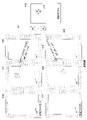
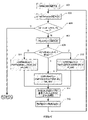
図1は、汎用的なブロック方式のハイブリッド映像符号化システムのブロック図である。入力映像信号102はブロック単位で処理される。既存のどの映像符号化標準でも映像ブロック単位は16×16画素からなり、そのようなブロック単位は一般に「マクロブロック」または「MB」と呼ばれる。現在、ITU-T/SG16/Q.6/VCEGおよびISO/IEC/MPEGのJCT-VC(Joint Collaborative Team on Video Coding)が、高効率映像符号化(High Efficiency Video Coding)または「HEVC」(非特許文献4)と呼ばれる次世代の映像符号化標準を開発中である。HEVCでは、拡張されたブロックサイズ(「符号化単位」または「CU」と呼ばれる)を使用して、高解像度(1080p以上)の映像信号を効率的に圧縮する。HEVCでは、CUは最大で64×64画素とすることができる。CUはさらに予測単位またはPUに分割することができ、PUに個別の予測方法が適用される。入力された映像ブロック(MBまたはCU)ごとに、空間予測(160)および/または時間予測(162)を行うことができる。空間予測(または「イントラ予測」)では、同じ映像ピクチャ/スライス中の既に符号化された隣接ブロックの画素を使用して現在の映像ブロックを予測する。空間予測は、映像信号に固有の空間的な冗長性を低減する。時間予測(「インター予測」または「動き補償予測」とも呼ばれる)は、既に符号化された映像ピクチャ(一般に「参照ピクチャ」と呼ばれる)の画素を使用して現在の映像ブロックを予測する。時間予測は、映像信号に固有の時間的な冗長性を低減する。所与の映像ブロックについての時間予測信号は、通常、現在のブロックと参照ピクチャ内のその予測ブロックとの間の動きの量および方向を示す1または複数の動きベクトルによってシグナリングされる。また、複数の参照ピクチャがサポートされる場合(H.264/AVCまたはHEVCなど近年の映像符号化標準の場合など)には、映像ブロックごとに、その参照ピクチャのインデックスも併せて送信される。参照ピクチャのインデックスは、再構築しようとする現在の映像ブロックの予測を生成するために、時間予測信号を取得すべき参照ピクチャストア(164)(「復号ピクチャバッファ」または「DPB」とも呼ぶ)内の参照ピクチャを特定する。空間予測および/または時間予測の後、エンコーダのモード決定ブロック(180)が、例えば伝送レート-歪み最適化の方法に基づいて最良の予測モードを選択する。そして現在の映像ブロックから予測ブロックが差し引かれ(116)、予測残余が変換され(104)、量子化される(106)。量子化された残余係数が逆量子化(110)および逆変換(112)されて、再構築された残余を形成し、それが予測ブロック(126)に入れられて再構築された映像ブロックを形成する。さらに、デブロッキングフィルタ、サンプル適応オフセット、および適合ループフィルタなどのインループフィルタリングが再構築された映像ブロックに適用(166)されてから、再構築された映像ブロックが参照ピクチャストア(164)に入れられ、将来の映像ブロックを符号化するために使用される。出力映像ビットストリーム120を形成するために、符号化モード(インターまたはイントラ)、予測モード情報、動き情報、および量子化された残余係数が全てエントロピー符号化部(108)に送られて、さらに圧縮されパックされてビットストリームを形成する。
FIG. 1 is a block diagram of a general-purpose block-type hybrid video coding system. The
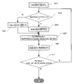
図2は、ブロック方式の映像デコーダの概略ブロック図である。映像ビットストリーム202はまず展開(unpack)され、エントロピー復号部208でエントロピー復号される。符号化モードおよび予測情報は空間予測部260(イントラ符号化の場合)か、または時間予測部262(インター符号化の場合)のどちらかに送られて、予測ブロックを形成する。インター符号化の場合、予測情報は、予測ブロックのサイズ、1または複数の動きベクトル(動きの方向および量を示す)、および1または複数の参照インデックス(予測信号を取得すべき参照ピクチャを示す)を含む。そして、動き補償予測が時間予測部262で適用されて時間予測ブロックを形成する。残余変換係数は、逆量子化部210および逆変換部212に送られて、残余ブロックを再構築する。そして226で予測ブロックと残余ブロックが共に足し合わされる。再構築されたブロックは参照ピクチャストア264に格納される前に、さらにインループフィルタリングをかけてもよい。参照ピクチャストア内の再構築された映像は、その後送出されて表示装置を駆動すると共に、将来の映像ブロックの予測に使用される。
FIG. 2 is a schematic block diagram of a block type video decoder. The
本明細書には、時間予測(図1のブロック162および図2のブロック262を参照されたい)に使用される参照ピクチャのシグナリングを改善するための柔軟性をもたらす方法およびシステムが記載される。詳細には、WD5(HEVC Working Draft 5)(非特許文献4、5)の種々の参照ピクチャリストのためのシグナリング方式および構築処理が改善される。
This specification describes methods and systems that provide flexibility for improving the signaling of reference pictures used for time prediction (see
一実施形態によれば、映像データ内の予測されたピクチャを復号するための参照ピクチャリストL0およびL1を生成する方法は、復号ピクチャバッファ(DPB)から参照ピクチャの第1の順序付けリストを生成するステップであって、前記リストは、現在のピクチャよりも時間的に前の参照ピクチャが前記DPBにある場合は、それらの参照ピクチャが前記現在のピクチャからの時間的距離に従って順に列記され、前記現在のピクチャよりも時間的に後の参照ピクチャが前記DPBにある場合はそれらの参照ピクチャが前記現在のピクチャからの時間的距離に従って順に列記され、長期参照ピクチャが前記DPBにある場合はそれらの参照ピクチャが前記DPBに格納されている順序で列記されるように順序付けられる、ステップと、前記DPBから参照ピクチャの第2の順序付けリストを生成するステップであって、前記リストは、前記DPBに前記現在のピクチャよりも時間的に後の参照ピクチャがある場合はそれらの参照ピクチャが前記現在のピクチャからの時間的距離に従って最初に順に列記され、前記現在のピクチャよりも時間的に後の参照ピクチャが前記DPBにある場合はそれらの参照ピクチャが前記現在のピクチャからの時間的距離に従って順に列記され、長期参照ピクチャが前記DPBにある場合はそれらの参照ピクチャが前記DPBに格納されている順序で列記されるように順序付けられる、ステップと、第1の順序付けリストおよび第2の順序付けリストからそれぞれ参照ピクチャを選択することによりリストL0およびL1の少なくとも一方を生成するステップとを含む。 According to one embodiment, a method of generating reference picture lists L0 and L1 for decoding a predicted picture in video data produces a first ordering list of reference pictures from the decoding picture buffer (DPB). The list is such that if reference pictures that are temporally earlier than the current picture are in the DPB, those reference pictures are listed in order according to the time distance from the current picture, and the current picture is described. If the reference pictures after the picture in time are in the DPB, those reference pictures are listed in order according to the time distance from the current picture, and if the long-term reference pictures are in the DPB, those references are made. A step in which the pictures are ordered to be listed in the order in which they are stored in the DPB, and a step of generating a second ordering list of reference pictures from the DPB, wherein the list is in the DPB at present. If there are reference pictures that are later in time than the current picture, those reference pictures are listed first in order according to the time distance from the current picture, and the reference pictures that are later in time than the current picture are listed. If they are in the DPB, they are listed in order according to their time distance from the current picture, and if the long-term reference pictures are in the DPB, they are listed in the order in which they are stored in the DPB. Includes a step that is ordered to be, and a step that produces at least one of lists L0 and L1 by selecting reference pictures from the first ordering list and the second ordering list, respectively.
別の実施形態によれば、PまたはBスライスヘッダを復号するために参照ピクチャリストのデコーダを初期化する方法は、
cIdx=0
NumRpsCurrTempList=NumRpsStCurr0+NumRpsStCurr1+NumRpsLtCurr
for(i=0;i<NumRpsStCurr0;cIdx++,i++)
RefPicSetCurrTempList0[cIdx]=RefPicSetStCurr0[i]
for(i=0;i<NumRpsStCurr1;cIdx++,i++)
RefPicSetCurrTempList0[cIdx]=RefPicSetStCurr1[i]
for(i=0;i<NumRpsLtCurr;cIdx++,i++)
RefPicSetCurrTempList0[cIdx]=RefPicSetLtCurr[i]
により第1の一時リストRefPicSetCurrTempList0を構築するステップを含む。
According to another embodiment, the method of initializing the reference picture list decoder to decode the P or B slice header is
cIdx = 0
NumRpsCurrTempList = NumRpsStCurr0 + NumRpsStCurr1 + NumRpsLtCurr
for (i = 0; i <NumRpsStCurr0; cIdx ++, i ++)
RefPicSetCurrTempList0 [cIdx] = RefPicSetStCurr0 [i]
for (i = 0; i <NumRpsStCurr1; cIdx ++, i ++)
RefPicSetCurrTempList0 [cIdx] = RefPicSetStCurr1 [i]
for (i = 0; i <NumRpsLtCurr; cIdx ++, i ++)
RefPicSetCurrTempList0 [cIdx] = RefPicSetLtCurr [i]
Includes a step to build the first temporary list RefPicSetCurrTempList0 by.
さらに別の実施形態によれば、複数の参照ピクチャリストの変更をシグナリングする方法は、統一されたシグナリング構文を使用して複数の参照ピクチャリストの変更をシグナリングするステップを含む。 According to yet another embodiment, the method of signaling changes in a plurality of reference picture lists comprises signaling changes in the plurality of reference picture lists using a unified signaling syntax.
もう一つの実施形態によれば、方法は、参照ピクチャリスト内のエントリの数を求めるステップと、前記参照ピクチャリスト内のエントリを特定する値を含むメッセージを生成するステップであって、前記値は、前記参照ピクチャリスト内のエントリの数が2つの場合は1ビットで表され、前記値は、参照ピクチャリスト内のエントリの数が3つ以上の場合は複数ビットで表され、参照ピクチャリスト内のエントリの数が1つの場合は前記メッセージは前記値を省略する、ステップとを含む。 According to another embodiment, the method is a step of determining the number of entries in the reference picture list and a step of generating a message containing a value identifying the entries in the reference picture list, wherein the values are. , The value is represented by one bit when the number of entries in the reference picture list is two, and the value is represented by multiple bits when the number of entries in the reference picture list is three or more. If the number of entries in is one, the message includes a step, omitting the value.
もう一つの実施形態によれば、第1の参照ピクチャのリストL0および第2の参照ピクチャのリストL1から、Bスライスの復号に使用される参照ピクチャの結合リストLCを作成する方法は、L0が2つ以上のエントリを含んでいるかどうかを判定するステップと、L1が2つ以上のエントリを含んでいるかどうかを判定するステップと、L0またはL1のいずれかが2つ以上のエントリを含んでいる場合、構文要素ref_idx_list_currを使用して、LCに追加すべき、L0およびL1の少なくとも一方のエントリを示すステップと、L0が1つのみのエントリを含んでいる場合、ref_idx_list_currを0に設定するステップと、L1が1つのみのエントリを含んでいる場合、ref_idx_list_currを0に設定するステップと、ref_idx_list_currの値を使用してLCを作成するステップとを含む。 According to another embodiment, the method of creating the combined list LC of the reference pictures used for decoding the B slice from the list L0 of the first reference picture and the list L1 of the second reference picture is L0. A step to determine if it contains more than one entry, a step to determine if L1 contains more than one entry, and one that either L0 or L1 contains more than one entry. If the syntax element ref_idx_list_curr is used to indicate at least one entry for L0 and L1 that should be added to the LC, and if L0 contains only one entry, the step to set ref_idx_list_curr to 0. If L1 contains only one entry, it includes a step of setting ref_idx_list_curr to 0 and a step of creating an LC using the value of ref_idx_list_curr.
添付図面と共に例として与えられる以下の説明から詳細な理解を得ることができる。 A detailed understanding can be obtained from the following description given as an example with the accompanying drawings.
時間予測に使用される参照ピクチャのシグナリングを改善するための柔軟性をもたらす方法およびシステムが提供される。 Methods and systems are provided that provide flexibility to improve the signaling of reference pictures used for time prediction.
本明細書で使用される場合、用語「時間予測」、「動き予測」、「動き補償予測」、および「インター予測」は同義で使用され、用語「参照ピクチャストア」、「復号ピクチャバッファ」、および「DPB」は同義で使用される。 As used herein, the terms "time prediction", "motion prediction", "motion compensation prediction", and "inter-prediction" are used interchangeably, the terms "reference picture store", "decrypted picture buffer", and the like. And "DPB" are used synonymously.
H.264およびHEVC WD 5で採用された既知の技術によると、単方向予測技術または双方向予測技術を使用して映像ブロックの時間予測が行われることができる。そのような技術で予測を行うために、参照ピクチャリストがシグナリングされ、構築される。単方向予測の場合は、現在のピクチャのブロックが予測される参照ピクチャのリストは1つあればよい。双方向予測の場合は、L0およびL1の2つのリストがあり、各リストから1つの参照ピクチャが選択されて、現在のピクチャのブロックの予測を形成する。さらに、双方向予測技術の提案がなされており(ただし執筆の時点では最新のHEVC WD9(非特許文献9)にはもう取り入れられていない)、これは、最初の2つのリストL0とL1を組み合わせたものであり第3のリストを使用するものであり、このリストを本明細書では「リストLC」と称する。本明細書に記載されるのは、全ての参照ピクチャリストL0、L1および/またはLCの変更の構文(Syntax)をシグナリングするための効率的で統一された技術、並びに結合された参照ピクチャリストLCをシグナリングする技術の方法およびシステムである。
H. According to the known techniques adopted in 264 and
図3は、インター予測処理部(例えば図1のブロック162)によって行われることができる単一の参照ピクチャリスト301による単方向予測を図式的に説明する図である。単方向予測技術によると、参照ピクチャリスト301は、隣接する既に符号化された映像フレームにある映像ブロック、例えばブロック304へのリンクを含むことにより現在の映像ブロックを予測し、従って、時間の相関関係を活用し、映像信号に固有の時間的な冗長性を解消することができる。そのような既に符号化された映像フレームは、復号ピクチャバッファ(DPB、例えば図1の参照ピクチャストア164)に格納される。H.264/AVCおよびHEVC WD5では、2つ以上の参照ピクチャを使用することができる。図3では、refn(n=0...N-1)と表記するN個の参照ピクチャ303のリストを使用して現在のピクチャ305の映像ブロック307を予測することができる。(mvx,mvy)の動きベクトルで現在のブロック307を予測する基準としてrefmが選択されるものとする。時間予測は次のように行われる。
P(x,y)=refm(x-mvx,y-mvy) 式(1)
refm(x,y)は、参照ピクチャrefm内の位置(x,y)における画素値であり、P(x,y)が予測されるブロックである。既存の映像符号化システムは、端数のある画素精度のインター予測に対応することができる(非特許文献1、2、4)。動きベクトル(mvx,mvy)が端数のある画素値を有する場合は、補間フィルタが適用されて端数のある画素位置における画素値を得る。
FIG. 3 is a diagram schematically illustrating unidirectional prediction by a single
P (x, y) = ref m (x-mvx, y-mvy) Equation (1)
ref m (x, y) is a pixel value at a position (x, y) in the reference picture ref m , and is a block in which P (x, y) is predicted. The existing video coding system can support inter-prediction of pixel accuracy with a fraction (
式(1)で、時間予測は1つのソース(即ち、refn)から得られ、これは一般に単方向予測と呼ばれる。そのピクチャまたはスライスの中にある全てのブロックが単方向予測を使用して予測されるピクチャまたはスライス(映像ブロックの群)を通例PピクチャまたはPスライスと呼ぶ。 In equation (1), the time prediction is obtained from one source (ie ref n ), which is commonly referred to as unidirectional prediction. A picture or slice (a group of video blocks) in which all blocks in the picture or slice are predicted using unidirectional prediction is usually referred to as a P-picture or P-slice.
時間予測の精度を向上するために、より新しいブロック方式の映像符号化システムは多仮説(multi-hypothesis)予測にも対応しており、この予測では異なる参照ピクチャからの複数の予測信号を合成して予測信号が形成される。通常使用される形態の多仮説予測は双方向予測と呼ばれ、各々が異なる参照ピクチャリストのピクチャから得られる2つの予測信号が組み合わせられて現在のブロックの予測を形成する。図4は双方向予測の説明を助ける図である。詳細には、2つの参照ピクチャリスト、リスト0 401およびリスト1 403を使用して現在のピクチャの映像ブロックを予測する。リスト0は合計N0個のピクチャ404を含み、リスト1は合計N1個のピクチャ404を含んでいる。図4で、動きベクトル(mvx0,mvy0)を持つリスト0 401のrefm0と、動きベクトル(mvx1,mvy1)を持つリスト1 403のrefm1が選択されて、式(2)のように現在のピクチャ412の予測ブロック410の双方向予測を形成する。
To improve the accuracy of time prediction, a newer block-based video coding system also supports multi-hypothesis prediction, which synthesizes multiple prediction signals from different reference pictures. A prediction signal is formed. A commonly used form of multi-hypothesis prediction is called bidirectional prediction, in which two prediction signals, each obtained from a picture in a different reference picture list, are combined to form the prediction of the current block. FIG. 4 is a diagram that aids in the explanation of bidirectional prediction. Specifically, two reference picture lists,
![]()
![]()
ここで、P0(x,y)およびP1(x,y)はそれぞれ第1および第2の予測ブロック407および408である。ピクチャまたはスライスは、通例、そのピクチャまたはスライス中のブロックの少なくとも一部が双方向予測を使用して予測される(その他のブロックは単方向予測を使用して予測することができる)場合にBピクチャまたはBスライスと呼ばれる。双方向予測は、MPEG2/4、VC1、H.264、およびHEVCなど、近年の映像符号化標準の全てでサポートされている。 Here, P 0 (x, y) and P 1 (x, y) are the first and second prediction blocks 407 and 408, respectively. A picture or slice is typically B when at least a portion of the blocks in the picture or slice are predicted using bidirectional prediction (other blocks can be predicted using unidirectional prediction). Called a picture or B slice. Bidirectional prediction is based on MPEG2 / 4, VC1, H.M. It is supported by all modern video coding standards such as 264 and HEVC.
予測の後、第1の加算器(図1の116参照)で予測ブロックP(x,y)が元の映像ブロックから差し引かれて予測残余ブロックを形成する。予測残余ブロックは、変換部104で変換され、量子化部106で量子化される。そして、量子化された残余変換係数ブロックはエントロピー符号化部108に送られてエントロピー符号化され、それによりさらにビットレートを減らす。次いで、エントロピー符号化された残余係数がパックされて、出力映像ビットストリーム120の一部を形成する。
After the prediction, the prediction block P (x, y) is subtracted from the original video block by the first adder (see 116 in FIG. 1) to form the prediction residual block. The predicted residual block is converted by the
Pピクチャ/スライスの参照ピクチャリストの構造は、全てのブロックが単方向予測を使用して予測され、即ち、1つの参照ピクチャリストで済むため、比較的単純である。一方、Bピクチャ/スライスでは、一部のブロックは双方向予測を使用して予測され、他のブロックは単方向予測を使用して予測される場合がある。HEVCでは、双方向予測のための参照ピクチャリスト、即ち、図4のリスト0(またはL0)401およびリスト1(またはL1)403はH.264/AVCと同じである。ただし、HEVCは、単方向予測のための参照ピクチャリストをBピクチャ/スライスについて形成する方法がH.264/AVCと異なる。H.264/AVCでは、Bピクチャ/スライスの映像ブロックに対する単方向予測は、まず、予測がL0から行われるか、またはL1から行われるかを示し、次いでその特定のリストのref_idxを示す必要がある。HEVCでは、第4回のJCT-VCの会合で、結合参照ピクチャリストの概念が提示された(非特許文献8)。本開示で「LC」と呼ぶ結合リストは、L0とL1を共に組み合わせることによって形成され、LCは、Bピクチャ/スライス内で単方向予測を使用して予測される全てのブロックのための唯一の参照ピクチャリストの役割を果たす。 The structure of the P-picture / slice reference picture list is relatively simple because all blocks are predicted using unidirectional prediction, i.e., only one reference picture list is required. On the other hand, in B-picture / slice, some blocks may be predicted using bidirectional prediction and others may be predicted using unidirectional prediction. In HEVC, the reference picture list for bidirectional prediction, ie, Listing 0 (or L0) 401 and Listing 1 (or L1) 403 in FIG. Same as 264 / AVC. However, HEVC has a method of forming a reference picture list for unidirectional prediction for B pictures / slices. Different from 264 / AVC. H. In 264 / AVC, a unidirectional prediction for a B-picture / slice video block must first indicate whether the prediction is made from L0 or L1 and then the ref_idx of that particular list. At HEVC, the concept of a combined reference picture list was presented at the 4th JCT-VC meeting (Non-Patent Document 8). The binding list referred to herein as "LC" is formed by combining L0 and L1 together, and LC is the only block for all blocks predicted using unidirectional prediction within a B picture / slice. Serves as a reference picture list.
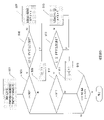
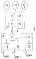
現在HEVCでは、デフォルトで、結合リストLCは、L0およびL1から重複しないピクチャを交互に取り出すことによって形成され、それにより結合リストの冗長性が最小になることを保証している。デフォルトの結合リスト生成のフローチャートを図5に示す。詳細には、それぞれリストL0、L1およびLCを指すインデックスi、jおよびkが501で初期化されると共に、2つのリストL0およびL1も初期化される。判定ブロック503で、L0の全ての参照ピクチャが検査済みであるかどうかが判定される。全てが検査済みではない場合は、判定ブロック505に進み、L0のインデックスiの参照ピクチャが既に結合リストLCにあるかどうかが判定される。まだ結合リストLCにない場合は、リストLCに追加され、結合リストLCのインデックスが増分される(507)。インデックスiも増分される(509)。一方、L0のインデックスiの参照ピクチャが既に結合リストLCにある場合は、505から直接509に進む。次いで、リストL1のインデックスjにある参照ピクチャに関して基本的に同じ処理が行われる。具体的には、判定ブロック511で、L1内の全ての参照ピクチャが検査済みであるかどうかが判定される。全てが検査済みではない場合は、判定ブロック513に進み、L1のインデックスjにある参照ピクチャが既に結合リストLCにあるかどうかが判定される。まだリストLCにない場合は追加され、LCのインデックスが増分される(515)。L1のインデックスjも増分される(517)。一方、L1のインデックスjの参照ピクチャが既にLCにある場合は、513から直接517に進む。判定ブロック519で理解されるように、この処理は、2つのリストの末尾に達するまで、リストL0とL1それぞれの次の参照ピクチャを交互に検査することにより繰り返される。
Currently in HEVC, by default, the join list LC is formed by alternating non-overlapping pictures from L0 and L1, thereby ensuring that the join list has minimal redundancy. The flowchart of the default join list generation is shown in FIG. Specifically, the indexes i, j and k pointing to the lists L0, L1 and LC are initialized at 501, and the two lists L0 and L1 are also initialized. In the
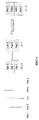
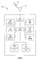
図5のフローチャートで説明する処理で作成される結合リストLCの一例を図6に示す。この例では、符号化対象の現在のピクチャは時間的に参照ピクチャ2と4の間にある。また、L0は参照ピクチャRef2、Ref1およびRef4をこの順序で含み、L1は参照ピクチャRef4、Ref5およびRef2をこの順序で含んでいる。図5の流れに従い、図6の例は、それぞれL0およびL1の3つの参照ピクチャ各々が既にLCにあるかどうかを交互に調べ、それまでに存在していない参照ピクチャを全てLCに追加することによって結合リストLCを形成する。その結果、図6の例では、L0の最初の参照ピクチャ(Ref2)、L1の最初の参照ピクチャ(Ref4)、L0の2番目の参照ピクチャ(Ref1)、L1の2番目の参照ピクチャ(Ref5)を順にLCに追加することにより4つの参照ピクチャを含む結合リストLCを形成する。L0の3番目の参照ピクチャ(Ref4)は、L1の最初の参照ピクチャと同じピクチャであるために既にLCに追加されているので飛ばし、L1の3番目の参照ピクチャ(Ref2)は、L0の最初の参照ピクチャと同じピクチャであるために既にLCに追加されているので飛ばす。
FIG. 6 shows an example of the combined list LC created by the process described in the flowchart of FIG. In this example, the current picture to be encoded is temporally between
図6の各リストL0、L1およびLCにおける参照ピクチャの符号化の順序は、参照ピクチャRef4およびRef5(表示の順序では後になる)が現在のピクチャより前に符号化されるため、表示の順序とは異なることに留意されたい。リストL0とL1を往復することによってLCを構築するこのデフォルトの処理では、LCの各エントリが符号化映像列中で重複しないピクチャを表し、従って冗長性を最小にすることを保証する。 The order of coding of the reference pictures in each of the lists L0, L1 and LC of FIG. 6 is the order of display because the reference pictures Ref4 and Ref5 (which are later in the display order) are coded before the current picture. Note that is different. This default process of constructing the LC by going back and forth between lists L0 and L1 ensures that each entry in the LC represents a non-overlapping picture in the coded video sequence and thus minimizes redundancy.
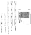
このデフォルトの処理は参照ピクチャの並べ替え(即ち、デフォルトのリストサイズと異なるリストサイズにすること、リストのエントリをデフォルトの処理と異なる順序にすること、リスト中で一部エントリを繰り返すこと、および/またはリストから一部のエントリを削除すること等)には対応しないので、HEVC WD5では追加的な構文要素が使用されて(下記の表1参照)、結合リストLCの変更処理に対応する。図7は結合リスト変更の2つの例を示し、第1の例は並べ替えたLCを示し、第2の例は、エントリが繰り返され、デフォルトのLCサイズ(4エントリ)と異なる変更後のLCサイズ(3エントリ)を有するLCを示す。HEVC WD5では、結合参照ピクチャリストLCは、表1の構文表を使用してシグナリングされる。 This default process is to sort the referenced pictures (ie, make the list size different from the default list size, make the list entries different from the default process, repeat some entries in the list, and so on. / Or deleting some entries from the list, etc.) is not supported, so additional syntax elements are used in HEVC WD5 (see Table 1 below) to support the process of changing the join list LC. FIG. 7 shows two examples of join list changes, the first example shows the sorted LCs, the second example is the changed LCs where the entries are repeated and different from the default LC size (4 entries). Shows LC with size (3 entries). In HEVC WD5, the join reference picture list LC is signaled using the syntax table in Table 1.

参照ピクチャリスト組合せの意味は以下の通りである。
ref_pic_list_combination_flagが1に等しい場合は、参照ピクチャリスト0と参照ピクチャリスト1が組み合わせられて、単方向予測対象のブロックまたは他の予測単位に使用する追加的な結合参照ピクチャリストを生成することを意味する。このフラグが0に等しいときは、参照ピクチャリスト0と参照ピクチャリスト1が全く同じであり、従って参照ピクチャリスト0を結合参照ピクチャリストとして使用できることを意味する。結合参照ピクチャリストは、表1に定義されるループの開始時に空(empty)に設定される。
num_ref_idx_lc_active_minus1+1は、結合参照ピクチャリスト内で参照ピクチャリスト0または参照ピクチャリスト1から選択される参照ピクチャの数を指定する。
ref_pic_list_modification_flag_lcが1に等しい場合は、結合参照ピクチャリストのエントリと参照ピクチャリスト0および参照ピクチャリスト1のエントリとの対応付けを指定するために構文要素pic_from_list_0_flagとref_idx_list_currが存在することを示す。
ref_pic_list_modification_flag_lcが0に等しい場合は、それらの構文要素が存在しないことを示す。結合参照ピクチャリストは、HEVC WD 5の下位条項8.2.2.4に規定されるように初期化される。
pic_from_list_0_flagは、結合参照ピクチャリストに追加される現在の参照ピクチャが参照ピクチャリスト0のピクチャであるか、参照ピクチャリスト1のピクチャであるかを示す。このフラグが1に等しい場合、参照ピクチャリスト0のピクチャであり、CurrRefPicListは参照ピクチャリスト0になる。このフラグが0に等しい場合は、参照ピクチャリスト1のピクチャであり、CurrRefPicListは参照ピクチャリスト1になる。
ref_idx_list_currは、参照ピクチャリストの結合の末尾に付加すべき、CurrRefPicListにあるピクチャの参照インデックスを示す。
The meaning of the reference picture list combination is as follows.
If ref_pic_list_combination_flag is equal to 1, it means that
If ref_pic_list_modification_flag_lc is equal to 1, it indicates that the syntax elements pic_from_list_0_flag and ref_idx_list_curr are present to specify the correspondence between the entries in the combined reference picture list and the entries in
If ref_pic_list_modification_flag_lc is equal to 0, it indicates that those syntax elements do not exist. The combined reference picture list is initialized as specified in subclause 8.2.2.4 of
pic_from_list_0_flag indicates whether the current reference picture added to the combined reference picture list is a picture in
ref_idx_list_curr indicates the reference index of the picture in the CurrRefPicList that should be added to the end of the join of the reference picture list.
参照ピクチャリストL0およびL1には変更を加えることができる。参照ピクチャリストL0およびL1の使用を柔軟にするために、デフォルトの構築処理と変更を加えた構築処理もHEVCでサポートされる。L0およびL1についての現在の参照ピクチャリストの構築および変更処理は、2011年11月の第7回のJCT-VCの会合で提示され(非特許文献6、7)、HEVC WD5に採用された(非特許文献4)。HEVC WD5におけるリスト0およびリスト1の参照ピクチャリスト変更の構文を下記の表2に示し、図8にフローチャート形式で表す。
Changes can be made to the reference picture lists L0 and L1. In order to make the use of reference picture lists L0 and L1 flexible, the default build process and the modified build process are also supported in HEVC. The process of constructing and modifying the current reference picture list for L0 and L1 was presented at the 7th JCT-VC meeting in November 2011 (Non-Patent Documents 6 and 7) and adopted by HEVC WD5 (Non-Patent Documents 6 and 7). Non-Patent Document 4). The syntax for changing the reference picture list of

参照ピクチャリスト変更の意味は以下の通りである。 The meaning of changing the reference picture list is as follows.
構文要素list_modification_idcおよびref_pic_set_idxは、初期の参照ピクチャリストから、スライスの復号に使用される参照ピクチャリストへの変更を指定する。 The syntax elements list_modification_idc and ref_pic_set_idx specify changes from the initial reference picture list to the reference picture list used to decrypt the slice.
ref_pic_list_modification_flag_l0が1に等しい場合は、参照ピクチャリスト0を指定する構文要素list_modification_idcが存在することを示し、ref_pic_list_modification_flag_l0が0に等しい場合は、その構文要素が存在しないことを示す。ref_pic_list_modification_flag_l0が1に等しいとき、ref_pic_list_modification_fiag_l0の後にlist_modification_idcが3に等しくない回数はnum_ref_idx_l0_active_minus1+1を超えてはならない。
If ref_pic_list_modification_flag_l0 is equal to 1, it indicates that the syntax element list_modification_idc that specifies the
ref_pic_list_modification_flag_l1が1に等しい場合は、参照ピクチャリスト1を指定する構文要素list_modification_idcが存在することを示し、ref_pic_list_modification_flag_l1が0に等しい場合はその構文要素が存在しないことを示す。ref_pic_list_modification_flag_l1が1に等しい場合、ref_pic_list_modification_fiag_l1の後にlist_modification_idcが3に等しくない回数はnum_ref_idx_l1_active_minus1+1を超えてはならない。
If ref_pic_list_modification_flag_l1 is equal to 1, it indicates that the syntax element list_modification_idc that specifies the
list_modification_idcは、ref_pic_set_idxと共に、どの参照ピクチャを対応付けし直すかを指定する。list_modification_idcの値を表3に指定する。ref_pic_list_modification_flag_l0またはref_pic_list_modification_flag_l1の直後の最初のlist_modification_idcの値は3に等しくあってはならない。 list_modification_idc, along with ref_pic_set_idx, specifies which reference picture to remap. Specify the value of list_modification_idc in Table 3. The value of the first list_modification_idc immediately after ref_pic_list_modification_flag_l0 or ref_pic_list_modification_flag_l1 must not be equal to 3.

ref_pic_set_idxは、参照ピクチャリストの現在のインデックスで参照される参照ピクチャのRefPicSetStCurr0、RefPicSetStCurr1、または、RefPicSetLtCurrのインデックスを指定する。ref_pic_set_idxの値は、0以上max_num_ref_frames以下の範囲とする。 ref_pic_set_idx specifies the index of RefPicSetStCurr0, RefPicSetStCurr1, or RefPicSetLtCurr of the reference picture referenced in the current index of the reference picture list. The value of ref_pic_set_idx shall be in the range of 0 or more and max_num_ref_frames or less.
図8は、一例としてL0を使用して、L0およびL1の参照ピクチャリストを変更する処理のフローチャートを示す。参照ピクチャのセット(RefPicSetStCurr0、RefPicSetStCurr1、およびRefPicSetLtCurr)の定義を含む、L0およびL1の詳細な変更処理は、HEVC WD5(非特許文献4)および非特許文献6、7の作業草案部分で得ることができる。以下に、図8の参照ピクチャセットを簡略的に定義する。
RefPicSetStCurr0:表示順序が早い、即ち、現在のピクチャよりも前の短期参照ピクチャ(例えば図6のRef1およびRef2)
RefPicSetStCurr1:表示順序が遅い、即ち、現在のピクチャよりも後の短期参照ピクチャ(例えば図6のRef4およびRef5)
RefPicSetLtCurr:長期参照ピクチャ(図6には図示せず)
FIG. 8 shows a flowchart of a process of changing the reference picture list of L0 and L1 using L0 as an example. Detailed modification of L0 and L1, including definitions of a set of reference pictures (RefPicSetStCurr0, RefPicSetStCurr1, and RefPicSetLtCurr), may be obtained in working draft parts of HEVC WD5 (Non-Patent Document 4) and Non-Patent Documents 6 and 7. can. The reference picture set of FIG. 8 is simply defined below.
RefPicSetStCurr0: Short-term reference pictures that are displayed earlier, that is, before the current picture (eg Ref1 and Ref2 in FIG. 6).
RefPicSetStCurr1: Slow display order, i.e., short-term reference pictures after the current picture (eg Ref4 and Ref5 in FIG. 6).
RefPicSetLtCurr: Long-term reference picture (not shown in FIG. 6)
801で、リストL0のインデックスがゼロに初期化される。803で、ref_modification_idcが読み込まれる。ref_modification_idcは、0、1、2および3の4つの値を有することができる。3の値は、それ以上変更が行われず、変更処理を終了してよいことを意味する。(0、1または2の値を有するref_modification_idcでシグナリングされる所期の変更を下記でステップ811、813および815との関係で説明する。)従って、判定ステップ805で、ref_modification_idcが3に設定されている場合は、それ以上構文を読み出さない。3以外の値である場合は、807でref_pic_set_idxが読み込まれる。これは、DPBにある3つのピクチャセット(即ち、復号対象の現在のピクチャより「前」のピクチャのセット、「後」のピクチャセット、または長期のピクチャセット)の1つを指すインデックスである。(下記で説明するように、3つのセットのうち特定の1つの選択がステップ811、813および815で行われる)。判定ステップ809で、ref_modification_idcが0であるか、1であるか、または2であるかが判定される。0の場合は、811で、リストL0への現在のインデックスであるRefIdxL0にあるリストL0のエントリが、DPB内で短期の時間的に前の参照ピクチャのセットの中の位置ref_pic_set_idcにある、表示順序がより早い短期参照ピクチャ(即ち、RefPicSetStCurr0)に設定される。そうではなく、1の場合は、813で、リストL0への現在のインデックスであるRefIdxL0にあるリストL0のエントリが、DPB内で短期で時間的に後の参照ピクチャのセット中の位置ref_pic_set_idcにある、符号化対象の現在のピクチャよりも表示順序が遅い短期参照ピクチャ(即ち、RefPicSetStCurr1)に設定される。最後に2の場合は、815で、リストL0への現在のインデックスであるRefIdxL0にあるリストL0のエントリが、DPB内で長期参照ピクチャのセット中の位置ref_pic_set_idcにある長期参照ピクチャ(即ち、RefPicSetLtCurr)に設定される。
At 801 the index of list L0 is initialized to zero. At 803, ref_modification_idc is read. ref_modification_idc can have four values of 0, 1, 2 and 3. A value of 3 means that no further changes are made and the change process may be terminated. (The desired changes signaled by ref_modification_idc having a value of 0, 1 or 2 will be described below in relation to
3つの場合のいずれでも次いで817に進み、リストL0内で今回変更されたエントリの後にあり、今回変更されたエントリと同じピクチャを参照するエントリが全てL0から削除される。819で、リストL0のインデックスが増分され、803に戻る。この処理はref_modification_idcが3の値になり、それ以上変更が行われないことを示すまで継続する。 In any of the three cases, the next step is to proceed to 817, and all the entries in the list L0 that follow the changed entry and refer to the same picture as the changed entry are deleted from L0. At 819, the index of list L0 is incremented back to 803. This process continues until ref_modification_idc has a value of 3 and indicates that no further changes will be made.
再度L0を例として使用して、図9に、(1)短期の時間的に前の参照ピクチャセット、即ち、RefPicSetStCurr0にある参照ピクチャRef2およびRef1(この順序)、および(2)短期で時間的に後の参照ピクチャのセット、即ち、RefPicSetStCurr1にある参照ピクチャRef4およびRef5(この順序)、を保持しているDPBについて図8のフローチャートで概説した参照ピクチャリスト変更処理の結果を示す。説明を簡潔にするために、かつ一般性を失うことなく、図9の例は、長期参照ピクチャの使用に関連するRefPicSetLtCurrは考慮せず、RefPicSetStCurr1およびRefPicSetStCurr1で示される短期参照ピクチャの使用のみを考慮する。 Using L0 as an example again, FIG. 9 shows (1) the short-term temporally previous reference picture set, ie, the reference pictures Ref2 and Ref1 (in this order) in RefPicSetStCurr0, and (2) the short-term temporal. The results of the reference picture list change process outlined in the flowchart of FIG. 8 are shown for the DPB holding the later set of reference pictures, that is, the reference pictures Ref4 and Ref5 (in this order) in RefPicSetStCurr1. For brevity and without loss of generality, the example in Figure 9 does not consider RefPicSetLtCurr related to the use of long-term reference pictures, only the use of short-term reference pictures indicated by RefPicSetStCurr1 and RefPicSetStCurr1. do.
図9に示すように、デフォルトのリストL0は、参照ピクチャRef2、Ref1、Ref4およびRef5から(この順序で)構成される。図9の例では、L0の最後のエントリの単純な変更が求められる。図8の処理では、変更が必要ない最初の3つのエントリを含むL0のエントリごとに1度ステップ803~819をループすることが必要となり、また、エントリごとにref_modification_idcとref_pic_set_idxをシグナリングし、その後さらに、処理が終了したことを、値が3のもう1つのref_modification_idcをさらにシグナリングすることによってシグナリングすることが必要となる。従って、対象の変更リストL0に到達するために5ステップが使用される。最後のステップを除く各ステップで、2つの構文要素(list_modification_idcおよびref_pic_set_idx)がシグナリングされ、追加的な変数RefIdxが維持され、増分される。
As shown in FIG. 9, the default list L0 is composed (in this order) of reference pictures Ref2, Ref1, Ref4 and Ref5. In the example of FIG. 9, a simple change of the last entry of L0 is required. In the process of FIG. 8, it is necessary to
さらに、LCの参照ピクチャリスト変更の処理(上記表1)とL0/L1の変更処理(上記表2および3)を比較すると、HEVC WD5におけるLCの変更処理はL0およびL1とは異なることに留意されたい。詳細には、LCの変更処理の方が単純である。これは、その特定のリスト中のエントリごとに2つの構文要素(list_modification_idcおよびref_pic_set_idx)をシグナリングするのではなく、変更後のLCの各エントリが明示的にシグナリングされるためである。 Further, comparing the LC reference picture list change process (Table 1 above) and the L0 / L1 change process (Tables 2 and 3 above), it should be noted that the LC change process in HEVC WD5 is different from L0 and L1. I want to be. In detail, the LC change process is simpler. This is because each entry in the modified LC is explicitly signaled, rather than signaling two syntax elements (list_modification_idc and ref_pic_set_idx) for each entry in that particular list.
これらのリスト変更処理を統合し、必要なシグナリングが低減されたより単純なL0およびL1のための変更処理を提供する方法が本明細書に記載される。 A method of integrating these list modification processes to provide simpler modification processes for L0 and L1 with reduced required signaling is described herein.
一実施形態では、参照ピクチャリストを結合する処理の効率を改善する方法が提供される。表4は、本発明の一実施形態による結合参照ピクチャリストを形成するための疑似コードを示す。表1(結合リストLCを形成するHEVC WD5の方法の疑似コード)からの変更をアスタリスクで示す。 In one embodiment, a method of improving the efficiency of the process of combining reference picture lists is provided. Table 4 shows pseudo-code for forming a combined reference picture list according to an embodiment of the present invention. Changes from Table 1 (pseudocode for the method of HEVC WD5 forming the join list LC) are indicated by asterisks.

構文ref_idx_list_currは、L0(pic_from_list_0_flagが1の場合)、またはL1(pic_from_list_1_flagが0の場合)が2つ以上のエントリを含んでいるときにのみシグナリングされることに留意されたい。これは、対応するリスト(L0またはL1)が1つしかエントリを含まない場合は何も送られる必要がないためである。従って、シグナリングの量が低減される。 Note that the syntax ref_idx_list_curr is signaled only when L0 (when pic_from_list_0_flag is 1) or L1 (when pic_from_list_1_flag is 0) contains more than one entry. This is because if the corresponding list (L0 or L1) contains only one entry, nothing needs to be sent. Therefore, the amount of signaling is reduced.
また、ue(v)を使用する代わりに、te(v)が、ref_idx_list_currをシグナリングするより効率的な手段になる。これは、エントロピー符号化方法te(v)(H.264(非特許文献1)の下位条項9.1)は、ref_idxのような構文要素を符号化するために特に設計されたものであるためである。Ue(v)(指数ゴロム符号として知られる)は、3ビットを使用して値1を送ることができる。一方、te(v)を使用して、はじめにref_idx_list_currにある可能性のある値の数を判定し(L0およびL1を調べることにより)、2つの値しかない場合は、1ビットを使用して構文要素が送られることができる。3つ以上の値がある場合はue(v)を使用することができる。
Also, instead of using ue (v), te (v) is a more efficient means of signaling ref_idx_list_curr. This is because the entropy coding method te (v) (subclause 9.1 of H.264 (Non-Patent Document 1)) is specifically designed to encode syntactic elements such as ref_idx. .. Ue (v) (known as the exponential Golomb code) can send the
即ち、構文要素がte(v)と符号化される場合は、構文要素の取り得る値の範囲をまず判定する。構文要素について取り得る値の範囲が0~1である場合は、1ビットのみを使用して構文要素を符号化し、それによりシグナリングのオーバーヘッドを節減する。そうでなく、構文要素の範囲が0~xの間である場合(x>1)は、ue(v)を使用して構文要素を符号化する。 That is, when the syntax element is encoded as te (v), the range of possible values of the syntax element is first determined. If the range of possible values for a syntax element is 0 to 1, only one bit is used to encode the syntax element, thereby reducing signaling overhead. Otherwise, if the range of the syntax element is between 0 and x (x> 1), ue (v) is used to encode the syntax element.
このように、本システムは、ref_idx_list_currの取り得る値に基づいて判定を行う。構文要素ref_idx_list_currの取り得る値が1つのみの場合は、何も送信されない。これは、他の値に基づいてエンコーダとデコーダの双方でその値を判断できるためである。構文要素ref_idx_list_currの取り得る値が2つある場合は、1ビットが送信される。そうでなく、構文要素ref_idx_list_currの取り得る値が3つ以上ある場合は、ue(v)を使用してref_idx_list_currを符号化する。 In this way, the system makes a judgment based on the possible values of ref_idx_list_curr. If the syntax element ref_idx_list_curr has only one possible value, nothing is sent. This is because both the encoder and the decoder can determine the value based on the other values. If the syntax element ref_idx_list_curr has two possible values, one bit is transmitted. Otherwise, if the syntax element ref_idx_list_curr has three or more possible values, ue (v) is used to encode ref_idx_list_curr.
従って、HEVC WD5と比べてシグナリングオーバーヘッドの節減が実現される。 Therefore, the signaling overhead can be reduced as compared with HEVC WD5.
さらに他の実施形態では、L0およびL1を変更するために使用できる、単一の統一された参照ピクチャリスト変更処理が開示される。この実施形態によると、L0およびL1の参照ピクチャリスト変更処理では、表5に示す構文を使用する。表2の疑似コード(即ち、HEVC WD5におけるリスト0およびリスト1の参照ピクチャリスト変更構文)と比較した変更をアスタリスクで示す。
In yet another embodiment, a single unified reference picture list modification process that can be used to modify L0 and L1 is disclosed. According to this embodiment, the reference picture list change processing of L0 and L1 uses the syntax shown in Table 5. The changes compared to the pseudocodes in Table 2 (ie, the reference picture list change syntax of

参照ピクチャリスト変更の意味は以下の通りである。
構文要素ref_pic_set_idxを使用して、初期の参照ピクチャリストから変更後の参照ピクチャリストへの変更を指定する。
ref_pic_list_modification_flag_l0が1に等しいときは、参照ピクチャリスト0を指定するために構文要素ref_pic_set_idxが存在することを示す。
ref_pic_list_modification_flag_l0が0に等しいときは、この構文要素が存在しないことを示す。
ref_pic_list_modification_flag_l1が1に等しいときは、参照ピクチャリスト1を指定する構文要素ref_pic_set_idxが存在することを示す。
ref_pic_list_modification_flag_l1が0に等しいときは、この構文要素が存在しないことを示す。
The meaning of changing the reference picture list is as follows.
Use the syntax element ref_pic_set_idx to specify changes from the initial reference picture list to the modified reference picture list.
When ref_pic_list_modification_flag_l0 is equal to 1, it indicates that the syntax element ref_pic_set_idx exists to specify the
When ref_pic_list_modification_flag_l0 is equal to 0, it indicates that this syntax element does not exist.
When ref_pic_list_modification_flag_l1 is equal to 1, it indicates that the syntax element ref_pic_set_idx that specifies the
When ref_pic_list_modification_flag_l1 is equal to 0, it indicates that this syntax element does not exist.
ref_pic_set_idxは、RefPicSetCurrTempListXのピクチャのインデックスを参照ピクチャリストLXの現在の位置に配置することを指定する(Xは、リストL0に関連する場合は0、リストL1に関連する場合は1になる)。構文ref_pic_set_idxは、リストLX内で0以上max_num_ref_frames-1以下の範囲でなければならない。構文要素ref_pic_set_idxが存在しない場合は、0に設定される。
ref_pic_set_idx specifies that the index of the picture in RefPicSetCurrTempListX should be placed at the current position in the reference picture list LX (X is 0 if it is related to list L0, 1 if it is related to list L1). The syntax ref_pic_set_idx must be in the
この新たな処理は、事例によっては(実際には恐らくは大半の事例で)シグナリングを大幅に減らす。簡単に述べると、表2の構文や図8のフローチャートのようにリストのエントリごとに行う変更の種類および使用する参照ピクチャのDPBのインデックスをシグナリングする代わりに、本発明の処理は、DPBへのインデックスのみをシグナリングし、リスト変更処理の終了を表す追加的な信号を必要としない。 This new process significantly reduces signaling in some cases (in fact, perhaps in most cases). Briefly, instead of signaling the type of changes made for each entry in the list and the index of the DPB of the reference picture to be used, as in the syntax of Table 2 and the flowchart of FIG. 8, the processing of the present invention is to the DPB. It signals only the index and does not require an additional signal to indicate the end of the list change process.
上記の表5に開示する処理では、L0および/またはL1各々の参照ピクチャの中間リストRefPicSetCurrTempListXを使用し、Xは、どちらの被変更リストを検討するかに応じて0または1を表す。この方式では、参照ピクチャリストに対して修正された初期化処理が提供される。この初期化処理は、PまたはBスライスのヘッダを復号する際に呼び出される。PまたはBスライスを復号する際には、RefPicSetStCurr0、RefPicSetStCurr1、またはRefPicSetLtCurrに少なくとも1つの参照ピクチャがある可能性がある。 In the process disclosed in Table 5 above, an intermediate list RefPicSetCurrTempListX of each reference picture of L0 and / or L1 is used, where X represents 0 or 1 depending on which modified list is considered. This method provides a modified initialization process for the reference picture list. This initialization process is called when decoding the header of the P or B slice. When decoding a P or B slice, RefPicSetStCurr0, RefPicSetStCurr1, or RefPicSetLtCurr may have at least one reference picture.
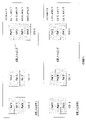
以下の手順が行われてRefPicSetCurrTempList0を構築する。
cIdx=0
NumRpsCurrTempList=NumRpsStCurr0+NumRpsStCurr1+NumRpsLtCurr
for(i=0;i<NumRpsStCurr0;cIdx++,i++)
RefPicSetCurrTempList0[cIdx]=RefPicSetStCurr0[i]
for(i=0;i<NumRpsStCurr1;cIdx++,i++)
RefPicSetCurrTempList0[cIdx]=RefPicSetStCurr1[i]
for(i=0;i<NumRpsLtCurr;cIdx++,i++)
RefPicSetCurrTempList0[cIdx]=RefPicSetLtCurr[i]
The following steps are performed to build RefPicSetCurrTempList0.
cIdx = 0
NumRpsCurrTempList = NumRpsStCurr0 + NumRpsStCurr1 + NumRpsLtCurr
for (i = 0; i <NumRpsStCurr0; cIdx ++, i ++)
RefPicSetCurrTempList0 [cIdx] = RefPicSetStCurr0 [i]
for (i = 0; i <NumRpsStCurr1; cIdx ++, i ++)
RefPicSetCurrTempList0 [cIdx] = RefPicSetStCurr1 [i]
for (i = 0; i <NumRpsLtCurr; cIdx ++, i ++)
RefPicSetCurrTempList0 [cIdx] = RefPicSetLtCurr [i]
ref_pic_list_modification_flag_l0が0の場合は、デフォルトのリストL0からの変更は行われず、デフォルトのRefPicList0は、RefPicSetCurrTempList0から最初のnum_ref_idx_l0_active_minus1+1個のエントリを順に取り出すことによって構築される。一方、ref_pic_list_modification_flag_l0が1の場合は、RefPicSetCurrTempList0およびnum_ref_idx_l0_active_minus1を入力とし、RefPicList0(L0)を出力として、参照ピクチャリストL0を変更するための表5の処理が呼び出される。 If ref_pic_list_modification_flag_l0 is 0, no changes are made from the default list L0, and the default RefPicList0 is constructed by extracting the first num_ref_idx_l0_active_minus1 + 1 entries from RefPicSetCurrTempList0 in order. On the other hand, when ref_pic_list_modification_flag_l0 is 1, RefPicSetCurrTempList0 and num_ref_idx_l0_active_minus1 are input, RefPicList0 (L0) is output, and the process of Table 5 for changing the reference picture list L0 is called.
簡単に説明すると、上記の疑似コードは、「前」のピクチャ、「後」のピクチャおよび長期ピクチャの数を加算することによりDPB(即ち、NumRpsCurrTempList)中の参照ピクチャの数を求めてから、最初に「前」ピクチャを(現在のピクチャから最も近い時間距離から最も遠い時間距離の順で)、次に「後」ピクチャを(同じく現在のピクチャから最も近い時間距離から最も遠い時間距離の順で)、次に長期参照ピクチャの順で配置する。 Briefly, the above pseudocode first calculates the number of reference pictures in the DPB (ie, NumRpsCurrTempList) by adding the number of "before", "after" and long-term pictures. The "before" picture (in the order of the closest time distance to the farthest time distance from the current picture), then the "after" picture (also in the order of the closest time distance to the farthest time distance from the current picture). ), Then arrange in the order of long-term reference pictures.
以下の手順が実施されてRefPicSetCurrTempList1を構築する。
cIdx=0
NumRpsCurrTempList=NumRpsStCurr0+NumRpsStCurr1+NumRpsLtCurr
for(i=0;i<NumRpsStCurr1;cIdx++,i++)
RefPicSetCurrTempList1[cIdx]=RefPicSetCurr1[i]
for(i=0;i<NumRpsStCurr0;cIdx++,i++)
RefPicSetCurrTempList1[cIdx]=RefPicSetCurr0[i]
for(i=0;i<NumRpsLtCurr;cIdx++,i++)
RefPicSetCurrTempList1[cIdx]=RefPicSetLtCurr[i]
The following procedure is executed to build RefPicSetCurrTempList1.
cIdx = 0
NumRpsCurrTempList = NumRpsStCurr0 + NumRpsStCurr1 + NumRpsLtCurr
for (i = 0; i <NumRpsStCurr1; cIdx ++, i ++)
RefPicSetCurrTempList1 [cIdx] = RefPicSetCurr1 [i]
for (i = 0; i <NumRpsStCurr0; cIdx ++, i ++)
RefPicSetCurrTempList1 [cIdx] = RefPicSetCurr0 [i]
for (i = 0; i <NumRpsLtCurr; cIdx ++, i ++)
RefPicSetCurrTempList1 [cIdx] = RefPicSetLtCurr [i]
ref_pic_list_modification_flag_l1が0の場合は、デフォルトのリストL1からの変更は行われず、デフォルトのRefPicList1は、RefPicSetCurrTempList1から最初のnum_ref_idx_l1_active_minus1+1個のエントリを取り出すことによって構築される。一方、ref_pic_list_modification_flag_l1が1の場合は、RefPicSetCurrTempList1およびnum_ref_idx_l1_active_minus1を入力とし、RefPicList1を出力として、参照ピクチャリストL1を変更するための表5の変更処理が呼び出される。 If ref_pic_list_modification_flag_l1 is 0, no changes are made from the default list L1 and the default RefPicList1 is constructed by extracting the first num_ref_idx_l1_active_minus1 + 1 entries from RefPicSetCurrTempList1. On the other hand, when ref_pic_list_modification_flag_l1 is 1, RefPicSetCurrTempList1 and num_ref_idx_l1_active_minus1 are input, RefPicList1 is output, and the change process of Table 5 for changing the reference picture list L1 is called.
簡単に説明すると、上記の疑似コードは、「前」のピクチャ、「後」のピクチャおよび長期ピクチャの数を加算することによりDPB(即ち、NumRpsCurrTempList)の参照ピクチャの数を求めてから、最初に「後」ピクチャを(現在のピクチャから最も近い時間距離から最も遠い時間距離の順で)、次に「前」ピクチャを(同じく現在のピクチャから最も近い時間距離から最も遠い時間距離の順で)、次に長期参照ピクチャの順で配置する。 Briefly, the above pseudocode calculates the number of reference pictures in the DPB (ie, NumRpsCurrTempList) by adding the number of "before", "after" and long-term pictures, and then first. The "after" picture (in the order of the closest time distance to the farthest time distance from the current picture), then the "before" picture (also in the order of the closest time distance to the farthest time distance from the current picture). , Then arrange in the order of long-term reference pictures.
2つのリストRpsCurrTempLXの作成は、参照ピクチャリストL0およびL1に変更が行われない場合でも有益であることに留意されたい。これは、そのような場合、RpsCurrTempLXの最初の数個のエントリが既にそれぞれリストL0およびL1のデフォルトの順序になっているため、参照ピクチャリストL0およびL1は、単にそれらのエントリを取り出すだけで非常に簡単に作成することができるためである。 Note that the creation of the two lists RpsCurrTempLX is useful even if no changes are made to the reference picture lists L0 and L1. This is because in such cases the first few entries in RpsCurrTempLX are already in the default order of lists L0 and L1, respectively, so the reference picture lists L0 and L1 are very simple to retrieve those entries. This is because it can be easily created.
表5に反映される参照ピクチャリストの変更処理は、入力として、上記の参照ピクチャの配列であるRefPicSetCurrTempLXと、参照ピクチャリストのサイズnum_ref_idx_lX_active_minus1を受け付ける(Xは、変更対象のリストに応じて0または1になる)。この処理の出力は、変更された参照ピクチャリストRefPicListXを含んでいる配列である。 The reference picture list change process reflected in Table 5 accepts RefPicSetCurrTempLX, which is an array of the above reference pictures, and the size num_ref_idx_lX_active_minus1 of the reference picture list (X is 0 or 1 depending on the list to be changed). become). The output of this process is an array containing the modified reference picture list RefPicListX.
図10は、例示的なリストL0について表5のリスト変更処理を説明するフローチャートである。この処理は、リストL1に対しても同様である。1001でリストL0のインデックスがゼロに初期化される。1003で、一時リストRefPicSetCurrTempL0が2つ以上のエントリを含んでいるかどうかが判定される。これは、リストが1つしかエントリを含まない場合はref_pic_set_idxのシグナリングが不要となるためである。リストが1つしかエントリを含まない場合は1004に進み、ref_pic_set_idxはシグナリングされず、代わりにデフォルトで0に設定される。そうでない場合は、1005に進み、中間リストRefPicSetCurrTempList0へのインデックス、ref_pic_set_idxが読み込まれる。1007で、変更リストL0の現在のインデックスにあるエントリが、RefPicSetCurrTempList0リスト内のシグナリングされたインデックス位置ref_pic_set_idxにある値に設定される。次いで、変更されたリストL0のインデックスが増分される(1009)。1011で、L0の最後に達したかどうかが判定される。最後まで達していない場合は1003に戻る。最後まで達した場合は処理が終了する。 FIG. 10 is a flowchart illustrating the list change process of Table 5 for the exemplary list L0. This process is the same for the list L1. At 1001, the index of list L0 is initialized to zero. At 1003, it is determined whether the temporary list RefPicSetCurrTempL0 contains more than one entry. This is because ref_pic_set_idx signaling is not required if the list contains only one entry. If the list contains only one entry, go to 1004 and ref_pic_set_idx is not signaled and instead defaults to 0. If not, the process proceeds to 1005, and the index to the intermediate list RefPicSetCurrTempList0, ref_pic_set_idx, is read. At 1007, the entry at the current index of changelist L0 is set to the value at the signaled index position ref_pic_set_idx in the RefPicSetCurrTempList0 list. The index of the modified list L0 is then incremented (1009). At 1011 it is determined whether or not the end of L0 has been reached. If it has not reached the end, it returns to 1003. When it reaches the end, the process ends.
上記のように、リストの変更が要求されない場合は、図10の処理は行われず、単にRefPicSetCurrTempListXの最初のnum_ref_idx_lx_active_minus1+1個のエントリが対応するリストLXになる。 As mentioned above, if the list change is not requested, the process of FIG. 10 is not performed, and the first num_ref_idx_lx_active_minus1 + 1 entries of RefPicSetCurrTempListX are simply the corresponding list LX.
図11は、提案される本発明の参照ピクチャリスト方式がどのように機能するかを図9と同じ例で示すものである。図11を図9と比べると、図11の変更処理で使用する構文要素の数は図9の半分であり、即ち、ref_pic_set_idxおよびlist_modification_idcをシグナリングするのではなく、リストL0の各エントリにつきref_pic_set_idxだけがシグナリングされる。さらに、図10のフローチャートで説明する処理は、リスト中の各エントリを明示的にシグナリングし、図8の複雑な処理を必要としない点で、図8のフローチャートの処理よりも単純である。 FIG. 11 shows how the proposed reference picture list scheme of the present invention works in the same example as in FIG. Comparing FIG. 11 to FIG. 9, the number of syntax elements used in the modification process of FIG. 11 is half that of FIG. 9, that is, instead of signaling ref_pic_set_idx and list_modification_idc, only ref_pic_set_idx for each entry in list L0. Signaled. Further, the process described in the flowchart of FIG. 10 is simpler than the process of the flowchart of FIG. 8 in that each entry in the list is explicitly signaled and the complicated process of FIG. 8 is not required.
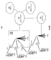
本明細書に記載されるシステムおよび方法は、有線および無線両方のネットワークを介した映像ストリームの通信に適する。有線ネットワークはよく知られる。各種無線デバイスおよびインフラストラクチャの概要を図12A~12Bとの関連で提供し、ネットワークの各種要素が本明細書に記載のシステムおよび方法を利用することができる。より具体的には、ベーストランシーバ局(BTS)、Node-B、eNodeB、Home NodeB、Home eNodeB、サイトコントローラ、アクセスポイント(AP)、無線ルータ、メディア認識ネットワークエレメント(MANE)などの基地局、並びに無線送受信ユニット(WTRU)が、符号化された映像データをあるエンティティから別のエンティティに伝達するために上記のシグナリングを生成および/または処理することができる。 The systems and methods described herein are suitable for communicating video streams over both wired and wireless networks. Wired networks are well known. An overview of the various wireless devices and infrastructure is provided in the context of FIGS. 12A-12B, and various elements of the network can utilize the systems and methods described herein. More specifically, base stations such as base transceiver stations (BTS), Node-B, eNodeB, Home NodeB, Home eNodeB, site controllers, access points (APs), wireless routers, media recognition network elements (MANE), and A wireless transmission / reception unit (WTRU) can generate and / or process the above signaling to transmit encoded video data from one entity to another.
図12Aは、1または複数の開示される実施形態が実施されうる例示的通信システム100の図である。通信システム100は、音声、データ、映像、メッセージング、放送等のコンテンツを複数の無線ユーザに提供する多重接続システムとすることができる。通信システム100は、複数の無線ユーザが、無線帯域等のシステムリソースの共有を通じてそのようなコンテンツにアクセスできるようにすることができる。例えば、通信システム100は、符号分割多重接続(CDMA)、時分割多重接続(TDMA)、周波数分割多重接続(FDMA)、直交FDMA(OFDMA)、単一キャリアFDMA(SC-FDMA)等の1または複数のチャネルアクセス方法を用いることができる。
FIG. 12A is a diagram of an
図12Aに示すように、通信システム100は、無線送信/受信ユニット(WTRU)102a、102b、102cおよび/または102d、無線アクセスネットワーク(RAN)104、コアネットワーク106、公衆交換電話網(PSTN)108、インターネット110および他のネットワーク112を含むが、開示される実施形態は、任意数のWTRU、基地局、ネットワークおよび/またはネットワーク要素を企図することが理解されよう。各WTRU102a、102b、102c、102dは、無線環境で動作および/または通信するように構成された任意種類の装置とすることができる。例えば、WTRU102a、102b、102c、102dは、無線信号を送信および/または受信するように構成され、ユーザ機器(UE)、移動局、固定型または移動型の加入者ユニット、ページャ、携帯電話、携帯情報端末(PDA)、スマートフォン、ラップトップ、ネットブック、パーソナルコンピュータ、無線センサ、消費者家電等を含むことができる。
As shown in FIG. 12A, the
通信システム100は、基地局114aおよび基地局114bも含むことができる。各基地局114a、114bは、WTRU102a、102b、102c、102dの少なくとも1つと無線でインタフェースをとって、コアネットワーク106、インターネット110および/またはネットワーク112等の1または複数の通信ネットワークへのアクセスを助けるように構成された任意種類の装置とすることができる。例えば、基地局114a、114bは、ベーストランシーバ局(BTS)、NodeB、eNodeB、ホームNodeB、ホームeNodeB、サイトコントローラ、アクセスポイント(AP)、無線ルータ等である。図では基地局114a、114bはそれぞれ1つの要素として示すが、基地局114a、114bは、任意数の相互接続された基地局および/またはネットワーク要素を含むことが可能であることが理解されよう。
基地局114aはRAN104の一部とすることができ、RAN104も、他の基地局、および/または基地局コントローラ(BSC)、無線ネットワークコントローラ(RNC)、中継ノード等のネットワーク要素(図示せず)を含むことができる。基地局114aおよび/または基地局114bは、セル(図示せず)とも呼ばれる特定の地理的領域内で無線信号を送信および/または受信するように構成されることができる。セルはさらにセルセクタに分割されることができる。例えば、基地局114aに関連付けられたセルが3つのセクタに分割される。従って、一実施形態では、基地局114aは、3つのトランシーバ(Transceiver:送受信機)、即ち、セルのセクタごとに1つのトランシーバを含むことができる。別の実施形態では、基地局114aは多入力多出力(MIMO)技術を用い、セルのセクタごとに複数のトランシーバを利用することができる。
The
基地局114a、114bは、エアインタフェース116を介してWTRU102a、102b、102c、102dの1または複数と通信することができ、エアインタフェースは、任意の適切な無線通信リンク(例えば、無線周波(RF)、マイクロ波、赤外線(IR)、紫外線(UV)、可視光等)とすることができる。エアインタフェース116は、任意の適切な無線アクセス技術(RAT)を使用して確立されることができる。
より具体的には、上記のように、通信システム100は多重接続システムとすることができ、CDMA、TDMA、FDMA、OFDMA、SC-FDMA等の1または複数のチャネルアクセス方式を用いることができる。例えば、RAN104内の基地局114aおよびWTRU102a、102b、102cは、総合移動遠隔通信システム(UMTS)地上無線アクセス(UTRA)等の無線技術を実装することができ、その場合、広帯域CDMA(WCDMA(登録商標))を使用してエアインタフェース116を確立することができる。WCDMAは、高速パケットアクセス(HSPA)および/または発展型HSPA(HSPA+)等の通信プロトコルを含むことができる。HSPAは、高速ダウンリンクパケットアクセス(HSDPA)および/または高速アップリンクパケットアクセス(HSUPA)を含むことができる。
More specifically, as described above, the
別の実施形態では、基地局114aおよびWTRU102a、102b、102cは、発展型UMTS地上無線アクセス(E-UTRA)等の無線技術を実装することができ、その場合はLTEおよび/またはLTE-Advanced(LTE-A)を使用してエアインタフェース116を確立することができる。
In another embodiment,
他の実施形態では、基地局114aおよびWTRU102a、102b、102cは、IEEE802.16(即ち、WiMAX)、CDMA2000、CDMA2000 1X、CDMA2000EV-DO、暫定標準2000(IS-2000)、暫定標準95(IS-95)、暫定標準856(IS-856)、GSM(登録商標)(Global System for Mobile Communications)、EDGE(Enhanced Data rates for GSM Evolution)、GSM EDGE(GERAN)等の無線技術を実装することができる。
In other embodiments, the
図12Aの基地局114bは、例えば、無線ルータ、ホームNodeB、ホームeNodeBまたはアクセスポイント等であり、職場、住宅、乗り物、施設構内等の限定された領域内で無線接続を容易にする適当なRATを利用することができる。一実施形態では、基地局114bおよびWTRU102c、102dは、IEEE802.11等の無線技術を実装して、無線ローカルエリアネットワーク(WLAN)を確立することができる。別の実施形態では、基地局114bおよびWTRU102c、102dはIEEE802.15等の無線技術を実装して、無線パーソナルエリアネットワーク(WPAN)を確立することができる。さらに別の実施形態では、基地局114bおよびWTRU102c、102dは、セルラー方式のRAT(例えば、WCDMA、CDMA2000、GSM、LTE、LTE-A等)を利用してピコセルまたはフェムトセルを確立することができる。図12Aに示すように、基地局114bはインターネット110への直接の接続を有することができる。従って、基地局114bは、コアネットワーク106を介してインターネット110にアクセスする必要がない場合もある。
RAN104は、コアネットワーク106と通信状態にあり、コアネットワークは、音声、データ、アプリケーションおよび/またはインターネットプロトコルによる音声伝送(VoIP)サービスをWTRU102a、102b、102c、102dの1または複数に提供するように構成された任意種類のネットワークとすることができる。例えば、コアネットワーク106は、呼制御、課金サービス、モバイル位置情報サービス、プリペイド通話、インターネット接続、映像配信等を提供し、かつ/またはユーザ認証等の高レベルのセキュリティ機能を行うことができる。図12Aには示さないが、RAN104および/またはコアネットワーク106は、RAN104と同じRATまたは異なるRATを用いる他のRANと直接または間接的に通信することが理解されよう。例えば、E-UTRA無線技術を利用するRAN104に接続されるのに加えて、コアネットワーク106は、GSM無線技術を用いる別のRAN(図示せず)とも通信状態にあることができる。
The
コアネットワーク106は、WTRU102a、102b、102c、102dがPSTN108、インターネット110および/または他のネットワーク112にアクセスするためのゲートウェイの役割も果たすことができる。PSTN108は、従来型の電話サービス(POTS)を提供する回線交換電話網を含むことができる。インターネット110は、TCP/IPインターネットプロトコルスイートのTCP、UDPおよびIP等の共通の通信プロトコルを使用する、相互接続されたコンピュータネットワークおよび装置からなる世界規模のシステムを含むことができる。ネットワーク112は、他のサービス提供者に所有および/または運営される有線または無線の通信ネットワークを含むことができる。例えば、ネットワーク112は、RAN104と同じRATまたは異なるRATを用いる1または複数のRANに接続された別のコアネットワークを含むことができる。
The
通信システム100内のWTRU102a、102b、102c、102dの一部または全ては、マルチモード能力を備えることができる。即ち、WTRU102a、102b、102c、102dは、種々の無線リンクを通じて種々の無線ネットワークと通信するための複数のトランシーバを含むことができる。例えば、図12Aに示すWTRU102cは、セルラー方式の無線技術を用いる基地局114a、およびIEEE802無線技術を用いる基地局114bと通信するように構成されることができる。
Some or all of the
図12Bは、例示的なWTRU102のシステム図である。図12Bに示すように、WTRU102は、プロセッサ118、トランシーバ120、送信/受信要素122、スピーカ/マイクロフォン124、キーパッド126、ディスプレイ/タッチパッド128、非リムーバブルメモリ130、リムーバブルメモリ132、電源134、GPSチップセット136および他の周辺機能138を備えることができる。WTRU102は、実施形態との整合性を保ちながら、上述の要素のサブコンビネーションを含むことが可能であることが理解されよう。
FIG. 12B is an exemplary WTRU102 system diagram. As shown in FIG. 12B, the
プロセッサ118は、汎用プロセッサ、特殊目的プロセッサ、従来のプロセッサ、デジタル信号プロセッサ(DSP)、複数のマイクロプロセッサ、DSPコアと関連した1または複数のマイクロプロセッサ、コントローラ、マイクロコントローラ、ASIC、FPGA回路、任意の他の種類の集積回路(IC)、状態機械等である。プロセッサ118は、信号の符号化、データ処理、電力制御、入出力処理、および/またはWTRU102が無線環境で動作することを可能にする他の機能を行うことができる。プロセッサ118はトランシーバ(送受信機)120に結合され、トランシーバ(送受信機)120は送信/受信要素122に結合されることができる。図12Bではプロセッサ118とトランシーバ120を別個の構成要素として示すが、プロセッサ118とトランシーバ(送受信機)120は電子パッケージやチップに共に一体化されてもよいことが理解されよう。
送信/受信要素122は、エアインタフェース116を通じて基地局(例えば基地局114a)との間で信号を送信または受信するように構成されることができる。例えば、一実施形態では、送信/受信要素122は、RF信号を送信および/または受信するように構成されたアンテナとすることができる。別の実施形態では、送信/受信要素122は、例えばIR、UV、または可視光信号を送信および/または受信するように構成されたエミッタ/検出器である。さらに別の実施形態では、送信/受信要素122は、RF信号と光信号の両方を送受信するように構成されることができる。送信/受信要素122は、各種無線信号の任意の組合せを送信および/または受信するように構成されてよいことが理解されよう。
The transmit / receive
また、図12Bでは送信/受信要素122を1つの要素として示すが、WTRU102は任意数の送信/受信要素122を含むことができる。より具体的には、WTRU102はMIMO技術を用いることができる。そのため、一実施形態では、WTRU102は、エアインタフェース116を通じて無線信号を送受信するために2つ以上の送信/受信要素122(例えば複数のアンテナ)を含むことができる。
Further, although the transmission /
トランシーバ120は、送信/受信要素122から送信しようとする信号を変調し、送信/受信要素122に受信された信号を復調するように構成されることができる。上記のように、WTRU102はマルチモード能力を有することができる。そのため、トランシーバ120は、WTRU102が例えばUTRAやIEEE802.11等の複数種類のRATを介して通信することを可能にする複数のトランシーバを含むことができる。
The
WTRU102のプロセッサ118は、スピーカ/マイクロフォン124、キーパッド126、および/またはディスプレイ/タッチパッド128(例えば液晶ディスプレイ(LCD)表示装置や有機発光ダイオード(OLED)表示装置)に結合され、それらからユーザ入力データを受け取ることができる。プロセッサ118はまた、スピーカ/マイクロフォン124、キーパッド126、および/またはディスプレイ/タッチパッド128にユーザデータを出力することができる。また、プロセッサ118は、非リムーバブルメモリ130および/またはリムーバブルメモリ132等の任意種類の適切なメモリの情報にアクセスし、データを記憶することができる。非リムーバブルメモリ130は、RAM、ROM、ハードディスク、または他の任意種類のメモリ記憶装置を含むことができる。リムーバブルメモリ132は、加入者識別モジュール(SIM)カード、メモリスティック、セキュアデジタル(SD)メモリカード等を含むことができる。他の実施形態では、プロセッサ118は、サーバや家庭コンピュータ(図示せず)等、物理的にWTRU102にないメモリの情報にアクセスし、データを記憶することができる。
The
プロセッサ118は、電源134から電力を受け取り、その電力をWTRU102中の他の構成要素に分配および/または制御するように構成されることができる。電源134は、WTRU102に電力を供給するのに適した任意の装置でよい。例えば、電源134は、1または複数の乾電池(例えばニッケルカドミウム(NiCd)、ニッケル亜鉛(NiZn)、ニッケル水素(NiMH)、リチウムイオン(Li-ion)等)、太陽電池、燃料電池等を含むことができる。
プロセッサ118はGPSチップセット136にも結合され、GPSチップセット136は、WTRU102の現在の位置に関する位置情報(例えば経度および緯度)を提供するように構成されることができる。GPSチップセット136からの情報に加えて、またはその代わりに、WTRU102は、基地局(例えば基地局114a、114b)からエアインタフェース116を介して位置情報を受信する、かつ/または、2つ以上の近隣の基地局から信号が受信されるタイミングに基づいて自身の位置を判定することができる。WTRU102は、実施形態との整合性を保ちながら、任意の適切な位置判定方法で位置情報を取得できることが理解されよう。
The
プロセッサ118はさらに他の周辺機能138に結合され、周辺機能は、追加的な機能、機能性、および/または有線若しくは無線接続を提供する1または複数のソフトウェアおよび/またはハードウェアモジュールを含むことができる。例えば、周辺機能138は、加速度計、電子コンパス、衛星トランシーバ、デジタルカメラ(写真または映像用)、ユニバーサルシリアルバス(USB)ポート、振動装置、テレビトランシーバ、ハンドフリーヘッドセット、Bluetooth(登録商標)モジュール、周波数変調(FM)無線ユニット、デジタル音楽プレーヤ、メディアプレーヤ、ビデオゲームプレーヤモジュール、インターネットブラウザ等を含むことができる。
図12Cは、実施形態によるRAN104およびコアネットワーク106のシステム図である。上記のように、RAN104は、UTRA無線技術を用いてエアインタフェース116を介してWTRU102a、102b、102cと通信することができる。RAN104は、コアネットワーク106とも通信状態にあることができる。図12Cに示すように、RAN104は、NodeB140a、140b、140cを含み、各NodeBは、エアインタフェース116を通じてWTRU102a、102b、102cと通信するために1または複数のトランシーバを備えることができる。NodeB140a、140b、140cは各々、RAN104内の特定のセル(図示せず)に関連付けることができる。RAN104はRNC142a、142bも含むことができる。RAN104は実施形態との整合性を保ちながら、任意数のNodeBおよびRNCを含むことが可能であることが理解されよう。
FIG. 12C is a system diagram of the
図12Cに示すように、NodeB140a、140bはRNC142aと通信状態にある。また、NodeB140cはRNC142bと通信状態にあることができる。NodeB140a、140b、140cは、Iubインタフェースを介してそれぞれのRNC142a、142bと通信することができる。RNC142a、142bは、Iurインタフェースを介して相互と通信することができる。各RNC142a、142bは、それぞれが接続されたNodeB140a、140b、140cを制御するように構成されることができる。また、各RNC142a、142bは、外部ループ電力制御、負荷制御、アドミッション制御、パケットスケジューリング、ハンドオーバー制御、マクロダイバーシティ、セキュリティ機能、データの暗号化等の他の機能を実行または支援するように構成されることができる。
As shown in FIG. 12C,
図12Cに示すコアネットワーク106は、メディアゲートウェイ(MGW)144、モバイル交換センター(MSC)146、サービングGPRSサポートノード(SGSN)148、および/またはゲートウェイGPRSサポートノード(GGSN)150を含むことができる。上記の各要素はコアネットワーク106の一部として図示するが、これらの要素の任意の1つはコアネットワークの運営者以外のエンティティにより所有および/または運営されてもよいことが理解されよう。
The
RAN104内のRNC142aは、IuCSインタフェースを介してコアネットワーク106内のMSC146に接続されることができる。MSC146はMGW144に接続されることができる。MSC146およびMGW144は、WTRU102a、102b、102cに、PSTN108等の回線交換ネットワークへのアクセスを提供して、WTRU102a、102b、102cと従来の地上回線通信機器との間の通信を容易にすることができる。
The
RAN104内のRNC142aは、IuPSインタフェースを介してコアネットワーク106のSGSN148にも接続することができる。SGSN148はGGSN150に接続されることができる。SGSN148およびGGSN150は、WTRU102a、102b、102cに、インターネット110等のパケット交換ネットワークへのアクセスを提供して、WTRU102a、102b、102cとIP対応機器との間の通信を容易にできる。
The
上記のように、コアネットワーク106はネットワーク112にも接続され、ネットワーク112は、他のサービス提供者に所有および/または運営される他の有線または無線のネットワークを含むことができる。
As mentioned above, the
図12Dは、別の実施形態によるRAN104およびコアネットワーク106のシステム図である。上記のように、RAN104は、E-UTRA無線技術を用いて、エアインタフェース116を通じてWTRU102a、102b、102cと通信することができる。RAN104はコアネットワーク106とも通信状態にあることができる。
FIG. 12D is a system diagram of the
RAN104はeNodeB160a、160b、160cを含むが、RAN104は実施形態との整合性を保ちながら任意数のeNodeBを含むことが可能であることが理解されよう。eNodeB160a、160b、160cはそれぞれ、エアインタフェース116を通じてWTRU102a、102b、102cと通信するための1または複数のトランシーバを含むことができる。一実施形態では、eNodeB160a、160b、160cはMIMO技術を実装することができる。従って、例えばeNodeB160aは、複数のアンテナを使用してWTRU102aとの間で無線信号を送受信することができる。
It will be appreciated that while RAN104 includes
各eNodeB160a、160b、160cは、特定のセル(図示せず)に関連付けられ、無線リソース管理に関する決定、ハンドオーバーの決定、アップリンクおよび/またはダウンリンクのユーザのスケジューリング等を処理するように構成することができる。図12Dに示すように、eNodeB160a、160b、160cはX2インタフェースを通じて相互と通信することができる。 Each eNodeB 160a, 160b, 160c is associated with a particular cell (not shown) and is configured to handle radio resource management decisions, handover decisions, uplink and / or downlink user scheduling, and the like. be able to. As shown in FIG. 12D, the eNodeB 160a, 160b, 160c can communicate with each other through the X2 interface.
図12Dに示すコアネットワーク106は、移動性管理ゲートウェイ(MME)162、サービングゲートウェイ164、およびパケットデータネットワーク(PDN)ゲートウェイ166を含むことができる。図では上述の各要素はコアネットワーク106の一部として示すが、それらの要素のいずれか1つは、コアネットワークの運営者以外のエンティティによって所有および/または運営される場合もあることが理解されよう。
The
MME162は、S1インタフェースを介してRAN104内のeNodeB160a、160b、160c各々に接続され、制御ノードの役割を果たすことができる。例えば、MME162は、WTRU102a、102b、102cのユーザの認証、ベアラのアクティブ化/非アクティブ化、WTRU102a、102b、102cの初回のアタッチ時の特定サービングゲートウェイの選択等を担う。MME162は、RAN104と、GSMやWCDMA等の他の無線技術を用いる他のRAN(図示せず)とを切替えるための制御プレーン機能も提供することができる。
The
サービングゲートウェイ164は、S1インタフェースを介してRAN104内の各eNodeB160a、160b、160cに接続されることができる。サービングゲートウェイ164は、一般に、WTRU102a、102b、102cとの間でユーザデータパケットを送信および転送することができる。サービングゲートウェイ164は、他の機能、例えば、eNodeB間のハンドオーバー時にユーザプレーンを固定する、WTRU102a、102b、102cに入手可能なダウンリンクデータがあるときにページングをトリガする、WTRU102a、102b、102cのコンテクストを管理および記憶する等も行うことができる。
The serving
サービングゲートウェイ164はPDNゲートウェイ166にも接続されて、WTRU102a、102b、102cとIP対応装置間の通信を容易にする。PDNゲートウェイ166は、WTRU102a、102b、102cにインターネット110等のパケット交換ネットワークへのアクセスを提供することができる。
The serving
コアネットワーク106は、他のネットワークとの通信を容易にすることができる。例えば、コアネットワーク106は、PSTN108等の回線交換ネットワークへのアクセスをWTRU102a、102b、102cに提供して、WTRU102a、102b、102cと従来の陸線通信機器との間の通信を容易にすることができる。例えば、コアネットワーク106は、コアネットワーク106とPSTN108間のインタフェースとして機能するIPゲートウェイ(例えばIPマルチメディアサブシステム(IMS)サーバ)を含むか、またはそれと通信することができる。また、コアネットワーク106は、WTRU102a、102b、102cにネットワーク112へのアクセスを提供することができ、ネットワーク112は、他のサービス提供者に所有および/または運営される他の有線または無線ネットワークを含むことができる。
The
図12Eは、別の実施形態によるRAN104およびコアネットワーク106のシステム図である。RAN104は、IEEE802.16無線技術を使用してエアインタフェース116を通じてWTRU102a、102b、102cと通信するアクセスサービスネットワーク(ASN)とすることができる。下記でさらに述べるように、WTRU102a、102b、102c、RAN104、およびコアネットワーク106の異なる機能エンティティ間の通信リンクが基準点として定義することができる。
FIG. 12E is a system diagram of the
図12Eに示すように、RAN104は、基地局170a、170b、170cおよびASNゲートウェイ172を含むことができるが、RAN104は、実施形態との整合性を保ちながら任意数の基地局およびASNゲートウェイを含むことが可能であることが理解されよう。基地局170a、170b、170cは各々RAN104内の特定のセル(図示せず)に関連付けられ、各々エアインタフェース116を通じてWTRU102a、102b、102cと通信するための1または複数のトランシーバを含むことができる。一実施形態では、基地局170a、170b、170cはMIMO技術を実装することができる。そのため、例えば基地局170aは、複数のアンテナを使用して、WTRU102aとの間で無線信号を送受信することができる。基地局170a、170b、170cは、ハンドオフのトリガ、トンネルの確立、無線リソース管理、トラフィックの分類、サービス品質(QoS)ポリシーの施行等の移動性管理機能も提供することができる。ASNゲートウェイ172はトラフィック集約点として機能し、ページング、加入者プロファイルのキャッシング、コアネットワーク106へのルーティング等を担うことができる。
As shown in FIG. 12E, the
WTRU102a、102b、102cとRAN104との間のエアインタフェース116は、IEEE802.16仕様を実装するR1基準点として定義することができる。また、WTRU102a、102b、102cはそれぞれ、コアネットワーク106との間に論理インタフェース(図示せず)を確立することができる。WTRU102a、102b、102cとコアネットワーク106との間の論理インタフェースは、認証、権限付与、IPホスト設定管理、および/または移動性管理に使用されるR2基準点として定義することができる。
The
各基地局170a、170b、170c間の通信リンクは、基地局間のWTRUのハンドオーバーおよびデータ転送を容易にするプロトコルを含むR8基準点として定義することができる。基地局170a、170b、170cとASNゲートウェイ172間の通信リンクは、R6基準点として定義することができる。R6基準点は、各WTRU102a、102b、102cに関連する移動事象に基づく移動性管理を容易にするプロトコルを含むことができる。
The communication link between the
図12Eに示すように、RAN104はコアネットワーク106に接続される。RAN104とコアネットワーク106間の通信リンクは、例えばデータ転送機能および移動性管理機能を容易にするプロトコルを含むR3基準点として定義することができる。コアネットワーク106は、モバイルIPホームエージェント(MIP-HA)174、認証、権限付与、課金(AAA)サーバ176、およびゲートウェイ178を含むことができる。上述の各要素はコアネットワーク106の一部として図示するが、これらの要素のいずれか1つはコアネットワークの運営者以外のエンティティにより所有および/または運営される場合もあることが理解されよう。
As shown in FIG. 12E, the
MIP-HA174は、IPアドレス管理を担い、WTRU102a、102b、102cが異なるASN間および/または異なるコアネットワーク間を移動できるようにする。MIP-HA174は、WTRU102a、102b、102cに、インターネット110等のパケット交換ネットワークへのアクセスを提供して、WTRU102a、102b、102cと、IP対応装置との間の通信を容易にすることができる。AAAサーバ176は、ユーザ認証およびユーザサービスの支援を担うことができる。ゲートウェイ178は、他のネットワークとの相互動作を容易にすることができる。例えば、ゲートウェイ178は、WTRU102a、102b、102cに、PSTN108等の回線交換ネットワークへのアクセスを提供して、WTRU102a、102b、102cと、従来の陸線通信機器との間の通信を容易にすることができる。また、ゲートウェイ178は、WTRU102a、102b、102cに、他のサービス提供者によって所有および/または運営される他の有線または無線ネットワークを含むネットワーク112へのアクセスを提供することができる。
The MIP-HA174 is responsible for IP address management and allows WTRU102a, 102b, 102c to move between different ASNs and / or between different core networks. The MIP-HA174 can provide WTRU102a, 102b, 102c with access to a packet-switched network such as the
図12Eには示さないが、RAN104は他のASNに接続され、コアネットワーク106は他のコアネットワークに接続されることが可能であることが理解されよう。RAN104と他のASNとの間の通信リンクはR4基準点として定義され、RAN104と他のASN間のWTRU102a、102b、102cの移動性を司るプロトコルを含むことができる。コアネットワーク106と他のコアネットワーク間の通信リンクはR5基準点として定義され、R5基準点は、ホームコアネットワークと一時利用される(visited)コアネットワーク間の相互動作を容易にするプロトコルを含むことができる。
Although not shown in FIG. 12E, it will be appreciated that the
実施形態
一実施形態では、映像データ内の予測されたピクチャを復号するための参照ピクチャリストL0およびL1を生成する方法が実施され、この方法は、復号ピクチャバッファ(DPB)から参照ピクチャの第1の順序付けリストRefPicSetCurrTempList0を生成するステップであって、リストは、現在のピクチャよりも時間的に前の参照ピクチャがDPBにある場合は、それらの参照ピクチャが現在のピクチャからの時間的距離に従って順に列記され、次いで現在のピクチャよりも時間的に後の参照ピクチャがDPBにある場合はそれらの参照ピクチャが現在のピクチャからの時間的距離に従って順に列記され、次いで長期参照ピクチャがDPBにある場合はそれらの参照ピクチャがDPBに格納されている順序で列記されるように順序付けられる、ステップと、DPBから参照ピクチャの第2の順序付けリストRefPicSetCurrTempList1を生成するステップであって、リストは、DPBに現在のピクチャよりも時間的に後の参照ピクチャがある場合はそれらの参照ピクチャが現在のピクチャからの時間的距離に従って最初に順に列記され、次いで現在のピクチャよりも時間的に後の参照ピクチャがDPBにある場合はそれらの参照ピクチャが現在のピクチャからの時間的距離に従って順に列記され、次いで長期参照ピクチャがDPBにある場合はそれらの参照ピクチャがDPBに格納されている順序で列記されるように順序付けられる、ステップと、RefPicSetCurrTempList0およびRefPicSetCurrTempList1からそれぞれ参照ピクチャを選択することによりリストL0およびL1の少なくとも一方を生成するステップとを含む。
Embodiment In one embodiment, a method of generating reference picture lists L0 and L1 for decoding a predicted picture in video data is performed, the method of which is the first of the reference pictures from the decoding picture buffer (DPB). In the step of generating the ordering list RefPicSetCurrTempList0, the list lists the referenced pictures in order according to their time distance from the current picture, if the referenced pictures are in the DPB in time before the current picture. Then, if the reference pictures that are later in time than the current picture are in the DPB, those reference pictures are listed in order according to the time distance from the current picture, and then if the long-term reference pictures are in the DPB, they are listed. A step in which the reference pictures of are ordered to be listed in the order in which they are stored in the DPB, and a step of generating a second ordering list of reference pictures from the DPB, RefPicSetCurrTempList1, where the list is the current picture in the DPB. If there are reference pictures that are later in time than the current picture, those reference pictures are listed first in order according to the time distance from the current picture, and then the reference pictures that are later in time than the current picture are in the DPB. If so, the referenced pictures are listed in order according to their time distance from the current picture, then if the long-term reference pictures are in the DPB, they are listed in the order in which they are stored in the DPB. , And the step of generating at least one of the lists L0 and L1 by selecting a reference picture from RefPicSetCurrTempList0 and RefPicSetCurrTempList1, respectively.
本実施形態によると、方法は、リストL0およびL1のどちらかを変更リストとすべきかどうかを判定するステップをさらに含むことができ、リストL0を変更リストとすべき場合は、リストL0を生成するステップは、参照ピクチャリストL0の参照ピクチャごとに、第1の順序付けリストを指す第1のインデックスを受け取り、第1の順序付けリスト内でそのインデックスで特定される参照ピクチャをL0内の対応するエントリに列記するステップを含み、リストL0を変更リストとすべき場合は、リストL1を生成するステップは、参照ピクチャリストL1の参照ピクチャエントリごとに、第2の順序付けリストを指す第2のインデックスを受け取り、第2の順序付けリスト内でそのインデックスで特定される参照ピクチャをL1内の対応するエントリに列記するステップを含む。 According to the present embodiment, the method can further include a step of determining whether either list L0 or L1 should be a change list, and if list L0 should be a change list, generate list L0. For each reference picture in the reference picture list L0, the step receives a first index pointing to the first ordering list and the reference picture identified by that index in the first ordering list to the corresponding entry in L0. If a list L0 should be a modified list, including the steps listed, the step generating the list L1 receives, for each reference picture entry in the reference picture list L1, a second index pointing to the second ordering list. A second ordering list comprises a step of listing the referenced picture identified by its index in the corresponding entry in L1.
上記実施形態の1または複数は、リストL0を変更リストとしない場合、リストL0を生成するステップは、第1の指定された数のエントリまでRefPicSetCurrTempList0から順にエントリを取り出すステップを含み、リストL1を変更リストとしない場合、リストL1を生成するステップは、第2の指定された数のエントリまでRefPicSetCurrTempList1から順にエントリを取り出すステップを含むことをさらに含むことができる。 If one or more of the above embodiments does not make the list L0 a change list, the step of generating the list L0 includes changing the list L1 in order from RefPicSetCurrTempList0 up to the first specified number of entries. If not a list, the step of generating the list L1 may further include a step of fetching entries from RefPicSetCurrTempList1 up to a second specified number of entries.
上記実施形態の1または複数は、判定するステップは、リストL0に関して構文要素ref_pic_list_modification_flag_l0を読み込み、リストL1に関して構文要素ref_pic_list_modification_flag_l1を読み込むステップを含むことをさらに含むことができる。 The determination step may further include reading the syntax element ref_pic_list_modification_flag_l0 for list L0 and reading the syntax element ref_pic_list_modification_flag_l1 for list L1.
上記実施形態の1または複数は、第1のインデックスおよび第2のインデックスは、ゼロからDPB内のピクチャ数までの範囲であることをさらに含むことができる。 One or more of the above embodiments may further include that the first index and the second index range from zero to the number of pictures in the DPB.
上記実施形態の1または複数は、構文要素ref_pic_set_idxが使用されて第1のインデックスおよび第2のインデックスを指定することをさらに含むことができる。 One or more of the above embodiments may further include the use of the syntax element ref_pic_set_idx to specify a first index and a second index.
上記実施形態の1または複数は、構文要素ref_pic_list_modification_flag_l1を読み込むステップをさらに含むことができ、ref_pic_list_modification_flag_l1が第1の値に等しい場合は、L1を指定する構文要素ref_pic_set_idxが存在することを示し、ref_pic_list_modification_flag_l1が第2の値に等しい場合は、L1を指定するこの構文要素が存在しないことを示す。 One or more of the above embodiments may further include a step to read the syntax element ref_pic_list_modification_flag_l1. If it is equal to a value of 2, it indicates that this syntax element that specifies L1 does not exist.
上記実施形態の1または複数は、構文要素ref_pic_list_modification_flag_l0を読み込むステップをさらに含むことができ、ref_pic_list_modification_flag_l0が第1の値に等しい場合は、L0を指定する構文要素ref_pic_set_idxが存在することを示し、ref_pic_list_modification_flag_l0が第2の値に等しい場合は、L0を指定するこの構文要素が存在しないことを示す。 One or more of the above embodiments may further include a step to read the syntax element ref_pic_list_modification_flag_l0, and if ref_pic_list_modification_flag_l0 is equal to the first value, it indicates that there is a syntax element ref_pic_set_idx that specifies L0, and ref_pic_list_modification_flag_l0 is the first. If it is equal to a value of 2, it indicates that this syntax element that specifies L0 does not exist.
上記実施形態の1または複数は、構文要素ref_pic_list_modification_flag_l1を読み込むステップをさらに含み、ref_pic_list_modification_flag_l1が第1の値に等しい場合は、L1を指定する構文要素ref_pic_set_idxが存在することを示し、ref_pic_list_modification_flag_l1が第2の値に等しい場合は、L1を指定するこの構文要素が存在しないことを示す。 One or more of the above embodiments further include a step to read the syntax element ref_pic_list_modification_flag_l1, and if ref_pic_list_modification_flag_l1 is equal to the first value, it indicates that the syntax element ref_pic_set_idx specifying L1 exists, and ref_pic_list_modification_flag_l1 is the second value. If is equal to, it indicates that this syntax element that specifies L1 does not exist.
上記実施形態の1または複数は、第1のインデックスが存在しない場合、第1のインデックスはゼロに設定され、第2のインデックスが存在しない場合、第2のインデックスはゼロに設定されることをさらに含むことができる。 In one or more of the above embodiments, the first index is set to zero if the first index does not exist, and the second index is set to zero if the second index does not exist. Can include.
別の実施形態で、または上記の実施形態のいずれかに関連して、PまたはBスライスヘッダを復号するために参照ピクチャリストのデコーダを初期化することを含む方法は、
cIdx=0
NumRpsCurrTempList=NumRpsStCurr0+NumRpsStCurr1+NumRpsLtCurr
for(i=0;i<NumRpsStCurr0;cIdx++,i++)
RefPicSetCurrTempList0[cIdx]=RefPicSetStCurr0[i]
for(i=0;i<NumRpsStCurr1;cIdx++,i++)
RefPicSetCurrTempList0[cIdx]=RefPicSetStCurr1[i]
for(i=0;i<NumRpsLtCurr;cIdx++,i++)
RefPicSetCurrTempList0[cIdx]=RefPicSetLtCurr[i]
により第1の一時リストRefPicSetCurrTempList0を構築するステップを含みうる。
In another embodiment, or in connection with any of the above embodiments, methods comprising initializing the reference picture list decoder to decode the P or B slice header.
cIdx = 0
NumRpsCurrTempList = NumRpsStCurr0 + NumRpsStCurr1 + NumRpsLtCurr
for (i = 0; i <NumRpsStCurr0; cIdx ++, i ++)
RefPicSetCurrTempList0 [cIdx] = RefPicSetStCurr0 [i]
for (i = 0; i <NumRpsStCurr1; cIdx ++, i ++)
RefPicSetCurrTempList0 [cIdx] = RefPicSetStCurr1 [i]
for (i = 0; i <NumRpsLtCurr; cIdx ++, i ++)
RefPicSetCurrTempList0 [cIdx] = RefPicSetLtCurr [i]
May include the step of constructing a first temporary list, RefPicSetCurrTempList0.
上記実施形態の1または複数は、フラグref_pic_list_modification_flag_l0が0である場合に、RefPicSetCurrTempList0の最初のnum_ref_idx_10_active_minus1+1個のエントリを取り出すことによりリストL0(RefPicList0)を構築するステップをさらに含むことができる。 One or more of the above embodiments may further include a step of constructing a list L0 (RefPicList0) by retrieving the first num_ref_idx_10_active_minus1 + 1 entries of RefPicSetCurrTempList0 when the flag ref_pic_list_modification_flag_l0 is 0.
上記実施形態の1または複数は、フラグref_pic_list_modification_flag_l0が1である場合、RefPicSetCurrTempList0およびnum_ref_idx_l0_active_minus1を入力としてピクチャリスト変更処理を呼び出すことによりリストL0を構築するステップをさらに含むことができる。 One or more of the above embodiments may further include a step of constructing the list L0 by calling the picture list change process with RefPicSetCurrTempList0 and num_ref_idx_l0_active_minus1 as inputs when the flag ref_pic_list_modification_flag_l0 is 1.
上記実施形態の1または複数は、Bスライスヘッダを復号する場合に、
cIdx=0
NumRpsCurrTempList=NumRpsStCurr0+NumRpsStCurr1+NumRpsLtCurr
for(i=0;i<NumRpsStCurr1;cIdx++,i++)
RefPicSetCurrTempList1[cIdx]=RefPicSetCurr1[i]
for(i=0;i<NumRpsStCurr0;cIdx++,i++)
RefPicSetCurrTempList1[cIdx]=RefPicSetCurr0[i]
for(i=0;i<NumRpsLtCurr;cIdx++,i++)
RefPicSetCurrTempList1[cIdx]=RefPicSetLtCurr[i]
により第2の一時リストRefPicSetCurrTempList1を構築するステップをさらに含みうる。
One or more of the above embodiments is when the B slice header is decoded.
cIdx = 0
NumRpsCurrTempList = NumRpsStCurr0 + NumRpsStCurr1 + NumRpsLtCurr
for (i = 0; i <NumRpsStCurr1; cIdx ++, i ++)
RefPicSetCurrTempList1 [cIdx] = RefPicSetCurr1 [i]
for (i = 0; i <NumRpsStCurr0; cIdx ++, i ++)
RefPicSetCurrTempList1 [cIdx] = RefPicSetCurr0 [i]
for (i = 0; i <NumRpsLtCurr; cIdx ++, i ++)
RefPicSetCurrTempList1 [cIdx] = RefPicSetLtCurr [i]
May further include the step of constructing a second temporary list, RefPicSetCurrTempList1.
上記実施形態の1または複数は、フラグ(ref_pic_list_modification_flag_l1)が0の場合に、RefPicSetCurrTempList1の最初のnum_ref_idx_ll_active_minus1+1個のエントリを取り出すことによりリストL1(RefPicList1)を構築するステップをさらに含むことができる。 One or more of the above embodiments may further include a step of constructing the list L1 (RefPicList1) by extracting the first num_ref_idx_ll_active_minus1 + 1 entries of RefPicSetCurrTempList1 when the flag (ref_pic_list_modification_flag_l1) is 0.
上記実施形態の1または複数は、フラグ(ref_pic_list_modification_flag_l1)が1である場合に、RefPicSetCurrTempList1およびnum_ref_idx_ll_active_minus1を入力として参照ピクチャリスト変更処理を呼び出すことによりリストL1(RefPicList1)を構築するステップをさらに含むことができる。 One or more of the above embodiments may further include a step of constructing the list L1 (RefPicList1) by calling the reference picture list change process with RefPicSetCurrTempList1 and num_ref_idx_ll_active_minus1 as inputs when the flag (ref_pic_list_modification_flag_l1) is 1. ..
上記実施形態の1または複数は、参照ピクチャリスト変更処理を使用してRefPicListXを生成し、Xは対応するリスト0または1を指定し、
refIdxLXを、参照ピクチャリストRefPicListLXを指すインデックスとして設定し、
refIdxLXがnum_ref_idx_lX_active_minus1+1より大きくなるまで
RefPicListX[refIdxLX++]=RefPicSetCurrTempLX[ref_pic_set_idx]
を反復することをさらに含むことができる。
One or more of the above embodiments generate RefPicListX using the reference picture list change process, where X specifies the
Set refIdxLX as an index pointing to the reference picture list RefPicListLX,
Until refIdxLX is greater than
RefPicListX [refIdxLX ++] = RefPicSetCurrTempLX [ref_pic_set_idx]
Can be further included in repeating.
別の実施形態で、または上記の実施形態のいずれかに関連して、複数の参照ピクチャリストの変更をシグナリングする方法は、統一されたシグナリング構文を使用して複数の参照ピクチャリストの変更をシグナリングするステップを含むことができる。 In another embodiment, or in connection with any of the above embodiments, a method of signaling changes in multiple reference picture lists uses a unified signaling syntax to signal changes in multiple reference picture lists. Can include steps to do.
上記実施形態の1または複数でさらに、複数の参照ピクチャリストは、L0、L1および結合リストLCを含むことができる。 In addition to one or more of the above embodiments, the plurality of reference picture lists can include L0, L1 and a combined list LC.
上記実施形態の1または複数でさらに、統一されたシグナリング構文は、エントロピー符号化法を使用して参照ピクチャのインデックスを符号化することを含むことができる。 Further, the unified signaling syntax in one or more of the above embodiments may include encoding the index of the reference picture using an entropy coding method.
上記実施形態の1または複数でさらに、統一されたシグナリング構文は、te(v)を使用して参照ピクチャのインデックスを符号化することを含むことができる。 Further in one or more of the above embodiments, the unified signaling syntax can include encoding the index of the reference picture using te (v).
別の実施形態で、または上記の実施形態のいずれかに関連して、方法は、参照ピクチャリスト内のエントリの数を求めるステップと、参照ピクチャリスト内のエントリを特定する値を含むメッセージを生成するステップであって、値は、参照ピクチャリスト内のエントリの数が2つの場合は1ビットで表され、値は、参照ピクチャリスト内のエントリの数が3つ以上の場合は複数ビットで表され、参照ピクチャリスト内のエントリの数が1つの場合は、メッセージは値を省略する、ステップとを含むことができる。 In another embodiment, or in connection with any of the above embodiments, the method generates a message that includes a step to determine the number of entries in the reference picture list and a value that identifies the entries in the reference picture list. The value is represented by one bit when the number of entries in the reference picture list is two, and the value is represented by multiple bits when the number of entries in the reference picture list is three or more. And if the number of entries in the referenced picture list is one, the message can include steps, omitting the value.
上記実施形態の1または複数で、値は、エントリの数が3以上の値であるときue(v)であることができる。 In one or more of the above embodiments, the value can be ue (v) when the number of entries is 3 or more.
上記実施形態の1または複数で、インデックスは、構文要素ref_idx_list_currで指定されることができる。 In one or more of the above embodiments, the index can be specified by the syntax element ref_idx_list_curr.
別の実施形態で、または上記の実施形態のいずれかに関連して、第1の参照ピクチャのリストL0および第2の参照ピクチャのリストL1から、Bスライスの復号に使用される参照ピクチャの結合リストLCを作成する方法は、L0が2つ以上のエントリを含んでいるかどうかを判定するステップと、L1が2つ以上のエントリを含んでいるかどうかを判定するステップと、L0またはL1のいずれかが2つ以上のエントリを含んでいる場合、構文要素ref_idx_list_currを使用して、LCに追加すべき、L0およびL1の少なくとも一方のエントリを示すステップと、L0が1つのみのエントリを含んでいる場合、ref_idx_list_currを0に設定するステップと、L1が1つのみのエントリを含んでいる場合、ref_idx_list_currを0に設定するステップと、ref_idx_list_currの値を使用してLCを作成するステップとを含むことができる。 In another embodiment, or in connection with any of the above embodiments, the combination of the reference pictures used to decode the B slice from the list L0 of the first reference picture and the list L1 of the second reference picture. The method of creating the list LC is a step of determining whether L0 contains two or more entries, a step of determining whether L1 contains two or more entries, and either L0 or L1. If contains more than one entry, the syntax element ref_idx_list_curr is used to indicate a step indicating at least one entry of L0 and L1 to be added to the LC, and L0 contains only one entry. It may include a step to set ref_idx_list_curr to 0, a step to set ref_idx_list_curr to 0 if L1 contains only one entry, and a step to create an LC using the value of ref_idx_list_curr. can.
上記実施形態の1または複数で、L0が2つ以上のエントリを含んでいるかどうかを判定するステップは、構文要素num_ref_idx_l0_active_minus1がゼロ以上であるかどうかを判定するステップを含み、L1が2つ以上のエントリを含んでいるかどうかを判定するステップは、構文要素num_ref_idx_l1_active_minus1がゼロ以上であるかどうかを判定するステップを含むことができる。 In one or more of the above embodiments, the step of determining whether L0 contains two or more entries includes a step of determining whether the syntax element num_ref_idx_l0_active_minus1 is zero or more, and L1 is two or more. The step of determining whether an entry is included can include a step of determining whether the syntax element num_ref_idx_l1_active_minus1 is greater than or equal to zero.
結び
上記では特徴および要素について特定の組合せで説明したが、当業者は、各特徴および要素は、単独で、または他の特徴および要素と組み合わせて使用可能なことを理解されよう。本明細書に記載される方法は、コンピュータまたはプロセッサによる実行のためにコンピュータにより読み出し可能な媒体に組み込まれた、コンピュータプログラム、ソフトウェアまたはファームウェアとして実装される。非一時的なコンピュータにより読み出し可能な記憶媒体の例は、これらに限定されないが、ROM、RAM、レジスタ、キャッシュメモリ、半導体メモリ装置、内蔵ハードディスクやリムーバブルディスク等の磁気媒体、光磁気媒体、およびCD-ROMディスクやデジタル多用途ディスク(DVD)等の光学媒体を含む。ソフトウェアと関連したプロセッサが使用されて、WTRU、UE、端末、基地局、RNC、またはホストコンピュータで使用するための無線周波トランシーバを実装することができる。
Conclusion Although features and elements have been described above in specific combinations, one of ordinary skill in the art will appreciate that each feature and element can be used alone or in combination with other features and elements. The methods described herein are implemented as computer programs, software or firmware embedded in a computer readable medium for execution by a computer or processor. Examples of storage media that can be read by a non-temporary computer are not limited to these, but are limited to ROM, RAM, registers, cache memory, semiconductor memory devices, magnetic media such as internal hard disks and removable disks, optomagnetic media, and CDs. -Includes optical media such as ROM discs and digital versatile discs (DVDs). Software-related processors can be used to implement radio frequency transceivers for use in WTRUs, UEs, terminals, base stations, RNCs, or host computers.
さらに、上記の実施形態では、処理プラットフォーム、コンピューティングシステム、コントローラ、およびプロセッサを内蔵する他の装置が記述される。これらの装置は、少なくとも1つの中央演算処理装置(「CPU」)およびメモリを内蔵することができる。コンピュータプログラミング技術の当業者の慣行に従い、操作または命令の動作内容および記号的表現への参照を各種CPUおよびメモリによって行うことができる。そのような動作および操作または命令は「実行される」、「コンピュータで実行される」、または「CPUで実行される」と表すことができる。 Further, in the above embodiment, other devices incorporating a processing platform, a computing system, a controller, and a processor are described. These devices may include at least one central processing unit (“CPU”) and memory. According to the practice of those skilled in the art of computer programming techniques, references to the operating content and symbolic representation of operations or instructions can be made by various CPUs and memories. Such actions and operations or instructions can be described as "executed", "executed by a computer", or "executed by a CPU".
当業者は、動作および記号的に表現された操作または命令は、CPUによる電気信号の操作を含むことを理解されよう。電気システムは、結果として電気信号の変換または低下、およびメモリシステム内の記憶位置にデータビットを維持させることができるデータビットを表すことにより、CPUの動作並びに信号の他の処理を再構成する、または他の形で変化させる。データビットが維持される記憶位置は、そのデータビットに対応する、またはそのデータビットを表す、特定の電気、磁気、光学、または有機的な特性を有する物理的な位置である。 Those skilled in the art will appreciate that operations and symbolically expressed operations or instructions include manipulation of electrical signals by the CPU. The electrical system reconstructs the operation of the CPU as well as other processing of the signal by representing the data bits that can result in the conversion or degradation of the electrical signal and the retention of the data bits in a storage location within the memory system. Or change it in some other way. The storage location where a data bit is maintained is a physical location with specific electrical, magnetic, optical, or organic properties that corresponds to or represents the data bit.
データビットは、コンピュータによる読み出しが可能な媒体に保持することもでき、そのような媒体は、磁気ディスク、光ディスク、およびCPUにより読み出し可能な他の揮発性(例えば、RAM)または不揮発性(例えば、ROM)大容量記憶システムを含む。コンピュータによる読み出しが可能な媒体は、協働する、または相互に接続されたコンピュータ読み出し可能媒体を含み、そのような媒体は排他的に処理システムに存在するか、または処理システムに対してローカルまたはリモートにある複数の相互接続された処理システムに分散される。例示的な実施形態は上記のメモリに限定されず、他のプラットフォームおよびメモリが記載される方法に対応し得ることが理解される。 The data bits can also be held on a computer-readable medium, such as a magnetic disk, optical disc, and other volatile (eg, RAM) or non-volatile (eg, RAM) or non-volatile (eg, RAM) readable by the CPU. ROM) Includes a large capacity storage system. Computer-readable media include collaborative or interconnected computer-readable media that exist exclusively in the processing system or are local or remote to the processing system. Distributed across multiple interconnected processing systems in. It is understood that exemplary embodiments are not limited to the memory described above and may correspond to other platforms and methods in which the memory is described.
本出願の記述で使用される要素、動作、または命令はいずれも明示的にその旨を記載しない限り、不可欠または必須と解釈すべきでない。また、本明細書で使用される冠詞「a」は1または複数の項目を含むものとする。1つのみの項目が意図される場合は、用語「1つの(one)」または同様の文言が使用される。さらに、その後に複数の項目の列挙および/または複数の項目の分類が続く用語「~のいずれか」は、本明細書で使用される場合、その項目および/または項目の分類の「いずれか」、「の任意の組合せ」、「のうち任意の複数個」、および/または「のうち任意の複数個の組合せ」を、個々に、または他の項目および/または項目の分類との関連で含むものとする。さらに、本明細書で使用される用語「セット(set)」は、ゼロを含む任意数の項目を含むものとする。さらに、本明細書で使用される用語「数(number)」は、ゼロを含む任意の数を含むものとする。 Any element, action, or order used in the description of this application should not be construed as essential or mandatory unless explicitly stated to that effect. Further, the article "a" used in the present specification shall include one or more items. If only one item is intended, the term "one" or similar wording is used. In addition, the term "any" followed by an enumeration of multiple items and / or classification of multiple items is, as used herein, "any" of that item and / or classification of items. , "Any combination of", "any combination of", and / or "any combination of", individually or in the context of other items and / or classification of items. It shall be unreasonable. In addition, the term "set" as used herein shall include any number of items, including zeros. Further, the term "number" as used herein is intended to include any number, including zeros.
さらに、請求項は、その旨を述べない限り、記載される順序または要素に限定すべきでない。また、請求項における用語「手段」の使用は、米国特許法第112条第6項を援用するものとし、単語「手段」を含まない請求項はいずれもそのような援用を意図しない。
Furthermore, the claims should not be limited to the order or elements described unless stated to that effect. In addition, the use of the term "means" in the claims shall be incorporated into
本明細書ではシステムおよび方法についてUWB多帯域通信システムに関連して説明したが、マイクロプロセッサ/汎用コンピュータ(図示せず)でソフトウェアとして実施することも可能であることが企図される。特定の実施形態では、各種構成要素の機能のうち1または複数が、汎用コンピュータを制御するソフトウェアとして実装可能である Although the systems and methods have been described herein in the context of UWB multiband communication systems, it is contemplated that they can also be implemented as software on microprocessors / general purpose computers (not shown). In certain embodiments, one or more of the functions of the various components can be implemented as software that controls a general purpose computer.
本発明は、デジタル映像符号化に利用することができる。 The present invention can be used for digital video coding.
100 通信システム
102a、102b、102c、102d 無線送信/受信ユニット
104 RAN
106 コアネットワーク
108 PSTN
110 インターネット
112 他のネットワーク
118 プロセッサ
120 トランシーバ(送受信機)
100
106
110
Claims (40)
復号ピクチャバッファ(DPB)から参照ピクチャの一時的順序付けリストを生成するステップであって、当該一時的順序付けリストは、
前記DPBにあって、現在復号されている現在のピクチャに対する参照ピクチャであって、前記現在のピクチャよりも時間的に前にあるものが、前記現在のピクチャからの時間的距離によって順に列記された、参照ピクチャ、
次いで前記DPBにあって、前記現在のピクチャに対する参照ピクチャであって、前記現在のピクチャよりも時間的に後にあるものが、前記現在のピクチャからの時間的距離によって順に列記された、参照ピクチャ、
次いで前記DPBにあって、前記現在のピクチャに対する長期参照ピクチャ
が順序付けられている、ステップと、
参照ピクチャの前記一時的順序付けリストから参照ピクチャを選択することによって参照ピクチャリストを生成するステップであって、前記参照ピクチャリストが変更されたリストとなることになるとき、前記参照ピクチャリストの中における各々のエントリに対して、少なくとも、参照ピクチャの前記一時的順序付けリストへのインデックスを読み取り、および、前記参照ピクチャリストの中における前記エントリに対して、参照ピクチャの前記一時的順序付けリストから前記インデックスによって識別された参照ピクチャを選択することによって、前記参照ピクチャリストを生成する、ステップと
を備えることを特徴とする方法。 How to generate a reference picture list
A step of generating a temporary ordering list of reference pictures from the decrypted picture buffer (DPB), which is the temporary ordering list.
Reference pictures for the current picture currently being decoded in the DPB, which precede the current picture in time, are listed in order according to the time distance from the current picture . , Reference picture,
Next , in the DPB, reference pictures for the current picture, which are later in time than the current picture, are listed in order according to the time distance from the current picture.
Then in the DPB, a long-term reference picture for the current picture
Are ordered , steps and
In the step of generating a reference picture list by selecting a reference picture from the temporary ordering list of reference pictures, when the reference picture list becomes a modified list, in the reference picture list. For each entry, at least read the index of the reference picture into the temporary ordering list, and for the entry in the reference picture list, by the index from the temporary ordering list of the reference picture. By selecting the identified reference picture, the step and step to generate the reference picture list.
A method characterized by providing.
をさらに備えることを特徴とする請求項1に記載の方法。 The method of claim 1, further comprising reading data indicating whether the reference picture list becomes the modified list .
復号ピクチャバッファ(DPB)から参照ピクチャの一時的順序付けリストを生成するよう構成されたプロセッサであって、当該一時的順序付けリストは、
前記DPBにあって、現在復号されている現在のピクチャに対する参照ピクチャであって、前記現在のピクチャよりも時間的に前にあるものが、前記現在のピクチャからの時間的距離によって順に列記された、参照ピクチャ、
次いで前記DPBにあって、前記現在のピクチャに対する参照ピクチャであって、前記現在のピクチャよりも時間的に後にあるものが、前記現在のピクチャからの時間的距離によって順に列記された、参照ピクチャ、
次いで前記DPBにあって、前記現在のピクチャに対する長期参照ピクチャ
が順序付けられている、プロセッサと、
参照ピクチャの前記一時的順序付けリストから参照ピクチャを選択することによって参照ピクチャリストを生成するようさらに構成された前記プロセッサであって、前記参照ピクチャリストが変更されたリストとなることになるとき、前記参照ピクチャリストの中における各々のエントリに対して、少なくとも、参照ピクチャの前記一時的順序付けリストへのインデックスを読み取り、および、前記参照ピクチャリストの中における前記エントリに対して、参照ピクチャの前記一時的順序付けリストから前記インデックスによって識別された参照ピクチャを選択することによって、前記参照ピクチャリストを生成する、前記プロセッサと
を備えたビデオデコーダ装置。 It ’s a video decoder device,
A processor configured to generate a temporary ordering list of referenced pictures from the decrypted picture buffer (DPB), which temporary ordering list is.
Reference pictures for the current picture currently being decoded in the DPB, which precede the current picture in time, are listed in order according to the time distance from the current picture. , Reference picture,
Next, in the DPB, reference pictures for the current picture, which are later in time than the current picture, are listed in order according to the time distance from the current picture.
Then in the DPB, a long-term reference picture for the current picture
Are ordered, with the processor,
The processor, further configured to generate a reference picture list by selecting a reference picture from the temporary ordering list of reference pictures, said when the reference picture list becomes a modified list. For each entry in the reference picture list, at least read the index of the reference picture into the temporary ordering list, and for the entry in the reference picture list, the temporary of the reference picture. With the processor that produces the reference picture list by selecting the reference picture identified by the index from the ordering list.
Video decoder device with .
前記DPBから参照ピクチャの第2の一時的順序付けリストを生成し、
第2の参照ピクチャリストを生成するようさらに構成され、前記第2の参照ピクチャリストは第2の変更されたリストとなることになり、前記第2の参照ピクチャリストの中における各々のエントリに対して、少なくとも、参照ピクチャの前記第2の一時的順序付けリストへの第2のインデックスを読み取り、および、前記第2の参照ピクチャリストの中における前記エントリに対して、参照ピクチャの前記第2の一時的順序付けリストから前記第2のインデックスによって識別された参照ピクチャを選択することによって、前記第2の参照ピクチャリストを生成することを特徴とする請求項9乃至12いずれかに記載のビデオデコーダ装置。 The processor
A second temporary ordering list of reference pictures was generated from the DPB and
Further configured to generate a second reference picture list, the second reference picture list will be a second modified list, for each entry in the second reference picture list. At a minimum, the second index of the reference picture into the second temporary ordering list is read, and for the entry in the second reference picture list, the second temporary of the reference picture. The video decoder apparatus according to any one of claims 9 to 12, wherein the second reference picture list is generated by selecting the reference picture identified by the second index from the target ordering list .
復号ピクチャバッファ(DPB)から参照ピクチャの一時的順序付けリストを生成するステップであって、当該一時的順序付けリストは、
前記DPBにあって、現在符号化されている現在のピクチャに対する参照ピクチャであって、前記現在のピクチャよりも時間的に前にあるものが、前記現在のピクチャからの時間的距離によって順に列記された、参照ピクチャ、
次いで前記DPBにあって、前記現在のピクチャに対する参照ピクチャであって、前記現在のピクチャよりも時間的に後にあるものが、前記現在のピクチャからの時間的距離によって順に列記された、参照ピクチャ、
次いで前記DPBにあって、前記現在のピクチャに対する長期参照ピクチャ
が順序付けられている、ステップと、
参照ピクチャの前記一時的順序付けリストから参照ピクチャを選択することによって参照ピクチャリストを生成し、前記参照ピクチャリストが変更されたリストとなることになるとき、参照ピクチャの前記一時的順序付けリストへのインデックスを生成し、および、前記インデックスをビットストリームへ符号化するステップであって、前記インデックスは、参照ピクチャの前記一時的順序付けリスト内で前記選択された参照ピクチャを特定することを特徴とする方法。 How to generate a reference picture list
A step of generating a temporary ordering list of reference pictures from the decrypted picture buffer (DPB), which is the temporary ordering list.
Reference pictures for the currently encoded current picture in the DPB that precede the current picture in time are listed in order by the time distance from the current picture. Reference picture,
Next, in the DPB, reference pictures for the current picture, which are later in time than the current picture, are listed in order according to the time distance from the current picture.
Then in the DPB, a long-term reference picture for the current picture
Are ordered, steps and
When a reference picture list is generated by selecting a reference picture from the temporary ordering list of reference pictures and the reference picture list becomes a modified list, the reference picture is indexed into the temporary ordering list. And encoding the index into a bitstream, wherein the index identifies the selected reference picture within the temporary ordering list of the reference pictures .
前記第2の構文要素は、前記第1の構文要素が前記参照ピクチャリストを生成するのに使用するため存在していることを示す第1の値に等しく、前記第2の構文要素は、前記第1の構文要素が前記参照ピクチャリストを生成するのに使用するため存在していないことを示す第2の値に等しいことを特徴とする請求項30に記載の方法。 With an additional step to encode the second syntax element,
The second syntax element is equal to the first value indicating that the first syntax element is present for use in generating the reference picture list, and the second syntax element is said. 30. The method of claim 30, wherein the first syntax element is equal to a second value indicating that it does not exist for use in generating the reference picture list .
復号ピクチャバッファ(DPB)から参照ピクチャの一時的順序付けリストを生成するよう構成されたプロセッサであって、当該一時的順序付けリストは、
前記DPBにあって、現在符号化されている現在のピクチャに対する参照ピクチャであって、前記現在のピクチャよりも時間的に前にあるものが、前記現在のピクチャからの時間的距離によって順に列記された、参照ピクチャ、
次いで前記DPBにあって、前記現在のピクチャに対する参照ピクチャであって、前記現在のピクチャよりも時間的に後にあるものが、前記現在のピクチャからの時間的距離によって順に列記された、参照ピクチャ、
次いで前記DPBにあって、前記現在のピクチャに対する長期参照ピクチャ
が順序付けられている、プロセッサを備え、
前記プロセッサは、参照ピクチャの前記一時的順序付けリストから参照ピクチャを選択することによって参照ピクチャリストを生成するよう構成され、
前記参照ピクチャリストが変更されたリストとなることになるとき、前記プロセッサは、参照ピクチャの前記一時的順序付けリストへのインデックスを生成し前記インデックスをビットストリームへ符号化するよう構成され、
前記インデックスは、参照ピクチャの前記一時的順序付けリスト内で前記選択された参照ピクチャを特定する
ことを特徴とするビデオ符号化装置。 It ’s a video encoding device.
A processor configured to generate a temporary ordering list of referenced pictures from the decrypted picture buffer (DPB), which temporary ordering list is.
Reference pictures for the currently encoded current picture in the DPB that precede the current picture in time are listed in order by the time distance from the current picture. Reference picture,
Next, in the DPB, reference pictures for the current picture, which are later in time than the current picture, are listed in order according to the time distance from the current picture.
Then in the DPB, a long-term reference picture for the current picture
Is ordered, with a processor,
The processor is configured to generate a reference picture list by selecting a reference picture from the temporary ordering list of reference pictures.
When the reference picture list becomes a modified list, the processor is configured to generate an index to the temporary ordering list of reference pictures and encode the index into a bitstream.
The index identifies the selected reference picture in the temporary ordering list of reference pictures.
A video encoding device characterized by that .
前記第2の構文要素は、前記第1の構文要素が前記参照ピクチャリストを生成するのに使用するため存在していることを示す第1の値に等しく、前記第2の構文要素は、前記第1の構文要素が前記参照ピクチャリストを生成するのに使用するため存在していないことを示す第2の値に等しいことを特徴とする請求項37に記載のビデオ符号化装置。 The processor is configured to encode a second syntax element.
The second syntax element is equal to the first value indicating that the first syntax element is present for use in generating the reference picture list, and the second syntax element is said. 37. The video encoding device of claim 37, wherein the first syntax element is equal to a second value indicating that it does not exist for use in generating the reference picture list .
Priority Applications (4)
| Application Number | Priority Date | Filing Date | Title |
|---|---|---|---|
| JP2022087414A JP7393474B2 (en) | 2012-01-19 | 2022-05-30 | Method and apparatus for signaling and constructing a video encoding reference picture list |
| JP2023198968A JP7568820B2 (en) | 2012-01-19 | 2023-11-24 | Method and apparatus for signaling and constructing a video coding reference picture list - Patents.com |
| JP2024174541A JP7723167B2 (en) | 2012-01-19 | 2024-10-03 | Method and apparatus for signaling and constructing a video coding reference picture list - Patents.com |
| JP2025128932A JP2025156470A (en) | 2012-01-19 | 2025-07-31 | Method and apparatus for signaling and constructing a video coding reference picture list - Patents.com |
Applications Claiming Priority (2)
| Application Number | Priority Date | Filing Date | Title |
|---|---|---|---|
| US201261588571P | 2012-01-19 | 2012-01-19 | |
| US61/588,571 | 2012-01-19 |
Related Parent Applications (1)
| Application Number | Title | Priority Date | Filing Date |
|---|---|---|---|
| JP2019020802A Division JP2019088022A (en) | 2012-01-19 | 2019-02-07 | Method and apparatus for signaling and constructing video coding reference picture list |
Related Child Applications (1)
| Application Number | Title | Priority Date | Filing Date |
|---|---|---|---|
| JP2022087414A Division JP7393474B2 (en) | 2012-01-19 | 2022-05-30 | Method and apparatus for signaling and constructing a video encoding reference picture list |
Publications (3)
| Publication Number | Publication Date |
|---|---|
| JP2020096387A JP2020096387A (en) | 2020-06-18 |
| JP2020096387A5 JP2020096387A5 (en) | 2020-10-15 |
| JP7083000B2 true JP7083000B2 (en) | 2022-06-09 |
Family
ID=47561871
Family Applications (7)
| Application Number | Title | Priority Date | Filing Date |
|---|---|---|---|
| JP2014553328A Active JP6480185B2 (en) | 2012-01-19 | 2013-01-10 | Method and apparatus for signaling and constructing video coding reference picture list |
| JP2019020802A Ceased JP2019088022A (en) | 2012-01-19 | 2019-02-07 | Method and apparatus for signaling and constructing video coding reference picture list |
| JP2020048604A Active JP7083000B2 (en) | 2012-01-19 | 2020-03-19 | How and equipment to signal and build a video-coded reference picture list |
| JP2022087414A Active JP7393474B2 (en) | 2012-01-19 | 2022-05-30 | Method and apparatus for signaling and constructing a video encoding reference picture list |
| JP2023198968A Active JP7568820B2 (en) | 2012-01-19 | 2023-11-24 | Method and apparatus for signaling and constructing a video coding reference picture list - Patents.com |
| JP2024174541A Active JP7723167B2 (en) | 2012-01-19 | 2024-10-03 | Method and apparatus for signaling and constructing a video coding reference picture list - Patents.com |
| JP2025128932A Pending JP2025156470A (en) | 2012-01-19 | 2025-07-31 | Method and apparatus for signaling and constructing a video coding reference picture list - Patents.com |
Family Applications Before (2)
| Application Number | Title | Priority Date | Filing Date |
|---|---|---|---|
| JP2014553328A Active JP6480185B2 (en) | 2012-01-19 | 2013-01-10 | Method and apparatus for signaling and constructing video coding reference picture list |
| JP2019020802A Ceased JP2019088022A (en) | 2012-01-19 | 2019-02-07 | Method and apparatus for signaling and constructing video coding reference picture list |
Family Applications After (4)
| Application Number | Title | Priority Date | Filing Date |
|---|---|---|---|
| JP2022087414A Active JP7393474B2 (en) | 2012-01-19 | 2022-05-30 | Method and apparatus for signaling and constructing a video encoding reference picture list |
| JP2023198968A Active JP7568820B2 (en) | 2012-01-19 | 2023-11-24 | Method and apparatus for signaling and constructing a video coding reference picture list - Patents.com |
| JP2024174541A Active JP7723167B2 (en) | 2012-01-19 | 2024-10-03 | Method and apparatus for signaling and constructing a video coding reference picture list - Patents.com |
| JP2025128932A Pending JP2025156470A (en) | 2012-01-19 | 2025-07-31 | Method and apparatus for signaling and constructing a video coding reference picture list - Patents.com |
Country Status (11)
| Country | Link |
|---|---|
| US (5) | US9467695B2 (en) |
| EP (5) | EP3624447B1 (en) |
| JP (7) | JP6480185B2 (en) |
| KR (7) | KR102037545B1 (en) |
| CN (2) | CN104170390B (en) |
| AU (2) | AU2013209989B2 (en) |
| ES (2) | ES2780849T3 (en) |
| MX (1) | MX338055B (en) |
| PL (2) | PL3624447T3 (en) |
| TW (8) | TWI863690B (en) |
| WO (1) | WO2013109460A1 (en) |
Families Citing this family (16)
| Publication number | Priority date | Publication date | Assignee | Title |
|---|---|---|---|---|
| US9237356B2 (en) * | 2011-09-23 | 2016-01-12 | Qualcomm Incorporated | Reference picture list construction for video coding |
| TWI863690B (en) | 2012-01-19 | 2024-11-21 | 美商內數位Vc控股公司 | Method and apparatus for signaling and construction of video coding referencepicture lists |
| WO2013154674A1 (en) * | 2012-04-11 | 2013-10-17 | Motorola Mobility Llc | Evaluation of signaling of collocated reference picture for temporal prediction |
| JP6065613B2 (en) * | 2013-01-29 | 2017-01-25 | 富士通株式会社 | Video encoding device |
| US20150172669A1 (en) * | 2013-03-15 | 2015-06-18 | KASAH Technology, Inc. | System and method for processing compressed images and video for improved data communication |
| US10412387B2 (en) * | 2014-08-22 | 2019-09-10 | Qualcomm Incorporated | Unified intra-block copy and inter-prediction |
| US9918105B2 (en) | 2014-10-07 | 2018-03-13 | Qualcomm Incorporated | Intra BC and inter unification |
| EP3281407B1 (en) * | 2015-04-29 | 2021-12-08 | HFI Innovation Inc. | Method and apparatus for intra block copy reference list construction |
| CN107925759B (en) * | 2015-06-05 | 2022-06-03 | 杜比实验室特许公司 | Method and apparatus for encoding and decoding intra prediction |
| WO2020059687A1 (en) * | 2018-09-21 | 2020-03-26 | Sharp Kabushiki Kaisha | Systems and methods for signaling reference pictures in video coding |
| CA3125551C (en) * | 2019-01-02 | 2023-12-19 | Lg Electronics Inc. | Method and device for processing video signal by using inter prediction |
| CN111726632B (en) * | 2019-03-18 | 2022-08-26 | 杭州海康威视数字技术股份有限公司 | Encoding and decoding method, device and equipment |
| WO2021237165A1 (en) * | 2020-05-21 | 2021-11-25 | Alibaba Group Holding Limited | Method for reference picture processing in video coding |
| EP4325852A4 (en) * | 2021-04-15 | 2025-03-26 | LG Electronics Inc. | Point cloud data transmission method, point cloud data transmission device, point cloud data reception method, and point cloud data reception device |
| EP4360629A4 (en) | 2021-06-25 | 2024-11-06 | Industry Foundation of Chonnam National University | PHARMACEUTICAL COMPOSITION CONTAINING LIPASE INHIBITOR FOR THE TREATMENT OR MANAGEMENT OF RNA VIRUS INFECTIONS |
| CN116881183A (en) * | 2023-09-06 | 2023-10-13 | 北京融为科技有限公司 | Method and device for processing decoded data |
Citations (3)
| Publication number | Priority date | Publication date | Assignee | Title |
|---|---|---|---|---|
| WO2011075071A1 (en) | 2009-12-17 | 2011-06-23 | Telefonaktiebolaget Lm Ericsson (Publ) | Method and arrangement for video coding |
| WO2012099656A1 (en) | 2011-01-22 | 2012-07-26 | Qualcomm Incorporated | Combined reference picture list construction for video coding |
| JP2014511645A (en) | 2011-03-11 | 2014-05-15 | サムスン エレクトロニクス カンパニー リミテッド | Video encoding method and apparatus, decoding method and apparatus thereof |
Family Cites Families (26)
| Publication number | Priority date | Publication date | Assignee | Title |
|---|---|---|---|---|
| CN100525443C (en) * | 1997-03-17 | 2009-08-05 | 松下电器产业株式会社 | Method for transmitting and receiving dynamic image data and apparatus therefor |
| JP2003259369A (en) | 2002-02-28 | 2003-09-12 | Techno Mathematical Co Ltd | Error concealment method employing electronic watermark of moving picture |
| CN101039427B (en) * | 2002-07-15 | 2010-06-16 | 株式会社日立制作所 | Decoding Method of Dynamic Image |
| KR100679740B1 (en) | 2004-06-25 | 2007-02-07 | 학교법인연세대학교 | Multi-view video encoding / decoding method with view selection |
| CN102263962A (en) | 2004-12-10 | 2011-11-30 | 韩国电子通信研究院 | Device for uniformly encoding multi-view video |
| US8879635B2 (en) | 2005-09-27 | 2014-11-04 | Qualcomm Incorporated | Methods and device for data alignment with time domain boundary |
| CN101455084A (en) * | 2006-03-30 | 2009-06-10 | Lg电子株式会社 | Method and apparatus for decoding/encoding video signal |
| US20100091845A1 (en) | 2006-03-30 | 2010-04-15 | Byeong Moon Jeon | Method and apparatus for decoding/encoding a video signal |
| KR100934671B1 (en) * | 2006-03-30 | 2009-12-31 | 엘지전자 주식회사 | Method and apparatus for decoding / encoding video signal |
| WO2008023967A1 (en) | 2006-08-25 | 2008-02-28 | Lg Electronics Inc | A method and apparatus for decoding/encoding a video signal |
| CN101647287B (en) * | 2007-04-04 | 2013-10-30 | 汤姆森特许公司 | Reference picture list management |
| US10298952B2 (en) | 2007-08-06 | 2019-05-21 | Interdigital Madison Patent Holdings | Methods and apparatus for motion skip move with multiple inter-view reference pictures |
| US8855199B2 (en) * | 2008-04-21 | 2014-10-07 | Nokia Corporation | Method and device for video coding and decoding |
| TWI387347B (en) * | 2009-02-18 | 2013-02-21 | Novatek Microelectronics Corp | Picture decoder, reference-picture communication interface, and method for controlling reference image |
| CN101547368B (en) * | 2009-04-24 | 2011-03-09 | 炬力集成电路设计有限公司 | Device, method and decoder for processing reference frame in image |
| ES2739475T3 (en) * | 2009-05-11 | 2020-01-31 | Ntt Docomo Inc | Device, method and program for encoding moving images, and device, method and program for decoding moving images |
| US20100296579A1 (en) * | 2009-05-22 | 2010-11-25 | Qualcomm Incorporated | Adaptive picture type decision for video coding |
| CN105812827B (en) * | 2010-07-21 | 2019-04-16 | 杜比实验室特许公司 | Coding/decoding method for the transmission of multilayer frame compatible video |
| EP2630799A4 (en) * | 2010-10-20 | 2014-07-02 | Nokia Corp | Method and device for video coding and decoding |
| US9066102B2 (en) | 2010-11-17 | 2015-06-23 | Qualcomm Incorporated | Reference picture list construction for generalized P/B frames in video coding |
| US20120230409A1 (en) * | 2011-03-07 | 2012-09-13 | Qualcomm Incorporated | Decoded picture buffer management |
| MX2013009352A (en) | 2011-09-19 | 2014-03-31 | Panasonic Corp | Image encoding method, image decoding method, image encoding device, image decoding device, and image encoding-decoding device. |
| US9451284B2 (en) * | 2011-10-10 | 2016-09-20 | Qualcomm Incorporated | Efficient signaling of reference picture sets |
| US20130094774A1 (en) * | 2011-10-13 | 2013-04-18 | Sharp Laboratories Of America, Inc. | Tracking a reference picture based on a designated picture on an electronic device |
| PL3742735T3 (en) | 2011-10-19 | 2022-11-14 | Sun Patent Trust | Image decoding method and image decoding apparatus |
| TWI863690B (en) * | 2012-01-19 | 2024-11-21 | 美商內數位Vc控股公司 | Method and apparatus for signaling and construction of video coding referencepicture lists |
-
2013
- 2013-01-10 TW TW112143124A patent/TWI863690B/en active
- 2013-01-10 KR KR1020147023154A patent/KR102037545B1/en active Active
- 2013-01-10 KR KR1020237024942A patent/KR20230111277A/en active Pending
- 2013-01-10 EP EP19199908.5A patent/EP3624447B1/en active Active
- 2013-01-10 EP EP21172075.0A patent/EP3917140B1/en active Active
- 2013-01-10 MX MX2014008573A patent/MX338055B/en active IP Right Grant
- 2013-01-10 CN CN201380006165.3A patent/CN104170390B/en active Active
- 2013-01-10 JP JP2014553328A patent/JP6480185B2/en active Active
- 2013-01-10 TW TW109105954A patent/TWI741503B/en active
- 2013-01-10 CN CN201810359032.9A patent/CN108462881B/en active Active
- 2013-01-10 KR KR1020197030879A patent/KR102163103B1/en active Active
- 2013-01-10 KR KR1020207028096A patent/KR102273741B1/en active Active
- 2013-01-10 US US13/738,437 patent/US9467695B2/en active Active
- 2013-01-10 KR KR1020227037142A patent/KR102559468B1/en active Active
- 2013-01-10 TW TW105118648A patent/TWI634781B/en active
- 2013-01-10 TW TW102100922A patent/TWI573445B/en active
- 2013-01-10 AU AU2013209989A patent/AU2013209989B2/en not_active Ceased
- 2013-01-10 KR KR1020217020082A patent/KR102367618B1/en active Active
- 2013-01-10 KR KR1020227005716A patent/KR102460288B1/en active Active
- 2013-01-10 ES ES18172546T patent/ES2780849T3/en active Active
- 2013-01-10 WO PCT/US2013/021014 patent/WO2013109460A1/en not_active Ceased
- 2013-01-10 PL PL19199908T patent/PL3624447T3/en unknown
- 2013-01-10 EP EP13700441.2A patent/EP2805512B1/en active Active
- 2013-01-10 ES ES13700441.2T patent/ES2689045T3/en active Active
- 2013-01-10 TW TW110131813A patent/TWI760276B/en active
- 2013-01-10 EP EP18172546.6A patent/EP3383042B1/en active Active
- 2013-01-10 EP EP23178613.8A patent/EP4224845A1/en active Pending
- 2013-01-10 TW TW106133960A patent/TWI680672B/en active
- 2013-01-10 TW TW111106073A patent/TWI825592B/en active
- 2013-01-10 TW TW107123962A patent/TW201921951A/en unknown
- 2013-01-10 PL PL21172075.0T patent/PL3917140T3/en unknown
-
2016
- 2016-09-09 US US15/260,392 patent/US10771780B2/en active Active
-
2017
- 2017-04-06 AU AU2017202286A patent/AU2017202286A1/en not_active Abandoned
-
2019
- 2019-02-07 JP JP2019020802A patent/JP2019088022A/en not_active Ceased
-
2020
- 2020-03-19 JP JP2020048604A patent/JP7083000B2/en active Active
- 2020-07-08 US US16/923,364 patent/US11490074B2/en active Active
-
2022
- 2022-05-30 JP JP2022087414A patent/JP7393474B2/en active Active
- 2022-09-15 US US17/945,714 patent/US12238275B2/en active Active
-
2023
- 2023-11-24 JP JP2023198968A patent/JP7568820B2/en active Active
-
2024
- 2024-10-03 JP JP2024174541A patent/JP7723167B2/en active Active
-
2025
- 2025-01-08 US US19/013,071 patent/US20250150577A1/en active Pending
- 2025-07-31 JP JP2025128932A patent/JP2025156470A/en active Pending
Patent Citations (3)
| Publication number | Priority date | Publication date | Assignee | Title |
|---|---|---|---|---|
| WO2011075071A1 (en) | 2009-12-17 | 2011-06-23 | Telefonaktiebolaget Lm Ericsson (Publ) | Method and arrangement for video coding |
| WO2012099656A1 (en) | 2011-01-22 | 2012-07-26 | Qualcomm Incorporated | Combined reference picture list construction for video coding |
| JP2014511645A (en) | 2011-03-11 | 2014-05-15 | サムスン エレクトロニクス カンパニー リミテッド | Video encoding method and apparatus, decoding method and apparatus thereof |
Non-Patent Citations (5)
| Title |
|---|
| Shuy Fang, Yue Yu and Limin Wang,The Construction of Combined List for HEVC,Joint Collaborative Team on Video Coding (JCT-VC) of ITU-T SG16 WP3 and ISO/IEC JTC1/SC29/WG11,JCTVC-F573-r2,6th Meeting: Torino, IT,2011年07月,pp.1-6 |
| Ye-Kui Wang and Ying Chen,AHG21: On DPB management,Joint Collaborative Team on Video Coding (JCT-VC) of ITU-T SG16 WP3 and ISO/IEC JTC1/SC29/WG11,JCTVC-G314,7th Meeting: Geneva, CH,2011年11月,pp.1-7 |
| Ye-Kui Wang and Zhenyu Wu,On reference picture list construction for uni-predicted partitions,Joint Collaborative Team on Video Coding (JCT-VC) of ITU-T SG16 WP3 and ISO/IEC JTC1/SC29/WG11,JCTVC-E348_r1,5th Meeting: Geneva, CH,2011年03月,pp.1-6 |
| Yong He and Yan Ye,AHG21: Unification of reference picture list modification processes,Joint Collaborative Team on Video Coding (JCT-VC) of ITU-T SG16 WP3 and ISO/IEC JTC1/SC29/WG11,JCTVC-H0138_r2,8th Meeting: San Jose, CA, USA,2012年02月,pp.1-14 |
| Yoshinori Suzuki et al.,Extension of uni-prediction simplification in B slices,Joint Collaborative Team on Video Coding (JCT-VC) of ITU-T SG16 WP3 and ISO/IEC JTC1/SC29/WG11,JCTVC-D421_r1,4th Meeting: Daegu, Korea,2011年01月,pp.1-8 |
Also Published As
Similar Documents
| Publication | Publication Date | Title |
|---|---|---|
| JP7083000B2 (en) | How and equipment to signal and build a video-coded reference picture list | |
| TWI911964B (en) | Method and apparatus for signaling and construction of video coding reference picture lists |
Legal Events
| Date | Code | Title | Description |
|---|---|---|---|
| A521 | Request for written amendment filed |
Free format text: JAPANESE INTERMEDIATE CODE: A523 Effective date: 20200420 |
|
| A621 | Written request for application examination |
Free format text: JAPANESE INTERMEDIATE CODE: A621 Effective date: 20200420 |
|
| A521 | Request for written amendment filed |
Free format text: JAPANESE INTERMEDIATE CODE: A523 Effective date: 20200901 |
|
| A977 | Report on retrieval |
Free format text: JAPANESE INTERMEDIATE CODE: A971007 Effective date: 20210528 |
|
| A131 | Notification of reasons for refusal |
Free format text: JAPANESE INTERMEDIATE CODE: A131 Effective date: 20210615 |
|
| A601 | Written request for extension of time |
Free format text: JAPANESE INTERMEDIATE CODE: A601 Effective date: 20210915 |
|
| TRDD | Decision of grant or rejection written | ||
| A01 | Written decision to grant a patent or to grant a registration (utility model) |
Free format text: JAPANESE INTERMEDIATE CODE: A01 Effective date: 20220329 |
|
| A601 | Written request for extension of time |
Free format text: JAPANESE INTERMEDIATE CODE: A601 Effective date: 20220426 |
|
| A61 | First payment of annual fees (during grant procedure) |
Free format text: JAPANESE INTERMEDIATE CODE: A61 Effective date: 20220530 |
|
| R150 | Certificate of patent or registration of utility model |
Ref document number: 7083000 Country of ref document: JP Free format text: JAPANESE INTERMEDIATE CODE: R150 |
|
| S111 | Request for change of ownership or part of ownership |
Free format text: JAPANESE INTERMEDIATE CODE: R313113 |
|
| R350 | Written notification of registration of transfer |
Free format text: JAPANESE INTERMEDIATE CODE: R350 |
|
| R250 | Receipt of annual fees |
Free format text: JAPANESE INTERMEDIATE CODE: R250 |