JP7082501B2 - Tape type disposable diapers - Google Patents
Tape type disposable diapers Download PDFInfo
- Publication number
- JP7082501B2 JP7082501B2 JP2018039088A JP2018039088A JP7082501B2 JP 7082501 B2 JP7082501 B2 JP 7082501B2 JP 2018039088 A JP2018039088 A JP 2018039088A JP 2018039088 A JP2018039088 A JP 2018039088A JP 7082501 B2 JP7082501 B2 JP 7082501B2
- Authority
- JP
- Japan
- Prior art keywords
- region
- elastic sheet
- cover layer
- tape
- dimensional deformation
- Prior art date
- Legal status (The legal status is an assumption and is not a legal conclusion. Google has not performed a legal analysis and makes no representation as to the accuracy of the status listed.)
- Active
Links
Images


Description
本発明は、テープタイプの使い捨ておむつに関するものである。 The present invention relates to a tape-type disposable diaper.
使い捨ておむつには、主にテープタイプ、パンツタイプ(特許文献5,6参照)、パッドタイプの三種類がある。このうち、テープタイプの使い捨ておむつは、展開状態で身体にあてがった後、背側部分の左右両側に設けられた連結部を腹側部分の外面に連結することにより装着を行うものである。 There are three main types of disposable diapers: tape type, pants type (see Patent Documents 5 and 6), and pad type. Of these, the tape-type disposable diaper is worn by applying it to the body in the unfolded state and then connecting the connecting portions provided on the left and right sides of the dorsal portion to the outer surface of the ventral portion.
一般的なテープタイプ使い捨ておむつは、前後方向中央を含む股間部と、前後方向 中央より前側に延びる腹側部分と、前後方向中央より後側に延びる背側部分を有し、腹側部分及び背側部分は、吸収体よりも左右両側に延び出たサイドフラップ部を有し、背側部分のサイドフラップ部は、後方に向かうにつれて側方に位置するように延びる脚周り縁と、この脚周り縁よりも後方に位置する胴周り構成領域とを有し、背側部分の胴周り構成領域に、腹側部分と着脱可能に連結するための連結手段を有している(例えば特許文献1~4参照)。このようなテープタイプ使い捨ておむつは、乳幼児向けとして用いられる他、介護用途(成人用途)で広く使用されている。
A general tape-type disposable diaper has a crotch part including the anterior-posterior center, a ventral part extending anteriorly from the anterior-posterior center, and a dorsal part extending posteriorly from the anterior-posterior center. The side portion has side flaps extending to the left and right sides of the absorber, and the side flap portion of the dorsal portion has a leg peripheral edge extending laterally toward the rear and the leg circumference. It has a waist circumference constituent area located behind the edge, and has a connecting means for detachably connecting to the ventral side portion in the waist circumference constituent area of the dorsal portion (for example,
このようなテープタイプ使い捨ておむつでは、胴周り構成領域は、身体表面の曲面(通常、腸骨稜に沿う部分の曲面)に当たる部分であるため、この曲面に対するフィット性に優れることが望ましい。 In such a tape-type disposable diaper, the waist circumference constituent area is a portion corresponding to a curved surface of the body surface (usually a curved surface of a portion along the iliac crest), and therefore it is desirable to have excellent fit to this curved surface.
しかしながら、従来の胴周り構成領域は展開状態で平坦であるため、弾性部材により幅方向等の伸縮性を付加すればフィット性が向上するとしても、曲面の頂部に対する接触圧が高くなり、この点でフィット性に改善の余地がある。 However, since the conventional waist circumference constituent area is flat in the unfolded state, even if the fit is improved by adding elasticity in the width direction by the elastic member, the contact pressure with respect to the top of the curved surface becomes high, which is a point. There is room for improvement in fit.
そこで、本発明の主たる課題は、サイドフラップ部の胴周り構成領域の身体表面に対するフィット性を改善することにある。 Therefore, a main object of the present invention is to improve the fit of the side flap portion around the waist to the body surface.
上記課題を解決したテープタイプ使い捨ておむつの各種態様は次のとおりである。
<第1の態様>
前後方向中央を含む股間部と、前後方向 中央より前側に延びる腹側部分と、前後方向中央より後側に延びる背側部分とを有し、
前記股間部を含む範囲に内蔵された吸収体を有し、
前記腹側部分及び前記背側部分は、前記吸収体よりも左右両側に延び出たサイドフラップ部を有し、
前記背側部分の前記サイドフラップ部は、後方に向かうにつれて側方に位置するように延びる脚周り縁と、この脚周り縁よりも後方に位置する胴周り構成領域とを有し、
前記背側部分の前記胴周り構成領域に、前記腹側部分と着脱可能に連結するための連結手段を有する、
テープタイプ使い捨ておむつにおいて、
前記背側部分の前記胴周り構成領域は、上領域、中間領域、及び下領域の3つの領域を有しており、
前記上領域に設けられた上弾性シートと、前記下領域に設けられた下弾性シートと、前記上領域、中間領域及び下領域にわたり、前記上弾性シート及び下弾性シートの表側を覆う第1カバー層と、前記上領域、中間領域及び下領域にわたり、前記上弾性シート及び下弾性シートの裏側を覆う第2カバー層とを有し、
前記上弾性シートの下縁は前記上領域の下縁に一致し、前記下弾性シートの上縁は前記下領域の上縁に一致し、
前記弾性シート、前記第1カバー層及び前記第2カバー層は一体化されており、
前記第1カバー層及び前記第2カバー層は伸縮性を有しておらず、
前記上領域は、前記上弾性シートにより幅方向に伸長可能に収縮した伸縮領域であり、
前記下領域は、前記下弾性シートにより幅方向に伸長可能に収縮した伸縮領域であり、
前記中間領域は、弾性素材を有しないか、又は弾性素材を有するとしてもその弾性素材により幅方向に収縮していない、
ことを特徴とするテープタイプ使い捨ておむつ。
Various aspects of the tape-type disposable diaper that solves the above problems are as follows.
<First aspect>
It has a crotch part including the center in the anterior-posterior direction, a ventral part extending anteriorly from the center in the anterior-posterior direction, and a dorsal part extending posteriorly from the center in the anterior-posterior direction.
It has an absorber built in the range including the crotch part, and has an absorber.
The ventral portion and the dorsal portion have side flap portions extending to the left and right sides of the absorber.
The side flap portion of the dorsal portion has a leg peripheral edge extending laterally toward the rear and a waist circumference constituent region located posterior to the leg peripheral edge.
A connecting means for detachably connecting to the ventral portion is provided in the waist circumference constituent region of the dorsal portion.
In tape-type disposable diapers
The waist circumference constituent region of the dorsal portion has three regions, an upper region, an intermediate region, and a lower region.
A first cover that covers the upper elastic sheet provided in the upper region, the lower elastic sheet provided in the lower region, the upper region, the intermediate region, and the lower region, and covers the front side of the upper elastic sheet and the lower elastic sheet. It has a layer and a second cover layer that covers the upper region, the intermediate region, and the lower region and covers the back side of the upper elastic sheet and the lower elastic sheet.
The lower edge of the upper elastic sheet coincides with the lower edge of the upper region, and the upper edge of the lower elastic sheet coincides with the upper edge of the lower region.
The elastic sheet, the first cover layer and the second cover layer are integrated.
The first cover layer and the second cover layer do not have elasticity and do not have elasticity.
The upper region is an expansion / contraction region that is extensible and contracted in the width direction by the upper elastic sheet.
The lower region is an expansion / contraction region that is extensible and contracted in the width direction by the lower elastic sheet.
The intermediate region has no elastic material, or even if it has an elastic material, it does not shrink in the width direction due to the elastic material.
A tape-type disposable diaper that features this.
(作用効果)
本態様のように、連結手段を有する胴周り構成領域の上領域及び下領域を伸縮領域とし、中間領域を非伸縮領域とすると、上領域及び下領域の収縮により中間領域を裏側に窪ませることができる。このため、装着時に上領域及び下領域を展開状態まで伸長させない限り、胴周り構成領域の内面に中間領域を主とする窪みを形成することができ、身体表面の曲面(特に、腸骨稜に沿う部分の曲面)に対して良好にフィットし、曲面の頂部に対する接触圧が高くなりにくい。しかも、上領域及び下領域の伸縮性により、胴周り方向の伸縮性も発揮され、全体として良好なフィット性が発揮される。
<第2の態様>
前記吸収体は、少なくとも前記下領域の間まで後方に延びており、
前記上弾性シートは、幅方向の一方の胴周り構成領域から他方の胴周り構成領域まで幅方向に連続する、左右共通の部材であり、
前記下弾性シートは、幅方向両側の一方の胴周り構成領域及び他方の胴周り構成領域に個別に設けられており、
前記吸収体と重なる領域に、前記下弾性シートを有しない部分が設けられている、
第1の態様のテープタイプ使い捨ておむつ。
(Action effect)
As in this embodiment, when the upper region and the lower region of the waist circumference constituent area having the connecting means are set as the stretchable region and the intermediate region is set as the non-stretchable region, the intermediate region is recessed to the back side by the contraction of the upper region and the lower region. Can be done. Therefore, as long as the upper region and the lower region are not extended to the expanded state at the time of wearing, a depression mainly in the intermediate region can be formed on the inner surface of the waist circumference constituent region, and the curved surface of the body surface (particularly on the iliac crest) can be formed. It fits well to the curved surface along the curved surface), and the contact pressure with respect to the top of the curved surface is unlikely to increase. Moreover, due to the elasticity of the upper region and the lower region, the elasticity in the waist circumference direction is also exhibited, and a good fit is exhibited as a whole.
<Second aspect>
The absorber extends posteriorly to at least between the lower regions.
The upper elastic sheet is a member common to the left and right, which is continuous in the width direction from one waist circumference constituent area in the width direction to the other waist circumference constituent region.
The lower elastic sheet is individually provided in one waist circumference constituent area and the other waist circumference constituent area on both sides in the width direction.
A portion that does not have the lower elastic sheet is provided in the region that overlaps with the absorber.
The tape type disposable diaper of the first aspect.
(作用効果)
本態様のように、上弾性シートを左右の胴周り構成領域に連続する共通の部材とすることにより、左右の胴周り構成領域だけでなく、その間の部分も含めて幅方向に伸長可能に収縮することとなり、テープタイプ使い捨ておむつの後端部(ウエスト縁部)のフィット性が良好となる。一方、下弾性シートは左右の胴周り構成領域に個別に設け、吸収体と重なる領域に非伸縮領域を形成すると、吸収体を有する部分のフィット性が良好となる。
<第3の態様>
前記連結手段は、前記胴周り構成領域に固定されたテープ取付部、及びこのテープ取付部から突出するテープ本体部と、このテープ本体部の幅方向中間部に設けられた、腹側部分に対する連結部とを有する連結テープであり、
前記テープ取付部は、前記胴周り構成領域における前記上領域の上端部と対応する前後方向位置から前記下領域の下端部と対応する前後方向位置まで延びている、
第1又は2の態様のテープタイプ使い捨ておむつ。
(Action effect)
As in this embodiment, by making the upper elastic sheet a common member continuous to the left and right waist circumference constituent regions, not only the left and right waist circumference constituent regions but also the portion between them can be expanded and contracted in the width direction. This will improve the fit of the rear end (waist edge) of the tape-type disposable diaper. On the other hand, if the lower elastic sheet is individually provided in the left and right waist circumference constituent regions and the non-stretchable region is formed in the region overlapping with the absorber, the fit of the portion having the absorber is improved.
<Third aspect>
The connecting means connects the tape mounting portion fixed to the waist circumference constituent region, the tape main body portion protruding from the tape mounting portion, and the ventral side portion provided in the widthwise intermediate portion of the tape main body portion. It is a connecting tape with a part and
The tape mounting portion extends from a front-rear direction position corresponding to the upper end portion of the upper region in the waist circumference constituent area to a front-rear direction position corresponding to the lower end portion of the lower region.
The tape-type disposable diaper of the first or second aspect.
(作用効果)
本態様のように構成されていることにより、テープ本体部を摘まんで引っ張るときに、上領域及び下領域の両方に対して直接的に力が伝わる。この結果、装着時に、胴周り構成領域の上領域及び下領域をバランスよく引っ張ることができ、より容易に適切な装着が可能となる。
<第4の態様>
前記中間領域は、前記第1カバー層及び第2カバー層の間に挟まれ、一体化された中間弾性シートを有するとともに、前記第1カバー層、前記第2カバー層及び前記中間弾性シートが重なる領域内に立体的変形領域を有し、
前記立体的変形領域における前記第1カバー層及び前記第2カバー層には、スリット又はこれを形成するためのミシン目からなるスリット部が複数本設けられており、
前記複数本のスリット部は、前記立体的変形領域を横切って前記立体的変形領域の一方の縁部から他方の縁部まで延びており、
前記複数本のスリット部は互いに交差しており、
前記第1カバー層及び前記第2カバー層における前記立体的変形領域内に位置する部分のすべてが、前記スリット部を介さずに、前記立体的変形領域外に位置する部分に連続している、
第1~3のいずれか1つの態様のテープタイプ使い捨ておむつ。
(Action effect)
Due to the configuration as in this embodiment, when the tape main body portion is picked and pulled, the force is directly transmitted to both the upper region and the lower region. As a result, the upper region and the lower region of the waist circumference constituent area can be pulled in a well-balanced manner at the time of mounting, and appropriate mounting becomes easier.
<Fourth aspect>
The intermediate region has an integrated intermediate elastic sheet sandwiched between the first cover layer and the second cover layer, and the first cover layer, the second cover layer, and the intermediate elastic sheet overlap each other. It has a three-dimensional deformation area in the area,
The first cover layer and the second cover layer in the three-dimensional deformation region are provided with a plurality of slit portions made of slits or perforations for forming the slits.
The plurality of slit portions extend from one edge portion of the three-dimensional deformation region to the other edge portion across the three-dimensional deformation region.
The plurality of slits intersect with each other and
All of the portions of the first cover layer and the second cover layer located in the three-dimensional deformation region are continuous with the portions located outside the three-dimensional deformation region without passing through the slit portion.
A tape-type disposable diaper according to any one of the first to third aspects.
(作用効果)
本態様の中間領域は、複数本のスリット部がそれらの交差位置に近づくほど大きく広がるような第1カバー層及び第2カバー層の変形を伴い、中間弾性シートが各スリット部の広がりに応じて弾性伸長可能である。この結果、立体的変形領域に厚み方向の一方側から他方側に向かう力が加えられたとき、立体的変形領域はこれに追従して、主に各スリット部と直交する複数方向に伸長しつつ、周囲部分に対して窪むように変形することができる。したがって、このような窪み変形する立体的変形領域を、胴周り構成領域の中間領域に設ければ、胴周り構成領域の上領域及び下領域がある程度まで伸長し、胴周り構成領域の窪みがほとんど無くなるような装着状態でも、立体的変形領域が窪むことにより、良好なフィット性が確保される。
また、複数本のスリット部により立体的変形領域が決まるため、一本の直線状のスリットの場合と比べて、伸縮方向に制限がなく、伸縮の程度も大きなものとすることができる。
さらに、第1カバー層及び第2カバー層における立体的変形領域内に位置する部分のすべてが、スリット部を介さずに、立体的変形領域外に位置する部分に連続しているため、既存の製造設備において、第1カバー層及び第2カバー層にスリット部を設けるだけで製造することが可能となる。
(Action effect)
The intermediate region of this embodiment is accompanied by deformation of the first cover layer and the second cover layer so that the plurality of slit portions expand larger as they approach the intersection position, and the intermediate elastic sheet responds to the expansion of each slit portion. It is elastically elongable. As a result, when a force is applied from one side to the other side in the thickness direction to the three-dimensional deformation region, the three-dimensional deformation region follows this and extends mainly in a plurality of directions orthogonal to each slit portion. , Can be deformed so as to be recessed with respect to the surrounding part. Therefore, if such a dented and deformed three-dimensional deformation region is provided in the intermediate region of the waist circumference constituent region, the upper region and the lower region of the waist circumference constituent region are extended to some extent, and most of the dents in the waist circumference constituent region are formed. Good fit is ensured by denting the three-dimensional deformation area even in a mounting state where it disappears.
Further, since the three-dimensional deformation region is determined by the plurality of slit portions, there is no limitation on the expansion / contraction direction and the degree of expansion / contraction can be increased as compared with the case of one linear slit.
Further, since all the portions of the first cover layer and the second cover layer located in the three-dimensional deformation region are continuous with the portions located outside the three-dimensional deformation region without passing through the slit portion, the existing portion is present. In the manufacturing equipment, it is possible to manufacture by simply providing a slit portion in the first cover layer and the second cover layer.
<第5の態様>
前記立体的変形領域は、自然長の状態では、前記中間弾性シートの収縮に伴い形成される収縮皺が前記第1カバー層及び第2カバー層に形成されない、
第4の態様のテープタイプ使い捨ておむつ。
<Fifth aspect>
In the three-dimensional deformation region, in the state of natural length, the shrinkage wrinkles formed by the shrinkage of the intermediate elastic sheet are not formed in the first cover layer and the second cover layer.
The tape type disposable diaper of the fourth aspect.
(作用効果)
スリット部による立体的変形領域を形成する場合、製造時に中間弾性シートを伸長した状態で取り付けてもよいが、その必要はない。したがって、製造時に中間弾性シートをほぼ伸長していない状態で第1カバー層及び第2カバー層と一体化することにより、本態様のように中間弾性シートの収縮による皺(襞含む)が形成されず、良好な外観の伸縮構造となる。この場合、第1カバー層及び第2カバー層にスリット部しか設けないことにより、自然長状態では、中間弾性シートが第1カバー層及び第2カバー層により綺麗に隠蔽されるという利点もある。
(Action effect)
When forming a three-dimensional deformation region by the slit portion, the intermediate elastic sheet may be attached in an extended state at the time of manufacturing, but it is not necessary. Therefore, by integrating the intermediate elastic sheet with the first cover layer and the second cover layer in a state where the intermediate elastic sheet is not substantially stretched at the time of manufacture, wrinkles (including folds) due to shrinkage of the intermediate elastic sheet are formed as in this embodiment. However, it has a stretchable structure with a good appearance. In this case, by providing only the slit portion in the first cover layer and the second cover layer, there is an advantage that the intermediate elastic sheet is neatly concealed by the first cover layer and the second cover layer in the natural length state.
<第6の態様>
前記スリット部は、前記立体的変形領域の中央部を通り、両端部が前記立体的変形領域の縁部まで延びる複数本のスリット部を含む、
第4又は5の態様のテープタイプ使い捨ておむつ。
<Sixth aspect>
The slit portion includes a plurality of slit portions that pass through the central portion of the three-dimensional deformation region and have both ends extending to the edges of the three-dimensional deformation region.
The tape-type disposable diaper according to the fourth or fifth aspect.
(作用効果)
スリット部は本態様のように、中央部を通るものを複数本含むことができる。この場合、スリット部は立体的変形領域の中央部から放射状(X状や十字状を含む)に延びることとなる。本態様では、最小限のスリット部の数で広範囲にわたる立体的変形領域を形成することができる。本態様は、立体的変形領域を円形や楕円形、ひし形とする場合に好適である。
(Action effect)
As in this embodiment, the slit portion may include a plurality of slit portions that pass through the central portion. In this case, the slit portion extends radially (including X-shaped and cross-shaped) from the central portion of the three-dimensional deformation region. In this embodiment, a wide range of three-dimensional deformation regions can be formed with a minimum number of slits. This aspect is suitable when the three-dimensional deformation region is circular, elliptical, or rhombic.
<第7の態様>
前記スリット部は、前記立体的変形領域の中央部を通り、両端部が前記立体的変形領域の縁部まで延びる中央スリット部と、この中央スリット部の端部を通り、両端部が前記立体的変形領域の縁部まで延びる端スリット部とを含む、
第4又は5の態様のテープタイプ使い捨ておむつ。
<Seventh aspect>
The slit portion passes through the central portion of the three-dimensional deformation region, the central slit portion whose both ends extend to the edge portion of the three-dimensional deformation region, and the end portion of the central slit portion, and both ends thereof are three-dimensional. Including an end slit portion extending to the edge of the deformed region,
The tape-type disposable diaper according to the fourth or fifth aspect.
(作用効果)
本態様のように、中央スリット部と、その端部を通る端スリット部を含むことができる。この場合、スリット部はT字状やH字状等に延びることとなる。本態様は、立体的変形領域を三角形や矩形とする場合に好適である。
(Action effect)
As in this embodiment, a central slit portion and an end slit portion passing through the end portion thereof can be included. In this case, the slit portion extends in a T-shape, an H-shape, or the like. This aspect is suitable when the three-dimensional deformation region is a triangle or a rectangle.
以上のとおり、本発明によれば、サイドフラップ部の胴周り構成領域が身体表面の曲面に対して良好にフィットするようになる、等の利点がもたらされる。 As described above, according to the present invention, there are advantages such that the waist circumference constituent region of the side flap portion fits well to the curved surface of the body surface.
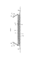
図1~図9はテープタイプ使い捨ておむつの一例を示しており、図中の符号Xは連結テープを除いたおむつの全幅を示しており、符号Lはおむつの全長を示しており、断面図における点模様部分はその表側及び裏側に位置する各構成部材を接合する接合手段としてのホットメルト接着剤を示している。ホットメルト接着剤は、スロット塗布、連続線状又は点線状のビード塗布、スパイラル状、Z状等のスプレー塗布、又はパターンコート(凸版方式でのホットメルト接着剤の転写)等、公知の手法により塗布することができる。これに代えて又はこれとともに、弾性部材の固定部分では、ホットメルト接着剤を弾性部材の外周面に塗布し、弾性部材を隣接部材に固定することができる。ホットメルト接着剤としては、例えばEVA系、粘着ゴム系(エラストマー系)、オレフィン系、ポリエステル・ポリアミド系などの種類のものが存在するが、特に限定無く使用できる。各構成部材を接合する接合手段としてはヒートシールや超音波シール等の素材溶着による手段を用いることもできる。 1 to 9 show an example of a tape-type disposable diaper, reference numeral X in the figure indicates the entire width of the diaper excluding the connecting tape, and reference numeral L indicates the total length of the diaper. The dotted pattern portion shows a hot melt adhesive as a joining means for joining the constituent members located on the front side and the back side thereof. The hot melt adhesive can be applied by a known method such as slot coating, continuous linear or dotted bead coating, spiral or Z-shaped spray coating, or pattern coating (transfer of hot melt adhesive by letterpress method). Can be applied. Instead of or in conjunction with this, at the fixed portion of the elastic member, a hot melt adhesive can be applied to the outer peripheral surface of the elastic member to fix the elastic member to the adjacent member. Examples of the hot melt adhesive include EVA type, adhesive rubber type (elastomer type), olefin type, polyester / polyamide type and the like, but they can be used without particular limitation. As a joining means for joining each component, a means by welding a material such as a heat seal or an ultrasonic seal can also be used.
このテープタイプ使い捨ておむつは、前後方向LDの中央を含む股間部と、前後方向LDの中央より前側に延びる腹側部分Fと、前後方向LDの中央より後側に延びる背側部分Bとを有している。また、このテープタイプ使い捨ておむつは、股間部を含む範囲に内蔵された吸収体56と、吸収体56の表側を覆う液透過性のトップシート30と、吸収体56の裏側を覆う液不透過性シート11と、液不透過性シートの裏側を覆い、製品外面を構成する外装不織布12とを有するものである。他方、腹側部分Fから背側部分Bにかけての幅方向両側には、吸収体56を有しないサイドフラップ部SFが形成されるとともに、背側部分のサイドフラップ部は、後方に向かうにつれて側方に位置するように延びる脚周り縁10と、この脚周り縁10よりも後方に位置する胴周り構成領域70とを有している。そして、背側部分Bの胴周り構成領域70は、腹側部分Fの外面に着脱可能に連結される連結テープ13を有している。装着状態では、例えば図9に示すように、連結テープ13が腹側部分Fの外面に連結される。図2等に示すように、腹側部分Fのサイドフラップ部にも、前方に向かうにつれて側方に位置するように延びる脚周り縁10と、この脚周り縁10よりも後方に位置する胴周り構成領域70を有している。腹側部分F及び背側部分Bの脚周り縁10は連続しており、テープタイプ使い捨ておむつの前後方向LDの中間がくびれた形状となっている。また、図示例のテープタイプ使い捨ておむつは、吸収体56の前側及び後側にそれぞれ延出する、吸収体56を有しない一対のエンドフラップ部EFを有している。
This tape-type disposable diaper has a crotch portion including the center of the anterior-posterior LD, a ventral portion F extending anteriorly from the center of the anterior-posterior LD, and a dorsal portion B extending posteriorly from the center of the anterior-posterior LD. is doing. In addition, this tape-type disposable diaper has an
以下、各部の素材及び特徴部分について順に説明する。
(吸収体)
吸収体56は、排泄液を吸収し、保持する部分であり、繊維の集合体により形成することができる。この繊維集合体としては、綿状パルプや合成繊維等の短繊維を積繊したものの他、セルロースアセテート等の合成繊維のトウ(繊維束)を必要に応じて開繊して得られるフィラメント集合体も使用できる。繊維目付けとしては、綿状パルプや短繊維を積繊する場合は、例えば100~300g/m2程度とすることができ、フィラメント集合体の場合は、例えば30~120g/m2程度とすることができる。合成繊維の場合の繊度は、例えば、1~16dtex、好ましくは1~10dtex、さらに好ましくは1~5dtexである。フィラメント集合体の場合、フィラメントは、非捲縮繊維であってもよいが、捲縮繊維であるのが好ましい。捲縮繊維の捲縮度は、例えば、2.54cm当たり5~75個、好ましくは10~50個、さらに好ましくは15~50個程度とすることができる。また、均一に捲縮した捲縮繊維を用いることができる。
Hereinafter, the materials and characteristic parts of each part will be described in order.
(Absorber)
The
(高吸収性ポリマー粒子)
吸収体56には、その一部又は全部に高吸収性ポリマー粒子を含有させることができる。高吸収性ポリマー粒子とは、「粒子」以外に「粉体」も含む。高吸収性ポリマー粒子54としては、この種の吸収性物品に使用されるものをそのまま使用できる。高吸収性ポリマー粒子の粒径は特に限定されないが、例えば500μmの標準ふるい(JIS Z8801-1:2006)を用いたふるい分け(5分間の振とう)、及びこのふるい分けでふるい下に落下する粒子について180μmの標準ふるい(JIS Z8801-1:2006)を用いたふるい分け(5分間の振とう)を行ったときに、500μmの標準ふるい上に残る粒子の割合が30重量%以下で、180μmの標準ふるい上に残る粒子の割合が60重量%以上のものが望ましい。
(Highly absorbent polymer particles)
The
高吸収性ポリマー粒子の材料としては、特に限定無く用いることができるが、吸水量が40g/g以上のものが好適である。高吸収性ポリマー粒子としては、でんぷん系、セルロース系や合成ポリマー系などのものがあり、でんぷん-アクリル酸(塩)グラフト共重合体、でんぷん-アクリロニトリル共重合体のケン化物、ナトリウムカルボキシメチルセルロースの架橋物やアクリル酸(塩)重合体などのものを用いることができる。高吸収性ポリマー粒子の形状としては、通常用いられる粉粒体状のものが好適であるが、他の形状のものも用いることができる。 The material of the highly absorbent polymer particles can be used without particular limitation, but those having a water absorption of 40 g / g or more are preferable. Highly absorbent polymer particles include starch-based, cellulose-based and synthetic polymer-based ones, which are starch-acrylic acid (salt) graft copolymers, starch-acrylonitrile copolymer sakens, and cross-linking of sodium carboxymethyl cellulose. A substance, an acrylic acid (salt) polymer, or the like can be used. As the shape of the highly absorbent polymer particles, the commonly used powder or granular material is preferable, but other shapes can also be used.
高吸収性ポリマー粒子としては、吸水速度が70秒以下、特に40秒以下のものが好適に用いられる。吸水速度が遅すぎると、吸収体56内に供給された液が吸収体56外に戻り出てしまう所謂逆戻りを発生し易くなる。
As the highly absorbent polymer particles, those having a water absorption rate of 70 seconds or less, particularly 40 seconds or less, are preferably used. If the water absorption rate is too slow, so-called reversion, in which the liquid supplied into the
また、高吸収性ポリマー粒子としては、ゲル強度が1000Pa以上のものが好適に用いられる。これにより、嵩高な吸収体56とした場合であっても、液吸収後のべとつき感を効果的に抑制できる。
Further, as the highly absorbent polymer particles, those having a gel strength of 1000 Pa or more are preferably used. As a result, even when the
高吸収性ポリマー粒子の目付け量は、当該吸収体56の用途で要求される吸収量に応じて適宜定めることができる。したがって一概には言えないが、50~350g/m2とすることができる。ポリマーの目付け量が50g/m2未満では、吸収量を確保し難くなる。350g/m2を超えると、効果が飽和するばかりでなく、高吸収性ポリマー粒子の過剰によりジャリジャリした違和感を与えるようになる。
The basis weight of the highly absorbent polymer particles can be appropriately determined according to the absorption amount required for the use of the
(包装シート)
高吸収性ポリマー粒子の抜け出しを防止するため、あるいは吸収体56の形状維持性を高めるために、吸収体56は包装シート58で包んでなる吸収要素50として内蔵させることができる。包装シート58としては、ティッシュペーパ、特にクレープ紙、不織布、ポリラミ不織布、小孔が開いたシート等を用いることができる。ただし、高吸収性ポリマー粒子が抜け出ないシートであるのが望ましい。クレープ紙に換えて不織布を使用する場合、親水性のSMMS(スパンボンド/メルトブローン/メルトブローン/スパンボンド)不織布が特に好適であり、その材質はポリプロピレン、ポリエチレン/ポリプロピレンなどを使用できる。繊維目付けは、5~40g/m2、特に10~30g/m2のものが望ましい。
(Packaging sheet)
The
この包装シート58は、図3及び図5に示すように、一枚で吸収体56の全体を包む構造とするほか、上下2枚等の複数枚のシートで吸収体56の全体を包むようにしてもよい。包装シート58は省略することもできる。
As shown in FIGS. 3 and 5, the
(トップシート)
トップシート30は液透過性を有するものであり、例えば、有孔又は無孔の不織布や、多孔性プラスチックシートなどを用いることができる。また、このうち不織布は、その原料繊維が何であるかは、特に限定されない。例えば、ポリエチレンやポリプロピレン等のオレフィン系、ポリエステル系、ポリアミド系等の合成繊維、レーヨンやキュプラ等の再生繊維、綿等の天然繊維などや、これらから二種以上が使用された混合繊維、複合繊維などを例示することができる。さらに、不織布は、どのような加工によって製造されたものであってもよい。加工方法としては、公知の方法、例えば、スパンレース法、スパンボンド法、サーマルボンド法、メルトブローン法、ニードルパンチ法、エアスルー法、ポイントボンド法等を例示することができる。例えば、柔軟性、ドレープ性を求めるのであれば、スパンレース法が、嵩高性、ソフト性を求めるのであれば、サーマルボンド法が、好ましい加工方法となる。
(Top sheet)
The
トップシート30は、前後方向では製品前端から後端まで延び、幅方向WDでは吸収体56よりも側方に延びているが、例えば後述する起き上がりギャザー60の起点が吸収体56の側縁よりも幅方向中央側に位置する場合等、必要に応じて、トップシート30の幅を吸収体56の全幅より短くする等、適宜の変形が可能である。
The
(中間シート)
トップシート30を透過した液を速やかに吸収体へ移行させるために、トップシート30より液の透過速度が速い、中間シート(「セカンドシート」とも呼ばれている)40を設けることができる。この中間シート40は、液を速やかに吸収体へ移行させて吸収体による吸収性能を高め、吸収した液の吸収体からの「逆戻り」現象を防止するためのものである。中間シート40は省略することもできる。
(Intermediate sheet)
In order to quickly transfer the liquid that has permeated the
中間シート40としては、トップシート30と同様の素材や、スパンレース不織布、スパンボンド不織布、SMS不織布、パルプ不織布、パルプとレーヨンとの混合シート、ポイントボンド不織布又はクレープ紙を例示できる。特にエアスルー不織布が嵩高であるため好ましい。エアスルー不織布には芯鞘構造の複合繊維を用いるのが好ましく、この場合芯に用いる樹脂はポリプロピレン(PP)でも良いが剛性の高いポリエステル(PET)が好ましい。目付けは17~80g/m2が好ましく、25~60g/m2がより好ましい。不織布の原料繊維の太さは2.0~10dtexであるのが好ましい。不織布を嵩高にするために、原料繊維の全部又は一部の混合繊維として、芯が中央にない偏芯の繊維や中空の繊維、偏芯且つ中空の繊維を用いるのも好ましい。
Examples of the
図示例の中間シート40は、吸収体56の幅より短く中央に配置されているが、全幅にわたって設けてもよい。また、中間シート40は、おむつの全長にわたり設けてもよいが、図示例のように排泄位置を含む中間部分にのみ設けてもよい。
Although the
(液不透過性シート)
液不透過性シート11は、特に限定されるものではないが、透湿性を有するものが好ましい。液不透過性シート11としては、例えば、ポリエチレンやポリプロピレン等のオレフィン系樹脂中に無機充填剤を混練して、シートを成形した後、一軸又は二軸方向に延伸して得られた微多孔性シートを好適に用いることができる。また、液不透過性シート11としては、不織布を基材として防水性を高めたものも用いることができる。
(Liquid impermeable sheet)
The liquid-
液不透過性シート11は、前後方向LD及び幅方向WDにおいて吸収体56と同じか又はより広範囲にわたり延びていることが望ましいが、他の遮水手段が存在する場合等、必要に応じて、前後方向LD及び幅方向WDにおいて吸収体56の端部を覆わない構造とすることもできる。
It is desirable that the liquid-
(外装不織布)
外装不織布12は液不透過性シート11の裏側全体を覆い、製品外面を布のような外観とするものである。外装不織布12としては特に限定されず、素材繊維としては、例えばポリエチレン又はポリプロピレン等のオレフィン系、ポリエステル系、ポリアミド系等の合成繊維の他、レーヨンやキュプラ等の再生繊維、綿等の天然繊維を用いることができ、加工法としてはスパンレース法、スパンボンド法、サーマルボンド法、エアスルー法、ニードルパンチ法等を用いることができる。ただし、肌触り及び強度を両立できる点でスパンボンド不織布やSMS不織布、SMMS不織布等の長繊維不織布が好適である。不織布は一枚で使用する他、複数枚重ねて使用することもできる。後者の場合、不織布相互をホットメルト接着剤等により接着するのが好ましい。不織布を用いる場合、その繊維目付けは10~50g/m2、特に15~30g/m2のものが望ましい。
(Exterior non-woven fabric)
The
(起き上がりギャザー)
トップシート30上を伝わって横方向に移動する排泄物を阻止し、いわゆる横漏れを防止するために、表面の幅方向WDの両側には、装着者の肌側に立ち上がる起き上がりギャザー60が設けられていると好ましい。もちろん、起き上がりギャザー60は省略することもできる。
(Get up gather)
In order to prevent excrement that travels laterally along the
起き上がりギャザー60を採用する場合、その構造は特に限定されず、公知のあらゆる構造を採用できる。図示例の起き上がりギャザー60は、実質的に幅方向WDに連続するギャザーシート62と、このギャザーシート62に前後方向LDに沿って伸長状態で固定された細長状のギャザー弾性部材63とにより構成されている。このギャザーシート62としては撥水性不織布を用いることができ、またギャザー弾性部材63としては糸ゴム等を用いることができる。弾性部材は、図1及び図2に示すように各複数本設ける他、各1本設けることができる。
When the rising gather 60 is adopted, its structure is not particularly limited, and any known structure can be adopted. The rising gather 60 of the illustrated example is composed of a gather
ギャザーシート62の内面は、トップシート30の側部上に幅方向WDの接合始端を有し、この接合始端から幅方向外側の部分は各サイドフラップ部SFの内面、つまり図示例では液不透過性シート11の側部及びその幅方向外側に位置する外装不織布12の側部にホットメルト接着剤などにより接合されている。
The inner surface of the gather
脚周りにおいては、起き上がりギャザー60の接合始端より幅方向内側は、製品前後方向両端部ではトップシート30上に固定されているものの、その間の部分は非固定の自由部分であり、この自由部分が弾性部材63の収縮力により立ち上がり、身体表面に密着するようになる。
Around the legs, the inside of the rising gather 60 in the width direction from the joint start end is fixed on the
(平面ギャザー)
各サイドフラップ部SFには、糸ゴム等の細長状弾性部材からなるサイド弾性部材64が前後方向LDに沿って伸長された状態で固定されており、これにより各サイドフラップ部SFの脚周り部分が平面ギャザーとして構成されている。脚周り弾性部材64は、図示例のように、ギャザーシート62の接合部分のうち接合始端近傍の幅方向外側において、ギャザーシート62と液不透過性シート11との間に設けるほか、サイドフラップ部SFにおける液不透過性シート11と外装不織布12との間に設けることもできる。脚周り弾性部材64は、図示例のように各側で複数本設ける他、各側に1本のみ設けることもできる。
(Plane gather)
A side
(連結テープ)
背側部分Bにおける胴周り構成領域70には、腹側部分Fの外面に対して着脱可能に連結される連結手段としての連結テープ13がそれぞれ設けられている。おむつの装着に際しては、連結テープ13を腰の両側から腹側部分Fの外面に回して、連結テープ13の連結部13Aを腹側部分F外面の適所に連結する。
(Connecting tape)
The waist circumference
連結テープ13の構造は特に限定されないが、図示例では、胴周り構成領域70に固定されたテープ取付部13C、及びこのテープ取付部13Cから突出するテープ本体部13Bをなすシート基材と、このシート基材におけるテープ本体部13Bの幅方向中間部に設けられた、腹側に対する連結部13Aとを有し、この連結部13Aより先端側が摘み部となっている。連結テープ13の形状も特に限定されるものではない。例えば、テープ取付部13Cは前後方向寸法が最も長くかつ一定の部分を有し、テープ本体部13Bは先端に向かうにつれて細くなるテーパー形状とすることができる。また、テープ取付部13Cの前後方向寸法は胴周り構成領域の前後方向寸法の50~90%であることが好ましく、後述する上弾性シート71Eの上縁から下弾性シート73Eの下縁までの前後方向寸法以上であることが好ましい。
The structure of the connecting
連結部13Aとしては、メカニカルファスナー(面ファスナー)のフック材(雄材)を設ける他、粘着剤層を設けてもよい。フック材は、その連結面に多数の係合突起を有するものであり、係合突起の形状としては、(A)レ字状、(B)J字状、(C)マッシュルーム状、(D)T字状、(E)ダブルJ字状(J字状のものを背合わせに結合した形状のもの)等が存在するが、いずれの形状であっても良い。
As the connecting
また、テープ取付部13Cからテープ本体部13Bまでを形成するシート基材としては、不織布、プラスチックフィルム、ポリラミ不織布、紙やこれらの複合素材を用いることができるが、繊度1.0~3.5dtex、目付け20~100g/m2、厚み1mm以下のスパンボンド不織布、エアスルー不織布、又はスパンレース不織布が好ましい。
Further, as the sheet base material forming the
(ターゲット部)
腹側部分Fにおける連結テープ13の連結箇所には、ターゲット部を設けることが好ましい。ターゲット部は、図示例のように、連結を容易にするためのターゲットシート20を腹側部分Fの外面に貼り付けることにより設けることができる。ターゲットシート20は、連結部13Aがフック材の場合、フック材の係合突起が絡まるようなループ糸がプラスチックフィルムや不織布からなるシート基材の表面に多数設けられたものを用いることができ、また粘着材層の場合には粘着性に富むような表面が平滑なプラスチックフィルムからなるシート基材の表面に剥離処理を施したものを用いることができる。また、腹側部分Fにおける連結テープ13の連結箇所が不織布からなる場合、例えば図示例のように外装不織布12を有する場合には、ターゲットシート20を省略し、フック材を外装不織布12の繊維に絡ませて連結することもできる。この場合、目印としてのターゲットシート20を外装不織布12と液不透過性シート11との間に設ける他、外装不織布12や液不透過性シート11の外面に目印を印刷してもよい。
(Target part)
It is preferable to provide a target portion at the connecting portion of the connecting
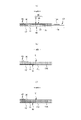
(背側部分の胴周り構成領域)
特徴的には、図8に拡大して示すように背側部分Bの胴周り構成領域70は、上領域71、中間領域72、及び下領域73の3つの領域を有している。また、図6に示すように、胴周り構成領域70は、上領域71に設けられた上弾性シート71Eと、下領域73に設けられた下弾性シート73Eと、上領域71、中間領域72及び下領域73にわたり、上弾性シート71E及び下弾性シート73Eの表側を覆う第1カバー層91と、上領域71、中間領域72及び下領域73にわたり、上弾性シート71E及び下弾性シート73Eの裏側を覆う第2カバー層92とを有している。図示例では、胴周り構成領域70の部位に応じて、第1カバー層91及び第2カバー層92となる素材や積層数が異なっているが、同一であってもよく、また積層数は一層であってもよい(図示例における最も積層数が少ない部分では、第1カバー層91はギャザーシート62のみからなり、第2カバー層92は外装不織布12のみからなる)。さらに、第1カバー層91及び第2カバー層92は伸縮性を有しないものであれば、そこに含まれるシートに伸縮性を有するものが含まれていてもよいが、表裏両面が不織布で形成されていることが好ましい。なお、伸縮性を有しない(非伸縮)とは、厚み方向と直交するあらゆる方向において弾性限界における伸長倍率が1.0~1.3倍のものを意味する。
(Constituent area around the waist of the dorsal part)
Characteristically, as shown in an enlarged manner in FIG. 8, the waist circumference
上弾性シート71E及び下弾性シート73Eとしては、弾性(エラスティック)フィルムや、伸縮不織布等のそれ自体で弾性伸縮する素材を用いることができる他、図7に示すように、二枚の不織布等の支持層81をホットメルト接着剤等の接着剤により貼り合わせるとともに、両支持層81間に有孔のシート状、網状、細長状(糸状又は紐状等)等の弾性部材82を幅方向WDに沿って伸長した状態で固定した積層伸縮体80を用いることもできる。この場合における支持層81の素材としては、外装不織布12と同様のものを用いることができる。弾性部材82の伸長率は150~250%程度であるのが好ましい。また、弾性部材82として細長状(糸状又は紐状等)のものを用いる場合、太さ420~1120dtexのものを3~10mmの間隔82dで5~15本程度設けるのが好ましい。
As the upper
このような積層伸縮体における幅方向WDの両端部は、製造時に吸引により保持して取り付けを行うために非伸縮領域86となっていてもよい。非伸縮領域86の寸法、及びこれらの間に位置し、幅方向WDに伸縮する中間伸縮領域85の寸法は適宜定めることができるが、中間伸縮領域85の幅は後述する左右の連結テープ13の連結部13A間の幅の45~90%とすることが好ましく、非伸縮領域86の幅は製造時の縮みやめくれ防止のため5~50mm程度とすることが好ましい。非伸縮領域86は弾性部材82を有しない領域としてもよいが、中間伸縮領域85及び非伸縮領域86にわたり弾性部材82を取り付けるとともに、非伸縮領域86では弾性部材82を切断する等により、非伸縮領域86に弾性部材82が残留するもののほとんど又は全く伸縮しない構造としてもよい。
Both ends of the widthwise WD in such a laminated stretchable body may be a
また、上弾性シート71E及び下弾性シート73Eとしては、無孔のものの他、通気のために多数の孔やスリットが形成されたものも用いることができる。上弾性シート71E及び下弾性シート73Eは、特性により限定されるものではないが、例えば幅方向WD(伸縮方向ED、MD方向)における引張強度が8~25N/35mm、前後方向LD(伸縮方向と直交する方向XD、CD方向)における引張強度が5~20N/35mm、幅方向WDにおける引張伸度が450~1050%、及び前後方向LDにおける引張伸度が450~1400%のものを用いることができる。上弾性シート71E及び下弾性シート73Eの厚みは特に限定されないが、弾性フィルムの場合、例えば20~40μm程度とすることができる。
Further, as the upper
上弾性シート71E及び下弾性シート73Eと第1カバー層91、並びに上弾性シート71E及び下弾性シート73Eと第2カバー層92は、それぞれホットメルト接着剤を介して接着することにより、又は少なくとも一方の溶着により一体化することができる。また、第1カバー層91、上弾性シート71E及び下弾性シート73E、並びに第2カバー層92は、それらが一体として伸縮可能である限り、隣接層の全体が連続的に接合されていても、間欠的に接合されていてもよい。また、特表2004-532758号公報や、特開2016-189826号公報に示される一体化手法を採用し、第1カバー層91及び第2カバー層92の間に上弾性シート71E及び下弾性シート73Eを挟んだ状態で散点状に超音波シールを行い、第1カバー層91及び第2カバー層92を多数の接合部で上弾性シート71E及び下弾性シート73Eに形成した貫通孔を通じて接合してもよい(図示略)。
The upper
本胴周り構成領域70では、上弾性シート71Eの下縁は上領域71の下縁に一致し、下弾性シート73Eの上縁は下領域73の上縁に一致している。また、上領域71は、上弾性シート71Eにより幅方向WDに伸長可能に収縮した伸縮領域となっており、下領域73は、下弾性シート73Eにより幅方向WDに伸長可能に収縮した伸縮領域となっており、中間領域72は、弾性素材を有しないか、又は弾性素材を有するとしてもその弾性素材により幅方向WDに収縮していない領域となっている。これら上領域71及び下領域73は、製造時に上弾性シート71E及び下弾性シート73Eを幅方向WDに伸長した状態で第1カバー層91及び第2カバー層92と一体化する公知の方法により製造できる。このように、胴周り構成領域70の上領域71及び下領域73を伸縮領域とし、中間領域72を非伸縮領域とすると、図8(b)に示すように、上領域71及び下領域73の収縮により中間領域72を裏側に窪ませることができる(窪み72S)。このため、装着時に上領域71及び下領域73を展開状態まで伸長させない限り、図9に示すように、胴周り構成領域70の内面に中間領域72を主とする窪み72Sを形成することができ、身体表面の曲面(特に、腸骨稜に沿う部分の曲面)に対して良好にフィットし、曲面の頂部に対する接触圧が高くなりにくい。しかも、上領域71及び下領域73の伸縮性により、胴周り方向の伸縮性も発揮され、全体として良好なフィット性が発揮される。
In the main body circumference
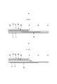
図2等に示すように、上弾性シート71Eは、幅方向WDの一方の胴周り構成領域70から他方の胴周り構成領域70まで幅方向WDに連続する、左右共通の部材であり、下弾性シート73Eは、幅方向WD両側の一方の胴周り構成領域70及び他方の胴周り構成領域70に個別に設けられており、吸収体56と重なる領域に、下弾性シート73Eを有しない部分が設けられていると好ましい。このように、上弾性シート71Eを左右の胴周り構成領域70に連続する共通の部材とすることにより、胴周り構成領域70だけでなく、その間の部分も含めて幅方向WDに伸長可能に収縮することとなり、テープタイプ使い捨ておむつの後端部(ウエスト縁部)のフィット性が良好となる。一方、下弾性シート73Eは左右の胴周り構成領域70に個別に設け、吸収体56と重なる領域に非伸縮領域を形成すると、吸収体56を有する部分のフィット性が良好となる。図示例では、上弾性シート71Eは、エンドフラップ部EFにのみ位置しているが、後述するウエスト弾性シート75のように、エンドフラップ部EFから吸収体56の後端部までにわたるように配置されていると、吸収体56の後端部がしっかりと体に押し当てられるため、好ましい。このように、幅方向WDにおいて、上弾性シート71Eは上領域71外まで、また下弾性シート73Eは下領域73外まで延びていてもよい。
As shown in FIG. 2 and the like, the upper
もちろん、図10(a)に示すように、上弾性シート71E及び下弾性シート73Eの両方を、左右の胴周り構成領域70に個別に設けることもできる。また、その場合、図10(b)に示すように、左右の上弾性シート71E及び下弾性シート73Eの間に別途のウエスト弾性シート75を配置し、胴周り構成領域70だけでなく、その間の部分も含めて幅方向WDに伸長可能に収縮させることにより、テープタイプ使い捨ておむつの後端部(ウエスト縁部)のフィット性を確保することもできる。ウエスト弾性シート75は、エンドフラップ部EFにのみ位置していてもよいが、図示例のようにエンドフラップ部EFから吸収体56の後端部までにわたるように配置されていると、吸収体56の後端部がしっかりと体に押し当てられるため、好ましい。
Of course, as shown in FIG. 10A, both the upper
上弾性シート71Eにおける吸収体56と重なる部分、及びウエスト弾性シート75における吸収体56と重なる部分は、図示例では、液不透過性シート11と吸収要素50との間に配置されているが、この配置に特に限定されるものではない。例えば、上弾性シート71Eにおける吸収体56と重なる部分、及びウエスト弾性シート75における吸収体56と重なる部分は、液不透過性シート11と外装不織布12との間に配置されていてもよい。
The portion of the upper
上弾性シート71E、下弾性シート73E、及び連結テープ13の位置関係は適宜定めることができる。図示例のように、テープ取付部13Cが、胴周り構成領域70における上領域71の上端部と対応する前後方向位置から下領域73の下端部と対応する前後方向位置まで延びているのは、一つの好ましい形態である。これにより、テープ本体部13Bを摘まんで引っ張るときに、上領域71及び下領域73の両方に対して直接的に力が伝わる。この結果、装着時に、胴周り構成領域70の上領域71及び下領域73をバランスよく引っ張ることができ、より容易に適切な装着が可能となる。また、同様の観点から、図示例のように、テープ取付部13Cの前後方向LDの中心と、中間領域72における前後方向LDの中心とを一致させることが好ましい。
The positional relationship between the upper
上弾性シート71E及び下弾性シート73Eは、連結テープ13のテープ取付部13Cと重なっていてもよいが、重ならずに幅方向WDの内側に配置されていると、連結テープ13のテープ取付部13Cが不必要に収縮することが無いため好ましい。
The upper
上領域71、下領域73及び中間領域72の寸法は適宜定めることができる。例えば、上領域71の前後方向寸法は胴周り構成領域70の前後方向寸法の15~30%とすることができ、下領域73の前後方向寸法は胴周り構成領域70の前後方向寸法の15~30%とすることができ、中間領域72の前後方向寸法は胴周り構成領域70の前後方向寸法の30~60%とすることができる。
The dimensions of the
(立体的変形領域)
図1、図6及び図8に示すように、中間領域72には立体的変形領域90が設けられている。すなわち、この立体的変形領域90では、立体的変形領域90の内外にわたる大きさの中間弾性シート93と、中間弾性シート93の表側を覆う第1カバー層91と、裏側を覆う第2カバー層92とが一体化されている。第1カバー層91及び第2カバー層92は、上領域71及び下領域73と同じ部材により形成されていても、異なっていてもよい。中間弾性シート93に用いうる素材又は部材は上弾性シート71E及び下弾性シート73Eの場合と同様である。また、中間弾性シート93と、第1カバー層91及び第2カバー層92との一体化は、上弾性シート71E及び下弾性シート73Eと第1カバー層91及び第2カバー層92との一体化と同じ手法を採用することができる。
(Three-dimensional deformation area)
As shown in FIGS. 1, 6 and 8, the
立体的変形領域90における第1カバー層91及び第2カバー層92には、スリット又はこれを形成するためのミシン目からなるスリット部95,96が複数本設けられる。これらスリット部95,96は、立体的変形領域90を横切って立体的変形領域90の一方の縁部から他方の縁部まで延びているとともに、互いに交差している。そして、第1カバー層91及び第2カバー層92における立体的変形領域90内に位置する部分のすべてが、スリット部95,96を介さずに、立体的変形領域90外に位置する部分に連続している。この結果、本例の立体的変形領域90では、図12(a)に示す例のように、複数本のスリット部がそれらの交差位置に近づくほど大きく広がるような第1カバー層91及び第2カバー層92の変形を伴い、中間弾性シート93がスリット部95,96の広がりに応じて弾性伸長可能である。
The
換言すると、本立体的変形領域90では、図12(b)に矢印で示すように立体的変形領域90に厚み方向の一方側から他方側に向かう力が加えられたとき、立体的変形領域90はこれに追従して、主に各スリット部95,96と直交する複数方向に伸長しつつ、周囲部分に対して窪むように変形することができる。したがって、このような窪み変形する立体的変形領域90を、胴周り構成領域70の中間領域72に設ければ、胴周り構成領域70の上領域71及び下領域73がある程度まで伸長し、胴周り構成領域70の窪み72Sがほとんど無くなるような装着状態でも、立体的変形領域90が窪むことにより、良好なフィット性が確保される。また、複数本のスリット部95,96により立体的変形領域90が決まるため、一本の直線状のスリットの場合と比べて、伸縮方向に制限がなく、伸縮の程度も大きなものとすることができる。さらに、第1カバー層91及び第2カバー層92における立体的変形領域90内に位置する部分のすべてが、スリット部95,96を介さずに、立体的変形領域90外に位置する部分に連続しているため、既存の製造設備において、第1カバー層91及び第2カバー層92にスリット部95,96を設けるだけで製造することが可能となる。
In other words, in the three-
中間弾性シート93は、製造時に伸長した状態で第1カバー層及び第2カバー層と一体化してもよい。その場合、立体的変形領域90は、中間弾性シート93が自然長まで収縮するのに伴い、第1カバー層91及び第2カバー層92が収縮し、第1カバー層91及び第2カバー層92に収縮皺が形成される。これと異なり、製造時に中間弾性シート93をほぼ伸長していない状態で第1カバー層91及び第2カバー層92と一体化することも可能である。図示例はこの場合を想定しており、自然長の状態では、立体的変形領域90に皺(襞含む)が形成されず、外観が良好となる。特に、第1カバー層91及び第2カバー層92にスリット部95,96しか設けないことにより、自然長の状態では、中間弾性シート93が第1カバー層91及び第2カバー層92により綺麗に隠蔽されるという利点もある。
The intermediate
スリット部95,96は、前後方向LDや幅方向WDのみならず、斜め方向に延びていてもよい。またスリット部95,96は立体的変形領域90を横切って縁部まで延びる限り、図示例のように直線状とする他、弧状や波線等の曲線状とすることができる。互いに交差する二本のスリット部95,96の交差角度は立体的変形領域90の寸法・形状やスリット部95,96の配置により適宜定めることができるが、通常の場合90度、又は交差角度の一方が鋭角の場合には15度以上90度未満、特に30~90度未満とすることができる。立体的変形領域90の寸法は適宜定めることができるが、通常の場合、前後方向寸法Y1は2~7mm程度、幅方向寸法X1は4~7mm程度の範囲内とすることができ、図11(a)に示すように前後方向寸法Y1が幅方向寸法X1より長くしたり、図示しないが幅方向寸法X1が前後方向寸法Y1より長くしたり、図示しないが前後方向寸法Y1及び幅方向寸法X1を同じとしたりすることができる。立体的変形領域90は、周縁に物品の端部を含まないことが好ましいが、一部含んでいてもよい。スリット部95,96の本数は限定されず、図示例より多くてもよい。
The
複数のスリット部95,96の配置は特に限定されない。例えば、図11に示す各例のように、一部の複数(図11(a)の例)のスリット部95、又は全部(図11(b)(c)のスリット部95が、立体的変形領域90の中央部を通り、両端部が立体的変形領域90の縁部まで延びているのは好ましい。この場合、スリット部95は立体的変形領域90の中央部から放射状(X状や十字状を含む)に延びることとなる。このようにスリット部95が立体的変形領域90の中央部から放射状に延びるように配置されていると、最小限のスリット部95の数で広範囲にわたる立体的変形領域90を形成することができる。また、このスリット部95の配置は、立体的変形領域90を円形や楕円形、ひし形とする場合に好適である。
The arrangement of the plurality of
図11(a)に示す例のように、スリット部95,96は、立体的変形領域90の中央部を通り、両端部が立体的変形領域90の縁部まで延びる中央スリット部95と、この中央スリット部の端部を通り、両端部が立体的変形領域90の縁部まで延びる端スリット部96とを含むのも好ましい。この場合、スリット部95,96はT字状やH字状等に延びることとなる。またこのスリット部95,96の配置は、立体的変形領域90を三角形や矩形とする場合に好適である。図11(d)に示すように、立体的変形領域90をU字状やV字状に囲むように端スリット部96を三本又は二本設けるだけでもよい。
As shown in the example shown in FIG. 11A, the
第1カバー層91のスリット部95,96、及び第2カバー層92のスリット部95,96は、同じ寸法・形状で、同じ位置に配置されている(つまり厚み方向に完全に重なる)ことが望ましいが、多少ずれていてもよい。また、第1カバー層91のスリット部95,96、及び第2カバー層92のスリット部95,96は、異なる寸法・形状であってもよい。
The
中間領域72における立体的変形領域90の幅方向WDの位置は、特に限定されないが、第1カバー層91及び第2カバー層92の素材積層数がそれぞれ1層の部分であると製造が容易となるため好ましい。このため、本例の場合、背側部分Bのサイドフラップ部SFにおける連結テープ13のテープ取付部13Cより幅方向内側に、立体的変形領域90が設けられていることが好ましい。この場合、第1カバー層91はギャザーシート62のみからなるものとなり、第2カバー層92は外装不織布12のみからなることとなる。
The position of the WD in the width direction of the three-
図10(b)に示す例のように、立体的変形領域90(つまり、中間弾性シート93及びスリット)を設けなくてもよい。
As in the example shown in FIG. 10B, the three-dimensional deformation region 90 (that is, the intermediate
<明細書中の用語の説明>
明細書中の以下の用語は、明細書中に特に記載が無い限り、以下の意味を有するものである。
・「前後方向」とは図中に符号LDで示す方向(縦方向)を意味し、「幅方向」とは図中にWDで示す方向(左右方向)を意味し、前後方向と幅方向とは直交するものである。
<Explanation of terms in the specification>
The following terms in the specification have the following meanings unless otherwise specified in the specification.
-The "front-back direction" means the direction (vertical direction) indicated by the symbol LD in the figure, and the "width direction" means the direction (horizontal direction) indicated by WD in the figure, and the front-back direction and the width direction. Are orthogonal.
・「展開状態」とは、収縮や弛み無く平坦に展開した状態を意味する。 -"Unfolded state" means a state in which the unfolded state is flat without shrinkage or slack.
・「伸長率」は、自然長を100%としたときの値を意味する。例えば、伸長率が200%とは、伸長倍率が2倍であることと同義である。 -"Elongation rate" means a value when the natural length is 100%. For example, an elongation rate of 200% is synonymous with an elongation ratio of 2 times.
・「ゲル強度」は次のようにして測定されるものである。人工尿(尿素:2wt%、塩化ナトリウム:0.8wt%、塩化カルシウム二水和物:0.03wt%、硫酸マグネシウム七水和物:0.08wt%、及びイオン交換水:97.09wt%)49.0gに、高吸収性ポリマーを1.0g加え、スターラーで攪拌させる。生成したゲルを40℃×60%RHの恒温恒湿槽内に3時間放置したあと常温にもどし、カードメーター(I.techno Engineering社製:Curdmeter-MAX ME-500)でゲル強度を測定する。 -"Gel strength" is measured as follows. Artificial urine (urea: 2 wt%, sodium chloride: 0.8 wt%, calcium chloride dihydrate: 0.03 wt%, magnesium sulfate heptahydrate: 0.08 wt%, and ion-exchanged water: 97.09 wt%) Add 1.0 g of highly absorbent polymer to 49.0 g and stir with a stirrer. The produced gel is left in a constant temperature and humidity chamber at 40 ° C. × 60% RH for 3 hours, then returned to room temperature, and the gel strength is measured with a card meter (Curdmeter-MAX ME-500 manufactured by I.techno Engineering).
・「目付け」は次のようにして測定されるものである。試料又は試験片を予備乾燥した後、標準状態(試験場所は、温度23±1℃、相対湿度50±2%)の試験室又は装置内に放置し、恒量になった状態にする。予備乾燥は、試料又は試験片を温度100℃の環境で恒量にすることをいう。なお、公定水分率が0.0%の繊維については、予備乾燥を行わなくてもよい。恒量になった状態の試験片から、試料採取用の型板(100mm×100mm)を使用し、100mm×100mmの寸法の試料を切り取る。試料の重量を測定し、100倍して1平米あたりの重さを算出し、目付けとする。
・吸収体の「厚み」は、株式会社尾崎製作所の厚み測定器(ピーコック、ダイヤルシックネスゲージ大型タイプ、型式J-B(測定範囲0~35mm)又は型式K-4(測定範囲0~50mm))を用い、試料と厚み測定器を水平にして、測定する。
・上記以外の「厚み」は、自動厚み測定器(KES-G5 ハンディ圧縮計測プログラム)を用い、荷重:0.098N/cm2、及び加圧面積:2cm2の条件下で自動測定する。
・「引張強度」及び「引張伸度(破断伸び)」は、試験片を幅35mm・長さ80mmの長方形状とする以外は、JIS K7127:1999「プラスチック-引張特性の試験方法-」に準じて、初期チャック間隔(標線間距離)を50mmとし、引張速度を300mm/minとして測定される値を意味する。引張試験機としては、例えばSHIMADZU社製のAUTOGRAPH AGS-G100Nを用いることができる。
・ "Metsuke" is measured as follows. After the sample or test piece is pre-dried, it is left in a test room or device in a standard state (the test place is a temperature of 23 ± 1 ° C. and a relative humidity of 50 ± 2%) to bring it into a constant weight state. Pre-drying refers to constant weight of a sample or test piece in an environment with a temperature of 100 ° C. For fibers with an official moisture content of 0.0%, pre-drying does not have to be performed. From the test piece in a constant weight state, a sample having a size of 100 mm × 100 mm is cut out using a sampling template (100 mm × 100 mm). The weight of the sample is measured and multiplied by 100 to calculate the weight per square meter, which is used as a basis weight.
-The "thickness" of the absorber is the thickness measuring instrument of Ozaki Works Paper Gauge (peacock, dial thickness gauge large type, model JB (measurement range 0 to 35 mm) or model K-4 (measurement range 0 to 50 mm)). The sample and the thickness measuring instrument are placed horizontally and measured.
-The "thickness" other than the above is automatically measured using an automatic thickness measuring device (KES-G5 handy compression measuring program) under the conditions of a load of 0.098 N / cm 2 and a pressurized area of 2 cm 2 .
-"Tensile strength" and "tensile elongation (break elongation)" are based on JIS K7127: 1999 "Plastic-Test method for tensile properties-" except that the test piece has a rectangular shape with a width of 35 mm and a length of 80 mm. It means a value measured with an initial chuck interval (distance between marked lines) of 50 mm and a tensile speed of 300 mm / min. As the tensile tester, for example, AUTOGRAPH AGS-G100N manufactured by SHIMADZU can be used.
・「吸水量」は、JIS K7223-1996「高吸水性樹脂の吸水量試験方法」によって測定する。 -"Water absorption" is measured by JIS K7223-1996 "Water absorption test method for highly water-absorbent resin".
・「吸水速度」は、2gの高吸収性ポリマー及び50gの生理食塩水を使用して、JIS K7224‐1996「高吸水性樹脂の吸水速度試験法」を行ったときの「終点までの時間」とする。 -"Water absorption rate" is the "time to the end point" when JIS K7224-1996 "Water absorption rate test method for highly water-absorbent resin" was performed using 2 g of highly absorbent polymer and 50 g of physiological saline. And.
・試験や測定における環境条件についての記載が無い場合、その試験や測定は、標準状態(試験場所は、温度23±1℃、相対湿度50±2%)の試験室又は装置内で行うものとする。
-If there is no description of the environmental conditions in the test or measurement, the test or measurement shall be performed in a test room or device under standard conditions (test location: temperature 23 ± 1 ° C,
・各部の寸法は、特に記載が無い限り、自然長状態ではなく展開状態における寸法を意味する。 -Unless otherwise specified, the dimensions of each part mean the dimensions in the unfolded state, not in the natural length state.
本発明は、上記例のようなテープタイプ使い捨ておむつの他、パンツタイプ、パッドタイプ等の各種使い捨ておむつ、生理用ナプキン、スイミングや水遊び用の使い捨て着用物品等、使い捨て着用物品全般における伸縮構造に利用できるものである。 INDUSTRIAL APPLICABILITY The present invention is used for a stretchable structure in all disposable wearing articles such as various disposable diapers such as pants type and pad type, sanitary napkins, disposable wearing articles for swimming and playing in the water, in addition to the tape type disposable diapers as in the above example. It can be done.
10…脚周り縁、11…液不透過性シート、12…外装不織布、13…連結テープ、13A…連結部、13B…テープ本体部、13C…テープ取付部、20…ターゲットシート、30…トップシート、40…中間シート、50…吸収要素、56…吸収体、58…包装シート、60…起き上がりギャザー、62…ギャザーシート、70…胴周り構成領域、71…上領域、71E…上弾性シート、72…中間領域、72S…窪み、73…下領域、73E…下弾性シート、75…ウエスト弾性シート、80…積層伸縮体、90…立体的変形領域、91…第1カバー層、92…第2カバー層、93…弾性シート、95,96…スリット部、95…中央スリット部、96…端スリット部、B…背側部分、F…腹側部分、LD…前後方向、SF…サイドフラップ部、WD…幅方向。 10 ... Leg circumference edge, 11 ... Liquid permeable sheet, 12 ... Exterior non-woven fabric, 13 ... Connecting tape, 13A ... Connecting part, 13B ... Tape body part, 13C ... Tape mounting part, 20 ... Target sheet, 30 ... Top sheet , 40 ... Intermediate sheet, 50 ... Absorbent element, 56 ... Absorber, 58 ... Packaging sheet, 60 ... Rising gather, 62 ... Gather sheet, 70 ... Waist circumference constituent area, 71 ... Upper area, 71E ... Upper elastic sheet, 72 ... Intermediate region, 72S ... Recess, 73 ... Lower region, 73E ... Lower elastic sheet, 75 ... Waist elastic sheet, 80 ... Laminated stretchable body, 90 ... Three-dimensional deformation region, 91 ... First cover layer, 92 ... Second cover Layer, 93 ... Elastic sheet, 95, 96 ... Slit part, 95 ... Central slit part, 96 ... End slit part, B ... Back side part, F ... Ventral part, LD ... Front-back direction, SF ... Side flap part, WD … In the width direction.
Claims (6)
前記股間部を含む範囲に内蔵された吸収体を有し、
前記腹側部分及び前記背側部分は、前記吸収体よりも左右両側に延び出たサイドフラップ部を有し、
前記背側部分の前記サイドフラップ部は、後方に向かうにつれて側方に位置するように延びる脚周り縁と、この脚周り縁よりも後方に位置する胴周り構成領域とを有し、
前記背側部分の前記胴周り構成領域に、前記腹側部分と着脱可能に連結するための連結手段を有する、
テープタイプ使い捨ておむつにおいて、
前記背側部分の前記胴周り構成領域は、上領域、中間領域、及び下領域の3つの領域を有しており、
前記上領域に設けられた上弾性シートと、前記下領域に設けられた下弾性シートと、前記上領域、中間領域及び下領域にわたり、前記上弾性シート及び下弾性シートの表側を覆う第1カバー層と、前記上領域、中間領域及び下領域にわたり、前記上弾性シート及び下弾性シートの裏側を覆う第2カバー層とを有し、
前記上弾性シートの下縁は前記上領域の下縁に一致し、前記下弾性シートの上縁は前記下領域の上縁に一致し、
前記弾性シート、前記第1カバー層及び前記第2カバー層は一体化されており、
前記第1カバー層及び前記第2カバー層は伸縮性を有しておらず、
前記上領域は、前記上弾性シートにより幅方向に伸長可能に収縮した伸縮領域であり、
前記下領域は、前記下弾性シートにより幅方向に伸長可能に収縮した伸縮領域であり、
前記中間領域は、弾性素材を有しないか、又は弾性素材を有するとしてもその弾性素材により幅方向に収縮しておらず、
前記中間領域は、前記第1カバー層及び第2カバー層の間に挟まれ、一体化された中間弾性シートを有するとともに、前記第1カバー層、前記第2カバー層及び前記中間弾性シートが重なる領域内に立体的変形領域を有し、
前記立体的変形領域における前記第1カバー層及び前記第2カバー層には、スリット又はこれを形成するためのミシン目からなるスリット部が複数本設けられており、
前記複数本のスリット部は、前記立体的変形領域を横切って前記立体的変形領域の一方の縁部から他方の縁部まで延びており、
前記複数本のスリット部は互いに交差しており、
前記第1カバー層及び前記第2カバー層における前記立体的変形領域内に位置する部分のすべてが、前記スリット部を介さずに、前記立体的変形領域外に位置する部分に連続している、
ことを特徴とするテープタイプ使い捨ておむつ。 It has a crotch part including the center in the anterior-posterior direction, a ventral part extending anteriorly from the center in the anterior-posterior direction, and a dorsal part extending posteriorly from the center in the anterior-posterior direction.
It has an absorber built in the range including the crotch part, and has an absorber.
The ventral portion and the dorsal portion have side flap portions extending to the left and right sides of the absorber.
The side flap portion of the dorsal portion has a leg peripheral edge extending laterally toward the rear and a waist circumference constituent region located posterior to the leg peripheral edge.
A connecting means for detachably connecting to the ventral portion is provided in the waist circumference constituent region of the dorsal portion.
In tape-type disposable diapers
The waist circumference constituent region of the dorsal portion has three regions, an upper region, an intermediate region, and a lower region.
A first cover that covers the upper elastic sheet provided in the upper region, the lower elastic sheet provided in the lower region, the upper region, the intermediate region, and the lower region, and covers the front side of the upper elastic sheet and the lower elastic sheet. It has a layer and a second cover layer that covers the upper region, the intermediate region, and the lower region and covers the back side of the upper elastic sheet and the lower elastic sheet.
The lower edge of the upper elastic sheet coincides with the lower edge of the upper region, and the upper edge of the lower elastic sheet coincides with the upper edge of the lower region.
The elastic sheet, the first cover layer and the second cover layer are integrated.
The first cover layer and the second cover layer do not have elasticity and do not have elasticity.
The upper region is an expansion / contraction region that is extensible and contracted in the width direction by the upper elastic sheet.
The lower region is an expansion / contraction region that is extensible and contracted in the width direction by the lower elastic sheet.
The intermediate region does not have an elastic material, or even if it has an elastic material, it does not shrink in the width direction due to the elastic material.
The intermediate region has an integrated intermediate elastic sheet sandwiched between the first cover layer and the second cover layer, and the first cover layer, the second cover layer, and the intermediate elastic sheet overlap each other. It has a three-dimensional deformation area in the area,
The first cover layer and the second cover layer in the three-dimensional deformation region are provided with a plurality of slit portions made of slits or perforations for forming the slits.
The plurality of slit portions extend from one edge portion of the three-dimensional deformation region to the other edge portion across the three-dimensional deformation region.
The plurality of slits intersect with each other and
All of the portions of the first cover layer and the second cover layer located in the three-dimensional deformation region are continuous with the portions located outside the three-dimensional deformation region without passing through the slit portion.
A tape-type disposable diaper that features this.
前記上弾性シートは、幅方向の一方の胴周り構成領域から他方の胴周り構成領域まで幅方向に連続する、左右共通の部材であり、
前記下弾性シートは、幅方向両側の一方の胴周り構成領域及び他方の胴周り構成領域に個別に設けられており、
前記吸収体と重なる領域に、前記下弾性シートを有しない部分が設けられている、
請求項1記載のテープタイプ使い捨ておむつ。 The absorber extends posteriorly to at least between the lower regions.
The upper elastic sheet is a member common to the left and right, which is continuous in the width direction from one waist circumference constituent area in the width direction to the other waist circumference constituent region.
The lower elastic sheet is individually provided in one waist circumference constituent area and the other waist circumference constituent area on both sides in the width direction.
A portion that does not have the lower elastic sheet is provided in the region that overlaps with the absorber.
The tape-type disposable diaper according to claim 1.
前記テープ取付部は、前記胴周り構成領域における前記上領域の上端部と対応する前後方向位置から前記下領域の下端部と対応する前後方向位置まで延びている、
請求項1又は2記載のテープタイプ使い捨ておむつ。 The connecting means connects the tape mounting portion fixed to the waist circumference constituent region, the tape main body portion protruding from the tape mounting portion, and the ventral side portion provided in the widthwise intermediate portion of the tape main body portion. It is a connecting tape with a part and
The tape mounting portion extends from a front-rear direction position corresponding to the upper end portion of the upper region in the waist circumference constituent area to a front-rear direction position corresponding to the lower end portion of the lower region.
The tape-type disposable diaper according to claim 1 or 2.
請求項1~3のいずれか1項に記載のテープタイプ使い捨ておむつ。 In the three-dimensional deformation region, in the state of natural length, the shrinkage wrinkles formed by the shrinkage of the intermediate elastic sheet are not formed in the first cover layer and the second cover layer.
The tape-type disposable diaper according to any one of claims 1 to 3 .
請求項1~4のいずれか1項に記載のテープタイプ使い捨ておむつ。 The slit portion includes a plurality of slit portions that pass through the central portion of the three-dimensional deformation region and have both ends extending to the edges of the three-dimensional deformation region.
The tape-type disposable diaper according to any one of claims 1 to 4 .
請求項1~4のいずれか1項に記載のテープタイプ使い捨ておむつ。 The slit portion passes through the central portion of the three-dimensional deformation region, the central slit portion whose both ends extend to the edge portion of the three-dimensional deformation region, and the end portion of the central slit portion, and both ends thereof are three-dimensional. Including an end slit portion extending to the edge of the deformed region,
The tape-type disposable diaper according to any one of claims 1 to 4 .
Priority Applications (1)
| Application Number | Priority Date | Filing Date | Title |
|---|---|---|---|
| JP2018039088A JP7082501B2 (en) | 2018-03-05 | 2018-03-05 | Tape type disposable diapers |
Applications Claiming Priority (1)
| Application Number | Priority Date | Filing Date | Title |
|---|---|---|---|
| JP2018039088A JP7082501B2 (en) | 2018-03-05 | 2018-03-05 | Tape type disposable diapers |
Publications (3)
| Publication Number | Publication Date |
|---|---|
| JP2019150404A JP2019150404A (en) | 2019-09-12 |
| JP2019150404A5 JP2019150404A5 (en) | 2021-03-11 |
| JP7082501B2 true JP7082501B2 (en) | 2022-06-08 |
Family
ID=67947371
Family Applications (1)
| Application Number | Title | Priority Date | Filing Date |
|---|---|---|---|
| JP2018039088A Active JP7082501B2 (en) | 2018-03-05 | 2018-03-05 | Tape type disposable diapers |
Country Status (1)
| Country | Link |
|---|---|
| JP (1) | JP7082501B2 (en) |
Citations (5)
| Publication number | Priority date | Publication date | Assignee | Title |
|---|---|---|---|---|
| JP2001145665A (en) | 1999-11-22 | 2001-05-29 | Kao Corp | Absorptive article |
| JP2005152168A (en) | 2003-11-21 | 2005-06-16 | Kao Corp | Disposable diaper |
| JP2009101047A (en) | 2007-10-25 | 2009-05-14 | Kao Corp | Disposable diaper |
| JP2010017341A (en) | 2008-07-10 | 2010-01-28 | Oji Nepia Co Ltd | Disposable diaper |
| JP2010035726A (en) | 2008-08-04 | 2010-02-18 | Oji Nepia Co Ltd | Tape type disposable diaper |
-
2018
- 2018-03-05 JP JP2018039088A patent/JP7082501B2/en active Active
Patent Citations (5)
| Publication number | Priority date | Publication date | Assignee | Title |
|---|---|---|---|---|
| JP2001145665A (en) | 1999-11-22 | 2001-05-29 | Kao Corp | Absorptive article |
| JP2005152168A (en) | 2003-11-21 | 2005-06-16 | Kao Corp | Disposable diaper |
| JP2009101047A (en) | 2007-10-25 | 2009-05-14 | Kao Corp | Disposable diaper |
| JP2010017341A (en) | 2008-07-10 | 2010-01-28 | Oji Nepia Co Ltd | Disposable diaper |
| JP2010035726A (en) | 2008-08-04 | 2010-02-18 | Oji Nepia Co Ltd | Tape type disposable diaper |
Also Published As
| Publication number | Publication date |
|---|---|
| JP2019150404A (en) | 2019-09-12 |
Similar Documents
| Publication | Publication Date | Title |
|---|---|---|
| JP5918795B2 (en) | Absorbent article manufacturing method and absorbent article | |
| WO2021192999A1 (en) | Connection-type disposable wearable article | |
| WO2021193000A1 (en) | Connecting disposable worn article | |
| JP7082501B2 (en) | Tape type disposable diapers | |
| JP6767175B2 (en) | Disposable diapers | |
| JP2020156835A (en) | Connection type disposable wearing article | |
| JP2020156835A5 (en) | ||
| JP7389432B2 (en) | absorbent articles | |
| JP2019150404A5 (en) | ||
| JP2019170555A (en) | Stretchable structure for disposable wearing article and pants-type disposable wearing article with such stretchable structure | |
| JP7129179B2 (en) | Elastic structure of absorbent article | |
| JP7009143B2 (en) | Disposable wear items | |
| JP2019150394A5 (en) | ||
| JP6990074B2 (en) | Tape type disposable diapers | |
| WO2021100776A1 (en) | Disposable diaper | |
| JP6860399B2 (en) | Tape type disposable diapers | |
| JP6990075B2 (en) | Tape type disposable diapers | |
| JP6910912B2 (en) | Tape type disposable diapers and their manufacturing methods | |
| WO2021193001A1 (en) | Connecting-type disposable wearable article | |
| JP6824774B2 (en) | Absorbent article | |
| WO2021193002A1 (en) | Absorbent article | |
| WO2021182445A1 (en) | Disposable absorbent article | |
| WO2021059959A1 (en) | Absorbent article | |
| JP6942502B2 (en) | Tape type disposable diapers | |
| JP6797056B2 (en) | Tape type disposable diapers |
Legal Events
| Date | Code | Title | Description |
|---|---|---|---|
| A521 | Request for written amendment filed |
Free format text: JAPANESE INTERMEDIATE CODE: A523 Effective date: 20210127 |
|
| A621 | Written request for application examination |
Free format text: JAPANESE INTERMEDIATE CODE: A621 Effective date: 20210127 |
|
| A977 | Report on retrieval |
Free format text: JAPANESE INTERMEDIATE CODE: A971007 Effective date: 20220120 |
|
| A131 | Notification of reasons for refusal |
Free format text: JAPANESE INTERMEDIATE CODE: A131 Effective date: 20220128 |
|
| A521 | Request for written amendment filed |
Free format text: JAPANESE INTERMEDIATE CODE: A523 Effective date: 20220310 |
|
| TRDD | Decision of grant or rejection written | ||
| A01 | Written decision to grant a patent or to grant a registration (utility model) |
Free format text: JAPANESE INTERMEDIATE CODE: A01 Effective date: 20220513 |
|
| A61 | First payment of annual fees (during grant procedure) |
Free format text: JAPANESE INTERMEDIATE CODE: A61 Effective date: 20220527 |
|
| R150 | Certificate of patent or registration of utility model |
Ref document number: 7082501 Country of ref document: JP Free format text: JAPANESE INTERMEDIATE CODE: R150 |