JP7082011B2 - Hydraulic drive of excavation work machine - Google Patents
Hydraulic drive of excavation work machine Download PDFInfo
- Publication number
- JP7082011B2 JP7082011B2 JP2018156095A JP2018156095A JP7082011B2 JP 7082011 B2 JP7082011 B2 JP 7082011B2 JP 2018156095 A JP2018156095 A JP 2018156095A JP 2018156095 A JP2018156095 A JP 2018156095A JP 7082011 B2 JP7082011 B2 JP 7082011B2
- Authority
- JP
- Japan
- Prior art keywords
- boom
- target
- cylinder
- flow rate
- bucket
- Prior art date
- Legal status (The legal status is an assumption and is not a legal conclusion. Google has not performed a legal analysis and makes no representation as to the accuracy of the status listed.)
- Active
Links
Images


Classifications
-
- E—FIXED CONSTRUCTIONS
- E02—HYDRAULIC ENGINEERING; FOUNDATIONS; SOIL SHIFTING
- E02F—DREDGING; SOIL-SHIFTING
- E02F9/00—Component parts of dredgers or soil-shifting machines, not restricted to one of the kinds covered by groups E02F3/00 - E02F7/00
- E02F9/20—Drives; Control devices
- E02F9/22—Hydraulic or pneumatic drives
- E02F9/2221—Control of flow rate; Load sensing arrangements
- E02F9/2232—Control of flow rate; Load sensing arrangements using one or more variable displacement pumps
- E02F9/2235—Control of flow rate; Load sensing arrangements using one or more variable displacement pumps including an electronic controller
-
- E—FIXED CONSTRUCTIONS
- E02—HYDRAULIC ENGINEERING; FOUNDATIONS; SOIL SHIFTING
- E02F—DREDGING; SOIL-SHIFTING
- E02F3/00—Dredgers; Soil-shifting machines
- E02F3/04—Dredgers; Soil-shifting machines mechanically-driven
- E02F3/28—Dredgers; Soil-shifting machines mechanically-driven with digging tools mounted on a dipper- or bucket-arm, i.e. there is either one arm or a pair of arms, e.g. dippers, buckets
- E02F3/36—Component parts
- E02F3/42—Drives for dippers, buckets, dipper-arms or bucket-arms
- E02F3/425—Drive systems for dipper-arms, backhoes or the like
-
- E—FIXED CONSTRUCTIONS
- E02—HYDRAULIC ENGINEERING; FOUNDATIONS; SOIL SHIFTING
- E02F—DREDGING; SOIL-SHIFTING
- E02F3/00—Dredgers; Soil-shifting machines
- E02F3/04—Dredgers; Soil-shifting machines mechanically-driven
- E02F3/28—Dredgers; Soil-shifting machines mechanically-driven with digging tools mounted on a dipper- or bucket-arm, i.e. there is either one arm or a pair of arms, e.g. dippers, buckets
- E02F3/36—Component parts
- E02F3/42—Drives for dippers, buckets, dipper-arms or bucket-arms
- E02F3/43—Control of dipper or bucket position; Control of sequence of drive operations
- E02F3/435—Control of dipper or bucket position; Control of sequence of drive operations for dipper-arms, backhoes or the like
- E02F3/437—Control of dipper or bucket position; Control of sequence of drive operations for dipper-arms, backhoes or the like providing automatic sequences of movements, e.g. linear excavation, keeping dipper angle constant
-
- E—FIXED CONSTRUCTIONS
- E02—HYDRAULIC ENGINEERING; FOUNDATIONS; SOIL SHIFTING
- E02F—DREDGING; SOIL-SHIFTING
- E02F9/00—Component parts of dredgers or soil-shifting machines, not restricted to one of the kinds covered by groups E02F3/00 - E02F7/00
- E02F9/20—Drives; Control devices
- E02F9/22—Hydraulic or pneumatic drives
- E02F9/2217—Hydraulic or pneumatic drives with energy recovery arrangements, e.g. using accumulators, flywheels
-
- E—FIXED CONSTRUCTIONS
- E02—HYDRAULIC ENGINEERING; FOUNDATIONS; SOIL SHIFTING
- E02F—DREDGING; SOIL-SHIFTING
- E02F9/00—Component parts of dredgers or soil-shifting machines, not restricted to one of the kinds covered by groups E02F3/00 - E02F7/00
- E02F9/20—Drives; Control devices
- E02F9/22—Hydraulic or pneumatic drives
- E02F9/2221—Control of flow rate; Load sensing arrangements
- E02F9/2225—Control of flow rate; Load sensing arrangements using pressure-compensating valves
- E02F9/2228—Control of flow rate; Load sensing arrangements using pressure-compensating valves including an electronic controller
-
- E—FIXED CONSTRUCTIONS
- E02—HYDRAULIC ENGINEERING; FOUNDATIONS; SOIL SHIFTING
- E02F—DREDGING; SOIL-SHIFTING
- E02F9/00—Component parts of dredgers or soil-shifting machines, not restricted to one of the kinds covered by groups E02F3/00 - E02F7/00
- E02F9/20—Drives; Control devices
- E02F9/22—Hydraulic or pneumatic drives
- E02F9/2264—Arrangements or adaptations of elements for hydraulic drives
- E02F9/2267—Valves or distributors
-
- E—FIXED CONSTRUCTIONS
- E02—HYDRAULIC ENGINEERING; FOUNDATIONS; SOIL SHIFTING
- E02F—DREDGING; SOIL-SHIFTING
- E02F9/00—Component parts of dredgers or soil-shifting machines, not restricted to one of the kinds covered by groups E02F3/00 - E02F7/00
- E02F9/20—Drives; Control devices
- E02F9/22—Hydraulic or pneumatic drives
- E02F9/2264—Arrangements or adaptations of elements for hydraulic drives
- E02F9/2271—Actuators and supports therefor and protection therefor
-
- E—FIXED CONSTRUCTIONS
- E02—HYDRAULIC ENGINEERING; FOUNDATIONS; SOIL SHIFTING
- E02F—DREDGING; SOIL-SHIFTING
- E02F9/00—Component parts of dredgers or soil-shifting machines, not restricted to one of the kinds covered by groups E02F3/00 - E02F7/00
- E02F9/20—Drives; Control devices
- E02F9/22—Hydraulic or pneumatic drives
- E02F9/2278—Hydraulic circuits
- E02F9/2282—Systems using center bypass type changeover valves
-
- E—FIXED CONSTRUCTIONS
- E02—HYDRAULIC ENGINEERING; FOUNDATIONS; SOIL SHIFTING
- E02F—DREDGING; SOIL-SHIFTING
- E02F9/00—Component parts of dredgers or soil-shifting machines, not restricted to one of the kinds covered by groups E02F3/00 - E02F7/00
- E02F9/20—Drives; Control devices
- E02F9/22—Hydraulic or pneumatic drives
- E02F9/2278—Hydraulic circuits
- E02F9/2285—Pilot-operated systems
-
- E—FIXED CONSTRUCTIONS
- E02—HYDRAULIC ENGINEERING; FOUNDATIONS; SOIL SHIFTING
- E02F—DREDGING; SOIL-SHIFTING
- E02F9/00—Component parts of dredgers or soil-shifting machines, not restricted to one of the kinds covered by groups E02F3/00 - E02F7/00
- E02F9/20—Drives; Control devices
- E02F9/22—Hydraulic or pneumatic drives
- E02F9/2278—Hydraulic circuits
- E02F9/2292—Systems with two or more pumps
-
- E—FIXED CONSTRUCTIONS
- E02—HYDRAULIC ENGINEERING; FOUNDATIONS; SOIL SHIFTING
- E02F—DREDGING; SOIL-SHIFTING
- E02F9/00—Component parts of dredgers or soil-shifting machines, not restricted to one of the kinds covered by groups E02F3/00 - E02F7/00
- E02F9/26—Indicating devices
- E02F9/264—Sensors and their calibration for indicating the position of the work tool
- E02F9/265—Sensors and their calibration for indicating the position of the work tool with follow-up actions (e.g. control signals sent to actuate the work tool)
-
- F—MECHANICAL ENGINEERING; LIGHTING; HEATING; WEAPONS; BLASTING
- F15—FLUID-PRESSURE ACTUATORS; HYDRAULICS OR PNEUMATICS IN GENERAL
- F15B—SYSTEMS ACTING BY MEANS OF FLUIDS IN GENERAL; FLUID-PRESSURE ACTUATORS, e.g. SERVOMOTORS; DETAILS OF FLUID-PRESSURE SYSTEMS, NOT OTHERWISE PROVIDED FOR
- F15B15/00—Fluid-actuated devices for displacing a member from one position to another; Gearing associated therewith
- F15B15/20—Other details, e.g. assembly with regulating devices
- F15B15/202—Externally-operated valves mounted in or on the actuator
-
- E—FIXED CONSTRUCTIONS
- E02—HYDRAULIC ENGINEERING; FOUNDATIONS; SOIL SHIFTING
- E02F—DREDGING; SOIL-SHIFTING
- E02F3/00—Dredgers; Soil-shifting machines
- E02F3/04—Dredgers; Soil-shifting machines mechanically-driven
- E02F3/28—Dredgers; Soil-shifting machines mechanically-driven with digging tools mounted on a dipper- or bucket-arm, i.e. there is either one arm or a pair of arms, e.g. dippers, buckets
- E02F3/30—Dredgers; Soil-shifting machines mechanically-driven with digging tools mounted on a dipper- or bucket-arm, i.e. there is either one arm or a pair of arms, e.g. dippers, buckets with a dipper-arm pivoted on a cantilever beam, i.e. boom
- E02F3/32—Dredgers; Soil-shifting machines mechanically-driven with digging tools mounted on a dipper- or bucket-arm, i.e. there is either one arm or a pair of arms, e.g. dippers, buckets with a dipper-arm pivoted on a cantilever beam, i.e. boom working downwardly and towards the machine, e.g. with backhoes
-
- E—FIXED CONSTRUCTIONS
- E02—HYDRAULIC ENGINEERING; FOUNDATIONS; SOIL SHIFTING
- E02F—DREDGING; SOIL-SHIFTING
- E02F9/00—Component parts of dredgers or soil-shifting machines, not restricted to one of the kinds covered by groups E02F3/00 - E02F7/00
- E02F9/20—Drives; Control devices
- E02F9/22—Hydraulic or pneumatic drives
- E02F9/2278—Hydraulic circuits
- E02F9/2296—Systems with a variable displacement pump
Landscapes
- Engineering & Computer Science (AREA)
- General Engineering & Computer Science (AREA)
- Mining & Mineral Resources (AREA)
- Civil Engineering (AREA)
- Structural Engineering (AREA)
- Mechanical Engineering (AREA)
- Physics & Mathematics (AREA)
- Fluid Mechanics (AREA)
- Life Sciences & Earth Sciences (AREA)
- General Life Sciences & Earth Sciences (AREA)
- Paleontology (AREA)
- Operation Control Of Excavators (AREA)
Description
本発明は、ブーム、アーム及びバケットを有する掘削装置を備えた掘削作業機械に設けられ、当該掘削装置を油圧によって駆動するための装置に関する。 The present invention relates to a device provided in an excavation work machine provided with an excavation device having a boom, an arm and a bucket, and for hydraulically driving the excavation device.
油圧ショベル等の掘削作業機械は、一般に、起伏可能なブームと、その先端に回動可能に連結されるアームと、このアームの先端に装着されるバケットと、を含む掘削装置を有する。このような掘削装置を油圧で駆動するための装置は、一般に、油圧ポンプと、当該油圧ポンプに接続される複数の油圧シリンダと、複数のコントロールバルブと、を備える。前記複数の油圧シリンダは、ブーム駆動用のブームシリンダ、アーム駆動用のアームシリンダ及びバケット駆動用のバケットシリンダを含む。前記複数のコントロールバルブは、前記ブームシリンダ、前記アームシリンダ及び前記バケットシリンダにそれぞれ接続される。各コントロールバルブは、例えばパイロット操作式の切換弁により構成され、入力されるパイロット圧に応じて当該コントロールバルブに対応する油圧アクチュエータへの作動油の供給の方向及び流量を変化させるように開弁作動する。 An excavation work machine such as a hydraulic excavator generally has an excavator including an undulating boom, an arm rotatably connected to the tip of the boom, and a bucket attached to the tip of the arm. A device for hydraulically driving such an excavation device generally includes a hydraulic pump, a plurality of hydraulic cylinders connected to the hydraulic pump, and a plurality of control valves. The plurality of hydraulic cylinders include a boom cylinder for driving a boom, an arm cylinder for driving an arm, and a bucket cylinder for driving a bucket. The plurality of control valves are connected to the boom cylinder, the arm cylinder, and the bucket cylinder, respectively. Each control valve is composed of, for example, a pilot-operated switching valve, and is opened so as to change the direction and flow rate of hydraulic oil supply to the hydraulic actuator corresponding to the control valve according to the input pilot pressure. do.
さらに近年は、オペレータの負担を軽減すべく、オペレータが簡単な操作を行うだけで前記バケットが予め設定された目標軌跡に沿って動くように前記ブーム及び前記アームの作業装置の駆動を制御する自動制御機能を備えた油圧駆動装置の開発が進められている。 Further, in recent years, in order to reduce the burden on the operator, the automatic operation that controls the drive of the boom and the work device of the arm so that the bucket moves along a preset target trajectory with a simple operation by the operator. The development of hydraulic drive devices with control functions is underway.
例えば特許文献1は、ブーム、アーム(特許文献1では「スティック」)及びバケットを備えた油圧ショベルに設けられる油圧駆動装置であって、アーム操作レバー(特許文献1ではスティック操作レバー)の操作に応じて前記バケットの刃先が目標の軌跡に沿って動くように各油圧シリンダの目標位置及び目標速度を演算して当該速度を制御するものが開示されている。 For example, Patent Document 1 is a hydraulic drive device provided on a hydraulic excavator provided with a boom, an arm (“stick” in Patent Document 1), and a bucket for operating an arm operating lever (stick operating lever in Patent Document 1). Accordingly, there is disclosed that the target position and the target speed of each hydraulic cylinder are calculated and the speed is controlled so that the cutting edge of the bucket moves along the trajectory of the target.
さらに、当該特許文献1には、ブームシリンダの負荷圧にシリンダ内の実質的な受圧面積を乗ずることにより転圧力を演算し、この転圧力を予め設定された目標転圧力に近づけるように前記バケットの高さ位置を自動調整すること(具体的にはバケットの位置を上げることにより掘削面の転圧力を下げ、またはバケット位置を下げることにより転圧力を上げること)により、実際の転圧力を目標転圧力に近づける制御を行うことが記載されている。 Further, in Patent Document 1, the rolling pressure is calculated by multiplying the load pressure of the boom cylinder by the substantial pressure receiving area in the cylinder, and the bucket is set so as to bring the rolling pressure closer to a preset target rolling pressure. By automatically adjusting the height position of the cylinder (specifically, by raising the position of the bucket to lower the rolling pressure of the excavated surface, or by lowering the bucket position to raise the rolling pressure), the actual rolling pressure is targeted. It is described that the control to approach the rolling pressure is performed.
前記特許文献1に記載される装置によれば、ブームシリンダの負荷に相当するシリンダ推力が転圧力すなわちバケットを施工面に押付ける押付け力に相当するものとして制御が行われているが、当該押付け力は作業装置の姿勢によっても変化するものであり、必ずしも当該シリンダ推力と完全に対応するものではない。従って、前記装置によれば、実際にバケットが施工面に押付けられる押付け力を正確に把握することができず、当該押付け力の制御を高い精度で行うことは困難である。 According to the apparatus described in Patent Document 1, the cylinder thrust corresponding to the load of the boom cylinder is controlled as the rolling pressure, that is, the pressing force for pressing the bucket against the construction surface. The force changes depending on the posture of the working device and does not necessarily correspond completely to the cylinder thrust. Therefore, according to the device, it is not possible to accurately grasp the pressing force that the bucket is actually pressed against the construction surface, and it is difficult to control the pressing force with high accuracy.
本発明は、ブーム、アーム及びバケットを含む作業装置を備えた作業機械に設けられる油圧駆動装置であって、前記バケットによる施工面を目標施工面に近づけ、かつ、バケットが施工面に押付けられる押付け力を目標押付け力に近づける制御を高精度で行うことが可能な油圧駆動装置を提供することを目的とする。 The present invention is a hydraulic drive device provided in a work machine provided with a work device including a boom, an arm and a bucket, in which the construction surface by the bucket is brought close to the target construction surface and the bucket is pressed against the construction surface. It is an object of the present invention to provide a hydraulic drive device capable of performing control to bring a force closer to a target pressing force with high accuracy.
提供されるのは、機体及びこれに取付けられる作業装置を備えた作業機械であって前記作業装置が当該機体に起伏可能に支持されるブームと当該ブームの先端部に回動可能に連結されるアームと当該アームの先端部に取付けられて施工面に押付けられるバケットとを含む作業機械に設けられ、前記ブーム、前記アーム及び前記バケットを油圧により駆動するための油圧駆動装置であって、駆動源により駆動されることにより作動油を吐出する少なくとも一つの油圧ポンプを含む作動油供給装置と、前記作動油供給装置からの作動油の供給を受けることにより伸縮して前記ブームを起伏させる少なくとも一つのブームシリンダと、前記作動油供給装置からの作動油の供給を受けることにより伸縮して前記アームを回動させるアームシリンダと、前記作動油供給装置からの作動油の供給を受けることにより伸縮して前記バケットを回動させるバケットシリンダと、前記作動油供給装置と前記少なくとも1つのブームシリンダとの間に介在し、当該作動油供給装置から前記少なくとも一つのブームシリンダに供給される作動油の流量であるブームシリンダ供給流量及び当該ブームシリンダから排出される作動油の流量であるブームシリンダ排出流量を変化させるように開閉動作することが可能なブーム流量制御弁と、前記バケットによる施工対象の目標形状を特定する目標施工面を設定する目標施工面設定部と、前記作業装置の姿勢を特定するための情報である姿勢情報を検出する作業姿勢検出部と、前記少なくとも一つのブームシリンダのヘッド側室及びロッド側室のそれぞれの圧力であるヘッド圧及びロッド圧を検出するブームシリンダ圧検出器と、前記作業姿勢検出部により検出される前記姿勢情報に基づいて前記ブームシリンダ、前記アームシリンダ及び前記バケットシリンダのそれぞれの作動速度であるシリンダ速度を演算するシリンダ速度算定部と、前記シリンダ速度算定部により算定されるそれぞれのシリンダ速度に基づいて、前記アームシリンダの伸縮による前記アームの動きに伴って前記バケットにより施工される面を前記目標施工面に近づけるための前記ブームシリンダの作動速度の目標値である目標ブームシリンダ速度を算定する目標ブームシリンダ速度算定部と、前記目標ブームシリンダ速度が得られるように前記ブーム流量制御弁を作動させるブーム流量操作部と、前記バケットを施工面に対して押付けるための押付け力の目標値である目標押付け力を設定する目標押付け力設定部と、前記作業姿勢検出部により検出される前記姿勢情報に基づいて前記作業装置の重心位置についての情報を算定する重心位置情報算定部と、前記重心位置情報により特定される前記作業装置の自重による荷重と前記ブームシリンダ圧検出器が検出する前記へッド圧及び前記ロッド圧により特定される前記ブームシリンダのシリンダ推力とに基づいて前記バケットが前記施工面に押付けられる押付け力を算定する押付け力算定部と、前記目標ブームシリンダ速度算定部により算定されるべき前記目標ブームシリンダ速度を前記目標押付け力と算定された前記押付け力との偏差を0に近づける方向に補正する補正部と、を備え、前記ブーム流量操作部は、前記補正部により補正された前記目標ブームシリンダ速度が得られるように前記ブーム流量制御弁を作動させる。 Provided is a work machine equipped with an airframe and a work device attached to the machine body, the work device being rotatably connected to a boom supported by the machine body in an undulating manner and a tip portion of the boom. A hydraulic drive device for hydraulically driving the boom, the arm and the bucket, which is provided in a work machine including an arm and a bucket attached to the tip of the arm and pressed against a construction surface, and is a drive source. A hydraulic oil supply device including at least one hydraulic pump that discharges hydraulic oil by being driven by, and at least one that expands and contracts by receiving the supply of hydraulic oil from the hydraulic oil supply device to undulate the boom. A boom cylinder, an arm cylinder that expands and contracts by receiving the supply of hydraulic oil from the hydraulic oil supply device to rotate the arm, and an arm cylinder that expands and contracts by receiving the supply of hydraulic oil from the hydraulic oil supply device. The flow rate of the hydraulic oil that is interposed between the bucket cylinder that rotates the bucket and the hydraulic oil supply device and the at least one boom cylinder and is supplied from the hydraulic oil supply device to the at least one boom cylinder. A boom flow control valve that can be opened and closed so as to change the boom cylinder supply flow rate and the boom cylinder discharge flow rate, which is the flow rate of the hydraulic oil discharged from the boom cylinder, and the target shape of the construction target by the bucket. A target construction surface setting unit that sets a target construction surface to be specified, a work attitude detection unit that detects attitude information that is information for specifying the attitude of the work device, and a head side chamber and a rod of the at least one boom cylinder. Each of the boom cylinder pressure detector that detects the head pressure and the rod pressure, which are the respective pressures in the side chamber, and the boom cylinder, the arm cylinder, and the bucket cylinder based on the posture information detected by the working posture detection unit. Based on the cylinder speed calculation unit that calculates the cylinder speed, which is the operating speed of the arm, and the respective cylinder speeds calculated by the cylinder speed calculation unit, construction is performed by the bucket as the arm moves due to expansion and contraction of the arm cylinder. A target boom cylinder speed calculation unit that calculates a target boom cylinder speed, which is a target value of the operating speed of the boom cylinder for bringing the surface to be brought closer to the target construction surface, and the boom so that the target boom cylinder speed can be obtained. Press the boom flow control unit that operates the flow control valve and the bucket against the construction surface. Information about the position of the center of gravity of the work device is calculated based on the target pressing force setting unit that sets the target pressing force, which is the target value of the pressing force for kicking, and the attitude information detected by the working posture detection unit. The cylinder of the boom cylinder specified by the center of gravity position information calculation unit, the load due to the own weight of the working device specified by the center of gravity position information, the head pressure detected by the boom cylinder pressure detector, and the rod pressure. The pressing force calculation unit that calculates the pressing force that the bucket is pressed against the construction surface based on the thrust, and the target boom cylinder speed that should be calculated by the target boom cylinder speed calculation unit are calculated as the target pressing force. A correction unit for correcting the deviation from the pressing force in a direction approaching 0 is provided, and the boom flow rate operation unit controls the boom flow rate so that the target boom cylinder speed corrected by the correction unit can be obtained. Activate the valve.
この装置では、作業装置姿勢検出部が検出する作業姿勢情報に基づいて重心位置情報算定部が重心位置情報を算定し、押付け力算定部は、前記ブームシリンダのへッド圧及びロッド圧により特定されるシリンダ推力に加え、前記重心位置上記法線により特定される前記作業装置の自重による荷重を考慮して前記押付け力の算定を行うので、当該押付け力の前記目標押付け力に対する偏差に基づいて、算定されるべき前記目標ブームシリンダ速度の補正が行われることにより、前記バケットによる施工面を前記目標施工面に近づけ、かつ、前記押付け力を前記目標押付け力に近づけるための制御を高精度で行うことが可能である。 In this device, the center of gravity position information calculation unit calculates the center of gravity position information based on the work attitude information detected by the work equipment attitude detection unit, and the pressing force calculation unit is specified by the head pressure and rod pressure of the boom cylinder. Since the pressing force is calculated in consideration of the load due to the own weight of the working device specified by the center of gravity position and the normal line in addition to the cylinder thrust to be performed, the pressing force is calculated based on the deviation of the pressing force from the target pressing force. By correcting the target boom cylinder speed to be calculated, the control for bringing the construction surface by the bucket closer to the target construction surface and the pressing force closer to the target pressing force can be performed with high accuracy. It is possible to do.
ここにおいて、「前記目標ブームシリンダ速度算定部により算定されるべき前記目標ブームシリンダ速度を前記目標押付け力と算定された前記押付け力との偏差を0に近づける方向に補正する」補正部は、当該目標ブームシリンダ速度算定部により前記目標ブームシリンダ速度が算定された後にその算定された目標ブームシリンダ速度を補正するものでもいし、当該目標ブームシリンダ速度算定部による前記目標ブームシリンダ速度の算定の完了の前の当該目標ブームシリンダ速度の算定に用いられるパラメータを補正することにより、最終的に算定される前記目標ブームシリンダ速度を補正するものであってもよい。例えば、前記目標ブームシリンダ速度算定部が、前記目標施工面に沿って前記バケットの特定部位を動かすべき目標方向を特定する目標方向ベクトルを演算する目標方向ベクトル演算部と、当該目標方向ベクトルと前記ブームシリンダの前記シリンダ速度とに基づいて前記目標ブームシリンダ速度を演算する目標ブームシリンダ速度演算部と、を有する場合、前記補正部は、前記目標方向ベクトル演算部により演算された前記目標方向ベクトルを前記偏差を0に近づける方向に補正するものでもよい。
Here, the correction unit "corrects the target boom cylinder speed to be calculated by the target boom cylinder speed calculation unit in a direction in which the deviation between the target pressing force and the calculated
前記ブーム流量制御弁が、ブーム上げパイロットポート及びブーム下げパイロットポートを有するパイロット操作式の方向切換弁であって、前記ブーム上げパイロットポートにブーム上げパイロット圧が入力されるときには前記ブームシリンダが前記ブームを起立させる方向に作動するように前記ブーム上げパイロット圧の大きさに対応した開度で開く一方、前記ブーム下げパイロットポートにブーム下げパイロット圧が入力されるときには前記ブームシリンダが前記ブームを倒伏させる方向に作動するように前記ブーム下げパイロット圧の大きさに対応した開度で開くものである場合、前記ブーム流量操作部は、パイロット油圧源と前記ブーム上げパイロットポートとの間に介在し、かつ、ブーム上げ流量指令信号の入力を受けることにより前記ブーム上げパイロットポートに入力される前記ブーム上げパイロット圧を前記ブーム上げ流量指令信号に対応した大きさのパイロット圧にするように開閉作動するブーム上げ流量操作弁と、前記パイロット油圧源と前記ブーム下げパイロットポートとの間に介在し、かつ、ブーム下げ流量指令信号の入力を受けることにより前記ブーム下げパイロットポートに入力される前記ブーム下げパイロット圧を前記ブーム下げ流量指令信号に対応した大きさのパイロット圧にするように開閉作動するブーム下げ流量操作弁と、前記補正部により補正された前記目標ブームシリンダ速度が得られるように前記ブーム上げ流量操作弁または前記ブーム下げ流量操作弁に流量指令信号を入力するブーム流量指令部と、を有するものが、好適である。 The boom flow rate control valve is a pilot-operated direction switching valve having a boom raising pilot port and a boom lowering pilot port, and when the boom raising pilot pressure is input to the boom raising pilot port, the boom cylinder is the boom. While opening at an opening corresponding to the magnitude of the boom raising pilot pressure so as to operate in the direction of standing up, the boom cylinder causes the boom to lie down when the boom lowering pilot pressure is input to the boom lowering pilot port. When the boom opening is opened with an opening corresponding to the magnitude of the boom lowering pilot pressure so as to operate in the direction, the boom flow rate operation unit is interposed between the pilot hydraulic pressure source and the boom raising pilot port, and Boom raising that opens and closes so that the boom raising pilot pressure input to the boom raising pilot port becomes a pilot pressure of a magnitude corresponding to the boom raising flow rate command signal by receiving the input of the boom raising flow rate command signal. The boom lowering pilot pressure that is input to the boom lowering pilot port by interposing between the flow rate operation valve, the pilot hydraulic pressure source, and the boom lowering pilot port and receiving the input of the boom lowering flow rate command signal is applied. The boom lowering flow rate operation valve that opens and closes so as to have a pilot pressure of a magnitude corresponding to the boom lowering flow rate command signal, and the boom raising flow rate operation so that the target boom cylinder speed corrected by the correction unit can be obtained. It is preferable to have a boom flow rate command unit for inputting a flow rate command signal to the valve or the boom lowering flow rate operation valve.
前記目標押付け力設定部は、予めプログラムに組込まれた目標押付け力の値を記憶してこれを設定するものでもよいし、作業者の入力操作によって入力された値を目標押付け力の値として記憶してこれを設定するものでもよいが、作業者による前記作業装置の手動操作によって前記バケットが施工面に押付けられたときに前記押付け力算定部が算定した前記押付け力を前記目標押付け力として記憶し設定するものが、好ましい。このような態様の目標押付け力設定部は、作業者が実際に作業装置を操作して好ましいと判断した押付け力を目標押付け力として設定することを可能にする。 The target pressing force setting unit may store and set the value of the target pressing force incorporated in the program in advance, or store the value input by the input operation of the operator as the value of the target pressing force. This may be set, but the pressing force calculated by the pressing force calculation unit when the bucket is pressed against the construction surface by the manual operation of the working device by the operator is stored as the target pressing force. It is preferable to set it. The target pressing force setting unit in such an embodiment enables the operator to actually operate the working device and set the pressing force determined to be preferable as the target pressing force.
以上のように、本発明によれば、ブーム、アーム及びバケットを含む作業装置を備えた作業機械に設けられて当該作業装置を油圧により動かす油圧駆動装置であって、前記バケットによる施工面を目標施工面に近づけ、かつ、バケットが施工面に押付けられる押付け力を目標押付け力に近づける制御を高精度で行うことが可能な油圧駆動装置が、提供される。 As described above, according to the present invention, it is a hydraulic drive device provided in a work machine provided with a work device including a boom, an arm and a bucket, and the work device is hydraulically moved, and the target is a construction surface by the bucket. Provided is a hydraulic drive device capable of performing control of bringing the bucket closer to the construction surface and bringing the pressing force of the bucket pressed against the construction surface closer to the target pressing force with high accuracy.
本発明の好ましい実施の形態を、図面を参照しながら説明する。 Preferred embodiments of the present invention will be described with reference to the drawings.
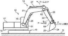
図1は、本発明の実施の形態に係る油圧駆動装置が搭載される作業装置の例である油圧ショベルを示す。この油圧ショベルは、地面Gの上を走行可能な下部走行体10と、前記下部走行体10に搭載される上部旋回体12と、上部旋回体12に搭載される作業装置14と、を備える。
FIG. 1 shows an example of a hydraulic excavator on which a hydraulic drive device according to an embodiment of the present invention is mounted. This hydraulic excavator includes a
前記下部走行体10及び前記上部旋回体12は、前記作業装置14を支持する機体を構成する。前記上部旋回体12は、旋回フレーム16と、その上に搭載される複数の要素と、を有する。当該複数の要素は、エンジンを収容するエンジンルーム17や運転室であるキャブ18を含む。
The
前記作業装置14は、掘削作業その他の必要な作業のための動作を行うことが可能であり、ブーム21、アーム22及びバケット24を含む。前記ブーム21は、前記旋回フレーム16の前端に起伏可能すなわち水平軸回りに回動可能に支持される基端部と、その反対側の先端部と、を有する。前記アーム22は、前記ブーム21の先端部に水平軸回りに回動可能に取付けられる基端部と、その反対側の先端部と、を有する。前記バケット24は、前記アーム22の先端部に回動可能に取付けられる。
The
前記油圧駆動装置は、前記作業装置14を油圧により駆動するための装置である。当該油圧駆動装置は、前記ブーム21、前記アーム22及び前記バケット24のそれぞれについて設けられる複数の伸縮可能な油圧シリンダ、具体的には、少なくとも一つのブームシリンダ26、アームシリンダ27及びバケットシリンダ28を含む。
The hydraulic drive device is a device for hydraulically driving the
前記少なくとも一つのブームシリンダ26は、前記上部旋回体12と前記ブーム21との間に介在し、当該ブーム21に起伏動作を行わせるように伸縮する。当該ブームシリンダ26は、図2に示されるヘッド側室26h及びロッド側室26rを有し、当該ヘッド側室26hに作動油が供給されることにより伸長して前記ブーム21をブーム上げ方向に動かすとともに前記ロッド側室26r内の作動油を排出する一方、前記ロッド側室26rに作動油が供給されることにより収縮して前記ブーム21をブーム下げ方向に動かすとともに前記ヘッド側室26h内の作動油を排出する。
The at least one
前記少なくとも一つのブームシリンダ26は、単一のブームシリンダのみを含むものでもよいが、この実施の形態では互いに左右方向に並列に配置された一対のブームシリンダ26を含む。
The at least one
前記アームシリンダ27は、前記ブーム21と前記アーム22との間に介在し、当該アーム22に回動動作を行わせるように伸縮するアームアクチュエータである。具体的に、当該アームシリンダ27は、図2に示されるヘッド側室27h及びロッド側室27rを有し、当該ヘッド側室27hに作動油が供給されることにより伸長して前記アーム22をアーム引き方向(当該アーム22の先端がブーム21に近づく方向)に動かすとともに前記ロッド側室27r内の作動油を排出する一方、前記ロッド側室27rに作動油が供給されることにより収縮して前記アーム22をアーム押し方向(当該アーム22の先端がブーム21から離れる方向)に動かすとともに前記ヘッド側室27h内の作動油を排出する。
The
前記バケットシリンダ28は、前記アーム22と前記バケット24との間に介在し、当該バケット24に回動動作を行わせるように伸縮する。具体的に、当該バケットシリンダ28は、伸長することにより前記バケット24を掬い方向(当該バケット24の先端25がアーム22に近づく方向)に回動させる一方、収縮することにより前記バケット24を開き方向(当該バケット24の先端25がアーム22から離れる方向)に回動させる。
The
図2は、前記油圧ショベルに搭載される油圧回路及びこれに電気的に接続されるコントローラ100を示す図であって、前記油圧駆動装置を構成する要素を含む。前記コントローラ100は、例えばマイクロコンピュータからなり、前記油圧回路に含まれる各要素の作動を制御する。
FIG. 2 is a diagram showing a hydraulic circuit mounted on the hydraulic excavator and a
前記油圧回路は、前記シリンダ26~28に加え、第1油圧ポンプ31及び第2油圧ポンプ32を含む作動油供給装置と、ブーム流量制御弁36と、アーム流量制御弁37と、バケット流量制御弁38と、パイロット油圧源40と、ブーム操作器46と、アーム操作器47と、バケット操作器48と、を含む。
In addition to the
前記第1油圧ポンプ31及び第2油圧ポンプ32は、駆動源である図略のエンジンに接続され、当該エンジンが出力する動力により駆動されて作動油を吐出する。第1及び第2油圧ポンプ31,32のそれぞれは可変容量型ポンプである。具体的に、当該第1及び第2油圧ポンプ31,32はそれぞれ容量操作弁31a,32aを有し、前記コントローラ100から前記容量操作弁31a,32aに入力されるポンプ容量指令によって前記第1及び第2油圧ポンプ31,32の容量が操作される。
The first
前記ブーム流量制御弁36は、前記第2油圧ポンプ32と前記ブームシリンダ26との間に介在し、ブーム流量、すなわち、当該第2油圧ポンプ32から当該ブームシリンダ26に供給される作動油の流量及び当該ブームシリンダ26からタンクに排出される作動油の流量、を変化させるように開閉動作する。具体的に、当該ブーム流量制御弁36は、ブーム上げパイロットポート36a及びブーム下げパイロットポート36bを有するパイロット操作式の3位置方向切換弁からなり、前記第2油圧ポンプ32に接続された第2センターバイパスラインCL2の途中に配置される。
The boom flow
前記ブーム流量制御弁36は、図略のスリーブとこれにストローク可能に装填されるスプールとを有する。当該スプールは、前記ブーム上げ及びブーム下げパイロットポート36a,36bのいずれにもパイロット圧が入力されないときは中立位置に保持され、前記第2センターバイパスラインCL2を開通して前記第2油圧ポンプ32と前記ブームシリンダ26との間を遮断することにより、前記ブームシリンダ26を停止状態に保持する。
The boom
前記ブーム上げパイロットポート36aにブーム上げパイロット圧が入力されると、前記ブーム流量制御弁36の前記スプールは、そのブーム上げパイロット圧の大きさに対応したストロークで前記中立位置からブーム上げ位置にシフトされる。これにより、当該ブーム流量制御弁36は、前記第2センターバイパスラインCL2から分岐する第2供給ラインSL2を通じて前記第2油圧ポンプ32から前記ブームシリンダ26のヘッド側室26hに前記ストロークに応じた流量(ブーム上げ流量)で作動油が供給されることを許容する開口を形成するとともに、当該ブームシリンダ26のロッド側室26rからタンクに作動油が戻ることを許容する開口を形成するように、開弁する。これにより、前記ブームシリンダ26は前記ブーム上げ方向(この実施の形態では伸長方向)に駆動される。
When the boom raising pilot pressure is input to the boom raising
前記ブーム流量制御弁36は、逆に、前記ブーム下げパイロットポート36bにブーム下げパイロット圧が入力されるとそのブーム下げパイロット圧の大きさに対応したストロークで前記中立位置からブーム下げ位置に切換えられ、前記第2供給ラインSL2を通じて前記第2油圧ポンプ32から前記ブームシリンダ26のロッド側室26rに前記ストロークに応じた流量(ブーム下げ流量)で作動油が供給されることを許容する開口を形成するとともに、当該ブームシリンダ26のヘッド側室26hからタンクに作動油が戻ることを許容する開口を形成するように、開弁する。これにより、前記ブームシリンダ26は前記ブーム下げ方向(この実施の形態では収縮方向)に駆動される。
On the contrary, when the boom lowering pilot pressure is input to the boom lowering
換言すれば、前記ブーム流量制御弁36は、前記ブーム上げ位置及び前記ブーム下げ位置において前記一対のブームシリンダ26のそれぞれのヘッド側室26h及びロッド側室26rにそれぞれ通ずるヘッド側開口36h及びロッド側開口36rを同時に形成し、かつ、これらの開口(絞り開口)36h,36rの面積である絞り開口面積(絞り開度)を前記ブーム上げ及びブーム下げパイロット圧に対応する前記スプールのストロークによって変化させる。
In other words, the boom
前記アーム流量制御弁37は、前記第1油圧ポンプ31と前記アームシリンダ27との間に介在し、当該第1油圧ポンプ31から当該アームシリンダ27に供給される作動油の流量であるアーム流量を変化させるように開閉動作する。具体的に、当該アーム流量制御弁37は、アーム引きパイロットポート37a及びアーム押しパイロットポート37bを有するパイロット操作式の3位置方向切換弁からなり、前記第1油圧ポンプ31に接続された第1センターバイパスラインCL1の途中に配置される。
The arm flow
前記アーム流量制御弁37は、図略のスリーブ及びこれにストローク可能に装填されるスプールを有する。当該スプールは、前記アーム引き及びアーム押しパイロットポート37a,37bのいずれにもパイロット圧が入力されないときは中立位置に切換えられ、前記第1センターバイパスラインCL1を開通して前記第1油圧ポンプ31と前記アームシリンダ27との間を遮断する。これにより、前記アームシリンダ27は停止状態に保持される。
The arm
前記アーム引きパイロットポート37aにアーム引きパイロット圧が入力されると、前記アーム流量制御弁37の前記スプールは、そのアーム引きパイロット圧の大きさに対応したストロークで前記中立位置からアーム引き位置にシフトされる。これにより、当該アーム流量制御弁37は、前記第1センターバイパスラインCL1から分岐する第1供給ラインSL1を通じて前記第1油圧ポンプ31から前記アームシリンダ27のヘッド側室27hに前記ストロークに応じた流量(アーム引き流量)で作動油が供給されることを許容するとともに、当該アームシリンダ27のロッド側室27rからタンクに作動油が戻ることを許容するように、開弁する。この開弁に伴い、前記アームシリンダ27は前記アーム引きパイロット圧に対応した速度で前記アーム引き方向に駆動される。
When the arm pulling pilot pressure is input to the arm pulling
前記アーム流量制御弁37は、逆に、前記アーム押しパイロットポート37bにアーム押しパイロット圧が入力されるとそのアーム押しパイロット圧の大きさに対応したストロークで前記中立位置からアーム押し位置に切換えられ、前記第1供給ラインSL1を通じて前記第1油圧ポンプ31から前記アームシリンダ27のロッド側室27rに前記ストロークに応じた流量(アーム押し流量)で作動油が供給されることを許容するとともに、当該アームシリンダ27のヘッド側室27hからタンクに作動油が戻ることを許容するように、開弁する。これにより、前記アームシリンダ27は前記アーム押しパイロット圧に対応した速度で前記アーム押し方向に駆動される。
On the contrary, when the arm pushing pilot pressure is input to the arm pushing
前記バケット流量制御弁38は、前記ブーム流量制御弁36とパラレルに配置されて前記第2油圧ポンプ32と前記バケットシリンダ28との間に介在し、当該第2油圧ポンプ32から当該バケットシリンダ28に供給される作動油の流量であるバケット流量を変化させるように開閉動作する。具体的に、当該バケット流量制御弁38は、バケット掬いパイロットポート38a及びバケット開きパイロットポート38bを有するパイロット操作式の3位置方向切換弁からなり、前記第2油圧ポンプ32に接続された第2センターバイパスラインCL2の途中に配置される。
The bucket flow
前記バケット流量制御弁38は、図略のスリーブ及びこれにストローク可能に装填されるスプールを有する。当該スプールは、前記バケット掬い及びバケット開きパイロットポート38a,38bのいずれにもパイロット圧が入力されないときは中立位置に切換えられ、前記第2センターバイパスラインCL2を開通して前記第2油圧ポンプ32と前記バケットシリンダ28との間を遮断する。これにより、前記バケットシリンダ28は停止状態に保持される。
The bucket
前記バケット掬いパイロットポート38aにバケット掬いパイロット圧が入力されると、前記バケット流量制御弁38の前記スプールは、そのバケット掬いパイロット圧の大きさに対応したストロークで前記中立位置からバケット掬い位置にシフトされる。これにより、当該バケット流量制御弁38は、前記第2供給ラインSL2を通じて前記第2油圧ポンプ32から前記バケットシリンダ28のヘッド側室28hに前記ストロークに応じた流量(バケット掬い流量)で作動油が供給されることを許容するとともに、当該バケットシリンダ28のロッド側室28rからタンクに作動油が戻ることを許容するように、開弁する。この開弁に伴い、前記バケットシリンダ28は前記バケット掬いパイロット圧に対応した速度で前記バケット掬い方向に駆動される。
When the bucket scooping pilot pressure is input to the bucket scooping
前記バケット流量制御弁38は、逆に、前記バケット開きパイロットポート38bにバケット開きパイロット圧が入力されるとそのバケット開きパイロット圧の大きさに対応したストロークで前記中立位置からバケット開き位置に切換えられ、前記第2供給ラインSL2を通じて前記第2油圧ポンプ32から前記バケットシリンダ28のロッド側室28rに前記ストロークに応じた流量(バケット開き流量)で作動油が供給されることを許容するとともに、当該バケットシリンダ28のヘッド側室28hからタンクに作動油が戻ることを許容するように、開弁する。これにより、前記バケットシリンダ28は前記バケット開きパイロット圧に対応した速度で前記バケット開き方向に駆動される。
On the contrary, when the bucket opening pilot pressure is input to the bucket
前記ブーム操作器46は、前記ブーム21を動かすためのブーム操作を受け、当該ブーム操作に対応したブーム上げパイロット圧またはブーム下げパイロット圧が前記ブーム流量制御弁36に入力されることを許容する。具体的に、当該ブーム操作器46は、前記運転室内において前記ブーム操作に相当する回動操作を受けることが可能なブームレバー46aと、当該ブームレバー46aに連結されたブームパイロット弁46bと、を有する。
The boom controller 46 receives a boom operation for moving the
前記ブームパイロット弁46bは、前記パイロット油圧源40と前記ブーム流量制御弁36の両パイロットポート36a,36bとの間に介在する。当該ブームパイロット弁46bは、前記ブームレバー46aに与えられる前記ブーム操作に連動して開弁し、前記両パイロットポートのうち前記ブーム操作の方向に対応するパイロットポートに対して当該ブーム操作の大きさに対応した大きさのブーム上げパイロット圧またはブーム下げパイロット圧が前記パイロット油圧源40から入力されることを許容するように開弁する。例えば、当該ブームパイロット弁46bは、前記ブームレバー46aにブーム上げ動作に対応した方向のブーム操作が与えられると、前記ブーム上げパイロットポート36aに対して前記ブーム操作の大きさに対応したブーム上げパイロット圧が供給されるのを許容するように開弁する。
The
前記アーム操作器47は、前記アーム22を動かすためのアーム操作を受け、当該アーム操作に対応したアーム引きパイロット圧またはアーム押しパイロット圧が前記アーム流量制御弁37に入力されることを許容する。具体的に、当該アーム操作器47は、前記運転室内において前記アーム操作に相当する回動操作を受けることが可能なアームレバー47aと、当該アームレバー47aに連結されたアームパイロット弁47bと、を有する。
The
前記アームパイロット弁47bは、前記パイロット油圧源40と前記アーム流量制御弁37の両パイロットポート37a,37bとの間に介在する。当該アームパイロット弁47bは、前記アームレバー47aに与えられる前記アーム操作に連動して開弁し、前記両パイロットポートのうち前記アーム操作の方向に対応するパイロットポートに対して当該アーム操作の大きさに対応した大きさのアーム引きパイロット圧またはアーム押しパイロット圧が前記パイロット油圧源40から入力されることを許容するように開弁する。例えば、当該アームパイロット弁47bは、前記アームレバー47aにアーム引き動作に対応した方向のアーム操作が与えられると、前記アーム引きパイロットポート37aに対して前記アーム操作の大きさに対応したアーム引きパイロット圧が供給されるのを許容するように開弁する。
The
前記バケット操作器48は、前記バケット24を動かすためのバケット操作を受け、当該バケット操作に対応したバケット掬いパイロット圧またはバケット開きパイロット圧が前記バケット流量制御弁38に入力されることを許容する。具体的に、当該バケット操作器48は、前記運転室内において前記バケット操作に相当する回動操作を受けることが可能なバケットレバー48aと、当該バケットレバー48aに連結されたバケットパイロット弁48bと、を有する。
The
前記バケットパイロット弁48bは、前記パイロット油圧源40と前記バケット流量制御弁38の両パイロットポート38a,38bとの間に介在する。当該バケットパイロット弁48bは、前記バケットレバー48aに与えられる前記バケット操作に連動して開弁し、前記両パイロットポートのうち前記バケット操作の方向に対応するパイロットポートに対して当該バケット操作の大きさに対応した大きさのバケット掬いパイロット圧またはバケット開きパイロット圧が前記パイロット油圧源40から入力されることを許容するように開弁する。例えば、当該バケットパイロット弁48bは、前記バケットレバー48aにバケット掬い動作に対応した方向のバケット操作が与えられると、前記バケット掬いパイロットポート38aに対して前記バケット操作の大きさに対応したバケット掬いパイロット圧が供給されるのを許容するように開弁する。
The
前記油圧駆動装置は、さらに、ブームシリンダヘッド圧センサ56H、ブームシリンダロッド圧センサ56R、作業装置姿勢検出部60、及びモード切換スイッチ120を備える。
The hydraulic drive system further includes a boom cylinder
前記ブームシリンダへッド圧センサ56H及び前記ブームシリンダロッド圧センサ56Rは、ブームシリンダ圧検出器を構成する。具体的に、前記ブームシリンダヘッド圧センサ56Hは、前記ブームシリンダ26のヘッド側室26hにおける作動油の圧力であるブームシリンダヘッド圧Phを検出し、前記ブームシリンダロッド圧センサ56Rは、前記ブームシリンダ26のロッド側室26rにおける作動油の圧力であるブームシリンダロッド圧Prを検出する。前記センサ56H及び56Rのそれぞれは、その検出した物理量をこれに対応する電気信号である検出信号に変換して前記コントローラ100に入力する。
The boom cylinder
前記作業装置姿勢検出部60は、前記作業装置14の姿勢を特定するための情報である姿勢情報を検出する。具体的に、当該作業装置姿勢検出部60は、図1に示すようなブーム角度センサ61、アーム角度センサ62及びバケット角度センサ64を含む。前記ブーム角度センサ61は、前記機体に対する前記ブーム21の起伏角度であるブーム角度を検出し、前記アーム角度センサ62は、前記ブーム21に対する前記アーム22の回動角度であるアーム角度を検出し、前記バケット角度センサ64は前記アーム22に対する前記バケット24の回動角度であるバケット角度を検出する。これらのセンサ61,62,64により生成される電気信号である角度検出信号も、前記コントローラ100に入力される。
The work device
前記モード切換スイッチ120は、運転室内に配置されるとともに、前記コントローラ100に電気的に接続される。当該モード切換スイッチ120は、前記コントローラ100の制御モードを手動操作モードと自動制御モードとに切換えるための操作を受けて当該操作に対応するモード指令信号を前記コントローラ100に入力する。
The
前記コントローラ100は、前記モード切換スイッチ120から入力されるモード指令信号に応じて前記手動操作モードと前記自動制御モードとに切換えられる。当該コントローラ100は、前記手動操作モードでは、作業者によって前記ブーム操作器46、前記アーム操作器47及び前記バケット操作器48にそれぞれ与えられる前記ブーム操作、前記アーム操作及び前記バケット操作に対応して前記ブーム流量、前記アーム流量及び前記バケット流量がそれぞれ変化するように前記ブーム流量制御弁36、前記アーム流量制御弁37及び前記バケット流量制御弁38が作動するのを許容する。一方、当該コントローラ100は、前記自動制御モードでは、前記アーム操作に対応した前記アーム22の動きに伴って前記バケット24により施工される施工面が予め設定された目標施工面に近づくように前記アームシリンダ27の伸縮に応じて前記ブームシリンダ26(この実施の形態ではブームシリンダ26及びバケットシリンダ28)の作動を自動制御するように構成されている。
The
具体的に、前記油圧駆動装置は、前記コントローラ100による前記ブームシリンダ26及び前記バケットシリンダ28の自動制御を可能にするための手段として、図2に示すようなブーム上げ流量操作弁76A、ブーム下げ流量操作弁76B、バケット開き流量操作弁78、シャトル弁71A,71B及びシャトル弁72をさらに備える。
Specifically, the hydraulic drive device includes a boom raising flow
前記ブーム上げ流量操作弁76Aは、前記ブーム操作器46とはパラレルに配置されながら前記パイロット油圧源40と前記ブーム上げパイロットポート36aとの間に介在し、前記パイロット油圧源40から前記ブーム上げパイロットポート36aに入力されるパイロット圧を前記コントローラ100から入力されるブーム流量指令信号に応じて(前記ブーム操作器46とは独立して)減圧することにより、前記ブーム上げパイロットポート36aに入力されるパイロット圧を前記コントローラ100が当該ブーム上げ流量操作弁76Aを通じて自動操作することを可能にする。前記シャトル弁71Aは、前記ブーム操作器46及び前記ブーム上げ流量操作弁76Aと前記ブーム上げパイロットポート36aとの間に介在し、前記ブーム操作器46の二次圧及び前記ブーム上げ流量操作弁76Aの二次圧のうち高い方の二次圧が最終的に前記ブーム上げパイロット圧として前記ブーム上げパイロットポート36aに入力されることを許容するように開弁する。
The boom raising flow
同様に、前記ブーム下げ流量操作弁76Bは、前記ブーム操作器46とはパラレルに配置されながら前記パイロット油圧源40と前記ブーム下げパイロットポート36bとの間に介在し、前記パイロット油圧源40から前記ブーム下げパイロットポート36bに入力されるパイロット圧を前記コントローラ100から入力されるブーム流量指令信号に応じて(前記ブーム操作器46とは独立して)減圧することにより、前記ブーム下げパイロットポート36bに入力されるパイロット圧を前記コントローラ100が当該ブーム下げ流量操作弁76Bを通じて自動操作することを可能にする。前記シャトル弁71Bは、前記ブーム操作器46及び前記ブーム下げ流量操作弁76Bと前記ブーム下げパイロットポート36bとの間に介在し、前記ブーム操作器46の二次圧及び前記ブーム下げ流量操作弁76Bの二次圧のうち高い方の二次圧が最終的に前記ブーム下げパイロット圧として前記ブーム下げパイロットポート36bに入力されることを許容するように開弁する。
Similarly, the boom lowering flow
また、前記バケット開き流量操作弁78は、前記バケット操作器48とはパラレルに配置されながら前記パイロット油圧源40と前記バケット開きパイロットポート38bとの間に介在し、前記パイロット油圧源40から前記バケット開きパイロットポート38bに入力されるパイロット圧を前記コントローラ100から入力されるバケット開き流量指令信号に応じて(前記バケット操作器48とは独立して)減圧することにより、前記バケット開きパイロットポート38bに入力されるパイロット圧を前記コントローラ100が当該バケット開き流量操作弁78を通じて自動操作することを可能にする。前記シャトル弁72は、前記バケット操作器48及び前記バケット開き流量操作弁78と前記バケット開きパイロットポート38bとの間に介在し、前記バケット操作器48の二次圧及び前記バケット開き流量操作弁78の二次圧のうち高い方の二次圧が最終的に前記バケット開きパイロット圧として前記バケット開きパイロットポート38bに入力されることを許容するように開弁する。
Further, the bucket opening flow
前記流量操作弁76A,76B及び78のそれぞれは、電磁弁(例えば電磁比例減圧弁や電磁逆比例減圧弁)からなり、前記コントローラ100から入力される流量指令信号に対応して開度が変化するように開閉動作することにより、当該流量指令に対応した大きさのパイロット圧を生成する。
Each of the flow
前記コントローラ100は、前記手動操作モードでは、前記流量操作弁76A,76B,78のそれぞれを実質上全閉の状態にすることにより前記ブーム、アーム及びバケット流量制御弁36,37,38がそれぞれ前記ブーム、アーム及びバケット操作器46,47,48に与えられる操作に連動して開閉することを許容する。一方、前記コントローラ100は、前記自動制御モードでは、前記流量操作弁76A,76B,78のそれぞれに流量指令信号を入力することにより、アームシリンダ27の収縮動作によるアーム22のアーム引き動作に前記ブームシリンダ26及び前記バケットシリンダ28の動作を追従させる自動制御を実行する。
In the manual operation mode, the
具体的に、前記コントローラ100は、前記自動制御を実行するための機能として、図3に示すような目標施工面設定部101、目標方向ベクトル演算部102、シリンダ長さ演算部103、シリンダ速度演算部104、目標バケットシリンダ速度演算部105、バケット開き流量指令部106、目標ブームシリンダ速度演算部107、重心位置演算部108、シリンダ推力演算部109、押付け力演算部110、目標押付け力設定部111、目標速度補正部112、及びブーム流量指令部113を有する。
Specifically, the
前記目標施工面設定部101は、前記キャブ18内に設けられた目標施工面入力部122により入力された施工面を記憶し、これを目標施工面として目標方向ベクトル演算部102に入力する。この目標施工面は、掘削対象である地盤の目標形状であって3次元の設計地形を特定する面である。当該目標施工面は、CIMなどの外部データによって特定されてもよいし、機体位置を基準にして設定されたものでもよい。
The target construction
前記目標方向ベクトル演算部102は、前記目標施工面に沿ってバケット24の先端25を動かすために当該バケットの特定部位を動かす方向を特定する目標方向ベクトルを演算する。前記特定部位は、例えば、前記先端25であってもよいし、前記アーム22の先端部に連結される部位であってもよい。
The target direction
前記シリンダ長さ演算部103は、前記作業装置姿勢検出部60により検出される前記姿勢情報に基づいて、前記ブームシリンダ26、前記アームシリンダ27及び前記バケットシリンダ28のシリンダ長さをそれぞれ演算する。前記シリンダ速度演算部104は、各シリンダ長さの時間微分によって前記ブームシリンダ26、前記アームシリンダ27及び前記バケットシリンダ28の伸縮速度であるシリンダ速度を演算する。つまり、この実施の形態に係る前記シリンダ長さ演算部103及び前記シリンダ速度演算部104は、前記姿勢情報に基づいて各シリンダ速度を算定するシリンダ速度算定部を構成する。
The cylinder
前記目標バケットシリンダ速度演算部105は、前記目標方向ベクトルと、前記シリンダ速度演算部104により演算される前記シリンダ速度のそれぞれと、に基づき、目標バケットシリンダ速度Vkoを演算する。前記目標バケットシリンダ速度Vkoは、前記アーム22の引き方向の動作にかかわらず前記バケット24の姿勢を一定に保つ(つまり目標施工面に沿ってバケット24を平行移動させる)ための前記バケットシリンダ28のバケット開き方向のシリンダ速度(この実施の形態では収縮方向の速度)の目標値である。
The target bucket cylinder
前記バケット開き流量指令部106は、前記目標バケットシリンダ速度Vkoを得るための目標バケット開き流量、つまり前記バケットシリンダ28のロッド側室28rに供給されるべき作動油の流量、を演算し、当該目標バケット開き流量を実現するためのバケット開き流量指令信号を生成して前記バケット開き流量操作弁78に入力する。当該バケット開き流量操作弁78は、当該バケット開き流量指令信号に対応した開度で開弁することにより、前記バケット流量制御弁38のバケット開きパイロットポート38bに入力されるパイロット圧を前記目標バケット開き流量を実現するようなパイロット圧に調節する。
The bucket opening flow
前記目標ブームシリンダ速度演算部107は、前記目標方向ベクトルと、前記シリンダ速度演算部104により演算される前記シリンダ速度のそれぞれと、に基づき、目標ブームシリンダ速度Vboを演算する。前記目標ブームシリンダ速度Vboは、前記アームシリンダ27の伸長による前記アーム22の引き方向の動作に伴って前記バケット24が施工する面である施工面を前記目標施工面に近づけるための前記ブームシリンダ26のブーム上げ方向のシリンダ速度(この実施の形態では伸長方向の速度)の目標値であり、前記アームシリンダ27のシリンダ速度(伸長速度)に対応する速度値である。
The target boom cylinder
従って、前記目標方向ベクトル演算部102及び前記目標ブームシリンダ速度演算部107は、本発明に係る目標ブームシリンダ速度算定部を構成する。一方、前記目標バケットシリンダ速度Vkoの算定は必ずしも要しない。例えば、バケットシリンダ28が静止していること、すなわちアーム22に対するバケット24の角度が固定されていること、を前提に前記目標ブームシリンダ速度Vboが算定されてもよい。このように前記目標バケットシリンダ速度Vkoが演算されない形態、つまりバケットシリンダ28の自動制御が省略される形態、においては、前記バケット開き流量指令部106及び前記バケット開き流量操作弁78は不要である。
Therefore, the target direction
前記重心位置演算部108は、前記シリンダ長さ演算部103とともに、前記作業装置14の重心位置についての情報である重心位置情報を算定する重心位置情報算定部を構成する。具体的に、前記重心位置演算部108は、前記シリンダ長さ演算部103により演算される前記シリンダ長さのそれぞれに基づき、前記ブーム21、前記アーム22及び前記バケット24のそれぞれの重心位置、より詳しくは、前記作業装置14全体の回動支点であるブーム21の回動中心、すなわちブームフット、を基準とした重心位置、を演算する。
The center of gravity
前記シリンダ推力演算部109及び前記押付け力演算部110は、前記バケット24を施工面に対して押付ける力である押付け力Fpを算定する押付け力算定部を構成する。
The cylinder thrust
前記シリンダ推力演算部109は、前記ブームシリンダヘッド圧センサ56H及び前記アームシリンダロッド圧センサ56Rによりそれぞれ検出される前記ヘッド圧Ph及び前記ロッド圧Prに基づき、前記ブームシリンダ26のシリンダ推力Fctを演算する。当該シリンダ推力Fctは、ブームシリンダ26の伸長方向の推力を正とすると次式(1)で表される。
The cylinder thrust
Fct=Ph*Ah-Pr*Ar …(1)
ここにおいて、Ahはブームシリンダ26のヘッド側室26hの断面積、Arはロッド側室26rの断面積であり、当該ロッド側室26rの断面積Arは、一般には、シリンダロッドの断面積の分だけヘッド側室26hの断面積Ahよりも小さい。
Fct = Ph * Ah-Pr * Ar ... (1)
Here, Ah is the cross-sectional area of the
前記押付け力演算部110は、前記重心位置演算部108により演算される前記ブーム21、前記アーム22及び前記バケット24のそれぞれの重心位置に基づき、当該作業装置14の回動支点であるブーム21のブームフットを中心とする前記作業装置14の自重による下向き荷重のモーメントMwを演算するとともに、前記シリンダ推力Fctによるモーメント(シリンダ推力Fctが正の場合は上向きのモーメント)Mctと、を演算し、両モーメントMw,Mctに基づいて、前記バケット24の先端25を前記施工面に押付ける力である前記押付け力Fpを演算する。
The pressing
前記目標押付け力設定部111は、前記キャブ18内に設けられた目標押付け力入力部124により入力された押付け力を記憶してこれを目標押付け力Fpoとして目標速度補正部112に入力する。当該目標押付け力Fpoの値は、例えば、予めプログラムにおいて組込まれた値であってもよいし、作業者の前記目標押付け力入力部124におけるテンキー等の操作によって入力された値でもよい。
The target pressing
あるいは、前記目標押付け力設定部111は、作業者が実際に作業装置14を操作してバケット24を地面に押付けた状態で前記目標押付け力入力部124に含まれる設定スイッチを操作した時点で前記押付け力演算部110により演算される押付け力Fpを前記目標押付け力Fpoとして記憶し設定してもよい。
Alternatively, the target pressing
前記目標速度補正部112は、前記目標押付け力Fpoと前記押付け力演算部110により演算された前記押付け力Fpとの偏差ΔFp(=Fpo-Fp)を演算し、当該偏差ΔFpを0に近づける方向に、前記目標ブームシリンダ速度演算部によって107によって演算された前記目標ブームシリンダ速度Vboを補正する。つまり、前記押付け力Fpを前記目標押付け力Fpoに近づけるような前記目標ブームシリンダ速度Vboの補正を行う。
The target
前記ブーム流量指令部113は、前記ブーム上げ流量操作弁76A及び前記ブーム下げ流量操作弁76Bとともに、前記目標速度補正部112により補正された後の目標ブームシリンダ速度Vboが得られるように前記ブーム流量制御弁36を作動させるブーム流量操作部を構成する。具体的に、当該ブーム流量指令部113は、前記補正後の目標ブームシリンダ速度Vboを得るための目標ブーム上げ流量または目標ブーム下げ流量を演算し、当該目標ブーム上げ流量を実現するためのブーム上げ流量指令信号を生成して前記ブーム上げ流量操作弁76Aに入力するか、あるいは、当該目標ブーム下げ流量を実現するためのブーム下げ流量指令信号を生成して前記ブーム下げ流量操作弁76Bに入力する。
The boom flow
次に、前記自動制御モードにおいて前記コントローラ100が前記ブームシリンダ26の駆動について行う演算制御動作及びこれに伴う油圧駆動装置の作用を、図4のフローチャートを併せて参照しながら説明する。
Next, the arithmetic control operation performed by the
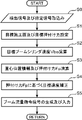
コントローラ100は、当該コントローラ100に入力される信号、具体的には各センサの検出信号や指定信号を取り込む(図4のステップS0)。指定信号には、オペレータによる目標施工面入力部122の操作により指定される目標施工面についての信号や、目標押付け力入力部124の操作により指定される目標押付け力Fpoについての信号が含まれる。これらの指定信号に基づき、前記コントローラ100の目標施工面設定部101及び目標押付け力設定部111はそれぞれ目標施工面及び目標押付け力Fpoの設定を行う(ステップS1)。
The
次に、前記コントローラ100の目標ブームシリンダ速度演算部107は、前記目標施工面と、シリンダ長さ演算部103及びシリンダ速度演算部104により算出される実際のシリンダ速度と、に基づき、アームシリンダ27のシリンダ速度に対応する目標ブームシリンダ速度Vboを算定する(ステップS2)。前記目標ブームシリンダ速度Vboは、上述のように、バケット24による施工面を前記目標施工面に近づけるように前記アーム22の引き方向の動作にブーム21の上げ方向の動作を連動させるために必要なブームシリンダ26の上げ方向の速度である。換言すれば、作業者によるアームレバー47の引き方向の操作に伴ってバケット24の特定部位(例えば当該バケット24の先端25、あるいは、アーム22の先端部に支持される基端部)が前記目標施工面に沿って移動するようにブームシリンダ26を作動させるべき速度である。
Next, the target boom cylinder
一方、前記コントローラ100の重心位置情報算定部は、作業装置14の重心位置情報を算定し、押付け力算定部は、前記バケット24の先端25を施工面に対して押付ける押付け力Fpを算定する(ステップS3)。具体的には、前記シリンダ長さ演算部103により演算された各シリンダ長さに基づいて前記重心位置演算部108がブーム21、アーム22及びバケット24のそれぞれの重心位置を演算する。一方、前記ブームシリンダヘッド圧センサ56H及びロッド圧センサ56Rがそれぞれ検出するブームシリンダ26のヘッド圧Ph及びロッド圧Prに基づいてシリンダ推力演算部109が当該ブームシリンダ26のシリンダ推力Fct(=Ph*Ah-Pr*Ar)を演算する。そして、前記押付け力演算部110は、前記各重心位置に基づいて前記作業装置14全体の自重による前記ブームフット回りの下向きのモーメントMwと、前記シリンダ推力Fctによる前記ブームフット回りの上向きのモーメントMctと、を演算し、両モーメントMw,Mctの差に基づいて前記押付け力Fpを算定する。
On the other hand, the center of gravity position information calculation unit of the
なお、前記ショベル24が施工面(法面を含む)から受ける反力であって前記押付け力Fpに相当する反力は、当該施工面の法線方向のベクトルによって与えられる。このときの押付け力Fpは、前記ブームフット回りのモーメントに対応して前記ショベル24から前記施工面に与えられる力(当該モーメントの半径方向に対して直交する方向の力)をFm、当該力Fmの方向と前記法線方向とのなす角度をθとすると、次式(2)で表される。
The reaction force that the
Fp=Fm*cosθ …(2)
前記コントローラ100の目標速度補正部112は、さらに、前記目標押付け力Fpoと前記押付け力Fpとの偏差ΔFp(=Fpo-Fp)を演算し、当該偏差ΔFpを0に近づけるような前記目標ブームシリンダ速度Vboの補正を行う(ステップS4)。この補正は、例えば、前記偏差ΔFpに特定のゲインを乗じた補正量を前記目標ブームシリンダ速度Vboから差し引くことにより、行われる。
Fp = Fm * cosθ ... (2)
The target
次に、前記コントローラ100のブーム流量指令部113は、前記のように補正された目標ブームシリンダ速度Vboを得るようなブーム上げ流量指令信号またはブーム下げ指令信号を生成してブーム上げ流量操作弁76Aまたはブーム下げ流量操作弁76Bに入力し(ステップS5、これにより、前記ブーム流量制御弁36の特定の絞り開口の制御を行う。
Next, the boom flow
具体的に、前記ブーム流量指令部113は、前記ブーム上げ流量操作弁76A及び前記ブーム下げ流量操作弁76Bのうち前記ブームシリンダ26に供給される作動油の流量を操作する流量操作弁に対して流量指令信号を入力し、これによりブームシリンダ26の速度を制御する。例えば、前記目標ブームシリンダ速度Vboの方向が伸長方向(ブーム上げ方向)である場合、前記ブーム流量指令部113は当該目標ブームシリンダ速度Vboに相当するブーム上げ流量指令信号を生成して前記ブーム上げ流量操作弁76Aに入力する。逆に、前記目標ブームシリンダ速度Vboの方向が収縮方向(ブーム下げ方向)である場合、前記ブーム流量指令部113は当該目標ブームシリンダ速度Vboに相当するブーム下げ流量指令信号を生成して前記ブーム上げ流量操作弁76Aに入力する。
Specifically, the boom flow
前記ブーム流量指令部113は、あるいは、前記目標ブームシリンダ速度Vboの方向と前記シリンダ推力Fctの方向との関係によってはブームシリンダ26から排出される作動油の流量を操作する流量操作弁に流量指令信号を入力してもよい。具体的には、前記目標ブームシリンダ速度Vboの方向と前記シリンダ推力Fctの方向とが逆である場合、つまり、目標ブームシリンダ速度Vboの方向が伸長方向で前記シリンダ推力Fctの方向が収縮方向である場合や、目標ブームシリンダ速度Vboの方向が収縮方向で前記シリンダ推力Fctの方向が伸長方向である場合には、ブームシリンダ26に作用している荷重の向きと同じ向きに、前記シリンダ推力Fctに抗して、ブームシリンダ26を伸長または収縮させるため、ブームシリンダ26の排出側の圧力が保持圧となるので、当該排出側の流量を制御するように、ブーム上げ流量操作弁76A及びブーム下げ流量操作弁76Bのうち操作すべき流量操作弁を選定してもよい。より具体的に、前記ブーム流量指令部113は、前記目標ブームシリンダ速度Vboが伸長方向で前記シリンダ推力Fctが収縮方向である場合にはブーム下げ流量操作弁76Bにブーム下げ流量指令信号を入力し、逆に前記目標ブームシリンダ速度Vboが収縮方向で前記シリンダ推力Fctが伸長方向である場合にはブーム上げ流量操作弁76Aにブーム上げ流量指令信号を入力するような演算制御動作を行ってもよい。
The boom flow
以上説明した装置によれば、ブームシリンダ26のシリンダ推力Fctに加え、作業装置姿勢検出部60が検出する作業姿勢情報さらには重心位置情報算定部が算定する重心位置情報により基づいて作業装置14の自重による荷重を考慮した押付け力Fpの算定が行われるので、当該押付け力Fpの目標押付け力Fpoに対する偏差ΔFpに基づいて算定されるべき目標ブームシリンダ速度Vboの補正を行うことにより、バケット24による施工面を目標施工面に近づけ、かつ、前記押付け力Fpを前記目標押付け力Fpoに近づけるための制御を高精度で行うことが可能である。
According to the apparatus described above, in addition to the cylinder thrust Fct of the
なお、本発明は以上説明した実施の形態に限定されない。本発明は、例えば次のような態様を包含する。 The present invention is not limited to the embodiments described above. The present invention includes, for example, the following aspects.
(1)算定されるべき目標ブームシリンダ速度の補正について
本発明において「目標ブームシリンダ速度算定部により算定されるべき目標ブームシリンダ速度を目標押付け力と算定された押付け力との偏差を0に近づける方向に補正する」補正部は、前記目標速度補正部112のように目標ブームシリンダ速度算定部により既に算定された目標ブームシリンダ速度Vboを補正するものに限らず、当該目標ブームシリンダ速度算定部による前記目標ブームシリンダ速度の算定の完了の前の当該目標ブームシリンダ速度の算定に用いられるパラメータを補正することにより、最終的に算定される前記目標ブームシリンダ速度を補正するものであってもよい。
(1) Correction of target boom cylinder speed to be calculated In the present invention, "the target boom cylinder speed to be calculated by the target boom cylinder speed calculation unit is set so that the deviation between the target pressing force and the calculated pressing force approaches 0. The correction unit that "corrects in the direction" is not limited to the one that corrects the target boom cylinder speed Vbo already calculated by the target boom cylinder speed calculation unit like the target
このような補正部を備えたコントローラ100の変形例を図5に示す。このコントローラ100は、図3に示される目標速度補正部112に代えて目標ベクトル補正部114を有する。当該目標ベクトル補正部114は、目標方向ベクトル演算部102により演算された目標方向ベクトルを、目標押付け力Fpoと算定された押付け力Fpとの偏差ΔFpを0に近づける方向に補正する。目標ブームシリンダ速度演算部107は、その補正された後の目標ベクトルとシリンダ速度演算部104が演算したシリンダ速度とに基づいて最終の目標ブームシリンダ速度Vboを演算する。この変形例に係る前記目標ベクトル補正部114も、最終的に算定される目標ブームシリンダ速度Vboを補正することが可能である。
FIG. 5 shows a modified example of the
(2)ブーム流量制御弁について
本発明に係るブーム流量制御弁の具体的な構成は限定されない。前記実施の形態に係るブーム流量制御弁36は、単一のスプールのストロークによってヘッド側開口36h及びロッド側開口36rの双方の開口面積を変化させるパイロット操作式の3位置方向切換弁により構成されるが、本発明に係るブーム流量制御弁は、例えば、ブームシリンダのヘッド側室及びロッド側室にそれぞれ個別に接続されるヘッド側流量制御弁及びロッド側流量制御弁の組合せであってもよい。
(2) Boom flow rate control valve The specific configuration of the boom flow rate control valve according to the present invention is not limited. The boom flow
(3)目標ブームシリンダ速度の算定について
目標ブームシリンダ速度の算定手法は、前記実施の形態における算定手法に限定されない。当該目標ブームシリンダ速度は、例えば、作業装置の姿勢を特定する姿勢情報と目標ブームシリンダ速度との関係について予め用意されたマップに基づき、実際の姿勢情報に対応して特定されてもよい。
(3) Calculation of target boom cylinder speed The calculation method of the target boom cylinder speed is not limited to the calculation method in the above-described embodiment. The target boom cylinder speed may be specified according to the actual posture information, for example, based on a map prepared in advance regarding the relationship between the posture information for specifying the posture of the working device and the target boom cylinder speed.
(4)アームの作動方向について
前記実施の形態は、アーム22のアーム引き方向の動きに対応してブームシリンダ26のシリンダ速度を制御するものであるが、本発明は、アームのアーム押し方向の動きやアーム引き方向及びアーム押し方向の往復動作に追従したブームシリンダの制御にも適用されることが可能である。例えば、アームの押し方向の動きに伴ってブームシリンダの収縮方向のシリンダ速度の制御が行われる場合でも、その目標ブームシリンダ速度の方向とシリンダ推力の方向とに基づいてブーム上げ流量及びブーム下げ流量のうち制御すべき流量(供給側流量または排出側流量)を選定することにより、前記と同様の効果を得ることが可能である。
(4) Regarding the operating direction of the arm In the above embodiment, the cylinder speed of the
前記実施の形態に係る装置を作動させたときに実際に生じる押付け力(kN)の時間変化を計測する実験が行われた。その結果を図6に示す。まず、作業者の手動操作により、ショベル24の背面を施工面に押付ける作業が行われ、そのときに押付け力算定部が算定する押付け力Fpが目標押付け力Fpoとして設定される。その後、当該目標押付け力Fpoと算定される押付け力Fpとの偏差ΔFpを0に近づける補正を含むブームシリンダ26の速度制御が実行されることにより、前記押付け力Fpの値を前記目標押付け力Fpoに近い値に保ちながら前記ショベル24による施工面を目標施工面に近づける自動制御が実現された。
An experiment was conducted in which the time change of the pressing force (kN) actually generated when the device according to the embodiment was operated was measured. The results are shown in FIG. First, the work of pressing the back surface of the
10 下部走行体(機体)
12 上部旋回体(機体)
14 作業装置
21 ブーム
22 アーム
24 バケット
26 ブームシリンダ
26h ヘッド側室
26r ロッド側室
27 アームシリンダ
28 バケットシリンダ
36 ブーム流量制御弁
40 パイロット油圧源
46 ブーム操作器
47 アーム操作器
48 バケット操作器
56H ブームシリンダヘッド圧センサ(ブームシリンダ圧検出器)
56R ブームシリンダロッド圧センサ(ブームシリンダ圧検出器)
60 作業装置姿勢検出部
76A ブーム上げ流量操作弁(ブーム流量操作部)
76B ブーム下げ流量操作弁(ブーム流量操作部)
100 コントローラ
101 目標施工面設定部
103 シリンダ長さ演算部(目標シリンダ速度算定部及び押付け力算定部)
104 シリンダ速度演算部(目標シリンダ速度算定部)
107 目標ブームシリンダ速度演算部(目標シリンダ速度算定部)
108 重心位置演算部(重心位置情報算定部)
109 シリンダ推力演算部(押付け力算定部)
110 押付け力演算部(押付け力算定部)
111 目標押付け力設定部
112 目標速度補正部(補正部)
113 ブーム流量指令部(ブーム流量操作部)
114 目標ベクトル補正部(補正部)
10 Lower traveling body (airframe)
12 Upper swivel body (airframe)
14
56R Boom Cylinder Rod Pressure Sensor (Boom Cylinder Pressure Detector)
60 Work equipment
76B Boom down flow rate operation valve (boom flow rate operation unit)
100
104 Cylinder speed calculation unit (target cylinder speed calculation unit)
107 Target boom cylinder speed calculation unit (target cylinder speed calculation unit)
108 Center of gravity position calculation unit (center of gravity position information calculation unit)
109 Cylinder thrust calculation unit (pressing force calculation unit)
110 Pushing force calculation unit (pressing force calculation unit)
111 Target pressing
113 Boom flow rate command unit (boom flow rate operation unit)
114 Target vector correction unit (correction unit)
Claims (5)
駆動源により駆動されることにより作動油を吐出する少なくとも一つの油圧ポンプを含む作動油供給装置と、
前記作動油供給装置からの作動油の供給を受けることにより伸縮して前記ブームを起伏させる少なくとも一つのブームシリンダと、
前記作動油供給装置からの作動油の供給を受けることにより伸縮して前記アームを回動させるアームシリンダと、
前記作動油供給装置からの作動油の供給を受けることにより伸縮して前記バケットを回動させるバケットシリンダと、
前記作動油供給装置と前記少なくとも1つのブームシリンダとの間に介在し、当該作動油供給装置から前記少なくとも一つのブームシリンダに供給される作動油の流量であるブームシリンダ供給流量及び当該ブームシリンダから排出される作動油の流量であるブームシリンダ排出流量を変化させるように開閉動作することが可能なブーム流量制御弁と、
前記バケットによる施工対象の目標形状を特定する目標施工面を設定する目標施工面設定部と、
前記作業装置の姿勢を特定するための情報である姿勢情報を検出する作業姿勢検出部と、
前記少なくとも一つのブームシリンダのヘッド側室及びロッド側室のそれぞれの圧力であるヘッド圧及びロッド圧を検出するブームシリンダ圧検出器と、
前記作業姿勢検出部により検出される前記姿勢情報に基づいて前記ブームシリンダ、前記アームシリンダ及び前記バケットシリンダのそれぞれの作動速度であるシリンダ速度を演算するシリンダ速度算定部と、
前記シリンダ速度算定部により算定されるそれぞれのシリンダ速度に基づいて、前記アームシリンダの伸縮による前記アームの動きに伴って前記バケットにより施工される面を前記目標施工面に近づけるための前記ブームシリンダの作動速度の目標値である目標ブームシリンダ速度を算定する目標ブームシリンダ速度算定部と、
前記目標ブームシリンダ速度が得られるように前記ブーム流量制御弁を作動させるブーム流量操作部と、
前記バケットを施工面に対して押付けるための押付け力の目標値である目標押付け力を設定する目標押付け力設定部と、
前記作業姿勢検出部により検出される前記姿勢情報に基づいて前記作業装置の重心位置についての情報を算定する重心位置情報算定部と、
前記重心位置情報により特定される前記作業装置の自重による荷重と前記ブームシリンダ圧検出器が検出する前記へッド圧及び前記ロッド圧により特定される前記ブームシリンダのシリンダ推力とに基づいて前記バケットが前記施工面に押付けられる押付け力を算定する押付け力算定部と、
前記目標ブームシリンダ速度算定部により算定されるべき前記目標ブームシリンダ速度を前記目標押付け力と算定された前記押付け力との偏差を0に近づける方向に補正する補正部と、を備え、
前記ブーム流量操作部は、前記補正部により補正された前記目標ブームシリンダ速度が得られるように前記ブーム流量制御弁を作動させる、油圧駆動装置。 A work machine equipped with a machine body and a work device attached to the machine body, the boom in which the work device is undulatingly supported by the machine body, an arm rotatably connected to the tip of the boom, and the tip of the arm. A hydraulic drive device for hydraulically driving the boom, the arm, and the bucket, which is provided in a work machine including a bucket attached to a portion and pressed against a construction surface.
A hydraulic oil supply device including at least one hydraulic pump that discharges hydraulic oil by being driven by a drive source.
At least one boom cylinder that expands and contracts by receiving the supply of hydraulic oil from the hydraulic oil supply device to raise and lower the boom, and
An arm cylinder that expands and contracts to rotate the arm by receiving the supply of hydraulic oil from the hydraulic oil supply device, and
A bucket cylinder that expands and contracts to rotate the bucket by receiving the supply of hydraulic oil from the hydraulic oil supply device, and
From the boom cylinder supply flow rate and the boom cylinder supply flow rate, which is the flow rate of the hydraulic oil that is interposed between the hydraulic oil supply device and the at least one boom cylinder and is supplied from the hydraulic oil supply device to the at least one boom cylinder. A boom flow control valve that can be opened and closed to change the boom cylinder discharge flow rate, which is the flow rate of the discharged hydraulic oil,
A target construction surface setting unit that sets a target construction surface that specifies the target shape of the construction target by the bucket, and
A work posture detection unit that detects posture information, which is information for specifying the posture of the work device, and a work posture detection unit.
A boom cylinder pressure detector that detects the head pressure and rod pressure, which are the pressures of the head side chamber and the rod side chamber of at least one boom cylinder, respectively.
A cylinder speed calculation unit that calculates the cylinder speed, which is the operating speed of each of the boom cylinder, the arm cylinder, and the bucket cylinder, based on the posture information detected by the working posture detection unit.
Based on each cylinder speed calculated by the cylinder speed calculation unit, the boom cylinder for bringing the surface constructed by the bucket closer to the target construction surface as the arm moves due to the expansion and contraction of the arm cylinder. The target boom cylinder speed calculation unit that calculates the target boom cylinder speed, which is the target value of the operating speed,
A boom flow rate operation unit that operates the boom flow rate control valve so that the target boom cylinder speed can be obtained, and
A target pressing force setting unit that sets a target pressing force, which is a target value of the pressing force for pressing the bucket against the construction surface, and a target pressing force setting unit.
A center of gravity position information calculation unit that calculates information about the center of gravity position of the work device based on the posture information detected by the work posture detection unit, and a center of gravity position information calculation unit.
The bucket is based on the load due to the weight of the working device specified by the center of gravity position information, the head pressure detected by the boom cylinder pressure detector, and the cylinder thrust of the boom cylinder specified by the rod pressure. Is the pressing force calculation unit that calculates the pressing force pressed against the construction surface.
The target boom cylinder speed to be calculated by the target boom cylinder speed calculation unit is provided with a correction unit for correcting the deviation between the target pressing force and the calculated pressing force so as to approach zero.
The boom flow rate operation unit is a hydraulic drive device that operates the boom flow rate control valve so that the target boom cylinder speed corrected by the correction unit can be obtained.
Priority Applications (5)
| Application Number | Priority Date | Filing Date | Title |
|---|---|---|---|
| JP2018156095A JP7082011B2 (en) | 2018-08-23 | 2018-08-23 | Hydraulic drive of excavation work machine |
| CN201980052258.7A CN112513380B (en) | 2018-08-23 | 2019-07-24 | Hydraulic drive device for excavating construction machine |
| US17/265,977 US11293163B2 (en) | 2018-08-23 | 2019-07-24 | Hydraulic drive device for excavation work machines |
| EP19852829.1A EP3816351B1 (en) | 2018-08-23 | 2019-07-24 | Hydraulic drive device for excavation work machines |
| PCT/JP2019/029038 WO2020039833A1 (en) | 2018-08-23 | 2019-07-24 | Hydraulic drive device for excavation work machines |
Applications Claiming Priority (1)
| Application Number | Priority Date | Filing Date | Title |
|---|---|---|---|
| JP2018156095A JP7082011B2 (en) | 2018-08-23 | 2018-08-23 | Hydraulic drive of excavation work machine |
Publications (2)
| Publication Number | Publication Date |
|---|---|
| JP2020029716A JP2020029716A (en) | 2020-02-27 |
| JP7082011B2 true JP7082011B2 (en) | 2022-06-07 |
Family
ID=69592482
Family Applications (1)
| Application Number | Title | Priority Date | Filing Date |
|---|---|---|---|
| JP2018156095A Active JP7082011B2 (en) | 2018-08-23 | 2018-08-23 | Hydraulic drive of excavation work machine |
Country Status (5)
| Country | Link |
|---|---|
| US (1) | US11293163B2 (en) |
| EP (1) | EP3816351B1 (en) |
| JP (1) | JP7082011B2 (en) |
| CN (1) | CN112513380B (en) |
| WO (1) | WO2020039833A1 (en) |
Families Citing this family (8)
| Publication number | Priority date | Publication date | Assignee | Title |
|---|---|---|---|---|
| JP7253949B2 (en) * | 2019-03-25 | 2023-04-07 | 株式会社小松製作所 | Work machines, systems and methods of controlling work machines |
| JP7354929B2 (en) * | 2020-05-28 | 2023-10-03 | コベルコ建機株式会社 | Compaction management system |
| JP7355072B2 (en) * | 2021-05-17 | 2023-10-03 | コベルコ建機株式会社 | working machine |
| JP7805796B2 (en) * | 2022-01-21 | 2026-01-26 | 国立大学法人広島大学 | CONSTRUCTION MACHINE CONTROL DEVICE AND CONSTRUCTION MACHINE EQUIPPED WITH THE SAME |
| CN114688004B (en) * | 2022-03-16 | 2023-10-27 | 三一重机有限公司 | Flow distribution method, device and operating machinery |
| CN119585482A (en) * | 2022-09-30 | 2025-03-07 | 日立建机株式会社 | Operating machinery |
| US20250109574A1 (en) | 2023-09-29 | 2025-04-03 | Caterpillar Inc. | Auto-level and down-force control in a work machine having articulating arms |
| US20250109571A1 (en) | 2023-09-29 | 2025-04-03 | Caterpillar Inc. | Down-force control in a work machine having articulating arms |
Citations (4)
| Publication number | Priority date | Publication date | Assignee | Title |
|---|---|---|---|---|
| WO2016056678A1 (en) | 2015-11-19 | 2016-04-14 | 株式会社小松製作所 | Construction machinery, and control method for construction machinery |
| JP2016205495A (en) | 2015-04-21 | 2016-12-08 | キャタピラー エス エー アール エル | Fluid pressure circuit and work machine |
| WO2018051511A1 (en) | 2016-09-16 | 2018-03-22 | 日立建機株式会社 | Work machinery |
| US20180172037A1 (en) | 2016-12-20 | 2018-06-21 | Caterpillar Global Mining Llc | System and method for providing hydraulic power |
Family Cites Families (15)
| Publication number | Priority date | Publication date | Assignee | Title |
|---|---|---|---|---|
| JP2966642B2 (en) * | 1992-05-21 | 1999-10-25 | 日立建機株式会社 | Vibration suppression control device for working equipment in hydraulic working machine |
| JP3258891B2 (en) | 1996-02-21 | 2002-02-18 | 新キャタピラー三菱株式会社 | Work machine control method and device for construction machine |
| KR100231757B1 (en) * | 1996-02-21 | 1999-11-15 | 사쿠마 하지메 | Method and device for controlling attachment of construction machine |
| JPH10219727A (en) * | 1997-01-31 | 1998-08-18 | Komatsu Ltd | Work machine control device for construction machinery |
| JP3608900B2 (en) * | 1997-03-10 | 2005-01-12 | 新キャタピラー三菱株式会社 | Method and apparatus for controlling construction machine |
| KR102137346B1 (en) * | 2012-06-08 | 2020-07-23 | 스미도모쥬기가이고교 가부시키가이샤 | Excavator control method and control device |
| CN103046606B (en) * | 2012-12-21 | 2014-12-24 | 中联重科股份有限公司 | Engineering mechanical equipment, movable counterweight system and control method |
| DE112014000134B4 (en) * | 2014-06-04 | 2016-09-22 | Komatsu Ltd. | Position calculation device for a work machine, work machine, and posture calculation method for a work machine |
| WO2015137524A1 (en) * | 2014-06-04 | 2015-09-17 | 株式会社小松製作所 | Construction machine control system, construction machine, and method for controlling construction machine |
| WO2016205495A1 (en) | 2015-06-16 | 2016-12-22 | Multicore Photonics, Inc. | System and method for determining one or more fluid concentrations in a fluid stream |
| JP6884702B2 (en) | 2015-09-16 | 2021-06-09 | 住友重機械工業株式会社 | Excavator |
| US9834905B2 (en) * | 2015-09-25 | 2017-12-05 | Komatsu Ltd. | Work machine control device, work machine, and work machine control method |
| JP6474718B2 (en) * | 2015-12-25 | 2019-02-27 | 日立建機株式会社 | Hydraulic control equipment for construction machinery |
| JP6539630B2 (en) * | 2016-09-30 | 2019-07-03 | 株式会社日立建機ティエラ | Small turning type hydraulic shovel |
| JP6779759B2 (en) * | 2016-11-21 | 2020-11-04 | 日立建機株式会社 | Construction machinery |
-
2018
- 2018-08-23 JP JP2018156095A patent/JP7082011B2/en active Active
-
2019
- 2019-07-24 CN CN201980052258.7A patent/CN112513380B/en active Active
- 2019-07-24 US US17/265,977 patent/US11293163B2/en active Active
- 2019-07-24 EP EP19852829.1A patent/EP3816351B1/en active Active
- 2019-07-24 WO PCT/JP2019/029038 patent/WO2020039833A1/en not_active Ceased
Patent Citations (4)
| Publication number | Priority date | Publication date | Assignee | Title |
|---|---|---|---|---|
| JP2016205495A (en) | 2015-04-21 | 2016-12-08 | キャタピラー エス エー アール エル | Fluid pressure circuit and work machine |
| WO2016056678A1 (en) | 2015-11-19 | 2016-04-14 | 株式会社小松製作所 | Construction machinery, and control method for construction machinery |
| WO2018051511A1 (en) | 2016-09-16 | 2018-03-22 | 日立建機株式会社 | Work machinery |
| US20180172037A1 (en) | 2016-12-20 | 2018-06-21 | Caterpillar Global Mining Llc | System and method for providing hydraulic power |
Also Published As
| Publication number | Publication date |
|---|---|
| CN112513380B (en) | 2022-10-11 |
| EP3816351B1 (en) | 2023-10-18 |
| CN112513380A (en) | 2021-03-16 |
| US11293163B2 (en) | 2022-04-05 |
| US20210301492A1 (en) | 2021-09-30 |
| JP2020029716A (en) | 2020-02-27 |
| EP3816351A4 (en) | 2021-10-06 |
| WO2020039833A1 (en) | 2020-02-27 |
| EP3816351A1 (en) | 2021-05-05 |
Similar Documents
| Publication | Publication Date | Title |
|---|---|---|
| JP7082011B2 (en) | Hydraulic drive of excavation work machine | |
| JP7096105B2 (en) | Hydraulic drive of excavation work machine | |
| JP6285787B2 (en) | Hydraulic drive | |
| KR102159596B1 (en) | Construction machinery | |
| US9932993B2 (en) | System and method for hydraulic energy recovery | |
| US20170211597A1 (en) | Hydraulic system and method for controlling an implement of a working machine | |
| US20120031088A1 (en) | Hydraulic drive system for construction machine | |
| US8095281B2 (en) | System for controlling a hydraulic system | |
| CN110520635A (en) | Fluid power system | |
| EP2918854B1 (en) | Hydraulic drive device for construction machinery | |
| JP6740025B2 (en) | Excavator | |
| US6938535B2 (en) | Hydraulic actuator control | |
| US20210123213A1 (en) | Hydraulic drive device for operating machine | |
| US8858151B2 (en) | Machine having hydraulically actuated implement system with down force control, and method | |
| JP6909115B2 (en) | Hydraulic excavator | |
| JP6816636B2 (en) | Automatic control device for work machines | |
| WO2020179204A1 (en) | Construction machine | |
| CN114423907B (en) | Engineering machinery | |
| JP3788686B2 (en) | Hydraulic drive control device | |
| JP6878073B2 (en) | Excavator | |
| JP7800180B2 (en) | Hydraulic drive system and construction machinery equipped with the same | |
| JP2010190368A (en) | Hydraulic control device of construction machine | |
| JPH11201108A (en) | Control device for construction machine | |
| JPH07102588A (en) | Control method of attitude of working attachment for construction equipment |
Legal Events
| Date | Code | Title | Description |
|---|---|---|---|
| A621 | Written request for application examination |
Free format text: JAPANESE INTERMEDIATE CODE: A621 Effective date: 20210421 |
|
| TRDD | Decision of grant or rejection written | ||
| A01 | Written decision to grant a patent or to grant a registration (utility model) |
Free format text: JAPANESE INTERMEDIATE CODE: A01 Effective date: 20220524 |
|
| A61 | First payment of annual fees (during grant procedure) |
Free format text: JAPANESE INTERMEDIATE CODE: A61 Effective date: 20220526 |
|
| R150 | Certificate of patent or registration of utility model |
Ref document number: 7082011 Country of ref document: JP Free format text: JAPANESE INTERMEDIATE CODE: R150 |
|
| R250 | Receipt of annual fees |
Free format text: JAPANESE INTERMEDIATE CODE: R250 |
|
| R250 | Receipt of annual fees |
Free format text: JAPANESE INTERMEDIATE CODE: R250 |