JP7080469B2 - Water purification equipment - Google Patents
Water purification equipment Download PDFInfo
- Publication number
- JP7080469B2 JP7080469B2 JP2018012150A JP2018012150A JP7080469B2 JP 7080469 B2 JP7080469 B2 JP 7080469B2 JP 2018012150 A JP2018012150 A JP 2018012150A JP 2018012150 A JP2018012150 A JP 2018012150A JP 7080469 B2 JP7080469 B2 JP 7080469B2
- Authority
- JP
- Japan
- Prior art keywords
- water
- unit
- water purification
- soft
- reclaimed
- Prior art date
- Legal status (The legal status is an assumption and is not a legal conclusion. Google has not performed a legal analysis and makes no representation as to the accuracy of the status listed.)
- Active
Links
Images


Classifications
-
- Y—GENERAL TAGGING OF NEW TECHNOLOGICAL DEVELOPMENTS; GENERAL TAGGING OF CROSS-SECTIONAL TECHNOLOGIES SPANNING OVER SEVERAL SECTIONS OF THE IPC; TECHNICAL SUBJECTS COVERED BY FORMER USPC CROSS-REFERENCE ART COLLECTIONS [XRACs] AND DIGESTS
- Y02—TECHNOLOGIES OR APPLICATIONS FOR MITIGATION OR ADAPTATION AGAINST CLIMATE CHANGE
- Y02W—CLIMATE CHANGE MITIGATION TECHNOLOGIES RELATED TO WASTEWATER TREATMENT OR WASTE MANAGEMENT
- Y02W10/00—Technologies for wastewater treatment
- Y02W10/30—Wastewater or sewage treatment systems using renewable energies
- Y02W10/37—Wastewater or sewage treatment systems using renewable energies using solar energy
Description
本発明は、井戸水、湖水、海水等の原水を飲料水にする浄水処理装置に関し、特にコンテナ内に複数の濾過処理部を配設した浄水処理装置に関する。 The present invention relates to a water purification device that uses raw water such as well water, lake water, and seawater as drinking water, and more particularly to a water purification device in which a plurality of filtration treatment units are arranged in a container.
まず特許文献1には、「コンテナ内に原水を受け入れる主管を設け、該主管の上流側から下流側に向かって3個以上の浄水処理部をそれぞれ接続し、最後の浄水処理部で処理した飲用水を水供給部に送る技術」が開示されている。 First, in Patent Document 1, "a main pipe for receiving raw water is provided in a container, and three or more water purification units are connected from the upstream side to the downstream side of the main pipe, respectively, and the drinking water treated by the final water treatment unit is used. "Technology for sending water to the water supply unit" is disclosed.
この特許文献1の浄水処理部を区分けすると、主管の上流側に接続した固液分離処理部1aと、この固液分離処理部で処理した処理水を浄水にする浄水処理部1bと、この浄水処理部で処理した浄水を複数の蛇口を有する水供給部1cとから成る。 When the water purification unit of Patent Document 1 is divided, a solid-liquid separation treatment unit 1a connected to the upstream side of the main pipe, a water purification treatment unit 1b that purifies the treated water treated by the solid-liquid separation treatment unit, and this water purification unit. The purified water treated by the treatment unit is composed of a water supply unit 1c having a plurality of faucets.
しかしながら、前記固液分離処理部1aは、汚れた原水の汚れを取る沈殿処理槽4、凝集混合反応装置6及び固液分離装置から成り、前記凝集混合反応装置6は、さらに、凝集剤タンク7a、攪拌羽根7b、混合タンク7、反応タンク8等の構成部材が必要であるため、上流側の濾過手段の構成が著しく複雑であるという問題点があった。また前記浄水処理部1bは、フイルター濾過槽20と、このフイルター濾過槽に接続する薬剤処理槽21から成るものの、前記フイルター濾過槽20のフイルターを自動的に洗浄することができないと共に、原水(硬水)を自動的に軟水にすることができないという問題点があった。さらに浄水処理部の適宜箇所には、制御部に接続する複数の制御弁やポンプが配設されているものの、制御部、制御弁、ポンプ等に使用される電源は、コンテナの中に配設された比較的大型の発電機60なので、コンテナのスペースを有効的に活用することができないと共に、自然エネルギーを活用するという思想の流れに沿わないものであった(符号は特許文献1のもの)。
However, the solid-liquid separation treatment unit 1a includes a
次に、特許文献2は、浄水装置のPO膜の寿命を著し長持ちさせるために、合計3本の逆浸透膜手段を直列状態に接続し、前記3本の逆浸透膜手段を所要時期に給水タンクの水を利用して一度に洗浄水で洗浄する技術が開示されている(図1)。また、イオン交換樹脂を再生水(塩水)で洗浄する技術も開示されている。
Next, in
しかしながら、この特許文献2は、逆浸透膜手段のPO膜を洗浄する際、各逆浸透膜手段の自動ローテンションが可能でないという問題点がある。また再生水(塩水)を手動式でイオン交換樹脂に送らなければならないという問題点もある。さらに、特許文献1と同様に自然エネルギーを有効活用していない等の問題点もある。
However,
次に、特許文献3の主たる課題は、蛇口が存在する家庭、宿泊施設等の所望する場所に手軽に持ち運べると共に、水道水の水圧を利用することにより、浄水装置の構成を簡易化し、かつ、硬水を軟水化して「ミネラル成分を含むおいしい水」を得ることができることである。これに加えて、メンテナンスの際には一時的に装置の稼動を停止する必要があるものの、イオン交換樹脂を交換する必要はなく、しかも、イオン交換樹脂を再生する際には、前記水道水の水圧を利用することにより、極力、労力がかからないようにすることである。
Next, the main problem of
この特許文献3に記載の発明は、再生水(塩水)を容器で運んで軟水化手段を内装する生成タンクに入れなければならないので、「省力化(労力を減らす)」の観点から幾つか改良すべき点があった。また、井戸水、湖水等の原水を生成水とすることができないので、ライフラインが十分でない発展途上国、島国、離島等で採用することが困難であるという問題点があった。
Since the invention described in
さらに、特許文献4は、カルシュウム,マグネシュウム等の硬度成分を除去するための軟水システム(たとえば、ボイラーの給水系統)における硬度漏れ検出装置に関するもので、第1図には、「軟水生成容器1と軟水を貯留する供水タンク8とを結ぶ軟水供給管に枝分かれしたサンプリング管4を設け、該サンプリング管4から供給される試料水容器に軟水の硬度を計測する硬度センサー7を設ける技術」が記載されている。
Further,
加えて、特許文献5にはコンテナ型浄水処理装置が開示されている。この特許文献5に記載のコンテナ型浄水処理装置は、コンテナの天板上に少なくとも太陽電池モジュールを配設し、一方、前記コンテナ内に前記太陽電池モジュールから得た電気で作動する複数個のポンプを有する浄水装置本体と、前記電気を利用すると共に該浄水装置本体を制御する制御盤とを配設し、前記浄水装置本体は、反応タンク内に汚れた原水と凝集剤を入れ、かつ該反応タンクに設けた駆動モータの駆動力により回転する攪拌手段を介して沈降化するフロックと色度が透明色へと変化した透明水に分離する固・液分離処理部と、該固・液分離処理部と下流側の濾過装置との間に配設された上澄み採取装置とを備え、前記上澄み採取装置は、下流側に移送ポンプを備え、かつ上澄み採取タンク内に水位の変位に対応して昇降動すると共に、該上澄み採取タンク内の透明水中に残存する浮上フロックを吸い込まないように上澄み部分を吸引する可動パイプ手段を介して前記上澄み部分を下流側へ圧送することを特徴とする。
In addition,
上記特許文献5には、コンテナの天板上に太陽電池モジュールを配設する技術が開示されているものの、コンテナ内に配設された浄水処理装置は、特許文献1と同様であることから、上流側の濾過手段の構成が著しく複雑である、原水(硬水)を自動的に軟水にすることができない、濾過部材を自動的に洗浄することができない等の同様の問題点があった。
Although the above-mentioned
本願発明の主たる課題は、特許文献1及び特許文献2の問題点に鑑み、井戸水、湖水、海水等の原水を飲料水として利用することにより、所望する場所に自由に設置することができるコンテナ内に複数個の浄水処理部の各構成をそれぞれ簡単に配設することができると共に、太陽モジュールから得た電源を蓄電することができると共に、該蓄電した電源を電気機器に有効的に活用することである。またメンテナンスを極力不要(各浄水処理部を可能な限り自動化)にすることである。また少なくとも4個以上の浄水処理部(最初の浄水処理部、軟水生成部、逆浸透膜処理部、最後の浄水処理部)を配設すること(コンテナの内部空間を有効的に活用すること)である。またコンテナに配設した制御部、制御弁、ポンプ等に使用される電源として太陽モジュールを使用することである。さらに、実施形態によっては、国家が要求する安全基準を十分に満たすと共に、美味しいミネラル水を得ることができること、
The main problem of the present invention is in a container that can be freely installed in a desired place by using raw water such as well water, lake water, and seawater as drinking water in view of the problems of Patent Document 1 and
加えて、所定或いは所要の時期に再生水を軟水の生成タンクに自動的に入れ、軟水化手段に付着したカルシュウム,マグネシュウム等の硬度分を除去(再生)すること、一度に所要量の比較的粒径の大きい塩を再生水貯留部に入れると、制御部は軟水の硬度を監視し、前記再生水貯留部の再生水を利用して軟水化手段の再生を経時的に複数回(例えば3回~5回)行うことができること、塩が貯留タンク本体の底壁部の再生水供給口に留まらないことなどである。 In addition, reclaimed water is automatically put into the soft water generation tank at a predetermined time or at the required time to remove (regenerate) the hardness of calcium, magnesium, etc. adhering to the softening means, and the required amount of relatively grains at one time. When a salt having a large diameter is put into the reclaimed water storage unit, the control unit monitors the hardness of the soft water and reclaims the water softening means multiple times (for example, 3 to 5 times) using the reclaimed water in the reclaimed water storage unit. ) What can be done, salt does not stay at the reclaimed water supply port on the bottom wall of the storage tank body.
本発明の浄水処理装置は、コンテナ内に主管を設け、該主管の上流側から下流側に向かって少なくとも4個以上の浄水処理部をそれぞれ接続し、最後の浄水処理部で処理した飲用水を水供給部に送る浄水処理装置に於いて、前記コンテナに太陽モジュールを設け、この太陽モジュールで発電された電気を貯める蓄電池と、この蓄電池を電源とする制御部と、少なくとも前記蓄電池を電源とする照明器具又は空調装置のいずれかを前記コンテナに設け、
一方、浄水処理部は、前記主管の上流側に設けられた最初の浄水処理部と、前記主管に方向制御弁を介して分岐した副管に接続しかつ原水と網目状の塩支持体に支持されかつ該塩支持体の網目よりも粒径が大きい工業用の塩とを混合した再生水を自動的に生成すると共に、所要量の再生水を貯留する再生水貯留部と、前記再生水を前記再生水貯留部及び前記主管に接続する再生水供給管に設けられかつ前記制御部で駆動が制御される圧送ポンプを介して受け入れると共に該再生水により軟水化手段を再生することができかつ該軟水化手段により前記原水を軟水にすることができる軟水生成部と、前記軟水生成部の接続ポイントよりも下流側の前記主管に接続すると共に、前記軟水生成部で生成した軟水を貯留する軟水貯留部と、この軟水貯留部に接続する逆浸透膜処理部と、この逆浸透膜処理部の逆浸透膜素材を前記制御部の制御信号により自動的に洗浄することができるように該逆浸透膜処理部に接続する逆浸透膜洗浄処理部と、前記逆浸透膜処理部に接続する飲料水貯留部と、この飲料水貯留部に接続する前記最後の浄水処理部及び水供給部を備えることを特徴とする。
In the water purification apparatus of the present invention, a main pipe is provided in a container, at least four or more water treatment units are connected from the upstream side to the downstream side of the main pipe, and the drinking water treated by the final water treatment unit is connected. In the water purification device sent to the water supply unit, a solar module is provided in the container, and a storage battery for storing the electricity generated by the solar module, a control unit using the storage battery as a power source, and at least the storage battery as a power source are used. Either a lighting fixture or an air conditioner is installed in the container.
On the other hand, the water purification unit is connected to the first water treatment unit provided on the upstream side of the main pipe and a sub pipe branched to the main pipe via a directional control valve, and is supported by raw water and a mesh-like salt support. A regenerated water storage unit that automatically generates regenerated water mixed with industrial salt having a particle size larger than the mesh of the salt support and stores a required amount of regenerated water, and the regenerated water storage unit that stores the regenerated water. And the raw water can be regenerated by the regenerated water while being received via a pressure feed pump provided in the regenerated water supply pipe connected to the main pipe and whose drive is controlled by the control unit, and the raw water can be regenerated by the regenerated water. A soft water storage unit that can be made into soft water, a soft water storage unit that connects to the main pipe on the downstream side of the connection point of the soft water generation unit, and stores the soft water generated by the soft water generation unit, and this soft water storage unit. The reverse osmosis membrane treatment unit connected to the reverse osmosis membrane treatment unit and the reverse osmosis membrane material connected to the reverse osmosis membrane treatment unit so that the reverse osmosis membrane material of the reverse osmosis membrane treatment unit can be automatically washed by the control signal of the control unit. It is characterized by including a membrane cleaning treatment unit, a drinking water storage unit connected to the reverse osmosis membrane treatment unit, and the final water purification treatment unit and a water supply unit connected to the drinking water storage unit.
上記構成に於いて、前記再生水貯留部は、上端部の原水吸引口部が接続する貯留タンク本体と、この貯留タンク本体の下端部の前記再生水供給管と接続する再生水供給口部よりも上位に位置付けされ、かつ、該貯留タンク本体に内設された前記網目状の塩支持体と、前記貯留タンク本体内の再生水の水位によって上下方向に位置変位するフロート弁から成ることを特徴とする。また最後の浄水処理部は、前記主管の下流側に設けた移送ポンプを介して粒状の活性炭を有する第1浄水部材と、これに接続すると共に中空糸膜を有する第2浄水部材を有することを特徴とする。さらに、最後の浄水処理部を経た飲料水は蛇口を有するミネラル供給部に送られることを特徴とする。 In the above configuration, the reclaimed water storage unit is higher than the storage tank main body to which the raw water suction port at the upper end is connected and the reclaimed water supply port to which the reclaimed water supply pipe at the lower end of the storage tank body is connected. It is characterized by comprising the mesh-like salt support that is positioned and internally installed in the storage tank body and a float valve that is displaced in the vertical direction depending on the water level of the reclaimed water in the storage tank body. Further, the last water purification unit has a first water purification member having granular activated carbon via a transfer pump provided on the downstream side of the main pipe, and a second water purification member connected to the first water purification member and having a hollow fiber membrane . It is a feature. Further, the drinking water that has passed through the last water purification unit is sent to the mineral supply unit having a faucet.
本発明の前記ならびにそのほかの課題と新規な特徴は、次の説明を添付図面と照らし合わせて読むと、より完全に明らかになるであろう。ただし、図面はもっぱら解説のためのものであって、本発明の技術的範囲を限定するものではない。 The above and other issues and novel features of the invention will become more fully apparent when the following description is read in light of the accompanying drawings. However, the drawings are for illustration purposes only and do not limit the technical scope of the present invention.
コンテナ内に配設する複数個の浄水処理部の各構成をそれぞれ合理的(簡単なもの)に構成すると共に、各浄水処理部で浄水処理を、極力自動的に行うことができるようにし、これにより、少なくとも4個以上の浄水処理部(最初の浄水処理部、軟水生成部、逆浸透膜処理部、最後の浄水処理部)を配設することができる。付言すると、コンテナの内部空間を有効的に活用することができる。 Each configuration of the plurality of water purification units arranged in the container is rationalized (simple), and each water treatment unit can perform water purification as automatically as possible. As a result, at least four or more water purification units (first water treatment unit, soft water generation unit, reverse osmosis membrane treatment unit, and last water purification unit) can be arranged. In addition, the internal space of the container can be effectively used.
またコンテナに配設した制御部、制御弁、ポンプ等に使用される電源として、現在の思想に流れに沿った太陽モジュールを使用することができる。さらに、井戸水、湖水、海水等の原水(硬水)を十分に軟水にすることができると共に、ライフラインが十分でない発展途上国、島国、離島等で採用することができる。 Further, as a power source used for a control unit, a control valve, a pump, etc. arranged in a container, a solar module that follows the current idea can be used. Furthermore, raw water (hard water) such as well water, lake water, and seawater can be sufficiently softened, and can be adopted in developing countries, island countries, remote islands, etc., where lifelines are not sufficient.
実施形態によっては、合理的な機構により、所定或いは所要の時期に再生水を軟水の生成タンクに自動的に入れ、軟水化手段に付着したカルシュウム,マグネシュウム等の硬度分を除去(再生)することができる。また塩が貯留タンク本体の底壁部の再生水供給口に留まらないようにすることができる。さらに、安全でかつ美味しい飲料水を得ることができる。 Depending on the embodiment, the reclaimed water may be automatically put into the soft water generation tank at a predetermined time or at a required time by a rational mechanism, and the hardness components such as calcium and magnesium adhering to the water softening means may be removed (regenerated). can. In addition, salt can be prevented from staying at the reclaimed water supply port on the bottom wall of the storage tank body. Furthermore, safe and delicious drinking water can be obtained.
図1乃至図22は本発明の一実施形態を示す各説明図。
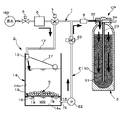
図1乃至図22は、本発明の第1実施形態の浄水処理装置Xである。図1はコンテナ51の天板52の上面に太陽モジュール53を設け、かつ、該コンテナ51の内部に軟水装置Aを含む浄水処理装置Xを略全て配設した概略説明図である。一方、図22は浄水処理装置Xを構成する各処理部及び電気機器の配置の説明図である。但し、図1は制御系及び電気系統をそれぞれ省略し、原水の流れ、生成・貯留した再生水の流れ、再生水の排出、再生水を排出した後の軟水の流れ、軟水を綺麗な飲料水にする流れ等を概略的に示してある。また図2はコンテナ51の斜視からの説明図である。さらに、図22は電気系統及び多数の制御弁等を省略した全体の説明図である。
1 to 22 are the water purification apparatus X according to the first embodiment of the present invention. FIG. 1 is a schematic explanatory view in which a
まず、図2を参照にして、横長収納箱状のコンテナ51の構成を説明する。このコンテナ51は、普通一般の貨物輸送用の金属製コンテナであるから、例えば20フイート、40フイート等の長さを有し、かつ運搬可能な収納箱である。もちろん、コンテナ51の外観形状に関しては、運搬可能な収納箱であるならば、天板52が山形状に形成されたハウス型のものでも良い。
First, the configuration of the horizontally long storage box-shaped
さて、54は前壁に相当する開閉扉、55は後壁、56は左右の側壁、57は前記左右の側壁のいずれか一方に形成された予備扉、58は前記左右の側壁のいずれか一方に形成された開閉窓、59はベース(床)である。実施形態のコンテナ51は、通気性を考慮して前記予備扉57及び開閉窓58をそれぞれ設けている。また太陽エネルギーを活用するためにコンテナ51の天板52の上面に少なくとも太陽電池モジュール53を水平或いは傾斜状に配設している。
54 is an opening / closing door corresponding to the front wall, 55 is the rear wall, 56 is the left and right side walls, 57 is a spare door formed on one of the left and right side walls, and 58 is one of the left and right side walls. The opening / closing
ここで、図13を参照にして、「電気系統」を簡単に説明する。符号41は太陽電池モジュール53の直流を貯める大容量の蓄電池である。蓄電池は、例えばケースに多数収納されている。45は後述する制御部で、この制御部45はインバータ42を有する。前記インバータ42は電源制御回路を有し、前記蓄電池41からの直流を交流に変換する。43は分電盤で、この分電盤43は、通電線を介して複数の切り替弁7、9、複数のポンプ、複数の制御弁a・b、照明灯91、空調設備92等に電気を送る。
Here, the "electrical system" will be briefly described with reference to FIG.
次に、図1及び図22を参照にして浄水処理装置Xの説明をする。なお、浄水処理装置Xは、主に図1乃至図12に示した「軟水装置A」と、主に図14乃至図21に示した「飲料水処理装置B」とから構成されている。以下、前者の軟水装置Aを説明し、その後に後者の飲料水処理装置Bを説明する。
図1は、浄水処理装置Xの全体を便宜上ブロック図で示したものである。図1を参照にして「軟水装置A」を方法的に説明する。
Next, the water purification device X will be described with reference to FIGS. 1 and 22. The water purification device X is mainly composed of the "soft water device A" shown in FIGS. 1 to 12 and the "drinking water treatment device B" mainly shown in FIGS. 14 to 21. Hereinafter, the former water softening device A will be described, and then the latter drinking water treatment device B will be described.
FIG. 1 is a block diagram showing the entire water purification apparatus X for convenience. The "water softening device A" will be described methodically with reference to FIG.
まず、軟水装置Aは、再生水貯留工程を有し、この再生水貯留工程では塩Sと原水(硬水)HWとを再生水貯留部2内で混合して、例えば100lの再生水WSを生成する。次に、軟水装置Aは、前記再生水貯留工程に続く再生工程がある。この再生工程では圧送手段22を介して前記再生水WSを軟水生成部3に導入し、該軟水生成部3の軟水化手段31を所定時間再生漬け(塩漬け)する。次に、軟水装置Aは、前記再生工程に続く処理水(塩水)排出工程がある。この処理水排出工程では、前記軟水化手段31を再生した後、前記軟水生成部3の生成タンク30内の硬度成分を有する再生水WSを処理水WS1として第1排水管10から排出する。次に、軟水装置Aは、前記処理水排出工程に続く軟水生成工程がある。この軟水生成工程では、前記処理水排出工程後に前記原水(硬水)HWを前記軟水生成部3に導入して軟水SWを生成する。次に、軟水装置Aは、前記軟水生成工程に続く軟水貯留工程がある。この軟水貯留工程では、前記軟水生成工程で生成した軟水SWを一時的に貯留する。
First, the soft water apparatus A has a reclaimed water storage step, in which the salt S and the raw water (hard water) HW are mixed in the reclaimed
軟水装置Aは、さらに前記軟水貯留工程の水槽本体に所要量の軟水が溜まって時に前記軟水生成部3での軟水を生成するのを停止する軟水生成停止工程を有し、その後、制御部45は前記再生工程を再び自動的に実行する。
The water softening device A further has a soft water generation stop step of stopping the generation of soft water in the soft
次に、図14を参照にして「飲料水処理装置B」の各処理部を説明する。この飲料水処理装置Bは逆浸透膜処理部61を有する。この逆浸透膜処理部61では電磁弁40を介して軟水貯留部4に溜まっている軟水SWを、高圧ポンプ71を介して複数の濾過手段72に導く。次に、濾過手段72の逆浸透膜(以下、「膜」という)が詰らないように定期的或いは所要の時期に洗浄するための逆浸透膜洗浄処理部62を有する。この逆浸透膜洗浄処理部62は、少なくとも前記複数の濾過手段72のいずれか一方から入口側の制御弁a1を介して浄水の一部を洗浄水貯留タンク73に取り入れる。この洗浄水貯留タンク73の浄水は、洗浄ポンプ74及び出口側の制御弁b1を介して洗浄対象の濾過手段72に送られる(例えば図15を参照)。特に図示しないが、洗浄時、逆浸透膜洗浄処理部62は前記濾過手段72に対して、軟水を利用して気泡を供給する気泡供給手段(エジェクタ)を備えているのが好ましい。
Next, each treatment unit of the "drinking water treatment device B" will be described with reference to FIG. This drinking water treatment device B has a reverse osmosis
次に、飲料水処理装置Bは前記濾過手段72に接続する飲料水貯留部63を有する。この飲料水貯留部63は、一方又は他方の濾過手段72から送られてくる軟水(飲料水)が常に所定水位になるように自動的に受け入れる。この時、制御部45は、飲料水貯留部63の大型の飲料水貯留槽75に設けた検知手段としての水位センサー(レベル計)76の検知信号に基づき、所要の制御弁の開閉を制御する。前記飲料水貯留槽は大型であり、例えば「10t」である。この大型の飲料水貯留槽75内に、注入ポンプ77、薬剤処理タンク78を有する薬剤供給部64から薬剤供給弁cを介して薬剤処理水を入れことが可能である(図19参照)。これにより、細菌を除去して国の定める安全基準を満たすことができる。
Next, the drinking water treatment device B has a drinking
さらに、飲料水処理装置Bは、前記飲料水貯留部63で除菌された飲料水を、移送ポンプ79を介して最後の浄水処理部65に移送する。この最後の浄水処理部65は、美味しくてかつ安全な飲料水を得るために、例えば第1浄水手段81と、これに接続する第2の浄水手段82を有している。そして、この最後の浄水処理部65を経た飲料水は「ミネラル水」としてミネラル供給部66に送られる。このミネラルn水供給部66は、所定間隔を有して併設された複数の蛇口83を有している(図21参照)。
Further, the drinking water treatment device B transfers the drinking water sterilized by the drinking
ここで、図1に戻って軟水装置Aの具体的説明をする。原水HWは、井戸水、湖水、河川、海水等の硬水である。軟水装置Xは、所要長の主管1に前記原水HWを、図示しない原水供給ポンプを介して導入する。この主管1には図面左側の上流側から図面右側の下流側に向かって、再生水貯留部2、軟水生成部3及び軟水貯留部4が直接又は間接的に順次接続している。
Here, returning to FIG. 1, a specific description of the water softening device A will be given. Raw water HW is hard water such as well water, lake water, rivers, and seawater. The water softening device X introduces the raw water HW into the main pipe 1 having a required length via a raw water supply pump (not shown). The reclaimed
また主管1には、同様に上流側から原水HWの流れを制御(止める/流す)する入口電動弁5、最初の浄水処理部(例えば活性炭槽)6、原水HWの流れを制御(方向変換)する第1三方切り替弁(方向制御弁)7、再生水の流量を計測する流量計8、軟水化手段を再生した後の硬度成分を含んだ処理水(除去硬度分を含む塩水)WS1を排出管10に流す第2三方切り替弁(方向制御弁)9、軟水の硬度を測定する硬度測定手段(測定器)11がそれぞれ順次設けられている。なお、前記入口電動弁5、第1三方切り替弁7、第2三方切り替弁9等は、後述する制御部で制御可能である。また前記最初の浄水処理部(例えば活性炭槽)6は、図20で示す第1浄水手段(例えば活性炭槽)81と同一である。これにより、製造コストの削減を図ることができる。
Similarly, the main pipe 1 has an inlet
本発明は、発明の一つの課題(再生時の労力を極力省くこと)との関係で、再生水貯留部2で再生済みの再生水WSを、定期的又は必要な時期に、少なくとも二回以上(好ましくは4回、5回等)、測定器からの情報に基づいて軟水生成部3に前記再生水貯留部2に貯留されている再生水WSを、圧送手段、再生用開閉弁等を介して自動的に軟水生成部3に圧送し、軟水生成部3の軟水化手段31を自動再生(付着物を除去)する構成を採用している。
In the present invention, in relation to one of the problems of the invention (reducing labor during regeneration as much as possible), the reclaimed water WS reclaimed in the reclaimed
そこで、主管1には第1三方切り替弁7及び副管12を介して再生水貯留部2が接続されている。実施形態の再生水貯留部2は、投入或いは予め収納した所要量の塩Sに原水HWとしての硬水を混合して「再生水WS」を所要量作り出す。この再生水WSは、後述の制御部45で制御される圧送手段22等により、自動的に軟水生成部3に所定量送られる。
Therefore, the reclaimed
図5は再生水貯留部2の一例を示す。この再生水貯留部2は、例えば100lの容積を有し、主管1から第1三方切り替弁7を介して分岐した副管12に、その上端部の原水吸引口部13が接続する貯留タンク本体14と、この貯留タンク本体14の下端部の再生水供給口部15よりも上位に位置けされ、かつ、該貯留タンク本体14に内設された略水平状態の塩支持体16と、前記貯留タンク本体内の再生水WSの水位によって上下方向に位置変位するフロートを有するフロート弁17から成る。前記フロート弁17は、例えばお手洗い(トイレ)等に設置されている機械式の流体開閉弁である。なお、このフロート弁17は、例えば電気的な水位センサーに置換することができる。
FIG. 5 shows an example of the reclaimed
また図6で示すように、前記塩支持体16は、好ましくは工業用塩S(塩支持体の網目16aよりも粒径が大きい塩)が貯留タンク本体14の底面14aに落下しない形状の網体が用いられている。そして、貯留タンク本体14の下端部の内壁側面14bには、網状の塩支持体16を支持することができる複数の突片18が左右又は前後に設けられている。
Further, as shown in FIG. 6, the
上記のように、塩支持体16を貯留タンク本体14の底面14aから底上げする理由は、再生水供給口部15に固形状の工業用塩Sが詰まらないようにするためである。なお、塩支持体16は、容器状又は袋状であっても良い。
As described above, the reason why the
以上のように、再生水貯留部2の再生水WSは、井戸水、湖水等の原水HWと網目状の塩支持体16に支持された工業用の塩Sとが互いに混ざり合って貯留タンク本体14内で生成される。そして、この再生水貯留部2の再生水WSは、再生時、再生水供給管21、該再生水供給管に設けられた圧送手段(例えば塩水ポンプ)22及び再生用開閉弁(例えば塩水電磁弁)23を介して第1三方切り替弁7の接続ポイントより下流側の主管1を介して再生及び軟水生成可能な軟水生成部3に送られる。
As described above, in the reclaimed water WS of the reclaimed
前記再生水供給管21は、例えば図5で示すように(貯留タンク本体14の外に配設)、再生水貯留部2の下端部と軟水生成部3よりも上流側の主管1に接続すると共に、前記再生水貯留部2の再生水WSを前記軟水生成部3の生成タンクに圧送する圧送手段22と、該圧送手段からの再生水WSの流れを制御(止める/流す)する開閉弁23とを有する。そして、前述した流量計8は、前記再生水供給管21と軟水生成部3の間の主管1の適宜部位に設けられ、再生水WSの流量を「パルス信号」として計測し、この計測情報は図2で示す制御部45に送られる。
As shown in FIG. 5, for example, the reclaimed
次に、図7及び図8を参照にして軟水生成部3を説明する。この軟水生成部3は、再生時、再生水貯留部2に貯留されている再生水WSを生成タンク30内に所要量受入れ、かつ、所要時間、いわゆる塩漬け状態にして軟水化手段(例えば粒状のイオン交換樹脂)31を再生する。
Next, the soft
しかして、軟水生成部3は、円筒状の生成及び再生タンク(便宜上「生成タンク」という)30と、この生成タンク30に内設された粒状或いは顆粒状のイオン交換樹脂31とから成り、前記生成タンク30は、上部の流入口部32と略垂直のパイプ状送出管33に接続する上部の流出口部34をそれぞれ有している。
The soft
実施形態のイオン交換樹脂31は塩化物イオン型の顆粒状の強塩基性陰イオン交換樹脂が望ましく、この種のイオン交換樹脂により、原水HWに含まれる硝酸性窒素及び亜硝酸性窒素がイオン交換によって除去される。このように軟水生成部3の顆粒状イオン交換樹脂31は、原水HWのpHに左右されずに中性塩を分解することが可能な陰イオン交換樹脂である。
The
したがって、中性塩を分解することが可能であれば、陰イオン交換樹脂を積層状態の脱塩膜部材に置換しても良い。また、生成タンク30内に顆粒状のイオン交換樹脂31のみを内装する場合するのみならず、該イオン交換樹脂と共に、重金属吸着剤であるセラミックス系吸着剤等を適宜に併存していても良い。
Therefore, if it is possible to decompose the neutral salt, the anion exchange resin may be replaced with a demineralized film member in a laminated state. Further, not only the case where only the granular
この実施形態では、再生時、生成タンク30の流入口部32から入る原水HWは、好ましくは再生水貯留部2に貯留されている再生水WSの量よりも少ない。イオン交換樹脂31は、再生時、生成タンク30内で、例えば80lの再生水WSで40分間再生漬け(塩漬け)されると、それに付着していたカルシュウム,マグネシュウム等の硬度成分HTは除去される(いわば綺麗に洗浄される)。そして、再生後、処理水(除去硬度成分を含む塩水)WS1は、第2三方切り替弁9を介して自動的に排出管10から排出される。
前記排出管10は、例えば図1、図3で示すように、第2三方切り替弁9から分岐し、例えば軟水生成部3と硬度測定手段11との間に主管1に接続する。前記硬度測定手段11は、軟水生成部3で生成された軟水の硬度を測定する高精度のインライン水硬度計であり、実施形態では、当業者に「EC」と称されている高精度の水硬度計が用いられている。なお、前記「EC」は主管1、飲料水貯留槽75等の適宜箇所に単数又は複数個設けることができる。
In this embodiment, the amount of raw water HW that enters from the
The
次に、軟水貯留部4は、軟水生成部3の接続ポイントCPよりも下流側の主管1に接続すると共に、軟水生成部3で生成した軟水を貯留する。軟水貯留部4は水槽本体36の一側壁に軟水出口部38を有する。また軟水生成部3は、好ましくは再生水貯留部2よりも容量が大きく、再生水貯留部2の略二倍である。また軟水生成部3は一次的貯留部としての意味合いがあるので、好ましくは水槽本体36及び蓋体37とから成る。
一方、前記蓋体37の適宜箇所には液面を検知するレベル計(例えば電極計)39が設けられている。前記レベル計39は水槽本体36内の飲料水としての軟水(SW)の水位を検知し、該検知信号を制御部45に送る。
Next, the soft
On the other hand, a level meter (for example, an electrode meter) 39 for detecting the liquid level is provided at an appropriate position on the
図4は制御系の概略説明図で、特に、制御部45と、主管1及び再生水供給管21の適宜箇所にそれぞれ設けられた原水用開閉弁6、第1三方切り替弁7、圧送手段22、再生水用の開閉弁23及び流量計8、第2三方切り替弁9、硬度測定手段11、単数又は複数のレベル計39を示す。
FIG. 4 is a schematic explanatory view of the control system, and in particular, the
制御部45は、例えば軟水化手段に付着した硬度化成分を取り除く再生時、前述した再生水供給管21よりも上流側の主管1に設けられた第1三方切り替弁7、前記再生水供給管21に設けられた圧送手段22及び再生水用開閉弁23をそれぞれ制御し、再生水貯留部2に貯留されている再生水WSを自動的に軟水生成部3に供給する。
The
そこで、制御部45は、前述したように太陽モジュール(ソーラー発電の電源)53と接続する。また操作スイッチ44からの入力信号、硬度測定手段11からの測定情報、レベル計39からの液面情報等の測定情報(イ)を受け入れる入力部46を有する。また制御プログラム47を格納した記憶部48と共に、タイマー49を有する。さらに、出力部50から制御信号(ロ)が出力される。
Therefore, the
したがって、制御部45は前記制御プログラム47、タイマー49、測定情報(イ)等に基づき、かつ、制御プログラム47に基づいて情報を出力し、制御信号(ロ)を原水用開閉弁5、第1三方切り替弁7、圧送手段22、再生水用の開閉弁23、第2三方切り替弁9等に送る。
Therefore, the
次に、図7は軟水生成部の具体的な構成部材を示すと共に、各流体の流れも示すものであるが、ここてば図8乃至図12を参照にして主に再生時の流れを説明する。図8は軟水化手段31に硬度成分HTが付着した説明図である。図8で示すように、軟水装置Xを一定期間使用すると、軟水化手段31に硬度成分HTが付着する。そこで、軟水化手段31を再生(洗浄)する必要がある。 Next, FIG. 7 shows a specific component of the soft water generation part and also shows the flow of each fluid. Here, the flow during regeneration is mainly described with reference to FIGS. 8 to 12. do. FIG. 8 is an explanatory diagram in which the hardness component HT is attached to the water softening means 31. As shown in FIG. 8, when the water softening device X is used for a certain period of time, the hardness component HT adheres to the water softening means 31. Therefore, it is necessary to regenerate (wash) the water softening means 31.
図9は軟水化手段31を再生するときの概略説明図である。前述したように、再生水貯留部2の再生タンク本体14には十分な生成済みの再生水WSが確保されている。この時、制御部45は原水用開閉弁5を「閉」にして原水HWの流れを止める。また再生タンク本体14の液面は所定の水位まで上昇済みなので、フロート弁17は作動を停止状態に切換え、また第1三方切り替弁7は「閉」の状態に切り替えられている。したがって、原水HWが軟水生成部3に流れる込むことはない。
FIG. 9 is a schematic explanatory view when the water softening means 31 is regenerated. As described above, a sufficient reclaimed water WS is secured in the reclaimed water tank
そこで、制御部45は再生水用の開閉弁23を「開」の状態に制御すると共に圧送手段(塩水ポンプ)22を起動させる。この時、再生水貯留部2の再生水WSが必要以上に軟水生成部3に流れ込まないように「タイマー49」をスタートさせる。それに加えて、実施形態では再生水供給管21を介して主管1に流れる再生水WSの流量を流量計8で計測する。再生水WSは前記流量計8を通過して生成タンク30に流れ込む。そこで、制御部45は所定時間(例えば3分)経過すると、又は/及び流量計8の測定情報(イ)に基づいて、圧送手段22を停止させると共に、再生水用の開閉弁23を「閉」の状態に制御する。これにより、前記生成タンク30内に、例えば80lの再生水WSが充填される。そして、所要時間(例えば40分間)、再生水(塩水)WSで顆粒状のイオン交換樹脂31を塩漬け状態にする。その結果、図10で示すように、顆粒状のイオン交換樹脂31に付着していた硬度成分HTが除去される。付言すると、図10は軟水化手段31を所要時間再生水漬けにし、硬度成分HTが軟水化手段31から除去された概念図である。
Therefore, the
図11は再生後、軟水生成部3から処理水WS1を排水する説明図である。この時、制御部45は、原水用開閉弁6及び第1三方切り替弁7をそれぞれ「開く」状態に制御すると共に、前記処理水WS1が軟水貯留部4に流れ込まないように第2三方切り替弁9を切替える。これにより、矢印でしめすように原水HWが主管1を介して生成タンク30に導入されるので、生成タンク内の再生水WSは処理水WS1として排出管10から排出される。この排出時間は、例えば「タイマー49」の時間情報に基づいて処理される。制御部45は所定時間経過後、生成タンク内の再生水WSが全て排出されたことを推測して、前記第2三方切り替弁9を切替える。
FIG. 11 is an explanatory diagram for draining the treated water WS1 from the soft
そうすると、図12で示すように、原水HWが主管1の原水用開閉弁5、最初の浄水処理部6、第1三方切り替弁7を経過して生成タンク30内に流れ込み、そこで原水HWとしての硬水は図5で記すように軟水化され、該軟水SWは、第2三方切り替弁9、硬度測定手段11を順次経過して軟水貯留部4に流れ込む。軟水貯留部4の軟水SWの液面は、レベル計39によって計測され、該測定情報(イ)は制御部45に送られる。制御部45が前記測定情報(イ)を適宜に処理する。そして、実施形態では、主管1の適宜箇所(例えば第2三方切り替弁9と軟水貯留部4の間)に硬度測定手段11を備えているので、主管1を流れる硬度情報を該硬度測定手段11から取得し、記憶部48に記録されている「硬度情報の閾値(国によって異なる)」を参照にして、再生段階に入るか否か判定される。
Then, as shown in FIG. 12, the raw water HW flows into the
次に、図15は逆浸透膜洗浄処理部62を含み、逆浸透膜処理部61に2本の高圧容器72a、72aを併設した場合の説明図である。ブロックで示した洗浄液貯留タンク73の右側を浄水の入口側(一次)とすると、前記洗浄液貯留タンク73の左側は洗浄水の出口側(二次)である。したがって、符号b1は洗浄水の出口側の制御弁となる。前記制御弁b1と前記洗浄液貯留タンク73の間には制御部45で駆動制御される洗浄ポンプ74が設けられ、2本の高圧容器72a、72aのいずれか一方がその洗浄時期になると、前記洗浄ポンプ74が所定時間駆動する。その結果、前記洗浄液貯留タンク73の洗浄水が高圧容器72aに送られる。なお、図15には多数の制御弁が適宜箇所に設けられているが、ここでは、便宜上、主管1側に設けた軟水入口側の制御弁を「a」とし、一方、高圧容器72aの膜72bを通過した飲料水を飲料水貯留部に送る側の制御弁を「b」として区別する。前記2本の高圧容器72a、72aに軟水を送る制御弁aと、飲料水を送る制御弁bは、制御部45の記憶部に格納された制御プログラム47及びタイマー49に基づき、選択的に利用される。したがって、複数の濾過手段72のいずれか一方を洗浄するときには、他方の濾過手段72をそのまま使用することができる(自動ローテンションが可能)。
Next, FIG. 15 is an explanatory diagram when the reverse osmosis membrane
図16は、逆浸透膜洗浄処理部62を含み、逆浸透膜処理部61に3本の高圧容器72aを併設した場合の実施形態である。つまり、濾過手段72が3個の実施形態である。このように、濾過手段72の数を適宜に増やしても良い。なお、符号は図15を援用し、詳細な説明を割愛する。また、洗浄済みの処理水を排出する排出ラインL1が適宜に設けられている(図1参照)。
FIG. 16 shows an embodiment including a reverse osmosis membrane
次に、図17は逆浸透膜洗浄処理部62のフローチャートの一例を示す説明図である。以下、符号を簡略化して簡単に説明する。なお、t1、t2等は時間の経過を意味する。ここでは一方の高圧容器72aのみを説明する。
Next, FIG. 17 is an explanatory diagram showing an example of a flowchart of the reverse osmosis membrane
まず、S1は逆浸透膜処理部61から逆浸透膜洗浄処理部62に浄水を送る工程である。この工程は高圧容器72aの洗浄開始の予備時前であるから、好ましくは一方の高圧容器72aを洗浄する前の早い時期t1に行われる。この時、浄水を洗浄液貯留タンク73に送る所定時間がタイマー49によってカウントされる。
First, S1 is a step of sending purified water from the reverse osmosis
次に所定時間t2が経過したならば膜洗浄開始S2となる。浄水供給と膜洗浄開始S2は、略同時又は多少遅延した後に膜洗浄開始S2が開始される。S3は膜洗浄時間であり、タイマー49が膜洗浄開始S2の時間をカウントしてから所定時間t3が経過したか否か監視される。所定時間t3が経過すると、膜洗浄終了S4である。S5は所定期間経過t4が監視される。所定期間経過t4経過したならば、洗浄済み高圧タンク72aの洗浄が使用可能S6となる。このS1~S6の間、他方の高圧容器72aは飲料水を継続的に製造するために利用されている(自動ローテンション)。
Next, when the predetermined time t2 has elapsed, the membrane cleaning is started S2. The purified water supply and the membrane cleaning start S2 are started at substantially the same time or after a slight delay, and the membrane cleaning start S2 is started. S3 is the membrane cleaning time, and it is monitored whether or not a predetermined time t3 has elapsed since the
次に、図18は飲料水貯留部63の一例を示す概略説明図である。この飲料水貯留部63は、前述したように飲料水貯留槽75と水位を検知する検知手段76から成る。なお、図18では、制御弁やポンプを割愛している。
Next, FIG. 18 is a schematic explanatory view showing an example of the drinking
次に、図19は薬剤供給部64の一例を示す概略説明図である。この薬剤供給部64は、前述したように、注入ポンプ77と、薬剤処理タンク78を有し、前記薬剤処理タンク78には、例えば次亜塩素塩ナトリュームやこれに類する薬剤が供給ノズルから点滴状に送られる。そして、薬剤処理タンク78の処理水は、前記薬剤を十分な時間をかけて確実に処理液に混合反応させた後、薬剤処理液として飲料水貯蔵部63に送られる。なお、実施形態では、前記処理液を供給する管には、制御部45によって開閉が制御される制御弁c及び注入ポンプ77が適宜に設けられている。
Next, FIG. 19 is a schematic explanatory view showing an example of the
次に、図20は最後の浄水処理部65の一例を示す概略説明図である。最後の浄水処理部65は、主管1の下流側に設けた移送ポンプ79及び開閉が制御される制御弁dを介して飲料水貯留槽75に接続する第1浄水部材81と、これに接続する第2浄水部材82を有する。
Next, FIG. 20 is a schematic explanatory view showing an example of the final
しかして、前記第1浄水部材81は、前述した生成タンク30と同一構成の浄水タンク81aと、この浄水タンクに充填された粒状の活性炭81bとを有する。浄水タンク81aの細部的事項(形状、入口、管、出口等)の説明は割愛する。
The first
また前記第2浄水部材82は、浄水タンク82aと、この浄水タンクに内装された中空糸膜82bとから成る。ここでは浄水タンク81a、82aの細部的事項の説明は割愛する。実施形態では、最後の浄水処理部65を設けたことから、「完全」かつ「美味しいミネラル水」を得ることができる。
The second
最後に、図21は水供給部66の説明図である。また図22は本発明の平面視からの各処理部及び電気機器の配置を示す説明図である。この図22から明らかなように、飲料水貯留部63は、他の浄水処理部、電気機器等よりも多くのスペースを取っている。このように、本発明では、各浄水処理部の構成を合理的(簡単なもの)にしたことから、コンテナ51の内部空間を有効的に活用し、飲料水貯留槽75を大型化することができる。
Finally, FIG. 21 is an explanatory diagram of the
本発明は、井戸水、湖水等の原水を軟水にする軟水装置を備えた飲料水の製造装置として利用される。 INDUSTRIAL APPLICABILITY The present invention is used as a drinking water production device provided with a water softening device for softening raw water such as well water and lake water.
X…浄水処理装置、
HW…原水、S…塩水、
WS…再生水、 WS1…処理水(排水)、
SW…軟水、 CP…接続ポイント、
A…軟水装置、 B…飲料水処理装置、
1…主管、
a、b、a1、b1…複数の制御弁、
2…再生水貯留部、 3…軟水生成部、
4…軟水貯留部、 6…最初の浄水処理部、
7…第1三方切り替弁(方向制御弁)、
8…流量計、
9…第2三方切り替弁(方向制御弁)、
10…排出管、
11…硬度測定手段、 14…貯留タンク本体、
17…フロート弁、 16…塩支持体、
21…再生水供給管、 22…圧送手段、
23…再生水用開閉弁、 30…生成タンク、
31…軟水化手段、 40…電磁弁(制御弁)、
41…蓄電池、 42…インバータ、
43…分電盤、 45…制御部、
47…制御プログラム、 48…記憶部、
49…タイマー、 50…出力部、
51…コンテナ、 53…太陽モジュール、
61…逆浸透膜処理部、
62…逆浸透膜洗浄処理部、
63…飲料水貯留部、 64…薬剤供給部、
65…最後の浄水処理部、
66…ミネラル水供給部(水供給部)、
71…高圧ポンプ、 72…濾過手段、
72a…高圧容器、 72b…膜、
74…洗浄ポンプ、 76…検知手段、
75…飲料水貯留槽、 77…注入ポンプ、
78…薬剤処理タンク、 79…移送ポンプ、
81…第1浄水部材、 82…第2浄水部材、
91…照明灯、 92…空調設備。
X ... Water purification equipment,
HW ... raw water, S ... salt water,
WS ... Reclaimed water, WS1 ... Treated water (drainage),
SW ... soft water, CP ... connection point,
A ... soft water equipment, B ... drinking water treatment equipment,
1 ... Chief,
a, b, a1, b1 ... Multiple control valves,
2 ... Reclaimed water storage section, 3 ... Soft water generation section,
4 ... Soft water storage section, 6 ... First water purification section,
7 ... 1st three-way switching valve (direction control valve),
8 ... Flow meter,
9 ... 2nd three-way switching valve (direction control valve),
10 ... Discharge pipe,
11 ... Hardness measuring means, 14 ... Storage tank body,
17 ... float valve, 16 ... salt support,
21 ... Reclaimed water supply pipe, 22 ... Pumping means,
23 ... Reclaimed water on-off valve, 30 ... Generation tank,
31 ... Water softening means, 40 ... Solenoid valve (control valve),
41 ... Storage battery, 42 ... Inverter,
43 ... Distribution board, 45 ... Control unit,
47 ... control program, 48 ... storage,
49 ... timer, 50 ... output section,
51 ... container, 53 ... solar module,
61 ... Reverse osmosis membrane processing unit,
62 ... Reverse osmosis membrane cleaning treatment unit,
63 ... Drinking water storage section, 64 ... Drug supply section,
65 ... The last water treatment department,
66 ... Mineral water supply section (water supply section),
71 ... high pressure pump, 72 ... filtration means,
72a ... high pressure container, 72b ... membrane,
74 ... Cleaning pump, 76 ... Detection means,
75 ... Drinking water storage tank, 77 ... Injection pump,
78 ... Chemical treatment tank, 79 ... Transfer pump,
81 ... 1st water purification member, 82 ... 2nd water purification member,
91 ... Lighting, 92 ... Air conditioning equipment.
Claims (4)
前記コンテナに太陽モジュールを設け、この太陽モジュールで発電された電気を貯める蓄電池と、この蓄電池を電源とする制御部と、少なくとも前記蓄電池を電源とする照明器具又は空調装置のいずれかを前記コンテナに設け、
一方、浄水処理部は、前記主管の上流側に設けられた最初の浄水処理部と、前記主管に方向制御弁を介して分岐した副管に接続しかつ原水と網目状の塩支持体に支持されかつ該塩支持体の網目よりも粒径が大きい工業用の塩とを混合した再生水を自動的に生成すると共に、所要量の再生水を貯留する再生水貯留部と、前記再生水を前記再生水貯留部及び前記主管に接続する再生水供給管に設けられかつ前記制御部で駆動が制御される圧送ポンプを介して受け入れると共に該再生水により軟水化手段を再生することができかつ該軟水化手段により前記原水を軟水にすることができる軟水生成部と、前記軟水生成部の接続ポイントよりも下流側の前記主管に接続すると共に、前記軟水生成部で生成した軟水を貯留する軟水貯留部と、この軟水貯留部に接続する逆浸透膜処理部と、この逆浸透膜処理部の逆浸透膜素材を前記制御部の制御信号により自動的に洗浄することができるように該逆浸透膜処理部に接続する逆浸透膜洗浄処理部と、前記逆浸透膜処理部に接続する飲料水貯留部と、この飲料水貯留部に接続する前記最後の浄水処理部及び水供給部を備える浄水処理装置。 A water purification device that provides a main pipe in the container, connects at least four or more water purification units from the upstream side to the downstream side of the main pipe, and sends the drinking water treated in the last water treatment unit to the water supply unit. In
A solar module is provided in the container, and a storage battery for storing electricity generated by the solar module, a control unit using the storage battery as a power source, and at least one of a lighting fixture or an air conditioner using the storage battery as a power source are provided in the container. Provide,
On the other hand, the water purification unit is connected to the first water treatment unit provided on the upstream side of the main pipe and a sub pipe branched to the main pipe via a directional control valve, and is supported by raw water and a mesh-like salt support. A regenerated water storage unit that automatically generates regenerated water mixed with industrial salt having a particle size larger than the mesh of the salt support and stores a required amount of regenerated water, and the regenerated water storage unit that stores the regenerated water. And the raw water can be regenerated by the regenerated water while being received via a pressure feed pump provided in the regenerated water supply pipe connected to the main pipe and whose drive is controlled by the control unit, and the raw water can be regenerated by the regenerated water. A soft water storage unit that can be made into soft water, a soft water storage unit that connects to the main pipe on the downstream side of the connection point of the soft water generation unit, and stores the soft water generated by the soft water generation unit, and this soft water storage unit. The reverse osmosis membrane treatment unit connected to the reverse osmosis membrane treatment unit and the reverse osmosis membrane material connected to the reverse osmosis membrane treatment unit so that the reverse osmosis membrane material of the reverse osmosis membrane treatment unit can be automatically washed by the control signal of the control unit. A water purification apparatus including a membrane cleaning unit, a drinking water storage unit connected to the reverse osmosis membrane treatment unit, and the final water purification treatment unit and a water supply unit connected to the drinking water storage unit.
Priority Applications (1)
| Application Number | Priority Date | Filing Date | Title |
|---|---|---|---|
| JP2018012150A JP7080469B2 (en) | 2018-01-29 | 2018-01-29 | Water purification equipment |
Applications Claiming Priority (1)
| Application Number | Priority Date | Filing Date | Title |
|---|---|---|---|
| JP2018012150A JP7080469B2 (en) | 2018-01-29 | 2018-01-29 | Water purification equipment |
Publications (2)
| Publication Number | Publication Date |
|---|---|
| JP2019130433A JP2019130433A (en) | 2019-08-08 |
| JP7080469B2 true JP7080469B2 (en) | 2022-06-06 |
Family
ID=67545339
Family Applications (1)
| Application Number | Title | Priority Date | Filing Date |
|---|---|---|---|
| JP2018012150A Active JP7080469B2 (en) | 2018-01-29 | 2018-01-29 | Water purification equipment |
Country Status (1)
| Country | Link |
|---|---|
| JP (1) | JP7080469B2 (en) |
Families Citing this family (4)
| Publication number | Priority date | Publication date | Assignee | Title |
|---|---|---|---|---|
| KR102435362B1 (en) * | 2020-03-13 | 2022-08-23 | 황태권 | Water purification system with salt storage tank for long-term supply of salt solution for cleaning filtering media of small water purifier |
| KR102597672B1 (en) * | 2020-11-11 | 2023-11-02 | 주식회사 현태 | Integrated solar power generation and water purification system |
| KR20220081711A (en) * | 2020-12-09 | 2022-06-16 | 주식회사 경동나비엔 | Water softener system |
| CN114931778B (en) * | 2022-04-29 | 2023-11-07 | 呼伦贝尔安泰热电有限责任公司汇流河发电厂 | Underground water and reclaimed water distribution system of large direct heating network in alpine region |
Citations (5)
| Publication number | Priority date | Publication date | Assignee | Title |
|---|---|---|---|---|
| JP2000288539A (en) | 1999-04-02 | 2000-10-17 | Heikei Sai | Prevention of bacterial contamination of reverse osmosis membrane water purifier, and bacteria-removing and antibacterial system |
| JP2003001072A (en) | 2001-06-22 | 2003-01-07 | Nefuronetto:Kk | Reverse osmosis equipment with function to automatically clean revers osmosis membrane and method of making pure water using this equipment |
| US20040262206A1 (en) | 2003-06-27 | 2004-12-30 | Doug Gettman | Mobile field electrical supply, freshwater and saltwater purification system, powder wash, wash station, and water collection and reclamation apparatus |
| JP2013070558A (en) | 2011-09-26 | 2013-04-18 | Panasonic Corp | Independency power supply using container |
| JP2017209624A (en) | 2016-05-25 | 2017-11-30 | 三浦工業株式会社 | Water treatment system |
Family Cites Families (2)
| Publication number | Priority date | Publication date | Assignee | Title |
|---|---|---|---|---|
| JPS5057971A (en) * | 1973-09-26 | 1975-05-20 | ||
| JPH07116659A (en) * | 1993-10-21 | 1995-05-09 | Cosmo Bio:Kk | Water purifying device |
-
2018
- 2018-01-29 JP JP2018012150A patent/JP7080469B2/en active Active
Patent Citations (5)
| Publication number | Priority date | Publication date | Assignee | Title |
|---|---|---|---|---|
| JP2000288539A (en) | 1999-04-02 | 2000-10-17 | Heikei Sai | Prevention of bacterial contamination of reverse osmosis membrane water purifier, and bacteria-removing and antibacterial system |
| JP2003001072A (en) | 2001-06-22 | 2003-01-07 | Nefuronetto:Kk | Reverse osmosis equipment with function to automatically clean revers osmosis membrane and method of making pure water using this equipment |
| US20040262206A1 (en) | 2003-06-27 | 2004-12-30 | Doug Gettman | Mobile field electrical supply, freshwater and saltwater purification system, powder wash, wash station, and water collection and reclamation apparatus |
| JP2013070558A (en) | 2011-09-26 | 2013-04-18 | Panasonic Corp | Independency power supply using container |
| JP2017209624A (en) | 2016-05-25 | 2017-11-30 | 三浦工業株式会社 | Water treatment system |
Also Published As
| Publication number | Publication date |
|---|---|
| JP2019130433A (en) | 2019-08-08 |
Similar Documents
| Publication | Publication Date | Title |
|---|---|---|
| JP7080469B2 (en) | Water purification equipment | |
| EP2258663A1 (en) | Grey water regeneration system | |
| CN102917984B (en) | Electrolyzed water generator | |
| CN205295018U (en) | Portable degree of depth water processing system | |
| KR20200109318A (en) | Marine seawater desalination device | |
| CN203904035U (en) | Water purifying device and water purifying dispenser with same | |
| JP2007136378A (en) | Septic tank | |
| CN211226634U (en) | Multifunctional water treatment machine | |
| JP7134458B2 (en) | water softener | |
| JP4027884B2 (en) | Water purification system using natural energy and water purification method | |
| CN212387891U (en) | Household water purifying device | |
| CN212403782U (en) | Household water purifying device | |
| CN212532570U (en) | Household water purifying device | |
| JPH1052686A (en) | Apparatus for reusing drainage water for detached house | |
| JP2019188369A (en) | Portable water purification system | |
| JPH07116659A (en) | Water purifying device | |
| CN113493272A (en) | Household water purifying device | |
| CN113135624A (en) | Purification system of tap water plant | |
| CN113402079A (en) | Household water purifying device | |
| CN113493268A (en) | Household water purifying device | |
| CN212833121U (en) | Reverse osmosis concentrated water utilization device | |
| CN212954680U (en) | Water treatment equipment for electroplating laboratory | |
| CN212403780U (en) | Household water purifying device | |
| JP2022017673A (en) | Soft water producing apparatus and method for producing soft water | |
| KR101897573B1 (en) | Water purifier and method for cleansing thereof |
Legal Events
| Date | Code | Title | Description |
|---|---|---|---|
| A621 | Written request for application examination |
Free format text: JAPANESE INTERMEDIATE CODE: A621 Effective date: 20210108 |
|
| A977 | Report on retrieval |
Free format text: JAPANESE INTERMEDIATE CODE: A971007 Effective date: 20211020 |
|
| A131 | Notification of reasons for refusal |
Free format text: JAPANESE INTERMEDIATE CODE: A131 Effective date: 20211105 |
|
| A521 | Request for written amendment filed |
Free format text: JAPANESE INTERMEDIATE CODE: A523 Effective date: 20211217 |
|
| TRDD | Decision of grant or rejection written | ||
| A01 | Written decision to grant a patent or to grant a registration (utility model) |
Free format text: JAPANESE INTERMEDIATE CODE: A01 Effective date: 20220419 |
|
| A61 | First payment of annual fees (during grant procedure) |
Free format text: JAPANESE INTERMEDIATE CODE: A61 Effective date: 20220518 |
|
| R150 | Certificate of patent or registration of utility model |
Ref document number: 7080469 Country of ref document: JP Free format text: JAPANESE INTERMEDIATE CODE: R150 |