JP7075568B2 - Pixel Array Medical Systems, Devices and Methods - Google Patents
Pixel Array Medical Systems, Devices and Methods Download PDFInfo
- Publication number
- JP7075568B2 JP7075568B2 JP2019543350A JP2019543350A JP7075568B2 JP 7075568 B2 JP7075568 B2 JP 7075568B2 JP 2019543350 A JP2019543350 A JP 2019543350A JP 2019543350 A JP2019543350 A JP 2019543350A JP 7075568 B2 JP7075568 B2 JP 7075568B2
- Authority
- JP
- Japan
- Prior art keywords
- skin
- partial
- array
- scalpet
- vacuum
- Prior art date
- Legal status (The legal status is an assumption and is not a legal conclusion. Google has not performed a legal analysis and makes no representation as to the accuracy of the status listed.)
- Active
Links
Images


Classifications
-
- A—HUMAN NECESSITIES
- A61—MEDICAL OR VETERINARY SCIENCE; HYGIENE
- A61B—DIAGNOSIS; SURGERY; IDENTIFICATION
- A61B17/00—Surgical instruments, devices or methods, e.g. tourniquets
- A61B17/32—Surgical cutting instruments
- A61B17/320068—Surgical cutting instruments using mechanical vibrations, e.g. ultrasonic
-
- A—HUMAN NECESSITIES
- A61—MEDICAL OR VETERINARY SCIENCE; HYGIENE
- A61B—DIAGNOSIS; SURGERY; IDENTIFICATION
- A61B17/00—Surgical instruments, devices or methods, e.g. tourniquets
- A61B17/32—Surgical cutting instruments
- A61B17/3205—Excision instruments
-
- A—HUMAN NECESSITIES
- A61—MEDICAL OR VETERINARY SCIENCE; HYGIENE
- A61B—DIAGNOSIS; SURGERY; IDENTIFICATION
- A61B17/00—Surgical instruments, devices or methods, e.g. tourniquets
- A61B17/32—Surgical cutting instruments
- A61B17/3205—Excision instruments
- A61B17/32053—Punch like cutting instruments, e.g. using a cylindrical or oval knife
-
- A—HUMAN NECESSITIES
- A61—MEDICAL OR VETERINARY SCIENCE; HYGIENE
- A61B—DIAGNOSIS; SURGERY; IDENTIFICATION
- A61B17/00—Surgical instruments, devices or methods, e.g. tourniquets
- A61B17/32—Surgical cutting instruments
- A61B17/322—Skin grafting apparatus
-
- A—HUMAN NECESSITIES
- A61—MEDICAL OR VETERINARY SCIENCE; HYGIENE
- A61B—DIAGNOSIS; SURGERY; IDENTIFICATION
- A61B18/00—Surgical instruments, devices or methods for transferring non-mechanical forms of energy to or from the body
- A61B18/04—Surgical instruments, devices or methods for transferring non-mechanical forms of energy to or from the body by heating
- A61B18/12—Surgical instruments, devices or methods for transferring non-mechanical forms of energy to or from the body by heating by passing a current through the tissue to be heated, e.g. high-frequency current
- A61B18/14—Probes or electrodes therefor
-
- A—HUMAN NECESSITIES
- A61—MEDICAL OR VETERINARY SCIENCE; HYGIENE
- A61B—DIAGNOSIS; SURGERY; IDENTIFICATION
- A61B90/00—Instruments, implements or accessories specially adapted for surgery or diagnosis and not covered by any of the groups A61B1/00 - A61B50/00, e.g. for luxation treatment or for protecting wound edges
- A61B90/02—Devices for expanding tissue, e.g. skin tissue
-
- A—HUMAN NECESSITIES
- A61—MEDICAL OR VETERINARY SCIENCE; HYGIENE
- A61B—DIAGNOSIS; SURGERY; IDENTIFICATION
- A61B90/00—Instruments, implements or accessories specially adapted for surgery or diagnosis and not covered by any of the groups A61B1/00 - A61B50/00, e.g. for luxation treatment or for protecting wound edges
- A61B90/03—Automatic limiting or abutting means, e.g. for safety
-
- A—HUMAN NECESSITIES
- A61—MEDICAL OR VETERINARY SCIENCE; HYGIENE
- A61B—DIAGNOSIS; SURGERY; IDENTIFICATION
- A61B90/00—Instruments, implements or accessories specially adapted for surgery or diagnosis and not covered by any of the groups A61B1/00 - A61B50/00, e.g. for luxation treatment or for protecting wound edges
- A61B90/39—Markers, e.g. radio-opaque or breast lesions markers
-
- A—HUMAN NECESSITIES
- A61—MEDICAL OR VETERINARY SCIENCE; HYGIENE
- A61B—DIAGNOSIS; SURGERY; IDENTIFICATION
- A61B17/00—Surgical instruments, devices or methods, e.g. tourniquets
- A61B17/20—Surgical instruments, devices or methods, e.g. tourniquets for vaccinating or cleaning the skin previous to the vaccination
- A61B17/205—Vaccinating by means of needles or other puncturing devices
-
- A—HUMAN NECESSITIES
- A61—MEDICAL OR VETERINARY SCIENCE; HYGIENE
- A61B—DIAGNOSIS; SURGERY; IDENTIFICATION
- A61B17/00—Surgical instruments, devices or methods, e.g. tourniquets
- A61B17/42—Gynaecological or obstetrical instruments or methods
-
- A—HUMAN NECESSITIES
- A61—MEDICAL OR VETERINARY SCIENCE; HYGIENE
- A61B—DIAGNOSIS; SURGERY; IDENTIFICATION
- A61B18/00—Surgical instruments, devices or methods for transferring non-mechanical forms of energy to or from the body
- A61B18/04—Surgical instruments, devices or methods for transferring non-mechanical forms of energy to or from the body by heating
- A61B18/12—Surgical instruments, devices or methods for transferring non-mechanical forms of energy to or from the body by heating by passing a current through the tissue to be heated, e.g. high-frequency current
- A61B18/14—Probes or electrodes therefor
- A61B18/1402—Probes for open surgery
-
- A—HUMAN NECESSITIES
- A61—MEDICAL OR VETERINARY SCIENCE; HYGIENE
- A61B—DIAGNOSIS; SURGERY; IDENTIFICATION
- A61B18/00—Surgical instruments, devices or methods for transferring non-mechanical forms of energy to or from the body
- A61B18/18—Surgical instruments, devices or methods for transferring non-mechanical forms of energy to or from the body by applying electromagnetic radiation, e.g. microwaves
- A61B18/20—Surgical instruments, devices or methods for transferring non-mechanical forms of energy to or from the body by applying electromagnetic radiation, e.g. microwaves using laser
-
- A—HUMAN NECESSITIES
- A61—MEDICAL OR VETERINARY SCIENCE; HYGIENE
- A61B—DIAGNOSIS; SURGERY; IDENTIFICATION
- A61B17/00—Surgical instruments, devices or methods, e.g. tourniquets
- A61B2017/00367—Details of actuation of instruments, e.g. relations between pushing buttons, or the like, and activation of the tool, working tip, or the like
- A61B2017/00398—Details of actuation of instruments, e.g. relations between pushing buttons, or the like, and activation of the tool, working tip, or the like using powered actuators, e.g. stepper motors, solenoids
-
- A—HUMAN NECESSITIES
- A61—MEDICAL OR VETERINARY SCIENCE; HYGIENE
- A61B—DIAGNOSIS; SURGERY; IDENTIFICATION
- A61B17/00—Surgical instruments, devices or methods, e.g. tourniquets
- A61B2017/00535—Surgical instruments, devices or methods, e.g. tourniquets pneumatically or hydraulically operated
- A61B2017/00561—Surgical instruments, devices or methods, e.g. tourniquets pneumatically or hydraulically operated creating a vacuum
-
- A—HUMAN NECESSITIES
- A61—MEDICAL OR VETERINARY SCIENCE; HYGIENE
- A61B—DIAGNOSIS; SURGERY; IDENTIFICATION
- A61B17/00—Surgical instruments, devices or methods, e.g. tourniquets
- A61B2017/00743—Type of operation; Specification of treatment sites
- A61B2017/00747—Dermatology
-
- A—HUMAN NECESSITIES
- A61—MEDICAL OR VETERINARY SCIENCE; HYGIENE
- A61B—DIAGNOSIS; SURGERY; IDENTIFICATION
- A61B17/00—Surgical instruments, devices or methods, e.g. tourniquets
- A61B2017/00743—Type of operation; Specification of treatment sites
- A61B2017/00747—Dermatology
- A61B2017/00752—Hair removal or transplantation
-
- A—HUMAN NECESSITIES
- A61—MEDICAL OR VETERINARY SCIENCE; HYGIENE
- A61B—DIAGNOSIS; SURGERY; IDENTIFICATION
- A61B17/00—Surgical instruments, devices or methods, e.g. tourniquets
- A61B2017/00743—Type of operation; Specification of treatment sites
- A61B2017/00747—Dermatology
- A61B2017/00761—Removing layer of skin tissue, e.g. wrinkles, scars or cancerous tissue
-
- A—HUMAN NECESSITIES
- A61—MEDICAL OR VETERINARY SCIENCE; HYGIENE
- A61B—DIAGNOSIS; SURGERY; IDENTIFICATION
- A61B17/00—Surgical instruments, devices or methods, e.g. tourniquets
- A61B2017/00743—Type of operation; Specification of treatment sites
- A61B2017/00747—Dermatology
- A61B2017/00769—Tattoo removal
-
- A—HUMAN NECESSITIES
- A61—MEDICAL OR VETERINARY SCIENCE; HYGIENE
- A61B—DIAGNOSIS; SURGERY; IDENTIFICATION
- A61B17/00—Surgical instruments, devices or methods, e.g. tourniquets
- A61B2017/00743—Type of operation; Specification of treatment sites
- A61B2017/00792—Plastic surgery
-
- A—HUMAN NECESSITIES
- A61—MEDICAL OR VETERINARY SCIENCE; HYGIENE
- A61B—DIAGNOSIS; SURGERY; IDENTIFICATION
- A61B17/00—Surgical instruments, devices or methods, e.g. tourniquets
- A61B2017/00743—Type of operation; Specification of treatment sites
- A61B2017/00796—Breast surgery
-
- A—HUMAN NECESSITIES
- A61—MEDICAL OR VETERINARY SCIENCE; HYGIENE
- A61B—DIAGNOSIS; SURGERY; IDENTIFICATION
- A61B17/00—Surgical instruments, devices or methods, e.g. tourniquets
- A61B17/30—Surgical pincettes without pivotal connections
- A61B2017/306—Surgical pincettes without pivotal connections holding by means of suction
-
- A—HUMAN NECESSITIES
- A61—MEDICAL OR VETERINARY SCIENCE; HYGIENE
- A61B—DIAGNOSIS; SURGERY; IDENTIFICATION
- A61B17/00—Surgical instruments, devices or methods, e.g. tourniquets
- A61B17/32—Surgical cutting instruments
- A61B2017/320044—Blunt dissectors
-
- A—HUMAN NECESSITIES
- A61—MEDICAL OR VETERINARY SCIENCE; HYGIENE
- A61B—DIAGNOSIS; SURGERY; IDENTIFICATION
- A61B17/00—Surgical instruments, devices or methods, e.g. tourniquets
- A61B17/32—Surgical cutting instruments
- A61B2017/320052—Guides for cutting instruments
-
- A—HUMAN NECESSITIES
- A61—MEDICAL OR VETERINARY SCIENCE; HYGIENE
- A61B—DIAGNOSIS; SURGERY; IDENTIFICATION
- A61B17/00—Surgical instruments, devices or methods, e.g. tourniquets
- A61B17/32—Surgical cutting instruments
- A61B17/320068—Surgical cutting instruments using mechanical vibrations, e.g. ultrasonic
- A61B2017/32007—Surgical cutting instruments using mechanical vibrations, e.g. ultrasonic with suction or vacuum means
-
- A—HUMAN NECESSITIES
- A61—MEDICAL OR VETERINARY SCIENCE; HYGIENE
- A61B—DIAGNOSIS; SURGERY; IDENTIFICATION
- A61B17/00—Surgical instruments, devices or methods, e.g. tourniquets
- A61B17/32—Surgical cutting instruments
- A61B17/322—Skin grafting apparatus
- A61B2017/3225—Skin grafting apparatus with processing of harvested tissue
-
- A—HUMAN NECESSITIES
- A61—MEDICAL OR VETERINARY SCIENCE; HYGIENE
- A61B—DIAGNOSIS; SURGERY; IDENTIFICATION
- A61B17/00—Surgical instruments, devices or methods, e.g. tourniquets
- A61B17/34—Trocars; Puncturing needles
- A61B17/3403—Needle locating or guiding means
- A61B2017/3405—Needle locating or guiding means using mechanical guide means
- A61B2017/3409—Needle locating or guiding means using mechanical guide means including needle or instrument drives
-
- A—HUMAN NECESSITIES
- A61—MEDICAL OR VETERINARY SCIENCE; HYGIENE
- A61B—DIAGNOSIS; SURGERY; IDENTIFICATION
- A61B18/00—Surgical instruments, devices or methods for transferring non-mechanical forms of energy to or from the body
- A61B2018/00053—Mechanical features of the instrument of device
- A61B2018/00273—Anchoring means for temporary attachment of a device to tissue
- A61B2018/00291—Anchoring means for temporary attachment of a device to tissue using suction
-
- A—HUMAN NECESSITIES
- A61—MEDICAL OR VETERINARY SCIENCE; HYGIENE
- A61B—DIAGNOSIS; SURGERY; IDENTIFICATION
- A61B18/00—Surgical instruments, devices or methods for transferring non-mechanical forms of energy to or from the body
- A61B2018/00315—Surgical instruments, devices or methods for transferring non-mechanical forms of energy to or from the body for treatment of particular body parts
- A61B2018/00452—Skin
- A61B2018/00458—Deeper parts of the skin, e.g. treatment of vascular disorders or port wine stains
- A61B2018/00464—Subcutaneous fat, e.g. liposuction, lipolysis
-
- A—HUMAN NECESSITIES
- A61—MEDICAL OR VETERINARY SCIENCE; HYGIENE
- A61B—DIAGNOSIS; SURGERY; IDENTIFICATION
- A61B18/00—Surgical instruments, devices or methods for transferring non-mechanical forms of energy to or from the body
- A61B2018/00315—Surgical instruments, devices or methods for transferring non-mechanical forms of energy to or from the body for treatment of particular body parts
- A61B2018/00452—Skin
- A61B2018/0047—Upper parts of the skin, e.g. skin peeling or treatment of wrinkles
-
- A—HUMAN NECESSITIES
- A61—MEDICAL OR VETERINARY SCIENCE; HYGIENE
- A61B—DIAGNOSIS; SURGERY; IDENTIFICATION
- A61B18/00—Surgical instruments, devices or methods for transferring non-mechanical forms of energy to or from the body
- A61B2018/00315—Surgical instruments, devices or methods for transferring non-mechanical forms of energy to or from the body for treatment of particular body parts
- A61B2018/00452—Skin
- A61B2018/00476—Hair follicles
-
- A—HUMAN NECESSITIES
- A61—MEDICAL OR VETERINARY SCIENCE; HYGIENE
- A61B—DIAGNOSIS; SURGERY; IDENTIFICATION
- A61B18/00—Surgical instruments, devices or methods for transferring non-mechanical forms of energy to or from the body
- A61B2018/00571—Surgical instruments, devices or methods for transferring non-mechanical forms of energy to or from the body for achieving a particular surgical effect
- A61B2018/00601—Cutting
-
- A—HUMAN NECESSITIES
- A61—MEDICAL OR VETERINARY SCIENCE; HYGIENE
- A61B—DIAGNOSIS; SURGERY; IDENTIFICATION
- A61B90/00—Instruments, implements or accessories specially adapted for surgery or diagnosis and not covered by any of the groups A61B1/00 - A61B50/00, e.g. for luxation treatment or for protecting wound edges
- A61B90/03—Automatic limiting or abutting means, e.g. for safety
- A61B2090/033—Abutting means, stops, e.g. abutting on tissue or skin
-
- A—HUMAN NECESSITIES
- A61—MEDICAL OR VETERINARY SCIENCE; HYGIENE
- A61B—DIAGNOSIS; SURGERY; IDENTIFICATION
- A61B90/00—Instruments, implements or accessories specially adapted for surgery or diagnosis and not covered by any of the groups A61B1/00 - A61B50/00, e.g. for luxation treatment or for protecting wound edges
- A61B90/39—Markers, e.g. radio-opaque or breast lesions markers
- A61B2090/3904—Markers, e.g. radio-opaque or breast lesions markers specially adapted for marking specified tissue
- A61B2090/3908—Soft tissue, e.g. breast tissue
-
- A—HUMAN NECESSITIES
- A61—MEDICAL OR VETERINARY SCIENCE; HYGIENE
- A61B—DIAGNOSIS; SURGERY; IDENTIFICATION
- A61B90/00—Instruments, implements or accessories specially adapted for surgery or diagnosis and not covered by any of the groups A61B1/00 - A61B50/00, e.g. for luxation treatment or for protecting wound edges
- A61B90/39—Markers, e.g. radio-opaque or breast lesions markers
- A61B2090/3933—Liquid markers
-
- A—HUMAN NECESSITIES
- A61—MEDICAL OR VETERINARY SCIENCE; HYGIENE
- A61B—DIAGNOSIS; SURGERY; IDENTIFICATION
- A61B90/00—Instruments, implements or accessories specially adapted for surgery or diagnosis and not covered by any of the groups A61B1/00 - A61B50/00, e.g. for luxation treatment or for protecting wound edges
- A61B90/39—Markers, e.g. radio-opaque or breast lesions markers
- A61B2090/3937—Visible markers
- A61B2090/395—Visible markers with marking agent for marking skin or other tissue
-
- A—HUMAN NECESSITIES
- A61—MEDICAL OR VETERINARY SCIENCE; HYGIENE
- A61B—DIAGNOSIS; SURGERY; IDENTIFICATION
- A61B2217/00—General characteristics of surgical instruments
- A61B2217/002—Auxiliary appliance
- A61B2217/005—Auxiliary appliance with suction drainage system
-
- A—HUMAN NECESSITIES
- A61—MEDICAL OR VETERINARY SCIENCE; HYGIENE
- A61B—DIAGNOSIS; SURGERY; IDENTIFICATION
- A61B2218/00—Details of surgical instruments, devices or methods for transferring non-mechanical forms of energy to or from the body
- A61B2218/001—Details of surgical instruments, devices or methods for transferring non-mechanical forms of energy to or from the body having means for irrigation and/or aspiration of substances to and/or from the surgical site
- A61B2218/007—Aspiration
-
- A—HUMAN NECESSITIES
- A61—MEDICAL OR VETERINARY SCIENCE; HYGIENE
- A61M—DEVICES FOR INTRODUCING MEDIA INTO, OR ONTO, THE BODY; DEVICES FOR TRANSDUCING BODY MEDIA OR FOR TAKING MEDIA FROM THE BODY; DEVICES FOR PRODUCING OR ENDING SLEEP OR STUPOR
- A61M37/00—Other apparatus for introducing media into the body; Percutany, i.e. introducing medicines into the body by diffusion through the skin
- A61M37/0015—Other apparatus for introducing media into the body; Percutany, i.e. introducing medicines into the body by diffusion through the skin by using microneedles
- A61M2037/0023—Drug applicators using microneedles
-
- A—HUMAN NECESSITIES
- A61—MEDICAL OR VETERINARY SCIENCE; HYGIENE
- A61M—DEVICES FOR INTRODUCING MEDIA INTO, OR ONTO, THE BODY; DEVICES FOR TRANSDUCING BODY MEDIA OR FOR TAKING MEDIA FROM THE BODY; DEVICES FOR PRODUCING OR ENDING SLEEP OR STUPOR
- A61M37/00—Other apparatus for introducing media into the body; Percutany, i.e. introducing medicines into the body by diffusion through the skin
- A61M37/0015—Other apparatus for introducing media into the body; Percutany, i.e. introducing medicines into the body by diffusion through the skin by using microneedles
- A61M2037/0061—Methods for using microneedles
-
- A—HUMAN NECESSITIES
- A61—MEDICAL OR VETERINARY SCIENCE; HYGIENE
- A61M—DEVICES FOR INTRODUCING MEDIA INTO, OR ONTO, THE BODY; DEVICES FOR TRANSDUCING BODY MEDIA OR FOR TAKING MEDIA FROM THE BODY; DEVICES FOR PRODUCING OR ENDING SLEEP OR STUPOR
- A61M2202/00—Special media to be introduced, removed or treated
- A61M2202/08—Lipoids
-
- A—HUMAN NECESSITIES
- A61—MEDICAL OR VETERINARY SCIENCE; HYGIENE
- A61M—DEVICES FOR INTRODUCING MEDIA INTO, OR ONTO, THE BODY; DEVICES FOR TRANSDUCING BODY MEDIA OR FOR TAKING MEDIA FROM THE BODY; DEVICES FOR PRODUCING OR ENDING SLEEP OR STUPOR
- A61M2210/00—Anatomical parts of the body
- A61M2210/04—Skin
-
- A—HUMAN NECESSITIES
- A61—MEDICAL OR VETERINARY SCIENCE; HYGIENE
- A61M—DEVICES FOR INTRODUCING MEDIA INTO, OR ONTO, THE BODY; DEVICES FOR TRANSDUCING BODY MEDIA OR FOR TAKING MEDIA FROM THE BODY; DEVICES FOR PRODUCING OR ENDING SLEEP OR STUPOR
- A61M37/00—Other apparatus for introducing media into the body; Percutany, i.e. introducing medicines into the body by diffusion through the skin
- A61M37/0015—Other apparatus for introducing media into the body; Percutany, i.e. introducing medicines into the body by diffusion through the skin by using microneedles
-
- A—HUMAN NECESSITIES
- A61—MEDICAL OR VETERINARY SCIENCE; HYGIENE
- A61N—ELECTROTHERAPY; MAGNETOTHERAPY; RADIATION THERAPY; ULTRASOUND THERAPY
- A61N7/00—Ultrasound therapy
- A61N2007/0004—Applications of ultrasound therapy
- A61N2007/0034—Skin treatment
-
- A—HUMAN NECESSITIES
- A61—MEDICAL OR VETERINARY SCIENCE; HYGIENE
- A61N—ELECTROTHERAPY; MAGNETOTHERAPY; RADIATION THERAPY; ULTRASOUND THERAPY
- A61N7/00—Ultrasound therapy
Landscapes
- Health & Medical Sciences (AREA)
- Surgery (AREA)
- Life Sciences & Earth Sciences (AREA)
- Engineering & Computer Science (AREA)
- General Health & Medical Sciences (AREA)
- Nuclear Medicine, Radiotherapy & Molecular Imaging (AREA)
- Biomedical Technology (AREA)
- Heart & Thoracic Surgery (AREA)
- Medical Informatics (AREA)
- Molecular Biology (AREA)
- Animal Behavior & Ethology (AREA)
- Public Health (AREA)
- Veterinary Medicine (AREA)
- Pathology (AREA)
- Oral & Maxillofacial Surgery (AREA)
- Dentistry (AREA)
- Mechanical Engineering (AREA)
- Dermatology (AREA)
- Plastic & Reconstructive Surgery (AREA)
- Transplantation (AREA)
- Physics & Mathematics (AREA)
- Plasma & Fusion (AREA)
- Otolaryngology (AREA)
- Surgical Instruments (AREA)
- Prostheses (AREA)
Description
本出願は、2017年2月9日出願の米国特許出願第62/456,775号の恩恵を主張する。
本出願は、2017年5月11日出願の米国特許出願第62/504,844号の恩恵を主張する。
本出願は、2010年12月17日出願の米国特許出願第12/972,013号の継続出願であり、現在米国特許第8,900,181号となっている、2014年12月1日出願の米国特許出願第14/556,648号の一部継続出願である。
本出願は、2017年11月14日出願の米国特許出願第15/812,952号の一部継続出願である。
本出願は、2013年12月6日出願の米国特許出願第14/099,380号の一部継続出願である。
本出願は、2017年11月22日出願の米国特許出願第15/821,258号の一部継続出願である。
本出願は、2014年10月2日出願の米国特許出願第14/505,090号の一部継続出願である。
本出願は、2014年10月2日出願の米国特許出願第14/505,183号の一部継続出願である。
本出願は、2017年11月22日出願の米国特許出願第15/821,325号の一部継続出願である。
本出願は、2015年8月31日出願の米国特許出願第14/840,274号の一部継続出願である。
本出願は、2015年8月31日出願の米国特許出願第14/840,284号の一部継続出願である。
本出願は、2015年8月31日出願の米国特許出願第14/840,267号の一部継続出願である。
本出願は、2015年8月31日出願の米国特許出願第14/840,290号の一部継続出願である。
本出願は、2015年8月31日出願の米国特許出願第14/840,307号の一部継続出願である。
本出願は、2016年2月5日出願の米国特許出願第15/016,954号の一部継続出願である。
本出願は、2016年2月5日出願の米国特許出願第15/017,007号の一部継続出願である。
本出願は、2017年2月13日出願の米国特許出願第15/431,230号の一部継続出願である。
本出願は、2017年2月13日出願の米国特許出願第15/431,247号の一部継続出願である。
This application claims the benefits of US Patent Application No. 62 / 456,775 filed February 9, 2017.
This application claims the benefits of US Patent Application No. 62 / 504,844 filed May 11, 2017.
This application is a continuation of US Patent Application No. 12 / 972,013 filed on December 17, 2010, and is currently US Patent No. 8,900,181, filed on December 1, 2014. This is a partial continuation application of US Patent Application No. 14 / 556,648.
This application is a partial continuation of US Patent Application No. 15 / 812,952 filed November 14, 2017.
This application is a partial continuation of US Patent Application No. 14 / 099,380 filed December 6, 2013.
This application is a partial continuation of US Patent Application No. 15 / 821,258 filed November 22, 2017.
This application is a partial continuation of US Patent Application No. 14 / 505,090 filed October 2, 2014.
This application is a partial continuation of US Patent Application No. 14 / 505,183 filed October 2, 2014.
This application is a partial continuation of US Patent Application No. 15 / 821,325 filed November 22, 2017.
This application is a partial continuation of US Patent Application No. 14 / 840,274 filed on August 31, 2015.
This application is a partial continuation of US Patent Application No. 14 / 840,284 filed on August 31, 2015.
This application is a partial continuation of US Patent Application No. 14 / 840,267 filed on August 31, 2015.
This application is a partial continuation of US Patent Application No. 14 / 840,290 filed on August 31, 2015.
This application is a partial continuation of US Patent Application No. 14 / 840,307 filed on August 31, 2015.
This application is a partial continuation of US Patent Application No. 15 / 016,954 filed February 5, 2016.
This application is a partial continuation of US Patent Application No. 15 / 017,007 filed February 5, 2016.
This application is a partial continuation of US Patent Application No. 15 / 431,230 filed February 13, 2017.
This application is a partial continuation of US Patent Application No. 15 / 431,247 filed February 13, 2017.
本明細書記載の実施形態は、医療用のシステム、器具若しくはデバイス、及び方法に関し、より具体的には、やけど、皮膚欠損、及び植毛術の外科的管理に適用される医療器具及び方法に関する。 The embodiments described herein relate to medical systems, instruments or devices, and methods, and more specifically to medical instruments and methods that apply to the surgical management of burns, skin defects, and hair transplantation.
老化プロセスは、垂れ下がった皮膚の弛緩が進行することによって最も視覚的に表される。この生涯プロセスは、一生のうち30代もの早期に目立ち始める場合があり、またその後の数10年かけて徐々に悪化する。組織学的研究は、皮膚の垂れ下がった拡張又は加齢による弛緩は、一部には皮膚の引張強度の減少に関連する進行性皮膚萎縮に起因することを示した。重力の下向き力と組み合わさって加齢による皮膚萎縮は、結果として皮膚エンベロープの2次元伸張を生ずることになる。この身体上の組織学的プロセスにおける臨床症状は余分な皮膚の弛緩である。最も影響を受ける部位は、頭頸部、上腕、乳房、下腹部及び膝の領域である。すべての部位で最も目につくのは頭頚部である。この領域において、首における目につく「雄七面鳥」的弛緩及び下部顔面の「顎の垂れ肉」は、これら部位における皮膚の非審美的な垂れ下がりに起因する。 The aging process is most visually represented by the progression of sagging skin relaxation. This lifelong process can begin to stand out as early as the thirties of a lifetime and gradually worsens over the next few decades. Histological studies have shown that sagging dilation or age-related relaxation of the skin is partly due to progressive skin atrophy associated with reduced tensile strength of the skin. Age-related skin atrophy, combined with the downward force of gravity, results in a two-dimensional stretch of the skin envelope. A clinical symptom in this histological process on the body is extra skin relaxation. The most affected areas are the head and neck, upper arm, breast, lower abdomen and knee areas. The most noticeable part of all parts is the head and neck. In this area, the noticeable "male turkey" relaxation in the neck and the "jaw sagging" of the lower face are due to the non-aesthetic sagging of the skin at these sites.
形成外科的処置は、余った弛緩皮膚を切除するよう開発された。これら処置は、一般的に、フェイスリフトのためには耳及び頭皮、及び乳房リフト(乳房固定術)のためには乳房下部褶曲部のような解剖学的境界周辺に隠れる長い切開部を採用しなければならない。しかし、皮膚弛緩切除の幾つかの部位は、より張りのある皮膚への審美的向上と外科的切開部の可視性との間におけるトレードオフに乏しい。この理由から、上腕、膝蓋上膝、大腿部、臀部における皮膚余剰は、外科的瘢痕の可視性に起因して切除しないのが普通である。 Plastic surgery procedures have been developed to remove excess loose skin. These procedures generally employ long incisions that hide around anatomical boundaries, such as the ears and scalp for face lifts and the lower breast folds for breast lifts (mastopexy). There must be. However, some sites of cutis laxa lack a trade-off between aesthetic enhancement to tighter skin and visibility of the surgical incision. For this reason, skin surpluses in the upper arm, patellar knee, thigh, and buttocks are usually not removed due to the visibility of the surgical scar.
この審美上の奇形の頻度及び社会的にネガティブな影響が「フェイスリフト」外科的処置の発展を促してきた。異なる領域における関連する他の形成外科的処置は、腹壁形成術(腹部)、乳房固定術(乳房)、及び腕足形成術(上腕)である。これら外科的処置特有の不利な特徴は、術後の痛み、瘢痕化及び外科的コンプライアンスのリスクである。これら処置の審美的向上が必要とされる大きな外科的切開部とのトレードオフが容認可能であるとしても、広範囲な永久的瘢痕化はこれら処置における常在する必然性である。この理由から、形成外科医達は、毛髪生え際(フェイスリフト)、乳房下部褶曲部(乳房固定術)、及び鼠径折り目部(腹壁形成術)のような解剖学的境界周辺における広範囲な瘢痕化を隠すこれら処置を設計する。しかし、これら切開部の多くは皮膚弛緩の領域から離れた位置に隠されており、したがって、効果は限定的である。膝蓋上(上部前側)膝のような他の皮膚弛緩領域は、より視覚的に見える外科的瘢痕とのトレードオフが貧弱であることに起因して形成外科的切除部に対して修復不可能である。 The frequency of this aesthetic malformation and its negative social impact have prompted the development of "facelift" surgical procedures. Other related plastic surgery procedures in different areas are abdominal wall plasty (abdomen), mastopexy (breast), and brachial plasty (brachial). Disadvantageous features specific to these surgical procedures are the risk of postoperative pain, scarring and surgical compliance. Extensive permanent scarring is a permanent necessity in these procedures, even though trade-offs with large surgical incisions that require aesthetic improvements in these procedures are acceptable. For this reason, plastic surgeons conceal extensive scarring around anatomical boundaries such as hairline (face lift), lower breast folds (mastopexy), and groin creases (abdominoplasty). Design these procedures. However, many of these incisions are hidden away from the area of cutis laxa and therefore have limited effect. Other cutis laxa areas, such as the suprapatellar (upper anterior) knee, are irreparable for plastic surgery resections due to poor trade-offs with more visually visible surgical scars. be.
より最近では、逆熱勾配を生ずる電磁的医療デバイスが試行され、外科手術することなく皮膚に張りを持たせる上で多様な成功をもたらした。このとき、電磁的デバイスは、皮膚弛緩部に適度な量となるよう患者に最適に展開される。電磁的デバイスの制限及び外科手術の潜在的副作用に起因して、外科手術に関連する瘢痕化及び皮膚の電磁的加熱の臨床的変動を回避するよう最低限の侵襲性技術が必要とされる。加齢による皮膚弛緩(首及び顔、腕、腋窩、大腿部、膝、臀部、腹部、ブラジャーライン、乳房下垂)を有する多くの患者にとって、過剰皮膚の部分的切除は従来式形成外科手術の大きい断片部を拡大するおそれがあった。 More recently, electromagnetic medical devices that produce a reverse heat gradient have been tried with varying successes in providing tension to the skin without surgery. At this time, the electromagnetic device is optimally deployed to the patient so that the amount is appropriate for the cutis laxa. Due to the limitations of electromagnetic devices and the potential side effects of surgery, minimally invasive techniques are required to avoid surgically associated scarring and clinical fluctuations in electromagnetic heating of the skin. For many patients with age-related skin relaxation (neck and face, arms, axillae, thighs, knees, hips, abdomen, brassiere line, ptosis), partial resection of excess skin is a conventional plastic surgery procedure. There was a risk of enlarging large fragments.
皮膚エンベロープの審美的修正よりもより大きな重要性は、やけど及び他の外傷に関する皮膚欠陥の外科的管理である。大きなやけどは、やけどした全身体面積及び熱破壊の深さによって分類される。第1度及び第2度のやけどは、一般的に非外科的に局所的な塗り薬及びやけど用包帯の適用で管理される。より深い第3度のやけどは皮膚全層の熱破壊を伴う。これら重篤な損傷の外科的管理には、やけど痂皮の創面切除及び分層植皮の適用を伴う。 More important than the aesthetic modification of the skin envelope is the surgical management of skin defects associated with burns and other trauma. Large burns are categorized by the burned whole body area and the depth of thermal destruction. First- and second-degree burns are generally managed by the application of non-surgical topical ointments and burn bandages. Deeper third-degree burns are accompanied by thermal destruction of all layers of the skin. Surgical management of these serious injuries involves the application of wound resection and split-thickness skin grafting of burned scabs.
最も頻繁にはやけど、外傷、又は皮膚悪性腫瘍切除から生ずるいかなる全層皮膚欠陥も、現行の市販されている器具を用いて皮弁移転又は皮膚移植片のいずれかで閉合することができる。双方の外科的アプローチともドナー部位からの摘出を必要とする。皮弁の使用は、さらに、周期的血液供給を含む必要性によって、また多くの場合ドナー部位を直接閉合する必要性によって制限される。 Most often, any full-thickness skin defect resulting from burns, trauma, or excision of a malignant cutaneous tumor can be closed with either flap transfer or skin graft using current commercially available instruments. Both surgical approaches require removal from the donor site. The use of flaps is further limited by the need to include a periodic blood supply and often by the need to directly close the donor site.
分層植皮処置は、免疫学的制約に起因して、自家皮膚移植片、すなわち当該患者からの摘出を必要とする。代表的には、やけど患者におけるドナー部位は、やけどしていない面域で選択され、また皮膚における部分的厚さのシートがその面域から摘出される。この処置の際における必然性は、そのドナー部位に部分的厚さの皮膚欠陥を創出することである。このドナー部位欠陥はそれ自体深い第2度やけどに類似する。この部位の再表皮形成による治癒にはしばしば大きな痛みを伴い、また数日間にわたり長引くことがあり得る。さらに目に見えるドナー部位の奇形部は、周りの皮膚よりも永久的に薄くかつ脱色されて生ずる。大きな表面積にわたるやけどを負った患者に関しては、皮膚移植の広範囲にわたる摘出は、やけどしていない面域の利用可能性によっても制限を受けることがあり得る。 The split-thickness skin graft procedure requires an autologous skin graft, i.e., removed from the patient due to immunological constraints. Typically, the donor site in a burn patient is selected in the non-burned area and a partial thickness sheet in the skin is removed from the area. The inevitability of this procedure is to create a partial thickness of skin defect at the donor site. This donor site defect is itself similar to a deep second degree burn. Healing by re-epidermal formation of this site is often very painful and can be prolonged for several days. In addition, visible donor site malformations occur that are permanently thinner and bleached than the surrounding skin. For patients with large surface area burns, extensive excision of skin grafts may also be limited by the availability of non-burned areas.
これらの理由から、急速拡大する審美的マーケットにおける審美的外科皮膚引き締め用の器具及び処置に対する必要性がある。さらに、ドナー部位の奇形を排除するとともに、同一ドナー部位から皮膚移植の繰り返しの摘出を可能にする、システム、器具若しくはデバイス及び処置に対する必要性もある。 For these reasons, there is a need for aesthetic surgical skin tightening instruments and procedures in the rapidly expanding aesthetic market. In addition, there is a need for systems, instruments or devices and procedures that eliminate donor site malformations and allow repeated removal of skin grafts from the same donor site.
本明細書に記述される各特許、特許出願及び/又は公報は、各個別の特許、特許出願及び/又は公報が特別に及び個別に記載されているのと同程度に、それらは参照により全体が本明細書に組み入れられるものとする。 Each patent, patent application and / or gazette described herein is as general as each individual patent, patent application and / or gazette is specifically and individually described. Is incorporated herein.
部分切除、脂肪組織切除、部分皮膚移植、及び/又は部分瘢痕形成術のうち1つ又はそれ以上を含む低侵襲的処置のためのシステム、器具、及び方法を記載する。実施形態は、キャリヤに結合したスカルペットアセンブリを備える器具を含み、スカルペットアセンブリは、スカルペットアレイを有する。スカルペットアレイは、部分切除、脂肪組織切除、部分皮膚移植、及び/又は部分瘢痕形成術を行うよう構成された1つ又はそれ以上のスカルペットを有する。システムは、スカルペットアセンブリに結合し、また部位から組織を抜き出すよう構成した真空コンポーネントを備える。キャリヤは、回転力及び/又は真空力をスカルペットアセンブリに対する回転力及び/又は真空力供給を制御するよう構成される。 Describes systems, instruments, and methods for minimally invasive procedures, including partial resection, adipose tissue resection, partial skin grafting, and / or one or more of partial scarring procedures. Embodiments include an instrument comprising a scalpet assembly coupled to a carrier, the scalpet assembly having a scalpet array. The scalpet array has one or more scalpets configured to perform partial resection, adipose tissue resection, partial skin grafting, and / or partial scarring. The system is equipped with vacuum components that are configured to be coupled to the scullpet assembly and to extract tissue from the site. The carrier is configured to control the rotational and / or vacuum force supply to the sculpt assembly with rotational force and / or vacuum force.
本明細書記載のスカルペットデバイスは、審美的外科皮膚引き締めのための器具及び処置に対する拡大する美容マーケットを満足させる。さらに、本発明の実施形態は、ドナー部位の奇形化を排除するとともに、同一ドナー部位から皮膚移植の繰り返しの摘出を可能にする。本明細書記載の実施形態は、眼に見える瘢痕化なしに余剰弛緩皮膚を切除するよう構成され、これにより余剰皮膚弛緩のすべての面域を、ピクセルアレイ採皮刀によって切除することができ、また処置は、従来では外科的切開の可視性に起因して限界があった面域で実施することができるようになる。本明細書記載の実施形態により実現される技術的効果としては、目に見える瘢痕化又は解剖学的境界線に沿う長い瘢痕がなく、滑らかに引き締まった皮膚が得られることである。 The skull pet devices described herein satisfy the expanding beauty market for instruments and procedures for aesthetic surgical skin tightening. Furthermore, embodiments of the present invention eliminate malformations of the donor site and allow repeated removal of skin grafts from the same donor site. The embodiments described herein are configured to excise excess cutis laxa without visible scarring, whereby all areas of excess cutis laxa can be excised with a pixel array skin sword. The procedure can also be performed in areas that were previously limited due to the visibility of the surgical incision. The technical effect achieved by the embodiments described herein is to obtain smooth, firm skin without visible scarring or long scarring along anatomical boundaries.
ピクセル皮膚移植器具及び方法を含む本明細書記載の実施形態は、ドナー部位の目に見える瘢痕化なしに、分層皮膚移植を繰り返し摘出する能力を提供するよう構成される。この処置中、ピクセルアレイ採皮刀(PAD:Pixel Array Dermatome)を使用して、選択したドナー部位から皮膚移植片を摘出する。摘出処置中、ピクセル化した皮膚移植片を可撓性の半多孔質粘着性薄膜上に載置させる。次に、摘出した皮膚移植片/薄膜複合体を被移植者の皮膚欠陥部位に直接当接する。部分的に切除したドナー部位は、バタフライバンデージのような或る期間(例えば、1週間等)にわたり機能する粘着性シート又はバンデージ(例えば、Flexzan(登録商標)シート、等々)を当接することにより閉合する。PADによって生ずる皮内皮膚欠陥は一次治癒プロセスを促進するよう閉合し、この一次治癒プロセスにおいて通常の表皮-真皮構造が解剖学的に再編成され、瘢痕化を最小限にする。術後に生ずることもあるように、粘着性薄膜は移植片の角質層とともに落屑し(剥がれ)、この後、薄膜は被移植床から移植片を分裂させることなく取り除くことができる。 The embodiments described herein, including pixel skin grafting devices and methods, are configured to provide the ability to repeatedly remove stratified skin grafts without visible scarring of the donor site. During this procedure, a Pixel Array Dermatome (PAD) is used to remove skin grafts from selected donor sites. During the excision procedure, the pixelated skin graft is placed on a flexible semi-porous adhesive thin film. Next, the excised skin graft / thin film complex is directly abutted on the skin defect site of the transplantee. The partially resected donor site is closed by abutting an adhesive sheet or bandage (eg, Flexzan® sheet, etc.) that functions over a period of time (eg, 1 week, etc.), such as a butterfly bandage. do. Intradermal skin defects caused by PAD are closed to facilitate the primary healing process, in which the normal epidermal-dermis structure is anatomically reorganized to minimize scarring. The adhesive thin film is desquamated (peeled) with the stratum corneum of the graft, as it may occur postoperatively, after which the thin film can be removed from the graft bed without splitting the graft.
ピクセル皮膚移植処置により実現される多くの効果は説明するに値する。皮膚移植片はピクセル化されているため、皮膚プラグのコンポーネント間における排膿(ドレナージ)のための隙間を生じ、このことは、シート状皮膚移植片に比べると「根付き(takes)」の割合を向上させる。術後の最初の1週間中に皮膚移植片は、新血管形成プロセスによって被移植部位に「根付き」、この新血管形成プロセスにおいては、皮膚欠陥の被移植床から新たな血管が新しい皮膚移植片内に成長する。半多孔質薄膜は滲出液を包帯へと導く。 Many of the benefits achieved by pixel skin graft procedures are worthy of explanation. Because the skin grafts are pixelated, they create gaps for drainage between the components of the skin plug, which is a percentage of "takes" compared to sheet-like skin grafts. Improve. During the first week after surgery, the skin graft "roots" at the site to be transplanted by a new angiogenesis process, in which in this new angiogenesis process new blood vessels are newly transferred from the skin defect bed. Grow in. The semi-porous thin film guides the exudate to the bandage.
可撓性薄膜は弾性反跳特性を有するよう構成し、この特性は、皮膚プラグのコンポーネントの移植片/薄膜複合体における付加を促進し、皮膚移植片プラグの一次隣接治癒を促進し、皮膚移植片のピクセル化された外観をより均一なシート状形態に変換させる。さらに、薄膜は皮膚プラグの微細構造コンポーネントを整列させ、これにより表皮を表皮に整列させ、また真皮を真皮に整列させ、これにより瘢痕化を減少させる一次治癒プロセスを促進する。 The flexible thin film is configured to have elastic rebound properties, which facilitate the attachment of skin plug components in the graft / thin film composite, promote primary adjacent healing of the skin graft plug, and skin graft. It transforms the pixelated appearance of a piece into a more uniform sheet-like form. In addition, the thin film aligns the microstructural components of the skin plug, thereby aligning the epidermis with the epidermis and also with the dermis, thereby promoting a primary healing process that reduces scarring.
本明細書記載の採皮刀に関する多くのメジャーな臨床的用途があり、これら用途としては、皮膚引き締めのための部分皮膚切除、脱毛症のための部分植毛、皮膚移植のための部分皮膚摘出がある。部分皮膚切除の実施形態は、粘着性薄膜を使用する皮膚プラグ摘出ステップを備えるが、部分的に切開される皮膚プラグは、摘出することなく押し出すことができる。切開、押し出し、及び閉合の枠組みは、皮膚引き締めの臨床的用途の最も限定的な用法である。本明細書記載の実施形態は、より多くのスカルペットを有するより大きいスカルペットアレイを提供するため、切開及び押し出しを容易にするよう構成され、実施形態は、皮膚表面を切開する新規な手段を備える。 There are many major clinical uses for the skin grafts described herein, such as partial skin resection for skin tightening, partial hair grafting for alopecia, and partial skin removal for skin transplantation. be. The embodiment of partial skin resection comprises a skin plug removal step using an adhesive thin film, but the partially incised skin plug can be extruded without removal. Incision, extrusion, and closure frameworks are the most limited use of skin tightening clinical applications. The embodiments described herein are configured to facilitate incision and extrusion to provide a larger scalpet array with more scalpets, and embodiments provide novel means of incising the skin surface. Be prepared.
ピクセルアレイの医療システム、器具又はデバイス、及び方法は、皮膚移植及び皮膚切除処置、並びに植毛処置に関して説明する。以下の説明において、多くの特定細部が本明細書における実施形態の完全な理解及び説明をもたらすよう導入される。しかし、当業者は、これら特定細部の1つ又はそれ以上がなくても、又は他のコンポーネント、システム等によって、これら実施形態を実現できることは理解できるであろう。他の場合において、周知の構造又は操作は示さない、又は開示した実施形態の態様を分かりにくくすることを回避するため詳細には説明しない。 Pixel array medical systems, instruments or devices, and methods describe skin graft and skin resection procedures, as well as hair graft procedures. In the following description, many specific details are introduced to provide a complete understanding and description of the embodiments herein. However, one of ordinary skill in the art will appreciate that these embodiments can be realized without one or more of these specific details, or with other components, systems, etc. In other cases, well-known structures or operations are not shown or will not be described in detail to avoid obscuring aspects of the disclosed embodiments.
以下の用語は、本明細書で使用できるような以下の趣旨を持たせることを意図する。しかし、これら用語は、本明細書記載の意味に限定されることなく、いかなる用語の意味も当業者が理解又は適用するような他の意味も含むことができる。 The following terms are intended to have the following intent as used herein. However, these terms are not limited to the meanings described herein and may include other meanings as understood or applied by one of ordinary skill in the art.
本明細書に使用する「第1度やけど(First degree burn)」は、真皮に達する表皮の破壊がない表面的熱傷を含む。第1度やけどは、皮膚の紅斑(発赤)として見える。 As used herein, "First degree burn" includes superficial burns without destruction of the epidermis reaching the dermis. First-degree burns appear as erythema (redness) on the skin.
本明細書に使用する「第2度やけど(Second degree burn)」は、真皮に達する表皮の破壊がある比較的深いやけどを含み、また真皮の可変厚さも変性する。多くの第2度やけどは水膨れ形成に関連する。深い第2度やけどは、通常酸化又は感染によって全層第3度やけどに変質するおそれがある。 As used herein, "Second degree burn" includes relatively deep burns with destruction of the epidermis reaching the dermis, and also denatures the variable thickness of the dermis. Many second-degree burns are associated with blistering. Deep second-degree burns can usually be transformed into full-thickness third-degree burns by oxidation or infection.
本明細書に使用する「第3度やけど(Third degree burn)」は、表皮及び真皮を含む皮膚の全層熱破壊に関連するやけどを含む。第3度やけどは、さらに、より深い下層組織(皮下層及び筋肉層)の熱破壊に関連する。 As used herein, "Third degree burn" includes burns associated with full-thickness thermal destruction of the skin, including the epidermis and dermis. Third-degree burns are further associated with thermal destruction of deeper underlying tissues (subcutaneous and muscular layers).
本明細書に使用する「アブレーション(ablation)」は、組織破壊による組織除去、例えば、レーザーによる皮膚損傷による熱的アブレーションを含む。
本明細書に使用する「自家移植片(Autograft)」は、同一患者から採取した移植片を含む。
本明細書に使用する「裏打ちされた粘着性薄膜(Backed Adherent Membrane)」は、切離した皮膚プラグを捕捉する弾性がある粘着性薄膜を含む。或る実施形態における裏打ちされた粘着性薄膜は、摘出中に皮膚プラグの整列を保持するよう外表面が裏打ちされている。皮膚プラグの摘出後、裏打ちは摘出した皮膚プラグを有する粘着性薄膜から除去する。或る実施形態における薄膜は、被移植部位に配置されるとき排膿(ドレナージ)できる多孔質である。或る実施形態の薄膜は、さらに、弾性反跳特性を有し、裏打ちを除去するとき、皮膚プラグ側の側面を互いに接近させ、シート状移植片のように被移植部位における治癒を促進する。
As used herein, "ablation" includes tissue removal by tissue destruction, eg, thermal ablation by laser skin damage.
As used herein, "autograft" includes grafts taken from the same patient.
As used herein, "Backed Adherent Membrane" includes an elastic adhesive thin film that captures a detached skin plug. The lined adhesive thin film in certain embodiments is lined with an outer surface to maintain the alignment of the skin plugs during excision. After removal of the skin plug, the lining is removed from the adhesive thin film with the removed skin plug. The thin film in certain embodiments is porous that can drain when placed at the site to be implanted. The thin films of certain embodiments also have elastic recoil properties that, when removing the lining, bring the sides of the skin plug side closer to each other and promote healing at the site to be transplanted, such as a sheet-like implant.
本明細書に使用する「やけど瘢痕縮小(Burn Scar Contraction)」は、負傷治癒プロセス中に生ずる瘢痕組織の引き締めを含む。このプロセスは、治療されなかった第3度やけどで起こる可能性がより高い。 As used herein, "Burn Scar Contraction" includes the tightening of scar tissue that occurs during the injury healing process. This process is more likely to occur with untreated third-degree burns.
本明細書に使用する「やけど瘢痕拘縮(Burn Scar Contracture)」は帯状の瘢痕組織を含み、患者の外見を歪める、すなわち、顔のやけど瘢痕拘縮のような瘢痕組織の結合部又は帯状部のいずれかの移動範囲を制限する帯状瘢痕組織を含む。 As used herein, "Burn Scar Contracture" includes band-shaped scar tissue and distorts the patient's appearance, i.e., a joint or band of scar tissue such as facial burn scar contracture. Includes banded scar tissue that limits the range of movement of any of the above.
本明細書に使用する「採皮刀(Dermatome)」は、「皮膚」を切断する、又はシート状分層皮膚移植片を摘出する器具を含む。ドラム式採皮刀の例としてはパジェット式及びリース式の採皮刀がある。電動式採皮刀は、ジマー式採皮刀及びパジェット式採皮刀の1つの電気式バージョンである。 As used herein, "Dermatome" includes an instrument that cuts "skin" or removes a sheet-like stratified skin graft. Examples of drum-type skin-removing swords include paget-type and wreath-type skin-removal swords. The electric skin sword is one electric version of the Zimmer type skin sword and the Paget type skin sword.
本明細書に使用する「真皮(Dermis)」は、主要構造的支持体であり、また主に非細胞コラーゲン繊維を含む皮膚の深層を含む。線維芽細胞は、コラーゲンタンパク質繊維を産生する真皮における細胞である。 As used herein, the "dermis" is the primary structural support and also includes a deep layer of skin that primarily contains non-cellular collagen fibers. Fibroblasts are cells in the dermis that produce collagen protein fibers.
本明細書に使用する「ドナー部位(Donor Site)」は、皮膚移植片が摘出される解剖学的部位を含む。 As used herein, "Donor Site" includes the anatomical site from which the skin graft is removed.
本明細書に使用する「表皮(Epidermis)」は、生きている表皮細胞及び生物学的バリアとして作用するよう生きていない角質層からなる皮膚の外側層を含む。 As used herein, "Epidermis" includes the outer layer of skin consisting of living epidermal cells and a non-living stratum corneum to act as a biological barrier.
本明細書に使用する「切り取る(Excise)」は、組織の外科的除去を含む。
本明細書に使用する「切取り皮膚欠陥(Excisional Skin Defect)」は、部分的厚さ欠陥、より代表的には皮膚(損傷部)の外科的除去による結果である全層欠陥を含む。
As used herein, "Excise" includes surgical removal of tissue.
As used herein, "Excisional Skin Defect" includes partial thickness defects, more typically full-thickness defects resulting from surgical removal of the skin (damaged area).
本明細書に使用する「FTSG」は、皮膚の全体厚さを摘出する全層皮膚移植片(Full Thickness Skin Graft)を含む。本明細書記載の器具以外では、ドナー部位は外科的切開のように閉合される。この理由から、FTSGは摘出できる表面積に限界がる。 As used herein, "FTSG" includes a Full Thickness Skin Graft for removing the total thickness of the skin. Other than the instruments described herein, the donor site is closed like a surgical incision. For this reason, FTSG has a limited surface area that can be removed.
本明細書に使用する「肉芽組織(granulation Tissue)」は、全層皮膚欠陥における皮膚が存在しないことに応答して成長する高度に血管が新生された組織を含む。肉芽組織は皮膚移植片の被移植部位に対して理想的な基礎をなす。 As used herein, "granulation tissue" includes highly vascularized tissue that grows in response to the absence of skin in full-thickness skin defects. Granulation tissue forms the ideal basis for the site of a skin graft.
本明細書に使用する「一次癒合による治癒(Healing by primary intention)」は、通常の解剖学的構造が最小瘢痕組織形成と再編成する創傷治癒プロセスを含む。形態学的には、瘢痕が見える可能性は少ない。 As used herein, "Healing by primary intention" includes a wound healing process in which normal anatomy reorganizes with minimal scar tissue formation. Morphologically, scars are unlikely to be visible.
本明細書に使用する「二次癒合による治癒(Healing by secondary intention)」は、治癒が通常の解剖学的構造との少ない再編成、及び瘢痕コラーゲンの増加した沈着で生ずる、組織化が少ない創傷治癒プロセスを含む。形態学的には、瘢痕が見える可能性はより高い。 As used herein, "Healing by secondary intention" refers to a less organized wound that heals with less reorganization with normal anatomy and increased deposition of scar collagen. Includes healing process. Morphologically, scars are more likely to be visible.
本明細書に使用する「同種移植片(Homograft)」は、異なる人から採取しまた一時的な生物学的包帯として患者の被移植部位に当接する移植片を含む。多くの同種移植片は死体皮膚として採取される。同種移植片の一時的「根付き(take)」は、部分的には免疫抑制で達成できるが、患者が生存し続ける場合、同種移植片を最終的に自家移植片に置き換える。 As used herein, "Homograft" includes a graft taken from a different person and abutting the patient's transplant site as a temporary biological bandage. Many allografts are collected as cadaveric skin. Temporary "take" of allogeneic transplants can be achieved, in part, with immunosuppression, but if the patient remains alive, the allogeneic transplant will eventually be replaced by an autologous transplant.
本明細書に使用する「切開する(Incise)」は、組織を除去することなく外科的切開を行うことを含む。 As used herein, "Incise" includes making a surgical incision without removing the tissue.
本明細書に使用する「メッシュ分層植皮(Mesh Split Thickness Skin Graft)」は、「メッシャー(mesher)」と称される器具で摘出される皮膚移植片を繰り返し切開することによって表面積が拡大される分層植皮を含む。メッシュ化された分層植皮は、シート状移植片よりも「根付き」の割合が高くなり、これはすなわち、移植片を通じての排膿(ドレナージ)が可能であり、また被移植部位の不規則輪郭によりよく順応するからである。しかし、結果として、被移植部位における移植片の見苦しい網目で覆われた外観となる。 The "Mesh Split Thickness Skin Graft" used herein is expanded in surface area by repeatedly incising a skin graft removed with an instrument called a "mesher". Includes split-thickness skin grafts. The meshed split-thickness skin graft has a higher rate of "rooting" than the sheet-like graft, which means that drainage through the graft is possible and the irregular contour of the transplanted site. Because it adapts better. However, the result is an unsightly mesh-covered appearance of the graft at the site to be transplanted.
本明細書に使用する「PAD」は、部分皮膚切除(fractional skin resection)のための器具に分類されるピクセルアレイ採皮刀(Pixel Array Dermatome)を含む。 As used herein, "PAD" includes a Pixel Array Dermatome, which is classified as an instrument for fractional skin resection.
本明細書に使用する「PADキット」は、使い捨て1回使用の処置キットを含み、このキットは、有孔案内プレート、スカルペットスタンパ、案内プレートフレーム、裏打ち粘着性薄膜及び切離(transection)ブレードを備える。 As used herein, the "PAD kit" includes a disposable single-use treatment kit, which includes a perforated guide plate, a scalpet stamper, a guide plate frame, a lined adhesive thin film and a transection blade. To prepare for.
本明細書に使用する「有孔案内プレート(Perforated Guide Plate)」は、有孔プレートを含み、この有孔プレートは、案内プレートの孔がハンドル付きスタンパ又はスリップオンPADにおけるスカルペットに整列する全移植片摘出面積を有する。このプレートは、さらに、隣接皮膚に対する不慮の裂創を防止するガードとして機能する。案内プレートの穿孔は、異なるジオメトリとすることができ、例えば、以下に限定しないが、丸形、楕円形、正方形、長方形及び/又は三角形とすることができる。 The "Perforated Guide Plate" as used herein includes a perforated plate, which is the entire perforated plate in which the holes in the guide plate align with the sculpt in a stamper with handle or slip-on PAD. Has a graft removal area. This plate also acts as a guard to prevent accidental lacerations on adjacent skin. The perforations in the guide plate can be of different geometries, eg, but not limited to, round, oval, square, rectangular and / or triangular.
本明細書に使用する「ピクセル化全層植皮(Pixelated Full Thickness Skin Graft)」は、本明細書記載の器具でドナー部位における目に見える瘢痕化を減少することなく摘出された全層植皮を含む。移植片は、さらに、被移植部位におけるシート状FTSGに類似する向上した外観を有するが、被移植部位によりよく順応し、また皮膚プラグ間におけるドレナージ隙間に起因して「根付き」の割合を高くする。シート状FTSGと比較したピクセル化FTSGの大きな他の利点は、そうしない場合にはSTSGが必要となるような、より大きい表面積を移植する能力である。この利点は、目に見える瘢痕化を少なくして複数のドナー部位から摘出する能力に起因する。 As used herein, "Pixelated Full Thickness Skin Graft" includes full-thickness skin grafts removed with the instruments described herein without reducing visible scarring at the donor site. .. The graft also has an improved appearance similar to a sheet-like FTSG at the transplant site, but adapts better to the transplant site and also increases the proportion of "rooting" due to the drainage gap between the skin plugs. .. Another major advantage of pixelated FTSG over sheeted FTSG is the ability to implant larger surface areas, which would otherwise require STSG. This advantage is due to the ability to remove from multiple donor sites with less visible scarring.
本明細書に使用する「ピクセル化移植片摘出(Pixelated Graft Harvest)」は、本明細書に詳細に記載する器具でドナー部位からの皮膚移植片摘出を含む。 As used herein, "Pixelated Graft Harvest" is an instrument detailed herein and includes skin graft removal from a donor site.
本明細書に使用する「ピクセル化分層植皮(Pixelated Split Thickness Skin Graft)」は、SRG器具で摘出された部分厚さ皮膚移植片を含む。皮膚移植片は、見苦しいドナー部位及び被移植部位がないメッシュ化皮膚移植片の利点を共有する。 As used herein, "Pixelated Split Thickness Skin Graft" includes a partial thickness skin graft removed with an SRG instrument. Skin grafts share the advantages of meshed skin grafts with no unsightly donor and transplant sites.
本明細書に使用する「被移植部位(Recipient Site)」は、皮膚移植片が当接される皮膚欠陥部位を含む。
本明細書に使用する「切除する(Resect)」は、切取り(excising)を含む。
本明細書に使用する「スカルペル(Scalpel)」は、皮膚及び軟組織を切開する単一端縁ナイフを含む。
As used herein, a "Recipient Site" includes a skin defect site to which a skin graft is abutted.
As used herein, "Resect" includes excising.
As used herein, "Scalpel" includes a single-edged knife that makes an incision in the skin and soft tissue.
本明細書に使用する「スカルペット(Scalpet)」は、皮膚プラグを切開する小さい幾何学的形状(例えば、円形、楕円形、長方形、正方形等)のスカルペルについて記述する用語を含む。 As used herein, "Scalpet" includes terms that describe scalpels of small geometric shapes (eg, circles, ellipses, rectangles, squares, etc.) that make incisions in skin plugs.
本明細書に使用する「スカルペットアレイ(Scalpet Array)」は、基板(例えば、ベースプレート、スタンパ、ハンドル付きスタンパ、チップ、使い捨てチップ等々)に固定した複数スカルペットの配列又はアレイを含む。 As used herein, a "Scalpet Array" includes an array or array of multiple scalpets secured to a substrate (eg, base plate, stamper, stamper with handle, tip, disposable tip, etc.).
本明細書に使用する「スカルペットスタンパ(Scalpet Stamper)」は、有孔案内プレートにより皮膚プラグを切開するPADキットのハンドル付きスカルペットアレイ器具コンポーネントを含む。 As used herein, a "Scalpet Stamper" includes a Skullpet Array instrument component with a handle in a PAD kit that incises a skin plug with a perforated guide plate.
本明細書に使用する「瘢痕(Scar)」は、創傷後の組織化されないコラーゲンの組織学的沈着、又は創傷後の組織化されないコラーゲンの組織学的沈着から視覚的に明らかな形態学的奇形を含む。 As used herein, "Scar" is a morphological malformation that is visually apparent from the histological deposition of unorganized collagen after the wound or the histological deposition of unorganized collagen after the wound. including.
本明細書に使用する「シート状全層植皮(Sheet Full Thickness Skin Graft)」は、連続シートとして被移植部位におけるFTSG当接への言及を含む。FTSGの外観はSTSGの外観より優れており、またこの理由から、主に顔のような、見て分かる面域における皮膚移植術に使用される。 As used herein, "Sheet Full Thickness Skin Graft" includes reference to FTSG abutment at the site to be transplanted as a continuous sheet. The appearance of FTSG is superior to that of STSG, and for this reason it is mainly used for skin grafting in visible areas such as the face.
本明細書に使用する「シート状分層植皮(Sheet Split Thickness Skin Graft)」は、連続シートであり、また典型的ドナー部位奇形がつきものである部分的厚さの移植片を含む。 As used herein, "Sheet Split Thickness Skin Graft" is a continuous sheet and also includes a partial thickness graft associated with a typical donor site malformation.
本明細書に使用する「皮膚欠陥(Skin Defect)」は、皮下脂肪層及び筋肉のようなより深い構造も含み得る皮膚の全厚がないことを含む。皮膚欠陥は、様々な原因、すなわち、やけど、外傷、悪性腫瘍の外科的切取り及び先天的奇形の修正から生ずる。 As used herein, "Skin Defect" includes the lack of total thickness of the skin, which may also include deeper structures such as the subcutaneous fat layer and muscle. Skin defects result from a variety of causes: burns, trauma, surgical excision of malignant tumors and correction of congenital malformations.
本明細書に使用する「皮膚ピクセル(Skin Pixel)」は、スカルペットで切断される、表皮及び真皮の部分的又は全体的な厚さよりなる皮膚片を含み、皮膚ピクセルは、皮下脂肪カフの有無に係わらず、毛嚢のような皮膚付属器を含むことができ、また皮膚プラグをも含むことができる。 As used herein, "Skin Pixel" includes a piece of skin consisting of a partial or total thickness of the epidermis and dermis that is cut with a skull pet, and the skin pixel is the presence or absence of a subcutaneous fat cuff. Regardless, skin appendages such as hair sac can be included, and skin plugs can also be included.
本明細書に使用する「皮膚プラグ(Skin Plug)」は、スカルペットで切開され、切離ブレードで切離され、また粘着性裏打ち薄膜によって捕捉される、表皮及び真皮の部分的又は全体的な厚さよりなる円形(又は他の幾何学的形状)の皮膚片を含む。 The "Skin Plug" used herein is a partial or total epidermis and dermis that is incised with a scullpet, cut with a dehiscence blade, and captured by an adhesive lining thin film. Includes a circular (or other geometrical shape) piece of skin consisting of a thickness.
本明細書に使用する「STSG」は、表皮及び真皮の一部分が移植片とともに摘出される部分的厚さ皮膚移植片を含む。 As used herein, "STSG" includes a partially thickened skin graft from which a portion of the epidermis and dermis is removed with the graft.
本明細書に使用する「皮下脂肪層(Subcutaneous Fat Layer)」は、皮膚の直ぐ下方であり、おもにリポサイトと称される脂肪細胞からなる層を含む。この層は、基本的に環境からの絶縁層として機能する。 As used herein, the "Subcutaneous Fat Layer" is just below the skin and includes a layer consisting primarily of adipocytes called liposite. This layer basically functions as an insulating layer from the environment.
本明細書に使用する「切離ブレード(Transection Blade)」は、水平に整列する単一端縁付きブレードを含み、このブレードは、本明細書に詳細に説明するように、有孔プレートのフレームに差し込む又はドラム式採皮刀の張り出し予めに取り付けることができる。切離ブレードは、切開した皮膚プラグのベース部を切離する。 As used herein, a "Transection Blade" includes a horizontally aligned single-edged blade that plugs into the frame of a perforated plate, as described in detail herein. Alternatively, the drum-type leather sword can be overhanging and attached in advance. The dissection blade dissects the base of the incised skin plug.
本明細書に使用する「創傷治癒(Wound Healing)」は、熱的、動力学的、及び外科的なもののうち1つ又はそれ以上であっても、いかなるタイプの創傷から生ずる、偏性生物学的プロセスを含む。 As used herein, "Wound Healing" refers to obligate biology resulting from any type of wound, whether thermal, kinetic, and surgical. Including the process.
本明細書に使用する「異種移植片(Xenograft)」は、異なる種から採取した移植片であり、また患者の被移植部位に一時的生物学的包帯として当接される移植片を含む。 As used herein, a "xenograft" is a graft taken from a different species and includes a graft that is abutted to the patient's transplant site as a temporary biological bandage.
ピクセルアレイの医療システム、器具又はデバイス、及び使用方法の複数の実施形態を本明細書に詳細に説明する。本明細書記載のシステム、器具又はデバイス、及び方法は、皮膚移植術のための、及び形成外科的処置のような種々の外科的処置に使用されるデバイスにより目に見える瘢痕化なしに弛緩した皮膚を引き締める皮膚切除のための、またさらに植毛のための侵襲性が最低限である外科的手法を有している。幾つかの実施形態において、デバイスは、1回使用の使い捨て器具である。本明細書記載の実施形態は、外科手術に関連する瘢痕化、及び皮膚の電磁的加熱による臨床的変動を回避し、皮膚の大きな形成外科的切除に代わって侵襲性が最低限であるものとして、皮膚における小さい複数のピクセル化切除を実施する。本明細書記載の実施形態は、さらに、植毛に、また外科的瘢痕の可視性に起因して形成外科手術に対する限界となり得る身体面域に採用することもできる。さらに、この手法は、ドナーの組織部位から被移植者の皮膚欠陥部位へと、皮膚切離切開部摘出による皮膚移植手術を、患者のドナー部位に対する瘢痕化を軽減させて実施することができる。 A plurality of embodiments of a pixel array medical system, instrument or device, and usage are described in detail herein. The systems, instruments or devices and methods described herein have been relaxed without visible scarring by devices used for skin grafting and for various surgical procedures such as plastic surgery procedures. It has minimally invasive surgical techniques for skin grafting to tighten the skin and also for hair grafting. In some embodiments, the device is a single-use disposable device. The embodiments described herein avoid surgical scarring and clinical variability due to electromagnetic heating of the skin, assuming minimal invasiveness in place of large plastic surgery resection of the skin. Perform multiple small pixelated excisions on the skin. The embodiments described herein can also be further employed in hair transplants and in areas of the body that can be limiting to plastic surgery due to the visibility of surgical scars. Furthermore, this technique can perform skin transplant surgery by excision of a skin incision from the tissue site of the donor to the skin defect site of the transplantee with reduced scarring on the donor site of the patient.
加齢による皮膚弛緩(非限定的例としては、首及び顔、腕、腋窩、大腿部、膝、臀部、腹部、ブラジャーライン、乳房下垂、等々)を有する多くの患者にとって、本明細書記載の低侵襲性ピクセルアレイの医療デバイス及び方法は、瘢痕化が不可避の形成外科手術にとって代わり、過剰皮膚のピクセル化切離/切除を実施する。概して、本明細書記載の処置は、周術期の不快感を最小限にする局所麻酔の下に診療室セッティングで実施されるが、これに限定するものではない。形成外科手術からの長引く治癒フェーズに比べると、短い回復期間だけが必要であり、好適には、治療面域に着用した包帯及び支持ガーメントを所定期間(例えば、5日間、7日間等々)にわたり当接させる。この処置には苦痛が最小限又は全く伴わない。 Described herein for many patients with age-related skin relaxation, such as neck and face, arms, axillae, thighs, knees, buttocks, abdomen, brassiere lines, ptosis, etc. The minimally invasive pixel array medical device and method replaces scarring-unavoidable plastic surgery and performs pixelated dissection / excision of excess skin. Generally, the procedures described herein are performed in a clinic setting under local anesthesia to minimize perioperative discomfort, but are not limited to. Only a short recovery period is required compared to the prolonged healing phase from plastic surgery, preferably bandages and supporting garments worn on the treatment area are applied over a predetermined period (eg, 5 days, 7 days, etc.). Contact. This procedure is minimal or no painful.
本明細書記載の器具によって生ずる比較的小さい(例えば、約0.5mm~4.0mmの範囲における)皮膚欠陥は、粘着性Flexan(登録商標)シートを当接して閉合する。大きなバタフライバンデージとして機能し、Flexan(登録商標)シートは、治療面域の審美的輪郭を最大化する方向(ベクトル)に引っ張ることができる。圧迫弾性ガーメントを包帯上に着用して審美的輪郭を一層支援する。初期治癒フェーズが完了した後、治療面域における複数の小さい線形の瘢痕は、同一面域におけるより大きな形成外科的切開部と比べると可視性が減少する。追加の皮膚引き締めは、遅発性創傷治癒応答に起因して数か月間にわたって生ずる可能性が高い。本明細書記載の実施形態の他の潜在的適用としては、植毛、並びに脱毛症治療、いびき/睡眠時無呼吸、整形外科/リハビリテーション医学、膣引き締め、女性尿失禁、及び消化管括約筋の引き締めがある。 Relatively small skin imperfections (eg, in the range of about 0.5 mm to 4.0 mm) caused by the instruments described herein are abutted and closed with an adhesive Flexan® sheet. Acting as a large butterfly bandage, the Flexan® sheet can be pulled in a direction (vector) that maximizes the aesthetic contours of the therapeutic surface area. Wear compression elastic garments on the bandage to further support the aesthetic contour. After the initial healing phase is complete, multiple small linear scars in the therapeutic area are less visible than in a larger plastic surgical incision in the same area. Additional skin tightening is likely to occur over several months due to a delayed wound healing response. Other potential applications of the embodiments described herein include hair transplantation and alopecia treatment, snoring / sleep apnea, orthopedic / rehabilitation medicine, vaginal tightening, female urinary incontinence, and gastrointestinal sphincter tightening. be.
大きなやけどはやけどした全身体面積及び熱破壊の深さによって分類され、またこれらやけどを管理するのに使用される方法は、この分類に大きく左右される。第1度及び第2度のやけどは、一般的に非外科的に局所的な塗り薬及びやけど用包帯の適用で管理される。より深い第3度のやけどは皮膚全層の熱破壊を伴い、全層皮膚欠陥を生ずる。この重篤な損傷の外科的管理には、通常やけど痂皮の創面切除及び分層植皮の適用を伴う。 Large burns are categorized by the area of the whole body and the depth of thermal destruction, and the method used to manage these burns is highly dependent on this classification. First- and second-degree burns are generally managed by the application of non-surgical topical ointments and burn bandages. Deeper third-degree burns are accompanied by thermal destruction of all layers of skin, resulting in full-thickness skin defects. Surgical management of this serious injury usually involves the application of wound resection and split-thickness skin grafting of the burned crust.
最も頻繁にはやけど、外傷、又は皮膚悪性腫瘍切除から生ずるいかなる全層皮膚欠陥も、従来の市販されている器具を用いて皮弁移転又は皮膚移植片のいずれかで閉合することができる。双方の外科的アプローチともドナー部位からの摘出を必要とする。皮弁の使用は、さらに、周期的血液供給を含む必要性によって、また多くの場合ドナー部位を直接閉合する必要性によって制限される。 Most often, any full-thickness skin defect resulting from a burn, trauma, or excision of a malignant cutaneous tumor can be closed with either a flap transfer or a skin graft using conventional commercially available instruments. Both surgical approaches require removal from the donor site. The use of flaps is further limited by the need to include a periodic blood supply and often by the need to directly close the donor site.
分層植皮処置は、免疫学的制約に起因して、当該患者からの自家皮膚移植片摘出を必要とする。代表的には、やけど患者におけるドナー部位は、やけどしていない面域で選択され、また皮膚における部分的厚さのシートがその面域から摘出される。この処置の際における必然性は、そのドナー部位に部分的厚さの皮膚欠陥を創出することである。このドナー部位欠陥はそれ自体深い第2度やけどに類似する。この部位の再表皮形成による治癒にはしばしば大きな痛みを伴い、また数日間にわたり長引くことがあり得る。さらに目に見えるドナー部位の奇形部は、周りの皮膚よりも永久的に薄くかつ脱色されて生ずる。大きな表面積にわたるやけどを負った患者に関しては、皮膚移植の広範囲にわたる摘出は、やけどしていない面域の利用可能性によっても制限を受けることがあり得る。 The split-thickness skin graft procedure requires autologous skin graft removal from the patient due to immunological constraints. Typically, the donor site in a burn patient is selected in a non-burned area and a partial thickness sheet in the skin is removed from that area. The inevitability of this procedure is to create a partial thickness of skin defect at the donor site. This donor site defect is itself similar to a deep second degree burn. Healing by re-epidermal formation of this site is often very painful and can be prolonged for several days. In addition, visible donor site malformations occur that are permanently thinner and bleached than the surrounding skin. For patients with large surface area burns, extensive excision of skin grafts may also be limited by the availability of non-burned areas.
皮膚欠陥を閉合する従来の外科的アプローチの双方(皮弁移転又は皮膚移植片)には、皮膚欠陥被移植部位の大きな瘢痕化に結び付くだけでなく、移植片を摘出するドナー部位の瘢痕化にも結び付く。これら従来の処置とは対照的に、本明細書記載の実施形態は、ピクセルアレイ処置とも称されるピクセル皮膚移植処置を有し、この処置は、ドナー部位の奇形を排除し、またシート状又はピクセル化したドナー部位のいずれかを含む任意な予め存在するドナー部位から皮膚移植片を再摘出する方法を提供する。予め存在するドナー部位からの皮膚移植片を再摘出するこの能力は、ドナー部位皮膚の表面積要件を軽減し、またやけどしていないドナー皮膚の表面積が限定された重篤やけど患者における追加的皮膚移植能力を提供する。 Both of the conventional surgical approaches to close skin defects (flap transfer or skin graft) not only lead to large scarring of the skin defect transplanted site, but also to scarring of the donor site from which the graft is removed. Also tied. In contrast to these conventional procedures, the embodiments described herein have a pixel skin graft procedure, also referred to as a pixel array procedure, which eliminates malformations at the donor site and is either sheet-like or sheet-like. Provided is a method of re-excising a skin graft from any pre-existing donor site, including any of the pixelated donor sites. This ability to re-extract skin grafts from pre-existing donor sites reduces the surface area requirement of donor site skin and also provides additional skin grafts in severely burned patients with limited surface area of non-burned donor skin. Provide the ability.
実施形態によるピクセル皮膚移植処置は全層皮膚移植として使用される。顔の皮膚移植術、手による外科手術及び先天性奇形修復のような多くの臨床的用途は、全層皮膚移植片で最もよく実施される。全層皮膚移植片の肌理、色素、及び全体的形態は、分層皮膚移植片よりも欠陥に隣接する皮膚により一層近似する。この理由から、目に明らかな面域における全層皮膚移植は分層皮膚移植よりも優れた外観を呈する。従来型の処置の下での全層皮膚移植の主な欠点は、全層ドナー部位欠陥の外科的閉合から生ずる広範囲に及ぶ線形的瘢痕化であり、この瘢痕化は、全層皮膚移植片のサイズ及び有用性を制限する。 The pixel skin graft procedure according to the embodiment is used as a full-thickness skin graft. Many clinical applications such as facial skin grafts, manual surgery and congenital malformation repair are best performed with full-thickness skin grafts. The texture, pigment, and overall morphology of full-thickness skin grafts are more similar to the skin adjacent to the defect than the split-thickness skin grafts. For this reason, full-thickness skin grafts in the apparent area of the eye present a better appearance than split-thickness skin grafts. The main drawback of full-thickness skin grafts under conventional procedures is widespread linear scarring resulting from surgical closure of full-thickness donor site defects, which is the scarring of full-thickness skin grafts. Limit size and usefulness.
これに比べると、本明細書記載のピクセル皮膚移植処置の全層皮膚移植は、線形的ドナー部位瘢痕が排除されるため、サイズ及び有用性による制限が少ない。したがって、通常は分層皮膚移植片でカバーされる多くの皮膚欠陥は、それに代わってピクセル化全層皮膚移植片を使用して治療されるであろう。 In comparison, full-thickness skin grafts of the pixel skin graft procedures described herein are less limited by size and usefulness because linear donor site scars are eliminated. Therefore, many skin defects normally covered by split-thickness skin grafts will be treated with pixelated full-thickness skin grafts instead.
ピクセル皮膚移植処置は、ドナー部位の目に見える瘢痕化を最小限にして分層皮膚移植片及び全層皮膚移植片を摘出する能力を提供する。処置中、ピクセルアレイ採皮刀(PAD:Pixel Array Dermatome)デバイスを用いて選択したドナー部位から皮膚移植片を摘出する。摘出処置中、ピクセル化皮膚移植片は粘着性薄膜上に載置させる。実施形態による粘着性薄膜としては可撓性の半多孔質粘着性薄膜があるが、実施形態はこれに限定されるものではない。次に、摘出した皮膚移植片/薄膜複合体を被移植者の皮膚欠陥部位に直接当接する。部分的に切除したドナー部位は、バタフライバンデージのように1週間にわたり機能する粘着性Flexan(登録商標)シートを当接することにより閉合する。比較的小さい(例えば、1.5mm)の皮内円形皮膚欠陥は一次治癒プロセスを促進するよう閉合され、この一次治癒プロセスにおいて通常の表皮-真皮構造が解剖学的に再編成され、瘢痕化を最小限にする。術後約1週間で生ずることもあるように、粘着性薄膜は移植片の角質層とともに落屑し(剥がれ)、この後、薄膜は被移植床から移植片を分裂させることなく取り除くことができる。このようにして、ドナー部位の治癒は不快感及び瘢痕化が最小限で急速に進行する。 Pixel skin graft procedures provide the ability to remove split-thickness and full-thickness skin grafts with minimal visible scarring at the donor site. During the procedure, skin grafts are removed from the selected donor site using a Pixel Array Dermatome (PAD) device. During the excision procedure, the pixelated skin graft is placed on an adhesive thin film. The adhesive thin film according to the embodiment includes a flexible semi-porous adhesive thin film, but the embodiment is not limited to this. Next, the excised skin graft / thin film complex is directly abutted on the skin defect site of the transplantee. The partially resected donor site is closed by abutting an adhesive Flexan® sheet that functions for a week like a butterfly bandage. Relatively small (eg, 1.5 mm) intradermal circular skin defects are closed to facilitate the primary healing process, in which the normal epidermal-dermis structure is anatomically reorganized and scarred. Minimize. The adhesive thin film is desquamated (peeled) with the stratum corneum of the graft, as it may occur about 1 week after surgery, after which the thin film can be removed from the graft bed without splitting the graft. In this way, healing of the donor site progresses rapidly with minimal discomfort and scarring.
ピクセル皮膚移植処置を使用する被移植欠陥部位における皮膚移植片はピクセル化されているため、皮膚プラグのコンポーネント間における排膿(ドレナージ)のための隙間を生じ、このことは、シート状皮膚移植片に比べると「根付き(takes)」の割合を向上させる。術後の最初の(ほぼ)1週間中に皮膚移植片は、新血管形成プロセスによって被移植部位に「根付き」、この新血管形成プロセスにおいては、皮膚欠陥の被移植床から新たな血管が新しい皮膚移植片内に成長する。半多孔質薄膜は滲出液(流体)を包帯へと導く。さらにまた、可撓性薄膜は弾性反跳特性を有するよう設計し、この特性は、皮膚プラグのコンポーネントの移植片/薄膜複合体における付加を促進し、皮膚移植片プラグの一次隣接治癒を促進し、皮膚移植片のピクセル化された外観をより均一なシート状形態に変換させる。さらに、薄膜は皮膚プラグの微細構造コンポーネントを整列させ、これにより表皮を表皮に整列させ、また真皮を真皮に整列させ、これにより瘢痕化を減少させる一次治癒プロセスを促進する。さらに、ピクセル化した皮膚移植片は不規則な被移植部位に容易に順応する。 Because the skin graft at the site of the transplant defect using the pixel skin graft procedure is pixelated, it creates a gap for drainage between the components of the skin plug, which is a sheet-like skin graft. Improves the percentage of "takes" compared to. During the first (almost) week after surgery, the skin graft "roots" at the transplant site by a new angiogenesis process, in which new blood vessels are renewed from the transplanted bed of skin defects. It grows in skin implants. The semi-porous thin film guides the exudate (fluid) to the bandage. Furthermore, the flexible thin film is designed to have elastic rebound properties, which facilitate the attachment of skin plug components in the graft / thin film composite and promote primary adjacent healing of the skin graft plug. , Transforms the pixelated appearance of skin grafts into a more uniform sheet-like morphology. In addition, the thin film aligns the microstructural components of the skin plug, thereby aligning the epidermis with the epidermis and also with the dermis, thereby promoting a primary healing process that reduces scarring. In addition, the pixelated skin grafts easily adapt to irregular transplant sites.
本明細書記載の実施形態は、ピクセル処置とも称されるピクセル皮膚切除処置を含む。加齢による皮膚弛緩(首及び顔、腕、腋窩、大腿部、膝、臀部、腹部、ブラジャーライン、乳房下垂、等々)を有する多くの患者にとって、過剰皮膚の部分切除は、瘢痕化が不可避の形成外科手術の大きなセグメントにとって代わることができる。概して、ピクセル処置は局所麻酔の下に診療室セッティングで実施される。術後回復期間は、支持ガーメントを治療面域に所定期間(例えば、5日間、7日間等々)にわたり着用する。この処置には苦痛が比較的少ない又は全く伴わないことが見込まれる。小さい(例えば、約0.5mm)円形の皮膚欠陥は、粘着性Flexan(登録商標)シートを当接して閉合する。大きなバタフライバンデージとして機能し、Flexan(登録商標)シートは、治療面域の審美的輪郭を最大化する方向(ベクトル)に引っ張られる。圧迫弾性ガーメントを包帯上に着用して審美的輪郭付けを一層支援する。初期治癒フェーズが完了した後、治療面域における複数の小さい線形の瘢痕は、見た目には明らかでなくなる。さらにまた、付加的皮膚引き締めが、その後に遅発性創傷治癒反応に起因して数か月間にわたって生ずる。したがって、ピクセル処置は、形成外科手術による広範囲な瘢痕化にとって代わる、侵襲性が最小限な処置である。 The embodiments described herein include a pixel skin resection procedure, also referred to as a pixel procedure. For many patients with age-related skin relaxation (neck and face, arms, axillae, thighs, knees, hips, abdomen, brassiere line, ptosis, etc.), partial excision of excess skin is inevitable for scarring. Can replace a large segment of plastic surgery. Generally, pixel procedures are performed in a clinic setting under local anesthesia. During the postoperative recovery period, the supporting garment is worn on the therapeutic surface area for a predetermined period (for example, 5 days, 7 days, etc.). This procedure is expected to be relatively painless or not accompanied at all. Small (eg, about 0.5 mm) circular skin defects are abutted and closed with an adhesive Flexan® sheet. Acting as a large butterfly bandage, the Flexan® sheet is pulled in a direction (vector) that maximizes the aesthetic contours of the therapeutic surface area. Wear compression elastic garments on the bandage to further support aesthetic contouring. After the initial healing phase is complete, multiple small linear scars in the therapeutic area are visually obscured. Furthermore, additional skin tightening subsequently occurs over several months due to the delayed wound healing response. Therefore, pixel treatment is a minimally invasive procedure that replaces widespread scarring by plastic surgery.
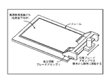
実施形態のピクセルアレイ医療デバイスはPADキットを含む。図1は、実施形態の下、標的部位に配置したPADキットを示す。PADキットは、平坦な有孔案内プレート(案内プレート)、スカルペットアレイを含むスカルペットパンチ又はスカルペットデバイス(図1~3参照)、裏打ちした粘着性薄膜又は粘着性基板(図4参照)、及び皮膚ピクセル切離ブレード(図5参照)を備えるが、これに限定しない。実施形態のスカルペットパンチはハンドル付きデバイスであるが、これに限定しない。案内プレートは、本明細書で詳細に説明するように、代案的実施形態では随意的なものである。 The pixel array medical device of the embodiment includes a PAD kit. FIG. 1 shows a PAD kit placed at a target site under an embodiment. The PAD kit includes a flat perforated guide plate (guide plate), a sculpt punch or scullpet device containing a scullpet array (see FIGS. 1-3), a lined adhesive thin film or adhesive substrate (see FIG. 4). And provided with, but not limited to, a skin pixel detachment blade (see FIG. 5). The skull pet punch of the embodiment is a device with a handle, but is not limited to this. The guide plate is optional in the alternative embodiment, as described in detail herein.
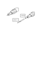
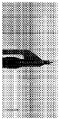
図2は、実施形態によるスカルペットアレイを有するPADキットのスカルペットパンチの断面を示す斜視図である。スカルペットアレイは1つ又はそれ以上のスカルペットを有する。図3は、実施形態によるスカルペットアレイを有するPADキットのスカルペットパンチの部分断面図である。この部分断面図は、スカルペットアレイにおけるスカルペットアレイの全長が、有孔案内プレートの厚さ及び皮膚内への切開深さによって決定されることを示すが、これに限定するものではない。 FIG. 2 is a perspective view showing a cross section of a skull pet punch of a PAD kit having a skull pet array according to an embodiment. The skull pet array has one or more skull pets. FIG. 3 is a partial cross-sectional view of a skull pet punch of a PAD kit having a skull pet array according to an embodiment. This partial cross-sectional view shows, but is not limited to, the overall length of the skull pet array in the skull pet array is determined by, but is not limited to, the thickness of the perforated guide plate and the depth of the incision into the skin.
図4は、実施形態によるPADキットに含まれる裏打ちを有する粘着性薄膜(粘着性基板)を示す。粘着性薄膜下面は標的部位の切開される皮膚に当接する。 FIG. 4 shows an adhesive thin film (adhesive substrate) having a backing included in the PAD kit according to the embodiment. The lower surface of the adhesive thin film abuts on the incised skin at the target site.
図5は、実施形態によるPADキットフレーム及びブレードアセンブリに使用するときの粘着性薄膜を示す。粘着性薄膜の頂面は、粘着性側面がフレーム内の下向きになるよう指向させ、また次に有孔プレート上に押し付け、本明細書でプラグ又は皮膚プラグとも称される、押し出される皮膚ピクセルを捕捉するようにする。 FIG. 5 shows an adhesive thin film when used in a PAD kit frame and blade assembly according to an embodiment. The top surface of the adhesive thin film is oriented with the adhesive side facing down in the frame and then pressed onto a perforated plate to extrude skin pixels, also referred to herein as plugs or skin plugs. Try to capture.
図1につき説明すると、有孔案内プレートは、PADキットを使用する処置中に皮膚切除/ドナー部位に当接する。スカルペットパンチは、皮膚ピクセルを切開するよう、有孔案内プレートにおける少なくとも1組の孔セットに当接させる。スカルペットパンチは、パンチのスカルペットアレイが案内プレートの孔の総数より少ない数のスカルペットしかないとき、多数の孔セットまで数回当接させる。スカルペットパンチの1つ又はそれ以上の順次の当接後、切開された皮膚ピクセル又はプラグは粘着性基板に捕捉される。このとき、粘着剤が押し出される皮膚ピクセル又はプラグを捕捉するように、粘着性基板を当接される。実施例のように、実施形態の粘着性基板の頂面は、粘着性側面がフレーム内で下向きになるよう指向させ、また次に有孔プレート上に押し付け、押し出される皮膚ピクセル又は皮膚プラグを捕捉するようにする。薄膜を引っ張り上げるとき、捕捉した皮膚ピクセルは切離ブレードによって底部で切離される。 As described in FIG. 1, the perforated guide plate abuts the skin excision / donor site during the procedure using the PAD kit. The scullpet punch abuts at least one set of holes in the perforated guide plate so as to make an incision in the skin pixel. The skull pet punch contacts a large number of hole sets several times when the punch's skull pet array has fewer skull pets than the total number of holes in the guide plate. After one or more sequential abutments of the sculpt punch, the incised skin pixel or plug is captured by the adhesive substrate. At this time, the adhesive substrate is abutted so as to capture the skin pixel or plug from which the adhesive is extruded. As in the embodiment, the top surface of the adhesive substrate of the embodiment is oriented so that the adhesive side faces downward in the frame and then pressed onto the perforated plate to capture the extruded skin pixel or skin plug. To do. When pulling up the thin film, the captured skin pixels are dissected at the bottom by the dissociation blade.
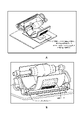
図6は、実施形態による皮膚ピクセルの除去を示す。粘着性基板は標的部位から引き上げかつ後方に移動させ、このことは切開した皮膚ピクセル又は皮膚プラグを持ち上げる又は引っ張る。粘着性基板を引っ張り上げるにつれて、切離ブレードを使用して切開された皮膚ピクセルの底部を切離する。図7は、実施形態によるPADキットによる、切開された皮膚ピクセルのブレード切離及び取出し状況の側面図である。ピクセル摘出は、皮膚ピクセル又は皮膚プラグの底部の切離で完了する。図8は、実施形態によるPADキットを使用する処置中におけるブレード/ピクセル相互作用状況の等角斜視図である。図9は、実施形態によるPADキットを使用する他の図であり(分かり易くするためブレードは省いている)、切離かつ捕捉された摘出皮膚ピクセル又はプラグ、及び切離前の非切離皮膚ピクセル又はプラグの双方を示す。ドナー部位は、Flexan(登録商標)シートを当接して閉合する。 FIG. 6 shows the removal of skin pixels by embodiment. The adhesive substrate is pulled up and moved backwards from the target site, which lifts or pulls the incised skin pixel or skin plug. As the adhesive substrate is pulled up, an incision blade is used to cut off the bottom of the incised skin pixel. FIG. 7 is a side view of the blade dissection and removal of the incised skin pixel by the PAD kit according to the embodiment. Pixel extraction is completed by dissection of the skin pixel or the bottom of the skin plug. FIG. 8 is an equiangular perspective view of the blade / pixel interaction situation during the procedure using the PAD kit according to the embodiment. FIG. 9 is another diagram using the PAD kit according to the embodiment (blades omitted for clarity), with excised and captured skin pixels or plugs, and undissected skin before dissection. Indicates both pixels or plugs. The donor site is closed by abutting the Flexan® sheet.
案内プレート及びスカルペットデバイスは、さらに、被移植部位における皮膚欠陥をも生ずる。皮膚欠陥は、ドナー部位で摘出又は捕捉した皮膚ピクセルを受け止めるよう構成される。被移植部位に使用される案内プレートは、ドナー部位に使用されたのと同一の案内プレートとすることができる、又は異なる孔パターン若しくは異なる孔構成を有するよう異なるものとすることができる。 Guide plates and skull pet devices also cause skin defects at the site of transplantation. Skin defects are configured to receive skin pixels removed or captured at the donor site. The guide plate used at the site to be transplanted can be the same guide plate used at the donor site, or can be different to have different hole patterns or different hole configurations.
切離中に粘着性基板上に定置された皮膚ピクセル又はプラグは、皮膚欠陥部位(被移植部位)に移転され、この場合、被移植皮膚欠陥部位でピクセル化された皮膚移植片として当接される。粘着性基板は弾性反跳特性を有し、皮膚移植片内に皮膚ピクセル又はプラグをより密接して整列させることができる。切開した皮膚ピクセルは、粘着性基板から直接被移植部位における皮膚欠陥に当接することができる。切開された皮膚ピクセルの被移植部位への当接は、切開された皮膚ピクセルの皮膚欠陥に対する整列するステップと、及び切開された皮膚ピクセルの被移植部位における対応する皮膚欠陥部内への挿入ステップとを含む。 The skin pixel or plug placed on the adhesive substrate during dissection is transferred to the skin defect site (implanted site), in which case it is abutted as a pixelated skin graft at the transplanted skin defect site. To. The adhesive substrate has elastic recoil properties and allows skin pixels or plugs to be more closely aligned within the skin graft. The incised skin pixel can abut the skin defect at the site to be implanted directly from the adhesive substrate. The abutment of the incised skin pixel to the implant site is a step of aligning the incised skin pixel to the skin defect and a step of inserting the incised skin pixel into the corresponding skin defect site at the implant site. including.
実施形態のピクセルアレイ医療デバイスはピクセルアレイ採皮刀(PAD:Pixel Array Dermatome)を備える。PADは、基板(例えば、運用プレート)に固定される比較的小さい円形のスカルペットの平坦なアレイを備え、また基板と組み合わさるスカルペットは、スカルペットアレイ、ピクセルアレイ、又はスカルペットプレートと称される。図10Aは、実施形態による運用プレートに固定したスカルペットを示すピクセルアレイの一部分の側面図である。図10Bは、他の実施形態による運用プレートに固定したスカルペットを示すピクセルアレイの一部分の側面図である。図10Cは、実施形態によるスカルペットプレートの平面図である。図10Dは、実施形態によるスカルペットプレートの一部分の拡大平面図である。スカルペットプレートは皮膚表面に直接当接する。スカルペットアレイにおける1つ又はそれ以上のスカルペットは、尖頭表面、ニードル、及び複数尖端を有するニードルを有する。 The pixel array medical device of the embodiment comprises a Pixel Array Dermatome (PAD). The PAD comprises a flat array of relatively small circular skull pets that are secured to a substrate (eg, an operational plate), and the skull pet that is combined with the substrate is referred to as a skull pet array, pixel array, or skull pet plate. Will be done. FIG. 10A is a side view of a portion of a pixel array showing a skull pet fixed to an operational plate according to an embodiment. FIG. 10B is a side view of a portion of a pixel array showing a skull pet fixed to an operational plate according to another embodiment. FIG. 10C is a plan view of the skull pet plate according to the embodiment. FIG. 10D is an enlarged plan view of a part of the scullpet plate according to the embodiment. The skull pet plate comes into direct contact with the skin surface. One or more skull pets in the skull pet array have a tip surface, a needle, and a needle with multiple tips.
ピクセルアレイ医療デバイス及び方法の実施形態は、案内プレートの代わりに摘出パターンを使用する。摘出パターンは、ドナー部位及び被移植部位のうち少なくとも一方における皮膚表面にインジケータ又はマーカーを含むが、これに限定するものではない。マーカーは、皮膚面域にマーク付けするよう皮膚に直接塗布できる任意な化合物を含む。摘出パターンはドナー部位に位置決めし、またデバイスのスカルペットアレイはドナー部位における摘出パターンに整列又は従うようにする。皮膚ピクセルは、本明細書記載のスカルペットアレイによりドナー部位で切開される。被移植部位は、摘出パターンを被移植部位に位置決めすることによって準備する。被移植部位に使用される摘出パターンは、ドナー部位に使用されるのと同一の摘出パターンとすることができる、又は異なるパターン若しくは構成のマーカーによる異なるものとすることができる。本明細書記載のように、皮膚欠陥を生成し、また切開した皮膚ピクセルを被移植部位に当接する。代案として、実施形態の案内プレートを摘出パターンに当接させた状態で使用するが、これに限定するものではない。 Pixel array medical device and method embodiments use extraction patterns instead of guide plates. The extraction pattern includes, but is not limited to, an indicator or marker on the skin surface at at least one of the donor site and the transplanted site. Markers include any compound that can be applied directly to the skin to mark areas of the skin surface. The extraction pattern is positioned at the donor site and the scullpet array of the device is aligned with or follows the extraction pattern at the donor site. Skin pixels are incised at the donor site by the sculpt array described herein. The site to be transplanted is prepared by positioning the excision pattern at the site to be transplanted. The extraction pattern used for the site to be transplanted can be the same extraction pattern used for the donor site, or can be different due to different patterns or constituent markers. As described herein, it creates a skin defect and also abuts the incised skin pixel to the site to be implanted. As an alternative, the guide plate of the embodiment is used in a state of being in contact with the extraction pattern, but the present invention is not limited to this.
確立された医療器具を活用するため、実施形態のアレイは、パジェット式採皮刀又はリース式採皮刀のように、ドラム式採皮刀と組み合わせて、又はドラム式採皮刀に変更して使用する。本明細書に言及するパジェットドラム式採皮刀は、元々1930年代にアール・パジェット博士によって開発されたもので、世界中の形成外科医師達が皮膚移植に広く利用され続けている。その後、摘出される皮膚移植片の厚さをよりよく較正するよう、パジェット式採皮刀に対するリース氏の変更が開発された。実施形態のドラム式採皮刀は、1回使用の使い捨て(1回の処置あたり)であるが、これに限定するものではない。 In order to utilize the established medical equipment, the array of embodiments is combined with a drum-type skin sword, such as a padget-type skin sword or a wreath-type skin sword, or changed to a drum-type skin sword. use. The paget drum type skin graft referred to herein was originally developed by Dr. Earl Padgett in the 1930s and continues to be widely used by plastic surgeons around the world for skin grafts. Later, Mr. Reese's modification to the Paget-type skin graft was developed to better calibrate the thickness of the skin graft to be removed. The drum-type skin-removing sword of the embodiment is disposable for one-time use (per treatment), but is not limited thereto.
概して、図11Aは実施形態による転動ピクセルドラム100の実施例を示す。図11Bは実施形態によるハンドルに組み付けた転動ピクセルドラム100の実施例を示す。図11Cは実施形態によるスカルペットプレートに使用するためのドラム式採皮刀を示す。
In general, FIG. 11A shows an example of a rolling
概して、本明細書記載のすべてのピクセルデバイスと同様に、ピクセルドラム100の幾何学的形状は、制限なく種々の形状、例えば、円形、半円形、楕円形、正方形、平坦又は正方形とすることができる。幾つかの実施形態において、ピクセルドラム100は、心軸/ハンドルアセンブリ102によって支持し、また例えば、電動モータによって作動するドラム回転コンポーネント104の周りに回転する。幾つかの実施形態において、ピクセルドラム100は、使用しないときスタンド(図示せず)上に配置することができ、このスタンドは、ドラムの作動回転コンポーネントに対する又はシリンジプランジャの作動コンポーネントに対するバッテリー充電器として機能することもできる。幾つかの実施形態において、真空(図示せず)をピクセルドラム100の皮膚表面に印加することができ、またアウトリガー(図示せず)を展開し、ピクセルドラム100のトラッキング及び安定性をよくするようにすることができる。
In general, like all pixel devices described herein, the geometry of the
幾つかの実施形態において、ピクセルドラム100は、ドラム100の表面にスカルペット106のアレイを組み込み、本明細書で皮膚プラグと称される複数の小さい(例えば、0.5~1.5mm)円形切開部を生ずるようにする。幾つかの実施形態において、スカルペットの境界ジオメトリ(幾何学的形状)は、皮膚プラグを生成するとともに、ピンクッション動作(「トラップドア」)を減少するよう設計することができる。各皮膚プラグの周長は、円形皮膚プラグの代わりにスカルペットによって長くすることができ、例えば、非限定的例として半円形、楕円形、正方形の皮膚プラグにすることができる。幾つかの実施形態において、スカルペット106の長さは、皮膚移植目的のために外科医が選択した皮膚面域の厚さ、すなわち、分層厚さ又は全層厚さに基づいて変化し得る。
In some embodiments, the
ドラム100を皮膚表面に当接させるとき、ドラムの内部に配置されるブレード108がスカルペットアレイによって生じた各皮膚プラグの底部を切離し、この場合、ブレード108は、中心のドラム心軸/ハンドルアセンブリ102に連結する及び/又は中心の心軸アセンブリ102に取り付けたアウトリガーに連結する。幾つかの代案的実施形態においては、皮膚切開の底部を切離する内部ブレード108はドラム心軸/ハンドルアセンブリ102に連結しない。幾つかの実施形態において、ピクセルドラム100の内部ブレード108は、手動又は電動モータによる動力で周期振動することができる。ドラム上における円形スカルペットの密度に基づいて、皮膚の可変割合(例えば、20%、30%、40%等々)を過剰な皮膚弛緩面域内で切離することができる。
When the
幾つかの実施形態において、皮膚移植操作を実施するようピクセルドラム摘出器112をドラム100の内部に追加して配置し、この皮膚移植操作実施は、ピクセルドナー組織からの切離/ピクセル化皮膚切開/プラグ(ピクセル移植片)を、ピクセルドラム100の内部に内張りした粘着性薄膜110に摘出及び整列させることによって行う。スカルペットアレイ106と粘着性薄膜110との間に内部ブレード108のための狭い隙間を生ずる。
In some embodiments, a
実施形態において、ブレード108は、切開した円形皮膚プラグの底部を切離する場合に、ドラム100及びスカルペットアレイ106の外部に配置する。他の実施形態において、外部ブレード108は、皮膚切開部の底部を切離するとき、ドラム心軸アセンブリ102に連結する。他の実施形態において、外部ブレード108は、皮膚切開部の底部を切離するときに、ドラム心軸アセンブリ102に連結しない。切離皮膚セグメントを押し出しまた整列する粘着性薄膜110は、後で患者の皮膚欠陥部位上に配置する。ブレード108(内部又は外部のいずれか)は、スカルペットアレイ106に整列したブレードの有窓層とすることができるが、これに限定するものではない。
In an embodiment, the
実施形態の順応可能な粘着性薄膜110は、整列した切離皮膚セグメント付きの薄膜をドラムから取り出しまた皮膚移植片として当接するとき、被移植皮膚欠陥部での排膿(ドレナージ)を可能にする半多孔質とすることができる。粘着性半多孔質のドラム状薄膜110は、移植のための切離/ピクセル化皮膚プラグを一斉に被移植の皮膚欠陥部位に送り出す弾性反跳特性を有することができ、すなわち、ピクセル化移植片付きの粘着性薄膜をドラム100から取り出した後より均一なシートとして、各皮膚プラグの周縁がより密に接近することができる。代案として、粘着性半多孔質ドラム状薄膜110は、非移植者の皮膚欠陥部位における大きな表面積をカバーするよう拡張することができる。幾つかの実施形態において、粘着性裏打ちシート112を粘着性薄膜110とドラム状摘出器112との間に塗布することができる。ドラム状スカルペットアレイ106、ブレード108、及び粘着性薄膜110は、本明細書に詳細に記載するような既存のドラム100に対してスリーブとして一緒に組み付けることができる。
The adaptable adhesive
実施形態のピクセルドラム110における内部ドラム状摘出器112は、使い捨て可能かつ交換可能である。使い捨てコンポーネントの使用に対する制限及び/又は制御は、以下に限定しないが、電子的、EPROM、機械的な、耐久性のある手段によって達成することができる。電子的及び/又は機械的な記録及び/又は使い捨てドラム用のドラム回転数制限、並びに使い捨てドラムの使用時間を、電子的若しくは機械的に記録、制御及び/又は制限することができる。
The
ドラム式採皮刀での処置における摘出部分中に、PADスカルペットアレイは皮膚表面に直接当接する。皮膚ピクセルを周方向に切開するため、ドラム式採皮刀はスカルペットアレイ上に位置決めし、下方の皮膚表面に対して荷重を加える。持続する荷重により、切開された皮膚ピクセルがスカルペットアレイの孔から押し出され、ドラム式採皮刀における粘着性薄膜上に捕捉される。採皮刀の切断アウトリガーブレード(スカルペットアレイ上に位置決めされる)は押し出された皮膚ピクセルの底部を切離する。薄膜及びピクセル化した皮膚複合体はこの後採皮刀ドラムから取り出し、皮膚移植片として被移植皮膚欠陥部に直接当接する。 During the excision portion of the drum-type skin sword procedure, the PAD scullpet array is in direct contact with the skin surface. To make a circumferential incision in the skin pixel, the drum-type skin sword is positioned on the scullpet array and applies a load to the underlying skin surface. The sustained load pushes the incised skin pixels out of the holes in the scullpet array and captures them on the adhesive thin film in a drum-type sword. Cutting the skinning sword The outrigger blade (positioned on the skull pet array) cuts off the bottom of the extruded skin pixel. The thin film and the pixelated skin complex are then removed from the skin graft drum and directly abutted on the skin graft defect as a skin graft piece.
図11Cにつき説明すると、実施形態は、本明細書記載のようにスカルペットプレートに使用するためのドラム式採皮刀を備える。より具体的には、図12Aは、実施形態によるスカルペットプレート上にドラム式採皮刀を位置決めする状況を示す。図12Bは、実施形態によるスカルペットプレート上にドラム式採皮刀を位置決めする他の角度から見た状況を示す。ドラム式採皮刀の切断アウトリガーブレードは、押し出された皮膚プラグを底部で切離するスカルペットアレイの頂部に位置決めする。 Explaining with reference to FIG. 11C, embodiments include a drum-type skinning sword for use with a scullpet plate as described herein. More specifically, FIG. 12A shows a situation in which a drum-type skin-picking sword is positioned on a skull pet plate according to an embodiment. FIG. 12B shows a situation seen from another angle in which the drum-type skin-removing sword is positioned on the skull pet plate according to the embodiment. The cutting outrigger blade of the drum-type sword is positioned at the top of the skull pet array, which dissects the extruded skin plug at the bottom.
図13Aは、実施形態による、ドラム式採皮刀(例えば、パジェット式採皮刀)をスカルペットプレート上に当接した等角斜視図であり、粘着性薄膜は、運用プレート上で転動する前に採皮刀のドラムに付着する。図13Bは、実施形態による、ドラム式採皮刀の一部の側面図であり、スカルペットプレートに対するブレード位置を示す。図13Cは、実施形態による、ドラム式採皮刀の一部の側面図であり、スカルペットプレートに対する異なるブレード位置を示す。図13Dは、実施形態による、ドラム式採皮刀の一部の側面図であり、スカルペットプレートに対する他のブレード位置を示す。図13Eは、実施形態による、切離ブレードクリップを有するドラム式採皮刀の側面図であり、ブレードクリップによって皮膚ピクセルを切離する状況を示す。図13Fは、実施形態による、スカルペットプレートとともにドラム式採皮刀の底面図を示す。図13Gは、実施形態による、スカルペットプレートとともにドラム式採皮刀の正面図を示す。図13Hは、実施形態による、スカルペットプレートとともにドラム式採皮刀の背面図を示す。 FIG. 13A is an equiangular perspective view of a drum-type skin-collecting sword (for example, a paget-type skin-collecting sword) abutting on a skull pet plate according to an embodiment, and the adhesive thin film rolls on the operation plate. Before sticking to the drum of the sword. FIG. 13B is a side view of a part of the drum type skin collecting sword according to the embodiment, and shows the blade position with respect to the skull pet plate. FIG. 13C is a side view of a portion of the drum-type skinning sword according to the embodiment, showing different blade positions with respect to the scullpet plate. FIG. 13D is a side view of a part of the drum-type skin-picking sword according to the embodiment, showing other blade positions with respect to the scullpet plate. FIG. 13E is a side view of a drum-type skinning sword having a cutting blade clip according to an embodiment, showing a situation in which a skin pixel is cut by a blade clip. FIG. 13F shows a bottom view of a drum-type skin collecting sword together with a skull pet plate according to an embodiment. FIG. 13G shows a front view of a drum-type skin-picking sword together with a skull pet plate according to an embodiment. FIG. 13H shows a rear view of a drum-type skin collecting sword together with a skull pet plate according to an embodiment.
臨床的用途に基づいて、ドラム式採皮刀の使い捨て粘着性薄膜は、切除した弛緩皮膚の沈着/廃棄、又はピクセル化皮膚移植片の摘出/整列に使用することができる。 Based on clinical use, the disposable adhesive thin film of the drum-type skin graft can be used for depositing / discarding excised loose skin or removing / aligning pixelated skin grafts.
本明細書記載の実施形態は、採皮刀、例えば、パジェット式採皮刀及びリース式採皮刀に使用するためのピクセル上張りスリーブ(POS)も含む。図14Aは、実施形態によるピクセル上張りスリーブ(POS)を有する採皮刀の組立て図を示す。POSは、採皮刀及び粘着性裏打ちを組み込んだブレード、粘着剤、並びにスカルペットアレイを有する。粘着性裏打ち、接着剤及びスカルペットアレイは、デバイスとして一体化するが、これに限定するものではない。図14Bは、実施形態によるピクセル上張りスリーブ(POS)を有する採皮刀の分解図を示す。図14Cは、実施形態によるピクセル上張りスリーブ(POS)を有する採皮刀の一部を示す。 The embodiments described herein also include a pixel overlay sleeve (POS) for use in skinning swords, such as padgett type skinning swords and wreath type skinning swords. FIG. 14A shows an assembled view of a sword with a pixel overlay sleeve (POS) according to an embodiment. The POS has a blade incorporating a sword and an adhesive lining, an adhesive, and a sculpt array. The adhesive lining, adhesive and sculpt array are integrated as a device, but are not limited to this. FIG. 14B shows an exploded view of a sword with a pixel overlay sleeve (POS) according to an embodiment. FIG. 14C shows a portion of a sword with a pixel overlay sleeve (POS) according to an embodiment.
「スリーブ」とも称されるPOSは、余剰弛緩皮膚の部分切除及び皮膚欠陥における分散皮膚移植のための使い捨てドラム式採皮刀上張りを提供する。上張りスリーブは、パジェット式採皮刀及びリース式採皮刀と関連して1回使用の使い捨てコンポーネントとして使用される。実施形態のPOSは、ドラム式採皮刀に滑り込ませる3面スリップオン使い捨てスリーブである。デバイスは、粘着性薄膜と、内部切離ブレードを有するスカルペットドラムアレイとを有する。実施形態における切離ブレードは、スカルペットドラムアレイの内面に沿って掃過する片面切断表面を有する。 The POS, also referred to as the "sleeve," provides a disposable drum-type skin graft overlay for partial excision of excess loose skin and dispersed skin grafts in skin defects. The lining sleeve is used as a one-time-use disposable component in connection with Padgett and Reese swords. The POS of the embodiment is a three-sided slip-on disposable sleeve that slides into a drum-type skin-picking sword. The device has an adhesive thin film and a sculpt drum array with internal decoupling blades. The disengagement blade in the embodiment has a single-sided cut surface that is swept along the inner surface of the scullpet drum array.
他のブレードの実施形態において、有窓切断層はスカルペットアレイの内面をカバーする。切断表面を有する各窓は、各個別のスカルペットに整列する。皮膚プラグの底部を切離する掃過運動の代わりに、有窓切断層はスカルペットドラムアレイ上で周期振動する。粘着性薄膜とスカルペットアレイとの間における狭い隙間はブレードの偏位運動のために形成する。皮膚移植処置中に多数回摘出のために、追加の粘着性薄膜用の挿入溝孔を設ける。粘着性薄膜上の保護層を、スリーブアセンブリの反対側の取出し溝孔から引っ張る細長い取出しタブによりその場で剥がし取る。他のピクセルデバイスの実施形態のように、粘着性薄膜は、皮膚移植皮膚欠陥部位でのドレナージのために半多孔質とする。ピクセル化皮膚移植片をより連続したシート状に変形させるため、薄膜には弾性反跳特性を持たせ、皮膚移植片内で皮膚プラグをより密に整列させることができるようにする。 In other blade embodiments, the windowed cutting layer covers the inner surface of the scullpet array. Each window with a cut surface is aligned with each individual skull pet. Instead of a sweeping motion that cuts off the bottom of the skin plug, the windowed cutting layer oscillates periodically on the skull pet drum array. A narrow gap between the adhesive thin film and the sculpt array is formed due to the displacement motion of the blade. Insertion grooves for additional adhesive thin films are provided for multiple excisions during skin graft procedures. The protective layer on the adhesive thin film is stripped in place by an elongated take-out tab that pulls from the take-out groove on the opposite side of the sleeve assembly. As in other pixel device embodiments, the adhesive thin film is semi-porous for drainage at the site of skin graft skin defects. In order to deform the pixelated skin graft into a more continuous sheet, the thin film is given elastic rebound properties, allowing the skin plugs to be more closely aligned within the skin graft.
本明細書記載の実施形態は、パジェット式採皮刀又はリース式採皮刀のいずれかで1回使用の使い捨てデバイスとして構成したスリップオンPADを含む。図15Aは、実施形態によるパジェット式ドラム採皮刀上に滑り込ませようとしているスリップオンPADを示す。図15Bは、実施形態によるパジェット式ドラム採皮刀上に設置したスリップオンPADを示す。 The embodiments described herein include a slip-on PAD configured as a single-use disposable device with either a padgett or wreath sword. FIG. 15A shows a slip-on PAD attempting to slide onto a padget-type drum sword according to an embodiment. FIG. 15B shows a slip-on PAD installed on a padget-type drum skinning sword according to the embodiment.
実施形態のスリップオンPADは有孔案内プレートと組み合わせて使用する(随意的に)。図16Aは、実施形態によるパジェット式ドラム採皮刀上に設置し、また有孔型板(テンプレート)又は案内プレートとともに使用されるスリップオンPADを示す。有孔案内プレートは、標的皮膚部位上に配置し、また向きを維持するようエプロンの底面における粘着剤で所定位置に保持する。スリップオンPADを有するパジェット式採皮刀は皮膚における有孔案内プレート上で転動する。 The slip-on PAD of the embodiment is used in combination with a perforated guide plate (optionally). FIG. 16A shows a slip-on PAD installed on a padget-type drum sword according to an embodiment and also used with a perforated plate (template) or guide plate. The perforated guide plate is placed on the target skin site and held in place with an adhesive on the bottom of the apron to maintain orientation. A paddet-type skinning sword with a slip-on PAD rolls on a perforated guide plate in the skin.
図16Bは、実施形態によるパジェット式ドラム採皮刀及び設置したスリップオンPADにより摘出している皮膚ピクセルを示す。皮膚ピクセル摘出のために、スリップオンPADを取り外し、粘着テープをパジェット式採皮刀のドラム上に付着し、またクリップオン式ブレードを採皮刀のアウトリガーアームに設置し、この後、このブレードを使用して皮膚ピクセルの底部を切離する。実施形態のスリップオンPADは、さらに、(随意的に)リボンリトラクターのような標準外科手術器具にも使用し、ドナー部位の隣接皮膚を保護する。 FIG. 16B shows skin pixels removed by a Padgett drum skinning sword and an installed slip-on PAD according to an embodiment. For skin pixel extraction, the slip-on PAD was removed, adhesive tape was attached onto the drum of the padget-type sword, and a clip-on blade was placed on the outrigger arm of the sword, after which the blade was attached. Use to cut off the bottom of the skin pixel. The slip-on PAD of the embodiment is also used (optionally) in standard surgical instruments such as ribbon retractors to protect the skin adjacent to the donor site.
本明細書記載のピクセル器具の実施形態は、1回使用の使い捨て器具又はデバイスであるピクセルドラム式採皮刀(PD2)を含む。PD2は、ハンドルに連結したシリンダ又は転動/回転ドラムを有し、このシリンダはスカルペットドラムアレイを有する。内部ブレードはドラム心軸/ハンドルアセンブリに相互連結する、及び/又は中心の心軸に取り付けたアウトリガーに相互連結する。本明細書記載のPAD及びPOSのように、皮膚の小さい複数ピクセル化切除は、皮膚弛緩領域で直接実施し、これにより目に見える瘢痕化を最小限にして皮膚引き締めの効果を向上させる。 Embodiments of the pixel device described herein include a single-use disposable device or device, a pixel drum type skin sword (PD2). The PD2 has a cylinder or rolling / rotating drum connected to a handle, which cylinder has a sculpt drum array. The internal blades interconnect to the drum axle / handle assembly and / or to the outriggers attached to the central axle. Similar to the PADs and POS described herein, small multi-pixel resections of the skin are performed directly in the cutis laxa area, thereby minimizing visible scarring and improving the effect of skin tightening.
図17Aは、実施形態による皮膚表面の標的部位に当接しているピクセルドラム採皮刀の実施例を示す。図17Bは、実施形態による皮膚表面の標的部位に当接しているピクセルドラム採皮刀の一部分における他の図を示す。 FIG. 17A shows an example of a pixel drum sword that is in contact with a target site on the skin surface according to the embodiment. FIG. 17B shows another view of a portion of a pixel drum sword abutting on a target site on the skin surface according to an embodiment.
PD2デバイスは皮膚表面に対してフルに転動/回転するドラムに適用し、「スカルペットドラムアレイ」により標的部位に複数の小さい(例えば、1.5mm)円形切開部を形成する。次に各皮膚プラグの底部を内部ブレードにより切離し、この内部ブレードは、中心のドラム心軸/ハンドルアセンブリに相互連結する、及び/又は中心の心軸に取り付けたアウトリガーに相互連結する。ドラムにおける円形スカルペットの密度に基づいて、皮膚の切除割合が変化することができる。PD2は皮膚の表面積の部分(例えば、20%、30%、40%等々)を過剰皮膚弛緩面域において目に見える瘢痕化がなく切除できるが、実施形態はこれに限定するものではない。 The PD2 device is applied to a drum that rolls / rotates fully with respect to the skin surface, forming multiple small (eg, 1.5 mm) circular incisions at the target site by a "skull pet drum array". The bottom of each skin plug is then dissected by an internal blade, which interconnects with a central drum core / handle assembly and / or with an outrigger attached to the central core. The rate of skin excision can vary based on the density of circular skull pets on the drum. PD2 can excise a portion of the surface area of the skin (eg, 20%, 30%, 40%, etc.) without visible scarring in the excess cutis laxa area, but embodiments are not limited to this.
本明細書記載のピクセル器具における他の代替的実施形態はピクセルドラム摘出器(PDH:Pixel Drum Harvester)である。ピクセルドラム採皮刀と同様に、追加した内部ドラムは、皮膚のピクセル化切除部を摘出し、また後に患者の被移植皮膚欠陥部位上に配置される粘着性薄膜に整列させる。順応する粘着性薄膜は、整列する切除皮膚セグメントを有する薄膜をドラムから取り出して皮膚移植片として当接するとき、被移植皮膚欠陥部のドレナージを可能にする半多孔質である。薄膜の弾性反跳特性によれば、部分的にピクセル化皮膚移植片を変換させるピクセル化皮膚セグメントを、被移植部位におけるシート状移植片により密に近似させる。 Another alternative embodiment of the pixel instrument described herein is a Pixel Drum Harvester (PDH). Similar to the pixel-drum skin graft, the added internal drum removes the pixelated excision of the skin and aligns it with an adhesive thin film that is later placed on the patient's site of the skin graft. The adaptable adhesive thin film is semi-porous, which allows drainage of the skin graft defect when the thin film with aligned excised skin segments is removed from the drum and abutted as a skin graft. The elastic rebound properties of the thin film allow the pixelated skin segments that partially transform the pixelated skin graft to be more closely approximated by the sheet-like graft at the site to be implanted.
本明細書記載のピクセルアレイによる医療用のシステム、器具又はデバイス、及び方法は、得られる臨床的転帰に不可避の細胞反応及び/又は細胞外反応を喚起又は可能にする。ピクセル採皮刀に関して、皮膚の表面積の物理的減少は、皮膚のピクセル化切除、すなわち皮膚プラグに起因して生ずる。さらに、皮膚のその後の引き締めは、遅発性創傷治癒反応に起因する結果として生ずる。各ピクセル化切除は、本明細書に詳述するように不可避の創傷治癒シーケンスを開始する。 Pixel array medical systems, instruments or devices, and methods described herein evoke or enable unavoidable cellular and / or extracellular responses to the resulting clinical outcome. With respect to the pixelated sword, the physical reduction in the surface area of the skin results from the pixelated excision of the skin, i.e. the skin plug. In addition, subsequent tightening of the skin results from a delayed wound healing response. Each pixelated resection initiates an unavoidable wound healing sequence as detailed herein.
このシーケンスの第1フェーズは、肥満(マスト)細胞の脱顆粒がヒスタミンを「創傷(wound)」内に放出する炎症フェーズである。ヒスタミン放出は毛細血管床の膨張を喚起し、また細胞外空間への血管透過性を亢進させることができる。この初期創傷治癒反応は創傷初日以内で生じ、また皮膚表面に紅斑として現れる。 The first phase of this sequence is the inflammatory phase in which degranulation of mast cells releases histamine into the "wound". Histamine release can evoke swelling of the capillary bed and increase vascular permeability to extracellular space. This initial wound healing reaction occurs within the first day of the wound and also appears as erythema on the surface of the skin.
第2フェーズ(線維増殖の)は「創傷」の3~4日以内で始まる。このフェーズ中、線維芽細胞の移転及び有糸分裂増殖がある。創傷の線維増殖は、新生コラーゲンの沈着及び創傷の筋線維芽細胞収縮を含む。 The second phase (of fibrosis) begins within 3-4 days of the "wound". During this phase there is fibroblast transfer and mitotic proliferation. Wound fibroblast proliferation involves the deposition of neoplastic collagen and the contraction of myofibroblasts in the wound.
組織学的には、新生コラーゲンの沈着は、真皮の圧密化及び肥大化として顕微鏡で識別することができる。このことは静的プロセスであるが、創傷の引張強度は相当増大する。線維増殖の他の特徴は、結果として創傷の多次元収縮を生ずる動的身体プロセスである。線維増殖のこの要素的特徴は、筋線維芽細胞の活性細胞収縮に起因する。形態学的には、創傷の筋線維芽細胞収縮は、皮膚表面における2次元引き締めとして見えるようになる。全体として、線維増殖の効果は、引き締まった下部構造を有する新生コラーゲンの静的支持足場の沈着を伴う皮膚性拘縮である。この臨床的効果は、数か月間にわたる皮膚の肌理における平滑化を伴う皮膚の遅発性引き締めとして実現する。臨床的エンドポイント(終着点)は、治療面域のより若く見える皮膚エンベロープである。 Histologically, the deposition of neoplastic collagen can be microscopically identified as consolidation and hypertrophy of the dermis. Although this is a static process, the tensile strength of the wound is significantly increased. Another feature of fibrosis is the dynamic body process that results in multidimensional contraction of the wound. This elemental feature of fibroblasts is due to active cell contraction of myofibroblasts. Morphologically, the myofibroblast contraction of the wound becomes visible as a two-dimensional tightening on the surface of the skin. Overall, the effect of fibrosis is cutaneous contracture with the deposition of statically supporting scaffolds of neoplastic collagen with a toned substructure. This clinical effect is achieved as a delayed tightening of the skin with smoothing in the texture of the skin over several months. The clinical endpoint is the skin envelope that looks younger in the therapeutic area.
遅発性創傷治癒反応における第3の最終フェーズは成熟である。このフェーズ中には、コラーゲン原線維マトリクス(真皮の)における増加した架橋に起因する治療面域の強度増強及び再形成がある。この最終段階は、「創傷」後6~12か月以内で始まり、また少なくとも1~2年にも及ぶこともあり得る。皮膚の小さいピクセル化切除は、この遅発性創傷治癒プロセス中に正常な皮膚構造を保存するはずであり、一般的には外科手術による大きな皮膚切除で生ずる目立つ瘢痕の生成がない。最後に、表皮増殖ホルモンの放出からの表皮の関連した刺激及び活性化がある。遅発性創傷治癒反応は、最小限の既存コラーゲンマトリクスを有する組織(筋肉又は脂肪)内における瘢痕コラーゲン沈着で喚起され得る。 The third final phase of the delayed wound healing response is maturity. During this phase there is increased strength and remodeling of the therapeutic surface area due to increased cross-linking in the collagen fibril matrix (of the dermis). This final stage begins within 6-12 months after the "wound" and can be at least 1-2 years. Small pixelated excision of the skin should preserve normal skin structure during this delayed wound healing process, and generally does not produce the prominent scarring that results from large surgical excision. Finally, there is associated stimulation and activation of the epidermis from the release of epidermal proliferative hormones. The delayed wound healing response can be evoked by scar collagen deposition in tissue (muscle or fat) with minimal existing collagen matrix.
審美目的の皮膚引き締めの他に、本明細書記載のピクセルアレイによる医療用のシステム、器具又はデバイス、及び方法は、他の医療関連用途があり得る。幾つかの実施形態において、ピクセルアレイデバイスは、標準の外科手術切除に頼ることなく、任意な軟組織構造の可変部分を切離することができる。より具体的には、ピクセルアレイデバイスによる皮膚の紫外線で損傷した面域の縮小が皮膚がん発症率を減少させるはずである。睡眠時無呼吸及びいびきの治療に関して、ピクセルアレイデバイスによるピクセル化粘膜縮小(軟口蓋、舌根及び咽頭側壁)は、より標準的外科手術処置に関連する罹患率を大きく減少するであろう。膣円蓋の出産による損傷に関して、ピクセルアレイデバイスによるピクセル化した皮膚及び膣粘膜切除は、A&P切除に頼ることなく、正常な分娩前ジオメトリ及び機能を再確立するであろう。関連する女性ストレス性失禁も同様に修正できるであろう。 In addition to aesthetic skin tightening, the pixel array medical systems, instruments or devices, and methods described herein may have other medical uses. In some embodiments, the pixel array device is capable of dissecting variable portions of any soft tissue structure without resorting to standard surgical excision. More specifically, the reduction of UV-damaged surface areas of the skin by pixel array devices should reduce the incidence of skin cancer. For the treatment of sleep apnea and snoring, pixelated mucosal reduction (soft palate, tongue base and pharyngeal sidewall) with pixel array devices will significantly reduce the prevalence associated with more standard surgical procedures. For childbirth damage to the vaginal fornix, pixelated skin and vaginal mucosal resection with a pixel array device will reestablish normal prepartum geometry and function without resorting to A & P resection. Related female stress incontinence could be corrected as well.
本明細書でスカルペットデバイスアセンブリとも称される実施形態のピクセルアレイ採皮刀(PAD)は、パンチ衝撃ハンドピースとも称される制御デバイスを有するシステム又はキットと、チップデバイスとも称されるスカルペットデバイスとを備える。制御デバイスに着脱可能に連結されるスカルペットデバイスは、スカルペットデバイス内に位置決めしたスカルペットのアレイを有する。実施形態の着脱可能スカルペットデバイスは、使い捨て可能であり、またしたがって、1回の処置での使用として構成されるが、これに限定するものではない。 The pixel array skinning sword (PAD) of the embodiment, also referred to herein as a skull pet device assembly, is a system or kit having a control device also referred to as a punch impact handpiece and a skull pet also referred to as a chip device. Equipped with a device. The skull pet device detachably coupled to the control device has an array of skull pets positioned within the skull pet device. The removable skull pet device of the embodiment is disposable and is therefore configured for use in a single procedure, but is not limited thereto.
PADは、スカルペットデバイスを包含するよう構成したハウジングを備える装置を含む。スカルペットデバイスは、基板及びスカルペットアレイを有し、またスカルペットアレイは、基板上の構成体として配列した複数個のスカルペットを有する。基板及び複数個のスカルペットは、ハウジングから展開しまたハウジング内に収納されるよう構成し、また複数個のスカルペットは、展開されるとき標的部位に切開した複数の皮膚ピクセルを生ずるよう構成する。制御デバイスの基端部はハンドヘルドの構成とする。ハウジングは、制御デバイスのコンポーネントであるレシーバに着脱可能に連結するよう構成する。制御デバイスは、アクチュエータ機構を包含する基端部と、レシーバを包含する末端部とを有する。制御デバイスは使い捨てとするが、代案として、制御デバイスは、洗浄、消毒、及び殺菌のうち少なくとも1つを行うよう構成する。 The PAD includes a device comprising a housing configured to include a skull pet device. The scalpet device has a substrate and a scalpet array, and the scalpet array has a plurality of scalpets arranged as components on the substrate. The substrate and the plurality of skull pets are configured to be deployed from and housed in the housing, and the plurality of skull pets are configured to produce multiple skin pixels incised in the target site when deployed. .. The base end of the control device shall be a handheld configuration. The housing is configured to be detachably connected to the receiver, which is a component of the control device. The control device has a base end that includes an actuator mechanism and an end that includes a receiver. The control device is disposable, but as an alternative, the control device is configured to perform at least one of cleaning, disinfection, and sterilization.
スカルペットアレイは、アクチュエータ機構の作動に応答して展開するよう構成する。実施形態のスカルペットデバイスは、アクチュエータ機構の作動に応答してペットアレイがスカルペットデバイスから展開しまたスカルペットデバイス内に収納されるよう構成する。代替的実施形態のスカルペットデバイスは、アクチュエータ機構の作動に応答してスカルペットデバイスから展開し、またアクチュエータ機構の解放に応答してスカルペットデバイスを収納するよう構成する。 The sculpt array is configured to deploy in response to the actuation of the actuator mechanism. The skull pet device of the embodiment is configured such that the pet array expands from the skull pet device and is housed in the skull pet device in response to the operation of the actuator mechanism. The scalpet device of the alternative embodiment is configured to deploy from the scalpet device in response to the actuation of the actuator mechanism and to house the scalpet device in response to the release of the actuator mechanism.
図18は、実施形態によるPADアセンブリの側方からの斜視図を示す。この実施形態におけるPADアセンブリは、手持ち式の構成とし、アクチュエータ又はトリガと、スカルペットアレイを有するスカルペットデバイスとを有する制御デバイスを含む。制御デバイスは再使用可能であるが、他の実施形態は使い捨て制御デバイスを有する。実施形態におけるスカルペットアレイは、本明細書に詳述するように、小さい切開部(例えば、1.5mm、2mm、3mm等々)のアレイを作成又は生成するよう構成する。実施形態におけるスカルペットデバイス本明細書に詳述するように、皮膚を切開するよう構成したスカルペットのばね負荷アレイを有するが、実施形態はこれに限定するものではない。 FIG. 18 shows a side perspective view of the PAD assembly according to the embodiment. The PAD assembly in this embodiment has a handheld configuration and includes a control device having an actuator or a trigger and a skull pet device having a skull pet array. The control device is reusable, but other embodiments have a disposable control device. The scullpet array in the embodiment is configured to create or generate an array of small incisions (eg, 1.5 mm, 2 mm, 3 mm, etc.), as detailed herein. Skullpet Devices in Embodiments As detailed herein, there is a spring-loaded array of skullpets configured to incise the skin, but embodiments are not limited thereto.
図19Aは、実施形態によるPADアセンブリに使用するスカルペットデバイスの頂面側から見た斜視図を示す。図19bは、実施形態によるPADアセンブリに使用するスカルペットデバイスの底面側から見た斜視図を示す。スカルペットデバイスは、基板を収容するよう構成したハウジングを有し、この基板は、プランジャに連結又はプランジャを有するものとする。ハウジングは、プランジャの基端部がハウジングの頂面から突出するよう構成する。ハウジングは、制御デバイスに着脱可能に連結するよう構成し、またプランジャの長さは、スカルペットデバイスを制御デバイスに連結するとき、制御デバイス及びアクチュエータに接触できる距離にわたり頂面から突出するよう構成する。 FIG. 19A shows a perspective view of the skull pet device used in the PAD assembly according to the embodiment as viewed from the top surface side. FIG. 19b shows a perspective view of the scullpet device used in the PAD assembly according to the embodiment as viewed from the bottom surface side. The scalpet device has a housing configured to house the substrate, which substrate shall be coupled to or have a plunger. The housing is configured such that the base end of the plunger projects from the top surface of the housing. The housing is configured to be detachably connected to the control device, and the length of the plunger is configured to project from the top over a distance that allows contact with the control device and actuator when connecting the skull pet device to the control device. ..
スカルペットデバイスの基板は、スカルペットアレイを形成する多数のスカルペットを保持するよう構成する。スカルペットアレイは、スカルペットデバイスアセンブリを使用する処置に適切な所定数のスカルペットを有する。スカルペットデバイスは、スカルペットアレイデバイスの作動に応答して下向きの力又は衝撃力又はパンチング力を加えるよう構成した少なくとも1つのばね機構を有し、この力は、スカルペットアレイによる切開部(ピクセル化皮膚切除部位)生成を支援する。代案として、ばね機構は、スカルペットアレイの収納後退を支援する上向き力、又は後退力を生ずるよう構成することができる。 The substrate of the skull pet device is configured to hold a large number of skull pets forming the skull pet array. The skull pet array has a predetermined number of skull pets suitable for procedures using the skull pet device assembly. The scalpet device has at least one spring mechanism configured to exert a downward force or impact force or punching force in response to the operation of the scalpet array device, which force is the incision (pixel) by the scalpet array. (Skin excision site) Supports generation. Alternatively, the spring mechanism can be configured to generate an upward or retracting force that assists in retracting the skull pet array.
実施形態の1つ又はそれ以上のスカルペットデバイス及び制御デバイスは、暗号化システム(例えば、EPROM)を有する。暗号化システムは、スカルペットデバイス及び/又は制御デバイスの不正使用及び略奪を阻止するよう構成するが、これに限定するものではない。 The sculpt device and control device of one or more embodiments have an encryption system (eg, EPROM). Cryptographic systems are configured to prevent unauthorized use and looting of skull pet devices and / or control devices, but are not limited to this.
処置中スカルペットデバイスアセンブリは、標的面域に1回だけ当接する、又は代案として、皮膚弛緩の指定標的治療面域内で逐次的に当接する。この後、治療面域内のピクセル化皮膚切除部位は、本明細書に詳述するように、Flexanシートを当接して閉合し、またこれらピクセル化切除部の直接的閉合は、治療部位における最大の審美的修正効果を与える方向に実施する。 During the procedure, the scullpet device assembly abuts only once in the target surface area, or, as an alternative, sequentially within the designated target treatment area of cutis laxa. After this, the pixelated skin resection sites within the treatment surface area are abutted and closed with the Flexan sheet, as detailed herein, and the direct closure of these pixelated resection sites is the greatest at the treatment site. Implement in the direction of giving an aesthetic correction effect.
他の実施形態におけるPADデバイスは、切開した皮膚ピクセルを取り出す真空コンポーネント又はシステムを有する。図20は、実施形態による真空コンポーネントを含むパンチ衝撃デバイスの側面図を示す。この実施例のPADは、制御デバイス内に、切開した皮膚ピクセルの吸引抜き出しを行う真空システム又はコンポーネントを含むが、これに限定するものではない。真空コンポーネントは、PADデバイスに着脱可能に連結し、またその使用は随意的である。この真空コンポーネントは、ハウジング、スカルペットデバイス、スカルペットアレイ及び制御デバイスのうち1つ若しくはそれ以上の内部又はそれらに隣接して低圧ゾーンを生ずるよう接続しまた構成する。低圧ゾーンは、切開した皮膚ピクセルを抜き出すよう構成する。 The PAD device in another embodiment has a vacuum component or system that extracts the incised skin pixel. FIG. 20 shows a side view of a punch impact device including a vacuum component according to an embodiment. The PAD of this embodiment includes, but is not limited to, a vacuum system or component within the control device that aspirates and extracts the incised skin pixels. The vacuum component is detachably connected to the PAD device and its use is optional. This vacuum component is connected and configured to create a low pressure zone inside or adjacent to one or more of the housing, skull pet device, skull pet array and control device. The low pressure zone is configured to extract the incised skin pixel.
他の代替的実施形態のPADデバイスは、皮膚ピクセルを生成するための高周波(RF)コンポーネント又はシステムを含む。RFコンポーネントは、ハウジング、スカルペットデバイス、スカルペットアレイ及び制御デバイスのうち1つ若しくはそれ以上の内部に又はそれらに隣接してエネルギーを供給又は結合するよう、接続し、また構成する。RFコンポーネントは、PADデバイスに着脱可能に接続し、またその使用は随意的である。RFコンポーネントによって供給されるエネルギーは、数例を挙げるとすると、熱エネルギー、振動エネルギー、回転エネルギー及び音響エネルギーのうち1つ又はそれ以上を含む。 Other alternative embodiments of PAD devices include radio frequency (RF) components or systems for producing skin pixels. RF components are connected and configured to supply or couple energy within or adjacent to one or more of housings, skull pet devices, skull pet arrays and control devices. The RF component is detachably connected to the PAD device and its use is optional. The energy supplied by the RF component includes one or more of thermal energy, vibrational energy, rotational energy and sound energy, to name a few.
さらに他の代替的実施形態によるPADデバイスは、真空コンポーネント又はシステム及びRFコンポーネント又はシステムを含む。この実施形態のPADは、ハンドピース内に切開した皮膚ピクセルを吸引で抜き出す真空システム及びコンポーネントを有する。真空コンポーネントは、PADデバイスに着脱可能に接続し、またその使用は随意的である。真空コンポーネントは、ハウジング、スカルペットデバイス、スカルペットアレイ及び制御デバイスのうち1つ若しくはそれ以上の内部又はそれらに隣接して低圧ゾーンを生ずるよう接続しまた構成する。低圧ゾーンは、切開した皮膚ピクセルを抜き出すよう構成する。付加的に、PADデバイスは、RFコンポーネントを含み、このRFコンポーネントは、ハウジング、スカルペットデバイス、スカルペットアレイ及び制御デバイスのうち1つ若しくはそれ以上の内部に又はそれらに隣接してエネルギーを供給又は結合するよう、接続し、また構成する。RFコンポーネントは、PADデバイスに着脱可能に接続し、またその使用は随意的である。RFコンポーネントによって供給されるエネルギーは、数例を挙げるとすると、熱エネルギー、振動エネルギー、回転エネルギー及び音響エネルギーのうち1つ又はそれ以上を含む。 PAD devices according to yet other alternative embodiments include vacuum components or systems and RF components or systems. The PAD of this embodiment has a vacuum system and components that aspirate the incised skin pixels into the handpiece. The vacuum component is detachably connected to the PAD device and its use is optional. Vacuum components are connected and configured to create a low pressure zone within or adjacent to one or more of the housing, skull pet device, skull pet array and control device. The low pressure zone is configured to extract the incised skin pixel. Additionally, the PAD device includes an RF component that supplies energy to or adjacent to one or more of the housing, scalpet device, scalpet array and control device. Connect and configure to combine. The RF component is detachably connected to the PAD device and its use is optional. The energy supplied by the RF component includes one or more of thermal energy, vibrational energy, rotational energy and sound energy, to name a few.
1つの特別な実施例として、実施形態のPADは、隣接する皮膚に対する熱誘発損傷を最小限にしてドナー皮膚又は皮膚プラグをより効果的に切開するよう構成した電気外科的発生器を有する。この理由から、RF発生器は、例えば、比較的短いデューティサイクルで比較的高い出力レベルを使用して動作する。RF発生器は、切断のための付加的圧縮力を供給するよう構成した動力付きインパクタコンポーネント、循環運動インパクタ、振動インパクタ、及び超音波振動子のうち1つ又はそれ以上に供給するよう構成する。 As one particular embodiment, the PAD of the embodiment has an electrosurgical generator configured to more effectively incise the donor skin or skin plug with minimal heat-induced damage to adjacent skin. For this reason, RF generators operate, for example, with relatively short duty cycles and relatively high output levels. The RF generator is configured to supply one or more of the powered impactor components, cyclic impactors, oscillating impactors, and ultrasonic transducers configured to provide additional compressive force for cutting.
この実施例のRF付きPADは、さらに、本明細書に記載のような真空コンポーネントを有する。この実施形態における真空コンポーネントは、スカルペットに向けて(例えば、スカルペットの管腔内へと)皮膚を引き上げて、部分切除区域内における皮膚のRF介在切開を安定化及び促進する真空を供給するよう構成するが、これに限定するものではない。RF発生器及び真空機器のうち1つ又はそれ以上はソフトウェアアプリケーションを実行するプロセッサの制御下となるよう接続する。さらに、この実施形態のPADは、本明細書で詳述するように案内プレートとともに使用できるが、これに限定するものではない。 The RF-equipped PAD of this embodiment further has a vacuum component as described herein. The vacuum component in this embodiment pulls the skin towards the skull pet (eg, into the lumen of the skull pet) to provide a vacuum that stabilizes and promotes an RF-mediated incision of the skin within the partial resection area. However, the present invention is not limited to this. One or more of the RF generators and vacuum devices are connected under the control of the processor running the software application. Further, the PAD of this embodiment can be used with, but is not limited to, a guide plate as detailed herein.
ドナー部位における部分切開の他に、部分皮膚移植は、被移植部位に対する移転のための、皮膚プラグの摘出及び定着(例えば、粘着性薄膜等々上への)を含む。部分皮膚切除のように、スカルペットのアレイにおけるデューティ・ドリブンRF切断エッジを使用してドナー皮膚プラグの切開を容易にする。切開された皮膚プラグの底部は、この後本明細書で詳述するように切離され、また摘出される。 In addition to partial incisions at the donor site, partial skin grafting involves removal and fixation of the skin plug (eg, on an adhesive thin film, etc.) for transfer to the site to be transplanted. Like partial skin resection, duty-driven RF cutting edges in an array of scullpets are used to facilitate incision of donor skin plugs. The bottom of the incised skin plug is then dissected and removed as detailed herein.
真空支援コンポーネントのタイミングはプロセッサ制御でRFのデューティサイクルで規定シーケンスを生ずるようにする。ソフトウェア制御により異なる変動も可能にし、真空支援と組み合わせたRF切断の最適シーケンスを生ずるようにすることができる。RFデューティサイクルに続いて、実施形態のシーケンス中の期間には、切開した皮膚プラグの吸収抜出しが含まれる。 The timing of the vacuum assist components is processor controlled to produce a specified sequence in the RF duty cycle. Software control allows for different variations and can result in an optimal sequence of RF cuts combined with vacuum support. Following the RF duty cycle, the period during the sequence of embodiments comprises the absorption and withdrawal of the incised skin plug.
PADの他の潜在的制御シーケンスとしては、限定しないが、RF及び真空支援の同時デューティサイクルがある。代案として、実施形態の制御シーケンスは、シーケンス内におけるRFデューティサイクルのパルス発生又は循環、及び/又はRF出力の変動若しくは異なるRF周波数での発生器使用を含む。 Other potential control sequences for PAD include, but are not limited to, RF and vacuum assisted simultaneous duty cycles. Alternatively, the control sequence of the embodiment includes pulse generation or circulation of RF duty cycles within the sequence, and / or fluctuations in RF output or use of generators at different RF frequencies.
他の代案的制御シーケンスとしては、部分切開の深さで生ずる指定RFサイクルがある。絶縁シャフトでのより低い出力かつより長い持続時間のRFデューティサイクル及び絶縁シャフトでのアクティブな切断チップは、深いところにある皮膚/皮下脂肪の組織界面に熱誘発損傷を生成するおそれがある。深い熱損傷は、皮膚表面の熱傷することなく、二次的に皮膚を引き締める遅発性創傷治癒シーケンスを喚起する。 Another alternative control sequence is the designated RF cycle that occurs at the depth of the partial incision. Lower power and longer duration RF duty cycles on the insulated shaft and active cutting tips on the insulated shaft can produce heat-induced damage to the tissue interface of deep skin / subcutaneous fat. Deep heat damage evokes a delayed wound healing sequence that secondarily tightens the skin without burning the skin surface.
ソフトウェア制御により異なる変動を可能にし、真空支援と組み合わせたRF切断及び動力による機械的切断の最適シーケンスを生ずるようにすることができる。実施例としては、限定しないが、動力による機械的切断と真空支援との組合せ、RF切断と動力による機械的切断及び真空支援との組合せ、RF切断と真空支援との組合せがある。組み合わせたソフトウェア制御のデューティサイクルの例としては、限定しないが、プレカット真空皮膚安定化期間、真空皮膚安定化を伴うRF切断デューティサイクル期間、真空皮膚安定化及び動力による機械的切断を伴うRF切断デューティサイクル期間、真空皮膚安定化を伴う機械的切断期間、皮膚引き締めのための創傷治癒反応を喚起する、より深い皮膚及び/又は皮下組織層での熱伝導加熱を生ずるポストカットRFデューティサイクル、及び皮膚引き締めのためのポストカット真空抜き出し期間がある。 Software control can allow different variations to produce the optimum sequence of RF cutting and powered mechanical cutting in combination with vacuum support. Examples include, but are not limited to, a combination of powered mechanical cutting and vacuum support, a combination of RF cutting and power mechanical cutting and vacuum support, and a combination of RF cutting and vacuum support. Examples of combined software-controlled duty cycles include, but are not limited to, pre-cut vacuum skin stabilization periods, RF cutting duty cycle periods with vacuum skin stabilization, RF cutting duty with vacuum skin stabilization and mechanical cutting by power. Cycle period, mechanical cutting period with vacuum skin stabilization, post-cut RF duty cycle resulting in heat conduction heating in deeper skin and / or subcutaneous tissue layer, evoking wound healing response for skin tightening, and skin. There is a post-cut vacuum extraction period for tightening.
本明細書記載のピクセルアレイ医療デバイスの他の実施形態としては、電動又は手動で展開(動力なし)のいずれかで展開されるスカルペット及びブレードの往復振動式平坦アレイがあり、本明細書記載のドラム/シリンダに代わるものとして皮膚引き締めに使用される。図21Aは、実施形態による往復振動式平坦スカルペットアレイ及びブレードデバイスの頂面方向から見た斜視図を示す。図21Aは、実施形態による往復振動式平坦スカルペットアレイ及びブレードデバイスの底面方向から見た斜視図を示す。ブレード108は、スカルペットアレイ106に整列するブレードの有窓層とすることができる。器具ハンドル102はブレードハンドル103とは離れており、また粘着性薄膜110は粘着剤裏打ち111から剥がすことができる。図21Cは、実施形態による、スカルペットアレイ106、ブレード108、粘着性薄膜110及び粘着剤裏打ち111を互いに組み合わせたときの平坦アレイの拡大図である。組み合わせたとき、スカルペットの平坦アレイは、均一摘出又は均一切除を生ずるよう計器測定することができる。幾つかの実施形態において、スカルペットの平坦アレイは、さらに、粘着性摘出薄膜110及び粘着剤裏打ち111のためのフィーダーコンポーネント115を有することができる。図21Dは、実施形態によるフィーダーコンポーネント115を有するスカルペットの平坦アレイの拡大図である。
Another embodiment of the pixel array medical device described herein is a reciprocating oscillating flat array of scullpets and blades deployed either electrically or manually (without power), as described herein. Used for skin tightening as an alternative to drums / cylinders. FIG. 21A shows a perspective view of the reciprocating vibration type flat sculpt array and the blade device according to the embodiment as viewed from the top surface direction. FIG. 21A shows a perspective view of the reciprocating vibration type flat sculpt array and the blade device according to the embodiment as viewed from the bottom surface. The
他の皮膚移植実施形態において、ピクセル移植片は、放射線照射死体皮膚マトリクス(図示せず)上に配置する。皮膚マトリクス上で培養されるとき、全層皮膚の移植片は、ピクセルドナーと免疫学的に同一である患者用に作成される。実施形態において、死体皮膚マトリクスは、さらに、摘出された皮膚ピクセル移植片とサイズが類似するよう円筒状に切離し、ピクセル化移植片を死体皮膚下部構造に組織学的に整列させることができるようにする。図22は、実施形態による、摘出された皮膚ピクセル移植片とサイズが類似するよう円筒状に切離した死体皮膚マトリクスを示す。幾つかの実施形態において、ドナー部位の摘出の割合は、被移植者の皮膚欠陥部位における正常な皮膚組織学を誘導することによって部分的に決定することができ、すなわち、皮膚移植片の正常な(より滑らかな)表面組織学を促進することができる。粘着性薄膜又は皮膚マトリクスのいずれかの実施形態により、ピクセルドラム摘出器は、患者のドナー部位における目に見える瘢痕化を大幅に低減又は排除して、移植片のためのより大きい表面積を摘出する能力を含む。 In other skin graft embodiments, the pixel grafts are placed on an irradiated corpse skin matrix (not shown). When cultured on a skin matrix, full-thickness skin grafts are made for patients who are immunologically identical to pixel donors. In embodiments, the cadaveric skin matrix is further truncated into a cylinder similar in size to the excised skin pixel implant so that the cadaveric implant can be histologically aligned with the cadaveric skin substructure. do. FIG. 22 shows a cadaveric skin matrix, according to an embodiment, cut into a cylindrical shape similar in size to an excised skin pixel implant. In some embodiments, the rate of removal of the donor site can be partially determined by inducing normal skin histology at the site of the skin defect in the transplantee, i.e., the normal of the skin graft. Can promote (smooth) surface histology. Depending on the embodiment of either the adhesive thin film or the skin matrix, the pixel drum remover significantly reduces or eliminates visible scarring at the patient's donor site and removes a larger surface area for the graft. Including ability.
本明細書記載のピクセルアレイ医療デバイスに加えて、実施形態は薬剤送達デバイスを含む。多くの部分に関して、薬剤の非経口投与は依然としてシリンジ及びニードル(針)による注射で行っている。ニードル及びシリンジシステムのネガティブな特徴を回避するため、密封パッチによる経皮的医薬局所吸収が開発された。しかし、これら薬剤送達システムは双方ともに大きな欠点がある。ニードル注射に対する人間の嫌悪は、ほぼ2世紀にもわたるその使用期間中に払拭されなかった。皮下又は筋肉のいずれかによる薬剤注射の体内吸収は薬剤の効能を低下させ、また患者に対する有害反応発生率を増加させることもあり得る。薬剤の脂質又は水性のキャリヤ流体に基づいて、局所的に当接した密封パッチは、表皮バリアを通過する可変吸収度に悩まされる。皮膚の大きな表面積にわたる局所麻酔を必要とする患者に関しては、シリンジ/ニードル注射又は表面麻酔のいずれも理想的ではない。シリンジ/ニードル「現場」注射は、しばしば痛みを伴い、また全身毒性を引き起こすこともあり得る過剰量の局所麻酔を注入するおそれがある。表面麻酔は、まれに皮膚関連の処置に必要な麻酔レベルをもたらす。 In addition to the pixel array medical devices described herein, embodiments include drug delivery devices. For many parts, parenteral administration of the drug is still done by syringe and needle injection. Percutaneous topical drug absorption with sealed patches has been developed to avoid the negative features of needle and syringe systems. However, both of these drug delivery systems have major drawbacks. Human aversion to needle injection has not been dispelled during its use for almost two centuries. Intrabody absorption of a drug injection, either subcutaneously or muscularly, may reduce the efficacy of the drug and may increase the incidence of adverse reactions to the patient. Locally abutted sealing patches based on the lipid or aqueous carrier fluid of the drug suffer from variable absorption through the epidermal barrier. Neither syringe / needle injection nor surface anesthesia is ideal for patients who require local anesthesia over a large surface area of the skin. Syringe / needle "field" injections are often painful and can inject excessive amounts of local anesthesia that can also cause systemic toxicity. Surface anesthesia rarely provides the level of anesthesia required for skin-related procedures.
図23は、実施形態によるドラムアレイ薬剤送達デバイス200である。この薬剤送達デバイス200は、他の薬剤送達システムにおける限界及び欠点にうまく対処する。このデバイスは、心軸/ハンドルアセンブリ204によって支持し、またドラム回転コンポーネント206の周りに回転するドラム/シリンダ202を備える。実施形態のハンドルアセンブリ204は、さらに、送達すべき薬剤のリザーバ208と、シリンジプランジャ210とを有する。ドラム202の表面は、均一長さのニードル212のアレイによってカバーし、これらニードル212は、均一な皮内(又は皮下)注入深さにして、より制御された薬剤量を患者の皮膚内に注入する。操作中、シリンジプランジャ210は、注入すべき薬剤をリザーバ208からドラム202内部の封止注入チャンバ214内に接続チューブ経由で押し出す。薬剤は、ドラム202の表面が皮膚に当たるまで、ニードル212のアレイを患者の皮膚内に押し込むとき、最終的に、均一深さで患者の皮膚内に送達される。麻酔されていない皮膚面域は回避され、また皮膚麻酔のより均一パターンを生ずる。薬剤送達デバイスの転動ドラム塗布は、さらに、患者に対する不快感を少なくして、局所麻酔をより速く沁み込ませる。
FIG. 23 is a drum array
図24Aは、実施形態によるニードルアレイ薬剤送達デバイス300の側面図である。図24Bは、実施形態によるニードルアレイ薬剤送達デバイス300の上方から見た斜視図である。図24Bは、実施形態によるニードルアレイ薬剤送達デバイス300の下方から見た斜視図である。薬剤送達デバイス300は、薬剤送達に利用できるマニホールド310に位置決めした均一長さの微小ニードル312の平坦アレイを有する。この例示的実施形態において、注入する薬剤を収納するシリンジ302をハンドル付き使い捨てアダプタ306内に差し込み、シール308を利用して、シリンジ302及び使い捨てアダプタ306が互いにしっかりと連結されるのを確実にする。シリンジプランジャ304を押し込むとき、シリンジ302内に収納されている薬剤がシリンジ302から使い捨てアダプタ306に送達される。薬剤は、さらに、マニホールド310が皮膚に当たるまでニードル312のアレイを患者の皮膚内に押し込むとき、均一深さでニードル312の平坦アレイ経由で患者の皮膚内に調達される。
FIG. 24A is a side view of the needle array
薬剤送達デバイス200の使用は、経皮的注射又は吸収を必要とする薬理学的薬剤の数と同じくらい多くの臨床的用途がある。非限定的例として、幾つかの潜在的用途は、局所麻酔注射、ボツリヌス毒素のような神経修飾物質(ボトックス)注射、インスリン注射、代用エストロゲン及び代用コルチコステロイドの注射である。
The use of the
幾つかの実施形態において、薬剤送達デバイス200のシリンジプランジャ210は、非限定的な例として、電動モータによって動作させることができる。幾つかの実施形態において、IVバッグ及び管路に取り付けた流体ポンプ(図示せず)を注入チャンバ214及び/又はリザーバ208に接続し、連続注入ができるようにする。幾つかの実施形態において、薬剤送達デバイス200のシリンジプランジャ210の内容量は較正し、またプログラム可能にする。
In some embodiments, the
本明細書に詳述するようなPAD(Pixel Array Dermatome)を有するピクセル皮膚移植片摘出の他の用途は脱毛症である。脱毛症はよくある審美的病弊であり、中年男性の母集団に最も頻発するが、年老いたベビーブーマー世代の女性母集団にも見られる。脱毛症の最もありふれた形態は、頭皮の前頭頂領域に生ずる男性型禿頭症(MPB)である。男性型はげ頭症は、X染色体によって母方から男性子孫に転写される伴性形質である。男性にとって、単に1つの遺伝子がこの表現型の発現に必要とされる。遺伝子が劣性であるとき、女性型禿頭症は、母方及び父方双方からのX染色体に連鎖した双方の遺伝子の転写を必要とする。表現型浸透度は親から親へと変化することができ、また発症年齢及び前頭部/頭頂部/後頭部における脱毛症の量で、最も頻繁に発現する。MPBの表現型発現における患者の変動性は、この伴性形質の可変遺伝子型翻訳に起因する。MPBの遺伝子型発現に基づいて、植毛の必要性が多くなる。遺伝子に関連しない他の病因論としては、外傷、真菌性感染、エリテマトーデス、放射線及び化学療法がある。 Another use for pixel skin graft removal with PAD (Pixel Array Dermatome) as detailed herein is alopecia. Alopecia is a common aesthetic illness that occurs most often in middle-aged male populations, but is also found in older baby boomer female populations. The most common form of alopecia is male-type baldness (MPB) that occurs in the anterior parietal region of the scalp. Male baldness is a sex-linked trait that is transcribed from the maternal to male offspring by the X chromosome. For men, only one gene is required for the expression of this phenotype. When the genes are recessive, feminine trichotillomania requires transcription of both genes linked to the X chromosome from both the maternal and paternal sides. Phenotypic penetrance can vary from parent to parent and is most frequently expressed in the age of onset and the amount of alopecia in the frontal / parietal / occipital region. Patient variability in MPB phenotypic expression is due to variable genotypic translation of this sex-linked trait. Based on the genotype expression of MPB, the need for hair transplantation increases. Other causes that are not related to genes include trauma, fungal infections, lupus erythematosus, radiation and chemotherapy.
広範囲で様々な治療選択肢が公衆に提案されてきた。これら選択肢としては、ミノキシジル及びフィナステライドのようなFDA承認局所用薬剤があるが、これらは成功例に限界があり、これはすなわち、これら薬剤は休眠毛嚢の成長期フェーズへの変換を必要とするからである。他の救済策としては、ヘアピース及びヘア編み込み(ウィーブ)がある。標準的技法として外科手術的植毛が残っており、これは有毛頭皮からの毛髪プラグ、ストリップ、及びフラップの無毛頭皮への移転を伴うものである。大部分に関しては、従来の植毛は、同一患者の有毛頭皮から無毛頭皮への多数の単一毛髪のマイクログラフ移転を伴う。代案として、ドナープラグを初期的に毛髪ストリップとして摘出し、次に二次的に被移植頭皮に移転するためのマイクログラフに薄片化する。それにも係わらず、この多数段階処理は、平均的患者にとって、外科手術に何時間もかかり面倒かつ高額である。 A wide variety of treatment options have been proposed to the public. These options include FDA-approved topical agents such as minoxidil and finasteride, but these have limited success, which means that these agents require conversion of the dormant hair follicles to the anagen phase. Because. Other remedies include hair pieces and hair braids (weaves). Surgical hair transplantation remains as a standard technique, which involves the transfer of hair plugs, strips, and flaps from the hairy scalp to the hairless scalp. For the most part, conventional hair transplantation involves micrograph transfer of multiple single hairs from the haired scalp of the same patient to the hairless scalp. Alternatively, the donor plug is initially removed as a hair strip and then sliced into a micrograph for secondary transfer to the transplanted scalp. Nonetheless, this multi-step process is time consuming, cumbersome and expensive for the average patient to operate.
従来の植毛マーケットは、数段階で実施される長時間かかる毛髪移植処置によって阻害されてきた。代表的毛髪移植処置は、有毛頭皮におけるドナー部位からの毛髪プラグを禿げている前頭-頭頂頭皮における被移植部位に移転することを伴う。多くの処置に関して、各毛髪プラグは被移植頭皮に個別に移転する。実施に数時間も要する処置中に数100個ものプラグを移植する場合があり得る。処置後の「根付き」又は植毛済み毛髪プラグの生存能力は被移植部位における新血管形成を制限する要因に起因して変動し得る。運動による出血及び機械的途絶が新血管形成及び毛髪移植片の「根付き」を減少させる主要因である。本明細書記載の実施形態は、数個の毛髪移植片を一度に頭皮の被移植部位に一斉に固定及び整列させるよう複数毛髪移植片を移転する構成とした外科手術器具を含む。実施形態のPADを使用する本明細書記載の処置は、従来の器具で必要とされる退屈さ及び時間を少なくする。 Traditional hair transplant markets have been hampered by lengthy hair transplant procedures performed in several stages. A typical hair transplant procedure involves transferring the hair plug from the donor site in the hairy scalp to the bald frontal-parietal scalp transplant site. For many procedures, each hair plug is individually transferred to the scalp to be transplanted. It is possible to implant hundreds of plugs during a procedure that can take hours to perform. The viability of "rooted" or transplanted hair plugs after treatment can vary due to factors that limit neovascularization at the site of transplantation. Exercise-induced bleeding and mechanical disruption are major factors in reducing new angioplasty and "rooting" of hair grafts. The embodiments described herein include surgical instruments configured to transfer multiple hair grafts so that several hair grafts are simultaneously fixed and aligned at the site to be transplanted on the scalp. The procedures described herein using the PAD of the embodiment reduce the boredom and time required for conventional instruments.
図25は人間の皮膚の組成を示す。皮膚は、表皮及び真皮と称される水平に層状化された2つの層を有し、外部環境に対する生物学的バリアとして作用する。表皮は、被包層であり、また上方に移行して生育不能層と称される角質層へと「成熟」する表皮細胞の生育可能な層を有する。角質層は、一次的生物学的バリアとして機能する脂質-ケラチン複合体であり、この層は、落屑と称されるプロセスで絶えず剥落しかつ再構成される。真皮は、皮膚の主要構造支持体である隣接層であり、また主に細胞外のものであり、コラーゲン繊維からなるものである。 FIG. 25 shows the composition of human skin. The skin has two horizontally layered layers called the epidermis and the dermis, which act as a biological barrier to the external environment. The epidermis is an encapsulating layer and has a viable layer of epidermal cells that migrates upwards and "matures" into the stratum corneum, called the incapacitated layer. The stratum corneum is a lipid-keratin complex that acts as a primary biological barrier, which is constantly shed and reconstituted in a process called desquamation. The dermis is an adjacent layer that is the main structural support of the skin, and is mainly extracellular and consists of collagen fibers.
水平に層状化された表皮及び真皮の他に、皮膚は、毛嚢脂腺ユニットを有する垂直方向に整列した要素又は細胞付属器を含み、毛嚢脂腺ユニットは毛嚢及び皮脂腺からなる。毛嚢脂腺ユニットそれぞれは皮脂油腺及び毛嚢を含む。皮脂腺は最も表在性であり、皮脂(油)を毛嚢の毛根に排出する。毛嚢の基底部は毛根と称され、また毛根の基底部は皮膚(真皮)乳頭と称される深い生成能力のある要素を有する。毛嚢は、一般的に皮膚表面に対して斜めの角度で整列する。頭皮の所定領域における毛嚢は互いに平行に整列する。毛嚢脂腺ユニットは外皮全体にわたり共通であり、頭皮の領域内におけるこれらユニットの密度及び活性は毛髪の全体的外観に対する決定主要因である。 In addition to the horizontally layered epidermis and dermis, the skin contains vertically aligned elements or cellular appendages with hair follicle sebaceous gland units, which consist of hair follicles and sebaceous glands. Each hair follicle sebaceous gland unit contains a sebaceous gland and a hair follicle. The sebaceous glands are the most superficial and drain sebum (oil) into the roots of the hair follicles. The base of the hair follicle is called the hair root, and the base of the hair root has a deeply producing element called the skin (dermis) papilla. Hair follicles are generally aligned at an oblique angle to the skin surface. Hair follicles in a given area of the scalp are aligned parallel to each other. Hair follicle sebaceous units are common throughout the scalp, and the density and activity of these units within the area of the scalp are the determinants of the overall appearance of the hair.
毛嚢脂腺ユニットの他に、汗腺も皮膚に垂直に延在する。これら汗腺は、温度調節を支援する水分ベースの浸出液を供給する。腋窩及び鼠径部におけるアポクリン汗腺は、体臭の原因となるより鼻につく刺激的な汗を滲出する。身体の残りの部分に関しては、エクリン汗腺は、温度調節のために刺激臭の少ない汗を排出する。 In addition to the hair follicle sebaceous unit, sweat glands also extend perpendicular to the skin. These sweat glands provide a water-based exudate that assists in temperature regulation. Apocrine sweat glands in the axillae and groin exude more irritating sweat on the nose that causes body odor. For the rest of the body, the eccrine sweat glands excrete less pungent sweat for temperature control.
毛嚢は毛髪成長の異なる生理学的サイクルで進展する。
図26は、毛髪成長の生理学的サイクルを示す。遺伝的傾向がある人におけるテストステロンの存在は、程度の差はあるにしても前頭-頭頂部の頭皮に脱毛症を発症する。本来、毛嚢は、成長期フェーズに戻ることなく休止期フェーズに進行することによって休眠状態になる。男性型禿頭症は、毛髪が休止期フェーズから成長期フェーズに復帰できなくなるときに発症する。
Hair follicles develop in different physiological cycles of hair growth.
FIG. 26 shows the physiological cycle of hair growth. The presence of testosterone in people who are genetically prone develops alopecia on the frontal-parietal scalp to varying degrees. Originally, hair follicles become dormant by progressing to the telogen phase without returning to the anagen phase. Male trichotillomania develops when hair is unable to return from the telogen phase to the anagen phase.
実施形態のPADは、有毛(毛髪担持)プラグを一斉に摘出するとともに、有毛プラグを無毛頭皮に一斉移植するよう構成し、これは植毛における従来の外科手術的処置を一掃するものである。概して、実施形態のデバイス、システム及び/又は方法は、1回の外科的ステップ又はプロセスで小さい有毛プラグを数多く摘出及び整列させるのに使用し、またこの同一器具を用いて、無毛頭皮の複数のピクセル化切除を実施することによって被移植部位を準備するのに使用する。複数の毛髪プラグ移植片を一斉に準備した被移植部位に移転して移植する。したがって、時間短縮された処置の使用により、数100もの有毛プラグをドナー部位から被移植部位に移転することができる。本明細書記載の実施形態を使用する植毛は、したがって、容易、簡単、かつ大幅な時間短縮できる1回の外科的処置で済む退屈で多段階に及ぶ従来のプロセスに対する解決法を提供し、容易、簡潔、かつ大幅な時間短縮できる1回の外科的処置で済ませることができる。 The PAD of the embodiment is configured to remove the hairy (hair-bearing) plugs all at once and transplant the haired plugs to the hairless scalp all at once, which eliminates the conventional surgical procedure in hair transplantation. be. In general, the devices, systems and / or methods of the embodiment are used to remove and align a large number of small hairy plugs in a single surgical step or process, and with this same instrument, of the hairless scalp. Used to prepare the site to be transplanted by performing multiple pixelation resections. Multiple hair plug grafts are transferred to the prepared transplant site all at once and transplanted. Therefore, with the use of time-saving procedures, hundreds of hairy plugs can be transferred from the donor site to the transplant site. Flocking using the embodiments described herein thus provides a solution to a tedious and multi-step conventional process that requires a single surgical procedure that is easy, easy and can significantly reduce time and is easy. It can be done with a single surgical procedure that is simple and can save a lot of time.
実施形態のピクセル採皮刀を使用する植毛は、従来の標準毛嚢ユニット抽出(FUT)植毛アプローチに対する改善を促進する。概して、実施形態の処置の下、摘出すべき毛嚢をドナーの後頭部の頭皮から採取する。これをするにあたり、ドナー部位の毛髪は部分的に剃髪し、実施形態の有孔プレートを頭皮上に配置し、また最適な摘出を行うよう向き決めする。図27は、実施形態によるドナー毛嚢摘出状況を示す。スカルペットスカルペットアレイにおけるスカルペットは、皮下脂肪に向けて下方に貫入して、後で毛嚢を捕捉するよう構成する。毛髪プラグが切開された後、本明細書で詳述するような切離ブレードで毛髪プラグの基底部を切離することによって毛髪プラグは粘着性薄膜に摘出される。ドナー部位における毛髪プラグの元の相対的整列状態は、基底部を切離する前に粘着性薄膜に付着することによって維持される。粘着性薄膜における毛髪プラグの整列したマトリクスは、この後、被移植者の前頭-頭頂部の頭皮における被移植部位に一斉に移植される。 Hair transplantation using the pixel skinning sword of the embodiment facilitates an improvement over the conventional standard hair follicle unit extraction (FUT) hair transplantation approach. Generally, under the procedure of the embodiment, the hair follicles to be removed are taken from the scalp of the occipital region of the donor. In doing this, the hair at the donor site is partially shaved, the perforated plate of the embodiment is placed on the scalp, and oriented for optimal removal. FIG. 27 shows a donor hair follicle removal situation according to an embodiment. Skullpet The skullpet in the skullpet array is configured to penetrate downward towards the subcutaneous fat and later capture the hair follicles. After the hair plug is incised, the hair plug is removed into an adhesive thin film by cutting the base of the hair plug with a cutting blade as detailed herein. The original relative alignment of the hair plug at the donor site is maintained by adhering to the adhesive thin film before dissecting the base. The aligned matrix of hair plugs in the adhesive thin film is then simultaneously implanted at the transplant site in the scalp of the subject's frontal-crown.
図28は、実施形態による被移植部位の準備状況を示す。被移植部位は、摘出された後頭部の頭皮におけるドナー部位とトポグラフィー的に同一のパターンで無毛皮膚プラグを切除することによって準備する。被移植部位は、実施形態によるドナー部位で使用したのと同一の器具を用いて毛髪プラグの大量移植のために準備し、またこれを行うにあたり、被移植部位に頭皮欠陥部を作出する。被移植部位に作出された頭皮欠陥部は、粘着性薄膜における摘出されたプラグと同一のジオメトリ(幾何学的形状)を有する。 FIG. 28 shows the preparation status of the transplanted site according to the embodiment. The site to be transplanted is prepared by excising the hairless skin plug in a topographically identical pattern to the donor site in the removed occipital scalp. The site to be transplanted is prepared for mass transplantation of hair plugs using the same instruments used at the site of donor according to the embodiment, and in doing so, a scalp defect is created at the site to be transplanted. The scalp defect created at the site to be transplanted has the same geometry (geometry) as the excised plug in the adhesive thin film.
摘出した毛髪プラグを担持する粘着性薄膜は、被移植部位における頭皮欠陥部と同一パターン上に当接する。行毎に各有毛(毛髪担持)プラグを鏡対称被移植欠陥部内に挿入する。図29は、実施形態による被移植部位での摘出した毛髪プラグの配置状況を示す。プラグ対プラグの整列は維持され、これにより移植された毛髪プラグから成長する毛髪は、ドナー部位で成長していたのと同様に自然に敷設される。在来頭皮と植毛された毛髪との間におけるより均一な整列も生ずる。 The adhesive thin film supporting the removed hair plug abuts on the same pattern as the scalp defect portion at the transplanted site. For each row, each haired (hair-supporting) plug is inserted into the mirror-symmetrical transplant defect. FIG. 29 shows the arrangement of the removed hair plug at the transplanted site according to the embodiment. Plug-to-plug alignment is maintained so that hair growing from the transplanted hair plug is laid naturally as if it had grown at the donor site. A more uniform alignment between the native scalp and the transplanted hair also occurs.
より具体的には、有孔プレートを頭皮に位置付ける又は配置するための準備を行うよう、ドナー部位の毛髪は部分的に剃髪される。有孔プレートは、最大限の摘出を行うよう後頭部の頭皮に位置決めする。図30は、実施形態による有孔プレートを後頭部頭皮に配置する状況を示す。大量毛髪プラグの大量摘出は、スカルペットステップチップ付きの衝撃パンチハンドピースを備えるばね負荷ピクセル化デバイスを用いて達成される。実施形態は、既製のFUE抽出デバイス又は生検パンチを用いて個別の毛髪プラグを摘出するよう構成し、有孔プレートにおける孔は、既製技術デバイスを収容するサイズとする。 More specifically, the hair at the donor site is partially shaved to prepare for positioning or placement of the perforated plate on the scalp. The perforated plate is positioned on the scalp of the occipital region for maximum removal. FIG. 30 shows a situation in which a perforated plate according to an embodiment is placed on the occipital scalp. Mass extraction of mass hair plugs is accomplished using a spring loaded pixelation device equipped with an impact punch handpiece with a skull pet step tip. The embodiment is configured to extract individual hair plugs using a ready-made FUE extraction device or biopsy punch, and the holes in the perforated plate are sized to accommodate the off-the-shelf technical device.
スカルペットアレイ使い捨てチップを有するスカルペットは、皮下脂肪に向けて下方に貫入して、後で毛嚢を捕捉するよう構成する。図31は、実施形態によるスカルペットが皮下脂肪層に貫入して毛嚢を捕捉するよう構成されているとき、皮膚内におけるスカルペット貫入深さを示す。毛髪プラグが切開された後、切離ブレードで毛髪プラグの基底部を切離することによって毛髪プラグは粘着性薄膜に摘出されるが、これに限定するものではない。図32は、実施形態による後頭部のドナー部位に有孔プレートを用いて、毛髪プラグを摘出する状況を示す。毛髪プラグの元の相対的整列状態は、粘着性薄膜に付着することによって維持される。粘着性薄膜は、切除されたピクセルの基底部を切離する前に付着されるが、これに限定するものではない。粘着性薄膜における毛髪プラグの整列したマトリクスは、この後、前頭-頭頂部の頭皮における被移植部位に一斉に移植される。 Skullpet Array Skullpets with disposable tips are configured to penetrate downward towards the subcutaneous fat and later capture the hair follicles. FIG. 31 shows the depth of scalpet penetration within the skin when the scalpet according to the embodiment is configured to penetrate the subcutaneous fat layer and capture the hair follicles. After the hair plug is incised, the hair plug is removed into an adhesive thin film by cutting off the base of the hair plug with an incision blade, but is not limited to this. FIG. 32 shows a situation in which a hair plug is removed by using a perforated plate at a donor site on the back of the head according to the embodiment. The original relative alignment of the hair plug is maintained by adhering to the adhesive thin film. The adhesive thin film is attached before, but is not limited to, the base of the excised pixel is cut off. The aligned matrix of hair plugs in the adhesive thin film is then simultaneously implanted at the site of implantation in the frontal-parietal scalp.
追加の単独毛髪プラグは、例えば、目に見える生え際を作出するのに使用するよう、有孔プレートにより摘出することができる。図33は、実施形態による目に見える生え際を作出する状況を示す。目に見える生え際は、手動式のFUT技術で決定及び展開する。目に見える生え際及び頭頂部の大量移植は同時又は個別の段階で実施することができる。目に見える生え際及び大量移植を同時に実施する場合、被移植部位は目に見える生え際から開始して展開する。 The additional single hair plug can be removed with a perforated plate, for example, for use in creating a visible hairline. FIG. 33 shows a situation that creates a visible hairline according to an embodiment. Visible hairline is determined and deployed by manual FUT technology. Massive transplantation of the visible hairline and crown can be performed simultaneously or at individual stages. When performing visible hairline and mass transplantation at the same time, the site to be transplanted starts from the visible hairline and develops.
摘出した毛髪プラグの移植は、摘出された後頭部の頭皮におけるドナー部位とトポグラフィー的に同一のパターンで無毛皮膚プラグを切除することによって準備する被移植部位準備ステップを有する。図34は、実施形態による被移植部位に同一皮膚欠陥部を作出するためパターン化有孔プレート及びばね負荷ピクセル化デバイスを用いて、ドナー部位を準備する状況を示す。実施形態の被移植部位は、ドナー部位で使用されたのと同一の有孔プレート及びばね負荷ピクセル化デバイスを用いて、毛髪プラグを大量移植するよう準備する。頭皮欠陥は被移植部位に作出する。これら頭皮欠陥部は、粘着性薄膜における摘出されたプラグと同一のジオメトリ(幾何学的形状)を有する。 Transplantation of the removed hair plug has a site preparation step prepared by excising the hairless skin plug in a topographically identical pattern to the donor site in the removed occipital scalp. FIG. 34 shows a situation in which a donor site is prepared using a patterned perforated plate and a spring loaded pixelation device to create the same skin defect site at the site to be transplanted according to the embodiment. The site to be transplanted of the embodiment prepares for mass transplantation of hair plugs using the same perforated plate and spring loaded pixelation device used at the donor site. Scalp defects are created at the site to be transplanted. These scalp defects have the same geometry as the excised plug in the adhesive thin film.
摘出した毛髪プラグを担持する粘着性薄膜は、被移植部位における頭皮欠陥部と同一パターン上に当接する。行毎に各毛嚢担持又は有毛(毛髪担持)プラグを鏡対称被移植欠陥部内に挿入する。図35は、実施形態による被移植部位に作出した対応皮膚欠陥部内に摘出した毛髪プラグを挿入することによって摘出したプラグを移植する状況を示す。プラグ対プラグの整列は維持され、これにより移植された毛髪プラグから成長する毛髪は、ドナー部位で成長していたのと同様に自然に敷設される。在来頭皮と植毛された毛髪との間におけるより均一な整列も生ずる。 The adhesive thin film supporting the removed hair plug abuts on the same pattern as the scalp defect portion at the transplanted site. For each row, each hair follicle-supported or hairy (hair-supported) plug is inserted into the mirror-symmetrical implant defect. FIG. 35 shows a situation in which the removed plug is transplanted by inserting the removed hair plug into the corresponding skin defect portion created at the transplanted site according to the embodiment. Plug-to-plug alignment is maintained so that hair growing from the transplanted hair plug is laid naturally as if it had grown at the donor site. A more uniform alignment between the native scalp and the transplanted hair also occurs.
臨床的エンドポイントは患者毎に変動するが、改善された新血管形成の結果としてより高い割合で毛髪プラグが「根付く」ことは期待される。図36は、実施形態によるピクセル採皮刀器具及び処置を使用する臨床的エンドポイントを示す。よりよい「根付き」、短い処置時間及びより自然に見える成果の組合せによれば、実施形態によるピクセル採皮刀器具及び処置が従来の植毛アプローチにおける欠点を克服できる。 Although clinical endpoints vary from patient to patient, it is expected that hair plugs will "root" at a higher rate as a result of improved neoangiogenesis. FIG. 36 shows a clinical endpoint using a pixel sword instrument and procedure according to an embodiment. With a combination of better "rooting", shorter treatment times and more natural-looking outcomes, pixelated sword instruments and treatments according to embodiments can overcome the shortcomings of traditional hair transplant approaches.
皮膚欠陥部に対するピクセル化皮膚移植及び皮膚弛緩に対するピクセル化皮膚切除の実施形態を本明細書に詳細に説明する。これら実施形態は、皮膚引き締めが望まれる弛緩皮膚の面域で皮膚ピクセルの区域を除去する。この処置によって生じた皮膚欠陥(例えば、約1.5~3mmの範囲における直径)は、目に見える瘢痕化なしに一次的治癒をするのに十分小さく、複数の皮膚欠陥部の創傷閉合は、所望輪郭効果を生ずるよう指向性を持たせて実施する。ピクセル切除処置の生きた動物による実験は優れた結果をもたらした。 Embodiments of pixelated skin grafts for skin defects and pixelated skin resections for cutis laxa are described in detail herein. These embodiments remove areas of skin pixels in the surface areas of loose skin where skin tightening is desired. The skin defects caused by this procedure (eg, diameter in the range of about 1.5-3 mm) are small enough for primary healing without visible scarring, and wound closure of multiple skin defects It is carried out with directivity so as to produce the desired contour effect. Experiments with live animals with pixel excision procedures have yielded excellent results.
実施形態のピクセル処置は、局所麻酔の下に診療室セッティングで実施するが、これに限定するものではない。外科医は、実施形態の器具類を使用して、皮膚ピクセル(例えば、円形、楕円形、正方形、等々)のアレイを迅速に切除する。この処置には比較的少ない痛みを伴うだけである。この処置中に生成される皮内皮膚欠陥は粘着性Flexan(3M、登録商標)シートを当接して閉合するが、実施形態はこれに限定するものではない。大きなバタフライバンデージとして機能し、Flexanシートは、治療面域の審美的輪郭を最大化する方向(ベクトル)に引っ張られる。圧迫弾性ガーメントを包帯上に着用して審美的輪郭付けを一層支援する。回復期間中、患者は、或る期間(例えば、5日間、等々)にわたり支持ガーメントを治療面域に着用する。初期治癒後、治療面域における複数の小さい線形の瘢痕は、見た目には明らかでなくなる。付加的皮膚引き締めが、その後に遅発性創傷治癒反応から数か月間にわたって生ずる。したがって、ピクセル処置は、従来の審美形成外科手術による広範囲な瘢痕化が回避されて、従来式にとって代わる侵襲性が最小限な皮膚引き締めの処置である。 The pixel treatment of the embodiment is performed in a clinic setting under local anesthesia, but is not limited to this. The surgeon uses the instruments of the embodiment to quickly excise an array of skin pixels (eg, circles, ovals, squares, etc.). This procedure is relatively painless. Intracutaneous skin defects produced during this procedure are abutted and closed with an adhesive Flexan® sheet, but the embodiments are not limited to this. Acting as a large butterfly bandage, the Flexan sheet is pulled in a direction (vector) that maximizes the aesthetic contours of the therapeutic surface area. Wear compression elastic garments on the bandage to further support aesthetic contouring. During the recovery period, the patient wears a supporting garment on the therapeutic surface for a period of time (eg, 5 days, etc.). After initial healing, multiple small linear scars in the therapeutic area are not visually apparent. Additional skin tightening subsequently occurs over several months from a delayed wound healing reaction. Therefore, the pixel procedure is a minimally invasive skin tightening procedure that avoids widespread scarring from conventional aesthetic plastic surgery and replaces conventional procedures.
ピクセル処置は、得られる臨床的転帰に不可避の細胞反応及び/又は細胞外反応を喚起する。皮膚の表面積の物理的減少は、弛緩面域で直接皮膚の一部分を物理的に除去する皮膚の部分切除に起因して生ずる。さらに、皮膚のその後の引き締めは、遅発性創傷治癒反応から生ずる。各ピクセル化切除は不可避の創傷治癒シーケンスを開始する。実施形態で達成される治癒反応は、本明細書で先に詳述したように3つのフェーズがある。 Pixel treatment evokes unavoidable cellular and / or extracellular responses to the resulting clinical outcome. The physical reduction in the surface area of the skin results from a partial excision of the skin that physically removes a portion of the skin directly in the relaxed surface area. In addition, subsequent tightening of the skin results from a delayed wound healing reaction. Each pixelated resection initiates an unavoidable wound healing sequence. The healing response achieved in the embodiment has three phases, as detailed herein above.
このシーケンスの第1フェーズは、肥満(マスト)細胞の脱顆粒がヒスタミンを「創傷(wound)」内に放出する炎症フェーズである。ヒスタミン放出は毛細血管床の膨張を喚起し、また細胞外空間への血管透過性を亢進させる。この初期創傷治癒反応は創傷初日以内で生じ、また皮膚表面に紅斑として現れる。 The first phase of this sequence is the inflammatory phase in which degranulation of mast cells releases histamine into the "wound". Histamine release evokes swelling of the capillary bed and enhances vascular permeability to extracellular space. This initial wound healing reaction occurs within the first day of the wound and also appears as erythema on the surface of the skin.
「創傷」の数日以内で治癒の第2フェーズ、すなわち、線維増殖が始まる。線維増殖中、線維芽細胞の転移及び有糸分裂増殖がある。線維増殖は、2つの重要な特徴、すなわち、新生コラーゲンの沈着及び創傷の筋線維収縮を有する。組織学的には、新生コラーゲンの沈着は、真皮の圧密化及び肥大化として顕微鏡で識別することができる。このことは静的プロセスであるが、皮膚の引張強度は相当増大する。筋線維収縮は、結果として皮膚表面の2次元引き締めを生ずる動的身体プロセスである。このプロセスは、筋線維芽細胞の活性細胞収縮及び細胞外マトリクス内における収縮性タンパク質の沈着に起因する。全体として、線維増殖の効果は、皮膚性拘縮及び引き締まった下部構造を有する新生コラーゲンの静的支持足場の沈着である。この臨床的効果は、数か月間にわたる皮膚の肌理における平滑化を伴う皮膚の遅発性引き締めとして実現する。臨床的エンドポイント(終着点)は、治療面域のより若く見える皮膚エンベロープである。 Within a few days of the "wound", the second phase of healing, i.e., fibrosis begins. During fibroblast proliferation, there is fibroblast metastasis and mitotic proliferation. Fibrosis has two important features: the deposition of neoplastic collagen and the contraction of muscle fibers in the wound. Histologically, the deposition of neoplastic collagen can be microscopically identified as consolidation and hypertrophy of the dermis. Although this is a static process, the tensile strength of the skin is significantly increased. Muscle fiber contraction is a dynamic body process that results in a two-dimensional tightening of the skin surface. This process results from active cell contraction of myofibroblasts and deposition of contractile proteins in the extracellular matrix. Overall, the effect of fibrosis is cutaneous contracture and the deposition of statically supporting scaffolds of neoplastic collagen with a toned substructure. This clinical effect is achieved as a delayed tightening of the skin with smoothing in the texture of the skin over several months. The clinical endpoint is the skin envelope that looks younger in the therapeutic area.
遅発性創傷治癒反応における第3の最終フェーズは成熟である。成熟中には、コラーゲン原線維マトリクス(真皮の)における増加した架橋に起因する治療面域の強度増強及び再形成がある。この最終段階は、「創傷」後6~12か月以内で始まり、また少なくとも1~2年にも及ぶこともあり得る。皮膚の小さいピクセル化切除は、成熟中に正常な皮膚構造を保存するはずであり、一般的には外科手術による大きな皮膚切除で生ずる目立つ瘢痕の生成がない。最後に、表皮増殖ホルモンの放出からの表皮の関連した刺激及び活性化がある。 The third final phase of the delayed wound healing response is maturity. During maturation, there is increased strength and remodeling of the therapeutic surface area due to increased cross-linking in the collagen fibril matrix (of the dermis). This final stage begins within 6-12 months after the "wound" and can be at least 1-2 years. Small pixelated excisions of the skin should preserve normal skin structure during maturation and generally do not produce the prominent scarring that results from large surgical excisions. Finally, there is associated stimulation and activation of the epidermis from the release of epidermal proliferative hormones.
図37~42は、実施形態による、生きた動物に行ったピクセル処置の結果得られたイメージを示す。本明細書記載の実施形態は、動物モデルにおける概念実証研究で使用されたもので、ピクセル処置が目に見える瘢痕化なしに審美的皮膚引き締めを生じたことを検証した。研究は、処置のため麻酔をかけた生きた豚モデルを使用した。図37は、実施形態による、切除すべき面域のコーナー及び中間ポイントに入れ墨した皮膚のイメージである。切除区域の周縁は術後評価のために入れ墨で画定したが、実施形態はこれに限定するものではない。処置は、部分切除のための面域を指定するよう、有孔プレート(例えば、10×10ピクセルアレイ)を使用して実施した。部分切除は生検パンチ(例えば、1.5mm直径)を用いて実施した。図38は、実施形態による、術後皮膚切除区域のイメージである。ピクセル切除に続いて、ピクセル化切除欠陥部をFlexan薄膜で閉合した(水平方向に)。 Figures 37-42 show images obtained as a result of pixel treatment performed on live animals according to embodiments. The embodiments described herein have been used in proof-of-concept studies in animal models to verify that pixel treatment resulted in aesthetic skin tightening without visible scarring. The study used a live pig model anesthetized for treatment. FIG. 37 is an image of the skin tattooed at the corners and midpoints of the surface area to be excised, according to the embodiment. The margin of the excision area is defined with tattoos for postoperative evaluation, but the embodiments are not limited to this. The procedure was performed using a perforated plate (eg, a 10x10 pixel array) to specify a surface area for partial excision. Partial excision was performed using a biopsy punch (eg, 1.5 mm diameter). FIG. 38 is an image of a postoperative skin resection area according to an embodiment. Following the pixel excision, the pixelized excision defect was closed (horizontally) with a Flexan thin film.
処置に続く11日ですべての切除部は、入れ墨で指定した面域で一次治癒しており、写真測定及び寸法測定を行った。図39は、実施形態による、術後11日目におけるイメージであり、測定した周縁とともに一次治癒した切除部を示す。写真測定及び寸法測定は、それに続いて術後29日間行った。図40は、実施形態による、術後29日目におけるイメージであり、測定した周縁とともに一次治癒した切除部及び一次治癒が継続する切除区域の成熟を示す。図41は、実施形態による、術後29日目におけるイメージであり、測定した側辺寸法とともに、一次治癒した切除部及び一次治癒が継続する切除区域の成熟を示す。写真測定及び寸法測定は、術後90日間繰り返し行い、また試験面域の皮膚は手触りが完全に滑らかであった。図42は、実施形態による、術後90日目におけるイメージであり、測定した側辺寸法とともに一次治癒した切除部及び一次治癒が継続する切除区域の成熟を示す。 On the 11th day following the procedure, all excisions were primary healed in the area specified by the tattoo, and photographic and dimensional measurements were taken. FIG. 39 is an image according to the embodiment on the 11th day after the operation, and shows the excision portion that has been primarily healed together with the measured peripheral edge. Photographic and dimensional measurements were subsequently performed for 29 days postoperatively. FIG. 40 is an image of the 29th postoperative day according to the embodiment, showing the maturation of the excised part that has been primary healed and the excised area where the primary healing continues together with the measured peripheral edge. FIG. 41 is an image of the 29th postoperative day according to the embodiment, showing the maturation of the primary healed excision and the excision area where the primary healing continues, along with the measured lateral dimensions. The photographic measurement and the dimensional measurement were repeated for 90 days after the operation, and the skin in the test surface area was completely smooth to the touch. FIG. 42 is an image according to the embodiment on the 90th day after surgery, showing the maturation of the excised part that has been primary healed and the excised area where the primary healing continues together with the measured lateral dimensions.
本明細書記載の部分切除は、皮内的に又は真皮の全厚にわたり実施した。スカルペット(例えば、丸形、正方形、楕円形、等々)による皮膚切開能力は、付加的な力を追加して向上させる。この付加的な力としてはスカルペット又はスカルペットアレイに印加する力であり、例えば、力は、回転力、動力学的衝撃力、振動力のうち1つ又はそれ以上の力を含み、これらすべての力を皮膚部分切除に関して本明細書に詳細に説明する。 The partial resection described herein was performed intradermally or over the entire thickness of the dermis. The ability of the skin incision by the skull pet (eg, round, square, oval, etc.) is enhanced by adding additional force. This additional force is the force applied to the scalpet or scalpet array, for example, the force includes one or more of rotational force, kinetic impact force, vibration force, all of which. The force of the force is described in detail herein with respect to partial cutaneous resection.
実施形態のスカルペットデバイスは、概して、スカルペットアセンブリ及びハウジングを備える。スカルペットアセンブリはスカルペットアレイを有し、これらスカルペットアレイは、多数のスカルペットと及び力付与コンポーネント又は駆動コンポーネントを有する。スカルペットアセンブリは、スカルペットアレイの形態に従って、スカルペットを正確に保持及び位置決めし、また操作者から切除標的とされる対象組織に力を伝達する(z軸方向)よう構成した1つ又はそれ以上の整列プレートを有する。スカルペットアセンブリは、整列プレートをスカルペットアレイに対して固定距離だけ離しかつ同軸状に保持するよう構成したスペーサを有するが、これに限定するものではない。 The skull pet device of the embodiment generally comprises a skull pet assembly and a housing. The skull pet assembly has a skull pet array, and these skull pet arrays have a large number of skull pets and a force applying component or a driving component. The scullpet assembly is one or the other configured to accurately hold and position the scullpet according to the form of the scullpet array and to transfer force from the operator to the target tissue to be excised (z-axis direction). It has the above alignment plate. The scullpet assembly has, but is not limited to, a spacer configured to hold the alignment plate coaxially and separated from the sculpt array by a fixed distance.
シェルは、スペーサ及び整列プレートを保持するよう構成し、またハウジング及び駆動シャフトのための取付けポイントを有する。整列プレート及び/又はスペーサは、シェルの所定位置に取り付け又は連結(例えば、スナップ連結、溶接(超音波、レーザー等々による)、焼きかしめ、等々)し、これにより剛体アセンブリを生ずるようにし、またスカルペットアレイの不正使用又は別目的のために再利用しようとする気を削がせる。さらに、シェルは、使用中に駆動機構又は歯車装置及びスカルペットを汚染から保護し、また歯車装置のトルク要件軽減また寿命延長するために潤滑剤(必要であれば)塗布できるようにする。 The shell is configured to hold spacers and alignment plates and also has mounting points for the housing and drive shaft. Alignment plates and / or spacers are attached or connected in place on the shell (eg, snap connections, welds (ultrasonic, laser, etc.), seizure, etc.), thereby resulting in rigid assembly and skulls. Discourage the misuse of pet arrays or their willingness to reuse them for other purposes. In addition, the shell protects the drive mechanism or gearing and scullpet from contamination during use and allows lubrication (if necessary) to be applied to reduce torque requirements and extend the life of the gearing.
本明細書記載の実施形態を使用して力を印加する例として、円形スカルペットで皮膚を切開する能力を回転トルクの付加で向上させることがある。皮膚を切開するのに使用される下向き軸方向力は、回転力と組み合わせて印加するとき大幅に軽減される。この向上した能力は、外科医が皮膚表面をより効果的にカットするため、圧迫(軸方向力)を同時に加えて皮膚にわたる運動を組み合わせて使用する場合の標準スカルペルで皮膚を切開する外科医と同様である。 As an example of applying force using the embodiments described herein, the ability to incise the skin with a circular skull pet may be enhanced by the addition of rotational torque. The downward axial force used to make an incision in the skin is significantly reduced when applied in combination with a rotational force. This improved ability is similar to that of a surgeon incising the skin with a standard scalpel when the surgeon uses a combination of simultaneous compression (axial force) and movement across the skin to cut the skin surface more effectively. be.
皮膚に穿刺するため、垂直方向の動力学的力を同時に採用する場合、必要とされる皮膚圧迫量は大幅に軽減される。例えば、注射用のダーツ投げ技術は、以前、皮膚に穿刺するよう健康管理プロバイダーによって使用されてきた。実施形態の円形スカルペットにより皮膚に与える「インパクタ」動作は、軸方向圧迫力及び軸方向動力学的力を同時に採用することによって、このモダリティのカッティング能力を向上させる。皮膚表面を切開するのに使用される軸方向圧迫力は、動力学的力と組み合わせて印加する場合、大幅に軽減される。 Since it punctures the skin, the amount of skin compression required is significantly reduced when vertical kinetic forces are applied at the same time. For example, darts throwing techniques for injection have previously been used by health care providers to puncture the skin. The "impactor" motion applied to the skin by the circular skull pet of the embodiment enhances the cutting ability of this modality by simultaneously adopting an axial compression force and an axial kinetic force. The axial compression force used to incise the skin surface is significantly reduced when applied in combination with kinetic forces.
従来の生検パンチは組織取出しにおける1回使用の用途を意図し、この組織取出しは、概して、中心軸線に沿って組織内に直接パンチを押し込むことによって達成される。同様に、実施形態による部分切除は円形形態のスカルペットを使用する。実施形態のスカルペットはスタンドアロン形態で使用できるとともに、代案的実施形態は、スカルペットが皮膚の複数域を取り出すよう種々のサイズのアレイとして互いに束ねるスカルペットアレイを含むが、これに限定するものではない。部分切除スカルペットを用いて皮膚に穿刺するのに使用される力は、アレイにおけるスカルペットの数の関数であり、アレイサイズが増加するにつれて、皮膚を穿刺するのに使用される力も増加する。 Traditional biopsy punches are intended for single-use use in tissue removal, which is generally achieved by pushing the punch directly into the tissue along the central axis. Similarly, partial excision according to the embodiment uses a circular skull pet. The Skullpet of the embodiment can be used in a stand-alone manner, and the alternative embodiment includes, but is not limited to, a Skullpet array that bundles each other as an array of various sizes so that the Skullpet can extract multiple areas of skin. do not have. The force used to puncture the skin with a partially excised skull pet is a function of the number of skull pets in the array, and as the array size increases, so does the force used to puncture the skin.
円形スカルペットにより皮膚を切開する能力は、中心軸線周りの回転運動及び/又は中心軸線に沿う衝撃力の付加により導入される皮膚穿刺に必要とされる力の軽減とともに、大幅に向上する。図43は、実施形態による印加される回転力及び/又は衝撃力を示すスカルペットである。この向上した回転形態は、標準スカルペットで皮膚を切開する外科医に類似する影響を有し、この場合、外科医は皮膚を横切る運動(動力学的エネルギー)と同時の圧迫(軸方向力)との組合せを使用して皮膚表面をより効果的にカットする。衝撃力は、ステープルガンの使用又は皮膚に衝撃を与える前に皮下注射ニードルを急速に動かすことに類似する。 The ability to incise the skin with a circular skull pet is greatly improved, along with a reduction in the force required for skin puncture introduced by the rotational movement around the central axis and / or the addition of impact force along the central axis. FIG. 43 is a skull pet showing the applied rotational force and / or impact force according to the embodiment. This improved rotational morphology has an effect similar to that of a surgeon incising the skin with a standard skull pet, in which case the surgeon has a movement across the skin (dynamic energy) and simultaneous compression (axial force). The combination is used to cut the skin surface more effectively. Impact force is similar to the use of a staple gun or the rapid movement of a subcutaneous injection needle prior to impacting the skin.
スカルペット回転形態における留意事項は、好ましい速度で複数のスカルペットを駆動するのに使用されるトルク量であり、これはすなわち、スカルペットアレイを駆動するのに使用されるシステムの物理的サイズ及び動力は必要とされるトルクの増加とともに増大するからである。スカルペットアレイに必要とされる切開力を軽減するためには、アレイの行若しくは列、又はセグメントはアレイ当接中に個別に駆動する又は順次に駆動することができる。スカルペットを回転させるアプローチとしては、限定しないが、ギア式、外側螺旋式、溝孔式、内側螺旋式、ピン駆動式、及び摩擦(弾性)式がある。 A consideration in the scalpet rotation mode is the amount of torque used to drive multiple scalpets at a preferred speed, that is, the physical size of the system used to drive the scalpet array and This is because the power increases as the required torque increases. To reduce the incision force required for the scalpet array, the rows or columns or segments of the array can be driven individually or sequentially during array abutment. The approach of rotating the sculpt includes, but is not limited to, a gear type, an outer spiral type, a groove type, an inner spiral type, a pin drive type, and a friction (elastic) type.
回転及び軸方向の組合せ切開を使用する部分切除用に構成したスカルペットアレイは、回転のための1つ又はそれ以上のデバイスを使用する。例えば、デバイスのスカルペットアレイは、ギア式、外側螺旋式、溝孔式、内側螺旋式、ピン駆動式、及び摩擦(弾性)式のうち1つ若しくはそれ以上の回転又は往復振動機構を使用して回転するよう構成するが、これに限定するものではない。種々の実施形態で使用される回転機構それぞれを、ここに詳述する。 Scalpet arrays configured for partial excision using a combination of rotational and axial incisions use one or more devices for rotation. For example, the device's sculpt array uses a rotary or reciprocating vibration mechanism of one or more of gear, outer spiral, grooved, inner spiral, pin driven, and friction (elastic) types. It is configured to rotate, but is not limited to this. Each of the rotation mechanisms used in the various embodiments will be described in detail herein.
図44は、実施形態による、ギア式(ギア付き)スカルペット及びギア式スカルペットを有するアレイを示す。図45は、実施形態による、ギア式スカルペットを有するスカルペットアセンブリを備える切除デバイスの底部から見た斜視図である。このデバイスは、スカルペットを回転させる回転トルクの印加するための、ギア式スカルペットアレイを有するよう構成したハウジング(細部を分かり易くするため透明なものとして示す)を備える。図46は、実施形態による、ギア式スカルペットアレイを有するスカルペットアセンブリ(ハウジングは図示せず)の底部から見た斜視図である。図47は、実施形態による、ギア式スカルペットアレイの拡大詳細図である。 FIG. 44 shows an array with a geared (geared) skull pet and a geared skull pet according to an embodiment. FIG. 45 is a perspective view from the bottom of an excision device comprising a skull pet assembly with a geared skull pet according to an embodiment. The device comprises a housing (shown as transparent for clarity) configured to have a geared sculpt array for applying rotational torque to rotate the sculpt. FIG. 46 is a perspective view from the bottom of a skull pet assembly (housing not shown) having a geared skull pet array according to an embodiment. FIG. 47 is an enlarged detailed view of the gear type scullpet array according to the embodiment.
ギア式(ギア付き)スカルペットアレイは、アレイを使用する切除処置に適切な数のスカルペットを有し、ギアは各スカルペットに結合又は連結する。例えば、ギアはスカルペット上又は周りに嵌合するが、実施形態はこれに限定するものではない。ギア付きスカルペットは、各スカルペットが隣接スカルペットと一緒に回転するようユニット又はアレイとして構成する。例えば、嵌合した後、ギア付きスカルペットは、各スカルペットが隣接する4つのスカルペットに係合して一緒に回転するようにし、またこれにより精密整列状態に保持されるよう整列プレートにともに設置する。ギア付きスカルペットアレイは、末端部にギアを担持する少なくとも1つの外部回転シャフトによって駆動するが、これに限定するものではない。回転シャフトは軸方向力を供給又は伝達するよう構成し、この軸方向力は切開中に皮膚内にアレイのスカルペットを圧迫する。代案として、軸方向力はスカルペットを保持するプレートに加えることができる。 A geared (geared) scullpet array has an appropriate number of sculpets for excision procedures using the array, with gears coupled or coupled to each sculpt. For example, the gear fits on or around the skull pet, but embodiments are not limited to this. Geared skull pets are configured as units or arrays such that each skull pet rotates with an adjacent skull pet. For example, after mating, the geared skull pets should be placed together on the alignment plate so that each skull pet engages with four adjacent skull pets and rotates together, thereby keeping them in a precise alignment state. Install. The geared scullpet array is driven by, but is not limited to, by at least one external rotating shaft carrying a gear at the end. The rotating shaft is configured to supply or transmit an axial force, which compresses the array's skull pet into the skin during the incision. Alternatively, an axial force can be applied to the plate holding the skull pet.
他の実施形態において、摩擦駆動を使用してアレイのスカルペットを駆動又は回転する。図48は、実施形態による摩擦駆動形態のスカルペットを有するアレイを示す。摩擦駆動形態は、ギア式実施形態におけるギア配置と同様に、各スカルペット周りに弾性リングを有し、隣接スカルペットのリング間の圧縮状態にある摩擦力が結果としてギア式アレイと同様にスカルペットの回転を生ずる。 In another embodiment, friction drive is used to drive or rotate the skull pet of the array. FIG. 48 shows an array with a friction driven form of skull pet according to an embodiment. The friction drive mode has elastic rings around each skull pet, similar to the gear arrangement in the gear type embodiment, and the frictional force in the compressed state between the rings of the adjacent skull pets results in the skull as well as the gear type array. Causes pet rotation.
切除デバイスは螺旋式スカルペットアレイを備え、限定しないが、外側螺旋及び内側螺旋のスカルペットアレイがある。図49は、実施形態による、螺旋式スカルペット(外側)及び螺旋式スカルペット(外側)を有するアレイを示す。図50は、実施形態による、螺旋式スカルペットアレイを有するスカルペットアセンブリの側方から見た斜視図(左側)、及び螺旋式スカルペットアレイを有するスカルペットアセンブリを備える切除デバイスの側方から見た斜視図(右側)(ハウジングを示す)の側方から見た斜視図を示す。図51は、実施形態による、螺旋式スカルペットアレイアセンブリを有するスカルペットアセンブリ(細部を分かり易くするため透明なものとして示したハウジング)を備える切除デバイスの側面図である。図52は、実施形態による、螺旋式スカルペットアレイアセンブリを有するスカルペットアセンブリ(細部を分かり易くするため透明なものとして示したハウジング)を備える切除デバイスの底部から見た斜視図である。図53は、実施形態による、螺旋式スカルペットアレイアセンブリを有するスカルペットアセンブリ(細部を分かり易くするため透明なものとして示したハウジング)を備える切除デバイスの頂部から見た斜視図である。 The excision device comprises a spiral sculpt array, including, but not limited to, outer and inner spiral sculpt arrays. FIG. 49 shows an array with a spiral skull pet (outside) and a spiral skull pet (outside), according to an embodiment. FIG. 50 is a side perspective view (left side) of a scalpet assembly having a spiral scalpet array and a side view of a resection device with a scalpet assembly having a spiral scalpet array, according to an embodiment. The perspective view (right side) (showing the housing) seen from the side is shown. FIG. 51 is a side view of an excision device comprising a scalpet assembly (a housing shown as transparent for clarity) with a spiral scalpet array assembly according to an embodiment. FIG. 52 is a perspective view from the bottom of an excision device comprising a sculpt assembly (a housing shown as transparent for clarity) with a spiral sculpt array assembly according to an embodiment. FIG. 53 is a perspective view from the top of an excision device comprising a sculpt assembly (a housing shown as transparent for clarity) with a spiral sculpt array assembly according to an embodiment.
螺旋式スカルペット形態は、スカルペットの端部領域上に嵌合するよう構成したスリーブを有し、スリーブの外側領域は1つ又はそれ以上の螺旋ねじ山を有する。各スカルペットにスリーブを装着した後、スリーブ付きスカルペットは、各スカルペットが隣接スカルペットと一緒に回転するようユニット又はアレイとして構成される。代案として、螺旋ねじ山は、各スカルペットのコンポーネント上に形成する又はコンポーネントとして形成する。 The spiral sculpt form has a sleeve configured to fit onto the end region of the sculpt, the outer region of the sleeve having one or more spiral threads. After attaching the sleeve to each skull pet, the sleeved skull pet is configured as a unit or array such that each skull pet rotates with the adjacent skull pet. Alternatively, a spiral thread is formed on or as a component of each skull pet.
螺旋式スカルペットアレイは、スカルペットアレイの中心軸線の領域に沿って上下に往復振動するプッシュプレートによって駆動するよう構成する。図54は、実施形態による、螺旋式スカルペットアレイのプッシュプレートである。このプッシュプレートは、アレイにおけるスカルペットの数に対応する数の整列孔を有する。各整列孔は、スカルペットスリーブにおける螺旋(外側)ねじ山に整合するよう構成した切欠きを有する。プッシュプレートを駆動するとき、アレイにおける各スカルペットの回転を生じさせる。図55は、実施形態による、プッシュプレートを有する螺旋式スカルペットアレイを示す。 The spiral sculpt array is configured to be driven by a push plate that reciprocates up and down along the region of the central axis of the sculpt array. FIG. 54 is a push plate of a spiral skull pet array according to an embodiment. This push plate has a number of alignment holes corresponding to the number of skull pets in the array. Each alignment hole has a notch configured to match the spiral (outer) thread in the skull pet sleeve. When driving the push plate, it causes the rotation of each skull pet in the array. FIG. 55 shows, according to an embodiment, a spiral sculpt array with a push plate.
切除デバイスは、さらに、内側螺旋スカルペットアレイを有する。このデバイスは、スカルペット回転用の回転トルクを加えるための螺旋式スカルペットアレイアセンブリを有するよう構成したハウジングを備える。図56は、実施形態による、内側螺旋式スカルペット及び内側螺旋式スカルペットを有するアレイを示す。内側螺旋式スカルペットは、スカルペットの開放端部内に嵌合するねじった正方形ロッド(例えば、中実、中空等々)又はインサートを有する。代案として、スカルペットは、螺旋領域を有する構成とする。ねじったインサートを、スカルペットの一部分をインサート周りに結合(例えば、捲縮、結合、ロウ付け、溶接、接着等々)することによって所定位置に保持する。代案として、インサートは接着ボンドで所定位置に保持する。このとき、内側螺旋スカルペットは、各スカルペットが隣接スカルペットと一緒に回転するよう構成して、ユニット又はアレイとして構成する。螺旋式スカルペットアレイは、スカルペットアレイの各スカルペットの螺旋領域に沿って上下に移動又は往復振動する駆動プレートによって駆動するよう構成する。駆動プレートは、アレイにおけるスカルペットの数に対応する数の正方形整列孔を有する。駆動プレートが駆動されるとき、アレイにおける各スカルペットの回転を生じさせる。図57は、実施形態による螺旋式スカルペットアレイを駆動プレートとともに示す。 The excision device further comprises an inner spiral sculpt array. The device comprises a housing configured to have a spiral sculpt array assembly for applying rotational torque for sculpt rotation. FIG. 56 shows an array with an inner spiral skull pet and an inner spiral skull pet according to an embodiment. The inner spiral skull has a twisted square rod (eg, solid, hollow, etc.) or insert that fits within the open end of the skull pet. As an alternative, the skull pet is configured to have a spiral region. The twisted insert is held in place by binding a portion of the scullpet around the insert (eg, crimping, binding, brazing, welding, gluing, etc.). Alternatively, the insert is held in place with an adhesive bond. At this time, the inner spiral skull pet is configured so that each skull pet rotates together with the adjacent skull pet, and is configured as a unit or an array. The spiral sculpt array is configured to be driven by a drive plate that moves or reciprocates up and down along the spiral region of each sculpt in the sculpt array. The drive plate has a number of square alignment holes corresponding to the number of skull pets in the array. When the drive plate is driven, it causes rotation of each skull pet in the array. FIG. 57 shows a spiral sculpt array according to an embodiment with a drive plate.
図58は、実施形態による、溝孔式スカルペット及び溝孔式スカルペットを有するアレイを示す。溝孔式スカルペット形態は、スカルペットの端部領域上に嵌合するよう構成したスリーブを有し、スリーブは1つ又はそれ以上のスパイラル溝孔を有する。代案として、各スカルペットは、スリーブを使用しないでスパイラル溝孔を有する。スリーブ付きスカルペットは、各スカルペットの溝孔の頂部領域が隣接頂部領域と互いに整列するよう、ユニット又はアレイとして構成する。外部駆動ロッドを溝孔の頂部に沿って水平に整列及び嵌合させる。駆動ロッドを下方に駆動するとき、結果としてスカルペットアレイの回転を生ずる。図59は、実施形態による、溝孔付きスカルペットアレイ(例えば、四(4)個のスカルペット)の一部分を駆動ロッドとともに示す。図60は、実施形態による、例示的溝孔付きスカルペットアレイ(例えば、25個のスカルペット)とともに駆動ロッドを示す。 FIG. 58 shows an array with a grooved skull pet and a grooved skull pet according to an embodiment. The grooved skull pet form has a sleeve configured to fit over the end region of the skull pet, the sleeve having one or more spiral grooves. Alternatively, each skull pet has a spiral groove without the use of a sleeve. The sleeved skull pet is configured as a unit or array such that the groove top regions of each skull pet are aligned with the adjacent top regions. The external drive rod is aligned and fitted horizontally along the top of the groove. Driving the drive rod downwards results in rotation of the sculpt array. FIG. 59 shows a portion of a grooved scullpet array (eg, four (4) scullpets) according to an embodiment with a drive rod. FIG. 60 shows a drive rod with an exemplary grooved skull pet array (eg, 25 skull pets) according to an embodiment.
図61は、実施形態による、往復振動ピン駆動アセンブリを示す。アセンブリは、スカルペットに結合又は連結してスカルペットを保持するよう構成した下側又は中間のプレートを有する。頂部プレート又は駆動プレートは、スカルペット及び中間プレートの上方のエリアに位置決めし、また駆動溝孔又は溝孔を有する。ピンをスカルペットの頂部部分に結合又は連結し、ピンの頂部領域はスカルペットの頂部を越えて突出する。溝孔はピンを収容しかつゆるく保持するよう構成する。溝孔は、ピンに対して相対位置決めし、頂部プレートの回転又は往復振動が溝孔内でピンを追従させることによってスカルペットを回転又は往復振動させるようにする。 FIG. 61 shows a reciprocating vibration pin drive assembly according to an embodiment. The assembly has a lower or intermediate plate configured to hold or connect to the skull pet to hold the skull pet. The top plate or drive plate is positioned in the area above the sculpt and intermediate plate and also has drive groove holes or groove holes. The pin is coupled or connected to the top of the skull pet, and the top region of the pin projects beyond the top of the skull pet. The groove is configured to accommodate and loosely hold the pin. The groove is positioned relative to the pin so that the rotation or reciprocating vibration of the top plate causes the skull pet to rotate or reciprocate by following the pin within the groove.
スカルペットデバイスの1つ又はそれ以上のコンポーネントは、標的部位におけるスカルペットアレイの展開中のスカルペット露出量(例えば、深さ)を制御するよう構成した調整手段を含む。例えば、実施形態の調整手段は、スカルペットアレイにおけるスカルペットの展開長さを集合的に制御するよう構成する。他の実施形態の調整手段は、スカルペットアレイにおけるスカルペットの一部分又はセットの展開長さを集合的に制御するよう構成する。他の実施形態において、調整手段は、スカルペットアレイにおけるスカルペットセットの各個別スカルペットの展開長さを個別に制御するよう構成する。スカルペット深さ制御手段は、スカルペット深さを調整可能に制御するよう構成した多くの機構を有する。 One or more components of the scalpet device include adjusting means configured to control the amount (eg, depth) of scalpet exposure during deployment of the scalpet array at the target site. For example, the adjusting means of the embodiment is configured to collectively control the deployment length of the skull pet in the skull pet array. The adjusting means of another embodiment is configured to collectively control the unfolded length of a portion or set of skull pets in the skull pet array. In another embodiment, the adjusting means is configured to individually control the deployment length of each individual skull pet in the skull pet set in the skull pet array. The skull pet depth control means has many mechanisms configured to control the skull pet depth in an adjustable manner.
実施形態の深さ制御手段は、各スカルペット上の調整可能なカラー又はスリーブを有する。カラーは、スカルペットの長さに沿って移動する構成(例えば、摺動可能等々)とし、カラーの位置によって制御される深さを越えて標的組織内にスカルペットが貫入するのを防止するよう構成する。カラーの位置は、処置に使用する前にスカルペットデバイスのユーザーが調整し、この場合、調整としては、例えば、手動調整、自動調整、電子的調整、空気圧調整、及びソフトウェア制御の下での調整がある。 The depth control means of the embodiment has an adjustable collar or sleeve on each skull pet. The collar should be configured to move along the length of the skull pet (eg, slidable, etc.) to prevent the skull pet from penetrating into the target tissue beyond the depth controlled by the position of the collar. Configure. The position of the collar is adjusted by the user of the Skullpet device prior to use in the procedure, in which case the adjustments include, for example, manual adjustment, automatic adjustment, electronic adjustment, pneumatic adjustment, and adjustment under software control. There is.
他の実施形態における深さ制御手段としては、スカルペットアレイのスカルペット長さに沿って移動するよう構成した調整可能なプレートがある。このプレートはプレートの位置によって制御される深さを越えて標的組織内にスカルペットアレイのスカルペットが貫入するのを防止するよう構成する。このようにして、スカルペットアレイは、プレートを越えて突出するスカルペット長さに等しい深さまで標的組織内に展開される。プレートの位置は、処置に使用する前にスカルペットデバイスのユーザーが調整し、この場合、調整としては、例えば、手動調整、自動調整、電子的調整、空気圧調整、及びソフトウェア制御の下での調整がある。 As a depth control means in another embodiment, there is an adjustable plate configured to move along the skull pet length of the skull pet array. The plate is configured to prevent the scalpets of the scalpet array from penetrating into the target tissue beyond the depth controlled by the position of the plate. In this way, the scullpet array is deployed in the target tissue to a depth equal to the length of the scullpet protruding beyond the plate. The position of the plate is adjusted by the user of the Skullpet device prior to use in the procedure, in which case the adjustments include, for example, manual adjustment, automatic adjustment, electronic adjustment, pneumatic adjustment, and adjustment under software control. There is.
プレートを使用する深さ制御調整の例として、可変長さスカルペット露出量は、スカルペットアセンブリのスカルペット案内プレートの調整により制御するが、これに限定するものではない。図62は、実施形態による、可変スカルペット露出制御をスカルペット案内プレートとともに示す。他の実施形態は、スカルペットアレイハンドピース内からのスカルペット露出量を制御する、及び/又はソフトウェア、ハードウェア、及び機械的制御のうち1つ又はそれ以上の制御の下で行う。 As an example of depth control adjustment using a plate, the variable length skullpet exposure is controlled by, but is not limited to, the adjustment of the skullpet guide plate of the skullpet assembly. FIG. 62 shows variable skull pet exposure control according to an embodiment together with a skull pet guide plate. Other embodiments control the amount of Skullpet exposure from within the Skullpet Array handpiece and / or under one or more of software, hardware, and mechanical controls.
実施形態は、軸方向力及び回転力をデバイス操作者からの圧迫力によって手動で加える機械的スカルペットアレイがある。図63は、実施形態による、操作者が手動で駆動するよう構成したスカルペットアレイ(螺旋式)を有するスカルペットアセンブリを示す。 Embodiments include a mechanical sculpt array in which axial and rotational forces are manually applied by compression forces from the device operator. FIG. 63 shows, according to an embodiment, a scalpet assembly having a scalpet array (spiral) configured to be manually driven by an operator.
実施形態は、軸方向力と組み合わせて皮膚を切開する最適な回転(例えば、RPM)及び回転トルクを生ずるよう構成した回転源を含む、及び/又はこのような回転源に結合若しくは連結する。スカルペットの最適回転は、回転速度と、増加した切断効率対増加した摩擦損失との間の最良のバランスに従うよう構成する。各スカルペットアレイ形態の最適回転は、幾つか例を挙げると、アレイサイズ(スカルペットの数)、スカルペット切断表面ジオメトリ、スカルペット及び整列プレートの材料選択、ギア材料、潤滑剤使用、及び皮膚の機械的特性に基づく。 Embodiments include, and / or are coupled to, a rotational source configured to produce optimum rotational (eg RPM) and rotational torque to incise the skin in combination with an axial force. Optimal rotation of the skull pet is configured to follow the best balance between rotational speed and increased cutting efficiency vs. increased friction loss. Optimal rotation of each scalpet array form is, to name a few examples, array size (number of scalpets), scalpet cutting surface geometry, scalpet and alignment plate material selection, gear materials, lubricant usage, and skin. Based on the mechanical properties of.
本明細書記載のスカルペット及びスカルペットアレイの形態で考慮すべき力に関して、図64は、皮膚に当接することによりスカルペットに加わる力を示す。実施形態による印加可能な力を決定する際に考慮されるパラメータとしては、以下のもの、すなわち、
平均スカルペット半径:r
スカルペット回転速度:ω
スカルペット軸方向力:Fn(スカルペットは皮膚に垂直に当接する)
皮膚摩擦係数 :μ
摩擦力 :Ff
スカルペットトルク :τ
モータ出力 :Php
である。
With respect to the forces to be considered in the form of skull pets and skull pet arrays described herein, FIG. 64 shows the forces exerted on the skull pet by contacting the skin. The parameters considered when determining the applicable force according to the embodiment are as follows, that is,
Average skull pet radius: r
Skull pet rotation speed: ω
Skullpet Axial force: F n (Skullpet abuts perpendicular to the skin)
Skin friction coefficient: μ
Friction force: F f
Skull pet torque: τ
Motor output: Php
Is.
初期当接の際に、スカルペットを回転させるのに使用されるトルクは、軸方向力(皮膚表面に対して垂直に加える)、及びスカルペットと皮膚との間における摩擦係数の関数である。摩擦力は、初期的にスカルペットの切断表面に作用する。皮膚に対するスカルペットの初期当接は、以下の通り、すなわち、=
Ff = μ・Fn
τ = Ff・r
Php= τ・ω/63025
である。
The torque used to rotate the scalpet during initial abutment is a function of the axial force (applied perpendicular to the skin surface) and the coefficient of friction between the scalpet and the skin. The frictional force initially acts on the cut surface of the skull pet. The initial contact of the skull pet with the skin is as follows, ie =
F f = μ · F n
τ = F f・ r
P hp = τ ・ ω / 630.25
Is.
スカルペットが皮膚に貫入する初期力は、スカルペットの鋭利性、軸方向力、皮膚の引張強度、皮膚とスカルペットとの間の摩擦係数の関数である。スカルペットの皮膚内への貫入後に、摩擦力は、スカルペットの側壁に作用する付加的摩擦力が存在するため増加する。 The initial force that a skullpet penetrates into the skin is a function of the skullpet's sharpness, axial force, skin tensile strength, and the coefficient of friction between the skin and the skullpet. After penetrating the skull pet into the skin, the frictional force increases due to the presence of additional frictional forces acting on the sidewalls of the skull pet.
実施形態の切除デバイスは、動力学的衝撃切開デバイス及び皮膚の非回転穿刺方法を含む。スカルペットを皮膚内に直接圧迫するアプローチとしては、限定しないが、軸方向力圧迫、単独軸方向力圧迫プラス動力学的衝撃力、及び皮膚に衝撃を与えかつ穿刺するようスカルペットを高速で移動させることが含まれる。図65は、実施形態による、スカルペットを用いた安定的軸方向力圧迫を示す。安定的軸方向力圧迫は、スカルペットを皮膚に直接接触させて配置する。所定位置に配置した後、皮膚を穿刺し、また真皮から皮下脂肪層に進行するまで、連続した安定的軸方向力をスカルペットに加える。 The excision device of the embodiment includes a kinetic impact incision device and a non-rotating puncture method of the skin. Approaches that directly compress the scalpet into the skin include, but are not limited to, axial force compression, single axial force compression plus kinetic impact force, and moving the scalpet at high speed to impact and puncture the skin. Includes letting. FIG. 65 shows a stable axial force compression using a skull pet according to an embodiment. Stable axial force compression places the skull pet in direct contact with the skin. After being placed in place, a continuous, stable axial force is applied to the skull pet until it punctures the skin and progresses from the dermis to the subcutaneous fat layer.
図66は、実施形態によるスカルペットを用いる安定的単独軸方向力圧迫プラス動力学的衝撃力付与の状況を示す。安定的単独軸方向力圧迫プラス動力学的衝撃力は、皮膚に直接接触するようスカルペットを配置する。軸方向力は接触を維持するように加える。次に、中心軸線に沿って付加的動力学的エネルギーを与える他の物体によって、スカルペットの末端部を打ち付ける。これら力により、スカルペットを皮膚に穿刺させ、また真皮から皮下脂肪層に進行させる。 FIG. 66 shows a situation of stable single axial force compression plus kinetic impact force application using a skull pet according to an embodiment. Stable single axial force compression plus kinetic impact force places the scullpet in direct contact with the skin. Axial forces are applied to maintain contact. The end of the sculpt is then struck by another object that provides additional kinetic energy along the central axis. These forces cause the skull pet to puncture the skin and also progress from the dermis to the subcutaneous fat layer.
図67は、実施形態による、皮膚に衝撃を与えて穿刺する速度でスカルペットを移動させる状況を示す。スカルペットは、皮膚の標的面域から短い距離だけ離して位置決めする。動力学的力をスカルペットに加えて、皮膚を穿刺するのに望ましい速度を得るようにする。この動力学的力によりスカルペットを皮膚に穿刺させ、また真皮から皮下脂肪層に進行させる。 FIG. 67 shows a situation in which the skull pet is moved at a speed of puncturing the skin by giving an impact to the skin according to the embodiment. The skull pet is positioned a short distance from the target surface area of the skin. A kinetic force is applied to the skull pet to obtain the desired speed for puncturing the skin. This kinetic force causes the skull pet to puncture the skin and also progress from the dermis to the subcutaneous fat layer.
実施形態のスカルペットは、スカルペットに関与する処置の切開方法に適切な多数の切断表面又はブレードジオメトリを有する。スカルペットブレードジオメトリとしては、例えば、直線的エッジ(例えば、円筒形)、傾斜付き、複数針状先端(例えば、鋸歯等々)正弦波状があるが、これに限定するものではない。一例として、図68は、実施形態による複数針状先端を示す。 The skull pet of the embodiment has a large number of cut surfaces or blade geometries suitable for the incision method of the procedure involving the skull pet. Scalpet blade geometries include, but are not limited to, linear edges (eg, cylindrical), slanted, multi-needle tips (eg, sawtooth, etc.) sinusoidal. As an example, FIG. 68 shows a plurality of needle-shaped tips according to an embodiment.
スカルペットは、例えば、1つ又はそれ以上のタイプの正方形スカルペットを含む。正方形スカルペットとしては、限定しないが、複数の鋭利尖端を持たない正方形スカルペット、及び複数の鋭利尖端又は歯を持つ正方形スカルペットがある。図69は、実施形態による、歯を持たない正方形スカルペット(左側)、及び複数の歯を持つ正方形スカルペット(右側)を示す。 Skull pets include, for example, one or more types of square skull pets. The square skull pet includes, but is not limited to, a square skull pet having a plurality of sharp tips or teeth, and a square skull pet having a plurality of sharp tips or teeth. FIG. 69 shows a toothless square skull pet (left side) and a toothless square skull pet (right side) according to an embodiment.
実施形態の部分切除デバイスは、直接的非回転動力学的衝撃力により皮膚切開を容易にする複数鋭利尖端を有するスカルペットアレイに組み付ける正方形スカルペットを含む。摘出される皮膚プラグの正方形ジオメトリは、粘着性薄膜に組み合わさった皮膚プラグの側-側及び点-点近似をもたらす。皮膚プラグのより緊密な近似は、被移植部位における皮膚移植片のより均一な外観を与える。さらに、摘出済み成分である各皮膚プラグは、付加的表面積を有する(例えば、20~25%)。 The partial excision device of the embodiment comprises a square scullpet assembled into a scullpet array with multiple sharp tips that facilitates skin incision by direct non-rotational kinetic impact force. The square geometry of the skin plug to be removed results in a side-side and point-point approximation of the skin plug combined with an adhesive thin film. A closer approximation of the skin plug gives a more uniform appearance of the skin graft at the site to be transplanted. In addition, each skin plug that is an excised component has an additional surface area (eg, 20-25%).
さらに、スカルペットとしては、1つ又はそれ以上のタイプの楕円形又は丸形のスカルペットを含む。丸形スカルペットとしては、限定しないが、斜め先端を有する丸形スカルペット、複数の鋭利尖端又は歯を持たない丸形スカルペット、及び複数の鋭利尖端又は歯を持つ丸形スカルペットがある。図70は、実施形態による、斜め先端を有する丸形スカルペットの複数の図、すなわち、側面図、正面(又は背面)図、及び側方からの斜視図を示す。図71は、実施形態による、鋸歯状エッジを有する丸形スカルペットを示す。 Further, the skull pet includes one or more types of elliptical or round skull pets. Round skull pets include, but are not limited to, round skull pets with diagonal tips, round skull pets without multiple sharp tips or teeth, and round skull pets with multiple sharp tips or teeth. FIG. 70 shows a plurality of views of a round skull pet with an oblique tip, i.e., a side view, a front (or back) view, and a side perspective view, according to an embodiment. FIG. 71 shows a round skull pet with serrated edges, according to an embodiment.
実施形態の切除デバイスはスカルペットに対応する押出しピンを含むよう構成する。図72は、実施形態による、スカルペットアレイ及び押出しピンを有するスカルペットアセンブリを含む切除デバイス(ハウジングは、細部を分かり易くするため透明なものとして示される)の側面図を示す。図73は、実施形態による、スカルペットアレイ及び押出しピンを有するスカルペットアセンブリを含む切除デバイス(ハウジングは、細部を分かり易くするため透明なものとして示される)の頂部から見た斜視図を示す。図74は、実施形態による、スカルペットアレイ及び押出しピンを含むスカルペットアセンブリの側面図及び頂部から見た斜視図を示す。 The excision device of the embodiment is configured to include an extrusion pin corresponding to the skull pet. FIG. 72 shows a side view of an excision device (the housing is shown as transparent for clarity), comprising a sculpt array and a scullpet assembly with extrusion pins, according to an embodiment. FIG. 73 shows a perspective view from the top of an excision device (the housing is shown as transparent for clarity), comprising a sculpt array and a scullpet assembly with extrusion pins, according to an embodiment. FIG. 74 shows a side view and a top-view perspective of the scalpet assembly including the scalpet array and the extrusion pins according to the embodiment.
実施形態の押出しピンは、保持した皮膚プラグを排出するよう構成する。他の実施形態の押出しピンは、被移植部位における部分欠陥部に投入するよう構成する。他の実施形態の押出しピンは、部分皮膚移植のためのドッキングステーションにおけるピクセルキャニスタ内に皮膚プラグを投入するよう構成する。 The extrusion pin of the embodiment is configured to eject the held skin plug. Extruded pins of other embodiments are configured to be driven into a partially defective portion at the site to be implanted. Extruded pins of other embodiments are configured to inject a skin plug into a pixel canister at a docking station for partial skin grafting.
本明細書記載の実施形態は、回転トルク/軸方向力での皮膚切開を容易にし、また回転なしの直接衝撃での皮膚切開を容易にするよう振動を用いる振動コンポーネント又はシステムの使用を含む。図75は、実施形態による、振動源に結合したスカルペットアレイアセンブリを有するスカルペットアセンブリを備える切除デバイスの側面図である。 The embodiments described herein include the use of a vibrating component or system that uses vibration to facilitate a skin incision with rotational torque / axial force and also to facilitate a skin incision with a direct impact without rotation. FIG. 75 is a side view of an excision device comprising a scullpet assembly having a scullpet array assembly coupled to a vibration source, according to an embodiment.
本明細書記載の実施形態は、電気-機械的スカルペットアレイ発生器を有する。図76は、実施形態による電気-機械的動力源又はスカルペットアレイ発生器により駆動されるスカルペットアレイを示す。発生器の機能は、電子的に制御されず動力で作動するが、実施形態はこれに限定するものではない。実施形態のプラットフォームは制御ソフトウェアを含む。 The embodiments described herein have an electrical-mechanical sculpt array generator. FIG. 76 shows a scalpet array driven by an electrical-mechanical power source or scalpet array generator according to an embodiment. The function of the generator is not electronically controlled and is powered by power, but the embodiments are not limited to this. The platform of the embodiment includes control software.
実施形態は、スカルペットアレイにおけるスカルペットにより皮膚(又は粘膜のような他の組織表面)を切開するのに使用される軸方向力を軽減するよう構成された補助エネルギー又は補助力を含む、及び/又は結合又は連結する。補助エネルギー又は補助力としては、回転トルク、動力学的回転エネルギー(RPM)、振動、超音波、及び電磁エネルギー(例えば、RF、等々)のうち少なくとも1つがあるが、これに限定するものではない。 Embodiments include and include auxiliary energy or auxiliary forces configured to reduce the axial force used to incise the skin (or other tissue surface such as mucous membranes) by the skull pet in the skull pet array. / Or combine or concatenate. Auxiliary energy or force includes, but is not limited to, at least one of rotational torque, kinetic rotational energy (RPM), vibration, ultrasonic, and electromagnetic energy (eg, RF, etc.). ..
本明細書記載の実施形態は、電磁放射源を備える及び/又は電磁放射源に接続したスカルペットアレイ発生器を含む。電磁放射源としては、例えば、高周波(RF)源、レーザー源、及び超音波源のうち1つ又はそれ以上がある。電磁放射は、スカルペットによる切断を支援するよう設ける。 The embodiments described herein include a sculpt array generator with and / or connected to an electromagnetic radiation source. Electromagnetic radiation sources include, for example, one or more of radio frequency (RF) sources, laser sources, and ultrasonic sources. Electromagnetic radiation is provided to support cutting by the skull pet.
実施形態は、スカルペットが手動、電気機械的、及び電子的な制御のうち少なくとも1つの下で反復して後退及び展開する、「縫製ミシン」式スカルペット又はスカルペットアレイのように構成したスカルペット機構を有する。この実施形態は、部位を行毎に切開する可動スカルペット又はスカルペットアレイを有する。この切開は、例えば、スカルペット又はスカルペットアレイが移動するスタンプ動作アプローチの形式をとることができ、又はアレイが治療すべき表面上で転動し、スカルペットアレイは所望切除密度を達成するよう所定距離で移動して切除を行うことができる。 The embodiment is a skull configured like a "sewing machine" type skull pet or skull pet array in which the skull pet repeatedly retracts and deploys under at least one of manual, electromechanical, and electronic controls. Has a pet mechanism. This embodiment has a movable skull pet or skull pet array that incises the site row by row. This incision can take the form of a stamping motion approach in which the scullpet or scullpet array moves, for example, or the array rolls on a surface to be treated so that the scullpet array achieves the desired excision density. The excision can be performed by moving a predetermined distance.
本明細書記載の部分切除は、部分切開皮膚ピクセルの摘出を各スカルペットシャフトの管腔内にプラグを定着させる真空で実施する切除及び移植を行うよう構成する。皮膚プラグは、次にスカルペットのシャフト内から皮膚プラグを押し出す基端ピンアレイによって、皮膚プラグを本明細書記載の別個のドッキングステーション内に挿入する。 The partial excision described herein is configured to perform excision and transplantation in which the excision of the partial incision skin pixel is performed in vacuum to anchor the plug in the lumen of each sculpt shaft. The skin plug is then inserted into the separate docking station described herein by a proximal pin array that pushes the skin plug out of the skull pet's shaft.
図77は、実施形態による、真空システムを含む切除デバイスの概略図である。この真空システムは、デバイスハウジング上/内の真空管路及び真空ポートを有して、ハウジングから空気を抜き出すことによってハウジング内に真空を発生するよう構成する。実施形態の真空は、スカルペット切開のための皮膚の留置/定着を生し、これにより深さ制御及び切断効率を向上させるよう構成する。 FIG. 77 is a schematic representation of a cutting device, including a vacuum system, according to an embodiment. This vacuum system has a vacuum tube and a vacuum port on / in the device housing and is configured to create a vacuum in the housing by evacuating air from the housing. The vacuum of the embodiment is configured to result in skin placement / fixation for a skull pet incision, thereby improving depth control and cutting efficiency.
他の実施形態の真空は、スカルペット管腔及びアレイマニホールドハウジングのうち1つ又はそれ以上への皮膚プラグ及び/又は毛髪プラグの真空退避又は摘出を行うよう構成する。図78は、実施形態による、切り取った皮膚/毛髪プラグの退避/摘出するため標的皮膚に当接した真空マニホールドを示す。皮膚表面上に直接当接するよう構成した真空マニホールドは、真空源に結合又は接続する。図79は、実施形態による、切り取った皮膚/毛髪プラグを退避/摘出するため皮膚表面に当接する一体化ワイヤメッシュを有する真空マニホールドを示す。 The vacuum of the other embodiment is configured to evacuate or remove the skin plug and / or the hair plug into one or more of the sculpt lumen and the array manifold housing. FIG. 78 shows a vacuum manifold in contact with the target skin to retract / remove the cut skin / hair plug according to the embodiment. A vacuum manifold configured to abut directly on the skin surface is coupled or connected to a vacuum source. FIG. 79 shows, according to an embodiment, a vacuum manifold having an integrated wire mesh that abuts on the skin surface to retract / remove the cut skin / hair plug.
さらに、外部真空マニホールドは、セルライト治療のために部分的に作成した区域における部分切除皮膚欠陥部から経皮的に表在性皮下脂肪を排除する吸収支援脂肪組織切除マシンに使用する。図80は、実施形態による、皮下脂肪を真空吸引するよう構成された一体型ワイヤメッシュを有する真空マニホールドを示す。 In addition, the external vacuum manifold is used in an absorption-assisted adipose tissue excision machine that percutaneously removes superficial subcutaneous fat from partially excised skin defects in areas created partially for cellulite treatment. FIG. 80 shows a vacuum manifold with an integrated wire mesh configured to vacuum-suck subcutaneous fat, according to an embodiment.
外部真空マニホールドは、さらに、移植のために皮膚プラグを摘出するよう組み込んだドッキングステーション(本明細書記載の)を有し、また展開するよう構成することができる。ドッキングステーションは、静的、伸展可能、及び/又は伸縮可能のうち1つ又はそれ以上の形態とすることができる。 The external vacuum manifold also has a docking station (as described herein) incorporated to remove the skin plug for implantation and can also be configured to deploy. The docking station can be in the form of one or more of static, extendable, and / or stretchable.
本明細書記載の部分切除デバイスは、部分的に摘出した皮膚プラグを皮膚移植用のより均一な皮膚シートに結集させるプラットフォームとして構成した別個のドッキングステーションを備える。ドッキングステーションは、スカルペットアレイにおけるスカルペットと同一パターン及び孔密度を有する有孔グリッドマトリクスを有する。各孔の下部に位置決めした保持キャニスタは、摘出した皮膚プラグを保持及び整列維持するよう構成する。実施形態において、表皮表面は孔のレベルで上向きとなる。他の実施形態において、ドッキングステーションは、粘着性薄膜に捕捉する前にドッキングした皮膚プラグをより近接させるよう部分的に伸縮可能とする。粘着性薄膜上に捕捉した部分皮膚移植片は、次に、組み込んだ又は組み込んでいない切離ブレードのいずれかで脂肪除去する。他の代案的実施形態において、粘着性薄膜自体は、捕捉した皮膚プラグをより密に整列させるよう送り込む又は位置決めする弾性反跳特性を有する。実施形態には関係なく、収縮した部分皮膚移植片/粘着性薄膜複合体を、次に被移植欠陥部位に直接当接する。 The partial excision device described herein comprises a separate docking station configured as a platform for aggregating partially excised skin plugs onto a more uniform skin sheet for skin grafting. The docking station has a perforated grid matrix with the same pattern and pore density as the skull pets in the skull pet array. A retention canister positioned at the bottom of each hole is configured to retain and align the removed skin plug. In embodiments, the epidermal surface faces upward at the level of the pores. In another embodiment, the docking station is partially stretchable to bring the docked skin plug closer to it before it is captured by the adhesive thin film. Partial skin grafts captured on the adhesive thin film are then defat with either an incorporated or non-incorporated decoupling blade. In another alternative embodiment, the adhesive thin film itself has elastic recoil properties that feed or position the captured skin plugs for closer alignment. Regardless of the embodiment, the contracted partial skin graft / adhesive thin film composite is then directly abutted at the site of the defect to be transplanted.
実施形態は、押出しピンによりスカルペットから取り出された又はイジェクトされた後に摘出された皮膚及び/又は毛髪プラグを受け入れかつ向きを維持するよう構成した伸縮可能ドッキングステーション又はトレイを有する。図81は、実施形態による、伸縮可能ドッキングステーション及び挿入された皮膚ピクセルを示す。ドッキングステーションは、弾性材料から形成するが、これに限定するものではない。ドッキングステーションは第1形状からハンドピースにおけるスカルペットアレイを有するピクセル受け部に整列する第2形状に伸張するよう構成する。図82は、ドッキングステーション(例えば、弾性)の伸張状態(左側)及び非伸張状態(右側)を示す平面図である。 The embodiment has a stretchable docking station or tray configured to accept and orient the skin and / or hair plug removed from the skull pet by an extrusion pin and / or removed after being ejected. FIG. 81 shows a stretchable docking station and inserted skin pixels according to an embodiment. The docking station is made of, but is not limited to, an elastic material. The docking station is configured to extend from the first shape to a second shape aligned with the pixel receiver with the sculpt array in the handpiece. FIG. 82 is a plan view showing a stretched state (left side) and a non-stretched state (right side) of the docking station (for example, elasticity).
ピクセルは、ドッキングステーションが満杯状態になるまでスカルペットアレイからドッキングステーション内にイジェクトされ、またドッキングステーションはこの後、ピクセルを互いにより近接させる効果を有する予伸張形状に弛緩する。可撓性のある粘着性を有する半浸透性薄膜は、このときドッキングステーション上に伸張されて配置する(粘着性のある側面を下向きにして)。ピクセルが薄膜に付着した後、薄膜をドッキングステーションから持ち上げる。次に薄膜は、通常の非伸張状態に復元させ、このこともピクセルを互いに引き寄せる効果を有する。薄膜は、この後被移植欠陥部位上に配置する。 Pixels are ejected from the sculpt array into the docking station until the docking station is full, after which the docking station relaxes into a pre-stretched shape that has the effect of bringing the pixels closer together. The flexible, sticky, semi-permeable thin film is then stretched and placed on the docking station (sticky side down). After the pixels attach to the thin film, lift the thin film from the docking station. The thin film is then restored to its normal non-stretched state, which also has the effect of attracting the pixels to each other. The thin film is then placed on the site of the defect to be transplanted.
本明細書記載の切除デバイスは、本明細書記載の切除デバイスで作成した切除欠陥部に治療薬剤を送達することを含む。このようにして、切除部位は、切除処置中又はその後に脂肪細胞減少(脂肪分解)用治療薬剤の送達又は塗布のために局所に適用される注入部位として使用するよう構成とする。 The excision device described herein comprises delivering a therapeutic agent to the excision defect created by the excision device described herein. In this way, the excision site is configured to be used as an injection site applied topically for delivery or application of a therapeutic agent for adipocyte depletion (lipolysis) during or after the excision procedure.
本明細書記載の実施形態は、ドナー部位の頭皮内毛髪プラグを真空摘出し、また被移植部位の部分切除した欠陥部内に摘出した毛髪プラグを大量投入する(個別の収集リザーバなしに)植毛のために構成する。この実施形態の下で、後頭部頭皮で展開されるドナースカルペットアレイは、被移植部位に欠陥部を作成するのに展開されるスカルペットアレイの構成スカルペットよりも比較的大きい直径を有するスカルペットを有する。ドナー部位における毛髪プラグの摘出に続いて、被移植部位に作成した欠陥部にスカルペットアレイで移転させられる摘出毛髪プラグを用いて植え込む。 The embodiments described herein are for vacuum removal of the intrascalp hair plug at the donor site and for transplanting a large amount of the removed hair plug into the partially excised defect at the site to be transplanted (without a separate collection reservoir). Configure for. Under this embodiment, the donor skull pet array deployed on the occipital scalp is a skull pet having a diameter relatively larger than the constituent skull pets of the skull pet array deployed to create defects at the site to be implanted. Has. Following the removal of the hair plug at the donor site, the hair plug is implanted at the defect site created at the transplant site using the removed hair plug transferred by the skull pet array.
切開された真皮の弾性後退に起因して、後頭部頭皮で摘出した毛髪プラグの弾性後退直径は、前頭-頭頂-後頭部頭皮における被移植部位の部分切除欠陥部の弾性後退直径に類似する。実施形態において、ドナースカルペットアレイ内に摘出した毛髪プラグは、スカルペットの管腔内における基端ピンにより、被移植部位スカルペットアレイによって作成した部分的欠陥部と同一パターンで押し出される。ドナー部位で展開したスカルペットアレイのスカルペット(ドナー毛髪プラグを含む)は、被移植頭皮部位における欠陥部の部分切除区域と同一パターンで整列する(視覚的に見て)。整列の際に各スカルペットのシャフト内における基端ピンはスカルペットのシャフトの下方に前進して、被移植部位の部分切除欠陥部内に毛髪プラグを押出し、これにより複数プラグを被移植部位に同時移植する。皮膚プラグの部分切除被移植部位(例えば、禿げた頭皮の)内へのこの大量植毛は、被移植頭皮部位の他の大量移植した毛髪プラグとの毛根整列を維持する可能性がより高い。ドナー部位区域における指向性閉合は、臨床的に最も効果のあるベクトルで実施するが、これに限定するものではない。 Due to the elastic retraction of the incised dermis, the elastic retraction diameter of the hair plug removed from the occipital scalp is similar to the elastic retraction diameter of the partial excision defect of the transplanted site in the frontal-parietal-occipital scalp. In an embodiment, the hair plug removed into the donor skull pet array is extruded by a proximal pin in the lumen of the skull pet in the same pattern as the partially defective portion created by the transplant site skull pet array. Skullpets of the Skullpet Array deployed at the donor site (including the donor hair plug) align (visually) in the same pattern as the partially resected area of the defect at the site of the transplanted scalp. During alignment, the proximal pin in the shaft of each scalpet advances below the shaft of the scalpet, pushing out the hair plug into the partial excision defect of the implant site, thereby simultaneously delivering multiple plugs to the implant site. To transplant. Partial excision of the skin plug This mass flocking into the transplanted site (eg, bald scalp) is more likely to maintain root alignment with other mass transplanted hair plugs at the transplanted scalp site. Directional closure in the donor site area is performed with, but is not limited to, the most clinically effective vector.
本明細書記載の部分切除デバイスは、タトゥー(入れ墨)除去用に構成する。人生後半で多くの患者は様々な理由から顔料着色されたタトゥーの除去を希望するようになる。概して、タトゥー除去は、真皮内に含浸された顔料除去を伴う。従来のタトゥー除去アプローチとしては、顔料の熱焼灼から直接的外科手術的切取りまでもが記載されている。レーザーによる熱焼灼は、結果として脱色又は部分表面瘢痕化を生ずる。タトゥーの外科手術的切取りは、外科処置による不可避な直線的瘢痕化は必至である。多くの患者にとって、タトゥー除去と処置の後遺傷との間におけるトレードオフは最低限度となり得る。 The partial excision device described herein is configured for tattoo removal. Later in life, many patients want to remove pigmented tattoos for a variety of reasons. In general, tattoo removal involves the removal of pigments impregnated in the dermis. Traditional tattoo removal approaches range from heat ablation of pigments to direct surgical excision. Thermal cauterization with a laser results in decolorization or partial surface scarring. Surgical excision of tattoos inevitably results in unavoidable linear scarring due to surgical procedures. For many patients, the trade-off between tattoo removal and post-procedure scars can be minimal.
タトゥー除去用に部分切除の使用は、目に見える瘢痕化を最小限にして真皮における顔料の大部分の割合を部分除去することを可能にする。部分切除は、タトゥーの境界を越えて拡張し、切除を非切除のタトゥーがない皮膚と融合させる。タトゥーパターンの描写除去(de-delineation)は、すべての残留顔料が除去されない又は除去できない場合であっても起こり得る。実施形態において、初期部分切除はスカルペットアレイで実施し、また後続の部分切除は、残留真皮顔料に対して単独のスカルペット切除によって実施する。本明細書記載の他の用途と同様に、指向性閉合は臨床的に最も効果のあるベクトルで実施する。 The use of partial excision for tattoo removal allows partial removal of the majority of the pigment in the dermis with minimal visible scarring. Partial excision extends beyond the boundaries of the tattoo and fuses the excision with non-excised tattoo-free skin. De-delineation of tattoo patterns can occur even if all residual pigments are not or cannot be removed. In embodiments, initial partial resection is performed on a scalpet array and subsequent partial resection is performed by scalpet resection alone for residual dermal pigment. As with other uses described herein, directional closure is performed with the most clinically effective vector.
本明細書記載の部分切除デバイスは、セルライト治療用に構成する。この審美的に見た奇形は、作用の病理学的機構が多因子性であるため、効果的治療に対して数10年にわたり抵抗してきた。セルライトは、年齢又は体重減少による皮膚弛緩と表在性脂肪被包化体の成長及び強調化との組合せである。皮膚の目に見えない敷石状外観は、臀部及び側方大腿部に共通して見られる。効果的な治療としては、奇形の各寄与因子に対処するべきである。 The partial resection device described herein is configured for cellulite treatment. This aesthetic malformation has resisted effective treatment for decades due to the multifactorial pathological mechanism of action. Cellulite is a combination of cutis laxa with age or weight loss and the growth and enhancement of superficial fat-encapsulated bodies. The invisible paving stone appearance of the skin is common to the buttocks and lateral thighs. Effective treatment should address each contributor to malformations.
本明細書記載の部分切除デバイスは、影響を受けた皮膚の引き締め、及びこれと同時に敷石状表面形態に関与する顕著な脂肪被包化体を減少させるため、皮膚の部分切除を行うよう構成する。皮膚引き締め用に作成した同一の部分切除欠陥部は、局所的に印加した真空を使用して、表在性脂肪被包化体を経皮的に吸引する。実施形態において、透明なマニホールド吸引カニューレを直接部分切除皮膚表面に当接する。吸引支援脂肪組織切除(SAL)ユニットに使用する適正真空圧力は、適量の皮下脂肪が吸引切除されていることを目で判断することによって決定される。マニホールドを当接する適正期間も処置のモニタリング因子である。部分皮膚引き締めと併用するとき、比較的少量の脂肪のみを吸引切除し、より滑らかな表面形態を生ずるようにする。本明細書記載の他の用途のように、部分切除区域は指向性閉合で閉合する。 The partial excision device described herein is configured to perform partial excision of the skin in order to tighten the affected skin and at the same time reduce the prominent fat encapsulation involved in paving stone surface morphology. .. The same partial excision defect created for skin tightening uses a locally applied vacuum to percutaneously aspirate the superficial fat encapsulation. In embodiments, a clear manifold suction cannula is directly abutted against the partially excised skin surface. The proper vacuum pressure used for the aspiration assisted adipose tissue ablation (SAL) unit is determined by visually determining that an appropriate amount of subcutaneous fat has been aspirated. The proper duration of contact with the manifold is also a monitoring factor for treatment. When used in combination with partial skin tightening, only a relatively small amount of fat is aspirated to produce a smoother surface morphology. As with other uses described herein, the partial resection area is closed with directional closure.
本明細書記載の部分切除デバイスは腹部線条及び瘢痕化の修正用に構成する。目に明らかな瘢痕化は、隣接する正常な皮膚から瘢痕描写の明確な除去を必要とする奇形である。瘢痕描写は、色素及び輪郭における肌理の変化によって生ずる。瘢痕を目で見てそれほど明らかでなくするためには、視覚的インパクトを大幅に軽減する瘢痕修正することに関して、瘢痕化のこれら3つの要素に対処しなければならない。接合部周囲の拘縮と称される幾つかの瘢痕は動きの範囲も制限するおそれがある。大部分に関して、瘢痕修正は外科的に実施し、この場合、瘢痕を楕円状に切り取り、また瘢痕化していない皮膚における切取り周縁の慎重な接合によって注意深く閉合する。しかし、いかなる外科的修正も瘢痕を再び導くことになり、またZ又はW形成術によって描写除去又は部分的な描写除去することもできる、不可避の外科的瘢痕に既存瘢痕が置き換わる。 The partial resection device described herein is configured for correction of abdominal streaks and scarring. Obvious scarring is a malformation that requires clear removal of scar depiction from adjacent normal skin. Scar depiction is caused by changes in texture in pigments and contours. In order to make scars less visible to the eye, these three elements of scarring must be addressed in terms of scar repair, which significantly reduces the visual impact. Some scars, called contractures around the joint, can also limit the range of movement. For the most part, scar repair is performed surgically, in which case the scar is cut in an oval shape and carefully closed by careful joining of the cut margins in the unscarred skin. However, any surgical modification will lead the scar again and will replace the existing scar with an unavoidable surgical scar that can be delineated or partially delineated by Z or W plasty.
瘢痕化は、診断上では肥大型及び発育不全型に分かれる。肥大型瘢痕は、一般的には隆起した輪郭で不規則な肌理を有し、またより深く色素沈着がある。これとは対照的に、発育不全型瘢痕は、隣接の正常な瘢痕化がない皮膚のレベルより落ち込んだ輪郭を有する。さらに、色はより白っぽい(脱色された)ものであり、また肌理も正常な隣接皮膚よりもより滑らかなものである。組織学的に見ると、肥大型瘢痕は、過剰活性のメラニン細胞により組織の乱れた皮膚瘢痕コラーゲンが多量に存在する。発育不全瘢痕は、メラニン細胞がほとんど又は全くない皮膚コラーゲン不足にある。 Scarring is diagnostically divided into hypertrophic and dysgenetic types. Hypertrophic scars generally have raised contours, irregular textures, and deeper pigmentation. In contrast, dysgenetic scars have a more depressed contour than the level of skin without adjacent normal scarring. In addition, the color is more whitish (bleached) and the texture is smoother than normal adjacent skin. Histologically, hypertrophic scars are rich in tissue-disordered skin scar collagen due to overactive melanocytes. Dysgenetic scars are deficient in skin collagen with few or no melanocytes.
本明細書記載の部分切除デバイスは、付加的外科手術瘢痕化を再導入せず、可視的にインパクトがある奇形の描写を大幅に除去する部分瘢痕修正用に構成する。外科的に誘発される線形状瘢痕に代わって、瘢痕の部分切除は、結果として、着色、肌理及び輪郭の要素を掛け値なしに減少させる。部分修正は瘢痕の線形寸法に沿って実施し、また瘢痕の境界を越えて正常な皮膚まで拡張する。瘢痕の部分修正は、残留瘢痕と瘢痕化されていない正常な皮膚とが微細に交錯している瘢痕組織の直接的な部分切取りを伴う。基本的に、微小W形成術を瘢痕域全体に沿って実施する。他の用途のように、部分切除区域は指向性閉合によって閉合する。部分修正を使用する例としては、発育不全型分娩後腹部線条の修正がある。線条における窪んだ瘢痕表皮及び真皮と、隣接の正常皮膚との微細交錯は、この奇形における窪んだ、線形状の脱色した外観を大幅に減少する。 The partial resection device described herein is configured for partial scar repair that does not reintroduce additional surgical scarring and significantly eliminates the depiction of visually impactful malformations. Instead of surgically induced linear scars, partial excision of the scar results in an invaluable reduction in coloring, texture and contour elements. Partial correction is performed along the linear dimensions of the scar and extends beyond the scar's boundaries to normal skin. Partial repair of scars involves a direct partial excision of scar tissue, where residual scars and unscarred normal skin are finely interlaced. Basically, micro W plasty is performed along the entire scar area. As in other applications, the partial excision area is closed by directional closure. An example of using partial modification is dysgenetic postpartum abdominal streak modification. The micro-intersection of the recessed scar epidermis and dermis in the streaks with the adjacent normal skin significantly reduces the depressed, linear bleached appearance in this malformation.
本明細書記載の部分切除デバイスは、分娩後膣弛緩及び脱出を修復するよう構成する。膣による満期胎児分娩は、部分的に膣入口及び膣管の過剰な伸張を伴う。分娩中膣管の長手方向局面の伸長が、陰唇、膣入口及び膣円蓋の断面方向における拡張とともに生ずる。多くの患者に関して、出産の外傷は、結果として、長手方向及び断面方向局面に沿って膣管の永久伸張を生ずる。膣脱出の膣修復は、一般的に、人工装具挿入とともに、膣粘膜前部-後部の切除として実施する。重篤な膣脱出を有する患者に関しては、前部及び後部の膣壁の付加的支援として必要である、この処置を必要とする。しかし、分娩後膣弛緩を有する多くの患者は、より侵襲性の少ない処置を希望している。 The partial resection device described herein is configured to repair postpartum vaginal relaxation and prolapse. Full-term fetal delivery by the vagina is partially accompanied by excessive extension of the vaginal entrance and vaginal canal. Elongation of the longitudinal aspect of the vaginal canal during labor occurs with dilation of the labia, vaginal entrance and vaginal fornix in the cross-sectional direction. For many patients, childbirth trauma results in permanent extension of the vaginal canal along the longitudinal and cross-sectional aspects. Vaginal repair of vaginal prolapse is generally performed as anterior-posterior resection of the vaginal mucosa with prosthetic insertion. For patients with severe vaginal prolapse, this procedure, which is needed as additional support for the anterior and posterior vaginal walls, is required. However, many patients with postpartum vaginal relaxation desire less invasive treatment.
本明細書記載の部分切除デバイスは、陰唇及び膣入口における拡張した膣管を周方向に狭くするため膣粘膜を部分切除するよう構成する。部分切除のパターンは、膣管が伸長しているとき長手方向に実施することもできる。部分切除区域の指向性閉合は、ステントとして部分切除した膣管を分娩前形態となるよう整形する真空止血栓で支援することができる。 The partial excision device described herein is configured to partially excise the vaginal mucosa to narrow the dilated vaginal canal at the labia and vaginal entrance in the circumferential direction. The pattern of partial resection can also be performed longitudinally when the vaginal canal is elongated. Directional closure of the partially resected area can be assisted by a vacuum thrombus that shapes the partially resected vaginal canal into a prepartum form as a stent.
本明細書記載の部分切除デバイスは、いびき及び睡眠時無呼吸の治療用に構成する。いびきには幾つか健康上の影響があるが、睡眠しているパートナーとの関係に対して音響的攪乱効果が見られる。大部分に関しては、いびきは、呼吸中の口腔、咽頭、及び鼻腔内における口内及び咽頭の軟組織構造の不快振動に起因する。より具体的には、口蓋、鼻甲介、咽頭側壁、及び舌根の振動がいびきを引き起こす主な解剖学的構造である。多くの外科手術処置及び医療デバイスは、その条件を改善する上での成功を制限してきた。軟口蓋の外科手術的縮小は、切開部位の細菌汚染に起因して回復の長期化及び痛みにより複雑化することがよくある。 The partial resection devices described herein are configured for the treatment of snoring and sleep apnea. Snoring has some health effects, but it has an acoustically disturbing effect on relationships with sleeping partners. For the most part, snoring results from unpleasant vibrations of the soft tissue structures of the mouth and pharynx in the oral cavity, pharynx, and nasal cavity during breathing. More specifically, vibrations of the palate, turbinates, pharyngeal sidewalls, and base of the tongue are the main anatomical structures that cause snoring. Many surgical procedures and medical devices have limited their success in improving their conditions. Surgical reduction of the soft palate is often complicated by prolonged recovery and pain due to bacterial contamination of the incision site.
本明細書記載の部分切除デバイスは、老化による口内及び咽頭における軟組織の粘膜余剰(及び弛緩)を縮小化し、並びに切開部位の細菌汚染に起因して回復の長期化及び痛みにより複雑化することがないよう、口腔咽頭粘膜の部分切除のために構成する。これら構造のサイズ及び弛緩の縮小は、空気が通過することによって発生する振動を減少する。有孔(部分切除区域に局所麻酔をスプレーするための孔付き)口内歯固定具(歯に固定して、軟口蓋の後部局面を覆う)を使用して、軟口蓋の前部及び後部寸法に指向性閉合を行う。睡眠時無呼吸を称されるより重篤な条件は、睡眠中の上気道閉塞によって生ずる低酸素症に起因して深刻な健康上の影響をもたらす。CPAPは睡眠時無呼吸治療の標準となったが、舌根及び咽頭側壁の選択的部分切除は、睡眠に関連する上気道閉塞を大幅に減少することができる。 The partial resection devices described herein can reduce mucosal excess (and relaxation) of soft tissues in the mouth and pharynx due to aging, and can be complicated by prolonged recovery and pain due to bacterial contamination of the incision site. Constructed for partial resection of the oropharyngeal mucosa so as not. The reduction in size and relaxation of these structures reduces the vibrations generated by the passage of air. Directional to the anterior and posterior dimensions of the soft palate using a perforated (with a hole for spraying local anesthesia into the partially resected area) oral tooth fixative (fixed to the tooth and covering the posterior aspect of the soft palate) Close the door. A more severe condition, referred to as sleep apnea, has serious health consequences due to hypoxia caused by upper airway obstruction during sleep. Although CPAP has become the standard for sleep apnea treatment, selective partial resection of the tongue base and pharyngeal sidewall can significantly reduce sleep-related upper airway obstruction.
本明細書記載の部分切除デバイスは、「カルチャースパンション」とも称される部分皮膚培養/拡張用に構成する。皮膚を器官型で成長させる能力は、大きな皮膚欠陥、例えば、やけど及び外傷、並びにポートワイン母斑及び海水着型母斑のような大きい先天性皮膚異常を有する患者にとって大きい成果であろう。従来の能力は、幾つかの報告書は創傷治癒が器官型皮膚培養標本で生じたことを示しているものの、摘出した皮膚の長い生存率をもたらす上で限界がある。向上した培養成果は、よりよい基質、培養培地、代謝副生成物のより効果的な濾過で生ずることが報告されている。成長ホルモン及び創傷治癒刺激のために遺伝子発現タンパク質学も有望である。しかし、現在のところ、皮膚が器官型で成長したとの報告はない。 The partial excision device described herein is configured for partial skin culture / expansion, also referred to as "culture spansion". The ability to grow the skin in an organ form would be a great achievement for patients with major skin defects such as burns and trauma, and large congenital skin abnormalities such as Portwine nevus and sea swimsuit nevus. Conventional capabilities, although some reports show that wound healing occurred in organ-type skin culture specimens, have limitations in achieving long survival of excised skin. Improved culture results have been reported to result from better substrates, culture media, and more effective filtration of metabolic by-products. Gene expression proteinology is also promising for growth hormone and wound healing stimulation. However, at present, there are no reports of organ-type growth of the skin.
実施形態による、皮膚移植用に自家移植ドナー皮膚の部分摘出は、従来は存在していなかった皮膚の器官型培養の機会を与える。本明細書記載の実施形態によって設けた伸縮可能なドッキングステーションに部分摘出皮膚移植片を定着させることは、皮膚プラグを互いに同格的に配置させることができる。創傷一次治癒の誘発は、部分皮膚移植片を既知の又はこれから開発される器官型培養技術による固体シートに変換することができる。さらに、機械的皮膚拡張の使用は、器官型保存/成長した皮膚の表面を大きく増大させることもできる。体外基質デバイス反復法は、限定しないが、部分摘出皮膚プラグを有する拡張可能ドッキングステーション、及び全層器官型培養皮膚の漸進的及び連続的拡張を生ずるよう制御可能な個別の基質(例えば、湾曲、平坦、等々)エキスパンダがある。さらに、器官型皮膚拡張の使用は、器官型成長のための連続的かつ相乗的創傷治癒刺激をもたらす。漸進的及び連続的拡張は、表皮が真皮から剥離する可能性をより低くする。さらに、器官型皮膚拡張は、体内拡張に関連する外科的リスク及び痛みを回避するのに役立つ。 Partial excision of autologous donor skin for skin grafting, according to embodiments, provides an opportunity for organ-type culture of skin that did not previously exist. Fixing the partially excised skin grafts to the stretchable docking station provided by the embodiments described herein allows the skin plugs to be placed apposition to each other. Induction of primary wound healing can convert partial skin grafts into solid sheets by known or upcoming organ-type culture techniques. In addition, the use of mechanical skin dilation can also significantly increase the surface of organ-type preserved / grown skin. Extracorporeal substrate device repeats include, but are not limited to, expandable docking stations with partially excised skin plugs, and individual substrates that can be controlled to result in gradual and continuous expansion of full-thickness organ-type cultured skin (eg, curvature, Flat, etc.) There is an expander. In addition, the use of organ-type skin dilation results in continuous and synergistic wound healing stimuli for organ-type growth. Progressive and continuous dilation makes the epidermis less likely to detach from the dermis. In addition, organ-type skin dilation helps avoid the surgical risks and pain associated with internal dilation.
本明細書記載の部分切除デバイスは、皮膚の器官型拡張方法を可能にする。この方法は、患者のドナー部位からの皮膚を自家部分摘出するステップを備える。例えば、正方形スカルペットアレイを、部分摘出した皮膚プラグの側面-側面及び先端-先端接合移転の際に使用する。この方法は、部分皮膚プラグを伸縮可能なドッキングステーションに移転させるステップを備え、このドッキングステーションは皮膚プラグの指向性を維持し、また同格関係を付与する。ドッキングされた皮膚プラグは、多孔質の粘着性薄膜上に捕捉され、この粘着性薄膜は配向性及び同格関係を維持する。粘着性薄膜の半弾性反跳特性は、皮膚プラグの付加的接触及び同格関係をもたらす。この方法は、粘着性薄膜/部分移植片複合体を、基質及び生存能力を保持しかつ器官型創傷治癒及び成長促進する培地を含む培養ベイに移転するステップを備える。皮膚プラグ周縁の治癒後に、機械的拡張可能基質を有する培養浴内に基質全体を配置する。この後、器官型拡張が漸進的及び連続的に開始される。拡張した全層皮膚を、自家的に患者の被移植部位欠陥に移植する。 The partial excision device described herein enables an organ-type dilation method of the skin. This method comprises the step of autologous partial removal of skin from the patient's donor site. For example, a square skull pet array is used for side-side and tip-tip junction transfer of partially excised skin plugs. This method comprises the step of transferring the partial skin plug to a stretchable docking station, which maintains the directivity of the skin plug and also imparts an apposition. The docked skin plug is trapped on a porous adhesive thin film, which maintains orientation and apposition. The semi-elastic recoil properties of the adhesive thin film result in additional contact and apposition of the skin plug. The method comprises transferring the sticky thin film / partial graft complex to a culture bay containing a medium that retains substrate and viability and promotes organ-type wound healing and growth. After healing of the skin plug margin, place the entire substrate in a culture bath with a mechanically expandable substrate. After this, organ-type expansion is initiated progressively and continuously. The dilated full-thickness skin is autologously transplanted into the patient's site defect.
器官型皮膚拡張は、部分的でない皮膚移植片、又はより代表的には任意な他の組織構造に対して器官型拡張として実施することができる。器官型培養のために創傷治癒反応を喚起する機械的刺激の使用は、効果的な補助でもあり得る。 Organ-type skin dilation can be performed as organ-type dilation for non-partial skin grafts, or more typically any other tissue structure. The use of mechanical stimuli that evoke a wound healing response for organ-type cultures can also be an effective aid.
本明細書記載の実施形態は、本明細書記載の及び参照により本明細書に組み入れられる関連出願に記載の1つ又はそれ以上のデバイス及び方法におけるコンポーネントに使用される及び/又はコンポーネントとして使用される。さらに、本明細書記載の実施形態は、皮膚及び脂肪の部分切除に関連するデバイス及び方法に使用することができる。 The embodiments described herein are used and / or used as components in one or more of the devices and methods described in the relevant applications described and referenced herein. To. In addition, the embodiments described herein can be used for devices and methods associated with partial excision of skin and fat.
実施形態は、従来の形成外科処置よりも広範囲に及ぶ利点を有する新規な低侵襲性外科的規範である。皮膚の部分切除は、切開による瘢痕の可視性と得られる向上量との間での貧弱なトレードオフに起因する従来の形成外科に対する解剖学的立ち入り禁止区域における新たなスタンドアロン処置として適用される。皮膚の部分切除は、脂肪吸引術のような確立した形成外科処置に対する補助としても適用され、また特別な用途に必要とされる切開長さを大幅に減少するのにも使用される。切開を短くすることは、形成外科の審美的及び再建的な双方分野での用途を有する。限定しないが、部分切除の処置上及び装置の発展を以下に詳細に説明する。 The embodiment is a novel minimally invasive surgical norm that has broader advantages over conventional plastic surgery procedures. Partial skin resection is applied as a new stand-alone procedure in an anatomical off-limits area for conventional plastic surgery due to the poor trade-off between scar visibility and the amount of improvement obtained by incision. Partial skin resection is also applied as an adjunct to established plastic surgery procedures such as liposuction and is also used to significantly reduce the incision length required for special applications. Shortening the incision has applications in both the aesthetic and reconstructive fields of plastic surgery. The procedure of partial resection and the development of the device are described in detail below, without limitation.
本明細書記載の実施形態は、従来の線形的皮膚切除に代わって、瘢痕化なしに複数の小さい皮膚切片を除去するよう構成する。複数の小さい皮膚切片の除去は、目に明らかな瘢痕化なしでの弛緩過剰皮膚の除去を含む。実施例のように、図83は、実施形態による、瘢痕化なしの弛緩過剰皮膚除去状況を示す。複数の小さい皮膚切片の除去は瘢痕化なしの皮膚引き締めも含み、例えば、図84は、実施形態による、瘢痕化なしの皮膚引き締め状況を示す。複数の小さい皮膚切片の除去は、さらに、臨床的エンドポイントが皮膚エンベロープの3次元輪郭付けを生ずる結果となる部分的皮膚引き締めを含む。図85は、実施形態による、皮膚エンベロープの3次元輪郭付けを示す。 The embodiments described herein are configured to remove multiple small skin sections without scarring, instead of conventional linear skin resection. Removal of multiple small skin sections involves removal of over-relaxed skin without obvious scarring to the eye. As in the examples, FIG. 83 shows a relaxed excess skin removal situation without scarring according to an embodiment. Removal of a plurality of small skin sections also includes skin tightening without scarring, for example, FIG. 84 shows a skin tightening situation without scarring according to an embodiment. Removal of multiple small skin sections further includes partial skin tightening resulting in clinical endpoints resulting in three-dimensional contouring of the skin envelope. FIG. 85 shows a three-dimensional contouring of the skin envelope according to an embodiment.
任意な外科的操作の臨床的有効性には、臨床的エンドポイントに信頼性高く導く基本的プロセスに対する完全な理解が必要とされる。部分皮膚引き締め及び輪郭付けに関しては、多数の作用メカニズムを以下に説明する。認識される基本的作用メカニズムは、2次元的部分皮膚引き締めの3次元的審美輪郭付けへの変換である(例えば、図3参照)。その基本的臨床的エンドポイントに寄与するのは、互いに協調する二次的作用メカニズムである。寄与する作用メカニズムは、臨床的エンドポイントを達成する能力に従って以下に説明するが、これに限定するものではない。 The clinical efficacy of any surgical procedure requires a complete understanding of the basic processes that lead to a reliable clinical endpoint. For partial skin tightening and contouring, a number of mechanisms of action are described below. The basic mechanism of action recognized is the conversion of two-dimensional partial skin tightening to three-dimensional aesthetic contouring (see, eg, FIG. 3). Contribution to its basic clinical endpoint is a coordinated secondary mechanism of action. The mechanism of action that contributes is described below according to, but not limited to, the ability to achieve clinical endpoints.
アウトライン付けした部分的区域内で部分切除する密度は、3次元的輪郭付けに寄与する2次元的皮膚引き締めの一次的決定要因である。概して、密度は、部分的区域内での部分切除皮膚の割合であるが、これに限定するものではない。図86は、実施形態による、治療面域内での可変部分切除密度を示す。部分切除密度(「部分的密度」)は、より選択された皮膚引き締め及び輪郭付けをもたらすとともに、部分切除されていない面域内へのより滑らかな遷移をもたらすために、可変のものとすることができる。したがって、例えば、部分切除されていない面域内への遷移は、部分的密度減少を含むが、これに限定するものではない。 The density of partial excision within the outlined partial area is a primary determinant of two-dimensional skin tightening that contributes to three-dimensional contouring. In general, density is, but is not limited to, the percentage of partially excised skin within a partial area. FIG. 86 shows the variable partial resection density within the therapeutic surface area according to the embodiment. The partial excision density (“partial density”) may be variable to provide a more selected skin tightening and contouring as well as a smoother transition into the non-partially excised surface area. can. Thus, for example, the transition into a non-partially excised surface area includes, but is not limited to, partial density reduction.
部分皮膚切除に関連する他の作用メカニズムは脂肪の部分切除である。図87は、実施形態による、脂肪部分切除を示す。皮膚の直ぐ下層に隣接するのは、真皮下又は皮下の脂肪層であり、この脂肪層において、切除される皮膚プラグとの解剖学的連続性を有して、可変量の脂肪を部分的に切除することができる。部分的に切除された可変量の脂肪、及びひいては皮膚引き締め及び輪郭付けの量が実施形態において制御され、この制御は、標的部位における切除深さ及び切除される脂肪量のうち1つ又はそれ以上を制御することによって行う。したがって、部分切除密度(「部分的密度」)は、部分的密度、切除深さ、及び切除される脂肪量のうち1つ又はそれ以上を制御することによって、より選択された皮膚引き締め及び輪郭付けをもたらすとともに、部分切除されていない面域内へのより滑らかな遷移をもたらすために、可変のものとすることができる。したがって、例えば、部分切除されていない面域内への遷移は、部分的密度、切除深さ、及び切除した脂肪量の組合せにおける減少を含むが、これに限定するものではない。 Another mechanism of action associated with partial skin resection is partial resection of fat. FIG. 87 shows partial fat resection according to an embodiment. Immediately adjacent to the underlying layer of skin is the dermis or subcutaneous fat layer, which has anatomical continuity with the excised skin plug and partially contains a variable amount of fat. Can be excised. A variable amount of partially excised fat, and thus the amount of skin tightening and contouring, is controlled in the embodiment, and this control is one or more of the excision depth and the amount of fat excised at the target site. Is done by controlling. Thus, partial excision density (“partial density”) is a more selected skin tightening and contouring by controlling one or more of the partial density, excision depth, and amount of fat excised. Can be variable to provide a smoother transition into the uncut surface area. Thus, for example, the transition into a non-partially excised surface area includes, but is not limited to, a decrease in a combination of partial density, excision depth, and excised fat mass.
部分脂肪切除の他のモダリティは、直接的な皮膚の部分欠陥部からの経皮的真空脂肪切除(PVR)である。部分脂肪切除の多数の臨床的用途が本明細書記載の実施形態で期待される。部分脂肪切除の最も重要な審美的用途はセルライト減少である。部分的な皮膚及び脂肪切除の複合的な継続する用途は、この審美上の奇形に潜む病理学に直接対処する。皮膚形態の可視的表面敷石状外観を生ずる脂肪による皮膚弛緩及び突き出た被包化体は、それぞれこの低侵襲性切除能力を協調して適用することによって解消される。図88は、皮膚表面における敷石状化を示す。 Another modality of partial fat resection is percutaneous vacuum fat resection (PVR) from a direct partial defect in the skin. Numerous clinical uses of partial adipose resection are expected in the embodiments described herein. The most important aesthetic use of partial fat resection is cellulite reduction. The combined continued use of partial skin and lipectomy directly addresses the pathology of this aesthetic malformation. Cutis laxa and protruding encapsulation due to fat that give rise to a visible surface paving stone appearance of skin morphology are eliminated by the coordinated application of this minimally invasive excision capacity, respectively. FIG. 88 shows paving stones on the surface of the skin.
さらに、他の汎用的用途としては、部分脂肪切除からの部分皮膚引き締め及び内方輪郭付けによる組合せの連続的アプローチにより3次元的輪郭異常を変更する能力がある。部分的区域における術前トポグラフィー的輪郭マッピングは、より予想可能な臨床的成果をもたらす上で支援する。基本的には、2次元的部分皮膚切除のトポグラフィー的マッピングを脂肪切除用の可変マーキングと組み合わせる。図89は、実施形態による部分脂肪切除のより深いレベルのためのトポグラフィー的マッピングを示す。マッピングは、さらに、部分的密度が減少される切除されていない面域へのフェザリング又は遷移ゾーンを含む。患者の術前トポグラフィー的マーキングに基づいて、部分皮膚切除との連続性を持たせるよう可変量の脂肪を部分切除する。 In addition, another versatile application is the ability to alter three-dimensional contour anomalies with a combined continuous approach of partial skin tightening from partial adipose resection and inward contouring. Preoperative topographic contour mapping in a partial area helps to deliver more predictable clinical outcomes. Basically, the topographical mapping of two-dimensional partial skin resection is combined with variable marking for adipose resection. FIG. 89 shows a topographic mapping for a deeper level of partial adipose resection by embodiment. The mapping further includes feathering or transition zones to uncut surface areas where partial density is reduced. Based on the patient's preoperative topographic marking, a variable amount of fat is partially resected to be continuous with the partial skin resection.
凸状輪郭を有する修正すべき面域はより深い部分脂肪切除を受ける。修正すべき凹状(窪んだ)面域は、部分皮膚切除を用いて修正する。マッピングされた部分的区域内における掛け値なしの結果は、皮膚の2次元的引き締めとともに、3次元的輪郭の全体的滑らかさである。 Areas to be corrected with convex contours undergo deeper partial adipose resection. Concave (recessed) surface areas to be corrected are corrected using partial skin resection. The unmultiplied result within the mapped partial area is the overall smoothness of the 3D contour, as well as the 2D tightening of the skin.
組合せの部分切除の使用は、従来の形成外科切開で必要とされる長さの減少及び医原性切開皮膚余剰(「縫合端皮膚変形(ドッグイヤー)」)の排除で最も明らかになる。皮膚病斑の標準的切除は、楕円状切開による付加的瘢痕化はないが、切り取った病斑の閉合に必要とされる線形的寸法における大幅な減少がある(図94参照)。 The use of combined partial resection is best manifested by the reduction in length required for conventional plastic surgery incisions and the elimination of iatrogenic incision skin surplus (“suture end skin deformity (dog ear)”). Standard resection of skin lesions does not result in additional scarring due to an elliptical incision, but there is a significant reduction in the linear dimensions required for closure of the excised lesion (see Figure 94).
部分皮膚切除に関連する他の作用メカニズムは、部分切除区域のアウトライン付けパターン全体のサイズである。部分切除した皮膚の全量は、部分切除した区域のサイズに左右される。区域が大きくなればなるほど、部分切除の特定密度でより多く皮膚引き締めを生ずる。図90は、実施形態による、複数治療アウトラインを示す。 Another mechanism of action associated with partial skin resection is the overall size of the outline pattern of the partial resection area. The total amount of partially excised skin depends on the size of the partially excised area. The larger the area, the more skin tightening occurs at a particular density of partial excision. FIG. 90 shows a multi-treatment outline according to an embodiment.
パターン化アウトラインの作用メカニズムは、各特定患者用の各特定解剖学的選択性曲線パターン付けを含む。レンダリング(及び向上させた輪郭に再レンダリング)したデジタル・ワイヤメッシュ・プログラムを含む患者のデジタル的に取得した画像でのトポグラフィー的解析は、選択した解剖学的領域及び患者のサイズ及び曲線的アウトラインのフォーマット化を支援する。特定の解剖学的領域に対する標準的な美容形成外科的切取りのパターンは、さらに、部分切除パターンのフォーマット化を支援する。図91は、実施形態による曲線状治療パターンを示す。図92は、実施形態による、レンダリングしたデジタル・ワイヤメッシュ・プログラムを有する患者のデジタル画像を示す。 The mechanism of action of the patterned outline includes each particular anatomical selectivity curve patterning for each particular patient. Topographic analysis of digitally acquired images of patients, including rendered (and re-rendered to improved contours) digital wire mesh programs, is a selected anatomical region and patient size and curvilinear outline. Supports formatting. Standard cosmetic plastic surgery cut patterns for specific anatomical areas also aid in the formatting of partial resection patterns. FIG. 91 shows a curvilinear treatment pattern according to an embodiment. FIG. 92 shows a digital image of a patient with a rendered digital wire mesh program, according to an embodiment.
実施形態による部分切除区域の指向性閉合は、向上した審美的輪郭付けを達成する選択的皮膚引き締め能力をもたらす。多くの用途に関して、ランゲル氏線に対して直角の角度で閉合を行うが、残りの皮膚の引張ラインに基づく閉合のように最大の審美的輪郭を達成するよう異なる方向で行うこともできる。図93は、実施形態による、部分切除区域の指向性閉合を示す。指向性閉合は、さらに、従来の形成外科処置に使用される既知のベクトルに追従することもできる(例えば、フェイスリフトの顔/顎下成分のフェイスリフトは上向き(部分的区域の水平方向に指向する閉合に対応する)であり、また頸部下顎角度下方の首成分はより傾斜した後方向き(部分的区域のより垂直方向に指向する閉合に対応する))。指向性閉合の複数ベクトルを、顔及び首のようなより複雑なトポグラフィー的領域に使用することもできる。 Directional closure of the partial excision area according to the embodiment provides selective skin tightening ability to achieve improved aesthetic contouring. For many applications, the closure is performed at an angle perpendicular to the Langer's line, but can also be done in different directions to achieve maximum aesthetic contours, such as closure based on the remaining skin tension line. FIG. 93 shows the directional closure of the partial excision area according to the embodiment. Directional closure can also follow known vectors used in conventional plastic surgery procedures (eg, the face lift of the face / submandibular component of the face lift is upward (horizontally oriented in the partial area). Corresponds to the closure), and the neck component below the cervical mandibular angle is more inclined posterior (corresponding to the more vertical orientation of the partial area)). Multiple vectors of directional closure can also be used for more complex topographic areas such as the face and neck.
実施形態は、処置の有効性を高める皮膚の指向性部分切除を含む。このプロセスは最大の皮膚切除に好適な方向に対して直交する角度に皮膚を予め伸張させることによって実施する。図94は、実施形態による、皮膚の指向性部分切除を示す。 Embodiments include directional partial resection of the skin that enhances the effectiveness of the procedure. This process is performed by pre-stretching the skin at an angle orthogonal to the direction suitable for maximum skin resection. FIG. 94 shows a directional partial resection of the skin according to an embodiment.
実施形態は、標的とする輪郭に隣接する部分的区域から生ずる機械的引っ張り(又はベクトル)の結果としての審美的輪郭付けを含む。部分的区域に対するこの効果は、標的輪郭から或る距離離して指向させる形成外科処置に基づく。さらに、区域内及びパターン化アウトラインに沿う切除密度の可変トポグラフィー的遷移付けを実現し、このことは、切除していない面域への選択的輪郭付け及びより滑らかな遷移付けを提供する。さらに、パターン化アウトライン内でのスカルペットサイズ切除(及びアレイ内での異なるスカルペットサイズでの)による可変トポグラフィー的遷移付けは、選択的2次元的皮膚引き締め及び3次元的輪郭付けを提供する。 Embodiments include aesthetic contouring as a result of mechanical pulling (or vector) resulting from a partial area adjacent to the targeted contour. This effect on partial areas is based on plastic surgery procedures that direct at some distance from the target contour. In addition, it provides variable topographical transition of excision density within the area and along the patterned outline, which provides selective contouring to the unexcised surface area and smoother transition. In addition, variable topographic transitions by sculpt size excision within the patterned outline (and at different sculpt sizes within the array) provide selective two-dimensional skin tightening and three-dimensional contouring. ..
本明細書記載の実施形態は、術後直後の期間中の一次治癒促進及びコラーゲン増殖フェーズ中の皮膚の遅発性二次収縮とともに、選択的創傷治癒シーケンスを喚起する。皮膚周縁における正確な接合の促進は、皮膚の小セグメントの複数(部分的)切除に固有のものであり、すなわち、皮膚周縁は、標準的形成外科切開に共通するより大きな線形的切除よりも閉合前により一層密に整列する。それに続く創傷収縮も、部分切除区域に固有のものであり、部分切除のパターンの伸びは、部分切除パターンの長手方向寸法に沿う指向性創傷治癒反応をもたらす。 The embodiments described herein evoke a selective wound healing sequence, along with accelerated primary healing during the immediate postoperative period and delayed secondary contraction of the skin during the collagen proliferation phase. The promotion of accurate junctions at the skin margin is unique to multiple (partial) resections of small segments of the skin, i.e., the skin margin is more closed than the larger linear resection common to standard plastic surgery incisions. Align more closely to the front. Subsequent wound contraction is also unique to the partial resection area, and the elongation of the partial resection pattern results in a directional wound healing response along the longitudinal dimension of the partial resection pattern.
部分皮膚切除の臨床的方法は指向性閉合方法を含む。解剖学的面域に基づいて、部分切除区域内の切取り皮膚欠陥の指向性閉合は、ランゲル氏線、残りの皮膚ライン、及び/又は最大の審美的輪郭付けを達成する方向に追従させることによって得る。最も容易に閉合が達成される方向は、指向性閉合の最も効果的なベクトルをガイドとして使用することもできる。多くの用途に関して、ランゲル氏線は、最大限の審美的引き締めをもたらすガイドとして使用される。ランゲル博士の元々の業績に続いて、部分切除欠陥部はランゲル氏線の方向を延長する。指向性閉合は、各部分切除欠陥部の皮膚周縁が最も近似する解剖学的領域におけるランゲル氏線に直交する角度で実施する。 Clinical methods of partial skin resection include directional closure methods. Based on the anatomical plane area, the directional closure of the cut skin defect within the partial excision area is by following the Langer line, the remaining skin line, and / or the direction to achieve the maximum aesthetic contouring. obtain. The direction in which closure is most easily achieved can also use the most effective vector of directional closure as a guide. For many applications, the Langer line is used as a guide for maximum aesthetic tightening. Following Dr. Langer's original work, the partial excision defect extends the direction of Langer's line. Directional closure is performed at an angle orthogonal to the Langer's line in the anatomical region where the skin margins of each partial resection defect are closest.
形成外科切開部に隣接又は連続して展開される連続的部分処置において、本明細書記載の実施形態により得られる最も大きな能力としては、切開部を短くする能力がある。皮膚がんを楕円状に切り取る必要性は、この技術適用範囲及び切開長さの双方で減少する。したがって、がん切除における側方への範囲を切り取る必要性はその同一側方局面における部分切除によって回避される。図95は、実施形態による、連続的部分処置における切開部を短縮化する状況を示す。 In a continuous partial procedure adjacent to or continuously deployed in a plastic surgery incision, the greatest ability gained by the embodiments described herein is the ability to shorten the incision. The need to cut skin cancer in an elliptical shape is reduced both in this technique scope and incision length. Therefore, the need to cut a lateral extent in cancer resection is avoided by partial resection in its colateral aspect. FIG. 95 shows a situation in which the incision is shortened in a continuous partial treatment according to an embodiment.
実施形態の下での部分的区域が目に見える瘢痕化なしに治癒するときのように、掛け値なしの結果は、切取りによる瘢痕長さの大幅な減少である。このカテゴリー内における他の用途は、乳房縮小術、乳房固定術及び腹壁形成術に使用される従来の形成外科切開における短縮化である。これら切開の側方範囲は、それをしない場合には同一長さの切開を生ずることになる、「縫合端皮膚変形(ドッグイヤー)」皮膚余剰を生成することなく短縮化することができる。図96は、乳房縮小術及び腹部形成術における「縫合端皮膚変形」皮膚余剰の例示図である。例えば、乳房縮小術のための乳房下部褶曲部を越える又は腹部形成術のための腸骨稜を越える切開範囲はもはや不要となる。術後「縫合端皮膚変形」皮膚余剰の部分的修正は、既存の切開範囲拡張なしに実施することもできる。 The result without multiplication is a significant reduction in scar length due to excision, as when the partial area under the embodiment heals without visible scarring. Another use within this category is shortening in conventional plastic surgical incisions used in breast reduction, mastopexy and abdominal wall plasty. The lateral extent of these incisions can be shortened without creating a "sutured end skin deformity (dog ear)" skin surplus, which would otherwise result in an incision of the same length. FIG. 96 is an exemplary illustration of “suture end skin deformity” skin surplus in breast reduction and abdominal plasty. For example, an incision area beyond the lower fold of the breast for breast reduction or beyond the iliac crest for abdominal plasty is no longer needed. Postoperative "sutured end skin deformity" partial correction of skin surplus can also be performed without pre-existing incision coverage expansion.
実施形態は、部分切除摘出部位及び被移植部位の双方における審美的向上をもたらす組合せ処置を含む。この方法最も明確な用途は、顎ひげの部分摘出を前頭部及び頭頂部の頭皮における植毛に使用することである。2重の恩恵は、審美的輪郭付けが前頸部に沿って、及び有毛頭皮の回復で生成される処置によって生ずる。 Embodiments include a combination procedure that results in aesthetic enhancement at both the site of partial resection and the site of implantation. The most obvious use of this method is to use partial removal of the beard for hair transplantation on the scalp of the frontal region and the crown. The double benefit arises from the procedure in which aesthetic contouring is produced along the anterior cervical region and in the restoration of the hairy scalp.
実施形態は、現在のところ目に見える外科的切開部と審美的向上量との間のトレードオフが貧弱であることに起因して形成外科手術によって対処されない解剖学的面域における個別の部分処置を含む。この部分処置カテゴリーには幾つかの例、例えば、膝蓋上の膝、上腕、肘、ブラジャー着用部分の皮膚、背中の余剰部分、大腿の内側面及び外側面、並びに臀部下褶曲部がある。 Embodiments are individual partial procedures in the anatomical plane that are not currently addressed by plastic surgery due to the poor trade-off between visible surgical incisions and aesthetic enhancements. including. There are several examples in this partial treatment category, such as the knee above the patella, the upper arm, the elbow, the skin of the brassiere wearing area, the excess part of the back, the medial and lateral surfaces of the thigh, and the lower buttock fold.
実施形態は、従来の形成外科的切開では非連続的に展開された補助的部分処置を含む。このカテゴリーとしては、臀部及び大腿部の外側面のような脂肪異栄養症の面域における皮下脂肪を吸引によって除去する吸引支援脂肪組織切除がある。しかし、多くの患者は吸引脂肪組織切除によって悪化する既存皮膚弛緩を有する。これら面域にわたる部分切除による皮膚エンベロープの引き締めは、これらの患者に幾つかの恩恵をもたらす。皮膚弛緩及び脂肪異栄養症がある多くの患者は、脂肪吸引処置には不適格であるとされていた皮膚弛緩及び脂肪異栄養症を有する多くの患者は、脂肪吸引の候補者になる。既存の皮膚弛緩はないが、より重篤な脂肪異栄養症がある患者に関しては、より大きな輪郭縮小を医原性皮膚弛緩なしに実施することができる。この処置は、より小さい部分切除に対する組合せ処置として又は段階的処置として展開することができる。 Embodiments include ancillary partial procedures that are discontinuously deployed in a conventional plastic surgical incision. This category includes suction-assisted adipose tissue resection, which removes subcutaneous fat by suction in areas of lipodystrophy, such as the lateral surface of the buttocks and thighs. However, many patients have pre-existing cutis laxa exacerbated by aspirated adipose tissue resection. Tightening of the skin envelope by partial resection over these areas brings several benefits to these patients. Many patients with skin relaxation and lipodystrophy were considered unfit for liposuction procedures Many patients with skin relaxation and lipodystrophy are candidates for liposuction. For patients with no existing cutis laxa but with more severe lipodystrophy, greater contour reduction can be performed without iatrogenic cutis laxa. This procedure can be developed as a combinational procedure for smaller partial resections or as a stepwise procedure.
部分区域の指向性閉合は縫合することなく実施され、また本明細書に詳述したような粘着性ステント薄膜の当接で達成される。部分区域は、多くの方法を用いて粘着性薄膜で閉合される。例示的方法は、部分区域の周縁外側に薄膜を定着させるステップを備える。このとき張力を粘着性薄膜の反対側端部に印加する。このとき、粘着性薄膜の本体は、区域内における残りの皮膚に対して行毎に部分区域に当接される。印加方向は指向性閉合の選択したベクトルに従う。時々の印加方向は、ランゲル氏線に対して直交する角度であるがこれに限定するものではなく、最大限の審美的輪郭付けが得られる任意な印加方向を選択することができる。 Directional closure of the subregion is performed without suturing and is achieved by abutment of the adhesive stent thin film as detailed herein. The partial area is closed with an adhesive thin film using many methods. The exemplary method comprises the step of anchoring the thin film on the outer periphery of the subregion. At this time, tension is applied to the opposite end of the adhesive thin film. At this time, the main body of the adhesive thin film is brought into contact with the partial area line by line with respect to the remaining skin in the area. The application direction follows the selected vector of directional closure. The occasional application direction is, but is not limited to, an angle orthogonal to the Langer's line, and any application direction can be selected to obtain the maximum aesthetic contouring.
他の方法は、部分区域を選択的に閉合するよう粘着性ステント包着材の弾性特性を使用する。この方法で粘着性ステント包着材の端部は伸張又は予負荷状態となり、またステント包着材は、この後部分区域に当接される。薄膜端部を釈放する際に、ステント包着材の弾性反跳が弾性反跳に直交する方向に部分欠陥を閉合する。 Another method uses the elastic properties of the adhesive stent encapsulant to selectively confine the partial area. In this way, the ends of the adhesive stent encapsulant are stretched or preloaded and the stent encapsulant is abutted into this posterior segment. Upon release of the thin film end, the elastic recoil of the stent encapsulant closes the partial defect in the direction orthogonal to the elastic recoil.
本明細書に詳述した実施形態は、本明細書で「sPAD」をも称される皮膚ピクセルアレイ採皮刀(skin Pixel Array Dermatome)を含む。このsPADは、複数の個別円形スカルペルを有する連動複数スカルペットアレイである。円形形態は、切開を容易にするよう回転トルクを皮膚に加えることができる。スカルペットの電気機械的動力源への連結又はリンク機構は、本明細書記載のように、各スカルペットと駆動シャフトとの間における一連のギアにより行う。さらに、ハウジング内に真空を発生させ、切開中の安定性を留保するよう構成する。この同一の真空能力は、切開のデューティサイクル中に付加的軸(Z軸)方向力を印加する空気圧支援としても適用することができる。他の真空適用は、部分区域における切開皮膚プラグの抜出しである。 The embodiments detailed herein include a skin Pixel Array Dermatome, also referred to herein as "sPAD". This sPAD is an interlocking multiple scalpel array with a plurality of individual circular scalpels. The circular form can apply rotational torque to the skin to facilitate the incision. The coupling or linking mechanism of the scalpet to the electromechanical power source is carried out by a series of gears between each scalpet and the drive shaft, as described herein. In addition, a vacuum is created in the housing to retain stability during the incision. This same vacuum capacity can also be applied as pneumatic support to apply additional axial (Z-axis) directional forces during the duty cycle of the incision. Another vacuum application is the extraction of an incised skin plug in a partial area.
sPADは、本明細書に詳述したような多数の形態がある。図97は、実施形態による、深さ制御を有する剥ぎ取り単一スカルペットを含むsPADである。図98は、実施形態による、標準の単一スカルペットを含むsPADである。図99は、実施形態によるペンシル型ギア減速ハンドピースを含むsPADである。図100は実施形態による、3×3の芯なしのアレイを含むsPADである。 The sPAD comes in many forms as detailed herein. FIG. 97 is an sPAD comprising a stripped single skull pet with depth control, according to an embodiment. FIG. 98 is an sPAD comprising a standard single skull pet according to an embodiment. FIG. 99 is an sPAD including a pencil-type gear deceleration handpiece according to an embodiment. FIG. 100 is an sPAD comprising a 3x3 coreless array according to an embodiment.
外科用ドリルを有する器具をsPADに使用するために設ける。図101は、実施形態による、大きなアレイのためのコードレス外科用ドリルを含むsPADである。図102は、実施形態による、5×5芯なしアレイを備え付けたドリルを有するsPADである。 An instrument with a surgical drill is provided for use in sPAD. FIG. 101 is an sPAD comprising a cordless surgical drill for a large array, according to an embodiment. FIG. 102 is an sPAD with a drill equipped with a 5x5 coreless array according to an embodiment.
実施形態は、本明細書において「VAPR sPAD」とも称される真空支援空気圧切除(VAPR)アレイsPADを含む。図103は、実施形態による、真空支援空気圧切除sPADを含むsPADである。VAPR sPADは、sPADからスカルペットを治療部位内に駆動するよう構成した真空圧力を使用する。VAPR sPADは、ドリルアレイ継手(DAC:Drill Array Coupling)を介してドリルに結合又は連結する。図104は、実施形態による、DACを介してドリルに結合したVAPR sPADである。DACはVAPR sPADのハウジングをドリルに固着するとともに、六角形の管材が治療中にVAPR sPADの駆動シャフトを上下に摺動させることができる。外部から供給する真空(図示せず)を、真空ポートを介してVAPR sPADに結合又は接続する。 Embodiments include a vacuum assisted pneumatic avalanche (VAPR) array sPAD, also referred to herein as "VAPR sPAD". FIG. 103 is an sPAD comprising a vacuum assisted pneumatic excision sPAD according to an embodiment. The VAPR sPAD uses a vacuum pressure configured to drive the skull pet from the sPAD into the treatment area. The VAPR sPAD is coupled or coupled to the drill via a drill array coupling (DAC). FIG. 104 is a VAPR sPAD coupled to a drill via a DAC, according to an embodiment. The DAC secures the housing of the VAPR sPAD to the drill and the hexagonal tube material allows the drive shaft of the VAPR sPAD to slide up and down during treatment. An externally supplied vacuum (not shown) is coupled or connected to the VAPR sPAD via a vacuum port.
図105は、実施形態による、準備状態(左側)及び伸展治療状態(右側)にあるVAPR sPADを示す。真空及びドリル操作により、単一治療サイクルは、治療部位に対してVAPR sPADを配置するステップと、ハウジングと治療部位との間に封止を生ずるステップとを備える。この封止が確立された後、真空は、回転ギアとともに、ピストンを治療部位に引き込む。所望の切断深さに達した後、sPADを治療部位から引き離す。このことにより封止が途絶え、またsPAD内のばねが強制的に準備状態に戻す。 FIG. 105 shows the VAPR sPAD in the preparatory state (left side) and the extension treatment state (right side) according to the embodiment. By vacuum and drill operation, a single treatment cycle comprises placing a VAPR sPAD relative to the treatment site and creating a seal between the housing and the treatment site. After this seal is established, the vacuum, along with the rotating gear, pulls the piston into the treatment area. After reaching the desired cutting depth, the sPAD is pulled away from the treatment site. This breaks the seal and forces the spring in the sPAD to return to the ready state.
実施形態は、VAPR sPADに類似の動作をするばね支援真空切除(SAVR)sPADを含む。図106は、実施形態による、準備状態(左側)及び後退状態(右側)にあるSAVR sPADを示す。SAVR sPADはDACを介してドリルに結合又は接続する。真空ポートは個別の真空源に取り付ける。駆動シャフトはドリルに取り付けたチューブ内で前後に摺動する。 Embodiments include a spring-assisted vacuum ablation (SAVR) sPAD that behaves similarly to a VAPR sPAD. FIG. 106 shows the SAVR sPAD in the ready state (left side) and the retracted state (right side) according to the embodiment. The SAVR sPAD is coupled or connected to the drill via the DAC. Vacuum ports are attached to separate vacuum sources. The drive shaft slides back and forth in a tube attached to the drill.
SAVR sPADにおいて、ばね及び真空の位置付けは、VAPR sPADとは全体的に逆転している。ばね及び真空ポートの双方は、ピストンの基端側に位置付けるが、これに限定するものではない。真空は、スカルペットから皮膚ピクセルを抜き出し、また治療部位から引き離す支援を行う。ばねは、回転スカルペットを治療部位内に駆動し、また皮膚を切開するよう軸方向力を付与する。スカルペットはアレイ準備状態にあるハウジングから伸展させられる。 In SAVR sPAD, the positioning of springs and vacuum is totally reversed from VAPR sPAD. Both the spring and the vacuum port are located on the base end side of the piston, but are not limited to this. The vacuum assists in extracting the skin pixels from the skull pet and also pulling them away from the treatment area. The spring drives the rotating skull pet into the treatment area and also applies an axial force to make an incision in the skin. The skull pet is extended from the housing ready for the array.
治療サイクルは、スカルペットを所望治療部位上に配置することからスタートする。真空を作動させ、ドリルを下向きに印加し、ピストン及びスカルペットをハウジング内に強制的に引き上げる(後退状態)。ドリルを作動させ、スカルペットを回転させる。スカルペットの回転と結合されるばね力は切除を行う結果となる。真空は、切除により生ずるピクセルをハウジング内に引き上げ、またそれに続いてハウジングから抜き出す。所望の切断深さが達成された後、SAVR sPADを治療部位から持ち上げ、サイクルを繰り返すことができる。 The treatment cycle begins with placing the skull pet on the desired treatment site. A vacuum is applied, a drill is applied downwards, and the piston and sculpt are forcibly pulled up into the housing (retracted state). Activate the drill and rotate the skull pet. The spring force combined with the rotation of the scalpet results in excision. The vacuum pulls the pixels produced by excision into the housing and subsequently withdraws from the housing. After the desired cutting depth is achieved, the SAVR sPAD can be lifted from the treatment site and the cycle repeated.
実施形態は、審美的外科手術皮膚引き締め用の器具及び処置、例えば、限定しないが、同一ドナー部位から皮膚移植片を繰り返し摘出するとともに、ドナー部位奇形を排除することができる器具又はデバイス及び処置を有するものとして記載する。本明細書記載の実施形態は、部分切除用に構成したデバイス、及び対応の方法又は処置を含み、単一スカルペット及び真空マニホールドを使用する多重スカルペットアレイのプラットフォームを有する。部分切除用に構成した対応デバイス及び対応の方法又は処置に関する他の開示は、それぞれ参照により全体が本明細書に組み入れられるものとする関連出願で見られる。部分切除区域に真空を使用することに関連して、真空マニホールドは、スカルペット内(又は多重スカルペットアレイ内)に真空を管腔内経由で印加するよう構成する。代案として、真空マニホールドは、スカルペットアセンブリのコンポーネント又は部分区域の皮膚に直接印加する個別マニホールドデバイスのいずれかのように管腔外経由で真空を印加するよう構成する。 Embodiments include instruments and procedures for aesthetic surgery skin tightening, such as, but not limited to, devices or devices and procedures capable of repeatedly removing skin grafts from the same donor site and eliminating donor site malformations. Describe as having. The embodiments described herein include a device configured for partial excision and a corresponding method or procedure, comprising a platform for a single sculpt and a multi-sculpet array using a vacuum manifold. Other disclosures relating to the corresponding devices configured for partial excision and the corresponding methods or procedures are found in the relevant applications, each of which is incorporated herein by reference in its entirety. In connection with the use of vacuum in the partial excision area, the vacuum manifold is configured to apply vacuum into the scalpet (or in the multiple scalpet array) via the lumen. Alternatively, the vacuum manifold is configured to apply vacuum via the outside of the lumen, such as either a component of a sculpt assembly or an individual manifold device that applies directly to the skin of a subregion.
スカルペットアセンブリの真空能力の用途としては、部分切開した皮膚プラグの吸引取出しがある(例えば、図108、112、及び113参照)。さらに、スカルペットアセンブリの真空能力の用途としては、部分切除中における皮膚表面の真空安定化がある(例えば、図109及び114参照)。スカルペットアセンブリの真空能力の他の用途としては、皮下又は真皮下の脂肪層の部分真空支援脂肪組織切除がある(例えば、図114参照)。 Applications of the vacuum capacity of the scalpet assembly include suction removal of partially incised skin plugs (see, eg, FIGS. 108, 112, and 113). In addition, an application of the vacuum capacity of the scullpet assembly is vacuum stabilization of the skin surface during partial excision (see, eg, FIGS. 109 and 114). Another use of the vacuum capacity of the Skullpet assembly is partial vacuum assisted adipose tissue resection of the subcutaneous or subdermal fat layer (see, eg, FIG. 114).
図107Aは、実施形態による、真空マニホールド1072を有するキャリヤ1071の一部断面とする側面図である。図107Bは、実施形態による、真空マニホールド1072を有するキャリヤ1071の一部断面とする等角斜視図である。図107Cは、実施形態による、真空マニホールド1072を有するキャリヤ1071の一部断面とする側面図である。真空マニホールド1072は、キャリヤ1071の末端領域及びスカルペットアセンブリ/スカルペットアレイ1073に結合又は取り付けるよう構成する。実施形態の真空マニホールド1072は、キャリヤ1071の末端部に着脱可能に結合するよう構成された「スリップオン」又はオーバーレイするエンケースメントを有する。この実施形態は、単一スカルペットを有するスカルペットアレイ1073を有するが、これに限定するものではない。
FIG. 107A is a side view showing a partial cross section of the
真空マニホールド1072は、真空源(図示せず)に接続するよう構成した真空ポート1074を有する。実施形態の真空マニホールド1072は、さらに、吸引装置(図示せず)を有するが、これに限定するものではない。真空マニホールド1072は、例えば、開孔(例えば、末端側、基端側、側面等々)及び/又はスカルペット1073の管腔に接続し、管腔内経由で標的部位に直接真空力を導くよう構成する。代案として、真空マニホールド1072は、管腔外経由で標的部位に直接真空力を導くよう構成する(図示せず)。
The
実施形態のデバイスの真空送給は、デバイス操作者が取扱い操作するよう構成した開孔コンポーネントによって制御する。図108は、実施形態による、開孔1075を介して手動制御するよう構成された真空マニホールド1072を有するキャリヤ1071の立体側面図である。代案として、真空コンポーネントは電子的に制御する。例えば、真空源のサイクル動作のオン/オフは、少なくとも部分的にコンピュータ制御とする(例えば、コンピュータ制御デューティサイクル等々)。電子的コントローラを使用して、スカルペットアセンブリの回転(RPM)コンポーネントの変更をサイクル動作させる。スカルペットの長さも手動制御又はコンピュータ制御のうち1つ又はそれ以上とすることができる。
The vacuum feeding of the device of the embodiment is controlled by a perforation component configured to be handled and operated by the device operator. FIG. 108 is a three-dimensional side view of a
実施形態の真空マニホールド1072は、深さガイド1076として作用するようスカルペット上で末端方向に伸展し、真空マニホールド1072の末端部はスカルペットアレイ1073の組織内への貫入深さを制御するよう構成する。種々の深さガイド依存の真空マニホールドは、異なる臨床的用途及び異なる解剖学的部位における可変皮膚深さに対処する。実施形態において、プラスチックマニホールドは、マニホールドに組み込んだ別個の真空ポートを有する1回処置使い捨て用として形成するが、これに限定するものではない。
The
他の実施形態において、真空能力は、真空が内部で供給される、キャリヤ又はハンドピースにおける「インライン」又は「直列(イン-シリーズ)」式の形態とし、また管腔及びスカルペットの長さを下る又はスカルペットの別個の側面開孔に送給されるようにすることができる。図109Aは、実施形態による、真空を含む又は組み込むよう構成されたハンドピースの等角斜視図である。図109Bは、実施形態による、真空を含む又は組み込むよう構成されたハンドピースの一部切除した等角斜視図である。 In other embodiments, the vacuum capacity is in the form of an "in-line" or "in-series" form in the carrier or handpiece where the vacuum is supplied internally, as well as the length of the lumen and scalpet. It can be fed down or to a separate side opening of the skull pet. FIG. 109A is an equiangular perspective view of a handpiece configured to include or incorporate a vacuum, according to an embodiment. FIG. 109B is a partially cutaway equiangular perspective view of a handpiece configured to contain or incorporate a vacuum, according to an embodiment.
図110Aは、実施形態による、インライン式真空コンポーネント1102に結合又は接続するよう構成した真空マニホールド1101の一部断面とする側面図である。図110Bは、実施形態による、インライン式真空コンポーネント1102に結合又は接続するよう構成した真空マニホールド1101の一部断面とする等角斜視図である。図110Cは、実施形態による、インライン式真空コンポーネント1102に結合又は接続するよう構成した真空マニホールド1101の立体側面図である。
FIG. 110A is a side view showing a partial cross section of the vacuum manifold 1101 configured to be coupled or connected to the
図111Aは、実施形態による、真空吸引装置に使用するスカルペットアレイの一部断面とする側面図である。この実施形態のデバイスは、多重スカルペット付きのスカルペットアレイ112を含むスカルペットアセンブリ111を有する。図111Bは、実施形態による、真空吸引装置に使用するスカルペットアレイの一部断面とする等角斜視図である。図111Cは、実施形態による、真空吸引装置に使用するスカルペットアレイの一部断面とする側面図である。真空吸引装置は、スカルペットアセンブリに結合又は接続し、また部分切除用に特別に適合した吸引装置、及び従来型外科用吸引装置又は吸引支援脂肪組織切除(SAL)用に特別に使用される吸引装置のうち1つ又はそれ以上として構成する。実施形態において、管腔内真空スカルペット又はスカルペットアレイは、皮膚切開能力及び脂肪吸引掻爬能力の双方を向上させる回転コンポーネントを有するが、これに限定するものではない。
FIG. 111A is a side view showing a partial cross section of the sculpt array used in the vacuum suction device according to the embodiment. The device of this embodiment has a
図112は、実施形態による、標的部位に当接した単一スカルペットデバイスの一部断面とする側面図である。この例示的動作実施形態は、部分切除部位からスカルペットの管腔及び側面開孔を介して真空力で抽出される組織を示す。図113は、実施形態による、標的部位に当接した単一スカルペットデバイスの一部断面とする等角斜視図である。 FIG. 112 is a side view showing a partial cross section of a single sculpt device in contact with a target site according to an embodiment. This exemplary motion embodiment shows tissue extracted by vacuum force from a partial excision site through a lumen and lateral perforation of a skull pet. FIG. 113 is an equiangular perspective view showing a partial cross section of a single sculpt device in contact with a target site according to an embodiment.
図114Aは、実施形態による、標的部位に当接した多重スカルペットデバイスの一部断面とする側面図である。図114Bは、実施形態による、標的部位に当接した多重スカルペットデバイスの一部断面とする等角斜視図である。この例示的実施形態は、真空吸引を使用して部分切除した組織を標的部位から除去する状況を示す。 FIG. 114A is a side view showing a partial cross section of the multiple sculpt device in contact with the target site according to the embodiment. FIG. 114B is an equiangular perspective view showing a partial cross section of the multiple sculpt device in contact with the target site according to the embodiment. This exemplary embodiment illustrates a situation in which partially excised tissue is removed from a target site using vacuum suction.
種々の実施形態のスカルペットデバイスは1つ又はそれ以上のスカルペットを有する。実施形態のスカルペットタイプは、溝孔付きスカルペット及び溝孔付き鈍頭微小チップカニューレのうち1つ又はそれ以上を含む。実施形態のスカルペット又はスカルペットデバイスは、スカルペット内部の管腔に隣接してスカルペット内における軸方向に位置している1つ若しくはそれ以上の開孔又はオリフィスを有するが、これに限定するものではない。図115は、実施形態による、開孔又は溝孔1151を有する例示的スカルペット1150である。図116は、実施形態による、開孔又は溝孔1161を有する例示的鈍頭微小チップスカルペット1160である。
The skull pet devices of various embodiments have one or more skull pets. The skull pet type of the embodiment includes one or more of a grooved skull pet and a grooved blunt head microchip cannula. The skull pet or skull pet device of the embodiment has one or more openings or orifices located axially in the skull pet adjacent to the lumen inside the skull pet, but is limited thereto. It's not a thing. FIG. 115 is an
本明細書記載の実施形態による真皮下/皮下の脂肪を部分吸引する能力には、標的とする解剖学的領域に基づいて幾つかの用途がある。これら用途としては、限定しないが、凸状3次元輪郭の平坦化、並びに顎下及び頸部-下顎角部のような審美的特徴を回復する解剖学的領域の内方輪郭付けがある。これら用途に関しては、側面溝孔付き開孔スカルペット及び鈍頭チップ側面溝孔付き開孔部分カニューレを以下に記載する。鈍頭チップカニューレは、主要血管又は神経構造が部分脂肪組織切除区域の直ぐ下方にある解剖学的領域に使用するよう構成する。スカルペット/カニューレのタイプには関係なく、システムの回転機能と真空能力の組合せは、真皮下/皮下の脂肪層の吸引掻爬をより効果的に行う手段を提供する。 The ability to partially aspirate subdermal / subcutaneous fat according to the embodiments described herein has several uses based on the targeted anatomical region. These uses include, but are not limited to, flattening of convex three-dimensional contours and inward contouring of anatomical areas that restore aesthetic features such as submandibular and cervical-mandibular horns. For these uses, side grooved perforated skull pets and blunt tip side grooved perforated partial cannulas are described below. The blunt tip cannula is configured for use in the anatomical region where the major vessel or neural structure is just below the partial adipose tissue resection area. Regardless of the type of skull pet / cannula, the combination of rotational function and vacuum capacity of the system provides a more effective means of suction curettage of the subdermal / subcutaneous fat layer.
実施形態としては、限定しないが、適切な部分切除密度を確実にするガイドとして構成した部分マーキングシステムがある。このガイドとしては、例えば、部分切除用ガイドとして使用するよう構成された型板(ステンシル)及び/又は粘着性半透明有孔プラスチック薄膜ガイド(ASPPMP)がある。型板マーキングシステムは、術前に標的部位に一時的に当接される、円又はドットのグリッドパターンを有する型板(例えば、インク等々のための)を備える。円又はドットとしては、グリッドパターンの陽型板及び型板のうち少なくとも一方があり、インク材料は、生体適合性であり、また患者準備中又は処置実施中にシミ又は劣化がないよう構成する。図117は、実施形態による、陰型板マーキングシステムの例である。図118は、実施形態による、陽型板マーキングシステムの例である。 Embodiments include, but are not limited to, a partial marking system configured as a guide to ensure an appropriate partial excision density. The guides include, for example, a template (stencil) configured for use as a guide for partial excision and / or an adhesive translucent perforated plastic thin film guide (ASPMPP). The template marking system comprises a template (eg, for ink, etc.) having a grid pattern of circles or dots that is temporarily abutted at the target site prior to surgery. The circles or dots are at least one of a grid pattern stencil and a template, and the ink material is configured to be biocompatible and free of stains or deterioration during patient preparation or treatment. FIG. 117 is an example of a stencil marking system according to an embodiment. FIG. 118 is an example of a positive plate marking system according to an embodiment.
ASPPMPマーキングシステムは粘着性半透明有孔プラスチック薄膜を含む。図119Aは、実施形態による、単一スカルペットデバイスとともに深さガイドとして使用するASPPMPの側方からの斜視図である。図119Bは、実施形態による、単一スカルペットデバイスとともに深さガイドとして使用するASPPMPの頂面からの等角斜視図である。有孔プラスチック薄膜は、さらに、確実に部分切除の規定深さを越えることがないようにする深さガイドとして作用するよう構成する。 The ASPMPM marking system includes an adhesive translucent perforated plastic thin film. FIG. 119A is a side perspective view of the ASPMPP used as a depth guide with a single skull pet device according to an embodiment. FIG. 119B is an equiangular perspective view from the top surface of ASPMPP used as a depth guide with a single skull pet device according to an embodiment. The perforated plastic thin film is further configured to act as a depth guide to ensure that the specified depth of partial excision is not exceeded.
単一スカルペット及び多重スカルペットアレイプラットフォームの臨床的用途としては、実施形態による皮膚引き締めと内方輪郭付けの組合せにより最も効果的に生ずる審美的輪郭付けがあるが、これに限定するものではない。処置中の皮膚及び脂肪を部分切除する能力は、従来の電磁的デバイス及び美容形成外科処置よりも大きな能力を提供し、これはすなわち、部分切除が目に見える瘢痕化なく皮膚(皮膚弛緩の面域における)を直接除去することを含むからである。皮膚を部分切除する実施形態の向上した能力は、より若々しい審美的輪郭を取り戻す真皮下/皮下の部分脂肪組織切除と組み合わさる。 Clinical applications for single and multiple skull pet array platforms include, but are not limited to, the most effective aesthetic contouring produced by the combination of skin tightening and inward contouring according to embodiments. .. The ability to partially remove skin and fat during the procedure provides greater ability than conventional electromagnetic devices and cosmetic plastic surgery procedures, which means that partial excision does not result in visible scarring of the skin (cutis laxa surface). This is because it involves directly removing (in the region). The enhanced ability of the embodiment to partially excise the skin is combined with subepithelial / subcutaneous partial adipose tissue excision to regain a more youthful aesthetic contour.
図120は、実施形態による、皮膚部分切除及び真皮下/皮下部分脂肪組織切除を示す。皮膚部分切除及び真皮下/皮下部分脂肪組織切除の例としては、限定しないが、顎下(顎先の下側)の治療がある。図121は、実施形態による、皮膚部分切除及び真皮下/皮下部分脂肪組織切除するための標的面域としての顎下部の側面図を示す。図122は、実施形態による、皮膚部分切除及び真皮下/皮下部分脂肪組織切除するための標的面域としての部分切除区域顎下の内部(上方に見上げた)図を示す。皮膚弛緩の存在及び顎下脂肪体の隆起は審美的奇形の主要素である。各患者は、各特定患者用に調整された、又は構成された選択的修正を必要とする可変量の各軟組織要素を有する。より具体的には、顎下の凸状輪郭は、主に、顎下脂肪体の脂肪異栄養症によって生じ、また頸部-下顎角部の損失は主に皮膚弛緩に起因する。 FIG. 120 shows partial skin resection and subdermal / partial adipose tissue resection according to embodiments. Examples of partial skin resection and subdermal / partial adipose tissue resection include, but are not limited to, submandibular (under the chin) treatment. FIG. 121 shows a side view of the lower jaw as a target surface area for partial skin resection and subdermal / partial adipose tissue resection according to an embodiment. FIG. 122 shows a view of the submandibular interior (looking up) of a partial resection area as a target surface area for partial skin resection and subdermal / subcutaneous partial adipose tissue resection according to an embodiment. The presence of cutis laxa and the bulge of the submandibular fat pad are the main components of aesthetic malformations. Each patient has a variable amount of each soft tissue element that requires selective modification tailored or configured for each particular patient. More specifically, the submandibular convex contour is mainly caused by lipodystrophy of the submandibular fat pad, and the loss of the cervical-mandibular horn is mainly due to skin relaxation.
患者は、一般的に可変量の顎下皮膚弛緩及び脂肪異栄養症を示し、したがって、実施形態は特定処置用に患者のプランニング及びマーキングを使用する。実施形態のアセンブリの組合せ能力は、審美的奇形の特定軟組織要素を変更する必要性と強く相関する。より深刻な皮膚弛緩を有する患者に関しては、顎下及び側方頸部におけるより広い水平に整列した治療面域に部分皮膚切除用のマーク付けをする。図123は、実施形態による、重度の皮膚弛緩に対する顎下部及び側方頸部における水平に整列する治療面域を示す。 Patients generally exhibit variable amounts of submandibular cutis laxa and lipodystrophy, so embodiments use patient planning and marking for specific treatments. The combined ability of the assembly of the embodiment strongly correlates with the need to modify the particular soft tissue element of the aesthetic malformation. For patients with more severe cutis laxa, a wider horizontally aligned therapeutic surface area in the submandibular and lateral necks is marked for partial skin resection. FIG. 123 shows a horizontally aligned therapeutic surface area in the lower jaw and lateral neck for severe cutis laxa, according to embodiments.
より重篤な脂肪異栄養症を発症している患者に関しては、より広い部分脂肪組織切除が治療面域内でマーク付けされる。部分脂肪組織切除の深さも、この凸状輪郭奇形のトポグラフィー的特徴に対処するため選択的に変更され得る。図124は、実施形態による、重度の脂肪異栄養症に対する顎下部におけるより広い範囲にわたる部分皮下脂肪組織切除を示す。 For patients with more severe lipodystrophy, wider partial adipose tissue resection is marked within the therapeutic area. The depth of partial adipose tissue resection can also be selectively altered to address the topographical features of this convex contour malformation. FIG. 124 shows a wider area of partial subcutaneous adipose tissue resection in the lower jaw for severe lipodystrophy according to an embodiment.
単一スカルペット及び多重スカルペットアレイプラットフォームの臨床的用途としては、指向性閉合仕様がある。瘢痕化を縮小する初期治癒(一次治癒)を促進するため、切開部の正確な閉合が形成外科処置に採用される基本原則である。しかし、閉合の方向も、審美的輪郭付けにとって重要である。皮膚引き締めの適切なベクトルは、審美的に向上させるべき解剖学的構造を考慮する。顔及び頸部のようなより複雑な審美的輪郭にとって、皮膚引き締めの複数ベクトルが処置中に採用される。 Clinical applications for single and multiple skull pet array platforms include directional closed specifications. Accurate closure of the incision is the basic principle adopted in plastic surgery to promote early healing (primary healing), which reduces scarring. However, the direction of closure is also important for aesthetic contouring. Appropriate vectors of skin tightening consider anatomical structures that should be aesthetically enhanced. For more complex aesthetic contours such as the face and neck, multiple vectors of skin tightening are employed during the procedure.
図125は、実施形態による、顔ベクトル及び首ベクトル指向性閉合を示す。皮膚引き締めベクトルに加えて、種々の閉合ラインも閉合の際における張力を制限する。閉合ラインは、カール・ランゲル氏によって記載されたものがあり、図126は、閉合のランゲル氏線を示す。ランゲル氏線によって示される皮膚切開部の閉合は、閉合の張力を減少するため、一次治癒を促進する。皮膚引き締めのベクトルとランゲル氏線との間における一致があるとき、結果として生ずる審美的輪郭付けと一次治癒は、互いに協調して機能して、最適な臨床的成果をもたらす。 FIG. 125 shows the face vector and neck vector directional closure according to the embodiment. In addition to the skin tightening vector, various closure lines also limit tension during closure. The closing line has been described by Karl Langer, and FIG. 126 shows the closing Langer line. Closure of the skin incision, indicated by the Langer line, reduces the tension of the closure and thus promotes primary healing. When there is a match between the skin tightening vector and the Langer line, the resulting aesthetic contouring and primary healing work in concert with each other to provide optimal clinical outcomes.
本明細書記載の実施形態としては、予想可能な臨床的成果を生ずるプラクティスをより均一に軽減するよう構成した段階的手順アルゴリズムがある。本明細書記載の多くの手順ステップ(及びステップシーケンス)は、部分切除処置にとって独特な進歩である。限定しないが、手順アルゴリズムは顎下部分切除にとって含まれる。 An embodiment described herein includes a stepwise procedural algorithm configured to more uniformly mitigate practices that produce predictable clinical outcomes. Many of the procedural steps (and step sequences) described herein are unique advances in partial resection procedures. A procedural algorithm, but not limited to, is included for submandibular resection.
実施形態の治療手順に従って、患者は術前に座った位置でマーク付けされる。比較的多くの皮膚弛緩を有する患者に関しては、部分切除用にアウトライン付けされる面域はより広範囲であり、側方頸部まで拡張する。皮膚弛緩が比較的少ない又は全くない患者に関しては、アウトライン付けした部分切除面域は、顎下脂肪体の脂肪異栄養症が凸状輪郭奇形を生じている面域に制限される。皮膚弛緩及び脂肪異栄養症の双方を有する患者に関しては、双方の面域が、単独の複合した治療アウトラインの成分として個別のアウトライン付けされる。図127は、実施形態による、頸部の部分切除及び顎下脂肪組織切除のマーキングした標的面域を示す。 According to the treatment procedure of the embodiment, the patient is marked in a sitting position preoperatively. For patients with a relatively large amount of cutis laxa, the area outlined for partial resection is wider and extends to the lateral neck. For patients with relatively little or no cutis laxa, the outlined partial excision surface area is restricted to the area where lipodystrophy of the submandibular fat pad is producing convex contour malformations. For patients with both cutis laxa and lipodystrophy, both areas are individually outlined as components of a single complex therapeutic outline. FIG. 127 shows the marked target surface areas for partial neck resection and submandibular adipose tissue resection according to embodiments.
部分区域密度の減少を回避するため、周囲浸潤局所麻酔を顎下/頸部の境界画定面域に施す。ドット/円型板を次に当接し、本明細書に詳述するように部分切除密度の適切さを確実にする。図128は、実施形態による例示的マーキング型板を示す。これら処置ステップは逆にすることもでき、この場合、型板刷りを局所麻酔注入前に実施する。型板刷りした皮膚の拡張は、より大きくアウトライン付けした治療面域で補償することができる。この後、部分皮膚切除を境界画定面域全体内で実施する。 Peripheral infiltration local anesthesia is applied to the submandibular / cervical demarcation plane area to avoid a decrease in partial area density. The dots / stencil are then abutted to ensure the appropriateness of the partial cut density as detailed herein. FIG. 128 shows an exemplary marking template according to an embodiment. These procedure steps can also be reversed, in which case stencil printing is performed prior to local anesthesia infusion. Stenciled skin dilation can be compensated for in a larger outlined therapeutic area. After this, a partial skin resection is performed within the entire demarcated surface area.
部分脂肪組織切除は、脂肪異栄養症のトポグラフィー的アウトライン付け面域(例えば、図127参照)に限定し、また部分皮膚切除中又はその後の処置ステップとして実施する。境界画定したアウトラインを越える遷移化又はフリーハンドのフェザリング(ぼかし化)は、部分切除境界の描写除去するために実施する。部分欠陥分離の指向性閉合は、閉合/皮膚引き締めの好ましいベクトル方向に伸張(予負荷付与)した吸収粘着性弾性バンデージにより実施する。 Partial adipose tissue resection is limited to the topographically outlined area of lipodystrophy (see, eg, FIG. 127) and is performed during or as a treatment step during or after partial skin resection. Transitional or freehand feathering across the demarcated outline is performed to delineate the partial excision boundary. Directional closure of partial defect separation is performed by an absorbent adhesive elastic bandage stretched (preloaded) in the preferred vector direction of closure / skin tightening.
バンデージ(例えば、Flexzan、等々)は、先ず部分区域を越える側方固定ポイントにバンデージの一方の端部を付着させることによって予負荷を付与することができる。固定した後、この負荷をバンデージの反対側の端部に付与する。付着中この負荷は維持される。代案的な負荷付与技術は、弾性バンデージの各側方範囲に互いに対向する負荷を付与する、すなわち、バンデージは、付着前に先ず材料の長手軸線方向に沿って伸張させる。負荷が維持されている状態で、次に弾性バンデージを部分区域に完全に付着させる。負荷を釈放すると、弾性反跳を生じて、指定ベクトルに沿って部分区域の欠陥部を閉合する。前頸部の皮膚弛緩が存在する顎下において、2つのベクトルによる2方向閉合が続行されるが、実施形態はこれに限定するものではない。 Bandages (eg, Flexzan, etc.) can be preloaded by first attaching one end of the bandage to a lateral fixation point that crosses a subregion. After fixing, this load is applied to the opposite end of the bandage. This load is maintained during adhesion. An alternative loading technique applies loads facing each other to each lateral range of the elastic bandage, i.e., the bandage is first stretched along the longitudinal axis of the material prior to attachment. With the load maintained, the elastic bandage is then fully adhered to the partial area. When the load is released, elastic recoil occurs and closes the defect in the sub-area along the designated vector. Under the jaw where cutis laxa of the anterior neck is present, bidirectional closure by the two vectors continues, but the embodiments are not limited to this.
図129は、実施形態による、顎下及び前頸部の例示的指向性閉合ベクトルを示す。前頸部(顎下の下方)のベクトルは、より横方向であり、頸部-下顎角度を強調するのに使用される。顎下に関して、閉合ベクトル(ランゲル氏線によって示されるような)は垂直である。この後、滅菌包帯を着用してこの処置を終了する。さらに、圧迫ガーメントも着用して、術後フェーズ中に圧迫及びベクトル付けされた支持を行う。 FIG. 129 shows exemplary directional closure vectors for the submandibular and anterior cervical regions according to embodiments. The anterior cervical (lower submandibular) vector is more lateral and is used to emphasize the cervical-mandibular angle. With respect to the submandibular gland, the closure vector (as indicated by the Langer line) is vertical. After this, a sterile bandage is worn to complete this procedure. In addition, compression garments are also worn to provide compression and vectorized support during the postoperative phase.
実施形態としては部分瘢痕修正がある。既存瘢痕奇形の可視的インパクトの減少は、この外科専門分野の発端からの形成外科における大きな焦点であった。瘢痕奇形のタイプに基づいて、異なる外科技術が採用されてきた。共通して採用された技術は、層状閉合による楕円形切取りである。瘢痕の線形性を減少するためにはZ形成術及びW形成術のような他の技術を試行された。図130は、Z-形成術及びW-形成術による瘢痕修正を示す。しかし、これら従来の技術は、瘢痕奇形を長くする。部分瘢痕修正は、瘢痕を長くすることなく瘢痕の可視的インパクトを軽減するよう構成される。 An embodiment is partial scar repair. The reduction of the visible impact of existing scar malformations has been a major focus in plastic surgery from the beginning of this surgical discipline. Different surgical techniques have been adopted based on the type of scar malformation. A commonly adopted technique is oval cutting with layered closure. Other techniques such as Z-plasty and W-plasty were tried to reduce scar linearity. FIG. 130 shows scar repair by Z-plasty and W-plasty. However, these conventional techniques prolong scar malformations. Partial scar repair is configured to reduce the visible impact of scars without lengthening the scars.
線形的瘢痕奇形に関しては、実施形態としては、瘢痕の各周縁に沿って交互嵌合する部分切除を実施する部分描写除去技術がある。描写除去を最大限にするため、部分区域の指向性閉合を線形的瘢痕に対して直交する角度で実施する。図131は、実施形態による、瘢痕切除における部分描写除去技術の実施例を示す。 For linear scar malformations, embodiments include partial depiction removal techniques that perform partial excision that alternates along each periphery of the scar. To maximize depiction removal, directional closure of the subregion is performed at an angle orthogonal to the linear scar. FIG. 131 shows an example of a partial depiction removal technique in scar resection according to an embodiment.
追加の描写除去を実施形態の下で瘢痕の周縁を越えてフリーハンドによる部分切除で行う。実施形態としては、皮膚病斑の削り落としによる生検切取りから生ずる広範囲な発育不全瘢痕に対する部分技術がある。瘢痕奇形の幅を減少するため、瘢痕の周縁内で部分瘢痕切取りを実施する。指向性閉合を以下に詳細に説明するように実施する。図132は、実施形態による、広範囲の発育不全瘢痕における部分瘢痕切除の実施例を示す。他の代案的実施形態は、双方の部分瘢痕修正技術を組み合せるものであり、この場合、組合せの修正は、単一の処置として又は計画した処置シーケンスとして実施するが、これに限定するものではない。 Additional depiction removal is performed under embodiments by freehand partial excision across the periphery of the scar. Embodiments include partial techniques for a wide range of dysgenetic scars resulting from biopsy excision by scraping off skin lesions. Partial scar excision is performed within the periphery of the scar to reduce the width of the scar malformation. Directional closure is performed as described in detail below. FIG. 132 shows an example of partial scar resection in a wide range of dysgenetic scars according to an embodiment. Another alternative embodiment is a combination of both partial scar repair techniques, in which the combination modification is performed as a single procedure or as a planned sequence of procedures, but is not limited to this. do not have.
他の実施形態としては、病斑切取りに必要な切開を短くする部分切除の用途がある。この新規な能力は、剰余皮膚切除に使用される長い形成外科切開を短くするのにも適用することができる。本明細書記載のデバイス及び方法を用いて各切開の側方局面が部分切除されている場合、切開の楕円形範囲(「縫合端皮膚変形(ドッグイヤー)」皮膚余剰を回避するための)は、もはや必要でなくなる。 Another embodiment has the use of partial resection to shorten the incision required for lesion excision. This new capability can also be applied to shorten long plastic surgery incisions used for surplus skin resection. If the lateral aspect of each incision is partially resected using the devices and methods described herein, the oval area of the incision (to avoid "suture end skin deformity (dog ear)" skin surplus) , No longer needed.
部分処置は、一次切取り処置と同時に又は計画付けしたその後に続く切除として実施することができる。実施形態の部分切除は、切取り後の既存縫合端皮膚変形余剰に対して使用することもできる。実施例は、乳房縮小及び/又は乳房再ポジショニングに必要とされる乳房下部切開による短縮化である。図133は、実施形態による、乳房縮小及び/又は乳房再ポジショニングに適用するような、乳房下部切開による短縮化ステップを備える実施例を示す。切開は、乳房下部褶曲部を越えて及ばないので、切開はより見えにくくなる。 The partial procedure can be performed at the same time as the primary excision procedure or as a planned subsequent resection. The partial excision of the embodiment can also be used for the existing sutured end skin deformity surplus after excision. An example is shortening by a lower breast incision required for breast reduction and / or breast repositioning. FIG. 133 shows an example comprising a shortening step with a lower breast incision, as applied to breast reduction and / or breast repositioning, according to embodiments. The incision does not extend beyond the lower fold of the breast, making the incision less visible.
本明細書記載の実施形態としては部分皮膚移植がある。これには、形成外科医の主要眼目でもあった全層皮膚欠陥部における閉合が含まれる。直接閉合によっては閉合できない大きな欠陥部はより複雑なアプローチを必要とする。形成外科が開発した2つの従来のアプローチは、皮弁(フラップ)閉合術及び皮膚移植術である。図134は例示的皮弁閉合を示す。近くの又は遠隔の皮弁による閉合は、ドナー部位の皮弁で摘出した内在性の又は有茎皮弁の血液源を必要とする。皮膚欠陥部の皮弁閉合は、ドナー部位における付加的瘢痕化形成によっても複雑になる。 An embodiment described herein is a partial skin graft. This includes closure in full-thickness skin defects, which was also the primary eye of plastic surgeons. Large defects that cannot be closed by direct closure require a more complex approach. Two conventional approaches developed by plastic surgery are flap closure and skin grafting. FIG. 134 shows exemplary flap closure. Closure with a near or distant flap requires a blood source of an endogenous or pedunculated flap removed with the flap at the donor site. Flip closure at the skin defect is also complicated by the formation of additional scarring at the donor site.
皮膚移植(分層又は全層のいずれか)術は大きな全層皮膚欠陥部の閉合に使用される他のアプローチである。皮膚移植アプローチを用いる場合、皮膚移植ドナー部位が必要とされ、これは大きな瘢痕化及び罹患率がつきものである。 Skin grafting (either split-thickness or full-thickness) is another approach used to close large full-thickness skin defects. When using a skin graft approach, a skin graft donor site is required, which is associated with large scarring and morbidity.
これら2つの形成外科アプローチを採用してきた数10年後に、新規な第3のアプローチが本明細書の実施形態において現在記載されている。部分皮膚移植術は、シート状皮膚移植につきものの副作用を回避することができ、これはすなわち、部分皮膚移植はシート状皮膚移植につきもののドナー部位奇形を回避する特有の能力を有するからである。部分皮膚移植は、さらに、同一ドナー部位からその後も皮膚移植片を採取する付加的能力をも提供する。図135は、実施形態による、ドナー部位に適用すべき移植片部分摘出ステップを備える実施例を示す。 Decades after adopting these two plastic surgery approaches, a novel third approach is now described in embodiments herein. Partial skin grafts can avoid the side effects inherent in sheet skin grafts, because partial skin grafts have the unique ability to avoid donor site malformations inherent in sheet skin grafts. Partial skin grafts also provide the additional ability to subsequently harvest skin grafts from the same donor site. FIG. 135 shows an example of an embodiment comprising a graft partial removal step to be applied to the donor site.
部分皮膚移植は、ドナー部位利用可能性が極めて制限される大きな表面積にわたるやけどを有する患者にとって特別に重要である。同一ドナー部位における逐次的摘出は、循環機能が低下することによって生ずる下肢の皮膚欠陥を有する患者にとっても重要である。静脈鬱滞、虚血性及び糖尿病性の潰瘍を有するような患者は、血管損傷による潰瘍における皮膚被覆が直ちに得られない場合、体肢を失うリスクが特にある。これら患者の多くは、皮膚被覆が得られた後に一連の皮膚移植を受けなければならない。複数のドナー部位が関与する長きにわたる皮膚移植プロセスにつきものの罹患率は、他の深刻な全身症状をも有している患者ではとくに悩ましいものになり得る。本明細書記載の部分皮膚移植によれば、同一ドナー部位からの継続的な皮膚移植片摘出能力に関連した単独の可視的ドナー部位奇形がないことが、これら患者に対して特別に可能となる治療選択肢を提供する。分層皮膚移植ドナー部位と比較すると、部分ドナー部位の指向性閉合は、より迅速な治癒をもたらし、ドナー部位の罹患率及び瘢痕化を劇的に減少する。 Partial skin grafts are of particular importance to patients with burns over large surface areas where availability of donor sites is extremely limited. Sequential removal at the same donor site is also important for patients with skin defects in the lower extremities caused by diminished circulatory function. Patients with venous stasis, ischemic and diabetic ulcers are at particular risk of loss of limbs if skin coverage in ulcers due to vascular injury is not immediately available. Many of these patients must undergo a series of skin grafts after the skin graft is obtained. The prevalence associated with long-term skin grafting processes involving multiple donor sites can be particularly annoying in patients who also have other severe systemic symptoms. Partial skin grafts described herein allow for these patients specifically the absence of a single visible donor site malformation associated with the ability to continuously remove skin grafts from the same donor site. Provide treatment options. Compared to segmented skin graft donor sites, directional closure of partial donor sites results in faster healing and dramatically reduces donor site morbidity and scarring.
実施形態の部分皮膚移植が全層であるとき、皮膚被覆の耐久性も部分皮膚移植よりも向上する。創傷を受けた被移植部位における創傷治癒に関して、部分皮膚移植片の当接は、部分皮膚セグメント(ピクセル)をより均一なシート上に形成することなく実施することができる。この臨床的セッティングで、「側方新血管形成」が個別の部分皮膚セグメントと被移植床との間に生ずる。図136は、実施形態による、被移植部位における部分移植片新血管形成ステップを備える実施例を示す。被移植部位は、部分皮膚セグメントを被移植床に対して側方配向性を持たせるよう組織化する生物学的ドッキングステーションとして機能する。 When the partial skin graft of the embodiment is full layer, the durability of the skin graft is also improved over the partial skin graft. For wound healing at the wounded site, abutting of the partial skin graft can be performed without forming partial skin segments (pixels) on a more uniform sheet. In this clinical setting, "lateral neovascularization" occurs between the individual partial skin segments and the bed to be transplanted. FIG. 136 shows an embodiment comprising a partial graft neovascularization step at the site to be transplanted, according to an embodiment. The site to be transplanted serves as a biological docking station that organizes the partial skin segment into a lateral orientation with respect to the bed to be transplanted.
他の創傷を受けていない及びより目につく皮膚欠陥に関し、実施形態としては、まず部分摘出した皮膚セグメントを機械的ドッキングステーションにおいてより均一な移植片として形成する選択肢がある。図137は、実施形態による、ドッキングトレイ及び調整可能スライドを備える例示的ドッキングステーションを示す。この臨床的セッティングにおいて、「ボトムアップ新血管形成」が被移植床から真皮の深い局面内に生ずる(例えば、図136参照)。各臨床的セッティングで、圧迫ステント包帯が新血管形成又は皮膚移植片の「根付き」を促進する付加的支持及び不動化をもたらす。 For other unwounded and more visible skin imperfections, an embodiment has the option of first forming a partially excised skin segment as a more uniform implant at a mechanical docking station. FIG. 137 shows an exemplary docking station with a docking tray and adjustable slides, according to embodiments. In this clinical setting, "bottom-up neoangiogenesis" occurs from the transplanted bed within the deep aspect of the dermis (see, eg, FIG. 136). In each clinical setting, compression stent bandages provide additional support and immobilization that promotes neovascularization or "rooting" of skin grafts.
実施形態としては、キャリヤを備えるシステムがある。このシステムは、キャリヤに結合するよう構成され、またスカルペットアレイを有するスカルペットアセンブリを備える。スカルペットアレイは、対象者の標的部位における組織の部分切除、部分脂肪組織切除のうち少なくとも一方のために構成された少なくとも1つのスカルペットを有する。キャリヤは、部分切除及び部分脂肪組織切除中に少なくとも1つのスカルペットに対する回転力付与を制御するよう構成される。システムは、スカルペットアセンブリに接続し、また真空力を用いて標的部位から組織を引き出すよう構成した真空コンポーネントを備える。 In an embodiment, there is a system including a carrier. The system is configured to bind to a carrier and comprises a skull pet assembly with a skull pet array. The scalpet array has at least one scalpet configured for at least one of partial or partial adipose tissue resection at the subject's target site. The carrier is configured to control the application of rotational force to at least one sculpt during partial and partial adipose tissue resection. The system comprises a vacuum component that connects to a sculpt assembly and is configured to use vacuum force to pull tissue out of the target site.
実施形態としては、キャリヤと、前記キャリヤに結合するよう構成され、またスカルペットアレイを有するスカルペットアセンブリであって、前記スカルペットアレイは、対象者の標的部位における組織の部分切除、部分脂肪組織切除のうち少なくとも一方のために構成された少なくとも1つのスカルペットを有し、前記キャリヤは、部分切除及び部分脂肪組織切除中に少なくとも1つのスカルペットに対する回転力付与を制御するよう構成されている、該スカルペットアセンブリと、前記スカルペットアセンブリに接続し、また真空力を用いて標的部位から組織を引き出すよう構成した真空コンポーネントと、を備えるシステムがある。 An embodiment is a scalpet assembly configured to bind to the carrier and having a scalpet array, wherein the scalpet array is a partial excision of tissue at a subject's target site, partial adipose tissue. It has at least one skull pet configured for at least one of the excisions, said carrier is configured to control the application of rotational force to the at least one skull pet during partial excision and partial adipose tissue excision. , A system comprising the skull pet assembly and a vacuum component connected to the skull pet assembly and configured to pull tissue out of a target site using vacuum force.
前記組織としては、前記部分切除中に部分区域を形成するよう切開される皮膚プラグ、及び部分脂肪組織切除中に前記部分区域から除去される脂肪がある。 The tissue includes a skin plug that is incised to form a partial area during the partial resection and fat that is removed from the partial area during partial adipose tissue resection.
前記少なくとも1つのスカルペットは、前記少なくとも1つのスカルペットの末端部から基端部に向けて少なくとも部分的に延在する管腔(ルーメン)を有する。 The at least one skull pet has a lumen that at least partially extends from the end to the proximal end of the at least one skull pet.
前記真空コンポーネントは、前記キャリヤの末端部に接続するよう構成された真空マニホールドを有し、前記真空マニホールドは真空源に接続するよう構成された真空ポートを有する。 The vacuum component has a vacuum manifold configured to connect to the end of the carrier, and the vacuum manifold has a vacuum port configured to connect to a vacuum source.
前記真空マニホールドは、前記管腔に接続し、また前記管腔を介して前記真空力を管腔内経由で前記標的部位に導くよう構成されている。 The vacuum manifold is configured to connect to the lumen and to direct the vacuum force through the lumen to the target site via the lumen.
前記真空マニホールドは、前記真空力を管腔外経由で前記標的部位に導くよう構成されている。 The vacuum manifold is configured to direct the vacuum force to the target site via the outside of the lumen.
前記真空マニホールドの末端部は、前記スカルペットアレイの組織内への貫入深さを制御する深さガイドとして構成される。
前記真空マニホールドの末端部は、深さガイドとともに使用するよう構成される。
前記真空マニホールドはオーバーレイエンケースメントを有する。
前記真空マニホールドは、前記キャリヤの前記末端部に着脱可能に接続する。
前記真空マニホールドは、前記真空力を前記標的部位に手動制御で送給するよう構成される。
The end of the vacuum manifold is configured as a depth guide that controls the penetration depth of the sculpt array into the tissue.
The end of the vacuum manifold is configured to be used with a depth guide.
The vacuum manifold has an overlay engagement.
The vacuum manifold is detachably connected to the end of the carrier.
The vacuum manifold is configured to manually deliver the vacuum force to the target site.
前記システムは、前記少なくとも1つのスカルペットに対する前記回転力及び前記標的部位に対する前記真空力の送給のうち少なくとも1つを自動的に制御するよう構成されたコントローラを備える。 The system comprises a controller configured to automatically control at least one of the rotational forces to the at least one sculpt and the vacuum forces to the target site.
前記真空コンポーネントは真空吸引装置を有する。
前記真空力は、前記部分切除中に前記標的部位を真空で安定化するよう構成される。
前記真空コンポーネントは、前記キャリヤ及び前記スカルペットアセンブリに対して直列に配置するよう構成される。
The vacuum component has a vacuum suction device.
The vacuum force is configured to stabilize the target site in vacuum during the partial excision.
The vacuum component is configured to be placed in series with the carrier and the scalpet assembly.
前記真空コンポーネントは、前記キャリヤの内部領域内にキャリヤ管腔を有し、前記キャリヤ管腔は、前記少なくとも1つのスカルペットの管腔に接続し、また前記キャリヤ管腔は、前記少なくとも1つのスカルペットの管腔を介して前記標的部位に真空力を進路付けるよう構成される。 The vacuum component has a carrier lumen within the internal region of the carrier, the carrier lumen is connected to the lumen of the at least one skull pet, and the carrier lumen is the at least one skull. It is configured to direct a vacuum force to the target site through the lumen of the pet.
前記少なくとも1つのスカルペットは、円筒形スカルペットを有し、前記末端部に近接する末端領域は、組織を切除及び受け入れるよう構成される。
前記末端領域は切断表面を有する。
The at least one skull pet has a cylindrical skull pet, and the terminal region close to the terminal portion is configured to excise and receive tissue.
The terminal region has a cut surface.
前記切断表面は、少なくとも1つの鋭利端縁、少なくとも1つの尖端、及び鋸歯状端縁のうち少なくとも1つを有する。
前記切断表面は鈍頭端縁を有する。
前記管腔及び前記基端部は、前記標的部位からの組織を通過させるよう構成される。
The cut surface has at least one sharp edge, at least one tip, and at least one serrated edge.
The cut surface has a blunt edge.
The lumen and the proximal end are configured to allow tissue from the target site to pass through.
前記少なくとも1つのスカルペットは、前記管腔に隣接して前記スカルペットで軸方向に位置決めされる少なくとも1つの開孔を有する。
前記少なくとも1つのスカルペットは、前記管腔に隣接して前記スカルペットで軸方向に位置決めされる複数の開孔を有する。
前記少なくとも1つの開孔は、前記標的部位からの組織を通過させるよう構成される。
前記少なくとも1つの開孔は、少なくとも1つの切断表面を有する。
前記少なくとも1つの開孔は、受け入れた組織を、前記管腔から半径方向外方及び前記管腔に向かう半径方向内方のうち少なくとも一方に転向させるよう構成される。
The at least one skull pet has at least one opening adjacent to the lumen and positioned axially with the skull pet.
The at least one skull pet has a plurality of openings adjacent to the lumen and positioned axially with the skull pet.
The at least one opening is configured to allow tissue from the target site to pass through.
The at least one perforation has at least one cut surface.
The at least one opening is configured to divert the received tissue in at least one of the radial outwards from the lumen and the radial inward towards the lumen.
前記システムは、部分区域の部分切除密度を表示するよう構成される部分マーキングシステムを備える。 The system comprises a partial marking system configured to display the partial excision density of a partial area.
前記部分マーキングシステムは、マーカーのグリッドパターンを含む型板を有する。
前記型板はインク型板を有する。
前記型板は、陽型板及び陰型板の少なくとも一方を含む。
前記マーカーは、前記標的部位をマーキングするよう構成される円形マーカー及びドットマーカーの少なくとも1つを含む。
The partial marking system has a template containing a grid pattern of markers.
The template has an ink template.
The template includes at least one of a positive template and a negative template.
The marker comprises at least one of a circular marker and a dot marker configured to mark the target site.
前記マーカーは、前記部分区域の少なくとも1つのコーナーにマーキングする少なくとも1つの切欠きを有する。
前記部分マーキングシステムは、孔付きの薄膜を有する。
前記薄膜は、前記スカルペットアレイの前記組織内への貫入深さを制御する深さガイドとして構成される。
The marker has at least one notch marking at least one corner of the subarea.
The partial marking system has a thin film with holes.
The thin film is configured as a depth guide that controls the penetration depth of the sculpt array into the tissue.
前記薄膜は、プラスチック、ポリマー、及び複合材のうち少なくとも1つを含む材料から構成し、前記薄膜は半透明である。
前記薄膜は、前記標的部位に付着するよう構成される。
前記スカルペットの前記管腔は、受け入れた組織を保持するよう構成されたリザーバに接続する。
前記リザーバはキャニスタを有する。
前記キャリヤは、ハンドヘルド式であるように構成される。
The thin film is composed of a material containing at least one of a plastic, a polymer, and a composite material, and the thin film is translucent.
The thin film is configured to adhere to the target site.
The lumen of the skull pet connects to a reservoir configured to hold the received tissue.
The reservoir has a canister.
The carrier is configured to be handheld.
前記システムは、前記スカルペットアセンブリに連結し、また前記少なくとも1つのスカルペットを駆動するよう構成されるモータを備える。
前記スカルペットアレイは複数のスカルペットを有する。
各スカルペットは、前記スカルペットの中心軸線周りに回転するように構成される。
The system comprises a motor that is coupled to the skull pet assembly and configured to drive the at least one skull pet.
The skull pet array has a plurality of skull pets.
Each skull pet is configured to rotate about the central axis of the skull pet.
前記スカルペットアセンブリは、各スカルペットに連結した駆動アセンブリを有し、前記駆動アセンブリは、各スカルペットの基端側領域に回転力を付与するよう構成し、また前記回転力は各スカルペットを前記中心軸線周りに回転させる。 The scalpet assembly has a drive assembly connected to each scalpet, the drive assembly is configured to apply a rotational force to a proximal region of each scalpet, and the rotational force applies each scalpet. Rotate around the central axis.
前記駆動アセンブリは、ギア駆動システム及び摩擦駆動システムのうち少なくとも一方を有する。
前記システムは、前記スカルペットアレイの前記組織内への貫入深さを制御する深さガイドを備える。
前記システムは、真空コンポーネントに連結した末端領域を有し、また前記標的部位に隣接する近接組織に接触させるとき真空シールを形成するよう構成されるハウジングを備える。
The drive assembly has at least one of a gear drive system and a friction drive system.
The system includes a depth guide that controls the penetration depth of the sculpt array into the tissue.
The system has a terminal region connected to a vacuum component and comprises a housing configured to form a vacuum seal when contacting adjacent tissue adjacent to the target site.
前記スカルペットアセンブリは、前記標的部位に対する前記スカルペットアレイの位置を制御するよう構成されるばねデバイスを有する。
前記真空力は、前記標的部位に対する前記スカルペットアレイの位置を制御するよう構成される。
前記スカルペットアセンブリは、前記真空力と協調して前記標的部位に対する前記スカルペットアレイの位置を制御するよう構成されるばねデバイスを有する。
The sculpt assembly has a spring device configured to control the position of the scullpet array with respect to the target site.
The vacuum force is configured to control the position of the sculpt array with respect to the target site.
The scalpet assembly has a spring device configured to control the position of the scalpet array with respect to the target site in coordination with the vacuum force.
実施形態としては、キャリヤに連結するよう構成されるスカルペットアセンブリを備えるデバイスがある。スカルペットアセンブリは、対象者の標的部位における組織の部分切除、部分脂肪組織切除のうち少なくとも一方のために構成されたスカルペットアレイを有する。キャリヤは、部分切除及び部分脂肪組織切除中に前記スカルペットアレイのスカルペットに対する回転力付与を制御するよう構成される。デバイスは、前記スカルペットアセンブリに着脱可能に結合するよう構成したマニホールドを備える。前記マニホールドは、前記スカルペットアレイにおけるスカルペットの前記組織内への貫入深さを制御するよう構成されている深さ制御デバイスを有する。前記マニホールドは、前記標的部位から組織を引き出すよう印加される真空力を制御するよう構成される。前記組織としては、前記部分切除中に部分区域を形成するよう切開される皮膚プラグ、及び部分脂肪組織切除中に前記部分区域から除去される脂肪がある。 In an embodiment, there is a device comprising a scullpet assembly configured to be coupled to a carrier. The scalpet assembly has a scalpet array configured for at least one of partial or partial adipose tissue resection at the subject's target site. The carrier is configured to control the rotational force application of the scalpet array to the scalpet during partial resection and partial adipose tissue resection. The device comprises a manifold configured to be detachably coupled to the scullpet assembly. The manifold has a depth control device configured to control the penetration depth of the skull pet into the tissue in the skull pet array. The manifold is configured to control the vacuum force applied to pull tissue out of the target site. The tissue includes a skin plug that is incised to form a partial area during the partial resection and fat that is removed from the partial area during partial adipose tissue resection.
実施形態としては、キャリヤに結合するよう構成され、またスカルペットアレイを有するスカルペットアセンブリであって、前記スカルペットは、対象者の標的部位における組織の部分切除、部分脂肪組織切除のうち少なくとも一方のために構成されたスカルペットアレイであり、前記キャリヤは、部分切除及び部分脂肪組織切除中に前記スカルペットアレイにおけるスカルペットに対する回転力付与を制御するよう構成されている、該スカルペットアセンブリと、及び前記スカルペットアセンブリに着脱可能に結合するよう構成したマニホールドであって、前記マニホールドは、前記スカルペットアレイにおけるスカルペットの前記組織内への貫入深さを制御するよう構成された深さ制御デバイスを有し、前記マニホールドは、また標的部位から組織を引き出すよう印加される真空力を制御するよう構成され、前記組織としては、前記部分切除中に部分区域を形成するよう切開される皮膚プラグ、及び部分脂肪組織切除中に前記部分区域から除去される脂肪があるものとする、該マニホールドと、を備えるデバイスがある。 An embodiment is a scalpet assembly configured to bind to a carrier and having a scalpet array, wherein the scalpet is at least one of partial or partial adipose tissue resection at the subject's target site. The scalpet assembly is configured to control the application of rotational force to the scalpet in the scalpet array during partial excision and partial adipose tissue excision. , And a manifold configured to be detachably coupled to the skull pet assembly, wherein the manifold is configured to control the penetration depth of the skull pet into the tissue in the skull pet array. Having a device, the manifold is also configured to control the vacuum force applied to pull tissue from the target site, where the tissue is a skin plug that is incised to form a partial area during the partial excision. And, there is a device comprising the manifold, which assumes that there is fat removed from the partial area during partial adipose tissue excision.
実施形態としては、基端側領域及び末端側領域を有するキャリヤを備えるデバイスがある。前記基端側領域はハンドヘルド式として構成される。前記デバイスは、前記末端側領域に連結するよう構成されたスカルペットアセンブリを備える。前記スカルペットアセンブリは、象者の標的部位における組織の部分切除、部分脂肪組織切除のうち少なくとも1つのために構成された少なくとも1つのスカルペットアレイを有する。前記スカルペットアレイはスカルペットを有し、各スカルペットは、中空領域及び対象者の標的部位における組織に貫入するよう構成された鋭利末端部を有するチューブからなるものである。前記デバイスは、前記末端側領域に接続するよう構成されたマニホールドを備える。前記マニホールドは、前記標的部位から組織を引き出すよう印加される真空力を制御するよう構成される。前記組織としては、前記部分切除中に部分区域を形成するよう切開される皮膚プラグ、及び部分脂肪組織切除中に前記部分区域から除去される脂肪があるものとする。 In an embodiment, there is a device including a carrier having a proximal region and a distal region. The proximal region is configured as a handheld type. The device comprises a sculpt assembly configured to connect to the terminal region. The scalpet assembly has at least one scalpet array configured for at least one of partial or partial adipose tissue resection at the target site of an elephant. The skull pet array comprises a skull pet, each skull pet consisting of a tube having a hollow region and a sharp end configured to penetrate tissue at the subject's target site. The device comprises a manifold configured to connect to the terminal region. The manifold is configured to control the vacuum force applied to pull tissue out of the target site. The tissue shall include a skin plug that is incised to form a partial area during the partial resection and fat that is removed from the partial area during partial adipose tissue resection.
実施形態としては、基端側領域及び末端側領域を有するキャリヤであって、前記基端側領域はハンドヘルド式として構成される、該キャリヤと、前記末端側領域に連結するよう構成されたスカルペットアセンブリであって、前記スカルペットアセンブリは、象者の標的部位における組織の部分切除、部分脂肪組織切除のうち少なくとも1つのために構成された少なくとも1つのスカルペットアレイを有し、前記前記スカルペットアレイはスカルペットを有し、各スカルペットは、中空領域及び対象者の標的部位における組織に貫入するよう構成された鋭利末端部を有するチューブからなるものである、該スカルペットアセンブリと、前記末端側領域に接続するよう構成されたマニホールドであって、前記マニホールドは、前記標的部位から組織を引き出すよう印加される真空力を制御するよう構成され、前記組織としては、前記部分切除中に部分区域を形成するよう切開される皮膚プラグ、及び部分脂肪組織切除中に前記部分区域から除去される脂肪があるものとする、該マニホールドと、を備えるデバイスがある。 In an embodiment, a carrier having a proximal region and a distal region, wherein the proximal region is configured as a handheld type, the carrier and a scullpet configured to be connected to the distal region. The scalpet assembly comprises at least one scalpet array configured for at least one of partial or partial adipose tissue resection at the target site of the elephant. The array has skull pets, each of which consists of a tube having a hollow region and a sharp end configured to penetrate tissue at the subject's target site, said sculpt assembly and said end. A manifold configured to connect to a lateral region, said manifold being configured to control the vacuum force applied to pull tissue from the target site, the tissue being a partial area during the partial excision. There is a device comprising a skin plug that is incised to form a, and a manifold, wherein there is fat removed from the partial area during partial adipose tissue excision.
実施形態としては、キャリヤを構成するステップであって、前記キャリヤはスカルペットアレイを有するスカルペットアセンブリに連結することによって対象者の標的部位における組織の部分切除、部分脂肪組織切除のうち少なくとも1つを行うようキャリヤを構成するステップを備える方法がある。前記方法は、前記スカルペットアレイに対する回転力付与を制御する、また前記スカルペットアセンブリに接続した真空コンポーネントによる真空力付与を制御するよう、前記キャリヤを構成するステップを備える。前記回転力は、前記標的部位で組織を切開するよう構成される。前記真空力は、前記標的部位から前記組織を引き出すよう構成される。前記組織は、前記部分切除中に部分区域を形成するよう切開される皮膚プラグ、及び部分脂肪組織切除中に前記部分区域から除去される脂肪のうち少なくとも一方を含むものである。 In an embodiment, it is a step of constructing a carrier, and the carrier is connected to a scalpet assembly having a scalpet array so that at least one of partial excision of tissue and partial adipose tissue excision at a target site of a subject is performed. There is a method of providing a step of constructing a carrier to do so. The method comprises steps constituting the carrier to control rotational force application to the sculpt array and to control vacuum force application by a vacuum component connected to the sculpt assembly. The rotational force is configured to incise the tissue at the target site. The vacuum force is configured to pull the tissue out of the target site. The tissue comprises a skin plug that is incised to form a partial area during the partial resection and at least one of the fats removed from the partial area during partial adipose tissue resection.
実施形態としては、キャリヤを構成するステップであって、対象者の標的部位における組織の部分切除、部分脂肪組織切除のうち少なくとも一方を行うよう、スカルペットアレイを有するスカルペットアセンブリに前記キャリヤを連結することによって、該キャリヤを構成するステップと、前記スカルペットアレイに対する回転力付与を制御する、また前記スカルペットアセンブリに接続した真空コンポーネントによる真空力付与を制御するよう、前記キャリヤを構成するステップであって、前記回転力は、前記標的部位で組織を切開するよう構成され、前記真空力は、前記標的部位から前記組織を引き出すよう構成され、前記組織は、前記部分切除中に部分区域を形成するよう切開される皮膚プラグ、及び部分脂肪組織切除中に前記部分区域から除去される脂肪のうち少なくとも一方を含むものである、該キャリヤを構成するステップと、を備える方法がある。 In an embodiment, the carrier is linked to a scalpet assembly having a scalpet array so as to perform at least one of partial excision and partial adipose tissue excision at the target site of the subject, which is a step of constructing the carrier. By doing so, in the step of forming the carrier and in the step of forming the carrier so as to control the application of rotational force to the scalpet array and to control the application of vacuum force by the vacuum component connected to the scalpet assembly. The rotational force is configured to incise the tissue at the target site, the vacuum force is configured to pull the tissue out of the target site, and the tissue forms a partial area during the partial excision. There is a method comprising a skin plug that is incised to do so, and a step that constitutes the carrier, comprising at least one of the fats that are removed from the partial area during partial adipose tissue resection.
前記方法は、前記対象者の前記標的部位にマーキングするステップを備える。
前記マーキングは、前記対象者の前記標的部位の周縁にマーキングステップを有する。
前記マーキングは、マーカーのグリッドパターンを含む型板を使用する。
前記マーカーは、前記標的部位にマーキングするよう構成された円形マーカー及びドットマーカーのうち少なくとも一方を含む。
The method comprises marking the target site of the subject.
The marking has a marking step on the periphery of the target site of the subject.
The marking uses a template containing a grid pattern of markers.
The marker comprises at least one of a circular marker and a dot marker configured to mark the target site.
前記型板は、部分区域の少なくとも1つのコーナーをマーキングするための少なくとも1つの切欠きを有する。
前記マーキングは、前記標的部位における第1領域及び第2領域のうち少なくとも一方にマーキングすることを含む。
前記第1領域は皮膚弛緩を呈する。
前記第2領域は脂肪異栄養症を呈する。
前記第2領域は顎下脂肪体の前記脂肪異栄養症を呈する。
The template has at least one notch for marking at least one corner of the partial area.
The marking includes marking at least one of a first region and a second region at the target site.
The first region exhibits cutis laxa.
The second region exhibits lipodystrophy.
The second region exhibits the lipodystrophy of the submandibular fat pad.
前記方法は、前記第1領域及び第2領域のうち少なくとも一方内で複数の部分切除部位をマーキングするステップを備える。
前記複数の部分切除部位のマーキングステップは、前記第1領域及び第2領域のうち少なくとも一方に部分マーキングシステムを当接するステップを含む。
The method comprises marking a plurality of partial excision sites within at least one of the first and second regions.
The marking step of the plurality of partial excision sites includes a step of contacting the partial marking system with at least one of the first region and the second region.
前記方法は、前記第1領域及び第2領域のうち少なくとも一方に部分切除を実施するステップを備える。
前記方法は、前記第2領域で部分脂肪組織切除を実施するステップを備える。
前記方法は、前記部分切除に続いて前記第2領域で前記部分脂肪組織切除を実施するステップを備える。
前記方法は、前記部分脂肪組織切除に続いて前記第2領域で前記部分切除を実施するステップを備える。
前記方法は、前記部分切除中に前記部分脂肪組織切除を実施するステップを備える。
前記方法は、前記第1領域の境界の描写除去を、前記境界を越えてのフェザリングによって行うステップを備える。
前記方法は、前記部分切除の部分区域を閉合する閉合ステップであって、前記閉合は指向性閉合を含む、該閉合ステップを備える。
The method comprises performing a partial excision in at least one of the first and second regions.
The method comprises performing a partial adipose tissue resection in the second region.
The method comprises performing the partial adipose tissue resection in the second region following the partial resection.
The method comprises performing the partial resection in the second region following the partial adipose tissue resection.
The method comprises performing the partial adipose tissue resection during the partial resection.
The method comprises the step of removing the depiction of the boundary of the first region by feathering across the boundary.
The method comprises a closure step of closing a partial area of the partial excision, wherein the closure comprises a directional closure.
前記指向性閉合は、ほぼ第1方向における閉合、複数の方向における閉合、ほぼ水平方向における閉合、及びほぼ垂直方向における閉合のうち少なくとも1つを含む。
前記指向性閉合は、ランゲル氏線を使用する。
前記指向性閉合は、残りの皮膚緊張線を使用する。
前記指向性閉合は、外科的皮膚切除処置の閉合ベクトルを使用する。
前記指向性閉合は、縫合の代わりにバンデージ及び粘着性薄膜のうち少なくとも一方を有する。
前記方法は、前記標的部位に包帯を着用するステップを備える。
The directional closure includes at least one of closure in a substantially first direction, closure in multiple directions, closure in a nearly horizontal direction, and closure in a nearly vertical direction.
The directional closure uses the Langer line.
The directional closure uses the remaining skin tension lines.
The directional closure uses the closure vector of the surgical skin resection procedure.
The directional closure has at least one of a bandage and an adhesive thin film instead of a suture.
The method comprises the step of wearing a bandage on the target site.
前記真空コンポーネントは、前記キャリヤの末端部に接続するよう構成された真空マニホールドを有する。
前記真空マニホールドは、真空源に接続するよう構成された真空ポートを有する。
前記真空マニホールドは、前記スカルペットアレイにおける少なくとも1つのスカルペットの管腔に接続され、また前記管腔を介して管腔内経由で前記真空力を前記標的部位に導くよう構成される。
前記真空マニホールドは、管腔外経由で前記真空力を前記標的部位に導くよう構成される。
前記真空コンポーネントは、真空吸引装置を有する。
前記真空力は、前記部分切除中に、前記標的部位を真空で安定化させるよう構成される。
The vacuum component has a vacuum manifold configured to connect to the end of the carrier.
The vacuum manifold has a vacuum port configured to connect to a vacuum source.
The vacuum manifold is connected to the lumen of at least one skull pet in the skull pet array and is configured to direct the vacuum force to the target site through the lumen and through the lumen.
The vacuum manifold is configured to direct the vacuum force to the target site via the outside of the lumen.
The vacuum component has a vacuum suction device.
The vacuum force is configured to stabilize the target site in vacuum during the partial excision.
前記方法は、前記少なくとも1つのスカルペットへの前記回転力付与及び前記標的部位への前記真空力送給のうち少なくとも一方を自動的に制御するよう構成されるコントローラを備える。 The method comprises a controller configured to automatically control at least one of the rotational force applied to the at least one skull pet and the vacuum force delivered to the target site.
前記スカルペットアレイは、少なくとも1つのスカルペットにおける末端部から基端部に向って少なくとも部分的に延在する管腔を有する円筒形のスカルペットからなる少なくとも1つのスカルペットを有し、前記末端部に近接する末端側領域は組織を切開しかつ受け入れるよう構成される。 The scalpet array comprises at least one scalpet consisting of a cylindrical scalpet having a lumen that at least partially extends from the end to the proximal end of the scalpet. The distal region in close proximity to the section is configured to incise and accept the tissue.
前記末端側領域は切断表面を有する。
前記切断表面は、鋭利端縁、少なくとも1つの尖端、鋸歯状端縁、及び鈍頭端縁のうち少なくとも1つを有する。
前記管腔及び基端部は、前記標的部位からの組織を通過させるよう構成される。
前記少なくとも1つのスカルペットは、中空領域に軸方向に隣接して位置決めされる少なくとも1つの開孔を有する。
The terminal region has a cut surface.
The cut surface has at least one of a sharp edge, at least one tip, a serrated edge, and a blunt edge.
The lumen and proximal end are configured to allow tissue from the target site to pass through.
The at least one skull pet has at least one opening positioned axially adjacent to the hollow region.
前記少なくとも1つの開孔は、受け入れた組織を、前記スカルペットの前記管腔から半径方向外方及び前記スカルペットの前記管腔に向かう半径方向内方のうち少なくとも一方に転向させるよう構成される。 The at least one opening is configured to divert the received tissue at least one of the radial outwards from the lumen of the scalpet and the radial inward towards the lumen of the scalpet. ..
前記スカルペットアレイは複数のスカルペットを有する。
各スカルペットは、前記スカルペットの中心軸線の周りに回転するよう構成される。
The skull pet array has a plurality of skull pets.
Each skull pet is configured to rotate around the central axis of the skull pet.
前記スカルペットアレイは少なくとも1つのスカルペットを有し、前記スカルペットアセンブリは前記スカルペットそれぞれに連結される駆動アセンブリを有し、前記駆動アセンブリは、回転力を各スカルペットの基端側領域に付与するよう構成し、前記回転力は各スカルペットをその中心軸線周りに回転させるよう構成されている。 The scalpet array has at least one scalpet, the scalpet assembly has a drive assembly coupled to each of the scalpets, and the drive assembly applies a rotational force to the proximal region of each scalpet. The rotational force is configured to apply, and the rotational force is configured to rotate each skull pet around its central axis.
前記キャリヤの構成は、前記キャリヤを深さガイドとともに使用するよう構成し、前記深さガイドはスカルペットアレイの前記組織内への貫入深さを制御する。 The carrier configuration is configured to use the carrier with a depth guide, which controls the penetration depth of the sculpt array into the tissue.
実施形態としては、スカルペットアレイを有するスカルペットアセンブリにキャリヤを連結することによって対象者の標的部位における組織の部分切除、部分脂肪組織切除のうち少なくとも一方を行うよう、前記キャリヤを構成するステップを備える方法がある。前記方法は、前記少なくとも1つのスカルペットに対する回転力供給を制御し、また前記スカルペットアセンブリに接続される真空コンポーネントによる真空力供給を制御するよう前記キャリヤを構成するステップを有する。前記真空力は、前記標的部位から組織を引き出すよう構成される。前記組織は、前記部分切除中に部分区域を形成するよう切開される皮膚プラグ、及び部分脂肪組織切除中に前記部分区域から除去される脂肪のうち少なくとも一方を含むものである。 In an embodiment, a step of constructing the carrier is performed so as to perform at least one of partial excision and partial adipose tissue excision at the target site of the subject by connecting the carrier to the skull pet assembly having the skull pet array. There is a way to prepare. The method comprises the steps of configuring the carrier to control the rotational force supply to the at least one sculpt and to control the vacuum force supply by the vacuum component connected to the sculpt assembly. The vacuum force is configured to pull tissue out of the target site. The tissue comprises a skin plug that is incised to form a partial area during the partial resection and at least one of the fats removed from the partial area during partial adipose tissue resection.
実施形態としては、キャリヤを構成するステップであって、対象者の標的部位における組織の部分切除、部分脂肪組織切除のうち少なくとも一方を行うよう、スカルペットアレイを有するスカルペットアセンブリに前記キャリヤを連結することによって、該キャリヤを構成するステップと、前記少なくとも1つのスカルペットに対する回転力付与を制御する、また前記スカルペットアセンブリに接続した真空コンポーネントによる真空力付与を制御するよう、前記キャリヤを構成するステップであって、前記真空力は、前記標的部位から前記組織を引き出すよう構成され、前記組織は、前記部分切除中に部分区域を形成するよう切開される皮膚プラグ、及び部分脂肪組織切除中に前記部分区域から除去される脂肪のうち少なくとも一方を含むものである、該キャリヤを構成するステップと、を備える方法がある。 In an embodiment, the carrier is linked to a scalpet assembly having a scalpet array so as to perform at least one of partial excision and partial adipose tissue excision at a target site of a subject, which is a step of constructing a carrier. By In a step, the vacuum force is configured to pull the tissue out of the target site, the tissue being incised to form a partial area during the partial excision, and during partial adipose tissue excision. There is a method comprising a step constituting the carrier, which comprises at least one of the fats removed from the subregion.
実施形態としては、患者データを使用するプロトコルを作成するステップを備える方法がある。前記プロトコルは、少なくとも1つの標的部位と、前記少なくとも1つの標的部位に適用するよう構成された部分皮膚切除のトポグラフィー的マップとを含む。前記方法は、少なくとも1つのスカルペット及び深さ制御デバイスを含むスカルペットアセンブリを有するキャリヤを前記標的部位に位置決めするステップを備える。前記少なくとも1つのスカルペットは、管腔と、前記少なくとも1つの標的部位における組織に貫入するよう構成された末端部とを有する。前記方法は、前記スカルペットアセンブリを用いて前記少なくとも1つの標的部位で皮膚ピクセルを周方向に切開し、また前記深さ制御デバイスを用いて前記切開の貫入深さを制御することによって、部分切除及び部分脂肪組織切除のうち少なくとも一方を実施するステップを備える。前記方法は、前記少なくとも1つのスカルペットにおけるオリフィスを介して、前記少なくとも1つの標的部位の少なくとも一部分の下側における前記皮膚ピクセル及び前記脂肪組織を取り出すステップを備える。 An embodiment is a method comprising the steps of creating a protocol that uses patient data. The protocol comprises at least one target site and a topographic map of partial skin resection configured to apply to the at least one target site. The method comprises positioning a carrier with a sculpt assembly comprising at least one sculpt and a depth control device at the target site. The at least one skull pet has a lumen and an end configured to penetrate the tissue at the at least one target site. The method involves partial excision by using the scullpet assembly to make a circumferential incision in the skin pixel at the at least one target site and controlling the penetration depth of the incision using the depth control device. And a step of performing at least one of partial adipose tissue resections. The method comprises the step of removing the skin pixel and the adipose tissue underneath at least a portion of the at least one target site via an orifice in the at least one skull pet.
実施形態としては、患者データを使用するプロトコルを作成するプロトコル作成ステップであって、前記プロトコルは、少なくとも1つの標的部位と、前記少なくとも1つの標的部位に適用するよう構成された部分皮膚切除のトポグラフィー的マップとを含むものである、該プロトコル作成ステップと、少なくとも1つのスカルペット及び深さ制御デバイスを含むスカルペットアセンブリを有するキャリヤを前記標的部位に位置決めする位置決めステップであって、前記少なくとも1つのスカルペットは、管腔、及び前記少なくとも1つの標的部位における組織に貫入するよう構成された末端部を有するものである、該位置決めステップと、前記スカルペットアセンブリを用いて前記少なくとも1つの標的部位で皮膚ピクセルを周方向に切開し、また前記深さ制御デバイスを用いて前記切開の貫入深さを制御することによって、部分切除及び部分脂肪組織切除のうち少なくとも一方を実施する切除ステップと、及び前記少なくとも1つのスカルペットにおけるオリフィスを介して、前記少なくとも1つの標的部位の少なくとも一部分の下側における前記皮膚ピクセル及び前記脂肪組織を取り出すステップと、を備える方法がある。 An embodiment is a protocol creation step of creating a protocol that uses patient data, wherein the protocol is a topo of at least one target site and a partial skin resection configured to apply to the at least one target site. A positioning step of positioning a carrier having a skull pet assembly including at least one skull pet and a depth control device at the target site, comprising the graphic map and the protocol creation step, said at least one skull. The pet has a lumen and an end configured to penetrate the tissue at the at least one target site, the positioning step and the skin at the at least one target site using the skull pet assembly. A resection step in which at least one of partial resection and partial adipose tissue resection is performed by making a circumferential incision in the pixel and controlling the penetration depth of the incision using the depth control device, and at least said. There is a method comprising the step of removing the skin pixel and the adipose tissue underneath at least a portion of the at least one target site via an orifice in one skull pet.
実施形態としては、キャリヤを構成するステップであって、少なくとも1つのスカルペットを含むスカルペットアレイ及び真空コンポーネントを有するスカルペットアセンブリに前記キャリヤを連結することによって、組織の部分切除及び部分脂肪組織切除による審美的輪郭付けを行うよう、前記キャリヤを構成するステップを備える方法がある。前記方法は、対象者の標的部位にマーキングするステップを備える。前記方法は、前記マーキングに従って、組織を部分切除することによって前記標的部位に部分区域を作成するステップを備える。前記部分切除は、前記スカルペットアセンブリの適用によって周方向に切開し、また少なくとも1つの皮膚プラグを取り出すことを含む。前記方法は、前記スカルペットアセンブリを用いて前記部分区域から脂肪組織を除去するステップであって、前記脂肪組織は、前記標的部位の少なくとも一部分の下側にあるものとする、ステップを備える。 In an embodiment, a partial excision and partial adipose tissue excision of tissue is performed by connecting the carrier to a scullpet assembly having a sculpt array containing at least one sculppet and a vacuum component, which is a step of constructing a carrier. There is a method of providing a step of forming the carrier so as to perform aesthetic contouring by. The method comprises a step of marking the target site of the subject. The method comprises creating a partial area at the target site by partially excising the tissue according to the marking. The partial excision comprises making a circumferential incision by application of the scullpet assembly and also removing at least one skin plug. The method comprises the step of removing adipose tissue from the partial area using the scullpet assembly, wherein the adipose tissue is below at least a portion of the target site.
実施形態としては、少なくとも1つのスカルペットを含むスカルペットアレイ及び真空コンポーネントを有するスカルペットアセンブリにキャリヤを連結することによって、組織の部分切除及び部分脂肪組織切除による審美的輪郭付けを行うよう前記キャリヤを構成するステップと、対象者の標的部位にマーキングするステップと、前記マーキングに従って、組織を部分切除することによって前記標的部位に部分区域を作成する部分区域作成ステップであって、前記部分切除は、前記スカルペットアセンブリの適用によって周方向に切開し、また少なくとも1つの皮膚プラグを取り出すことを含むものである、該部分区域作成ステップと、及び前記スカルペットアセンブリを用いて前記部分区域から脂肪組織を除去する脂肪組織除去ステップであって、前記脂肪組織は、前記標的部位の少なくとも一部分の下側にあるものとする、該脂肪組織除去ステップと、を備える方法がある。 In an embodiment, the carrier is coupled to a scalpet assembly with a scalpet array containing at least one scalpet and a vacuum component to perform aesthetic contouring by partial tissue resection and partial adipose tissue resection. A step of marking a target site of a subject, a step of creating a partial area in the target site by partially excising the tissue according to the marking, and the partial excision. The application of the scalpet assembly involves making a circumferential incision and removing at least one skin plug, the subregion creation step, and using the scalpet assembly to remove adipose tissue from the subregion. There is a method comprising the adipose tissue removing step, wherein the adipose tissue is below at least a portion of the target site.
前記マーキングステップは、前記スカルペットアレイを適用してマーキングするステップを含む。
前記マーキングステップは、前記対象者の前記標的部位の周縁にマーキングするステップを含む。
前記マーキングステップは、前記標的部位の第1領域及び第2領域のうち少なくとも一方にマーキングするステップを含む。
前記第1領域は皮膚弛緩を呈する。
前記第2領域は脂肪異栄養症を呈する。
前記第2領域は顎下脂肪体の前記脂肪異栄養症を呈する。
The marking step includes applying and marking the skull pet array.
The marking step includes marking the periphery of the target site of the subject.
The marking step includes marking at least one of a first region and a second region of the target site.
The first region exhibits cutis laxa.
The second region exhibits lipodystrophy.
The second region exhibits the lipodystrophy of the submandibular fat pad.
前記第1領域の面域は前記第2領域の面域よりも大きい。
前記第2領域の面域は脂肪異栄養症の重篤度に基づいて決定される。
前記第1領域は、前記対象者の顎下部の少なくとも一部分を含む。
前記第1領域は、前記対象者の横頸部面域の少なくとも一部分を含む。
前記マーキングステップは、前記第1領域及び第2領域のうち少なくとも一方の内部で複数の部分切除部位をマーキングするステップを含む。
The surface area of the first region is larger than the surface area of the second region.
The area of the second region is determined based on the severity of lipodystrophy.
The first region includes at least a portion of the subject's lower jaw.
The first region includes at least a part of the lateral neck surface region of the subject.
The marking step includes marking a plurality of partial excision sites within at least one of the first and second regions.
前記複数の部分切除部位をマーキングするステップは、前記第1領域及び第2領域のうち少なくとも一方に部分マーキングシステムを当接するステップを含む。 The step of marking the plurality of partial excision sites includes a step of contacting the partial marking system with at least one of the first region and the second region.
前記方法は、前記第1領域及び第2領域のうち少なくとも一方に部分切除を実施するステップを備える。
前記方法は、前記第2領域で部分脂肪組織切除を実施するステップを備える。
The method comprises performing a partial excision in at least one of the first and second regions.
The method comprises performing a partial adipose tissue resection in the second region.
前記部分脂肪組織切除の深さは可変である。
前記部分脂肪組織切除の深さは、前記第2領域における凸状輪郭奇形のトポグラフィー的特徴に基づいて選択的に制御する。
The depth of the partial adipose tissue resection is variable.
The depth of the partial adipose tissue resection is selectively controlled based on the topographical features of the convex contour malformation in the second region.
前記方法は、前記部分切除に続いて前記第2領域で前記部分脂肪組織切除を実施するステップを備える。
前記方法は、前記部分脂肪組織切除に続いて前記第2領域で前記部分切除を実施するステップを備える。
前記方法は、前記部分切除中に前記部分脂肪組織切除を実施するステップを備える。
前記方法は、前記第1領域の境界の描写除去を、前記境界を越えてのフェザリングによって行うステップを備える。
前記方法は、前記部分切除の部分区域を閉合する閉合ステップであって、前記閉合は指向性閉合を含む、該閉合ステップを備える。
The method comprises performing the partial adipose tissue resection in the second region following the partial resection.
The method comprises performing the partial resection in the second region following the partial adipose tissue resection.
The method comprises performing the partial adipose tissue resection during the partial resection.
The method comprises the step of removing the depiction of the boundary of the first region by feathering across the boundary.
The method comprises a closure step of closing a partial area of the partial excision, wherein the closure comprises a directional closure.
前記指向性閉合は、ほぼ第1方向における閉合、複数の方向における閉合、ほぼ水平方向における閉合、及びほぼ垂直方向における閉合のうち少なくとも1つを含む。
前記指向性閉合は、ほぼ第1ベクトル及び第2ベクトルに沿う閉合ステップであって、前記第1ベクトルは顔の領域に対応し、また前記第2ベクトルは対象者の頸部の領域に対応するものである、該閉合ステップを有する。
前記指向性閉合は、ランゲル氏線の使用を含む。
前記指向性閉合は、残りの皮膚緊張線の使用を含む。
前記指向性閉合は、外科的皮膚切除処置の閉合ベクトルの使用を含む。
前記指向性閉合は、縫合の代わりにバンデージ及び粘着性薄膜のうち少なくとも一方の使用を含む。
前記方法は、前記標的部位に包帯を着用するステップを備える。
The directional closure includes at least one of closure in a substantially first direction, closure in multiple directions, closure in a nearly horizontal direction, and closure in a nearly vertical direction.
The directional closure is a closure step approximately along the first and second vectors, wherein the first vector corresponds to the region of the face and the second vector corresponds to the region of the subject's neck. It has the closure step of the same.
The directional closure involves the use of Langer's wire.
The directional closure involves the use of the remaining skin tension lines.
The directional closure involves the use of a closure vector for surgical skin resection procedures.
The directional closure involves the use of at least one of a bandage and an adhesive thin film instead of suturing.
The method comprises the step of wearing a bandage on the target site.
前記キャリヤを構成するステップは、真空コンポーネントを前記スカルペットアセンブリに接続するステップを含み、前記真空コンポーネントは、真空力を用いて組織及び脂肪組織を取り出すよう構成される。 The steps constituting the carrier include connecting the vacuum component to the sculpt assembly, the vacuum component being configured to use vacuum force to remove tissue and adipose tissue.
真空コンポーネントは、前記キャリヤの末端部に接続するよう構成された真空マニホールドを有し、前記真空マニホールドは、真空源に接続するよう構成された真空ポートを有する。
前記真空マニホールドは、少なくとも1つのスカルペットの管腔に接続され、また前記管腔を介して管腔内経由で前記真空力を前記標的部位に導くよう構成される。
前記真空マニホールドは、管腔外経由で前記真空力を前記標的部位に導くよう構成される。
前記真空コンポーネントは、真空吸引装置を有する。
前記真空力は、前記部分切除中に前記標的部位を真空で安定化させるよう構成される。
The vacuum component has a vacuum manifold configured to connect to the end of the carrier, the vacuum manifold having a vacuum port configured to connect to a vacuum source.
The vacuum manifold is connected to the lumen of at least one skull pet and is configured to direct the vacuum force to the target site through the lumen and through the lumen.
The vacuum manifold is configured to direct the vacuum force to the target site via the outside of the lumen.
The vacuum component has a vacuum suction device.
The vacuum force is configured to stabilize the target site in vacuum during the partial excision.
前記方法は、前記少なくとも1つのスカルペットへの前記回転力付与及び前記標的部位への前記真空力送給のうち少なくとも一方を自動的に制御するよう構成されるコントローラを備える。 The method comprises a controller configured to automatically control at least one of the rotational force applied to the at least one skull pet and the vacuum force delivered to the target site.
前記少なくとも1つのスカルペットは、前記少なくとも1つのスカルペットにおける末端部から基端部に向って少なくとも部分的に延在する管腔を有する円筒形のスカルペットを有し、前記末端部に近接する末端側領域は組織を切開しかつ受け入れるよう構成される。 The at least one skull pet has a cylindrical skull pet with a lumen that at least partially extends from the end to the proximal end of the at least one skull pet and is in close proximity to the end. The distal region is configured to incise and accept the tissue.
前記末端側領域は切断表面を有する。
前記切断表面は、鋭利端縁、少なくとも1つの尖端、鋸歯状端縁、及び鈍頭端縁のうち少なくとも1つを有する。
前記管腔及び基端部は、前記標的部位からの組織を通過させるよう構成される。
前記少なくとも1つのスカルペットは、中空領域に軸方向に隣接して位置決めされる少なくとも1つの開孔を有する。
The terminal region has a cut surface.
The cut surface has at least one of a sharp edge, at least one tip, a serrated edge, and a blunt edge.
The lumen and proximal end are configured to allow tissue from the target site to pass through.
The at least one skull pet has at least one opening positioned axially adjacent to the hollow region.
前記少なくとも1つの開孔は、受け入れた組織を、前記スカルペットの内部領域から半径方向外方及び前記スカルペットの前記内部領域に向かう半径方向内方のうち少なくとも一方に転向させるよう構成される。
前記スカルペットアレイは複数のスカルペットを有する。
各スカルペットは、前記スカルペットの中心軸線の周りに回転するよう構成される。
The at least one opening is configured to divert the received tissue at least one of the radial outwards from the internal region of the scalpet and the radial inward towards the internal region of the scalpet.
The skull pet array has a plurality of skull pets.
Each skull pet is configured to rotate around the central axis of the skull pet.
前記スカルペットアセンブリは各スカルペットに連結される駆動アセンブリを有し、前記駆動アセンブリは、回転力を各スカルペットの基端側領域に付与するよう構成し、前記回転力は各スカルペットをその中心軸線周りに回転させるよう構成されている。 The scalpet assembly has a drive assembly coupled to each scalpet, the drive assembly being configured to apply a rotational force to the proximal region of each scalpet, the rotational force having each scalpet thereof. It is configured to rotate around the central axis.
前記キャリヤの構成は、前記キャリヤを深さガイドとともに使用するよう構成し、前記深さガイドはスカルペットアレイの前記組織内への貫入深さを制御する。 The carrier configuration is configured to use the carrier with a depth guide, which controls the penetration depth of the sculpt array into the tissue.
実施形態としては、キャリヤを構成するステップであって、少なくとも1つのスカルペットを含むスカルペットアレイ及び真空コンポーネントを有するスカルペットアセンブリに前記キャリヤを連結することによって、組織の部分切除及び部分脂肪組織切除による審美的輪郭付けを行うよう、前記キャリヤを構成するステップを備える方法がある。前記方法は、組織を部分切除することによって前記標的部位に部分区域を作成するステップを備える。前記部分切除は、前記スカルペットアセンブリの適用によって少なくとも1つの皮膚プラグを周方向に切開し、また取り出すことを含む。前記方法は、前記スカルペットアセンブリを用いて前記部分区域から脂肪組織を除去するステップを備える。前記脂肪組織は、前記標的部位の少なくとも一部分の下側にあるものとする。 In an embodiment, a partial excision and partial adipose tissue excision of tissue is performed by connecting the carrier to a scullpet assembly having a sculpt array containing at least one sculppet and a vacuum component, which is a step of constructing a carrier. There is a method of providing a step of forming the carrier so as to perform aesthetic contouring by. The method comprises the step of creating a partial area at the target site by partial excision of the tissue. The partial excision involves making a circumferential incision and removing the at least one skin plug by application of the scullpet assembly. The method comprises the step of removing adipose tissue from the partial area using the skull pet assembly. The adipose tissue shall be below at least a portion of the target site.
実施形態としては、少なくとも1つのスカルペットを含むスカルペットアレイ及び真空コンポーネントを有するスカルペットアセンブリにキャリヤを連結することによって、組織の部分切除及び部分脂肪組織切除による審美的輪郭付けを行うよう前記キャリヤを構成するステップと、組織を部分切除することによって前記標的部位に部分区域を作成する部分区域作成ステップであって、前記部分切除は、前記スカルペットアセンブリの適用によって周方向に切開し、また少なくとも1つの皮膚プラグを取り出すことを含むものである、該部分区域作成ステップと、及び前記スカルペットアセンブリを用いて前記部分区域から脂肪組織を除去する脂肪組織除去ステップであって、前記脂肪組織は、前記標的部位の少なくとも一部分の下側にあるものとする、該脂肪組織除去ステップと、を備える方法がある。 In an embodiment, the carrier is coupled to a scalpet assembly with a scalpet array containing at least one scalpet and a vacuum component to perform aesthetic contouring by partial tissue resection and partial adipose tissue resection. And a partial area creation step of creating a partial area at the target site by partial excision of the tissue, wherein the partial excision is a circumferential incision by application of the sculpt assembly and at least. A subregional creation step comprising removing one skin plug and an adipose tissue removal step of removing adipose tissue from the subregion using the scullpet assembly, wherein the adipose tissue is the target. There is a method comprising the adipose tissue removal step, which shall be below at least a portion of the site.
実施形態としては、キャリヤを構成するステップであって、少なくとも1つのスカルペットを含むスカルペットアレイ及び真空コンポーネントを有するスカルペットアセンブリに前記キャリヤを連結することによって、部分瘢痕修正を行うよう、前記キャリヤを構成するステップを備える方法がある。前記方法は、対象者の標的部位として瘢痕奇形部に隣接する少なくとも1つの面域を識別するステップを備える。前記方法は、前記瘢痕奇形部に隣接する前記少なくとも1つの面域近傍の組織を部分切除することによって部分区域を作成するステップを備える。前記部分切除は、前記スカルペットアセンブリの適用によって周方向に切開し、また少なくとも1つの皮膚プラグを取り出すことを含む。 In an embodiment, the carrier is configured to perform partial scar repair by connecting the carrier to a scalpet array comprising at least one scalpet and a scalpet assembly having a vacuum component. There is a way to provide steps to configure. The method comprises identifying at least one surface area adjacent to the scar malformation as the target site of the subject. The method comprises the step of creating a partial area by partially excising the tissue in the vicinity of the at least one surface area adjacent to the scar malformation. The partial excision comprises making a circumferential incision by application of the scullpet assembly and also removing at least one skin plug.
実施形態としては、キャリヤを構成するステップであって、少なくとも1つのスカルペットを含むスカルペットアレイ及び真空コンポーネントを有するスカルペットアセンブリに前記キャリヤを連結することによって、部分瘢痕修正を行うよう、前記キャリヤを構成するステップと、対象者の標的部位として瘢痕奇形部に隣接する少なくとも1つの面域を識別するステップと、及び前記瘢痕奇形部に隣接する前記少なくとも1つの面域近傍の組織を部分切除することによって部分区域を作成する部分区域作成ステップであって、前記部分切除は、前記スカルペットアセンブリの適用によって周方向に切開し、また少なくとも1つの皮膚プラグを取り出すことを含むものである、該部分区域作成ステップと、を備える方法がある。 In an embodiment, the carrier is configured to perform partial scar repair by connecting the carrier to a scalpet array comprising at least one scalpet and a scalpet assembly having a vacuum component. A step of identifying at least one surface area adjacent to the scar malformation as a target site of the subject, and a partial excision of the tissue in the vicinity of the at least one surface area adjacent to the scar malformation. A partial area creation step thereby creating a partial area, wherein the partial excision involves making a circumferential incision by applying the sculpt assembly and removing at least one skin plug. There are steps and ways to prepare.
前記瘢痕奇形部は線形瘢痕奇形を含む。
前記組織の部分切除は、前記瘢痕奇形部の各周縁に沿って組織を部分切除することを含む。
前記方法は、前記瘢痕奇形部の各周縁に交互に嵌合する切開領域を形成するステップを備える。
前記方法は、前記周縁それぞれを越えて組織を部分切除することによって切開領域の境界を描写除去するステップを備える。
前記組織の部分切除は、前記瘢痕奇形部の1つ又はそれ以上の端部における組織を部分切除することを含む。
前記瘢痕奇形部は、広範囲の瘢痕奇形部を含み、前記組織の部分切除は、前記瘢痕奇形部の周縁内の組織を部分的に切開することを含む。
The scar malformation includes a linear scar malformation.
Partial excision of the tissue comprises partial excision of the tissue along each periphery of the scar malformation.
The method comprises forming incision regions that alternately fit around each periphery of the scar malformation.
The method comprises the steps of delineating and removing the boundaries of the incision region by partially excising the tissue beyond each of the perimeters.
Partial excision of the tissue comprises partial excision of the tissue at one or more ends of the scar malformation.
The scar malformation includes a wide range of scar malformations, and partial excision of the tissue comprises partially incising the tissue within the periphery of the scar malformation.
前記組織の部分切除は、前記瘢痕奇形部の各周縁に沿って組織を部分的に切除することと、前記瘢痕奇形部の周縁内で組織を部分的に切開することを含む。 Partial excision of the tissue comprises partial excision of the tissue along each perimeter of the scar malformation and partial incision of the tissue within the perimeter of the scar malformation.
前記方法は、前記瘢痕奇形部の各周縁に交互に嵌合する切開領域を形成するステップを備える。
前記方法は、前記周縁それぞれを越えて組織を部分切除することによって切開領域の境界を描写除去するステップを備える。
前記方法は、前記標的部位をマーキングするマーキングステップであって、前記マーキングは、前記瘢痕奇形部に隣接する少なくとも1つの面域に複数の部分切除部位をマーキングするものである、該マーキングステップを備える。
The method comprises forming incision regions that alternately fit around each periphery of the scar malformation.
The method comprises the steps of delineating and removing the boundaries of the incision region by partially excising the tissue beyond each of the perimeters.
The method comprises a marking step of marking the target site, wherein the marking marks a plurality of partial excision sites in at least one surface area adjacent to the scar malformation. ..
前記複数の部分切除部位のマーキングは、前記瘢痕奇形部に隣接する少なくとも1つの面域に部分マーキングシステムを当接することを含む。
前記方法は、前記部分切除の前記部分区域を閉合する閉合ステップであって、前記閉合は指向性閉合を含むものである、該閉合ステップを備える。
Marking of the plurality of partial excision sites comprises contacting the partial marking system with at least one surface area adjacent to the scar malformation.
The method comprises a closing step of closing the partial area of the partial excision, wherein the closing comprises a directional closure.
前記指向性閉合は、前記瘢痕奇形部の方向にほぼ直交する方向の指向性閉合を含む。
前記指向性閉合は、ランゲル氏線の使用を含む。
前記指向性閉合は、残りの皮膚緊張線の使用を含む。
前記指向性閉合は、縫合の代わりにバンデージ及び粘着性薄膜のうち少なくとも一方の使用を含む。
前記方法は、前記標的部位に包帯を着用するステップを備える。
The directional closure includes a directional closure in a direction substantially orthogonal to the direction of the scar malformation.
The directional closure involves the use of Langer's wire.
The directional closure involves the use of the remaining skin tension lines.
The directional closure involves the use of at least one of a bandage and an adhesive thin film instead of suturing.
The method comprises the step of wearing a bandage on the target site.
前記キャリヤを構成するステップは、真空コンポーネントを前記スカルペットアセンブリに接続するステップを含み、前記真空コンポーネントは、真空力を用いて、組織を取り出すよう構成される。 The steps constituting the carrier include connecting the vacuum component to the sculpt assembly, the vacuum component being configured to use vacuum force to remove tissue.
前記真空コンポーネントは、前記キャリヤの末端部に接続するよう構成された真空マニホールドを有し、前記真空マニホールドは、真空源に接続するよう構成された真空ポートを有する。
前記真空マニホールドは、少なくとも1つのスカルペットの管腔に接続され、また前記管腔を介して管腔内経由で前記真空力を前記標的部位に導くよう構成される。
前記真空マニホールドは、管腔外経由で前記真空力を前記標的部位に導くよう構成される。
前記真空コンポーネントは、真空吸引装置を有する。
前記真空力は、前記部分切除中に前記標的部位を真空で安定化させるよう構成される。
The vacuum component has a vacuum manifold configured to connect to the end of the carrier, and the vacuum manifold has a vacuum port configured to connect to a vacuum source.
The vacuum manifold is connected to the lumen of at least one skull pet and is configured to direct the vacuum force to the target site through the lumen and through the lumen.
The vacuum manifold is configured to direct the vacuum force to the target site via the outside of the lumen.
The vacuum component has a vacuum suction device.
The vacuum force is configured to stabilize the target site in vacuum during the partial excision.
前記方法は、前記少なくとも1つのスカルペットへの前記回転力付与及び前記標的部位への前記真空力送給のうち少なくとも一方を自動的に制御するよう構成されるコントローラを備える。 The method comprises a controller configured to automatically control at least one of the rotational force applied to the at least one skull pet and the vacuum force delivered to the target site.
前記少なくとも1つのスカルペットは、前記少なくとも1つのスカルペットにおける末端部から基端部に向って少なくとも部分的に延在する管腔を有する円筒形のスカルペットを有し、前記末端部に近接する末端側領域は組織を切開しかつ受け入れるよう構成される。 The at least one skull pet has a cylindrical skull pet with a lumen that at least partially extends from the end to the proximal end of the at least one skull pet and is in close proximity to the end. The distal region is configured to incise and accept the tissue.
前記末端側領域は切断表面を有する。
前記切断表面は、鋭利端縁、少なくとも1つの尖端、鋸歯状端縁、及び鈍頭端縁のうち少なくとも1つを有する。
前記管腔及び基端部は、前記標的部位からの組織を通過させるよう構成される。
前記少なくとも1つのスカルペットは、中空領域に軸方向に隣接して位置決めされる少なくとも1つの開孔を有する。
The terminal region has a cut surface.
The cut surface has at least one of a sharp edge, at least one tip, a serrated edge, and a blunt edge.
The lumen and proximal end are configured to allow tissue from the target site to pass through.
The at least one skull pet has at least one opening positioned axially adjacent to the hollow region.
前記少なくとも1つの開孔は、受け入れた組織を、前記スカルペットの内部領域から半径方向外方及び前記スカルペットの前記内部領域に向かう半径方向内方のうち少なくとも一方に転向させるよう構成される。 The at least one opening is configured to divert the received tissue at least one of the radial outwards from the internal region of the scalpet and the radial inward towards the internal region of the scalpet.
前記スカルペットアレイは複数のスカルペットを有する。
各スカルペットは、前記スカルペットの中心軸線の周りに回転するよう構成される。
前記スカルペットアセンブリは各スカルペットに連結される駆動アセンブリを有し、前記駆動アセンブリは、回転力を各スカルペットの基端側領域に付与するよう構成し、前記回転力は各スカルペットをその中心軸線周りに回転させるよう構成されている。
前記キャリヤの構成は、前記キャリヤを深さガイドとともに使用するよう構成し、前記深さガイドはスカルペットアレイの前記組織内への貫入深さを制御する。
The skull pet array has a plurality of skull pets.
Each skull pet is configured to rotate around the central axis of the skull pet.
The scalpet assembly has a drive assembly coupled to each scalpet, the drive assembly being configured to apply a rotational force to the proximal region of each scalpet, the rotational force having each scalpet thereof. It is configured to rotate around the central axis.
The carrier configuration is configured to use the carrier with a depth guide, which controls the penetration depth of the sculpt array into the tissue.
実施形態としては、キャリヤを構成するステップであって、少なくとも1つのスカルペットを含むスカルペットアレイ及び真空コンポーネントを有するスカルペットアセンブリに前記キャリヤを連結することによって、組織の部分切除を含む部分皮膚移植を行うよう、前記キャリヤを構成するステップを備える方法がある。前記方法は、対象者の標的部位をマーキングするステップを備える。前記標的部位はドナー部位を含む。前記方法は、前記マーキングに従って組織を部分切除することによって前記標的部位に部分区域を作成するステップを備える。前記部分切除は、前記スカルペットアセンブリの少なくとも1回の適用によって複数の皮膚プラグを周方向に切開し、また取り出すことを含む。皮膚移植片は前記複数の皮膚プラグを含む。前記方法は、被移植部位に前記皮膚移植片を移転させ、また配置するステップを備える。 In an embodiment, a partial skin graft comprising partial excision of tissue by connecting the carrier to a scalpet array comprising at least one scalpet and a scalpet assembly having a vacuum component, which is a step of constructing the carrier. There is a method including a step of forming the carrier so as to perform the above. The method comprises a step of marking the target site of the subject. The target site includes a donor site. The method comprises creating a partial area at the target site by partially excising the tissue according to the marking. The partial excision involves making and removing a plurality of skin plugs in the circumferential direction by at least one application of the scullpet assembly. The skin graft comprises the plurality of skin plugs. The method comprises the steps of transferring and placing the skin graft to the site to be transplanted.
実施形態としては、キャリヤを構成するステップであって、少なくとも1つのスカルペットを含むスカルペットアレイ及び真空コンポーネントを有するスカルペットアセンブリに前記キャリヤを連結することによって、組織の部分切除を含む部分皮膚移植を行うよう、前記キャリヤを構成するステップと、対象者の標的部位をマーキングするマーキングステップであって、前記標的部位はドナー部位を含むものである、該マーキングステップと、前記マーキングに従って組織を部分切除することによって前記標的部位に部分区域を作成する部分区域作成ステップであって、前記部分切除は、前記スカルペットアセンブリの少なくとも1回の適用によって複数の皮膚プラグを周方向に切開し、また取り出すことを含むものであり、皮膚移植片は前記複数の皮膚プラグを含むものである、該部分区域作成ステップと、及び被移植部位に前記皮膚移植片を移転させ、また配置するステップと、を備える方法がある。 In an embodiment, a partial skin graft comprising partial excision of tissue by connecting the carrier to a scalpet array comprising at least one scalpet and a scalpet assembly having a vacuum component, which is a step constituting the carrier. A step of constructing the carrier and a marking step for marking the target site of the subject, wherein the target site includes a donor site, the marking step and partial excision of the tissue according to the marking. A partial area creation step of creating a partial area at the target site, wherein the partial excision involves circumferentially incising and removing multiple skin plugs by at least one application of the sculpt assembly. There is a method comprising the subregion creation step, wherein the skin graft comprises the plurality of skin plugs, and a step of transferring and placing the skin graft to the site to be grafted.
前記複数の皮膚プラグの取り出しは、前記皮膚プラグを収集キャニスタ内への導入を含む。
前記皮膚移植片の移転は、前記複数の皮膚プラグの不均一移転を含む。
前記複数の皮膚プラグの不均一移転は自由形式の移転を含む。
前記皮膚移植片の移転は、前記複数の皮膚プラグの均一移転を含む。
前記複数の皮膚プラグの均一移転は、複数の受容器を有するドッキングトレイでの移転を含むものであり、前記ドッキングトレイは、前記ドナー部位から取り出した前記複数の皮膚プラグを受け入れるものである。
Removal of the plurality of skin plugs involves introduction of the skin plugs into a collecting canister.
The transfer of the skin graft includes the heterogeneous transfer of the plurality of skin plugs.
The non-uniform transfer of the plurality of skin plugs includes a free-form transfer.
The transfer of the skin graft includes the uniform transfer of the plurality of skin plugs.
The uniform transfer of the plurality of skin plugs comprises a transfer in a docking tray having a plurality of receptors, the docking tray receiving the plurality of skin plugs taken from the donor site.
前記ドッキングトレイは前記ドナー部位から取り出した前記複数の皮膚プラグの配向性を維持する。
前記ドッキングトレイはエラストマー材料から構成する。
前記均一移転は、前記ドッキングトレイから前記複数の皮膚プラグを捕捉する粘着性基板での移転とする。
前記粘着性基板は、前記被移植部位に対する移転及び当接中前記複数の皮膚プラグの相対的位置決めを維持する。
前記粘着性基板は、前記皮膚ピクセルを前記被移植部位に当接させる。
前記粘着性基板は、前記皮膚ピクセルを前記被移植部位に整列させる。
The docking tray maintains the orientation of the plurality of skin plugs removed from the donor site.
The docking tray is made of an elastomer material.
The uniform transfer is a transfer on an adhesive substrate that captures the plurality of skin plugs from the docking tray.
The adhesive substrate maintains the relative positioning of the plurality of skin plugs during transfer and abutment to the implant site.
The adhesive substrate brings the skin pixel into contact with the transplanted site.
The adhesive substrate aligns the skin pixels with the transplanted site.
前記被移植部位における前記皮膚移植片の配置は、前記被移植部位の面域にわたる前記複数の皮膚プラグの展延を含む。
前記展延は、前記複数の皮膚プラグを側方配向性状態で前記被移植部位に接触する配置を含む。
The placement of the skin graft at the transplant site comprises the spread of the plurality of skin plugs over the surface area of the transplant site.
The spread comprises an arrangement in which the plurality of skin plugs are in contact with the transplanted site in a laterally oriented state.
前記複数の皮膚プラグは、前記被移植部位における側方新血管形成を喚起する。
前記展延は、前記複数の皮膚プラグを水平配向性状態で前記被移植部位に接触する配置を含む。
前記複数の皮膚プラグは、前記被移植部位における側端新血管形成を喚起する。
前記複数の皮膚プラグは、前記被移植部位における創傷治癒反応を喚起する。
前記複数の皮膚プラグの取り出しで生じた複数の空所は、ドナー部位における創傷治癒反応を喚起する。
The plurality of skin plugs evoke lateral neovascularization at the transplanted site.
The spread comprises an arrangement in which the plurality of skin plugs are in contact with the transplanted site in a horizontally oriented state.
The plurality of skin plugs evoke lateral end neovascularization at the transplanted site.
The plurality of skin plugs evoke a wound healing reaction at the transplanted site.
The vacant spaces created by the removal of the plurality of skin plugs evoke a wound healing reaction at the donor site.
前記マーキングは、前記標的部位における複数の部分切除部位のマーキングを含む。 The marking includes marking of a plurality of partially resected sites at the target site.
前記複数の部分切除部位のマーキングは、部分マーキングシステムの前記標的部位への当接を含む。
前記部分マーキングシステムの前記標的部位への当接は前記スカルペットアレイの前記標的部位への当接を含む。
前記スカルペットアレイの前記標的部位への当接は、前記標的部位における適切な部分密度摘出を生ずる。
The marking of the plurality of partial excision sites comprises contacting the target site of the partial marking system.
The contact of the partial marking system to the target site includes contact of the sculpt array to the target site.
Contact of the scalpet array with the target site results in proper partial density extraction at the target site.
前記マーキングは、前記標的部位における複数の第2部分切除部位のマーキングを含む。 The marking includes marking of a plurality of second partial resection sites at the target site.
前記方法は、前記マーキングに従う組織の第2部分切除を使用して、前記複数の第2部分切除部位における第2部分区域を作成するステップを備える。 The method comprises the step of creating a second partial area at the plurality of second partial excision sites using the second partial excision of the tissue according to the marking.
前記第2部分切除は、少なくとも1回の前記スカルペットアレイの適用によって複数の第2皮膚プラグの周方向切開及び取出しを含み、第2皮膚移植片は前記複数の第2皮膚プラグを含む。 The second partial excision comprises a circumferential incision and removal of a plurality of second skin plugs by at least one application of the scullpet array, and the second skin graft comprises the plurality of second skin plugs.
前記方法は、前記被移植部位に対して前記第2皮膚移植片を移転及び配置するステップを備える。
前記方法は、前記対象者の第2標的部位を識別する識別ステップであって、前記第2標的部位は第2ドナー部位を含むものである、該識別ステップを備える。
The method comprises the steps of transferring and placing the second skin graft with respect to the site to be transplanted.
The method comprises an identification step of identifying a second target site of the subject, wherein the second target site comprises a second donor site.
前記方法は、前記第2マーキングに従う組織の第2部分切除を使用して、前記第2標的部位における第2部分区域を作成するステップを備える。 The method comprises the step of creating a second partial area at the second target site using a second partial excision of the tissue according to the second marking.
前記第2部分切除は、少なくとも1回の前記スカルペットアレイの適用によって複数の第2皮膚プラグの周方向切開及び取出しを含み、第2皮膚移植片は前記複数の第2皮膚プラグを含む。 The second partial excision comprises a circumferential incision and removal of a plurality of second skin plugs by at least one application of the scullpet array, and the second skin graft comprises the plurality of second skin plugs.
前記方法は、前記被移植部位に対して前記第2皮膚移植片を移転及び配置するステップを備える。 The method comprises the steps of transferring and placing the second skin graft with respect to the site to be transplanted.
前記真空コンポーネントは、真空力を使用して前記組織を取り出すよう構成される。
前記真空コンポーネントは、前記キャリヤの末端部に接続するよう構成された真空マニホールドを有し、前記真空マニホールドは、真空源に接続するよう構成された真空ポートを有する。
前記真空マニホールドは、少なくとも1つのスカルペットの管腔に接続され、また前記管腔を介して管腔内経由で前記真空力を前記標的部位に導くよう構成される。
前記真空マニホールドは、管腔外経由で前記真空力を前記標的部位に導くよう構成される。
前記真空コンポーネントは、真空吸引装置を有する。
前記真空力は、前記部分切除中に前記標的部位を真空で安定化させるよう構成される。
The vacuum component is configured to use vacuum force to remove the tissue.
The vacuum component has a vacuum manifold configured to connect to the end of the carrier, and the vacuum manifold has a vacuum port configured to connect to a vacuum source.
The vacuum manifold is connected to the lumen of at least one skull pet and is configured to direct the vacuum force to the target site through the lumen and through the lumen.
The vacuum manifold is configured to direct the vacuum force to the target site via the outside of the lumen.
The vacuum component has a vacuum suction device.
The vacuum force is configured to stabilize the target site in vacuum during the partial excision.
前記方法は、前記少なくとも1つのスカルペットへの前記回転力付与及び前記標的部位への前記真空力送給のうち少なくとも一方を自動的に制御するよう構成されるコントローラを備える。 The method comprises a controller configured to automatically control at least one of the rotational force applied to the at least one skull pet and the vacuum force delivered to the target site.
前記少なくとも1つのスカルペットは、前記少なくとも1つのスカルペットにおける末端部から基端部に向って少なくとも部分的に延在する管腔を有する円筒形のスカルペットを有し、前記末端部に近接する末端側領域は組織を切開しかつ受け入れるよう構成される。 The at least one skull pet has a cylindrical skull pet with a lumen that at least partially extends from the end to the proximal end of the at least one skull pet and is in close proximity to the end. The distal region is configured to incise and accept the tissue.
前記末端側領域は切断表面を有する。
前記切断表面は、鋭利端縁、少なくとも1つの尖端、鋸歯状端縁、及び鈍頭端縁のうち少なくとも1つを有する。
The terminal region has a cut surface.
The cut surface has at least one of a sharp edge, at least one tip, a serrated edge, and a blunt edge.
前記管腔及び基端部は、前記標的部位からの組織を通過させるよう構成される。
前記少なくとも1つのスカルペットは、中空領域に軸方向に隣接して位置決めされる少なくとも1つの開孔を有する。
The lumen and proximal end are configured to allow tissue from the target site to pass through.
The at least one skull pet has at least one opening positioned axially adjacent to the hollow region.
前記少なくとも1つの開孔は、受け入れた組織を、前記スカルペットの内部領域から半径方向外方及び前記スカルペットの前記内部領域に向かう半径方向内方のうち少なくとも一方に転向させるよう構成される。 The at least one opening is configured to divert the received tissue at least one of the radial outwards from the internal region of the scalpet and the radial inward towards the internal region of the scalpet.
前記スカルペットアレイは複数のスカルペットを有する。
各スカルペットは、前記スカルペットの中心軸線の周りに回転するよう構成される。
The skull pet array has a plurality of skull pets.
Each skull pet is configured to rotate around the central axis of the skull pet.
前記スカルペットアセンブリは各スカルペットに連結される駆動アセンブリを有し、前記駆動アセンブリは、回転力を各スカルペットの基端側領域に付与するよう構成し、前記回転力は各スカルペットをその中心軸線周りに回転させるよう構成されている。 The scalpet assembly has a drive assembly coupled to each scalpet, the drive assembly being configured to apply a rotational force to the proximal region of each scalpet, the rotational force having each scalpet thereof. It is configured to rotate around the central axis.
前記キャリヤの構成は、前記キャリヤを深さガイドとともに使用するよう構成し、前記深さガイドはスカルペットアレイの前記組織内への貫入深さを制御する。 The carrier configuration is configured to use the carrier with a depth guide, which controls the penetration depth of the sculpt array into the tissue.
文脈でそれ以外を必要とすると明示しない限り、本明細書全体にわたり、用語「備える(comprise)」、「備えている(comprising)」等々は、排他的又は絶対的な意味に反する包括的な意味で解すべきであり、すなわち、「含むが、それに限定しない」の意味であると解釈されたい。単数又は複数を使用する用語も、それぞれ複数又は単数を含む。さらに、用語「ここに(herein)」、「この下で(hereunder)」、「上述の(above)」、「下記の(below)」、及び同様の趣旨の用語は、本明細書で使用されるとき、本出願全体に言及するものであり、本出願の任意の特別な部分に言及するものではない。用語「又は(or)」が2又はそれ以上の項目列挙に言及して使用されるとき、その用語は、その用語の後続の解説、列挙における任意な項目、列挙におけるすべての項目、及び列挙における項目の任意な組合せ、のすべてをカバーする。 Throughout this specification, the terms "comprise", "comprising", etc. have a comprehensive meaning that is contrary to exclusive or absolute meaning, unless the context explicitly states that it is otherwise required. It should be understood in, that is, it should be interpreted as meaning "including, but not limited to". Terms that use the singular or the plural also include the plural or the plural, respectively. In addition, the terms "herein", "hereunder", "above", "below", and similar terms are used herein. When, it refers to the entire application and not to any special part of the application. When the term "or" is used to refer to two or more item enumerations, the term is used in subsequent commentary on the term, any item in the enumeration, all items in the enumeration, and in the enumeration. Covers all of any combination of items.
実施形態の上述した説明は、システム及び方法を開示した正確な形態に徹する又は限定することを意図しない。医療デバイス及び方法の特別な実施形態又は実施例は説明目的で本明細書に記載したが、種々の等価の変更例も、当業者には理解されるように、システム及び方法の範囲内であり得る。本明細書で行った医療デバイス及び方法の教示は、上述したシステム及び方法だけでなく他のシステム及び方法にも適用することができる。 The above description of embodiments is not intended to be devoted to or limited to the exact embodiments disclosed in the system and method. Although particular embodiments or embodiments of medical devices and methods have been described herein for purposes of illustration, various equivalent modifications are also within the scope of the system and method, as will be appreciated by those of skill in the art. obtain. The teachings of medical devices and methods made herein can be applied not only to the systems and methods described above, but also to other systems and methods.
上述した種々の実施形態の要素及び動作は他の実施形態となるよう組み合わせることができる。医療デバイス及び方法に対して先に詳述した説明を考慮してこれら及び他の変更を加えることができる。 The elements and actions of the various embodiments described above can be combined into other embodiments. These and other modifications can be made in light of the previously detailed description of medical devices and methods.
概して、特許請求の範囲において使用される用語は、医療デバイス及び方法並びに対応のシステム及び方法を、本明細書及び特許請求の範囲に開示した特別な実施形態に限定するものと解すべきではなく、特許請求の範囲の下で動作するすべてのシステムを含むと解すべきである。したがって、医療デバイス及び方法並びに対応のシステム及び方法は、本明細書記載の開示によって限定されるのではなく、その範囲は特許請求の範囲によって全体的に決定されるものである。 In general, the terms used in the claims should not be construed as limiting medical devices and methods as well as corresponding systems and methods to the special embodiments disclosed herein and in the claims. It should be understood to include all systems operating under the claims. Accordingly, medical devices and methods and corresponding systems and methods are not limited by the disclosures described herein, but their scope is entirely determined by the claims.
医療デバイス及び方法並びに対応のシステム及び方法における若干の態様は、若干の特許請求の範囲の請求項で記載されるとともに、本発明者らは、出願後に他の請求項を追加して、このような追加請求項形態を他の態様の医療デバイス及び方法並びに対応のシステム及び方法に対して訴追する権利を保有する。
Some aspects of medical devices and methods and corresponding systems and methods are described in some claims, and we add other claims after filing, such as this. We reserve the right to prosecute additional claims against other aspects of medical devices and methods as well as corresponding systems and methods.
Claims (29)
前記キャリヤに結合するよう構成され、またスカルペットアレイを有するスカルペットアセンブリであって、前記スカルペットアレイは、対象者の標的部位における組織の部分切除及び部分脂肪組織切除のうち少なくとも一方のために構成された少なくとも1つのスカルペットを有し、前記キャリヤは、前記部分切除及び部分脂肪組織切除中に前記少なくとも1つのスカルペットに対する回転力付与を制御するよう構成されている、該スカルペットアセンブリと、
前記スカルペットアセンブリに接続し、また真空力を用いて前記標的部位から前記組織を引き出すよう構成した真空コンポーネントと、
を備え、
前記真空マニホールドの末端部は、深さガイドとともに使用されて、前記スカルペットアレイの前記組織内への貫入深さを制御するよう構成される、システム。 With the carrier
A scalpet assembly configured to bind to the carrier and also having a scalpet array, the scalpet array for at least one of partial or partial adipose tissue resection at the subject's target site. With the scalpet assembly having at least one configured scalpet, the carrier is configured to control the application of rotational force to the at least one scalpet during the partial resection and partial adipose tissue resection. ,
A vacuum component that is connected to the sculpt assembly and configured to pull the tissue out of the target site using vacuum force.
Equipped with
The end of the vacuum manifold is used in conjunction with a depth guide to control the penetration depth of the sculpt array into the tissue .
前記末端領域は切断表面を有し、
前記切断表面は、鋭利端縁、少なくとも1つの尖端、鋸歯状端縁及び鈍頭端縁のうち少なくとも1つを有する、システム。 In the system of claim 3, the at least one skull pet has a cylindrical skull pet, and the terminal region close to the terminal portion is configured to excise and receive tissue.
The terminal region has a cut surface and
The system, wherein the cut surface has at least one of a sharp edge, at least one tip, a serrated edge and a blunt edge.
前記スカルペットアセンブリに着脱可能に結合するよう構成したマニホールドであって、前記マニホールドは、前記スカルペットアレイにおけるスカルペットの前記組織内への貫入深さを制御するよう構成された深さ制御デバイスを有し、前記マニホールドは、また前記標的部位から前記組織を引き出すよう印加される真空力を制御するよう構成され、前記組織としては、前記部分切除中に部分区域を形成するよう切開される皮膚プラグ、及び部分脂肪組織切除中に前記部分区域から除去される脂肪があるものとする、該マニホールドと、
を備えるデバイス。
A scalpet assembly configured to bind to a carrier and having a scalpet array, said scalpet assembly for at least one of partial or partial adipose tissue resection at a subject's target site. The scalpet assembly and the carrier are configured to control the application of rotational force to the scalpet in the scalpet array during the partial excision and partial adipose tissue excision.
A manifold configured to be detachably coupled to the scalpet assembly, wherein the manifold is a depth control device configured to control the penetration depth of the scalpet into the tissue in the scalpet array. The manifold is also configured to control the vacuum force applied to pull the tissue out of the target site, the tissue being a skin plug that is incised to form a partial area during the partial excision. , And the manifold, which shall have fat removed from the partial area during partial adipose tissue resection.
A device equipped with.
Applications Claiming Priority (15)
| Application Number | Priority Date | Filing Date | Title |
|---|---|---|---|
| US201762456775P | 2017-02-09 | 2017-02-09 | |
| US62/456,775 | 2017-02-09 | ||
| US15/431,247 | 2017-02-13 | ||
| US15/431,230 | 2017-02-13 | ||
| US15/431,247 US10368904B2 (en) | 2013-12-06 | 2017-02-13 | Pixel array medical systems, devices and methods |
| US15/431,230 US11109887B2 (en) | 2013-12-06 | 2017-02-13 | Pixel array medical systems, devices and methods |
| US201762504844P | 2017-05-11 | 2017-05-11 | |
| US62/504,844 | 2017-05-11 | ||
| US15/812,952 | 2017-11-14 | ||
| US15/812,952 US10773064B2 (en) | 2009-12-18 | 2017-11-14 | Skin treatment device and methods |
| US15/821,258 | 2017-11-22 | ||
| US15/821,325 US10335191B2 (en) | 2010-12-17 | 2017-11-22 | Pixel array medical devices and methods |
| US15/821,325 | 2017-11-22 | ||
| US15/821,258 US20180250027A1 (en) | 2012-12-06 | 2017-11-22 | Pixel array medical devices and methods |
| PCT/US2018/017100 WO2018148214A2 (en) | 2014-10-02 | 2018-02-06 | Pixel array medical systems, devices and methods |
Publications (3)
| Publication Number | Publication Date |
|---|---|
| JP2020507401A JP2020507401A (en) | 2020-03-12 |
| JP2020507401A5 JP2020507401A5 (en) | 2021-02-18 |
| JP7075568B2 true JP7075568B2 (en) | 2022-05-26 |
Family
ID=67766781
Family Applications (1)
| Application Number | Title | Priority Date | Filing Date |
|---|---|---|---|
| JP2019543350A Active JP7075568B2 (en) | 2017-02-09 | 2018-02-06 | Pixel Array Medical Systems, Devices and Methods |
Country Status (6)
| Country | Link |
|---|---|
| JP (1) | JP7075568B2 (en) |
| KR (1) | KR20200042877A (en) |
| CN (1) | CN110891503B (en) |
| AU (1) | AU2018219219B2 (en) |
| CA (1) | CA3053243C (en) |
| SG (1) | SG11201907384TA (en) |
Families Citing this family (4)
| Publication number | Priority date | Publication date | Assignee | Title |
|---|---|---|---|---|
| CN113017783B (en) * | 2021-03-02 | 2022-02-11 | 中国人民解放军总医院第四医学中心 | Cone skin taking device |
| CN113397698B (en) * | 2021-05-20 | 2023-04-18 | 东莞市飞越激光设备有限公司 | Laser tangent device capable of ensuring high precision and high speed |
| TWI794105B (en) | 2022-05-26 | 2023-02-21 | 奇美醫療財團法人奇美醫院 | vaginal dilator |
| CN115429978B (en) * | 2022-09-21 | 2023-06-30 | 苏州芙迈蕾医疗科技有限公司 | Intelligent electronic injector control boosting device |
Citations (2)
| Publication number | Priority date | Publication date | Assignee | Title |
|---|---|---|---|---|
| US20120271320A1 (en) | 2011-04-20 | 2012-10-25 | Kci Licensing, Inc. | Skin graft devices and methods |
| US20160317170A1 (en) | 2013-12-06 | 2016-11-03 | Edward KNOWLTON | Pixel array medical systems, devices and methods |
Family Cites Families (5)
| Publication number | Priority date | Publication date | Assignee | Title |
|---|---|---|---|---|
| US5693064A (en) * | 1994-11-04 | 1997-12-02 | Arnold; James E. | Dermal punch for hair transplantation and methods |
| US5615690A (en) * | 1995-02-15 | 1997-04-01 | Symbiosis Corporation | Tissue core biopsy cannula |
| US6299620B1 (en) * | 1999-03-18 | 2001-10-09 | Aq Technologies, Inc. | Instruments and techniques for inducing neocollagenesis in skin treatments |
| US7144406B2 (en) * | 2003-03-26 | 2006-12-05 | New Hair Institute | Hair transplant device |
| WO2004099363A2 (en) * | 2003-05-01 | 2004-11-18 | Medgenics Inc. | Dermal micro organs, methods and apparatuses for producing and using the same |
-
2018
- 2018-02-06 CA CA3053243A patent/CA3053243C/en active Active
- 2018-02-06 AU AU2018219219A patent/AU2018219219B2/en not_active Expired - Fee Related
- 2018-02-06 JP JP2019543350A patent/JP7075568B2/en active Active
- 2018-02-06 KR KR1020197026150A patent/KR20200042877A/en active IP Right Grant
- 2018-02-06 CN CN201880023723.XA patent/CN110891503B/en active Active
- 2018-02-06 SG SG11201907384TA patent/SG11201907384TA/en unknown
Patent Citations (2)
| Publication number | Priority date | Publication date | Assignee | Title |
|---|---|---|---|---|
| US20120271320A1 (en) | 2011-04-20 | 2012-10-25 | Kci Licensing, Inc. | Skin graft devices and methods |
| US20160317170A1 (en) | 2013-12-06 | 2016-11-03 | Edward KNOWLTON | Pixel array medical systems, devices and methods |
Also Published As
| Publication number | Publication date |
|---|---|
| CA3053243A1 (en) | 2018-08-16 |
| AU2018219219B2 (en) | 2020-11-26 |
| CN110891503A (en) | 2020-03-17 |
| SG11201907384TA (en) | 2019-09-27 |
| CA3053243C (en) | 2022-05-31 |
| CN110891503B (en) | 2024-05-31 |
| AU2018219219A1 (en) | 2019-09-05 |
| JP2020507401A (en) | 2020-03-12 |
| KR20200042877A (en) | 2020-04-24 |
Similar Documents
| Publication | Publication Date | Title |
|---|---|---|
| US11839402B2 (en) | Pixel array medical systems, devices and methods | |
| US10335190B2 (en) | Pixel array medical systems, devices and methods | |
| JP6805157B2 (en) | Pixel Array Medical Systems, Devices and Methods | |
| US10772658B2 (en) | Pixel array medical systems, devices and methods | |
| KR102448313B1 (en) | Pixel Array Medical Systems, Devices and Methods | |
| AU2017218014B2 (en) | Pixel array medical systems, devices and methods | |
| JP7075568B2 (en) | Pixel Array Medical Systems, Devices and Methods | |
| US11278309B2 (en) | Pixel array medical systems, devices and methods | |
| US11000310B2 (en) | Pixel array medical systems, devices and methods | |
| US20240197358A1 (en) | Pixel Array Medical Systems, Devices and Methods | |
| US20240252202A1 (en) | Pixel array medical systems, devices and methods | |
| JP2020116398A (en) | Pixel array medical device and method |
Legal Events
| Date | Code | Title | Description |
|---|---|---|---|
| A521 | Request for written amendment filed |
Free format text: JAPANESE INTERMEDIATE CODE: A523 Effective date: 20201221 |
|
| A621 | Written request for application examination |
Free format text: JAPANESE INTERMEDIATE CODE: A621 Effective date: 20201221 |
|
| A521 | Request for written amendment filed |
Free format text: JAPANESE INTERMEDIATE CODE: A523 Effective date: 20201223 |
|
| A131 | Notification of reasons for refusal |
Free format text: JAPANESE INTERMEDIATE CODE: A131 Effective date: 20211026 |
|
| A977 | Report on retrieval |
Free format text: JAPANESE INTERMEDIATE CODE: A971007 Effective date: 20211029 |
|
| A601 | Written request for extension of time |
Free format text: JAPANESE INTERMEDIATE CODE: A601 Effective date: 20220125 |
|
| A521 | Request for written amendment filed |
Free format text: JAPANESE INTERMEDIATE CODE: A523 Effective date: 20220301 |
|
| TRDD | Decision of grant or rejection written | ||
| A01 | Written decision to grant a patent or to grant a registration (utility model) |
Free format text: JAPANESE INTERMEDIATE CODE: A01 Effective date: 20220405 |
|
| A61 | First payment of annual fees (during grant procedure) |
Free format text: JAPANESE INTERMEDIATE CODE: A61 Effective date: 20220426 |
|
| R150 | Certificate of patent or registration of utility model |
Ref document number: 7075568 Country of ref document: JP Free format text: JAPANESE INTERMEDIATE CODE: R150 |